army tm 9-2320-361-34 air force to 36a12-1b-1094-12 - jatonka
TRANSCRIPT

* ARMY TM 9-2320-361-34AIR FORCE TO 36A12-1B-1094-12
*This publication supersedes TM 9-2320-209-34-1, TM 9-2320-209-4-2-1, TM 9-2320-209-34-2-2, and TM 9-2320-209-34-2-3, 20 May
1981, applicable information to M44A2 series vehicles. Retain allTM 9-2320-209-34 publications for reference pertaining to M44 andM44A1 series trucks.
HOW TO USE THIS MANUAL iv
INTRODUCTION 1-1
TECHNICAL MANUAL
DIRECT SUPPORT AND GENERALSUPPORT MAINTENANCE
FOR
2-1 /2-TON, 6X6, M44A2SERIES TRUCKS (MULTIFUEL)
Model
Truck, Cargo
TRUCK, Tank, Fuel
Truck, Tank, Water
Truck, Van, Shop
Truck, InstrumentRepair Shop
Truck, Tractor
Truck, Dump
Truck, Maintenance,Pipeline Construction
Truck, Maintenance,Earth Boring andPolesetting
M35A2M35A2CM36A2
M49A2C
M50A2M50A3
M109A3
M185A3
M275A2
M342A2
M756A2
M764
NSN Without Winch
2320-00-077-16162320-00-926-08732320-00-077-1618
2320-00-077-1631
2320-00-077-16332320-00-937-4036
2320-00-077-1636
4940-00-077-1638
2320-00-077-1640
2320-00-077-1643
NSN With Winch
2320-00-077-16172320-00-926-08752320-00-077-1619
2320-00-077-1632
2320-00-077-16342320-00-937-5264
2320-00-077-1637
4940-00-077-1639
2320-00-077-1641
2320-00-077-1644
2320-00-904-3277
2320-00-937-5980
DISTRIBUTION STATEMENT A. Approved for public release;tribution is unlimited.
I SERVICE AND TROUBLESHOOTING 2-1INSTRUCTIONS
ENGINE MAINTENANCE 3-1
CLUTCH SYSTEM MAINTENANCE 4-1
FUEL SYSTEM MAINTENANCE 5-1
COOLING SYSTEM MAINTENANCE 6-1
ELECTRICAL SYSTEM MAINTENANCE 7-1
TRANSMISSION MAINTENANCE 8-1
TRANSFER CASE MAINTENANCE 9-1
AXLES AND SUSPENSIONMAINTENANCE 10-1
BRAKE SYSTEM MAINTENANCE 11-1
STEERING GEAR MAINTENANCE 12-1
FRAME MAINTENANCE 13-1
BODY, CAB, AND HOODMAINTENANCE 14-1
SPECIAL PURPOSE BODIESMAINTENANCE 15-1
WINCH, HOIST, AND POWERTAKEOFF MAINTENANCE 16-1
SPECIAL PURPOSE KITSMAINTENANCE 17-1
HEADQUARTERS, DEPARTMENT OF THE ARMY MAY 1992


TM 9-2320-361-34
1
2
3
4
5
6
●
●
●
●
●
●
WARNING
EXHAUST GASES CAN KILL
DO NOT operate your vehicle engine in enclosed area.
DO NOT idle vehicle engine with cab windows closed.
DO NOT drive vehicle with inspection plates or cover plates removed.
BE ALERT at all times for exhaust odors.
BE ALERT for exhaust poisoning symptoms. They are:
. H E A D A C H E
● Dizziness
● Sleepiness
. Loss of muscular control
If YOU SEE another person with exhaust poisoning symptoms:
● Remove person from area● Expose to open air
● Keep person warm
. Do not permit person to move
. Administer artificial respiration, if necessary*
* For artificial respiration, refer to FM 21-11.
WARNING SUMMARY
Exhaust gases can kill, do not operate personnel heater in enclosed area. Ensure work area is well-ventilated and exhaust fumes are directed away from area. Failure to do this may result in injury ordeath to personnel.Do not operate a deadlined vehicle without preliminary inspection. Failure to do so may cause furtherdamage to a disabled component and possible injury to personnel.Compressed air source will not exceed 30 psi (207 kPa). When cleaning with compressed air, eyeshieldsmust be worn. Failure to wear eyeshields may result in injury to personnel.Ensure fuel shutoff valve and ignition switch are OFF before cranking engine. Failure to do so mayresult in injury to personnel.All personnel must stand away from engine during crank test to clear fluid from cylinders. Eyeprotection is required during crank test. Failure to stand clear and wear eye protection may cause injuryto personnel.Eye protection is required during inspection of fuel injection pump and drive gear input shafl seal withengine operating. Oil may spray or splash from gear area. Failure to wear eye protection may result ininjury to personnel.
a

TM9-2320-361-34
●
●
●
●
●
●
●
●
●
●
●
●
●
e
●
●
●
●
●
●
●
e
●
●
b
WARNING SUMMARY (Contd)Stay clear of drive gear area during inspection of input shaft seal when engine is operating. Failure tostay clear of drive gear area may result in injury to personnel.Fuel is flammable. Do not perform troubleshooting checks near open flame, sparks, or electricity. Injuryto personnel may result.Eye protection is required when performing fuel system troubleshooting checks. Failure to wear eyeprotection may result in injury to personnel.Ignition switch must remain off during fuel system troubleshooting checks. Failure to verifi that ignitionsystem is turned off may result in injury to personnel.When rod clevis position is not tight against cover window bearing screw, fuel shutoff rod maybe binding.Verify fuel shutoff rod travels freely before adjusting clearance between rod clevis and bearing screw.Failure to verify fuel shutoff rod condition may result in governor sticking under acceleration and injuryto personnel.Hot coolant is under pressure. Care should be used when removing radiator filler cap or inspecting hotengine coolant leaks. Steam or hot coolant under pressure may cause severe injury to personnel.Overhead lifting device capacity must exceed dump body weight. A shifting or falling load may causeinjury to personnel.Bleed hydraulic pressure before cracking hydraulic lines. Failure to do so may result in injury topersonnel or damage to equipment.Use properly rated hydraulic hose when performing hydraulic system checks on vehicles not equippedwith dump body lock. Failure to do so may result in injury to personnel.Overhead lifting device must remain attached to dump body until troubleshooting is completed.All personnel must stand clear of dump body during lowering test. Falling dump body may cause injuryto personnel.Eye protection is required when inspecting internal clutch case operation on vehicle. Failure to do so mayresult in fluid contacting eyes and injury to personnel.Eye protection is required when performing hydraulic systems checks. Failure to do so may result ininjury to personnel.Improper cleaning methods and use of unauthorized cleaning solvents may cause injury to personnel ordamage to equipment.Hand protection must be worn during nut retightening. Engine surface is hot and can cause injury topersonnel.Flywheel is heavy. Use care when removing flywheel. Failure to do so may result in injury to personnel ordamage to equipment.Disconnect battery ground cable prior to performing valve adjustment procedure. Failure to do so maycause injury to personnel.Axle is heavy. Ensure axle is balanced and body parts are clear before lowering axle. Failure to do so mayresult in injury to personnel.Tandem axle is heavy. Support tandem axle during removal. Failure to do so may result in injury topersonnel.Do not perform fuel system or heater testing procedures while smoking or within 50 feet of sparks oropen flame. Fuel is flammable and can explode, causing injury or death to personnel and damage toequipment.Support main drive idler gear housing before removing hardware. Failure to do so may result in injury topersonnel or damage to equipment.Ensure lifting capacity of hoist is greater than the weight of the component being raised. Failure to do somay result in injury to personnel.Toolbox is heavy. Support toolbox during removal and installation. Failure to do so may result in injury topersonnel.Power divider is heavy. Support power divider during removal and installation. Failure to do so mayresult in injury to personnel.

TM9-2320-361-34
WARNING SUMMARY (Contd).All personnel must stand clear during lifting operations. A swinging or shifting load may cause injury topersonnel..Use prybar to free engine/transfer case/transmission during lifting operations. Failure to do so maycause injury to personnel..Drycleaning solvent is flammable and will not be used near open flame. Use only in well-ventilatedplaces. Failure to do this may result in injury to personnel..Do not detach hoist chain from engine until all engine weight is equally distributed and engine is stable.An improperly supported engine may cause injury to personnel..Do not disconnect air lines before draining air reservoirs. Small parts under pressure may shoot out withhigh velocity, causing injury to personnel.Do not work under vehicle that is supported by jack only. Jack may slip, causing vehicle to fall, andresult in injury or death to personnel..Be careful when working under vehicle body which is placed on supports. Failure to do so may result ininjury to personnel..Weight of vehicle must be supported on jack stands at all times. Do not attempt to support weight ofvehicle on hydraulic jack. Injury or death to personnel may result if jack fails..Lifting device must have weight capacity greater than the weight of the engine and transmission toprevent injury to personnel and damage to equipment..Ensure engine compartment is free of all tools and working materials before starting engine. Failure todo so may cause damage to equipment and injury to personnel..Hand protection must be worn at all times when working with heated parts. Failure to do so may resultin injury to personnel..Diesel fuel is flammable. Do not perform fuel system procedures near open flame. Injury to personnelmay result..Ensure transfer case is securely mounted to jack with safety chain or strap during removal/installation.Failure to do so may result in injury to personnel..Transfer case is heavy and bulky. Allow adequate clearance to remove transfer case from vehicle. Failureto do so may result in injury to personnel..Do not use compressed air or dry brush for cleaning when working in areas of vehicle where asbestosbrake lining dust may accumulate. Remove asbestos dust and other residue from these areas using a softbristle brush or cloth soaked with water. Breathing asbestos dust may cause injury to personnel..Eye protection must be worn when removing or installing springs under tension. Failure to do so mayresult in injury to personnel..Plunger rack is under spring tension. Keep hands clear of plunger rack during removal. Failure to do somay cause injury to personnel..Never work under dump body until safety braces are properly positioned. Injury or death to personnelmay occur if dump body suddenly lowers..Ensure dump control lever is in neutral at all times. Injury or death to personnel may result if liftcylinder is operated when not secured..When using steam cleaning equipment, do not come in direct contact with spray. Bums or severe injuryto personnel may result..Discharge valve internal spring is compressed. Eye protection must be worn during bonnetremoval/installation from valve housing. Failure to do so may result in injury to personnel..Eye protection must be worn during discharge valve internal spring load test. Failure to do so may resultin injury to personnel..Gloves, eyeshields, and dust mask must be worn during panel removal and installation. Failure to do somay result in injury to personnel..During removal and installation, only two teeth of worm leveling gear support derrick are in horizontalposition. Do not lower derrick below horizontal or derrick may fall and cause injury or death to personnel.
c

TM 9-2320-361-34
●
●
●
●
●
●
●
●
●
●
●
d
WARNING SUMMARY (Contd)Derrick tube is heavy. Provide adequate support for derrick tube during removal and installation overrack bar. Failure to do so may result in injury or death to personnel.Ensure auger rack bar is balanced on chain during removal and installation. Failure to do so may causeauger rack bar to slip from chain, causing injury to personnel or damage to equipment.Before removing horizontal or vertical leveling worm gear housing, place supports under intermediatecase to prevent case from turning. If intermediate case turns, injury to personnel and/or damage toequipment may result.Be prepared to support clutch and brake otherwise it may fall and cause injury to personnel and/ordamage to equipment.Use lifting device and chains during repair of winches to prevent injury to personnel.Eye protection is required when using wire brush for cleaning. Failure to do so may result in injury topersonnel.Allow time for heater to cool before removing from test equipment. Failure to do so may result in injuryto personnel or damage to equipment.Eye protection is required when working with hydraulic hoses. Failure to wear eye protection may resultin injury to personnel.Eye protection is required when removing plugs. Failure to wear eye protection may result in injury topersonnel.Eye protection must be worn during welding procedures. Failure to wear eye protection may result ininjury to personnel.Welding procedures may produce poisonous fumes. Perform welding in well-ventilated areas. Failure todo so may result in injury to personnel.

* ARMY TM 9-2320-361-34AIR FORCE TO 36A12-1B-1094-12
HEADQUARTERSDEPARTMENT OF THE ARMYWashington D.C.,8 MAY 1992
TECHNICAL MANUALNO. 9-2320-361-34
TECHNICAL ORDERNO. 36A12-1B-1094-12
TECHNICAL MANUALDIRECT SUPPORT AND GENERAL SUPPORT MAINTENANCE
FOR2-1 /2-TON, 6X6, M44A2 SERIES TRUCKS
(MULTIFUEL)
Model NSN Without Winch NSN With Winch
Truck, Cargo
Truck, Tank, Fuel
M35A2M35A2CM36A2
2320-00-077-16162320-00-926-08732320-00-077-1618
2320-00-077-16172320-00-926-08752320-00-077-1619
M49A2C 2320-00-077-1631 2320-00-077-1632
Truck, Tank, Water M50A2M50A3
2320-00-077-16332320-00-937-4036
2320-00-077-16342320-00-937-5264
Truck, Van, Shop M109A3 2320-00-077-1636 2320-00-077-1637
Truck, Instrument Repair Shop M185A3 4940-00-077-1638 4940-00-077-1639
Truck, Tractor M275A2 2320-00-077-1640 2320-00-077-1641
Truck, Dump M342A2 2320-00-077-1643 2320-00-077-1644
Truck, Maintenance,Pipeline Construction
M756A2 2320-00-904-3277
Truck, Maintenance, Earth Boringand Polesetting
M764 2320-00-937-5980
This publication supersedes TM 9-2320-209-34-1, TM 9-2320-209-34-2-1, TM 9-2320-209-34-2-2, and TM9-2320-209-34-2-3, 20 May 1981, applicable information to M44A2 series vehicles. Retain all TM 9-2320-209-34 publications for reference pertaining to M44 and M44A1 series trucks.
4
DISTRIBU TION STATEMENT A. Approved for public release;distribution is unlimited.
i

TM 9-2320-361-34
REPORTING OF ERRORSYou can help improve this manual. If you find any mistakes or if you know of a way toimprove the procedures, please let us know. Mail your letter, DA Form 2028 (Recom-mended Changes to Publications and Blank Forms), or DA Form 2028-2 located in backof this manual direct to: Commander, U.S. Army Tank-Automotive Command, ATTN:AMSTA-MB, Warren, MI 48397-5000. A reply will be furnished to you.
CHAPTER 1
Section I.II.
CHAPTER 2
Section I.
II.III.
CHAPTER 3
Section I.II.
CHAPTER 4
CHAPTER 5
CHAPTER 6
CHAPTER 7
CHAPTER 8
CHAPTER 9
CHAPTER 10
Section I.II.
CHAPTER 11
CHAPTER 12
lHOW TO USE THIS MANUAL l.. . . . . . . . . . . . . . . . . . . . . . . . . . . . . . . . . .
lINTRODUCTION . . . . . . . . . . . . . . . . . . . . . . . . . . . . . . . . . . . . . . . . . . . .
General Information . . . . . . . . . . . . . . . . . . . . . . . . . . . . . . . . . . . . . . . . . . . . . .Equipment Description and Data . . . . . . . . . . . . . . . . . . . . . . . . . . . . . . . . . . . .
SERVICE AND TROUBLESHOOTING INSTRUCTIONS . . . . . . . . . . . . . . . .
Repair Parts, Special Tools, Test, Measurement, and Diagnostic Equipment(TMDE), and Support Equipment . . . . . . . . . . . . . . . . . . . . . . . . . . . . . . . . . . .
Troubleshooting . . . . . . . . . . . . . . . . . . . . . . . . . . . . . . . . . . . . . . . . . . . . . . . . .General Maintenance Instructions . . . . . . . . . . . . . . . . . . . . . . . . . . . . . . . . . . .
ENGINE MAINTENANCE . . . . . . . . . . . . . . . . . . . . . . . . . . . . . . . . . . . . .
In-Vehicle Engine Maintenance. . . . . . . . . . . . . . . . . . . . . . . . . . . . . . . . . . . . . .Engine Replacement . . . . . . . . . . . . . . . . . . . . . . . . . . . . . . . . . . . . . . . . . . . . . .
CLUTCH SYSTEM MAINTENANCE. . . . . . . . . . . . . . . .
FUEL SYSTEM MAINTENANCE . . . . . . . . . . . . . . . . . . . . . . . . . . . . . . . .
COOLING SYSTEM MAINTENANCE . . . . . . . . . . . . . . .
ELECTRICAL SYSTEM MAINTENANCE . . . . . . . . . . . . . . . . . . . . . . . . . .
. . . . . . . . . . . . . . . . . . . . . . . . . . . . . . . .
. . . . . . . . . . . . . . . . . . . . . . . . . . . . . .
Page
iv
1-1
1-1
1-2
2-1
2-1
2-1
2-32
3-1
3-1
3-58
4-1
5-1
6-1
7-1
8-1
9-1
AXLESAND SUSPENSION MAINTENANCE. . . . . . . . . . . . . . . . . . . . . . 10-1
Front Axle Maintenance . . . . . . . . . . . . . . . . . . . . . . . . . . . . . . . . . . . . . . . . . 10-1
Rear Axle and Suspension Maintenance . . . . . . . . . . . . . . . . . . . . . . . . . . . . . . 10-43
. . . . . . . . . . . . . . . . . . . . . . . . . . . . . . 11-1
STERRING GEAR MAINTENANCE I.. . . . . . . . . . . . . . . . . . . . . . . . . . . . 12-1
ii

TM9-2320-361-34
CHAPTER 13
CHAPTER 14
CHAPTER 15
Section I.
II.
III.
IV.
v.VI.
CHAPTER 16
Section I.
II.
III.
CHAPTER 17
Page
FRAME MAINTENANCE . . . . . . . . . . . . . . . . . . . . . . . . . . . . . . . . . . . . . 13-1
BODY, CAB, AND HOOD MAINTENANCE . . . . . . . . . . . . . . . . . . . . . . . . 14-1
lSPECIAL PURPOSE BODIES MAINTENANCE I . . . . . . . . . . . . . . . . . . . . .
Cargo Bodies Maintenance . . . . . . . . . . . . . . . . . . . . . . . . . . . . . . . . . . . . . . .
Dump Body Maintenance . . . . . . . . . . . . . . . . . . . . . . . . . . . . . . . . . . . . . . . .
Fuel Tank andWater Tank Bodies Maintenance . . . . . . . . . . . . . . . . . . . . . . . .
Van Body Maintenance . . . . . . . . . . . . . . . . . . . . . . . . . . . . . . . . . . . . . . . . . .
Earth Boring and Polesetting Bodies Maintenance . . . . . . . . . . . . . . . . . . . . . .
Pipeline Construction Body Maintenance . . . . . . . . . . . . . . . . . . . . . . . . . . . . .
WINCH,HOIST,AND POWER TAKEOFF MAINTENANCE . . . . . . . . . . . .
Winch Maintenance . . . . . . . . . . . . . . . . . . . . . . . . . . . . . . . . . . . . . . . . . . . .
Hoist Maintenance . . . . . . . . . . . . . . . . . . . . . . . . . . . . . . . . . . . . . . . . . . . . .
Power Takeoff Maintenance . . . . . . . . . . . . . . . . . . . . . . . . . . . . . . . . . . . . . .
lSPECIAL PURPOSE KITS MAINTENANCE . . . . . . . . . . . . . . . . . . . . . . .
15-1
15-1
15-8
15-24
15-63
15-122
15-215
16-1
16-1
16-56
16-95
17-1
APPENDIX A
APPENDIX B
APPENDIX C
APPENDIX D
APPENDIX E
APPENDIX F
INDEX
REFERENCES . . . . . . . . . . . . . . . . . . . . . . . . . . . . . . . . . . . . . . . . . . . . . . . A-1
COMMON AND SPECIAL TOOLS LIST . . . . . . . . . . . . . . . . . . . . . . . . . . . . . B-1
EXPENDABLE/DURABLE SUPPLIES AND MATERIALS LIST . . . . . . . . . . . . C-1
ILLUSTRATED LIST OF MANUFACTURED ITEMS . . . . . . . . . . . . . . . . . . . . D-1
TORQUE LIMITS . . . . . . . . . . . . . . . . . . . . . . . . . . . . . . . . . . . . . . . . . . . . . E-1
MANDATORY REPLACEMENT PARTS . . . . . . . . . . . . . . . . . . . . . . . . . . . . . . F-1
. . . . . . . . . . . . . . . . . . . . . . . . . . . . . . . . . . . . . . . . . . . . . . . . . . . . . . . . . . . . Index-1
iii

TM9-2320-361-34
HOW TO USE THIS MANUAL
ABOUT YOUR MANUAL
Spend some time looking through this manual. You’ll find that it has a new look, different than most ofthe TM'S you’ve been using.
New features added to improve the convenience of this manual and increase your efficiency are:
a.
b.
c.
d.
Accessing Information – These include features such as the bleed-to-edge locators on the cover andedge of the manual. Extensive troubleshooting guides for specific systems lead directly to step-by-stepdirections for problem solving and maintenance tasks.
Illustrations – A variety of methods are used to make locating and fixing components much easier.Locator illustrations with keyed text, exploded views, and cut-away diagrams make the information inthis manual easier to understand and follow.
Keying Text With Illustrations - Illustrations/text are located on facing pages that show thespecific task you are working on. In some cases, the task steps and illustrations are located side byside. Continue reading for an example of modular text and illustrations.
General Features – Your TM is the best source available for providing information and data criticalto vehicle operation and maintenance:
●
●
●
●
●
●
●
●
●
●
A typical example of how to use this manual is provided on the following pages.
Safety warning summary (pages a through d)General information, equipment descriptions, and data (chapter 1)Mechanical troubleshooting (chapter 2, section II)Detailed maintenance procedures (chapters 3 through 17)References (appendix A)Common and special tools list (appendix B)Expendable/durable supplies and materials list (appendix C)Illustrated list of manufactured items (appendix D)Torque limits (appendix E)Mandatory replacement items (appendix F)
iv

TM 9-2320-361-34
USING YOUR MANUAL: AN EXAMPLE ITASK The direct and general support maintenancemechanic of an M44A2 series vehicle reports thatthe engine will not crank. The vehicle has beenassigned to you for repair.
TROUBLESHOOTING STEPS:
1,
2<
3.
4,
5.
6,
7.8.
Look at the cover of this manual. You’ll seechapter/section titles listed from top to bottomon the right-hand side.Look at the right edge of the manual. On someof the pages you’ll see edge indicators (blackbars) that are alined with the chapter/sectionbars on the cover. These are the locations of thechapter/section in the text.Look for “SERVICE AND TROUBLE-SHOOTING INSTRUCTIONS” in the chapterlist on the cover. This is where thetroubleshooting information is located.
Turn to those pages with the edge indicatormatching the black bar for service andtroubleshooting instructions. Page numbers arealso listed next to chapter/section titles.
One of the first pages having service andtroubleshooting instructions edge indicators isthe “MECHANICAL TROUBLESHOOTINGINDEX.”Look down the list until you find “ENGINE.”Beneath that heading you will find thesymptoms noted by the maintenance mechanic:“Engine will not crank.”
Turn to the page indicated: 2-6.
On page 2-6, steps/tests relating to resolvingthe problem of “Engine will not crank” arefound.
You inspect the oil pump and find that it isdefective and must be replaced. Paragraph 3-12is referenced.
The rest of the inspection shows no other causefor the problem.

TM 9-2320-361-34
9. To locate paragraph 3-12 refer to the first pageof chapter 3, section I (page 3-1). Find “Oil -
Pump Maintenance” in the”In-Vehicle EngineMaintenance Index.” You are directed to page3-36.
10. Turn to paragraph 3-12 on page 3-36. Hereyou will find the detailed procedure forremoving the old oil pump and replacing itwith a new one.
vi

TM9-2320-361-34
DETAILED MAINTENANCE PROCEDURES:
11.
12.
13.
14.
Detailed procedures: Include everything you must do to accomplish a basic maintenance task.a.
b.
c.
d,
Before beginning the maintenance task, look through the procedure. You must familiarize yourselfwith the entire maintenance procedure before beginning the maintenance task. The entire procedureof paragraph 3-12: “Oil Pump Maintenance” includes: a. Removal, b. Inspection, and c. Installation.
The eight basic headings listed under “INITIAL SETUP” outline special tools, materials, personnelrequirements, and special conditions. Headings will not be listed if there are no entries. Theheadings are:
●
●
●
●
●
●
●
●
●
APPLICABLE MODELS Any model(s) that require that particular maintenance task.
TEST EQUIPMENT Test equipment needed to complete the task.
SPECIAL TOOLS Special tools needed to complete the task.
TOOLS Common tools, not in the General Mechanic’s Tool Kit, needed to complete the task.
MATERIALS/PARTS All parts or materials needed to complete the task.
PERSONNEL REQUIRED The number of personnel needed to perform the task. If only onemechanic is needed, this heading will not be used. If you think that you need more help tocorrectly or safely complete a task (perhaps as the result of unusual conditions, etc.), alertyour supervisor and ask for help.
REFERENCES (TM) Additional manuals needed to complete the task.
EQUIPMENT CONDITION Notes the conditions that must exist before starting the task.
GENERAL SAFETY INSTRUCTIONS Summarizes all safety warnings for the maintenance task.
A step-by-step maintenance procedure follows the “INITIAL SETUP” and gives detailed instructionsfor the procedure. These instructions give part name and action performed. The numbers inparentheses correspond to the part’s callout number in the accompanying illustration. Warnings,cautions, and notes give additional information.
●
●
●
WARNINGS– Indicate conditions, practices, or procedures which must be observed to avoidpersonnel injury, loss of life, or long-term health hazard.
CAUTIONS- Indicate conditions, practices, or procedures which must be observed to avoiddamage to equipment or destruction of equipment.
NOTES - Include essential information of special importance, interest, or aid in jobperformance.
At the end of a procedure, “FOLLOW-ON TASK(S)” will list the additional task(s) that must beperformed to complete the procedure.
You can also use the Table of Contents (page ii) to find more information about the vehicle.
Refer to TM 9-2320-361-34P, Direct Support and General Support Maintenance Repair Parts andSpecial Tools List for Truck, 2-1/2-Ton, 6x6, M44A2 Series, when requisitioning parts, special tools, andequipment for direct support and general support maintenance.
Your manual is easier to use once you understand its design. We hope it will encourage you to use itmore often as an aid to maintenance support for M44A2 series vehicles.
vii (viii blank)


TM 9-2320-361-34
CHAPTER 1INTRODUCTION
Section I. General Information (page 1-1)Section II. Equipment Description and Data (page 1-2)
.
Section 1. GENERAL INFORMATION
a. This technical manual contains instructions for direct support and general support maintenance of2-1/2-ton, 6x6, multifuel, M44A2 series vehicles.
b. The vehicle model numbers and equipment names are:(1) M35A2 Cargo Truck, WO/W and WIW(2) M35A2C Cargo Truck With Dropsides, WO/W and W/W(3) M36A2 Cargo Truck With Extra Long Wheel Base, WO/W and W/W(4) M49A2C Fuel Tank Truck, WO/W and W/W(5) M50A2 Water Tank Truck (400- and 600-Gallon Tanks), WO/W and W/W(6) M50A3 Water Tank Truck (Two 500-Gallon Tanks), WO/W and W/W(7) M109A3 Shop Van Truck, WO/W and W/W(8) M185A3 Instrument Repair Shop Truck, WO/W and W/W(9) M275A2 Tractor Truck, WO/W and W/W
(10) M342A2 Dump Truck, WO/W and W/W(11) M756A2 Pipeline Construction Maintenance Truck, W/W(12) M764 Earth Boring and Polesetting Maintenance Truck, W/W
I 1-2. MAINTENANCE FORMS, RECORDS, AND REPORTS
Department of the Army forms and procedures used for equipment maintenance will be those prescribedby DA Pam 738-750, The Army Maintenance Management System (TAMMS).
I 1-3. DESTRUCTION OF ARMY MATERIEL TO PREVENT ENEMY USE
Procedures for destruction of Army materiel to prevent enemy use are found in TM 750-244-6.
I 1-4. PREPARATION FOR STORAGE OR SHIPMENT
Storage and shipment instructions are in TM 9-2320-361-20. Additional information can be found inTM 746-10, Marking, Packaging and Shipment of Supplies and Equipment: General Packaging Instructionsfor Field Use.
I 1-5. OFFICIAL NOMENCLATURE, NAMES, AND DESIGNATIONS I
The nomenclature, names, and designations used in this manual are in accordance with MIL-HDBK-63038-2.
1-6. REPORTING QUALITY DEFICIENCIES, IDEAS, AND EQUIPMENTIMPROVEMENT RECOMMENDATIONS
If your 2-1/2-ton, M44A2 series vehicle needs improvement, let us know. Send us an EIR. You, the user,are the only one who can tell us what you don’t like about your equipment. Let us know why you don’t likethe design. Put it on an SF 368 (Quality Deficiency Report). Mail in accordance with DA-PAM 738-750.
1-1

TM 9-2320-361-34
1-7. EQUIPMENT IMPROVEMENT REPORT AND MAINTENANCE DIGEST (EIR MD)
The quarterly Equipment Improvement Report and Maintenance Digest, TB 43-0001-39 series, containsvaluable field information on the equipment covered in this manual. The information in TB 43-0001-39series is compiled from some of the Equipment Improvement Reports (EIR's) that you prepared on thevehicles covered in this manual. Many of these articles resulted from comments, suggestions, andimprovement recommendations that you submitted to the EIR program. The TB 43-0001-39 series containsinformation on equipment improvements, minor alterations, proposed Modification Work Orders (MWO’S),warranties (if applicable), actions taken on some of your DA Form 2028’s (Recommended Changes toPublications), and advance information on proposed changes that may affect this manual. The informationwill help you in doing your job better and will help in keeping you advised of the latest changes to thismanual. Also refer to DA Pam 25-30, Consolidated Index of Army Publications and Blank Forms, andAppendix A, References, in this manual.
1-8. WARRANTY INFORMATION
The transfer case, transmission, transmission shaft, front axle assembly, rear axle assembly, differentialcarrier, air hydraulic cylinder, steering gear, cargo body, winch, power takeoff assembly, and delivery pumpare warranted in accordance with TB 9-2320-209-14 for the M35A2 and M35A2C cargo trucks, M49A2C fueltank truck, M50A3 water tank truck, and M275A2 tractor truck. The warranty starts on the date found inblock 23, DA Form 2408-9, in the logbook. Report all defects in material or workmanship to your supervisor,who will take appropriate action.
Section Il. EQUIPMENT DESCRIPTION AND DATA
1-9. EQUIPMENT DESCRIPTION AND DATA
Detailed descriptions covering the 2-1/2-ton, 6x6, M44A2 series vehicles are in TM 9-2320-361-10and TM 9-2320-361-20.
1-2
TM 9-2320-361-34
CHAPTER 2SERVICE AND TROUBLESHOOTING INSTRUCTIONS
Section I. Repair Parts, Special Tools, Test, Measurement, and Diagnostic Equipment(TMDE), and Support Equipment (page 2-1)
Section II. Troubleshooting (page 2-1)Section III. General Maintenance Instructions (page 2-32)
Section 1. REPAIR PARTS, SPECIAL TOOLS, TEST, MEASUREMENT, AND DIAGNOSTICEQUIPMENT (TMDE), AND SUPPORT EQUIPMENT
I 2-1. COMMON TOOLS AND EQUIPMENT
Refer to Modified Table of Organization and Equipment (MTOE) for authorized common tools andequipment applicable to your unit.
I 2-2. SPECIAL TOOLS AND SUPPORT EQUIPMENT ISpecial tools and support equipment are listed and illustrated in TM 9-2320-361-34P.
I 2-3. TEST MEASUREMENT AND DIAGNOSTIC EQUIPMENT (TMDE)
Calibrate all measuring and test equipment used to determine equipment conformance in accordancewith MIL-STD-120, MIL-C-45662, and MIL-L-45607.
2-4. FABRICATED TOOLS
Fabricated tools needed to maintain the equipment mentioned in this manual can be found inAppendix D. These tools are not available for issue; therefore, each one must be fabricated and applied bydirect or general support personnel.
2-5. REPAIR PARTS
Repair parts are listed and illustrated in TM 9-2320-361-34P.
Section Il. TROUBLESHOOTING
I 2-6. GENERAL TROUBLESHOOTING INSTRUCTIONS
2-1

TM 9-2320-361-34
2-6. GENERAL TROUBLESHOOTING INSTRUCTIONS (Contd)
c. Double check before disassembly. The source of most engine problems can be traced to more than onepart in a system. For example:
(1) Excessive fuel consumption may not be caused by the fuel pump alone. In addition, the troublecould be a clogged air cleaner reducing air inflow or a restricted exhaust passage causing abnormally highback pressure.
(2) Engines often are disassembled in search of a complaint and the real evidence of the problem isdestroyed. Check again to be sure an easier solution to the problem has not been overlooked.
(3) Check all tags, service request forms, and vehicle logbook for repair history. This may help lead tosource of problems.
d. Before attempting to correct a problem, diagnose the cause of the problem. Do not allow the samefailure to occur again.
e. This troubleshooting covers in-vehicle engine repair. For out-vehicle engine repair, refer toTM 9-2815-210-34-1,-2-1, 2-2, and -34P.
2-2

TM 9-2320-361-34
MECHANICAL SYSTEMS TROUBLESHOOTING SYMPTOM INDEX
MALFUNCTION TROUBLESHOOTINGNO. MALFUNCTION PROCEDURE
PAGE
1.2.3.4.5.6.
9.10,11.12.13.14.15.16.17.
18.19.20.21.
22.23.
24.25.26.27.28.
29.30.31
32.33.34.35.36.
ENGINEEngine will not crank . . . . . . . . . . . . . . . . . . . . . . . . . . . . . . . . . . . 2-6Starter cranks engine slowly . . . . . . . . . . . . . . . . . . . . . . . . . . . . . . 2-7Engine cranks but will not start . . . . . . . . . . . . . . . . . . . . . . . . . . . . 2-7Engine starts but stops when accelerator is operated . . . . . . . . . . . . . 2-8Engine stops when accelerator is returned to idle position. . . . . . . . . . 2-8Poor acceleration and/or lack of power. . . . . . . . . . . . . . . . . . . . . . . . 2-8Engine delivers excessive black exhaust smoke . . . . . . . . . . . . . . . . . 2-8Engine surges . . . . . . . . . . . . . . . . . . . . . . . . . . . . . . . . . . . . . . . . 2-8Engine misfires during operation. . . . . . . . . . . . . . . . . . . . . . . . . . . 2-9Engine stops during normal operation. . . . . . . . . . . . . . . . . . . . . . . . 2-9Exhaust color blue during normal operation . . . . . . . . . . . . . . . . . . . 2-9Exhaust color white during normal operation and idle . . . . . . . . . . . . 2-10Engine oil pressure low or zero at normal operating temperature. . . . . 2-11Engine oil pressure extremely high at normal operating temperature. . 2-12Engine oil loss during normal operation . . . . . . . . . . . . . . . . . . . . . . 2-13Engine noise abnormal . . . . . . . . . . . . . . . . . . . . . . . . . . . . . . . . . . 2-13Engine vibration abnormal . . . . . . . . . . . . . . . . . . . . . . . . . . . . . . . 2-14
FUEL SYSTEMNo fuel at fuel injectors . . . . . . . . . . . . . . . . . . . . . . . . . . . . . . . . . . 2-14Low fuel supply at injector nozzles.. . . . . . . . . . . . . . . . . . . . . . . . . 2-16Fuel injectors inoperative . . . . . . . . . . . . . . . . . . . . . . . . . . . . . . . . 2-16Fuel injectors deliver excess fuel into engine . . . . . . . . . . . . . . . . . . . 2-16
COOLING SYSTEMCoolant loss during normal operation . . . . . . . . . . . . . . . . . . . . . . . . 2-17Coolant temperature excessive.. . . . . . . . . . . . . . . . . . . . . . . . . . . 2-17
CLUTCHVehicle will not move or engine stalls with clutch engaged. . . . . . . . . . 2-17Burning odor evident with clutch engaged. . . . . . . . . . . . . . . . . . . . . 2-18Clutch noisy during engagement and disengagement . . . . . . . . . . . . . 2-18Vibration during clutch engagement. . . . . . . . . . . . . . . . . . . . . . . . . 2-19Clutch pedal will not travel depress . . . . . . . . . . . . . . . . . . . . . . . 2-19
TRANSMISSIONTransmission oily. . . . . . . . . . . . . . . . . . . . . . . . . . . . . . . . . . . . . 2-19Transmission leaks oil . . . . . . . . . . . . . . . . . . . . . . . . . . . . . . . . . . 2-19Transmission grinds and/or pops out of gear during shifting . . . . . . . . 2-20
TRANSFER CASETransfer case will not operate front differential . . . . . . . . . . . . . . . . . 2-20Transfer case will not operate rear dfierential. . . . . . . . . . . . . . . . . . 2-20Transfer case leaks oil . . . . . . . . . . . . . . . . . . . . . . . . . . . . . . . . . 2-20Transfer case noisy . . . . . . . . . . . . . . . . . . . . . . . . . . . . . . . . . . . . . 2-21Transfer case grinds or pops out of gear during normal
vehicle operation . . . . . . . . . . . . . . . . . . . . . . . . . . . . . . . . . . . . . . 2-21
2-3

TM 9-2320-361-34
MECHANICAL SYSTEMS TROUBLESHOOTING SYMPTOM INDEX (Contd)
MALFUNCTIONTROUBLESHOOTING
NO. MALFUNCTION PROCEDUREPAGE
37.38.39.40.41.
42.43.44.
45.46.47.48.
49.50.51.
52.53.54.55.
56.57.58.
59.60.61.62.63.64.
65.66.67.
2-4
DIFFERENTIALDifferential noisy . . . . . . . . . . . . . . . . . . . . . . . . . . . . . . . . . . . . . . 2-21Differential clunks during turns or initial takeoff. . . . . . . . . . . . . . . . 2-21Differential leaks oil . . . . . . . . . . . . . . . . . . . . . . . . . . . . . . . . . . . . 2-21Abnormal tirewear(front axle) . . . . . . . . . . . . . . . . . . . . . . . . . . . . 2-22Abnormal tirewear(rear axle) . . . . . . . . . . . . . . . . . . . . . . . . . . . . . 2-22
STEERING GEARExcessive play in steering . . . . . . . . . . . . . . . . . . . . . . . . . . . . . . . . 2-22Steering gear leaking oil . . . . . . . . . . . . . . . . . . . . . . . . . . . . . . . . . 2-22Steering wheel hard to turn . . . . . . . . . . . . . . . . . . . . . . . . . . . . . . . 2-22
POWER TAKEOFF(Transmission-driven) Power takeoff inoperative . . . . . . . . . . . . . . . . 2-23(Transfer-driven) Power takeoff inoperative. . . . . . . . . . . . . . . . . . . . 2-23Transmission power takeoff leaks oil. . . . . . . . . . . . . . . . . . . . . . . . . 2-23Transfer power takeoff leaks oil.. . . . . . . . . . . . . . . . . . . . . . . . . . . 2-23
DUMP BODY (M342A2)Dump body will not raise . . . . . . . . . . . . . . . . . . . . . . . . . . . . . . . . . 2-24Dump body will not lower . . . . . . . . . . . . . . . . . . . . . . . . . . . . . . . . 2-25Dump body will not hold in raisedposition . . . . . . . . . . . . . . . . . . . . 2-25
FUEL TANK (M49A2C)Fuel will not pump from compartments or pumps slowly. . . . . . . . . . . 2-25Fuel will not gravity drain from selected compartments . . . . . . . . . . . 2-26Fuel tank compartments cannot be suction filled . . . . . . . . . . . . . . . . 2-26Fuel mixed with water when dispensed. . . . . . . . . . . . . . . . . . . . . . . 2-26
WATER TANK (M50A2 AND M50A3)Water will not pump from compartments or pumps slowly . . . . . . . . . 2-26Water will not gravity drain from selected compartments . . . . . . . . . . 2-27Water tank compartments cannot be suction filled. . . . . . . . . . . . . . . 2-27
EARTH BORING AND POLESETTING (M764)Earth boring machine drive inoperative . . . . . . . . . . . . . . . . . . . . . . 2-27Earth boring machine feed inoperative . . . . . . . . . . . . . . . . . . . . . . . 2-27Earth boring machine brake inoperative . . . . . . . . . . . . . . . . . . . . . . 2-28Earth boring machine will not move vertically. . . . . . . . . . . . . . . . . . 2-28Earth boring machine will not move horizontally. . . . . . . . . . . . . . . . 2-28Earth boring machine excessively noisy . . . . . . . . . . . . . . . . . . . . . . 2-28
OUTRIGGERSOutriggers inoperative . . . . . . . . . . . . . . . . . . . . . . . . . . . . . . . . . . 2-29Outriggers operate unevenly . . . . . . . . . . . . . . . . . . . . . . . . . . . . . . 2-29Outriggers will not hold in extended position. . . . . . . . . . . . . . . . . . . 2-29

TM 9-2320-361-34
MECHANICAL SYSTEMS TROUBLESHOOTING SYMPTOM INDEX (Contd)
MALFUNCTION TROUBLESHOOTING
NO. MALFUNCTION PROCEDUREPAGE
WINCHES68.69.70.71.72.
73.74.75.76.77.78.79.80.81.
Clutch will not engage drum..... . . . . . . . . . . . . . . . . . . . . . . . . . 2-30Winch noisy when under load . . . . . . . . . . . . . . . . . . . . . . . . . . . . . . 2-30Drum overruns cable or cable coils loosen when paying out cable. . . . . 2-30Winch does not hold load when power released . . . . . . . . . . . . . . . . . 2-30Winch leaks oil . . . . . . . . . . . . . . . . . . . . . . . . . . . . . . . . . . . . . . . . 2-30
WINTERIZATION KITSHeater fails to turn on . . . . . . . . . . . . . . . . . . . . . . . . . . . . . . . . . . . 2-31Heater overheats – overheat switch is good . . . . . . . . . . . . . . . . . . . . 2-31Heater overheats –continues to run . . . . . . . . . . . . . . . . . . . . . . . . . 2-31Heater output too low . . . . . . . . . . . . . . . . . . . . . . . . . . . . . . . . . . . 2-31Heater smokes and bangs when starting. . . . . . . . . . . . . . . . . . . . . . 2-31Blower will not stop after turn off. . . . . . . . . . . . . . . . . . . . . . . . . . . 2-31Odor of fuel in ventilating air..... . . . . . . . . . . . . . . . . . . . . . . . . . 2-32Blower runs but heater fails to ignite . . . . . . . . . . . . . . . . . . . . . . . . 2-32Heater smokes during normal operation . . . . . . . . . . . . . . . . . . . . . . 2-32
2-5

TM 9-2320-361-34
Table 2-l. Mechanical Troubleshooting.
MALFUNCTIONTEST OR lNSPECTlON
CORRECTIVE ACTION
ENGINE
NOTEEngine should be test run after each completed action.
1. ENGINE WILL NOT CRANKStep 1. Check fuel injection pump for seizure. Remove drive gear access cover from engine timing
gear cover (para. 5-4). Remove injection pump drive gear (para. 5-4). Manually turninjection pump shaft at center hub screw.If shaft will not rotate, replace (para. 5-4) and repair fuel injection pump (TM 9-2815-210-34-2-2).
● Ensure fuel shutoff valve and ignition switch are OFF beforecranking engine. Failure to do so may result in injury topersonnel.
. All personnel must stand away from engine during crank test toclear fluid from cylinders. Eye protection is required during cranktest. Failure to stand clear and wear eye protection may causeinjury to personnel.
Step 2. Check engine cylinders for fluid-locked pistons. Remove all fuel injector nozzles (para. 5-2).Crank engine with starter.a. If crankshaft turns freely, identify any fluid expelled from cylinders. If fluid sample is
identified as coolant, proceed to step 9. If fluid sample is identified as fuel, proceed tomalfunction 21.
b. If engine crankshaft will not turn or turns hard, check internal engine components forseizure. Remove oil pan (para. 3-11) and inspect crankshaft for nicks, burns, grooves,scuffs, or discoloration due to overheating. If nicked, burned, grooved, scuffed, ordiscolored, replace engine (para. 3-18).
Step 3. Install fuel injector nozzles (para. 5-2).Step 4. Check oil pump for seizure. Remove oil pump (para. 3-12) and manually turn oil pump
drive gear.If drive gear will not turn, replace oil pump (para. 3-12).
Step 5. Check air intake manifold for presence of water.If water is present within air cleaner, disassemble and drain air intake manifold(para. 3-17).
CAUTION
Starting engine after correcting piston fluid-locked condition mustbe done with care. When pistons have been fluid-locked withincylinders, connecting rods may have been damaged and can beidentified during test run by abnormal vibration or noise. Do notoperate engine when these conditions exist. Permanent enginedamage may result.
Step 6. Test run engine if water was present and removed from air induction system.If engine operates with unusual sounds or vibrations, perform malfunction 16 and/or 17.
2-6

TM 9-2320-361-34
Table 2-1. Mechanical Troubleshooting (Contd).
MALFUNCTIONTEST OR INSPECTION
CORRECTIVE ACTION
Step 7.
Step 8.
Step 9.
Step 10.
Step 11.
Check turbocharger housing for presence of water, identified by water on turbocharger finsor hub.If water is present, replace turbocharger (para. 5-6).Test run engine.If engine operates with unusual sounds or vibrations, perform malfunction 16 and/or 17.Check intake manifold and gasket. Remove intake manifold and gasket and inspect fordefects (para. 3-17).If intake manifold is defective, replace (para. 3-17).Test run engine.a. If engine operates with unusual sounds or vibrations, perform malfunction 16 and/or
17.b. If engine exhaust color remains white during test run, check cylinder heads and
gaskets. Remove cylinder heads and gaskets and inspect for defects (para. 3-3).If cylinder heads or gaskets are defective, replace (para. 3-3).
Test run engine.If engine exhaust color remains white during test run, replace engine (para. 3-18).
END OF TESTING!
2. STARTER CRANKS ENGINE SLOWLYStep 1. Check electrical systems (TM 9-2320-361-20).Step 2. Check fuel injection pump for seizure (malfunction 1, step 1).Step 3. Check internal engine components for seizure (malfunction 1, steps 2b and 4).
END OF TESTING!
3. ENGINE CRANKS BUT WILL NOT STARTStep 1. Check fuel delivery systems (malfunctions 18 through 21).Step 2. Visually check valve train operation and that valve lash is within specifications (para. 3-7).
a. If valve train is not operating, check camshaft and crankshaft gears for damaged ormissing teeth. Remove timing cover (para. 3-8) and replace both gears(TM 9-2815-210-34-2-1) if either gear is damaged.
b. If valve lash is not within specifications, adjust valve lash (para. 3-7).c. If valve lash cannot be adjusted within specifications, check valve train components for
wear or defects (para. 3-7). Replace worn or defective components.Step 3. Check engine cylinders for low compression readings (malfunction 11, steps 1 and 2).
a.
b.
If compression readings are low or zero, perform wet compression check (malfunction 11,steps 1 and 2).If wet compression readings increase 50 psi (345 kPa) or more, piston rings or cylinderbores may be worn. Replace engine (para. 3-18).
END OF TESTING!
2-7

TM9-2320-361-34
Table 2-1. Mechanical Troubleshooting (Contd).
I MALFUNCTIONTEST OR INSPECTION
4. ENGINE STARTS BUT STOPS WHEN ACCELERATOR IS OPERATEDStep 1. Check fuel leakage at inlet side of fuel supply pump (mounted on fuel injection pump)
(malfunction 18, step 4).Step 2. Check fuel delivery systems (malfunction 18).
END OF TESTING!
5. ENGINE STOPS WHEN ACCELERATOR IS RETURNED TO IDLE POSITIONCheck fuel delivery systems (malfunction 18).
END OF TESTING!
6. POOR ACCELERATION AND/OR LACK OF POWERStep 1.Step 2.Step 3.
Step 4.
Step 5.
Step 6,Step 7.
Check vehicle clutch system for slippage (malfunction 25).Perform fuel delivery malfunction 18, steps 1,2, and 3.Check fuel injection pump timing is set within engine specifications (para. 5-4).If fuel injection pump timing is incorrect, adjust (para. 5-4).Check turbocharger operation. Remove plug from top of inlet manifold. Install low pressuregage with adapter into plug opening. Start engine and accelerate engine to fill throttle andimmediately decelerate. Observe pressure gage readings.If no gage movement or only a small pressure increase by gage is evident, replace defectiveturbocharger (para. 5-6).Check turbocharger outlet hose, intake manifold elbow, and gasket for leaks (para. 5-6).Tighten base screws and clamps. Replace any missing screws or clamps(TM 9-2320-361-20).
If no improvement during test run, remove and inspect turbocharger hoses, intakemanifold elbow, and gasket for defects (para. 5-6). Replace defective components (para. 5-6and TM 9-2320-361-20).Check engine valve train operation and valve lash adjustment (malfunction 3, step 2).Check engine cylinder compression (malfunction 11, steps 1 and 2).
END OF TESTING!
7. ENGINE DELIVERS EXCESSIVE BLACK EXHAUST SMOKEComplete troubleshooting malfunction 21.
END OF TESTING!
8. ENGINE SURGESStep 1. Check fuel supply pump (mounted on fuel injection pump) operation (malfunction 18,
step 4).
Step 2. Check fuel injector nozzles operation (malfunction 18, step 2).Step 3. Check fuel shutoff system for correct operation and adjustment (malfunction 18, step 1).
END OF TESTING!
2-8

TM9-2320-361-34
Table 2-1. Mechanical Troubleshooting (Contd).
MALFUNCTIONTEST OR lNSPECTlON
CORRECTIVE ACTION
9. ENGINE MISFIRES DURING OPERATIONStep 1.
Step 2.Step 3.Step 4.Step 5.
Verify fuel injector nozzle feed lines are correctly installed in fuel injector pump hydraulichead (para. 5-3).If fuel injector nozzle feed lines are incorrectly installed, remove and install in correctlocation (para. 5-3).Check fuel injector nozzle operation (malfunction 18, step 2).Check fuel injection pump operation (malfimction 18, step 6).Check engine valve train operation and valve lash adjustment (malfunction 3, step 2).Check engine cylinders compression readings (malfunction 11, steps 1 and 2).
END OF TESTING!
10. ENGINE STOPS DURING NORMAL OPERATIONStep 1. Perform engine troubleshooting malfunction 4.Step 2. Perform engine troubleshooting malfunction 1, step 2.
END OF TESTING!
11. EXHAUST COLOR BLUE DURING NORMAL OPERATIONNOTE
Blue exhaust indicates presence of excess engine oil in cylindercombustion chamber.
Step 1. Engine cylinder compression test,a.
b.
c.d.
Preparation: Check for proper valve and rocker arms movement and ensure they areadjusted to specifications (para. 3-7); cutoff fuel supply at fuel pump (TM 9-2320-361-20);ensure batteries are fully charged and starter operates normally; and remove all plugsin cylinder heads.Connect compression gage and necessary adapter to plug port of number 1 cylinder.Crank engine through at least five compression strokes or until gage stops rising.Record cylinder number and maximum gage reading. Remove gage from number 1cylinder. This is the “dry” test.Repeat step 1b for remaining cylinders.Add 1 to l-1/2 oz (29-44 ml) of clean engine oil through plug port for each cylinder beforeconnecting compression gage. Repeat steps 1b and 1c. This is the “wet” test. Record gagereadings for “wet” test beside readings for “dry” test for each cylinder.
Step 2. Analysis of compression test results.a.
b.
Compute compression loss for “dry” test for each cylinder compared to cylinder withhighest reading using the following formula:
Highest SampleCylinder Reading - Cylinder Reading X 100=% Compression Loss
Highest CylinderReading
If one or more cylinders has an 8-10% or greater compression loss in “dry” test, butimproved to acceptable (less than 8%) loss in “wet” test, piston, piston rings, or cylinderliner problem is indicated. Remove head(s) and inspect pistons, piston rings, and cylinderliner for breaks, wear, and scoring. If damaged, replace engine (para. 3-18).
2-9

TM 9-2320-361-34
Table 2-1. Mechanical Troubleshooting (Contd).
MALFUNCTIONTEST OR INSPECTION
I CORRECTIVE ACTION
c.
e.
If one or more cylinders had an 8-10% or greater loss in both “wet” and “dry” tests, thecompression loss is on top of engine. Remove head(s) and inspect valves, valve seats andguides, and cylinder head gasket(s). Repair (TM 9-2815-210-34-2-2) or replace defectiveparts (para. 3-3).If repairs of b and/or c do not sufficiently restore engine to normal operation, removerocker arm covers (para. 3-6), inspect for camshaft, tappets, and pushrod defects. Repair(TM 9-2815-210-34-2-2) or replace defective parts (paras. 3-7,3-8, and 3-10).Replace valve seals and guides (para. 3-3 and TM 9-2815-210-34-2-2) if compression testreadings are within limits for all cylinders and engine develops normal power but stillshows blue exhaust.
Step 3. Perform engine oil consumption test. Operate vehicle and closely check engine oil level untiloil level reaches one quart low. Stop vehicle operation.
Step 4. Record vehicle mileage. Calculate engine oil consumption by subtracting mileage whenengine oil level was topped off from current mileage recorded when engine oil level was onequart low. The difference is the mileage using one quart of oil.a. If the mileage is less than 60 mi (96 km) check for and repair all oil leaks.b. If there were no oil leaks, proceed to step 7.
Step 5. Repeat steps 3 and 4 of engine oil consumption test except steps 4a and 4b.a. If engine oil consumption remains less than 60 mi (96 km) for a one quart oil,
check all oil seals.b. If engine oil consumption is greater than or equal to 60 mi (96 km) for one quart oil, oil
consumption is acceptable.Step 6. Check valve seats, valve guides, and cylinder head gaskets for defects. Remove cylinder
heads and disassemble (TM 9-2815-210-34-2-1,-2-2, and para. 3-3).If valve seats, valve guides, or cylinder heads are defective, replace (TM 9-2815-210-34-2-2and para. 3-3).
Step 7. Repeat steps 4 and 5 of oil consumption test except steps 4a and 4b.a. If oil consumption remains more than one quart for every 60 mi (96 km), piston rings or
cylinder bores may be worn or defective.b. Perform compression test of malfunction 11, steps 1 and 2. If the wet compression test,
malfunction 11, step 1d, raises compression readings more than 50 psi (345 kPa), apiston ring or cylinder bore problem is indicated. Remove engine (para. 3-18),disassemble, and repair defective parts (TM 9-2815-210-34-2-1 and -2-2).
END OF TESTING!
12. EXHAUST COLOR WHITE DURING NORMAL OPERATION AND IDLE
CAUTIONThick white smoke indicates coolant is present in engine combus-tion chambers during operation. When this condition is evident,shut engine down immediately and determine cause. Continuedengine operation may result in permanent engine damage.
Step 1. Check engine temperature. Ensure engine temperature is at specified level(TM9-2320-361-10).If engine temperature is above operating level, perform malfunction 1, steps 9 and 10.
2-10

TM9-2320-361-34
Table 2-1. Mechanical Troubleshooting (Contd).
MALFUNCTIONTEST OR INSPECTION
CORRECTIVE ACTION
Hot coolant is under pressure. Care should be used when removingcoolant filler cap or inspecting hot engine coolant leaks. Steam orhot coolant under pressure may cause severe injury to personnel.
Step 2. Pressure test warm engine cooling system (TM 750-254). Observe pressure tester reading.a.
b.
c.
If pressure tester reading declines and there are no indications of external leaks,coolant is leaking internally into engine or combustion chambers. Remove oil dipstickand check engine oil for presence of coolant.If coolant is present on oil dipstick, check intake manifold and gasket for defects(malfunction 1, step 9). Check cylinder heads and gaskets for defects (malfunction 1,step 10b).
NOTEWhen engine exhaust color remains white during test run aftercylinder heads or gaskets replacement, internal engine blockcooling jacket failure is indicated.
Replace engine (para. 3-18).
END OF TESTING!
13. ENGINE OIL PRESSURE LOW OR ZERO AT NORMAL OPERATING TEMPERATURE
CAUTIONDo not operate engine except during testing when condition of no oilpressure is evident. Continued operation may damage engineinternally.
Step 1. Check oil pressure regulator for leaks or defective operation. Remove oil pressure regulatorand inspect (para. 3-13).If oil pressure regulator is defective, replace (para. 3-13).
NOTEWhen oil pump operation or condition becomes defective, usuallythere is a lack of oil supply or restriction from oil sludge.
Step 2. Check oil pump operation and condition. Remove oil pan and oil pump (paras. 3-11 and3-12). Inspect oil pump (TM 9-2815-210-34-2-2).If oil pump is defective, replace (para. 3-12) or repair oil pump (TM 9-2815-210-34-2-2). Donot install oil pickup or oil pan.
Step 3. Check oil pickup for restrictions.If oil pickup is restricted, clean or replace (para. 3-12). Do not install oil pan.
NOTELack of oil supply due to oil pickup restrictions reducing or cuttingoff oil supply may cause damage to main and rod bearings,crankshaft, and rods.
Step 4. Inspect crankshaft for nicks, burns, grooves, scuffs or discoloration due to overheating. Ifdamaged, replace engine (para. 3-18).
2-11

TM9-2320-361-34
Table 2-1. Mechanical Troubleshooting (Contd).
MALFUNCTIONTEST OR INSPECTION
CORRECTIVE ACTION
Step 5. Check oil cooler for leaks, restrictions, or defects. Remove and inspect oil cooler (para.3-l4).a. If oil cooler is restricted, clean.b. If oil cooler gasket is defective, replace (para. 3-14).
Step 6.
Step 7.
Step 8.
Step 9.
Step 10.
Step 11.
Check turbocharger for internal and external oil leaks. Remove and inspect turbocharger(para. 5-6).If oil is present inside turbocharger housing, on hub fins, or externally on housing, but notin the area of oil inlet or outlet ports, replace turbocharger (para. 5-6).Check fuel injection pump for external oil leaks.If fuel injection pump is leaking oil, replace (para. 5-4) and repair fuel injection pump(TM9-2815-210-34-2-2).Check fuel injection pump for internal oil leaks at drive gear input shaft. Remove drivegear access cover (para. 5-4).
● Eye protection is required during inspection of fuel injectionpump and drive gear input shaft seal with engine operating. Oilmay spray or splash from gear area. Failure to wear eyeprotection may result in injury to personnel.
● Stay clear of drive gear area during inspection of input shaftseal when engine is operating. Failure to stay clear of drive geararea may result in injury to personnel.
Clean all existing oil traces from drive gear area of timing cover housing. Operate engineand visually check for oil flow from drive gear housing or timing cover.If oil flow is rapid from drive gear area, replace fuel injection pump (para. 5-4) and repairfuel injection pump (TM9-2815-210-34-2-2).Check camshaft and bearings for wear or defects.If camshaft or bearings are worn or defective, replace engine (para. 3-18) and repair engine(TM9-2815-210-34-2-2).
NOTEWhen engine oil pressure remains low after completing trouble-shooting, internal engine block oil passage failure is indicated.
Replace engine (para. 3-18).
END OF TESTING!
14. ENGINE OIL PRESSURE EXTREMELY HIGH AT NORMAL OPERATING TEMPERATUREStep 1. Check oil pressure regulator for leaks or defective operation. Remove oil pressure regulator
and inspect (para. 3-13).If oil pressure regulator is defective, replace (para. 3-13).
NOTEContinued high oil pressure may indicate that internal enginebearings are spun, the engine block oil feed is restricted, or thereturn passages are restricted.
2-12

TM9-2320-361-34
Table 2-1. Mechanical Troubleshooting (Contd).
MALFUNCTIONTEST OR INSPECTION
CORRECTIVE ACTION
Step 2. Disassemble engine and check for spun bearings or restricted oil passages(TM 9-2815-210-34-2-1 and -2-2).If, during inspection, evidence of spun engine bearings or restricted oil passages is found,replace engine (para. 3-18).
END OF TESTING!
15 ENGINE OIL LOSS DURING NORMAL OPERATIONStep 1. Complete troubleshooting malfunction 13, steps 1 and 5 through 7.Step 2. Complete troubleshooting malfunction 11.
END OF TESTING!
16. ENGINE NOISE ABNORMAL
Step 1.
Step 2.
Step 3.
Step 4.
NOTEWhen abnormal engine noise is evident, engine should be checkedand location of noise determined to ensure that engine will not bepermanently damaged.
When a knocking noise is located at front of engine, check camshaft gear, crankshaft gear,or fuel injection pump gear for damage, excessive backlash, or loose fit. Check excessivecamshaft end play. Remove timing gear cover (para. 3-8).a. If gears are loose on shafts, tighten or replace gears (TM 9-2815-210-34-2-1 and -2-2).b. If gears are worn, defective, or have excessive backlash, replace (TM 9-2815-210-34-2-1 and
-2-2).c. If camshaft end play is excessive, replace camshaft thrust plate (TM 9-2815 -210-34-2-1
and -2-2).When a knocking noise is located at top of engine, remove rocker arm covers (para. 3-6) andcheck valve train components mounted on cylinder heads for wear, defects, or incorrectadjustment (para. 3-7).a. If valve train components are worn excessively or are defective, replace (paras. 3-7, 3-8,
and 3-10).b. If valve train components are out of adjustment, adjust (para. 3-7).When knocking noise is located at side of engine, remove side tappet chamber covers, valvecovers, valve train components, and tappets (paras. 3-9 and 3-10). Check valve traincomponents and tappets for defects or wear (TM 9-2815 -210-34-2-1 and -2-2).If valve train components are excessively worn or defective, replace (paras. 3-7,3-8, and 3-10).
NOTEWhen flywheel is loose on crankshaft, damage to flywheel/crank-shaft mating surfaces can occur. Inspection of mating surfacesshould be performed prior to tightening flywheel screws.
When a knocking noise is located at bottom or rear of engine, check flywheel for loosecondition. Position in neutral, start engine, and press and release clutch a number of times.If noise changes, remove transmission (para. 8-2) and clutch (para. 4-1) and check flywheelscrews for loose condition. Tighten loose screws or replace damaged or defective flywheelcomponents (para. 3-5).
2-13

TM9-2320-361-34
Table 2-1. Mechanical Troubleshooting (Contd).
MALFUNCTIONTEST OR INSPECTION
CORRECTIVE ACTION
17.
Step 5. When a knocking noise is located at bottom of engine, remove oil pan (para. 3-11) and checkcondition of bearings, crankshaft, and rods for wear or defects.a.
b.
c.
If bearings are worn or defective, replace engine (para. 3-18) and repair(TM 9-2815-210-34-2-1 and -2-2).If crankshaft or connecting rods are defective or damaged, replace engine (para. 3-18),repair crankshaft or connecting rods (TM 9-2815-210-34-2-1 and -2-2).If no defects are found, replace engine (para. 3-18). Remove pistons and rods and checkconnecting rod wrist pins and pistons for wear or defects. Replace defective components(TM 9-2815-210-34-2-1 and -2-2).
END OF TESTING!
ENGINE VIBRATION ABNORMALStep 1. Check for loose or defective vibration damper. Inspect vibration damper
(para. 3-4).a. If vibration damper is loose, check woodruff key and crankshaft/vibration damper
mating surfaces for damages. Replace damaged components (para. 3-4).b. If vibration damper is defective, replace (para. 3-4).
Step 2. Check for crossed fuel injector lines (para. 5-3).If fuel injector lines are crossed, remove lines and install in correct locations (para. 5-3).
NOTEIf, after correctly installing crossed fuel injector lines, the enginecontinues to vibrate excessively, pistons may have been burnedwithin engine combustion chambers. This condition cannot becorrected unless affected piston(s) are replaced.
Step 3. Check engine cylinders compression readings (malfunction 11, steps 1 and 2).Step 4. Complete troubleshooting malfunction 9.
END OF TESTING!
FUEL SYSTEM
● Fuel is flammable. Do not perform troubleshooting checks near openflame, sparks, or electricity. Injury to personnel may result.
. Eye protection is required when performing fuel system trouble-shooting checks. Failure to wear eye protection may result in injuryto personnel.
. Ignition switch must remain off during fuel system troubleshootingchecks. Failure to verify that ignition system is turned off may resultin injury to personnel.
18. NO FUEL AT FUEL INJECTORSStep 1. Check fuel injection pump fuel shutoff operation and adjustment (TM 9-2815-210-34-2-1
and -2-2 or TM 9-2910-226-34). Place fuel shutoff cable control on instrument panel in RUNposition. Remove timing cover on fuel injection pump (para. 5-4). Visually inspect that fuelshutoff clevis is tight against timing cover window bearing screw (para. 5-4).
2-14

TM9-2320-361-34
Table 2-1. Mechanical Troubleshooting (Contd).
MALFUNCTIONTEST OR INSPECTION
CORRECTIVE ACTION I
Step 2.
Step 3.
Step 4.
Step 5.
a.
b.
c.
If rod clevis is not positioned tightly against cover window bearingscrew, fuel shutoff rod may be binding. Verify fuel shutoff rodtravels freely before adjusting clearance between rod clevis andbearing screw. Failure to verify fuel shutoff rod condition may resultin governor sticking under acceleration and injury to personnel.
If clearance between rod clevis and screw exists, check fuel shutoff rod condition(TM9-2910-226-34).If clearance between rod clevis and bearing screw exists, adjust operating cable(TM9-2910-226-34).
CAUTION
Shutoff rod cover installation will require fuel shutoff rod clevisoperating cable to be placed in the RUN position and governorlinkage in the LOW IDLE position. Incorrect positioning of governorlinkage and/or fuel shutoff cable may result in jamming of governorlinkage in FULL FUEL LOAD position. Engine will run wide openwhen started and may cause damage to engine.
If fuel shutoff rod is damaged or defective,replace fuel shutoff assembly(TM9-2910-226-34).
NOTEAir entering fuel delivery lines may block fuel flow. Air can enterline(s) when fitting(s) is loose or line(s) or fitting(s) is defective. Thisis indicated by leaking fuel.
Check operation of fuel injector nozzles. Remove fuel injector nozzles (para. 5-2) and benchtest fuel injector nozzles (TM 9-2815-210-34- 1,-2-1 and, -2-2).a. If fuel injector nozzles operation is incorrect, clean, adjust, and retest
(TM9-2815-210-34-1 and -2-2).b. If fuel injector nozzles are internally defective, replace (para. 5-2).Check fuel delivery lines mounted on, and from, fuel injection pump (TM 9-2320-361-20 andpara. 5-3).If fuel delivery line(s) is leaking or restricted, tighten line(s) or fitting(s), repair fuel deliveryline(s), or replace fitting(s) (para. 5-3). Bleed air from fuel injection system (TM9-2320-361-20).Check fuel supply pump (mounted on fuel injection pump) operation (TM9-2910-226-34).Clean dirt, grease, and paint from fuel delivery line fitting at the final fuel filters which aremounted in fuel supply pump. Operate in-tank fuel pump and crank engine. Observe thegreen port of fuel supply pump.If no fuel flows from outlet port of fuel supply pump, replace fuel supply pump(TM9-2910-226-34).Check fuel density compensator operation (TM9-2910-226-34). Clean dirt, grease, andpaint from fuel delivery line and hydraulic head. Loosen fuel delivery line fitting inhydraulic head. Operate in-tank fuel pump and crank engine. Observe loose fitting inhydraulic head.If no fuel flows from fitting location, replace fuel injection pump (para. 5-4) and repair fuelinjection pump (TM9-2910-226-34).
2-15

TM9-2320-361-34
Table 2-1. Mechanical Troubleshooting (Contd).
I MALFUNCTIONTEST OR INSPECTION
CORRECTIVE ACTION
Step 6. Check fuel injection pump delivery operation. Loosen one injector line nut in hydraulichead. Operate in-tank fuel pump and crank engine. Observe location of loose injector linenut in hydraulic head.If some traces of fuel, or no fuel pressure, is evident, replace fuel injection pump (para. 5-4)and repair fuel injection pump (TM 9-2910-226-34).
END OF TESTING!
19. LOW FUEL SUPPLY AT INJECTOR NOZZLESStep 1. Check fuel injection pump timing to engine (para. 5-4).
If fuel injection pump timing to engine is incorrect, adjust to specifications (para. 5-4).Step 2. Perform troubleshooting malfunction 18.Step 3. Check fuel injection pump internal timing.
WARNING
Ensure fuel shutoff valve is OFF and remove throttle cable beforecranking engine. Failure to do so may result in injury to personnel.
a.b.c.
d.e.f.g.h.i.j.
k.
Ensure fuel shutoff valve is OFF.Remove radiator (TM9-2320-361-20).Slowly rotate crankshaft in clockwise direction (TM 9-2815-210-34-1). Stop cranksh~rotation when correct timing mark on crankshaft damper is 2 in. (50.8 mm) beforeengine timing pointer.Place fuel shutoff cable in RUN position and governor lever in FUEL LOAD position.Remove plug from hydraulic head delivery valve.Remove valve spring and install plug in delivery valve.Remove no. 1 injector fuel delivery line from no. 1 injector.Remove timing cover located on fuel injector advance unit (para. 5-4).Operate in-tank fuel pump.Slowly turn engine crankshaft in clockwise direction. Fuel flow should be evident fromno. 1 injector fuel delivery line until damper timing mark alines with engine timingpointer.If no fuel flows or fuel continues to flow from no. 1 injector line when advance unit hubtiming mark is l/16 in. (1.6 mm) from advance unit timing pointer (TM 9-2910-226-34),replace (para. 5-4) and repair defective fuel injection pump (TM 9-2910-226-34).
END OF TESTING!
20. FUEL INJECTORS INOPERATIVEStep 1. Check fuel injector nozzles operation (malfunction 18, step 2).Step 2. Perform troubleshooting malfunction 18.
END OF TESTING!
21. FUEL INJECTORS DELIVER EXCESS FUEL INTO ENGINE
Step 1. Check fuel injection pump fuel return line.If fuel return line is bent, kinked, or restricted, replace fuel return line (TM 9-2320-361-20).
2-16

TM9-2320-361-34
Table 2-1. Mechanical Troubleshooting (Contd).
MALFUNCTlONTEST OR INSPECTION
CORRECTIVE ACTION IStep 2. Check fuel injection pump timing to engine (para. 5-4).
If fuel injection pump timing to engine is incorrect, adjust to specifications (para. 5-4).Step 3. Check fuel injection pump internal timing (malfunction 19, step 3).Step 4. Check fuel injector nozzles operation (malfunction 18, steps 1 and 2).Step 5. Perform troubleshooting malfunction 3.
END OF TESTING!
COOLING SYSTEM
WARNINGHot coolant is under pressure. Care should be used whenremoving radiator filler cap or inspecting hot engine coolantleaks. Steam or hot coolant under pressure may cause severeinjury to personnel.Wear hand protection at all times when working with heatedparts. Failure to do so may result in injury to personnel.
●
●
22. COOLANT LOSS DURING NORMAL OPERATIONFlow-test warm engine cooling system (TM 750-254). Observe flow-test reading.
a. If flow-test reading declines and there are no indications of external leaks, coolant isleaking internally into engine or combustion chambers. Remove oil dipstick and checkengine oil for presence of coolant.
b. If coolant is present on oil dipstick, replace engine (para. 3-18).END OF TESTING!
23. COOLANT TEMPERATURE EXCESSIVEPerform troubleshooting malfunction 1, steps 9 and 10.
END OF TESTING!
CLUTCH24. VEHICLE WILL NOT MOVE OR ENGINE STALLS WITH CLUTCH ENGAGED
Check transmission condition. Place transfer case in neutral and transmission in first gear.Engage clutch and observe transmission-to-transfer propeller shaft for evidence of rotation.a.
b.
c.
d.e.
If engine stalls, disconnect transmission-to-transfer case propeller shaft fromtransmission. Verify problem in transmission or transfer case.Place transmission in neutral. If transmission output shaft will not turn, replace(para. 8-2) and repair transmission (TM 9-2520-246-34-1).If transmission-to-transfer case propeller shaft will not spin, remove transmission(para. 8-2). Remove pressure plate and clutch disc from flywheel (para. 4-l). Checkpressure plate and clutch disc for defects. Verify flywheel condition (para. 3-5).If pressure plate and clutch disc are defective, replace (para. 4-1).Check flywheel condition (para. 3-5). If flywheel is burned or damaged, replace (para. 3-5)and repair flywheel (TM 9-2815-210-34-2-2).
END OF TESTING!
2-17

TM9-2320-361-34
Table 2-1. Mechanical Troubleshooting (Contd).
MALFUNCTIONTEST OR INSPECTION
CORRECTIVE ACTION
25. BURNING ODOR EVIDENT WITH CLUTCH ENGAGED
Clutch engagement followed by a burning odor indicates clutchimproperly engaged and slipping. When this condition is evident,inspection of vehicle clutch operation is required immediately.Prolonged operation of vehicle under these conditions may resultin damaged clutch disc, pressure plate, and flywheel.Clutch slippage due to improper clutch disc operation mav resultin damage to pressure plate, clutch disc, and flywheel contactsurface.
NOTELight surface discoloration of pressure plate and flywheel contactsurfaces may be removed with crocus cloth. Deeper discolorationand hard spots on flywheel may require replacement of part.
Check clutch assembly condition. Remove transmission (para. 8-2). Remove pressure plate andclutch disc for inspection (para. 4-1). Remove release bearing for inspection (para. 8-4).
a. If flywheel or pressure plate surface is only slightly discolored or damaged, clean withcrocus cloth. If damage is greater, replace and repair (paras. 4-1 and 3-5).
b. If evidence of burned or hard spots on flywheel exist, replace (para. 3-5).c. Clutch disc and release bearing defects require replacement of parts (paras. 8-4
and 4-1).END OF TESTING!
26. CLUTCH NOISY DURING ENGAGEMENT AND DISENGAGEMENTStep 1. Check clutch noise. Place transmission in neutral. Start engine and push clutch pedal to
floor and release.If noise increases when pedal is depressed and released, remove transmission (para. 8-2).a. Check release bearing for defects (para. 8-4).b. Check clutch pressure plate levers (TM 9-2815-210-34-2-2 and adjust if necessary).
Step 2. Place transmission in first gear, start engine, and engage clutch.
b.
c.
a If clutch noise increased when engaged, remove transmission (para. 8-2).Remove and inspect pressure plate and clutch disc for defects (para. 4-1).If pressure plate or clutch disc are defective, replace (para. 4-1).Check flywheel condition (para. 3-5).If flywheel is burned or damaged, replace and repair (para. 3-5).
END OF TESTING!
2-18

TM9-2320-3S61-34
Table 2-1. Mechanical Troubleshooting (Contd).
MALFUNCTIONTEST OR lNSPECTlON
CORRECTIVE ACTION
27. VIBRATION DURING CLUTCH ENGAGEMENT
CAUTIONVibration during clutch engagement indicates a warped and/orburned pressure plate and flywheel. When this condition is evident,immediate vehicle clutch inspection is required. Prolonged vehicleoperation may result in permanent damage of flywheel andunnecessary damage to transmission.
Check clutch assembly. Remove transmission (para. 8-2). Remove and inspect pressure plate, flywheel,and clutch disc (paras. 3-5 and 4-1).
If pressure plate and clutch disc are defective, replace (para. 4-1).Check flywheel condition (para. 3-5). If flywheel is burned or damaged, replace andrepair (para 3-5).Check clutch pressure plate levers (TM 9-2815-210-34-2-2) and adjust if necessary.Check pilot bushing condition (para. 4-1). If pilot bushing is damaged or defective,replace (para. 4-1).
END OF TESTING!
28. CLUTCH PEDAL WILL NOT TRAVEL OR DEPRESSCheck clutch release bearing and yoke condition. Remove transmission (para. 8-2) and inspecthousing pivot. Remove release bearing and inspect bearing (para. 8-4) and yoke (para. 8-2).
a. If transmission housing pivot is damaged, replace and repair (para. 8-2).b. If release bearing is defective, replace (para. 8-4).c. If transmission yoke is defective, replace (para. 8-2).
END OF TESTING!
TRANSMISSION29. TRANSMISSION NOISY
Step 1. Check clutch condition (malfunction 26).Step 2. Remove transmission for inspection (para. 8-2).
If transmission is defective or damaged, replace and repair (para. 8-2).Step 3. Check transfer case condition (malfunction 35, step 2 and malfunction 36).
END OF TESTING!
30. TRANSMISSION LEAKS OILCheck and verify approximate location of oil leak(s).
c.
d.
e.
f.
If transmission top cover gasket is leaking, replace gasket (para. 8-3).If transmission PTO gasket is leaking, replace gasket in vehicle (TM 9-2520-246-34-1).If transmission countershaft rear bearing cover gasket is leaking, replace in vehicle(TM9-2520-246-34-1).If transmission rear companion flange oil seal is leaking, replace seal in vehicle(TM9-2520-246-34-1).If transmission bearing cap gasket is leaking, replace gasket in vehicle(TM9-2520-246-34-1).If transmission leak(s) continues, replace (para. 8-2) and repair (TM 9-2520-246-34-1)transmission.
END OF TESTING!
2-19

TM9-2320-361-34
Table 2-1. Mechanical Troubleshooting (Contd).
MALFUNCTIONTEST OR INSPECTION
CORRECTIVE ACTION
31. TRANSMISSION GRINDS AND/OR POPS OUT OF GEAR DURING SHIFTINGRemove transmission top cover exposing shift forks and synchronizers (para. 8-3).
a. If any shift fork position is incorrect, adjust (TM 9-2520-246-34-1).b. If synchronizers are damaged or defective, replace (para. 8-2) and repair (TM 9-2520-
246-34-1) transmission.END OF TESTING!
TRANSFER CASE32. TRANSFER CASE WILL NOT OPERATE FRONT DIFFERENTIAL
Step 1. Check sprag air cylinder operation (TM 9-2520-246-34-1) and test using outside air sourcewith engine stopped.If sprag air cylinder operation is defective, replace sprag cylinder (para. 9-2).
Step 2. With air tanks full and engine off, loosen air lines at sprag air cylinder and listen for spragclutch engagement in transfer sprag unit.a. If forward and reverse sprag engagements are not heard, replace transfer sprag air
cylinder (para. 9-3).b. If sprag engagement is heard, repair sprag unit in transfer case (TM 9-2520-246-34-1).
END OF TESTING!
33. TRANSFER CASE WILL NOT OPERATE REAR DIFFERENTIALStep 1. Confirm transmission-to-transfer propeller shafi turns.
a. Proceed to step 2 if transmission-to-transfer propeller shaft can be turned withtransmission and transfer assembly in neutral.
b. If transmission-to-transfer propeller shaft will not turn with transmission and transferassembly in neutral. Repair or replace transfer case (para. 9-2).
Step 2. Confirm transfer-to-forward rear axle propeller shaft can be turned. Place transfer shifterinto neutral and raise both rear wheels on one side of vehicle (TM 9-2320-361-20).a. Remove and repair transfer assembly if propeller shaft turns (para. 9-2).b. If rear axle propeller shaft will not turn, proceed to differential and rear axle
mechanical troubleshooting sections of TM 9-2320-361-20. If propeller and axles turnfreely replace transfer case (para. 9-2).
END OF TESTING!
34. TRANSFER CASE LEAKS OILCheck and verify approximate location of oil leak(s).
a. If transfer case front output shaft cover gasket is leaking, remove transfer case andreplace gasket (para. 9-2).
b. If transfer case housing gasket is leaking, remove transfer case and replace gasket(para. 9-2).
c. If transfer case input flange oil seal is leaking, replace seal (TM 9-2520-246-34-1).d. If transfer case front output flange oil seal is leaking, replace seal
(TM 9-2520-246-34-1).e. If transfer case input shaft bearing cover gasket is leaking, replace gasket (TM 9-2520-
246-34-1).f. If transfer case rear output bearing cover gasket is leaking, replace gasket (TM 9-2520-
246-34-1).
2-20

TM9-2320-361-34
Table 2-1. Mechanical Troubleshooting (Contd).
MALFUNCTIONTEST OR INSPECTION
CORRECTIVE ACTION
35.
36.
37.
38.
39.
TRANSFERStep 1
Step 2.
TRANSFER
g.
h.
i.
j.k.l.
If countershaft rear bearing cover gasket is leaking, remove transfer case and replacegasket (para. 9-2 and TM 9-2520-246-34-1).If rear output shaft oil seal is leaking, remove transfer case (para. 9-2) and replace seal(TM 9-2520-246-34-1).If rear output shaft bearing retainer gasket is leaking, remove transfer case (para. 9-2)and replace gasket (TM 9-2520-246-34-1).If top cover gasket is leaking, replace (TM 9-2520-246-34-1).If PTO is leaking oil, repair (malfunction 47).If transfer case oil leak(s) continues, remove transfer case (para. 9-2) and disassemble(TM 9-2520-246-34-1). Check transfer housing halves for defects. Replace defectivecomponents (TM 9-2520-246-34-1).
.
END OF TESTING!CASE NOISYDrain transfer case fluid (LO 9-2320-209-12-1) and check for signs of broken gears, metalshavings, and contamination.If broken gears, metal shavings, or contamination are found in transfer case or onmagnetic drain plug, repair or replace transfer case (para 9-2).Check transfer case operation in high and low range and in neutral.If transfer case is defective, repair or replace (para. 9-2).
END OF TESTING!
CASE GRINDS OR POPS OUT OF GEAR DURING NORMAL VEHICLE OPERATIONReplace and repair transfer case (para. 9-2).
END OF TESTING!
DIFFERENTIALDIFFERENTIAL NOISY
Step 1. Check transfer case operation and noise (malfunction 35).Step 2. Check differential operation. Remove differential drive propeller shaft(s) (TM 9-2320-
361-20). Raise wheels (TM 9-2320-361-20) and manually turn wheels and observedifferential operation.If tires still will not rotate, remove differential assembly and replace and repair (para. 10-3 or10-4).
END OF TESTING!
DIFFERENTIAL CLUNKS DURING TURNS OR INITIAL TAKEOFFCheck differential internal operation. Remove differential and disassemble (para. 10-3 or 10-4).
Replace and repair defective components (para. 10-3 or 10-4).
END OF TESTING!
DIFFERENTIAL LEAKS OILStep 1. Check differential shafts seals condition. Inspect for presence of gear oil at gaskets and
companion flange areas.a. If oil is present, replace seals and gaskets (para. 10-5).b. If repeated seal replacements does not correct problem and leak continues, remove
differential (para. 10-3) and repair (para. 10-4).
2-21
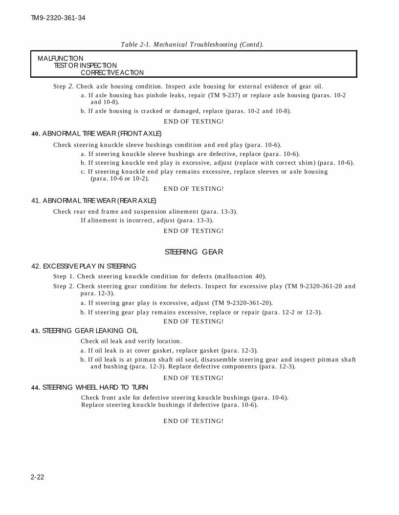
TM9-2320-361-34
Table 2-1. Mechanical Troubleshooting (Contd).
MALFUNCTIONTEST OR INSPECTION
CORRECTIVE ACTION
Step 2. Check axle housing condition. Inspect axle housing for external evidence of gear oil.a. If axle housing has pinhole leaks, repair (TM 9-237) or replace axle housing (paras. 10-2
and 10-8).b. If axle housing is cracked or damaged, replace (paras. 10-2 and 10-8).
END OF TESTING!
40. ABNORMAL TIRE WEAR (FRONT AXLE)Check steering knuckle sleeve bushings condition and end play (para. 10-6).
a. If steering knuckle sleeve bushings are defective, replace (para. 10-6).b. If steering knuckle end play is excessive, adjust (replace with correct shim) (para. 10-6).c. If steering knuckle end play remains excessive, replace sleeves or axle housing
(para. 10-6 or 10-2).
END OF TESTING!
41. ABNORMAL TIRE WEAR (REAR AXLE)Check rear end frame and suspension alinement (para. 13-3).
If alinement is incorrect, adjust (para. 13-3).
END OF TESTING!
STEERING GEAR
42. EXCESSIVE PLAY IN STEERINGStep 1. Check steering knuckle condition for defects (malfunction 40).
Step 2. Check steering gear condition for defects. Inspect for excessive play (TM 9-2320-361-20 andpara. 12-3).a. If steering gear play is excessive, adjust (TM 9-2320-361-20).b. If steering gear play remains excessive, replace or repair (para. 12-2 or 12-3).
END OF TESTING!43. STEERING GEAR LEAKING OIL
Check oil leak and verify location.a. If oil leak is at cover gasket, replace gasket (para. 12-3).b. If oil leak is at pitman shaft oil seal, disassemble steering gear and inspect pitman shaft
and bushing (para. 12-3). Replace defective components (para. 12-3).
END OF TESTING!44. STEERING WHEEL HARD TO TURN
Check front axle for defective steering knuckle bushings (para. 10-6).Replace steering knuckle bushings if defective (para. 10-6).
END OF TESTING!
2-22

TM 9-2320-361-34
Table 2-1. Mechanical Troubleshooting (Contd).
MALFUNCTIONTEST OR INSPECTION
CORRECTIVE ACTION
POWER TAKEOFF
45. (TRANSMISSION-DRIVEN) POWER TAKEOFF INOPERATIVEStep 1. Check power takeoff. Engage power takeoff and visually confirm output propeller shaft
rotation.If propeller shaft is not rotating (but power takeoff is in engaged position), removetransmission (para. 8-2) with power takeoff. Remove and inspect power takeoff. Repair(TM 9-2520-246-34-1) or replace power takeoff (para. 16-20).
Step 2. Visually inspect transmission power takeoff drive gear for damage.If drive gear is damaged, repair (TM 9-2520-246-34-1) or replace power takeoff (para. 16-20).
END OF TESTING!46. (TRANSFER-DRIVEN) POWER TAKEOFF INOPERATIVE
If power takeoff is inoperable, replace (para. 16-20) and repair (TM 9-2320-246-34-1). Engage andvisually confirm output propeller shaft rotation.
a. If transfer case half is defective, replace (para. 9-2) or repair (TM 9-2520-246-34-1).b. If power takeoff is defective, replace (para. 16-20) or repair (TM 9-2520-246-34-1).
END OF TESTING!
47. TRANSMISSION POWER TAKEOFF LEAKS OILDetermine oil leak location.
a. If power takeoff cover gasket is leaking, replace gasket in vehicle (para. 16-22).
CAUTION
b.
c.
. When replacing gaskets between power takeoff and transmis-sion housing, replace with the exact number of gaskets removed.Failure to use the correct number of new gaskets will affectpower takeoff-to-transmission gears spacing and gear backlash.With incorrect gear backlash, equipment may be damaged.
● When power takeoff requires bearing or gear replacement,transmission must be removed in order to adjust power takeoffgear and transmission gear backlash. Failure to adjust backlashmay result in damage to equipment.
If power takeoff shifter shaft seal, rear output shaft seal, input shaft seal, rear outputshaft housing gasket, or input shaft bearing cover gasket is leaking oil, remove powertakeoff from transmission and replace defective parts (para. 16-20).If power takeoff gears or bearings require replacement, remove transmission para. 8-2).Remove power takeoff from transmission and replace (para. 16-20) and repair”’(TM9-2520-246-34-1).
END OF TESTING!
48. TRANSFER POWER TAKEOFF LEAKS OILCheck oil feed line between transfer case and power takeoff for loose fittings or damaged line(para. 16-21).
a. If oil line fittings are loose, tighten. If damaged, replace (paras. 9-2 and 16-21).b. If gaskets or seals on power takeoff are leaking, replace gaskets or seals (para. 16-21).
END OF TESTING!
2-23

TM9-2320-361-34
Table 2-1. Mechanical Troubleshooting (Contd).
MALFUNCTIONTEST OR lNSPECTlON
CORRECTIVE ACTION
DUMP BODY (M342A2)
49. DUMP BODY WILL NOT RAISE
Step 1.
Step 2.
Step 3.
Step 4.
Step 5.
Step 6.
Step 7.
Step 8.
2-24
WARNING
● Overhead lifting device capacity must exceed dump body weight.A shifting, swinging, or falling load may cause injury topersonnel.
. Bleed hydraulic pressure before cracking hydraulic lines. Failure todo so may result in damage to equipment and injury to personnel.
Apply parking brake (TM 9-2320-361-10).NOTE
Some vehicles may not be updated to use dump body hydraulic locksystem. When vehicles do not have this system, substitutehydraulic hose will be needed to take the place of existing hydraulichose on lock system called out in hydraulic system checks.
Check hydraulic lock operation. Operate controls to raise dump body (TM 9-2320-361-10).Observe hydraulic lock operation.If hydraulic lock will not release, manually open hydraulic lock and secure in open position.Operate dump body to raise. If dump body raises, replace hydraulic lock cylinder or lockassembly (para. 16-13).Check hydraulic system for leaks.
WARNING
Use properly rated hydraulic hose when performing hydraulicsystem checks on vehicles not equipped with dump body lock.Failure to do this may result in injury to personnel.
NOTETag hydraulic hose ends of hydraulic lock system before removalfor installation.
Attach overhead lifting device to dump body and secure dump body hydraulic lock. Raisedump body with lifting device until dump body is in fully raised position. Secure dump bodywith safety braces (TM 9-2320-36 1-10).Remove all hydraulic hose ends from upper and lower control box manifolds. Install teefitting into one of three open ports of upper manifold and plug two ports in upper and lowermanifold. Install high pressure gage into tee. Remove one hydraulic hose from lock cylinderand adapt ends so that one end can connect to tee and the other end to open port on lowermanifold (para. 16-7).Operate dump body with main control lever set in D position (TM 9-2320-361-10). Maintainengine speed at 1,000 rpm for 10 seconds and observe pressure gage.If pressure reading is uneven or zero, replace hydraulic pump (para. 16-12).Check pump spacer for cracks or defects (para. 16-12).If spacer is cracked or defective, replace (para. 16-12).Replace control valve if pressure readings decrease slowly (para. 16-10).
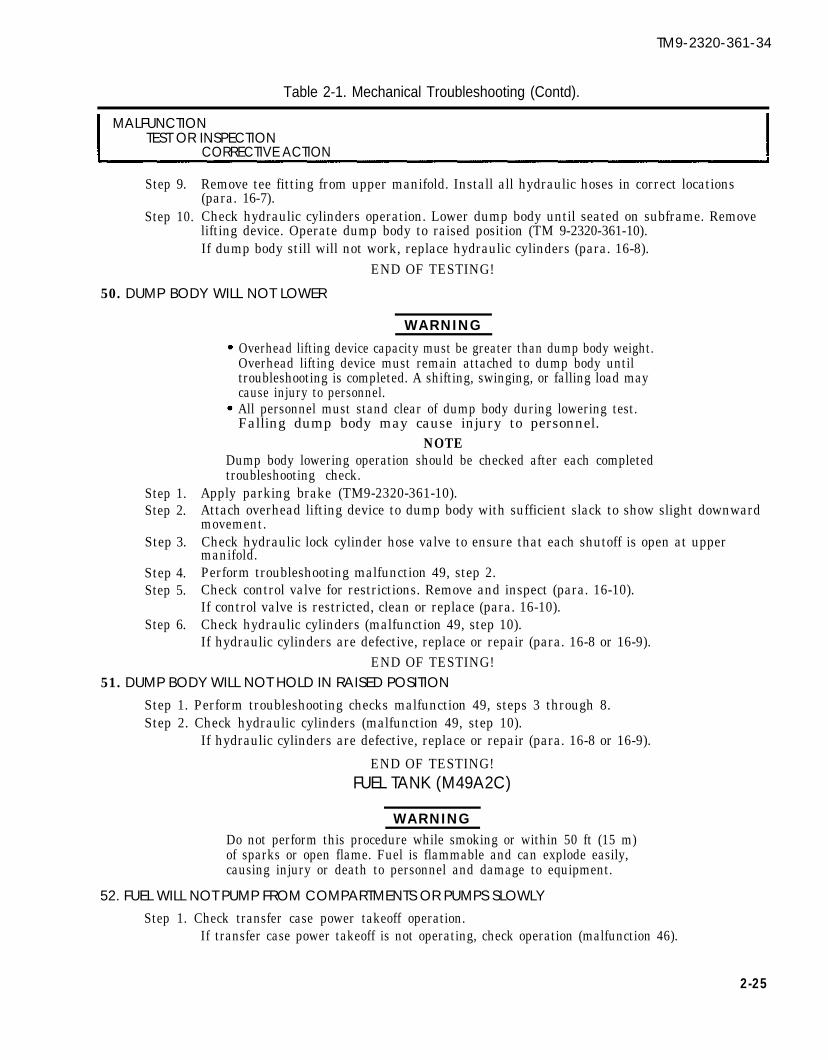
TM9-2320-361-34
Table 2-1. Mechanical Troubleshooting (Contd).
MALFUNCTIONTEST OR INSPECTION
CORRECTIVE ACTION
Step 9.
Step 10.
Remove tee fitting from upper manifold. Install all hydraulic hoses in correct locations(para. 16-7).Check hydraulic cylinders operation. Lower dump body until seated on subframe. Removelifting device. Operate dump body to raised position (TM 9-2320-361-10).If dump body still will not work, replace hydraulic cylinders (para. 16-8).
END OF TESTING!
50. DUMP BODY WILL NOT LOWER
WARNING
Overhead lifting device capacity must be greater than dump body weight.Overhead lifting device must remain attached to dump body untiltroubleshooting is completed. A shifting, swinging, or falling load maycause injury to personnel.All personnel must stand clear of dump body during lowering test.
Step 1.Step 2.
Step 3.
Step 4.Step 5.
Step 6.
Falling dump body may cause injury to personnel. NOTE
Dump body lowering operation should be checked after each completedtroubleshooting check.
Apply parking brake (TM9-2320-361-10).Attach overhead lifting device to dump body with sufficient slack to show slight downwardmovement.Check hydraulic lock cylinder hose valve to ensure that each shutoff is open at uppermanifold.Perform troubleshooting malfunction 49, step 2.Check control valve for restrictions. Remove and inspect (para. 16-10).If control valve is restricted, clean or replace (para. 16-10).Check hydraulic cylinders (malfunction 49, step 10).If hydraulic cylinders are defective, replace or repair (para. 16-8 or 16-9).
END OF TESTING!51. DUMP BODY WILL NOT HOLD IN RAISED POSITION
Step 1. Perform troubleshooting checks malfunction 49, steps 3 through 8.Step 2. Check hydraulic cylinders (malfunction 49, step 10).
If hydraulic cylinders are defective, replace or repair (para. 16-8 or 16-9).
END OF TESTING!FUEL TANK (M49A2C)
WARNINGDo not perform this procedure while smoking or within 50 ft (15 m)of sparks or open flame. Fuel is flammable and can explode easily,causing injury or death to personnel and damage to equipment.
52. FUEL WILL NOT PUMP FROM COMPARTMENTS OR PUMPS SLOWLYStep 1. Check transfer case power takeoff operation.
If transfer case power takeoff is not operating, check operation (malfunction 46).
2-25

TM9-2320-361-34
Table 2-1. Mechanical Troubleshooting (Contd).
MALFUNCTIONTEST OR INSPECTION
CORRECTIVE ACTION
Step 2. Check discharge valve operation for selected compartment.a. If discharge valve operation is defective, remove and inspect discharge valve internal
components (para. 15-13).b. If discharge valve internal components are defective, replace (para. 15-13).
Step 3. Check delivery pump operation.a. If delivery pump screen and filter separator are not restricted, remove and inspect delivery
pump internal components (para. 15-12).b. If delivery pump internal components are defective, replace components (para. 15-12).
END OF TESTING!
53. FUEL WILL NOT GRAVITY DRAIN FROM SELECTED COMPARTMENTSComplete troubleshooting malfunction 52, step 2.
END OF TESTING!
54. FUEL TANK COMPARTMENTS CANNOT BE SUCTION FILLEDComplete troubleshooting malfunction 52, steps 1 and 3.
END OF TESTING!
55. FUEL MIXED WITH WATER WHEN DISPENSEDIf dump drain valves operation is defective, remove sump assembly and replace dump drainvalve(s) (TM9-2320-361-20).
a. If drain valves operation is not defective, disassemble sump valve assembly and inspectinternal components (para. 15-13).
b. If sump valve components are defective, replace components (para. 15-13).
END OF TESTING!
WATER TANK (M50A2 AND M50A3)56. WATER WILL NOT PUMP FROM COMPARTMENTS OR PUMPS SLOWLY
Step 1. Check transfer case power takeoff operation.If transfer case power takeoff is not operating, check transfer case (malfunctions 32 through 36).
Step 2. Check discharge valve operation for selected compartment.a. If discharge valve operation is defective, remove and inspect discharge valve internal
components (para. 15-10 or 15-11).b. If discharge valve internal components are defective, replace (para. 15-10 or 15-11).
Step 3. Check delivery pump operation.a. If delivery pump screen and filter separator are not restricted, remove and inspect
delivery pump internal components (para. 15-12).b. If delivery pump internal components are defective, replace components (para. 15-12).
END OF TESTING!
2-26

TM 9-2320-361-34
MALFUNCTIONTEST OR INSPECTION
CORRECTIVE ACTION
Table 2-1. Mechanical Troubleshooting (Contd).
57.
58.
59.
60.
WATER WILL NOT GRAVITY DRAIN FROM SELECTED COMPARTMENTS
Complete troubleshooting malfunction 56, step 2.
END OF TESTING!
WATER TANK COMPARTMENTS CANNOT BE SUCTION FILLED
Complete troubleshooting malfunction 56, steps 1 and 3.END OF TESTING!
EARTH BORING AND POLESElllNGEARTH BORING MACHINE DRIVE INOPERATIVE
Step 1.
Step 2.
Step 3.
WARNING
(M764)
Eye protection is required when inspecting internal clutch caseoperation on vehicle. Failure to do this may result in fluidcontacting eyes and injury to personnel.
Check clutch case internal drive hubs. Remove top plug from clutch case housing. Operateearth boring machine with drive engaged and feed in neutral (TM9-2320-361-10). Lookingthrough plug hole, observe drive hubs for rotation.a. If rotation of drive hubs is evident, check and replace idler gears (para. 15-43).b. If no rotation of drive hubs is evident, repair or replace clutch case assembly (para. 15-44).Check intermediate case drive gears. Operate earth boring machine power leveler(TM9-2320-361-10).If power leveler will not operate, replace or repair intermediate gear assembly(para. 15-42).Check boring case. Remove inspection cover of boring case. Manually rotate rack barclockwise and observe boring case gears operation.If rack bar will not turn, replace or repair boring case (para. 15-38).
END OF TESTING!
EARTH BORING MACHINE FEED INOPERATIVE
WARNING
Eye protection is required when inspecting clutch case operationon vehicle. Failure to do this may result in injury to personnel.
NOTE
Earth boring machine auger feed cannot be moved up or downmanually without vehicle power to aid operation.
Step 1. Check clutch case internal feed hubs. Remove top breather and adapter from clutch casehousing. Operate earth boring machine with feed engaged and drive in neutral(TM9-2320-361-10).a. If rotation of feed hubs is evident, replace or repair clutch case assembly (para. 15-44).b. If no rotation of feed hubs is evident, check and replace defective idler gears (para. 15-43).
2-27

Table 2-1. Mechanical Troubleshooting (Contd).h t
TM 9-2320-361-34
MALFUNCTIONTEST OR INSPECTION
CORRECTIVE ACTION
Step 2. Check boring case. Remove inspection cover from boring case. Operate earth boringmachine with feed engaged and drive in neutral (TM9-2320-361-10).a. If no internal gear movement is evident, replace or repair intermediate gear assembly
(para. 15-42).b. If internal gear movement is evident, remove boring case from intermediate case and
replace or repair boring case (para. 15-38).END OF TESTING!
61. EARTH BORING MACHINE BRAKE INOPERATIVEReplace or repair defective clutch brake case assembly (para.
END OF TESTING!
62. EARTH BORING MACHINE WILL NOT MOVE VERTICALLY
15-44).
Step 1. Check power leveler. Operate power leveler vertical control (TM9-2320-361-10). Observepower leveler output shaft rotation.If power leveler top output shaft does not rotate, remove power leveler and replace orrepair (para. 15-41).
CAUTION
When power leveler-to-intermediate case drive gear is damaged,intermediate case gear should be checked for damage or defects.Failure to check intermediate case gears may damage new powerleveler drive gear.
Step 2. Replace or repair defective intermediate case gears (para. 15-42).END OF TESTING!
63. EARTH BORING MACHINE WILL NOT MOVE HORIZONTALLYPerform troubleshooting malfunction 62.
END OF TESTING!
64. EARTH BORING MACHINE EXCESSIVELY NOISYStep 1. Check backlash between feed idler gear and rack feed spur pinion gear (para. 15-43).
If backlash is incorrect, adjust shims on boring case gears (para. 15-38).Step 2. Check earth boring machine internal gears backlash (paras. 15-41 through 15-42).
If backlash is incorrect, adjust shims on boring case gears (paras. 15-38 through 15-42).END OF TESTING!
2-28

TM9-2320-361-34
Table 2-1. Mechanical Troubleshooting (Contd).
MALFUNCTIONTEST OR INSPECTION
CORRECTIVE ACTION
●
●
OUTRIGGERS
WARNINGHydraulic fluid is under high pressure. When additional compo-nents are required to perform troubleshooting, use equally ratedhydraulic components. Failure to use correctly rated componentsmay result in component failure and injury to personnel.Eye protection is required when performing hydraulic systemschecks. Failure to do this may result in fluid contacting-eyes andinjury to personnel.
NOTETag hydraulic hoses for installation.
65. OUTRIGGERS INOPERATIVEStep 1.
Step 2.Step 3.
Step 4.
Check hydraulic pump. Remove hydraulic hose from tee fitting below check valve. Installtest hydraulic tee into check valve hydraulic tee and install high pressure gage into testtee. Operate outrigger control lever (TM9-2320-361-10).a. If pressure gage reading is uneven, replace regulator valve (para. 15-46).b. If pressure gage reading is low and uneven, replace hydraulic pump (para. 15-45).Remove test hydraulic tee and high pressure gage. Install hydraulic hose in check valve tee.Check control valve. Remove four hydraulic hoses from control valve. Install one tee in eachof four open ports of control valve. Install one pressure gage in each of four tees. Installhydraulic hoses in correct tee on proper port of control valve (para. 15-46).Operate earth boring machine hydraulic pump and outrigger control to extend outriggers(TM9-2320-361-10). Observe pressure gages readings.a. If pressure reading on all gages decreases, replace control valve (para. 15-46).b. If pressure reading on one or more gages is normal and even, repair hydraulic
cylinder(s) as appropriate (para. 15-48).END OF TESTING!
66. OUTRIGGERS OPERATE UNEVENLYStep 1. Perform troubleshooting malfunction 65, steps 3 and 4.Step 2. Replace or repair hydraulic cylinders (para. 15-48).
END OF TESTING!
67. OUTRIGGERS WILL NOT HOLD IN EXTENDED POSITIONComplete troubleshooting malfunction 65, steps 3 and 4.
END OF TESTING!
2-29

TM9-2320-361-34
Table 2-1. Mechanical Troubleshooting (Contd).
MALFUNCTIONTEST OR lNSPECTION
CORRECTIVE ACTION
WINCHES
68. CLUTCH WILL NOT ENGAGE DRUMStep 1. Check shifter shaft and clutch.
a. Remove end case and disassemble (para. 16-2, 16-3, or 16-4).b. Remove rust and dried lubricant from end case, reassemble, and install (para. 16-2, 16-3,
or 16-4).Step 2. Check for mechanical obstruction if clutch handle moves short distance, then clatters.
Remove end case and disassemble. Inspect clutch and drum jaws for burrs, breaks, andmisalinement. Repair winch if defective (para. 16-2, 16-3, or 16-4).
END OF TESTING!
69. WINCH NOISY WHEN UNDER LOADStep 1. Check drum for radial free play.
Replace bushings if radial free play is present (para. 16-2, 16-3, or 16-4).Step 2. Check wormshaft radial free play.
Disassemble gearcase, inspect parts, and replace parts if defective(para. 16-2, 16-3, or 16-4).
Step 3. Check automatic brake.Replace brakeshoe if defective (para. 16-2, 16-3, or 16-4).
END OF TESTING!
70. DRUM OVERRUNS CABLE OR CABLE COILS LOOSEN WHEN PAYING OUT CABLECheck drag brake adjustment (TM9-2320-361-20).
Replace drag brake if noisy or no adjustment remains (para. 16-2, 16-3, or 16-4).
END OF TESTING!
71. WINCH DOES NOT HOLD LOAD WHEN POWER RELEASEDStep 1. Check for presence of burned odor.
Replace automatic brakeshoe if defective (para. 16-2, 16-3, or 16-4).Step 2. Automatic brake does not hold load after adjustment.
Replace automatic brakeshoe if defective and inspect drum (para. 16-2, 16-3, or 16-4).
END OF TESTING!
72. WINCH LEAKS OILStep 1. Check for defective oil seals and gaskets.
Replace oil seals and gaskets if defective (para. 16-2, 16-3, or 16-4).Step 2. Check for cracked covers and housings.
Replace covers and housings if cracked (para. 16-2, 16-3, or 16-4).
END OF TESTING!
2-30

TM9-2320-361-34
Table 2-1. Mechanical Troubleshooting (Contd).
MALFUNCTIONTEST OR INSPECTION
CORRECTIVE ACTION
73.
74.
75.
76.
77.
78.
WINTERIZATION KITS
NOTEMechanical troubleshooting for personnel and engine coolantheaters are the same. The following is for fuel burning personnelheaters.
HEATER FAILS TO TURN ONBench test for defective control parts (para. 17-19 or 17-20).
If defective, replace control parts (paras. 17-2 through 17-18, as necessary).
END OF TESTING!
HEATER OVERHEATS - OVERHEAT SWITCH IS GOODStep 1.
Step 2.
Check for obstructed air flow.If obstructed, clear obstructions from fuel supply air and ventilating air passages(para. 17-8 or 17-14).Check fuel control valve (para. 17-19 or 17-20).
Replace fuel control valve if defective (para. 17-6 or 17-12).
END OF TESTING!
HEATER OVERHEATS - CONTINUES TO RUNTest overheat switch (para. 17-19 or 17-20).
Replace overheat switch if defective (para. 17-7 or 17-17).
END OF TESTING!
HEATER OUTPUT TOO LOWStep 1. Check for obstructed fuel lines or contaminated fuel supply.
a. If obstructed, clear fuel supply lines (para. 17-8 or 17-14 for internal fuel supply andTM 9-2320-361-20 for external fuel supply).
b. Drain fuel control valve (para. 17-19 or 17-20).
Replace fuel control valve if defective (para. 17-6 or 17-12).
Step 2. Check fuel control valve (para. 17-19 or 17-20).Replace fuel control valve if defective (para. 17-6 or 17-12).
END OF TESTING!
HEATER SMOKES AND BANGS WHEN STARTINGPerform malfunction 76, step 2.
END OF TESTING!
BLOWER WILL NOT STOP AFTER TURN OFFCheck flame detector switch condition (para. 17-19 or 17-20).
Replace flame detector switch if defective (para. 17-2 or 17-15).
END OF TESTING!
2-31

TM9-2320-361-34
Table 2-1. Mechanical Troubleshooting (Contd).
MALFUNCTIONTEST OR INSPECTION
CORRECTIVE ACTION
79. ODOR OF FUEL IN VENTILATING AIRStep 1. Check for leaking fuel connections at stand pipe and fuel valve.
Tighten connections if loose (para, 17-8 or 17-14).Step 2. Check burner preformed packing and gasket (para. 17-9 or 17-16).
Replace preformed packing and gasket if defective (para. 17-9 or 17-16).
END OF TESTING!
80. BLOWER RUNS BUT HEATER FAILS TO IGNITEStep 1. Test igniter (para. 17-19 or 17-20).
Replace igniter if defective (para. 17-7 or 17-13).Step 2. Check fuel control valve (para. 17-19 or 17-20).
Replace fuel control valve if defective (para. 17-6 or 17-12).Step 3. Check for obstructed ignition air passages.
Clear ignition air passages of obstruction.
END OF TESTING!
81. HEATER SMOKES DURING NORMAL OPERATIONStep 1.
Step 2.
Check for slow blower motor operation (para. 17-19 or 17-20).Replace blower motor if defective (para. 17-3 or 17-11).Test fuel control valve (para. 17-19 or 17-20).Replace fuel control valve if defective, (para. 17-6 or 17-12).
END OF TESTING!
Section Ill. GENERAL MAINTENANCE INSTRUCTIONS
2-7. GENERAL MAINTENANCE INSTRUCTIONS INDEX
Publications which provide additional information on general shop practice techniques, preservation,welding, sheet metal work, etc., are listed in Appendix A, References, of this manual. To find a particulargeneral maintenance instruction, use the instruction index below.
PARA. TITLE PAGENO. NO.
2-8. Cleaning 2-332-9. Inspection 2-342-10. Repair 2-352-11. Assembly - Precautionary Rules 2-36
2-32

TM 9-2320-361-34
2-8. CLEANINGa. General Instructions. Cleaning procedures will be the same for the majority of parts and components
which make up the vehicle subassemblies. General cleaning procedures are detailed in “b” through “k.”b. The Importance of Cleaning. Great care and effort are required in all cleaning operations. The
presence of dirt and foreign material is a constant threat to satisfactory vehicle operation and maintenance.The following will apply to all cleaning operations:
(1) Clean all parts before inspection, after repair, and before assembly.(2) Hands must be kept free of large amounts of grease, which can collect dust and grit.(3) After cleaning, all parts must be covered or wrapped in plastic or paper to protect them from
dust and/or dirt.
WARNING
Compressed air source will not exceed 30 psi (207 kPa). Whencleaning with compressed air, eyeshields must be worn. Failure towear eyeshields may result in injury to personnel.
c. External Engine Cleaning. All electrical equipment and other parts that could be damaged by steamcleaning or moisture must be removed and all openings covered before cleaning. Dry with compressed air.
d. Disassembled Parts Cleaning.(1)(2)(3)(4)(5)
Place all disassembled parts in wire basket(s) for cleaning.Dry and cover all cleaned parts.Place on or in “racks” and hold for inspection or repair.All parts subject to rusting must be lightly oiled and wrapped.Keep all related parts and components together. Do not mix parts.
WARNING
Improper cleaning methods and use of unauthorized cleaningsolvents may cause damage to equipment or injury to personnel.Refer to TM 9-247 for cleaning method information.
e. Castings.(1) Clean inner and outer surfaces of castings, and all areas likely to collect grease and oil, with cleaning
solvents (TM 9-247).(2) Use a stiff brush to remove sludge and gum deposits.
WARNING
Compressed air source will not exceed 30 psi (207 kPa). Whencleaning with compressed air, eyeshields must be worn. Failure towear eyeshields may result in injury to personnel.
(3) Use compressed air to blow out all tapped screw holes and to dry castings after cleaning.f. Oil Passages. Particular attention must be given to all oil passages in castings and machined parts. Oil
passages must be kept clean and free of any obstructions.(1)(2)(3)
Clean passages with wire probes to break up any sludge or gum deposits.Wash passages by flushing with cleaning solvents (TM 9-247).Dry passages with compressed air.
CAUTION
Do not allow drycleaning solvents to come in contact with seals, cables,or flexible hoses. These cleaners cause leather, rubber, and syntheticmaterials to dry out, rot, and lose pliability, making them unserviceable.
g. Oil Seals, Electrical Cables, and Flexible Hoses. Clean with soap and water.
2-33
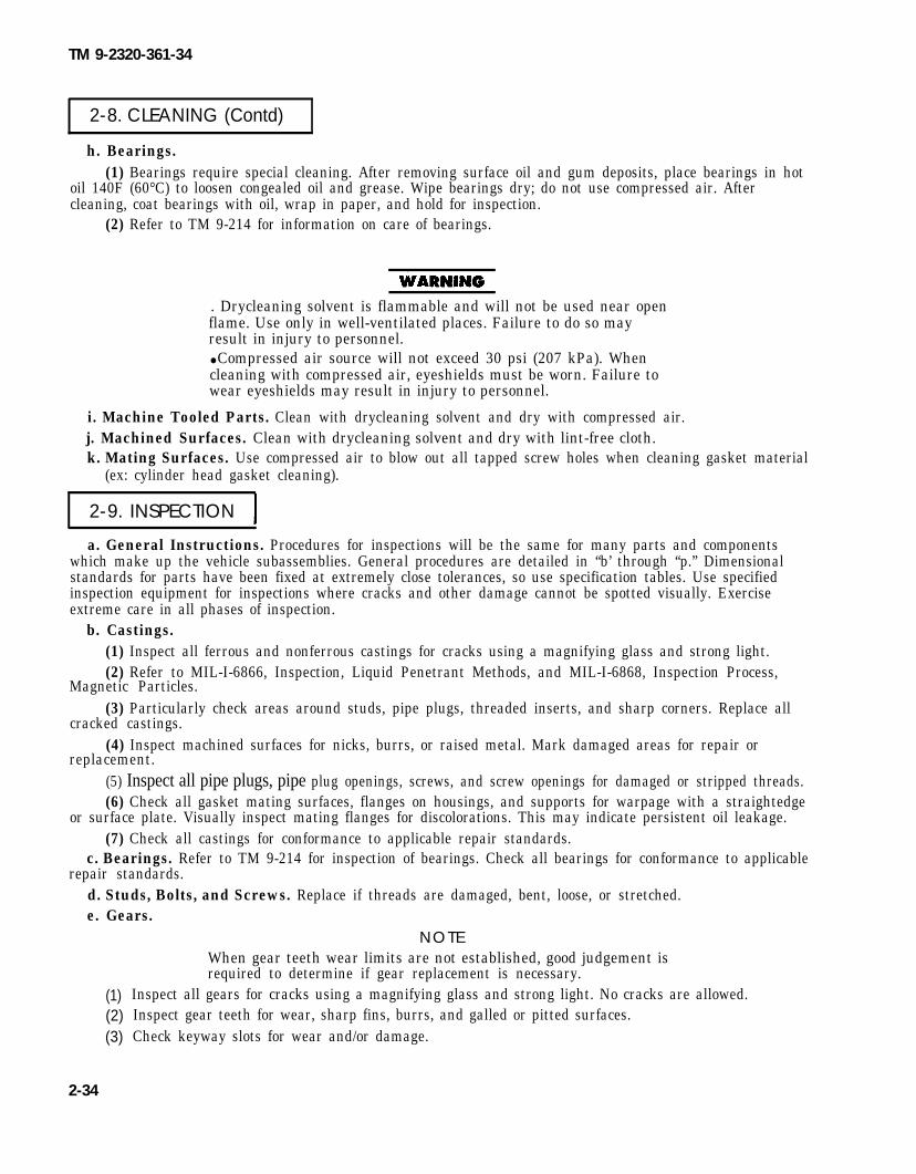
TM 9-2320-361-34
2-8. CLEANING (Contd)
h. Bearings.(1) Bearings require special cleaning. After removing surface oil and gum deposits, place bearings in hot
oil 140F (60°C) to loosen congealed oil and grease. Wipe bearings dry; do not use compressed air. Aftercleaning, coat bearings with oil, wrap in paper, and hold for inspection.
(2) Refer to TM 9-214 for information on care of bearings.
. Drycleaning solvent is flammable and will not be used near openflame. Use only in well-ventilated places. Failure to do so mayresult in injury to personnel.● Compressed air source will not exceed 30 psi (207 kPa). Whencleaning with compressed air, eyeshields must be worn. Failure towear eyeshields may result in injury to personnel.
i. Machine Tooled Parts. Clean with drycleaning solvent and dry with compressed air.j. Machined Surfaces. Clean with drycleaning solvent and dry with lint-free cloth.k. Mating Surfaces. Use compressed air to blow out all tapped screw holes when cleaning gasket material
(ex: cylinder head gasket cleaning).
2-9. INSPECTION
a. General Instructions. Procedures for inspections will be the same for many parts and componentswhich make up the vehicle subassemblies. General procedures are detailed in “b’ through “p.” Dimensionalstandards for parts have been fixed at extremely close tolerances, so use specification tables. Use specifiedinspection equipment for inspections where cracks and other damage cannot be spotted visually. Exerciseextreme care in all phases of inspection.
b. Castings.(1) Inspect all ferrous and nonferrous castings for cracks using a magnifying glass and strong light.(2) Refer to MIL-I-6866, Inspection, Liquid Penetrant Methods, and MIL-I-6868, Inspection Process,
Magnetic Particles.(3) Particularly check areas around studs, pipe plugs, threaded inserts, and sharp corners. Replace all
cracked castings.(4) Inspect machined surfaces for nicks, burrs, or raised metal. Mark damaged areas for repair or
replacement.(5) Inspect all pipe plugs, pipe plug openings, screws, and screw openings for damaged or stripped threads.(6) Check all gasket mating surfaces, flanges on housings, and supports for warpage with a straightedge
or surface plate. Visually inspect mating flanges for discolorations. This may indicate persistent oil leakage.(7) Check all castings for conformance to applicable repair standards.
c. Bearings. Refer to TM 9-214 for inspection of bearings. Check all bearings for conformance to applicablerepair standards.
d. Studs, Bolts, and Screws. Replace if threads are damaged, bent, loose, or stretched.e. Gears.
(1)(2)(3)
2-34
NOTEWhen gear teeth wear limits are not established, good judgement isrequired to determine if gear replacement is necessary.
Inspect all gears for cracks using a magnifying glass and strong light. No cracks are allowed.Inspect gear teeth for wear, sharp fins, burrs, and galled or pitted surfaces.Check keyway slots for wear and/or damage.

TM9-2320-361-34
2-9. lNSPECTION(Contd)
f. Bushings and Bushing Type Bearings.(1) Check all bushings and bushing-type bearings for secure fit, evidence of overheating, wear, burrs,
nicks, and out-of-round condition.(2) Check for dirt in lubrication holes or grooves. Holes and grooves must be clean and free from damage.
g. Oil Seals. Oil seals are mandatory replacement items.h. Core Hole Expansion Plugs. Inspect for leakage. Replace plugs when leakage is present.i. Machine Tooled Parts. Inspect for cracks, breaks, elongated holes, wear, and chips.j. Machined Surfaces. Inspect for cracks, evidence of wear, galled or pitted surface, burrs, nicks, and
scratches.k. Mated Surfaces. Inspect for remains of old gasket, seal, evidence of leakage, pitting, and secure fit.1. Rusted Surfaces. Inspect for pitting, holes, and severe damage.m. Oil Bathed Internal Parts. Inspect for cracks, nicks, burrs, evidence of overheating, and wear.n. Air-Actuated Internal Parts. Inspect for cracks, nicks, burrs, evidence of overheating, and wear.o. Externally Exposed Parts. Inspect for breaks, cracks, rust damage, and wear.p. Springs. Inspect for broken, collapsed, and twisted coils.
2-10. REPAIRSa. General Instructions. Repair of most parts and components is limited to general procedures outlined
in applicable maintenance instructions and the following procedures, “b” through “h.”
CAUTIONRepaired items must be thoroughly cleaned to remove metal chipsand abrasives. Metal chips and abrasives can enter working partsof vehicle and cause damage to equipment.
b. Castings.(1) All cracked castings will be replaced.(2) Only minor repairs to machined surfaces, flanges, and gasket mating surfaces are permitted. Remove
minor nicks, burrs, and/or scratches with:(a) Fine mill file.(b) Crocus cloth dipped in cleaning solvent.(c) Lapping across a surface plate.
(3) Remachining of machined surfaces to repair damage, warpage, or uneven surfaces is not permitted.Replace castings.
(4) Repair damaged threaded pipe plug and/or screw threads with a tap. Repair oversize holes withthreaded inserts.
c. Bearings. Refer b TM 9-214.d. Studs. Replace all bent and stretched studs. Repair minor thread damage with a thread die. Replace
studs having stripped or damaged threads as outlined below:(1) Remove using a stud remover. Back studs out slowly to avoid heat buildup and seizure which can
cause stud to break off.
CAUTION
Refer to TM 9-237, Welding Instructions, to avoid damage tocastings if welding method is used.
(2) If studs break off too short to use a stud remover, use a stud extractor to remove, or use “weldingmethod.”
2-35

TM 9-2320-361-34
I 2-10. REPAIR (Contd)
(3) Broken studs can be removed by welding a nut or bar stock to stud and removing with wrench.
NOTEStandard studs may have a coarse thread on one end and a finethread on the other end. The coarse thread end is installed in thealuminum casting. Studs having coarse threads on both ends areused in some applications. The short threaded end goes into thecasting. Refer to TM 9-2320-361-34P for correct part numbers.
(4) Replacement studs have a special coating and must have a small amount of antiseize compound(MILA-907) applied on threads before stud is installed. Install replacement stud slowly to prevent heatbuildup and snapping off.
e. Gears.(1) Remove gears using pullers.(2) Use the same methods described in paragraph 2-10b to remove minor nicks, burrs, or scratches on
gear teeth.(3) If keyways are worn or enlarged, replace gear.
f. Bushings and Bushing-Type Bearings. When bushings and bushing-type bearings seize to a shaftand spin in the bore, the associated part must also be replaced.
g. Oil Seals.(1) Remove oil seals by pressing or prying out. Be carefbl not to damage casting or adapter bore.(2) Always install new seal in bore using proper seal replacing tool.
h. Cylinder Head - Cylinder Block. Repair of cylinder head and cylinder block is limited to proceduresoutlined in TM 9-2815-210-34-2-2.
I I2-11. ASSEMBLY - PRECAUTIONARY RULES
a. Cleanliness is essential in all component assembly operations. Dirt and dust, even in small quantities,are abrasive. Parts must be cleaned as specified and kept clean. Wrap or cover parts and components whenassembly procedures are not immediately completed.
b. Coat all bearings and contact surfaces with operating oil (axle oil for axle parts, transmission oil fortransmission parts, etc.) to ensure lubrication of parts during initial operation after repair.
c. Use new gaskets and preformed packings during assembly of all components.
2 - 3 6

TM 9-2320-361-34
CHAPTER 3ENGINE MAINTENANCE
Section I. In-Vehicle Engine Maintenance (page 3-1)Section II. Engine Replacement (page 3-56)
Section 1. IN-VEHICLE ENGINE MAINTENANCE
3-1. IN-VEHICLE ENGINE MAINTENANCE INDEX
PARA TITLE PAGEN O . NO.
3 - 23 - 33 - 43 - 53 - 63 - 73 - 83 - 93 - 1 03 - 1 13 - 1 23 - 1 33 - 1 43 - 1 53 - 1 63 - 1 7
Engine Front and Rear Mounting Brackets ReplacementCylinder Head MaintenanceVibration Damper and Seal MaintenanceFlywheel and Transmission Adapter Plate MaintenanceRocker Arm Covers ReplacementRocker Arms and Pushrods MaintenanceTiming Gears Cover and Gasket ReplacementTappet Chamber Cover and Gasket ReplacementValve Tappets MaintenanceOil Pan ReplacementOil Pump MaintenanceOil Pressure Regulator Housing MaintenanceEngine Oil Cooler ReplacementEngine Oil Cooler and Oil Filter Housing MaintenanceAir Compressor Support and Gasket ReplacementIntake and Exhaust Manifolds Maintenance
3-13-43-103-143-163-203-283-303-323-343-363-403-463-483-503-52
3-2. ENGINE FRONT AND REAR MOUNTING BRACKETS REPLACEMENTTHIS TASK COVERS:a. Front Mounting Bracket Removal c. Rear Mounting Bracket Removalb. Front Mounting Bracket Installation d. Rear Mounting Bracket Installation
INITIAL SETUP
APPLICABLE MODELSAllTOOLSGeneral mechanic’s tool kit (Appendix B, Item 1)Torque wrench, 3/4-in. dr. (Appendix B, Item 6)1-1/8-in. socket, 3/4-in. dr.
(Appendix B, Item 33)1-1/4-in. socket, 3/4-in. dr.
(Appendix B, Item 37)Breaker bar, 3/4-in. dr. (Appendix B, Item 34)MATERIALS/PARTSThree lockscrews (front bracket)
(Appendix F, Item 115)Lockscrew (front bracket)
(Appendix F, Item 116)Lockscrew (front bracket)
(Appendix F, Item 117)Four locknuts (rear bracket)
(Appendix F, Item 88)PERSONNEL REQUIRED
REFERENCES (TM)TM 9-2320-361-10TM 9-2320-361-20TM 9-2320-361-34PEQUIPMENT CONDITION● Hood raised and secured (TM 9-2320-361-10).. Wheels chocked (TM 9-2320-361-10).● Battery ground cable disconnected
(TM 9-2320-361-20).. Primary fuel filter removed (right front mount
only) (TM 9-2320-361-20).● Steering gear removed (left front mount only
(para. 12-2).GENERAL SAFETY INSTRUCTIONS● All personnel must stand clear during lifting
operations.● Do not detach lifting device from engine until all
engine weight is equally distributed and engine isstable.
● Lifting device must have weight capacity greaterthan the weight of the engine and transmission.
Two
3-1

TM 9-2320-361-34
I 3-2. ENGINE FRONT AND REAR MOUNTING BRACKETS REPLACEMENT (Contd)
WARNING
● All personnel must stand clear during lifting operations. Aswinging or shifting load may cause injury to personnel.
. Do not detach lifting device from engine until all engine weight isequally distributed and engine is stable. An improperly supportedengine may cause injury to personnel.
● Lifting device must have a weight capacity greater than theweight of the engine and transmission to prevent damage toequipment and injury to personnel.
CAUTION
Closely observe all engine and transmission attachments duringremoval to prevent damage to equipment.
NOTEAssistant will help with lifting operations.
a. Front Mounting Bracket Removal
1. Attach lifting device to front engine lifting bracket (10). Raise lifting device enough to remove slack.2. Remove three lockscrews (7) and washers (8) from front bracket (5) and mounting plate (9). Discard
lockscrews (7).3. Remove lockscrew (4), washer (2), lockscrew (3), washer (2), and front bracket (5) from engine
block (6). Discard lockscrews (3) and (4).
I b. Front Mounting Bracket InstallationI
1. Install front bracket (5) on engine block (6) with washer (2), new lockscrew (3), washer (2), and newlockscrew (4). Tighten lockscrews (4) and (3) 200-250 lb-ft (271-339 N.m).
2. Install front bracket (5) on mounting plate (9) with three washers (8) and new lockscrews (7).Tighten three lockscrews (7) 25-27 lb-ft (34-37 N.m).
3. Lower lifting device and remove from front engine lifting bracket (10).
c. Rear Mounting Bracket Removal
1. Attach lifting device to rear engine lifting bracket (1). Raise lifting device enough to remove slack.2. Remove rear engine mount pad (TM 9-2320-361-20).3. Remove four locknuts (12) and rear bracket (13) from flywheel housing studs (11). Discard lock-
nuts (12).
I d. Rear Mounting Bracket InstallationI
1. Install rear bracket (13) on flywheel housing studs (11) with four new locknuts (12). Tightenlocknuts (17) 45-55 lb-ft (61-75 N.m).
2. Install rear engine mount pad (TM 9-2320-361-20).3. Lower lifting device and remove lifting device from rear engine lifting bracket (l).
3-2

para 12-2
TM 9-2320-361-20
TM 9-2320-361-20
TM 9-2320-361-10
TM 9-2320-361-34
3-2. ENGINE FRONT AND REAR MOUNTING BRACKETS REPLACEMENT (Contd) I
3-3

TM 9-2320-361-34
3-3. CYLINDER HEAD MAINTENANCE
THIS TASK COVERS:a. Removal c. Installationb. Cleaning, Inspection, and Repair
INITIAL SETUP
APPLICABLE MODELSAll
TOOLSGeneral mechanic’s tool kit
(Appendix B, Item 1)Torque wrench, l/2-in. dr.
(Appendix B, Item 7)
SPECIAL TOOLSCylinder head wrench (Appendix B, Item 62)
MATERIALS/PARTSGasket (Appendix F, Item 36)Two lockwashers (Appendix F, Item 129)Lubricating oil (Appendix C, Item 13)Sealing compound, gasket forming
(Appendix C, Item 19)
REFERENCES (TM)TM 9-2320-361-10TM 9-2320-361-20TM 9-2320-361-34PTM 9-2815-210-34-2-2
EQUIPMENT CONDITION.Battery ground cable disconnected
(TM 9-2320-361-20).● Air intake tube and cap removed
(TM 9-2320-361-20).● Rocker arms and pushrods removed (para. 3-7).● Fuel injector nozzles and holders removed
(para. 5-2).● Intake and exhaust manifolds removed
(para. 3-17).
GENERAL SAFETY INSTRUCTIONS● Ensure engine compartment is free of all tools and
working materials before starting engine.● Hand protection must be worn during nut
retightening. Engine components are hot.
I a. Removal
1. Remove two screws (8), lockwashers (7), bracket (6), and lifting bracket (9) from cylinderhead (2). Discard lockwashers (7).
2. Using cylinder head wrench, remove fourteen nuts (1) and washers (10) from studs (5).
CAUTION
Uneven lifting and binding of cylinder head may damage studs andcause misalinement of cylinder head during installation.
NOTECylinder head is heavy and may require the use of a lifting deviceduring removal.
3. Remove cylinder head (2) and gasket (3) from engine block (4). Discard gasket (3).
3-4

3-3.
TM 9-2320-361-34
3-5

3-3.
para. 2-8.
para. 2-9. para. 2-10.
TM 9-2815-210-34-2-2
TM 9-2320-361-34
C A U T I O N
1.2.
3.
4.
5.
7.8.
9.10.11.12.
Do not allow lubricating oil to contact the surface on engine blockwhere cylinder head gasket bonds. Cylinder head gasket maybecome contaminated with oil and fail to seal on engine block andcylinder head.
Apply a thin coat of new engine oil on threads of fourteen studs (5) and nuts (1) facings.Locate point (11) on new gasket (3) approximately 2 in. (51 mm) above edge (13). Begin atpoint (11) and apply a thin, uniform coat of sealing compound approximately 0.5 in, (12.7 mm) widealong edge (13) on both sides of gasket (3) until reaching point (12) as shown.
CAUTIONDo not bind cylinder head against studs during installation.Bending of studs may cause cylinder head misalinement to guidepins. Cylinder head cannot be installed on engine block when thiscondition exists.
Install new gasket (3) and cylinder head (2) on fourteen studs (5) and engine block (4) with fourteenwashers (10) and nuts (1).
NOTEIf studs rotate when torquing nuts, remove cylinder head (task a)and replace or repair studs (para. 2-10).
Tighten fourteen nuts (1) to 40 lb-ft (54 N.m) in torque sequence shown.a. Using torque sequence, tighten nuts (1) to 80 lb-ft (109 N.m).b. Using torque sequence, tighten nuts (1) to 110 lb-ft (149 N.m).c. Using torque sequence, tighten nuts (1) to 130 lb-ft (176 N.m).Install lifting bracket (9) and bracket (6) on cylinder head (2) with two new lockwashers (7) andscrews (8).Install intake and exhaust manifolds (para. 3-17).Install and adjust rocker arms and pushrods (para. 3-7).
NOTEDo not apply sealing compound on rocker arm cover gasket at thistime.
Install rocker arm cover and gasket (para. 3-6).Install fuel injector nozzles and holders (para. 5-2).Install air intake tube and cap (TM 9-2320-361-20).Connect battery ground cable (TM 9-2320-361-20).
3 - 6

TM 9-2320-361-34
3-3. CYLINDER HEAD MAINTENANCE (Contd)
0.5 IN:(12.7 MM) 2 IN. 51 MM)
SEALANT DIAGRAM TORQUE SEQUENCE
3-7

TM 9-2320-361-34
3-3. CYLINDER HEAD MAINTENANCE (Contd)
WARNING
Ensure engine compartment is free of all tools and workingmaterials before starting engine. Failure to do this may result indamage to equipment and injury to personnel.
12. Start engine (TM 9-2320-36 1-10). Idle engine until coolant temperature reaches a minimumof 175°F (79C) before engine shutdown.
13. Remove no. 1 through no. 3 injector tubes (para. 5-3).14. Remove rocker arm cover and gasket (para. 3-6).15. Remove rocker arm assembly (para. 3-7).
WARNING
Hand protection must be worn during nut retightening. Enginesurface is hot and can cause injury to personnel.
CAUTION●
●
All nuts must rotate during tightening recheck. Failure of nut(s)to rotate may result in improper torque setting, cylinder headwarpage, and gasket failure.During nuts tightening recheck, engine coolant temperature mustremain 170F (77C) or above to maintain cylinder headexpansion. Tightening of nuts when coolant is below 170F (77°C)may result in cylinder head warpage and gasket failure.
NOTEIf studs rotate when torquing nuts, remove cylinder head (task a)and repair or replace studs (para. 2-10).
16. Tighten fourteen nuts (1) to 130 lb-ft (176 N.m) in torque sequence shown.
3-8

para.3-7.
para. 3-6.
para. 5-3
TM 9-2320-361-34
3-3. CYLINDER HEAD MAINTENANCE (Contd)
3 - 9

TM 9-2320-361-34
3-4. VIBRATION DAMPER AND SEAL MAINTENANCETHIS TASK COVERS:a. Removal c. Installationb. Cleaning and Inspection
INITIAL SETUP
APPLICABLE MODELSAll
TOOLSGeneral mechanic’s tool kit (Appendix B, Item 1)Torque wrench, 3/4-in. dr. (Appendix B, Item 6)1-5/8-in. socket, 3/4-in. dr. (Appendix B, Item 45)Handle, socket wrench, 3/4-in. dr.
(Appendix B, Item 46)Mechanical puller (Appendix B, Item 22)Magnetic particle equipment
(Appendix B, Item 63)
REFERENCESTM 9-2320-361-10TM 9-2320-361-20TM 9-2320-361-34P
EQUIMENT CONDITION● Parking brake set (TM 9-2320-361-10).● Fuel shutoff valve disconnected
(TM 9-2320-361-10).● Vehicle in fifth gear (TM 9-2320-361-10).● Battery ground cable disconnected
(TM 9-2320-361-20).SPECIAL TOOLS ● Radiator removed (TM 9-2320-361-20).
Crankshaft driver (Appendix B, Item 48) ● Drivebelts removed (TM 9-2320-361-20).
Oil seal inserter (Appendix B, Item 47) GENERAL SAFETY INSTRUCTIONS
MATERIALS/PARTS Hand protection must be worn at all times whenSeal (Appendix F, Item 220) handling heated vibration damper and pulley.
Two lockwashers (Appendix F, Item 123)Lubricating oil OE/HDO 30
(Appendix C, Item 13)
1. Remove two screws (9), lockwashers (10), and lockplate (8) from vibration damper and pulley (6).Discard lockwashers (10).
a. Removal
2. Remove retainer bolt (7) and washer (1) from crankshaft (4) and vibration damper and pulley (6).3. Remove vibration damper and pulley (6) from crankshaft (4) and timing cover (5).4. Remove plug (2) from key way (3) of crankshaft (4).5. Install retainer bolt (7) in end of crankshaft (4) and turn until key (3) position is approximately
12 o’clock. Remove retainer bolt (7).6. Using mechanical puller, remove oil seal (11) from timing cover (5). Discard oil seal (11).
I b. Cleaning and Inspection
1.2.
3.
4.
5.
6.
3-10
For general cleaning instructions, refer to para. 2-8Visually inspect vibration damper and pulley (6) for nicks, cracks, or damage. Replace vibrationdamper and pulley (6) if damaged.Inspect exposed section of key (3) on crankshaft (4) for looseness or damage. Remove engine(para. 3-20) and replace crankshaft (4) if defective.Hold rear half of vibration damper (6) on floor with your feet. Try to turn vibration damper andpulley (6). Replace vibration damper and pulley (6) if loose.Inspect threads of two puller screw holes for damage. Fix minor thread damage with tap if damaged.Replace vibration damper and pulley (16) if damaged beyond repair.Inspect lockplate (8) for cracks or damage. Replace lockplate (8) if cracked or damaged.

TM 9-2320-361-34
3-4. VIBRATION DAMPER AND SEAL MAINTENANCE (Contd)
7. Inspect rubber insert in vibration damper and pulley (6) for cracks. Replace vibration damper andpulley (6) if cracked.
8. Ensure rubber insert in vibration damper and pulley (6) has not pulled away from vibration damperand pulley (6). Replace vibration damper and pulley (6) if damaged.
N O T E● Perform step 9 for LDS-465-2 engines.● Perform step 10 for engines other than LDS-465-2.
9. Inspect liquid deflector for looseness and damage. Replace liquid deflector if loose or damaged.10. Using magnetic particle equipment, inspect exposed section of crankshaft (4) for cracks or damage.
Replace crankshaft (4) if cracked or damaged.
3-11

TM 9-2320-361-34
3-4. VIBRATION DAMPER AND SEAL MAINTENANCE (Contd)
c. Installation 1.
2.
3.4.
5.6.
7.
8.9.
10.
11.
12.
13.
3-12
Assemble vibration damper pulley bolt (10), washer (6), and adapter to form oil seal inserter.NOTE
Oil seal must be installed with lip of oil seal facing out and extendedsteel body towards vibration damper. Open side of oil seal ispositioned towards timing cover. Failure to install oil seal correctlymay result in oil leak.
Install new oil seal (1) in timing cover (2) with oil seal inserter on crankshaft (3). Tighten vibrationdamper bolt until adapter contacts timing cover (2).Remove vibration damper pulley bolt, washer, and adapter from timing cover (2) and crankshaft. (3).Lightly coat the lip surface of oil seal (1) with new engine oil.
CAUTIONVibration damper and pulley must be installed slowly on crankshaftand into new oil seal. Do not crimp oil seal lip with end of vibrationdamper and pulley assembly. Crimping of oil seal lip maypermanently damage oil seal and result in oil leak.
Install plug (7) in key way (8) of crankshaft (3).Heat vibration damper and pulley (9) for thirty minutes at 200F (93.3°C).
WARNINGHand protection must be worn at all times when handling heatedvibration damper and pulley. Failure to do so may cause injury topersonnel.
Aline plug (7) and key way (8) in vibration damper and pulley (9) and install vibration damper andpulley (9) on crankshaft (3) until seated.Assemble crankshaft driver tool as shown.Install washer (6) against vibration damper and pulley (9) with crankshaft driver tool threaded intoend of crankshaft. (3).Hold bolt and turn nut on driver tool clockwise until vibration damper and pulley (9) is seated oncrankshaft (3).Loosen nut and remove crankshaft driver tool and washer (6) from crankshaft (3) and vibrationdamper and pulley (9).Install washer (6) and retainer bolt (10) against vibration damper and pulley (9) and crankshaft (3).Tighten retainer bolt (10) 225-250 lb-ft (305-339 N.m).Install lockplate (11) around retainer bolt (10) on vibration damper and pulley (9) with two newlockwashers (5) and screws (4).

TM 9-2320-361-34
3-4. VIBRATION DAMPER AND SEAL MAINTENANCE (Contd)
FOLLOW-ON TASKS: ●
●
●
●
Install drivebelts (TM 9-2320-361-20).Install radiator (TM 9-2320-361-20).Connect battery ground cable (TM 9-2320-361-20).Connect fuel shutoff valve (TM 9-2320-361-10).
3-13

TM 9-2320-361-34
3-5. FLYWHEEL AND TRANSMISSION ADAPTER PLATE MAINTENANCETHIS TASK COVERS:a. Adapter Plate Removal d. Flywheel Installationb. Flywheel Removal e. Adapter Plate Installationc. Cleaning, Inspection, and Repair
INITIAL SETUP
APPLICABLE MODELSAllTOOLSGeneral mechanic’s tool kit
(Appendix B, Item 1)Torque wrench, l/2-in. dr. (Appendix B, Item 7)FABRICATED TOOLSFlywheel guide screw (Appendix D, Item 3)
MATERIALS/PARTSSix lockscrews (Appendix F, Item 114)Thirteen lockwashers (Appendix F, Item 123)Gasket (Appendix F, Item 38)
REFERENCES (TM)TM 9-2320-361-10TM 9-2320-361-20TM 9-2320-361-34PTM 9-2815-210-34-2-2EQUIPMENT CONDITION. Wheels chocked (TM 9-2320-361-10).● Battery ground cable disconnected
(TM 9-2320-361-20).. Pressure plate and clutch disc removed (para. 4-1).GENERAL SAFETY INSTRUCTIONSFlywheel is heavy. Use care when removing flywheel.
a. Adapter Plate Removal
1. Remove thirteen nuts (6) and lockwashers (5) from adapter plate (7) and flywheel housing studs (2)Discard lockwashers (5).
2. Remove adapter plate (7) and gasket (4) from flywheel housing (l). Discard gasket (4).
b. Flywheel Removal
WARNING
Flywheel is heavy. Use care when removing flywheel. Failure to doso may result in injury to personnel.
1. Remove one of six lockscrews (8) from approximately six o’clock position on flywheel (10). Discardlockscrew (8).
2. Install guide screw through flywheel (10) in crankshaft (3).3. Remove five remaining lockscrews (8) from flywheel (10). Discard lockscrews (8).4. Remove flywheel (10) from crankshaft (3) and guide screw.5. Remove guide screw from crankshaft (3).
I c. Cleaning, Inspection, and Repair
1. For general cleaning instruction, refer to para. 2-8.2. For general inspection instructions, refer to para. 2-9.3. For repair of flywheel and components, refer to TM 9-2815-210-34-2-2.
d. Flywheel Installation
1. Locate the X (11) marked on crankshaft (3) above one of six screw holes and install guidescrew in marked hole.
3-14

TM 9-2320-361-34
3-5. FLYWHEEL AND TRANSMISSION ADAPTER PLATE MAINTENANCE (Contd)
CAUTIONAlinement mark on flywheel must be matched with X marked oncrankshaft during installation. Incorrect positioning of flywheel oncrankshaft will not allow installation of all six screws in flywheeland crankshaft. Do not attempt to install screws if screws will notturn easily when starting in threaded holes in crankshaft. Seriousdamage to equipment may result when engine is operated.
NOTEAn alinement drill point or punch mark can be located on thebackside of flywheel approximately two and one-half inches outfrom one of six screw holes.
2. Locate alinement mark on the backside of flywheel (10). Use an erasable marking device and mark thecorresponding hole (9) at the clutch disc side of flywheel (10).
3. Aline the marked hole (9) with guide screw and seat flywheel (10) against crankshaft (3)4. Install five of six new lockscrews (8) in flywheel (10) and crankshaft (3).
5. Remove guide screw from crankshaft (3) and flywheel (10).6. Install new lockscrew (8) in flywheel (10) and crankshaft (3).
7. Tighten six lockscrews (8) 80-90 lb-ft (109-122 N.m). Repeat tightening until 115-120 lb-ft(156-163 N.m) is achieved.
e. Adapter Plate Installation
1. Position new gasket (4) on flywheel housing studs (2).2. Install adapter plate (7) on flywheel housing(1) with thirteen new lockwashers (5) and nuts (6).
FOLLOW-ON TASKS: . Install clutch disc and pressure plate (para. 4-l).● Connect battery ground cable (TM 9-2320-361-20).● Wheels unchocked (TM 9-2320-361-10).
3-15

TM 9-2320-361-34
3-6. ROCKER ARM COVERS REPLACEMENT
THIS TASK COVERS:a. Front Rocker Arm Cover Removal c. Front Rocker Arm Cover Installationb. Rear Rocker Arm Cover Removal d. Rear Rocker Arm Cover Installation
INITIAL SETUP
APPLICABLE MODELS REFERENCES (TM)All TM 9-2320-361-10
TOOLSTM 9-2320-361-20TM 9-2320-361-34P
General mechanic’s tool kit (Appendix B, Item 1)Torque wrench, 3/8-in. dr. (Appendix B, Item 8) EQUIPMENT CONDITION
MATERIALS/PARTSCrankcase breather tube adapter removed(TM 9-2320-361-20).
Two gaskets (Appendix F, Item 37)Two locknuts (Appendix F, Item 92)Locknut (Appendix F, Item 95)Fourteen lockscrews (Appendix F, Item 118)Sealing compound, gasket forming
(Appendix C, Item 19)Sealing compound, thread locking
(Appendix C, Item 18)
a. Front Rocker Arm Cover Removal
1.
2.
3.
4.
5.6.7.
8.9.
10.
Remove screw (32), washer (31), and retainer (30) from water outlet manifold (25). Remove oilcap (33) from rocker arm cover (27).Remove locknut (39), clamp (34), screw (36), clamp (37), and personnel heater hoses (35) frombracket (38). Discard locknut (39).Remove two lockscrews (13) and washers (14) from hangers (15). Rotate hangers (15) away fromrocker arm cover (27). Discard Iockscrews (13).Remove two lockscrews (10) and washers (11) from brackets (12). Discard lockscrews (10), Securebrackets (12) away from rocker arm covers (27) and (5).Remove four lockscrews (2) and washers (1) from rocker arm cover (27). Discard lockscrews (2).Remove locknut (29) and washer (28) horn rocker arm cover (27). Discard locknut (29).Remove nuts (16) and (18), screws (20) and (24), and clevis (19) from bracket (17) and front liftingbracket (22).Loosen two screws (21) and front lifting bracket (22).Remove rocker arm cover (27) and gasket (26) from cylinder head (23). Discard gasket (26).Remove all remaining gasket material from cylinder head (23) and rocker arm cover (27).
I b. Rear Rocker Arm Cover Removal
1. Remove two lockscrews (10) and washers (11) from brackets (12). Discard lockscrews (10). Securebracket (12) away from rocker arm cover (5).
2. Remove six lockscrews (6) and washers (7) from rocker arm cover (5). Discard lockscrews (6).3. Remove locknut (3) and washer (4) from rocker arm cover (5). Discard locknut (3).4. Remove rocker arm cover(5) and gasket(8) from cylinder head (9). Discard gasket(8).5. Remove all remaining gasket material from cylinder head (9) and rocker arm cover (5).
3-16

TM 9-2320-361-34
3-6. ROCKER ARM COVERS REPLACEMENT (Contd)
3-17
TM 9-2320-361-34
3-6. ROCKER ARM COVERS REPLACEMENT (Contd)
c. Front Rocker Arm Cover Installation
1.2.3.
4.
5.
6.7.
8.
9.10.
11.
Apply a thin coat of sealing compound on both sides of new gasket (26).Apply a thin coat of sealing compound on threads of new lockscrews (2), (13), and (10).Install new gasket (26) and rocker arm cover (27) on cylinder head (23) with washer (28) and newlocknut (29). Do not tighten locknut (29).Install four washers (1) and new lockscrews (2) on rocker arm cover (27). Do not tighten lock-screws (2).Install two brackets (12) on rocker arm covers (27) and (5) with washers (11) and new lockscrews(10). Do not tighten lockscrew (10).Install two hangers (15) on rocker arm cover (27) with washers (14) and new lockscrews (13).Install retainer (30) on water outlet manifold (25) with new lockwasher (31) and screw (32). Installoil cap (33) on rocker arm cover (27).Tighten lockscrews (2), (13), and (10) and locknut (29)30 lb-in. (3.4 N.m). Repeat tightening until50-60 lb-in. (5.7-6.8 N.m) is achieved.Tighten two screws (21) on front lifting bracket (22).Install clevis (19) on bracket (17) and front lifting bracket (22) with screws (24) and (21) andnuts (16) and (18).Install personnel heater hoses (35) on bracket (38) with clamp (37), screw (36), clamp (34), and newlocknut (39).
d. Rear Rocker Arm Cover Installation
1.2.3.
4.
5.
6.
Apply a thin coat of sealing compound on both sides of new gasket (8).Apply a thin coat of sealing compound on the threads of lockscrews (6) and (10).Install new gasket (8) and rocker arm cover (5) on cylinder head (9) with washer (4) and newlocknut (3). Do not tighten locknut (3).Install rocker arm cover (5) on cylinder head (9) with six washers (7) and new lockscrews (6). Do nottighten lockscrews (6).Install two brackets (12) on rocker arm covers (5) and (27) with washers (11) and new lock-screws (10). Do not tighten lockscrews (10).Tighten lockscrews (6) and (10) and locknut (3)30 lb-in. (3.4 N.m). Repeat tightening until50-60 lb-in. (5.7-6.8 N.m) is achieved.
3-18

TM 9-2320-361-34
3-6. ROCKER ARM COVERS REPLACEMENT (Ccntd) I
FOLLOW-ON TASK: Install crankcase breather tube adapter (TM 9-2320-361-20).
3-19

TM 9-2320-361-34
3-7. ROCKER ARMS AND PUSHRODS MAINTENANCE
THIS TASK COVERS:a. Removal d. Rocker Arm Assemblyb. Rocker Arm Disassembly e. Installationc. Cleaning and Inspection f. Adjustment
INITIAL SETUP
APPLICABLE MODELSAll
TOOLSGeneral mechanic’s tool kit (Appendix B, Item 1)Torque wrench, 3/4-in. dr. (Appendix B, Item 6)Micrometer, inside (Appendix B, Item 16)Micrometer, outside (Appendix B, Item 17)1-5/8-in. socket, 3/4-in. dr.
(Appendix B, Item 45)Handle, socket wrench, 3/4-in. dr.
(Appendix B, Item 46)
MATERIALS/PARTSSix lockwashers (Appendix F, Item 123)
PERSONNEL REQUIREDTwo
REFERENCES (TM)TM 9-2320-361-10TM 9-2320-361-20TM 9-2320-361-34P
EQUIPMENT CONDITIONRocker arm cover(s) removed (para. 3-6).
GENERAL SAFETY INSTRUCTIONSDisconnect battery ground cable prior to performingvalve adjustment procedure.
Two retainers (Appendix F, Item 203)
NOTEFront and rear rocker arm assemblies are identical and are replacedand repaired the same. This procedure covers the front rocker armassembly.
a. Removal
NOTETag components for installation.
1. Loosen six nuts (9) while holding adjustment screws (8).2. Turn atiustment screw (8) counterclockwise until rocker arm (6) is loose against pushrod (5) end.
Repeat for remaining five screws (8).3. Remove six screws (1), lockwashers (7), and three supports (2) with six rocker arms (6) from
cylinder head (4) and six pushrods (5). Discard lockwashers (7).
CAUTIONEngine oil may cause a suction between pushrods and tappets.Pushrods must be removed from tappets using a sharp upwardsnap motion. Failure to do this may result in tappets becomingdislodged from bores in engine block.
4. Remove six pushrods (5) from tappets (3) and cylinder head (4).
3-20

TM 9-2320-361-34
3-7. ROCKER ARMS AND PUSHRODS MAINTENANCE (Contd)
3-21

TM 9-2320-361-34
3-7. ROCKER ARMS AND PUSHRODS MAINTENANCE (Contd)
b. Rocker Arm Disassembly
NOTETag components for assembly.
1. Remove retainer (13) and thrust washer (14) from shaft (17). Discard retainer (13).2. Remove rocker arm (15) from support (12) and shaft (17).
3. Remove retainer (1) and thrust washer (2) from shaft (17). Discard retainer (1).4. Remove rocker arm (3), support (4), rocker arm (5), spring (6), rocker arm (7), support (8), rocker
arm (9), spring (10), rocker arm (11), and support (12) from shaft (17).5. Remove nut (19) from adjustment screw (20).6. Remove adjustment screw (20) from rocker arm (15).7. Repeat steps 5 and 6 for each rocker arm (3), (5), (7), (9), and (11), as necessary.
c. Cleaning and Inspection
1.2.
3.4.5.6.
7.
8.
9.
10.11.12.
13.
3-22
For general cleaning instructions, refer to para. 2-8.For general inspection instructions, refer to para. 2-9.
Table 3-1. Rocker Arm Assembly Wear Limits
ITEM WEAR LlMIT/TOLERANCESNO. lTEM/POINT OF MEASUREMENT
INCHES MILLIMETERS
3,5 ,7 ,9 Rocker arms (inside diameter) 0.98-1.02 24.89-26.1111, 154,8, 12 Supports (inside diameter) 0.99-1.01 25.20-25.7617 Shaft (outside diameter) 0.97-1.01 24.84-25.65
Remove oil deposits from oil passages inside components.Inspect dowel pin (16) in shaft (17) for looseness. Replace if loose.Inspect two plugs (18) in shaft (17) ends for evidence of oil leakage. Replace if oil leakage is present.Inspect shaft (17) for scoring or wear. Refer to table 3-1, Rocker Arm Assembly Wear Limits, formeasurements. Replace if damaged or worn past limits.Inspect supports (4), (8), and (12) for surface scoring or wear on shaft and rocker arm ridingsurfaces. Refer to table 3-1, Rocker Arm Assembly Wear Limits, for measurements. Replace ifdamaged or worn past limits.Inspect rocker arms (3), (5), (7), (9), (11), and (15) for surface scoring or wear on shaft and supportriding surfaces. Refer to table 3-1, Rocker Arm Assembly Wear Limits, for measurements. Replace ifdamaged or worn past limits.Inspect rocker arms (3) (5), (7), (9), (11), and (15) for thread or valve stem riding surface damage.Replace if damaged.Inspect thrust washers (2) and (14) for cracks or grooving. Replace if damaged.Inspect springs (6) and (10) for distortion. Replace if damaged.Inspect six pushrods (21) for scored or grooved ends and sides, cracks, and straightness. Replace ifdamaged.Inspect six adjustment screws (20) for head damage, grooving, or scoring. Replace if damaged.

TM 9-2320-361-34
3-7. ROCKER ARMS AND PUSHRODS MAINTENANCE (Contd)
3-23

TM 9-2320-361-34
3-7. ROCKER ARMS AND PUSHRODS MAINTENANCE (Contd)
d. Rocker Arm Assembly
1. Install adjustment screw (19) in rocker arm (15) until seated.2. Install nut (18) on adjustment screw (19). Do not tighten nut (18).3. Repeat steps 1 and 2 for each rocker arm (3), (5), (7), (9), and (11), as necessary.4. Position support (12) on shaft (17) with dowel slot (20) over dowel pin (16).5. Install rocker arm (11), spring (10), rocker arm (9), support (8), rocker arm (7), spring (6), rocker
arm (5), support (4), rocker arm (3), and thrust washer (2) on shaft (17) with new retainer (1).6. Install rocker arm (15) on shaft (17) against support (12) with thrust washer (14) and new retainer (13).
3-24

TM 9-2320-361-34
I 3-7. ROCKER ARMS AND PUSHRODS MAINTENANCE (Contd) I e. Installation
CAUTION
All rocker arm adjusting screws must be backed off flush withrocker arm body before installation on cylinder head. Failure to doso may bend pushrods and damage rocker arms.
1. Position six pushrods (6) in channels (5) through cylinder head (4) and seat in six tappets (3).2. Position six rocker arms (7) on pushrods (6) and three supports (2) on cylinder head (4).3. Install three supports (2) on cylinder head (4) with six new lockwashers (8) and screws (1).4. Tighten six screws (1)28 lb-ft (38 N•m).
3-25

TM 9-2320-361-34
3-7. ROCKER ARMS AND PUSHRODS MAINTENANCE (Contd)
1.
2.
3.4.
5.
6.7.
8.9.
10.
11.
WARNING
Disconnect battery ground cable prior to performing valve adjust-ment procedure. Failure to do so may cause injury to personnel.
Disconnect battery ground cable (TM 9-2320-361-20).
NOTEThe intake valve is the front valve and the exhaust valve is therear valve in each cylinder.Cylinders are numbered from the front of the truck to the rear.Assistant will help with this procedure.
Remove radiator (TM 9-2320-361-20).Rotate crankshaft bolt (1) clockwise until rocker arm (2), No. 1 cylinder intake valve, is fully open.Adjust valves to proper clearance. Refer to table 3-2, Valve Clearance Limits, for measurements.Perform steps 5 through 8.
Table 3-2. Valve Clearance Limits
CYLINDERNUMBER
1
2
3
4
5
6
VALVES ADJUSTEDIN STEP 4
E
I AND E
I
E
I
VALVES ADJUSTEDIN STEP 11
I
E
I
I AND E
E
VALVE CLEARANCE SETTING
I = Intake valve gap 0.010 in. (0.254 mm)E = Exhaust valve gap 0.025 in. (0.635 mm)
NOTEAll rocker levers are adjusted the same way.
Loosen nut (6) and turn adjustment screw (5) two full turns counterclockwise.Place feeler gage between rocker arm head (4) and valve stem (7).Tighten or loosen adjustment screw (5) until a slight drag is felt on feeler gage.Hold adjustment screw (5) stationary and tighten nut (6).When all valves in step 4 are adjusted, perform steps 10 and 11.Rotate crankshaft bolt (1) 360° clockwise until rocker arm (3), No. 6 cylinder intake valve, isfully open.Adjust remaining valves to proper clearance. Refer to table 3-2, Valve Clearance Limits, formeasurements. Repeat steps 5 through 8 to adjust remaining valves.
3-26

TM 9-2320-361-34
3-7. ROCKER ARMS AND PUSHRODS MAINTENANCE (Contd)
12.13.14.
15.
Install radiator (TM 9-2320-361-20).Connect battery ground cable (TM 9-2320-361-20).Install rocker arm cover(s) (para. 3-6).
CAUTION
When engine is started, if any unusual noises are heard, stopengine immediately and check valve clearances. Failure to do somay result in damage to equipment.
Start engine (TM 9-2320-361-10). Allow engine to reach normal operating temperature(TM 9-2320-361-10). Stop engine.
3-27

TM 9-2320-361-34
3-8. TIMING GEARS COVER AND GASKET REPLACEMENT
THIS TASK COVERS:a. Removal b. Installation
INITIAL SETUP
APPLICABLE MODELSAll
REFERENCES (TM)TM 9-2320-361-10
TOOLSTM 9-2320-361-20TM 9-2320-361-34P
General mechanic’s tool kit(Appendix B, Item 1) EQUIPMENT CONDITION
MATERIALS/PARTS● Vibration damper removed (para. 3-4).● Tachometer cable adapter removed
Gasket (Appendix F, Item 45) (TM 9-2320-361-20).Eighteen lockwashers (Appendix F, Item 123) ● Water pump and housing removedGasket (Appendix F, Item 28) (TM 9-2320-361-20).Lockwasher (Appendix F, Item 128)Sealing compound, thread locking
(Appendix C, Item 18)Sealing compound, gasket forming
(Appendix C, Item 19)
1. Remove nut (21) and lockwasher (20) from timing cover stud (23).2. Remove four nuts (12), lockwashers (11), screws (22), access cover (19) and gasket (18). Discard
lockwashers (11) and gasket (18).3.
4.
5.6.
Remove seven screws (25) and lockwashers (24) from adapter plate (13) and timing cover (4).Discard lockwashers (23).Remove nut (8), lockwasher (7), nut (10), lockwasher (9), and screws (1) and (26) from adapterplate (13) and timing cover (4). Discard lockwashers (7) and (9).Remove nut (2) and lockwasher (3) from timing cover (4) and stud (6). Discard lockwasher (3).Remove four screws (16) and lockwashers (17) from timing cover (4) and oil pan (14). Discardlockwashers (17).
7.
8.
Oil pan gasket may stick to timing cover. Use care when removingtiming cover from oil pan. Failure to do this may damage oil pangasket.
Remove timing cover (4) and gasket (5) from adapter plate (13) and oil pan gasket (15). Discardgasket (5).Remove all remaining gasket (5) material from timing cover (4) and adapter plate (13).
b. Installation
1. With new gasket (5) laying flat on timing cover (4), trim bottom edges of gasket (5) even with thebottom edge of timing cover (4).
2. Apply a thin, even coat of gasket sealing compound on both sides of new timing cover gasket (5) andexposed surface of oil pan gasket (15).
3-28

TM 9-2320-361-34
3-8. TIMING GEARS COVER AND GASKET REPLACEMENT (Contd)
3. Apply a thin coat of thread locking sealing compound on the threads of seven screws (25).4. Install new gasket (5) and timing cover (4) on adapter plate (13) with seven new lockwashers (24)
and screws (25).5. Install screws (1) and (26) through timing cover (4) and adapter plate (13) with new lockwashers (7)
and (9) and nuts (8) and (10).6. Install new lockwasher (3) and nut (2) on stud (6) and timing cover (4).7. Install timing cover (4) on oil pan (14) with four new lockwashers (17) and screws (16).8. Install new gasket (18) and access cover (19) on timing cover (4) with new lockwasher (20), nut (21),
four screws (22), new lockwashers (11) and nuts (12).
FOLLOW-ON TASKS: . Install water pump and housing (TM 9-2320-361-20).● Install tachometer cable adapter (TM 9-2320-361-20).● Install vibration damper (para. 3-4).
3-29

TM 9-2320-361-34
3-9. TAPPET CHAMBER COVER AND GASKET REPLACEMENT
THIS TASK COVERS:a. Removal b. Installation
INITIAL SETUP
APPLICABLE MODELSAll
TOOLSGeneral mechanic’s tool kit
(Appendix B, Item 1)
REFERENCES (TM)TM 9-2320-361-10TM 9-2320-361-34P
EQUIPMENT CONDITION“ Parking brake set (TM 9-2320-361-10).
MATERIALS/PARTS● Engine-oil cooler removed (para. 3-13).
Gasket (Appendix F, Item 46)Sealing compound, thread locking
(Appendix C, Item 18)Sealing compound, gasket forming
(Appendix C, Item 19)
1. Remove eleven screws (6), washers (5), cover (l), and gasket (2) from three studs (3) and engineblock (4). Discard gasket (2).
2. Remove all remaining gasket (2) material from cover (1) and engine block (4).
1. Apply a light, even coat of sealing compound on both sides of new gasket (2).2. Apply a light coat of thread locking sealing compound on the threads of eleven screws (6).3, Install new gasket (2) and cover (1) on three studs (3) and engine block (4) with eleven washers (5)
and screws (6).
3 - 3 0

TM 9-2320-361-34
3-9. TAPPET CHAMBER COVER AND GASKET REPLACEMENT (Contd)
FOLLOW-ON TASK:. Install engine oil cooler (para. 3-13).
3-31

TM9-2320-361-34
3-10. VALVE TAPPETS MAINTENANCE
THIS TASK COVERS:a. Removal c. Installationb. Cleaning and Inspection
INITIAL SETUP
APPLICABLE MODELSAll
TOOLSGeneral mechanic’s tool kit
(Appendix B, Item 1)
MATERIALS/PARTSLubricating oil, OE/HDO 30
(Appendix C, Item 13)
REFERENCES (TM)TM 9-2320-361-10TM 9-2320-361-34PTM 9-2815-210-34-2-2
EQUIPMENT CONDITION● Parking brake set (TM 9-2320-361-10).● Air compressor support removed (front only)
(para. 3-15).● Oil cooler and oil cooler filter housing removed,
front only (para. 3-14).● Tappet chamber cover removed (rear only)
(para. 3-9).● Rocker arms and pushrods removed (para. 3-7).
CAUTIONCamshaft and tappets are a matched set. All tappets removed mustbe tagged for installation. Failure to do this may result in damageto tappets or camshaft.
NOTESludge from engine oil may build upon external surfaces of tappets.When this condition exists, drycleaning solvent maybe applied totappets while working tappets up and down to loosen sludge and aidremoval.
Remove and tag twelve tappets (2) from tappet bores (1) in engine block (3).
b. Cleaning and Inspection
1. For general cleaning instructions, refer to para. 2-8.
N O T ENormal tappet and camshaft lobe wear is indicated by a slight inwardconing or dishing effect of the cam contact surface on tappets.
2. Inspect tappets (2) for coned, scored, or grooved cam contact. Minor surface coning is acceptablewhen cam contact surface is free of grooving and scoring, otherwise replace.
3. Inspect machined sides of twelve tappets (2) for grooving or scoring. Replace if defective.4. If tappets (2) need replacement, inspect twelve tappet bores (1) and lobe surfaces of camshaft. Refer
to TM 9-2815-210-34-2-2 for inspection.
3-32

TM 9-2320-361-34
I 3-10. VALVE TAPPETS MAINTENANCE (Contd)
CAUTION
Tappets exterior must be coated with new engine oil prior toinstallation. This provides for initial lubrication when engine isstarted. Failure to oil tappets may result in damage to tappet bores,tappets, or camshaft lobes.
1. Coat twelve tappets (2) with new engine oil.2. Install and seat twelve tappets (2) in tappet bores (1) of engine block (3).
FOLLOW-ON TASKS: . Install rocker arms and pushrods (para. 3-7).● Install tappet chamber cover (if removed) (para. 3-9).● Install oil cooler and oil filter housing (if removed) (para. 3-14).● Install air compressor support (if removed) (para. 3-15).
3-33

TM 9-2320-361-34
3-11. OIL PAN REPLACEMENT
THIS TASK COVERS:a. Removal b. Installation
INITIAL SETUP
APPLICABLE MODELSAll
REFERENCES (TM)LO 9-2320-209-12-1
TOOLSTM 9-2320-361-10TM 9-2320-361-34P
General mechanic’s tool kit(Appendix B, Item 1) EQUIPMENT CONDITION
Hydraulic jack . Wheels chocked (TM 9-2320-361-10).Jack stands
MATERIALSIPARTS
● Parking brake set (TM 9-2320-361-10).● Engine oil drained (LO 9-2320-209-12-1).
Thirty lockwashers (Appendix F, Item 123)Gasket (Appendix F, Item 47)Sealing compound, gasket forming
(Appendix C, Item 19)
1. Place hydraulic jack under driver’s side front axle (4) and rake vehicle.
2. Place jack stand under driver’s side frame (1) and lower hydraulic jack.3. Remove thirty screws (6), lockwashers (7), oil pan (8), and gasket (5) from engine block (3) and
timing cover (2). Discard lockwashers (7) and gasket (5).4. Remove gasket remains from oil pan (8), engine block (3), and timing cover (2).
1. Apply light coat of sealing compound to new gasket (5).2. Install new gasket (5) and oil pan (8) on engine block (3) and timing cover (2) with thirty new
lockwashers (7) and screws (6).3. Place hydraulic jack under driver’s (left) side front axle (4) and raise vehicle.4. Remove jack stand from under frame (1).5. Remove hydraulic jack.
3 - 3 4

TM 9-2320-361-34
3-11. OIL PAN REPLACEMENT (Contd)
FOLLOW-ON TASK: Replace engine oil to required level (LO 9-2320-209-12-1).
3 - 3 5

TM 9-2320-361-34
I 3-12. OIL PUMP MAINTENANCE
THIS TASK COVERS:a. Removal c. Installationb. Inspection
INITIAL SETUP
APPLICABLE MODELSAll
TOOLSGeneral mechanic’s tool kit
(Appendix B, Item 1)Mechanical puller kit (Appendix B, Item 22)6-in. Extension, 3/8-in. dr.
(Appendix B, Item 54)Universal joint, 3/8-in. (Appendix B, Item 18)Adapter, 1/2-in. male, 3/8-in. female
(Appendix B, Item 18)
SPECIAL TOOLS5/8-in. crowfoot adapter (Appendix B, Item 56)
MATERIALS/PARTSThree lockscrews (Appendix F, Item 120)Gasket (Appendix F, Item 39)Gasket (Appendix F, Item 40)Gasket (Appendix F, Item 41)Preformed packing (Appendix F, Item 179)Thirteen lockwashers (Appendix F, Item 121)Cotter pin (Appendix F, Item 4)Safety wire (Appendix C, Item 31)Lubricating oil, OE/HDO 30 (Appendix C, Item 13)
REFERENCES (TM)TM 9-2320-361-34P
EQUIPMENT CONDITIONOil pan removed para. 3-11).
NOTEHave drainage container ready to catch excess oil.
1. Remove safety wire (8) from two screws (9). Discard safety wire (8).2. Remove two screws (9), outlet tube (7), and gasket (6) from engine block (2) and flange (12). Discard
gasket (6).3. Remove two screws (10), lockwashers (11), flange (12), and packing (13) from oil pump (14). Discard
lockwashers (11) and packing (13).4. Remove nut (18), lockwasher (17), and screw (22) from pickup tube clamp (21) and brace (16).
Discard lockwasher (17).5. Remove two screws (24), lockwashers (25), pickup tube (23), and gasket (26) from oil pump (14).
Discard lockwashers (25) and gasket (26).6. Remove two screws (30) and lockwashers (29) from scavenger tube (28) and engine block (2).
Discard lockwashers (29).7. Remove two screws (34), lockwashers (35), scavenger tube (28), and gasket (27) from oil pump (14).
Discard lockwashers (35) and gasket (27).8. Remove two screws (20), lockwashers (19), and brace (16) from oil pump (14). Discard lock-
washers (19).9. Remove three lockscrews (15) and oil pump (14) from two bearing caps (l). Discard lockscrews (15).
10. Remove cotter pin (5), nut (4), and gear (3) from pump (14). Discard cotter pin (5).11. Remove gear (3) from pump (14) with mechanical puller.12. Remove two nuts (31), lockwashers (32), and screws (33) from scavenger tube (28). Discard
lockwashers (32).
3-36

TM 9-2320-361-34
I 3-12. OIL PUMP MAINTENANCE (Contd) I
3-37

TM 9-2320-361-34
3-12. OIL PUMP MAINTENANCE (Contd)
b. Inspection
1. Inspect gear (3) for damaged teeth or scored bearing surfaces. Remove minor burrs with fine millfile. If damage is beyond repair, replace.
2. Inspect all tubes (7), (23), and (28) for dents, cracks, bent flanges, flattened areas, and cracked, torn,or loose screen. If damaged, replace.
1.2.3.
4.5.
6.
7.
8.
9.
10.
11.
12.
13.
3-38
Install gear (3) on oil pump (14) with nut (4).Prime oil pump (14) with oil.Install oil pump (14) on two bearing caps (1) with three new lockscrews (15), Tighten lock-screws (15) 53-58 lb-ft (72-79 N.m).Tighten nut (4) 44-46 lb-ft (60-62 N.m) and install new cotter pin (5).Install new gasket (27) and scavenger tube (28) on oil pump (14) with two new lockwashers (35) andscrews (34). Tighten screws (34) 75-100 lb-in. (8-11 N.m).Install two new lockwashers (29) and screws (30) on scavenger tube (28) and engine block (2).Tighten screws (30) 150-175 lb-in. (17-20 N.m).Install two screws (33) on scavenger tube (28) with two new lockwashers (32) and nuts (31). Tightennuts (31) 75-100 lb-in. (8-11 N.m).Install brace (16) on oil pump (14) with two new lockwashers (19) and screws (20). Tighten screws (20)75-100 lb-in. (8-11 N.m).Install new gasket (26) and pickup tube (23) on oil pump (14) with two new lockwashers (25) andscrews (24). Tighten screws (24) 75-100 lb-in. (8-11 N.m).Install screw (22) through pickup tube clamp (21) and brace (16) with new lockwasher (17) andnut (18). Tighten nut (18) 75-100 lb-in. (8-11 N.m).Install new packing (13) and flange (12) on outlet tube (7) and oil pump (14) with two new lock-washers (11) and screws (10). Tighten screws (10) 75-100 lb-in. (8- 11 N.m).Install new gasket (6) and outlet tube (7) on engine block (2) with two screws (9). Tighten screws (9)150-175 lb-in. (17-20 N.m).Install new safety wire (8) on screws (9).

TM 9-2320-361-34
3-12. OIL PUMP MAINTENANCE (Contd)
FOLLOW-ON TASK: Install oil pan (para. 3-11).
3-39
TM 9-2320-361-34
I 3-13. OIL PRESSURE REGULATOR HOUSING MAINTENANCE
THIS TASK COVERS:a. Removal d. Assemblyb. Disassembly e. Installationc. Cleaning and Inspection
INITIAL SETUP
APPLICABLE MODELSAll
REFERENCES (TM)TM 9-2320-361-10
TOOLSTM 9-2320-361-34P
General mechanic’s tool kit EQUIPMENT CONDITION(Appendix B, Item 1) ● Parking brake set (TM 9-2320-361-10).
Spring tester (Appendix B, Item 38) ● Hood raised and secured (TM 9-2320-361-10).Inside micrometer (Appendix B, Item 16)Outside micrometer (Appendix B, Item 17)Torque wrench, l/2-in. dr. (Appendix B, Item 7)
MATERIALS/PARTSGasket (Appendix F, Item 83)Two gaskets (Appendix F, Item 51)Four lockwashers (Appendix F, Item 123)Crocus cloth (Appendix C, Item 7)
a. Removal NOTE● Perform steps 1 and 2 for vehicles equipped with engine models
LD-465-1 and LD-465-1C.● Perform step 3 for vehicles equipped with engine models
LDT-465-1C and LDT-465-1D.
1. Remove screw (1) and lockwasher (2) from bracket (3) and engine (4). Discard lockwasher (2).2. Remove three screws (1), lockwashers (2), regulator valve housing (6) and gasket (5) from engine (4).
Discard gasket (5) and lockwashers (2).3. Remove four screws (1), lockwashers (2), regulator valve housing (6) and gasket (5) from engine (4).
Discard gasket (5) and lockwashers (2).
3-40

TM 9-2320-361-34
1 3-13. OIL PRESSURE REGULATOR HOUSING MAINTENANCE (Contd)
LD-465-1 and LD-465-1 CMODELS
LDT-465-1 C and LDT-465-1 DMODELS
3-41

TM 9-2320-361-34
3-13. OIL PRESSURE REGULATOR HOUSING MAINTENANCE (Contd)
b. Disassembly I1. Remove oil pressure regulator valve plug (6) and gasket (5) from regulator valve housing (1) Discard
gasket (5).2. Remove oil pressure regulator spring (4) and plunger (3) from regulator valve housing (1).3. Remove piston oil cooling control valve plug (7) and gasket (8) from regulator valve housing (1).
Discard gasket (8).4. Remove piston oil cooling control valve spring (9) and plunger (3) from regulator valve housing (1).5. Remove plug (10) from regulator valve housing (1).
c. Cleaning and Inspection
1. For general cleaning instructions, refer to para. 2-9.2. For general inspection instructions, refer to para. 2-10.3. Inspect bores (2) for burrs, scratches, or wear. Refer to table 3-3, Oil Pressure Regulator Wear
Limits, for measurements. Remove burrs and scratches with crocus cloth. Replace if excessivelyburred, scratched, or worn.
4. Inspect oil pressure regulator spring (4) for distortion, cracks, and collapsed coils. Refer totable 3-3, Oil Pressure Regulator Wear Limits, for measurements. Replace oil pressure regulatorspring (4) if distorted, cracked, coils are collapsed, or worn.
5. Using spring tester, compress oil pressure regulator spring (4) to 3.44 in. (87.38 mm). Loadmeasured should be 24.6 -28.6 lb (11.17 -13.0 kg), Replace oil pressure regulator spring (4) if notwithin limits.
6. Inspect piston cooling relief valve spring (9) for distortion, cracks, collapsed coils, or wear. Refer totable 3-3, Oil Pressure Regulator Wear Limits, for measurements. Replace piston cooling reliefvalve spring (9) if distorted, cracked, coils are collapsed, or worn.
7. Using spring tester, compress piston cooling relief valve spring (9) to 1.38 in. (35.05 mm), Loadmeasured should be 6.95-8.35 lb (3.16-3.79 kg). Replace piston cooling relief valve spring (9) if notwithin limits.
8. Inspect two plungers (3) for nicks, burrs, or scratches. Refer to table 3-3, Oil Pressure RegulatorWear Limits, for measurements. Replace plungers (3) if nicked, burred, scratched, or worn.
Table 3-3. Oil Pressure Regulator Wear Limits.
Item Item/Point of MeasurementWear Limits/Tolerance
No. Inches Millimeters
2 Inside Diameter of PlungerBores in Housing 0.803-0.804 20.40-20.42
3,10 Outside Diameter of Plunger 0.8000-0.801 2.032-20.354 Piston Cooling Relief Valve Spring
Free Length 1.6200 41.149 Oil Pressure Regulator Spring
Free Length 4.650 118.11
3-42

TM 9-2320-361-34
3-13. OIL PRESSURE REGULATOR HOUSING MAINTENANCE (Contd)
3-43

3-13. OIL PRESSURE REGULATOR HOUSING MAINTENANCE (Contd)
d. Assembly1. Install plunger (2) and piston oil cooling control valve spring (8) in regulator valve housing (1).2. Install new gasket (7) and piston oil cooling control valve plug (6) in regulator valve housing (1).3. Install plunger (2) and oil pressure regulator spring (3) in regulator valve housing (1)4. Install new gasket (4) and oil pressure regulator valve plug (5) in regulator valve housing (1).5. Install plug (9) in regulator valve housing (1).
3-44

TM9-2320-361-34
3-13. OIL PRESSURE REGULATOR HOUSING MAINTENANCE (Contd)4
I e. Installation
● Perform step 1 for vehicles equipped with engine modelsLDT-465-1C and LDT-465-1D.
● Perform steps 2 and 3 for vehicles equipped with engine modelsLD-465-1 and LD-465-1C.
1. Install new gasket (13) and oil pressure regulator valve housing (1) on engine (12) with four newlockwashers (11) and screws (10).
2. Install new gasket (13) and oil pressure regulator valve housing (1) on engine (12) with three newlockwashers (11) and screws (10).
3. Install new lockwasher (11) and screw (10) to bracket (14) and engine (12).
LDT-465-1C and LDT-465-1DMODEI.5
LD-465-1 and LD-465-1CMODEL5
3-45

TM 9-2320-361-34
3-14. ENGINE OIL COOLER REPLACEMENT
THIS TASK COVERS:a. Removal b. Installation
INITIAL SETUP
APPLICABLE MODELS REFERENCES (TM)All TM 9-2320-361-20
TOOLSTM 9-2320-361-34P
General mechanic’s tool kit EQUIPMENT CONDITION(Appendix B, Item 1) . Engine coolant drained (TM 9-2320-361-20).
11/16-in. flare wrench (Appendix B, Item 52) . Secondary fuel filter head removed
MATERIALS/PARTS(TM 9-2320-361-20).
Thirteen lockwashers (Appendix F, Item 121)Two preformed packings (Appendix F, Item 179)Gasket (Appendix F, Item 48)Gasket (Appendix F, Item 49)Cap and plug set (Appendix C, Item 5)Sealing compound (Appendix C, Item 17)
CAUTIONCap or plug all openings immediately after disconnecting lines andhoses to prevent contamination. Remove caps or plugs prior toinstallation. Failure to do so may result in damage to equipment.
a. Removal 1. Remove nut (3) and lockwasher (4) from stud (20). Discard lockwasher (4).2. Remove four dust covers (1) from injector ports (22) and slide up injector line (23) and three
lines (2).3. Remove two locknuts (27), screws (26), washers (25), and clamps (24) from injector line (23).
NOTETag injector lines for installation.
4. Remove injector line (23) from injector pump port (22).5. Remove three injector lines (2) from injector pump ports (22) and injectors (9) and remove injector
line retainer clamp (5) and washer (21) from stud (20).6. Remove nut (14), lockwasher (13), and clamp (12) from stud (8). Discard lockwasher (13).
NOTEHave drainage container ready to catch coolant.
7. Remove eleven nuts (16), lockwashers (15), cover (17), gasket (11), oil cooler (10), gasket (18), andtwo preformed packings (19) from oil cooler housing (6), and studs (7) and (8). Discard gaskets (11)and (18), preformed packings (19), and lockwashers (15).
8. Remove gasket remains from cover (17), oil cooler (10), and oil cooler housing (6).
3-46

TM 9-2320-361-20
TM 9-2320-361-20
TM 9-2320-361-34
3-14. ENGINE OIL COOLER REPLACEMENT (Contd)
I b. Installation
1.2.
3.4.
5.6.7.8.
Apply light coat of sealing compound to new gasket (18) and new gasket (11).Install two new preformed packings (19), new gasket (18), oil cooler (10), new gasket (11), andcover (17) on oil cooler housing (6), eleven studs (7), and stud (8) with eleven new lockwashers (15)and nuts (16).Install clamp (12) on stud (8) and cover (17) with new lockwasher (13) and nut (14).Install washer (21) and injector line retainer clamp (5) on stud (20) with new lockwasher (4) andnut (3).Install three injector lines (2) on three injector pump ports (22) and injectors (9).Install injector line (23) and dust cover (1) on injector pump port (22).Install two clamps (24), washers (25), screws (26), and new locknuts (27) on injector line (23).Install three dust covers (1) over three injector pump ports (22).
3-47

TM 9-2320-361-34
3-15. ENGINE OIL COOLER AND OIL FILTER HOUSING MAINTENANCETHIS TASK COVERS:a. Removal d. Assemblvb. Disassembly e. Installationc. Inspection
INITIAL SETUP
APPLICABLE MODELSAll
TOOLSGeneral mechanic’s tool kit (Appendix B, Item 1)1/2-in. allen wrench (Appendix B, Item 49)1-1/4-in. open end wrench
(Appendix B, Item 50)
MATERIALS/PARTSTwo gaskets (Appendix F, Item 51)Gasket (Appendix F, Item 52)Hose (Appendix F, Item 85)
MATERIALS/PARTS (CONTD)Sealing compound, thread locking
(Appendix C, Item 18)Sealing compound, gasket forming
(Appendix C, Item 19)
REFERENCES (TM]TM 9-2320-361-20TM 9-2320-361-34P
EQUIPMENT CONDITION● Engine oil filters removed (TM 9-2320-361-20).● Engine oil cooler removed (para. 3-13).
a. Removal
NOTEHave drainage container ready to catch oil and coolant.
1. Remove plug (15). Allow coolant to drain.2. Loosen two clamps (1).
b. Disassembly
3. Remove seventeen screws (10) and washers (9) from engine block (2) and housing (4).4. Remove housing (4) and gasket (17) from hose (19) and engine block (2). Discard gasket (17).5. Remove two clamps (1) and hose (19) from coolant tube (18). Discard hose (19).
1. Remove two oil pressure plugs (12), gaskets (11), springs (13), and valves (14) from housing (4).Discard gaskets (11).
2. Remove two adapter bushings (3) from housing (4).3. Remove plug (16) from housing (4).4. Remove draincock (7) and adapter (6) from housing (4).
c. Inspection
1. Refer to para. 2-9 for inspection instructions.2. Inspect twelve studs (5) and stud (8) for damage. If stud(s) is damaged, replace.3. Inspect housing (4) for cracks. If housing (4) is damaged, replace.
d. Assembly1. Install adapter (6) and draincock (7) in housing (4).2. Install plugs (16) and (15) in housing (4).3. Coat outer threads of two bushings (3) with sealing compound.4, Install two adapter bushings (3) in housing (4).5. Install two valves (14), springs (13), new gaskets (11), and oil pressure plugs (12) in housing (4).
3-48

TM 9-2320-361-34
3-15. ENGINE OIL COOLER AND OIL FILTER HOUSING MAINTENANCE (Contd)
1. Install new hose (19) and two clamps (1) on coolant tube (18). Do not tighten clamps (l).2. Apply light coat of sealing compound to threads of seventeen screws (10).
e. Installation
3. Apply light coat of sealing compound to new gasket (17).
4. Install new gasket (17) and housing (4) on engine block (2) with seventeen washers (9) andscrews (10).
5. Install hose (19) on housing (4) and tighten two hose clamps (1).
FOLLOW-ON TASKS: ● Install engine oil cooler (para. 3-13).● Install engine oil filters (TM 9-2320-361-20).
3-49

TM 9-2320-361-34
3-16. AIR COMPRESSOR SUPPORT AND GASKET REPLACEMENT
THIS TASK COVERS:a. Removal b. Installation
INITIAL SETUP
APPLICABLE MODELS REFERENCES (TM)All TM 9-2320-361-10
TOOLSTM 9-2320-361-20TM 9-2320-361-34P
General mechanic’s tool kit(Appendix B, Item 1) EQUIPMENT CONDITION
MATERIALS/PARTS● Parking brake set (TM 9-2320-361-10).
Gasket (Appendix F, Item 42)● Air compressor removed (TM 9-2320-361-20).
Sealing compound, thread locking(Appendix C, Item 18)
Sealing compound, gasket forming(Appendix C, Item 19)
a. Removal 1. Remove seven screws (5), washers (4), support (3), and gasket (2) from engine block (1). Discard
gasket (2).2. Remove all excess gasket (2) material from engine block (1) and support (3).3. Remove sealer from threads of seven screws (5).
b. Installation
1. Apply a thin coat of sealing compound on threads of seven screws (5).2. Apply a thin, even coat of sealing compound on both sides of gasket (2).3. Install new gasket (2) and support (3) on engine block (1) with seven washers (4) and screws (5).
3 - 5 0

TM 9-2320-361-34
3-16. AIR COMPRESSOR SUPPORT AND GASKET REPLACEMENT (Contd)
FOLLOW-ON TASK: Install air compressor (TM 9-2320-361-20).
3-51

TM 9-2320-361-34
3-17. INTAKE AND EXHAUST MANIFOLDS MAINTENANCE
THIS TASK COVERS:
a. Intake and Exhaust Manifolds Removal d. Exhaust Manifold Assemblyb. Exhaust Manifold Disassembly e. Intake and Exhaust Manifolds Installationc. Cleaning and Inspection
INITIAL SETUP
APPLICABLE MODELS EQUIPMENT CONDITIONAll ● Thermostat and housing removed
TOOLS (TM 9-2320-361-20).● Personnel heater hoses removed
General mechanic’s tool kit(Appendix B, Item 1)
(TM 9-2320-361-20).● Oil dipstick tube removed (TM 9-2320-361-20).
MATERIALS/PARTS● Turbocharger removed (para. 5-5).● Uncovered manifold heater removed, if installed
Two gaskets (Appendix F, Item 27) (TM 9-2320-361-20).Six seal rings (Appendix F, Item 241) ● Covered manifold heater removed, if installedTwelve locknuts (Appendix F, Item 90) (TM 9-2320-361-20).
PERSONNEL REQUIRED● Water outlet manifolds removed
(TM 9-2320-361-20).Two ● Engine temperature sending unit removed
REFERENCES (TM) (TM 9-2320:361-20) . ● Air cleaner assembly removed
TM 9-2320-361-20TM 9-2320-361-34P
(TM 9-2320-361-20).
I a. Intake and Exhaust Manifolds Removal
1. Remove drain valve (7) and plug (8) from intake manifold (4).2. Remove sixteen nuts (6) and washers (5) from intake manifold (4).
3. Remove twelve locknuts (11) and washers (10) from exhaust manifold (9). Discard locknuts (11).4. Loosen two screws (17) on starter solenoid bracket (18).
NOTEAssistant will help with steps 5 and 6.
5. Remove intake manifold (4), exhaust manifold (9), and two gaskets (3) from cylinder heads (1)and (2). Discard gaskets (3).
6. Remove excess gasket (3) material from cylinder heads (1) and (2), intake manifold (4), and exhaustmanifold (9).
b. Exhaust Manifold Disassembly
1. Remove manifold sections (12) and (14) from manifold section (16).
2. Remove six flange seal rings (13) from manifold sections (12) and (14). Discard seal rings (13).3. Remove two plugs (15) from exhaust manifold sections (12) and (14).
c. Cleaning and Inspection
1. For general cleaning instructions, refer to para. 2-8.2. For general inspection instructions, refer to para. 2-9.3. Inspect three expansion plugs (13) for looseness, leaking or damage. If loose or damaged, replace,
3-52

TM 9-2320-361-34
3-17. lNTAKE AND EXHAUST MANIFOLDS MAINTENANCE (Contd)
4. Inspect four studs (12) for looseness, stripped, cross-threaded, or other damage. Repair threaddamage. If more repair is required, replace intake manifolds (4).
5. Inspect gasket surfaces on intake manifold (4) and intake manifold (9) for nicks, burrs, or scratches.Repair with fine mill file or crocus cloth.
6. Inspect intake manifold (4) and exhaust manifold (9) for cracks or bends. If damaged, replace.
3-53

TM 9-2320-361-34
3-17. INTAKE AND EXHAUST MANIFOLDS MAINTENANCE (Contd)
d. Exhaust Manifold Assembly
1. Install six new flange seal rings (14) on manifold sections (13) and (15).2. Install manifold sections (13) and (15) in manifold section (17).3. Install two plugs (16) in exhaust manifold sections (13) and (15).
e. Intake and Exhaust Manifolds Installation
1.
2.
3.
4.5.6.
Position two gaskets (4) on thirty studs (3).
NOTEAssistant will help with steps 2 and 3.
Install exhaust manifold (10) on twelve studs (3) and cylinder head (1) with twelve washers (11) andnew locknuts (12). Do not tighten locknuts (12).Hold exhaust manifold (10). Install intake manifold (5) on cylinder head (2) with sixteen washers (6)and nuts (7),Tighten twelve locknuts (12).Install plug (9) and drain valve (8) on intake manifold (5).Tighten two screws (18) on starter solenoid bracket (19).
3-54

TM 9-2320-361-34
I 3-17. INTAKE AND EXHAUST MANIFOLDS MAINTENANCE (Contd) I
FOLLOW-ON TASKS: ● Install air cleaner assembly (TM 9-2320-361-20).● Install engine temperature sending unit (TM 9-2320-361-20).● Install water outlet manifolds (TM 9-2320-361-20).● Install covered manifold heater, if removed (TM 9-2320-361-20).● Install uncovered manifold heater, if removed (TM 9-2320-361-20).● Install turbocharger (para. 5-5).. Install oil dipstick tube (TM 9-2320-361-20).● Install personnel heater hoses (TM 9-2320-361-20).● Install thermostat and housing (TM 9-2320-361-20).
3-55

TM 9-2320-361-34
Section Il. ENGINE REPLACEMENT
3-18. ENGINE REPLACEMENT
THIS TASK COVERS:a. Removal b. Installation
INITIAL SETUP
APPLICABLE MODELSAll
TOOLSGeneral mechanic’s tool kit
(Appendix B, Item 1)Torque wrench, 3/8-in. dr. (Appendix B, Item 8)1-1/8-in. socket, 3/4-in. dr. (Appendix B, Item 33)Sling (Appendix B, Item 14)1-1/4-in, box wrench (Appendix B, Item 51)Bar, breaking, 3/4-in. dr. (Appendix B, Item 34)Torque wrench, 3/4-in. dr. (Appendix B, Item 6)Lifting deviceTransmission jack
MATERIALS/PARTSEight locknuts (Appendix F, Item 88)Four locknuts (Amendix F. Item 102)Two locknuts (Appendix F,-Item 91)Locknut (Appendix F, Item 97)Locknut (Appendix F, Item 96)Lockwasher (Appendix F, Item 150)Two lockwashers (Appendix F, Item 131)Twelve screw-assembled lockwashers
(Appendix F, Item 155)Lockwasher (Appendix F, Item 124)Cotter pin (Appendix F, Item 16)Gasket (Appendix F, Item 31)Gasket (Appendix F, Item 80)Cap and plug set (Appendix C, Item 5)Adhesive sealant (Appendix C, Item 2)Antiseize tape (Appendix C, Item 25)
PERSONNEL REQUIREDTwo
REFERENCES (TM)LO 9-2320-209-12-1TM 9-2320-361-10TM 9-2320-361-20TM 9-2320-361-34P
EQUIPMENT CONDITION. Parking brake set (TM 9-2320-361-10).. Wheels chocked (TM 9-2320-361-10)..Battery ground cable disconnected
(TM 9-2320-361-20).● Air reservoirs drained (TM 9-2320-361-10).● Engine oil drained (LO 9-2320-209-12-1).● Propeller shaft removed (TM 9-2320-361-20).● Air cleaner assembly removed
(TM 9-2320-361-20).● Cab tunnel panel removed (TM 9-2320-361-20)..Transmission gearshift lever removed
(TM 9-2320-361-20).● Radiator and brackets removed (TM 9-2320-361-20).● Front winch propeller shaft removed, if installed
(TM 9-2320-361-20).
GENERAL SAFETY INSTRUCTIONS. All personnel must stand clear of engine during
lifting operations. A swinging or shifting load maycause injury to personnel.
● Do not detach chain from engine until all engineweight is supported on engine stand.
● Do not disconnect air lines before draining airreservoirs. Small parts under pressure may shootout with high velocity, causing injury to personnel.
. Use prybar to free engine during lifting operations.● Do not put hands between frame and engine
supports during lifiing operations.. Lifting device must have weight capacity greater
than the weight of engine and transmission toprevent damage to equipment and injury topersonnel.
● Diesel fuel is flammable. Do not perform this tasknear open flames.
3-56

TM 9-2320-361-34
3-18. ENGINE REPL.ACEMENT (Contd)
WARNINGDiesel fuel is flammable. Do not perform fuel system proceduresnear open flame. Injury to personnel may result.
CAUTION
Cap or plug all openings immediately afler disconnecting lines andhoses to prevent contamination. Remove cap or plugs prior toinstallation. Failure to do so may result in damage to equipment.
a. Removal NOTE
● Prior to removal, tag wires, hoses, and tubes for installation.● Secure wires, hoses, and tubes away from engine after removal or
disconnection.1. Remove screw (4), ground strap (3), and washer (2) from rear of engine (1).2. Remove screw-assembled lockwasher (8), mound strap (7), and lockwasher (6) from trans-
3 - 5 7

TM 9-2320-361-34
3-18. ENGINE REPLACEMENT (Contd)
3. Remove screw (1), lockwasher (2), and clamp (3) from fuel injector pump (5). Discard lockwasher (2).4. Loosen screw (7) and remove engine stop control cable (4) from swivel (6).5. Remove throttle return spring (15) from swivel (14) and throttle return clip (17).6. Remove cotter pin (9), pin (16), and swivel (14) from pump lever (8). Discard cotter pin (11).7. Remove screw (10), connector (11), and throttle control cable (12) from accelerator rod (13).
WARNING
Diesel fuel is flammable. Do not perform fuel system proceduresnear open flame. Injury to personnel may result.
NOTEHave fuel drainage container ready to catch excess fuel.
8. Disconnect fuel line (18) from fuel pump elbow (19).9. Disconnect fuel line(21) from fuel filter elbow
w
3 - 5 8

TM 9-2320-361-34
3-18. ENGINE REPLACEMENT (Contd) I10. Disconnect tachometer driveshaft (29) from tachometer drive unit (28).11. Remove locknut (31), screw (27), clamp (30), and tachometer driveshaft (29) from bracket (32).
Discard locknut (31).12. Remove two locknuts (23), screws (26), four clamps (24), tachometer driveshaft. (29), and wiring
harness (33) from two brackets (25). Discard locknuts (23).
3 - 5 9

TM 9-2320-361-34
I 3-18. ENGINE REPLACEMENT (Contd)
WARNINGDo not disconnect air lines before draining air reservoirs. Smallparts under pressure may shoot out with high velocity, causinginjury to personnel.
13. Disconnect air line (2) from air governor (1).14. Disconnect air line (4) from air compressor (3).
NOTEHave drainage container ready to catch excess water.
15. Remove two clamps (6), inlet hose (5), and outlet hose (7) from hot water personnel heater (8).
3-60

TM 9-2320-361-34
3-18. ENGINE REPLACEMENT (Contd)
16.17.18.
19.20.21.
Remove two screws (22) and lockwashers (21) from terminal cover (20).Remove terminal cover (20) and water proofing sealant from alternator (25).Remove two screws (14), lockwashers (13), wire retaining strap (12), and spacer (11) fromalternator (25).
NOTENever alternators have an extra stud not used on M44A2 seriestrucks.
Remove screw (16), lockwasher (15), and ground wire (17) from alternator (25).Remove nut (19), lockwasher (18), and positive wire (23) from alternator stud (24).Disconnect wire (26) from accessory wire (27). n
3-61

TM 9-2320-361-34
3-18. ENGINE REPLACEMENT (Contd)
22. Disconnect wire (4) from engine temperature sending unit (1).23. Disconnect wire (3) from manifold heater harness (2).24. Remove nut-assembled lockwasher (6), clamp (7), and front wiring harness (5) from intake
manifold (8). Discard nut-assembled lockwasher (6).25. Disconnect vent tube (10) from crankcase breather tube (9).26. Loosen clamp (11) and remove elbow (13), clamp (11), and gasket (14) from turbocharger (12).
Discard gasket (14).
3-62

TM 9-2320-361-34
3-18. ENGINE REPLACEMENT (Contd)
27. Disconnect wire (16) from oil pressure sending unit (15).28. Remove nut (19), washer (18), and wire (17) from starter relay stud (20).29. Remove nut (27), lockwasher (26), wires (25) and (24), and cable (23) from solenoid stud (22).
Discard lockwasher (26).30. Remove nut (28), lockwasher (29), and ground cable (30) from ground stud (31) on starter
motor (21). Discard lockwasher (29).31. Loosen nut (34), Pull pin (35) to side of clevis (33), and disconnect clevis (33) from remote control
l e v e r ( 3 2 ) .
3-63

TM 9-2320-361-34
3-18. ENGINE REPLACEMENT (Contd)
NOTE● Do not remove spring-loaded pin from clevis. Bearing will fall free
from clevis if pin is removed.✎ Step 32 applies to vehicles equipped with transmission power
takeoff.
32. Pull pin (10) to one side of clevis (11) and remove clevis (11) from power takeoff arm (8).33. Install chain to lifting eye (5) with two washers (3), screw (2), and nut (4).34. Connect lifting device to sling.35. Connect sling to lifting eye (1) and chain.36. Remove two locknuts (15), washers (14), lower mounting pads (13), screws (6), and washers (7) from
frame (12). Discard locknuts (15).37. Remove two locknuts (16), washers (17), lower mounting pads (18), screws (23), and washers (22)
from support plate (21) and crossmember (19). Discard locknuts (16).
WARNING
● Lifting device must have a weight capacity greater than theweight of the engine and transmission to prevent damage toequipment and injury to personnel.
● All personnel must stand clear during lifting operations. Aswinging or shifting load may cause injury to personnel.
● Use prybar to free engine during lifting operations. Failure to doso may cause injury to personnel.
● Do not detach chain from engine until engine is supported onengine stand. An improperly supported engine may cause injuryto personnel.
CAUTIONClosely observe all engine and transmission attachments duringremoval to prevent damage to equipment.
NOTE● Assistant will help with step 38.● Engine angle must be adjusted constantly during engine removal.
38. Raise engine (24) from engine compartment.39. Lower engine (24) and position on supports.40. Remove lifting device and sling from chain and lifling eye (1).41. Remove nut (4), screw (2), two washers (3), and chain from lifting eye (5).
42. Remove two mounting pads (9) and (20) from frame (12) and crossmember (19).
3-64

TM 9-2320-361-34
3-18. ENGINE REPLACEMENT (Contd)
3-65

TM 9-2320-361-34
3-18. ENGINE REPLACEMENT (Contd)
43. Remove six screws (7), washers (8), and support plate (10) from two front engine supports (9).44. Remove two screws (5), screws (6), washers (4), and two front engine supports (9) from engine (1).45. Remove eight locknuts (3) and two rear engine supports (2) from engine (1). Discard
locknuts (3).
3 - 6 6

TM 9-2320-361-34
3-18. ENGINE REPLACEMENT (Contd)
CAUTION
Before removing transmission, ensure transmission is properlysupported. Failure to do so may result in damage to equipment.
46. Position transmission jack or wooden supports under transmission (13).47. Remove twelve screw-assembled lockwashers (12) from transmission (13) and flywheel housing (11).
Discard screw-assembled lockwashers (12).48. Remove transmission (13) and gasket (14) from flywheel housing (11). Discard gasket (14).
NOTEIf clutch replacement is required, perform step 49.
49. Remove pressure plate and clutch (para. 4-1).
I b. Installation I
1.2.3.
4.
Remove all plugs or caps prior to installation. Failure to do so mayresult in damage to equipment.
NOTEPerform step 1 if clutch and pressure plate were removed.
Install pressure plate and clutch (para. 4-1).Position transmission (13) to flywheel housing (11) with transmission jack.Install new gasket (14) and transmission (13) on flywheel housing (11) with twelve new screw-assembled lockwashers (12). Tighten screw-assembled lockwashers ( 12) 23-26 lb-ft (31-35 N.m).Remove transmission jack from transmission (13).
3-67

TM 9-2320-361-34
3-18. ENGINE REPLACEMENT (Contd)
5. Install two rear engine supports (2) on engine (1) with eight new locknuts (3). Tightenlocknuts (3) 45-55 lb-ft (61-75 N.m).
6. Install two front engine supports (9) on engine (1) with four washers (4), two screws (5), andscrews (6). Tighten screws (5) and (6) 200-250 lb-ft (271-339 N.m).
7. Install support plate (10) on two front engine supports (9) with six washers (8) and screws (7).Tighten screws (7) 24-27 lb-ft (33-37 N.m).
8.9.
10.
Install chain on lifting eye (16) with washers (14) and (13), screw (16), and nut (15).Connect lifting device to sling.Connect sling to lifiing eye (11) and chain.
11.
12.
● Lifiing device must have a weight capacity greater than theweight of the engine and transmission to prevent damage toequipment and injury to personnel.
● All personnel must stand clear during lifting operations. Aswinging or shifling load may cause injury to personnel.
● Use prybar to free engine during lifting operations. Failure to doso may cause injury to personnel.
o Do not detach chain from engine until all engine weight is equallydistributed and engine is stable. A improperly supported enginemay cause injury to personnel.
Raise engine (1) from supports.
NOTE● Two assistants will help with step 12.● Engine angle must be adjusted constantly during engine
installation.Lower engine (1) into engine compartment. Do not lower completely.
3-68

TM 9-2320-361-34
I 3-18. ENGINE REPLACEMENT (Contd)
13.
14.
15.
16.
17.
18.
19.
20,
Keep hands clear of supported engine during placement of enginemounts. Failure to do so may result in injury to personnel.
Position two mounting pads (20) and (31) on frame (23) and crossmember (30).Lower engine (1) until it rests on frame (23) and crossmember (30). Ensure mounting holes are alined.Install two washers (32), screws (33), lower mounting pads (29), washers (28), and new lock-nuts (27) on support plate (10) and crossmember (30). Tighten locknuts (30) 65-70 lb-ft (88-95 N.m).Install two washers (18), screws (17), lower mounting pads (24), washers (25), and new locknuts (26)on frame (23). Finger tighten locknuts (26).Tighten locknuts (26) 65-70 lb-ft (88-95 N.m).Remove lifting device and sling from chain and lifting eye (11).Remove nut (15), screw (16), washers (14) and (13), and chain from lifting eye (16).
NOTEPerform step 20 if vehicle is equipped with transmission power takeoff.
Position clevis (22) on power takeoff arm (19) and push pin (21) in clevis (22) until head of pin (21)seats against clevis (22).
)
LIFTING DEVICE
SLING \
3-69

TM 9-2320-361-34
3-18. ENGINE REPLACEMENT (Contd)
21. Connect wire (2) to oil pressure sending unit (1).22. Install ground wire (10) on ground stud (11) and starter motor (3) with new locknut (9).23. Install cable (5) and wires (6) and (7) on solenoid stud (4) with new locknut (8).24. Install wire (12) on starter relay (15) with washer (13) and nut (14).25. Connect wire (19) to engine temperature sending unit (16).26. Connect wire (18) to manifold heater harness (17).27. Install front wiring harness (20) and clamp (22) on intake manifold (23) with new locknut (21).
I3-70

TM 9-2320-361-34
I 3-18. ENGINE REPLACEMENT (Contd)
28. Connect wire (41) to accessory wire (42).NOTE
Ensure terminals are clean before connections are made.
29. Install positive wire (38) on alternator (40) with new lockwasher (33) and nut (34). Tighten nut (34)45-55 lb-in. (5-6 N.m).
30. Install ground wire (32) on alternator (40) with new lockwasher (30) and screw (31). Tighten screw (31)82-102 lb-in. (9-12 N.m).
31. Install spacer (26) in alternator (40) and wire retaining strap (27) on terminal (39) with two newlockwashers (28) and screws (29). Tighten screws (29) 30-35 lb-in. (3-4 N.m).
32. Seal terminal (39) and terminal cover (35) completely with adhesive sealant.33. Install terminal cover (35) on alternator (40) with two new lockwashers (36) and screws (37).
3-71

TM 9-2320-361-34
3-18. ENGINE REPLACEMENT (Contd)
34. Install new gasket (2) and elbow (1) on turbocharger (4) with clamp (3).NOTE
Vent line threads must be wrapped with antiseize tape prior toinstallation.
35. Connect vent tube (6) on crankcase breather tube (5).36. Position clevis (8) on remote control lever (7). push pin (1) in Clevis (8) until head of pin (10) seats
against clevis (8). Tighten nut (9).
3-72

TM 9-2320-361-34
3-18. ENGINE REPLACEMENT (Contd)
37. Connect air line (12) to air governor (11).38. Connect air line (14) to air compressor (13).39. Connect fuel line (15) to fuel pump elbow (16).40. Connect fuel line (18) to fuel filter elbow (17).
3-73

TM 9-2320-361-34
3-18. ENGINE REPLACEMENT (Contd)
41. Install swivel (7) on pump lever (1) with pin (9) and new cotter pin (2).42. Insert throttle control cable (5) through flange on accelerator rod (6) and install with connector (4)
and screw (3). Do not tighten screw (3). Position connector (4) 1/8 in. (3 mm) from flange onaccelerator rod (6) and tighten screw (3).
43. Install throttle return spring (8) on swivel (7) and throttle return clip (10).44. Insert cable control wire (16) through swivel (14). Do not tighten screw (15).45. Install clamp (12) on fuel injector pump (13) with new lockwasher (17) and screw (11).
\
3-74

TM 9-2320-361-34
3-18. ENGINE REPLACEMENT (Contd)
46. Connect tachometer driveshaft (25) on tachometer drive unit (24).47. Install tachometer driveshaft (24) and clamp (26) on bracket (28) with screw (23) and new
locknut (27).48. Install wiring harness (29), tachometer driveshaft (25), and four clamps (20) on two brackets (21)
with two screws (22) and new locknuts (19).49. Install inlet hose (30) and outlet hose (31) on hot water personnel heater (33) with two clamps (32).
3-75

TM 9-2320-361-34
I 3-18. ENGINE REPLACEMENT (Contd)
50. Remove screw-assembled lockwasher (8) and lockwasher (6) from transmission (5) and installlockwasher (6) and ground strap (7) on transmission (5) with screw-assembled lockwasher (8).Tighten screw-assembled lockwasher (8) 23-26 lb-ft (31-35 N.m).
51. Remove screw (4) from engine (1) and install washer (2) and ground strap (3) on engine (1) withscrew (4).
FOLLOW-ON TASKS: ● Install air cleaner assembly (TM 9-2320-361-20).● Install transmission gearshift lever (TM 9-2320-361-20).● Install radiator and brackets (TM 9-2320-361-20).● Install cab tunnel panel (TM 9-2320-361-20).● Install front winch propeller shah, if equipped (TM 9-2320-361-20).● Install propeller shaft (TM 9-2320-361-20).● Fill engine crankcase to proper oil level (LO 9-2320-209-12-1).● Adjust hand throttle control cable (TM 9-2320-361-20).● Adjust engine stop control cable (TM 9-2320-361-20).● Adjust accelerator linkage (TM 9-2320-361-20),● Adjust clutch control linkage (TM 9-2320-361-20).● Connect battery ground cable (TM 9-2320-361-20).
3-76

TM 9-2320-361-34
CHAPTER 4CLUTCH SYSTEM MAINTENANCE
4-1. CLUTCH MAINTENANCE
THIS TASK COVERS:a. Removal c. Installationb. Cleaning and Inspection
INITIAL SETUP
APPLICABLE MOOELSAll
TOOLSGeneral mechanic’s tool kit (Appendix B, Item 1)Clutch alinement kit (Appendix B, Item 4‘Ibrque wrench, 3/8-in. dr. (Appendix B, Item 8)Mechanical puller (Appendix B, Item 65)Bearing installer (Appendix B, Item 66)
REFERENCES (TM)TM 9-2320-361-34P
EQUIPMENT CONDITIONTransmission removed (para. 8-2).
GENERAL SAFETY INSTRUCTIONSRessure plate is heavy. Support pressure plateduring removal.
MATERIALS/PARTSEight lockwashers (Appendix F, Item 132)
4-1

TM9-2320-361-34
a. Removal
4-1. CLUTCH MAINTENANCE (Contd)
WARNINGPressure plate is heavy. Support pressure plate during removal.Failure to do so may result in injury to personnel.
NOTENew and old clutch pressure plates are replaced the same. Thedifference between the two is that the new clutch plate has threerelease levers as opposed to four found in the old clutch plates. Thisprocedure covers old clutch pressure plates.
Remove eight screws (7), lockwashers (8), pressure plate (6), and clutch disc (4) from flywheel (1). Discardlockwashers (8).
I b. Cleaning and Inspection l
1. Check clutch face of flywheel (1) for grooves, scuff marks, and overheating discoloration. Replaceflywheel (1) if damaged (para. 3-5).
2. Check clutch pilot bearing (3) from flywheel end of crankshaft (2) for scoring, nicks, or cracks.Replace clutch pilot bearing (3) if damaged.
NOTEPerform steps 3 and 4 if pilot bearing is damaged.
3. Using bearing puller, remove clutch pilot bearing (3) from flywheel end of crankshaft (2) and removeany debris from clutch pilot bearing hole in crankshaft (2).
4. Using bearing installer, install new clutch pilot bearing (3) in flywheel end of crankshaft. (2) flushwith counter bored area of crankshaft (2).
c . Ins ta l la t ion
1.2.
3.
4.
5.
4-2
CAUTIONClutch disc and clutch pilot bearing must be alined prior toinstallation (TM 9-28 15-210-34-2-2). Failure to do so may result indamage to equipment.
Position clutch disc (4) on flywheel (1) with long end of drive hub (5) facing away from flywheel (1).Insert clutch alinement tool through clutch disc (4) and crankshaft (2).Position pressure plate (6) against flywheel (1) and clutch disc (4) and aline holes of pressureplate (6) with holes of clutch disc (4).Install eight new lockwashers (8) and screws (7) on pressure plate (6). Tighten eight screws (7)23-27 lb-ft (31-37 N.m).Remove clutch alinement tool from clutch disc (4) and crankshaft (1).

TM 9-2320-361-34
4-1. CLUTCH MAINTENANCE (Contd)
FOLLOW-ON TASK: Install transmission (para. 8-2).
4-3 (4-4 blank)


TM 9-2320-361-34
CHAPTER 5FUEL SYSTEM MAINTENANCE
5-1 FUEL SYSTEM MAINTENANCE INDEX
PARA. TITLE PAGENO. NO.
5-2. Fuel Injector Nozzle and Holder Replacement 5-15-3. Fuel Injector Tubes Maintenance 5-45-4. Fuel Injection Pump Replacement 5-85-5. Turbocharger Maintenance 5-16
5-2. FUEL INJECTOR NOZZLE AND HOLDER REPLACEMENTTHIS TASK COVERS:a. Removal c. Installationb. Repair
INITIAL SETUP
APPLICABLE MODELSAll
TOOLSGeneral mechanic’s tool kit
(Appendix B, Item 1)‘Iorque Wrench, l/2-in. dr. (Appendix B, Item 7)
MATERIALS/PARTSTwo lockwashers (Appendix F, Item 124)Dust seal (Appendix F, Item 237)Locknut (Appendix F, Item 101)Cap and plug set (Appendix C, Item 5)Silicone compound (Amendix C. Item 21)
REFERENCES (TM)TM 9-2320-361-10TM 9-2320-361-20TM 9-2320-361-34PTM 9-2815-210-34-2-2
EQUIPMENT CONDITIONFuel return tees and tubes removed
(TM 9-2320-361-20).
GENERAL SAFETY INSTRUCTIONSDiesel fuel is flammable. Do not perform this tasknear open flames.
5-1

TM 9-2320-361-34
5-2. FUEL INJECTOR NOZZLE AND HOLDER REPLACEMENT(Contd)
WARNING
Diesel fuel is flammable. Do not perform fuel system proceduresnear open flame. Injury to personnel may result.
CAUTION
Cap or plug all openings immediately after disconnecting lines andhoses to prevent contamination. Remove caps or plugs prior toinstallation. Failure to do so may result in damage to equipment.
NOTEAll fuel injector nozzle and holder assemblies are removed andinstalled basically the same. This procedure covers no. 4 cylinderinjector nozzle.
1. Loosen tube nut (12) on fuel injector tube (6) and disconnect from fuel injector nozzle (4).2. Remove locknut (11), screw (9), washer (8), two retainers (7), and cushions (10) from injector
tubes (5) and (6). Discard locknut (11).3. Remove two screws (1), lockwashers (2), fuel injector holder (3), and fuel injector nozzle (4) from
engine (13). Discard lockwashers (2).4. Remove dust seal (14) from fuel injector nozzle body (15). Retain dust seal (14) if serviceable.
For fuel injector nozzle cleaning, inspection, and repair procedures, refer to TM 9-2815-210-34-2-2.
c. Installation
a. Removal
b. Repair
1.2.
3.
4.
5.6.
5-2
Apply a coat of silicone compound to fuel injector nozzle body (15).Install dust seal (14) onto fuel injector nozzle body (15).Install fuel injector nozzle (4) and holder (3) into engine (13) with two new lockwashers (2) andscrews (1).Evenly tighten two screws (1) 13-15 lb-ft (17-20 N.m).Connect fuel injector tube (6) to fuel injector nozzle (4) with tube nut (12).Install two cushions (10) and retainers (7) on fuel injector tubes (5) and (6) with washer (8),screw (9), and new locknut (11).

TM 9-2320-361-34
5-2. FUEL INJECTOR NOZZLE AND HOLDER REPLACEMENT (Contd) I
—
FOLLOW-ON TASKS: ● Install fuel return tees and tubes (TM 9-2320-361-20).● Bleed fuel system (TM 9-2320-361-20).● Start engine (TM 9-2320-361-10) and check for fuel leaks.
5-3

TM 9-2320-361-34
5-3. FUEL INJECTOR TUBES MAINTENANCE
THIS TASK COVERS:a. Removal c. Installationb. Inspection
INITIAL SETUP
APPLICABLE MODELSAllTOOLSGeneral mechanic’s tool kit
REFERENCES (TM)TM 9-2320-361-10TM 9-2320-361-20TM 9-2320-361-34P
(Appendix B, Item 1) EQUIPMENT CONDITION11/16-in. flare wrench, 12 pt.
(Appendix B, Item 41). Hood raised and secured (TM 9-2320-361-10).● Fuel burning personnel heater removed (if
FABRICATED TOOLS equipped) (TM 9-2320-361-20).
Fuel line dust cap assembly tool GENERAL SAFETY INSTRUCTIONS(Appendix D, Item 2) Diesel fuel is flammable. Do not perform this task
MATERIALS/PARTSnear open flames.
Eight locknuts (Appendix F, Item 101)Two locknuts (Appendix F, Item 100)Cap and plug set (Appendix C, Item 5)
WARNINGDiesel fuel is flammable. Do not perform fuel system proceduresnear open flame. Injury to personnel may result.
Cap or plug all hoses, connections, and openings immediately afterdisconnection or component removal to prevent contamination.Remove caps or plugs prior to installation. Failure to do so mayresult in damage to equipment.
NOTE● Perform steps 1 through 5 for fuel injectors 2, 4, and 6.● Perform steps 6 through 10 for fuel injectors 1, 3, and 5.
a. Removal 1. Remove two locknuts (18), screws (25), washers (9), and two retainers (17) from fuel injector
tubes (21), (22), and (24) and bracket (19). Discard locknuts (18).2. Remove two locknuts (2), screws (23), and clamps (20) from brackets (1). Discard locknuts (2).
NOTE● Tag fuel injector tubes for installation.● Have fuel drainage container ready to catch excess fuel.
3. Lift three dust caps (16) for fiel injector tubes (21), (22), and (24).4. Loosen three nuts (15) and remove fuel injector tubes (21), (22), and (24) from fuel injector
pump (14).5. Loosen three nuts (26) and remove three fuel injector tubes (21), (22), and (24) from injector
nozzles (3).
5-4

TM 9-2320-361-34
5-3. FUEL INJECTOR TUBES MAINTENANCE (Contd)
6. Remove nut (11),lockwasher (12), two retiner halves (17), and washer (9) from stud(l3).7. Remove six locknuts (27), ten retainers (8), eight cushion halves (7), six washers (9), and
screws (10) from fuel injector tubes (4), (5), and (6). Discard six locknuts (27).8. Lift three dust caps (16) for fuel injector tubes (4), (5), and (6).9. Loosen three nuts (15) and remove fuel injector tubes (4), (5), and (6) from fuel injector pump (14).
10. Loosen three nuts (26) and remove three fuel injector tubes (4), (5), and (6) from injector nozzles (3).
b. Inspection
1. Inspect injector tubes (4), (5), (6), (21), (22), and (24) for cracks, bends, or damaged flaring. Replaceif cracked, bent, or damaged.
2. Inspect six dust caps ( 16) for damage. Using fabricated tool, replace dust caps (16) if damaged.
5-5

TM 9-2320-361-34
I 5-3. FUEL INJECTOR TUBES MAINTENANCE (Contd)
c. Insta l lat ion
1.
2.
3.
4.5.
6.7.
8.9.
10.
11.12.
5-6
NOTE● Perform steps 1 through 5 for fuel injectors 2, 4, and 6.● Perform steps 6 through 11 for fuel injectors 1, 3, and 5.
Install three fuel injector tubes (21), (22), and (24) on fuel injector nozzles (3) with three nuts (26).Install three fuel injector tubes (21), (22), and (24) on fuel injection pump (14) ports no. 2, no. 6, andno. 4 respectively with three nuts (15). Do not tighten nuts (15).Install two retainer halves (17) and three fuel injector tubes (21), (22), and (24) on bracket (19) withtwo screws (25), washers (9), and nuts (18).Install two clamps (20) on brackets (1) with screws (23) and new locknuts (2).Install three fuel injector tubes (21), (22), and (24) on fuel injector nozzles (3) with three nuts (26).Tighten nuts (26) 23-25 lb-ft (31-34 N.m).Tighten nuts (15) 23-25 lb-ft (31-34 N.m) and lower dust caps (16) over nuts (15).Install three fuel injector tubes (4), (5), and (6) on fuel injector pump (14) ports no. 3, no. 5, and no.1 respectively with three nuts (15). Do not tighten nuts (15).Install three fuel injector tubes on injector nozzles (3) with three nuts (26). Do not tighten nuts (26).Install eight retainer halves (8) and cushion halves (7) on fuel injector tubes (4), (5), and (6) withfour screws (10), washers (9), and new locknuts (27).Install washer (9), two retainer halves (17), and fuel injector tubes (4), (5), and (6) on stud (13) withnew locknut (11).Tighten three nuts (15) and (26) 23-35 lb-ft (31-34 N.m).Lower dust cabs (16) over nuts (15).

TM 9-2320-361-34
5-3. FUEL INJECTOR TUBES MAINTENANCE (Contd)
FOLLOW-ON TASKS: .●
Install fuel burning personnel heater (if equipped) (TM 9-2320-361-20).Bleed fuel system (TM 9-2320-361-20).
5-7

TM 9-2320-361-34
I 5-4. FUEL INJECTION PUMP REPLACEMENT
THIS TASK COVERS:a. Removal b. InstallationINITIAL SETUP
APPLICABLE MODELS MATERIALS/PARTS (Contd)All
SPECIAL TOOLSCrowfoot attachment
(Appendix B, Item 63)
TOOLSGeneral mechanic’s tool kit
(Appendix B, Item 1)Mechanical puller kit (Appendix B, Item 21)
FABRICATED TOOLSFuel injection pump gear hub wrench
(Appendix D, Item 1)
MATERIALS/PARTSLockplate (Appendix F, Item 113)Gasket (Appendix F, Item 34)Gasket (Appendix F, Item 35)Six lockwashers (Appendix F, Item 131)Six lockwashers (Appendix F, Item 123)Three lockwashers (Appendix F, Item 124)Six lockwashers (Appendix F, Item 130)Gasket (Appendix F, Item 30)
Gasket (Appendix F, Item 28)Cap and plug set (Appendix C, Item 5)Sealing compound (Appendix C, Item 1)Sealing compound, gasket forming
(Appendix C, Item 18)
REFERENCES (TM)TM 9-2320-361-10TM 9-2320-361-20TM 9-2320-36 1-34P
EQUIPMENT CONDITION● Hood raised and secured (TM 9-2320-361-10).● Radiator removed (TM 9-2320-361-20).● Engine stop control cable disconnected
(TM 9-2320-361-20).● Accelerator cable removed (TM 9-2320-361-20).. Fuel injector tubes removed (para. 5-3).● Fuel burning personnel heater removed (if
installed) (TM 9-2320-36 1-20).
GENERAL SAFETY INSTRUCTIONSDiesel fuel is flammable. Do not perform this tasknear open flames.
WARNINGDiesel fuel is flammable. Do not perform fuel system proceduresnear open flame. Injury to personnel may result.
CAUTIONCap or plug all openings immediately after disconnecting lines andhoses to prevent contamination. Remove caps or plugs prior toinstallation. Failure to do so may result in damage to equipment.
NOTE. Have drainage container ready to catch excess fuel..Tag tubes for installation.
a. Removal
1. Remove two nuts (5), lockwashers (4), and screws (1) from adapter plate (6), timing cover (7), andaccess cover (2). Discard lockwashers (4).
2. Remove three nuts (10), lockwashers (9), access cover (2), and gasket (3) from timing cover studs (8).Discard Iockwashers (9) and gasket (3).
3. Remove all remaining gasket (3) material from timing cover (7) and access cover (2).
5-8

TM 9-2320-361-34
5-4. FUEL INJECTION PUMP REPLACEMENT (Contd)
5-9

TM 9-2320-361-34
5-4. FUEL INJECTION PUMP REPLACEMENT (Contd)
4.
5.
6.7.
8.
9.10.
11.
12.
13.
14.
15.16.
17.18.
5-10
Disconnect crankcase-to-fuel injection pump pressure oil hose (17) from tee (16) at bottom of fuelinjection pump (30).Disconnect fuel return-to-fuel injection pump overflow valve tube (4) from tee (7).Disconnect fuel filter outlet-to-fuel density compensate inlet tube (10) from tee (9) at compensator (8).Disconnect fuel transfer pump-to-fuel filter inlet tube (11) from elbow (12) at transfer pump (13).Disconnect fuel injection pump-to-fuel filter fuel return tube (6) from elbow (5).Disconnect transfer pump-to-flame heater fuel filter tube (14) from adapter (15).Aline timing mark (20) on crankshaft damper (22) with timing pointer (19).Remove three screws (l), lockwashers (2), retaining plate (3), and drive gear (21) from drive gearhub (18). Discard lockwashers (2).Straighten lockplate (25) and remove two screws (26), lockwashers (27), and lockplate (25) frombracket (28) and fuel injection pump (30). Discard lockwashers (27) and lockplate (29).Remove two screws (29), Iockwashers (24), and bracket (28) from crankcase (23). Discard lock-washers (24).Remove two screws (37), lockwashers (36), screw (38), and fuel injection pump (30) fromadapter (35). Discard lockwashers (36).Install fabricated tool on hub (18) with two screws (31).Hold hub (18) and remove nut (34) and lockwasher (33) from fuel injection pump. Discardlockwasher (33). Remove two screws (31) and tool.Remove drive gear hub (18) from timing device shaft (32).Remove gasket (39) from adapter (35). Discard gasket (39).

TM 9-2320-361-34
5-4. FUEL INJECTION PUMP REPLACEMENT (Contd)
5-11

TM9-2320-361-34
5-4. FUEL INJECTION PUMP REPLACEMENT (Contd)
Remove caps or plugs from hoses, connections, and openings beforereconnection. Failure to do so may result in damage to equipment.
b. Installation
1.2.
3.
4.
5.
6.
7.
8.
9.
10.
11.
12.13.14.15.
5-12
Aline timing marks (6) on crankshaft damper (8) with timing pointer (5).Install drive gear hub (4) on fuel injection pump (10) with new lockwasher (11) and nut (12).Install fabricated tool on drive gear hub (4) with two screws (13). Tighten nut (12) 66-71 lb-ft(90-96 N-m). Remove screws (13) and tool.Remove four screws (14), lockwashers (15), timing cover (16), and gasket (17) from fuel injectionpump (10). Discard lockwashers (15) and gasket (17).Remove two screws (22), lockwashers (23), timing window cover (21), and gasket (20) from fuelinjection pump (10). Discard lockwashers (23) and gasket (20).
NOTEThe fuel injection pump camshaft contains an over-center lobewhich may prevent the timing mark on the hub from remaining inline with the pointer. The pump mark must be alined with thepointer when installing the fuel injection pump drive gear andretaining plate.
Aline timing mark (18) on drive gear hub (4) with pointer (19) when the marked tooth (24) in thetiming window (25) is visible.Install new gasket (30) and fuel injection pump (10) on adapter (31) with two new lockwashers (26),screws (27), and screw (29).Install bracket (34) and new lockplate (37) on fuel injection pump (10) and crankcase (32) with twonew lockwashers (33), screws (38), new lockwashers (36), and screws (35). Bend lockplate ends (37)over screws (35).Install drive gear (7) on drive gear hub (4).
NOTEThe three elongated holes in the fuel injection pump drive gearallow about 20° free rotation around the injection pump drive gearhub. In cases where the alinement mark will not aline with pointer,it will be necessary to remove drive gear retaining plate and drivegear to reposition the gear on hub.
Install retaining plate (3) on drive gear (7) with three new lockwashers (2) and screws (1). Do nottighten screws (1).Rotate shaft (9) clockwise, as necessary, to aline timing mark (18) on drive gear hub (4) withpoint (19).Hold shaft (9), in alined position, and tighten three screws (1) 23-27 lb-ft (31-37 N-m).Aline timing marks (6) on crankshaft damper (8) with timing pointer (5).Install new gasket (20) and timing window cover (21) with two new lockwashers (23) and screws (22).Install new gasket (17) and timing cover (16) on fuel injection pump with four new lockwashers (15)and screws (14).

TM 9-2320-361-34
5-4. FUEL INJECTION PUMP REPLACEMENT (Contd)
5 - 1 3
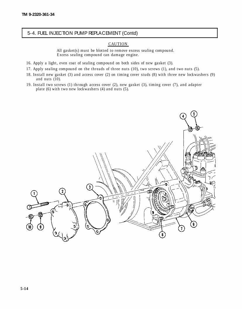
TM 9-2320-361-34
5-4. FUEL INJECTION PUMP REPLACEMENT (Contd)
CAUTION
All gasket(s) must be blotted to remove excess sealing compound.Excess sealing compound can damage engine.
16. Apply a light, even coat of sealing compound on both sides of new gasket (3).17. Apply sealing compound on the threads of three nuts (10), two screws (1), and two nuts (5).18. Install new gasket (3) and access cover (2) on timing cover studs (8) with three new lockwashers (9)
and nuts (10).19. Install two screws (1) through access cover (2), new gasket (3), timing cover (7), and adapter
plate (6) with two new lockwashers (4) and nuts (5).
5-14

TM 9-2320-361-34
5-4. FUEL INJECTION PUMP REPLACEMENT (Contd)
20. Install injector tubes (para. 5-3).21. Connect fuel injection pump-to-fuel filter fuel return tube (13) on elbow (12).22. Connect transfer pump-to-flame heater fuel filter tube (22) on adapter (21).23. Connect fuel transfer pump-to-fuel filter inlet tube (18) on elbow (19) at transfer pump (20).24. Connect fuel filter outlet-to-fuel density compensator inlet tube (17) on tee (16) at compensator (15).25. Connect fuel return-to-fuel injection pump overflow valve tube (11) on tee (14).26. Connect crankcase-to-fuel injection pump pressure oil hose (22) on tee (21).
FOLLOW-ON TASKS: • Install accelerator cable (TM 9-2320-361-20).● Install engine stop control cable (TM 9-2320-361-20).● Install radiator (TM 9-2320-361-20).● Install fuel burning personnel heater (if removed) (TM 9-2320-361-20).● Bleed fuel system (TM 9-2320-361-20).● Start engine (TM 9-2320-361-10) and check for fuel leaks.
5-15

TM 9-2320-361-34
5-5. TURBOCHARGER REPLACEMENT
THIS TASK COVERS:
a. Removal b. Installation
INITIAL SETUP
APPLICABLE MODELSAll
TOOLSGeneral mechanic’s tool kit
(Appendix B, Item 1)
MATERIALS/PARTSGasket (Appendix F, Item 29)Gasket (Appendix F, Item31)Gasket (Appendix F, Item 50)Four locknuts (Appendix F, Item 93)Locknut (Appendix F, Item 94)Cap and plug set (Appendix C, Item 5)Lubricating oil, OE/HDO 10
(Appendix C, Item 12)
PERSONNEL REQUIRED
REFERENCES (TM)TM 9-2320-361-10TM 9-2320-361-20TM 9-2320-361-34PTM 9-2815 -210-34P
EQUIPMENT CONDITION● Parking brake set (TM 9-2320-361-10).● Battery ground cable disconnected
(TM 9-2320-361-20).● Air intake tube removed (TM 9-2320-361-20).● Manifold heater removed (TM 9-2320-361-20).. Crankcase breather tube removed
(TM 9-2320-361-20).● Turbocharger oil drain tube, hose, and adapter
removed (TM 9-2320-36 1-20).● Turbocharger oil inlet tube and adapter removed
(TM 9-2320-361-20).
Two
CAUTION
Cap or plug all openings immediately after disconnecting lines andhoses to prevent contamination. Remove caps or plugs prior toinstallation. Failure to do so may result in turbocharger and/orengine damage.
a. Removal 1. Remove locknut (12) and screw (9) from coupling (11). Discard locknut (12).2. Remove coupling (11), gasket (13), and elbow (8) from flex tube (10). Discard gasket (13).3. Loosen clamp (7) and remove elbow (8), clamp (7), and gasket (6) from turbocharger (5). Discard
gasket (6).NOTE
Assistant will help with step 4.4. Remove four locknuts (3), two screws (2), turbocharger (5), and gasket (14) from exhaust manifold (1).
Discard locknuts (3) and gasket (14).
b. Installation
1.
2.3.4.5.
5-16
NOTEAssistant will help with step 1.
Install new gasket (14) and turbocharger (5) on exhaust manifold (1) with two screws (2) and fournew locknuts (3).Install new gasket (6), clamp (7), and elbow (8) on turbocharger (5). Do not tighten clamp (7).Install new gasket (13) on elbow (8).Install elbow (8) on flex tube (10) with coupling (11), screw (9), and new locknut (12).Tighten clamp (7).

TM 9-2320-361-34
5-5. TURBOCHARGER REPLACEMENT (Contd)
Ensure oil is added before operating engine. Failure to do so mayresult in damage to turbocharger bearings.
6. Pour 2 oz (59 ml) of lubricating oil into turbocharger (5) through oil inlet tube port (4).
FOLLOW-ON TASKS: . Install turbocharger oil drain tube, hose, and adapter (TM 9-2320-361-20).● Install turbocharger oil inlet tube and adapter (TM 9-2320-361-20).● Install crankcase breather tube (TM 9-2320-361-20).● Install manifold heater (TM 9-2320-361-20).● Install air intake tube (TM 9-2320-361-20).● Connect battery ground cable (TM 9-2320-361-20).
5-17 (5-18 blank)


TM 9-2320-361-20
TM 9-2320-361-34
CHAPTER 6
COOLING SYSTEM MAINTENANCE
6-1. RADIATOR MAINTENANCE
THIS TASK COVERS:a. Cleaning and Inspection b. Test and Repair
INITIAL SETUP
APPLICABLE MODELSMATERIALS/PARTS
All Solder (Appendix C, Itern 23)
TOOLS REFERENCES (TM)
General mechanic’s tool kit TM 9-2320-361-20(Appendix B, Item 1) TM 9-2320-361-34P
Soldering iron TM 750-254(Apppendix B, Item 13) EQUIPMENT CONDITION
Radiator and brackets removed (TM 9-2320-361-20).
I a. Cleaning and Inspection I
1. Clean radiator (5) (TM 750-254).2. Inspect radiator (5) for cracked, broken, or damaged components.3. Inspect radiator upper tank (l), lower tank (4), filler neck (2), and overflow pipe (3) for obvious
defects. Repair or replace if defective (TM 750-254).
b. Test and Repair
1. Pressure test radiator (5) for leaks (TM 750-254).2. Repair defective radiator components (TM 750-254).
6-1


TM 9-2320-361-34
CHAPTER 7ELECTRICAL SYSTEM MAINTENANCE
7-1. ELECTRICAL SYSTEM MAINTENANCE INDEX
PARA NO.
T I T L E P A G E N O .
7-2. 60 Ampere Alternator Repair 7-1
7-3.
7-4.
Front Wiring Harness ReplacementRear Wiring Harness Replacement
7-19
7-35
7-2. 60 AMPERE ALTERNATOR REPAIR ITHIS TASK COVERS:
a. Disassembly c. Inspection
INITIAL SETUP
APPLICABLE MODELSAll
TEST EQUIPMENTMultimeter (Appendix B, Item 3)
b. Cleaning d. AssembIy
MATERIALS/PARTSGenerator parts kit (Appendix F, Item 187)Generator parts kit (Appendix F, Item 188)Tiedown strap (Appendix C, Item 15)Adhesive sealant (Appendix C, Item 2)
SPECIAL TOOLSTorx socket TLE60 (Appendix B, Item 36)
TOOLSGeneral mechanic’s tool kit
(Appendix B, Item 1)Tool kit, electrical
(Appendix B, Item 2)Soldering iron
(Appendix B, Item 13)Torque wrench, 3/8-in. dr.
(Appendix B, Item 8)Arbor press
GAA grease (Appendix C, Item 8)Insulating compound (Appendix C, Item 10)Lubricating oil, OE/HDO 30 (Appendix C, Item 13)Silicone compound (Appendix C, Item 22)Solder (Appendix C, Item 28)
REFERENCES (TM)TM 9-214TM 9-237TM 9-2320-361-20TM 9-2920-225-34P
EQUIPMENT CONDITIONAlternator removed (TM 9-2320-361-20).
7-1

TM 9-2320-361-34
a. Disassembly
7-2. 60 AMPERE ALTERNATOR REPAlR(Contd)
NOTETag leads for assembly.
1. Remove access plug (7) from endhousing (4).2. Remove six screws (1), end cover (2), and O-ring (3) from end housing (4). Discard O-ring (3).
NOTERegulator is part of end cover; do not disassemble.
3. Disconnect three leads (10) from three terminals (11) on regulator (12).4. Remove two screw-assembled lockwashers (6) and output plate cover (5) from end housing (4).
Discard screw-assembled lockwashers (6).5. Remove sealer from three stator leads (8).
CAUTION
Use heat sink when resoldering leads. Failure to do so may resultin damage to equipment.
6. Desolder and disconnect three stator leads (8) from three stator lead terminals (9).
7-2

TM 9-2320-361-34
7-2. 60 AMPERE ALTERNATOR REPAIR (Contd)
7-3

TM 9-2320-361-34
7-2. 60 AMPERE ALTERNATOR REPAIR (Contd)
7.
8.
9.10.
11.
12.13.14.
7-4
Scribe a locating mark (5) on end housing (2) and intermediate housing (1).NOTE
Brush springs will fall free when end housing is removed fromintermediate housing.
Using torx socket, remove six torx head screws (4), lockwashers (3), and end housing (2) fromintermediate housing (1). Discard lockwashers (3).Remove insulating compound from capacitor (6).Remove screw (18), nut (19), lockwasher (20), washer (21), and capacitor (6) from negative rectifierplate (16) and output plate stud (11). Discard lockwasher (20).Remove two screws (12), lockwasher (17), two brush leads (13), and lead (15) from insulator (14) andoutput strap (7). Discard lockwasher (17).Remove two brushes (24) and springs (23) from brush holder (26).Remove three screws (25), brush holder (26), insulator (14), and shim (22) from end housing (2).Remove screw (8), lockwasher (9), and output strap (7) from positive rectifier plate (10) and outputplate stud (11). Discard lockwasher (9).

TM 9-2320-361-34
7-2. 60 AMPERE ALTERNATOR REPAIR (Contd)
7-5

TM 9-2320-361-34
7-2. 60 AMPERE ALTERNATOR REPAIR (Contd)
15. Remove tiedown strap (1) from three leads (2). Discard tiedown strap (1).16. Disconnect lead (20) from output plate stud (6).17. Remove insulating compound from four rectifier terminals (10) and three rectifier terminals (16).
CAUTION
Use heat sink when resoldering leads. Failure to do so may resultin damage
18. Desolder and disconnect six positive rectifier leads (11) from four positive rectifier terminals (10).19. Remove three screws (12), washers (13), nylon washers (14), positive rectifier plate (9), and positive
rectifier insulator (8) from end housing (3).
CAUTION
Use heat sink when desoldering leads. Failure to do so may resultin damage to equipment.
20. Desolder and disconnect three negative rectifier leads (15) from three negative rectifier terminals (16).21. Remove two screws (17), washers (18), and negative rectifier plate (19) from end housing (3).22. Remove four screws (4), output plate (5), O-ring (7), six positive rectifier leads (11), three negative
rectifier leads (15), and leads (2) from end housing (3). Discard O-ring (7).23. Scribe locating marks (24) on intermediate housing (23), stator (22), and drive end housing (21).
7-6

TM 9-2320-361-34
7-2. 60 AMPERE ALTERNATOR REPAIR (Contd)
7-7

TM 9-2320-361-34
7-2. 60 AMPERE ALTERNATOR REPAIR (Contd)
24.25.
26.
27.28.29.30.31.32.
33.34.
Remove O-ring (12) from intermediate housing (6). Discard O-ring (12).Using torx socket, remove six torx head screws (2), lockwashers (3), and intermediate housing (6)from stator (4) and drive end housing (1). Discard lockwashers (3).Remove snapring (11), felt retainer (10), felt seal (9), and felt retainer (8) from intermediate housing (6).Discard snapring (11), felt retainers (10) and (8), and felt seal (9).Remove seal (5) from intermediate housing (6). Discard seal (5).Press bearing (7) out of intermediate housing (6). Discard bearing (7).Remove six screws (16), bearing retainer (17), and O-ring (18). Discard O-ring (18).Remove sleeve spacer seal (19) from bearing retainer (17). Discard sleeve spacer seal (19).Remove sleeve spacer (20), O-ring (21), and washer (22) from rotor shaft (14). Discard O-ring (21)Position drive end housing (1) in press and press rotor and fan assembly (13) out of drive endhousing (1).Remove stator (4) from drive end housing (1).Remove bearing (23) and seal (15) from drive end housing (1). Discard seal (15) and bearing (23).
7-8

TM 9-2320-361-34
7-2. 60 AMPERE ALTERNATOR REPAIR (Contd)
7-9

TM 9-2320-361-34
7-2. 60 AMPERE ALTERNATOR REPAIR (Contd)
b. Cleaning For general cleaning instructions, refer to para. 2-8.
c. Inspection
1.2.
3.
4.
5.6.7.
8.
9.
10.
11.12.
13.
14.
7-10
For general inspection instructions, refer to para. 2-9.Inspect end housing (2) for cracks, breaks, and stripped threads. Replace end housing (2) ifdefective.Check brushes (11) for roughness, galling, and wear. Replace brushes (11) if rough, worn, or brushlength is less than 0.250 in. (6.35 mm).Check brush holder (8), brush holder insulator (9), and positive rectifier insulator (3) for cracks andbreaks. Replace brush holder (8), brush holder insulator (9), or positive rectifier insulator (3) ifcracked or broken.Check brush springs (10) for damage. Replace brush springs (10) if damaged.Check output plate (1) for burned, frayed, or broken wiring. Replace output plate (1) if defective.Check rectifier terminals (4) and (6) in rectifier plates (5) and (7) for continuity in one direction andinfinite resistance in opposite direction. Replace rectifier terminals (4) or (6) if defective. Check forshorts from rectifier terminals (4) and (6) to rectifier plates (5) and (7). Replace rectifier plate (5)or (7) if defective.Check stator (18) for grounds. Touch multimeter negative probe to stator (18) and positive probe tothe following stator leads: (a) lead (15), (b) lead (16), and (c) lead (17). If continuity is present in anycheck, stator (18) is grounded; replace alternator.Check stator (18) for open circuits. Touch multimeter probes to the following stator leads: (a) leads (15)and (16), (b) leads (16) and (17), and (c) leads (15) and (17). If continuity is NOT present in any check,replace alternator.Check rotor (14) for grounds. Touch multimeter probe to rotor shaft (13) and other probe toslipring (12). If ohmmeter does not read over 10,000 ohms, replace alternator.Inspect rotor (14) bearing surfaces (TM 9-214). If bearing is defective, replace.Inspect intermediate housing (20) for cracks, breaks, and stripped threads. Replace alternator ifcracked, broken, or threads are stripped.Inspect drive end housing (19) for cracks and breaks. Replace alternator if housing (19) is cracked orbroken.Replace end cover (21) if all components pass testing and problem remains.

TM 9-2320-361-34
7-2 .60 AMPERE ALTERNATOR REPAIR (Ccntd)
7-11

TM 9-2320-361-34
7-2. 60 AMPERE ALTERNATOR REPAIR (Contd)
d. Assembly 1.
2.3.
4.5.
6.7.8.9.
10.
11.12.13.14.
15.
Install new bearing (12) and new seal (4) into drive end housing (13). Apply thin film of grease to lipof new seal (4).Aline locating scribe marks (25) and install stator (3) into drive end housing (13).Press rotor and fan assembly (1) into new bearing (12) inside of stator (3) and drive endhousing (13).Install washer (11), new O-ring (10), and sleeve spacer (9) on rotor shaft (2).Install new sleeve spacer seal (8) and new O-ring (7) on bearing retainer (6). Apply thin film ofgrease to lip of new spacer seal (8).Install bearing retainer (6) on drive end housing (13) with six screws (5).Press new bearing (18) into intermediate housing (17).Install new seal (16) into intermediate housing (17).Install new felt retainer (19) into intermediate housing (17).Saturate new felt seal (20) with lubricating oil and install into intermediate housing (17).Install new felt retainer (21) into intermediate housing (17) with new snapring (22).Aline locating scribe marks (25) on drive end housing (13), stator (3), and intermediate housing (17).Insert stator (3) wires through holes (24) in intermediate housing (17).
Install intermediate housing (17) on stator (3) and drive end housing (13) with six new lockwashers (15)and torx head screws (14).Install new O-ring (23) in intermediate housing (17).
w
7-12

TM9-2320-361-34
7-2. 60 AMPERE ALTERNATOR REPAIR (Contd)
7-13

TM 9-2320-361-34
7-2. 60 AMPERE ALTERNATOR REPAIR (Contd)
16. Install new O-ring (4), three negative rectifier leads (13), six positive rectifier leads (9), threeleads (20), and output plate (2) into end housing (5) with four screws (1).
17. Apply silicone compound to negative rectifier plate (17).18. Install negative rectifier plate (17) on end housing (5) with two washers (16) and screws (15).
CAUTION
● Do not overheat rectifier leads when soldering to rectifierterminals. Damage to rectifiers may result.
● Use heat sink when soldering. Failure to do so may result indamage to equipment.
19. Connect and solder three negative rectifier leads (13) to three negative rectifier terminals (14).20. Apply silicone compound to insulator (6) and positive rectifier plate (7).21. Install insulator (6) and positive rectifier plate (7) on end housing (5) with three nylon washers (12),
washers (11), and screws (10).
CAUTION
● Do not overheat rectifier leads when soldering to rectifierterminals. Damage to rectifiers may result.
��� Use heat sink when soldering. Failure to do so may result indamage to equipment.
22. Connect and solder six positive rectifier leads (9) to four positive rectifier terminals (8).23. Apply insulating compound to three rectifier terminals (14) and four rectifier terminals (8).24. Connect lead (18) to output plate stud (3).25. Install new tiedown strap (19) to four leads (20).
7-14

TM 9-2320-361-34
7-2. 60 AMPERE ALTERNATOR REPAIR (Contd)
7-15

TM 9-2320-361-34
7-2. 60 AMPERE ALTERNATOR REPAIR (Contd)
26.27.
28.29.
30.
31.32.33.
34.
Install shim (2), insulator (3), and brush holder (7) on end housing (1) with three screws (6).Position positive output strap (9) on output plate stud (13) and install on positive rectifier plate (12)with new lockwasher (11) and screw (10).Install two springs (4) into brush holder (7).Install two brush leads (15) and lead (16) on insulator (3) and output strap (9) with newlockwasher (18) and two screws (14).Install capacitor (8) on output plate stud (13) and negative rectifier plate (17) with washer (22), newlockwasher (21), nut (19), and screw (20).Position capacitor (8) on end housing (1) with insulating compound.Install brushes (5) in brush holder (7) against springs (4). Hold in position.Install end housing (1) on intermediate housing (23) with six new Iockwashers (24) and torx headscrews (25).Aline locating scribe marks (26) on intermediate housing (23) and end housing (1).
7-16

TM 9-2320-361-34
7-2. 60 AMPERE ALTERNATOR REPAIR (Contd)
7-17

TM 9-2320-361-34
7-2. 60 AMPERE ALTERNATOR REPAlR(Contd)
CAUTION
● Do not overheat stator leads when soldering to stator terminals.Damage to stator may result.
● Use heat sink when soldering. Failure to do so may result indamage to equipment.
35. Connect and solder stator leads (1), (2), and (3) to stator terminals (4), (5), and (6).36. Seal leads (1), (2), and (3) to terminals (4), (5), and (6) with adhesive sealant.37. Install output plate cover (13) on end housing (12) with two new screw-assembled lockwashers (14).38. Install new O-ring (11) on end housing (12).39. Connect three leads (7) to three terminals (8) on regulator (9).40. Install end cover (10) on end housing (12) with six screws (16).41. Install access plug (15) on end housing (12). Tighten access plug (15) 24-36 lb-in. (3-4 N.m).
FOLLOW-ON TASKS: . Install alternator (TM 9-2320-361-20).. Adjust alternator (TM 9-2320-361-20).
7-18

TM 9-2320-361-34
7-3. FRONT WIRING HARNESS REPLACEMENT
THIS TASK COVERS:a. Removal b. Installation
INITIAL SETUP
APPLICABLE MODELSAll
TEST EQUIPMENTMultimeter (Appendix B, Item 3)
TOOLSGeneral mechanic’s tool kit
(Appendix B, Item 1)Tool kit, electrical
(Appendix B, Item 2)Torque wrench, 3/8-in. dr.
(Appendix B, Item 8)
MATERIALS/PARTSSix lockwashers (Appendix F, Item 132)Lockwasher (Appendix F, Item 124)Six locknuts (Appendix F, Item 95)Three locknuts (Appendix F, Item 89)Two tiedown straps (Appendix C, Item 15)Adhesive sealant (Appendix C, Item 2)
REFERENCES (TM)TM 9-2320-361-20TM 9-2320-361-34P
EQUIPMENT CONDITIONAccessorv switch removed (TM 9-2320-361-20).
“
NOTETag wires for installation.
1. Disconnect wire (9) from horn wire (8).2. Disconnect wires (3) and (5) from left headlamp (1).3. Disconnect wire (11) from blackout drive lamp (12).4. Remove nut (7) and clamp (6) from front wiring harness (10) and stud (13).5. Remove tiedown strap (4) from front wiring harness (10) and brush guard support (2). Discard
tiedown strap (4).
7-19

TM 9-2320-361-34
7-3. FRONT WIRING HARNESS REPLACEMENT (Contd)
6.7.
8.9.
10.
11.12.13.14.15.16.17.18.19.20.
7-20
NOTESteps 6 through 9 cover the left side front composite lights.
Remove four nuts (8) and plate (5) from four screws (15).Disconnect wires (4), (6), and (10) from left composite light wires (3), (1), and (16) and removeplate (5) from wires (4), (6), and (10).Remove grommet (7) from plate (5) and grommet (17) from fender (13).Remove two nuts (14), screws (12), and clamps (11) from fender support (2) and front wiring harness (9).Repeat steps 6 through 9 for right side front composite lights.
Remove two screws (49), lockwashers (58), and cover (57) from alternator (38).Remove two screws (46), lockwashers (45), plate (44), ans spacer (43) from alternator (34).Disconnect wire (41) from alternator wire (42).Remove sealant from nut (54).Remove nut (54), lockwasher (53), and wire (52) from terminal (51).Disconnect wire (48) from temperature sending unit (19).Disconnect wire (21) from preheater wire (20).Disconnect two wires (50) from horn (30).Disconnect two wires (24) from right headlamp (30),Remove tiedown strap (22) from front wiring harness (40) and brush guard support (23). Discardtiedown strap (22).

TM 9-2320-361-34
7-3. FRONT WIRING HARNESS REPLACEMENT (Contd)
21. Remove four nuts (29), screws (27), and clamps (28) from front wiring harness (40), headlamppanel (25), and cable bracket (34).
22. Remove nut (55), lockwasher (56), and clamp (47) from stud (18) and front wiring harness (40).Discard lockwasher (56).
7-21

TM 9-2320-361-34
7-3. FRONT WIRING HARNESS REPLACEMENT (Contd)
NOTEPerform step 23 for all vehicles except M756A2, M50A2, M50A3,M49A2C, and M49A2.
23. Remove nut (10) and wire (11) from starter terminal (12).
28. Remove nut (39), lockwasher (38), wire (37), screw (36), and lockwasher (35) from flasher unit (34).Discard Iockwashers (38) and (35).
29. Remove plug (33) from flasher unit (34).NOTE
Perform steps 30 and 31 for M275A2 vehicles.
30. Remove locknut (46), screw (48), and clamp (47) from firewall (1) and wiring harness (16). Discardlocknut (46).
31. Disconnect wires (44) and (49) from auxiliary circuit breaker (45).32. Disconnect wires (26) and (27) from circuit breaker (25).33. Disconnect wires (30), (29), and (28) from beam selector switch (31).
7-22

TM 9-2320-361-34
7-3. FRONT WIRING HARNESS REPLACEMENT (Contd)
NOTEPerform step 34 if vehicle is equipped with fuel pressure switch.
34. Disconnect wires (40) and (42) from fuel pressure sending unit (41).NOTE
Assistant will help with steps 35 and 36.35. Remove four locknuts (20), screws (32), and clamps (19) from front wiring harness (16) and firewall (1).
Discard locknuts (20).
7-23

TM 9-2320-361-34
7-3. FRONT WIRING HARNESS REPLACEMENT (Contd)
37. Loosen two screws (5) and position bracket (4) so that plug (2) maybe removed.38. Disconnect plug (2) from turn signal switch (1).39. Remove nut (3), screw (7), and clamp (6) from steering column (9) and front wiring harness (8).
40.41.42.43.44.45.46.47.48.49.
Disconnect wire (12) from low air buzzer switch (13).Disconnect wires (27) and (28) from transfer switch (30) and lamp (29).Disconnect wire (15) from high beam indicator lamp (21).Disconnect wire (14) from panel lamp (36).Disconnect wire (32) from panel lamp (33).Disconnect wire (22) from wire (25).Disconnect wire (35) from coolant temperature gage (34).Disconnect wire (11) from fuel gage (10).Disconnect wire (26) from oil gage (31).Disconnect plug (23) from starter switch (24).
7-24

TM 9-2320-361-34
7-3. FRONT WIRING HARNESS REPLACEMENT (Contd)
50. Disconnect wires (18) and (19) from preheater switch (20).51. Disconnect plug (16) from lamp selector switch (17).
7-25

TM 9-2320-361-34
7-3. FRONT WIRING HARNESS REPLACEMENT (Contd)
52. Disconnect wires (10) and (11) from stoplight switch (12).53. Remove two nuts (14), screws (13), and front wiring harness (1) horn rear wiring harness (15) and
brace (16).54. Remove two locknuts (2), screws (8), and clamps (3) from brace (4), front wiring harness (1), and
frame (9). Discard locknuts (2).55. Remove nut (5) and clamp (7) from front wiring harness (1) and U-bolt (6).
CAUTION● Prior to removal of wiring harness, ensure all clamps anddisconnections have been performed. Failure to do so may result indamage to equipment.
● Use care when removing front wiring harness. Snagging andpulling may cause damage to harness.
56. Remove front wiring harness (1) from left side frame (17), fright side frame (18), over steering column (19), and through firewell (21).
b. Installation CAUTION
Use care when routing front wiring harness. Snagging and pullingmay cause damage to front wiring harness.
NOTE● If new wiring harness is to be installed, remove tags from oldharness and install on new harness.
● For additional wiring harness installation information, refer toElectrical System Wiring Diagram (TM 9-2320-361-20).
1. Install front wiring harness (1) through firewall (21), left side frame (17), and right side frame (18),over steering column (19), and under cab (20).
7-26

TM 9-2320-361-34
7-3. FRONT WIRING HARNESS REPLACEMENT (Contd)
7-27

TM 9-2320-361-34
7-3. FRONT WIRING HARNESS REPLACEMENT (Contd)
2. Connect front wiring harness (1) to rear wiring harness (15).3. Install front wiring harness (1) on brace (16) with two screws (13) and new locknuts (14).4. Connect wires (11) and (10) to stoplight switch (12).5. Remove slack from front wiring harness (1).6. Install two clamps (3) on front wiring harness (1), brace (4), and frame (9) with two screws (8) and
new locknuts (2).7. Install clamp (6) on front wiring harness (1) and U-bolt(7) with nut(5).
8. Install clamp (28) on steering column (29) and front wiring harness (1) with screw (31) and nut (30).9. Connect wire (19) to low air buzzer switch (20).
10. Connect wires (38) and (39) to transfer switch (41) and lamp (40).11. Connect wire (22) to high beam indicator lamp (36).12. Connect wire (43) to panel lamp (44).13. Connect wire (21) to panel lamp (47).14. Connect wire (34) to wire (35).15. Connect wire (46) to coolant temperature gage (45).16. Connect wire (18) to fuel gage (17).17. Connect wire (37) to oil gage (42).18. Connect plug (32) to starter switch (33).
7-28

TM 9-2320-361-34
7-3. FRONT WIRING HARNESS REPLACEMENT (Contd)
19. Connect wires (25) and (26) to preheater switch (27).20. Connect plug (23) to lamp selector switch (24).21. Install clamp (28) on steering column (29) and front wiring harness (1) with screw (31) and nut (30).
7-29

TM 9-2320-361-34
7-3. FRONT WIRING HARNESS REPLACEMENT (Contd)
22.
23.24.
25.
26.
27.
28.29.
30.31.
32.
7-30
Position bracket (4) on two screws (5) so that front wiring harness (8) is between bracket (4) andsteering column (9). Tighten two screws (5).Connect plug (2) to signal switch (1).Install clamp (6) on steering column (9) and front wiring harness (8) with screw (7) and nut (3).
Install wire (28) on flasher unit (25) with new lockwasher (26), screw (27), new lockwasher (29), andnut (30).Connect plug (24) to flasher unit (25).
NOTEPerform step 27 for vehicles equipped with fuel pressure sendingunits.
Connect wires (32) and (34) to fuel pressure sending unit (33).Connect wires (18), (19), and (20) to beam selector switch (22).Connect wires (16) and (17) to circuit breaker (15).
NOTEPerform steps 30 and 31 for M275A2 vehicles.
Connect wires (36) and (41) to auxiliary circuit breaker (37).Install clamp (39) on firewall (21) and wiring harness (8) with screw (40) and locknut (38).
NOTEAssistant will help with steps 32 through 34.
Install two clamp halves (13) on firewall (21) with washer (35), clamp (12), two screws (11), and newlocknuts (14).

TM 9-2320-361-34
7-3. FRONT WIRING HARNESS REPLACEMENT (Contd)
33. Remove slack from front wiring harness (8).
34. Install four clamps (31) on front wiring harness (8) and firewall (21) with four screws (23) and newlocknuts (10).
7-31

TM 9-2320-361-34
7-3. FRONT WIRING HARNESS REPLACEMENT (Contd)
35.36.37.38.39.
40.41.42.43.44.45.46.
47.48.49.50.
7-32
NOTESteps 35 through 39 cover the left side front composite lights.
Route wires (13), (14), and (19) through plate (15).Install grommet (16) in plate (15) and grommet (26) in fender (25).Connect wires (13), (14), and (19) to wires (12), (27), and (24).Install plate (15) on four screws (23) with four nuts (18).Install two clamps (20) on front wiring harness (17) and fender support (11) with two screws (21)and nuts (22).Repeat steps 35 through 39 for right side front composite lights.Connect wire (9) to horn wire (10).Connect wire (8) to blackout lamp (28).Connect wires (3) and (5) to lefi headlamp (l).Remove slack from front wiring harness (17).Install clamp (6) on front wiring harness (17) and stud (29) with nut (7).Install wires (3), (5), and (8) on brush guard support (2) with new tiedown strap (4).
Connect wires (43) and (64) to horn (44).Connect wires (36) and (40) to right headlamp (38).Connect wire (63) to temperature sending unit (31).Connect wire (33) to preheater wire (32).

TM 9-2320-361-34
7-3. FRONT WIRING HARNESS REPLACEMENT (Contd)
51. Install plate (56) and spacer (55) on alternator (50) with two new lockwashers (57) and screws (58).52. Install wire (64) through spacer (55) and on alternator terminal (63) with new lockwasher (65) and
nut (66). Tighten nut (66) 45-55 lb-in. (5-6 N-m).53. Install wire (53) through spacer (55) and to alternator wire (54).54. Coat wire (64) and bottom of cover (69) with sealant.55. Install cover (69) on alternator (50) with two new lockwashers (70) and screws (61).56. Remove slack from front wiring harness (52).57. Install two wires (62) and (36) on brush guard support (35) with new tiedown strap (34).58. Install clamps (49) and (40) on front wiring harness (52), cable bracket (46), and headlamp
panel (37) with screws (39) and (48) and nuts (41) and (51).59. Install clamp (59) on front wiring harness (52) and stud (30) with new lockwasher (68) and nut (67).60. Install clamp (45) on front wiring harness (52) and alternator support plate (43) with screw (44) and
nut (47).
7-33

TM 9-2320-361-34
7-3. FRONT WIRING HARNESS REPLACEMENT (Contd).
60. Install wire (12) on starter terminal (13) with nut (11).61. Install wire (8) on starter relay terminal (7) with washer (9) and nut (10).62. Install wire (5) on starter relay terminal (6) with washer (4) and nut (3).63. Connect wire (15) to oil pressure sending unit (14).64. Remove slack from front wiring harness (16).
NOTEAssistant will help with step 65.
65. Install clamp (17) on front wiring harness (16) and firewall (1) with screw (2) and new locknut (18).
FOLLOW-ON TASK: Install accessory switch (TM 9-2320-361-20).
7-34

TM9-2320-361-34
I 7-4. REAR WIRING HARNESS REPLACEMENT
THIS TASK COVERS:a. Removal b. Installation
INITIAL SETUP
APPLICABLE MODELSAll
TEST EQUIPMENTMultimeter (Appendix B, Item 3)
TOOLSGeneral mechanic’s tool kit
(Appendix B, Item 1)Tool kit, electrical (Appendix B, Item 2)
MATERIALS/PARTSFifteen locknuts (Appendix F, Item 89)Six locknuts (M275A2) (Amendix F. Item 95)
MATERIALS/PARTS (Contd)Two locknuts (M756A2) (Appendix F, Item 95)Twelve locknuts (M764) (Appendix F, Item 95)Two lockwashers (Appendix F, Item 138)Five lockwashers (M275A2) (Appendix F, Item 134)Five tiedown straps (Appendix C, Item 15)
REFERENCES (TM)TM 9-2320-361-20TM 9-2320-361-34P
EQUIPMENT CONDITIONBattery ground cable disconnected(TM 9-2320-361-20).
NOTETag wires for installation.
1.
2.
Disconnect rear wiring harness (1) from front wiring harness (2).
NOTEPerform step 2 for M756A2 vehicles.
Disconnect wires (3) and (6) from rear wiring harness wires (4) and (5).
7-35

TM 9-2320-361-34
7-4. REAR WIRING HARNESS REPLACEMENT (Contd)
3.
4.5.6.
7.
8.9.
10.11.
12.
13.
7-36
Remove locknut (12), lockwasher (13), ground wire (14), and screw (2) from support (1). Discardlocknut (12) and lockwasher (13).Disconnect plug (11) from fuel pump (10).Disconnect wire (8) from fuel level sending unit (9).Remove two locknuts (7), screws (4), and clamps (3) from rear wiring harness (5) and crossmember (6).Discard locknuts (7).
NOTEPerform steps 7 through 13 for M275A2 vehicles.
Remove locknut (16), screw (21), lockwasher (22), and ground wire (20) from support (17) andframe (15). Discard locknut (16) and lockwasher (22).Disconnect plug (24) from fuel pump (23).Disconnect wire (18) from fuel level sending unit (19).Disconnect trailer coupling harness (25) from receptacle (28).Remove four locknuts (31), lockwashers (30), ground wire (29), guard (32), four screws (27), cap (26),and receptacle (28) from support (39). Discard locknuts (31) and lockwashers (30).Remove locknut (37), screw (34), and clamp (33) from rear wiring harness (5) and deck (35). Discardlocknut (37).Remove five tiedown straps (38) from rear wiring harness (5) and fuel and brake leads (36). Discardtiedown straps (38).

7-37
TM 9-2320-361-34
7-4. REAR WIRING HARNESS REPLACEMENT (Contd)

M756A2
M756A2
TM 9-2320-361-34
7-4. REAR WIRING HARNESS REPLACEMENT (Contd)
14.15.
16.17.
18.19.
20.
21.
22.
23.
NOTEPerform steps 14 through 17 for M756A2 vehicles.
Disconnect wires (2) and (1) from front clearance light wires (3) and (4).Remove locknut (9), screw (7), and clamp (8) from rear wiring harness (6) and frame (5). Discardlocknut (9).Disconnect wires (16) and (12) from rear clearance light wires (10) and (11).Remove locknut (15), screw (13), and clamp (14) from subframe (17) and rear wiring harness (6).Discard locknut (15).
NOTESteps 18 and 19 cover left side composite light.
Disconnect wires (25), (26), (27), and (28) from composite light wires (24), (23), (22), and (21).Remove locknut (29), screw (19), and clamp (18) from bracket (20) and rear wiring harness (6).Discard locknut (29).Repeat steps 18 and 19 for right side composite light.
NOTEAll trailer receptacles are removed basically the same.
Remove four locknuts (45), lockwasher (44), ground wire (31), four screws (41), cap (40), andreceptacle (3o) from bracket (43). Discard locknuts (45) and lockwasher (44).Remove two locknuts (37), screws (42), and clamps (38) from tail frame (39) and rear wiring harness (7).Discard locknuts (37).Remove four locknuts (32). screws (34), nut (36), and five clamps (33) from frame (5), stud (35), andrear wiring harness (7). Discard locknuts (32).
7-38

TM 9-2320-361-34
7-4. REAR WIRING HARNESS REPLACEMENT (Contd)
7-39

M764
TM 9-2320-361-34
7-4. REAR WIRING HARNESS REPLACEMENT (Contd)
24.25.
26.
27.
28.
29.30.31.
NOTE● Perform steps 24 through 27 for M764 vehicles.● Steps 24 through 27 cover the left side composite light extensions.
Disconnect wires (2), (3), (5), and (6) from extension wires (22), (21), (20), and (7).Disconnect extension wires (17), (10), (11), and (12) from rear composite light wires (16), (15), (14),and (13).Remove five locknuts (9), six screws (18), and clamps (1) from bracket (19), composite light bracket (8),subframe (4), tail frame (27), and two extension wires (29). Discard locknuts (9).Remove locknut (28), screw (23), and clamp (26) from rear wiring harness (25) and brace (24).Discard locknut (28).Repeat steps 24 through 27 for M764 right side composite light extensions.
NOTE● Perform steps 29 and 30 for M275A2 vehicles.● Steps 29 and 30 cover the left rear composite light disconnection.
Disconnect wires (33), (34), (35), and (36) from rear composite light wires (40), (39), (38), and (37).Remove nut (30) and clamp (31) from stud (32) and rear wiring harness (25).Repeat steps 29 and 30 for M275A2 right rear composite light disconnection.
7-40

M275A2
TM 9-2320-361-34
7-4. REAR WIRING HARNESS REPLACEMENT (Contd)
7-41

TM 9-2320-361-34
7-4. REAR WIRING HARNESS REPLACEMENT (Contd)
CAUTION
● Prior to removal of wiring harness, ensure all clamp removals andwire disconnections have been performed. Failure to do so mayresult in damage to equipment.
● Use care when removing or installing rear wiring harness.Snagging and pulling may cause damage to rear wiring harness.
NOTEPerform step 32 for all vehicles except M275A2
32. Remove rear wiring harness (1) from left side frame (5) and four cross braces (2) and through twoholes (4) and hole (3).
NOTEPerform step 33 for M275A2 vehicles.
33. Remove rear wiring harness (1) from left side frame (5) and five cross braces (6) and throughholes (3) and (4).
b. Installation
N O T EPerform step 1 for all vehicles except M275A2.
1. Route rear wiring harness (1) between front left side frame (5) and four cross braces (2) and throughtwo holes (4) and hole (3).
NOTEPerform step 2 for M275A2 vehicles.
2. Route rear wiring harness (1) between left side frame (5) and five cross braces (6) and throughhole (3) and hole (4).
7-42

M245A2
7-43
TM 9-2320-361-34
7-4. REAR WIRING HARNESS REPLACEMENT (Contd)

M764
TM 9-2320-361-34
7-4. REAR WIRING HARNESS Replacement (Contd) I
3.
4.5.6.7.
8.9.
10.11.
12.
13.
7-44
NOTE. Perform steps 3 through 6 for M764 vehicles.● Steps 3 through 6 cover the left side composite light extensions.
Install two sets of extension wires (29) on each rear composite light bracket (8), bracket (19), tailframe (27), and subframe (4) with six clamps (1), screws (18), and five new locknuts (9).Connect wires (10), (11), (12), and (13) to rear composite light wires (17), (16), (15), and (14).Connect wires (2), (3), (5), and (6) to wiring harness wires (22), (21), (20), and (7).Install clamp (26) on rear wiring harness (25) and brace (24) with screw (23) and new locknut (28).Repeat steps 3 through 6 for M764 right side composite light extensions.
NOTE● Perform steps 8 and 9 for M275A2 vehicles.● Steps 8 and 9 cover the left rear composite lights.
Connect wires (35), (36), (37), and (38) to rear composite light wires (31), (30), (40), and (39).Install clamp (33) on rear wiring harness (25) and stud (34) with nut (32).Repeat steps 8 and 9 for M275A2 right rear composite lights.Install receptacle (41) and cap (54) on bracket (57) with four screws (55), ground wire (42), newlockwasher (48), and four new locknuts (47).Remove slack from rear wiring harness (25) and install five clamps (44) on rear wiring harness (25),stud (49), and lefl side frame (45) with four screws (46), new locknuts (43), and nut (50).Install rear wiring harness (25) on tail frame (53) with two clamps (52), screws (56), and newlocknuts (51).

TM 9-2320-361-34
7-4. REAR WIRING HARNESS REPLACEMENT (Contd)
M275A2
7 - 4 5

TM 9-2320-361-34
7-4. REAR WIRING HARNESS REPLACEMENT (Contd)
14.15.
16.
17.18.19.20.
21.
22.
23.24.
NOTESteps 14 and 15 cover the left side rear composite lights.
Connect wires (9), (10), (11), and (12) to rear composite light wires (8), (7), (6), and (5).Remove slack from rear wiring harness (1) and install clamp (2) and rear wiring harness (1) onbracket (4) with screw (3) and new locknut (13).Repeat steps 14 and 15 for right rear composite lights.
NOTEPerform steps 17 through 20 for M756A2 vehicles.
Connect wires (20) and (16) to rear clearance light wires (14) and (15).Install clamp (18) on subframe (21) and rear wiring harness (1) with screw (17) and new locknut (19).Connect wires (24) and (23) to front clearance wires (25) and (26).Install clamp (29) on rear wiring harness (1) and frame (27) with screw (28) and new locknut (22).
N O T EPerform steps 21 through 24 for M275A2 vehicles.
Install receptacle (34), cap (32), guard (38), and ground wire (35) on support (30) with four screws (33),new lockwashers (36), and new locknuts (37).Remove slack from rear wiring harness (1) and install clamp (39) on rear wiring harness (1) anddeck (41) with screw (40) and new locknut (43).Install five tiedown straps (44) on rear wiring harness (1) and fuel and brake leads (42).Connect trailer coupling harness (31) to receptacle (34).
7-46

M756A2
M275A2
TM 9-2320-361-34
7-4. REAR WIRING HARNESS REPLACEMENT (Contd)
7-47

M275A2
TM 9-2320-361-34
I 7-4. REAR WIRING HARNESS REPLACEMENT (Contd)
25. Connect wire (6) to fuel sending unit (12).26. Connect plug (14) to fuel pump (13).27. Install ground wire (3) on support (4) with new lockwasher (2), screw (5), and new locknut (1).28, Remove slack from rear wiring harness (9) and install two clamps (7) on rear wiring harness (9) and
crossmember (10) with two screws (8) and new locknuts (11).NOTE
Perform steps 29 through 31 for M275A2 vehicles.29. Connect wire (18) to fuel sending unit (19).30. Connect plug (23) to fuel pump (22).31. Install ground wire (17) to support (16) with new lockwasher (21), screw (20), and new locknut (15).
7 - 4 8

M756A2
TM 9-2320-361-34
I 7-4. REAR WIRING HARNESS REPLACEMENT (Contd)
32.33.
NOTEPerform step 32 for M756A2 vehicles.
Connect wires (27) and (24) to rear wiring harness wires (26) and (25).Connect rear wiring harness (9) to front wiring harness (28).
FOLLOW-ON TASK: Connect battery ground cable (TM 9-2320-361-20).
7-49 (7-50 blank)


TM 9-2320-361-34
CHAPTER 8TRANSMISSION MAINTENANCE
8-1. TRANSMISSION MAINTENANCE INDEX
PARA. TITLE PAGENO. NO.
8-2. Transmission Maintenance 8-18-3. Clutch Release Bearing, Shaft, and Fork Replacement 8-68-4. Transmission Top Cover Replacement 8-8
8-2. TRANSMISSION MAINTENANCETHIS TASK COVERS:a. Removal c. Installationb. Inspection and Repair
INITIAL SETUP
APPLICABLE MODELS EQUIPMENT CONDITIONAll
TOOLSGeneral mechanic’s tool kit
(Appendix B, Item 1)Sling (Appendix B, Item 14)Breaker bar, l/2-in. dr. (Appendix B, Item 15)Torque wrench, 1/2-in. dr. (Appendix B, Item 7)Lifting deviceTwo chains
Four screws (Appendix F, Item 217)Four washers (Appendix F, Item 271)
MATERIALS/PARTSTwelve screw-assembled lockwashers
(Appendix F, Item 156)Four screw-assembled lockwashers
(Appendix F, Item 157)Two locknuts (Appendix F, Item 96)Gasket (Appendix F, Item 80)Lockwasher (Appendix F, Item 128)
PERSONNEL REQUIRED
● Battery negative ground cable disconnected(TM 9-2320-361-20).
● Cab top removed (if overhead lifting device is used)(TM 9-2320-361-10).
. Transmission gearshift lever removed(TM 9-2320-361-20).
● Cab tunnels removed (TM 9-2320-361-20).● Power takeoff propeller shaft removed (vehicles
w/PTO installed) (TM 9-2320-361-20).● Transfer case to transmission propeller shaft
removed (TM 9-2320-361-20).. Transfer case to differential propeller shaft
removed (TM 9-2320-361-20).. Transmission oil drained (LO 9-2320-209-12-1).
GENERAL SAFETY INSTRUCTIONS● Use prybar to free transmission during lifting
operations.● All personnel must stand clear during lifting
operations.
Two
REFERENCES (TM)LO 9-2320-209-12-1TM 9-2320-361-10TM 9-2320-361-20TM 9-2320-361-34PTM 9-2520-246-34-1
8-1

TM 9-2320-361-34
8-2. TRANSMISSION MAINTENANCE (Contd)
a. Removal 1.2.
3.
4.
5.
6.
7.8.
9.
10.
11.12.
Remove clutch return spring (2) from clutch shaft lever (1) and frame (3).Remove locknut (4), screw (5), and rod (6) fmm shaft lever (1). Discard locknut (4).
NOTE. Do not remove spring-loaded pin from clevis. Bearing will fall freefrom clevis if pin is removed.
� Step 3 applies to vehicles with transmission power takeoff installed.
Pull pin (16) to one side of clevis (18) on power takeoff shift lever (17) and remove PTO shift lever (17)from PTO arm (19).Pull pin (7) to one side of clevis (8) on rod (6) and remove rod (6) from lever (9).
NOTEMark position of lever and shaft for installation.
Remove locknut (22), screw (23), and lever (9) from shaft (21). Discard locknut (22).
NOTEScrew-assembled lockwashers must be reinstalled in transmission iftransmission requires replacement.
Remove four screw-assembled lockwashers (14) from transmission (15). Discard screw-assembledlockwashers (14).Install utility chains on transmission (15) with four washers (13) and screws (12).Attach utility chains to sling. Attach sling to lifting device.
●
●
WARNINGUse prybar to free transmission during lifting operations. Failure todo so may result in injuqy to personnel or damage to equipment.All personnel must stand clear during lifiing operations. Aswinging or shifling load may cause injury to personnel.
NOTEIf a new transmission is not being installed, the adapter plate maybe removed and installed with the transmission.
Remove twelve screw-assembled lockwashers (20), ground strap (24), and lockwasher (25) from flangeof transmission (15). Discard screw-assembled lockwashers (20) and lockwasher (25).Remove transmission (15) and gasket (11) from flywheel housing (10) and lower transmission (15).Discard gasket (11).Remove lifting device from sling. Remove sling from utility chains.Remove four screws (12), washers (13), and utility chains from transmission (15).
b. Inspection and Repair1. Remove top cover (para. 8-4).2. Visually inspect internal components for damage or seized bearings. Replace transmission (15) if
damaged.3. For transmission repair, refer to TM 9-2520-246-34-1.
8-2

TM 9-2320-361-34
8-2. TRANSMISSION MAINTENANCE (Contd)
8-3

TM 9-2320-361-34
8-2. TRANSMISSION MAINTENANCE (Contd)
c. Installation
1.2.3.
4.
5.
6.7.8.
9.
10.
11.
12.13.14.15.
8-4
Install utility chains on transmission (6) with four washers (4) and screws (3).Attach sling to utility chains. Attach lifting device to sling.Position transmission (6) under vehicle and raise transmission (6).
WARNING
Use prybar to free transmission during lifting operations. Failureto do so may result in injury to personnel or damage toequipment.Al l personnel must s tand c lear dur ing l i f t ing operat ions. As w i n g i n g o r s h i f t i n g l o a d m a y c a u s e i n j u r y t o p e r s o n e l .
CAUTION
Ensure transmission is alined with clutch and pilot bearing.Failure to do so may result in damage to equipment.
Install new gasket (2) and transmission (6) on flywheel housing (1) with eleven new screw-assembled lockwashers (11). Tighten screw-assembled lockwashers (11) 23-26 lb-ft (31-35 N.m).Install new lockwasher (17) and ground strap (16) on transmission (6) with new screw-assembledlockwasher (11). Tighten screw-assembled lockwasher (11) 23-26 lb-ft (31-35 N.m).Remove lifting device from sling. Remove sling from utility chains.Remove four screws (3), washers (4), and utility chains from transmission (6).Install four new screw-assembled lockwashers (5) on transmission (6). Tighten screw-assembledlockwashers (5) 25-32 lb-ft (34-43 N.m).Aline mark on lever (14) with shaft (12) and install lever (14) on shaft (12) with screw (15) and newlocknut (13).
NOTEIf mark does not exist on shaft or lever, position lever on spline torear of shaft centerline.
Push lower end of lever (14) forward until resistance is felt. Measure distance from center of hole onlever (14) to flange of transmission (6). Measurement should be 3.25 in. (8.26 cm). Rotate lever (14)one spline at a time if necessary to obtain 3.25 in. (8.26 cm) measurement. Tighten locknut (13).
NOTEPerform step 11 if PTO is installed.
Attach power takeoff shift lever (8) on PTO arm (10) and push pin (7) in clevis (9) until head ofpin (7) seats against clevis (9).Install rod (23) on clutch shaft lever (18) with screw (22) and new locknut (21).Install clevis (25) on lever (14).Push pin (24) in clevis (25) until head of pin (24) seats against clevis (25).Install clutch return spring (19) on clutch shaft lever (18) and frame (20).

TM9-2320-361-34
8-2. TRANSMISSION MAINTENANCE (Contd)
FOLLOW-ON TASKS: ● Fill transmission to proper fluid level (LO 9-2320-209-12-1).. Install transfer case to differential propeller shaft (TM 9-2320-361-20).. Install transfer case to transmission propeller shaft (TM 9-2320-361-20).● Install power takeoff propeller shaft (if removed) (TM 9-2320-361-20).. Install cab tunnels (TM 9-2320-361-20).. Install transmission gearshift lever (TM 9-2320-361-20).. Install cab top (if removed) (TM 9-2320-361-10).● Connect battery negative ground cable (TM 9-2320-361-20).● Adjust clutch pedal free play (TM 9-2320-361-20).
8-5

TM 9-2320-361-34
I 8-3. CLUTCH RELEASE BEARING, SHAFT, AND FORK REPLACEMENT
THIS TASK COVERS:a. Removal c. Installationb. Inspection
INITIAL SETUP
APPLICABLE MODELS REFERENCES (TM)All LO 9-2320-209-12-1
TOOLSTM 9-214TM 9-2320-361-34P
General mechanic’s tool kit(Appendix B, Item 1) EQUIPMENT CONDITION
Torque wrench, 1/2-in. dr. (Appendix B, Item 7) Transmission removed (para. 8-2).
MATERIALS/PARTSTwo lockwashers (Appendix F, Item 135)Seal (Appendix F, Item 221)
a. Removal 1. Remove two support springs (9) from clutch release bearing assembly (8) and clutch release fork (7).2. Remove clutch release bearing assembly (8) from input shaft (10).3. Remove two screws (6), lockwashers (5), and thrust washers (4) from clutch release fork (7). Discard
lockwashers (5).4. Slide clutch release shaft (3) out of clutch release fork (7).5. Remove clutch release fork (7) and clutch release shaft (3) from transmission (1).6. Remove seal (2) from bell housing of transmission (1). Discard seal (2).
NOTEPerform step 7 if bearing requires replacement.
7. Remove grease fitting (13), two buttons (14), and bearing (12) from clutch release housing (11).
b. Inspection
1. Inspect bearing (12) (TM 9-214). Replace bearing (12) if damaged.2. Visually inspect shaft (3) and clutch release fork (7) for wear or damage. Replace shaft (3) or
fork (7) if damaged.
c. Installation
1.
2.3.
4.
5.6.
8-6
NOTEPerform step 1 if bearing was replaced.
Install bearing (12), two buttons (14), and grease fittinng (13) on clutch release bearinghousing (11).Install new seal (2) on bell housing of transmission (1).Slide clutch release shaft (3) through transmission (1) and clutch release fork (7). Aline holes infork (7) with slots in shaft (3).Install two thrust washers (4) on clutch release fork (7) with two new lockwashers (5) andscrews (6). Tighten screws (6) 40-50 lb-ft (54-68 N.m).Position clutch release bearing assembly (8) on input shaft (10) and clutch release fork (7).Install clutch release bearing assembly (8) on clutch release fork (7) with two support springs (9).

TM 9-2320-361-34
8-3. CLUTCH RELEASE BEARING, SHAFT, AND FORK REPLACEMENT (Contd)
.
FOLLOW-ON TASKS: . Lubricate clutch release bearing (LO 9-2320-209-12-1).● Lubricate clutch release shaft (LO 9-2320-209-12-1).. Install transmission (para. 8-2).
8-7

TM 9-2320-361-34
8-4. TRANSMISSION TOP COVER REPLACEMENT
THIS TASK COVERS:a. Removal b. Installation
INITIAL SETUP
APPLICABLE MODELS REFERENCES (TM)All TM 9-2320-361-20
TOOLSTM 9-2320-361-34P
General mechanic’s tool kit EQUIPMENT CONDITION(Appendix B, Item 1) ● Transmission gearshift lever removed
Torque wrench, 1/2-in. dr. (Appendix B, Item 7) (TM 9-2320-361-20).
MATERIALS/PARTS. Cab tunnel cover removed (TM 9-2320-361-20).
Gasket (Appendix F, Item 81)Eight screw-assembled lockwashers
(Appendix F, Item 157)
a. Removal CAUTION
Prevent dirt from entering transmission when performing this task.Failure to do so may damage equipment.
Remove eight screw-assembled lockwashers (1), transmission top cover (6), and gasket (4) fromtransmission (3). Discard screw-assembled lockwashers (1) and gasket (4).
I b. Installation
1. Aline shifter forks (5) with synchronizers (2).2. Install new gasket (4) and transmission top cover (6) on transmission (3) with eight new screw-
assembled lockwashers (1). Tighten screw-assembled lockwashers (1) 25-32 lb-ft (34-43 N-m).
/
FOLLOW-ON TASKS: . Install cab tunnel cover (TM 9-2320-361-20).● Install transmission gearshift lever (TM 9-2320-361-20).
8-8

TM 9-2320-361-34
CHAPTER 9TRANSFER CASE MAINTENANCE
9-1. TRANSFER CASE MAINTENANCE INDEX
PARA. TITLE PAGENO. NO.
9-2. Transfer Case Maintenance 9-19-3. Front Axle Engagement Air Cylinder Maintenance 9-6
I 9-2. TRANSFER CASE MAINTENANCETHIS TASK COVERS:a. Removal c. Installationb. Inspection and Repair
INITIAL SETUP
APPLICABLE MODELSAll
TOOLSGeneral mechanic’s tool kit
(Appendix B, Item 1)Torque wrench, l/2-in. dr. (Appendix B, Item 7)1-1/8-in. socket, 1/2-in. dr. (Appendix B, Item 10)1-1/16-in. socket, 1/2-in. dr. (Appendix B, Item 11)Lift, transmission, and differential
MATERIALS/PARTSSeven locknuts (Appendix F, Item 102)Six locknuts (Appendix F, Item 103)Locknut (Appendix F, Item 95)Two lockwashers (Appendix F, Item 135)Lockwasher (Appendix F, Item 136)
PERSONNEL REQUIREDTwo
REFERENCES (TM)LO 9-2320-209-12-1TM 9-2320-361-10TM 9-2320-361-20TM 9-2320-361-34PTM 9-2520-246-34-1
EQUIPMENT CONDITION● Wheels chocked (TM 9-2320-361-10).. Transfer case drained (LO 9-2320-209-12-1).● Spare wheel removed (TM 9-2320-361-10).● Air reservoir drained (TM 9-2320-361-10).● Cab tunnels removed (TM 9-2320-361-20).● Front axle propeller shaft removed
(TM 9-2320-361-20).● Transmission to transfer propeller shaft removed
(TM 9-2320-361-20).● Forward rear axle propeller shaft removed
(TM 9-2320-361-20).. Power takeoff propeller shaft removed (vehicles
with PTO installed) (TM 9-2320-361-20).● Rear winch drive chain removed (M756A2 only)
(TM 9-2320-361-20).
GENERAL SAFETY INSTRUCTIONS● Transfer case is heavy and bulky. Allow adequate
clearance to remove transfer case from vehicle.● Ensure transfer case is securely mounted to jack
stands with safety chain or strap.● Use prybar to free transfer case during lifting
9-1

TM 9-2320-361-34
9-2. TRANSFER CASE MAINTENANCE (Contd)
a. Removal 1. Remove spring (31) from parking brake lever (30) and bracket (35).
NOTEMark threaded end of parking brake cable nut for installation.
2.
3.
4.5.
6.
Remove nut (32) from threaded end (6) of parking brake cable (9) and slide parking brake cable (9)out of parking brake lever (30).Remove screw (5), lockwasher (4), and parking brake cable (9) from parking brake bracket (3) ontransfer case (25). Discard lockwasher (4).Remove air line (16) from air cylinder (24) on front of transfer case (25).Remove speedometer drive shaft (38), adapter (37), and adapter drive shaft (36) from transfercase (25).
NOTEStep 6 applies to vehicles with transfer case PTO installed.
Remove locknut (10) from ball pivot end (1) and PTO shift arm (2). Discard locknut (10).
7.
8.
9.
10.
11.
12.
13.
14.
WARNING● Use prybar to free transfer case during lifting operations. Failure
to do so may result in injury to personnel.● Ensure transfer case is securely mounted to jack with safety
chain or strap. Failure to do so may result in injury to personnel.● Transfer case is heavy and bulky. Allow adequate clearance to
remove transfer case from vehicle. Failure to do so may result ininjury to personnel.
Position transfer case jack stand under transfer case (25) and secure transfer case (25) to jackstand with safety chain or strap.Remove four locknuts (26) and screws (20) from support (28) and mounting plate (18). Discardlocknuts (26).Remove two locknuts (23), washers (22), four bushings (19), two screws (17), and mounting plate (18)from support brackets (21). Discard locknuts (23).Remove locknut (33), washer (34), two bushings (12), and screw (13) from support brackets (15) and (11).Lower jack stand and remove transfer case (25) from vehicle. Discard locknut (33).Remove two screws (7), lockwashers (8), and parking brake bracket (3) from transfer case (25).Discard lockwashers (8).Remove four locknuts (27) and left transfer case support (28) from four studs (29) on transfer case (25).Discard locknuts (27).Remove two locknuts (14) and right transfer case support (15) from two studs (29) on transfer case (25).Discard locknuts (14).
N O T EPerform step 14 if stud(s) is damaged.
Remove threaded stud(s) (29) from transfer case (25).
I b. Inspection and Repair
Inspect and, if necessary, repair transfer case (TM 9-2520-246-34-1).
9-2

TM 9-2320-361-34
I 9-2. TRANSFER CASE MAINTENANCE (Contd) I
9-3

TM 9-2320-361-34
9-2. TRANSFER CASE MAINTENANCE (Contd)
c. Installation
1.2.
3.
4.
5.
6.
7.
8.
9.
10.11.12.
13.14.
15.
N O T EPerform step 1 if stud(s) was removed.
Install threaded stud(s) (29) on transfer case (25). Tighten stud(s) (29) 125-135 lb-ft (170-183 N.m).Place transfer case (25) on transfer case jack stand (30). Secure transfer case (25) with safety chainor strap.Install right transfer case support (15) on transfer case studs (29) with two new locknuts (14).Tighten locknuts (14) 125-135 lb-ft (170-183 N.m).Install left transfer case support (28) on transfer case studs (29) with four new locknuts (27).Tighten locknuts (27) 125-135 lb-ft (170-183 N.m).Install parking brake bracket (3) on transfer case (25) with two new lockwashers (8) and screws (7).Tighten screws (7) 60-77 lb-ft (81-104 N.m).Raise transfer case (25) into mounting position underneath vehicle.Install mounting plate (18) on two support brackets (21) with four bushings (19), two washers (22),screws (17), and new locknuts (23). Tighten locknuts (23) 65-75 lb-ft (88-102 N.m).Install left transfer case support (28) on mounting plate (18) with four screws (20) and new locknuts (26).Tighten locknuts (26) 65-70 lb-ft (88-95 N.m).Install right transfer case support (15) to support bracket (11) with screw (13), two bushings (12),washer (34), and new locknut (33). Tighten locknut (33) 65-70 lb-ft (88-95 N.m).Install adapter drive shaft (36), adapter (37), and speedometer shaft (39) on transfer case (25).Install spring (31) on parking brake lever (30) and bracket (35).Slide parking brake cable (9) in parking brake lever (30) and install nut (32) on threaded end (6) ofparking brake cable (9).Install parking brake cable (9) on parking brake bracket (3) with new lockwasher (4) and screw (5).Connect air line (16) to air cylinder (24) on front of transfer case (25).
NOTEStep 15 applies to vehicles with transfer case PTO installed.
Install ball pivot end (1) on PTO shift arm (2) with new locknut (10).
9-4

TM 9-2320-361-34
TRANSFER CASE JACK STAND
FOLLOW-ON TASKS: . Install rear winch drive chain (M756A2 only) (TM 9-2320-361-20).. Install power takeoff propeller shaft (vehicles w/PTO) (TM 9-2320-361-20).● Install forward rear axle propeller shaft (TM 9-2320-361-20).. Install transmission to transfer propeller shaft (TM 9-2320-361-20).. Install front axle propeller shaft (TM 9-2320-361-20).● Install cab tunnels (TM 9-2320-361-20).● Install spare wheel (TM 9-2320-361-10).● Fill transfer case to proper fluid level (LO 9-2320-209-12-1).● Adjust hand brake (TM 9-2320-361-20).
9-5

TM 9-2320-361-34
I 9-3. FRONT AXLE ENGAGEMENT AIR CYLINDER MAINTENANCE
THIS TASK COVERS:a. Removal c. Installationb. Cleaning and Inspection
INITIAL SETUP
APPLICABLE MODELS REFERENCES (TM)All TM 9-2320-361-34P
TOOLS EQUIPMENT CONDITIONGeneral mechanic’s tool kit
(Appendix B, Item 1)Transfer case removed (para. 9-2).
MATERIALS/PARTSAir cylinder parts kit (Appendix F, Item 186)GM grease (Appendix C, Item 8)
1. Bend four locktabs (4) down and remove four screws (5), locktabs (4), air cylinder cover (3), andbrass ring (6) from transfer case (2). Discard locktabs (4) and brass ring (6).
2. Remove air cylinder (11) from transfer case (2).3. Remove nut (7), washer (8), piston (10), washer (8), and brass ring (6) from shifter shaft (1). Discard
washers (8) and brass ring (6).4. Remove seal (9) from piston (10). Discard seal (9).
b. Cleaning and Inspection
Clean and inspect air cylinder cover (3), air cylinder (11), and piston (10) (paras. 2-8 and 2-9).
I c. Installation I1. Apply a small amount of GAA grease on new seal (9) and install on piston (10).2. Install piston (10) on shifter shaft (1) with two new washers (8) and nut (7). Tighten nut (7)
48-61 lb-ft (65-83 N.m).NOTE
Ensure air cylinder cover is installed with air line openingpositioned toward bottom of transfer case.
3. Install new brass ring (6), air cylinder (11), new brass ring (6), air cylinder cover (3), four newlocktabs (4), and screws (5) on transfer case (2). Tighten screws (5) 5-8 lb-ft (7-11 N.m).
4. Bend locktabs (4) down on transfer case (2) and bend locktabs (4) upon air cylinder screws (5).
9 - 6

TM 9-2320-361-34
9-3. FRONT AXLE ENGAGEMENT AIR CYLINDER MAINTENANCE (Contd)
FOLLOW-ON TASK: Install transfer case (para. 9-2).
9-7 (9-8 blank)


TM 9-2320-361-34
CHAPTER 10AXLES AND SUSPENSION MAINTENANCE
Section I. Front Axle Maintenance (page 10-1)Section II Rear Axle and Suspension Maintenance (page 10-43)
Section 1. FRONT AXLE MAINTENANCE
10-1. FRONT AXLE MAINTENANCE INDEX
I PARA.NO.
TITLE PAGENO. I
10-2. Front Axle Replacement 10-110-3. Differential Carrier Replacement 10-410-4. Differential Carner Repair 10-610-5. Front and Rear Differential Oil Seal Replacement 10-3410-6. Steering Knuckle and Steering Arm Maintenance 10-36
10-2. FRONT AXLE REPLACEMENT
THIS TASK COVERS:a. Removal b. Installation
INITIAL SETUP
APPLICABLE MODELSAl l
TOOLSGeneral mechanic’s tool kit
(Appendix B, Item 1)Torque wrench, 3/4-in. dr.
(Appendix B, Item 6)Hydraulic jackJack stands
MATERIALS/PARTSEight lockwashers (Appendix F, Item 148)
PERSONNEL REQUIREDTwo
EQUIPMENT CONDITION“ Parking brake set (TM 9-2~20-36 1-10).● Front wheels removed (TM9-2320-361-20).. Front propeller shaft removed (TM 9-2320-361-20).● Drag link removed (TM 9-2320-361-20).● Brake line removed at tee fitting on front axle
(TM 9-2320-361-20).● Front shock absorbers removed
(TM 9-2320-361-20).
GENERAL SAFETY INSTRUCTIONS● Weight of vehicle must be supported on jack
stands at all times.● Ensure axle is balanced and personnel are clear
before lowering axle.
REFERENCES (TM)LO 9-2320-209-12-1TM 9-2320-361-10TM 9-2320-361-20TM 9-2320-361-34P
10-1

TM 9-2320-361-34
10-2. FRONT AXLE REPLACEMENT (Contd)
WARNING
Weight of vehicle must be supported on jack stands at all times. Donot attempt to support weight of vehicle on hydraulic jack. Injury ordeath to personnel may result if jack fails.
a. Removal 1. Raise axle (4) with hydraulic jack under differential (3) and place two jack stands under left and
right springs (10) between axle (4) and spring (10) hangers.2. Remove eight nuts (6), lockwashers (7), and two clamp plates (8) from axle (4). Discard lock-
washers (7).3. Remove four U-bolts (1) and two saddle plates (2).
N O T ETwo assistants will help with step 4.
4. Lower axle (4) until it clears vehicle. Remove axle (4) from under vehicle and place on jack stands.
b. Installation
WARNING
Axle is heavy. Ensure axle is balanced and personnel are clearbefore lowering axle. Failure to do so may result in injury topersonnel.
NOTETwo assistants will help with installation.
1. Remove axle (4) from jack stands and place under vehicle.2. Nine spring seats (5) on axle (4) under springs (10).
3. Raise axle (4) until holes in spring seats (5) meet spring centering bolts (9).4. Install four U-bolts (1) on two saddle plates (2).
NOTEInstall clamp plates with shock absorber mounting holes on outside,toward rear of vehicle, and angled down.
5. Install two clamp plates (8) on four U-bolts (1) with eight new lockwashers (7) and nuts (6). Tightennuts (6) 190-230 lb-ft (258-312 N.m).
10-2

TM 9-2320-361-34
10-2. FRONT AXLE REPLACEMENT (Contd)
FOLLOW-ON TASKS: . Install front shock absorbers (TM 9-2320-361-20).● Install brake line at tee fitting on front axle (TM 9-2320-361-20).● Install drag link (TM 9-2320-361-20).. Install front propeller shaft (TM 9-2320-361-20).. Install front wheels (TM 9-2320-361-20).. Fill axle housing with GO 80/90 (LO 9-2320-209-12-1).
10-3

TM 9-2320-361-34
10-3. DIFFERENTIAL CARRIER REPLACEMENT
THIS TASK COVERS:a. Removal b. Installation
INITIAL SETUP
APPLICABLE MODELS PERSONNEL REQUIREDAl l Two
REFERENCES (TM)LO 9-2320-209-12-1
TOOLSGeneral mechanic’s tool kit
(Appendix B, Item 1) TM 9-2320-361-20Torque wrench, l/2-in. dr. TM 9-2320-361-34P
(Appendix B, Item 7)Lifting device EQUIPMENT CONDITIONChains . Axle shafts removed (TM 9-2320-361-20).
MATERIALS/PARTS● Axle assembly removed (para. 10-2 or 10-8).
Gasket (Appendix F, Item 79) GENERAL SAFETY INSTRUCTIONSLubricating oil, GO 80/90 (Appendix C, Item 11) Personnel must stand clear during lifting
operations.
CAUTION
Work area should be clean, well-ventilated, and free from blowingdust and dirt. Damage to equipment could result if the area is notclean.
NOTE
IHave drainage container ready to catch oil.
a. Removal
1.2.3.4.
Remove drain plug (12) from bottom of housing (6) and drain gear oil.Remove eight nuts (1) and washers (2) from eight studs (3).Loosen four remaining nuts (10) on studs (8).Remove screw (5) and washer (4) from carrier (7).
5.
6,
7.
8.9.
10.
WARNINGAll personnel must stand clear during lifting operations. A swingingor shifting load may cause injury or death to personnel.
CAUTIONWhen lifting differential carrier out of axle housing, use care not todamage mounting studs.
NOTEAssistant will help with steps 5 through 7.
Install chains on carrier (7) with washer (4) and screw (5). Attach lifting device on chains.Using lifting device, raise carrier (7) 1/2 in. (1.3 cm) out of housing (6) and remove four remainingnuts (10) and washers (9) from studs (8).Remove carrier (7) from housing (6).Remove gasket (11) from housing (6). Discard gasket (11).Lower carrier (7) to workbench and remove lifting device from chains.Remove screw (5), washer (4), and chains from carrier (7).
10-4

TM 9-2320-361-34
I 10-3. DIFFERENTIAL CARRIER REPLACEMENT (Contd) II b. Installation I
1.2.3.
4.
5.6.7.8.9.
10.11.
Install chains on carrier (7) with washer (4) and screw (5).Install new gasket (11) on housing (6).Install lifting device on chain.
WARNINGAll personnel must stand clear during lifting operations. A swingingor shifting load may cause injury to personnel.
CAUTIONWhen lowering differential carrier onto axle housing, use care notto damage mounting studs.
NOTEAssistant will help with steps 4 and 5.
Using lifting device, install carrier (7) on housing (6) leaving 1/2 in. (1.3 cm) gap between carrier (7)and housing (6).Install four washers (9) and nuts (10) on studs (8) and lower carrier (7) onto housing (6).Install eight remaining washers (2) and nuts (1) on eight studs (3).Alternately tighten nuts (10) and (1).Remove lifting device from chain.Remove screw (5), washer (4), and chain from carrier (7).Install washer (4) and screw (5) on carrier (7). Tighten screw (5) 65-85 lb-ft (88-115 N.m).Install drain plug (12) on bottom of housing (6). Tighten drain plug (12)35 lb-ft (48 N.m).
FOLLOW-ON TASKS: .●
●
Install axle assembly (para. 10-2 or 10-8).Install axle shafts (TM 9-2320-361-20).Fill axle housing with GO 80/90 oil (LO 9-2320-209-12-1).
10-5

TM 9-2320-361-34
I 10-4. DIFFERENTIAL CARRIER REPAIR
THIS TASK COVERS:a. Disassembly c. Assembly and Adjustmentb. Cleaning and Inspection
INITIAL SETUPAPPLICABLE MODELSAll
SPECIAL TOOLSHandle (Appendix B, Item 23)Oil seal replacer (Appendix B, Item 25)Oil seal remover (Appendix B, Item 28)Bearing sleeve remover/replacer
(Appendix B, Item 24)Bearing replacer (Appendix B, Item 26)Two puller screws (Appendix B, Item 29)Screw (Appendix B, Item 27)
TOOLSGeneral mechanic’s tool kit
(Appendix B, Item 1)Mechanical puller kit (Appendix B, Item 23)Torque wrench, 1./2-in. dr. (Appendix B, Item 7)Torque wrench, 3/4-in. dr. (Appendix B, Item 6)Dial indicator (Appendix B, Item 21)Inside caliper micrometer
(Appendix B, Item 16)Outside caliper micrometer
(Appendix B, Item 17)Gage, force, mechanical
(Appendix B, Item 53)Arbor pressVise
MATERIALS/PARTSEight lockwashers (Appendix F, Item 125)Six lockwashers (Appendix F, Item 138)Two cotter pins (Appendix F, Item 13)Two oil seals (Appendix F, Item 240)Gasket and shim set (Appendix F, Item 84)Woodruff key (Appendix F, Item 297)Blue pigment (Appendix C, Item 14)Lubricating oil GO 80/90 (Appendix C, Item 11)GAA grease (Appendix C, Item 8)Sealing compound (Appendix C, Item 19)Safety wire (Appendix C, Item 30)
PERSONNEL REQUIREDTwo
REFERENCES (TM)TM 9-214TM 9-2320-361-34P
EQUIPMENT CONDITIONDifferential carrier removed (para. 10-3).
a. DisassemblyCAUTION
1 .2.
3.
4.
Scribe or center punch different marks on each side of carrier foreasy identification. Improper installation will result in damage toparts.
Scribe or center punch alinement marks on bearing caps (1) and carrier (17).Remove two safety wires (5), two screws (3), and adjusting nut locks (2) from bearing caps (1).Discard safety wires (5).Remove four screws (4), washers (6), and two bearing caps (1) from carrier (17).
CAUTION
Scribe or center punch different marks on case halves and helicaldrive gear. Marks should match those placed on bearing caps.Improper installation will result in damage to equipment.
Scribe or center punch alinement marks on case halves (12) and (22) and helical drive gear (19).
10-6

TM 9-2320-361-34
10-4. DIFFERENTIAL CARRIER REPAIR (Contd)
6.7.
8.9.
10.11.12.
13.
Secure differential gear assembly (18) in vise.Remove safety wire (20), eight nuts (21), and screws (14) from case halves (12) and (22). Discardsafety wire (20).Remove case half (12) from helical drive gear (19).Remove spider (7) with four thrust washers (9), pinion gears (8), two side gears (10), and thrustwashers (11) from case half (22).
NOTEIf washers, gears, and spider are not to be replaced, retain themtogether and proceed to step 12.
Remove four thrust washers (9) and pinion gears (8) from spider (7).Remove two side gears (10) and thrust washers (11) from spider (7).Remove helical drive gear (19) from case half (22).
NOTETag bearings for installation.
Using mechanical puller, remove two bearings (13) from case halves (12) and (22).
10-7

TM 9-2320-361-34
10-4. DIFFERENTIAL CARRIER REPAIR (Contd)
14.
15.
16.17.
18.19.
20.21.
22.23.24.25.
10-8
Remove eight screws (2), lockwashers (1), top cover (3), and gasket (4) from earner (5). Discardlockwashers (1) and gasket (4).Remove four screws (9), washers (8), inspection cover (7), and gasket (6) from carrier (5). Discardgasket (6).
NOTEEnsure flanges are secured in vise for easy removal of nuts andwashers.
Remove two cotter pins (10), nuts (11), and washers (12) from shaft (24). Discard cotter pins (10).Using mechanical puller, remove two flanges (13) with dirt deflectors (14) from shaft (24).
N O T EPerform step 18 if dirt deflectors are damaged or flanges requirereplacement.
Remove two dirt deflectors (14) from flanges (13).Remove twelve screws (15), washers (16), front retainer (17), rear retainer (19), and shims (18) fromcarrier (5). Record number/thickness of shims (18) removed from front retainer (17) and rearretainer (19). Tie shims (18) to front retainer (17) and rear retainer (19).Remove spacer (27) from shaft (24).Using oil seal remover, remove two oil seals (20) from retainers (17) and (19). Discard oil seals (20).
CAUTIONUse brass drift to remove shaft and bearing seat. Failure to do somay result in damage to shaft and bearing seat.
Remove shaft (24) and bearing seat (21) through rear of carrier (5).Remove bearing seat (26) from front of carrier (5).Remove front bearing (25) and pinion (23) with rear bearing (22) from shaft (24).Remove rear bearing (22) from hub of pinion (23).

TM 9-2320-361-34
10-4. DIFFERENTIAL CARRIER REPAIR (Contd)
10-9

TM 9-2320-361-34
10-4. DIFFERENTIAL CARRIER REPAIR (Contd)
26. Remove six screws (5), lockwashers (4), bearing cover (3), and shims (2) from carrier (1). Discardlockwashers (4). Record number/thickness of shims (2) removed. Tie shims (2) to bearing cover (3).
NOTEUse brass drift to hold bevel gear in place while removing screws.
27. Remove safety wire (8), two screws (7), and plate (6) from helical pinion shaft (11). Discard safetywire (8).
Puller screws must be turned evenly until bearing cage is free fromearner. Failure to remove cage evenly will result in damage tobearing cage, bearings, and carrier.
28. Remove bearing cage (9) and shims (10) from carrier (1) with two puller screws. Recordnumber/thickness of shims (10) removed. Tie shims (10) to bearing cage (9).
CAUTION
Use brass drift to remove bearings and bearing seat from bearingcage. Failure to do so may result in damage to bearings and bearingseat.
29. Remove bearing seat (12), bearings (13) and (14), and bearing seat (15) from bearing cage (9).
● Support beveled gear with soft spacers. Failure to do so mayresult in damage to equipment.
● When removing pinion shaft ensure shaft does not becomecaught on carrier housing. Failure to do so may result in damageto pinion shaft.
30. Press helical pinion shaft (11) from bevel gear (16).31. Remove woodruff key (21) from helical pinion shaft (11). Discard woodruff key (21).
CAUTION
Use brass drift to remove bevel gear, bearing, and spacer fromcarrier. Failure to do so may result in damage to gear, bearings, orspacer.
32. Remove bevel gear (16), bearing (20), and spacer (19) from carrier (1).33. Remove spacer (19) from bearing (20).34. Remove bearing (20) from bevel gear (16).35. Remove setscrew (17) from carrier (1).36. Using bearing sleeve remover/replacer, remove sleeve (18) from carrier (1).
10-10

TM 9-2320-361-34
10-4. DIFFERENTIAL CARRIER REPAIR (Contd]
10-11

TM 9-2320-361-34
I 10-4. DIFFERENTIAL CARRIER REPAIR (Contd) II b. Cleaning and Inspection
1. For general cleaning instructions, refer to para. 2-8.2. Inspect two bearing assemblies (5) and bearing (7) (TM 9-214). Replace bearing assemblies (5) or
bearing (7) if damaged.3. Measure inside diameter of inner race on two bearings (6). Refer to table 10-1, Wear Limits, for
measurements. Replace bearings (6) if not within wear limits.4. Measure inside diameter of bearing (7). Refer to table 10-1, Wear Limits, for measurements. Replace
bearing (7) if not within wear limits.5. Measure outside diameter of bearing (7). Refer to table 10-1, Wear Limits, for measurements.
Replace bearing (7) if not within wear limits.6. Inspect helical pinion gear (10) for chips, breaks, cracks, burrs, or uneven wear. Replace helical
pinion gear (10) and helical drive gear (1) if chipped, broken, cracked, burred, or worn unevenly.7. Measure outside diameter of smaller helical pinion shaft (9). Refer to table 10-1, Wear Limits, for
measurements. Replace helical pinion gear (10) and helical drive gear (1) if not within wear limits.8. Measure outside diameter of larger helical pinion shaft (8). Refer to table 10-1, Wear Limits, for
measurements. Replace helical pinion gear (10), bevel gear (2), and pinion (3) if not within wearlimits.
9. Inspect bevel gear (2) for chips, breaks, cracks, burrs, or uneven wear. Replace bevel gear (2) andpinion (3) if chipped, broken, cracked, burred, or worn unevenly.
10. Inspect sleeve (4) for chips, cracks, or distortion. Replace sleeve (4) if chipped, cracked, or distorted.11. Measure inside diameter of sleeve (4). Refer to table 10-1, Wear Limits, for measurements. Replace
sleeve (4) if not within wear limits.
Table 10-1. Wear Limits..—
WEAR LIMITS/TOLERANCESITEM NO. lTEM/POINT OF MEASUREMENT
INCHES MILLIMETERS
8 Pinion shaft (outaide diameter of larger shaft)Used 2.953-2.954 75.01-75.03New 2.951-2.952 74.96-75.00
9 Pinion shaft (outside diameter of smaller shaft) 1.625-1.626 41.28-41.304 Sleeve (inside diameter) 5.122-5.123 130.10-130.127 Bearing
Outside diameter 5.117-5.118 129.97-130.00Inside diameter 2.9522-2.9528 74.99-75.00
6 Bearing (inside diameter of inner race) 1.6250-1.6255 41.28-41.29
10-12

TM 9-2320-361-34
10-4. DIFFERENTIAL CARRIER REPAIR (Contd)
10-13

TM 9-2320-361-34
I 10-4. DIFFERENTIAL CARRIER REPAIR (Contd)
12. Inspect pinion (5) for chips, breaks, cracks, burrs, or uneven wear. Replace pinion (5) and helicaldrive gear (8) if chipped, broken, cracked, burred, or worn unevenly.
13. Measure outside diameter of hub on pinion (5). Refer to table 10-2, Wear Limits, for measurements.Replace pinion (5) and helical drive gear (8) if not within wear limits.
14. Inspect rear bearing (6) for chips or distortion. Replace bearing (6) if chipped or distorted.15. Measure inside diameter of inner race on rear bearing (6). Refer to table 10-2, Wear Limits, for
measurements. Replace if not within wear limits.16. Inspect shaft (4) for chips, breaks, cracks, burrs, or uneven wear. Replace if chipped, broken,
cracked, burred, or worn unevenly.17. Measure outside diameter of shaft (4) at spline (10) where front bearing (3) fits. Refer to table 10-2.
Wear Limits, for measurements. Replace if not within wear limits. 18. Measure outside diameter of shaft (4) at spline (9) where pinion (5) fits. Refer to table 10-2, Wear
Limits, for measurements. Replace if not within wear limits.19. Inspect bearing (3) for chips or distortion. Replace if chipped or distorted.20. Measure inside diameter of inner race on front bearing (3). Refer to table 10-2, Wear Limits, for
measurements. Replace bearing (3) if not within wear limits.21. Measure outside diameter of bearing seat (1). Refer to table 10-2, Wear Limits, for measurements.
Replace bearing (3) and bearing seat (1) if not within wear limits.22. Measure outside diameter of bearing seat (7). Refer to table 10-2, Wear Limits, for measurements.
Replace rear bearing (6) and bearing seat (7) if not within wear limits.23. Measure diameter of bearing seats (1) and (7) openings in carrier housing (2). Refer to table 10-2,
Wear Limits, for measurements. Replace housing and cap assembly (2) if not within wear limits.
Table 10-2. Wear Limits.
WEAR LIMITS/TOLERANCESITEM NO. lTEM/POINT OF MEASUREMENT
INCHES MILLIMETERS
1 Bearing seat (outside diameter) 3.250-3.251 82.55-82.582 Carrier housing (inside diameter):
Outer race (1) opening 3.250-3.251 82.55-82.58Outer race (7) opening 4.331-4.332 110.01-110.03
3 Bearing (inside diameter of inner race) 1.687-1.688 42.85-42.884 Shaft:
Outside diameter at front bearing (10) end 1.688-1.689 42.88-42.90Outside diameter at pinion (9) end 1.626-1.627 41.30-41.33
5 Pinion (outside diameter of hub) 2.50-2.51 63.51-63.756 Bearing (inside diametxw of inner race) 2.500-2.501 63.50-63.537 Bearing seat (outside diameter) 4.331-4.332 110.01-110.03
10-14

TM 9-2320-361-34
I 10-4. DIFFERENTIAL CARRIER REPAIR (Contd)
1 0 - 1 5

TM 9-2320-361-34
10-4. DIFFERENTIAL CARRIER REPAIR (Contd)
24.
25.
26.
27.
28.
29.
30.
31.
32.
Inspect carrier housing (12), two bearing caps (6), and adjusting nuts (10). Replace carrierhousing (12) if bearing caps (6) are cracked or distorted. Replace carrier housing (12) or adjustingnuts (10) if cracked, cross-threaded, or stripped.Inspect two bearings (1) and bearing seats (11) and (13) for chips or distortion. Replace bearings (1)or bearing seats (11) and (13) if chipped or distorted.Measure inside diameter of inner race on two bearings (1). Refer to table 10-3, Wear Limits, formeasurements. Replace bearings (1) if not within wear limits.Inspect two case halves (2) for chips, cracks, or distortion. Replace differential assembly (14) if casehalves are chipped, cracked, or distorted.Measure outside diameter of case halves (2) at point where bearing (1) inner race fits. Refer to table10-3, Wear Limits, for measurements. Replace differential assembly (14) if case halves (2) are notwithin wear limits.Inspect helical drive gear (5) teeth for chips, breaks, cracks, burrs, or uneven wear. Replace helicaldrive gear (5) if teeth are chipped, broken, cracked, burred, or worn unevenly.Inspect two thrust washers (3), side gears (4), four thrust washers (9), pinion gears (8), andspider (7) for chips, breaks, cracks, burrs, or uneven wear. Replace two thrust washers (3), sidegears (4), four thrust washers (9), pinion gears (8), and spider (7) if any are chipped, broken,cracked, burred, or worn unevenly.Measure inside diameter of four pinion gears (8). Refer to table 10-3, Wear Limits, for measure-ments. Replace two thrust washers (3), side gears (4), four thrust washers (9), pinion gears (8), andspider (7) if any pinion gear (8) is not within wear limits.Measure outside diameter of each arm of spider (7). Refer to table 10-3, Wear Limits, formeasurements. Replace two thrust washers (3), side gears (4), four thrust washers (9), piniongears (8), and spider (7) if any arm of spider (7) is not within wear limits.
ITEM NO.
1278
Table 10-3. Wear Limits.
WEAR LIMITS/TOLERANCESlTEM/POINT OF MEASUREMENT
INCHES MILLIMETERS
Bearing (inside diameter of inner race) 2.500-2.501 63.50-63.53Case half (outside diameter) 2.504-2.505 63.60-63.63Spider (outside diameter of arms) 0.87-0.88 22.10-22.35Pinion gear (inside diameter) 0.877-0.879 22.28-22.33
10-16

TM 9-2320-361-34
10-4. DIFFERENTIAL CARRIER REPAlR(Contd)
10-17

TM 9-2320-361-34
10-4. DIFFERENTIAL CARRIER REPAIR (Contd)
NOTELubricate all parts before assembly.
c. Assembly and Adjustment
1.2.3.4.
5.
6.
7.
8.
9.10.
11.12.
13.14.
15.
10-18
Press pinion (9) on long end of shaft (10).Press bearing (8) on hub of pinion (9).Press bearing (11) on shaft (10).Install shaft (10) in carrier (12) through opening in rear of carrier (12).
CAUTION
Use brass drift to insert bearing seats in carrier. Failure to do somay result in damage to bearing seats.
Install bearing seats (7) and (13) on carrier (12) over bearings (8) and (11).Using oil seal replacer and handle, install new oil seal (6) in front retainer (3) and new oil seal (6) inrear retainer (5).
NOTEBegin installation of shims with same thickness of shims on frontand rear retainer as removed during disassembly.
Aline holes in shims (4) with holes in retainers (3) and (5) and install shims (4), front retainer (3),shims (4), and rear retainer (5) on carrier (12) with twelve washers (2) and screws (1). Tightenscrews (1) 65-85 lb-ft (88-115 N.m).Wrap cable of bearing preload tester around shaft (10) and pull on tester until shaft (10) turns.Proper bearing preload measurement is 7.44-34.04 lb (3.37-15.44 kg).If bearing preload is correct, go to step 14.Remove six screws (1), washers (2), and either retainer (3) or (5) from carrier (12).
NOTE● If measurement is more than limit, add a shim or use a thicker
shim.● If measurement is less than limit, remove a shim or use a thinner
shim.Add or remove shims (4) as necessary.Install retainer (3) or (5) on carrier (12) with six screws (1) and washers (2). Tighten screws (1) 65-85lb-ft (88-115 N.m).Repeat step 8.Remove six screws (1), washers (2), rear retainer (5), and shims (4) from carrier (12). Tie shims (4) toretainer (6).
CAUTION
Use brass drift to remove shaft from carrier. Failure to do so mayresult in damage to shaft.
NOTEDo not remove bearings or pinion from shaft.
Remove bearing seat (7) and shaft (10) through hole in rear of carrier (12).

TM 9-2320-361-34
10-4. DIFFERENTIAL CARRIER REPAIR (Contd)
10-19

TM 9-2320-361-34
I 10-4. DIFFERENTIAL CARRIER REPAIR (Contd)
16. Using bearing sleeve remover/replacer and screw, aline hole in sleeve (1) with setscrew (7) hole incarrier (2) and install sleeve (1) in carrier (2).
17. Install setscrew (7) in carrier (2) and sleeve (1).NOTE
Install bearing with beveled side toward gear.
18. Press bearing (4) on bevel gear (3).19. Install spacer (8) on bevel gear (3) until seated against bearing (4).
20.
CAUTION
Use brass drift to install bevel gear. Failure to do so may result indamage to gear.
Install bevel gear (3) in carrier (2) so bevel gear (3) rests in sleeve (1).21. Install key (6) on helical pinion shaft (5).
CAUTION
22.
Use soft metal spacers to securely support bevel gear on sleeveduring installation. The bevel gear must not be able to move withinthe housing. Failure to do so may result in damage to bevel gearand/or housing.
NOTEEnsure alinement of key in helical pinion shaft with keyway inbevel gear.
Press pinion shaft (5) through carrier (2) into bevel gear (3).
10-20

TM 9-2320-361-34
10-4. DIFFERENTIAL CARRIER REPAIR (Contd)
10-21

TM 9-2320-361-34
10-4. DIFFERENTIAL CARRIER REPAIR (Contd)
23.
24.
25.
26.
27.28.
29.
30.
31.32.
33.34.35.36.
10-22
Seat bearing seat (17) in bearing cage (13).NOTE
● Begin installation of shims with same thickness of shims on carrieras removed during disassembly.
● When installing cage, bearings, and races, hold bevel gear in placewith soft spacers.
Aline holes in shims (14) with holes in bearing cage (13) and install shims (14) and bearing cage (13)on carrier (16).Using bearing replacer and arbor press, install bearings (18) and (20) and bearing seat (19) inbearing cage (13).
NOTESecure bevel gear with brass drift to prevent rotation.
Install plate (11) on helical pinion shaft (15) with two screws (12). Tighten screws (12) 60-77 Ib-ft(81-104 N.m).Inspect carrier (16) for metal shavings. Clean carrier (16) of all shavings.Aline holes in shims (8) with holes in bearing cover (9).
NOTE. Ensure even installation of bearing cage by evenly tightening
screws.● Begin installation with same thickness of shims on cage as
removed during disassembly.Install shims (8) and bearing cover (9) on bearing cage (13) and carrier (16) with six screws (10).Tighten screws (10) 65-85 lb-ft (88-115 N.m).Wrap cable of bearing preload tester around bevel gear (1) and pull on tester until helical pinionshaft (15) turns. Record measurement. Proper measurement is 2.4-7.1 lbs (1.1-3.2 kg).If bearing preload is correct, go to step 35.Remove six screws (10) and bearing cover (9) from bearing cage (13) and carrier (16).
●
●
Add or remove
NOTEIf measurement in step 30 is more than limit, add a shim or use athicker shim.If measurement in step 30 is less than limit, remove a shim or usea thinner shim.
shims (8) as necessary.Repeat steps 29 and 30.Install shaft (2) and bearing seat (3) in carrier (16) through opening in rear of carrier (16).Install shims (4) and retainer (5) on carrier (16) with six washers (6) and screws (7). Tightenscrews (7) 65-85 lb-ft (88-115 N.m).

TM 9-2320-361-34
10-4. DIFFERENTIAL CARRIER REPAIR (Contd)
10-23

TM 9-2320-361-34
10-4. DIFFERENTIAL CARRIER REPAIR (Contd)
37.38.
39.40.
41.42.
43.44.
45.
46.
47.48.
NOTEEnsure pinion shaft is secured to prevent rotation.
Install dial indicator on carrier (1) and position plunger against tooth of bevel gear (2).Measure backlash between bevel gear (2) and helical pinion (3). Proper backlash is 0.005-0.015 in.(0.013-0.038 cm).If backlash is correct, go to step 48.Remove six screws (6), bearing cover (5), and shims (4) from carrier (1). Tie shims (4) to bearingcover (3).
NOTESecure bevel gear with brass drift to prevent rotation of bevel gear.
Remove two screws (8) and plate (9) from helical pinion shaft (12).Remove bearing cage (10) from carrier (1) with two puller screws.
NOTE● If backlash is greater than 0.015 in. (0.038 cm), remove a shim or
use a thinner shim.● If backlash is less than 0.005 in. (0.013 cm), add a shim or use a
thicker shim.● Ensure even installation of bearing cage by evenly tightening
screws.Add or remove shims (11) as necessary.Aline hole in shims (11) with holes in bearing cage (10) and install bearing cage (10) and shim (11)and two puller screws on carrier (1).
NOTESecure bevel gear with brass drift to prevent rotation of bevel gear.
Install plate (9) on helical pinion shaft (12) with two screws (8). Tighten screws (8) 60-77 lb-ft.(81-104 N.m).Aline holes in shims (4) with holes in bearing cover (5), and install shims (4) and bearing cover (5) oncarrier (1) with screws (6). Tighten screws (6) 65-85 lb-ft (88-115 N.m).Repeat steps 37 and 38.Remove dial indicator from carrier (1).
10-24

TM 9-2320-361-34
10-4. DIFFERENTIAL CARRIER REPAIR (Contd)
10-25

TM 9-2320-361-34
10-4. DIFFERENTIAL CARRIER REPAIR (Contd)
49.50.51.52.
53.
54.
55.56.57.
58.
59.
60.
61.
62.63.64.
10-26
Coat teeth of pinion (7) with blue pigment.Install flange (10) on pinion (7) end of shaft (8).Turn flange (10) clockwise one-half to one turn.Inspect teeth of bevel gear (2). Note pattern of contact marks. Pattern “A” shows correct toothcontact.
When correcting tooth contact, always add or remove equal numberand thickness of shims for each end of shaft with pinion gear.Bearing preload will change if shims are interchanged unequally.
If tooth contact pattern is correct, clean blue pigment from teeth of pinion (7) and bevel gear (2) andgo to step 64.Remove six screws (13), bearing cover (12), and shims (11) from carrier (1). Tie shims (11) to bearingcover (12).
NOTESecure bevel gear with brass drift to prevent rotation of bevel gear.
Remove two screws (15) and plate (14) from pinion shaft (19).Remove bearing cage (16) from carrier (1) with two puller screws.Remove flange (10), six screws (3), washers (4), rear retainer (9), and shims (6) from carrier (1). Tieshims (6) to rear retainer (9).Remove six screws (3), washers (4), front retainer (5), and shims (6) from carrier (1). Tieshims (6) to front retainer (5).
NOTE● If tooth contact pattern is “B,” remove a shim from rear retainer,
and add a shim to front retainer. Add a shim to bearing cage.. If tooth contact pattern is “C,” remove a shim from rear retainer
and add a shim to front retainer. Remove a shim from bearing cage.● If tooth contact pattern is “D,” remove a shim from front retainer
and add a shim to rear retainer. Add a shim to bearing cage.● If tooth contact pattern is “E,” remove a shim from front retainer
and add a shim to rear retainer. Remove a shim from bearing cage.Remove or add shims (6) and/or (16) to front retainer (5), rear retainer (9), and bearing cage (15), asnecessary.Aline holes in shims (17) and bearing cage (16), and install shims (17), bearing cage (16), shims (11),and bearing cover (12) (steps 24 and 26 through 29) on carrier (1).Aline holes in shims (6) with holes in retainers (5) and (9) and install shims (6), front retainer (5),shims (6), and rear retainer (9) on carrier (1) with twelve washers (4) and screws (3).Clean blue pigment from teeth of pinion (7) and bevel gear (2).Repeat steps 49 through 52.Remove six screws (13), bearing cover (12), and shims (11) from carrier (1).

TM 9-2320-361-34
10-4. DIFFERENTIAL CARRIER REPAIR (Contd)
10-27
TM 9-2320-361-34
I 10-4. DIFFERENTIAL CARRIER REPAIR (Contd)
65. Install new safety wire (11) on two screws (10).66. Install bearing cover (8) and shims (9) on carrier (12) with six new lockwashers (6) and screws (7).
Tighten screws (7) 65-85 lb-ft (88-115 N.m).
67. Remove flange (4) from pinion end of shaft (13).68. Perform step 69 if dirt deflectors (5) were removed.69. Install two dirt deflectors (5) on two flanges (4).
NOTE✎ Apply light coat of GM grease to splines of flanges before
installation.● Flanges must be installed with four holes alined.● Before tightening nuts, secure flanges in vise.● Ensure cotter pin holes are alined before removing carrier
from vise.70. Install spacer (14) and two flanges (4) on carrier (12) with two washers (3) and nuts (1). Tighten
nuts (1) 300-600 lb-ft (407-814 N.m).71. Install two new cotter pins (2) in two nuts (1).
10-28

TM 9-2320-361-34
10-4. DIFFERENTIAL CARRIER REPAIR (Contd)
10-29

TM 9-2320-361-34
10-4. DIFFERENTIAL CARRIER REPAIR (Contd)NOTE
72.73.
74.75.76.77.
78.
79.
80.
81.82.83.84.
10-30
Ensure wide end of taper on bearings faces case halves.
Press two bearings (1) on case halves (2).If spider (9), thrust washers (11) and (3), pinion gears (10), and side gears (4) were not replaced,proceed in step 77.Install thrust washer (3) and side gear (4) in case half (2).Install four pinion gears (10) and thrust washers (11) on spider (9).Install thrust washer (3) and side gear (4) on spider (9).Install spider (9), four pinion gears (10), side gear (4), four thrust washers (11), and thrustwasher (3) in case half (2).
NOTEAline marks on helical drive gear and case halves.
Install helical drive gear (5) on case half (2).
NOTEGear assembly should be in vise when tightening nuts.
Install other case half (2) on gear assembly with eight screws (12) and nuts (18). Tighten nuts (18)130-167 lb (176-227 N.m). Aline holes in screws and nuts for installation of safety wire (17).Install new safety wire (17) through eight nuts (18).
NOTE● Differential gear is installed as an assembly with case halves and
bearings, thrust washers, side gears, spider, and pinion gearsattached to helical drive gear.
● Install bearing seats and adjusting nuts as tagged forinstallation.
Install bearing seats (14) on bearings (1).Install differential gear assembly (16) on carrier (15).Position two adjusting nuts (13) on carrier (15) until seated against bearing seats (14).Install two bearing caps (6) on carrier (15) with four washers (7) and screws (8). Finger tightenscrews (8), and alternately tighten two adjusting nuts (13) to contact bearing seats (14).

TM 9-2320-361-34
10-4. DIFFERENTIAL CARRIER REPAIR (Contd)
10-31

TM 9-2320-361-34
10-4. DIFFERENTIAL CARRIER REPAIR (Contd)
85.86.
87.88.
89.
90.
91.
92.
93.
94.95.
96.
Turn helical drive gear (8) several times to seat bearings.Install dial indicator (position A) on carrier (6) so plunger is against side face of helical drivegear (8).Push and pull helical drive gear (8) and check reading on dial indicator (position A).Alternately tighten two adjusting nuts (4) one notch width (5) at a time until dial indicator(position A) reads 0.000 in. (0.00 mm) when helical drive gear (8) is push/pulled.To ensure bearing preload, continue alternately turning adjusting nuts (4) to aline notches for locktabs (3) up to 1.75-7.5 in. (4.45-19.05 cm) notch widths (5) for both sides.Rotate helical drive gear (8) in one direction to check for runout of 0.008 in. (0.203 mm) or less. Ifrunout is more than 0.008 in. (0.203 mm) replace helical drive gear (8) and pinion gear (7).Install dial indicator (position B) on carrier (6) so plunger is on flat side of tooth of helical drivegear (8).
NOTEHold pinion shaft or gear to prevent turning.
Rotate helical drive gear (8) to set teeth tight on pinion gear teeth (7) and zero dial indicator(position B).Rotate helical drive gear (8) in opposite direction. Gear backlash should be 0.007-0.014 in.(0.178-0.356 mm). If reading is out of range, replace pinion gear (7) and helical drive gear (8).Tighten four screws (10) 116-149 lb-ft (157-202 N.m).Install two lock tabs (3) on bearing caps (9) with two screws (2). Tighten screws (2) 16-20 lb-ft(22-27 N.m).Install new safety wire (1) on four screws (10) and two screws (2). Ensure lock tabs (3) are bent innotches (5).
10-32

TM 9-2320-361-34
10-4. DIFFERENTIAL CARRIER REPAIR (Contd)
97. Install new gasket (14) and cover (13) on carrier (6) with eight new lockwashers (11) andscrews (12). Tighten screws (12) 20-35 lb-ft (27-47 N.m.
NOTEInstall gasket with tab toward top of carrier.
98. Install new gasket (15) and cover (16) on carrier (6) with four washers (17) and screws (18). Tightenscrews (18) 20-35 lb-ft (27-47 N.m).
FOLLOW-ON TASK: Install differential carrier (para. 10-3).
10-33

TM 9-2320-361-34
10-5. FRONT AND REAR DIFFERENTIAL OIL SEAL REPLACEMENT
THIS TASK COVERS:a. Removal b. Installation
INITAL SETUP
APPLICABLE MODELSAll
SPECIAL TOOLSReplacer, oil seal (Appendix B, Item 25)
TOOLSGeneral mechanic’s tool kit
MATERIALS/PARTSOil seal (Appendix F, Item 240)Cotter pin (Appendix F, Item 13)
REFERENCES (TM)TM 9-2320-361-20TM 9-2320-361-34P
(Appendix B, Item 1) EQUIPMENT CONDITIONMechanical puller (Appendix B, Item 22)Torque wrench, 3/4-in. dr.
Propeller shaft removed (if installed)
(Appendix B, Item 6)(TM 9-2320-361-20).
a. Removal
1. Remove cotter pin (12), nut (1), and washer (2) from shaft (8). Discard cotter pin (12).2. Remove flange (3) from shaft (8).
NOTEPerform step 3 if replacing dirt deflectors.
3. Remove dirt deflector (4) from flange (3).4. Remove six screws (11) and washers (10) from retainer (6).
NOTECount and record number of shims for installation.
5. Remove retainer (6) and shims (7) from carrier (9).6. Remove oil seal (5) from retainer (6). Discard oil seal (5).
1. Install new oil seal (5) in retainer (6).
b. Installation
2. Install shims (7) and retainer (6) on carrier (9) with six washers (10) and screws (11). Tightenscrews (11) 65-85 lb-ft (88-115 N.m).
NOTEPerform step 3 if replacing dirt deflectors.
3. Install dirt deflector (4) on flange (3) and install flange (3) on shaft (8).4. Install washer (2) and nut (1) on shaft (8). Tighten nut (1) 300-600 lb-ft (407-814 N.m).5. Install new cotter pin (12) on nut (1) and shaft (8).
10-34

TM 9-2320-361-34
10-5. FRONT AND REAR DIFFERENTiAL OIL SEAL REPLACEMENT (Contd)
FOLLOW-ON TASK: Install propeller shaft (if removed) (TM 9-2320-361-20).
10-35

TM 9-2320-361-34
10-6. STEERING KNUCKLE AND STEERING ARM MAINTENANCE
THIS TASK COVERS:a. Steering Arm Removal e. Steering Arm Installationb. Steering Knuckle Removal f. End Play Testc. Cleaning and Inspection g. Turn Angle Screw Adjustmentd. Steering Knuckle Installation
INITIAL SETUPAPPLICABLE MODELSAll
TOOLSGeneral mechanic’s tool kit
(Appendix B, Item 1)Mechanical puller (Appendix B, Item 22)Inside micrometer
(Appendix B, Item 16)Outside micrometer
(Appendix B, Item 17)1-5/16-in. socket, 3/4-in. dr.
(Appendix B, Item 31)Wheel alinement indicator
(Appendix B, Item 32)Dial indicator (Appendix B, Item 21)Torque wrench, 3/4-in. dr.
(Appendix B, Item 6)Jack stands
MATERIALS/PARTSFour lockwashers (Appendix F, Item 149)Six lockwashers (Appendix F, Item 130)Four bushings (Appendix F, Item 1)Lubricating oil, GO 80/90 (Appendix C, Item 11)
REFERENCES (TM)TM 9-237TM 9-2320-361-20TM 9-2320-361-34P
EQUIPMENT CONDITION● Front axle shaft removed (TM 9-232-361-20).. Steering knuckle boot removed (TM 9-2320-361-20).. Tie rod removed (TM 9-2320-361-20).● Drag link removed (TM 9-2320-361-20).
GENERAL SAFETY INSTRUCTIONS● Wear hand protection at all times when working
with heated parts.. Eye protection must be worn during welding
procedures.● Welding procedures may produce poisonous fumes.
Perform welding in well-ventilated area.
I a. Steering Arm Removal I1. Remove lubrication fitting (4) from steering arm (5).2. Remove four nuts (2) and lockwashers (3) from steering arm (5). Discard lockwashers (3).3. Tap steering arm (5) at point “A” to loosen four bushings (1).4. Remove four bushings (1) and steering arm (5) from steering knuckle (8). Discard four bushings (1).5. Remove four bushings (1) from steering arm (5).
b. Steering Knuckle Removal INOTE
Perform step 1 for left steering knuckle. Perform step 2 for rightsteering knuckle.
1. Remove lubrication fitting (11) from steering knuckle (8).2. Remove lubrication fitting (19), two screws (18), lockwashers (17), and plate (20) from steering
knuckle (8). Discard lockwashers (17).3. Remove spacer (6), bearing (7), and sleeve (16) from left and right steering knuckles (8).4. Remove two screws (10), lockwashers (9), plate (12), sleeve (14), and bearing (13) from left and right
steering knuckles (8). Discard lockwashers (9).5. Remove left and right steering knuckles (8) from two pins (15).
10-36

TM 9-2320-361-34
10-6. STEERING KNUCKLE AND STEERING ARM MAINTENANCE
10-37

TM 9-2320-361-34
10-6 STEERING KNUCKLE AND STEERING ARM MAINTENANCE (Contd) c. Cleaning and Inspection
2.For general cleaning instructions, refer to para. 2-8.Measure outside diameter of ball stud (21). Replace ball stud (21) if outside diameter is lessthan 1.24 in. (3.15 cm).
3.
4.
5.
6.
7.
8.
9.
10.
I d. Steering Knuckle Installation1. Install left and right steering knuckles (10) on pins (18) with studs (19) facing up.2. Install sleeve (17), plate (15), and bearing (16) on left and right steering knuckles (10) with two new
lockwashers (12) and screws (13). Tighten screws (13) 116-149 lb-ft (157-202 N.m).3. Install sleeve (20), bearing (9), and spacer (8) on left. and right steering knuckles (10).
NOTEPerform steps 4 and 5 for right steering knuckle. Perform step 6 forleft steering knuckle.
Visually inspect ball stud (21) for nicks, scratches, pits, scores, or scratches. Replace ball stud (21)if damaged.Measure outside diameter of steering knuckle pins (18). Replace front axle if outside diameter ofsteering knuckle is less than 1.123 in. (2.852 cm).Inspect steering knuckle pins (18) for nicks, scratches, pitting, scores, and cracks. Replace front axleif pins (18) are nicked, scratched, pitted, scored, or cracked.Inspect sleeves (17) and (20) for nicks, scratches, scores, cracks, and signs of wear. Replacesleeve (17) or (20) and bearing (16) or (9) if nicked, scratched, scored, cracked, or worn.Measure inside diameter of bearings (9) and (16). Replace bearing (9) or (16) if inside diameter isgreater than 1.126 in. (2.860 cm).Inspect bearings (9) and (16) for nicks, scratches, pitting, scores or cracks. Replace if nicked,scratched, pitted, scored, or cracked.Inspect four studs (19) and twelve studs (11) for bends or stripped threads. Replace stud(s) (19)or (11) if bent or threads are stripped.Inspect turn angle screw (7) for bends. Replace angle screw (7) if damaged.
4. Install plate (24) with two new lockwashers (26) and screws (22) on steering knuckle (10). Tightenscrews (22) 116-149 lb-ft (157-202 N.m).
5. Install lubrication fitting (23) on plate (24) and lubrication fitting (25) on plate (15).6. Install lubrication fitting (14) on steering knuckle (10).
e. Steering Arm Installation
1. Install four new bushings (1) on steering arm (5).2. Install steering arm (5) on four studs (19) with four new lockwashers (3) and nuts (2). Tighten
nuts (2) 130-167 lb-ft (176-226 N.m).3. Install lubrication fitting(4) on steering arm (5).
10-38

TM 9-2320-361-34
10-6. STEERING KNUCKLE AND STEERING ARM MAINTENANCE (Contd)
10-39

TM 9-2320-361-34
10-6 STEERING KNUCKLE AND STEERING ARM MAINTENANCE (Contd).
f. End Play Test 1. Install dial indicator on front axle housing (3) so measuring point touches steering arm mounting
plate (2).2. Install lever and support under steering knuckle (1).3. Pry upward with lever and support and observe dial indicator. Correct reading is 0.004-0.014 in.
(O.102-0.356 mm).
N O T E● If dial indicator reading is correct, proceed to step 14.● Perform steps 4 through 13 if dial indicator reading is
incorrect.● Steps 4 through 6 apply to left steering knuckle.● Step 7 applies to right steering knuckle.
Remove lubrication fitting (6), two nuts (4), and lockwashers (5) from steering arm (7). Discardlockwashers (5).Tap steering arm (7) at point “A" to loosen steering arm (7).Remove steering arm (7) from steering knuckle (1).Remove lubrication fitting (11), two screws (10), lockwashers (12), and plate (2) from steeringknuckle (1). Discard lockwashers (12).
10 -40

TM 9-2320-361-34
10-6. STEERING KNUCKLE AND STEERING ARM MAINTENANCE (Contd)
8.
9.
10.
11.
12.13.14.15.16.17.
Remove spacer (8) from left and right steering knuckles (3).
NOTE● If dial indicator reading was less than 0.004 in. (O.102 mm),
install smaller spacer.. If dial indicator reading was more than 0.014 in. (0.356 mm),
install larger spacer.Install spacer (8) on left and right steering knuckles (3).
NOTE● Step 10 applies to right steering knuckle.● Steps 11 and 12 apply to left steering knuckle.
Install plate (1), two-new lockwashers (12), screws (10), and lubrication fitting (11) on steeringknuckle (3). Tighten screws (10) 116-149 lb-ft, (157-202 N.m).Install steering arm (7) on four studs (9) with four new lockwashers (5) and nuts (4). Tightennuts (4) 130-167 lb-ft (176-226 N.m).Install lubrication fitting (6) on steering arm (7).Check endplay (steps 1 through 3).Install drag link (TM 9-2320-361-20).Install tie rod (TM 9-2320-361-20).Install steering knuckle boot (TM 9-2320-361-20).Install front axle shaft (TM 9-2320-361-20).
LEFT SIDE RIGHT SIDE
10-41

TM 9-2320-361-34
10-6. STEERING KNUCKLE AND STEERING ARM MAINTENANCE (Contd)g. Turn Angle Screw Adjustment
1.2.
3.
4.
5.6.7.
8.
Count number of threads showing on screw (2) above nut (3) and record.Break welds and remove screw (2) and nut (3) from steering knuckle (4). Discard screw (2) andnut (3).Install new nut (3) and new screw (2) on steering knuckle (4) with same number of threads showingabove nut (3) as in step 1.
NOTEEnsure wheels are in straight position.
Place wheel alinement device 3 in. (7.6 cm) from outer tire surface and place turning radius gageagainst outer tire surface.Aline pointer with center of wheel (5) and zero degree mark on alinement device.Turn wheel (5) outward and read degrees of travel. Correct travel is 27-28 degrees.Adjust screw (2) until head contacts axle housing (1) and tighten nut (3) 94-120 lb-ft (127-163 N.m).
WARNING
. Wear hand protection at all times when working with heatedparts. Failure to do so may result in injury to personnel.
● Eye protection must be worn during welding procedures. Failureto wear eye protection may result in injury to personnel.
● Welding procedures may produce poisonous fumes. Performwelding in well-ventilated areas. Failure to do so may result ininjury to personnel.
Tack weld nut (3) to screw (2) and steering knuckle (4) (TM 9-237).
10-42

TM 9-2320-361-34
SectIon Il. REAR AXLE AND SUSPENSION MAINTENANCE
10-7. REAR AXLE AND SUSPENSION MAINTENANCE INDEX IPARA. TITLE PAGENO. NO.
10-8. Forward-Rear and Rear-Rear Axle Assembly Replacement 10-43
10-9. Tandem Axle Replacement 10-48
I 10-8. FORWARD-REAR AND REAR-REAR AXLE ASSEMBLY REPLACEMENT
THIS TASK COVERS:
a. Removal b. Installation
INITIAL SETUP
APPLICABLE MODELSAll
TOOLSGeneral mechanic’s tool kit
(Appendix B, Item 1)1-1/8-in. socket, 3/4in. dr. (Appendix B, Item 33)Torque wrench, 3/4-in. dr. (Appendix B, Item 6)Breaker bar, 3/4-in. dr. (Appendix B, Item 34)Handle, socket wrench, 3/4-in. dr.
(Appendix B, Item 35)Jack standsHydraulic jack
MATERIALS/PARTSTwelve lockwashers (Appendix F, Item 148)Three locknuts (Appendix F, Item 89)Four seal washers (Appendix F, Item 243)Brake fluid (Appendix C. Item 4)
PERSONNEL REQUIREDTwo
REFERENCES (TM)TM 9-2320-361-10TM 9-2320-361-20TM 9-2320-361-34P
EQUIPMENT CONDITION● Inner and outer wheels removed (as required)
(TM 9-2320-361-20).● Propeller shafts removed (if installed)
(TM 9-2320-361-20).
GENERAL SAFETY INSTRUCTIONS. Weight of vehicle must be supported on jack
stands at all times.● Ensure axle is balanced and personnel are clear
before lowering axle.
10-43

TM 9-2320-361-34
10-8. FORWARD-REAR AND REAR-REAR AXLE ASSEMBLY REPLACEMENT (Contd)
NOTE● The rear-rear and forward-rear axles are replaced basically the
same. This procedure covers the rear-rear axle.● Ensure front wheels are chocked before raising vehicle
(TM 9-2320-361-10).
1.
2.3.
4.
5.
6.7.8.
9.
10.
11.12.
13.
10-44
Place hydraulic jack under differential housing (8) on axle (7) and raise vehicle enough to move twojack stands from under axle (7) to under tandem axle spring seats (18).Place two jack stands under tandem axle spring seats (18).Lower hydraulic jack enough to relieve tension on springs (19).
N O T EHave drainage container ready to catch coolant.
Remove two screws (32), hose connectors (34), and four seal washers (33) from two wheelcylinders (20). Discard seal washers (33).Remove two locknuts (30), screws (31), clamps (22), and brake line (23) from two brackets (1).Discard locknuts (30).Remove nut (29), washer (28), clamp (27), and brake line (23) from differential carrier (8).Disconnect hose (26) from tee (25).Remove locknut (21), screw (24), and tee (25) from bracket (6). Discard locknut (21).
NOTEStep 9 applies to left side.
Remove four nuts (9), lockwashers (10), screws (5), two brackets (6), plate (11), and bracket (4) fromaxle (7). Tie upper torque rod (3) out of the way. Discard lockwashers (10).Remove eight nuts (16), lockwashers (17), screws (2), and two brackets (1) from two brackets (15).Lower two brackets (15). Discard lockwashers (17).Remove two axle spring seats (12) from four guide pins (14) and axle (7).Remove two seats (13) from axle (7).
WARNING
Axle is heavy. Ensure axle is balanced and personnel are clearbefore lowering axle. Failure to do so may result in injury topersonnel.
NOTEAssistant will help with step 13.
Lower hydraulic jack and remove axle (7) from vehicle.

TM 9-2320-361-34
10-8 FORWARD-REAR AND REAR-REAR AXLE ASSEMBLY REPLACEMENT (CONTd)
10-45

TM 9-2320-361-34
10-8. FORWARD-REAR AND REAR-REAR AXLE ASSEMBLY REPLACEMENT (Contd)
1.
2.
3.4.
5.
6.7.8.
9.
10.
11.
12.13.
10-46
WARNING
Axle is heavy. Ensure axle is balanced and personnel are clearbefore raising axle. Failure to do so may result in injury topersonnel.
NOTEAssistant will help with step 1.
Place hydraulic jack and axle under vehicle and postion two axle spring seats (8) over ends ofspring (14).Raise hydraulic jack until springs (14) meet brackets (11) and aline holes in axle spring seats (8)with guide pins (10) on axle.Place two seats (9) in axle.Aline two brackets (11) with axle spring seats (8) and install on axle with eight screws (16), twobrackets (15), eight new Iockwashers (13), and nuts (12). Tighten nuts (12) 200-275 lb-ft (271-373 N.m).
NOTEStep 5 applies to left side.
Aline upper torque rod (1) and bracket (2) with plate (7) and install on axle with four screws (3), twobrackets (4), four new lockwashers (6), and nuts (5). Tighten nuts (5) 200-275 lb-ft (271-373 N.m).Install tee (22) on bracket (4) with screw (21) and new locknut (18).Install hose (23) in tee (22)Install four new seal washers (30) and two hose connectors (31) on two wheel cylinders (17) withtwo screws (29).Install brake line (20) and two clamps (19) on two brackets (15) with two screws (28) and newlocknuts (27).Install brake line (20) and clamp (24) on differential housing with washer (25) and nut (26). Tightennut (26) 53-76 lb-f’t (72-103 N.m).Raise vehicle enough to move two jack stands from under tandem axle spring seats (14) to underaxle.Place jack stands under axle.Remove hydraulic jack from under vehicle.

TM 9-2320-361-34
10-8. FORWARD-REAR AND REAR-REAR AXLE ASSEMBLY REPLACEMENT (Contd)
FOLLOW-ON TASKS: . Install propeller shaft (as required) (TM 9-2320-361-20).● Install inner and outer wheels (as required) (TM 9-2320-361-20).● Bleed service brakes (TM 9-2320-361-20).
10-47

TM 9-2320-361-34
I 10-9. TANDEM AXLE REPLACEMENT
THIS TASK COVERS:—
a. Removal b. Installation
REFERENCES (TM)TM 9-2320-361-20
INITIAL SETUP
APPLICABLE MODELSAll
TOOLSGeneral mechanic’s tool kit
(Appendix B, Item 1)Torque wrench, 3/4-in. dr. (Appendix B, Item 6)1-5/16-in. socket, 3/4-in. dr.
(Appendix B, Item 31)Handle, socket wrench, 3/4-in. dr.
(Appendix B, Item 35)Jack stands
MATERIALS/PARTSTwelve locknuts (Appendix F, Item 104)
PERSONNEL REQUIRED
TM 9-2320-361-34P
EQUIPMENT CONDITION● Lower torque rods removed (tandem axle end only)
(TM 9-2320-361-20).. Rear spring seats removed (TM 9-2320-361-20).
GENERAL SAFETY INSTRUCTIONS● Weight of vehicle must be supported on jack
stands at all times.. Tandem axle is heavy. Support tandem axle
during removal and installation.
Two
WARNING
Weight of vehicle must be supported on jack stands at all times. Donot attempt to support weight of vehicle on hydraulic jack. Injury ordeath to personnel may result if jack fails.
1. Install jack stands under frame of vehicle behind rear-rear axle (3).a. Removal
2. Position hydraulic jack under center of tandem axle bracket (5).
WARNINGTandem axle is heavy. Support tandem axle during installation.Failure to do so may result in injury to personnel or damage toequipment.
3. Remove twelve locknuts (4) and screws (1) from tandem axle bracket (5) and two rear axle bogiesupports (2). Discard locknuts (4).
NOTEAssistant will help with step 4.
4. Lower hydraulic jack and remove tandem axle bracket (5) from vehicle.
10-48

TM 9-2320-361-34
10-9. TANDEM AXLE REPLACEMENT (Contd)
WARNING
Tandem axle is heavy. Support tandem axle during installation.Failure to do so may result in injury to personnel.
NOTEAssistant will help with step 1.
b . Instal lat ion1. Using hydraulic jack, lift tandem axle bracket (5) into position under vehicle.2. Install tandem axle bracket (5) on two rear axle bogie supports (2) with twelve screws (1) and new
locknuts (4). Tighten locknuts (4) 180-220 lb-ft (244-298 N.m).3. Remove hydraulic jack from under vehicle.
FOLLOW-ON TASKS: . Install rear spring seats (TM 9-2320-361-20).● Connect lower torque rods (TM 9-2320-361-20).
10-49 (10-50 blank)


TM 9-2320-361-34
CHAPTER 11BRAKE SYSTEM MAINTENANCE
11-1. BRAKE SYSTEM MAINTENANCE INDEX
PARA.NO.
TITLE PAGENO.
11-2. Parking and Service Brakedrum Repair 11-111-3. Parking and Service Brakeshoe Repair 11-4
11-2. PARKING AND SERVICE BRAKEDRUM REPAIR
THIS TASK COVERS:a. Cleaning and Inspection b. Repair
INITIAL SETUP
APPLICABLE MODELSAl l
TOOLSGeneral mechanic’s tool kit
(Appendix B, Item 1)Brake reliner (Appendix B, Item 12)
MATERIALS/PARTSDrycleaning solvent (Appendix C, Item 24)
EQUIPMENT CONDITIONParking or service brakedrums removed(TM 9-2320-361-20).
GENERAL SAFETY INSTRUCTIONS● Do not use compressed air or dry brush for
cleaning in areas where asbestos brake lining dustmay accumulate.
● Keep fire extinguisher nearby when usingdrycleaning solvent.
REFERENCES (TM)TM 9-2320-361-20TM 9-2320-361-34PTM 9-4910-482-10
11-1

TM 9-2320-361-34
I 11-2. PARKING AND SERVICE BRAKEDRUM REPAIR (Contd)
a. Cleaning and Inspection
WARNING
● Do not use compressed air or dry brush for cleaning whenworking in areas of vehicle where asbestos brake lining dust mayaccumulate. Remove asbestos dust and other residue from theseareas using a soft bristle brush or cloth soaked with water.Breathing asbestos dust may cause injury to personnel.
● Drycleaning solvent is flammable and will not be used near openflame. Use only in well-ventilated places. Failure to do so mayresult in injury or death to personnel.
1. Wash parking or service brakedrums (1) or (2) with water and sofi bristle brush. Allow to air dry.Clean with drycleaning solvent.
2. Inspect parking or service brakedrums (1) or (2) for warps or cracks. Replace if warped or cracked.3. Inspect parking or service brakedrums (1) or (2) for scores or pits. If scored or pitted, measure
inside diameter.a. Replace parking brakedrum (1) if inside diameter is greater than 13.41 in. (34.06 cm).b. Replace service brakedrum (2) if inside diameter is greater than 15.0 in. (38.1 cm).
4. If inside diameter is less than 13.41 in. (34.06 cm) for parking brakedrum (1) or less than15.0 in. (38. 1 cm) for service brakedrum (2), repair (1) or (2), as necessary.
b. Repair 1. Remove scores or pits from parking brakedrum (1) or service brakedmm (2) by machining
(TM9-4910-482-10).2. If parking brakedrum (1) or service brakedrum (2) were machined, measure inside diameter. If
inside diameter measurement is greater than limits, replace parking brakedrum (1) or servicebrakedrum (2).
11-2

TM 9-2320-361-34
11-2. PARKING AND SERVICE BRAKEDRUM REPAIR (Contd)
FOLLOW-ON TASK: Install service or parking brakedrums (TM 9-2320-361-20).
1 1 - 3

TM 9-2320-361-34
I 11-3. PARKING AND SERVICE BRAKESHOE REPAIR
THIS TASK COVERS:a. Disassembly c. Assemblyb. Cleaning and Inspection
INITIAL SETUP
APPLICABLE MODELS REFERENCES (TM)All TM 9-2320-361-20
TOOLSTM 9-2320-361-34P
General mechanic’s tool kit(Appendix B, Item 1)
EQUIPMENT CONDITIONParking or service brakeshoes removed
Brake reliner (Appendix B, Item 12) (TM 9-2320-361-20).
MATERIALS/PARTS GENERAL SAFETY INSTRUCTIONSService brakeshoe parts kit ● Do not use compressed air or dry brush for
(Appendix F, Item 190) cleaning in areas where asbestos brake lining dustParking brakeshoe parts kit may accumulate.
(Appendix F, Item 189) ● Keep fire extinguisher nearby when usingDrycleaning solvent (Appendix C, Item 24) drycleaning solvent.
NOTE● Parking and service brakeshoes are repaired
basically the same. This task covers servicebrakeshoe repair.
● All service and parking brakeshoe linings mustbe replaced as matched sets.
Remove fourteen rivets (4) and lining (2) from service brakeshoe (1). Discard rivets (4).
I b. Cleaning and Inspection I
WARNING
● Do not use compressed air or dry brush for cleaning whenworking in areas of vehicle where asbestos brake lining dust mayaccumulate. Remove asbestos dust and other residue from theseareas using a soft bristle brush or cloth soaked with water.Breathing asbestos dust may cause injury to personnel.
● Drycleaning solvent is flammable and will not be used near openflame. Use only in well-ventilated places. Failure to do so mayresult in injury or death to personnel.
1. Clean brakeshoe (1) with water and soft bristle brush. Allow to air dry. Clean with drycleaning
2. Check brakeshoe (1) for cracks, warps, flat spots on faces, and out-of-round rivet holes (3). Replace ifcracked, warped, flat, or holes are out-of-round.
solvent.
c. Assembly Install lining (2) on service brakeshoe (1) with fourteen new rivets (4).
1 1 - 4

TM 9-2320-361-34
11-3. PARKING AND SERVICE BRAKESHOE REPAIR (Contd)
11-5 (11 -6 blank)


TM 9-2320-361-34
CHAPTER 12STEERING GEAR MAINTENANCE
12-1. STEERING GEAR MAINTENANCE INDEX
PARA. TITLE PAGENO. NO.
12-2. Steering Gear Replacement 12-112-3. Steering Gear Repair 12-6
12-2. STEERING GEAR REPLACEMENT
THIS TASK COVERS:a. Removal b. Installation
INITIAL SETUP
APPLICABLE MODELSAl l
TOOLSGeneral mechanic’s tool kit
(Appendix B, Item 1)Torque wrench, 1/2-in. dr. (Appendix B, Item 7)
MATERIALS/PARTSScrew-assembled lockwasher
(Appendix F, Item 155)Four lockscrews (Appendix F, Item 119)Four locknuts (Appendix F, Item 95)Tiedown strap (Appendix C, Item 15)
EQUIPMENT CONDITION● Steering wheel removed (TM 9-2320-361-20).. Horn cable removed (TM 9-2320-361-20).. Turn signal control removed (TM 9-2320-361-20).● Airbrake hand control valve removed (if installed)
(TM 9-2320-361-20).● Personnel heater removed (TM 9-2320-361-20).● Front winch propeller shaft removed, if installed
(TM 9-2320-361-20).● Fuel injection pump removed (para. 5-4).✎ Left front engine mount bracket removed (para. 3-2).● Pitman arm removed (TM 9-2320-361-20).● Steering gear drained (LO 9-2320-209-12-1).
REFERENCES (TM)LO 9-2320-209-12-1TM 9-2320-361-20TM 9-2320-361-34P
12-1

TM 9-2320-361-34
I 12-2. STEERING GEAR REPLACEMENT (Contd)
a R e m o v a l
1.2.3.
4.
6.6.
7.8.
12-2
Remove four screws (13) and washers (14) from pad (15).Remove pad (15) from firewall (17) and steering column (3).Turn four studs (7) 1/4 turn to the left and pull instrument cluster (8) away frominstrument panel (16).Remove two locknuts (18), washers (19), screws (12), and bracket (11) from collar (2).Discard locknuts (18).Remove two locknuts (20), washers (21), and screws (1) from collar (2). Discard locknuts (20).Remove screw-asssembled lockwasher (10) from bracket (9). Discard screw-assembledlockwasher (10).Remove bushing (6) from steering column (3).Remove spring (4) and retainer (5) from steering column (3).

TM 9-2320-361-34
12-2. STEERING GEAR REPIACEMENT(Contd)
CAUTIONDo not bind or bend steering column. Permanent damage to columnmay result.
9. Remove tiedown strap (23) and engine stop control cable (22) from steering column (3). Discardtiedown strap (23).
10. Remove air line (24) from air compressor (30).11. Remove four lockscrews (26) and two spacers (27) from frame support (29) and steering gear (25).
Discard lockscrews (26).12. Remove pitman shaft end (28) from hole in frame support (29).13. Remove steering gear (25) and steering column (3) from firewall (15).
12-3

TM 9-2320-361-34
I 12-2. STEERING GEAR REPLACEMENT (Contd)
1.2.3.
4.5.
CAUTIONDo not bind or bend steering column. Permanent damage to columnmay result.
Install steering column (5) through firewall (4).Insert pitman shaft end (10) through frame support (11).Install steering gear (7) on frame support (11) with two spacers (9) and four new lockscrews (8).Tighten four lockscrews (8) 62-68 lb-ft (84-92 N.m).Install air line (6) on air compressor (1).Install new tiedown strap (4) around engine stop control cable (2) and steering column (5).
6.
7.
8.9.
10.
11.
12-4
Install bushing (20) over steering column (5) into collar (17) and fasten bracket (23) with new screw-assembled lockwasher (24).Install two screws (16) through collar (17) and instrument panel (4) with two washers (15) and newlocknuts (14).Install bracket (25) on collar (17) with two screws (26), washers (13), and new locknuts (12).Install pad (29) on steering column (5) and firewall (30) with four washers (28) and screws (27).Position instrument cluster (22) on instrument panel (4) and lock in place by turning fourstuds (21) 1/4 turn to right.Install retainer (19) and spring (18) on steering column (5).

TM 9-2320-361-34
12-2. STEERING GEAR REPLACEMENT (Contd)
FOLLOW-ON TASKS: . Fill steering gear to proper oil level (LO 9-2320-209-12-1).. Install pitman arm (TM 9-2320-361-20).● Install left front engine mount bracket (para. 3-2).. Install fuel injection pump (para. 5-4).● Install front winch propeller shaft, if removed (TM 9-2320-361-20),● Install personnel heater (TM 9-2320-361-20),● Install airbrake hand control, if removed (TM 9-2320-361-20).● Install turn signal control (TM 9-2320-361-20).● Install horn cable (TM 9-2320-361-20).● Install steering wheel (TM 9-2320-361-20).● Adjust steering gear (TM 9-2320-361-20).
12-5

TM 9-2320-361-34
12-3. STEERING GEAR REPAIR
THIS TASK COVERS:a. Disassembly c. Assemblyb. Cleaning and Inspection
INITIAL SETUP
APPLICABLE MODELSAll
TOOLSGeneral mechanic’s tool kit (Appendix B, Item 1)Inside micrometer (Appendix B, Item 16)Outside micrometer (Appendix B, Item 17)Torque wrench, 1/2-in. dr. (Appendix B, Item 7)Torque wrench, 3/8-in. dr. (Appendix B, Item 8)1-1/4-in. socket, 1/2-in. dr. (Appendix B, Item 19)
MATERIALS/PARTSSteering gear repair kit (Appendix F, Item 191)Gasket (Appendix F, Item 33)Seal (Appendix F, Item 238)Two gaskets (Appendix F, Item 32)Lubricating oil, GO 80/90 (Appendix C, Item 11)
REFERENCES (TM)TM 9-214TM 9-2320-361-34P
EQUIPMENT CONDITIONSteering gear removed (para. 12-2).SPECIAL TOOLS
Bushing remover and replacer(Appendix B, Item 59)
Sleeve bearing hand burnisher(Appendix B, Item 60)
Screw, remover and replacer(Appendix B, Item 64)
a.Disassembly
1. Remove six screws (11), washers (12), side cover (13), and gasket (7) from gear housing (4). Discardgasket (7).
2. Remove plug (8), nut (10), and preload screw (9) from side cover (13).3. Clamp gear housing mounting flange (3) in vise with gear tube (14) in up position.
CAUTION
All dirt and grease must be removed from exposed pitman shaft endprior to removal. Failure to clean pitman shaft end may result inscoring of shaft bushings.
4. Remove pitman shaft (6) from gear housing (4).
NOTESteering gear may have one or more shims under tube cover. Tagshim(s) in order removed for installation.
5. Remove four screws (15), washers (16), gear tube cover (17), gear tube (14), gasket (18), shim(s) (19),and gasket (18) from cam (22). Discard gaskets (18).
CAUTION
When removing cam from bearing cup bores, do not chip camgrooves, or wedge cam bearings against gear housing. Damage tocam, cam bearings, or gear housing may result.
6. Remove cam (22) from gear housing (4) and end cover tube (25).7. Remove cam bearing (21) and cup (2o) from cam (22).8. Remove cam bearing (23) and cup (24) from cam (22).
12-6

TM 9-2320-361-34
12-3. STEERING GEAR REPAIR (Contd)
CAUTIONDo not score pitman shaft bushings when removing oil seal fromgear housing. Damaged bushings may score pitman shaft.
9. Remove seal (1) from gear housing (4). Discard seal (1).10. Remove plugs (2) and (5) from gear housing (4).
12-7

TM 9-2320-361-34
12-3. STEERING GEAR REPAIR (Contd)
b. Cleaning and Inspection
NOTEMagnifying glass is recommended for detailed parts inspection.
For general cleaning instructions, refer to para. 2-8.Inspect plugs (2), (4), and (6) (para. 2-9). Replace if defective.Inspect side cover (7) and gasket mating surface for cracks or other damage. Replace if defective.Inspect wear limits on pitman shaft (5). For measurements, refer to Table 12-1, Steering Gear WearLimits. Replace pitman shaft (5) if worn past limits.Inspect pitman shaft (5) for scoring, bends, and wear. Replace if defective.Inspect gear tube (9) for bends or damage. Replace if defective.Inspect gear tube cover (8) for cracks or breaks. Replace if defective.Inspect cam (13) for bends or cracks. Replace if defective.Inspect cam (13) for chipped, cracked, or scored bearing races and cam grooves. Replace if defective.Inspect cam bearings (12) and cups (11) for cracks or scoring. Replace if defective.Inspect gear housing (1) and gasket surfaces for cracks or other damage. Replace if defective.Inspect end cover (3) in gear housing (1) for oil leaks or damage. Replace if defective.Inspect tube bearing (10) for wear (TM 9-214). Replace if defective.Inspect pitman shaft taper stud bearings (12) for wear (TM 9-214). Replace if defective.Bend tang washer tabs (17) down on each bearing (18) and release nut (16). Check each nut (16) forbearing preload. Each bearing preload is 2.5-6 lb-in. (0.28-0.68 N.m) with rotating bearing. Replaceif bearing(s) (18) will not rotate after correct preload is set.Inspect wear limits on pitman shaft bushings (14) and (15). For measurements, refer to Table 12-1,Steering Gear Wear Limits. Replace bushings (14) and (15) if worn past limits.Inspect pitman shaft bushings (14) and (15) in gear housing (1) for scoring, wear, or other damage.Replace if defective. Perform steps 17 through 19.
Table 12-1. Steering Gear Wear Limits.
ITEM WEAR LIMITS/TOLERANCESNO. lTEM/POINT OF MEASUREMENT
INCHES MILLIMETERS
5 Pitman shaft (outside diameter) 1.372-1.373 34.85-34.8714& 15 Pitman shaft bushing(s) (inner diameter) 1.373-1.375 34.87-34.93
1 2 - 8

TM 9-2320-361-34
I 12-3. STEERING GEAR REPAIR (Contd)
12-9

TM 9-2320-361-34
12-3.STEERING GEAR REPAIR (CONTd)
CAUTIONAssembly area must be free of dirt and grease. Dirt or grease maydamage internal steering gear components.
1. Install new seal (9) in gear housing(3).
12-10

TM 9-2320-361-34
12-3. STEERING GEAR REPAIR (Contd)
2.
3.4.5.6.7.8.
9.
Clamp gear housing mounting seal (11) in vise with cam (5) bore positioned up.Install cup (7) over end cover tube (8) and seat in gear housing (3).Lubricate cam bearings (29) and (6) with oil prior to cam (5) installation.Install cam bearings (29) and (6) and cup (28) on cam (5).Install cam (5) over end cover tube (8) through gear housing (3) and seat bearing (6) on cup (7).Install plugs (10), (12), and (16) in gear housing (3) and side cover (21).Position new gasket (26), shim(s) (27), new gasket (26), gear tube cover (25), and gear tube (22) overcam (5) on gear housing (3) and install with four washers (23) and new screws (24). Tightenscrews (24) 35 lb-ft (47.5 N.m).Ensure rotational drag on cam end (30) is 3-8 lb-in. (0.3-0.9 N.m).
NOTEIf rotational drag on shaft is not within specifications, add orremove smallest shim for each adjustment until specificationsare met.
10. Lubricate pitman shaft bearings (14) with gear oil prior to pitman shaft (13) installation.11. Install pitman shaft (13) in gear housing (3).12. Install new gasket (15) and side cover (21) on gear housing (3) with six washers (20) and screws (19).13. Install preload screw (17) with nut (18) in side cover (21). Do not tighten screw (17) or nut (18).
FOLLOW-ON TASK :Install steering gear (para. 12-2).
12-11 (12-12 blank)


TM 9-2320-361-34
CHAPTER 13FRAME MAINTENANCE
13-1. FRAME MAINTENANCE INDEX
PARA. TITLE PAGENO. NO.
13-2. General 13-113-3. Frame Alinement Inspection 13-113-4. Fifth Wheel Maintenance 13-12
13-2. GENERAL
Refer to technical bulletin TB 9-2300-247-40, Tactical Wheeled Vehicles: “Repair of Frames,” for authorizedrepair of frames used on M44A2 series vehicles.
13-3. FRAME ALINEMENT INSPECTION
THIS TASK COVERS:
a. Frame Leveling d. Frame Squarenessb. Horizontal Bow Inspection, Frames e. Vertical Bow Inspection, Frames 20 Ft (6 M) or Less
20 Ft (6 M) or Less f. Vertical Bow Inspection, Frames 20 Ft (6 M) or Morec. Horizontal Bow Inspection, Frames
20 Ft (6 M) or More
INITIAL SETUP
APPLICABLE MODELS PERSONNEL REQUIREDAll Two
TOOLSGeneral mechanic’s tool kit
(Appendix B, Item 1)Plumb bob (Appendix B, Item 5)Tape measure (Appendix B, Item 30)Two straight edges (Appendix B, Item 52)Jack standsHydraulic jack
REFERENCES (TM)TB 9-2300-247-40TM 9-2320-361-10TM 9-2320-361-34P
EQUIPMENT CONDITION● Vehicle undercarriage clean and free of mud and
debris.
MATERIALS/PARTS . Tires checked for proper air pressure(TM 9-2320-361-10).
Twine (Appendix C, Item 29)Chalk (Appendix C, Item 6)Tape, masking (Appendix C, Item 27)Tape, transparent (Appendix C, Item 28)
13-1

TM 9-2320-361-34
I 13-3. FRAME ALINEMENT INSPECTION (Contd)
NOTE● Any loose or missing cross member rivets, loose or broken
crossmembers, or damaged frame rails must be repaired prior toinspection.
● Ensure inspection procedure is performed on a flat level surface.
I a. Frame Leveling
1. Drive truck into inspection position from a 12 ft (3.7 m) straight line of travel. Apply parking brake(TM 9-2320-361-10) and chock wheels (TM 9-2320-361-10).
2. Using tape measure, determine distance from floor (3) to bottom of front flame rails (1) in front ofcrossmember (4). If one frame rail (1) is lower, use hydraulic jack and raise one side of front axle tolevel frame rails (1) to within 1/8 in. (3 mm) of each other.
3. Using tape measure, determine distance from floor (3) to bottom of rear frame rails (1) at cross-member (2). If one frame rail (1) is lower, use hydraulic jack and raise one side of rear-rear axle tolevel frame rails (1) to within 1/8-5/16 in. (3-8 mm) of each other.
I b. Horizontal Bow Inspection, Frames 20 Ft (6 M) or Less
1. Tape one 8 x 10⁻¹/2 in. (20x 27 cm) sheet of white paper to floor (3) under each end of framecrossmembers (6) and in front of crossmember (4) where attached to frame rails (1).
2. Tape one 8 x 10⁻¹/2 in. (20x 27 cm) sheet of white paper to floor (3) under each front bogiebracket (5).
NOTEEnsure plumb bob string is placed flat against frame rails free ofobstructions such as bolts, rivets, brackets, and rear springs. Allowplumb bob to stop swinging before making mark on paper.
3. Hold string with plumb bob to outside of frame rails (1), above paper, and 4 in. (10 cm) up frombottom of frame rails (1). Accurately locate point of paper directly below plumb bob.
4. Carefully mark spot on each paper directly below plumb point.
13-2

TM 9-2320-361-34
13-3. FRAME ALINEMENT INSPECTION (Contd)
13-3

TM 9-2320-361-34
13-3. FRAME ALINEMENT INSPECTION (Contd)
NOTEStrings used for horizontal bow measurement will remain in placeuntil procedure d, frame squareness, is completed. On frames longerthan 20 ft (6 m), the two front and rear strings will be used.
5. Stretch string tightly on floor (5) between front and rear plumb bob marks (2) under each framerail (1). Place weights on string to keep it taut or tie ends of string to jack stands.
NOTEFor frame rail sections with added fishplate, subtract 5/16 in.(7.94 mm) from plumb bob marks to compensate for the fishplateadded to frame rail.
6. Measure distance between string and each plumb bob mark (2). If distance is more than 1/2 in.(13 mm) from bow (3), or 1/2 in. (13 mm) from bow (4), frame rails (1) are out of tolerance.
NOTEIf measured frame rails are out of tolerance, notify supervisor. Ifframe rails are verified to be out of tolerance, truck will be classifiedas unserviceable.
c. Horizontal Bow Inspection, Frames 20 Ft (6 M) or More
NOTEOn trucks with a frame longer than 20 ft (6 m), the front 20 ft (6 m)of frame rail (measured from front to rear) and the rear 20 ft (6 m)of frame rail (measured from rear to front) are measured separately.This will cause an overlap in measurement.
Perform procedure b for each 20 ft (6 m) section of left and right frame rails (1).
13-4

TM 9-2320-361-34
13-3. FRAME ALINEMENT INSPECTION (Contd)
13-5

TM 9-2320-361-34
13-3. FRAME ALINEMENT INSPECTION (Contd)
I d. Frame Squareness
1. Locate and clean two front grease fittings (2) on right and left front spring shackles (1).2. Tape an 8 x 10⁻¹/2 in. (20x 27 cm) sheet of white paper to floor (4) under right and left front spring
shackles (1).
NOTEEnsure plumb bob is placed toward front of truck on both right andleft grease fittings. If not, inaccurate measurement of framesquareness will result.
3. Place string over grease fitting (2) on right front spring shackle (1) with plumb bob toward front oftruck. Lower plumb bob and locate a point on paper below spring shackle (1).
NOTEDo not mark paper until plumb bob has stopped swinging and isclose to, but not touching, paper.
4. Carefully mark spot (3) on paper directly below plumb bob point.5. Place one edge of square (7) along horizontal line (6) used to measure horizontal bow on right side of
truck and other edge of square (7) touching plumb bob mark (3).6. Stretch string along edge of square (7) to left side of truck. Allow string to extend 6 in. (15 cm)
beyond left horizontal line (5). Tape or secure string to floor (4).
13-6

TM 9-2320-361-34
I 13-3. FRAME ALINEMENT INSPECTION (Contd)
13-7

TM 9-2320-361-34
13-3. FRAME ALINEMENT INSPECTION (Contd)
NOTEEnsure plumb bob is placed toward front of truck on both right andleft grease fittings. If not, inaccurate measurement of framesquareness will result.
7. Place string over grease fitting (2) on left front spring shackle (1) with plumb bob toward front oftruck. Lower plumb bob and locate a point on paper below spring shackle (1).
NOTEDo not make mark on paper until plumb bob has stopped swingingand is close to, but not touching, paper.
8. Carefully mark spot (3) on paper directly below plumb bob point.9. Measure distance between left side plumb bob mark (3) and string on floor (4). If distance is more
than 1/4 in. (6 mm), frame rails (5) are out of tolerance.
NOTE● If measured frame rails are out of tolerance, notify supervisor. If
frame rails are verified to be out of tolerance, truck will beclassified as unserviceable.
● At end of inspection, remove plumb bob and string.
1 3 - 8

TM 9-2320-361-34
13-3 FRAME ALINEMENT INSPECTION (Contd)
13-9

TM 9-2320-361-34
13-3. FRAME ALINEMENT INSPECTION (Contd)
e. Vertical Bow Inspection, Frmnes20 Ft (6 M) or Less
1. Stretch string on floor and position weight under bottom and at front of frame rail (1) or tie ends ofstring to jack stands. Pull string tight. Position weights or jack stands at 20 ft (6 m) measurement.
2. Measure distance between string and bottom of frame rail (1) at closest point to each weight or jackstand. Adjust string height until each measurement is the same and the entire length of string isunobstructed.
3. Measure distance between string and bottom of frame rail (1) near crossmembers (2) and as close tothe midway point as possible. If frame rail (1) bows more than 1/8-5/16 in. (3-8 mm) up or down, theframe rail (1) is out of tolerance.
NOTEIf measured frame rails are out of tolerance, notify supervisor. Ifframe rails are verified to be out of tolerance, truck will be classifiedas unserviceable.
f. Vertical Bow Inspection, Frames 20 Ft (6 M) or More
NOTEOn trucks with a frame longer than 20 ft (6 m), the front 20 ft (6 m)of frame rail (measured from front to rear) and the rear 20 ft (6 m)of frame rail (measured from rear to front) are measured separately.This will cause an overlap in measurement.
Perform subtask e for each 20 ft (6 m) section of left and right frame rails (1).
13-10
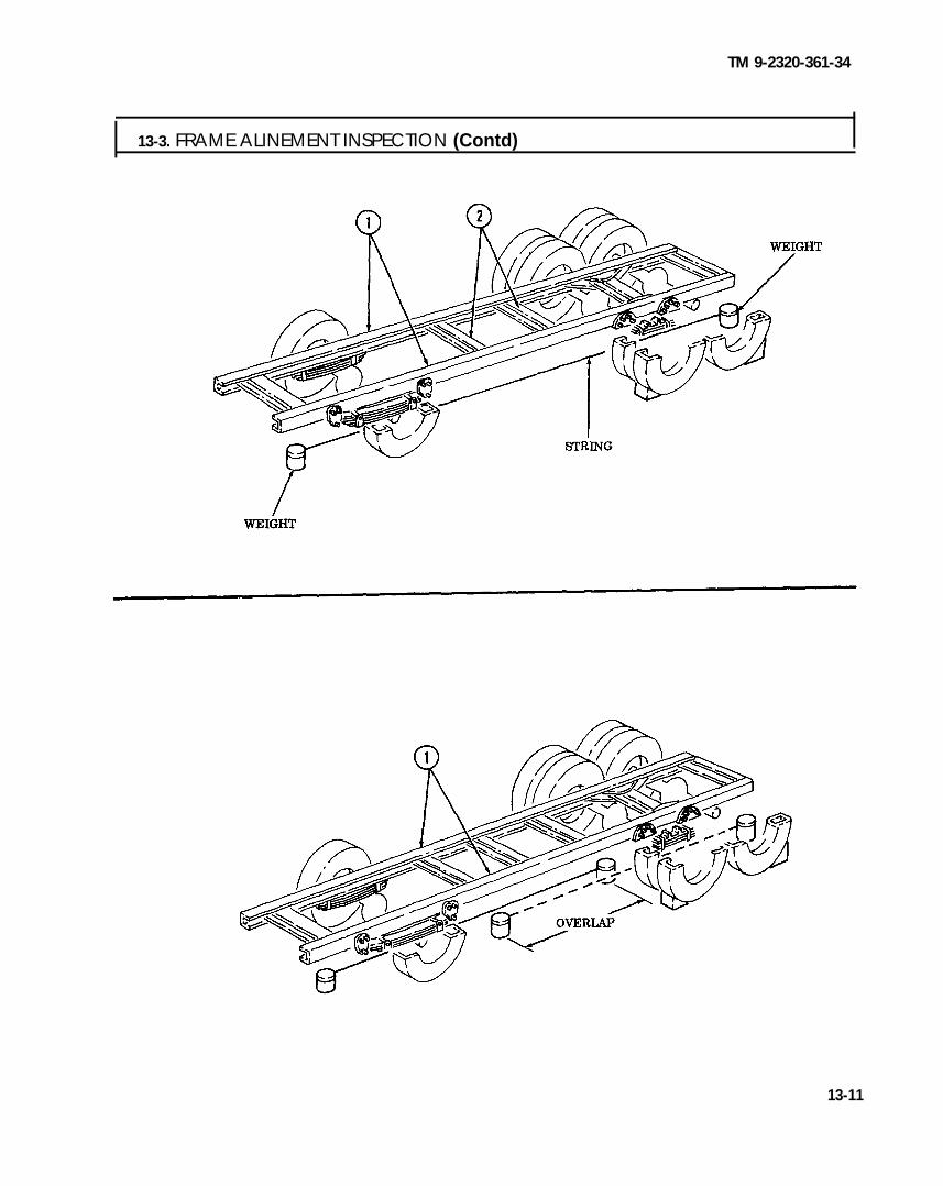
TM 9-2320-361-34
13-3. FRAME ALINEMENT INSPECTION (Contd)
13-11

TM 9-2320-361-34
I 13-4. FIFTH WHEEL MAINTENANCETHIS TASK COVERS:
a. Disassembly c. Assemblyb. Cleaning and Inspection
INITIAL SETUP
APPLICABLE MODELSM275A2
TOOLSGeneral mechanic’s tool kit
(Appendix B, Item 1)Torque wrench, 3/4-in. dr. (Appendix B, Item 6)Caliper, vernier (Appendix B, Item 9)Lifting device
Four washers (Appendix F, Item 268)Two screws (Appendix F, Item 212)Two locknuts (Appendix F, Item 99)
MATERIALS/PARTSCotter pin (Appendix F, Item 3)Cotter pin (Appendix F, Item 5)Two locknuts (Appendix F, Item 96)Locknut (Appendix F, Item 97)Locknut (Appendix F, Item 98)Two lockwashers (Appendix F, Item 126)Lockwasher (Appendix F, Item 127)Safety wire (Appendix C, Item 30)
PERSONNEL REQUIREDTwo
REFERENCES (TM)LO 9-2320-209-12-1TM 9-2320-361-34P
EQUIPMENT CONDITIONFifth wheel removed (TM 9-2320-361-20).
GENERAL SAFETY INSTRUCTIONS. All personnel must stand clear during lifting
operations.. Eye protection must be worn when removing or
installing springs under tension.● Personnel must stand clear during release of
plunger rack.
I a. Disassembly
1. Attach chain to fifth wheel housing (1) with four washers (2), two screws (5), and locknuts (3).2. Attach lifting device to chain. Apply tension to chain.3. Remove two lubrication fittings (4) from fifth wheel housing (1).
CAUTIONDo not use heat to remove pivot pins from fifth wheel housing.Damage to equipment will result.
4. Remove two retaining pins (7) and pivot pins (8) from fifth wheel housing (1) and base (6).
WARNINGAll personnel must stand clear during lifting operations. Aswinging or shifting load may cause injury or death to personnel.
5. Remove fifth wheel housing (1) from base (6).
●
●
6. Position fifth
NOTEAssistant will help with step 6.Fifth wheel housing must be 6 in. (15.2 cm) above workbench forbushing removal.wheel housing (1) on workbench with trailer mating surface (9) side down.
13-12

TM 9-2320-361-34
13-4. FIFTH WHEEL MAINTENANCE (Contd)
13-13

TM 9-2320-361-34
13-4. FIFTH WHEEL MAINTENANCE (Contd)
WARNINGEye protection must be worn when removing or installingsprings under tension. Failure to do so may result in injury topersonnel.
7. Remove spring (26) and cotter pin (23) from fifth wheel housing (18) and handle (28). Discard cotterpin (23).
8. Remove two lubrication fittings (34), screws (35), lockwashers (36), and washers (37) from twocoupler jaws (31). Discard lockwashers (36).
9. Remove spring (32) from two coupler jaws (31).
10.11.
12.
13.
14.
15.
16.
17.
18.
19.
20.
21.
WARNINGPlunger rack is under spring tension. Keep hands clear ofplunger rack during removal. Failure to do so may cause injuryto personnel.
Release plunger rack latch (14) and allow plunger rack (7) to slide to unloaded position.Remove spring (12) from plunger rack latch (14) and cotter pin (13).Remove cotter pin (13) from fifth wheel housing (18). Discard cotter pin (13).Remove safety wire (8), two locknuts (9), three washers (10), bracket (11), and plunger racklatch (14) from stud (17), screw (19), and fifth wheel housing (18). Discard safety wire (8) andlocknuts (9).Remove spring (3), plunger rack (7), screw (19), and spacer (15) from fifth wheel housing (18).Remove screw (25), lockwasher (24), cam (22), and bushing (21) from fifth wheel housing (18).Discard lockwasher (24).Remove two coupler jaws (31), compression arm (33), and two bushings (38) from fifih wheelhousing (18).Remove locknut (2), washer (1), screw (27), and yoke (30) from pinion gear (16). Discard locknut (2).Remove handle (28) from fifth wheel housing (18).Loosen jamnut (29) and remove handle (28) from yoke (30).Remove locknut (6), screw (20), washer (5), spacer (4), and pinion gear (16) from fifth wheelhousing (18). Discard locknut (6).
Remove jamnut (29) from handle (28).
13-14

TM 9-2320-361-34
I 13-4. FIFTH WHEEL MAINTENANCE (Contd) I
13-15

TM 9-2320-361-34
13-4. FIFTH WHEEL MAINTENANCE (Contd)
I b. Cleaning and Inspection I1.2.
3.
4.
5.
6.
7.
8.
9.
10.11.12.13.
13-16
For general cleaning instructions, refer to para 2-8.Inspect two coupler jaws (12) for cracks and breaks. Replace if cracked or broken.Inspect cam (10) for grooves and breaks. Replace if grooved or broken.Inspect springs (2), (5), (11), and (13) for bends, breaks, and collapsed coils. Measure spring lengths.Refer to table 13-1, Fifth Wheel Spring Length, for measurements. Replace if bent, broken, or coilsare collapsed.Inspect pinion gear (6) for damaged gear teeth. Replace if damaged.Inspect plunger rack (3) for cracks and breaks. Replace if cracked or broken.Inspect handle (1) for bends and cracks. Replace if bent or cracked.Inspect fifth wheel housing surface (8) for grooves, gouges, and breaks in metal. Replace if damagedor broken.Inspect plunger rack latch (4) for bends and scoring. Replace if bent or scored.Inspect stud (7) for breaks, cracks, and stripped threads. Replace if damaged.Inspect bushings (15) for cuts, wear, or damage. Replace if damaged.Inspect compression arm (14) for cracks, breaks, and bends. Replace if cracked, broken, or bent.Inspect plunger rack (3), pivot pin (9), and cam (10) for wear. Measure plunger rack (3), pivot pin (9),and cam (10). Refer to table 13-2, Fifth Wheel Wear Limits, for measurements. Replace if worn.
Table 13-1. Fifth Wheel Spring Length.
ITEM SPRING FREE LENGTHNO. lTEM/POINT OF MEASUREMENT
INCHES MILLIMETERS
2 Plunger rack spring 7.25 184.155 Plunger rack latch spring 2.06 52.32
11 Handle spring 6.00 152.413 Coupler jaw spring 2.31 58.67
Table 13-2. Fifih Wheel Wear Limits.
ITEMlTEM/POINT OF MEASUREMENT
WEAR LIMITS/TOLERANCESNO. INCHES MILLIMETERS
3 Plunger rack, outer diameter 2.874-2.878 72.999-73.1019 Pivot pin
Outer diameter 1.47 -1.53 37.34-38.86Length 6.44-6.59 163.57-167.38
10 Cam, inner diameter 1.093-1.099 27.76-27.91

TM 9-2320-361-34
1 3 - 4 . F I F T H W H E E L M A I N T E N A N C E ( C o n t d )
13-17

TM 9-2320-361-34
13-4. FIFTH WHEEL MAINTENANCE (Contd)
c. Assembly1.
2.
3.
4.
5.
6.
7.
8.
9.
10.
11.
12.
13.
14.
15.
13-18
Install pinion gear (16) on fifih wheel housing (18) with screw (20), spacer (4), washer (5), andnew locknut (6).
Install jamnut (29) and handle (28) on yoke (30).
Install yoke (30) on pinion gear (16) with screw (27), washer (1), and new locknut (2).
Aline hole in compression arm (33) with hole in fifth wheel housing (18).
Install compression arm (33) and two coupler jaws (31) in fifth wheel housing (18) with twobushings (38).
Install bushing (21) and cam (22) on fifth wheel housing (18) with new lockwasher (24) andscrew (25).
Place spring (3) on plunger rack (7).
Install screw (19), spacer (15), and plunger rack (7) on fifth wheel housing (18).
NOTEAdd washers as needed to obtain proper height on plunger racklatch. Latch must set level with latch on plunger rack.
Install plunger rack latch (14), bracket (11), three washers (10), two new locknuts (9), and new safetywire (8) on screw (19) and stud (17).
Install new cotter pin (13) in fifth wheel housing (18) with eye of cotter pin (13) facing back of fifthwheel housing (18).
WARNINGEye protection must be worn when removing or installingsprings under tension. Failure to do so may result in injury topersonnel.
Instal l spring (12) on plunger rack latch (14) and cotter pin (13).
Install spring (32) on two coupler jaws (31).
Install two washers (37), new lockwashers (36), screws (35), and lubrication fittings (34) on twobushings (38). Tighten screws (35) 150-200 lb-ft (203-271 N.m).
Install new cotter pin (23) in fifth wheel housing (18).
Install spring (26) on handle (28) and cotter pin (23).

TM 9-2320-361-34
1 3 - 4 . F I F T H W H E E L M A I N T E N A N C E ( C o n t d )
13-19

TM 9-2320-361-34
I 13-4. FIFTH WHEEL MAINTENANCE (Contd)
16.17.18.
19.20.
WARNING
All personnel must stand clear during lifting operations. Aswinging or shifting load may cause injury or death to personnel.
Remove fifth wheel housing (1) from workstand.Position fifth wheel housing (1) on base (6).Insert two pivot pins (8) through fifth wheel housing (1) and base (6) and install with two retainingpins (7).Install two lubrication fittings (4) in fifth wheel housing (1).Remove lifting device, two locknuts(3),screws (5), four washers (2), and chain from fifth wheel h o u s i n g ( 1 ) .
FOLLOW-ON TASKS: . Install fifth wheel (TM 9-2320-361-20).. Lubricate fifth wheel (LO 9-2320-209-12-1).
13-20

TM 9-2320-361-34
CHAPTER 14BODY, CAB, AND HOOD MAINTENANCE
14-1. BODY, CAB, AND HOOD MAINTENANCE INDEX
PARA.NO.
TITLE PAGENO. I
14-2. General Information 14-114-3. Cab Replacement 14-1
14-4. Windshield Glass Replacement 14-214-5. Door Glass Replacement 14-4
14-6. Door Glass Channel Replacement 14-5
14-2. GENERAL INFORMATION
a. The M44A2 series, 6x6, 2-1/2-ton vehicles use common cab, hood, and fender components. All major bodycomponents are composed of steel and are subject to common welding and metal body repair procedures.
b. Refer to TM 9-237 for welding body repair and to TC 9-510 for metal body repair instructions. Refer toTM 43-0139 for preparation of body components and painting instructions. Refer to TB 43-0209 for camouflagepainting and military marking instructions.
14-3. CAB REPLACEMENT
Refer to cab replacement kit (P/N 12300779, NSN 2510-01-161-2127) for cab replacement instructions.
14-1

TM 9-2320-361-34
14-4. WINDSHIELD GLASS REPLACEMENTTHIS TASK COVERS:
a. Removal b. Installation
INITIAL SETUPAPPLICABLE MODELSAll
REFERENCES (TM)TM 9-2320-361-20
TOOLS TM 9-2320-361-34P
General mechanic’s tool kit(Appendix B, Item 1)
EQUIPMENT CONDITION. Windshield assembly removed (TM 9-2320-361-20).
MATERIALS/PARTS ● Windshield arm, glass, and handle removedTwo lockwashers (Appendix F, Item 139) (TM 9-2320-361-20).Filler strip (Appendix F, Item 264)Filler strip (Appendix F, Item 265)Adhesive (Appendix C, Item 1)
a. Removal 1. Remove six screws (1), two nuts (4), four washers (9), and two lockwashers (3) from windshield
frame (8). Discard lockwashers (3).2. Remove crosspiece (2) from windshield frame (8).
NOTEMeasure old frame filler strips for installation.
3. Remove crosspiece filler strip (5) from crosspiece (2). Discard crosspiece filler strip (5).4. Remove glass (6) and frame filler strips (7) from windshield frame (8). Discard frame filler
strips (7).
b. InstallationNOTE
Cut four new filler strips to size.1. Apply adhesive to new frame filler strips (7). Install new frame filler strips (7) on glass (6).2. Install glass (6) in windshield frame (8). Tap glass (6) gently into position.3. Apply adhesive to new crosspiece filler strip (5). Install new crosspiece filler strip (5) on glass (6).4. Install crosspiece (2) on windshield frame (8) and gently tap until screw holes aline.5. Install crosspiece (2) on windshield frame (8) with six screws (1), four washers (9), two new
lockwashers (3), and nuts (4). Trim excess filler strips (7) and (5) and adhesive from aroundglass (6).
14-2

TM 9-2320-361-34
14-4. WINDSHIELD GLASS REPLACEMENT (Contd)
FOLLOW-ON TASKS: . Install windshield arm, glass, and handle (TM 9-2320-361-20).● Install windshield assembly (TM 9-2320-361-20).
14-3

TM 9-2320-361-34
14-5. DOOR GLASS REPLACEMENT
THIS TASK COVERS:a. Removal b. Installation
INITIAL SETUP
APPLICABLE MODELS REFERENCES (TM)All TM 9-2320-361-20
TOOLSTM 9-2320-361-34P
General mechanic’s tool kit EQUIPMENT CONDITION(Appendix B, Item 1) Cab door glass and frame removed
MATERIALS/PARTS(TM 9-2320-361-20).
Frame seal (Appendix F, Item 238)Channel lift seal (Appendix F, Item 235)Channel lift filler (Appendix F, Item 236)
a. Removal1. Remove four screws (4) from channel lift (5) and frame (3).2. Remove channel lift (5), channel lift filler (6), and channel lift seal (7) from frame (3). Discard
channel lift filler (6) and channel lift seal (7).3. Slide glass (1) out of frame (3).4. Remove frame seal (2) from frame (3). Discard frame seal (2).
I b. Installation
1. Install new frame seal (2) in frame (3).2. Install glass (1) in frame (3). Tap glass (1) gently into position.3. Install new channel lift seal (7) on bottom of glass (1).4. Install new channel lift filler (6) on channel lift (5).5. Install channel lift (5) on frame (3) with four screws (4).
2
FOLLOW-ON TASK: Install cab door glass and frame (TM 9-2320-361-20).
14-4

TM 9-2320-361-34
14-6. DOOR GLASS CHANNEL REPLACEMENT
THIS TASK COVERS:a. Removal b. Installation
INITIAL SETUP
APPLICABLE MODELSAll
TOOLSGeneral mechanic’s tool kit (Appendix B, Item 1)Riveting tool (Appendix B, Item 20)
MATERIALS/PARTSPOp rivet (Appendix F. Item 207)
REFERENCES (TM)TM 9-2320-361-20TM 9-2320-361-34P
EQUIPMENT CONDITIONCab door glass and frame. removed(TM 9-2320-361-20).
a. Removal1. Remove screw (2) and channel (3) from cab door (4).2. Remove pop rivet (5) and channel (1) from cab door (4). Discard pop rivet (5).
I b. Installation I1. Install channel (1) in cab door (4) with new pop rivet (5).2. Install channel (3) in cab door (4) with screw (2).
FOLLOW-ON TASK.: Install cab door glass and frame (TM 9-2320-361-20).
14-5 (14-6 blank)


TM 9-2320-361-34
CHAPTER 15SPECIAL PURPOSE BODIES MAINTENANCE
Section I. Cargo Bodies Maintenance (page 15-1)Section II. Dump Body Maintenance (page 15-8)Section III. Fuel Tank and Water Tank Bodies Maintenance (page 15-24)Section IV. Van and Repair Shop Bodies Maintenance (page 15-63)Section V. Earth Boring and Polesetting Bodies Maintenance (page 15-122)Section VI. Pipeline Construction Body Maintenance (page 15-215)
Section 1. CARGO BODIES MAINTENANCE
I 15-1. CARGO BODIES MAINTENANCETHIS TASK COVERS:a. Removal c. Repairb. Cleaning and Inspection d. Installation
INITIAL SETUP
APPLICABLE MODELSM35A2, M35A2C, and M36A2
TOOLSGeneral mechanic’s tool kit
(Appendix B, Item (1) 1-1/8-in. socket, 3/4-in. dr.
(Appendix B, Item 33)1-1/16-in. socket. 3/4-in. dr.
(Appendix B, Item 61)Torque wrench, 3/4-in. dr.
(Appendix B, Item 6)Breaker bar, 3/4-in. dr. (Appendix B, Item 34)Handle, socket wrench, 3/4-in. dr.
(Appendix B, Item 35)Lifting device
MATERIALS/PARTSFour locknuts (Appendix F, Item 95)Four locknuts (Appendix F, Item 103)Four locknuts (Appendix F, Item 105)Six locknuts (Appendix F, Item 104)
PERSONNEL REQUIREDTwo
REFERENCES (TM)TB 43-0209TC 9-510TM 9-2320-361-20TM 9-2320-361-34PTM 9-237TM 43-0139
EQUIPMENT CONDITION● Cargo body side racks and troop seat removed
(M35A2C, M36A2) (TM 9-2320-361-20).● Cargo body front rack removed (M35A2C, M36A2)
(TM 9-2320-361-20).. Cargo body front splash guards removed (M35A2C,
M36A2) (TM 9-2320-361-20).● Cargo body upper and lower rear splash guards
removed (M35A2C) (TM 9-2320-361-20).● Reflectors removed (TM 9-2320-361-20).
GENERAL SAFETY INSTRUCTIONS● All personnel must stand clear during lifting
operations.● Ensure lifting capacity is greater than weight of
cargo body.
15-1
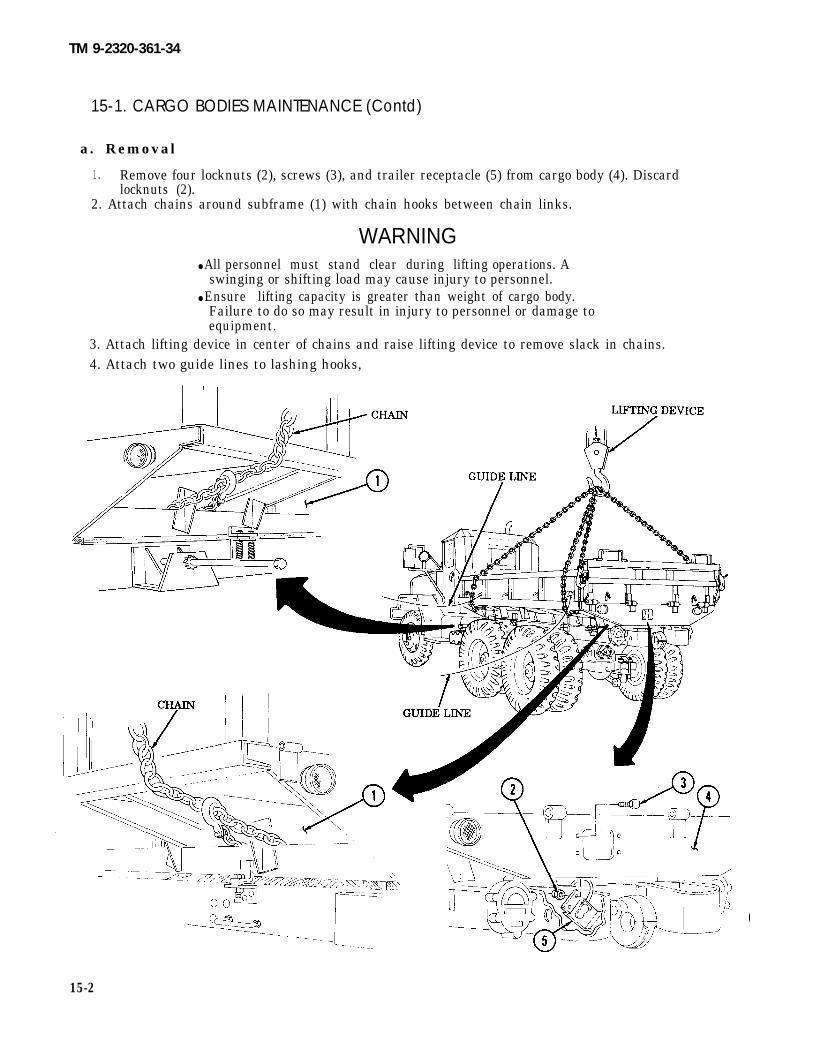
TM 9-2320-361-34
15-1. CARGO BODIES MAINTENANCE (Contd)
a. Removal
1. Remove four locknuts (2), screws (3), and trailer receptacle (5) from cargo body (4). Discardlocknuts (2).
2. Attach chains around subframe (1) with chain hooks between chain links.
WARNING● All personnel must stand clear during lifting operations. A
swinging or shifting load may cause injury to personnel.● Ensure lifting capacity is greater than weight of cargo body.
Failure to do so may result in injury to personnel or damage toequipment.
3. Attach lifting device in center of chains and raise lifting device to remove slack in chains.4. Attach two guide lines to lashing hooks,
15-2

M36A2
TM 9-2320-361-34
15-1. CARGO BODIES MAINTENANCE (Contd)
5.
6.
7.
Remove four locknuts (18), washers (19), springs (20) and (21), and screws (22) from two brackets (6)and brackets (17). Discard locknuts (18).Remove six locknuts (10), washers (11), and screws (12) from six brackets (7) and brackets (9).Discard locknuts (10).
NOTEM36A2 long wheelbase models have two additional sets of body andframe brackets. For hardware removal, perform step 7.
Remove four locknuts (14), washers (15), and screws (16) from two brackets (8) and brackets (13).Discard locknuts (14).l
15-3
TM 9-2320-361-34
15-1. CARGO BODIES MAINTENANCE (Contd)
WARNINGAll personnel must stand clear during lifting operations. A swingingor shifting load may cause injury to personnel.
NOTEAssistant will help guide cargo body during lifting operations.
8. Remove cargo body (1) and place on wooden supports.NOTE
Perform steps 9 and 10 if replacing cargo body.
9. Remove cargo body tailgate (3) (TM 9-2320-361-20).10. Remove cargo body dropside (2) (M35A2C) (TM 9-2320-361-20).11. Remove one frame sill (4) from each frame rail (5) for inspection.
I b. Cleaning and Inspection I1. For general cleaning instructions of cargo body (1), refer to para. 2-8.2. Inspect all screws, washers, and springs for defects. Replace if defective.3. Inspect frame sills (4) for end splits or rotting. Replace if end split(s) exceeds width of frame sill or
frame sill is rotting.4. Inspect cargo body (1) for structural damage or rust. Replace if damage or rust is severe and exceeds
available repair procedures.
c. Repair
1. Remove and install lashing hooks and/or data plates in area(s) to be repaired (TM 9-2320-361-20).2. Remove paint and/or rust from area(s) to be welded or repaired (TM 9-237).3. Repair cargo body (1) (TM 9-237 and TC 9-510).4. Paint cargo body as necessary (TM 43-0139 and TB 43-0209).
d. Installation
WARNINGAll personnel must stand clear during lifting operations. A swingingor shifting load may cause injury to personnel.
NOTE. Use breaker bar to aline body and frame brackets.● Assistant will help guide cargo body during lifting operations.
1. Place one frame sill (4) on each frame rail (5).NOTE
Perform steps 2 and 3 if installing new cargo body.2. Install cargo body dropside (2) (M35A2C) (TM 9-2320-361-20).3. Install cargo body tailgate (3) (TM 9-2320-361-20).4. Lift cargo body (1) off supports and lower onto frame rails (5).
15-4

TM 9-2320-361-34
15-1. CARGO BODIES MAINTENANCE (Contd)
15-5

TM9-2320-361-34
15-1. CARGO BODIES MAINTENANCE (Contd)
5. Install trailer receptacle (3) behind cargo body (2) with four screws (1) and new locknuts (4).
NOTEM35A2 front left side bracket mounting screws secure two sets ofsprings positioned on top of body brackets. Right side spring setsare the same and are secured below frame brackets.
6. Install four screws (21) in two brackets (5) and brackets (16). Install four springs (19) inside foursprings (20) and over four screws (21) with four washers (18) and new locknuts (17).
7. Adjust spring screws (21) to set springs (19) and (20) height to 6.375 in. (16.19 cm).NOTE
M36A2 long wheelbase models have two additional body and framebrackets. Perform step 8 for hardware installation.
8. Install four screws (15) in two brackets (7) and brackets (12) with four washers (14) and new lock-nuts (13). Tighten locknuts (13) 105-145 lb-ft (142-197 N.m).
9. Install six screws (8) to six brackets (6) and brackets (9) with six washers (11) and newlocknuts (10). Tighten locknuts (10) 125-165 lb-ft (170-224 N.m).
10. Remove lifting device, chains, and guide lines from cargo body (2).
15-6

TM 9-2320-361-34
FOLLOW-ON TASKS: . Install reflectors (TM 9-2320-361-20).● Install cargo body upper and lower rear splash guards (M35A2C)
(TM 9-2320-361-20).● Install cargo body front splash guards (M35A2C, M36A2) (TM 9-2320-361-20).. Install cargo body front rack (M35A2C, M36A2) (TM 9-2320-361-20).. Install cargo body side racks and troop seat (M35A2C, M36A2)
(TM 9-2320-361-20).
15-7

TM 9-2320-361-34
Section Il. DUMP BODY MAINTENANCE
I 15-2. DUMP BODY MAINTENANCE INDEX
PARA. TITLE PAGENO. NO.
15-3. Control Lever and Lock Replacement 15-8
15-4. Dump Body Maintenance 15-1115-5. Tailgate Control Linkage Maintenance 15-1615-6. Cab Protector Maintenance 15-20
I 15-3. CONTROL LEVER AND LOCK REPLACEMENT
THIS TASK COVERS:a. Removal b. Installation
INITIAL SETUP
APPLICABLE MODELSM342A2
REFERENCES (TM)LO 9-2320-209-12-1
TOOLSTM 9-2320-361-10TM 9-2320-361-20
General mechanic’s tool kit TM 9-2320-361-34P(Appendix B, Item 1)
EQUIPMENT CONDITIONMATERIALS/PARTS
● Parking brake set (TM 9-2320-361-10).Five locknuts (Appendix F, Item 89)
● Driver’s seat removed (TM 9-2320-361-20).Locknut (Appendix F, Item 106)Woodruff key (Appendix F, Item 272)Cotter pin (Appendix F, Item 6)
a. Removal 1. Remove cotter pin (10), clevis pin (8), and linkage (9) from lever (15). Discard cotter pin (10).2. Remove four locknuts (12) and screws (14) from two brackets (7) and floor (13). Discard lock-
nuts (12).3. Remove shaft (18), brackets (7), and boot (11) from floor (13).4. Remove locknut (17), screw (16), and lever (15) from shaft (18). Discard locknut (17).5. Remove woodruff key (19) from shaft (18). Discard woodruff key (19).6. Remove two brackets (7) from shaft (18).7. Remove two lubrication fittings (6) from brackets (7).8. Remove locknut (5), washer (4), spring (3), and lock (1) from lever handle (2). Discard
locknut (5).
1 5 - 8

TM 9-2320-361-34
15-3. CONTROL LEVER AND LOCK REPLACEMENT
1 5 - 9

TM 9-2320-361-34
15-3. CONTROL LEVER AND LOCK REPLACEMENT (Contd)
b. Installation 1. Install lock (1), spring (3), washer (4), and new locknut (5) on lever handle (2).2. Install two lubrication fittings (6) on brackets (7).3. Install two brackets (7) on shaft (18).4. Install new woodruff key (19) on shaft (18).5. Install lever (15) on shaft (18) with new locknut (17) and screw (16).6. Install lever (15), shaft (18), lever handle (2), boot (11), and two brackets (7) on floor (13) with four
new locknuts (12) and screws (14).7. Install linkage (9) on lever (15) with clevis pin (8) and new cotter pin (10).
FOLLOW-ON TASKS: ● Lubricate lever and lock (LO 9-2320-209-12-1).. Install driver’s seat (TM 9-2320-361-20).
15-10

TM 9-2320-361-34
15-4. DUMP BODY MAINTENANCE
THIS TASK COVERS:a. Removal c. Installationb. Inspection and Repair
INITIAL SETUP
APPLICABLE MODELSM342A2
TOOLSGeneral mechanic’s tool kit
(Appendix B, Item 1)1-1/8-in. socket, 1/2-in. dr.
(Appendix B, Item 10)1-1/16-in. socket, 1/2-in. dr.
(Appendix B, Item 11)Lifting device
MATERIALS/PARTSTwelve locknuts (Appendix F, Item 89)‘Iwo locknuts (Appendix F, Item 105)Two locknuts (Appendix F, Item 99)
PERSONNEL REQUIREDTwo
REFERENCES (TM)LO 9-2320-209-12-1TB 43-0209TC 9-510TM 9-237TM 9-2320-361-10TM 9-2320-361-34PTM 43-0139
EQUIPMENT CONDITION. Parking brake set (TM 9-2320-361-10).● Wheels chocked (TM 9-2320-361-10).● Dump body raised and safety braces in place
(TM 9-2320-361-10).● Cab protector removed (para. 15-6).
GENERAL SAFETY INSTRUCTIONS● Position safety braces before working under raised
dump body.. Do not operate dump controls when dump body is
removed.. All personnel must stand clear during lifting
operations.
15-11

TM 9-2320-361-34
I 15-4. DUMP BODY MAINTENANCE (Contd) Ia. Removal
WARNING
1.2.3.
4.5.6.7.
8.9.
10.
11.
Never work under dump body until safety braces are properlypositioned. Injury or death to personnel may occur if dump bodysuddenly lowers.
Remove two lubrication fittings (1) from two thrust plate pins (2).Remove two locknuts (5) and screws (6) from two thrust plate pins (2). Discard locknuts (5).Lower two safety braces (3).
CAUTION
Wooden supports must be able to hold weight of dump body.NOTE
Ensure block support is in place before lowering dump body orlockdown latch may latch on dump body.
Install wooden support between subframe (9) and dump body (8).Lower dump body (8) onto wooden support.Attach two chains to four corners of dump body (8). Attach two guide lines to dump body (8).Attach lifting device to chains and remove slack from chains.
WARNING
Ensure dump control lever is in neutral at all times. Injury or deathto personnel may result if lift cylinder is operated when notsecured.
Remove two thrust plate pins (2) from roller arms (7) and thrust plates (4).Remove twelve locknuts (10) and screws (12) from two hinge brackets (17) and dump body (8).Discard locknuts (10).Remove two locknuts (16) and screws (11) from two hinge brackets (17). Remove two hingebrackets (17) from dump body (8) and pivot pins (14). Discard locknuts (16).Remove two lubrication fittings (15) from pivot pins (14).
WARNINGAll personnel must stand clear during lifting operations. A swingingor shifting load may cause injury to personnel.
NOTEAssistant will help guide dump body during lifting operations.
12. Raise dump body (8) clear of vehicle.
CAUTION
Wooden supports must be able to hold weight of dump body.
13. Lower dump body (8) and place on wooden supports.14. Remove lifting device, two chains, and guide lines from dump body (8).
15-12

TM 9-2320-361-34
15-4. DUMP BODY MAINTENANCE (Contd)
b. Inspection and Repair
1. Inspect dump body (8) for dents, cracks, and rust. Repair if damaged (FM 43-2 and TM 9-237).2. Clean and paint as necessary (TM 43-0139 and TB 43-0209).
15-13

TM 9-2320-361-34
15-4. DUMP BODY MAINTENANCE (Contd)
1. Attach two chains to four corners of dump body (1) and attach lifting device to two chains.2. Attach two guide lines to dump body (1).
W A R N I N G
All personnel must stand clear during lifting operations. A swingingor shifting load may cause injury or death to personnel.
NOTETwo assistants will help guide dump body during lifting operations.
3. Raise dump body (1) and position on subframe (2).4. Install two lubrication fittings (8) on pivot pins (7).5. Install two hinge brackets (10) on two pivot pins (7) and dump body(1) with twelve screws (5) and
new locknuts (3).6. Install two screws (4) and new locknuts (9) on two hinge brackets (10).7. Install two thrust plate pins (15) in two roller arms (16) and thrust plates (12).
8. Install two lubrication fittings (17) on thrust plate pins (15).9. Remove lifting device, two chains, and guide lines from dump body (1).
W A R N I N G
Never work under dump body until safety braces are positionedproperly. Injury or death to personnel may occur if dump bodysuddenly lowers.
10. Raise dump body (1) (TM 9-2320-361-10).11. Raise two safety braces (11) to upright position.12. Install two screws (14) and new locknuts (13) on two thrust plate pins (15).13. Return safety braces (11) to stowed position.14. Lower dump body (1) (TM 9-2320-361-10).
15-14

TM 9-2320-361-34
15-4. DUMP BODY MAINTENANCE (Contd)
FOLLOW-ON TASKS: .●
Lubricate dump body (LO 9-2320-209-12-1).Install cab protector (para. 15-6).
15-15

TM 9-2320-361-34
I 15-5. TAlLGATE CONTROL LINKAGE MAINTENANCE
THIS TASK COVERS:a. Removal c. Installationb. Inspection, Cleaning, and Repair
lNITIAL SETUP
APPLICABLE MODELS REFERENCES (TM)M342A2 TB 43-0209
TOOLSTM 9-214TM 9-2320-361-10
General mechanic’s tool kit TM 9-2320-361-20(Appendix B, Item 1) TM 9-2320-361-34P
MATERIALS/PARTS TM 43-0139
Six locknuts (Appendix F, Item 96) EQUIPMENT CONDITIONThree locknuts (Appendix F, Item 105) . Parking brake set (TM 9-2320-361-10).Two woodruff keys (Appendix F, Item 272) ● Dump body raised and safety braces in place
(TM 9-2320-361-10).. Open tailgate (TM 9-2320-361-10).
a. Removal 1. Remove two locknuts (4), screws (1), and washers (3) from two clevises (2) and levers (13) and (7).
Discard locknuts (4).2. Remove two locknuts (5) and screws (10) from levers (13) and (7). Discard locknuts (5).3. Remove two levers (13) and (7) from cross-shaft (12).4. Remove two woodruff keys (11) from cross-shaft (12). Discard woodruff keys (11).5. Remove cross-shaft (12) from three bearings (6).6. Remove four nuts (9) and two clevises (2) from two control rods (8).7. Remove two locknuts (16) and link plates (15) from control rods (8), control bar (14), and
dump body (23). Discard locknuts (16).8. Remove control rod (8) from dump body (23).9. Remove three locknuts (17), screws (18), and tailgate latch (19) with control bar (14) from dump
body (23). Discard locknuts (17).10. Remove pin (22) and control bar (14) from tailgate latches (19).11. Remove pin (21) and pawl (20) from tailgate latch (19).12. Repeat steps 7 through 11 for left side control bar and panel removal.
b. Inspection, Cleaning, and Repair 4
1. Inspect all parts for rust, bends, cracks, and heavily worn areas. Replace if damaged beyond repair.2. Clean and paint parts as necessary (TB 43-0209 and TM 43-0139).3. Slide bearings (6) on cross-shaft (12). Twist and check for excessive play. Inspect bearings (6) for
wear (TM 9-214). Replace bearing(s) (6) if damaged.
15-16

TM 9-2320-361-34
15-5. TAILGATE CONTROL LINKAGE MAINTENANCE (Contd)
15-17

TM 9-2320-361-34
15-5. TAlLGATE CONTROL LINKAGE MAINTENANCE (Contd)
c. Installation
1. Install control bar (11) on tailgate latch (5) with pin (8).2. Install pawl (6) on tailgate latch (5) with pin (7).3. Install control bar (11) on dump body (9).4. Install tailgate latch (5) and control bar (11) on dump body (9) with three screws (4) and new
locknuts (3).5. Install two link plates (1) on control rod (10), control bar (11), and dump body (9) with two new
locknuts (2).6. Install two clevises (13) on two control rods (10) with four nuts (19).7. Insert cross-shaft (22) through three bearings (17).8. Install two new woodruff keys (21) on cross-shaft (22).9. Install levers (23) and (18) on cross-shaft (22) with two screws (20) and new locknuts (16).10. Install two clevises (13) and control rods (10) on levers (23) and (18) with two screws (12).
washers (14), and new locknuts (15).
15-18

TM 9-2320-361-34
15-5. TAlLGATE CONTROL LINKAGE MAINTENANCE (Contd)
FOLLOW-ON TASKS: . Close tailgate (TM 9-2320-361-10).● Lower dump body and safety braces (TM 9-2320-361-10).● Adjust tailgate linkage (TM 9-2320-361-20).
15-19

TM 9-2320-361-34
15-6. CAB PROTECTOR MAINTENANCETHIS TASK COVERS:a. Removal c. Installationb. Cleaning and Inspection
INITIAL SETUPAPPLICABLE MODELSM342A2
TOOLSGeneral mechanic’s tool kit (Appendix B, Item 1)Lifting device
Two screws (Appendix F, Item 213)Two locknuts (Appendix F, Item 106)Four washers (Appendix F, Item 268)
MATERIALS/PARTSFifteen locknuts (Appendix F, Item 105)Four cotter pins (Appendix F, Item 7)
PERSONNEL REQUIRED
REFERENCES (TM)FM 43-2TB 43-0209TM 9-237TM 9-2320-361-10TM 9-2320-361-34PTM 43-0139
EQUIPMENT CONDITIONParking brake set (TM 9-2320-361-10).
GENERAL SAFETY INSTRUCTIONSAll personnel must stand clear during liftingoperations.
T w o
a . Removal
Remove three screws (6) and locknuts (7) from cab protector (10) and dump body (20). Discardlocknuts (7).
2.
3.
4.
5.6.7.
W A R N I N G
8,
9.10.
11.12.
13.
Remove four screws (19) and locknuts (18) from upper and lower cab protector brackets (13).Discard locknuts (18).
NOTEAssistant will help with step 3.
Tilt upper cab protector (17) over top of lower cab protector (10) and install on lower cabprotector (10) with four screws (4) and nuts (5).Install chain on lower cab protector brackets (13) with two screws (11), washers (12), washers (14),and locknuts (15).Install guide line on cab protector (17).Install lifting device on chain and remove slack from chain.Remove eight screws (9) and locknuts (8) from lower cab protector (10) and dump body (20). Discardlocknuts (8).
All personnel must stand clear during lifting operations. A shiftingor swinging load may cause injury to personnel.
Remove upper and lower cab protectors (17) and (10) from dump body (20) and place on woodensupports.Remove four nuts (5) and screws (4) horn upper and lower cab protectors (17) and (10).Remove four cotter pins (3), washers (2), and two pins (1) from two hinges (16). Discard cotterpins (3).Lift upper cab protector (17) away from lower cab protector (10) and place on wooden supports.Remove lifting device from chain. Remove two nuts (15), screws (11), two washers (14), washers (12)and chain from lower cab protector brackets (13).Remove guide line from cab protector (17).
15-20

TM9-2320-361-34
15-6. CAB PROTECTOR MAINTENANCE (Contd)
15-21

TM 9-2320-361-34
15-6. CAB PROTECTOR MAINTENANCE (Contd)
I b. Cleaning and Inspection I1. Inspect cab protectors (17) and (11) for cracks, dents, and rust. Repair if damaged (FM 43-2 and
TM 9-237).2. Clean and paint as necessary (TB 43-0209 and TM 43-0139).
c. Installation 1. Install chains on cab protector brackets (14) with two screws (12), washers (13), and nuts (15).
Install lifting device on chains.2. Install guide line on cab protector bracket (14).3. Position upper cab protector (17) on lower cab protector (11) and install two pins (1), four
washers (2), and new cotter pins (3) through two hinges (16).4. Install upper cab protector (17) on lower cab protector (11) with four screws (4) and nuts (5).
WARNING
5.6.7.
8.9.
10.11.12.
All personnel must stand clear during lifting operations. A swingingor shifting load may cause injury to personnel.
Position upper and lower cab protectors (17) and (11) on dump body (8).Install lower cab protector (11) on dump body (8) with eight screws (10) and new locknuts (9).Remove lifting device from chain. Remove two nuts (15), washers (13), screws (12), and chains fromcab protector brackets (14).Remove guide line from cab protector bracket (14).Remove four screws (4) and nuts (5) from upper and lower cab protectors (17) and (11).
NOTEAssistant will help with step 10.
Tilt upper cab protector (17) over cab.Install four screws (19) and new locknuts (18) on upper and lower cab protector brackets (14).Install three screws (6) and new locknuts (7) on lower cab protector (11) and dump body (8).
15-22

TM 9-2320-361-34
15-6. CAB PROTECTOR MAINTENANCE (Contd) I
15-23

15-24
TM 9-2320-361-34
Section Ill. FUEL TANK AND WATER TANK BODIES MAINTENANCE
I 15-7. FUEL TANK AND WATER TANK BODIES MAINTENANCE INDEX
PARA. TITLE PAGENO. NO.
15-8. Fuel and Water Tank Bodies Maintenance 15-2515-9. Tank Bodies Frame Sill Maintenance 15-3215-10. Discharge Valve Repair (M50A2) 15-3615-11. Discharge Valve Repair (M49A2C and M50A3) 15-4215-12. Delivery Pump Repair 15-4815-13. Sump Valve, Drain Valves, and Drain Tubes Maintenance (M49A2C) 15-56

TM 9-2320-361-34
15-8. FUEL AND WATER TANK BODIES MAINTENANCE
THIS TASK COVERS:a. Removal c. Repairb. Cleaning and Inspection d. Installation
INITIAL SETUP
APPLICABLE MODELS EQUIPMENT CONDITION [Contd)M49A2C, M50A2, and M50A3 ● Nozzle holder removed ( M49A2C)
TOOLS ●
General mechanic’s tool kit(Appendix B, Item 1) ●
Torque wrench, 1/2-in. dr. (Appendix B, Item 7)Torque wrench, 3/4-in. dr. (Appendix B, Item 6) ●
1-1/8-in. socket, 3/4-in. dr. (Appendix B, Item 33)1-1/4-in. socket. 3/4-in. dr. (Appendix B. Item 37) ●
Handle, 3/4-in. dr. (AppendixB, Item 35)Breaker bar, 3/4-in. dr. (Appendix B, Item 34)Lifting device
MATERIALS/PARTSFour locknuts (M50A2 and M50A3)
(Appendix F, Item 103)Four locknuts (M50A2 and M50A3)
(Appendix F, Item 105)Four locknuts (M49A2C) (Appendix F, Item 105)Six locknuts (Appendix F, Item 103)
PERSONNEL REQUIREDTwo
REFERENCES (TM)TB 43-0212TC 9-510TM 9-2320-361-10TM 9-2320-361-20TM 9-2320-361-34PTM 9-237TM 43-0139TM 43-0209
EQUIPMENT CONDITION● Parking brake set (TM 9-2320-361-10).● Tank body drained (TM 9-2320-361-10).. Tank body purged (M49A2C) (TB 43-0212).. Tank body upper and lower splash guards
removed (TM 9-2320-361-20).. Tank body front splash guards removed
(TM 9-2320-361-20).● Manhole cover removed (M50A3)
(TM9-2320-361-20).● Water tank filler cover removed (M50A2 and.
M50A3) (TM 9-2320-361-20).
(TM 9-2320-361-20).Exhaust system removed (M50A2 and M50A3)(TM 9-2320-361-20).Tank body rear compartment doors removed(TM 9-2320-361-20).Water tank discharge tubes and valves removed(M50A2 and M50A3) (TM 9-2320-361-20).Fuel tank discharge valves removed (M49A2C)(TM 9-2320-361-20).Fuel tank discharge tubes removed (M49A2C)(TM 9-2320-361-20).Delivery pump rear propeller shaft removed(TM 9-2320-361-20).Delivery pump front propeller shaft removed(TM 9-2320-361-20).Static reel removed (M49A2C) (TM 9-2320-361-20).Discharge valve control levers removed(TM 9-2320-361-20).Gallon meter removed (M49A2C)(TM 9-2320-361-20).Delivery pump strainer removed(TM 9-2320-361-20).Filter separator removed (M49A2C)(TM 9-2320-361-20).Sump assembly, drain valves, and tubes removed(M49A2C) (para. 15-13).Gate valves removed (TM 9-2320-361-20).Water tank pump manifold removed (M50A2 andM50A3) (TM 9-2320-361-20).Overturn tubes removed (M49A2C)(TM 9-2320-361-20).Water or fuel cans and brackets removed(TM 9-2320-361-20).Fire extimzuishers removed (M49A2C)(TM 9-2310-361-20).
GENERAL SAFETY INSTRUCTIONS● All personnel must stand clear during lifting
operations.● Do not come in direct contact of spray during tank
steam cleaning.● Eye protection must be worn when removing or
installing springs under tension.● Lifting and support capacity must be greater than
weight of tank body.
15-25

TM 9-2320-361-34
15-8. FUEL AND WATER TANK BODIES MAINTENANCE (Contd).
a. R e m o v a l
1.
2.
3.
4.
5.6.
WARNING
Eye protection must be worn when removing or installing springsunder tension. Failure to do so may result in injury to personnel.
NOTEThe fuel (M49A2C) and water tank bodies (M50A2, M50A3) arereplaced basically the same. The fuel tank body has two additionalsets of body and frame brackets. This procedure covers the watertank body.
Remove four locknuts (5), washers (6), two springs (7) and (8), and four screws (3) from two brackets(1) and brackets (4). Discard locknuts (5).Remove four locknuts (12), washers (11), and screws (9) from four brackets (2) and brackets (10).Discard locknuts (12).Attach chains to tank body (1) and position lifting device in center of chains. Raise lifting device andremove slack in chains.Attach guide lines on lashing hooks (2).
WARNING● All personnel must stand clear during lifting operations. A
swinging or shifting load may cause injury to personnel.● Ensure lifting and support capacity are greater than weight of
tank body. Failure to do so may result in injury to personnel ordamage to equipment.
NOTEAssistant will help guide tank body during lifting operations.
Remove tank body (1) and place on wooden supports.Remove lifting device, chains, and guide lines from tank body (1).
15-26

15-8.
TM 9-2320-361-34
15-27

TM 9-2320-361-34
15-8. FUEL AND WATER TANK BODIES MAINTENANCE (Contd)
b. Cleaning and Inspection
WARNING
When using steam cleaning equipment, do not come in directcontact of spray. Burns or severe injury to personnel may result.
CAUTION
When steam cleaning tank body, do not apply steam on rustproofingunless area needs repair.
NOTE● Refer to TB 43-0212 for internal cleaning of fuel tank.● Perform steps 1 through 3 for internal cleaning of water tank.
1. Place steam nozzle in manhole and direct spray within compartment(s) from top to bottom.2. Wash all sludge and scale down to bottom of each compartment and remove. Rinse inside of each
compartment thoroughly with fresh water,3. Inspect tank body (1) for damage or rust. Replace tank body (1) if damage or rust on tank body (1) is
excessive and beyond available repair procedures.4. Inspect frame sills (para. 15-9).
1. Remove and install lashing hooks and data plates in area(s) to be repaired (TM 9-2320-361-20).2. Remove paint or rust from area(s) to be welded or repaired (TM 9-237).3. Repair tank body (1) (TM 9-237 and TC 9-510).4, Paint tank body as necessary (TM 43-0139 and TB 43-0209).
d. Installation
WARNING● All personnel must stand clear during lifting operations. A
swinging or shifting load may cause injury to personnel.● Ensure lifting capacity is greater than weight of tank body.
Failure to do so may result in injury to personnel.NOTE
● Use breaker bar to aline body and frame brackets.● Assistant will help guide tank body during lifting operations.
1. Attach chains to tank body (1).2. Attach lifting device to chains and install guide lines to tank body (1).3. Lift tank body (1) off wooden supports and lower onto vehicle frame (2).4. Remove lifting device from chains. Remove chains from tank body (1).5. Remove guide lines from lashing hooks (3).
15-28

TM 9-2320-361-34
15-8. FUEL AND WATER TANK BODIES MAINTENANCE (Contd)
15-29

TM 9-2320-361-34
15-8. FUEL AND WATER TANK BODIES MAINTENANCE (contd)
NOTEFuel tank models have two additional sets of body and frame brackets.
6. Install four screws (11) in four brackets (15) and brackets (12) with four washers (13) and newlocknuts (14). Tighten locknuts (14) 105-145 lb-ft (142-197 N.m).
W A R N I N G
Eye protection must be worn when installing springs under tension.Failure to do so may result in injury to personnel.
7. Place four screws (5) in two brackets (4) and brackets (6). Install springs (9) inside springs (10) andover screws (5) with four washers (8) and new locknuts (7).
NOTE“ Fuel tank bracket springs installed height is 6.4 in. (163 mm).● Water tank bracket springs installed height is 6.5 in. (165 mm).
8. Tighten four locknuts (7) and adjust springs (9) and (10) to height specification.
1 5 - 3 0

TM 9-2320-361-34
15-8. FUEL AND WATER TANK BODIES MAINTENANCE (Contd)
FOLLOW-ON TASKS: . Install fire extinguishers (M49A2C) (TM 9-2320-361-20).● Install water or fuel cans and brackets (TM 9-2320-361-20).● Install overturn tubes (M49A2C) (TM 9-2320-361-20).● Install water tank pump manifold (M50A2 and M50A3) (TM 9-2320-361-20).● Install gate valves (TM 9-2320-361-20).● Install sump assembly, drain valves, and tubes (M49A2C (para. 15-13).● Install filter separator (M49A2C) (TM 9-2320-361-20).● Install delivery pump strainer (TM 9-2320-361-20).● Install gallon meter (M49A2C) (TM 9-2320-361-20).● Install discharge valve control levers (TM 9-2320-361-20).. Install static reel (M49A2C) (TM 9-2320-361-20).. Install delivery pump front propeller shaft (TM 9-2320-361-20).● Install delivery pump rear propeller shaft (TM 9-2320-361-20).● Install fuel tank discharge tubes (M49A2C) (TM 9-2320-361-20).● Install fuel tank discharge valves (M49A2C) (TM 9-2320-361-20).● Install water tank discharge tubes and valves (M50A2 and M50A3)
(TM 9-2320-361-20).● Install exhaust system (M50A2 and M50A3) (TM 9-2320-361-20).● Install tank body rear compartment doors (TM 9-2320-361-20).. Install nozzle holder (M49A2C) (TM 9-2320-361-20).● Install water tank filler cover (M50A2 and M50A3) (TM 9-2320-361-20).● Install manhole cover (M50A3) (TM 9-2320-361-20).● Install tank body front splash guards (TM 9-2320-361-20).● Install tank body upper and lower splash guards (TM 9-2320-361-20).
15-31

TM 9-2320-361-34
15-9. TANK BODIES FRAME SILL MAINTENANCE
THIS TASK COVERS:a. Removal c. Installationb. Inspection
INITIAL SETUP
APPLICABLE MODELSM49A2C, M50A2, and M50A3
REFERENCES (TM)TM 9-2320-361-34P
TOOLS EQUIPMENT CONDITIONGeneral mechanic’s tool kit
(Appendix B, Item 1)Tank body removed (para. 15-8).
Breaker bar, 1/2-in. dr. (Appendix B, Item 15) GENERAL SAFETY INSTRUCTIONS1-1/8-in. socket, 1/2-in. dr. (Appendix B, Item 10) ● Use care when working under tank body.1-1./4-in. socket, 1/2-in. dr. (Appendix B, Item 19) ● Ensure lifting capacity is greater than weight ofTorque wrench, 1/2-in. dr. (Appendix B, Item 7) tank body.
MATERIALS/PARTSTwo locknuts (M49A2C and M50A3)
(Appendix F, Item 89)Three locknuts (M50A2) (Appendix F, Item 89)
WARNING
● Be careful when working under tank body placed on supports.Tank body may fall causing injury to personnel.
● Ensure lifting capacity is greater than weight of tank body.Failure to do so may cause injury to personnel.
a. Removal
NOTE● Perform steps 1 through 3 for M50A2 sill removal.● Perform step 4 for M49A2C sill removal.● Perform steps 5 and 6 for M50A3 sill removal.
1. Remove locknut (8), washer (9), and screw (12) from frame sill (7). Discard locknut (8).2. Remove locknut (11), screw (2), and bracket (10) from bracket (3). Discard locknut (11).
NOTEAssistants will help remove frame sill.
3. Remove locknut (4), washer (5), screw (6), and frame sill (7) from tank body (l). Discard locknut (4).
15-32

TM 9-2320-361-3415-9. TANK BODIES FRAME SILL MAINTENANCE (Contd)
15-33

TM 9-2320-361-34
I 15-9. TANK BODIES FRAME SILL MAINTENANCE (Contd)
b. Inspection
c. Installation
4. Remove two locknuts (2), washers (3), screws (4), and frame sill (5) from tank body (1). Discardlocknuts (2).
5. Remove locknut (11), washer (12), and screw (13) from bracket (14) and frame sill (10). Discardlocknut (11).
6. Remove locknut (7), washer (8), screw (9), and frame sill (10) from tank body (6). Discard lock-nut (7).
Inspect each frame sill (19), (5), or (10) for end splits or rotting. Replace if end split exceeds width offrame sill (19), (5), or (10) or frame sill (19), (5), or (10) is damaged.
NOTE● Perform steps 1 through 3 for M50A2 sill installation.. Perform step 4 for M49A2C sill installation.. Perform steps 5 and 6 for M50A3 sill installation.. Assistant will help with installation of frame sill.
1. Install frame sill (19) on tank body (15) with screw (18), washer (17), and new locknut (16).2. Install bracket (22) on frame sill (19) with screw (24), washer (21), and new locknut (20). Do not
tighten locknut (20).3. Install bracket (22) on bracket (25) with screw (26) and new locknut (23). Tighten locknut (20).4. Install frame sill (5) on tank body (1) with two screws (4), washers (3), and new locknuts (2).5. Install frame sill (10) end on tank body (6) with screw (9), washer (8), and new locknut (7).6. Install frame sill (10) end on tank body (6) and bracket (14) with screw (13), washer (12), and new
locknut (11).
15-34

TM 9-2320-361-34
15-9. TANK BODIES FRAME SILL MAINTENANCE (Contd)
FOLLOW-ON TASK: Ins ta l l tank body (para . 15-8 ) .
15-35

TM 9-2320-361-34
15-10. DISCHARGE VALVE REPAIR (M50A2)
THIS TASK COVERS:a. Disassembly c. Assemblyb. Cleaning and Inspection
INITIAL SETUP
APPLICABLE MODELSM50A2
TEST EQUIPMENTMicrometer (Appendix B, Item 3)
TOOLSGeneral mechanic’s tool kit
(Appendix B, Item 1)Handle, socket wrench, 1-in. dr.
(Appendix B, Item 43)Spring tester (Appendix B, Item 38)Torque wrench, 1/2-in. dr. (Appendix B, Item 7)Pipe wrench (Appendix B, Item 39)2-1/4-in. socket, 1-in. dr. (Appendix B, Item 57)Adjustable wrench (Appendix B, Item 62)
MATERIALS/PARTSPacking (Appendix F, Item 179)Disc (Appendix F, Item 25)Cotter pin (Appendix F, Item 8)Rags (Appendix C, Item 16)
REFERENCES (TM)TM 9-2320-361-20TM 9-2320-361-34P
EQUIPMENT CONDITIONDischarge valve removed (TM 9-2320-361-20).
GENERAL SAFETY INSTRUCTIONSEye protection must be worn when working withdischarge valve internal spring.
a. Disassembly WARNING
Discharge valve internal spring is compressed by bonnet. Eyeprotection must be worn during bonnet removal from valve housing.Failure to do so may result in injury to personnel.
1.2.3.
4.5.6.7.8.9.
10.
11.
Remove strainer (2) from discharge valve housing (13).Remove bonnet (3) from valve housing (13) and upper plunger (5).Remove spring (4) and upper plunger (5) with nut (1), disc (15), and lower plunger (14) from valvehousing (13).Remove nut (1) and disc (15) from lower plunger (14) and upper plunger (5). Discard disc (15).Remove upper plunger (5) from lower plunger (14).Remove cotter pin (8) from lever arm (7) and stem (9). Discard cotter pin (8).Remove lever arm (7) from stem (9).Remove plug (6) from valve housing (13) and stem (9).Remove stem (9) from cam (12) and stem bore (11) of valve housing (13).Remove cam (12) horn valve housing (13).Remove packing (10) from stem bore (11). Discard packing (10).
15-36

TM 9-2320-361-34
15-10. DISCHARGE VALVE REPAIR (M50A2) (Contd)
15-37

TM9-2320-361-34
1 15-10. DISCHARGE VALVE REPAIR (M50A2) (Contd)
I b. Cleaning and Inspection
1.
2.
3.
4.
5.
6.7.8.
9.
10.11.12.
15-38
Wash all parts with soap and hot water. Rinse all parts with hot water and dry using a clean,soft rag.
Table 15-1. Discharge Valve Wear Limits.
ITEM WEAR LIMITS/TOLERANCESNO. lTEM/POINT OF MEASUREMENT
STANDARD METRIC
2 Upper plunger (bonnet end diameter) 0.48-0.51 in. 12.19-12.95 mm3 Bonnet (plunger hole diameter) 0.50-0.51 in. 12.70-12.95 mm4 Spring
Free length 5.18-5.43 in. 131.6 -137.9 mmCompressed to 2.43 in. (61.7 mm) 22-28 lb-in. 2.5- 3.2 N.m
5 Plug (stem hole diameter) 0.65-0.66 in. 16.51-16.76 mm8 Cam stem:
Inside stem bore end diameter 0.42-0.43 in. 10.67-10.92 mmPlug end diameter 0.644-0.648 in. 16.36-16.46 mmMachined with square 0.49-0.50 in. 12.44-12.70 mm
9 Lower plunger (length) 3.23-3.26 in. 82.64-82.80 mm10 Discharge valve housing
Inside stem bore/inner diameter 0.43-0.44 in. 10.67-11.18 mmOuter stem bore/inner diameter 0.65-0.66 in. 16.51-16.76 mm
Inspect discharge valve housing (10) for scoring, cracks, or thread and mating surface damage andwear. Refer to table 15-1, Discharge Valve Wear Limits, for measurements. Replace if damaged orworn past limits.Inspect bonnet (3) for cracks, thread damage, and wear at plunger hole. Refer to table 15-1,Discharge Valve Wear Limits, for measurements. Replace bonnet (3) if damaged or worn past limits.Inspect upper plunger (2) for wear, bends, cracks, and thread damage. Refer to table 15-1, DischargeValve Wear Limits, for measurements. Replace upper plunger (2) if damaged or worn past limits.Inspect lower plunger (9) for wear, bends, cracks, and thread damage. Refer to table 15-1, DischargeValve Wear Limits, for measurements. Replace lower plunger (9) if damaged or worn past limits.Inspect nut (1) for thread and mating surface damage. Replace if damaged.Inspect cam (7) for mating surface damage at lower plunger. Replace if damaged.Inspect cam stem (8) for bends, cracks, and machined surface wear. Refer to table 15-1, DischargeValve Wear Limits, for measurements. Replace cam stem (8) if damaged or wornpast limits.Inspect plug (5) for wear and thread damage. Refer to table 15-1, Discharge Valve Wear Limits, formeasurements. Replace plug (5) if damaged or worn past limits.Inspect lever arm (6) for cracks or pinhole damage. Replace if damaged.Inspect spring (4) for collapsed coils or breakage. Replace if damaged.Inspect spring (4) length. Refer to table 15-1, Discharge Valve Wear Limits, for measurements.Replace sping (4) if worn past limits.

TM 9-2320-361-34
I 15-10. DISCHARGE VALVE REPAIR (M50A2) (Contd)
WARNINGEye protection must be worn during discharge valve internal springload test. Failure to do so may result in injury to personnel.
NOTEPerform step 13 for testing new or used discharge valve internalspring prior to assembly.
13. Check load on spring (4). Refer to table 15-1, Discharge Valve Wear Limits, for measurements.Replace spring (4) if load is incorrect.
15-39

TM 9-2320-361-34
15-10. DISCHARGE VALVE REPAIR (M50A2) (Contd)
c. Assembly
1.2.3.4.5.6.7.8.
9.
10.11.12,13.
14.
Install new packing (11) in bore (12) of valve housing (15).Place cam (14) in valve housing (15) with outward rounded edge positioned up.Install cam stem (10) through packing (11), bore (12), and cam (14).Install plug (6) over cam stem (10) into valve housing (15).Install new disc (17), with sealing edge positioned down, and nut (1) on lower plunger (16).Install upper plunger (5) in lower plunger (16).Install upper plunger (5) with nut (1), new disc (17), and lower plunger (16) in valve housing (15).Install spring (4) over upper plunger (5) and seat on nut (1).
WARNINGEye protection must be worn during spring compression/bonnetinstallation. Failure to do this may result in injury to personnel.
Install bonnet (3) over upper plunger (5) into valve housing (15).
NOTEIf cam stem replacement is required, perform steps 10 through 12.
Place valve housing tube flange (13) on flat surface. Place lever arm (7) on cam stem (10).Position lever arm (7) end hole center (8) 5.219 in. (132.6 mm) above flat surface.Drill 0.25 in. (6.4 mm) hole in center of slot in lever arm (7) through cam stem (10).Install lever arm (7) on cam stem (10) with new cotter pin (9). Bend cotter pin (9) legs even withlever arm (7).Install strainer (2) on valve housing (15).
15-40

TM 9-2320-361-34
15-10. DISCHARGE VALVE REPAIR (M50A2) (Contd)
FOLLOW-ON TASK: Install discharge valve (TM 9-2320-361-20).
15-41
TM9-2320-361-34
15-11. DISCHARGE VALVE REPAIR (M49A2C AND M50A3)THIS TASK COVERS:a. Disassembly c. Assemblyb. Cleaning and Inspection
INITIAL SETUPAPPLICABLE MODELS REFERENCES (TM)M49A2C and M50A3 TM 9-2320-361-20
TEST EQUIPMENTMicrometer (Appendix B, Item 3)
TOOLS
TM 9-2320-361-34P
EQUIPMENT CONDITIONDischarge valve removed (TM 9-2320-361-20).
General mechanic’s tool kit GENERAL SAFETY INSTRUCTIONSEye protection must be worn when removingor installing valve housing cover and during loadtest of internal spring.Keep fire extinguisher nearby when usingdrycleaning solvent.
(Appendix B, Item 1) ●
Torque wrench, 1/2-in. dr. (Appendix B, Item 8)Spring tester (Appendix B, Item 38)MATERIALS/PARTS .
Two seals (Appendix F, Item 222)Packing (Appendix F, Item 179)Disc (Appendix F, Item 24)Antiseize tape (Appendix C, Item 25)Rag (Appendix C, Item 16)Drycleaning solvent (Appendix C, Item 24)
a. Disassembly WARNING
Discharge valve internal spring is compressed in cap. Eyeprotection must be worn when removing screws and cap from valvehousing. Failure to do this may cause injury to personnel.
1.2.3.4.5.6.7.8.9.
10.
Remove strainer (2) from valve housing (7).Remove four setscrews (15) from valve housing (7).Remove cap (3) and spring (4) from stem (5).Remove stem (5) with holder (1), disc (17), and retainer (16) from valve housing (7).Remove retainer (16), disc (17), and holder (1) from stem (5). Discard disc (17).Remove nut (13) from bore (8) in valve housing (7).Remove seals (11) and (14) from bore (12) in nut (13). Discard seals (11) and (14).Remove cam stem (10) from cam (6) and valve housing (7).Remove cam (6) from valve housing (7).Remove packing (9) from bore (8) in valve housing (7). Discard packing (9).
15-42

TM 9-2320-361-34
15-11. DISCHARGE VALVE REPAIR (M49A2C AND M50A3) (Contd)
b. Cleaning and Inspection
WARNlNGDrycleaning solvent is flammable and will not be used near openflame. Use only in well-ventilated places. Failure to do so mayresult in injury or death to personnel.
NOTE● Perform step 1 for cleaning M49A2C fuel tank discharge valves.● Perform step 2 for cleaning M50A3 water tank discharge valves.
1. Wash all parts with drycleaning solvent and allow to air dry.2. Wash all parts with soap and hot water. Rinse all parts with hot water and dry using a clean, soft
rag.
15-43

TM 9-2320-361-34
15-11. DISCHARGE VALVE REPAIR (M49A2C AND M50A3) (Contd)
3.
4.5.
6.7.8.9.
10.11.12.13.
14.
15-44
Table 15-2. Discharge Value Wear Limits.
ITEM WEAR LIMITS/TOLERANCESNO. ITEM/POINT OF MEASUREMENT
INCHES MILLIMETERS
4 Spring (flee length) 5.0 127.07 Cam stem:
Inside stem bore end diameter 0.422-0.437 10.72-11.09Plug end diameter 0.644-0.648 16.36-16.46Machined with square 0.497-0.500 12.62-12.70
9 Discharge valve housing:Inside stem bore/inner diameter 0.433-0.443 10.99-11.25Outer stem bore/inner diameter 0.651-0.661 16.53-16.79
Inspect cam stem (7) for scoring or cracks and wear. Refer to table 15-2, Discharge Valve WearLimits, for measurements. Replace if damaged or worn past limits.Inspect strainer (2) for tears. Replace if damaged.Inspect valve housing (9) for cracks, stripped threads, scoring, or worn bores. Refer to table 15-2,Discharge Valve Wear Limits, for measurements. Replace if damaged or worn past limits.Inspect cap (3) for wear or cracks at stem hole. Replace if damaged.Inspect holder (1) for wear or cracks at tapered stem hole. Replace if damaged.Inspect retainer (10) for cracks or damaged threads. Replace if damaged.Inspect stem (5) for cracks, scoring, damaged threads, or wear. Replace if damaged or worn.Inspect cam (6) for wear at stem hole and curved driving surface. Replace if worn.Inspect nut (8) for wear at stem hole and thread damage. Replace if damaged or worn.Inspect spring (4) for weak or collapsed coils. Replace if damaged.Inspect spring (4) free length. Refer to table 15-2, Discharge Valve Wear Limits, for measurements.Replace spring (4) if worn past limits.
WARNINGEye protection must be worn during load test of internal spring.Failure to do this may cause injury to personnel.
NOTEPerform step 14 for test of new or used internal spring prior toassembly.
Check load on spring (4). Spring load must be 5.5-6.4 lb-ft (7.5-8.7 N.m) when compressed to 3 in.(76.2 mm).

TM 9-2320-361-34
15-11. DISCHARGE VALVE REPAIR (M49A2C AND M50A3) (Contd)
—
15-45

TM 9-2320-361-34
15-11. DISCHARGE VALVE REPAIR (M49A2C AND M50A3) (Contd)
c. Asssembly
1.2.3.4.
5.6.
7.8.9.
Install new packing (9) in bore (8) of valve housing (7).Position cam (6) inside valve housing (7) with rounded edge facing up.Insert cam stem (10) in bore (8) through cam (6) until seated.Install two new seals (12) and (14) in bore (11) of nut (13). Wrap nut (13) threads with antiseize tapeand install nut (13) over cam stem (10) into valve housing (7).Install holder (1) and new disc (17) on stem (5) with retainer (16).Position stem (5) with holder (1), new disc (17), and retainer (16) in valve housing (7) until seated.
WARNINGEye protection must be worn during spring and cap installation.Failure to do this may result in injury to personnel.
Position spring (4) over stem (5) on holder (1).Install cap (3) on stem (5), compressing spring (4) into valve housing (7), with four setscrews (15).Install strainer (2) over valve housing (7).
15-46

TM 9-2320-361-34
15-11. DISCHARGE VALVE REPAIR (M49A2C AND M50A3) (Contd)
I
I
I
FOLLOW-ON TASK: Install discharge valve (TM 9-2320-361-20).
15-47

TM 9-2320-361-34
15-12. DELlVERY PUMP REPAIR
THIS TASK COVERS:a. Disassembly c. Inspectionb. Cleaning d. Assembly
INITIAL SETUP
APPLICABLE MODELS REFERENCES (TM)M49A2C, M50A2, and M50A3 LO 9-2320-209-12-1
TOOLS TM 9-214
General mechanic’s tool kitTM 9-2320-361-20
(Appendix B, Item 1)TM 9-2320-361-34P
Snapring pliers (Appendix B, Item 40) EQUIPMENT CONDITIONMATERIALS/PARTS ● Delivery pump drain cock removed, if installedTwo O-ring seals (Appendix F, Item 177) (TM 9-2320-361-20).Two snaprings (Appendix F, Item 263) ● Delivery pump removed (TM 9-2320-361-20).Five seals (Appendix F, Item 233) ● Strainer element removed (TM 9-2320-361-20).Two gaskets (Appendix F, Item 54) SPECIAL ENVIRONMENTAL CONDITIONSGasket (Appendix F, Item 43)Gasket (Appendix F, Item 44)
Work area must be clean and free from blowing dirtand dust.
Gasket (Appendix F, Item 53)Thirty-two lockwashers (Appendix F, Item 146)GAA grease (Appendix C, Item 8)Rag (Appendix C, Item 16)
I a. Disassembly
1.
2.3.4.
5.6.7.
8.
9.
10.
11.
15-48
Remove four screws (3), lockwashers (2), strainer body (1), and gasket (46) from pump body (40).Discard lockwashers (2) and gasket (46).Remove valve cap (7) and gasket (6) from setscrew (5). Discard gasket (6).Place a locator mark on setscrew (5) threads where threads meet cover (4). Remove setscrew (5).Remove four screws (8), lockwashers (9), cover (4), and gasket (10) from pump body (40). Discardlockwashers (9) and gasket (10).Remove spring guide (11), spring (12), and bypass valve (13) from pump body (40).Remove grease fittings (23) and (32) and fittings (25) and (31) from covers (24) and (30).Remove four screws (26), Lockwashers (27), cover (24), and gasket (22) from pump head (16). Discardlockwashers (27) and gasket (22).
NOTELiner pins may stay with pump heads or liner during removal of pumpheads.
Remove eight screws (15), lockwashers (14), pump head (16), and O-ring seal (41) from pumpbody (40). Discard lockwashers (14) and O-ring seal (41).Remove four screws (33), lockwashers (34), cover (30), and gasket (28) from pump head (43). Discardlockwashers (34) and gasket (28).Remove eight screws (44), lockwashers (45), pump head (43), and O-ring seal (42) from pumpbody (40). Discard lockwashers (45) and O-ring seal (42).Remove seal (29) from cover (30). Discard seal (29).

TM 9-2320-361-34
15-12. DELIVERY PUMP REPAIR (Contd)
NOTERotor bearings are snug fit in pump heads. Rotor bearings must beremoved to gain access to snaprings in pump heads.
12. Remove rotor bearings (21) and (35) from pump heads (16) and (43).13. Remove snaprings (20) and (36), seals (19) and (37), washers (18) and (38), and seals (17) and (39)
from pump heads (16) and (43). Discard snaprings (20) and (36) and seals (17), (19), (39), and (37).
15-49

TM 9-2320-361-34
15-12. DELIVERY PUMP REPAIR (Contd)
14. Remove rotor (1) from liner (3).15. Remove four vanes (4) and two rods (5) from rotor (1).16. Mark liner (3) and pump body (2) for alinement during assembly.17. Remove liner (3) from pump body (2).
b. Cleaning
1. For general cleaning instructions, refer to para. 2-8.
NOTERefer to steps 2 and 3 for final cleaning of (M50A2 and M50A3)delivery pump internal components.
2. Wash delivery pump internal components with soap and hot water. Rinse internal componentsthoroughly with hot water.
3. Dry internal components using a clean, soft rag.
15-50

TM 9-2320-361-34
15-12. DELlVERY PUMP REPAIR (Contd)
c. Inspection
1.
Table 15-3. Delivery Pump Wear Limits.I TEM
NO ITEM/POINT OF MEASUREMENT WEAR LIMITS/ TOLERANCESINCHES MILLIMETERS
1 R o t o r : S h a f t d i a m e t e r a t s e a l s V a n e s l o t w i d t h
1 . 1 8 2 9 . 9 70.50 1 2 . 7
24
Pump body (bore diameter bypass valve 1 . 2 5 3 1 . 7 5 V a n e : Thickness W id th Clearance when installed in rotor
0.48-0.491.20-1.210.01-0.02
12.19-12.4530.48-30.730 . 2 5 - 0 . 5 1
6 Bypass valve (diameter) 1.24 3 1 . 5 0
2.
3.
4.
5.
For general inspection instructions, refer to para. 2-9.
Inspect pump body (2) for cracks, damaged threads, wear, or defects. Refer to table 15-3, DeliveryPump Wear Limits, for measurements. Replace if damaged or worn past limits.
Inspect rotor (1) for bent shaft, scoring or wear at shaft, key slot, or vane slot. Refer to table 15-3,Delivery Pump Wear Limits, for measurements. Replace if damaged or worn past limits.Inspect four vanes (4) for bends, cracks, scoring, or wear. Refer to table 15-3, Delivery Pump WearLimits, for measurements. Replace if damaged or worn past limits.
Inspect bypass valve (6) for breakage, scoring, or wear. Refer to table 15-3, Delivery Pump WearLimits, for measurements. Replace if damaged or worn past limits.
15-51

TM 9-2320-361-34
I 15-12. DELlVERY PUMP REPAIR (Contd)
6.7.8.9.
10.11.12.13.14.15.16.17.18.
15-52
Inspect liner (12) for cracks, scoring, or worn chrome plating. Replace if damaged or worn.Inspect two rods (18), rotor (19), and four vanes (17) for bends or scoring. Replace if damaged.Inspect washers (9) and (14) for grooves and cracks. Replace if damaged.Inspect pump heads (8) and (13) for cracks or thread damage. Replace if damaged.Inspect rotor bearings (10) and (15) (TM 9-214). Replace if damaged.Inspect covers (11) and (16) for cracks or thread damage. Replace if damaged.Inspect spring guide (3) for cracks. Replace if damaged.Inspect spring (2) for collapsed coils or breakage. Replace if damaged.Inspect cover (4) for cracks or thread damage. Replace if damaged.Inspect strainer body (1) for cracks or other damage. Replace if damaged.Inspect valve cap (5) for thread or gasket contact surface damage. Replace if damaged.Inspect setscrew (6) for threads or tip damage. Replace if damaged.Inspect two pins (7) in either the liner (12) or heads (8) and (13) for looseness or other damage.Replace if damaged.

TM 9-2320-361-34
15-12. DELlVERY PUMP REPAIR (Contd)
15-53

TM 9-2320-361-34
15-12. DELlVERY PUMP REPAIR (Contd)
d. A s s e m b l y
1. Aline locator marks and install liner (3) in pump body (2).2. Install two rods (5) and four vanes (4) in rotor (1).3.
4.
5.,
6.7.8.
9.10.11.12.
13.14.15.
16.17.18.
15-54
Position rotor (1) in liner (3).
Install new O-ring seal (19) and pump head (22) on pump body (2) with eight new lockwashers (20)and screws (21).Install new O-ring seal (46) and pump head (47) on pump body (2) with eight new lockwashers (49)and screws (48).Install new seal (23), washer (24), and new seal (25) in pump head (22) with new snapring (26).Install bearing (27) in pump head (22).Install new gasket (28) and cover (30) on pump head (22) with four new Iockwashers (33) andscrews (32).Install new seal (45), washer (44), and new seal (43) in pump head (47) with new snapring (42).Install bearing (41) in pump head (47).Install new seal (35) in cover (36).Install new gasket (34) and cover (36) on pump head (47) with four new lockwashers (39) andscrews (40).Install grease fittings (29) and (38) and fittings (31) and (37) in covers (30) and (36).Position bypass valve (18), spring (17), and spring guide (16) in pump body (2).Install new gasket (15) and cover (9) over spring guide (16) on pump body (2) with fournew Iockwashers (14) and screws (13).Install setscrew (10) in cover (9) with locator mark even with cover (9).Install new gasket (11) on setscrew (10) and cover (9) with valve cap (12).Install new gasket (50) and strainer body (6) on pump body (2) with four newlockwashers (7) and screws (8).

TM 9-2320-361-34
L
15-12. DELlVERY PUMP REPAIR (Contd)
FOLLOW-ON TASKS: . Install strainer element (TM 9-2320-361-20).● Install delivery pump (TM 9-2320-361-20).. Install delivery pump draincock, if removed (TM 9-2320-361-20).● Lubricate delivery pump covers (LO 9-2320-209-12-1).
15-55

TM 9-2320-361-34
15-13. SUMP VALVE, DRAIN VALVES, AND DRAIN TUBES MAINTENANCE (M49A2C)
THIS TASK COVERS:a. Sump Valve Removal e. Sump Valve Assemblyb. Drain Tubes and Drain Valves Removal f. Drain Tubes and Drain Valves Installationc. Sump Valve Disassembly g. Sump Valve Installationd. Cleaning and Inspection
INITIAL SETUP
APPLICABLE MODELS REFERENCES (TM)M49A2C TM 9-2320-361-20
TOOLSGeneral mechanic’s tool kit
(Appendix B, Item 1)
MATERIALS/PARTSSix locknuts (Appendix F, Item 89)Gasket (Appendix F, Item 55)Six cotter pins (Appendix F, Item 23)Valve seat (Appendix F, Item 244)
TM 9-2320-361-34P
EQUIPMENT CONDITIONFilter separator-to-sump pipe removed(TM 9-2320-361-20).
GENERAL SAFETY INSTRUCTIONSKeep fire extinguisher nearby when usingdrycleaning solvent.
Antiseize tape-(Appendix C, Item 25)Drycleaning solvent (Appendix C, Item 24)
a. Sump Valve Removal
NOTEMark location of two holes in sump cover, where support attaches,for assembly.
1. Remove two screws (12) from sump valve (5) and support (11).2. Remove two locknuts (15), screws (13), and support (11) from cabinet (14). Discard locknuts (15).
3. Remove two locknuts (6), screws (3), collar (7), and pad (4) from sump valve (5) and bracket (2).Discard locknuts (6).
4. Remove two locknuts (16), screws (1), and bracket (2) from cabinet (14). Discard locknuts (16).
5. Remove sump valve (5) and drain tubes (8) and (9) from cabinet floor (10).
15-56

TM 9-2320-361-34
15-13. SUMP VALVE, DRAIN VALVES, AND DRAIN TUBES MAINTENANCE(M49A2C) (Contd)
I
1
15-57

TM 9-2320-361-34
15-13. SUMP VALVE, DRAIN VALVES, AND DRAIN TUBES MAINTENANCE(M49A2C) (Contd)
b. Drain Tubes and Drain Valves Removal
1. Disconnect tube nuts (7) and (11) from elbows (5) and (13).2. Remove tubes (8) and (10) with tube nuts (7) and (11) and sleeves (6) and (12).3. Remove valve (14) from drain valve housing (15).4. Remove elbow (13), drain valve housing (15), and nipple (1) from tank (3).
NOTEThe short nipple should be removed if defective or damaged.
5. Remove elbow (5) and drain valve (4) from nipple (9).
c. Sump Valve Disassembly
1. Remove six screws (19), cover (18), and gasket (17) from tank (3). Discard gasket (17).2. Remove sump valve (16) from cover (18).3. Remove six cotter pins (23) from six pins (25). Discard cotter pins (23).4. Remove six pins (25), link (21) with float (20), float lever (22), lever links (24) and (30), valve
lever (29), and needle valve (26) from frame (28).5. Remove link (21) from float (20).6. Remove valve seat (27) from frame (28). Discard valve seat (27).
d. Cleaning and Inspecticm
1.2.3.4.5.6.
7.
8.
9.
10.
11.
15-58
For general cleaning instructions, refer to para. 2-8.For general inspection instructions, refer to para. 2-9.Inspect pad (2) for tears or dry rot. Replace pad (2) if damaged.Inspect tank (3) for cracks or damaged threads. Replace tank (3) if damaged.Inspect cover (18) for cracks or damaged threads. Replace cover (18) if damaged.Inspect drain valve (4), drain valve housing (15), and valve (14) for damaged threads, leakage, orcracks. Replace drain valve (4), drain valve housing (15), or valve (14) if damaged.Inspect nipple (9) in cover (18) and nipple (1) for damaged threads or cracks. Replace cover (18) ornipple if damaged.Inspect elbows (5) and (13) for cracks, damaged sleeve contact surface, or damaged threads.Replace elbow (5) or (13) if damaged.Inspect tube nuts (7) and (11) on tubes (8) and (10) for cracks or damaged sleeve contact surfacesor damaged threads. Replace tube (8) or (10) if damaged.Inspect sleeves (6) and (12) on tubes (8) and (10) for cracks or defects. Remove sleeves (6) and (12)from tubes (8) and (10) and replace if damaged.Inspect tubes (8) and (10) for kinks, cracks, or other damage. Replace tube (8) or (10) if damaged.

TM 9-2320-341-34
15-13. SUMP VALVE, DRAIN VALVES, AND DRAIN TUBES MAINTENANCE(M49A2C) (Contd)
WARNING
Drycleaning solvent is flammable and will not be used near openflame. Use only in well-ventilated places. Failure to do so mayresult in injury or death to personnel.
12. Submerge float (20) in solvent and check for internal leakage. Replace if damaged.
I I
15-59

TM 9-2320-361-34
15-13. SUMP VALVE, DRAIN VALVES, AND DRAIN TUBES MAINTENANCE(M49A2C) (Contd)
I e. Sump Valve Assembly
1. Wrap sealing tape on the threaded portion of frame (15) and new valve seat (14).2. Install new valve seat (14) in frame (15) and tighten 30 lb-ft (41 N.).
CAUTIONAll cotter pin legs must be spread flush with pin ends. Failure tobend legs correctly may result in valve binding or sticking duringoperation.
3. Install valve lever (17) on frame (15) with pin (18) and new cotter pin (16).4. Install needle valve (13) in frame (15) and on valve lever (17) with pin (10) and new cotter pin (9).5. Install lever links (2) and (7) on valve lever (17) and float lever (5) with two pins (1) and new cotter
pins (8).6. Install7. Install8. Install9. Install
float lever (5) on frame (15) with pin (12) and new cotter pin (11).link (4) in float (3) and tighten 3-5 lb-ft (4-7 N.m).link (4) on float lever (5) with pin (19) and new cotter pin (6).sump valve (21) on cover (23).
CAUTION
Do not install screws in two marked holes of cover where supportattaches. If screws are in place, sump valve cannot be attached onsupport.
10. Install new gasket (22) and cover (23) on tank (20) with six screws (24).
NOTEA new sump tank will require decal installation on exterior.
11. Install new decal(s) (TM 9-2320-361-20).
I f. Drain Tubes and Drain Valves Installation
1. Wrap antiseize tape on all exposed pipe and2. Install nipple (25) on tank (20).
fitting threads.
3. Install valve (26) and valve housing (37) on nipples (31) and (25).4. Install elbows (27) and (35) on valve (26) and valve housing (37).5. Install valve (26) on valve housing (37).6. Position sleeves (28) and (34), with tubes (30) and (32) attached, on elbows (27) and (35).7. Install tubes (30) and (32) on elbows (27) and (35) with tube nuts (29) and (33).
15-60

TM 9-2320-361-34
15-13. SUMP VALVE, DRAIN VALVES, AND DRAIN TUBES MAINTENANCE(M49A2C) (Contd)
I
15-61

TM 9-2320-361-20
15-62
TM 9-2320-361-34
15-13. SUMP VALVE, DRAIN VALVES, AND DRAIN TUBES MAINTENANCE(M49A2C) (Contd)
g. Sump Valve Installation
1. Install support (16) on cabinet (13) with two screws (12) and new locknuts (14).2.
3 .4 .5 .6 .
Place sump valve (5) on support (16) with drain tubes (8) and (9) through two holes in cabinetfloor (10).Install sump valve (5) on support (16) with two screws (11). Do not tighten two screws (11).Position pad (4) around sump valve (5).Install bracket (2) on cabinet (13) against pad (4) with two screws (1) and new locknuts (15).Install collar (7) around pad (4) and on bracket (2) with two screws (3) and new locknuts (6).
7 . Tighten two screws (11).

TM 9-2320-361-34
Section IV. VAN BODY MAINTENANCE
15-14. VAN BODY MAINTENANCE INDEX
I PARA.NO.
TITLE PAGENO. I
15-15.15-16.15-17.15-18.15-19.15-20.15-21.15-22.15-23.15-24.15-25.15-26.15-27.15-28.15-29.15-30.15-31.15-32.15-33.
Van Body Cabinet and Work Bench Table ReplacementVan Body Ceiling Panel ReplacementVan Body Side Panel Replacement115-Volt AC Receptacle Replacement24-Volt DC Receptacle Replacement (M185A3)115-Volt Receptacle Replacement115-Volt Receptacle Strip Replacement115-Volt Wiring Harness ReplacementWire Plug Wiring Harness Replacement115- and 24-Volt Wiring Harness ReplacementBlackout Switch ReplacementMultibreaker Box ReplacementSafety Switch Box ReplacementCircuit Breaker Harness ReplacementFront Window Sash MaintenanceSide Window Sash MaintenanceAccess Door ReplacementAccess Plate, Access Cover, and Retainer Assembly ReplacementVan Body Replacement
15-6315-6615-6815-7015-7215-7415-7615-7715-7815-8015-10015-10215-10415-10815-11015-11215-11415-11615-118
15-15. VAN BODY CABINET AND WORK BENCH TABLE REPLACEMENTTHIS TASK COVERS:a. Bracket Removal e. Shelf Table Installationb. Cabinet Removal f. Drawer Table Installationc. Drawer Table Removal g. Cabinet Installationd. Shelf Table Removal h. Bracket Installation
INITIAL SETUP
APPLICABLE MODELSM185A3 and M109A3
TOOLSGeneral mechanic’s tool kit
(Appendix B, Item 1)
MATERIALS/PARTSTwelve locknuts (Appendix F, Item 110)Four lockwashers (Appendix F, Item 131)Twelve locknuts (Appendix F, Item 89)Eight lockwashers (Appendix F, Item 127)
PERSONNEL REQUIREDT w o
REFERENCES (TM)TM 9-2320-361-10TM 9-2320-361-34P
EQUIPMENT CONDITIONParking brake set (TM 9-2320-361-10).
15-63
TM 9-2320-361-34
15-15. VAN BODY CABINET AND WORK BENCH TABLE REPLACEMENT (Contd)
I a. Bracket Removal I1. Remove twelve screws (7), washers (6), washers (4), and locknuts (3) from bracket (5) and van
wall (8). Discard locknuts (3).2. Remove eight screws (22), lockwashers (23), washers (24), and bracket (5) from cabinet (14), drawer
table (21), and shelf table (2). Discard lockwashers (23).
I b. Cabinet Removal I1. Remove bottom cabinet drawer (17) and four screws (27) from van body floor (16).2. Remove four nuts (9), lockwashers (10), washers (11), screws (13), brackets (12), cabinet (14), and
spacer (15) from van body floor (16). Discard lockwashers (10).
I c. Drawer Table Removal I●
●
Remove six locknuts (18),Discard locknuts (18).
NOTELocknuts are removed from underside of van body.Assistant will help with drawer table removal.
washers (19), screws (20), and drawer table (21) from van body floor (16).
d. Shelf Table Removal
●
●
NOTELocknuts are removed from underside of van body.Assistant will help with shelf table removal.
Remove six locknuts (26), washers (25), screws (1), and shelf table (2) from van body floor (16).Discard locknuts (26).
e. Shelf Table Installation
NOTE● Locknuts are installed from underside of van body. ● Assistant will help with shelf table installation.
Install shelf table (2) on van body floor (16) with six screws (1), washers (25), and new locknuts (26).
I f. Drawer Table Installation
NOTE● Locknuts are installed from underside of van body.● Assistant will help with drawer table installation.
Install drawer table (21) on van body floor (16) with six screws (20), washers (19), and new locknuts (18).
15-64

TM 9-2320-361-34
15-15. VAN BODY CABINET AND WORK BENCH TABLE REPLACEMENT (Contd)
g. Cabinet Installation
1. Install spacer (15) and cabinet (14) on van body floor (16) with four screws (13), brackets (12),washers (11), new lockwashers (10), nuts (9), and screws (27).
2. Install lower cabinet drawer (17) in cabinet (14).
h. Bracket Installation
1. Install bracket (5) on cabinet (14), drawer table (21), and shelf table (2) with eight washers (24), newlockwashers (23), and screws (22).
2. Install twelve screws (7), washers (6), washers (4), and new locknuts (3) in bracket (5) and vanwall (8).
15-65

TM 9-2320-361-34
15-16. VAN BODY CEILING PANEL REPLACEMENT
THIS TASK COVERS:a. Removal b. Installation
INITIAL SETUP
APPLICABLE MODELSM185A3 and M109A3
TOOLSGeneral mechanic’s tool kit
(Appendix B, Item 1)
PERSONNEL REQUIREDTwo
REFERENCES (TM)TM 9-2320-361-20TM 9-2320-361-34P
EQUIPMENT CONDITION (Contd). Dome lights removed (TM 9-2320-361-20).. Front and side window sashes removed (paras.
15-29 and 15-30).● Exhaust blower motor and bracket removed
(TM 9-2320-361-20).● Multibreaker and safety switch boxes removed
(paras. 15-26 and 15-27)..115-volt receptacle strip removed (para. 15-21).● Primary or secondary van body heaters removed
(if installed) (TM 9-2320-361-20).
GENERAL SAFETY INSTRUCTIONS
EQUIPMENT CONDITION Gloves, eyeshields, and dust mask must be wornduring panel removal and installation.
● Parking brake set (TM 9-2320-361-10).
WARNINGGloves, eyeshields, and dust mask must be worn during panelremoval and installation. Failure to do so may result in injury topersonnel.
NOTECeiling panels on both sides of van ceiling are removed and installedbasically the same. This procedure covers one side.
a. Removal 1. Remove twenty screws (5) and center ceiling panel (6) from two ceiling panels (1), ceiling panel (8), and
frame (2).2. Remove thirty-two screws (7), two ceiling panels (1), and ceiling panel (8) from frame (2).
b. Installation
1. Position two ceiling panels (1) and ceiling panel (8) on frame (2) and aline panel (1) screw holes (4)with screw holes (3) in frame (2).
2. Install two ceiling panels (1) and ceiling panel (8) with thirty-two screws (7).
3. Install center ceiling panel (6) on frame (2), two ceiling panels (1), and ceiling panel (8) with twentyscrews (5).
15-66

TM 9-2320-361-34
15-16. VAN BODY CEILING PANEL REPLACEMENT (Contd)
i
FOLLOW-ON TASKS: . Install primary or secondary van body heaters (if removed) (TM 9-2320-361-20).● Install 115-volt receptacle strip (para. 15-21).● Install multibreaker and safety switch boxes (paras. 15-26 and 15-27).• Install exhaust blower motor and bracket (TM 9-2320-361-20).● Install front and side window sashes (paras. 15-29 and 15-30).● Install dome lights (TM 9-2320-361-20).
15-67

TM 9-2320-361-34
I 15-17. VAN BODY SIDE PANEL REPLACEMENT
THIS TASK COVERS:a. Removal b. Installation
INITIAL SETUP
APPLICABLE MODELS REFERENCES (TM)M185A3 and M109A3 TM 9-2320-361-34P
TOOLS EQUIPMENT CONDITIONGeneral mechanic’s tool kit Van body cabinet and work benches removed
(Appendix B, Item 1) (para. 15-15).
PERSONNEL REQUIREDTwo
GENERAL SAFETY INSTRUCTIONSGloves, eyeshields, and dust mask must be wornduring panel removal and installation.
WARNING
Gloves, eyeshields, and dust mask must be worn during panelremoval and installation. Failure to do so may result in injury topersonnel.
NOTEAll van body side panels are removed and installed basically thesame.
Remove twenty-four screws (3) and side panel (5) from van body wall (l).
b. Installation
1. Place side panel (5) on van body wall (1) and aline panel screw holes (4) with screw holes (2)in frame.
2. Install side panel (5) with twenty-four screws (3).
15-68

TM 9-2320-361-34
15-17. VAN BODY SIDE PANEL REPLACEMENT (Contd)
FOLLOW-ON TASK.: Install van body cabinet and work benches (para. 15-15).
15-69

TM 9-2320-361-34
15-18. 115-VOLT AC RECEPTACLE REPLACEMENT ITHIS TASK COVERS:
a. Removal b. Installation
INITIAL SETUPAPPLICABLE MODELS PERSONNEL REQUIREDM185A3 and M109A3 Two
TEST EQUIPMENT REFERENCES (TM)Multimeter (Appendix B, Item 3) TM 9-2320-361-10
TOOLSTM 9-2320-361-20TM 9-2320-361-34P
General mechanic’s tool kit (Appendix B, Item 1)Tool kit, electrical (Appendix B, Item 2) EQUIPMENT CONDITION
MATERIALS/PARTS. Parking brake set (TM 9-2320-361-10).● Battery ground cable disconnected
Gasket (Appendix F, Item 82) (TM 9-2320-361-20).Safety wire (Appendix C, Item 35)Electrical tape (Appendix C, Item 26)
CAUTIONUse care when removing or installing wiring harness. Excessivesnagging or pulling may damage wires.
NOTETag wires and terminals for installation.
1. Slide handle (3) on safety switch box (2) to OFF position and open cover (5).
NOTE● Perform step 2 for M109A3 vehicles. Perform step 3 for M185A3 vehicles.● Safety wire must be attached to wires with electrical tape.
2. Loosen two screws (1) and remove two wires (4) from safety switch box (2).3. Loosen two screws (7) and remove two wires (6) and wires (4) from safety switch box (2).4. Attach safety wire (8) to two wires (4).5. Remove four screws (11), receptacle (10), wires (4), and gasket (9) from van body (12). Discard
gasket (9).6. Remove two wires (4) from safety wire (8).
1. Attach safety wire (8) to two wires (4).
NOTEAssistant will help with step 2.
2. Pull safety wire (8) and two wires (4) through van body (12).3. Install new gasket (9) and receptacle (10) on van body (12) with four screws (11).4. Remove safety wire (8) from two wires (4).
NOTEPerform step 5 for M185A3 vehicles. Perform step 6 for M109A3 vehicles.
5. Install two wires (4) and wires (6) on safety switch box (2) by tightening two screws (7).
6. Install two wires (4) on safety switch box (2) by tightening two screws (1).7. Close cover (5) on safety switch box (2) and slide handle (3) to ON position.
15-70

TM 9-2320-361-34
15-18. 115-VOLT AC RECEPTACLE REPLACEMENT (Contd)
FOLLOW-ON TASK : Connect battery ground cable (TM 9-2320-361-20).
15-71

TM 9-2320-361-34
15-19. 24-VOLT DC RECEPTACLE REPLACEMENT (M185A3)THIS TASK COVERS:a. Removal b. Installation
INITIAL SETUPAPPLICABLE MODELSM185A3
PERSONNEL REQUIREDTwo
TEST EQUIPMENT REFERENCES (TM)Multimeter (Appendix B, Item 3) TM 9-2320-361-10
TOOLSGeneral mechanic’s tool kit (Appendix B, Item 1)Tool kit, electrical (Appendix B, Item 2)
MATERIALS/PARTSFour lockwashers (Appendix F, Item 142)Gasket (Appendix F, Item 82)Safety wire (Appendix C, Item 31)Electrical tape (Appendix C, Item 26)
TM 9-2320-361-20TM 9-2320-361-34P
EQUIPMENT CONDITION. Parking brake set (TM 9-2320-361-10).● Battery ground cable disconnected
(TM 9-2320-361-20).
CAUTIONUse care when removing or installing wiring harnesses. Excessivesnagging or pulling may damage wires.
NOTE
1.2.3.4.
5.6.
7.
Tag wires and terminals for installation.Slide handle (4) on safety switch box (3) to OFF position and open cover (1).Loosen two screws (2) and remove two wires (5) from safety switch box (3).Remove two screws (10) and cover (9) from start/top switch (8).Remove three screws (7) and wires (6) from start/top switch (8).
NOTESafety wire must be attached to wires with electrical tape.
Attach safety wire (11) to two wires (5) and three wires (6).Remove four screws (15), lockwashers (14), receptacle (13), two wires (5), three wires (6), andgasket (12) from van body (16). Discard gasket (12) and lockwashers (14).Remove two wires (5) and three wires (6) from safety wire (11).
b. Installation
1. Attach safety wire (11) to two wires (5) and three wires (6).
2.3.4.5.6.7.8.
15-72
NOTEAssistant will help with step 2.
Pull two wires (5) and three wires (6) through van body (16).Install new gasket (12) and receptacle (13) on van body (16) with four new Iockwashers (14) and screws (15).Remove safety wire (11) from two wires (4) and three wires (6).Install two wires (5) on safety switch box (3) by tightening two screws (2).Install three wires (6) on start/stop switch (8) with three screws (7).Install cover (9) on start/stop switch (8) with two screws (10).Close cover (1) on safety switch box (3) and slide handle (4) to ON position.

TM 9-2320-361-20
TM 9-2320-361-34
15-19. 24-VOLT DC RECEPTACLE REPLACEMENT (M1 8583) (Contd)
15-73

TM 9-2320-361-34
15-20. 115-VOLT RECEPTACLE REPLACEMENT
THIS TASK COVERS:
a. Removal b. Installation
INITIAL SETUP
APPLICABLE MODELSM185A3 and M109A3
EQUIPMENT CONDITION. Parking brake set (TM 9-2320-361-10).●
TOOLSGeneral mechanic’s tool kit ●
(Appendix B, Item 1)Tool kit, electrical (Appendix B, Item 2)
REFERENCES (TM)TM 9-2320-361-10TM 9-2320-361-20TM 9-2320-361-34P
Battery - ground cable disconnected(TM 9-2320-361-20).Safety switch in OFF position(TM 9-2320-361-10).
a. Removal
NOTETag wires, leads, terminals, and cables for installation.
1. Remove cap (1), clip (2), and cover (3) from base (5) on van wall (4).2. Remove two screws (7) from receptacle (6) and retainers (8).3. Pull receptacle (6) away from van wall (4).4. Loosen three screws (10) and remove six wire leads (9) from receptacle (6).5. Remove receptacle (6) from van wall (4).6. Remove two retainers (8) from base (5).
1. Install two retainers (8) on base (5).2. Install six wire leads (9) on receptacle (6) by tightening three screws (10).3. Install receptacle (6) on two retainers (8) with two screws (7).4. Install cover (3), clip (2), and cap (1) on base (5).
b. Installation
15-74

TM 9-2320-361-34
15-20. 115-VOLT RECEPTACLE REPLACEMENT (Contd)
FOLLOW-ON TASKS: ●
●
Connect battery ground cable (TM 9-2320-361-20).Place safety switch in ON position (TM 9-232-361-10).
15-75

TM 9-2320-361-34
I 15-21. 115-VOLT RECEPTACLE STRIP REPLACEMENT
THIS TASK COVERS:a. Removal b. Installation
INITIAL SETUP
APPLICABLE MODELSM185A3 and M109A3
REFERENCES (TM)TM 9-2320-361-34P
TOOLS EQUIPMENT CONDITIONGeneral mechanic’s tool kit
(Appendix B, Item 1)115-volt receptacles removed (para. 15-20).
a . Removal
1. Remove five screws (3) from receptacle strip (1).2. Remove receptacle strip (1) from van wall (2).
I b. Installation
1. Position receptacle strip (1) on van wall (2).2. Install receptacle strip (1) on van wall (2) with five screws (3).
FOLLOW-ON TASK: Install 115-volt receptacles (para. 15-20).
15-76

TM 9-2320-361-34
15-22. 115-VOLT WIRING HARNESS REPLACEMENT
THIS TASK COVERS:
a. Removal b. Installation
INITIAL SETUP
APPLICABLE MODELS REFERENCES (TM)M185A3 and M109A3 TM 9-2320-361-34P
TOOLS EQUIPMENT CONDITIONGeneral mechanic’s tool kit (Appendix B, Item 1) 115-volt receptacles removed (para. 15-20).Tool kit, electrical (Appendix B, Item 2)
MATERIALS/PARTSElectrical tape (Appendix C, Item 26)
NOTE● Tag wires, leads, cables, and terminals for installation.● Both 115-volt receptacle wiring harnesses are removed basically
the same. This procedure covers one harness.
a . R e m o v a l
1. Remove electrical tape from connectors (4).2. Cut receptacle wiring harness (3) from main wiring harness (1) at connectors (4).3. Remove receptacle wiring harness (3) from receptacle strip (2).
b. Installation 1. Place receptacle wiring harness (3) in receptacle strip (2).
2. Connect receptacle wiring harness (3) to main wiring harness (1) at connectors (4).
3. Wrap connectors (4) with electrical tape.
FOLLOW-ON TASK: Install 115-volt receptacles (para. 15-20).
15-77

TM 9-2320-361-34
15-23. WIRE PLUG WIRING HARNESS REPLACEMENT
THIS TASK COVERS:a. Removal b. Installation
INITIAL SETUP
APPLICABLE MODELS REFERENCES (TM)M185A3 and M109A3 TM 9-2320-361-10
TOOLSTM 9-2320-361-20TM 9-2320-361-34P
General mechanic’s tool kit(Appendix B, Item 1) EQUIPMENT CONDITION
MATERIALS/PARTS● Parking brake set (TM 9-2320-361-10).● Battery ground cable disconnected
Safety wire (Appendix C, Item 31) (TM 9-2320-361-20).Electrical tape (Appendix C, Item 26) . Place safety switch in OFF position
(TM 9-2320-361-10).
CAUTION
Use care when removing or installing wiring harnesses. Excessivesnagging or pulling may damage wires.
NOTETag wires, leads, cables, and terminals for installation.
a. Removal 1. Remove eight screws (1) from two housings (2) and van wall (3).2. Remove two snaprings (8) from two wire plugs (7).3. Remove two wire plugs (7) from two housings (2).
NOTE. Safety wire will be used to install new wiring harness. Do not cut
safety wire from spool until wiring harness has been pulledthrough van wall and proper length has been obtained.
. Safety wire must be attached to wires with electrical tape.
4. Attach safety wire (5) to one end of wiring harness (4).5. Pull on other end of wiring harness (4) and remove wiring harness (4) from van wall (3).6. Remove wiring harness (4) from safety wire (5).7. Cut safety wire (5) from spool (6).
I b. Installation
1. Attach safety wire (5) to one end of wiring harness (4).2. Pull safety wire (5) and wiring harness (4) through van wall (3).3. Remove safety wire (5) from wiring harness (4).4. Position two snaprings (8) on two wire plugs (7).5. Install two snaprings (8) and two wire plugs (7) in two housings (2).6. Install two housings (2) on van wall (3) with eight screws (1).
15-78

TM 9-2320-361-34
15-23. WIRE PLUG WIRING HARNESS REPLACEMENT (Contd)
FOLLOW-ON TASKS: ● Connect battery ground cable (TM 9-2320-361-20).● Place safety switch in ON position (TM 9-2320-361-10).
15-79

TM 9-2320-361-34
15-24. 115- AND 24-VOLT WIRING HARNESS REPLACEMENT
THIS TASK COVERS:
a. Removal b. Installation
INITIAL SETUP
APPLICABLE MODELSM185A3 and M109A3
TOOLSGeneral mechanic’s tool kit
(Appendix B, Item 1)Tool kit, electrical (Appendix B, Item 2)Pipe wrench (Appendix B, Item 39)Open-end wrench (Appendix B, Item 50)
MATERIALS/PARTSSixteen lockwashers (Appendix F, Item 151)Electrical tape (Appendix C, Item 26)Safety wire (Appendix C, Item 31)
REFERENCES (TM)TM 9-2320-361-10TM 9-2320-361-20TM 9-2320-361-34P
EQUIPMENT CONDITION● Parking brake set (TM 9-2320-361-10).●
●
Battery ground cable disconnected(TM 9-2320-361-20).Lamp and domelight assemblies removed(TM 9-2320-361-20).115-volt AC receptacle removed (para. 15-18).24-volt DC receptacle removed (M185A3)(para. 15-19).Power switch removed (TM 9-2320-361-20).Blower motor receptacle removed(TM 9-2320-361-20).Converter receptacle removed (TM 9-2320-361-20).Blackout light switches removed(TM 9-2320-361-20).
CAUTION
Use care when removing wiring harnesses. Excessive snagging orpulling may damage wires.
NOTE● Tag wires, leads, cables, and terminals for installation.● Safety wire must be secured to wiring harness with electrical tape.
a. Removal NOTE
All three ceiling panels are removed basically the same. Thisprocedure covers the removal of one ceiling panel.
1. Remove ten screws (3) and center ceiling panel (4) from van body ceiling (1).NOTE
● Safety wire will be used to install new wiring harness. Do not cutsafety wire from spool until harness has been pulled from vanand proper length has been obtained.
. Safety wire must be attached to wires with electrical tape.2. Attach safety wire (8) to wires (7), (10), and (11).3. Bend tabs (2) out of the way.4. Pull wiring harness (6) out of van body rear wall (5).5. Remove safety wires (8) from wires (7), (10), and (11).6. Cut safety wires (8) from spools (9).
15-80

TM 9-2320-361-34
15-24. 115- AND 24-VOLT WIRING HARNESS REPLACEMENT (Contd)
15-81

TM 9-2320-361-34
15-24. 115- AND 24-VOLT WIRING HARNESS REPLACEMENT (Contd)
6.7.
8.9.
10.11.12.13.14.15.16.17.18.19.20.
21.22.23.24.25.26.27.28.
NOTEPerform steps 6 and 7 on each side of van.
Remove cap (1), clip (2), and cover (3) from receptacle strip (4).Pull receptacle wires (6) forward, remove electrical tape from connectors (7) and cut receptaclewires (6) from main wiring harness (5).
NOTESafety wire will be used to install new wiring harness. Do not cutsafety wire from spool until harness has been pulled from van andproper length has been obtained.
Attach safety wire (15) to 115-volt domelight wires (13).Pull 115-volt domelight wires (13) out of van body (8).Remove safety wire (15) from 115-volt domelight wires (13).Cut safety wire (15) from spool (14).Attach safety wire (15) to 24-volt domelight wires (12).Pull 24-volt domelight wires (12) out of van body (8).Remove safety wire (15) from 24-volt domelight wires (12).Cut safety wire (15) from spool (14).Attach safety wire (15) to 115-volt domelight wires (11).Pull 115-volt domelight wires (11) out of van body (8).Remove safety wire (15) from 115-volt domelight wires (11).Cut safety wire (15) from spool (14).Attach safety wire (15) to 24-volt domelight wires (10).
NOTEBoth 115-volt receptacle connections are removed the same. Thisprocedure covers one connection.
Attach safety wire (15) to 115-volt receptacle connections (16).Pull 24-volt domelight wires (10) and 115-volt receptacle connections (16) out of van body (8).Remove safety wire (15) from wires (10) and 115-volt receptacle connections (16).Cut safety wire (15) from spool (14).Attach safety wire (15) to 115-volt domelight wires (9).Pull 115-volt domelight wires (9) out of van body (8).Remove safety wire (15) from wires (9).Cut safety wire (15) from spool (14).
15-82

TM 9-2320-361-34
15-24. 115- AND 24-VOLT WIRING HARNESS REPLACEMENT (Contd)
15-83

TM 9-2320-361-34
15-24. 115- AND 24-VOLT WIRING HARNESS REPLACEMENT (Contd)
29. Remove four screws (4), lockwashers (3), and cover (5) from multibreaker box (2). Discardlockwashers (3).
30. Remove four screws (6), lockwashers (7), and cover (8) from blackout switch (1). Discardlockwashers (7).
31. Remove five screws (12), lockwashers (11), and wires (9), (10), (13), (14), (15), (16), and (17) fromblackout switch (1).
15-84

TM 9-2320-361-34
I 15-24. 115- AND 24-VOLT WIRING HARNESS REPLACEMENT (Contd)
32. Remove four screws (20) and wires (18) from multibreaker box (2).33. Loosen five screws (22) and remove five wires (19) from multibreaker box (2).34. Loosen two screws (23) and remove three wires (21) from multibreaker box (2).35. Remove capnut (28), wires (27) and (26), and nut (25) from safety switch box (24).
NOTEPerform step 36 for M109A3 vehicles.
36. Loosen two screws (29) and remove two wires (30) from safety switch box (24).
15-85

TM 9-2320-361-34
15-24. 115- AND 24-VOLT WIRING HARNESS REPLACEMENT (Contd)
37. Remove bushing (3) from nipple (2) and blackout switch (4).38. Remove two nuts (5), lockwashers (6), and blackout switch (4) from mounting bracket (1). Discard
lockwashers (6).39. Remove bushing (9) from nipple (12) and multibreaker box (8).40. Remove two nuts (10), lockwashers (11), and multibreaker box (8) from mounting brackets (7) and
nipple (12). Discard lockwasher (11).
15-86

TM 9-2320-361-34
15-24. 115- AND 24-VOLT WIRING HARNESS REPLACEMENT (Contd)
15-87

TM 9-2320-361-34
15-24. 115- AND 24-VOLT WIRING HARNESS REPLACEMENT (Contd)
41.42.43.
44.45.46.47.48.49.
15-88
NOTEPerform steps 41 and 42 for M185A3 vbehicles
Remove bushing (5) from nipple (6) and safety switch box (2).Remove start/stop switch (9), two screws (7), switch bracket (8), and spacer (10) from van wall (11).Remove four nuts (4), lockwashers (3), and safety switch box (2) from two mounting brackets (1).Discard lockwashers (3).
NOTE� Tag wires, cables, leads, and terminals for installation.● Safety wire will be used to install new wiring harness. Do not cut
safety wire from spool until harness has been pulled from van andproper length has been obtained.
Attach safety wires (14) to wire leads (12), (13), (16), (18), and (19).Remove three grommets (17) from van wall (11) and wire leads (12), (13), and (16).Remove two grommets (20) from van wall (11) and wire leads (18) and (19).Pull wire leads (12), (13), (16), (18), and (19) out of van wall (11).Remove safety wires (14) from wire leads (12), (13), (16), (18), and (20).Cut safety wires (14) from spools (15).

TM 9-2320-361-34
15-24. 115- AND 24-VOLT WIRING HARNESS REPLACEMENT (Contd)
15-89

TM 9-2320-361-34
15-24. 115- AND 24-VOLT WIRING HARNESS REPLACEMENT (Contd)
b. Installation
CAUTIONUse care when installing wiring harnesses. Excessive snagging orpulling may damage wires.
N O T ESafety wire must be secured to wiring harnesses with electrical tape.
1.2.3.4.
5.
Position main wiring harness (2) in roof (3).Secure main wiring harness (2) by closing tabs (1).Install three grommets (9) and two grommets (13) in van wall (4).Attach safety wires (7) to five wire leads (5), (6), (8), (11), and (12).
N O T EDo not remove safety wire from wire leads
Pull safety wires (7) so that wire leads (5), (6), (8), (11),
until wires are connected.
and (12) are pulled through van wall (4).
15-90

TM 9-2320-361-34
15-24. 115- AND 24-VOLT WIRING HARNESS REPLACEMENT (Contd)
15-91

TM 9-2320-361-34
15-24. 115- AND 24-VOLT WIRING HARNESS REPLACEMENT (Contd)
6. Attach safety wires (5) to six 115-volt domelight wire leads (1).7. Attach safety wires (5) to two 24-volt domelight wire leads (2).8. Attach safety wires (5) to two 115-volt receptacle connectors (6).
NOTEDo not remove safety wire from wire leads until wire leads areconnected.
9. Pull safety wires (5) so that six 115-volt domelight wire leads (1) and two 24-volt domelight wireleads (2) are pulled through van body ceiling rails (3) and two 115-volt receptacle connector wireleads (6) are pulled through van body ceiling rails (3) and side rails (4).
15-92

TM 9-2320-361-34
15-24. 115- AND 24-VOLT WIRING HARNESS REPLACEMENT (Contd)
NOTEDo not remove safety wire from wire leads until wire leads areconnected.
10. Attach safety wires (11) to four power switch wires (8), two blackout switch wires (9), and blowerreceptacle wires (10).
11. Pull three safety wires (11) so that wires (8), (9), and (10) are pulled through van body rear wall (7).
15-93

TM 9-2320-361-34
15-24. 115- AND 24-VOLT WIRING HARNESS REPLACEMENT (Contd)
12.
13.
14.
15.
16.
17.
18.
19.
20.
21.
22.
23.
15-94
Remove safety wire (3) from wire bunches (1), (2), and (4).
Insert wires (4) through access hole in safety switch box (6).Install safety switch box (6) on mounting brackets (5) with four new lockwashers (7) and nuts (8).
NOTEPerform steps 15 through 17 for M185A3 vehicles.
Position nipple (10) with switch bracket (12) through safety switch box (6) and secure nipple (10)with bushing (9).Install spacer (15) and switch bracket (12) on van wall (14) with two screws (11).Install start/stop switch (13) into switch bracket (12).
Insert wires (2) in access hole of multibreaker box (16).Secure multibreaker box (16) on nipple (20) with bushing (17).Install multibreaker box (16) on mounting brackets (5) with two new lockwashers (19) andnuts (18).Insert wires (1) through access hole in blackout switch (23).Position blackout switch (23) on nipple (21) and secure with bushing (22).Install blackout switch (23) on mounting bracket (26) with two new lockwashers (25) and nuts (24).

TM 9-2320-361-34
15-24. 115- AND 24-VOLT WIRING HARNESS REPLACEMENT (Contd)
15-95

TM9-2320-361-34
15-24. 115- AND 24-VOLT WIRING HARNESS REPLACEMENT (Contd)
24.25.26.27.28.29.
30.31.32.33.34.35.36.
15-96
Install nut (2) and wires (3) and (4) on safety switch box (1) with capnut (5).Back out nut (2) to tighten leads (3) and (4) against capnut (5).Install two wires (6) on fuse block (8) and tighten two screws (7).Insert wires (18) and (25) through nipple (23) and into multibreaker box (10).Insert wire (27) through nipple (23), multibreaker box (10), nipple (9) and into blackout switch (26).Insert wires (24) through nipple (23), multibreaker box (10), nipple (9), and into blackoutswitch (26).Install wire (21) on multibreaker box (10) with screw (22).Insert opposite end of wire (21) through nipple (9) and into blackout switch (26).Position wire (18) in multibreaker box (10) and tighten screw (19).Position wires (25) and (14) in multibreaker box (10) and tighten screw (28).Insert wire (20) in bridge (15) and tighten screw (17).Install three wires (12) on multibreaker box (10) with three screws (13).Insert four wires (11) in bridge (15) and tighten four screws (16).

TM 9-2320-361-34
15-24. 115- AND 24-VOLT WIRING HARNESS REPLACEMENT (Contd)
15-97

TM9-2320-361-34
15-24. 115- AND 24-VOLT WIRING HARNESS REPLACEMENT (Contd)
37.
38.
lockwashers (3) and screws (4).Install opposite end of wire (8) and wire (9) on blackout switch (10) with lockwasher (3) andscrew (4).
15-98
Install wires (1), (2), (5), (6), (7), and one end of wire (8) on blackout switch (10) with four

TM 9-2320-361-34
15-24. 115- AND 24-VOLT WIRING HARNESS REPLACEMENT (Contd)
39. Install cover (15) on multibreaker box (12) with four new lockwashers (13) and screws (14).40. Install cover (11) on blackout switch (10) with four new lockwashers (17) and screws (16).
FOLLOW-ON TASKS: ● Install blackout light switch (TM 9-2320-361-20).Install converter receptacle (TM 9-2320-361-20).Install blower motor receptacle (TM 9-2320-361-20).Install power switch (TM 9-2320-361-20).Install 24-volt DC receptacle (M185A3) (para. 15-19).Install 115-volt AC receptacle (para. 15-18).Install lamp and domelight assemblies (TM 9-2320-361-20).Connect battery ground cable (TM 9-2320-361-20).
15-99

TM 9-2320-361-34
15-25. BLACKOUT SWITCH REPLACEMENT
THIS TASK COVERS:a. Removal b. Installation
lNITIAL SETUP
APPLICABLE MODELS MATERIALS/PARTSM185A3 and M109A3 Six lockwashers (Appendix F, Item 151)
TEST EQUIPMENTMultimeter (Appendix B, Item 3)
TOOLSGeneral mechanic’s tool kit
(Appendix B, Item 1)Tool kit, electrical (Appendix B, Item 2)Pipe wrench (Appendix B, Item 39)
REFERENCES (TM)TM 9-2320-361-10TM 9-2320-361-20TM 9-2320-361-34P
EQUIPMENT CONDITION● Parking brake set (TM 9-2320-361-10).● Battery ground cable disconnected(TM9-2320-361-20).
a. Removal
NOTETag wires, leads, and terminals for installation.
1. Remove four screws (3), lockwashers (4), and cover (1) from blackout switch (2). Discard lock-washers (4).
2. Remove five screws (8), lockwashers (7), and wires (5), (6), (9), (10), (11), (12), and (13) from blackoutswitch (2).
3. Remove bushing (16) from nipple (15).4. Remove two nuts (17), lockwashers (18), and blackout switch (2) from mounting bracket (14).
Discard lockwashers (18).
b. Installation
1. Install blackout switch (2) on mounting bracket (14) with two new lockwashers (18) and nuts (17).2. Install blackout switch (2) on nipple (15) with bushing (16).3. Install wires (5), (6), (9), (10), (11), and one end of (12) on blackout switch (2) with four lock-
washers (7) and screws (8).4. Install wire (13) and other end of wire (12) on blackout switch (2) with lockwasher (7) and screw (8).5. Install cover (1) on blackout switch (2) with four new lockwashers (4) and screws (3).
15-100

TM 9-2320-361-34
15-25. BLACKOUT SWITCH REPLACEMENT
FOLLOW-ON TASKS: ● Connect battery ground cable (TM 9-2320-361-20).● Check blackout light operations (TM 9-2320-361-10).
15-101

TM 9-2320-361-34
15-26. MULTIBREAKER BOX REPLACEMENT
THIS TASK COVERS:a. Removal b. Installation
INITIAL SETUP
APPLICABLE MODELSM185A3 and M109A3
REFERENCES (TM)TM 9-2320-361-10
TEST EQUIPMENTTM 9-2320-361-20TM 9-2320-361-34P
Multimeter (Appendix B, Item 3)EQUIPMENT CONDITION
TOOLS . Parking brake set (TM 9-2320-361-10).General mechanic’s tool kit (Appendix B, Item 1) ● Battery ground cable disconnectedPipe wrench (Appendix B, Item 39) (TM 9-2320-361-20).1-1/4-in. open-end wrench (Appendix B, Item 50) ● Safety switch in OFF position (TM 9-2320-361-10).
MATERIALS/PARTSSix lockwashers (Appendix F, Item 151)
a. Removal
NOTETag wires, leads, and terminals for installation.
1. Remove four screws (7), lockwashers (6), and cover (5) from multibreaker box (12). Discardlockwashers (6).
2. Remove four screws (16) and wires (15) from multibreaker box (12).
3. Loosen five screws (17) and remove five wires (20).4. Loosen two screws (19) and remove three wires (18).5. Remove bushing (4) from nipple (1).
6. Remove bushing (8) from nipple (13).
7. Remove two nuts (10) and lockwashers (11) from studs (3) on mounting bracket (2).
8. Remove multibreaker box (12) and nut (9) from nipple (13) and van body (14). Discard lock-washers (11).
1. Route wires through access hole in multibreaker box (12).
2. Install nut (9) on nipple (13) and position multibreaker box (12) on nipples (13) and (1).
3. Install multibreaker box (12) on studs (3) of mounting bracket (2) and van body (14) with two newlockwashers (11) and nuts (10).
4. Install multibreaker box (12) on nipple (13) with bushing (8).
5. Install multibreaker box (12) on nipple (1) with bushing (4).6. Install three wires (18) in multibreaker box (12) and tighten two screws (19).
7. Install five wires (20) in multibreaker box (12) by tightening five screws (17).
8. Install four wires (15) in multibreaker box (12) with four screws (16).9. Install cover (5) on multibreaker box (12) with four new lockwashers (6) and screws (7).
b. Installation
15-102

TM 9-2320-361-34
15-26. MULTIBREAKER BOX REPLACEMENT (Contd)
FOLLOW-ON TASKS: .●
Connect battery ground cable (TM 9-2320-361-20).Place safety switch in ON positon (TM 9-2320-361-10).
15-103

TM 9-2320-361-34
15-27. SAFETY SWITCH BOX REPLACEMENT
THIS TASK COVERS:a. Removal b. Installation
INITIAL SETUP
APPLICABLE MODELSM185A3 and M109A3
TEST EQUIPMENTMultimeter (Appendix
REFERENCES [TM)TM 9-2320-361-10TM 9-2320-361-20TM 9-2320-361-34P
B, Item 3)EQUIPMENT CONDITION
TOOLSGeneral mechanic’s tool kit (Appendix B, Item 1)
. Parking brake set (TM 9-2320-361-10).● Battery ground cable disconnected
Tool kit, electrical (Appendix B, Item 2) (TM 9-2320-361-20).
MATERIALS/PARTS. Safety switch in OFF position (TM 9-2320-361-10).
Four lockwashers (Appendix F, Item 151)
NOTETag wires, leads, cables, and terminals for proper installation.
1. Open cover (1) on safety switch box (2).a. Removal
NOTEPerform step 2 on M185A3 vehicles.
2. Remove two screws (4) and cover (3) from start/stop switch (5).
15-104

TM 9-2320-361-34
15-27. SAFETY SWITCH BOX REPLACEMENT (Contd)
3.
4.
5.
NOTEPerform step 3 for M109A3 vehicles.
Loosen four screws (6) and remove two wires (7) and wires (8) from safety switch box (2).NOTE
Perform steps 4 and 5 on M185A3 vehicles.Loosen four screws (6) and remove two wires (9), wires (10), and wires (11) from safety switchbox (2).Remove three screws (13) and three wires (12) from start/stop switch (14).
15-105

TM 9-2320-361-34
15-27. SAFETY SWITCH BOX REPLACEMENT (Contd)
6. Remove bushing (3) from nipple (1) and safety switch box (4).7. Remove four nuts (6) and lockwashers (5) from studs (2) and remove safety switch box (4) from
mounting brackets (8) and van body wall (7). Discard lockwashers (5).NOTE
Perform steps 8 through 10 on M185A3 vehicles.8. Remove bushing (9) from nipple (10) and safety switch box (4).9. Pull start/stop switch (13) from switch bracket (12).
10. Remove two screws (11), switch bracket (12), and spacer (14) from van body wall (7).
I b. Installation I1.2.
3.
4.
Pull wires through access hole in safety switch box (4).Install safety switch box (4) on nipple (1) and studs (2) of mounting brackets (8) with bushing (3), fournew lockwashers (5), and nuts (6).
NOTEPerform steps 3 through 7 on M185A3 vehicles.
Install spacer (14), switch bracket (12), and nipple (10) on safety switch box (4) and van bodywall (7) with bushing (9) and two screws (11).Install start/stop switch (13) in switch bracket (12).
15-106

TM 9-2320-361-34
15-27. SAFETY SWITCH BOX REPLACEMENT (Contd)
5. Install two wires (16), wires (17), and wires (21) on safety switch box (4) by tightening fourscrews (15).
6. Install three wires (18) on start/stop switch (20) with three screws (19). 7. Install cover (23) on start/stop switch (20) with two screws (24).
NOTEPerform step 8 on M109A3 vehicles
8. Install two wires (25) and wires (26) on safety switch box (4) by tightening four screws (15).9. Close cover (22) on safety switch box (4).
FOLLOW-ON TASKS: ●
●
Connect battery ground cable (TM 9-2320-361-20).Place safety switch in ON position (TM 9-2320-361-10).
15-107

TM 9-2320-361-34
15-28. CIRCUIT BREAKER HARNESS REPLACEMENT
THIS TASK COVERS:
a. Removal b. Installation
INITIAL SETUP
APPLICABLE MODELS REFERENCES (TM)M185A3 and M109A3 TM 9-2320-361-10
TOOLSTM 9-2320-361-20
General mechanic’s tool kitTM 9-2320-361-34P
(Appendix B, Item 1) EQUIPMENT CONDITION● Parking brake set (TM 9-2320-361-10).● Battery ground cable disconnectedTM 9-2320-361-20
a. Removal NOTE
Tag wires for installation.
1. Remove harness (3) from receptacle (2).2. Remove cables (6) and (7) from 24V circuit breaker (11).3. Remove six screws (5), harness mounting clamps (4), and harness (3) from van body (1).4. Disconnect cable (7) from battery terminal (8).
NOTEPeform step 5 if van body heater fuel pump is installed on vehicle.
5. Remove cable (9) from fuel pump (10).
b. Installation 1. Install harness (3) on receptacle (2).2. Install cables (6) and (7) on 24V circuit breaker (11).3. Install six harness mounting clamps (4) and harness (3) on van body (1) with six screws (5).4. Connect cable (7) to battery terminal (8).
NOTEPeform step 5 if van body heater fuel pump is installed on vehicle.
5. Connect cable (9) to fuel pump (10).
15-108

TM9-2320-361-34
15-28. CIRCUIT BREAKER HARNESS REPLACEMENT(Contd)
FOLLOW-ON TASK: Connect battery ground cable (TM 9-2320-361-20).
15-109

TM 9-2320-361-34
15-29. FRONT WINDOW SASH MAINTENANCE
THIS TASK COVERS:a. Removal c. Installationb. Inspection and Repair
INITIAL SETUP
APPLICABLE MODELS REFERENCES (TM)M185A3 and M109A3 TM 9-2320-361-10
TOOLSTM 9-2320-361-20TM 9-2320-361-34P
General mechanic’s tool kit(Appendix B, Item 1) EQUIPMENT CONDITION
MATERIALS/PARTS● Parking brake set (TM 9-2320-361-10).
Eighteen screw-assembled lockwashers● Canvas cab cover removed (if installed)
(Appendix F, Item 161)(TM 9-2320-361-20).
Eight screw-assembled lockwashers(Appendix F, Item 160)
a. Removal
1. Slide blackout panel (1) open and remove eight screw-assembled lockwashers (3) and upper andlower guides (2), with blackout panel (1) attached, from van body wall (4). Discard screw-assembledlockwashers (3).
2. Remove eighteen screw-assembled lockwashers (10) and sash frames (5) and (9) from van bodywall (4). Discard screw-assembled Iockwashers (10).
3. Remove twenty-two screws (6), sash frame (5), weatherstrip (8), and window glass (7) from sashframe (9).
I b. Inspection and Repair
1. Inspect blackout panel (1), guides (2), and sash frames (5) and (9) for bends, dents, and tears.Replace blackout panel (1), guide(s) (2), and sash frame(s) (5) and (9) if bent, dented, or torn.
2. Inspect window glass (7) for cracks. Inspect weatherstrip (8) for tears and wear. Replace crackedwindow glass (7) and torn or worn weatherstrip (8).
1. Install weatherstrip (8) on window glass (7).2. Install window glass (7) between sash frames (5) and (9) with twenty-two screws (6).3. Install sash frames (5) and (9) on van body wall (4) with eighteen new screw-assembled lock-
washers (10).4. Install upper and lower guides (2) with blackout panel (1) on van body wall (4) with eight new
screw-assembled lockwashers (3).
15-110

TM 9-2320-361-34
15-29. FRONT WINDOW SASH MAINTENANCE (Contd)
FOLLOW-ON TASK: Install canvas cab cover (if removed) (TM 9-2320-361-20)
15-111

TM 9-2320-361-34
15-30. SIDE WINDOW SASH MAINTENANCE
THIS TASK COVERS:a. Removal c. Installationb. Inspection and Repair
INITIAL SETUP
APPLICABLE MODELSM185A3 and M109A3
TOOLS
REFERENCES (TM)TM 9-2320-361-10TM 9-2320-361-34P
General mechanic’s tool kit (Appendix B, Item 1) EQUIPMENT CONDITlONRiveting tool (Appendix B, Item 20) Parking brake set (TM 9-2320-361-10).
MATERIALS/PARTSEighteen screw-assembled lockwashers
(Appendix F, Item 162)Tool screw-assembled lockwashers
(Appendix F, Item 163)Rivet (Appendix F, Item 211)Six screw-assembled lockwashers
(Appendix F, Item 164)
1. Remove lever ring (9), eighteen screw-assembled lockwashers (10), and screen (8) from sashframes (1) and (4). Discard screw-assembled lockwashers (10).
NOTEPull down blackout panel from outside van body.
2. Remove ten screw-assembled lockwashers (14), two guides (15), and blackout panel (16) from vanbody wall (6). Discard screw-assembled Iockwashers (14).
3. Remove six screw-assembled lockwashers (12) and hinge (13) horn van body wall (6). Discard screw-assembled lockwashers (12).
4. Remove twenty-two screws (11), sash frames (1) and (4), weatherstrip (2), and window glass (3)from van body wall (6).
5. Drill rivet (5) out of arm (7) and remove arm (7) from sash frame (4). Discard rivet (5).
b. Inspection and Repair
Inspect screen (8), blackout panel (16), two guides (15), and window glass (3) for holes, bends, dents,or cracks. Repair screen (8) by patching. Replace cracked window glass (3). Replace blackoutpanel (16) or guide(s) (15) if bent, dented, or cracked.
c. Installation
1. Install arm (7) on sash frame (4) with new rivet (5).2. Install weatherstrip (2) on window glass (3).3. Install window glass (3) and sash frame (4) on sash frame (1) with twenty-two screws (11).4. Install hinge (13) on van body wall (6) with six new screw-assembled lockwashers (12).5. Install two guides (15) and blackout panel (16) on van body wall (6) with ten new screw-
assembled lockwashers (14).6. Install screen (8) on sash frames (1) and (4) with eighteen new screw-assembled lockwashers (10).7. Install lever ring (9) on arm (7).
15-112
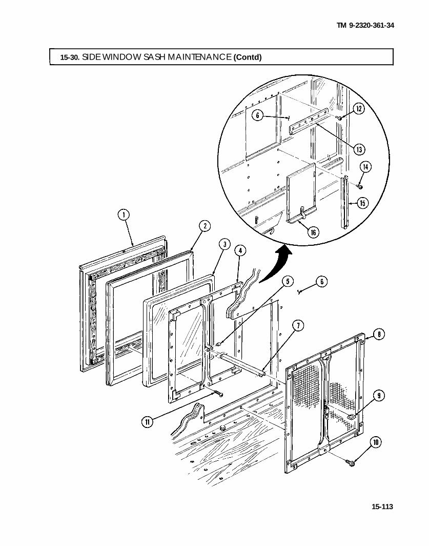
TM 9-2320-361-34
15-30. SIDE WINDOW SASH MAINTENANCE (Contd)
15-113

TM 9-2320-361-34
15-31. ACCESS DOOR REPLACEMENT
THIS TASK COVERS:a. Removal b. Installation
INITIAL SETUP
APPLICABLE MODELS MATERIALS/PARTSM185A3 and M109A3 Five rivets (Appendix F, Item 211)
TOOLS Five plugs (Appendix F, Item 202)
General mechanic’s tool kit (Appendix B, Item 1) REFERENCES (TM)Riveting tool (Appendix B, Item 20) TM 9-2320-361-34P
a. Removal 1. Open access door (2).2. Drill plug (5) and rivet (4) out of van wall (1) and chain (3). Discard plug (5) and rivet (4).3. Unfasten two hinges (6) from two latch locks (9).4. Remove access door (2) from van wall (1).5. Drill out four plugs (7) and rivets (8) from van wall (1) and latch locks (9). Discard plugs (7) and
rivets (8).6. Remove two latch locks (9) and spacers (10) from van wall (1).7. Remove screw (11), handle (12), and washer (13) from access door (2).
I b. Installation
1. Install washer (13) and handle (12) on access door (2) with screw (11).2. Install two spacers (10) and latch locks (9) on van wall (1) with four new rivets (8) and new
plugs (7).3. Position access door (2) on van wall (1).4. Fasten two hinges (6) on two latch locks (9).5. Install new rivet (4) and new plug (5) through chain (3) and on van wall (1).6. Close access door (2).
15-114

TM 9-2320-361-34
15-31. ACCESS DOOR REPLACEMENT (Contd)
15-115

TM 9-2320-361-34
15-32. ACCESS PLATE, ACCESS COVER, AND RETAINER ASSEMBLY REPLACEMENT
THIS TASK COVERS:a. Access P1ate Removal d. Access Cover Installationb. Access Plate Installation e. Retainer Assembly Removalc. Access Cover Removal f. Retainer Assembly Installation
INITIAL SETUP
APPLICABLE MODELSM185A3 and M109A3
TOOLSGeneral mechanic’s tool kit
(Appendix B, Item 1)
MATERIALS/PARTSEighteen screw-assembled lockwashers
(Appendix F, Item 167)Six screw-assembled lockwashers
(Appendix F, Item 166)Four screw-assembled Iockwashers
(Appendix F, Item 165)
REFERENCES (TM)TM 9-2320-361-34P
NOTEAll access plates and covers are removed and installed basically the same.
I a. Access Plate Removal
Remove four screw-assembled lockwashers (2) and access plate (3) from van wall (4). Discard screw-assembled lockwashers (2).
b. Access Plate Installation
Install access plate (3) on van wall (4) with four new screw-assembled lockwashers (2).
c. Access Cover Removal IRemove six screw-assembled lockwashers (1) and access cover (10) from van wall (4). Discard screw-assembled lockwashers (l).
I d. Access Cover Installation
Install access cover (10) on van wall (4) with six new screw-assembled lockwashers (l).
e. Retainer Assembly Removal
1. Remove ten screw-assembled lockwashers (7) and two retainers (6) from van wall (4). Discardscrew-assembled lockwashers (7).
2. Remove four screw-assembled lockwashers (7) and retainer (9) from van wall (4). Discard screw-assembled lockwashers (7).
3. Remove four screw-assembled lockwashers (7), retainer with door catch (8), and weather seal (5)from van wall (4). Discard screw-assembled lockwashers (7).
I f. Retainer Assembly Installation
1. Install weather seal (5) and retainer with door catch (8) on van wall (4) with four new screw-assembled lockwashers (7).
2. Install retainer (9) on van wall (4) with four new screw-assembled lockwashers (7).
3. Install two retainers (6) on van wall (4) with ten new screw-assembled lockwashers (7).
15-116

TM 9-2320-361-34
15-32. ACCESS PLATE, ACCESS COVER, AND RETAINER ASSEMBLYREPLACEMENT (Contd)
15-117

TM 9-2320-361-34
15-33. VAN BODY REPLACEMENTTHIS TASK COVERS:a. Removal b. Installation
INITIAL SETUP
APPLICABLE MODELSM185A3 and M109A3
TOOLSGeneral mechanic’s tool kit
(Appendix B, Item 1)1-1/8-in. socket, 1/2-in. dr. (Appendix B, Item 10)1-1/4-in. socket, 1/2-in. dr. (Appendix B, Item 19)Lifting device
MATERIALS/PARTSTen locknuts (Appendix F, Item 103)
PERSONNEL REQUIREDTwo
REFERENCES (TM)TM 9-2320-361-10TM 9-2320-361-20TM 9-2320-361-34P
EQUIPMENT CONDITION● Parking brake set (TM 9-2320-361-10).● Battery ground cable disconnected
(TM 9-2320-361-20).. Front and rear splash shields removed
(TM 9-2320-361-20).● Ladders removed (TM 9-2320-361-20).
GENERAL SAFETY INSTRUCTIONS● All personnel must stand clear during lifting
operations.● Lifting capacity must exceed weight of van body.
a. Removal 1. Disconnect lead (7) from circuit breaker (2).2. Remove screw (5) from clamp (6).3. Remove screw (4) from bond assembly (3).
NOTE● Perform step 4 if van body is equipped with heater.● Have drainage container ready to catch fuel.
4. Loosen nut (9) and disconnect fuel line (8) from elbow (1). Allow excess fuel to drain into container.5. Remove six locknuts (18) and screws (17) from six mounting brackets (16). Discard locknuts (18).
NOTEStep 6 applies to M109A3 vehicles.
6. Remove four locknuts (10), screws (15), washers (14), and springs (13) and (12) from two mountingbrackets (11). Discard locknuts (10).
NOTEStep 7 applies to M185A3 vehicles.
7. Remove four locknuts (19), screws (21), eight spring keepers (20), four springs (22), and springs (23)from two mounting brackets (11). Discard locknuts (19).
15-118

TM 9-2320-361-34
15-33. VAN BODY REPLACEMENT (Contd]
15-119

TM 9-2320-361-34
15-33. VAN BODY REPLACEMENT (Contd)
WARNING
Lifting capacity must be greater than weight of van body. Failure toensure this may result in injury to personnel or damage toequipment.
8. Install chains to four lifting shackles (1) and lifting device.9. Attach guide lines to van body (2).
WARNING
All personnel must stand clear during lifting operations. A swingingor shifting load may cause injury to personnel.
CAUTIONSupport capacity must be greater than weight of van body. Ensurethat support capacity is not less that 5,535 lb (2513 kg). Failure todo this may result in damage to equipment.
NOTEAssistant will help with lifting operations.
10. Remove van body (2) and frame sills (4) from chassis (3) and lower van body (2) onto wooden supports.11. Remove lifting device, chains, and guide lines from van body (2).
b. Installation
1.2.
3.
4.
5.
6.7.
WARNING
Lifting capacity must be greater than weight of van body. Failure toensure this may result in injury to personnel or damage toequipment.
Install chains to four lifting shackles (1) and lifting device.Attach guide lines to van body (2).
WARNING
All personnel must stand clear during lifting operations. A swingingor shifting load may cause injury to personnel.
Install two frame sills (4) and van body (2) on chassis (3).NOTE
Step 4 applies to M185A3 vehicles.Install eight spring keepers (10), four springs (13), springs (12), screws (11), and new locknuts (9) ontwo mounting brackets (5).
NOTEStep 5 applies to M109A3 vehicles.
Install four springs (15), springs (16), washers (17), screws (18), and new locknuts (14) on twomounting brackets (5).Install six screws (7) and new locknuts (8) on six mounting brackets (6).Remove lifting device, chains, and guide lines from van body (2).
15-120

TM 9-2320-361-34
15-33. VAN BODY REPLACEMENT (Contd)
NOTEPeform step 8 if van body is equipped with heater.
8. Connect fuel line (26) to elbow (19) by tightening nut (27).9. Install bond assembly (21) on van body (2) with screw (22).
10. Install clamp (24) on van body (2) with screw (23).11. Connect lead (25) to circuit breaker (20).
FOLLOW-ON TASKS: ●
●
●
Ins ta l l ladders (TM 9-2320-361-20) .
Install front and rear splash shields (TM 9-2320-361-20).Connect battery ground cable (TM 9-2320-361-20).
15-121

TM 9-2320-361-34
Section V. EARTH BORING AND POLESETTING BODIES MAINTENANCE
15-34. EARTH BORING AND POLESETTIG BODIES MAINTENANCE INDEX
PARA. PAGENO.
TITLENO.
15-35.15-36.15-37.15-38.15-39.15-40.15-41.15-42.15-43.15-44.15-45.15-46.15-47.15-48.15-49.
Earth Boring Machine ReplacementIntegral Derrick MaintenanceDerrick Sheave MaintenanceBoring Case MaintenanceHorizontal Leveling Worm Gear MaintenanceVertical Leveling Worm Gear MaintenancePower Leveler MaintenanceIntermediate Case MaintenanceMain Drive Idler Gear MaintenanceBrake, Feed, and Drive Clutch MaintenanceHydraulic Pump ReplacementOutrigger Control Valve ReplacementOutrigger Leg MaintenanceHydraulic Cylinder RepairEarth Boring and Polesetting Body Maintenance
15-12215-12615-12815-13015-14615-15215-15815-16615-18215-18615-20215-20415-20615-21015-212
15-35. EARTH BORING MACHINE REPLACEMENTTHIS TASK COVERS:a. Removal b. Installation
INITIAL SETUP
APPLICABLE MODELSM764
TOOLSGeneral mechanic’s tool kit
(Appendix B, Item 1)Lifting device
MATERIALS/PARTSFour locknuts (Appendix F, Item 98)Four lockwashers (Appendix F, Item 141)
PERSONNEL REQUIREDT w o
EQUIPMENT CONDITION.Parking brake set (TM 9-2320-361-10).● Earth boring machine seat and backrest removed
(TM 9-2320-361-20).● Hydraulic pump universal joints removed
(TM 9-2320-361-20).● Integral derrick removed (para. 15-36).● Auger rack bar removed (para. 15-38).
GENERAL SAFETY INSTRUCTIONS● All personnel must stand clear during lifting
operations.● Ensure lifting capacity is greater than weight of
earth boring machine.REFERENCES (TM)TM 9-2320-361-10TM 9-2320-361-20TM 9-2320-361-34P
15-122

TM 9-2320-361-34
15-35. EARTH BORING MACHINE REPLACEMENT (Contd)
NOTEFor proper balance of earth boring machine, boring case must be invertical position during removal and installation.
a. Removal
1. Remove four locknuts (6), screws (8), and shaft flange (5) from clutch drive flange (7). Discardlocknuts (6).
2. Install chain on earth boring machine (1) and attach chain to lifting device. Apply tension to chain.3. Remove four screws (4) and lockwashers (3) from earth boring machine (1) and body (2). Discard
lockwashers (3).
WARNING
● All personnel must stand clear during lifting operations. Aswinging or shifting load may cause injury to personnel.
● Earth boring machine is heavy. Ensure lifting capacity is greaterthan weight of earth boring machine. Failure to do so may resultin damage to equipment or injury to personnel.
NOTEAssistant will help with lifting operations.
4. Remove earth boring machine (1) from body (2) and place on wooden supports.5. Remove lifting device and chain from earth boring machine (1).
-
15-123

TM 9-2320-361-34
15-35. EARTH BORING MACHINE REPLACEMENT (Contd)
b. Installation
1. Install chain on earth boring machine (1) and attach lifting device to chain.
WARNINGAll personnel must stand clear during lifting operations.A snapped chain, shifiing or swinging load may cause injury topersonnel.
NOTEAssistant will help with lifting operations.
2. Install earth boring machine (1) on body (2) with four screws (4) and new lockwashers (3).3. Remove lifting device and chain from earth boring machine (1).4. Install shaft flange (5) on clutch drive flange (7) with four screws (8) and new locknuts (6).
15-124

TM 9-2320-361-34
15-35. EARTH BORING MACHINE REPLACEMENT (Contd)
FOLLOW-ON TASKS: ● Install auger rack bar (para. 15-38).● Install integral derrick (para. 15-36).● Install hydraulic pump universal joints (TM 9-2320-361-20).● Install earth boring machine seat and backrest (TM 9-2320-361-20).
15-125

TM 9-2320-361-34
15-36. INTEGRAL DERRICK MAINTENANCE
THIS TASK COVERS:a. Removal c. Installationb. Inspection
INITIAL SETUP
APPLICABLE MODELS REFERENCES (TM)M764 TM 9-2320-361-10
TOOLSTM 9-2320-361-34P
General mechanic’s tool kit EQUIPMENT CONDITION(Appendix B, Item 1) ● Parking brake set (TM 9-2320-361-10).
MATERIALS/PARTS● Outrigger arms lowered (TM 9-2320-361-10).. Derrick sheave removed (para. 15-37).
GAA grease (Appendix C, Item 8)Three locknuts (Appendix F, Item 105) GENERAL SAFETY INSTRUCTIONS
PERSONNEL REQUIRED● Do not lower derrick below horizontal position.. Derrick tube is heavy. Provide adequate support
Two when removing or installing derrick tube.
WARNING. During removal and installation, only two teeth of worm leveling
gear support derrick in horizontal position. Do not lower derrickbelow horizontal or derrick may fall and cause injury or death topersonnel.
● Derrick tube is heavy. Provide adequate support for derrick tubeduring removal and installation over rack bar. Failure to do somay result in injury or death to personnel.
NOTEBefore removal of derrick, ensure there is 20 ft (6 m) clearance tothe right of vehicle and 6 ft (2 m) clearance to the left of the vehicle.
a. Removal
1. Lower derrick (7) to near horizontal and manually turn horizontal leveling worm gearshift (1) untilderrick (7) is horizontal (TM 9-2320-361-10). Worm gear (10) will hold two teeth of worm wheel (9).
CAUTIONDo not feed rack bar more than 6 ft (2 m) from bottom of boring casewhile in horizontal position. Weight of rack bar may cause damageto pinions in boring gearcase.
2. Feed auger rack bar (8) 5 ft (1.5 m) out of derrick (7) (TM 9-2320-361-10).
NOTEAssistant will help with step 3.
3. Loosen three locknuts (4) and screws (3) and remove derrick tube bar (5) from base (2) and augerrack bar (8). Discard locknuts (4).
15-126

TM 9-2320-361-34
15-36. INTEGRAL DERRICK MAINTENANCE (Contd)
b. Inspection Inspect derrick tube (5) for bends, breaks, cracks, or flat spots. Straighten minor bends. Replace ifderrick tube (5) is badly bent, broken, or cracked.
c. Installation
1.
2.
3.4.
5.
Apply a coat of GAA grease inside base (2).
NOTEAssistant will help with steps 2 and 3.
Slide derrick tube (5) over auger rack bar (8) and into base (2).Aline sighting hole (6) to face three screws (3). Tighten screws (3) and new locknuts (4) on base (2).
Retract auger rack bar (8) into derrick tube (5) (TM 9-2320-361-10).Return derrick (7) to resting position (TM 9-2320-361-10).
FOLLOW-ON TASKS: . Install derrick sheave (para. 15-37).● Install earth boring machine seat and backrest (TM 9-2320-361-20).
15-127

TM 9-2320-361-34
15-37. DERRICK SHEAVE MAINTENANCE
THIS TASK COVERS:a. Removal d. Assemblyb. Disassembly e. Installationc. Cleaning and Inspection
INITIAL SETUPAPPLICABLE MODELS REFERENCES (TM)M764 TM 9-237
TM 9-2320-361-10TOOLS TM 9-2320-361-34PGeneral mechanic’s tool kit
(Appendix B, Item 1) EQUIPMENT CONDITIONOutside micrometer (Appendix B, Item 17) Parking brake set (TM 9-2320-361-10).
MATERIALS/PARTSLockwasher (Appendix F, Item 141)Two locknuts (Appendix F, Item 108)Graphite grease (Appendix C, Item 9)
a. Removal Loosen two screws (11) and remove support block (4) from derrick tube (10).
b. Disassembly1. Remove nut (6), lockwasher (5), screw (12), and pulley (1) from support block (4). Discard
lockwasher (5).2. Remove bearing sleeve (3) from pulley (1).3. Remove two locknuts (7), screws (9), and sheave cover (8) from support block (4). Discard
locknuts (7).
I c. Cleaning and Inspection
1. Clean all parts (para. 2-8).2. Check support block (4) for cracks and other damage. If cracked, repair support block (4) by
welding (TM 9-237). Replace if otherwise damaged.3. Check pulley (1) for cracks and other damage. Replace pulley (1) if worn or damaged.4. Check bearing sleeve (3) for nicks, burrs, cracks, and wear. Outside diameter should be no less than
1.475 in. (37.5 mm). Raised metal can be removed with a fine mill file. Replace bearing sleeve (3) ifworn or damaged.
5. Check sheave cover (8) for bends and other damage. Straighten if bent. Replace sheave cover (8) ifdamaged.
1. Install sheave cover (8) on support block (4) with two screws (9) and new locknuts (7).2. Apply graphite grease in bearing (2) and install bearing sleeve (3) in pulley (1).3. Install pulley (1), screw (12), new lockwasher (5), and nut (6) in support block (4).
d. Assembly
e. Installation Install support block (4) in derrick tube (10) and tighten two screws (11).
15-128

TM 9-2320-361-34
15-37. DERRICK SHEAVE MAINTENANCE (Contd)
15-129

TM 9-2320-361-34
15-38. BORING CASE MAINTENANCE
THIS TASK COVERS:a. Auger Rack Bar Removal e. Boring Gear Assemblyb. Boring Gear and Case Removal f. Boring Gear and Case Installationc. Boring Gear Disassembly g. Auger Rack Bar Installationd. Cleaning, Inspection, and Repair
INITIAL SETUP
APPLICABLE MODELSM764
TOOLSGeneral mechanic’s tool kit (Appendix B, Item 1)Mechanical puller kit (Appendix B, Item 22)Dial indicator (Appendix B, Item 21)Inside micrometer (Appendix B, Item 16)Outside micrometer (Appendix B, Item 17)Two puller screws (Appendix F, Item 216)Lifting deviceTwo screws (Appendix F, Item 215)Two washers (Appendix F, Item 270)
MATERIALS/PARTSShim set, rack carrier bearings
(Appendix F, Item 246)Shim set, rack feed idler gear bearings
(Appendix F, Item 247)Shim set, rack drive gear
(Appendix F, Item 248)Shim set, rack carrier upper nut
(Appendix F, Item 245)Seal retainer (Appendix F, Item 204)Seal (Appendix F, Item 223)Two cotter pins (Appendix F, Item 9)Twelve lockwashers (Appendix F, Item 140)Lockwasher (Appendix F, Item 137)Ten lockwashers (Appendix F, Item 127)Nine lockwashers (Appendix F, Item 142)
MATERIALS/PARTS (CONTD)Lockwasher (Appendix F, Item 150)Two felt pads (Appendix F, Item 26)GAA grease (Appendix C, Item 8)Safety wire (Appendix C, Item 31)
PERSONNEL REQUIREDTwo
REFERENCES (TM)LO 9-2320-209-12-1TM 9-214TM 9-2320-361-10TM 9-2320-361-20TM 9-2320-361-34P
EQUIPMENT CONDITION. Parking brake set (TM 9-2320-361-10).● Integral derrick removed (para. 15-36).● Snatch sleeve removed (TM 9-2320-361-20).
GENERAL SAFETY INSTRUCTIONS● Ensure auger rack bar is properly balanced on
chain during removal and installation.● All personnel must stand clear during lifting
operations.● Support boring case before removing hardware.● Ensure lifting capacity is greater than weight of
boring gears.
I a. Auger Rack Bar Removal
1. Remove six screws (4), lockwashers (3), and derrick tube base (2) from boring case (16). Discardlockwashers (3).
2. Remove setscrew (7), lockwasher (6), retaining pin (5), and auger rack bar guide (8) from auger rackbar (1). Discard lockwasher (6).
3. Install chain on auger rack bar (1). Attach lifting device to chain.
WARNING
Ensure auger rack bar is balanced on chain during removal. Failureto do so may cause auger rack bar to slip from chain, causing injuryto personnel or damage to equipment.
NOTEAssistant will help with step 4.
4. Feed auger rack bar (1) out of boring case (16) until it disengages (TM 9-2320-361-10).
15-130

TM 9-2320-361-34
15-38. BORING CASE MAINTENANCE (Contd)
b. Boring Gear and Case Removal I1.
2.
3.4.
5.
Remove two screws (9), rack carrier nut (10), shims (11), thrust plate retainer (12), and thrust plates(13) and (14) from carrier (15). Record thickness of shims (11) and discard.Loosen two screws (20) and remove rack carrier nut (19), thrust plate retainer (18), and thrustplates (17) and (21) from carrier (15).Manually turn horizontal leveling worm gear (27) until boring case (16) is vertical (TM 9-2320-361-10).Remove nine screws (22), circular level (23), ten lockwashers (24), and boring case cover (25) fromboring case (16). Discard lockwashers (24)
NOTEHave drainage container ready to catch oil.
Remove drainplug (26) from boring case (16). ,
15-131

TM 9-2320-361-34
15-38. BORING CASE MAINTENANCE (Contd)
6. Install rack carrier nut (1) on rack carrier (2).7. Install chain on rack carrier nut (1) with two washers and screws.
WARNING
● All personnel must stand clear during lifting operations.A swinging or shifting load may cause injury to personnel.
● Boring gears are heavy. Ensure lifting capacity is greater thanweight of boring gears. Failure to do so may result in injury topersonnel or damage to equipment.
N O T EAssistant will help with step 8.
8. Attach lifting device to chain and remove rack carrier (2) from boring case (3).9. Remove two screws, washers, and chain from rack carrier nut (1).
10. Remove rack carrier nut (1) from rack carrier (2).NOTE
Assistant will help with steps 11 through 16.11. Remove three nuts (9), lockwashers (8), and screws (5) from retainer ring (7) and boring case (3).
Discard lockwashers (8).12. Remove four screws (4), lockwashers (6), retainer ring (7), and two felt pads (14) from boring
case (3). Discard lockwashers (6) and felt pads (14).13. Remove jamnut (10), lockwasher (13), and screw (16) from worm gear wheel (15) and boring
case (3). Discard lockwasher (13).14. Remove three nuts (11), lockwashers (12), and screws (17) from worm gear wheel (15) and boring
case (3). Discard lockwashers (12).
WARNING
Support boring case before removing hardware. Failure to do somay result in injury to personnel or damage to equipment.
15. Remove four screws (19), lockwashers (18), and worm gear wheel (15) from boring case (3). Discardlockwashers (18).
16. Remove worm gear wheel (15) and boring case (3) from intermediate case (20).
15-132

TM 9-2320-361-34
15-38. BORING CASE MAINTENANCE (Contd)
15-133

TM 9-2320-361-34
15-38. BORING CASE MAINTENANCE (Contd)
c. Boring Gear Disassembly
1.
2.
3.
4.
5.
6.
7.
8.9.
10.11.
12.13.
14.15.
16.
17.18.
19.
Remove roller bearing (7) and shims (8) from rack carrier (6). Record thickness of shims (8) anddiscard.Remove cotter pin (1) and nut (2) from thrust roller shaft (9). Discard cotter pin (1).Install two puller screws (44) in thrust bearing (3) and remove thrust bearing (3) from rackcarrier (6).Remove two puller screws (44) from thrust bearing (3).Remove thrust roller shaft (9), rack thrust roller (5), and roller bearing (4) from rack carrier (6).Remove cotter pin (37) and nut (38) from rack feed gearshaft (20). Discard cotter pin (37).Install two puller screws (36) in thrust bearing (35) and remove thrust bearing (35) from rackcarrier (6).Remove two puller screws (36) from thrust bearing (35).Remove safety wire (34) from screw (33) and setscrew (42), and loosen setscrew (42) in rack earner (6).Discard safety wire (34).Remove rack feed gearshaft (20), rack feed gear (41), and two bearings (43) from rack carrier (6).Remove seal retainer (39) and seal (40) from rack feed gear (41). Discard seal retainer (39) andseal (40).Remove safety wire (18) and setscrew (17) from rack carrier (6). Discard safety wire (18).Remove spur pinion shaft (19), spur pinion (10), inner bearing (11), outer bearing (12), thrustwasher (13), and retaining pin (14) from rack carrier (6).Remove safety wire (15) and three screws (16) from rack carrier (6). Discard safety wire (15).Remove nine screws (33), rack drive gear (22), and shims (21) from rack carrier (6). Recordthickness of shims (21). Discard shims (21) and safety wire (15).Remove roller bearing (26) and shims (27) from rack carrier (6). Record thickness of shims (27) anddiscard.Remove spacer sleeve (28) from rack carrier (6).Straighten tabs on lockwasher (30) and remove adjusting nut (29), lockwasher (30), and adjustingnut (31) from rack carrier (6). Discard lockwasher (30).Remove roller bearing (32), rack feed idler gear (25), roller bearing (24), and shims (23) from rackcarrier (6). Record thickness of shims (23) and discard.
15-134

TM 9-2320-361-34
I 15-38. BORING CASE MAINTENANCE (Contd) I
15-135

TM 9-2320-361-34
15-38. BORING CASE MAINTENANCE (Contd)
d. Cleaning, Inspection, and Repair 1.2.
3.
4.
For general cleaning instructions, refer to para. 2-8.Inspect rack feed gear (34), spur pinion (12), rack drive gear (24), rack feed idler gear (23), spur pinionshaft (19), rack feed gearshaft (20), thrust roller shaft, (11), and carrier (8) for burrs, chips, cracks,damaged teeth, or splines. Burrs maybe removed with a fine mill file. Replace component if damaged.
NOTERack drive gear, rack feed idler gear, and rack feed spur pinionmust each be replaced with associated pinion as a matched set.
Inspect thrust plates (9) and (10), rack thrust roller (5), thrust bearings (29) and (3), and thrustwasher (15) for wear or other damage. Refer to table 15-4, Boring Case Wear Limits, formeasurements. Replace if worn or otherwise damaged.Inspect all bearings for wear or other damage (TM 9-214). Replace bearings if worn or damaged.
Table 15-4. Boring Case Wear Limits.
ITEM WEAR LIMITS/TOLERANCES
NO. lTEM/POINT OF MEASUREMENTINCHES MII.I.IMETERS
5 Rack thrust roller:Inside diameter 1.750-1.753 44.45-44.53Outside diameter 3.328-3.330 84.53-84.58
9 Thrust plate (thickness) 0.370-0.376 9.40-9.5510 Thrust plate (thickness) 0.307-0.313 7.80-7.9515 Thrust washer (thickness) 0.140-0.145 3.56-3.68
29&3 Thrust bearing (thickness) 0.734-0.765 18.64-19.43
I e. Boring Gear Assembly
1.2.
3.4.5.
6.7.
8.
9.
10.11.
12.
Pack inner bearing (13) and outer bearing (14) with GAA grease and install in spur pinion (12).Install thrust washer (15), retaining pin (16), and spur pinion (12) in rack carrier (8) with spurpinion shaft (19) and setscrew (18).Pack two bearings (36) with GAA grease and install on rack feed gear (34).Install new seal (33) and new seal retainer (32) on rack feed gear (34).Install rack feed gear (34) in rack carrier (8) with rack feed gearshaft (20), thrust bearing (29), nut (31),and new cotter pin (30). Tighten setscrew (35).Pack bearing (4) with GAA grease and install in rack thrust roller (5).Install rack thrust roller (5) in rack carrier (8) with thrust roller shaft (11), thrust bearing (3), nut (2),and new cotter pin (1).
NOTEFor steps 8 through 11, new shims must be the same thickness asrecorded in removal.
Pack roller bearing (6) with GAA grease and install new shims (7) and roller bearing (6) on rackcarrier (8).Install new shims (25) and rack drive gear (24) on rack carrier (8) with three screws (17) and ninescrews (28).Pack roller bearings (22) and (27) with GAA grease.Install new shims (21), roller bearing (22), rack feed idler gear (23), and roller bearing (27) on rackcarrier (8) with adjusting nut (26).Tighten adiusting nut (26) until rack feed idler gear (23) has no in and out play then back offadjusting nut (26) 1/8 turn.
.
15-136

TM 9-2320-361-34
15-38. BORING CASE MAINTENANCE (Contd)
15-137

TM 9-2320-361-34
15-38. BORING CASE MAINTENANCE (Contd)
13,
14.
15.
16.
17.
18.
19.
Place dial indicator against rack feed idler gear (1) and measure backlash between rack feed idlergear (1) and rack feed spur pinion (2).
NOTEIf backlash is 0.006-0.016 in. (O. 15-0.41 mm), proceed to step 17. Ifbacklash is outside limits, proceed to step 14.
Remove bearing adjusting nut (11), roller bearing (12), rack feed idler gear (1), and roller bearing (5)from carrier (3).
NOTEIf dial indicator reading is not within limits, add or remove shims asrequired.
Install or remove shims (4) as required, and install roller bearing (5), rack feed idler gear (1), rollerbearing (12), and bearing adjusting nut (11) on rack carrier (3).Tighten bearing adjusting nut (11) until rack feed idler gear (1) has no in and out play, then backoff bearing adjusting nut (11) 1/8 turn. Perform step 13.Install new lockwasher (10) and bearing adjusting nut (9) on carrier (3). Tighten bearing adjustingnut (9) and bend tabs of new lockwasher (10) against bearing adjusting nuts (11) and (9).
Install sleeve spacer (8) on rack carrier (3).
NOTEFor step 19, shim must be same thickness as recorded during removal.
Pack roller bearing (6) with GAA grease and install new shims (7) and roller bearing (6) on carrier (3).
15-138

TM 9-2320-361-34
15-38. BORING CASE MAINTENANCE (Contd)
f. Boring Gear and Case Installation
1.
2.
3.
4.5.
NOTEAssistant will help with steps 1 and 2.
Position worm gear wheel (25) and boring case (17) on intermediate case (30).
Install screw (26), new lockwasher (21), and jamnut (20) on boring case (17) and worm gearwheel (25).Install three screws (27), new lockwashers (23), and nuts (22) on boring case (17) and worm gearwheel (25).Install four new lockwashers (28) and screws (29) on boring case (17) and worm gear wheel (25).Install two felt pads (24) and retainer ring (16) on boring case (17) with four new lockwashers (15),screws (14), three screws (13), lockwashers (18), and nuts (19).
1 5 - 1 3 9

TM 9-2320-361-34
15-38. BORING CASE MAINTENANCE (Contd)
6. Install rack carrier nut (1) on rack carrier (2).7. Install chain on rack carrier nut (1) with two washers and screws.8. Remove eight screws (7), lockwashers (6), inspection cover (5), and gasket (4) from boring case (3).
Discard lockwashers (6) and gasket (4).
WARNINGAll personnel must stand clear during lifting operations.A swinging or shifting load may cause injury to personnel.
NOTEAssistant will help with step 9.
9. Attach lifting device to chain and position rack carrier (2) in boring case (3).10. Remove lifting device, two screws, washers, and chain from rack carrier nut (1).11. Remove rack carrier nut (1) from rack carrier (2).12. Install boring case cover (8) on boring case (3) with ten new lockwashers (10), nine screws (9), and
circular level (11).13. Rotate boring case (3) 90 degrees until inspection hole (12) is facing upwards.
15-140

TM 9-2320-361-34
15-38. BORING CASE MAINTENANCE (Contd)
NOTEEnsure that heel of second reduction drive pinion and toe of secondreduction feed pinion are alined with toe of rack drive gear and rackfeed idler gear. If depth of second reduction drive and feed pinions aremisalined, adjust by removing or adding shims (para. 15-42).
14. Working through inspection hole (12), place dial indicator against rack drive gear (13) and measurebacklash between rack drive gear (13) and second reduction drive pinion (16). Backlash should be0.008-0.022 in. (0.20-0.56 mm).
15. Place dial indicator against rack feed idler gear (14) and measure backlash between rack feedidler gear (14) and secondary reduction feed pinion (15). Backlash should be 0.011-0.022 in.(0.28-0.56 mm).
NOTEBoring gear must be removed from boring case and disassembledin order to adjust the backlash of rack drive and idler gears.(subtasks a, b, and c)..If backlash is within limits, proceed to step 20.If backlash of rack drive gear is incorrect, perform step 16.If backlash of idler gear is incorrect, perform steps 17 and 18.
15-141

TM 9-2320-361-34
15-38. BORING CASE MAINTENANCE (Contd)
16. To increase backlash for rack drive gear (1), remove rack drive gear shim (2). To decrease backlashfor rack drive gear (1), add rack drive gear shim (2).
17. To increase backlash for rack feed idler gear (3), add lower rack carrier bearing shim (5) and rackdrive gear shim (2) and remove upper rack carrier bearing shim (4).
18. To decrease backlash for rack feed idler gear (3), remove lower rack carrier bearing shim (5) andrack drive gear shim (2), and add upper rack carrier bearing shim (4).
19. Assemble and install boring gear (subtasks e and f).NOTE
If adjustment does not correct rack drive and feed gear backlash,refer to para. 15-42 for backlash adjustment of feed and drive pinions.
20.21.
22.
23.24.
25.
Rotate boring case (10) to upright position.Install new gasket (12) and inspection hole cover (13) on boring case (10) with eight newlockwashers (14) and screws (15).Remove circular level (8), nine screws (6), ten lockwashers (7), and boring case cover (9) from boringcase (10). Discard lockwashers (7).Install six new safety wires (19) on three screws (17), nine screws (18), and two setscrews (16).Install boring case cover (9) on boring case (10) with ten new lockwashers (7), nine screws (6), andcircular level (8).Install drainplug (11) in boring case (10).
15-142

TM 9-2320-361-34
15-38. BORING CASE MAINTENANCE (Contd)
15-143

TM 9-2320-361-34
15-38. BORING CASE MAINTENANCE (Contd)
g. Auger Rack Bar Installation
1. Manually turn horizontal leveling worm gear (9) until boring case (16) is horizontal(TM 9-2320-361-10).
2. Coat auger rack bar (1) with GAA grease.3. Place chain on auger rack bar (1) approximately 4ft (1.22 m) from left end.4. Attach lifting device to chain.
WARNINGEnsure auger rack bar is balanced on chain during installation.Failure to do so may cause auger rack bar to slip from chain,causing injury to personnel or damage to equipment.
NOTE● Ensure teeth of auger rack bar face to the right.● Assistant will help with step 5.
5. Insert auger rack bar (1) in boring case (17) until it engages. Continue feeding until it extendsapproximately two feet out of carrier (10). Remove lifting device and chain.
NOTE. Thinnest thrust plate is mounted on shortest stud of thrust plate
retainer and installed against teeth of auger rack bar.● All shims are installed to previously recorded distance.
6. Place thrust plates (11) and (12) in thrust plate retainer (13) and install on carrier (10).7. Install new shims (14) and rack carrier nut (16) on carrier (10) with two screws (15).8. Place thrust plates (18) and (22) in thrust plate retainer (19) and install on carrier (10).9. Install rack carrier nut (20) on carrier (10). Tighten two screws (21).
10. Install derrrick tube case (2) on boring case (17) with six new lockwashers (3) and screws (4).11. Install auger rack bar guide (8) on auger rack bar (1) with retaining pin (5), new lockwasher (6),
and setscrew (7).
15-144

TM 9-2320-361-34
15-38. BORING CASE MAINTENANCE (Contd)
FOLLOW-ON TASKS: . Fill boring case to proper oil level (LO 9-2320-209-12-1).● Install integral derrick (para. 15-36).● Install snatch sleeve (TM 9-2320-361-20).
15-145

TM 9-2320-361-34
15-39. HORIZONTAL LEVELING WORM GEAR MAINTENANCE
THIS TASK COVERS:a. Removal d. Assemblyb. Disassembly e. Installationc. Inspection
INITIAL SETUP
APPLICABLE MODELSM764
TOOLSGeneral mechanic’s tool kit
(Appendix B, Item 1)Outside micrometer (Appendix B, Item 17)Inside micrometer (Appendix B, Item 16)MATERIALS/PARTSFour cotter pins (Appendix F, Item 10)Shim set (Appendix F, Item 249)Shim set (Appendix F, Item 250)Shim set (Appendix F, Item 251)Four lockwashers (Appendix F, Item 138)Two lockwashers (Apendix F, Item 127)Woodruff key (Appendix F, Item 297)Woodruff key (Appendix F, Item 274)Safety wire (Appendix C, Item 31)
a. Removal
1.
2.
3.4.5.
6.
7.8.
9.
PERSONNEL REQUIREDTwo
REFERENCES [TM]LO 9-2320-209-12-1TM 9-237TM 9-2320-361-10TM 9-2320-361-20TM 9-2320-361-34P
EQUIPMENT CONDITION● Parking brake set (TM 9-2320-361-10).● Horizontal leveling worm drivechain removed
(TM 9-2320-361-20).
GENERAL SAFETY INSTRUCTIONSBefore removing horizontal leveling worm gearhousing, support intermediate case to prevent fromturning.
WARNINGBefore removing horizontal leveling worm gear housing, placesupports under intermediate case to prevent case from turning. Ifintermediate case turns, injury to personnel and/or damage toequipment may result.
NOTEAssistant will help with entire procedure.
Place handle (5) in center slot of bracket (6). Remove cotter pin (1), nut (2), washer (3), handle (5),and spring (4) from rod (7). Discard cotter pin (1).Remove two cotter pins (8), clevis pins (10), and retaining links (9) from rod (7) and power levelerhousing (12). Discard cotter pins (8).Remove cotter pin (14), clevis pin (11), and rod (7) from shifter shaft (13). Discard cotter pin (14).Loosen screw (20) and remove sprocket (15) from bracket (18).Remove two screws (31) and lockwashers (30) from power leveler housing (12). Discard lock-washers (30).Remove two screws (16), Iockwashers (17), bracket (18), and shims (19) from worm gear housing (21).Record thickness of shims (19). Discard shims (19) and lockwashers (17).Remove vent plug (28) from intermediate case (29).Remove safety wire (27), two screws (26), bracket (6), and shims (25) from worm gear housing (21).Record thickness of shims (25). Discard shims (25) and safety wire (27).Remove two safety wires (24), four nuts (22), worm gear housing (21), and shims (23) fromintermediate case (29). Record thickness of shims (23). Discard shims (23) and safety wire (24).
15-146

TM9-2320-361-34
15-39. HORIZONTAL LEVELING WORM GEAR MAINTENANCE (Contd)
15-147
I

TM 9-2320-361-34
15-39. HORIZONTAL LEVELING WORM GEAR MAINTENANCE (Contd)
b. Disassembly
1.
2.3.
4.5.
6.7.
Remove safety wire (8), loosen setscrew (9), and remove sprocket (10) and woodruff key (11) fromworm gear shaft (6). Discard safety wire (8) and woodruff key (11).Remove lubrication fitting (17) and bushing (16) from shaft (6).Remove setscrews (1) and (4), two screws (2), and lockwashers (3) from worm gear housing (5),Discard lockwashers (3).
NOTEMeasure and record distance shaft extends from worm gear housing.
Loosen worm adjusting bearing (15).Aline woodruff key (12) in shaft (6) with keyway of thrust washer (13). Tap round end of shaft (6)and remove sleeve bearing (7), woodruff key (12), and shaft (6) from worm gear housing (5).Remove thrust washer (13), worm gear (14), and adjusting bearing (15) from worm gear housing (5).Remove woodruff key (12) and sleeve bearing (7) from shaft (6). Discard woodruff key (12).
c. Inspection 1. Check worm gear housing (5) for cracks or other damage. Repair by welding if cracked (TM 9-237).
Replace if damaged.2. Check all parts for small chips, burrs, and scratches. Raised metal can be removed with a fine mill file.3. Check sprocket (10) and worm gear (14) for chipped and broken teeth. Replace if damaged.4. Inspect adjusting bearing (15), shaft (6), sleeve bearing (7), and thrust washer (13) for wear or other
damage. Refer to table 15-5, Horizontal Leveling Worm Gear Wear Limits, for measurements.Replace if worn or otherwise damaged.
Table 15-5. Horizontal Leveling Worm Gear Wear Limits.
I T E MN O .
WEAR LIMITS/TOLERANCESITEM/POINT OF MEASUREMENT INCHES
67
1315
Shaft (diameter)Sleeve bearing
Inside diameterOutside diameter
Thrust washer (thickness)Bearing (inside diameter)
1.371-1.372
1.376-1.3781.99-2.000.411.37-1.38
d. Assembly 1. Install adjusting bearing (15) and worm gear (14) in worm gear housing (5).
MILLIMETERS
34.82-34.85
34.95-35.0050.55-50.8010.4134.80-35.05
2. Install thrust washer (13) so that setscrew notch faces away from worm gear (14) and keyway alineswith keyway of worm gear (14).
3. Install new woodruff key (12) in shaft (6) and install shaft (6) in worm gear housing (5).
15-148

TM 9-2320-361-34
15-39. HORIZONTAL LEVELING WORM GEAR MAINTENANCE (Contd)
4.
5.
6.
7.
8.
9.10.11.
Install shaft (6) to extend from worm gear housing (5) as previously measured. Finger tightenadjusting bearing (15).Install sleeve bearing (7) on shaft (6) and into worm gear housing (5). Aline sleeve bearing (7) soscrew (2) will pass through slot.Install two new lockwashers (3), screws (2), and setscrews (1) and (4) in worm gear housing (5). Donot tighten setscrews (1) and (4). Ensure that shaft (6) turns freely.Turn shaft (6) until notch in thrust washer (13) is alined with setscrew (4). Tighten setscrew (4)until it touches thrust washer (13) then back off 1/4 turn.Tighten adjusting bearing (15) until shaft (6) does not move from end to end. Ensure that shaft (6)turns freely.Tighten setscrew (1) until it touches adjusting bearing (15) then back off 1/2 turn.Instill bushing (16) and lubrication fitting (17) in shaft (6).Install new woodruff key (11) and sprocket (10) on shaft (6). Install setscrew (9) and install newsafety wire (8) on sprocket (10).
15-149

TM 9-2320-361-34
15-39. HORIZONTAL LEVELING WORM GEAR MAINTENANCE (Contd)
e. Installation NOTE
● Install all shims to previously recorded thickness.● When installing worm gear, check that gear is centered and teeth
mesh with worm wheel. If misalined, remove worm gear andadjust backlash by removing or adding shims.
1.2.3.4.5.6.
7.8.9.
10.
11.
Install new shims (10) and worm gear housing (7) on intermediate case studs (19) with four nuts (8).Install new shims (12) and bracket (13) on intermediate case (17) with two screws (14).Install two new safety wires (11) on intermediate case studs (19) and setscrews (6).Install vent plug (16) on intermediate case (17).Install two new safety wires (15) on screws (14).Install new shims (5) and bracket (4) on worm gear housing (7) with two new lockwashers (3) andscrews (2).Install two new lockwashers (3) and screws (20) on power leveler housing (18).Install sprocket (1) in bracket (4) and tighten screw (9).Install rod (26) on shifter shaft (31) with clevis pin (30) and new cotter pin (32).Install rod (26) on power leveler housing (18) with two retaining links (28), clevis pins (29), and newcotter pins (27).Install handle (25), spring (24), washer (23), nut (22), and new cotter pin (21) on rod (26).
15-150

TM 9-2320-361-34
15-39. HORIZONTAL LEVELING WORM GEAR MAINTENANCE (Contd)
FOLLOW-ON TASKS: ● Install horizontal leveling worm drivechain (TM 9-2320-361-20).● Lubricate worm gear shaft (LO 9-2320-209-12-1).
15-151

TM 9-2320-361-34
15-40. VERTICAL LEVELING WORM GEAR MAINTENANCE
THIS TASK COVERS:a. Removal d. Assemblyb. Disassembly e. Installationc. Inspection
INITIAL SETUP
APPLICABLE MODELSM764
TOOLSGeneral mechanic’s tool kit
(Appendix B, Item 1)1-1/4-in. socket, 1/2-in. dr.
(Appendix B, Item 19)
MATERIALS/PARTSSix lockwashers (Appendix F, Item 127)Shim set (Appendix F, Item 250)Shim set (Appendix F, Item 251)Shim set (Appendix F, Item 252)Woodruff key (Appendix F, Item 273)Woodruff key (Appendix F, Item 274)
REFERENCES (TM)LO 9-2320-209-12-1TM 9-237TM 9-2320-361-10TM 9-2320-361-20TM 9-2320-361-34P
EQUIPMENT CONDITION. Parking brake set (TM 9-2320-361-10).. Vertical leveling worm drivechain removed
(TM 9-2320-361-20).
GENERAL SAFETY INSTRUCTIONSPlace derrick in cradle or support boring case toprevent case from turning.
a. Removal WARNING
1.
2.3.
4.
5.
6.
Before removing vertical leveling worm gear housing, place derrickin cradle or place supports under boring case to prevent case fromturning. If boring case turns, injury to personnel or damage toequipment may result.
Remove safety wire (3), loosen setscrew (4), and remove sprocket (5) and woodruff key (13) fromshaft (14). Discard safety wire (3) and woodruff key (13).Loosen nut (7) and remove sprocket (2) from bracket (6).Remove safety wire (3), two screws (19), washers (18), and shims (17) from intermediate case (20) andworm gear housing (16). Record thickness of shims (17). Discard safety wire (3) and shims (17).Remove two screws (24), lockwashers (23), and washers (22) from bracket (6) and power levelerhousing (21). Discard lockwashers (23).Remove screws (8) and (9), two lockwashers (10), bracket (6), and shims (1) and (11) from powerleveler housing (23) and shaft (14). Discard shims (1) and (11) and lockwashers (10).Remove safety wire (3), four nuts (15), worm gear housing (16), and shims (12) from intermediatecase (20). Record thickness of shims (12) and discard.
15-152

TM 9-2320-361-34
15-40. VERTICAL LEVELING WORM GEAR MAINTENANCE (Contd)
15-153

TM 9-2320-361-34
15-40. VERTICAL LEVELING WORM GEAR MAINTENANCE (Contd)b. Disassembly
1. Remove two lubrication fittings (8) from shaft (6).2. Remove two screws (2), lockwashers (3), and setscrews (1) and (4) from housing (5)
lockwashers (3).NOTE
Measure and record distance shaft extends from worm gear housing.
3. Loosen worm adjusting bearing (12).
Discard
4. Nine woodruff key (9) of shaft(6) with keyway of thrust washer (10). Tap square end of shaft (6)and remove sleeve bearing (7), woodruff key (9), and shaft (6) from worm gear housing (5).
5. Remove thrust washer (10), worm gear (11), and adjusting bearing (12) from worm gear housing (5).6. Remove woodruff key (9) and sleeve bearing(7) from shaft (6). Discard woodruff key (9).
c. Inspection
1. Check worm gear housing (5) for cracks or other damage. Repair by welding if cracked (TM 9-237).Replace if damaged.
2. Check all parts for small chips, burrs, and scratches. Raised metal can be removed with a fine mill file.3. Check worm gear (11) for chipped and broken teeth. Replace if damaged.4. Inspect adjusting bearing (12), shaft (6), sleeve bearing(7), and thrust washer (10) for wear or other
damage. Refer to table 15-6, Vertical Leveling Worm Gear Wear Limits, for measurements. Replaceif worm or otherwise damaged.
Table 15-6. Vertical Leveling Worm Gear Wear Limits.
ITEM WEAR LIMITS/TOLERANCESNO. lTEM/POiNT OF MEASUREMENT
INCHES MILLIMETERS
6 Shaft (diameter) 1.371-1.372 34.82-34.857 Sleeve bearing
Inside diameter 1.376-1.378 34.95-35.00Outside diameter 1.999-2.000 50.77-50.80
10 Thrust washer (thickness) 0.406 10.3112 Bearing (inside diameter) 1.376-1.378 34.95-35.00
d. Assembly 1. Install adjusting bearing (12) and worm gear (11) in worm gear housing (5).2. Install thrust washer (10) in worm gear housing (5) so that setscrew notch faces away from worm
gear (11) and keyway alines with keyway of worm gear (11).3. Install new woodruff key (9) in shaft (6) and install shaft(6) in worm gear housing(5).4. Set shaft (6) to extend from worm gear housing (5) as previously measured. Finger tighten adjusting
bearing (12).
15-154

TM 9-2320-361-34
15-40. VERTICAL LEVELING WORM GEAR MAINTENANCE (Contd)
5. Install sleeve bearing (7) on shaft (6) and into housing (5). Aline slot on sleeve bearing (7) soscrew (2) will pass through slot.
6. Install two new lockwashers (3), screws (2), and setscrews (1) and (4) in worm gear housing (5). Donot tighten setscrews (1) and (4). Ensure that shaft (6) turns freely.
7. Turn shaft (6) until notch in thrust washer (10) is alined with setscrew (4). Tighten setscrew (4)until it touches thrust washer (10) then back off 1/4 turn.
8. Tighten adjusting bearing (12) until shaft (6) does not move from end to end. Ensure that shaft (6)turns freely.
9. Tighten setscrew (1) until it touches adjusting bearing (12) then back off 1/2 turn.10. Install two lubrication fittings (8) on shaft (6).
15-155

TM 9-2320-361-34
15-40. VERTICAL LEVELING WORM GEAR MAINTENANCE (Contd)
1.
2.
3.
4.5.6.7.8.
NOTE● Install all shims to previously recorded thickness.● When installing worm gear, check that gear is centered and teeth
mesh with worm wheel. If misalined, remove worm gear andadjust backlash by removing or adding shims.
Install new shims (20) and worm gear housing (18) on intermediate case mounting studs (22) withfour nuts (17).Install new shims (19), two washers (23), and screws (24) on worm gear housing (18) andintermediate case (25).Install new shims (1) and (11) and bracket (6) on power leveler (21) and shaft (16) with two newlockwashers (10) and screws (8) and (9).Install two washers (12), new lockwashers (13), and screws (14) on bracket (6).Install new safety wire (5) on nuts (17).Install sprockets (2) on bracket (6) and tighten nut (7).Install new woodruff key (15) and sprocket (3) on shaft (16) and tighten setscrew (4).Install new safety wire (5) on sprocket (3).
15-156

TM 9-2320-361-34
15-40. VERTICAL LEVELING WORM GEAR MAINTENANCE (Contd)
FOLLOW-ON TASKS: ● Install vertical leveling worm drivechain (TM 9-2320-361-20).● Lubricate worm gear shaft (LO 9-2320-209-12-1).
15-157

TM 9-2320-361-34
15-41. POWER LEVELER MAINTENANCE
THIS TASK COVERS:a. Removal d. Assemblyb. Disassembly e. Installationc. Cleaning and Inspection
INITIAL SETUP
APPLICABLE MODELSM764
TOOLSGeneral mechanic’s tool kit
(Appendix B, Item 1)Mechanical puller kit (Appendix B,
MATERIALS/PARTSThree cotter pins (Appendix F, Item 8)Two cotter pins (Appendix F, Item 9)Cotter pin (Appendix F, Item 10)Two woodruff keys (Appendix F, Item 274)Woodruff key (Appendix F, Item 299)Two lockwashers (Appendix F, Item 138)Six lockwashers (Appendix F, Item 127)Shim set (Appendix F, Item 252)Shim set (Appendix F, Item 251)Shim set (Appendix F, Item 253)
MATERIALS/PARTS (Contd)Shim set (Appendix F, Item 254)Safety wire (Appendix C, Item 31)GAA grease (Appendix C, Item 8)
REFERENCES (TM)tern 22) TM 9-214
TM 9-2320-361-10TM 9-2320-361-20TM 9-2320-361-34P
EQUIPMENT CONDITION● Parking brake set (TM 9-2320-361-10).. Horizontal leveling worm drivechain removed
(TM 9-2320-361-20).● Vertical leveling worm drivechain removed
(TM 9-2320-361-20).
1.2.
3.
4.
5.
6.
7.
Loosen nut (26) and remove sprocket (25) from bracket (22).Remove two screws (23) and lockwashers (24) from bracket (22). Discard lockwashers (24).Remove two cotter pins (16), clevis pins (1), and retaining links (2) from shifiing rod (28) and powerleveler housing (21). Discard cotter pins (16).Remove cotter pin (27), clevis pin (17), and shifting rod (28) from shifter shaft (18). Discard cotterpin (27).Remove safety wire (10), loosen setscrew (9), and remove sprocket (8) and woodruff key (19) fromshaft (20). Discard safety wire (10) and woodruff key (19).Loosen nut (12) and remove sprocket (7) from bracket (11).Remove screws (13) and (14), two screws (6), four lockwashers (5), two washers (4), bracket (11), andshims (3) and (15) from power leveler housing (21). Record thickness of shims (3) and (15). Discardshims (3) and (15) and lockwashers (5).
15-158

TM 9-2320-361-34
15-41. POWER LEVELER MAINTENANCE (Contd)
15-159

TM 9-2320-361-34
15-41. POWER LEVELER MAINTENANCE (Contd)
8. Remove screw (1), stud (3), two lockwashers (2), and power leveler housing (4) from intermediatecase (5). Discard lockwashers (2).
b. Disassembly
1.
2.
3.4.
5.
6.7.
8.
Remove two screws (25), lockwashers (24), and housing cap (29) from housing (12). Discardlockwashers (24).Remove safety wire (27), loosen setscrew (26), and remove sprocket (28) and woodruff key (30) fromworm drive pinion (31).Remove worm drive pinion (31) from housing cap (29).Remove cotter pin (17), nut (16), washer (15), takeoff pinion (14), woodruff key (19), and spacer (13)from drive shaft (18). Discard cotter pin (17) and woodruff key (19).Remove cotter pin (7), nut (6), bearing retainer (8), shims (9), sprocket (10), and bearing (11) fromshaft (18). Record thickness of shims (9). Discard shims (9) and cotter pin (7).Remove shaft (18) from housing (12).Remove cotter pin (20), nut (21), bearing (22), and shims (23) from housing (12). Record thickness ofshims (23). Discard shims (23) and cotter pin (20).Remove shaft (35), yoke (34), clutch (33), and worm drive gear (32) from housing (12).
15-160

TM9-2320-361-34
15-41. POWER LEVELER MAINTENANCE (Contd)
15-161

TM 9-2320-361-34
15-41. POWER LEVELER MAINTENANCE (Contd)
c. Cleaning and Inspection
1. Clean and inspect bearings (7) and (16) and housing (8) (TM 9-214). Replace if damaged.2. Inspect all gears and sprockets for small chips, burrs, and scratches. Raised metal can be removed
with a fine mill file.3. Inspect all parts for cracks, breaks, and other damage. Replace if damaged.4. Inspect sprocket (6), worm drive gear (28), worm drive pinion (10), shaft (19), bearing in housing
cap (25), and bearings (31) and (32) in housing (8) for wear and other damage. Refer to table 15-7,Power Leveler Wear-Limits, for measurements. Replace if worn or damaged.
Table 15-7. Power Leveler Wear Limits.
ITEM WEAR LIMITS/TOLERANCESNO. lTEM/POINT OF MEASUREMENT
INCHES MILLIMETERS
6 Sprocket:Inside diameter 1.751-1.753 44.48-44.53Outside diameter 2.873-2.874 72.97-73.00
10 Worm drive pinion (diameter) 1.376-1.377 34.95-34.9819 Shaft:
Diameter “A” 1.249-1.250 31.72-31.75Diameter “B” 1.378-1.379 35.00-35.03
25 Bearing housing cap (inside diameter) 1.379-1.381 35.03-35.0828 Worm drive gear (outside diameter) 2.247-2.249 57.07-57.1231 Bearing (inside diameter) 2.875-2.876 73.03-73.0532 Bearing (inside diameter) 2.250-2.251 57.15-57.18
d. Assembly
1.2.3.4.5.
6.
7.8.
9.
10.
15-162
N O T EInstall all shims to measured distance.
Pack bearings (7) and (16) with GAA grease.Install new shim(s) (17), bearing (16), nut (15), and new cotter pin (14) in housing (8).Install worm drive gear (28), clutch (29), yoke (30), and shaft (1) in housing (8).Install shaft (19) in housing (8).Install bearing (7), sprocket (6), new shim(s) (5), bearing retainer (4), nut (2), and new cotter pin (3)on shaft (19).Install spacer (9), new woodruff key (18), takeoff pinion (10), washer (11), nut (12), and new cotterpin (13) on shaft (19).Pack housing (8) with GAA grease.Position worm drive pinion (27) in housing cap (25).
NOTEEnsure teeth of worm drive pinion aline with teeth of worm drive gear.
Install new woodruff key (26) and sprocket (24) on worm drive pinion (27). Tighten setscrew (22) andinstall new safety wire (23).Install housing cap (25) on housing (8) with two new lockwashers (20) and screws (21).

TM 9-2320-361-34
15-41. POWER LEVELER MAINTENANCE (Contd)
15-163

TM 9-2320-361-34
I 15-41. POWER LEVELER MAINTENANCE (Contd)
e. Installation 1.
2.
3.4.5.
6.7.8.
Install power leveler housing (4) on intermediate case (5) with two new lockwashers (2), stud (3),and screw (1).Install new shim (8), two new shims (19), and bracket (20) on shaft (24) and power leveler housing (4)with two washers (9), four new lockwashers (10), two screws (11), and screws (17) and (18).Install sprocket (12) in bracket (20) and tighten nut (16).Install shifting rod (32), clevis pin (22), and new cotter pin (31) on shifter shaft (25).Install two retaining links (7), clevis pins (6), and new cotter pins (21) on shifting rod (32) and powerleveler housing (4).Install two new lockwashers (28) and screws (27) on bracket (26).Install sprocket (29) in bracket (26) and tighten nut (30).Install new woodruff key (23) and sprocket (13) on shaft (24). Tighten setscrew (14) and install newsafety wire (15).
15-164

TM 9-2320-361-34
15-41. POWER LEVELER MAINTENANCE (Contd)
FOLLOW-ON TASKS: . Install horizontal leveling worm drivechain (TM 9-2320-361-20).● Install vertical leveling worm drivechain (TM 9-2320-361-20).
15-165

TM 9-2320-361-34
15-42. INTERMEDIATE CASE MAINTENANCE
THIS TASK COVERS:a. Removal f. Second Reduction Feed Pinion Adjustmentb. Intermediate Gear Disassemblyc. Cleaning and Inspection
g. Second Reduction Drive Pinion Adjustmenth. Drive Gear Backlash Adjustment
d. Intermediate Gear Assembly i. Feed Gear and Hub Backlash Adjustmente. Installation
INITIAL SETUP
APPLICABLE MODELSM764
TOOLSGeneral mechanic’s tool kit (Appendix B, Item 1)Dial indicator (Appendix B, Item 21)1-1/2-in. socket, 3./4-in. dr.
(Appendix B, Item 41)Handle, socket wrench, 3/4-in. dr.
(Appendix B, Item 35)Lifting device
Two screws (Appendix F, Item 214)Two washers (Appendix F, Item 268)
MATERIALS/PARTSFifteen lockwashers (Appendix F, Item 140)Six lockwashers (Appendix F, Item 138)Twelve lockwashers (Appendix F, Item 142)Cotter pin (Appendix F, Item 19)Two shim sets (Appendix F, Item 256)Shim set (Appendix F, Item 255)Shim set (Appendix F, Item 257)Two felt pads (Appendix F, Item 26)Sleeve (Appendix F, Item 261)Gasket (Appendix F, Item 56)
MATERIALS/PARTS (Contd)Gasket (Appendix F, Item 57)Two woodruff keys (Appendix F, Item 275)GAA grease (Appendix C, Item 8)
PERSONNEL REQUIREDTwo
REFERENCES (TM)LO 9-2320 -209-12-1TM 9-214TM 9-2320-361-10TM 9-2320-361-34P
EQUIPMENT CONDITION● Parking brake set (TM 9-2320-361-10).● Boring case removed (para. 15-38).● Horizontal leveling worm gear removed
(para. 15-39).. Vertical leveling worm gear removed (para. 15-40).● Power leveler removed (para. 15-41).
GENERAL SAFETY INSTRUCTIONSAll personnel must stand clear during liftingoperations.
a. Removal NOTE
Have drainage container ready to catch oil.1. Remove two drainplugs (11) from intermediate case (8) and drain oil.2. Manually rotate intermediate case (8) so bearing retainer (6) is on top.3. Install lifting device and chain on bearing retainer (6) with two washers and screws.4. Remove eight screws (4) and lockwashers (5) from bearing retainer (6) and intermediate case (8).
Discard lockwashers (5).5. Tighten two screws installed in step 3 until bearing retainer (6) comes free of intermediate case (8).
WARNING
All personnel must stand clear during lifting operations.A swinging or shifting load may cause injury to personnel.
6. Remove intermediate gear assembly (7) from intermediate case (8).7. Remove lifting device, two screws, washers, and chain from bearing retainer (6).
15-166

TM 9-2320-361-34
15-42. INTERMEDIATE CASE MAINTENANCE (Contd)
N O T EAssistant will help with steps 8 and 9.
8. Remove seven nuts (13), lockwashers (12), screws (9), retaining ring (10), and two felt pads (3) frommain support tube (16). Discard lockwashers (12) and felt pads (3).
9. Remove eight nuts (14), lockwashers (15), screws (2), worm gear (1), and intermediate case (8) frommain support tube (16). Discard lockwashers (15).
15-167

TM 9-2320-361-34
15-42. INTERMEDIATE CASE MAINTENANCE (Contd)
b. Intermediate Gear Disassembly
1.
2.3.
4.
5.
6.
7.
8.
Remove four screws (1), lockwashers (2), cap cover (3), and gasket (4) from cap (5). Discard lock-washers (2) and gasket (4).Remove six screws (14), lockwashers (15), and cap (5) from bearing retainer (13). Discard lockwashers (15).Remove cotter pin (7), nut (6), bearing (8), and shims (10) from shaft of second reduction feedpinion (32). Record thickness of shims (10) for assembly. Discard shims (10) and cotter pin (7).Remove retaining ring (9), adjusting nut (11), bearing (12), retainer (13), and shims (16) from gearand hub (17). Record thickness of shims (16) for assembly. Discard shims (16).Remove gear and hub (17) and shims (18) from shaft of second reduction drive pinion (30). Recordthickness of shims (18) for assembly. Discard shims (18).
CAUTIONBearing rollers are not held in place. When pulling second reductionfeed pinion, be careful not to drop or lose any bearing rollers.
Remove second reduction feed pinion (32) and twenty-four bearing rollers (31) from second reductiondrive pinion (30).Remove retaining ring (20), adjusting nut (19), bearing (21), drive gear (22), two woodruff keys (29),shims (23), and spacer (24) from second reduction drive pinion (30). Record thickness of shims (23)for assembly. Discard shims (23) and woodruff keys (29).Remove retaining ring (26), adjusting nut (25), bearing (27), and shims (28) from second reductiondrive pinion (30).Record thickness of shims (28) for a;sembly. Discard shims (28).
c. Cleaning and Inspection
1. Clean all parts (para. 2-8).2. Inspect cap cover (3), cap (5), and bearing retainer (13) for chips, cracks, and small holes. Replace if
damaged.3. Inspect gear and hub (17), drive gear (22), second reduction drive pinion (30), and second reduction
feed pinion (32) for nicks, scratches, burrs, and damaged teeth. Small nicks, scratches, or burrs maybe removed with a fine mill file. Replace if damaged.
NOTEGears and pinions must be replaced as matched sets with associatedpinions and gears.
4. Inspect bearings (8), (12), (21), (27), and (31) for damage (TM 9-214). Replace if damaged.
15-168

TM 9-2320-361-34
15-42. INTERMEDIATE CASE MAINTENANCE (Contd)
15-169

TM 9-2320-361-34
15-42. INTERMEDIATE CASE MAINTENANCE (Contd)
d. Intermediate Gear Assembly
1.
2.
3.
4.
5.6.7.
8.
9.10.
Pack bearings (8), (12), (21), and (27) with GAA grease.NOTE
● When bearing is installed, bearing shield must face gear.● Install all new shims to thickness previously measured.
Install new shims (28), bearing (27), adjusting nut (25), and retaining ring (26) on second reductiondrive pinion (30).Install spacer (24), new shims (23), two new woodruff keys (29), drive gear (22), bearing (21),adjusting nut (19), and retaining ring (20) on second reduction drive pinion (30).Pack twenty-four roller bearings (31) with GAA grease and install bearings (31) in second reductiondrive pinion (30).Install second reduction feed pinion (32) in second reduction drive pinion (30).Install new shims (18) and gear and hub (17) on second reduction drive pinion (30).Install new shims (16), bearing retainer (13), bearing (12), adjusting nut (11), and retaining ring (9)on gear and hub (17).Install new shims (10), bearing (8), nut (6), and new cotter pin (7) on shaft of second reduction feedpinion (32).Install cap (5) on bearing retainer (13) with six new lockwashers (15) and screws (14).Install new gasket (4) and cap cover (3) on cap (5) with four new lockwashers (2) and screws (1).
15-170

TM 9-2320-361-34
15-42. INTERMEDIATE CASE MAINTENANCE (Contd)
e. Installation
NOTEAssistant will help with steps 1 and 2.
1. Position intermediate case (40) and worm gear (33) on main support tube (48) and install with eightscrews (34), new lockwashers (47), and nuts (46).
2. Install two new felt pads (35) and retaining ring (42) on main support tube (48) with sevenscrews (41), new lockwashers (44), and nuts (45).
3. Rotate intermediate case (40) so opening for bearing retainer (38) is on top.4. Install chain, two washers, and screws on bearing retainer (38).
WARNING
All personnel must stand clear during lifting operations.A snapped cable, shifting, or swinging load may cause injury topersonnel.
NOTEAssistant will help with step 5.
5. Attach lifting device to chain and position intermediate gear assembly (39) in intermediate case (40).
6. Install two new lockwashers (37) and screws (36) in bearing retainer (38). Remove lifting device,two screws, washers, and chain from bearing retainer (38).
7. Install two drainplugs (43) in intermediate case (40).
15-171

TM 9-2320-361-34
I 15-42. INTERMEDIATE CASE MAINTENANCE (Contd)
8.9.
10.
11.
12.
Install boring case (5) on intermediate case (2) (para. 15-38).Look through inspection hole (4) of boring case (5) and ensure that heel of second reduction drivepinion (9) is alined with toe of rack drive gear (6), and toe of second reduction feed pinion (8) is alinedwith heel of rack feed idler gear (7). If adjustment of feed pinion (8) is required, refer to subtask ofthis paragraph. If adjustment of drive pinion (9) is required, refer to subtask g.Look through power leveler shaft hole (1) on intermediate case (2) and ensure that toe of firstreduction drive pinion (12) is alined with toe of drive gear (10) and heel of first reduction feed pinion (3)is alined with heel of gear and hub (11).
NOTEDepth of first reduction feed and drive pinions are adjusted byadding or removing the appropriate shims (para. 15-38).
Position dial indicator through power leveler shaft hole (1) and against drive gear (10) and measurebacklash between drive gear (10) and first reduction drive pinion (12). Backlash should be0.006-0.016 in. (0.15-0.41 mm). If adjustment of drive gear (10) is required, refer to subtask h.Place dial indicator against gear and hub (11) and measure backlash between gear and hub (11) andfirst reduction drive pinion (12). Backlash should be 0.006-0.016 in. (O. 15-0.41 -mm). If adjustment ofgear and hub (11) is required, refer to subtask i.
15-172

TM 9-2320-361-34
15-42. INTERMEDIATE CASE MAINTENANCE (Contd)
13. If checks and measurements obtained in steps 9 through 12 are correct, perform steps 14 through 16.
14. Install bearing retainer (15) on intermediate case (2) with six new lockwashers (14) and screws (13).15. Install new gasket (19) and inspection plate (16) on boring case (5) with eight new lockwashers (18)
and screws (17).16. Proceed to follow-on tasks.
15-173

TM 9-2320-361-34
15-42. INTERMEDIATE CASE MAINTENANCE (Contd)
f. Second Reduction Feed Pinion Adjustment
1.
2.
3.4.
5.
6.
7.
8.
9.10.
NOTEIntermediate gear assembly must be removed and disassembled inorder to adjust the depth of second reduction feed pinion.
To increase or decrease the depth of second reduction feed pinion (11), add or remove shims (9);perform steps 2 through 10.Remove second reduction gear assembly (17) from intermediate case (18) (subtask a, steps 3through 7).Remove four screws (1), lockwashers (2), cap cover (3), and gasket (4) from cap (5).Remove six screws (13), lockwashers (12), and cap (5) from bearing retainer (10).Remove cotter pin (7), nut (6), bearing (8), and shims (9) from shaft of second reduction feedpinion (11). Discard cotter pin (7).Add shims (9) to increase depth or remove shims (9) to decrease depth in relation to rack drivegear (16).Assemble second reduction gear assembly (17) (subtask d, steps 8 and 9).Install second recuction gear assembly (17) into intermediate case (18) (subtask e, steps 3through 6).Looking through hole (14) in boring case (15), confirm that gear (11) alines with gear (16).If gear (11) does not aline with gear (16), repeat steps 1 through 8 above. If gear (11) is in properalinement with gear (16), perform subtask e, steps 14 and 15.
15-174
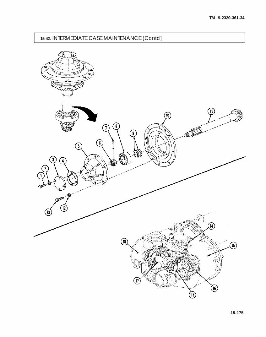
TM 9-2320-361-34
15-42. INTERMEDIATE CASE MAINTENANCE (Contd]
15-175

TM 9-2320-361-34
15-42. INTERMEDIATE CASE MAINTENANCE (Contd)
g. Second Reduction Drive Pinion Adjustment
1.
2.
3,4.
5.
6.
7.8.
9.
10.
11.12.
13.14.15.
NOTEIntermediate gear assembly must be removed and disassembled inorder to adjust depth of second reduction drive pinion.
‘To increase or decrease depth of second reduction drive pinion (30), add and remove equal amount ofshims between shims (23) and (28); perform steps 2 through 15.Remove second reduction gear assembly (35) from intermediate case (36) (subtask a, steps 3through 7).Remove four screws (1), lockwashers (2), cap cover (3), and gasket (4) from cap (5).Remove six screws (15), lockwashers (14), and cap (5) from bearing retainer (13).Remove cotter pin (7), nut (6), bearing (8), and shims (9) from shaft of second reduction feedpinion (31).Remove retaining ring (11), adjusting nut (10), bearing (12), retainer (13), and shims (16) from gearand hub (17).Remove gear and hub (17) and shims (18) from shaft of second reduction drive pinion (30).Remove retaining ring (20), adjusting nut (19), bearing (21), drive gear (22), two woodruff keys (29),shims (23), and spacer (24) from second reduction drive pinion (30).Remove retaining ring (26), adjusting nut (25), bearing (27), and shims (28) from second reductiondrive pinion (30).To increase depth of second reduction drive pinion (30), add shims (23) and remove shims (28) inequal amounts. To decrease depth of second reduction drive pinion (30), remove shims (23) and addshims (28) in equal amounts.Assemble second reduction gear assembly (35) (subtask d, steps 2,3, and 6 through 10).Install second reduction gear assembly (35) into intermediate case (36) (subtask e, steps 3through 6).Looking through hole (32) in boring case (33), confirm that gear (30) alines with gear (34).If gear (30) does not aline with gear (34), repeat steps 1 through 12 above.If gear (30) is in proper alinement with gear (34), perform subtask e, steps 14 and 15.
15-176

TM 9-2320-361-34
15-42. INTERMEDIATE CASE MAINTENANCE (Contd)
15-177

TM 9-2320-361-34
15-42. INTERMEDIATE CASE MAINTENANCE (Contd)
h. Drive Gear BackhshAdjustient
1.
2.
3.4.5.
6.
7.8.
9.
10.11.
12.
13.14.
NOTEIntermediate gear assembly must be removed and disassembled inorder to adjust the backlash of drive gear.
To adjust the backlash of drive gear (22) with reduction drive pinion gear (29), add and removeshims (23) and (18) in equal amounts; perform steps 2 through 14.Remove second reduction gear assembly (30) from intermediate case (27), (subtask a, steps 3through 7).Remove four screws (1), lockwashers (2), cap cover (3), and gasket (4) from cap (5).Remove six screws (15), lockwashers (14), and cap (5) from bearing retainer (13).Remove cotter pin (7), nut (6), bearing (8), and shims (9) from shaft of second reduction feedpinion (26).Remove retaining ring (10), adjusting nut (11), bearing (12), retainer (13), and shims (16) fromgear and hub (17).Remove gear and hub (17) and shims (18) from second reduction drive pinion (25).Remove retaining ring (20), adjusting nut (19), bearing (21), drive gear (22), two woodruff keys (24),and shims (23) from second reduction drive pinion (25).To increase backlash of drive gear (22), add shims (23) and remove shims (18) in equal amounts. Todecrease backlash of drive gear (22), remove shims (23) and add shims (18) in equal amounts.Assemble second reduction gear assembly (30) (subtask d, steps 3,6, and 7 through 10).Install second reduction gear assembly (30) into intermediate case (27) (subtask e, steps 3through 6).Set up dial indicator gage through hole (28) in intermediate case (27) and confirm backlash betweendrive gear (22) and reduction drive pinion gear (29) is 0.006-0.016 in. (0.15-0.41 mm).If the backlash is not correct, repeat steps 1 through 12 above.If the backlash is correct, perform subtask e, steps 14 and 15.
15-178

TM 9-2320-361-34
I 15-42. INTERMEDIATE CASE MAINTENANCE (Contd)
15-179

TM 9-2320-361-34
15-42. INTERMEDIATE CASE MAINTENANCE (Contd)
I i. Feed Gear and Hub Backlash Adjustment I
1.,
2.
3.4.
5.
6.
7.
8.
9.10.
11.
12.13.
NOTEIntermediate gear assembly must be removed and disassembled inorder to adjust feed gear and hub backlash.
To adjust the backlash of gear and hub (17) with reduction drive pinion gear (22), add and removeshims (16) and (18) in equal amounts; perform steps 2 through 13.Remove second reduction gear assembly (23) from intermediate case (24) (subtask a, steps 3through 7).Remove four screws (1), lockwashers (2), cap cover (3), and gasket (4) from cap (5).Remove six screws (15), lockwashers (14), and cap (5) from bearing retainer (13).Remove cotter pin (7), nut (6), bearing (8), and shims (9) from second reduction feed pinion (20).Remove retaining ring (10), adjusting nut (11), bearing (12), retainer (13), and shims (16) from gearand hub (17).Remove gear and hub (17) and shims (18) from second reduction drive pinion (19).To increase gear and hub (17) backlash, add shims (18) and remove shims (16) in equal amounts. Todecrease backlash of gear and hub (17), remove shims (18) and add shims (16) in equal amounts.Assemble second reduction gear assembly (23) (subtask d, steps 6 through 10).Install second reduction gear assembly (23) into intermediate case (24) (subtask e, steps 4through 6).Set up dial indicator gage through hole (21) in intermediate case (24). Confirm that backlashbetween gear and hub (17) and reduction drive pinion gear (22) is 0.006-0.016 in. (O. 15-0.41 mm).If the backlash is not correct, repeat steps 1 through 11 above.If the backlash is correct, go to subtask e, steps 14 and 15.
15-180

TM 9-2320-361-34
15-42. INTERMEDIATE CASE MAINTENANCE (Contd)
FOLLOW-ON TASKS: ● Install power leveler (para. 15-41).● Install vertical leveling worm rear (para. 15-40).● Install horizontal leveling worm gea;r (para. 15-39).● Complete boring case installation (para. 15-38).. Replace lubricant (LO 9-2320-209-12-1).
15-181

TM 9-2320-361-34
I 15-43. MAIN DRIVE IDLER GEAR MAINTENANCE
THIS TASK COVERS:a. Removal d. Assemblyb. Disassembly e. Installationc. Cleaning and Inspection
INITIAL SETUP
APPLICABLE MODELSM764
TOOLSGeneral mechanic’s tool kit (Appendix B, Item 1)Mechanical puller kit (Appendix B, Item 22)
MATERIALS/PARTSSixteen lockwashers (Appendix F, Item 138)Cotter pin (Appendix F, Item 6)Cotter pin (Appendix F, Item 13)Gasket (Appendix F, Item 58)Gasket (Appendix F, Item 59)No gaskets (Appendix F, Item 60)Two O-rings (Appendix F, Item 170)O-ring (Appendix F, Item 171)Two woodruff keys (Appendix F, Item 276)Two oil seals (Appendix F, Item 239)Four locknuts (Appendix F, Item 98)Sealing compound (Appendix C, Item 17)
PERSONNEL REQUIREDTwo
REFERENCES (TM)LO 9-2320-209-12-1TM 9-214TM 9-2320-361-10TM 9-2320-361-20TM 9-2320-361-34P
EQUIPMENT CONDITION. Parking brake set (TM 9-2320-361-10).. Hydraulic pump universal joint removed
(TM 9-2320-361-20).● Main drive idler gear housing drained
(LO 9-2320-209-12-1).
GENERAL SAFETY INSTRUCTIONSSupport housing before removing hardware.
—
a. Removal 1. Remove four locknuts (18), screws (21), and shaft flange (20) from flange (19). Discard locknuts (18)
WARNINGSupport main drive idler gear housing before removing hardware.Failure to do so may result in injury to personnel or damage toequipment.
2. Remove eight nuts (7), lockwashers (6), screws (2), housing (5), and gasket (3) from clutch case (1).Discard lockwashers (6) and gasket (3).
b. Disassembly 1.
2.3.
4.
5.6.7.
Remove cotter pin (30), nut (29), shaft (9), and idler gear (4) with bearings (35) from housing (5).Discard cotter pin (30).Remove two O-rings (8) from shaft (9). Discard O-rings (8).Remove cotter pin (24), nut (23), washer (22), flange (19), woodruff key (33), and gasket (34) fromshaft (27), Discard cotter pin (24), woodruff key (33), and gasket (34).Remove eight screws (11), lockwashers (10), two retainers (12), and gaskets (17) from housing (5).Discard lockwashers (10) and gaskets (17).Press two oil seals (16) from retainers (12). Discard oil seals (16).Loosen setscrew (13) and remove collar (14) and O-ring (31) from shaft (27). Discard O-ring (31).Remove shaft (27) with bearings (26) and (28) and main drive gear (25) from housing (5).
15-182

TM 9-2320-361-34
15-43. MAIN DRIVE IDLER GEAR MAINTENANCE (Contd)
c. Cleaning and Inspection
1. Clean all parts (para. 2-8).2. Inspect bearings (26) and (28) for damage (TM 9-214). Press from shaft (27) and replace if damaged.3. Inspect main idler gear (4) for nicks, scratches, burrs, and chipped or broken teeth. Remove nicks,
scratches, or burrs with a fine mill file. If teeth are chipped or broken, press two bearings (35) frommain idler gear (4) and replace gear (4).
4. Inspect main drive gear (25) for nicks, scratches, burrs, and chipped or broken teeth. Remove nicks,scratches, or burrs with a fine mill file. If teeth are chipped or cracked, press main drive gear (25)and woodruff key (32) from shaft (27) and replace woodruff key (32) and gear (25).
5. Inspect collar (14), sleeve (15), and flange (19) for damage. Remove two sleeves (15) if damaged andpress on new ones.
I
15-183

TM 9-2320-361-34
15-43. MAIN DRIVE IDLER GEAR MAINTENANCE (Contd)
d. Assembly
1. Press two new oil seals (15) in retainers (12).2. Install shaft (25) with two bearings (24) and main drive gear (27) in housing (5).3. Install new O-ring (28) and collar (14) on shaft (25). Tighten setscrew (13).4. Apply sealant to gasket surfaces and install two new gaskets (16) and retainers (12) on housing (5)
with eight new lockwashers (10) and screws (11).5. Apply sealant to gasket surfaces and install new gasket (31), new woodruff key (26), and flange (18)
on shaft (25) with washer (23), nut (22), and new cotter pin (21).6. Install two new O-rings (8) on shaft (9).
NOTEEnsure teeth of idler gear mesh with those of main drive gearduring installation.
7. Install idler gear (4) in housing (5) with shaft (9), nut (30), and new cotter pin (29).
e. Installation
N O T EAssistant will help with step 1.
1. Apply sealant to gasket surfaces and install new gasket (3) and housing (5) on clutch case (1) witheight screws (2), new lockwashers (6), and nuts (7).
2. Install shaft flange (19) on flange (18) with four screws (20) and new locknuts (17).
15-184

TM 9-2320-361-34
15-43. MAIN DRIVE IDLER GEAR MAINTENANCE (Contd)
FOLLOW-ON TASKS: . Install hydraulic pump universal joint (TM 9-2320-361-20).● Fill main drive idler gear housing with oil (LO 9-2320-209-12-1).
15-185

TM 9-2320-361-34
15-44. BRAKE, FEED, AND DRIVE CLUTCH MAINTENANCE
THIS TASK COVERS:
INITIAL SETUP
APPLICABLE MODELSM764
TOOLSGeneral mechanic’s tool kit (Appendix B, Item 1)Mechanical puller kit (Appendix B, Item 22)Lifting device
MATERIALS/PARTSSix lockwashers (Appendix F, Item 125)Four lockwashers (Appendix F, Item 138)Twenty-two lockwashers (Appendix F, Item 127)Four gaskets (Appendix F, Item 61)Four gaskets (Appendix F, Item 63)Gasket (Appendix F, Item 62)Four O-rings (Appendix F, Item 172)Shim set (Appendix F, Item 258)Shim set (Appendix F, Item 259)Shim set (Appendix F, Item 257)Four woodruff keys (Appendix F, Item 277)Woodruff key (Appendix F, Item 276)Cotter pin (Appendix F, Item 6)Seal (Appendix F, Item 224)GAA grease (Appendix C, Item 8)Sealing compound (Appendix C, Item 19)Safety wire (Appendix C, Item 31)Lubricating oil, OE/HDO 30 (Appendix C, Item 13)
PERSONNEL REQUIREDTwo
REFERENCES (TM)LO 9-2320-209-12-1TM 9-214TM 9-237TM 9-2320-361-10TM 9-2320-361-20TM 9-2320-361-34P
EQUIPMENT CONDITION. Parking brake set (TM 9-2320-361-10).● Clutch case drained (LO 9-2320-209-12-1).. Earth boring machine removed (para. 15-35).● Main drive idler gear removed (para. 15-43).● Intermediate case removed (para. 15-42).. Operation levers removed (TM 9-2320-361-20).
GENERAL SAFETY INSTRUCTIONS. Be prepared to support clutch and brake.● All personnel must stand clear during lifting
operations.
a. Disassembly 1.2.
3.
4.
5.
6.
Remove dipstick (23) and nipple (24) from clutch case (9).Remove eight screws (17), lockwashers (16), two cam housings (15), gaskets (12), and cams (13) fromcase (9). Discard lockwashers (16) and gaskets (12).Remove eight screws (19), lockwashers (18), two cam housings (20), gaskets (22), and cams (21) fromcase (9). Discard lockwashers (18) and gaskets (22).Remove four rings (10), sleeves (11), and O-rings (14) from two cams (21) and two cams (13). DiscardO-rings (14).Remove four screws (1), lockwashers (2), clutch case scap cover (26), gasket (27), and shims (28)from clutch case cap (5). Record thickness of shims (28). Discard shims (28), gasket (27), and lock-washers (2).
NOTEPerform steps 6 through 11 if adjusting depth of feed pinion.
Remove six screws (3), lockwashers (4), four nuts (8), clutch case cap (5), two gaskets (7), brake shell (25),and shims (6) from case (9). Record thickness of shims (6). Discard shims (6), gaskets (7), andlockwashers (4).
15-186

TM 9-2320-361-34
15-44. BRAKE, FEED, AND DRIVE CLUTCH MAINTENANCE (Contd)
15-187

15-188
TM 9-2320-361-34
15-44. BRAKE, FEED, AND DRIVE CLUTCH MAINTENANCE (Contd)
7.8.
9.10.11.
12.
13.
14.
Install chains on case (7), attach lifting device to chains, and apply tension to chains.Remove four nuts (1), six screws (3), and lockwashers (2) from case (7) and clutch and brake (4).Discard lockwashers (2).
●
●
WARNING
Be prepared to support clutch and brake otherwise it may fall andcause injury to personnel, and/or damage to equipment.All personnel must stand clear during lifting operations.A snapped chain, shifting or swinging load may cause injury topersonnel.
NOTEAssistant will help with lifting operations.
Slide case (7) and gasket (6) off clutch and brake (4). Discard gasket (6).Remove lifting device and chains from case (7).Remove bearing (30), drive sleeve (10) with clutch assembly (5), and woodruff key (13) from driveshaft (12). Discard woodruff key (13).
NOTEIf adjusting depth of feed pinion, proceed to step 20.
Remove safety wire (21), loosen setscrew (22), and remove adjusting nut (29) and bearing (28) fromdrive sleeve (10). Discard safety wire (21).Remove brake hub (27) with thirteen clutch plates (25) and (26) from drive sleeve (10).
NOTENote number and sequence of clutch plates before removing frombrake hub.
Remove thirteen clutch plates (25) and (26) from brake hub (27). Tie clutch plates (25) and (26)together in sequence.

TM 9-2320-361-34
15-44. BRAKE, FEED, AND DRIVE CLUTCH MAINTENANCE (Contd)
15. Loosen adjusting nut (23) and remove brake pressure plate (24), throw ring (20), and bearing (18)with clutch pressure plate (17) from sleeve bearing (19).
16. Remove sleeve bearing (19) from clutch hub (8).17. Remove clutch hub (8) with clutch plates (14), (15), and (16) and woodruff key (11) from drive
sleeve (10). Discard woodruff key (11).
NOTENote number and sequence of clutch plates before removing fromclutch hub.
18. Remove clutch plate (16), nine clutch plates (14), and eight clutch plates (15) from clutch hub (8). Tieclutch plates (14), (15), and (16) together in sequence.
19. Remove bearing (9) from drive sleeve (10).
15-189

TM 9-2320-361-34
15-44. BRAKE, FEED, AND DRIVE CLUTCH MAINTENANCE (Contd)
20.21.
22.
23.
24.
25.26.
27.28.
NOTEPerform steps 20 through 22 and 24 through 26 only if adjustingdepth of feed pinion.
Remove main drive gear (23) from bearing (19).Remove safety wire (22), loosen setscrew (21), and remove adjusting nut (20) and bearing (19) fromfeed shaft (4). Discard safety wire (22).Remove clutch hub (18) with clutch plates (16), (15), and (17) from feed shaft (4).
NOTENote number and sequence of clutch plates before removing fromclutch hub.
Remove clutch plate (15), nine clutch plates (16), and eight clutch plates (17) from clutch hub (18).Tie clutch plates together in sequence.Remove clutch pressure plate (14), bearing (13), and throw ring (11) from pressure plate (9). Loosenadjusting nut (10) and remove brake pressure plate (9) from sleeve bearing (12).Remove sleeve bearing (12) from brake hub (1).Remove brake hub (1) with brake plates (7) and (8) and woodruff key (5) from feed shaft (4). Discardwoodruff key (5).
NOTE● Note number and sequence of clutch plates before removing from
brake hub.● If adjusting depth of feed pinion, proceed to step 31.
Remove thirteen clutch plates (8) and (7) from brake hub (1). Tie clutch plates together in sequence.Remove brake shell (2) and gasket (3) from main support tube (6). Discard gasket (3).
15-190

TM 9-2320-361-34
15-44. BRAKE, FEED, AND DRIVE CLUTCH MAINTENANCE (Contd)
29. Remove cotter pin (28), nut (29), drive pinion (30), and woodruff key (39) from drive shaft (40).Discard cotter pin (28) and woodruff key (39).
30. Tap shaft (40) and remove from feed shaft (4).NOTE
Perform steps 31, 35, and 36 if adjusting depth of feed pinion.
31. Tap feed shaft (4) and remove from main support tube (6).32. Remove feed pinion (34) with bearing (35), two washers (36), and spacer (37), and woodruff key (38)
from feed shaft (4). Discard woodruff key (38).33. Remove spacer (37) and washer (36) from feed pinion (34).34, Remove two bearings (31), spacer (32), and seal (33) from feed pinion (34). Discard seal (33).35. Remove bearing (25) and shims (26) from main support tube (6). Record thickness of shims (26).
Discard shims (26).3
15-191

TM 9-2320-361-34
15-44. BRAKE, FEED, AND DRIVE CLUTCH MAINTENANCE (Contd)
b. Inspection
1. For general inspection instructions, refer to para. 2-9.2. Inspect two sleeve bearings (10), two roller bearings (9), four bearings (12), and bearings (3) and (17)
(TM 9-214). Replace if damaged.NOTE
Feed pinion gear or drive pinion gear must be replaced with associatedintermediate case ring gears as a matched set.
3. Inspect main drive gear (14), drive pinion (15), and feed pinion (16) for burrs, nicks, chips, cracks,and damaged teeth. Small nicks or burrs can be removed with a fine mill file. Replace if damaged.
15-192

TM 9-2320-361-34
15-44. BRAKE, FEED, AND DRIVE CLUTCH MAINTENANCE (Contd)
4. Inspect two brake shells (4), four hubs (11), and main drive gear (14) for notching of splines. Replaceif damaged.
5. Inspect all clutch plates (6), (7), and (13) for scoring and scorching. Replace all clutch plates ifdamaged.
6. Inspect lining of clutch plates (13) for damage and wear. Plate thickness should be 0.138-0.106 in.(3.50-2.69 mm). Place clutch plate (13) on clutch pressure plate (8) and check for coning by usingfeeler gage to measure gap at inside diameter. Gap should not exceed 0.15 in. (0.38 mm). Replace ifworn or damaged.
7., Inspect clutch cap (5), clutch case cap (2), and clutch case cap cover (1) for chips, cracks, and smallholes. Repair cracks or small holes by welding. Refer to TM 9-237. Replace if damaged.
15-193

TM 9-2320-361-34
I 15-44. BRAKE, FEED, AND DRIVE CLUTCH MAINTENANCE (Contd)
c. Assembly ●
●
●
●
NOTEIf adjusting depth of drive pinion, proceed to steps 40 and 44through 47.If adjusting depth of feed pinion, perform steps 42 through 47.Coat all brake and clutch plates with oil before installation.Pack all bearings with GAA grease before assembly.
1.
2.3.
4.5.6.7.
8.9.
10.11.
12.
13.14.
Install retainer (4) and sleeve (1) in main support tube (5).
NOTE. Apply sealing compound on gasket mating surfaces before
installation.● Install all shims to previous recorded distances.
Place new gasket (9) and brake shell (10) on main support tube (5).Install new shims (3) and bearing (2) on feed shaft (6) and insert feed shaft (6) through sleeve (1)and into main support tube (5).Install thirteen clutch plates (12) and (13) on brake hub (11) in number and sequence noted.Install new woodruff key (7) and brake hub (11) on feed shaft (6).Install sleeve bearing (17) on brake hub (11).Install brake pressure plate (14) with adjusting nut (15), throw ring (16), and bearing (18) withclutch pressure plate (19) on sleeve bearing (17).Install clutch plates (20), (21), and (22) on clutch hub (23) in number and sequence noted.Install clutch hub (23) on feed shaft (6).Install bearing (24) and adjusting nut (25) on feed shaft (6).Tighten adjusting nut (15) to eliminate end play of bearing (24) and hubs (11) and (23). Tightensetscrew (27) and install new safety wire (26).Rotate adjusting nut (15) to apply pressure to brake pressure plate (14) until adjusting nut (15)becomes tight. Then back adjusting nut (15) off 3/8 turn (4 to 5 notches) until lock groove is engaged.Install main drive gear (28) on bearing (24).Install drive shaft (8) in feed shaft (6).
15-194

TM 9-2320-361-34
15-44. BRAKE, FEED, AND DRIVE CLUTCH MAINTENANCE (Contd)
15-195

TM 9-2320-361-34
I 15-44. BRAKE, FEED, AND DRIVE CLUTCH MAINTENANCE (Contd)
15.16.17.18.19.
20.21.22.23.24.
25.
26.
Install bearing (2) on drive sleeve (3).Install nine clutch plates (7), eight clutch plates (8), and clutch plate (9) on clutch hub (1).Install new woodruff key (4) and clutch hub (1) on drive sleeve (3).Install sleeve bearing (12) on clutch hub (1).Install clutch pressure plate (10) with bearing (11), throw ring (13), and brake pressure plate (17)with adjusting nut (16) on sleeve bearing (12).Install thirteen clutch plates (18) and (19) on brake hub (20).Install brake hub (20) on drive sleeve (3).Install new woodruff key (6) and drive sleeve (3) on drive shaft (5).Install bearing (21) and adjusting nut (22) on drive sleeve (3).Tighten adjusting nut (22) to eliminate end play of bearings (2) and (21) and hubs (1) and (20).Tighten setscrew (15) and install safety wire (14).Rotate adjusting nut (16) to apply pressure to brake pressure plate (17) until adjusting nut (16) istight. Then back adjusting nut (16) off 3/8 turn (4 to 5 notches) until lock groove is engaged.Install bearing (23) on drive shaft (5).
15-196

TM 9-2320-361-34
❞ 15-44. BRAKE, FEED, AND DRIVE CLUTCH MAINTENANCE (Contd)
NOTEApply sealing compound to gasket mating surfaces before installation.
27. Install new gasket (26) on clutch case (29).28. Install chains and lifting device on case (29).
WARNING
All personnel must stand clear during lifting operations. A snappedchain, shifting or swinging load may cause injury to personnel.
NOTEAssistant will help with lifting operations.
29. Position case (29) over clutch and brake (28) and install with six new lockwashers (25), screws (27),and four nuts (24).
30. Remove lifting device and chains from case (29).NOTE
. Apply sealing compound to gasket mating surfaces before installation.● Install all new shims to previously recorded thickness.
31. Install two new gaskets (35) and brake shell (36) on case (29).32. Install new shims (38), clutch case cap (34), six new lockwashers (33), screws (32), and four nuts (37)
on case (29).33. Install new shims (39). new gasket (40). and clutch case cap cover (41) on clutch case cap (34) with
15-197

TM 9-2320-361-34
15-44. BRAKE, FEED, AND DRIVE CLUTCH MAINTENANCE (Contd)
34. Install new seal (14), two bearings (12), and spacer (13) on drive shaft (2).35. Install washer (5) and spacer (4) on feed pinion (7).36. Install feed pinion (7) with bearing (6) and new woodruff key (8) on feed shaft (1).37. Install new woodruff key (3), drive pinion (11), nut (10), and new cotter pin (9) on drive shaft (2).38. Install intermediate gear and case (16) on main support tube (17) (para. 15-42).39. Look through power leveler shaft hole (15) to ensure that toe of drive pinion (11) is alined with toe of
drive gear (18) and heel of feed pinion (7) is alined with heel of hub and gear (19).
15-198

TM 9-2320-361-34
15-44. BRAKE, FEED, AND DRIVE CLUTCH MAINTENANCE (Contd)
15-199

TM 9-2320-361-34
15-44. BRAKE, FEED, AND DRIVE CLUTCH MAINTENANCE (Contd)
40.
41.
42.
43.
44.
45.
46.
47.
NOTE● If alinement is correct, proceed to step 44.● If depth of drive pinion is incorrect, perform steps 40, 41, and 44
through 47.● If depth of feed pinion is incorrect, perform steps 42 through 47.
Remove four screws (20), lockwashers (21), clutch case cap cover (17), and gasket (18) from clutchcase (1). Discard lockwashers (21) and gasket (18).To increase the depth of drive pinion (26), add shims (19). To decrease the depth of drive pinion (26),remove shims (19).
NOTE● Apply sealing compound to gasket mating surfaces before
installation.. Intermediate gear and case must be removed from main support
tube in order to adjust depth of feed pinion. Perform removalsteps of para. 15-42, then disassemble brake, feed, and driveclutch and add or remove shims as necessary.
To increase depth of feed pinion (24), add shims (22) and remove shims (23) in equal thicknesses. Todecrease depth, remove shims (22) and add shims (23) in equal thicknesses.Install intermediate gear and case (27) on main support tube (25). Refer to installation steps ofpara. 15-42.Install four new O-rings (6), sleeves (4), and rings (3) on two cams (5) and two cams (13).Install two cams (5), new gaskets (2), and cam housings (7) on clutch case (1) with eight newlockwashers (8) and screws (9).Install two cams (13), new gaskets (14), and cam housings (12) on clutch case (1) with eight newlockwashers (11) and screws (10).Install nipple (16) and dipstick (15) on clutch case (1).
15-200

TM 9-2320-361-34
15-44. BRAKE, FEED, AND DRIVE CLUTCH MAINTENANCE (Contd)
FOLLOW-ON TASKS: ● Install main drive idler gear (para. 15-43).● Fill clutch case with oil (LO 9-2320-209-12-1).● Install intermediate case (para. 15-42).● Install earth boring machine (para. 15-35).. Install operation levers (TM 9-2320-361-20).
15-201

TM 9-2320-361-34
I 15-45. HYDRAULIC PUMP REPLACEMENT
THIS TASK COVERS:a. Removal b. Installation
INITIAL SETUP
APPLICABLE MODELSM764
TOOLSGeneral mechanic’s tool kit (Appendix B, Item 1)
MATERIALS/PARTSFour locknuts (Appendix F, Item 89)Woodruff key (Appendix F, Item 278)Cap and plug set (Appendix C, Item 5)Antiseize tape (Appendix C, Item 25)
REFERENCES (TM]LO 9-2320-209-12-1TM 9-2320-361-10TM 9-2320-361-34P
EQUIPMENT CONDITION● Parking brake set (TM 9-2320-361-10).● Hydraulic tank drained (LO 9-2320-209-12-1).
CAUTION
a. Removal
When disconnecting hydraulic hoses, plug all openings to preventdirt from entering and causing internal parts damage. Prior toinstallation, remove plugs from openings. Failure to do so mayresult in damage to equipment.
NOTE● Tag all hoses for proper installation.● Have drainage container ready to catch oil.
1. Remove hose (10) and adapter (8) from tee (7).2. Remove hose (5) and elbow (6) from tee (7).3. Remove hose (13) and check valve (14) from tee (15).4. Remove hose (11) and adapter (12) from tee (15).5. Remove tees (7) and (15) from pump (16).6. Loosen setscrew (3) on universal joint (2).7. Remove four locknuts (l), screws (4), pump (16), and woodruff key (9) from bracket (17) and
universal joint (2). Discard locknuts (1) and woodruff key (9).
NOTEApply antiseize tape to male pipe threads before installation.
1. Install new woodruff key (9) on pump (16).2. Install pump (16) on universal joint (2).3. Install pump (16) on bracket (17) with four screws (4) and new locknuts (1).4. Tighten setscrew (3) on universal joint (2).5. Install tees (7) and (15) on pump (16).6. Install adapter (12) and hose (11) on tee (15).7. Install check valve (14) and hose (13) on tee (15). Ensure arrow of valve (14) points away from tee (15).8. Install elbow (6) and hose (5) on tee (7).9. Install adapter (8) and hose (10) on tee (7).
b. Installtion
15-202

TM 9-2320-361-34
15-45. HYDRAULIC PUMP REPLACEMENT (Contd)
FOLLOW-ON TASK: Fill hydraulic tank (LO 9-2320-209-12-1) and check for leaks.
15-203

TM 9-2320-361-34
15-46. OUTRIGGER CONTROL VALVE REPLACEMENT
THIS TASK COVERS:a. Removal b. Installation
INITIAL SETUP
APPLICABLE MODELSM764
TOOLSGeneral mechanic’s tool kit
(Appendix B, Item 1)
MATERIALS/PARTSFour cotter pins (Appendix F, Item 22)
REFERENCES (TM)LO 9-2320-209-12-1TM 9-2320-361-10TM 9-2320-361-34P
EQUIPMENT CONDITION● Parking brake set (TM 9-2320-361-10).. Hydraulic tank drained (LO 9-2320-209-12-1).
Three lockwashers-(Appendix F, Item 125)Cap and plug set (Appendix C, Item 5)Antiseize tape (Appendix C, Item 25)
CAUTIONWhen disconnecting hydraulic lines, plug all openings to preventdirt from entering and causing internal parts damage. Prior toinstallation, remove plugs from openings. Failure to do so mayresult in damage to equipment.
a. Removal NOTE
. Tag hoses for installation.● Have drainage container ready to catch oil.
1. Remove six hoses (2) and elbows (7) from control valve (9).2. Remove four cotter pins (5), straight pins (4), and two control levers (3) from control valve (9).
Discard cotter pins (5).3. Remove three screws (6), lockwashers (8), and control valve (9) from body (1). Discard lockwashers (8).
I b. Installation INOTE
Apply antiseize tape to male pipe threads before installation.1. Install control valve (9), three new lockwashers (8), and screws (6) on body (1).2. Install two control levers (3), four straight pins (4), and new cotter pins (5) on control valve (9).3. Install six elbows (7) and hoses (2) on control valve (9).
15-204

TM 9-2320-361-34
15-46. OUTRIGGER CONTROL VALVE REPLACEMENT (Contd)
FOLLOW-ON TASK: Fill hydraulic tank (LO 9-2320-209-12-1) and check for leaks.
15-205

TM 9-2320-361-34
I 15-47. OUTRIGGER LEG MAINTENANCE
THIS TASK COVERS:a. Removal c. Assemblyb. Disassembly d. Installation
INITIAL SETUP
APPLICABLE MODELSM764
TOOLSGeneral mechanic’s tool kit
(Appendix B, Item 1)
MATERIALS/PARTSTwenty locknuts (Appendix F, Item 109)Locknut (Appendix F, Item 89)Cap and plug set (Appendix C, Item 5)
PERSONNEL REQUIREDTwo
REFERENCES (TM)LO 9-2320-209-12-1TM 9-2320-361-10TM 9-2320-361-20TM 9-2320-361-34P
EQUIPMENT CONDITION● Parking brake set (TM 9-2320-361-10).● Hydraulic tank drained (LO 9-2320-209-12-1).● Rear splash guards removed (TM 9-2320-361-20).
CAUTION● When disconnecting hydraulic hoses, plug all openings to prevent
dirt from entering and causing internal parts damage. Prior toinstallation, remove plugs from opening. Failure to do so mayresult in damage to equipment.
● Use care when working on outrigger leg. Hydraulic tubes can beeasily damaged.
NOTE● Tag hoses for installation.● Have drainage container ready to catch oil.
a. Removal 1. Remove two hoses (4) and adapters (3) from new cylinder tubes (5).2. Remove locknut (6), screw (1), two clamps (2), and cylinder tubes (5) from bracket (7). Discard
locknut (6).3. Remove shoe (8) from bracket (19).
NOTEAssistant will help with steps 4 and 5.
4. Remove sixteen locknuts (13) and screws (9) from upper leg (10). Leave screw (9) and locknut (13)on each corner of upper leg (10) to keep it from shifting. Discard locknuts (13).
5. Remove four locknuts (13), screws (9), and upper leg (10) from body (14). Discard locknuts (13).
I b. Disassembly
1. Remove ring (12) and pin (11) from upper leg (10) and cylinder (18).2. Remove lower leg (15) with cylinder (18) from upper leg (10).3. Remove locknut (20), screw (22), and latch (21) from upper leg (10). Discard locknut (20).4. Loosen setscrew (17) and remove tube (16) and cylinder (18) from lower leg (15).
15-206

TM 9-2320-361-34
15-47. OUTRIGGER LEG MAINTENANCE (Contd)
15-207

TM 9-2320-361-34
I 15-47. OUTRIGGER LEG MAINTENANCE (Contd)
c. Assembly 1.. Install cylinder (11) and tube (9) in lower leg (8). Tighten setscrew (10).2. Install lower leg(8) in upper leg(3) with pin (4) and ring(5).3. Install latch (14) on upper leg (3) with screw (15) and new locknut (13).
d. Installation N O T E
Assistant will help with step 1.
1. Install upper leg (3), twenty screws (2), and new locknuts (6) on body (7).2. Install shoe (1) in bracket (12).3. Install cylinder tubes (2o) on bracket (22) with two clamps (17), screw (16), and new 10cknut (21).4. Connect two adapters (18) and hoses (19) on cylinder tubes (20).
15-208

TM 9-2320-361-34
15-47. OUTRIGGER LEG MAINTENANCE (Contd)
FOLLOW-ON TASKS: . Fill hydraulic tank (LO 9-2320-209-12-1) and check for leaks.● Install rear splash guards (TM 9-2320-361-20).
15-209

TM 9-2320-361-34
15-48. HYDRAULIC CYLINDER REPAIR
THIS TASK COVERS:a. Disassembly c. Assemblyb. Inspection
INITIAL SETUP
APPLICABLE MODELSM764
TOOLSGeneral mechanic’s tool kit
(Appendix B, Item 1)
MATERIALS/PARTSThree lockwashers (Appendix F, Item 131)O-ring (Appendix F, Item 173)Cotter pin (Appendix F, Item 5)Washer (Appendix F, Item 267)Packing, preformed (Appendix F, Item 181)Packing set (Appendix F, Item 185)Lubricating oil, OE/HDO 30 (Appendix C, Item 13)
REFERENCES (TM)LO 9-2320-209 -12-1TM 9-2320-361-10TM 9-2320-361-34P
EQUIPMENT CONDITION“ Parking brake set (TM 9-2320-361-10).. Hydraulic tank drained (LO 9-2320-209-12-1).● Outrigger leg removed and disassembled
(para. 15-47).
a. Disassembly
NOTEHave drainage container ready to catch oil.
1.2.3.4.
5.6.7.
8.
9.
Pull rod (7) from cylinder (18) as far as possible and drain oil into container.Remove tubes (16) and (19) and connectors (17) and (20) from cylinder (18).Loosen cylinder head (8) and remove rod (7) from cylinder (18).Remove cotter pin (15), nut (14), two retaining plates (10), two cups (12), follower (13), andpreformed packing (11) from rod (7). Discard cotter pin (15) and preformed packing (11).Remove cylinder head (8) from rod (7).Remove O-ring (9) from cylinder head (8). Discard O-ring (9).Remove three screws (6), lockwashers (5), retainer (3), and rod wiper (4) from cylinder head (8).Discard lockwashers (5).Remove rod wiper (4) from retainer (3).Remove packing set (2) and washer (1) from cylinder head (8). Discard packing set (2) and washer (1).
b. Inspection
Inspect all parts for bends, cracks, chips, grooves, burrs, and scoring. Replace if damaged.
NOTEInstall packing set with tapered end toward washer.
1. Coat packing set (2) with oil and install new washer (1) and packing set (2) in cylinder head (8).2. Install rod wiper (4) in retainer (3).3. Install retainer (3), wiper (4), three new lockwashers (5), and screws (6) on cylinder head (8).
15-210

TM 9-2320-361-34
15-48. HYDRAULIC CYLINDER REPAIR (Contd)
4. Install new O-ring (9) on cylinder head (8).5. Install cylinder head (8) on rod (7).6. Install new preformed packing (11), two retaining plates (10), cups (12), follower (13), nut (14), and
new cotter pin (15) on rod (7).7. Install rod (7) in cylinder body (18) and tighten cylinder head (8).8. Install connectors (17) and (20) and tubes (16) and (19) to cylinder (18).
FOLLOW-ON TASKS: ● Assemble and install outrigger leg (para. 15-47).● Fill hydraulic tank (LO 9-2320-209-12-1) and check for leaks.
15-211

TM 9-2320-361-34
15-49. EARTH BORING AND POLESETTING BODY MAINTENANCE
THIS TASK COVERS:a. Removal c. Installationb. Inspection
INITIAL SETUP
APPLICABLE MODELSM764
TOOLSGeneral mechanic’s tool kit (Appendix B, Item 1)1-1/8-in. socket, 1/2-in. dr. (Appendix B, Item 10)1-1/16-in. socket, 1/2-in. dr.
(Appendix B, Item 11)Torque wrench, 1/2-in. dr. (Appendix B, Item 7)Lifting device
MATERIALS/PARTSFour locknuts (Appendix F, Item 105)Four locknuts (Appendix F, Item 104)
EQUIPMENT CONDITION● Parking brake set (TM 9-2320-361-10).. Earth auger bits removed (TM 9-2320-361-10).● Cab protector removed (TM 9-2320-361-20).. Outrigger hydraulic lines removed
(TM 9-2320-361-20).● Taillights removed (TM 9-2320-361-20).● Taillight wiring harness removed
(TM 9-2320-361-20).● Pioneer tool bracket removed (TM 9-2320-361-20).● Splash guards removed (TM 9-2320-361-20).● Power divider removed (para. 16-15).● Earth boring machine removed (para. 15-35).
PERSONNEL REQUIRED GENERAL SAFETY INSTRUCTIONS
Two ● All personnel must stand clear during liftingoperations.
REFERENCES (TM) ● Ensure lifting capacity is greater than weight ofFM 43-2 frame.TC 9-510TM 9-237TM 9-2320-361-10TM 9-2320-361-20TM 9-2320-361-34P
a. Removal N O T E
Assistant will help remove and install body.1. Remove four locknuts (6), washers (7), screws (10), and springs (8) and (9) from brackets (1) of
frame (13) and body (11). Discard locknuts (6).2. Remove four locknuts (5), washers (4), and screws (3) from four brackets (2) of frame (13) and body (11).
Discard locknuts (5).3. Install two chains and guidelines on body (11) and attach lifting device to chains.
WARNING● All personnel must stand clear during lifting operations. A swinging
or shifting load may cause injury or death to personnel.● Ensure lifting capacity is greater than weight of frame. Failure to
do so may result in injury to personnel or damage to equipment.
4. Remove body (11) from frame (13) and place on wooden supports.5. Remove two sills (12) from frame (13).6. Remove lifting device, chains, and guide lines from body (11).
15-212

TM 9-2320-361-34
15-49. EARTH BORING AND POLESETTING BODY MAINTENANCE (Contd)
15-213

TM 9-2320-361-34
15-49. EARTH BORING AND POLESETTING BODY MAINTENANCE (Contd)
b. Inspection 1. Inspect screws (10) and (3) for cracks, stripped threads, or other damage. Replace if damaged.2. Inspect body (11) for bends, cracks, dents, or broken welds. Straighten if bent or dented (TC 9-510).
Weld breaks or cracks (TM 9-237).3. Inspect springs (8) and (9) for wear or broken coils. Replace if worn or damaged.
c. Installation
1. Position two sills (2) on frame (3).
WARNING
● All personnel must stand clear during lifting operations. Aswinging or shifting load may cause injury to personnel.
● Ensure lifting capacity is greater than weight of frame. Failure todo so may result in injury to personnel or damage to equipment.
2. Install two guide lines and chains on body (1) and attach lifting device to chains.3. Position body (1) on frame (3) and aline holes in brackets (4) and (5).4. Install four screws (13), springs (12), springs (11), washers (10), and new locknuts (9) on brackets (4)
of frame (3) and body (1). Tighten screws (13) until springs (12) and (11) compress to 6.375 in.(161.93 mm).
5. Install four screws (6), washers (7), and new locknuts (8) on brackets (5) of frame (3) and body (1).Tighten screws (6) 125-165 lb-ft (170-224 N.m).
6. Remove lifting device, chains, and guidelines.
15-214

TM 9-2320-361-34
15-49. EARTH BORING AND POLESETTING BODY MAINTENANCE (Contd)
FOLLOW-ON TASKS: . Install earth boring machine (para. 15-35).. Install power divider (para. 16-15).● Install splash guards (TM 9-2320-361-20).● Install pioneer tool bracket (TM 9-2320-361-20).● Install taillight wiring harness (TM 9-2320-361-20).. Install taillights (TM 9-2320-361-20).● Install outrigger hydraulic lines (TM 9-2320-361-20).. Install cab protector (TM 9-2320-361-20).● Install earth auger bits (TM 9-2320-361-10).
15-215

TM 9-2320-361-34
Section VI. PIPELINE CONSTRUCTION BODY MAINTENANCE
I 15-50. PIPELINE CONSTRUCTION BODY MAINTENANCE INDEX
PARA. TITLE PAGENO. NO.
15-51. Pipeline Construction Body Maintenance 15-21515-52. Pipeline Construction ‘Ibolbox Maintenance 15-22215-53. Pipeline Construction Tailboard Roller Maintenance 15-226
15-216

TM 9-2320-361-34
I 15-51. PIPELINE CONSTRUCTION BODY MAINTENANCE
THIS TASK COVERS:
a. Subframe Removal d. Flooring Installationb. Flooring Removal e. Subframe Installationc. Inspection
INITIAL SETUP
APPLICABLE MODELS EQUIPMENT CONDITIONM756A2
TOOLSGeneral mechanic’s tool kit
(Appendix B, Item 1)Torque wrench, 1/2-in. dr.
(Appendix B, Item 7)1-1/8-in. socket, 1/2-in. dr.
(Appendix B, Item 10)1-1/16-in. socket, 1/2-in. dr.
(Appendix B, Item 11)
MATERIALS/PARTSFifty-six locknuts (Appendix F, Item 110)Six locknuts (Appendix F, Item 89)Eight locknuts (Appendix F, Item 104)Six locknuts (Appendix F, Item 103)
PERSONNEL REQUIREDTwo
REFERENCES (TM)TB 43-0209
●
●
●
●
●
●
Bows and tarp removed (TM 9-2320-361-10).Side panels removed (TM 9-2320-361-20).Tailgate removed (TM 9-2320-361-20).Stiff leg jack removed (TM 9-2320-361-20).Gin pole removed (TM 9-2320-361-20).Front and rear splash guards removed(TM 9-2320-361-20).Step plate removed (TM 9-2320-361-20).Tailboard roller removed (para. 15-53).
GENERAL SAFETY INSTRUCTIONS● All personnel must stand clear during lifting
operations.● Toolbox is heavy. Ensure toolbox is empty and
supported before removal and installation.. Toolbox and subframe are heavy. Ensure lifting
capacity is greater than weight of the toolbox andsubframe.
TM 9-2320-361-10TM 9-2320-361-20TM 9-2320-361-34P
15-217

TM 9-2320-361-34
15-51. PIPELINE CONSTRUCTION BODY MAINTENANCE (Contd)
I a. Subframe Removal
NOTEPerform step 1 if installing new subframe.
1.
2.
3.
4.
5.6.
7.8.
Remove six locknuts (19), four screws (1), and two screws (3) from toolbox (20) and two brackets (2)from subframe (6). Discard locknuts (19).Remove eight locknuts (13), washers (12), four screws (4), and screws (5) from two brackets (18),brackets (7), frame brackets (14), and frame brackets (15). Discard locknuts (13).Remove six locknuts (9), four screws (17) and two screws (16) from two plates (8) and frame (11).Discard locknuts (9).Attach chains, lifting device, and guide lines to subframe (9).
WARNING. All personnel must stand clear during lifting operations. A
swinging or shifting load may cause injury to personnel.● Toolbox and subframe are heavy. Ensure lifting device has a
weight capacity greater than the weight of the toolbox andsubframe. Failure to do so may result in injury to personnel ordamage to equipment.
Remove subframe (6) from toolbox (20) and frame (11) and place on wooden supports.Remove lifting device and chains from subframe (6).
WARNINGToolbox is heavy. Ensure toolbox is empty before removing fromframe. Support toolbox during removal. Failure to do so may resultin injury to personnel.
NOTEPerform step 7 if installing new subframe.
Remove toolbox (20) from frame (11).Remove and inspect two fillers (10) for splitting and wear. Replace if split or worn.
15-218

TM 9-2320-361-34
15-51. PIPELINE CONSTRUCTION BODY MAINTENANCE (Contd)
15-219

TM 9-2320-361-34
15-51. PIPELINE CONSTRUCTION BODY MAINTENANCE (Contd)
I b. Flooring Removal
NOTEMark location of floorboards for proper installation.
1. Remove fourteen screws (2), washers (3), locknuts (10), two slats (4), and board (1) fromsubframe (9). Discard locknuts (10).
2. Remove twenty-one screws (2), washers (3), locknuts (10), three slats (11), (6), and (4), twoboards (5), board (7), and board (8) from subframe (9). Discard locknuts (10).
3. Remove twenty-one screws (2), washers (3), locknuts (10), four slats (4), and three boards (5) fromsubframe (9). Discard locknuts (10).
c . Inspection
1. Inspect boards (1), (5), (7), and (8) for warpage, rot, and splits that exceed board width. Replace ifwarped, rotted, or splits exceed board width. Inspect two boards (1) for 1.31 in. (3.33 cm) thickness.Replace if thickness is not correct.
2. Paint parts as needed (TB 43-0209).
I e. Flooring Installation
1. Position two boards (1), boards (7) and (8), and five boards (5) on subframe (9) and install with sevenslats (4), forty-nine screws (2), washers (3), and new locknuts (10).
2. Install two slats (11) and (6) on boards (7) and (5) and subframe (9) with seven screws (2),washers (3), and new locknuts (10).
15-220

TM 9-2320-361-34
15-51. PIPELINE CONSTRUCTION BODY MAINTENANCE (Contd)
15-221

TM 9-2320-361-34
I 15-51. PIPELINE CONSTRUCTION BODY MAINTENANCE (Contd)
e. Subframe Installation
1.
2.3.
4.
5.6.
7.
Position two fillers (8) on frame (9).
WARNINGToolbox is heavy. Support toolbox during installation. Failure to doso may result in injury to personnel.
NOTEPerform step 2 if installing new subframe.
Position toolbox (20) on frame (9) and two fillers (8).Attach chains and lifting device to subframe (4).
WARNING
● All personnel must stand clear during lifting operations. Aswinging or shifting load may cause injury to personnel.
● Toolbox and subframe are heavy. Ensure lifting device has liftingcapacity greater than the weight of the toolbox and subframe.Failure to do so may result in injury to personnel or damage toequipment.
Position subframe (4) on frame (9) and aline two subframe brackets (5) and bracket (18) with two framebrackets (15) and bracket (14).
NOTEPerform step 5 if installing new subframe.
Install toolbox (20) on subframe (4) and two brackets (2) with six screws (1) and new locknuts (19).Install two subframe brackets (18) and subframe brackets (5) on two frame brackets (14) and framebrackets (15) with eight screws (3), four washers (10), four washers (13), new locknuts (11), and newlocknuts (12). Tighten four locknuts (11) 65-85 lb-ft (88-115 N.m). Tighten four locknuts (12) 125-165lb-ft (170-224 N.m).Install four screws (17), two screws (16), and six locknuts (7) on two plates (6) and frame (9).
15-222

TM 9-2320-361-34
I 15-51. PIPELINE CONSTRUCTION BODY MAINTENANCE (Contd)
FOLLOW-ON TASKS: ● Place tools in toolbox, if removed.Install tailboard roller (para. 15-53).Install step plate (TM 9-2320-361-20).Install front and rear splash guards (TM 9-2320-361-20).Install gin pole (TM 9-2320-361-20).Install stiff leg jack (TM 9-2320-361-20).Install tailgate (TM 9-2320-361-20).Install side panels (TM 9-2320-361-20).Install bows and tarp (TM 9-2320-361-10).
15-223

TM 9-2320-361-34
15-52. PIPELINE CONSTRUCTION TOOLBOX REPLACEMENT
THIS TASK COVERS:a. Removal b. Installation
INITIAL SETUP
APPLICABLE MODELS REFERENCES (TM)M756A2 W/W TM 9-2320-361-10
TOOLSTM 9-2320-361-20TM 9-2320-361-34P
General mechanic’s tool kit(Appendix B, Item 1) EQUIPMENT CONDITION
1-1/8-in. socket, 1/2-in. dr. (Appendix B, Item 10) ● Bow and tarp kit removed (TM 9-2320-361-10).1-1/16-in. socket, 1/2-in. dr. (Appendix B, Item 11) ● Side panels removed (TM 9-2320-361-20).Torque wrench, 1/2-in. dr. (Appendix B, Item 7) . Step plate removed (TM 9-2320-361-20).Lifting device ● Front splash guard removed (TM 9-2320-361-20).
MATERIALS/PARTS GENERAL SAFETY INSTRUCTIONSSix locknuts (Appendix F, Item 89) ● All personnel must stand clear during liftingEight locknuts (Appendix F, Item 104) operations.Six locknuts (Appendix F, Item 103) . Toolbox is heavy. Ensure toolbox is empty and
PERSONNEL REQUIREDsupported before removal and installation.
Two
a. Removal 1. Remove four locknuts (9), locknuts (11), eight washers (8), and screws (2) from two brackets (12) and
four brackets (7). Discard locknuts (9) and (11).2.3.4.
5.6.7.8.
Remove four locknuts (6) and screws (2) from two plates (4) and frame (10). Discard locknuts (6).Loosen two locknuts (5).Remove six locknuts (13) and screws (1) from toolbox (15) and two subframe brackets (14). Discardlocknuts (13).
WARNING
● All personnel must stand clear during lifting operations. Aswinging or shifting load may cause injury to personnel.
● Toolbox is heavy. Ensure toolbox is empty before removing fromframe. Support toolbox during removal. Failure to do so mayresult in injury to personnel.
CAUTION
Do not lift, subframe 0.5 in. (1.27 cm) above frame. Damage toequipment may result.
NOTEAssistant will help with lifting operations.
Attach lifting device and chains to subframe (3).Raise subframe (3) from frame (10) 0.5 in. (1.27 cm) maximum.Remove toolbox (15) from frame (10).Lower subframe (3) and remove chains from lifting device and subframe (3).
15-224

TM 9-2320-361-34
15-52. PIPELINE CONSTRUCTION TOOLBOX REPLACEMENT (Contd)
15-225

TM 9-2320-361-34
15-52. PIPELINE CONSTRUCTION TOOLBOX REPLACEMENT (Contd)
b. Installation
WARNING
1.2.
3.4.5.6.7.
8.
9.10.11.
● All personnel must stand clear during lifting operations. Aswinging or shifting load may cause injury to personnel.
● Toolbox is heavy. Support toolbox during installation. Failure to doso may result in injury to personnel.
CAUTION
Do not lift subframe 0.5 in. (1.27 cm) above frame. Damage toequipment may result.
NOTEAssistant will help with lifting operations.
Attach chains to subframe (3) and lifting device.Raise subframe (3) from frame (11) 0.5 in. (1.27 cm) maximum.
CAUTION
Use care when installing toolbox on frame and sills. Damage toequipment may result.
Position toolbox (15) on frame (11) and lower subframe (3) onto frame (11).Install toolbox (15) on subframe (3) with six screws (1) and new locknuts (14).Remove two locknuts (6) from two screws (5). Discard locknuts (6).Ensure subframe (3) is correctly positioned on frame (11).Install four screws (2), washers (9), and new locknuts (12) on two brackets (13). Tighten lock-nuts (12) 65-85 lb-ft (88-115 N.m).Install four screws (2), washers (9), and new locknuts (10) on four brackets (8). Tighten lock-nuts (10) 125-165 lb-ft (170-224 N.m).Install four screws (2) and new locknuts (7) on two plates (4).Install two new locknuts (6) on two screws (5).Remove chains and lifting device from subframe (3).
15-226

TM 9-2320-361-20
TM 9-2320-361-20
TM 9-2320-361-20
TM 9-2320-361-10
TM 9-2320-361-34
15-52. PIPELINE CONSTRUCTION TOOLBOX REPLACEMENT (Contd)
15-227

TM 9-2320-361-34
15-53. PIPELINE CONSTRUCTION TAlLBOARD ROLLER MAINTENANCE
THIS TASK COVERS:a. Removal d. Assemblyb. Disassembly e. Installationc. Inspection
INITIAL SETUP
APPLICABLE MODELS REFERENCES (TM)M756A2 W/W TM 9-214
TOOLSTM 9-2320-361-10TM 9-2320-361-20
General mechanic’s tool kit(Appendix B, Item 1)
TM 9-2320-361-34P
Mechanical puller (Appendix B, Item 22) EQUIPMENT CONDITIONDial indicator (Appendix B, Item 21) ● Parking brake set (TM 9-2320-361-10).
MATERIALS/PARTS● Tailgate removed (TM 9-2320-361-20).● Side panels removed (TM 9-2320-361-20).
Shims (Appendix F, Item 260)Eight lockwashers (Appendix F, Item 142) GENERAL SAFETY INSTRUCTIONSTwo seals (Appendix F, Item 231) All personnel must stand clear during liftingLubricating oil OE/HDO 10 operations.
(Appendix C, Item 12)
PERSONNEL REQUIREDTwo
a. Removal 1. Attach lifting device and chain to roller (7) until supported.
NOTECount and record number of shims between two housings and pinsbefore removal.
2. Remove eight screws (2), lockwashers (3), two pins (1), and shims (10) from housings (9) androller (7). Discard lockwashers (3).
WARNINGAll personnel must stand clear during lifting operations. A swingingor shifting load may cause injury to personnel.
NOTEAssistant will help with lifting operations.
3. Remove roller (7) from subframe (8).4. Remove lifting device and chain from roller (7).
I b. Disassembly
Remove two seals (4), eight screws (5), two seats (6), and bearings (11) from roller (7). Discard seals (4).
Inspect two bearings (11) for wear (TM 9-214). Replace bearings (11) if damaged.c. Inspection
15-228

TM 9-2320-361-34
15-53. PIPELINE CONSTRUCTION TAlLBOARD ROLLER MAINTENANCE (Contd)
15-229

TM 9-2320-361-34
15-53. PIPELINE CONSTRUCTION TAILBOARD ROLLER MAlNTENANCE(Contd)
d. Assembly NOTE
Lubricate bearings and seats before installation.
Install two bearings (11) and seats (6) on roller (7) with eight screws (5) and two new seals (4).
I e. Installation
1.2.3.
4.5.6.
WARNING
All personnel must stand clear during lifting operations. A swingingor shifting load may cause injury to personnel.
NOTEAssistant will help with lifting operations.
Attach lifting device and chain to roller (7).Position roller (7) between two housings (9) on subframe (8).Install roller (7) and recorded number of shims (10) on housings (9) with two pins (1), eight newlockwashers (3), and screws (2).Use dial indicator to measure end play between roller (7) and housing (9).Install or remove shims, as needed (step 3), to provide 0.03 in. (0.76 mm) minimum end play.Remove lifting device and chain from roller (7).
15-230

TM 9-2320-361-34
15-53. PIPELINE CONSTRUCTION TAlLBOARD ROLLER MAINTENANCE (Contd)
FOLLOW-ON TASKS: . Install side panels (TM 9-2320-361-20).● Install tailgate (TM 9-2320-361-20).
15-231 (15-232 blank)


WINCH, HOIST,Section I.Section II.Section III.
TM 9-2320-361-34
CHAPTER 16AND POWER TAKEOFF MAINTENANCEWinch Maintenance (page 16-1)Hoist Maintenance (page 16-56)Power Takeoff Maintenance (page 16-95)
Section I. WINCH MAINTENANCE
16-1. WINCH MAINTENANCE INDEX IPARA. TITLE PAGENO. NO.
16-2. Front Winch Repair 16-116-3. Rear Winch Repair (M756A2) 16-1216-4. Rear Winch Repair (M764) 16-2416-5. Rear Winch Replacement (M764) 16-54
16-2. FRONT WINCH REPAIRTHIS TASK COVERS:a. Front Winch Disassembly e. Front Winch Gearcase Assemblyb. Front Winch End Frame Disassembly f. Front Winch End Frame Assemblyc. Front Winch Gearcase Disassembly g. Front Winch Assemblyd. Cleaning and Inspection
INITIAL SETUP
APPLICABLE MODELSAll
TOOLSGeneral mechanic’s tool kit
(Appendix B, Item 1)Mechanical puller kit (Appendix B, Item 22)Spring tester (Appendix B, Item 38)Torque wrench, 1/2-in. dr. (Appendix B, Item 7)Outside micrometer (Appendix B, Item 17)Inside micrometer (Appendix B, Item 16)Dial indicator (Appendix B, Item 21)
MATERIALS/PARTSLocknut (Appendix F, Item 111)Twenty-seven lockwashers
(Appendix F, Item 138)Seven lockwashers (Appendix F, Item 143)Lockwasher (Appendix F, Item 153)O-ring (Appendix F, Item 175)Seal (Appendix F, Item 225)Seal (Appendix F, Item 226)Seal (Appendix F, Item 227)
MATERIALS/PARTS (Cord)Seal (Appendix F, Item 228)Seal (Appendix F, Item 229)Two gaskets (Appendix F, Item 65)Gasket (Appendix F, Item 66)Gasket (Appendix F, Item 64)Two woodruff keys (Appendix F, Item 279)Two woodruff keys (Appendix F, Item 281)Two woodruff keys (Appendix F, Item 279)Woodruff key (Appendix F, Item 280)Six screw-assembled lockwashers
(Appendix F, Item 158)Pin (Appendix F, Item 194)Plug (Appendix F, Item 200)
REFERENCES [TM)TM 9-214TM 9-2320-361-20TM 9-2320-361-34PTM 9-3830-206-35P
EQUIPMENT CONDITIONFront winch removed (TM 9-2320-361-20).
16-1

TM 9-2320-361-34
16-2. FRONT WINCH REPAIR (Contd)
a. Front Winch Disassembly
1. Remove four screws (4), lockwashers (5), and channel (3) from gearcase (7) and end frame (12).Discard lockwashers (5).
2. Remove six screws (2), lockwashers (1), and channel (6) from gearcase (7) and end frame (12).Discard lockwashers (1).
3. Remove locknut (13) and end frame (12) from rod (9) and drum shaft (10). Discard locknut (13).4. Remove plug (11) from end frame (12).5. Remove plug (8) from gearcase (7).
I b. Front Winch End Frame Disassembly
1.
2.
3.4.5.6.
7.
8.
9.
10.11.
16-2
Remove six screws (48), lockwashers (47), washers (46), and spacers (45) from end frame (12).Discard lockwashers (47).Remove drum sliding clutch (37), thrust ring (36), and seal (39) from end frame (12). Discardseal (39).Remove adjusting screw (44), spring (42), and drag brakeshoe (41) from end frame (12).Remove plug (34) and setscrew (33) from end frame (12).Remove setscrew (38) from shifter fork (35).Remove shifter fork (35) and woodruff key (24) from shifter shaft(31) while removing shiftershaft (31), ball (29), and spring (28) from end frame (12). Discard woodruff key (24).Remove screw (27), lockwasher (26), lever (25), and woodruff key (30) from shifter shaft (31).Discard lockwasher (26) and woodruff key (30).Remove screw (23), lockwasher (22), plate (21), and seal (32) horn end frame (12). Discard lock-washer (22) and seal (32).Remove two nuts (14), poppet latch (15), poppet nut (16), spring (17), and poppet (18) from endframe (12).Remove plug (19), three plugs (20), and pin (43) from end frame (12). Discard pin (43).Remove sleeve (40) from end frame (12).

TM 9-2320-361-34
16-2. FRONT WINCH REPAIR (Contd)
16-3

TM 9-2320-361-34
I 16-2. FRONT WINCH REPAIR (Contd)
I c. Front Winch Gearcase Disassembly
1.
2.3.4.
5.
6.
7.
8.9.
10.11.12.
13.
14.15.16.17.18.
Remove two woodruff keys (1), drum thrust ring (2), and drum (3) from drum shaft (13). Discardwoodruff keys (1).Remove rod (45) from gearcase (5).Remove two jamnuts (44) from rod (45).Remove six screw-assembled lockwashers (33), brake cover (32), and gasket (30) from brake-case (28). Discard screw-assembled lockwashers (33) and gasket (30).Remove screw (39), washer (40), O-ring (41), spring (37), and brakeband (31) from brakecase (28)and brakedrum (3). Discard O-ring (41).Remove screw (34), lockwasher (35), washer (36), brakedrum (38), and woodruff key (24) from wormgear (23). Discard lockwasher (35) and woodruff key (24).Remove four screws (42), lockwashers (43), brakecase (28), and gasket (26) from gearcase (5).Discard lockwashers (43) and gasket (26).Remove seal (27) and plug (29) from brakecase (28). Discard seal (27) and plug (29).Remove eight screws (18), lockwashers (19), six washers (20), spacers (21), cover (17), andgasket (22) from gearcase (5). Discard lockwashers (19) and gasket (22).Remove drum shaft (13) from gearcase (5).Remove spur gear (16) and two woodruff keys (14) from drum shaft (13). Discard woodruff keys (14).Remove four screws (11), lockwashers (12), bearing cap (10), and gasket(8) from gearcase (5).Discard lockwashers (12) and gasket (8).Remove seal (9) from bearing cap (10). Discard seal (9).
CAUTION
Excessive tapping may damage worm gear.
Tap worm gear (23) with bearing (7) from gearcase (5).Remove bearing (7) from worm gear shaft (23).Remove bearing (25) from gearcase (5).Remove two setscrews (15) and plug (6) from gearcase (5).Remove seal (4) from gearcase (5). Discard seal (4).
16-4

TM 9-2320-361-34
16-2. FRONT WINCH REPAIR (Contd)
16-5

TM 9-2320-361-34
16-2. FRONT WINCH REPAIR (Contd)
d. Cleaning and Inspection
1.2.
3.
4.
5.
6.
7.
8.
9
16-6
For general cleaning instructions, refer to para. 2-8.For general inspection instructions, refer to para. 2-9.Inspect two bushings (1) of drum (2) for wear. Refer to table 16-1, Front Winch Wear Limits, formeasurements. Replace if worn past limit.Inspect two gearcase bushings (6) for wear. Refer to table 16-1, Front Winch Wear Limits, formeasurements. Replace if worn past limit.Inspect poppet spring (7), drag brake spring (11), automatic brake spring (3), and shift leverspring (4) for wear. Refer to table 16-1, Front Winch Wear Limits, for measurements. Replace ifworn past limit.Inspect drag brakeshoe (8) lining for wear. Refer to table 16-1, Front Winch Wear Limits, formeasurements. Replace if worn past limit.Inspect automatic brake (12) lining for wear. Refer to table 16-1, Front Winch Wear Limits, formeasurements. Replace if worn past limit.Inspect sliding clutch (13), end frame thrust ring (5), drum thrust ring (9), and sleeve (10) for wear.Refer to table 16-1, Front Winch Wear Limits, for measurements. Replace if worn past limit.Visually inspect bearings (14) for damage or wear (TM 9-214). Replace bearings if worn or damaged.
Table 16-1. Front Winch Wear Limits
ITEMNO.
WEAR LIMITS/TOLERANCES
13
4
56789
1011
1213
lTEM/POINT OF MEASUREMENT
Bushings (inner diameter)Automatic brake spring:
Free lengthCompressed to 1 in. (2.54 cm)
Shift lever springFree lengthCompressed to 0.625 in. (1.59 cm)
End frame thrust ring (inner diameter)Gearcase bushings (inner diameter)Poppet spring (free length)Drag brakeshoe lining (thickness)Drum thrust ring (inner diameter)Sleeve (inner diameter)Drag brake spring
Free lengthCompressed to 1.7 in. (4.3 cm)
Automatic brake lining (thickness)Sliding clutch (inner diameter)
STANDARD
1.877-1.880 in.
1.5 in.52 lb-ft
0.6875 in.19.9 lb-ft
1.887-1.889 in.1.877-1.880 in.
1.906 in.0.194-0.25 in.1.887-1.889 in.1.887-1.889 in.
2 in.48 lb-ft
0.17-0.19 in.1.887-1.889 in.
METRIC
4.768-4.775 cm
3.81 cm70.51 N.m
1.746 cm26.98 N.m
4.793-4.798 cm4.768-4.775 cm
4.841 cm0.493-0.635 cm4.793-4.798 cm4.793-4.798 cm
5.08 cm65.09 N.m
0.4318-0.4826 CM
4.793-4.798 cm

TM 9-2320-361-34
16-2. FRONT WINCH REPAIR (Contd)
16-7

TM 9-2320-361-34
16-2. FRONT WINCH REPAIR (Contd)
e. Front Winch Gearcase Assembly
1.2.3.4.5.
6.7.
8.9.
10.
11.
12.
Install bearing (9) in gearcase (1).Install bearing (2) on worm gear shaft (8).Position worm gear shaft (8) in gearcase (1) and through bearing (9). Tap bearing (2) until seated.Install new seal (10) in brakecase (11).Install new gasket (14) and brakecase (11) on gearcase (1) with four new lockwashers (13) andscrews (12).Install new seal (3) in bearing cap (4).Install new gasket (7) and bearing cap (4) on gearcase (1) with four new lockwashers (6) andscrews (5).Install dial indicator on gearcase (1) with plunger positioned on the end of worm gear shaft (8).Measure end play of worm gear shaft (8) by moving worm gear shaft(8) back and forth. End playshould not be less than 0.005 in. (O.127 mm).Remove dial indicator from gearcase (1).
NOTEIf end play is correct, go to step 13. If end play is incorrect, go tostep 11.
Remove four screws (5), lockwashers (6), and bearing cap (4) from gearcase (1). Discard lock-washers (6).Perform steps 7 through 10 to install additional gasket (7).
16-8

TM 9-2320-361-34
16-2. FRONT WINCH REPAIR (Contd)
NOTEFor assembly precautions, refer to para. 2-11.
f. Front Winch End Frame Assembly I1.2.3.4.5.6.
7.
8.9.
10.
11.12.
Install drum shaft (22) in gearcase (19).Install new seal (18) on gearcase (19).Install two setscrews (48) and plugs (20) and (24) in gearcase (19).Install two new woodruff keys (23) and spur gear (31) on drum shaft (22).Install spur gear (31) in gearcase (19) and on worm gear (49).Install new gasket (30) and cover (29) on gearcase (19) with six spacers (25), washers (26), eightnew lockwashers (28), and screws (27).Install new woodruff key (32) and brakedrum (42) on worm gear (49) with washer (40), newlockwasher (39), and screw (38).Install new plug (33) in brakecase (21).Install brakeband (35) on brakedrum (42) and brakecase (21) with spring (41), new O-ring (43),washer (44), and screw (45).Install new gasket (34) and cover (37) on brakecase (21) with six new screw-assembled lock-washers (36).Install two jamnuts (46) on rod (47) and install rod (47) on gearcase (19).Install drum (17), thrust ring (16), and two new woodruff keys (15) on drum shaft (22).
16-9

TM 9-2320-361-34
I 16-2. FRONT WINCH REPAIR (Contd)
13. Install sleeve (27) in end frame (31).14. Install three plugs (7), plug (6), and new pin (30) in end frame (31).15. Install poppet (5) and spring (4) in end frame (31) with poppet nut (3).16. Install poppet latch (2) on poppet nut (3) in lock position with two nuts (1).17. Install new seal (19) on end frame (31) with plate (8), new lockwasher (9), and screw (10).18. Install new woodruff key (17) and lever (12) on shifter shaft (18) with new lockwasher (13) and
screw (14).19. Position shifter shaft (18) in end frame (31) and install new woodruff key (11) on shifter shaft (18).20. Pull shifter shaft (18) partially out of end frame (31) and position spring (15) and ball (16) in
lever (12) and install shifter fork (22) on shifter shaft (18) with setscrew (25).21. Install setscrew (20) and plug (21) in end frame (31).22. Install drag brake (28) and spring (29) in end frame (31) with adjusting screw (32).23. Install thrust ring (24), drum sliding clutch (23), and new seal (26) in end frame (31).24. Install six spacers (33) on end frame (31) with six washers (34), new lockwashers (35), and
screws (36).
I g. Front Winch Assembly
NOTEEnsure sliding clutch and woodruff keys are properly alined.
1. Install end frame (31) on rod (47) and drum shaft (43).2. Install channel (37) on gearcase (45) and end frame (31) with six new lockwashers (38) and
screws (39).3. Install channel (40) on gearcase (45) and end frame (31) with four new lockwashers (42) and
screws (41).4. Install new locknut (50) on rod (47) and tighten two jamnuts (48).5. Install plug (49) in end frame (31).6. Install plug (46) in gearcase (45).
16-10

16-2.
TM 9-2320-361-20
16-11
TM9-2320-361-34

TM 9-2320-361-34
I 16-3. REAR WINCH REPAIR (M756A2)THIS TASK COVERS:a. Rear Winch Disassembly e. Rear Winch End Frame Assemblyb. Rear Winch Gearcase Disassembly f. Rear Winch Gearcase Assemblyc. Rear Winch End Frame Disassemblyd. Cleaning and Inspection
g. Rear Whch Assembly
INITIAL SETUPAPPLICABLE MODELSM756A2TOOLSGeneral mechanic’s tool kit
(Appendix B, Item 1)Spring tester (Appendix B, Item 38)Dial indicator (Appendix B, Item 21)Torque wrench, 1/2-in. dr. (Appendix B, Item 7Inside micrometer (Appendix B, Item 16)Lifting deviceChains
MATERIALS/PARTSSix screw-assembled lockwashers
(Appendix F, Item 158)Two woodruff keys (Appendix F, Item 283)Woodruff key (Appendix F, Item 284)Woodruff key (Appendix F, Item 279)Woodruff key (Appendix F, Item 285)Seal (Appendix F, Item 228)Seal (Appendix F, Item 227)Seal (Appendix F, Item 226)Seal (Appendix F, Item 230)Seal (Appendix F, Item 229)Two gaskets (Amendix F, Item 68)
MATERIALS/PARTS (Contd)Gasket (Appendix F, Item 67)Gasket (Appendix F, Item 69)Eight lockwashers (Appendix F, Item 140)Five lockwashers (Appendix F, Item 138)Two lockwashers (Appendix F, Item 127)Plug (Appendix F, Item 201)Pin (Appendix F, Item 194)Sealing compound, thread locking
(Appendix C, Item 18)
PERSONNEL REQUIREDTwoREFERENCES (TM)TM 9-214TM 9-2320-361-20TM 9-2320-361-34PEQUIPMENT CONDITIONRear winch removed (M756A2) (TM 9-2320-361-20).GENERAL SAFETY INSTRUCTIONS● Use lifting device during repair.● Support drum with overhead lifting device and
chain.
WARNINGUse lifting device during repair. Failureinjury to personnel.
to do so may result in
a. Rear Winch Disassembly
1. Remove four screws (12), lockwashers (11), and channel (10) from end frame (13) and gearcase (7).Discard lockwashers (11).
2. Remove nut (14) from rod (9).
WARNING
Support drum with overhead lifting device and chain. Failure to doso may result in injury or death to personnel.
3. Separate end frame (13) from drum (4) and shaft (6).4. Remove seal (2) from end frame (13). Discard seal (2).5. Remove rod (9) from gearcase (7).6. Remove two jamnuts (8) from rod (9).
16-12

TM 9-2320-361-34
16-3. REAR WINCH REPAIR (M756A2) (Contd)
7. Remove two woodruff keys (1), drum thrust ring (3), and drum (4) from shaft (6). Discard woodruffkeys (1).
8. Remove seal (5) from drum (4). Discard seal (5).
16-13

TM 9-2320-361-34
16-3. REAR WINCH REPAIR (M756A2) (Contd)
b. Rear Winch Gearcase Disassembly
1.2.
3.4.
5.
6.
7.
8.9.
10.
11.12.13.14.15.16.
16-14
Remove four screws (34), cover (33), and gasket (32) from gearcase (7). Discard gasket (32).Remove four screws (1), lockwashers (2), cap (3), and gasket (4) from gearcase (7). Discardlockwashers (2) and gasket (4).Remove seal (38) from cap (3). Discard seal (38).Remove six screw-assembled lockwashers (22), cover (23), and gasket (24) from brakecase (11).Discard screw-assembled lockwashers (22) and gasket (24).Remove adjusting screw (14), washer (15), spring (16), and brakeband (17) from brakedrum (18).Remove screw (25), lockwasher (26), washer (27), brakedrum (18), and woodruff key (28) from wormgear (29) and brakecase (11). Discard lockwasher (26) and woodruff key (28).
NOTEEnsure gearcase and brakecase are marked for assembly.
Remove four screws (13), lockwashers (12), brakecase (11), and gasket (10) from gearcase (7).Discard Iockwashers (12) and gasket (10).Remove seal (19) and plug (20) from brakecase (11). Discard seal (19) and plug (20).Remove gear (37) and drum shaft (36) from worm gear (29) and gearcase (7).Remove gear (37) and two woodruff keys (35) from drum shaft (36). Discard woodruff keys (35).
CAUTIONExcessive tapping may damage worm gear.
Tap worm gear (29) and bearing (30) from gearcase (7).Remove bearing (30) from worm gear (29).Remove bearing (21) from gearcase (7).Remove breather (5) and bushing (6) from gearcase (7).Remove two screws (9) and block (8) from gearcase (7).Remove two plugs (31) from gearcase (7).

TM 9-2320-361-34
16-3. REAR WINCH REPAIR (M756A2) (Contd)
16-15

TM9-2320-361-34
I 16-3. REAR WINCH REPAIR (M756A2) (Contd)
c. Rear Winch End Frame Disassembly
1.2.3.4.5.6.
7.8.9.
10.11.12.13.
16-16
Remove drum sliding clutch (12), end frame thrust ring (11), and sleeve (13) from end frame (17).Remove screw (21), drag brake (14), and spring (15) from end frame (17).Remove three plugs (6) and plug (8) from end frame (17) and elbow (7).Remove two screws (4) and block (5) from end frame (17).Place poppet latch (24) in engaged position.Remove two jamnuts (23), poppet latch (24), poppet nut (22), spacer (25), spring (26), andpoppet (27) from end frame (17).Remove two screws (2), lockwashers (3), and lock (1) from end frame (17). Discard lockwashers (3).Remove setscrew (9) from shifter fork (10).Remove shifter shaft (19) and woodruff key (20) from end frame (17). Discard woodruff key (20).Remove shifter fork (10) from end frame (17).Remove pin (16) from end frame (17). Discard pin (16).Remove seal (18) from end frame (17). Discard seal (18).Remove elbow (7) from end frame (17).

TM 9-2320-361-34
16-3. REAR WINCH REPAIR (M756A2) (Contd)
16-17

TM 9-2320-361-34
16-3. REAR WINCH (M756A2) REPAIR (Contd)
d. Cleaning and Inspection
1.2.3.
4.
5.
6.
7.
8.
9.
For general cleaning instructions, refer to para. 2-8.For general inspection instructions, refer to para. 2-9.Inspect drum thrust ring (1) and end frame thrust ring (2) for wear. Refer to table 16-2, M756A2Rear Winch Wear Limits, for measurements. Replace if worn past limit.Inspect five drum shaft bushings (3) for wear. Refer to table 16-2, M756A2 Rear Winch Wear Limits,for measurements. Replace if worn past limit.Inspect drum sliding clutch (4) for wear. Refer to table 16-2, M756A2 Rear Winch Wear Limits, formeasurements. Replace if worn past limit.Inspect poppet spring (5), drag brake spring (6), and automatic brake spring (7) for wear. Refer totable 16-2, M756A2 Rear Winch Wear Limits, for measurements. Replace if worn past limit.Inspect end frame sleeve (8) for wear. Refer to table 16-2, M756A2 Rear Winch Wear Limits, formeasurements. Replace if worn past limit.Inspect brakeband (9) and drag brake (10) for wear. Refer to table 16-2, M756A2 Rear Winch WearLimits, for measurements. Replace if worn past limit.Inspect and clean bearing (11) (TM 9-214). Replace bearing if worn or damaged.
Table 16-2. M756A2 Rear Winch Wear Limits.
ITEM WEAR LIMITS/TOLERANCESNO. lTEM/POINT OF MEASUREMENT
STANDARD METRIC
1 Drum thrust ringInner diameter 2.13-2.14 in. 5.41-5.44 cmThickness 0.48-0.49 in. 12.12-12.45 mm
2 End frame thrust ringInner diameter 2.13-2.14 in. 5.41-5.43 cmThickness 0.49-0.51 in. 12.45-12.95 mm
3 Drum shaft bushings:Steel, inner diameter 2.11-2.13 in. 5.36-5.41 cmCopper, inner diameter 2.13-2.131 in. 5.41-5.413 cm
4 Drum sliding clutch:Inner diameter 2.133-2.135 in. 5.418-5.423 cmKey engagement slots 0.504-0.508 in. 12.802-12.903 mm
5 Poppet spring (free length) 1.91 in. 4.85 cm6 Drag brake spring:
Free length 2 in. 5.08 cmCompressed to 1.0625 in. (2.699 cm) 52 lb-ft 70.51 N.m
7 Automatic brake spring:Free length 1.5 in. 3.81 cmCompressed to 1 in. (2.54 cm) 48 lb-ft 65.09 N.m
8 End frame sleeve (inner diameter) 2.375-2.376 in. 6.033-6.035 cm9 Brakeband (thickness) 0.1725-0.1875 in. 4.382-4.762 mm
10 Drag brake (thickness) 0.235-0.25 in. 5.969-6.35 mm
16-18

TM 9-2320-361-34
16-3. REAR WINCH REPAIR (M756A2) (Contd)
16-19

TM 9-2320-361-34
16-3. REAR WINCH REPAIR (M756A2) (Contd)
e. Rear Winch End Frame Assembly
1.2.
3.4.
5.6.7.8.9.
10.11.
12.
Apply light coat of sealing compound to elbow (7) threads and install elbow (7) in end frame (15).Apply light coat of sealing compound to outer diameter of new seal (16) and install seal (16) in endframe (15).Position shifter fork (10) in end frame (15).Position shifter shaft (17) through end frame (15), install new woodruff key (18) on shiftershaft (17), and install shifter shaft (17) in shifter fork (10).Install setscrew (9) in shifter fork (10).Install new pin (14) and sleeve (11) in end frame (15).Install lock (1) on end frame (15) with two new lockwashers (3) and screws (2).Install poppet (25), spring (24), and spacer (23) in end frame (15) with poppet nut (20).Install poppet latch (22) in engaged position on poppet (25) with two jamnuts (21).Install block (5) on end frame (15) with two screws (4).Apply light coat of sealing compound to threads of three plugs (6) and plug (8) and install threeplugs (6) and plug (8) on end frame (15) and elbow (7).Install spring (13) and drag brake (12) in end frame (15) with screw (19).
16-20

TM 9-2320-361-34
16-3. REAR WINCH REPAIR (M756A2) (Contd)
f. Rear Winch Gearcase Assembly
1.2.
3.4.5.
6.
7.
8.
9.
10.
11.
12.
Install bearing (37) in gearcase (29).Install bearing (35) on worm gear (36).Install worm gear (36) and bearing (35) in gearcase (29).Install new seal (34) in brakecase (31).Install new gasket (30) and brakecase (31) on gearcase (29) with four new lockwashers (32) andscrews (33).Install new seal (39) in bearing cap (28).Install new gasket (38) and bearing cap (28) on gercase (29) with four new lockwashers (27) andscrews (26).Install dial indicator on gearcase (29) with plunger positioned on the end of wormgear (36).Measure end play of worm gear (36) by moving worm gear (36) back and forth. End play should notbe less than 0.005 in. (O.127 mm).Remove dial indicator from gearcase (29).
NOTEIf end play is correct, go to step 13. If end play is incorrect, go tostep 11.
Remove four screws (26), lockwashers (27), and bearing cap (28) from gearcase (29). Discardlockwashers (27).Perform steps 7 through 10 to install additional new gasket (38).
16-21

TM 9-2320-361-34
16-3. REAR WINCH REPAIR (M756A2) (Contd)
13.
14.15.
16.
17.
18.
19.20.21.22.23.
24.
Place new woodruff key (20) on worm gear (7) and install brakedrum (17) on worm gear (7) withwasher (10), new lockwasher (11), and screw (12).Install new plug (19) in brakecase (18).Install brakeband (16) on brakedrum (17) and brakecase (18) with spring (9), washer (8), andadjusting screw (6).Tighten adjusting screw (6) until spring (9) is compressed between 1.125-1.187 in.(2.86-3.02cm).Install new gasket (13) and cover (14) on brakecase (18) with six new screw-assembledlockwashers (15).Apply light coat of sealing compound to threads of bushing (2) and breather (1) and installbushing (2) and breather (1) on gearcase (3).Position gear (25) in gearcase (3) and on worm gear (7).Install two new woodruff keys (26) on drum shaft (27).Install drum shaft (27) through gear (25) and gearcase (3).Install new gasket (22) and cover (23) on gearcase (3) with four screws (24).Apply light coat of sealing compound to threads of two plugs(21) and install two plugs (21) ongearcase (3).Install block (4) on gearcase (3) with two screws (5).
16-22

TM 9-2320-361-34
16-3. REAR WINCH REPAIR (M756A2) (Contd)
I g. Rear Winch Assembly
1. Apply thin coat of sealing compound to outer diameter of new seal (29) and install in drum (28).2. Apply thin coat of sealing compound to outer diameter of new seal (40) and install in end frame (38).
WARNINGSupport drum with overhead lifting device and chain. Failure to doso may result in injury to personnel or damage to equipment.
3. Install drum (28), drum thrust ring (43), two new woodruff keys (34), drum sliding clutch (42), andend frame thrust ring (41) on drum shaft (30).
4. Install two jamnuts (32) on rod (33) and install rod (33) on gearcase (31).
NOTEEnsure shifter fork engages with sliding clutch when positioningend frame.
5. Position end frame (38) on rod (33) and drum shaft (30).
6. Install channel (35) on end frame (38) and gearcase (31) with four new lockwashersscrews (37).
7. Install nut (39) on rod (33).
8. Tighten two jamnuts (32) to gearcase (31) and end frame (38).
(36) and
FOLLOW-ON TASK: Install rear winch (M756A2) (TM 9-2320-361-20).
16-23

TM 9-2320-361-34
16-4. REAR WINCH REPAIR (M764)
THIS TASK COVERS:a. Rear Winch Disassembly g. Carriage Assemblyb. Worm Housing Disassembly h. Clutch Assemblyc. Drum Disassembly i. Drum Assemblyd. Clutch Disassembly J Worm Housing Assemblye. Carriage Disassembly k. Rear Winch Assemblyf. Cleaning and Inspection
INITIAL SETUP
APPLICABLE MODELSM764
TOOLSGeneral mechanic’s tool kit
(Appendix B, Item 1)Mechanical puller kit (Appendix B, Item 22)Riveting tool (Appendix B, Item 20)Outside micrometer (Appendix B, Item 17)Inside micrometer (Appendix B, Item 16)Dial indicator (Appendix B, Item 21)Lifting deviceMATERIALS/PARTSSeventeen lockwashers (Appendix F, Item 138)Seventeen lockwashers (Appendix F. Item 127)Eleven lockwashers (Appendix F, Item 125)Four lockwashers (Appendix F, Item 139)Three lockwashers (Appendix F, Item 140)Lockwasher (Appendix F, Item 144)Five woodruff keys (Appendix F, Item 286)Two woodruff keys (Appendix F, Item 290)Two woodruff keys (Appendix F, Item 291)Woodruff key (Appendix F, Item 293)Woodruff key (Appendix F, Item 287)Woodruff key (Appendix F, Item 288)Woodruff key (Appendix F, Item 289)Four cotter pins (Appendix F, Item 10)Three cotter pins (Appendix F, Item 15)Two cotter pins (Appendix F, Item 13)Two cotter pins (Appendix F, Item 14)Two cotter pins (Appendix F, Item 16)Three gaskets (Appendix F, Item 72)Two gaskets (Appendix F, Item 70)Gasket (Appendix F, Item 71)Two pins (Appendix F. Item 197)
MATERIALS/PARTS (Contd)Five pins (Appendix F, Item 198)Pin (Appendix F, Item 199)Pin (Appendix F, Item 195)Pin (Appendix F, Item 196)Ten rivets (Appendix F, Item 209)Four rivets (Appendix F, Item 210)Rivet (Appendix F, Item 208)Nineteen locknuts (Appendix F, Item 106)Two locknuts (Appendix F, Item 99)Two clip rings (Appendix F, Item 2)Two packings (Appendix F, Item 178)Seal (Appendix F, Item 231)Seal (Appendix F, Item 239)Sealing compound (Appendix C, Item 19)Safety wire (Appendix C, Item 31)PERSONNEL REQUIREDTwoREFERENCES (TM]TM 9-214TM 9-2320-361-20TM 9-2320-361-34PEQUIPMENT CONDITION. Rear winch removed (M764) (para. 16-5).● First reduction drivechain removed (M764)
(TM 9-2320-361-20).● Carriage cross chain removed (M764)
(TM 9-2320-361-20).GENERAL SAFETY INSTRUCTIONS● All personnel must stand clear during lifting—
operations.. Wear eye protection when removing collar. Collar
is under spring tension.. - . .
I a. Rear Winch Disassembly
1. Remove screw (20), lockwasher (21), and washer (23) from rod (22) and bracket (26). Discardlockwasher (21).
2. Remove four screws (4), lockwashers (5), and speed reducer (2) from adapter (27). Discardlockwashers (5).
16-24

TM 9-2320-361-34
16-4. REAR WINCH REPAIR (M764) (Contd)
3.
4.5.
6.7.8.9.
10.11.12.13.14.
Remove two screws (1), screws (25), lockwashers (24), and adapter (27) from bracket (26). Discardlockwashers (24).Remove setscrew (18) from sprocket (17).Remove sprocket (17), woodruff key (19), and first idler bracket (11) from shaft (3). Discard woodruffkey (19).Remove bushing (28) from first idler bracket (11).Remove setscrew (6) from collar (7).Remove collar (7) from shaft (13).Remove sprocket (14) and shaft (13) from first idler bracket (11).Remove setscrew (15) from sprocket (14).Remove sprocket (14) and woodruff key (16) from shaft (13). Discard woodruff key (16).Remove bushing (12) from first idler bracket (11).Remove two oil cups (10) from first idler bracket (11).Remove two nuts (8), washer (9), and rod (22) from first idler bracket (11).
16-25

TM 9-2320-361-34
16-4. REAR WINCH REPAIR (M764) (Contd)
15.16.
17.18.19.20.21.22.23.24.25.
Remove setscrew (13) from sprocket (12).Remove sprocket (12), woodruff key (14), and second idler bracket (3) from shaft (16). Discardwoodruff key (14).Remove bushing (15) from second idler bracket (3).Remove setscrew (2) from collar (1).Remove collar (1) and shaft (8) from second idler bracket (3).Remove setscrew (10) from sprocket (9).Remove sprocket (9) and woodruff key (11) from shaft (8). Discard woodruff key (11).Remove bushing (7) from second idler bracket (3).Remove two oil cups (4) from second idler bracket (3).Remove screw (5) and nut (6) from second idler bracket (3).Remove nut (6) from screw (5).
16-26

TM 9-2320-361-34
16-4. REAR WINCH REPAIR (M764) (Contd)
26. Remove two screws (20) and lockwashers (21) from tie rod bracket (22), drum support (19), anddrum support cap (18). Discard Iockwashers (21).
27. Remove two screws (26) and lockwashers (27) from speed reducer support (28), bearing cap (29), andworm gear housing (30). Discard lockwashers (27).
28. Remove screw (23), lockwasher (24), and washer (25) from speed reducer support (28), worm gearhousing cap (17), and worm gear housing (30). Discard lockwasher (24).
29. Remove speed reducer support (28) and tie rod bracket (22) from worm gear housing cap (17) anddrum support cap (18).
16-27

TM 9-2320-361-34
16-4. REAR WINCH REPAIR (M764) (Contd)
30.31.32.
33.34.
35.36.
37.38.39.40.
41.
Remove cotter pin (13) and nut (12) from eyebolt (19). Discard cotter pin (13).Remove eyebolt (19) and washer (10) from control lever (9).Remove two screws (16) and lockwashers (17) from shifter fork bracket (2) and worm gear housingcap (21). Discard lockwashers (17).Remove breather (24) and reducers (25) and (26) from worm gear housing cap (21).Remove screw (14) and lockwasher (15) from shifter fork bracket (2) and worm gear housingcap (21). Discard lockwasher (15).Remove shifter fork bracket (2) and washer (11) from worm gear housing cap (21).Remove five screws (23), lockwashers (22), worm gear housing cap (21), and two gaskets (20) fromworm gear housing (18). Discard lockwashers (22) and gaskets (20).Remove pin (1) from control lever (9). Discard pin (1).Remove control lever (9) from fork shaft (4).Remove rivet (8) and two pins (7) from fork (6). Discard rivet (8).Remove shifter fork bracket (2), fork (6), and woodruff key (5) from fork shaft (4). Discard woodruffkey (5).Remove two grease fittings (3) from shifter fork bracket (2).
16-28

M 9-2320-361-34
16-4. REAR WINCH REPAIR (M764) (Contd)
16-29

TM9-2320-361-34
I 16-4. REAR WINCH REPAIR (M764) (Contd)
42. Remove four screws (1), lockwashers (2), and drum support cap (3) from drum support (5). Discardlockwashers (2).
43. Secure chain to winch drum (15) and lifting device.
WARNING
All personnel must stand clear during lifting operations. A swingingor shifting load may cause injury to personnel.
44. Remove drum (15) and drum shaft (4) from worm gear housing (13) and drum support (5). Tensionroller (14) will recoil.
45.
46.
Remove eight locknuts (12), bevel washers (11), screws (10), and worm gear housing (13) from frame (9).Discard locknuts (12).Remove eight locknuts (8), bevel washers (7), screws (6), and drum support (5) from frame (9).Di
16-30

TM 9-2320-361-34
16-4. REAR WINCH REPAIR (M764) (Contd)
47.
48.
49.
50.51.52.53.54.55.56.
57.58.59.
Remove three locknuts (25), bevel washers (24), screws (22), and tension roller (23) from frame (9).Discard locknuts (25).Remove cotter pin (31), nut (30), retainer (33), bearing (29), two clip rings (28), bearing (35), andpulley (34) from shaft (26). Discard clip rings (28) and cotter pin (31).
Remove two packings (27) and grease fitting (32) from retainer (33) and shaft (26). Discardpackings (27).Remove four screws (36), washers (37), and idler bracket (38) from frame (9).Remove adjusting screw (39) from frame (9).Remove jamnut (40) from adjusting screw (39).Remove cotter pin (17), clevis pin (48), and eyebolt (16) from control rod (18). Discard cotter pin (17).Remove cotter pin (19), clevis pin (46), and control rod (18) from lever (21). Discard cotter pin (19).Remove two locknuts (42) and screws (43) from levers (41) and (21). Discard locknuts (42).Slide levers (21) and (41) to center of shaft (45) and remove two woodruff keys (44) from shaft (45).Discard woodruff keys (44).Scribe position of jamnut (47) on control rod (18).Remove clevis (20) and jamnut (47) from control rod (18).Remove shaft (45) and levers (41) and (2) from frame (9).
16-31

TM 9-2320-361-34
16-4. REAR WINCH REPAIR (M764) (Contd)
b. Worm Housing Disassembly
1.
2.
3.
4.
5.
6.
7.
8.
9.
10.
11.12.
13.14.
15.
16.
17.18.
19.
20.
Remove two screws (24), lockwashers (25), washer (26), gasket (27), and pin (19) from wormbrake (28). Discard gasket (27) and lockwashers (25).Loosen four nuts (7) from four adjusting screws (1).Remove four adjusting screws (1), plate (6), two thimbles (30), and springs (31) from cagehousing (9).Remove four cotter pins (5), nuts (7), plate (6), four thimbles (4), springs (3), and washers (2) fromfour adjusting screws (1). Discard cotter pins (5).Remove brake plate (23), brake lining (22), brake plate (21), brake lining (20), and worm brake (28)from two studs (18) and cage housing (9).Loosen two nuts (17) and remove two studs (18) from cage housing (9).Remove four screws (29), lockwashers (8), cage housing (9), and gasket (12) from worm housing (11).Discard lockwashers (8) and gasket (12).Remove safety wire (13) from four screws (14). Discard safety wire (13).Remove four screws (14), plate (10), bearing (15), and seal (16) from cage housing (9). Discardseal (16).Remove cotter pins (43) and (46) and pin (44) from sprocket (48). Discard cotter pins (43)and (46).Remove retaining ring (45) and sprocket (48) from sleeve (49).Remove screw (41), lockwasher (42), sleeve (49), woodruff key (35), shim set (50), and spacer (52)from worm gear (34). Discard lockwasher (42) and woodruff key (35).Remove safety wire (56) from two screws (57). Discard safety wire (56).Remove two screws (57), retainer (58), gasket (59), sleeve (38), and gasket (37) from wormhousing (11). Discard gaskets (59) and (37).Remove four screws (51), lockwashers (53), plate (54), and seal (55) from retainer (58). Discardlockwashers (53) and seal (55).Remove worm gear (34) from worm housing (11).Remove pin (62), brake stop (32), and stud (33) from worm gear (34). Discard pin (62).Remove bearing (39), shims (40), and bearing (60) from retainer (38).Remove grease fitting (47) from sprocket (48).Remove plug (61) and two plugs (36) from worm housing (11).
16-32

TM 9-2320-361-34
16-4. REAR WINCH REPAIR (M764) (Contd)
16-33

TM 9-2320-361-34
16-4. REAR WINCH REPAIR (M764) (Contd)
c. Drum Disassembly
Remove bushing (5) from drum shaft (7).Remove pin (3) from collar (6) and drum shaft (7). Discard pin (3).Remove collar (6) and drum (2) from drum shaft (7).
L I
1. Remove pin (8) from drum shaft (7). Discard pin (8).2. Remove pin (4) from bushing (5). Discard pin (4).3.4.5.
6.7.8.9.
10.
11.12.
13.
14.
15.
16.
17.
18.
19.
20.
WARNINGWear eye protection when removing collar. Collar is installed underspring tension. Collar may spring out when pin is removed. Failureto wear eye protection may result in injury to personnel.
Remove pin (1) from collar (22) and drum shaft (7). Discard pin (1).Remove collar (22) and spring (9) from drum shaft (7).Remove pin (19) from bushing (18). Discard pin (19).
Remove bushing (18) and washer (17) from drum shaft (7).Remove safety wire (21) from two screws (20). Discard safety wire (21).Remove two screws (20) from gear (15).Remove gear (15), two woodruff keys (16), and washer (14) from drum shaft (7). Discard woodruffkeys (16).Remove pin (12) from bushing (13). Discard pin (12).
Remove bushing (13) from drum shaft (7).Remove screw (35) and lockwasher (36) from clutch plate (10). Discard lockwasher (36).Remove screw (33) and lockwasher (34) from clutch plate (10). Discard lockwasher (34).Move sleeve (24) to aline with two balls (28) and remove two balls (28) from clutch plate (10).
NOTEBalls and detents may spring out when plug is removed.
Remove plug (32) from clutch plate (10).Aline sleeve (24) with two balls (26) and remove two balls (26), detents (27), and spring (31) from drumshaft (7) and sleeve (24).Remove clutch plate (10) and two woodruff keys (11) from drum shaft (7). Discard woodruff keys (11).
d. Clutch Disassembly
1. Remove four rivets (25) from ring (23) and clutch plate (10). Discard rivets (25).2. Remove ring (23) and sleeve (24) from clutch plate (10).3. Remove ten rivets (29) and clutch lining (30) from clutch plate (10). Discard rivets (29).
16-34

TM 9-2320-361-34
1-4. REAR WINCH REPAIR (M764) (Contd)
16-35

TM 9-2320-361-34
16-4. REAR WINCH REPAIR (M764) (Contd)
e. Carriage Disassembly
1.2.3.4.
5.
6.7.8.9.
10.11.12.
16-36
Loosen screw (26) on support (25).Loosen two nuts (24) and remove two setscrews (23), nuts (24), and support (25) from two rods (30).Remove nut (21), lockwasher (27), and screw (26) from support (25). Discard lockwasher (22).Remove two nuts (28), lockwashers (27), screws (20), and bracket (17) from two rods (30). Discardlockwashers (27).Remove setscrew (18), sprocket (19), woodruff key (14), sprocket (29), and washer (15) frombracket (17). Discard woodruff key (14).Loosen screw (6) on bracket (5).Loosen two nuts (8) and remove two screws (9) and bracket (5) from two rods (30).Remove two nuts (7) and bracket (5) from studs (4) and (12).Remove nut (1) and washer (2) from stud (12).Remove studs (4) and (12) from bracket (31) and remove four nuts (3) from studs (4) and (12).Remove nut (11), lockwasher (10), and screw (6) from bracket (5). Discard lockwasher (10).Remove two oil caps (16) from brackets (17) and (13).

TM 9-2320-361-34
16-4. REAR WINCH REPAIR (M764) (Contd)
13.
14.
15.16.17.18.19.
20.21.
22.
Remove two nuts (32), lockwashers (33), and plate (51) from two carriage horns (34). Discardlockwashers (33).Remove four screws (42), lockwashers (43), washers (44), spacers (46), and guard (45) from cage (50).Discard lockwashers (43).Remove setscrew (62), pin (57), and roller (56) from cage (50).Remove cotter pin (61), washer (60), pin (58), and roller (59) from cage (50). Discard cotter pin (61).Remove two cotter pins (52), shafts (53), and rollers (55) from cage (50). Discard cotter pins (61).Remove four bearing sleeves (54) from two rollers (55).Remove two nuts (38), lockwashers (37), screws (39), and bracket (13) from two rods (30). Discardlockwashers (37).Remove setscrew (40), collar (41), sprocket (35), and washer (36) from bracket (13).Remove four screws (48), lockwashers (49), and two wear guides (47) from cage (50). Discardlockwasher (49).Remove two rods (30) from cage (50).
16-37

TM 9-2320-361-34
16-4. REAR WINCH REPAIR (M764) (Contd)
f. Cleaning and Inspectim
1. For general cleaning instructions, refer to para. 2-8.2. For general inspection instructions, refer to para. 2-9.3.
4.
5.
6.
Inspect two reduction bearing sleeves (1), second reduction bearing sleeve (2), and first reductionbearing sleeve (3) for wear. Refer to table 16-3, M764 Rear Winch Wear Limits, for measurements.Replace if worn past limits.Inspect two drum bushings (4), drum shaft bushing (5), two thrust collars (6), and worm gearhousing cap bushings (7) for wear. Refer to table 16-3, M764 Rear Winch Wear Limits, formeasurements. Replace if worn past limits.Inspect two horn sprocket bearing sleeves (8), horn roller bearing sleeves (9), and horn roller bearingsleeves (10) for wear. Refer to table 16-3, M764 Rear Winch Wear Limits, for measurements. Replaceif worn past limits.Inspect four thimble springs (11), thimble spring (12), detent spring (13), and clutch spring (14) for wear.Refer to table 16-3, M764 Rear Winch Wear Limits, for measurements. Replace if worn past limits.
7. Inspect two brake linings (15) and clutch lining (16) for wear. Refer to table 16-3, M764 Rear WinchWear Limits, for measurements. Replace if worn past limits.
8. Inspect bearing (17) (TM 9-214). Replace bearing (17) if worn or damaged.
Table 16-3. M764 Rear Winch Wear Limits.
ITEM WEAR LIMITS/TOLERANCES
NO. ITEM/POINT OF MEASUREMENTINCHES MILLIMETERS
1 Reduction sleeves:Inner diameter 0.875-0.876 22.22-22.25Outer diameter 1.127-1.128 28.6-28.7
2 Second reduction bearing sleeve:Inner diameter 1.00-1.001 25.4-25.42Outer diameter 1.127-1.128 28.6-28.65
3 First reduction bearing sleeve:Inner diameter 0.752-0.753 19.10-19.13Outer diameter 1.127-1.128 28.6-28.65
4 Drum bushings:Inner diameter 2.446-2.448 62.13-62.18Outer diameter 3.001-3.002 76.23-76.25
5 Drum shaft bushing:Inner diameter 2.446-2.448 62.13-62.18Outer diameter 3.00-3.002 76.2-76.25
6 Thrust collars (inside diameter) 2.439-2.442 61.95-62.027 Worm gear cap bushings:
Inner diameter 2.446-2.448 62.13-62.18Outer diameter 3.00-3.002 76.2-76.25
8 Horn sprocket bearing sleeves:Inner diameter 1.253-1.254 31.83-31.85Outer diameter 1.503-1.504 38.18-38.2
9 Horn roller bearing sleeves:Inner diameter 0.501-0.502 12.73-12.75Outer diameter 0.752-0.753 19.1-19.13
10 Horn roller bearing sleeves:Inner diameter 0.51-0.53 12.95-13.46Outer diameter 1.0 25.4
16-38

TM 9-2320-361-34
16-4. REAR WINCH REPAIR (M764) (Contd)
ITEMNO.
111213141516
Table 16-3. M764 Rear Winch Wear Limits (Contd).
lTEM/POINT OF MEASUREMENT
Thimble springs (free length)Thimble spring (free length)Detent spring (free length)Clutch spring (free length)Brake lining (thickness)Clutch lining (thickness)
WEAR LIMITS/TOLERANCES
INCHES MILLIMETERS
2.38-2.5 60.45 -63.50.66-0.72 16.67-18.29
1.5 38.14.25 107.9
0.063-0.13 1.6- 3.30.168-0.38 4.27-9.65
16-39

TM 9-2320-361-34
16-4. REAR WINCH REPAIR (M764) (Contd)
g. Carriage Assembly
1. Install two rods (18) in cage (21).2. Install two wear guides (17) on cage (21) with four new lockwashers (20) and screws (19).3. Install washer (5) and sprocket (4) on bracket (8) with collar (11) and setscrew (10).4. Install bracket (8) on two rods (18) with two screws (9), new lockwashers (6), and nuts (7).5. Install four bearing sleeves (25) in two rollers (26).6. Install two rollers (26) in cage (21) with two shafts (24) and new cotter pins (23).7. Install roller (30) in cage (21) with pin (29), washer (31), and new cotter pin (32).8. Install roller (27) in cage (21) with pin (28) and setscrew (33).9. Install four spacers (16) and guard (15) on cage (21) with four washers (14), new lockwashers (13),
and screws (12).10. Install plate (22) on two carriage horns (3) with two new lockwashers (2) and nuts (1).
16-40

TM9-2320-361-34
16-4. REAR WINCH REPAIR (M764) (Contd)
11. Install two oil caps (48) on bracket (8) and bracket (49).12. Install four nuts (36) on studs (37) and (45) and install studs (36) and (45) on bracket (62).13. Install washer (35) on stud (45) with nut (34).14. Install bracket (38) on studs (45) and (37) with two nuts (40).15. Install bracket (38) on two rods (18) with two nuts (41) and screws (42).16. Position screw (39) through bracket (38) and install new lockwasher (43) and nut (44) on screw (39).17. Install bracket (38) on bracket (8) and tighten screw (39).18. Install washer (47), sprocket (61), new woodruff key (46), and sprocket (51) on bracket (49) with
setscrew (50).19. Install bracket (49) on two rods (18) with two screws (52), new lockwashers (59), and nuts (60).20. Install support (57) on two rods (18) with two setscrews (55) and nuts (56).21. Position screw (58) through support (57) and install new lockwasher (54) and nut (53) on screw (58).22. Install support (57) on bracket (49) and tighten screw (58).
16-41

TM 9-2320-361-34
16-4. REAR WINCH REPAIR (M764) (Contd)
h. Clutch Assembly
1. Install clutch lining (30) on clutch plate (10) with ten new rivets (29).2. Position sleeve (24) and ring (23) on clutch plate (10).
3. Install four new rivets (25) in ring (23) and clutch plate (10).
i. Drum Assembly
1.2.
3.
4.5.6.7.8.9.
10.11.
12.13.
16-42
Install two new woodruff keys (11) and clutch plate (10) on drum shaft (7).
Aline sleeve (24) and clutch plate (10) and install two balls (28) in clutch plate (10) and sleeve (24)with new lockwasher (34) and screw (33).Aline sleeve (24), clutch plate (10), and drum shaft (7) and install spring (31), two detents (27), andtwo balls (26) with plug (32).Aline sleeve (24) with clutch plate (10) and install with new lockwasher (36) and screw (35).Install spring (9) and collar (22) on drum shaft (7).
Aline collar (22) with drum shaft (7) and install new pin (1) in collar (22) and drum shaft (7).Install drum (2) on drum shaft (7) with collar (6) and new pin (3).
Install bushing (5) on drum shaft (7) with new pin (4).Install new pin (8) in drum shaft (7).
Install bushing (13) on drum shaft (7) with new pin (12).Install washer (14), two new woodruff keys (16), and gear (15) on drum shaft (7) with two screws (20).
Lace two screws (20) with new safety wire (21).Install washer (17) and bushing (18) on drum shaft (7) with new pin (19).

TM 9-2320-361-34
16-4. REAR WINCH REPAIR (M764) (Contd)
16-43

TM 9-2320-361-34
16-4. REAR WINCH REPAIR (M764) (Contd)
j. Worm Housing Assembly
1.2.3.4.5.6.
7.8.9.
10.
11.
12.
13.
14.15.16.17.18.
19.20.
Apply light coat of sealing compound on outer diameter of new seal (1).Install new seal (1) in cage (4).Install bearing (5) in cage (4) with retainer (6) and four screws (8).Lace four screws (8) together with new safety wire (7).Apply light coat of sealing compound to outer diameter of cage (4).Install new gasket (19) and cage (4) on worm gear housing (9) with four new lockwashers (3) andscrews (2).Install worm gear (20) in worm gear housing (9).Install bearing (12), two shims (13), and bearing (14) in sleeve (11).Install new gasket (10), sleeve (11), new gasket (13), and retainer (14) on worm gear housing (9) withfour screws (17).Install dial indicator on worm gear housing (9) with plunger positioned on the end ofworm gear (20).Measure end play of worm gear (20) by moving worm gear (20) back and forth. End playmeasurement should read 0.005-0.007 in. (O.127-0.178 mm).Remove dial indicator from worm gear housing (9).
NOTEIf end play is correct, go to step 20. If end play is incorrect, go tostep 13.
Remove four screws (17), retainer (16), gasket (15), sleeve (11), and gasket (10) from worm gearhousing (9).Remove bearing (14) from sleeve (11).If end play is greater than 0.007 in. (0.178 mm), remove a shim (13) or use a thinner shim (13).If end play is less than 0.005 in. (O.127 mm), add a shim (13) or use a thicker shim (13).Install bearing (14) in sleeve (11).Install gasket (10), sleeve (11), gasket (15), and retainer (16) on worm gear housing (9) with fourscrews (17).Perform steps 10 through 12.Lace four screws (17) together with new safety wire (18).
16-44

TM 9-2320-361-34
16-4. REAR WINCH REPAIR (M764) (Contd)
16-45

TM 9-2320-361-34
16-4. REAR WINCH REPAIR (M764) (Contd)
21.22.23.24.25.26.27.28.29.30.31.32.33.34.
35.
36.37.38.
39.
Install stud (37) on worm gear (19).Install brake stop (39) on stud (37) with new pin (38).Install two nuts (35) on two studs (36).Install two studs (36) on worm gear housing (17) and tighten two nuts (35) to worm gear housing (17).Position brake nut (6) and pin (40) on worm gear (19).Apply light coat of sealing compound to front and back sides of new gasket (5).Install new gasket (5) and washer (4) on brake nut (6) with two new lockwashers (3) and screws (2).Install four springs (11), washers (10), and screws (9) in thimbles (12) with four new cotter pins (13).Position lining (41), plate (42), lining (1), and plate (43) on brake nut (6) and two studs (36).Install two springs (8) in two thimbles (7).Install four nuts (15) on four screws (9).Position two thimbles (7) in plate (14).Install plate (14) on brake nut (6) with four screws (9). Tighten four nuts (15) to worm gear housing (17).Install new seal (20) in worm gear housing (17) with plate (21), four new lockwashers (33), andscrews (32).Install spacer (22), four shims (23), new woodruff key (18), sleeve (24), and sprocket (27) on wormgear (19) with pin (25) and two new cotter pins (26).Install retaining ring (28) on sleeve (24).Install grease fitting (31) on sprocket (27).Install new lockwasher (29) and screw (30) on worm gear (19). Tighten screw (30) 200-225 lb-ft(271-305 N.m).Install plug (34) and two plugs (16) in worm gear housing (17).
16-46

TM 9-2320-361-34
16-4. REAR WINCH REPAIR (M764) (Contd)
16-47

TM 9-2320-361-34
16-4. REAR WINCH REPAIR (M764) (Contd)
I k. Rear Winch Assembly
1.
2.
3.4.5.6.7.8.9.
10.
11.
Position shaft (30) partially through frame (10) and position lever (26) and lever (6) on shaft (30) andslide shaft (30) completely in place.Install two new woodruff keys (29) on shaft (30) and position levers (26) and (6) over two newwoodruff keys (29).Install two screws (28) on levers (26) and (6) with two new locknuts (27).Install jamnut (32) and clevis (5) on control lever (3) even with scribe mark.Install control rod (3) on lever (6) with clevis pin (31) and new cotter pin (4).Install eyebolt (1) on control rod (3) with clevis pin (33) and new cotter pin (2).Install jamnut (24) on adjusting screw (25) and install adjusting screw (25) on frame (10).Install idler bracket (23) on frame (10) with four washers (22) and screws (21).Install two new packings (14) and grease fitting (18) on shaft (20) and retainer (15).Install bearing (15), new clip ring (12), pulley (19), new clip ring (12), bearing (13), and retainer (15)on shaft (20) with nut (17) and new cotter pin (16).Install tension roller (8) on frame (10) with three screws (7), bevel washers (9), and new locknuts (11).
16-48

TM 9-2320-361-34
16-4. REAR WINCH REPAIR (M764) (Contd)
12.
13.
14.
Install drum support (38) on frame (10) with eight screws (39), beveled washers (40), and newlocknuts (41).Install worm gear housing (45) on frame (10) with eight screws (42), beveled washers (43), and newlocknuts (44).Secure chain to winch drum (47) and lifting device.
15.
16.
WARNING
All personnel must stand clear during lifting operations. A swingingor shifting load may cause injury to personnel.
NOTEDrum shaft bushings must line up with drum support and wormgear housing.
Support tension roller (46) and position winch drum (47) and drum shaft (37) on worm gearhousing (45) and drum support (38).Install drum support cap (36) on drum support (38) with four new lockwashers (35) and screws (34).
16-49

TM 9-2320-361-34
16-4. REAR WINCH REPAIR (M764) (Contd)
17. Install two grease fittings (3) in fork bracket (2).
18. Install new woodruff key (5) on fork shaft (4). Position fork (6) in fork bracket (2) and install forkshaft (4) through fork bracket (2) and fork (6).
19. Install two pins (7) and new rivet (8) in fork (6).20. Install control lever (9) on fork shaft (4) with new pin (1).21. Install adapters (12) and (11) and breather (10) on worm gear housing cap (23).
22. Install two new gaskets (22) and worm gear housing cap (23) on worm gear housing (20) with fivenew lockwashers (24) and screws (25).
NOTEEnsure fork properly engages with clutch.
23. Install washer (19) and fork bracket (2) on worm gear housing cap (23) with new lockwasher (17)and screw (16).
24. Install two screws (18) and new lockwashers (17) on fork bracket (2) and worm gear housingcap (23).
25. Install washer (13) and eyebolt (21) on control lever (9) with nut (14) and new cotter pin (15).
16-50

TM 9-2320-361-34
16-4. REAR WINCH REPAIR (M764) (Contd)
26. Position speed reducer support (36) and tie rod bracket (29) on worm gear housing cap (23) anddrum support cap (26).
27. Install washer (33), new lockwasher (32), and screw (31) on speed reducer support (36), worm gearhousing cap (23), and worm gear housing (21).
28. Install two new lockwashers (35) and screws (34) on speed reducer support (36), bearing cap (37),and worm gear housing (21).
29. Install two new lockwashers (28) and screws (27) on tie rod bracket (29), drum support cap (26), anddrum support (30).
1 6 - 5 1

TM 9-2320-361-34
16-4. REAR WINCH REPAIR (M764) (Contd)
30.31.32.33.34.35.36.37,38.39.40.41.42.43.44.45.46.47.48,49.50.51.52.53.54.
Install nut (7) on screw (6).Install screw (6) and nut (7) on second reduction bracket (4).Install two oil cups (5) on second reduction bracket (4).Install bushing (8) in second reduction bracket (4).Install new woodruff key (12) and sprocket (10) on shaft (9).Install setscrew (11) in sprocket (10).Install shaft (9) and collar (2) on second reduction bracket (4).Install setscrew (3) in collar (2).Install bushing (16) on second reduction bracket (4).Install second reduction bracket (4), new woodruff key (15), and sprocket (13) on shaft (17).Install setscrew (14) in sprocket (13).Install rod (39) on first idler bracket (28) with washer (26) and two nuts (25).Install two oil cups (27) on first idler bracket (28).Install bushing (29) on first idler bracket (28).Install new woodruff key (33) and sprocket (31) on shaft (30).Install setscrew (32) in sprocket (31).Install shaft (30) and sprocket (31) on first idler bracket (28).Install collar (24) on shaft (30).Install setscrew (23) on collar (24).Install bushing (44) on first idler bracket (28).Install first idler bracket (28), new woodruff key (38), and sprocket (34) on shaft (20).Install setscrew (35) in sprocket (34).Install adapter (19) on bracket (41) with two new lockwashers (43), screws (42), and screws (18).Install speed reducer (1) on adapter (19) with four new lockwashers (22) and screws (21).Install washer (40), new lockwasher (37), and screw (36) on rod (39) and bracket (41).
16-52

TM 9-2320-361-34
16-4. REAR WINCH REPAIR (M764) (Contd)
FOLLOW-ON TASKS: ● Install carriage cross chain (M764) (TM 9-2320-361-20).. Install first reduction drive chain (M764) (TM 9-2320-361-20).● Install rear winch (M764) (para. 16-5).
16-53

TM9-2320-361-34
16-5. REAR WINCH REPLACEMENT (M764)
THIS TASK COVERS:a. Removal b. Installation
INITIAL SETUP
APPLICABLE MODELS REFERENCES (TM)M764 TM 9-2320-361-20
TOOLSTM 9-2320-361-34P
General mechanic’s tool kit EQUIPMENT CONDITION(Appendix B, Item 1)
Sling (Appendix B, Item 14)● Rear winch oil drain tubes removed (M764)
(TM 9-2320-361-20).Lifting device ● Rear winch cable removed (TM 9-2320-361-20).
MATERIALS/PARTS. Power divider removed (para. 16-15).
Cotter pin (Appendix F, Item 10)● Cab protector and mounting tubes removed
(TM 9-2320-361-20).Six locknuts (Appendix F, Item 89)Four locknuts (Appendix F, Item 112) GENERAL SAFETY INSTRUCTIONSSixteen lockwashers (Appendix F, Item 138) . All personnel must stand clear during lifting
PERSONNEL REQUIREDTwo
operations.● Ensure lifting capacity is greater than weight of
winch.
a. Removal 1. Remove cotter pin (14), clevis pin (16), and winch control clevis (15) from winch lever (13). Discard
cotter pin (16).2.
3.
4.
5.
6.
Remove six locknuts (2), screws (4), and cap (3) from body (5). Discard locknuts (2).Remove four locknuts (18) and screws (17) from two rear winch frames (6) and subframe (8).Discard locknuts (18).Remove sixteen nuts (12), lockwashers (11), screws (7), washers (9), and two power dividerbrackets (10) from two rear winch frames (6). Discard lockwashers (11).Secure chain to rear winch (1) and lifting device.
●
●
WARNING
All personnel must stand clear of winch during lifting operations.A swinging or shifting load may cause injury to personnel.Ensure lifting capacity is greater than the weight of winch.Failure to do so may result in injury to personnel or damage toequipment.
NOTEAssistant will help with step 6.
Remove rear winch (1) from two subframes (8).
16-54

TM 9-2320-361-34
16-5. REAR WINCH REPLACEMENT (M764) (Contd)
b. Installation
WARNING
All personnel must stand clear of winch during lifting operations.A swinging or shifting load may cause injury to personnel.
NOTEAssistant will help with steps 1 and 2.
1.2.
3.
4.
5.
6.7.
Install chain on rear winch (1) and lifting device.Lift rear winch (1) onto two subframes (8).
Install two power divider brackets (10) on two rear winch frames (6) with sixteen washers (9),screws (7), new lockwashers (11), and nuts (12).Install four screws (17) and new locknuts (18) on two rear winch frames (6) and subframes (8).
Install cap (3) on body (5) with six screws (4) and new locknuts (2).
Install control clevis (15) on rear winch lever (13) with clevis pin (16) and new cotter pin (14).Remove chain from rear winch (1) and lifting device.
FOLLOW-ON TASKS: ● Install cab protector and mounting tubes (TM 9-2320-361-20).● Install power divider (para. 16-15).● Install rear winch cable (M764) (TM 9-2320-361-20).● Install rear winch oil drain tubes (M764) (TM 9-2320-361-20).
16-55

TM 9-2320-361-34
Section Il. HOIST MAINTENANCE
16-6. HOIST MAINTENANCE INDEX
PARA. TITLE PAGENO. NO.
16-7.16-8.16-9.16-10.16-11.16-12.16-13.16-14.16-15.16-16.16-17.16-18.
Hydraulic Line Replacement (M342A2)Hydraulic Cylinder Replacement (M342A2)Hydraulic Cylinder Repair (M342A2)Control Valve Replacement (M342A2)Control Box Replacement (M342A2)Hydraulic Pump Replacement (M342A2)Hydraulic Safety Latch Replacement (M342A2)Dump Body Subframe MaintenancePower Divider Replacement (M764)Power Divider Repair (M764)Power Divider Shaft Oil Seals Replacement (M764)Power Divider Drivebelt Replacement (M764)
16-5616-6016-6216-6616-6816-7016-7216-7416-7816-8016-9216-94
16-7. HYDRAULIC LINE REPLACEMENT (M342A2)
THIS TASK COVERS:a. Removal b. Installation
INITIAL SETUP
APPLICABLE MODELSM342A2
TOOLSGeneral mechanic’s tool kit
(Appendix B, Item 1)Lifting device
REFERENCES (TM)LO 9-2320-209-12-1TM 9-2320-361-10TM 9-2320-361-34P
EQUIPMENT CONDITIONParking brake set (TM 9-2320-361-10).
ChainsGENERAL SAFETY INSTRUCTIONS
MATERIALS/PARTS ● Position safety braces before working under raisedCap and plug set (Appendix C, Item 5) dump body.
. All personnel must stand clear during liftingPERSONNEL REQUIRED operations.T w o ● Wear eye protection when working with fluid
under pressure.
16-56

TM 9-2320-361-34
16-7. HYDRAULIC LINE REPLACEMENT (M342A2) (Contd)
NOTEAll hydraulic lines are removed the same. This procedure covers thedump hoist cylinder lines.
a. Removal
1.
2.3.
NOTEPerform steps 1 through 3 for hydraulic cylinder lines.
Secure chain to dump body (1) and lifting device.
WARNING
● All personnel must stand clear during lifting operations. Aswinging or shifting load may cause injury to personnel.
● Never work under dump body until safety braces are properlypositioned. Injury to personnel may occur if dump body suddenlylowers.
NOTEAssistant will help with lifting operations.
Raise dump body (1) and position on two safety braces (2).Remove chain from dump body (1) and lifting device.
16-57

TM 9-2320-361-34
16-7. HYDRAULIC LINE REPLACEMENT (M342A2) (Contd)
WARNINGWear eye protection when working with hydraulic hoses. Fluid inhoses may be under pressure. Failure to wear eye protection mayresult in injury to personnel.
CAUTIONCap or plug all openings immediately after disconnecting lines andhoses to prevent contamination. Remove caps or plugs prior toinstallation. Failure to do so may result in component damage.
NOTE● Have drainage container ready to catch oil.● Drain lines before plugging.● Tag lines for installation.
4. Remove coupling nut (3) from manifold (4).5. Remove connecting nut (2) from hydraulic cylinder (1).
b. InstallationWARNING
Wear eye protection when working with hydraulic hoses. Fluid inhoses may be under pressure. Failure to wear eye protection mayresult in injury to personnel.
16-58

TM 9-2320-361-34
16-7. HYDRAULIC LINE REPLACEMENT (M342A2) (Contd)
3 .
WARNING
4.5.
NOTEPerform steps 3 through 5 for hydraulic cylinder lines.
Secure chain to dump body (5) and lifting device.
● All personnel must stand clear during lifting operations. Aswinging or shifting load may cause injury to personnel.
● Never work under dump body until safety braces are properlypositioned. Injury to personnel may occur if dump body suddenlylowers.
NOTEAssistant will help with lifting operations.
Raise dump body (5) and lower two safety braces (6).Lower dump body (5) and remove chain from dump body (5) and lifting device.
FOLLOW-ON TASK: Fill hydraulic reservoir to proper level (LO 9-2320-209-12-1) and check dump bodyoperation (TM 9-2320-361-10).
16-59

TM 9-2320-361-34
16-8. HYDRAULIC CYLINDER REPLACEMENT (M342A2)THIS TASK COVERS:
a. Removal b. InstallationINITIAL SETUP
APPLICABLE MODELS REFERENCES (TM)M342A2 LO 9-2320-209 -12-1
TOOLSGeneral mechanic’s tool kit (Appendix B, Item 1)Lifting deviceChains
MATERIALS/PARTSSix lockwashers (Appendix F, Item 140)
PERSONNEL REQUIREDTwo
pressure.
TM9-2320-361-10TM9-2320-361-34P
EQUIPMENT CONDITIONParking brake set (TM 9-2320-361-10).
GENERAL SAFETY INSTRUCTIONS. All personnel must stand clear during lifting operations.● Position safety braces before working under raised
dump body.● Wear eye protection when working with fluid under
CAUTION● Cap or plug all openings immediately after disconnecting lines and
hoses to prevent contamination. Remove caps or plugs prior toinstallation. Failure to do so may result in damage to equipment.
● Bypass tubes on outside of hydraulic cylinder are easily damaged.Use care when replacing hydraulic cylinder.
NOTEAssistant will help with lifting operations.
a. RemovalWARNING
1.2.
● All personnel must stand clear during lifting operations. Aswinging or shifting load may cause injury to personnel.
● Never work under dump body until safety braces are properly posi-tioned. Injury to personnel may result if dump body suddenly lowers.
Secure chains to dump body (1) and lifting device.Raise dump body (1) and position on two safety braces (2). Remove chains from dump body (1) andlifting device.
WARNING
3.4.5.
6.
7.8.9.
Wear eye protection when working with hydraulic hoses. Fluid inhoses may be under pressure failure to wear eye protection mayresult in injury to personnel.
Disconnect two hydraulic lines (13) from cylinders (8).Secure chain to hydraulic cylinder (8) and lifting device and remove as much slack as possible from chain.Remove four screws (9), lockwashers (10), and two caps (11) from two frame braces (12). Discardlockwashers (10).Remove two screws (3), lockwashers (4), and two retainer halves (5) from crosshead (6). Discardlockwashers (4).Remove shaft (7) from crosshead (6) and slide shaft (7) into hydraulic cylinder (8).Remove hydraulic cylinder (8) from two frame braces (12).Remove chain from lifting device and hydraulic cylinder (8).
16-60

TM 9-2320-361-34
16-8. HYDRAULIC CYLINDER REPLACEMENT (M342A2) (Contd)
b. Installation1. Secure chain to hydraulic cylinder (8) and lifting device.2. Position hydraulic cylinder (8) on two frame braces (12).3. Install two caps (11) on frame braces (12) with four new lockwashers (10) and screws (9).4. Install shaft (7) in crosshead (6) with two retainer halves (5), new lockwashers (4), and screws (3).5. Remove chain from hydraulic cylinder (8) and lifting device.
WARNING
Wear eye protection when working with hydraulic hoses. Fluid in hoses maybeunder pressure. Failure to wear eye protection may result in injury to personnel.
6. Connect two hydraulic lines (13) from hydraulic cylinders (8).
WARNING.All personnel must stand clear during lifting operations. A swinging or shifting load may cause injury to personnel. . Never work under dump body until safety braces are properly posi-tioned. Injuryto opersonnel may result if dump body suddenly lowers. 7 . S e c u r e c h a i n t o d u m p b o d y ( 1 ) a n d l i f t i n g d e v i c e .8 . R a i s e d u m p b o d y ( 1 ) a n d l o w e r t w o s a f t e y b r a c e s ( 2 ) .9. Lower dump body (1) and remove chain from dump body (1) and lifting device.
FOLLOW-ON TASK: Fill hydraulic reservoir to proper level (LO 9-2320-209-12-1) and check for leaks.
16-61

TM 9-2320-361-34
16-9. HYDRAULIC CYLINDER REPAIR (M342A2)‘
THIS TASK COVERS:a. Disassembly c. Assemblyb. Cleaning and Inspection
INITIAL SETUP
APPLICABLE MODELS MATERIALS/PARTS (CONTD)M342A2 Three lockwashers (Appendix F, Item 125)
TOOLSThree spacer rings (Appendix F, Item 206)
General mechanic’s tool kit REFERENCES (TM)(Appendix B, Item 1) LO 9-2320-209-12-1
Inside micrometer (Appendix B, Item 16) TM 9-2320-361-10Torque wrench, 1/2-in. dr. (Appendix B, Item 7) TM 9-2320-361-34P
MATERIALS/PARTS EQUIPMENT CONDITIONCotter pin (Appendix F, Item 17) Hydraulic cylinder removed (para. 16-8).O-ring (Appendix F, Item 176)Preformed packing (Appendix F, Item 182) GENERAL SAFETY INSTRUCTIONSThree piston rings (Appendix F, Item 205) Wear eye protection when removing plugs. PlugsTen lockwashers (Appendix F, Item 145) are under spring tension.
a. Disassembly
1. Remove two adapters (6) and spacer rings (5) from hydraulic cylinder (1). Discard spacer rings (5).
2.3.
4.5.6.
7,
8.9.
10.
WARNING
Wear eye protection when removing plugs. Plugs are under springtension and may spring out during removal. Failure to wear eyeprotection may result in injury to personnel.
Remove three plugs (4), springs (3), and balls (2) from hydraulic cylinder (1).Remove plug (7), spacer ring (8), and fluid restrictor (9) from hydraulic cylinder (1). Discard spacerring (8).Remove two setscrews (12) and pin (11) from hydraulic cylinder (1).Remove fitting (10) from pin (11).Remove three screws (23), lockwashers (22), gland (21), and preformed packing (20) from head (17).Discard lockwashers (22) and preformed packing (20).Remove ten screws (19), lockwashers (18), head (17), and O-ring (16) from hydraulic cylinder (1).Discard lockwashers (18) and O-ring (16).Remove piston rod (24) and piston (15) from hydraulic cylinder (1).Remove three piston rings (25) from piston (15). Discard piston rings (25).Remove cotter pin (13), nut (14), and piston (15) from piston rod (24). Discard cotter pin (13).
I b. Cleaning and Inspection
1. For general cleaning instructions, refer to para. 2-8.2. For general inspection instructions, refer to para. 2-9.3. Inspect piston (15) for wear. Refer to table 16-4, M342A2 Hydraulic Cylinder Wear Limits, for
measurements. Replace piston (15) if worn past limit.4. Inspect hydraulic cylinder(1) for wear. Refer to table 16-4, M342A2 Hydraulic Cylinder Wear
Limits, for measurements. Replace hydraulic cylinder (1) if worn past limit.
16-62

TM 9-2320-361-34
16-9. HYDRAULIC CYLINDER REPAIR (M342A2) (Contd)
Table 16-4. M342A2 Hydraulic Cylinder Wear Limits.
ITEM WEAR LIMITS/TOLERANCES
NO. lTEM/POINT OF MEASUREMENTINCHES CENTIMETERS
1 Hydraulic cylinder (inner diameter) 5.25-5.254 13.335-13.34515 Piston (inner diameter) 5.241-5.244 13.312-13.320
16-63

TM 9-2320-361-34
16-9. HYDRAULIC CYLINDER REPAIR (M342A2) (Contd)
c. A s s e m b l y
1. Install piston (15) on piston rod (24) with nut (14) and new cotter pin (13).NOTE
2.
3.4.
5.
6.7.8.9.
10.
When installing piston rings, piston ring gaps must be 90° fromeach other.
Install three new piston rings (25) on piston (15). Ensure gaps of piston rings (25) are 90° apart fromeach other.Install piston (15) and piston rod (24) in hydraulic cylinder (1).Install new O-ring (16) and head (17) on hydraulic cylinder (1) with ten new lockwashers (18) andscrews (19).Install new packing (20) and gland (21) on head (17) with three new lockwashers (22) and screws (23).Tighten screws (23) 8-10 lb-ft (11-14 N.m).Install fitting (10) in pin (11).Install pin (11) in hydraulic cylinder (1) with two setscrews (12).Install fluid restnctor (9), new spacer ring (8), and plug (7) in hydraulic cylinder (1).Install three balls (2) and springs (3) in hydraulic cylinder (1) with three plugS (4).Install two new spacer rings (5) and adapters (6) in hydraulic cylinder (1).
16-64

TM 9-2320-361-34
16-9. HYDRAULIC CYLINDER REPAIR (M342A2) (Contd)
FOLLOW-ON TASK:. Install hydraulic cylinder (para. 16-8).
16-65

TM 9-2320-361-34
16-10. CONTROL VALVE REPLACEMENT (M342A2)
THIS TASK COVERS:a. Removal b. Installation
INITIAL SETUP
APPLICABLE MODELS REFERENCES (TM)M342A2 TM 9-2320-361-34P
TOOLS EQUIPMENT CONDITIONGeneral mechanic’s tool kit
(Appendix B, Item 1)● Hydraulic pump removed (para. 16-12).● Control box removed (para. 16-11).
MATERIALS/PARTS GENERAL SAFETY INSTRUCTIONSFifteen lockwashers (Appendix F, Item 125) ● Wear eye protection when working with hydraulicTwo gaskets (Appendix F, Item 73) hoses.Gasket (Appendix F, Item 74) ● Wear eye protection when removing plugs.
WARNING
Wear eye protection when working with hydraulic hoses. Fluid inhoses may be under pressure. Failure to wear eye protection mayresult in injury to personnel.
CAUTIONCap or plug all openings immediately after disconnecting lines andhoses to prevent contamination. Remove caps or plugs prior toinstallation. Failure to do so may result in damage to equipment.
a. Removal NOTE
● Tag hydraulic lines for installation.● Have drainage container ready to catch hydraulic fluid.
1. Disconnect six hydraulic lines (5) from two manifolds (4).2. Remove seven screws (6), lockwashers (7), cover (8), gasket (10), valve (3), and gasket (2) from
hydraulic tank (9). Discard lockwashers (7) and gaskets (2) and (10).3. Remove eight screws (1), lockwashers (13), adapter (12), and gasket (11) from valve (3). Discard
lockwashers (13) and gasket (11).4. Remove two manifolds (4) from valve (3).
b. Installation WARNING
Wear eye protection when removing plugs. Plugs are under springtension and may spring out during removal. Failure to wear eyeprotection may result in injury to personnel.
1. Install two manifolds (4) on valve (3).2. Install new gasket (11) and adapter (12) on valve (3) with eight new lockwashers (13) and screws (1).3. Install new gasket (2) and valve (3) on hydraulic tank (9) with new gasket (10), cover (8), and seven
new lockwashers (7) and screws (6).4. Connect six hydraulic lines (5) on two manifolds (4).
16-66

TM 9-2320-361-34
16-10. CONTROL VALVE REPLACEMENT (M342A2) (Contd)
FOLLOW-ON TASKS: . Install control box (para. 16-11).. Install hydraulic pump (para. 16-12).
16-67

TM 9-2320-361-34
16-11. CONTROL BOX REPLACEMENT (M342A2)
THIS TASK COVERS:a. Removal b. Installation
INITIAL SETUP
APPLICABLE MODELS REFERENCES (TM)M342A2 TM 9-2320-361-10
TOOLSTM 9-2320-361-34P
General mechanic’s tool kit EQUIPMENT CONDITION(Appendix B, Item 1) Parking brake set (TM 9-2320-361-10).
MATERIALS/PARTSTwo cotter pins (Appendix F, Item 6)Two lockwashers (Appendix F, Item 125)Two lockwashers (Appendix F, Item 131)Four woodruff keys (Appendix F, Item 294)Two screw-assembled lockwashers
(Appendix F, Item 159)
a. Removal 1. Remove cotter pin (12), pin (16), and control rod (17) from control rod lever (6). Discard cotter
pin (12).2. Remove cotter pin (13), pin (19), and control rod (18) from power takeoff lever (25). Discard cotter
pin (13).3. Remove nut (14), lockwasher (15), screw (21), two lever halves (20), and woodruff keys (29) from
camshaft (31) and valve block (1). Discard lockwasher (15) and woodruff keys (29).4. Remove two screw-assembled lockwashers (3), screw (27), lockwasher (28), and control box (30) from
control valve (2) and hydraulic reservoir (7). Discard screw-assembled lockwashers (3) andlockwasher (28).
5. Remove nut(4), lockwasher (5), screw (8), control rod lever (6), and woodruff key (11) from shaft (9).Discard lockwasher (5) and woodruff key (11).
6. Remove nut (22), lockwasher (23), screw (26), power takeoff lever (25) and woodruff key (24) fromshaft (10). Discard lockwasher (23) and woodruff key (24).
b. Installation 1.
2.
3.
4.
5.6.
Install new woodruff key (24) and power takeoff lever (25) on shaft (10) with screw (26), new lock-washer (23), and nut (22).Install new woodruff key (11) and control rod lever (6) on shaft (9) with screw (8), new lock-washer (5), and nut (4).Install control box (30) on hydraulic reservoir (7) and control valve (2) with two new screw-assembled lockwashers (3), new lockwasher (28), and screw (27).Install two new woodruff keys (29) and control lever halves (20) on valve block (1) and camshaft (31)with screw (21), new lockwasher (15), and nut (14).Install control rod (18) on power takeoff lever (25) with pin (19) and new cotter pin (13).Install control rod (17) on control rod lever (6) with pin (19) and new cotter pin (12).
16-68

TM 9-2320-361-34
16-11 .CONTROL BOX REPLACEMENT (M342A2)(Contd)
16-69

TM 9-2320-361-34
16-12. HYDRAULIC PUMP REPLACEMENT (M342A2)
THIS TASK COVERS:a. Removal b. Installation
INITIAL SETUP
APPLICABLE MODELSM342A2
TOOLSGeneral mechanic’s tool kit
(Appendix B, Item 1)
MATERIALS/PARTSTwelve lockwashers (Appendix F, Item 138)Two gaskets (Appendix F, Item 75)
REFERENCES (TM)TM 9-2320-361-20TM 9-2320-361-34PLO 9-2320-209-12-1
EQUIPMENT CONDITION. Hydraulic reservoir drained (LO 9-2320-209-12-1).● Hydraulic hoist propeller shaft removed
(TM 9-2320-361-20).
GENERAL SAFETY INSTRUCTIONS● Wear eye protection when working with hydraulic
hoses.● Wear eye protection when removing plugs.
a. Removal WARNING
Wear eye protection when working with hydraulic hoses. Fluid inhoses may be under pressure. Failure to wear eye protection mayresult in injury to personnel.
NOTE. Have drainage container ready to catch hydraulic fluid.● Assistant will help with step 1.
1. Remove six screws (7), lockwashers (6), pump (5), and gasket (4) from spacer (3). Discard lock-washers (6) and gasket (4).
2. Remove six screws (9), lockwashers (8), spacer (3), and gasket (2) from adapter (1). Discardgasket (2) and lockwashers (8).
b. Installation
WARNING
Wear eye protection when removing plugs. Plugs are under springtension and may spring out during removal. Failure to wear eyeprotection may result in injury to personnel.
1. Install new gasket (2) and spacer (3) on adapter (1) with six new lockwashers (8) and screws (9).NOTE
Assistant will help with step 2.2. Install new gasket (4) and pump (5) on spacer (3) with six new lockwashers (6) and screws (7).
16-70

TM 9-2320-361-34
16-12. HYDRAULIC PUMP REPLACEMENT (M342A2) (Contd)
FOLLOW-ON TASKS: ●
●
Install hydraulic hoist propeller shaft (TM 9-2320-361-20).Replace hydraulic oil to required level (LO 9-2320-209-12-1).
16-71

TM 9-2320-361-34
16-13. HYDRAULIC SAFETY LATCH REPLACEMENT (M342A2)THIS TASK COVERS:
a. Removal b. InstallationINITIAL SETUP
APPLICABLE MODELS REFERENCES (TM)M342A2 LO 9-2320-209-12-1
TOOLSGeneral mechanic’s tool kit
(Appendix B, Item 1)
TM 9-2320-361-10TM 9-2320-361-34PEQUIPMENT CONDITIONParking brake set (TM 9-2320-361-10).
MATERIALS/PARTS GENERAL SAFETY INSTRUCTIONSFive locknuts (Appendix F, Item 98) ● Position safety braces before working under raisedTwo cotter pins (Appendix F, Item 21) dump body.Cotter pin (Appendix F, Item 18) ● All personnel must stand clear during lifting
operations.● Wear eye protection when working with hydraulic
hoses.
WARNINGa. Removal
All personnel must stand clear during lifting operations. Aswinging or shifting load may cause injury to personnel.
1. Secure chain to dump body (1) and lifting device.
WARNINGNever work under dump body until safety braces are properly posi-tioned. Injury to personnel may occur if dump body suddenly lowers.
2. Raise dump body (1) and position two safety braces (2).3. Remove chain from dump body (1) and lifting device.
WARNINGWear eye protection when working with hydraulic hoses. Fluid inhoses may be under pressure. Failure to wear eye protection mayresult in injury to personnel.
4. Disconnect two hydraulic lines (4) from hydraulic cylinders (3).5. Remove four locknuts (11), washers (10), screws (6), locknut (8), screw (7), and bracket (5) from sub-
frame (9). Discard locknuts (8) and (11).6. Remove two cotter pins (16), washers (15), pins (14), four washers (13), and latch cylinder (17) from
bracket (5) and latch (22). Discard cotter pins (16).7. Remove cotter pin (20), washer (19), latch (22), pin (12), and spring (23) horn bracket (5). Discard
cotter pin (20).8. Remove two grease fittings (18) and (21) from latch (22).
1. Install two grease fittings (18) and (21) in latch (22).2. Install spring (23) on bracket (5) with pin (12), latch (22), washer (19), and new cotter pin (20).3. Install latch cylinder (17) on bracket (5) and latch (22) with four washers (13), two pins (14),
washers (15), and new cotter pins (16).
b. Installation
16-72

TM 9-2320-361-34
16-13. HYDRAULIC SAFETY LATCH REPLACEMENT (M342A2) (Contd)
4 Install bracket (5) on subframe (9) with four screws (6), washers (10), new locknuts (11), screw (7),and new locknut (8).
5. Secure chain to dump body (1) and lifting device.
WARNING
All personnel must stand clear during lifting operations. A swingingor shifting load may cause injury to personnel.
NOTEAssistant will help with lifting operations.
6. Connect two hydraulic lines (4) to hydraulic cylinders (3).7. Raise dump body (1) and lower two safety braces (2).8. Lower dump body (1) and remove chain from dump body (1).
FOLLOW-ONTASKS: . Lubricate latch grease fittings (LO 9-2320-209-12-1).. Fill hydraulic reservoir to proper level (LO 9-2320-209-12-1).● Start engine (TM 9-2320-361-10), check for leaks.
16-73

TM 9-2320-361-34
16-14. DUMP BODY SUBFRAME MAINTENANCE
THIS TASK COVERS:
a. Removal c. Installationb. Inspection
INITIAL SETUP
APPLICABLE MODELS REFERENCES (TM)M342A2 TM 9-2320-361-10
TOOLSTM 9-2320-361-20TM 9-2320-361-34P
1-1/8-in, socket, 3/4-in. dr. (Appendix B, Item 33)1-1/4-in. socket, 3/4-in. dr. (Appendix B, Item 37) EQUIPMENT CONDITIONTorque wrench, 3/4-in. dr. (Appendix B, Item 6) ● Parking brake set (TM 9-2320-361-10).Handle, socket wrench, 3/4-in. dr. . Hydraulic pump propeller shaft removed
(Appendix B, Item 35) (TM 9-2320-361-20).Lifting device ● Splash guards removed (TM 9-2320-361-20).Sling ● Dump body removed (para. 15-3).
MATERIALS/PARTSSix locknuts (Appendix F, Item 105)Four locknuts (Appendix F, Item 107)
PERSONNEL REQUIREDTwo
GENERAL SAFETY INSTRUCTIONSAll personnel must stand clear during liftingoperations.
a. Removal 1. Remove six locknuts (5) and screws (7) from two subframe brackets (4) and frame (6). Discard
2.
3.
4.
locknuts (5).Remove four locknuts (11), washers (12), screws (9), eight keepers (13) and, springs (14), and eightkeepers (13) from two subframe brackets (1) and frame brackets (8). Discard locknuts (11).Attach two chains to subframe channels (2). Attach lifting device to center two chains and removeslack from chains.Attach two guide lines to front and rear of subframe (3).
5.6.7.8,
9.10.11.
WARNINGAll personnel must stand clear during lifting operations. A swingingor shifting load may cause injury to personnel.
NOTEAssistant will help guide subframe during lifting operations.
Lift subframe (3) clear of frame sill (10) and frame (6) and place on wooden supports.Disconnect lifting device tlom two chains.Remove two chains from subframe channels (2).Disconnect two guide lines from front and rear of subframe (3).
NOTEPerform steps 9 through 11 if replacing subframe with new subframe.
Remove control valve (para. 16-10).Remove hydraulic cylinders (para. 16-8).Remove hydraulic safety latch (para. 16-13).
16-74

TM 9-2320-361-34
16-14. DUMP BODY SUBFRAME MAINTENANCE (Contd)
b. Inspection Inspect frame sill (10) and subframe channels (2) for splinters, warp, and excessive rotting. Replaceif splinted, warped, or excessively rotted.
16-75

TM 9-2320-361-34
16-14. DUMP BODY SUBFRAME MAINTENANCE (Contd)
c. Installation
NOTEPerform steps 1 through 3 if installing new subframe.
1. Install hydraulic safety latch (para. 16-13).2. Install hydraulic cylinders (para. 16-8).3. Install control valve (para. 16-10).4. Attach two chains to subframe channels (2).5. Attach lifting device to center of two chains.6. Attach two guide lines to front and rear of subframe (3).
WARNINGAll personnel must stand clear during lifting operations. A swingingor shifting load may cause injury or death to personnel.
NOTEAssistant will help guide subframe during lifting operations.
7. Lift subframe (3) clear of wooden supports.8. Lower subframe (3) on frame sill (10) and frame (6) with brackets (1) and (8) alined.9. Install two subframe brackets (4) on frame (6) with six screws (7) and new locknuts (5).
10. Install two subframe brackets (1) to frame brackets (8) with four screws (9), four keepers (13), foursprings (14), keepers (13), washers (12), and new locknuts (11).
11. Remove lifting device from two chains. Remove two chains from subframe channels (2).12. Remove two guide lines from front and rear of subframe (3).
16-76
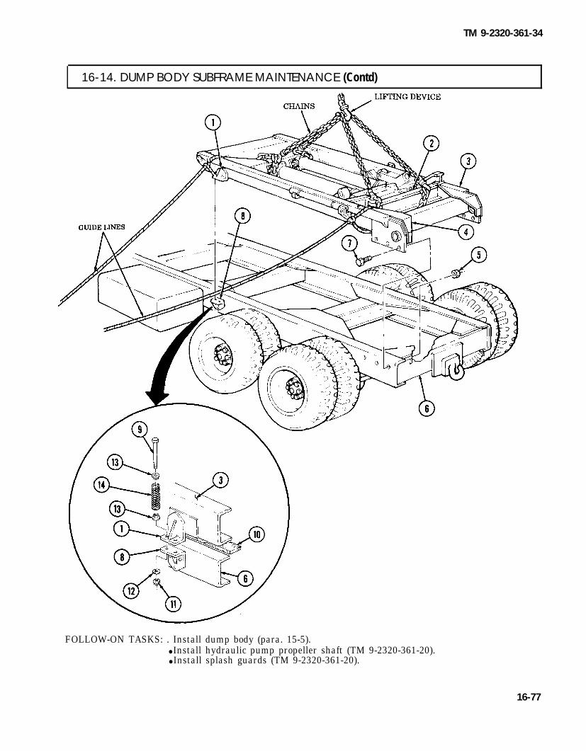
TM 9-2320-361-34
I 16-14. DUMP BODY SUBFRAME MAINTENANCE (Contd)
FOLLOW-ON TASKS: . Install dump body (para. 15-5).● Install hydraulic pump propeller shaft (TM 9-2320-361-20).● Install splash guards (TM 9-2320-361-20).
16-77

TM 9-2320-361-34
16-15. POWER DIVIDER REPLACEMENT (M764)
THIS TASK COVERS:a. Removal b. Installation
INITIAL SETUP
APPLICABLE MODELS REFERENCES (TM)M764 LO 9-2320-209-12-1
TOOLSGeneral mechanic’s tool kit (Appendix B, Item 1)1-1/8-in. socket, 1/2-in. dr. (Appendix B, Item 10)1-3/4-in. socket, 1-in. dr. (Appendix B, Item 42)Handle, socket wrench, 1-in. dr.
(Appendix B, Item 43)Transmission and differential lift
MATERIALS/PARTSTwo cotter pins (Appendix F, Item 19)Cotter pin (Appendix F, Item 10)Four lockwashers (Appendix F, Item 140)
PERSONNEL REQUIREDT w o
TM 9-214TM 9-2320-361-20TM 9-2320-361-34P
EQUIPMENT CONDITION. Power divider drained (LO 9-2320-209-12-1).● Power divider propeller shaft removed
(TM 9-2320-361-20).● Earth boring machine propeller shaft removed
(TM 9-2320-361-20).. Air-hydraulic cylinder removed (TM 9-2320-361-20).. Power divider drivebelt removed (para. 16-18).
GENERAL SAFETY INSTRUCTIONSSupport power divider during removal andinstallation.
WARNING
Power divider is heavy. Support power divider during removal andinstallation. Failure to do so may result in injury to personnel.
a. Removal 1. Remove cotter pin (2), clevis pin (1), and control rod (18) from lever (17). Discard cotter pin (2).
NOTEAssistant will help with step 2.
2. Remove four screws (11), lockwashers (10), and power divider (4) from two brackets (3). Discardlockwashers (10).
3. Remove cotter pin (13), nut (14), washer (15), and seal (12) from input shaft (16). Discard cotterpin (12).
4. Remove cotter pin (7), nut (6), washer (8), and seal (9) from output shaft (5). Discard cotter pin (7).
b. Installation 1. Install seal (9) on output shaft (5) with washer (8), nut (6), and new cotter pin (7).2. Install seal (12) on input shaft (16) with washer (15), nut (14), and new cotter pin (13).
NOTEAssistant will help with step 3.
3. Install power divider (4) on two brackets (3) with four new lockwashers (10) and screws (11).4. Install control rod (18) on lever (17) with clevis pin (1) and new cotter pin (2).
16-78

TM 9-2320-361-34
16-15. POWER DIVIDER REPLACEMENT (M764) (Contd)
FOLLOW-ON TASKS: . Install● Install● Install● Install
power divider drivebelt (para. 16-18).air-hydraulic cylinder (TM 9-2320-361-20).earth boring machine propeller shaft. (TM 9-2320-361-20).power divider propeller shaft (TM 9-2320-361-20).
● Replace power divider oil to required level (LO 9-2320-209-12-1).
16-79

TM 9-2320-361-34
16-16. POWER DIVIDER REPAIR (M764)
THIS TASK COVERS:a. Disassembly c. Assemblyb. Cleaning and Inspection
INITIAL SETUP
APPLICABLE MODELSM764
TOOLSGeneral mechanic’s tool kit
(Appendix B, Item 1)Mechanical puller kit (Appendix B, Item 22)Inside micrometer (Appendix B, Item 16)Outside micrometer (Appendix B, Item 17)Dial indicator (Appendix B, Item 21)
MATERIALS/PARTSThree cotter pins (Appendix F, Item 20)Cotter pin (Appendix F, Item 19)Twenty-five lockwashers
(Appendix F, Item 125)Four lockwashers (Appendix F, Item 131)
MATERIALS/PARTS (CONTD)Lockwasher (Appendix F, Item 140)Packing (Appendix F, Item 184)Packing (Appendix F, Item 183)Three shim sets (Appendix F, Item 260)Three seals (Appendix F, Item 232)Gasket (Appendix F, Item 76)Woodruff key (Appendix F, Item 295)Woodruff key (Appendix F, Item 292)
REFERENCES (TM)TM 9-214TM 9-2320-361-34P
EQUIPMENT CONDITIONPower divider removed (para. 16-15).
a. Disassembly
1. Remove breather (1) and bushings (2) and (3) from housing (4).2.3.
4.
5.
6.
7.
8.
9.
10.11.12.
13.
16-80
Remove three plugs (48) from housing (4) and cover (50).Remove cotter pin (26), nut (27), washer (25), sprocket (24), and woodruff key (33) from shouldershaft (34). Discard cotter pin (26) and woodruff key (33).Remove eight screws (5), lockwashers (6), cover (50), gasket (7), and two pins (49) from housing (4).Discard lockwashers (6) and gasket (7).Place shifter fork (45) in third notch of straight rod (10).
NOTEMeasure thickness of shim(s) for assembly.
Remove four screws (47), lockwashers (46), cap (43), shim(s) (44), output shaft (41), and gear (35)from input shaft (20) and housing (4). Discard lockwashers (46) and shim(s) (44).Remove bushing (40), bearing (39), spacers (38) and (37), and bearing (36) from output shaft (41).Remove seal (42) from cap (43). Discard seal (42).
NOTEMeasure thickness of shim(s) for assembly.
Remove four screws (29), lockwashers (30), cap (31), and shim(s) (32) from housing (4). Discardlockwashers (30) and shim(s) (32).Remove seal (28) from cap (31). Discard seal (28).Remove bushing (22) and input shaft (20) from housing (4).Remove spacer (23) and bearing (21) from input shaft (20).
NOTEScribe positions of jamnuts on shifter rod and eyebolt for assembly.
Loosen jamnuts (8) and (16) on shifter rod (18) and eyebolt (17).

TM 9-2320-361-34
16-16. POWER DIVIDER REPAIR (M764) (Contd)
14.15.16.
17.18.
19.
Remove shifter rod (18) from shifter fork (45).Remove lockwasher (9) and jamnut (8) from shifter rod (18). Discard lockwasher (9).Remove eyebolt (17), jamnut (16), and lockwasher (15) from shifter rod (18). Discard lock-washer (15).Remove jamnut (16) from eyebolt (17).Remove four screws (19), lockwashers (14), and packing plate (13) from housing (4). Discardlockwashers (14).Remove packings (11) and (12) from packing plate (13). Discard packings (11) and (12).
16-81

TM 9-2320-361-34
16-16. POWER DIVIDER REPAIR (M764) (Contd)
20.21.22.23.
24.
25.
26.27.
28.
29.30.
NOTE● Spring and detent will come out of shifter fork when shifter rod is
removed.● Scribe position of straight rod for assembly.
Remove nut (30), straight rod (3), shifter fork (1), spring (32), and detent (31) from housing (2).Remove two cotter pins (12) and nuts (13) from idler shaft (14). Discard cotter pins (12).Remove idler shaft (14) and gear (21) from housing (2).Remove two washers (15), spacer (20), bearing (19), spacers (18) and (17), and bearing (16) fromgear (21).Remove four screws (24), lockwashers (23), and cap (22) from housing (2). Discard lockwashers (23).
NOTEMeasure thickness of shim(s) for assembly.
Remove four screws (10), lockwashers (11), cap (8), and shim(s) (7) from housing (2). Discardlockwashers (11) and shim(s) (7).Remove seal (9) from cap (8). Discard seal (9).Remove cotter pin (25) and nut (26) from shoulder shaft (5). Discard cotter pin (25).
CAUTIONExcessive tapping may damage threads of shoulder shaft.
Tap shoulder shaft (5) and bearing (6) out of housing (2) and remove gears (28) and (29) fromhousing (2).Remove bearing (27) from housing (2).Remove bearing (6) and woodruff key (4) from shoulder shaft (5). Discard woodruff key (4).
16-82

TM 9-2320-361-34
16-16. POWER DIVIDER REPAIR (M764) (Contd)
16-83

TM 9-2320-361-34
16-16. POWER DIVIDER REPAlR(M764) (Contd)
b. Cleaning and Inspection
1. For general cleaning instructions, refer to para. 2-8.2. For general inspection instructions, refer to para. 2-9.3.
4.
5.
6.
Inspect two caps (1) and cap (2) for cracks, breaks, and wear. Refer to table 16-5, Power DividerWear Limits, for measurements. Replace caps (1) or (2) if damaged or worn past limits.Inspect two washers (3) for cracks, bends, and thickness. Refer to table 16-5, Power Divider WearLimits, for measurements. Replace washers (3) if damaged or worn past limits.Inspect two bushings (6) for cracks, breaks, and wear. Refer to table 16-5, Power Divider WearLimits, for measurements. Replace bushings (6) if damaged or worn past limits.Inspect five spacers (4), (5), (7), (8), and (9) for cracks, brakes, and wear. Refer to table 16-5, PowerDivider Wear Limits, for measurements. Replace spacers (4), (5), (7), (8), or (9) if damaged or worn
7.
past limits.Inspect bearing (10) (TM 9-214). Replace bearing (10) if worn or damaged.
Table 16-5. Power Divider Wear Limits.
ITEM WEAR LIMITS/TOLERANCESNO. lTEM/POINT OF MEASUREMENT
INCHES CENTIMETERS
1 Cap:Inner diameter 2.999-3.001 7.617-7.623Outer diameter 3.342-3.345 8.489-8.496
2 Cap:Inner diameter 2.75 6.985Outer diameter 3.328 8.453
3 Washer:Thickness 0.120-0.125 0.305-0.318Inner diameter 0.982-0.984 2.494-2.499
4 Spacer:Inner diameter 0.751-0.753 1.908-1.913Outer diameter 0.984-0.986 2.499-2.504
5 Spacer:Inner diameter 1.50 3.81Outer diameter 2.031 5.159
6 Bushing:Inner diameter 1.796 4.562Outer diameter 2.187 5.555
7 Spacer:Inner diameter 1.000-1.015 2.54-2.578Outer diameter 1.25 3.175
8 Spacer:Inner diameter 1.796 4.562Outer diameter 2.187 5.555
9 Spacer:Inner diameter 1.775-1.785 4.509-4.534Outer diameter 2.75 6.985
16-84
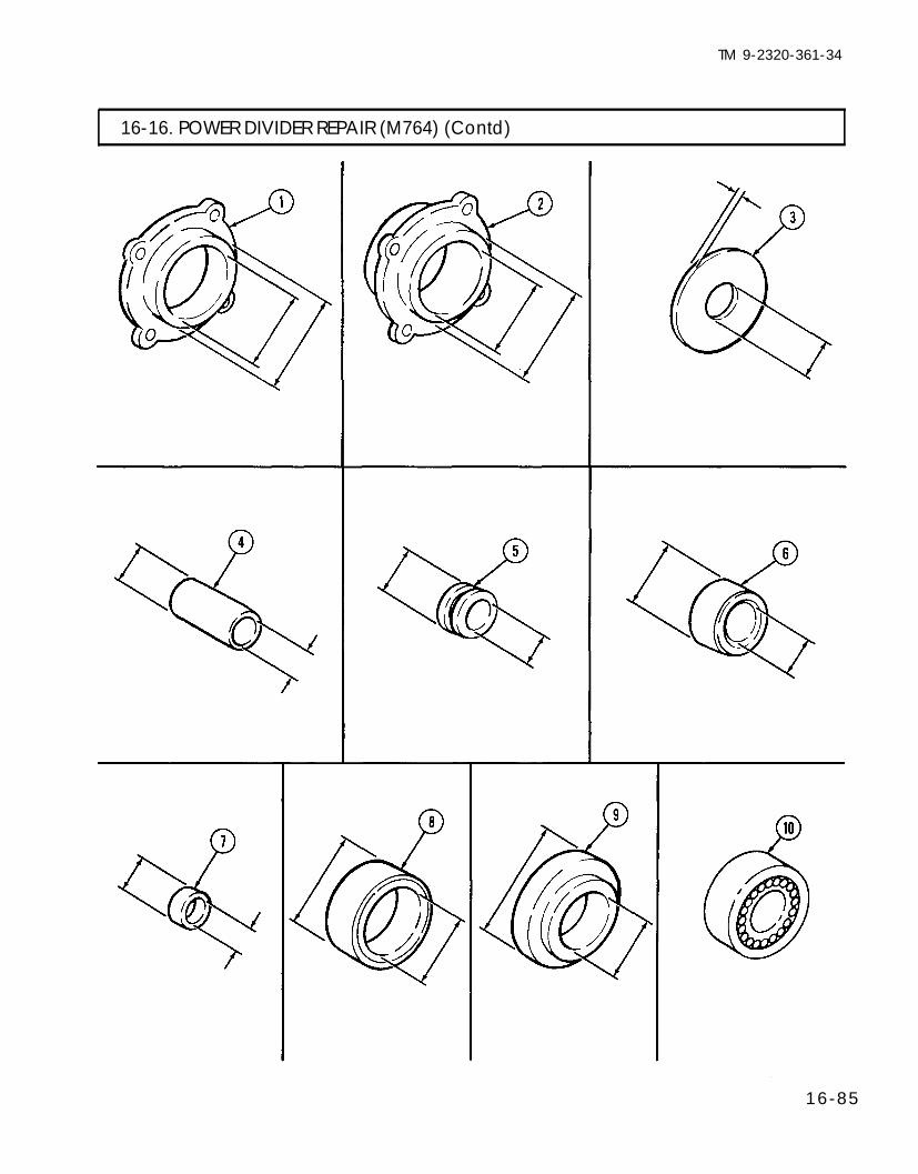
TM 9-2320-361-34
16-16. POWER DIVIDER REPAIR (M764) (Contd)
16-85

TM 9-2320-361-34
I 16-16. POWER DIVIDER REPAIR (M764) (Contd)
c. Assembly1.2.3.4.5.
6.7.
8.9.
10.11.12.
13.14.
16-86
Press bearing (6) and install new woodruff key (4) on shoulder shaft (5).Install gears (28) and (29) in housing (2) with shoulder shaft (5).Press bearing (27) in housing (2).Install nut (26) and new cotter pin (25) on shoulder shaft (5).Install cap (22) on housing (2) with four new lockwashers (23) and screws (24).
NOTEStep 6 establishes shim pack starting thickness.
Place cap (8) on housing (2) and measure distance between cap (8) and housing (2).Remove cap (8) from housing (2) and install new seal (9) in cap (8).
NOTEUse measurement obtained in step 6 plus a 0.015 in. (0.381 mm)shim for starting shim pack thickness.
Install new shim(s) (7) and cap (8) on housing (2) with four new lockwashers (11) and screws (10).Install bearing (16), spacer (20), bearing (19), spacers (18) and (17), and two washers (15) on gear (21).Install gear (21) in housing (2) with idler shaft (14).Install two nuts (13) and new cotter pins (12) on idler shaft (14).Install spring (32) and detent (31) in shifter fork (1).
NOTEDetent may spring out of shifter fork during assembly.
Install shifter fork (1) in housing (2) with straight rod (3).Install nut (30) on straight rod (3).

TM 9-2320-361-34
16-16. POWER DIVIDER REPAIR (M764) (Contd)
16-87

TM 9-2320-361-34
16-16. POWER DIVIDER REPAIR (M764) (Contd)
15.16.17.
18.
19.
20.21.
22.23.
24.
25.26.
27.28.
29.
30.
31.32.
Install two new packings (8) and (9) on straight rod (7) and housing (27).Install plate (10) on housing (27) with four new lockwashers (16) and screws (15).Install jamnut (13) on eyebolt (14).
NOTEPrior to tightening jamnut, aline eyebolt with scribe mark.
Install new lockwasher (12) and eyebolt (14) on shifter rod (11) and tighten jamnut (13).
NOTEPrior to tightening janmut, aline shifter rod with scribe mark.
Position shifter rod (11) through new packing (9) and install jamnut (4) on shifter rod (11) andinstall new lockwasher (5) and shifter rod (11) on shifter fork (6).Install spacer (20) and bearing (19) on input shaft (17).Position gear (26) in shifter fork (6) and install input shaft (17) through gear (26) and housing (27).
NOTEStep 22 establishes shim pack starting thickness.
Place cap (22) on housing (27) and measure distance between cap (22) and housing (27).Remove cap (22) from housing (27) and install new seal (23) in cap (22).
NOTEUse measurement obtained in step 22 plus a 0.015 in. (0.381 mm)shim for starting shim pack thickness.
Install spacer (18) on input shaft (17). Install shim(s) (21) and cap (22) on housing (27) with four newlockwashers (25) and screws (24).Install bearing (28), spacers (29) and (30), bearing (31), and spacer (32) on output shaft (33).Install output shaft (33) in housing (27) and input shaft (17).
NOTEStep 27 establishes shim pack starting thickness.
Place cap (35) on housing (27) and measure distance between cap (35) and housing (27).Remove cap (35) from housing (27) and install new seal (36) in cap (35).
NOTEUse measurement obtained in step 27 plus a 0.015 in. (0.381 mm)shim for starting shim pack thickness.
Install new shim(s) (34) and cap (35) on housing (27) with four new lockwashers (38) andscrews (37).Install two pins (40), new gasket (3), and cover (41) on housing (27) with eight new lockwashers (2)and screws (1).Install three plugs (39) in housing (27) and cover (41).Install bushings (44) and (43) and breather (42) on housing (27).
16-88

TM 9-2320-361-34
16-16. POWER DIVIDER REPAIR (M764) (Contd)
16-89

TM 9-2320-361-34
16-16. POWER DIVIDER REPAIR (M764) (Contd)
33.34.
35.
36.37.38.39.40.41.
42.
43.44.45.46.47.48.
49.
50.51.52.53.54.
16-90
Install dial indicator on housing (1) and position plunger on end of input shaft (2).Measure and record end play by pulling input shaft (2) back and forth. Proper end play reading is0.0001-0.005 in. (0.00254-0.127 mm).
NOTEIf end play is correct, go to step 40. If end play is incorrect, go tostep 35.
Remove dial indicator, four screws (12), lockwashers (11), and cap (10) from input shaft (2) andhousing (1). Discard lockwashers (11).If end play is greater than 0.005 in. (0.127 mm), remove a shim (9) or use a thinner shim (9).If end play is less than 0.0001 in. (0.00254 mm), add a shim (9) or use a thicker shim (9).Install cap (10) on housing (1) with four new lockwashers (11) and screws (12).Perform steps 33 and 34. Perform procedure until correct end play is achieved.Reposition dial indicator on housing (1) so that plunger is positioned on the end of output shaft (3).Measure and record end play by pulling output shaft (3) back and forth. Proper end play reading is0.0001-0.005 in. (0.00254-0.127 mm).
NOTEIf end play is correct, go to step 47. If end play is incorrect, go tostep 42.
Remove dial indicator, four screws (7), lockwashers (8), and cap (6) from housing (1) and outputshaft (3). Discard lockwashers (8).If end play is greater than 0.005 in. (0.127 mm), remove a shim (5) or use a thinner shim (5).If end play is less than 0.0001 in. (0.00254 mm), add a shim (5) or use a thicker shim (5).Install cap (6) on housing (1) with four new lockwashers (8) and screws (7).Perform steps 40 and 41.Reposition dial indicator on housing (1) so that plunger is positioned on the end of shoulder shaft (4).Measure end play by pulling shoulder shaft (4) back and forth. Proper end play reading is0.0001-0.005 in. (0.00254-0.127 mm).
NOTEIf end play is correct, go to step 54. If end play is incorrect, go tostep 49.
Remove dial indicator, four screws (5), lockwashers (6), and cap (13) from housing (1) and shouldershaft (4). Discard lockwashers (6).If end play is greater than 0.005 in. (0.127 mm), remove a shim (7) or use a thinner shim (7).If end play is less than 0.0001 in. (0.00254 mm), add a shim or use a thicker shim (7).Install cap (13) on housing (1) with four new lockwashers (6) and screws (5).Perform steps 47 and 48. Perform procedure until correct end play is achieved.Install new woodruff key (20) and sprocket (19) on shoulder shaft (4) with washernew cotter pin (21).
(18), nut 17), and

TM 9-2320-361-34
16-16. POWER DIVIDER REPAIR (M764) (Contd)
FOLLOW-ON TASK: Install power divider (para. 16-14).
16-91

TM 9-2320-361-34
I 16-17. POWER DIVIDER SHAFT OIL SEALS REPLACEMENT (M764)
THIS TASK COVERS:a. Removal b. Installation
INITIAL SETUP
APPLICABLE MODELS REFERENCES (TM)M764 LO 9-2320-209-12-1TOOLSGeneral mechanic’s tool kit
TM 9-2320-361-20TM 9-2320-361-34P
(Appendix B, Item 1) EQUIPMENT CONDITIONMechanical puller (Appendix B, Item 22) . Power divider drained (LO 9-2320-209-12-1).M A T E R I A L S / P A R T S Cotter pin (Appendix F, Item 19)Oil seal (Appendix F, Item 232)
. Power divider propeller shaft removed (if input oilseal is to be replaced) (TM 9-2320-361-20).
● Earth boring machine propeller shaft removed(TM 9-2320-361-20).
● Power divider drivebelt removed (if shoulder shaftoil seal is to be replaced) (para. 16-18).
a. Removal NOTE
Input and output shoulder shaft seals are removed the same. Thisprocedure covers the output shoulder shaft seal.
1. Remove cotter pin (4), nut (3), washer (2), and bushing (6) from output shoulder shaft (1) andflange (5). Discard cotter pin (4).
2. Using mechanical puller, remove flange (5) from output shoulder shaft (1).NOTE
Input, output, and shoulder shaft oil seals are removed the same.This procedure covers the output shoulder shaft oil seal.
3. Remove output shoulder shaft oil seal (7) from bearing cap (8). Discard output shoulder shaft oilseal (7).
b. Installation
NOTEInput, output, and shoulder shaft oil seals are installed the same.This procedure covers the output shoulder shaft seal.
1. Install new output shoulder shaft oil seal (7) in bearing cap (8).2. Install flange (5) on output shoulder shaft (1) with washer (2), nut (3), and new cotter pin (4).
16-92

TM 9-2320-361-34
16-17. POWER DIVIDER SHAFT OIL SEALS REPLACEMENT (M764) (Contd)
FOLLOW-ON TASKS: . Install power divider drivebelt (if removed) (para. 16-18).● Install earth boring machine propeller shaft (if removed ) (TM 9-2320-361-20).● Install power divider propeller shaft (if removed) (TM 9-2320-361-20).. Fill power divider oil to required level (LO 9-2320-209-12-1).
16-93

TM 9-2320-361-34
16-18. POWER DIVIDER DRIVEBELT REPLACEMENT (M764)
THIS TASK COVERS:a. Removal b. Installation
INITIAL SETUP
APPLICABLE MODELSM764
TOOLS
REFERENCES (TM)TM 9-2320-361-10TM 9-2320-361-34P
General mechanic’s tool kit(Appendix B, Item 1)
EQUIPMENT CONDITIONParking brake set (TM 9-2320-361-10).
1. Loosen four screws (5) from idler bracket (3).2. Loosen jamnut (2) and turn adjusting screw (1) out enough for removal of drivebelt (7).3. Remove drivebelt (7) from worm gear sprocket (4), power divider sprocket (8), and idler wheel (6).
b. Installation
1. Install drivebelt (7) on worm gear sprocket (4), power divider sprocket (8), and idler wheel2. Turn adjusting screw (1) until slack is removed from drivebelt (7) and tighten jamnut (2).3. Tighten four screws (5) on idler bracket (3).
(6).
16-94

TM9-2320-361-34
Section Ill. POWER TAKEOFF MAINTENANCE
16-19. POWER TAKEOFF (PTO) MAINTENANCE INDEX
PARA. TITLE PAGENO. NO.
16-20. Transmission Power Takeoff (PTO) Maintenance 16-9516-21. Transfer Case Power Takeoff (PTO) Maintenance 16-9816-22. Transmission Power Takeoff (PTO) Cover and Gasket Replacement 16-100
16-20. TRANSMISSION POWER TAKEOFF (PTO) MAINTENANCE
THIS TASK COVERS:a. Removal c. Inspection and Repairb. Cleaning d. Installation
INITIAL SETUP
APPLICABLE MODELS REFERENCES (TM)All vehicles except M342A2 TM 9-2320-361-10
TOOLSTM 9-2320-361-34PTM 9-2520-246-34-1
General mechanic’s tool kit TM 9-2520-246-34P(Appendix B, Item 1)
Dial indicator (Appendix B, Item 21) EQUIPMENT CONDITIONTorque wrench, 1/2-in. dr. (Appendix B, Item 7) ● Transmission power takeoff cover and gasket
MATERIALS/PARTSremoved (para. 16-22).
. Transmission top cover removed (para. 8-3).Six lockwashers (Appendix F, Item 125)Gasket (Appendix F, Item 77)Sealing compound (Appendix C, Item 20)
16-95

TM 9-2320-361-34
16-20. TRANSMISSION POWER TAKEOFF (PTO) MAINTENANCE (Ccntd)
a. Removal
CAUTIONPrevent dirt from entering transmission and power takeoff whenperforming this task. Failure to do so may cause damage toequipment.
Remove six nuts (6), lockwashers (7), power takeoff (PTO) (5), and gasket (4) from transmission (1).Discard gasket (4) and lockwashers (7).
Remove gasket material and debris from transmission (1) and PTO (5) mating surfaces.
b. Cleaning
c. Inspection and Repair
1. Check PTO (5) and transmission (1) mating surfaces for scratches, cracks, and galling. Refer toTM 9-2520-246-34-1 if scratched, cracked, or galled.
2. Check transmission gear teeth (2) for wear, cracks, and discoloration. Refer to TM 9-2520-246-34-1 ifgear teeth are worn, cracked, or discolored.
3. Inspect stud(s) (3). Replace stud(s) (3) if damaged (para. 2-9).
d. Installation
1.2.
3.
4.5.
16-96
N O T EEnsure transmission output gear is stabilized while measuringbacklash.
Shift into second gear (TM 9-2320-361-10).Install new gasket (4) and PTO (5) on transmission (1) with six nuts (6). Tighten nuts (6)15-20 lb-ft (20-27 N.m).Set dial indicator on PTO (5) to measure PTO input gear (8) backlash.a. Check PTO backlash. Backlash should be 0.008-0.012 in. (0.203-0.305 mm).b. If backlash is 0.008-0.012 in. (0.203-0.305 mm), perform steps 5 through 7.
NOTEIt maybe necessary to use more than one gasket to obtain0.008-0.012 in. (0.203-0.305 mm) backlash. Each gasket will changebacklash approximately 0.006 in. (O.152 mm).
c. If backlash is less than 0.008 in. (0.203 mm), remove dial indicator and PTO (5) fromtransmission (1) and continue with step 7 using two new gaskets (4) to obtain 0.008-0.012 in.(0.203-0.305 mm) measurement.
d. If 0.008-0.012 in. (0.203-0.305 mm) backlash measurement cannot be obtained, replace (para. 8-2)and repair (TM 9-2520-246-34-1) transmission (1).
Remove dial indicator from PTO (5).Remove six nuts (6), PTO (5), and gasket (4) from transmission (1).

TM 9-2320-361-34
16-20. TRANSMISSION POWER TAKEOFF (PTO) MAINTENANCE (Contd)
6. Apply sealing compound on gasket (4) and transmission (1) mating surfaces.7. Install new gasket(s) (4) and PTO (5) on transmission (1) with six new lockwashers
Tighten nuts (6) 15-20 lb-ft (20-27 N.m).(7) and nuts (6).
FOLLOW-ON TASKS: .Install transmission top cover (para. 8-3).● Install transmission power takeoff cover and gasket (para. 16-22).
16-97

TM 9-2320-361-34
16-21. TRANSFER CASE POWER TAKEOFF (PTO) MAINTENANCE
THIS TASK COVERS:
a. Removal c. Inspection and Repairb. Cleaning d. Installation
INITIAL SETUP
APPLICABLE MODELSM49A2C, M50A2, M50A3,M756A2, and M764
TOOLSGeneral mechanic’s tool kit
(Appendix B, Item 1)Torque wrench, 3/4-in. dr.
(Appendix B, Item 6)Mechanical puller kit
(Appendix B, Item 22)1-1/2-in. socket, 3/4-in. dr.
MATERIALS/PARTSSix lockwashers (Appendix F, Item 147)Gasket (Appendix F, Item 78)Cotter pin (Appendix F, Item 6)Two studs (Appendix F, Item 266)Woodruff key (Appendix F, Item 296)Sealing compound (Appendix C, Item 17)REFERENCES (TM)TM 9-2320-361-34PTM 9-2520-246-34-1TM 9-2520-246-34P
(Appendix B, Item 41) EQUIPMENT CONDITIONTransfer case removed (para. 9-2).
a. Removal NOTE
Perform step 1 for M756A2 vehicles.
1. Remove cotter pin (9), nut (8), sprocket (21), and woodruff key (11) from power takeoff (PTO)spindle (10). Discard cotter pin (9) and woodruff key (11).
2. Loosen setscrew (6) and remove cotter pin (9), nut (8), yoke (7), and woodruff key (11) from PTOspindle (10). Discard cotter pin (9) and woodruff key (11).
3. Disconnect line (1) from oil pump (12).4. Remove four screws (13), lockwashers (14), two nuts (4), lockwashers (3), PTO (5), and gasket (15)
from transfer case (2). Discard lockwashers (14) and (3) and gasket (15).5. Remove screw (19), washer (18), and clamp (17) from transfer case (2).6. Remove line (1) and elbow (16) from transfer case (2).
b. Cleaning Remove gasket material and debris from transfer case (2) and PTO (5) mating surface.
c. Inspection and Repair
1. Check PTO (5) and transfer case (2) mating surface for scratches, cracks, and galling. Refer to TM 9-2520-246-34-1 if scratched, cracked, or galled.
2. Check PTO gear for wear, cracks, and discoloration. Refer to TM 9-2520-246-34-1 if gear teeth areworn, cracked, or discolored.
3. Inspect studs (20). Replace studs (20) if damaged (para. 2-9).
16-98

para. 9-2
TM9-2320-361-34
I 16-21. TRANSFER CASE POWER TAKEOFF (PTO) MAINTENANCE (Contd)
I d. Installation
1.2.
3.
4.5.
6.
NOTECoat threads of sealing compound prior to installation.
Install elbow (16) on transfer case (2).Connect line (1) to elbow (16) and install line (1) on transfer case (2) with clamp (17), washer (18), andscrew (19). Tighten screw (19) 60-77 lb-ft (81-104 N.m).Install new gasket (15) and PTO (5) on transfer case (2) with two new lockwashers (3), nuts (4), fournew lockwashers (14), and screws (13). Tighten nuts (4) 32-40 lb-ft (43-54 N.m). ‘Tighten screws (13)60-77 lb-ft (81-104 N.m).Connect line (1) on oil pump (12).Install new woodruff key (11), yoke (7), and nut (8) on spindle (10). Tighten nut (8) 150-250 lb-ft (203-339 N.m) and install new cotter pin (9) and tighten setscrew (6).
NOTEPerform step 6 for M756A2 vehicles.
Install new woodruff key (11), sprocket (21), and nut (8) on spindle (10). Tighten nut (8) 150-250 lb-ftl(203-339 N.m) and insta l new cotter pin (9).
16-99

TM 9-2320-361-34
16-22. TRANSMISSION POWER TAKEOFF (PTO) COVER AND GASKET REPLACEMENT
THIS TASK COVERS:a. Removal c. Installationb. Cleaning
INITIAL SETUPAPPLICABLE MODELSAll vehicles except M342A2TOOLSGeneral mechanic’s tool kit
(Appendix B, Item 1)
MATERIALS/PARTSSix lockwashers (Appendix F, Item 146)Gasket (Appendix F, Item 77)
REFERENCES (TM)TM 9-2320-361-10TM 9-2320-361-34PTM 9-2520-246-34PLO 9-2320-209-12-1EQUIPMENT CONDITION● Parking brake set (TM 2320-361-10).● Wheels chocked (TM 9-2320-361-10).● Transmission oil drained (LO 9-2320-209-12-1).
a. Removal
Remove six screws (5), lockwashers (4), cover (3), and gasket (2) from transmission power takeoff(PTO) (1). Discard gasket (2) and lockwashers (4).
I b. Cleaning
c. Installation
Clean mating surface between cover (3) and PTO (1).
Install new gasket (2) and cover (3) on PTO (1) with six new lockwashers (4) and screws (5).
FOLLOW-ON TASK: Fill transmission to proper fluid level (LO 9-2320-209-12-1).
16-100

TM 9-2320-361-34
CHAPTER 17SPECIAL PURPOSE KITS MAINTENANCE
17-1. SPECIAL PURPOSE KITS MAINTENANCE INDEX
PARA. TITLE PAGENO. NO.
17-2.
17-3.
17-4.
17-5.
17-6.
17-7.
17-8.
17-9.
17-10.
17-11.
17-12.
17-13.
17-14.
17-15.
17-16.
17-17.
17-18.
17-19.
17-20.
17-21.
Engine Coolant Heater Flame Detector SwitchMaintenanceEngine Coolant Heater Blower Motor MaintenanceEngine Coolant Heater Restriction ThermostatMaintenanceEngine Coolant Heater Component BracketMaintenanceEngine Coolant Heater Fuel Control ValveReplacementEngine Coolant Heater Overheat Switch andIgniter ReplacementEngine Coolant Heater Fuel Tube and PreheatResistor ReplacementEngine Coolant Heater Burner MaintenanceEngine Coolant Heater Housing MaintenancePersonnel Heater Guard and Blower MotorReplacementPersonnel Heater Fuel Control Valve ReplacementPersonnel Heater Igniter and Ignition ControlUnit ReplacementPersonnel Heater Fuel Line and Blower HousingReplacementPersonnel Heater Flame Detector Switch MaintenancePersonnel Heater Burner MaintenancePersonnel Heater Overheat Switch and ReceptacleReplacementPersonnel Heater Heat Exchanger ReplacementEngine Coolant Heater TestingFuel Burning Personnel Heater TestingHardtop Rear Panel Window Maintenance
17-2
17-6
17-8
17-10
17-14
17-16
17-20
17-22
17-24
17-26
17-28
17-30
17-34
17-36
17-40
17-44
17-47
17-48
17-56
17-62
17-1

TM 9-2320-361-34
17-2. ENGINE COOlANT HEATER FLAME DETECTOR SWITCH MAINTENANCE
THIS TASK COVERS:a. Removal d. Assemblyb. Disassembly e. Installationc. Inspection
INITIAL SETUPAPPLICABLE MODELS MATERIALS/PARTSAll Sleeve (Appendix F, Item 261)
TEST EQUIPMENTMultimeter (Appendix B, Item 3)
TOOLSGeneral mechanic’s tool kit
(Appendix B, Item 1)Tool kit, electrical (Appendix B, Item 2)
REFERENCES (TM)TM 9-2320-361-20TM 9-2320-361-34P
EQUIPMENT CONDITIONEngine coolant heater removed (TM 9-2320-361-20).
N O T ETag wires for installation.a . Removal
1. Remove four screws (6) and guard (7) from heater housing (8).2. Remove nut-assembled lockwasher (2), ground lead (3), air tube (4), and elbows (1) and (5) from
heater housing (8).3. Remove five screw-assembled lockwashers (11) and six leads (12) from flame detector switch (10).4. Loosen nut (9) and remove flame detector switch (10) from heater housing (8).
b. Disassembly
1. Remove adjusting screw (15), washer (16), and spring (17) from switch bracket (24) and mount (18).
CAUTION
Ceramic rod is very brittle and is easily broken; handle carefully.
2. Tilt microswitch (13) back on switch bracket (24), invert, and remove ceramic rod (22) fromprobe (20).
3. Remove two nut-assembled lockwashers (14), screws (23), and microswitch (13) from switch bracket (24).4. Remove split roll pin (21) and switch bracket (24) from mount (18).5. Remove sleeve (19) and nut (9) from probe (20).
c. Inspection
1. Inspect flame detector switch (10) for broken ceramic rod (22) or bent probe (20). Replace ceramicrod (22) if broken. Replace flame detector switch (10) if probe (20) is bent.
2. Inspect flame detector switch (10) for carbon buildup and corrosion. Remove carbon buildup orcorrosion.
17-2

TM 9-2320-361-34
17-2. ENGINE COOLANT HEATER FLAME DETECTOR SWITCH MAINTENANCE (Contd)
17-3

TM 9-2320-361-34
17-2. ENGINE COOlANT HEATER FLAME DETECTOR SWITCH MAINTENANCE (Contd)
d . A s s e m b l y
1.2.3.
4.
5.
6.
Install nut (7) and new sleeve (8) on probe (9).Install switch bracket (13) on mount (6) with split roll pin (10).Install microswitch (1) on switch bracket (13) with two screws (12) and nut-assembled lock-washers (2).
CAUTION
Ceramic rod is very brittle and is easily broken; handle carefully.
Tilt microswitch (1) and switch bracket (13) back on mount (6) and insert ceramic rod (11) intoprobe (9).Rotate microswitch (1) back on mount (6) and install spring (5), washer (4), and adjusting screw (3)on switch bracket (13) and mount (6).Tighten adjusting screw (3) until microswitch (1) clicks. Then continue 3/4 turn past click point.
I e. Installation I1. Install flame detector switch (22) on heater housing (21) and tighten nut (7).2. Install six leads (24) on flame detector switch (22) with five screw-assembled lockwashers (23).3. Install air tube (17), elbows (14) and (18) and ground lead (16) on heater housing (21) with nut-
assembled lockwasher (15).4. Install guard (20) on heater housing (21) with four screws (19).
17-4

TM 9-2320-361-34
17-2. ENGINE COOLANT HEATER FLAME DETECTOR SWITCH MAINTENANCE (Contd)
FOLLOW-ON TASK: Test engine coolant heater (para. 17-19).
1 7 - 5

TM 9-2320-361-34
I 17-3. ENGINE COOLANT HEATER BLOWER MOTOR MAINTENANCE
THIS TASK COVERS:a. Removal c. Installationb. Cleaning and Inspection
INITIAL SETUP
APPLICABLE MODELSAll
TEST EQUIPMENTMultimeter (Appendix B, Item 3)
TOOLS
REFERENCES (TM)TM 9-2320-361-20TM 9-2320-361-34P
EQUIPMENT CONDITIONEngine coolant heater removed (TM 9-2320-361-20).
General mechanic’s tool kit GENERAL SAFETY INSTRUCTIONS(Appendix B, Item 1) ● Keep fire extinguisher nearby when using
Tool kit, electrical(Appendix B, Item 2)
drycleaning solvent.● Compressed air source will not exceed 30 psi
MATERIAIS/PARTS(207 kPa).
. Eyeshields must be worn when cleaning withTiedown strap (Appendix C, Item 15) compressed air.Drycleaning solvent (Appendix C, Item 24)Rag (Appendix C, Item 16)
NOTETag wires for installation.
a. Removal 1. Remove four screws (11) and guard (12) from heater housing (13).2. Remove tiedown strap (6) from heater wiring. Discard tiedown strap (6).3. Remove nut-assembled lockwasher (2), ground lead (3), air tube (4), and elbows (1) and (5) from
heater housing (13).4. Remove screw-assembled lockwasher (8) and wire (7) from heater component bracket (14).5. Remove four nut-assembled lockwashers (10) and blower motor (9) from heater housing (13).
b. Cleaning and Inspection
1. Inspect blower motor (9) for dirt, grease, and carbon.
WARNING
Drycleaning solvent is flammable and will not be used near openflame. Use only in well-ventilated places. Failure to do so mayresult in injury to personnel.Compressed air source will not exceed 30 psi (207 kPa). Whencleaning with compressed air, eyeshields must be worn. Failure towear eyeshields may result in injury to personnel.
2. Clean housing (13) surface with drycleaning solvent and dry with clean rag or compressed air.Do not immerse in solvent.
17-6

TM 9-2320-361-34
17-3. ENGINE COOLANT HEATER BLOWER MOTOR MAINTENANCE (Contd)
I c. Installation
1. Install blower motor (9) on heater housing (13) with four nut-assembled lockwashers (10).2. Install wire (7) on heater component bracket (14) with screw-assembled lockwasher (8).
3. Install elbows (1) and (5), air tube (4), and ground lead (3) on heater housing (13) with nut-assembled lockwasher (2).
4. Place new tiedown strap (6) around heater wiring.
5. Install guard (12) on heater housing (13) with four screws (11).
FOLLOW-ON TASK: Test engine coolant heater (para 17-19).
17-7
TM 9-2320-361-34
17-4. ENGINE COOLANT HEATER RESTRICTION THERMOSTAT MAINTENANCE
THIS TASK COVERS:a. Removal c. Installationb. Inspection
INITIAL SETUPAPPLICABLE MODELS REFERENCES (TM)All TM 9-2320-361-34P
TEST EQUIPMENT EQUIPMENT CONDITIONMultimeter (Appendix B, Item 3) Engine coolant heater blower motor removed
(para. 17-3).TOOLSGeneral mechanic’s tool kit
(Appendix B, Item 1)Tool kit, electrical (Appendix B, Item 2)
a. Removal NOTE
Tag wires for installation.1. Disconnect two leads (1) from restriction thermostat (3).2. Remove two nut-assembled lockwashers (2), restriction thermostat (3), and two spacers (4) from two
studs (5).
b. Inspection
1. Inspect restriction thermostat (3) for corrosion and bends. Replace if corroded or bent.2. Check thermostat continuity at room temperature. If continuity exists, replace thermostat (3).
CAUTION
Do not place thermostat m liquid for cooling. Placing thermostatin liquid will cause damage to equipment.
3. Cool thermostat to 20F (-6.7°C). Check thermostat continuity. If continuity does not exist, replacethermostat.
I c. Installation
1. Install restriction thermostat (3) and two spacers (4) on two studs (5) with two nut-assembledlockwashers (2).
2. Connect two leads (1) to restriction thermostat (3).
17-8

TM 9-2320-361-34
17-4. ENGINE COOLANT HEATER RESTRICTION THERMOSTAT MAINTENANCE (Contd)
FOLLOW-ON TASK: Install engine coolant heater blower motor (para. 17-3).
17-9

TM 9-2320-361-34
I 17-5. ENGINE COOLANT HEATER COMPONENT BRACKET MAINTENANCE
THIS TASK COVERS:a. Removal d. Assemblyb. Disassembly e. Installationc. Inspection
INITIAL SETUP
APPLICABLE MODELSAll
TEST EQUIPMENTMultimeter (Appendix B, Item 3)
MATERIALS/PARTSTiedown strap (Appendix C, Item 15)
REFERENCES (TM]TM 9-2320-361-34P
TOOLS EQUIPMENT CONDITIONGeneral mechanic’s tool kit Engine coolant heater blower motor removed
(Appendix B, Item 1) (para. 17-3).Tool kit, electrical (Appendix B, Item 2)
NOTE
a. Removal Tag wires for installation.
1. Remove tiedown strap (1) from wires. Discard tiedown strap (1).2. Remove two screw-assembled lockwashers (4), and leads (2), (3), and (5) from heater component
bracket (6).3. Remove leads (8) and (3) from restriction thermostat (9).4. Remove grommet (11) from leads (3) and (8) and heater housing (10).5. Remove three screw-assembled lockwashers (16) and leads (13), (14), (15), and (17) from flame
detector switch (12).6. Remove four screws (7) and heater component bracket (6) from heater housing (10).
NOTENote direction of arrow on diode for installation.
1.2.
3.4.5.
6.7.
8.
17-10
Remove diode (23) from diode holder (22).Remove screw-assembled lockwashers (20) and (26), resistor leads (19) and (27), and diode lead (21)from terminal strip (29).Remove screw-assembled lockwasher (25) from diode holder (22) and terminal strip (29).Remove screw (24) and diode holder (22) from heater component bracket (31).Remove four screw-assembled lockwashers (28), terminal strip (29), and plate (30) from heatercomponent bracket (31).Remove nut-assembled lockwasher (34), screw (37), and resistor (18) from resistor holder (35).Remove four screw-assembled lockwashers (36) and receptacle (33) from heater componentbracket (31).Remove nut-assembled lockwasher (32) and resistor holder (35) from heater componentbracket (31).

TM 9-2320-361-34
17-5. ENGINE COOLANT HEATER COMPONENT BRACKET MAINTENANCE (Contd)
1. Check diode (23) for continuity. Reverse leads on diode (23) and check for continuity. If circuit isopen in both test conditions or closed in both test conditions, replace diode (23).
2. Check resistor (18) for continuity. If continuity does not exist, replace resistor (18).
17-11

TM9-2320-361-34
17-5. ENGINE COOLANT HEATER COMPONENT BRACKET MAINTENANCE (Contd)
1. Install receptacle (15) on heater component bracket (13) with four screw-assembled lockwashers (1).2. Install resistor holder (17) on heater component bracket (13) with screws (17) with nut-
assembled lockwasher (16).3. Install resistor (18) on resistor holder (17) with screw (19) and nut-assembled lockwasher (16).4. Install terminal strip (11) on heater component bracket (13) with four screw-assembled lock-
washers (19).5. Install diode holder (4) on heater component bracket (13) with screw (6).6. Install diode (5) on diode holder (4) with arrow pointed in direction previously noted.7. Install resistor leads (2) and (8), diode lead (3), and diode holder (4) on terminal strip (11) with
screw-assembled lockwashers (20), (9), and (7).
1. Install heater component bracket (30) on heater housing (35) with four screws (31).2. Install leads (26), (27), and (29) on heater component bracket (30) with two screw-assembled
lockwashers (28).
e. Installation
3. Place grommet (34) on leads (27) and (32) and install on heater housing (35).4. Install leads (21), (22), (24), and (37) on flame detector switch (36) with three screw-assembled
lockwashers (23).5. Install leads (32) and (27) on restriction thermostat (33).6. Install tiedown strap (25) around wires.
17-12

TM 9-2320-361-34
17-5. ENGINE COOLANT HEATER COMPONENT BRACKET MAINTENANCE (Contd)
FOLLOW-ON TASK: Install engine coolant heater blower motor (para. 17-3).
17-13

TM9-2320-361-34
17-6. ENGINE COOLANT HEATER FUEL CONTROL VALVE REPLACEMENT
THIS TASK COVERS:a. Removal b. Installation
INITIAL SETUPAPPLICABLE MODELSAll
TEST EQUIPMENTMultimeter (Appendix B, Item 3)
TOOLSGeneral mechanic’s tool kit
(Appendix B, Item 1)Tool kit, electrical (Appendix B, Item 2)
REFERENCES (TM)TM 9-2320-361-20TM 9-2320-361-34P
EQUIPMENT CONDITIONEngine coolant heater removed (TM 9-2320-361-20).
a. Removal NOTE
Tag wires for installation.
1. Remove four screws (8) and guard (7) from heater housing (6).2. Remove nut-assembled lockwasher (2), ground lead (3), air tube (4), and elbows (1) and (5) from
heater housing (6).3. Disconnect fuel control valve leads (9) and (10) from tab connector (19).4. Loosen nut (16) and slide down fuel tube (15).5. Remove screw-assembled lockwasher (22) and lead (21) from heater component bracket (20).6. Remove screw-assembled lockwasher (11) and lead (17) from flame detector switch (18).7. Remove two screw-assembled lockwashers (13) and fuel control valve (12) from bracket (14).
b. Installation 1.2.
3.4.
5.6.
7.
Position fuel control valve (12) on fuel tube (15) and bracket (14).Tighten nut (16) and install fuel control valve (12) on bracket (14) with two screw-assembledlockwashers (13).Install lead (21) on heater component bracket (20) with screw-assembled lockwasher (22).Install lead (17) on flame detector switch (18) with screw-assembled lockwasher (11).Connect fuel control leads (9) and (10) on tab connector (19).Install air tube (4), elbows (1) and (5), and ground lead (3) on heater housing (6) with nut-assembledlockwasher (2).Install guard (7) on heater housing (6) with four screws (8).
17-14

TM 9-2320-361-20
TM 9-2320-361-34
17-6. ENGINE COOLANT HEATER FUEL CONTROL VALVE REPLACEMENT (Contd)
17-15

TM 9-2320-361-34
17-7. ENGINE COOLANT HEATER OVERHEAT SWITCH AND IGNITER REPLACEMENT
THIS TASK COVERS:a. Overheat Switch Removal d. Igniter Installationb. Igniter Removal e. Overheat Switch Installationc. Inspection
INITIAL SETUP
APPLICABLE MODELS MATERIALS/PARTSAll Igniter (Appendix F, Item 87)
TEST EQUIPMENT REFERENCES (TM)Multimeter (Appendix B, Item 3) TM 9-2320-361-20
TOOLSTM 9-2320-361-34P
General mechanic’s tool kit EQUIPMENT CONDITION(Appendix B, Item 1) Engine coolant heater removed (TM 9-2320-361-20).
Tool kit, electrical (Appendix B, Item 2)
N O T ETag all leads for installation.
I a. Overheat Switch Removal I1. Remove four screws (6) and guard (7) from heater housing (8).2. Remove nut-assembled lockwasher (2), ground lead (3), air tube (4), and elbows (1) and (5) from
heater housing (8).3. Disconnect lead (9) from overheat switch (13).4. Disconnect leads (10) and (12) from tab connector (11) and tab connector (11) from overheat
switch (13).5. Remove nut (33), lockwasher (32), retainer (31), overheat switch (13), washer (14), and O-ring (15)
from heater housing (8).
b. Igniter Removal
1. Remove four nut-assembled lockwashers (27) and end plate (26) from heater housing (8).2. Remove screw-assembled lockwasher (21), ground strap (22), igniter lead (23), and lockwasher (24)
from burner (16).3. Remove nut (28), ground strap (22), and lockwasher (29) from stud (30).
CAUTION
Igniter is fragile. Use care when removing igniter. Failure to doso may result in damage to equipment.
4. Remove nuts (19) and (18), preheater resistor strap (17), igniter (20), and gasket (25) fromburner (16). Discard igniter (20).
c. Inspection
Test overheat switch (13) for continuity. If continuity does not exist, replace overheat switch (13).
17-16

TM 9-2320-361-34
17-7. ENGINE COOLANT HEATER OVERHEAT SWITCH AND IGNITER REPLACEMENT (Contd)
17-17

TM 9-2320-361-34
I 17-7. ENGINE COOLANT HEATER OVERHEAT SWITCH AND IGNITER REPLACEMENT (Contd)
d. Igniter InstallationCAUTION
Igniter is fragile. Use care when installing igniter. Failure to doso may result in damage to equipment.
1. Install gasket (18) and new igniter (13) on burner (9).2. Place preheater resistor strap (10) on igniter (13) and install with two nuts (11) and (12).3. Install lockwasher (22) and ground strap (15) on stud (23) with nut (21).4. Install ground strap (15), igniter lead (16), and lockwasher (17) on burner (9) with screw-assembled
lockwasher (14).5. Install end plate (19) on heater housing (8) with four nut-assembled lockwashers (20).
e. Overheat Switch Installation
1. Install O-ring (7), washer (6), overheat switch (5), and retainer (24) on heater housing (8) withlockwasher (25) and nut (26).
2. Install leads (2) and (4) on tab connector (3) and install tab connector (3) on overheat switch (5).3. Install lead (1) on overheat switch (5).4. Install air tube (29), elbows (26) and (30), and ground lead (28) on heater housing (8) with nut-
assembled lockwasher (27).5. Install guard (32) on heater housing (8) with four screws (31).
17-18

TM 9-2320-361-34
17-7. ENGINE COOLANT HEATER OVERHEAT SWITCH AND IGNITER REPLACEMENT (Contd)
FOLLOW-ON TASK:Test engine coolant heater (para. 17-19).
17-19

TM 9-2320-361-34
I 17-8. ENGINE COOLANT HEATER FUEL TUBE AND PREHEAT RESISTOR REPLACEMENT
THIS TASK COVERS:a. Removal b. Installation
INITIAL SETUP
APPLICABLE MODELS MATERIALS/PARTSAl l Sleeve (Appendix F, Item 262)
TEST EQUIPMENT REFERENCES (TM)Multimeter (Appendix B, Item 3) TM 9-2320-361-34PTOOLSGeneral mechanic’s tool kit
(Appendix B, Item 1)Tool kit, electrical (Appendix B, Item 2)
EQUIPMENT CONDITIONEngine coolant heater overheat switch and igniterremoved (para. 17-7).
NOTETag wires for installation,.
I a. Removal
1. Remove two screws (1), bracket (2), flange (3), and tapping plate (4) from heater housing (15).2. Remove grommet (14) from hole (13) in heater housing (15) and slide up on lead (10).3. Remove nut-assembled lockwasher (5), screw-assembled lockwasher (9), and lead (10) from pre-
heater resistor (8).4. Remove fuel tube (11) with preheat resistor (8) from burner (12).5. Remove sleeve (6), nut (7), and preheat resistor (8) from fuel tube (11). Discard sleeve (6).
1. Install preheater resistor (8), nut (7), and new sleeve (6) on fuel tube (11).
b. Installation
2. Install fuel tube (11) with preheater resistor (8) on burner (12).3. Insert lead (10) through hole (13) in heater housing (15) and install on preheater resistor (8) with
screw-assembled lockwasher (9) and nut-assembled lockwasher (5).4. Install grommet (14) in hole (13) on heater housing (15).5. Position tapping plate (4), flange (3), and bracket (2) on heater housing (15) and install with two
screws (1).
17 -20

TM 9-2320-361-34
17-8. ENGINE COOLANT HEATER FUEL TUBE AND PREHEAT RESISTOR REPLACEMENT (Contd)
FOLLOW-ON TASK: Install engine coolant heater overheat switch and igniter (para. 17-7).
17-21

TM 9-2320-361-34
17-9. ENGINE COOLANT HEATER BURNER MAINTENANCE
THIS TASK COVERS:a. Removal c. Installationb. Cleaning and Inspection
INITIAL SETUP
APPLICABLE MODELS EQUIPMENT CONDITIONAll Engine coolant heater fuel tube and preheat resistor
removed (para. 17-8).TEST EQUIPMENT
..
Multimeter (Appendix B, Item 3) GENERAL SAFETY INSTRUCTIONS● Keep fire extinguisher nearby when using
TOOLS drycleaning solvent.General mechanic’s tool kit ● Compressed air source will not exceed 30 psi
(Appendix B, Item 1) (207 kPa).Tool kit, electrical (Appendix B, Item 2) ● Eyeshields must be worn when cleaning with
compressed air.REFERENCES (TM)TM 9-2320-361-34P
MATERIALS/PARTSGasket (Appendix F, Item 47)O-ring (Appendix F, Item 174)Drycleaning solvent (Appendix C, Item 24)
Remove four nuts (5), clamps (6), hook bolts (7), burner (4), O-ring (3), and gasket (2) from heaterexchanger (1). Discard O-ring (3) and gasket (2).
a . R e m o v a l
b. Cleaning and Inspection
WARNING
●
●
Drycleaning solvent is flammable and will not be used near openflame. Use only in well-ventilated places. Failure to do so mayresult in injury to personnel.Compressed air source will not exceed 30 psi (207 kPa). Whencleaning with compressed air, eyeshields must be worn. Failure towear eyeshields may result in injury to personnel.
c. Installation
Inspect burner (4) for scorched and charred surfaces. If scorched or charred, clean burner (4) surfaceswith wire brush, wipe clean with drycleaning solvent, and dry. Replace burner (4) if insulating pad ischarred or parts are missing.
Position new gasket (2), new O-ring (3), and burner (4) on heat exchanger (1) and install with four hookbolts (7), clamps (6), and nuts (5).
17-22

TM 9-2320-361-34
17-9. ENGINE COOLANT HEATER BURNER MAINTENANCE (Contd)
FOLLWW-ON TASK: Install engine Coolant heater fuel tube and preheater resistor (para. 17-8).
17-23

TM 9-2320-361-34
17-10. ENGINE COOLANT HEATER HOUSING MAINTENANCE
THIS TASK COVERS:a. Removal c. Installationb. Cleaning and Inspection
INITIAL SETUPAPPLICABLE MODELS EQUIPMENT CONDITIONAll ● Engine coolant heater flame detector switch
TOOLSremoved (para. 17-2).
. Engine coolant heater restriction thermostatGeneral mechanic’s tool kit (Appendix B, Item 1) removed (para. 17-4).
REFERENCES (TM)TM 9-2320-361-34P
● Engine coolant heater burner removed(para. 17-9).
GENERAL SAFETY INSTRUCTIONS● Compressed air source will not exceed 30 psi
(207 kpa).● Eyeshields must be worn when cleaning with
a . Removal
1. Remove three screws (2) from heater housing (1).2. Separate heater housing (1) and remove heat exchanger (5) from heater housing (1).
b. Cleaning and Inspection
WARNING
Compressed air source will not exceed 30 psi (207 kPa). Whencleaning with compressed air, eyeshields must be worn. Failure towear eyeshields may result in injury to personnel.
Inspect heat exchanger (5) for exterior damage, leaks, and corrosion. Replace if damaged, heavilycorroded, or leaks are present. To remove carbon from heat exchanger, soak in water for a short time anddry with compressed air.
c. Installation
Ensure flame detector adapter (3) and exhaust tube (4) are alined and install heat exchanger (5) inheater housing (1) with three screws (2).
17-24

TM 9-2320-361-34
17-10. ENGINE COOLANT HEATER HOUSING MAINTENANCE (Contd)
FOLLOW-ON TASKS: .Install burner (para. 17-9).● Install restriction thermostat (para. 17-4).● Install flame detector switch (para. 17-2).
17-25

TM 9-2320-361-34
17-11. PERSONNEL HEATER GUARD AND BLOWER MOTOR REPLACEMENT
a. Guard Removal c. Blower Motor Installationb. Blower Motor Removal d. Guard Installation
INITIAL SETUPAPPLICABLE MODELS MATERIALS/PARTSAll Screw-assembled lockwasher
TEST EQUIPMENT(Appendix F, Item 169)
Multimeter (Appendix B, Item 3) REFERENCES (TM)TM 9-2320-361-20
TOOLS TM 9-2320-361-34PGeneral mechanic’s tool kit
(Appendix B, Item 1) EQUIPMENT CONDITIONTool kit, electrical (Appendix B, Item 2) Fuel burning personnel heater removed
(TM 9-2320-361-20).NOTE
Tag wires for installation.
a. Guard Removal
Release two dzus fasteners (10) and remove guard (1) from heater housing (7).
I b. Blower Motor Removal
1. Remove screw-assembled lockwasher (2) and blower motor lead (3) from flame detector switch (4).Discard screw-assembled lockwasher (2).
2. Remove screw (5) and nut-assembled lockwasher (9) from clamp (6) and ignition control unit (8).3. Remove grommet (11) from heater housing (7).4. Loosen four screw-assembled lockwashers (12) and remove blower motor (13) from heater housing (7).
I c. Blower Motor Installation I1. Install grommet (11) in heater housing (7).2. Route blower motor lead (3) through grommet (11) in heater housing (7).3. Install blower motor (13) on heater housing (7) by tightening four screw-assembled lockwashers
(12).4. Install blower motor lead (3) on flame detector switch (4) with new screw-assembled
lockwasher (2).5. Install clamp (6) on ignition control unit (8) with screw (5) and nut-assembled lockwasher (9).
I d. Guard Installation
Position guard (1) on heater housing (7) and hold in place with two dzus fasteners (10).
17-26

TM 9-2320-361-34
I 17-11. PERSONNEL HEATER GUARD AND BLOWER MOTOR REPLACEMENT (Contd)
FOLLOW-ON TASK: Test fuel burning personnel heater (para. 17-20).
17-27

TM 9-2320-361-34
17-12. PERSONNEL HEATER FUEL CONTROL VALVE REPLACEMENT
THIS TASK COVERS:a. Removal c. Installationb. Inspection
INITIAL SETUP
APPLICABLE MODELSAll
TEST EQUIPMENTMultimeter (Appendix B, Item 3)
TOOLSGeneral mechanic’s tool kit
(Appendix B, Item 1)Tool kit, electrical (Appendix B, Item 2)
MATERIALS/PARTSTwo nut-assembled lockwashers
(Appendix F, Item 154)Screw-assembled lockwasher
(Appendix F, Item 169)
REFERENCES (TM)TM 9-2320-361-34P
EQUIPMENT CONDITIONPersonnel heater guard removed (para. 17-11).
a. Removal NOTE
Tag wires for installation.1. Remove nut-assembled lockwasher (8), screw (4), and clamp (5) from ignition control unit (9).2. Remove elbow (12) and nipple (11) from fuel control valve (10).3. Remove screw-assembled lockwasher (1) and restriction solenoid lead (2) from receptacle (3).
Discard screw-assembled lockwasher (1).4. Remove nut-assembled lockwasher (21) and shutoff valve lead (6) from overheat switch (17). Discard
nut-assembled lockwasher (21).5. Remove nut-assembled lockwasher (20), thermostat lead (19), receptacle lead (7), and ignition
control lead (18) from overheat switch (17). Discard nut-assembled lockwasher (20).6. Remove clamp (5) from wires (6), (2), and (7).7. Loosen nut (16) and disconnect fuel line (15) from fuel control valve (10).8. Remove four screws (13) and fuel control valve (10) from heater housing (14).
b. Inspection Visually inspect fuel control valve (10) for dents or loose wires. Replace fuel control valve (10) ifdamaged.
c. Installation 1. Install fuel control valve (10) on heater housing (14) with four screws (13).2. Install fuel line (15) on fuel control valve (10). Tighten nut (16).3. Slide clamp (5) over wires (6), (2), and (7).4. Install restriction solenoid lead (2) on receptacle (3) with new screw-assembled lockwasher (1).5. Install ignition control lead (18), receptacle lead (7), and thermostat lead (19) on overheat
switch (17) with new nut-assembled lockwasher (20).6. Install shutoff valve lead (6) on overheat switch (17) with new nut-assembled lockwasher (21).7. Install clamp (5) on ignition control unit (9) with screw (4) and new nut-assembled lockwasher (8).8. Install nipple (11) and elbow (12) on fuel control valve (10).
17-28

TM 9-2320-361-34
17-12. PERSONNEL HEATER FUEL CONTROL VALVE REPLACEMENT (Contd)
FOLLOW-ON TASK: Install personnel heater guard (para. 17-11).
17-29

TM 9-2320-361-34
17-13. PERSONNEL HEATER IGNITER AND IGNITION CONTROL UNIT REPLACEMENT
THIS TASK COVERS:a. Igniter Removal c. Ignition Control Unit Installationb. Ignition Control Unit Removal d. Igniter Installation
INITIAL SETUPAPPLICABLE MODELS MATERIALS/PARTS (Contd)All Nut-assembled lockwasher
TEST EQUIPMENTMultimeter (Appendix B, Item 3)
(Appendix F, Item 154)Igniter (Appendix F, Item 86)Two lockwashers (Appendix F, Item 122)
TOOLS REFERENCES (TM)General mechanic’s tool kit
(Appendix B, Item 1)TM 9-2320-361-34P
Tool kit, electrical (Appendix B, Item 2) EQUIPMENT CONDITION
MATERIAIS/PARTSPersonnel heater guard and blower motor removed(para. 17-11).
Two screw-assembled lockwashers(Appendix F, Item 169)
NOTETag wires for installation.
a. Igniter Removal
1. Remove nut (6), receptacle ground lead (13), ground strap (12), and lockwasher (11) from ignitioncontrol unit (8). Discard lockwasher (11).
2. Disconnect igniter leads (7) and (10) from ignition control unit (8) and igniter hatch cover (9).3. Release two fly screws (14) and remove igniter hatch cover (9) from heater housing (15).
CAUTIONIgniter is fragile. Use care when removing igniter. Failure to doso may result in damage to equipment.
4. Press and turn igniter (18) 1/4 turn left and remove from igniter tube (17). Discard igniter (18).5. Remove screw (16) and igniter tube (17) from heater housing (15).
I b. Ignition Control Unit Removal
NOTERemove igniter before removing ignition control unit (subtask a).
1. Remove nut-assembled lockwasher (1), thermostat lead (5), receptacle lead (4), and ignition controllead (3) from overheat switch (2). Discard nut-assembled lockwasher (1).
2. Remove two screw-assembled lockwashers (19) and ignition control leads (20) from flame detectorswitch (23). Discard screw-assembled lockwashers (19).
3. Remove three screws (21), ignition control unit (8), and lockwasher (22) from heater housing (15).Discard lockwasher (22).
17-30

TM9-2320-361-34
17-13. PERSONNEL HEATER IGNITER AND IGNITION CONTROL UNIT REPLACEMENT (Contd)
17-31
TM 9-2320-361-34
17-13. PERSONNEL HEATER IGNITER AND IGNITION CONTROL UNIT REPLACEMENT (Contd)
I c. Ignition Control Unit Installation
1. Install new lockwasher (6) and ignition control unit (4) on heater housing (5) with three newscrews (3).
2. Install two ignition control leads (2) on flame detector switch (7) with two new screw-assembledlockwashers (1).
3. Install ignition control lead (8), receptacle lead (9), and thermostat lead (10) on overheat switch (7)with new nut-assembled lockwasher (6).
I d. Igniter Installation
1. Install igniter tube (17) in blower housing (15) with new screw (16).
CAUTIONIgniter is fragile. Use care when removing igniter. Failure to doso may result in damage to equipment.
2. Install new igniter (16) in igniter tube (15) and press and turn 1/4-turn to right to hold in place.3. Install igniter hatch cover (17) on heater housing (5) and hold in place with two fly screws (13).4. Connect igniter leads (19) and (20) on ignition control unit (4) and igniter hatch cover (17).5. Install new lockwasher (21), ground strap (22), and receptacle ground lead (23) on ignition control
unit (4) with nut (18).
17-32

TM 9-2320-361-34
17-13. PERSONNEL HEATER IGNITER AND IGNITION CONTROL UNIT REPLACEMENT (Contd)
FOLLOW-ON TASK: Install personnel heater guard and blower motor (para. 17-11).
17-33

TM 9-2320-361-34
17-14. PERSONNEL HEATER FUEL LINE AND BLOWER HOUSING REPLACEMENT
THIS TASK COVERS:a. Removal b. Installation
INITIAL SETUP
APPLICABLE MODELS REFERENCES (TM)All TM 9-2320-361-34P
TEST EQUIPMENT EQUIPMENT CONDITIONMultimeter (Appendix B, Item 3) Personnel heater igniter removed (para. 17-13).
TOOLSGeneral mechanic’s tool kit
(Appendix B, Item 1)Tool kit, electrical (Appendix B, Item 2)
I a. Removal
1. Loosen nut (3) and remove fuel line (4) from fuel control valve (1).2. Loosen nut (5) and remove fuel line (4) from burner fuel inlet (6).3. Remove blower housing (2) from heat exchanger (7) and heater housing (8).
b. Installation
1. Place blower housing (2) in heater housing (8).2. Install fuel line (4) on burner fuel inlet (6) through blower housing (2). Do not fully tighten nut (5).3. Install fuel line (4) on fuel control valve (1). Finger tighten nut(3).
17-34

TM 9-2320-361-34
17-14. PERSONNEL HEATER FUEL LINE AND BLOWER HOUSING REPLACEMENT (Contd)
FOLLOW-ON TASK: Install personnel heater igniter (para. 17-13).
17-35
TM9-2320-361-34
17-15. PERSONNEL HEATER FLAME DETECTOR SWITCH MAINTENANCE
THIS TASK COVERS:a. Removal d. Assemblyb. Disassembly e. Installationc. Cleaning and Inspection
INITIAL SETUPAPPLICABLE MODELS MATERIALS/PARTSAll Five screw-assembled lockwashers
TEST EQUIPMENTMultimeter (Appendix B, Item 3)
TOOLSGeneral mechanic’s tool kit
(Appendix B, Item 1)Tool kit, electrical (Appendix B, Item 2)
(Appendix F, Item 169)
REFERENCES (TM)TM 9-2320-361-34P
EQUIPMENT CONDITIONPersonnel heater guard removed (para. 17-11).
NOTETag wires for installation.
I a. Removal
1. Remove two screw-assembled lockwashers (8) and ignition control leads (4) from flame detectorswitch (7). Discard screw-assembled lockwashers (8).
2. Remove screw-assembled lockwasher (1) and blower motor lead (9) from flame detector switch (7).Discard screw-assembled lockwasher (1).
3. Remove two screw-assembled lockwashers (2) and receptacle leads (3) from flame detectorswitch (7). Discard screw-assembled lockwashers (2).
4. Loosen nut (6) and remove flame detector switch (7) from heater housing (5).
I b. Disassembly
1. Remove adjusting screw (10), washer (11), and spring (17) from microswitch (12) and mount (13).
CAUTION
Ceramic rod is very brittle and is easily broken; handle carefully.2. Tilt microswitch (12) back on mount (13).3. Invert microswitch (12) and remove ceramic rod (18) from probe (14).4. Remove nut (15) and sleeve (16) from probe (14).
c. Cleaning and Inspection
Inspect flame detector switch (7) for oxidation and dirt, broken ceramic rod (18), and bent or distortedprobe (14). If oxidized or dirty, clean by removing ceramic rod (18) and lightly rapping side of probe (14)to loosen oxides and dirt. Replace flame detector switch (7) if ceramic rod (18) is broken or probe (14) isdamaged.
17-36

TM 9-2320-361-34
17-15. PERSONNEL HEATER FIAME DETECTOR SWITCH MAINTENANCE (Contd)
17-37

TM9-2320-361-34
d. Assembly
17-15. PERSONNEL HEATER FLAME DETECTOR SWITCH MAINTENANCE (Contd)
CAUTIONCeramic rod is very brittle and is easily broken; handle carefully.
1. Tilt microswitch (4) back on mount (5) and insert ceramic rod (1) in probe (6).2. Position spring (9) in place and tilt microswitch (4) back into position.3. Install washer (3) and adjusting screw (2) until microswitch (4) clicks, then continue an additional
3/4 turn.4. Install sleeve (8) and nut (7) on probe (6).
I e. Installation
1. Install flame detector switch (16) on heater housing (14). Tighten nut (15).2. Install receptacle leads (12) on flame detector switch (16) with two new screw-assembled lock-
washers (11).3. Install blower motor lead (18) on flame detector switch (16) with new screw-assembled lock-
washer (10).4. Install ignition control leads (13) on flame detector switch (16) with two new screw-assembled lock-
washers (17).
17-38

TM 9-2320-361-34
17-15. PERSONNEL HEATER FLAME DETECTOR SWITCH MAINTENANCE (Contd)
FOLLOW-ON TASK: Install personnel heater guard (para 17-11).
17-39

TM 9-2320-361-34
17-16. PERSONNEL HEATER BURNER MAINTENANCE
THIS TASK COVERS:a. Removal d. Assemblyb. Disassembly e. Installationc. Cleaning and Inspection
INITIAL SETUP
APPLICABLE MODELSAll
TOOLSGeneral mechanic’s tool kit
(Appendix B, Item 1)Tool kit, electrical (Appendix B, Item 2)
MATERIALS/PARTSVehicular heater parts kit
(Appendix F, Item 193)Vehicular heater parts kit
(Appendix F, Item 192)Lockwasher (Appendix F, Item 122)Rag (Appendix C, Item 16)Drycleaning solvent (Appendix C, Item 24)
REFERENCES (TM)TM 9-2320-361-34P
EQUIPMENT CONDITIONPersonnel heater fuel line and blower housingremoved (para. 17-14).
GENERAL SAFETY INSTRUCTIONS● Keep fire extinguisher nearby when using
drycleaning solvent.● Eye protection is required when using wire brush
for cleaning.
a. Removal 1. Remove screw (7), nut-assembled lockwasher (4), nut-assembled lockwasher (3), ground strap (5),
and lockwasher (6) from heater housing (9) and heat exchanger (10). Discard nut-assembled
2.
3.4.
lockwasher (4) and lockwasher (6). - -
Loosen four nut-assembled lockwashers (2) and remove four hook bolts and clamps (1) fromburner (8) and heat exchanger (10).Remove burner (8) from heat exchanger (10).Remove O-ring (11) and preformed packing (12) from burner (8). Discard preformed packing (12) andO-ring (11).
b. Disassembly 1. Remove three nuts (14) and lockwashers (15) and separate burner cup (13) from header (23).
Discard lockwashers (15).2. Remove screw (22), shield (21), washers (20) and (19), vaporizer (18), and fiber washer (17) from
burner cup (13). Discard fiber washer (17).3. Remove wick (16) from burner cup (13). Discard wick (16).
17-40

TM9-2320-361-34
17-16. PERSONNEL HEATER BURNER MAINTENANCE (Contd)
c. Cleaning and Inspection
●
WARNINGDrycleaning solvent is flammable and will not be used near open
●
flame. Use only in well-ventilated places. Failure to do so mayresult in injury to personnel.Eye protection is required when using wire brush for cleaning.Failue to do this may result in injury to personnel.
Inspect burner (8) for scorched and charred surfaces. If scorched or charred, clean surfaces with wire brushand wipe clean with drycleaning solvent and clean rag.
17-41

TM 9-2320-361-34
d. Assembly
17-16. PERSONNEL HEATER BURNER MAINTENANCE (Contd)
1. Insert new wick (5) in burner cup (4). Do not twist wick (5).2. Lay strands of wick (5) in notches of fiber washer (6).3. Install new fiber washer (6), vaporizor (7), washers (8) and (9), shield (10), and screw (11) on burner
cup (4).4. Position burner cup (4) on header (1) and secure with three new lockwashers (2) and nuts (3).
1. Position new preformed packing (12), new O-ring (13), and burner (14) on heat exchanger (23) andinstall with four clamp and hook bolts (16). Tighten nut-assembled lockwasher (17).
2. Install new lockwasher (21) and ground strap (20) on heater housing (15) and hook bolt (16) withscrew (22), new nut-assembled lockwasher (18) and nut-assembled lockwasher (19).
e. Installation
17-42
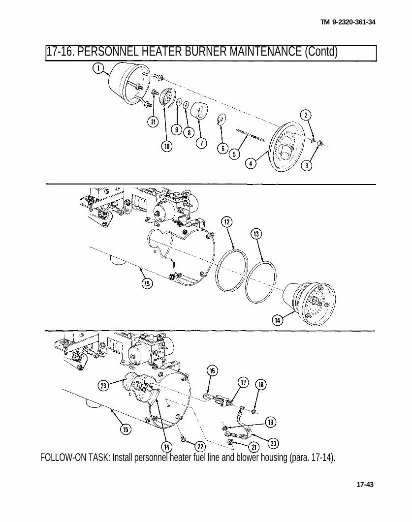
TM 9-2320-361-34
17-16. PERSONNEL HEATER BURNER MAINTENANCE (Contd)
FOLLOW-ON TASK: Install personnel heater fuel line and blower housing (para. 17-14).
17-43

TM 9-2320-361-34
17-17. PERSONNEL HEATER OVERHEAT SWITCH AND RECEPTACLE REPLACEMENT
THIS TASK COVERS:a. Overheat Switch Removal c. Receptacle Installationb. Receptacle Removal d. Overheat Switch Installation
INITIAL SETUP
APPLICABLE MODELS MATERIALS/PARTS (Contd)A l l Two screw-assembled lockwashers
TEST EQUIPMENT(Appendix F, Item 169)
Four screw-assembled lockwashersMultimeter (Appendix B, Item 3) (Appendix F, Item 168)
TOOLS REFERENCES (TM)General mechanic’s tool kit TM 9-2320-361-34P
(Appendix B, Item 1)Tool kit, electrical (Appendix B, Item 2)
MATERIALS/PARTSThree nut-assembled lockwashers
(Appendix F, Item 154)
EQUIPMENT CONDITIONPersonnel heater guard removed (para. 17-11).
N O T ETag wires for installation.
a. Overheat Switch Removal
1. Remove nut-assembled lockwasher (1) and shutoff valve lead (2) from overheat switch (5). Discardnut-assembled lockwasher (1).
2. Remove nut-assembled lockwasher (6), receptacle lead (7), thermostat lead (8), and ignition controllead (9) from overheat switch (5). Discard nut-assembled lockwasher (6).
3. Remove two screw-assembled lockwashers (4) and overheat switch (5) from heater housing (3).
b. Receptacle Removal
1. Remove screw-assembled lockwasher (11) and restriction solenoid lead (12) from receptacle (25).Discard screw-assembled lockwasher (11).
2. Remove nut-assembled lockwasher (22) and thermostat lead (21) from overheat switch (20). Discardnut-assembled lockwasher (22).
3. Remove screw-assembled lockwashers (15) and (16) and leads (17) and (13) from flame detectorswitch (23). Discard screw-assembled lockwashers (15) and (16).
4. Remove nut (14) and receptacle ground lead (24) from stud (19).5. Remove four screw-assembled lockwashers (10) and receptacle (25) from bracket (18). Discard
screw-assembled lockwashers (10).
17-44

TM 9-2320-361-34
17-17. PERSONNEL HEATER OVERHEAT SWITCH AND RECEPTACLE REPLACEMENT (Contd)
17-45

TM 9-2320-361-34
I 17-17. PERSONNEL HEATER OVERHEAT SWITCH AND RECEPTACLE REPLACEMENT (Contd)
c. Receptacle Installation
1. Install receptacle (15) on bracket (8) with four new screw-assembled lockwashers (l).
2. Install receptacle ground lead (14) on stud (9) with nut (4).3. Install leads (16) and (7) on flame detector switch (11) with new screw-assembled lockwashers (5)
and (6).4. Install receptacle lead (12) on overheat switch (10) with new nut-assembled lockwasher (13).5. Install restriction solenoid lead (3) on receptacle (15) with new screw-assembled lockwasher (2).
d. Overheat Switch Installation
1. Install overheat switch (21) on heater housing (19) with two screw-assembled lockwashers (20).2. Install ignition control lead (25), thermostat lead (24), and receptacle lead (23) on overheat
switch (21) with new nut-assembled lockwasher (22).3. Install shutoff valve lead (18) on overheat switch (21) with new nut-assembled lockwasher (17).
FOLLOW-ON TASK: Install personnel heater guard (para. 17-11).
17-46

TM 9-2320-361-34
17-18. PERSONNEL HEATER HEAT EXCHANGER REPLACEMENT
THIS TASK COVERS:a. Removal b. Installation
INITIAL SETUPAPPLICABLE MODELS REFERENCES (TM)Al l TM 9-2320-361-34P
TEST EQUIPMENT EQUIPMENT CONDITIONMultimeter (Appendix B, Item 3) ● Personnel heater blower motor removed
(para. 17-11).TOOLS ● Personnel heater burner removed (para. 17-16).General mechanic’s tool kit ● Personnel heater flame detetor switch removed
(Appendix B, Item 1) (para. 17-15).Tool kit, electrical (Appendix B, Item 2)
a. Removal
1. Remove three screws (4).2. Separate heater housing (5).3. Remove heat exchanger (3) from heater housing (5).
1. Separate heater housing (5) and install heat exchanger (3) in heater housing (5) with threescrews (4).
2. Ensure exhaust tube (2) and flame detector adapter (1) extend through holes of heater housing (5).
b. Installation
FOLLOW-ON TASKS: ● Install personnel heater flame detector switch (para. 17-15).● Install personnel heater burner (para. 17-16).● Install personnel heater blower motor (para. 17-11).
17-47

TM 9-2320-361-34
17-19. ENGINE COOLANT HEATER TESTING
THIS TASK COVERS:a. Preparation e. Blower Motor Testb. Igniter Test f. Restriction Thermostat Testc. Flame Detector Switch Test g. Overheat Switch Testd. Fuel Control Valve Test h. Test Equipment Removal
INITIAL SETUP
APPLICABLE MODELSAll
TEST EQUIPMENT24-volt DC power sourceFuel containerCoolant container (5gal.)Test standThermometerFlowmeterMultimeter (Appendix B, Item 3)
MATERIALS/PARTSAntifreeze (Appendix C, Item 3)
REFERENCESTM 9-2320-361-20TM 9-2320-361-34P
EQUIPMENT CONDITIONEngine coolant heater removed(TM 9-2320-361-20).
GENERAL SAFETY INSTRUCTIONS● Keep fire extinguisher nearby when working with
open fuel lines.● Do not perform procedure near open flame,
smoking, or sparking object. . Do not perform procedure in enclosed areas.● Allow time for heater to cool before removing from
test equipment.
a. Preparation
WARNING
● Do not perform this procedure while smoking or within 50 feet ofsparks or open flame. Fuel is flammable and can explode easily,causing injury or death to personnel and damage to equipment.
● Exhaust gases can kill. Do not operate personnel heater inenclosed areas. Ensure work area is well-ventilated and exhaustfumes are directed away from test area.
NOTE● Perform “preparation” subtask before performing any test and
perform “test equipment removal” after each test is complete.● Heater must be tested in same position as mounted on vehicle.. Use proper coolant required for engines which are being heated.
Water cannot be used because the overheat switch and restrictionthermostat are set for temperatures above the boiling point ofwater.
1. Connect coolant heater (13) to test equipment using schematic on next page.NOTE
. Coolant container must be vented and raised above the testapparatus in order for thermosyphon circulation to occur.
● Fuel pump, fuel filter, heater, wiring harness, fuel tubing, controlbox, and coolant must be the same type used on vehicle.
17-48

TM 9-2320-361-34
17-19. ENGINE COOLANT HEATER TESTING (Contd)
1.2.
3.
4.
5.
6.
7.
8.
9.
KEY TO TEST EQUIPMENT ARRANGEMENTElectric fuel pump 10. Coolant inlet hoseFuel tubing 11. Power source leadFuel filter 12. 24-volt DC power sourceFuel flowmeter 13. MultimeterFuel shutoff valve 14. Coolant heater assemblyCoolant outlet hose 15. Wiring harnessThermometer 16. Control boxCoolant container 17. Fuel tankCoolant shutoff valve
17-49

TM 9-2320-361-34
I 17-19. ENGINE COOLANT HEATER TESTING (Contd)
2. Remove four screws (2) and guard (1) from heater (9).3.4.5.6.
7.
8.9.
10.11.12.13.14.15.
16.
Disconnect lead (16) from 24-volt power source (17).Remove screw-assembled lockwasher (11) and igniter lead (12) from flame detector switch (10).Disconnect fuel control valve leads (6) and (8) from overheat switch (7).Connect hose (4) to bleed screw (13) on fuel control valve (3) and place other end of hose (4) incontainer (5).Open two fuel shutoff valves (14).
NOTEHave drainage container ready to catch fuel.
Connect lead (16) to power source (17).Ensure switch (21) is in LO position. Place switch (19) in START position and hold. Open bleedscrew (13) and let fuel flow until no air bubbles are observed in fuel flowing into container (5).Place switch (19) in OFF position. Close bleed screw (13).Disconnect lead (16) from power source (17).Install igniter lead (12) on flame detector switch (10) with screw-assembled lockwasher (11).Connect fuel control valve leads (6) and (8) on overheat switch (7).Open coolant shutoff valve (15).Check for signs of coolant leaks. Tighten loose connections or replace damaged parts if leaking(paras. 17-2 through 17-10, as necessary).Close coolant shutoff valve (15).
I b. Igniter Test
NOTEIgnition time is the interval from activating control box switch toSTART position until indicator lamp illuminates.
1. Place switch (19) in START position and hold. Record time interval from activating switch (19)until indicator lamp (20) illuminates. During this time interval, record ignition amperage onammeter (18).
2. If ignition time exceeds three minutes, or if ignition amperage exceeds 15 amperes, check fuel flowcomponents (paras. 17-2 through 17-10, as necessary).
3. Place switch (19) in OFF position.
17-50

TM 9-2320-361-34
17-19. ENGINE COOLANT HEATER TESTING (Contd)
17-51

TM 9-2320-361-34
17-19. ENGINE COOLANT HEATER TESTING (Contd)
I c. Flame Detector Switch Test
1. Place switch (3) in START position.2. When indicator lamp (4) illuminates, place switch (3) in RUN position.3. If indicator lamp (4) does not light, adjustor replace flame detector switch (6) (para. 17-2).4. Place switch (3) in OFF position.
I d. Fuel Control Valve Test
1. Place switch (3) in START position.2. When indicator lamp (4) illuminates, place switch (3) in RUN position.3. Check fuel consumption at flowmeter (1). Fuel consumption should be 8-11 cc/min at low heat, and
14-19 cc/min at high heat. Replace fuel control valve (2) if fuel consumption rate is not withinlimits (para. 17-6).
4. Check operating amperage on ammeter (2). If operating amperage exceeds 4 amperes, check heaterwiring. Replace damaged parts (paras. 17-2 through 17-10, as necessary).
5. Move switch (5) from LO to HI position. Burning in heater (8) should intensify or decrease. Replacefuel control valve (7) if burning in heater (8) does not intensify or decrease (para. 17-6).
6. Place switch (5) in LO position.7. Place switch (3) in OFF position.
When indicator lamp (4) illuminates, place switch (3) in RUN position. Allow heater to run for a fewminutes.
NOTEPurge time is the interval from turning control box to OFF positionuntil the indicator lamp goes out.
Place switch (3) in OFF position and record purge time. Burning should stop within thirty seconds;blower motor should continue to run up to three minutes. Replace or adjust flame detectorswitch (6) (para. 17-2) if purge time exceeds three minutes.
I e. Blower Motor Test
1. Place switch (3) in START position.2.
3.
17-52

TM 9-2320-361-34
17-19. ENGINE COOLANT HEATER TESTING (Contd)
1
17-53

TM 9-2320-361-34
17-19. ENGINE COOLANT HEATER TESTING (Contd)
f. Restriction Thermostat Test
1. Place switch (4) in START position.2. When indicator lamp (5) illuminates, place switch (4) in RUN position. Allow heater to run.3. Check temperature of coolant at thermometer (1). Temperature should be 140-170° F (60.0-76.7° C).
Replace restriction thermostat if coolant temperature is not within limits (para. 17-4).4. Place switch (4) in OFF position.
g. Overheat Switch Test
1. Place switch (4) in START position.2. When indicator lamp (5) illuminates, place switch (4) in RUN position. Allow heater (8) to run.3. Partially restrict air inlet with a sheet of cardboard or sheet metal. Overheat switch (9) should
activate and shut down heater (8) within five minutes. Replace overheat switch (9) if heater (8) doesnot shut down after five minutes (para. 17-7).
4. Check temperature of coolant at thermometer (1). Temperature should be 220-250° F(104.4-121.1° C).
5. Replace overheat switch (9) if coolant temperature is not within limits (para. 17-7).6. Place switch (4) in OFF position.
I h. Test Equipment Removal
WARNING
Allow time for heater to cool before removing from test equipment.Failure to do so may result in injury to personnel or damage toequipment.
17-54
1. Disconnect lead (2) from 24-volt power source (3).2. Install guard (6) on heater (8) with four screws (7).3. Remove heater (8) from test equipment.

TM 9-2320-361-34
17-19. ENGINE COOLANT HEATER TESTING (Contd)
I
FOLLOW-ON TASK: Install engine coolant heater (TM 9-2320-361-20).
17-55
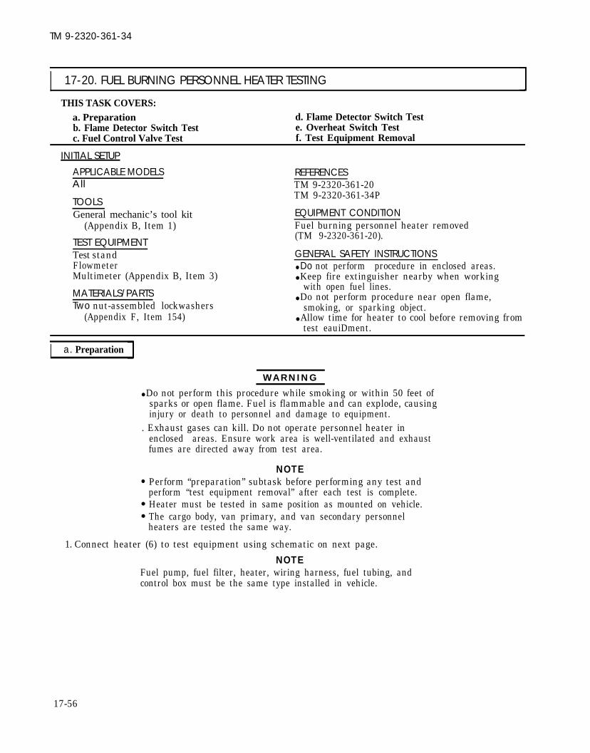
TM 9-2320-361-34
I 17-20. FUEL BURNING PERSONNEL HEATER TESTING
THIS TASK COVERS:a. Preparation d. Flame Detector Switch Testb. Flame Detector Switch Test e. Overheat Switch Testc. Fuel Control Valve Test f. Test Equipment Removal
INITIAL SETUPAPPLICABLE MODELS REFERENCESAll TM 9-2320-361-20
TOOLSTM 9-2320-361-34P
General mechanic’s tool kit(Appendix B, Item 1)
EQUIPMENT CONDITIONFuel burning personnel heater removed
TEST EQUIPMENT(TM 9-2320-361-20).
Test standFlowmeterMultimeter (Appendix B, Item 3)
MATERIALS/PARTSTwo nut-assembled lockwashers
(Appendix F, Item 154)
GENERAL SAFETY INSTRUCTIONS● Do not perform procedure in enclosed areas.● Keep fire extinguisher nearby when working
with open fuel lines.● Do not perform procedure near open flame,
smoking, or sparking object.● Allow time for heater to cool before removing from
test eauiDment.
I a. Preparation
WARNING
● Do not perform this procedure while smoking or within 50 feet ofsparks or open flame. Fuel is flammable and can explode, causinginjury or death to personnel and damage to equipment.
. Exhaust gases can kill. Do not operate personnel heater in
●
●
●
1. Connect heater (6) to test equipment using schematic on next page.
NOTEFuel pump, fuel filter, heater, wiring harness, fuel tubing, andcontrol box must be the same type installed in vehicle.
enclosed areas. Ensure work area is well-ventilated and exhaustfumes are directed away from test area.
NOTEPerform “preparation” subtask before performing any test andperform “test equipment removal” after each test is complete.Heater must be tested in same position as mounted on vehicle.The cargo body, van primary, and van secondary personnelheaters are tested the same way.
17-56

TM 9-2320-361-34
17-20. FUEL BURNING PERSONNEL HEATER TESTING (Contd)
KEY TO TEST SCHEMATIC1. Electric fuel pump 7. Power source lead2. Fuel tubing 8. 24-volt DC power source3. Fuel filter 9. Multimeter4. Fuel flowmeter 10. Wiring harness5. Fuel shutoff valve 11. Control box6. Heater assembly 12. Fuel tank
17-57

TM 9-2320-361-34
17-20. FUEL BURNING PERSONNEL HEATER TESTING (Contd)
2.
3.4.
5.
6.
7.8.
9.
10.
11.
12.
13.
14.
Turn two dzus fasteners (11) and remove guard (5) from heater (13).Disconnect lead (18) from 24-volt power source (20).Disconnect igniter lead (7) from ignition control unit (6).Remove nut-assembled lockwasher (1), shutoff valve lead (2), nut-assembled lockwasher (15), andthermostat lead (14) from overheat switch (3). Discard nut-assembled lockwashers (1) and (15).Connect hose (10) to bleed screw (8) on fuel control valve (9) and place other end of hose (10) incontainer (12).Connect lead (18) to 24-volt power source (20).Open fuel shutoff valves (17).
NOTEHave drainage container ready to catch fuel.
Place switch (23) in LO position. Place switch (21) in START position and hold. Open bleed screw (8)and let fuel flow from bleed screw (8) until no air bubbles are observed in fuel.Place switch (21) in OFF position. Close bleed screw (8).Install thermostat lead (14) and shutoff valve lead (2) on overheat switch (3) with new nut-assembled lockwashers (15) and (1).Connect igniter lead (7) on ignition control unit (6).
NOTEIgnition time is the interval from activating control box switch toSTART position until indicator lamp illuminates.
Place switch (21) in START position and hold. Record time interval from activating switch (21) untilindicator lamp (22) illuminates. During this time interval, record ignition amperage onammeter (19). Place switch (21) in OFF position.If ignition time exceeds three minutes, or if ignition amperage exceeds 15 amperes, check fuel flowand replace damaged parts (paras. 17-11 through 17-18, as necessary).
b. Flame Detector Switch Test
1. Place switch (21) in START position.2. When indicator lamp (22) illuminates, place switch (21) in RUN position.3. If indicator lamp (22) does not light, adjustor replace flame detector switch (4) (para. 17-15).4. Place switch (21) in OFF position.
c. Fuel Control Valve Testing
1.2.3.
4.
5.
17-58
Place switch (21) in START position.When indicator lamp (22) illuminates, place switch (21) in RUN position.Check fuel consumption at flowmeter (16). Fuel consumption should be 10-13 cc/min at low heat,and 19-24 cc/min at high heat. If fuel consumption rate is not within limits, replace fuel controlvalve (9) (para. 17-12).Check operating amperage at ammeter (19). If operating amperage exceeds 10 amperes, checkheater wiring and replace damaged parts (para. 17-11 through 17-18, as necessary).Place switch (21) in OFF position.

TM 9-2320-361-34
I 17-20. FUEL BURNING PERSONNEL HEATER TESTING (Contd)
1 7 - 5 9

TM 9-2320-361-34
17-20. FUEL BURNING PERSONNEL HEATER TESTING (Contd)
d. Flame Detector Switch Test
1. Place switch (4)in START position.NOTE
Purge time is the interval from turning control box switch to OFFposition until indicator lamp goes out.
2. Place switch (4) in OFF position and record purge time. Burning should stop within thirty secondsand blower motor (9) should continue to run up to three minutes. If purge time exceeds threeminutes, replace or adjust flame detector switch (6) (para. 17-15). Place switch (4) in OFF position.
I e. Overheat Switch Test
1. Place switch (4) in START position.2. When indicator lamp (5) illuminates, place switch (4) in RUN position and allow heater (10) to
operate for one minute.3. Partially restrict air inlet with a sheet of cardboard or sheet metal. Overheat switch (11) should
activate and shut down heater (10) within five minutes.4. If heater (10) does not shut down after five minutes, replace overheat switch (11) (para. 17-17).
I f. Test Equipment Removal
WARNINGAllow time for heater to cool before removing from test equipment.Failure to do so may result in injury to personnel or damage toequipment.
1. Close fuel shutoff valves (1).2. Disconnect lead (2) from power source (3).3. Remove heater (10) from test equipment.4. Place guard (7) on heater (10) and turn two dzus fasteners (8) to secure.
17-60

TM 9-2320-361-34
17-20. FUEL BURNING PERSONNEL HEATER TESTING (Contd)
FOLLOW-ON TASK: Install fuel burning personnel heater (TM 9-2320-361-20).
17-61

TM 9-2320-361-34
17-21. HARDTOP REAR PANEL WINDOW MAINTENANCE
THIS TASK COVERS:a. Disassembly b. Assembly
INITIAL SETUPAPPLICABLE MODELS REFERENCESAll TM 9-2320-361-20
TM 9-2320-361-34PTOOLSGeneral Mechanic’s Tool Kit EQUIPMENT CONDITION
(Appendix B, Item 1) Rear panel window removed (TM 9-2320-361-20).
MATERIALS/PARTSTwo rubber seals (Appendix F, Item 242)
a. Disassembly 1. Remove two screws (8), separate window frame (7), and remove two sashes (6) from window
frame (7).2. Remove two screws (10), sleeves (9), frame rail (5), and glass (3) from sash frame (1).3. Remove rubber seals (2) and (4) from glass (3) and frame rail (5). Discard seals (2) and (4).
b. Assembly
1. Install new rubber seal (4) in frame rail (5).2. Place new rubber seal (2) around glass (3).3. Install glass (3) and frame rail (5) on sash frame (1) with two screws (10) and sleeves (9).4. Install two sashes (6) in window frame (7) with two screws (8).
17-62
FOLLOW-ON TASK: Install rear panel window (TM 9-2320-361-20).

TM 9-2320-361-34
APPENDIX AREFERENCES
A-1. SCOPE This appendix lists all forms, manuals, and technical manuals for use with this vehicle.
A-2. PUBLICATION INDEX
The following should be consulted frequently for latest changes to, or revisions of, references given in thisappendix and for new publications or instructions relating to material covered in this manual.
Consolidated Index of Army Publications and Blank Forms . . . . . . . . . . . . . . . . . . . . . . . . . . . . . . . DA PAM 25-30
A-3. FORMS
Equipment Control Record . . . . . . . . . . . . . . . . . . . . . . . . . . . . . . . . . . . . . . . . . . . . . . . . . . . . . . . . . . . .. DA Form2408.9Exchange Tag . . . . . . . . . . . . . . . . . . . . . . . . . . . . . . . . . . . . . . . . . . . . . . . . . . . . . . . . . . . . . . . . . . . . . . . . . . . . DA Form 2402Maintenance Request. . . . . . . . . . . . . . . . . . . . . . . . . . . . . . . . . . . . . . . . . . . . . . . . . . . . . . . . . . . . . . . . . . . . . DA Form 2407Maintenance Request-Continuation Sheet . . . . . . . . . . . . . . . . . . . . . . . . . . . . . . . . . . . . . . . . . . .. DA Form 2407.1Maintenance Request Register . . . . . . . . . . . . . . . . . . . . . . . . . . . . . . . . . . . . . . . . . . . . . . . . . . . . . . . . . .. DA Form 2405Materiel Condition Status Report . . . . . . . . . . . . . . . . . . . . . . . . . . . . . . . . . . . . . . . . . . . . . . . . . . . . . . . .. DA Form2406Operator Report Motor Vehicle Accidents . . . . . . . . . . . . . . . . . . . . . . . . . . . . . . . . . . . . . . . . . . . . . . . .. SF Form 91Organizational Control Record for Equipment . . . . . . . . . . . . . . . . . . . . . . . . . . . . . . . . . . . . . . . . . . .. DA Form2401Preventive Maintenance Schedule and Record . . . . . . . . . . . . . . . . . . . . . . . . . . . . . . . . . . . . . . . . . . . . . DD Form 314Processing and Reprocessing Record for Shipment, Storage, and Issue of Vehicles and
Spare Engines . . . . . . . . . . . . . . . . . . . . . . . . . . . . . . . . . . . . . . . . . . . . . . . . . . . . . . . . . . . . . . . . . . . . . . . . . . DD Form 1397Product Quality Deficiency Report . . . . . . . . . . . . . . . . . . . . . . . . . . . . . . . . . . . . . . . . . . . . . . . . . . . . . . . . . SF Form 368Recommended Changes to Publications and Blank Forms . . . . . . . . . . . . . . . . . . . . . . . . . . . . . . . . DA Form 2028The Army Maintenance Management System (TAMMS) . . . . . . . . . . . . . . . . . . . . . . . . . . . . . . . DA PAM 738-750U. S. Army Accident Investigation Report . . . . . . . . . . . . . . . . . . . . . . . . . . . . . . . . . . . . . . . . . . . . . . . . .. DA Form285U.S. Government Motor Vehicle Operator’s Identification Card . . . . . . . . . . . . . . . . . . . . . . . . . . . . . . . . . . . OF 346
A-4. FIELD MANUALS I
Basic Cold Weather Manual . . . . . . . . . . . . . . . . . . . . . . . . . . . . . . . . . . . . . . . . . . . . . . . . . . . . . . . . . . . . . . . . . ..FM 31-70Combat Vehicles and Tactical Support Vehicles:Metal Body Repair . . . . . . . . . . . . . . . . . . . . . . . . . . . . . . . . . . . . . . . . . . . . . . . . . . . . . . . . . . . . . . . . . . . . . . . . . . . . . FM 43-2
First Aid for Soldiers . . . . . . . . . . . . . . . . . . . . . . . . . . . . . . . . . . . . . . . . . . . . . . . . . . . . . . . . . . . . . . . . . . . . . . . . .. FM21-11Manual forthe Wheeled Vehicle Driver. . . . . . . . . . . . . . . . . . . . . . . . . . . . . . . . . . . . . . . . . . . . . . . . . . . . . .. FM 21-305NorthernOperation s . . . . . . . . . . . . . . . . . . . . . . . . . . . . . . . . . . . . . . . . . . . . . . . . . . . . . . . . . . . . . . . . . . . . . . . ..FM 31-71Operation and Maintenance of Army Materiel in Extreme
Cold Weather (00F to-650F) . . . . . . . . . . . . . . . . . . . . . . . . . . . . . . . . . . . . . . . . . . . . . . . . . . . . . . . . . . . . . . . . .. FM9-207Petroleum Supply Point Equipment and Operations . . . . . . . . . . . . . . . . . . . . . . . . . . . . . . . . . . . . . . . . . .. FM10-69
A-5. TECHNICAL MANUALS
Administrative Storage of Equipment . . . . . . . . . . . . . . . . . . . . . . . . . . . . . . . . . . . . . . . . . . . . . . . . . . . . ..TM 740-90-1Care, Maintenance, and Repair of Pneumatic Tires, Inner Tubes, and
Radial Tires . . . . . . . . . . . . . . . . . . . . . . . . . . . . . . . . . . . . . . . . . . . . . . . . . . . . . . . . . . . . . . . . . . . . . . . .. TM9-2610-200-24Chemical Agent Alarm Maintenance, Automatic, Portable . . . . . . . . . . . . . . . . . . . . . . . . . . . . TM 3-6665-225-12Cooling Systems, Tactical Vehicles . . . . . . . . . . . . . . . . . . . . . . . . . . . . . . . . . . . . . . . . . . . . . . . . . . . . . . . . . . TM 750-254Decontaminating Apparatus Maintenance, Portable, DS2 . . . . . . . . . . . . . . . . . . . . . . . . . . TM 3-4230-204-12&PDeepwater Fording of Ordnance Material . . . . . . . . . . . . . . . . . . . . . . . . . . . . . . . . . . . . . . . . . . . . . . . . . . . . ..TM 9-238Destruction of Tank-Automotive Equipment to Prevent Enemy Use . . . . . . . . . . . . . . . . . . . . . . . TM 750-244-6
A-1

TM 9-2320-361-34
APPENDIX A (Contd)
I A-5. TECHNICAL MANUALS (Contd)
Direct and General Support Repair Parts and Special Tools Lists,Truck, 2-1/2-Ton, 6x6, Multifuel, M44A2 Series . . . . . . . . . . . . . . . . . . . . . . . . . . . . . . . . . . . . . TM 9-2320-361-34P
Direct Support and General Support Maintenance Manual,Starter, Leece.Neville . . . . . . . . . . . . . . . . . . . . . . . . . . . . . . . . . . . . . . . . . . . . . . . . . . . . . . . . . . . . . . .. TM9-2920-243-34
Direct Support, General Support, and Depot Maintenance Manual,Starter, Delco . . . . . . . . . . . . . . . . . . . . . . . . . . . . . . . . . . . . . . . . . . . . . . . . . . . . . . . . . . . . . . . . . . . . . . . . TM 9-2920-242-35
Direct Support, General Support, and Depot Maintenance Manual,Starter, Prestolite . . . . . . . . . . . . . . . . . . . . . . . . . . . . . . . . . . . . . . . . . . . . . . . . . . . . . . . . . . . . . . . . . . . TM 9-2920-248-35
Fuel Pump Metering and Distributing Assembly . . . . . . . . . . . . . . . . . . . . . . . . . . . . . . . . . . . . . . TM 9-2910-226-34Generator Assembly Maintenance . . . . . . . . . . . . . . . . . . . . . . . . . . . . . . . . . . . . . . . . . . . . . . . . . . . . TM 9-2920-225-34General Packing Instructions . . . . . . . . . . . . . . . . . . . . . . . . . . . . . . . . . . . . . . . . . . . . . . . . . . . . . . . . . . . . . . . . . TM 746-10Grinding Machine, Valve Face, Bench Mounting . . . . . . . . . . . . . . . . . . . . . . . . . . . . . . . . . . . . . . TM 9-4910-484-10Inspection and Classification of Tires . . . . . . . . . . . . . . . . . . . . . . . . . . . . . . . . . . . . . . . . . . . . . . . . . TM 9-2610-201-14Inspection and Repair of Transfer Case, Transmission, and Power Takeoff . . . . . . . . . .TM 9-2520-246-34-1Inspection, Care, and Maintenance of Antifriction Bearings . . . . . . . . . . . . . . . . . . . . . . . . . . . . . . . . . . . . TM 9-214Lead-Acid Storage Battery Maintenance . . . . . . . . . . . . . . . . . . . . . . . . . . . . . . . . . . . . . . . . . . . . . . TM 9-6140-200-14Lubrication Order, Truck, 2-1/2-Ton, 6x6, Multifuel, M44A2 Series . . . . . . . . . . . . . . . . . . LO 9-2320-209-12-1Maintenance, Direct Support and General Support
Level Engine Assembly Diesel (Multifuel) . . . . . . . . . . . . . . . . . . . . . . . . . . . . . . . . . . . . . . .TM 9-2815-210-34-2-1Maintenance, Direct Support and General Support
Level Engine Assembly, Diesel (Multifuel) . . . . . . . . . . . . . . . . . . . . . . . . . . . . . . . . . . . . . . .TM 9-2815-210-34-2-2Materials Used for Cleaning, Preserving, Abrading, and Cementing . . . . . . . . . . . . . . . . . . . . . . . . . . . TM 9-247Operator, Organizational, Direct Support and General Support
Maintenance Manual (including Repair Parts and Special Tools List) . . . . . . . . . . . . . TM 9-4910-387-14&POperator’s Manual, Truck, 2-1/2-Ton, 6x6, Multifuel, M44A2 Series . . . . . . . . . . . . . . . . . . . TM 9-2320-361-10Operator’s Manual: Welding Theory and Application . . . . . . . . . . . . . . . . . . . . . . . . . . . . . . . . . . . . . . . . . . . TM 9-237Organizational Maintenance Manual, Truck, 2-1/2-Ton, 6x6,Multifuel, M44A2 Series . . . . . . . . . . . . . . . . . . . . . . . . . . . . . . . . . . . . . . . . . . . . . . . . . . . . . . . . . . . . . TM 9-2320-361-20
Organizational Maintenance Repair Parts, Truck, 2-1/2-Ton, 6x6,Multifuel, M44A2 Series . . . . . . . . . . . . . . . . . . . . . . . . . . . . . . . . . . . . . . . . . ......... . . . . . . . . .TM 9-2320-361-20P
Painting Instructions for Field Use . . . . . . . . . . . . . . . . . . . . . . . . . . . . . . . . . . . . . . . . . . . . . . . . . . . . . . . . . . TM 43-0139Preservation, Packaging, and Packing of Military Supplies
and Equipment. . . . . . . . . . . . . . . . . . . . . . . . . . . . . . . . . . . . . . . . . . . . . . . . . . . . . . . . . . TM 38-230-1 and TM 38-230-2Principles of Automotive Vehicles . . . . . . . . . . . . . . . . . . . . . . . . . . . . . . . . . . . . . . . . . . . . . . . . . . . . . . . . . . . . . TM 9-8000Railcar Loading Procedures . . . . . . . . . . . . . . . . . . . . . . . . . . . . . . . . . . . . . . . . . . . . . . . . . . . . . . . . . . . . . . . . .. TM55.601Simplified Test Equipment for Internal Combustion Engines . . . . . . . . . . . . . . . . . . . . . . TM 9-4910-571-12&PStorage and Matetials Handling . . . . . . . . . . . . . . . . . . . . . . . . . . . . . . . . . . . . . . . . . . . . . . . . . . . . . . . .. TM9-743-2001Troubleshooting, Direct Support and General Support
Level Engine Assembly Diesel (Multifuel) . . . . . . . . . . . . . . . . . . . . . . . . . . . . . . . . . . . . . . . . . TM 9-2815-210-34-1Turbocharger Maintenance and Repair . . . . . . . . . . . . . . . . . . . . . . . . . . . . . . . . . . . . . . . . . . . . TM 9-2990-201-40&P
I A-6. TECHNICAL BULLETINS IColor, Marking, and Camouflage Painting of Military Vehicles, Construction
Equipment, and Materials Handling Equipment . . . . . . . . . . . . . . . . . . . . . . . . . . . . . . . . . . . . . . . . . . .. TB43-0209Description, Use, Bonding Techniques, and Properties of Adhesives . . . . . . . . . . . . . . . . . . . . . . . TB ORD 1032Functional Grouping Codes . . . . . . . . . . ............ . . . . . . . . . . . . . . . . . . . . . . . . . . . . . . . , ,... ,., .0 TB 750-93-1Load-Testing Vehicles Used to Handle Missiles and Rockets . . . . . . . . . . . . . . . . . . . . . . . . . . . . . . . . . . . . TB 9-352Major Vehicle Mechanical Components Warranty . . . . . . . . . . . . . . . . . . . . . . . . . . . . . . . . . . . . . . TB 9-2320-209-14
A-2

TM 9-2320-361-34
APPENDIX A (Contd)
I A-6. TECHNICAL BULLETINS (Contd)
Mandatory Brake Hose Inspection and Replacement . . . . . . . . . . . . . . . . . . . . . . . . . . . . . . . . . . TB 9-2300-405-14Purging, Cleaning, and Coating Interior Ferrous and Terne Sheet Vehicle Fuel Tanks . . . . . . . TB 43-0212Rustproofing Procedures . . . . . . . . . . . . . . . . . . . . . . . . . . . . . . . . . . . . . . . . . . . . . . . . . . . . . . . . . . . . . . . . . . . ..TB 43-0213Safety Inspection and Testing of Lifting Devices . . . . . . . . . . . . . . . . . . . . . . . . . . . . . . . . . . . . . . . . . . . ..TB 43-0142Security of Tactical Wheeled Vehicles . . . . . . . . . . . . . . . . . . . . . . . . . . . . . . . . . . . . . . . . . . . . . . . . . . TB 9-2300-422-20Standards for Oversea Shipment and Domestic Issue of Combat,
Tactical. and Special Purpose Vehicles . . . . . . . . . . . . . . . . . . . . . . . . . . . . . . . . . . . . . . . . . . . . . . ..TB 9-2300-281-35Tactical Wheeled Vehicles: Repair of Frames . . . . . . . . . . . . . . . . . . . . . . . . . . . . . . . . . . . . . . . . ..TB 9-2300-247-40Use of Antifreeze Solutions and Cleaning Compounds in Engine Cooling Systems . . . . . . . . . . . . TB 750-651Warranty Program for 2-1/2 Ton, 6x6, M44A2 Series Trucks . . . . . . . . . . . . . . . . . . . . . . . . . . . TB 9-2320-209-14
A-7. OTHER PUBLICATIONS
Antiseize Compound, High Temperature . . . . . . . . . . . . . . . . . . . . . . . . . . . . . . . . . . . . . . . . . . . . . . . . . . . .. MIL-A.907Calibration Systems Requirements . . . . . . . . . . . . . . . . . . . . . . . . . . . . . . . . . . . . . . . . . . . . . . . . . . . . . . .. MIL-C-45662Gage Inspection . . . . . . . . . . . . . . . . . . . . . . . . . . . . . . . . . . . . . . . . . . . . . . . . . . . . . . . . . . . . . . . . . . . . . . . . . . . MIL-STD-120Inspection Equipment, Acquisition, Maintenance, and Disposition . . . . . . . . . . . . . . . . . . . . . . . . . . MIL-I-45607Inspection Process, Magnetic Particle . . . . . . . . . . . . . . . . . . . . . . . . . . . . . . . . . . . . . . . . . . . . . . . . . . . . . . . . MIL-I-6868Marking for Shipment and Storage . . . . . . . . . . . . . . . . . . . . . . . . . . . . . . . . . . . . . . . . . . . . . . . . . . . . . . . . MIL-STD-129Methods of Preservation . . . . . . . . . . . . . . . . . . . . . . . . . . . . . . . . . . . . . . . . . . . . . . . . . . . . . . . . . . . . . . . . . . . . . . MIL-P-116Official Nomenclature, Names, and Desigations . . . . . . . . . . . . . . . . . . . . . . . . . . . . . . . . . . .. MIL-HDBK-63038-2Personnel Heater and Winterization Kit Policy for Army Tank-Automotive Materiel . . . . . . . . . . . . . SB 9-16Preparation for Shipment and Storage of Basic Issue Items . . . . . . . . . . . . . . . . . . . . . . . . . . . . . . . . MIL-B-12841Shipment and Limited Storage . . . . . . . . . . . . . . . . . . . . . . . . . . . . . . . . . . . . . . . . . . . . . . . . . . . . . . . . . . . .. MIL-V-62038Softwood Lumber . . . . . . . . . . . . . . . . . . . . . . . . . . . . . . . . . . . . . . . . . . . . . . . . . . . . . . . . . . . . . . . . . . . . . . . . . . . .. MM-L-751
A-8. ARMY REGULATIONS
Accident Reporting and Records . . . . . . . . . . . . . . . . . . . . . . . . . . . . . . . . . . . . . . . . . . . . . . . . . . . . . . . . . . . . ...385.40Packaging of Materiel . . . . . . . . . . . . . . . . . . . . . . . . . . . . . . . . . . . . . . . . . . . . . . . . . . . . . . . . . . . . . . . . . . . . . . . . . AR 700-15Prevention of Motor Vehicle Accidents . . . . . . . . . . . . . . . . . . . . . . . . . . . . . . . . . . . . . . . . . . . . . . . . . . . . . . ..385.55
A-9. TECHNICAL CATALOG
Camouflage. Pattern Painting . . . . . . . . . . . . . . . . . . . . . . . . . . . . . . . . . . . . . . . . . . . . . . . . . . . . . . . . . . . . . . . . .. TC5-2OO
A-10. COMMON TABLE OF ALLOWANCES
Army Medical Depatiment Expendable/Durable Items . . . . . . . . . . . . . . . . . . . . . . . . . . . . . . . . . . . . . . .. CTA 8-100Expendable/Durable Items (except Medical, Class V, Repair Parts,and Heraldic Items) . . . . . . . . . . . . . . . . . . . . . . . . . . . . . . . . . . . . . . . . . . . . . . . . . . . . . . . . . . . . . . . . . . . . . . . . . CTA 50-970
A-3 (A-4 blank)


TM 9-2320-361-34
APPENDIX BCOMMON AND SPECIAL TOOLS LIST
B-1 . SCOPE
This appendix lists special and common tools outside the General Mechanic’s Tool Kit which you willneed when servicing the M44A2 series vehicles.
B-2. EXPLANATION OF COLUMNS
a. Column (1) - Reference Code Number. This number is assigned to each entry in the listing and isreferenced in the “Initial Setup” of applicable tasks under the heading of “Special Tools,” “Test Equipment,”or “Tools.”
b. Column (2) - Nomenclature. Name or identification of special tool or common tool.c. Colunm (3) - Part Number. This identifies the manufacturer’s part number or catalog number
assigned to each tool or kit.d. Column (4) - National/NATO Stock Number. This is the National Stock Number assigned to
each tool or kit; use it to request or requisition the tool or kit.e. Column (5) - Supply Catalog. This is the supply catalog number in which the common tool can be
found. Special tools are not found in supply catalogs.
B-1

TM 9-2320-361-34
COMMON AND SPECIAL TOOLS LIST
(1) Reference (4)
CODE NATIONAL/NATONUMBER NUMBER STOCK NUMBER CATALOG
1 General Mechanic’s Tool Kit SC5180-90-CL-N26 5180-00-177-70332 Tool Kit, Electrical 7550526 5180-00-876-9336 4910-95-CL-A313 Multimeter ANURM105C 6625-00-999-6282 4910-95-CL-A314 Clutch Alinement Kit A37M 5180-00-449-3785 4910-95-CL-A315 Plum Bob MS 15747-8 5120-00-238-3299 4910-95-CL-A026 Torque Wrench, 3/4-in. dr. TESI800A 5120-01-118-3679 4910-95-CL-A317 Torque Wrench, 1/2-in. dr. A-A-2411 5120-00-640-6364 4910-95-CL-A318 Torque Wrench, 3/8-in. dr. TE-12A 5120-00-230-6380 4910-95-CL-A319 Caliper, Vernier 6420 5210-01-113-1548 4910-95-CL-A31
10 1-1/8-in. Socket, 1/2-in. dr. 11677025-10 5120-00-189-7914 5180-90-CL-N0511 1-1/16-in. Socket, 1/2-in. dr. 11677025-8 5120-00-189-7913 5180-90-CL-N0512 Brake Reliner MILR13495TY1CL1 4910-00-173-5310 4940-95-B2013 Soldering Gun 8200G3 3439-00-542-0396 4910-95 -CL-A3114 Sling 1806 4910-00-944-4915 4910-95-CL-A3 115 Bar, Breaker, 1/2-in. dr. MLK7101998-12 5120-00-224-1393 4910-95-CL-A3116 Inside Micrometer 124B 5120-00-221-1921 4910-95-A6317 Outside Micrometer GGG-C-105TY1CL1STA 5210-00-554-7134 4910-95-CL-A6318 Adapter, 1/2-in. Male - SJ409-
3/8-in. Female ZANDN02DRIFTPIN 5130-00-449-7698 4910-95-CL-A3119 1-1/4-in. Socket, 1/2-in. dr. 5216 5120-00-237-0977 5180-90-CL-N0520 Riveting Tool 250K 5120-00-017-2849 4910-95-A7421 Indicator, Dial 196A 5120-00-277-8840 4910-95-A6322 Mechanical Puller Kit PE12 5120-00-423-1596 4910-95-CL-A3123 Handle 7083241 5340-00-708-3241 Special Tool24 Bearing Sleeve Remover/
Replacer 7083246 5120-00-708-3246 Special Tool25 Oil Seal Replacer 7083256 5120-00-708-3256 Special Tool26 Bearing Replacer 7083252 5120-00-708-3252 Special Tool27 Screw 7083216 5120-00-708-3216 Special Tool28 Oil Seal Remover 7083250 5120-00-708-3250 Special Tool29 Puller Screw 8366689 5120-00-836-6689 Special Tool30 Tape Measure GGG-T-
106TY2CLBCAVST3 5210-00-234-6745 4910-95 -CL-A3131 1-5/16-in. Socket, 3/4-in. dr. 1242 5120-00-232-5681 4910-95-CL-A3132 Wheel Alinement Indicator AR40 4910-00-221-2472 4910-95-CL-A3133 1-1/8-in. Socket, 3/4-in. dr. 1818 5120-00-239-0021 4910-95-CL-A3 134 Bar, Breaker, 3/4-in. dr. NPB124 5120-00-224-1393 4910-95-CL-A3 135 Handle, Socket Wrench,
3/4-in. dr. 1940708 5120-00-249-1076 4910-95-CL-A3136 Torx Socket TLE60 5120-00-227-3159 Special Tool37 1-1/4-in. Socket, 3/4-in. dr. F3105A 5120-00-235-5871 4910-95-CL-A3 138 Spring Tester SPT 6635-00-641-7346 4910-95-A63
( 2 ) NOMENCLATURE
( 3 )PART
( 5 )SUPPLY
B-2

TM 9-2320-361-34
COMMON AND SPECIAL TOOLS LIST (Contd)
(1)REFERENCE (2) ( 3 ) (4) ( 5 )
CODE NOMENCLATURE NATIONAL/NATONUMBER NUMBER STOCK NUMBER CATALOG
39 Pipe Wrench TKCX1H 5120-00-277-1486 4910-95-CL-A3140 Snapring Pliers 4440R 5120-00-789-0492 5180-90-CL-N0541 1-1/2-in. Socket, 3/4-in. dr. 47148 5120-00-293-0094 4910-95-CL-A3142 1-3/4-in. Socket, 1-in. dr. 8156 5120-00-261-2837 4910-95-CL-A3143 Handle, Socket Wrench,
1-in. dr. 14-906 5120-00-221-7968 4910-95-CL-A3144 11/16-in. Flare Wrench, 12 pt. 11655785-2 5120-00-224-3141 4910-95-CL-N0545 1-5/8-in. Socket, 3/4-in. dr. 5552 5120-00-199-7765 4910-95-CL-A3146 Handle, Socket Wrench,
3/4-in. dr. 5668 5120-00-221-7959 4910-95-CL-A3147 Oil Seal Inserter 11642003 5120-00-134-7481 Special Tool48 Crankshaft Driver 11642010 5120-00-134-7464 Special Tool49 1/2-in. Allen Wrench 024-0067-00 5120-00-198-5391 4910-95-CL-A3150 1-1/4-in. Open-End Wrench 1037 5120-00-187-7134 4910-95-CL-A0151 1-1/4-in. Box Wrench GGG-W-636 5120-00-184-8677 4910-95-A6252 Straightedge 564000-36 6675-00-224-8807 4910-95-A6353 Gage, Force, Mechanical AAA-S-133 6670-00-254-4634 4910-95-CL-A7254 12-in. Extension, 3/8-in. dr. 35W198 5120-00-243-1691 4910-95-CL-A3155 Universal Joint, 3/8-in. dr. 1060775 5120-00-224-9215 4910-95-CL-A3156 5/8-in. Crowfoot Adapter 11642001 5120-00-134-7459 Special Tool57 2-1/4-in. Socket, 1-in. dr. B107.1CL1STA 5120-00-261-2843 4910-95-CL-A3158 Wrench, Box, Cylinder
Head Nuts 10951485 5120-00-930-6346 Special Tool59 Bushing Remover/Replacer 7083248 5120-00-708-3248 Special Tool60 Sleeve Bearing Hand
Burnisher 7083238 5120-00-708-3238 Special Tool61 1-1/16-in. Socket, 3/4-in. dr. A-A-1394 5120-00-189-7928 4910-95-CL-A3162 Adjustable Wrench 2117080 5120-00-264-3793 4910-95-A7463 Crowfoot Attachment 11642001 5120-00-134-7459 Special Tool64 Screw, Remover/
Replacer 7083216 5120-00-708-3216 Special Tool65 Puller, Mechanical GGGP00781 5120-00-449-3769 4910-95-CL-A3166 Puller Kit, Universal A57QB 5180-00-089-3660
B-3 (B-4 blank)


TM 9-2320-361-34
APPENDIX CEXPENDABLE/DURABLE SUPPLIES AND MATERIALS LIST
Section I. Introduction (page C-1)Section II. Expendable/Durable Supplies and Materials List (page C-2)
Section I. INTRODUCTION
C - 1 . S C O P E
This appendix lists expendable/durable supplies and materials you will need to maintain M44A2 seriesvehicles. This listing is for informational purposes only and is not authority to requisition listed items. Theseitems are authorized to you by CTA 50-970, Expendable/Durable Items (except Medical, Class V, RepairParts, and Heraldic Items), or CTA 8-100, Army Medical Department Expendable/Durable Items.
C-2. EXPLANATION OF COLUMNSa. Column (1) - Item Number. This number is assigned to the entry in the listing and is referenced in
the “INITIAL SETUP’ of applicable tasks under the heading of “Materials/Parts.”
b. Column (2) - Level. This column identifies the lowest level of maintenance that requires the listed item.
c — Operator/Crewo — Unit MaintenanceF — Direct Support MaintenanceH — General Support Maintenance
c. Column (3) - National Stock Number. This is the National Stock Number assigned to the item; useit to request or requisition the item.
d. Column (4) - Description. This column indicates the Federal item name and, if required, adescription to identify the item. The last line for each item indicates the Federal Supply Code forManufacturer (FSCM) in parenthesis followed by the part number.
e. Column (5) - Unit of Measure (U/M). This column indicates the measure used in performing theactual maintenance function. This measure is expressed by a two-character alphabetical abbreviation (e.g.,EA, GL, OZ). If the unit of measure differs from the unit of issue, requisition the lowest unit of issue that willsatisfy your requirements. Adjust when higher category maintenance requirements are involved.
C-1

TM 9-2320-361-34
Section II. EXPENDABLE/DURABLE SUPPLIES AND MATERIAL LIST“ - . - . . . . . - . - - - - , - - - - - - - - w . . - ” - - - . - . . . - - ”
(1) (2) (3) (4) (5)
NATIONALITEM STOCK
NUMBER LEVEL NUMBER DESCRIPTION U/M
1 0 ADHESIVE: reclaimed rubber(19203) 829899
8040-00-262-9028 1-Pint Can PT
2 0 ADHESIVE: silicone rubber, non-hardening(94833) 52498
8040-00-833-9563 1 Kit KT
3 0 ANTIFREEZE: permanent,ethylene glycol [-60° F (-51° C)]inhibited (0-A-548) type I, heavy-duty,(81349) MIL-A-46153
6850-00-181-7929 1-Gallon Container GL
6850-00-181-7933 5-Gallon Can GL
6850-00-181-7940 55-Gallon Drum GL
4 c BRAKE FLUID, AUTOMOTIVE: silicone,all weather, operational and preservative(81349) MIL-B-46176
9150-01-102-9455 1-Gallon Can GL
9150-01-123-3152 5-Gallon Can GL
9150-01-072-8379 55-Gallon Drum GL
5 0 CAP AND PLUG SET(19207) 10935405
5340-00-450-5718 1 Set EA
6 0 CHALK marking, white(81348) SS-C-266
7510-00-164-8893 1 Gross GR
7 F CLOTH, ABRASIVE (CROCUS CLOTH):abrasive (crocus)9 inch x 11 inch sheets,(58536) A-A-1206
5350-00-221-0872 50 Sheets/Package SH
8 C GREASE, AUTOMOTIVE AND ARTILLERY(81349) MIL-G-10924
9150-00-935-1017 14-Ounce Cartridge OZ
9150-00-190-0904 1-3/4-Pound Can LB
9150-00-190-0905 6-1/2-Pound Can LB
9 F GREASE, GRAPHITE:(81348) W-G-671
9150-00-190-0919 6-1/2-Pound Can LB
C-2

TM 9-2320-361-34
Section Il. EXPENDABLE/DURABLE SUPPLIES AND MATERIALS LIST (Contd),——–––-——— —–-—–—–- –-—–-–-
(1) (2) (3) (4) (5)
NATIONALITEM STOCK
NUMBER LEVEL NUMBER DESCRIPTION U/M
10 F INSULATING COMPOUND KIT, ELECTRICAL:(76381) Scotchcast 10,20 Pound
5970-00-186-6529 20-Pound Can LB
11 c LUBRICATING OIL, GEAR: GO 80/90, multi-purpose,(81349) MIL-L-2105
9150-01-035-5392 1-Quart Can QT
9150-01-035-5393 5-Gallon Drum GL
9150-01-035-5394 55-Gallon Drum GL
12 c LUBRICATING OIL, ENGINE: OE/HDO 10,(81349) MIL-L-2104
9150-00-189-6727 1-Quart Can QT
9150-00-186-6668 5-Gallon Drum GL
9150-00-191-2772 55-Gallon Drum GL
9150-00-183-7807 Bulk GL
13 c LUBRICATING OIL, ENGINE: OE/HDO 30,(81349) MIL-L-2104
9150-00-186-6681 1-Quart Can QT
9150-00-188-9858 5-Gallon Drum GL
9150-00-189-6729 55-Gallon Drum GL
9150-00-183-7808 Bulk GL
14 H PIGMENT, PAINT PRODUCTS: ultramarine, blue(96906) MS35740-1
8010-00-247-8707 1/2-Pint Can PT
15 0 PLASTIC STRAP, TIEDOWN, ELECTRICALCOMPONENTS: nylon, self-locking, type I,10 inches long(96906) MS3367-7-9
5975-00-570-9598 1 Hundred EA
16 c RAG, WIPING: unbleached cotton andcotton-synthetic, mixed colors(58536) A-A-531
7920-00-205-1711 50-Pound Bale EA
17 F SEALING COMPOUND:(79225) Permatex 1
8030-00-247-2525 11-Ounce Tube TU
C-3

TM 9-2320-361-34
Section Il. EXPENDABLE/DURABLE SUPPLIES AND MATERIALS LIST (Contd).
(1) (2) (3) (4) (5)
NATIONALITEM STOCK
NUMBER LEVEL NUMBER DESCRIPTION U/M
18 F SEALING COMPOUND: thread locking(05972) 078-31
8030-00-081-2325 50-Cubic Centimeter Bottle CC
19 0 SEALING COMPOUND: non-hardening,gasket forming cement, type II(80064) 1756371
8030-00-252-3391 11-Ounce Tube OZ
20 F SEALING COMPOUND:(81349) MIL-S-7916
8030-00-543-4384 1-Pint Can PT
21 H SILICONE COMPOUND:(D2222) MIL-S-8660-2UNZENTUBE
6850-00-177-5094 2-Ounce Tube Oz
22 F SILICONE COMPOUND:(71984) DC 340
6850-01-137-8525 2-Ounce Package Oz
6850-00-927-9461 5-Ounce Tube Oz
23 F SOLDER, TIN ALLOYrosin core(81348) SN6WRAP3 0.0945LB
3439-00-224-3567 5-Pound LB
24 c SOLVENT, DRYCLEANING: type II(81348) P-D-680, ASTM D235-87
6850-00-110-4498 1-Pint Can PT
6850-00-274-5421 5-Gallon Drum GL
6850-00-285-8012 55-Gallon Drum GL
6850-00-637-6135 Bulk GL
25 0 TAPE, ANTISEIZING: white, 0.05-in. wide x260-in. long x 0.0035-in. thick, with snap-on shell(81755) P5025-2R, MIL-T-27730
8030-00-889-3535 1 Each (Spool) EA
26 0 TAPE, INSULATION, ELECTRICAL:(75037) 17 3-4 IN BLACK
5970-00-419-4291 108-Foot Roll FT
C-4

TM 9-2320-361-34
Section Il. EXPENDABLE/DURABLE SUPPLIES AND MATERIALS LIST [Contd). ., —— ...-.,
(1) (2) (3) (4) (5)
NATIONALITEM STOCK
NUMBER LEVEL NUMBER DESCRIPTION U/M
27 F TAPE, PRESSURE SENSITIVEADHESIVE: 60-yard roll1/2-inch wide, tan in color(81348) PPP-T-42
7150-00-290-2023 60-Yard Roll YD
28 F TAPE, PRESSURE SENSITIVEADHESIVE: polyester film, opaque1 inch wide, 2 mil thick(19203) 8790710
7510-00-283-0612 60-Yard Roll YD
29 F TWINE:(96599) 4PLY40Z12
4020-00-446-1053 60-Yard Roll YD
30 F WIRE, NON-ELECTRICAL:(80244) 22-W-1642-125
9505-00-198-9125 1 Pound LB
31 F WIRE, NON-ELECTRICAL (SAFETY WIRE):(96906) MS20995NC40
9525-00-990-7799 1 Pound LB
32 H WIRE, NON-ELECTRICAL:(96906) MS20995F47
9505-00-248-9850 1 Pound LB
C-5 (C-6 blank)


TM 9-23209361-34
APPENDIX DILLUSTRATED LIST OF MANUFACTURED ITEMS
This appendix includes complete instructions for making items authorized to be manufactured orfabricated at direct and general support maintenance levels.
D-1. Fuel Injection Pump Gear Hub Wrench D-1D-2. Fuel Line Dust Cap Assembly Tool D-2D-3. Flywheel Guide Screw D-3
Notes:
1. Fabricate from NSN 9510-00-596-2063, QQS634, carbon steel bar, 8 in. (203.20 mm) x 2 in.(50.8 mm) x 0.38 in. (9.65 mm).
2. The tolerance on all three place decimal dimensions is ±0.005 in. (0.127 mm) and the tolerance onall two place decimal dimensions is ±0.03 in. (0.76 mm).
3. Trim steel to specifications per above diagram.
4. Drill two holes to specifications per above diagram.
5. Tool is used for removal of hub on fuel injection pump.Figure D-1. Fuel Injection Pump Gear Hub Wrench.
D-1
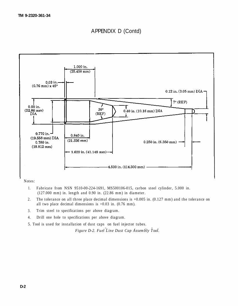
TM 9-2320-361-34
APPENDIX D (Contd)
Notes:
1. Fabricate from NSN 9510-00-224-1691, MS500106-015, carbon steel cylinder, 5.000 in.(127.000 mm) in. length and 0.90 in. (22.86 mm) in diameter.
2. The tolerance on all three place decimal dimensions is +0.005 in. (0.127 mm) and the tolerance onall two place decimal dimensions is +0.03 in. (0.76 mm).
3. Trim steel to specifications per above diagram.
4. Drill one hole to specifications per above diagram.
5. Tool is used for installation of dust caps on fuel injector tubes.-. . . - .
Figure D-2. Fuel Line Dust Cap Assembly Tool.
D-2

TM 9-2320-361-34
APPENDIX D (Contd)
D-3 (D-4 blank)
Notes:
1. Fabricate from NSN 5305-00-716-8179, MS 90726-121, 1/2-20 UNF 2A x 3.500 in. (88.9 mm) screw.
2. The tolerance on all three place decimal dimensions is + 0.005 in. (0.127 mm).
3. Cut off hexagon head of screw per above diagram.
4. Grind sharp edges from cut end.
5. Tool is used for removal and installation of flywheel.
Figure D-3. Flywheel Guide Screw.


TM 9-2320-361-34
APPENDIX ETORQUE LIMITS
E-1. GENERALThis section provides general torque limits for screws used on the M44A2 series vehicles. Special torque
limits are indicated in the maintenance procedures for applicable components. The general torque limitsgiven in this appendix shall be used when specfic torque limits are not indicated in the maintenanceprocedure. These general torque limits cannot be applied to screws that retain rubber components. Therubber components will be damaged before the correct torque limit is reached. If a special torque limit is notgiven in the maintenance instructions, tighten the screw or nut until it touches the metal bracket, thentighten it one more turn.
E-2. TORQUE LIMITS
Table E-1 lists dry tarque limits. Dry torque limits are used on screws that do not have lubricants appliedto the threads. Table E-2 lists wet torque limits. Wet torque limits are used on screws that have highpressure lubricants applied to the threads.
E-3. HOW TO USE TORQUE TABLE
a. Measure the diameter of the screwyou are installing.
c. Under the heading SIZE, look down the left handcolumn until you find the diameter of the screw youare installing (there will usually be two linesbeginning with the same size).
d. In the second column under SIZE, fid the numberof threads per inch that matches the number ofthreads you counted in step b.
CAPSCREW HEAD MARKINGSManufactwer’s marks may vay.These are all SAE Grade 5(3-line).
e.
f.
To find the grade screw you are installing, match themarkings on the head to the correct picture ofCAPSCREW HEAD MARKINGS on the torquetable.Look down the column under the picture you foundin step e. until you find the torque limit (in lb-ft orN.m) for the diameter and threads per inch of thescrew.
b. count the number of threads perinch .
E-1

TM 9-2320-361-34
Table E-1. Torque Limits for Dry Fasteners.
CAPSCREW HEAD MARKINGS
TORQUE
SIZE SAE GRADE 5AE GRADE SAE GRADE SAE GRADENo. 1 or 2 No. 5 NO.6or7 NO. 8
DIA THREADS DIA. POUND NEWTON POUND NEWTON POUND NEWTON POUND NEWTONINCHES PER INCH MILLIMtlERS FEET METERS FEET METERS FEET METERS FEET METERS
1/4 20 6.35 5 6.78 8 10.85 10 13.56 12 16.27
1/4 28 6.35 6 8.14 10 13.56 - – 14 18.98
5/1 6 18 7.94 11 14.92 17 23.05 19 25.76 24 32.52
5/1 6 24 7.94 13 17.63 19 25.76 - - 27 36.61
3/8 16 9.53 18 24.41 31 42.04 34 46.10 44 59.66
3/8 24 9.53 20 27.12 35 47.46 - - 49 66.44
7/1 6 14 11.11 28 37.97 49 66.44 55 74.58 70 94.92
7/1 6 20 11.11 30 40.68 55 74.58 - - 78 105.77
1/2 13 12.70 39 52.88 75 101.70 85 115.26 105 142.38
1/2 20 12.70 41 55.60 85 115.26 - — 120 162.72
9/1 6 12 14.29 51 69.16 110 149.16 120 162.72 155 210.18
9/1 6 18 14.29 55 74.58 120 162.72 – - 170 230.52
5/8 11 15.88 63 85.43 150 203.40 167 226.45 210 284.76
5/8 18 15.88 95 128.82 170 230.52 - - 240 325.44
3/4 10 19.05 105 142.38 270 366.12 280 379.68 375 508.50
3/4 16 19.05 115 155.94 295 400.02 - - 420 569.52
7/8 9 22.23 160 216.96 395 535.62 440 596.64 605 820.38
7/8 14 22.23 175 237.30 435 589.86 - - 675 915.30
8 25.40 235 318.66 590 800.04 660 894.96 910 1233.96
14 25.40 250 339.00 660 894.96 - - 990 1342.44
1/8 - 25.58 - - 1084.8. - - 1280 1735.7880 1193.3 1440 1952.6
1/4 - 31.75 - - - - - - 1 8 2 0 2 4 6 7 . 92712.0
1-3/8 - 34.93 - - 1460. 1979.8 - - 3227.31680 2278.1 3688.3
1/2 . - 38.10 - - 1940 3160 4285.0 -2200 3560 4827.4
11
2630.62983.2
E - 2

TM 9-2320-361-34
Table E-2 Torque Limits for Wet Fasteners
CAPSCREW HEAD MARKINGS
TORQUE
SIZE SAE GRADE SAE GRADE SEA GRADE SAE GRADENo. 1or 2 No. 5 NO.6or7 NO. 8
DIA THREADS DIA. POUND NEWTON POUND NEWTON POUND NEWTONINCHES PER INCH MILLIMETERS FEET
POUND NEWTONMETERS FEET METERS FEET METERS FEET METERS
1/4 20 6.35 4,5 6.1 7.2 9.76 9.0 12.20 10.8 14.64
1/4 28 6.35 5.4 7.32 9.0 12.20 - — 12.6 17.09
5/16 18 7.94 9.9 13.42 15.3 20.75 17.1 23.19 21.6 29.29
5/16 24 7.94 11.7 15.87 17.1 23.19 - - 24.3 32.95
3/8 16 9.53 16.2 21.97 27.9 37.83 30.6 41.49 39.6 53.70
3/8 24 9.53 18.0 24.41 31.5 42.71 - 44.1 59.80
7/16 14 11.11 25.2 34.17 44.1 59.80 49.5 67.12 63.0 85.43
7/16 20 11.11 27.0 36.61 49.5 67.12 - - 70.2 95.19
1/2 13 12.70 35.1 47.60 67.5 91.53 76.5 103.73 94.5 128.14
1/2 20 12.70 36.9 50.04 76.5 103.73 - — 108.0 146.4
9/16 12 14.29 45.9 62.24 99.0 134.24 108.0 146.45 139.5 189.16
9/16 18 14.29 49.5 67.12 108.0 146.45 - — 153.0 207.47
5/8 11 15.88 56.7 76.89 135.0 183.06 150.3 203.81 189.0 254.28
5/8 18 15.88 85.5 115.94 153.0 207.47 - - 216.0 292.90
3/4 10 19.05 94.5 128.14 243.0 329.51 252.0 341.71 337.5 457.65
3/4 16 19.05 103.5 140.35 265.5 360.02 - - 378.0 512.57
7/8 9 22.23 144.0 195.26 355.5 482.06 396.0 536.98 544.5 738.34
7/8 14 22.23 157.5 213.57 391.5 530.87 - - 607.5 823.77
I 8 25.40 211.5 286.79 531.0 720.04 594.0 805.46 819.0 1110.56
14 25.40 225.0 305.10 594.0 805.46 - - 891.0 1208.20
1-1/8 - 25.58 - - 720.0 976.32- - - 1152.0 1562.11-792.0 1073.95 1296.0 1757.38
1-1/4 — 31.75 - - 1637.99 2221.11-1800.00 2440.80
1-3/8 - 34.93 - - 1314.0 1781.78. — - 2142.0 2904.55-1512.0 2050.27 2448.0 3319.49
1-1/2 - 38.10 - - 1746.0- 2367.58. — - 2844.0 3856.5-1980.0 2684.88 3204.0 4344.62
1
1
E-3

TM 9-2320-361-34
APPENDIX E (Contd)
Tubing Application Tightening Assmbly Instructhns
Slide tubing over barbed insert until it bottoms on MINI-BARBfitting.
1. Slide nut and then sleeve on tubing.2. Slide I.D. of tubing onto fitting insert until it
bottoms.3. Assemble nut b fitting body.4. Tighten assembly finger tight to cover body
1.2.
3.4.
Slide nut and then sleeve on tubing.Slide I.D. of tubing onto fitting insert until itbottoms. A s s e m b l e n u t t o f i t t i n g b o d y .Tighten assembly f inger t ight to cover bodythreads.
1. Cut tubing to desired length. Ensure ends arecut reasonably square.
2. Slide tubing into the preassembled fitting andpush until tube bottoms.
3. Tighten nut as indicated in chart. Anothercheck on proper assembly is dimension “A,”when nut is fidly tightened.
REASSEMBLY- Push tubing and insert into
DISASSEMBLY — Remove nut and pull tubingout of fitting body. Insert will remain on tubing.
fitting body until it bottoms. Thread nut ontofitting body and tighten as in step 3.
E-4

1.
2.
3.
4.
TM 9-2320-361-34
APPENDIX E (Contd)Tubing Application Tightening Assembly Instructions (Contd)
Slide nut and then sleeve on tubing. Threadedend of nut (C) must face out.Insert tubing into fitting. Ensure tubing isbottomed on fitting shoulder.Thread nut onto fitting body until it is handtight.From that point, tighten with a wench the
COPPER TUBINGFOR AIRBRAKE
number of turns indicated at right.
TUBESIZE
ADDlTONAL NUMBEROF TURNS FROM HAND TIGHT
1/4, 3/8 1-3/4l/2, 5/8, 3/4 3-1/4
I E-4. TORQUE WRENCH ADAPTERS
Some tasks require the use of a torque wrench adapter when the nut or screw cannot be reached with aregular socket on the end of the torque wrench. These adapters add to the overall length of the torquewench and make the dial or scale reading less than the actual torque applied to the nut or screw. Toprevent overtorquing and damage to equipment, calculate correct dial or scale reading using. ConversionFormula (para. E-5).
E-5

TM 9-2320-361-34
APPENDIX E (Contd)
E-5. CONVERSION FORMULA
Corrected dial or scale readings are determined by the use of the following formula:
Correctedreading =
Example:
Required Length of torque wrench + Length of adaptertorque value + Length of torque wrench
NOWThe length of the torque wrench ismeasured from the center of the handleto the center of the drive. The length ofthe adapter is measured from the centerof the drive to the center of the wrench.
In this example, the torque wrench measures 22 in. (55.9 cm) and the adapter is 3 in. (7.6 cm). Therequired torque is 19 lb-fl (25.8 N.m)
Correctedreading
Correctedreading
Correctedreading
Correctedreading
19 Ib-ft (25.8 N.m) + 22 in. (55. 9 cm) + 3 in. (7.6 cm)= 22 in. (55.9 cm)
19 lb-ft (25.8 N.m) + 25 (63. 5 m)= 22in. (55.9 cm)
19 lb-ft (25.8 N.m) + 1.14=
17 lb-ft (23.1 N.m)=
E-4

APPENDIX FMANDATORY REPLACEMENT PARTS
Section I. Introduction (page F-1)Section II. Mandatory Replacement Parts (page F-2)
Section I. INTRODUCTION
TM 9-2320-361-34
This appendix lists mandatory replacement parts you will need to maintain M44A2 series vehicles.
F-2. EXPLANATION OF COLUMNSa. Column (1) - Item Number. This number is assigned to each entry in the listing and is referenced in
the “Initial Setup” of applicable tasks under the heading of “Materials/Parts.”b. Column (2) - Nomenclature. Name or identification of the part.C. Column (3) - Part Number. The manufacturer’s part number.d. Column (4) - National Stock Number. The national stock number of the part.
F-1

TM 9-2320-361-34
(1)ITEMNO.
1234567891011121314151617181920212223242526272829303132333435363738394041424344454647
F-2
Section II. MANDATORY REPLACEMENT PARTS
(4)(2)
NOMENCIANJRE
Bushing, TaperedClip RingCotter PinCotter PinCotter PinCotter PinCotter PinCotter PinCotter PinCotter PinCotter PinCotter PinCotter PinCotter PinCotter PinCotter PinCotter PinCotter PinCotter PinCotter PinCotter PinCotter PinCotter PinDiscDiscFelt PadGasketGasketGasketGasketGasketGasketGasketGasketGasketGasketGasketGasketGasketGasketGasketGasketGasketGasketGasketGasketGasket
(3)PART
NUMBER
7521964MS16625-193MS24665-493MS24665-304MS24665-625M$24665-357137185MS24665-566MS24665-495MS24665-283MS24665-289MS24665-287MS24665-359MS24665-285MS24665-353MS24665-134MS24665-498MS9245-95MS24665-360MS24665-355MS24665-372MS24665-151116405408330136732625911623258109356521088972411609349-21088972311677119736850275214857748854116628561095142810899080108990621093520110935199109351971088993383278488327849108897361088994010889730
NATIONAL/NATOSTOCKNUMBER
2805-00-752-19645365-00-995-86745315-00-018-79885315-00-241-73305315-00-209-72735315-00-298-14815315-00-839-58225315-00-843-01385315-00-234-16645315-00-842-30445315-00-845-77875315-00-011-91205315-00-013-72145315-00-005-04425315-00-839-58225315-00-839-58205315-00-849-98545315-01-127-72015315-00-298-14995315-00-012-01235315-00-059-04915315-00-815-1405
4820-00-321-64254820-00-536-9718
5330-00-908-63405330-00-862-90655330-00-127-54175330-00-862-90645330-00-106-85555330-00-298-13985330-00-752-14855330-00-871-54255330-00-419-94675330-00-930-09805330-00-885-57235330-00-863-31655330-00-078-89985330-00-075-17685330-00-078-89975330-00-860-05745330-00-832-78485330-01-017-25355330-00-860-05605330-00-056-01945330-00-885-3422

(1)ITEMNO.
48495051525354555657585960616263646566676869707172737475767778
Q8182838485868788899091929394
TM 9-2320-361-34
Section Il. MANDATORY REPLACEMENT PARTS (Contd)
(2)
NOMENCI.AWRE
GasketGasketGasketGasketGasketGasketGasketGasketGasketGasketGasketGasketGasketGasketGasketGasketGasketGasketGasketGasketGasketGasketGasketGasketGasketGasketGasketGasketGasketGasketGasketGasketGasketGasketGasketGasketGasket and Shim SetHoseIgniterIgniterLocknutLocknutLocknutLocknutLocknutLocknutLocknut
(3)PART
NUMBER
108898621088985711641832MS35769-18108898588327846832784710937245700509211623235116231961162315411623184116231811162318211623183753873675387287538737740982174098227973339770175377355247701749740908974090817409082737403283273228344200-1752178275209597521061108970871160996375217648357967-5CS-4520-SV-0705G484055MS51943-39MS51922-21400D612MS51922-5MS51943-331164165611609727-2
(4)NiUIONAL/NATOSTOCKNUMBER
5330-00-860-91415330-00-860-91405330-01-153-82315330-00-834-29125330-01-018-71535330-00-832-78465330-00-832-78475330-00-489-83465330-00-700-50925330-00-143-74395330-00-410-98015330-00-143-74975330-00-143-74985330-00-410-58335330-00-143-74865330-00-143-74905330-00-753-87365330-00-753-87285330-00-753-87375330-00-740-98215330-00-057-38235330-00-895-34245330-00-770-17535330-00-196-27415330-00-770-17495330-00-740-90895330-00-740-90815330-00-242-55875330-00-737-40325330-00-234-33175330-00-522-84285330-00-752-17825330-00-752-09595330-00-752-10615330-00-406-15435330-00-930-92295330-00-752-17644720-01-270-04264520-00-217-57824520-00-312-20175310-00-488-38895310-00-959-14885310-00-998-73855310-00-959-76005310-00-814-06735310-00-791-95255310-00-176-6690
F-3

TM 9-2320-361-34
(1)ITEMNO.
9596979899
100101102103104105106107108109110111112113114115116117118119120121122123124125126127128129130131132133134135136137138139140141
Section Il. MANDATORY REPLACEMENT PARTS (Contd)
(4)(2)
NOMENCUUURE
LocknutLocknutLocknutLocknutLocknutLocknutLocknutLocknutLocknutLocknutLocknutLocknutLocknutLocknutLocknutLocknutLocknutLocknutLockplateLockscrewLockscrewLockscrewLockscrewLockscrewLockscrewLockscrewLockwasherLockwasherLockwasherLockwasherLockwasherLockwasherLockwasherLockwasherLockwasherLockwasherLockwasherLockwasherLockwasherLockwasherLockwasherLockwasherLockwasherLockwasherLockwasherLockwasherLockwasher
(3)PART
NUMBER
MS21044N4MS21044N8MS21045-10MS21045-8MS51922-13MS21042-3MS21042-4MS51943-40MS51943-44MS51943-46MS51922-53MS51922-37MS51922-61MS51922-17MS51943-38MS51922-9272629MS51943-481161020710898724MS35764-1295MS35764-1579MS35764-157510912494MS35764-852MS35764-248MS35340-44MS45904-57MS35340-46MS35340-45MS35338-46MS35335-40MS35338-50MS35340-48MS35340-47MS35338-49MS35338-44MS45904-61MS45904-69MS45904-68MS35338-47MS35335-34MS35333-40MS35338-48MS35333-39MS35338-51MS35338-53
NATIONAL/NATOSTOCK NUMBER
5310-00-877-57965310-00-877-57955310-00-982-50095310-00-062-49545310-00-984-38075310-00-807-14675310-00-807-14685310-00-935-37505310-00-241-66645310-00-935-35695310-00-225-64085310-00-067-95075310-00-832-97195310-00-087-46525310-00-994-10065310-00-984-38065310-00-014-58435310-00-241-66655340-00-101-56005306-00-850-38845306-01-015-56755306-01-129-75905306-01-131-94745306-00-081-98125306-00-241-65925306-01-118-31345310-00-682-59305310-00-061-00045310-00-959-46755310-00-959-46795310-00-637-95415310-00-275-36835310-00-820-66535310-00-834-76065310-00-655-93705310-00-167-06805310-00-582-59655310-00-889-27695310-00-067-63575310-00-889-25285310-00-209-09655310-00-514-66745310-00-550-11305310-00-584-52725310-00-576-57525310-01-004-90125310-00-584-7889
F-4

ITEM
144145146147148149150151152153154155156157158159160161162163164165166167168169170171172173174175176177178179180
185
TM 9-2320-361-34
Section Il. MANDATORY REPLACEMENT PARTS (Contd)
(2)
NOMENCIAURE
LockwasherLockwasherLockwasherLockwasherLockwasherLockwasherLockwasherLockwasherLockwasherLockwasherLockwasherLockwasherLockwasher, Nut-AssembledLockwasher, Screw-AssembledLockwasher, Screw-AssembledLockwasher, Screw-AssembledLockwasher, Screw-AssembledLockwasher, Screw-AssembledLockwasher, Screw-AssembledLockwasher, Screw-AssembledLockwasher, Screw-AssembledLockwasher, Screw-AssembledLockwasher, Screw-AssembledLockwasher, Screw-AssembledLockwasher, Screw-AssembledLockwasher, Screw-AssembledLockwasher, Screw-AssembledLockwasher, Screw-AssembledO-ringO-ringO-ringO-ringO-ringO-ringO-ringO-ringPackingPackingPacking, PreformedPacking, PreformedPacking, PreformedPacking, PreformedPacking, PreformedPacking SetParts Kit, Air CylinderParts Kit, GeneratorParts Kit, Generator
(3)PART
NUMBER
MS35338-45MS35339-30MS35335-37MS35338-42MS35335-35MS35338-108MS35340-51MS35335-38MS35335-31MS35335-331215747005141511-061800-0042357159411911668680187527425601709243470924437092435709243670924377092446709244570924388359533170677MS2956 1-210MS2956 1-214MS29561-222MS28775-334718768-22MS28775-128327984MS29513-258116230708330888MS9388-21OMS28775-2141160921573740411162290211623667570415990-253290-2531
(4)NATIONAL/NATOSTOCK NUMBER
5310-00-407-95665310-00-013-11395310-00-209-51165310-00-045-32995310-00-627-61285310-00-680-68235310-00-052-64545310-00-616-63545310-00-596-76935310-00-209-07865310-00-012-15745310-00-426-31435310-00-603-73605305-00-042-3571.5305-00-317-31025305-01-128-56565306-00-018-75275305-00-042-56015305-00-508-19545305-00-237-62595305-00-144-15095305-01-163-95665305-01-014-51155305-01-268-9486
5305-00-494-27085305-00-135-30325305-00-456-25825330-00-690-95945330-00-618-25175330-00-618-25185330-00-292-05785330-00-179-02475330-01-311-46285330-00-291-24395330-00-599-30725330-00-194-47915330-00-318-43235330-00-864-71835330-00-579-31635330-00-269-49535330-00-472-52135330-00-143-76645330-01-289-78482520-00-394-97182920-01-168-41302920-01-168-4129
F-5

TM 9-2320-361-34
(1)ITEMNO.189190191192193194195196197198199200201202203204205206207208209210211212213214215216217218219220221222223224225226227228229230231232233234235
Section Il. MANDATORY REPLACEMENT PARTS (Contd)
(4)(2)
NOMENCLAWRE
Parts Kit, Parking BrakeshoeParts Kit, Service BrakeshoeParts Kit, Steering GearParts Kit, Vehicular, HeaterParts Kit, Vehicular, HeaterPinPinPinPinPinPinPlugPlugPlugRetainerRetainer, SealRing, PistonRing, SpacerRivetRivetRivetRivetRivetScrewScrewScrewScrewScrewScrewScrewScrewSealSealSealSealSealSealSealSealSealSealSealSealSealSealSealSeal, Channel Lift
(3)PART
NUMBER123567565704531752148657040515704052590029MS24692-3311162305511623022MS24692-388117869501511MS35648-311608954MS16626-1100EA2433832798574090807B5049MS20613-8P28MS16536-180MS20613-8P1O11608955MS90726-172MS90727-170MS90727-78MS90727-162MS35308-378MS90727-70MS90725-65MS16998-102109125141361OA833090911623381500294206555753870475386947538693746117657155-542465500117MS51OOO-129-2867578353429377373301
NATIONAL/NATOSTOCK NUMBER
2530-01-281-52242530-01-217-84272530-00-752-14862540-00-201-34742540-00-200-42495315-00-059-00295315-00-198-59865315-00-145-18725315-00-409-65835315-00-054-55525315-00-011-78695340-00-050-15115340-00-050-15895320-01-176-94075365-00-281-98855330-00-700-51354310-00-287-81265365-00-182-96355320-00-262-64925320-00-051-86145320-00-058-98865320-00-067-58405320-01-176-93965305-00-725-41455350-00-726-25575305-00-269-45315305-00-727-22835305-00-406-77815305-00-269-32465305-00-269-32155305-00-983-80765330-00-081-34165330-00-178-46685330-00-318-43265330-00-134-51585330-00-286-82255330-00-286-81495330-00-695-11705330-00-696-02795330-00-286-81545330-00-291-15545330-01-150-96915330-00-286-70515330-00-113-62375330-00-566-07945330-00-534-29379390-00-737-3301
F-6

(1)ITEMNO.
236237238239240241242243244245246247248249250251252253254255256257258259260261262263264265266267268269270271272273274275276277278279280281282
TM 9-2320-361-34
Section Il. MANDATORY REPLACEMENT PARTS (Contd)
(2)
NOMENCLATURE
Seal, Channel Lift FillerSeal, DustSeal, FrameSeal, OilSeal, OilSeal, RingSeal, RubberSeal, WasherSeat, ValveShim SetShim SetShim SetShim SetShim SetShim SetShim SetShim SetShim SetShim SetShim SetShim SetShim SetShim SetShim SetShim SetSleeveSleeveSnapringStrip, FillerStrip, FillerStudWasherWasherWasherWasherWasherWoodrufT KeyWoodrutT KeyWoodrufT KeyWoodruff KeyWoodruil’ KeyWoodruff KeyWoodruff KeyWoodruff KeyWoodrufT KeyWoodrutY KeyWoodruff Key
(3)PART
NUMBER
10906350109514757373300116629417521241108897577085399516032311640548700512970051407005142700513611623244700517670051681162324511623246116232427005154700515270051531162317873740097374033222-652476624736305573733257005421832801011662511MS15795-825MS27183-13MS15795-819MS15795-814MS35756-14700517411623807607722700515711623169-1MS20066-1878330519MS35756-128328341MS35756-11
(4)NATIONAL/NATOSTOCK NUMBER
2510-00-179-57085330-00-930-59619390-00-737-33005365-01-064-28055330-00-143-86665330-00-899-67265330-00-174-86345310-00-209-1761
5365-00-700-51295365-00-700-51405365-00-700-51425365-00-700-51365365-01-179-92295365-01-235-46925365-00-700-51685365-01-179-92315365-00-252-56715365-01-179-92305365-00-700-51545365-00-700-51525365-00-700-51535365-01-179-92285365-01-151-27485365-00-737-40334730-01-193-73904730-00-701-77375365-00-698-43465330-00-737-33255330-00-700-54215307-00-500-37875310-00-236-05925310-00-902-66595310-00-087-74935310-00-656-01145310-00-773-76185315-00-616-55205315-00-426-31385315-00-177-07083020-00-281-79175315-00-700-51575315-00-177-07095315-00-264-30995315-01-035-42145315-00-616-55225315-00-281-76515315-00-616-5523
F-7

TM 9-2320-361-34
(1)ITEMNO.
283284285286287288289290291292293294295296297298299
Section Il. MANDATORY REPLACEMENT PARTS (Contd)
[4)(2)
NOMENCLATURE
Woodrutf KeyWoodrutT KeyWoodru.R KeyWoodruff KeyWoodrufY KeyWoodru.fT KeyWoodrufl’ KeyWoodrufT KeyWoodrufT KeyWoodrufT KeyWoodrutT KeyWoodrufY KeyWoodruiT KeyWoodrufT KeyWoodrufT KeyWoodrti KeyWoodrufT Key
(3)PART
NUMBER
83274437409197MS35756-13MS35756-15MS20066-252MS20066-261MS20066-304MS20068-364MS20068-366MS20068-202MS35756-18110731MS20068-207516886175217917748817MS20066-379
NATIONAL/NATOSTOCK NUMBER
5315-00-281-7650
5315-00-616-55215315-00-616-55305315-00-990-26305315-00-732-28355315-00-732-05785315-00-951-86955315-00-781-20365315-00-150-40805315-00-616-55275315-00-011-07315315-00-150-40795315-00-032-18725315-00-696-02715315-00-406-34195315-00-849-7237
F-8

TM 9-2320-361-34
INDEX
Para
A
AC receptacle. 115-volt. replacement:I n s t a l l a t i o n . . . . . . . . . . . . . . . . . . . . .Removal . . . . . . . . . . . . . . . . . . . . . . . .
Access cover, access plate, andretainer assembly replacementAccess cover installation . . . . . . . .Access cover removal . . . . . . . . . . . .Access plate installation . . . . . . . .Access plate removal . . . . . . . . . . . .Retainer assembly installation . .Retainer assembly removal . . . . .
Access door replacement:Installation . . . . . . . . . . . . . . . . . . . . .Removal . . . . . . . . . . . . . . . . . . . . . . . .
Access plate, access cover, andretainer assembly replacement
Access cover installation . . . . . . . .Access cover removal . . . . . . . . . . . .Access plate installation . . . . . . . .Access plate removal . . . . . . . . . . . .Retainer assembly installation..Retainer assembly removal . . . . .
Air compressor support and gasketreplacement:
15-18b15-18a
15-32d15-32c15-32b15-32a15-32f15-32e
15-31b15-31a
15-32d15-32c15-32b15-32a15-32f15-32e
Installation . . . . . . . . . . . . . . . . . . . . . 3-15bRemoval . . . . . . . . . . . . . . . . . . . . . . . . 3-15a
Air cylinder, front axle engagement,maintenance:
Cleaning and inspection . . . . . . . . . 9-3bInstallation . . . . . . . . . . . . . . . . . . . . . 9-3CRemoval . . . . . . . . . . . . . . . . . . . . . . . . 9-3a
Alinement, frame, inspection:Frameleveling . . . . . . . . . . . . . . . . . 13-3aFrame squareness . . . . . . . . . . . . . . 13-3dHorizontal bow inspection, frames
20 ft(6m) orless . . . . . . . . . . . . . . . 13-3bHorizontal bow inspection, frames
20 ft(6m) ormore . . . . . . . . . . . . . . 13-3cVertical bow inspection, frames
20 ft, (6m) or less . . . . . . . . . . . . . . . 13-3eVertical bow inspection, frames
20 ft(6m) ormore . . . . . . . . . . . . . . 13-3fAlternator, 60 ampere, repair:
Assembly . . . . . . . . . . . . . . . . . . . . . . . 7-2dCleaning . . . . . . . . . . . . . . . . . . . . . . . . 7-.2bDisassembly . . . . . . . . . . . . . . . . . . . . 7-2aInspection . . . . . . . . . . . . . . . . . . . . . . 7-2c
Appendix & references . . . . . . . . . . . .Appendix B, common and specialtools list. . . . . . . . . . . . . . . . . . . . . . . . . .
Appendix C, expendable/durablesupplies and materials list . . . . . . .
Page
15-7015-70
15-11615-11615-11615-11615-11615-116
15-11415-114
15-11615-11615-11615-11615-11615-116
3-503-50
9-69-69-6
13-213-6
13-2
13-4
13-10
13-10
7-127-107-27-10A-1
B-1
C-1
Para
Appendix D, illustrated list ofmanufactured items . . . . . . . . . . . . . .
Appendix E, torque limits . . . . . . . . .Appendix F, mandatory replacement
parts . . . . . . . . . . . . . . . . . . . . . . . . . . . . .Assembly-precautionary rules . . . . . 2-11Axle assembly, forward-rear and
rear-rear, replacement:Installation . . . . . . . . . . . . . . . . . . . . . 10-8bRemoval . . . . . . . . . . . . . . . . . . . . . . . . 10-8a
Axle, front, replacement:Installation . . . . . . . . . . . . . . . . . . . . . 10-2bRemoval . . . . . . . . . . . . . . . . . . . . . . . . 10-2a
Axle, tandem, replacement:Installation . . . . . . . . . . . . . . . . . . . . . 10-9bRemoval . . . . . . . . . . . . . . . . . . . . . . . . 10-9a
B
Blackout switch replacement:Installation . . . . . . . . . . . . . . . . . . . . . 15-25bRemoval . . . . . . . . . . . . . . . . . . . . . . . . 15-25a
Blower housing, personnel heaterfuel line and, replacement
Installation . . . . . . . . . . . . . . . . . . . . . 17-14bRemoval . . . . . . . . . . . . . . . . . . . . . . . . 17-14a
Blower motor, engine coolantheater, maintenance:
Cleaning and inspection . . . . . . . . . 17-3bInstallation . . . . . . . . . . . . . . . . . . . . . 17-3cRemoval . . . . . . . . . . . . . . . . . . . . . . . . 17-3a
Blower motor, personnel heaterguard and, replacement
Blower motor installation . . . . . . . 17-11cBlower motor removal . . . . . . . . . . 17-11bGuard installation . . . . . . . . . . . . . . 17-11dGuard removal . . . . . . . . . . . . . . . . . . 17-11a
Bodies, cargo, maintenance:Cleaning and inspection.. . . . . . . . 15-1bInstallation . . . . . . . . . . . . . . . . . . . . . 15-1dRemoval . . . . . . . . . . . . . . . . . . . . . . . . 15-1aRepair . . . . . . . . . . . . . . . . . . . . . . . . . . 15-1c
Body, cab, and hood maintenanceindex: . . . . . . . . . . . . . . . . . . . . . . . . . . . . 14-1
Body, dump, maintenance:Inspection and repair . . . . . . . . . . . 15-4bInstallation . . . . . . . . . . . . . . . . . . . . . 15-4cRemoval . . . . . . . . . . . . . . . . . . . . . . . . 15-4a
Body, pipeline construction,maintenance:
Flooring installation . . . . . . . . . . . . 15-51dFlooring removal . . . . . . . . . . . . . . . . 15-51bInspection . . . . . . . . . . . . . . . . . . . . . . 15-51cSubframe installation . . . . . . . . . . . 15-51eSubframe removal . . . . . . . . . . . . . . 15-51a
Page
D-1E-1
F-12-36
10-4610-44
10-210-2
10-4910-48
15-10015-100
17-3417-34
17-617-717-6
17-2617-2617-2617-26
15-415-415-215-4
14-1
15-1315-1415-12
15-22015-22015-22015-22215-218
Index 1

TM 9-2320-361-34
INDEX (Contd)
Para
Body, van, maintenance index . . . . . 15-14Body, van, replacement:
Installation . . . . . . . . . . . . . . . . . . . . . 15-33bRemoval . . . . . . . . . . . . . . . . . . . . . . . . 15-33a
Boring case maintenance:Auger rack bar installation . . . . . . 15-38gAuger rack bar removal . . . . . . . . . 15-38aBoring gear and case installation 15-38fBoring gear and case removal ... 15-38bBoring gear assembly . . . . . . . . . . . 15-38eBoring gear disassembly . . . . . . . . 15-38cCleaning, inspection, and repair. 15-38d
Boring, earth, machine replacementInstallation . . . . . . . . . . . . . . . . . . . . . 15-35bRemoval . . . . . . . . . . . . . . . . . . . . . . . . 15-35a
Box, control, replacement (M342A2):Installation . . . . . . . . . . . . . . . . . . . . . 16-11bRemoval. . . . . . . . . . . . . . . . . . . . . . . . 16-11a
Page
15-63
15-12015-118
15-14415-13015-13915-13115-13615-13415-136
15-12415-123
16-6816-68
Brakedrum, parking and service,repair
Cleaning and inspection . . . . . . . . .Repair . . . . . . . . . . . . . . . . . . . . . . . . . .
Brake, feed, and drive clutchmaintenance:
Assembly . . . . . . . . . . . . . . . . . . . . . . .Disassembly . . . . . . . . . . . . . . . . . . . .Inspection . . . . . . . . . . . . . . . . . . . . . .
Brakeshoe, parking and service,repair:
Assembly . . . . . . . . . . . . . . . . . . . . . . .Cleaning and inspection . . . . . . . . .Disassembly . . . . . . . . . . . . . . . . . . . .
Brake system maintenance index..Burner, engine coolant heater,
maintenance:Cleaning and inspection . . . . . . . . .Installation . . . . . . . . . . . . . . . . . . . . .Removal . . . . . . . . . . . . . . . . . . . . . . . .
Burner, personnel heater,maintenance:
Assembly . . . . . . . . . . . . . . . . . . . . . . .Cleaning and inspection . . . . . . . . .Disassembly . . . . . . . . . . . . . . . . . . . .Installation . . . . . . . . . . . . . . . . . . . . .Removal . . . . . . . . . . . . . . . . . . . . . . . .
cCap protector maintenance:
Cleaning and inspection . . . . . . . . .Installation . . . . . . . . . . . . . . . . . . . . .Removal . . . . . . . . . . . . . . . . . . . . . . . .
Cap replacement . . . . . . . . . . . . . . . . . .
11-2a 11-211-2b 11-2
15-44c 15-19415-44a15-44b
11-3C11-3b11-3a11-1
17-9b17-9C17-9a
17-16d17-16c17-16b17-16e17-16a
15-6b15-6c15-6a14-3
15-18615-192
11-411-411-411-1
17-2217-2217-22
17-4217-4117-4017-4217-40
15-2215-2215-2014-1
Para
Cargo bodies maintenance:Cleaning and inspection . . . . . . . . . 15-1bInstallation . . . . . . . . . . . . . . . . . . . . . 15-1dRemoval . . . . . . . . . . . . . . . . . . . . . . . . 15-1aRepair . . . . . . . . . . . . . . . . . . . . . . . . . . 15-1C
Carrier, differential, repair:Assembly and adjustment . . . . . . . 10-4CCleaning and inspection . . . . . . . . . 10-4bDisassembly . . . . . . . . . . . . . . . . . . . . 10-4a
Carrier, differential, replacementInstallation . . . . . . . . . . . . . . . . . . . . . 10-3bRemoval . . . . . . . . . . . . . . . . . . . . . . . . 10-3a
Case, boring, maintenance:Auger rack bar installation . . . . . . 15-38gAuger rack bar removal . . . . . . . . . 15-38aBoring gear and case
installation . . . . . . . . . . . . . . . . . . . . 15-38fBoring gear and case removal . . . 15-38bBoring gear assembly . . . . . . . . . . . 15-38eBoring gear disassembly . . . . . . . . 15-38cCleaning, inspection, and repair 15-38d
Case, intermediate, maintenance:Cleaning and inspection . . . . . . . . 15-42cDrive gear backlash adjustment. 15-42hFeed gear and hub backlash
adjustment . . . . . . . . . . . . . . . . . . . . 15-42iInstallation . . . . . . . . . . . . . . . . . . . . . 15-42eIntermediate gear assembly . . . . 15-42dIntermediate gear disassembly . 15-42bRemoval . . . . . . . . . . . . . . . . . . . . . . . . 15-42aSecond reduction drive pinion
adjustment . . . . . . . . . . . . . . . . . . . . 15-42gSecond reduction feed pinion
adjustment . . . . . . . . . . . . . . . . . . . . 15-42fCeiling panel, van body, replacement:
Installation . . . . . . . . . . . . . . . . . . . . . 15-16bRemoval . . . . . . . . . . . . . . . . . . . . . . . . 15-16a
Channel, door glass, replacement:Installation . . . . . . . . . . . . . . . . . . . . . 14-6bRemoval . . . . . . . . . . . . . . . . . . . . . . . . 14-6a
Circuit breaker harness replacement:Installation . . . . . . . . . . . . . . . . . . . . . 15-28bRemoval . . . . . . . . . . . . . . . . . . . . . . . . 15-28a
Cleaning . . . . . . . . . . . . . . . . . . . . . . . . . . 2-8Clutch maintenance:
Cleaning and inspection . . . . . . . . 4-1bInstallation . . . . . . . . . . . . . . . . . . . . . 4-1cRemoval . . . . . . . . . . . . . . . . . . . . . . . . 4-1a
Clutch release bearing, shaft, andfork replacement:
Inspection . . . . . . . . . . . . . . . . . . . . . . 8-3bInstallation . . . . . . . . . . . . . . . . . . . . . 8-3cRemoval . . . . . . . . . . . . . . . . . . . . . . . . 8-3a
Page
15-415-415-215-4
10-1810-1210-6
10-510-4
15-14415-130
15-13915-13115-13615-13415-136
15-16815-178
15-18015-17115-17015-16815-166
15-176
15-174
15-6615-66
14-514-5
15-10815-1082-33
4-24-24-2
8-68-68-6
Index 2

TM 9-2320-361-34
INDEX (Contd)
Para
Common and special tool list,appendix B . . . . . . . . . . . . . . . . . . . . . . .
Common tools and equipment . . . . . 2-1Control box replacement (M342A2):
Installation . . . . . . . . . . . . . . . . . . . . . 16-11bRemoval . . . . . . . . . . . . . . . . . . . . . . . . 16-11a
Control lever and lock replacement:Installation . . . . . . . . . . . . . . . . . . . . . 15-3bRemoval . . . . . . . . . . . . . . . . . . . . . . . . 15-3a
Control linkage, tailgate,maintenance:
Inspection, cleaning, and repair. 15-5bInstallation . . . . . . . . . . . . . . . . . . . . . 15-5cRemoval . . . . . . . . . . . . . . . . . . . . . . . . 15-5a
Control valve, outrigger,replacement:
Installation . . . . . . . . . . . . . . . . . . . . . 15-46bRemoval . . . . . . . . . . . . . . . . . . . . . . . . 15-46a
Control valve replacement(M342A2):
Installation . . . . . . . . . . . . . . . . . . . . . 16-10bRemoval . . . . . . . . . . . . . . . . . . . . . . . . 16-10a
Cover, transmission top, replacement:Installation . . . . . . . . . . . . . . . . . . . . . 8-4bRemoval . . . . . . . . . . . . . . . . . . . . . . . . 8-4a
Covers, rocker arm, replacement:Front rocker arm cover
installation . . . . . . . . . . . . . . . . . . . . 3-6cFront rocker arm cover removal 3-6aRear rocker arm cover
installation . . . . . . . . . . . . . . . . . . . . 3-6dRear rocker arm cover removal.. 3-6b
Cylinder head maintenance:Cleaning, inspection, and repair 3-3bInstallation . . . . . . . . . . . . . . . . . . . . . 3-3cRemoval . . . . . . . . . . . . . . . . . . . . . . . . 3-3a
Cylinder, hydraulic, repair:Assembly . . . . . . . . . . . . . . . . . . . . . . . 15-48cDisassembly . . . . . . . . . . . . . . . . . . . . 15-48aInspection . . . . . . . . . . . . . . . . . . . . . . 15-48b
Cylinder, hydraulic, repair (M342A2):Assembly . . . . . . . . . . . . . . . . . . . . . . . 16-9cCleaningand inspection.....,.. 16-9bDisassembly . . . . . . . . . . . . . . . . . . . . 16-9a
Cylinder, hydraulic, replacement(M342A2):
Installation . . . . . . . . . . . . . . . . . . . . . 16-8bRemoval . . . . . . . . . . . . . . . . . . . . . . . . 16-8a
D
Data, equipment description and... 1-9
Page
B-12-1
16-6816-68
15-1015-8
15-1615-1815-16
15-20415-204
16-6616-66
8-88-8
3-183-16
3-183-16
3-63-63-4
15-21015-21015-210
16-6416-6216-62
16-6116-60
1-2
Para
DC receptacle, 24-volt, replacement(M185A3):
Installation . . . . . . . . . . . . . . . . . . . . . 15-19bRemoval . . . . . . . . . . . . . . . . . . . . . . . . 15-19a
Delivery pump repair:Assembly . . . . . . . . . . . . . . . . . . . . . . . 15-12dCleaning . . . . . . . . . . . . . . . . . . . . . . . . 15-12bDisassembly . . . . . . . . . . . . . . . . . . . . 15-12aInspection . . . . . . . . . . . . . . . . . . . . . . 15-12c
Derrick, integral, maintenance:Inspection . . . . . . . . . . . . . . . . . . . . . . 15-36bInstallation . . . . . . . . . . . . . . . . . . . . . 15-36cRemoval . . . . . . . . . . . . . . . . . . . . . . . . 15-36a
Derrick sheave maintenance:Assembly . . . . . . . . . . . . . . . . . . . . . . . 15-37dCleaning and inspection . . . . . . . . 15-37cDisassembly . . . . . . . . . . . . . . . . . . . . 15-37bInstallation. . . . . . . . . . . . . . . . . . . . . 15-37eRemoval . . . . . . . . . . . . . . . . . . . . . . . . 15-37a
Designations, official nomenclature,names, and . . . . . . . . . . . . . . . . . . . . . . 1-5
Destruction of Army materiel toprevent enemy use . . . . . . . . . . . . . . . 1-3
Differential carrier repair:Assembly and adjustment . . . . . . 10-4CCleaning and inspection . . . . . . . . 10-4bDisassembly . . . . . . . . . . . . . . . . . . . . 10-4a
Differential carrier replacement:Installation . . . . . . . . . . . . . . . . . . . . . 10-3bRemoval . . . . . . . . . . . . . . . . . . . . . . . . 10-3a
Differential oil seal, front and rear,replacement:
Installation . . . . . . . . . . . . . . . . . . . . . 10-5bRemoval . . . . . . . . . . . . . . . . . . . . . . . . 10-5a
Discharge valve repair (M49A2CandM50A3):
Assembly . . . . . . . . . . . . . . . . . . . . . . . 15-11cCleaning and inspection . . . . . . . . 15-11bDisassembly . . . . . . . . . . . . . . . . . . . . 15-11a
Discharge valve repair (M50A2):Assembly . . . . . . . . . . . . . . . . . . . . . . . 15-10CCleaning and inspection . . . . . . . . 15-10bDisassembly . . . . . . . . . . . . . . . . . . . . 15-10a
Divider, power, repair (M764):Assembly . . . . . . . . . . . . . . . . . . . . . . . 16-16cCleaning and inspection . . . . . . . . 16-16bDisassembly . . . . . . . . . . . . . . . . . . . . 16-16a
Divider, power, replacement (M764):Installation . . . . . . . . . . . . . . . . . . . . . 16-15bRemoval . . . . . . . . . . . . . . . . . . . . . . . . 16-15a
Door, access, replacement:Installation . . . . . . . . . . . . . . . . . . . . . 15-31bRemoval . . . . . . . . . . . . . . . . . . . . . . . . 15-31a
Page
15-7215-72
15-5415-5015-4815-51
15-12715-12715-126
15-12815-12815-12815-12815-128
1-1
1-1
10-1810-1210-6
10-510-4
10-3410-34
15-4615-4315-42
15-4015-3815-36
16-8616-8416-80
16-7816-78
15-11415-114
Index 3

TM 9-2320-361-34
INDEX (Contd)
Para
Door glass channel replacement:Installation . . . . . . . . . . . . . . . . . . . . . 14-6bRemoval . . . . . . . . . . . . . . . . . . . . . . . . 14-6a
Door glass replacement:Installation . . . . . . . . . . . . . . . . . . . . . 14-5bRemoval . . . . . . . . . . . . . . . . . . . . . . . . 14-5a
Drain tubes, drain valves, sumpvalve, and, maintenance (M49A2C):
Cleaning and inspection . . . . . . . . 15-13dDrain tubes and drain valves
installation . . . . . . . . . . . . . . . . . . . . 15-13fDrain tubes and drain valves
removal . . . . . . . . . . . . . . . . . . . . . . . 15-13bSump valve assembly . . . . . . . . . . . 15-13eSump valve disassembly . . . . . . . . 15-13cSump valve installation . . . . . . . . 15-13gSump valve removal . . . . . . . . . . . . 15-13a
Drain valves, sump valve, and draintubes maintenance (M49A2C):
Cleaning and inspection . . . . . . . . 15-13dDrain tubes and drain valves
installation . . . . . . . . . . . . . . . . . . . . 15-13fDrain tubes and drain valves
removal . . . . . . . . . . . . . . . . . . . . . . . 15-13bSump valve assembly . . . . . . . . . . . 15-13eSump valve disassembly . . . . . . . . 15-13cSump valve installation . . . . . . . . 15-13gSump valve removal . . . . . . . . . . . . 15-13a
Drivebelt, power divider,replacement (M764):
Installation . . . . . . . . . . . . . . . . . . . . . 16-18bRemoval . . . . . . . . . . . . . . . . . . . . . . . . 16-18a
Drive clutch, brake, feed, and,maintenance:
Assembly . . . . . . . . . . . . . . . . . . . . . . . 15-44cDisassembly . . . . . . . . . . . . . . . . . . . . 15-44aInspection . . . . . . . . . . . . . . . . . . . . . . 15-44b
Dump body maintenance:Inspection and repair . . . . . . . . . . . 15-4bInstallation . . . . . . . . . . . . . . . . . . . . . 15-4cRemoval . . . . . . . . . . . . . . . . . . . . . . . . 15-4a
Dump body maintenanceindex . . . . . . . . . . . . . . . . . . . . . . . . . . . . 15-2
Dump body subframe maintenance:Inspection . . . . . . . . . . . . . . . . . . . . . . 16-14bInstallation . . . . . . . . . . . . . . . . . . . . . 16-14cRemoval . . . . . . . . . . . . . . . . . . . . . . . . 16-14a
E
Earth boring and polesetting bodymaintenance:
Inspection . . . . . . . . . . . . . . . . . . . . . . 15-49b
Page
14-514-5
14-414-4
15-58
15-60
15-5815-6015-5815-6215-56
15-58
15-60
15-5815-6015-5815-6215-56
16-9416-94
15-19415-18615-192
15-1315-1415-12
15-8
16-7516-7616-74
15-214
Para
Installation . . . . . . . . . . . . . . . . . . . . . 15-49cRemoval . . . . . . . . . . . . . . . . . . . . . . . . 15-49a
Earth boring and polesetting bodiesmaintenance index . . . . . . . . . . . . . . 15-34
Earth boring machine replacement:Installation . . . . . . . . . . . . . . . . . . . . . 15-35bRemoval . . . . . . . . . . . . . . . . . . . . . . . . 15-35a
Electrical system maintenanceindex . . . . . . . . . . . . . . . . . . . . . . . . . . . . 7-1
Engine coolant heater blower motormaintenance:
Cleaning and inspection . . . . . . . . 17-3bInstallation . . . . . . . . . . . . . . . . . . . . . 17-3cRemoval . . . . . . . . . . . . . . . . . . . . . . . . 17-3a
Engine coolant heater burnermaintenance:
Cleaning and inspection . . . . . . . . 17-9bInstallation . . . . . . . . . . . . . . . . . . . . . 17-9cRemoval . . . . . . . . . . . . . . . . . . . . . . . . 17-9a
Engine coolant heater componentbracket maintenance:
Assembly . . . . . . . . . . . . . . . . . . . . . . . 17-5dDisassembly . . . . . . . . . . . . . . . . . . . . 17-5bInspection . . . . . . . . . . . . . . . . . . . . . . 17-5cInstallation . . . . . . . . . . . . . . . . . . . . . 17-5eRemoval . . . . . . . . . . . . . . . . . . . . . . . . 17-5a
Engine coolant heater flame detectorswitch maintenance:
Assembly . . . . . . . . . . . . . . . . . . . . . . . 17-2dDisassembly . . . . . . . . . . . . . . . . . . . . 17-2bInspection . . . . . . . . . . . . . . . . . . . . . 17-2cInstallation . . . . . . . . . . . . . . . . . . . . . 17-2eRemoval . . . . . . . . . . . . . . . . . . . . . . . . 17-2a
Engine coolant heater fbel controlvalve replacement:
Installation . . . . . . . . . . . . . . . . . . . . . 17-6bRemoval . . . . . . . . . . . . . . . . . . . . . . . . 17-6a
Engine coolant heater fuel tube andpreheat resistor replacement:
Installation . . . . . . . . . . . . . . . . . . . . . 17-8bRemoval . . . . . . . . . . . . . . . . . . . . . . . . 17-8a
Engine coolant heater housingmaintenance:
Cleaning and inspection . . . . . . . . 17-10bInstallation . . . . . . . . . . . . . . . . . . . . . 17-10cRemoval . . . . . . . . . . . . . . . . . . . . . . . . 17-10a
Engine coolant heater overheatswitch and igniter replacement:
Igniter installation. . . . . . . . . . . . . . 17-7dIgniter removal . . . . . . . . . . . . . . . . . 17-7bInspection . . . . . . . . . . . . . . . . . . . . . . 17-7cOverheat switch installation . . . . 17-7eOverheat switch removal.. . . . . . . 17-7a
Page
15-21415-212
15-122
15-12415-123
7-1
17-617-717-6
17-2217-2217-22
17-1217-1017-1117-1217-10
17-417-217-217-417-2
17-1417-14
17-2017-20
17-2417-2417-24
17-1817-1617-1617-1817-16
Index 4

TM 9-2320-361-34
INDEX (Contd)
Engine coolant heater restrictionthermostat maintenance:
Inspection . . . . . . . . . . . . . . . . . . . . . .Installation . . . . . . . . . . . . . . . . . . . . .Removal . . . . . . . . . . . . . . . . . . . . . . . .
Engine coolant heater testingBlower motartest . . . . . . . . . . . . . . .Flame detector switch test . . . . . .Fuel control valve test . . . . . . . . . . .Igniter test . . . . . . . . . . . . . . . . . . . . . .Overheat switch test . . . . . . . . . . . .Preparation . . . . . . . . . . . . . . . . . . . . .Restriction thermostat test . . . . . .Tested equipment removal . . . . . . . . .
Engine front and rear mountingbrackets replacement
Front mounting bracketinstallation . . . . . . . . . . . . . . . . . . . .
Front mounting bracketremoval . . . . . . . . . . . . . . . . . . . . . . .
Rear mounting bracketinstallatio n . . . . . . . . . . . . . . . . . . .
Rear mounting bracketremoval . . . . . . . . . . . . . . . . . . . . . . .
Engine oil cooler and oil filterhousing maintenance:
Assembly . . . . . . . . . . . . . . . . . . . . . . .Disassembly . . . . . . . . . . . . . . . . . . . .Inspection . . . . . . . . . . . . . . . . . . . . . .Installation . . . . . . . . . . . . . . . . . . . . .Removal . . . . . . . . . . . . . . . . . . . . . . . .
Engine oil cooler replacementInstallation . . . . . . . . . . . . . . . . . . . . .Removal . . . . . . . . . . . . . . . . . . . . . . . .
Engine replacement:Installation . . . . . . . . . . . . . . . . . . . . .Removal . . . . . . . . . . . . . . . . . . . . . . . .
Equipment description and data . . .Equipment improvement report
and maintenance digest (EIR MD)Exhaust manifolds, intake and,
maintenance:Cleaning and inspection . . . . . . . . .Exhaust manifold
assembly . . . . . . . . . . . . . . . . . . . . . .Exhaust manifold
disassembly . . . . . . . . . . . . . . . . . . .Intake and exhaust manifolds
installation . . . . . . . . . . . . . . . . . . . .Intake and exhaust manifolds
removal . . . . . . . . . . . . . . . . . . . . . .Expendable/durable supplies and
materials list, appendix C. . . . . . . .
Para
17-4b17-4c17-4a
17-19e17-19c17-19d17-19b17-19g17-19a17-19f17-19h
3-2b
3-2a
3-2d
3-2c
3-15d3-15b3-15c3-15e3-15a
3-14b3-14a
3-18b3-18a1-9
1-7
3-17c
3-17d
3-17b
3-17e
3-17a
Page
17-817-817-8
17-5217-5217-5217-5017-5417-4817-5417-54
3-2
3-2
3-2
3-2
3-483-483-483-493-48
3-473-46
3-673-561-2
1-2
3-52
3-54
3-52
3-54
3-52
C-1
Para
F
Fabricated tools . . . . . . . . . . . . . . . . . . . 2-4Feed, brake, and drive clutch
maintenance:Assembly . . . . . . . . . . . . . . . . . . . . . . . 15-44cDisassembly . . . . . . . . . . . . . . . . . . . . 15-44aInspection . . . . . . . . . . . . . . . . . . . . . . 15-44b
Fifth wheel maintenance:Assembly . . . . . . . . . . . . . . . . . . . . . . . 13-4cCleaning and inspection . . . . . . . . . 13-4bDisassembly . . . . . . . . . . . . . . . . . . . . 13-4a
Flame detector switch, enginecoolant heater, maintenance:
Assembly . . . . . . . . . . . . . . . . . . . . . . 17-2dDisassembly . . . . . . . . . . . . . . . . . . . 17-2bInspection . . . . . . . . . . . . . . . . . . . . . 17-2cInstallation . . .. . . . . . . . . . . . . . . . . . 17-2eRemoval . . . . . . . . . . . . . . . . . . . . . . . . 17-2a
Flame detector stitch, personnelheater, maintenance:
Assembly . . . . . . . . . . . . . . . . . . . . . . . 17-15dCleaning and inspection . . . . . . . . . 17-15cDisassembly . . . . . . . . . . . . . . . . . . . . 17-15bInstallation . . . . . . . . . . . . . . . . . . . . . 17-15eRemoval . . . . . . . . . . . . . . . . . . . . . . . . 17-15a
Flywheel and transmission adapterplate maintenance:
Adapter plate installation . . . . . . . 3-5eAdapter plate removal . . . . . . . . . . 3-5aCleaning, inspection, and repair. 3-5cFlywheel installation . . . . . . . . . . . . 3-5dFlywheel removal . . . . . . . . . . . . . . . 3-5b
Fork, clutch release bearing, shaft,and, replacement:
Inspection . . . . . . . . . . . . . . . . . . . . . 8-3bInstallation . . . . . . . . . . . . . . . . . . . . 8-3cRemoval . . . . . . . . . . . . . . . . . . . . . . . 8-3a
Forward-rear and rear-rear axleassembly replacement:
Installation . . . . . . . . . . . . . . . . . . . . . 10-8bRemoval . . . . . . . . . . . . . . . . . . . . . . . . 10-8a
Frame alinement inspection:Frame leveling . . . . . . . . . . . . . . . . . . 13-3aFrame squareness . . . . . . . . . . . . . . 13-3dHorizontal bow inspection, frames
20 ft (6m) or less . . . . . . . . . . . . . . . 13-3bHorizontal bow inspection, frames
20 ft (6m) or more . . . . . . . . . . . . . . 13-3cVertical bow inspection, frames
20 ft (6m) or less . . . . . . . . . . . . . . . 13-3eVertical bow inspection, frames
20 ft (6m) or more . . . . . . . . . . . . . . 13-3f
Page
2-1
15-19415-18615-192
13-1813-1613-12
17-417-217-217-417-2
17-3817-3617-3617-3817-36
3-153-143-143-143-14
8-68-68-6
10-4610-44
13-213-6
13-2
13-4
13-10
13-10
Index 5

TM 9-2320-361-34
INDEX (Contd)
Frame maintenance index . . . . . . . . .Frame sill, tank bodies,maintenance:
Inspection . . . . . . . . . . . . . . . . . . . . . .Installation . . . . . . . . . . . . . . . . . . . . .Removal . . . . . . . . . . . . . . . . . . . . . . . .
Front and rear differential oil sealreplacement
Installation . . . . . . . . . . . . . . . . . . . . .Removal . . . . . . . . . . . . . . . . . . . . . . . .
Front axle engagement air cylindermaintenance:
Cleaning and inspection . . . . . . . . .Installation . . . . . . . . . . . . . . . . . . . . .Removal . . . . . . . . . . . . . . . . . . . . . . . .
Front axle maintenance index . . . . .Front axle replacement
Installation . . . . . . . . . . . . . . . . . . . . .Removal . . . . . . . . . . . . . . . . . . . . . . . .
Front winch repairCleaning and inspection . . . . . . . . .Front winch assembly . . . . . . . . . . .Front winch disassembly . . . . . . . .Front winch end frame
assembly . . . . . . . . . . . . . . . . . . . . . .Front winch end frame
disassembly . . . . . . . . . . . . . . . . . . .Front winch gearcase assembly .Front winch gearcase
disassembly . . . . . . . . . . . . . . . . . . .Front window sash maintenance:
Inspection and repair . . . . . . . . . . .Installation . . . . . . . . . . . . . . . . . . . . .Removal . . . . . . . . . . . . . . . . . . . . . . . .
Front wiring harness replacementInstallation . . . . . . . . . . . . . . . . . . . . .Removal . . . . . . . . . . . . . . . . . . . . . . . .
Fuel and water tank bodiesmaintenance:
Cleaning and inspection . . . . . . . . .Installation . . . . . . . . . . . . . . . . . . . . .Removal . . . . . . . . . . . . . . . . . . . . . . . .Repair . . . . . . . . . . . . . . . . . . . . . . . . . .
Fuel burning personnel heatertesting
Flame detector switch test . . . . . .Flame detector switch test . . . . . .Fuel control valve test . . . . . . . . . . .Overheat switch test . . . . . . . . . . . .Preparation . . . . . . . . . . . . . . . . . . . . .Test equipment removed . . . . . . .
Fuel control valve, engine coolantheater, replacement:
Installation . . . . . . . . . . . . . . . . . . . . .
Para
13-1
15-9b15-9C15-9a
10-5b10-5a
9-3b9-3C9-3a10-1
9-6
10-2b10-2a
16-2d16-2g16-2a
16-2f
16-2b16-2e
16-2c
15-29b15-29c15-29a
7-3b7-3a
15-8b15-8d15-8a15-8c
Cleaning
17-20b17-20d17-20c17-20e17-20a17-2of
17-6b
Page
13-1
15-3415-3415-32
10-3410-34
9-6
9-610-1
10-210-2
16-616-1016-2
16-9
16-216-8
16-4
15-11015-11015-110
7-267-19
15-2815-2815-2615-28
17-5817-6017-5817-6017-5617-60
17-14
Para
Removal . . . . . . . . . . . . . . . . . . . . . . . . 17-6aFuel control valve, personnel heater,replacement
Inspection . . . . . . . . . . . . . . . . . . . . . . 17-12bInstallation . . . . . . . . . . . . . . . . . . . . . 17-12cRemoval . . . . . . . . . . . . . . . . . . . . . . . . 17-12a
Fuel injection pump replacement:Installation . . . . . . . . . . . . . . . . . . . . . 5-4bRemoval . . . . . . . . . . . . . . . . . . . . . . . . 5-4a
Fuel injector nozzle and holderreplacement
Installation . . . . . . . . . . . . . . . . . . . . . 5-2cRemoval . . . . . . . . . . . . . . . . . . . . . . . . 5-2aRepair . . . . . . . . . . . . . . . . . . . . . . . . . . 5-2b
Fuel injector tubes maintenance:Inspection . . . . . . . . . . . . . . . . . . . . . . 5-3bInstallation . . . . . . . . . . . . . . . . . . . . . 5-3cRemoval . . . . . . . . . . . . . . . . . . . . . . . . 5-3a
Fuel system maintenance index . . . 5-1Fuel tank and water tank bodies
maintenance index . . . . . . . . . . . . . . . 15-7Fuel tube, engine coolant heater, and
preheat resistor replacement:Installation . . . . . . . . . . . . . . . . . . . . . 17-8bRemoval . . . . . . . . . . . . . . . . . . . . . . . . 17-8a
G
Gasket, air compressor support and,replacement:
Installation . . . . . . . . . . . . . . . . . . . . . 3-16bRemoval . . . . . . . . . . . . . . . . . . . . . . . . 3-16a
Gasket, tappet chamber cover and,replacement
Installation . . . . . . . . . . . . . . . . . . . . . 3-9bRemoval . . . . . . . . . . . . . . . . . . . . . . . . 3-9a
Gasket, timing gears cover and,replacement:Installation . . . . . . . . . . . . . . . . . . . . . 3-8bRemoval . . . . . . . . . . . . . . . . . . . . . . . . 3-8a
Gasket, transmission power takeoff((PTO) cover and, replacement:
. . . . . . . . . . . . . . . . . . . . . . . . 16-22bInstallation . . . . . . . . . . . . . . . . . . . . . 16-22cRemoval . . . . . . . . . . . . . . . . . . . . . . . . 16-22a
Gear, main drive idler, maintenance:Assembly . . . . . . . . . . . . . . . . . . . . . . . 15-43dCleaning and inspection . . . . . . . . . 15-43cDisassembly . . . . . . . . . . . . . . . . . . . . 15-43bInstallation . . . . . . . . . . . . . . . . . . . . . 15-43eRemoval . . . . . . . . . . . . . . . . . . . . . . . . 15-43a
Gear, steering, repainAssembly . . . . . . . . . . . . . . . . . . . . . . . 12-3cCleaning and inspection . . . . . . . . . 12-3bDisassembly . . . . . . . . . . . . . . . . . . . . 12-3a
Page
17-14
17-2817-2817-28
5-125-8
5-25-25-2
5-55-65-45-1
15-24
17-2017-20
3-503-50
3-303-30
3-283-28
16-10016-10016-100
15-18415-18315-18215-18415-182
12-1012-812-6
Index 6

TM 9-2320-361-34
Para
Gear, steering, replacement:Installation . . . . . . . . . . . . . . . . . . . . . 12-2bRemoval . . . . . . . . . . . . . . . . . . . . . . . . 12-2a
General. frame maintenance . . . . . 13-2General information, body, cab, and
hood maintenance . . . . . . . . . . . . . . . . 14-2General maintenance instructions
index . . . . . . . . . . . . . . . . . . . . . . . . . . . . . 2-7General troubleshooting
instructions . . . . . . . . . . . . . . . . . . . . . . 2-6Glass, door, channel replacement
Installation . . . . . . . . . . . . . . . . . . . . . 14-6bRemoval . . . . . . . . . . . . . . . . . . . . . . . . 14-6a
Glass, door, replacementInstallation . . . . . . . . . . . . . . . . . . . . . 14-5bRemoval . . . . . . . . . . . . . . . . . . . . . . . . 14-5a
Glass, windshield, replacement:Installation . . . . . . . . . . . . . . . . . . . . . 14-4bRemoval . . . . . . . . . . . . . . . . . . . . . . . . 14-4a
H
Hardtop rear panel windowmaintenance:
Assembly . . . . . . . . . . . . . . . . . . . . . . . 17-21bDisassembly . . . . . . . . . . . . . . . . . . . . 17-21a
Harness, circuit breaker,replacement:
Installation . . . . . . . . . . . . . . . . . . . . .Removal . . . . . . . . . . . . . . . . . . . . . . . .
Harness, front wiring, replacement:Installation . . . . . . . . . . . . . . . . . . . . .Removal . . . . . . . . . . . . . . . . . . . . . . . .
Harness, rear wiring, replacementInstallation . . . . . . . . . . . . . . . . . . . . .Removal . . . . . . . . . . . . . . . . . . . . . . . .
Head, cylinder, maintenance:Cleaning, inspection, and repair:Installation . . . . . . . . . . . . . . . . . . . . .Removal . . . . . . . . . . . . . . . . . . . . . . . .
Heater component bracket, enginecoolant heater, maintenance:
Assembly . . . . . . . . . . . . . . . . . . . . . . .Disassembly . . . . . . . . . . . . . . . . . . . .Inspection . . . . . . . . . . . . . . . . . . . . . .Installation . . . . . . . . . . . . . . . . . . . . .Removal . . . . . . . . . . . . . . . . . . . . . . . .
Heater, engine coolant, testing:Blower motor test . . . . . . . . . . . . . . .Flame detector switch test . . . . . .Fuel control valve test . . . . . . . . . . .Igniter test . . . . . . . . . . . . . . . . . . . . . .Overheat switch test . . . . . . . . . . . .Preparation . . . . . . . . . . . . . . . . . . . . .Restriction thermostat test . . . . . .Test equipment removal . . . . . . . . .
15-28b15-28a
7-3b7-3a
7-4b7-4a
3-3b3-3C3-3a
17-5d17-5b17-5c17-5e17-5a
17-19e17-19c17-19d17-19b17-19g17-19a17-19f17-19h
INDEX
Page
12-412-213-1
14-1
2-32
2-1
14-514-5
14-414-4
14-314-2
17-6217-62
15-10815-108
7-267-19
7-427-35
3-63-63-4
17-1217-1017-1117-1217-10
17-5217-5217-5217-5017-5417-4817-5417-54
(Contd)
Para Page
Heat exchanger, personnel heater,replacement
Installation . . . . . . . . . . . . . . . . . . . . . 17-18bRemoval . . . . . . . . . . . . . . . . . . . . . . . . 17-18a
Hoist maintenance index . . . . . . . . . . 16-6Horizontal leveling worm gear
maintenance:Assembly . . . . . . . . . . . . . . . . . . . . . . . 15-39dDisassembly . . . . . . . . . . . . . . . . . . . . 15-39bInspection . . . . . . . . . . . . . . . . . . . . . . 15-39cInstallation . . . . . . . . . . . . . . . . . . . . . 15-39eRemoval . . . . . . . . . . . . . . . . . . . . . . . . 15-39a
Housing, engine coolant heater,maintenance:
Cleaning and inspection . . . . . . . . . 17-10bInstallation . . . . . . . . . . . . . . . . . . . . . 17-1OCRemoval . . . . . . . . . . . . . . . . . . . . . . . . 17-10a
Hydraulic cylinder repair:Assembly . . . . . . . . . . . . . . . . . . . . . . . 15-48cDisassembly . . . . . . . . . . . . . . . . . . . . 15-48aInspection . . . . . . . . . . . . . . . . . . . . . . 15-48b
Hydraulic cylinder repair (M342A2):Assembly . . . . . . . . . . . . . . . . . . . . . . . 16-9cCleaning and inspection . . . . . . . . . 16-9bDisassembly . . . . . . . . . . . . . . . . . . . . 16-9a
Hydraulic cylinder replacement(M342A2):
Installation . . . . . . . . . . . . . . . . . . . . . 16-8bRemoval . . . . . . . . . . . . . . . . . . . . . . . . 16-8a
Hydraulic line replacement(M342A2):
Installation . . . . . . . . . . . . . . . . . . . . . 16-7bRemoval . . . . . . . . . . . . . . . . . . . . . . . . 16-7a
Hydraulic pump replacementInstallation . . . . . . . . . . . . . . . . . . . . . 15-45bRemoval . . . . . . . . . . . . . . . . . . . . . . . . 15-45a
Hydraulic pump replacement(M342A2):
Installation . . . . . . . . . . . . . . . . . . . . . 16-12bRemoval . . . . . . . . . . . . . . . . . . . . . . . . 16-12a
Hydraulic safety latch replacement(M342A2):
Installation . . . . . . . . . . . . . . . . . . . . 16-13bRemoval . . . . . . . . . . . . . . . . . . . . . . . . 16-13a
17-4717-4716-56
15-14815-14815-14815-15015-146
17-2417-2417-24
15-21015-21015-210
16-6416-6216-62
16-6116-60
16-5816-57
15-20215-202
16-7016-70
16-7216-72
I
Idler gear, main drive, maintenance:Assembly . . . . . . . . . . . . . . . . . . . . . . . 15-43d 15-184Cleaning and inspection . . . . . . . . . 15-43c 15-183Disassembly . . . . . . . . . . . . . . . . . . . . 15-43b 15-182Installation . . . . . . . . . . . . . . . . . . . . . 15-43e 15-184Removal . . . . . . . . . . . . . . . . . . . . . . . . 15-43a 15-182
Index 7

TM 9-2320-361-34
INDEX (Contd)
Para
Ignition control unit, personnel heaterigniter and, replacement:
Ignition control unit installation. 17-13cIgnition control unit removal . . . . 17-13bIgniter installation . . . . . . . . . . . . . . 17-13dIgniter removal . . . . . . . . . . . . . . . . . 17-13a
Illustrated list of manufactureditems, appendix D . . . . . . . . . . . . . . . .
Information, warranty . . . . . . . . . . . . . 1-8Inspection . . . . . . . . . . . . . . . . . . . . . . . . . 2-9Intake and exhaust manifolds
maintenance:Cleaning and inspection . . . . . . . . . 3-17cExhaust manifold assembly . . . . . 3-17dExhaust manifold disassembly.. 3-17bIntake and exhaust manifolds
installation . . . . . . . . . . . . . . . . . . . . 3-17eIntake and exhaust manifolds
removal . . . . . . . . . . . . . . . . . . . . . . . 3-17aIntegral derrick maintenance:
Inspection . . . . . . . . . . . . . . . . . . . . . . 15-36bInstallation . . . . . . . . . . . . . . . . . . . . . 15-36cRemoval . . . . . . . . . . . . . . . . . . . . . . . . 15-36a
Intermediate case maintenance:Cleaning and inspection . . . . . . . . . 15-42cDrive gear backlash adjustment. 15-42hFeed gear and hub backlash
adjustment . . . . . . . . . . . . . . . . . . . . 15-42iInstallation . . . . . . . . . . . . . . . . . . . . . 15-42eIntermediate gear assembly . . . . . 15-42dIntermediate gear disassembly.. 15-42bRemoval . . . . . . . . . . . . . . . . . . . . . . . . 15-42aSecond reduction drive pinion
adjustment . . . . . . . . . . . . . . . . . . . . 15-42gSecond reduction feed pinion
adjustment . . . . . . . . . . . . . . . . . . . . 15-42fIn-vehicle engine maintenanceindex. . . . . . . . . . . . . . . . . . . . . . . . . . . . . 3-1
L
Leg, outrigger, maintenance:Assembly . . . . . . . . . . . . . . . . . . . . . . .Disassembly . . . . . . . . . . . . . . . . . . . .Installation . . . . . . . . . . . . . . . . . . . . .Removal . . . . . . . . . . . . . . . . . . . . . . . .
Leveler, power, maintenance:Assembly . . . . . . . . . . . . . . . . . . . . . . .Cleaning and inspection . . . . . . . . .Disassembly . . . . . . . . . . . . . . . . . . . .Installation . . . . . . . . . . . . . . . . . . . . .Removal . . . . . . . . . . . . . . . . . . . . . . . .
15-47C15-47b15-47d15-47a
15-41d15-41C15-41b15-41e15-41a
Page
17-3217-3017-3217-30
D-11-22-34
3-523-543-52
3-54
3-52
15-12715-12715-126
15-16815-178
15-18015-17115-17015-16815-166
15-176
15-174
3-1
15-20815-20615-20815-206
15-16215-16215-16015-16415-158
Para
Leveling worm gear, horizontal,maintenance:
Assembly . . . . . . . . . . . . . . . . . . . . . . . 15-39dDisassembly . . . . . . . . . . . . . . . . . . . . 15-39bInspection . . . . . . . . . . . . . . . . . . . . . . 15-39cInstallation . . . . . . . . . . . . . . . . . . . . . 15-39eRemoval . . . . . . . . . . . . . . . . . . . . . . . . 15-39a
Leveling worm gear, vertical,maintenance:
Assembly . . . . . . . . . . . . . . . . . . . . . . . 15-40dDisassembly . . . . . . . . . . . . . . . . . . . . 15-40bInspection . . . . . . . . . . . . . . . . . . . . . . 15-40cInstallation . . . . . . . . . . . . . . . . . . . . . 15-40eRemoval . . . . . . . . . . . . . . . . . . . . . . . . 15-40a
Line, hydraulic, replacement(M342A2):
Installation . . . . . . . . . . . . . . . . . . . . . 16-7bRemoval . . . . . . . . . . . . . . . . . . . . . . . . 16-7a
Lock, control lever and, replacement:Installation . . . . . . . . . . . . . . . . . . . . . 15-3bRemoval . . . . . . . . . . . . . . . . . . . . . . . . 15-3a
M
Main drive idler gear maintenance:Assembly . . . . . . . . . . . . . . . . . . . . . . .Cleaning and inspection . . . . . . . . .Disassembly . . . . . . . . . . . . . . . . . . . .Installation . . . . . . . . . . . . . . . . . . . . .Removal . . . . . . . . . . . . . . . . . . . . . . . .
Maintenance, clutch:Cleaning and inspection . . . . . . . . .Installation . . . . . . . . . . . . . . . . . . . . .Removal . . . . . . . . . . . . . . . . . . . . . . . .
Maintenance digest, equipmentimprovement report and,(EIRMD) . . . . . . . . . . . . . . . . . . . . . . . .
Maintenance forms, records, andreports . . . . . . . . . . . . . . . . . . . . . . . . . . .
Maintenance forms, records, andreports . . . . . . . . . . . . . . . . . . . . . . . .
Maintenance, radiatmCleaning and inspection . . . . . . . . .Test and repair . . . . . . . . . . . . . . . . . .
Maintenance, transfer case:Inspection and repair . . . . . . . . . . .Installation . . . . . . . . . . . . . . . . . . . . .Removal . . . . . . . . . . . . . . . . . . . . . . . .
Maintenance, transmission:Inspection and repair . . . . . . . . . . .Installation . . . . . . . . . . . . . . . . . . . . .Removal . . . . . . . . . . . . . . . . . . . . . . . .
Mandatory replacement parts,appendix F . . . . . . . . . . . . . . . . . . . . . . .
15-43d15-43C15-43b15-43e15-43a
4-1b4-1C4-1a
1-7
1-2
1-2
6-1a6-1b
9-2b9-2c9-2a
8-2b8-2c8-2a
Page
15-14815-14815-14815-15015-146
15-15415-15415-15415-15615-152
16-5816-57
15-1015-8
15-18415-18315-18215-18415-182
4-24-24-2
1-2
1-1
1-1
6-16-1
9-29-49-2
8-28-48-2
F-1
Index 8

TM 9-2320-361-34
INDEX (Contd)
Para
Manifolds, intake and exhaust,maintenance:
Cleaning and inspection.... . . . . 3-17cExhaust manifold assembly . . . . . 3-17dExhaust manifold disassembly . . 3-17bIntake and exhaust manifolds
installation . . . . . . . . . . . . . . . . . . . . 3-17eIntake and exhaust manifolds
removal . . . . . . . . . . . . . . . . . . . . . . . 3-17aMechanical troubleshooting,
table 2-1 . . . . . . . . . . . . . . . . . . . . . . . . .Mounting brackets, engine front and
rear, replacementFront mounting bracket
installation . . . . . . . . . . . . . . . . . . . . 3-2bFront mounting bracket
removal . . . . . . . . . . . . . . . . . . . . . . . 3-2aRear mounting bracket
installation . . . . . . . . . . . . . . . . . . . . 3-2dRear mounting bracket removal.. 3-2c
Multibreaker box replacementInstallation . . . . . . . . . . . . . . . . . . . . . 15-26bRemoval . . . . . . . . . . . . . . . . . . . . . . . . 15-26a
N
Names, official nomenclature,and designations . . . . . . . . . . . . . . . . . 1-5
Nozzle, fuel injector, and holderreplacement
Installation . . . . . . . . . . . . . . . . . . . . . 5-2cRemoval . . . . . . . . . . . . . . . . . . . . . . . . 5-2aRepair . . . . . . . . . . . . . . . . . . . . . . . . . . 5-2b
oOfficial nomenclature, names, and
designations . . . . . . . . . . . . . . . . . . . . .Oil cooler, engine, and oil filter
housing maintenance:Assembly . . . . . . . . . . . . . . . . . . . . . . .Disassembly . . . . . . . . . . . . . . . . . . . .Inspection . . . . . . . . . . . . . . . . . . . . . .Installation . . . . . . . . . . . . . . . . . . . . .Removal . . . . . . . . . . . . . . . . . . . . . . . .
Oil cooler, engine, replacement:Installation ... . . . . . . . . . . . . . . . . . .Removal . . . . . . . . . . . . . . . . . . . . . . .
Oil filter housing, engine oil coolerand, maintenance:
Assembly . . . . . . . . . . . . . . . . . . . . . . .Disassembly . . . . . . . . . . . . . . . . . . . .Inspection . . . . . . . . . . . . . . . . . . . . . .Installation . . . . . . . . . . . . . . . . . . . . .Removal . . . . . . . . . . . . . . . . . . . . . . . .
1-5
3-15d3-15b3-15C3-15e3-15a
3-14b3-14a
3-15d3-15b3-15C3-15e3-15a
Page
3-523-543-52
3-54
3-52
2-6
3-2
3-2
3-23-2
15-10215-102
1-1
5-25-25-2
1-1
3-483-483-483-493-48
3-473-46
3-483-483-483-493-48
Para
Oil pan replacementInstallation . . . . . . . . . . . . . . . . . . . . . 3-11bRemoval . . . . . . . . . . . . . . . . . . . . . . . . 3-ha
Oil pressure regulator housingmaintenance:
Assembly . . . . . . . . . . . . . . . . . . . . . . . 3-13dCleaning and inspection . . . . . . . . . 3-13cDisassembly . . . . . . . . . . . . . . . . . . . . 3-13bInstallation . . . . . . . . . . . . . . . . . . . . . 3-13eRemoval . . . . . . . . . . . . . . . . . . . . . . . . 3-13a
Oil pump maintenance:Inspection . . . . . . . . . . . . . . . . . . . . . . 3-12bInstallation . . . . . . . . . . . . . . . . . . . . . 3-12cRemoval . . . . . . . . . . . . . . . . . . . . . . . . 3-12a
Oil seal, front and rear differential,replacement:
Installation . . . . . . . . . . . . . . . . . . . . . 10-5bRemoval . . . . . . . . . . . . . . . . . . . . . . . . 10-5a
Oil seals, power divider shaft,replacement (M764):
Installation . . . . . . . . . . . . . . . . . . . . . 16-17bRemoval . . . . . . . . . . . . . . . . . . . . . . . . 16-17a
115- and 24-volt wiring harnessreplacement
Installation . . . . . . . . . . . . . . . . . . . . . 15-24bRemoval . . . . . . . . . . . . . . . . . . . . . . . . 15-24a
115-volt AC receptacle replacementInstallation . . . . . . . . . . . . . . . . . . . . . 15-18bRemoval . . . . . . . . . . . . . . . . . . . . . . . . 15-18a
115-volt receptacle replacement:Installation . . . . . . . . . . . . . . . . . . . . . 15-20bRemoval . . . . . . . . . . . . . . . . . . . . . . . . 15-20a
115-volt receptacle strip replacementInstallation . . . . . . . . . . . . . . . . . . . . . 15-21bRemoval . . . . . . . . . . . . . . . . . . . . . . . . 15-21a
115-volt wiring harness replacementInstallation . . . . . . . . . . . . . . . . . . . . . 15-22bRemoval . . . . . . . . . . . . . . . . . . . . . . . . 15-22a
Outrigger control valve replacement:Installation . . . . . . . . . . . . . . . . . . . . . 15-46bRemoval . . . . . . . . . . . . . . . . . . . . . . . . 15-46a
Outrigger leg maintenance:Assembly . . . . . . . . . . . . . . . . . . . . . . . 15-47cDisassembly . . . . . . . . . . . . . . . . . . . . 15-47bInstallation . . . . . . . . . . . . . . . . . . . . . 15-47dRemoval . . . . . . . . . . . . . . . . . . . . . . . . 15-47a
Overheat switch and igniter, enginecoolant heater, replacement:
Igniter installation . . . . . . . . . . . . . 17-7dIgniter removal . . . . . . . . . . . . . . . . . 17-7bInspection . . . . . . . . . . . . . . . . . . . . . . 17-7cOverheat switch installation . . . 17-7eOverheat switch removal . . . . . . . 17-7a
Page
3-343-34
3-443-423-423-453-40
3-383-383-36
10-3410-34
16-9216-92
15-9015-80
15-7015-70
15-7415-74
15-7615-76
15-7715-77
15-20415-204
15-20815-20615-20815-206
17-1817-1617-1617-1817-16
index 9

TM 9-2320-361-34
Overheat switch and receptacle,personnel heater, replacement:
Overheat switch installation . . .Overheat switch removal . . . . . . .Receptacle installation . . . . . . . . .Receptacle removal . . . . . . . . . . . . .
P
Pan, oil, replacement:Installation . . . . . . . . . . . . . . . . . . . . .Removal . . . . . . . . . . . . . . . . . . . . . . . .
Parking and service brakedrumrepair:
Cleaning and inspection . . . . . . . .Repair . . . . . . . . . . . . . . . . . . . . . . . . . .
Parking and service brakeshoerepair:
Assembly . . . . . . . . . . . . . . . . . . . . . . .Cleaning and inspection . . . . . . . .Disassembly . . . . . . . . . . . . . . . . . . . .
Personnel heater burnermaintenance:
Assembly . . . . . . . . . . . . . . . . . . . . . . .Cleaning and inspection . . . . . . . .Disassembly . . . . . . . . . . . . . . . . . . . .Installation . . . . . . . . . . . . . . . . . . . . .Removal . . . . . . . . . . . . . . . . . . . . . . . .
Personnel heater flame detectorswitch maintenance:
Assembly . . . . . . . . . . . . . . . . . . . . . . .Cleaning and inspection . . . . . . . .Disassembly . . . . . . . . . . . . . . . . . . . .Installation . . . . . . . . . . . . . . . . . . . . .Removal . . . . . . . . . . . . . . . . . . . . . . . .
Personnel heater, fuel burning,testing
Flame detector switch test . . . . .Flame detector switch test . . . . .Fuel control valve test . . . . . . . . . .Overheat switch test . . . . . . . . . . .Preparation . . . . . . . . . . . . . . . . . . . .Test equipment removed . . . . . . .
Personnel heater fuel controlvalve replacement:
Inspection . . . . . . . . . . . . . . . . . . . . . .Installation . . . . . . . . . . . . . . . . . . . . .Removal . . . . . . . . . . . . . . . . . . . . . . . .
Personnel heater fuel line andblower housing replacement:
Installation . . . . . . . . . . . . . . . . . . . . .Removal . . . . . . . . . . . . . . . . . . . . . . . .
Para
17-17d17-17a17-17C17-17b
3-11b3-11a
11-2a11-2b
11-3c11-3b11-3a
17-16d17-16c17-16b17-16e17-16a
17-15d17-15c17-15b17-15e17-15a
17-20b17-20d17-20c17-20e17-20a17-20f
17-12b17-12c17-12a
17-14b17-14a
INDEX (Contd)
Page Para P a g e
17-4617-4417-4617-44
3-343-34
11-211-2
11-411-411-4
17-4217-4117-4017-4217-40
17-3817-3617-3617-3817-36
17-5817-6017-5817-6017-5617-60
17-2817-2817-28
17-3417-34
Personnel heater guard and blowermotor replacement:
Blower motor installation . . . . . . 17-11cBlower motor removal. . . . . . . . . . 17-11bGuard installation . . . . . . . . . . . . . 17-11dGuard removal . . . . . . . . . . . . . . . . . 17-11a
Personnel heater heat exchangerreplacement:
Installation . . . . . . . . . . . . . . . . . . . . . 17-18bRemoval . . . . . . . . . . . . . . . . . . . . . . . . 17-18a
Personnel heater igniter andignition control unit replacement:
Ignition control unitinstallation. . . . . . . . . . . . . . . . . . . . 17-13c
Ignition control unit removal. 17-13bIgniter installation . . . . . . . . . . . . . 17-13dIgniter removal . . . . . . . . . . . . . . . . . 17-13a
Personnel heater overheat switchand receptacle replacement:
Overheat switch installation . . . 17-17dOverheat switch removal . . . . . . . 17-17aReceptacle installation . . . . . . . . . 17-17cReceptacle removal . . . . . . . . . . . . . 17-17b
Pipeline construction bodymaintenance:
Flooring installation . . . . . . . . . . . . 15-51dFlooring removal . . . . . . . . . . . . . . . 15-51bInspection . . . . . . . . . . . . . . . . . . . . . . 15-51cSubframe installation . . . . . . . . . . 15-51eSubframe removal . . . . . . . . . . . . . . 15-51a
Pipeline construction bodymaintenance index . . . . . . . . . . . . . . 15-50
Pipeline construction tailboard rollermaintenance:
Assembly . . . . . . . . . . . . . . . . . . . . . . . 15-53dDisassembly . . . . . . . . . . . . . . . . . . . . 15-53bInspection . . . . . . . . . . . . . . . . . . . . . . 15-53cInstallation . . . . . . . . . . . . . . . . . . . . . 15-53eRemoval . . . . . . . . . . . . . . . . . . . . . . . . 15-53a
Pipeline construction toolboxreplacement:
Installation . . . . . . . . . . . . . . . . . . . . . 15-52bRemoval . . . . . . . . . . . . . . . . . . . . . . . . 15-52a
Polesetting body, earth boring and,maintenance:
Inspection . . . . . . . . . . . . . . . . . . . . . . 15-49bInstallation . . . . . . . . . . . . . . . . . . . . . 15-49cRemoval . . . . . . . . . . . . . . . . . . . . . . . . 15-49a
Polesetting bodies, earth boring and,maintenance index . . . . . . . . . . . . . . 15-34
Power divider drivebelt replacement
17-2617-2617-2617-26
17-4717-47
17-3217-3017-3217-30
17-4617-4417-4617-44
15-22015-22015-22015-22215-218
15-216
15-23015-22815-22815-23015-228
15-22615-224
15-21415-21415-212
15-122
(M764):Installation . . . . . . . . . . . . . . . . . . . . . 16-18b 16-94Removal . . . . . . . . . . . . . . . . . . . . . . . . 16-18a 16-94
Index 10

TM 9-2320-361-34
INDEX (Contd)
Para
Power divider repair (M764):Assembly . . . . . . . . . . . . . . . . . . . . . . . 16-16cCleaning and inspection . . . . . . . . 16-16bDisassembly . . . . . . . . . . . . . . . . . . . . 16-16a
Power divider replacement (M764):Installation . . . . . . . . . . . . . . . . . . . . . 16-15bRemoval . . . . . . . . . . . . . . . . . . . . . . . . 16-15a
Power divider shaft oil sealsreplacement (M764):
Installatio n . . . . . . . . . . . . . . . . . . . . 16-17bRemoval . . . . . . . . . . . . . . . . . . . . . . . . 16-17a
Power leveler maintenance:Assembly . . . . . . . . . . . . . . . . . . . . . . . 15-41dCleaning and inspection . . . . . . . . 15-41cDisassembly . . . . . . . . . . . . . . . . . . . . 15-41bInstallation . . . . . . . . . . . . . . . . . . . . . 15-41eRemoval . . . . . . . . . . . . . . . . . . . . . . . . 15-41a
Power takeoff (PTO) maintenanceindex . . . . . . . . . . . . . . . . . . . . . . . . . . . . 16-19
Power takeoff (PTO), transfer case,maintenance:
Cleaning . . . . . . . . . . . . . . . . . . . . . . . 16-21bInspection and repair . . . . . . . . . 16-21cInstallation . . . . . . . . . . . . . . . . . . . . . 16-21dRemoval . . . . . . . . . . . . . . . . . . . . . . . . 16-21a
Power takeoff (PTO), transmission,maintenance:
Cleaning . . . . . . . . . . . . . . . . . . . . . . . 16-20bInspection and repair . . . . . . . . . . 16-20cInstallation . . . . . . . . . . . . . . . . . . . . . 16-20dRemoval . . . . . . . . . . . . . . . . . . . . . . . . 16-20a
Power takeoff (PTO) cover, trans-mission, and gasket replacement:
Cleaning . . . . . . . . . . . . . . . . . . . . . . . 16-22bInstallation . . . . . . . . . . . . . . . . . . . . . 16-22cRemoval . . . . . . . . . . . . . . . . . . . . . . . . 16-22a
Precautionary rules, assembly- . . . 2-11Preheat resistor, engine coolantheater fuel tube and, replacement:
Installation . . . . . . . . . . . . . . . . . . . . . 17-8bRemoval . . . . . . . . . . . . . . . . . . . . . . . . 17-8a
Preparation for storage orshipment . . . . . . . . . . . . . . . . . . . . . . . . 1-4
Protector, cab, maintenance:Cleaning andinspection . . . . . . . . 15-6bInstallation . . . . . . . . . . . . . . . . . . . . . 15-6c
Page Para
16-8616-8416-80
16-7816-78
16-9216-92
15-16215-16215-16015-16415-158
16-95
16-9816-9816-9916-98
16-9616-9616-9616-96
16-10016-10016-1002-36
17-2017-20
1-1
15-2215-22
Removal . . . . . . . . . . . . . . . . . . . . . . . . 15-6a 15-20Pump, delivery, repair:
Assembly . . . . . . . . . . . . . . . . . . . . . . . 15-12d 15-54Cleaning . . . . . . . . . . . . . . . . . . . . . . . 15-12b 15-50Disassembly . . . . . . . . . . . . . . . . . . . . 15-12a 15-48Inspection . . . . . . . . . . . . . . . . . . . . . . 15-12c 15-51
Pump, fuel injection, replacement:Installation . . . . . . . . . . . . . . . . . . . . . 5-4b 5-12Removal . . . . . . . . . . . . . . . . . . . . . . . . 5-4a 5-8
Pump, hydraulic, replacement:Installation . . . . . . . . . . . . . . . . . . . . .Removal . . . . . . . . . . . . . . . . . . . . . . . .
Pump, hydraulic, replacement(M342A2):
Installation . . . . . . . . . . . . . . . . . . . . .Removal . . . . . . . . . . . . . . . . . . . . . . . .
Pump, oil, maintenance:Inspection . . . . . . . . . . . . . . . . . . . . . .Installation . . . . . . . . . . . . . . . . . . . . .Removal . . . . . . . . . . . . . . . . . . . . . . . .
Pushrods, rocker arms and,maintenance:
Adjustment . . . . . . . . . . . . . . . . . . . . .Cleaning and inspection . . . . . . . .Installation . . . . . . . . . . . . . . . . . . . . .Removal . . . . . . . . . . . . . . . . . . . . . . . .Rocker arm assembly . . . . . . . . . .Rocker arm disassembly . . . . . . .
15-45b15-45a
16-12b16-12a
3-12b3-12C3-12a
3-7f3-7C3-7e3-7a3-7d3-7b
R
Radiator maintenance:Cleaning and inspection . . . . . . . . 6-1aTest and repair . . . . . . . . . . . . . . . . . 6-1b
Rear axle and suspensionmaintenance index . . . . . . . . . . . . . . 10-7
Rear differential oil seal, front and,replacement:
Installation . . . . . . . . . . . . . . . . . . . . . 10-5bRemoval . . . . . . . . . . . . . . . . . . . . . . . . 10-5a
Rear panel window, hardtop,maintenance:
Assembly . . . . . . . . . . . . . . . . . . . . . . . 17-21bDisassembly . . . . . . . . . . . . . . . . . . . . 17-21a
Rear-rear axle assembly, forward-rear and, replacement:
Installation . . . . . . . . . . . . . . . . . . . . . 10-8bRemoval . . . . . . . . . . . . . . . . . . . . . . . . 10-8a
Rear winch repair (M756A2):Cleaning and inspection . . . . . . . . 16-3dRear winch assembly . . . . . . . . . . . 16-3gRear winch disassembly . . . . . . . . 16-3aRear winch end frame assembly 16-3eRear winch end frame
disassembly . . . . . . . . . . . . . . . . . . . 16-3cRear winch gearcase assembly.. 16-3fRear winch gearcase
disassembly . . . . . . . . . . . . . . . . . . . 16-3bRear winch repair (M764):
Carriage assembly . . . . . . . . . . . . . 16-4gCarriage disassembly . . . . . . . . . . 16-4eCleaning and inspection . . . . . . . . 16-4f
Page
15-20215-202
16-7016-70
3-383-383-36
3-263-223-253-203-243-22
6-16-1
10-43
10-3410-34
17-6217-62
10-4610-44
16-1816-2316-1216-20
16-1616-21
16-14
16-4016-3616-38
Index 11

TM 9-2320-361-34
INDEX (Contd)
Para
Clutch assembly . . . . . . . . . . . . . . . . 16-4hClutch disassembly . . . . . . . . . . . . 16-4dDrum assembly . . . . . . . . . . . . . . . . 16-4iDrum disassembly. . . . . . . . . . . . . 16-4cRear winch assembly . . . . . . . . . . . 16-4kRear winch disassembly . . . . . . . . 16-4aWorm housing assembly . . . . . . . 16-4jWorm housing disassembly . . . . 16-4b
Rear winch replacement (M764):Installation . . . . . . . . . . . . . . . . . . . . . 16-5bRemoval . . . . . . . . . . . . . . . . . . . . . . . . 16-5a
Rear wiring harness replacement:Installation... . . . . . . . . . . . . . . . . . 7-4bRemoval . . . . . . . . . . . . . . . . . . . . . . . . 7-4a
Receptacle, 115-volt AC,replacement:
Installation . . . . . . . . . . . . . . . . . . . . . 15-18bRemoval . . . . . . . . . . . . . . . . . . . . . . . . 15-18a
Receptacle, 115-volt, replacement:Installation . . . . . . . . . . . . . . . . . . . . . 15-20bRemoval . . . . . . . . . . . . . . . . . . . . . . . . 15-20a
Receptacle, personnel heateroverheat switch and, replacement:Overheat switch installation .. 17-17dOverheat switch removal . . . . . . . 17-17aReceptacle installation . . . . . . . . . 17-17cReceptacle removal . . . . . . . . . . . . . 17-17b
Receptacle strip, 115-volt,replacement
Installation. . . . . . . . . . . . . . . . . . . . . 15-21bRemoval . . . . . . . . . . . . . . . . . . . . . . . . 15-21a
Receptacle, 24-volt DC, replace-ment(M185A3):
Installation . . . . . . . . . . . . . . . . . . . . . 15-19bRemoval . . . . . . . . . . . . . . . . . . . . . . . . 15-19a
Records, maintenance forms, andreports. . . . . . . . . . . . . . . . . . . . . . . . . . . 1-2
References, appendix A . . . . . . . . . . .Regulator, oil pressure, housing
maintenance:Assembly . . . . . . . . . . . . . . . . . . . . . . . 3-13dCleaning and inspection . . . . . . . . 3-13cDisassembly . . . . . . . . . . . . . . . . . . . . 3-13bInstallation . . . . . . . . . . . . . . . . . . . . . 3-13eRemoval . . . . . . . . . . . . . . . . . . . . . . . . 3-13a
Repair . . . . . . . . . . . . . . . . . . . . . . . . . . . . 2-10Repair parts . . . . . . . . . . . . . . . . . . . . . 2-5Replacement, engine:
Installation . . . . . . . . . . . . . . . . . . . . . 3-18bRemoval . . . . . . . . . . . . . . . . . . . . . . . . 3-18a
Reporting quality deficiencies,ideas, and equipment improvementrecommendations . . . . . . . . . . . . . . . . 1-6
Page
16-4216-3416-4216-3416-4816-2416-4416-32
16-5516-54
7-427-35
15-7015-70
15-7415-74
17-4617-4417-4617-44
15-7615-76
15-7215-72
1-1A-1
3-443-423-423-453-402-352-1
3-673-57
1-1
Reports, maintenance forms,records, and. . . . . . . . . . . . . . . . . . . . . .
Restriction thermostat, enginecoolant heater, maintenance:
Inspection . . . . . . . . . . . . . . . . . . . . . .Installation . . . . . . . . . . . . . . . . . . . . .Removal . . . . . . . . . . . . . . . . . . . . . . . .
Retainer assembly, access plate,access cover, and, replacement:
Access cover installation . . . . . . .Access cover removal . . . . . . . . . . .Access plate installation . . . . . . .Access plate removal . . . . . . . . . . .Retainer assembly installation.Retainer assembly removal . . . .
Rocker arms and pushrodsmaintenance:
Adjustment . . . . . . . . . . . . . . . . . . . . .Cleaning and inspection . . . . . . . .Installation . . . . . . . . . . . . . . . . . . . . .Removal . . . . . . . . . . . . . . . . . . . . . . . .Rocker arm assembly . . . . . . . . . .Rocker arm disassembly . . . . . . .
Rocker arm covers replacement:Front rocker arm cover
installation . . . . . . . . . . . . . . . . . . . .Front rocker arm cover removalRear rocker arm cover
installation . . . . . . . . . . . . . . . . . . . .Rear rocker arm cover removal.
Roller, pipeline constructiontailboard, maintenance:
Assembly . . . . . . . . . . . . . . . . . . . . . . .Disassembly . . . . . . . . . . . . . . . . . . . .Inspection . . . . . . . . . . . . . . . . . . . . . .Installation. . . . . . . . . . . . . . . . . . . . .Removal. . . . . . . . . . . . . . . . . . . . . . . .
s
Para
1-2
17-4b17-4c17-4a
15-32d15-32c15-32b15-32a15-32f15-32e
3-7f3-7c3-7e3-7a3-7d3-7b
3-6c3-6a
3-6d3-6b
15-53d15-53b15-53c15-53e15-53a
Safety latch, hydraulic, replacement(M342A2):
Installation . . . . . . . . . . . . . . . . . . . . . 16-13bRemoval . . . . . . . . . . . . . . . . . . . . . . . . 16-13a
Safety switch box replacement:Installation . . . . . . . . . . . . . . . . . . . . . 15-27bRemoval . . . . . . . . . . . . . . . . . . . . . . . . 15-27a
Scope . . . . . . . . . . . . . . . . . . . . . . . . . . . . . 1-1Seal, vibration damper and,
maintenance:Cleaning and inspection . . . . . . . . 3-4bInstallation . . . . . . . . . . . . . . . . . . . . . 3-4cRemoval . . . . . . . . . . . . . . . . . . . . . . . . 3-4a
Page
1-1
17-817-817-8
15-11615-11615-11615-11615-11615-116
3-263-223-253-203-243-22
3-183-16
3-183-16
15-23015-22815-22815-23015-228
16-7216-72
15-10615-1041-1
3-103-123-10
index 12

TM 9-2320-361-34
INDEX (Contd)
Para
Service brakedrum, parking and,repair:
Cleaning and inspection . . . . . . . . 11-2aRepair . . . . . . . . . . . . . . . . . . . . . . . . . . 11-2b
Service brakeshoe, parking and,repair:
Assembly . . . . . . . . . . . . . . . . . . . . . . . 11-3cCleaning and inspection . . . . . . . . 11-3bDisassembly . . . . . . . . . . . . . . . . . . . . 11-3a
Shaft, clutch release bearing, andfork replacement:
Inspection . . . . . . . . . . . . . . . . . . . . . . 8-4bInstallation . . . . . . . . . . . . . . . . . . . . . 8-4cRemoval . . . . . . . . . . . . . . . . . . . . . . . . 8-4a
Sheave, derrick, maintenance:Assembly . . . . . . . . . . . . . . . . . . . . . . . 15-37dCleaning and inspection . . . . . . . . 15-37cDisassembly . . . . . . . . . . . . . . . . . . . . 15-37bInstallation . . . . . . . . . . . . . . . . . . . . . 15-37eRemoval . . . . . . . . . . . . . . . . . . . . . . . . 15-37a
Side panel, van body, replacement:Installation . . . . . . . . . . . . . . . . . . . . . 15-17bRemoval . . . . . . . . . . . . . . . . . . . . . . . . 15-17a
Side window sash maintenance:Inspection and repair . . . . . . . . . . 15-30bInstallation . . . . . . . . . . . . . . . . . . . . . 15-30cRemoval . . . . . . . . . . . . . . . . . . . . . . . .
60 ampere alternator repair:Assembly . . . . . . . . . . . . . . . . . . . . . . .Cleaning . . . . . . . . . . . . . . . . . . . . . . .Disassembly . . . . . . . . . . . . . . . . . . . .Inspection . . . . . . . . . . . . . . . . . . . . . .
Special purpose kits maintenanceindex . . . . . . . . . . . . . . . . . . . . . . . . . . . .
Special tools and supportequipment . . . . . . . . . . . . . . . . . . . . . . .
Steering arm, steering knuckleand.maintenance:
Cleaning and inspection. . . . . . . .End play test . . . . . . . . . . . . . . . . . . .Steering arm installation . . . . . .Steering arm removal . . . . . . . . . .Steering knuckle installation . .Steering knuckle removal . . . . . .Turn angle screw adjustment . .
Steering gear maintenance index.Steering gear repair:
Assembly . . . . . . . . . . . . . . . . . . . . . . .Cleaning and inspection . . . . . . . .Disassembly . . . . . . . . . . . . . . . . . . . .
Steering gear replacement:Installation . . . . . . . . . . . . . . . . . . . . .Removal . . . . . . . . . . . . . . . . . . . . . . . .
15-30a
7-2d7-2b7-2a7-2c
17-1
2-2
10-6c10-6f10-6e10-6a10-6d10-6b10-6g12-1
12-3c12-3b12-3a
12-2b12-2a
Page
11-211-2
11-411-411-4
8-88-88-8
15-12815-12815-12815-12815-128
15-6815-68
15-11215-11215-112
7-127-107-27-10
17-1
2-1
10-3810-4010-3810-3610-3810-3610-4212-1
12-1012-812-6
12-412-2
Para
Steering knuckle and steering armmaintenance:
Cleaning and inspection . . . . . . . . 10-6CEnd play test . . . . . . . . . . . . . . . . . . . 10-6fSteering arm installation . . . . . . 10-6eSteering arm removal . . . . . . . . . 10-6aSteering knuckle installation . . 10-6dSteering knuckle removal . . . . . . 10-6bTurn angle screw adjustment . . 10-6g
Storage or shipment, preparationfor . . . . . . . . . . . . . . . . . . . . . . . . . . . . . . . 1-4
Subframe, dump body,maintenance:
Inspection . . . . . . . . . . . . . . . . . . . . . . 16-14bInstallation . . . . . . . . . . . . . . . . . . . . . 16-14cRemoval . . . . . . . . . . . . . . . . . . . . . . . . 16-14a
Sump valve, drain valves, and draintubes maintenance (M49A2C):
Cleaning and inspection . . . . . . . . 15-13dDrain tubes and drain valves
installation . . . . . . . . . . . . . . . . . . . . 15-13fDrain tubes and drain valves
removal . . . . . . . . . . . . . . . . . . . . . . . 15-13bSump valve assembly . . . . . . . . . . 15-13eSump valve disassembly . . . . . . . 15-13cSump valve installation . . . . . . . . 15-13gSump valve removal . . . . . . . . . . . . 15-13a
Suspension, rear axle and, main-tenance index . . . . . . . . . . . . . . . . . . . . 10-7
Switch, blackout, replacement:Installation . . . . . . . . . . . . . . . . . . . . . 15-25bRemoval . . . . . . . . . . . . . . . . . . . . . . . . 15-25a
Switch box, safety, replacement:Installation . . . . . . . . . . . . . . . . . . . . . 15-27bRemoval . . . . . . . . . . . . . . . . . . . . . . . . 15-27a
T
Tailgate control linkage maintenance:Inspection, cleaning, and repair 15-5bInstallation . . . . . . . . . . . . . . . . . . . . . 15-5cRemoval . . . . . . . . . . . . . . . . . . . . . . . . 15-5a
Tandem axle replacement:Installation . . . . . . . . . . . . . . . . . . . . . 10-9bRemoval . . . . . . . . . . . . . . . . . . . . . . . . 10-9a
Tank bodies frame sillmaintenance:
Inspection . . . . . . . . . . . . . . . . . . . . . . 15-9bInstallation . . . . . . . . . . . . . . . . . . . . . 15-9cRemoval . . . . . . . . . . . . . . . . . . . . . . . . 15-9a
Tappet chamber cover and gasketreplacement:
Installation . . . . . . . . . . . . . . . . . . . . . 3-9bRemoval . . . . . . . . . . . . . . . . . . . . . . . . 3-9a
Page
10-3810-4010-3810-3610-3810-3610-42
1-1
16-7516-7616-74
15-58
15-60
15-5815-6015-5815-6215-56
10-43
15-10015-100
15-10615-104
15-1615-1815-16
10-4910-48
15-3415-3415-32
3-303-30
Index 13

TM 9-2320-361-34
INDEX (Contd)
Para Page Para Page
Tappets, valve, maintenance:Cleaning and inspection . . . . . . . .Installation . . . . . . . . . . . . . . . . . . . . .Removal . . . . . . . . . . . . . . . . . . . . . . . .
Test, measurement, and diagnosticequipment (TMDE) . . . . . . . . . . . . . .
Timing gears cover and gasketreplacement:
Installation . . . . . . . . . . . . . . . . . . . . .Removal . . . . . . . . . . . . . . . . . . . . . . . .
Toolbox, pipeline construction,replacement:
Installation . . . . . . . . . . . . . . . . . . . . .Removal . . . . . . . . . . . . . . . . . . . . . . . .
Torque limits, appendix E . . . . . . . .Transfer case maintenance:
Inspection and repair . . . . . . . . . .Installation . . . . . . . . . . . . . . . . . . . . .Removal . . . . . . . . . . . . . . . . . . . . . . . .
Transfer case maintenance index..Transfer case power takeoff (PTO)
maintenance:Cleaning . . . . . . . . . . . . . . . . . . . . . . .Inspection and repair . . . . . . . . . .Installation . . . . . . . . . . . . . . . . . . . . .Removal . . . . . . . . . . . . . . . . . . . . . . . .
Transmission adapter plate,flywheel and, maintenance:
Adapter plate installation . . . . . .Adapter plate removal . . . . . . . . .Cleaning, inspection, and
repair . . . . . . . . . . . . . . . . . . . . . . . . .Flywheel installation . . . . . . . . . . .Flywheel removal . . . . . . . . . . . . . .
Transmission maintenance:Inspection and repair . . . . . . . . . .Installation . . . . . . . . . . . . . . . . . . . . .Removal . . . . . . . . . . . . . . . . . . . . . . . .
Transmission maintenance index.Transmission power takeoff (PTO)
cover and gasket replacement:Cleaning . . . . . . . . . . . . . . . . . . . . . . . .Installation . . . . . . . . . . . . . . . . . . . . .Removal . . . . . . . . . . . . . . . . . . . . . . . .
Transmission power takeoff (PTO)maintenance:
Cleaning . . . . . . . . . . . . . . . . . . . . . . .Inspection and repair . . . . . . . . . .Installation . . . . . . . . . . . . . . . . . . . . .Removal . . . . . . . . . . . . . . . . . . . . . . . .
Troubleshooting, general,instructions . . . . . . . . . . . . . . . . . . . . . . 2-6
Tubes, fuel injector, maintenance:Inspection . . . . . . . . . . . . . . . . . . . . . . 5-3bInstallation . . . . . . . . . . . . . . . . . . . . . 5-3cRemoval . . . . . . . . . . . . . . . . . . . . . . . . 5-3a
Turbocharger replacement:Installation . . . . . . . . . . . . . . . . . . . . . 5-5bRemoval . . . . . . . . . . . . . . . . . . . . . . . . 5-5a
24-volt DC receptacle replacement(M185A3):
Installation . . . . . . . . . . . . . . . . . . . . . 15-19bRemoval . . . . . . . . . . . . . . . . . . . . . . . . 15-19a
24-volt wiring harness, 115-and,replacement:
Installation . . . . . . . . . . . . . . . . . . . . . 15-24bRemoval . . . . . . . . . . . . . . . . . . . . . . . . 15-24a
v
2-1
5-5
3-10b3-10C3-10a
3-323-333-32
5-65-42-3 2-1
5-165-163-8b
3-8a3-283-28
15-7215-7215-52b
15-52a15-22615-224E-1
15-9015-80
9-2b9-2c9-2a9-1
9-29-49-29-1
Valve, control, replacement(M342A2):
Installation . . . . . . . . . . . . . . . . . . . . .Removal . . . . . . . . . . . . . . . . . . . . . . . .
Valve, discharge,repair (M49A2CandM50A3):
Assembly . . . . . . . . . . . . . . . . . . . . . . .Cleaning and inspection. . . . . . . .Disassembly . . . . . . . . . . . . . . . . . . . .
Valve, discharge, repair (M50A2):Assembly . . . . . . . . . . . . . . . . . . . . . . .Cleaning and inspection. . . . . . . .Disassembly . . . . . . . . . . . . . . . . . . . .
Valve, outrigger control,replacement:
Installation . . . . . . . . . . . . . . . . . . . . .Removal . . . . . . . . . . . . . . . . . . . . . . . .
Valve tappets maintenance:Cleaning and inspection. . . . . . . .Installation . . . . . . . . . . . . . . . . . . . . .Removal . . . . . . . . . . . . . . . . . . . . . . . .
Van body cabinet and workbenchtable replacement:
Bracket installation . . . . . . . . . . . .Bracket removal . . . . . . . . . . . . . . . .Cabinet installation . . . . . . . . . . . .Cabinet removal . . . . . . . . . . . . . . . .Drawer table installation . . . . . .Drawer table removal . . . . . . . . . .Shelf table installation . . . . . . . . .Shelf table removal . . . . . . . . . . . . .
16-21b16-21c16-21d16-21a
16-9816-9816-9916-98
16-10b16-10a
16-6616-66
15-11C15-11b15-11a
15-4615-4315-42
3-5e3-5a
3-153-14
3-5c3-5d3-5b
3-143-143-14
15-10c15-10b15-10a
15-4015-3815-36
8-2b8-2c8-2a8-1
8-28-48-28-1
15-46b15-46a
15-20415-204
3-10b3-10c3-10a
3-323-333-3216-22b
16-22c16-22a
16-10016-10016-100
15-15h15-15a15-15g15- 15b15-15f15-15c15-15e15-15d
15-6515-6415-6515-64
16-20b16-20c16-20d16-20a
16-9616-9616-9616-96 15-64
15-64Transmission top cover replacement:Installation . . . . . . . . . . . . . . . . . . . . . 8-4b 8-8Removal . . . . . . . . . . . . . . . . . . . . . . . . 8-4a 8-8
15-6415-64
Index 14

TM 9-2320-361-34
INDEX (Contd)
Para
Van body ceiling panel replacement:Installation . . . . . . . . . . . . . . . . . . . . . 15-16bRemoval . . . . . . . . . . . . . . . . . . . . . . . . 15-16a
Van body maintenance index . . . . . 15-14Van body replacement:
Installation . . . . . . . . . . . . . . . . . . . . . 15-33bRemoval . . . . . . . . . . . . . . . . . . . . . . . . 15-33a
Van body side panel replacement:Installation . . . . . . . . . . . . . . . . . . . . . 15-17bRemoval . . . . . . . . . . . . . . . . . . . . . . . . 15-17a
Vertical leveling worm gearmaintenance:
Assembly . . . . . . . . . . . . . . . . . . . . . . . 15-40dDisassembly . . . . . . . . . . . . . . . . . . . . 15-40bInspection . . . . . . . . . . . . . . . . . . . . . . 15-40cInstallation . . . . . . . . . . . . . . . . . . . . . 15-40eRemoval . . . . . . . . . . . . . . . . . . . . . . . . 15-40a
Vibration damper and sealmaintenance:
Cleaning and inspection . . . . . . . 3-4bInstallation . . . . . . . . . . . . . . . . . . . . . 3-4cRemoval . . . . . . . . . . . . . . . . . . . . . . . . 3-4a
wWarranty information . . . . . . . . . . . .Water tank bodies, fuel and,
maintenance:Cleaning and inspection . . . . . . . .Installation . . . . . . . . . . . . . . . . . . . . .Removal . . . . . . . . . . . . . . . . . . . . . . . .Repair . . . . . . . . . . . . . . . . . . . . . . . . . .
Wheel, fifth, maintenance:Assembly . . . . . . . . . . . . . . . . . . . . . . .Cleaning and inspection . . . . . . . .Disassembly . . . . . . . . . . . . . . . . . . . .
Winch, front, repair:Cleaning and inspection . . . . . . . .Front winch assembly. . . . . . . . . .Front winch disassembly . . . . . . .Front winch end frame
assembly . . . . . . . . . . . . . . . . . . . . . .Front winch end frame
disassembly . . . . . . . . . . . . . . . . . . .Front winch gearcase assembly.Front winch gearcase
disassembly . . . . . . . . . . . . . . . . . . .Winch maintenance index . . . . . . . .Winch, rear, repair (M756A2):
Cleaning and inspection . . . . . . . .Rear winch assembly . . . . . . . . . . .Rear winch disassembly . . . . . . . .Rear winch end frame
assembly . . . . . . . . . . . . . . . . . . . . . .
1-8
15-8b15-8d15-8a15-8c
13-4C13-4b13-4a
16-2d16-2g16-2a
16-2f
16-2b16-2e
16-2c16-1
16-3d16-3g16-3a
16-3e
Page
15-6615-6615-63
15-12015-118
15-6815-68
15-15415-15415-15415-15615-152
3-103-123-10
1-2
15-2815-2815-2615-28
13-1813-1613-12
16-616-1016-2
16-9
16-216-8
16-416-1
16-1816-2316-12
16-20
Para
Rear winch end framedisassembly . . . . . . . . . . . . . . . . . . . 16-3c
Rear winch gearcase assembly.. 16-3fRear winch gearcase
disassembly . . . . . . . . . . . . . . . . . . . 16-3bWinch, rear, repair (M764):
Carriage assembly . . . . . . . . . . . . . 16-4gCarriage disassembly . . . . . . . . . . 16-4eCleaning and inspection . . . . . . . . 16-4fClutch assembly . . . . . . . . . . . . . . . . 16-4hClutch disassembly . . . . . . . . . . . . . 16-4dDrum assembly . . . . . . . . . . . . . . . . 16-4iDrum disassembly . . . . . . . . . . . . . 16-4cRear winch assembly . . . . . . . . . . . 16-4kRear winch disassembly . . . . . . . . 16-4aWorm housing assembly . . . . . . . 16-4jWorm housing disassembly . . . . 16-4b
Winch, rear, replacement (M764):Installation . . . . . . . . . . . . . . . . . . . . . 16-5bRemoval . . . . . . . . . . . . . . . . . . . . . . . . 16-5a
Window, hardtop rear panel,maintenance:
Assembly . . . . . . . . . . . . . . . . . . . . . . . 17-21bDisassembly . . . . . . . . . . . . . . . . . . . . 17-21a
Window sash, front, maintenance:Inspection and repair . . . . . . . . . . 15-29bInstallation . . . . . . . . . . . . . . . . . . . . . 15-29cRemoval . . . . . . . . . . . . . . . . . . . . . . . . 15-29a
Window sash, side, maintenance:Inspection and repair . . . . . . . . . . 15-30bInstallation . . . . . . . . . . . . . . . . . . . . . 15-30cRemoval . . . . . . . . . . . . . . . . . . . . . . . 15-30a
Windshield glass replacement:Installation . . . . . . . . . . . . . . . . . . . . . 14-4bRemoval . . . . . . . . . . . . . . . . . . . . . . . . 14-4a
Wire plug wiring harnessreplacement:
Installation . . . . . . . . . . . . . . . . . . . . . 15-23bRemoval . . . . . . . . . . . . . . . . . . . . . . . . 15-23a
Wiring, front, harness replacement:Installation . . . . . . . . . . . . . . . . . . . . . 7-3bRemoval . . . . . . . . . . . . . . . . . . . . . . . . 7-3a
Wiring harness, 115- and 24-volt,replacement:
Installation . . . . . . . . . . . . . . . . . . . . . 15-24bRemoval . . . . . . . . . . . . . . . . . . . . . . . . 15-24a
Wiring harness, 115-volt,replacement:
Installation. . . . . . . . . . . . . . . . . . . . 15-22bRemoval . . . . . . . . . . . . . . . . . . . . . . . . 15-22a
Wiring harness, wire plug,replacement:
Installation . . . . . . . . . . . . . . . . . . . . . 15-23bRemoval . . . . . . . . . . . . . . . . . . . . . . . . 15-23a
Page
16-1616-21
16-14
16-4016-3616-3816-4216-3416-4216-3416-4816-2416-4416-32
16-5516-54
17-6217-62
15-11015-11015-110
15-11215-11215-112
14-214-2
15-7815-78
7-267-19
15-9015-80
15-7715-77
15-7815-78
Index 15

TM 9-2320-361-34
INDEX (Contd)
Para Page
Whing, rear, harness replacement:Installation . . . . . . . . . . . . . . . . . . . . . 7-4bRemoval . . . . . . . . . . . . . . . . . . . . . . . . 7-4a
Work bench table, van body cabinetand, replacement
Bracket installation . . . . . . . . . . . . 15-15hBracket removal . . . . . . . . . . . . . . . . 15-15aCabinet installation . . . . . . . . . . . . 15-15gCabinet removal . . . . . . . . . . . . . . . . 15-15bDrawer table installation . . . . . . 15-15fDrawer table removal . . . . . . . . . . 15-15cShelf table installation . . . . . . . . . 15-15eShelf table removal . . . . . . . . . . . . . 15-15d
7-427-35
15-6515-6415-6515-6415-6415-6415-6415-64
Worm gear, horizontal leveling,maintenance:
Assembly . . . . . . . . . . . . . . . . . . . . . . .Disassembly . . . . . . . . . . . . . . . . . . . .Inspection . . . . . . . . . . . . . . . . . . . . . .Installation . . . . . . . . . . . . . . . . . . . . .Removal . . . . . . . . . . . . . . . . . . . . . . . .
Wormgear, vertical leveling,maintenance:
Assembly . . . . . . . . . . . . . . . . . . . . . . .Disassembly . . . . . . . . . . . . . . . . . . . .Inspection . . . . . . . . . . . . . . . . . . . . . .Installation . . . . . . . . . . . . . . . . . . . . .Removal . . . . . . . . . . . . . . . . . . . . . . . .
Para Page
15-39d15-39b15-39C15-39e15-39a
15-40d15-40b15-40C15-40e15-40a
15-14815-14815-14815-15015-146
15-15415-15415-15415-15615-152
Index 16

By Order of the Secretary of the Army:
Official:
MILTON H. HAMILTONAdministrative Assistant to the
Secretary of the Army01580
By Order of the Secretary of the Air Force:
GORDON R. SULLIVANGeneral, United States Army
Chief of Staff
MERRILL A. McPEAKGeneral, United States Air Force
Chief of Staff
CHARLES C. McDONALDGeneral, United States Air Force
Commander, Air Force Logistics Command
Distribution:To be distributed in accordance with DA Form 12-38-E (Block 0418) Direct Support and General Support
maintenance requirements for TM9-2320-361-34.
* U.S. GOVERNMENT PRINTING OFFICE: 1992 643-016/60124


PIN : 069918-000