arch399 summer practice i summer training
TRANSCRIPT

ARCH399 SUMMER PRACTICE I
SUMMER TRAINING REPORT
Gökçenur Yazar

CONSTRUCTION SITE I
Project Name: Ankara Demetevler Oral and Dental Health Care Center
Category: Government Instutional Dental Helth Care Building
Year: 2017 - …
After all the applications and the confirmations completed, the
first day of the summer training practice was mostly informative
and it required brief examinations and understanding of the
general features of the project and the construction site. I found
the opportunity to study the architectural project drawings of the
building which were produced by the related architects and
engineers. The site plan, floor plans (two basement floor plans,
a ground floor plan, two floor plans and a terrace plan), the
section drawings and the elevations were observed and tried to
be figured out. Since the drawings were quite detailed, it took
some time for me to study. All the necessary information was in
these drawings such as materials, systems, measurements, and
more. Since I did not enter the construction site on the first day,
I tried to gain general information about the project, the
construction site, the construction team, and its organization
and the construction equipment.
The architect of the construction site mentioned that since it is a governmental-institutional health care building, it does not carry artistic design features of
architecture very much. Comparing to government independent projects it needs to fit some strict rules of the requirements which are decided by the related
government institution (Republic of Turkey Ministry of Health). But the core idea for this type of hospital and health care projects is circulation. In the case
of emergency, simplicity, and perceptibility of the circulation system matters a lot. So rather than an intricate system, legible patterns and comfortable
circulation is preferred. On the other hand, because it is a center for oral and dental health care, specialized materials and teams for a wide range of
systems (such as ventilation, oxygen, canalizations, medical gases, etc.) are required. For the examination units, operating room, X-ray rooms and sterilized
spaces the materials implied to the walls and to the floors are quite important.
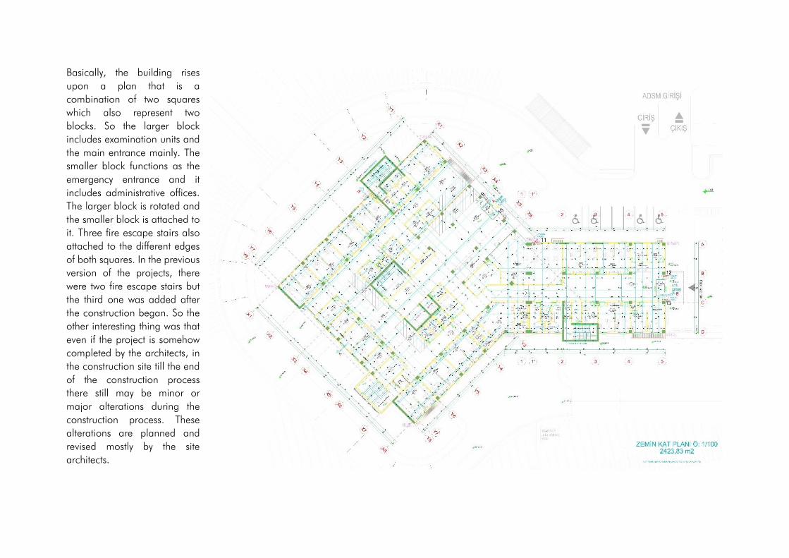
Basically, the building rises
upon a plan that is a
combination of two squares
which also represent two
blocks. So the larger block
includes examination units and
the main entrance mainly. The
smaller block functions as the
emergency entrance and it
includes administrative offices.
The larger block is rotated and
the smaller block is attached to
it. Three fire escape stairs also
attached to the different edges
of both squares. In the previous
version of the projects, there
were two fire escape stairs but
the third one was added after
the construction began. So the
other interesting thing was that
even if the project is somehow
completed by the architects, in
the construction site till the end
of the construction process
there still may be minor or
major alterations during the
construction process. These
alterations are planned and
revised mostly by the site
architects.

17.06.2019 - 19.06.2019
• Glass Curtain-wall Facade System (Silicone)
The glass curtain wall system was used in the main entrance part and the use of a glass facade differentiates and denotes the
main entrance well since it was not implied on the other facades of the building.
Mainly, glass curtain-wall systems create almost perfectly flush-fitted glass facades since the glass panels are at the same level
as the frame in which they are mounted. This appearance is achieved by using profiles (grid construction that the panels mounted
on) which are visible only from inside.
Double glazed units are bonded to the bar by using structural silicone. After the curtain-wall grid is produced at the site, glass
units locked into the grid by special connectors. Lastly, in order to create a smooth surface silicone is applied on the vertical
and horizontal joints. Glass curtain-wall facade was already complete except some openings where the entrance doors will be
mounted. Silicone strips had not applied on some of the joints between glass panels in the lower levels and it will be completed
later. Anchorage System
• Aluminum Composite Facade System
As one of the most common facade cladding system in modern architecture and construction field, aluminum composite facade systems are preferred for
not only exterior facade of the building but also interior surfaces. These panels can be in any shape and any color by request.
Aluminum composite panels are lighter comparing to other façade cladding materials, so structural load-bearing system elements and columns do not
carry huge extra loads. Since they are easy to clean and shape, and it provides a wide range of color options, aluminum composite panel façade systems
allow architects and engineers to create flexible designs. Durability, longevity, and insulation (thermal, fire, etc.) are also make composite panels more
desirable.
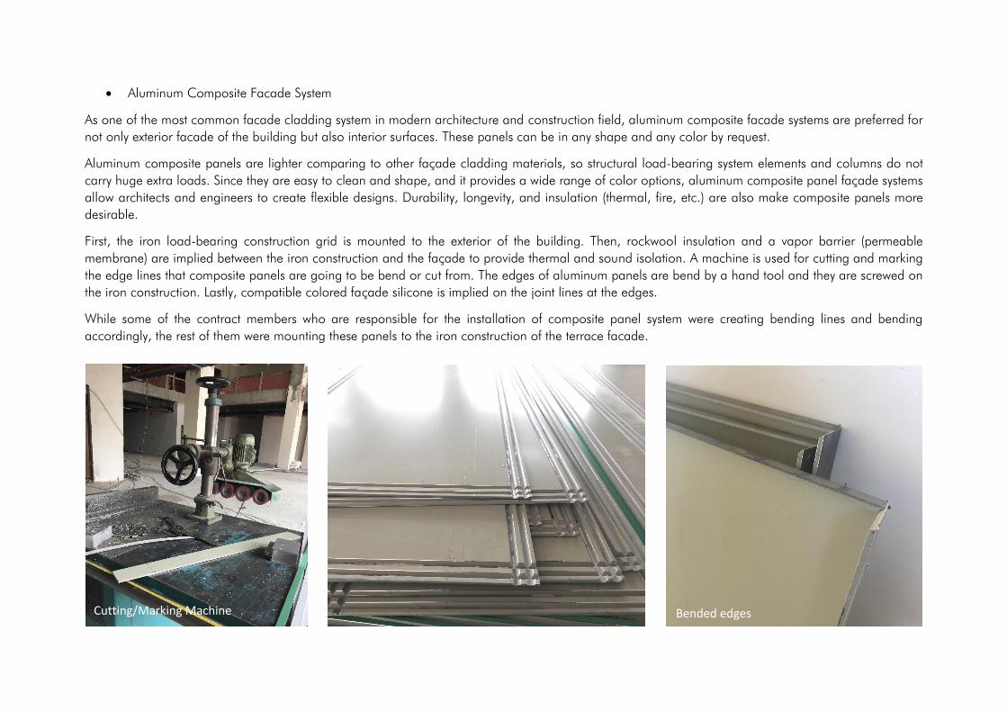
First, the iron load-bearing construction grid is mounted to the exterior of the building. Then, rockwool insulation and a vapor barrier (permeable
membrane) are implied between the iron construction and the façade to provide thermal and sound isolation. A machine is used for cutting and marking
the edge lines that composite panels are going to be bend or cut from. The edges of aluminum panels are bend by a hand tool and they are screwed on
the iron construction. Lastly, compatible colored façade silicone is implied on the joint lines at the edges.
While some of the contract members who are responsible for the installation of composite panel system were creating bending lines and bending
accordingly, the rest of them were mounting these panels to the iron construction of the terrace facade.
Cutting/Marking Machine Bended edges
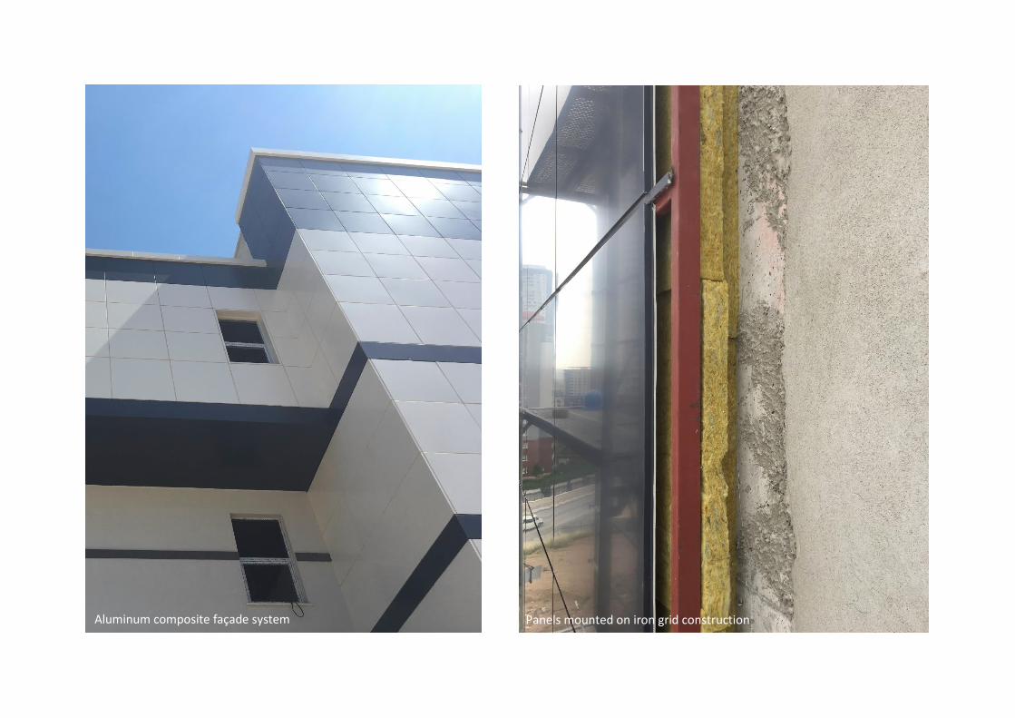
Panels mounted on iron grid construction Aluminum composite façade system

• BIMS (Pumice Brick)
As a very common material in the construction sector, BIMS has a low density due to its sponge-like porosity. This volcanic natural material is resistant to
physical and chemical effects, also it provides thermal and sound insulation thanks to its voids. Because of high elasticity both in Turkey and in other
countries, it is widely preferred as one of the favorite lightweight construction material. Because of its high elasticity, BIMS based materials are more resistant
compared to others. They can absorb and resist bending and breaking effects of seismic waves.
In order to achieve alignment and required levels while building a BIMS block wall, a string level is set. Between blocks mortar (includes cement, lime,
sand, and water) is used to stick blocks together. Each block is shifted in a way that it will load half of its weight to lower two blocks so that joints will not
be aligned in the vertical axis; which makes the whole wall more resistant to overturning.
For the walls of the building, BIMS blocks and ordinary bricks are main materials. The reason that normal bricks were also used is that resizing BIMS blocks
by cutting or shattering is harder compared to those of normal bricks. So, when smaller pieces are needed normal bricks were used rather than BIMS
blocks.
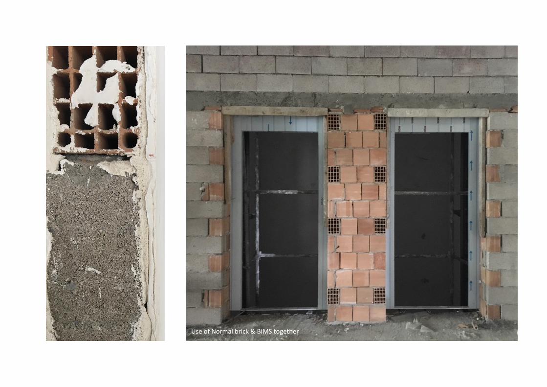
Use of Normal brick & BIMS together
20.06.2019 - 22.06.2019
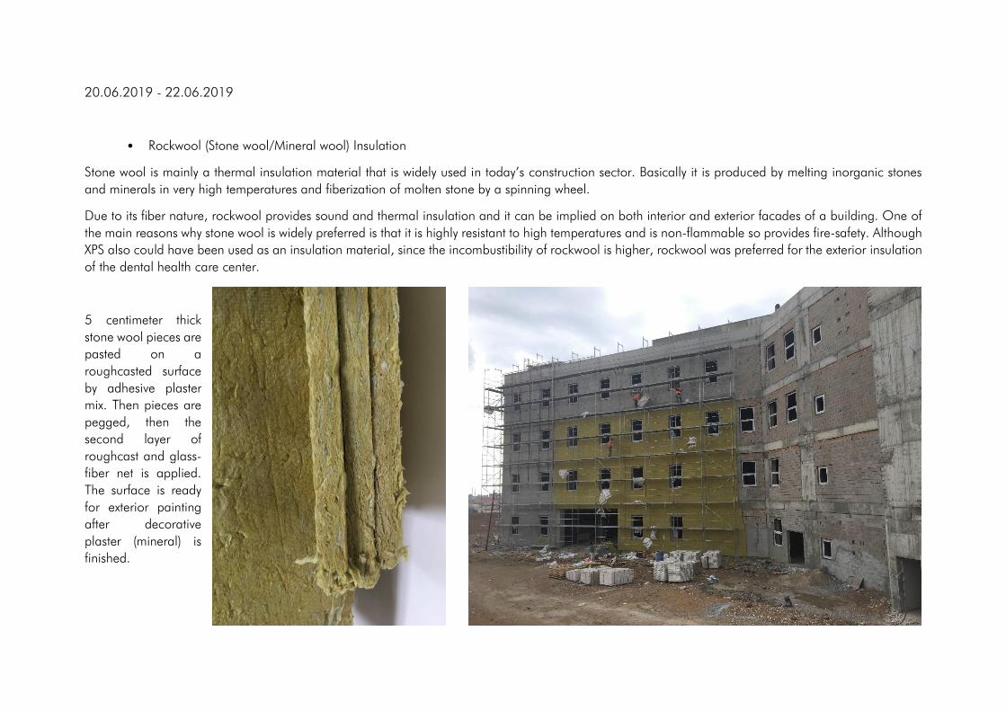
• Rockwool (Stone wool/Mineral wool) Insulation
Stone wool is mainly a thermal insulation material that is widely used in today’s construction sector. Basically it is produced by melting inorganic stones
and minerals in very high temperatures and fiberization of molten stone by a spinning wheel.
Due to its fiber nature, rockwool provides sound and thermal insulation and it can be implied on both interior and exterior facades of a building. One of
the main reasons why stone wool is widely preferred is that it is highly resistant to high temperatures and is non-flammable so provides fire-safety. Although
XPS also could have been used as an insulation material, since the incombustibility of rockwool is higher, rockwool was preferred for the exterior insulation
of the dental health care center.
5 centimeter thick
stone wool pieces are
pasted on a
roughcasted surface
by adhesive plaster
mix. Then pieces are
pegged, then the
second layer of
roughcast and glass-
fiber net is applied.
The surface is ready
for exterior painting
after decorative
plaster (mineral) is
finished.

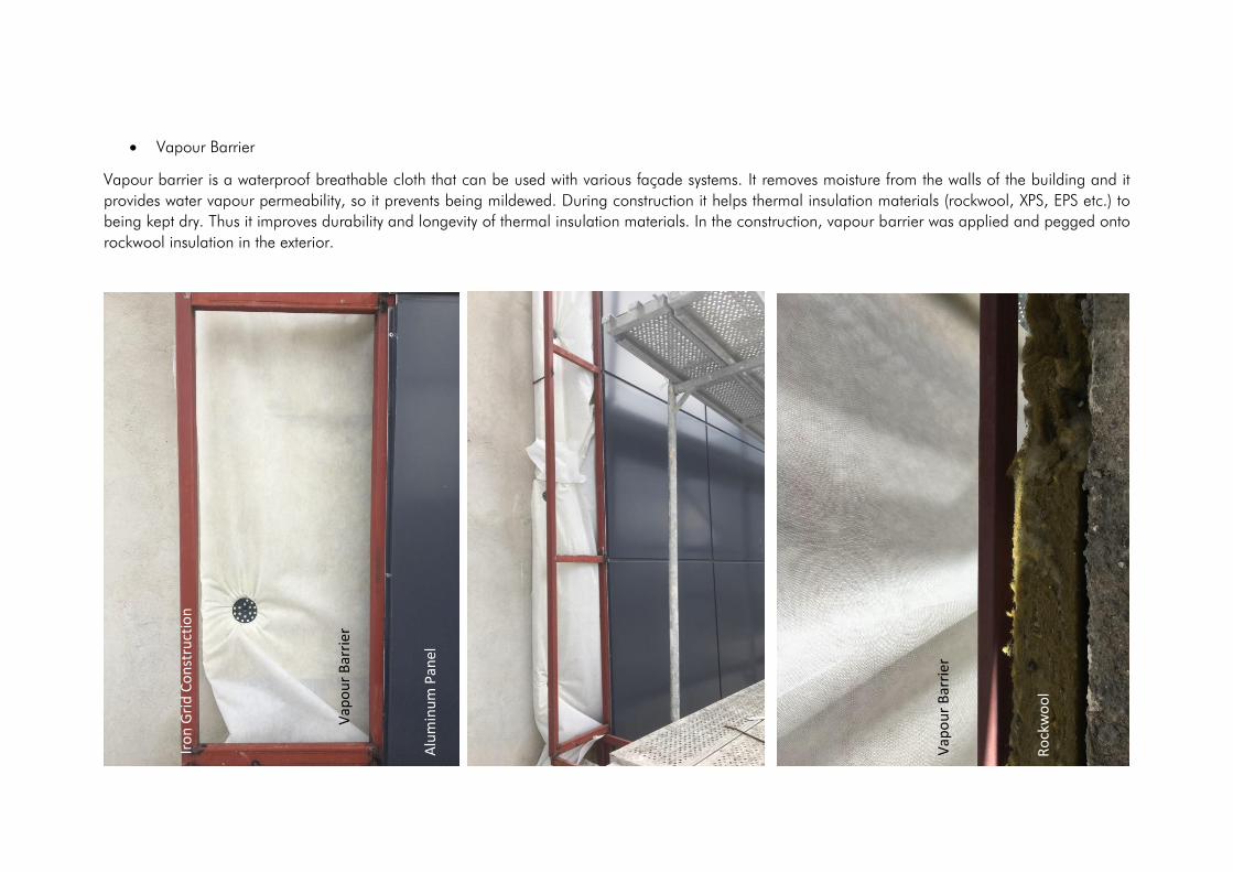
• Vapour Barrier
Vapour barrier is a waterproof breathable cloth that can be used with various façade systems. It removes moisture from the walls of the building and it
provides water vapour permeability, so it prevents being mildewed. During construction it helps thermal insulation materials (rockwool, XPS, EPS etc.) to
being kept dry. Thus it improves durability and longevity of thermal insulation materials. In the construction, vapour barrier was applied and pegged onto
rockwool insulation in the exterior.
Alu
min
um
Pan
el
Iro
n G
rid
Co
nst
ruct
ion
Vap
ou
r B
arri
er
Vap
ou
r B
arri
er
Ro
ckw
oo
l

• Fiberglass Net/Fiberglass Mesh
Fiberglass net is a reinforcing mesh that is woven from fiber glass material and it prevents plaster to crack. It is also known as plaster mesh, and it needs
to be applied beneath the plaster layer so that it meets the tension stress that plaster cannot bear. Especially in parts where columns and beams join
together and where brick walls and concrete load-bearing elements work together (as two different systems), fiberglass plaster meshes can prevent cracks
due to tension. These nets can be produced in different sizes and weights.
• Window Subframe
Window subframe is an actual frame
that is produced by using box profile
metal components. During brick wall
building, craftsmen leave the door
and window openings wider than
window frames that are going to be
mounted. A subframe is fitted in
between the wall and the window
frame in order to achieve a perfect fit
between the wall and the main
window frame. The gaps between the
subframe and the wall are filled with
polyurethane foam. filled with After
all the installations are done the
subframe and the polyurethane foam
are not visible since it is hidden as a
component of a wall.
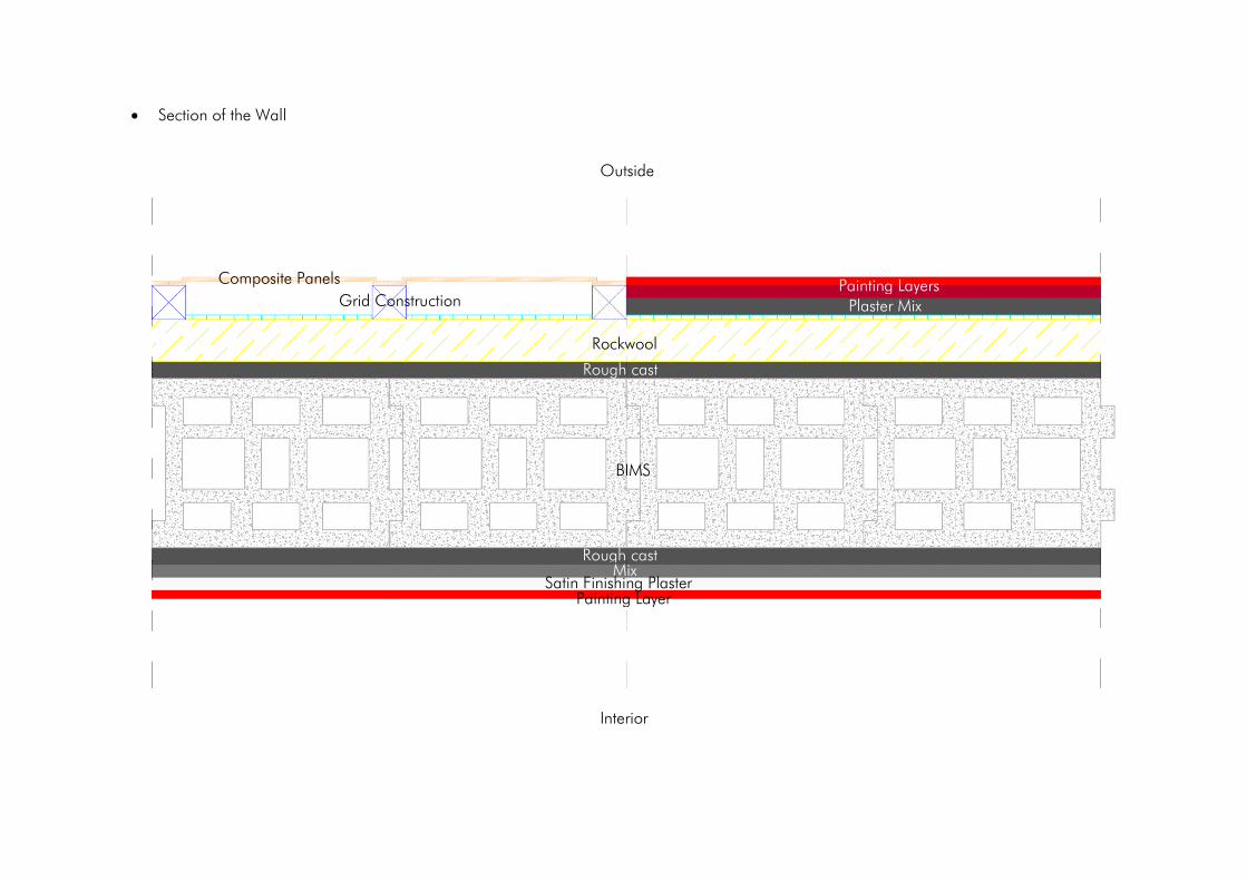
• Section of the Wall
BIMS
Rockwool
Rough cast
Plaster Mix Painting Layers
Mix Satin Finishing Plaster
Painting Layer
Composite Panels
Grid Construction
Outside
Interior
Rough cast
24.06.2019 - 26.06.2019
• Satin Surface Finishing Plaster
As a final coating plaster, satin plaster provides a very smooth finish for many surfaces such as concrete, brick wall and plasterboards. It covers the cavities,
burrs, and tissue deformations. After it is mixed with water by given proportions, mortar is applied to the surface with a trowel. Generally, the thickness of
satin plaster layer is 0.5 mm and after the application is done shaving with trowel improves the smoothness.
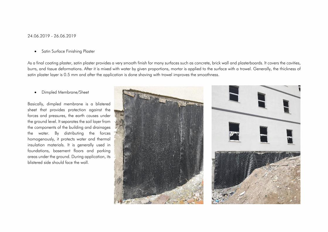
• Dimpled Membrane/Sheet
Basically, dimpled membrane is a blistered
sheet that provides protection against the
forces and pressures, the earth causes under
the ground level. It separates the soil layer from
the components of the building and drainages
the water. By distributing the forces
homogenously, it protects water and thermal
insulation materials. It is generally used in
foundations, basement floors and parking
areas under the ground. During application, its
blistered side should face the wall.
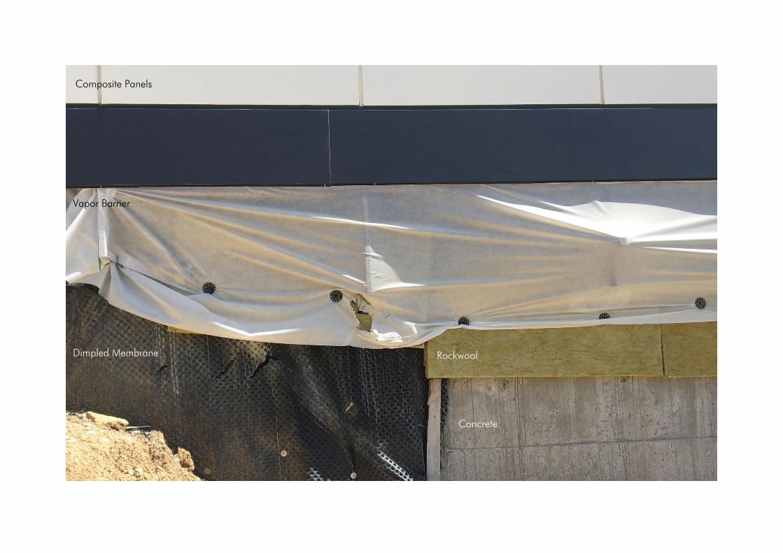
Composite Panels
Vapor Barrier
Dimpled Membrane Rockwool
Concrete
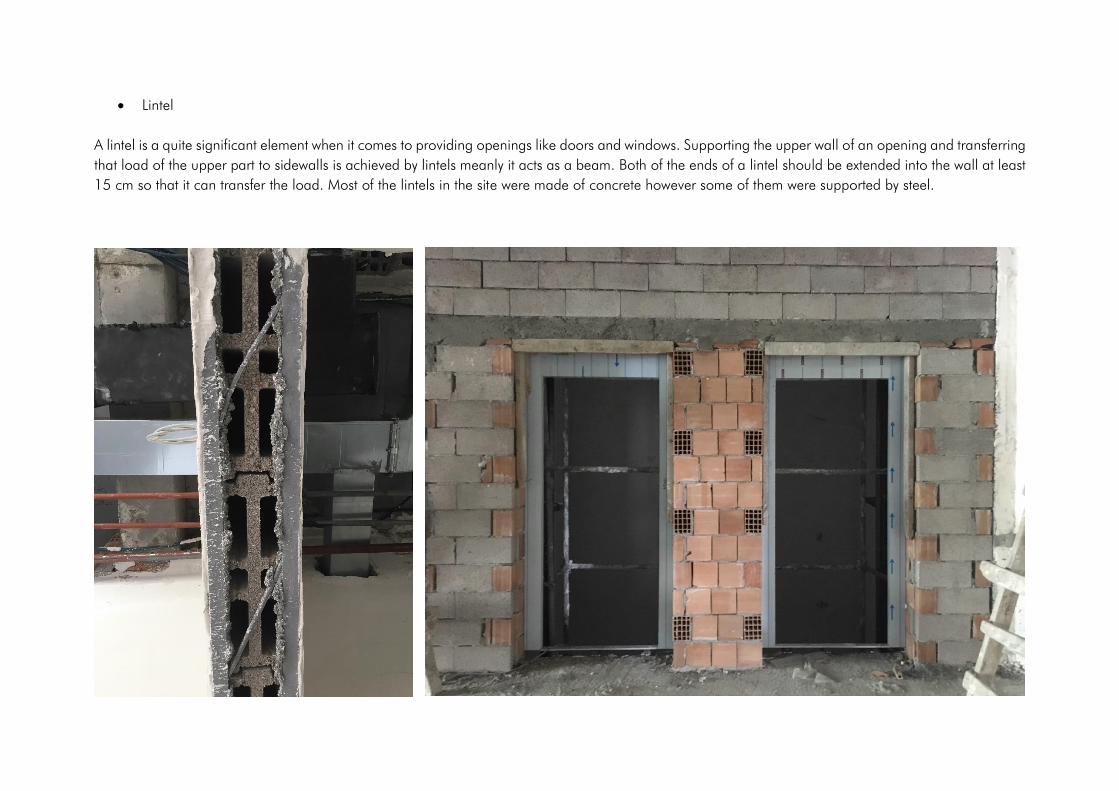
• Lintel
A lintel is a quite significant element when it comes to providing openings like doors and windows. Supporting the upper wall of an opening and transferring
that load of the upper part to sidewalls is achieved by lintels meanly it acts as a beam. Both of the ends of a lintel should be extended into the wall at least
15 cm so that it can transfer the load. Most of the lintels in the site were made of concrete however some of them were supported by steel.
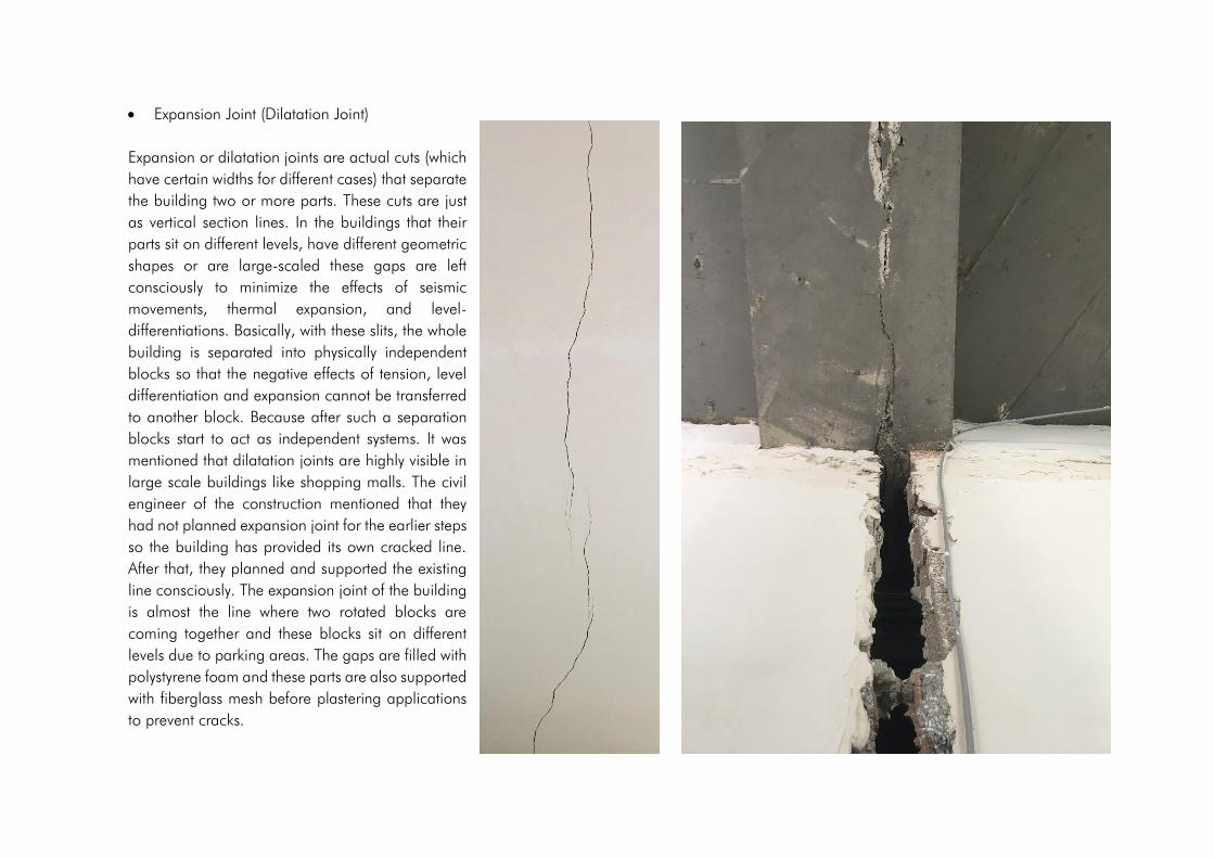
• Expansion Joint (Dilatation Joint)
Expansion or dilatation joints are actual cuts (which
have certain widths for different cases) that separate
the building two or more parts. These cuts are just
as vertical section lines. In the buildings that their
parts sit on different levels, have different geometric
shapes or are large-scaled these gaps are left
consciously to minimize the effects of seismic
movements, thermal expansion, and level-
differentiations. Basically, with these slits, the whole
building is separated into physically independent
blocks so that the negative effects of tension, level
differentiation and expansion cannot be transferred
to another block. Because after such a separation
blocks start to act as independent systems. It was
mentioned that dilatation joints are highly visible in
large scale buildings like shopping malls. The civil
engineer of the construction mentioned that they
had not planned expansion joint for the earlier steps
so the building has provided its own cracked line.
After that, they planned and supported the existing
line consciously. The expansion joint of the building
is almost the line where two rotated blocks are
coming together and these blocks sit on different
levels due to parking areas. The gaps are filled with
polystyrene foam and these parts are also supported
with fiberglass mesh before plastering applications
to prevent cracks.
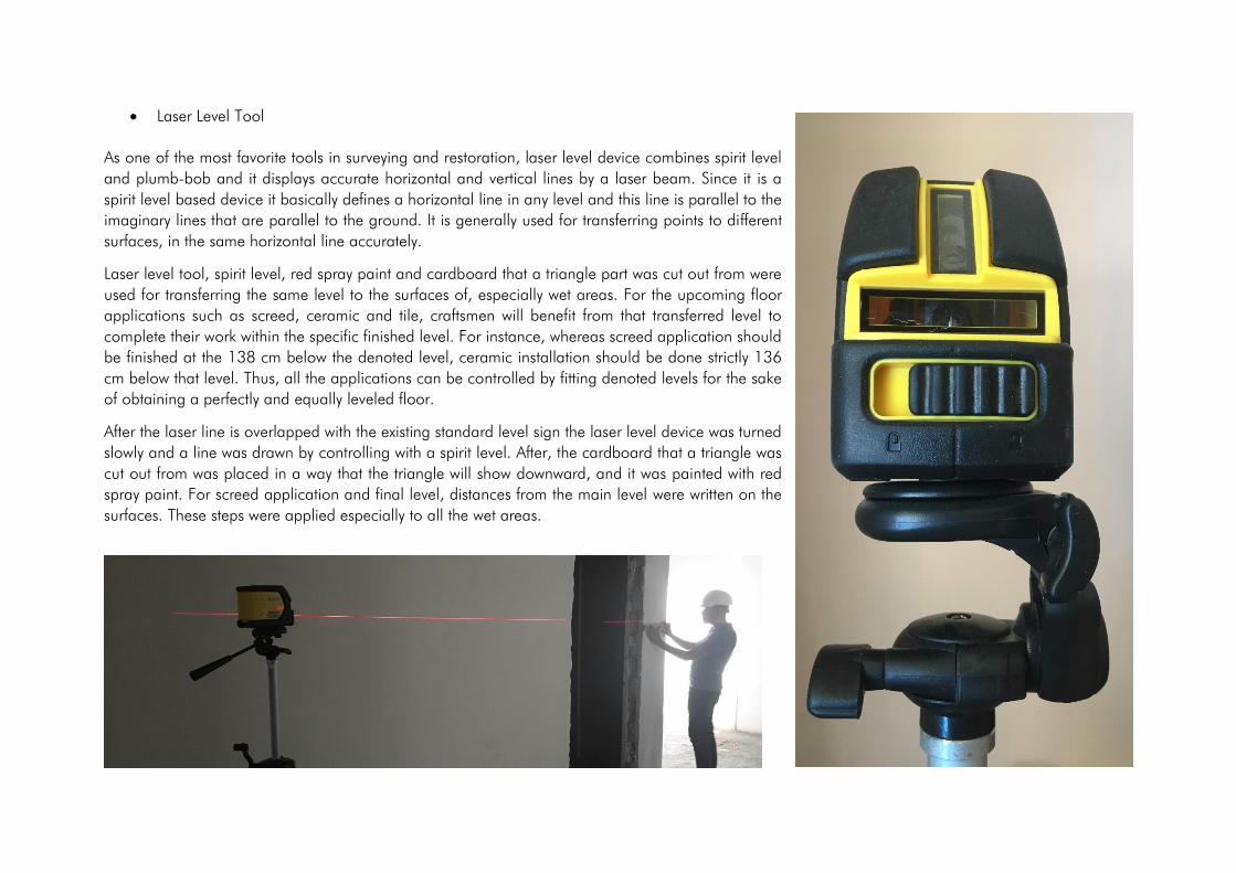
• Laser Level Tool
As one of the most favorite tools in surveying and restoration, laser level device combines spirit level
and plumb-bob and it displays accurate horizontal and vertical lines by a laser beam. Since it is a
spirit level based device it basically defines a horizontal line in any level and this line is parallel to the
imaginary lines that are parallel to the ground. It is generally used for transferring points to different
surfaces, in the same horizontal line accurately.
Laser level tool, spirit level, red spray paint and cardboard that a triangle part was cut out from were
used for transferring the same level to the surfaces of, especially wet areas. For the upcoming floor
applications such as screed, ceramic and tile, craftsmen will benefit from that transferred level to
complete their work within the specific finished level. For instance, whereas screed application should
be finished at the 138 cm below the denoted level, ceramic installation should be done strictly 136
cm below that level. Thus, all the applications can be controlled by fitting denoted levels for the sake
of obtaining a perfectly and equally leveled floor.
After the laser line is overlapped with the existing standard level sign the laser level device was turned
slowly and a line was drawn by controlling with a spirit level. After, the cardboard that a triangle was
cut out from was placed in a way that the triangle will show downward, and it was painted with red
spray paint. For screed application and final level, distances from the main level were written on the
surfaces. These steps were applied especially to all the wet areas.


• Ventilation System
For the buildings as hospitals and health centers heating, ventilating and air conditioning (HVAC) is one of the most important mechanical systems in terms
of minimizing airborne contaminations, providing fresh air, maintaining humidity and temperature and, heating/cooling. Basically, this system provides
clear airflow to enclosed areas. While some of the components function for sucking fresh air to spaces, others exhust polluted air from them. The whole
system consists of square ducts, fans, air-cleaning devices and many other components that support the system. Most of the ventilation canals were included
in the same vertical passageway/gap and is called ventilation shaft. Square ducts are mounted to each other and they are distributed to different floors
with different shaped ducts. In order to increase the efficiency and the insulation of the system, all of ducts are covered with a rubber sheet and craftsmen
applied silicone to joining surfaces of ducts. It was mentioned that the size and shape of ducts can be different for different types of projects. These huge
canals which are hanged to the ceilings are hidden by suspended ceiling applications, except parking areas.
Workers who are responsible for the ventilation system installation continued to cover ducts with rubber sheets and adding these to different branches that
thrives from the main canals in the ventilation shafts in the first and second floors.
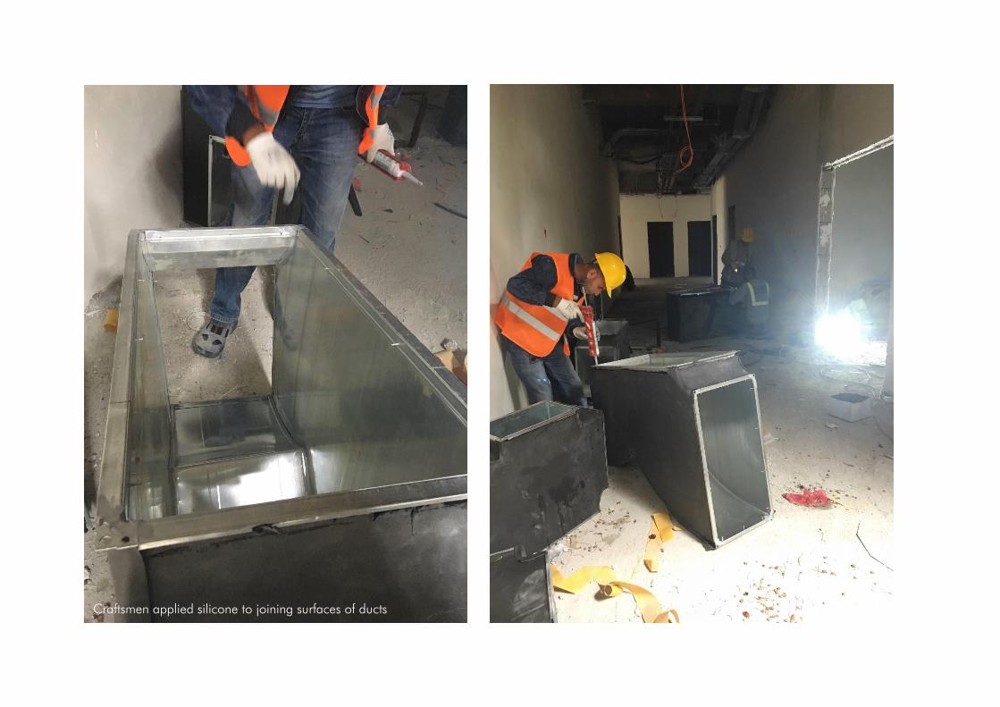
Craftsmen applied silicone to joining surfaces of ducts

Ventilation Shaft

27.06.2019 - 29.06.2019
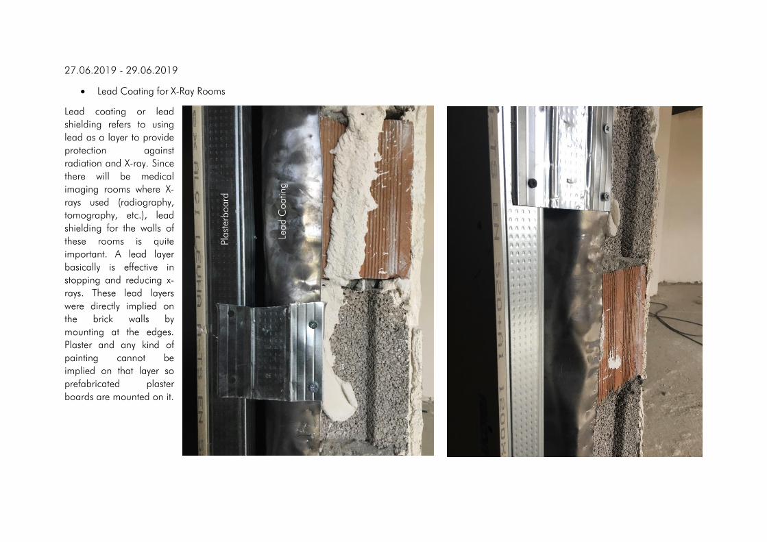
• Lead Coating for X-Ray Rooms
Lead coating or lead
shielding refers to using
lead as a layer to provide
protection against
radiation and X-ray. Since
there will be medical
imaging rooms where X-
rays used (radiography,
tomography, etc.), lead
shielding for the walls of
these rooms is quite
important. A lead layer
basically is effective in
stopping and reducing x-
rays. These lead layers
were directly implied on
the brick walls by
mounting at the edges.
Plaster and any kind of
painting cannot be
implied on that layer so
prefabricated plaster
boards are mounted on it.
Lead C
oatin
g
Plast
erboard
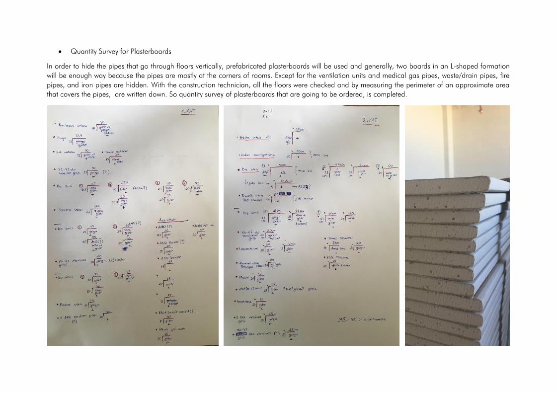
• Quantity Survey for Plasterboards
In order to hide the pipes that go through floors vertically, prefabricated plasterboards will be used and generally, two boards in an L-shaped formation
will be enough way because the pipes are mostly at the corners of rooms. Except for the ventilation units and medical gas pipes, waste/drain pipes, fire
pipes, and iron pipes are hidden. With the construction technician, all the floors were checked and by measuring the perimeter of an approximate area
that covers the pipes, are written down. So quantity survey of plasterboards that are going to be ordered, is completed.
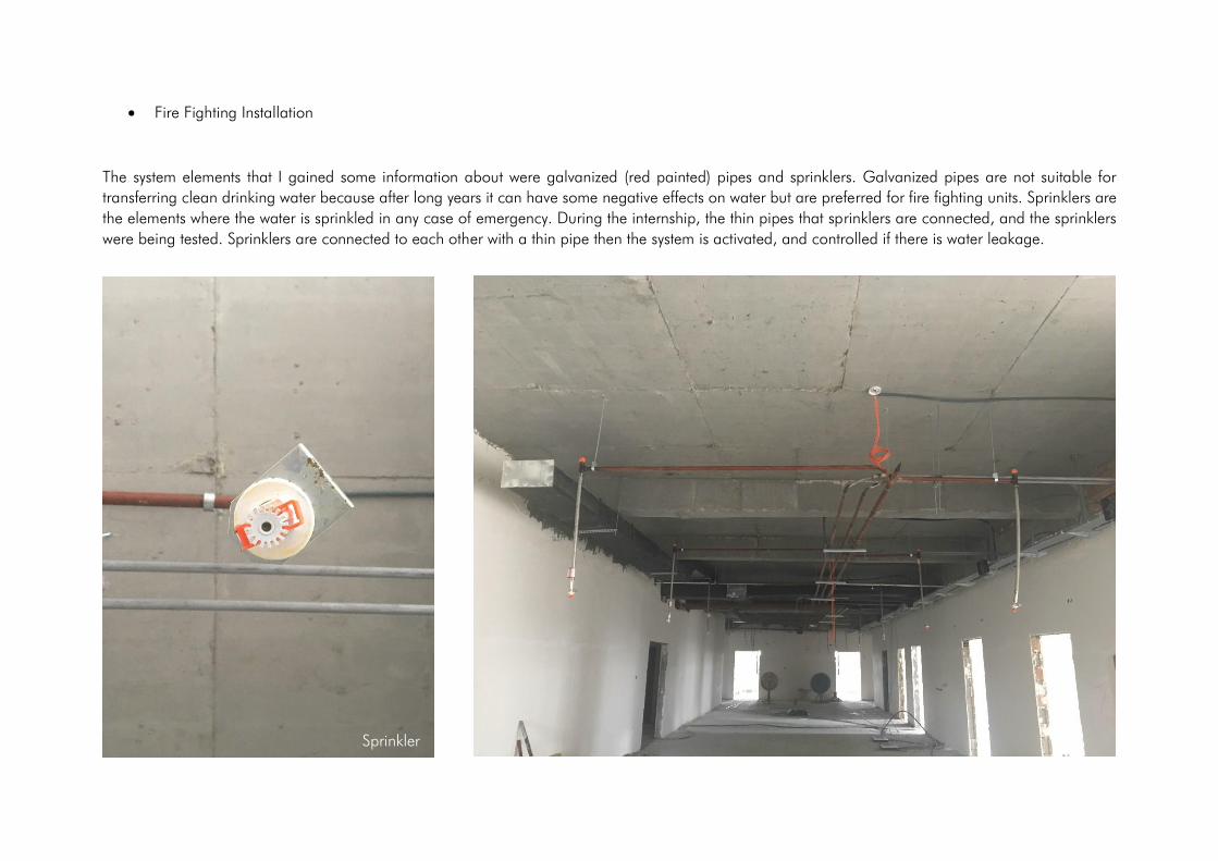
• Fire Fighting Installation
The system elements that I gained some information about were galvanized (red painted) pipes and sprinklers. Galvanized pipes are not suitable for
transferring clean drinking water because after long years it can have some negative effects on water but are preferred for fire fighting units. Sprinklers are
the elements where the water is sprinkled in any case of emergency. During the internship, the thin pipes that sprinklers are connected, and the sprinklers
were being tested. Sprinklers are connected to each other with a thin pipe then the system is activated, and controlled if there is water leakage.
Sprinkler

• PVC and PPRC Pipes
PPRC and PVC pipes are probably the most preferred pipe types in the construction field. Unlike galvanized pipes that are preferred for fire fighting systems,
PPRC and PVC pipes are suitable for cold/hot clean water transport both in the buildings and the underground parts of the system. These pipes are quite
resistant to corrosion that affects the quality of drinking water in terms of taste, smell, and color. According to the distance from the main distributor, pipes
in different perimeters are used. Pipes are mounted to walls by using the component which is called clamp. Wastewater that comes from air conditioners
is also transferred with these pipes.

• Medical Gas System
The medical gas system is another complex system that is housed in the construction of oral and dental health care center. The team that installs the pipes
and all kinds of system components to the building is a specialized team other than the teams responsible for mechanical systems such as water transport
and fire fighting system. There are five different gasses for medical purposes and for transferring galvanized thin pipes are used. At some points, these
pipes are connected to the gas releasing units that are connected to the gas tubes inside control rooms.
Med
ical G
as
Pipes

01.07.2019 - 04.07.2019
• Screed for Wet Floors
In order to achieve a smooth and flat surface, a layer that is a mix of sand and cement is laid over on a concrete subfloor and is called screed. This
concrete-like layer is equally leveled with the help of a screed board that is basically a wooden stick. This implication is very important for upcoming
installations like ceramics, tiles, and parquet. To install ceramics for wet floors afterward such as toilets and baths 5 cm screed layer is implied. The
necessary inclination for water to flow to filters can be also provided in this layer but it was mentioned that the inclination will be achieved in the ceramic
layer. The screed layer got almost completely dry a day later.
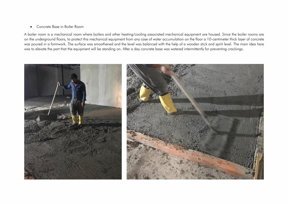
• Concrete Base in Boiler Room
A boiler room is a mechanical room where boilers and other heating/cooling associated mechanical equipment are housed. Since the boiler rooms are
on the underground floors, to protect this mechanical equipment from any case of water accumulation on the floor a 10-centimeter thick layer of concrete
was poured in a formwork. The surface was smoothened and the level was balanced with the help of a wooden stick and spirit level. The main idea here
was to elevate the part that the equipment will be standing on. After a day concrete base was watered intermittently for preventing crackings.

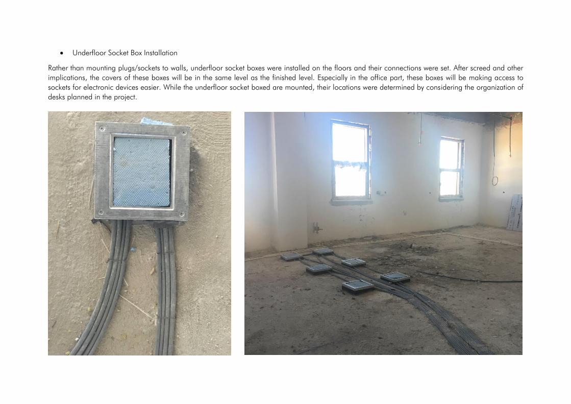
• Underfloor Socket Box Installation
Rather than mounting plugs/sockets to walls, underfloor socket boxes were installed on the floors and their connections were set. After screed and other
implications, the covers of these boxes will be in the same level as the finished level. Especially in the office part, these boxes will be making access to
sockets for electronic devices easier. While the underfloor socket boxed are mounted, their locations were determined by considering the organization of
desks planned in the project.

• Ceramic Implications on Wet Floors
In order to place ceramic tiles to the surfaces in a way that leftover parts will be minimum and aesthetically proper, the placement of 30x60 ceramic tiles
with 3-millimeter joint lines is planned and drawn digitally. After the water insulation chemical got dried adhesive mortar was spread by notched trowel.
Ceramic tiles were placed by tapping it gently with a soft tip mallet. 3-millimeter tile spacers were put at the corners and edges of tiles. These steps continued
to be applied both on the floors and the walls. Spirit level was used frequently to achieve the finished level. By providing a slight inclination towards the
filters on the floor, the water flow direction was controlled. When resizing was necessary ceramic tiles were cut with a tool.


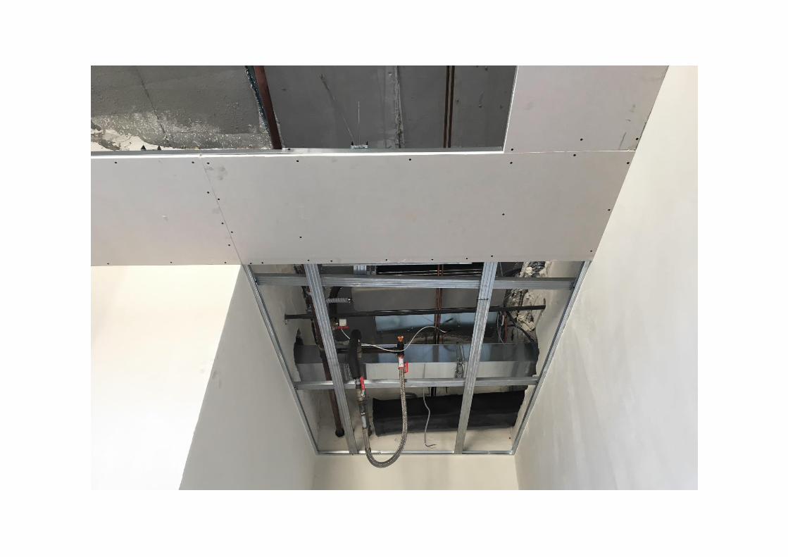
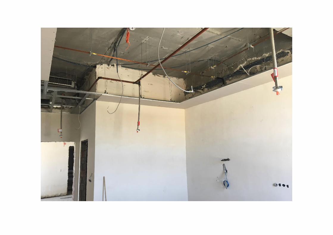
• Suspended Ceiling Installation
Suspended or dropped ceiling is a secondary ceiling that is hung below the main concrete ceiling (floor slabs) and it provides a void for mechanical and
electrical systems components above it. After the level that the ceiling planned to be installed was decided, the lines were drawn on the walls and controlled
carefully by spirit level. Wall angles, that are long L-shaped pieces to support runners and other grid components, were sized accordingly and mounted on
the drawn level lines all around the room. Hanging wires with a hook-like part on the end were also mounted to the actual ceiling for carrying tiles and
runners from above. Plasterboard panels were placed on the edge parts of the grid construction. Runners and panels were connected to hanging wires. In
the upcoming steps, the middle parts of the grid construction are going to be completed and square tiles will be placed till the whole ceiling is covered.
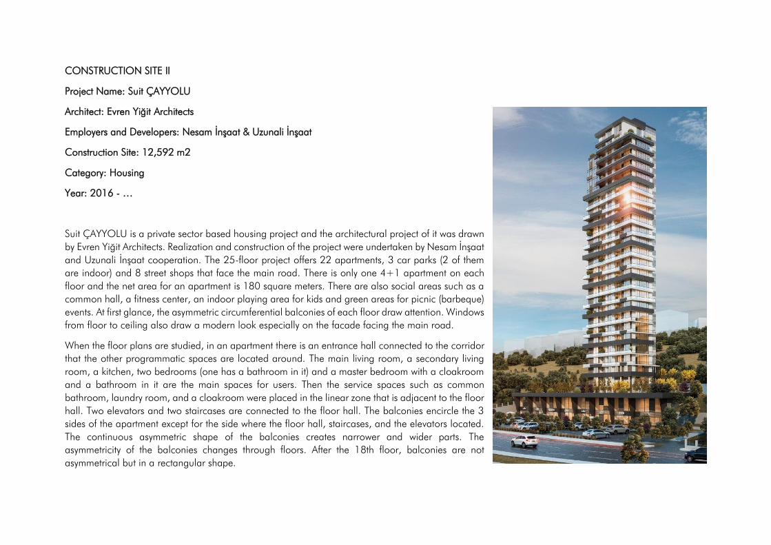
CONSTRUCTION SITE II
Project Name: Suit ÇAYYOLU
Architect: Evren Yiğit Architects
Employers and Developers: Nesam İnşaat & Uzunali İnşaat
Construction Site: 12,592 m2
Category: Housing
Year: 2016 - …
Suit ÇAYYOLU is a private sector based housing project and the architectural project of it was drawn
by Evren Yiğit Architects. Realization and construction of the project were undertaken by Nesam İnşaat
and Uzunali İnşaat cooperation. The 25-floor project offers 22 apartments, 3 car parks (2 of them
are indoor) and 8 street shops that face the main road. There is only one 4+1 apartment on each
floor and the net area for an apartment is 180 square meters. There are also social areas such as a
common hall, a fitness center, an indoor playing area for kids and green areas for picnic (barbeque)
events. At first glance, the asymmetric circumferential balconies of each floor draw attention. Windows
from floor to ceiling also draw a modern look especially on the facade facing the main road.
When the floor plans are studied, in an apartment there is an entrance hall connected to the corridor
that the other programmatic spaces are located around. The main living room, a secondary living
room, a kitchen, two bedrooms (one has a bathroom in it) and a master bedroom with a cloakroom
and a bathroom in it are the main spaces for users. Then the service spaces such as common
bathroom, laundry room, and a cloakroom were placed in the linear zone that is adjacent to the floor
hall. Two elevators and two staircases are connected to the floor hall. The balconies encircle the 3
sides of the apartment except for the side where the floor hall, staircases, and the elevators located.
The continuous asymmetric shape of the balconies creates narrower and wider parts. The
asymmetricity of the balconies changes through floors. After the 18th floor, balconies are not
asymmetrical but in a rectangular shape.
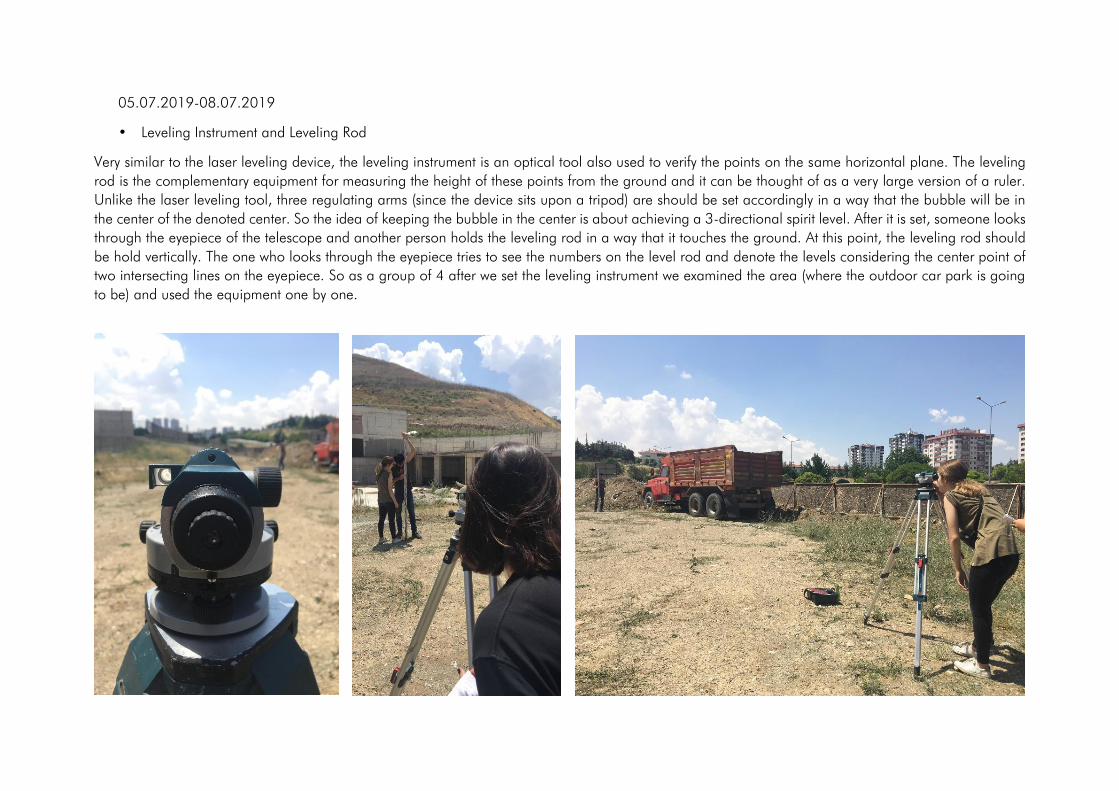
05.07.2019-08.07.2019
• Leveling Instrument and Leveling Rod
Very similar to the laser leveling device, the leveling instrument is an optical tool also used to verify the points on the same horizontal plane. The leveling
rod is the complementary equipment for measuring the height of these points from the ground and it can be thought of as a very large version of a ruler.
Unlike the laser leveling tool, three regulating arms (since the device sits upon a tripod) are should be set accordingly in a way that the bubble will be in
the center of the denoted center. So the idea of keeping the bubble in the center is about achieving a 3-directional spirit level. After it is set, someone looks
through the eyepiece of the telescope and another person holds the leveling rod in a way that it touches the ground. At this point, the leveling rod should
be hold vertically. The one who looks through the eyepiece tries to see the numbers on the level rod and denote the levels considering the center point of
two intersecting lines on the eyepiece. So as a group of 4 after we set the leveling instrument we examined the area (where the outdoor car park is going
to be) and used the equipment one by one.
• Subcontracted Worker Teams
In the construction site, there were three teams for different or related fields of the construction process. These teams were electricians, concrete formwork
team and ironworkers. 10 ironworker, 8 concrete formworker and two electricians continued to work.
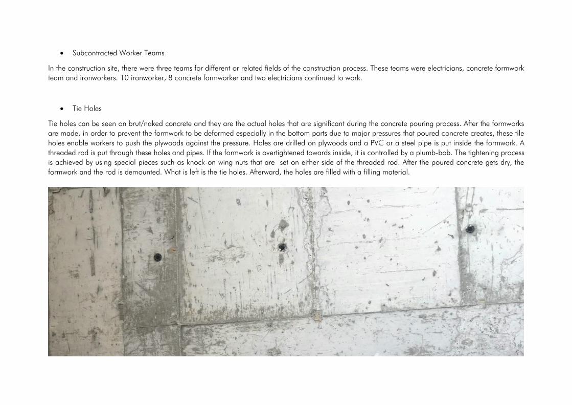
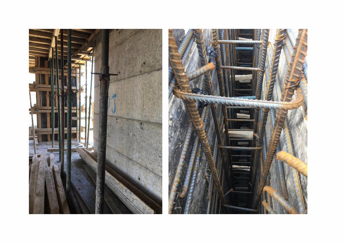
• Tie Holes
Tie holes can be seen on brut/naked concrete and they are the actual holes that are significant during the concrete pouring process. After the formworks
are made, in order to prevent the formwork to be deformed especially in the bottom parts due to major pressures that poured concrete creates, these tile
holes enable workers to push the plywoods against the pressure. Holes are drilled on plywoods and a PVC or a steel pipe is put inside the formwork. A
threaded rod is put through these holes and pipes. If the formwork is overtightened towards inside, it is controlled by a plumb-bob. The tightening process
is achieved by using special pieces such as knock-on wing nuts that are set on either side of the threaded rod. After the poured concrete gets dry, the
formwork and the rod is demounted. What is left is the tie holes. Afterward, the holes are filled with a filling material.
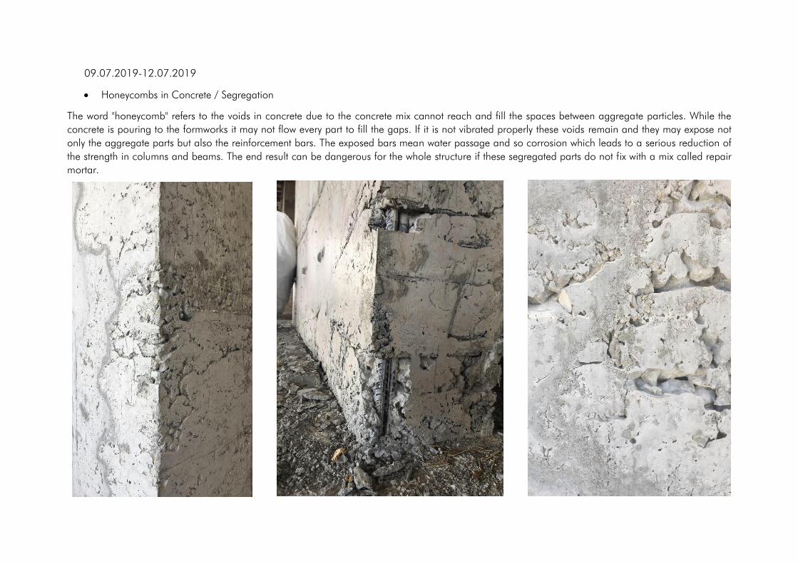
09.07.2019-12.07.2019
• Honeycombs in Concrete / Segregation
The word "honeycomb" refers to the voids in concrete due to the concrete mix cannot reach and fill the spaces between aggregate particles. While the
concrete is pouring to the formworks it may not flow every part to fill the gaps. If it is not vibrated properly these voids remain and they may expose not
only the aggregate parts but also the reinforcement bars. The exposed bars mean water passage and so corrosion which leads to a serious reduction of
the strength in columns and beams. The end result can be dangerous for the whole structure if these segregated parts do not fix with a mix called repair
mortar.

• Sample Apartment for Showing
The sample apartment is more about the marketing part of the construction site and it is a complete apartment ready to live in. To possible buyers this
completed sample apartment is presented. The sample apartment on the second floor also provides an earlier trial and error for the finished work and can
control the upcoming problems and/or future alterations for the other apartments. Especially the underfloor heating/cooling system, the colors of the doors
and the locations of sockets were testing in this apartment during my internship.
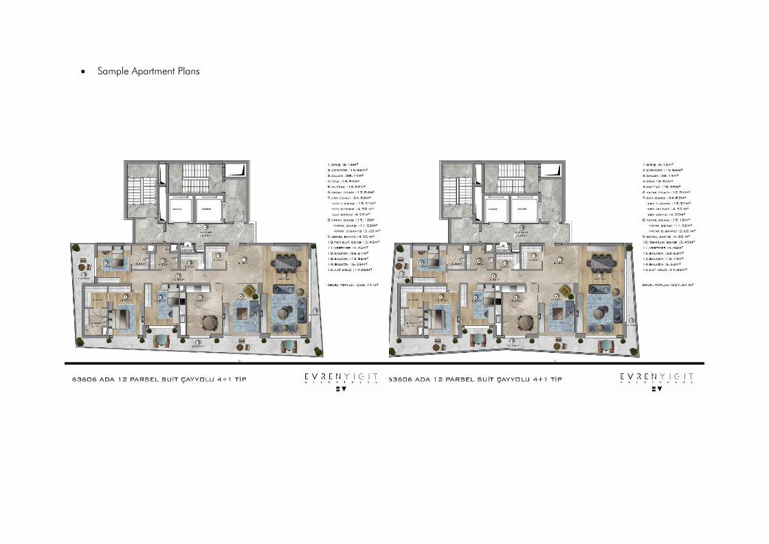
• Sample Apartment Plans

• Slab Reinforcement (21st Floor)
All the concrete elements in the construction include iron bars and their specific connections, that are strictly denoted static project. Basically these iron
bars or rods provide strength and reinforcement against compression and tension stresses. In the slab reinforcement, the aim is to transfer loads of the slab
to columns and shear walls through beams and being able to carry the cantilever parts such as balconies with the main slab. Basically a grid system is
produced in multiple layers with iron bars in different thicknesses, and most of the intersection point of each bar with another is connected with a wire and
fixed. Iron pieces that are called "chair rebar" are often put under the grid for preventing it to bend through downward. A series of thicker and longer bars
are put in a crosswise manner in order to meet extra stress at these zones where the balconies (cantilever parts) are placed. These unique bars are called
"şapo" in Turkish. In order to keep the reinforcement in place (in concrete) pieces of stones were used as spacers between the reinforcement and the slab
plywoods
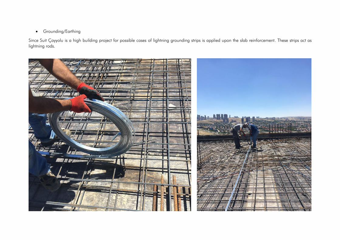
• Grounding/Earthing
Since Suit Çayyolu is a high building project for possible cases of lightning grounding strips is applied upon the slab reinforcement. These strips act as
lightning rods.
13.07.2019-17.07.2019
Açıklama Adet En Boy Yükseklik G11 1 0,25 1,55 3,18 1,23225
G10 1 0,25 0,95 3,18 0,75525
G8 1 0,25 1,2 3,18 0,954
G6 1 0,25 1,2 3,18 0,954
G3 1 0,25 1,2 3,18 0,954
G1 1 0,25 2,65 3,18 2,10675
F10 1 0,25 1 3,18 0,795
F7 1 0,25 2,4 3,18 1,908
F2 1 0,25 4,75 3,18 3,77625
E11 1 0,25 1,55 3,18 1,23225
E10 1 0,25 2,65 3,18 2,10675
E6 1 0,25 2,65 3,18 2,10675
E3 1 0,25 2,65 3,18 2,10675
E1 1 0,25 1,45 3,18 1,15275
Ç.P. 1 0,25 40,05 3,18 31,83975
K2211 1 0,25 33,8 0,38 3,211
K2213 1 0,25 3,4 0,6 0,51
DÖŞEME 1 334,55 0,22 1 73,601
D.M. 1 -2,5 0,22 1 -0,55
D.M. 1 -6,37 0,22 1 -1,4014
D.M. 1 -5,635 0,22 1 -1,2397
D.M. 1 -3,57 0,22 1 -0,7854
D.M. 2 -7,05 0,22 1 -3,102
D.M. 4 0,894 1,25 1 4,47
128,694
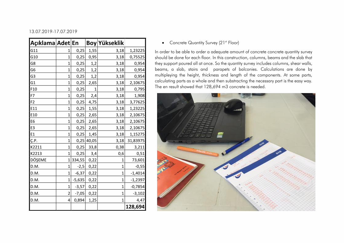
• Concrete Quantity Survey (21st Floor)
In order to be able to order a adequate amount of concrete concrete quantity survey
should be done for each floor. In this construction, columns, beams and the slab that
they support poured all at once. So the quantity survey includes columns, shear walls,
beams, a slab, stairs and parapets of balconies. Calculations are done by
multipleying the height, thickness and length of the components. At some parts,
calculating parts as a whole and then substracting the necessary part is the easy way.
The en result showed that 128,694 m3 concrete is needed.
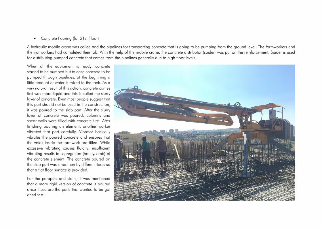
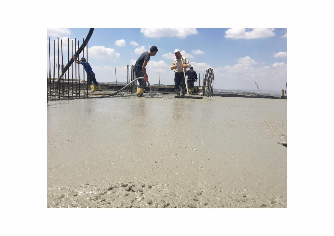
• Concrete Pouring (for 21st Floor)
A hydraulic mobile crane was called and the pipelines for transporting concrete that is going to be pumping from the ground level. The formworkers and
the ironworkers had completed their job. With the help of the mobile crane, the concrete distributor (spider) was put on the reinforcement. Spider is used
for distributing pumped concrete that comes from the pipelines generally due to high floor levels.
When all the equipment is ready, concrete
started to be pumped but to ease concrete to be
pumped through pipelines, at the beginning a
little amount of water is mixed to the tank. As a
very natural result of this action, concrete comes
first was more liquid and this is called the slurry
layer of concrete. Even most people suggest that
this part should not be used in the construction,
it was poured to the slab part. After the slurry
layer of concrete was poured, columns and
shear walls were filled with concrete first. After
finishing pouring an element, another worker
vibrated that part carefully. Vibrator basically
vibrates the poured concrete and ensures that
the voids inside the formwork are filled. While
excessive vibrating causes fluidity, insufficient
vibrating results in segregation (honeycomb) of
the concrete element. The concrete poured on
the slab part was smoothen by different tools so
that a flat floor surface is provided.
For the parapets and stairs, it was mentioned
that a more rigid version of concrete is poured
since these are the parts that wanted to be got
dried fast.

Pouring the columns and the shear walls

Vibrating the poured concrete in the columns and shear walls
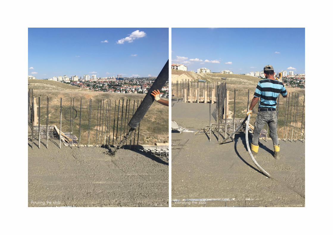
Pouring the slab Vibrating the slab

More solid concrete poured in stairs More solid concrete poured in stairs and vibrated

• Occupational Health and Safety Training & Exam
For the new workers and interns (for us) who are attending the construction site, the expert gave a short informative lecture about the construction site and
its safety preventions, the actions should and should not be taken in the site and the specific signs. We took the exam prepared to evaluate the knowledge
of safety rules and actions.

• Formwork Disassemble/Undo
After the day concrete pouring for the 21st floor was completed, the six workers of formwork
team started to undo the formworks of columns, beams, and shear walls. The nails on plywoods,
on timber studs, on double wales, on braces, and on stakes were removed by an iron hand
tool named "manila" in Turkish. All the timber pieces (5x10 and 10x10) were gathered to be
used for the next floor.
• Water Curing of Concrete and Shrinkage Cracks
Water, cement, sand, and gravel are the components of ordinary concrete and it is known that
the chemical reaction between these components, in fact, completed in approximately 28 days.
Which means concrete reaches its ideal strength after a month. During this process since the
reaction is exothermic one can feel the warmth of the columns by touching. Concrete, in this
period, loses moisture due to hydration. Quick water evaporation from the surfaces can lead
to stress and shrinkage cracks. So concrete slabs need to be watered frequently, especially the
first 5 days after pouring. So the 21st-floor slab was watered by caretaker at the night, and by
the formworkers during the day.
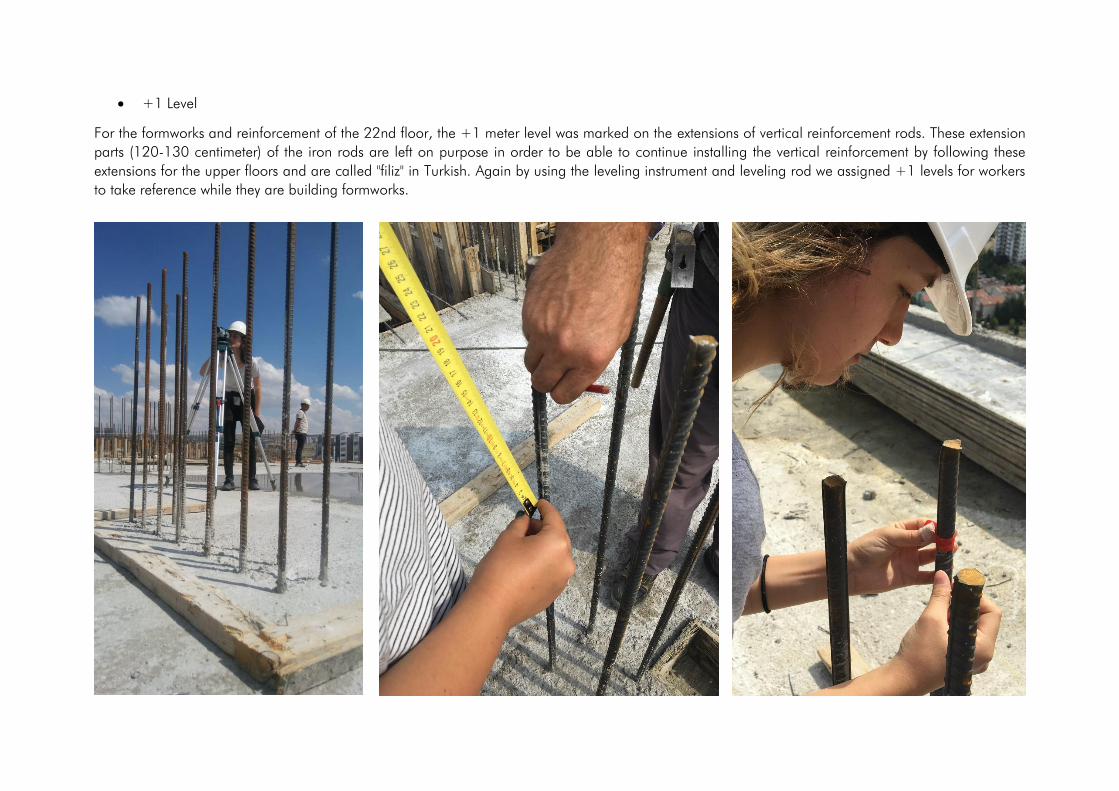
• +1 Level
For the formworks and reinforcement of the 22nd floor, the +1 meter level was marked on the extensions of vertical reinforcement rods. These extension
parts (120-130 centimeter) of the iron rods are left on purpose in order to be able to continue installing the vertical reinforcement by following these
extensions for the upper floors and are called "filiz" in Turkish. Again by using the leveling instrument and leveling rod we assigned +1 levels for workers
to take reference while they are building formworks.
18.07.2019-21.07.2019
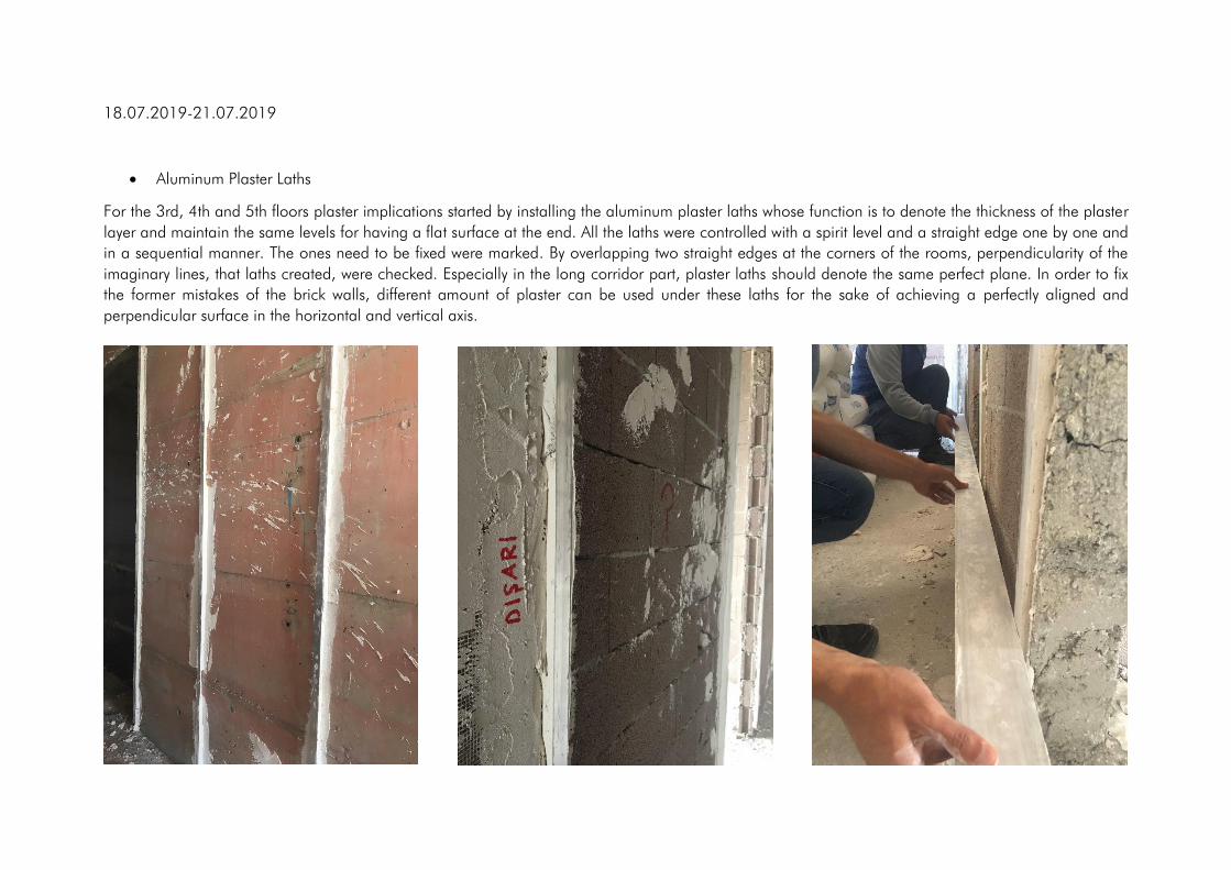
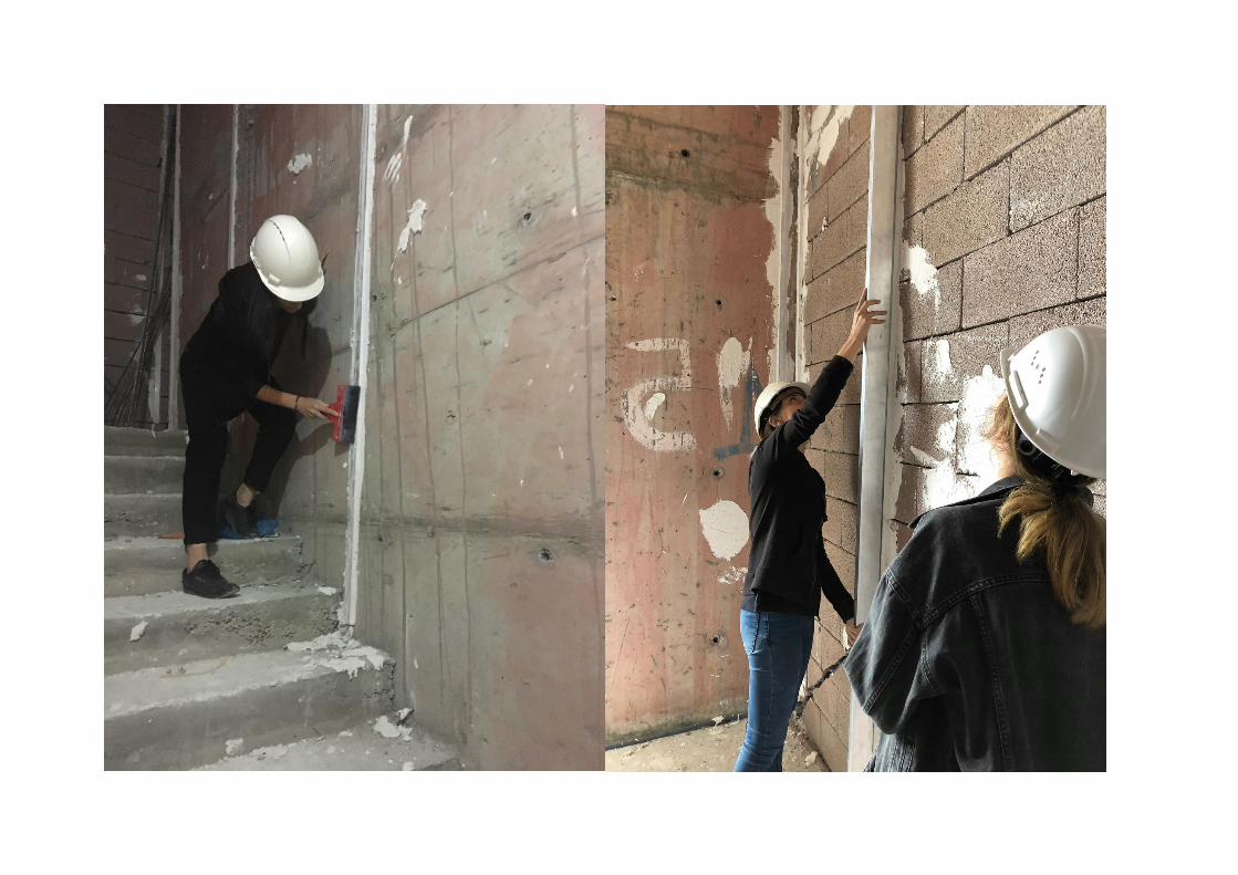
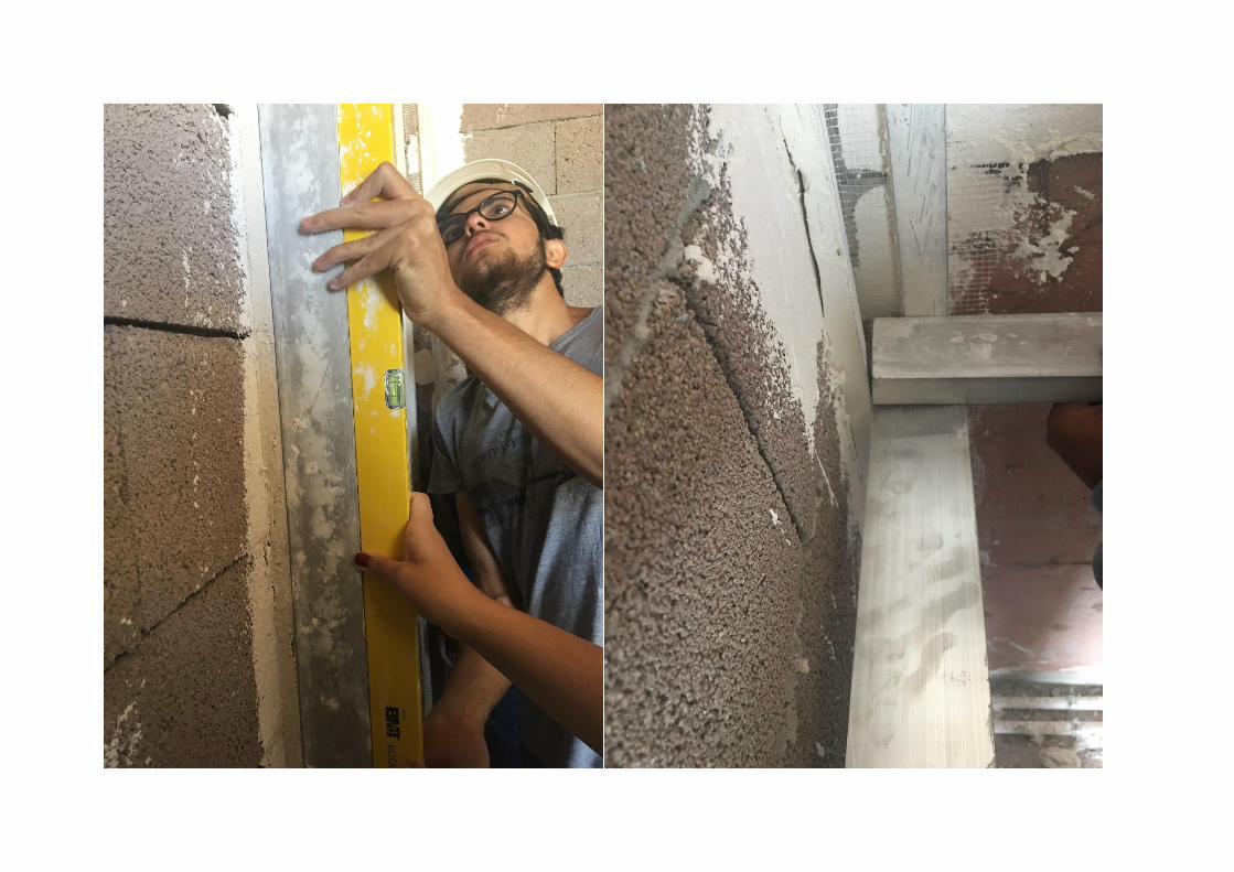
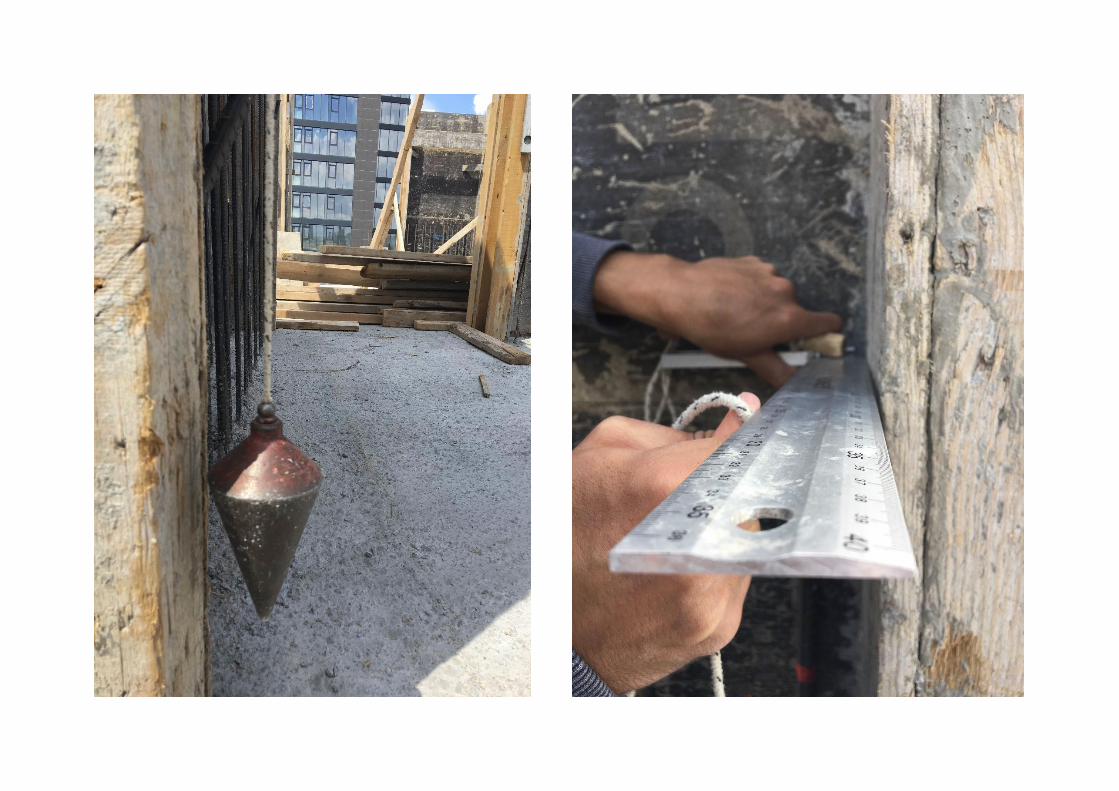
• Aluminum Plaster Laths
For the 3rd, 4th and 5th floors plaster implications started by installing the aluminum plaster laths whose function is to denote the thickness of the plaster
layer and maintain the same levels for having a flat surface at the end. All the laths were controlled with a spirit level and a straight edge one by one and
in a sequential manner. The ones need to be fixed were marked. By overlapping two straight edges at the corners of the rooms, perpendicularity of the
imaginary lines, that laths created, were checked. Especially in the long corridor part, plaster laths should denote the same perfect plane. In order to fix
the former mistakes of the brick walls, different amount of plaster can be used under these laths for the sake of achieving a perfectly aligned and
perpendicular surface in the horizontal and vertical axis.
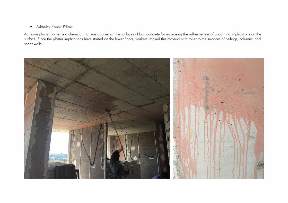
• Adhesive Plaster Primer
Adhesive plaster primer is a chemical that was applied on the surfaces of brut concrete for increasing the adhesiveness of upcoming implications on the
surface. Since the plaster implications have started on the lower floors, workers implied this material with roller to the surfaces of ceilings, columns, and
shear walls.
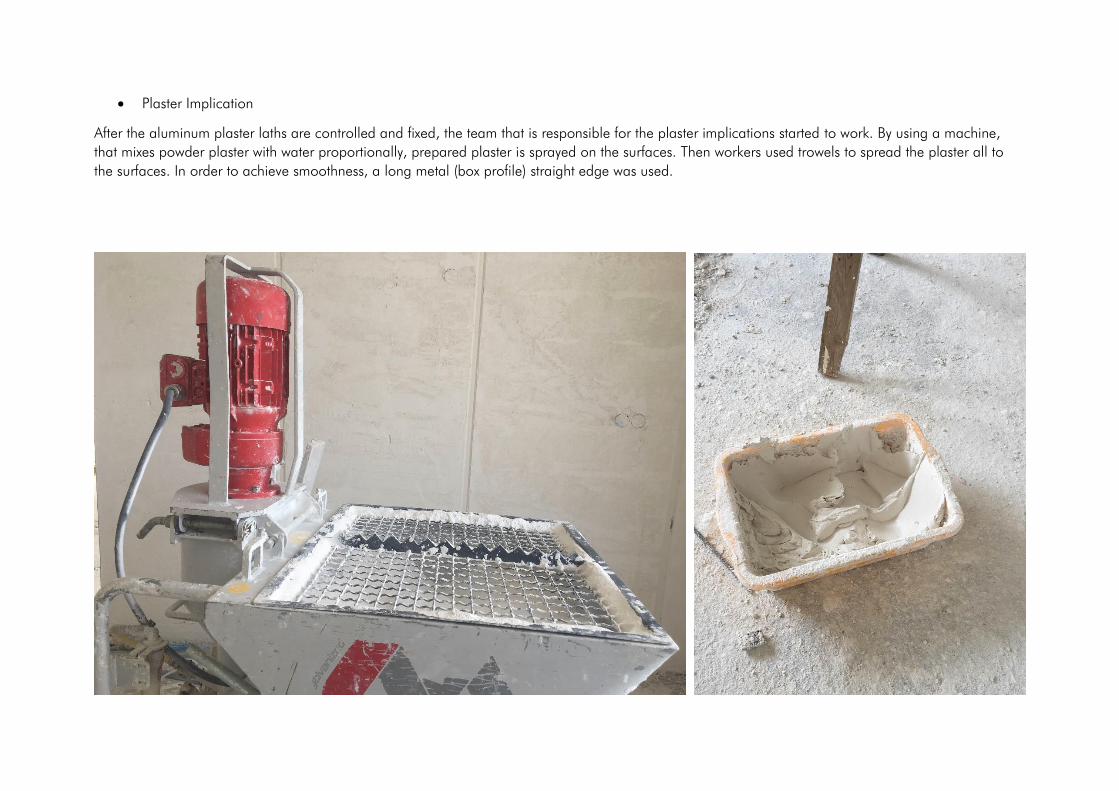
• Plaster Implication
After the aluminum plaster laths are controlled and fixed, the team that is responsible for the plaster implications started to work. By using a machine,
that mixes powder plaster with water proportionally, prepared plaster is sprayed on the surfaces. Then workers used trowels to spread the plaster all to
the surfaces. In order to achieve smoothness, a long metal (box profile) straight edge was used.


22nd Floor Formwork & Reinforcement (21.07.2019-25.07.2019)
•


• 22nd Floor Concrete Pouring