aquarea installation guide 1.2 - panasonic pro club
TRANSCRIPT

AQUAREA INSTALLATION GUIDE 1.2MONOBLOC SOLUTIONS H & J GENERATION
WelcomeThank you for selecting a Panasonic Aquarea Monobloc A2W Heat Pump. Panasonic has been manufacturing A2W (Air to Water) Heat Pumps since 1973 and have become synonymous with market leading performance, efficiency and reliability.
Panasonic Aquarea Monobloc heat pump comes as standard with the following items:
1. Heat Pump Controller2. Circulating Pump3. Expansion Vessel (for primary hot water)4. Strainer (Filter)5. Magnetic Filter (J Series)6. Pressure Relief Valve7. Bottom Mounting Rails8. Built in Electric Backup Heater used for:
a. Additional output support, depending on design (if required)b. Backup for DHW tank sterilisation operation (if required)c. Heat Pump protection in cold periods (if required)d. Assistance with defrost operation (if required)
By including the above components inside the Heat Pump, the Panasonic Aquarea is one of the most compact A2W heat pumps on the market. This reduces the number of additional components that would otherwise need to be purchased and installed inside the property. This makes it ideal for retrofit projects and equally beneficial to new builds, where internal space is limited. Due to the high quality mounting system of the compressor and subsequent suppression of noise transmission, Panasonic Monobloc units do not require flexible hoses to transition from the Heat Pump to the pipe work used in the installation.
This Installation Guide covers various installation layouts:
1. Direct Connection - Auto Bypass (Single Zone)2. Hydraulic Separation – Low Loss Header (Single Zone)3. Hydraulic Separation - Buffer Tank (Single Zone)4. Hydraulic Separation - Pre Plumbed Cylinder with built in Buffer Tank (Single Zone)5. Two Zone - Direct Flow Temperatures6. Two Zone - 1 Zone Direct Flow , 1 Zone Mixed Flow Temperatures7. Two Zone - Mixed Flow Temperatures8. Bi-Valent (Hybrid) – Heat Pump & Boiler
Implementing the correct hydraulic layout with the coinciding controller setup, as detailed in this guide, will enable the Heat Pump system to operate efficiently and reliably. This makes for a smooth installation, a happy installer and a happy end user. The heating distribution design does not fall within the scope of this guide regarding the layout or individual controls. Layouts are for indication purpose only and Panasonic accept no liability covering designs.
This installation guide does not replace the Installation Manual or Service Manual, which both provide more in-depth guidance to installation requirements. Installation/Service manuals can be downloaded directly from Panasonic Pro Club.
www.panasonicproclub.com
2
Contents
Aquarea Smart Cloud ....................................................................................................................................................................... 4
Panasonic Pro Club .......................................................................................................................................................................... 6
Outdoor Siting of Unit ....................................................................................................................................................................... 7
Electrical Requirements ................................................................................................................................................................... 8
Primary Pipework (heating) Sizing Guide ........................................................................................................................................ 8
Expansion Vessel (heating) .............................................................................................................................................................. 8
Flow Rates......................................................................................................................................................................................... 8
Main Components (Single Fan Unit)................................................................................................................................................. 9
Main Components (Twin Fan Unit).................................................................................................................................................... 9
Installation Schematics..................................................................................................................................................................... 10
Auto Bypass Install....................................................................................................................................................................... 10
Low Loss Header........................................................................................................................................................................... 11
Buffer Tank.................................................................................................................................................................................... 12
Pre-plumbed Duo Tank ................................................................................................................................................................ 13
Wiring ................................................................................................................................................................................................ 14
Remote Controller Simple Setup ..................................................................................................................................................... 15
Error Codes during Commissioning ................................................................................................................................................ 31
Advanced Installations - 2 Zone Setup ............................................................................................................................................ 34
Installation Schematics ............................................................................................................................................................... 35
Direct Flow Temperatures ........................................................................................................................................................... 35
Direct and Mixed Flow Temperatures ......................................................................................................................................... 36
Both Mixed Flow Temperatures ................................................................................................................................................... 37
2 Zone Wiring - Main PCB ................................................................................................................................................................ 38
2 Zone Wiring - Additional PCB ....................................................................................................................................................... 39
2 Zone Controller Setup .................................................................................................................................................................... 40
Operating 2 Zones ............................................................................................................................................................................ 42
Mixing Valves .................................................................................................................................................................................... 43
Wiring ................................................................................................................................................................................................ 45
Advanced Installations - Bi-Valent ................................................................................................................................................... 46
Basic Layout ................................................................................................................................................................................. 47
Independent Buffer Connection ................................................................................................................................................... 47
Bi-Valent - Main PCB ....................................................................................................................................................................... 48
Bi-Valent - Optional PCB ................................................................................................................................................................. 49
Bi-Valent Controller Setup ............................................................................................................................................................... 50
Smart Grid (SG) Bivalent Option for J Series ................................................................................................................................... 55
Accessories and Control ................................................................................................................................................................... 56
Warranty ........................................................................................................................................................................................... 57
Commissioning Sheets .................................................................................................................................................................... 63
NEW — AQUAREA
3

More possibilities with IFTTT. IF This Then That: IFTTT service enables user to automatically trigger actions for Aquarea system based on other apps, web services or devices.
Connect your Aquarea to your voice assistant, get an e-mail if your Aquarea gets an error or automatically turn on your Aquarea on Heat Mode when outdoor temperature drops below specified level.
https://ifttt.com/aquarea_smart_cloud
AdvantagesEnergy savings, comfort and control from anywhere. Increased efficiency and resources management, operating costs savings and owner satisfaction.The Aquarea Smart Cloud services are focused on enabling full remote maintenance of the Aquarea system. This allows maintenance specialists to engage in predictive maintenance and system fine-tuning, as well as fixing malfunctions when they occur.
Easy and powerful energy managementThe Aquarea Smart Cloud is much more than a simple thermostat for switching a heating device ON or OFF. It is a powerful and intuitive service for remotely controlling a range of heating and hot water functions, including monitoring energy consumption.
How does it work?After connecting an Aquarea J or H generation to the cloud by wireless LAN or by wired LAN, the user accesses the Cloud portal to remotely operate various functions of their heat pump. They can also permit service partners to access personalised functions for remote maintenance and monitoring.
Requirements1. Aquarea J or H Generation with
either buit in Wifi or with the CZ-TAW1 Wifi Module Accessory
2. In-house internet connection with router wireless LAN or wired LAN
3. A Panasonic ID, available from: https://aquarea-smart.panasonic.com/
Functions:· Visualisation and Control· Scheduling· Energy Statistics· Malfunction notification
Aquarea Smart Cloud for end usersThe most advanced heating control for today and for the future. Aquarea can be connected to the Cloud with CZ-TAW1, enabling both end user control and remote maintenance by service partners.
* User interface image may change without notification.
WATCH DEMO
Aquarea compatibility J and H Generation
Connection point CN-CNT Aquarea port
Home router connection Wireless or Wired LAN
Temperature sensor Can use remote controller sensor
Tablet or PC browser compatibility* Yes
Operation from remote — ON/OFF — Temperature setting Mode selection — DHW setting — Error codes — Scheduling
Yes
Heating areas Up to 2 zones
Power consumption estimation — Operation log history Yes — Yes
* Check browsers and version compatibility.
4
Home page.Status of connected users at a glance. 2 view options: map view or list view.
Statistics tab.Customisable statistics of a maximum of 73 parameters.Available anytime with the information of the last 7 days.
Status tab.Current status of unit with a maximum 28 parameters.
Settings tab.Most of the user and installer settings can be done remotely.
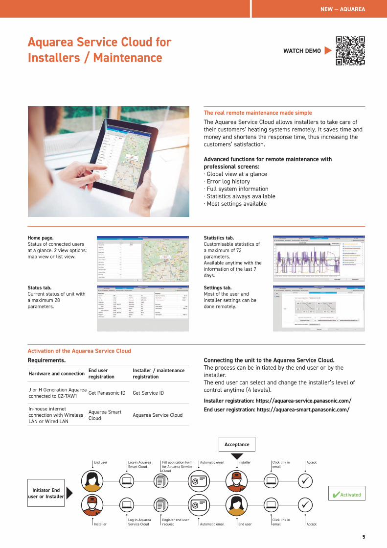
Activation of the Aquarea Service CloudRequirements.
Hardware and connection End user registration
Installer / maintenance registration
J or H Generation Aquarea connected to CZ-TAW1 Get Panasonic ID Get Service ID
In-house internet connection with Wireless LAN or Wired LAN
Aquarea Smart Cloud Aquarea Service Cloud
Connecting the unit to the Aquarea Service Cloud.The process can be initiated by the end user or by the installer.The end user can select and change the installer’s level of control anytime (4 levels).
Installer registration: https://aquarea-service.panasonic.com/End user registration: https://aquarea-smart.panasonic.com/
Acceptance
✔Activated
End user
Installer
Installer
End user
Automatic email
Automatic email
Log-in Aquarea Smart Cloud
Log-in Aquarea Service Cloud
Click link in email
Click link in email
ü
ü
Accept
Accept
Fill application form for Aquarea Service Cloud
Register end user request
Initiator End user or Installer
Aquarea Service Cloud for Installers / Maintenance
WATCH DEMO
The real remote maintenance made simpleThe Aquarea Service Cloud allows installers to take care of their customers’ heating systems remotely. It saves time and money and shortens the response time, thus increasing the customers’ satisfaction.
Advanced functions for remote maintenance with professional screens:· Global view at a glance· Error log history· Full system information · Statistics always available· Most settings available
NEW — AQUAREA
5

This Installation Guide is to assist and supplement the installation of the Heat Pump system. If you require full Installation Instructions or Service Manuals please download these from Panasonic Pro Club.
Panasonic has an impressive range of support services for designers, specifiers, engineers and distributors working in the heating and cooling industry. Panasonic PRO Club is the online tool which makes your life easier! You just have to register and many useful tools and features are freely available to you, where ever you are, from your computer or smart phone!
Aquarea DesignerPanasonic provides bespoke software helping system designers, installers and dealers to very quickly design and size systems, create wiring diagrams and issue bills of quantities at the push of a button.
Panasonic helps you to calculate the system labelSince 26th September 2015, installers can be assured that all products manufactured after this date will be sold with the required ErP labels which will aid installers with their paperwork. While it is the manufacturer’s responsibility to issue their products with the required labels, the installers will need to calculate and issue an efficiency label for the entire heating system. Whether installing a new heating system or installing new boilers, controls or renewables into an existing system, it is, and will continue to be, the installer’s responsibility to calculate and issue efficiency labels. Calculators which assist installers with this process are available on the Panasonic Heating and Cooling Solutions website.
Download on www.panasonicproclub.com or connect simply with your smart phone to the PRO Club using this QR
PRO Club. The professional website of Panasonic
6
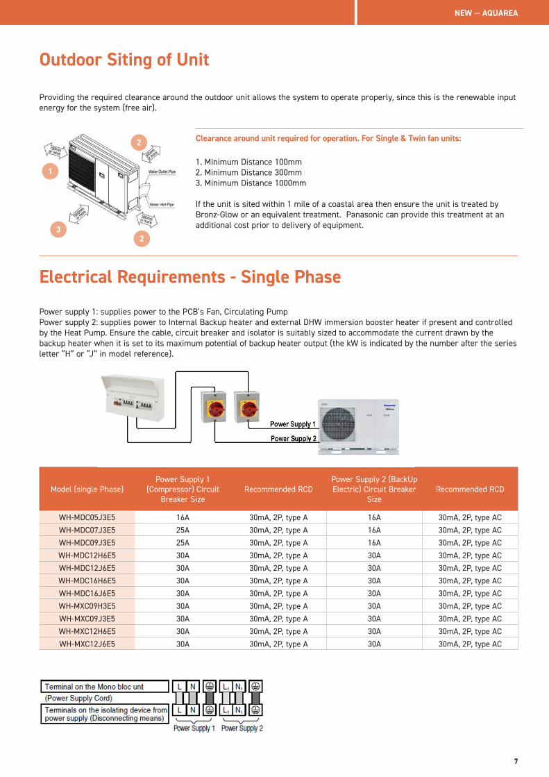
Outdoor Siting of Unit
Clearance around unit required for operation. For Single & Twin fan units:
1. Minimum Distance 100mm2. Minimum Distance 300mm3. Minimum Distance 1000mm
If the unit is sited within 1 mile of a coastal area then ensure the unit is treated by Bronz-Glow or an equivalent treatment. Panasonic can provide this treatment at an additional cost prior to delivery of equipment.
Model (single Phase)Power Supply 1
(Compressor) Circuit Breaker Size
Recommended RCDPower Supply 2 (BackUp Electric) Circuit Breaker
Size Recommended RCD
WH-MDC05J3E5 16A 30mA, 2P, type A 16A 30mA, 2P, type AC
WH-MDC07J3E5 25A 30mA, 2P, type A 16A 30mA, 2P, type AC
WH-MDC09J3E5 25A 30mA, 2P, type A 16A 30mA, 2P, type AC
WH-MDC12H6E5 30A 30mA, 2P, type A 30A 30mA, 2P, type AC
WH-MDC12J6E5 30A 30mA, 2P, type A 30A 30mA, 2P, type AC
WH-MDC16H6E5 30A 30mA, 2P, type A 30A 30mA, 2P, type AC
WH-MDC16J6E5 30A 30mA, 2P, type A 30A 30mA, 2P, type AC
WH-MXC09H3E5 30A 30mA, 2P, type A 30A 30mA, 2P, type AC
WH-MXC09J3E5 30A 30mA, 2P, type A 30A 30mA, 2P, type AC
WH-MXC12H6E5 30A 30mA, 2P, type A 30A 30mA, 2P, type AC
WH-MXC12J6E5 30A 30mA, 2P, type A 30A 30mA, 2P, type AC
Electrical Requirements - Single Phase
1
2
2
3
Providing the required clearance around the outdoor unit allows the system to operate properly, since this is the renewable input energy for the system (free air).
Power supply 1: supplies power to the PCB’s Fan, Circulating PumpPower supply 2: supplies power to Internal Backup heater and external DHW immersion booster heater if present and controlled by the Heat Pump. Ensure the cable, circuit breaker and isolator is suitably sized to accommodate the current drawn by the backup heater when it is set to its maximum potential of backup heater output (the kW is indicated by the number after the series letter “H” or “J” in model reference).
NEW — AQUAREA
7
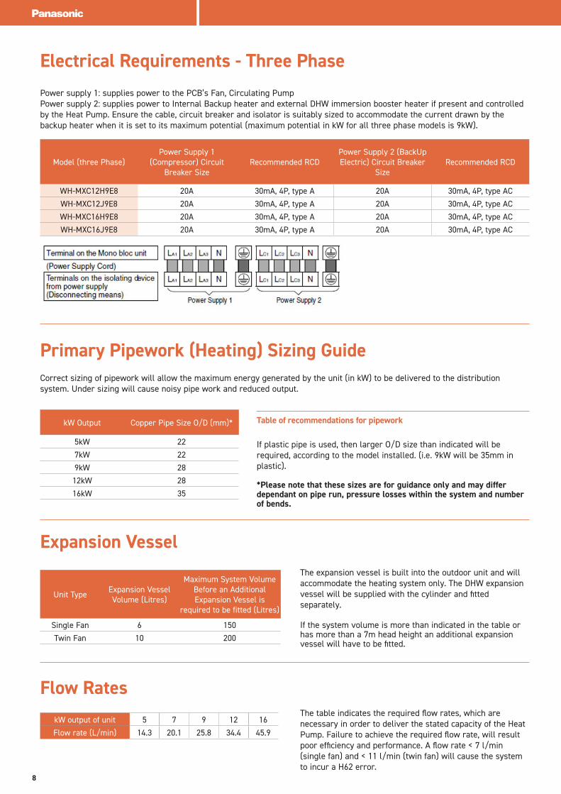
Electrical Requirements - Three Phase
Model (three Phase)Power Supply 1
(Compressor) Circuit Breaker Size
Recommended RCDPower Supply 2 (BackUp Electric) Circuit Breaker
Size Recommended RCD
WH-MXC12H9E8 20A 30mA, 4P, type A 20A 30mA, 4P, type AC
WH-MXC12J9E8 20A 30mA, 4P, type A 20A 30mA, 4P, type AC
WH-MXC16H9E8 20A 30mA, 4P, type A 20A 30mA, 4P, type AC
WH-MXC16J9E8 20A 30mA, 4P, type A 20A 30mA, 4P, type AC
Primary Pipework (Heating) Sizing Guide
Table of recommendations for pipework
If plastic pipe is used, then larger O/D size than indicated will be required, according to the model installed. (i.e. 9kW will be 35mm in plastic).
*Please note that these sizes are for guidance only and may differ dependant on pipe run, pressure losses within the system and number of bends.
kW Output Copper Pipe Size O/D (mm)*
5kW 22
7kW 22
9kW 28
12kW 28
16kW 35
Expansion VesselThe expansion vessel is built into the outdoor unit and will accommodate the heating system only. The DHW expansion vessel will be supplied with the cylinder and fitted separately.
If the system volume is more than indicated in the table or has more than a 7m head height an additional expansion vessel will have to be fitted.
Unit Type Expansion Vessel Volume (Litres)
Maximum System Volume Before an Additional Expansion Vessel is
required to be fitted (Litres)
Single Fan 6 150
Twin Fan 10 200
Power supply 1: supplies power to the PCB’s Fan, Circulating PumpPower supply 2: supplies power to Internal Backup heater and external DHW immersion booster heater if present and controlled by the Heat Pump. Ensure the cable, circuit breaker and isolator is suitably sized to accommodate the current drawn by the backup heater when it is set to its maximum potential (maximum potential in kW for all three phase models is 9kW).
Correct sizing of pipework will allow the maximum energy generated by the unit (in kW) to be delivered to the distributionsystem. Under sizing will cause noisy pipe work and reduced output.
Flow RatesThe table indicates the required flow rates, which are necessary in order to deliver the stated capacity of the Heat Pump. Failure to achieve the required flow rate, will result poor efficiency and performance. A flow rate < 7 l/min (single fan) and < 11 l/min (twin fan) will cause the system to incur a H62 error.
kW output of unit 5 7 9 12 16
Flow rate (L/min) 14.3 20.1 25.8 34.4 45.9
8
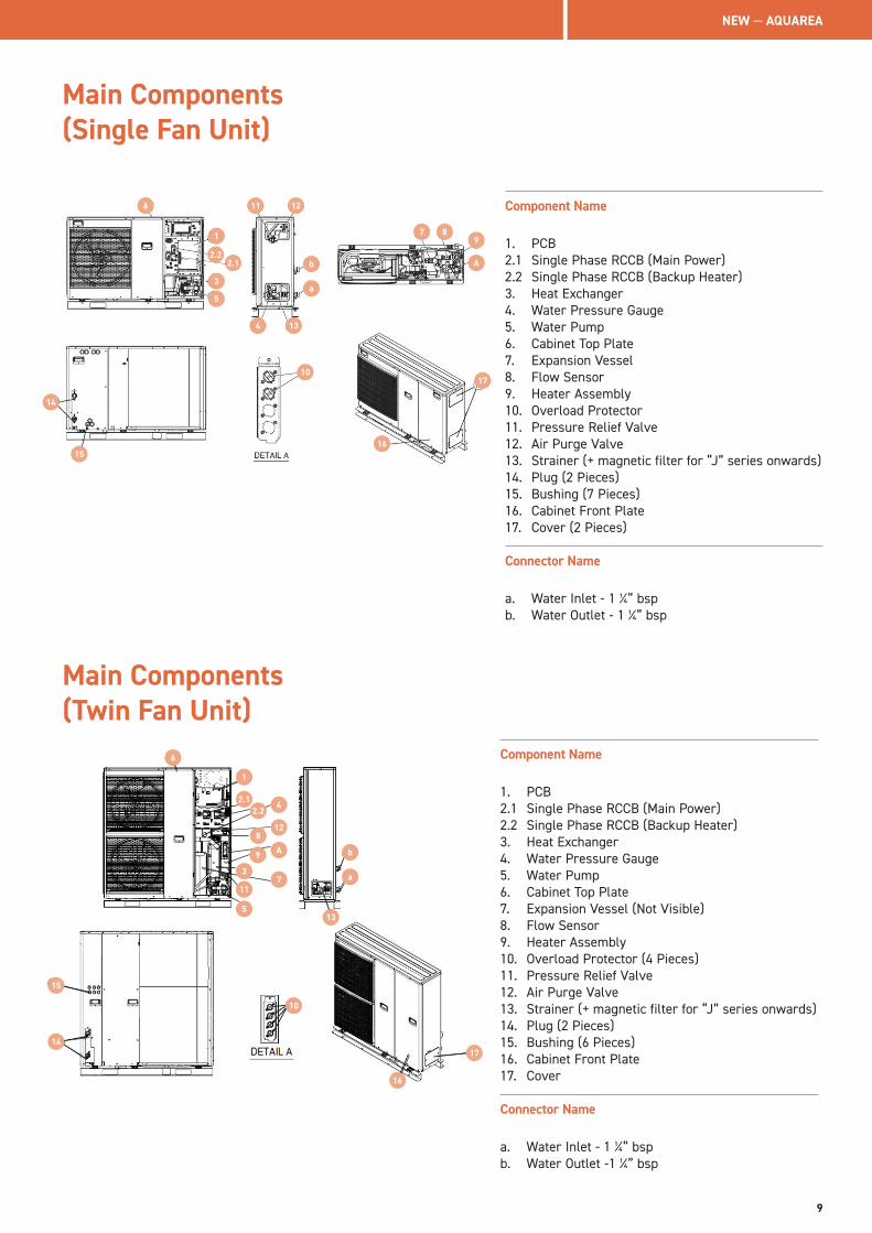
Main Components (Single Fan Unit)
Component Name
1. PCB2.1 Single Phase RCCB (Main Power)2.2 Single Phase RCCB (Backup Heater)3. Heat Exchanger4. Water Pressure Gauge5. Water Pump6. Cabinet Top Plate7. Expansion Vessel8. Flow Sensor9. Heater Assembly 10. Overload Protector11. Pressure Relief Valve12. Air Purge Valve13. Strainer (+ magnetic filter for “J” series onwards)14. Plug (2 Pieces)15. Bushing (7 Pieces)16. Cabinet Front Plate17. Cover (2 Pieces)
Connector Name
a. Water Inlet - 1 1/4” bspb. Water Outlet - 1 1/4” bsp
Main Components (Twin Fan Unit)
Component Name
1. PCB2.1 Single Phase RCCB (Main Power)2.2 Single Phase RCCB (Backup Heater)3. Heat Exchanger4. Water Pressure Gauge5. Water Pump6. Cabinet Top Plate7. Expansion Vessel (Not Visible)8. Flow Sensor9. Heater Assembly 10. Overload Protector (4 Pieces)11. Pressure Relief Valve12. Air Purge Valve13. Strainer (+ magnetic filter for “J” series onwards)14. Plug (2 Pieces)15. Bushing (6 Pieces)16. Cabinet Front Plate17. Cover
Connector Name
a. Water Inlet - 1 1/4” bspb. Water Outlet -1 1/4” bsp
a
b
13
1
2.1
8
9
11
5
4
12
A
73
2.2
6
17
16
15
14
10
a
b
6 11 12
4 13
10
16
17
A
7 89
15
14
1
5
3
2.12.2
NEW — AQUAREA
9
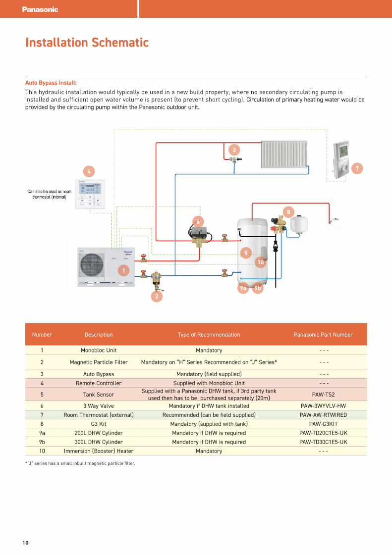
Installation Schematic
Auto Bypass Install: This hydraulic installation would typically be used in a new build property, where no secondary circulating pump is installed and sufficient open water volume is present (to prevent short cycling). Circulation of primary heating water would be provided by the circulating pump within the Panasonic outdoor unit.
Number Description Type of Recommendation Panasonic Part Number
1 Monobloc Unit Mandatory - - -
2 Magnetic Particle Filter Mandatory on “H” Series Recommended on “J” Series* - - -
3 Auto Bypass Mandatory (field supplied) - - -
4 Remote Controller Supplied with Monobloc Unit - - -
5 Tank Sensor Supplied with a Panasonic DHW tank, if 3rd party tank used then has to be purchased separately (20m) PAW-TS2
6 3 Way Valve Mandatory if DHW tank installed PAW-3WYVLV-HW
7 Room Thermostat (external) Recommended (can be field supplied) PAW-AW-RTWIRED
8 G3 Kit Mandatory (supplied with tank) PAW-G3KIT
9a 200L DHW Cylinder Mandatory if DHW is required PAW-TD20C1E5-UK
9b 300L DHW Cylinder Mandatory if DHW is required PAW-TD30C1E5-UK
10 Immersion (Booster) Heater Mandatory - - -
2
4
1
3
7
5
6
8
9a 9b
10
*“J” series has a small inbuilt magnetic particle filter.
10
Number Description Type of Recommendation Panasonic Part Number
1 Monobloc Unit Mandatory - - -
2 Magnetic Particle Filter Mandatory on “H” Series Recommended on “J” Series* - - -
3 Auto Bypass Mandatory (field supplied) - - -
4 Remote Controller Supplied with Monobloc Unit - - -
5 Tank Sensor Supplied with a Panasonic DHW tank, if 3rd party tank used then has to be purchased separately (20m) PAW-TS2
6 3 Way Valve Mandatory if DHW tank installed PAW-3WYVLV-HW
7 Room Thermostat (external) Recommended (can be field supplied) PAW-AW-RTWIRED
8 G3 Kit Mandatory (supplied with tank) PAW-G3KIT
9a 200L DHW Cylinder Mandatory if DHW is required PAW-TD20C1E5-UK
9b 300L DHW Cylinder Mandatory if DHW is required PAW-TD30C1E5-UK
10 Immersion (Booster) Heater Mandatory - - -
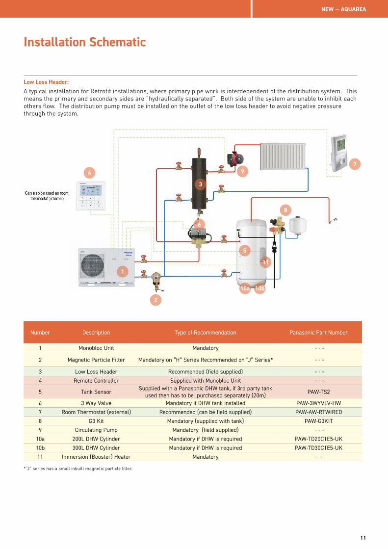
Installation Schematic
Low Loss Header:A typical installation for Retrofit installations, where primary pipe work is interdependent of the distribution system. This means the primary and secondary sides are “hydraulically separated”. Both side of the system are unable to inhibit each others flow. The distribution pump must be installed on the outlet of the low loss header to avoid negative pressure through the system.
3
2
4
1
Number Description Type of Recommendation Panasonic Part Number
1 Monobloc Unit Mandatory - - -
2 Magnetic Particle Filter Mandatory on “H” Series Recommended on “J” Series* - - -
3 Low Loss Header Recommended (field supplied) - - -
4 Remote Controller Supplied with Monobloc Unit - - -
5 Tank Sensor Supplied with a Panasonic DHW tank, if 3rd party tank used then has to be purchased separately (20m) PAW-TS2
6 3 Way Valve Mandatory if DHW tank installed PAW-3WYVLV-HW
7 Room Thermostat (external) Recommended (can be field supplied) PAW-AW-RTWIRED
8 G3 Kit Mandatory (supplied with tank) PAW-G3KIT
9 Circulating Pump Mandatory (field supplied) - - -
10a 200L DHW Cylinder Mandatory if DHW is required PAW-TD20C1E5-UK
10b 300L DHW Cylinder Mandatory if DHW is required PAW-TD30C1E5-UK
11 Immersion (Booster) Heater Mandatory - - -
*“J” series has a small inbuilt magnetic particle filter.
5
6
7
8
9
10a 10b
11
NEW — AQUAREA
11
Installation Schematic
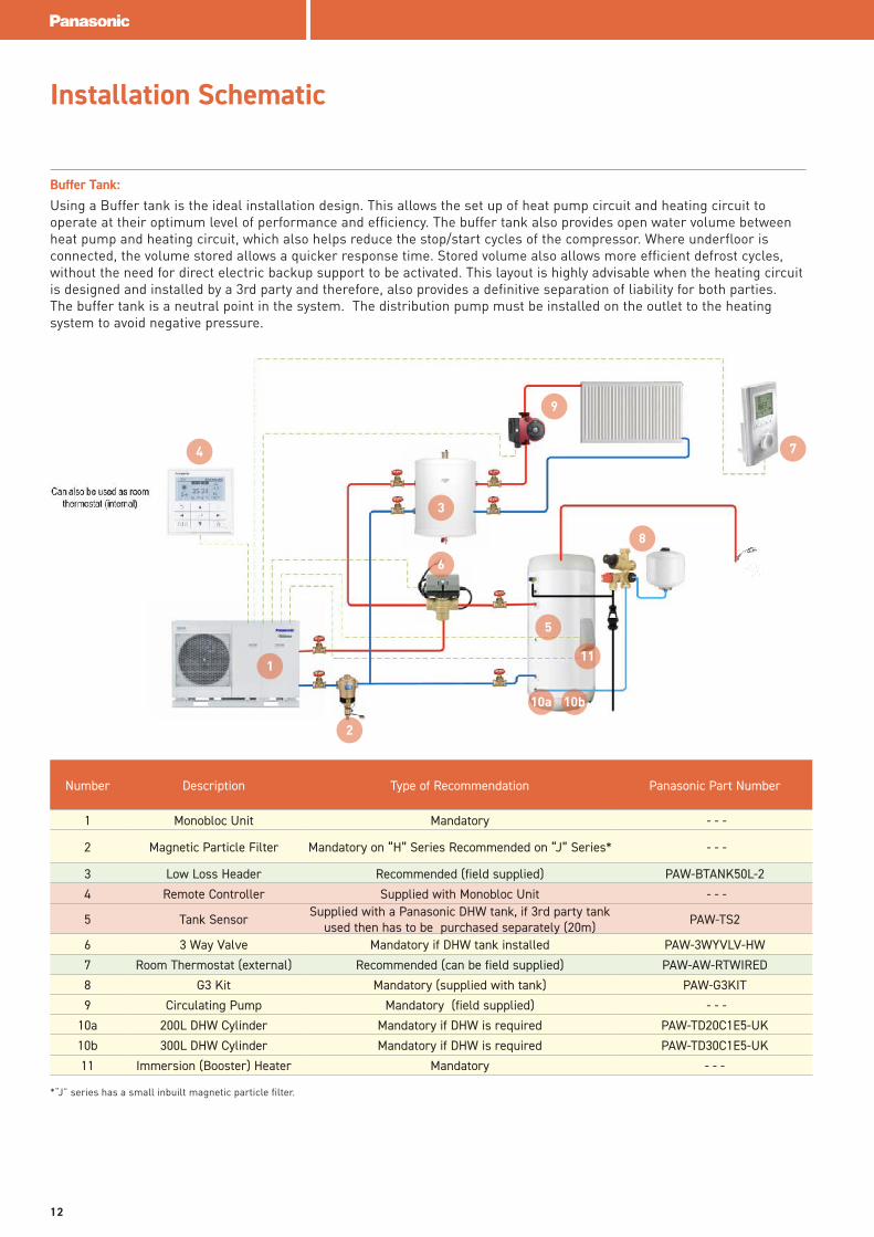
Buffer Tank: Using a Buffer tank is the ideal installation design. This allows the set up of heat pump circuit and heating circuit to operate at their optimum level of performance and efficiency. The buffer tank also provides open water volume between heat pump and heating circuit, which also helps reduce the stop/start cycles of the compressor. Where underfloor is connected, the volume stored allows a quicker response time. Stored volume also allows more efficient defrost cycles, without the need for direct electric backup support to be activated. This layout is highly advisable when the heating circuit is designed and installed by a 3rd party and therefore, also provides a definitive separation of liability for both parties. The buffer tank is a neutral point in the system. The distribution pump must be installed on the outlet to the heating system to avoid negative pressure.
3
2
4
1
5
6
7
8
9
Number Description Type of Recommendation Panasonic Part Number
1 Monobloc Unit Mandatory - - -
2 Magnetic Particle Filter Mandatory on “H” Series Recommended on “J” Series* - - -
3 Low Loss Header Recommended (field supplied) PAW-BTANK50L-2
4 Remote Controller Supplied with Monobloc Unit - - -
5 Tank Sensor Supplied with a Panasonic DHW tank, if 3rd party tank used then has to be purchased separately (20m) PAW-TS2
6 3 Way Valve Mandatory if DHW tank installed PAW-3WYVLV-HW
7 Room Thermostat (external) Recommended (can be field supplied) PAW-AW-RTWIRED
8 G3 Kit Mandatory (supplied with tank) PAW-G3KIT
9 Circulating Pump Mandatory (field supplied) - - -
10a 200L DHW Cylinder Mandatory if DHW is required PAW-TD20C1E5-UK
10b 300L DHW Cylinder Mandatory if DHW is required PAW-TD30C1E5-UK
11 Immersion (Booster) Heater Mandatory - - -
*“J” series has a small inbuilt magnetic particle filter.
10a 10b
11
12
Installation Schematic
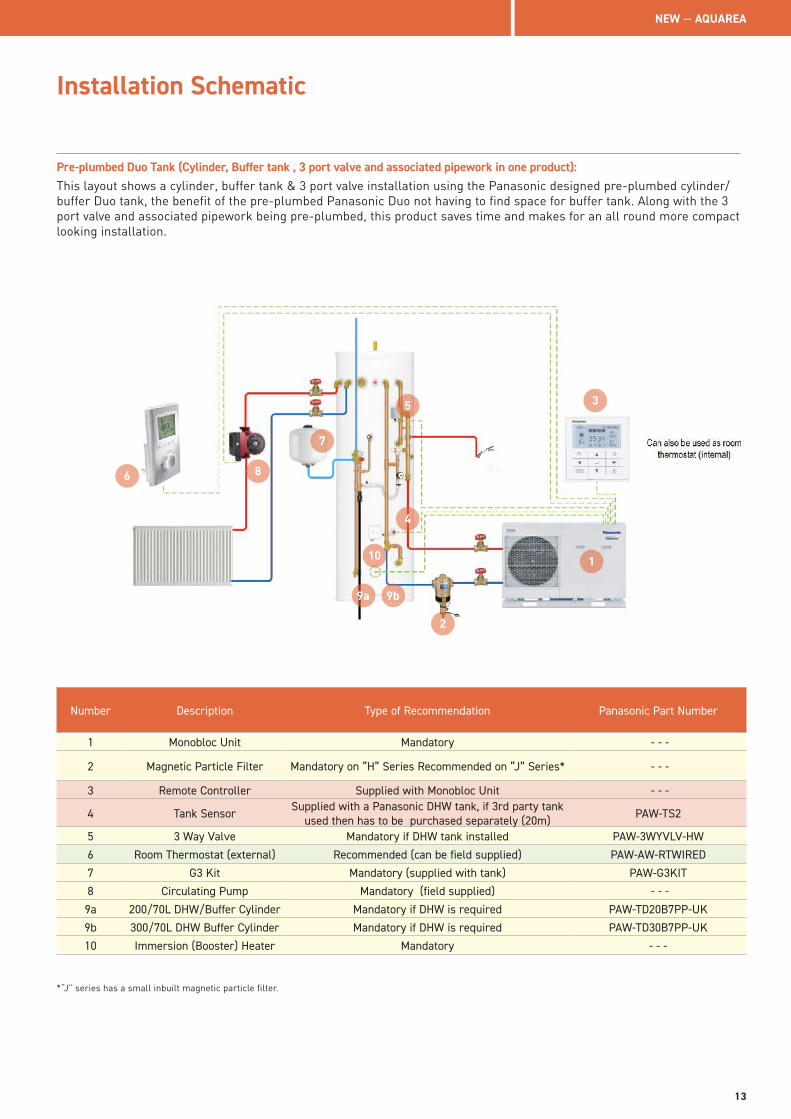
Pre-plumbed Duo Tank (Cylinder, Buffer tank , 3 port valve and associated pipework in one product): This layout shows a cylinder, buffer tank & 3 port valve installation using the Panasonic designed pre-plumbed cylinder/buffer Duo tank, the benefit of the pre-plumbed Panasonic Duo not having to find space for buffer tank. Along with the 3 port valve and associated pipework being pre-plumbed, this product saves time and makes for an all round more compact looking installation.
3
2
4
1
5
6
7
8
9a
Number Description Type of Recommendation Panasonic Part Number
1 Monobloc Unit Mandatory - - -
2 Magnetic Particle Filter Mandatory on “H” Series Recommended on “J” Series* - - -
3 Remote Controller Supplied with Monobloc Unit - - -
4 Tank Sensor Supplied with a Panasonic DHW tank, if 3rd party tank used then has to be purchased separately (20m) PAW-TS2
5 3 Way Valve Mandatory if DHW tank installed PAW-3WYVLV-HW
6 Room Thermostat (external) Recommended (can be field supplied) PAW-AW-RTWIRED
7 G3 Kit Mandatory (supplied with tank) PAW-G3KIT
8 Circulating Pump Mandatory (field supplied) - - -
9a 200/70L DHW/Buffer Cylinder Mandatory if DHW is required PAW-TD20B7PP-UK
9b 300/70L DHW Buffer Cylinder Mandatory if DHW is required PAW-TD30B7PP-UK
10 Immersion (Booster) Heater Mandatory - - -
*“J” series has a small inbuilt magnetic particle filter.
9b
10
NEW — AQUAREA
13
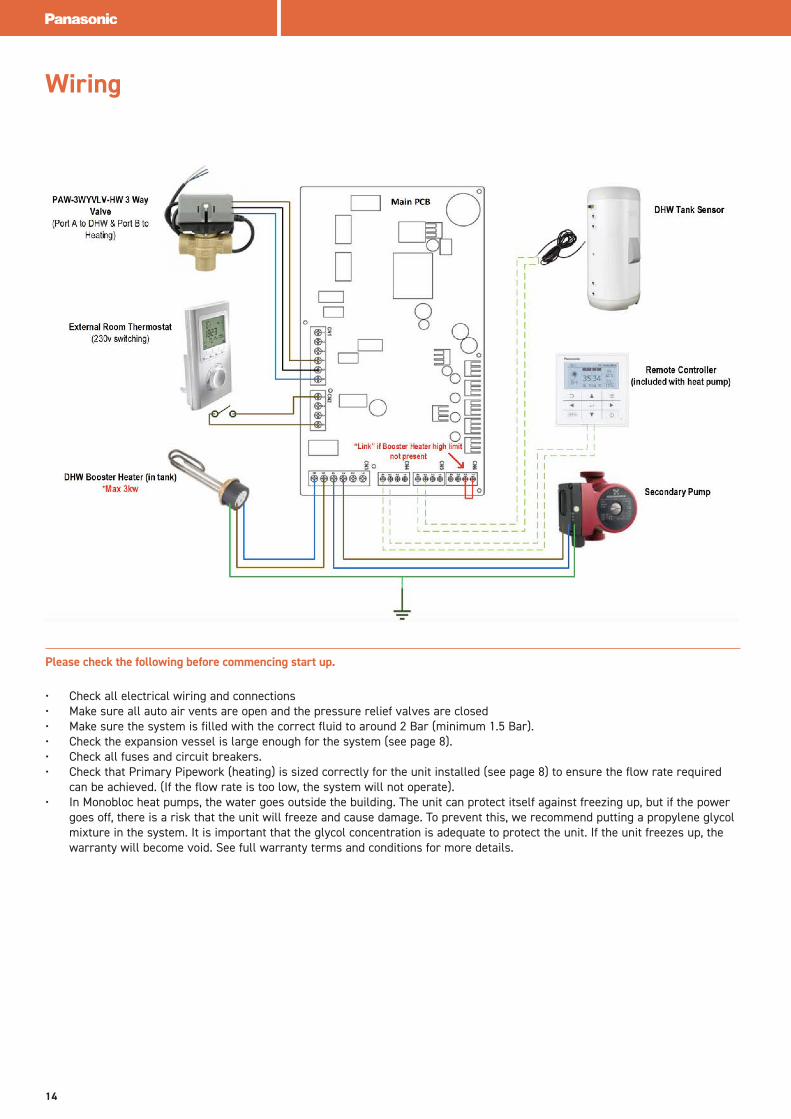
Wiring
Please check the following before commencing start up.
• Check all electrical wiring and connections• Make sure all auto air vents are open and the pressure relief valves are closed• Make sure the system is filled with the correct fluid to around 2 Bar (minimum 1.5 Bar).• Check the expansion vessel is large enough for the system (see page 8). • Check all fuses and circuit breakers.• Check that Primary Pipework (heating) is sized correctly for the unit installed (see page 8) to ensure the flow rate required
can be achieved. (If the flow rate is too low, the system will not operate). • In Monobloc heat pumps, the water goes outside the building. The unit can protect itself against freezing up, but if the power
goes off, there is a risk that the unit will freeze and cause damage. To prevent this, we recommend putting a propylene glycol mixture in the system. It is important that the glycol concentration is adequate to protect the unit. If the unit freezes up, the warranty will become void. See full warranty terms and conditions for more details.
14
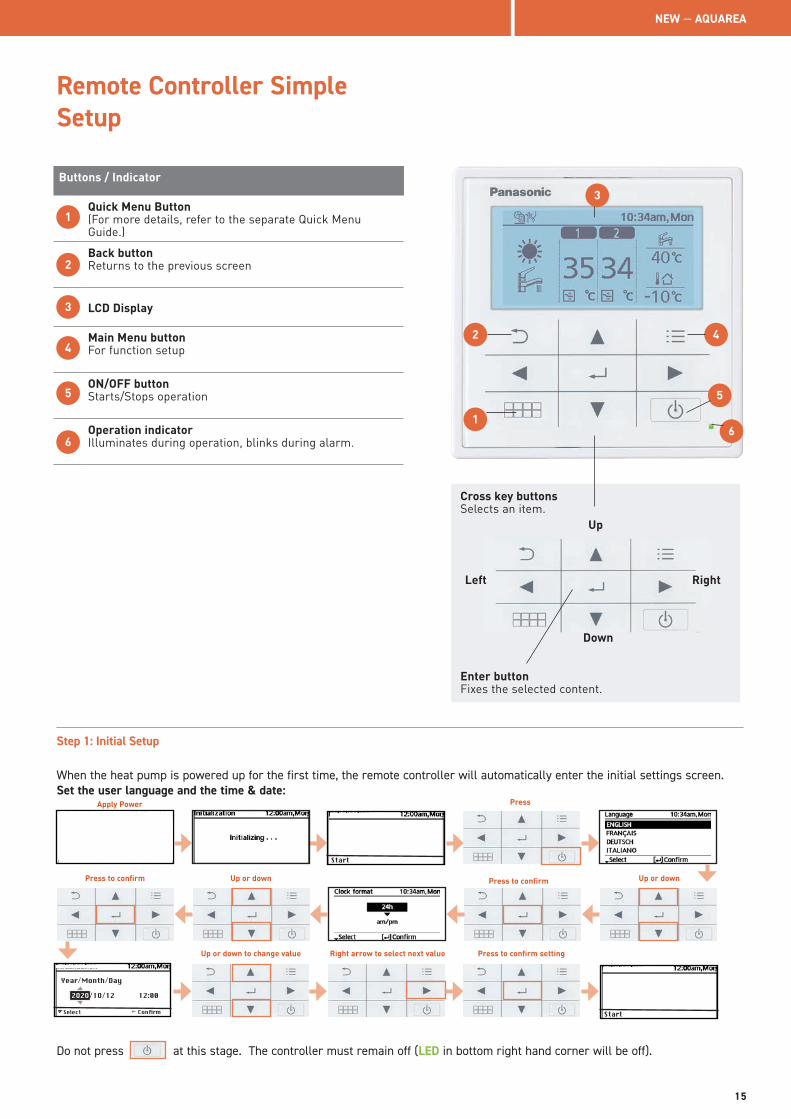
Remote Controller Simple Setup
4
3
2
1
5
6
Cross key buttonsSelects an item.
Enter buttonFixes the selected content.
RightLeft
Down
Up
Buttons / Indicator
Quick Menu Button(For more details, refer to the separate Quick Menu Guide.)
Back buttonReturns to the previous screen
LCD Display
Main Menu buttonFor function setup
ON/OFF buttonStarts/Stops operation
Operation indicatorIlluminates during operation, blinks during alarm.
1
2
3
4
5
6
Step 1: Initial Setup
When the heat pump is powered up for the first time, the remote controller will automatically enter the initial settings screen.Set the user language and the time & date:
Apply Power
Start
Start
Do not press at this stage. The controller must remain off (LED in bottom right hand corner will be off).
Hour:Min
Select
Year/Month/Day
2O2O2O2O/1O/12 12:00
Confirm
Press
Up or down Up or down
Up or down to change value
Press to confirm
Right arrow to select next value Press to confirm setting
Press to confirm
NEW — AQUAREA
15
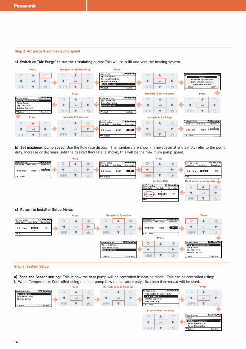
Step 2: Air purge & set max pump speed
a) Switch on “Air Purge” to run the circulating pump: This will help fill and vent the heating system.
b) Set maximum pump speed: Use the flow rate display. The numbers are shown in hexadecimal and simply refer to the pump duty. Increase or decrease until the desired flow rate is shown, this will be the maximum pump speed.
Select
System CheckPersonal CheckupService ContactInstaller setup
Confirm
Main Menu
Select
Pump Maximum SpeedPump DownDry ConcreteService Contact
Confirm
Service setup
Select
System SetupOperation SetupService setup
Confirm
Installer Setup
Select Confirm
Main MenuCaution
(Authorised Installer zone)Wrong settings can cause
system malfunctionClose Enter
Select
OFF
Service setupFlow Rate Max. Duty Operation
O.O L/min OXOO
Select
Air Purge
Service setupFlow Rate Max. Duty Operation
O.O L/min OXOO
Select
Air Purge
Service setupFlow Rate Max. Duty Operation
O.O L/min OXOO
Select
ON
Service setupFlow Rate Max. Duty Operation
O.O L/min OXOO
Select
ON
Service setupFlow Rate Max. Duty Operation
O.O L/min OXOO
ON
Service setupFlow Rate Max. Duty Operation
O.O L/min OXOO
c) Return to Installer Setup Menu:
Select
Pump Maximum SpeedPump DownDry ConcreteService Contact
Confirm
Service setup
Select
System SetupOperation SetupService setup
Confirm
Installer Setup
ON
Service setupFlow Rate Max. Duty Operation
O.O L/min OXOO
Select
OFF
Service setupFlow Rate Max. Duty Operation
O.O L/min OXOO
Step 3: System Setup
a) Zone and Sensor setting: This is how the heat pump will be controlled in heating mode. This can be controlled using:i. Water Temperature: Controlled using the heat pump flow temperature only. No room thermostat will be used.
Select
Pump Maximum SpeedPump DownDry ConcreteService Contact
Confirm
Zone & Sensor
Select
System setup
Select
System SetupOperation SetupService setup
Confirm
Installer Setup
Water TemperatureRoom ThermostatRoom Thermistor
Sensor
Optional PCB connectivityZone & SensorHeater CapacityAnti Freezing
Press Navigate to Installer Setup Press
PressNavigate to Service SetupPress
Press Navigate to Operation Navigate to Air Purge
Press Press
Up or down to change dutySet Flow Rate
Press Press
Press
Navigate to Operation
Press PressNavigate to Zone & Sensor
Press to confirm setting
16
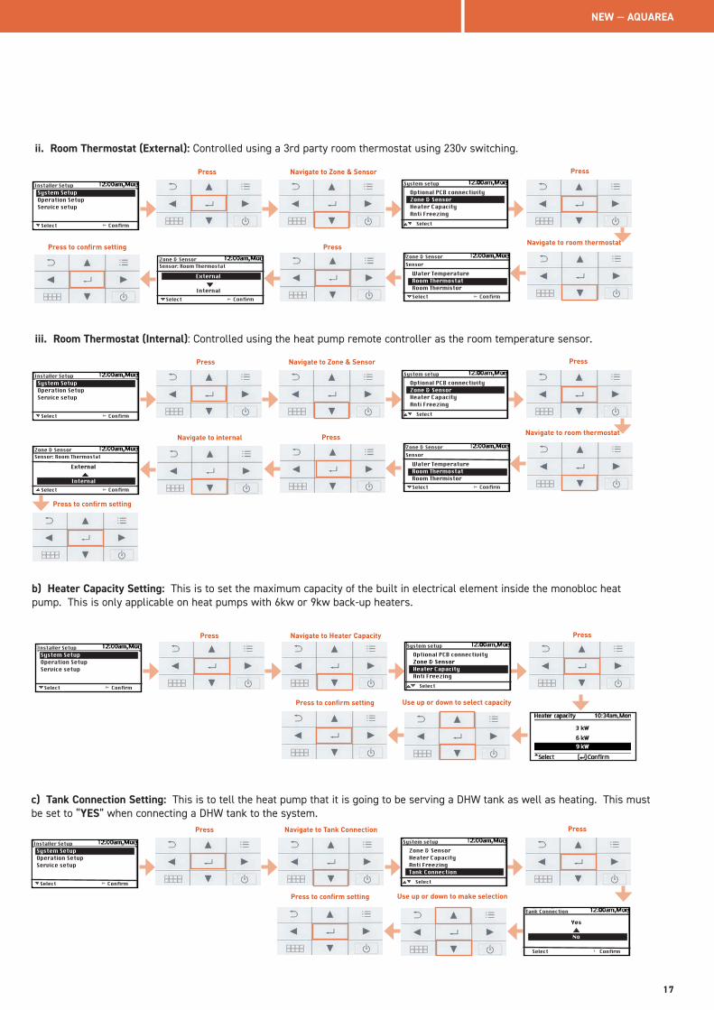
ii. Room Thermostat (External): Controlled using a 3rd party room thermostat using 230v switching.
Select
Pump Maximum SpeedPump DownDry ConcreteService Contact
Confirm
Zone & Sensor
Select
System setup
Select
System SetupOperation SetupService setup
Confirm
Installer Setup
Water TemperatureRoom ThermostatRoom Thermistor
Sensor
Optional PCB connectivityZone & SensorHeater CapacityAnti Freezing
Select Confirm
Zone & Sensor
External
Internal
Sensor: Room Thermostat
iii. Room Thermostat (Internal): Controlled using the heat pump remote controller as the room temperature sensor.
Select
Pump Maximum SpeedPump DownDry ConcreteService Contact
Confirm
Zone & Sensor
Select
System setup
Select
System SetupOperation SetupService setup
Confirm
Installer Setup
Water TemperatureRoom ThermostatRoom Thermistor
Sensor
Optional PCB connectivityZone & SensorHeater CapacityAnti Freezing
Select Confirm
Zone & Sensor
External
Internal
Sensor: Room Thermostat
b) Heater Capacity Setting: This is to set the maximum capacity of the built in electrical element inside the monobloc heat pump. This is only applicable on heat pumps with 6kw or 9kw back-up heaters.
Pump Maximum SpeedPump DownDry ConcreteService Contact
Select
System setup
Select
System SetupOperation SetupService setup
Confirm
Installer SetupOptional PCB connectivityZone & SensorHeater CapacityAnti Freezing
c) Tank Connection Setting: This is to tell the heat pump that it is going to be serving a DHW tank as well as heating. This must be set to “YES” when connecting a DHW tank to the system.
Pump Maximum SpeedPump DownDry ConcreteService Contact
Select
System setup
Select
System SetupOperation SetupService setup
Confirm
Installer SetupZone & SensorHeater CapacityAnti FreezingTank Connection
Select Confirm
Tank Connection
Yes
No
Press PressNavigate to Zone & Sensor
Navigate to room thermostatPress to confirm setting Press
Press PressNavigate to Zone & Sensor
Navigate to room thermostatPressNavigate to internal
Press to confirm setting
Press PressNavigate to Heater Capacity
Use up or down to select capacityPress to confirm setting
Press PressNavigate to Tank Connection
Use up or down to make selectionPress to confirm setting
NEW — AQUAREA
17
Select
System SetupOperation SetupService setup
Confirm
Installer Setup
Auto
Manual
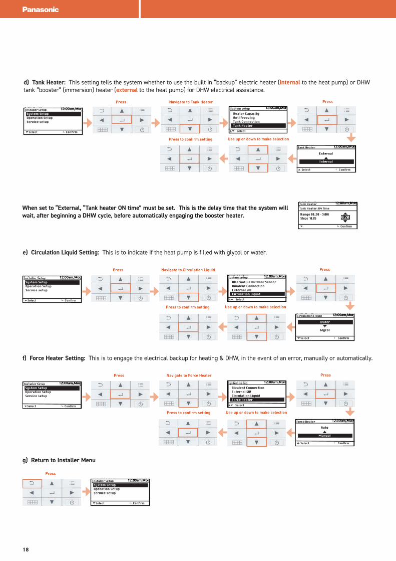
d) Tank Heater: This setting tells the system whether to use the built in “backup” electric heater (internal to the heat pump) or DHW tank “booster” (immersion) heater (external to the heat pump) for DHW electrical assistance.
Pump Maximum SpeedPump DownDry ConcreteService Contact
Select
System setup
Select
System SetupOperation SetupService setup
Confirm
Installer SetupHeater CapacityAnti FreezingTank ConnectionTank Heater
Pump Maximum SpeedPump DownDry ConcreteService Contact
SelectSelect
System SetupOperation SetupService setup
Confirm
Installer SetupAlternative Outdoor SensorBivalent ConnectionExternal SWCirculation Liquid
Select Confirm
Circulation Liquid
Water
Glycol
e) Circulation Liquid Setting: This is to indicate if the heat pump is filled with glycol or water.
System setup
Select Confirm
Tank Heater
External
Internal
Pump Maximum SpeedPump DownDry ConcreteService Contact
SelectSelect
System SetupOperation SetupService setup
Confirm
Installer SetupBivalent ConnectionExternal SWCirculation LiquidForce Heater
Force Heater
f) Force Heater Setting: This is to engage the electrical backup for heating & DHW, in the event of an error, manually or automatically.
System setup
Select Confirm
g) Return to Installer Menu
Press
Press PressNavigate to Tank Heater
Use up or down to make selectionPress to confirm setting
Press PressNavigate to Circulation Liquid
Use up or down to make selectionPress to confirm setting
Press PressNavigate to Force Heater
Use up or down to make selectionPress to confirm setting
When set to “External, “Tank heater ON time” must be set. This is the delay time that the system will wait, after beginning a DHW cycle, before automatically engaging the booster heater.
Confirm
Tank Heater
Range (0.20 - 3.00)Steps ̂ 0.05
Tank Heater: ON Time
0.20
18
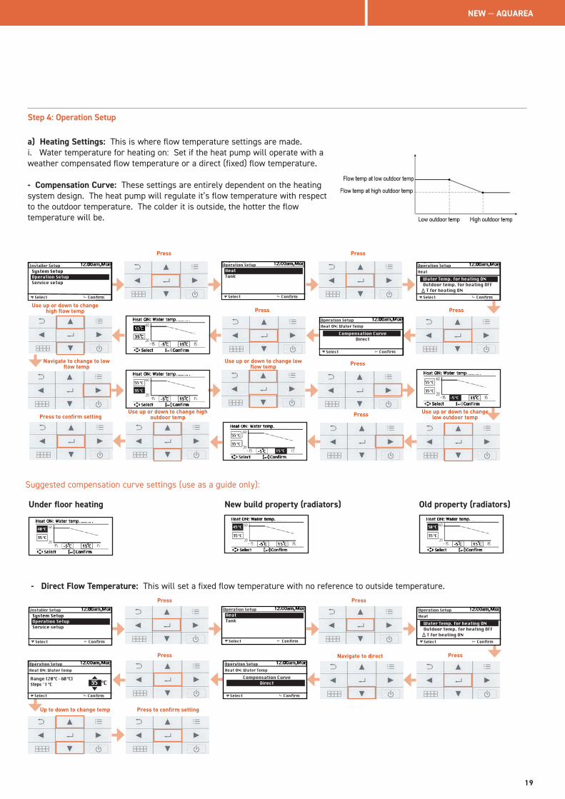
Step 4: Operation Setup
a) Heating Settings: This is where flow temperature settings are made.i. Water temperature for heating on: Set if the heat pump will operate with a weather compensated flow temperature or a direct (fixed) flow temperature.
- Compensation Curve: These settings are entirely dependent on the heating system design. The heat pump will regulate it’s flow temperature with respect to the outdoor temperature. The colder it is outside, the hotter the flow temperature will be.
Select
HeatTank
Confirm
Operation Setup
Select
System SetupOperation SetupService setup
Confirm
Installer Setup
Select Confirm
Operation Setup
Water Temp. for heating ONOutdoor temp. for heating OFF T for heating ON
Heat
Select Confirm
Operation Setup
Compensation CurveDirect
Heat ON: Water Temp
35 °C
55 °C
35 °C
55 °C
35 °C
55 °C
-5 °C
15 °C
Suggested compensation curve settings (use as a guide only):
35 °C
40 °C35 °C
45 °C
35 °C
50 °C
Under floor heating New build property (radiators) Old property (radiators)
- Direct Flow Temperature: This will set a fixed flow temperature with no reference to outside temperature.
Select
HeatTank
Confirm
Operation Setup
Select
System SetupOperation SetupService setup
Confirm
Installer Setup
Select Confirm
Operation Setup
Water Temp. for heating ONOutdoor temp. for heating OFF T for heating ON
Heat
Select Confirm
Operation Setup
Compensation CurveDirect
Heat ON: Water Temp
Select Confirm
Operation Setup
Range (20°C - 60 °C)Steps ̂ 1 °C
Heat ON: Water Temp
°C35
Press Press
Press Press
Navigate to change to low flow temp Press
Use up or down to change high flow temp
Use up or down to change low flow temp
PressUse up or down to change high outdoor tempPress to confirm setting
Use up or down to change low outdoor temp
Press Press
Press to confirm setting
Press Navigate to direct
Up to down to change temp
Press
NEW — AQUAREA
19
Select Confirm
Operation Setup
Range (20°C - 60 °C)Steps ̂ 1 °C
Heat ON: Water Temp
°C35
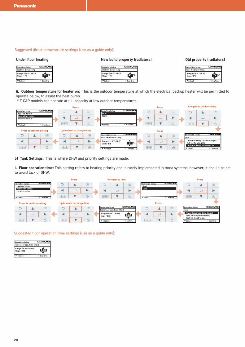
Suggested direct temperature settings (use as a guide only):
Under floor heating New build property (radiators) Old property (radiators)
Select Confirm
Operation Setup
Range (20°C - 60 °C)Steps ̂ 1 °C
Heat ON: Water Temp
°C55
Select Confirm
Operation Setup
Range (20°C - 60 °C)Steps ̂ 1 °C
Heat ON: Water Temp
°C45
ii. Outdoor temperature for heater on: This is the outdoor temperature at which the electrical backup heater will be permitted to operate below, to assist the heat pump. * T-CAP models can operate at full capacity at low outdoor temperatures.
Select
HeatTank
Confirm
Operation Setup
Select
System SetupOperation SetupService setup
Confirm
Installer Setup
Select Confirm
Operation Setup
Outdoor temp. for heating OFF T for heating ONOutdoor temp of heater ON
Heat
Select Confirm
Operation Setup
Range (-15°C - 20 °C)Steps ̂ 1 °C
Heat ON: Outdoor Temp
°C 0
b) Tank Settings: This is where DHW and priority settings are made.
i. Floor operation time: This setting refers to heating priority and is rarely implemented in most systems; however, it should be set to avoid lack of DHW.
Select
HeatTank
Confirm
Operation Setup
Select
System SetupOperation SetupService setup
Confirm
Installer Setup
Select Confirm
Operation Setup
Floor Operation time (max)Tank heat up time (max)Tank re-heat temp.
Tank
Select Confirm
Operation Setup
Range (0:30-10:00)Steps ̂ 0:30
Tank:Floor ope. Time (Max)
8:00
Suggested floor operation time settings (use as a guide only):
Select Confirm
Operation Setup
Range (0:30-10:00)Steps ̂ 0:30
Tank: Floor ope. time (max)
1:00
Press Press
Press
Press Press
Press
Press to confirm setting
Press to confirm setting
Up to down to change temp
Up to down to change time
Navigate to tank
Navigate to outdoor temp
20
Select Confirm
Operation Setup
Range (-12°C - 2 °C)Steps ̂ 1 °C
Tank: Re heat temp.
°C-8
Select Confirm
Operation Setup
Range (0:05-4:00)Steps ̂ 0:05
Tank: Heat up time (max)
1:00
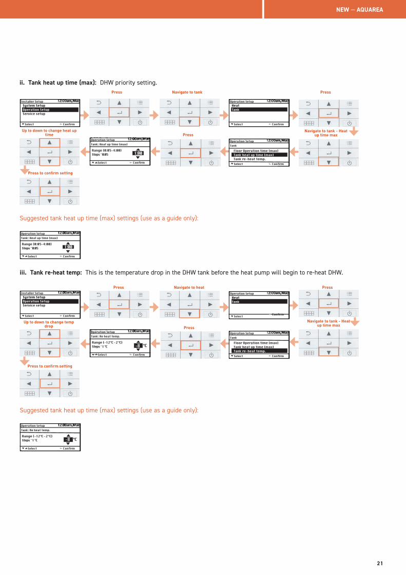
ii. Tank heat up time (max): DHW priority setting.
Select
HeatTank
Confirm
Operation Setup
Select
System SetupOperation SetupService setup
Confirm
Installer Setup
Select Confirm
Operation Setup
Floor Operation time (max)Tank heat up time (max)Tank re-heat temp.
Tank
Select Confirm
Operation Setup
Range (0:05-4:00)Steps ̂ 0:05
Tank: Heat up time (max)
1:00
Suggested tank heat up time (max) settings (use as a guide only):
iii. Tank re-heat temp: This is the temperature drop in the DHW tank before the heat pump will begin to re-heat DHW.
Select
HeatTank
Confirm
Operation Setup
Select
System SetupOperation SetupService setup
Confirm
Installer Setup
Select Confirm
Operation Setup
Floor Operation time (max)Tank heat up time (max)Tank re-heat temp.
Tank
Suggested tank heat up time (max) settings (use as a guide only):
Select Confirm
Operation Setup
Range (-12°C - 2 °C)Steps ̂ 1 °C
Tank: Re heat temp.
°C-8
Press Press
Press to confirm setting
Up to down to change heat up time
Navigate to tank
Navigate to tank - Heat up time maxPress
Press Press
Press to confirm setting
Up to down to change temp drop
Navigate to heat
Navigate to tank - Heat up time max
Press
NEW — AQUAREA
21
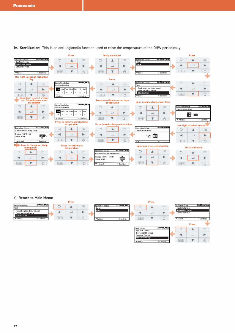
iv. Sterilization: This is an anti-legionella function used to raise the temperature of the DHW periodically.
Select
HeatTank
Confirm
Operation Setup
Select
System SetupOperation SetupService setup
Confirm
Installer Setup
Select Confirm
Operation Setup
Tank heat up time (max)Tank re-heat temp.Steilization
Tank
Select Confirm
Operation Setup
Range (O:O5 - 1:OO)Steps ̂ O:O5
Sterilization Ops. time (max)
O:1O
Select Confirm
Operation Setup
Range (55 °C - 65)Steps ̂ O:O5
Sterilization: Boiling temp.
°C65
Select Confirm
Operation SetupSterilization Day
Sun Mon Tue Wed Thu Fri Sat
ü ------
Select Confirm
Operation SetupSterilization Day
Sun Mon Tue Wed Thu Fri Sat
ü ------
Select Confirm
Operation SetupSterilization: Time
12: OO
Select Confirm
Operation SetupSterilization: Time
12 : OO
c) Return to Main Menu:
Select
System SetupOperation SetupService setup
Confirm
Installer Setup
Select Confirm
Operation Setup
Tank heat up time (max)Tank re-heat temp.Steilization
Tank
Select
HeatTank
Confirm
Operation Setup
Select
System CheckPersonal CheckupService ContactInstaller setup
Confirm
Main Menu
Press PressNavigate to heat
PressUse right to change higlighted
day
Up or down to select or clear day. Tick will appear when
day selectedPress to confirm selected days
of operation Up or down to change hour time
Use right to select minuteUp or down to change minute timePress to confirm selected time
of operation
Up or down to change set temp (if required)
Press to confirm set temperature Press to confirm
Press Press
Press
Up or down to select duration
22
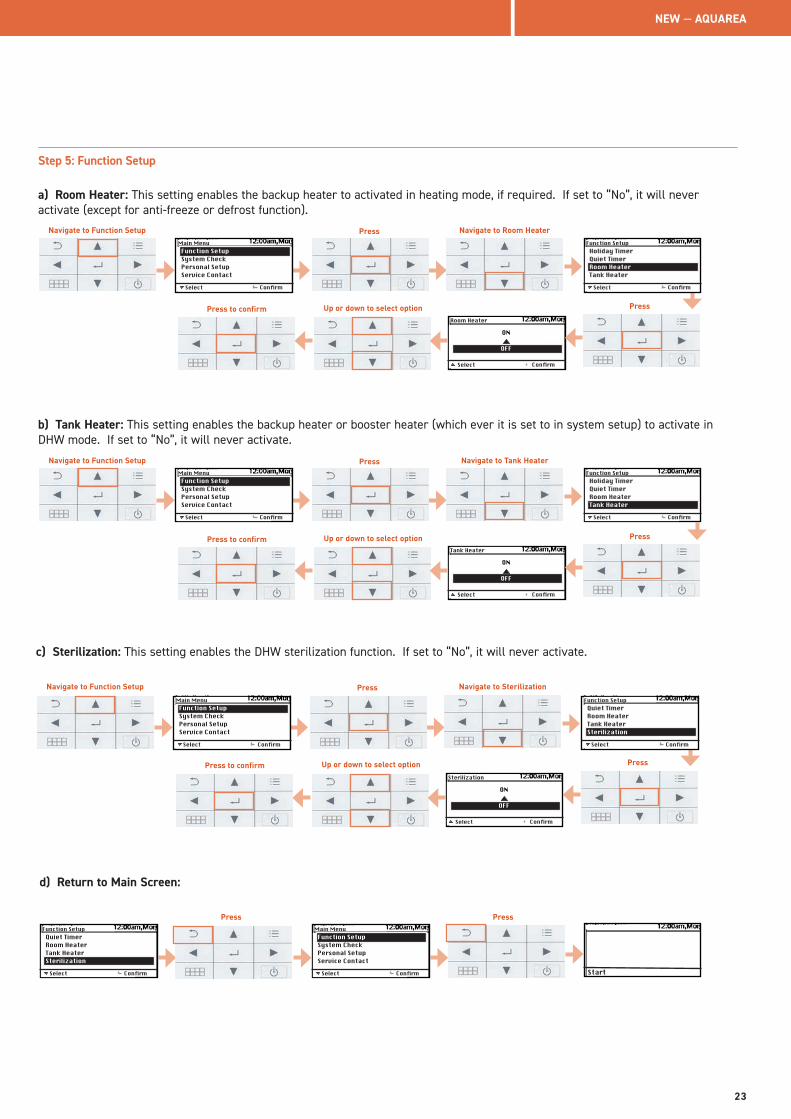
Step 5: Function Setup
a) Room Heater: This setting enables the backup heater to activated in heating mode, if required. If set to “No”, it will never activate (except for anti-freeze or defrost function).
Select Confirm
Room Heater
ON
OFF
Select
Function SetupSystem CheckPersonal SetupService Contact
Confirm
Main Menu
Select
Holiday TimerQuiet TimerRoom HeaterTank Heater
Confirm
Function Setup
b) Tank Heater: This setting enables the backup heater or booster heater (which ever it is set to in system setup) to activate in DHW mode. If set to “No”, it will never activate.
Select Confirm
Tank Heater
ON
OFF
Select
Function SetupSystem CheckPersonal SetupService Contact
Confirm
Main Menu
Select
Holiday TimerQuiet TimerRoom HeaterTank Heater
Confirm
Function Setup
c) Sterilization: This setting enables the DHW sterilization function. If set to “No”, it will never activate.
Select Confirm
Sterilization
ON
OFF
Select
Function SetupSystem CheckPersonal SetupService Contact
Confirm
Main Menu
Select
Quiet TimerRoom HeaterTank HeaterSterilization
Confirm
Function Setup
d) Return to Main Screen:
Select
Quiet TimerRoom HeaterTank HeaterSterilization
Confirm
Function Setup
Select
Function SetupSystem CheckPersonal SetupService Contact
Confirm
Main Menu
Start
PressNavigate to Function Setup Navigate to Room Heater
PressPress to confirm Up or down to select option
PressNavigate to Function Setup Navigate to Tank Heater
PressPress to confirm Up or down to select option
PressNavigate to Function Setup Navigate to Sterilization
PressPress to confirm Up or down to select option
Press Press
NEW — AQUAREA
23
432
1 5
6
7
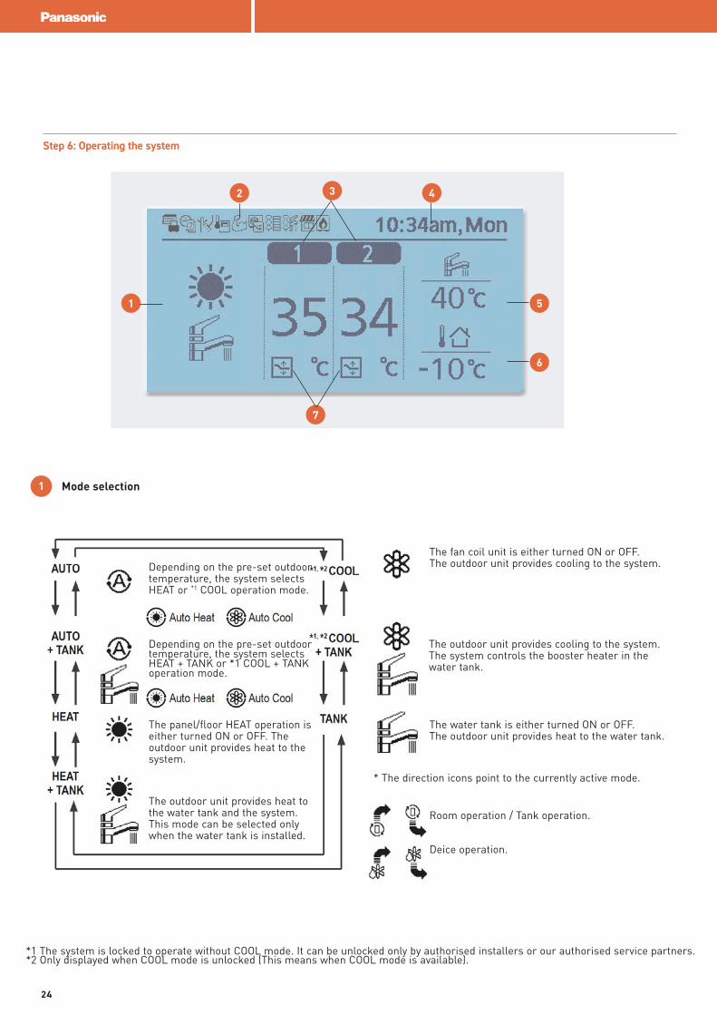
1 Mode selection
Depending on the pre-set outdoor temperature, the system selects HEAT or *1 COOL operation mode.
Depending on the pre-set outdoor temperature, the system selects HEAT + TANK or *1 COOL + TANK operation mode.
The panel/floor HEAT operation is either turned ON or OFF. The outdoor unit provides heat to the system.
The outdoor unit provides heat to the water tank and the system.This mode can be selected onlywhen the water tank is installed.
The fan coil unit is either turned ON or OFF.The outdoor unit provides cooling to the system.
The outdoor unit provides cooling to the system.The system controls the booster heater in the water tank.
The water tank is either turned ON or OFF.The outdoor unit provides heat to the water tank.
* The direction icons point to the currently active mode.
Room operation / Tank operation.
Deice operation.
*1 The system is locked to operate without COOL mode. It can be unlocked only by authorised installers or our authorised service partners.*2 Only displayed when COOL mode is unlocked (This means when COOL mode is available).
Step 6: Operating the system
24
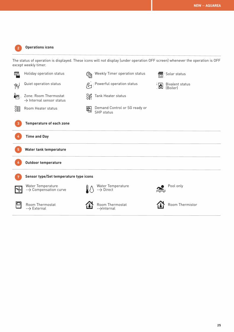
Water Temperature-> Compensation curve
Room Thermostat-> External
Water Temperature-> Direct
Room Thermostat->Internal
Pool only
Room Thermistor
2 Operations icons
The status of operation is displayed. These icons will not display (under operation OFF screen) whenever the operation is OFF except weekly timer.
3 Temperature of each zone
4 Time and Day
5 Water tank temperature
6 Outdoor temperature
7 Sensor type/Set temperature type icons
Holiday operation status
Quiet operation status
Zone: Room Thermostat> Internal sensor status
Room Heater status
Weekly Timer operation status
Powerful operation status
Tank Heater status
Demand Control or SG ready or SHP status
Solar status
Bivalent status(Boiler)
NEW — AQUAREA
25
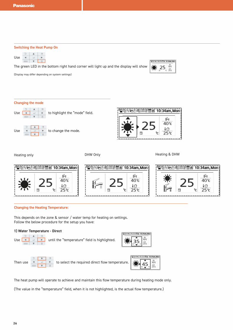
Switching the Heat Pump On
Use
The green LED in the bottom right hand corner will light up and the display will show
(Display may differ depending on system settings)
Changing the mode
Use to highlight the “mode” field.
Use to change the mode.
Heating only DHW Only Heating & DHW
Changing the Heating Temperature:
This depends on the zone & sensor / water temp for heating on settings.Follow the below procedure for the setup you have:
1) Water Temperature - Direct
Use until the “temperature” field is highlighted.
Then use to select the required direct flow temperature.
The heat pump will operate to achieve and maintain this flow temperature during heating mode only.
(The value in the “temperature” field, when it is not highlighted, is the actual flow temperature.)
35
45
26
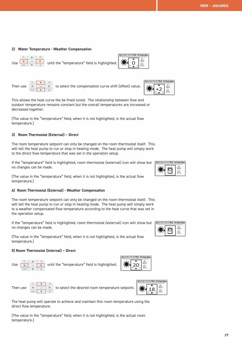
2) Water Temperature - Weather Compensation
Use until the “temperature” field is highlighted.
Then use to select the compensation curve shift (offset) value.
This allows the heat curve the be fined tuned. The relationship between flow and outdoor temperature remains constant but the overall temperatures are increased or decreased together.
(The value in the “temperature” field, when it is not highlighted, is the actual flow temperature.)
3) Room Thermostat (External) – Direct
The room temperature setpoint can only be changed on the room thermostat itself. This will tell the heat pump to run or stop in heating mode. The heat pump will simply work to the direct flow temperature that was set in the operation setup.
If the “temperature” field is highlighted, room thermostat (external) icon will show but no changes can be made.
(The value in the “temperature” field, when it is not highlighted, is the actual flow temperature.)
4) Room Thermostat (External) - Weather Compensation
The room temperature setpoint can only be changed on the room thermostat itself. This will tell the heat pump to run or stop in heating mode. The heat pump will simply work to a weather compensated flow temperature according to the heat curve that was set in the operation setup.
If the “temperature” field is highlighted, room thermostat (external) icon will show but no changes can be made.
(The value in the “temperature” field, when it is not highlighted, is the actual flow temperature.)
5) Room Thermostat (Internal) – Direct
Use until the “temperature” field is highlighted.
Then use to select the desired room temperature setpoint.
The heat pump will operate to achieve and maintain this room temperature using the direct flow temperature.
(The value in the “temperature” field, when it is not highlighted, is the actual room temperature.)
18
20
0
+2
NEW — AQUAREA
27
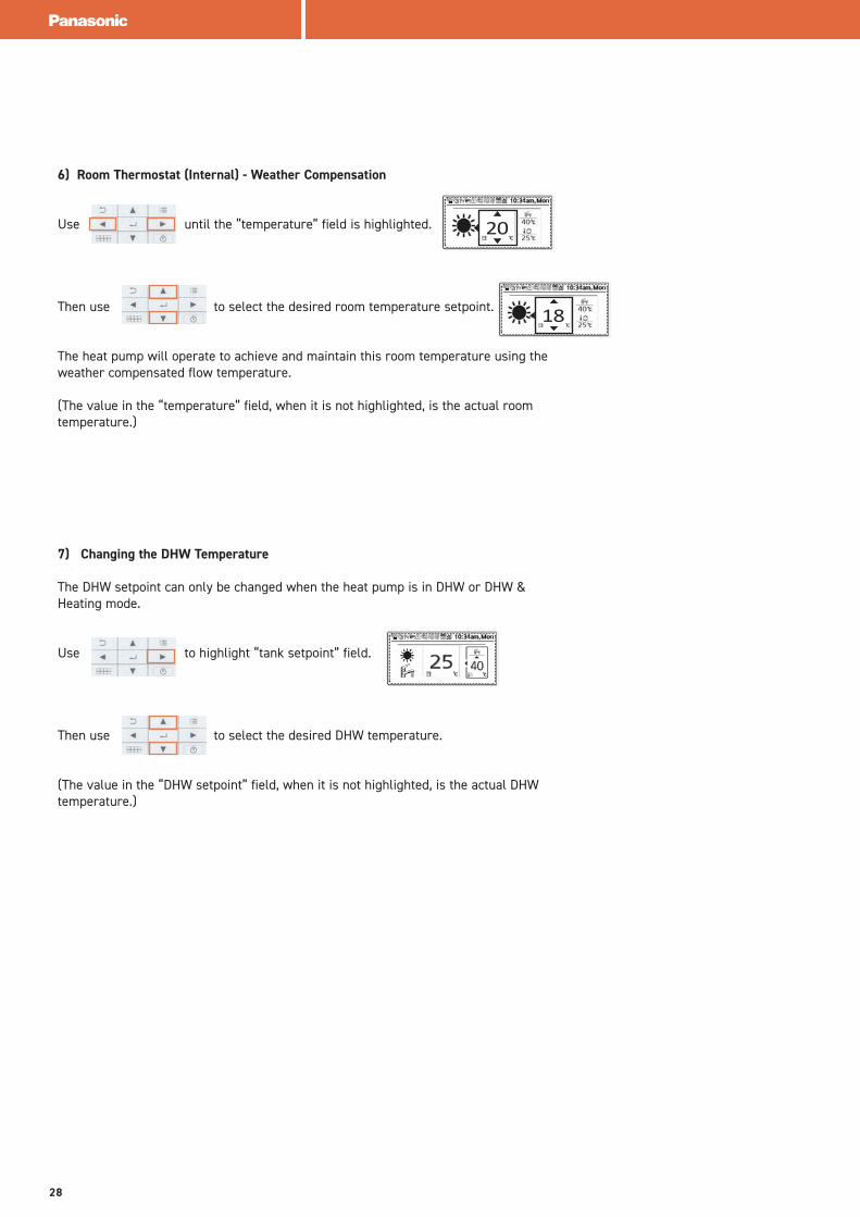
6) Room Thermostat (Internal) - Weather Compensation
Use until the “temperature” field is highlighted.
Then use to select the desired room temperature setpoint.
The heat pump will operate to achieve and maintain this room temperature using the weather compensated flow temperature.
(The value in the “temperature” field, when it is not highlighted, is the actual room temperature.)
7) Changing the DHW Temperature
The DHW setpoint can only be changed when the heat pump is in DHW or DHW & Heating mode.
Use to highlight “tank setpoint” field.
Then use to select the desired DHW temperature.
(The value in the “DHW setpoint” field, when it is not highlighted, is the actual DHW temperature.)
18
20
28
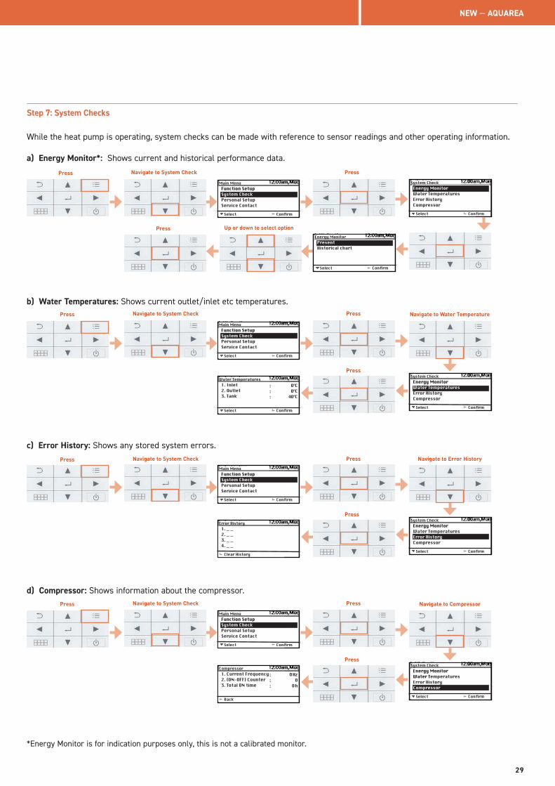
Step 7: System Checks
While the heat pump is operating, system checks can be made with reference to sensor readings and other operating information.
a) Energy Monitor*: Shows current and historical performance data.
Select
Function SetupSystem CheckPersonal SetupService Contact
Confirm
Main Menu
Select
Energy MonitorWater TemperaturesError HistoryCompressor
Confirm
System Check
Select
PresentPreseWater Historical chart
Confirm
Energy Monitor
b) Water Temperatures: Shows current outlet/inlet etc temperatures.
Select
Function SetupSystem CheckPersonal SetupService Contact
Confirm
Main Menu
Select
Energy MonitorWater TemperaturesError HistoryCompressor
Confirm
System Check
Select
1. Inlet2. Outlet3. Tank
Confirm
Water Temperatures:::
O°CO°C
4O°C
c) Error History: Shows any stored system errors.
Select
Function SetupSystem CheckPersonal SetupService Contact
Confirm
Main Menu
Select
Energy MonitorWater TemperaturesError HistoryCompressor
Confirm
System Check
1. _ _2. _ _3. _ _4. _ _
Clear History
Error History
d) Compressor: Shows information about the compressor.
Select
Function SetupSystem CheckPersonal SetupService Contact
Confirm
Main Menu
Select
Energy MonitorWater TemperaturesError HistoryCompressor
Confirm
System Check
1. Current Frequency2. (ON-OFF) Counter3. Total ON time
Compressor:::
O HzO
O h
Back
Press Navigate to System Check
Up or down to select option
Press
Press
Press Navigate to System Check Press
Press Navigate to System Check Press
Press Navigate to System Check Press
Press
Press
Press
Navigate to Water Temperature
Navigate to Error History
Navigate to Compressor
*Energy Monitor is for indication purposes only, this is not a calibrated monitor.
NEW — AQUAREA
29
Select
Function SetupSystem CheckPersonal SetupService Contact
Confirm
Main Menu
Select
Water TemperaturesError HistoryCompressorHeater
Confirm
System CheckHaeter
:
:
ON
ONBack
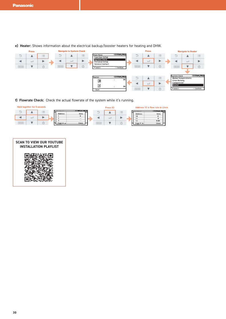
e) Heater: Shows information about the electrical backup/booster heaters for heating and DHW.
f) Flowrate Check: Check the actual flowrate of the system while it’s running.
Press X3Hold together for 5 seconds
Select
Main Menu
Page Close
Address Data1 02 --3 --
Select
Main Menu
Page Close
Address Data10 011 012 0.00
Press Navigate to System Check Press Navigate to Heater
Address 12 is flow rate in l/min
SCAN TO VIEW OUR YOUTUBEINSTALLATION PLAYLIST
30
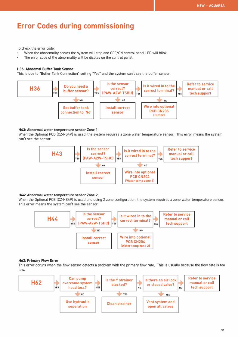
Error Codes during commissioning
To check the error code: • When the abnormality occurs the system will stop and OFF/ON control panel LED will blink. • The error code of the abnormality will be display on the control panel.
H36: Abnormal Buffer Tank Sensor This is due to “Buffer Tank Connection” setting “Yes” and the system can’t see the buffer sensor.
H36 Do you need a buffer sensor?
Set buffer tank connection to ‘No’
Is the sensor correct?
(PAW-A2W-TSBU)
Install correct sensor
Is it wired in to the correct terminal?
Wire into optional PCB CN205
(Buffer)
Refer to service manual or call tech supportYES YES YES YES
NO NO NO
H43: Abnormal water temperature sensor Zone 1When the Optional PCB (CZ-NS4P) is used, the system requires a zone water temperature sensor. This error means the system can’t see the sensor.
H43Is the sensor
correct? (PAW-A2W-TSHC)
Install correct sensor
Is it wired in to the correct terminal?
Wire into optional PCB CN204
(Water temp zone 1)
Refer to service manual or call tech supportYES YES YES
NO NO
H44: Abnormal water temperature sensor Zone 2When the Optional PCB (CZ-NS4P) is used and using 2 zone configuration, the system requires a zone water temperature sensor. This error means the system can’t see the sensor.
H44Is the sensor
correct? (PAW-A2W-TSHC)
Install correct sensor
Is it wired in to the correct terminal?
Wire into optional PCB CN204
(Water temp zone 2)
Refer to service manual or call tech supportYES YES YES
NO NO
H62: Primary Flow Error This error occurs when the flow sensor detects a problem with the primary flow rate. This is usually because the flow rate is too low.
H62Can pump
overcome system head loss?
Use hydraulic seperation
Is the Y strainer blocked?
Clean strainer
Is there an air lock or closed valve?
Vent system and open all valves
Refer to service manual or call tech supportYES YES NO NO
NO YES YES
NEW — AQUAREA
31
Error Codes during commissioning
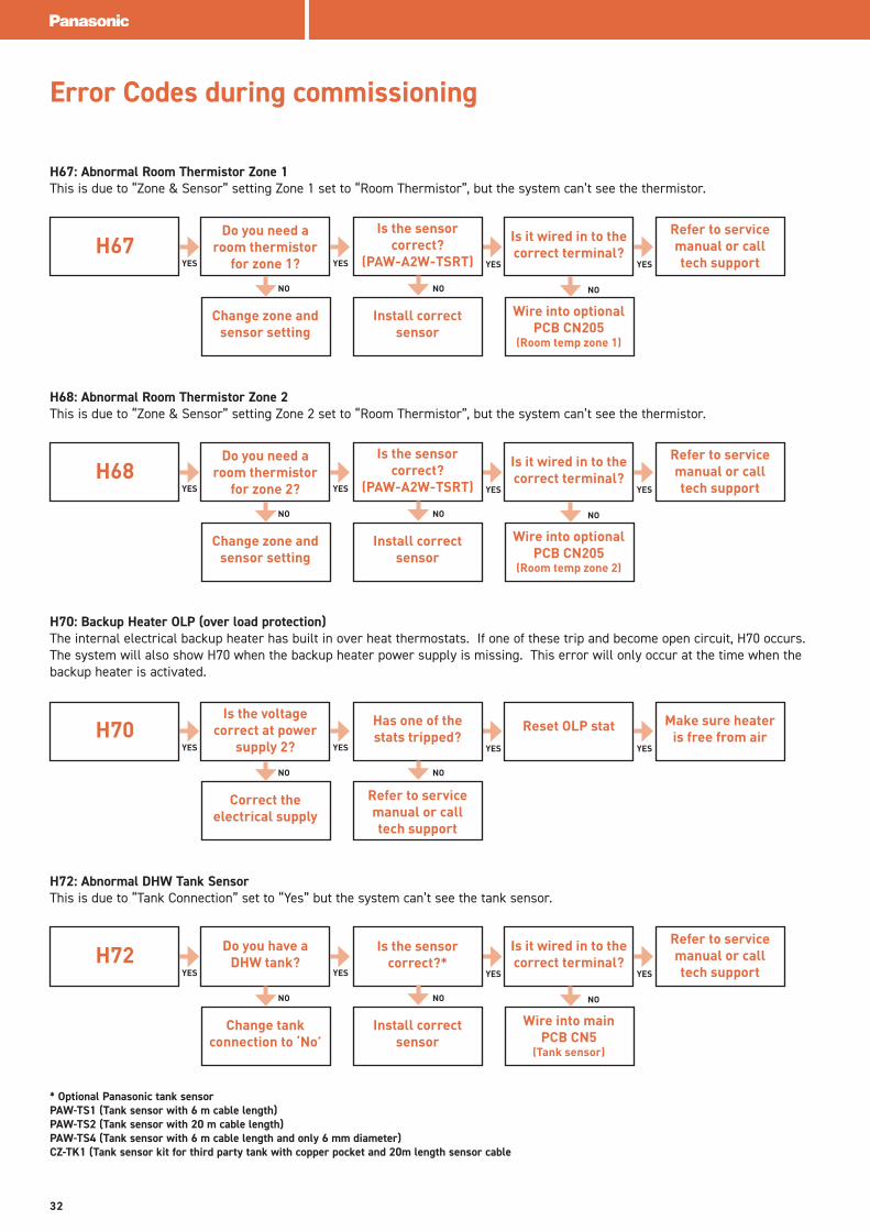
H67: Abnormal Room Thermistor Zone 1This is due to “Zone & Sensor” setting Zone 1 set to “Room Thermistor”, but the system can’t see the thermistor.
H67Do you need a
room thermistor for zone 1?
Change zone and sensor setting
Is the sensor correct?
(PAW-A2W-TSRT)
Install correct sensor
Is it wired in to the correct terminal?
Wire into optional PCB CN205
(Room temp zone 1)
Refer to service manual or call tech supportYES YES YES YES
NO NO NO
H68: Abnormal Room Thermistor Zone 2This is due to “Zone & Sensor” setting Zone 2 set to “Room Thermistor”, but the system can’t see the thermistor.
H68Do you need a
room thermistor for zone 2?
Change zone and sensor setting
Is the sensor correct?
(PAW-A2W-TSRT)
Install correct sensor
Is it wired in to the correct terminal?
Wire into optional PCB CN205
(Room temp zone 2)
Refer to service manual or call tech supportYES YES YES YES
NO NO NO
H70: Backup Heater OLP (over load protection) The internal electrical backup heater has built in over heat thermostats. If one of these trip and become open circuit, H70 occurs. The system will also show H70 when the backup heater power supply is missing. This error will only occur at the time when the backup heater is activated.
H70Is the voltage
correct at power supply 2?
Correct the electrical supply
Has one of the stats tripped?
Refer to service manual or call tech support
Reset OLP stat Make sure heater is free from air
YES YES YES YES
NO NO
H72: Abnormal DHW Tank SensorThis is due to “Tank Connection” set to “Yes” but the system can’t see the tank sensor.
H72 Do you have a DHW tank?
Change tank connection to ‘No’
Is the sensor correct?*
Install correct sensor
Is it wired in to the correct terminal?
Wire into main PCB CN5
(Tank sensor)
Refer to service manual or call tech supportYES YES YES YES
NO NO NO
* Optional Panasonic tank sensor PAW-TS1 (Tank sensor with 6 m cable length) PAW-TS2 (Tank sensor with 20 m cable length) PAW-TS4 (Tank sensor with 6 m cable length and only 6 mm diameter)CZ-TK1 (Tank sensor kit for third party tank with copper pocket and 20m length sensor cable
32

H91: Tank Heater OLP (over load protection)When “Tank Heater” set to “External” the system will error if the tank heater OLP is open circuit. This is like a high limit for the booster (immersion) heater. This error will only occur when the booster heater is actually activated.
H91Do you require HP to control
immersion heater?
Set tank heater to ‘internal’
Do you have high limit stat for
immersion heater?
‘Link’ CN6 OLP booster on main
PCB
Has it tripped? Reset and find out why
YES YES YES YES
NO NO NO
Refer to service manual or call tech support
Panasonic Technical Support contact details Telephone: 01344 85 3393Email: [email protected]
NEW — AQUAREA
33
Advanced Installations2 zone setup - Heating circuit
The basic principle is that both heating circuits will draw off the buffer tank independently, using their own circulating pump. The flow temperature of each zone is monitored by the heat pump using zone water temperature sensors, which are mandatory to the installation. These sensors are placed on the flow pipe for both circuits. Both zones can be set to differing flow temperatures but can only be physically regulated differently when mixing valves are used. (e.g. If zone 1 is a radiator circuit set to operate at 50˚C and zone 2 is an UFH circuit set to operate at 35˚C, the heat pump would operate to 50˚C and control zone 2 mixing valve toblend 50˚C down to 35˚C. Of course, the mixing valve is not necessary if the UFH manifold already has a thermostatic blending valve built in; therefore, the flow temperature setting could be the same for both circuits.) The heat pump will always operate to the higher of the two flow temperature settings in heating mode and the cooler of the two flow temperature settings in cooling mode.
Both zones can be controlled using either:• Water Temperature (flow temperature for each zone, no room temperatures are used)• Room Thermostat Internal (remote controller sensor as room temperature reference)• Room Thermostat External (3rd party thermostat as room temperature reference)• Room Thermistor (Panasonic room sensor as room temperature reference (both zones can be controlled by differing
methods)).
Accessories that are MANDATORY for 2 zone installations:• Optional PCB (CZ-NS4P)• 2x Zone Water Sensors (PAW-A2W-TSHC)• Circulating Pumps (Field Supplied)
Accessories that are optional (depending on your installation) for 2 zone installations:• Panasonic Room Thermistor (PAW-A2W-TSRT)• Buffer Tank Sensor (PAW-A2W-TSBU)• Panasonic Room Thermostat 230v switching (PAW-A2W-RTWIRED)• Panasonic Wireless Room Thermostat 230v switching (PAW-A2W-RTWIRELESS) • 3rd Party Room Thermostat 230v switching (Field Supplied) • Blending Valves (Field Supplied)
34
Installation Schematic
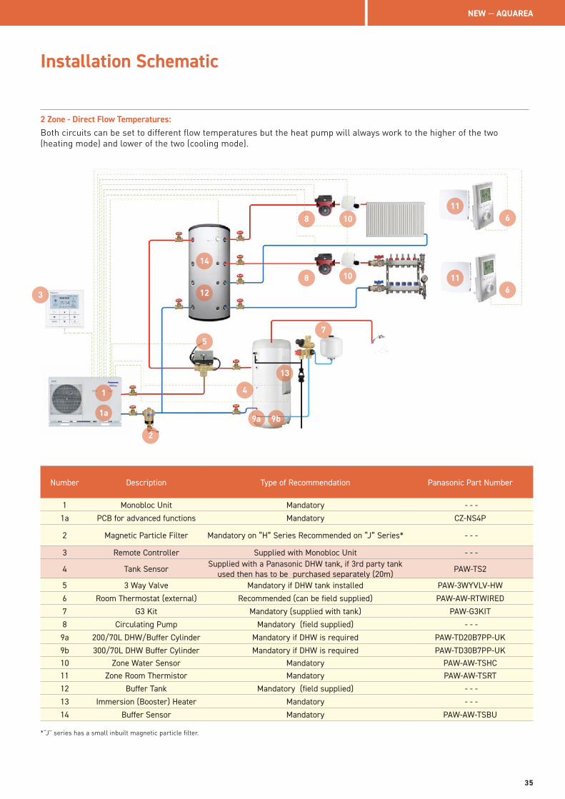
2 Zone - Direct Flow Temperatures:Both circuits can be set to different flow temperatures but the heat pump will always work to the higher of the two (heating mode) and lower of the two (cooling mode).
3
2
41
5
6
7
8
9a
Number Description Type of Recommendation Panasonic Part Number
1 Monobloc Unit Mandatory - - -
1a PCB for advanced functions Mandatory CZ-NS4P
2 Magnetic Particle Filter Mandatory on “H” Series Recommended on “J” Series* - - -
3 Remote Controller Supplied with Monobloc Unit - - -
4 Tank Sensor Supplied with a Panasonic DHW tank, if 3rd party tank used then has to be purchased separately (20m) PAW-TS2
5 3 Way Valve Mandatory if DHW tank installed PAW-3WYVLV-HW
6 Room Thermostat (external) Recommended (can be field supplied) PAW-AW-RTWIRED
7 G3 Kit Mandatory (supplied with tank) PAW-G3KIT
8 Circulating Pump Mandatory (field supplied) - - -
9a 200/70L DHW/Buffer Cylinder Mandatory if DHW is required PAW-TD20B7PP-UK
9b 300/70L DHW Buffer Cylinder Mandatory if DHW is required PAW-TD30B7PP-UK10 Zone Water Sensor Mandatory PAW-AW-TSHC11 Zone Room Thermistor Mandatory PAW-AW-TSRT
12 Buffer Tank Mandatory (field supplied) - - -
13 Immersion (Booster) Heater Mandatory - - -
14 Buffer Sensor Mandatory PAW-AW-TSBU
*“J” series has a small inbuilt magnetic particle filter.
9b
11
12
86
11
13
14
10
10
1a
NEW — AQUAREA
35
Installation Schematic
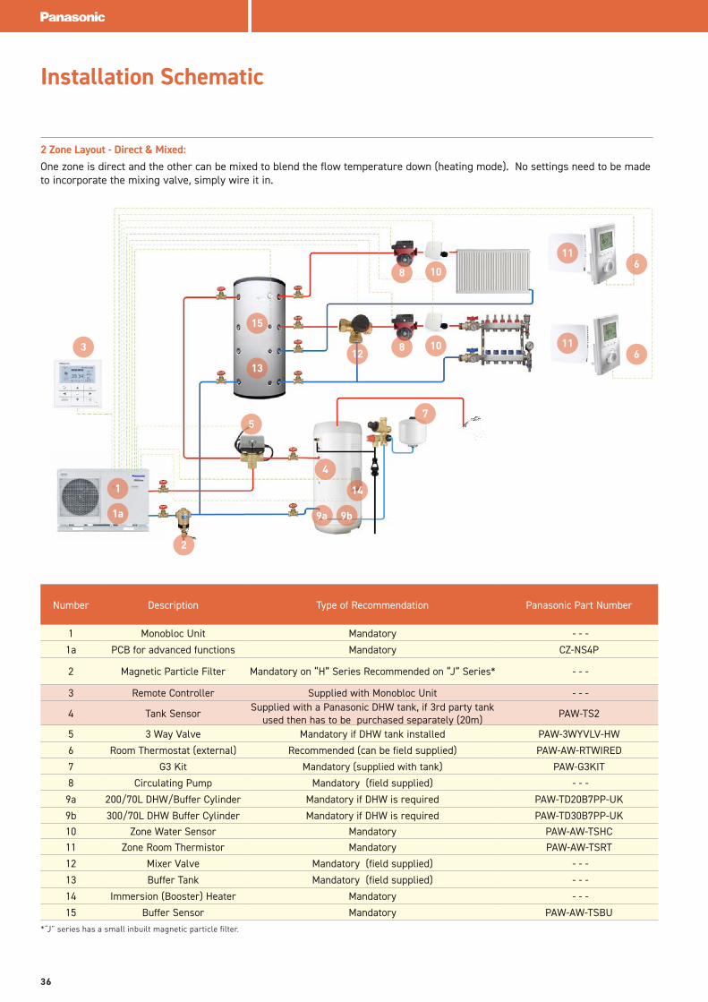
2 Zone Layout - Direct & Mixed:One zone is direct and the other can be mixed to blend the flow temperature down (heating mode). No settings need to be made to incorporate the mixing valve, simply wire it in.
*“J” series has a small inbuilt magnetic particle filter.
Number Description Type of Recommendation Panasonic Part Number
1 Monobloc Unit Mandatory - - -
1a PCB for advanced functions Mandatory CZ-NS4P
2 Magnetic Particle Filter Mandatory on “H” Series Recommended on “J” Series* - - -
3 Remote Controller Supplied with Monobloc Unit - - -
4 Tank Sensor Supplied with a Panasonic DHW tank, if 3rd party tank used then has to be purchased separately (20m) PAW-TS2
5 3 Way Valve Mandatory if DHW tank installed PAW-3WYVLV-HW
6 Room Thermostat (external) Recommended (can be field supplied) PAW-AW-RTWIRED
7 G3 Kit Mandatory (supplied with tank) PAW-G3KIT
8 Circulating Pump Mandatory (field supplied) - - -
9a 200/70L DHW/Buffer Cylinder Mandatory if DHW is required PAW-TD20B7PP-UK
9b 300/70L DHW Buffer Cylinder Mandatory if DHW is required PAW-TD30B7PP-UK10 Zone Water Sensor Mandatory PAW-AW-TSHC11 Zone Room Thermistor Mandatory PAW-AW-TSRT
12 Mixer Valve Mandatory (field supplied) - - -
13 Buffer Tank Mandatory (field supplied) - - -
14 Immersion (Booster) Heater Mandatory - - -
15 Buffer Sensor Mandatory PAW-AW-TSBU
3
2
4
5
6
7
8
9a 9b
11
128
611
13
14
15
10
10
1
1a
36
Installation Schematic
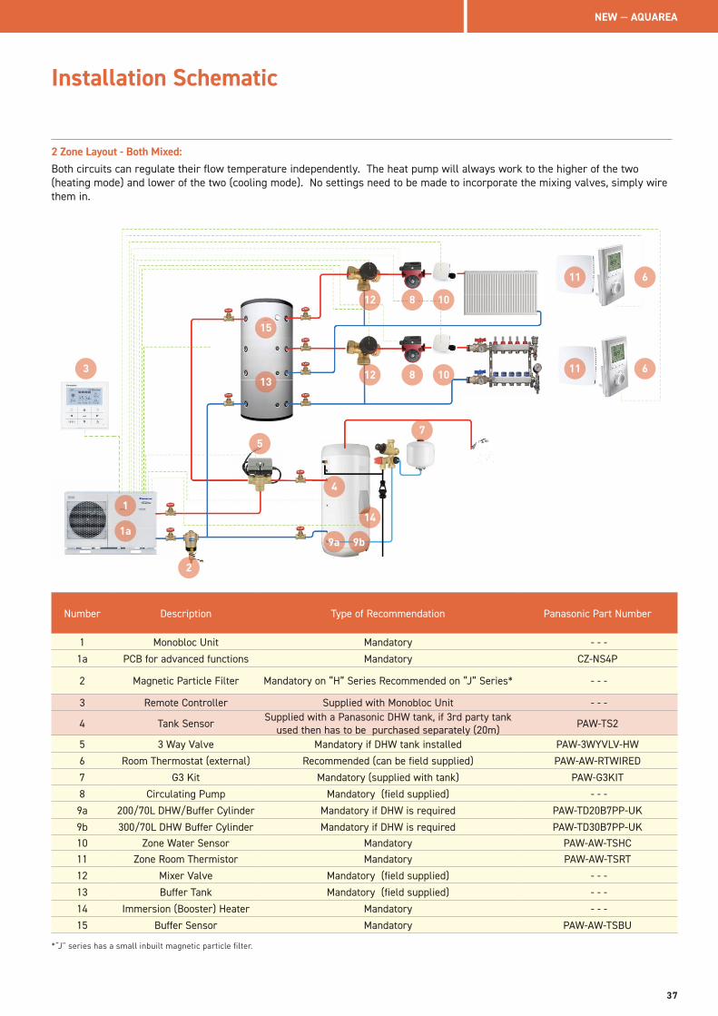
2 Zone Layout - Both Mixed:Both circuits can regulate their flow temperature independently. The heat pump will always work to the higher of the two (heating mode) and lower of the two (cooling mode). No settings need to be made to incorporate the mixing valves, simply wire them in.
3
2
4
5
6
7
8
9a
Number Description Type of Recommendation Panasonic Part Number
1 Monobloc Unit Mandatory - - -
1a PCB for advanced functions Mandatory CZ-NS4P
2 Magnetic Particle Filter Mandatory on “H” Series Recommended on “J” Series* - - -
3 Remote Controller Supplied with Monobloc Unit - - -
4 Tank Sensor Supplied with a Panasonic DHW tank, if 3rd party tank used then has to be purchased separately (20m) PAW-TS2
5 3 Way Valve Mandatory if DHW tank installed PAW-3WYVLV-HW
6 Room Thermostat (external) Recommended (can be field supplied) PAW-AW-RTWIRED
7 G3 Kit Mandatory (supplied with tank) PAW-G3KIT
8 Circulating Pump Mandatory (field supplied) - - -
9a 200/70L DHW/Buffer Cylinder Mandatory if DHW is required PAW-TD20B7PP-UK
9b 300/70L DHW Buffer Cylinder Mandatory if DHW is required PAW-TD30B7PP-UK10 Zone Water Sensor Mandatory PAW-AW-TSHC11 Zone Room Thermistor Mandatory PAW-AW-TSRT
12 Mixer Valve Mandatory (field supplied) - - -
13 Buffer Tank Mandatory (field supplied) - - -
14 Immersion (Booster) Heater Mandatory - - -
15 Buffer Sensor Mandatory PAW-AW-TSBU
9b
10
11
12 8 611
12
13
14
*“J” series has a small inbuilt magnetic particle filter.
15
10
1
1a
NEW — AQUAREA
37
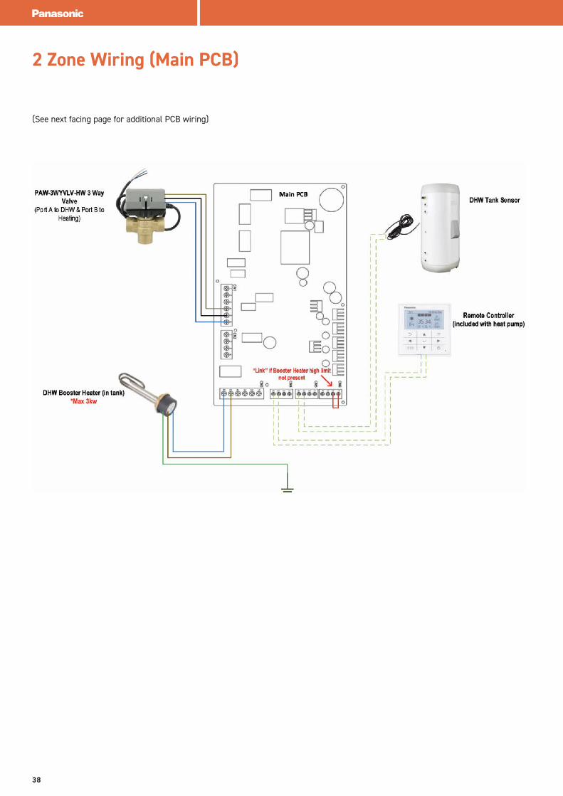
2 Zone Wiring (Main PCB)
(See next facing page for additional PCB wiring)
38
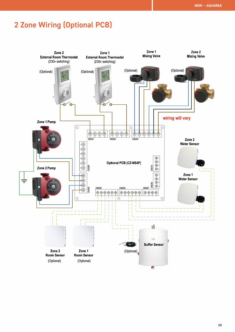
2 Zone Wiring (Optional PCB)
NEW — AQUAREA
39
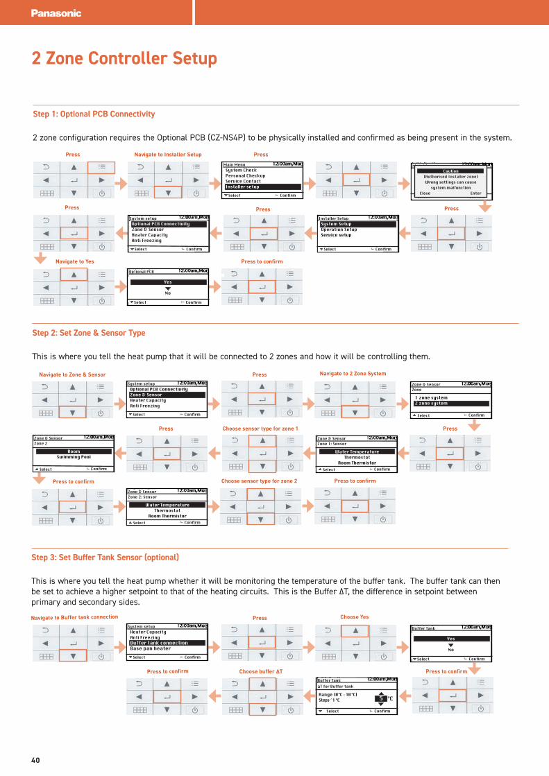
Step 1: Optional PCB Connectivity
2 zone configuration requires the Optional PCB (CZ-NS4P) to be physically installed and confirmed as being present in the system.
Select
System CheckPersonal CheckupService ContactInstaller setup
Confirm
Main Menu
Select
Optional PCB ConnectivityZone & SensorHeater CapacityAnti Freezing
Confirm
System setup
Select
System SetupOperation SetupService setup
Confirm
Installer Setup
Select Confirm
Main MenuCaution
(Authorised Installer zone)Wrong settings can cause
system malfunctionClose Enter
Step 3: Set Buffer Tank Sensor (optional)
This is where you tell the heat pump whether it will be monitoring the temperature of the buffer tank. The buffer tank can then be set to achieve a higher setpoint to that of the heating circuits. This is the Buffer ΔT, the difference in setpoint between primary and secondary sides.
Press Navigate to Installer Setup Press
PressPressPress
Navigate to Yes Press to confirm
Press to confirm
2 Zone Controller Setup
Select Confirm
Optional PCB
Yes
No
Step 2: Set Zone & Sensor Type
This is where you tell the heat pump that it will be connected to 2 zones and how it will be controlling them.
Navigate to Zone & Sensor Press
PressPress
Press to confirm
Select
Optional PCB ConnectivityZone & SensorHeater CapacityAnti Freezing
Confirm
System setup
Navigate to 2 Zone System
Confirm
Zone & Sensor
1 zone system2 zone system
Zone
Select
Choose sensor type for zone 1
Press to confirm Choose sensor type for zone 2
Confirm
Zone & Sensor
Water Temperature Thermostat
Room Thermistor
Zone 1: Sensor
SelectConfirm
Zone & Sensor
RoomSwimming Pool
Zone 2
Select
Confirm
Zone & Sensor
Water Temperature Thermostat
Room Thermistor
Zone 2: Sensor
Select
Navigate to Buffer tank connection Press
Select
Heater CapacityAnti FreezingBuffer tank connectionBase pan heater
Confirm
System setup
Choose Yes
Select Confirm
Buffer Tank
Yes
No
Select Confirm
Buffer Tank
Range (0°C - 10 °C)Steps ̂ 1 °C
ΔT for Buffer tank
°C 5
Press to confirm Choose buffer ΔT
40
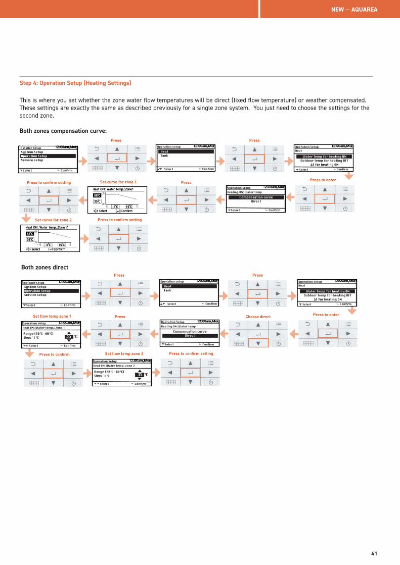
Step 4: Operation Setup (Heating Settings)
This is where you set whether the zone water flow temperatures will be direct (fixed flow temperature) or weather compensated. These settings are exactly the same as described previously for a single zone system. You just need to choose the settings for the second zone.
Both zones compensation curve:
Select Confirm
Operation Setup
Select
System SetupOperation SetupService setup
Confirm
Installer Setup
Compensation curveDirect
Heating ON: Water temp
Both zones direct
Press
Set curve for zone 1 Press to enterPress to confirm setting Press
Press to confirm setting
Pump Maximum SpeedPump DownDry ConcreteService Contact
Select
Operation setupHeatTank
Confirm
Press
Confirm
Operation Setup
Water Temp for heating ONOutdoor temp for heating OFF
ΔT for heating ON
Heat
Select
2
Set curve for zone 2
Select Confirm
Operation Setup
Select
System SetupOperation SetupService setup
Confirm
Installer Setup
Compensation curveDirect
Heating ON: Water temp
Press
Set flow temp zone 1 Press to enterPress
Press to confirm setting
Pump Maximum SpeedPump DownDry ConcreteService Contact
Select
Operation setupHeatTank
Confirm
Press
Confirm
Operation Setup
Water Temp for heating ONOutdoor temp for heating OFF
ΔT for heating ON
Heat
Select
Set flow temp zone 2
Choose direct
Select Confirm
Operation setup
Range (20°C - 60 °C)Steps ̂ 1 °C
Heat ON: Water temp.: Zone 1
°C35
Select Confirm
Operation Setup
Range (20°C - 60 °C)Steps ̂ 1 °C
Heat ON: Water temp: zone 2
°C 35
Press to confirm
NEW — AQUAREA
41
Water Temperature-> Compensation curve
Room Thermostat-> External
Water Temperature-> Direct
Room Thermostat->Internal
Pool only
Water Temperature
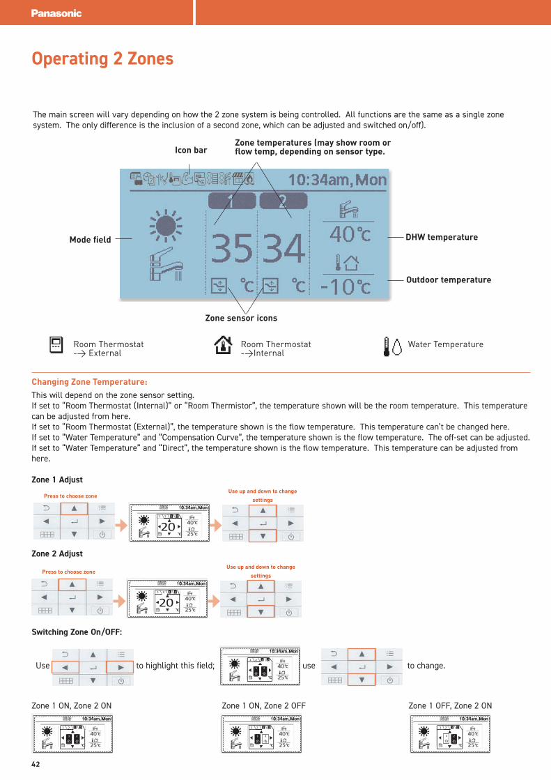
Changing Zone Temperature:This will depend on the zone sensor setting. If set to “Room Thermostat (Internal)” or “Room Thermistor”, the temperature shown will be the room temperature. This temperature can be adjusted from here. If set to “Room Thermostat (External)”, the temperature shown is the flow temperature. This temperature can’t be changed here.If set to “Water Temperature” and “Compensation Curve”, the temperature shown is the flow temperature. The off-set can be adjusted.If set to “Water Temperature” and “Direct”, the temperature shown is the flow temperature. This temperature can be adjusted from here.
Zone 1 Adjust
Zone 2 Adjust
The main screen will vary depending on how the 2 zone system is being controlled. All functions are the same as a single zone system. The only difference is the inclusion of a second zone, which can be adjusted and switched on/off).
Operating 2 Zones
Press to choose zoneUse up and down to change
settings
201 2 1 2
Press to choose zoneUse up and down to change
settings
201 2 1 2
Switching Zone On/OFF:
Use to highlight this field; use to change.
Zone 1 ON, Zone 2 ON Zone 1 ON, Zone 2 OFF Zone 1 OFF, Zone 2 ON
1 2 1 2
1 2
1 2 1 2
1 2
1 2 1 2
1 2
1 2 1 2
21
Mode field
Icon barZone temperatures (may show room or flow temp, depending on sensor type.
DHW temperature
Outdoor temperature
Zone sensor icons
42
Pool only
Water Temperature
DHW temperature
Outdoor temperature
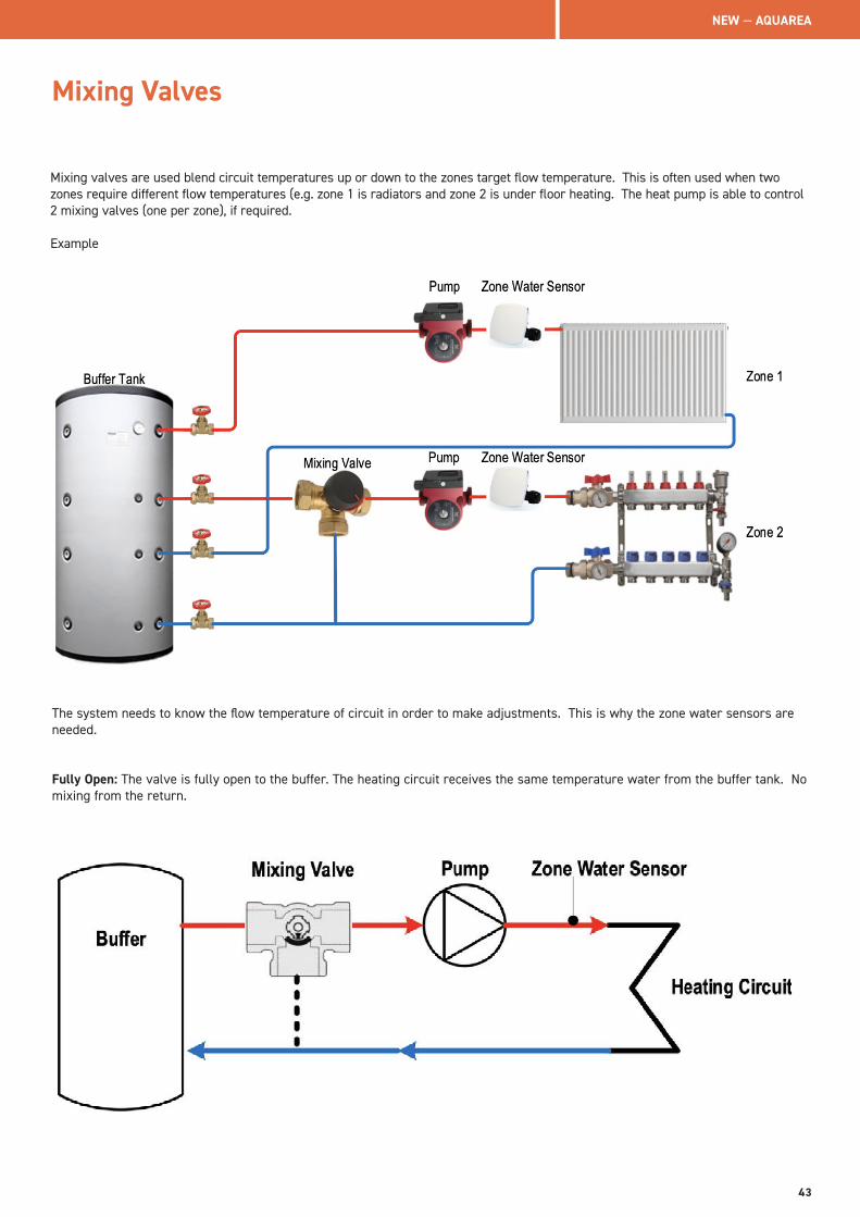
Mixing Valves
Mixing valves are used blend circuit temperatures up or down to the zones target flow temperature. This is often used when two zones require different flow temperatures (e.g. zone 1 is radiators and zone 2 is under floor heating. The heat pump is able to control 2 mixing valves (one per zone), if required.
Example
The system needs to know the flow temperature of circuit in order to make adjustments. This is why the zone water sensors are needed.
Fully Open: The valve is fully open to the buffer. The heating circuit receives the same temperature water from the buffer tank. No mixing from the return.
NEW — AQUAREA
43
Mixing Valves
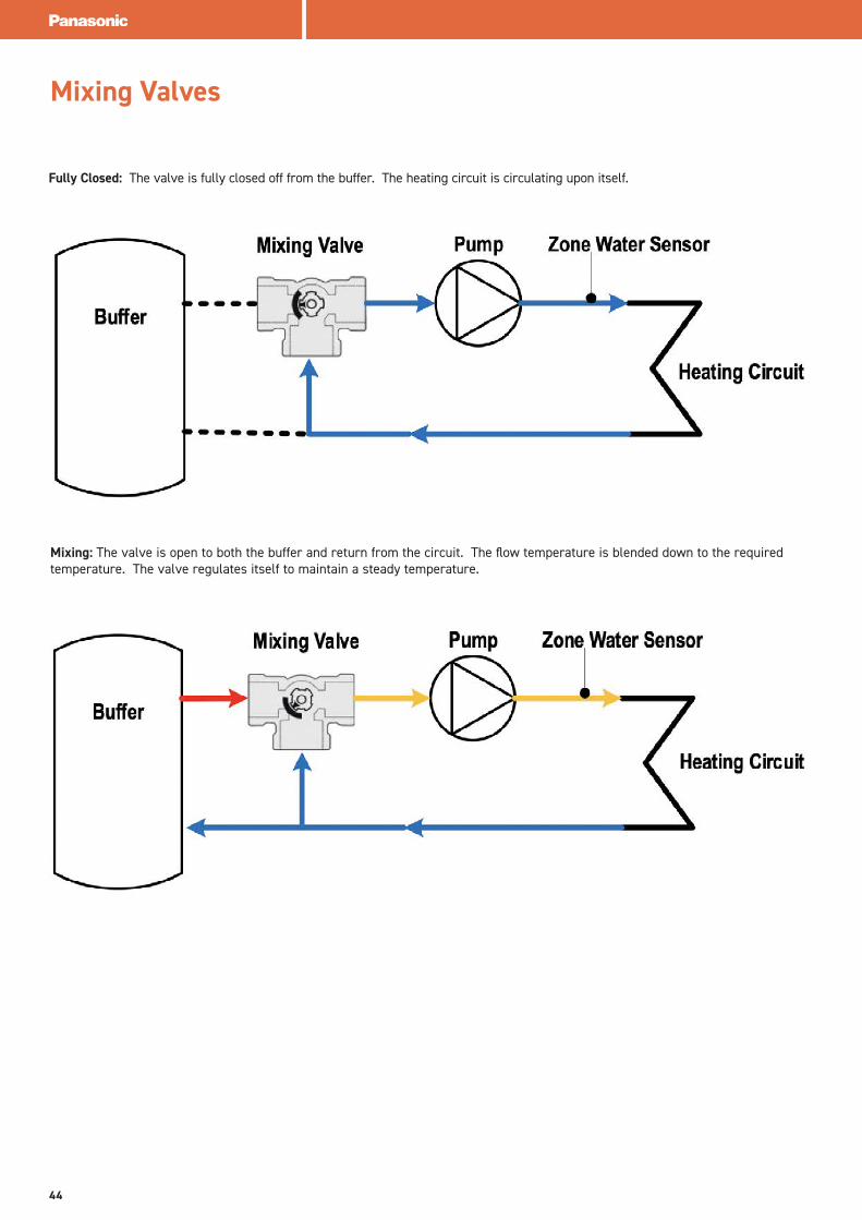
Fully Closed: The valve is fully closed off from the buffer. The heating circuit is circulating upon itself.
Mixing: The valve is open to both the buffer and return from the circuit. The flow temperature is blended down to the required temperature. The valve regulates itself to maintain a steady temperature.
44
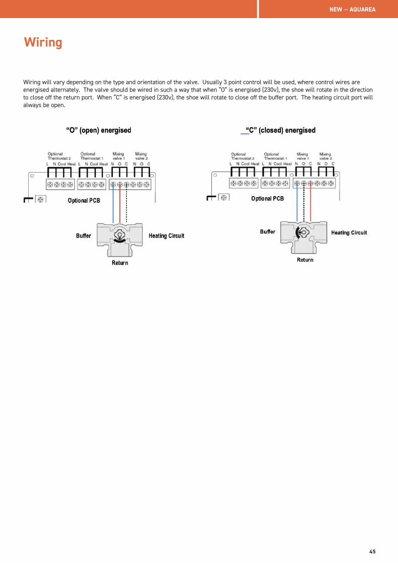
Wiring
Wiring will vary depending on the type and orientation of the valve. Usually 3 point control will be used, where control wires are energised alternately. The valve should be wired in such a way that when “O” is energised (230v), the shoe will rotate in the direction to close off the return port. When “C” is energised (230v), the shoe will rotate to close off the buffer port. The heating circuit port will always be open.
NEW — AQUAREA
45
Aquarea is able to control a fossil fuel boiler as part of the heating system. The basic principle is that the heat pump will have full control of all aspects of the system and will run the backup boiler as and when required, depending on system design and settings. Zoning, solar, swimming pool or any other system control setup remains unchanged by bivalent control. The boiler needs to be connected into the system in parallel and preferably, into a buffer tank. The control signal, to the run the boiler, is made by closing a “dry contact” on the heat pump main PCB. The boiler operation and temperature is managed by the boiler controls. Ensure the system return temperature does not exceed 55˚C. The heat pump simply gives a signal to run. The boiler is required to have its own circulating pump.
J series models also have the option to remotely enable/disable boiler or heat pump operation using 3rd party switch permutations (Smart Grid control. This will be explained. There are 3 different bivalent control methods:• Alternative: Heat pump and boiler operate independent of each other, never together. Once the outside temperatures drops
below “Turn On” setpoint, heat pump stops and boiler takes over. • Parallel: Heat pump and boiler can operate together. Once the outside temperatures drops below “Turn On” setpoint, boiler
runs as well as heat pump. • Advanced Parallel: Heat pump and boiler can operate together. Certain control conditions need to be met before boiler is
signalled to run, which will be explained. Advanced Parallel configuration requires optional PCB (CZ-NS4P) and buffer tank sensor (PAW-A2W-TSBU).
Buffer tank sensor is not strictly necessary with “Alternative” or “Parallel” setups but it’s recommended, as the system will function better. “Advanced Parallel” setups always require a buffer tank sensor and will not work without one. This guide will demonstrate layouts using a buffer sensor for all control methods.
Accessories that are needed for Bivalent installations:• Optional PCB (CZ-NS4P)• Buffer Tank Sensor (PAW-A2W-TSBU)• Zone Water Sensor (PAW-A2W-TSHC) Note – 2 required for 2 zone setups
Advanced InstallationsBivalent Heating Setup
46
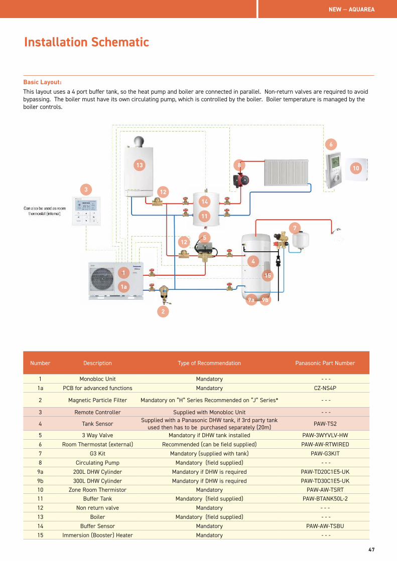
Installation Schematic
Basic Layout:This layout uses a 4 port buffer tank, so the heat pump and boiler are connected in parallel. Non-return valves are required to avoid bypassing. The boiler must have its own circulating pump, which is controlled by the boiler. Boiler temperature is managed by the boiler controls.
Number Description Type of Recommendation Panasonic Part Number
1 Monobloc Unit Mandatory - - -
1a PCB for advanced functions Mandatory CZ-NS4P
2 Magnetic Particle Filter Mandatory on “H” Series Recommended on “J” Series* - - -
3 Remote Controller Supplied with Monobloc Unit - - -
4 Tank Sensor Supplied with a Panasonic DHW tank, if 3rd party tank used then has to be purchased separately (20m) PAW-TS2
5 3 Way Valve Mandatory if DHW tank installed PAW-3WYVLV-HW
6 Room Thermostat (external) Recommended (can be field supplied) PAW-AW-RTWIRED
7 G3 Kit Mandatory (supplied with tank) PAW-G3KIT
8 Circulating Pump Mandatory (field supplied) - - -
9a 200L DHW Cylinder Mandatory if DHW is required PAW-TD20C1E5-UK
9b 300L DHW Cylinder Mandatory if DHW is required PAW-TD30C1E5-UK10 Zone Room Thermistor Mandatory PAW-AW-TSRT11 Buffer Tank Mandatory (field supplied) PAW-BTANK50L-2
12 Non return valve Mandatory - - -
13 Boiler Mandatory (field supplied) - - -
14 Buffer Sensor Mandatory PAW-AW-TSBU
15 Immersion (Booster) Heater Mandatory - - -
3
2
4
5
6
7
9a 9b
10
12
8
11
13
14
15
12
1
1a
NEW — AQUAREA
47
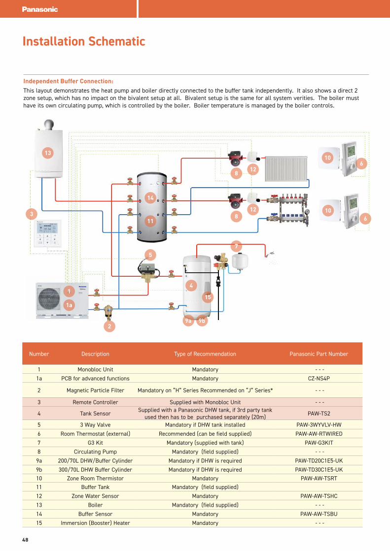
Independent Buffer Connection:This layout demonstrates the heat pump and boiler directly connected to the buffer tank independently. It also shows a direct 2 zone setup, which has no impact on the bivalent setup at all. Bivalent setup is the same for all system verities. The boiler must have its own circulating pump, which is controlled by the boiler. Boiler temperature is managed by the boiler controls.
Installation Schematic
Number Description Type of Recommendation Panasonic Part Number
1 Monobloc Unit Mandatory - - -
1a PCB for advanced functions Mandatory CZ-NS4P
2 Magnetic Particle Filter Mandatory on “H” Series Recommended on “J” Series* - - -
3 Remote Controller Supplied with Monobloc Unit - - -
4 Tank Sensor Supplied with a Panasonic DHW tank, if 3rd party tank used then has to be purchased separately (20m) PAW-TS2
5 3 Way Valve Mandatory if DHW tank installed PAW-3WYVLV-HW
6 Room Thermostat (external) Recommended (can be field supplied) PAW-AW-RTWIRED
7 G3 Kit Mandatory (supplied with tank) PAW-G3KIT
8 Circulating Pump Mandatory (field supplied) - - -
9a 200/70L DHW/Buffer Cylinder Mandatory if DHW is required PAW-TD20C1E5-UK
9b 300/70L DHW Buffer Cylinder Mandatory if DHW is required PAW-TD30C1E5-UK10 Zone Room Thermistor Mandatory PAW-AW-TSRT11 Buffer Tank Mandatory (field supplied)
12 Zone Water Sensor Mandatory PAW-AW-TSHC
13 Boiler Mandatory (field supplied) - - -
14 Buffer Sensor Mandatory PAW-AW-TSBU
15 Immersion (Booster) Heater Mandatory - - -
3
2
4
57
8
9a 9b
10
11
128 6
10
12
13
14
15
6
1
1a
48
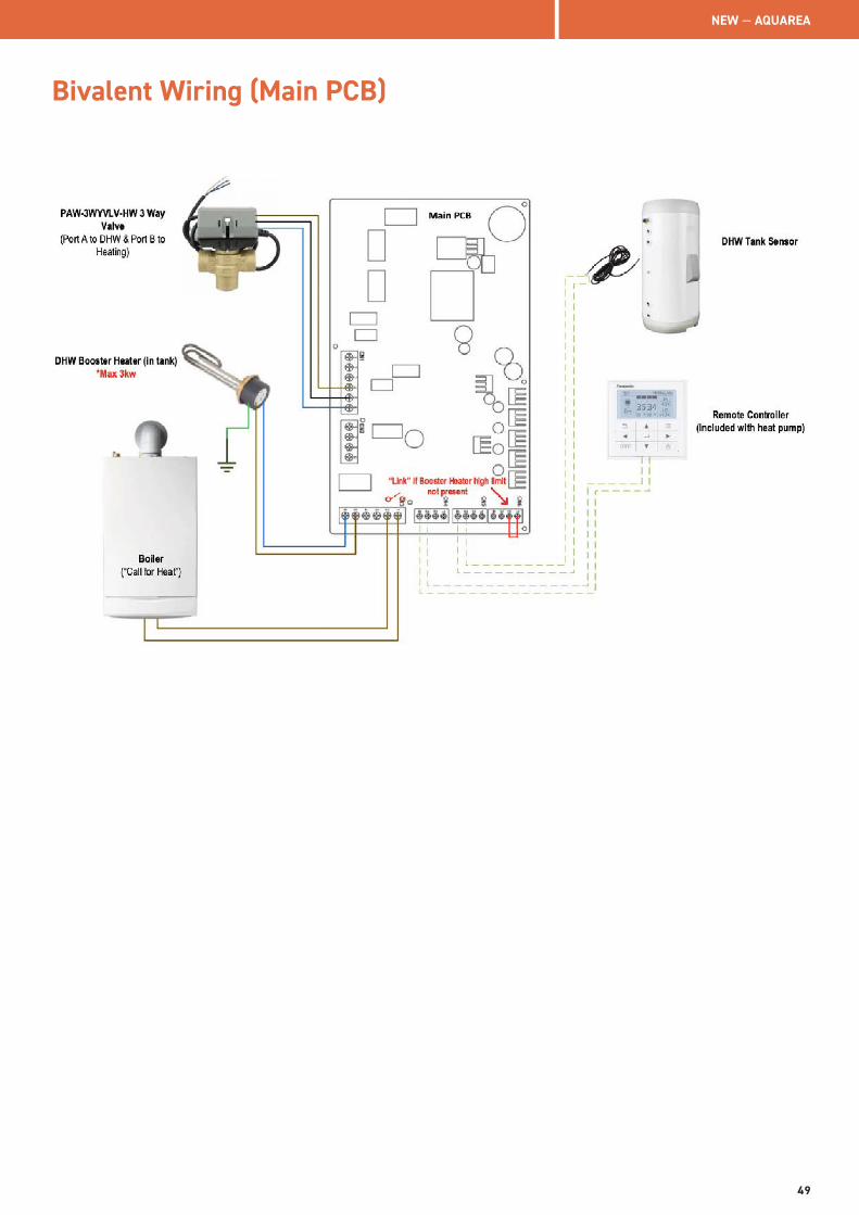
Bivalent Wiring (Main PCB)
NEW — AQUAREA
49
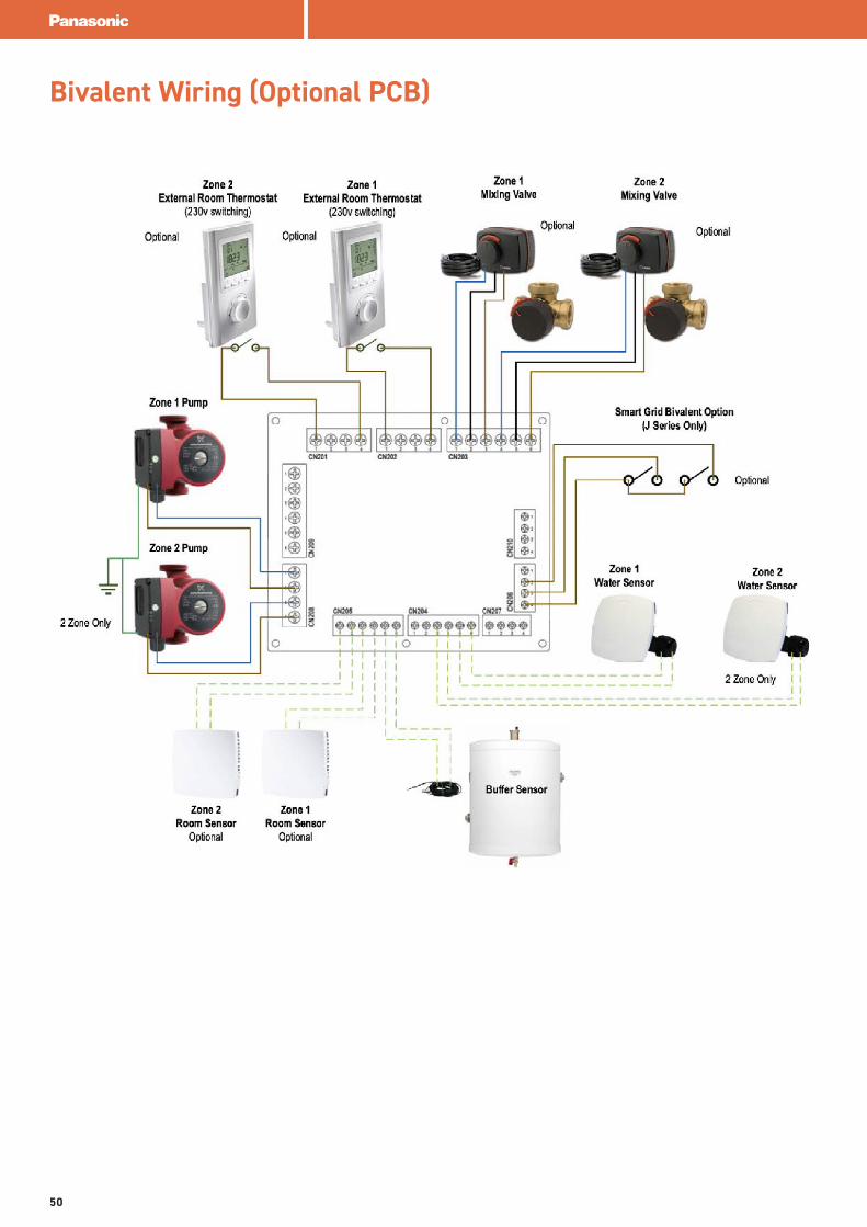
Bivalent Wiring (Optional PCB)
50
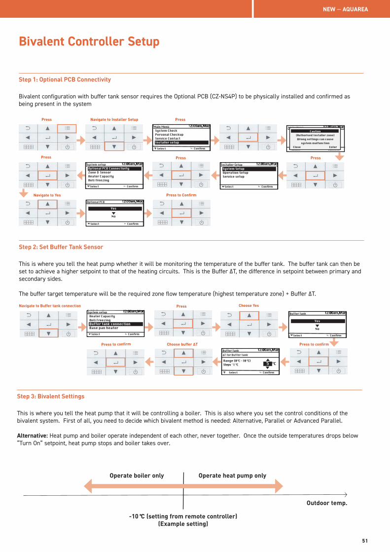
Bivalent Controller Setup
Step 1: Optional PCB Connectivity
Bivalent configuration with buffer tank sensor requires the Optional PCB (CZ-NS4P) to be physically installed and confirmed as being present in the system
Select
System CheckPersonal CheckupService ContactInstaller setup
Confirm
Main Menu
Select
Optional PCB ConnectivityZone & SensorHeater CapacityAnti freezing
Confirm
System setup
Select
System SetupOperation SetupService setup
Confirm
Installer Setup
Select Confirm
Main MenuCaution
(Authorised Installer zone)Wrong settings can cause
system malfunctionClose Enter
Press Navigate to Installer Setup Press
Press
Navigate to Yes
PressPress
Press to Confirm
Select Confirm
Optional PCB
Yes
No
Step 2: Set Buffer Tank Sensor
This is where you tell the heat pump whether it will be monitoring the temperature of the buffer tank. The buffer tank can then be set to achieve a higher setpoint to that of the heating circuits. This is the Buffer ΔT, the difference in setpoint between primary and secondary sides.
The buffer target temperature will be the required zone flow temperature (highest temperature zone) + Buffer ΔT.
Press to confirm
Navigate to Buffer tank connection Press
Select
Heater CapacityAnti FreezingBuffer tank connectionBase pan heater
Confirm
System setup
Choose Yes
Select Confirm
Buffer Tank
Yes
No
Select Confirm
Buffer Tank
Range (0°C - 10 °C)Steps ̂ 1 °C
ΔT for Buffer tank
°C 5
Press to confirm Choose buffer ΔT
Step 3: Bivalent Settings
This is where you tell the heat pump that it will be controlling a boiler. This is also where you set the control conditions of the bivalent system. First of all, you need to decide which bivalent method is needed: Alternative, Parallel or Advanced Parallel.
Alternative: Heat pump and boiler operate independent of each other, never together. Once the outside temperatures drops below “Turn On” setpoint, heat pump stops and boiler takes over.
Operate boiler only Operate heat pump only
-10 °C (setting from remote controller)(Example setting)
Outdoor temp.
NEW — AQUAREA
51
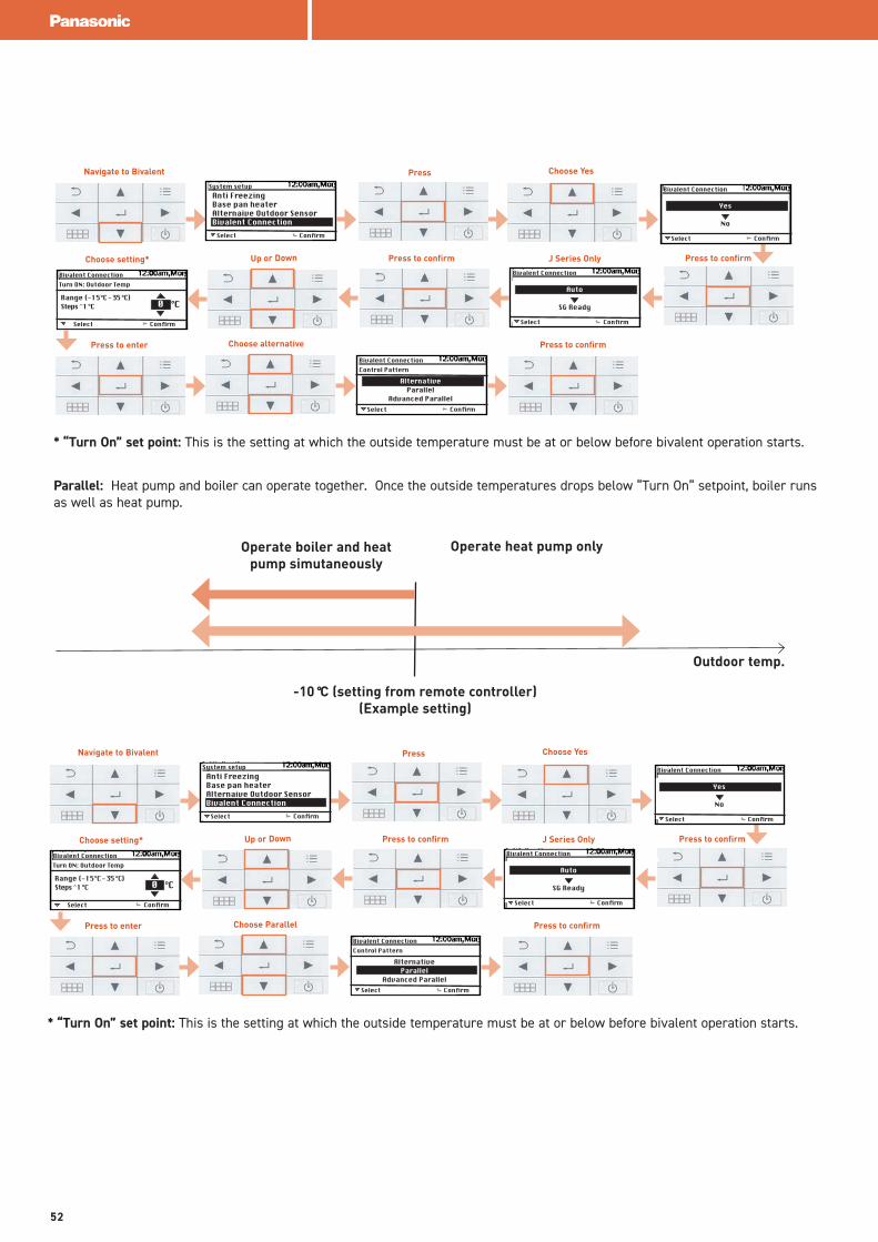
* “Turn On” set point: This is the setting at which the outside temperature must be at or below before bivalent operation starts.
Press to confirm
Navigate to Bivalent Press
Select
Anti FreezingBase pan heaterAlternaive Outdoor SensorBivalent Connection
Confirm
System setup
Choose Yes
Select Confirm
Bivalent Connection
Yes
No
Up or Down Press to confirm
Select Confirm
Bivalent Connection
Auto
SG Ready
Select Confirm
Bivalent Connection
Range (-15°C - 35 °C)Steps ̂ 1 °C
Turn ON: Outdoor Temp
°C 0
Press to enter Choose alternative
Select Confirm
Bivalent Connection
AlternativeParallel
Advanced Parallel
Control Pattern
Press to confirm
Choose setting* J Series Only
Parallel: Heat pump and boiler can operate together. Once the outside temperatures drops below “Turn On” setpoint, boiler runs as well as heat pump.
Operate boiler and heat pump simutaneously
Operate heat pump only
-10 °C (setting from remote controller)(Example setting)
Outdoor temp.
* “Turn On” set point: This is the setting at which the outside temperature must be at or below before bivalent operation starts.
Press to confirm
Navigate to Bivalent Press
Select
Anti FreezingBase pan heaterAlternaive Outdoor SensorBivalent Connection
Confirm
System setup
Choose Yes
Select Confirm
Bivalent Connection
Yes
No
Up or Down Press to confirm
Select Confirm
Bivalent Connection
Auto
SG Ready
Select Confirm
Bivalent Connection
Range (-15°C - 35 °C)Steps ̂ 1 °C
Turn ON: Outdoor Temp
°C 0
Press to enter Choose Parallel
Select Confirm
Bivalent Connection
AlternativeParallel
Advanced Parallel
Control Pattern
Press to confirm
Choose setting* J Series Only
52
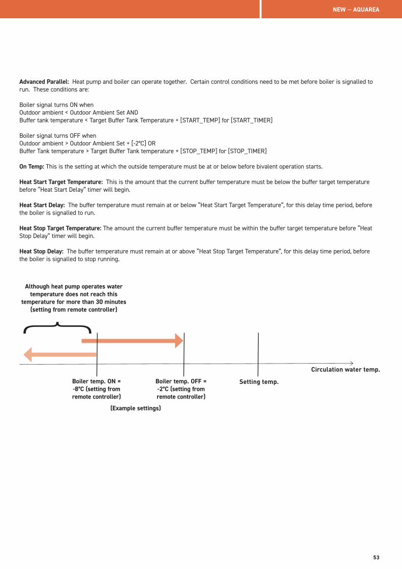
Advanced Parallel: Heat pump and boiler can operate together. Certain control conditions need to be met before boiler is signalled to run. These conditions are:
Boiler signal turns ON whenOutdoor ambient < Outdoor Ambient Set ANDBuffer tank temperature < Target Buffer Tank Temperature + [START_TEMP] for [START_TIMER] Boiler signal turns OFF whenOutdoor ambient > Outdoor Ambient Set + [-2°C] ORBuffer Tank temperature > Target Buffer Tank temperature + [STOP_TEMP] for [STOP_TIMER]
On Temp: This is the setting at which the outside temperature must be at or below before bivalent operation starts.
Heat Start Target Temperature: This is the amount that the current buffer temperature must be below the buffer target temperature before “Heat Start Delay” timer will begin. Heat Start Delay: The buffer temperature must remain at or below “Heat Start Target Temperature”, for this delay time period, before the boiler is signalled to run.
Heat Stop Target Temperature: The amount the current buffer temperature must be within the buffer target temperature before “Heat Stop Delay” timer will begin. Heat Stop Delay: The buffer temperature must remain at or above “Heat Stop Target Temperature”, for this delay time period, before the boiler is signalled to stop running.
Although heat pump operates water temperature does not reach this
temperature for more than 30 minutes (setting from remote controller)
Boiler temp. ON = -8°C (setting from remote controller)
Circulation water temp.
}
(Example settings)
Boiler temp. OFF = -2°C (setting from remote controller)
Setting temp.
NEW — AQUAREA
53
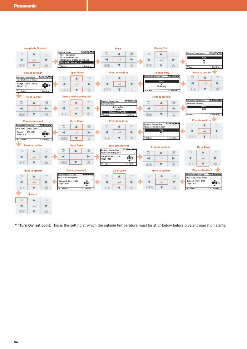
* “Turn On” set point: This is the setting at which the outside temperature must be at or below before bivalent operation starts.
Press to confirm
Navigate to Bivalent Press
Select
Anti FreezingBase pan heaterAlternaive Outdoor SensorBivalent Connection
Confirm
System setup
Choose Yes
Select Confirm
Bivalent Connection
Yes
No
Up or Down Press to confirm
Select Confirm
Bivalent Connection
Auto
SG Ready
Select Confirm
Bivalent Connection
Range (-15°C - 35 °C)Steps ̂ 1 °C
Turn ON: Outdoor Temp
°C 0
Press to enter Choose Advanced Parallel
Select Confirm
Bivalent Connection
AlternativeParallel
Advanced Parallel
Control Pattern
Press to confirm
Choose setting* J Series Only
Select Confirm
Bivalent Connection
HeatDHW
Advanced Parallel
Press to confirm
Select Confirm
Bivalent Connection
YesNo
Advanced Parallel: Heat
Up or Down Press to confirm
Select Confirm
Bivalent Connection
Range (-10°C - 0°C)Steps ̂ 1 °C
Heat Start: Target Temp
°C -8
(See explanation)
Press to confirm Up or Down
Select Confirm
Bivalent Connection
Range (0:00 - 1:30)Steps ̂ 0.05
Heat Start: Delay time
0:30
(See explanation) Press to confirm Up or Down
Select Confirm
Bivalent Connection
Range (-10°C - 0°C)Steps ̂ 1 °C
Heat Stop: Target Temp
°C -2
(See explanation)Up or Down Press to confirm
Select Confirm
Bivalent Connection
Range (0:00 - 1:30)Steps ̂ 0.05
Heat Stop: Delay time
0:30
(See explanation)Press to confirm
Return
54
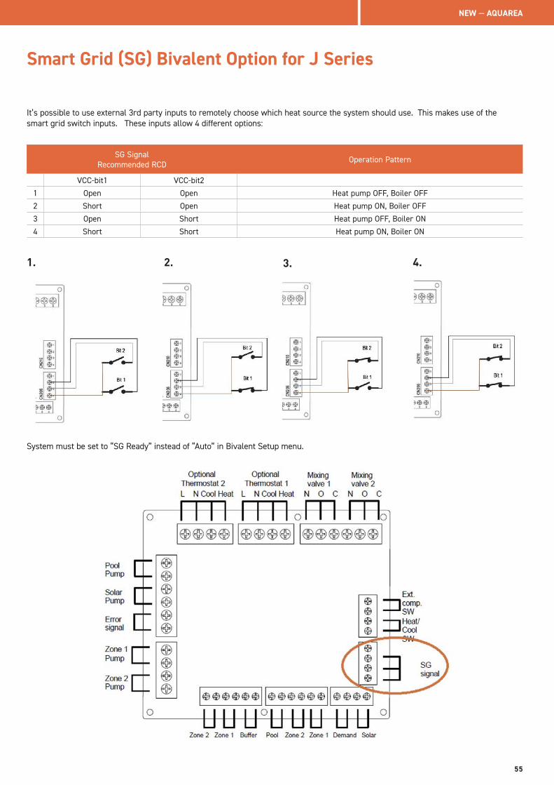
Smart Grid (SG) Bivalent Option for J Series
It’s possible to use external 3rd party inputs to remotely choose which heat source the system should use. This makes use of the smart grid switch inputs. These inputs allow 4 different options:
SG Signal Recommended RCD Operation Pattern
VCC-bit1 VCC-bit2
1 Open Open Heat pump OFF, Boiler OFF
2 Short Open Heat pump ON, Boiler OFF
3 Open Short Heat pump OFF, Boiler ON
4 Short Short Heat pump ON, Boiler ON
1. 2. 3. 4.
System must be set to “SG Ready” instead of “Auto” in Bivalent Setup menu.
NEW — AQUAREA
55
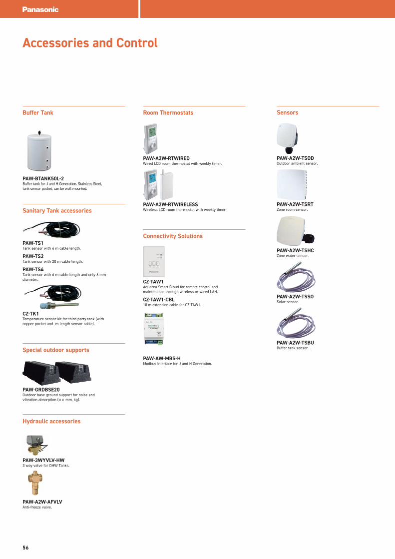
Accessories and Control
Buffer Tank
PAW-BTANK50L-2Buffer tank for J and H Generation. Stainless Steel, tank sensor pocket, can be wall mounted.
Sanitary Tank accessories
PAW-TS1Tank sensor with 6 m cable length.
PAW-TS2Tank sensor with 20 m cable length.
PAW-TS4Tank sensor with 6 m cable length and only 6 mm diameter.
CZ-TK1Temperature sensor kit for third party tank (with copper pocket and m length sensor cable).
Special outdoor supports
PAW-GRDBSE20Outdoor base ground support for noise and vibration absorption ( x x mm, kg).
Hydraulic accessories
PAW-3WYVLV-HW3 way valve for DHW Tanks.
PAW-A2W-AFVLVAnti-freeze valve.
Room Thermostats
PAW-A2W-RTWIREDWired LCD room thermostat with weekly timer.
PAW-A2W-RTWIRELESSWireless LCD room thermostat with weekly timer.
Connectivity Solutions
CZ-TAW1Aquarea Smart Cloud for remote control and maintenance through wireless or wired LAN.
CZ-TAW1-CBL10 m extension cable for CZ-TAW1.
PAW-AW-MBS-HModbus Interface for J and H Generation.
Sensors
PAW-A2W-TSODOutdoor ambient sensor.
PAW-A2W-TSRTZone room sensor.
PAW-A2W-TSHCZone water sensor.
PAW-A2W-TSSOSolar sensor.
PAW-A2W-TSBUBuffer tank sensor.
56
Technical Helpline – 01344 853393Email – [email protected] address – www.aircon.panasonic.co.uk
GENERAL
The Heating & Cooling Solutions Warranty for Air to Water Products (“Warranty”) is offered by Panasonic UK, a branch of Panasonic Marketing Europe GmbH. whose registered address is, Maxis 2,Western Road Bracknell, Berkshire RG12 1RT, UK (“Panasonic”).
The Warranty is offered in the United Kingdom (“UK”), including Northern Ireland, the Channel Islands, Isle of Man and the Republic of Ireland (the “Area”). This Warranty is an addition to, and does not in any way affect, any statutory or other rights.
The Warranty periods detailed within this document apply to installation carried out within the Area only . If the country of installation is different to the country of purchase, the Warranty will be provided in accordance with the terms and conditions applicable in the country of installation. By subscribing to this Warranty end users will be deemed to have read and accepted these Terms and Conditions. These Terms and Conditions are governed by and construed in accordance with the laws of England and Wales.
CONDITIONS OF COVER
The Warranty covers the Panasonic Heat Pump system(s), cylinder(s) and ancillaries (“Product”) when installed by a suitably competent, qualified and trained installer, contractor or engineer (“Installer”), in accordance with the Panasonic Heating & Cooling Solutions (“Panasonic”) Installation Guidelines and Recommendations provided with the Products.
Panasonic reserves the right to amend the Warranty conditions and cover from time to time, subject to a minimum period of one month’s notice, which will be published on the Panasonic Website.
This Warranty resides with the Product and will remain with the Product, but is limited to the original site of installation in which the Product is installed, and applies to the original site and positioning of installation only (“Property”). This Warranty may be transferred to a new Property owner, or user (“End User”), provided the Product is not moved from the original site and positioning of installation, unless carried out by a Panasonic approved Installer. This Warranty is offered on the condition that the Product is properly maintained in accordance with Panasonic Maintenance Guidelines as published on www.panasonicproclub.com/
Panasonic offers three types of Warranty coverage; 3 Year Standard Warranty (“Standard Warranty”), 5 Year Extended Warranty (“Extended Warranty”) and 7 Year Extended+ Warranty (“Extended+ Warranty”), for Products purchased from an approved reseller (“Distributor”). (List available upon request, approved companies may be found at www.aircon.panasonic.co.uk) (“Website”). The Extended Warranty and Extended+ Warranty are only available to the Installer who meets with the conditions detailed within the Warranty Type and Criteria section.
The Warranty period, will commence within 3 months of the date of commissioning, or 6 months from sale by Panasonic and no later than 18 months from date of manufacture, whichever is sooner. For Extended+ the warranty documentation must be submitted via the Service section of the Panasonic website www.panasonicproclub.com (“PROClub”) within 3 months of the date of commissioning, or 6 months from sale by Panasonic and no later than 18 months from date of manufacture, whichever is sooner.
WARRANTY TYPE AND CRITERIA
For the Warranty to be valid, the Installer must have the required expertise to fit the Product or ensure that a relevant installer with the necessary expertise’s carries out the installation.
The Installer must have a relevant knowledge and understanding of the installation of A2W systems, and where applicable, be F-Gas qualified, or have a relationship with a local qualified F-Gas qualified installer to enable the installation of bi-bloc and all in one heat pump systems. Fault finding on Panasonic Heat pumps will also require F-gas qualifications or working relationship with a local F-Gas qualified Engineer.
The Installer must complete a Panasonic certified Pro Partner training course for the A2W Products if they wish to be able to supply the End User with a 5 year Extended
Warranty. The training may be provided by Panasonic directly or by a Panasonic accredited training centre/distributor. Upon successful completion of the training course, Panasonic will issue a Training Certification Code (“TCC”), which may be requested, for the purpose of verification, during a Warranty claim. The TCC will be valid for a period of 36 months from the date of issue. Installations must be carried out by an Installer who has successfully completed the aforementioned training. The Installer will be required to attend range specific training in order to qualify for being able to provide the End User with an Extended Warranty for specific a Product range. The TCC will commence from the date of initial training. From time to time, additional training may be required in order to comply with warranty amendments and new Product introductions.
Warranty
NEW — AQUAREA
57
In order to obtain the 7 year Extended+ Warranty, the Installer must fulfil all requirements of the Standard and Extended Warranty and in addition, the relevant project(s) must be submitted to the PRO Club via the Warranty submission portal. Details of the installation must be provided including but not limited to: the installation address, Installer details, supplying Distributor, the Installer’s TCC and a fully completed Panasonic approved commissioning sheet. The Extended+ Warranty registration documentation must be provided by the Installer. Incomplete and or incorrectly completed documentation will be returned to the Installer for completion. The fully completed documentation must be resubmitted within 30 days of issue, or the Product will be eligible for the Extended Warranty only. It is the responsibility of the Installer to ensure the documentation is completed and returned. Panasonic will provide guidance on any incomplete / incorrect details and reserves the right to provide clarification of the Product installation prior to acceptance.
Please ensure full contact details are provided to allow contact to be made readily. Panasonic holds no responsibility for the failure to provide adequate contact details resulting in the late submission of a warranty registration.
For the avoidance of doubt, Panasonic reserves the right not to offer (or to withdraw) any Warranty in respect of submitted Warranty documentation that is deemed incomplete, inaccurate or containing any misrepresentation or otherwise unsatisfactory.
To meet the requirements of the Standard Warranty, which is for three years and covers parts only, the product must be installed, maintained and serviced annually by a suitably trained and qualified engineer and service records kept. In order to meet the requirements of the Extended and Extended+ Warranty, the Product must be maintained by a competent service company and service records kept. If this is not adhered to the Warranty will revert to a 3 year Standard Warranty assuming the Standard Warranty maintenance guidelines have been met. Records of all maintenance must be kept and be available for inspection by Panasonic prior to any Panasonic service/repair Warranty work being carried out. Failure to maintain the system or keep adequate records of maintenance will invalidate the Warranty.
LIABILITY
What is covered.From expiration of the national statutory warranty, the Standard Warranty will cover the Product for a further two years (three years total), the Extended Warranty will cover the Product for an additional four years (total period five years), and the Extended+ Warranty will provide a total period of seven years (six years in addition to the statutory). The warranties cover breakdowns due to initial
manufacturing defect of the Product only. The Extended Warranty (five and seven years) covers the costs for spare parts and fixed labour allowance relevant to the item repaired. The labour allowance is up to a maximum amount of an equivalent replacement of the Product.
What is not covered.Panasonic accepts no liability for the workmanship of the Installer. All Installers including PRO Partners are independent of Panasonic and any cause of action for Installation shall not be against Panasonic but against the individual Installers. For the avoidance of doubt, Panasonic is not liable for any pipework, connections, ancillary equipment or controls that are connected to the Product that are not supplied by Panasonic.
Panasonic do not provide indemnified designs unless agreed in advance of installation, and any indemnified designs will be provided via a fully insured third party. Any design guidance provided is for general guidance only. It is the responsibility of the Installer or designer to ensure the Product meets with the requirements of the Property.
Panasonic will not under no circumstances let any replacement parts or any warranty work carried out by a third party or by Panasonic lead to an extension of warranty or an extension of the original warranty expiration date.
Panasonic is not liable for any consequential or economic loss, howsoever arising from any defects affecting the Product or from any delay in repairing or replacing the Product. Panasonic are not liable whatsoever for any fault or costs of repair resulting from: incorrect selection and/or installation of the equipment, including defective design and/or application, inadequate commissioning, inappropriate maintenance or neglect, accidental and/or deliberate damage, misuse, normal wear and tear and any unauthorised alteration or repair; the costs of any ordinary or specified product maintenance, and costs and/or faults resulting from any other use but the purpose the Products are intended. Panasonic accepts no liability for and excludes from the warranty the following;
1. Misrepresentation contained within submitted warranty documentation;
2. Parts subject to wear and tear (included but not limited to, filters, glycol, inhibitors, electrodes, anodes, batteries, fuses, gaskets and sealing materials), which are to be replaced during service work according to the details of the manufacturer guidelines;
3. Damage or failure to the withdrawal of services by a third party;
4. Failure due to excessive dirt, dust or materials affecting the normal operation of the system;
58
5. Failure of third party equipment resulting in a defect or failure within the product;
6. Element failure due to scale build-up;
7. Environmental conditions or pollutants resulting in excessive degradation of the Product materials (including but not limited to; rust, coil failure, electrical sheathing);
8. Incorrect selection or erection of equipment, incorrect fixtures and fittings, unsuitable electrical protective devices or wiring systems, unstable or unsuitable mounting locations and insufficient access for maintenance or repair;
9. Repairs of purely visual faults, which does not affect the functionality of the devices (e.g. scratches and signs of wear), unless advised at the time of installation and where there is clear evidence of transport damage not identified at the time of delivery (additional proofs may be required);
10. Damages caused by improper or deliberate action (including but not limited to filling of the respective Product with contaminated liquids or gases, or operating substances not considered by the manufacturer);
11. Failure due to the incorrect or unstable electrical supply (including temporary supplies from generators);
12. Faults resulting from an alteration to the original design of the Product;
13. Faults due to misuse in conflict with the manufacturer’s guidelines and recommendations Damage due to deliberate destruction (e.g. vandalism) or animal bites;
14. Natural hazards caused by storms, frost, corrosion, lightning, excess voltage, earthquakes, high water levels, hail, landslides, flooding, explosion, nuclear power accidents, fire, war events, terrorism or similar;
15. Failures not related directly to the Product (wrong settings, wrong installation due to non-Panasonic equipment, etc.);
MINIMUM INSTALLATION REQUIREMENTS
It is the responsibility of Installer to ensure system volume and flow rates meet with the nominal levels detailed within the installation manual provided with the unit. The installation must also meet Local/British domestic compliance guidelines. Failure to meet the minimum flow may result in poor performance, system errors, component failure, reduction in system longevity and could deem the Warranty void upon inspection by Panasonic or an independent Panasonic approved engineer.
All electrical wiring, piping and ancillary installation, must be carried out in accordance with the local regulations. Failure to meet the minimum legislative requirements/domestic compliance guidelines will invalidate the Warranty.
Suitable isolation must be provided to allow safe working of the Product in the event of a failure. Panasonic will not be held responsible for a system that cannot be suitably and safely isolated in order to carry out and inspection or affect a repair.
Panasonic reserves the right to refuse to carry out any reparations and/or works deemed unsafe due to lack of suitable isolation, and may recover costs for an aborted visit.
For A2W, in order to comply with the Warranty conditions the following minimum conditions must be met:
• Strainer installed in return flow as close as possible to system inlet, with mesh weave no greater than 600 microns (30 mesh) - (pre- fitted within the H series onwards A2W systems);
• For Panasonic Heat Pumps up to and including H Series, a magnetic filter must be installed within the return flow, as close as possible to the heat pump system inlet. For these models the filter must be cleaned during annual maintenance. For the J series Heat Pump onwards there is a pre-installed internal magnetic filter which shall be cleaned during annual maintenance in accordance with the installation manual provided with the unit.
• As specified within the Installation manual, minimum primary flow rates and primary system volume for the unit installed must be achieved.
WATER QUALITY
Panasonic A2W must be fitted to a closed water system only. Failure to install to a closed water system may result in excessive corrosion and leads to the risk of introducing foreign materials into the system which may cause damage and improper operation. The water quality for supply to hot water cylinders shall be in accordance with European Council Directive 98/83 EC, or revised version at the date of installation, and water provided to the closed system shall comply with water quality standard guidelines for A/C and refrigeration equipment (JRA-GL 02-1994) The parameter quality limits for tap water on the secondary side can be found in the installation documentation supplied with the product.
If fed with water from a private supply, then a test report shall be carried out to confirm the water is within the minimum parameters of the water quality as stated below.
NEW — AQUAREA
59
• Chloride content: Max. 200 mg/l
• Sulphate content: Max. 200 mg/l
• Combination chloride/sulphate: Max. 300 mg/l (in total)
Glycol / AntifreezeAny damage to a Panasonic Monobloc heat pump caused by freezing is not covered under the Warranty. It is the responsibility of the Installer to determine and implement applicable preventative measures (if required) to reduce the risk of pipes freezing. Please note that freezing could cause damage to the heat pump. Guidance is provided in the installation manual. However, please note that the guidance is general and Installers are required to relevantly assess the measures for specific local conditions. Installers should consider commissioning data collected during annual maintenance visits and local conditions to assess and implement requirements. Please note, Panasonic take no responsibility, and have no liability, for Installers action or inaction in this regard
MAINTENANCE
The Product is subject to a periodic maintenance regime (minimum 12 months), in accordance with the Manufacturer Maintenance Guidelines as defined below. It is the responsibility of the End User to demonstrate the regular maintenance and inspection of the system. Inspection and maintenance must be carried out by a suitably trained and qualified engineer In accordance with the regulatory guidelines relating to the maintenance of refrigerant systems and the Manufacturer Guidelines, the periodic maintenance shall include, as a minimum, the following inspections points:
1. Visual inspection of system integrity, cleanliness and general system condition, structure and support of the Product and where appropriate affect a repair;
2. Verification of lagging / insulation materials.
3. Verification of electrical integrity, protective devices, integrity of wiring and earthing systems, cable connections, and where applicable tightening, reconnecting, re- terminating, or replacing accordingly.
4. Leak detection test (refrigerant and water);
5. Testing of components; including but not limited to fan motors (bearings and rotation), condensate systems (motor / pump operation, pipework and drain capability), outdoor unit evaporator condition (care must be taken when cleaning, so as to not damage fins), safety valve test (hydraulic), cleaning of filters and strainers (hydraulic), pressure vessels and pressure relief devices (hydraulic), external thermostatic controls (hydraulic), valves operation(hydraulic);
6. Inspection and verification of glycol / inhibitor condition (hydraulic);
7. Verification of system operation against original commissioning data, recording system operation (liquid, suction and discharge temperatures / pressures where applicable), thermistor readings for both internal and external units, verification of volume flow (air/ hydraulic where applicable), control strategy and error history;
Upon completion of maintenance and inspection works, detailed and accurate documentation must be left with the End User, which may be required when making a warranty claim.
REPAIR PROCESS
After inspection of the system Panasonic will determine (directly or through the intervention of an authorised third party) if the defect is subject to the Warranty. In case the defect is subject to the Extended Warranty, Panasonic (through the intervention of an authorised third party) will repair the defect.
When Warranty service involves the exchange of a Product or the replacement of a part, subject to applicable law, the item exchanged or replaced becomes the property of Panasonic. If, after repeated efforts, Panasonic is unable to restore the product to good working order, at Panasonic’s discretion, Panasonic may replace the Product with an identical or functionally equivalent product. The replacement may be a new or refurbished item.
Where Panasonic is required to carry out any reparation works, this will only be carried out if the environment is deemed safe to do so. Any relevant access permits, risk assessments and method statements are the responsibility of the claimant. Access equipment required must be provided by the claimant in advance of attendance. Panasonic accepts no liability for failure to provide access equipment resulting in an aborted visit. Panasonic reserves the right to refuse to carry out site works if the installation or environment is deemed unsafe. In the event of unsafe conditions Panasonic will only re-attend site once confirmation has been received that the conditions are deemed suitably safe and reserves the right to charge for an aborted visit.
PRIVACY AND DATA PROTECTION
Any personal data relating to End Users will be used by Panasonic solely for the purpose of provision and administration of the Warranty and is in accordance with applicable UK Data Protection Laws.
60
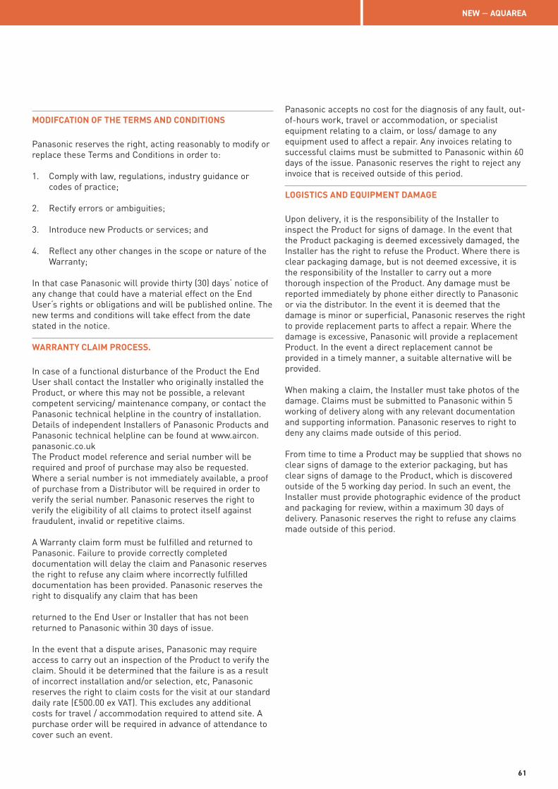
MODIFCATION OF THE TERMS AND CONDITIONS
Panasonic reserves the right, acting reasonably to modify or replace these Terms and Conditions in order to:
1. Comply with law, regulations, industry guidance or codes of practice;
2. Rectify errors or ambiguities;
3. Introduce new Products or services; and
4. Reflect any other changes in the scope or nature of the Warranty;
In that case Panasonic will provide thirty (30) days‘ notice of any change that could have a material effect on the End User‘s rights or obligations and will be published online. The new terms and conditions will take effect from the date stated in the notice.
WARRANTY CLAIM PROCESS.
In case of a functional disturbance of the Product the End User shall contact the Installer who originally installed the Product, or where this may not be possible, a relevant competent servicing/ maintenance company, or contact the Panasonic technical helpline in the country of installation. Details of independent Installers of Panasonic Products and Panasonic technical helpline can be found at www.aircon.panasonic.co.uk The Product model reference and serial number will be required and proof of purchase may also be requested. Where a serial number is not immediately available, a proof of purchase from a Distributor will be required in order to verify the serial number. Panasonic reserves the right to verify the eligibility of all claims to protect itself against fraudulent, invalid or repetitive claims.
A Warranty claim form must be fulfilled and returned to Panasonic. Failure to provide correctly completed documentation will delay the claim and Panasonic reserves the right to refuse any claim where incorrectly fulfilled documentation has been provided. Panasonic reserves the right to disqualify any claim that has been returned to the End User or Installer that has not been returned to Panasonic within 30 days of issue.
In the event that a dispute arises, Panasonic may require access to carry out an inspection of the Product to verify the claim. Should it be determined that the failure is as a result of incorrect installation and/or selection, etc, Panasonic reserves the right to claim costs for the visit at our standard daily rate (£500.00 ex VAT). This excludes any additional costs for travel / accommodation required to attend site. A purchase order will be required in advance of attendance to cover such an event.
Panasonic accepts no cost for the diagnosis of any fault, out-of-hours work, travel or accommodation, or specialist equipment relating to a claim, or loss/ damage to any equipment used to affect a repair. Any invoices relating to successful claims must be submitted to Panasonic within 60 days of the issue. Panasonic reserves the right to reject any invoice that is received outside of this period.
LOGISTICS AND EQUIPMENT DAMAGE
Upon delivery, it is the responsibility of the Installer to inspect the Product for signs of damage. In the event that the Product packaging is deemed excessively damaged, the Installer has the right to refuse the Product. Where there is clear packaging damage, but is not deemed excessive, it is the responsibility of the Installer to carry out a more thorough inspection of the Product. Any damage must be reported immediately by phone either directly to Panasonic or via the distributor. In the event it is deemed that the damage is minor or superficial, Panasonic reserves the right to provide replacement parts to affect a repair. Where the damage is excessive, Panasonic will provide a replacement Product. In the event a direct replacement cannot be provided in a timely manner, a suitable alternative will be provided.
When making a claim, the Installer must take photos of the damage. Claims must be submitted to Panasonic within 5 working of delivery along with any relevant documentation and supporting information. Panasonic reserves to right to deny any claims made outside of this period.
From time to time a Product may be supplied that shows no clear signs of damage to the exterior packaging, but has clear signs of damage to the Product, which is discovered outside of the 5 working day period. In such an event, the Installer must provide photographic evidence of the product and packaging for review, within a maximum 30 days of delivery. Panasonic reserves the right to refuse any claims made outside of this period.
NEW — AQUAREA
61
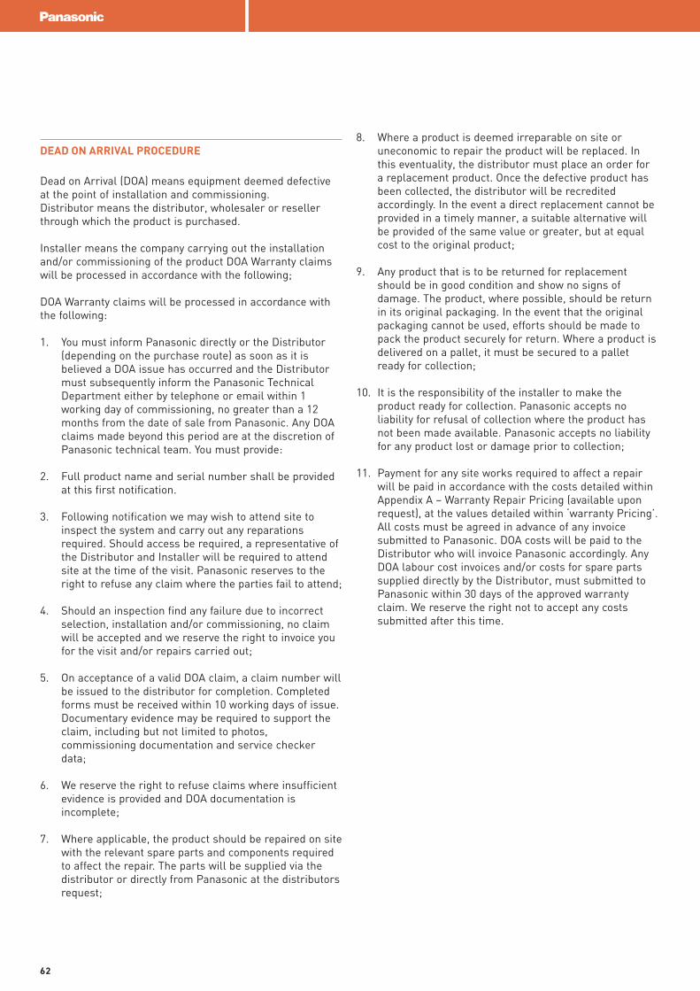
DEAD ON ARRIVAL PROCEDURE
Dead on Arrival (DOA) means equipment deemed defective at the point of installation and commissioning.Distributor means the distributor, wholesaler or reseller through which the product is purchased.
Installer means the company carrying out the installation and/or commissioning of the product DOA Warranty claims will be processed in accordance with the following;
DOA Warranty claims will be processed in accordance with the following:
1. You must inform Panasonic directly or the Distributor (depending on the purchase route) as soon as it is believed a DOA issue has occurred and the Distributor must subsequently inform the Panasonic Technical Department either by telephone or email within 1 working day of commissioning, no greater than a 12 months from the date of sale from Panasonic. Any DOA claims made beyond this period are at the discretion of Panasonic technical team. You must provide:
2. Full product name and serial number shall be provided at this first notification.
3. Following notification we may wish to attend site to inspect the system and carry out any reparations required. Should access be required, a representative of the Distributor and Installer will be required to attend site at the time of the visit. Panasonic reserves to the right to refuse any claim where the parties fail to attend;
4. Should an inspection find any failure due to incorrect selection, installation and/or commissioning, no claim will be accepted and we reserve the right to invoice you for the visit and/or repairs carried out;
5. On acceptance of a valid DOA claim, a claim number will be issued to the distributor for completion. Completed forms must be received within 10 working days of issue. Documentary evidence may be required to support the claim, including but not limited to photos, commissioning documentation and service checker data;
6. We reserve the right to refuse claims where insufficient evidence is provided and DOA documentation is incomplete;
7. Where applicable, the product should be repaired on site with the relevant spare parts and components required to affect the repair. The parts will be supplied via the distributor or directly from Panasonic at the distributors request;
8. Where a product is deemed irreparable on site or uneconomic to repair the product will be replaced. In this eventuality, the distributor must place an order for a replacement product. Once the defective product has been collected, the distributor will be recredited accordingly. In the event a direct replacement cannot be provided in a timely manner, a suitable alternative will be provided of the same value or greater, but at equal cost to the original product;
9. Any product that is to be returned for replacement should be in good condition and show no signs of damage. The product, where possible, should be return in its original packaging. In the event that the original packaging cannot be used, efforts should be made to pack the product securely for return. Where a product is delivered on a pallet, it must be secured to a pallet ready for collection;
10. It is the responsibility of the installer to make the product ready for collection. Panasonic accepts no liability for refusal of collection where the product has not been made available. Panasonic accepts no liability for any product lost or damage prior to collection;
11. Payment for any site works required to affect a repair will be paid in accordance with the costs detailed within Appendix A – Warranty Repair Pricing (available upon request), at the values detailed within ‘warranty Pricing’. All costs must be agreed in advance of any invoice submitted to Panasonic. DOA costs will be paid to the Distributor who will invoice Panasonic accordingly. Any DOA labour cost invoices and/or costs for spare parts supplied directly by the Distributor, must submitted to Panasonic within 30 days of the approved warranty claim. We reserve the right not to accept any costs submitted after this time.
62
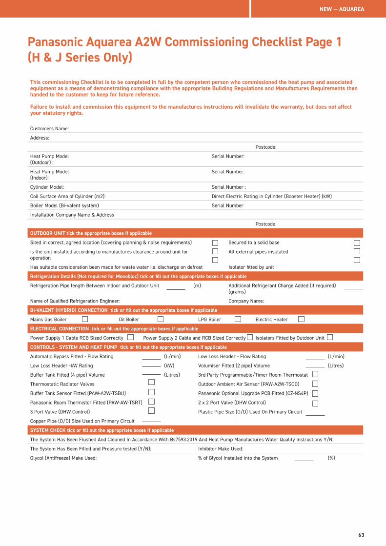
Panasonic Aquarea A2W Commissioning Checklist Page 1 (H & J Series Only)
This commissioning Checklist is to be completed in full by the competent person who commissioned the heat pump and associated equipment as a means of demonstrating compliance with the appropriate Building Regulations and Manufactures Requirements then handed to the customer to keep for future reference.
Failure to install and commission this equipment to the manufactures instructions will invalidate the warranty, but does not affect your statutory rights.
Customers Name:
Address:
Postcode:
Heat Pump Model (Outdoor) :
Serial Number:
Heat Pump Model (Indoor):
Serial Number:
Cylinder Model: Serial Number :
Coil Surface Area of Cylinder (m2): Direct Electric Rating in Cylinder (Booster Heater) (kW)
Boiler Model (Bi-valent system) Serial Number
Installation Company Name & Address
Postcode
OUTDOOR UNIT tick the appropriate boxes if applicable
Sited in correct, agreed location (covering planning & noise requirements) Secured to a solid base
Is the unit installed according to manufactures clearance around unit for operation
All external pipes insulated
Has suitable consideration been made for waste water i.e. discharge on defrost Isolator fitted by unit
Refrigeration Details (Not required for Monobloc) tick or fill out the appropriate boxes if applicable
Refrigeration Pipe length Between Indoor and Outdoor Unit (m) Additional Refrigerant Charge Added (if required) (grams)
Name of Qualified Refrigeration Engineer: Company Name:
BI-VALENT (HYBRID) CONNECTION tick or fill out the appropriate boxes if applicable
Mains Gas Boiler Oil Boiler LPG Boiler Electric Heater
ELECTRICAL CONNECTION tick or fill out the appropriate boxes if applicable
Power Supply 1 Cable RCB Sized Correctly Power Supply 2 Cable and RCB Sized Correctly Isolators Fitted by Outdoor Unit
CONTROLS - SYSTEM AND HEAT PUMP tick or fill out the appropriate boxes if applicable
Automatic Bypass Fitted - Flow Rating (L/min) Low Loss Header - Flow Rating (L/min)
Low Loss Header -kW Rating (kW) Volumiser Fitted (2 pipe) Volume (Litres)
Buffer Tank Fitted (4 pipe) Volume (Litres) 3rd Party Programmable/Timer Room Thermostat
Thermostatic Radiator Valves Outdoor Ambient Air Sensor (PAW-A2W-TSOD)
Buffer Tank Sensor Fitted (PAW-A2W-TSBU) Panasonic Optional Upgrade PCB Fitted (CZ-NS4P)
Panasonic Room Thermistor Fitted (PAW-AW-TSRT) 2 x 2 Port Valve (DHW Control)
3 Port Valve (DHW Control) Plastic Pipe Size (O/D) Used On Primary Circuit
Copper Pipe (O/D) Size Used on Primary Circuit
SYSTEM CHECK tick or fill out the appropriate boxes if applicable
The System Has Been Flushed And Cleaned In Accordance With Bs7593:2019 And Heat Pump Manufactures Water Quality Instructions Y/N:
The System Has Been Filled and Pressure tested (Y/N): Inhibitor Make Used:
Glycol (Antifreeze) Make Used: % of Glycol Installed into the System (%)
NEW — AQUAREA
63
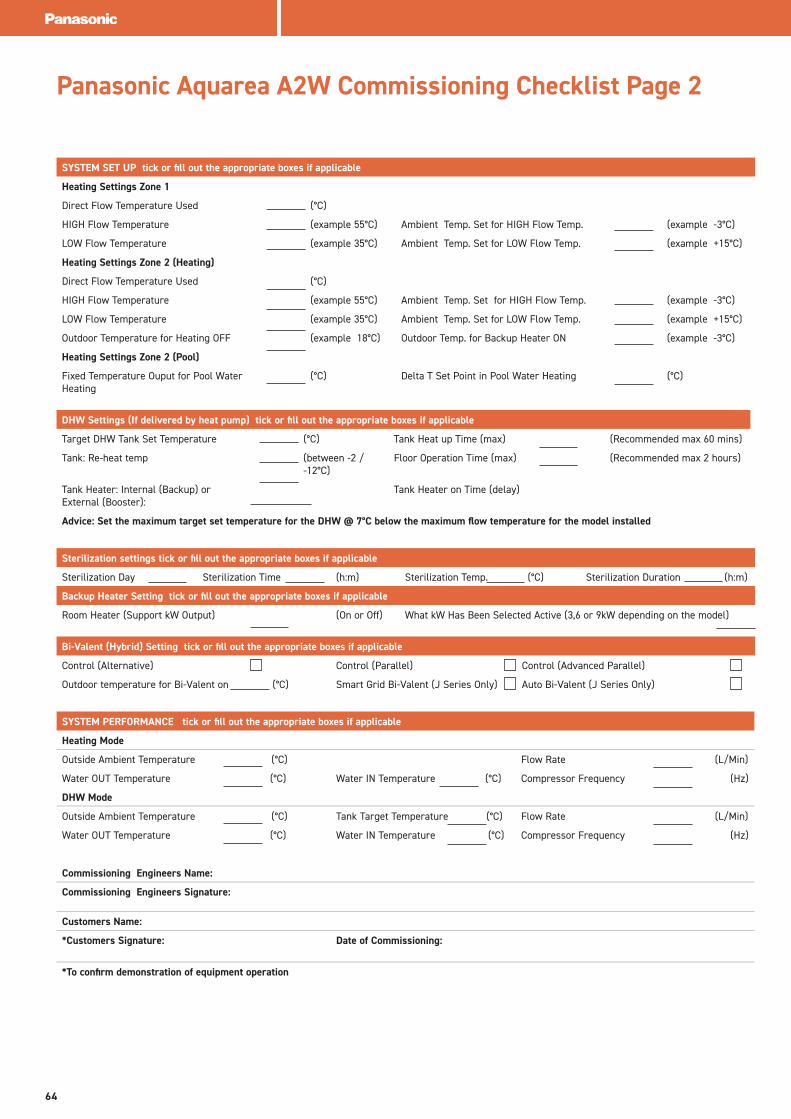
Panasonic Aquarea A2W Commissioning Checklist Page 2
DHW Settings (If delivered by heat pump) tick or fill out the appropriate boxes if applicable
Target DHW Tank Set Temperature (°C) Tank Heat up Time (max) (Recommended max 60 mins)
Tank: Re-heat temp (between -2 / -12°C)
Floor Operation Time (max) (Recommended max 2 hours)
Tank Heater: Internal (Backup) or External (Booster):
Tank Heater on Time (delay)
Advice: Set the maximum target set temperature for the DHW @ 7°C below the maximum flow temperature for the model installed
SYSTEM SET UP tick or fill out the appropriate boxes if applicable
Heating Settings Zone 1
Direct Flow Temperature Used (°C)
HIGH Flow Temperature (example 55°C) Ambient Temp. Set for HIGH Flow Temp. (example -3°C)
LOW Flow Temperature (example 35°C) Ambient Temp. Set for LOW Flow Temp. (example +15°C)
Heating Settings Zone 2 (Heating)
Direct Flow Temperature Used (°C)
HIGH Flow Temperature (example 55°C) Ambient Temp. Set for HIGH Flow Temp. (example -3°C)
LOW Flow Temperature (example 35°C) Ambient Temp. Set for LOW Flow Temp. (example +15°C)
Outdoor Temperature for Heating OFF (example 18°C) Outdoor Temp. for Backup Heater ON (example -3°C)
Heating Settings Zone 2 (Pool)
Fixed Temperature Ouput for Pool Water Heating
(°C) Delta T Set Point in Pool Water Heating (°C)
Sterilization settings tick or fill out the appropriate boxes if applicable
Sterilization Day Sterilization Time (h:m) Sterilization Temp. (°C) Sterilization Duration (h:m)
Backup Heater Setting tick or fill out the appropriate boxes if applicable
Room Heater (Support kW Output) (On or Off) What kW Has Been Selected Active (3,6 or 9kW depending on the model)
Bi-Valent (Hybrid) Setting tick or fill out the appropriate boxes if applicable
Control (Alternative) Control (Parallel) Control (Advanced Parallel)
Outdoor temperature for Bi-Valent on (°C) Smart Grid Bi-Valent (J Series Only) Auto Bi-Valent (J Series Only)
SYSTEM PERFORMANCE tick or fill out the appropriate boxes if applicable
Heating Mode
Outside Ambient Temperature (°C) Flow Rate (L/Min)
Water OUT Temperature (°C) Water IN Temperature (°C) Compressor Frequency (Hz)
DHW Mode
Outside Ambient Temperature (°C) Tank Target Temperature (°C) Flow Rate (L/Min)
Water OUT Temperature (°C) Water IN Temperature (°C) Compressor Frequency (Hz)
Commissioning Engineers Name:
Commissioning Engineers Signature:
Customers Name:
*Customers Signature: Date of Commissioning:
*To confirm demonstration of equipment operation
64
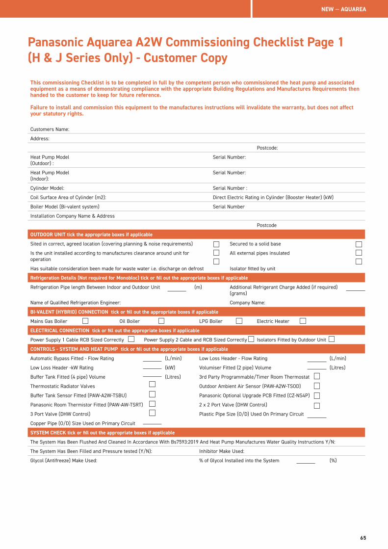
Panasonic Aquarea A2W Commissioning Checklist Page 1 (H & J Series Only) - Customer Copy
This commissioning Checklist is to be completed in full by the competent person who commissioned the heat pump and associated equipment as a means of demonstrating compliance with the appropriate Building Regulations and Manufactures Requirements then handed to the customer to keep for future reference.
Failure to install and commission this equipment to the manufactures instructions will invalidate the warranty, but does not affect your statutory rights.
Customers Name:
Address:
Postcode:
Heat Pump Model (Outdoor) :
Serial Number:
Heat Pump Model (Indoor):
Serial Number:
Cylinder Model: Serial Number :
Coil Surface Area of Cylinder (m2): Direct Electric Rating in Cylinder (Booster Heater) (kW)
Boiler Model (Bi-valent system) Serial Number
Installation Company Name & Address
Postcode
OUTDOOR UNIT tick the appropriate boxes if applicable
Sited in correct, agreed location (covering planning & noise requirements) Secured to a solid base
Is the unit installed according to manufactures clearance around unit for operation
All external pipes insulated
Has suitable consideration been made for waste water i.e. discharge on defrost Isolator fitted by unit
Refrigeration Details (Not required for Monobloc) tick or fill out the appropriate boxes if applicable
Refrigeration Pipe length Between Indoor and Outdoor Unit (m) Additional Refrigerant Charge Added (if required) (grams)
Name of Qualified Refrigeration Engineer: Company Name:
BI-VALENT (HYBRID) CONNECTION tick or fill out the appropriate boxes if applicable
Mains Gas Boiler Oil Boiler LPG Boiler Electric Heater
ELECTRICAL CONNECTION tick or fill out the appropriate boxes if applicable
Power Supply 1 Cable RCB Sized Correctly Power Supply 2 Cable and RCB Sized Correctly Isolators Fitted by Outdoor Unit
CONTROLS - SYSTEM AND HEAT PUMP tick or fill out the appropriate boxes if applicable
Automatic Bypass Fitted - Flow Rating (L/min) Low Loss Header - Flow Rating (L/min)
Low Loss Header -kW Rating (kW) Volumiser Fitted (2 pipe) Volume (Litres)
Buffer Tank Fitted (4 pipe) Volume (Litres) 3rd Party Programmable/Timer Room Thermostat
Thermostatic Radiator Valves Outdoor Ambient Air Sensor (PAW-A2W-TSOD)
Buffer Tank Sensor Fitted (PAW-A2W-TSBU) Panasonic Optional Upgrade PCB Fitted (CZ-NS4P)
Panasonic Room Thermistor Fitted (PAW-AW-TSRT) 2 x 2 Port Valve (DHW Control)
3 Port Valve (DHW Control) Plastic Pipe Size (O/D) Used On Primary Circuit
Copper Pipe (O/D) Size Used on Primary Circuit
SYSTEM CHECK tick or fill out the appropriate boxes if applicable
The System Has Been Flushed And Cleaned In Accordance With Bs7593:2019 And Heat Pump Manufactures Water Quality Instructions Y/N:
The System Has Been Filled and Pressure tested (Y/N): Inhibitor Make Used:
Glycol (Antifreeze) Make Used: % of Glycol Installed into the System (%)
NEW — AQUAREA
65
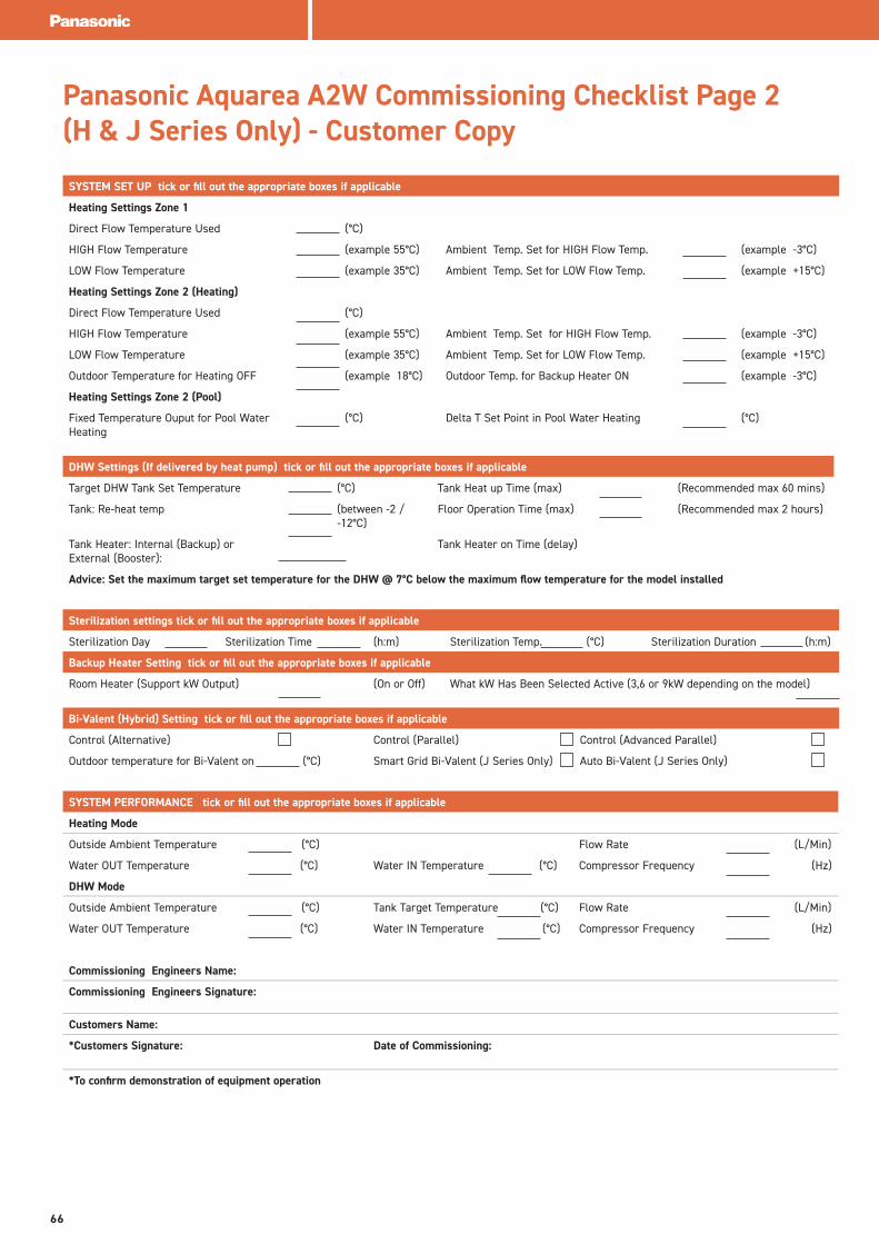
Panasonic Aquarea A2W Commissioning Checklist Page 2 (H & J Series Only) - Customer Copy
DHW Settings (If delivered by heat pump) tick or fill out the appropriate boxes if applicable
Target DHW Tank Set Temperature (°C) Tank Heat up Time (max) (Recommended max 60 mins)
Tank: Re-heat temp (between -2 / -12°C)
Floor Operation Time (max) (Recommended max 2 hours)
Tank Heater: Internal (Backup) or External (Booster):
Tank Heater on Time (delay)
Advice: Set the maximum target set temperature for the DHW @ 7°C below the maximum flow temperature for the model installed
SYSTEM SET UP tick or fill out the appropriate boxes if applicable
Heating Settings Zone 1
Direct Flow Temperature Used (°C)
HIGH Flow Temperature (example 55°C) Ambient Temp. Set for HIGH Flow Temp. (example -3°C)
LOW Flow Temperature (example 35°C) Ambient Temp. Set for LOW Flow Temp. (example +15°C)
Heating Settings Zone 2 (Heating)
Direct Flow Temperature Used (°C)
HIGH Flow Temperature (example 55°C) Ambient Temp. Set for HIGH Flow Temp. (example -3°C)
LOW Flow Temperature (example 35°C) Ambient Temp. Set for LOW Flow Temp. (example +15°C)
Outdoor Temperature for Heating OFF (example 18°C) Outdoor Temp. for Backup Heater ON (example -3°C)
Heating Settings Zone 2 (Pool)
Fixed Temperature Ouput for Pool Water Heating
(°C) Delta T Set Point in Pool Water Heating (°C)
Sterilization settings tick or fill out the appropriate boxes if applicable
Sterilization Day Sterilization Time (h:m) Sterilization Temp. (°C) Sterilization Duration (h:m)
Backup Heater Setting tick or fill out the appropriate boxes if applicable
Room Heater (Support kW Output) (On or Off) What kW Has Been Selected Active (3,6 or 9kW depending on the model)
Bi-Valent (Hybrid) Setting tick or fill out the appropriate boxes if applicable
Control (Alternative) Control (Parallel) Control (Advanced Parallel)
Outdoor temperature for Bi-Valent on (°C) Smart Grid Bi-Valent (J Series Only) Auto Bi-Valent (J Series Only)
SYSTEM PERFORMANCE tick or fill out the appropriate boxes if applicable
Heating Mode
Outside Ambient Temperature (°C) Flow Rate (L/Min)
Water OUT Temperature (°C) Water IN Temperature (°C) Compressor Frequency (Hz)
DHW Mode
Outside Ambient Temperature (°C) Tank Target Temperature (°C) Flow Rate (L/Min)
Water OUT Temperature (°C) Water IN Temperature (°C) Compressor Frequency (Hz)
Commissioning Engineers Name:
Commissioning Engineers Signature:
Customers Name:
*Customers Signature: Date of Commissioning:
*To confirm demonstration of equipment operation
66

Notes:
NEW — AQUAREA
67
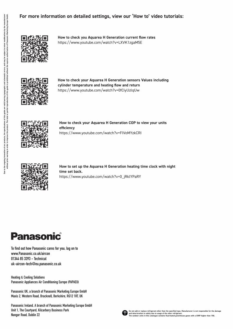
Do not add or replace refrigerant other than the specified type. Manufacturer is not responsible for the damage and deterioration in safety due to usage of the other refrigerant.The outdoor units in this catalogue contains fluorinated greenhouse gases with a GWP higher than 150.
To find out how Panasonic cares for you, log on to www.Panasonic.co.uk/aircon01344 85 3393 - Technical [email protected]
Due
to th
e on
goin
g in
nova
tion
of o
ur p
rodu
cts,
the
spec
ifica
tions
of t
his
guid
e ar
e va
lid b
arri
ng ty
pogr
aphi
c an
d sc
hem
atic
err
ors,
and
may
be
subj
ect t
o m
inor
mod
ifica
tions
by
the
man
ufac
ture
r w
ithou
t pri
or w
arni
ng in
ord
er to
impr
ove
the
prod
uct.
The
tota
l or
part
ial r
epro
duct
ion
of th
is g
uide
is p
rohi
bite
d w
ithou
t the
exp
ress
aut
hori
satio
n of
Pan
ason
ic M
arke
ting
Euro
pe G
mbH
.
How to check you Aquarea H Generation current flow rates https://www.youtube.com/watch?v=LXVK1zgaM5E
How to check your Aquarea H Generation sensors Values including cylinder temperature and heating flow and return https://www.youtube.com/watch?v=0fCiyUzlqUw
How to check your Aquarea H Generation COP to view your units efficiency https://www.youtube.com/watch?v=FIVoMYzkCRI
How to set up the Aquarea H Generation heating time clock with night time set back.https://www.youtube.com/watch?v=0_jRklYPaRY
For more information on detailed settings, view our ‘How to’ video tutorials:
Heating & Cooling SolutionsPanasonic Appliances Air Conditioning Europe (PAPAEU)
Panasonic UK, a branch of Panasonic Marketing Europe GmbHMaxis 2, Western Road, Bracknell, Berkshire, RG12 1RT, UK
Panasonic Ireland. A branch of Panasonic Marketing Europe GmbHUnit 1, The Courtyard, Kilcarbery Business ParkNangor Road, Dublin 22