apr 250, apr 260, apr 262, apr 265, apr 266, apr 267
TRANSCRIPT

BG
503
5 B
EN
/ B
(20
14-0
8)
A P A S S I O N F O R P E R F E C T I O N
APR 250, APR 260, APR 262, APR 265, APR 266, APR 267 Compact Piezo Gauge
Operating Instructions

2 BG 5035 BEN / B (2014-08) APR 250 ... 267.oi
In all communications with Pfeiffer Vacuum, please specify the information given on the product nameplate. For convenient reference transfer this information into the diagram below.
Pfeiffer Vacuum, D-35614 AsslarTyp:No: F-No: V W
This document applies to products with part number
P 5215 102 TF (APR 250 DN 16 ISO-KF 100 kPa) P 5215 112 TF (APR 260 DN 16 ISO-KF 100 kPa) P 5215 114 TF (APR 260 DN 16 CF-F 100 kPa) P 5215 120 TF (APR 262 G1/4" 200 kPa) P 5215 126 TF (APR 265 G1/4" 500 kPa) P 5215 132 TF (APR 266 G1/4" 1000 kPa)
P 5215 133 TF (APR 266 4 VCR male 1000 kPa) P 5215 138 TF (APR 267 G1/4" 5000 kPa)
The part number (No) can be taken from the product nameplate.
If not indicated otherwise in the legends, the illustrations in this document correspond to the gauge with the vacuum connection DN 16 ISO-KF. They apply to gauges with other vacuum connections by analogy
We reserve the right to make technical changes without prior notice.
The Compact Piezo Gauges have been designed for vacuum measurement in a pressure range of 0.1 hPa … 5500 kPa, depending on the configuration.
The gauges can be used with a Pfeiffer Vacuum measurement unit for compact gauges or with another evaluation unit.
Over the entire measurement range, the measuring signal is linearly dependent on the pressure.
A piezoresistive pressure sensor is used as the measuring element. The meas-urement is not dependent on the type of gas being measured.
Product Identification
Validity
Intended Use
Functional Principle

BG 5035 BEN / B (2014-08) APR 250 ... 267.oi 3
Contents
Product Identification 2 Validity 2 Intended Use 2 Functional Principle 2
1 Safety 4 1.1 Symbols Used 4 1.2 Personnel Qualifications 4 1.3 Safety Information 4 1.4 Liability and Warranty 4 2 Technical Data 5 3 Installation 7 3.1 Vacuum Connection 7 3.2 Electrical Connection 8 3.2.1 Use With a Pfeiffer Vacuum Measurement Unit 8 3.2.2 Use With Another Evaluation Unit 8 4 Operation 10 5 Maintenance 11 5.1 Aligning the Gauge (Zero Alignment) 11 5.2 Cleaning the Gauge 12 5.3 Troubleshooting 13 6 Deinstallation 13 7 Accessories 14 8 Decommissioning 14
Appendix 15 A: Relationship Measuring Signal vs. Pressure 15 B: Conversion of Pressure Units 15
For cross references to other documents, the symbol (→ XY) is used, for cross-references to other documents, the symbol (→ [Z]).
4 BG 5035 BEN / B (2014-08) APR 250 ... 267.oi
1 Safety
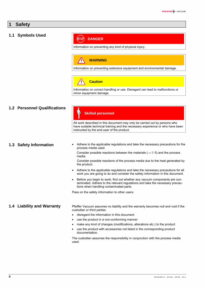
DANGER
Information on preventing any kind of physical injury.
WARNING
Information on preventing extensive equipment and environmental damage.
Caution
Information on correct handling or use. Disregard can lead to malfunctions or minor equipment damage.
Skilled personnel
All work described in this document may only be carried out by persons who have suitable technical training and the necessary experience or who have been instructed by the end-user of the product.
• Adhere to the applicable regulations and take the necessary precautions for the process media used.
Consider possible reactions between the materials (→ 5) and the process media.
Consider possible reactions of the process media due to the heat generated by the product.
• Adhere to the applicable regulations and take the necessary precautions for all work you are going to do and consider the safety information in this document.
• Before you begin to work, find out whether any vacuum components are con-taminated. Adhere to the relevant regulations and take the necessary precau-tions when handling contaminated parts.
Pass on the safety information to other users.
Pfeiffer Vacuum assumes no liability and the warranty becomes null and void if the custodian or third parties
• disregard the information in this document
• use the product in a non-conforming manner
• make any kind of changes (modifications, alterations etc.) to the product
• use the product with accessories not listed in the corresponding product documentation.
The custodian assumes the responsibility in conjunction with the process media used.
1.1 Symbols Used
1.2 Personnel Qualifications
1.3 Safety Information
1.4 Liability and Warranty

BG 5035 BEN / B (2014-08) APR 250 ... 267.oi 5
2 Technical Data
APR 250 APR 260 APR 262 APR 265 APR 266 APR 267
Storage temperature [°C] -40 … +80 -40 … +80 -40 … +80 -40 … +80 -40 … +80 -40 … +80
Operating temperature [°C] +10 … +80 +10 … +80 +10 … +80 +10 … +80 +10 … +80 +10 … +80
Bakeout temperature [°C] 80 80 80 80 80 80
Relative humidity max. 80% at temperatures up to +31 °C, decreasing to 50 % at +40 °C
Use indoors only, altitude up to 2000 m (6600 ft.)
Measurement range [hPa] 0.1 … 1100 0.1 … 1100 0.2 … 2200 0.5 … 5500 1 … 11000 5 … 55000
Full scale [hPa] 1000 1000 2000 5000 10000 50000
Accuracy [%F.S.] 2 1 2 2 2 2
Linearity and hysteresis [%F.S.] <0.5 <0.2 <0.5 <0.5 <0.5 <0.5
Zero stability [%F.S. / year] <0.5 <0.3 <0.5 <0.5 <0.5 <0.5
Stability of sensibility [% / year] <0.5 <0.2 <0.2 <0.2 <0.2 <0.2
Thermal zero drift [%F.S.] <0.5 <0.2 <0.5 <0.5 <0.5 <0.5
Thermal sensitivity drift [%F.S.] <0.5 <0.5 <0.5 <0.5 <0.5 <0.5
Admissible overpressure [kPa] 300 300 500 750 1500 7500
Output signal measurement range [V] 1.0 … 9.8 1.0 … 9.8 1.0 … 9.8 1.0 … 9.8 1.0 … 9.8 1.0 … 9.8
Error signal [V] <0.4 <0.4 <0.4 <0.4 <0.4 <0.4
Minimum load (short-circuit proof) [kΩ] 10 10 10 10 10 10
Materials exposed to the vacuum stainless steel (1.4435)
Internal volume DN 16 ISO-KF [cm3] DN 16 CF-F [cm3] G¼" [cm3] 4 VCR [cm3]
2 – – –
2 6 – –
– – 0.5 –
– – 0.5 –
– – 0.5 1.0
– – 0.5 –
Supply
DANGER
The gauges may only be connected to supply or measurement units that conform to the requirements of a grounded protective extra-low voltage (SELV). The connection to the gauge has to be fused.
Voltage at the gauge 13.0 … 30.0 VDC (max. ripple 1 Vpp)
Power consumption ≤0.2 W
Fuse (to be switched in) ≤1 AT
Type of protection IP 65
The minimum voltage of the power supply must be increased proportionally to the length of the measurement cable.
Voltage at the supply unit with maximum cable length
16.0 ... 30.0 VDC (max. ripple 1 Vpp)
Electrical connection Hirschmann compact connector type GO 6, 6 contacts, pins
Cable 5-pin plus screening
Maximum cable length 50 m (0.34 mm² conductor cross section)

6 BG 5035 BEN / B (2014-08) APR 250 ... 267.oi
Output signal (measuring signal)
Voltage range ≈0 V … ≈+13.5 V
Relationship voltage-pressure linear (→ Appendix )
Error signal <0.4 V (sensor error)
>9.8 V (overrange)
Output impedance ≤10 Ω
Normal load 100 kΩ
Minimum load 10 kΩ, short-circuit proof
Response time <10 ms
Grounding concept → Figure 1
Supply common-signal common conducted separately; differential measurement recommended for cable lengths ≥10 m
Gauge identification 13.2 kΩ ± 1%
Dimensions [mm]
G1/4" 4 VCR male
ø33
610
015
.8
12
DN 16 ISO-KF DN 16 CF-F
ø33
613
1
104
Weight 120 g (ISO-KF flange and G¼") 150 g (CF-F flange) 200 g (4 VCR flange)

BG 5035 BEN / B (2014-08) APR 250 ... 267.oi 7
3 Installation
Caution
Caution: vacuum component
Dirt and damages impair the function of the vacuum component.
When handling vacuum components, take appropriate measures to ensure cleanliness and prevent damages.
The gauge can be mounted in any orientation. However, it should be mounted so that any particles present cannot penetrate into the measuring chamber.
See the dimension drawings for space requirements (→ 5 f.).
Remove the protective cap.
Keep the protective lid
Make the flange connection.
DANGER
DANGER: overpressure in the vacuum system >250 kPa
KF flange connections with elastomer sealing rings (e.g. O-rings) cannot withstand such pressures. Process media can thus leak and possibly damage your health.
Use sealing rings provided with an outer centering ring.
DANGER
DANGER: overpressure in the vacuum system >100 kPa
If clamps are opened incorrectly, injury can be caused by cata-pulted parts and your health can be damaged by leaking proc-ess gases.
Use the type of clamps which can only be opened and closed by means of a tool (e.g. hose clip clamping ring).
3.1 Vacuum Connection

8 BG 5035 BEN / B (2014-08) APR 250 ... 267.oi
DANGER
The gauge must be electrically connected to the grounded vacuum chamber. The connection must conform to the re-quirements of a protective connection according to EN 61010:
• CF and VCR flanges fulfill this requirement
• For gauges with KF flanges, use a a conductive metallic clamping ring
If the gauge is used with a Pfeiffer Vacuum measurement unit for Compact gauges, a corresponding connection cable is required (→ 14).
• Secure the connector on the gauge with a screw.
Caution
Set the full scale value of the gauge used on your evaluation unit (→ corresponding ).
The gauge can also be operated with other evaluation units. In this case, an individual connection cable must be made.
For cable lengths up to 10 m (with a conductor cross section of 0.34 mm2), the measuring signal can be read directly between the positive signal output (pin 2) and the supply common (pin 5) without the degree of accuracy being lowered. For longer measurement cable lengths, we recommend a differential measurement between the signal output and the signal common (pin 3) (as a result of the voltage drop along the supply cable ground lead, the common mode signal is approx. 1.0 V for the maximum admissible cable length).
Prepare the connection socket (ordering number → 14).
3.2 Electrical Connection
3.2.1 Use With a Pfeiffer Vacuum Measurement Unit
3.2.2 Use With Another Evaluation Unit
Procedure

BG 5035 BEN / B (2014-08) APR 250 ... 267.oi 9
Solder the connection cable according to the diagram.
–+
–+
10
10
13k2
2
3
1
4
5
6
Figure 1: Electrical connection
Pin 1 identification Pin 2 signal output (measuring signal) Pin 3 signal common Pin 4 supply Pin 5 supply common Pin 6 screen
2
5
3
4
1
6
WARNING
The supply common (pin 5) and the screen (pin 6) must be connected to the supply unit with protective ground.
Incorrect connection, incorrect polarity, or inadmissible supply voltages can damage the gauge.
Reassemble the connection socket.
Plug in the connection socket.
Secure the connector on the gauge with the screw.

10 BG 5035 BEN / B (2014-08) APR 250 ... 267.oi
4 Operation
As soon as the required voltage is applied, the measuring signal is available between pins 2 and 3 (→ Appendix for the relationship between the measuring signal and the pressure).
The measuring signal is not dependent on the type of gas being measured (absolute pressure measurement).

BG 5035 BEN / B (2014-08) APR 250 ... 267.oi 11
5 Maintenance
DANGER
DANGER: contaminated parts
Contaminated parts can be detrimental to health.
Before you begin to work, find out whether any parts are contami-nated. Adhere to the relevant regulations and take the necessary precautions when handling contaminated parts.
The gauge is factory-calibrated. Realigning is usually not necessary. If realignment should nevertheless be required, proceed as follows:
• Screw driver No. 1
• Vacuum pump with a final pressure << 0.1 hPa
• Loosen the union nut.
• Lift the connection terminal.
Evacuate: p << 0.1 hPa.
Correct alignment:
Display = 0 (U = 1 V). +
–
Reassemble the gauge in reverse order.
5.1 Aligning the Gauge (Zero Alignment)
Tools / material required
Procedure

12 BG 5035 BEN / B (2014-08) APR 250 ... 267.oi
• Cleaning alcohol
DANGER
DANGER: cleaning agents
Cleaning agents can be detrimental to health and environment.
Adhere to the relevant regulations and take the necessary precautions when handling and disposing of cleaning agents.
Remove the gauge from the vacuum system (→ 13).
• Fill it with cleaning alcohol.
• Allow the alcohol to work for 5 minutes.
Pour the alcohol out of the measuring chamber.
Allow the measuring chamber to dry for at least 10 minutes.
Reinstall the gauge (→ 7).
5.2 Cleaning the Gauge
Tools / material required
Procedure

BG 5035 BEN / B (2014-08) APR 250 ... 267.oi 13
Problem Possible cause Remedy
Measuring signal constantly < 0.5 V.
No supply. Switch on the supply unit.
Supply voltage too low. Increase the supply volt-age (→ 5).
Gauge defective. Replace the gauge.
Measuring signal con-stantly in the range 0.4 ... 0.6 V (underrange).
Pressure in the vacuum chamber < measurement range.
–
6 Deinstallation
DANGER
DANGER: contaminated parts
Contaminated parts can be detrimental to health.
Before you begin to work, find out whether any parts are contami-nated. Adhere to the relevant regulations and take the necessary precautions when handling contaminated parts.
Caution
Caution: vacuum component
Dirt and damages impair the function of the vacuum component.
When handling vacuum components, take appropriate measures to ensure cleanliness and prevent damages.
Deactivate the gauge.
Unplug the connector.
Remove the gauge from the vacuum system.
5.3 Troubleshooting
Procedure

14 BG 5035 BEN / B (2014-08) APR 250 ... 267.oi
Place the protective cap.
7 Accessories
Ordering number
Connection cable to Pfeiffer Vacuum measurement unit for Compact gauges 3 m 6 m 10 m
Connection socket, Hirschmann GO 6 WF, 6-pin, angled, female
PT 448 250-T PT 448 251-T PT 448 252-T
B 4707 283 MA
8 Decommissioning
WARNING
WARNING: substances detrimental to the environment
Products, operating materials etc. may have to be specially decom-missioned.
For environmentally compatible disposal, please contact your nearest Pfeiffer Vacuum Service Center.

BG 5035 BEN / B (2014-08) APR 250 ... 267.oi 15
Appendix
Measuring signal U [V]
Pressure p
0 ... 0.4 Sensor error
0.4 ... 0.6 Underrange
0.6
1.0
1.8
2.6
...
8.2
9.0
9.8
-5% F.S.
0% F.S.
10% F.S.
20% F.S.
...
90% F.S.
100% F.S.
110% F.S.
9.8...13.5 Overrange
General: U 1V 0.8Vp 10
F. S.= + ×
×
where U measuring signal
p pressure measured
F.S. full scale of the gauge used (→ 5)
(same pressure unit)
mbar bar Pa hPa kPa Torr mm HG
mbar 1 1×10⁻³ 100 1 0.1 0.75 bar 1×10³ 1 1×10⁵ 1×10³ 100 750 Pa 0.01 1×10⁻⁵ 1 0.01 1×10⁻³ 7.5×10⁻³
hPa 1 1×10⁻³ 100 1 0.1 0.75 kPa 10 0.01 1×10³ 10 1 7.5 Torr
mm HG 1.332 1.332×10⁻³ 133.32 1.3332 0.1332 1
1 Pa = 1 N/m2
A: Relationship Measuring Signal vs. Pressure
B: Conversion of Pressure Units
9.8
9
1
0.6
U [V]
p [% F.S.] -5 0 100 110

A P A S S I O N F O R P E R F E C T I O N
Vacuum solutions from a single source
Complete range of products
Competence in theory and practice
Pfeiffer Vacuum stands for innovative and custom vacuum solutions worldwide, technological perfection, competent advice and reliable service. From a single component to complex systems: We are the only supplier of vacuum technology that provides a complete product portfolio. Benefit from our know-how and our portfolio of training opportunities! We can support you with your plant layout and provide first-class on-site-service worldwide.
Are you looking for a perfect vacuum solution? Please contact us:
Pfeiffer Vacuum GmbH Headquarters ● Germany Tel.: +49 (0) 6441 802-0 [email protected] www.pfeiffer-vacuum.com
Original: German BG 5035 BDE / B (2014-08)
bg5035ben/ b