applications of augmented-vision head-mounted systems in vision rehabilitation
TRANSCRIPT

Applications of Augmented Vision Head-Mounted Systems inVision Rehabilitation
Eli Peli1, Gang Luo1, Alex Bowers1, and Noa Rensing2
1The Schepens Eye Research Institute, Dept. of Ophthalmology, Harvard Medical School, Boston, MA
2MyVu Corp. Westwood, MA
AbstractVision loss typically affects either the wide peripheral vision (important for mobility), or centralvision (important for seeing details). Traditional optical visual aids usually recover the lost visualfunction, but at a high cost for the remaining visual function. We have developed a novel concept ofvision-multiplexing using augmented vision head-mounted display systems to address vision loss.Two applications are discussed in this paper. In the first, minified edge images from a head-mountedvideo camera are presented on a see-through display providing visual field expansion for people withperipheral vision loss, while still enabling the full resolution of the residual central vision to bemaintained. The concept has been applied in daytime and nighttime devices. A series of studiessuggested that the system could help with visual search, obstacle avoidance, and nighttime mobility.Subjects were positive in their ratings of device cosmetics and ergonomics. The second applicationis for people with central vision loss. Using an on-axis aligned camera and display system, centralvisibility is enhanced with 1:1 scale edge images, while still enabling the wide field of the unimpairedperipheral vision to be maintained. The registration error of the system was found to be low inlaboratory testing.
KeywordsHead-mounted display; multiplexing; tunnel vision; central vision loss; night blindness
1 IntroductionWith normal vision we enjoy the benefits of a wide field of view, primarily used for navigationand orientation, together with the high-resolution capabilities of the fovea that enablediscrimination of fine details. Visual impairments due to diseases or injuries typically affectonly one of these two aspects, either restricting the wide peripheral visual field (VF) inconditions such as retinitis pigmentosa (RP) and glaucoma, or damaging the central high-resolution vision in conditions such as age-related macular degeneration (AMD). Whenperipheral VF loss is severe (leaving useful VFs less than 20° in diameter, i.e. tunnel vision),a patient's mobility can be greatly affected due to reduced ability to spot obstacles anddifficulties in navigation. Social interactions of patients may be affected by failing to note orrespond to people appropriately. In addition, RP and other similar retinal diseases often causenight blindness due to early loss of the rod cells that function at low light levels. Damage tocentral vision causes reduced visual resolution and reduced contrast sensitivity, which resultin difficulties in performing tasks that require the ability to discern fine detail or smalldifferences in contrast.
Traditional vision rehabilitation devices are usually designed to recover, at least partially, thelost visual function, but at a high cost for the remaining visual function. For example,magnification increases resolution but inherently limits the field of view. Similarly, minifying
NIH Public AccessAuthor ManuscriptJ Soc Inf Disp. Author manuscript; available in PMC 2008 January 2.
Published in final edited form as:J Soc Inf Disp. 2007 December ; 15(12): 1037–1045.
NIH
-PA Author Manuscript
NIH
-PA Author Manuscript
NIH
-PA Author Manuscript

devices increase the field of view, but cause a loss of resolution in addition to generating spatialdistortions, and may restrict scanning eye movements. A design approach for vision-rehabilitation devices called “vision multiplexing” attempts to avoid or reduce these limitationsby combining the wide field-of-view and the high-resolution capabilities in devices in waysthat permit these functionalities to be both separable and useful [1]. We have suggested the useof an augmented vision system based on a see-through head-mounted display (HMD) thatimplements spatial multiplexing via superposition [1].
For patients with tunnel vision, an augmented-vision system using a miniature video camerawith a wider field of view than that of the see-through HMD has been developed. The camera'simages are processed at video rates to provide cartoon-like edge images of the scene, and areshown in the HMD (see Figure 1). The minified edge images enable the patients to see anddetect potential obstacles and locate other objects that, without the minification, would falloutside of their residual VF. Once an object is detected in the HMD, patients can view it directlythough the see-through display with the full resolution and color sensitivity of their naturalvision. Since the edges occupy only a small portion of the display, they do not limit the clarityof the see-through view. We have developed and started to test such systems for patients withtunnel vision for use in daytime and nighttime conditions.
For patients with central vision impairments, a camera-HMD aligned system has beendeveloped based on our finding that superposition of edge images [2] on an original TV imageis preferred by patients with resolution and/or contrast sensitivity losses [3]. In this system, thevisibility of real-world objects are enhanced by high contrast edges, however, the edges haveto be precisely aligned with the natural see-through view. As illustrated in Figure 2, for peoplewith reduced high-resolution vision, HMD devices that provide magnification [4] can enablethem to see more detail in a distant object (Figure 2b), but the restricted VF caused by themagnification may result in failure to detect potential obstacles in the periphery (e.g., the chairin the corridor). On the other hand, the on-axis aligned camera and HMD system allows usersto maintain their full VF, while at the same time enhancing visibility (Figure 2c).
2 Hardware2.1 The augmented vision HMD visual field expander
In an initial evaluation, we compared 4 off-the-shelf HMD systems and 2 different cameras[5]. The HMDs were the Glasstron PLM-50 (Sony Corp., Tokyo, Japan), Virtual Stereo I-O i-glasses HMD (I-O Display Systems, Sacramento, CA), PC Eye-Trek (Olympus Optical Co.Ltd. Shinjuku-ku, Tokyo, Japan), Integrated EyeGlass (MicroOptical Corp., Westwood, MA),and two of MicroOptical's ClipOn systems: the QVGA CO-1 and VGA CO-3. Following theinitial evaluation, we contracted with MicroOptical to modify their integrated EyeGlassesdesign for further assessments. Early prototypes were used to demonstrate the VF expansionand vision multiplexing potential of the system, and to assess usability with 2 RP patients [5].The patients, who had severely restricted VFs, commented that the augmented-vision conceptcould be useful for navigation, obstacle avoidance, and hazard prevention. They did not finda small field-of-view display to be restrictive, provided that they could see through it(multiplexing) and it had an open design allowing viewing outside the display area (clearance)[6]; and they preferred a relatively high level of minification and minimal user control(automated system). A number of designs and experimental iterations served to refine thecarrier lens size and the shape of the frame, including facilities for adjustments to ensure theframe fits securely and comfortably on people with various facial dimensions. The currentgeneration of HMD weighs approximately 110g and provides a field of view of 16°(H) by 12°(V) (Figure 3), which represents a substantial improvement in cosmetics and ergonomics(reduced weight and better fit). In addition, it has a vertically-expanded exit pupil such that
Peli et al. Page 2
J Soc Inf Disp. Author manuscript; available in PMC 2008 January 2.
NIH
-PA Author Manuscript
NIH
-PA Author Manuscript
NIH
-PA Author Manuscript

normal variation in device position while walking (e.g., the HMD sliding down the nose) canbe accommodated without significant detriment to the display image.
2.1.1 CamerasThe 2 cameras used in the early study [5] were the Mitsubishi M64283FP CMOS ArtificialRetina (Mitsubishi Electric Research Laboratories, Cambridge) with 128×128 in-chip imageprocessing, including edge enhancement that provided horizontal angular fields of 58° and 78°with 2 lenses, and a color 640×480 adaptation of the ViCam® USB PC Digital Camera byVista Imaging Inc. (San Carlos, CA) that provided 59°, 72°, and 97° horizontal fields with 3lenses. In a further evaluation, we used a Marshall V3214 lipstick CCD camera that providedhorizontal fields of 52° and 90° with 2 lenses. After the manufacturer discontinued that product,it was replaced with a miniature CMOS camera (Supercircuits PC206) that provided a field ofview of 60°. Because the sensitivity of that camera was insufficient for the night visionapplication, it was replaced with the KT&C KPC-S500 camera equipped with Sony's Ex-ViewCCD chipset, which provides a field of view of 80°. This camera is currently used for both theday and nighttime application of the system and provides 5× field expansion.
2.1.2 Edge detectionIn the early evaluation [5], edge detection was performed using software provided with thecameras. Convolution with a simple 4-pixel neighbor gradient filter performed theenhancement which was followed by thresholding to obtain a binary edge image. The updaterate of the systems was compromised in these early designs (5fps). These were replaced firstwith a dedicated edge detection system developed for us by DigiVision (San Diego, CA) andmore recently by an integrated controller developed by MicroOptical. The DigiVision FPGA-based system provided edge video images at a rate of 30 frames/sec with only a 73μs delay (alittle more than one scan line of the NTSC signal). Such a small delay was not a problem forour HMD field expander, as there is no registration requirement. The DigiVision edge detector,powered by a 1.5kg sealed lead acid battery, was used in the visual search study described insection 3.1.
In the latest system (Figure 3), a small controller box (the size of a deck of cards) includes theedge detection functionality, and also drives the camera and display. This controller weighsonly 175g including a 2-hour Li-ion battery. The edge detection was implemented on the FPGA(100K gates) of the control box of the display system.
2.2 On-axis HMD image enhancement systemUnlike in the HMD system for patients with tunnel vision, accurate registration is critical inthe visibility enhancement application for patients with central vision impairments (resolutionor contrast sensitivity loss). A miniature video camera (Panasonic GP-KS462) with the samefield of view (15°) as the display was aligned with the viewer's eye in the system (Figure 4a).Camera optics and display optics share the same path in the carrier lens, but in differentpolarization directions [7]. 1:1 scaled edge images derived using the same Digivision processoras mentioned above were precisely superimposed over the patients' natural view to create anappearance illustrated in Figure 2c.
The registration error of the on-axis HMD system was found to be consistent across a widedepth range (Figure 4b). The registration difference between targets at 3 and 7 feet was only0.07° [7]. We found the variability in the position of the HMD relative to the eye to be themajor cause of this registration error, while the on-axis alignment of the HMD itself could bevery accurate. For example, 2mm deviation of eye position relative to the HMD caused 0.06°registration difference, which can easily occur in daily wearing, but may not be a problem forpeople with central vision loss. Although the registration error of the on-axis HMD system is
Peli et al. Page 3
J Soc Inf Disp. Author manuscript; available in PMC 2008 January 2.
NIH
-PA Author Manuscript
NIH
-PA Author Manuscript
NIH
-PA Author Manuscript
low, it is not yet ready for evaluations by patients with central vision loss. The edge imagesare not of sufficient quality, as the on-axis optics reduces the light reaching the camera, andthe miniature camera used in the registration evaluation had limited light sensitivity.
3 Laboratory and outdoor evaluations of HMD visual field expanderA series of studies were conducted to test the value of the augmented vision HMD visual fieldexpander for a variety of tasks and conditions. Laboratory studies allowed us to assess deviceprototypes, identify limitations, acquire early users' feedback, and thereafter improve designand configuration. These studies were interleaved with successive prototype development. Forexample, pilot trials with the device indicated that patients with severe tunnel vision mighthave difficulty locating a real target, even though they could see a contour image of the targetin the HMD. We realized that with residual VFs much smaller than the display, patients couldnot determine where within the transparent display they were looking, and therefore they haddifficulty in registering the minified view to the real-world view. A center mark was added tothe display as a registration aid to help users locate targets in the real world. In a simplecalibration procedure, the camera is adjusted so that the center mark, a real target seen throughthe display, and the minified target contour are aligned. In real use, when a target contour isnoted in the display, moving the head to align the center mark with the target contour imagewill bring the real target into the see-through view. We also noted in early mobility (walking)studies that, although the image visibility was satisfactory in indoor environments and outdoorson cloudy days, it was not adequate outdoors on sunny days. Therefore the prototype of thedaytime device was redesigned with a tinted carrier lens and an improved beam splitter.
3.1 Visual searchWithin a controlled environment, visual search tasks resemble some of the visual demands ofdaily life (e.g., navigation, scanning the environment, and finding objects of interest). Kuyket al. [8,9] found that scanning ability in a visual search task was one of the main predictorsof mobility of visually impaired adults. We conducted a search study similar to Kuyk's. Subjectswith severe tunnel vision searched for targets with and without the augmented vision system,and with auditory cues indicating target directions [10]. The search targets were displayed inrandom positions outside of subjects' residual VFs. Therefore, the targets could not be detectedwith natural vision when looking at a fixation point at the center of the screen (Figure 5).
Each of the targets was composed of a random low-contrast letter within a black frame (triangle,square, or circle selected randomly), 3° or 5° in size. Only the target frame could be detectedand recognized in the minified contour view. Subjects had to look through the display to viewthe low contrast letter targets foveally in order to identify the letter. Two experiments wereconducted using large and small search areas (90°x74° and 66°x52°, respectively) on a blankgray background. Subjects were allowed to move their eyes and heads freely during the search.Head and eye positions were recorded and used to compute the gaze positions, directness ofsearch path, angular speed of gaze; and to determine the search time to find the target. Thedirectness score for a whole search path was the average cos(θ) weighted by the length of thecurrent gaze shift, where θ was the angle between the current sample gaze shift and the targetdirection. A perfect path would have a directness of 1, regardless of gaze speed. Normally-sighted subjects performing the same task had directness scores of about 0.95.
For the larger search area used in the first experiment, all three subjects found the targetssignificantly faster using either auditory cues (39-58% less time, p≤0.003) or contour (edge-image) cues (28-74% less time, p≤0.024) than without a cue (Figure 6a). Auditory and contourcues also helped significantly improve their directness by 94∼126% (p≤0.015, Figure 6b). Forthe smaller search area used in the second experiment, the contour cues significantly improvedthe directness score by 62% (Figure 6d, p=0.014), but the search time performances with the
Peli et al. Page 4
J Soc Inf Disp. Author manuscript; available in PMC 2008 January 2.
NIH
-PA Author Manuscript
NIH
-PA Author Manuscript
NIH
-PA Author Manuscript
HMD were mixed (Figure 6c). Among the 9 subjects, 6 subjects with VFs ≥10° (horizontaldiameter) found targets more quickly with the device, but the other 3 with smaller VFs (<10°)were slower. We believe this was associated with lack of device familiarity (subjects had onlyabout an hour of training before the study) as gaze speed was quite slow when using the HMD(about half the speed without the device). Regression analyses suggested that, if the gaze speedincreases, the minimum VF required to gain a benefit from the device would be less than 10°[10]. Since the directness of the search improved for all subjects, any increase in gaze speedwould then result in reduced search times, even for patients with smaller VFs. In fact, theanalyses suggest that, in relative terms, patients with smaller VFs would benefit more, but ofcourse their absolute performances would remain lower than those of patients with widerresidual VFs.
In the experiments reported above, targets were presented on a simple blank gray background,which is not representative of the real world. In a third experiment, targets were presented ona 66°×52° street-picture background (the picture changed on each trial). Figure 7 shows thesearch time performance of 9 subjects. As in the first and second experiments, auditory cueswere very helpful and significantly reduced search times. However, when using the HMD onlysubject #5 performed faster with than without it, while subject #3 was unable to perform thesearches using the HMD.
These search results on the picture background appear disappointing, suggesting that the HMDmight not helpful in a more complex visual environment. However, results from our outdoorand indoor mobility evaluations (section 3.3) indicate that people with RP are able to use thecontour image to assist search in complex environments. Based on subjects' comments afterthe visual search experiment, we determined that a critical cause of the disappointing resultswas probably the LCD leakage in the device we used. In order to see the edge images presentedby the HMD, the brightness of the display had to be set much higher for the picture than theblank background. This resulted in severe leakage, i.e. the non-edge pixels formed a whitebackground blocking (or significantly reducing) the see-through view. This created suchdifferent “see-through” views for the two eyes that subject #3 could not switch attentionbetween the background and the edge image presentation. The successful subject #5 reporteda strategy he developed himself; he first moved his head to align the see-through window to arelatively dark area of the picture background so that he could easily find targets in the minifiededge images, and then located the real targets guided by the contour cues. Other studies in ourlab suggest that without leakage, users should be able to attend to either the background or thesuperimposed contour images, and easily switch back and forth [11]. Emitting displaytechnologies, such as the OLED display or a scanning laser display, do not suffer from suchleakage. We plan to test their use to confirm that search will be performed faster over the imagebackground with than without the augmented-vision HMD field expander.
3.2 Collision detectionOnce a person with tunnel vision sees an obstacle, s/he can judge potential collisions, so thattimely maneuvers to avoid a collision can be taken. When a patient is wearing the augmentedvision device, it might be preferable if the risk of collision could be judged directly from theminified edge images, as that would speed up the response. However, the minified edge imagesmay impede the user's ability to make such judgments accurately and confidently. One concernis that with minification patients might feel that they are going to collide with everything seenin the display. This could cause too many unnecessary collision-avoidance maneuvers, or evenrejection of the device. To evaluate the ability to make collision judgments with the minifiededge images, we conducted a study in a virtual environment (a walking simulator) [12].
Ten normally sighted subjects stood 77cm from a wide (94°×79°) rear-projection screen thatdisplayed a photo-realistic video model of a shopping-mall corridor. The movie scene was
Peli et al. Page 5
J Soc Inf Disp. Author manuscript; available in PMC 2008 January 2.
NIH
-PA Author Manuscript
NIH
-PA Author Manuscript
NIH
-PA Author Manuscript

updated as if a subject was walking along a preset zig-zag path at a speed of 1.5m/s. Each trialconsisted of walking one straight segment of the path while a stationary human-sized obstacleappeared at 5m and stayed on for one second. The obstacles were placed at varying distancesfrom the trajectory of the path segment (path offset). Subjects reported verbally whether theywould make any contact with the obstacle if they continued on the same trajectory without anavoidance maneuver. The subjects were instructed to make a forced choice. Response valuesat different path offsets were fit to a Gaussian cumulative density function. The mean of theGaussian represents the perceived safe passing distance (PSPD), calculated for left and rightsides separately, and the summation of PSPD for both sides represents the size of a space(collision envelope), within which any obstacle would be perceived by one to cause collision.The standard deviation of the fitted Gaussian represents the decision certainty.
With only a few minutes practice, each subject performed the task with and without theaugmented vision device. The see-through views of both eyes were blocked so that subjectscould only see the images in the display with one eye. In the without-device condition, the eyethat would not be fit with the display in the with-device condition was patched.
It was found the collision envelope increased by only 16% (13cm, p=0.048, see Figure 8). Thechange was mainly for obstacles on the camera side (p=0.004), but not for the display side(p=0.890). The difference between the two sides is likely to be a result of the parallax due tothe position difference between the display and the camera. In addition, there seemed to be atrend for the augmented device to reduce judgment certainty, but that effect was not statisticallysignificant (p=0.089). It is encouraging that despite the very small and low resolution imagesseen in the HMD, subjects' judgments of potential collisions did not change much comparedto the natural viewing condition. This suggests that with training users should be able to usethe minified images directly for obstacle avoidance, in addition to judging by direct observationof real obstacles.
3.3 Night vision system evaluationTwo generations of the prototype night vision device have been evaluated by patients with RPand night blindness. The first study [13] evaluated an early prototype (LV-3), in which theedge-image mode had not been implemented, and therefore the device displayed only gray-scale images. Visual function measurements (acuity, letter contrast sensitivity, and VFs) andindoor mobility assessments (walking through a high-density obstacle course) were conductedwithout a device, with the LV-3, and with a commercially-available comparison device (Multi-Vision), which is an opaque HMD showing gray-scale images in 1:1 scale. Subjects had onlybrief training in how to use the devices. The assessment was conducted at two light levels, 16and 2 lux that represent well-lit and poorly-lit streets in the Boston downtown area. As expectedfrom the 4× minification of the early prototype, the LV-3 substantially expanded patients' VFs;the average expansion was 287% at 2 lux. Patients preferred its better comfort, fit and lighterweight in comparison to the Multi-Vision device (Figure 9a). However, they found it difficultto make use of the gray-scale images superimposed over the see-through view, and walkingspeed was slower and mobility errors were greater with the LV-3 than without a device. Thestudy suggested that insufficient light sensitivity of the prototype camera limited LV-3performance.
In response to the feedback received and device limitations noted in the first study, theprototype underwent further development and an improved version (NV-3) was evaluated ina small-scale, extended wear pilot study. The improved prototype incorporated a fullimplementation of the minified edge-image mode, a software-adjustable center (registration)mark, and the KT&C KPC-S500 camera with better sensitivity at low light levels. Four RPpatients participated in the second study, each taking the NV-3 and the comparison Multi-Vision device home for a minimum of 2 weeks in counterbalanced order. They were
Peli et al. Page 6
J Soc Inf Disp. Author manuscript; available in PMC 2008 January 2.
NIH
-PA Author Manuscript
NIH
-PA Author Manuscript
NIH
-PA Author Manuscript

encouraged to use the devices in a variety of situations (indoors and outdoors; quiet and busystreets) and lighting levels (almost total darkness to bright street lighting). They completed adiary of their experiences with each device, recording their comments and noting the locationsin which the device was evaluated.
Diary entries, questionnaire responses, and informal observations of mobility during trainingwalks with the device on a specially designed outdoor course [14] confirmed that patients wereable to see the minified edge images superimposed over their natural view, and that withpractice they could identify objects from the image and to a limited extent could use the imagefor orientation and to guide mobility. Subjects rated the improved NV-3 as very good forprolonged wearing, and thought that it was reasonably helpful for mobility in well-lit andpoorly-lit areas (Figure 9b). By comparison the MultiVision device was rated less highly forprolonged wearing (it was more uncomfortable to wear), but was considered very helpful formobility in totally dark areas (Figure 9b). For those patients with very poor night vision, thesee-through feature of the HMD did not help much in very dark areas. We also noted that, evenwith the better camera, the edge images were degraded at low light levels because the edgedetection algorithm is sensitive to image noise, while the gray-scale images were still useable.
All patients demonstrated VF expansion with the NV-3 at low light levels (2 lux) in the clinic.At 2 lux without a device, patients' horizontal VF extents shrank on average to 58% of the VFsize under normal room lighting (Figure 10a & b). The Multi-Vision device restored VFs tobaseline levels (normal room lighting). By comparison, the NV-3 substantially increased theVF extent by 313% (Figure 10a & b). This VF expansion was less than that which wouldtheoretically be predicted from the 5x minification provided by the device, mainly due to thebarrel distortion of the micro camera's lens.
At low light levels, in addition to the peripheral visual field restriction, patients with nightblindness suffer severe loss of resolution and contrast sensitivity (much more than normally-sighted people). At 2 lux, the patients had a reduction of 0.6 log units in their contrast sensitivity(Figure 10c). While the MultiVision device restored sensitivity to the levels achieved undernormal room lighting, the NV-3 device had no effect on this aspect of visual function (Figure10c). These results were expected. With the MultiVision (M-V) device, the contrast sensitivitytest was viewed as a gray-scale intensified image, but with the NV-3 the test was viewed withnatural low-light vision in the see-through view. The restoration of central vision sensitivitywith the MultiVision device explains why it was found to be so helpful in totally dark areas(patients reported that it was like seeing in daylight).
The diary entries revealed that patients might not have had sufficient time to integrate the useof the multiplexed, minified edge image view with their habitual mobility behaviors (totalwearing times reported by each subject across the 2-week period of home use were: 3, 6, 2, 2hrs, respectively). Although all the patients reported walking independently at night, they hadalready modified their lifestyle to severely limit outdoor night mobility. At the time the studywas conducted, three of the patients habitually walked less than 40 minutes after dark in atypical week. Wearing times at night were also limited by bad weather in winter in the Bostonarea, and long day light hours in summer. Evaluations of night vision devices might be betterconducted in geographical areas where people with night blindness frequently walk outdoorsafter dark.
4 DiscussionWe have described two applications of our augmented vision systems: one for people withperipheral vision loss and one for people with central vision loss. The latter is at an early stagein development, while the former has undergone many prototype iterations and improvements
Peli et al. Page 7
J Soc Inf Disp. Author manuscript; available in PMC 2008 January 2.
NIH
-PA Author Manuscript
NIH
-PA Author Manuscript
NIH
-PA Author Manuscript
and has reached the point where it was possible for patients to take the device home in a pilotextended wear trial. Although the registration error of the on-axis aligned camera and HMDimage enhancement system for people with central vision loss is low, evaluations of the systemby patients have not been undertaken as the edge images are not yet sufficiently bright. Weplan to conduct further evaluation once we find suitable micro displays.
In initial laboratory-based evaluations, the augmented vision HMD visual field expanderappears to enable more efficient visual search, which with more training may provide increasedspeed of search for tunnel vision patients even with very narrow VFs. The ability to properlyjudge collisions using the minified edge image carries the promise that users will be able torespond directly to that image, initiating early avoidance maneuvers without being confused.Both functions should increase the safety and comfort of patients' mobility. Preliminaryfindings from the evaluations of the nighttime version of the HMD visual field expanderprovide evidence that patients with night blindness can use the device within a real worldenvironment, and derive benefit from the VF expansion provided by the minified edge-images.
Active eye-movement scanning is a very important method by which patients can compensatefor their VF loss. It is much more natural, easier, and more effective to move the eyes than tomove the head. Despite restricted VFs, eye movements of patients with tunnel vision are notlargely confined. In walking, only the horizontal eye position dispersion was found to besmaller than that of normally sighted people (9° vs 14°) [15], but the saccade sizes of patientswith tunnel vision are similar to those of normally sighted people [16].
Therefore, a visual aid for tunnel vision should not restrict eye movements. Optical see-throughHMD systems with an open design have advantages over opaque HMD systems for daytimeuse, as patients can move their eyes freely when wearing them. However, because patients withnight blindness can not benefit from the see-through view on badly-lit streets under nightconditions [13], an opaque HMD presenting a gray-scale image may have advantages over anoptical see-through HMD, provided the opaque HMD system has a sufficiently wide field ofview to minimally limit eye movements (30°). The multiplexing concept can still beimplemented in opaque HMD systems, if VF expansion multiplexing is desired. The minifiededge images of the wide field can be superimposed on gray-scale intensified night vision imagesshown in the display, creating a video-augmented view in place of the optical-augmented viewof our basic system.
With our expanded understanding of patients' needs and continuous improvements in HMDtechnology, we continue our efforts to create novel devices that can effectively help peoplewith vision impairment cope better with their disabilities.
5 Acknowledgement
Supported in part by NIH grants EY12890 and EY 05957 (to EP) and EY12912 (to NR)
6 References1. Peli E. Vision multiplexing: an engineering approach to vision rehabilitation device development.
Optometry and Vision Science 2001;78(5):304–315. [PubMed: 11384008]2. Peli E. Feature detection algorithm based on a visual system model. Proceedings of the IEEE 2002;90
(1):78–93.3. Peli E, Kim J, Yitzhaky Y, Goldstein RB, Woods RL. Wideband enhancement of television images
for people with visual impairment. Journal of the Optical Society of America A: Optics, Image Science,and Vision 2004;21(6):937–950.
4. Culham LE, Chabra A, Rubin GS. Clinical performance of electronic, head-mounted, low-visiondevices. Ophthalmic and Physiological Optics 2004;24(4):281–290. [PubMed: 15228505]
Peli et al. Page 8
J Soc Inf Disp. Author manuscript; available in PMC 2008 January 2.
NIH
-PA Author Manuscript
NIH
-PA Author Manuscript
NIH
-PA Author Manuscript
5. Vargas-Martin F, Peli E. Augmented-view for restricted visual field: multiple device implementations.Optometry and Vision Science 2002;79(11):715–723. [PubMed: 12462540]
6. Woods, RL.; Fetchenheuer, I.; Vargas-Martin, F.; Peli, E. SID 2002. Digest of Technical Papers Societyfor Information Display 2002; San Jose, CA: 2002. The impact of non-immersive head-mounteddisplays (HMD) on the visual field; p. 998-1001.
7. Luo G, Rensing NM, Weststrate E, Peli E. Registration of an on-axis see-through head mounted displayand camera system. Optical Engineering 2005;44(2):024002.
8. Kuyk T, Elliot JL, Fuhr PW. Visual correlates of mobility in real world settings in older adults withlow vision. Optometry and Vision Science 1998;75(7):538–547. [PubMed: 9703043]
9. Kuyk T, Elliott JL, Fuhr PS. Visual correlates of obstacle avoidance in adults with low vision.Optometry and Vision Science 1998;75(3):174–182. [PubMed: 9547798]
10. Luo G, Peli E. Use of an augmented-vision device for visual search by patients with tunnel vision.Investigative Ophthalmology & Visual Science 2006;47(9):4152–4159. [PubMed: 16936136]
11. Apfelbaum HL, Apfelbaum DH, Woods RL, Peli E. The effect of edge filtering on inattentionalblindness (abstract). Journal of Vision 2005;5(8):547.
12. Luo, G.; Lichtenstein, L.; Peli, E. SPIE BiOS. San Jose, CA 6426: 2007. Collision judgment whenviewing minified images through a HMD visual field expander; p. 64261Z
13. Bowers AR, Luo G, Rensing NM, Peli E. Evaluation of a prototype minified augmented-view devicefor patients with impaired night vision. Ophthalmic and Physiological Optics 2004;24(4):296–312.[PubMed: 15228507]
14. Zebehazy K, Zimmerman G, Bowers A, Luo G, Peli E. Establishing mobility measures to assess theeffectiveness of night vision devices: results of a pilot study. Journal of Visual Impairment &Blindness 2005;99(10):663–670.
15. Vargas-Martin F, Peli E. Eye movements of patients with tunnel vision while walking. InvestigativeOphthalmology & Visual Science 2006;47(12):5295–5302. [PubMed: 17122116]
16. Luo G, Peli E. Patients with tunnel vision frequently saccade to outside their visual fields in visualsearch (abstract). Journal of Vision 2006;6(6):505–505.
Peli et al. Page 9
J Soc Inf Disp. Author manuscript; available in PMC 2008 January 2.
NIH
-PA Author Manuscript
NIH
-PA Author Manuscript
NIH
-PA Author Manuscript

Figure 1.Simulation of a street-crossing scene as it might appear to a patient with tunnel vision usingan augmented-vision visual field expander. The faded area in the wide-scene picture (upperpanel) represents the peripheral field that patients with tunnel vision typically cannot see whenlooking straight ahead. The picture in the lower panel provides a magnified representation ofthe display area and the view seen through the display. The natural (see-through) view isobserved in full resolution, while the superimposed minified edge images provide a wide fieldof view enabling detection of all the pedestrians (not just the lady in the see-through view),which could be potential collisions not visible without the display.
Peli et al. Page 10
J Soc Inf Disp. Author manuscript; available in PMC 2008 January 2.
NIH
-PA Author Manuscript
NIH
-PA Author Manuscript
NIH
-PA Author Manuscript
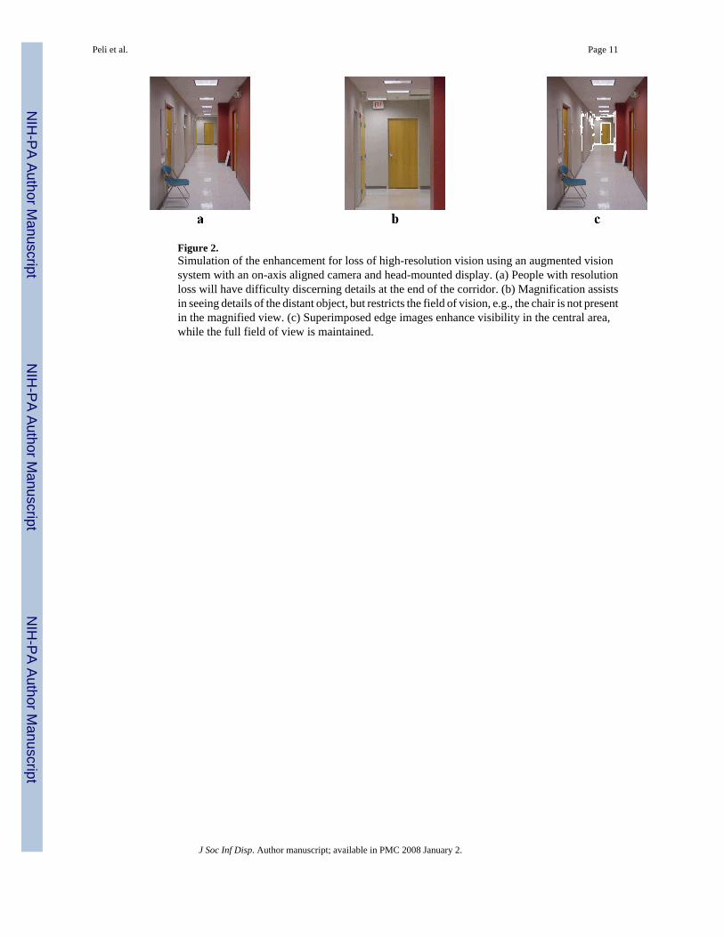
Figure 2.Simulation of the enhancement for loss of high-resolution vision using an augmented visionsystem with an on-axis aligned camera and head-mounted display. (a) People with resolutionloss will have difficulty discerning details at the end of the corridor. (b) Magnification assistsin seeing details of the distant object, but restricts the field of vision, e.g., the chair is not presentin the magnified view. (c) Superimposed edge images enhance visibility in the central area,while the full field of view is maintained.
Peli et al. Page 11
J Soc Inf Disp. Author manuscript; available in PMC 2008 January 2.
NIH
-PA Author Manuscript
NIH
-PA Author Manuscript
NIH
-PA Author Manuscript

Figure 3.The current generation of the augmented vision HMD visual field expander for patients withtunnel vision. The wide-angle image captured by the video camera is processed by thecontroller to provide edge contour images of the scene. The edge images are displayed on thesee-through display providing an expanded view. Once an object is detected via the minifiedcartoon, it can be examined with full resolution and color through the transparent display.
Peli et al. Page 12
J Soc Inf Disp. Author manuscript; available in PMC 2008 January 2.
NIH
-PA Author Manuscript
NIH
-PA Author Manuscript
NIH
-PA Author Manuscript
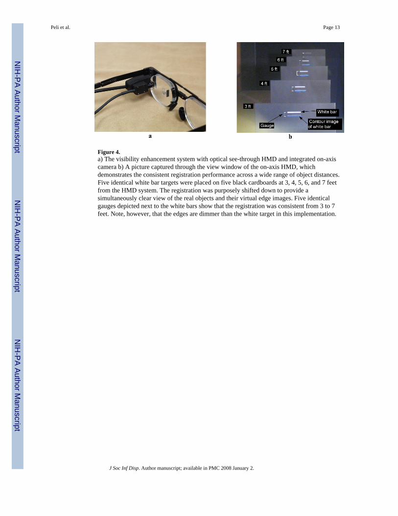
Figure 4.a) The visibility enhancement system with optical see-through HMD and integrated on-axiscamera b) A picture captured through the view window of the on-axis HMD, whichdemonstrates the consistent registration performance across a wide range of object distances.Five identical white bar targets were placed on five black cardboards at 3, 4, 5, 6, and 7 feetfrom the HMD system. The registration was purposely shifted down to provide asimultaneously clear view of the real objects and their virtual edge images. Five identicalgauges depicted next to the white bars show that the registration was consistent from 3 to 7feet. Note, however, that the edges are dimmer than the white target in this implementation.
Peli et al. Page 13
J Soc Inf Disp. Author manuscript; available in PMC 2008 January 2.
NIH
-PA Author Manuscript
NIH
-PA Author Manuscript
NIH
-PA Author Manuscript

Figure 5.The visual search task on a picture background. Targets were presented outside subjects'residual visual fields. The faded area of the image represents the blind area of the subject'sfield. Auditory direction cues were provided by buzzers around the screen. When using theHMD system, minified edge images could provide cues for both the direction and eccentricityof targets (See Figure 1).
Peli et al. Page 14
J Soc Inf Disp. Author manuscript; available in PMC 2008 January 2.
NIH
-PA Author Manuscript
NIH
-PA Author Manuscript
NIH
-PA Author Manuscript
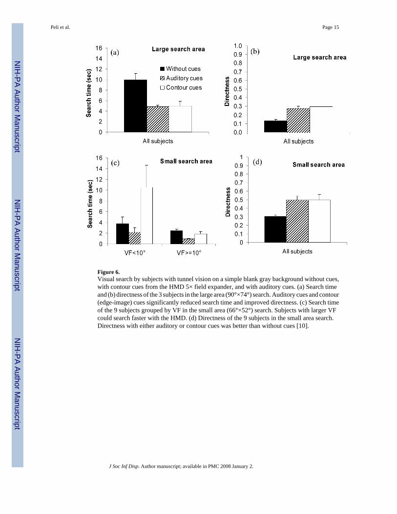
Figure 6.Visual search by subjects with tunnel vision on a simple blank gray background without cues,with contour cues from the HMD 5× field expander, and with auditory cues. (a) Search timeand (b) directness of the 3 subjects in the large area (90°×74°) search. Auditory cues and contour(edge-image) cues significantly reduced search time and improved directness. (c) Search timeof the 9 subjects grouped by VF in the small area (66°×52°) search. Subjects with larger VFcould search faster with the HMD. (d) Directness of the 9 subjects in the small area search.Directness with either auditory or contour cues was better than without cues [10].
Peli et al. Page 15
J Soc Inf Disp. Author manuscript; available in PMC 2008 January 2.
NIH
-PA Author Manuscript
NIH
-PA Author Manuscript
NIH
-PA Author Manuscript
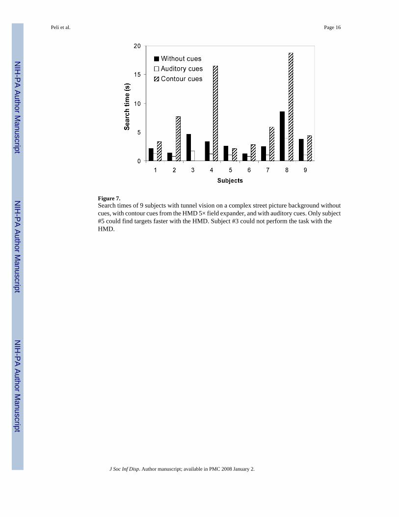
Figure 7.Search times of 9 subjects with tunnel vision on a complex street picture background withoutcues, with contour cues from the HMD 5× field expander, and with auditory cues. Only subject#5 could find targets faster with the HMD. Subject #3 could not perform the task with theHMD.
Peli et al. Page 16
J Soc Inf Disp. Author manuscript; available in PMC 2008 January 2.
NIH
-PA Author Manuscript
NIH
-PA Author Manuscript
NIH
-PA Author Manuscript
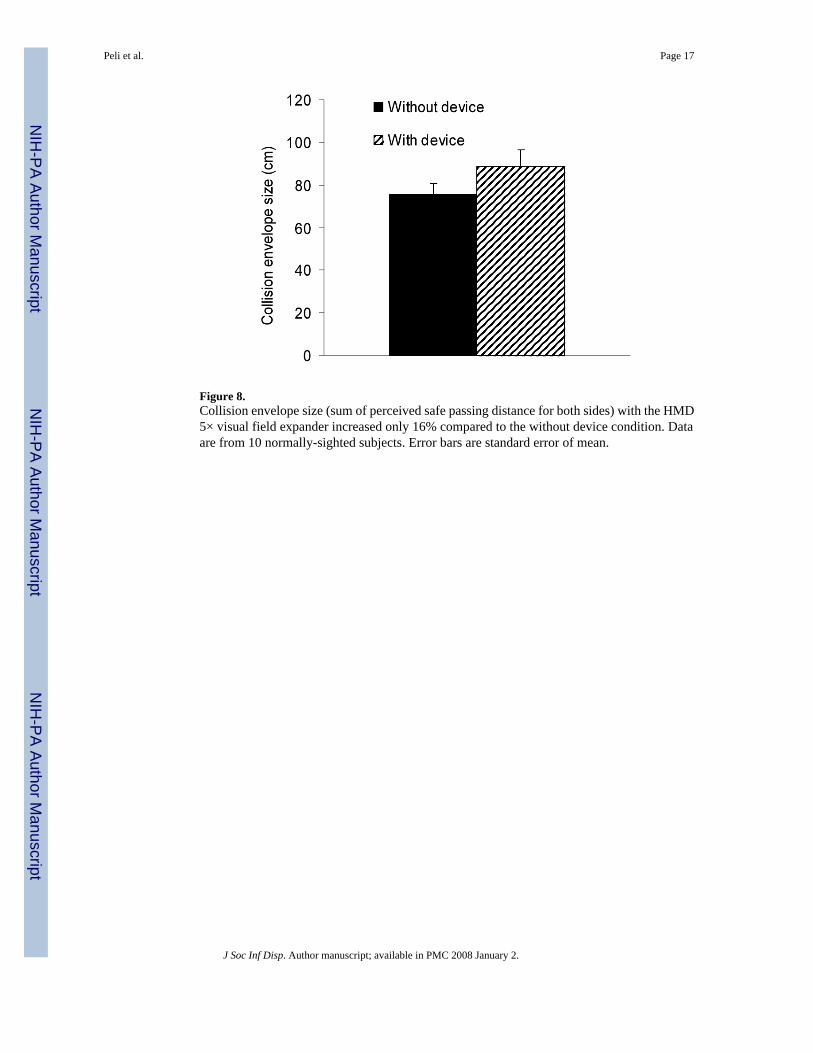
Figure 8.Collision envelope size (sum of perceived safe passing distance for both sides) with the HMD5× visual field expander increased only 16% compared to the without device condition. Dataare from 10 normally-sighted subjects. Error bars are standard error of mean.
Peli et al. Page 17
J Soc Inf Disp. Author manuscript; available in PMC 2008 January 2.
NIH
-PA Author Manuscript
NIH
-PA Author Manuscript
NIH
-PA Author Manuscript
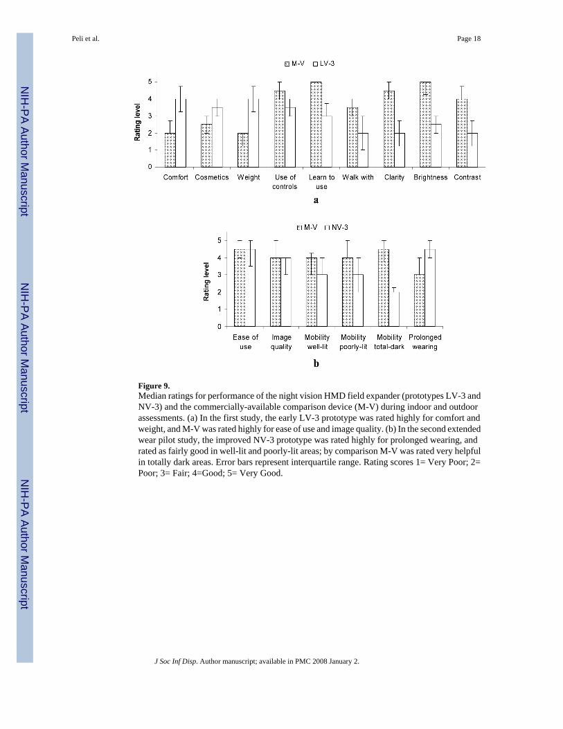
Figure 9.Median ratings for performance of the night vision HMD field expander (prototypes LV-3 andNV-3) and the commercially-available comparison device (M-V) during indoor and outdoorassessments. (a) In the first study, the early LV-3 prototype was rated highly for comfort andweight, and M-V was rated highly for ease of use and image quality. (b) In the second extendedwear pilot study, the improved NV-3 prototype was rated highly for prolonged wearing, andrated as fairly good in well-lit and poorly-lit areas; by comparison M-V was rated very helpfulin totally dark areas. Error bars represent interquartile range. Rating scores 1= Very Poor; 2=Poor; 3= Fair; 4=Good; 5= Very Good.
Peli et al. Page 18
J Soc Inf Disp. Author manuscript; available in PMC 2008 January 2.
NIH
-PA Author Manuscript
NIH
-PA Author Manuscript
NIH
-PA Author Manuscript
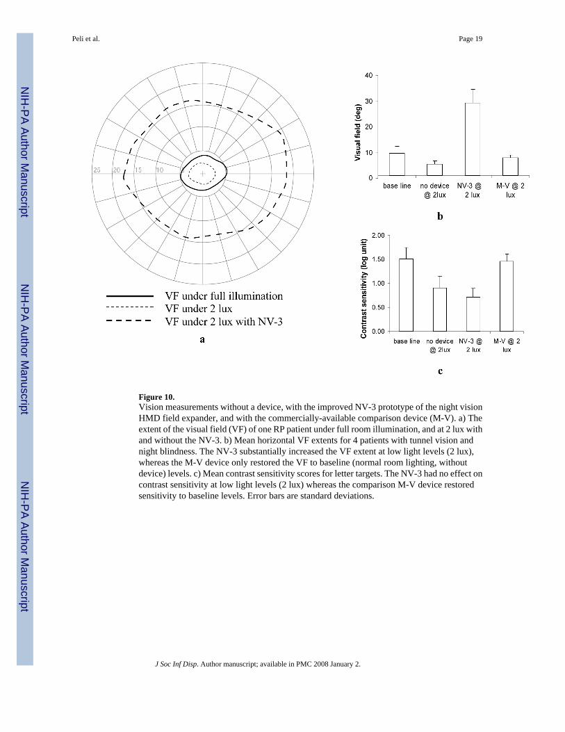
Figure 10.Vision measurements without a device, with the improved NV-3 prototype of the night visionHMD field expander, and with the commercially-available comparison device (M-V). a) Theextent of the visual field (VF) of one RP patient under full room illumination, and at 2 lux withand without the NV-3. b) Mean horizontal VF extents for 4 patients with tunnel vision andnight blindness. The NV-3 substantially increased the VF extent at low light levels (2 lux),whereas the M-V device only restored the VF to baseline (normal room lighting, withoutdevice) levels. c) Mean contrast sensitivity scores for letter targets. The NV-3 had no effect oncontrast sensitivity at low light levels (2 lux) whereas the comparison M-V device restoredsensitivity to baseline levels. Error bars are standard deviations.
Peli et al. Page 19
J Soc Inf Disp. Author manuscript; available in PMC 2008 January 2.
NIH
-PA Author Manuscript
NIH
-PA Author Manuscript
NIH
-PA Author Manuscript