application and uses of biosensors
TRANSCRIPT
CHEMILUMINISCENE - BASED BIOSENSORS:APPLICATION AND USES OF BIOSENSORS
(Week 6)WCU Project ,
Centre for NanoBioengineering & Spintronics, ChungnamNational University,Daejeon,Korea
10/5/2009 1
What is Chemiluminescence?Why is Chemiluminescenceimportant?Where can Chemiluminescence be used?Some case StudiesConclusionsKey References
10/5/2009 2WCU Project,CNU,[email protected]
Light is a form of energyTo create light, another form of energy must be supplied
There are two common ways for this to occur:
Incandescence luminescence
10/5/2009 3WCU Project,CNU,[email protected]

IncandescenceIncandescence is light from heat energy
If we heat something to a high enough temperature,
it begins to glow
When an electric stove heater or metal in a flame
begins to glow "red hot", that is incandescence
When the tungsten filament of an ordinary
incandescent light bulb is heated still hotter, it
glows brightly "white hot" by the samemeans
The sun and stars glow by incandescence.
10/5/2009 4WCU Project,CNU,[email protected]

LuminescenceLuminescence is "cold light“ (cold body radiation), light
from other sources of energy, which can take place at normal
and lower temperatures (i.e. with limited generation of heat)
Matter is luminescent if it gives off energy in the formof light
In luminescence, some energy source kicks an electron of an
atom out of its "ground" (lowest‐energy) state into an
"excited" (higher‐energy) state; then the electron gives back
the energy in the form of light so it can fall back to its
"ground" state.
10/5/2009 5WCU Project,CNU,[email protected]
Luminescence
Luminescence is the emission of light by a substance.
It occurs when an electron returns to the electronic ground state from an excited stateand loses it's excess energy as a photon.
Luminescence spectroscopy is a collective name given to three related spectroscopictechniques.
•Molecular fluorescence spectroscopy•Molecular phosphorescence spectroscopy•Chemiluminescence spectroscopy
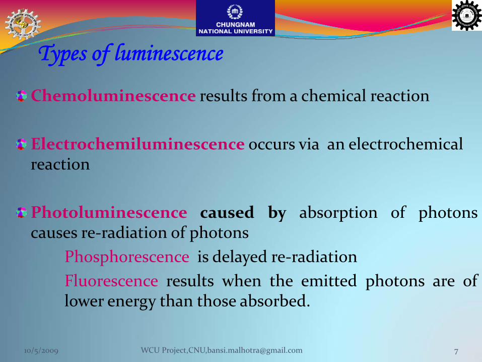
Types of luminescence
Chemoluminescence results from a chemical reaction
Electrochemiluminescence occurs via an electrochemical reaction
Photoluminescence caused by absorption of photonscauses re‐radiation of photons
Phosphorescence is delayed re‐radiationFluorescence results when the emitted photons are oflower energy than those absorbed.
10/5/2009 7WCU Project,CNU,[email protected]
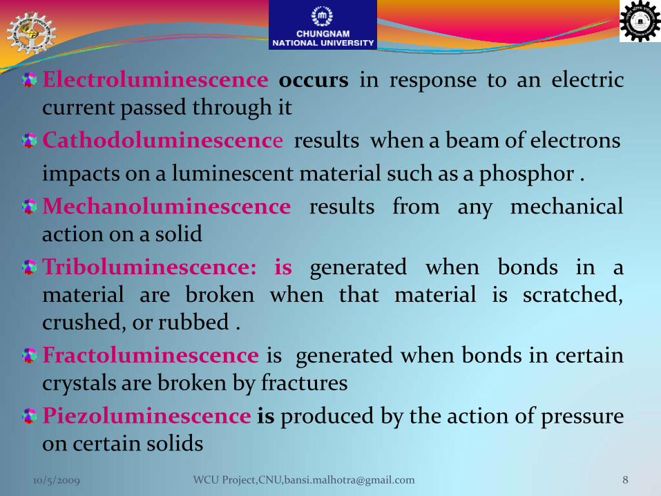
Electroluminescence occurs in response to an electriccurrent passed through itCathodoluminescence results when a beam of electronsimpacts on a luminescent material such as a phosphor .Mechanoluminescence results from any mechanicalaction on a solidTriboluminescence: is generated when bonds in amaterial are broken when that material is scratched,crushed, or rubbed .Fractoluminescence is generated when bonds in certaincrystals are broken by fracturesPiezoluminescence is produced by the action of pressureon certain solids
10/5/2009 8WCU Project,CNU,[email protected]
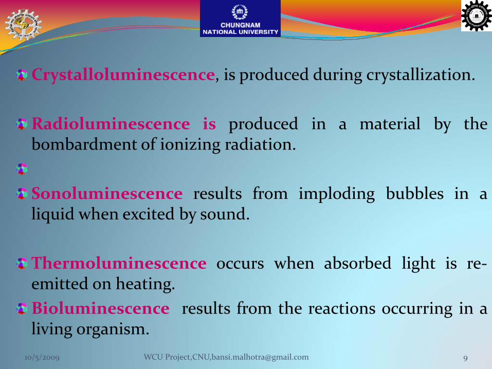
Crystalloluminescence, is produced during crystallization.
Radioluminescence is produced in a material by thebombardment of ionizing radiation.
Sonoluminescence results from imploding bubbles in aliquid when excited by sound.
Thermoluminescence occurs when absorbed light is re‐emitted on heating.Bioluminescence results from the reactions occurring in aliving organism.
10/5/2009 9WCU Project,CNU,[email protected]
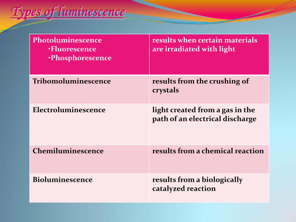
Photoluminescence•Fluorescence•Phosphorescence
results when certain materials are irradiated with light
Tribomoluminescence results from the crushing ofcrystals
Electroluminescence light created from a gas in the path of an electrical discharge
Chemiluminescence results from a chemical reaction
Bioluminescence results from a biologically catalyzed reaction
Types of luminescence
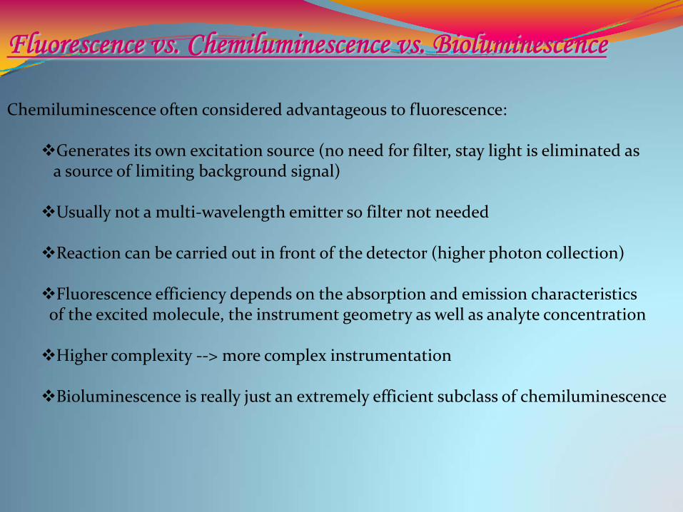
Fluorescence vs. Chemiluminescence vs. Bioluminescence
Chemiluminescence often considered advantageous to fluorescence:
Generates its own excitation source (no need for filter, stay light is eliminated asa source of limiting background signal)
Usually not a multi‐wavelength emitter so filter not needed
Reaction can be carried out in front of the detector (higher photon collection)
Fluorescence efficiency depends on the absorption and emission characteristicsof the excited molecule, the instrument geometry as well as analyte concentration
Higher complexity ‐‐> more complex instrumentation
Bioluminescence is really just an extremely efficient subclass of chemiluminescence
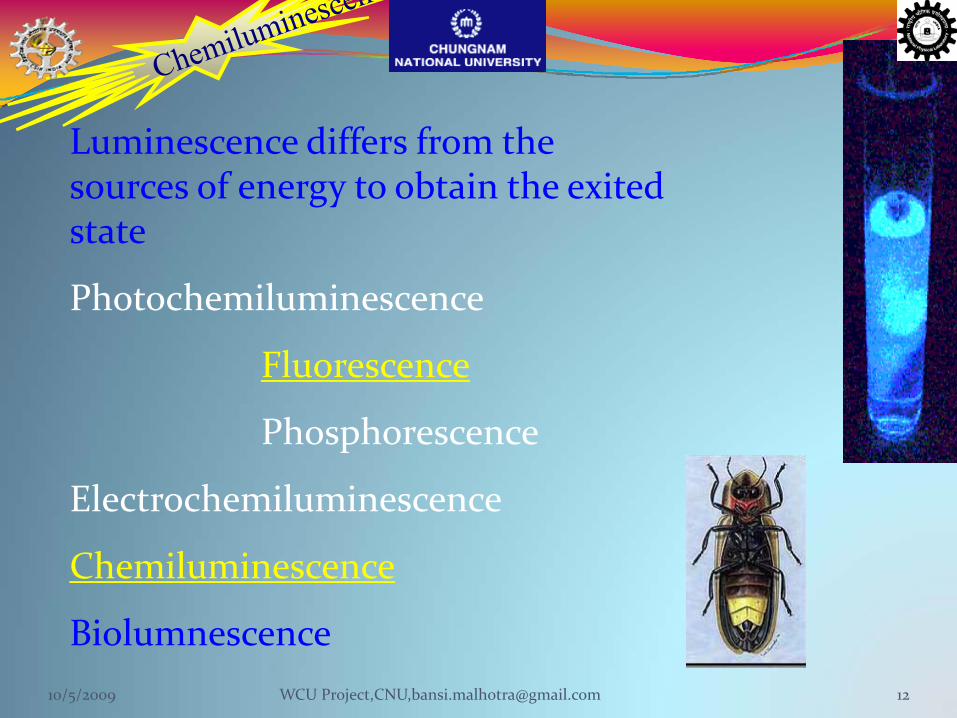
Luminescence differs from the sources of energy to obtain the exited state
Photochemiluminescence
Fluorescence
Phosphorescence
Electrochemiluminescence
Chemiluminescence
Biolumnescence10/5/2009 12WCU Project,CNU,[email protected]
10/5/2009 13WCU Project,CNU,[email protected]
10/5/2009 14WCU Project,CNU,[email protected]

10/5/2009 15WCU Project,CNU,[email protected]
10/5/2009 16WCU Project,CNU,[email protected]
10/5/2009 17WCU Project,CNU,[email protected]
ChemiluminescenceChemoluminescence
Chemi + luminescence
The term "chemiluminescence" was first coined by EilhardtWeidemann in 1888
10/5/2009 18WCU Project,CNU,[email protected]
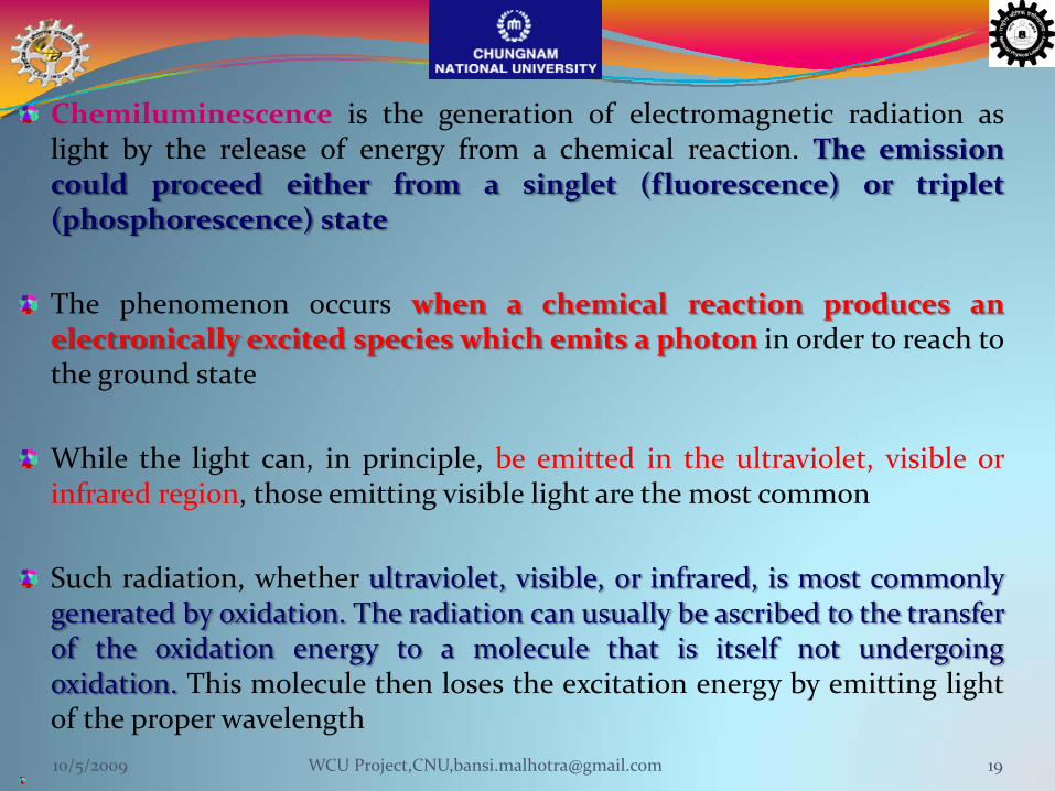
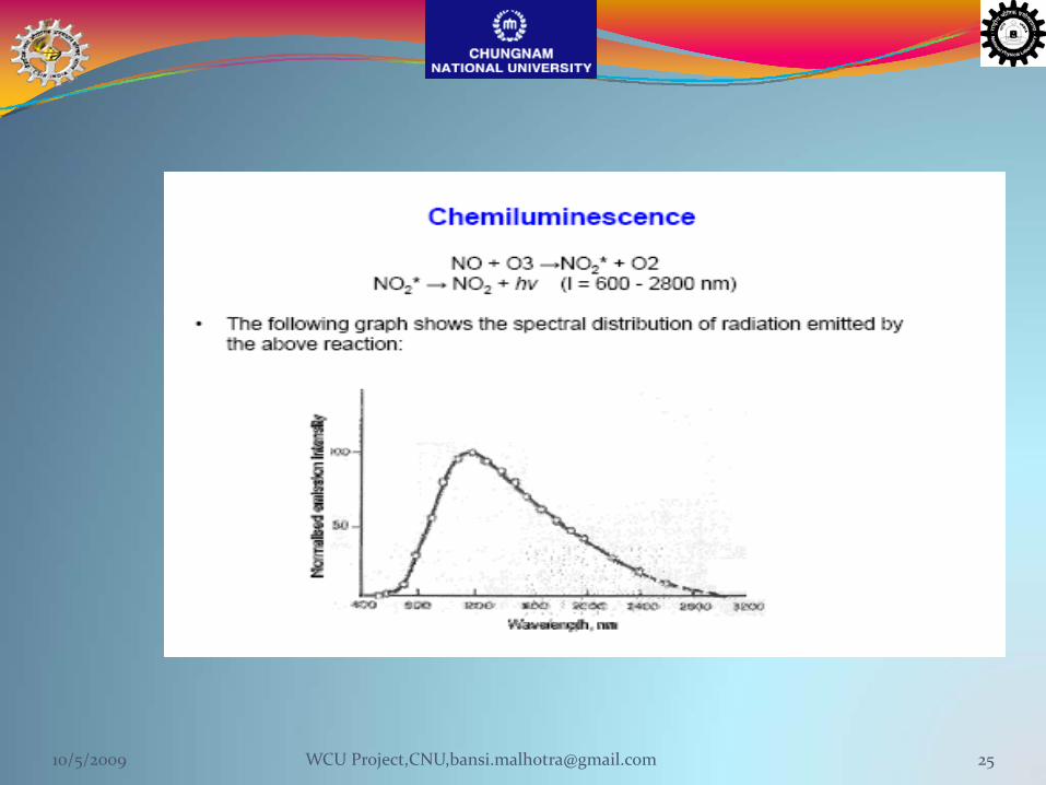
Chemiluminescence is the generation of electromagnetic radiation aslight by the release of energy from a chemical reaction. The emissioncould proceed either from a singlet (fluorescence) or triplet(phosphorescence) state
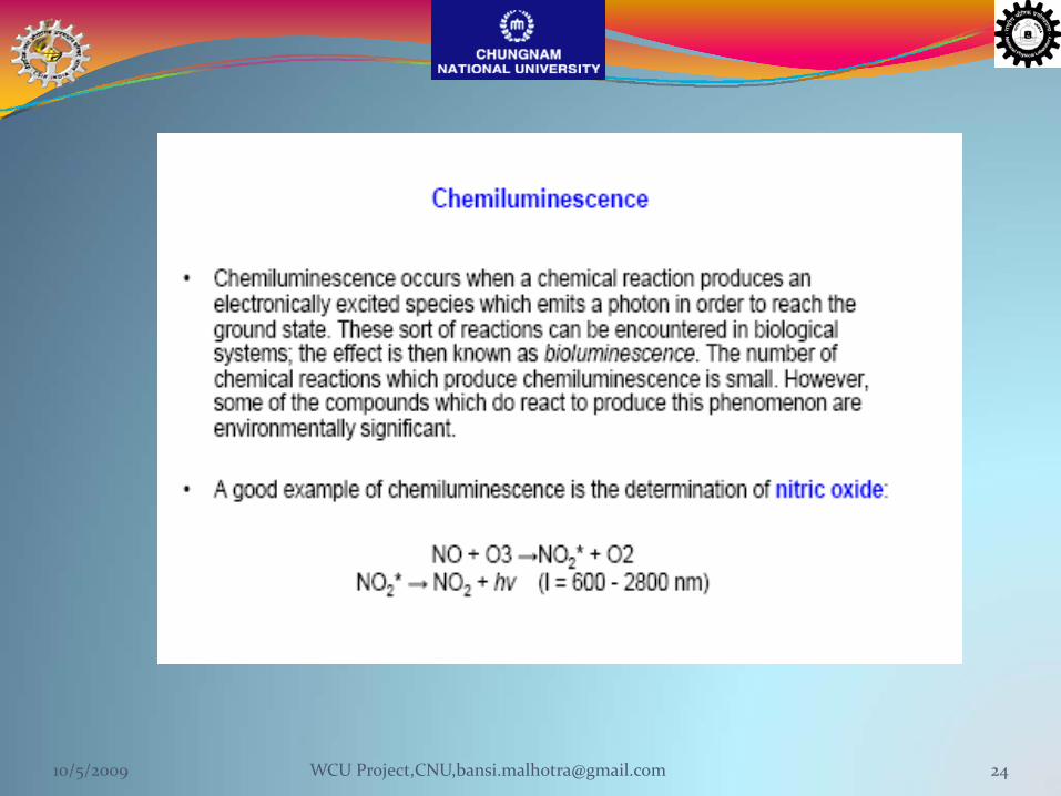
The phenomenon occurs when a chemical reaction produces anelectronically excited species which emits a photon in order to reach tothe ground state
While the light can, in principle, be emitted in the ultraviolet, visible orinfrared region, those emitting visible light are the most common
Such radiation, whether ultraviolet, visible, or infrared, is most commonlygenerated by oxidation. The radiation can usually be ascribed to the transferof the oxidation energy to a molecule that is itself not undergoingoxidation. This molecule then loses the excitation energy by emitting lightof the proper wavelength10/5/2009 19WCU Project,CNU,[email protected]
ChemiluminescenceEmission of light as a result of a chemical reaction
Requirements:
1)Energy must be sufficient to produce electronically excited State
2) The reaction pathway must favour the formation of an electronically excited state. Theexcited state must luminesce or transfer its energy to another molecule that then luminesces.
Chemiluminescence is highly specific – very few reactions result in light emissionVery sensitive >> fluorescence (no stray light)
The light emitted in such reactions has differing degrees ofintensity and lifetime, thus in order to achieve the highest levels ofsensitivity, a chemiluminescent reaction must be asefficient as possible in generating photons of light
As the reaction progresses, the chemical composition changes, andthe light will begin to die off before fading away entirely as a resultof conversion. Often, chemiluminescence is very brief, atleast to the naked eye, although scientific tools can beused tomeasure the reaction as it continues.
A large number of substances (e.g., formaldehyde, paraldehyde,acrolein, lophine, glucose, lecithin, and cholesterol) luminesce ifslowly oxidized in alcoholic alkaline solution
10/5/2009 21WCU Project,CNU,[email protected]
Each chemiluminescent compound or group can produce no more thanone photon of light. A perfectly efficient reaction would have achemiluminescence quantum yield ΦCL of one, i.e. one photon/moleculereacted according to the equation:
ΦCL = ΦCE × ΦF × ΦR
where, ΦCE = chemiexcitation quantum yield (between 0 and 1)0 completely dark reaction1 all product molecules are generated in the
excited statemost useful chemiluminescent reactions have aΦCE of about 10‐3 or more
ΦF = fluorescence quantum yield is the probability of theexcited state emitting a photon by fluorescence rather than decaying byother processes (ranges 0 to 1)
ΦR = reaction quantum yield is the fraction of startingmolecules which undergo the luminescent reaction rather than a sidereaction (value is usually about 1)
10/5/2009 22WCU Project,CNU,[email protected]
It is possible to increase the yield of chemiluminescence when the emitter is
poorly fluorescent low ΦF. A highly fluorescent acceptor is used in these cases
in order to transfer the excitation energy from the primary excited state
compound to the fluorescent acceptor/emitter. The chemiluminescence
quantumyield is then determined by the equation:
ΦCL =ΦCE ×ΦR ×ΦET ×ΦF′
The energy transfer quantum yield ΦET expresses the efficiency of converting
the primary excited state formed in the reaction into the excited state of the
acceptor. This value is often near 1. The fluorescence quantum yield of the
acceptor/emitter ΦF′ should also be near 1
10/5/2009 23WCU Project,CNU,[email protected]
10/5/2009 24WCU Project,CNU,[email protected]
10/5/2009 25WCU Project,CNU,[email protected]
A wide variety of systems that use chemiluminescence orbioluminescence have been developed with the aim of detectinglow concentrations of biologically active molecules. Even whenemission efficiencies are <1%, chemiluminescence is a sensitive labeldetection method compared with isotopic methods in which very largenumbers of molecules must be present for each detecteddisintegration (e.g., about 1 × 10⁷ atoms of 125I give 1 count/s)
The main importance of chemiluminescence is in the fact that it is acold system. Energy in the form of light is produced directly from thechemical reaction without first going through an intermediate stageinvolving heat.Chemiluminescent glow products never heat up, are not a source ofignition, and are non flammable. This is why modern science wishedto copy the firefly! Glow products have an abundance of uses as a cold,portable, light source and are an excellent source of SAFE FUN
10/5/2009 26WCU Project,CNU,[email protected]

Chemiluminescent reactions can be grouped into three types:
Chemical reactions using synthetic compounds and usually involving a highly
oxidized species such as a peroxide are commonly termed chemiluminescent
reactions
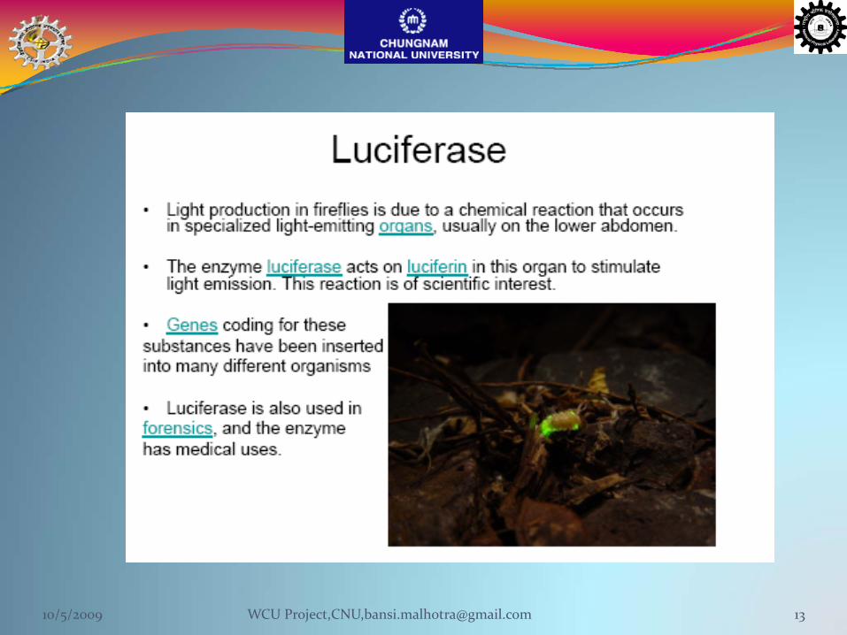
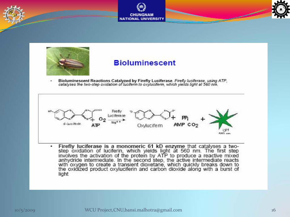
These sorts of reactions can be encountered in biological systems; the
effect is then known as bioluminescence. Light‐emitting reactions
arising from a living organism, such as the firefly or jellyfish (oxidation
of luciferin in the presence of an enzyme, luciferase), are commonly
termed bioluminescent reactions .
Light‐emitting reactions which take place by the use of electrical current
are designated electrochemiluminescent reactions.
10/5/2009 27WCU Project,CNU,[email protected]

The number of chemical reactions which produce
chemiluminescence is small. However, some of the compounds
which do react to produce this phenomenon are
environmentally significant.
Chemiluminescent and bioluminescent reactions usually
involve the cleavage or fragmentation of the O‐O bond an
organic peroxide compound. Peroxides, especially cyclic
peroxides, are prevalent in light emitting reactions because the
relatively weak peroxide bond is easily cleaved and the
resulting molecular reorganization liberates a large amount of
energy
10/5/2009 28WCU Project,CNU,[email protected]

Most chemiluminescence methods involve only a few chemical
components to actually generate light. Luminol chemiluminescence
and peroxyoxalate chemiluminescence are both used in bioanalytical
methods
In each system, a "fuel" is chemically oxidized to produce an excited state
product
In many luminol methods it is this excited product that emits the
light for the signal
In peroxyoxalate chemiluminescence, the initial excited state
product does not emit light at all and instead it reacts with
another compound, often a compound(a fluorescent dye) and it is
this fluorophore which becomes excited and emits light.10/5/2009 29WCU Project,CNU,[email protected]
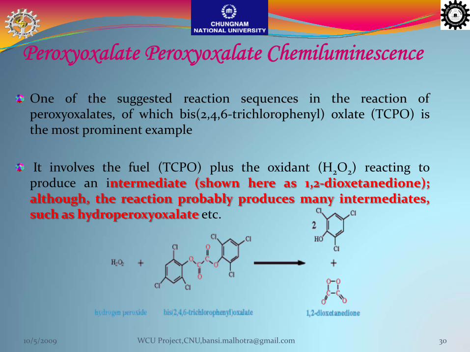
Peroxyoxalate Peroxyoxalate Chemiluminescence
One of the suggested reaction sequences in the reaction ofperoxyoxalates, of which bis(2,4,6‐trichlorophenyl) oxlate (TCPO) isthe most prominent example
It involves the fuel (TCPO) plus the oxidant (H2O2) reacting toproduce an intermediate (shown here as 1,2‐dioxetanedione);although, the reaction probably produces many intermediates,such as hydroperoxyoxalate etc.
10/5/2009 30WCU Project,CNU,[email protected]
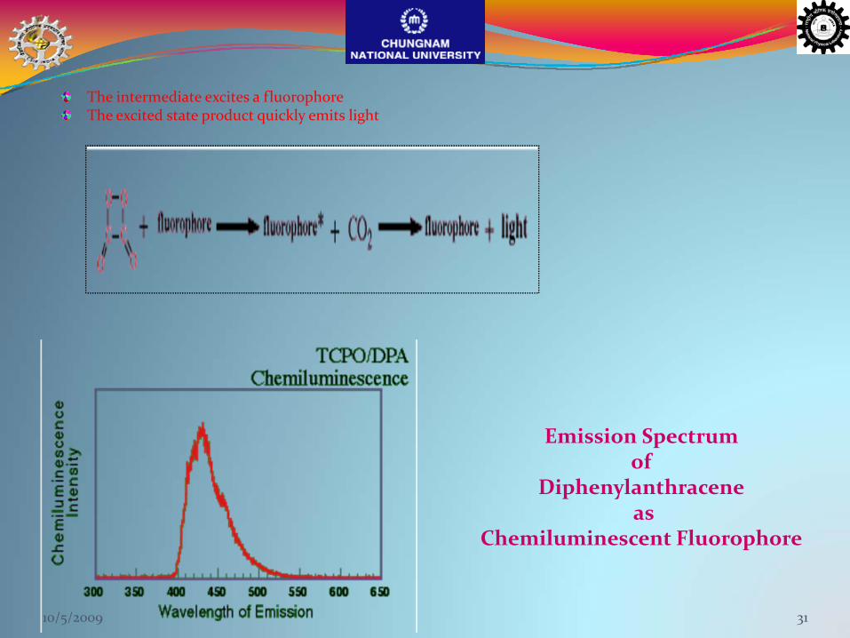
The intermediate excites a fluorophoreThe excited state product quickly emits light
Emission Spectrum of
Diphenylanthraceneas
Chemiluminescent Fluorophore
10/5/2009 31
Chemiluminescent Primer
The process of transferring the energy of the initial reaction,the chemical reaction of hydrogen peroxide with TCPO, tolight emission from the excited state fluorophore(fluorophore*) can be side‐tracked along the way by lossesin each step of the process.
The initial oxidation to produce the intermediate, thereaction of the intermediate with a fluorophore, and thereaction of the excited fluorophore to produce light.
10/5/2009 32WCU Project,CNU,[email protected]
The initial oxidation can yield the high energy intermediate orTCPO can be hydrolyzed instead orOxidation can occur that doesn't yield chemiluminescentproducts
The high energy intermediate can react to excite thefluorophore or
The intermediate can react with a quencher more easilyoxidized than the fluorophoreThe intermediate and fluorophore can react without yieldingexcited fluorophoreThe intermediate can decompose or be further oxidized byresidual H2O2
Finally the excited fluorophore can loose energy by emission oflight or
The excited fluorophore can de‐excited by production ofheat instead of light.10/5/2009 33

No excitation source (as does fluorescence and phosphorescence) .
Only a single light detector such as a photomultiplier tube required.
No monochromatic and often not even a filter.
No radioactivity or hazardous chemicals.
The chemiluminescence reagents are not hazardous to health.
Very sensitive in detection.
Why Chemiluminescence for Sensors ?
10/5/2009 34WCU Project,CNU,[email protected]
Luminol Chemiluminescence
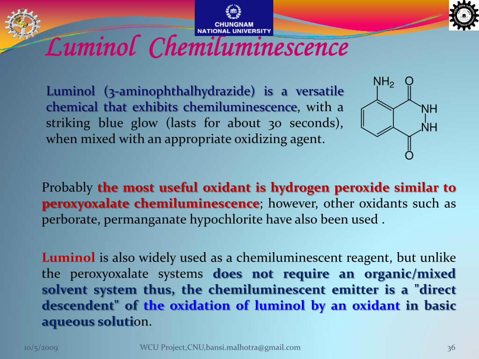
Probably the most useful oxidant is hydrogen peroxide similar toperoxyoxalate chemiluminescence; however, other oxidants such asperborate, permanganate hypochlorite have also been used .
Luminol is also widely used as a chemiluminescent reagent, but unlikethe peroxyoxalate systems does not require an organic/mixedsolvent system thus, the chemiluminescent emitter is a "directdescendent" of the oxidation of luminol by an oxidant in basicaqueous solution.
Luminol (3‐aminophthalhydrazide) is a versatilechemical that exhibits chemiluminescence, with astriking blue glow (lasts for about 30 seconds),when mixed with an appropriate oxidizing agent.
10/5/2009 36WCU Project,CNU,[email protected]
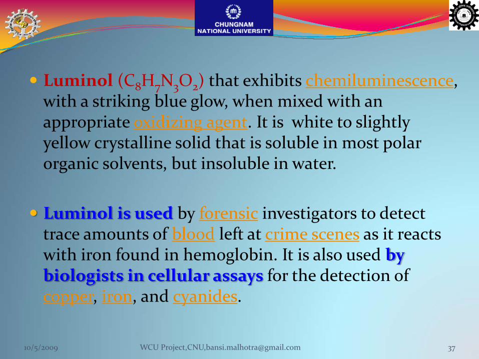
Luminol (C8H7N3O2) that exhibits chemiluminescence, with a striking blue glow, when mixed with an appropriate oxidizing agent. It is white to slightly yellow crystalline solid that is soluble in most polar organic solvents, but insoluble in water.
Luminol is used by forensic investigators to detect trace amounts of blood left at crime scenes as it reacts with iron found in hemoglobin. It is also used by biologists in cellular assays for the detection of copper, iron, and cyanides.
10/5/2009 37WCU Project,CNU,[email protected]
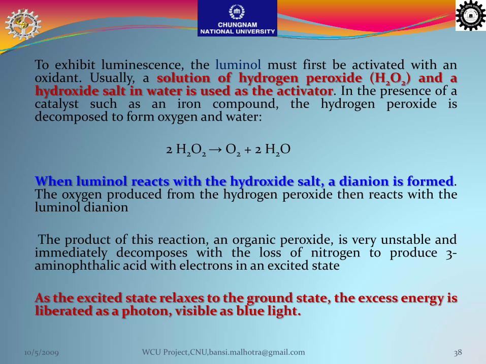
To exhibit luminescence, the luminol must first be activated with anoxidant. Usually, a solution of hydrogen peroxide (H2O2) and ahydroxide salt in water is used as the activator. In the presence of acatalyst such as an iron compound, the hydrogen peroxide isdecomposed to form oxygen and water:
2 H2O2 → O2 + 2 H2O
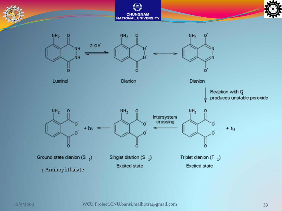
When luminol reacts with the hydroxide salt, a dianion is formed.The oxygen produced from the hydrogen peroxide then reacts with theluminol dianion
The product of this reaction, an organic peroxide, is very unstable andimmediately decomposes with the loss of nitrogen to produce 3‐aminophthalic acid with electrons in an excited state
As the excited state relaxes to the ground state, the excess energy isliberated as a photon, visible as blue light.
10/5/2009 38WCU Project,CNU,[email protected]
Luminol can be the foundation of significantly differentanalytical determinations. For instance, this system canbe used:
To determine luminol itself by holding other variablesconstantTo determine luminol‐like derivatives
To determine hydrogen peroxide or the progress ofreactions that produce H2O2
To determine the concentrations of metal cations.To determine analytes that effect the concentration ofmetal catalysts
10/5/2009 40WCU Project,CNU,[email protected]
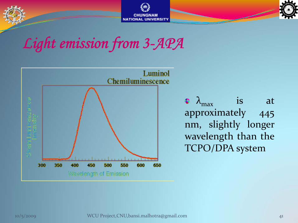
Light emission from 3-APA
λmax is atapproximately 445nm, slightly longerwavelength than theTCPO/DPA system
10/5/2009 41WCU Project,CNU,[email protected]
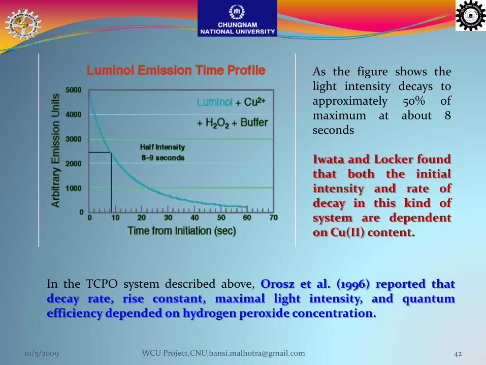
As the figure shows thelight intensity decays toapproximately 50% ofmaximum at about 8seconds
Iwata and Locker foundthat both the initialintensity and rate ofdecay in this kind ofsystem are dependenton Cu(II) content.
In the TCPO system described above, Orosz et al. (1996) reported thatdecay rate, rise constant, maximal light intensity, and quantumefficiency depended on hydrogen peroxide concentration.
10/5/2009 42WCU Project,CNU,[email protected]
Chemiluminescent assays Based on Enzymes
Glucose oxidase (GOX) is an enzyme that produces H2O2during a preincubation period that is appropriately selectedin order to increase the sensitivity of the system. GOXoxidizes glucose to yield H2O2which can be measured by CLreaction of TCPO/ ANS
3‐D‐Galactosidase (BGase) is an enzyme that catalyzes thehydrolysis of lactose to a‐D‐glucose and f3‐D‐galactose.Hydrogen peroxide generated from the coupled enzyme(GOX) reaction is measured by the CL reaction usingisoluminol/microperoxidase or peroxyoxalate/fluorescentdye.
10/5/2009 43WCU Project,CNU,[email protected]
Enhanced Chemiluminescence The series of compounds which, when added to the reaction, increase thelight emission by several orders of magnitude, are known as enhancersand the phenomenon is known as Enhanced Chemiluminescence
Enhancers act synergistically in the peroxidase—catalysed luminol—peroxide reaction. This reaction is catalyzed by metal ions at high pH,resulting in emission of blue light (emission peak about 425 nm). Atlower pH, the reaction is catalyzed by hemecontaining enzymes, such ashorseradish peroxidase, catalase, cytochrome C, and hemoglobin.However, the light output is low with a half‐life of a few seconds
The presence of any one of a series of “enhancer molecules” increases thelight emission from horseradish peroxidase by 1000‐fold or more, andalters the kinetics so that a steady glow is produced lasting several hours
10/5/2009 44WCU Project,CNU,[email protected]
Enhancer Effect of Fluorescein on the Luminol–H2O2–HorseradishPeroxidase Chemiluminescence:Energy Transfer Process
The maximum intesity and the total chemiluminescenceemission (between 380 and 580 nm) of luminol withfluorescein is more than three times greater than withoutfluorescein; however, the emission duration is shorter.
A. Navas Díaz1*, J. A. González García1 and J. Lovillo1, J BIOLUMIN CHEMILUMIN 1997: 12: 199–205
10/5/2009 45WCU Project,CNU,[email protected]
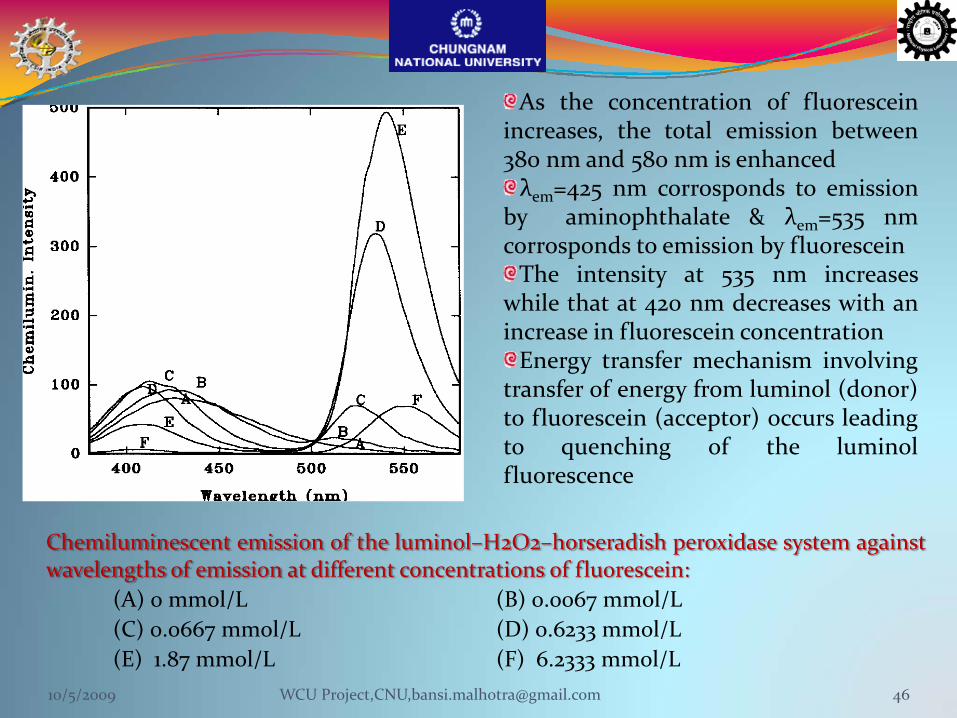
Chemiluminescent emission of the luminol–H2O2–horseradish peroxidase system againstwavelengths of emission at different concentrations of fluorescein:
(A) 0 mmol/L (B) 0.0067 mmol/L(C) 0.0667 mmol/L (D) 0.6233 mmol/L(E) 1.87 mmol/L (F) 6.2333 mmol/L
As the concentration of fluoresceinincreases, the total emission between380 nm and 580 nm is enhancedλem=425 nm corrosponds to emission
by aminophthalate & λem=535 nmcorrosponds to emission by fluoresceinThe intensity at 535 nm increases
while that at 420 nm decreases with anincrease in fluorescein concentrationEnergy transfer mechanism involving
transfer of energy from luminol (donor)to fluorescein (acceptor) occurs leadingto quenching of the luminolfluorescence
10/5/2009 46WCU Project,CNU,[email protected]
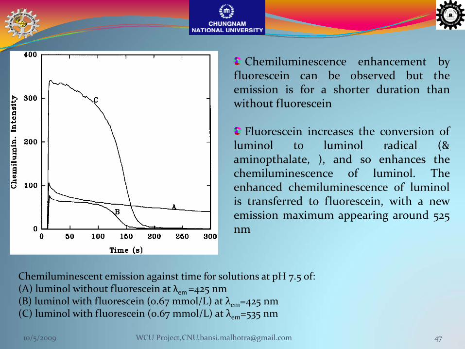
Chemiluminescent emission against time for solutions at pH 7.5 of:(A) luminol without fluorescein at λem =425 nm(B) luminol with fluorescein (0.67 mmol/L) at λem=425 nm(C) luminol with fluorescein (0.67 mmol/L) at λem=535 nm
Chemiluminescence enhancement byfluorescein can be observed but theemission is for a shorter duration thanwithout fluorescein
Fluorescein increases the conversion ofluminol to luminol radical (&aminopthalate, ), and so enhances thechemiluminescence of luminol. Theenhanced chemiluminescence of luminolis transferred to fluorescein, with a newemission maximum appearing around 525nm
10/5/2009 47WCU Project,CNU,[email protected]

First synthesized in Germany in 1902, but the compound was not namedluminol until the late 1920s.
Used to detect trace amounts of blood (even invisible) as it reacts with ironfound in haemoglobin.Also used by biologists in cellular assays for the detection of copper, iron,
and cyanides.Exhibits a blue‐green chemiluminescence when mixed with an appropriate
oxidizing agent.Glows in the dark.Is a relatively simple chemical containing only carbon, nitrogen, oxygen and
hydrogen and is a white to slightly yellow crystalline solid powder, soluble inwater and most polar organic solvents.
Luminol - Chemiluminescent Blood DetectorForensic Investigators' Essential Tool for Crime Scene Investigation
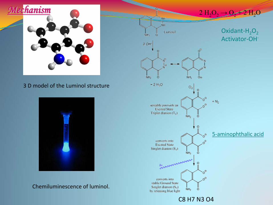
3 D model of the Luminol structure
C8 H7 N3 O4
Chemiluminescence of luminol.
5‐aminophthalic acid
2 H2O2 → O2 + 2 H2O
Oxidant‐H2O2Activator‐OH‐
Mechanism

Used by forensic investigators to detect trace amounts of blood left atcrime scenesMost sensitive presumptive blood testCan detect bloodstains diluted up to 300,000 times
Luminol for Blood Test

Enzyme LabelA common means for generating chemiluminescence is touse a label enzyme to catalyze a chemiluminescent reactionEach label can initiate multiple chemiluminescentreactions, so it is usually only necessary to incorporate oneor a few enzyme labels/analyte
Light intensity is alinear function of theamount of label enzyme
Representation of the time course of light emissionof a typical enzymatic chemiluminescent reaction
10/5/2009 51WCU Project,CNU,[email protected]
Some Factors in Choosing a Detection Reaction:Enzyme Label or Direct Label?
Components of a chemiluminescent (e.g.luminol) orbioluminescent reaction (e.g., a luciferase, aequorin) can be usedas a label, or a chemiluminescent or bioluminescent reaction canbe used to monitor an enzyme label or its productsDirectly labeled chemiluminescent systems produce <1photon/label and require complex chemical synthesis to produceeach new labeled molecule.Chemiluminescent detection of enzyme labels combines theadvantages of a high specific activity label with the convenienceof relatively simple coupling chemistries, which use commercialreagents
10/5/2009 52WCU Project,CNU,[email protected]
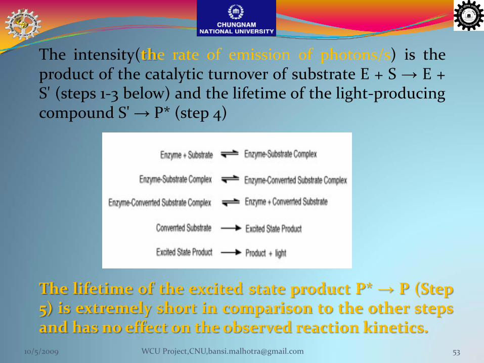
The intensity(the rate of emission of photons/s) is theproduct of the catalytic turnover of substrate E + S → E +S' (steps 1‐3 below) and the lifetime of the light‐producingcompound S'→ P* (step 4)
The lifetime of the excited state product P* → P (Step5) is extremely short in comparison to the other stepsand has no effect on the observed reaction kinetics.
10/5/2009 53WCU Project,CNU,[email protected]
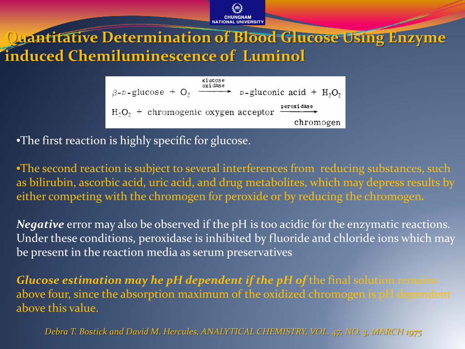
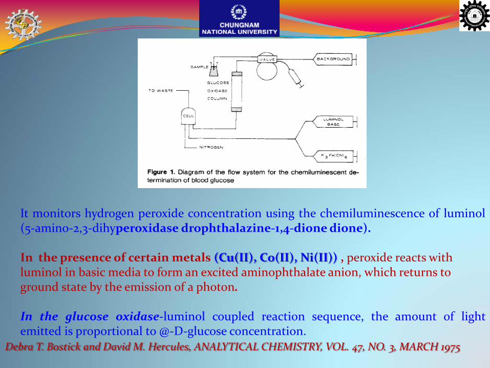
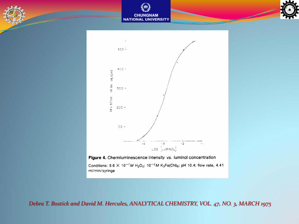
Quantitative Determination of Blood Glucose Using Enzyme induced Chemiluminescence of Luminol
Debra T. Bostick and David M. Hercules, ANALYTICAL CHEMISTRY, VOL. 47, NO. 3, MARCH 1975
•The first reaction is highly specific for glucose.
•The second reaction is subject to several interferences from reducing substances, such as bilirubin, ascorbic acid, uric acid, and drug metabolites, which may depress results by either competing with the chromogen for peroxide or by reducing the chromogen.
Negative error may also be observed if the pH is too acidic for the enzymatic reactions. Under these conditions, peroxidase is inhibited by fluoride and chloride ions which may be present in the reaction media as serum preservatives
Glucose estimation may he pH dependent if the pH of the final solution remains above four, since the absorption maximum of the oxidized chromogen is pH dependent above this value.
Debra T. Bostick and David M. Hercules, ANALYTICAL CHEMISTRY, VOL. 47, NO. 3, MARCH 1975
It monitors hydrogen peroxide concentration using the chemiluminescence of luminol(5‐amino‐2,3‐dihyperoxidase drophthalazine‐1,4‐dionedione).
In the presence of certain metals (Cu(II), Co(II), Ni(II)) , peroxide reacts with luminol in basic media to form an excited aminophthalate anion, which returns to ground state by the emission of a photon.
In the glucose oxidase‐luminol coupled reaction sequence, the amount of lightemitted is proportional to @‐D‐glucose concentration.
Debra T. Bostick and David M. Hercules, ANALYTICAL CHEMISTRY, VOL. 47, NO. 3, MARCH 1975
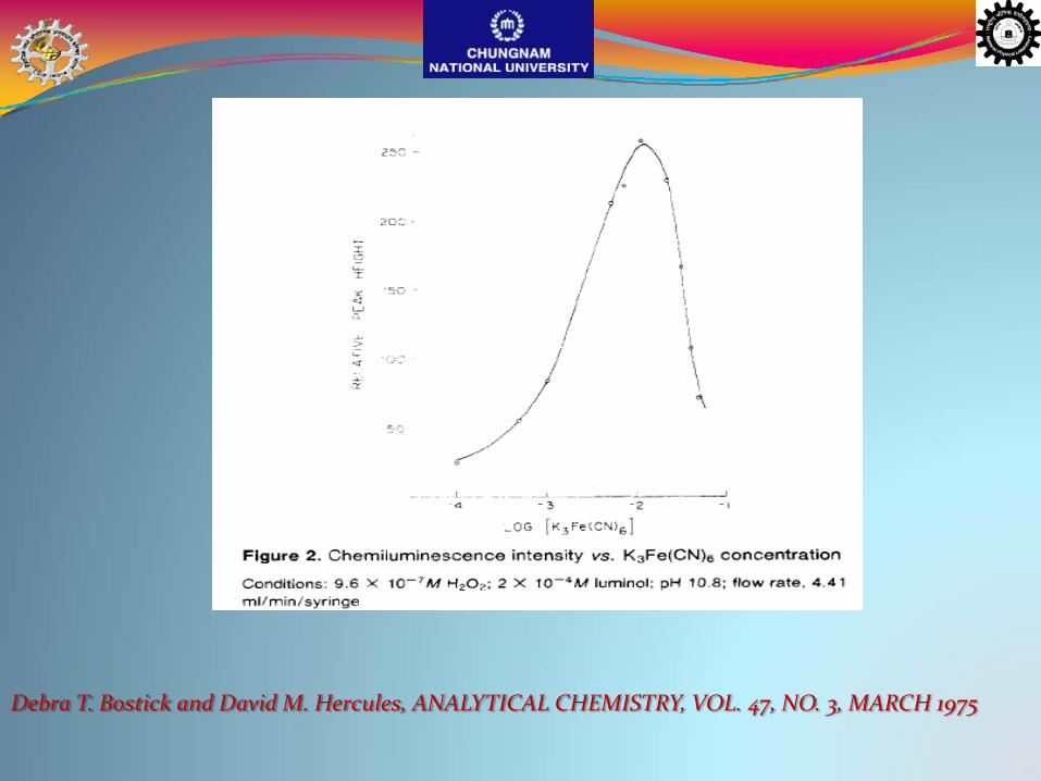
Debra T. Bostick and David M. Hercules, ANALYTICAL CHEMISTRY, VOL. 47, NO. 3, MARCH 1975
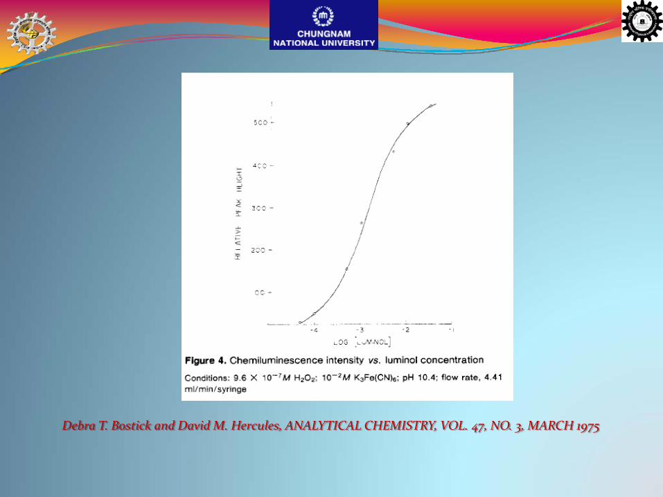
Debra T. Bostick and David M. Hercules, ANALYTICAL CHEMISTRY, VOL. 47, NO. 3, MARCH 1975
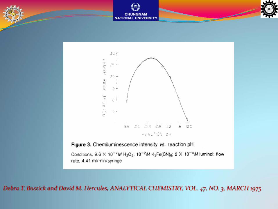
Debra T. Bostick and David M. Hercules, ANALYTICAL CHEMISTRY, VOL. 47, NO. 3, MARCH 1975

Debra T. Bostick and David M. Hercules, ANALYTICAL CHEMISTRY, VOL. 47, NO. 3, MARCH 1975
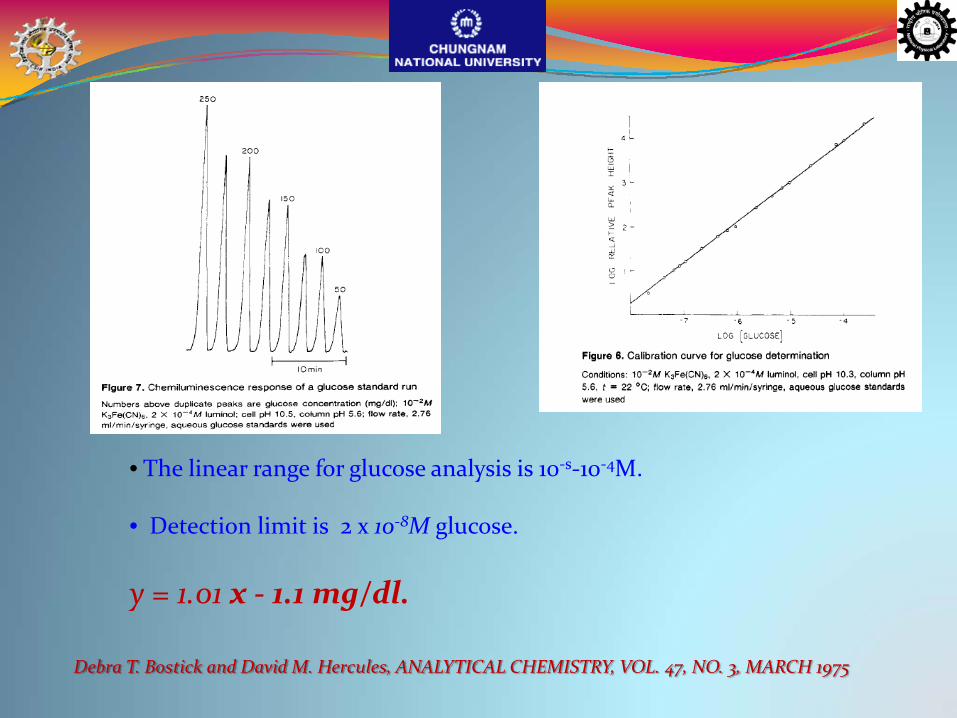
y = 1.01 x ‐ 1.1 mg/dl.
Debra T. Bostick and David M. Hercules, ANALYTICAL CHEMISTRY, VOL. 47, NO. 3, MARCH 1975
• The linear range for glucose analysis is 10‐s‐10‐4M.
• Detection limit is 2 x 10‐8M glucose.

10/5/2009 WCU Project,CNU,[email protected] 62
Immobilization of glucose oxidase on a support other than Sepharose. Sepharose beads are deformable under pressure; with continued use of the column, Further packing of the column results in increased back‐pressure.Modification
10/5/2009 63WCU Project,CNU,[email protected]
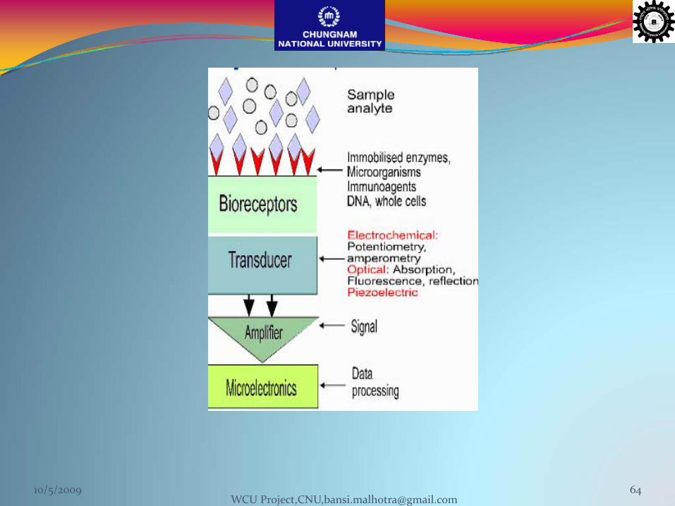
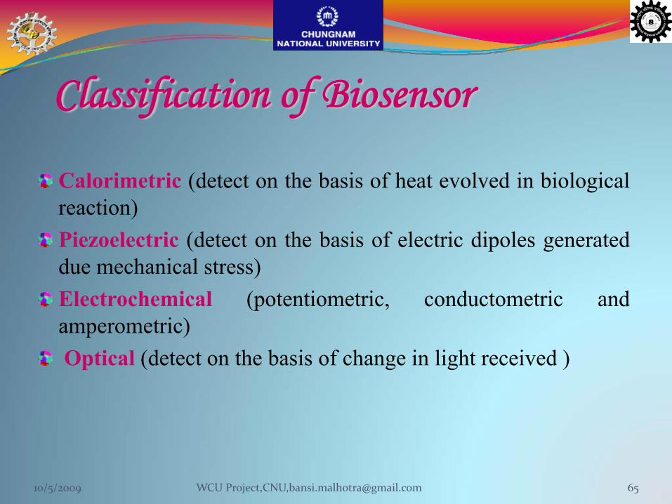
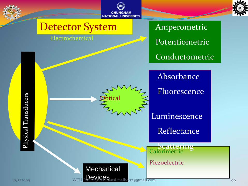
Classification of Biosensor
Calorimetric (detect on the basis of heat evolved in biologicalreaction)Piezoelectric (detect on the basis of electric dipoles generateddue mechanical stress)Electrochemical (potentiometric, conductometric andamperometric)Optical (detect on the basis of change in light received )
10/5/2009 65WCU Project,CNU,[email protected]
WCU Project,CNU,[email protected]/5/2009
Characteristics of a Biosensor
Specificity
Sensitive within biological range Stable for several monthsAble to be used 5000-10000 timesShelf- life should be at least six monthSenapable of miniaturizationFast responseMust not be poisonous
66
Broad Applications of Biosensors
Food and drink production and analysisMicrobiology: bacterial and viral analysisPharmaceutical and drug analysisIndustrial effluent controlPollution control and monitoringMining, industrial and toxic gasesMilitary applicationsClinical diagnosis and biomedicineFarm, garden and veterinary analysisProcess control: fermentation control and analysis
10/5/2009 67WCU Project,CNU,[email protected]
H2O2 + horse radish peroxidase (HRP)
catalyzes the oxidation of luminol.
Immediately following the oxidation of luminol,
an excited state,
then decays to the ground state by emitting light.
Using this method it is possible to detect antigens(EP/MP).
Principle of CL based technique
10/5/2009 68WCU Project,CNU,[email protected]
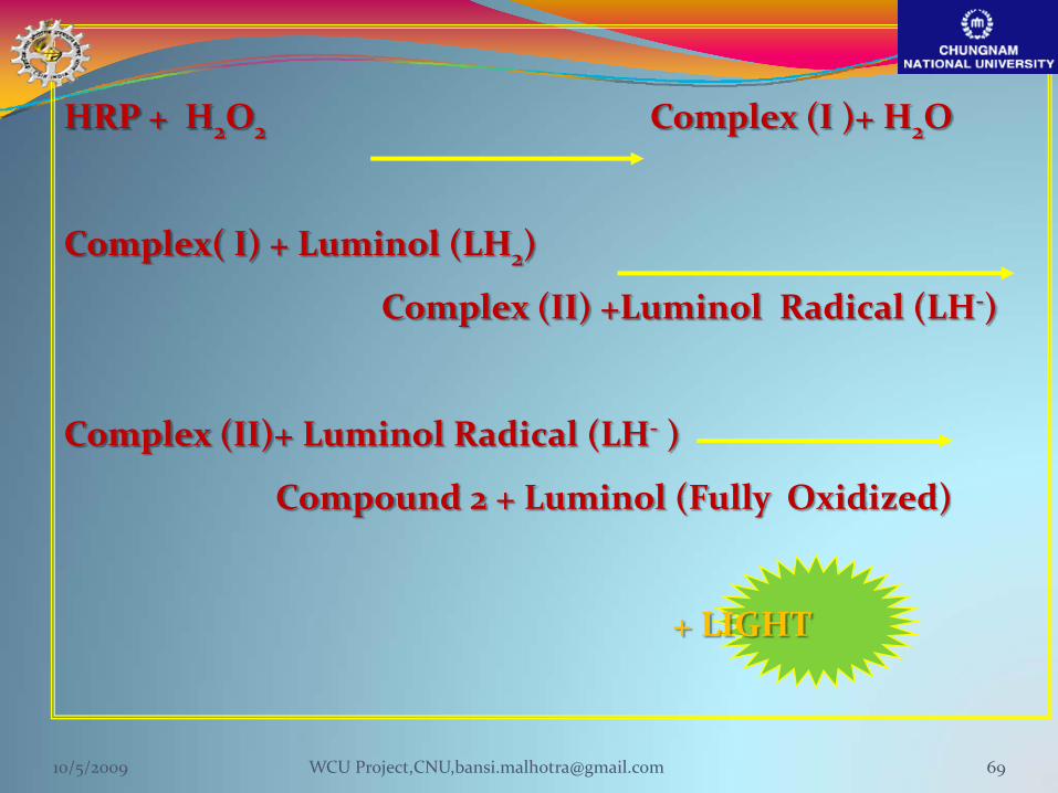
HRP + H2O2 Complex (I )+ H2O
Complex( I) + Luminol (LH2)
Complex (II) +Luminol Radical (LH‐)
Complex (II)+ Luminol Radical (LH‐ )
Compound 2 + Luminol (Fully Oxidized)
+ LIGHT
10/5/2009 69WCU Project,CNU,[email protected]

Direct LabelAnother way to use a chemiluminescent reaction for detecting ananalyte in an immunoassay is to covalently label one of thecomplementary binding partners directly with a chemiluminescentcompound. Triggering the chemiluminescent label to undergo thelight‐emitting reaction produces a signal for detecting the analyte
The label, upon triggering, should emit all of the light in the briefestpossible period of time
When the chemiluminescence is emittedgradually over a period of time, signalintensity (photons/sec) is diminished and,in the worst case, can be low enough toimpair detection sensitivity
10/5/2009 70WCU Project,CNU,[email protected]
This work has demonstrated that the selectivity of ECL‐based on the base‐pairprinciple could be improved by using hairpin DNA as a recognition element
The hairpin ECL biosensor presents relatively sensitive DNA detection and goodselectivity for discriminating complementary target ss‐DNA from bothnoncomplementary and singlebase mismatch ss‐DNA.
Binding strength and sensitivity are found to be dependent on the number of thematched bases. Changes in the length of the probe loop present a promisingalternative approach for improvement of the sensitivity and selectivity of DNAhybridization assays. It appears that relatively longer length loops may benefit theselectivity and sensitivity of ECL‐based biosensors for the detection ofcomplementary target DNA
The ability to discriminate the complementary from singlebase mismatchDNA is the gold standard of DNA biosensors, and the ability to sensitivelydetect single‐base mutation is crucial to gene detection in early stagediagnosis.
10/5/2009 71WCU Project,CNU,[email protected]
Electrogenerated Chemiluminescence DNA Biosensor Based on Hairpin DNA Probe Labeled with Ruthenium Complex
A highly selective electrogenerated chemiluminescence (ECL) biosensorfor the detection of target single‐strand DNA (ss‐DNA) has beendeveloped using hairpin DNA as the recognition element andruthenium complex as the signal producing compound.An ECL probe (P1), thiolated hairpin DNA tagged with rutheniumcomplex, is self‐assembled on the surface of a gold electrode
The hybridization kinetics of the ECL biosensor is found to bedependent on the concentration of probe, loop length and the structuresof both DNA probe and target ss‐DNA.
Jing Zhang, Honglan Qi, Yan Li, Jia Yang, Qiang Gao, and Chengxiao Zhang, Anal. Chem. 2008, 80, 2888‐2894
10/5/2009 72WCU Project,CNU,[email protected]
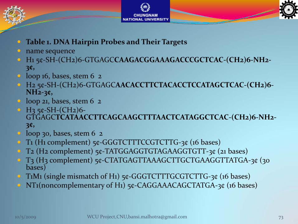
Table 1. DNA Hairpin Probes and Their Targetsname sequenceH1 5¢‐SH‐(CH2)6‐GTGAGCCAAGACGGAAAGACCCGCTCAC‐(CH2)6‐NH2‐3¢,loop 16, bases, stem 6 2H2 5¢‐SH‐(CH2)6‐GTGAGCAACACCTTCTACACCTCCATAGCTCAC‐(CH2)6‐NH2‐3¢,loop 21, bases, stem 6 2H3 5¢‐SH‐(CH2)6‐GTGAGCTCATAACCTTCAGCAAGCTTTAACTCATAGGCTCAC‐(CH2)6‐NH2‐3¢,loop 30, bases, stem 6 2T1 (H1 complement) 5¢‐GGGTCTTTCCGTCTTG‐3¢ (16 bases)T2 (H2 complement) 5¢‐TATGGAGGTGTAGAAGGTGTT‐3¢ (21 bases)T3 (H3 complement) 5¢‐CTATGAGTTAAAGCTTGCTGAAGGTTATGA‐3¢ (30 bases)T1M1 (single mismatch of H1) 5¢‐GGGTCTTTGCGTCTTG‐3¢ (16 bases)NT1(noncomplementary of H1) 5¢‐CAGGAAACAGCTATGA‐3¢ (16 bases)
10/5/2009 73WCU Project,CNU,[email protected]
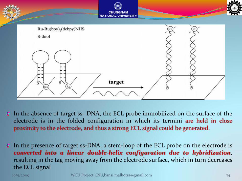
In the absence of target ss‐ DNA, the ECL probe immobilized on the surface of theelectrode is in the folded configuration in which its termini are held in closeproximity to the electrode, and thus a strong ECL signal could be generated.
In the presence of target ss‐DNA, a stem‐loop of the ECL probe on the electrode isconverted into a linear double‐helix configuration due to hybridization,resulting in the tag moving away from the electrode surface, which in turn decreasesthe ECL signal10/5/2009 74WCU Project,CNU,[email protected]
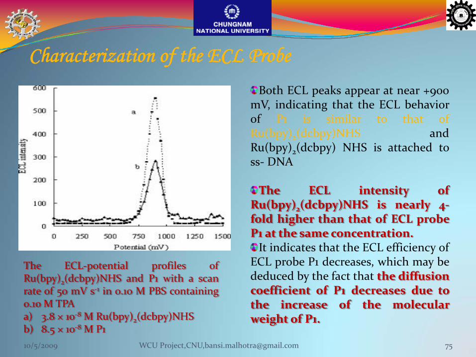
Characterization of the ECL Probe
The ECL‐potential profiles ofRu(bpy)2(dcbpy)NHS and P1 with a scanrate of 50 mV s‐1 in 0.10 M PBS containing0.10 M TPAa) 3.8 × 10‐8 M Ru(bpy)2(dcbpy)NHSb) 8.5 × 10‐8 M P1
Both ECL peaks appear at near +900mV, indicating that the ECL behaviorof P1 is similar to that ofRu(bpy)2(dcbpy)NHS andRu(bpy)2(dcbpy) NHS is attached toss‐ DNA
The ECL intensity ofRu(bpy)2(dcbpy)NHS is nearly 4‐fold higher than that of ECL probeP1 at the same concentration.It indicates that the ECL efficiency of
ECL probe P1 decreases, which may bededuced by the fact that the diffusioncoefficient of P1 decreases due tothe increase of the molecularweight of P1.
10/5/2009 75WCU Project,CNU,[email protected]
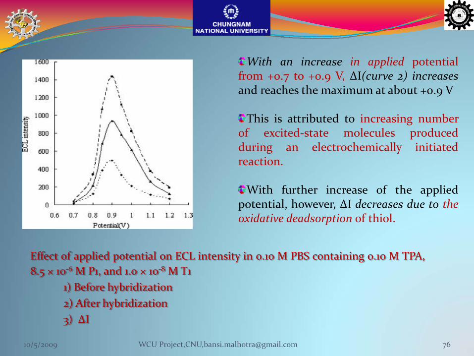
Effect of applied potential on ECL intensity in 0.10 M PBS containing 0.10 M TPA,8.5 × 10‐6 M P1, and 1.0 × 10‐8 M T1
1) Before hybridization2) After hybridization3) ΔI
With an increase in applied potentialfrom +0.7 to +0.9 V, ΔI(curve 2) increasesand reaches the maximum at about +0.9 V
This is attributed to increasing numberof excited‐state molecules producedduring an electrochemically initiatedreaction.
With further increase of the appliedpotential, however, ΔI decreases due to theoxidative deadsorption of thiol.
10/5/2009 76WCU Project,CNU,[email protected]

Effect of hybridization timeon normalized ECL intensity.a) 8.5 × 10‐6 M P1; 4.0 10‐8M T1b) 5.5 × 10‐6 M P3; 4.0 10‐8 M T3
The hybridization time is optimized using twoECL biosensors by:
a) P1 (loop 16‐mer, stem 6)b) P3 (loop 30 mer, stem 6)
for their complementary target ss‐DNA T1 and T3,respectively
ECL signal decreases sharply with an increase ofthe hybridization time.
A 50% decrease was observed in theapproximately 10 min after hybridization, and asteady state was reached in less than 30 min forP1‐T1 (curve a), whereas P3‐ T3 reached its steadystate in about 90 min (curve b)
This suggests that the initial hybridizationreaction proceeds quickly for P1‐T1 and thehybridization reaction is completed in about 30min (owing to faster duplex formation due tolesser steric crowding)
10/5/2009 77WCU Project,CNU,[email protected]
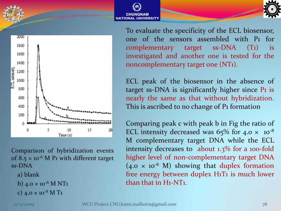
Comparison of hybridization eventsof 8.5 × 10‐6 M P1 with different targetss‐DNAa) blankb) 4.0 × 10‐6 M NT1c) 4.0 × 10‐8 M T1
To evaluate the specificity of the ECL biosensor,one of the sensors assembled with P1 forcomplementary target ss‐DNA (T1) isinvestigated and another one is tested for thenoncomplementary target one (NT1).
ECL peak of the biosensor in the absence oftarget ss‐DNA is significantly higher since P1 isnearly the same as that without hybridization.This is ascribed to no change of P1 formation
Comparing peak c with peak b in Fig the ratio ofECL intensity decreased was 65% for 4.0 × 10‐8M complementary target DNA while the ECLintensity decreases to about 1.3% for a 100‐foldhigher level of non‐complementary target DNA(4.0 × 10‐6 M) showing that duplex formationfree energy between duplex H1T1 is much lowerthan that in H1‐NT1.
10/5/2009 78WCU Project,CNU,[email protected]
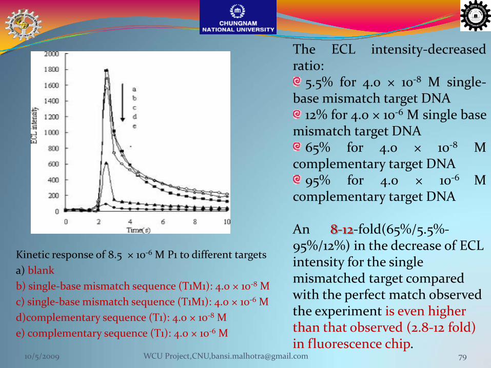
Kinetic response of 8.5 × 10‐6 M P1 to different targetsa) blankb) single‐base mismatch sequence (T1M1): 4.0 × 10‐8 Mc) single‐base mismatch sequence (T1M1): 4.0 × 10‐6 Md)complementary sequence (T1): 4.0 × 10‐8 Me) complementary sequence (T1): 4.0 × 10‐6 M
The ECL intensity‐decreasedratio:5.5% for 4.0 × 10‐8 M single‐
base mismatch target DNA12% for 4.0 × 10‐6 M single base
mismatch target DNA65% for 4.0 × 10‐8 M
complementary target DNA95% for 4.0 × 10‐6 M
complementary target DNA
An 8‐12‐fold(65%/5.5%‐95%/12%) in the decrease of ECL intensity for the single mismatched target compared with the perfect match observed the experiment is even higher than that observed (2.8‐12 fold) in fluorescence chip.
10/5/2009 79WCU Project,CNU,[email protected]
Electrochemiluminescence Based Immunosensor ?
Electrochemiluminescence is a relative latecomer among the detection techniquesused in the field of bioaffinity assays.
Generally, electrochemiluminescent labels have the same benefits asphotoluminescent labels
long shelf -life of reagentsno interference with biological compoundswide dynamic rangehigh sensitivity
No excitation optics are need
Can be very useful, especially in microanalytical systems of the future.
Electrochemical luminescence immunosensor for α‐fetoprotein
Sensors and Actuators B 35‐36 (1996) 458‐‐462
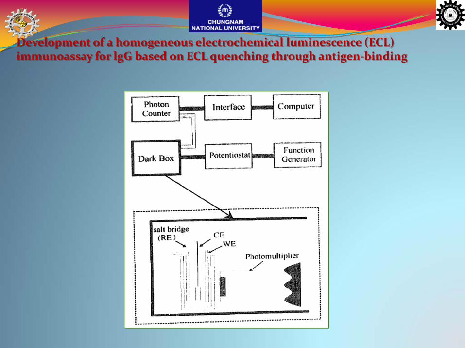
Development of a homogeneous electrochemical luminescence (ECL) immunoassay for lgG based on ECL quenching through antigen‐binding
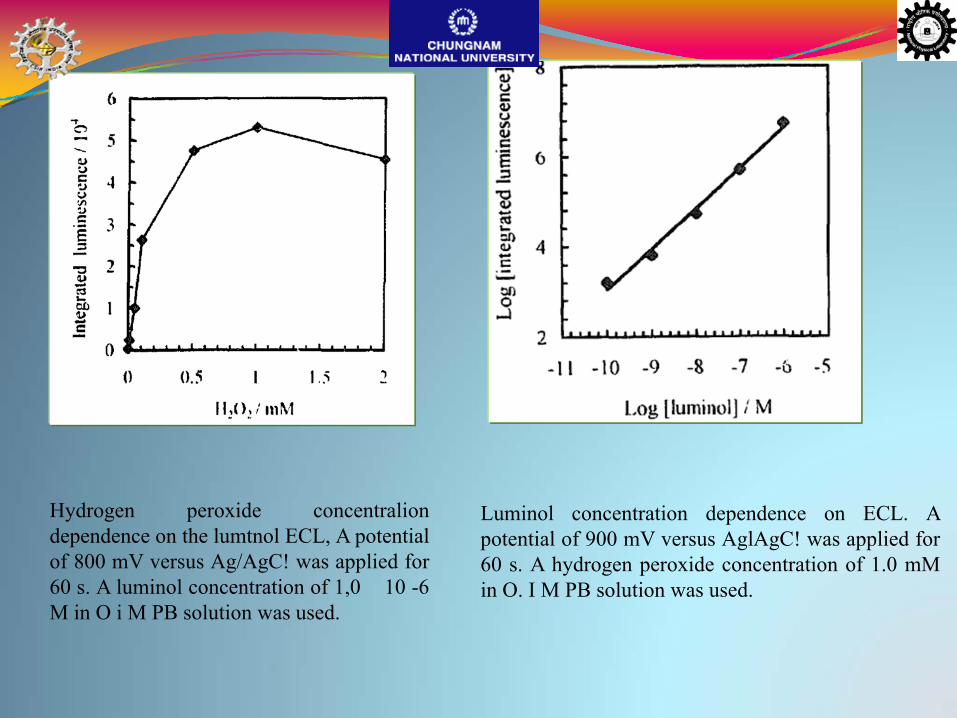
Hydrogen peroxide concentraliondependence on the lumtnol ECL, A potentialof 800 mV versus Ag/AgC! was applied for60 s. A luminol concentration of 1,0 10 -6M in O i M PB solution was used.
Luminol concentration dependence on ECL. Apotential of 900 mV versus AglAgC! was applied for60 s. A hydrogen peroxide concentration of 1.0 mMin O. I M PB solution was used.
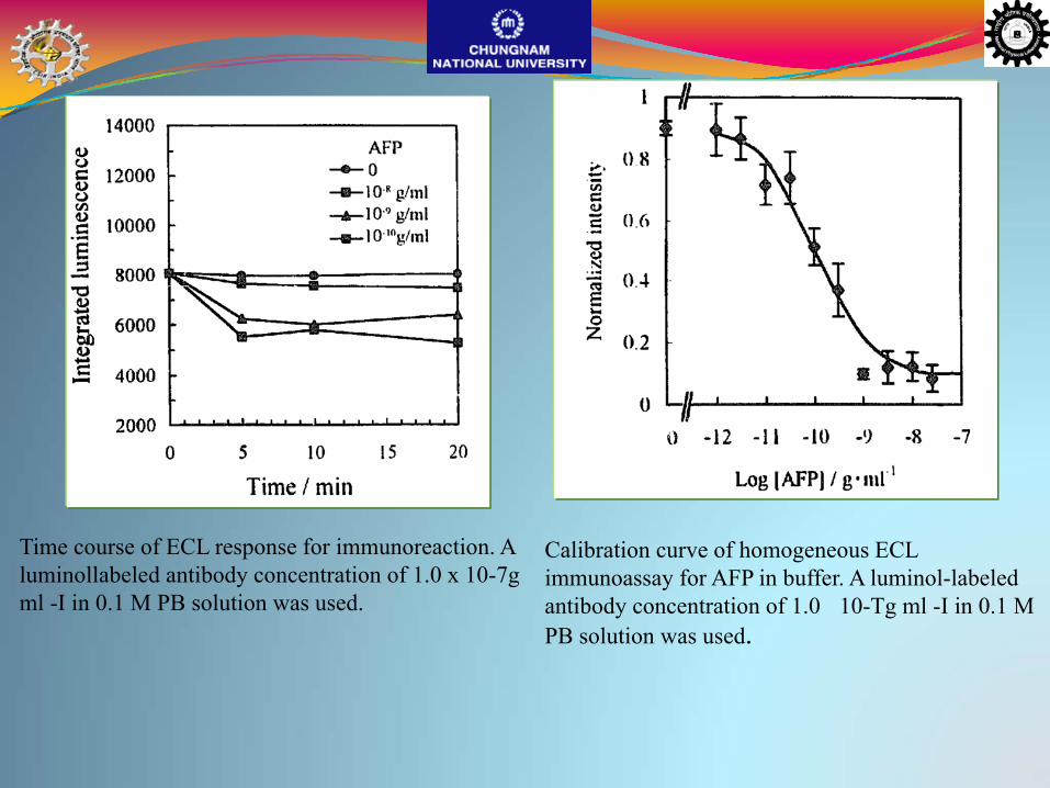
Time course of ECL response for immunoreaction. A luminollabeled antibody concentration of 1.0 x 10⁻⁷g ml -I in 0.1 M PB solution was used.
Calibration curve of homogeneous ECL immunoassay for AFP in buffer. A luminol-labeled antibody concentration of 1.0 10-Tg ml -I in 0.1 M PB solution was used.
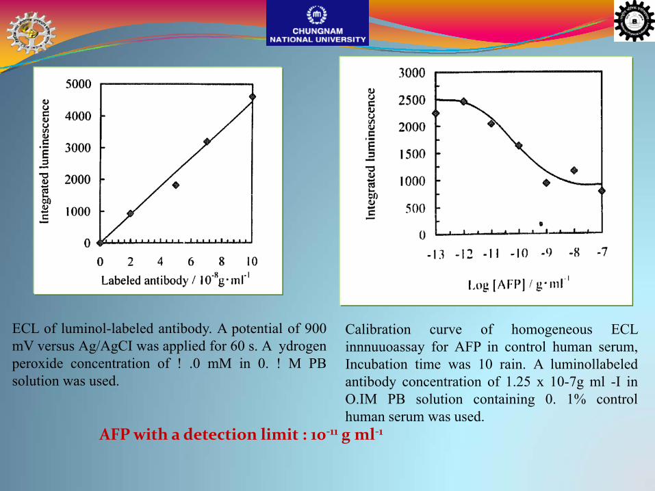
ECL of luminol-labeled antibody. A potential of 900mV versus Ag/AgCI was applied for 60 s. A ydrogenperoxide concentration of ! .0 mM in 0. ! M PBsolution was used.
Calibration curve of homogeneous ECLinnnuuoassay for AFP in control human serum,Incubation time was 10 rain. A luminollabeledantibody concentration of 1.25 x 10⁻⁷g ml -I inO.IM PB solution containing 0. 1% controlhuman serum was used.
AFP with a detection limit : 10‐11 g ml‐1
CdS Nanocrystal‐Based Electrochemiluminescence Biosensor for the Detection of Low‐Density Lipoprotein by Increasing Sensitivity with Gold Nanoparticles Amplification
Mercaptoacetic acid (RSH)‐capped CdS nanocrystals (NCs) is electrochemicallyreduced during potential scan and react with the coreactant S2O8
2‐ to generatestrong electrochemiluminescence (ECL) in aqueous solution
Based on the ECL, a novel non‐labeled ECL biosensor has been successfullyfabricated by a self‐assembly technique for LDL determination.
Guifen Jie, Bo Liu, Hongcheng Pan, Jun‐Jie Zhu,* and Hong‐Yuan Chen, Anal. Chem. 2007, 79, 5574‐5581
10/5/2009 87WCU Project,CNU,[email protected]
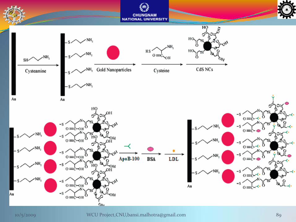
Fabrication of Gold Nanoparticles Based CL BiosensorThe gold nanoparticles first assembled onto a cysteamine monolayer on the gold
electrode surface
This gold nanoparticle‐covered electrode is treated with cysteine and then reacted
with CdS NCs to afford a CdS NC‐electrode
Finally, apoB‐100 (ligand of LDL receptor is covalently conjugated to the CdS NC‐
electrode
The resulting modified electrode is tested as ECL biosensor for LDL detection. The
LDL concentration was measured through the decrease in ECL intensity resulting
from the specific binding of LDL to apoB‐100
10/5/2009 88WCU Project,CNU,[email protected]
10/5/2009 89WCU Project,CNU,[email protected]
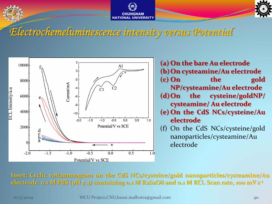
Inset: Cyclic voltammogram on the CdS NCs/cysteine/gold nanoparticles/cysteamine/Auelectrode. 0.1 M PBS (pH 7.4) containing 0.1 M K2S2O8 and 0.1 M KCl. Scan rate, 100 mV s‐1
(a) On the bare Au electrode(b)On cysteamine/Au electrode(c) On the gold
NP/cysteamine/Au electrode(d)On the cysteine/goldNP/
cysteamine/ Au electrode(e)On the CdS NCs/cysteine/Au
electrode(f) On the CdS NCs/cysteine/gold
nanoparticles/cysteamine/Auelectrode
Electrochemeluminescence intensity versus Potential
10/5/2009 90WCU Project,CNU,[email protected]
ECL Behaviors of the CdS NanocrystalsIt has been found that all the background ECL signals from the Auelectrode without CdS NCs are very low, indicating that thecysteamine, cysteine, and gold nanoparticles could not generate ECL.Thus, ECL is from the CdS NCs
However, ECL intensity of CdS NCs on the bare Au electrode isenhanced by 1.6 orders of magnitude on the gold nanoparticle‐modifiedelectrode, demonstrating that the gold nanoparticles amplify ECLsignal of CdS NC
10/5/2009 91WCU Project,CNU,[email protected]
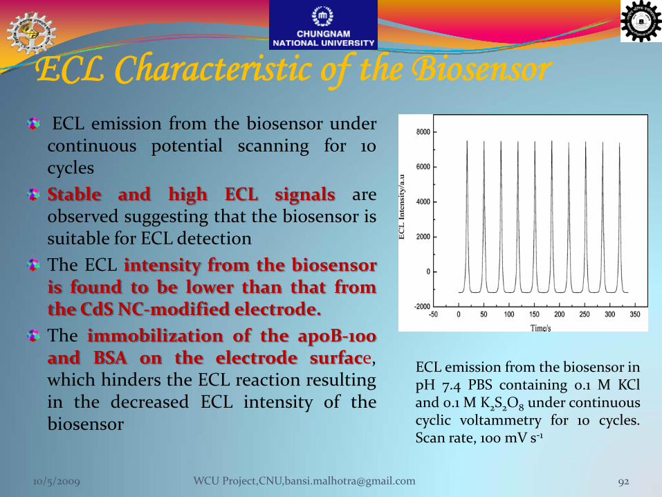
ECL Characteristic of the BiosensorECL emission from the biosensor undercontinuous potential scanning for 10cyclesStable and high ECL signals areobserved suggesting that the biosensor issuitable for ECL detectionThe ECL intensity from the biosensoris found to be lower than that fromthe CdS NC‐modified electrode.The immobilization of the apoB‐100and BSA on the electrode surface,which hinders the ECL reaction resultingin the decreased ECL intensity of thebiosensor
ECL emission from the biosensor inpH 7.4 PBS containing 0.1 M KCland 0.1 M K2S2O8 under continuouscyclic voltammetry for 10 cycles.Scan rate, 100 mV s‐1
10/5/2009 92WCU Project,CNU,[email protected]
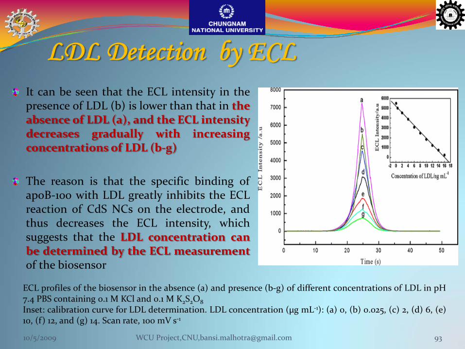
LDL Detection by ECL It can be seen that the ECL intensity in thepresence of LDL (b) is lower than that in theabsence of LDL (a), and the ECL intensitydecreases gradually with increasingconcentrations of LDL (b‐g)
The reason is that the specific binding ofapoB‐100 with LDL greatly inhibits the ECLreaction of CdS NCs on the electrode, andthus decreases the ECL intensity, whichsuggests that the LDL concentration canbe determined by the ECL measurementof the biosensor
ECL profiles of the biosensor in the absence (a) and presence (b‐g) of different concentrations of LDL in pH7.4 PBS containing 0.1 M KCl and 0.1 M K2S2O8Inset: calibration curve for LDL determination. LDL concentration (µg mL‐1): (a) 0, (b) 0.025, (c) 2, (d) 6, (e)10, (f) 12, and (g) 14. Scan rate, 100 mV s‐1
10/5/2009 93WCU Project,CNU,[email protected]

10/5/2009 WCU Project,CNU,[email protected] 94
•The ECL intensity decreased linearly with the LDL concentration from 0.025 to 16 ng mL‐1 with a detection limit of 0.006 ng mL‐1. • Linearity : 5210‐324C (unit of C is ng mL‐1), and the correlation coefficient : 0.9962.
•Higher plasma LDL levels can be detected by an appropriate dilution with pH 7.4 PBS.
• The relative errors were 1.6 and 2.5%, respectively. Thus, the proposed biosensor could be satisfactorily applied to the clinical determination of LDL levels in human plasma.
•The biosensor was used for 20 times, the analytical performances did not show an obvious decline, demonstrating that the sensing layers of the biosensor possessed good stability.
M.S.Thakur et al Biosensors and Bioelectronics 21 (2006) 1264–1271
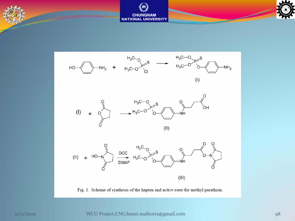
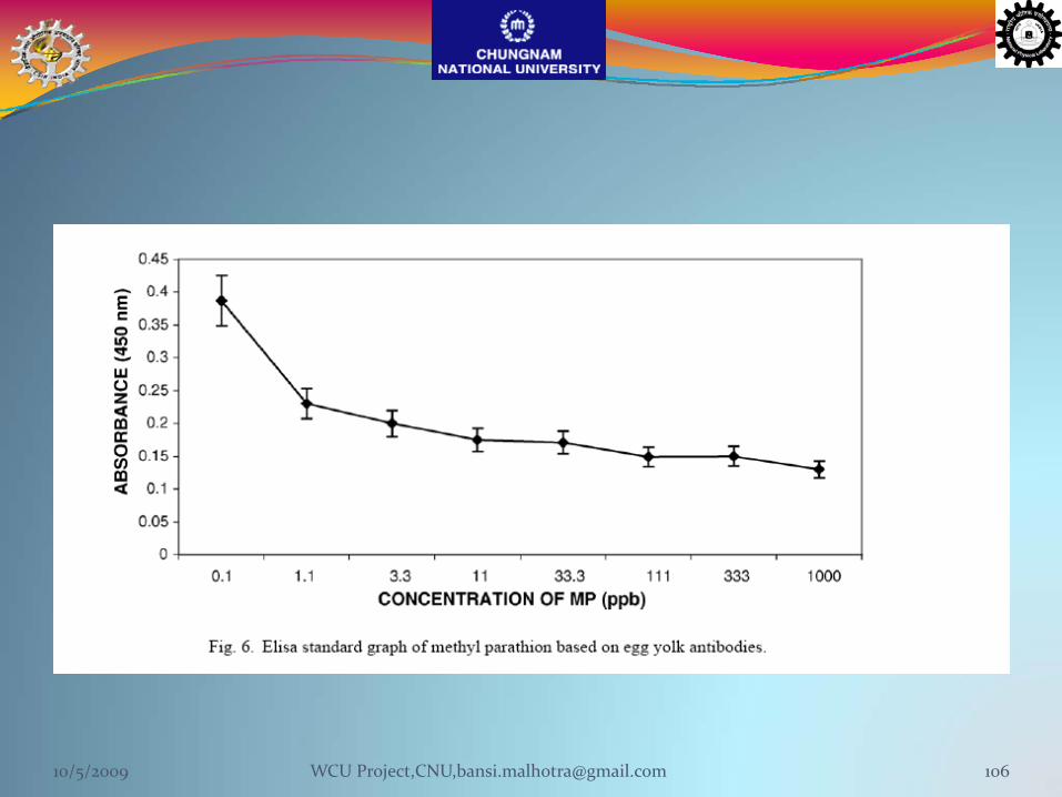
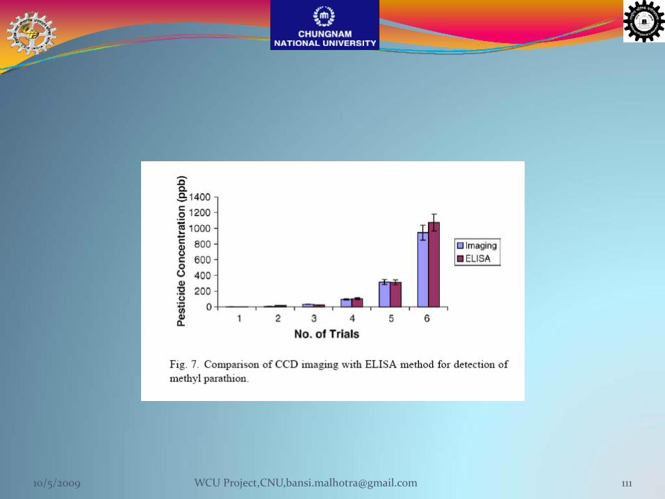
Detection of methyl parathion using immuno‐chemiluminescence based image analysis using charge coupled device
The commonly used analytical methods for pesticide analysis include liquid chromatography, gas chromatography and ELISA methods
These conventional methods are sensitive up to ppb level,time consuming, laborious, and require skilled techniciansand expensive instrumentation
10/5/2009 96WCU Project,CNU,[email protected]

Methyl parathion is an organophosphate (OP) insecticide that has caused many health problems ‐ particularly in developing countries ‐ since its introduction onto the market in the early 1950s. Methyl parathion was originally developed by the German pesticide company Bayer. It is a non‐systemic pesticide that kills pests by acting as a stomach poison.
It is used to control chewing and sucking insects in a wide range of crops, including cereals, fruit, vines, vegetables, ornamentals, cotton and field crops(1).
Methyl parathion is generally applied as a spray, mainly as an emulsifiable concentrate formulation. The recommended application rates are 15‐25g of active ingredient per 100 litres(2).
UsageThe basic manufacturers of methyl parathion are All India Medical Co (India), Bayer India, Bayer Mexico, Cheminova (Denmark), Rallis India and Sundat (Singapore)(3). In 1993, other production facilities existed in Brazil, the former East Germany, China and the former USSR. Although not used in the UK, methyl parathion is widely used throughout the world, and is registered in at least 38 countries(4).Information on global sales and production data are not widely available. For the financial year 1995‐96, India produced an estimated 2,200 tonnes of technical grade methyl parathion(5).Acute toxicityThe World Health Organisation classifies methyl parathion as a class Ia 'extremely hazardous' pesticide. It is highly toxic by inhalation and ingestion, and moderately toxic by dermal adsorption (it is also readily adsorbed through the skin). The oral LD50 in rats is 2.9 mg/kg, in mice is 33.1‐119.5 mg/kg, in rabbits is 19‐420 mg/kg and dogs is 50 mg/kg(9). The dermal rat LD50 is 44‐67mg/kg.
Like other organophosphate insecticides, methyl parathion is a cholinesterase When inhaled, the first adverse effects are a bloody or runny nose, coughing, chest discomfort and difficulty breathing. Skin contact may cause localised sweating and involuntary muscle contractions. Following exposure by any route, other systemic effects may begin within a few minutes, or be delayed for up to 12 hours. These may include pallor, nausea, vomiting, diarrhoea, abdominal cramps, headache, dizziness, eye pain, blurred vision,constriction or dilation of the pupils, tears, salivation, sweating and confusion. In severe cases, poisoning will affect the central nervous system, producing in‐coordination, slurred speech, loss of reflexes, weakness, fatigue, and eventual paralysis of the body extremities and respiratory muscles. Death may be caused by respiratory failure or cardiac arrest.
What is Methyl parathion?
10/5/2009 97
10/5/2009 98WCU Project,CNU,[email protected]
Electrochemical
Optical
Calorimetric
Piezoelectric
Amperometric
Potentiometric
Conductometric
Absorbance
Fluorescence
Luminescence
Reflectance
Scattering
MechanicalDevices10/5/2009 99WCU Project,CNU,[email protected]

Chemiluminescence based biosensor device being developed at CFTRI for pesticide analysis
10/5/2009 100WCU Project,CNU,[email protected]
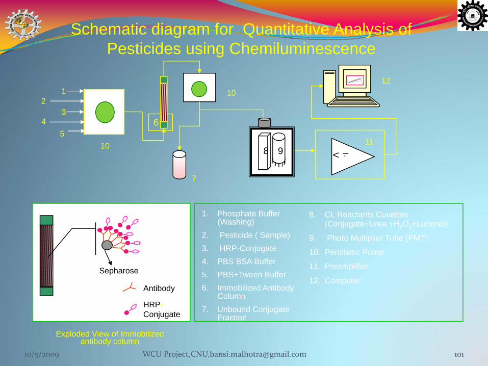
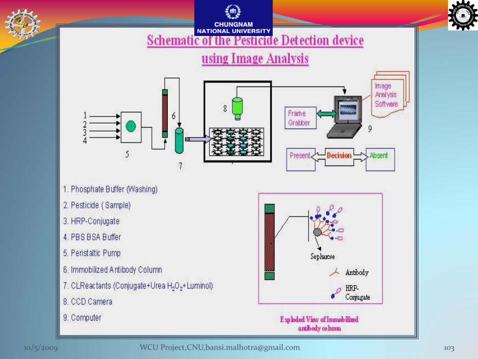
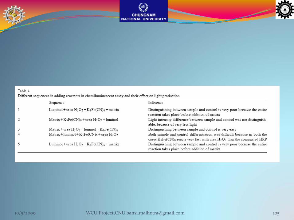
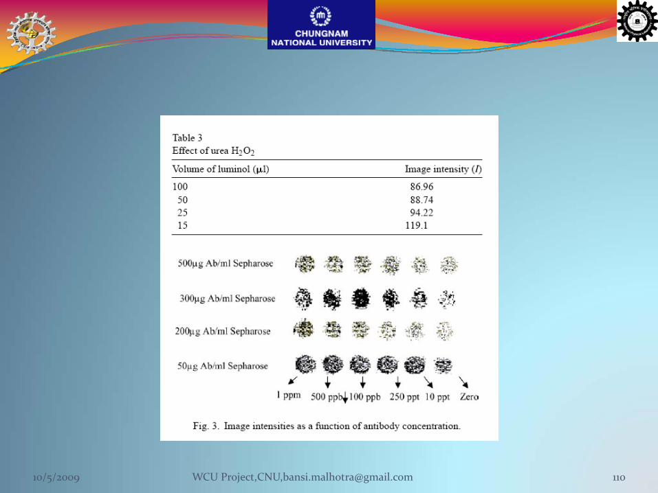
8. CL Reactants Cuvettee (Conjugate+Urea +H2O2+Luminol)
9. Photo Multiplier Tube (PMT)
10. Peristaltic Pump
11. Preamplifier
12. Computer
Schematic diagram for Quantitative Analysis of Pesticides using Chemiluminescence
Antibody
Exploded View of Immobilizedantibody column
Sepharose
HRP-Conjugate
7
6
12
34
5
10
10
11
12
11I-V8 9
1. Phosphate Buffer (Washing)
2. Pesticide ( Sample)3. HRP-Conjugate4. PBS BSA Buffer5. PBS+Tween Buffer6. Immobilized Antibody
Column7. Unbound Conjugate
Fraction
10/5/2009 101WCU Project,CNU,[email protected]
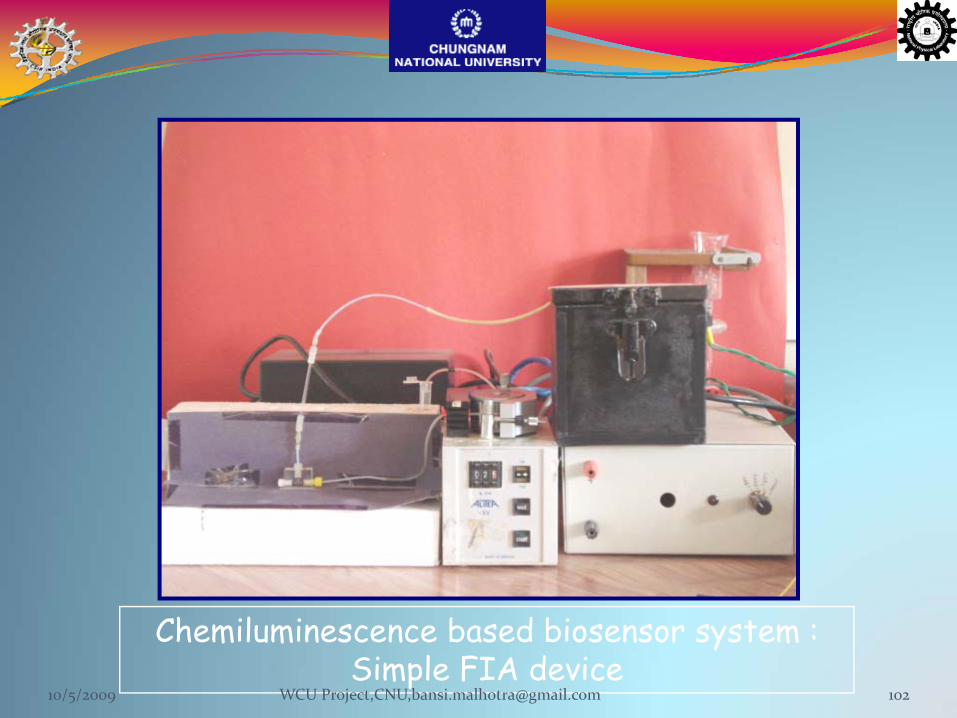
Chemiluminescence based biosensor system : Simple FIA device
10/5/2009 102WCU Project,CNU,[email protected]
10/5/2009 103WCU Project,CNU,[email protected]

10/5/2009 104WCU Project,CNU,[email protected]
10/5/2009 105WCU Project,CNU,[email protected]
10/5/2009 106WCU Project,CNU,[email protected]
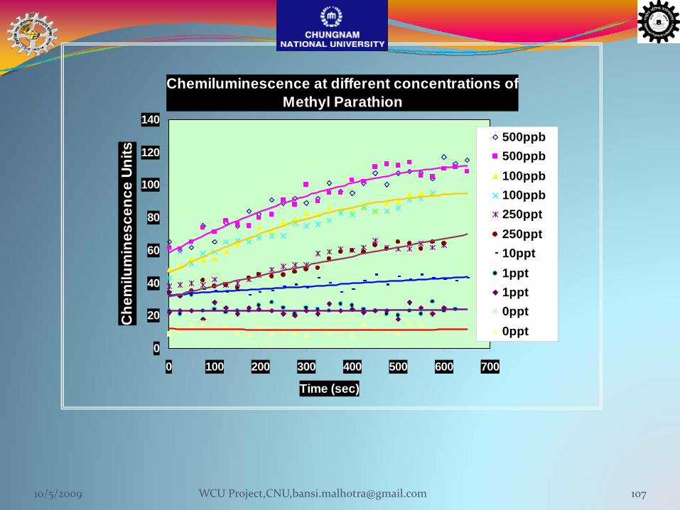
Chemiluminescence at different concentrations of Methyl Parathion
0
20
40
60
80
100
120
140
0 100 200 300 400 500 600 700
Time (sec)
Che
milu
min
esce
nce
Units
500ppb500ppb100ppb100ppb250ppt250ppt10ppt1ppt1ppt0ppt0ppt
10/5/2009 107WCU Project,CNU,[email protected]
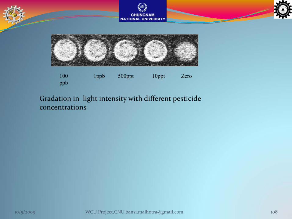
100ppb
1ppb 500ppt 10ppt Zero
Gradation in light intensity with different pesticide concentrations
10/5/2009 108WCU Project,CNU,[email protected]
10/5/2009 109WCU Project,CNU,[email protected]
10/5/2009 110WCU Project,CNU,[email protected]
10/5/2009 111WCU Project,CNU,[email protected]
Ultrasensitive detection of TNT in soil, water, using enhanced electrogenerated
chemiluminescence
Analytica Chimica Acta 632 (2009) 197–202
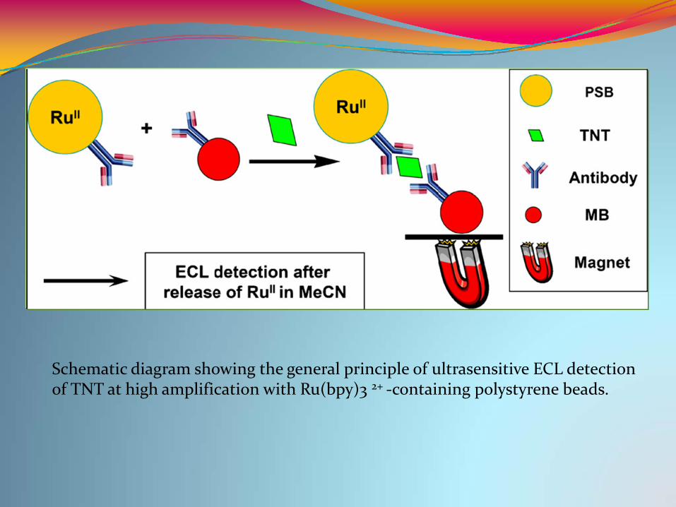
Schematic diagram showing the general principle of ultrasensitive ECL detection of TNT at high amplification with Ru(bpy)3 2+ ‐containing polystyrene beads.

(a) CV and ECL responses obtainedfrom a 2mm diameter Pt electrodeplaced in contact with a 0.10MTPrA–0.055MTFAA–0.10M(TBA)BF4MeCN reaction medium containingdissolved PSB < TNT >MBaggregates formed in the presence of1.0 ppt TNT. The scan rate used was50mVs−1. (b) ECL response shown in(a) as a function of time.
Relationship between the standard TNT concentration and the integratedECL intensity. Experimental conditions used were as in Fig. 2. For comparison, thebackground ECL that was obtained in the absence of added TNT is also included.
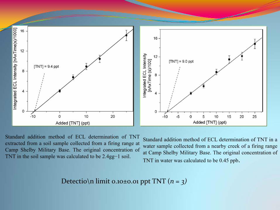
Standard addition method of ECL determination of TNTextracted from a soil sample collected from a firing range atCamp Shelby Military Base. The original concentration ofTNT in the soil sample was calculated to be 2.4gg−1 soil.
Standard addition method of ECL determination of TNT in awater sample collected from a nearby creek of a firing rangeat Camp Shelby Military Base. The original concentration ofTNT in water was calculated to be 0.45 ppb.
Detectio\n limit 0.10±0.01 ppt TNT (n = 3)
ConclusionsThis approach has the advantage of being more straightforward and avoids the need to use large, relatively "sticky" labelsCL method has numerous advantages such as sensitivity, rapid assay.The chemiluminescence (CL) based methods are very sensitive to detect desired analytes even at very low concentrations.There is possibility of robust and inexpensive instrumentation.It may become an attractive analytical tool in biosensorsLimitations
10/5/2009 116WCU Project,CNU,[email protected]
Key References (Week 6)Hypohalites and related oxidants as chemiluminescence reagents: a review
CdS Nanocrystal‐Based Electrochemiluminescence Biosensor for the Detection of Low‐Density Lipoprotein by Increasing Sensitivity with Gold Nanoparticle Amplification Guifen Jie, Bo Liu, Hongcheng Pan, Jun‐Jie Zhu,* and Hong‐Yuan Chen, Analytical Chemistry 2007, 79, 5574‐5581
Electrogenerated Chemiluminescence DNA Biosensor Based on Hairpin DNA Probe Labeled with Ruthenium Complex, Jing Zhang, Honglan Qi, Yan Li, Jia Yang, Qiang Gao, and Chengxiao Zhang, Analytical Chemistry, 2008, 80, 2888‐2894.
Detection of methyl parathion using immuno‐chemiluminescence based image analysis using charge coupled device, R.S. Chouhan, K. Vivek Babu , M.A. Kumar, N.S. Neeta , M.S. Thakur ,B.E. Amitha Rani , Akmal Pasha , N.G.K. Karanth , N.G. Karanth, Biosensors and Bioelectronics 21 (2006) 1264–1271
Electrochemical biosensor for pesticides based on acetylcholinesterase immobilized on polyaniline deposited on vertically assembled carbon nanotubes wrapped with ssDNA, Subramanian Viswanathan, Hanna Radecka, Jerzy Radecki ,Biosensors and Bioelectronics 24 (2009) 2772–2777.
Iron oxide‐chitosan hybrid nanobiocomposite based nucleic acid sensor for pyrethroid detection,AjeetKaushika,b, Pratima R. Solankib, Anees A. Ansari, Bansi D. Malhotra, Sharif Ahmad, Biochemical Engineering Journal,2009, 46 ,132–140
Label‐free ultra‐sensitive detection of atrazine based on nanomechanics, C Raman Suri, Jasdeep Kaur, SonuGandhi and Gajendra S Shekhawat, Nanotechnology 19 (2008) 235502 (6pp) (Week5)
10/5/2009 117WCU Project,CNU,[email protected]