antenna mount and rooftop analysis - west chester borough
TRANSCRIPT
Antenna Mount and Rooftop Analysis
FOR PHI West Chester DT
2 West Market Street West Chester, PA 19382
Chester County Lat/long: 39.959594, -75.604406
Mount Utilization: 68.7% Rooftop Utilization: ADEQUATE
March 9, 2021
Cellco Partnership d/b/a Verizon Wireless 512 Township Line Road
Building 2 Floor 3 Blue Bell, PA 19422
Prepared By
Maser Consulting 2000 Midlantic Drive, Suite 100
Mount Laurel, NJ 08054 856.797.0412
___________________________ Shawn M. Sacks, P.E.
Senior Project Manager Pennsylvania License No. PE082892
MC Project No. 19960016A Rev. 3
03/09/2021 Page 2 of 8
Prepared by VRD Checked by SMS
MC #: 19960016A Rev. 0
Objective: The objective of this report is to determine the capacity of the proposed antenna support mounts and existing rooftop at the subject facility for the final wireless telecommunications configuration, per the applicable codes and standards. Introduction: Maser Consulting has reviewed the following documents in completing this report:
Document Type Remarks Source
Lease Exhibit Maser Consulting Project #: 19960016A, Rev K Dated November 19, 2020
Maser Consulting
Radio Frequency Data Sheet (RFDS)
RFDS ID #: 499841 Dated October 26, 2020
Verizon Wireless
Site Visit April 11, 2019, June 6, 2019 and September 25, 2019 Maser Consulting HD Rooftop Mount Perfect Vision P/N PV-RFN12HD-B HD Perfect Vision Ballast Mount Site Pro 1 P/N RTP-14 Site Pro 1 Dual Mount Antenna Bracket
Quintel P/N AS-005246 Quintel
Codes, Standards and Loading: Jurisdictional adopted codes and standards:
Pennsylvania Uniform Construction Code, Incorporating the 2015 International Building Code Maser Consulting utilized the following codes and standards:
Structural Standards for Antenna Supporting Structures and Antennas and Small Wind Turbine Support Structures ANSI/TIA-222-H
o Ultimate Wind Speed – 114 mph (3-Second Gust) o Exposure Category – B o Risk Category – II o Topographic Factor, Kzt – 1.0 o Mean Base Elevation (AMSL) – 450.61’ o Ice Wind Speed – 40 mph (3-Second Gust) o Design Ice Thickness – 1.00”
03/09/2021 Page 3 of 8
Prepared by VRD Checked by SMS
MC #: 19960016A Rev. 0
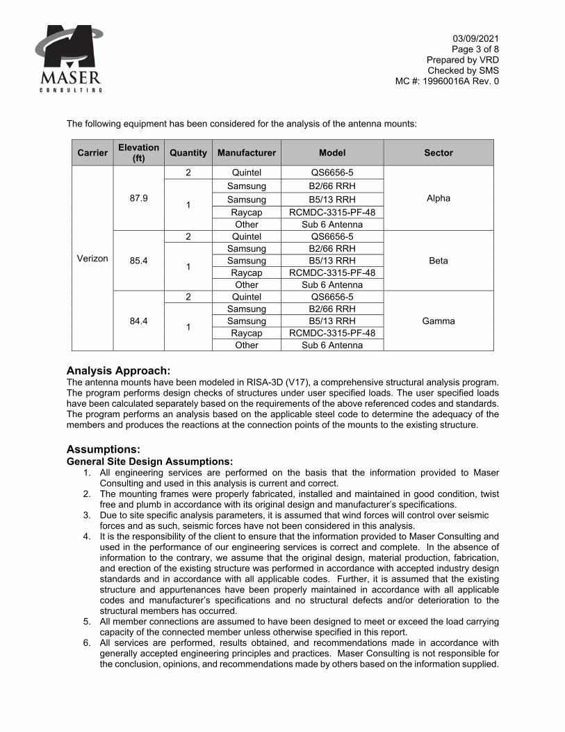
The following equipment has been considered for the analysis of the antenna mounts:
Carrier Elevation
(ft) Quantity Manufacturer Model Sector
Verizon
87.9
2 Quintel QS6656-5
Alpha 1
Samsung B2/66 RRH
Samsung B5/13 RRH Raycap RCMDC-3315-PF-48 Other Sub 6 Antenna
85.4
2 Quintel QS6656-5
Beta 1
Samsung B2/66 RRH Samsung B5/13 RRH Raycap RCMDC-3315-PF-48 Other Sub 6 Antenna
84.4
2 Quintel QS6656-5
Gamma 1
Samsung B2/66 RRH Samsung B5/13 RRH Raycap RCMDC-3315-PF-48 Other Sub 6 Antenna
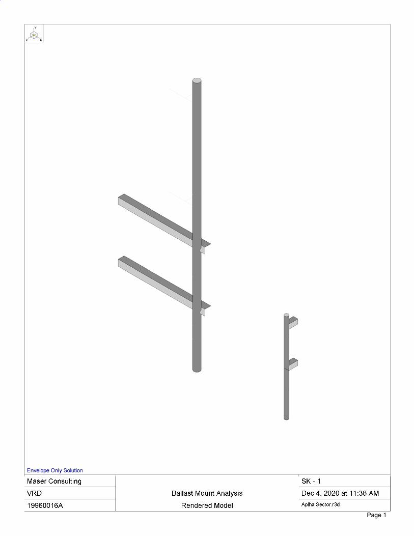
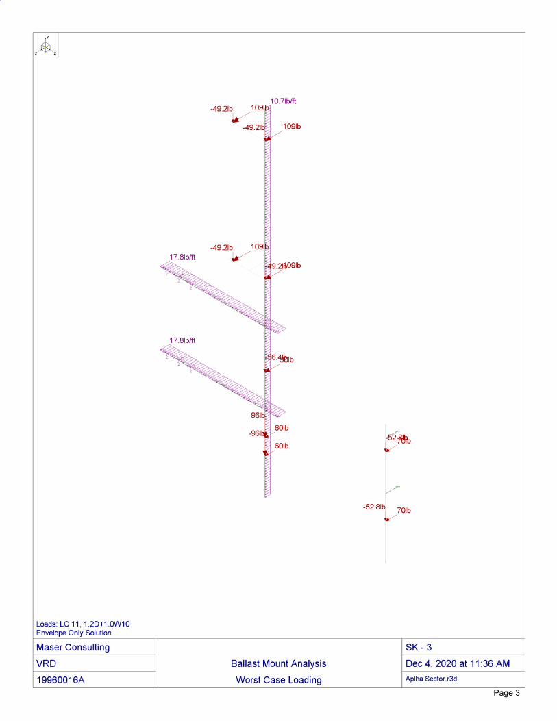
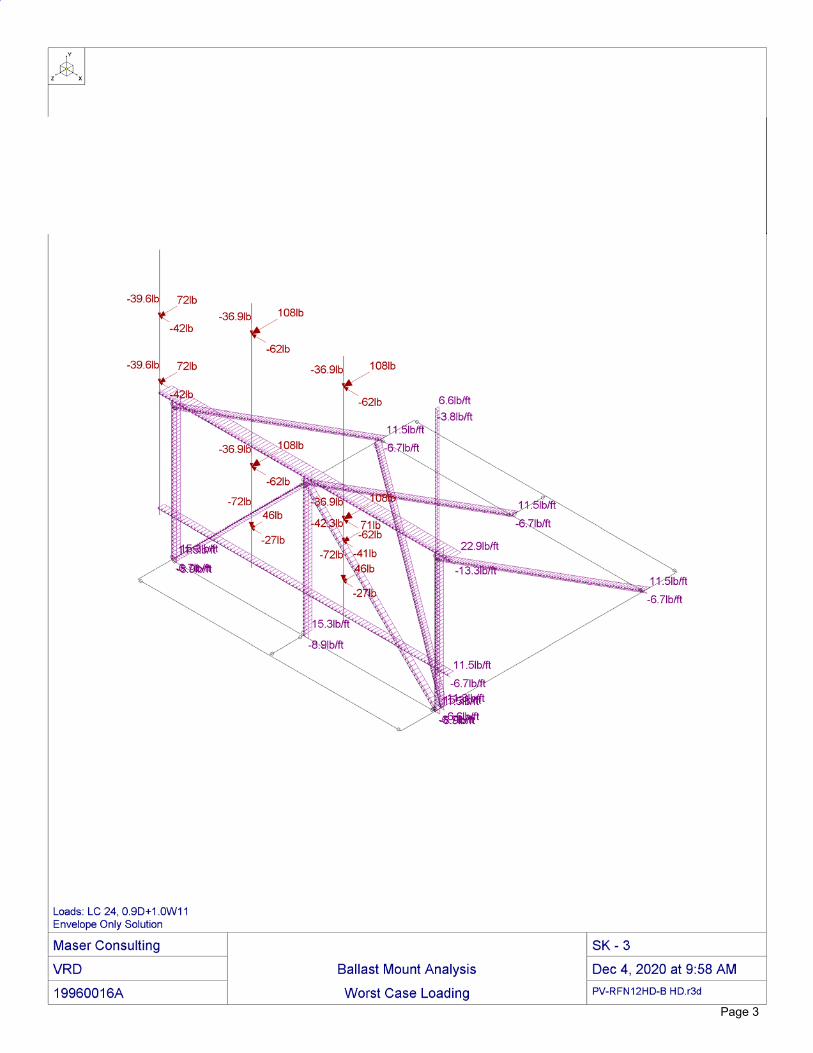
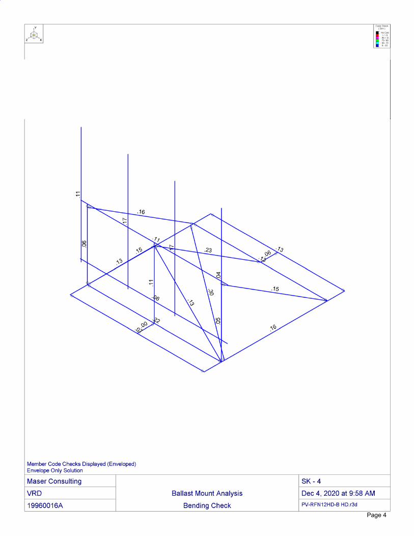
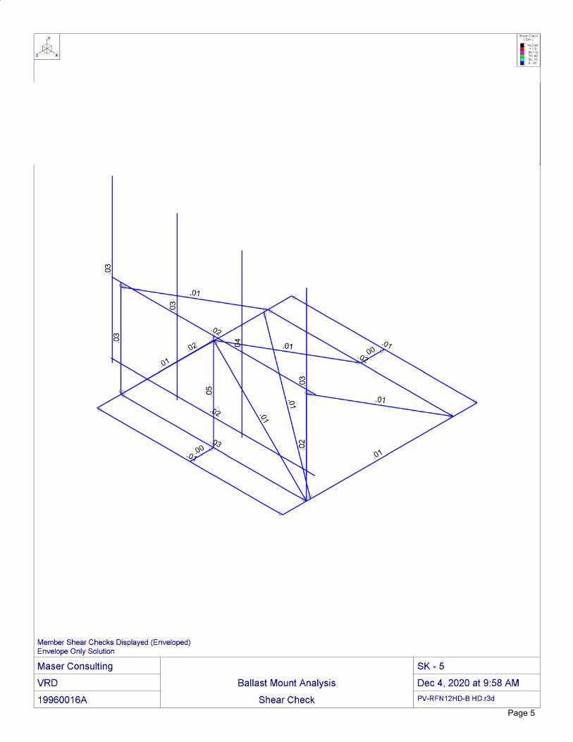
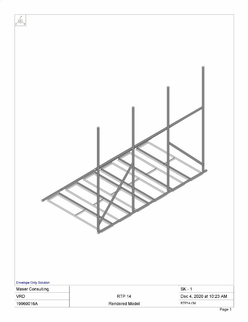
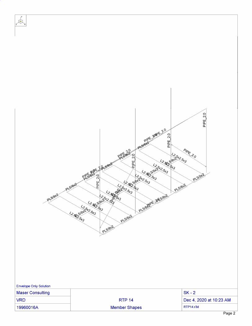
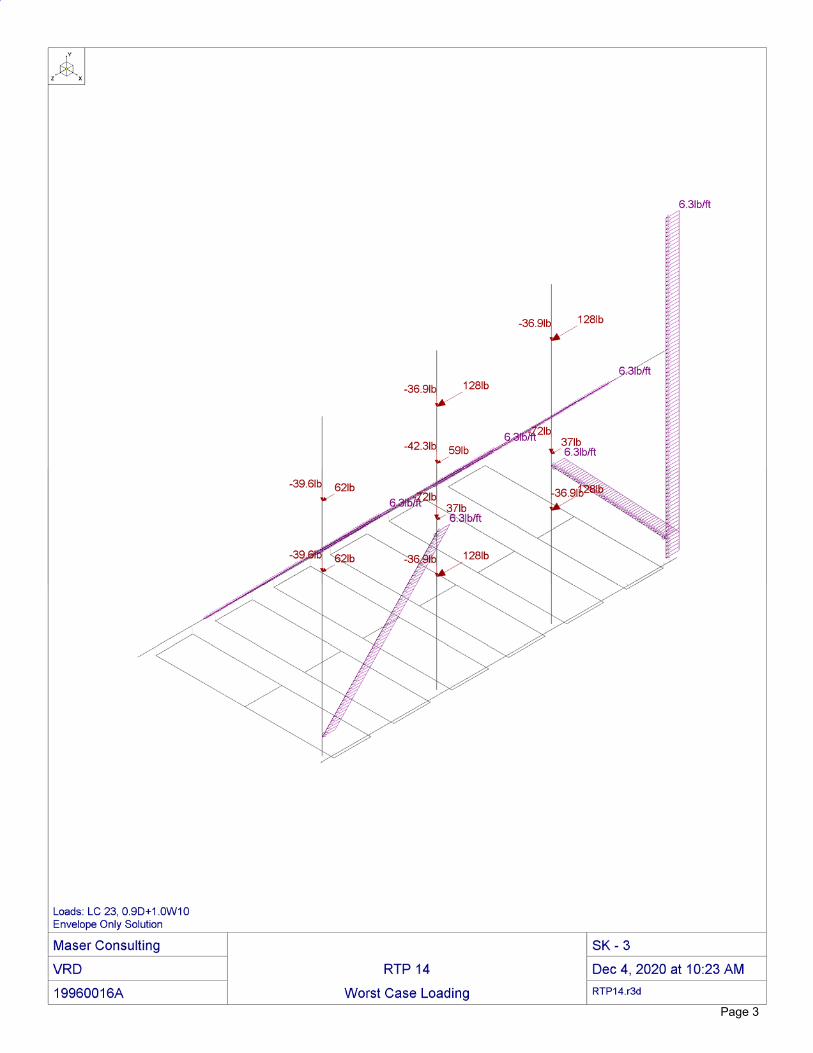
Analysis Approach: The antenna mounts have been modeled in RISA-3D (V17), a comprehensive structural analysis program. The program performs design checks of structures under user specified loads. The user specified loads have been calculated separately based on the requirements of the above referenced codes and standards. The program performs an analysis based on the applicable steel code to determine the adequacy of the members and produces the reactions at the connection points of the mounts to the existing structure. Assumptions: General Site Design Assumptions:
1. All engineering services are performed on the basis that the information provided to Maser Consulting and used in this analysis is current and correct.
2. The mounting frames were properly fabricated, installed and maintained in good condition, twist free and plumb in accordance with its original design and manufacturer’s specifications.
3. Due to site specific analysis parameters, it is assumed that wind forces will control over seismic forces and as such, seismic forces have not been considered in this analysis.
4. It is the responsibility of the client to ensure that the information provided to Maser Consulting and used in the performance of our engineering services is correct and complete. In the absence of information to the contrary, we assume that the original design, material production, fabrication, and erection of the existing structure was performed in accordance with accepted industry design standards and in accordance with all applicable codes. Further, it is assumed that the existing structure and appurtenances have been properly maintained in accordance with all applicable codes and manufacturer’s specifications and no structural defects and/or deterioration to the structural members has occurred.
5. All member connections are assumed to have been designed to meet or exceed the load carrying capacity of the connected member unless otherwise specified in this report.
6. All services are performed, results obtained, and recommendations made in accordance with generally accepted engineering principles and practices. Maser Consulting is not responsible for the conclusion, opinions, and recommendations made by others based on the information supplied.
03/09/2021 Page 4 of 8
Prepared by VRD Checked by SMS
MC #: 19960016A Rev. 0
Site Specific Assumptions and Design Parameters:
1. Structural Steel Grades used in this analysis are as follows, if applicable, unless otherwise noted in this analysis:
o Angle, Plate ASTM A36 (Gr. 36) o Pipe ASTM A53 (Gr. B-35) o Through Bolts ASTM A307 o U-Bolt SAE J429 Gr. 2
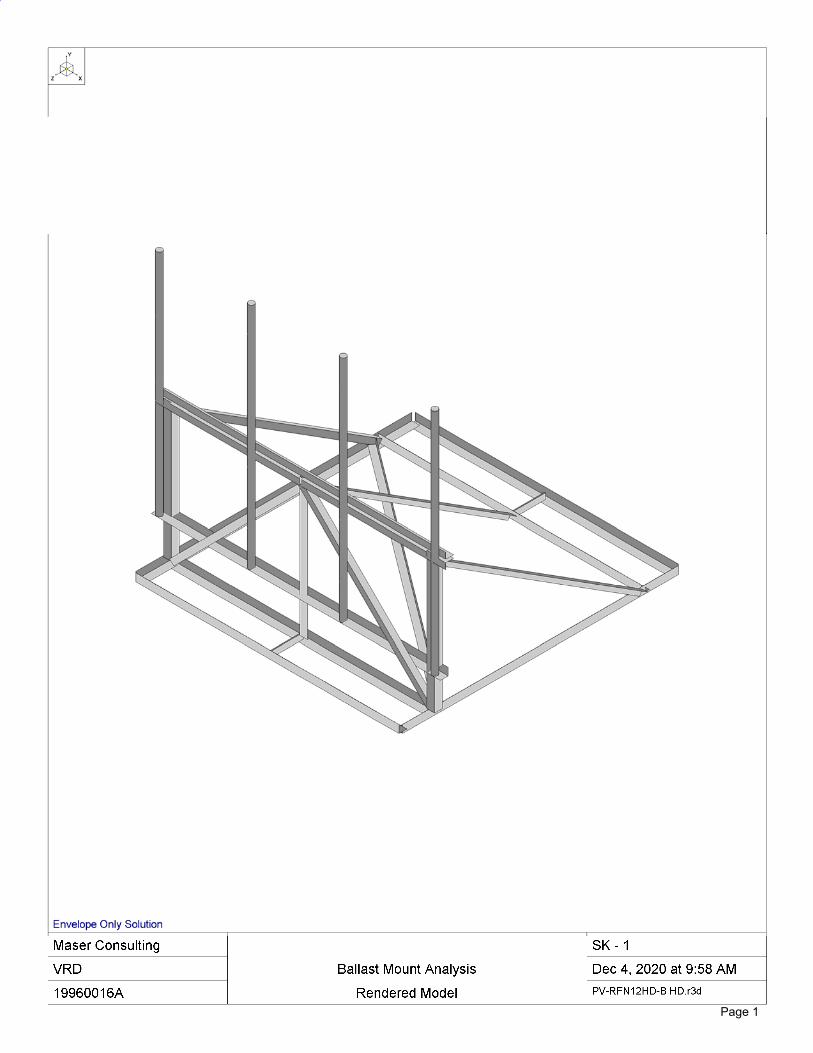
2. All proposed equipment locations are to be as depicted in the rendered diagram in Appendix A of this report. Any changes made to the proposed equipment locations will render this report invalid.
3. All abandoned posts interfering with the location of the ballast mounts are to be filed down to the existing flashing.
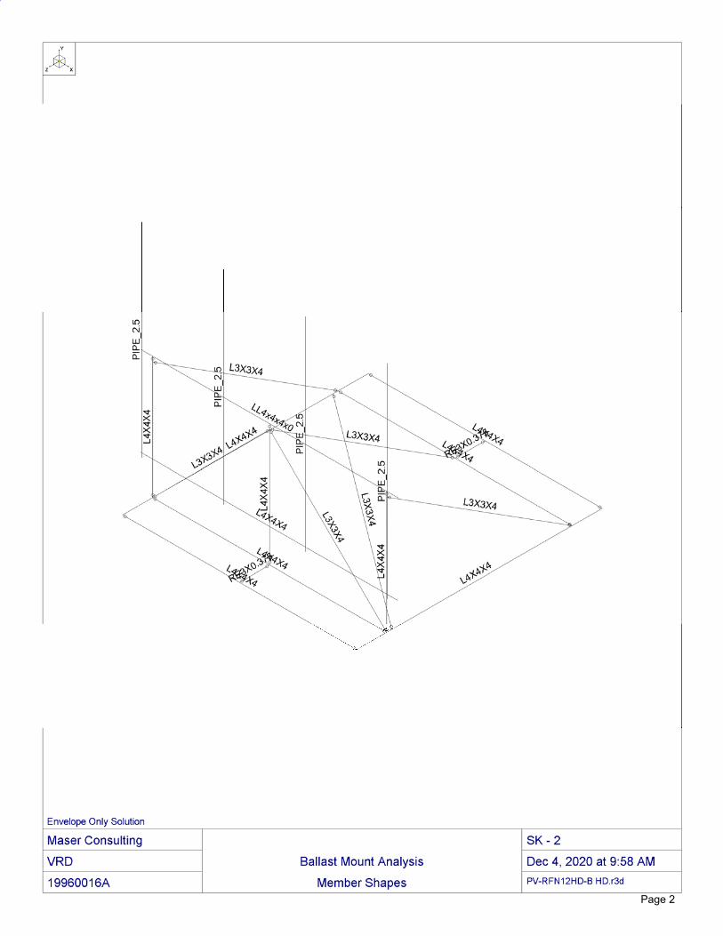
4. The existing roof is designed for a live load of 20 psf. 5. The proposed mount in Beta Sector is to be Perfect Vision HD Rooftop Mounts (P/N PV-RFN12HD-
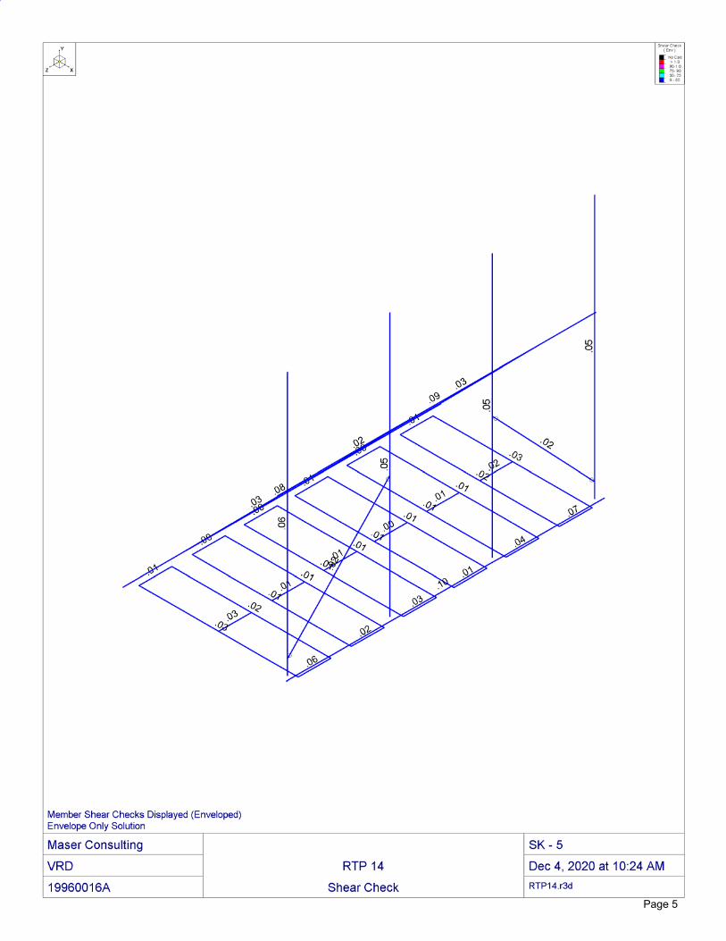
B HD) with four (4) 120” P2.5 STD mounting pipes. 6. The proposed mount in Gamma Sector is to be a Site Pro 1 Ballast Mount (P/N RTP-14) with four
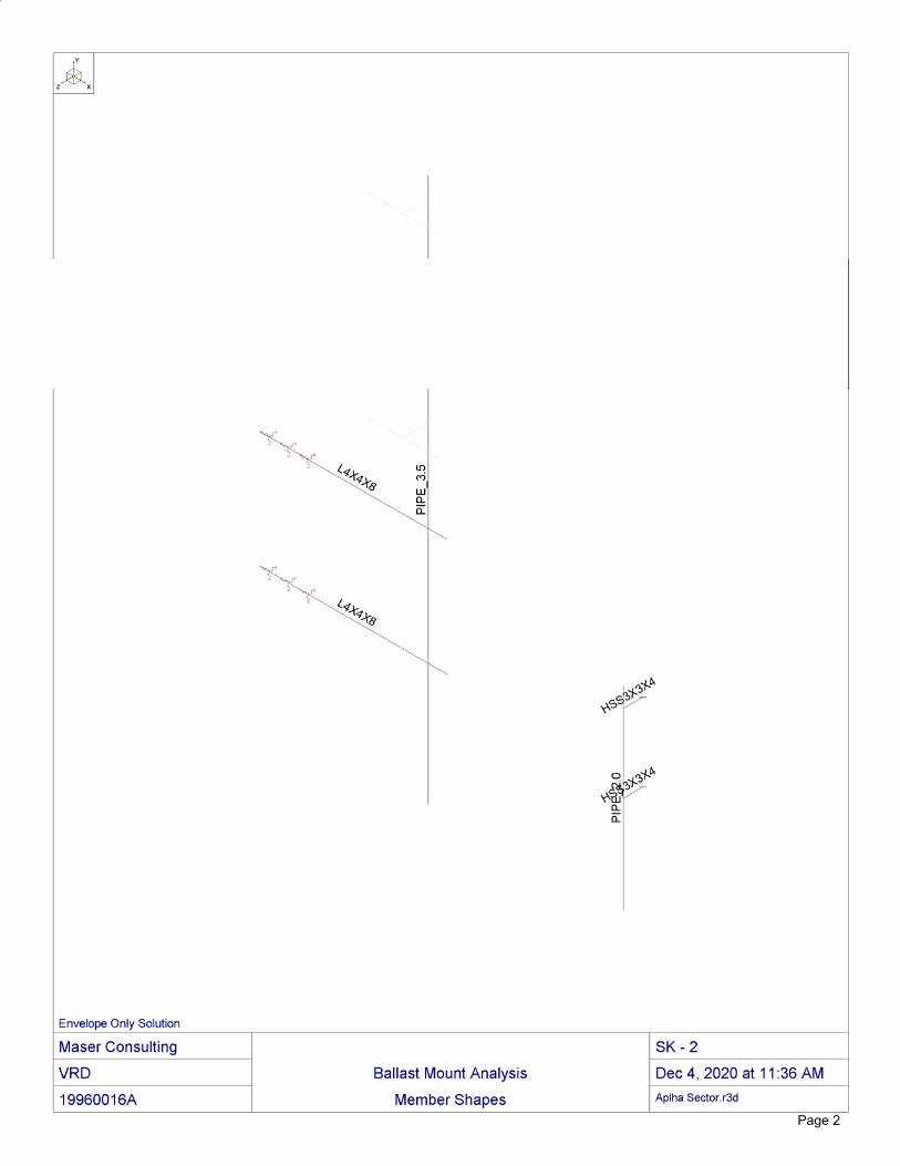
(4) 144” P2.0 STD mounting pipes. 7. The proposed corner mount in Alpha Sector is to consist of a 168” long P3.5 STD mounting pipe
with two (2) 60” L4x4x1/2 angles. The angles are to connect to the existing penthouse will with three (3) ½” dia. through bolts each and to the mounting pipe with two (2) U-bolts each. The penthouse wall in this location is assumed to be constructed of concrete.
8. The proposed flush mount in Alpha Sector is to utilize a 60” P2.0 STD mount pipe with 6” long HSS3x3x4 standoffs. The standoffs are to have plates welded on each end. The connection to the penthouse wall is to utilize through bolts that sandwich a minimum of two (2) studs (contractor to verify stud locations in field). See Construction Drawings for details. The penthouse wall in this location is assumed to be constructed of wood studs.
Discrepancies between in-field conditions and the assumptions listed above may render this analysis invalid unless explicitly approved by Maser Consulting. Calculations: Selected calculations and analysis output can be found in Appendix A of this report.
03/09/2021 Page 5 of 8
Prepared by VRD Checked by SMS
MC #: 19960016A Rev. 0
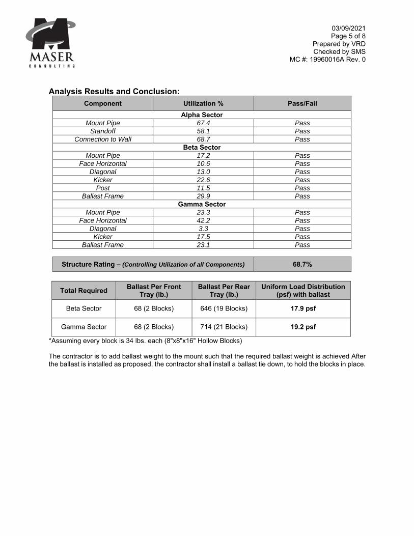
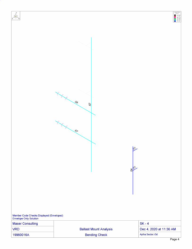
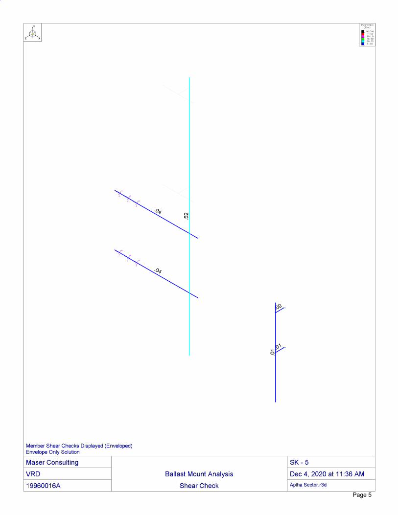
Analysis Results and Conclusion:
Component Utilization % Pass/Fail
Alpha Sector Mount Pipe 67.4 Pass
Standoff 58.1 Pass Connection to Wall 68.7 Pass
Beta Sector Mount Pipe 17.2 Pass
Face Horizontal 10.6 Pass Diagonal 13.0 Pass
Kicker 22.6 Pass Post 11.5 Pass
Ballast Frame 29.9 Pass Gamma Sector
Mount Pipe 23.3 Pass Face Horizontal 42.2 Pass
Diagonal 3.3 Pass Kicker 17.5 Pass
Ballast Frame 23.1 Pass
Structure Rating – (Controlling Utilization of all Components) 68.7%
Total Required Ballast Per Front
Tray (lb.) Ballast Per Rear
Tray (lb.) Uniform Load Distribution
(psf) with ballast
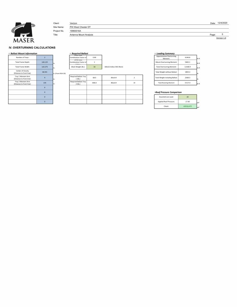
Beta Sector 68 (2 Blocks) 646 (19 Blocks) 17.9 psf
Gamma Sector 68 (2 Blocks) 714 (21 Blocks) 19.2 psf
*Assuming every block is 34 lbs. each (8"x8"x16" Hollow Blocks) The contractor is to add ballast weight to the mount such that the required ballast weight is achieved After the ballast is installed as proposed, the contractor shall install a ballast tie down, to hold the blocks in place.
03/09/2021 Page 6 of 8
Prepared by VRD Checked by SMS
MC #: 19960016A Rev. 0
Recommendation: The proposed mounting frames are SUFFICIENT for the final loading configuration. Maser Consulting has determined that since the uniform distributed load of 19.2 psf is less than the assumed live load, the existing rooftop is ADEQUATE for the final loading configuration. The increase in wind loading on the existing penthouse wall is negligible compared to the overall wind loading. Therefore, the penthouse wall is ADEQUATE for the final loading configuration. The conclusions reached by Maser Consulting in this evaluation are only applicable for the structural members supporting the Verizon telecommunications installation described herein. Maser Consulting reserves the right to amend this report if additional information regarding the members is provided. The conclusions reached by Maser Consulting in this report are only valid for the appurtenances listed in this report. Any change to the installation will require a revision to this structural analysis. We appreciate the opportunity to be of service on this project. If you should have any questions or require any additional information, please do not hesitate to call our office. Sincerely, Maser Consulting Shawn M. Sacks, P.E. Vincent DiGirolamo Senior Project Manager Senior Engineer R:\Projects\2019\19960000A\19960016A\Structural\Mount Analysis\Rev 2\Word\PHI West Chester DT.MA.Rev 2.docx

03/09/2021 Page 7 of 8
Prepared by VRD Checked by SMS
MC #: 19960016A Rev. 0
Disclaimer of Warranties:
The engineering services rendered by Maser Consulting in connection with this structural analysis are limited to a computer analysis of the antenna support mount and theoretical capacity of its main structural members. No allowance has been made for any damaged, bent, missing, loose, or rusted members or connections. Maser Consulting will accept no liability which may arise due to any deficiency in design, material, fabrication, erection, construction, or lack of maintenance. Maser Consulting has not performed a site visit of the antenna support mount to verify member sizes or equipment loading. Contractor should inspect the condition of the existing structure, antenna support mount and connections and notify Maser Consulting of any discrepancies or deficiencies before proceeding with installation. All services are performed, results obtained, and recommendations made in accordance with generally accepted engineering principles and practices. Maser Consulting is not responsible for the conclusion, opinions, and recommendations made by others based on the information supplied. The attached sketch is a schematic representation of the analyzed antenna support mount. The contractor shall be responsible for field verifying the existing conditions, proper fit, and clearances in the field. Any mention of structural modifications are reasonable estimates and should not be used as a construction document. Construction documents depicting the required modification are obtainable from Maser Consulting, but are beyond the scope of this report. Miscellaneous items such as antenna brackets, etc., have not been designed or detailed as part of our work. We recommend that material of suitable size and strength be purchased from a reputable manufacturer. Maser Consulting makes no warranties, expressed and/or implied, in connection with this report and disclaims any liability arising from material, fabrication, and erection of the antenna support mount. Maser Consulting will not be responsible whatsoever for, or on account of, consequential or incidental damages sustained by any person, firm, or organization as a result of any data or conclusions contained in this report.
03/09/2021 Page 8 of 8
Prepared by VRD Checked by SMS
MC #: 19960016A Rev. 0
Appendix A
Client: Verizon Date:
Site Name: PHI West Chester DT
Project No. 19960016A
Title: Antenna Mount Analysis Page:
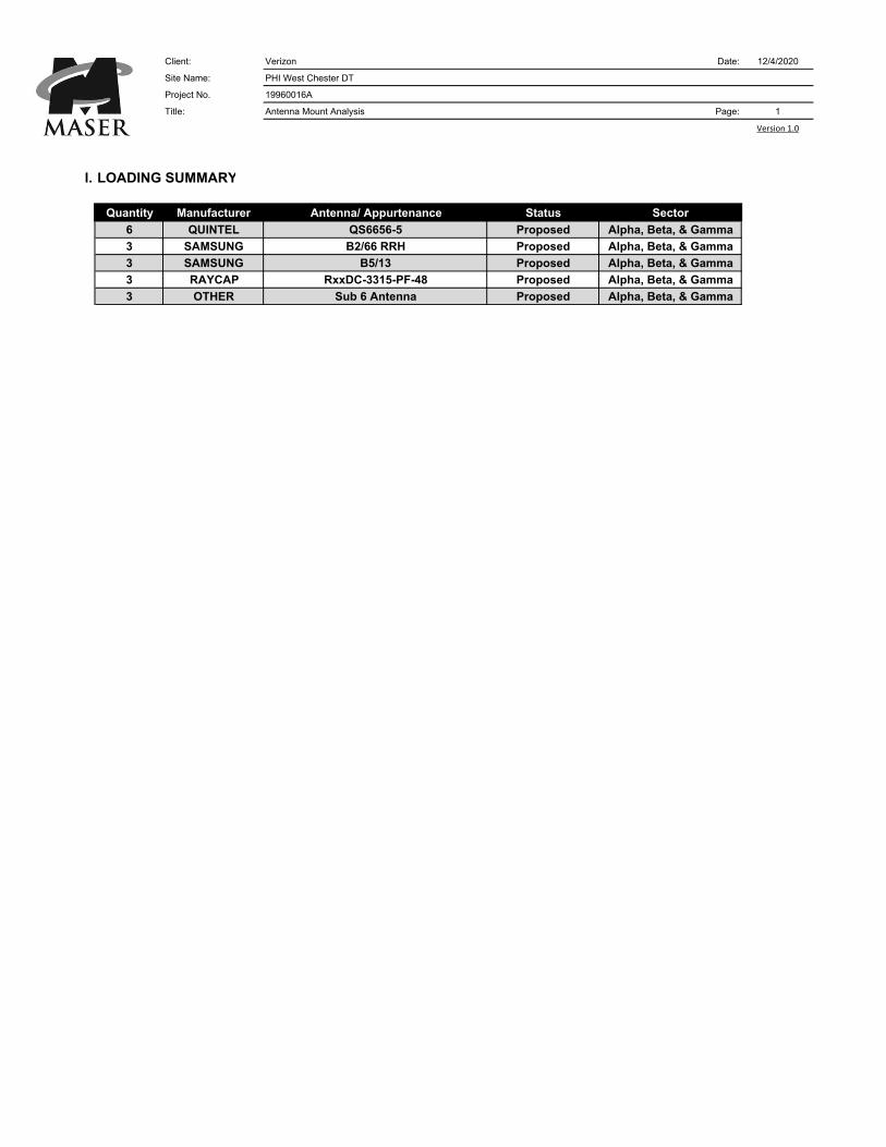
l. LOADING SUMMARY
Quantity Manufacturer Antenna/ Appurtenance Status Sector
6 QUINTEL QS6656-5 Proposed Alpha, Beta, & Gamma
3 SAMSUNG B2/66 RRH Proposed Alpha, Beta, & Gamma
3 SAMSUNG B5/13 Proposed Alpha, Beta, & Gamma
3 RAYCAP RxxDC-3315-PF-48 Proposed Alpha, Beta, & Gamma
3 OTHER Sub 6 Antenna Proposed Alpha, Beta, & Gamma
Analysis completed for Alpha Sector
Quantity Manufacturer Antenna/ Appurtenance Status
2 QUINTEL QS6656-5 Proposed
1 SAMSUNG B2/66 RRH Proposed
1 SAMSUNG B5/13 Proposed
1 RAYCAP RxxDC-3315-PF-48 Proposed
1 OTHER Sub 6 Antenna Proposed
Version 1.0
12/4/2020
1

Client: Verizon Date: 12/4/2020
Site Name: PHI West Chester DT
Project No. 19960016A
Title: Antenna Mount Analysis Page: 2
Version 1.0
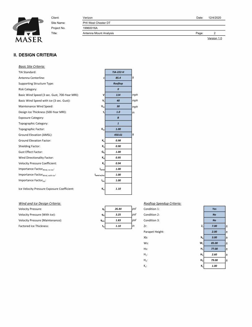
Il. DESIGN CRITERIA
Basic Site Criteria: Seismic Data:
TIA Standard: TIA‐222‐H Ss: ‐
Antenna Centerline: z 87.9 ft S1: ‐
Supporting Structure Type: Rooftop Structure Height: 250.00 ft
Risk Category: ll R: 2.0
Basic Wind Speed (3 sec. Gust, 700‐Year MRI): V 114 mph As: 3.00
Basic Wind Speed with ice (3 sec. Gust): Vi 40 mph Importance FactorSeismic: 1.00
Maintenance Wind Speed: Vm 30 mph Site Class: D
Design Ice Thickness (500‐Year MRI): ti 1.0 in Fa: 1.20
Exposure Category: B SDS: 0.00
Topographic Category: 1 Cs: 0.00
Topographic Factor: Kzt 1.00 1
Ground Elevation (AMSL): 450.61 ft
Ground Elevation Factor: Ke 0.98 0.9838
Shielding Factor: Ka 0.90 Is the structure base on a building? Yes
Gust Effect Factor: Gh 1.00 Is the Structure bracketed to a building? No
Wind Directionality Factor: Kd 0.95
Velocity Pressure Coefficient: Kz 0.95
Importance FactorWind, no ice: Iwind 1.00
Importance FactorWind, with ice: Iwind w/ice 1.00 Seismic Multipliers:
Importance FactorIce: Iice 1.00 Vertical Seismic Multiplier: 0.000
Lateral Seismic Multiplier: 0.000
Wind and Ice Design Criteria: Rooftop Speedup Criteria:
Velocity Pressure: qz 26.66 psf Condition 1: Yes
Velocity Pressure (With Ice): qzi 3.28 psf Condition 2: No
Velocity Pressure (Maintenance): qzm 1.85 psf Condition 3: No
Factored Ice Thickness: tiz 1.10 in Zr: Zr 7.00 ft
Parapet Height: 2.00 ft
Grating Loading: Xb: Xb 3.00 ft
Grating Type: ‐ Ws: Ws 85.00 ft
Grating Self Weight: ‐ psf Hs: Hs 77.00 ft
Grating Ice Weight: 10.3 psf H1: H1 2.60 ft
H2: H2 79.00 ft
Ks: Ks 1.00
ft
Seismic Info for Telecom Support Structures Attached
to Buildings:
Ice Velocity Pressure Exposure Coefficient: 1.10Kiz
0.00Max elev. along structure @ attachment to
building (base of structure = 0'):
Client: Verizon Date: 12/4/2020
Site Name: PHI West Chester DT
Project No. 19960016A
Title: Antenna Mount Analysis Page: 3
Version 1.0
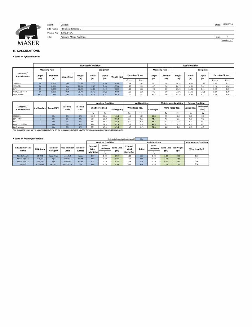
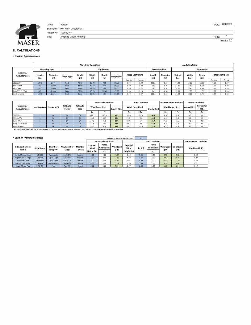
IlI. CALCULATIONS
▪ Load on Appurtenances
Ca Front Ca Side Ca Front Ca Side
QS6656‐5 0.0 0.000 Rect 72.00 12.00 9.60 80.60 1.36 1.42 0.0 0.0 74.21 14.21 11.81 1.32 1.37
B2/66 RRH 0.0 0.000 Rect 22.00 12.10 7.40 80.00 1.20 1.22 0.0 0.0 24.21 14.31 9.61 1.20 1.20
B5/13 0.0 0.000 Rect 22.00 12.10 7.40 80.00 1.20 1.22 0.0 0.0 24.21 14.31 9.61 1.20 1.20
RxxDC‐3315‐PF‐48 0.0 0.000 Rect 25.70 15.70 10.30 47.00 1.20 1.20 0.0 0.0 27.91 17.91 12.51 1.20 1.20
Sub 6 Antenna 60.0 2.375 Rect 35.12 16.06 5.51 87.10 1.20 1.37 62.2 4.6 37.33 18.27 7.72 1.20 1.30
Vertical (lbs.)Horizontal
(lbs.)
FN FT FN FT FN FT EV EHQS6656‐5 2 No 0% 0% 108.4 90.6 40.3 15.9 13.7 68.6 7.5 6.3 0.0 0.0
B2/66 RRH 1 No 0% 0% 59.1 36.8 80.0 9.5 6.5 41.5 4.1 2.5 0.0 0.0
B5/13 1 No 0% 0% 59.1 36.8 80.0 9.5 6.5 41.5 4.1 2.5 0.0 0.0
RxxDC‐3315‐PF‐48 1 No 0% 0% 89.6 58.8 47.0 13.7 9.7 62.3 6.2 4.1 0.0 0.0
Sub 6 Antenna 2 No 0% 0% 69.2 40.4 43.6 10.9 8.2 37.9 4.8 2.8 0.0 0.0
* ALL CALCULATED LOADS ARE PER MOUNTING BRACKET. TO GET THE TOTAL EQUIPMENT LOAD, MULTIPLY THE INDIVIDUAL LOADS BY THE NUMBER OF BRACKETS
▪ Load on Framing Members Optimize Ca Factors by Member Length? No
Ca Ca
Standoff Angle L4X4X8 Equal Angle L4x4x1/2 Square 4.00 2.00 17.77 6.21 5.66 2.00 3.39 9.11
Mount Pipe 3.0 PIPE_3.5 Pipe Pipe 3.5 Round 4.00 1.20 10.66 6.21 4.00 1.20 2.04 6.88
Mount Pipe 2.0 PIPE_2.0 Pipe Pipe 2.0 Round 2.38 1.20 0.00 4.58 2.38 1.20 0.00 4.69
Standoff HSS3X3X4 Rect. HSS HSS3X3X1/4 HSS 3.00 1.25 8.33 5.21 4.24 1.25 1.78 7.20
Wind Load (plf)
Gravity (lbs.)Wind Force (lbs.)
Non‐Iced Condition
Wind Load
(plf)
Ice Weight
(plf)
Force
Coefficient
Force
CoefficientExposed
Wind
Height (in)
Wind Load
(plf)
Exposed
Wind
Height (in)
DC (in)
Gravity (lbs.)Wind Force (lbs.)Wind Force (lbs.)
Non‐Iced Condition
RISA Section Set
NameRISA Shape
Member
Category
AISC Member
Label
Member
Surface
Antenna/
Appurtenance Length
(in)
Diameter
(in)Shape Type
Height
(in)
Antenna/
Appurtenance# of Brackets Turned 90°?
% Shield
Front
% Shield
Side
Maintenance Condition
Diameter
(in)
Mounting Pipe Equipment Mounting Pipe Equipment
Force CoefficientForce Coefficient Length
(in)
Iced Condition Maintenance Condition Seismic Condition
Iced Condition
Iced ConditionNon‐Iced Condition
Width
(in)
Depth
(in)Weight (lbs)
Height
(in)
Width
(in)
Depth
(in)
1.23
0.74
0.00
0.58
Client: Verizon Date:Site Name: PHI West Chester DTProject No. 19960016A
Title: Antenna Mount Analysis Page:
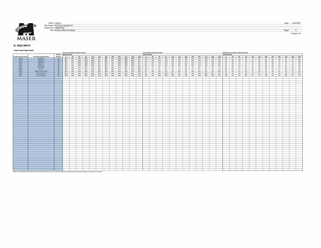
IV. RISA INPUT
▪ Joint Load Input DataNon‐Iced Condition, Wind Force (lbs.) Iced Condition, Wind Force (lbs.) Maintenance Condition, Wind Force (lbs.)
Global Azimuth Global Azimuth Global Azimuth
0 30 60 90 120 150 180 210 240 270 300 330 0 30 60 90 120 150 180 210 240 270 300 330 0 30 60 90 120 150 180 210 240 270 300 330
N518 QS6656‐5 90 90.6 95.1 103.9 108.4 103.9 95.1 90.6 95.1 103.9 108.4 103.9 95.1 13.7 14.3 15.3 15.9 15.3 14.3 13.7 14.3 15.3 15.9 15.3 14.3 6.3 6.6 7.2 7.5 7.2 6.6 6.3 6.6 7.2 7.5 7.2 6.6
N519 QS6656‐5 90 90.6 95.1 103.9 108.4 103.9 95.1 90.6 95.1 103.9 108.4 103.9 95.1 13.7 14.3 15.3 15.9 15.3 14.3 13.7 14.3 15.3 15.9 15.3 14.3 6.3 6.6 7.2 7.5 7.2 6.6 6.3 6.6 7.2 7.5 7.2 6.6
N520 QS6656‐5 90 90.6 95.1 103.9 108.4 103.9 95.1 90.6 95.1 103.9 108.4 103.9 95.1 13.7 14.3 15.3 15.9 15.3 14.3 13.7 14.3 15.3 15.9 15.3 14.3 6.3 6.6 7.2 7.5 7.2 6.6 6.3 6.6 7.2 7.5 7.2 6.6
N521 QS6656‐5 90 90.6 95.1 103.9 108.4 103.9 95.1 90.6 95.1 103.9 108.4 103.9 95.1 13.7 14.3 15.3 15.9 15.3 14.3 13.7 14.3 15.3 15.9 15.3 14.3 6.3 6.6 7.2 7.5 7.2 6.6 6.3 6.6 7.2 7.5 7.2 6.6
N522 B2/66 RRH 90 36.8 42.4 53.5 59.1 53.5 42.4 36.8 42.4 53.5 59.1 53.5 42.4 6.5 7.2 8.7 9.5 8.7 7.2 6.5 7.2 8.7 9.5 8.7 7.2 2.5 2.9 3.7 4.1 3.7 2.9 2.5 2.9 3.7 4.1 3.7 2.9
N509 B5/13 90 36.8 42.4 53.5 59.1 53.5 42.4 36.8 42.4 53.5 59.1 53.5 42.4 6.5 7.2 8.7 9.5 8.7 7.2 6.5 7.2 8.7 9.5 8.7 7.2 2.5 2.9 3.7 4.1 3.7 2.9 2.5 2.9 3.7 4.1 3.7 2.9
N524 RxxDC‐3315‐PF‐48 90 58.8 66.5 81.9 89.6 81.9 66.5 58.8 66.5 81.9 89.6 81.9 66.5 9.7 10.7 12.7 13.7 12.7 10.7 9.7 10.7 12.7 13.7 12.7 10.7 4.1 4.6 5.7 6.2 5.7 4.6 4.1 4.6 5.7 6.2 5.7 4.6
N38 Sub 6 Antenna 90 40.4 47.6 62.0 69.2 62.0 47.6 40.4 47.6 62.0 69.2 62.0 47.6 8.2 8.9 10.2 10.9 10.2 8.9 8.2 8.9 10.2 10.9 10.2 8.9 2.8 3.3 4.3 4.8 4.3 3.3 2.8 3.3 4.3 4.8 4.3 3.3
N39 Sub 6 Antenna 90 40.4 47.6 62.0 69.2 62.0 47.6 40.4 47.6 62.0 69.2 62.0 47.6 8.2 8.9 10.2 10.9 10.2 8.9 8.2 8.9 10.2 10.9 10.2 8.9 2.8 3.3 4.3 4.8 4.3 3.3 2.8 3.3 4.3 4.8 4.3 3.3
Note: Azimuths determined with the mount face parallel with z‐axis in model as 0 degrees and sequential orientations clockwise in 30 degree increments.
Associated AppurtenanceLoaded Joints by Name
Version 1.0
12/4/2020
6
Relative
Azimuth
Page 1
Page 2
Page 3
Page 4
Page 5
Client: Verizon Date: 12/4/2020
Site Name: PHI West Chester DT
Project No. 19960016A
Title: Antenna Mount Analysis Page: 1
Version 2.5
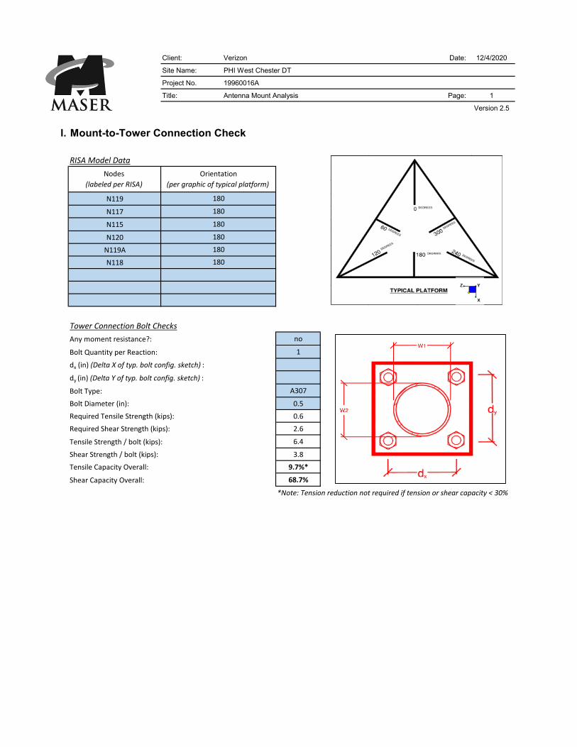
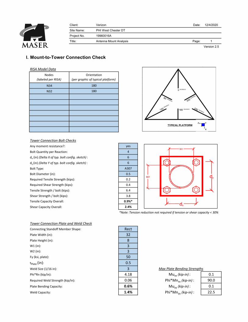
l. Mount-to-Tower Connection Check
RISA Model Data
N119
N117
N115
N120
N119A
N118
Tower Connection Bolt Checks
no
1
0
0
A307
0.5
0.6
2.6
6.4
3.8
9.7%*
68.7%
*Note: Tension reduction not required if tension or shear capacity < 30%
Tower Connection Plate and Weld Check Unique Weld Check
Rect
9
12 L1 (in):
3 L2 (in):
8
50
0.625
5 Max Plate Bending Strengths
6.96 #N/A
0.12 39.6
#N/A #N/A
1.7% 52.7
Required Weld Strength (kip/in):
Plate Bending Capacity:
Weld Capacity:
Weld
Pattern:Plate Width (in):
Phi*Mnxx (kip‐in) :
Muxx (kip‐in) :
Phi*Mnyy (kip‐in) :
Muyy (kip‐in) :
Weld Size (1/16 in):
Phi*Rn (kip/in):
Connecting Standoff Member Shape:
W2 (in):
W1 (in):
Fy (ksi, plate):
tPlate (in):
Plate Height (in):
Bolt Quantity per Reaction:
dx (in) (Delta X of typ. bolt config. sketch) :
dy (in) (Delta Y of typ. bolt config. sketch) :
Bolt Type:
Bolt Diameter (in):
Required Tensile Strength (kips):
Required Shear Strength (kips):
Tensile Strength / bolt (kips):
Shear Strength / bolt (kips):
Tensile Capacity Overall:
Shear Capacity Overall:
Any moment resistance?:
180
180
Nodes
(labeled per RISA)
Orientation
(per graphic of typical platform)
180
180
180
180
Client: Verizon Date: 12/4/2020
Site Name: PHI West Chester DT
Project No. 19960016A
Title: Antenna Mount Analysis Page: 1
Version 2.5
l. Mount-to-Tower Connection Check
RISA Model Data
N34
N32
Tower Connection Bolt Checks
yes
4
6
6
A307
0.5
0.2
0.4
6.4
3.8
0.9%*
2.4%
*Note: Tension reduction not required if tension or shear capacity < 30%
Tower Connection Plate and Weld Check Unique Weld Check
Rect
32
8 L1 (in):
3 L2 (in):
3
50
0.5
3 Max Plate Bending Strengths
4.18 0.1
0.06 90.0
0.6% 0.1
1.4% 22.5
Any moment resistance?:
Nodes
(labeled per RISA)
Orientation
(per graphic of typical platform)
180
180
Bolt Quantity per Reaction:
dx (in) (Delta X of typ. bolt config. sketch) :
dy (in) (Delta Y of typ. bolt config. sketch) :
Bolt Type:
Bolt Diameter (in):
Required Tensile Strength (kips):
Required Shear Strength (kips):
Tensile Strength / bolt (kips):
Shear Strength / bolt (kips):
Tensile Capacity Overall:
Shear Capacity Overall:
Weld
Pattern:Plate Width (in):
Phi*Mnxx (kip‐in) :
Muxx (kip‐in) :
Phi*Mnyy (kip‐in) :
Muyy (kip‐in) :
Weld Size (1/16 in):
Phi*Rn (kip/in):
Connecting Standoff Member Shape:
W2 (in):
W1 (in):
Fy (ksi, plate):
tPlate (in):
Plate Height (in):
Required Weld Strength (kip/in):
Plate Bending Capacity:
Weld Capacity:

Client: Verizon Date:
Site Name: PHI West Chester DT
Project No. 19960016A
Title: Antenna Mount Analysis Page:
l. LOADING SUMMARY
Quantity Manufacturer Antenna/ Appurtenance Status Sector
6 QUINTEL QS6656-5 Proposed Alpha, Beta, & Gamma
3 SAMSUNG B2/66A RRH Proposed Alpha, Beta, & Gamma
3 SAMSUNG B5/13 RRH Proposed Alpha, Beta, & Gamma
3 RAYCAP RxxDC-3315-PF-48 Proposed Alpha, Beta, & Gamma
3 OTHER Sub 6 Antenna Proposed Alpha, Beta, & Gamma
Analysis completed for Alpha Sector
Quantity Manufacturer Antenna/ Appurtenance Status
2 QUINTEL QS6656-5 Proposed
1 SAMSUNG B2/66A RRH Proposed
1 SAMSUNG B5/13 RRH Proposed
1 RAYCAP RxxDC-3315-PF-48 Proposed
1 OTHER Sub 6 Antenna Proposed
Version 1.0
12/4/2020
1
Client: Verizon Date: 12/4/2020
Site Name: PHI West Chester DT
Project No. 19960016A
Title: Antenna Mount Analysis Page: 2
Version 1.0
Il. DESIGN CRITERIA
Basic Site Criteria: Seismic Data:
TIA Standard: TIA‐222‐H Ss: ‐
Antenna Centerline: z 85.4 ft S1: ‐
Supporting Structure Type: Rooftop Structure Height: 250.00 ft
Risk Category: ll R: 2.0
Basic Wind Speed (3 sec. Gust, 700‐Year MRI): V 114 mph As: 3.00
Basic Wind Speed with ice (3 sec. Gust): Vi 40 mph Importance FactorSeismic: 1.00
Maintenance Wind Speed: Vm 30 mph Site Class: D
Design Ice Thickness (500‐Year MRI): ti 1.0 in Fa: 1.20
Exposure Category: B SDS: 0.00
Topographic Category: 1 Cs: 0.00
Topographic Factor: Kzt 1.00 1
Ground Elevation (AMSL): 450.61 ft
Ground Elevation Factor: Ke 0.98 0.9838
Shielding Factor: Ka 0.90 Is the structure base on a building? Yes
Gust Effect Factor: Gh 1.00 Is the Structure bracketed to a building? No
Wind Directionality Factor: Kd 0.95
Velocity Pressure Coefficient: Kz 0.94
Importance FactorWind, no ice: Iwind 1.00
Importance FactorWind, with ice: Iwind w/ice 1.00 Seismic Multipliers:
Importance FactorIce: Iice 1.00 Vertical Seismic Multiplier: 0.000
Lateral Seismic Multiplier: 0.000
Wind and Ice Design Criteria: Rooftop Speedup Criteria:
Velocity Pressure: qz 26.44 psf Condition 1: Yes
Velocity Pressure (With Ice): qzi 3.25 psf Condition 2: No
Velocity Pressure (Maintenance): qzm 1.83 psf Condition 3: No
Factored Ice Thickness: tiz 1.10 in Zr: Zr 7.00 ft
Parapet Height: 2.00 ft
Grating Loading: Xb: Xb 3.00 ft
Grating Type: ‐ Ws: Ws 85.00 ft
Grating Self Weight: ‐ psf Hs: Hs 77.00 ft
Grating Ice Weight: 10.3 psf H1: H1 2.60 ft
H2: H2 79.00 ft
Ks: Ks 1.00
ft
Seismic Info for Telecom Support Structures Attached
to Buildings:
Ice Velocity Pressure Exposure Coefficient: 1.10Kiz
0.00Max elev. along structure @ attachment to
building (base of structure = 0'):
Client: Verizon Date: 12/4/2020
Site Name: PHI West Chester DT
Project No. 19960016A
Title: Antenna Mount Analysis Page: 3
Version 1.0
IlI. CALCULATIONS
▪ Load on Appurtenances
Ca Front Ca Side Ca Front Ca Side
QS6656‐5 120.0 2.875 Rect 72.00 12.00 9.60 80.60 1.36 1.42 122.2 5.1 74.20 14.20 11.80 1.32 1.37
B2/66A RRH 0.0 0.000 Rect 22.00 12.10 7.40 80.00 1.20 1.22 0.0 0.0 24.20 14.30 9.60 1.20 1.20
B5/13 RRH 0.0 0.000 Rect 22.00 12.10 7.40 80.00 1.20 1.22 0.0 0.0 24.20 14.30 9.60 1.20 1.20
RxxDC‐3315‐PF‐48 0.0 0.000 Rect 25.70 15.70 10.30 47.00 1.20 1.20 0.0 0.0 27.90 17.90 12.50 1.20 1.20
Sub 6 Antenna 120.0 2.875 Rect 35.12 16.06 5.51 87.10 1.20 1.37 122.2 5.1 37.32 18.26 7.71 1.20 1.30
Vertical (lbs.)Horizontal
(lbs.)
FN FT FN FT FN FT EV EHQS6656‐5 2 No 0% 0% 122.7 127.9 40.3 19.0 21.9 68.4 8.5 8.9 0.0 0.0
B2/66A RRH 1 No 0% 0% 58.6 36.5 80.0 9.4 6.4 41.4 4.1 2.5 0.0 0.0
B5/13 RRH 1 No 0% 0% 58.6 36.5 80.0 9.4 6.4 41.4 4.1 2.5 0.0 0.0
RxxDC‐3315‐PF‐48 1 No 0% 0% 88.9 58.3 47.0 13.5 9.6 62.1 6.2 4.0 0.0 0.0
Sub 6 Antenna 2 No 0% 0% 89.0 62.4 43.6 15.1 12.6 37.8 6.2 4.3 0.0 0.0
* ALL CALCULATED LOADS ARE PER MOUNTING BRACKET. TO GET THE TOTAL EQUIPMENT LOAD, MULTIPLY THE INDIVIDUAL LOADS BY THE NUMBER OF BRACKETS
▪ Load on Framing Members Optimize Ca Factors by Member Length? No
Ca Ca
Vertical Frame Angle L4X4X4 Equal Angle L4x4x1/4 Square 4.00 2.00 17.62 6.20 5.66 2.00 3.36 9.08
Diagonal Brace Angle L3X3X4 Equal Angle L3x3x1/4 Square 3.00 2.00 13.22 5.20 4.24 2.00 2.82 7.18
Top Face Angle LL4X4X4X0 Equal Angle 2L4x4x1/4 Square 8.00 2.00 35.25 10.20 8.94 2.00 5.53 13.50
Bottom Face Angle L4X4X4 Double Angle L4x4x1/4 Square 4.00 2.00 17.62 6.20 5.66 2.00 3.36 9.08
Empty Mount Pipe PIPE_2.5 Pipe Pipe 2.5 Round 2.88 1.20 7.60 5.07 2.88 1.20 1.65 5.34
1.22
0.92
2.44
1.22
0.53
Iced ConditionNon‐Iced Condition
Width
(in)
Depth
(in)Weight (lbs)
Height
(in)
Width
(in)
Depth
(in)
Maintenance Condition
Diameter
(in)
Mounting Pipe Equipment Mounting Pipe Equipment
Force CoefficientForce Coefficient Length
(in)
Iced Condition Maintenance Condition Seismic Condition
Iced Condition
Antenna/
Appurtenance# of Brackets Turned 90°?
% Shield
Front
% Shield
Side
Antenna/
Appurtenance Length
(in)
Diameter
(in)Shape Type
Height
(in)
RISA Section Set
NameRISA Shape
Member
Category
AISC Member
Label
Member
SurfaceWind Load (plf)
Gravity (lbs.)Wind Force (lbs.)
Non‐Iced Condition
Wind Load
(plf)
Ice Weight
(plf)
Force
Coefficient
Force
CoefficientExposed
Wind
Height (in)
Wind Load
(plf)
Exposed
Wind
Height (in)
DC (in)
Gravity (lbs.)Wind Force (lbs.)Wind Force (lbs.)
Non‐Iced Condition
Client: Verizon Date: 12/4/2020
Site Name: PHI West Chester DT
Project No. 19960016A
Title: Antenna Mount Analysis Page: 4
Version 1.0
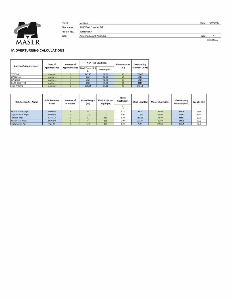
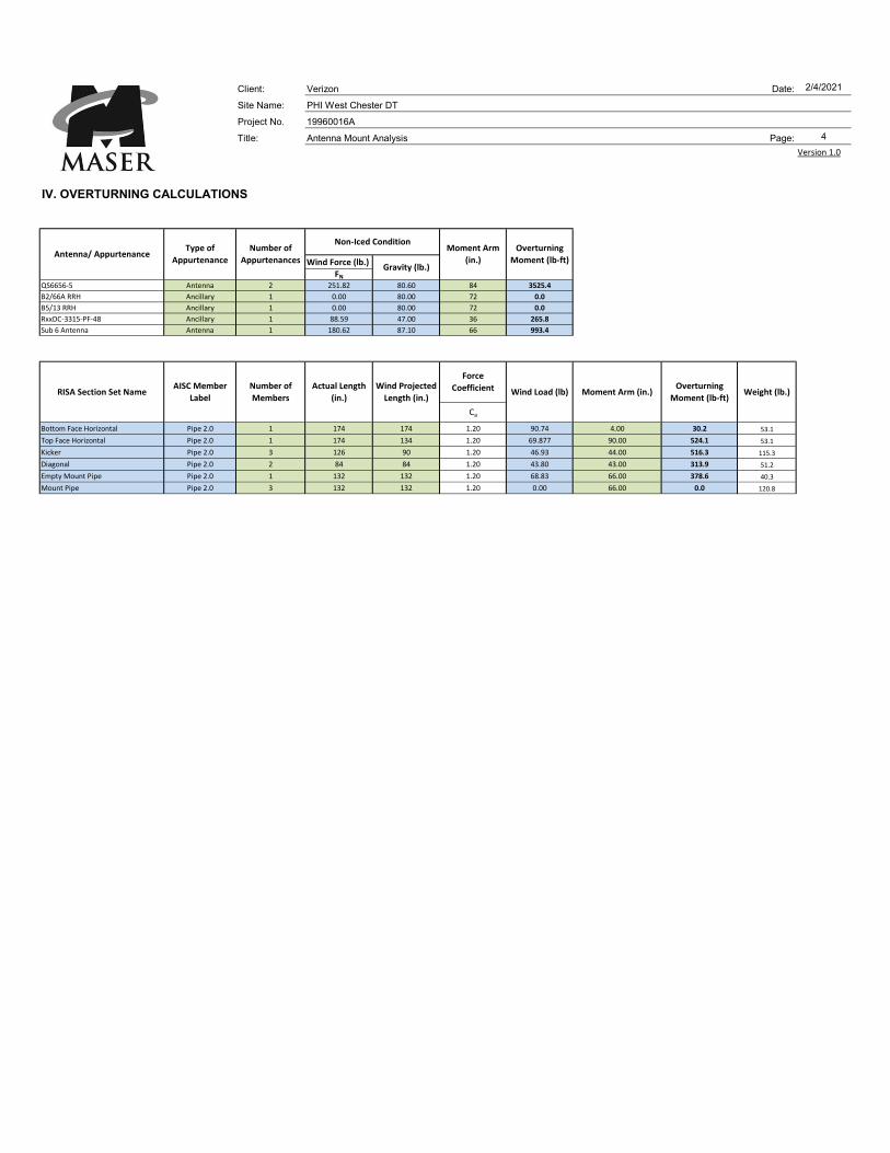
IV. OVERTURNING CALCULATIONS
Wind Force (lb.)
FNQS6656‐5 Antenna 2 245.40 80.60 96 3926.3
B2/66A RRH Ancillary 1 58.65 80.00 36 175.9
B5/13 RRH Ancillary 1 58.65 80.00 36 175.9
RxxDC‐3315‐PF‐48 Ancillary 1 88.89 47.00 60 444.5
Sub 6 Antenna Antenna 1 178.02 87.10 96 1424.2
Ca
Vertical Frame Angle L4x4x1/4 3 72 72 1.77 93.39 36.00 840.5 118.8
Diagonal Brace Angle L3x3x1/4 5 128 72 1.97 77.966 36.00 1169.5 261.3
Top Face Angle 2L4x4x1/4 1 151 151 1.80 398.18 72.00 2389.1 166.1
Bottom Face Angle L4x4x1/4 1 151 151 2.00 221.77 20.00 369.6 83.1
Empty Mount Pipe Pipe 2.5 1 120 120 1.20 76.01 100.00 633.4 58.0
Number of
Members
Force
Coefficient Overturning
Moment (lb‐ft)Weight (lb.)
Gravity (lb.)
RISA Section Set NameAISC Member
LabelMoment Arm (in.)
Antenna/ Appurtenance
Non‐Iced ConditionMoment Arm
(in.)
Type of
Appurtenance
Number of
Appurtenances
Overturning
Moment (lb‐ft)
Wind Projected
Length (in.)Wind Load (lb)
Actual Length
(in.)
Client: Verizon Date: 12/4/2020
Site Name: PHI West Chester DT
Project No. 19960016A
Title: Antenna Mount Analysis Page: 5
Version 1.0
IV. OVERTURNING CALCULATIONS
▪ Ballast Mount Information ▪ Required Ballast ▪ Loading Summary
Number of Trays: 2
Dead Load
Combination Factor of
Safety:
0.90Appurtenance Overturning
Moment:6146.8
lb‐ft
Total Frame Depth: 144.125in.
Wind Load
Combination Factor of
Safety:
1 Mount Overturning Moment: 5402.1lb‐ft
Total Frame Width: 143.375in.
Block Weight (lb.): 34 8x8x16 Hollow CMU Blocks Total Overturning Moment: 11548.9lb‐ft
Center of Gravity
(Distance to front line):38.441
in. (From RISA 3D)Total Weight without Ballast: 1854.3
lb
Tray 1 Moment Arm
(Distance to front line):9
in.
Required Ballast Tray
1 (lb.):68.0 Block #: 2 Total Weight including Ballast: 2568.3
lb
Tray 2 Moment Arm
(Distance to front line):135
in.Required Ballast Tray
2 (lb.):646.0 Block #: 19 Total Resisting Moment 15117.0
lb‐ft
0
0 ▪Roof Pressure Comparison
0 Assumed Live Load: 20
0 Applied Roof Pressure: 17.90psf
Check: ADEQUATEpsf
Client: Verizon Date:Site Name: PHI West Chester DTProject No. 19960016A
Title: Antenna Mount Analysis Page:
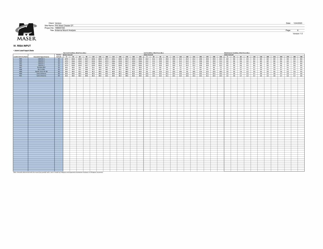
IV. RISA INPUT
▪ Joint Load Input DataNon‐Iced Condition, Wind Force (lbs.) Iced Condition, Wind Force (lbs.) Maintenance Condition, Wind Force (lbs.)
Global Azimuth Global Azimuth Global Azimuth
0 30 60 90 120 150 180 210 240 270 300 330 0 30 60 90 120 150 180 210 240 270 300 330 0 30 60 90 120 150 180 210 240 270 300 330
N83 QS6656‐5 90 127.9 126.6 124.0 122.7 124.0 126.6 127.9 126.6 124.0 122.7 124.0 126.6 21.9 21.2 19.8 19.0 19.8 21.2 21.9 21.2 19.8 19.0 19.8 21.2 8.9 8.8 8.6 8.5 8.6 8.8 8.9 8.8 8.6 8.5 8.6 8.8
N84 QS6656‐5 90 127.9 126.6 124.0 122.7 124.0 126.6 127.9 126.6 124.0 122.7 124.0 126.6 21.9 21.2 19.8 19.0 19.8 21.2 21.9 21.2 19.8 19.0 19.8 21.2 8.9 8.8 8.6 8.5 8.6 8.8 8.9 8.8 8.6 8.5 8.6 8.8
N85 QS6656‐5 90 127.9 126.6 124.0 122.7 124.0 126.6 127.9 126.6 124.0 122.7 124.0 126.6 21.9 21.2 19.8 19.0 19.8 21.2 21.9 21.2 19.8 19.0 19.8 21.2 8.9 8.8 8.6 8.5 8.6 8.8 8.9 8.8 8.6 8.5 8.6 8.8
N86 QS6656‐5 90 127.9 126.6 124.0 122.7 124.0 126.6 127.9 126.6 124.0 122.7 124.0 126.6 21.9 21.2 19.8 19.0 19.8 21.2 21.9 21.2 19.8 19.0 19.8 21.2 8.9 8.8 8.6 8.5 8.6 8.8 8.9 8.8 8.6 8.5 8.6 8.8
N87 B2/66A RRH 90 36.5 42.0 53.1 58.6 53.1 42.0 36.5 42.0 53.1 58.6 53.1 42.0 6.4 7.2 8.6 9.4 8.6 7.2 6.4 7.2 8.6 9.4 8.6 7.2 2.5 2.9 3.7 4.1 3.7 2.9 2.5 2.9 3.7 4.1 3.7 2.9
N88 B5/13 RRH 90 36.5 42.0 53.1 58.6 53.1 42.0 36.5 42.0 53.1 58.6 53.1 42.0 6.4 7.2 8.6 9.4 8.6 7.2 6.4 7.2 8.6 9.4 8.6 7.2 2.5 2.9 3.7 4.1 3.7 2.9 2.5 2.9 3.7 4.1 3.7 2.9
N89 RxxDC‐3315‐PF‐48 90 58.3 66.0 81.2 88.9 81.2 66.0 58.3 66.0 81.2 88.9 81.2 66.0 9.6 10.6 12.6 13.5 12.6 10.6 9.6 10.6 12.6 13.5 12.6 10.6 4.0 4.6 5.6 6.2 5.6 4.6 4.0 4.6 5.6 6.2 5.6 4.6
N90 Sub 6 Antenna 90 62.4 69.0 82.4 89.0 82.4 69.0 62.4 69.0 82.4 89.0 82.4 69.0 12.6 13.3 14.5 15.1 14.5 13.3 12.6 13.3 14.5 15.1 14.5 13.3 4.3 4.8 5.7 6.2 5.7 4.8 4.3 4.8 5.7 6.2 5.7 4.8
N91 Sub 6 Antenna 90 62.4 69.0 82.4 89.0 82.4 69.0 62.4 69.0 82.4 89.0 82.4 69.0 12.6 13.3 14.5 15.1 14.5 13.3 12.6 13.3 14.5 15.1 14.5 13.3 4.3 4.8 5.7 6.2 5.7 4.8 4.3 4.8 5.7 6.2 5.7 4.8
Note: Azimuths determined with the mount face parallel with z‐axis in model as 0 degrees and sequential orientations clockwise in 30 degree increments.
Associated AppurtenanceLoaded Joints by Name
Version 1.0
12/4/2020
6
Relative
Azimuth
Page 1
Page 2
Page 3
Page 4
Page 5

Client: Verizon Date:
Site Name: PHI West Chester DT
Project No. 19960016A
Title: Antenna Mount Analysis Page:
l. LOADING SUMMARY
Quantity Manufacturer Antenna/ Appurtenance Status Sector
6 QUINTEL QS6656-5 Proposed Alpha, Beta, & Gamma
3 SAMSUNG B2/66A RRH Proposed Alpha, Beta, & Gamma
3 SAMSUNG B5/13 RRH Proposed Alpha, Beta, & Gamma
3 RAYCAP RxxDC-3315-PF-48 Proposed Alpha, Beta, & Gamma
3 OTHER Sub 6 Antenna Proposed Alpha, Beta, & Gamma
Analysis completed for Alpha Sector
Quantity Manufacturer Antenna/ Appurtenance Status
2 QUINTEL QS6656-5 Proposed
1 SAMSUNG B2/66A RRH Proposed
1 SAMSUNG B5/13 RRH Proposed
1 RAYCAP RxxDC-3315-PF-48 Proposed
1 OTHER Sub 6 Antenna Proposed
Version 1.0
2/4/2021
1

Client: Verizon Date: 2/4/2021
Site Name: PHI West Chester DT
Project No. 19960016A
Title: Antenna Mount Analysis Page: 2
Version 1.0
Il. DESIGN CRITERIA
Basic Site Criteria: Seismic Data:
TIA Standard: TIA‐222‐H Ss: ‐
Antenna Centerline: z 84.4 ft S1: ‐
Supporting Structure Type: Rooftop Structure Height: 250.00 ft
Risk Category: ll R: 2.0
Basic Wind Speed (3 sec. Gust, 700‐Year MRI): V 114 mph As: 3.00
Basic Wind Speed with ice (3 sec. Gust): Vi 40 mph Importance FactorSeismic: 1.00
Maintenance Wind Speed: Vm 30 mph Site Class: D
Design Ice Thickness (500‐Year MRI): ti 1.0 in Fa: 1.20
Exposure Category: B SDS: 0.00
Topographic Category: 1 Cs: 0.00
Topographic Factor: Kzt 1.00 1
Ground Elevation (AMSL): 450.61 ft
Ground Elevation Factor: Ke 0.98 0.9838
Shielding Factor: Ka 0.90 Is the structure base on a building? Yes
Gust Effect Factor: Gh 1.00 Is the Structure bracketed to a building? No
Wind Directionality Factor: Kd 0.95
Velocity Pressure Coefficient: Kz 0.94
Importance FactorWind, no ice: Iwind 1.00
Importance FactorWind, with ice: Iwind w/ice 1.00 Seismic Multipliers:
Importance FactorIce: Iice 1.00 Vertical Seismic Multiplier: 0.000
Lateral Seismic Multiplier: 0.000
Wind and Ice Design Criteria: Rooftop Speedup Criteria:
Velocity Pressure: qz 26.35 psf Condition 1: Yes
Velocity Pressure (With Ice): qzi 3.24 psf Condition 2: No
Velocity Pressure (Maintenance): qzm 1.82 psf Condition 3: No
Factored Ice Thickness: tiz 1.10 in Zr: Zr 7.00 ft
Parapet Height: 2.00 ft
Grating Loading: Xb: Xb 3.00 ft
Grating Type: ‐ Ws: Ws 85.00 ft
Grating Self Weight: ‐ psf Hs: Hs 77.40 ft
Grating Ice Weight: 10.3 psf H1: H1 2.60 ft
H2: H2 79.40 ft
Ks: Ks 1.00
ft
Seismic Info for Telecom Support Structures Attached
to Buildings:
Ice Velocity Pressure Exposure Coefficient: 1.10Kiz
0.00Max elev. along structure @ attachment to
building (base of structure = 0'):
Client: Verizon Date: 2/4/2021
Site Name: PHI West Chester DT
Project No. 19960016A
Title: Antenna Mount Analysis Page: 3
Version 1.0
IlI. CALCULATIONS
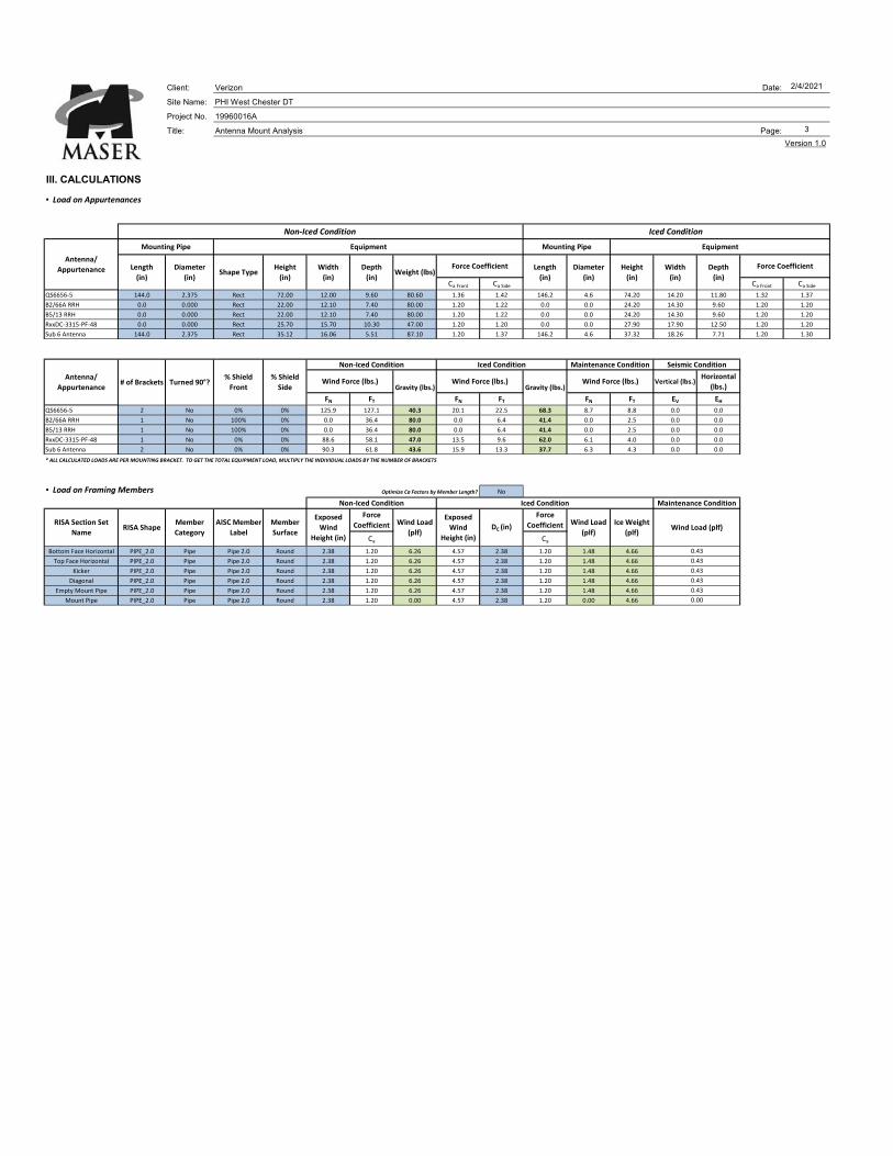
▪ Load on Appurtenances
Ca Front Ca Side Ca Front Ca Side
QS6656‐5 144.0 2.375 Rect 72.00 12.00 9.60 80.60 1.36 1.42 146.2 4.6 74.20 14.20 11.80 1.32 1.37
B2/66A RRH 0.0 0.000 Rect 22.00 12.10 7.40 80.00 1.20 1.22 0.0 0.0 24.20 14.30 9.60 1.20 1.20
B5/13 RRH 0.0 0.000 Rect 22.00 12.10 7.40 80.00 1.20 1.22 0.0 0.0 24.20 14.30 9.60 1.20 1.20
RxxDC‐3315‐PF‐48 0.0 0.000 Rect 25.70 15.70 10.30 47.00 1.20 1.20 0.0 0.0 27.90 17.90 12.50 1.20 1.20
Sub 6 Antenna 144.0 2.375 Rect 35.12 16.06 5.51 87.10 1.20 1.37 146.2 4.6 37.32 18.26 7.71 1.20 1.30
Vertical (lbs.)Horizontal
(lbs.)
FN FT FN FT FN FT EV EHQS6656‐5 2 No 0% 0% 125.9 127.1 40.3 20.1 22.5 68.3 8.7 8.8 0.0 0.0
B2/66A RRH 1 No 100% 0% 0.0 36.4 80.0 0.0 6.4 41.4 0.0 2.5 0.0 0.0
B5/13 RRH 1 No 100% 0% 0.0 36.4 80.0 0.0 6.4 41.4 0.0 2.5 0.0 0.0
RxxDC‐3315‐PF‐48 1 No 0% 0% 88.6 58.1 47.0 13.5 9.6 62.0 6.1 4.0 0.0 0.0
Sub 6 Antenna 2 No 0% 0% 90.3 61.8 43.6 15.9 13.3 37.7 6.3 4.3 0.0 0.0
* ALL CALCULATED LOADS ARE PER MOUNTING BRACKET. TO GET THE TOTAL EQUIPMENT LOAD, MULTIPLY THE INDIVIDUAL LOADS BY THE NUMBER OF BRACKETS
▪ Load on Framing Members Optimize Ca Factors by Member Length? No
Ca Ca
Bottom Face Horizontal PIPE_2.0 Pipe Pipe 2.0 Round 2.38 1.20 6.26 4.57 2.38 1.20 1.48 4.66
Top Face Horizontal PIPE_2.0 Pipe Pipe 2.0 Round 2.38 1.20 6.26 4.57 2.38 1.20 1.48 4.66
Kicker PIPE_2.0 Pipe Pipe 2.0 Round 2.38 1.20 6.26 4.57 2.38 1.20 1.48 4.66
Diagonal PIPE_2.0 Pipe Pipe 2.0 Round 2.38 1.20 6.26 4.57 2.38 1.20 1.48 4.66
Empty Mount Pipe PIPE_2.0 Pipe Pipe 2.0 Round 2.38 1.20 6.26 4.57 2.38 1.20 1.48 4.66
Mount Pipe PIPE_2.0 Pipe Pipe 2.0 Round 2.38 1.20 0.00 4.57 2.38 1.20 0.00 4.66 0.00
0.43
0.43
0.43
0.43
0.43
Iced ConditionNon‐Iced Condition
Width
(in)
Depth
(in)Weight (lbs)
Height
(in)
Width
(in)
Depth
(in)
Maintenance Condition
Diameter
(in)
Mounting Pipe Equipment Mounting Pipe Equipment
Force CoefficientForce Coefficient Length
(in)
Iced Condition Maintenance Condition Seismic Condition
Iced Condition
Antenna/
Appurtenance# of Brackets Turned 90°?
% Shield
Front
% Shield
Side
Antenna/
Appurtenance Length
(in)
Diameter
(in)Shape Type
Height
(in)
RISA Section Set
NameRISA Shape
Member
Category
AISC Member
Label
Member
SurfaceWind Load (plf)
Gravity (lbs.)Wind Force (lbs.)
Non‐Iced Condition
Wind Load
(plf)
Ice Weight
(plf)
Force
Coefficient
Force
CoefficientExposed
Wind
Height (in)
Wind Load
(plf)
Exposed
Wind
Height (in)
DC (in)
Gravity (lbs.)Wind Force (lbs.)Wind Force (lbs.)
Non‐Iced Condition
Client: Verizon Date: 2/4/2021
Site Name: PHI West Chester DT
Project No. 19960016A
Title: Antenna Mount Analysis Page: 4
Version 1.0
IV. OVERTURNING CALCULATIONS
Wind Force (lb.)
FNQS6656‐5 Antenna 2 251.82 80.60 84 3525.4
B2/66A RRH Ancillary 1 0.00 80.00 72 0.0
B5/13 RRH Ancillary 1 0.00 80.00 72 0.0
RxxDC‐3315‐PF‐48 Ancillary 1 88.59 47.00 36 265.8
Sub 6 Antenna Antenna 1 180.62 87.10 66 993.4
Ca
Bottom Face Horizontal Pipe 2.0 1 174 174 1.20 90.74 4.00 30.2 53.1
Top Face Horizontal Pipe 2.0 1 174 134 1.20 69.877 90.00 524.1 53.1
Kicker Pipe 2.0 3 126 90 1.20 46.93 44.00 516.3 115.3
Diagonal Pipe 2.0 2 84 84 1.20 43.80 43.00 313.9 51.2
Empty Mount Pipe Pipe 2.0 1 132 132 1.20 68.83 66.00 378.6 40.3
Mount Pipe Pipe 2.0 3 132 132 1.20 0.00 66.00 0.0 120.8
Number of
Members
Force
Coefficient Overturning
Moment (lb‐ft)Weight (lb.)
Gravity (lb.)
RISA Section Set NameAISC Member
LabelMoment Arm (in.)
Antenna/ Appurtenance
Non‐Iced ConditionMoment Arm
(in.)
Type of
Appurtenance
Number of
Appurtenances
Overturning
Moment (lb‐ft)
Wind Projected
Length (in.)Wind Load (lb)
Actual Length
(in.)

Client: Verizon Date: 2/4/2021
Site Name: PHI West Chester DT
Project No. 19960016A
Title: Antenna Mount Analysis Page: 5
Version 1.0
IV. OVERTURNING CALCULATIONS
▪ Ballast Mount Information ▪ Required Ballast ▪ Loading Summary
Number of Trays: 2
Dead Load
Combination Factor of
Safety:
0.90Appurtenance Overturning
Moment:4784.6
lb‐ft
Total Frame Depth: 89.375in.
Wind Load
Combination Factor of
Safety:
1 Mount Overturning Moment: 1763.1lb‐ft
Total Frame Width: 174in.
Block Weight (lb.): 34 8x8x16 Hollow CMU Blocks Total Overturning Moment: 6547.7lb‐ft
Center of Gravity
(Distance to front line):22.69
in. (From RISA 3D)Total Weight without Ballast: 1292.3
lb
Tray 1 Moment Arm
(Distance to front line):8
in.
Required Ballast Tray
1 (lb.):68.0 Block #: 2 Total Weight including Ballast: 2074.3
lb
Tray 2 Moment Arm
(Distance to front line):81.375
in.Required Ballast Tray
2 (lb.):714.0 Block #: 21 Total Resisting Moment 6890.8
lb‐ft
0
0 ▪Roof Pressure Comparison
0 Assumed Live Load: 20
0 Applied Roof Pressure: 19.21psf
Check: ADEQUATEpsf

Client: Verizon Date:Site Name: PHI West Chester DTProject No. 19960016A
Title: Antenna Mount Analysis Page:
IV. RISA INPUT
▪ Joint Load Input DataNon‐Iced Condition, Wind Force (lbs.) Iced Condition, Wind Force (lbs.) Maintenance Condition, Wind Force (lbs.)
Global Azimuth Global Azimuth Global Azimuth
0 30 60 90 120 150 180 210 240 270 300 330 0 30 60 90 120 150 180 210 240 270 300 330 0 30 60 90 120 150 180 210 240 270 300 330
N146 QS6656‐5 0 125.9 126.2 126.8 127.1 126.8 126.2 125.9 126.2 126.8 127.1 126.8 126.2 20.1 20.7 21.9 22.5 21.9 20.7 20.1 20.7 21.9 22.5 21.9 20.7 8.7 8.7 8.8 8.8 8.8 8.7 8.7 8.7 8.8 8.8 8.8 8.7
N148 QS6656‐5 0 125.9 126.2 126.8 127.1 126.8 126.2 125.9 126.2 126.8 127.1 126.8 126.2 20.1 20.7 21.9 22.5 21.9 20.7 20.1 20.7 21.9 22.5 21.9 20.7 8.7 8.7 8.8 8.8 8.8 8.7 8.7 8.7 8.8 8.8 8.8 8.7
N145 QS6656‐5 0 125.9 126.2 126.8 127.1 126.8 126.2 125.9 126.2 126.8 127.1 126.8 126.2 20.1 20.7 21.9 22.5 21.9 20.7 20.1 20.7 21.9 22.5 21.9 20.7 8.7 8.7 8.8 8.8 8.8 8.7 8.7 8.7 8.8 8.8 8.8 8.7
N147 QS6656‐5 0 125.9 126.2 126.8 127.1 126.8 126.2 125.9 126.2 126.8 127.1 126.8 126.2 20.1 20.7 21.9 22.5 21.9 20.7 20.1 20.7 21.9 22.5 21.9 20.7 8.7 8.7 8.8 8.8 8.8 8.7 8.7 8.7 8.8 8.8 8.8 8.7
N151 Sub 6 Antenna 0 90.3 83.2 69.0 61.8 69.0 83.2 90.3 83.2 69.0 61.8 69.0 83.2 15.9 15.3 13.9 13.3 13.9 15.3 15.9 15.3 13.9 13.3 13.9 15.3 6.3 5.8 4.8 4.3 4.8 5.8 6.3 5.8 4.8 4.3 4.8 5.8
N152 Sub 6 Antenna 0 90.3 83.2 69.0 61.8 69.0 83.2 90.3 83.2 69.0 61.8 69.0 83.2 15.9 15.3 13.9 13.3 13.9 15.3 15.9 15.3 13.9 13.3 13.9 15.3 6.3 5.8 4.8 4.3 4.8 5.8 6.3 5.8 4.8 4.3 4.8 5.8
N149 B2/66A RRH 0 0.0 9.1 27.3 36.4 27.3 9.1 0.0 9.1 27.3 36.4 27.3 9.1 0.0 1.6 4.8 6.4 4.8 1.6 0.0 1.6 4.8 6.4 4.8 1.6 0.0 0.6 1.9 2.5 1.9 0.6 0.0 0.6 1.9 2.5 1.9 0.6
N150 B5/13 RRH 0 0.0 9.1 27.3 36.4 27.3 9.1 0.0 9.1 27.3 36.4 27.3 9.1 0.0 1.6 4.8 6.4 4.8 1.6 0.0 1.6 4.8 6.4 4.8 1.6 0.0 0.6 1.9 2.5 1.9 0.6 0.0 0.6 1.9 2.5 1.9 0.6
N153 RxxDC‐3315‐PF‐48 0 88.6 81.0 65.7 58.1 65.7 81.0 88.6 81.0 65.7 58.1 65.7 81.0 13.5 12.5 10.5 9.6 10.5 12.5 13.5 12.5 10.5 9.6 10.5 12.5 6.1 5.6 4.6 4.0 4.6 5.6 6.1 5.6 4.6 4.0 4.6 5.6
Note: Azimuths determined with the mount face parallel with z‐axis in model as 0 degrees and sequential orientations clockwise in 30 degree increments.
Associated AppurtenanceLoaded Joints by Name
Version 1.0
2/4/2021
6
Relative
Azimuth
Page 1
Page 2
Page 3

Page 4
Page 5