analysis of finite arrays of axially directed printed dipoles on
TRANSCRIPT

2586 IEEE TRANSACTIONS ON ANTENNAS AND PROPAGATION, VOL. 52, NO. 10, OCTOBER 2004
Analysis of Finite Arrays of Axially Directed PrintedDipoles on Electrically Large Circular Cylinders
Vakur B. Ertürk, Member, IEEE, Roberto G. Rojas, Fellow, IEEE, and Kit Wing Lee
Abstract—Various arrays consisting of finite number of printeddipoles on electrically large dielectric coated circular cylinders areinvestigated using a hybrid method of moments/Green’s functiontechnique in the spatial domain. This is basically an “element byelement” approach in which the mutual coupling between dipolesthrough space as well as surface waves is incorporated. The effi-ciency of the method comes from the computation of the Green’sfunction, where three types of spatial domain Green’s function rep-resentations are used interchangeably, based on their computa-tional efficiency and regions where they remain accurate. Numer-ical results are presented in the form of array current distributions,active reflection coefficient and far-field pattern to indicate the ef-ficiency and accuracy of the method. Furthermore, these resultsare compared with similar results obtained from finite arrays ofprinted dipoles on grounded planar dielectric slabs. It is shownthat planar approximations, except for small separations, can notbe used due to the mutual coupling between the array elements.Consequently, basic performance metrics of printed dipole arrayson coated cylinders show significant discrepancies when comparedto their planar counterparts.
Index Terms—Coated cylinders, conformal arrays, Green’sfunction, method of moments (MoM), mutual coupling.
I. INTRODUCTION
THE design and analysis of conformal arrays of printedantennas is of interest in applications ranging from satellite
and wireless communications (mobile phone base stations, spacedivision multiple access (SDMA) applications, etc.) to militarysystems (flush-mounted antennas for aircraft and missiles, radioguidance of missiles, etc.). In these applications, conformality isrequired for aerodynamic reasons, such that the array elementsmust conform to their supporting surface, or to reduce thearray’s radar cross section and in commercial applications foresthetic reasons. However, the lack of adequate design andanalysis tools, in particular for electrically large arrays, isa problem that remains to be solved for conformal printedantenna arrays.
Several design tools and numerical techniques have been im-plemented in CAD packages for the efficient analysis and designof printed finite and infinite arrays for planar geometries [1]–[3].
Manuscript received January 6, 2003; revised August 7, 2003.V. B. Ertürk is with the Department of Electrical and Electronics Engi-
neering, Bilkent University, TR-06800, Bilkent, Ankara, Turkey (e-mail:[email protected]).
R. G. Rojas is with the Department of Electrical and Computer Engineering,ElectroScience Laboratory, The Ohio State University, Columbus, OH 43212-1191 USA (e-mail: [email protected]).
K. W. Lee was with the Department of Electrical Engineering, Electro-Science Laboratory, The Ohio State University, Columbus, OH 43212-1191USA. He is now with Texas Instruments, Inc., Dallas, TX 75243 USA (e-mail:[email protected])
Digital Object Identifier 10.1109/TAP.2004.834443
Note that the analysis of electrically large planar finite arrays isstill difficult and it is being investigated by many researchers.In contrast, a limited number of design and numerical analysistools have been developed for conformal arrays. Unfortunately,the majority of them become inefficient and intractable whenthe array and/or supporting structure become large. Therefore,one of the most urgent challenges is to develop efficient andaccurate design and analysis tools for conformal arrays so thattheir properties can be accurately predicted, resulting in betterdesigns for the aforementioned applications.
Several authors [4]–[14] have studied the properties of singleantennas or arrays of printed antennas on material coated cylin-ders. However, either some approximate models have been used,where the mutual coupling between the array elements is ig-nored and, in general, the main focus has been the radiationpatterns rather than the currents, or spectral domain techniqueshave been used, which are applicable to small arrays on electri-cally small cylinders. Furthermore, for antennas on electricallylarge cylinders (usually radius is greater than , where isthe free-space wavelength), the shape of the host cylinder hasbeen considered only for the radiation patterns, and methodsapplicable to planar geometries have been used in character-izing the input impedance and current distribution since a mi-crostrip antenna is a highly resonant structure [12], [15], [16].Although this is a reasonable approximation for the case of asingle printed antenna, it does not hold for large arrays of printedantennas on large cylinders due to mutual coupling between el-ements through space and surface waves.
In this paper, our goal is twofold: 1) To perform a full waveanalysis of large phased arrays of printed dipoles on electricallylarge dielectric coated circular cylinders. Note that, to the best ofour knowledge, this is the first paper which presents a rigorousanalysis of finite phased arrays of printed dipoles on large coatedcylinders, where all the mutual coupling effects are incorporated.2) To make a one-to-one comparison between arrays of printeddipoles on electrically large dielectric coated circular cylindersand arrays of printed dipoles on grounded planar dielectricslabs in terms of currents, reflection coefficient magnitudes andradiation patterns. Thereby showing some interesting featuresof arrays of printed dipoles on cylindrical structures whichare different from their planar counterparts. To achieve thesegoals, various arrays consisting of finite number of printeddipoles on electrically large dielectric coated circular cylindersare investigated using an efficient and accurate hybrid methodbased on the combination of method of moments (MoM) withan appropriate spatial domain cylindrical Green’s function.This method is basically an “element by element” approach inwhich the mutual coupling between the dipoles is incorporated.
0018-926X/04$20.00 © 2004 IEEE
brought to you by COREView metadata, citation and similar papers at core.ac.uk
provided by Bilkent University Institutional Repository
ERTÜRK et al.: ANALYSIS OF FINITE ARRAYS OF AXIALLY DIRECTED PRINTED DIPOLES 2587
Although this calculation may appear to be extremely timeconsuming for large arrays, it is efficient for large cylindersbecause of the fast computation of the Green’s function whichis the kernel of the integral equation to be solved via MoM.Therefore, based on their computational efficiency and accuracy,three types of spatial domain cylindrical Green’s functionrepresentations are used [17]–[20]. Each representation is validin some region of space and fortunately the three regions overlap,making the transition from one representation to another stable.In Section II, the formulation of the problem, in particular,the integral equation, the MoM procedure and the types ofthe Green’s function representations used in this paper, arepresented. In Section III, numerical results are presented in theform of array current distribution, active reflection coefficientmagnitude and radiation patterns to assess the accuracy ofthis method. These results are then compared with those ofphased arrays of printed dipoles on grounded planar dielectricslabs. An time dependence is assumed and suppressedthroughout this paper.
II. FORMULATION
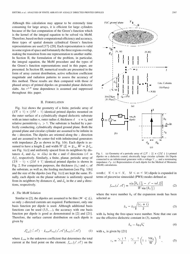
Fig. 1(a) shows the geometry of a finite, periodic array ofidentical printed dipoles mounted on
the outer surface of a cylindrically shaped dielectric substratewith an inner radius , outer radius , thickness andrelative permittivity . The substrate is backed by a per-fectly conducting, cylindrically shaped ground plane. Both theground plane and circular cylinder are assumed to be infinite inthe direction. The dipoles are oriented along the directionand are assumed to be center-fed with infinitesimal generatorswith impedance as shown in Fig. 1(b). Each dipole is as-sumed to have a length and width [ , ,see Fig. 1(c)] and uniformly spaced from its neighbors by dis-tances and in the and directions
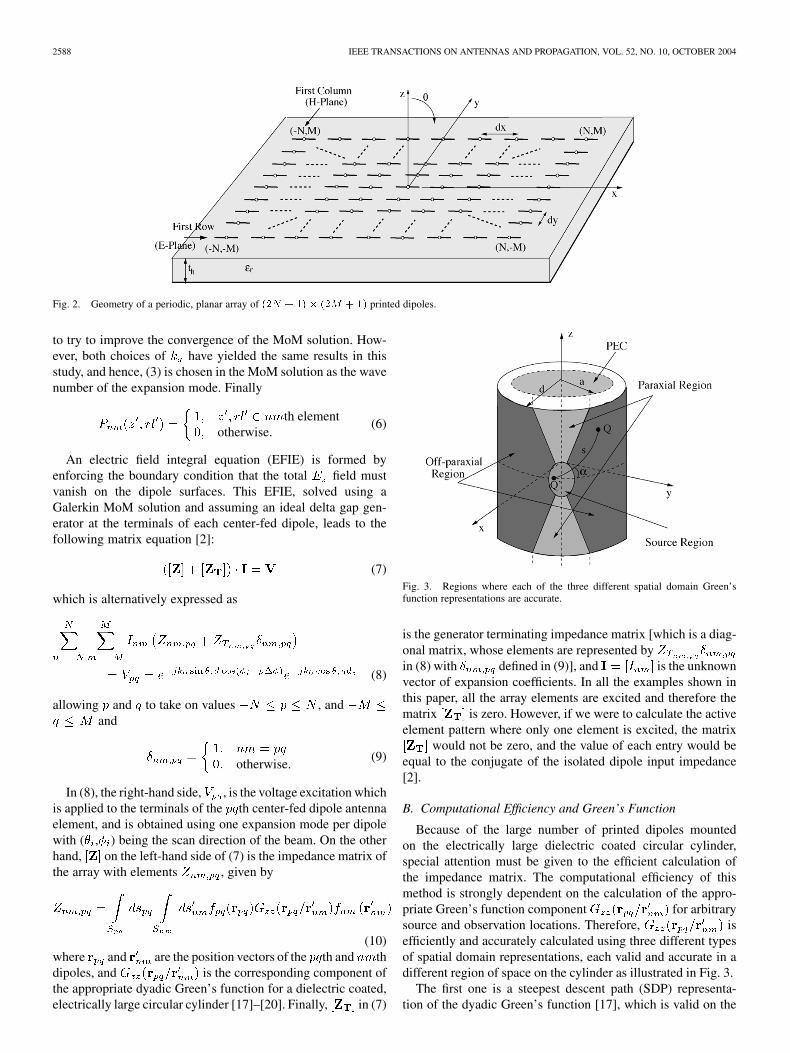
, respectively. Similarly, a finite, planar, periodic array ofidentical printed dipoles is shown in
Fig. 2. For comparison purposes, the thickness and ofthe substrate, as well as, the feeding mechanism [see Fig. 1(b)]and the size of the dipoles [see Fig. 1(c)] are kept the same. Fi-nally, each dipole on the planar substrate is uniformly spacedfrom its neighbors by distances and in the and direc-tions, respectively.
A. The MoM Solution
Similar to [2], the dipoles are assumed to be thin ,so only -directed currents are required. Furthermore, only onebasis function per dipole is used. Although additional basisfunctions can be used (3,5, ), the accuracy with one basisfunction per dipole is good as demonstrated in [2] and [21].Therefore, the surface current distribution on each dipole isgiven by
(1)
where is the unknown coefficient that determines the totalcurrent at the feed point on the element. on the
Fig. 1. (a) Geometry of a periodic array of (2N + 1) � (2M + 1) printeddipoles on a dielectric coated, electrically large circular cylinder. (b) Dipoleconnected to an infinitesimal generator with a voltage V and a terminatingimpedance Z . (c) Representation of each dipole for the Method of Moments(MoM) calculations.
th ( , ) dipole is expanded interms of piecewise sinusoidal (PWS) modes defined as
(2)
where the wave number of the expansion mode has beenselected as
(3)
with being the free-space wave number. Note that one canuse the effective dielectric constant in (3), namely
(4)
with is given by [21]
(5)
2588 IEEE TRANSACTIONS ON ANTENNAS AND PROPAGATION, VOL. 52, NO. 10, OCTOBER 2004
Fig. 2. Geometry of a periodic, planar array of (2N + 1) � (2M + 1) printed dipoles.
to try to improve the convergence of the MoM solution. How-ever, both choices of have yielded the same results in thisstudy, and hence, (3) is chosen in the MoM solution as the wavenumber of the expansion mode. Finally
th elementotherwise.
(6)
An electric field integral equation (EFIE) is formed byenforcing the boundary condition that the total field mustvanish on the dipole surfaces. This EFIE, solved using aGalerkin MoM solution and assuming an ideal delta gap gen-erator at the terminals of each center-fed dipole, leads to thefollowing matrix equation [2]:
(7)
which is alternatively expressed as
(8)
allowing and to take on values , andand
otherwise.(9)
In (8), the right-hand side, , is the voltage excitation whichis applied to the terminals of the th center-fed dipole antennaelement, and is obtained using one expansion mode per dipolewith ( , ) being the scan direction of the beam. On the otherhand, on the left-hand side of (7) is the impedance matrix ofthe array with elements , given by
(10)where and are the position vectors of the th and thdipoles, and is the corresponding component ofthe appropriate dyadic Green’s function for a dielectric coated,electrically large circular cylinder [17]–[20]. Finally, in (7)
Fig. 3. Regions where each of the three different spatial domain Green’sfunction representations are accurate.
is the generator terminating impedance matrix [which is a diag-onal matrix, whose elements are represented byin (8) with defined in (9)], and is the unknownvector of expansion coefficients. In all the examples shown inthis paper, all the array elements are excited and therefore thematrix is zero. However, if we were to calculate the activeelement pattern where only one element is excited, the matrix
would not be zero, and the value of each entry would beequal to the conjugate of the isolated dipole input impedance[2].
B. Computational Efficiency and Green’s Function
Because of the large number of printed dipoles mountedon the electrically large dielectric coated circular cylinder,special attention must be given to the efficient calculation ofthe impedance matrix. The computational efficiency of thismethod is strongly dependent on the calculation of the appro-priate Green’s function component for arbitrarysource and observation locations. Therefore, isefficiently and accurately calculated using three different typesof spatial domain representations, each valid and accurate in adifferent region of space on the cylinder as illustrated in Fig. 3.
The first one is a steepest descent path (SDP) representa-tion of the dyadic Green’s function [17], which is valid on the
ERTÜRK et al.: ANALYSIS OF FINITE ARRAYS OF AXIALLY DIRECTED PRINTED DIPOLES 2589
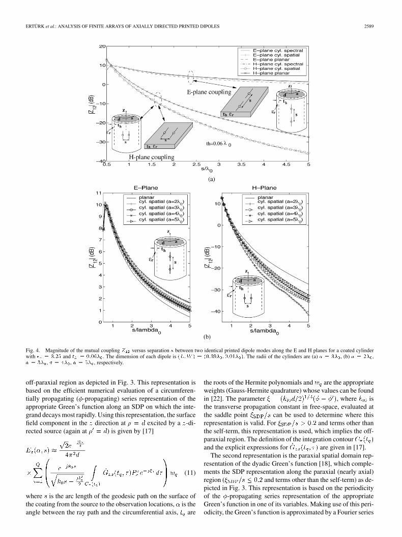
Fig. 4. Magnitude of the mutual coupling Z versus separation s between two identical printed dipole modes along the E and H planes for a coated cylinderwith � = 3:25 and t = 0:06� . The dimension of each dipole is (L;W ) = (0:39� ; 0:01� ). The radii of the cylinders are (a) a = 3� , (b) a = 2� ,a = 3� , a = 4� , a = 5� , respectively.
off-paraxial region as depicted in Fig. 3. This representation isbased on the efficient numerical evaluation of a circumferen-tially propagating ( -propagating) series representation of theappropriate Green’s function along an SDP on which the inte-grand decays most rapidly. Using this representation, the surfacefield component in the direction at excited by a -di-rected source (again at ) is given by [17]
(11)
where is the arc length of the geodesic path on the surface ofthe coating from the source to the observation locations, is theangle between the ray path and the circumferential axis, are
the roots of the Hermite polynomials and are the appropriateweights (Gauss-Hermite quadrature) whose values can be foundin [22]. The parameter , where isthe transverse propagation constant in free-space, evaluated atthe saddle point can be used to determine where thisrepresentation is valid. For and terms other thanthe self-term, this representation is used, which implies the off-paraxial region. The definition of the integration contourand the explicit expressions for are given in [17].
The second representation is the paraxial spatial domain rep-resentation of the dyadic Green’s function [18], which comple-ments the SDP representation along the paraxial (nearly axial)region ( and terms other than the self-term) as de-picted in Fig. 3. This representation is based on the periodicityof the -propagating series representation of the appropriateGreen’s function in one of its variables. Making use of this peri-odicity, the Green’s function is approximated by a Fourier series
2590 IEEE TRANSACTIONS ON ANTENNAS AND PROPAGATION, VOL. 52, NO. 10, OCTOBER 2004
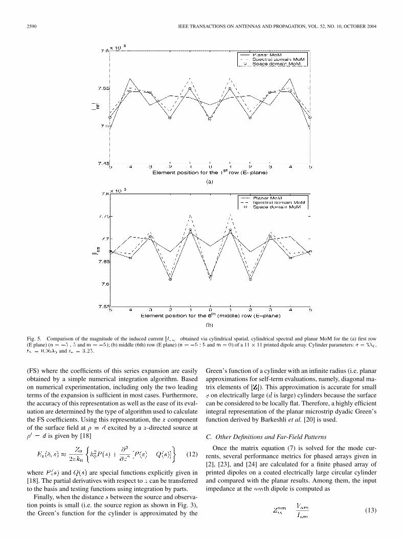
Fig. 5. Comparison of the magnitude of the induced current jI j obtained via cylindrical spatial, cylindrical spectral and planar MoM for the (a) first row(E plane) (n = �5 : 5 and m = �5); (b) middle (6th) row (E plane) (n = �5 : 5 and m = 0) of a 11 � 11 printed dipole array. Cylinder parameters: a = 3� ,t = 0:06� and � = 3:25.
(FS) where the coefficients of this series expansion are easilyobtained by a simple numerical integration algorithm. Basedon numerical experimentation, including only the two leadingterms of the expansion is sufficient in most cases. Furthermore,the accuracy of this representation as well as the ease of its eval-uation are determined by the type of algorithm used to calculatethe FS coefficients. Using this representation, the componentof the surface field at excited by a -directed source at
is given by [18]
(12)
where and are special functions explicitly given in[18]. The partial derivatives with respect to can be transferredto the basis and testing functions using integration by parts.
Finally, when the distance between the source and observa-tion points is small (i.e. the source region as shown in Fig. 3),the Green’s function for the cylinder is approximated by the
Green’s function of a cylinder with an infinite radius (i.e. planarapproximations for self-term evaluations, namely, diagonal ma-trix elements of ). This approximation is accurate for small
on electrically large ( is large) cylinders because the surfacecan be considered to be locally flat. Therefore, a highly efficientintegral representation of the planar microstrip dyadic Green’sfunction derived by Barkeshli et al. [20] is used.
C. Other Definitions and Far-Field Patterns
Once the matrix equation (7) is solved for the mode cur-rents, several performance metrics for phased arrays given in[2], [23], and [24] are calculated for a finite phased array ofprinted dipoles on a coated electrically large circular cylinderand compared with the planar results. Among them, the inputimpedance at the th dipole is computed as
(13)
ERTÜRK et al.: ANALYSIS OF FINITE ARRAYS OF AXIALLY DIRECTED PRINTED DIPOLES 2591
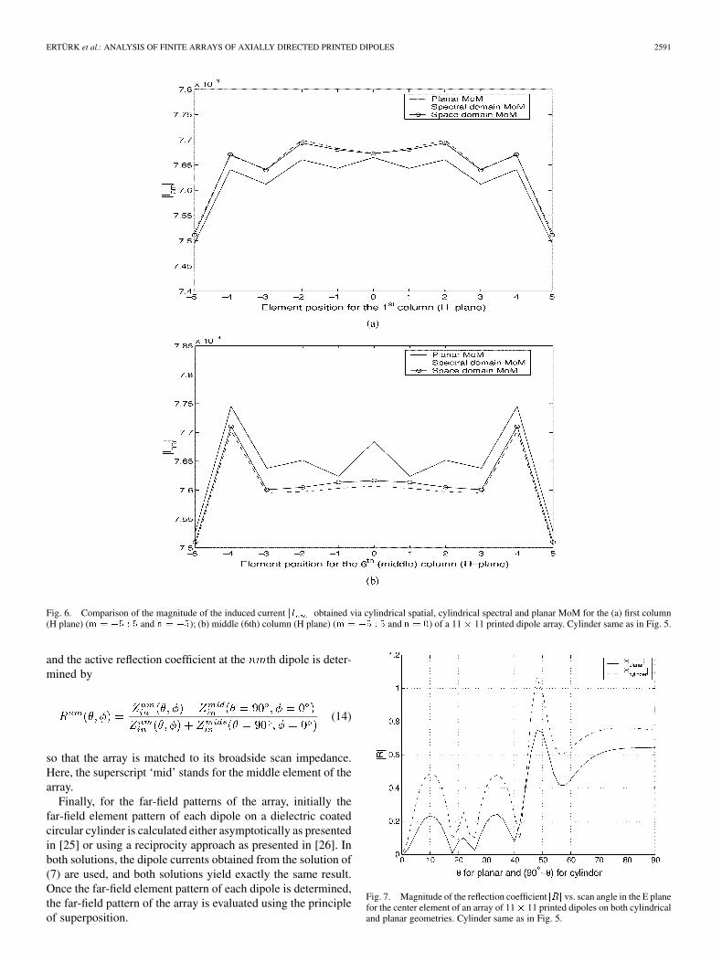
Fig. 6. Comparison of the magnitude of the induced current jI j obtained via cylindrical spatial, cylindrical spectral and planar MoM for the (a) first column(H plane) (m = �5 : 5 and n = �5); (b) middle (6th) column (H plane) (m = �5 : 5 and n = 0) of a 11 � 11 printed dipole array. Cylinder same as in Fig. 5.
and the active reflection coefficient at the th dipole is deter-mined by
(14)
so that the array is matched to its broadside scan impedance.Here, the superscript ‘mid’ stands for the middle element of thearray.
Finally, for the far-field patterns of the array, initially thefar-field element pattern of each dipole on a dielectric coatedcircular cylinder is calculated either asymptotically as presentedin [25] or using a reciprocity approach as presented in [26]. Inboth solutions, the dipole currents obtained from the solution of(7) are used, and both solutions yield exactly the same result.Once the far-field element pattern of each dipole is determined,the far-field pattern of the array is evaluated using the principleof superposition.
Fig. 7. Magnitude of the reflection coefficient jRj vs. scan angle in the E planefor the center element of an array of 11� 11 printed dipoles on both cylindricaland planar geometries. Cylinder same as in Fig. 5.
2592 IEEE TRANSACTIONS ON ANTENNAS AND PROPAGATION, VOL. 52, NO. 10, OCTOBER 2004
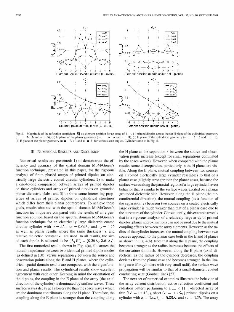
Fig. 8. Magnitude of the reflection coefficient jRj vs. element position for an array of 11 � 11 printed dipoles across the (a) H plane of the cylindrical geometry(m = �5 : 5 and n = 0), (b) H plane of the planar geometry (m = �5 : 5 and n = 0), (c) E plane of the cylindrical geometry (n = �5 : 5 and m = 0),(d) E plane of the planar geometry (n = �5 : 5 and m = 0) for various scan angles. Cylinder same as in Fig. 5.
III. NUMERICAL RESULTS AND DISCUSSION
Numerical results are presented: 1) to demonstrate the ef-ficiency and accuracy of the spatial domain MoM/Green’sfunction technique, presented in this paper, for the rigorousanalysis of finite phased arrays of printed dipoles on elec-trically large dielectric coated circular cylinders; 2) to makea one-to-one comparison between arrays of printed dipoleson these cylinders and arrays of printed dipoles on groundedplanar dielectric slabs; and 3) to show some interesting prop-erties of arrays of printed dipoles on cylindrical structureswhich differ from their planar counterparts. To achieve thesegoals, results obtained with the spatial domain MoM/Green’sfunction technique are compared with the results of an eigen-function solution based on the spectral domain MoM/Green’sfunction technique for an electrically large dielectric coatedcircular cylinder with , andas well as planar results where the same thickness andrelative dielectric constant are used. In all results, the sizeof each dipole is selected to be .
The first numerical result, shown in Fig. 4(a), illustrates themutual impedance between two identical printed dipole modes[as defined in (10)] versus separation between the source andobservation points along the E and H planes, where the cylin-drical spatial domain results are compared with the eigenfunc-tion and planar results. The cylindrical results show excellentagreement with each other. Keeping in mind the orientation ofthe dipoles, the coupling in the E plane of the array (the axialdirection of the cylinder) is dominated by surface waves. Thesesurface waves decay at a slower rate than the space waves whichare the dominant contributors along the H plane. Therefore, thecoupling along the E plane is stronger than the coupling along
the H plane as the separation between the source and obser-vation points increase (except for small separations dominatedby the space waves). However, when compared with the planarresults, some discrepancies, particularly in the H plane, are vis-ible. Along the E plane, mutual coupling between two sourceson a coated electrically large cylinder resembles to that of aplanar case (slightly stronger than the planar case), because thesurface waves along the paraxial region of a large cylinder have abehavior that is similar to the surface waves excited on a planargrounded dielectric slab. However, along the H plane (the cir-cumferential direction), the mutual coupling (as a function ofthe separation ) between two sources on a coated electricallylarge cylinder is much weaker than that of a planar case due tothe curvature of the cylinder. Consequently, this example revealsthat in a rigorous analysis of a relatively large array of printeddipoles, planar approximations can not be used due to the mutualcoupling effects between the array elements. However, as the ra-dius of the cylinder increases, the mutual coupling between twosources approach to the planar case both in the E and H planesas shown in Fig. 4(b). Note that along the H plane, the couplingbecomes stronger as the radius increases because the effects ofthe curvature diminish. However, along the E plane (axial di-rection), as the radius of the cylinder decreases, the couplingdeviates from the planar case and becomes stronger. In the lim-iting case (for cylinders with very small radii), the surface wavepropagation will be similar to that of a small-diameter, coatedconducting wire (Goubau line) [27].
The next set of numerical examples illustrate the behavior ofthe array current distribution, active reflection coefficient andradiation pattern pertaining to a , -directed array ofthin , short printed dipoles on acylinder with , and . The array
ERTÜRK et al.: ANALYSIS OF FINITE ARRAYS OF AXIALLY DIRECTED PRINTED DIPOLES 2593
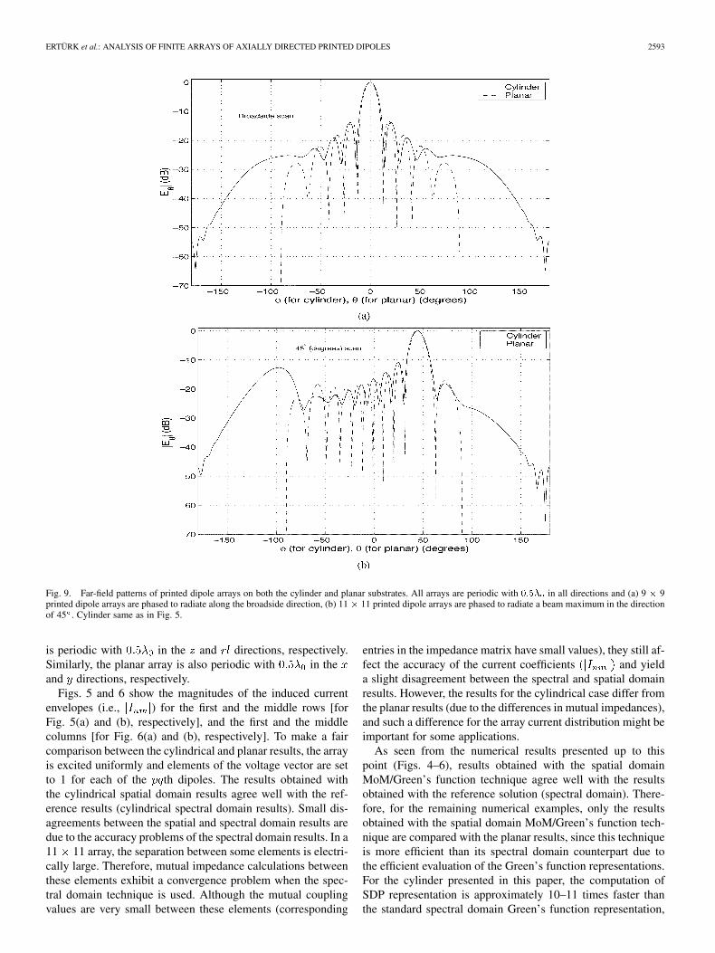
Fig. 9. Far-field patterns of printed dipole arrays on both the cylinder and planar substrates. All arrays are periodic with 0:5� in all directions and (a) 9 � 9printed dipole arrays are phased to radiate along the broadside direction, (b) 11 � 11 printed dipole arrays are phased to radiate a beam maximum in the directionof 45 . Cylinder same as in Fig. 5.
is periodic with in the and directions, respectively.Similarly, the planar array is also periodic with in theand directions, respectively.
Figs. 5 and 6 show the magnitudes of the induced currentenvelopes (i.e., ) for the first and the middle rows [forFig. 5(a) and (b), respectively], and the first and the middlecolumns [for Fig. 6(a) and (b), respectively]. To make a faircomparison between the cylindrical and planar results, the arrayis excited uniformly and elements of the voltage vector are setto 1 for each of the th dipoles. The results obtained withthe cylindrical spatial domain results agree well with the ref-erence results (cylindrical spectral domain results). Small dis-agreements between the spatial and spectral domain results aredue to the accuracy problems of the spectral domain results. In a11 11 array, the separation between some elements is electri-cally large. Therefore, mutual impedance calculations betweenthese elements exhibit a convergence problem when the spec-tral domain technique is used. Although the mutual couplingvalues are very small between these elements (corresponding
entries in the impedance matrix have small values), they still af-fect the accuracy of the current coefficients and yielda slight disagreement between the spectral and spatial domainresults. However, the results for the cylindrical case differ fromthe planar results (due to the differences in mutual impedances),and such a difference for the array current distribution might beimportant for some applications.
As seen from the numerical results presented up to thispoint (Figs. 4–6), results obtained with the spatial domainMoM/Green’s function technique agree well with the resultsobtained with the reference solution (spectral domain). There-fore, for the remaining numerical examples, only the resultsobtained with the spatial domain MoM/Green’s function tech-nique are compared with the planar results, since this techniqueis more efficient than its spectral domain counterpart due tothe efficient evaluation of the Green’s function representations.For the cylinder presented in this paper, the computation ofSDP representation is approximately 10–11 times faster thanthe standard spectral domain Green’s function representation,
2594 IEEE TRANSACTIONS ON ANTENNAS AND PROPAGATION, VOL. 52, NO. 10, OCTOBER 2004
whereas, the paraxial representation is approximately 5–6 timesfaster than the standard spectral domain Green’s function repre-sentation. Also, it should be kept in mind that, as the electricalsize (radius) of the cylinder and/or the separation betweenthe source and observation points get larger, the difference inthe computation time for the evaluation of each representationstrongly favors the spatial domain representations. Further-more, for large cylinders and large separations between thesource and observation points, the spectral domain solution hassevere convergence problems. These are very important issuesfor the rigorous analysis of large arrays on large cylinders.
Fig. 7 depicts the magnitude of the reflection coefficientversus scan angle of a 11 11 dipole array on the aforemen-tioned cylinder along the E plane, and it is compared with theresult of a planar array with similar dipoles (and same parame-ters, i.e. , , etc.). The array is excited using the right handside of (8), where and is varying from 90 to 0 . Asimilar excitation is used for the planar array as explained in [2].Note that in both geometries illustrated in Figs. 1(a) and 2, theangle is defined from the axis. Therefore, a result obtainedat an angle for the planar case is compared with the resultobtained at for the cylinder case. For example, thebroadside scan for the planar case occurs at ,whereas, it occurs at for the cylindricalgeometry. The reflection coefficients of both arrays (cylindricaland planar) are computed at the center element of the arrayswhich are matched at broadside scan. The result shows thatthe printed dipole array mounted on the cylinder shows a scanblindness at approximately . At this scan angle, thereflection coefficient magnitude of the center element is greaterthan unity. This simply means that this dipole delivers power toits generator, which is transferred from other ports. Although,the shape of the reflection coefficient magnitude correspondingto the planar case is similar to that of cylinder case and it peaksalmost at the same angle, it never exceeds to unity for theparameters used in this example and hence, no scan blindnessis observed. Since scan blindness is attributed to the surfacewave fields excited within the substrate of this array [1], [2],the curvature of the supporting structure will surely changethe behavior of these fields. Therefore, it is not surprising thatthe results for the planar and cylindrical arrays are somewhatdifferent.
Based on Fig. 7 and as explained in [2], the input impedanceacross the finite arrays (both cylindrical and planar ones) are ex-pected to be nonuniform. Fig. 8 demonstrates this variation forfinite phased arrays of printed dipoles both on grounded cylin-drical and planar substrates, showing the magnitude of the re-flection coefficient as a function of element position across theH and E planes of the 11 11 array, for various scan angles. Inall plots the value of . Therefore, a symmetry with re-spect to the center element is expected and observed across theH plane as shown in Fig. 8(a) and (b). On the other hand, the
(or for planar case) case is symmetric aboutthe center of the array in both planes, and the center elementis perfectly matched at broadside, though the other elements areslightly mismatched. For other values, the mismatch is greaterand an asymmetry is observed across the E plane as expected.One can notice that the mismatch for the array of printed dipoles
on the cylinder is always greater than its planar counterpart.On the other hand, the data across the H plane [seeFig. 8(a)] and data across the E plane [see Fig. 8(c)]show that a number of dipole ports on the array have reflectioncoefficient magnitudes greater than unity, which means that theother dipoles are absorbing power from their gen-erators and delivering this power to the elements with .However, for the planar case, although the shape of the reflectioncoefficient magnitude for each scan angle resembles its cylin-drical counterpart, none of them exceeds unity as shown clearlyin Fig. 8(b) and (d). Consequently, Figs. 7 and 8 reveal that thecurvature plays a significant role for the scan blindness phenom-enon for a finite phased array of axially oriented printed dipoles.
Finally, the normalized far-field radiation patterns of a 9 9and a 11 11 phased arrays of printed dipoles on the aforemen-tioned cylinder are obtained using the principle of superposition(i.e. using an element by element approach) and are comparedwith those of planar ones for two scan angles in Fig. 9(a) and (b),respectively. In both figures, the arrays are scanned along the Hplane. Therefore, for the cylinder geometry, is kept constantat 90 while the angle is scanned. For the planar geometry,
is kept at 90 while the angle is scanned. Also, no spe-cial beam forming techniques is applied for the excitation ofthe arrays. Each dipole is excited uniformly and phased to ra-diate a beam maximum in the broadside direction and in thedirection of for the cylinder ( for the planarcase) in Fig. 9(a) and (b), respectively. Both of the cylindricalprinted dipole arrays are periodic with in the and di-rections. The same periodicity is valid for the planar array in the
and directions. The size of each dipole as well as the param-eters of both the coated cylinder and the grounded slab are keptthe same as before. It is observed that pattern of a cylindricalprinted dipole array is close to that of a planar one along themain beam and furthermore, the first couple of side lobe levelsare also close. However, away from the main lobe, the shape ofthe patterns change significantly. That is expected and it is due tothe curvature of the cylinder. In particular, high sidelobes occurwhen the cylindrical printed dipole arrays are fed uniformly asillustrated in Fig. 9(b) for the 11 11 array. This is expected forlarge conformal arrays since some of the element patterns havetheir peaks at angles other than the intended main beam direc-tion as explained in [24]. Therefore, the port excitations mustbe modified for the array on the cylinder to avoid these highsidelobes. In fact, array synthesis algorithms for the cylindricalarray have to be different from the well known algorithms forthe planar case.
IV. CONCLUSION
This paper has presented an efficient and accurate analysisof a finite phased array of printed dipoles mounted on an elec-trically large dielectric coated circular cylinder using a methodbased on the combination of the MoM with a special Green’sfunction in the spatial domain. The efficiency and accuracy ofthe method comes directly from the computation of the Green’sfunction, which is the kernel of the EFIE to be solved usingthe MoM. Therefore, relatively large arrays on electrically large

ERTÜRK et al.: ANALYSIS OF FINITE ARRAYS OF AXIALLY DIRECTED PRINTED DIPOLES 2595
coated cylinders can be analyzed rigorously in which the mu-tual coupling through both the space and surface waves has beenincorporated.
Several numerical examples, in the form of mutual couplingbetween two printed dipole modes and array current distri-butions for a relatively large array, have been calculated andcompared with a reference solution to assess the accuracy ofthis method. Furthermore, basic performance metrics of arrayshave been obtained and compared with similar printed arrayson grounded planar substrates. Certain discrepancies have beenobserved and discussed.
A number of other related problems, as well as the effectof various array parameters (e.g., element spacing, size of thedipoles, thickness and dielectric constant of the coating, etc.)on the behavior of the array can be addressed to assess the per-formance of printed phased arrays on electrically large coatedcylinders.
REFERENCES
[1] D. M. Pozar and D. H. Schaubert, “Scan blindness in infinite phasedarrays of printed dipoles,” IEEE Trans. Antennas Propagat., vol. AP-32,pp. 602–610, June 1984.
[2] D. M. Pozar, “Analysis of finite phased arrays of printed dipoles,” IEEETrans. Antennas Propagat., vol. AP-33, pp. 1045–1053, Oct. 1985.
[3] A. K. Skrivervik and J. R. Mosig, “Finite phased arrays of microstrippatch antennas: the infinite array approach,” IEEE Trans. AntennasPropagat., vol. 40, pp. 579–582, May 1992.
[4] A. Nakatini, N. G. Alexopoulus, N. K. Uzunoglu, and P. L. E. Uslenghi,“Accurate Green’s function computation for printed circuit antennas oncylindrical antennas,” Electromagnetics, vol. 6, pp. 243–254, July–Sept.1986.
[5] T. M. Habashy, S. M. Ali, and J. A. Kong, “Input impedance and radi-ation pattern of cylindrical-rectangular and wraparound microstrip an-tennas,” IEEE Trans. Antennas Propagat., vol. 38, pp. 722–731, May1990.
[6] A. Dreher and M. Thiel, “Dyadic Green’s function of multilayer cylin-drical closed and sector structures for waveguide, microstrip-antenna,and network analysis,” IEEE Trans. Microwave Theory and Techniques,vol. 50, pp. 2576–2579, Nov. 2002.
[7] W. Y. Tam, A. K. Y. Lai, and K. M. Luk, “Mutual coupling betweencylindrical-rectangular microstrip antennas,” IEEE Trans. AntennasPropagat., vol. 43, pp. 897–899, Aug. 1995.
[8] C.-Y. Huang and Y.-T. Chang, “Curvature effects on the mutual couplingof cylindrical-rectangular microstrip antennas,” Electron. Lett., vol. 33,pp. 1108–1109, June 1997.
[9] K.-L. Wong, Design of Nonplanar Microstrip Antennas and Transmis-sion Lines. New York: Wiley, 1999.
[10] I. Jayakumar, R. Garg, B. K. Sarap, and B. Lal, “A conformal cylindricalmicrostrip array for producing omnidirectional radiation pattern,” IEEETrans. Antennas Propagat., vol. 34, pp. 1258–1261, Oct. 1986.
[11] C. M. Da Silva, F. Lumini, J. S. Da S. Lacava, and F. P. Richards, “Anal-ysis of cylindrical arrays of microstrip rectangular patches,” Electron.Lett., vol. 27, pp. 778–780, April 1991.
[12] D. I. Wu, “Omnidirectional circularly-polarized microstrip array fortelemetry applications,” in Proc. IEEE Antennas and Propagat. Symp.Dig., vol. 2, June 1995, pp. 998–1001.
[13] D. Loffler, W. Wiesbeck, and B. Johannisson, “Conformal aperture cou-pled microstrip phased array on a cylindrical surface,” in Proc. IEEEAntennas and Propagat. Symp. Dig., vol. 2, July 1999, pp. 882–885.
[14] Y. Liu, Y. Wang, and R. Yang, “A cylindrical spiral patch array,” IEEETrans. Antennas Propagat., vol. 49, pp. 196–199, Feb. 2001.
[15] K. M. Luk, K. F. Lee, and J. S. Dahele, “Analysis of cylindrical-rect-angular patch antenna,” IEEE Trans. Antennas Propagat., vol. 37, pp.143–147, Feb. 1989.
[16] J.-M. Jin, J. A. Berrie, R. Kipp, and S.-W. Lee, “Calculation of radiationpatterns of microstrip antennas on cylindrical bodies of arbitrary crosssection,” IEEE Trans. Antennas Propagat., vol. 45, pp. 126–132, Jan.1997.
[17] V. B. Ertürk and R. G. Rojas, “Efficient computation of surface fieldsexcited on a dielectric coated circular cylinder,” IEEE Trans. AntennasPropagat., vol. 48, pp. 1507–1516, Oct. 2000.
[18] , “Paraxial space-domain formulation for surface fields on dielectriccoated circular cylinder,” IEEE Trans. Antennas Propagat., vol. 50, pp.1577–1587, Nov. 2002.
[19] , “Efficient analysis of input impedance and mutual coupling ofmicrostrip antennas mounted on large coated cylinders,” IEEE Trans.Antennas Propagat., vol. 51, pp. 739–749, Apr. 2003.
[20] S. Barkeshli, P. H. Pathak, and M. Marin, “An asymptotic closed-formmicrostrip surface Green’s function for the efficient moment methodanalysis of mutual coupling in microstrip antennas,” IEEE Trans. An-tennas Propagat., vol. 38, pp. 1374–1383, Sept. 1990.
[21] D. M. Pozar, “Input impedance and mutual coupling of rectangular mi-crostrip antennas,” IEEE Trans. Antennas Propagat., vol. AP-30, pp.1191–1196, Nov. 1982.
[22] M. Abramowitz and I. A. Stegun, Handbook of Mathematical Func-tions. New York: Dover Publications, 1970.
[23] R. C. Hansen, Phased Array Antennas. New York: Wiley, 1998.[24] R. J. Mailloux, Phased Array Antenna Handbook. Boston: Artech,
1994.[25] J. Ashkenazy, S. Shtrikman, and D. Treves, “Electric surface current
model for the analysis of microstrip antennas on cylindrical bodies,”IEEE Trans. Antennas Propagat., vol. 33, pp. 295–300, Mar. 1985.
[26] R. A. Martin and D. H. Werner, “A reciprocity approach for calculatingthe far-field radiation patterns of a center-fed helical microstrip antennamounted on a dielectric coated circular cylinder,” IEEE Trans. AntennasPropagat., vol. 49, pp. 1754–1762, Dec. 2001.
[27] G. Goubau, “Surface waves and their applications to transmission lines,”J. Appl. Phys., vol. 21, pp. 1119–1128, Nov. 1950.
Vakur B. Ertürk (M’00) received the B. S. degree in electrical engineeringfrom the Middle East Technical University, Ankara, Turkey, in 1993 and theM. S. and Ph.D. degrees from The Ohio-State University (OSU), Columbus, in1996 and 2000, respectively.
He is currently an Assistant Professor with the Electrical and ElectronicsEngineering Department, Bilkent University, Ankara. His research interests in-clude the design and analysis of planar and conformal arrays, active integratedantennas, analysis of propagation over large terrain profiles.
Roberto G. Rojas (S’80–M’85–SM’90–F’01) received the B.S.E.E. degreefrom New Mexico State University, Las Cruces, in 1979, and the M.S. andPh.D. degrees in electrical engineering from The Ohio State University (OSU)Columbus, in 1981 and 1985, respectively.
He is currently a Professor in the Department of Electrical and Computer En-gineering with The Ohio State University. His current research interests includethe analysis and design of conformal arrays, active integrated arrays, nonlinearmicrowave circuits, as well as the analysis of electromagnetic radiation and scat-tering phenomena in complex environments.
Dr. Rojas an elected Member of U.S. Commission B of URSI. He wonthe 1988 R. W. P. King Prize Paper Award, the 1990 Browder J. ThompsonMemorial Prize Award, both given by IEEE, and the 1989 and 1993 LumleyResearch Awards, given by the College of Engineering, OSU. He has servedas a Chairman, Vice-Chairman, and Secretary/Treasurer of the Columbus, OHChapter of the IEEE Antennas and Propagation and Microwave Theory andTechniques Societies.
Kit Wing Lee received the B.S.E.E. and MS. degrees from The Ohio State Uni-versity, in 1996 and 1998, respectively, where he is currently working towardthe Ph.D. degree in the Department of Electrical and Computer Engineering.
Since January of 2003, he has been employed by Texas Instruments, Inc.,Dallas, TX, as an IC designer. His research interests include RF and microwavecircuit design, computational electromagnetic techniques, coupled oscillator an-tenna array and ultrawide-band technologies.