an efficient method for packing polygonal domains with disks for 2d discrete element simulation
TRANSCRIPT
Computers and Geotechnics 36 (2009) 568–576
Contents lists available at ScienceDirect
Computers and Geotechnics
journal homepage: www.elsevier .com/ locate/compgeo
An efficient method for packing polygonal domains with disks for 2D discreteelement simulation
A.M. ZsakiDepartment of Building, Civil and Environmental Engineering, Concordia University, 1455 de Maisonneuve Blvd. West, Montreal, Quebec, Canada H3G1M8
a r t i c l e i n f o a b s t r a c t
Article history:Received 23 October 2007Received in revised form 16 July 2008Accepted 17 October 2008Available online 28 November 2008
Keywords:Discrete elementSimulationPackingComputational geometry
0266-352X/$ - see front matter � 2008 Elsevier Ltd.doi:10.1016/j.compgeo.2008.10.005
E-mail address: [email protected]
The discrete element method (DEM) is frequently used in numerical simulation of the behaviour of dis-continuum often encountered in granular flow, soil or rock mechanics or powder compaction. The DEMrequires an assemblage of elements that need to fill the domain geometry. Generation of such arrange-ment of elements, such as disks in 2D DEM simulation is not a trivial task. The available methods to createthe arrangements of disks can either take considerable time, have limited control over the final outcomeof the disk generation or exhibit difficulty in generating a tight arrangement of disk with varying radii.This paper presents an algorithm employing principles of computational geometry to efficiently generatea tight packing of disks while addressing the common problems of disk generation. The algorithm’s per-formance is linear with respect to time and scales well. As a demonstration of the algorithm’s capabilities,a DEM model of an ore pass is presented.
� 2008 Elsevier Ltd. All rights reserved.
1. Introduction
The simulation of the mechanical behaviour of rock often needsto consider the discontinuous nature of the rock mass. The discon-tinuities, such as joints or fractures, dictate the deformation of therock mass by sliding or rotation of the constituent blocks. Similarly,the mechanical behaviour of granular materials, such as sands andgravels can be modeled with success using discontinuum theories.The discrete element method (DEM) is one of the techniques tomodel this discontinuum behaviour [1]. Within the DEM thereare a number of approaches to modeling, differing mainly in thegeometry of the discrete elements or how the contacts betweenthe elements are handled, or if bonding of particles is consideredin the simulation [2–4]. The application of DEM in sciences andengineering, apart from soil and rock mechanics, ranges from sim-ulating powder compaction in the pharmaceutical industry [5],modeling sea ice mechanics [6] and structural masonry [7]. Re-cently DEM found its use not only in engineering simulations,but in the computer game industry, where it is used to enhance ri-gid body physics in the interaction of in-game objects [8,9]. Theusefulness of DEM simulations in soil and rock mechanics couldbe severely limited by the inherently long computation times. Anaïve implementation of a DEM results in an O(n2) running timewith respect to the number of elements. Thus, if realistic grainsizes are used in the simulation, the problem domain is limited
All rights reserved.
to a relatively small area such as a size of a triaxial specimen oronly part of a larger domain, such as a tunnel, can be modeled withDEM [2]. The time complexity of the method can be reduced by cle-ver techniques for collision detection between discrete elementsusing spatial and temporal coherence [4] or by accelerating partof the computation in hardware [10].
No matter how the DEM is implemented, the simulation re-quires an initial arrangement of discrete elements that fill the do-main geometry. Although often overlooked, the generation of thisinitial arrangement of discrete elements, or disks in 2D for ourimplementation, can potentially influence the simulation; bothrunning time and numerical stability. Paralleling to the develop-ment of the DEM, there have been various approaches in creatingthe initial arrangement of the disks. Usually a random arrange-ment of disks of varying radii, sampled from a particle size distri-bution, is sought after to ensure a physically accurate model. Thispaper addresses the generation of such random arrangement ofdisks for 2D DEM simulation by presenting a algorithm, or meth-od, with close to O(n) running time that can generate a tightpacking of disks filling an arbitrarily shaped polygonal domain.The algorithm is capable to fill a polygonal domain at a rate ofless than 0.5 s per one million disks on commodity hardware.The encountered difficulties are presented in the disk generationalgorithm, often posed by the geometry of the problem and solu-tions are provided to address them. Finally a practical example isshown of the application of the algorithm to generate an initialarrangement of disks for a DEM simulation of ore flow to a drawpoint in mining.
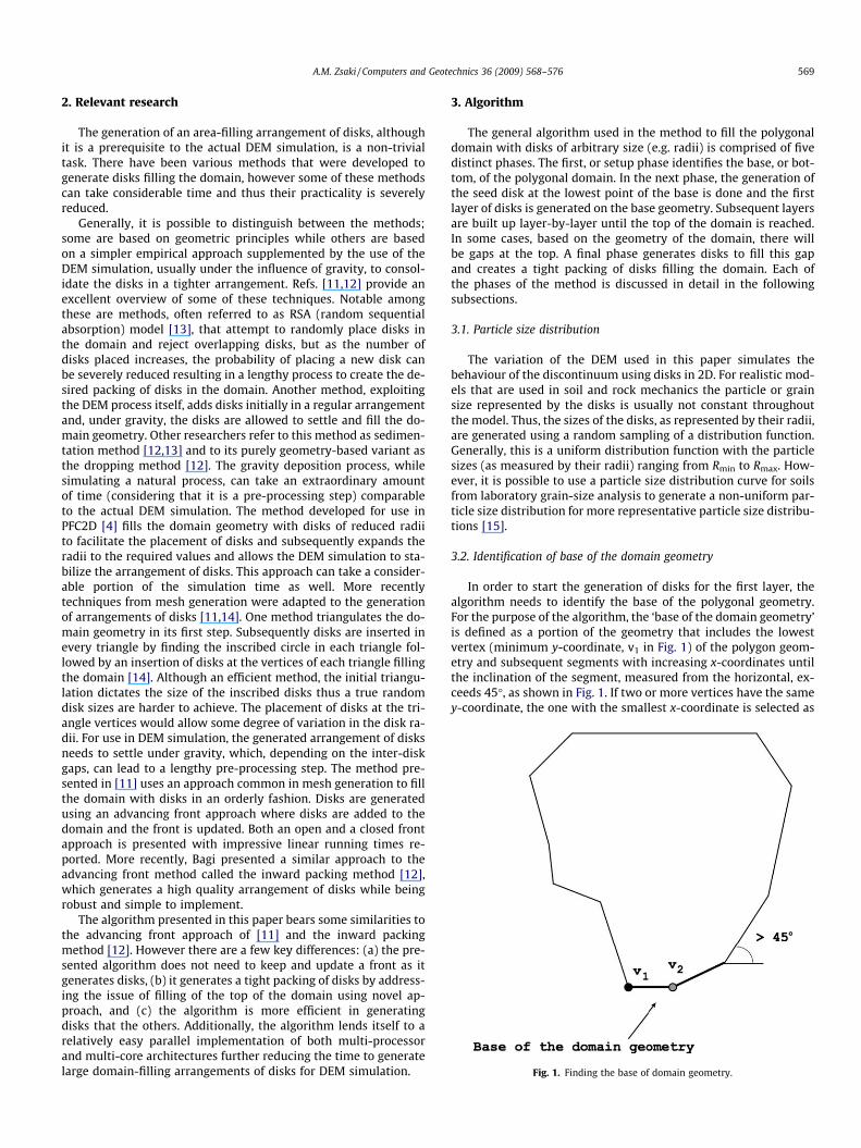
Fig. 1. Finding the base of domain geometry.
A.M. Zsaki / Computers and Geotechnics 36 (2009) 568–576 569
2. Relevant research
The generation of an area-filling arrangement of disks, althoughit is a prerequisite to the actual DEM simulation, is a non-trivialtask. There have been various methods that were developed togenerate disks filling the domain, however some of these methodscan take considerable time and thus their practicality is severelyreduced.
Generally, it is possible to distinguish between the methods;some are based on geometric principles while others are basedon a simpler empirical approach supplemented by the use of theDEM simulation, usually under the influence of gravity, to consol-idate the disks in a tighter arrangement. Refs. [11,12] provide anexcellent overview of some of these techniques. Notable amongthese are methods, often referred to as RSA (random sequentialabsorption) model [13], that attempt to randomly place disks inthe domain and reject overlapping disks, but as the number ofdisks placed increases, the probability of placing a new disk canbe severely reduced resulting in a lengthy process to create the de-sired packing of disks in the domain. Another method, exploitingthe DEM process itself, adds disks initially in a regular arrangementand, under gravity, the disks are allowed to settle and fill the do-main geometry. Other researchers refer to this method as sedimen-tation method [12,13] and to its purely geometry-based variant asthe dropping method [12]. The gravity deposition process, whilesimulating a natural process, can take an extraordinary amountof time (considering that it is a pre-processing step) comparableto the actual DEM simulation. The method developed for use inPFC2D [4] fills the domain geometry with disks of reduced radiito facilitate the placement of disks and subsequently expands theradii to the required values and allows the DEM simulation to sta-bilize the arrangement of disks. This approach can take a consider-able portion of the simulation time as well. More recentlytechniques from mesh generation were adapted to the generationof arrangements of disks [11,14]. One method triangulates the do-main geometry in its first step. Subsequently disks are inserted inevery triangle by finding the inscribed circle in each triangle fol-lowed by an insertion of disks at the vertices of each triangle fillingthe domain [14]. Although an efficient method, the initial triangu-lation dictates the size of the inscribed disks thus a true randomdisk sizes are harder to achieve. The placement of disks at the tri-angle vertices would allow some degree of variation in the disk ra-dii. For use in DEM simulation, the generated arrangement of disksneeds to settle under gravity, which, depending on the inter-diskgaps, can lead to a lengthy pre-processing step. The method pre-sented in [11] uses an approach common in mesh generation to fillthe domain with disks in an orderly fashion. Disks are generatedusing an advancing front approach where disks are added to thedomain and the front is updated. Both an open and a closed frontapproach is presented with impressive linear running times re-ported. More recently, Bagi presented a similar approach to theadvancing front method called the inward packing method [12],which generates a high quality arrangement of disks while beingrobust and simple to implement.
The algorithm presented in this paper bears some similarities tothe advancing front approach of [11] and the inward packingmethod [12]. However there are a few key differences: (a) the pre-sented algorithm does not need to keep and update a front as itgenerates disks, (b) it generates a tight packing of disks by address-ing the issue of filling of the top of the domain using novel ap-proach, and (c) the algorithm is more efficient in generatingdisks that the others. Additionally, the algorithm lends itself to arelatively easy parallel implementation of both multi-processorand multi-core architectures further reducing the time to generatelarge domain-filling arrangements of disks for DEM simulation.
3. Algorithm
The general algorithm used in the method to fill the polygonaldomain with disks of arbitrary size (e.g. radii) is comprised of fivedistinct phases. The first, or setup phase identifies the base, or bot-tom, of the polygonal domain. In the next phase, the generation ofthe seed disk at the lowest point of the base is done and the firstlayer of disks is generated on the base geometry. Subsequent layersare built up layer-by-layer until the top of the domain is reached.In some cases, based on the geometry of the domain, there willbe gaps at the top. A final phase generates disks to fill this gapand creates a tight packing of disks filling the domain. Each ofthe phases of the method is discussed in detail in the followingsubsections.
3.1. Particle size distribution
The variation of the DEM used in this paper simulates thebehaviour of the discontinuum using disks in 2D. For realistic mod-els that are used in soil and rock mechanics the particle or grainsize represented by the disks is usually not constant throughoutthe model. Thus, the sizes of the disks, as represented by their radii,are generated using a random sampling of a distribution function.Generally, this is a uniform distribution function with the particlesizes (as measured by their radii) ranging from Rmin to Rmax. How-ever, it is possible to use a particle size distribution curve for soilsfrom laboratory grain-size analysis to generate a non-uniform par-ticle size distribution for more representative particle size distribu-tions [15].
3.2. Identification of base of the domain geometry
In order to start the generation of disks for the first layer, thealgorithm needs to identify the base of the polygonal geometry.For the purpose of the algorithm, the ‘base of the domain geometry’is defined as a portion of the geometry that includes the lowestvertex (minimum y-coordinate, v1 in Fig. 1) of the polygon geom-etry and subsequent segments with increasing x-coordinates untilthe inclination of the segment, measured from the horizontal, ex-ceeds 45�, as shown in Fig. 1. If two or more vertices have the samey-coordinate, the one with the smallest x-coordinate is selected as
570 A.M. Zsaki / Computers and Geotechnics 36 (2009) 568–576
the starting vertex (Fig. 1, v1 is selected instead of v2). Although it isunderstood that there could be geometries for which this simplemethod may fail or generate inappropriate results, for most practi-cal problems encountered in simulating soil and rock mechanicsproblems using DEM, the method proved to be successful.
3.3. Generation of the seed disk
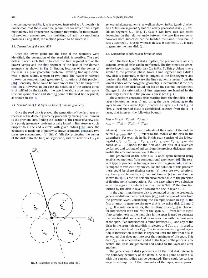
Once the lowest point and the base of the geometry wereidentified, the generation of the seed disk is possible. The seeddisk is placed such that it touches the first segment left of thelowest vertex and the first segment of the base of the domaingeometry as shown in Fig. 2. Finding location of the center ofthe disk is a pure geometric problem, involving finding a circle,with a given radius, tangent to two lines. The reader is referredto texts on computational geometry for solutions of this problem[16]. Generally, there could be four circles that can be tangent totwo lines. However, in our case the selection of the correct circleis simplified by the fact that the two lines share a common point(the end-point of one and starting point of the next line segment)as shown in Fig. 2.
3.4. Generation of first layer on base of domain geometry
Once the seed disk is placed, the generation of the first layer onthe base of the domain geometry proceeds by placing disks. Similarto the previous step, finding the location of the center of a new diskis a purely geometric problem usually found in literature as circletangent to a line and a circle with given radius [16]. Since thegeometry is made up of piecewise linear segments, generally twocases are encountered: (a) disk Ci falls (by projecting the centerof the disk onto the line) on segment Li and the new disk Ci + 1 is
Fig. 2. Generation of the seed disk, after [16].
generated along segment Li as well, as shown in Fig. 3,and (b) whendisk Ci falls on segment Li, but the newly generated disk Ci + 1 willfall on segment Li + 1 (Fig. 4). Case b can have two sub-cases;depending on the relative angle between the two line segments,however both sub-cases can be treaded the same. Therefore, incase a segment Li is used, whereas in case b, segment Li + 1 is usedto generate the new disk Ci + 1.
3.5. Generation of subsequent layers of disks
With the base layer of disks in place, the generation of all sub-sequent layers of disks can be performed. The first step is to gener-ate the layer’s starting disk (disk Cn,0 in Fig. 5). This problem is verysimilar to the previous phase. Given a line segment and a disk anew disk is generated, which is tangent to the line segment andtouches the disk. In this case the line segment, starting from thelowest vertex of the polygonal geometry is incremented if the pro-jection of the new disk would not fall on the current line segment.Changes in the orientation of line segments are handled in thesame way as case b in the previous phase (cf. Fig. 4).
The algorithm generates disks starting from the first disk in thelayer (denoted as layer n) and using the disks belonging to thelayer below the current layer (denoted as layer n � 1 on Fig. 5).First, a local span of disks is established, selected from the n � 1layer, that intersect the following bounds:
xmin ¼ xðCn;iÞ � rðCn;iÞ � rðCn;iþ1Þxmax ¼ xðCn;iÞ þ rðCn;iÞ þ 2rðCn;iþ1Þ
where x(. . .) denotes the x-coordinate of the center of the disk la-beled Clayer,index and r(. . .) refers to the radius of the disk in theparenthesis. For example in Fig. 5, this span consists of the follow-ing disks; Cn� 1,j, Cn � 1,j + 1, Cn � 1,j + 2, Cn � 1,j+3 and Cn � 1,j + 4 and de-noted as Sn � 1. Checks for the first and last disk of a layer areperformed and caching of indices from the previous disk generationenable the efficient generation of the span.
The generation of the new disk is once again handled usingestablished methods from computational geometry [16]. The rele-vant type of problem is finding a circle, with a given radius, whichis tangent to two existing circles. For the solution of this problemthere could be there distinct cases: (a) there are two solutions,e.g. two possible circles, (b) one solution or (c) no solution, asshown in Fig. 6. Case b is seldom encountered due to the precisionof floating point computations. For the case where two solutionsexist, the algorithm selects the disk that is ‘left of’ the directionformed by the disk in layer n toward the one in layer n � 1.
In the algorithm, the new disk is generated using the previouslygenerated disk on the current layer (Cn,i) and the span of disks fromthe previous layer. Considering the example shown in Fig. 5, thefirst attempt to generate the new disk is by using disk Cn,i and Cn � 1,j. If a solution is exists, the resulting disk (Cn,t1) is checkedfor intersection with the rest of the span Sn � 1 from left to right.If no solution exists, the next disk in the span is used to generatethe new trial disk and checked for intersection with the remainderof the span. If an intersection is found between Cn,t1 and any of thedisks in the span, this trial disk is rejected and Cn � 1,j + 1 is used togenerate a new trial disk Cn,t2. The intersection testing and rejec-tion, if intersection is found, is repeated until the first trial disk isgenerated that does not intersect the remainder of the span. Thisdisk (Cn,i + 1) is accepted and added to the layer n. The process is re-peated and disks are generated and added to the layer one afteranother.
The generation of disks proceeds until the trial disk intersectsthe boundary geometry of the domain. At this point no new diskwith the current radius can be generated. There could be variousways to attempt to fill the remainder of the layer; one approach
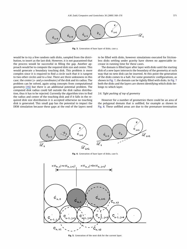
Fig. 3. Generation of base layer of disks, case a.
A.M. Zsaki / Computers and Geotechnics 36 (2009) 568–576 571
would be to try a few random radii disks, sampled from the distri-bution, to insert as the last disk. However, it is not guaranteed thatthe process would be successful in filling the gap. Another ap-proach would be to compute the required disk size and center. Thiswould generate a boundary touching disk. This problem is morecomplex since it is required to find a circle such that it is tangentto two other circles and to a line. There are three unknowns in thiscase; the center (x- and y-coordinates) of the disk and its radius. Theproblem can be solved, again using concepts from computationalgeometry [16] but there is an additional potential problem. Thecomputed disk radius could fall outside the disk radius distribu-tion, thus it has to be rejected. Currently the algorithm tries to findthe radius and center of the touching disk and if it falls in the re-quired disk size distribution it is accepted otherwise no touchingdisk is generated. This small gap has the potential to impact theDEM simulation because these gaps at the end of the layers need
Fig. 4. Generation of base
Fig. 5. Generation of the next
to be filled with disks, however simulations executed for friction-less disks settling under gravity have shown no appreciable in-crease in running time for these cases.
The domain is filled layer after layer with disks until the startingdisk of a new layer intersects the boundary of the geometry at suchway that no new disk can be inserted. At this point the generationof the disks comes to a halt. For some geometric configurations, asshown in Fig. 7, the domain can be tightly filled with disks. In Fig. 7both the disks and the layers are shown identifying which disks be-longs to which layer.
3.6. Tight packing of top of geometry
However for a number of geometries there could be an area ofthe polygonal domain that is unfilled, for example as shown inFig. 8. These unfilled areas are due to the premature termination
layer of disks, case b.
disk for the current layer.
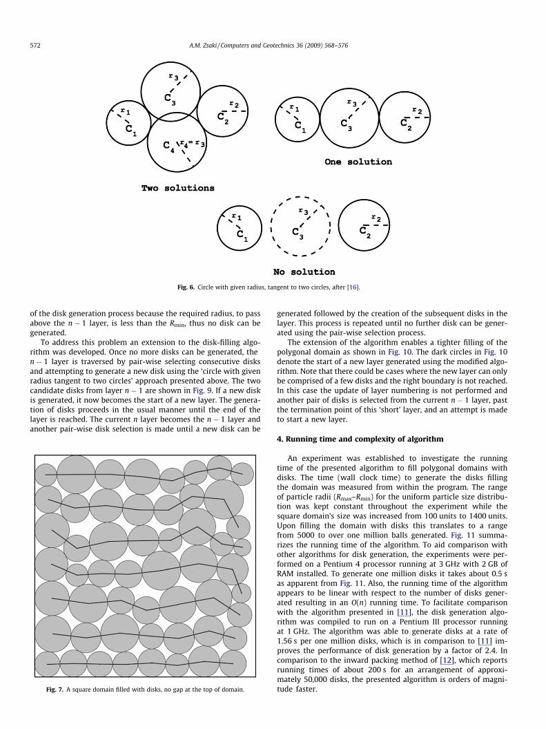
Fig. 6. Circle with given radius, tangent to two circles, after [16].
572 A.M. Zsaki / Computers and Geotechnics 36 (2009) 568–576
of the disk generation process because the required radius, to passabove the n � 1 layer, is less than the Rmin, thus no disk can begenerated.
To address this problem an extension to the disk-filling algo-rithm was developed. Once no more disks can be generated, then � 1 layer is traversed by pair-wise selecting consecutive disksand attempting to generate a new disk using the ‘circle with givenradius tangent to two circles’ approach presented above. The twocandidate disks from layer n � 1 are shown in Fig. 9. If a new diskis generated, it now becomes the start of a new layer. The genera-tion of disks proceeds in the usual manner until the end of thelayer is reached. The current n layer becomes the n � 1 layer andanother pair-wise disk selection is made until a new disk can be
Fig. 7. A square domain filled with disks, no gap at the top of domain.
generated followed by the creation of the subsequent disks in thelayer. This process is repeated until no further disk can be gener-ated using the pair-wise selection process.
The extension of the algorithm enables a tighter filling of thepolygonal domain as shown in Fig. 10. The dark circles in Fig. 10denote the start of a new layer generated using the modified algo-rithm. Note that there could be cases where the new layer can onlybe comprised of a few disks and the right boundary is not reached.In this case the update of layer numbering is not performed andanother pair of disks is selected from the current n � 1 layer, pastthe termination point of this ‘short’ layer, and an attempt is madeto start a new layer.
4. Running time and complexity of algorithm
An experiment was established to investigate the runningtime of the presented algorithm to fill polygonal domains withdisks. The time (wall clock time) to generate the disks fillingthe domain was measured from within the program. The rangeof particle radii (Rmax–Rmin) for the uniform particle size distribu-tion was kept constant throughout the experiment while thesquare domain’s size was increased from 100 units to 1400 units.Upon filling the domain with disks this translates to a rangefrom 5000 to over one million balls generated. Fig. 11 summa-rizes the running time of the algorithm. To aid comparison withother algorithms for disk generation, the experiments were per-formed on a Pentium 4 processor running at 3 GHz with 2 GB ofRAM installed. To generate one million disks it takes about 0.5 sas apparent from Fig. 11. Also, the running time of the algorithmappears to be linear with respect to the number of disks gener-ated resulting in an O(n) running time. To facilitate comparisonwith the algorithm presented in [11], the disk generation algo-rithm was compiled to run on a Pentium III processor runningat 1 GHz. The algorithm was able to generate disks at a rate of1.56 s per one million disks, which is in comparison to [11] im-proves the performance of disk generation by a factor of 2.4. Incomparison to the inward packing method of [12], which reportsrunning times of about 200 s for an arrangement of approxi-mately 50,000 disks, the presented algorithm is orders of magni-tude faster.

Fig. 10. Tighter filling of the polygonal domain with the extended algorithm.
Fig. 8. Premature termination of the disk generation process.
Fig. 9. Restarting the disk generation process to fill gaps.
A.M. Zsaki / Computers and Geotechnics 36 (2009) 568–576 573
5. Measure of the quality of the disk packing
In order to evaluate the quality of the disk packing various met-rics can be employed. However, most of them evaluate the dense-ness or tightness of the packing [14]. The void ratio e, from soilmechanics, is defined as the ratio of the volume occupied by thevoids in the soil (Vv) to the volume of the soil solids (Vs), or
e ¼ VV
Vs
where the total volume of the soil system is V = Vs + Vv [15]. Inmaterial sciences, the concept of denseness is quantified by thecoordination number, representing the average number of contactsper disk [14]. Accepting the definition of coordination number as sta-ted in [14] but expanding it to include contacts with the boundariesof the domain [12], it can be written as
N ¼ 2NC þ NCB
NP
where NC is the number of contacts between disks, NCB is the num-ber of contacts between disks and the boundaries and NP is thenumber of disks in the model.
The range of disk radii in the model can greatly influence thevoid ratio and the coordination number. For the model shown inFig. 12, the range of particles radii was from 0.3 to 1.1 units
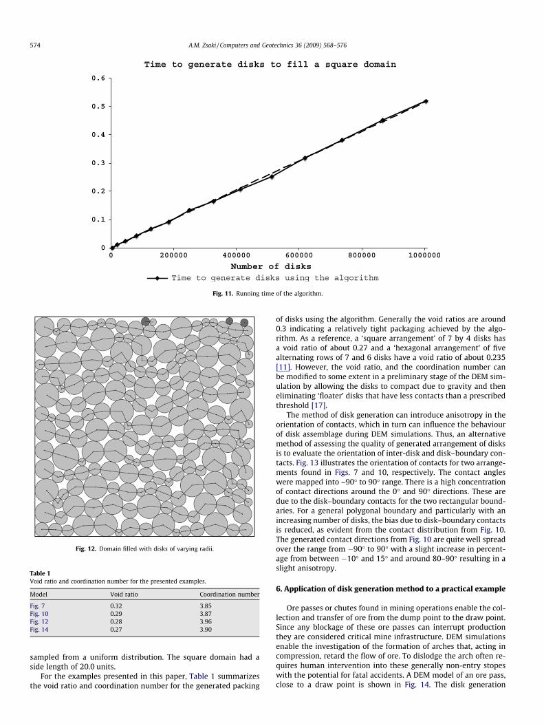
Fig. 11. Running time of the algorithm.
Fig. 12. Domain filled with disks of varying radii.
Table 1Void ratio and coordination number for the presented examples.
Model Void ratio Coordination number
Fig. 7 0.32 3.85Fig. 10 0.29 3.87Fig. 12 0.28 3.96Fig. 14 0.27 3.90
574 A.M. Zsaki / Computers and Geotechnics 36 (2009) 568–576
sampled from a uniform distribution. The square domain had aside length of 20.0 units.
For the examples presented in this paper, Table 1 summarizesthe void ratio and coordination number for the generated packing
of disks using the algorithm. Generally the void ratios are around0.3 indicating a relatively tight packaging achieved by the algo-rithm. As a reference, a ‘square arrangement’ of 7 by 4 disks hasa void ratio of about 0.27 and a ‘hexagonal arrangement’ of fivealternating rows of 7 and 6 disks have a void ratio of about 0.235[11]. However, the void ratio, and the coordination number canbe modified to some extent in a preliminary stage of the DEM sim-ulation by allowing the disks to compact due to gravity and theneliminating ‘floater’ disks that have less contacts than a prescribedthreshold [17].
The method of disk generation can introduce anisotropy in theorientation of contacts, which in turn can influence the behaviourof disk assemblage during DEM simulations. Thus, an alternativemethod of assessing the quality of generated arrangement of disksis to evaluate the orientation of inter-disk and disk–boundary con-tacts. Fig. 13 illustrates the orientation of contacts for two arrange-ments found in Figs. 7 and 10, respectively. The contact angleswere mapped into –90� to 90� range. There is a high concentrationof contact directions around the 0� and 90� directions. These aredue to the disk–boundary contacts for the two rectangular bound-aries. For a general polygonal boundary and particularly with anincreasing number of disks, the bias due to disk–boundary contactsis reduced, as evident from the contact distribution from Fig. 10.The generated contact directions from Fig. 10 are quite well spreadover the range from �90� to 90� with a slight increase in percent-age from between �10� and 15� and around 80–90� resulting in aslight anisotropy.
6. Application of disk generation method to a practical example
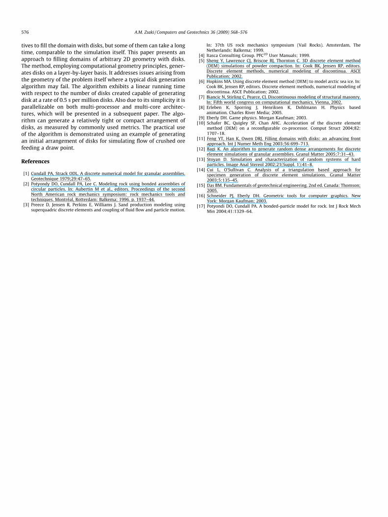
Ore passes or chutes found in mining operations enable the col-lection and transfer of ore from the dump point to the draw point.Since any blockage of these ore passes can interrupt productionthey are considered critical mine infrastructure. DEM simulationsenable the investigation of the formation of arches that, acting incompression, retard the flow of ore. To dislodge the arch often re-quires human intervention into these generally non-entry stopeswith the potential for fatal accidents. A DEM model of an ore pass,close to a draw point is shown in Fig. 14. The disk generation
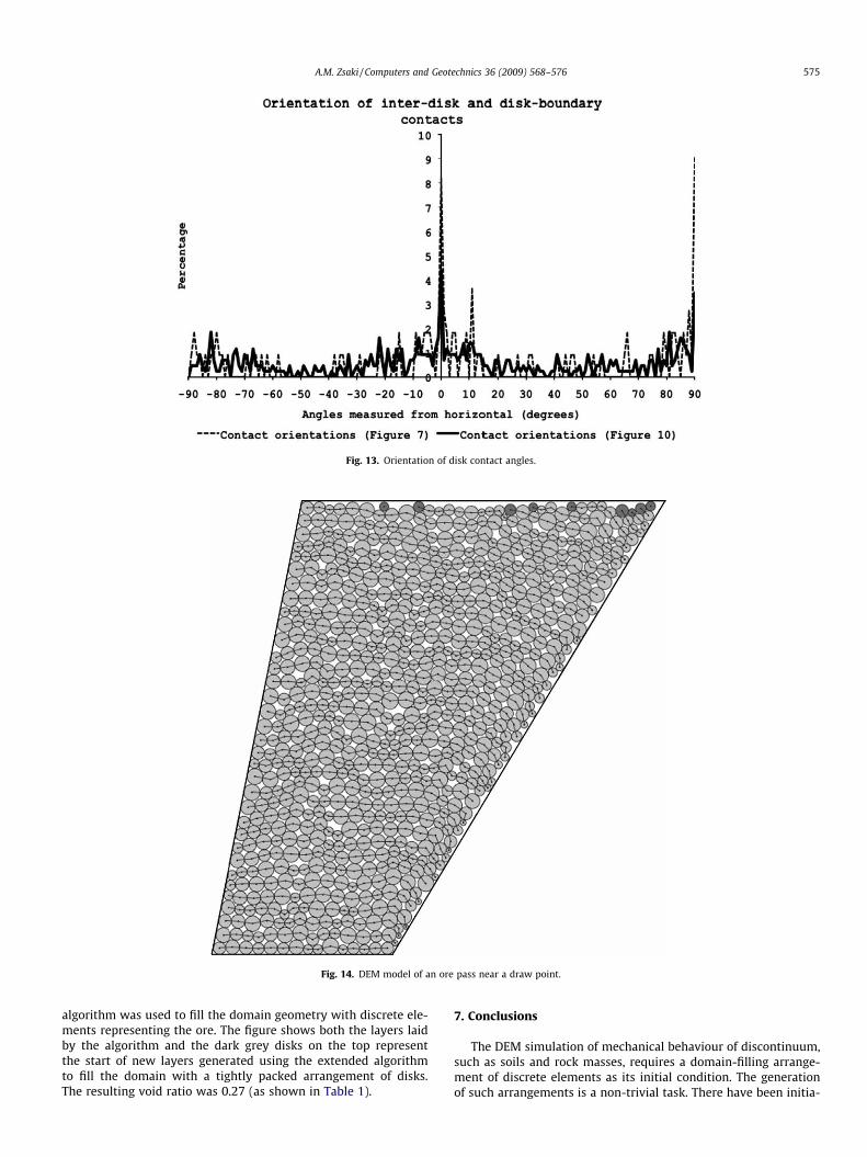
Fig. 13. Orientation of disk contact angles.
Fig. 14. DEM model of an ore pass near a draw point.
A.M. Zsaki / Computers and Geotechnics 36 (2009) 568–576 575
algorithm was used to fill the domain geometry with discrete ele-ments representing the ore. The figure shows both the layers laidby the algorithm and the dark grey disks on the top representthe start of new layers generated using the extended algorithmto fill the domain with a tightly packed arrangement of disks.The resulting void ratio was 0.27 (as shown in Table 1).
7. Conclusions
The DEM simulation of mechanical behaviour of discontinuum,such as soils and rock masses, requires a domain-filling arrange-ment of discrete elements as its initial condition. The generationof such arrangements is a non-trivial task. There have been initia-
576 A.M. Zsaki / Computers and Geotechnics 36 (2009) 568–576
tives to fill the domain with disks, but some of them can take a longtime, comparable to the simulation itself. This paper presents anapproach to filling domains of arbitrary 2D geometry with disks.The method, employing computational geometry principles, gener-ates disks on a layer-by-layer basis. It addresses issues arising fromthe geometry of the problem itself where a typical disk generationalgorithm may fail. The algorithm exhibits a linear running timewith respect to the number of disks created capable of generatingdisk at a rate of 0.5 s per million disks. Also due to its simplicity it isparallelizable on both multi-processor and multi-core architec-tures, which will be presented in a subsequent paper. The algo-rithm can generate a relatively tight or compact arrangement ofdisks, as measured by commonly used metrics. The practical useof the algorithm is demonstrated using an example of generatingan initial arrangement of disks for simulating flow of crushed orefeeding a draw point.
References
[1] Cundall PA, Strack ODL. A discrete numerical model for granular assemblies.Geotechnique 1979;29:47–65.
[2] Potyondy DO, Cundall PA, Lee C. Modeling rock using bonded assemblies ofcircular particles. In: Aubertin M et al., editors. Proceedings of the secondNorth American rock mechanics symposium: rock mechanics tools andtechniques. Montréal, Rotterdam: Balkema; 1996. p. 1937–44.
[3] Preece D, Jensen R, Perkins E, Williams J. Sand production modeling usingsuperquadric discrete elements and coupling of fluid flow and particle motion.
In: 37th US rock mechanics symposium (Vail Rocks). Amsterdam, TheNetherlands: Balkema; 1999.
[4] Itasca Consulting Group. PFC2D User Manuals; 1999.[5] Sheng Y, Lawrence CJ, Briscoe BJ, Thornton C. 3D discrete element method
(DEM) simulations of powder compaction. In: Cook BK, Jensen RP, editors.Discrete element methods, numerical modeling of discontinua. ASCEPublication; 2002.
[6] Hopkins MA. Using discrete element method (DEM) to model arctic sea ice. In:Cook BK, Jensen RP, editors. Discrete element methods, numerical modeling ofdiscontinua. ASCE Publication; 2002.
[7] Biancic N, Stirling C, Pearce, CJ. Discontinuous modeling of structural masonry.In: Fifth world congress on computational mechanics, Vienna, 2002.
[8] Erleben K, Sporring J, Henriksen K, Dohlmann H. Physics basedanimation. Charles River Media; 2005.
[9] Eberly DH. Game physics. Morgan Kaufman; 2003.[10] Schafer BC, Quigley SF, Chan AHC. Acceleration of the discrete element
method (DEM) on a reconfigurable co-processor. Comput Struct 2004;82:1707–18.
[11] Feng YT, Han K, Owen DRJ. Filling domains with disks: an advancing frontapproach. Int J Numer Meth Eng 2003;56:699–713.
[12] Bagi K. An algorithm to generate random dense arrangements for discreteelement simulations of granular assemblies. Granul Matter 2005;7:31–43.
[13] Stoyan D. Simulation and characterization of random systems of hardparticles. Image Anal Stereol 2002;21(Suppl. 1):41–8.
[14] Cui L, O’Sullivan C. Analysis of a triangulation based approach forspecimen generation of discrete element simulations. Granul Matter2003;5:135–45.
[15] Das BM. Fundamentals of geotechnical engineering. 2nd ed. Canada: Thomson;2005.
[16] Schneider PJ, Eberly DH. Geometric tools for computer graphics. NewYork: Morgan Kaufman; 2003.
[17] Potyondi DO, Cundall PA. A bonded-particle model for rock. Int J Rock MechMin 2004;41:1329–64.