aleos 4.12.0 software configuration user guide for airlink
TRANSCRIPT

ALEOS 4.12.0Software Configuration
User Guide for AirLink RV55
41113126Rev 2
ALEOS 4.12.0 Software Configuration User Guide for AirLink RV55
Important Notice
Due to the nature of wireless communications, transmission and reception of data can never be guaranteed. Data may be delayed, corrupted (i.e., have errors) or be totally lost. Although significant delays or losses of data are rare when wireless devices such as the Sierra Wireless product are used in a normal manner with a well-constructed network, the Sierra Wireless product should not be used in situations where failure to transmit or receive data could result in damage of any kind to the user or any other party, including but not limited to personal injury, death, or loss of property. Sierra Wireless accepts no responsibility for damages of any kind resulting from delays or errors in data transmitted or received using the Sierra Wireless product, or for failure of the Sierra Wireless product to transmit or receive such data.
Limitation of Liability
The information in this manual is subject to change without notice and does not represent a commitment on the part of Sierra Wireless. SIERRA WIRELESS AND ITS AFFILIATES SPECIFICALLY DISCLAIM LIABILITY FOR ANY AND ALL DIRECT, INDIRECT, SPECIAL, GENERAL, INCIDENTAL, CONSEQUENTIAL, PUNITIVE OR EXEMPLARY DAMAGES INCLUDING, BUT NOT LIMITED TO, LOSS OF PROFITS OR REVENUE OR ANTICIPATED PROFITS OR REVENUE ARISING OUT OF THE USE OR INABILITY TO USE ANY SIERRA WIRELESS PRODUCT, EVEN IF SIERRA WIRELESS AND/OR ITS AFFILIATES HAS BEEN ADVISED OF THE POSSIBILITY OF SUCH DAMAGES OR THEY ARE FORESEEABLE OR FOR CLAIMS BY ANY THIRD PARTY.
Notwithstanding the foregoing, in no event shall Sierra Wireless and/or its affiliates aggregate liability arising under or in connection with the Sierra Wireless product, regardless of the number of events, occurrences, or claims giving rise to liability, be in excess of the price paid by the purchaser for the Sierra Wireless product.
Patents This product may contain technology developed by or for Sierra Wireless Inc. This product includes technology licensed from QUALCOMM®. This product is manufactured or sold by Sierra Wireless Inc. or its affiliates under one or more patents licensed from MMP Portfolio Licensing.
Copyright © Sierra Wireless. All rights reserved.
Trademarks Sierra Wireless®, AirPrime®, AirLink®, and the Sierra Wireless logo are registered trademarks of Sierra Wireless.
Windows® and Windows Vista® are registered trademarks of Microsoft Corporation.
Macintosh® and Mac OS X® are registered trademarks of Apple Inc., registered in the U.S. and other countries.
QUALCOMM® is a registered trademark of QUALCOMM Incorporated. Used under license.
Other trademarks are the property of their respective owners.
Rev. 2 Jul. 19 2 41113126
Preface
Contact Information
Sales information and technical support, including warranty and returns
Web: sierrawireless.com/company/contact-us/
Global toll-free number: 1-877-687-7795
6:00 am to 5:00 pm PST
Corporate and product information Web: sierrawireless.com
Rev. 2 Jul. 19 3 41113126
Contents
Introduction . . . . . . . . . . . . . . . . . . . . . . . . . . . . . . . . . . . . . . . . . . . . . . . . . . . . . . . . . . . .13
Overview. . . . . . . . . . . . . . . . . . . . . . . . . . . . . . . . . . . . . . . . . . . . . . . . . . . . . . . . . . . . 13
Sierra Wireless AirLink Products . . . . . . . . . . . . . . . . . . . . . . . . . . . . . . . . . . . . . . . . . 13
About Documentation. . . . . . . . . . . . . . . . . . . . . . . . . . . . . . . . . . . . . . . . . . . . . . . . . . 13
Tools and Reference Documents . . . . . . . . . . . . . . . . . . . . . . . . . . . . . . . . . . . . . . . . . 14
Gateway Configuration . . . . . . . . . . . . . . . . . . . . . . . . . . . . . . . . . . . . . . . . . . . . . . . . . . .15
Recovery Mode . . . . . . . . . . . . . . . . . . . . . . . . . . . . . . . . . . . . . . . . . . . . . . . . . . . . . . 16
Toolbar . . . . . . . . . . . . . . . . . . . . . . . . . . . . . . . . . . . . . . . . . . . . . . . . . . . . . . . . . . . . . 18
Configuring your AirLink Gateway . . . . . . . . . . . . . . . . . . . . . . . . . . . . . . . . . . . . . . . . 18
Saving a Custom Configuration as a Template . . . . . . . . . . . . . . . . . . . . . . . . . . . . . . 18
Applying a Template. . . . . . . . . . . . . . . . . . . . . . . . . . . . . . . . . . . . . . . . . . . . . . . . . . . 21
Update the ALEOS Software and Radio Module Firmware . . . . . . . . . . . . . . . . . . . . . 24
Step 1—Planning Your Update . . . . . . . . . . . . . . . . . . . . . . . . . . . . . . . . . . . . . . . .25
Recommendations . . . . . . . . . . . . . . . . . . . . . . . . . . . . . . . . . . . . . . . . . . . . . . . . . .26
Step 2—Update the ALEOS Software and Radio Module Firmware . . . . . . . . . . . .27
Updating Only the Radio Module Firmware . . . . . . . . . . . . . . . . . . . . . . . . . . . . . . .31
Enterprise LAN Management . . . . . . . . . . . . . . . . . . . . . . . . . . . . . . . . . . . . . . . . . . . . 32
Configuring Your Gateway for use in a PCI Compliant System . . . . . . . . . . . . . . . . . . 34
Status . . . . . . . . . . . . . . . . . . . . . . . . . . . . . . . . . . . . . . . . . . . . . . . . . . . . . . . . . . . . . . . . .36
Home . . . . . . . . . . . . . . . . . . . . . . . . . . . . . . . . . . . . . . . . . . . . . . . . . . . . . . . . . . . . . . 36
Cellular . . . . . . . . . . . . . . . . . . . . . . . . . . . . . . . . . . . . . . . . . . . . . . . . . . . . . . . . . . . . . 38
Ethernet . . . . . . . . . . . . . . . . . . . . . . . . . . . . . . . . . . . . . . . . . . . . . . . . . . . . . . . . . . . . 46
Wi-Fi . . . . . . . . . . . . . . . . . . . . . . . . . . . . . . . . . . . . . . . . . . . . . . . . . . . . . . . . . . . . . . . 49
LAN IP/MAC Table . . . . . . . . . . . . . . . . . . . . . . . . . . . . . . . . . . . . . . . . . . . . . . . . . . . . 52
VPN . . . . . . . . . . . . . . . . . . . . . . . . . . . . . . . . . . . . . . . . . . . . . . . . . . . . . . . . . . . . . . . 54
Security. . . . . . . . . . . . . . . . . . . . . . . . . . . . . . . . . . . . . . . . . . . . . . . . . . . . . . . . . . . . . 57
Services . . . . . . . . . . . . . . . . . . . . . . . . . . . . . . . . . . . . . . . . . . . . . . . . . . . . . . . . . . . . 58
Location . . . . . . . . . . . . . . . . . . . . . . . . . . . . . . . . . . . . . . . . . . . . . . . . . . . . . . . . . . . . 60
Serial . . . . . . . . . . . . . . . . . . . . . . . . . . . . . . . . . . . . . . . . . . . . . . . . . . . . . . . . . . . . . . 62
Rev. 2 July 2019 4 41113126

Contents
Applications . . . . . . . . . . . . . . . . . . . . . . . . . . . . . . . . . . . . . . . . . . . . . . . . . . . . . . . . . 64
Policy Routing . . . . . . . . . . . . . . . . . . . . . . . . . . . . . . . . . . . . . . . . . . . . . . . . . . . . . . . 65
RSR (Reliable Static Routing) . . . . . . . . . . . . . . . . . . . . . . . . . . . . . . . . . . . . . . . . . . . 66
PNTM (Private Network Traffic Management) . . . . . . . . . . . . . . . . . . . . . . . . . . . . . . . 67
About . . . . . . . . . . . . . . . . . . . . . . . . . . . . . . . . . . . . . . . . . . . . . . . . . . . . . . . . . . . . . . 68
WAN/Cellular Configuration . . . . . . . . . . . . . . . . . . . . . . . . . . . . . . . . . . . . . . . . . . . . . . 70
Monitoring WAN Connections . . . . . . . . . . . . . . . . . . . . . . . . . . . . . . . . . . . . . . . . . . . 70
Related Features . . . . . . . . . . . . . . . . . . . . . . . . . . . . . . . . . . . . . . . . . . . . . . . . . . . 71
General . . . . . . . . . . . . . . . . . . . . . . . . . . . . . . . . . . . . . . . . . . . . . . . . . . . . . . . . . . . . 72
Interface Priority . . . . . . . . . . . . . . . . . . . . . . . . . . . . . . . . . . . . . . . . . . . . . . . . . . . 72
Bandwidth Throttle . . . . . . . . . . . . . . . . . . . . . . . . . . . . . . . . . . . . . . . . . . . . . . . . . . 74
Ping Response . . . . . . . . . . . . . . . . . . . . . . . . . . . . . . . . . . . . . . . . . . . . . . . . . . . . 77
Cellular. . . . . . . . . . . . . . . . . . . . . . . . . . . . . . . . . . . . . . . . . . . . . . . . . . . . . . . . . . . . . 78
General . . . . . . . . . . . . . . . . . . . . . . . . . . . . . . . . . . . . . . . . . . . . . . . . . . . . . . . . . . 78
Automatic SIM switching . . . . . . . . . . . . . . . . . . . . . . . . . . . . . . . . . . . . . . . . . . . . . 85
IPv6 Support . . . . . . . . . . . . . . . . . . . . . . . . . . . . . . . . . . . . . . . . . . . . . . . . . . . . . . 89
SIM Slot 1 and 2 Configuration . . . . . . . . . . . . . . . . . . . . . . . . . . . . . . . . . . . . . . . . 90
SIM PIN . . . . . . . . . . . . . . . . . . . . . . . . . . . . . . . . . . . . . . . . . . . . . . . . . . . . . . . . . . . . 92
Enable the SIM PIN . . . . . . . . . . . . . . . . . . . . . . . . . . . . . . . . . . . . . . . . . . . . . . . . . 92
Change the SIM PIN ALEOS Enters at Reboot . . . . . . . . . . . . . . . . . . . . . . . . . . . . 93
Disable the SIM PIN . . . . . . . . . . . . . . . . . . . . . . . . . . . . . . . . . . . . . . . . . . . . . . . . 94
Unblocking a SIM PIN . . . . . . . . . . . . . . . . . . . . . . . . . . . . . . . . . . . . . . . . . . . . . . . 94
Cellular > Monitor . . . . . . . . . . . . . . . . . . . . . . . . . . . . . . . . . . . . . . . . . . . . . . . . . . 96
Ethernet . . . . . . . . . . . . . . . . . . . . . . . . . . . . . . . . . . . . . . . . . . . . . . . . . . . . . . . . . . . . 98
Static Configuration . . . . . . . . . . . . . . . . . . . . . . . . . . . . . . . . . . . . . . . . . . . . . . . . . 98
Ethernet > Monitor . . . . . . . . . . . . . . . . . . . . . . . . . . . . . . . . . . . . . . . . . . . . . . . . . . 99
Reliable Static Routing (RSR) . . . . . . . . . . . . . . . . . . . . . . . . . . . . . . . . . . . . . . . . . . 101
Policy Routing . . . . . . . . . . . . . . . . . . . . . . . . . . . . . . . . . . . . . . . . . . . . . . . . . . . . . . 105
Dynamic Mobile Network Routing (DMNR) . . . . . . . . . . . . . . . . . . . . . . . . . . . . . . . . 108
PNTM Configuration . . . . . . . . . . . . . . . . . . . . . . . . . . . . . . . . . . . . . . . . . . . . . . . . . 114
Rev. 2 July 2019 5 41113126

ALEOS 4.12.0 Software Configuration User Guide for AirLink RV55
Wi-Fi Configuration . . . . . . . . . . . . . . . . . . . . . . . . . . . . . . . . . . . . . . . . . . . . . . . . . . . . 116
General . . . . . . . . . . . . . . . . . . . . . . . . . . . . . . . . . . . . . . . . . . . . . . . . . . . . . . . . . . . 116
Access Point (LAN) Mode . . . . . . . . . . . . . . . . . . . . . . . . . . . . . . . . . . . . . . . . . . . . . 120
Captive Portal . . . . . . . . . . . . . . . . . . . . . . . . . . . . . . . . . . . . . . . . . . . . . . . . . . . . 124
WEP . . . . . . . . . . . . . . . . . . . . . . . . . . . . . . . . . . . . . . . . . . . . . . . . . . . . . . . . . . . 127
WPA/WPA2 Personal . . . . . . . . . . . . . . . . . . . . . . . . . . . . . . . . . . . . . . . . . . . . . . 128
WPA2 Enterprise . . . . . . . . . . . . . . . . . . . . . . . . . . . . . . . . . . . . . . . . . . . . . . . . . . 129
Client (WAN) Mode . . . . . . . . . . . . . . . . . . . . . . . . . . . . . . . . . . . . . . . . . . . . . . . . . . 129
LAN Configuration . . . . . . . . . . . . . . . . . . . . . . . . . . . . . . . . . . . . . . . . . . . . . . . . . . . . . 136
DHCP/Addressing . . . . . . . . . . . . . . . . . . . . . . . . . . . . . . . . . . . . . . . . . . . . . . . . . . . 136
Ethernet . . . . . . . . . . . . . . . . . . . . . . . . . . . . . . . . . . . . . . . . . . . . . . . . . . . . . . . . . . . 143
RADIUS Framed Route . . . . . . . . . . . . . . . . . . . . . . . . . . . . . . . . . . . . . . . . . . . . . 145
USB . . . . . . . . . . . . . . . . . . . . . . . . . . . . . . . . . . . . . . . . . . . . . . . . . . . . . . . . . . . . . . 146
Installing the USB Drivers . . . . . . . . . . . . . . . . . . . . . . . . . . . . . . . . . . . . . . . . . . . . . 147
Link WAN Coverage . . . . . . . . . . . . . . . . . . . . . . . . . . . . . . . . . . . . . . . . . . . . . . . . . 149
Host Port Routing. . . . . . . . . . . . . . . . . . . . . . . . . . . . . . . . . . . . . . . . . . . . . . . . . . . . 150
Global DNS . . . . . . . . . . . . . . . . . . . . . . . . . . . . . . . . . . . . . . . . . . . . . . . . . . . . . . . . 152
PPPOE. . . . . . . . . . . . . . . . . . . . . . . . . . . . . . . . . . . . . . . . . . . . . . . . . . . . . . . . . . . . 154
Configure the AirLink gateway to Support PPPoE . . . . . . . . . . . . . . . . . . . . . . . . 155
Configuring a PPPoE Connection in Windows 7 . . . . . . . . . . . . . . . . . . . . . . . . . . 156
VLAN . . . . . . . . . . . . . . . . . . . . . . . . . . . . . . . . . . . . . . . . . . . . . . . . . . . . . . . . . . . . . 160
VRRP. . . . . . . . . . . . . . . . . . . . . . . . . . . . . . . . . . . . . . . . . . . . . . . . . . . . . . . . . . . . . 161
Host Interface Watchdog . . . . . . . . . . . . . . . . . . . . . . . . . . . . . . . . . . . . . . . . . . . . . . 166
VPN Configuration . . . . . . . . . . . . . . . . . . . . . . . . . . . . . . . . . . . . . . . . . . . . . . . . . . . . . 168
General . . . . . . . . . . . . . . . . . . . . . . . . . . . . . . . . . . . . . . . . . . . . . . . . . . . . . . . . . . . 168
Standard Vs. Legacy IPsec Implementation . . . . . . . . . . . . . . . . . . . . . . . . . . . . . 168
Split Tunnel . . . . . . . . . . . . . . . . . . . . . . . . . . . . . . . . . . . . . . . . . . . . . . . . . . . . . . . . 171
VPN Failover . . . . . . . . . . . . . . . . . . . . . . . . . . . . . . . . . . . . . . . . . . . . . . . . . . . . . . . 172
Rev. 2 July 2019 6 41113126

Contents
IPsec Overview . . . . . . . . . . . . . . . . . . . . . . . . . . . . . . . . . . . . . . . . . . . . . . . . . . . . . 174
IPsec (Legacy) . . . . . . . . . . . . . . . . . . . . . . . . . . . . . . . . . . . . . . . . . . . . . . . . . . . . 175
IPsec (Standard) . . . . . . . . . . . . . . . . . . . . . . . . . . . . . . . . . . . . . . . . . . . . . . . . . . 181
GRE . . . . . . . . . . . . . . . . . . . . . . . . . . . . . . . . . . . . . . . . . . . . . . . . . . . . . . . . . . . . . . 189
OpenVPN Tunnel. . . . . . . . . . . . . . . . . . . . . . . . . . . . . . . . . . . . . . . . . . . . . . . . . . . . 191
Security Configuration . . . . . . . . . . . . . . . . . . . . . . . . . . . . . . . . . . . . . . . . . . . . . . . . . . 196
Solicited vs. Unsolicited . . . . . . . . . . . . . . . . . . . . . . . . . . . . . . . . . . . . . . . . . . . . . . . 196
Port Forwarding . . . . . . . . . . . . . . . . . . . . . . . . . . . . . . . . . . . . . . . . . . . . . . . . . . . . . 196
Single port . . . . . . . . . . . . . . . . . . . . . . . . . . . . . . . . . . . . . . . . . . . . . . . . . . . . . . . 197
Range of ports . . . . . . . . . . . . . . . . . . . . . . . . . . . . . . . . . . . . . . . . . . . . . . . . . . . . 198
DMZ . . . . . . . . . . . . . . . . . . . . . . . . . . . . . . . . . . . . . . . . . . . . . . . . . . . . . . . . . . . . . . 201
Port Filtering—Inbound . . . . . . . . . . . . . . . . . . . . . . . . . . . . . . . . . . . . . . . . . . . . . . . 202
Port Filtering — Outbound . . . . . . . . . . . . . . . . . . . . . . . . . . . . . . . . . . . . . . . . . . . . . 203
Trusted IPs—Inbound (Friends) . . . . . . . . . . . . . . . . . . . . . . . . . . . . . . . . . . . . . . . . 205
Trusted IPs—Outbound. . . . . . . . . . . . . . . . . . . . . . . . . . . . . . . . . . . . . . . . . . . . . . . 206
MAC Filtering . . . . . . . . . . . . . . . . . . . . . . . . . . . . . . . . . . . . . . . . . . . . . . . . . . . . . . . 207
Services Configuration . . . . . . . . . . . . . . . . . . . . . . . . . . . . . . . . . . . . . . . . . . . . . . . . . 208
ALMS (AirLink Management Service) . . . . . . . . . . . . . . . . . . . . . . . . . . . . . . . . . . . . 208
ACEmanager . . . . . . . . . . . . . . . . . . . . . . . . . . . . . . . . . . . . . . . . . . . . . . . . . . . . . . . 213
Power Management. . . . . . . . . . . . . . . . . . . . . . . . . . . . . . . . . . . . . . . . . . . . . . . . . . 216
Dynamic DNS . . . . . . . . . . . . . . . . . . . . . . . . . . . . . . . . . . . . . . . . . . . . . . . . . . . . . . 224
Understanding Domain Names . . . . . . . . . . . . . . . . . . . . . . . . . . . . . . . . . . . . . . . 229
Dynamic Names . . . . . . . . . . . . . . . . . . . . . . . . . . . . . . . . . . . . . . . . . . . . . . . . . . 230
SMS Overview . . . . . . . . . . . . . . . . . . . . . . . . . . . . . . . . . . . . . . . . . . . . . . . . . . . . . . 230
Sending SMS Commands to an AirLink Gateway . . . . . . . . . . . . . . . . . . . . . . . . . 231
SMS Modes . . . . . . . . . . . . . . . . . . . . . . . . . . . . . . . . . . . . . . . . . . . . . . . . . . . . . . 233
Password Only . . . . . . . . . . . . . . . . . . . . . . . . . . . . . . . . . . . . . . . . . . . . . . . . . . . 233
Control Only . . . . . . . . . . . . . . . . . . . . . . . . . . . . . . . . . . . . . . . . . . . . . . . . . . . . . . 235
Gateway Only . . . . . . . . . . . . . . . . . . . . . . . . . . . . . . . . . . . . . . . . . . . . . . . . . . . . 236
Control and Gateway . . . . . . . . . . . . . . . . . . . . . . . . . . . . . . . . . . . . . . . . . . . . . . . 242
Rev. 2 July 2019 7 41113126
ALEOS 4.12.0 Software Configuration User Guide for AirLink RV55
SMS Wakeup. . . . . . . . . . . . . . . . . . . . . . . . . . . . . . . . . . . . . . . . . . . . . . . . . . . . . . . 243
SMS Security . . . . . . . . . . . . . . . . . . . . . . . . . . . . . . . . . . . . . . . . . . . . . . . . . . . . . . . 245
Inbound SMS Messages . . . . . . . . . . . . . . . . . . . . . . . . . . . . . . . . . . . . . . . . . . . . 245
Trusted Phone Number . . . . . . . . . . . . . . . . . . . . . . . . . . . . . . . . . . . . . . . . . . . . . 246
SMS Password Security . . . . . . . . . . . . . . . . . . . . . . . . . . . . . . . . . . . . . . . . . . . . 247
SMS > Advanced . . . . . . . . . . . . . . . . . . . . . . . . . . . . . . . . . . . . . . . . . . . . . . . . . . 248
SMSM2M . . . . . . . . . . . . . . . . . . . . . . . . . . . . . . . . . . . . . . . . . . . . . . . . . . . . . . . . 250
AT (Telnet/SSH). . . . . . . . . . . . . . . . . . . . . . . . . . . . . . . . . . . . . . . . . . . . . . . . . . . . . 251
Email (SMTP). . . . . . . . . . . . . . . . . . . . . . . . . . . . . . . . . . . . . . . . . . . . . . . . . . . . . . . 253
Management (SNMP) . . . . . . . . . . . . . . . . . . . . . . . . . . . . . . . . . . . . . . . . . . . . . . . . 255
Time (SNTP) . . . . . . . . . . . . . . . . . . . . . . . . . . . . . . . . . . . . . . . . . . . . . . . . . . . . . . . 261
Authentication . . . . . . . . . . . . . . . . . . . . . . . . . . . . . . . . . . . . . . . . . . . . . . . . . . . . . . 261
LDAP Authentication . . . . . . . . . . . . . . . . . . . . . . . . . . . . . . . . . . . . . . . . . . . . . . . 262
RADIUS Authentication . . . . . . . . . . . . . . . . . . . . . . . . . . . . . . . . . . . . . . . . . . . . . 264
TACACS+ Authentication . . . . . . . . . . . . . . . . . . . . . . . . . . . . . . . . . . . . . . . . . . . 265
Device Status Screen . . . . . . . . . . . . . . . . . . . . . . . . . . . . . . . . . . . . . . . . . . . . . . . . 267
Location . . . . . . . . . . . . . . . . . . . . . . . . . . . . . . . . . . . . . . . . . . . . . . . . . . . . . . . . . . . . . 268
ALEOS Supported Location Report Protocols . . . . . . . . . . . . . . . . . . . . . . . . . . . . . . 268
Before Configuring Location . . . . . . . . . . . . . . . . . . . . . . . . . . . . . . . . . . . . . . . . . . . 269
Enable Location Service . . . . . . . . . . . . . . . . . . . . . . . . . . . . . . . . . . . . . . . . . . . . 270
Global Settings. . . . . . . . . . . . . . . . . . . . . . . . . . . . . . . . . . . . . . . . . . . . . . . . . . . . . . 271
Servers 1 to 4. . . . . . . . . . . . . . . . . . . . . . . . . . . . . . . . . . . . . . . . . . . . . . . . . . . . . . . 275
Local/Streaming. . . . . . . . . . . . . . . . . . . . . . . . . . . . . . . . . . . . . . . . . . . . . . . . . . . . . 287
Local/Streaming—Local IP Report . . . . . . . . . . . . . . . . . . . . . . . . . . . . . . . . . . . . . . 289
Events Reporting Configuration . . . . . . . . . . . . . . . . . . . . . . . . . . . . . . . . . . . . . . . . . . 293
Introduction . . . . . . . . . . . . . . . . . . . . . . . . . . . . . . . . . . . . . . . . . . . . . . . . . . . . . . . . 293
Rev. 2 July 2019 8 41113126

Contents
Configuring Events Reporting . . . . . . . . . . . . . . . . . . . . . . . . . . . . . . . . . . . . . . . . . . 294
Configuring Events Reporting . . . . . . . . . . . . . . . . . . . . . . . . . . . . . . . . . . . . . . . . 294
Email . . . . . . . . . . . . . . . . . . . . . . . . . . . . . . . . . . . . . . . . . . . . . . . . . . . . . . . . . . . 295
SMS . . . . . . . . . . . . . . . . . . . . . . . . . . . . . . . . . . . . . . . . . . . . . . . . . . . . . . . . . . . . 297
Relay Link . . . . . . . . . . . . . . . . . . . . . . . . . . . . . . . . . . . . . . . . . . . . . . . . . . . . . . . 299
SNMP TRAP . . . . . . . . . . . . . . . . . . . . . . . . . . . . . . . . . . . . . . . . . . . . . . . . . . . . . 300
Location Reports . . . . . . . . . . . . . . . . . . . . . . . . . . . . . . . . . . . . . . . . . . . . . . . . . . 300
Events Protocol Reports . . . . . . . . . . . . . . . . . . . . . . . . . . . . . . . . . . . . . . . . . . . . 302
Turn Off Services . . . . . . . . . . . . . . . . . . . . . . . . . . . . . . . . . . . . . . . . . . . . . . . . . . 304
Report Data Group . . . . . . . . . . . . . . . . . . . . . . . . . . . . . . . . . . . . . . . . . . . . . . . . 305
Event Types . . . . . . . . . . . . . . . . . . . . . . . . . . . . . . . . . . . . . . . . . . . . . . . . . . . . . . 308
Serial Configuration . . . . . . . . . . . . . . . . . . . . . . . . . . . . . . . . . . . . . . . . . . . . . . . . . . . . 313
RS232 Configuration . . . . . . . . . . . . . . . . . . . . . . . . . . . . . . . . . . . . . . . . . . . . . . . . . 313
General . . . . . . . . . . . . . . . . . . . . . . . . . . . . . . . . . . . . . . . . . . . . . . . . . . . . . . . . . 313
PAD . . . . . . . . . . . . . . . . . . . . . . . . . . . . . . . . . . . . . . . . . . . . . . . . . . . . . . . . . . . . 317
Reverse Telnet/SSH . . . . . . . . . . . . . . . . . . . . . . . . . . . . . . . . . . . . . . . . . . . . . . . 322
PPP . . . . . . . . . . . . . . . . . . . . . . . . . . . . . . . . . . . . . . . . . . . . . . . . . . . . . . . . . . . . 326
SLIP . . . . . . . . . . . . . . . . . . . . . . . . . . . . . . . . . . . . . . . . . . . . . . . . . . . . . . . . . . . . 327
MODBUS . . . . . . . . . . . . . . . . . . . . . . . . . . . . . . . . . . . . . . . . . . . . . . . . . . . . . . . . 328
MODBUS Address List . . . . . . . . . . . . . . . . . . . . . . . . . . . . . . . . . . . . . . . . . . . . . 330
Configuring IP to Serial with Answer and Serial to IP . . . . . . . . . . . . . . . . . . . . . . . . 331
LED Indicator . . . . . . . . . . . . . . . . . . . . . . . . . . . . . . . . . . . . . . . . . . . . . . . . . . . . . . . 335
Applications Configuration . . . . . . . . . . . . . . . . . . . . . . . . . . . . . . . . . . . . . . . . . . . . . . 336
Data Usage . . . . . . . . . . . . . . . . . . . . . . . . . . . . . . . . . . . . . . . . . . . . . . . . . . . . . . . . 336
Garmin . . . . . . . . . . . . . . . . . . . . . . . . . . . . . . . . . . . . . . . . . . . . . . . . . . . . . . . . . . . . 344
ALEOS Application Framework . . . . . . . . . . . . . . . . . . . . . . . . . . . . . . . . . . . . . . . . . 346
I/O Configuration . . . . . . . . . . . . . . . . . . . . . . . . . . . . . . . . . . . . . . . . . . . . . . . . . . . . . . 350
Analog inputs . . . . . . . . . . . . . . . . . . . . . . . . . . . . . . . . . . . . . . . . . . . . . . . . . . . . . 350
Digital inputs . . . . . . . . . . . . . . . . . . . . . . . . . . . . . . . . . . . . . . . . . . . . . . . . . . . . . 350
Relay outputs . . . . . . . . . . . . . . . . . . . . . . . . . . . . . . . . . . . . . . . . . . . . . . . . . . . . . 351
Current State . . . . . . . . . . . . . . . . . . . . . . . . . . . . . . . . . . . . . . . . . . . . . . . . . . . . . . . 351
Rev. 2 July 2019 9 41113126
ALEOS 4.12.0 Software Configuration User Guide for AirLink RV55
Pulse Count . . . . . . . . . . . . . . . . . . . . . . . . . . . . . . . . . . . . . . . . . . . . . . . . . . . . . . . . 354
Configuration . . . . . . . . . . . . . . . . . . . . . . . . . . . . . . . . . . . . . . . . . . . . . . . . . . . . . . . 354
Transformed Analog . . . . . . . . . . . . . . . . . . . . . . . . . . . . . . . . . . . . . . . . . . . . . . . 356
Admin . . . . . . . . . . . . . . . . . . . . . . . . . . . . . . . . . . . . . . . . . . . . . . . . . . . . . . . . . . . . . . . 358
Change Password . . . . . . . . . . . . . . . . . . . . . . . . . . . . . . . . . . . . . . . . . . . . . . . . . . . 358
AAF User Password . . . . . . . . . . . . . . . . . . . . . . . . . . . . . . . . . . . . . . . . . . . . . . . 359
Advanced. . . . . . . . . . . . . . . . . . . . . . . . . . . . . . . . . . . . . . . . . . . . . . . . . . . . . . . . . . 360
Radio Passthru . . . . . . . . . . . . . . . . . . . . . . . . . . . . . . . . . . . . . . . . . . . . . . . . . . . . . 371
Log. . . . . . . . . . . . . . . . . . . . . . . . . . . . . . . . . . . . . . . . . . . . . . . . . . . . . . . . . . . . . . . 372
Configure Logs . . . . . . . . . . . . . . . . . . . . . . . . . . . . . . . . . . . . . . . . . . . . . . . . . . . 373
Trace Level Logging . . . . . . . . . . . . . . . . . . . . . . . . . . . . . . . . . . . . . . . . . . . . . . . 374
Remote Logging . . . . . . . . . . . . . . . . . . . . . . . . . . . . . . . . . . . . . . . . . . . . . . . . . . 374
View Logs . . . . . . . . . . . . . . . . . . . . . . . . . . . . . . . . . . . . . . . . . . . . . . . . . . . . . . . 376
Radio Module Firmware. . . . . . . . . . . . . . . . . . . . . . . . . . . . . . . . . . . . . . . . . . . . . . . 378
Windows Dial-up Networking (DUN) . . . . . . . . . . . . . . . . . . . . . . . . . . . . . . . . . . . . . . 382
Installing a Device Driver . . . . . . . . . . . . . . . . . . . . . . . . . . . . . . . . . . . . . . . . . . . . . . 382
Creating a Dial-Up Networking (PPP) Connection. . . . . . . . . . . . . . . . . . . . . . . . . . . 392
Modbus/BSAP Configuration . . . . . . . . . . . . . . . . . . . . . . . . . . . . . . . . . . . . . . . . . . . . 401
Modbus Overview . . . . . . . . . . . . . . . . . . . . . . . . . . . . . . . . . . . . . . . . . . . . . . . . . . . 401
Telemetry . . . . . . . . . . . . . . . . . . . . . . . . . . . . . . . . . . . . . . . . . . . . . . . . . . . . . . . . 401
Remote Terminal Unit (RTU) . . . . . . . . . . . . . . . . . . . . . . . . . . . . . . . . . . . . . . . . . 401
Supervisory Control and Data Acquisition (SCADA) . . . . . . . . . . . . . . . . . . . . . . . 401
Programmable Logic Controller (PLC) . . . . . . . . . . . . . . . . . . . . . . . . . . . . . . . . . 402
Modbus TCP/IP . . . . . . . . . . . . . . . . . . . . . . . . . . . . . . . . . . . . . . . . . . . . . . . . . . . 402
Modbus on UDP . . . . . . . . . . . . . . . . . . . . . . . . . . . . . . . . . . . . . . . . . . . . . . . . . . 402
Configuring AirLink routers at the Polling Host for Modbus on UDP . . . . . . . . . . . . . 402
Configuring Remote AirLink routers for Modbus with UDP . . . . . . . . . . . . . . . . . . . . 403
Configure IP Addresses for the Host . . . . . . . . . . . . . . . . . . . . . . . . . . . . . . . . . . . 404
SNMP: Simple Network Management Protocol . . . . . . . . . . . . . . . . . . . . . . . . . . . . . 405
Rev. 2 July 2019 10 41113126

Contents
Management Information Base (MIB) . . . . . . . . . . . . . . . . . . . . . . . . . . . . . . . . . . . . 405
SNMP Traps . . . . . . . . . . . . . . . . . . . . . . . . . . . . . . . . . . . . . . . . . . . . . . . . . . . . . . . 405
Sierra Wireless MIB . . . . . . . . . . . . . . . . . . . . . . . . . . . . . . . . . . . . . . . . . . . . . . . . . . 405
AT Commands. . . . . . . . . . . . . . . . . . . . . . . . . . . . . . . . . . . . . . . . . . . . . . . . . . . . . . . . 450
AT Command Set Summary . . . . . . . . . . . . . . . . . . . . . . . . . . . . . . . . . . . . . . . . . . . 450
Reference Tables. . . . . . . . . . . . . . . . . . . . . . . . . . . . . . . . . . . . . . . . . . . . . . . . . . . . 451
Device Updates . . . . . . . . . . . . . . . . . . . . . . . . . . . . . . . . . . . . . . . . . . . . . . . . . . . . . 452
Status. . . . . . . . . . . . . . . . . . . . . . . . . . . . . . . . . . . . . . . . . . . . . . . . . . . . . . . . . . . . . 454
WAN/Cellular . . . . . . . . . . . . . . . . . . . . . . . . . . . . . . . . . . . . . . . . . . . . . . . . . . . . . . . 459
LAN . . . . . . . . . . . . . . . . . . . . . . . . . . . . . . . . . . . . . . . . . . . . . . . . . . . . . . . . . . . . . . 476
Wi-Fi. . . . . . . . . . . . . . . . . . . . . . . . . . . . . . . . . . . . . . . . . . . . . . . . . . . . . . . . . . . . . . 478
VPN . . . . . . . . . . . . . . . . . . . . . . . . . . . . . . . . . . . . . . . . . . . . . . . . . . . . . . . . . . . . . . 487
Security . . . . . . . . . . . . . . . . . . . . . . . . . . . . . . . . . . . . . . . . . . . . . . . . . . . . . . . . . . . 493
Services . . . . . . . . . . . . . . . . . . . . . . . . . . . . . . . . . . . . . . . . . . . . . . . . . . . . . . . . . . . 494
Location . . . . . . . . . . . . . . . . . . . . . . . . . . . . . . . . . . . . . . . . . . . . . . . . . . . . . . . . . . . 504
Standard (Hayes) commands . . . . . . . . . . . . . . . . . . . . . . . . . . . . . . . . . . . . . . . . 519
I/O . . . . . . . . . . . . . . . . . . . . . . . . . . . . . . . . . . . . . . . . . . . . . . . . . . . . . . . . . . . . . . . 526
Applications . . . . . . . . . . . . . . . . . . . . . . . . . . . . . . . . . . . . . . . . . . . . . . . . . . . . . . . . 526
Admin. . . . . . . . . . . . . . . . . . . . . . . . . . . . . . . . . . . . . . . . . . . . . . . . . . . . . . . . . . . . . 531
SMS Commands . . . . . . . . . . . . . . . . . . . . . . . . . . . . . . . . . . . . . . . . . . . . . . . . . . . . . . 534
SMS Command format . . . . . . . . . . . . . . . . . . . . . . . . . . . . . . . . . . . . . . . . . . . . . . . 534
List of SMS Commands . . . . . . . . . . . . . . . . . . . . . . . . . . . . . . . . . . . . . . . . . . . . . . . 535
Rev. 2 July 2019 11 41113126

ALEOS 4.12.0 Software Configuration User Guide for AirLink RV55
Q & A and Troubleshooting . . . . . . . . . . . . . . . . . . . . . . . . . . . . . . . . . . . . . . . . . . . . . 537
ACEmanager Web UI . . . . . . . . . . . . . . . . . . . . . . . . . . . . . . . . . . . . . . . . . . . . . . 537
Templates . . . . . . . . . . . . . . . . . . . . . . . . . . . . . . . . . . . . . . . . . . . . . . . . . . . . . . . 537
Updating the ALEOS Software and Radio Module Firmware . . . . . . . . . . . . . . . . 538
Poor Wireless Network Connection . . . . . . . . . . . . . . . . . . . . . . . . . . . . . . . . . . . . 540
Connection not working . . . . . . . . . . . . . . . . . . . . . . . . . . . . . . . . . . . . . . . . . . . . . 540
Wi-Fi . . . . . . . . . . . . . . . . . . . . . . . . . . . . . . . . . . . . . . . . . . . . . . . . . . . . . . . . . . . 541
LTE Networks . . . . . . . . . . . . . . . . . . . . . . . . . . . . . . . . . . . . . . . . . . . . . . . . . . . . 541
SIM Card is Blocked . . . . . . . . . . . . . . . . . . . . . . . . . . . . . . . . . . . . . . . . . . . . . . . 542
Remote connections . . . . . . . . . . . . . . . . . . . . . . . . . . . . . . . . . . . . . . . . . . . . . . . 542
Radio Band Selection . . . . . . . . . . . . . . . . . . . . . . . . . . . . . . . . . . . . . . . . . . . . . . 543
Low Voltage Standby Mode . . . . . . . . . . . . . . . . . . . . . . . . . . . . . . . . . . . . . . . . . . 543
Reliable Static Routing (RSR) . . . . . . . . . . . . . . . . . . . . . . . . . . . . . . . . . . . . . . . . 544
Inbound Ports Used by ALEOS . . . . . . . . . . . . . . . . . . . . . . . . . . . . . . . . . . . . . . . 544
Setting for Band . . . . . . . . . . . . . . . . . . . . . . . . . . . . . . . . . . . . . . . . . . . . . . . . . . . 545
Ethernet Ports . . . . . . . . . . . . . . . . . . . . . . . . . . . . . . . . . . . . . . . . . . . . . . . . . . . . 546
LAN Networks . . . . . . . . . . . . . . . . . . . . . . . . . . . . . . . . . . . . . . . . . . . . . . . . . . . . 547
Wi-Fi . . . . . . . . . . . . . . . . . . . . . . . . . . . . . . . . . . . . . . . . . . . . . . . . . . . . . . . . . . . 548
VPN . . . . . . . . . . . . . . . . . . . . . . . . . . . . . . . . . . . . . . . . . . . . . . . . . . . . . . . . . . . . 548
Port Forwarding . . . . . . . . . . . . . . . . . . . . . . . . . . . . . . . . . . . . . . . . . . . . . . . . . . . 549
SMS . . . . . . . . . . . . . . . . . . . . . . . . . . . . . . . . . . . . . . . . . . . . . . . . . . . . . . . . . . . . 549
AirLink Management Service . . . . . . . . . . . . . . . . . . . . . . . . . . . . . . . . . . . . . . . . . 550
Location . . . . . . . . . . . . . . . . . . . . . . . . . . . . . . . . . . . . . . . . . . . . . . . . . . . . . . . . . 553
Event Reporting . . . . . . . . . . . . . . . . . . . . . . . . . . . . . . . . . . . . . . . . . . . . . . . . . . . 553
TCP Connections . . . . . . . . . . . . . . . . . . . . . . . . . . . . . . . . . . . . . . . . . . . . . . . . . 554
TCP/IP and UDP/IP Auto Answer . . . . . . . . . . . . . . . . . . . . . . . . . . . . . . . . . . . . 554
ALEOS Application Framework (AAF) . . . . . . . . . . . . . . . . . . . . . . . . . . . . . . . . . . 555
Network Operator Switching . . . . . . . . . . . . . . . . . . . . . . . . . . . . . . . . . . . . . . . . . 555
Glossary of Terms. . . . . . . . . . . . . . . . . . . . . . . . . . . . . . . . . . . . . . . . . . . . . . . . . . . . . 557
Index. . . . . . . . . . . . . . . . . . . . . . . . . . . . . . . . . . . . . . . . . . . . . . . . . . . . . . . . . . . . . . . . 562
Rev. 2 July 2019 12 41113126

1
1: IntroductionNote: This user guide is intended for the AirLink RV55. If you have a different AirLink gateway or router, refer to the ALEOS Software Configuration User Guide for your gateway or router.
Overview
ACEmanager™ is the free, web-based utility used to manage and configure AirLink® gateways. It is a web application integrated in the ALEOS™ software that runs on the AirLink RV55. AirLink Embedded Operating System (ALEOS) is purpose-built to maintain a wireless connection and to configure the RV55 to the needs of the system. ACEmanager provides comprehensive configuration, monitoring, and control functionality to all AirLink gateways and routers.
ACEmanager enables you to: • Log in and configure parameters• Adjust network settings• Change security settings• Update events reporting and control outputs• Update ALEOS software and radio module firmware• Copy configuration settings to other AirLink RV55s
Since ACEmanager can be accessed remotely over-the-air as well as locally, the many features of ALEOS can be managed from any location.
An ALEOS configuration template can be created using ACEmanager, after a single device is configured and installed, to program other AirLink RV55s with the same configuration values. This enables quick, accurate deployment of large pools of devices.
Sierra Wireless AirLink Products
For more information on specific AirLink products, go to www.sierrawireless.com
About Documentation
Each chapter in the ALEOS Configuration User Guide describes a section (a tab in the user interface) of ACEmanager.
Chapters in this user guide explain:• Parameter descriptions in ACEmanager• Relevant configuration details• User scenarios for certain sections in the guide.
Rev. 2 July 2019 13 41113126

ALEOS 4.12.0 Software Configuration User Guide for AirLink RV55
Tools and Reference Documents
Document Description
AirLink RV55 Hardware User Guide
This hardware document describes how to:
• Install the AirLink RV55
• Connect the radio antennas
• Connect a notebook computer and other input/output (I/O) devices
• Interpret the LEDs and indicators on the AirLink RV55.
ALMS User Guide AirLink Management Service features online help, videos and “How-To” pages that explain how to use ALMS for the remote management of Sierra Wireless AirLink gateways.
Rev. 2 July 2019 14 41113126
2
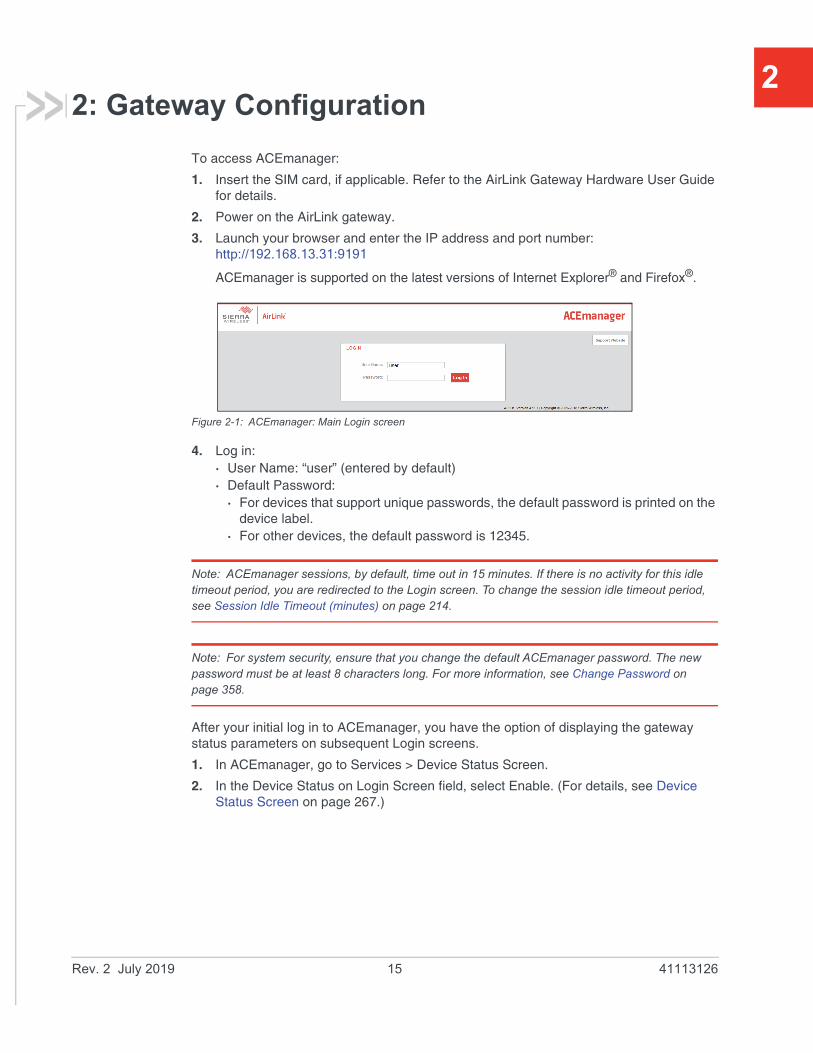
2: Gateway ConfigurationTo access ACEmanager:
1. Insert the SIM card, if applicable. Refer to the AirLink Gateway Hardware User Guide for details.
2. Power on the AirLink gateway.
3. Launch your browser and enter the IP address and port number: http://192.168.13.31:9191
ACEmanager is supported on the latest versions of Internet Explorer® and Firefox®.
Figure 2-1: ACEmanager: Main Login screen
4. Log in:· User Name: “user” (entered by default)· Default Password:
· For devices that support unique passwords, the default password is printed on the device label.
· For other devices, the default password is 12345.
Note: ACEmanager sessions, by default, time out in 15 minutes. If there is no activity for this idle timeout period, you are redirected to the Login screen. To change the session idle timeout period, see Session Idle Timeout (minutes) on page 214.
Note: For system security, ensure that you change the default ACEmanager password. The new password must be at least 8 characters long. For more information, see Change Password on page 358.
After your initial log in to ACEmanager, you have the option of displaying the gateway status parameters on subsequent Login screens.
1. In ACEmanager, go to Services > Device Status Screen.
2. In the Device Status on Login Screen field, select Enable. (For details, see Device Status Screen on page 267.)
Rev. 2 July 2019 15 41113126

ALEOS 4.12.0 Software Configuration User Guide for AirLink RV55
Figure 2-2: ACEmanager: Main Login screen with Location and Device Status enabled.
If you have Location fields selected on the Device Status screen, but Location Service is disabled, the gateway Login screen will show Location Service Disabled.
Recovery Mode
In the unlikely event that ALEOS becomes corrupted, or if the RV55 is unresponsive to ACEmanager input and AT commands, you can manually put the gateway into recovery mode.
Recovery mode enables you to update the ALEOS software and return the gateway to working order.
Note: ALEOS software updates done in Recovery mode do not preserve any custom settings such as cellular settings, AAF applications, etc.
To enter Recovery mode:
1. Use an Ethernet cable to connect the gateway to your computer. (Recovery mode is not supported on USBnet.)
2. Power on the AirLink gateway.
3. On the gateway, press the Reset button for more than 20 seconds. (Release the button when the Power LED flashes amber.)
4. Launch your browser and enter the IP address and port number http://192.168.13.31:9191.
Rev. 2 July 2019 16 41113126
Gateway Configuration
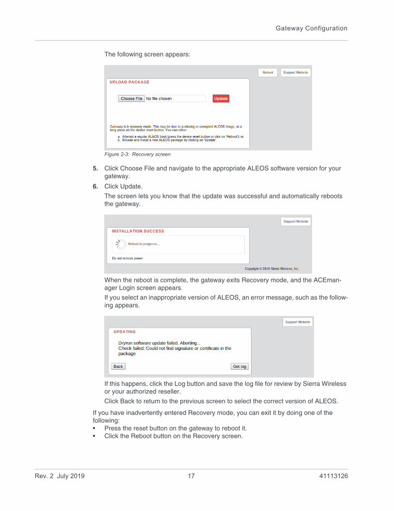
The following screen appears:
Figure 2-3: Recovery screen
5. Click Choose File and navigate to the appropriate ALEOS software version for your gateway.
6. Click Update.
The screen lets you know that the update was successful and automatically reboots the gateway.
When the reboot is complete, the gateway exits Recovery mode, and the ACEman-ager Login screen appears.
If you select an inappropriate version of ALEOS, an error message, such as the follow-ing appears.
If this happens, click the Log button and save the log file for review by Sierra Wireless or your authorized reseller.
Click Back to return to the previous screen to select the correct version of ALEOS.
If you have inadvertently entered Recovery mode, you can exit it by doing one of the following:• Press the reset button on the gateway to reboot it.• Click the Reboot button on the Recovery screen.
Rev. 2 July 2019 17 41113126

ALEOS 4.12.0 Software Configuration User Guide for AirLink RV55
• Wait 10 minutes. If no action is taken within 10 minutes of the device entering Recovery mode (for example, if the Recovery screen has not been loaded by the web browser), it automatically reboots and exits Recovery mode.
Toolbar
The buttons on the ACEmanager toolbar are:• Software and Firmware: Updates the ALEOS software and the radio module firmware• Template:
· Download and save a configuration as a template· Upload a saved template to apply settings
• Reboot: Reboots the gateway• Refresh All: Refreshes all ACEmanager pages• Help• Logout
Configuring your AirLink Gateway
There are three options for configuring the AirLink gateway:• Use your browser-based ACEmanager (as detailed in this guide)• Use a terminal emulator application (e.g., Tera Term, PuTTY, etc.) to enter AT
commands for many of the configuration options.• Use the cloud-based AirLink Management Service application (see www.sierraw-
ireless.com/products-and-solutions/gateway-solutions/alms/ for more details.)
Saving a Custom Configuration as a Template
If you have a gateway configured to match your requirements, you can use ACEmanager to download and save that gateway’s configuration as a template and then apply it to other Sierra Wireless AirLink gateways.
Note: Sierra Wireless recommends that templates be created and applied to AirLink gateways running the same version of ALEOS. If you apply a template created using an older version of ALEOS to a gateway running a newer version of ALEOS, settings for newly added features are not updated.
To download and save a custom configuration as a template:
1. Connect a laptop to the gateway with the configuration you want to save as a template.
2. In ACEmanager, click the Template button on the toolbar.
Figure 2-4: ACEmanager: Template button
Rev. 2 July 2019 18 41113126
Gateway Configuration
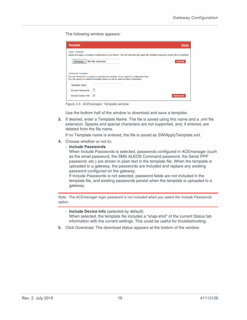
The following window appears:
Figure 2-5: ACEmanager: Template window
Use the bottom half of the window to download and save a template.
3. If desired, enter a Template Name. The file is saved using this name and a .xml file extension. Spaces and special characters are not supported, and, if entered, are deleted from the file name.
If no Template name is entered, the file is saved as SWIApplyTemplate.xml.
4. Choose whether or not to:· Include Passwords
When Include Passwords is selected, passwords configured in ACEmanager (such as the email password, the SMS ALEOS Command password, the Serial PPP password, etc.) are shown in plain text in the template file. When the template is uploaded to a gateway, the passwords are included and replace any existing password configured on the gateway. If Include Passwords is not selected, password fields are not included in the template file, and existing passwords persist when the template is uploaded to a gateway.
Note: The ACEmanager login password is not included when you select the Include Passwords option.
· Include Device Info (selected by default)When selected, the template file includes a “snap-shot” of the current Status tab information with the current settings. This could be useful for troubleshooting.
5. Click Download. The download status appears at the bottom of the window.
Rev. 2 July 2019 19 41113126

ALEOS 4.12.0 Software Configuration User Guide for AirLink RV55
Figure 2-6: Download template complete
Once the download is complete, the following window opens:
Figure 2-7: Open or Save the template file
6. In most cases, you will want to save the file to your computer for uploading to other AirLink gateways, but you also have the option to open the file. · Select Save File and click OK—file is saved to your computer (by default to the
Downloads folder). If you entered a template name, the file is saved using that name. Otherwise, it is saved under the default name, SWIApplyTemplate.xml.
· Select Open and click OK—file opens in a text or XML editor as a human readable file. Use this option if you selected Include Device Info when you saved the file and want to view the device information (the text between the <devicestatus> and </devicestatus> tags is the snap-shot of the Device Info), or you want to compare this template with another template.
Warning: Do not attempt to change settings directly in the template file. Changing settings in the template file could result in unexpected behavior in the AirLink gateway. Alter the template only if you are specifically directed to do so by your distributor or Sierra Wireless Technical Support.
Rev. 2 July 2019 20 41113126

Gateway Configuration
Tip: If you want to compare a new template with the previous one, download and save the old template before applying the new one. You can use any 3rd party text comparison tool to check the differences between two templates.
Applying a Template
Note: If you are using Internet Explorer 9 to upload the template, see Templates on page 537 for instructions on configuring the browser’s Internet options to allow the upload.
Note: Sierra Wireless recommends resetting the gateway to the factory default settings before applying the template.
To upload and apply a template to an AirLink gateway:
1. Connect the computer (where the template is saved) to the AirLink gateway you want to upload the template to, or connect to the gateway over the air.
2. Log in to ACEmanager, and go to Admin > Advanced.
3. Select the Reset Mode:· Preserve Cellular Authentication Settings—Recommended if you are applying a
template remotely using a remote ACEmanager connection (or ALMS). For a list of preserved settings, see Reset Mode on page 370.
· Reset All— Recommended if you are applying a template locally (i.e your computer is physically connected to the gateway).
4. Once the gateway reboots, log in to ACEmanager.
5. In ACEmanager, click the Template button on the toolbar.
Figure 2-8: ACEmanager: Template button
Rev. 2 July 2019 21 41113126
ALEOS 4.12.0 Software Configuration User Guide for AirLink RV55
The following window appears:
Figure 2-9: ACEmanager: Template window
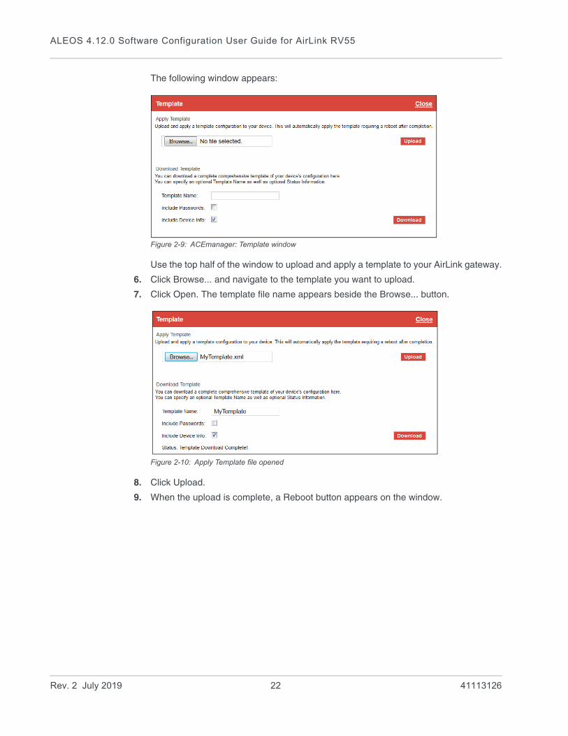
Use the top half of the window to upload and apply a template to your AirLink gateway.
6. Click Browse... and navigate to the template you want to upload.
7. Click Open. The template file name appears beside the Browse... button.
Figure 2-10: Apply Template file opened
8. Click Upload.
9. When the upload is complete, a Reboot button appears on the window.
Rev. 2 July 2019 22 41113126

Gateway Configuration
Figure 2-11: Template file uploaded
10. Click Reboot.
11. To confirm that the new template has been applied or to find out which template is currently on a gateway, go to Status > About and check the Template Name field.
Note: The Template Name field shows the last template applied and does not indicate any configu-ration changes made since the last template was applied.
Rev. 2 July 2019 23 41113126

ALEOS 4.12.0 Software Configuration User Guide for AirLink RV55
Figure 2-12: ACEmanager: Status > About
Note: If no template has been applied to the gateway since it was set or reset to the factory default settings, the template field is blank.
Update the ALEOS Software and Radio Module Firmware
To take advantage of new features available in the latest version of ALEOS, update the ALEOS software and radio module firmware on your AirLink gateways.
You can use ACEmanager to update one gateway at a time or you can use AirLink Management Service (ALMS) to update one or multiple gateways at the same time.
Important: Sierra Wireless always recommends updating ALEOS to the latest version to take advantage of new features and security updates. If your application requires you to install an earlier version of ALEOS than your current version, please note that Sierra Wireless:
• does not recommend using any version prior to ALEOS 4.9.3.
• recommends that ALEOS devices be reset to factory defaults following any downgrade operation.
Rev. 2 July 2019 24 41113126
Gateway Configuration
Note: ALEOS software releases may not apply to all AirLink devices. Please ensure that the version you select is compatible with your device.
Note: If the update includes a radio module firmware update, the radio module firmware stored on the gateway is also automatically updated. If there is not enough room in the storage, the radio module firmware update fails, so you may need to remove one of the versions stored on the gateway to free up space. For more information, see Radio Module Firmware on page 378.
Step 1—Planning Your Update
1. Sierra Wireless recommends that you download a template from the gateway(s) before you begin the update process. For instructions, see Saving a Custom Configu-ration as a Template on page 18.
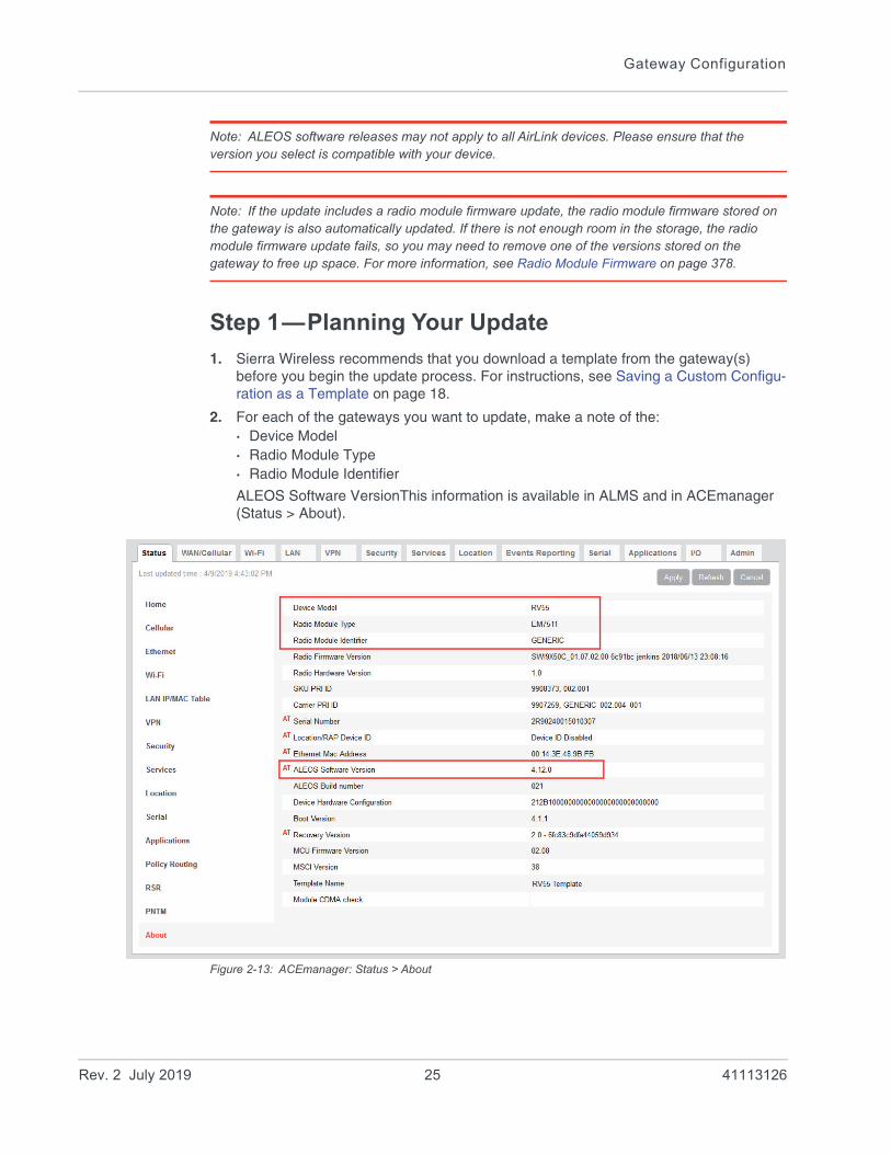
2. For each of the gateways you want to update, make a note of the:· Device Model· Radio Module Type· Radio Module Identifier
ALEOS Software VersionThis information is available in ALMS and in ACEmanager (Status > About).
Figure 2-13: ACEmanager: Status > About
Rev. 2 July 2019 25 41113126
ALEOS 4.12.0 Software Configuration User Guide for AirLink RV55
3. If you are planning to use ACEmanager to do the update:
a. Go to source.sierrawireless.com and select your product and mobile network operator to get to the download page for your gateway.
b. Download the new ALEOS software version for your system. If new radio module firmware is available, it is included with the ALEOS software in a .zip file.
Important: Do not install radio module firmware unless you are prompted to do so.
Note: If low power mode or time of day reboot are configured, and the following events are likely to coincide with the update:
• The gateway entering low power mode
• The Time of Day reset occurring
Sierra Wireless recommends that you disable these features before beginning the update.
Recommendations
If you have any questions about the update process, contact your authorized Sierra Wireless distributor before updating the radio module firmware.
Scheduling the update
The update can take up to 30 minutes to complete, depending on the speed of your network connection. The AirLink gateway being updated will be off-line during the update, so take this into account when scheduling the update.
Important: BE PATIENT! The firmware update can take up to 30 minutes to complete. Waiting for the process to complete is faster than troubleshooting the problems that can be caused by interrupting the process midway. (Interrupting the process may result in having to return the gateway to the factory for repairs.)
Note: For LTE-M/NB-IoT AirLink gateways: Due to the lower data rates supported by LTE-M/NB-IoT networks, over-the-air software updates can take an extended period of time. When using a Windows PC and ACEmanager to update ALEOS software over-the-air, please ensure that sleep and low power states are disabled on the PC so that the file transfer is not disrupted. Under these conditions, the ALEOS upgrade may take between 3 to 5 hours.
Sierra Wireless recommends using ALMS or AMM for remote software upgrades.
Rev. 2 July 2019 26 41113126
Gateway Configuration
Step 2—Update the ALEOS Software and Radio Module Firmware
Using ACEmanager to Update a Single AirLink Gateway
To update the ALEOS software and radio module firmware on one AirLink gateway:
1. Connect the AirLink gateway you want to update to your laptop, launch your browser and enter the URL for the gateway. The default IP address/port for the Ethernet interface is http://192.168.13.31:9191. If it is a remote gateway, enter the domain name or public IP (WAN) address.
Note: If you are connected to the gateway remotely, any files transferred to the gateway are trans-ferred over-the-air and you may incur data charges.
2. Log in to ACEmanager.
Default user name: user
Default password: Printed on the device label. If the password is not printed on the label, the default password is 12345.
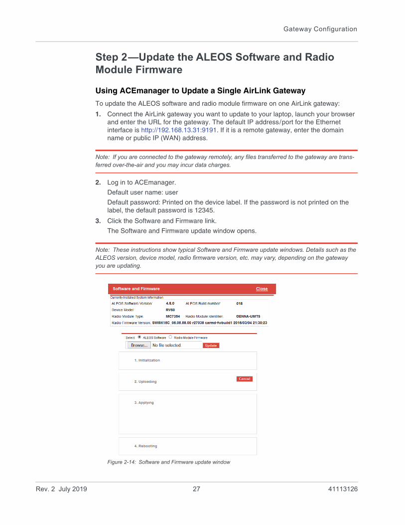
3. Click the Software and Firmware link.
The Software and Firmware update window opens.
Note: These instructions show typical Software and Firmware update windows. Details such as the ALEOS version, device model, radio firmware version, etc. may vary, depending on the gateway you are updating.
Figure 2-14: Software and Firmware update window
Rev. 2 July 2019 27 41113126

ALEOS 4.12.0 Software Configuration User Guide for AirLink RV55
The update window gives you the option to update both ALEOS and the radio module firmware, or update only the radio module firmware.
Unless advised otherwise by Sierra Wireless, select ALEOS software (which updates ALEOS and prompts you to update the radio module firmware if a newer version is available for your gateway).
4. Click Browse... and navigate to the ALEOS software you downloaded from the Sierra Wireless Web site. This is a .bin file named for the gateway and the ALEOS software version. For example, RV55_4.12.0.010.bin.
Figure 2-15: ALEOS file selected in Software and Firmware update window
5. Click Update.
The ALEOS software update runs automatically and green check marks appear beside each step as it is completed.
Rev. 2 July 2019 28 41113126

Gateway Configuration
Figure 2-16: ALEOS software update in progress
Important: Do not disconnect the AirLink gateway from the computer, and do not power cycle or reset the gateway during the update. If you see any error messages, refer to the Updating the ALEOS Software and Radio Module Firmware on page 538.
6. Depending on the gateway and your Mobile Network Operator, you may be prompted to update the radio module firmware.
If you do not receive a prompt, the radio firmware is up to date. Proceed to step 9.Only if prompted to update the firmware, proceed to step 7.
Figure 2-17: Prompt for Radio Module Firmware
7. Under Applying, click Browse... and navigate to the radio module firmware file that was included in the .zip file you downloaded. This is an .iso file named for the gateway’s radio module and the mobile network operator’s network (or “GENERIC”, if it is intended for more than one operator network). For example, MC7354_GENER-IC_2820.iso.
8. Click Upload Radio Firmware.
A message appears on the window indicating that the firmware has been successfully uploaded.
Rev. 2 July 2019 29 41113126
ALEOS 4.12.0 Software Configuration User Guide for AirLink RV55
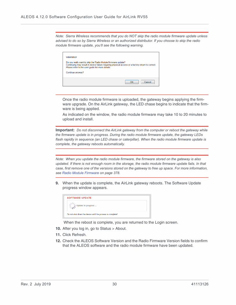
Note: Sierra Wireless recommends that you do NOT skip the radio module firmware update unless advised to do so by Sierra Wireless or an authorized distributor. If you choose to skip the radio module firmware update, you’ll see the following warning.
Once the radio module firmware is uploaded, the gateway begins applying the firm-ware upgrade. On the AirLink gateway, the LED chase begins to indicate that the firm-ware is being applied.
As indicated on the window, the radio module firmware may take 10 to 20 minutes to upload and install.
Important: Do not disconnect the AirLink gateway from the computer or reboot the gateway while the firmware update is in progress. During the radio module firmware update, the gateway LEDs flash rapidly in sequence (an LED chase or caterpillar). When the radio module firmware update is complete, the gateway reboots automatically.
Note: When you update the radio module firmware, the firmware stored on the gateway is also updated. If there is not enough room in the storage, the radio module firmware update fails. In that case, first remove one of the versions stored on the gateway to free up space. For more information, see Radio Module Firmware on page 378.
9. When the update is complete, the AirLink gateway reboots. The Software Update progress window appears.
When the reboot is complete, you are returned to the Login screen.
10. After you log in, go to Status > About.
11. Click Refresh.
12. Check the ALEOS Software Version and the Radio Firmware Version fields to confirm that the ALEOS software and the radio module firmware have been updated.
Rev. 2 July 2019 30 41113126

Gateway Configuration
Using AirLink Management Service (ALMS) to Update One or Multiple AirLink gateways Over-the-Air
You can use AirLink Management Service to update the ALEOS software and radio module firmware over-the-air on one or multiple AirLink gateways.
If you don’t have an ALMS account:
1. In ACEmanager, go to the Services tab and ensure that ALMS is enabled and the server URL is https://na.m2mop.net/device/msci/com. If this is not the case, enter the correct URL, click Apply and then click Reboot.
2. Go to www.sierrawireless.com/ALMS for more information.
Updating to ALEOS software with an ALMS account:
1. Go to airvantage.net and log in.
2. Follow the instructions in the online ALMS documentation to update the ALEOS software and radio module firmware.
Updating Only the Radio Module Firmware
Important: This feature should be used only if directed by Sierra Wireless or an authorized reseller.
If Sierra Wireless or your authorized reseller directs you to update only the Radio Module Firmware:
1. Select the Radio Module Firmware button.
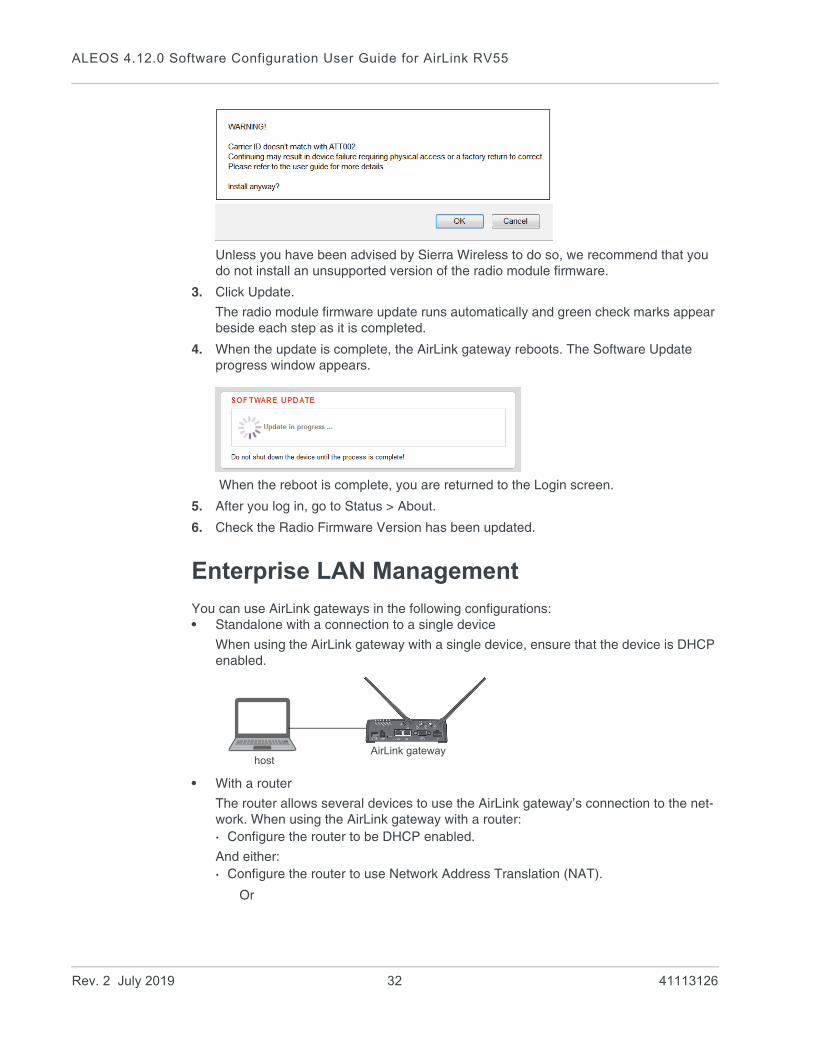
2. Select the appropriate firmware file for your gateway and click Update. This is an .iso file named for the gateway’s radio module and the mobile network operator’s network (or “GENERIC”, if it is intended for more than one operator network). For example, MC7354_GENERIC_2820.iso.
If you select a file for radio module firmware that is not supported on your gateway, you will see a warning message similar to the following:
Rev. 2 July 2019 31 41113126
ALEOS 4.12.0 Software Configuration User Guide for AirLink RV55
Unless you have been advised by Sierra Wireless to do so, we recommend that you do not install an unsupported version of the radio module firmware.
3. Click Update.
The radio module firmware update runs automatically and green check marks appear beside each step as it is completed.
4. When the update is complete, the AirLink gateway reboots. The Software Update progress window appears.
When the reboot is complete, you are returned to the Login screen.
5. After you log in, go to Status > About.
6. Check the Radio Firmware Version has been updated.
Enterprise LAN Management
You can use AirLink gateways in the following configurations:• Standalone with a connection to a single device
When using the AirLink gateway with a single device, ensure that the device is DHCP enabled.
• With a router
The router allows several devices to use the AirLink gateway’s connection to the net-work. When using the AirLink gateway with a router:· Configure the router to be DHCP enabled.
And either:· Configure the router to use Network Address Translation (NAT).
Or
hostAirLink gateway
Rev. 2 July 2019 32 41113126

Gateway Configuration
· Configure ALEOS (in ACEmanager) to use Host Port Routing. For information on using ALEOS with a router that is not configured to use NAT, see Host Port Routing on page 150.
Note: Other than for VLANs, ALEOS does not provide DHCP addresses to router connected devices.
hosts
AirLink gatewayRouter
Rev. 2 July 2019 33 41113126

ALEOS 4.12.0 Software Configuration User Guide for AirLink RV55
Over the Air (OTA) Connections
Access AirLink gateways
You can use an OTA connection to access AirLink gateways that are in either configuration described above (stand alone or with a router).
Access connected devices
To use an OTA connection to access a connected device through the AirLink gateway, configure the device in ALEOS as the DMZ or port forwarding destination. For information on inbound OTA connections to the host, see DMZ on page 201 and Port Forwarding on page 196.
Configuring Your Gateway for use in a PCI Compliant System
The credit card industry requires retailers to comply with Payment Card Industry (PCI) standard to maintain a secure environment when processing payment card transactions. For these transactions, the AirLink gateway acts as a wireless data conduit for routers and PoSs (point-of-sale-terminals) that have been configured for PCI compliance.
Figure 2-18: Sample PCI compliant network
The PCI compliant network must be set up so that:• The USBnet is on a different subnet from the point-of-sale-terminal.• All security protocols must be established from the point-of-sale terminal to the
payment processor. • Payment card terminals must be on a dedicated LAN or VLAN.
AirLink gateway
Payment Processor
DSL Gateway
Internet
Router configured for
Retail store
Wi-Fi
LAN
LAN
Cellular WAN
WAN
PoSWireless Access Point
PoS
PCI compliance
Rev. 2 July 2019 34 41113126
Gateway Configuration
• The AirLink gateway must be connected to a router that is configured for PCI compliance.
Note: The serial port on the AirLink gateway has no access to the IP data path and does not need to be disabled.
If you are using the AirLink gateway for a payment card industry application, to meet PCI Data Security Standard compliance requirements the following steps must be done by a PCI certified service company.
For each gateway:
1. Connect the AirLink gateway to a router that has been configured for PCI compliance.
2. Log in to ACEmanager. (User name is user; default password is 12345.)
Change the password regularly, in accordance with PCI recommendations.
3. Go to the Admin tab and change the default password.
Do not share the ACEmanager password.
4. Go to Applications > ALEOS Application Framework and set the ALEOS Application Framework field to Disable.
Rev. 2 July 2019 35 41113126

3
3: StatusAll fields in the Status group are read-only and provide information about the AirLink gateway. Depending on individual settings, the onboard radio module, and the type of network, the actual status pages may look different than the pages shown here.
Tip: To be sure you are viewing the current status for all fields, click the Refresh button on the upper right side of the screen.
Home
The Home section of the Status tab is the first page displayed when you log in to ACEmanager. It shows basic information about the WAN network connection, the mobile network connection, and important information about the gateway.
Figure 3-1: ACEmanager: Status > Home
Field Description
General
Active WAN IPv4 IP Address
The current IPv4 WAN IP address for the gateway
Rev. 2 July 2019 36 41113126
Status
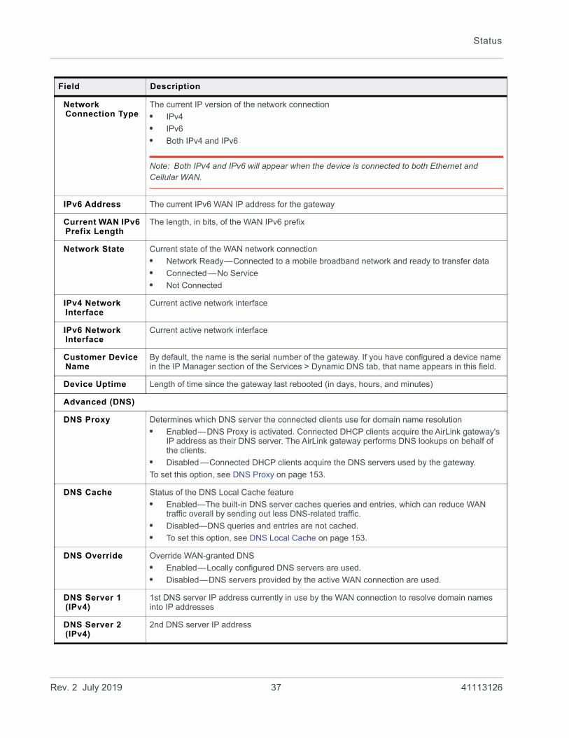
Network Connection Type
The current IP version of the network connection
• IPv4
• IPv6
• Both IPv4 and IPv6
Note: Both IPv4 and IPv6 will appear when the device is connected to both Ethernet and Cellular WAN.
IPv6 Address The current IPv6 WAN IP address for the gateway
Current WAN IPv6 Prefix Length
The length, in bits, of the WAN IPv6 prefix
Network State Current state of the WAN network connection
• Network Ready—Connected to a mobile broadband network and ready to transfer data
• Connected —No Service
• Not Connected
IPv4 Network Interface
Current active network interface
IPv6 Network Interface
Current active network interface
Customer Device Name
By default, the name is the serial number of the gateway. If you have configured a device name in the IP Manager section of the Services > Dynamic DNS tab, that name appears in this field.
Device Uptime Length of time since the gateway last rebooted (in days, hours, and minutes)
Advanced (DNS)
DNS Proxy Determines which DNS server the connected clients use for domain name resolution
• Enabled—DNS Proxy is activated. Connected DHCP clients acquire the AirLink gateway's IP address as their DNS server. The AirLink gateway performs DNS lookups on behalf of the clients.
• Disabled —Connected DHCP clients acquire the DNS servers used by the gateway.
To set this option, see DNS Proxy on page 153.
DNS Cache Status of the DNS Local Cache feature
• Enabled—The built-in DNS server caches queries and entries, which can reduce WAN traffic overall by sending out less DNS-related traffic.
• Disabled—DNS queries and entries are not cached.
• To set this option, see DNS Local Cache on page 153.
DNS Override Override WAN-granted DNS
• Enabled—Locally configured DNS servers are used.
• Disabled—DNS servers provided by the active WAN connection are used.
DNS Server 1 (IPv4)
1st DNS server IP address currently in use by the WAN connection to resolve domain names into IP addresses
DNS Server 2 (IPv4)
2nd DNS server IP address
Field Description
Rev. 2 July 2019 37 41113126

ALEOS 4.12.0 Software Configuration User Guide for AirLink RV55
Cellular
The Cellular section provides specific information about the connection including the IP address and how much data has been transmitted or received. Some of the information on this screen is repeated on the Home page for quick reference.
Figure 3-2: ACEmanager: Status > Cellular
Rev. 2 July 2019 38 41113126
Status
General
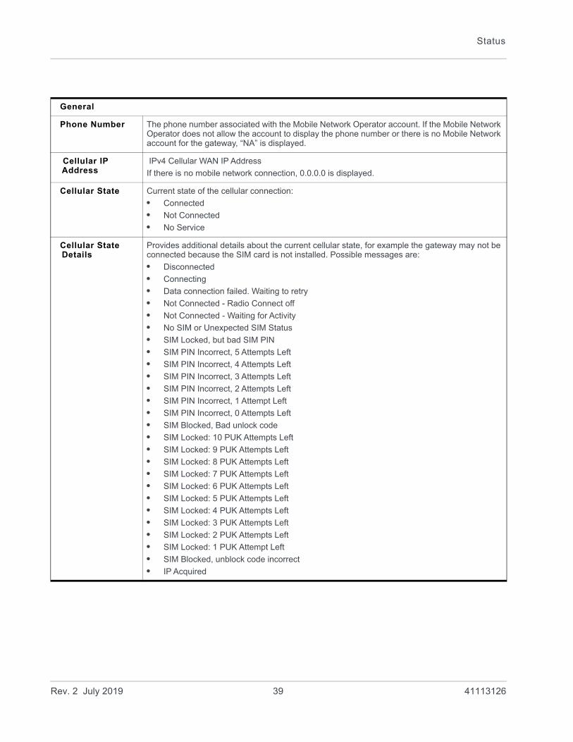
Phone Number The phone number associated with the Mobile Network Operator account. If the Mobile Network Operator does not allow the account to display the phone number or there is no Mobile Network account for the gateway, “NA” is displayed.
Cellular IP Address
IPv4 Cellular WAN IP Address
If there is no mobile network connection, 0.0.0.0 is displayed.
Cellular State Current state of the cellular connection:
• Connected
• Not Connected
• No Service
Cellular State Details
Provides additional details about the current cellular state, for example the gateway may not be connected because the SIM card is not installed. Possible messages are:
• Disconnected
• Connecting
• Data connection failed. Waiting to retry
• Not Connected - Radio Connect off
• Not Connected - Waiting for Activity
• No SIM or Unexpected SIM Status
• SIM Locked, but bad SIM PIN
• SIM PIN Incorrect, 5 Attempts Left
• SIM PIN Incorrect, 4 Attempts Left
• SIM PIN Incorrect, 3 Attempts Left
• SIM PIN Incorrect, 2 Attempts Left
• SIM PIN Incorrect, 1 Attempt Left
• SIM PIN Incorrect, 0 Attempts Left
• SIM Blocked, Bad unlock code
• SIM Locked: 10 PUK Attempts Left
• SIM Locked: 9 PUK Attempts Left
• SIM Locked: 8 PUK Attempts Left
• SIM Locked: 7 PUK Attempts Left
• SIM Locked: 6 PUK Attempts Left
• SIM Locked: 5 PUK Attempts Left
• SIM Locked: 4 PUK Attempts Left
• SIM Locked: 3 PUK Attempts Left
• SIM Locked: 2 PUK Attempts Left
• SIM Locked: 1 PUK Attempt Left
• SIM Blocked, unblock code incorrect
• IP Acquired
Rev. 2 July 2019 39 41113126

ALEOS 4.12.0 Software Configuration User Guide for AirLink RV55
Cellular End-to-End Connection
Describes the state of the cellular network connection, based on Cellular network monitoring (see Cellular > Monitor on page 96). Possible states are:
• Not Verified—The monitoring function is set to disable and therefore the availability of the cellular network cannot be verified.
• Pending—The monitoring function is enabled, but has not yet completed its test. Once the first test is complete, this option only appears again if monitoring is disabled and then re-enabled.
• Established—The monitoring system has determined that service is available on the cellular network.
• Not Established—The monitoring system has determined that the cellular interface has no service (ping test failed).
Carrier Availability
Indicates whether or not the mobile network operator (carrier) is able to provide service to the gateway’s radio module
Possible values:
• Available
• Not Available
SIM Network Operator
The SIM card’s home network, i.e, the Mobile Network Operator when the gateway is not roaming
Serving Network Operator
The network currently in use
This field only appears when the gateway has a network connection.
• If the gateway is not roaming, this field is the same as the SIM Network Operator field.
• If the gateway is roaming, this field displays the roaming Mobile Network Operator.
Signal Strength (RSSI)
Received Signal Strength Indicator
The average received signal power measured in the air interface channel
Indicates if there is a strong signal available for the AirLink gateway to connect to
See also LTE Signal Strength (RSRP) and LTE Signal Quality (RSRQ).
The value varies, depending on the network characteristics and the AirLink gateway.
Signal Quality (ECI0)
2G/3G signal quality
Indicates the signal quality with a ratio of the average signal energy to co-channel interference in dB
ESN/EID/IMEI Electronic Serial Number for the internal radio
RSSI Signal strength
> -78 dBm Good
-78 dBm to -93 dBm Fair
-94 dBm to -102 dBm Poor
< -103 dBm Inadequate
ECI0 Signal quality
0 to -6 Good
-7 to -10 Fair
-11 to -20 Poor
Rev. 2 July 2019 40 41113126
Status
SIM ID Identification number for the SIM card in use
APN Status Current APN in use by the network connection
• (Configured) is a default APN based on the SIM card in use.
• (User Entered) is a custom APN entered manually into the configuration.
Note: APN is configured on the WAN/Cellular configuration tab.
Number of SIMs present
Indicates the number of SIM cards present in the gateway
Primary SIM Indicates which SIM card slot contains the primary SIM card. If two SIM cards are installed, the Primary SIM card is used for network connections.
Active SIM Indicates which SIM slot contains the Active SIM card (The SIM card that is used for the current data connection.)
Radio Technology Type of service being used by the gateway (e.g. LTE, HSPA+, UMTS, HSPA, or GPRS)
If you are connected to a network other than that of your Mobile Network Operator, the network service type indicates that you are roaming (and additional charges may apply).
Network Service Type
Type of network the gateway is connected to (e.g. 4G, 3G)
Network Connection Type
This field only appears if the IP Address Preference field on the WAN/Cellular tab is set to IPv4 and IPv6 Gateway.
Displays the type of IP connection that has been established (None, IPv4, or Both IPv4 and IPv6)
Active Frequency Band
Current cellular band being used (LTE BAND 4, etc.)
Statistics
Bytes Sent Number of bytes sent to the mobile network since system startup or reboot
Bytes Received Number of bytes received from the mobile network since system startup or reboot
Persisted Bytes Sent
Number of bytes sent
The count starts when the gateway first goes on air and persists over reboot. The field resets to zero on reset to factory default settings.For the RV55, this value is the cumulative traffic for both SIM cards, if more than one SIM card is present.
Persisted Bytes Received
Number of bytes received
The count starts when the gateway first goes on air and persists over reboot. The field resets to zero on reset to factory default settings. For the RV55, this value is the cumulative traffic for both SIM cards, if more than one SIM card is present.
Packets Sent Number of packets sent to the network since system startup or reboot
Packets Received Number of packets received from the network since system startup or reboot
Monitor
Test Interval (minutes)
The configured amount of time between tests of the cellular connection
Monitor Type The configured type of test being run on the interface to diagnose its ability to provide end-to-end connectivity
Rev. 2 July 2019 41 41113126
ALEOS 4.12.0 Software Configuration User Guide for AirLink RV55
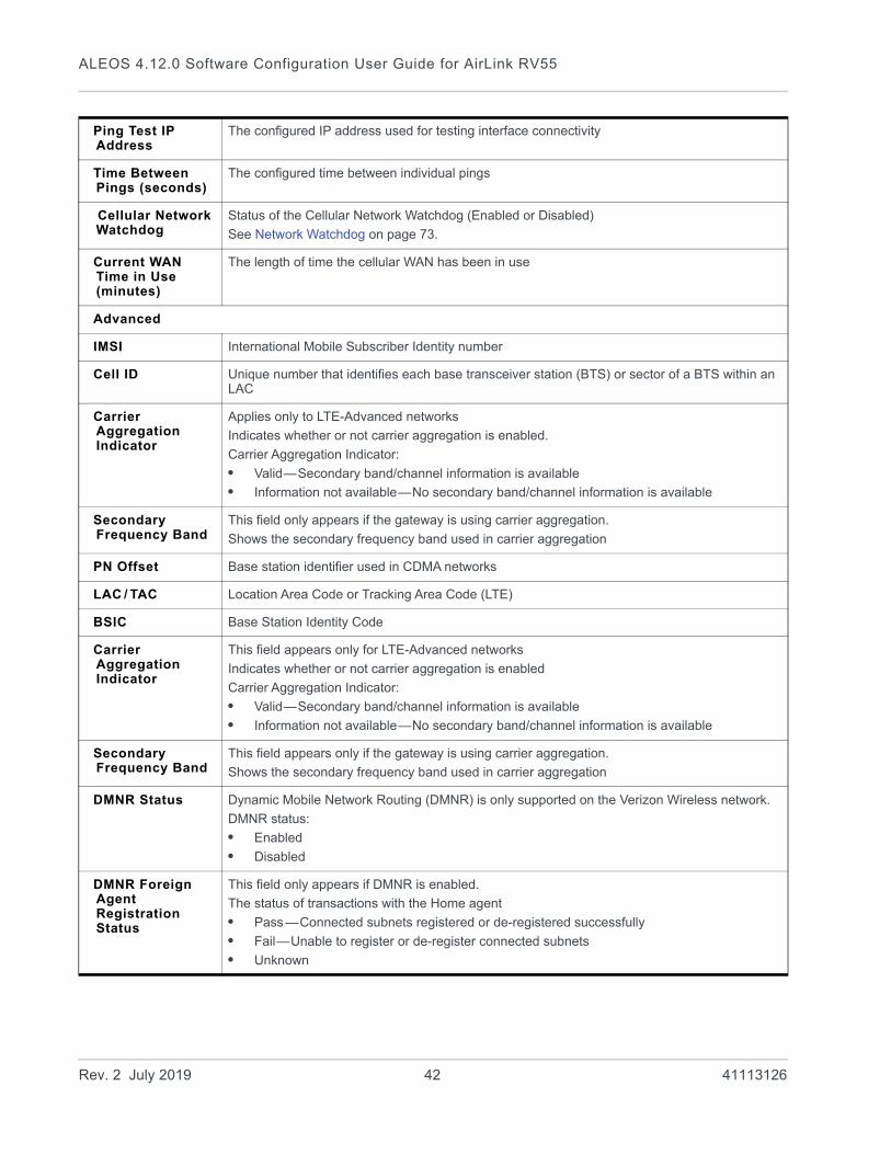
Ping Test IP Address
The configured IP address used for testing interface connectivity
Time Between Pings (seconds)
The configured time between individual pings
Cellular Network Watchdog
Status of the Cellular Network Watchdog (Enabled or Disabled)
See Network Watchdog on page 73.
Current WAN Time in Use (minutes)
The length of time the cellular WAN has been in use
Advanced
IMSI International Mobile Subscriber Identity number
Cell ID Unique number that identifies each base transceiver station (BTS) or sector of a BTS within an LAC
Carrier Aggregation Indicator
Applies only to LTE-Advanced networks
Indicates whether or not carrier aggregation is enabled.
Carrier Aggregation Indicator:
• Valid—Secondary band/channel information is available
• Information not available—No secondary band/channel information is available
Secondary Frequency Band
This field only appears if the gateway is using carrier aggregation.
Shows the secondary frequency band used in carrier aggregation
PN Offset Base station identifier used in CDMA networks
LAC / TAC Location Area Code or Tracking Area Code (LTE)
BSIC Base Station Identity Code
Carrier Aggregation Indicator
This field appears only for LTE-Advanced networks
Indicates whether or not carrier aggregation is enabled
Carrier Aggregation Indicator:
• Valid—Secondary band/channel information is available
• Information not available—No secondary band/channel information is available
Secondary Frequency Band
This field appears only if the gateway is using carrier aggregation.
Shows the secondary frequency band used in carrier aggregation
DMNR Status Dynamic Mobile Network Routing (DMNR) is only supported on the Verizon Wireless network.
DMNR status:
• Enabled
• Disabled
DMNR Foreign Agent Registration Status
This field only appears if DMNR is enabled.
The status of transactions with the Home agent
• Pass —Connected subnets registered or de-registered successfully
• Fail—Unable to register or de-register connected subnets
• Unknown
Rev. 2 July 2019 42 41113126

Status
DMNR Reverse Tunnelling Agent Status
This field only appears if DMNR is enabled.
Status of the NEMO tunnel:
• Up
• Down
Cell Info Cell information such as the Base Station Identity Code (BSIC), TCH, Received Signal Strength Indicator (RSSI), Location Area Code (LAC), and the cell ID
For additional information, including cell info for LTE networks, see *CELLINFO2? on page 454 and LTE Networks on page 541.
Channel WAN network channel
The current active channel number for the mobile network connection
Network Operator Switching
Network Operator Switching status (See Radio Module Firmware on page 378.) Possible status:
• OK—The SIM in use matches the currently active radio module firmware.
• Manually disabled—SIM-based image switching is disabled on the Admin > Radio Module Firmware screen.
• Disabled: <carrier> firmware is not in the local store—The required radio module firmware is not stored on the gateway. For instructions on how to install the radio module firmware, see Radio Module Firmware on page 378.
• Disabled: Unknown MCC/MNC—The gateway does not recognize the Mobile Country Code (MCC) or the Mobile Network Code (MNC) for the SIM card.
• Disabled: SIM card not ready at boot—SIM card error. Ensure that the SIM card is installed properly, and has a valid account associated with it. If the problem persists, contact your Mobile Network Provider.
• Disabled: SIM card not usable at boot—The gateway is unable to read the SIM card. Check the Network State field to ensure that the SIM card is not PIN-blocked. Ensure that the SIM card is installed properly, and has a valid account associated with it. If the problem persists, contact your Mobile Network Provider.
• Disabled: DVT-Mode—The gateway is in an advanced diagnostic mode, normally only used at the factory. Contact your Sierra Wireless authorized distributor.
• Disabled: internal error—Indicates a problem with the Network Operator Switching feature. Contact your Sierra Wireless authorized distributor.
LTE IoT Operating Mode
This field appears only if the RV55 is connected to a Cat-M1 or NB-IoT LTE network. The value indicates the connected IoT network type.
Possible values:
• Cat-M1
• NB-IoT
Signal Strength and Quality
Different radio technologies have different ways of reporting signal strength and signal quality. The fields displayed in ACEmanager depend on the type of network it is connected to.
Received Signal Code Power (RSCP)
The RSCP is the power measured by the receiver on a particular physical channel. It provides an indication of signal strength for UMTS connections, and appears under Cellular > Advanced. Expected values are in the range of -50 dB to -120 dB.
Rev. 2 July 2019 43 41113126
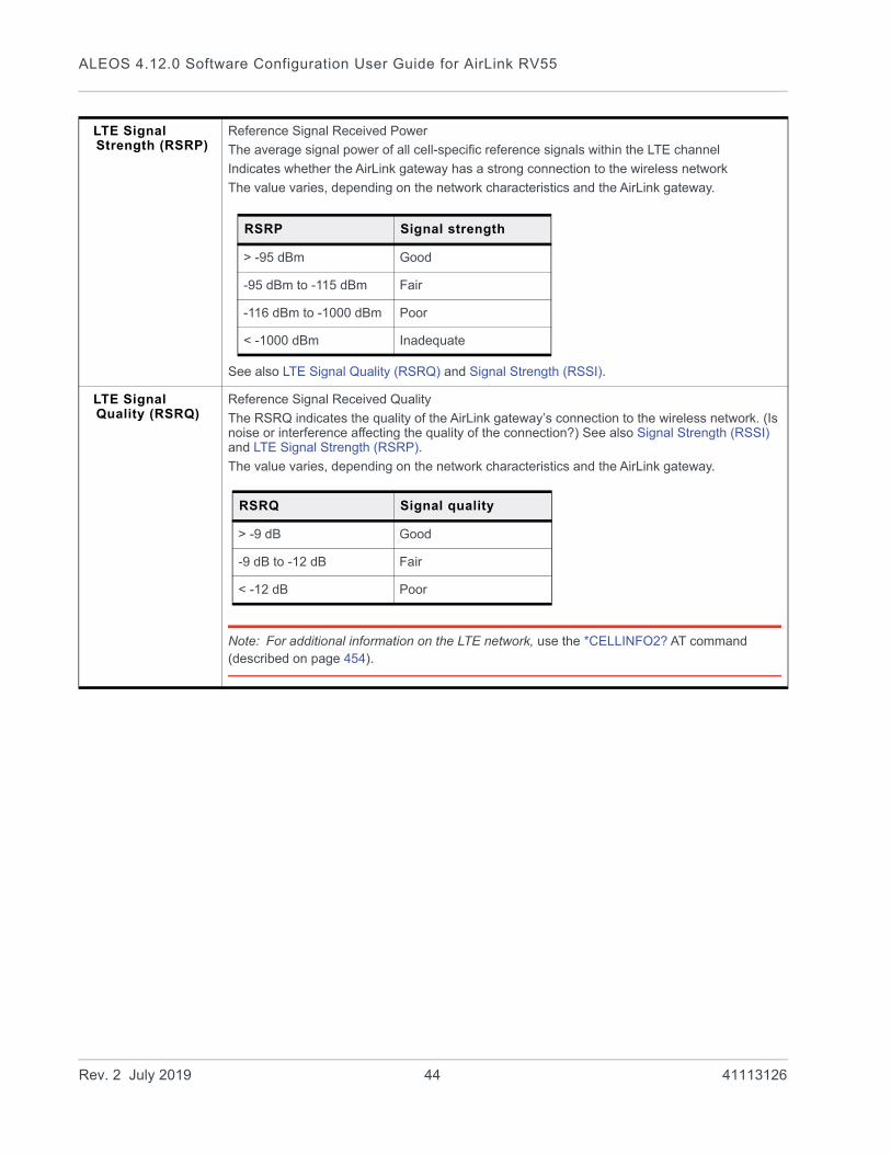
ALEOS 4.12.0 Software Configuration User Guide for AirLink RV55
LTE Signal Strength (RSRP)
Reference Signal Received Power
The average signal power of all cell-specific reference signals within the LTE channel
Indicates whether the AirLink gateway has a strong connection to the wireless network
The value varies, depending on the network characteristics and the AirLink gateway.
See also LTE Signal Quality (RSRQ) and Signal Strength (RSSI).
LTE Signal Quality (RSRQ)
Reference Signal Received Quality
The RSRQ indicates the quality of the AirLink gateway’s connection to the wireless network. (Is noise or interference affecting the quality of the connection?) See also Signal Strength (RSSI) and LTE Signal Strength (RSRP).
The value varies, depending on the network characteristics and the AirLink gateway.
Note: For additional information on the LTE network, use the *CELLINFO2? AT command (described on page 454).
RSRP Signal strength
> -95 dBm Good
-95 dBm to -115 dBm Fair
-116 dBm to -1000 dBm Poor
< -1000 dBm Inadequate
RSRQ Signal quality
> -9 dB Good
-9 dB to -12 dB Fair
< -12 dB Poor
Rev. 2 July 2019 44 41113126
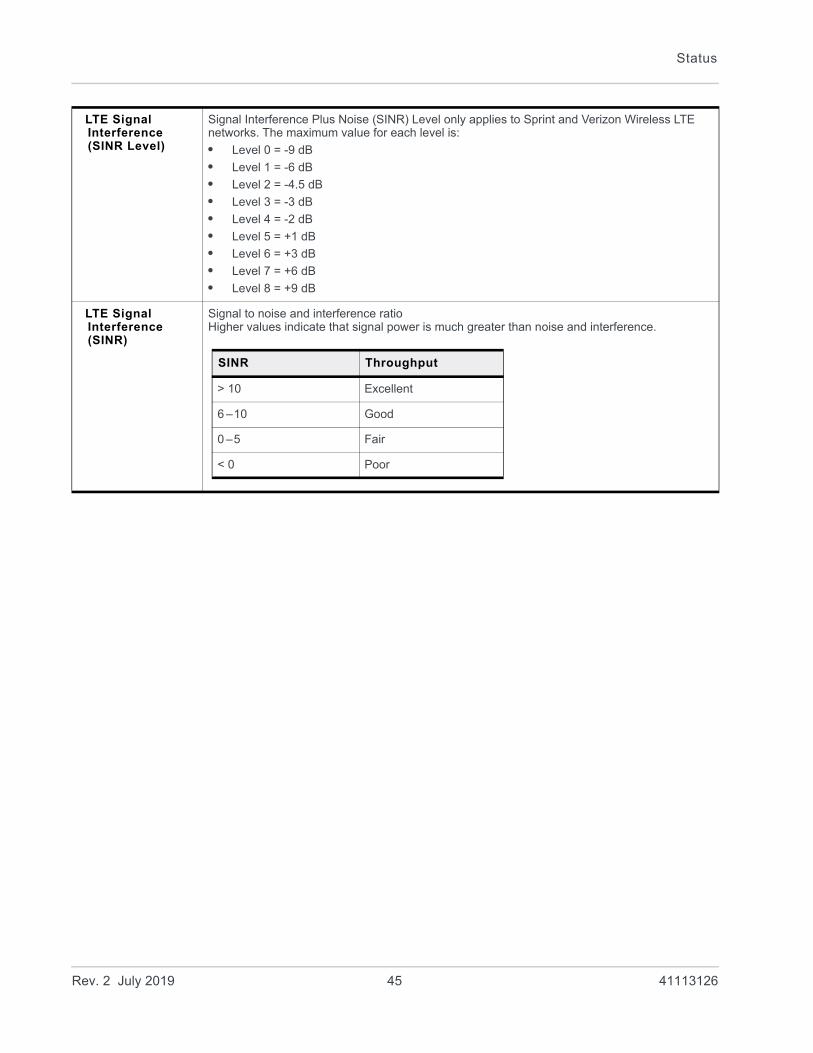
Status
LTE Signal Interference (SINR Level)
Signal Interference Plus Noise (SINR) Level only applies to Sprint and Verizon Wireless LTE networks. The maximum value for each level is:
• Level 0 = -9 dB
• Level 1 = -6 dB
• Level 2 = -4.5 dB
• Level 3 = -3 dB
• Level 4 = -2 dB
• Level 5 = +1 dB
• Level 6 = +3 dB
• Level 7 = +6 dB
• Level 8 = +9 dB
LTE Signal Interference (SINR)
Signal to noise and interference ratioHigher values indicate that signal power is much greater than noise and interference.
SINR Throughput
> 10 Excellent
6 –10 Good
0 –5 Fair
< 0 Poor
Rev. 2 July 2019 45 41113126

ALEOS 4.12.0 Software Configuration User Guide for AirLink RV55
Ethernet
Figure 3-3: ACEmanager: Status > Ethernet
Rev. 2 July 2019 46 41113126

Status
Field Description
Ethernet LAN
DHCP Mode Status of DHCP mode
• Server—The AirLink gateway is acting as a DHCP server for all Ethernet connections.
• Disable—The AirLink gateway is not acting as a DHCP server or client. All devices connected to the AirLink gateway must have a static LAN IP or use PPPoE.
• Auto—Default setting used by authorized AirLink resellers for initial gateway configu-ration. See DHCP Mode on page 138 for more information.
DHCP Auto Status Status of DHCP mode (This field only appears when the DHCP mode is Auto.)
• Server—ALEOS is acting as a DHCP server.
• Client—ALEOS is acting as a DHCP client.
USB Mode Which USB port mode is set (USBnet, USB serial, or Disabled)
Connected Clients Number of connected devices that obtained their IP address through DHCP over Ethernet or USBnet. The value in this field does not include devices connected via PPP or PPPoE.
VRRP Mode VRRP status
Proxy ARP Proxy ARP status:
• Enabled
• Disabled
For more information, see Proxy ARP (Primary Gateway) on page 151.
Ethernet Port Status
Port Number Port number (The number of Ethernet ports available varies depending on the gateway.)
MAC Address MAC addresses of the Ethernet ports
Status Status of the Ethernet port(s):
• Disabled—The Ethernet port has not been enabled (Default)
• Link Speed—Link speed depends on the gateway and the network
• Disconnected—No device is connected to the Ethernet port
• Disabled (Public IP)—The Connection mode is set to “Ethernet Uses Public IP”. All the Ethernet ports except the Public Mode Ethernet port are automatically disabled.
Port Mode Mode of each Ethernet port
Packets Sent Number of packets sent over the Ethernet port
Packets Received Number of packets received over the Ethernet port
Ethernet WAN
Ethernet State Current state of the Ethernet connection:
• Connected
• Not Connected
• No Service
Ethernet State Details Provides additional details about the current Ethernet connection status. Possible messages are:
• IP Acquired
• Disconnected
• Not configured for WAN
Rev. 2 July 2019 47 41113126
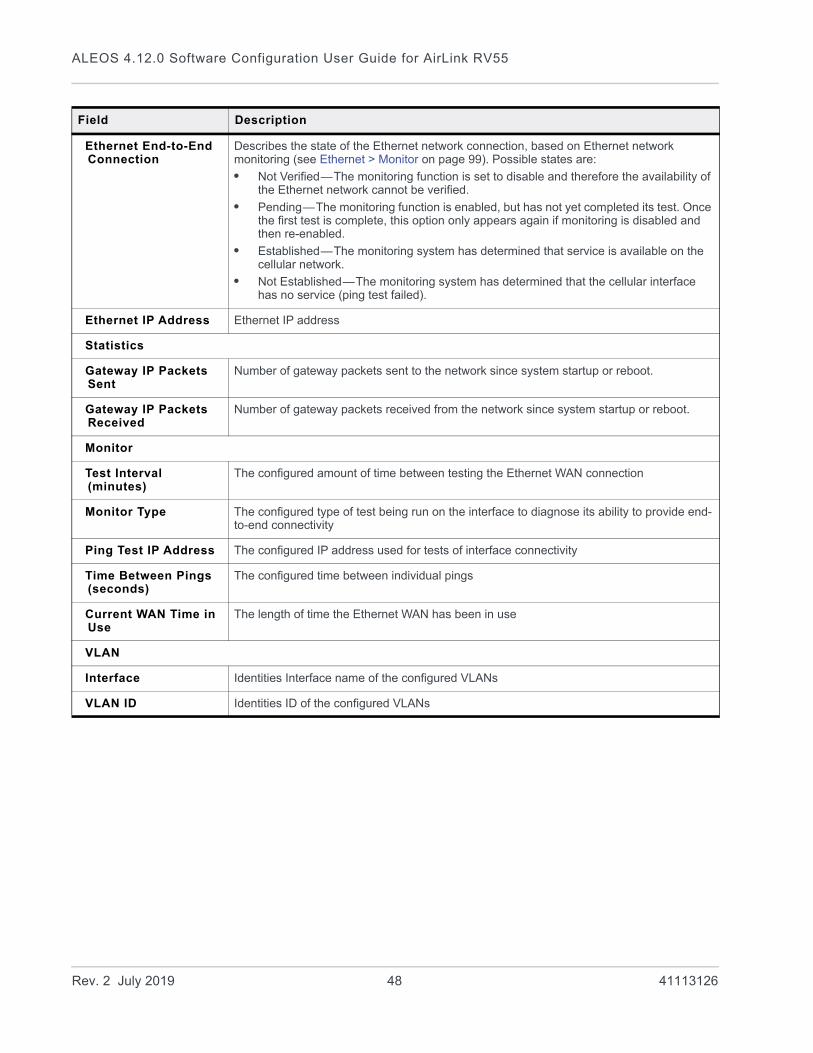
ALEOS 4.12.0 Software Configuration User Guide for AirLink RV55
Ethernet End-to-End Connection
Describes the state of the Ethernet network connection, based on Ethernet network monitoring (see Ethernet > Monitor on page 99). Possible states are:
• Not Verified—The monitoring function is set to disable and therefore the availability of the Ethernet network cannot be verified.
• Pending—The monitoring function is enabled, but has not yet completed its test. Once the first test is complete, this option only appears again if monitoring is disabled and then re-enabled.
• Established—The monitoring system has determined that service is available on the cellular network.
• Not Established—The monitoring system has determined that the cellular interface has no service (ping test failed).
Ethernet IP Address Ethernet IP address
Statistics
Gateway IP Packets Sent
Number of gateway packets sent to the network since system startup or reboot.
Gateway IP Packets Received
Number of gateway packets received from the network since system startup or reboot.
Monitor
Test Interval (minutes)
The configured amount of time between testing the Ethernet WAN connection
Monitor Type The configured type of test being run on the interface to diagnose its ability to provide end-to-end connectivity
Ping Test IP Address The configured IP address used for tests of interface connectivity
Time Between Pings (seconds)
The configured time between individual pings
Current WAN Time in Use
The length of time the Ethernet WAN has been in use
VLAN
Interface Identities Interface name of the configured VLANs
VLAN ID Identities ID of the configured VLANs
Field Description
Rev. 2 July 2019 48 41113126

Status
Wi-Fi
If you have an AirLink RV55 with Wi-Fi, click the Wi-Fi tab on the left side of the screen to view the Wi-Fi Status.
Figure 3-4: ACEmanager: Status > Wi-Fi (example, with Wi-Fi A Access Point and Wi-Fi B Client)
Rev. 2 July 2019 49 41113126

ALEOS 4.12.0 Software Configuration User Guide for AirLink RV55
Field Description
Wi-Fi Status
Wi-Fi A, Wi-Fi B Mode Wi-Fi A and B modes. For more information, see Wi-Fi Configuration on page 116.
Access Point (LAN)
These fields only appear when the Wi-Fi A and/or B mode is set to Access Point (LAN).
SSID Configured SSID
Security Encryption Type
Wi-Fi security encryption (security authentication) type
(i.e. WEP, WPA, WPA2 Personal, WPA2 Enterprise)
Connected Clients Number of connected clients
Configured Access Point Mode
Current Wi-FI access point mode. For example if the access point mode on the gateway is configured for n/ac Enabled (for 5 GHz band) and the client only supports b/g (2.4 GHz band), the access point mode in use is b/g (2.4 GHz band).
Local AP Frequency (GHz)
Frequency being used by the Access Point
Channel in Use Channel being used by the Access Point
Access Point MAC Address
MAC address that hosts connect to when the gateway is configured as an access point. For more information, see Access Point (LAN) Mode on page 120.
Wi-Fi Bridge to Ethernet
Status of the Bridge Wi-Fi to Ethernet field.
• Enabled—The Ethernet interface and the Wi-Fi interface share the same subnet. This allows routing between all LAN devices.
• Disabled—Wi-Fi LAN devices are isolated from all other LAN devices. (default)
See Bridge Wi-Fi to Ethernet on page 124.
Client (WAN)
These fields only appear when the Wi-Fi A or B mode is set to Client (WAN).
Wi-Fi State Current state of the Wi-Fi connection:
• Connected
• Not Connected
• No Service
Wi-Fi State Details Provides additional details about the current Wi-Fi connection. Possible messages are:
• IP Acquired
• Disconnected
• Associating
• Associated
• Connecting
Rev. 2 July 2019 50 41113126
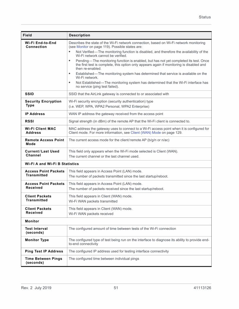
Status
Wi-Fi End-to-End Connection
Describes the state of the Wi-Fi network connection, based on Wi-Fi network monitoring (see Monitor on page 119). Possible states are:
• Not Verified—The monitoring function is disabled, and therefore the availability of the Wi-Fi network cannot be verified.
• Pending—The monitoring function is enabled, but has not yet completed its test. Once the first test is complete, this option only appears again if monitoring is disabled and then re-enabled.
• Established—The monitoring system has determined that service is available on the Wi-Fi network.
• Not Established—The monitoring system has determined that the Wi-Fi interface has no service (ping test failed).
SSID SSID that the AirLink gateway is connected to or associated with
Security Encryption Type
Wi-Fi security encryption (security authentication) type
(i.e. WEP, WPA, WPA2 Personal, WPA2 Enterprise)
IP Address WAN IP address the gateway received from the access point
RSSI Signal strength (in dBm) of the remote AP that the Wi-Fi client is connected to.
Wi-Fi Client MAC Address
MAC address the gateway uses to connect to a Wi-Fi access point when it is configured for Client mode. For more information, see Client (WAN) Mode on page 129.
Remote Access Point Mode
The current access mode for the client/remote AP (b/g/n or n/ac)
Current / Last Used Channel
This field only appears when the Wi-Fi mode selected is Client (WAN).
The current channel or the last channel used.
Wi-Fi A and Wi-Fi B Statistics
Access Point Packets Transmitted
This field appears in Access Point (LAN) mode.
The number of packets transmitted since the last startup/reboot.
Access Point Packets Received
This field appears in Access Point (LAN) mode.
The number of packets received since the last startup/reboot.
Client Packets Transmitted
This field appears in Client (WAN) mode.
Wi-Fi WAN packets transmitted
Client Packets Received
This field appears in Client (WAN) mode.
Wi-Fi WAN packets received
Monitor
Test Interval (seconds)
The configured amount of time between tests of the Wi-Fi connection
Monitor Type The configured type of test being run on the interface to diagnose its ability to provide end-to-end connectivity
Ping Test IP Address The configured IP address used for testing interface connectivity
Time Between Pings (seconds)
The configured time between individual pings
Field Description
Rev. 2 July 2019 51 41113126

ALEOS 4.12.0 Software Configuration User Guide for AirLink RV55
LAN IP/MAC Table
The LAN IP/MAC table shows the status of the local network.
Figure 3-5: ACEmanager: Status > LAN
Current WAN Time in Use (minutes)
The time, in minutes, that the gateway has been connected to the current WAN network.
Note: The value of this field is 0 if the gateway is not connected to a WAN mobile network.
Remote AP MAC Address
This field only appears when the Wi-Fi Status is Associated, Connecting, or Connected.
The MAC address of the remote access point
Remote AP Frequency (GHz)
This field only appears when the Wi-Fi Status is Associated, Connecting, or Connected.
The frequency being used by the remote access point
Packets Transmitted Number of IP packets sent to the access point host interface over Wi-Fi LAN since the system startup
Packets Received Number of IP packets received by the access point host interface over Wi-Fi LAN since the system startup
Field Description
Rev. 2 July 2019 52 41113126
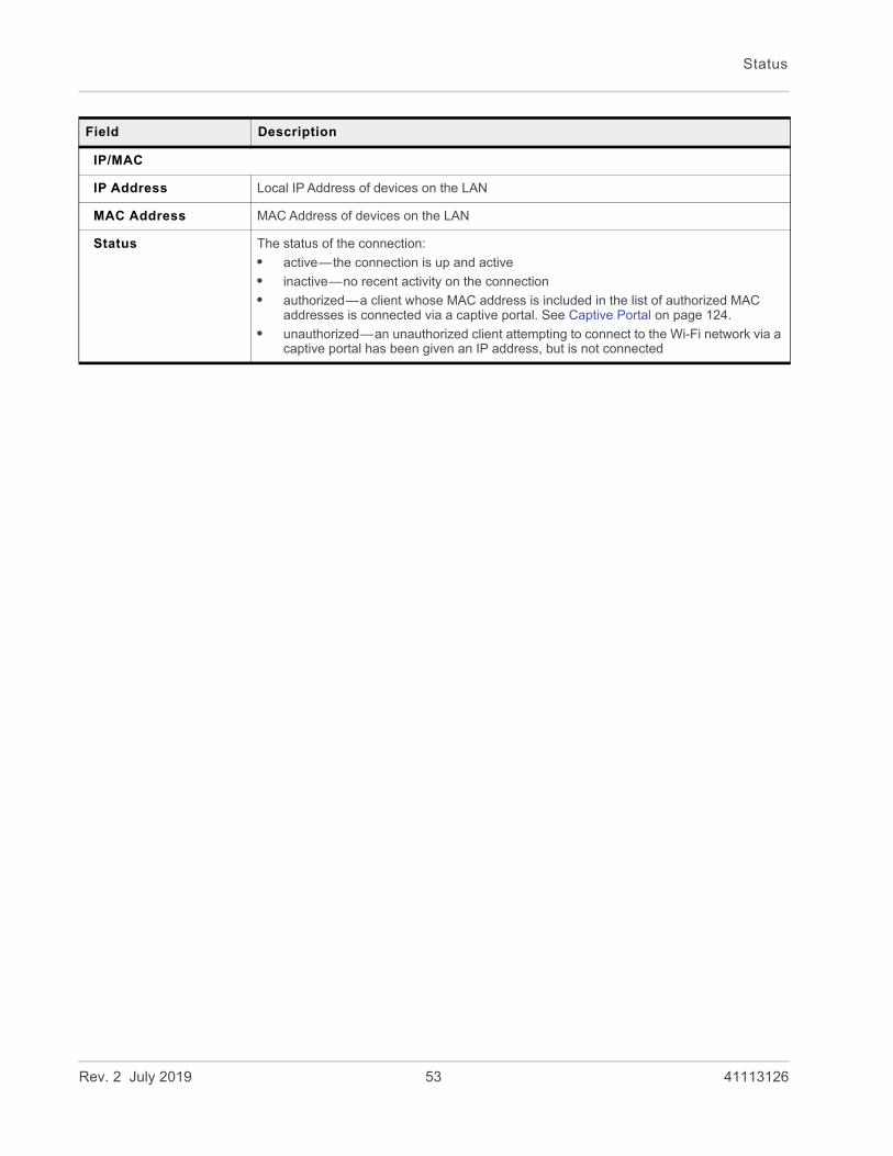
Status
Field Description
IP/MAC
IP Address Local IP Address of devices on the LAN
MAC Address MAC Address of devices on the LAN
Status The status of the connection:
• active—the connection is up and active
• inactive—no recent activity on the connection
• authorized—a client whose MAC address is included in the list of authorized MAC addresses is connected via a captive portal. See Captive Portal on page 124.
• unauthorized—an unauthorized client attempting to connect to the Wi-Fi network via a captive portal has been given an IP address, but is not connected
Rev. 2 July 2019 53 41113126

ALEOS 4.12.0 Software Configuration User Guide for AirLink RV55
VPN
The VPN section gives an overview of the VPN settings and indicates whether a VPN connection has been made.
Figure 3-6: ACEmanager: Status > VPN
Field Description
Incoming Out of Band Whether Incoming Out of Band traffic is allowed or blocked
Outgoing Management Out of Band
Whether outgoing ALEOS Out of Band traffic is allowed or blocked
Outgoing Host Out of Band Whether Outgoing Host Out of Band traffic is allowed or blocked
IPsec FIPS mode Whether IPsec FIPS mode is enabled (available when strongSwan IPsec is enabled)
Rev. 2 July 2019 54 41113126
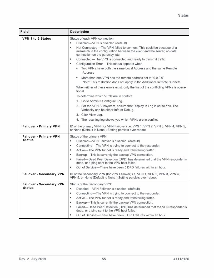
Status
VPN 1 to 5 Status Status of each VPN connection:
• Disabled—VPN is disabled (default)
• Not Connected—The VPN failed to connect. This could be because of a mismatch in the configuration between the client and the server, no data connection on the gateway, etc.
• Connected—The VPN is connected and ready to transmit traffic.
• Configuration Error—This status appears when:
• Two VPNs have both the same Local Address and the same Remote Address
• More than one VPN has the remote address set to “0.0.0.0” Note: This restriction does not apply to the Additional Remote Subnets.
When either of these errors exist, only the first of the conflicting VPNs is opera-tional.
To determine which VPNs are in conflict:
1. Go to Admin > Configure Log.
2. For the VPN Subsystem, ensure that Display in Log is set to Yes. The Verbosity can be either Info or Debug.
3. Click View Log.
4. The resulting log shows you which VPNs are in conflict.
Failover - Primary VPN ID of the primary VPN (for VPN Failover) i.e. VPN 1, VPN 2, VPN 3, VPN 4, VPN 5, or None (Default is None.) Setting persists over reboot.
Failover - Primary VPN Status
Status of the primary VPN:
• Disabled—VPN Failover is disabled. (default)
• Connecting—The VPN is trying to connect to the responder.
• Active—The VPN tunnel is ready and transferring traffic.
• Backup—This is currently the backup VPN connection.
• Failed—Dead Peer Detection (DPD) has determined that the VPN responder is dead, or a ping sent to the VPN host failed.
• Out of Service—There have been 5 DPD failures within an hour.
Failover - Secondary VPN ID of the Secondary VPN (for VPN Failover) i.e. VPN 1, VPN 2, VPN 3, VPN 4, VPN 5, or None (Default is None.) Setting persists over reboot.
Failover - Secondary VPN Status
Status of the Secondary VPN:
• Disabled—VPN Failover is disabled. (default)
• Connecting—The VPN is trying to connect to the responder.
• Active—The VPN tunnel is ready and transferring traffic.
• Backup—This is currently the backup VPN connection.
• Failed—Dead Peer Detection (DPD) has determined that the VPN responder is dead, or a ping sent to the VPN host failed.
• Out of Service—There have been 5 DPD failures within an hour.
Field Description
Rev. 2 July 2019 55 41113126

ALEOS 4.12.0 Software Configuration User Guide for AirLink RV55
Failover - Overall VPN Status
Status of the overall VPN:
• Disabled—VPN Failover is disabled. (default)
• Connecting—One of the VPNs is trying to connect to the responder.
• Active—One VPN tunnel is currently in use. The backup VPN is available.
• Backup_Unavailable —One VPN tunnel is currently in use. The backup VPN is not available.
• Out of Service—Neither the primary nor secondary VPN is operational.
• N/A—The overall VPN status is temporarily not available. Click Refresh.
Failover - Number of Primary VPN Failures
Number of times DPD has failed on the primary VPN since the gateway has been rebooted or the “Set VPN Policy” button was clicked
Failover - Number of Secondary VPN Failures
Number of times DPD has failed on the Secondary VPN since the gateway has been rebooted or the “Set VPN Policy” button was clicked
Failover - Number of Switches to Primary VPN
Number of times traffic was switched to the primary VPN since the gateway has been rebooted or the “Set VPN Policy” button was clicked
Failover - Number of Switches to Secondary VPN
Number of times traffic was switched to the Secondary VPN since the gateway has been rebooted or the “Set VPN Policy” button was clicked
Field Description
Rev. 2 July 2019 56 41113126
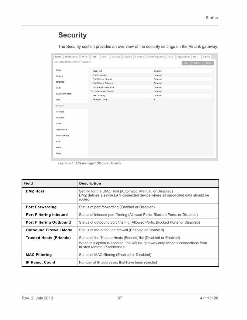
Status
Security
The Security section provides an overview of the security settings on the AirLink gateway.
Figure 3-7: ACEmanager: Status > Security
Field Description
DMZ Host Setting for the DMZ Host (Automatic, Manual, or Disabled)DMZ defines a single LAN connected device where all unsolicited data should be routed.
Port Forwarding Status of port forwarding (Enabled or Disabled)
Port Filtering Inbound Status of inbound port filtering (Allowed Ports, Blocked Ports, or Disabled)
Port Filtering Outbound Status of outbound port filtering (Allowed Ports, Blocked Ports, or Disabled)
Outbound Firewall Mode Status of the outbound firewall (Enabled or Disabled)
Trusted Hosts (Friends) Status of the Trusted Hosts (Friends) list (Disabled or Enabled)
When this option is enabled, the AirLink gateway only accepts connections from trusted remote IP addresses.
MAC Filtering Status of MAC filtering (Enabled or Disabled)
IP Reject Count Number of IP addresses that have been rejected
Rev. 2 July 2019 57 41113126
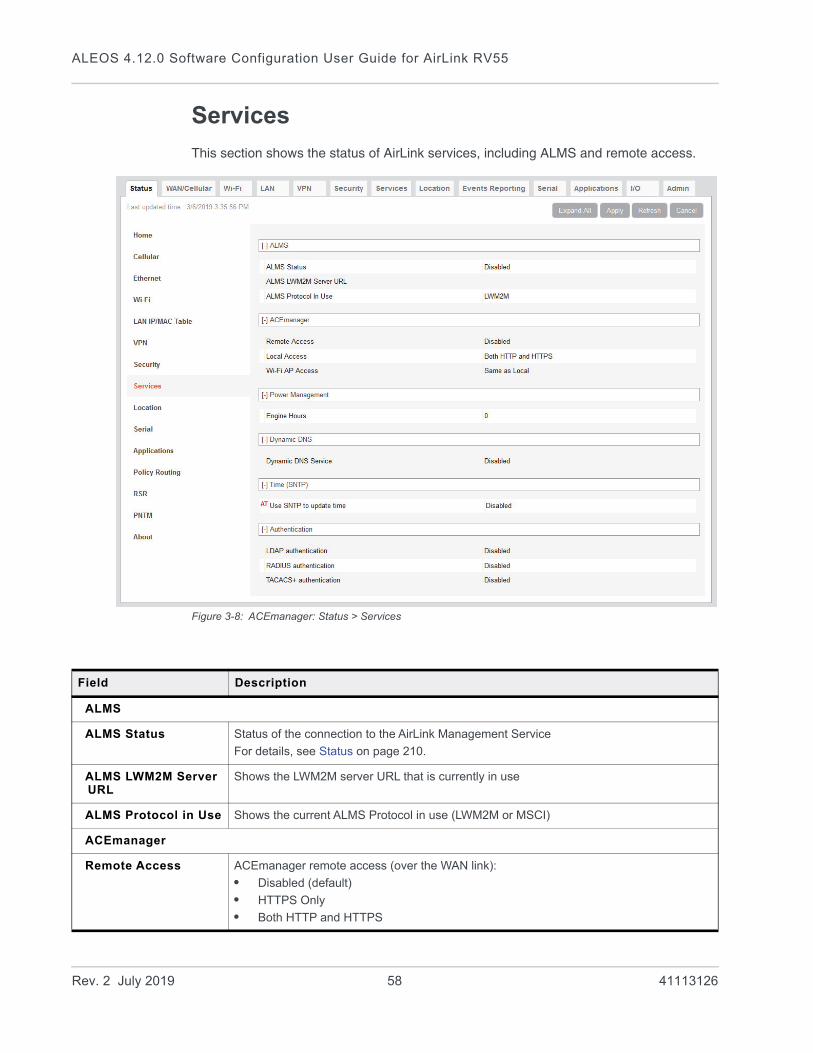
ALEOS 4.12.0 Software Configuration User Guide for AirLink RV55
Services
This section shows the status of AirLink services, including ALMS and remote access.
Figure 3-8: ACEmanager: Status > Services
Field Description
ALMS
ALMS Status Status of the connection to the AirLink Management Service
For details, see Status on page 210.
ALMS LWM2M Server URL
Shows the LWM2M server URL that is currently in use
ALMS Protocol in Use Shows the current ALMS Protocol in use (LWM2M or MSCI)
ACEmanager
Remote Access ACEmanager remote access (over the WAN link):
• Disabled (default)
• HTTPS Only
• Both HTTP and HTTPS
Rev. 2 July 2019 58 41113126

Status
Local Access ACEmanager local access (Ethernet, USBnet):
• HTTPS Only
• Both HTTP and HTTPS (default)
Wi-Fi AP Access This field only applies to the Wi-Fi model of the RV55.
ACEmanager Wi-Fi access:
• Same as Local (default)
• Disabled
Power Management
Engine Hours Time the engine has been running. Depending on your configuration, this is based on:
• Voltage on the Power Pin from the vehicle battery (Engine Hours On Voltage Level)
• Voltage on the Ignition Sense Pin (Engine Hours Ignition Enable)
Dynamic DNS
Dynamic DNS Service Service in use for Dynamic DNS translation
Full Domain Name If the Dynamic DNS Service is configured to use a 3rd party host, the domain name configured is displayed. If the Dynamic DNS Service is configured to use IP Manager, this field does not display.
Time (SNTP)
Use SNTP to update time
Daily SNTP updates of the system time
Authentication
LDAP Authentication Status of the LDAP client:
• Enabled
• Disabled (default)
RADIUS Authentication
Status of the RADIUS client:
• Enabled
• Disabled (default)
TACACS+ Authentication
Status of the TACACS+ client:
• Enabled
• Disabled (default)
Field Description
Rev. 2 July 2019 59 41113126
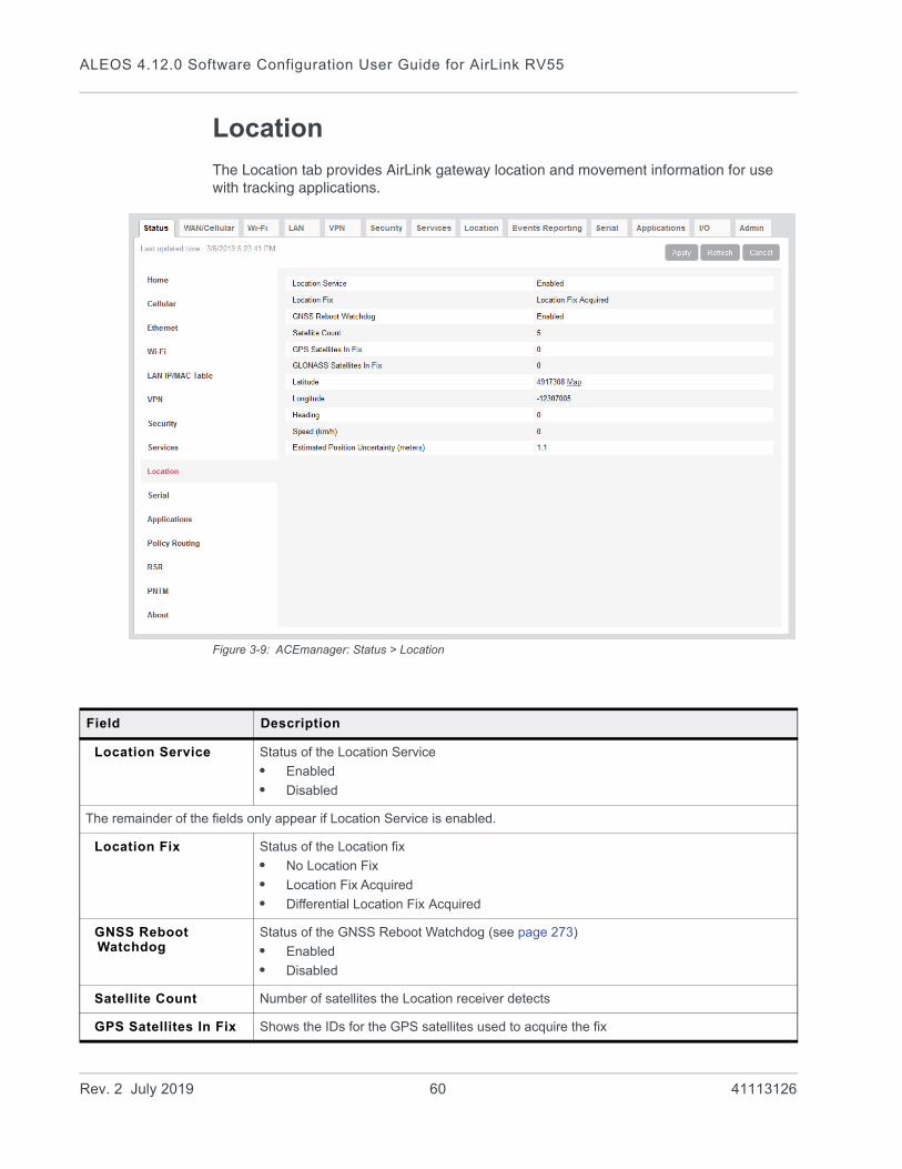
ALEOS 4.12.0 Software Configuration User Guide for AirLink RV55
Location
The Location tab provides AirLink gateway location and movement information for use with tracking applications.
Figure 3-9: ACEmanager: Status > Location
Field Description
Location Service Status of the Location Service
• Enabled
• Disabled
The remainder of the fields only appear if Location Service is enabled.
Location Fix Status of the Location fix
• No Location Fix
• Location Fix Acquired
• Differential Location Fix Acquired
GNSS Reboot Watchdog
Status of the GNSS Reboot Watchdog (see page 273)
• Enabled
• Disabled
Satellite Count Number of satellites the Location receiver detects
GPS Satellites In Fix Shows the IDs for the GPS satellites used to acquire the fix
Rev. 2 July 2019 60 41113126
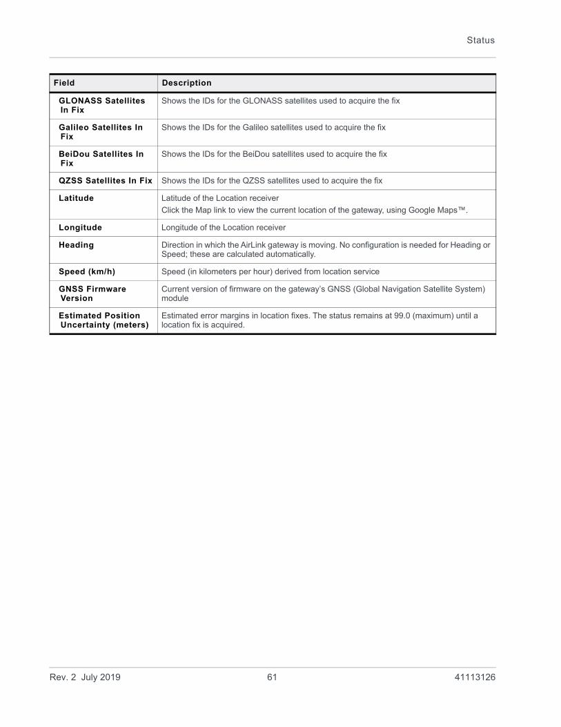
Status
GLONASS Satellites In Fix
Shows the IDs for the GLONASS satellites used to acquire the fix
Galileo Satellites In Fix
Shows the IDs for the Galileo satellites used to acquire the fix
BeiDou Satellites In Fix
Shows the IDs for the BeiDou satellites used to acquire the fix
QZSS Satellites In Fix Shows the IDs for the QZSS satellites used to acquire the fix
Latitude Latitude of the Location receiver
Click the Map link to view the current location of the gateway, using Google Maps™.
Longitude Longitude of the Location receiver
Heading Direction in which the AirLink gateway is moving. No configuration is needed for Heading or Speed; these are calculated automatically.
Speed (km/h) Speed (in kilometers per hour) derived from location service
GNSS Firmware Version
Current version of firmware on the gateway’s GNSS (Global Navigation Satellite System) module
Estimated Position Uncertainty (meters)
Estimated error margins in location fixes. The status remains at 99.0 (maximum) until a location fix is acquired.
Field Description
Rev. 2 July 2019 61 41113126
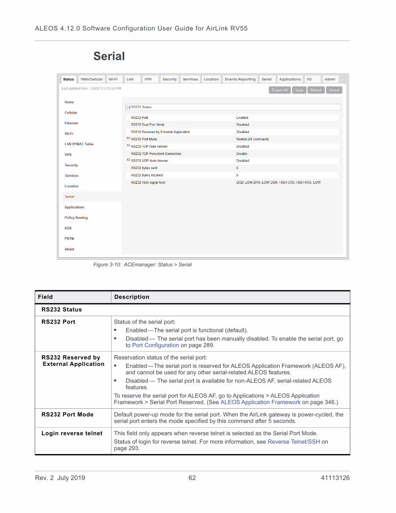
ALEOS 4.12.0 Software Configuration User Guide for AirLink RV55
Serial
Figure 3-10: ACEmanager: Status > Serial
Field Description
RS232 Status
RS232 Port Status of the serial port:
• Enabled—The serial port is functional (default).
• Disabled — The serial port has been manually disabled. To enable the serial port, go to Port Configuration on page 289.
RS232 Reserved by External Application
Reservation status of the serial port:
• Enabled—The serial port is reserved for ALEOS Application Framework (ALEOS AF), and cannot be used for any other serial-related ALEOS features.
• Disabled — The serial port is available for non-ALEOS AF, serial-related ALEOS features.
To reserve the serial port for ALEOS AF, go to Applications > ALEOS Application Framework > Serial Port Reserved. (See ALEOS Application Framework on page 346.)
RS232 Port Mode Default power-up mode for the serial port. When the AirLink gateway is power-cycled, the serial port enters the mode specified by this command after 5 seconds.
Login reverse telnet This field only appears when reverse telnet is selected as the Serial Port Mode.
Status of login for reverse telnet. For more information, see Reverse Telnet/SSH on page 293.
Rev. 2 July 2019 62 41113126
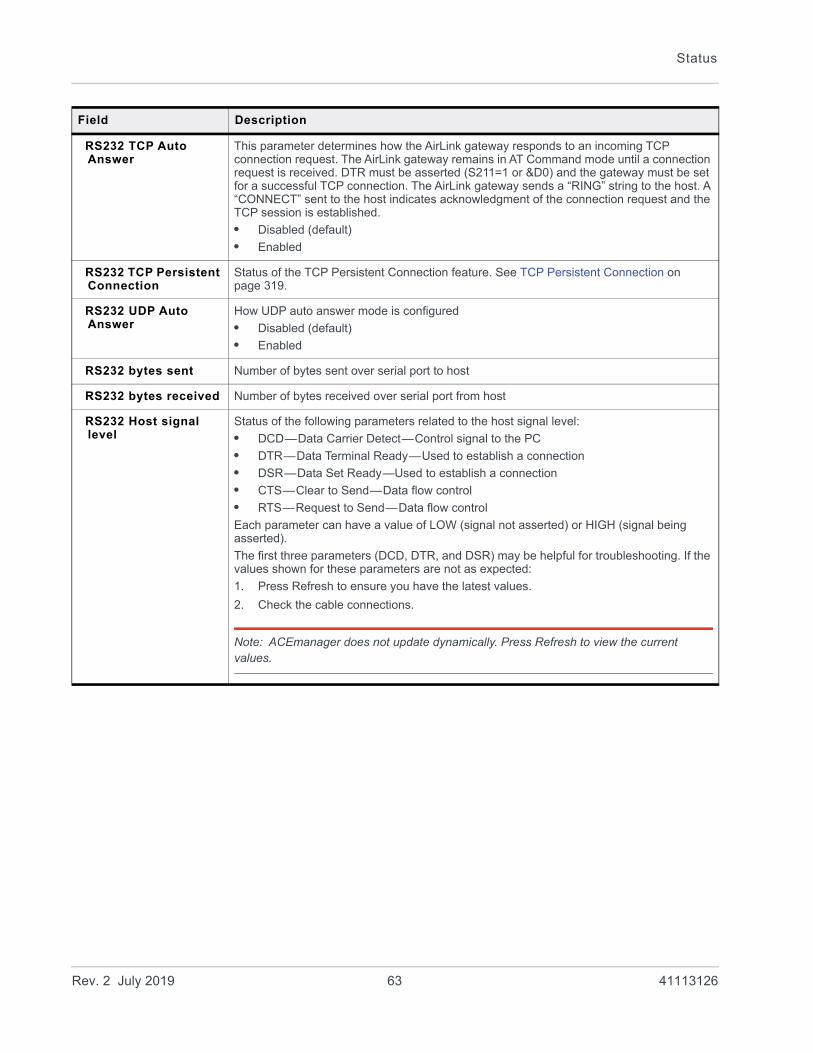
Status
RS232 TCP Auto Answer
This parameter determines how the AirLink gateway responds to an incoming TCP connection request. The AirLink gateway remains in AT Command mode until a connection request is received. DTR must be asserted (S211=1 or &D0) and the gateway must be set for a successful TCP connection. The AirLink gateway sends a “RING” string to the host. A “CONNECT” sent to the host indicates acknowledgment of the connection request and the TCP session is established.
• Disabled (default)
• Enabled
RS232 TCP Persistent Connection
Status of the TCP Persistent Connection feature. See TCP Persistent Connection on page 319.
RS232 UDP Auto Answer
How UDP auto answer mode is configured
• Disabled (default)
• Enabled
RS232 bytes sent Number of bytes sent over serial port to host
RS232 bytes received Number of bytes received over serial port from host
RS232 Host signal level
Status of the following parameters related to the host signal level:
• DCD—Data Carrier Detect—Control signal to the PC
• DTR—Data Terminal Ready—Used to establish a connection
• DSR—Data Set Ready—Used to establish a connection
• CTS—Clear to Send—Data flow control
• RTS—Request to Send—Data flow control
Each parameter can have a value of LOW (signal not asserted) or HIGH (signal being asserted).
The first three parameters (DCD, DTR, and DSR) may be helpful for troubleshooting. If the values shown for these parameters are not as expected:
1. Press Refresh to ensure you have the latest values.
2. Check the cable connections.
Note: ACEmanager does not update dynamically. Press Refresh to view the current values.
Field Description
Rev. 2 July 2019 63 41113126

ALEOS 4.12.0 Software Configuration User Guide for AirLink RV55
Applications
The Applications section of the Status group provides information on the status of the Garmin gateway and data service.
Figure 3-11: ACEmanager: Status > Applications
Field Description
Data Service Data Service field displays “Available (under usage limit)” if the configured usage limit has not been exceeded.
Available RAM (KB) Available RAM in kilobytes (1000 bytes), updated every 30 seconds
Available Flash (KB) Available Flash on the user partition in kilobytes (1024 bytes), updated every 30 seconds
CPU Load (Last 15 minutes)
CPU load, averaged over the last 15 minutes and updated every 30 seconds
The CPU load relates to how many applications are attempting to execute in parallel over the 15-minute period. If the load is greater than 1, some applications are waiting for CPU capacity to become available and may be delayed in launching.
ALEOS Application Framework
Whether ALEOS Application Framework is enabled or disabled
Serial Port Reserved Reservation of the serial port:
• Disabled (default)
• Enabled
Rev. 2 July 2019 64 41113126

Status
Policy Routing
The Policy Routing section of the Status group provides information on the routing policy configuration.
Figure 3-12: ACEmanager: Status > Policy Routing
Serial Port 2 Reserved
Reservation of serial port 2:
• Disabled (default)
• Enabled
QCOM DM Port Resource Reserve
Reservation of the QCOM DM port:
• Disabled (default)
• Enabled
Field Description
Field Description
Policy Route # Status Displays the Policy Route Status for each of the five configurable policies
Rev. 2 July 2019 65 41113126

ALEOS 4.12.0 Software Configuration User Guide for AirLink RV55
RSR (Reliable Static Routing)
The RSR section of the Status group provides basic information about the RSR configuration. For more information, see Reliable Static Routing (RSR) on page 101.
Figure 3-13: ACEmanager: Status > RSR
Field Description
Reliable Static Route Status of the Reliable Static Routing feature:
• Enabled
• Disabled
Tracking Object Status of the Tracking Object:
• Enabled
• Disabled
RSR Active Route Active route for Reliable Static Routing
• Primary—Specified network traffic is currently using the configured primary route.
• Backup—Specified network traffic is currently using the configured backup route.
• None—RSR is not enabled.
RSR Test Result Result of the most recent Object Tracking test
RSR Test Timestamp Time of the most recent Object Tracking test
Rev. 2 July 2019 66 41113126

Status
PNTM (Private Network Traffic Management)
The PNTM section of the Status group provides basic information about the PNTM configuration.
Figure 3-14: ACEmanager: Status > PNTM
Field Description
Rule # PNTM rule number
Status Status of the PNTM rule (Enabled or Disabled)
Destination The destination IP address
DSCP The priority level
Tx Packets Number of packets transmitted
Tx Bytes Number of bytes transmitted
Rev. 2 July 2019 67 41113126
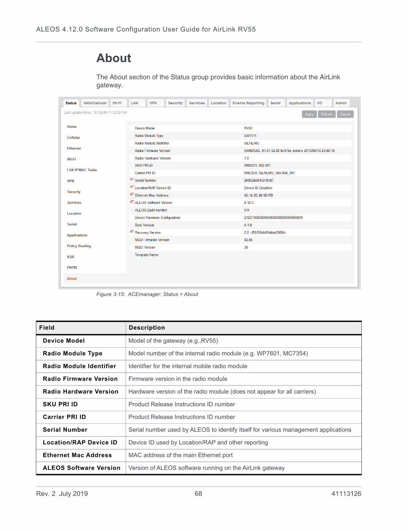
ALEOS 4.12.0 Software Configuration User Guide for AirLink RV55
About
The About section of the Status group provides basic information about the AirLink gateway.
Figure 3-15: ACEmanager: Status > About
Field Description
Device Model Model of the gateway (e.g.,RV55)
Radio Module Type Model number of the internal radio module (e.g. WP7601, MC7354)
Radio Module Identifier Identifier for the internal mobile radio module
Radio Firmware Version Firmware version in the radio module
Radio Hardware Version Hardware version of the radio module (does not appear for all carriers)
SKU PRI ID Product Release Instructions ID number
Carrier PRI ID Product Release Instructions ID number
Serial Number Serial number used by ALEOS to identify itself for various management applications
Location/RAP Device ID Device ID used by Location/RAP and other reporting
Ethernet Mac Address MAC address of the main Ethernet port
ALEOS Software Version Version of ALEOS software running on the AirLink gateway
Rev. 2 July 2019 68 41113126
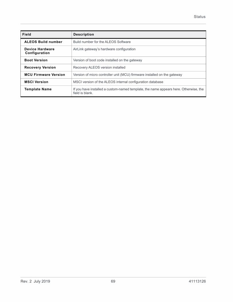
Status
ALEOS Build number Build number for the ALEOS Software
Device Hardware Configuration
AirLink gateway’s hardware configuration
Boot Version Version of boot code installed on the gateway
Recovery Version Recovery ALEOS version installed
MCU Firmware Version Version of micro controller unit (MCU) firmware installed on the gateway
MSCI Version MSCI version of the ALEOS internal configuration database
Template Name If you have installed a custom-named template, the name appears here. Otherwise, the field is blank.
Field Description
Rev. 2 July 2019 69 41113126

4
4: WAN/Cellular ConfigurationThe WAN/Cellular tab in ACEmanager allows you to view and modify mobile network connection settings. The settings available depend on the gateway model and the radio module. This chapter is divided into sections based on the left side menu items.
The first time you power up the gateway on its home network, it automatically begins the activation/provisioning process and attempts to connect to the network. This process typically takes 5–10 minutes. If the gateway does not automatically connect to the network, see Network Credentials on page 79.
Note: The fields displayed vary depending on the ACEmanager settings.
Monitoring WAN Connections
ALEOS enables you to:• Monitor each WAN interface—cellular, Ethernet WAN, and Wi-Fi—independently,
regardless of which one is active• Set the priority for each WAN interface
Monitoring confirms whether or not the interface provides connectivity from the gateway to a ping destination on the WAN. Interface priority enables you to choose which interface has priority and which interface to switch to if the highest-priority interface is not available.
Interface priority checks the link layer connection (for example, in an Ethernet WAN setup, the connection to the router). It does not verify whether or not the router has a WAN connection. With monitoring, you can configure the gateway to ping a destination on the WAN. If the gateway does not receive a response to the ping, it attempts to connect to the next highest priority interface. See Figure 4-1 and Table 4-1.
Figure 4-1: Interface priority alone vs. interface priority with monitoring
Gateway
Router
Wi-Fi Access Point
Cell tower Internet
Ping
Ethernet
Cellular
Wi-Fi
Connections verified by interface priority (monitoring disabled)
Connections verified by monitoring
destination
Rev. 2 July 2019 70 41113126
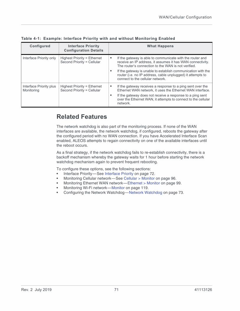
WAN/Cellular Configuration
Related Features
The network watchdog is also part of the monitoring process. If none of the WAN interfaces are available, the network watchdog, if configured, reboots the gateway after the configured period with no WAN connection. If you have Accelerated Interface Scan enabled, ALEOS attempts to regain connectivity on one of the available interfaces until the reboot occurs.
As a final strategy, if the network watchdog fails to re-establish connectivity, there is a backoff mechanism whereby the gateway waits for 1 hour before starting the network watchdog mechanism again to prevent frequent rebooting.
To configure these options, see the following sections:• Interface Priority—See Interface Priority on page 72.• Monitoring Cellular network—See Cellular > Monitor on page 96.• Monitoring Ethernet WAN network—Ethernet > Monitor on page 99.• Monitoring Wi-Fi network—Monitor on page 119.• Configuring the Network Watchdog—Network Watchdog on page 73.
Table 4-1: Example: Interface Priority with and without Monitoring Enabled
Configured Interface Priority Configuration Details
What Happens
Interface Priority only Highest Priority = EthernetSecond Priority = Cellular
• If the gateway is able to communicate with the router and receive an IP address, it assumes it has WAN connectivity. The router’s connection to the WAN is not verified.
• If the gateway is unable to establish communication with the router (i.e. no IP address, cable unplugged) it attempts to connect to the cellular network.
Interface Priority plus Monitoring
Highest Priority = EthernetSecond Priority = Cellular
• If the gateway receives a response to a ping sent over the Ethernet WAN network, it uses the Ethernet WAN interface.
• If the gateway does not receive a response to a ping sent over the Ethernet WAN, it attempts to connect to the cellular network.
Rev. 2 July 2019 71 41113126

ALEOS 4.12.0 Software Configuration User Guide for AirLink RV55
General
Interface Priority
This screen allows you to set the WAN interface priority. If multiple available interfaces have the same priority, the order of priority is: Ethernet, Wi-Fi, and cellular.
Figure 4-2: ACEmanager: WAN/Cellular > General > Interface Priority
Field Description
WAN Interface Priority Configuration
Network Interface Read-only field that shows the current network interface or None if the gateway does not have a network connection
Rev. 2 July 2019 72 41113126
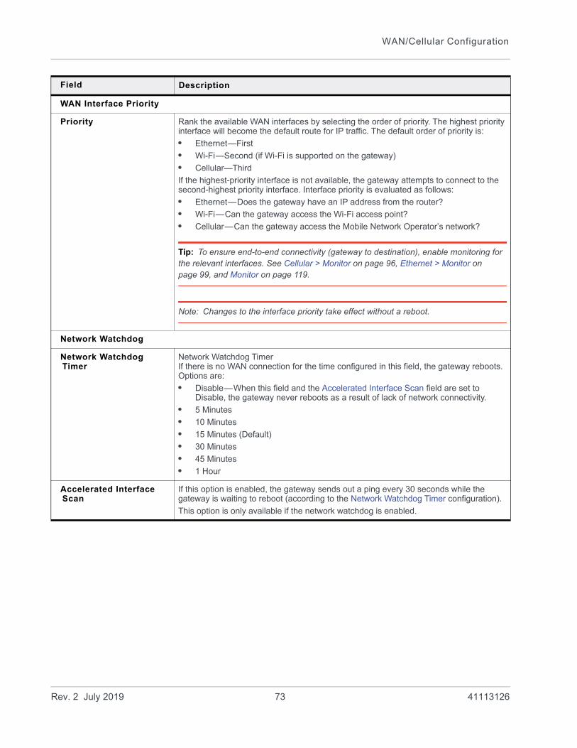
WAN/Cellular Configuration
WAN Interface Priority
Priority Rank the available WAN interfaces by selecting the order of priority. The highest priority interface will become the default route for IP traffic. The default order of priority is:
• Ethernet—First
• Wi-Fi—Second (if Wi-Fi is supported on the gateway)
• Cellular—Third
If the highest-priority interface is not available, the gateway attempts to connect to the second-highest priority interface. Interface priority is evaluated as follows:
• Ethernet—Does the gateway have an IP address from the router?
• Wi-Fi—Can the gateway access the Wi-Fi access point?
• Cellular—Can the gateway access the Mobile Network Operator’s network?
Tip: To ensure end-to-end connectivity (gateway to destination), enable monitoring for the relevant interfaces. See Cellular > Monitor on page 96, Ethernet > Monitor on page 99, and Monitor on page 119.
Note: Changes to the interface priority take effect without a reboot.
Network Watchdog
Network Watchdog Timer
Network Watchdog TimerIf there is no WAN connection for the time configured in this field, the gateway reboots. Options are:
• Disable—When this field and the Accelerated Interface Scan field are set to Disable, the gateway never reboots as a result of lack of network connectivity.
• 5 Minutes
• 10 Minutes
• 15 Minutes (Default)
• 30 Minutes
• 45 Minutes
• 1 Hour
Accelerated Interface Scan
If this option is enabled, the gateway sends out a ping every 30 seconds while the gateway is waiting to reboot (according to the Network Watchdog Timer configuration).
This option is only available if the network watchdog is enabled.
Field Description
Rev. 2 July 2019 73 41113126
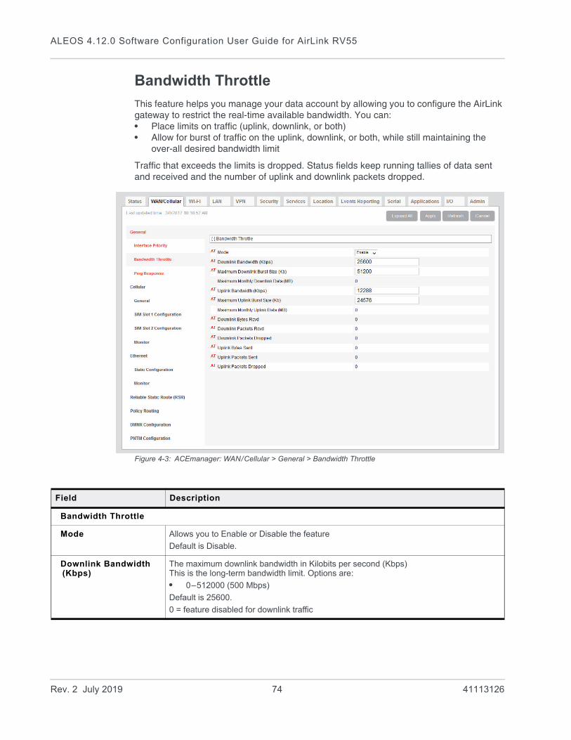
ALEOS 4.12.0 Software Configuration User Guide for AirLink RV55
Bandwidth Throttle
This feature helps you manage your data account by allowing you to configure the AirLink gateway to restrict the real-time available bandwidth. You can:• Place limits on traffic (uplink, downlink, or both)• Allow for burst of traffic on the uplink, downlink, or both, while still maintaining the
over-all desired bandwidth limit
Traffic that exceeds the limits is dropped. Status fields keep running tallies of data sent and received and the number of uplink and downlink packets dropped.
Figure 4-3: ACEmanager: WAN/Cellular > General > Bandwidth Throttle
Field Description
Bandwidth Throttle
Mode Allows you to Enable or Disable the feature
Default is Disable.
Downlink Bandwidth (Kbps)
The maximum downlink bandwidth in Kilobits per second (Kbps)This is the long-term bandwidth limit. Options are:
• 0–512000 (500 Mbps)
Default is 25600.
0 = feature disabled for downlink traffic
Rev. 2 July 2019 74 41113126

WAN/Cellular Configuration
Maximum Downlink Burst Size (Kb)
Maximum size for bursts of downlink traffic in Kilobits (Kb)This field allows the AirLink gateway to handle temporary bursts of downlink traffic without dropping packets. When the actual downlink traffic is less than the value configured in the Downlink Bandwidth (Kbps) field, ALEOS collects credits that can be used for bursty traffic. The value in this field is the maximum amount of credit that can be collected. Options are:
• 64–512000 (500 Mb)
Default is 51200.
Note: Sierra Wireless recommends that the Maximum Downlink Burst Size be set at 2x the value configured in the Downlink Bandwidth (Kbps) field. If the Maximum Downlink Burst Size is set at more than 60x the value configured in the Downlink Bandwidth (Kbps) field, the bandwidth throttle feature is disabled for downlink traffic.
Maximum Monthly Downlink Data (MB)
An estimate of the maximum monthly downlink data in Megabytes (MB), based on the value set in the Downlink Bandwidth (Kbps).
Maximum monthly downlink data (MB) = Downlink bandwidth × 2592000 ÷ 8192
Where:
2592000 is the number of seconds in a month (30 days/month)
1 MB = 1024 KB; 1024 × 8 = 8192 Kb/MB
Uplink Bandwidth (Kbps)
The maximum uplink bandwidth in Kilobits per second (Kbps)This is the long-term bandwidth limit. Options are:
• 0–204800 (200 Mbps)
Default is 12288.
0 = feature disabled for uplink traffic
Maximum Uplink Burst Size (Kb)
Maximum size for bursts of uplink traffic in Kilobits (Kb)This field allows the AirLink gateway to handle temporary bursts of uplink traffic without dropping packets. When the actual uplink traffic is less than the value configured in the Uplink Bandwidth (Kbps) field, ALEOS collects credits that can be used for bursty traffic. The value in this field is the maximum amount of credit that can be collected. Options are:
• 32–204800 (200 Mb)
Default is 24576.
Note: Sierra Wireless recommends that the Maximum Uplink Burst Size be set at 2x the value configured in the Uplink Bandwidth (Kbps) field. If the Maximum Uplink Burst Size is set at more than 60x the value configured in the Uplink Bandwidth (Kbps) field, the bandwidth throttle feature is disabled for uplink traffic.
Maximum Monthly Uplink Data (MB)
An estimate of the maximum monthly uplink data i in Megabytes (MB), based on the value set in the Uplink Bandwidth (Kbps)
Maximum monthly uplink data (MB) = Uplink bandwidth × 2592000 ÷ 8192
Where:
2592000 is the number of seconds in a month (30 days/month)
1 MB = 1024 KB; 1024 × 8 = 8192 Kb/MB
Downlink Bytes Rcvd Number of downlink bytes received
The value is updated every 30 seconds, and is reset to zero on gateway reboot or reset to factory default settings.
Field Description
Rev. 2 July 2019 75 41113126
ALEOS 4.12.0 Software Configuration User Guide for AirLink RV55
Downlink Packets Rcvd
Number of downlink packets received
The value is updated every 30 seconds, and is reset to zero on gateway reboot or reset to factory default settings.
Downlink Packets Dropped
Number of downlink packets dropped because the limits set in Downlink Bandwidth (Kbps) and Maximum Downlink Burst Size (Kb) have been exceeded
The value is updated every 30 seconds, and is reset to zero on gateway reboot or reset to factory default settings.
Uplink Bytes Sent Number of uplink bytes sent
The value is updated every 30 seconds, and is reset to zero on gateway reboot or reset to factory default settings.
Uplink Packets Sent Number of uplink packets sent
The value is updated every 30 seconds, and is reset to zero on gateway reboot or reset to factory default settings.
Uplink Packets Dropped
Number of uplink packets dropped because the limits set in Uplink Bandwidth (Kbps) and Maximum Uplink Burst Size (Kb) have been exceeded
The value is updated every 30 seconds, and is reset to zero on gateway reboot or reset to factory default settings.
Field Description
Rev. 2 July 2019 76 41113126

WAN/Cellular Configuration
Ping Response
Figure 4-4: ACEmanager: WAN/Cellular > General > Ping Response
Field Description
Response to Incoming Ping
When a ping is received by the gateway from a remote location, the Response to Incoming Ping redirects it to the selected location.
• No response: The incoming ping is completely ignored.
• ALEOS Responds (default): ALEOS responds to the incoming ping.
• Pass to Host: The ping is forwarded to the DMZ host with any response from the host forwarded back to the OTA location. If no host is connected, there is no ping response.
Note: Some Mobile Network Operators may block all ICMP traffic on their network. When ICMP is blocked by the operator, a ping sent to the gateway from a remote location is not received.
Rev. 2 July 2019 77 41113126

ALEOS 4.12.0 Software Configuration User Guide for AirLink RV55
Cellular
General
The RV55, with its two SIM card slots, has Multi SIM and Automatic SIM switching capability. Settings for configuring these features appear on the Cellular > General page. For information on multiple SIM settings, see Dual SIM Card Support on page 83 and Automatic SIM switching on page 85.
Figure 4-5: ACEmanager: WAN/Cellular > Cellular > General
Rev. 2 July 2019 78 41113126

WAN/Cellular Configuration
Network Credentials
RX Diversity (3G only) Allows two antennas to provide a more reliable connection
• Disable
• Enable (default)
If you are not using a diversity antenna, diversity should be disabled.
Note: Two antennas are required when connecting to an LTE network.
IP Address Preference Use this field to select the preferred IP Address version. To use IPv6, it must be supported by your Mobile Network Operator and your account (SIM and APN).
Options are:
• IPv4—When the gateway connects to the mobile network, it is assigned only an IPv4 address.
• IPv4 and IPv6 Gateway—When the gateway connects to the mobile network, it is assigned an IPv4 address and an IPv6 address. The IPv6 address and routing information are passed to the LAN clients so that they can acquire IPv6 addresses and pass IPv6 traffic over the mobile network.
Note: The LAN client must have IPv6 enabled and must be configured to use SLAAC (Stateless address auto configuration). The IPv6 address and routing information, and DNS servers are passed to the LAN clients via SLAAC.
Note: Other than routing IPv6 packets between the WAN and the LAN, no other AirLink features are supported on IPv6.
The IP addresses are displayed on the Status > Home screen.
Note: For more information, see IPv6 Support on page 89.
Band Setting
Current Radio Module Band
Band reported by the radio module as the one currently in use.
Setting for Band For setting band details for your gateway, see Setting for Band on page 545.
Band 26 These fields appear depending on your AirLink device and radio module. They allow you to disable Band 26 and Band 41. Leave the default settings unless advised by your Mobile Network Operator to change them. Band 41
Cellular Watchdog
Cellular Network Watchdog
Cellular Network Watchdog
Options are:
• Enable—When this Watchdog is enabled, the gateway reboots after several failed attempts to attach to the mobile network. (default)
• Disable—When this field and the Network Watchdog Timer field are both set to Disable, the gateway never reboots as a result of lack of network connectivity.
Rev. 2 July 2019 79 41113126
ALEOS 4.12.0 Software Configuration User Guide for AirLink RV55
Advanced
Set Carrier (Operator) Selection
Manually specify an operator. Enter the desired parameters in the following format:
mode[,format[,oper]]
• mode= 0: Automatic — any affiliated carrier [default]
• mode= 1: Manual — use only the operator <oper> specified
• mode= 4: Manual/automatic — if manual selection fails, goes to automatic mode
• format= 0: Alphanumeric (“name”)
• format= 2: Numeric
• oper=”name”
See also +COPS on page 463 and *NETOP? on page 458.
Note: Not all carriers or accounts allow specifying the operator. If the carrier doesn't support it, this command may appear to fail.
Rev. 2 July 2019 80 41113126
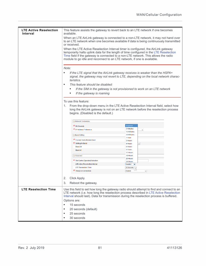
WAN/Cellular Configuration
LTE Active Reselection Interval
This feature assists the gateway to revert back to an LTE network if one becomes available.
When an LTE AirLink gateway is connected to a non-LTE network, it may not hand over to an LTE network when one becomes available if data is being continuously transmitted or received.
When the LTE Active Reselection Interval timer is configured, the AirLink gateway temporarily halts uplink data for the length of time configured in the LTE Reselection Time field if the gateway is connected to a non-LTE network. This allows the radio module to go idle and reconnect to an LTE network, if one is available.
Note:
• If the LTE signal that the AirLink gateway receives is weaker than the HSPA+ signal, the gateway may not revert to LTE, depending on the local network charac-teristics.
• This feature should be disabled:
• If the SIM in the gateway is not provisioned to work on an LTE network
• If the gateway is roaming
To use this feature:
1. From the drop-down menu in the LTE Active Reselection Interval field, select how long the AirLink gateway is not on an LTE network before the reselection process begins. (Disabled is the default.)
2. Click Apply.
3. Reboot the gateway.
LTE Reselection Time Use this field to set how long the gateway radio should attempt to find and connect to an LTE network (i.e. how long the reselection process described in LTE Active Reselection Interval should last). Data for transmission during the reselection process is buffered.
Options are:
• 15 seconds
• 20 seconds (default)
• 25 seconds
• 30 seconds
Rev. 2 July 2019 81 41113126
ALEOS 4.12.0 Software Configuration User Guide for AirLink RV55
Always on connection This field is intended for International gateways on the Vodafone network.
This option allows you to configure the AirLink gateway to use minimal wireless network resources when there has not been any outgoing WAN network traffic.
• Enabled—The AirLink gateway maintains a mobile network data connection. (default)
• Disabled-Connect on traffic—The AirLink gateway only establishes a mobile network data connection:
• When there is network traffic
• If SMS Wakeup is configured and the gateway receives the specified type of SMS (For information on configuring SMS Wakeup, see SMS Wakeup on page 243.)
Note: You can also use AT*RADIO_CONNECT to switch the mobile network connection on and off. See *RADIO_CONNECT on page 471.
Connection Timeout (minutes)
This field is intended for International gateways on the Vodafone network.
This field only appears when Always on connection is set to Disabled - Connect on traffic, and defines the timeout period for Always on connection.
If there is no outgoing packet through the WAN interface during the period set in this field (in minutes), the AirLink gateway disables the WAN connection. This timer is triggered after every outgoing packet, except AT*IPPINGADDR keep alive packets.
• 2–65535 minutes (default is 2)
Note: You can also use AT*TRAFWUPTOUT to set the timeout period. See *TRAFWUPTOUT on page 475.
Cellular Debounce Timer (seconds)
Use this field to configure how long it takes for the gateway to respond after cellular service is lost. This timer can prevent service interruptions caused by brief cellular network outages.
• 0–20 seconds (default is 4)
Enable MSS Clamping MSS (Maximum TCP Segment Size) Clamping controls the maximum packet size used for TCP connections between a local (LAN-side) host and a remote host over the cellular WAN interface.
Enabling MSS Clamping helps avoid possible issues with sending and receiving large TCP packets over the cellular network when other standard MTU mechanisms do not appear to be working with your installation.
Options are:
• Enable—MSS is clamped to the specified maximum value bi-directionally for all inbound (remote-to-LAN) and outbound (LAN-to-remote) TCP connections when the TCP session is established using the cellular interface.
• Disable (default)
Maximum Segment Size - MSS (bytes)
When MSS Clamping is enabled, set the Maximum TCP Segment Size
• 256–1460 bytes (default is 1460)
Turn Off NAT When enabled, ALEOS routes outbound packets from connected devices without performing NAT on them. For example, when a connected device that has an IP address of 192.168.13.100 sends data to a remote destination, the outbound packets have a source IP of 192.168.13.100.
If you are configuring RADIUS Framed Route, set this field to Enable. For more information, see RADIUS Framed Route on page 145. In most other cases, it is best to leave this field at the default setting (Disable).
Rev. 2 July 2019 82 41113126
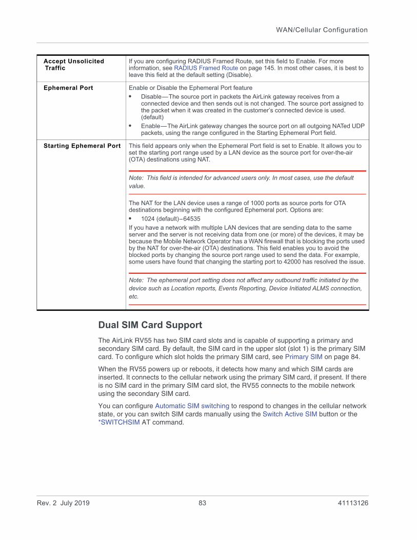
WAN/Cellular Configuration
Dual SIM Card Support
The AirLink RV55 has two SIM card slots and is capable of supporting a primary and secondary SIM card. By default, the SIM card in the upper slot (slot 1) is the primary SIM card. To configure which slot holds the primary SIM card, see Primary SIM on page 84.
When the RV55 powers up or reboots, it detects how many and which SIM cards are inserted. It connects to the cellular network using the primary SIM card, if present. If there is no SIM card in the primary SIM card slot, the RV55 connects to the mobile network using the secondary SIM card.
You can configure Automatic SIM switching to respond to changes in the cellular network state, or you can switch SIM cards manually using the Switch Active SIM button or the *SWITCHSIM AT command.
Accept Unsolicited Traffic
If you are configuring RADIUS Framed Route, set this field to Enable. For more information, see RADIUS Framed Route on page 145. In most other cases, it is best to leave this field at the default setting (Disable).
Ephemeral Port Enable or Disable the Ephemeral Port feature
• Disable—The source port in packets the AirLink gateway receives from a connected device and then sends out is not changed. The source port assigned to the packet when it was created in the customer’s connected device is used. (default)
• Enable—The AirLink gateway changes the source port on all outgoing NATed UDP packets, using the range configured in the Starting Ephemeral Port field.
Starting Ephemeral Port This field appears only when the Ephemeral Port field is set to Enable. It allows you to set the starting port range used by a LAN device as the source port for over-the-air (OTA) destinations using NAT.
Note: This field is intended for advanced users only. In most cases, use the default value.
The NAT for the LAN device uses a range of 1000 ports as source ports for OTA destinations beginning with the configured Ephemeral port. Options are:
• 1024 (default)–64535
If you have a network with multiple LAN devices that are sending data to the same server and the server is not receiving data from one (or more) of the devices, it may be because the Mobile Network Operator has a WAN firewall that is blocking the ports used by the NAT for over-the-air (OTA) destinations. This field enables you to avoid the blocked ports by changing the source port range used to send the data. For example, some users have found that changing the starting port to 42000 has resolved the issue.
Note: The ephemeral port setting does not affect any outbound traffic initiated by the device such as Location reports, Events Reporting, Device Initiated ALMS connection, etc.
Rev. 2 July 2019 83 41113126

ALEOS 4.12.0 Software Configuration User Guide for AirLink RV55
Figure 4-6: ACEmanager: WAN/Cellular > Cellular > General (Dual SIM settings)
Field Description
Multi SIM
Active SIM Shows which SIM slot contains the Active SIM card, i.e. the SIM card account that is used for the current data connection.
You can also use the *ACTIVESIM? AT Command to query the SIM card slot that contains the Active SIM.
Primary SIM Select which SIM card slot contains the primary SIM card. If two SIM cards are installed, the Primary SIM card is used for network connections. Options are:
• Slot 1—The SIM card in Slot 1 (upper slot) is the primary SIM card. (default)
• Slot 2—The SIM card in Slot 2 (lower slot) is the primary SIM card.
If there is no SIM card in the primary SIM card slot, the gateway connects to the cellular network using the secondary SIM card.
You can also use the *PRIMARYSIM AT Command to query or set the primary SIM card slot.
Slot 1 Indicates whether or not a SIM card is inserted in SIM slot 1 (the upper SIM slot)
You can also use the *SIM1PRESENT? AT Command to query the presence of a SIM card in slot 1.
Slot 2 Indicates whether or not a SIM card is inserted in SIM slot 2 (the lower SIM slot)
You can also use the *SIM2PRESENT? AT Command to query the presence of a SIM card in slot 2.
Rev. 2 July 2019 84 41113126
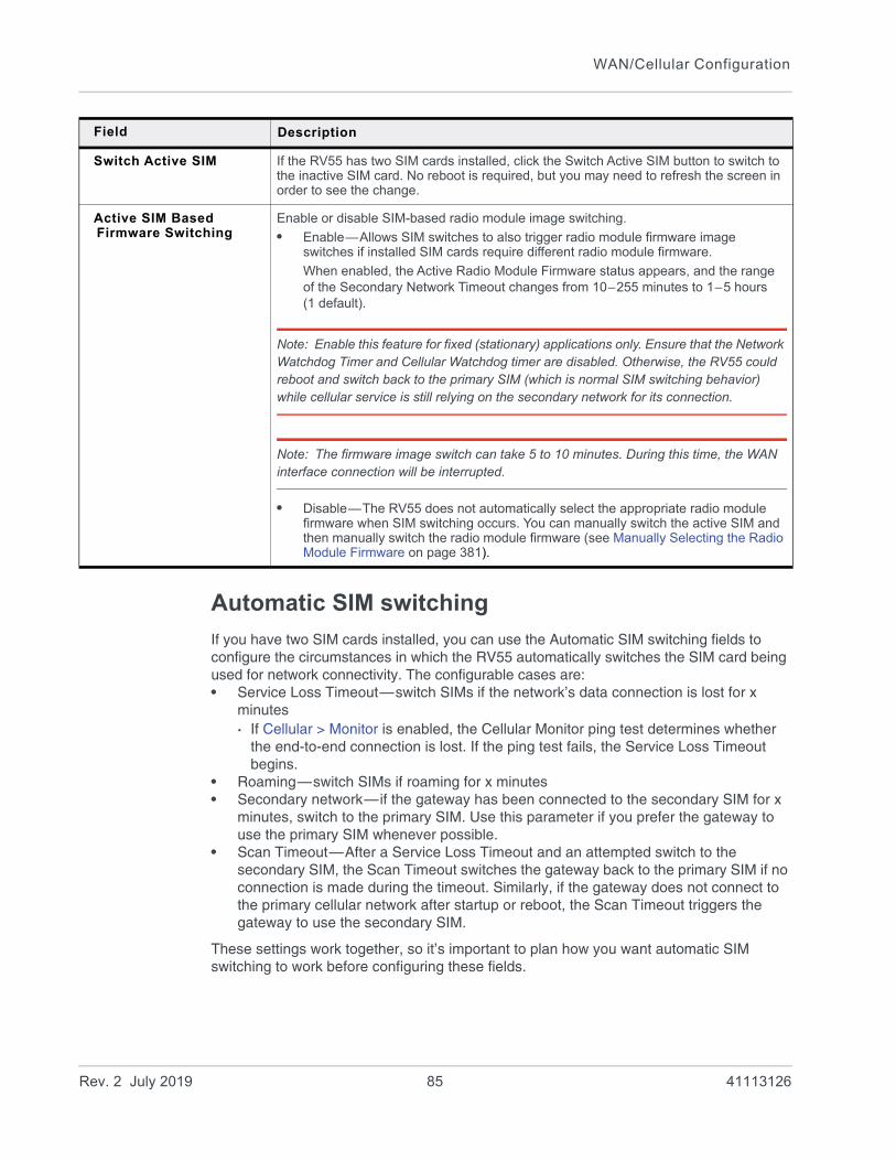
WAN/Cellular Configuration
Automatic SIM switching
If you have two SIM cards installed, you can use the Automatic SIM switching fields to configure the circumstances in which the RV55 automatically switches the SIM card being used for network connectivity. The configurable cases are:• Service Loss Timeout—switch SIMs if the network’s data connection is lost for x
minutes· If Cellular > Monitor is enabled, the Cellular Monitor ping test determines whether
the end-to-end connection is lost. If the ping test fails, the Service Loss Timeout begins.
• Roaming—switch SIMs if roaming for x minutes• Secondary network—if the gateway has been connected to the secondary SIM for x
minutes, switch to the primary SIM. Use this parameter if you prefer the gateway to use the primary SIM whenever possible.
• Scan Timeout—After a Service Loss Timeout and an attempted switch to the secondary SIM, the Scan Timeout switches the gateway back to the primary SIM if no connection is made during the timeout. Similarly, if the gateway does not connect to the primary cellular network after startup or reboot, the Scan Timeout triggers the gateway to use the secondary SIM.
These settings work together, so it’s important to plan how you want automatic SIM switching to work before configuring these fields.
Switch Active SIM If the RV55 has two SIM cards installed, click the Switch Active SIM button to switch to the inactive SIM card. No reboot is required, but you may need to refresh the screen in order to see the change.
Active SIM Based Firmware Switching
Enable or disable SIM-based radio module image switching.
• Enable—Allows SIM switches to also trigger radio module firmware image switches if installed SIM cards require different radio module firmware.
When enabled, the Active Radio Module Firmware status appears, and the range of the Secondary Network Timeout changes from 10–255 minutes to 1–5 hours (1 default).
Note: Enable this feature for fixed (stationary) applications only. Ensure that the Network Watchdog Timer and Cellular Watchdog timer are disabled. Otherwise, the RV55 could reboot and switch back to the primary SIM (which is normal SIM switching behavior) while cellular service is still relying on the secondary network for its connection.
Note: The firmware image switch can take 5 to 10 minutes. During this time, the WAN interface connection will be interrupted.
• Disable—The RV55 does not automatically select the appropriate radio module firmware when SIM switching occurs. You can manually switch the active SIM and then manually switch the radio module firmware (see Manually Selecting the Radio Module Firmware on page 381).
Field Description
Rev. 2 July 2019 85 41113126

ALEOS 4.12.0 Software Configuration User Guide for AirLink RV55
Note: Sierra Wireless recommends that whenever you configure automatic SIM switching, you include a setting for Scan Timeout. This helps to ensure that if the desired network is not available, the gateway maintains a data connection by attempting to connect to the other network.If you intend to use Active SIM-based Firmware Switching, disable the Scan Timeout by setting it to 0. This ensures the firmware image switch does not take place if the gateway cannot connect to the secondary network.
Service loss example
In this example, the desired outcome is to use the primary SIM (for example, a less expensive network connection) whenever possible, but if necessary, to switch to the secondary SIM to maintain the data connection.
The Network Watchdog and Cellular Watchdog are both disabled or configured for a longer interval than the Service Loss Timeout, which enables SIM switching to persist. The watchdogs may prompt the gateway to reboot, which causes the gateway to revert to using the primary SIM card.
Note: If Active SIM Based Firmware Switching is enabled, switching to the secondary SIM also loads the appropriate radio module firmware for the secondary SIM card. As well, if Active SIM Based Firmware Switching is enabled, the Secondary Network Timeout changes from minutes (as shown in Figure 4-7) to hours.
Figure 4-7: ACEmanager: WAN/Cellular > Automatic SIM Switching
With this configuration:
If the gateway loses the data connection on the primary SIM for 20 minutes, it switches to the secondary SIM.
Note: If Active SIM Based Firmware Switching is enabled, switching to the secondary SIM also loads the appropriate radio module firmware for the secondary SIM card.
If the gateway connects to the network using the secondary SIM, it uses the secondary SIM for 60 minutes and then attempts again to connect to the primary SIM’s network for another 10 minutes.
If the gateway cannot connect to the secondary network for 10 minutes (the Scan Timeout), it attempts to reconnect using the primary SIM for another 20 minutes.
Rev. 2 July 2019 86 41113126

WAN/Cellular Configuration
Note: The “service loss” used for automatic SIM switching is based on network information about the cellular connection. You can also use the Cellular Monitor to trigger the change in cellular network state. This enhances your network monitoring capability by sending pings to a configured IP address to confirm your end-to-end connection. If the ping test fails, then the Service Loss Timeout begins, followed by the SIM switch. To configure the Cellular Monitor, see Cellular > Monitor on page 96.
Roaming example
In this example, the desired outcome is to avoid roaming as much as possible, but if the roaming network is the only one available, to maintain a data connection.
Figure 4-8: ACEmanager: WAN/Cellular > Automatic SIM Switching (Roaming example)
With this configuration:
If the gateway is roaming, for example, on the primary SIM for 10 minutes, it switches to the secondary SIM.
If the secondary SIM’s network is not immediately available, the gateway continues to attempt to connect for 30 minutes. The gateway switches to the secondary SIM’s network as soon as it becomes available. If, after 30 minutes, the gateway is still unable to establish a data connection with the secondary SIM, the gateway switches back to the primary SIM.
Automatic SIM Switching
Service Loss Timeout (minutes)
If the data connection is lost for more than the configured time (in minutes), the gateway switches to the inactive SIM card. Options are:
• 0—The feature is disabled (default)
• 10–255
You can also use the *MSNOSERVICETOUT AT Command to configure or query this setting.
Tip: If you prefer to use the Primary SIM account as much as possible, configure the Secondary Network Timeout (minutes)/(hours) and the Scan Timeout (minutes) so the gateway will periodically check, and switch back to the Primary network when it becomes available.
Rev. 2 July 2019 87 41113126

ALEOS 4.12.0 Software Configuration User Guide for AirLink RV55
Roaming Timeout (minutes)
If the gateway has been roaming for longer than the time (in minutes) configured in this field, it automatically switches to the inactive SIM card. Options are:
• 0—The feature is disabled (default)
• 10–255
You can also use the *MSROAMINGTOUT AT Command to configure or query this setting.
This option is useful if the gateway frequently crosses an international border where there are different Mobile Network Operators in each country. You can set up the gateway with two SIM cards—one for a Mobile Network Operator in each country. The gateway then automatically switches to the SIM that is not roaming (after a configured delay) whenever the gateway crosses the border.
Secondary Network Timeout (minutes)/(hours)
If the gateway has been connected to a network using a secondary SIM card for the time configured in this field (in minutes), it automatically switches to the primary SIM card. This allows you to configure the gateway to fallback to the primary network if, for example, the data rate is better on the primary network. Options are:
• 0—The feature is disabled (default)
• 10–255
Note: If Active SIM Based Firmware Switching is enabled, the range changes to 1–5 hours (default is 1 hour).
You can also use the *MSSECONDARYTOUT AT Command to configure or query this setting.
Scan Timeout (minutes) If the gateway has been trying to connect to a network for more than the configured time (in minutes), the gateway switches to the other SIM card. Options are:
• 0—The feature is disabled (default)
• 10–255
You can also use the *MSSCANTOUT AT Command to configure or query this setting.
Note: If you are using Automatic SIM switching, this field should always be configured.
Note: The automatic SIM switch is initiated if the gateway is unable to establish a data connection or if the SIM card is unable to register on the network. If this is a new SIM card, check that the APN in Use is correct and that it is able to register on the network.
Rev. 2 July 2019 88 41113126

WAN/Cellular Configuration
IPv6 Support
IPv6 support is available for cellular network connections. The LAN connections can be Ethernet or Wi-Fi (depending on your gateway model), but the WAN connection must be an active cellular connection. IPv6 support has been tested on the Verizon Wireless network.
If security is a concern use only IPv4, which provides VPN support.
Figure 4-9: IPv6 support network
To configure the gateway to use IPv6 addressing:
1. In ACEmanager, go to the Status > Home screen.
2. If the Network Interface field value is anything other than Cellular, go to the WAN/Cellular screen > WAN Interface Priority Configuration section and set the priority for Cellular to First.
3. If any of the LAN clients are using Wi-Fi to connect to the gateway, go to the Wi-Fi screen and for each SSID being used, set the Bridge Wi-Fi to Ethernet field to Enabled. Note that you should only do this for trusted Wi-Fi clients.
4. Reboot the gateway.
IPv6 Technical Implementation Details
Sierra Wireless IPv6 supports:• Linux operating system• SLAAC addressing for clients• Router advertisement for the IPv6 DNS server addresses
Note: Make sure rdnssd daemon is installed on your LAN client to take the IPv6 DNS server addresses.
Troubleshooting tip: If you experience problems with Internet access, try setting the MTU for LAN clients to 1280.
InternetCellular
Ethernet
Wi-Fi
Sierra Wireless gateway
LAN
WAN
Rev. 2 July 2019 89 41113126
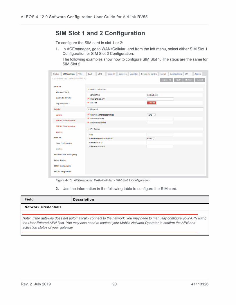
ALEOS 4.12.0 Software Configuration User Guide for AirLink RV55
SIM Slot 1 and 2 Configuration
To configure the SIM card in slot 1 or 2:
1. In ACEmanager, go to WAN/Cellular, and from the left menu, select either SIM Slot 1 Configuration or SIM Slot 2 Configuration.
The following examples show how to configure SIM Slot 1. The steps are the same for SIM Slot 2.
Figure 4-10: ACEmanager: WAN/Cellular > SIM Slot 1 Configuration
2. Use the information in the following table to configure the SIM card.
Field Description
Network Credentials
Note: If the gateway does not automatically connect to the network, you may need to manually configure your APN using the User Entered APN field. You may also need to contact your Mobile Network Operator to confirm the APN and activation status of your gateway.
Rev. 2 July 2019 90 41113126

WAN/Cellular Configuration
APN in Use This field only appears for the Active SIM.
The APN in use for the current mobile network connection.
When you power on the AirLink gateway, the APN the gateway is using for authentication on the mobile network is displayed.
• If a User Entered APN is configured, the User Entered APN is displayed.
• If there is no User Entered APN configured, an automatically-selected APN is displayed.
• When the Backup APN is configured, the APN in Use displays the configured Backup APN when it is being used for authentication on the mobile network.
If ALEOS is unable to find the appropriate APN to use (No APN found), contact your Mobile Network Operator for the APN and enter it in the User Entered APN field.
User Entered APN The APN entered in this field takes priority over the automatically-selected APN.
1. Enter the APN in this field (maximum 100 characters).
2. Click Apply.
3. Click Reboot.
Note: If you reset the gateway to factory defaults, you have the option to preserve the custom APN, if entered. See Reset Mode on page 370.
Note: For gateways on the Sprint network, the correct APN is automatically sent to the gateway. Leave this field blank unless specifically asked by Sprint to enter an APN.
SIM PIN Click this button to configure the PIN for the SIM card in SIM slot 1. For more information, see SIM PIN on page 92. By default, the gateway does not use a SIM PIN for the SIM in slot 1.
Advanced
Network Authentication Mode
Specifies the authentication method to use when connecting to a mobile network Options are:
• NONE
• CHAP
• PAP (default)
Network User ID Network User ID
The login that is used to log in to the mobile network, when required.
• Maximum 128 characters
Network Password Network Password is the password that, when required, is used to log in to the mobile network.
• Maximum 30 characters
Field Description
Rev. 2 July 2019 91 41113126
ALEOS 4.12.0 Software Configuration User Guide for AirLink RV55
SIM PIN
If you have a SIM card with a PIN configured, you can configure ALEOS to enter the PIN on reboot, so human intervention is not required.
This feature has two requirements:• A PIN-locked SIM card—Contact your Mobile Network Operator to ensure that they
support this feature and to obtain a PIN-locked SIM card and PIN.• The SIM PIN feature in ACEmanager must be enabled. See Enable the SIM PIN.
If the AirLink gateway has a PIN-locked SIM installed and this feature is not enabled in ACEmanager, the AirLink gateway is unable to go on air and the Network Status field on the Status > Home screen displays the message “SIM PIN incorrect, # attempts left”.
Note: On gateways with ALEOS 4.7.0 or later, you can use AT Commands to enable, disable, or change the SIM PIN the SIM card requests when the gateway boots up. For details, see *CHGSIMPIN on page 461 and *ENASIMPIN on page 464.
Enable the SIM PIN
To enable or enter the SIM PIN:
1. In ACEmanager, go to WAN/Cellular > SIM Slot 1 or 2 Configuration.
2. Click the SIM PIN button. The following pop-up window appears.
APN Backup
This feature enables you to configure a backup APN to be used as a backup network connection mechanism, only if the primary APN is not available. When it is enabled, the gateway connects to the backup APN only if it is unable to connect to the primary APN.
Note: Switching to the backup APN can take five minutes or more, depending on the gateway. If the gateway is always connecting to the backup APN, check the primary APN to ensure that it is configured correctly.
Note: Do not configure a backup APN for gateways on the Sprint network. For more information, contact Sprint.
APN Enter the backup APN (maximum 100 characters).
Network Authentication Mode
Select the Network Authentication Mode. The options are:
• PAP (default)
• CHAP
• NONE
Network User ID Enter the Network User ID, if it is required for the wireless network.
Network Password Enter the Network Password, if it is required for the wireless network.
Field Description
Rev. 2 July 2019 92 41113126
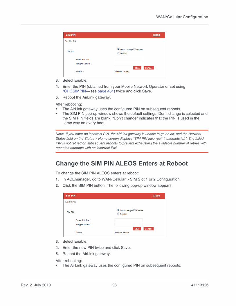
WAN/Cellular Configuration
3. Select Enable.
4. Enter the PIN (obtained from your Mobile Network Operator or set using *CHGSIMPIN—see page 461) twice and click Save.
5. Reboot the AirLink gateway.
After rebooting:• The AirLink gateway uses the configured PIN on subsequent reboots.• The SIM PIN pop-up window shows the default settings. Don’t change is selected and
the SIM PIN fields are blank. “Don’t change” indicates that the PIN is used in the same way on every boot.
Note: If you enter an incorrect PIN, the AirLink gateway is unable to go on air, and the Network Status field on the Status > Home screen displays “SIM PIN incorrect, # attempts left”. The failed PIN is not retried on subsequent reboots to prevent exhausting the available number of retries with repeated attempts with an incorrect PIN.
Change the SIM PIN ALEOS Enters at Reboot
To change the SIM PIN ALEOS enters at reboot:
1. In ACEmanager, go to WAN/Cellular > SIM Slot 1 or 2 Configuration.
2. Click the SIM PIN button. The following pop-up window appears.
3. Select Enable.
4. Enter the new PIN twice and click Save.
5. Reboot the AirLink gateway.
After rebooting:• The AirLink gateway uses the configured PIN on subsequent reboots.
Rev. 2 July 2019 93 41113126
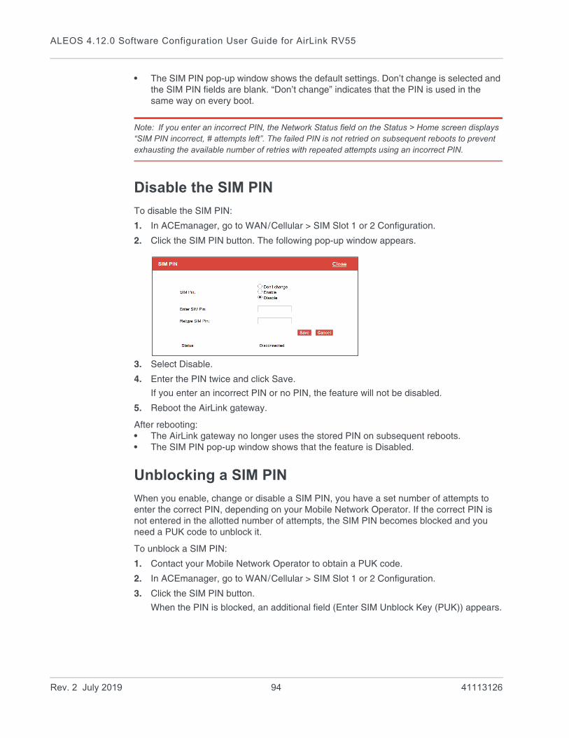
ALEOS 4.12.0 Software Configuration User Guide for AirLink RV55
• The SIM PIN pop-up window shows the default settings. Don’t change is selected and the SIM PIN fields are blank. “Don’t change” indicates that the PIN is used in the same way on every boot.
Note: If you enter an incorrect PIN, the Network Status field on the Status > Home screen displays “SIM PIN incorrect, # attempts left”. The failed PIN is not retried on subsequent reboots to prevent exhausting the available number of retries with repeated attempts using an incorrect PIN.
Disable the SIM PIN
To disable the SIM PIN:
1. In ACEmanager, go to WAN/Cellular > SIM Slot 1 or 2 Configuration.
2. Click the SIM PIN button. The following pop-up window appears.
3. Select Disable.
4. Enter the PIN twice and click Save.
If you enter an incorrect PIN or no PIN, the feature will not be disabled.
5. Reboot the AirLink gateway.
After rebooting:• The AirLink gateway no longer uses the stored PIN on subsequent reboots.• The SIM PIN pop-up window shows that the feature is Disabled.
Unblocking a SIM PIN
When you enable, change or disable a SIM PIN, you have a set number of attempts to enter the correct PIN, depending on your Mobile Network Operator. If the correct PIN is not entered in the allotted number of attempts, the SIM PIN becomes blocked and you need a PUK code to unblock it.
To unblock a SIM PIN:
1. Contact your Mobile Network Operator to obtain a PUK code.
2. In ACEmanager, go to WAN/Cellular > SIM Slot 1 or 2 Configuration.
3. Click the SIM PIN button.
When the PIN is blocked, an additional field (Enter SIM Unblock Key (PUK)) appears.
Rev. 2 July 2019 94 41113126

WAN/Cellular Configuration
4. Select Enable.
5. Enter the new PIN code.
6. Enter the PUK and click Save.
Be careful when entering the PUK. You have a limited number of attempts to enter the correct PUK (generally 10) before the SIM card is disabled. If the PUK does not unblock the SIM PIN after the first few attempts, contact your Mobile Network Opera-tor.
If you have exhausted all the alloted attempts to enter the correct PUK, the Mobile Network Operator may give you a new SIM card, or a new code to enable your existing SIM card.
To enter the code:
a. Remove the SIM card from your AirLink gateway (following the instructions in the AirLink gateway Hardware User Guide) and insert it in a cell phone that accom-modates a MiniSIM (2FF) card.
b. Enter a new code provided by the Mobile Network Operator and then return the SIM card to the AirLink gateway.
Rev. 2 July 2019 95 41113126

ALEOS 4.12.0 Software Configuration User Guide for AirLink RV55
Cellular > Monitor
Figure 4-11: ACEmanager: WAN / Cellular > Cellular > Monitor
Use these fields to monitor the cellular network connection.
Field Description
Test Interval (seconds)
The amount of time between tests of the cellular connection. Available range is:
• 1–15300 seconds (Default is 900.)
Most applications work well with an interval of 900 to 3600 seconds (15 to 60 minutes).
Monitor Type Determines the type of test run on the interface to diagnose its ability to provide end-to-end connectivity for this interface. Options are:
• Disabled—No end-to-end diagnostic runs and the service state cannot be verified. Therefore it is assumed that this interface provides service if an IP is assigned.
• Traffic Monitor—A ping test is only performed if there is no traffic during the configured interval.
• Ping Test—A ping is sent at the end of the test interval regardless of whether or not there has been any traffic during the interval (i.e. if the interface receives ingress traffic regularly, no additional traffic is generated by the gateway).
Note: Using pings to monitor the interface may accrue data charges. Each individual ping is approx-imately 98 bytes (196 bytes for ping sent plus ping response).
Ping Test IP Address
Enter the IP address to ping.
Rev. 2 July 2019 96 41113126
WAN/Cellular Configuration
Time Between Pings (seconds)
Time between individual pings
Available range is:
• 1–20 seconds (Default is 20.)
If the first ping fails, the AirLink gateway sends additional pings at the configured interval. If all pings fail, the AirLink gateway declares the service state as “Not Established” and attempts to switch to another interface according to the Interface Priority (see page 72) configuration, and interface availability.
If this field is set to 10 (with Number of Pings set to 5) and the test is started and fails, the interface does not provide service for a total of 50 seconds.
Number of Pings
Sets the number of consecutive missed pings before the AirLink gateway declares the service state as “Not Established” and attempts to switch to another interface.
Available range is:
• 1–12 (Default is 5.)
Field Description
Rev. 2 July 2019 97 41113126

ALEOS 4.12.0 Software Configuration User Guide for AirLink RV55
Ethernet
Static Configuration
Before configuring the Ethernet WAN mode, go to LAN > Ethernet and ensure that the Ethernet port is set to WAN.
Figure 4-12: ACEmanager: Wan/Cellular > Ethernet > Static Configuration
Field Description
Ethernet WAN
Ethernet WAN Mode
Set the Ethernet WAN IP address mode
Options are:
• Dynamic (default)—WAN IP address is assigned by the DHCP server
• Static—Choose this mode to statically assign an IP address when required. After you select Static, click Apply.
Static WAN IP Enter the static IP address for the AirLInk RV55
Example: 192.168.0.55
Static WAN Netmask
Enter the subnet mask
Example: 255.255.255.0
Static WAN Gateway
Enter the static IP address for the router/gateway
Example: 192.168.0.1
Rev. 2 July 2019 98 41113126
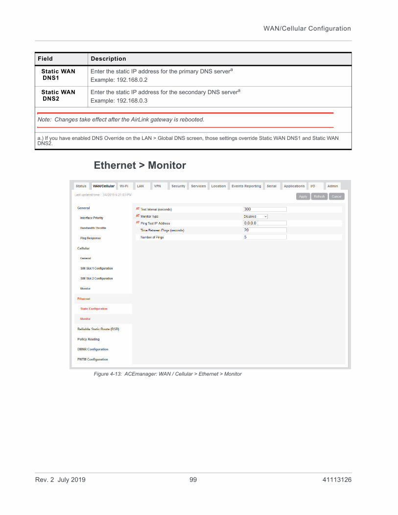
WAN/Cellular Configuration
Ethernet > Monitor
Figure 4-13: ACEmanager: WAN / Cellular > Ethernet > Monitor
Static WAN DNS1
Enter the static IP address for the primary DNS servera
Example: 192.168.0.2
Static WAN DNS2
Enter the static IP address for the secondary DNS servera
Example: 192.168.0.3
Note: Changes take effect after the AirLink gateway is rebooted.
a.) If you have enabled DNS Override on the LAN > Global DNS screen, those settings override Static WAN DNS1 and Static WAN DNS2.
Field Description
Rev. 2 July 2019 99 41113126

ALEOS 4.12.0 Software Configuration User Guide for AirLink RV55
Field Description
Test Time Interval (seconds)
The amount of time between tests of the Ethernet WAN connection. Available range is:
• 1–15300 seconds (Default is 300.)
Most applications work well with an interval of 900 to 3600 seconds (15 to 60 minutes).
Monitor Type Determines the type of test run on the interface to monitor its ability to provide end-to-end connectivity for this interface. Options are:
• Disabled—No end-to-end diagnostic runs and the service state cannot be verified. Therefore it is assumed that this interface provides service if an IP is assigned.
• Traffic Monitor—A ping test is only performed if there is no traffic during the configured interval.
• Ping Test—A ping is sent at the end of the test interval regardless of whether or not there has been any traffic during the interval (i.e. if the interface receives ingress traffic regularly, no additional traffic is generated by the gateway).
Note: Using pings to monitor the interface may accrue data charges. Each individual ping is approx-imately 98 bytes (196 bytes for ping sent plus ping response).
Ping Test IP Address
Enter the IP address to ping.
Time Between Pings (seconds)
Time between individual pings
Available range is:
• 1–20 seconds (Default is 20.)
If the first ping fails, the AirLink gateway sends additional pings at the configured interval. If all pings fail, the AirLink gateway declares the service state as “Not Established” and attempts to switch to another interface according to the Interface Priority (see page 72) configuration, and interface availability.
If this field is set to 10 (with Number of Pings set to 5) and the test is started and fails, the interface does not provide service for a total of 50 seconds.
Number of Pings
Sets the number of consecutive missed pings before the AirLink gateway declares the service state as “Not Established” and attempts to switch to another interface.
Available range is:
• 1–12 (Default is 5.)
Rev. 2 July 2019 100 41113126
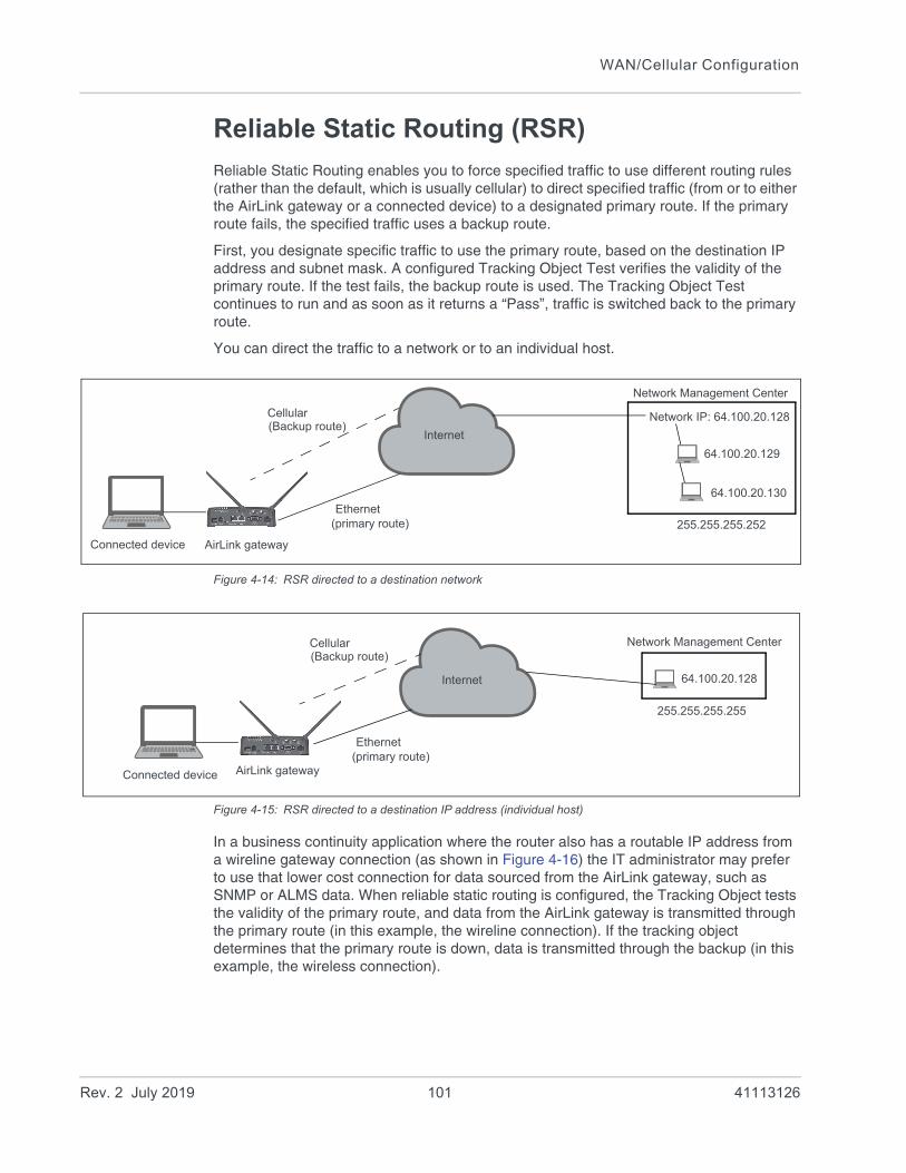
WAN/Cellular Configuration
Reliable Static Routing (RSR)
Reliable Static Routing enables you to force specified traffic to use different routing rules (rather than the default, which is usually cellular) to direct specified traffic (from or to either the AirLink gateway or a connected device) to a designated primary route. If the primary route fails, the specified traffic uses a backup route.
First, you designate specific traffic to use the primary route, based on the destination IP address and subnet mask. A configured Tracking Object Test verifies the validity of the primary route. If the test fails, the backup route is used. The Tracking Object Test continues to run and as soon as it returns a “Pass”, traffic is switched back to the primary route.
You can direct the traffic to a network or to an individual host.
Figure 4-14: RSR directed to a destination network
Figure 4-15: RSR directed to a destination IP address (individual host)
In a business continuity application where the router also has a routable IP address from a wireline gateway connection (as shown in Figure 4-16) the IT administrator may prefer to use that lower cost connection for data sourced from the AirLink gateway, such as SNMP or ALMS data. When reliable static routing is configured, the Tracking Object tests the validity of the primary route, and data from the AirLink gateway is transmitted through the primary route (in this example, the wireline connection). If the tracking object determines that the primary route is down, data is transmitted through the backup (in this example, the wireless connection).
AirLink gateway
Internet
Network Management Center
Ethernet
Cellular
(primary route)
(Backup route)Network IP: 64.100.20.128
255.255.255.252
64.100.20.129
64.100.20.130
Connected device
AirLink gateway
Internet
Network Management Center
Ethernet
Cellular
(primary route)
(Backup route)
64.100.20.128
255.255.255.255
Connected device
Rev. 2 July 2019 101 41113126
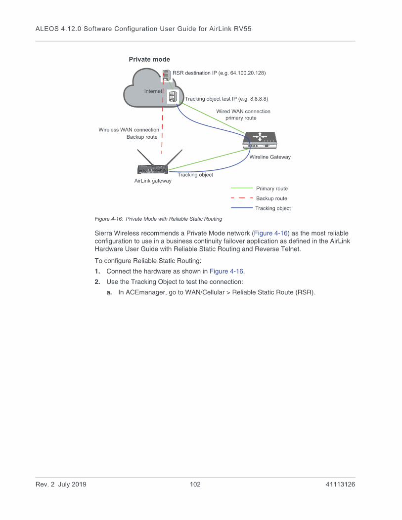
ALEOS 4.12.0 Software Configuration User Guide for AirLink RV55
Figure 4-16: Private Mode with Reliable Static Routing
Sierra Wireless recommends a Private Mode network (Figure 4-16) as the most reliable configuration to use in a business continuity failover application as defined in the AirLink Hardware User Guide with Reliable Static Routing and Reverse Telnet.
To configure Reliable Static Routing:
1. Connect the hardware as shown in Figure 4-16.
2. Use the Tracking Object to test the connection:
a. In ACEmanager, go to WAN/Cellular > Reliable Static Route (RSR).
Internet
AirLink gateway
Private mode
Wireless WAN connection
Wired WAN connection
Wireline Gateway
primary route
Backup route
Tracking object
Backup route
Primary route
Tracking object
Tracking object test IP (e.g. 8.8.8.8)
RSR destination IP (e.g. 64.100.20.128)
Rev. 2 July 2019 102 41113126

WAN/Cellular Configuration
Figure 4-17: ACEmanager: WAN/Cellular > Reliable Static Route (RSR) >Tracking Object
b. Under Tracking Object, enter the Test IP address, using a host behind the gateway that has a reliable IP address, such as 8.8.8.8.
c. From the drop-down menu, select Ethernet 1 as the Test Interface.
d. Leave the default values for the Test Interval, Test Timeout, and Maximum number of retries.
e. In the Tracking Object field, select Enable.
f. Click Apply.
g. The Tracking Object pings the Test IP address configured in step b. In ACEma-nager go to Status > RSR and note the result in the RSR Test Result field.
3. Disable Tracking Object.
Note: Configure all the other fields before setting the Enable/Disable Reliable Static Routing field. Once you enable RSR, some fields on this page are not editable.
4. Go to WAN/Cellular > Reliable Static Route (RSR) > Reliable Static Route (RSR).
Rev. 2 July 2019 103 41113126

ALEOS 4.12.0 Software Configuration User Guide for AirLink RV55
Figure 4-18: ACEmanager: WAN/Cellular > Reliable Static Route (RSR) > Reliable Static Route (RSR)
5. Select the interfaces for the primary and backup routes. The options are:· Ethernet 1 (default for primary route) · USB· Wi-Fi · Cellular (default for backup route)
If you select Ethernet 1, you are given the option to enter a gateway IP address that is
used as the next hop for reaching the destination network.1
· If the Tracking Object test completed in step 2 was successful, leave this field at the default value (0.0.0.0).
· If the Tracking Object test completed in step 2 failed, enter the gateway IP address in this field.
6. Set the Destination IP/Network and Destination Subnet Mask.
To configure the RSR destination as a network for this example, enter:· 64.100.20.128 in the Destination IP/Network field. · 255.255.255.252 in the Destination Subnet Mask field.
To configure the RSR destination as an individual host for this example, enter:· 64.100.20.128 in the Destination IP/Network field. · 255.255.255.255 in the Destination Subnet Mask field.
1. This applies to both the primary and the Backup interface.
Rev. 2 July 2019 104 41113126

WAN/Cellular Configuration
7. Set the Tracking Object (Tracking Object 1 or No Tracking Object). Normally, you would select Tracking Object 1 from the drop-down menu.
8. Under Tracking Object, leave the Enable/Disable Tracking Object set at Disable until you finish configuring the other Tracking Object fields.
9. Enter the Test IP address (normally an IP address within the Traffic Selection Criteria Network/Subnet).
10. From the drop-down menu, select the desired Test Interface (normally the same interface as the primary route). Options are:· Ethernet 1· USB· Wi-Fi · Cellular
11. Enter the Test Interval in seconds. This is the interval between Tracking Object Tests.
For most applications, the default values for the Test Interval, Test Timeout, and Maxi-mum number of retries should be fine.
If you want to change these values, be aware of the following:· Selecting a short test interval increases network traffic and may lead to false
failures if the network is busy.· Selecting a long test interval may mean that traffic does not switch to the secondary
route quickly enough when the primary route fails.· The test interval must be greater than the product of Test Timeout × Maximum
number of Test Retries. [Test Interval] > [Test Timeout] × [Maximum number of Retries]
12. Enter the Test Timeout in seconds. This is the time to wait for a response. If this time expires before a response is received, the test attempt fails.
13. Enter the Maximum number of Test Retries. If the first Tracking Object Test fails, this is the number of times the gateway sends additional test messages (without receiving a response) before it declares the test as failed and switches the specified traffic to the backup network.
14. In the Tracking Object field, select Enable.
15. In the RSR field, select Enable.
Note: Alway click Apply after enabling or disabling this feature.
Go to Status > WAN/Cellular to check the RSR Test Result and confirm that traffic is being sent through the primary route. If the RSR Test Result field indicates that the Tracking Object Test has failed, validate the connectivity of the primary path. (A test result of Unknown indicates that the test has not yet run.)
Policy Routing
You can use Policy Routing to configure up to 5 policy routing rules used to determine the WAN interface over which outbound traffic is sent. When policy routing is configured, all traffic from the gateway is compared to the rules, in order of priority. If a match is found, the traffic flows over the WAN interface specified by the rule. If no match is found or the selected interface is not available, the active WAN interface is used.
Rev. 2 July 2019 105 41113126

ALEOS 4.12.0 Software Configuration User Guide for AirLink RV55
Do not include devices in the policy if they need to access ACEmanager.
You can create rules based on the following components:• Destination IP address/destination subnet mask• Destination port• Source IP address/source subnet mask• Source port
Any component left with its default value is excluded from the traffic filtering.
Examples:• If Source IP/subnet mask and Destination IP/subnet mask are configured, traffic from
specific LAN hosts with a remote destination matching the configured destination IP and subnet mask uses the policy and is sent over the configured interface. All other traffic uses the current active WAN interface.
• If only the Destination port is configured, traffic from the gateway or from any connected device being sent to the configured remote port uses the policy. All other traffic uses the current active WAN interface.
Note: It is possible to configure a policy routing rule in such a way that you could lose the network connection you are using to configure the gateway with ACEmanager. For example, if you are using ACEmanager through an Ethernet connection to configure the gateway with IP address 192.168.13.100 and you inadvertently configure a rule to send all traffic destined for 192.168.13.100 over the cellular interface, the Ethernet connection you are using to configure the gateway will be lost. If that happens, use a different IP address.
Figure 4-19: ACEmanager: Policy Routing
Rev. 2 July 2019 106 41113126
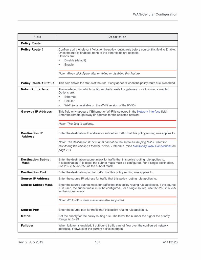
WAN/Cellular Configuration
Field Description
Policy Route
Policy Route # Configure all the relevant fields for the policy routing rule before you set this field to Enable. Once the rule is enabled, none of the other fields are editable.Options are:
• Disable (default)
• Enable
Note: Alway click Apply after enabling or disabling this feature.
Policy Route # Status This field shows the status of the rule. It only appears when the policy route rule is enabled.
Network Interface The interface over which configured traffic exits the gateway once the rule is enabledOptions are:
• Ethernet
• Cellular
• Wi-Fi (only available on the Wi-Fi version of the RV55)
Gateway IP Address This field only appears if Ethernet or Wi-Fi is selected in the Network Interface field.Enter the remote gateway IP address for the selected network.
Note: This field is optional.
Destination IP Address
Enter the destination IP address or subnet for traffic that this policy routing rule applies to.
Note: The destination IP or subnet cannot be the same as the ping test IP used for monitoring the cellular, Ethernet, or Wi-Fi interface. (See Monitoring WAN Connections on page 70.)
Destination Subnet Mask
Enter the destination subnet mask for traffic that this policy routing rule applies to. If a destination IP is used, the subnet mask must be configured. For a single destination, use 255.255.255.255 as the subnet mask.
Destination Port Enter the destination port for traffic that this policy routing rule applies to.
Source IP Address Enter the source IP address for traffic that this policy routing rule applies to.
Source Subnet Mask Enter the source subnet mask for traffic that this policy routing rule applies to. If the source IP is used, the subnet mask must be configured. For a single source, use 255.255.255.255 as the subnet mask.
Note: /26 to /31 subnet masks are also supported.
Source Port Enter the source port for traffic that this policy routing rule applies to.
Metric Set the priority for the policy routing rule. The lower the number the higher the priority. Range is: 0–99
Failover When failover is enabled, if outbound traffic cannot flow over the configured network interface, it flows over the current active interface.
Rev. 2 July 2019 107 41113126
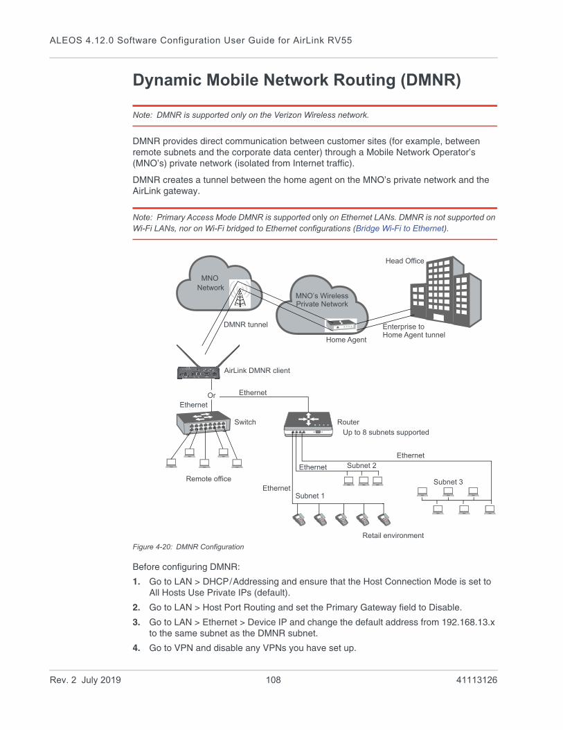
ALEOS 4.12.0 Software Configuration User Guide for AirLink RV55
Dynamic Mobile Network Routing (DMNR)
Note: DMNR is supported only on the Verizon Wireless network.
DMNR provides direct communication between customer sites (for example, between remote subnets and the corporate data center) through a Mobile Network Operator’s (MNO’s) private network (isolated from Internet traffic).
DMNR creates a tunnel between the home agent on the MNO’s private network and the AirLink gateway.
Note: Primary Access Mode DMNR is supported only on Ethernet LANs. DMNR is not supported on Wi-Fi LANs, nor on Wi-Fi bridged to Ethernet configurations (Bridge Wi-Fi to Ethernet).
Figure 4-20: DMNR Configuration
Before configuring DMNR:
1. Go to LAN > DHCP/Addressing and ensure that the Host Connection Mode is set to All Hosts Use Private IPs (default).
2. Go to LAN > Host Port Routing and set the Primary Gateway field to Disable.
3. Go to LAN > Ethernet > Device IP and change the default address from 192.168.13.x to the same subnet as the DMNR subnet.
4. Go to VPN and disable any VPNs you have set up.
MNO’s WirelessPrivate Network
Subnet 1
Router
AirLink DMNR client
Home Agent
Subnet 2
Ethernet
Ethernet
Ethernet
Subnet 3
DMNR tunnel
Head Office
Enterprise to
Ethernet
Up to 8 subnets supported
MNONetwork
Home Agent tunnel
EthernetOr
Remote office
Retail environment
Switch
Rev. 2 July 2019 108 41113126

WAN/Cellular Configuration
Once DMNR is configured, all traffic from the connected LANs goes through the DMNR tunnel.
5. Go to Security > Port Forwarding and set the DMZ Enabled field to Disable.
6. Reboot the gateway.
Note: For the DMNR registration process to complete successfully, there must be a switch, router, or other device physically connected to the AirLink gateway’s Ethernet port.
Note: Ensure that the default route of the switch or router points to the AirLink gateway.
To configure DMNR:
1. Go to WAN/Cellular > DMNR Configuration.
Figure 4-21: ACEmanager: WAN/Cellular > DMNR Configuration
Rev. 2 July 2019 109 41113126

ALEOS 4.12.0 Software Configuration User Guide for AirLink RV55
2. Configure the fields as outlined in the following table.
Field Description
Dynamic Mobile Network Routing
DMNR Enable Enables Dynamic Mobile Network Routing. Options are:
• Enable
• Disable (default)a
Note: Configure all the other parameters first and then set this field to Enable. When this field is set to Enable, the other fields in this window are read-only.
Note: Alway click Apply after enabling or disabling this feature.
Home Address Enter a home address for the AirLink gateway. This address is used to distinguish the AirLink gateway used for DMNR. Use 1.2.3.4 for all gateways configured for DMNR. This field cannot be left blank.
Home Agent Address IP address of the Home Agent (available from your Mobile Network Operator)
N-MHAE-SPI NEMO Authentication Extension Security Parameter Index (available from your Mobile Network Operator)
N-MHAE-KEY NEMO Authentication Extension Key (available from your Mobile Network Operator)
Note: The value regularly used successfully for gateways on the Verizon Wireless network (subject to change) is VzWNeMo.
Subnet 1 – 8 Enter the IP addresses for the subnets you want to include in the DMNR network. You can configure up to 8 subnets.0.0.0.0 indicates that the subnet is not configured.
Note: If you want to remove a subnet from the DMNR configuration, replace the IP address with 0.0.0.0 rather than deleting it.
Subnet 1 – 8 NetMask Enter the subnet masks for the subnets you want to include in the DMNR network.0.0.0.0 indicates that the subnet mask is not configured.
Note: If you want to remove a subnet mask from the DMNR configuration, replace the IP address with 0.0.0.0 rather than deleting it.
a. If you disable DMNR when the DMNR tunnel is up, no disconnect message is sent, resulting in a temporary mismatch between the reachability of the (NEMO) subnets on the gateway and the Home Agent.
Rev. 2 July 2019 110 41113126
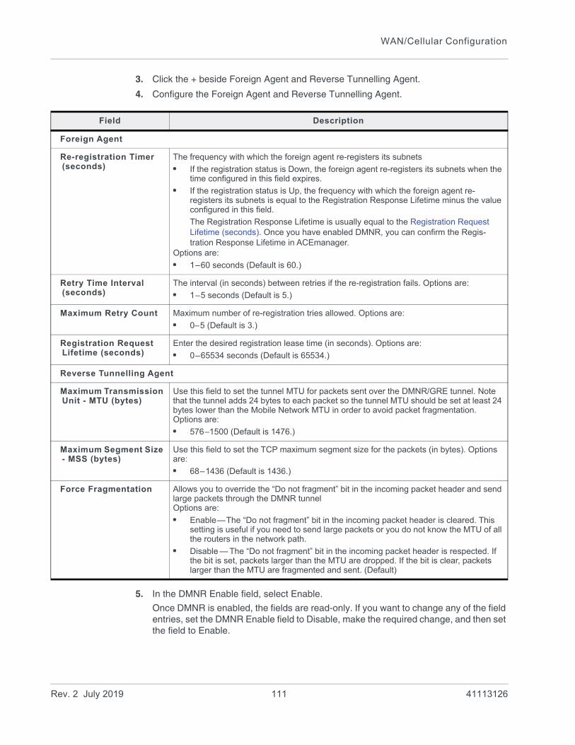
WAN/Cellular Configuration
3. Click the + beside Foreign Agent and Reverse Tunnelling Agent.
4. Configure the Foreign Agent and Reverse Tunnelling Agent.
5. In the DMNR Enable field, select Enable.
Once DMNR is enabled, the fields are read-only. If you want to change any of the field entries, set the DMNR Enable field to Disable, make the required change, and then set the field to Enable.
Field Description
Foreign Agent
Re-registration Timer (seconds)
The frequency with which the foreign agent re-registers its subnets
• If the registration status is Down, the foreign agent re-registers its subnets when the time configured in this field expires.
• If the registration status is Up, the frequency with which the foreign agent re-registers its subnets is equal to the Registration Response Lifetime minus the value configured in this field.
The Registration Response Lifetime is usually equal to the Registration Request Lifetime (seconds). Once you have enabled DMNR, you can confirm the Regis-tration Response Lifetime in ACEmanager.
Options are:
• 1–60 seconds (Default is 60.)
Retry Time Interval (seconds)
The interval (in seconds) between retries if the re-registration fails. Options are:
• 1–5 seconds (Default is 5.)
Maximum Retry Count Maximum number of re-registration tries allowed. Options are:
• 0–5 (Default is 3.)
Registration Request Lifetime (seconds)
Enter the desired registration lease time (in seconds). Options are:
• 0–65534 seconds (Default is 65534.)
Reverse Tunnelling Agent
Maximum Transmission Unit - MTU (bytes)
Use this field to set the tunnel MTU for packets sent over the DMNR/GRE tunnel. Note that the tunnel adds 24 bytes to each packet so the tunnel MTU should be set at least 24 bytes lower than the Mobile Network MTU in order to avoid packet fragmentation. Options are:
• 576–1500 (Default is 1476.)
Maximum Segment Size - MSS (bytes)
Use this field to set the TCP maximum segment size for the packets (in bytes). Options are:
• 68–1436 (Default is 1436.)
Force Fragmentation Allows you to override the “Do not fragment” bit in the incoming packet header and send large packets through the DMNR tunnelOptions are:
• Enable—The “Do not fragment” bit in the incoming packet header is cleared. This setting is useful if you need to send large packets or you do not know the MTU of all the routers in the network path.
• Disable — The “Do not fragment” bit in the incoming packet header is respected. If the bit is set, packets larger than the MTU are dropped. If the bit is clear, packets larger than the MTU are fragmented and sent. (Default)
Rev. 2 July 2019 111 41113126

ALEOS 4.12.0 Software Configuration User Guide for AirLink RV55
Figure 4-22: ACEmanager: WAN/Cellular > DMNR Enabled
Rev. 2 July 2019 112 41113126
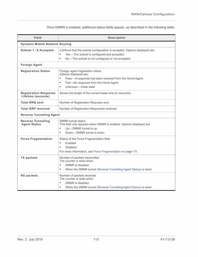
WAN/Cellular Configuration
Once DMNR is enabled, additional status fields appear, as described in the following table.
Field Description
Dynamic Mobile Network Routing
Subnet 1 – 8 Accepted Confirms that the subnet configuration is accepted. Options displayed are:
• Yes—The subnet is configured and accepted.
• No—The subnet is not configured or not accepted.
Foreign Agent
Registration Status Foreign agent registration statusOptions displayed are:
• Pass—A response has been received from the Home Agent.
• Fail—No response from the Home Agent.
• Unknown—Initial state
Registration Response Lifetime (seconds)
Shows the length of the current lease time (in seconds).
Total RRQ sent Number of Registration Requests sent
Total RRP received Number of Registration Responses received
Reverse Tunnelling Agent
Reverse Tunnelling Agent Status
DMNR tunnel statusThis field only appears when DMNR is enabled. Options displayed are:
• Up—DMNR tunnel is up.
• Down—DMNR tunnel is down.
Force Fragmentation Status of the Force Fragmentation field
• Enabled
• Disabled
For more information, see Force Fragmentation on page 111.
TX packets Number of packets transmittedThe counter is reset when:
• DMNR is disabled.
• When the DMNR tunnel (Reverse Tunnelling Agent Status) is down.
RX packets Number of packets receivedThe counter is reset when:
• DMNR is disabled.
• When the DMNR tunnel (Reverse Tunnelling Agent Status) is down.
Rev. 2 July 2019 113 41113126
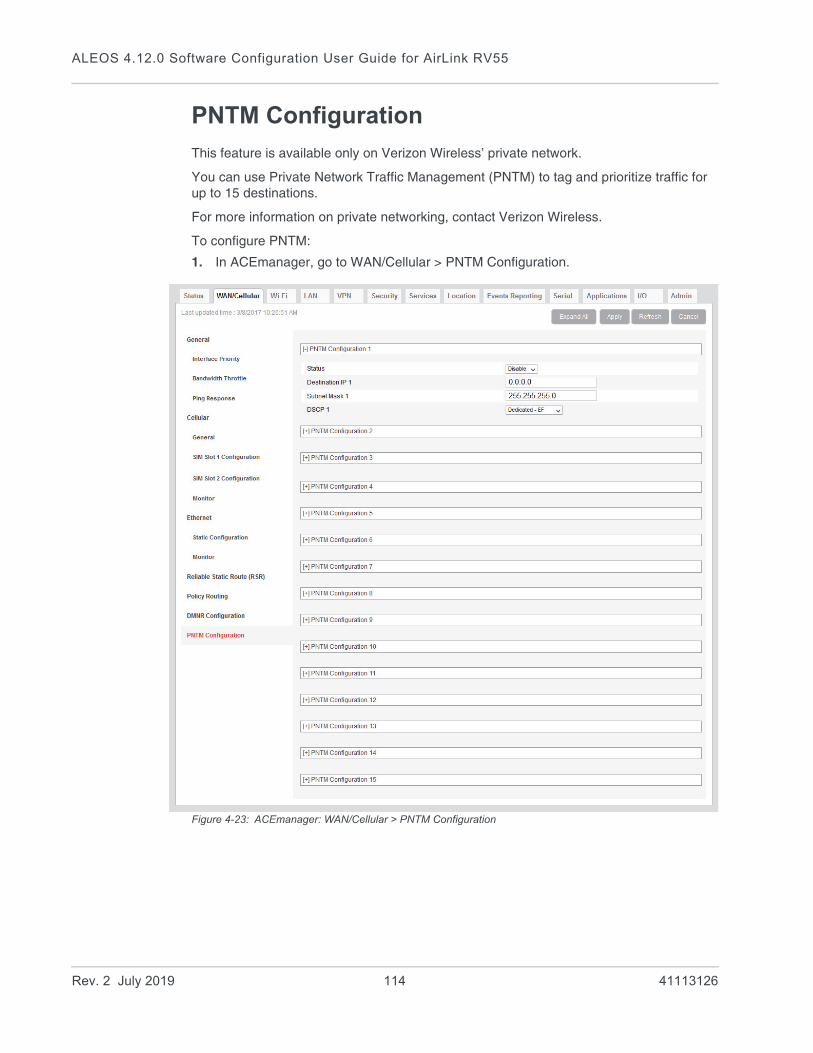
ALEOS 4.12.0 Software Configuration User Guide for AirLink RV55
PNTM Configuration
This feature is available only on Verizon Wireless’ private network.
You can use Private Network Traffic Management (PNTM) to tag and prioritize traffic for up to 15 destinations.
For more information on private networking, contact Verizon Wireless.
To configure PNTM:
1. In ACEmanager, go to WAN/Cellular > PNTM Configuration.
Figure 4-23: ACEmanager: WAN/Cellular > PNTM Configuration
Rev. 2 July 2019 114 41113126

WAN/Cellular Configuration
2. Configure the PNTM parameters as described in the following table.
Field Description
PNTM Configuration #
Status # Configure all the fields for the PNTM before you set this field to Enable. Once the PNTM is enabled, all the fields are read-only and this field shows the status of the PNTM connection.
Note: Always click Apply after enabling or disabling this feature.
Destination IP # Enter the destination IP address.
Subnet Mask # Enter the destination subnet mask.
DSCP # Select the desired priority level.
Rev. 2 July 2019 115 41113126
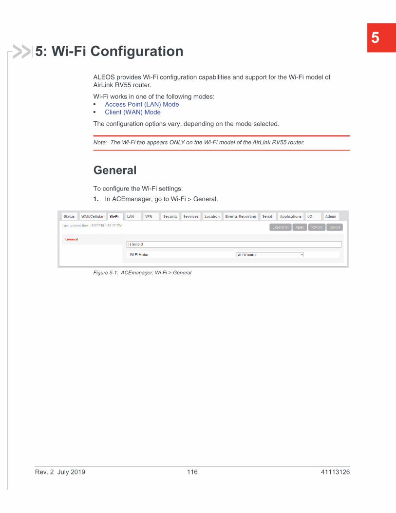
5
5: Wi-Fi ConfigurationALEOS provides Wi-Fi configuration capabilities and support for the Wi-Fi model of AirLink RV55 router.
Wi-Fi works in one of the following modes: • Access Point (LAN) Mode• Client (WAN) Mode
The configuration options vary, depending on the mode selected.
Note: The Wi-Fi tab appears ONLY on the Wi-Fi model of the AirLink RV55 router.
General
To configure the Wi-Fi settings:
1. In ACEmanager, go to Wi-Fi > General.
Figure 5-1: ACEmanager: Wi-Fi > General
Rev. 2 July 2019 116 41113126

Wi-Fi Configuration
2. Select the Wi-Fi mode, and click Apply.
The fields available on the General screen depend on the option chosen.
Figure 5-2: ACEmanager: Wi-Fi > General > Wi-Fi A Client (WAN) Mode
Field Description
General
Wi-Fi Modes Allows you to choose the Wi-Fi mode of operation. For the RV55 with Dual Wi-Fi, the Wi-Fi modes allow you to configure Wi-Fi A only, Wi-Fi B only, or both Wi-Fi A and Wi-Fi B. The options are:
• Wi-Fi Disable—Both Wi-Fi radios are disabled
• Wi-Fi A Access Point—Wi-Fi A radio is configured as an access point, and Wi-Fi B is disabled
• Wi-Fi A Client—Wi-Fi A radio is configured as a client, and Wi-Fi B is disabled
• Wi-Fi B Access Point—Wi-Fi B radio is configured as an access point, and Wi-Fi A is disabled
• Wi-Fi B Client—Wi-Fi B radio is configured as a client, and Wi-Fi A is disabled
• Wi-Fi A Access Point --- Wi-Fi B Access Point—Wi-Fi A and Wi-Fi B radios are configured as access points
• Wi-Fi A Client --- Wi-Fi B Access Point—Wi-Fi A radio is configured as a client, and Wi-Fi B is configured as an access point
• Wi-Fi A Access Point --- Wi-Fi B Client—Wi-Fi A radio is configured as an access point, and Wi-Fi B is configured as a client
•
Rev. 2 July 2019 117 41113126
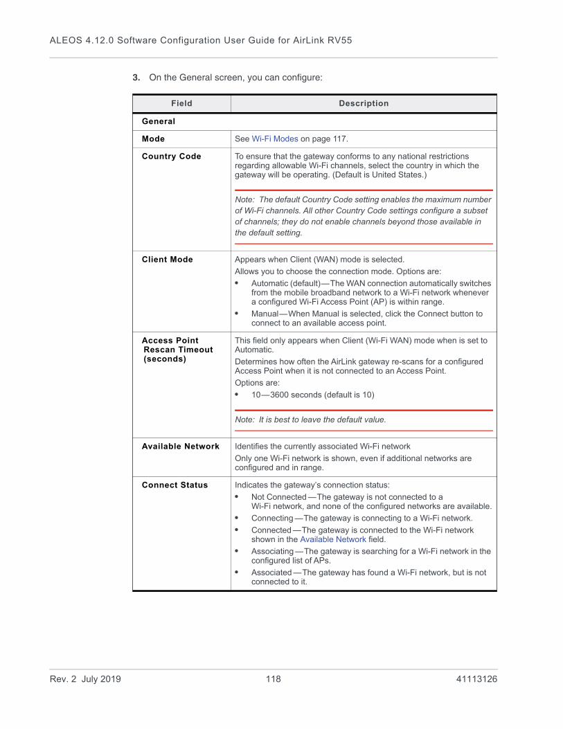
ALEOS 4.12.0 Software Configuration User Guide for AirLink RV55
3. On the General screen, you can configure:
Field Description
General
Mode See Wi-Fi Modes on page 117.
Country Code To ensure that the gateway conforms to any national restrictions regarding allowable Wi-Fi channels, select the country in which the gateway will be operating. (Default is United States.)
Note: The default Country Code setting enables the maximum number of Wi-Fi channels. All other Country Code settings configure a subset of channels; they do not enable channels beyond those available in the default setting.
Client Mode Appears when Client (WAN) mode is selected.
Allows you to choose the connection mode. Options are:
• Automatic (default)—The WAN connection automatically switches from the mobile broadband network to a Wi-Fi network whenever a configured Wi-Fi Access Point (AP) is within range.
• Manual—When Manual is selected, click the Connect button to connect to an available access point.
Access Point Rescan Timeout (seconds)
This field only appears when Client (Wi-Fi WAN) mode when is set to Automatic.
Determines how often the AirLink gateway re-scans for a configured Access Point when it is not connected to an Access Point.
Options are:
• 10—3600 seconds (default is 10)
Note: It is best to leave the default value.
Available Network Identifies the currently associated Wi-Fi network
Only one Wi-Fi network is shown, even if additional networks are configured and in range.
Connect Status Indicates the gateway’s connection status:
• Not Connected —The gateway is not connected to a Wi-Fi network, and none of the configured networks are available.
• Connecting —The gateway is connecting to a Wi-Fi network.
• Connected —The gateway is connected to the Wi-Fi network shown in the Available Network field.
• Associating —The gateway is searching for a Wi-Fi network in the configured list of APs.
• Associated —The gateway has found a Wi-Fi network, but is not connected to it.
Rev. 2 July 2019 118 41113126

Wi-Fi Configuration
Monitor
Test Interval (seconds)
The amount of time between tests of the Wi-Fi connection. Available range is:
• 1–15300 seconds (default is 300)
Most applications work well with an interval of 900 to 3600 seconds (15 to 60 minutes).
Monitor Type Determines the type of test run on the interface to diagnose its ability to provide end-to-end connectivity for this interface. Options are:
• Disabled—No end-to-end diagnostic runs and the service state cannot be verified. Therefore it is assumed that this interface provides service if an IP is assigned.
• Traffic Monitor—A ping test is only performed if there is no traffic during the configured interval.
• Ping Test—A ping is sent at the end of the test interval regardless of whether or not there has been any traffic during the interval (i.e. if the interface receives ingress traffic regularly, no additional traffic is generated by the gateway).
Note: Using pings to monitor the interface may accrue data charges. Each individual ping is approximately 98 bytes (196 bytes for ping sent plus ping response).
Ping Test IP Address
Enter the IP address to ping.
Time Between Pings (seconds)
Time between individual pings
Available range is:
• 1–20 seconds (Default is 20)
If the first ping fails, the AirLink gateway sends additional pings at the configured interval. If all pings fail, the AirLink gateway declares the service state as “Not Established” and attempts to switch to another interface according to the Interface Priority (see page 72) configuration, and interface availability.
If this field is set to 10 (with Number of Pings set to 5) and the test is started and fails, the interface does not provide service for a total of 50 seconds.
Number of Pings Sets the number of consecutive missed pings before the AirLink gateway declares the service state as “Not Established” and attempts to switch to another interface.
Available range is:
• 1–12 (Default is 5)
Field Description
Rev. 2 July 2019 119 41113126
ALEOS 4.12.0 Software Configuration User Guide for AirLink RV55
Access Point (LAN) Mode
In this mode, the AirLink gateway acts as an access point.
To configure Access Point (LAN) mode:
1. Select Access Point (LAN) from the drop-down menu in the Mode field.
2. Click Apply.
3. If you have not already done so, configure the General settings.
4. On the left menu, under Access Point (LAN), select General.
Enable Wi-Fi RSSI Link Monitoring
Enables the gateway to monitor RSSI to determine whether to switch the network interface. When the RSSI is consistently below the loss threshold for a qualification period, the network interface switches from Wi-Fi to Cellular. When RSSI is consistently high enough for a qualification period, the network interface switches back from Cellular to Wi-Fi.
Options are:
• Enable (when enabled, additional RSSI settings appear)
• Disable
Wi-Fi RSSI Loss Threshold
Sets the level at which the Wi-Fi signal is considered to be “lost” (defined as an absolute signal strength in dBm)
Available range is:
• -100 – -20 dBm (Default is -55 dBm)
Wi-Fi RSSI Hysteresis
Sets the signal level at which the Wi-Fi signal is considered to be “acquired” (defined as a relative level above the Loss Threshold in dB)
Available range is:
• 0–30 dB (Default is 10 dB)
Wi-Fi Service Loss Wait Time (seconds)
Sets the timer for the “loss” state. If the signal level is consistently below the Loss Threshold for the Service Loss Wait Time, the link is considered “lost” and the gateway switches network interfaces.
Available range is:
• 0–3600 seconds (Default is 3)
Wi-Fi Service Restored Wait Time (seconds)
Sets the timer for the “acquired” state. If the signal level is consistently above the Loss Threshold + RSSI Hysteresis for the Service Restored Wait Time, the link is considered “restored” and the gateway resumes using Wi-Fi as the WAN interface.
Available range is:
• 0–3600 seconds (Default is 10)
Field Description
Rev. 2 July 2019 120 41113126

Wi-Fi Configuration
Figure 5-3: ACEmanager: Wi-Fi > Access Point (LAN)
Field Description
General
Access Point Mode The access point mode configures operation for either n/ac or b/g/n.
Options are:
• Enable b/g/n (default) (for 2.4 GHz band)
• Enable n/ac (for 5 GHz band)
Channel, Frequency, Width
This field only appears when n/ac is selected in the Access Point Mode field.
Select from the list of Wi-Fi channel/frequency/width in the 5 GHz band. Each option includes the channel, frequency, and bandwidth. When a wider channel is available, higher data rates are possible. Choosing the 5 GHz band enables faster and more efficient Wi-Fi.
The available 5 GHz channels are Ch 36, Ch 40, Ch 44, Ch 48, Ch 149, Ch 153, Ch 157, Ch 161, Ch 165.
Default: Ch 44 (5.220 GHz) 20 MHz
Note: The drop-down list displays the channels that are supported by the RV55. Depending on the regulatory restrictions in the country selected in the Country Code field, some listed channels may not be operational. For more information, see The Wi-Fi channel I selected is not working. on page 541.
Note: If you select WPA Personal security authentication along with n/ac, note that only 20 MHz channels can be used with WPA Personal. For example, Ch 36 (5.180 GHz) 20 MHz or Ch 165 (5.825 GHz) 20 MHz can be used. See Security Authentication type on page 124.
Rev. 2 July 2019 121 41113126

ALEOS 4.12.0 Software Configuration User Guide for AirLink RV55
5. On the left menu, select .
Channel and Frequency
This field only appears when b/g/n is selected in the Access Point Mode field.
Select from the list of Wi-Fi channel/frequency.
The available 2.4 GHz channels are 1, 2, 3, 4, 5, 6, 7, 8, 9, 10, 11
Default: Channel 1–2.412 GHz.
Note: The drop-down list displays the channels that are supported by the gateway. Depending on the regulatory restrictions in the country selected in the Country Code field, some listed channels may not be operational For more information, see The Wi-Fi channel I selected is not working. on page 541.
Advanced
Beacon Interval (milliseconds)
How frequently the AirLink gateway sends periodic message (beacons) to advertise its availability (in milliseconds)
Options are:
• 1–65535 milliseconds (Default is 100)
DTIM Interval The number of beacons the client device can sleep through before waking up to check for messages
For example, if the DTIM Interval is set to 3, the client wakes up every third beacon. The higher the setting in the DTIM Interval field, the longer the client device can sleep, and the more battery power the client device can potentially save. However, high DTIM intervals can also reduce throughput to the client.
Options are:
• 1–255 (Default is 1)
Client Power Save Mode Ageout Timer (seconds)
Length of time that a client in power save mode is inactive (does not transmit any traffic) before the access point drops the connection to the client.
Options are:
• 0 (disabled)–3600 seconds (Default is 40)
802.11w support Enable 802.11w operation. The 802.11w standard uses Security Association Query Requests to ensure that clients are legitimate.
Options are:
• Optional (default)
• Disabled
• Required
By default, 802.11w works with devices that support it. When Optional is selected, devices that support 802.11w will be protected, while other devices will still connect to the router.
Select Disabled to disable 802.11w operation.
Select Required to force 802.11w operation. The router will reject unsupported clients and access points.
Field Description
Rev. 2 July 2019 122 41113126
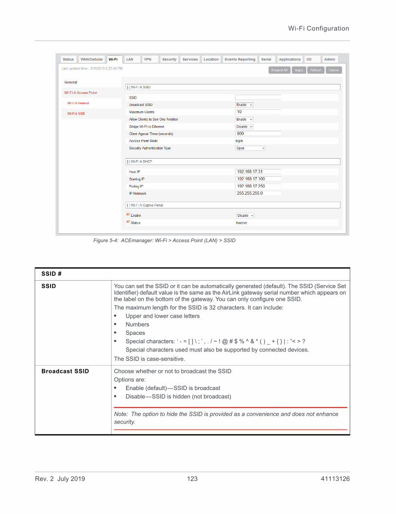
Wi-Fi Configuration
Figure 5-4: ACEmanager: Wi-Fi > Access Point (LAN) > SSID
SSID #
SSID You can set the SSID or it can be automatically generated (default). The SSID (Service Set Identifier) default value is the same as the AirLink gateway serial number which appears on the label on the bottom of the gateway. You can only configure one SSID.
The maximum length for the SSID is 32 characters. It can include:
• Upper and lower case letters
• Numbers
• Spaces
• Special characters: ‘ - = [ ] \ ; ’ , . / ~ ! @ # $ % ^ & * ( ) _ + { } | : ”< > ?
Special characters used must also be supported by connected devices.
The SSID is case-sensitive.
Broadcast SSID Choose whether or not to broadcast the SSID
Options are:
• Enable (default)—SSID is broadcast
• Disable—SSID is hidden (not broadcast)
Note: The option to hide the SSID is provided as a convenience and does not enhance security.
Rev. 2 July 2019 123 41113126
ALEOS 4.12.0 Software Configuration User Guide for AirLink RV55
Captive Portal
Captive portal enables you to redirect traffic from unauthenticated clients to a specified portal before granting devices full Internet access.
Captive portal has three components:• Redirecting HTTP traffic• Providing website authentication• Managing RADIUS server accounts
Note: Captive Portal replaces the Wi-Fi Landing Page feature from previous versions of ALEOS. After you have configured Captive Portal settings, you can direct traffic to a page hosted by the captive portal solution you are using.
Maximum Clients Indicates the maximum number of concurrent users (clients) supportedOptions:
• 1 to 10 (Default is 10.)
Allow Clients to See One Another
Enabled by default. If you do not want clients on the network to be able to see each other, select Disable.
Bridge Wi-Fi to Ethernet
This field allows you to create a unified bridge (virtual interface) between the AirLink gateway’s Wi-Fi and Ethernet interfaces.
Options are:
• Enable—the Ethernet interface and the Wi-Fi interface share the same subnet. The Wi-Fi devices get their DHCP IP addresses from the Ethernet pool (when Ethernet DHCP is enabled). This allows routing between all LAN devices.
• Disable—Wi-Fi is a separate LAN subnet from the Ethernet LAN. There is no routing between the two interfaces and their connected devices. (default)
Client Ageout Timer (seconds)
Length of time (in seconds) that a client is inactive before the access point drops the connection to the client. Options are:
• 60–3600 (Default is 900)
Access Point Mode Displays the access point mode selected in the General settings.
Security Authentication type
Select the authentication type. Options are:
• Open—No authentication is needed when this option is selected. This option allows any user to connect to the AP and is generally not recommended.
• WEP
• WPA Personal
• WPA2 Personal
• WPA2 Enterprise
DHCP Available only when the Wi-Fi has its own subnet (Bridge Wi-Fi to Ethernet is disabled.)
Host IP Displays the AP’s IP address. Default: 192.168.17.31
Starting IP Displays the beginning IP address to be served. Default: 192.168.17.100
Ending IP Displays the ending IP address to be served. Default: 192.168.17.250
IP Netmask Displays the subnet IP netmask of the Wi-Fi network. Default: 255.255.255.0
Captive Portal See Captive Portal.
Rev. 2 July 2019 124 41113126

Wi-Fi Configuration
Redirecting HTTP traffic is handled by the AirLink gateway. For website authentication and managing RADIUS server accounts, use a solution compatible with Coova Chilli such as Colony Networks or HotspotSystem.
Before you begin:
1. Set Wi-Fi mode to Access Point (LAN).
2. On the SSID page, ensure Bridge Wi-Fi to Ethernet is set to Disable.
Note: Captive portal is only available when the Wi-Fi mode is set to Access Point (LAN).
To configure the gateway to redirect HTTP traffic:
1. On the Wi-Fi screen, select SSID on the side menu.
2. In the Captive portal section, set the Enable field to “Enable” and configure the other fields in this section as described in the following table.
Figure 5-5: ACEmanager: Wi-Fi > SSID > Captive Portal
Note: You can also use AT Commands to configure Captive Portal fields. See Wi-Fi on page 478.
Enable Enables or disables the captive portal feature
Options are:
• Enable
• Disable (default)
Status Shows the current status of captive portal
Possible statuses include: Idle, Inactive, Disabled, Initializing, Running, Stopped, and Error. This field also displays error messages when there is an error with the configuration of captive portal.
Restart Use the Restart button to restart the feature with the current configuration.
Rev. 2 July 2019 125 41113126
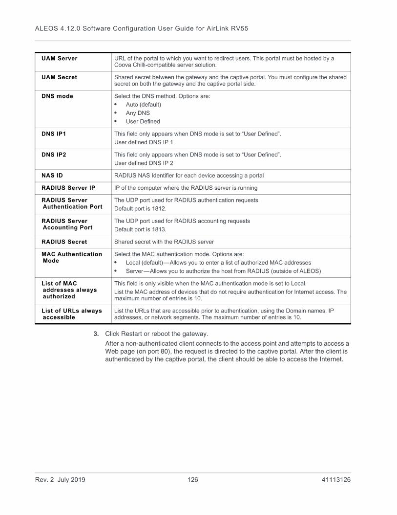
ALEOS 4.12.0 Software Configuration User Guide for AirLink RV55
3. Click Restart or reboot the gateway.
After a non-authenticated client connects to the access point and attempts to access a Web page (on port 80), the request is directed to the captive portal. After the client is authenticated by the captive portal, the client should be able to access the Internet.
UAM Server URL of the portal to which you want to redirect users. This portal must be hosted by a Coova Chilli-compatible server solution.
UAM Secret Shared secret between the gateway and the captive portal. You must configure the shared secret on both the gateway and the captive portal side.
DNS mode Select the DNS method. Options are:
• Auto (default)
• Any DNS
• User Defined
DNS IP1 This field only appears when DNS mode is set to “User Defined”.
User defined DNS IP 1
DNS IP2 This field only appears when DNS mode is set to “User Defined”.
User defined DNS IP 2
NAS ID RADIUS NAS Identifier for each device accessing a portal
RADIUS Server IP IP of the computer where the RADIUS server is running
RADIUS Server Authentication Port
The UDP port used for RADIUS authentication requests
Default port is 1812.
RADIUS Server Accounting Port
The UDP port used for RADIUS accounting requests
Default port is 1813.
RADIUS Secret Shared secret with the RADIUS server
MAC Authentication Mode
Select the MAC authentication mode. Options are:
• Local (default)—Allows you to enter a list of authorized MAC addresses
• Server—Allows you to authorize the host from RADIUS (outside of ALEOS)
List of MAC addresses always authorized
This field is only visible when the MAC authentication mode is set to Local.
List the MAC address of devices that do not require authentication for Internet access. The maximum number of entries is 10.
List of URLs always accessible
List the URLs that are accessible prior to authentication, using the Domain names, IP addresses, or network segments. The maximum number of entries is 10.
Rev. 2 July 2019 126 41113126
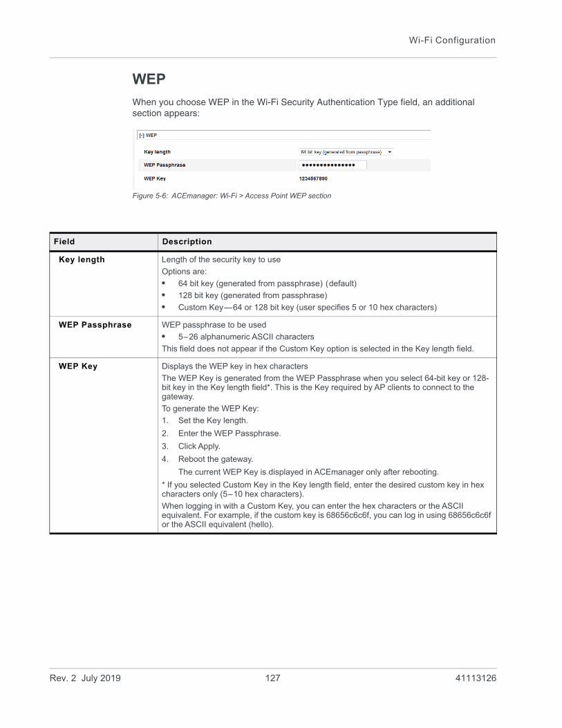
Wi-Fi Configuration
WEP
When you choose WEP in the Wi-Fi Security Authentication Type field, an additional section appears:
Figure 5-6: ACEmanager: Wi-Fi > Access Point WEP section
Field Description
Key length Length of the security key to use
Options are:
• 64 bit key (generated from passphrase) (default)
• 128 bit key (generated from passphrase)
• Custom Key—64 or 128 bit key (user specifies 5 or 10 hex characters)
WEP Passphrase WEP passphrase to be used
• 5–26 alphanumeric ASCII characters
This field does not appear if the Custom Key option is selected in the Key length field.
WEP Key Displays the WEP key in hex characters
The WEP Key is generated from the WEP Passphrase when you select 64-bit key or 128-bit key in the Key length field*. This is the Key required by AP clients to connect to the gateway.
To generate the WEP Key:
1. Set the Key length.
2. Enter the WEP Passphrase.
3. Click Apply.
4. Reboot the gateway.
The current WEP Key is displayed in ACEmanager only after rebooting.
* If you selected Custom Key in the Key length field, enter the desired custom key in hex characters only (5–10 hex characters).
When logging in with a Custom Key, you can enter the hex characters or the ASCII equivalent. For example, if the custom key is 68656c6c6f, you can log in using 68656c6c6f or the ASCII equivalent (hello).
Rev. 2 July 2019 127 41113126

ALEOS 4.12.0 Software Configuration User Guide for AirLink RV55
WPA/WPA2 Personal
If WPA Personal or WPA2 Personal are selected for the Wi-Fi Security Authentication Type field, a WPA/WPA2 Personal section appears.
Figure 5-7: ACEmanager: Wi-Fi > Access Point WPA/WPA2 security options
Field Description
WPA/WPA2 Personal
Wi-Fi Encryption Specify the encryption type for WPA or WPA2 authentication. Options are:
• AES (default)
• TKIP
WPA Passphrase Specify the WPA Passphrase AP clients use to connect to the gateway. Default: None.
The WPA Passphrase must be 8 to 64 characters long. It can include:
• Upper and lower case letters
• Numbers
• Spaces
• Special characters: ‘ - = [ ] \ ; ’ , . / ~ ! @ # $ % ^ & * ( ) _ + { } | : ”< > ?
Special characters used must also be supported by connected devices.
The WPA Passphrase is case-sensitive.
If your password is not at least 8 characters long, a warning message appears when you click Apply.
Enter a valid password, click an empty area on the page to remove the warning, and then click Apply again.
Rev. 2 July 2019 128 41113126

Wi-Fi Configuration
WPA2 Enterprise
If WPA2 Enterprise is selected for the Wi-Fi Security Authentication Type field, a WPA2 Enterprise section appears.
Network administrators can use WPA2 Enterprise to design network Authentication around their specific needs and policies, and to change or revoke access rights for individual users. WPA2 Enterprise uses RADIUS authentication.
Figure 5-8: ACEmanager: Wi-Fi > Access Point WPA2 Enterprise security options
Client (WAN) Mode
In Client Mode, the AirLink gateway acts as a Wi-Fi client and can connect to an access point. While connected, the Wi-Fi or WAN link is primarily an uplink for the AirLink gateway and all connected devices. All outbound traffic is routed over the Wi-Fi connection instead of the mobile broadband connection.
Client Mode has been tested with the top 5 WLAN Access Point vendors: Cisco®, Aruba Networks®, Motorola™, HP®, and NETGEAR®.
You can configure up to 10 Access Points for each AirLink gateway. Only one Access Point is used at a time for the client connection. Having additional APs configured allows for portability. Since the AirLink gateway generally runs unattended, it does not do a broadcast discovery to display all available APs in the area. You need to know the specific configuration details for the APs you want to configure in ACEmanager.
Field Description
WPA/WPA2 Enterprise
RADIUS Authentication Server IP Address
IP address for the RADIUS Authentication Server
RADIUS Authentication Server Port
RADIUS Authentication Server port number
Default is 1812
Shared Secret The shared secret is an ASCII string, typically up to 64 characters
RADIUS Accounting Server IP Address
IP address for the RADIUS Accounting Server
RADIUS Accounting Server Port
RADIUS Accounting Server port number
Default is 1812
Shared Secret The shared secret is an ASCII string, typically up to 64 characters
Rev. 2 July 2019 129 41113126

ALEOS 4.12.0 Software Configuration User Guide for AirLink RV55
Select Client Mode in the Wi-Fi Mode field, and in the left menu, select Client (WAN).
To configure Client (WAN) mode:
1. Select Client (WAN) from the drop-down menu in the Mode field.
2. Click Apply.
3. if you have not already done so, configure the General settings.
4. On the left menu, select Client (WAN), and select the desired Remote AP from the list in the left menu.
Note: Access Points that have already been configured have a dot beside them.
Figure 5-9: ACEmanager: Wi-Fi Client (WAN) Remote AP configuration
Rev. 2 July 2019 130 41113126

Wi-Fi Configuration
Field Description
Remote AP 1, Remote AP 2... Remote AP 10
Remote SSID(#) Use this field to configure the remote access point you want the AirLink gateway to be able to scan for and connect to. The gateway scans for available APs in the order they are configured in ACEmanager, so you may want to configure the most commonly used AP as Remote Wi-Fi AP 1.
For the Remote AP SSID, the gateway supports:
• Upper and lower case letters
• Numbers
• Spaces
• Special characters: ‘ - = [ ] \ ; ’ , . / ~ ! @ # $ % ^ & * ( ) _ + { } | : ”< > ?
Special characters used must also be supported by connected devices.
The SSID is case-sensitive.
Note: The configured parameters for the remote AP must be accurate. The AirLink gateway does not prompt if there is a mismatch.
2.4GHz Preference Select the 2.4GHz channels that the gateway uses for Wi-Fi. The RV55 will scan and associate to the Access Points that are operating on the specified channels and frequencies.
The options are:
• Not Preferred—The RV55 will only connect to an Access Point operating on 2.4 GHz channels if an Access Point operating on 5GHz channels is not available.
• All 2.4GHz Channels
• Specific 2.4GHz Channels
Note: Setting both 2.4GHz and 5GHz Preference fields to Not Preferred will create an Invalid Configuration file. The Wi-Fi Client will fail to associate to a Remote Access Point.
Specific 2.4GHz Channels
When Specific 2.4GHz Channels is selected under 2.4GHz Preferences, the Specific 2.4GHz Channels field appears.
Enter the desired 2.4GHz channels as a comma-delimited list; for example, 1,6,11.
Note: Enter only channels that the RV55 supports. These channels are listed under the Channel, Frequency, Width and Channel and Frequency settings. If you enter unsupported channels or channels that are excluded by your Country Code settings, these channels will not take effect. See also The Wi-Fi channel I selected is not working.
Rev. 2 July 2019 131 41113126
ALEOS 4.12.0 Software Configuration User Guide for AirLink RV55
5GHz Preference Select the 5GHz channels that the gateway uses for Wi-Fi. The RV55 will only scan and associate to the Access Points that are operating on the specified channels and frequencies.
The options are:
• Not Preferred—The RV55 will only connect to an Access Point operating on 5GHz channels if an Access Point operating on 2.4GHz channels is not available.
• All 5GHz Channels
• Specific 5GHz Channels
Note: Setting both 2.4GHz and 5GHz Preference fields to Not Preferred will create an Invalid Configuration file. The Wi-Fi Client will fail to associate to a Remote Access Point.
Specific 5GHz Channels
When Specific 5GHz Channels is selected under 5GHz Preferences, the Specific 5GHz Channels field appears.
Enter the desired 5GHz channels as a comma-delimited list; for example, 36,40,149.
Note: Enter only channels that the RV55 supports. These are listed under the Channel, Frequency, Width and Channel and Frequency settings. If you enter unsupported channels or channels that are excluded by your Country Code settings, these channels will not take effect. See also The Wi-Fi channel I selected is not working.
Security Authentication Type
Use this field to configure the authentication type used by the access point. Options are:
• Open—No authentication is needed when this option is selected. Connecting to an Open (no authentication) AP is generally not recommended. (default)
• WEP—Connecting to a WEP AP is generally not recommended since it offers very low authentication/encryption.
• WPA/WPA2 Personal
• WPA2 Enterprise
Note: If the Access Point requires a secondary authentication through a landing page, the gateway cannot enter those credentials. This type of AP may not allow full functionality for the gateway or devices connected to the AirLink gateway.
802.11w support Enable 802.11w operation. The 802.11w standard uses Security Association Query Requests to ensure that clients are legitimate.
Options are:
• Optional (default)
• Required
• Disabled
By default, 802.11w works with devices that support it. When Optional is selected, devices that support 802.11w will be protected, while other devices will still connect to the router.
Select Required to force 802.11w operation. The router will reject unsupported clients and access points.
The remaining fields depend on the option chosen in the Remote AP Security Authentication Type field.
Field Description
Rev. 2 July 2019 132 41113126

Wi-Fi Configuration
WEP
Client Password—Enter a WEP password. The WEP password must be 8 to 125 characters long. It can include:
• Upper and lower case letters
• Numbers
• Spaces
• Special characters: ‘ - = [ ] \ ; ’ , . / ~ ! @ # $ % ^ & * ( ) _ + { } | : ”< > ?
Special characters used must also be supported by connected devices.
The WEP password is case-sensitive.
If your password is not at least 8 characters long, a warning message appears when you click Apply.
Enter a valid password, click an empty area on the page to remove the warning, and then click Apply again.
WPA/WPA2 Personal
Client Password—Enter a WPA password. The WPA password must be 8 to 125 characters long. It can include:
• Upper and lower case letters
• Numbers
• Spaces
• Special characters: ‘ - = [ ] \ ; ’ , . / ~ ! @ # $ % ^ & * ( ) _ + { } | : ”< > ?
Special characters used must also be supported by connected devices.
The WPA password is case-sensitive.
If your password is not at least 8 characters long, a warning message appears when you click Apply.
Enter a valid password, click an empty area on the page to remove the warning, and then click Apply again.
WPA2 Enterprise
Authentication Type Select either:
• EAP-TLS—Extensible Authentication Protocol-Transport Layer Security
• PEAP—Protected Extensible Authentication Protocol
Field Description
Rev. 2 July 2019 133 41113126

ALEOS 4.12.0 Software Configuration User Guide for AirLink RV55
Authentication Type If you select EAP-TLS, the following fields appear:
• Client EAP Identity—Enter the Extensible Authentication Protocol (EAP) Identity. The Client EAP Identity is an ASCII string.
• Client CA Certificate—Click the Client CA Certification button, navigate to the certif-icate file and click Upload file.
• Currently Installed Client CA Certificate—Status field shows the current Client CA Certificate file name.
• Client Certificate—Click the Client Certification button, navigate to the certificate file and click Upload file.
• Currently Installed Client Certificate—Status field shows the current Client Certificate file name.
• Client Private Key— Click the Client Private Key button, navigate to the desired file and click Upload file.
• Currently Installed Client Private Key—Status field shows the current Client Private Key.
• Client Private Key Password—Enter the Private Key password. The Client Private Key Password is an ASCII string.
Note: The certificate and certificate key must meet the following conditions:
• The certificate must be an X.509 certificate
• The certificate and the private key must be in .pem format, and they must be in separate files.
• There is no limit to the size of the private key, but the larger the key, the more the performance is affected. Sierra Wireless recommends that the key does not exceed 2048 bits.
Note: The RV55 supports pre-defined cipher suites using 128-bit cipher algorithms.
Field Description
Rev. 2 July 2019 134 41113126

Wi-Fi Configuration
If you select PEAP, the following fields appear:
• Access Point Certificate—Select whether to use PEAP Authentication with or without a Client CA Certificate. By default, using the certificate is required (and the Client CA Certificate must be installed).
Note: If you select Not Used and click Apply, you must accept a warning that this configuration may put your system at risk.
• Client EAP Identity—Enter the Extensible Authentication Protocol (EAP) Identity. The Client EAP Identity is an ASCII string.
• Client EAP Password—Enter the EAP password.
• Client CA Certificate—Click the Client CA Certification button, navigate to the certif-icate file and click Upload file.
• Currently Installed Client CA Certificate—Status field shows the current Client CA Certificate file name.
Note: The certificate and certificate key must meet the following conditions:
• The certificate must be an X.509 certificate
• The certificate and the private key must be in .pem format, and they must be in separate files.
• There is no limit to the size of the private key, but the larger the key, the more the performance is affected. Sierra Wireless recommends that the key does not exceed 2048 bits.
Note: The RV55 supports pre-defined cipher suites using 128-bit cipher algorithms.
Field Description
Rev. 2 July 2019 135 41113126
6
6: LAN ConfigurationYou can use the AirLink RV55 to route data between one or more connected devices and the Internet via the mobile network.
Port Use
Applications running on a LAN client such as a router or laptop must use different ports from those used by ALEOS features on the AirLink RV55. For a list of inbound ports used by ALEOS, see Inbound Ports Used by ALEOS on page 544.
DHCP/Addressing
This page governs the DHCP and addressing for all interfaces.
The LAN Address Summary is a display of the IP addresses assigned to interfaces on their respective configuration pages. To change the addressing for the Ethernet interface, go to the Ethernet side menu. To change the addressing for the USBnet interface, go to the USB side menu.
Rev. 2 July 2019 136 41113126
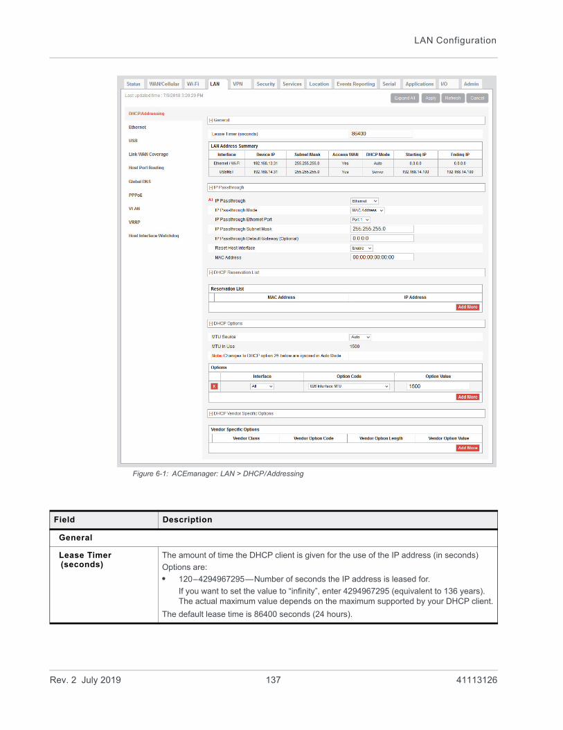
LAN Configuration
Figure 6-1: ACEmanager: LAN > DHCP/Addressing
Field Description
General
Lease Timer (seconds)
The amount of time the DHCP client is given for the use of the IP address (in seconds)
Options are:
• 120–4294967295—Number of seconds the IP address is leased for.
If you want to set the value to “infinity”, enter 4294967295 (equivalent to 136 years). The actual maximum value depends on the maximum supported by your DHCP client.
The default lease time is 86400 seconds (24 hours).
Rev. 2 July 2019 137 41113126
ALEOS 4.12.0 Software Configuration User Guide for AirLink RV55
LAN Address Summary
Displays the interfaces which have been enabled. By default, only the Ethernet and USBNET Interfaces are enabled.
This table also includes VLAN if configured and Wi-Fi if it is configured as Access Point (LAN) and not bridged to Ethernet.
Interface The physical interface port or VLAN ID
If Wi-Fi is bridged to Ethernet, “Ethernet/Wi-Fi” is displayed.
Device IP The IP address of the AirLink gateway for the specified interface port. By default, this is set to 192.168.13.31 for Ethernet,192.168.17.31 for Wi-Fi, and 192.168.14.31 for USB/net.
Subnet Mask Subnet mask indicates the range of device IP addresses that can be reached directly. Changing this limits or expands the number of clients that can connect to the AirLink gateway. The default of 255.255.255.0 means that 253 IP addresses can connect to the AirLink gateway. Uses 192.168.13. as the first three octets of the IP address if the gateway IP is 192.168.13.31.
Note: Do not use the same IP addresses/subnet mask for WAN and LAN connections. For example, you cannot have 192.168.13.0/24 as a LAN subnet if the WAN the gateway is connecting to is using 192.168.13.0/24.
Access WAN Appears if the interface is configured to allow connected device(s) access to the Internet
Note: Internet access cannot be disabled for Ethernet or Wi-Fi hosts.
DHCP Mode Indicates whether or not the interface has a DHCP server enabled to provide dynamically allocated IP addresses provided to connected devices
Note: The DHCP server can only be disabled for Ethernet and VLAN.
Starting IP Ethernet DHCP pool starting IP address (DHCP low address)
Ending IP The ending IP for the interface (DHCP high address). If the starting and ending IP are the same, there is a single address in the pool and only one connected device receives an IP address from the DHCP server for that interface. Some interfaces, such as USB, can only have a single device connection. For others, statically assigned IP addresses in the same subnet, but outside of the DHCP pool, can still connect and use the gateway in the same way as a DHCP connected device.
IP Passthrough
In IP Passthrough mode, the AirLink gateway passes the WAN IP address to the selected LAN interface or device.
Note: IP Passthrough is only available on the WAN cellular interface.
IP Passthrough Select the interface that will be used for IP passthrough. Options are:
• Disabled—Private IP addresses are used (default)
• Ethernet—Ethernet interface is used for IP passthrough
• USB—USB interface is used for IP passthrough
• Serial DUN—Serial DUN interface is used for IP passthrough
Field Description
Rev. 2 July 2019 138 41113126
LAN Configuration
IP Passthrough Mode Choose the IP passthrough mode. Options are:
• First Host—The first connected device gets the WAN IP. Subsequent devices do not receive an IP address. (default)
• MAC Address—The device with the configured MAC address gets the WAN IP. Subsequent devices use the private IP address corresponding to the interface configured in IP Passthrough.
IP Passthrough Subnet Mask
Enter the IP passthrough subnet mask. This field does not appear when IP Passthrough is set to Serial DUN.
The default setting is 255.255.255.0
IP Passthrough Default Gateway (Optional)
Configure the address of the IP passthrough default gateway.
The default setting is 0.0.0.0
Reset Host Interface When this option is enabled, the host interface is reset when the device gets a new WAN IP. Options are:
• Enable (default)
• Disable
MAC Address When IP Passthrough Mode is set to MAC Address, enter the MAC address of the device that you want to receive the WAN IP.
DHCP Reservation List
Reservation List Use this list to reserve IP addresses for up to 20 connected devices, based on their MAC addresses. This feature is useful if you have multiple connected devices behind the AirLink gateway where you need to use DHCP addressing and also need to assign a specific IP addresses to some devices.
To reserve an IP address:
1. Click Add More.
2. Complete the MAC Address and IP Address fields.
The device does not need to be connected when you complete these fields.
3. Click Apply.
To delete a reserved IP address, click the X beside the reserved IP address.
Note:
• A reserved IP address must be from a private subnet configured for the applicable interface. For example, 192.168.13.10 for an Ethernet connected device.
• When Host Connection Mode is set to Public for a particular interface, the DHCP reservations for that interface are overridden. Any device connected to the specified interface (and port for Ethernet) receives the public IP. Any other device connected to the same interface type does not receive any IP from DHCP.
• The reservation list supports Ethernet and Wi-Fi hosts.
• If Wi-Fi Bridge to Ethernet mode is enabled, you can reserve an IP address for a Wi-Fi connected device in the Ethernet range only.
MAC Address Enter the MAC address of the device you want to reserve an IP address for.
IP Address Enter the IP address you want to reserve for the device.
Field Description
Rev. 2 July 2019 139 41113126

ALEOS 4.12.0 Software Configuration User Guide for AirLink RV55
DHCP Options
Enables IT Administrators to configure up to 10 DHCP options, allowing you to push DHCP options to connected devices.
Interface Select the interface to use:
• All (default)
• Ethernet
• USB
• Wi-Fi (only available for RV55 with Wi-Fi)
Note: VLAN hosts only receive the DHCP options when the Interface is set to All.
MTU Source Use this field to select where the Maximum Transmit Unit (MTU) value for LAN and Wi-Fi clients is obtained. Options are:
• Auto—The MTU value distributed to clients is obtained from the radio module. This option ensures that all interfaces use the same MTU as the radio module. (default)
When Auto is selected in this field, the MTU value configured for Option Code 026 Interface MTU is ignored.
• Manual—The MTU value configured for the Option Code 026 Interface MTU is distributed to clients.
Note: If you are using a new SIM card for the first time, Auto MTU takes effect after the second reboot.
MTU in Use This field only appears when MTU Source is set to Auto.
Displays the Maximum Transmit Unit (MTU) value (from the radio module) being distributed to clients
Option Code Choose from the options in the drop-down menu. For a list of supported Option Codes, see Table 6-1. For additional information on the option codes, refer to the Internet Engineering Task Force (IETF) memorandum on Internet Protocols and Standards, RFC-2131.
Note: When MTU Source is set to Auto, the MTU value configured for Option Code 026 Interface MTU is ignored.
Option Value The format for the option value depends on the Option Code selected, as formats must conform with RFC 2132. For a list of accepted formats for each of the supported DHCP Option Codes, see Table 6-1.
Use a comma to separate multiple values.
DHCP Vendor Specific Options
Enables IT Administrators to configure up to 5 vendor-specific options
Vendor Class Enter the vendor class
Vendor Option Code Enter the vendor option code. Possible entries are:
• 0–255
Field Description
Rev. 2 July 2019 140 41113126
LAN Configuration
Vendor Option Length This field allows you to specify the DHCP vendor specific option length in order to ensure that the DHCP datagram is correctly formatted for the DHCP client. Options are:
• Undefined— Use this setting for IP addresses and strings (default)
• 1 byte—Use for decimal values of 255 or less
• 2 bytes—Use for decimal values between 256 and 65535
• 4 bytes—Use for decimal values greater than 65535
Note: If the size used for the data is not correct, the option is ignored by the client.
Vendor Option Value Enter the vendor option value in one of the following formats:
• Dotted-quad IPv4 address
• Decimal number
• Colon-separated hex digits
• Text string
Use a comma to separate multiple values.
Field Description
Table 6-1: Supported DHCP Options
DHCP Option Type of entry Accepted values (if applicable)
002 Time Offset 32-bit unsigned integer -43200–43200a
003 Router 1 or more IP addresses
007 Log Server 1 or more IP addresses
009 LPR Server 1 or more IP addresses
013 Boot File Size 16-bit unsigned integer 1–65535
015 Domain Name Fully Qualified Domain Name (FQDN)
016 Swap Server 1 or more IP addresses
017 Root Path ASCII string
018 Extension Path ASCII string
019 IP Forward Enable/Disable Single octet Boolean 0 (Disable) or 1 (Enable)
020 Non-Local Source Routing Single octet Boolean 0 (Disable) or 1 (Enable)
021 Policy Filter 1 or more pairs of IP addresses or IP address/mask pairs
022 Max Datagram Reassembly Size 16-bit unsigned integer 576–65535
023 IP TTL 8-bit unsigned integer 1–255
026 Interface MTU 16-bit unsigned integer 68–65535 (Default is 1500.)
027 All Subnets Are Local Single octet Boolean 0 (Disable) or 1 (Enable)
Rev. 2 July 2019 141 41113126

ALEOS 4.12.0 Software Configuration User Guide for AirLink RV55
031 Perform Router Discovery Single octet Boolean 0 (Disable) or 1 (Enable)
032 Router Solicitation Address Single IP address
034 Trailer Encapsulation Single octet Boolean 0 (Disable) or 1 (Enable)
035 ARP Timeout 32-bit unsigned integer 6–65535
036 Ethernet Encapsulation Single octet Boolean 0 (Disable) or 1 (Enable)
037 TCP TTL 8-bit unsigned integer 1–255
038 TCP Keepalive 32-bit unsigned integer 0–65535
040 NIS Domain ASCII string Domain name
041 NIS Server Single IP address
042 NTP Server Single IP address
044 NetBIOS Name Server 1 or more IP addresses
045 NetBIOS Datagram Distribution Server 1 or more IP addresses
046 NetBIOS Node Type 8-bit unsigned integer 1, 2, 4, or 8
047 NetBIOS Scope ASCII string
048 X Windows System Font Server 1 or more IP addresses
049 X Windows System Display Manager 1 or more IP addresses
064 NIS+ Domain Domain name
065 NIS+ Server Single IP address
066 TFTP Server ASCII string or IP address Name, domain name, or IP address
067 Bootfile Name ASCII string Name
068 Mobile IP Home 1 or more IP addresses
069 SMTP Server 1 or more IP addresses
070 POP3 Server 1 or more IP addresses
071 NNTP Server 1 or more IP addresses
074 IRC Server 1 or more IP addresses
a. The time offset is entered as seconds. See Table 6-2 for a list of hour/second conversions.
Table 6-1: Supported DHCP Options
DHCP Option Type of entry Accepted values (if applicable)
Rev. 2 July 2019 142 41113126
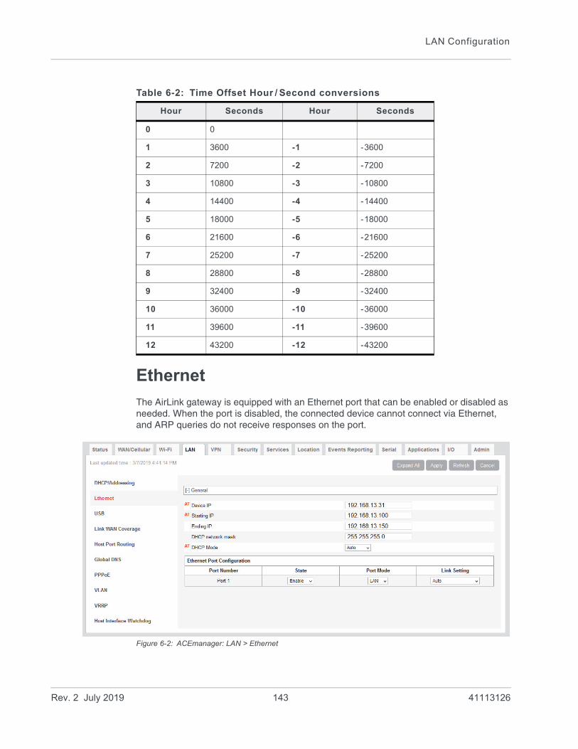
LAN Configuration
Ethernet
The AirLink gateway is equipped with an Ethernet port that can be enabled or disabled as needed. When the port is disabled, the connected device cannot connect via Ethernet, and ARP queries do not receive responses on the port.
Figure 6-2: ACEmanager: LAN > Ethernet
Table 6-2: Time Offset Hour / Second conversions
Hour Seconds Hour Seconds
0 0
1 3600 -1 -3600
2 7200 -2 -7200
3 10800 -3 -10800
4 14400 -4 -14400
5 18000 -5 -18000
6 21600 -6 -21600
7 25200 -7 -25200
8 28800 -8 -28800
9 32400 -9 -32400
10 36000 -10 -36000
11 39600 -11 -39600
12 43200 -12 -43200
Rev. 2 July 2019 143 41113126

ALEOS 4.12.0 Software Configuration User Guide for AirLink RV55
Field Description
General
Device IP The Ethernet IP address of the AirLink gateway. By default this is set to 192.168.13.31.
Starting IP Ethernet DHCP pool starting IP address
Default is 192.168.13.100.
Note: If only one computer or device is connected directly to the Ethernet port, this is the IP address it is assigned.
Ending IP The ending IP address for the Ethernet interface DHCP pool
Default is 192.168.13.150.
DHCP network mask The Netmask given to any Ethernet DHCP client
Default is 255.255.255.0.
DHCP Mode Determines how DHCP operates on the Ethernet interface
Options are:
• Server—The AirLink gateway acts as a DHCP server for all Ethernet connections.
• Disable—The AirLink gateway acts as neither a DHCP server or client. All devices connected to the AirLink gateway must have a static LAN IP or use PPPoE.
Auto—When the gateway is powered on or reboots, it attempts to determine if a DHCP server is present on the Ethernet network. If a DHCP server is found, the gateway obtains an IP address and it can communicate with AirLink Management Service (ALMS). If a DHCP server is not found, the gateway becomes a DHCP server. (default)
When using Auto DHCP, set the Ethernet port as Auto or LAN (not WAN). See Mode on page 145.
For a full-featured auto DHCP, see Ethernet WAN Auto Mode.
Most of the time you can leave this field set to the default value.
Ethernet Port Configuration
Port Number Ethernet Port number
The number of Ethernet ports available varies depending on the gateway.
State State of the Ethernet Port (Enable or Disable)
Note: When the port is disabled, the device ignores any physical connection to the Ethernet port.
Rev. 2 July 2019 144 41113126

LAN Configuration
RADIUS Framed Route
If you have a private APN that is authenticated with a unique user name and password through a RADIUS authentication server, Framed Route enables you to associate a pool of IP address (for example a /24 subnet) with that user name, effectively creating a remote branch of a private corporate network. Refer to the RADIUS specifications for more details.
For an AirLink gateway to work effectively with Framed Route, set the following two fields on the LAN > Ethernet screen to “Enable”:• Accept Unsolicited Traffic—Enabling this field allows a device on the corporate
network to dial out to a device connected on the LAN side of the AirLink gateway.• Turn Off NAT—Enabling this field allows traffic from the LAN side of the AirLink
gateway to flow back to the corporate network.
Mode You can set the following modes on the Ethernet port:
• Auto— When the gateway is powered on or reboots, it attempts to determine if a DHCP server is present on the Ethernet network. If a DHCP server is found, the gateway obtains an IP address from the DHCP server, and all four Ethernet ports act as a bridged WAN connection. If no DHCP server is found, the ports act as a bridged LAN connection. (default)
• LAN—The Ethernet port acts as a LAN connection.
WAN—Port is used as a WAN connection. Any security settings configured on the gateway, such as DMZ, IP filters, and port forwarding rules apply to this WAN connection.
Link Setting Configures the Ethernet port speed and duplex setting
Most of the time you can leave the default setting and the device you are connecting automatically negotiates the speed and duplex setting with the AirLink gateway. However, if the connected device has a fixed setting, use this field to change the AirLink gateway setting to match that of the connected device.
Note: If you select 100 Mb Full Duplex or 10 Mb Full Duplex for the gateway, ensure that the same speed is selected on the connected device.
The options are:
• Auto—(default) The gateway auto-negotiates with the connected device to use the fastest speed possible—10 Mb, 100 Mb, or 1000 Mb. For best results, ensure that the connected device is also set to auto-negotiation.
If your highest priority is power saving, select one of the 100 Mb or 10 Mb settings.
• 100 Mb Full Duplex
• 100 Mb Half Duplex
• 10 Mb Full Duplex
• 10 Mb Half Duplex
You can view the current speed and duplex setting on the Status > Ethernet page. See page 47.
Field Description
Rev. 2 July 2019 145 41113126

ALEOS 4.12.0 Software Configuration User Guide for AirLink RV55
USB
The AirLink gateway is equipped with a USB port that increases the methods by which you can send and receive data from a connected computer. You can set up the USB port to work as either a virtual Ethernet port or a virtual serial port, or you can disable it to prevent access by USB. You may need to install a USB driver to use these modes. For more information, see Installing the USB Drivers on page 147.
By default, the port is set to work as a virtual Ethernet port.
Note: Sierra Wireless recommends that you use a USB 2.0 cable with your AirLink gateway and connect directly to your computer for best throughput.
To change the USB port to allow virtual serial port communication:
1. In ACEmanager, go to LAN > USB, and choose USB Serial as the USB Device Mode.
To disable the USB port, select Disable from the same menu.
Figure 6-3: ACEmanager: LAN > USB
Field Description
General
USB Device Mode The USB mode on gateway startup
• USB Serial—USB port acts as a virtual Serial port.
• USBNET—USB port acts as a virtual Ethernet port. (default)
• Disabled—USB port is disabled.
You can also configure this parameter using the AT Command *USBDEVICE. See *USBDEVICE on page 477.
Note: A reboot is required to activate the USB mode change.
Rev. 2 July 2019 146 41113126

LAN Configuration
Installing the USB Drivers
A USB driver is required if you want to use the USB port on the gateway as a virtual serial port (USB Serial). If you want to use the USB port as a virtual Ethernet port (USBnet), a driver is not required as the default Microsoft Windows 7 and Windows 8 drivers are used.
To install the USB Serial drivers for Windows 7 and Windows 8:
1. Go to source.sierrawireless.com and download the USB Serial Driver One-Click Tool.
2. Double-click the downloaded file (AirLink_Serial_<version number>.exe).
3. As the drivers installs, a progress box appears in the lower right-hand corner of the monitor.
Figure 6-4: USB Serial One-Click Tool progress window
4. In ACEmanager, go to LAN > Ethernet and set the USB Device Mode field to USB Serial.
5. Connect a gateway to the computer using a USB cable.
The driver installation completes and a window opens indicating the Serial Port number.
USB Serial Mode When USB Device Mode is set to USB Serial, select the USB Serial Mode. Options are:
• AT (default)
• PPP
Device USB IP The USBNET IP address of the AirLink gateway. By default this is set to 192.168.14.31.
Host USB IP The IP for the computer or device connected to the USB port
USB Network Mask Use this field to configure a subnet mask for USBNET
Default is 255.255.255.0
USB Serial Echo The AT command echo mode when the USB is configured as a virtual serial port
Options:
• Enable—Echoes commands to the computer (so you can see what you type) (default)
• Disable—Does not echoes commands to the computer (you cannot see what you type)
USBNET Host WAN Connectivity
Controls access to the WAN over the USB port
Options are:
• Enable—USB can be used to access the WAN (default)
• Disable—Access to the WAN over USB is blocked.
Field Description
Rev. 2 July 2019 147 41113126
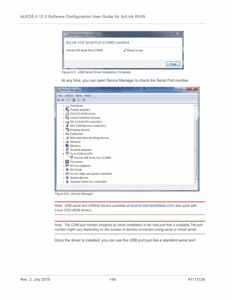
ALEOS 4.12.0 Software Configuration User Guide for AirLink RV55
Figure 6-5: USB Serial Driver Installation Complete
At any time, you can open Device Manager to check the Serial Port number.
Figure 6-6: Device Manager
Note: USB serial and USBnet drivers available at source.sierrawireless.com also work with Linux CDC-ACM drivers.
Note: The COM port number assigned by driver installation is the next port that is available.The port number might vary depending on the number of devices connected (using serial or virtual serial).
Once the driver is installed, you can use the USB port just like a standard serial port.
Rev. 2 July 2019 148 41113126

LAN Configuration
Link WAN Coverage
You can link WAN coverage to a selected LAN port (Ethernet or USB). If the AirLink gateway loses WAN coverage, the selected port is disabled for a configurable duration.
Figure 6-7: ACEmanager: LAN > Link WAN Coverage
Field Description
General
Link WAN coverage to Interface
This disables the specified port when there is no WAN connection. Options are:
• Disable (default)
• Ethernet
• USB
Interface Disabled Duration
Sets the period of time (in seconds) that the LAN interface is disabled when linking a LAN port to the WAN. Either the Ethernet or the USB LAN port can be linked to the WAN connection, but not at the same time. Options are:
• Interface Disabled when WAN is disconnected (default)
• 5 seconds
• 10 seconds
• 15 seconds
• 20 seconds
• 25 seconds
• 30 seconds
Rev. 2 July 2019 149 41113126
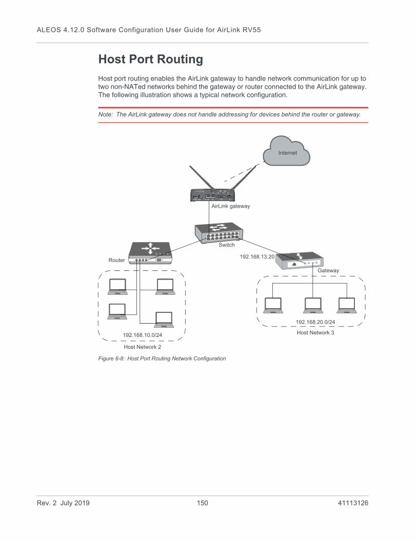
ALEOS 4.12.0 Software Configuration User Guide for AirLink RV55
Host Port Routing
Host port routing enables the AirLink gateway to handle network communication for up to two non-NATed networks behind the gateway or router connected to the AirLink gateway. The following illustration shows a typical network configuration.
Note: The AirLink gateway does not handle addressing for devices behind the router or gateway.
Figure 6-8: Host Port Routing Network Configuration
192.168.13.20
192.168.20.0/24
192.168.10.0/24
Internet
AirLink gateway
Switch
Gateway
Router
Host Network 2
Host Network 3
Rev. 2 July 2019 150 41113126

LAN Configuration
Figure 6-9: ACEmanager: LAN > Host Port Routing
Field Description
Proxy ARP (Primary Gateway)
When enabled, the AirLink gateway responds to Address Resolution Protocol (ARP) requests to resolve WAN addresses for devices on the connected LANs. In doing so, the gateway becomes the primary gateway for connected LANs.
Default is Enabled.
Host Network 2Host Network 3
Enter the IP address for Host Network 2 and 3. These are LAN networks connected to the AirLink gateway behind a router or gateway. They do not have the same IP range as the AirLink gateway LAN network. For example, 192.168.10.0.
Host Network Subnet Mask 2Host Network Subnet Mask 3
The subnet for the applicable network. For example, 255.255.255.0, which would with the setting above define a secondary network of 192.168.10.0/24.
Rev. 2 July 2019 151 41113126
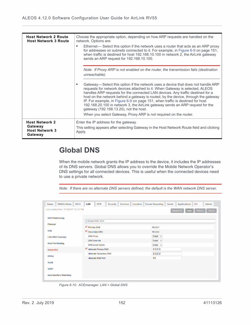
ALEOS 4.12.0 Software Configuration User Guide for AirLink RV55
Global DNS
When the mobile network grants the IP address to the device, it includes the IP addresses of its DNS servers. Global DNS allows you to override the Mobile Network Operator’s DNS settings for all connected devices. This is useful when the connected devices need to use a private network.
Note: If there are no alternate DNS servers defined, the default is the WAN network DNS server.
Figure 6-10: ACEmanager: LAN > Global DNS
Host Network 2 RouteHost Network 3 Route
Choose the appropriate option, depending on how ARP requests are handled on the network. Options are:
• Ethernet— Select this option if the network uses a router that acts as an ARP proxy for addresses on subnets connected to it. For example, in Figure 6-9 on page 151, when traffic is destined for host 192.168.10.100 in network 2, the AirLink gateway sends an ARP request for 192.168.10.100.
Note: If Proxy ARP is not enabled on the router, the transmission fails (destination unreachable).
• Gateway—Select this option if the network uses a device that does not handle ARP requests for network devices attached to it. When Gateway is selected, ALEOS handles ARP requests for the connected LAN devices. Any traffic destined for a host on the network behind a gateway is routed, by the device, through the gateway IP. For example, in Figure 6-9 on page 151, when traffic is destined for host 192.168.20.100 in network 3, the AirLink gateway sends an ARP request for the gateway (192.168.13.20), not the host.
When you select Gateway, Proxy ARP is not required on the router.
Host Network 2 GatewayHost Network 3 Gateway
Enter the IP address for the gateway.
This setting appears after selecting Gateway in the Host Network Route field and clicking Apply.
Rev. 2 July 2019 152 41113126
LAN Configuration
Field Description
Primary DNS Primary Mobile Network Operator’s DNS IP Address. This and the secondary DNS are generally granted by the mobile network along with the Network IP.
Secondary DNS Secondary Mobile Network Operator’s DNS IP Address
DNS Proxy Determines whether or not the AirLink gateway is used as a DNS proxy server.
Note: Using the AirLink gateway as a proxy DNS server can help reduce mobile network data use.
Options are:
• Enable (default) —All connected DHCP clients (PPP, PPPoE, Wi-Fi, USBNET, and Ethernet) send their DNS IP address resolution requests to the AirLink gateway. The AirLink gateway performs DNS lookups on behalf of the DHCP client.
• If the AirLink gateway is able to resolve the request, it sends a response to the DHCP client.
• If the AirLink gateway does not have the necessary information to resolve the request, it sends the request to the DNS server configured in the DNS Override field. When the AirLink gateway receives a response, it forwards it to the DHCP client and saves the information so that it can resolve the same request in the future.
• Disable—All connected DHCP clients send their DNS IP address resolution requests to the DNS server received from the mobile network or the alternate server specified by DNS Override, if enabled. The AirLink gateway is not used as a DNS server.
DNS Override Overrides the Mobile Network Operator’s DNS address with the DNS server configured in the Alternate Primary DNS and Alternate Secondary DNS fields.
Options are:
• Disable (default)—Mobile Network Operator’s DNS server is used
• Enable—Alternate DNS server is used
In order to ensure consistent DNS resolution, DNS override, when configured, applies to all WAN interfaces, including Ethernet WAN with static IP configuration. (See Static Configuration on page 98.)
DNS Local Cache Configures caching for the gateway’s DNS server.
Options are:
• Enable—The built-in DNS server caches queries and entries, which can reduce WAN traffic overall by sending out less DNS-related traffic.
• Disable—DNS queries and entries are not cached.
Alternate Primary DNS
Configure the primary DNS server to use instead of the Mobile Network Operator’s DNS server
Rev. 2 July 2019 153 41113126

ALEOS 4.12.0 Software Configuration User Guide for AirLink RV55
R
PPPOE
PPPoE (Point-to-Point Protocol over Ethernet) allows a point-to-point connection while using Ethernet. Just like the dial up protocol on which it is based, PPPoE can use traditional user name and password authentication to establish a direct connection between two Ethernet devices on a network (e.g., your AirLink gateway and your computer or router).
examples for PPPoE with your AirLink gateway: • Backup connectivity solution for your network• Individualized Internet connection on a LAN• Password restricted Internet connection
Only one computer, router, or other network device at a time can connect to the AirLink gateway using PPPoE. If you are using the AirLink gateway connected to a router as a back up Internet connection for your network, you should configure the router to use the PPPoE connection and not the individual computers.
Note: To configure a PPPoE connection on some operating systems, you need adminis-trator privileges to the computer you are configuring or access granted by an administrator on the network to add/remove devices to your computer.
Alternate Secondary DNS
Configure the secondary DNS server to use instead of the Mobile Network Operator’s DNS server
Alternate DNS Port If you want to specify the port on the connected device that the AirLink gateway sends IP address resolution responses to:
1. Ensure that the DNS Override field is set to Enable.
2. Enter the desired port number in this field.
3. Click Apply.
When this field is set to 53 (default) or 0, packets are sent to port 53, the standard DNS port.
Field Description
ev. 2 July 2019 154 41113126

LAN Configuration
Figure 6-11: ACEmanager: LAN > PPPoE
Configure the AirLink gateway to Support PPPoE
Note: You must disable the DHCP server for PPPoE to work.
To configure an AirLink gateway to support PPPoE:
1. In ACEmanager, go to LAN > Ethernet.
2. Under General, in the DHCP Server Mode field, select Disable.
Note: PPPoE authentication is optional. If you use PPPoE authentication, no other tethered LAN connection will have network access, regardless of whether or not the PPPoE host is connected. If you are using non-authenticated PPPoE, other tethered LAN connections will have network access until a PPPoE host is connected.
Field Description
Host Authentication Mode
Host Authentication Mode: Use PAP or CHAP to request the user login and password during PPP or CHAP negotiation on the host connection. The username and password set in *HOSTUID and *HOSTPW is used.
• NONE (default)
• PAP and CHAP
• CHAP
Host User ID User ID for authentication (up to 64 bytes)
Host Password Password for authentication
Rev. 2 July 2019 155 41113126

ALEOS 4.12.0 Software Configuration User Guide for AirLink RV55
3. If you want to use authenticated PPPoE:
a. Go to LAN > PPPoE, and in the Host Authentication Mode field, select PAP and CHAP.
b. In the Host User ID, enter a user ID for the PPPoE connection.
c. In the Host Password field, enter a password for the PPPoE to connection.
4. Click Apply.
5. Reboot the gateway.
Tip: If you leave Host User ID and Host Password blank, any computer or device can connect to the AirLink gateway using PPPoE.
Note: ACEmanager shows the existing value for the PPPoE password as stars (****).
Optional: Configure the Device Name
1. In ACEmanager, go to Services > Dynamic DNS.
2. In the Service field, select IP Manager.
3. Under Dynamic IP, enter a name in the Device Name field, such as AirLink gateway or the ESN. The name can be up to 20 characters long.
The name you choose for Device Name does not affect the connection, but may need to be configured in PPPoE settings for the router, device, or computer you connect to your AirLink gateway.
Configuring a PPPoE Connection in Windows 7
1. In Windows 7, go to Start > Control Panel.
Figure 6-12: Windows 7: Control Panel
2. Select Network and Internet.
Rev. 2 July 2019 156 41113126
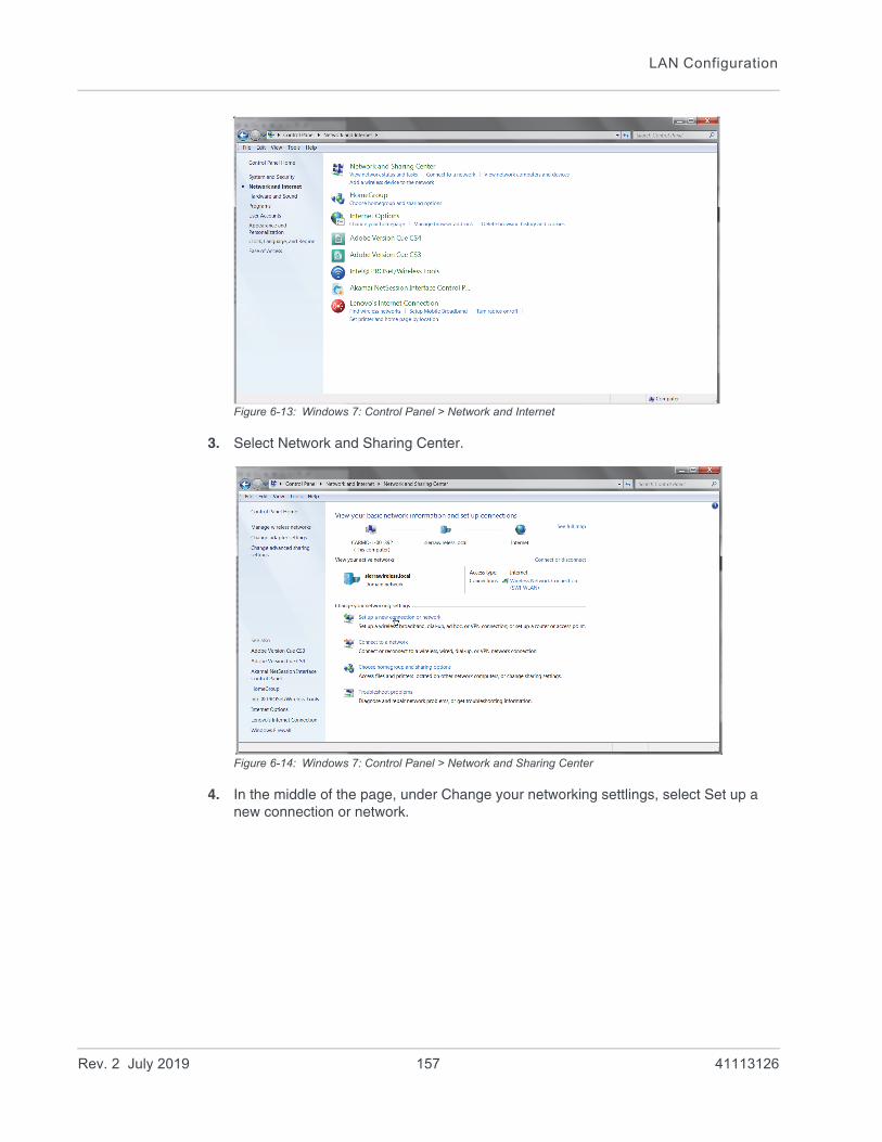
LAN Configuration
Figure 6-13: Windows 7: Control Panel > Network and Internet
3. Select Network and Sharing Center.
Figure 6-14: Windows 7: Control Panel > Network and Sharing Center
4. In the middle of the page, under Change your networking settlings, select Set up a new connection or network.
Rev. 2 July 2019 157 41113126
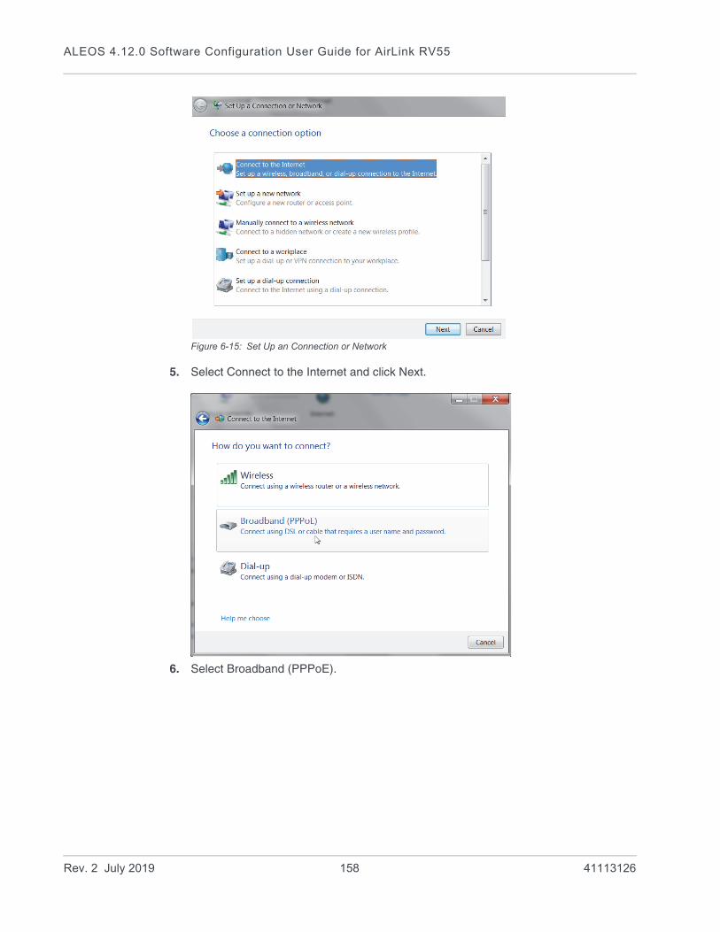
ALEOS 4.12.0 Software Configuration User Guide for AirLink RV55
Figure 6-15: Set Up an Connection or Network
5. Select Connect to the Internet and click Next.
6. Select Broadband (PPPoE).
Rev. 2 July 2019 158 41113126
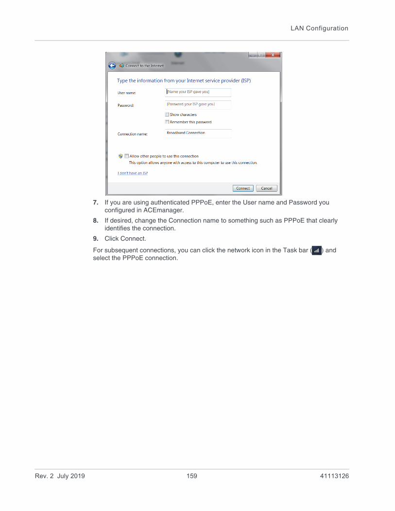
LAN Configuration
7. If you are using authenticated PPPoE, enter the User name and Password you configured in ACEmanager.
8. If desired, change the Connection name to something such as PPPoE that clearly identifies the connection.
9. Click Connect.
For subsequent connections, you can click the network icon in the Task bar ( ) and select the PPPoE connection.
Rev. 2 July 2019 159 41113126

ALEOS 4.12.0 Software Configuration User Guide for AirLink RV55
VLAN
ALEOS supports up to three Virtual Local Area Networks (VLANs) on its Ethernet port. VLANs are logical groupings of network devices that share the same broadcast domain. All devices on the same VLAN can ping each other without routing. ALEOS does not support routing between VLANs.
Note: The VLANs must also be configured on the switch.
Figure 6-16: VLAN network configuration
Figure 6-17: ACEmanager: LAN > VLAN
WAN
VLAN Switch
on VLAN 1 on VLAN 2on VLAN 2 on VLAN 1on VLAN 2
on VLAN 1
Connected device Connected device Connected device Connected device Connected device
Connected device
Rev. 2 July 2019 160 41113126

LAN Configuration
VRRP
VRRP (Virtual Router Redundancy Protocol) enables you to configure a backup WAN connection to be used if the primary connection fails. You can configure VRRP on the AirLink gateway’s Ethernet port or for VLANs.
You configure a VRRP Master and VRRP Backup device(s) and set their priorities. The device with the highest priority (normally the VRRP Master) becomes the primary route for the data connection.
The VRRP Master and Backups share a common virtual IP.
For information on configuring VLANs, see VLAN on page 160.
One common scenario is to use a 3rd party router for the primary connection and the AirLink gateway, either with or without VLANs, for the backup connection.
Field Description
Interface Displays the three VLANs you can configure
VLAN ID VLAN ID
• 0—VLAN is disabled (default)
• 1–4094—Valid range for VLAN ID
Device IP The IP address of the AirLink gateway for that VLAN interface
Subnet Mask The subnet mask indicates the range of host IP addresses that can be reached directly. Changing the subnet mask limits or expands the number of devices that can connect to the AirLink gateway.
Access WAN Choose whether or not devices on the configured VLAN have access to the WAN.
• Yes
• No
DHCP Server Mode Choose whether or not the AirLink gateway acts as a DHCP server
Options are:
• Enable—AirLink gateway acts as the DHCP server
• Disable (default)
Starting IP VLAN interface DHCP pool starting IP address
Ending IP VLAN interface DHCP pool ending IP address
Rev. 2 July 2019 161 41113126

ALEOS 4.12.0 Software Configuration User Guide for AirLink RV55
Figure 6-18: VRRP Network Configuration without VLANs
Figure 6-19: VRRP Network Configuration with VLANs
Connected device
Router (VRRP Master)
(VRRP Backup)AirLink gateway
WAN
Switch
Connected device Connected device Connected device Connected device
Connected device
Primary WAN connection
Backup WAN connection
AirLink gateway
WAN
VLAN Switch
on VLAN 1 on VLAN 2on VLAN 2 on VLAN 1on VLAN 2
on VLAN 1
Connected device Connected device Connected device Connected device Connected device
Connected device
Router (VRRP Master)
(VRRP Backup)
Primary WAN connection
Backup WAN connection
Rev. 2 July 2019 162 41113126
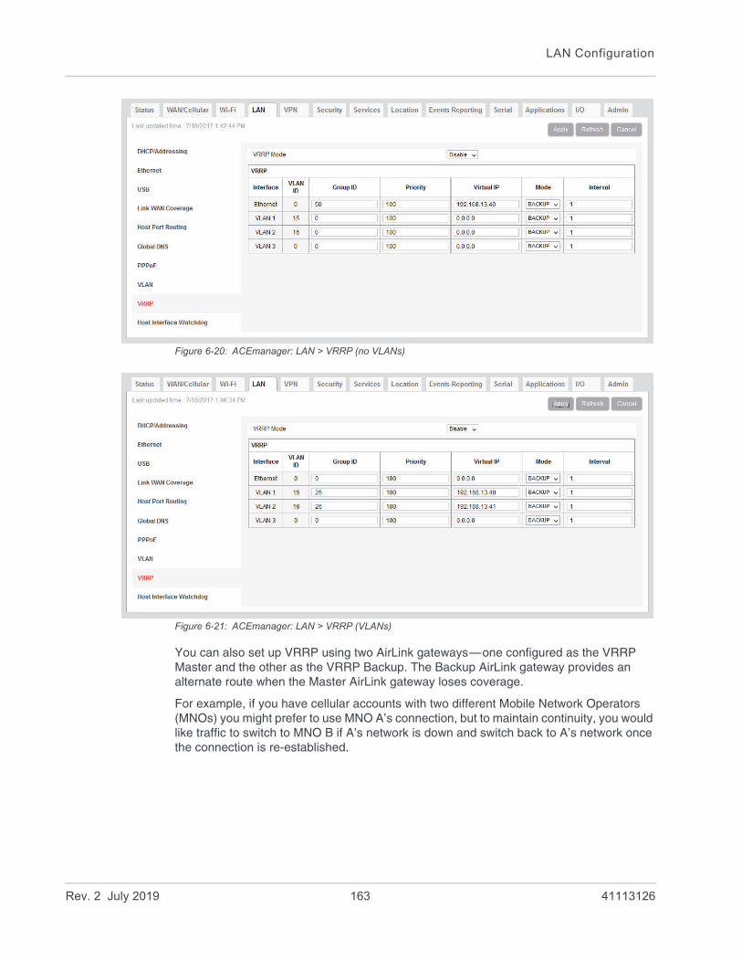
LAN Configuration
Figure 6-20: ACEmanager: LAN > VRRP (no VLANs)
Figure 6-21: ACEmanager: LAN > VRRP (VLANs)
You can also set up VRRP using two AirLink gateways—one configured as the VRRP Master and the other as the VRRP Backup. The Backup AirLink gateway provides an alternate route when the Master AirLink gateway loses coverage.
For example, if you have cellular accounts with two different Mobile Network Operators (MNOs) you might prefer to use MNO A’s connection, but to maintain continuity, you would like traffic to switch to MNO B if A’s network is down and switch back to A’s network once the connection is re-established.
Rev. 2 July 2019 163 41113126

ALEOS 4.12.0 Software Configuration User Guide for AirLink RV55
Figure 6-22: VRRP Network Configuration using two AirLink gateways
Connected device
AirLink gateway on MNO A’s network
WAN
Switch
Connected device Connected device
(VRRP Master, with priority configured as 100, for example)
AirLink gateway on MNO B’s network(VRRP Backup, with priorityconfigured as 75, for example)
Wireless connection on MNO B’s network(Backup route for datawhen the primary route is down)
Wireless connection on MNO A’s network (primary route for data)
Field Description
VRRP Enabled Allows you to activate VRRP. Options are:
• Enable
• Disable (default)
VRRP — The VLAN ID, Group ID, and Virtual IP address must be the same on the VRRP Master and VRRP Backup devices.
Interface Displays Ethernet port on AirLink gateway and the VLAN numbers
VLAN ID Displays the VLAN ID
This value is inherited from the LAN > VLAN screen. (See VLAN on page 160.)
• 0—VLAN is disabled
• 1– 4094—Valid range for VLAN ID
Group ID Enter the VRRP Group ID. Configure the VRRP Master (for example, the 3rd party router) and the VRRP Backup (for example the AirLink gateway) with the same Group ID.
Options are:
• 0–255 (Default is 0.)
Rev. 2 July 2019 164 41113126

LAN Configuration
Priority Use this field to configure the priority for the AirLink gateway.
The device with the highest priority (typically a 3rd party router) provides the primary data traffic route. If the device loses its connection to the WAN, its priority number drops. If the device fails, then when the failure is detected, the next highest priority router becomes the active router.
The priority number configured on the VRRP Backup (typically the AirLink gateway) should be less than the initial priority number on the VRRP Master and greater than the value that the VRRP Master’s priority number would be if it drops as a result of losing its WAN connection.
For example, if the VRRP Master router has an initial priority number of 200 that drops to 80 if it loses its WAN connection, setting the AirLink gateway’s priority to 100 ensures that it becomes the primary route if the VRRP Master loses its WAN connection. When the 3rd party router re-establishes its connection, its priority returns to 200 and it once again becomes the primary route for data.
Options are:
• 1–255 (Default is 100.)
Virtual IP Configure the same virtual IP for the VRRP Backup (typically the AirLink gateway) and the VRRP Master (typically a 3rd party router). The virtual IP must be unique within the VLAN subnet and cannot be within a pool of addresses assigned via DHCP.
Mode Indicates the initial mode for the AirLink gateway
Options are:
• MASTER
• BACKUP (default)
Note: Designating a device as “Master” in this field does not make it the primary route for data unless it is also given a higher priority number than the VRRP Backup device. See Priority.
Interval If the AirLink gateway is acting as VRRP Master, it advertises its Master status at the interval (in seconds) configured in this field. Options are:
• 1–65535 seconds (Default value is 1.)
Field Description
Rev. 2 July 2019 165 41113126
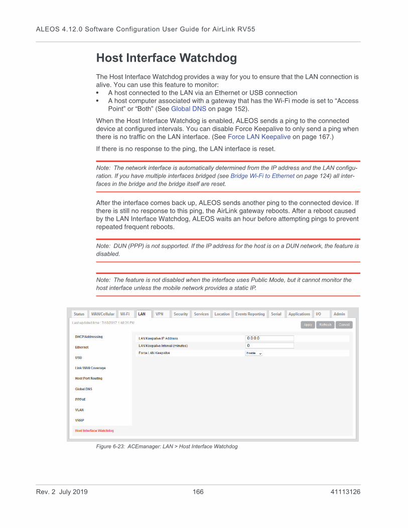
ALEOS 4.12.0 Software Configuration User Guide for AirLink RV55
Host Interface Watchdog
The Host Interface Watchdog provides a way for you to ensure that the LAN connection is alive. You can use this feature to monitor:• A host connected to the LAN via an Ethernet or USB connection• A host computer associated with a gateway that has the Wi-Fi mode is set to “Access
Point” or “Both” (See Global DNS on page 152).
When the Host Interface Watchdog is enabled, ALEOS sends a ping to the connected device at configured intervals. You can disable Force Keepalive to only send a ping when there is no traffic on the LAN interface. (See Force LAN Keepalive on page 167.)
If there is no response to the ping, the LAN interface is reset.
Note: The network interface is automatically determined from the IP address and the LAN configu-ration. If you have multiple interfaces bridged (see Bridge Wi-Fi to Ethernet on page 124) all inter-faces in the bridge and the bridge itself are reset.
After the interface comes back up, ALEOS sends another ping to the connected device. If there is still no response to this ping, the AirLink gateway reboots. After a reboot caused by the LAN Interface Watchdog, ALEOS waits an hour before attempting pings to prevent repeated frequent reboots.
Note: DUN (PPP) is not supported. If the IP address for the host is on a DUN network, the feature is disabled.
Note: The feature is not disabled when the interface uses Public Mode, but it cannot monitor the host interface unless the mobile network provides a static IP.
Figure 6-23: ACEmanager: LAN > Host Interface Watchdog
Rev. 2 July 2019 166 41113126

LAN Configuration
Field Description
LAN Keepalive IP address
Enter the IP address of the device to ping
If a device IP address is not configured, the Host Interface Watchdog is disabled.
LAN Keepalive Interval (minutes)
The interval (in minutes) at which ALEOS pings the LAN-connected device
Options are: 1–1440
If this field is set to 0, the Host Interface Watchdog is disabled. (default)
To prevent the gateway from rebooting frequently when a connection is not available, if the gateway reboots as a result of a failed keepalive ping, it waits 60 minutes before sending another keepalive ping. Once the ping is successful, the gateway returns to the interval configured in this field.
Force LAN Keepalive • Enabled (default) —The network interface statistics are not monitored and a ping is always sent at the interval configured in the Keepalive Interval field.
• Disabled—The network interface statistics are monitored and connectivity is assumed when there is traffic received. A ping is only sent when there is no traffic for a period greater than the interval set in the Keepalive Interval field.
Rev. 2 July 2019 167 41113126
7
7: VPN ConfigurationThe AirLink RV55 can act as a Virtual Private Network (VPN) device, providing enterprise VPN access to any device connected to the AirLink gateway even when a device has no VPN client capability on its own. The AirLink gateway supports three types of VPN: IPsec, GRE, and OpenVPN. The RV55 can support up to five VPN tunnels at the same time.
Note: Dynamic Mobile Network Routing (DMNR) is not compatible with VPN tunnels. If you are using DMNR, disable all VPN tunnels.
General
On the General page you can select your IPsec Implementation and reset all VPN tunnels so that the RV55 doesn’t have to be rebooted in order for changes to be used.
The available settings on the General page depend on which IPsec implementation you have selected.
Standard Vs. Legacy IPsec Implementation
The AirLink RV55 supports Legacy IPsec implementation (in place prior to ALEOS 4.12.0) or the new Standard IPsec implementation. Sierra Wireless recommends that you migrate any existing Legacy VPN implementations to the Standard version for increased features and support. For configuration information, see IPsec (Legacy) on page 175 and IPsec (Standard) on page 181.
The Standard implementation is fully IKEv1 and IKEv2 compliant, and supports MOBIKE when operating over IKEv2. Standard implementation also offers increased security through certificate-based authentication and a larger set of cryptographic algorithms than the Legacy implementation. You can use Standard for Host-to-LAN and peer-to-peer applications. In addition, the Standard implementation provides the option to configure IPsec tunnels to FIPS (Federal Information Processing Standards) standards. For more information, see IPsec FIPS Mode on page 170.
Rev. 2 July 2019 168 41113126

VPN Configuration
Figure 7-1: ACEmanager: VPN > General (Legacy)
Figure 7-2: ACEmanager: VPN > General (Standard)
Rev. 2 July 2019 169 41113126
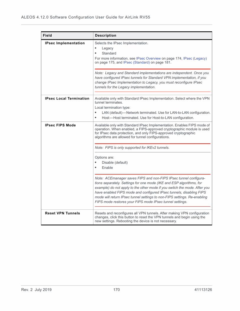
ALEOS 4.12.0 Software Configuration User Guide for AirLink RV55
Field Description
IPsec Implementation Selects the IPsec Implementation.
• Legacy
• Standard
For more information, see IPsec Overview on page 174, IPsec (Legacy) on page 175, and IPsec (Standard) on page 181.
Note: Legacy and Standard implementations are independent. Once you have configured IPsec tunnels for Standard VPN implementation, if you change IPsec Implementation to Legacy, you must reconfigure IPsec tunnels for the Legacy implementation.
IPsec Local Termination Available only with Standard IPsec Implementation. Select where the VPN tunnel terminates.
Local termination type:
• LAN (default)—Network terminated. Use for LAN-to-LAN configuration.
• Host—Host terminated. Use for Host-to-LAN configuration.
IPsec FIPS Mode Available only with Standard IPsec Implementation. Enables FIPS mode of operation. When enabled, a FIPS-approved cryptographic module is used for IPsec data protection, and only FIPS-approved cryptographic algorithms are allowed for tunnel configurations.
Note: FIPS is only supported for IKEv2 tunnels.
Options are:
• Disable (default)
• Enable
Note: ACEmanager saves FIPS and non-FIPS IPsec tunnel configura-tions separately. Settings for one mode (IKE and ESP algorithms, for example) do not apply to the other mode if you switch the mode. After you have enabled FIPS mode and configured IPsec tunnels, disabling FIPS mode will return IPsec tunnel settings to non-FIPS settings. Re-enabling FIPS mode restores your FIPS mode IPsec tunnel settings.
Reset VPN Tunnels Resets and reconfigures all VPN tunnels. After making VPN configuration changes, click this button to reset the VPN tunnels and begin using the new settings. Rebooting the device is not necessary.
Rev. 2 July 2019 170 41113126

VPN Configuration
Split Tunnel
The AirLink gateway supports split tunnels, where some traffic can be routed through an encrypted VPN, while other incoming and/or outgoing traffic is routed through the public Internet (“Out of Band” traffic). Split tunnel configurations should be set up with care, as a configuration with both an enterprise VPN and access to the public Internet can inadvertently expose company resources.
Note: Split Tunnel settings are not implemented in FIPS mode for full tunnels. To allow Out-of-Band traffic from a network/IP, add the IP to the exemption list in the tunnel configuration. See Remote Address/Subnet Exemption List on page 186.
Figure 7-3: ACEmanager: VPN > Split Tunnel
Field Description
Incoming Out of Band Controls incoming public Internet traffic.
Options are:
• Blocked—Incoming public Internet traffic is blocked. Only traffic through the VPN tunnel is allowed. (default)
• Allowed—Incoming public Internet traffic is allowed.
Outgoing Management Out of Band
Controls outgoing traffic from the AirLink gateway
• Blocked—Outgoing traffic from the AirLink gateway to the public Internet is blocked. Only traffic through the VPN tunnel is allowed.
• Allowed—Outgoing traffic from the AirLink gateway to the public Internet is allowed. (default)
Outgoing Host Out of Band
Controls of outgoing Host out of band traffic.
Options are:
• Blocked—Public Internet traffic from the host device is blocked. Only traffic through the VPN tunnel is allowed. (default)
• Allowed—Public Internet traffic from the host device is allowed.
Rev. 2 July 2019 171 41113126

ALEOS 4.12.0 Software Configuration User Guide for AirLink RV55
VPN Failover
VPN Failover is only available for IPsec VPN tunnels. To use this feature, configure a primary and a secondary VPN tunnel. Dead Peer Detection (DPD) verifies the status of the active connection. For example, if the primary/active VPN goes down (i.e. DPD detects that the end device is not responding) traffic is automatically switched to a backup VPN tunnel. The VPN Failover feature continues to ping the VPN responder for the tunnel that has gone down. If configured to do so, once the primary VPN tunnel is up, traffic automatically reverts to the primary VPN. Status fields on the Failover page inform you of the current status of the two VPNs.
Figure 7-4: VPN Failover Configuration
To configure VPN Failover:
1. Configure two IPsec VPN tunnels. The one you want to designate as the primary VPN must have Dead Peer Detection configured. For the Secondary VPN, you only need to configure the remote gateway address. For other settings, such as the local and remote subnets, the secondary VPN uses the same settings as the primary VPN.
For instructions on configuring IPsec VPN tunnels, see IPsec (Legacy) on page 175 and IPsec (Standard) on page 181.
2. Go to VPN > Failover and configure the first three fields. See the table following the screen shot for details.
3. Click Apply and Reset VPN Tunnels or reboot the AirLink gateway.
Primary/Active VPN
Secondary/Backup VPN
AirLink gatewayDPD and VPN Failoverconfigured on AirLink gateway
LAN
Subnet 1Subnet 2
Switch
Two IPsec VPN tunnels are configured, but only one is active at a time. If DPD determines the responder is dead, traffic is switched to the Secondary/Backup VPN.
Rev. 2 July 2019 172 41113126
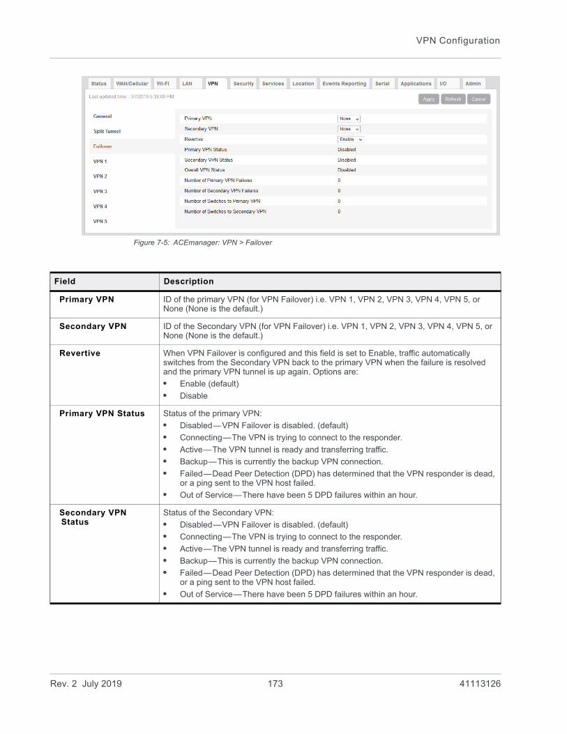
VPN Configuration
Figure 7-5: ACEmanager: VPN > Failover
Field Description
Primary VPN ID of the primary VPN (for VPN Failover) i.e. VPN 1, VPN 2, VPN 3, VPN 4, VPN 5, or None (None is the default.)
Secondary VPN ID of the Secondary VPN (for VPN Failover) i.e. VPN 1, VPN 2, VPN 3, VPN 4, VPN 5, or None (None is the default.)
Revertive When VPN Failover is configured and this field is set to Enable, traffic automatically switches from the Secondary VPN back to the primary VPN when the failure is resolved and the primary VPN tunnel is up again. Options are:
• Enable (default)
• Disable
Primary VPN Status Status of the primary VPN:
• Disabled—VPN Failover is disabled. (default)
• Connecting—The VPN is trying to connect to the responder.
• Active—The VPN tunnel is ready and transferring traffic.
• Backup—This is currently the backup VPN connection.
• Failed—Dead Peer Detection (DPD) has determined that the VPN responder is dead, or a ping sent to the VPN host failed.
• Out of Service—There have been 5 DPD failures within an hour.
Secondary VPN Status
Status of the Secondary VPN:
• Disabled—VPN Failover is disabled. (default)
• Connecting—The VPN is trying to connect to the responder.
• Active—The VPN tunnel is ready and transferring traffic.
• Backup—This is currently the backup VPN connection.
• Failed—Dead Peer Detection (DPD) has determined that the VPN responder is dead, or a ping sent to the VPN host failed.
• Out of Service—There have been 5 DPD failures within an hour.
Rev. 2 July 2019 173 41113126
ALEOS 4.12.0 Software Configuration User Guide for AirLink RV55
IPsec Overview
The IP protocol that drives the Internet is inherently insecure. Internet Protocol Security (IPsec), which is a standards-based protocol, secures communications of IP packets over public networks.
IPsec is a common network layer security control and is used to create a virtual private network (VPN).
Note: ALEOS offers two IPsec implementations: Standard and Legacy (compatible with ALEOS releases prior to 4.12.0). All installations are encouraged to upgrade to ALEOS 4.12.0 to take advantage of the new Standard implementation, with its increased security. For configuration infor-mation, see IPsec (Legacy) on page 175 and IPsec (Standard) on page 181.
The advantages of using the IPsec feature includes:• Data Protection: Data Content Confidentiality allows you to protect your data from any
unauthorized view, because the data is encrypted (encryption algorithms are used).• Access Control: Access Control implies a security service that prevents unauthorized
use of a Security Gateway, a network behind a gateway or bandwidth on that network.
• Data Origin Authentication: Data Origin Authentication verifies the actual sender, thus eliminating the possibility of forging the actual sender’s identification by a third-party.
• Data Integrity: Data Integrity Authentication allows both ends of the communication channel to confirm that the original data sent has been received as transmitted, without being tampered with in transit. This is achieved by using authentication algorithms and their outputs.
Overall VPN Status Status of the overall VPN:
• Disabled—VPN Failover is disabled. (default)
• Connecting—One of the VPNs is trying to connect to the responder.
• Active—One VPN tunnel is currently in use. The backup VPN is available.
• Backup_Unavailable —One VPN tunnel is currently in use. The backup VPN is not available.
• Out of Service—Neither the primary nor secondary VPN is operational.
• N/A—The overall VPN status is temporarily not available. Click Refresh.
Number of Primary VPN Failures
Number of times DPD has failed on the primary VPN since the device last lost its WAN connection.
Number of Secondary VPN Failures
Number of times DPD has failed on the Secondary VPN since the device last lost its WAN connection.
Number of Switches to Primary VPN
Number of times traffic was switched to the primary VPN since the device last lost its WAN connection.
Number of Switches to Secondary VPN
Number of times traffic was switched to the Secondary VPN since the device last lost its WAN connection.
Field Description
Rev. 2 July 2019 174 41113126

VPN Configuration
The IPsec architecture model includes the Sierra Wireless AirLink gateway as a local gateway at one end, communicating through a VPN tunnel with a remote VPN gateway at the other end. The remote gateway is connected to a remote network and the VPN is connected to the local network. You can configure up to three remote subnets.
The IPsec VPN employs the IKE (Internet Key Exchange) protocol to set up a Security Association (SA) between the AirLink RV55 and AirLink Connection Manager or a Cisco (or Cisco compatible) enterprise VPN server. IPsec has two phases for setting up an SA between peer VPNs. Phase 1 creates a secure channel between the RV55 VPN and the enterprise VPN, thereby enabling IKE exchanges. Phase 2 sets up the IPsec SA that is used to securely transmit enterprise data.
Note: If you configure custom settings, they are saved and the tunnel can be disabled and re-enabled without needing to re-enter the settings. For a successful configuration, all settings for the VPN tunnel must be identical between the AirLink RV55 VPN and the enterprise VPN server.
You can also configure VPN Failover for IPsec VPN tunnels. For more information, see VPN Failover on page 172.
IPsec (Legacy)
The Legacy IPsec implementation was in place prior to ALEOS 4.12.0. You can configure IPsec tunnels in Legacy mode if you absolutely must retain an existing configuration. Otherwise, Sierra Wireless recommends using the Standard IPsec implementation. For more information, see Standard Vs. Legacy IPsec Implementation on page 168.
To configure an IPsec VPN tunnel in Legacy mode:
1. In ACEmanager, go to VPN.
2. On the General page, under IPsec Implementation, select Legacy.
3. Select the VPN you want to configure (1, 2, 3, 4, or 5).
4. In the VPN Type field, select IPsec Tunnel. The screen expands to show the IPsec Tunnel fields.
Rev. 2 July 2019 175 41113126

ALEOS 4.12.0 Software Configuration User Guide for AirLink RV55
Figure 7-6: ACEmanager: VPN > VPN 1 > IPSec Tunnel (Legacy)
5. See the following table for instructions on completing the IPsec Tunnel fields.
6. Once the configuration is complete, click Apply and Reset VPN Tunnels or reboot the AirLink gateway.
7. Check the VPN Status field to confirm the status of the VPN connection.
Rev. 2 July 2019 176 41113126
VPN Configuration
Field Description
Type
VPN # Type Use this field to select the type of VPN tunnel. If you configure custom settings, they are saved and the tunnel can be disabled and re-enabled without needing to re-enter the settings.
Options are:
• Tunnel Disabled (default)
• IPsec Tunnel
• GRE Tunnel
• OpenVPN Tunnel (only available for VPN 1)
VPN # Status Status of the VPN connection:
• Not Enabled—VPN is disabled (default)
• Not Connected—The VPN failed to connect. This could be because of a mismatch in the configuration between the client and the server, no data connection on the device, etc.
• Connected—The VPN is connected and ready to transmit traffic.
• Configuration Error—This status appears when:
• Two VPNs have the same Local Address and Remote Address
• More than one VPN has the remote address set to “0.0.0.0”
When either of these errors exist, only the first of the conflicting VPNs is operational.
To determine which VPNs are in conflict:
1. Go to Admin > Configure Log.
2. For the VPN Subsystem, ensure that Display in Log is set to Yes. The Verbosity can be either Info or Debug.
3. Click View Log.
4. The resulting log shows you which VPNs are in conflict.
General (Legacy)
VPN Gateway Address
The IP address of the server that this VPN client connects to. This address must be open to connections from the AirLink gateway. The default VPN Gateway IP Addresses are static address on Sierra Wireless Servers. They are:
You can use these default IP addresses to confirm that an IPsec connection can be established with your wireless configuration before making any configuration changes, and as an example to model your VPN configuration after.
VPN Gateway IP Address
1 208.81.123.21
2 208.81.123.22
3 208.81.123.26
4 208.81.123.23
5 208.81.123.24
Rev. 2 July 2019 177 41113126

ALEOS 4.12.0 Software Configuration User Guide for AirLink RV55
Pre-shared Key 1 The pre-shared key (PSK) is used to initiate the VPN tunnel.
• Pre-shared key length: Maximum supported length is 128 characters.
• Valid characters are: 1234567890abcdefghijklmnopqrstuvwxyzABCDEFGHIJKLM NOPQRSTUVWXYZ!%-~@#$^*
• Invalid characters: ><?&
My Identity Type Sets the host authentication ID. Options are:
• IP (default)—The My Identity - IP field appears with the WAN IP address assigned by the carrier
• FQDN—The My Identity - FQDN field appears. Enter a fully qualified domain name (FQDN) e. g., modemname.domainname.com
• User FQDN—The My Identity - FQDN field appears. Enter a User FQDN whose values should include a username (e.g. [email protected])
My Identity - IP orMy Identity - FQDN
• My Identity—IP appears only when IP is selected from the My Identity Type drop-down menu. The WAN IP address assigned by the carrier appears.
• My Identity—FQDN appears only when User FQDN or FQDN is selected from the My Identity Type drop-down menu. Enter an FQDN or User FQDN.
Note: If you are using a FQDN for your device (My Identity Type) either:
• Set up a Dynamic DNS on the Services > Dynamic DNS tab (See Dynamic DNS on page 224) or
• Use a DNS server as your domain host
Peer Identity Type Required in some configurations to identify the client or peer side of a VPN connection. Options are:
• IP (default)—The Peer Identity - IP field appears with the IP address of a VPN server set up by Sierra Wireless for your testing purposes
• FQDN—The Peer Identity - FQDN field appears. Enter an FQDN (e. g. modemname.domainname.com)
• User FQDN—The Peer Identity - FQDN field appears. Enter a User FQDN whose values should include a username (e.g., [email protected])
Peer Identity - IP orPeer Identity - FQDN
• Peer Identity—IP appears only when IP is selected from the Peer Identity Type drop-down menu. The VPN Gateway IP Address appears.
• Peer Identity—FQDN appears only when User FQDN or FQDN is selected from the Peer Identity Type drop-down menu. Enter the Peer FQDN or Peer User FQDN.
Negotiation Mode Enable Aggressive mode for the VPN. Aggressive mode offers increased performance at the expense of security.
Options are:
• Main (default)
• Aggressive
IKE Encryption Algorithm
Determines the type and length of encryption key used to encrypt/decrypt IKE packets. 3DES supports 168-bit encryption. AES (Advanced Encryption Standard) supports both 128-bit and 256-bit encryption.
Options are: DES, 3DES, AES-128 (default), and AES-256
IKE Authentication Algorithm
MD5 is an algorithm that produces a 128-bit digest for authentication. SHA is a more secure algorithm that produces a 160-bit digest.
Options are: MD5 and SHA1 (default)
Field Description
Rev. 2 July 2019 178 41113126
VPN Configuration
IKE Key Group Options are: DH1, DH2 (default), or DH5
IKE SA Life Time Determines how long the VPN tunnel is active in seconds.
Options are: 180 to 86400; Default: 7200
IKE DPD Dead Peer Detection (DPD)Options are:
• Disable (default)
• Enable
When DPD is enabled, the AirLink gateway checks to see if the server is still present if there has been no traffic for a configured interval. If it does not receive an acknowledgment, it retries at 5 second intervals. If there is no acknowledgment after 5 retries, the status of the VPN is set to Not Connected and the device attempts to renegotiate IPSEC security parameters with its peer.
Note: Sierra Wireless recommends that you Enable IKE DPD. Otherwise the AirLink gateway has no way of detecting that the connection to the VPN server is still available.
IKE DPD Interval (seconds)
Use this field to set the DPD interval (in seconds). If there has been no traffic for the period of time set in this field, the AirLink gateway retries checking with the server, as described in IKE DPD.
Options are: 0 to 3600 (default is 1200)
If this field is set to 0, DPD monitoring is turned off (or disabled as described in the IKE DPD section), but the AirLink gateway still responds to DPD requests from the server.
Local Address Type The network information of the device. Options are:
• Subnet Address (default)
• Use the Host Subnet
• Single Address
Local Address Device subnet address
Local Address - Netmask
Device subnet mask information
Default: 255.255.255.0
Remote Address Type The network information of the IPsec server behind the IPsec gateway. Options are:
• Subnet Address (default)
• Single Address
Field Description
Rev. 2 July 2019 179 41113126

ALEOS 4.12.0 Software Configuration User Guide for AirLink RV55
Remote Address The IP address or subnet of the device(s) connected to the gateway
If the remote address is 0.0.0.0, the remote address netmask should also be 0.0.0.0.
Note that you can only have one remote address of 0.0.0.0 for all the VPNs.
Default values are:
Remote Address - Netmask
Remote subnet mask information
Default: 255.255.255.0
0.0.0.0 is allowed for the remote address subnet mask as long as the remote address is also 0.0.0.0.
Perfect Forward Secrecy
Perfect Forward Secrecy (PFS) is enabled by default. Leave the default setting in this field.
To disable PFS, see IPsec Key Group.
IPsec Encryption Algorithm
Determines the type and length of encryption key used to encrypt/decrypt ESP (Encapsulating Security Payload) packets. 3DES supports 168-bit encryption. AES (Advanced Encryption Standard) supports both 128-bit and 256-bit encryption.
Options are: None, DES, 3DES, AES-128 (default), and AES-256.
IPsec Authentication Algorithm
Can be configured with MD5 or SHA1. MD5 is an algorithm that produces a 128-bit digest for authentication. SHA is a more secure algorithm that produces a 160-bit digest.
Options are: None, MD5 and SHA1 (default)
IPsec Key Group Use this field to select the DH (Diffie-Hellman) group pre-shared key length used for authentication, or to disable Perfect Forward Secrecy (PFS).
The DH group number determines the length of the key used in the key exchange process. Longer keys are more secure, but take longer to compute. Also note that both peers in the VPN exchange must use the same DH group.
PFS is enabled by default. It adds additional security because each session uses a unique temporary public/private key pair to generate the shared secret. One key cannot be derived from another. This ensures previous and subsequent encryption keys are secure, even if one key is compromised.
Options are:
• None —Disables PFS
• DH1 —Uses DH Group 1 (key length is 768 bits)
• DH2 —Uses DH Group 2 (default—key length is 1,024 bits)
• DH5 —Uses DH Group 5 (key length is 1,536 bits)
IPsec SA Life Time Determines how long the VPN tunnel is active in seconds
Options are: 180 to 86400; Default: 7200
Field Description
VPN Remote Address
1 10.11.12.0
2 10.11.13.0
3 10.11.14.0
4 10.11.15.0
5 10.11.16.0
Rev. 2 July 2019 180 41113126

VPN Configuration
IPsec (Standard)
The Standard implementation offers increased security and connectivity, and is the recommended configuration. For more information, see Standard Vs. Legacy IPsec Implementation on page 168.
To configure an IPsec VPN tunnel in Standard mode:
1. In ACEmanager, go to VPN.
2. On the General page, under IPsec Implementation, select Standard.
3. Select your desired Local Termination and (depending on your application) enable FIPS mode.
4. Select the VPN you want to configure (1, 2, 3, 4, or 5).
5. In the VPN Type field, select IPsec Tunnel. The screen expands to show the IPsec Tunnel fields.
Additional Remote Subnets
Remote Subnet 2 Address Type
The network information for subnet 2 IPsec server behind the IPsec gateway.
Options are: Subnet Address (default) and Single Address
Remote Subnet 2 Address
The IP address for the subnet 2 device behind the gateway
Remote Subnet 2 Address - Netmask
Remote subnet 2 mask information
Default: 255.255.255.0
Remote Subnet 3 Address Type
The network information for subnet 3 IPsec server behind the IPsec gateway.
Options are: Subnet Address (default) and Single Address
Remote Subnet 3 Address
The IP address for the subnet 3 device behind the gateway
Remote Subnet 3 Address - Netmask
Remote subnet 3 mask information
Default: 255.255.255.0
Field Description
Rev. 2 July 2019 181 41113126
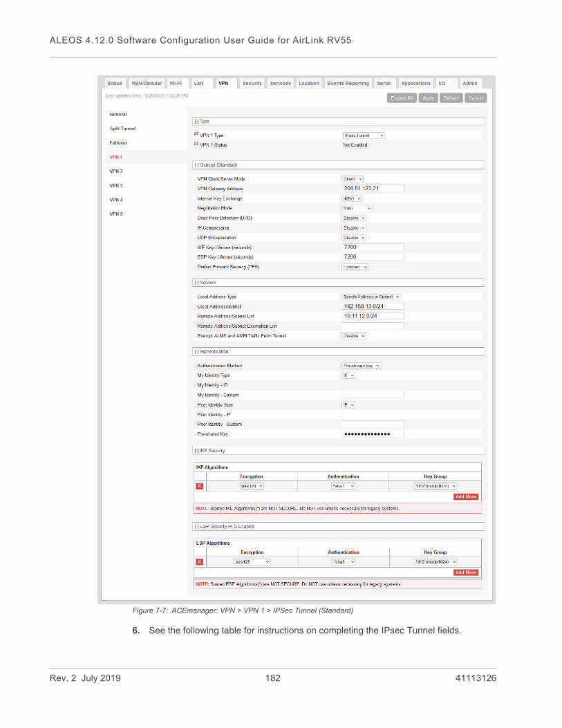
ALEOS 4.12.0 Software Configuration User Guide for AirLink RV55
Figure 7-7: ACEmanager: VPN > VPN 1 > IPSec Tunnel (Standard)
6. See the following table for instructions on completing the IPsec Tunnel fields.
Rev. 2 July 2019 182 41113126
VPN Configuration
7. Once the configuration is complete, click Apply and Reset VPN Tunnels or reboot the AirLink gateway.
8. Check the VPN Status field to confirm the status of the VPN connection.
Field Description
Type
VPN # Type Use this field to select the type of VPN tunnel. If you configure custom settings, they are saved and the tunnel can be disabled and re-enabled without needing to re-enter the settings.
Options are:
• Tunnel Disabled (default)
• IPsec Tunnel
• GRE Tunnel
• OpenVPN Tunnel (only available for VPN 1)
VPN # Status Status of the VPN connection:
• Disabled—VPN is disabled (default)
• Error Connecting—The VPN failed to connect. This could be because of a mismatch in the configuration between the client and the server, no data connection on the device, etc.
• Connected—The VPN is connected and ready to transmit traffic.
• Not Connected—The tunnel is enabled and trying to connect.
• Error in Gateway—The gateway/peer was an FQDN, and it could not be found; i.e., the IP address could not be found.
General (Standard)
VPN Client/Server Mode
• Client
• Server
Note: Server Mode is not compatible with Host-to-LAN configurations. Do not select Server when IPsec Local Termination is set to Host.
Note: In Server Mode, the following is not a supported configuration:
• Negotiation Mode—Aggressive
• Internet Key Exchange—IKEv1
• Authentication Method—Pre-Shared Key
Sierra Wireless recommends setting Negotiation Mode to Main (default) in this case.
Rev. 2 July 2019 183 41113126

ALEOS 4.12.0 Software Configuration User Guide for AirLink RV55
VPN Gateway Address
Available in Client Mode. The IP address or FQDN (Fully Qualified Domain Name) of the server that this VPN client connects to. This address must be open to connections from the AirLink gateway. The RV55 supports IPv6 addresses for “4-in-6” tunnels, where it is able to pass IPv4 traffic from the local IPv4 subnet to remote IPv4 subnets over the IPv6 network.
The default VPN Gateway IP Addresses are static addresses on Sierra Wireless Servers. They are:
You can use these default IP addresses to confirm that an IPsec connection can be established with your wireless configuration before making any configuration changes, and as an example to model your VPN configuration after.
VPN Peer Address Available in Server Mode. The IP address or FQDN (Fully Qualified Domain Name) of the client/peer that can connect to this VPN server. This address must be open to connections from the AirLink gateway.
Note: The default IP Address in this field relates to the VPN Gateway Address setting described above. It can be disregarded when configuring the VPN Peer Address.
Internet Key Exchange (FIPS)
• IKEv1 (default)
• IKEv2 (default in FIPS mode—IKEv2 is the only option available)
Negotiation Mode Enable Aggressive mode for the VPN. Aggressive mode offers increased performance at the expense of security.
Note: This setting applies to IKEv1 mode only.
Options are:
• Main (default)
• Aggressive
MOBIKE Available when Internet Key Exchange: IKEv2 is selected. MOBIKE allows a VPN tunnel to stay connected, even if the WAN interface used by the tunnel changes. For example, the tunnel stays connected if the WAN interface changes from Ethernet to cellular. Options are:
• Enable (default)
• Disable
Field Description
VPN Gateway IP Address
1 208.81.123.21
2 208.81.123.22
3 208.81.123.26
4 208.81.123.23
5 208.81.123.24
Rev. 2 July 2019 184 41113126

VPN Configuration
Dead Peer Detection (DPD)
Dead Peer Detection (DPD)Options are:
• Disable (default)
• Enable
When DPD is enabled, the AirLink gateway checks to see if the server is still present if there has been no traffic for a configured delay. If it does not receive an acknowledgment after several retries, the status of the VPN is set to Not Connected and an attempt is made to restart the tunnel.
Note: Sierra Wireless recommends that you enable DPD. Otherwise the AirLink gateway has no way of detecting that the connection to the VPN server is still available.
DPD Delay (seconds) Use this field to set the DPD delay (in seconds). If there has been no traffic for the period of time set in this field, the AirLink gateway retries checking with the server, as described in Dead Peer Detection (DPD).
Options are: 0 to 3600 (default is 10)
Setting this field to 0 disables Dead Peer Detection as described in Dead Peer Detection (DPD). The AirLink gateway always responds to DPD requests from the server.
DPD Timeout (seconds)
Available for IKEv1 only. Periodic interval for Dead Peer Detection. If there is no communication from the server (including DPD responses) within this interval, the status of the VPN is set to Not Connected and an attempt is made to restart the tunnel.
IP Compression Enable or disable IP packet compression. When enabled, IP packets are compressed before being encrypted, improving throughput for slow connections.
• Disable (default)
• Enable
Note: Disable IP Compression if the VPN server (Server Address field) doesn’t support compression.
UDP Encapsulation Allows you to enable UDP encapsulation in cases where it must be manually enabled if firewall restrictions require it. If either peer is behind a NAT device, UDP encapsulation is automatically enabled.
• Enabled—When the VPN server is behind a firewall, firewall configuration is simplified as the firewall only has to allow ports 500 (IKE) and 4500 (IKE and UDP-encapsulated ESP).
• Disabled (Default)—When disabled, port 50 must also be allowed for the ESP protocol to pass.
Note: This setting can usually be left at default. Do not use if the gateway is IPv6.
IKE Key Lifetime (seconds)
Sets the lifetime for the IKE Security Association (SA). After this time expires, a new SA is negotiated, either by re-keying (IKEv2) or re-authentication (IKEv1).
Range: 180–86400 (default 7200)
Note: Either end may initiate the negotiation; both ends need not agree.
Field Description
Rev. 2 July 2019 185 41113126
ALEOS 4.12.0 Software Configuration User Guide for AirLink RV55
ESP Key Lifetime (seconds)
Sets the lifetime for the ESP Security Association (SA). After this time expires, a new SA is negotiated by re-keying.
Range: 180–86400 (default 7200)
Note: Either end may initiate the negotiation; both ends need not agree.
Perfect Forward Secrecy (PFS)
Perfect Forward Secrecy (PFS) is enabled by default. Options are:
• Disabled
• Enabled (default)
Network
Local Address Type The network information of the device. Options are:
• Use the Host Subnet
• Specify Address or Subnet (default)
Local Address/Subnet If Specify Address or Subnet is selected, enter the local address or subnet in CIDR notation; for example, 192.168.13.0/24.
Note: More than one local address/subnet is not supported.
Remote Address/Subnet List
The IP address or subnet (in CIDR notation) of the device(s) connected to the remote VPN server. These addresses/subnets will be accessible from any hosts connected locally to the gateway.
Note that you can only have one remote address of 0.0.0.0/0 for all the VPNs.
Note: Enter subnets or addresses as a comma-separated list, ensuring that there are no spaces before or after commas.
Default values are:
Remote Address/Subnet Exemption List
Comma-separated list of Remote Addresses or subnets (in CIDR notation) to be exempted.
Note: Enter subnets or addresses as a comma-separated list, ensuring that there are no spaces before or after commas.
Field Description
VPN Remote Address
1 10.11.12.0/24
2 10.11.13.0/24
3 10.11.14.0/24
4 10.11.15.0/24
5 10.11.16.0/24
Rev. 2 July 2019 186 41113126
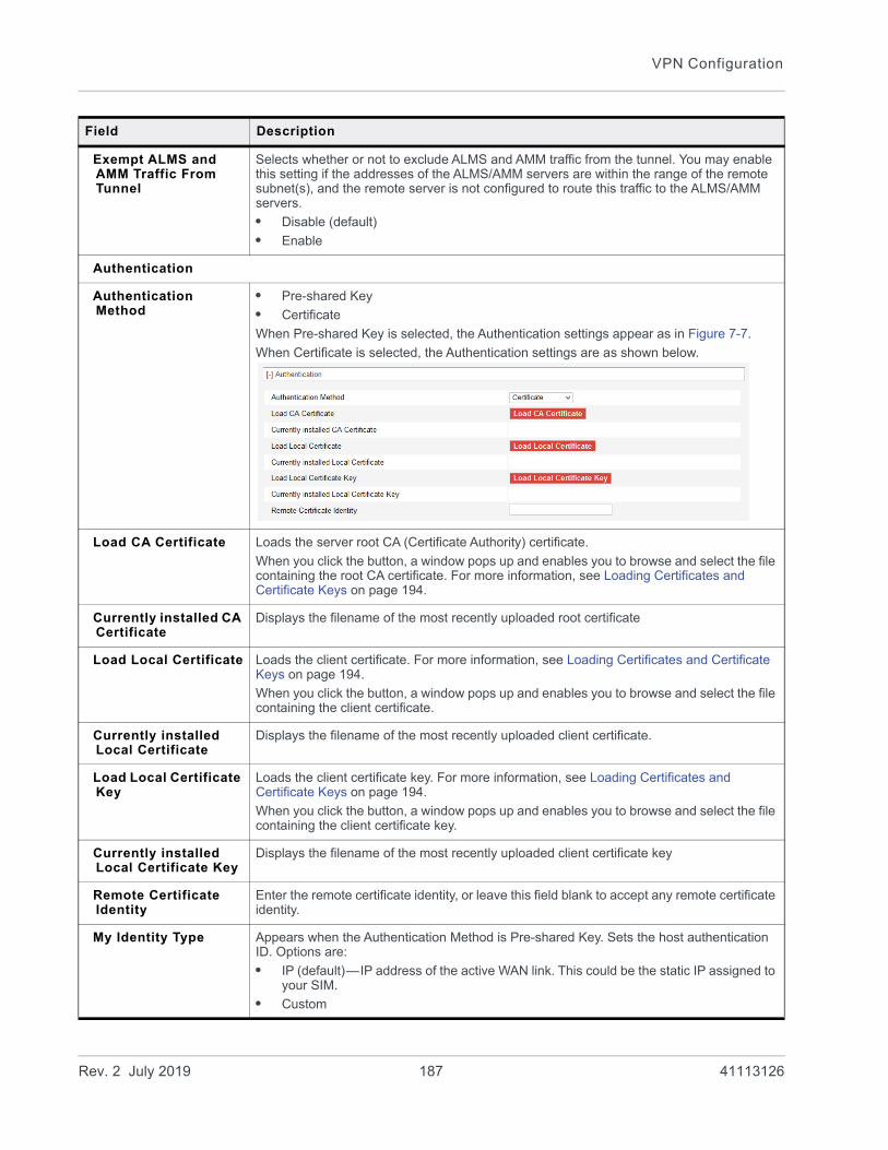
VPN Configuration
Exempt ALMS and AMM Traffic From Tunnel
Selects whether or not to exclude ALMS and AMM traffic from the tunnel. You may enable this setting if the addresses of the ALMS/AMM servers are within the range of the remote subnet(s), and the remote server is not configured to route this traffic to the ALMS/AMM servers.
• Disable (default)
• Enable
Authentication
Authentication Method
• Pre-shared Key
• Certificate
When Pre-shared Key is selected, the Authentication settings appear as in Figure 7-7.
When Certificate is selected, the Authentication settings are as shown below.
Load CA Certificate Loads the server root CA (Certificate Authority) certificate.
When you click the button, a window pops up and enables you to browse and select the file containing the root CA certificate. For more information, see Loading Certificates and Certificate Keys on page 194.
Currently installed CA Certificate
Displays the filename of the most recently uploaded root certificate
Load Local Certificate Loads the client certificate. For more information, see Loading Certificates and Certificate Keys on page 194.
When you click the button, a window pops up and enables you to browse and select the file containing the client certificate.
Currently installed Local Certificate
Displays the filename of the most recently uploaded client certificate.
Load Local Certificate Key
Loads the client certificate key. For more information, see Loading Certificates and Certificate Keys on page 194.
When you click the button, a window pops up and enables you to browse and select the file containing the client certificate key.
Currently installed Local Certificate Key
Displays the filename of the most recently uploaded client certificate key
Remote Certificate Identity
Enter the remote certificate identity, or leave this field blank to accept any remote certificate identity.
My Identity Type Appears when the Authentication Method is Pre-shared Key. Sets the host authentication ID. Options are:
• IP (default)—IP address of the active WAN link. This could be the static IP assigned to your SIM.
• Custom
Field Description
Rev. 2 July 2019 187 41113126
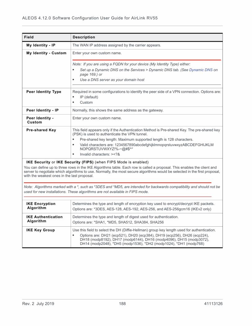
ALEOS 4.12.0 Software Configuration User Guide for AirLink RV55
My Identity - IP The WAN IP address assigned by the carrier appears.
My Identity - Custom Enter your own custom name.
Note: If you are using a FQDN for your device (My Identity Type) either:
• Set up a Dynamic DNS on the Services > Dynamic DNS tab. (See Dynamic DNS on page 169.) or
• Use a DNS server as your domain host
Peer Identity Type Required in some configurations to identify the peer side of a VPN connection. Options are:
• IP (default)
• Custom
Peer Identity - IP Normally, this shows the same address as the gateway.
Peer Identity - Custom
Enter your own custom name.
Pre-shared Key This field appears only if the Authentication Method is Pre-shared Key. The pre-shared key (PSK) is used to authenticate the VPN tunnel.
• Pre-shared key length: Maximum supported length is 128 characters.
• Valid characters are: 1234567890abcdefghijklmnopqrstuvwxyzABCDEFGHIJKLM NOPQRSTUVWXYZ!%-~@#$^*
• Invalid characters: ><?&
IKE Security or IKE Security (FIPS) (when FIPS Mode is enabled)
You can define up to three rows in the IKE Algorithms table. Each row is called a proposal. This enables the client and server to negotiate which algorithms to use. Normally, the most secure algorithms would be selected in the first proposal, with the weakest ones in the last proposal.
Note: Algorithms marked with a *, such as *3DES and *MD5, are intended for backwards compatibility and should not be used for new installations. These algorithms are not available in FIPS mode.
IKE Encryption Algorithm
Determines the type and length of encryption key used to encrypt/decrypt IKE packets.
Options are: *3DES, AES-128, AES-192, AES-256, and AES-256gcm16 (IKEv2 only)
IKE Authentication Algorithm
Determines the type and length of digest used for authentication.
Options are: *SHA1, *MD5, SHA512, SHA384, SHA256
IKE Key Group Use this field to select the DH (Diffie-Hellman) group key length used for authentication.
• Options are: DH21 (ecp521), DH20 (ecp384), DH19 (ecp256), DH26 (ecp224), DH18 (modp8192), DH17 (modp6144), DH16 (modp4096), DH15 (modp3072), DH14 (modp2048), *DH5 (modp1536), *DH2 (modp1024), *DH1 (modp768)
Field Description
Rev. 2 July 2019 188 41113126
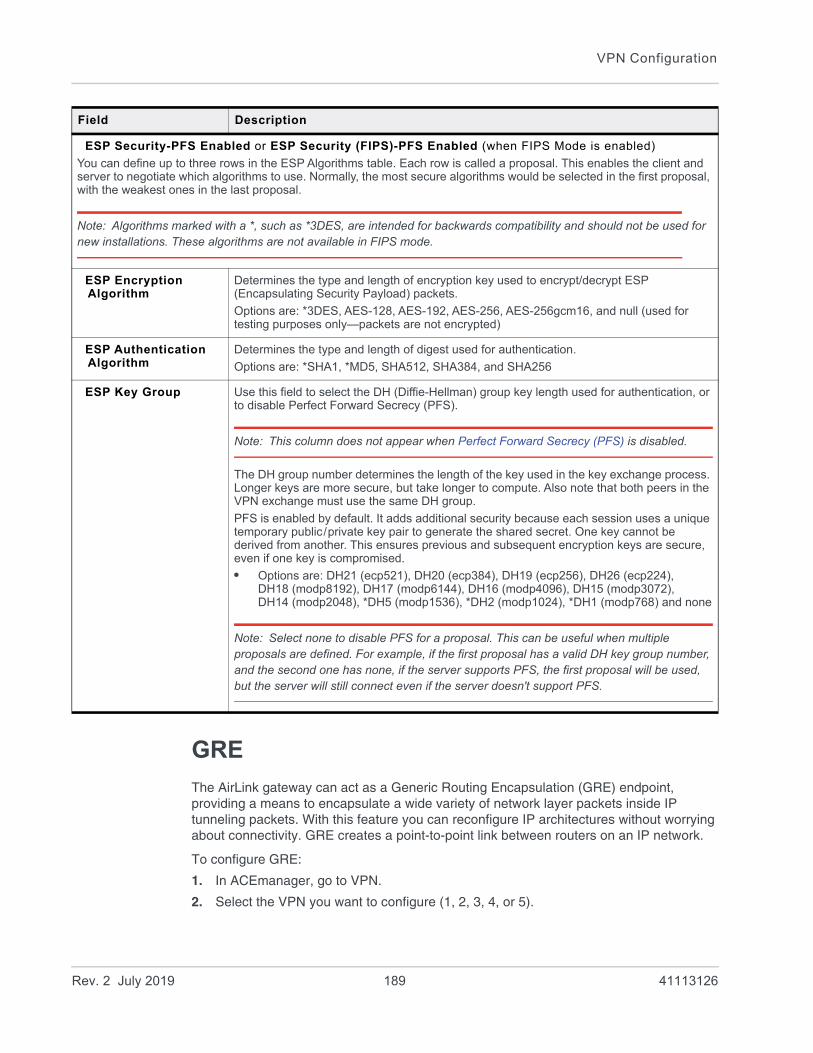
VPN Configuration
GRE
The AirLink gateway can act as a Generic Routing Encapsulation (GRE) endpoint, providing a means to encapsulate a wide variety of network layer packets inside IP tunneling packets. With this feature you can reconfigure IP architectures without worrying about connectivity. GRE creates a point-to-point link between routers on an IP network.
To configure GRE:
1. In ACEmanager, go to VPN.
2. Select the VPN you want to configure (1, 2, 3, 4, or 5).
ESP Security-PFS Enabled or ESP Security (FIPS)-PFS Enabled (when FIPS Mode is enabled)
You can define up to three rows in the ESP Algorithms table. Each row is called a proposal. This enables the client and server to negotiate which algorithms to use. Normally, the most secure algorithms would be selected in the first proposal, with the weakest ones in the last proposal.
Note: Algorithms marked with a *, such as *3DES, are intended for backwards compatibility and should not be used for new installations. These algorithms are not available in FIPS mode.
ESP Encryption Algorithm
Determines the type and length of encryption key used to encrypt/decrypt ESP (Encapsulating Security Payload) packets.
Options are: *3DES, AES-128, AES-192, AES-256, AES-256gcm16, and null (used for testing purposes only—packets are not encrypted)
ESP Authentication Algorithm
Determines the type and length of digest used for authentication.
Options are: *SHA1, *MD5, SHA512, SHA384, and SHA256
ESP Key Group Use this field to select the DH (Diffie-Hellman) group key length used for authentication, or to disable Perfect Forward Secrecy (PFS).
Note: This column does not appear when Perfect Forward Secrecy (PFS) is disabled.
The DH group number determines the length of the key used in the key exchange process. Longer keys are more secure, but take longer to compute. Also note that both peers in the VPN exchange must use the same DH group.
PFS is enabled by default. It adds additional security because each session uses a unique temporary public/private key pair to generate the shared secret. One key cannot be derived from another. This ensures previous and subsequent encryption keys are secure, even if one key is compromised.
• Options are: DH21 (ecp521), DH20 (ecp384), DH19 (ecp256), DH26 (ecp224), DH18 (modp8192), DH17 (modp6144), DH16 (modp4096), DH15 (modp3072), DH14 (modp2048), *DH5 (modp1536), *DH2 (modp1024), *DH1 (modp768) and none
Note: Select none to disable PFS for a proposal. This can be useful when multiple proposals are defined. For example, if the first proposal has a valid DH key group number, and the second one has none, if the server supports PFS, the first proposal will be used, but the server will still connect even if the server doesn't support PFS.
Field Description
Rev. 2 July 2019 189 41113126
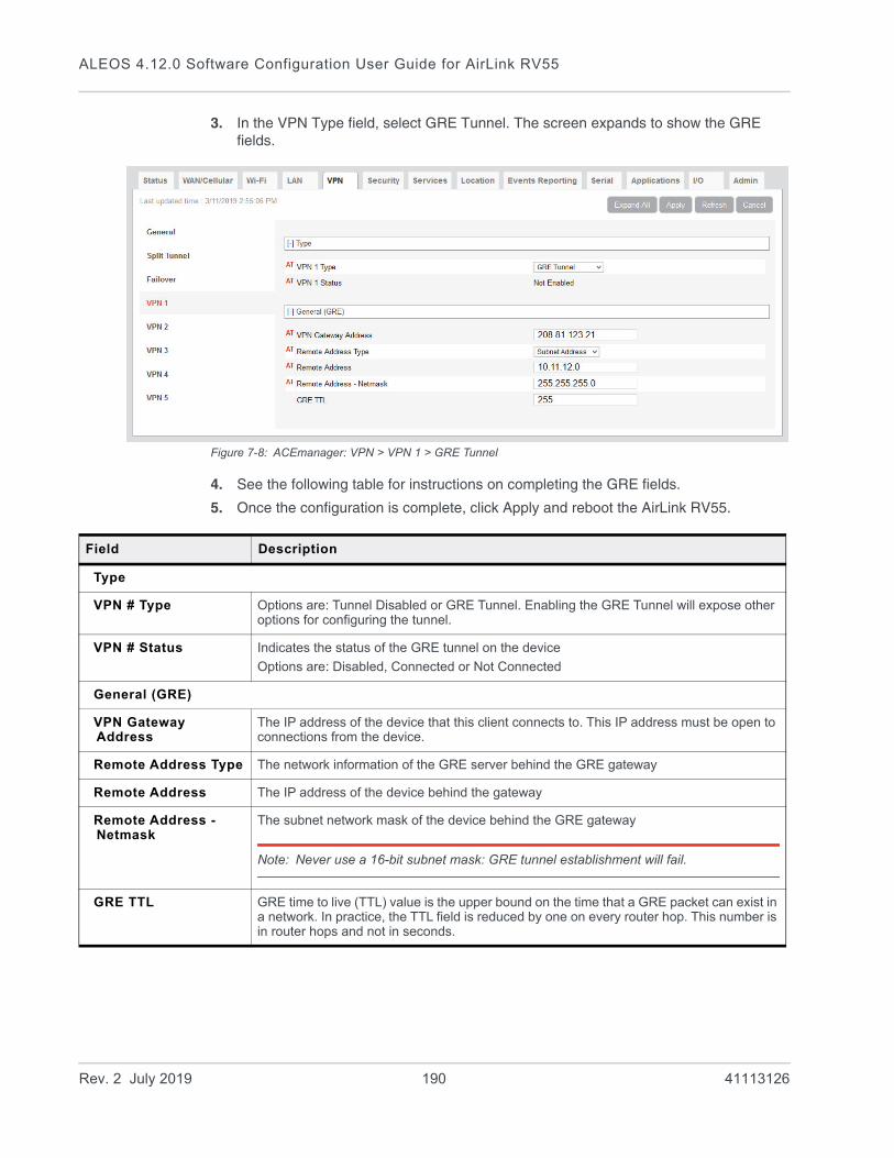
ALEOS 4.12.0 Software Configuration User Guide for AirLink RV55
3. In the VPN Type field, select GRE Tunnel. The screen expands to show the GRE fields.
Figure 7-8: ACEmanager: VPN > VPN 1 > GRE Tunnel
4. See the following table for instructions on completing the GRE fields.
5. Once the configuration is complete, click Apply and reboot the AirLink RV55.
Field Description
Type
VPN # Type Options are: Tunnel Disabled or GRE Tunnel. Enabling the GRE Tunnel will expose other options for configuring the tunnel.
VPN # Status Indicates the status of the GRE tunnel on the device
Options are: Disabled, Connected or Not Connected
General (GRE)
VPN Gateway Address
The IP address of the device that this client connects to. This IP address must be open to connections from the device.
Remote Address Type The network information of the GRE server behind the GRE gateway
Remote Address The IP address of the device behind the gateway
Remote Address -Netmask
The subnet network mask of the device behind the GRE gateway
Note: Never use a 16-bit subnet mask: GRE tunnel establishment will fail.
GRE TTL GRE time to live (TTL) value is the upper bound on the time that a GRE packet can exist in a network. In practice, the TTL field is reduced by one on every router hop. This number is in router hops and not in seconds.
Rev. 2 July 2019 190 41113126

VPN Configuration
OpenVPN Tunnel
Note: OpenVPN Tunnel configuration is only available on VPN 1.
OpenVPN uses SSL/TLS to facilitate key exchange and supports up to 256-bit encryption. OpenVPN is capable of crossing network address translators (NATs) and firewalls. Peers can authenticate each other using pre-shared keys, certificates, or username and password.
The AirLink gateway client authenticates the server using a PKI certificate. The server likewise authenticates the client. The Root CA certificate for the server certificate must be loaded on the device.
To configure an OpenVPN tunnel:
1. In ACEmanager, go to VPN.
2. Select the VPN 1.
3. In the VPN Type field, select OpenVPN Tunnel. The screen expands to show the OpenVPN Tunnel fields.
Rev. 2 July 2019 191 41113126
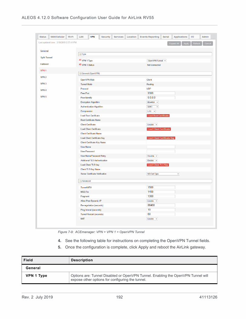
ALEOS 4.12.0 Software Configuration User Guide for AirLink RV55
Figure 7-9: ACEmanager: VPN > VPN 1 > OpenVPN Tunnel
4. See the following table for instructions on completing the OpenVPN Tunnel fields.
5. Once the configuration is complete, click Apply and reboot the AirLink gateway.
Field Description
General
VPN 1 Type Options are: Tunnel Disabled or OpenVPN Tunnel. Enabling the OpenVPN Tunnel will expose other options for configuring the tunnel.
Rev. 2 July 2019 192 41113126
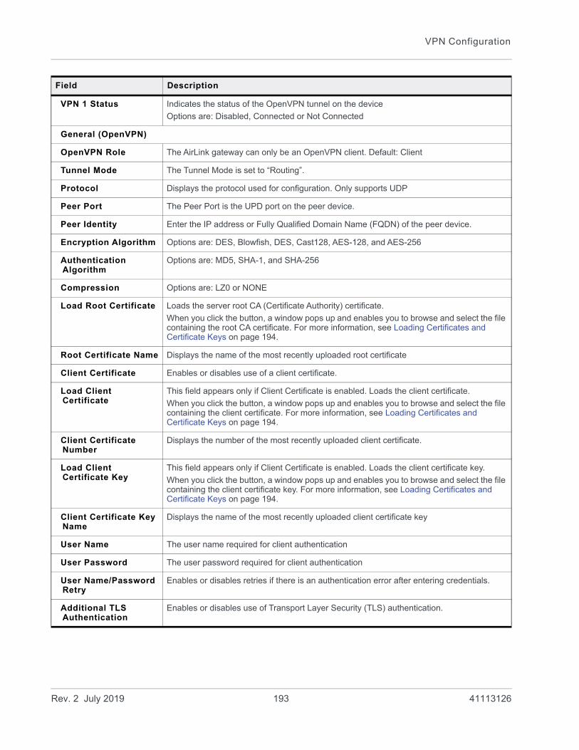
VPN Configuration
VPN 1 Status Indicates the status of the OpenVPN tunnel on the device
Options are: Disabled, Connected or Not Connected
General (OpenVPN)
OpenVPN Role The AirLink gateway can only be an OpenVPN client. Default: Client
Tunnel Mode The Tunnel Mode is set to “Routing”.
Protocol Displays the protocol used for configuration. Only supports UDP
Peer Port The Peer Port is the UPD port on the peer device.
Peer Identity Enter the IP address or Fully Qualified Domain Name (FQDN) of the peer device.
Encryption Algorithm Options are: DES, Blowfish, DES, Cast128, AES-128, and AES-256
Authentication Algorithm
Options are: MD5, SHA-1, and SHA-256
Compression Options are: LZ0 or NONE
Load Root Certificate Loads the server root CA (Certificate Authority) certificate.
When you click the button, a window pops up and enables you to browse and select the file containing the root CA certificate. For more information, see Loading Certificates and Certificate Keys on page 194.
Root Certificate Name Displays the name of the most recently uploaded root certificate
Client Certificate Enables or disables use of a client certificate.
Load Client Certificate
This field appears only if Client Certificate is enabled. Loads the client certificate.
When you click the button, a window pops up and enables you to browse and select the file containing the client certificate. For more information, see Loading Certificates and Certificate Keys on page 194.
Client Certificate Number
Displays the number of the most recently uploaded client certificate.
Load Client Certificate Key
This field appears only if Client Certificate is enabled. Loads the client certificate key.
When you click the button, a window pops up and enables you to browse and select the file containing the client certificate key. For more information, see Loading Certificates and Certificate Keys on page 194.
Client Certificate Key Name
Displays the name of the most recently uploaded client certificate key
User Name The user name required for client authentication
User Password The user password required for client authentication
User Name/Password Retry
Enables or disables retries if there is an authentication error after entering credentials.
Additional TLS Authentication
Enables or disables use of Transport Layer Security (TLS) authentication.
Field Description
Rev. 2 July 2019 193 41113126
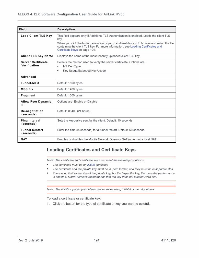
ALEOS 4.12.0 Software Configuration User Guide for AirLink RV55
Loading Certificates and Certificate Keys
Note: The certificate and certificate key must meet the following conditions:
• The certificate must be an X.509 certificate
• The certificate and the private key must be in .pem format, and they must be in separate files.
• There is no limit to the size of the private key, but the larger the key, the more the performance is affected. Sierra Wireless recommends that the key does not exceed 2048 bits.
Note: The RV55 supports pre-defined cipher suites using 128-bit cipher algorithms.
To load a certificate or certificate key:
1. Click the button for the type of certificate or key you want to upload.
Load Client TLS Key This field appears only if Additional TLS Authentication is enabled. Loads the client TLS key.
When you click the button, a window pops up and enables you to browse and select the file containing the client TLS key. For more information, see Loading Certificates and Certificate Keys on page 194.
Client TLS Key Name Displays the name of the most recently uploaded client TLS key.
Server Certificate Verification
Selects the method used to verify the server certificate. Options are:
• NS Cert Type
• Key Usage/Extended Key Usage
Advanced
Tunnel-MTU Default: 1500 bytes
MSS Fix Default: 1400 bytes
Fragment Default: 1300 bytes
Allow Peer Dynamic IP
Options are: Enable or Disable
Re-negotiation (seconds)
Default: 86400 (24 hours)
Ping Interval (seconds)
Sets the keep-alive sent by the client. Default: 10 seconds
Tunnel Restart (seconds)
Enter the time (in seconds) for a tunnel restart. Default: 60 seconds
NAT Enables or disables the Mobile Network Operator NAT (note: not a local NAT).
Field Description
Rev. 2 July 2019 194 41113126
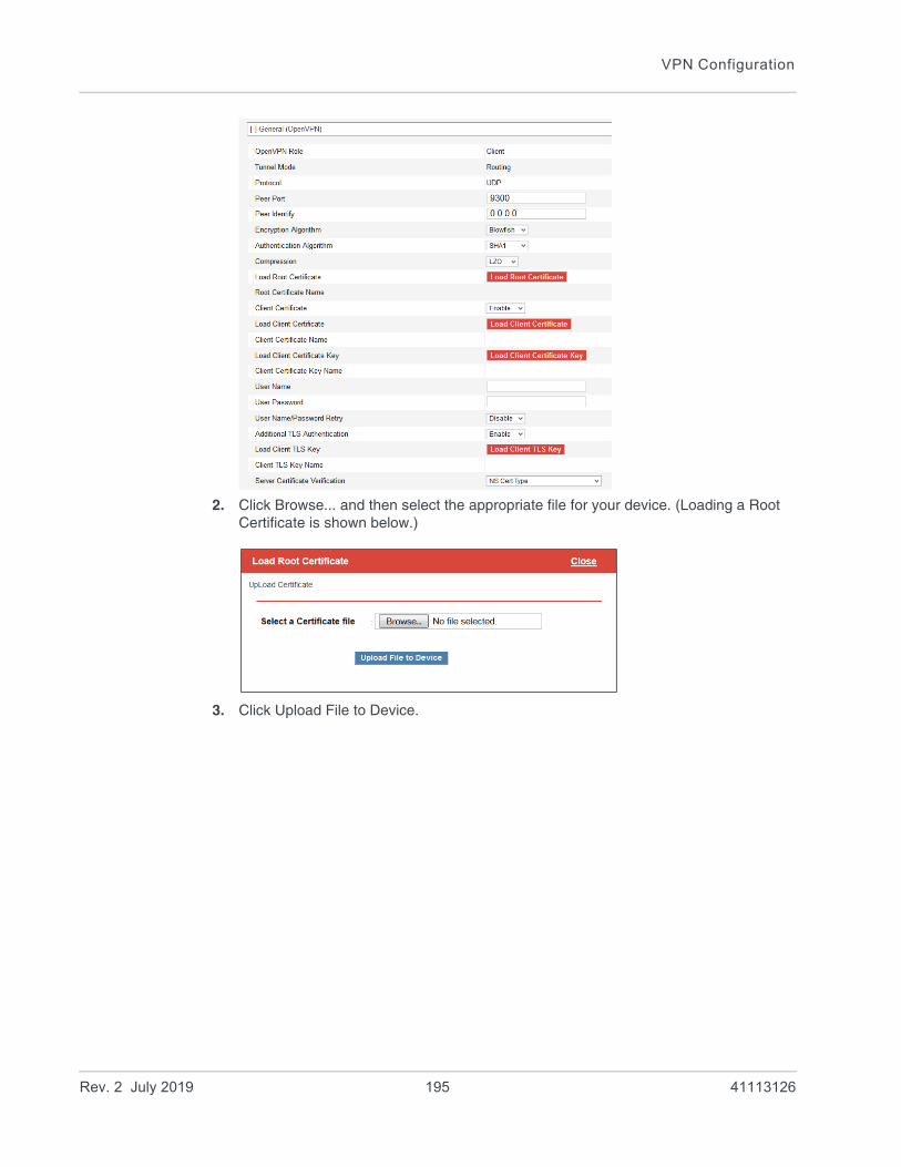
VPN Configuration
2. Click Browse... and then select the appropriate file for your device. (Loading a Root Certificate is shown below.)
3. Click Upload File to Device.
Rev. 2 July 2019 195 41113126
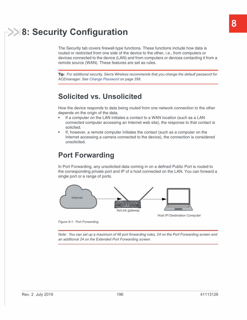
8
8: Security ConfigurationThe Security tab covers firewall-type functions. These functions include how data is routed or restricted from one side of the device to the other, i.e., from computers or devices connected to the device (LAN) and from computers or devices contacting it from a remote source (WAN). These features are set as rules.
Tip: For additional security, Sierra Wireless recommends that you change the default password for ACEmanager. See Change Password on page 358.
Solicited vs. Unsolicited
How the device responds to data being routed from one network connection to the other depends on the origin of the data. • If a computer on the LAN initiates a contact to a WAN location (such as a LAN
connected computer accessing an Internet web site), the response to that contact is solicited.
• If, however, a remote computer initiates the contact (such as a computer on the Internet accessing a camera connected to the device), the connection is considered unsolicited.
Port Forwarding
In Port Forwarding, any unsolicited data coming in on a defined Public Port is routed to the corresponding private port and IP of a host connected on the LAN. You can forward a single port or a range of ports.
Figure 8-1: Port Forwarding
Note: You can set up a maximum of 48 port forwarding rules, 24 on the Port Forwarding screen and an additional 24 on the Extended Port Forwarding screen.
Internet
AirLink gateway
Host IP/Destination Computer
Rev. 2 July 2019 196 41113126
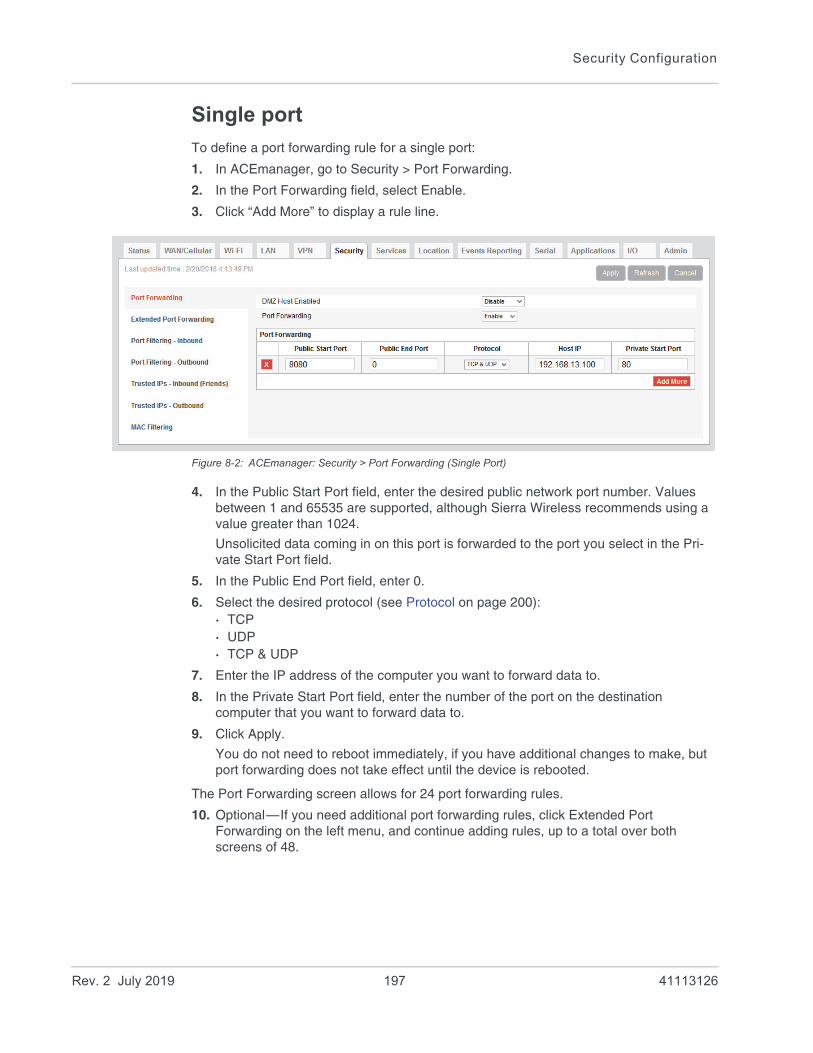
Security Configuration
Single port
To define a port forwarding rule for a single port:
1. In ACEmanager, go to Security > Port Forwarding.
2. In the Port Forwarding field, select Enable.
3. Click “Add More” to display a rule line.
Figure 8-2: ACEmanager: Security > Port Forwarding (Single Port)
4. In the Public Start Port field, enter the desired public network port number. Values between 1 and 65535 are supported, although Sierra Wireless recommends using a value greater than 1024.
Unsolicited data coming in on this port is forwarded to the port you select in the Pri-vate Start Port field.
5. In the Public End Port field, enter 0.
6. Select the desired protocol (see Protocol on page 200):· TCP· UDP· TCP & UDP
7. Enter the IP address of the computer you want to forward data to.
8. In the Private Start Port field, enter the number of the port on the destination computer that you want to forward data to.
9. Click Apply.
You do not need to reboot immediately, if you have additional changes to make, but port forwarding does not take effect until the device is rebooted.
The Port Forwarding screen allows for 24 port forwarding rules.
10. Optional—If you need additional port forwarding rules, click Extended Port Forwarding on the left menu, and continue adding rules, up to a total over both screens of 48.
Rev. 2 July 2019 197 41113126
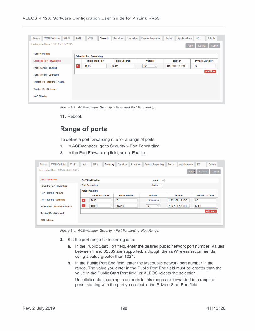
ALEOS 4.12.0 Software Configuration User Guide for AirLink RV55
Figure 8-3: ACEmanager: Security > Extended Port Forwarding
11. Reboot.
Range of ports
To define a port forwarding rule for a range of ports:
1. In ACEmanager, go to Security > Port Forwarding.
2. In the Port Forwarding field, select Enable.
Figure 8-4: ACEmanager: Security > Port Forwarding (Port Range)
3. Set the port range for incoming data:
a. In the Public Start Port field, enter the desired public network port number. Values between 1 and 65535 are supported, although Sierra Wireless recommends using a value greater than 1024.
b. In the Public Port End field, enter the last public network port number in the range. The value you enter in the Public Port End field must be greater than the value in the Public Start Port field, or ALEOS rejects the selection.
Unsolicited data coming in on ports in this range are forwarded to a range of ports, starting with the port you select in the Private Start Port field.
Rev. 2 July 2019 198 41113126

Security Configuration
4. Select the desired protocol (see Protocol on page 200): · TCP· UDP· TCP & UDP
5. Enter the IP address of the computer you want to forward data to.
To forward a port to a local ALEOS Service, set the Host IP to 127.0.0.1.
6. In the Private Start Port field, enter the starting port number for the range of ports on the destination computer that you want to forward data to.
7. If you want to add another range, click Add More to display a new rule line.
8. Click Apply.
The Port Forwarding screen allows for 24 port forwarding rules.
9. Optional—If you need additional port forwarding rules, click Extended Port Forwarding on the left menu, and continue adding rules, up to a total over both screens of 48.
Figure 8-5: ACEmanager: Security > Extended Port Forwarding
10. Reboot.
You do not need to reboot immediately, if you have additional changes to make, but port forwarding does not take effect until the device is rebooted.
Note: Sierra Wireless recommends that the total number of port forwardings be fewer than 1000 ports, including single port forwarding and port forwarding within a range.
Field Description
Port Forwarding Enables port forwarding rules. Options are Enable and Disable (default).
Public Start Port Port on the public network or starting port on the public network for a range of ports.
• Supported values: 1–65535 (Recommended values: greater than 1024)
Rev. 2 July 2019 199 41113126

ALEOS 4.12.0 Software Configuration User Guide for AirLink RV55
Port Forwarding Example
The following example shows you how to configure a port forward rule for a range of 6 ports on an Ethernet-connected device:
1. In ACEmanager, go to Security > Port Forwarding, and enable Port Forwarding.
2. Click “Add More” to display a rule line.
3. Enter 8080 for the Public Start Port.
4. Enter 8085 for the Public End Port.
5. Select TCP & UDP.
6. Enter 192.168.13.100 as the Host IP.
7. Enter 80 as the Private Start Port.
Figure 8-6: ACEmanager: Port Forwarding example
8. Click Apply.
9. Reboot.
You do not need to reboot immediately, if you have additional changes to make, but port forwarding does not take effect until the device is rebooted.
Public End Port Ending port for a range of ports on the public network.
• For a single port forwarding, this field must be 0.
• For a range of ports, this value must be greater than the value in the Public Start Port field.
Protocol The protocol to be used with the forwarded port:
• TCP—Only unsolicited data requests using TCP are forwarded
• UDP—Only unsolicited data requests using UDP are forwarded
• TCP & UDP—Unsolicited data requests using either TCP or UDP are forwarded
Host IP IP address of the computer (or device) you want to forward data to.
Private Start Port Port on the destination computer used as the port for single port forwarding rules, or as the start port for a port forwarding range.
Field Description
Rev. 2 July 2019 200 41113126

Security Configuration
An unsolicited TCP and UDP data request coming in to the AirLink gateway on port 8080 is forwarded to the LAN connected device, 192.168.13.100, at port 80. In addition, unsolicited data requests coming in from the Internet on ports 8081, 8082, 8083, 8084, and 8085 are forwarded to ports 81, 82, 83, 84, and 85 respectively.
DMZ
The DMZ is used to direct unsolicited inbound traffic to a specific LAN device such as a computer running a web server or other internal application. The DMZ with public mode is particularly useful for certain services like VPN, NetMeeting, and streaming video where the remote server may require a WAN connection to the LAN device rather than being NATed by the router.
Options for DMZ are Automatic, Manual, and Disable (default is Disable).
Automatic uses the first connected device. If more than one host is available (multiple Ethernet on a switch connected to the device and/or Ethernet with USBnet) and you want to specify the host to use as the DMZ, select Manual and enter the IP address of the desired host.
Figure 8-7: ACEmanager: Security > Port Forwarding (DMZ)
Field Description
DMZ Host Enabled The AirLink gateway allows a single client to connect to the Internet through a demilitarized zone (DMZ). Options are:
• Automatic—enables the first connected device or the Public Mode interface as the DMZ
• Manual—inserts a specific IP address in the DMZ IP field
• Disable—no connected device receives unsolicited traffic from the cellular network or Internet (default)
Rev. 2 July 2019 201 41113126
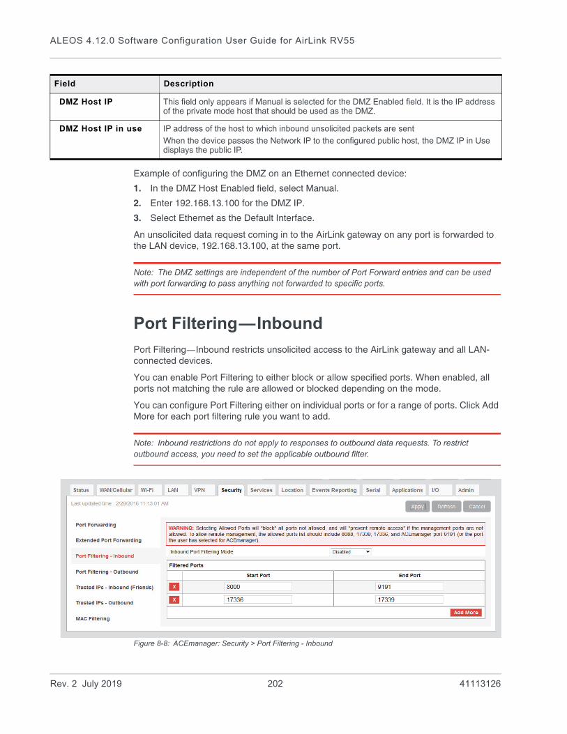
ALEOS 4.12.0 Software Configuration User Guide for AirLink RV55
Example of configuring the DMZ on an Ethernet connected device:
1. In the DMZ Host Enabled field, select Manual.
2. Enter 192.168.13.100 for the DMZ IP.
3. Select Ethernet as the Default Interface.
An unsolicited data request coming in to the AirLink gateway on any port is forwarded to the LAN device, 192.168.13.100, at the same port.
Note: The DMZ settings are independent of the number of Port Forward entries and can be used with port forwarding to pass anything not forwarded to specific ports.
Port Filtering—Inbound
Port Filtering—Inbound restricts unsolicited access to the AirLink gateway and all LAN-connected devices.
You can enable Port Filtering to either block or allow specified ports. When enabled, all ports not matching the rule are allowed or blocked depending on the mode.
You can configure Port Filtering either on individual ports or for a range of ports. Click Add More for each port filtering rule you want to add.
Note: Inbound restrictions do not apply to responses to outbound data requests. To restrict outbound access, you need to set the applicable outbound filter.
Figure 8-8: ACEmanager: Security > Port Filtering - Inbound
DMZ Host IP This field only appears if Manual is selected for the DMZ Enabled field. It is the IP address of the private mode host that should be used as the DMZ.
DMZ Host IP in use IP address of the host to which inbound unsolicited packets are sent
When the device passes the Network IP to the configured public host, the DMZ IP in Use displays the public IP.
Field Description
Rev. 2 July 2019 202 41113126

Security Configuration
Warning: Selecting Allowed Ports will *block* all ports not allowed, and will *prevent remote access* if the management ports are not allowed. To allow remote management, the allowed ports list should include 8088, 17339, 17336, and ACEmanager port 9191 (or the port you selected for ACEmanager).
Port Filtering — Outbound
Port Filtering—Outbound restricts LAN access to the external network, i.e., the Internet.
Port Filtering can be enabled to block ports specified or allow specified ports. When enabled, all ports not matching the rule will be allowed or blocked depending on the mode.
Port Filtering can be configured on individual ports or for a range of ports. Click Add More for each port filtering rule you want to add.
Note: Outbound restrictions do not apply to responses to inbound data requests. To restrict inbound access, you need to set the applicable inbound filter.
Figure 8-9: ACEmanager: Security > Port Filtering - Outbound
Field Description
Inbound Port Filtering Mode
Options are:
• Disable (default)
• Blocked Ports—ports through which traffic is blocked (Shown in Filtered Ports list)
• Allowed Ports—ports through which traffic is allowed (Shown in Filtered Ports list)
Filtered Ports
Start Port A single port or the first port in a range of ports on the public network (mobile network accessible)
End Port The end of the range on the public network (mobile network accessible).
Rev. 2 July 2019 203 41113126

ALEOS 4.12.0 Software Configuration User Guide for AirLink RV55
Field Description
Outbound Port Filtering Mode
Allowed and blocked ports through which traffic is either allowed or blocked (respectively) are listed. Options are:
• Disable (default)
• Blocked Ports—ports through which traffic is blocked (Shown in Filtered Ports list)
• Allowed Ports—ports through which traffic is allowed (Shown in Filtered Ports list)
Note: Outbound IP filter supports up to 9 ports.
Start Port The first of a range or a single port on the LAN
End Port The end of the range on the LAN
Rev. 2 July 2019 204 41113126

Security Configuration
Trusted IPs—Inbound (Friends)
Trusted IPs—Inbound restricts access to the AirLink gateway and all LAN connected devices.
Tip: Trusted IPs-Inbound was called Friends List in legacy AirLink products.
When enabled, IP packets with a source address not matching those in the list or range of trusted hosts will be ignored/dropped by the gateway.
Note: Inbound restrictions do not apply to responses to outbound data requests. To restrict outbound access, you need to set the applicable outbound filter.
Figure 8-10: ACEmanager: Security >Trusted IPs - Inbound (Friends)
Field Description
Inbound Trusted IP (Friends List) Mode
Disables or Enables port forwarding rules. Options are Disable (default) or Enable.
Inbound Trusted IP List
Enter a single trusted IP address for example 64.100.100.2. Click Add More to add additional IP addresses to the list.
Inbound Trusted IP Range
Use this section of the page to enter a range of trusted IP addresses.
Range Start Specify the start and end IP addresses for the trusted IP address range, for example, entering 64.100.10.2 as the Range Start and 64.100.10.15 as the Ranges End would allow 64.100.10.5 but would not allow 64.100.10.16.Range End
Rev. 2 July 2019 205 41113126

ALEOS 4.12.0 Software Configuration User Guide for AirLink RV55
Trusted IPs—Outbound
Trusted IPs—Outbound restricts LAN access to the external network (Internet).
When enabled, only packets with the destination IP addresses matching those in the list of trusted hosts will be routed from the LAN to the external location.
Note: Outbound restrictions do not apply to responses to inbound data requests. To restrict inbound access, you need to set the applicable inbound filter.
Figure 8-11: ACEmanager: Security > Trusted IPs - Outbound
Field Description
Outbound Firewall Mode
Disables or enables the Outbound Firewall
Options are:
• Disable (default)—Allows all outbound traffic
• Enable—Only outbound traffic destined for an IP address on the Trusted IP list is allowed. All other outbound traffic is blocked.
Outbound Trusted IP List
Each entry can be configured to allow a single IP address (e.g., 64.100.100.2) Click Add More to add additional IP addresses to the list.
Rev. 2 July 2019 206 41113126
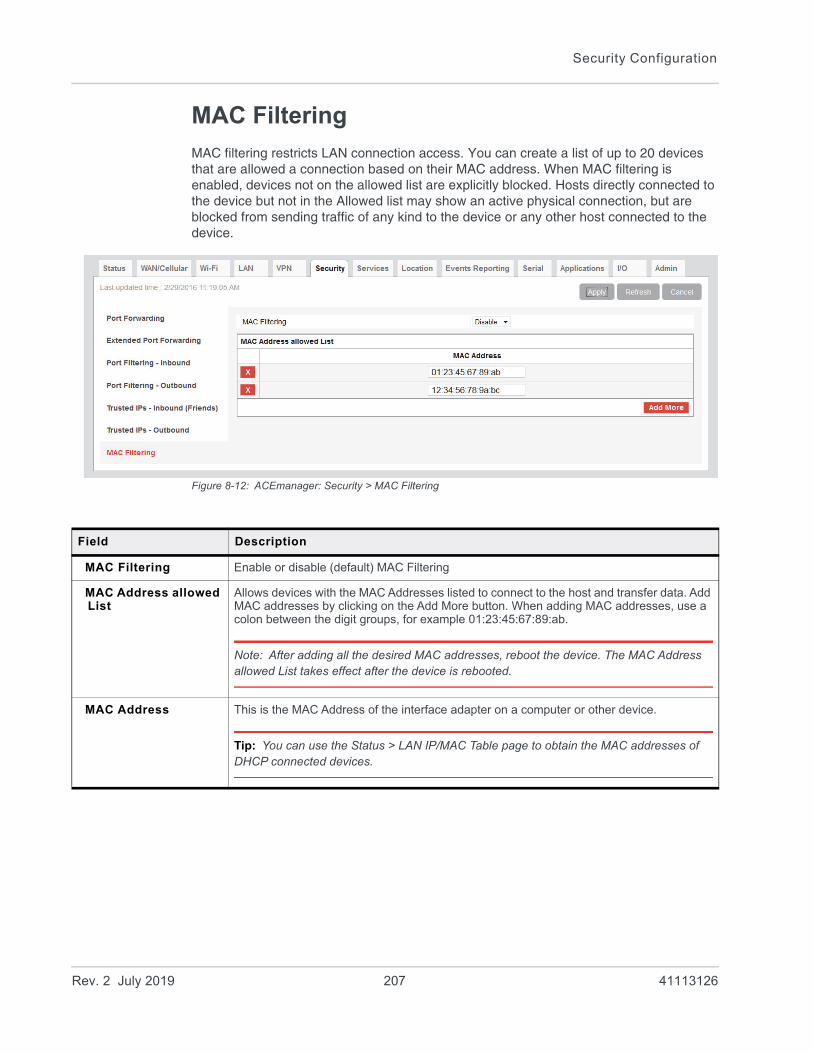
Security Configuration
MAC Filtering
MAC filtering restricts LAN connection access. You can create a list of up to 20 devices that are allowed a connection based on their MAC address. When MAC filtering is enabled, devices not on the allowed list are explicitly blocked. Hosts directly connected to the device but not in the Allowed list may show an active physical connection, but are blocked from sending traffic of any kind to the device or any other host connected to the device.
Figure 8-12: ACEmanager: Security > MAC Filtering
Field Description
MAC Filtering Enable or disable (default) MAC Filtering
MAC Address allowed List
Allows devices with the MAC Addresses listed to connect to the host and transfer data. Add MAC addresses by clicking on the Add More button. When adding MAC addresses, use a colon between the digit groups, for example 01:23:45:67:89:ab.
Note: After adding all the desired MAC addresses, reboot the device. The MAC Address allowed List takes effect after the device is rebooted.
MAC Address This is the MAC Address of the interface adapter on a computer or other device.
Tip: You can use the Status > LAN IP/MAC Table page to obtain the MAC addresses of DHCP connected devices.
Rev. 2 July 2019 207 41113126

9
9: Services ConfigurationThe Services tab sections allow the configuration of external services that extend the functionality of the AirLink RV55.
ALMS (AirLink Management Service)
Figure 9-1: ACEmanager: Services > ALMS
Rev. 2 July 2019 208 41113126
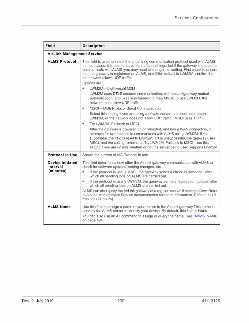
Services Configuration
Field Description
AirLink Management Service
ALMS Protocol This field is used to select the underlying communication protocol used with ALMS. In most cases, it is best to leave the default settings, but if the gateway is unable to communicate with ALMS, you may need to change this setting. First check to ensure that the gateway is registered on ALMS, and if the default is LWM2M, confirm that the network allows UDP traffic.
Options are:
• LWM2M—Lightweight M2M
LWM2M uses DTLS secured communication, with server/gateway mutual authentication, and uses less bandwidth than MSCI. To use LWM2M, the network must allow UDP traffic.
• MSCI—Multi-Protocol Serial Communication
Select this setting if you are using a private server that does not support LWM2M, or the network does not allow UDP traffic. (MSCI uses TCP.)
• Try LWM2M, Fallback to MSCI
After the gateway is powered on or rebooted, and has a WAN connection, it attempts for two minutes to communicate with ALMS using LWM2M. If it is successful, the field is reset to LWM2M. If it is unsuccessful, the gateway uses MSCI, and the setting remains as Try LWM2M, Fallback to MSCI. Use this setting if you are unsure whether or not the server being used supports LWM2M.
Protocol in Use Shows the current ALMS Protocol in use
Device Initiated Interval (minutes)
This field determines how often the AirLink gateway communicates with ALMS to check for software updates, setting changes, etc.
• If the protocol in use is MSCI, the gateway sends a check-in message, after which all pending jobs on ALMS are carried out.
• If the protocol in use is LWM2M, the gateway sends a registration update, after which all pending jobs on ALMS are carried out.
ALMS can also query the AirLink gateway at a regular interval if settings allow. Refer to AirLink Management Service documentation for more information. Default: 1440 minutes (24 hours).
ALMS Name Use this field to assign a name of your choice to the AirLink gateway.This name is used by the ALMS server to identify your device. By default, this field is blank.
You can also use an AT command to assign or query the name. See *AVMS_NAME on page 494.
Rev. 2 July 2019 209 41113126
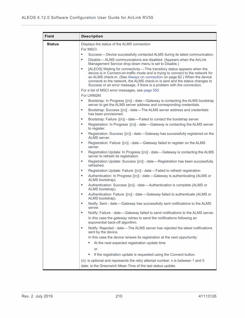
ALEOS 4.12.0 Software Configuration User Guide for AirLink RV55
Status Displays the status of the ALMS connection
For MSCI:
• Success— Device successfully contacted ALMS during its latest communication.
• Disable— ALMS communications are disabled. (Appears when the AirLink Management Service drop-down menu is set to Disable.)
• [ALEOS] Waiting for connectivity —This transitory status appears when the device is in Connect-on-traffic mode and is trying to connect to the network for an ALMS check-in. (See Always on connection on page 82.) When the device connects to the network, the ALMS check-in is sent and the status changes to Success or an error message, if there is a problem with the connection.
For a list of MSCI error messages, see page 550.
For LWM2M:
• Bootstrap: In Progress [(n)] - date—Gateway is contacting the ALMS bootstrap server to get the ALMS server address and corresponding credentials.
• Bootstrap: Success [(n)] - date—The ALMS server address and credentials has been provisioned.
• Bootstrap: Failure [(n)] - date—Failed to contact the bootstrap server
• Registration: In Progress [(n)] - date—Gateway is contacting the ALMS server to register.
• Registration: Success [(n)] - date—Gateway has successfully registered on the ALMS server.
• Registration: Failure [(n)] - date—Gateway failed to register on the ALMS server.
• Registration Update: In Progress [(n)] - date—Gateway is contacting the ALMS server to refresh its registration.
• Registration Update: Success [(n)] - date—Registration has been successfully refreshed.
• Registration Update: Failure [(n)] - date—Failed to refresh registration
• Authentication: In Progress [(n)] - date—Gateway is authenticating (ALMS or ALMS bootstrap).
• Authentication: Success [(n)] - date—Authentication is complete (ALMS or ALMS bootstrap).
• Authentication: Failure [(n)] - date—Gateway failed to authenticate (ALMS or ALMS bootstrap).
• Notify: Sent - date—Gateway has successfully sent notifications to the ALMS server.
• Notify: Failure - date—Gateway failed to send notifications to the ALMS server.
In this case the gateway retries to send the notifications following an exponential back-off algorithm.
• Notify: Rejected - date—The ALMS server has rejected the latest notifications sent by the device.
In this case the device renews its registration at the next opportunity:
• At the next expected registration update time
or
• If the registration update is requested using the Connect button.
(n): is optional and represents the retry attempt number. n is between 1 and 5
date: is the Greenwich Mean Time of the last status update.
Field Description
Rev. 2 July 2019 210 41113126
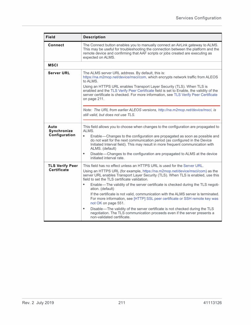
Services Configuration
Connect The Connect button enables you to manually connect an AirLink gateway to ALMS. This may be useful for troubleshooting the connection between the platform and the remote device and confirming that AAF scripts or jobs created are executing as expected on ALMS.
MSCI
Server URL The ALMS server URL address. By default, this is:https://na.m2mop.net/device/msci/com, which encrypts network traffic from ALEOS to ALMS.
Using an HTTPS URL enables Transport Layer Security (TLS). When TLS is enabled and the TLS Verify Peer Certificate field is set to Enable, the validity of the server certificate is checked. For more information, see TLS Verify Peer Certificate on page 211.
Note: The URL from earlier ALEOS versions, http://na.m2mop.net/device/msci, is still valid, but does not use TLS.
Auto Synchronize Configuration
This field allows you to choose when changes to the configuration are propagated to ALMS.
• Enable—Changes to the configuration are propagated as soon as possible and do not wait for the next communication period (as configured in the Device Initiated Interval field). This may result in more frequent communication with ALMS. (default)
• Disable—Changes to the configuration are propagated to ALMS at the device initiated interval rate.
TLS Verify Peer Certificate
This field has no effect unless an HTTPS URL is used for the Server URL.
Using an HTTPS URL (for example, https://na.m2mop.net/device/msci/com) as the server URL enables Transport Layer Security (TLS). When TLS is enabled, use this field to set the TLS certificate validation.
• Enable—The validity of the server certificate is checked during the TLS negoti-ation. (default)
If the certificate is not valid, communication with the ALMS server is terminated. For more information, see [HTTP] SSL peer certificate or SSH remote key was not OK on page 551.
• Disable—The validity of the server certificate is not checked during the TLS negotiation. The TLS communication proceeds even if the server presents a non-validated certificate.
Field Description
Rev. 2 July 2019 211 41113126
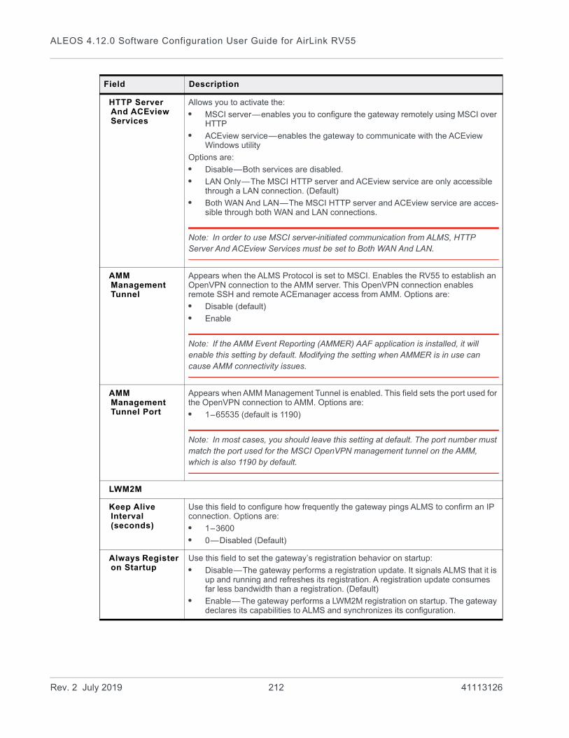
ALEOS 4.12.0 Software Configuration User Guide for AirLink RV55
HTTP Server And ACEview Services
Allows you to activate the:
• MSCI server—enables you to configure the gateway remotely using MSCI over HTTP
• ACEview service—enables the gateway to communicate with the ACEview Windows utility
Options are:
• Disable—Both services are disabled.
• LAN Only—The MSCI HTTP server and ACEview service are only accessible through a LAN connection. (Default)
• Both WAN And LAN—The MSCI HTTP server and ACEview service are acces-sible through both WAN and LAN connections.
Note: In order to use MSCI server-initiated communication from ALMS, HTTP Server And ACEview Services must be set to Both WAN And LAN.
AMM Management Tunnel
Appears when the ALMS Protocol is set to MSCI. Enables the RV55 to establish an OpenVPN connection to the AMM server. This OpenVPN connection enables remote SSH and remote ACEmanager access from AMM. Options are:
• Disable (default)
• Enable
Note: If the AMM Event Reporting (AMMER) AAF application is installed, it will enable this setting by default. Modifying the setting when AMMER is in use can cause AMM connectivity issues.
AMM Management Tunnel Port
Appears when AMM Management Tunnel is enabled. This field sets the port used for the OpenVPN connection to AMM. Options are:
• 1–65535 (default is 1190)
Note: In most cases, you should leave this setting at default. The port number must match the port used for the MSCI OpenVPN management tunnel on the AMM, which is also 1190 by default.
LWM2M
Keep Alive Interval (seconds)
Use this field to configure how frequently the gateway pings ALMS to confirm an IP connection. Options are:
• 1–3600
• 0—Disabled (Default)
Always Register on Startup
Use this field to set the gateway’s registration behavior on startup:
• Disable—The gateway performs a registration update. It signals ALMS that it is up and running and refreshes its registration. A registration update consumes far less bandwidth than a registration. (Default)
• Enable—The gateway performs a LWM2M registration on startup. The gateway declares its capabilities to ALMS and synchronizes its configuration.
Field Description
Rev. 2 July 2019 212 41113126

Services Configuration
ACEmanager
Figure 9-2: ACEmanager: Services > ACEmanager
AAF
ALEOS Application Framework
AAF status: Enabled or Disabled. To enable AAF, see ALEOS Application Framework on page 346.
M3DA Protocol Password
M3DA Protocol Password
This password must be configured on the AirLink device and on ALMS. The default M3DA password is the default ACEmanager password as shown on the device label.
Note: This password is reset to default when the device is reset to factory defaults using the hardware Reset button, or using the Reset to Factory Default command in ACEmanager (when the Reset Mode is Preserve Only User Password or Reset All). See Reset to Factory Default on page 369 and Reset Mode on page 370.
Manual Connection Status
Displays the current manual connection status if AAF is enabled.
Connect The Connect button enables you to manually connect an AirLink device to ALMS. This may be useful for troubleshooting the connection between the platform and the remote device and confirming that AAF scripts or jobs created are executing as expected on ALMS.
Field Description
Rev. 2 July 2019 213 41113126

ALEOS 4.12.0 Software Configuration User Guide for AirLink RV55
Field Description
General
Remote Access Configure ACEmanager remote access (over the WAN link)
Options are:
• Disable (default)
• HTTPS Only
• Both HTTP and HTTPS
Local Access Configure ACEmanager local access (Ethernet, USBnet, or Serial/DUN)
Options are:
• HTTPS Only
• Both HTTP and HTTPS (default)
Wi-Fi AP Access Configure ACEmanager Wi-Fi network access (for clients connected to the gateway)
Options are:
• Same as Local (default)
• Disabled
HTTP Port Configure the HTTP port for ACEmanager access. Reboot the device after applying the port change.
Default value is 9191.
HTTPS Port Configure the HTTPS port for ACEmanager access. Reboot the device after applying the port change.
Default is 9443.
Session Idle Timeout (minutes)
If ACEmanager is idle for the configured timeout, it automatically logs out and returns you to the Login screen. Options are:
• 0–60 (minutes)
Default is 15
If you set the Session Idle Timeout to zero (0), the session remains active until you manually log out.
Maximum Login Attempts
Number of failed login attempts allowed before the user account is temporarily locked
Options are:
• 0—The account lock-out feature is disabled.
• 1–5—Maximum number of failed login attempts before the user account is locked for the length of time specified in the Unlock Time (seconds) field
Default is 3
Unlock Time (seconds)
The length of time (in seconds) that the user account is locked after the maximum number of failed login attempts (configured in Maximum Login Attempts)
Options are:
• 1–3600 (1 hour)
Default is 120 (2 minutes)
Rev. 2 July 2019 214 41113126

Services Configuration
Advanced
Custom Certificate
Enabling this feature allows you to load a custom SSL certificate. (Some restrictions apply; see Note below for details.)
Options are:
• Enable—Additional fields appear that allow you to load a custom SSL certif-icate and a custom private key. The ACEmanager web server uses this custom certificate for authentication during HTTPS communication, instead of the default certificate.
• Disable—The ACEmanager web server uses the default SSL certificate for authentication during HTTPS communication. (default)
Note: The custom certificate and private key must meet the following conditions:
• The certificate must be an X.509 certificate
• The certificate and the private key must be in .pem format, and they must be in separate files.
• There is no limit to the size of the private key, but the larger the key, the more the performance is affected. Sierra Wireless recommends that the key does not exceed 2048 bits.
Note: The RV55 supports pre-defined cipher suites using 128-bit cipher algorithms.
Load Custom Certificate
This field only appears when the Custom Certificate field is set to Enable.
To load a custom SSL certificate:
1. Click Load Custom Certificate.
2. Click Browse... and navigate to the SSL certificate file.
3. Click Upload file to device.
4. Once you have uploaded the custom certificate and the custom private key, click Apply and reboot the device.
Custom Certificate Name
This field only appears when the Custom Certificate field is set to Enable.
Displays the name of the custom certificate.
Load Custom Private Key
This field only appears when the Custom Certificate field is set to Enable.
Allows you to enter a custom private key (Some restrictions apply; see Custom Certificate for details.)
To load a custom private key:
1. Click Load Private Key.
2. Click Browse... and navigate to the private key file.
3. Click Upload file to device.
4. Once you have uploaded the custom certificate and the custom private key, click Apply and reboot the device.
Custom Private Key Name
This field only appears when the Custom Certificate field is set to Enable.
Displays the name of the private key.
Field Description
Rev. 2 July 2019 215 41113126

ALEOS 4.12.0 Software Configuration User Guide for AirLink RV55
Power Management
The AirLink RV55 gives you a number of options for managing power usage, depending on your application and hardware configuration. For example, you can use the Services > Power Management screen to configure the RV55 to automatically enter standby mode based on the state of the ignition switch, an I/O input, low voltage input to the RV55, or time of day.
Figure 9-3: ACEmanager: Services > Power Management
Field Description
Ignition Shutdown Delay
Shutdown Delay after Ignition off (seconds)
Set the delay (in seconds) between the time the ignition input goes low and the RV55 shuts down.
• Range: 2–65535 (18 hours)
• Default is 2.
The timer is reset if the ignition comes on during the delay period.
Rev. 2 July 2019 216 41113126

Services Configuration
Low Voltage
Note: Changes to the low voltage settings take effect when you click Apply, but the new values are not permanently stored on the gateway it is rebooted. Also note that, after a change is made, the first reboot may take longer than usual.
Note: Exercise caution when setting the Low Voltage Standby fields. Before setting the Resume immediately at Voltage field, ensure that you have a power source readily available that can supply the configured voltage. The reset button is not available when the gateway is in standby mode, so you cannot use it to reset the gateway to factory default settings. If you have inadvertently set the Resume Voltage too high, follow the instructions in How do I get my RV55 out of Low Voltage Standby mode? to return your gateway to normal operation.
Low Voltage Standby Mode
Use this field to chose a set of predefined values for low voltage standby mode or to enable the option to configure custom values.
• Custom—Allows you to configure the values used for low voltage standby mode. For more information on the configurable fields, see Standby Voltage (100 milliVolts), Standby Qualification Period (seconds), and Resume immediately at Voltage (100 milliVolts). When configuring these fields, the difference between the number in the Standby Voltage field and the number in the Resume immediately at Voltage field must be greater than 5, with the smaller number in the Low Voltage Standby Mode field. For example, if you enter 120 in the Resume immediately at Voltage field, the highest number you can enter in the Low Voltage Standby mode field is 114.
• Automatic—The gateway uses preset values. (default)
• Off —The gateway uses the lowest possible preset values for low voltage standby mode and enters standby mode if the voltage falls below 5.8 V.
Field Description
Table 9-1: Low Voltage Standby Mode Configurable Ranges and Preset Values
Low Voltage Standby Mode
Standby Voltage (100 milliVolts)
Standby Qualification Period (seconds)
Resume immediately at Voltage (100 milliVolts)
Custom 58–294
Default is 90.
30–3600
Default is 30.
68 –300
Default is 105.
Automatic 90 30 105
Off 58 30 68
Rev. 2 July 2019 217 41113126
ALEOS 4.12.0 Software Configuration User Guide for AirLink RV55
Standby Voltage (100 milliVolts)
If the incoming voltage to the gateway is below the value set in this field for the period of time set in the Standby Qualification Period (seconds) field, the gateway goes into standby mode.
This field is read-only if the Low Voltage Standby Mode is set to Automatic or Off. If Low Voltage Standby Mode is set to Custom, the valid range is:
• 58–294 hundreds of milliVolts
• Default value depends on the setting in the Low Voltage Standby Mode field. See Table 9-1.
Enter the value in tenths of Volts. For example, for 11.5 V, enter 115.
The difference between the number in the Standby Voltage field and the number in the Resume immediately at Voltage (100 milliVolts) field must be greater than 5, with the smaller number in the Low Voltage Standby Mode field. For example, if you enter 120 in the Resume immediately at Voltage field, the highest number you can enter in the Low Voltage Standby mode field is 114.
Standby Qualification Period (seconds)
Set the time period (in seconds) that the voltage to the gateway is below the value set in the Standby Voltage (100 milliVolts) field before the gateway goes into standby mode.
This field is read-only if the Low Voltage Standby Mode is set to Automatic or Off. If Low Voltage Standby Mode is set to Custom, the valid range is:
• 30–3600 seconds
• Default is 30.
Resume immediately at Voltage (100 milliVolts)
Set the voltage at which the gateway exits standby mode and resumes normal operation.
This field is read-only if the Low Voltage Standby Mode is set to Automatic or Off. If Low Voltage Standby Mode is set to Custom, the valid range is:
• 68–300 hundreds of milliVolts
• Default value depends on the setting in the Low Voltage Standby Mode field. See Table 9-1.
Enter the value in tenths of Volts. For example, for 12.5 V, enter 125.
The difference between the number in the Standby Voltage (100 milliVolts) field and the number in the Resume immediately at Voltage field must be greater than 5, with the smaller number in the Low Voltage Standby Mode field. For example, if you enter 120 in the Resume immediately at Voltage field, the highest number you can enter in the Low Voltage Standby mode field is 114.
Standby
Use Standby Mode Select the type of Standby mode you want to configure
Options are:
• Disable (default)
• Timed
• I/O
• I/O + Timed
Changes take effect when you click Apply. No reboot is required.
Note: You cannot set this field to I/O or I/O + Timed if the I/O line is already being used by the Relay Output or by the Pull-up for I/O.
Field Description
Rev. 2 July 2019 218 41113126

Services Configuration
Timed
Mode Select the Mode:
• Hourly—Wake Time (HH:MM offset from start of period) and Return to Standby (HH:MM offset from start of period) operate on an hourly basis
• Daily—Wake Time (HH:MM offset from start of period) and Return to Standby (HH:MM offset from start of period) operate on an daily basis
• Custom—Provides the option set a test period to repeat the Wake/Standby cycle
Wake Time (HH:MM offset from start of period)
Set the time (hours:minutes on a 24 hour clock) at which the gateway wakes up.
If you selected Hourly in the Mode field, set the minutes (the hour portion is ignored) and the gateway wakes up every hour at the configured time.
If you selected Daily in the Mode field, the gateway wakes up every day at the configured time.
Return to Standby (HH:MM offset from start of period)
Set the time (hours:minutes on a 24 hour clock) at which the gateway goes into standby mode.
If you selected Hourly in the Mode field, set the minutes (the hour portion is ignored) and the gateway goes into standby mode every hour at the configured time.
If you selected Daily in the Mode field, the gateway goes into standby mode every day at the configured time.
Note: There must be at least 5 minutes between the Wake Time (HH:MM offset from start of period) and the Return to Standby time.
Repeat Period This field only appears if you select Custom in the Mode field.
Use this field to configure how often the Wake Time (HH:MM offset from start of period)/Return to Standby (HH:MM offset from start of period) cycle is repeated. The options are:
• 2 Hours (default)
• 3 Hours
• 4 Hours
• 6 Hours
• 8 Hours
• 12 Hours
Field Description
Rev. 2 July 2019 219 41113126

ALEOS 4.12.0 Software Configuration User Guide for AirLink RV55
I / O
Wake when I/O is Select the I/O state that causes the gateway to wake. Options are:
• High (default)
• Low
Note: If the I /O line is already configured for another purpose, this I/O option is not available.
Delay return to Standby (seconds)
Select the delay between the I/O state change and the gateway entering Standby mode (in seconds).
• Range is 1–43200 (12 hours)
• Default is 1 second.
Field Description
Rev. 2 July 2019 220 41113126

Services Configuration
I/O + Timed
To configure the fields for I/O + Timed, see Timed on page 219 and I/O on page 220.
When both I/O and Timed are configured, the gateway is standby mode only when both I/O and Timed conditions for standby mode are met. The gateway exits standby and returns to the normal operating mode when either the Timed or I/O (or both) conditions for standby are no longer met.
Example: The following example is based on the default settings.
• Timed is set to wake at 10 minutes after the hour and return to standby 50 minutes after the hour.
• I/O is set to wake when the I/O is high.
Field Description
Timed
I/O
Gateway power mode
1:50 2:10 2:50 3:10 3:50 4:10 4:50 5:101:10
Wake
Standby
I/O High
I/O Low
Wake
Standby
(Wake)
(Standby)
Time
Rev. 2 July 2019 221 41113126

ALEOS 4.12.0 Software Configuration User Guide for AirLink RV55
Engine Hours — ALEOS can start and stop counting engine hours based on:
• Voltage on power connector Pin 1 (Power pin) from the vehicle battery (Engine Hours On Voltage Level)
• State (High/Low) of power connector Pin 3 (Ignition Sense pin) (Engine Hours Ignition Enable)
If you configure both fields, both conditions must be met before the device begins counting engine hours.
For more information on the power connector pins, refer to the Hardware Configuration User Guide for your AirLink gateway.
Engine Hours On Voltage Level (100 millivolt)
If you want to use this field to trigger counting engine hours, the AirLink gateway must be using the vehicle battery as a power source (i.e. Pin 1 [VCC] and Pin 2 [ground] on the AirLink gateway’s power connector are connected to the vehicle battery).
Enter the voltage level above which the AirLink gateway starts counting engine hours. When the voltage from the vehicle battery falls below that value, the device stops counting engine hours. Enter the desired value of the ignition in millivolts. For example, to set the voltage level at 13.0 volts, enter 130.
The default value is 0, which means the feature is disabled. Engine hours are not incremented based on the power pin voltage level.
Engine Hours Ignition Enable
If Pin 3 (the ignition sense pin) on the AirLink gateway’s power connector is wired to the vehicle’s ignition switch, oil pressure switch, or some other digital input, you can use this field to trigger counting engine hours. The device starts counting engine hours when the voltage on Pin 3 is high and stops counting when the voltage is low (Ground or 0 volts). For more information on the power connector pins, refer to the Hardware User Guide for your AirLink gateway.
Options are:
• Disable (default) Engine hours are not incremented based on changes to Pin 3.
• Enable
Engine Hours Value (hours)
Displays an estimate of the number of hours the engine has been running, based on either the input voltage from the vehicle battery or the voltage on the ignition sense pin, depending on which of the two previous fields you configured. For more information on the power connector pins, refer to the Hardware User Guide for your AirLink gateway.
You can also set the engine hours value to an initial value. The default value is 0. The maximum allowed value is 65535.
You can also use an AT Command to set this value. For more information, see *ENGHRS on page 494.
Note: You can configure Events Reporting to send reports based on this value. For more information, see Events Reporting Configuration on page 293.
Field Description
Rev. 2 July 2019 222 41113126
Services Configuration
Power LED Configuration
LED Pattern You can configure the Power LED to flash or turn off when the device is in Low Power Mode, which saves power. For more information about RV55 power consumption, see the RV55 Hardware Guide.
Options are:
• On (default)—During Low Power Mode, the Power LED behaves according to the LED Toggle Interval
• Off—LED is off during Low Power Mode
LED Toggle Interval (seconds)
Appears when LED Pattern is set to On. Sets the flashing interval, in seconds, for the Power LED during Low Power Mode.
Options are:
• 0 (default—LED is always on) to 5 (LED flashes once every 5 seconds).
Field Description
Rev. 2 July 2019 223 41113126
ALEOS 4.12.0 Software Configuration User Guide for AirLink RV55
Dynamic DNS
Dynamic DNS allows an AirLink gateway’s WAN IP address to be published either to a proprietary Sierra Wireless dynamic DNS service called IP Manager, or to a 3rd party DNS service.
Whether you have one Sierra Wireless AirLink gateway or multiple devices, it can be difficult to keep track of the current IP addresses especially if the addresses are not static but change every time the devices connect to the mobile network. If you need to connect to a specific gateway, or the device behind it, it is much easier when you have a domain name (mypage.mydomain.com).
Reasons to Contact or Connect to a Device:
• Requesting a location update from a delivery truck• Contacting a surveillance camera to download logs or survey a specific area • Triggering an oil derrick to begin pumping• Sending text to be displayed by a road sign• Updating the songs to be played on a juke box• Updating advertisements to be displayed in a cab• Remote accessing a computer, a PLC, an RTU, or other system• Monitoring and troubleshooting the status of the gateway itself without needing to
bring it in or go out to it.
A dynamic IP address is suitable for many Internet activities such as web browsing, looking up data on another computer system, for data only being sent out, or for data only being received after an initial request (also called Mobile Originated). However, if you need to contact the AirLink gateway directly, a device connected to the AirLink gateway, or a host system using your AirLink gateway (also called Mobile Terminated), a dynamic IP will not give you a reliable address to contact (since it may have changed since the last time it was assigned).
Domain names are often only connected to static IP addresses because of the way most domain name (DNS) servers are set-up. Dynamic DNS servers require notification of IP Address changes so they can update their DNS records and link a dynamic IP address to the correct name.• Dynamic IP addresses are granted only when your AirLink gateway is connected and
can change each time the gateway reconnects to the network.• Static IP addresses are granted the same address every time your AirLink gateway is
connected and are not in use when your gateway is not connected.
Since many mobile network operators, such as wire-based ISPs, do not offer static IP addresses or static address accounts (which can cost a premium as opposed to dynamic accounts), Sierra Wireless AirLink Solutions developed IP Manager. IP Manager works with a Dynamic DNS server to receive notification from Sierra Wireless AirLink gateways to translate the dynamic IP address to a fully qualified domain name. Thus, you can contact your AirLink gateway directly from the Internet using a domain name.
Rev. 2 July 2019 224 41113126
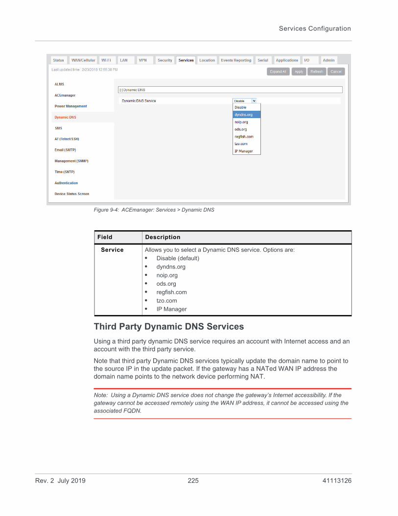
Services Configuration
Figure 9-4: ACEmanager: Services > Dynamic DNS
Third Party Dynamic DNS Services
Using a third party dynamic DNS service requires an account with Internet access and an account with the third party service.
Note that third party Dynamic DNS services typically update the domain name to point to the source IP in the update packet. If the gateway has a NATed WAN IP address the domain name points to the network device performing NAT.
Note: Using a Dynamic DNS service does not change the gateway’s Internet accessibility. If the gateway cannot be accessed remotely using the WAN IP address, it cannot be accessed using the associated FQDN.
Field Description
Service Allows you to select a Dynamic DNS service. Options are:
• Disable (default)
• dyndns.org
• noip.org
• ods.org
• regfish.com
• tzo.com
• IP Manager
Rev. 2 July 2019 225 41113126
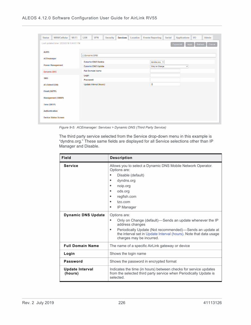
ALEOS 4.12.0 Software Configuration User Guide for AirLink RV55
Figure 9-5: ACEmanager: Services > Dynamic DNS (Third Party Service)
The third party service selected from the Service drop-down menu in this example is “dyndns.org.” These same fields are displayed for all Service selections other than IP Manager and Disable.
Field Description
Service Allows you to select a Dynamic DNS Mobile Network Operator. Options are:
• Disable (default)
• dyndns.org
• noip.org
• ods.org
• regfish.com
• tzo.com
• IP Manager
Dynamic DNS Update Options are:
• Only on Change (default)—Sends an update whenever the IP address changes
• Periodically Update (Not recommended)—Sends an update at the interval set in Update Interval (hours). Note that data usage charges may be incurred.
Full Domain Name The name of a specific AirLink gateway or device
Login Shows the login name
Password Shows the password in encrypted format
Update Interval (hours)
Indicates the time (in hours) between checks for service updates from the selected third party service when Periodically Update is selected.
Rev. 2 July 2019 226 41113126
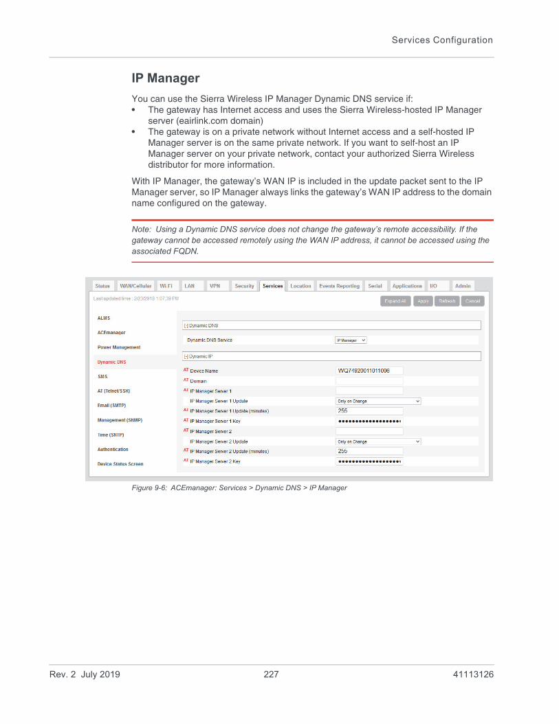
Services Configuration
IP Manager
You can use the Sierra Wireless IP Manager Dynamic DNS service if:• The gateway has Internet access and uses the Sierra Wireless-hosted IP Manager
server (eairlink.com domain)• The gateway is on a private network without Internet access and a self-hosted IP
Manager server is on the same private network. If you want to self-host an IP Manager server on your private network, contact your authorized Sierra Wireless distributor for more information.
With IP Manager, the gateway’s WAN IP is included in the update packet sent to the IP Manager server, so IP Manager always links the gateway’s WAN IP address to the domain name configured on the gateway.
Note: Using a Dynamic DNS service does not change the gateway’s remote accessibility. If the gateway cannot be accessed remotely using the WAN IP address, it cannot be accessed using the associated FQDN.
Figure 9-6: ACEmanager: Services > Dynamic DNS > IP Manager
Rev. 2 July 2019 227 41113126

ALEOS 4.12.0 Software Configuration User Guide for AirLink RV55
Field Description
Device Name The name you want for the device (up to 20 characters)
If you want to use the current device phone number as part of the FQDN (for example, 6175551234.eairlink.com) enter #NETPHONE in this field. #NETPHONE is displayed in this field and everywhere else the device name is used, including on the Home > Status page, in SMS messages, in Event reports, as the PPPoE station name, etc.
Using #NETPHONE as the device name is recommended if the account phone number may change and you want the device to continue to use the current phone number as part of the FQDN, or if you are creating a template that will be applied to multiple devices.
If you are not using #NETPHONE, the Device Name is limited to alpha-numeric characters, plus – (dash). You cannot include other special characters or spaces.
To use this feature, you must have IP Manager selected in the Service field.
Domain The domain name to be used by the device
This is the domain name of the server configured for *IPMANAGER1.
Note: As a service, Sierra Wireless maintains IP Manager servers that can be used with any AirLink gateway. To use one of the free IP Manager servers, enter eairlink.com in this field.
IP Manager Server 1 The IP address or domain name of the dynamic DNS server that is running IP Manager
Note: To use the Sierra Wireless IP Manager server, enter: edns1.eairlink.com
IP Manager Server 1 Update
Options are:
• Only on Change (default)—Sends an update whenever the IP address changes
• Periodically Update (Not recommended)—Sends an update at the interval set in IP Manager Server 1 Update (minutes). Note that data usage charges may be incurred.
IP Manager Server 1 Update (minutes)
How often, in minutes, the address sent to the IP Manager
Options are: 5–255
IP Manager Server 1 Key
User-defined password key used instead of the AirLink secret key when using an IP Manager server other than the one provided by Sierra Wireless
IP Manager Server 2 The IP address or domain name of the dynamic DNS server that is running IP Manager.
Note: To use the Sierra Wireless IP Manager server, enter: edns2.eairlink.com
Rev. 2 July 2019 228 41113126

Services Configuration
Tip: Some PPPoE connections can use a Service Name to differentiate PPPoE devices. Use the device name to set a Station Name for the PPPoE connection.
Understanding Domain Names
A domain name is a name of a server or device on the Internet associated with an IP address. Similar to how the street address of your house or your phone number are ways to contact you, both the IP address and the domain name can be used to contact a server or device on the Internet. While contacting you at your house address or with your phone number employ different methods, using a domain name instead of the IP address uses the same method, just as a word based name is easier for most people to remember than a string of numbers.
Understanding the parts of a domain name can help to understand how IP Manager works and what you need to be able to configure the device. A fully qualified domain name (FQDN) generally has several parts. • Top Level Domain (TLD): The TLD is the ending suffix for a domain name (.com,
.net, .org, etc.)• Country Code Top Level Domain (ccTLD): This suffix is often used after the TLD for
most countries except the US (.ca, .uk, .au, etc.)• Domain name: This is the name registered with ICANN (Internet Corporation for
Assigned Names and Numbers) or the registry for a the country of the ccTLD (i.e., if a domain is part of the .ca TLD, it would be registered with the Canadian domain registry). A name must be registered before it can be used.
• Sub-domain or server name: A domain name can have many sub-domain or server names associated with it. Sub-domains need to be registered with the domain, but do not need to be registered with ICANN or any other registry. It is the responsibility of a domain to keep track of its own subs.
mypage.mydomain.com
• .com is the TLD• mydomain is the domain (usually noted as mydomain.com since the domain is
specific to the TLD)
IP Manager Server 2 Update
Options are:
• Only on Change (default)—Sends an update whenever the IP address changes
• Periodically Update (Not recommended)—Sends an update at the interval set in IP Manager Server 2 Update (minutes). Note that data usage charges may be incurred.
IP Manager Server 2 Update (minutes)
How often, in minutes, the address sent to the IP Manager
Options are: 5–255
IP Manager Server 2 Key
User-defined password key used instead of the AirLink secret key when using an IP Manager server other than the one provided by Sierra Wireless.
Field Description
Rev. 2 July 2019 229 41113126
ALEOS 4.12.0 Software Configuration User Guide for AirLink RV55
• mypage is the subdomain or server name associated with the device, computer, or device registered with mydomain.com
mypage.mydomain.ca
This would be the same as above, but with the addition of the country code. In this example, the country code (.ca) is for Canada.
Tip: A URL (Universal Resource Locator) is different from a domain name in that it also provides information on the protocol used by a web browser to contact that address such as http://www.sierrawireless.com. www.sierrawireless.com is a fully qualified domain name, but http://, the protocol identifier, is what makes the whole thing a URL.
Dynamic Names
When an IP address is not expected to change, the DNS server can indicate to all queries that the address can be cached and not looked up for a long period of time. Dynamic DNS servers, conversely, have a short caching period for the domain information to prevent other Internet sites or queries from using the old information. Since the IP address of a device with a dynamic account can change frequently, if the old information was used (e.g., with a DNS server that indicates the address can be cached for a long period of time) when the IP address changed, the domain would no longer point to the new and correct IP address of the device.
If your AirLink gateway is configured for Dynamic IP when it first connects to the Internet, it sends an IP change notification to the IP Manager. The IP Manager acknowledges the change and updates the Dynamic DNS server. The new IP address is then the address for your device’s configured name.
When your device IP address has been updated in IP Manager, it can be contacted by name. If the IP address is needed, use the domain name to determine the IP address.
Note: The fully qualified domain name of your AirLink gateway will be a subdomain of the domain used by the IP Manager server.
SMS Overview
Note: The RV55 uses the cellular network to send SMS. To use SMS with the RV55, you must have a data subscription from a Mobile Network Operator. Your account may need to have SMS enabled if it is not included with your service.
AirLink gateways can:• Receive commands via SMS message and send responses, even when the device
does not have a full data connection. For example, you can provision a device via SMS without having a data connection (a basic attachment to the cellular network is still required)
• Act as an SMS gateway for a device connected to a local interface
Rev. 2 July 2019 230 41113126
Services Configuration
ACEmanager has four SMS modes. Table 9-2 summarizes the capabilities of each mode.
Sending SMS Commands to an AirLink Gateway
The format for sending an SMS command varies depending on the mode. See Table 9-3 for details.
Table 9-2: SMS Mode Capabilities
Mode SMS Command
with password
SMS Command without password
SMS Gateway
Password Only Yes No No
Control Only Yes Yes* No
Gateway Only Yes No Yes*
Control & Gateway Yes Yes* Yes*
* Provided either:
• Trusted Phone Number List is disabled.
• Trusted Phone Number List is enabled and the device’s phone number is in the Trusted Phone Number List.
For more information on Trusted Phone Number List, see Inbound SMS Messages on page 245.
Table 9-3: SMS Command Formats
Mode SMS Command Format
Password Only PW [Password] [Prefix][Command]
Control Only (from a number on the Trusted Phone Number list)
[Prefix][Command] or
PW [Password] [Prefix][Command]
Control Only (from a number not on the Trusted Phone Number list)
PW [Password] [Prefix][Command]
Gateway Only PW [Password] [Prefix][Command]
Note: Insert a space before and after [Password]; no space between [Prefix] and [Command].
Mobile
Remote device AirLink gateway
SMS
SMS response
Network
Connecteddevice
Rev. 2 July 2019 231 41113126

ALEOS 4.12.0 Software Configuration User Guide for AirLink RV55
Examples:
[Prefix][Command]
“&&&reset”, where:· &&& is the prefix
If the ALEOS Command Prefix field in ACEmanager (Services > SMS) is blank, the prefix is not required.
· reset is the command
PW [Password] [Prefix][Command]
“PW 1234 &&&reset”, where:· 1234 is the password
For more information, see SMS Password Security on page 247.· &&& is the prefix
If the ALEOS Command Prefix field in ACEmanager (Services > SMS) is blank, the prefix is not required.
· reset is the command
For information on sending SMS commands and a list of available commands, see page 534.
Note: The maximum length of the ALEOS Command Prefix is 3 characters (alphanumeric or special characters).
Rev. 2 July 2019 232 41113126
Services Configuration
SMS Modes
The first step in configuring SMS is to select the SMS mode from the following options:• Password Only—See page 233.• Control Only— See page 235.• Gateway Only—See page 236.• Control and Gateway—See page 242.• Outbound Only—Select this mode if you plan to use +CMGD or +CMGL AT
commands to manage SMS messages. When you choose this mode, inbound messages are stored on the radio module until another mode is chosen. Note that inbound messages could be lost if the storage becomes full.
For a list of available SMS commands, see page 534. For a list of SMS-related AT commands, see SMS on page 497.
Password Only
In Password Only mode, you can send SMS commands to a device, provided you use the password. Gateway SMS messaging is not supported in this mode.
Note: In Password Only mode, the password is always required. The Trusted Phone Number List is not available.
To configure Password Only mode:
1. In ACEmanager, go to Services > SMS.
Figure 9-7: ACEmanager: Services > SMS (Password Only)
2. In the SMS Mode field, select Password Only.
3. Enter the desired password in the ALEOS Command Password field or leave the field blank to use the default password.
Rev. 2 July 2019 233 41113126

ALEOS 4.12.0 Software Configuration User Guide for AirLink RV55
The password you enter can be any alphanumeric string between 1 and 255 charac-ters long.
For more information see SMS Password Security on page 247.
4. If desired, configure SMS Wakeup (see SMS Wakeup on page 243) and Advanced options (see SMS > Advanced on page 248).
5. Click Apply.
For information on the message format, see Sending SMS Commands to an AirLink Gateway on page 231.
Rev. 2 July 2019 234 41113126
Services Configuration
Control Only
In Control Only mode, you can send SMS commands to an AirLink gateway, but you cannot send non-command (gateway) SMS messages.
You can send an SMS command without a password if:• Trusted Phone Number is disabled.• Trusted Phone Number is enabled and your phone number is on the Trusted Phone
Number List.
If Trusted Phone Number is enabled and your number is not on the Trusted Phone Number List, you can still send an SMS command provided you use the password.
Configure ALEOS for Control Only mode
1. In ACEmanager, go to Services > SMS.
Figure 9-8: ACEmanager: Services > SMS (Control Only)
2. In the SMS Mode field, select Control Only.
3. Enter the desired password in the ALEOS Command Password field or leave the field as is to use the default password.
The password you enter can be any alphanumeric string between 1 and 255 charac-ters long.
Rev. 2 July 2019 235 41113126
ALEOS 4.12.0 Software Configuration User Guide for AirLink RV55
For more information see SMS Password Security on page 247.
Note: If all the SMS commands you send in Control Only mode are from a trusted number, you do not need to include a password when you send the command.
4. If desired, change the ALEOS Command Prefix or use the default prefix, &&&.
Note: The maximum length of the ALEOS Command Prefix is 3 characters (alphanumeric or special characters). If you leave the ALEOS Command Prefix field blank, no prefix is required when you send the SMS command. The option to omit the prefix is only available in Control Only mode.
5. If desired, configure SMS Security options (see SMS Security on page 245), SMS Wakeup (see SMS Wakeup on page 243), and Advanced options (see SMS > Advanced on page 248).
6. Click Apply.
For information on the message format, see Sending SMS Commands to an AirLink Gateway on page 231.
Gateway Only
In Gateway Only mode you can send and receive SMS gateway messages through the AirLink gateway to a local device. SMS messages received by the AirLink gateway (inbound) are sent on to the configured local device. Messages sent by the local device to a configured port on the AirLink gateway are sent out as SMSs (outbound) to a remote destination. Essentially, the AirLink gateway sends SMS messages between the cellular radio and the connected device.
In Gateway Only mode, you can also send SMS commands provided you include a password. For more information, see Sending SMS Commands to an AirLink Gateway on page 231.
To configure ALEOS for Gateway Only mode and format a Gateway message:
1. In ACEmanager, go to Services > SMS.
Rev. 2 July 2019 236 41113126

Services Configuration
Figure 9-9: ACEmanager: Services > SMS (Gateway Only)
2. In the SMS Mode field, select Gateway Only.
3. Enter the desired password in the ALEOS Command Password field or leave the field blank to use the default password.
The password you configure can be any alphanumeric string between 1 and 255 char-acters long.
For more information see SMS Password Security on page 247.
Rev. 2 July 2019 237 41113126

ALEOS 4.12.0 Software Configuration User Guide for AirLink RV55
4. The SMS destination is the local interface where ALEOS forwards an SMS from the mobile network.In the SMS destination field, select from the following options:· Serial—Messages are forwarded to the Serial port on the destination device.
If you want to include the phone number as part of the information sent to the serial port, select Yes in the Include Phone Number on Serial field.
Proceed to step 13.· IP—Messages are sent using UDP over IP to a designated LAN device. Proceed to
step 5.
Local Device Interface Configuration (Applies to inbound [to the local device] gateway messages when IP is the SMS destination and outbound [from the local device])
Inbound
5. Enter the Local Host IP address.
This is the IP address of the LAN device that is used as the destination for all incoming Gateway messages.
6. Enter the Local Host Port.
This is the UDP port the destination device listens to for incoming messages.
Outbound
7. Enter the ALEOS port.
This is the UDP port on which the AirLink gateway listens for outbound Gateway mes-sages sent from any local device.
Message Format Configuration (Only applies if you selected IP in the SMS destination field)
8. In the Start field, enter the start of message delimiter, or use the default (<<<).
9. In the Field Delimiter field, enter the delimiter to be used between fields in the SMS message, or use the default (,).
10. In the End field, enter the end of message delimiter, or use the default (>>>).
11. In the ACK field, enter the desired acknowledgment message, or use the default (ACK). The acknowledgment is sent to the device as a UDP packet on the same port as the device used to send the message.
ALEOS provides a message acknowledgment for every SMS message when it is passed to the radio. If ALEOS does not send an ACK, wait for 30 seconds, and then retry.
Security
12. If desired, configure SMS Security options (see SMS Security on page 245), SMS Wakeup (see SMS Wakeup on page 243), and Advanced options (see SMS > Advanced on page 248).
13. Click Apply.
If you are using IP as the destination and you have changed the IPs or port numbers, reboot the device.
For information on the message format for an SMS Command, see Sending SMS Commands to an AirLink Gateway on page 231.
Rev. 2 July 2019 238 41113126
Services Configuration
Sending a gateway message from a local IP device to a remote destination
The AirLink gateway acts as a gateway to send SMS messages from an IP connected device using AirLink SMS Protocol. The IP device sends a UDP packet to the AirLink gateway, which then sends the SMS to its destination.
Note: Outgoing SMS messages are limited to 140 characters.
To use AirLink SMS Protocol to send an SMS message from a connected device:
1. Begin with the start field.
2. Follow with the destination phone number. This number must be in the same format as the phone numbers in the Trusted Phone Number List.
Note: There is no space between the start number and the destination phone number or between any delimiter and the data fields.
3. Add the field delimiter.
4. Add the data type for the message:
5. Add another field delimiter.
6. Add the number of ASCII characters in your original message (before it is converted to ASCII hex format).
7. Add another field delimiter.
8. Add the message to be sent in ASCII hex format. ASCII is case sensitive. Do not use any punctuation, such as a colon, or characters between hex pairs.
9. Finish with the end field.
For: Enter:
ASCII ASCII
8-bit 8BIT
Unicode UCS-2
Data types are case sensitive.
Remote device AirLink gateway
SMS SMS message in UDP packet
AirLink gateway unpacks UDP packet and sends SMS to remote device.
MobileNetwork
Ethernet or
USB Ethernetconnected device
Rev. 2 July 2019 239 41113126

ALEOS 4.12.0 Software Configuration User Guide for AirLink RV55
Example: You want to send the following message: “Test message” to phone number (510) 555-4200. To use this feature, convert the message to hex:54657374206d657373616765. Then format the message as follows:
<<<15105554200,ASCII,12,54657374206d657373616765>>>
where:· “<<<” is the start delimiter· “15105554200” is the phone number· “,” is the delimiter between fields· “ASCII” is the data type· “12” is the number of characters in the original message (before it is converted to
ASCII hex format)· “54657374206d657373616765” is the message itself· “>>>” is the end delimiter
10. Send the UDP packet to the configured ALEOS port.
After your message is sent, you receive an ACK message in the format ACK Field acknowledgment Code ACK Field. For example, if your message was successfully queued to be sent, you receive the message: ACK0ACK.
If you receive an error message, see SMS on page 549 for details.
Note: You can also use AT*SMSM2M to send an SMS message to the remote device. For more information, see SMSM2M on page 250.
Sending a gateway message to the connected device using IP address and port as the SMS destination
Messages from a remote device can be sent to the AirLink gateway. The AirLink gateway encapsulates the message in a UDP packet using AirLink SMS Protocol, and sends it to the configured Local Host IP and Local Host Port on the connected device.
Message example:
Example:
1. An SMS is sent from phone number (640) 555-4200 to the device: “Test message”
2. The AirLink gateway receives the SMS and determines it is a gateway message.
3. The AirLink gateway converts the message into a UDP packet using the AirLink SMS Protocol and sends it to the configured Local Host IP at Local Host Port. The message as follows:
<<<16045554200,ASCII,12,54657374206d657373616765>>>
Remote device AirLink gateway
SMS SMS message in UDP packet
AirLink gateway encapsulates SMS into a UDP packet and sends it to the connected device.
MobileNetwork
Ethernet or
USB EthernetConnected device
Rev. 2 July 2019 240 41113126

Services Configuration
where:· “<<<” is the start delimiter· “16045554200” is the phone number· “,” is the delimiter between fields· “ASCII” is the message type*· “12” is the number of characters in the message· “54657374206d657373616765” is the message itself· “>>>” is the end delimiter
* In this example the message is in ASCII, but it could also be in 8-bit or Unicode format:
Sending a gateway message to the connected device using Serial or USB Serial as the SMS destination
A message can be sent from a remote device to the AirLink gateway. The AirLink gateway sends the body of the message in ASCII text to the connected device. If the Include Phone Number on Serial field is set to Yes, the AirLink gateway prepends the phone number to the message.
For: Enter:
ASCII ASCII
8-bit 8BIT
Unicode UCS-2
Data types are case sensitive.
Remote device
AirLink gateway
SMS ASCII text
AirLink gateway sends the body of the SMS message to the serial port on the connected device as ASCII text. If the Include Phone Number on Serial field is set to Yes, it adds the phone number to the beginning of the message.
Serial
MobileNetwork
or USB SerialConnected device
Rev. 2 July 2019 241 41113126
ALEOS 4.12.0 Software Configuration User Guide for AirLink RV55
Control and Gateway
In Control and Gateway mode you can do both—send commands to the device and send gateway messages to the connected device. When the Trusted Phone Number List is enabled, all SMS messages from trusted devices that do not begin with the password indicator (PW) or the command prefix are sent to the connected device as a gateway message.
For more information, see Trusted Phone Number on page 246.
Configure ALEOS for Control and Gateway mode
1. In ACEmanager, go to Services > SMS.
2. Select Control and Gateway.
Rev. 2 July 2019 242 41113126

Services Configuration
Figure 9-10: ACEmanager: Services > SMS (Control and Gateway)
For more information, see Control Only on page 235 and Gateway Only on page 236.
SMS Wakeup
This feature is supported on International AirLink gateways on the Vodafone network.
When the AirLink gateway is in Connect on traffic mode (for details, see Always on connection on page 82), you can configure the AirLink gateway to also initiate a mobile network data connection on receipt of an SMS. After the connection is established, it
Rev. 2 July 2019 243 41113126

ALEOS 4.12.0 Software Configuration User Guide for AirLink RV55
remains active until the configured timeout expires. The mobile network data connection closes after the specified timeout period. Outgoing traffic sent after the timer is triggered does not reset the timer.
To configure SMS Wakeup:
1. In ACEmanager go to WAN/Cellular > Advanced and ensure that the Always on connection field is set to Disabled - Connect on traffic.
2. Go to Services > SMS.
Figure 9-11: ACEmanager: Services > SMS
3. In the SMS Wakeup Trigger field, select the type of SMS that should wake up the device. The options are:· Feature Disabled· Any Class 0 message· Class 0 Wake Command· Any SMS message· Wake Command
Note: “Class 0 Wake Command” and “Wake Command” are SMS commands.
4. Click Apply.
5. In the Connection timeout (minutes) field, enter the number of minutes the mobile network data connection remains active after SMS Wakeup Trigger is received. Accepted values for this field are 2–65535. The default value is 2.
You can also set the Connection timeout using an AT command. For more information, see *SMSWUPTOUT on page 499.
6. If you selected Class 0 Wake Command or Wake Command in step 3, you can specify the SMS command name in the Wake Command field or use the default value, WAKEUP. Sending this SMS to the device will wake it up. Example: &&&WAKEUP (&&& is the SMS command prefix.)
7. Click Apply.
Rev. 2 July 2019 244 41113126

Services Configuration
SMS Security
Inbound SMS Messages
Incoming SMS messages are received as UDP packets, and forwarded to the local device IP address and port. The UDP packets are in the same format as sent messages.
When Trusted Phone Number security is enabled, incoming messages coming from the phone numbers in the Trusted Phone Number list are the only ones for which commands will be performed (relay, response etc.) or gateway messages forwarded. Incoming messages from all other phone numbers will be ignored. Commands sent to the device with the correct password are always treated as coming from a trusted number.
All non-alphanumeric characters except a space will be replaced by a dot in ACEmanager.
Figure 9-12: ACEmanager: Services > SMS > Security
Field Description
SMS Security - Inbound SMS Messages
Trusted Phone Number
Allows you to Enable or Disable a trusted phone number
Last Incoming Phone Number
The last inbound phone number is displayed here. This will only be erased with a reset to defaults.
Rev. 2 July 2019 245 41113126

ALEOS 4.12.0 Software Configuration User Guide for AirLink RV55
Trusted Phone Number
Follow the instructions below to add a Trusted Phone Number on the SMS page.
1. Send an SMS command to the device, and hit Refresh. If Trusted Phone Number is enabled, and the phone number is not in the Trusted Phone Number List, no action is performed on the message.
2. Once you have the Last Incoming Phone Number that shows up on the SMS window in ACEmanager, note the exact phone number displayed.
3. Click Add More to add the Trusted Phone Number. The Last Phone Number will continue to display. Additions to the Trusted Phone Number become effective immedi-ately. You do not need to reboot the device.
Note: The Trusted Phone number can be up to 15 characters long and must be comprised of numbers only.
Note: Phone Numbers (both trusted and not trusted) will be displayed in the Last Incoming Phone Number field.
4. Enter the Last Incoming Phone Number as the Trusted Phone Number.
5. Click Apply.
Note: Do not enter any extra digits, and use the Last Incoming display as a guide to type the phone number. Use “1” only if it is used in the beginning of the Last Incoming Phone Number.
With Trusted Phone Number enabled, only those SMS messages from Trusted Phone Numbers will receive responses to commands or messages acted on as applicable.
Last Incoming Message
The last incoming message is the last inbound SMS from the phone number. This will only be erased with a reset to defaults.
Trusted Phone Number List
Trusted phone numbers are listed here
Field Description
Rev. 2 July 2019 246 41113126
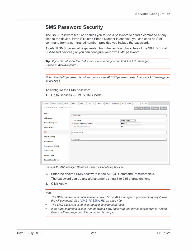
Services Configuration
SMS Password Security
The SMS Password feature enables you to use a password to send a command at any time to the device. Even if Trusted Phone Number is enabled, you can send an SMS command from a non-trusted number, provided you include the password.
A default SMS password is generated from the last four characters of the SIM ID (for all SIM-based devices ) or you can configure your own SMS password.
Tip: If you do not know the SIM ID or ESN number you can find it in ACEmanager (Status > WAN/Cellular).
Note: The SMS password is not the same as the ALEOS password used to access ACEmanager or Telnet/SSH.
To configure the SMS password:
1. Go to Services > SMS > SMS Mode.
Figure 9-13: ACEmanager: Services > SMS (Password Only Security)
2. Enter the desired SMS password in the ALEOS Command Password field.
The password can be any alphanumeric string 1 to 255 characters long.
3. Click Apply.
Note:
• The SMS password is not displayed in plain text in ACEmanager. If you want to query it, use the AT command. See *SMS_PASSWORD on page 499.
• The SMS password is not cleared by a configuration reset.
• If an SMS command is sent with the wrong SMS password, the device replies with a “Wrong Password” message, and the command is dropped.
Rev. 2 July 2019 247 41113126
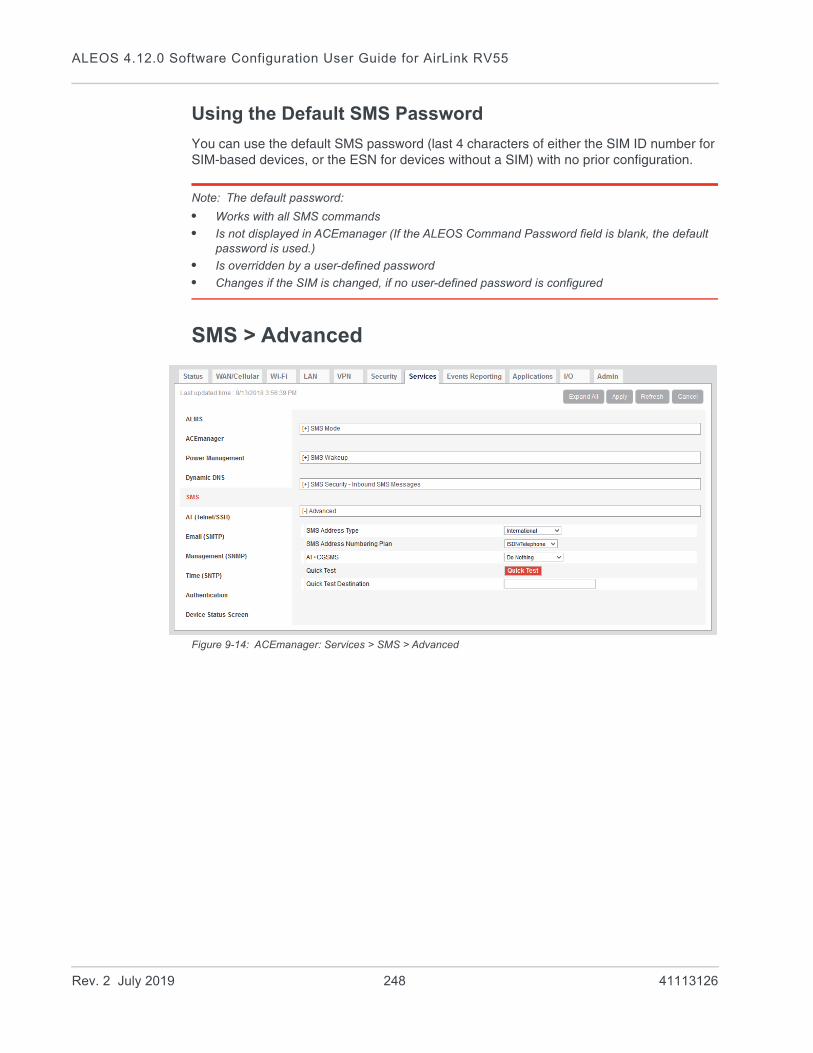
ALEOS 4.12.0 Software Configuration User Guide for AirLink RV55
Using the Default SMS Password
You can use the default SMS password (last 4 characters of either the SIM ID number for SIM-based devices, or the ESN for devices without a SIM) with no prior configuration.
Note: The default password:
• Works with all SMS commands
• Is not displayed in ACEmanager (If the ALEOS Command Password field is blank, the default password is used.)
• Is overridden by a user-defined password
• Changes if the SIM is changed, if no user-defined password is configured
SMS > Advanced
Figure 9-14: ACEmanager: Services > SMS > Advanced
Rev. 2 July 2019 248 41113126

Services Configuration
Field Description
SMS Address Type For most networks, use the default setting (International). The address type of the phone number used to send outgoing messages and command responses.
Options are:
• International (default)
• National
• Network Specific
• Subscriber
• Abbreviated
SMS Address Numbering Plan
For most networks, use the default setting (ISDN/Telephone). The address numbering plan of the phone number used to send outgoing messages and command responses.
Options are:
• Unknown
• ISDN/Telephone (default)
• Date Numbering
• Telex
• National
• Private
• ERMES
AT+CGSMS Allows you to choose the technology used to send SMS messages. For most networks, use the default setting (Do nothing).
Options are:
• Do nothing (default)
• Set AT+CGSMS=0—GPRS
• Set AT+CGSMS=1—Circuit switched
• Set AT+CGSMS=2—GPRS Preferred (Uses circuit switched if GPRS is not available)
• Set AT+CGSMS=3—Circuit Switched Preferred (Uses GPRS if circuit switched is not available)
Note: If your gateway is able to receive SMS messages, but is unable to send them, try changing this field to Set AT+CGSMS=1.
Quick Test Allows you to send a test message to the destination entered in the Quick Test Destination field.
Quick Test Destination
Enter the phone number to use for the test message. Click Apply before clicking the Quick Test button.
This field is cleared on reboot.
Rev. 2 July 2019 249 41113126

ALEOS 4.12.0 Software Configuration User Guide for AirLink RV55
SMSM2M
SMS messages can be sent from the serial command interface. EnterAT*SMSM2M=”[phone] [message]”. The phone number needs to be in the same format as numbers entered in the Trusted Phone Number List.
The message must not exceed 140 characters. To send several messages back to back, you must wait for the OK before sending the next message.
Command Description
*SMSM2M*SMSM2M_8*SMSM2M_u
*SMSM2M is the command for ASCII text.
*SMSM2M_8 is the command for 8-bit data.
*SMSM2M_u is the command for unicode.
Format:
*smsm2m=”[phone][ascii message]”
*smsm2m_8=”[phone][hex message]”
*smsm2m_u=”[phone][hex message]”
• The phone number can only consist of numbers (NO spaces or other characters). The phone number should be as it appears in the Last Incoming Phone Number field.Example 1 (US): 14085551212 (including leading 1 and area code)Example 2 (US): 4085551212 (ignore leading 1, include area code)Example 3 (UK): 447786111717 (remove leading 0 and add country code)
Command Examples:*smsm2m=”18005551212 THIS IS A TEST” sends in ASCII.
*smsm2m_8="17604053757 5448495320495320412054455354" sends the message “THIS IS A TEST” as 8-bit data.
*smsm2m_u="17604053757 000102030405060708090a0b0c0d0e0f808182838485868788898A8b8c8d8e8f" sends the bytes:
00 01 02 03 04 05 06 07 08 09 0a 0b 0c 0d 0e 0f
80 81 82 83 84 85 86 87 88 89 8a 8b 8c 8d 8e 8f
Note: Not all cellular carriers support 8-bit or unicode SMS messages.
Rev. 2 July 2019 250 41113126
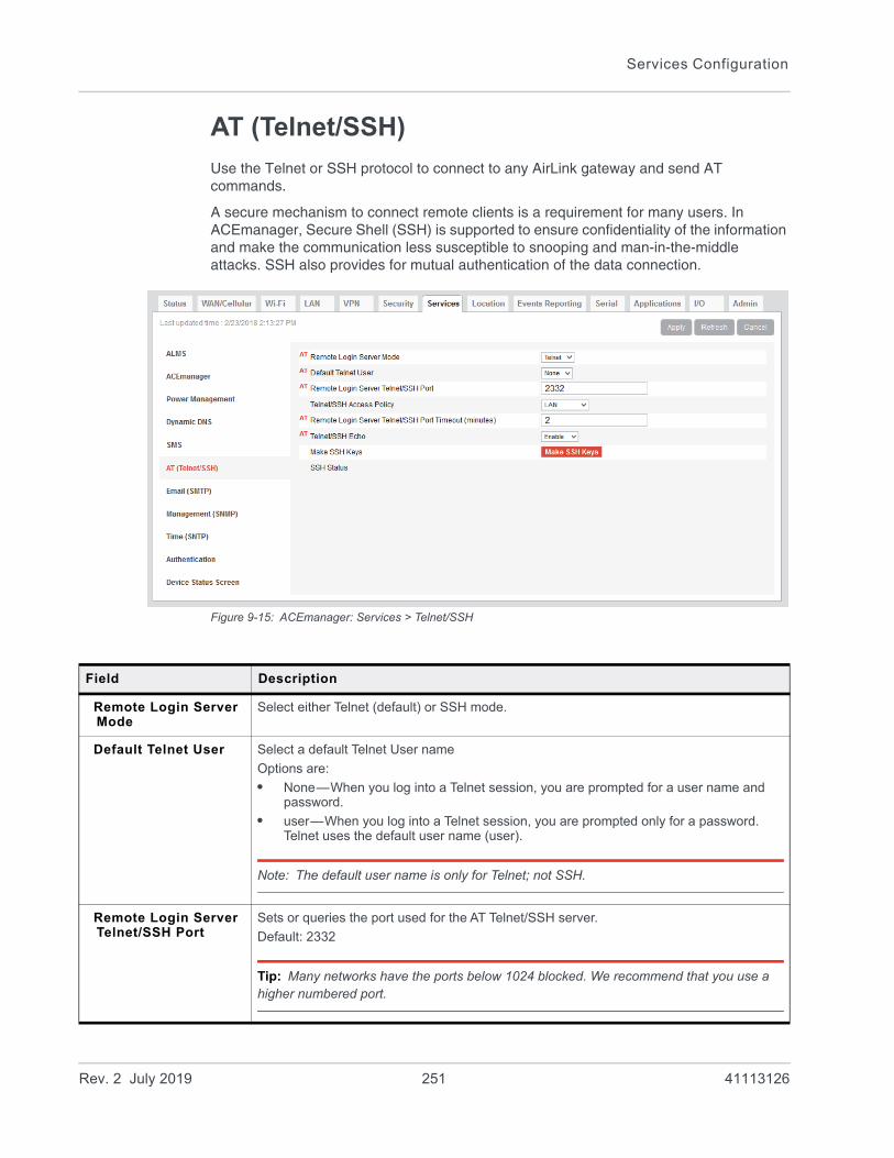
Services Configuration
AT (Telnet/SSH)
Use the Telnet or SSH protocol to connect to any AirLink gateway and send AT commands.
A secure mechanism to connect remote clients is a requirement for many users. In ACEmanager, Secure Shell (SSH) is supported to ensure confidentiality of the information and make the communication less susceptible to snooping and man-in-the-middle attacks. SSH also provides for mutual authentication of the data connection.
Figure 9-15: ACEmanager: Services > Telnet/SSH
Field Description
Remote Login Server Mode
Select either Telnet (default) or SSH mode.
Default Telnet User Select a default Telnet User name
Options are:
• None—When you log into a Telnet session, you are prompted for a user name and password.
• user—When you log into a Telnet session, you are prompted only for a password. Telnet uses the default user name (user).
Note: The default user name is only for Telnet; not SSH.
Remote Login Server Telnet/SSH Port
Sets or queries the port used for the AT Telnet/SSH server.
Default: 2332
Tip: Many networks have the ports below 1024 blocked. We recommend that you use a higher numbered port.
Rev. 2 July 2019 251 41113126

ALEOS 4.12.0 Software Configuration User Guide for AirLink RV55
Note: When you are connected to SSH locally, you cannot have OTA SSH connected.
Telnet/SSH Access Policy
Restricts access to Telnet/SSH
Options are:
• LAN+WAN
• LAN (default)
• Disabled
Remote Login Server Telnet/SSH Port Timeout (mins)
Telnet/SSH port inactivity timeout. This setting also applies to Reverse Telnet sessions.
Default: 2 (minutes)
Telnet/SSH Echo Enable (default) or disable AT command echo mode.
Make SSH Keys Creates keys for SSH session applications
SSH Status Provides the status of the SSH session
Field Description
Rev. 2 July 2019 252 41113126
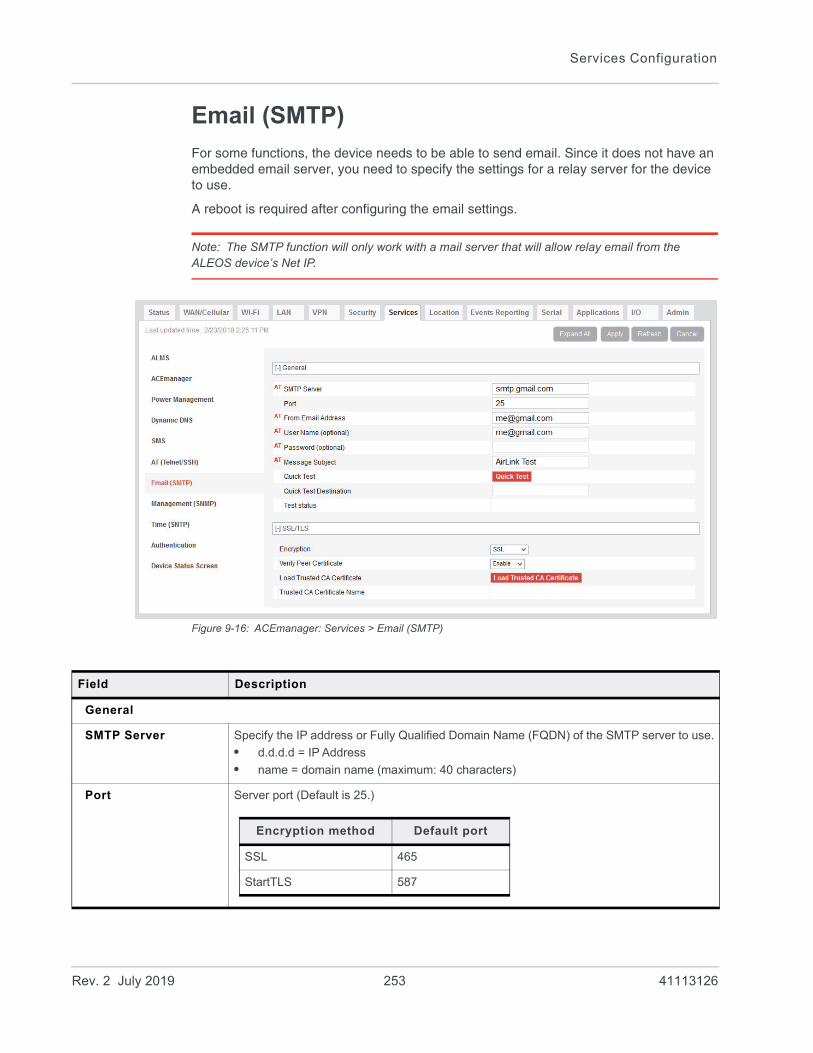
Services Configuration
Email (SMTP)
For some functions, the device needs to be able to send email. Since it does not have an embedded email server, you need to specify the settings for a relay server for the device to use.
A reboot is required after configuring the email settings.
Note: The SMTP function will only work with a mail server that will allow relay email from the ALEOS device’s Net IP.
Figure 9-16: ACEmanager: Services > Email (SMTP)
Field Description
General
SMTP Server Specify the IP address or Fully Qualified Domain Name (FQDN) of the SMTP server to use.
• d.d.d.d = IP Address
• name = domain name (maximum: 40 characters)
Port Server port (Default is 25.)
Encryption method Default port
SSL 465
StartTLS 587
Rev. 2 July 2019 253 41113126

ALEOS 4.12.0 Software Configuration User Guide for AirLink RV55
From Email Address Sets the email address from which the SMTP message is being sent.
• email = email address (maximum: 30 characters)
User Name (optional) Specifies the username to use when authenticating with the server
Password (optional) Sets the password to use when authenticating the email account (*SMTPFROM) with the server (*SMTPADDR).
• pw = password
Note: The email server used for the relay may require a user name or password.
Message Subject Allows configuration of the default Subject to use if one is not specified in the message by providing a “Subject: xxx” line as the initial message line.
• subject = message subject
Quick Test After completing the other fields on this screen, click the Quick Test button to send a test email. The status of the test appears in the Test status field.
Quick Test Destination
Enter the email address you want the test email sent to.
Test status After you press the Quick Test button, the status of the email test appears in this field.
SSL/TLS
Encryption Choose the encryption method:
• None—No encryption is used (default)
• SSL—Use a secure connection directly
• StartTLS—Transforms an non-secure connection to a secure one
For SSL and StartTLS default ports, see Port on page 253.
Verify Peer Certificate Choose whether or not to use a peer certificate
Disable—No certificate is used (default)
Enable—Verifies that the server name used for the connection matches the name and alternative names in the certificate loaded using the Load Trusted CA Certificate field.
Field Description
Rev. 2 July 2019 254 41113126
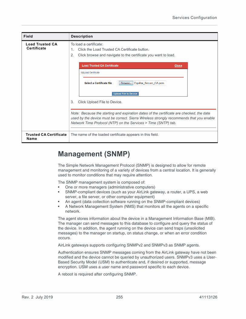
Services Configuration
Management (SNMP)
The Simple Network Management Protocol (SNMP) is designed to allow for remote management and monitoring of a variety of devices from a central location. It is generally used to monitor conditions that may require attention.
The SNMP management system is composed of:• One or more managers (administrative computers)• SNMP-compliant devices (such as your AirLink gateway, a router, a UPS, a web
server, a file server, or other computer equipment)• An agent (data collection software running on the SNMP-compliant devices)• A Network Management System (NMS) that monitors all the agents on a specific
network.
The agent stores information about the device in a Management Information Base (MIB). The manager can send messages to this database to configure and query the status of the device. In addition, the agent running on the device can send traps (unsolicited messages) to the manager on startup, on status change, or when an error condition occurs.
AirLink gateways supports configuring SNMPv2 and SNMPv3 as SNMP agents.
Authentication ensures SNMP messages coming from the AirLink gateway have not been modified and the device cannot be queried by unauthorized users. SNMPv3 uses a User-Based Security Model (USM) to authenticate and, if desired or supported, message encryption. USM uses a user name and password specific to each device.
A reboot is required after configuring SNMP.
Load Trusted CA Certificate
To load a certificate:
1. Click the Load Trusted CA Certificate button.
2. Click browse and navigate to the certificate you want to load.
3. Click Upload File to Device.
Note: Because the starting and expiration dates of the certificate are checked, the date used by the device must be correct. Sierra Wireless strongly recommends that you enable Network Time Protocol (NTP) on the Services > Time (SNTP) tab.
Trusted CA Certificate Name
The name of the loaded certificate appears in this field.
Field Description
Rev. 2 July 2019 255 41113126

ALEOS 4.12.0 Software Configuration User Guide for AirLink RV55
SNMPv2
Figure 9-17: ACEmanager: Services > Management (SNMP) (Version 2)
Field Description
SNMP Configuration
Enable SNMP Allows you to enable/disable SNMP
Default: Disable
SNMP Version Allows you to select either SNMP protocol Version 2 (default) or Version 3 communications.
SNMP Port Controls which port the SNMP Agent listens on:
• 1–65535
• Default is 161.
SNMP Contact This is a personal identifier of the contact person you want to address queries to.
This is a customer defined field.
SNMP Name This is the name of the device you want to refer to.
This is a customer defined field.
SNMP System Description
Use this field to enter a system description, if desired. The default value, which appears after the SNMP agent is enabled and the gateway rebooted, is the product name.
Read Only SNMP User
Community Name The community name is a text string that acts as a password. It is used to authenticate messages that are sent between the management station and the device.
Default is public.
Rev. 2 July 2019 256 41113126

Services Configuration
Read/Write SNMP User
Community Name The community name is a text string that acts as a password. It is used to authenticate messages that are sent between the management station and the device.
Default is private.
TRAP Server User
TRAP Server IP/FQDN Identifies the IP address or fully qualified domain name (FQDN) of the trap server that the AirLink gateway sends SNMP traps to
TRAP Server Port Identifies the specific port the trap server is on
• 1–65535
• Default is 162.
Community Name The community name is a text string that acts as a password. It is used to authenticate messages that are sent between the management station and the device.
There is no default value.
Field Description
Rev. 2 July 2019 257 41113126
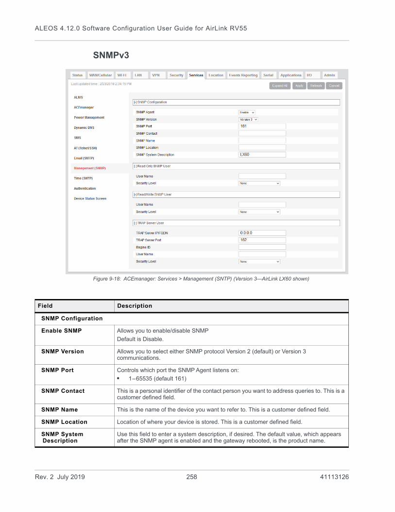
ALEOS 4.12.0 Software Configuration User Guide for AirLink RV55
SNMPv3
Figure 9-18: ACEmanager: Services > Management (SNTP) (Version 3—AirLink LX60 shown)
Field Description
SNMP Configuration
Enable SNMP Allows you to enable/disable SNMP
Default is Disable.
SNMP Version Allows you to select either SNMP protocol Version 2 (default) or Version 3 communications.
SNMP Port Controls which port the SNMP Agent listens on:
• 1–65535 (default 161)
SNMP Contact This is a personal identifier of the contact person you want to address queries to. This is a customer defined field.
SNMP Name This is the name of the device you want to refer to. This is a customer defined field.
SNMP Location Location of where your device is stored. This is a customer defined field.
SNMP System Description
Use this field to enter a system description, if desired. The default value, which appears after the SNMP agent is enabled and the gateway rebooted, is the product name.
Rev. 2 July 2019 258 41113126
Services Configuration
Read Only SNMP
User Name Allows these SNMP users to view, but not change the network configuration
Security Level Security types available: None, Authentication Only, and Authentication and Privacy.
Authentication Type Authentication types available: MD5 or SHA
Note: This field is only available when you select either Authentication and Privacy, or Authentication Only in the Security Level field.
Authentication Key This key authenticates SNMP requests for SNMPv3.
• Minimum length: 8 ASCII characters
• Maximum length: 255 ASCII characters
Example: My Key_1234
Note: This field is only available when you select either Authentication and Privacy, or Authentication Only in the Security Level field.
Privacy Type Privacy types available: AES or DES
Note: This field is only available when you select Authentication and Privacy in the Security Level field.
Privacy Key This key ensures the confidentiality of SNMP messages via encryption
• Minimum length: 8 ASCII characters
• Maximum length: 255 ASCII characters
Example: My Key_56789
Note: This field is only available when you select Authentication and Privacy in the Security Level field.
Read/Write SNMP
For a description of the Read/Write SNMP fields, see Read Only SNMP on page 259.
TRAP Server User
TRAP Server IP/FQDN Identifies the IP address or fully qualified domain name (FQDN) of the trap server that the AirLink gateway sends SNMP traps to
TRAP Server Port Identifies the specific port the trap server is on
• 1–65535 (default is 162)
Field Description
Rev. 2 July 2019 259 41113126
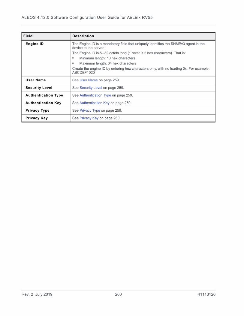
ALEOS 4.12.0 Software Configuration User Guide for AirLink RV55
Engine ID The Engine ID is a mandatory field that uniquely identifies the SNMPv3 agent in the device to the server.
The Engine ID is 5–32 octets long (1 octet is 2 hex characters). That is:
• Minimum length: 10 hex characters
• Maximum length: 64 hex characters
Create the engine ID by entering hex characters only, with no leading 0x. For example, ABCDEF1020
User Name See User Name on page 259.
Security Level See Security Level on page 259.
Authentication Type See Authentication Type on page 259.
Authentication Key See Authentication Key on page 259.
Privacy Type See Privacy Type on page 259.
Privacy Key See Privacy Key on page 260.
Field Description
Rev. 2 July 2019 260 41113126

Services Configuration
Time (SNTP)
The device can be configured to synchronize its internal clock with a time server on the Internet using the Simple Network Time Protocol.
Figure 9-19: ACEmanager: Services > Time (SNTP)
Authentication
ALEOS supports ACEmanager login using secure LDAP, RADIUS, and TACACS+ authentication schemes. This enables enterprise IT managers to centrally manage access to AirLink gateways and produce an audit trail showing which users logged into specific devices and when.
Note the following:• You can configure any or all of these schemes at the same time. When more than
one scheme is configured, the authentication is successful if at least one of the schemes authenticates the user.
• Successful authentication can take time. For example, if you have all three authenti-cation schemes enabled, ALEOS first attempts to reach the LDAP server. If it is unable to reach the LDAP server in the configured timeout period, it abandons the attempt and tries to reach the RADIUS server. If that server is unreachable after the
Field Description
Enable time update Enables daily SNTP update of the system time.
Default: Disable
SNTP Server Address SNTP Server IP address, or fully qualified domain name, to use if *SNTP=1. If blank, time.nist.gov is used.
• d.d.d.d=IP address
• name=domain name
Rev. 2 July 2019 261 41113126

ALEOS 4.12.0 Software Configuration User Guide for AirLink RV55
timeout period, it then tries to reach the TACACS+ server. If none of the servers are reachable in the configured timeout periods, ALEOS falls back to ACEmanager user name and password authentication.
• LDAP, RADIUS, and TACACS+ provide authentication (checks the user’s credentials) but do not check authorization (account expiration date, user rights, etc.) All users authenticated using the LDAP, RADIUS, and TACACS+ servers have administrative rights (i.e. a user account) and can modify the AirLink gateway settings. Ensure that LDAP, RADIUS, and TACACS+ users are authorized to modify device settings.
• LDAP, RADIUS, and TACACS+ are supported for ACEmanager logins, but are not supported by other AirLink gateway services such as Telnet, SSH, PPPoE, etc.
For instructions on configuring these authentication schemes, see:• LDAP Authentication on page 262• RADIUS Authentication on page 264• TACACS+ Authentication on page 265
LDAP Authentication
Lightweight Directory Access Protocol (LDAP) is a network protocol for accessing and manipulating information stored in a directory. It is suitable for using with information that must be easily available and accessible, and does not change frequently. AirLink gateways support LDAP version 3.
To configure LDAP:
1. Go to Services > Authentication.
2. In the LDAP Client field, select Enable.
Figure 9-20: ACEmanager: Services > Authentication > LDAP
3. Enter:· The LDAP server IP address or resolvable domain name· The Port number (default is TCP port 389)
Rev. 2 July 2019 262 41113126
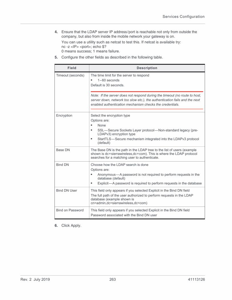
Services Configuration
4. Ensure that the LDAP server IP address/port is reachable not only from outside the company, but also from inside the mobile network your gateway is on.
You can use a utility such as netcat to test this. If netcat is available try: nc -z <IP> <port>; echo $?0 means success; 1 means failure.
5. Configure the other fields as described in the following table.
6. Click Apply.
Field Description
Timeout (seconds) The time limit for the server to respond
• 1–60 seconds
Default is 30 seconds.
Note: If the server does not respond during the timeout (no route to host, server down, network too slow etc.), the authentication fails and the next enabled authentication mechanism checks the credentials.
Encryption Select the encryption type
Options are:
• None
• SSL—Secure Sockets Layer protocol—Non-standard legacy (pre-LDAPv3) encryption type
• StartTLS—Secure mechanism integrated into the LDAPv3 protocol (default)
Base DN The Base DN is the path in the LDAP tree to the list of users (example shown is dc=sierrawireless,dc=com). This is where the LDAP protocol searches for a matching user to authenticate.
Bind DN Choose how the LDAP search is done
Options are:
• Anonymous—A password is not required to perform requests in the database (default)
• Explicit—A password is required to perform requests in the database
Bind DN User This field only appears if you selected Explicit in the Bind DN field
The full path of the user authorized to perform requests in the LDAP database (example shown is cn=admin,dc=sierrawireless,dc=com)
Bind on Password This field only appears if you selected Explicit in the Bind DN field
Password associated with the Bind DN user
Rev. 2 July 2019 263 41113126

ALEOS 4.12.0 Software Configuration User Guide for AirLink RV55
RADIUS Authentication
Remote Authentication Dial In User Service (RADIUS) uses UDP and checks authentication credentials, using a shared key.
To configure RADIUS:
1. Go to Services > Authentication.
2. In the RADIUS Client field, select Enable.
Figure 9-21: ACEmanager: Services > Authentication > RADIUS
3. Configure the other fields as described in the following table.
4. Click Apply.
Field Description
RADIUS Server RADIUS server IP address or resolvable domain name
Port By default, RADIUS uses UDP port 1812
Timeout (seconds) The time limit for the server to respond
• 1–60 seconds
Default is 30 seconds.
Note: If the server does not respond during the timeout (no route to host, server down, network too slow etc.), the authentication fails and the next enabled authentication mechanism checks the credentials.
Secret Shared secret for configured server
Rev. 2 July 2019 264 41113126

Services Configuration
TACACS+ Authentication
Terminal Access Controller Access-Control System Plus (TACACS+) uses TCP protocol and encrypts the entire packet, except the header.
To configure TACACS+:
1. Go to Services > Authentication.
2. In the TACACS+ Client field, select Enable.
Figure 9-22: ACEmanager: Services > Authentication > TACACS+
3. Enter:· The TACACS+ server IP address or resolvable domain name· The Port number (default is TCP port 49)
4. Ensure that the TACACS+ server IP address/port is reachable not only from outside the company, but also from inside the mobile network your gateway is on.
You can use a utility such as netcat to test this. If netcat is available try: nc -z <IP> <port>; echo $?0 means success; 1 means failure.
Rev. 2 July 2019 265 41113126

ALEOS 4.12.0 Software Configuration User Guide for AirLink RV55
5. Configure the other fields as described in the following table.
6. Click Apply.
Field Description
Timeout (seconds) The time limit for the server to respond
• 1–60 seconds
Default is 30 seconds.
Note: If the server does not respond during the timeout (no route to host, server down, network too slow etc.), the authentication fails and the next enabled authentication mechanism checks the credentials.
Authentication service
The type of bind used for authentication
Options are:
• PAP—Password Authentication Protocol (default)
• CHAP—Challenge Handshake Authentication Protocol The stronger of the two protocols. Recommended, provided it is supported by all the client devices.
• Login— User name and password
Secret Shared secret for configured server
Rev. 2 July 2019 266 41113126

Services Configuration
Device Status Screen
The Device Status Screen feature, when enabled, allows you to add Location and network status parameters to the ACEmanager Login screen. Once enabled, subsequent log ins to ACEmanager display whatever status parameters have been previously checked on the Device Status Screen.
Figure 9-23: ACEmanager: Services > Device Status Screen
Field Description
Enable Device Status on Login Screen
Enables device status parameters on the Login screen
Options are: Disable or Enable (default)
Status to display Select the location and network status parameters you to display on the Login screen
Rev. 2 July 2019 267 41113126

10
10: LocationMost AirLink devices are equipped with location tracking to ascertain their position and track the movements of a vehicle or other devices that move. The AirLink RV55 relays the information of its location as well as other data for use with tracking applications.
Common Uses for Location
• Driver navigation—The AirLink gateway provides real time location data via the serial or Ethernet port to a local application, including applications that provide mapping and navigation support.
• Automatic Vehicle Location (AVL)—The AirLink gateway provides real time location data to the server that tracks the location and other variables of the vehicle or asset.
ALEOS Supported Location Report Protocols
• Remote Access Protocol (RAP)
RAP is a proprietary binary message format developed and maintained by Sierra Wireless and used by many 3rd party applications. Because it is designed and main-tained by Sierra Wireless, RAP supports more ALEOS features than other location protocols. It is a low-byte-usage protocol that can be used to develop low cost AVL solutions.
The RAP messages are in hex and are referred to by their message ID. Reports can include location data alone, as well as location data with the date and time, radio fre-quency data, radio status information, and I/O state changes, and power state changes. For an example, see Location RAP Report Sequence Example on page 285. For more information, contact your Sierra Wireless Sales representative for information on how to obtain a copy of the RAP Protocol Guide.
• National Marine Electronics Association (NMEA®)
NMEA is an ASCII protocol used by many location tracking applications.
• Trimble® ASCII Interface Protocol (TAIP)
TAIP is a digital communication interface based on printable ASCII characters over a serial data link. TAIP was designed specifically for vehicle tracking applications but has become common in a number of other applications, such as data terminals and portable computers, because of its ease of use.
• Xora®
Protocol specific to Xora asset management and tracking applications
Rev. 2 July 2019 268 41113126

Location
Before Configuring Location
To decide what configuration you need for your AirLink gateway, there are some fundamental considerations you should determine:• Protocol—What is the location protocol used by your tracking application and what
type of reports will you need? (See Location Report Type on page 280.)• Dynamic IP Address—Does your device have a dynamic IP address and you need
to track the specific asset? (See Device ID in Local Reports on page 292.) You can also associate your device with a dynamic DNS configuration. (See Dynamic DNS on page 224.)
• Server location and type of connection—Will you be using a local server, a remote server, or both? Will you need a serial or local IP connection?
• Multiple Location servers—Will you need to have location data sent to more than one location server?
Figure 10-1: Server location and connection type
Note: Most Global settings (described on page 271) apply to remote and local servers. All location configuration changes go into effect immediately. No reboot of the AirLink gateway is necessary. After you configure any settings there is a short pause in receiving location reports while the device is re-initialized with the new configuration.
Server Location?
Remote Local
Serial connection Streaming report to local IP connection
See Servers 1 to 4 on page 275.
See Local/Streaming—Local IP Report on page 289 or Servers 1 to 4 on page 275.
See Local/Streaming on page 287.
Rev. 2 July 2019 269 41113126

ALEOS 4.12.0 Software Configuration User Guide for AirLink RV55
Enable Location Service
To enable Location Service:
1. In ACEmanager, go to Location.
Figure 10-2: ACEmanager: Location
2. In the Location Service field, select Enable.
3. Click Apply.
4. Reboot the gateway.
Rev. 2 July 2019 270 41113126

Location
Global Settings
Note: Most of the Global settings apply to all location server and local reports.These screens are only visible when Location is enabled. See Location Service on page 271.
Figure 10-3: ACEmanager: Location > Global Settings
Table 10-1: Location: Global Settings
Field Description
Location Settings
Location Service Sierra Wireless recommends that you disable Location if you are not using location reporting. Options are:
• Enable (default)
• Disable
The change takes effect after you reboot the gateway.
Rev. 2 July 2019 271 41113126
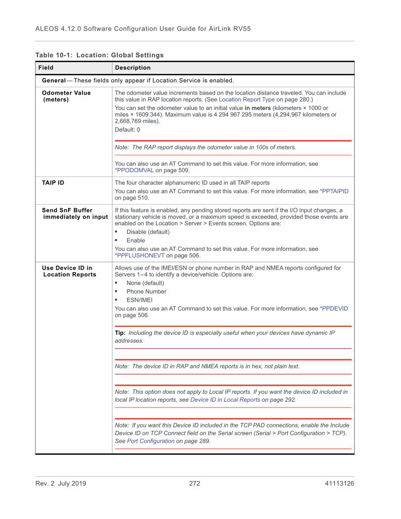
ALEOS 4.12.0 Software Configuration User Guide for AirLink RV55
General — These fields only appear if Location Service is enabled.
Odometer Value (meters)
The odometer value increments based on the location distance traveled. You can include this value in RAP location reports. (See Location Report Type on page 280.)
You can set the odometer value to an initial value in meters (kilometers × 1000 or miles × 1609.344). Maximum value is 4 294 967 295 meters (4,294,967 kilometers or 2,668,769 miles).
Default: 0
Note: The RAP report displays the odometer value in 100s of meters.
You can also use an AT Command to set this value. For more information, see *PPODOMVAL on page 509.
TAIP ID The four character alphanumeric ID used in all TAIP reports
You can also use an AT Command to set this value. For more information, see *PPTAIPID on page 510.
Send SnF Buffer immediately on input
If this feature is enabled, any pending stored reports are sent if the I/O input changes, a stationary vehicle is moved, or a maximum speed is exceeded, provided those events are enabled on the Location > Server > Events screen. Options are:
• Disable (default)
• Enable
You can also use an AT Command to set this value. For more information, see *PPFLUSHONEVT on page 506.
Use Device ID in Location Reports
Allows use of the IMEI/ESN or phone number in RAP and NMEA reports configured for Servers 1–4 to identify a device/vehicle. Options are:
• None (default)
• Phone Number
• ESN/IMEI
You can also use an AT Command to set this value. For more information, see *PPDEVID on page 506.
Tip: Including the device ID is especially useful when your devices have dynamic IP addresses.
Note: The device ID in RAP and NMEA reports is in hex, not plain text.
Note: This option does not apply to Local IP reports. If you want the device ID included in local IP location reports, see Device ID in Local Reports on page 292.
Note: If you want this Device ID included in the TCP PAD connections, enable the Include Device ID on TCP Connect field on the Serial screen (Serial > Port Configuration > TCP). See Port Configuration on page 289.
Table 10-1: Location: Global Settings
Field Description
Rev. 2 July 2019 272 41113126

Location
Advanced — These fields only appear is Location Service is enabled.
TCP Location Port You can obtain a single location snapshot from the device via a TCP session using the AirLink gateway’s IP address and the device port configured in this field.
• 1–65535 (default 9494)
• 0 = Disable
You can also use an AT Command to set this value. For more information, see *PPTCPPOLL on page 510.
Note: Access is restricted to the IP address defined for server 1. (See Report Server IP Address on page 281.)
Location Fix Mode Specifies the location fix mode. Options are:
• Standalone (default)
• MS Based—(Mobile Station Based fix) Uses assistance location data from a remote server over the WAN interface
Heading Sensitivity Sets the sensitivity of the location heading reading
• Normal (default)
• High
It is recommended that you leave the field set to Normal to avoid showing misleading heading values from poor location signal (poor sky view, reflections in urban canyon, etc.), but if your location application has its own location heading sensitivity algorithms, try changing this setting to High.
GNSS Reboot Watchdog
Enables or disables automatic GNSS-related reboots. Disabling the GNSS Reboot Watchdog helps maintain data connectivity if GNSS-related errors occur. Errors that might prompt a reboot include:
• GNSS fix loss
• GNSS tracking restarts
• NMEA data stream loss
Options:
• Enable (default)—The RV55 reboots after GNSS-related errors
• Disable
Enable NMEA Logging (GNSS debugging)
Enables or disables writing NMEA (and proprietary debug) sentences to a log file for troubleshooting purposes. To download the NMEA log file, see Download NMEA Files on page 274.
Options:
• Enable—starts compiling the log file
• Disable (default)
Table 10-1: Location: Global Settings
Field Description
Rev. 2 July 2019 273 41113126
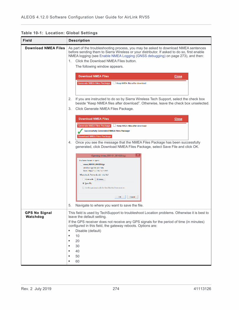
ALEOS 4.12.0 Software Configuration User Guide for AirLink RV55
Download NMEA Files As part of the troubleshooting process, you may be asked to download NMEA sentences before sending them to Sierra Wireless or your distributor. If asked to do so, first enable NMEA logging (see Enable NMEA Logging (GNSS debugging) on page 273), and then:
1. Click the Download NMEA Files button.
The following window appears.
2. If you are instructed to do so by Sierra Wireless Tech Support, select the check box beside “Keep NMEA files after download”. Otherwise, leave the check box unselected.
3. Click Generate NMEA Files Package.
4. Once you see the message that the NMEA Files Package has been successfully generated, click Download NMEA Files Package, select Save File and click OK.
5. Navigate to where you want to save the file.
GPS No Signal Watchdog
This field is used by TechSupport to troubleshoot Location problems. Otherwise it is best to leave the default setting.
If the GPS receiver does not receive any GPS signals for the period of time (in minutes) configured in this field, the gateway reboots. Options are:
• Disable (default)
• 10
• 20
• 30
• 40
• 50
• 60
Table 10-1: Location: Global Settings
Field Description
Rev. 2 July 2019 274 41113126

Location
Servers 1 to 4
You can configure up to four servers as report destinations. Each server is configured independently and can be configured to report the same or different information. This enables you to simultaneously receive location and other information at more than one location, either local or remote.
The configuration fields are the same for each of the four servers, except that Server 1 has the option to configure one or two redundant servers.
Note: These side tabs only appear if Location Service (on the Global Settings side tab) is Enabled.
Note: These screens are only visible when Location is enabled. See Location Service on page 271.
To configure one of the servers:
1. In ACEmanager, go to Location.
2. From the menu on the left side of the screen, select the Server you want to configure.
Rev. 2 July 2019 275 41113126

ALEOS 4.12.0 Software Configuration User Guide for AirLink RV55
Figure 10-4: ACEmanager: Location > Server 1
Rev. 2 July 2019 276 41113126

Location
Table 10-2: Location: Servers 1 – 4
Field Description
Events — Configure when the location reports are sent
Report Interval Time (seconds)
Location Report Time Interval
The amount of time between location reports (in seconds)
Options are:
• 1– 65535
• 0 = Disables location reporting based on a time interval (default)
With this option disabled, you can still receive reports based on distance traveled or the vehicle being stationary for a configured time. (See Report Interval Distance (meters) on page 277 and Stationary Vehicle Timer (minutes) on page 278.)
You can also use an AT Command to set this value. For more information, see *PPTIME on page 510.
Note: Your cellular carrier may impose a minimum transmit time.
Report Interval Distance (meters)
Location Report Distance Interval in meters
The distance (in meters) that the vehicle (or device) travels between sending location reports
Options are:
• 40– 65535
Note that setting the resolution near the low end of the range may result in incorrect reports as a result of location jitter (i.e. apparent motion caused by the inherent inaccuracy in location measurements).
• 0 = Disables sending location reports based on a distance interval (default)
With this option disabled, you can still receive reports based on time passed or the vehicle being stationary for a configured time. (See Report Interval Time (seconds) on page 277 and Stationary Vehicle Timer (minutes) on page 278.)
You can also use the AT Command, *PPDISTM, to set this value. For more information, see page 506.
Note: An an additional AT Command, *PPDIST, allows you to configure the location report distance interval in 100 meter units. This option is only available through AT Commands. For more information, see page 506.
Note: If the report interval time and report interval distance fields are both set, location reports are sent when either interval is reached. For example, if the time interval is reached, a location report is sent even if the distance is not reached. Conversely, if the vehicle travels the specified distance, a location report is sent even if the time interval was not reached.
Rev. 2 July 2019 277 41113126

ALEOS 4.12.0 Software Configuration User Guide for AirLink RV55
Stationary Vehicle Timer (minutes)
You can use this field if you want to receive less frequent reports when the vehicle is stationary. A location report is sent every x minutes the vehicle (or device) is stationary, where x is the value configured in this field. When the vehicle is stationary, this value overrides the value configured in the Report Interval Time field.
Options are:
• 1–255
• 0 = Disables location reporting based on a vehicle being stationary (default)
You can also use an AT Command to set this value. For more information, see *PPTSV on page 510.
Maximum Speed Event Report (km/h)
A location report is sent if the speed (in kilometers per hour) configured in this field is exceeded, and again when the speed goes back down below the configured value.
• 0 = Disable (default)
• 1–255
Note: If you are using one of the RAP location report types (see Location Report Type on page 280) the location report triggered by this feature includes:
• A marker to indicate that it was triggered by the configured speed being exceeded and when the speed is goes back down below the configured value.
• The standard location information for the configured report type
For more information, refer to the RAP Protocol Guide.If you are not using a RAP location report, a standard report is sent.
Send Stationary Vehicle Event in Seconds
A location report is sent if the vehicle (or device) has been in one location for more than the specified time (in seconds) and again when the vehicle (or device) moves from that location. Options are:
• 1–255
• 0 = Disables sending location reports based on a vehicle being stationary (default)
Note: If you are using one of the RAP location report types (see Location Report Type on page 280) the location report triggered by this feature includes:
• A marker to indicate that it was triggered by the vehicle either being stationary or starting to move again
• The standard location information for the configured report type
For more information, refer to the RAP Protocol Guide.If you are not using a RAP location report, a standard report is sent.
You can configure Stationary Vehicle Event in Seconds and Stationary Vehicle Timer together to receive a special report when the device is stationary longer than x seconds, a normal report every x minutes it is stationary (instead of the Report Interval Time) and a special report when the vehicle begins moving again.
Table 10-2: Location: Servers 1 – 4
Field Description
Rev. 2 July 2019 278 41113126

Location
Enable Digital Input Event
A location report is sent if the configured digital input changes. For example, this could be used to trigger a report being sent when an emergency light or siren is turned on or off, or when a door is opened or closed. The location data in the report informs you of where the event took place.
Options are:
• Disable (default)
• Enable
Note: If you are using one of the RAP location report types (see Location Report Type on page 280) the location report triggered by this feature includes:
• A marker to indicate that it was triggered by a change in status of the configured digital input
• The standard location information for the configured report type
For more information, refer to the RAP Protocol Guide.If you are not using a RAP location report, a standard report is sent.
You can also use an AT Command to set this value. For more information, see *PPINPUTEVT on page 507.
Report Type
Location Report Format
Configures the format of location reports.
Options are:
• Predefined (default)—When selected, the reports contain TAIP and NMEA GPS strings. If Predefined is selected, you can select Location Report Type. See Location Report Type on page 280.
• User-defined NMEA—You can enable or disable GGA, RMC, VTG, GSA, and GSV sentences individually.
Table 10-2: Location: Servers 1 – 4
Field Description
Rev. 2 July 2019 279 41113126

ALEOS 4.12.0 Software Configuration User Guide for AirLink RV55
Location Report Type If the Location Report Format is Predefined, sets the type of location report.
Options are:
RAP
• Location Data—RAP location report that contains only location data
• Location+Date—RAP location report that contains location data with the UTC time and date (default)
• Location+Date+RF—RAP location report that contains location data, the UTC time and date, and radio frequency information for the cellular connection
• Location+Date+RF+EIO—RAP location report that contains location data, the UTC time and date, radio frequency information for the cellular connection, and the current I/O state
Note: The maximum satellite count for RAP reports is 15. If there are more than 15 satellites visible, RAP reports 15 satellites. To see the actual number of satellites, go to Status > Location.
NMEA
• NMEA GGA+VTG—NMEA location report that contains fix information, vector track, and speed over ground
• NMEA GGA+VTG+RMC—NMEA location report that contains fix information, vector track, speed over ground, and recommended minimum location data
• NMEA GGA+VTG+RMC+GSA+GSV—NMEA location report that contains fix infor-mation, vector track, speed over ground, the recommended minimum location data, overall satellite data, and detailed satellite data
TAIP
• TAIP data—TAIP location report that contains position and velocity
• Compact TAIP data—TAIP location report that contains the compact position
• TAIP LN report—TAIP location report that contains a long navigation message
• TAIP TM report—TAIP location report that contains the time and date
XORA
• XORA data—location report used with Xora asset tracking
Note: Only RAP location reports can be configured to include odometer and digital I/O information.
Note: You can also use an AT Command to set this value. For more information, see *PPGPSR on page 507.
Table 10-2: Location: Servers 1 – 4
Field Description
Rev. 2 July 2019 280 41113126

Location
Servers—Configure where the reports are sent
Report Server IP Address
IP address or FQDN (fully qualified domain name) of the server where location reports are sent
Example: 192.100.100.100
The IP address can be for a local host or a remote server that is accessed over-the-air or via a VPN tunnel.
If an IP with the last octet of 255 is configured (i.e. 192.168.13.255), a report would be broadcast to all IPs on that subnet. When configured to a local host subnet, any connected device would receive the report.
Note: If you want to use it as a LAN device, it must have a private IP address. If you want to use a public IP address, use a Local IP report. (See Local/Streaming—Local IP Report on page 289.)
You can also use an AT Command to set this value. For more information, see *PPIP on page 507.
Table 10-2: Location: Servers 1 – 4
Field Description
Rev. 2 July 2019 281 41113126
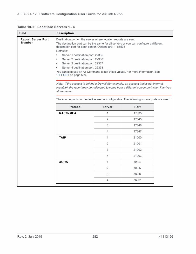
ALEOS 4.12.0 Software Configuration User Guide for AirLink RV55
Report Server Port Number
Destination port on the server where location reports are sent
The destination port can be the same for all servers or you can configure a different destination port for each server. Options are: 1–65535
Defaults:
• Server 1 destination port: 22335
• Server 2 destination port: 22336
• Server 3 destination port: 22337
• Server 4 destination port: 22338
You can also use an AT Command to set these values. For more information, see *PPPORT on page 509.
Note: If the account is behind a firewall (for example, an account that is not Internet-routable), the report may be redirected to come from a different source port when it arrives at the server.
The source ports on the device are not configurable. The following source ports are used:
Table 10-2: Location: Servers 1 – 4
Field Description
Protocol Server Port
RAP / NMEA 1 17335
2 17345
3 17346
4 17347
TAIP 1 21000
2 21001
3 21002
4 21003
XORA 1 9494
2 9495
3 9496
4 9497
Rev. 2 July 2019 282 41113126
Location
Redundant Servers — Only available for Server 1
If the redundant server is configured, whenever a report is sent to server 1, an identical report is sent to any configured redundant server(s). Transport/SNF configuration settings do not apply to redundant servers. Commands from redundant servers are ignored. Reports originate from port 17335. The redundant servers can be a local host or a remote server that is accessed over-the-air or via a VPN tunnel.
Redundant Server 1 IP Address
IP address or FQDN of the first redundant server
Redundant Server 1 Port Number
Port number of the first redundant server
The port number can be the same as or different from that of other servers.
Redundant Server 2 IP Address
IP address or FQDN of the second redundant server
Redundant Server 2 Port Number
Port number of the second redundant server
The port number can be the same as or different from that of other servers.
Minimum Report Time (secs)
Specifies the minimum time (in seconds) between partial reports or grouped packets being sent
You can also use an AT Command to set this value. For more information, see *PPMINTIME on page 508.
Transport / Store and Forward (SNF)
This feature is designed to accommodate periods when the AirLink gateway is outside the area of mobile network coverage or otherwise unable to reach the report server. Reports are stored and then “forwarded” in a combined packet when the device is again able to contact the server.
There are four Location servers and five Events Reporting servers. Each server has its own buffer and can store a maximum of 395 reports. The maximum length of each report is 255 bytes. Note that this is separate from any SNF done by AAF applications, including the AirLink Vehicle Telemetry Application (AVTA).
SNF for Unreliable Mode
Store and Forward causes location reports to be stored if the AirLink gateway goes out of network coverage. Once the device/vehicle is in coverage the stored location reports are sent to the server. Options are:
• Disable (default)—If there is no mobile network coverage, reports are not stored.
• Enable—If there is no mobile network coverage, reports are stored until the AirLink gateway can access the server.
Note: When you are using location and Wi-Fi Client mode: If the Wi-Fi client is connected, reports are sent over the Wi-Fi WAN connection rather than the mobile network. With SNF for Unreliable Mode enabled, if the Wi-Fi WAN connection is active and the cellular connection is not (i.e. out of the cellular coverage area) reports continue to be sent over Wi-Fi. Only if both networks are down are the reports stored and forwarded later when either network is back up.
Note: You can also use an AT Command to set this value. For more information, see *PPSNF on page 509.
Table 10-2: Location: Servers 1 – 4
Field Description
Rev. 2 July 2019 283 41113126

ALEOS 4.12.0 Software Configuration User Guide for AirLink RV55
SNF Reliable Mode Store and Forward Reliability: location reports are retransmitted if not acknowledged by the server.
Options are:
• OFF (Unreliable Mode) (default)—If this field is Off, the device does not expect acknowledgment to any location report sent to the server.
• Reliable Mode—A sequence number (1–127) is added to each packet (page). The server acknowledges every 8th packet. If there is no ACK from the server, ALEOS pings the server and re-sends the packets when the server responds. If the server receives packets out of sequence, the server NAKs the first and last missed packets. ALEOS retransmits the missing packets.
Note: Reliable mode is valid only when a RAP report is selected as the Location Report Type.
• Simple Reliable Mode—ALEOS attempts to contact the server the configured number of times, after which it stops attempting to contact the server and discards messages that cannot be transmitted or received after the configured number of tries. When contacted, the server responds with the ASCII string UDPACK. For information on configuring the maximum number of retries see SNF Simple Reliable Max Retries on page 284. For information on configuring the backoff time, see SNF Simple Reliable Backoff Time (secs) on page 284.)
• UDP Sequence Mode—A hex sequence number (30–7f) is prepended to the packet. The server responds with SEQACK and the sequence number. The sequence number is not stored and is re-initialized when the AirLink gateway is reset or power cycled. Unacknowledged packets are dropped after the configured number of retries.
• TCP Listen Mode—This mode is the same as UDP Sequence Mode, except that the server initiates the connection using TCP. Use this mode if your server is behind a firewall. If you are using this mode, the AirLink gateway must have a mobile terminated/Internet routable IP address.
• TCP—By default, location reports are sent over UDP. Select this option if you want the location reports sent over TCP. Because TCP is an inherently reliable protocol, no additional headers are added to the report packet. TCP works with all location report types.
Note: You can also use an AT Command to set this field. For more information, see *PPSNFR on page 509.
SNF Simple Reliable Max Retries
When the AirLink gateway is configured to use Simple Reliable Mode, use this field to set the maximum number of retries when a report is sent and there is no response. Use the SNF Simple Reliable Backoff Time (secs) field to set the interval between retries.
Options are:
• Disabled
• 1–255 retries (Default is 10.)
You can also use an AT Command to set this value. For more information, see *PPMAXRETRIES on page 508.
SNF Simple Reliable Backoff Time (secs)
When the AirLink gateway is configured to use Simple Reliable Mode, use this field to set the interval for the retries. (Use the SNF Simple Reliable Max Retries field to set the maximum number of retries.)
• 0–255 (Default is 10.)
You can also use an AT Command to set this value. For more information, see *PPSIMPLETO on page 509.
Table 10-2: Location: Servers 1 – 4
Field Description
Rev. 2 July 2019 284 41113126

Location
Redundant Servers
When one or two redundant servers are enabled, each time a message is sent out to the main server a second identical message is sent to the redundant server(s).
The redundant servers can be running the same or different application than the primary server. The messages to the redundant server are independent of the primary server settings or state.
You can configure one or both redundant servers. The messages are sent independently to either or both.
Note: Messages are sent whether or not the server is available and do not use any reliable mode format. Receipt of a message is not acknowledged nor is any message resent. Messages to redundant servers are in UDP only.
Location RAP Report Sequence Example
In this example:
The AirLink gateway is installed in a police car.• Digital input 2 is connected to the switch that controls the siren.• Digital input 3 is connected to the laptop docking station.
ACEmanager has the following configuration:• Report Interval Time: 30 seconds• Report Interval Distance: 150 meters• Stationary Vehicle Timer: 5 minutes• Send Stationary Vehicle Event in Seconds: 6 seconds• Maximum Speed Event: 100 km/h• Enable Digital Input Event: Enable• Report Type: Location + Date (RAP location report type 0x12)• Low Voltage Standby Mode: Automatic
Additional DataWhen configured, these options add additional data to RAP reports (see Location Report Type on page 280) sent in response to any trigger.
Report Odometer Enables odometer reporting. Options are:
• Disable (default)
• Enable
You can also use an AT Command to set this value. For more information, see *PPODOM on page 509.
Report Digital Inputs Enables digital input reporting. Options are:
• Disable (default)
• Enable
You can also use an AT Command to set this value. For more information, see *PPREPORTINPUTS on page 509.
Table 10-2: Location: Servers 1 – 4
Field Description
Rev. 2 July 2019 285 41113126
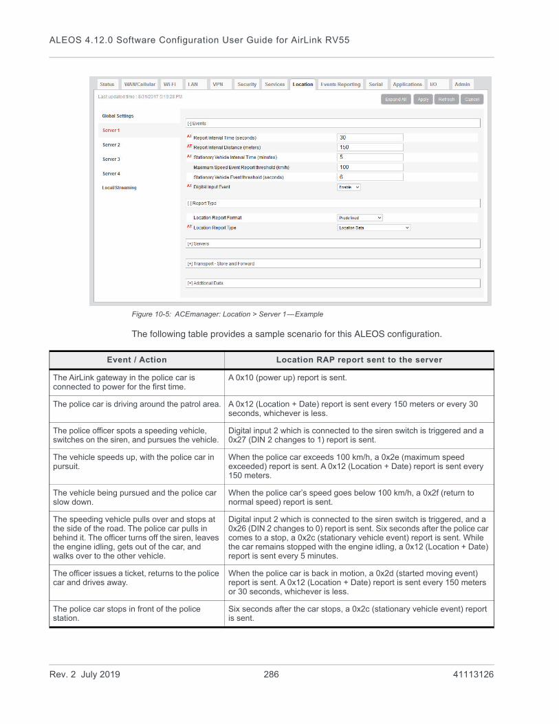
ALEOS 4.12.0 Software Configuration User Guide for AirLink RV55
Figure 10-5: ACEmanager: Location > Server 1—Example
The following table provides a sample scenario for this ALEOS configuration.
Event / Action Location RAP report sent to the server
The AirLink gateway in the police car is connected to power for the first time.
A 0x10 (power up) report is sent.
The police car is driving around the patrol area. A 0x12 (Location + Date) report is sent every 150 meters or every 30 seconds, whichever is less.
The police officer spots a speeding vehicle, switches on the siren, and pursues the vehicle.
Digital input 2 which is connected to the siren switch is triggered and a 0x27 (DIN 2 changes to 1) report is sent.
The vehicle speeds up, with the police car in pursuit.
When the police car exceeds 100 km/h, a 0x2e (maximum speed exceeded) report is sent. A 0x12 (Location + Date) report is sent every 150 meters.
The vehicle being pursued and the police car slow down.
When the police car’s speed goes below 100 km/h, a 0x2f (return to normal speed) report is sent.
The speeding vehicle pulls over and stops at the side of the road. The police car pulls in behind it. The officer turns off the siren, leaves the engine idling, gets out of the car, and walks over to the other vehicle.
Digital input 2 which is connected to the siren switch is triggered, and a 0x26 (DIN 2 changes to 0) report is sent. Six seconds after the police car comes to a stop, a 0x2c (stationary vehicle event) report is sent. While the car remains stopped with the engine idling, a 0x12 (Location + Date) report is sent every 5 minutes.
The officer issues a ticket, returns to the police car and drives away.
When the police car is back in motion, a 0x2d (started moving event) report is sent. A 0x12 (Location + Date) report is sent every 150 meters or 30 seconds, whichever is less.
The police car stops in front of the police station.
Six seconds after the car stops, a 0x2c (stationary vehicle event) report is sent.
Rev. 2 July 2019 286 41113126

Location
Local/Streaming
Some in-vehicle/navigation applications accept location reports via a serial connection, generally using either NMEA or TAIP. To configure serial streaming for DB-9 (RS-232) ports and/or USB Serial ports, go to Location > Local/Streaming. Reports are sent as ASCII text.
Note: These screens are only visible when Location is enabled. See Location Service on page 271.
Figure 10-6: ACEmanager: Location > Local/Streaming > Serial
The officer disconnects the laptop from the dock.
Digital input 3 connected to the docking station is triggered. A 0x28 (DIN 3 changes to 0) report is sent.
The officer turns off the ignition. Before the AirLink gateway goes into Low Power Standby mode, it sends a 0x30 (entering Low Power mode) report.
The officer on the next shift gets into the car and turns on the ignition.
When the AirLink gateway wakes up from Low Power Standby mode, it sends a 0x31 (Wake up from Low Power mode event) report.
Event / Action Location RAP report sent to the server
Rev. 2 July 2019 287 41113126

ALEOS 4.12.0 Software Configuration User Guide for AirLink RV55
Table 10-3: Location: Local/Streaming
Field Description
Serial
Location Reports port The serial port or USB serial link that reports are sent to.
Options are:
• NONE (default)
• DB9 Serial
• USB Serial
• DB9 and USB
You can also use an AT Command to set this value. For more information, see *PGPS on page 504.
Note: If you want to stream location data to a USB port, the USB port must be configured on the LAN > USB page to act as a serial port. See USB Device Mode on page 146.
Location Reports Format
Configures the format of location reports to send using the serial link.
Options are:
• Predefined (default)—When selected, the reports contain TAIP and NMEA GPS strings. If Predefined is selected, you can select Location Reports Type for serial streaming. See Location Reports Type on page 288.
• User-defined NMEA—You can enable or disable GGA, RMC, VTG, GSA, and GSV sentences individually.
Location Reports Type If Location Reports Format is Predefined, select the ASCII text location report type to send via the serial link:
• NMEA GGA+VTG+RMC—NMEA location report that contains fix information and vector track and speed over ground, and recommended minimum location data (default)
• NMEA GGA+VTG+RMC+GSA+GSV—NMEA location report that contains fix infor-mation and vector track and speed over ground, the recommended minimum location data, overall satellite data, and detailed satellite data
• TAIP data—TAIP location report that contains position and velocity
• TAIP compact data—TAIP location report that contains the compact position
• TAIP LN report—TAIP location report that contains a long navigation message
• TAIP TM report—TAIP location report that contains the time and date
You can also use an AT Command to set this value. For more information, see *PGPSR on page 505.
Location Reports Frequency (secs)
How frequently (in seconds) the location report is sent to the serial link.
Options are:
• 1– 65535—(up to 18.2 hours)
You can also use an AT Command to set this value. For more information, see *PGPSF on page 505.
Rev. 2 July 2019 288 41113126

Location
Local/Streaming—Local IP Report
Local IP reports are limited to tethered IP-based LAN devices (Ethernet, USB/net, DUN, PPPoE). Local IP reports do not have any transport/SNF options. The reports are always sent regardless of cellular coverage. Reports are sent over UDP.
The destination IP cannot be configured directly. The first connected LAN device is used. If multiple devices are connected, the priority is the device using the Public IP address, or if all devices are using Private IP addresses, the priority is:• Ethernet• USB• DUN
Note: These screens are only visible when Location is enabled. See Location Service on page 271.
Location Coverage This field refers to the mobile network coverage.
Options are:
• ALWAYS (default)—Location reports are always streamed to the serial link.
• Out of Coverage—Location reports are only streamed to the serial link when the device has no cellular connection.
You can also use an AT Command to set this value. For more information, see *PGPSC on page 505.
Tip: The Out of Coverage option enables you to use a backup in-vehicle mapping appli-cation that does not rely on mobile network access.
Location Reports Delay (secs)
The delay (in seconds) before the out of the coverage stream begins. This field only applies if the location coverage field is set to “Out of Coverage”.
• 0 (default)
• 1–255
You can also use an AT Command to set this value. For more information, see *PGPSD on page 505.
Table 10-3: Location: Local/Streaming
Field Description
Rev. 2 July 2019 289 41113126
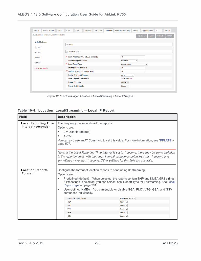
ALEOS 4.12.0 Software Configuration User Guide for AirLink RV55
Figure 10-7: ACEmanager: Location > Local/Streaming > Local IP Report
Table 10-4: Location: Local/Streaming — Local IP Report
Field Description
Local Reporting Time Interval (seconds)
The frequency (in seconds) of the reports
Options are:
• 0 = Disable (default)
• 1–255
You can also use an AT Command to set this value. For more information, see *PPLATS on page 507.
Note: If the Local Reporting Time Interval is set to 1 second, there may be some variation in the report interval, with the report interval sometimes being less than 1 second and sometimes more than 1 second. Other settings for this field are accurate.
Location Reports Format
Configure the format of location reports to send using IP streaming.
Options are:
• Predefined (default)—When selected, the reports contain TAIP and NMEA GPS strings. If Predefined is selected, you can select Local Report Type for IP streaming. See Local Report Type on page 291.
• User-defined NMEA—You can enable or disable GGA, RMC, VTG, GSA, and GSV sentences individually.
Rev. 2 July 2019 290 41113126

Location
Local Report Type If the Location Reports Format is Predefined, sets one of the following Local Report types:
RAP
• Location Data—RAP location report that contains only location data
• Location+Date—RAP location report that contains location data with the UTC time and date (default)
• Location+Date+RF—RAP location report that contains location data, the UTC time and date, and radio frequency information for the cellular connection
• Location+Date+RF+EIO—RAP location report that contains location data, the UTC time and date, radio frequency information for the cellular connection, and the current I/O state
NMEA
• NMEA GGA+VTG—NMEA location report that contains fix information, vector track, and speed over ground
• NMEA GGA+VTG+RMC—NMEA location report that contains fix information, vector track, speed over ground, and recommended minimum location data
• NMEA GGA+VTG+RMC+GSA+GSV—NMEA location report that contains fix infor-mation, vector track, speed over ground, the recommended minimum location data, overall satellite data, and detailed satellite data
TAIP
• TAIP data—TAIP location report that contains position and velocity
• Compact TAIP data—TAIP location report that contains the compact position
• TAIP LN report—TAIP location report that contains a long navigation message
• TAIP TM report—TAIP location report that contains the time and date.
Note: You can also use an AT Command to set this value. For more information, see *PPLATSR on page 508.
Note: Local IP Report does not have an option for Xora reports.
Starting Destination Port
The primary port that reports are sent to
The Local IP report source port is 17335. This is not configurable.
Number of Extra Destination Ports
You can send the report to up to 7 additional consecutive ports. For example, if the starting port is 12351 and you set this field to 5, reports are sent to ports 12351, 12352, 12353, 12354, 12355, and 12356.
The default is 0, which means only the starting port is used.
You can also use an AT Command to set this value. For more information, see *PPLATSEXTRA on page 508.
Table 10-4: Location: Local/Streaming — Local IP Report
Field Description
Rev. 2 July 2019 291 41113126

ALEOS 4.12.0 Software Configuration User Guide for AirLink RV55
Device ID in Local Reports
Allows use of the IMEI/ESN or phone number in local IP RAP and NMEA reports to identify a device/vehicle. Options are:
• None (default)
• Phone Number
• ESN/IMEI
Tip: Including the device ID is especially useful when your devices have dynamic IP addresses.
Note: If you want the device ID included in all other RAP and NMEA location reports, see Use Device ID in Location Reports on page 272.
Local Report Destination IP
This read-only field shows the IP address of the destination that Local IP reports are send to. Through its use of DHCP, ALEOS detects if there is a connected device and designates that device's IP as the local IP destination. When no device is connected at startup, ALEOS uses the first IP address in the Ethernet DHCP pool as the destination. When using Public mode for an interface, that interface will be the local IP destination even if it's not the first device connected.
Note: The Local Report Destination IP is not configurable. If you want a location report to go to a specific device IP, use Server 1–4 configuration. (See Servers 1 to 4 on page 275.)
Report Odometer Enables odometer reporting. Options are:
• Disable (default)
• Enable
Note: Only applies for RAP report types.
Report Digital Inputs Enables digital input reporting. Options are:
• Disable (default)
• Enable
Note: Only applies for RAP report types.
Table 10-4: Location: Local/Streaming — Local IP Report
Field Description
Rev. 2 July 2019 292 41113126

11
11: Events Reporting ConfigurationIntroduction
You can configure the AirLink RV55 to generate reports or initiate actions based on specified events. Events can either be generated internally, such as a change in location fix status or a signal quality indicator crossing a specified threshold, or by external devices attached to the analog or digital inputs.
Events that can trigger reports or actions include: • A switch on connected equipment opens or closes (digital input)• A pulse accumulation crosses a configured threshold• An analog meter on connected equipment crosses a configured threshold (Analog
input is reported in volts or transformed to meaningful units.)• Changes to location information such as a location fix obtained or lost, changes in
vehicle speed or heading, engine hours threshold crossed• Changes to network status such as signal strength, network state, and network
service• The gateway’s power supply (in volts) crosses a configured threshold• The AirLink gateway board or radio temperature crosses a configured threshold• A configured threshold for daily or monthly data usage is crossed
Depending on the type of report, reports can be sent to a local or remote report server, or an email address, or by SMS to a cell phone.
The occurrence of a configured event can also turn on or off a relay link.
Figure 11-1 summarizes how Event reporting works.
Figure 11-1: Events Reporting
Events/Actions are not one-shot activities. After an Action is performed, the Event is still active and will trigger an Action the next time the state change or threshold crossing occurs.
A single Event may activate one or more Actions. For example, if RSSI is below threshold, you can send an email (Action 1) and send an SMS message (Action 2).
Local server
AirLink gateway
Internet
CellularNetwork
Cell phone
Computer
Report server
SMS
Internal Events, e.g.- RSSI- Temperature- Location
Connectedequipment
External Events, e.g.- Digital I/O- Analog I/O- Relay control
Rev. 2 July 2019 293 41113126
ALEOS 4.12.0 Software Configuration User Guide for AirLink RV55
A single Action may be activated by one or more Events. For example, if either the network state changes to Network Ready or the RSSI crosses a configured threshold, the same Action is performed.
Configuring Events Reporting
Before you begin
If you plan to use either of the following, configure that feature in ACEmanager before configuring Events Reporting:• Email (Email (SMTP) on page 253)• SNMP Trap (Management (SNMP) on page 255)
Configuring Events Reporting
When configuring Events Reporting, first configure the Action (that is, how you want to be notified when the Event occurs). Then configure the Event you want reported, and finally, link the Event to the Action.
Note: All Events Reporting configuration changes take effect after a short delay (about one minute). No reboot of the AirLink gateway is necessary.
Configuring the Action
Note: You can define a maximum of 5 Actions.
If an Action requires an IP connection, the following source ports are used. These are not configurable.
Click the appropriate link for instructions on configuring the desired Action. Once the Action is configured, proceed to Event Types on page 308.• Email• SMS• Relay Link• SNMP TRAP• Location Reports
· Location RAP Report 13
Actions (in the order configured) Source port
Action 1 17348
Action 2 17349
Action 3 17351
Action 4 17352
Action 5 17353
Rev. 2 July 2019 294 41113126
Events Reporting Configuration
· NMEA GGA+VTG· NMEA GGA+VTG+RMC· NMEA GGA+VTG+RMC+GSA+GSV· TAIP data· Compact TAIP data· TAIP LN report· TAIP TM report· XORA report
• Events Protocol Reports· Type, Length, Value· Binary· CSV- ASCII· XML
• Turn Off Services
Note: Sending an email report is limited to SMTP servers that are open and do not require a secure login.
To configure ALEOS to send an email report:
1. Ensure that email is configured on the Services > Email (SMTP) screen. (See Email (SMTP) on page 253.)
2. On the Events Reporting tab, select Actions from the menu on the left.
3. Enter the desired Action Name.
4. From the drop-down menu in the Action Type field, select Email.
Rev. 2 July 2019 295 41113126
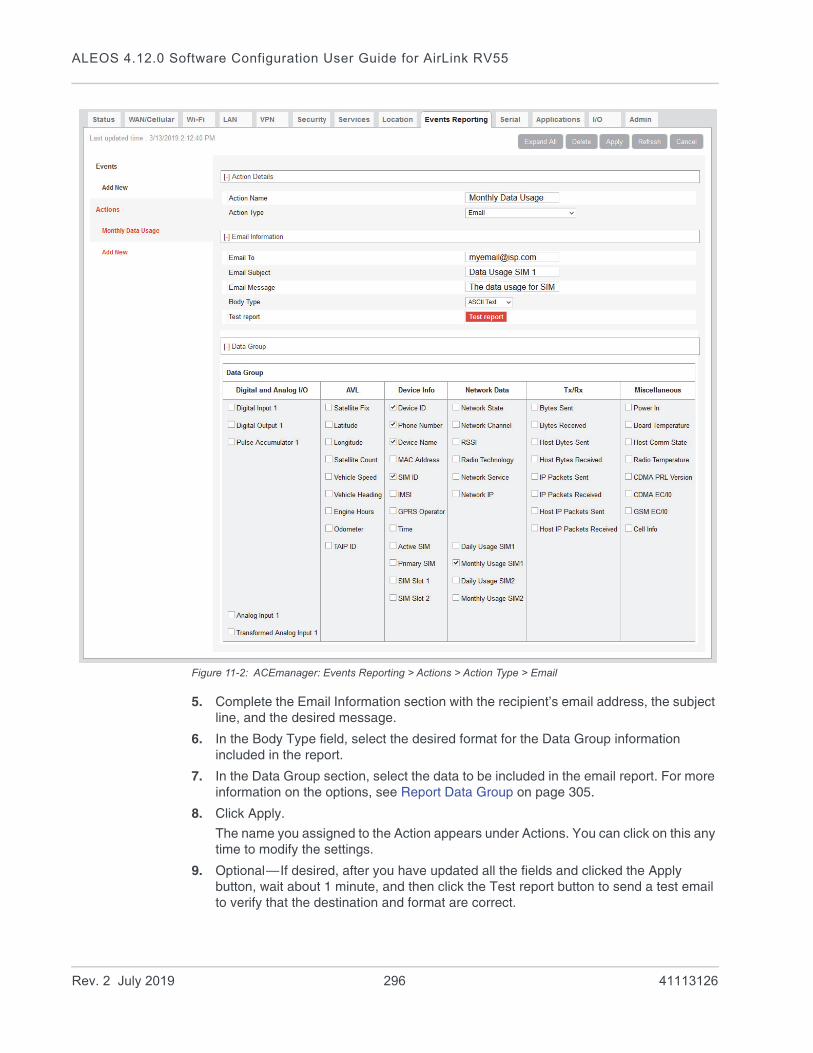
ALEOS 4.12.0 Software Configuration User Guide for AirLink RV55
Figure 11-2: ACEmanager: Events Reporting > Actions > Action Type > Email
5. Complete the Email Information section with the recipient’s email address, the subject line, and the desired message.
6. In the Body Type field, select the desired format for the Data Group information included in the report.
7. In the Data Group section, select the data to be included in the email report. For more information on the options, see Report Data Group on page 305.
8. Click Apply.
The name you assigned to the Action appears under Actions. You can click on this any time to modify the settings.
9. Optional—If desired, after you have updated all the fields and clicked the Apply button, wait about 1 minute, and then click the Test report button to send a test email to verify that the destination and format are correct.
Rev. 2 July 2019 296 41113126
Events Reporting Configuration
10. Click Events on the menu on the left and follow the instructions on Event Types on page 308 to configure the Event you want associated with this Action and to link the Action to the Event.
SMS
Note: You can only send SMS from your AirLink gateway if your cellular account allows SMS. You may need to have SMS added to the account. SMS from data accounts is blocked on some mobile networks. Outgoing SMS messages are limited to 140 characters. If the selected data exceeds 140 characters, the message is truncated.
To configure ALEOS to send an SMS message:
1. On the Events Reporting tab, select Actions from the menu on the left.
2. Enter the desired Action Name.
3. From the drop-down menu in the Action Type field, select SMS.
Rev. 2 July 2019 297 41113126

ALEOS 4.12.0 Software Configuration User Guide for AirLink RV55
Figure 11-3: ACEmanager: Events Reporting > Actions > Action Type > SMS
4. Complete the SMS Information section with the recipient’s phone number and the desired message to be included with the information from the Data Groups. The combined message and Data Group information cannot exceed 140 characters.
5. In the Data Group section, select any data you would like to be included in the SMS. For more information on the options, see Report Data Group on page 305.
6. Click Apply.
The name you assigned to the Action appears under Actions. You can click on this any time to modify the settings.
7. Optional—If desired, after you have updated all the fields and clicked the Apply button, wait until the progress circle disappears (about 30 seconds), and then click the Test report button to send a test SMS.
Rev. 2 July 2019 298 41113126
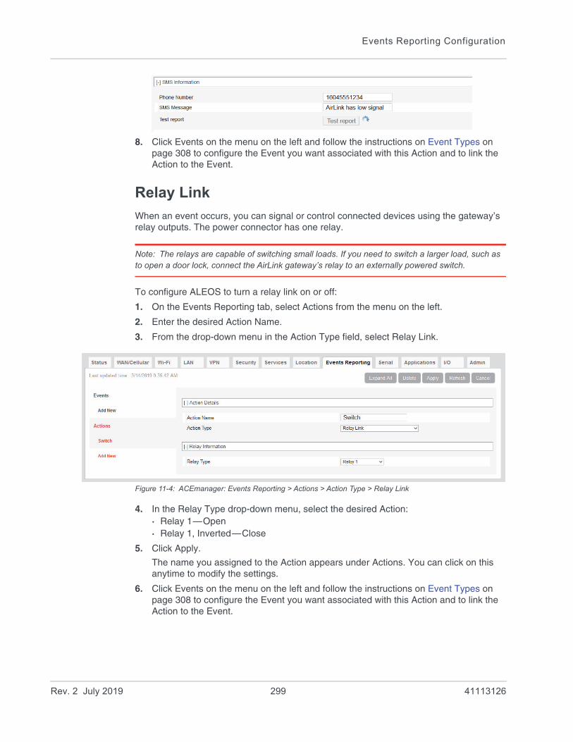
Events Reporting Configuration
8. Click Events on the menu on the left and follow the instructions on Event Types on page 308 to configure the Event you want associated with this Action and to link the Action to the Event.
Relay Link
When an event occurs, you can signal or control connected devices using the gateway’s relay outputs. The power connector has one relay.
Note: The relays are capable of switching small loads. If you need to switch a larger load, such as to open a door lock, connect the AirLink gateway’s relay to an externally powered switch.
To configure ALEOS to turn a relay link on or off:
1. On the Events Reporting tab, select Actions from the menu on the left.
2. Enter the desired Action Name.
3. From the drop-down menu in the Action Type field, select Relay Link.
Figure 11-4: ACEmanager: Events Reporting > Actions > Action Type > Relay Link
4. In the Relay Type drop-down menu, select the desired Action:· Relay 1—Open· Relay 1, Inverted—Close
5. Click Apply.
The name you assigned to the Action appears under Actions. You can click on this anytime to modify the settings.
6. Click Events on the menu on the left and follow the instructions on Event Types on page 308 to configure the Event you want associated with this Action and to link the Action to the Event.
Rev. 2 July 2019 299 41113126

ALEOS 4.12.0 Software Configuration User Guide for AirLink RV55
SNMP TRAP
To configure ALEOS to send an SNMP TRAP notification:
1. Ensure that SNMP is configured on the Services > Management (SNMP) page. See Management (SNMP) on page 255.
2. On the Events Reporting tab, select Actions from the menu on the left.
3. Enter the desired Action Name.
4. From the drop-down menu in the Action Type field, select SNMP TRAP.
Figure 11-5: ACEmanager: Event Reporting > Actions > Action Type > SNMP TRAP
5. Click Apply.
The name you assigned to the Action appears under Actions. You can click on this any time to modify the settings.
6. Click Events on the menu on the left and follow the instructions on Event Types on page 308 to configure the Event you want associated with this Action and to link the Action to the Event.
If you have more than one event or action configured, the trap indicates which Event triggered which Action.
Location Reports
Location reports can be sent using:• Standard NMEA, TAIP, and XORA• Sierra Wireless’ Remote Application Protocol (RAP)
RAP reports are very small and conserve over-the-air bandwidth. They can include vehicle odometer and digital input information.
To configure ALEOS to send a location report:
1. On the Events Reporting tab, select Actions from the menu on the left.
2. Enter the desired Action Name.
3. From the drop-down menu in the Action Type field, select the desired type of location report.
Note: For more information on location report types, see Location Report Type on page 280.
Rev. 2 July 2019 300 41113126

Events Reporting Configuration
Figure 11-6: ACEmanager: Events Reporting > Actions > Action Type > TAIP data
4. Enter the server information and if desired, the store and forward SNF parameters.
Note: The Reliable, Simple Reliable, and UDP Sequence SNF modes apply only to RAP reports. For more information on SNF, see page 283.
5. Optional (location RAP Report 13 only)—Enable Report Odometer and/or Report Digital Inputs.
6. Click Apply.
The name you assigned to the Action appears under Actions. You can click on this at any time to modify the settings.
7. Click Events on the menu on the left and follow the instructions on Event Types on page 308 to configure the Event you want associated with this Action and to link the Action to the Event.
Rev. 2 July 2019 301 41113126
ALEOS 4.12.0 Software Configuration User Guide for AirLink RV55
Events Protocol Reports
Sierra Wireless’ Events Reporting protocol allows for messages to be sent to the report server in four formats:• 1 — Type, Length, Value (TLV)—The TLV message consists of the MSCI ID as the
type, the length of the data, and the actual data.• 2 — Binary—A binary condensed form of the TLV message• 3 — CSV-ASCII—An ASCII condensed and comma-delimited form of the TLV
message• 4 — XML—An XML form of the data
Tip: Because of its flexibility and robustness, the TLV message type is recommended for most reports using the Events Protocol. The Binary and ASCII forms do not contain a “type field” which can result in misinterpretation of data. Since the TLV and XML forms always include the type as well as the data, an unintentional type can be identified much easier.
To configure an Events protocol report:
1. On the Events Reporting tab, select Actions from the menu on the left.
2. Enter the desired Action Name.
3. From the drop-down menu in the Action Type field, select the desired Events protocol report format.
Rev. 2 July 2019 302 41113126

Events Reporting Configuration
Figure 11-7: ACEmanager: Events Reporting > Actions > Action Type > Type, Length, Value
4. Enter the server information and if desired, the store and forward parameters.
5. In the Data Group section, select any data you would like to be included in the report. For more information on the options, see Report Data Group on page 305.
6. Click Apply.
The name you assigned to the Action appears under Actions. You can click on this at any time to modify the settings.
7. Click Events on the menu on the left and follow the instructions on Event Types on page 308 to configure the Event you want associated with this Action and to link the Action to the Event.
Rev. 2 July 2019 303 41113126

ALEOS 4.12.0 Software Configuration User Guide for AirLink RV55
Turn Off Services
This setting limits services and is primarily used in conjunction with monitoring data usage. For example, you could set the AirLink gateway to limit network service when data usage exceeds a configured threshold. For more information, see Data Usage on page 336.
Figure 11-8: ACEmanager: Events Reporting > Actions > Action Type > Turn Off Services
Turn Off Services does not turn off all network use. Reports are still sent and over-the-air access to the device is allowed. You can still access the AirLink gateway locally, but Ethernet, USBnet, and Wi-Fi host access to the mobile network is blocked.
Rev. 2 July 2019 304 41113126

Events Reporting Configuration
Report Data Group
For email, SMS, and Events Protocol (TLV, Binary, CSV-ASCII, and XML) messages, you can select the data you want to be included in the report. Check the box corresponding to the data displayed. By default, all the boxes are clear.
Figure 11-9: ACEmanager: RV55 Events Reporting > Actions > Data Group
The reports attributes are:• Digital and Analog I/O
Options are to include:· Digital Input 1—The status of the digital input· Digital Output 1—The status of the digital output· Pulse Accumulator 1—The pulse count for the digital input· Analog Input 1—The status of the analog input (reported in volts)· Transformed Analog Input 1—The status of the analog input (reported in units
configured in ACEmanager I/O > Configuration—see Configuration on page 354)• AVL
Options are to include:· Satellite Fix—Whether or not there is a usable location satellite fix· Latitude—The latitude reported by the location fix· Longitude—The longitude reported by the location fix· Satellite Count—The number of satellites the location technology is using to get a
satellite fix· Vehicle Speed—The speed of the vehicle reported by the location fix· Vehicle Heading—The direction the vehicle is traveling reported by the location fix· Engine Hours—The number of hours the engine has been on, based on either
Power In or Ignition Sense · Odometer—The number of miles reported by the location fix· TAIP ID—The TAIP ID for the AirLink gateway
• Device Info
Options are to include:
Rev. 2 July 2019 305 41113126

ALEOS 4.12.0 Software Configuration User Guide for AirLink RV55
· Device ID—The device ID (serial number) for the AirLink gateway· Phone Number—The phone number of the AirLink gateway· Device Name—The name of the AirLink gateway· MAC Address—The MAC Address of the Ethernet port of the AirLink gateway· SIM ID—The SIM ID of the AirLink gateway· IMSI—The IMSI of the SIM installed in the AirLink gateway· GPRS Operator—The wireless Mobile Network Operator the SIM card is
associated with· Time—The time the AirLink gateway is active· Active SIM—The SIM card slot that contains the SIM card currently being used for
the network connection· Primary SIM—The SIM card slot that contains the Primary SIM card (the primary
one is used for network connections if two SIM cards are installed)· SIM Slot 1—Whether or not a SIM card is present in SIM slot 1 (the upper SIM slot)· SIM Slot 2—Whether or not a SIM card is present in SIM slot 2 (the lower SIM slot)
• Network Data
Options are to include:· Network State—The network state for the AirLink gateway· Network Channel—The network channel to which the AirLink gateway is connected· RSSI—The signal strength for the AirLink gateway· Radio Technology—Type of service being used by the device (e.g. HSPA, LTE)· Network Service—The network service for the AirLink gateway· Network IP—The IP address given by the mobile network· Daily Usage SIM 1—The daily usage of the SIM card in slot 1 (Units as configured
on the Applications > Data Usage screen)· Daily Usage SIM 2—The daily usage of the SIM card in slot 2 (Units as configured
on the Applications > Data Usage screen)· Monthly Usage SIM 1—The monthly usage of the SIM card in slot 1 (Units as
configured on the Applications > Data Usage screen)· Monthly Usage SIM 2—The monthly usage of the SIM card in slot 2 (Units as
configured on the Applications > Data Usage screen)• Tx/Rx
The Network Traffic in this group relates to the mobile network and the network between the AirLink gateway and any directly connected device(s). Options are to include:· Bytes Sent—The number of bytes sent on the mobile network since last reset· Bytes Received—The number of bytes received from the mobile network since last
reset· Host Bytes Sent—The number of bytes sent from the network between the AirLink
gateway and the connected device(s) since last reset· Host Bytes Received—The number of bytes received from the network between the
AirLink gateway and the connected device(s) since last reset· IP Packets Sent—The number of IP packets sent on the mobile network since last
reset· IP Packets Received—The number of IP packets received from the mobile network
since last reset· Host IP Packets Sent—The number of IP packets sent from the network between
the AirLink gateway and the connected device(s) since last reset
Rev. 2 July 2019 306 41113126

Events Reporting Configuration
· Host IP Packets Received—The number of IP packets received from the network between the AirLink gateway and the connected device(s) since last reset
• Misc Data
Options are to include:· Power In—The voltage level of the power coming in to the AirLink gateway at the
time of the report· Board Temperature—The temperature of the internal hardware of the AirLink
gateway at the time of the report· Host Comm State—The signal level between the AirLink gateway and the
connected device(s)· Radio Temperature—The temperature of the internal radio module· CDMA PRL Version—PRL version used by the AirLink gateway · CDMA EC/IO—The quality of the signal from the cellular CDMA network · GSM EC/IO—The quality of the signal from the cellular GSM network· Cell Info—The mobile network cell information for the AirLink gateway
Rev. 2 July 2019 307 41113126
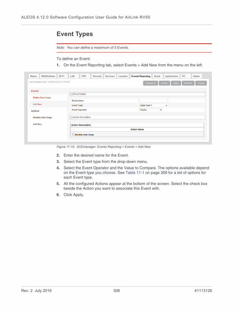
ALEOS 4.12.0 Software Configuration User Guide for AirLink RV55
Event Types
Note: You can define a maximum of 5 Events.
To define an Event:
1. On the Event Reporting tab, select Events > Add New from the menu on the left.
Figure 11-10: ACEmanager: Events Reporting > Events > Add New
2. Enter the desired name for the Event.
3. Select the Event type from the drop-down menu.
4. Select the Event Operator and the Value to Compare. The options available depend on the Event type you choose. See Table 11-1 on page 309 for a list of options for each Event type.
5. All the configured Actions appear at the bottom of the screen. Select the check box beside the Action you want to associate this Event with.
6. Click Apply.
Rev. 2 July 2019 308 41113126

Events Reporting Configuration
Figure 11-11: ACEmanager: Events Reporting > Events
Table 11-1: Event Types
Event Name Event Type Event Operator Options Values to Compare
Digital Inputs
Digital Input State Change • Disable
• When Switch Closed
• When Switch Opened
• On any change
N/A
Pulse Accumulator Threshold Crossing • Disable
• When Changed By
• Pulse Accumulator Delta
• Starting Trigger Value
Analog Input (volts) Threshold Crossing • Disable
• When Above Threshold
• When Below Threshold
• When Cross Threshold
Value To Compare (Threshold (volts))
Transformed Analog
Threshold Crossing • Disable
• When Above Threshold
• When Below Threshold
• When Cross Threshold
Value To Compare
(Units configured on the I/O screen) See Transformed Analog on page 356.
AVL
Location Fix State Change • Disable
• Fix Lost
• Fix Obtained
• On any change
N/A
Rev. 2 July 2019 309 41113126
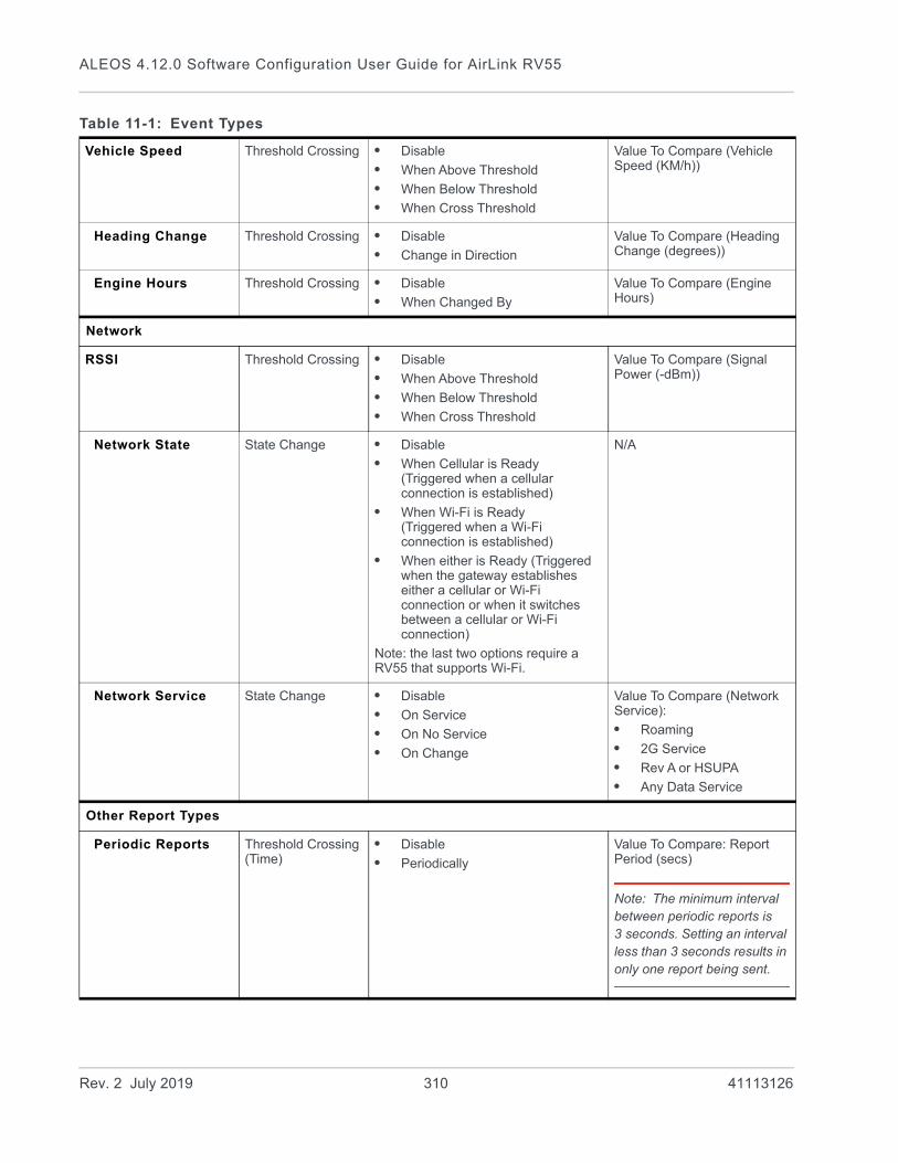
ALEOS 4.12.0 Software Configuration User Guide for AirLink RV55
Vehicle Speed Threshold Crossing • Disable
• When Above Threshold
• When Below Threshold
• When Cross Threshold
Value To Compare (Vehicle Speed (KM/h))
Heading Change Threshold Crossing • Disable
• Change in Direction
Value To Compare (Heading Change (degrees))
Engine Hours Threshold Crossing • Disable
• When Changed By
Value To Compare (Engine Hours)
Network
RSSI Threshold Crossing • Disable
• When Above Threshold
• When Below Threshold
• When Cross Threshold
Value To Compare (Signal Power (-dBm))
Network State State Change • Disable
• When Cellular is Ready(Triggered when a cellular connection is established)
• When Wi-Fi is Ready(Triggered when a Wi-Fi connection is established)
• When either is Ready (Triggered when the gateway establishes either a cellular or Wi-Fi connection or when it switches between a cellular or Wi-Fi connection)
Note: the last two options require a RV55 that supports Wi-Fi.
N/A
Network Service State Change • Disable
• On Service
• On No Service
• On Change
Value To Compare (Network Service):
• Roaming
• 2G Service
• Rev A or HSUPA
• Any Data Service
Other Report Types
Periodic Reports Threshold Crossing (Time)
• Disable
• Periodically
Value To Compare: Report Period (secs)
Note: The minimum interval between periodic reports is 3 seconds. Setting an interval less than 3 seconds results in only one report being sent.
Table 11-1: Event Types
Rev. 2 July 2019 310 41113126

Events Reporting Configuration
Power In Threshold Crossing • Disable
• When Above Threshold
• When Below Threshold
• When Cross Threshold
Value To Compare (Power In Threshold (volts))
Board Temperature Threshold Crossing • Disable
• When Above Threshold
• When Below Threshold
• When Cross Threshold
Value To Compare (Temperature Threshold (°C))
Radio Temperature Threshold Crossing • Disable
• When Above Threshold
• When Below Threshold
• When Cross Threshold
Value To Compare (Temperature Threshold (°C))
Data Usage
Note: You can choose whether the Event is for the SIM card in slot 1 or slot 2.
Daily Data Usage Threshold Crossing • Disable
• When Above Threshold
Value To Compare (% of Limit)
Monthly Data Usage Threshold Crossing • Disable
• When Above Threshold
Value To Compare (% of Limit)
Note: You can only configure one Event with either a Daily Data Usage or Monthly Data Usage trigger. If you configure more than one, for example, a trigger when the Daily Data Usage reaches a certain percentage and a trigger when the Monthly Data Usage reaches a certain percentage, only the last threshold configured is used.
ALEOS Data Usage is approximate and should not be compared with data usage recorded by the Mobile Network Operator. SIERRA WIRELESS IS NOT RESPONSIBLE FOR DATA OVERAGES.
Table 11-1: Event Types
Rev. 2 July 2019 311 41113126

ALEOS 4.12.0 Software Configuration User Guide for AirLink RV55
Rev. 2 July 2019 312 41113126
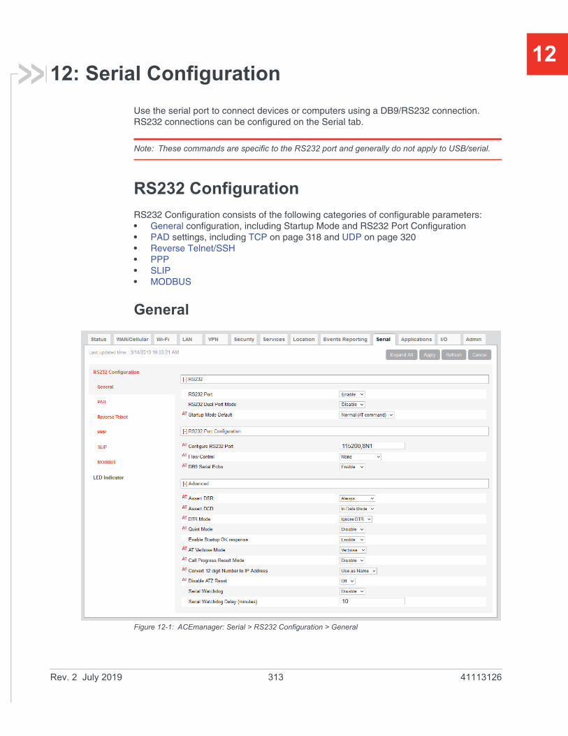
12
12: Serial ConfigurationUse the serial port to connect devices or computers using a DB9/RS232 connection. RS232 connections can be configured on the Serial tab.
Note: These commands are specific to the RS232 port and generally do not apply to USB/serial.
RS232 Configuration
RS232 Configuration consists of the following categories of configurable parameters:• General configuration, including Startup Mode and RS232 Port Configuration• PAD settings, including TCP on page 318 and UDP on page 320• Reverse Telnet/SSH• PPP• SLIP• MODBUS
General
Figure 12-1: ACEmanager: Serial > RS232 Configuration > General
Rev. 2 July 2019 313 41113126

ALEOS 4.12.0 Software Configuration User Guide for AirLink RV55
Table 12-1: RS232 Configuration > General
Field Description
RS232
RS232 Port Enable or disable the RS232 port. Default is Enable.
RS232 Dual Port Mode Enable or disable RS232 dual port mode. Default is Disable.
When dual port mode is enabled, you can configure the general and PAD settings for each port separately. See Configure RS232 Port on page 315, Advanced on page 315 and PAD settings, including TCP on page 318 and UDP on page 320.
Startup Mode Default Default power-up mode for the RS232 port. When the AirLink RV55 is power-cycled, the RS232 port enters the communication mode specified.
Note: It can take up to 5 minutes to establish a connection.
• Normal (AT command) (default)
• SLIP
• PPP
• UDP
• TCP
• Reverse Telnet/SSH—Allows you to telnet or SSH into a router or other device connected to the AirLink gateway via RS232. For information on configuring reverse telnet, see Reverse Telnet/SSH on page 322.
• Modbus ASCII
• Modbus RTU (Binary)
• BSAP—Bristol Standard Asynchronous Protocol
• Variable Modbus
• UDP Multiple Unicast—Data from the RS232 port is packed into UDP packets and sent to multiple IP addresses (for example, multiple AirLink gateways). For more infor-mation, see UDP Multiple Unicast for RS232 on page 322.
Note: In dual port mode, the Startup Mode Default settings are under RS232 Port 1 Configuration > General and RS232 Port 2 Configuration > General. Only Normal (AT command), UDP, and TCP are available.
You can also use an AT command to configure this field. See MD on page 513.
Rev. 2 July 2019 314 41113126

Serial Configuration
RS232 Port Configuration
Configure RS232 Port Format: [speed][data bits][parity][stop bits]
Valid speeds are 300–115200, data bits: 7 or 8, parity: O,E,N,M, stop bits: 1,1.5.
Default is 115200,8N1.
You can also use an AT command to configure this field. See S23 on page 524.
Flow Control RS232 port flow control setting
• None—No flow control is being used (default)
• Hardware—RTS/CTS hardware flow control is being used
• Transparent SW—Transparent software flow control. Uses escaped XON and XOFF for flow control. XON and XOFF characters in data stream are escaped with the @ character (0x40). @ in data is sent as @@.
You can also use an AT command to configure this field. See \Q on page 522.
DB9 Serial Echo AT command echo mode
• Enable—Text is visible as you type (default)
• Disable—Text you type is not visible
You can also use an AT command to configure this field. See E on page 521.
Advanced
Assert DSR Assert DSR always when the device is in a data mode (UDP, TCP, etc.), or when the device is in network coverage. Options are:
• Always (default)
• In Data Mode
• In Coverage
Note: This setting is not available in dual port mode.
You can also use an AT command to configure this field. See &S on page 522.
Assert DCD Assert DCD always, or when the device is in a data mode (UDP, TCP, etc.) or when the device is in network coverage. Options are:
• Always
• In Data Mode (default)
• In Coverage
Note: This setting is not available in dual port mode.
You can also use an AT command to configure this field. See &C on page 519.
DTR Mode Use DTR from the serial device, or ignore DTR (same as S211 on page 524). Options are:
• Use DTR
• Ignore DTR (default)
Note: This setting is not available in dual port mode.
Table 12-1: RS232 Configuration > General
Field Description
Rev. 2 July 2019 315 41113126
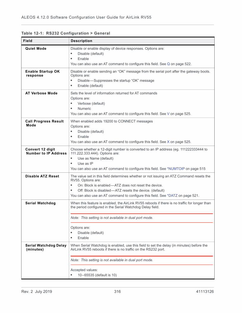
ALEOS 4.12.0 Software Configuration User Guide for AirLink RV55
Quiet Mode Disable or enable display of device responses. Options are:
• Disable (default)
• Enable
You can also use an AT command to configure this field. See Q on page 522.
Enable Startup OK response
Disable or enable sending an “OK” message from the serial port after the gateway boots. Options are:
• Disable—Suppresses the startup “OK” message
• Enable (default)
AT Verbose Mode Sets the level of information returned for AT commands
Options are:
• Verbose (default)
• Numeric
You can also use an AT command to configure this field. See V on page 525.
Call Progress Result Mode
When enabled adds 19200 to CONNECT messages
Options are:
• Disable (default)
• Enable
You can also use an AT command to configure this field. See X on page 525.
Convert 12 digit Number to IP Address
Choose whether a 12-digit number is converted to an IP address (eg. 111222333444 to 111.222.333.444). Options are:
• Use as Name (default)
• Use as IP
You can also use an AT command to configure this field. See *NUMTOIP on page 515
Disable ATZ Reset The value set in this field determines whether or not issuing an ATZ Command resets the RV55. Options are:
• On: Block is enabled—ATZ does not reset the device.
• Off: Block is disabled—ATZ resets the device. (default)
You can also use an AT command to configure this field. See *DATZ on page 521.
Serial Watchdog When this feature is enabled, the AirLink RV55 reboots if there is no traffic for longer than the period configured in the Serial Watchdog Delay field.
Note: This setting is not available in dual port mode.
Options are:
• Disable (default)
• Enable
Serial Watchdog Delay (minutes)
When Serial Watchdog is enabled, use this field to set the delay (in minutes) before the AirLink RV55 reboots if there is no traffic on the RS232 port.
Note: This setting is not available in dual port mode.
Accepted values:
• 10–65535 (default is 10)
Table 12-1: RS232 Configuration > General
Field Description
Rev. 2 July 2019 316 41113126

Serial Configuration
PAD
Figure 12-2: ACEmanager: Serial > RS232 Configuration > PAD
Table 12-2: RS232 Configuration > PAD
Field Description
General
Device Port The port on the AirLink gateway used for incoming TCP/UDP communication (Default is 12345)
If either, or both, of the UDP Answer or TCP Answer parameters are enabled, when the AirLink gateway receives incoming TCP or UDP packets that are destined for this port, it strips off the IP header and send the packet payload out its serial port.
You can also use an AT command to configure this field. See *DPORT on page 511.
Rev. 2 July 2019 317 41113126

ALEOS 4.12.0 Software Configuration User Guide for AirLink RV55
Serial MTU The serial maximum transmit unit (PAD payload)
Valid range: 256–4096 bytes (Default is 1304)
Recommended settings if you want to prevent packet fragmentation:
• UDP PAD—less than 1472 bytes
• TCP PAD—less than 1460 bytes
You can also use an AT command to configure this field. See *UDPPADMTU on page 518.
Destination Port The destination port that TCP/UDP communication is sent to
You can also use an AT command to configure this field. See S53 on page 516.
Destination Address IP address TCP/UDP communication is sent to
You can also use an AT command to configure this field. See S53 on page 516.
Default Dial Mode Protocol used to send messages
Options are:
• TCP
• UDP (default)
You can also use an AT command to configure this field. See S53 on page 516.
Data Forwarding Timeout (.1 second)
The Data Forwarding Timeout feature causes ALEOS to wait until no data has been received on the serial port for the specified period of time beyond the built-in delay of 100 ms before sending a new PAD packet.
Acceptable values are: 0–255. (Unit is 0.1 second; default is 1.)
If the field is set to 0 or 1, the feature is disabled. ALEOS sends the new PAD packet after the built-in 100 ms delay.
Data Forwarding Timeout is not applicable to AT and PPP modes.
Data Forwarding Character
PAD data forwarding character. ASCII code of character that causes data to be forwarded. Used in UDP or TCP PAD mode
Default is 0 (No forwarding character).
You can also use an AT command to configure this field. See S51 on page 515.
TCP
TCP Auto Answer This determines how the AirLink gateway responds to an incoming TCP connection request. The AirLink gateway remains in AT Command mode until a connection request is received. The AirLink gateway sends a “RING” string to the host. A “CONNECT” sent to the host indicates acknowledgment of the connection request and the TCP session is established.
• Disable (default)
• Enable
You can also use an AT command to configure this field. See S0 on page 523.
Table 12-2: RS232 Configuration > PAD
Field Description
Rev. 2 July 2019 318 41113126

Serial Configuration
TCP Persistent Connection
This feature assists the RV55 to maintain a TCP connection to the remote server.
Options are:
• Disable (default)
• Enable—TCP Persistent Connection attempts to maintain the TCP connection by:
• Automatically reconnecting after the connection to the server is closed for any reason. A back-off mechanism will try to reconnect with an increased waiting period between each retry (maximum wait time is 30 minutes).
• Using TCP keepalive probe packets, which the device sends when the connection is idle (no traffic). You can configure a Keepalive Time, Keepalive Interval and the number of Keepalive Probes.
Keepalive Time (seconds)
Sets the interval between the last data packet sent and the first keepalive probe.
Appears when TCP Persistent Connection is enabled.
Options are:
• 0–65535 (Default is 30)
Keepalive Interval (seconds)
Sets the interval between keepalive probes.
Appears when TCP Persistent Connection is enabled.
Options are:
• 0–65535 (Default is 10)
Keepalive Probes (seconds)
Sets the number of unacknowledged probes to send before considering the TCP connection dead.
Appears when TCP Persistent Connection is enabled.
Options are:
• 0–65535 (Default is 3)
TCP Connect Timeout (seconds)
Specifies the number of seconds to wait for a TCP connection to be established when dialing out (default is 30).
You can also use an AT command to configure this field. See S7 on page 523.
TCP Idle Timeout TCP idle time-out in the configured units (See TCP Idle Timeout Unit on page 319). Specifies a time interval upon which if there is no in or outbound traffic through a TCP connection, the connection is terminated.
Default is 5.
You can also use an AT command to configure this field. See TCPT on page 517.
TCP Idle Timeout Unit Units used for the TCP Idle Timeout Interval.
Options are:
• Minutes (default)
• Seconds
You can also use an AT command to configure this field. See TCPS on page 517.
TCP Connect Response Delay (seconds)
The number of seconds to delay the “CONNECT' response upon establishing a TCP connection, or the number of tenths of seconds to delay before outputting ENQ on the serial port after the CONNECT when the ENQ feature is enabled.
• 0–255 (Default is 0.)
You can also use an AT command to configure this field. See S221 on page 525.
Table 12-2: RS232 Configuration > PAD
Field Description
Rev. 2 July 2019 319 41113126

ALEOS 4.12.0 Software Configuration User Guide for AirLink RV55
Include Device ID on TCP Connect
If this option is enabled, after a TCP connection is established, ALEOS sends a packet that contains the device ID (and optionally a prefix, suffix, and CRLF). Options are:
• Disable (default)
• Enable
Note: To use this feature, ensure that the Device ID is configured in the Use Device ID in Location Reports field on the Location screen (Location > Global Settings > General). See Global Settings on page 271.
Device ID Prefix If Include Device ID on TCP Connect is enabled, sets the Prefix DID in the device identification packet upon TCP connection. Maximum length of the prefix is 80 characters.
Device ID Suffix If Include Device ID on TCP Connect is enabled, sets the Suffix DID in the device identification packet upon TCP connection. Maximum length of the suffix is 80 characters.
Send CR LF after Device ID
If Include Device ID on TCP Connect is enabled, enables a carriage return to be inserted in the device identification packet after the Suffix DID. Options are:
• no CR LF
• send CR
• send CR LF (carriage return, line feed) Default
UDP
UDP Auto Answer Whether the AirLink gateway answers and incoming UDP connection request
Options are:
• Disable (default)
• Enable
You can also use an AT command to configure this field. See S82 on page 516.
UDP Idle Timeout (seconds)
UDP Idle Timeout in seconds
Specifies a time interval upon which if there is no in or outbound traffic through a UDP connection, the connection is terminated.
• 0—No idle time-out
• 1–255 Timeout in seconds (Default is 50.)
You can also use an AT command to configure this field. See S83 on page 517.
Note: UDP Idle Timeout only takes effect if the UDP Auto Answer is set to Enable.
UDP Connect Last Allows you to choose to use the last accepted IP address and port number as the default settings, instead of using S53 (destination address)
Options are:
• Do not change S53 (default)
• Set S53 to last IP
Note: Resetting the device restores the configured S53 (destination address).
You can also use an AT command to configure this field. See *UDPLAST on page 518.
Table 12-2: RS232 Configuration > PAD
Field Description
Rev. 2 July 2019 320 41113126

Serial Configuration
Allow Any Incoming IP When UDP answer is enabled, use this field to select whether to allow any incoming IP address to connect or to only allow the configured destination IP address to connect.
Options are:
• Allow only S53 (default)
• Allow any IP address
If you select Allow only S53, the Destination Port and Destination Address fields under RS232 Configuration > PAD > General must be configured. (See Table 12-2 on page 317.)
You can also use an AT command to configure this field. See AIP on page 511.
Allow All UDP Accepts UDP packets from all IP addresses when a UDP session is active. If there is no UDP session active, an incoming UDP packet is treated according to the UDP answer and AIP settings. Options are:
• No effect (default)
• Allow all—The AirLink gateway accepts all UDP traffic from any IP address during a UDP session.
You can also use an AT command to configure this field. See *UALL on page 518.
UDP Auto Answer Response
Half-Open Response—In UDP answer (half-open) mode. Options are:
• No Response—No Response codes when UDP session is initiated (default)
• RING CONNECT—RING CONNECT response codes sent out serial link before the data from the first UDP packet
Note: Quiet Mode must be Off.
You can also use an AT command to configure this field. See HOR on page 521.
Dial UDP Always The dial command always uses UDP, even when using ATDT. Options are:
• Disable—Dial using the means specified (default)
• Enable—Dial UDP always, even when using ATDT
Note: When this parameter is set you cannot establish a TCP PAD connection.
You can also use an AT command to configure this field. See *DU on page 512.
UDP Serial Delay (.1 second)
Waits the specified delay before sending the first received UDP packet and the subsequent UDP packets out to the serial port (in 100 ms units).
• No UDP packet delay (default)
• 1–255—Delay in 100 ms units, from 100 ms to 25.5 sec.
You can also use an AT command to configure this field. See *USD on page 518.
Table 12-2: RS232 Configuration > PAD
Field Description
Rev. 2 July 2019 321 41113126

ALEOS 4.12.0 Software Configuration User Guide for AirLink RV55
UDP Multiple Unicast for RS232
With UDP Multiple Unicast, data from the serial port is packed into UDP packets and sent to multiple IP addresses. To configure UDP Multiple Unicast:
1. Go to Serial > RS232 Configuration > General.
2. In the Startup Mode Default field, select UDP Multiple Unicast.
3. Click Apply.
4. Under RS232 Configuration > PAD > General, in the Destination Port field, enter the remote port to be used.
5. Click Apply.
6. Go to RS232 Configuration > MODBUS > General > Address List and enter the index numbers and IP addresses of the devices you want the data sent to. (See MODBUS Address List on page 330.)
7. Click Apply.
8. Reboot the device.
Note: To avoid flooding the network, there is a 20 millisecond pause between sending the UDP packet to each destination.
Reverse Telnet/SSH
The Reverse Telnet/SSH feature allows you to connect to and configure a router or other device that has a serial connection to your AirLink gateway.
You can have only one Reverse Telnet session open at a time. If a new Reverse Telnet session is started, any existing Reverse Telnet connection will be closed.
However, you can simultaneously have:• One Telnet session for Reverse Telnet (using the port configured in the Device Port
field on the RS232 Configuration > Reverse Telnet page)
UDP Keepalive (seconds)
Use this field to configure the time interval (in seconds) for sending UDP keepalive packets. Options are:
• 1–65535—ALEOS sends a UDP packet, containing the AirLink gateway’s IMEI (in little endian) to the configured Destination IP Address:Destination Port when the UDP connection is first established and then at the configured interval.
If the AirLink gateways WAN IP address changes, a UDP packet is sent and the timer is reset.
• 0—UDP Keepalive is disabled. (default)
UDP Recovery Ping If an IP is provided in this field and no UDP packets are received from the server for the UDP Idle Timeout period, the gateway sends a single ping to this IP.
This functionality is designed to resolve a known issue where a Verizon Wireless GX440 becomes temporarily unreachable from the mobile network after a period of time in which no data is sent or received.
Table 12-2: RS232 Configuration > PAD
Field Description
Rev. 2 July 2019 322 41113126
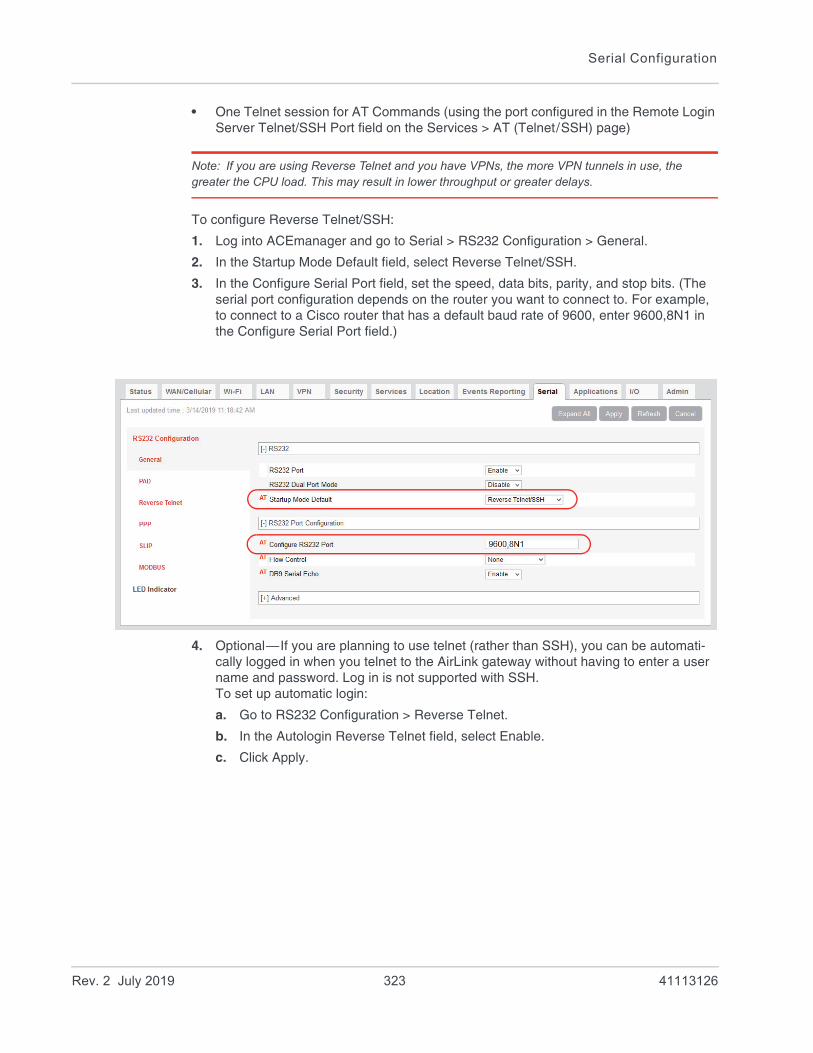
Serial Configuration
• One Telnet session for AT Commands (using the port configured in the Remote Login Server Telnet/SSH Port field on the Services > AT (Telnet/SSH) page)
Note: If you are using Reverse Telnet and you have VPNs, the more VPN tunnels in use, the greater the CPU load. This may result in lower throughput or greater delays.
To configure Reverse Telnet/SSH:
1. Log into ACEmanager and go to Serial > RS232 Configuration > General.
2. In the Startup Mode Default field, select Reverse Telnet/SSH.
3. In the Configure Serial Port field, set the speed, data bits, parity, and stop bits. (The serial port configuration depends on the router you want to connect to. For example, to connect to a Cisco router that has a default baud rate of 9600, enter 9600,8N1 in the Configure Serial Port field.)
4. Optional—If you are planning to use telnet (rather than SSH), you can be automati-cally logged in when you telnet to the AirLink gateway without having to enter a user name and password. Log in is not supported with SSH. To set up automatic login:
a. Go to RS232 Configuration > Reverse Telnet.
b. In the Autologin Reverse Telnet field, select Enable.
c. Click Apply.
Rev. 2 July 2019 323 41113126

ALEOS 4.12.0 Software Configuration User Guide for AirLink RV55
5. Go to Services > AT (Telnet/SSH).
6. In the Remote Login Server Mode field, select:· Telnet—if you want to Telnet into the connected device· SSH—if you want to SSH into the connected device
Note: If you enabled login, select Telnet.
7. Click Apply.
8. Reboot the AirLink gateway.
9. Use a Telnet or SSH terminal client such as Putty or Teraterm to connect to the appro-priate port:· If you are using login, Telnet to the port specified in the Device Port field (default is
12345). SSH is not available with login.· If you are not using login, you can Telnet or SSH into the port specified in the
Remote Login Server Telnet/SSH Port field (default is 2332).
Rev. 2 July 2019 324 41113126

Serial Configuration
10. If prompted, log in with the following credentials:· User name: sconsole· Password: 12345 (default)
For information on changing the default reverse telnet password, see Change Pass-word on page 358.
ALEOS redirects you to the router or other device connected to the AirLink gateway serial port. You can use this connection to configure connected device.
Note: You may be required to enter a user name and password to access the router or other device.
Rev. 2 July 2019 325 41113126

ALEOS 4.12.0 Software Configuration User Guide for AirLink RV55
PPP
Use Point-to-Point Protocol (PPP) to establish a connection between a host PC serial port and the AirLink gateway, as shown in Figure 12-3.
Figure 12-3: PPP connection
Figure 12-4: ACEmanager: Serial > RS232 Configuration > PPP
AirLink gatewayHost PC
Internet
Serial cable
PPP connection
WAN connection
Table 12-3: RS232 Configuration > PPP
Field Description
Device PPP IP Sets the device IP address (in private mode)
Default is 192.168.15.31
Host PPP IP Sets the host IP address (in private mode)
Default is 192.168.15.100
Host Authentication Mode
Sets the authentication method the host uses for PPP. Options are:
• None (default)
• CHAP—The stronger of the two protocols. Recommended, provided it is supported by all the client devices
• PAP and CHAP—If CHAP is not supported by the client, the host reverts to PAP.
PPP User ID Sets the User ID for authentication
PPP Password Sets the User Password for authentication
Rev. 2 July 2019 326 41113126
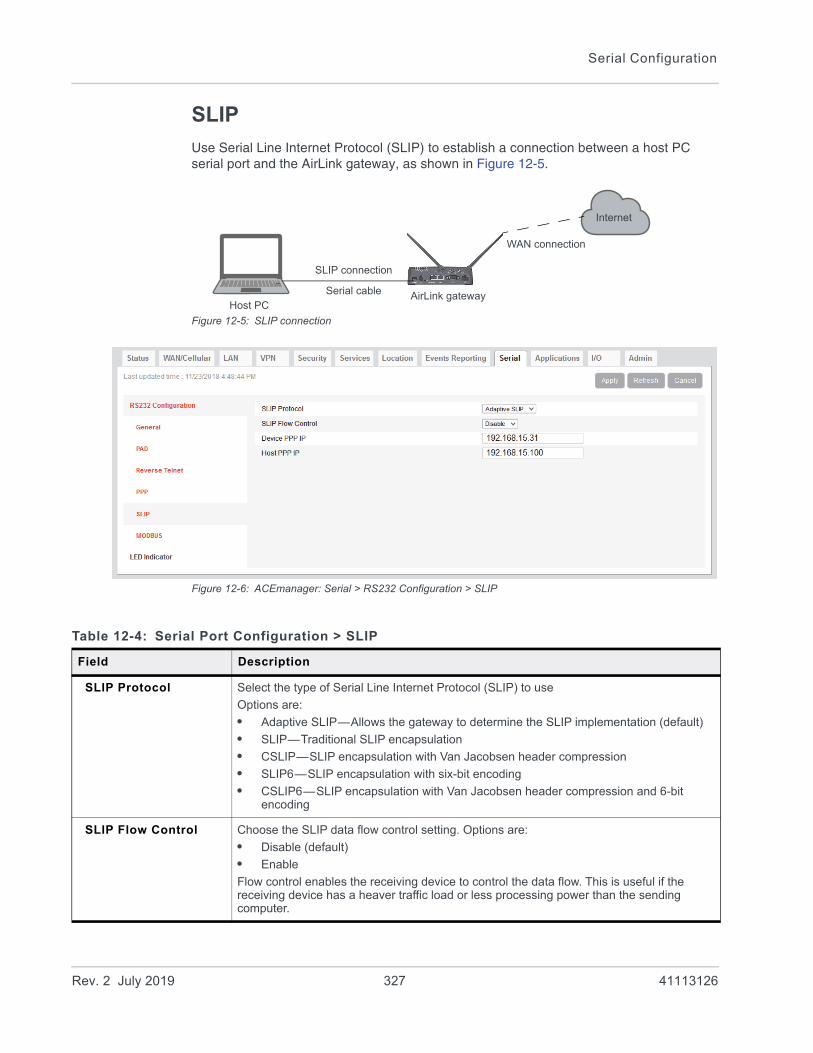
Serial Configuration
SLIP
Use Serial Line Internet Protocol (SLIP) to establish a connection between a host PC serial port and the AirLink gateway, as shown in Figure 12-5.
Figure 12-5: SLIP connection
Figure 12-6: ACEmanager: Serial > RS232 Configuration > SLIP
AirLink gatewayHost PC
Internet
Serial cable
SLIP connection
WAN connection
Table 12-4: Serial Port Configuration > SLIP
Field Description
SLIP Protocol Select the type of Serial Line Internet Protocol (SLIP) to use
Options are:
• Adaptive SLIP—Allows the gateway to determine the SLIP implementation (default)
• SLIP—Traditional SLIP encapsulation
• CSLIP—SLIP encapsulation with Van Jacobsen header compression
• SLIP6—SLIP encapsulation with six-bit encoding
• CSLIP6—SLIP encapsulation with Van Jacobsen header compression and 6-bit encoding
SLIP Flow Control Choose the SLIP data flow control setting. Options are:
• Disable (default)
• Enable
Flow control enables the receiving device to control the data flow. This is useful if the receiving device has a heaver traffic load or less processing power than the sending computer.
Rev. 2 July 2019 327 41113126
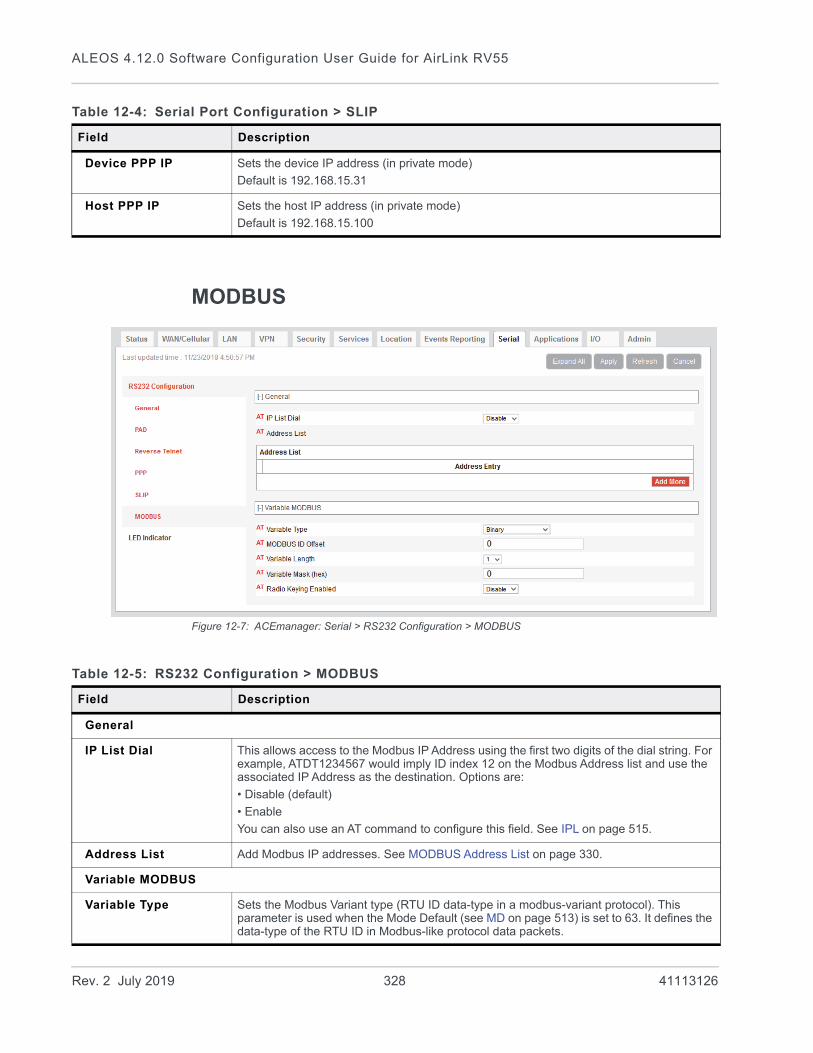
ALEOS 4.12.0 Software Configuration User Guide for AirLink RV55
MODBUS
Figure 12-7: ACEmanager: Serial > RS232 Configuration > MODBUS
Device PPP IP Sets the device IP address (in private mode)
Default is 192.168.15.31
Host PPP IP Sets the host IP address (in private mode)
Default is 192.168.15.100
Table 12-4: Serial Port Configuration > SLIP
Field Description
Table 12-5: RS232 Configuration > MODBUS
Field Description
General
IP List Dial This allows access to the Modbus IP Address using the first two digits of the dial string. For example, ATDT1234567 would imply ID index 12 on the Modbus Address list and use the associated IP Address as the destination. Options are:
• Disable (default)
• Enable
You can also use an AT command to configure this field. See IPL on page 515.
Address List Add Modbus IP addresses. See MODBUS Address List on page 330.
Variable MODBUS
Variable Type Sets the Modbus Variant type (RTU ID data-type in a modbus-variant protocol). This parameter is used when the Mode Default (see MD on page 513) is set to 63. It defines the data-type of the RTU ID in Modbus-like protocol data packets.
Rev. 2 July 2019 328 41113126
Serial Configuration
MODBUS ID Offset Sets the Modbus (Variable mode) offset in the data of where the Modbus ID starts.
Options are 0 (default)–255
Variable Length Sets the length (in bytes) of the RTU ID in a Modbus Variant protocol.
Options are 1 (default)–5
Variable Mask (hex) Sets the Modbus Variant ID Mask. This is the 16-bit hex mask to use when extracting the ID. This parameter is used when the Mode Default (see MD on page 513) is set to hex 63.
Radio Keying Enabled Enable MDS Radio transceiver keying. Radio keying is designed to assert CTS when a packet is received, delay the time as specified, send the data out of the serial port, wait the same amount of time, drop CTS. This way the CTS signal can be used to key a transmitter on and give it time to reach its power level before data is sent to it. Delay interval is specified in S221.
Options are:
• Enable
• Disable (default)
Table 12-5: RS232 Configuration > MODBUS
Field Description
Rev. 2 July 2019 329 41113126
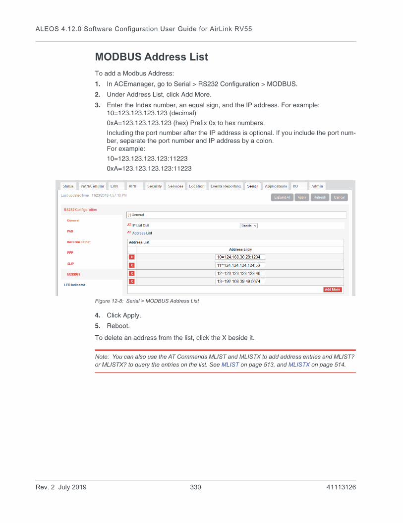
ALEOS 4.12.0 Software Configuration User Guide for AirLink RV55
MODBUS Address List
To add a Modbus Address:
1. In ACEmanager, go to Serial > RS232 Configuration > MODBUS.
2. Under Address List, click Add More.
3. Enter the Index number, an equal sign, and the IP address. For example: 10=123.123.123.123 (decimal)
0xA=123.123.123.123 (hex) Prefix 0x to hex numbers.
Including the port number after the IP address is optional. If you include the port num-ber, separate the port number and IP address by a colon. For example:
10=123.123.123.123:11223
0xA=123.123.123.123:11223
Figure 12-8: Serial > MODBUS Address List
4. Click Apply.
5. Reboot.
To delete an address from the list, click the X beside it.
Note: You can also use the AT Commands MLIST and MLISTX to add address entries and MLIST? or MLISTX? to query the entries on the list. See MLIST on page 513, and MLISTX on page 514.
Rev. 2 July 2019 330 41113126

Serial Configuration
Configuring IP to Serial with Answer and Serial to IP
You can configure the AirLink gateway to:• Answer incoming TCP/IP or UDP/IP connections and send the packet payload out the
AirLink gateway’s serial port to a connected device• Create and send TCP/IP or UDP/IP packets containing payload data that the AirLink
gateway receives over its serial port from a connected device• Both receive and send TCP/IP or UDP/IP packets (that is, both of the above function-
alities)
Figure 12-9: TCP and UDP Answer
To configure the AirLink RV55 for TCP/UDP answer, sending IP packets or both:
1. In ACEmanager, go to Serial > RS232 Configuration > General.
2. Use Table 12-6 and Step 5 onwards to configure the desired options for this feature.
Internet
AirLink gateway Connected device
Serial
TCP /IP packet
UDP/IP packet Packet contentsstreamed over serial
TCP /IP packet
UDP/IP packet
TCP /IP packet
UDP/IP packet
Packet contentsstreamed over serial
Packet contentsstreamed over serial
Receive packets; send payload
Receive payload data over serial;
data out over serial
create and send out packets
Both: receive packets; send payloaddata out over serial AND receivepayload data, create and send outpackets
Table 12-6: Quick Guide to Configuring IP to Serial with Answer and Serial to IP
Field To receive packets and send data payload out
over serial
To receive data payloads over serial
and send out packets
Both (to receive packets - send out data payload AND receive
data payload and send out packets)
Startup Mode DefaultSee step Step 5.
N/A UDP or TCP UDP or TCP
Configure Serial PortSee Step 6.
115200,8N1 115200,8N1 115200,8N1
Flow ControlSee Step 7.
None None None
Rev. 2 July 2019 331 41113126

ALEOS 4.12.0 Software Configuration User Guide for AirLink RV55
Figure 12-10: ACEmanager: Serial > RS232 Configuration > General
3. Go to Serial > RS232 Configuration > PAD
4. Use Table 12-7 and Step 5 onwards to configure the desired options for this feature.
Required field for receiving data payloads over serial, creating IP packets to send
Required fields both receiving data payloads over serial, creating IP packets to send and receiving data payloads over serial, creating IP packets to send
Table 12-7: Quick Guide to Configuring IP to Serial with Answer and Serial to IP
Field To receive packets and send data payload out
over serial
To receive data payloads over serial
and send out packets
Both (to receive packets - send out data payload AND receive
data payload and send out packets)
Device PortSee Step 8.
12345 N/A 12345
Destination PortSee Step 8.
N/A Required Required
Destination AddressSee Step 9.
N/A Required Required
Rev. 2 July 2019 332 41113126

Serial Configuration
Figure 12-11: ACEmanager: Serial > Port Configuration
5. Startup Default Mode—When the Startup Mode is set to UDP or TCP, the AirLink gateway takes any data sent to its serial port by a connected device and encapsulates it into a TCP/IP or UDP/IP packet.
6. Configure Serial Port—Set the baud rate of the serial port on the AirLink gateway so that it matches the baud rate of the serial port on the connected device. (The default baud rate is 115200 bps.) You can also use this field to set the framing characteristics for the serial port communication on those rare occasions when the default value of 8N1 does not apply.
7. Flow Control—This field can usually be left at the default value (None) as most serial devices use only a 3-wire connection (Tx, RX, and Gnd). However, if the serial device uses the RTS and CTS pins on the serial connection to control data flow between the two devices, set this field to Hardware.
8. Device Port—Data received on a TCP/IP or UDP/IP connection to the configured Device Port is sent out the serial port. The default value for the port is 12345. Desti-nation Port—The AirLink gateway uses the port value specified in this field to determine which port it sends the IP packet containing the data payload to. The AirLink gateway enters the value in the Destination Port field in the header of the IP packet it creates.
9. Destination Address—The AirLink gateway uses the IP address specified in this field to determine the IP address to send the packet it creates to. The AirLink gateway enters this IP address in the header of the IP packet it creates.
10. If you are configuring the AirLink gateway to:· Create and send packets only, go to step Step 11.· Receive TCP/UDP packets, complete the following instructions.
For Receiving TCP/IP Packets:
a. Expand the +TCP section of the screen.
Required fields for receiving data payloads over serial, creating IP packets to send
Required field for receiving IP packets and sending out data payloads over serial
Rev. 2 July 2019 333 41113126
ALEOS 4.12.0 Software Configuration User Guide for AirLink RV55
Figure 12-12: ACEmanager: Serial > RS232 Configuration > PAD > TCP
b. Set the TCP Auto Answer field to Enable.
For Receiving UDP/IP Packets:
a. Expand the +UDP section of the screen.
Figure 12-13: ACEmanager: Serial > RS232 Configuration > PAD > UDP
b. Set the UDP Auto Answer field to Enable.
c. Set the Allow Any Incoming IP field to Allow Any IP. (If this field is left at the default value, the AirLink gateway only accepts incoming UDP/IP packets from the IP address specified in the Destination Address field in the Port Configuration section of the screen.
11. For information on the other parameters, see RS232 Configuration on page 313.
12. Click Apply.
13. Click Reboot (in the upper right of the screen).
14. Once the reboot is complete, this feature is enabled.
If the packet contents are not being sent to the connected device, see the troubleshooting information in TCP/IP and UDP/IP Auto Answer on page 554.
Rev. 2 July 2019 334 41113126

Serial Configuration
LED Indicator
You can configure the Activity LED on the AirLink gateway to flash red when traffic is being transmitted or received over the serial port.
Figure 12-14: ACEmanager: Serial > LED Indicator
Table 12-8: Serial > LED Indicator
Field Description
Display Options are:
• Disable (default)
• Enable
If this field is set to Enable, the Activity LED ( ) on the AirLink gateway flashes red when traffic is being transmitted/received on the serial port.
You can also use an AT command to configure this field. See *SERIALLEDDISPLAY on page 517. For a complete list of LED behavior, refer to the Hardware User Guide for your product.
Serial Port When the MP70 is in Dual Port Mode, sets the port that the Activity LED indicates. If two devices are connected to the serial port using a split cable, and Port 1 is selected, the activity LED will flash when there is data on UART1. If Port 2 is selected, the activity LED will flash when there is data on UART5.
Options are:
• Port 1 (default)
• Port 2
Activity LED Traffic
Off No traffic
Flashing Green Traffic on WAN interface
Flashing Red Traffic on selected serial port
Flashing Yellow Traffic on both the WAN interface and selected serial port
Rev. 2 July 2019 335 41113126

13
13: Applications ConfigurationThe Applications tab consists of a Data Usage section, a Garmin application, and an ALEOS Application Framework section.
Data Usage
Note: Before configuring Data Usage, ensure that the AirLink gateway receives date and time infor-mation from the mobile network, or from GNSS in the case of a gateway using Location technology. You can also use the ACEmanager SNTP client to receive time from an SNTP server. (See Time (SNTP) on page 261.) If necessary, contact your Mobile Network Operator to confirm that the mobile network provides date and time information to connected devices.
The Data Usage feature on the Applications tab in conjunction with Events Reporting provides you with a way to actively monitor cellular data usage.
Once data usage is configured, you can use event reporting to:• Actively monitor the cellular data usage by configuring monthly and/or daily usage
level thresholds that result in notifications being sent to you (e.g. email, SMS, or SNMP Trap) when the threshold is reached.
• Limit mobile network communication until the end of the billing period when the data limit is reached by blocking connected LAN devices from using the mobile network. Traffic sent to and from the AirLink gateway is not blocked. Over-the-air access to ACEmanager and the Telnet/SSH AT interface is still available.
Note: You can configure Events Reporting to notify you when the threshold set in Data Usage is reached, but ALEOS does not block further access to the mobile network unless you also create a second action to Turn Off Services.
Note: ALEOS Data Usage is approximate and should not be compared with data usage recorded by the Mobile Network Operator. Sierra Wireless is NOT responsible for data overages.
Rev. 2 July 2019 336 41113126

Applications Configuration
Step 1—Configure Data Usage
1. In ACEmanager, go to Applications > Data Usage.
2. In the Usage Monitoring field, select Enable.
3. In the side menu, select the screen for the SIM slot you want to configure (Data Usage Slot 1 or Data Usage Slot 2).
Data usage monitors the slot. If you change the SIM card in the slot being monitored, the data usage tracked is the accumulative data usage for all SIM cards placed in that slot.
4. Enter the desired values in the Daily or Monthly Limit fields (in GB or MB), and the day of the month that the billing cycle starts. For more details, see the table starting on page 337.
5. Click Apply.
Figure 13-1: ACEmanager: Applications > Data Usage Slot 1
Field Description
General
Usage Monitoring Use this field to enable or disable data usage monitoring. Options are:
• Disable (default)
• Enable
Rev. 2 July 2019 337 41113126

ALEOS 4.12.0 Software Configuration User Guide for AirLink RV55
Data Service This field is intended for use in conjunction with Events Reporting, specifically a Data Usage Event with Turn Off Services as the configured action. For more information and instructions on configuring the appropriate Event Reporting settings, see Stopping Service when the Event Reporting Threshold is Reached on page 342.
Warning: This field shows the status of the data usage, but mobile network access is not actually stopped when this field reads “Blocked (usage limit exceeded” unless you have also configured Event Reporting to Turn Off Services when the threshold is reached. See Stopping Service when the Event Reporting Threshold is Reached on page 342.
Plan Units Select the units used for your data plan. The options are:
• MB—Megabytes (default)
• KB—Kilobytes
Note: When you change the units in this field, the units for values in the Daily Limit and Monthly Limit fields are not converted and must be updated manually.
Field Description
Data Usage Turn Off Services Events Reporting action configured
Data Service displays....
Over threshold configured in Events Reporting
No Available (under usage limit)
Under threshold configured in Events Reporting
Yes Available (under usage limit)
Over threshold configured in Events Reporting
Yes Blocked (usage limit exceeded)
Rev. 2 July 2019 338 41113126
Applications Configuration
Daily Limit
Daily Limit (MB) This is the user-specified daily (24 hour) data usage limit (in MB or KB, depending on the value in the Plan Units field). You can specify data usage limits on a daily basis. A limit is essentially a threshold that can trigger the software to take a user-specified action if the usage goes above the threshold. See Events Reporting Configuration on page 293.
Note: The Daily Limit value MUST be expressed as an integer (i.e., a whole number) and NOT as a fraction (e.g., “3.5”).
Note: Daily usage is cleared at midnight, UTC.
Caution: Data usage limits are approximate and based on reporting conditions in ALEOS. Data usage may run over the amount set in this field before the action specified for the threshold trigger takes effect.
Tip: ALEOS reads the data usage every 3 to 5 minutes. If you are using an application that requires high data usage, you can set an alert to warn you when data usage reaches a safe limit that takes into account the amount of data expected over the 3 to 5 minutes between data usage readings. For information on how to set an alert or other action, see Events Reporting Configuration on page 293.
Current Daily Usage (MB)
Displays the current daily data usage (in MB or KB, depending on the option selected in the Plan Units field)
Note: Data usage includes data sent and data received.
Field Description
Rev. 2 July 2019 339 41113126

ALEOS 4.12.0 Software Configuration User Guide for AirLink RV55
Monthly Limit
Monthly Limit Units Select the units used for your monthly data plan. This option does not appear if KB is selected for Plan Units. The options are:
• MB—Megabytes (default)
• GB—Gigabytes
Monthly Limit This is the user-specified monthly data usage limit (in KB, MB or GB, depending on the option selected in the Plan Units and Monthly Limit Units field). Data usage accumulates on a monthly basis and on the date you specified (the “rolling month”). Data usage accumulates during the month until the end of the next billing period, at which point the data usage totals are reset.
Note: The Monthly Limit value MUST be expressed as an integer (i.e., a whole number) and NOT as a fraction (e.g., “3.5”)
Note: Monthly usage is cleared at midnight, UTC on the last day of the billing cycle.
Caution: Data usage limits are approximate and based on reporting conditions in ALEOS. Data usage may run over the amount set in this field before the action specified for the threshold trigger takes effect.
Current Monthly Usage
Displays the current monthly data usage (in MB or KB, depending on the value configured in Plan Units on page 338.)
Note: Data usage includes data sent and data received.
Start of Billing Cycle (Day of Month)
Enter the desired start of the billing cycle. For example, 3 (Day 3 of every month)
Changing the value in this field resets the Current Monthly Usage field to zero.
Previous Day
Previous Daily Usage Shows the data usage for the previous day (in MB or KB, depending on the value configured in Plan Units on page 338.)
Note: Data usage includes data sent and data received.
Field Description
Rev. 2 July 2019 340 41113126

Applications Configuration
Step 2—Configure Event Reporting
1. In ACEmanager, go to Events Reporting > Actions.
Figure 13-2: ACEmanager: Events Reporting > Actions
2. Select the desired Action to be performed when the Event is triggered, such as SNMP Trap or Email, and enter the appropriate information in the related fields. For detailed instructions, see Configuring Events Reporting on page 294.
3. Some reports give you the option to include additional information. If applicable, select the check box(es) in the Data Group section of the screen to indicate the infor-mation to be included in the report.
Rev. 2 July 2019 341 41113126
ALEOS 4.12.0 Software Configuration User Guide for AirLink RV55
Note: You can have more than one Action for a single Event, but you can only have one Daily Usage and one Monthly Usage Event.
4. Click Apply.
5. Go to Events Reporting > Events and configure a data usage threshold.
The threshold is specified as a percentage of the monthly or daily limit. For example, if you have a monthly limit of 5 GB, and the threshold is set at 80%, then threshold is reached at 4 GB of data. For detailed instructions, see Configuring Events Reporting on page 294.
Figure 13-3: ACEmanager: Events Reporting > Events
6. At the bottom of the screen, select the check box beside the Action you want to associate the Event with.
7. Click Apply.
Stopping Service when the Event Reporting Threshold is Reached
When you are approaching the data plan limit, you may want to turn off cellular communication to any LAN connected user devices until the next billing cycle starts.
To turn off services on the data plan when the limit is reached:
1. In ACEmanager, go to Events Reporting and select Actions Add New on the left menu.
2. Enter the desired name for the action.
3. In the Action Type field, select Turn Off Services.
When triggered, this action prevents cellular communication to all LAN connected devices. Traffic sent from the AirLink gateway is not blocked. Over-the-air access to ACEmanager and the Telnet/SSH AT interface is still available.
Rev. 2 July 2019 342 41113126
Applications Configuration
Figure 13-4: ACEmanager: Events Reporting
4. Click Apply.
5. Select Events on the left menu.
6. Enter the desired Event Name.
7. In the Event Type field, select either Daily Data Usage or Monthly Data Usage.
8. In the Event Operator field, select When Above Threshold.
9. Set the desired Value to Compare (% of limit).
10. At the bottom of the screen, select the check box beside the Action you want to associate the Event with.
Figure 13-5: ACEmanager: Events Reporting > Events
11. Click Apply.
Note: When the configured threshold is crossed, all traffic between connected devices and the cellular network is blocked. This helps to reduce data usage, but it does not completely stop it. Traffic to and from the AirLink gateway is not blocked, and over-the-air access to ACEmanager and the Telnet/SSH AT interface is still available. Setting the “Turn Off Services” threshold at a level below 100% of the data plan helps to reduce data usage before the data plan limits are exceeded.
Rev. 2 July 2019 343 41113126

ALEOS 4.12.0 Software Configuration User Guide for AirLink RV55
Garmin
Garmin provides navigation devices for versatile fleet monitoring solutions. AirLink gateways provide Internet access to Garmin devices and a mechanism to enable via cellular. ALEOS also monitors links to the Garmin device and communication between the Garmin device and the server.
To configure Garmin in ACEmanager:
1. Under the Applications > Garmin, set the Garmin Device Attached feature to Enabled.
Figure 13-6: ACEmanager: Applications > Garmin
2. Go to Serial > RS232 Configuration > General and set the Startup Mode Default field to TCP.
Note: Ensure that Dual Port Mode is disabled. AirLink RV55 supports a connection to a Garmin device only in Single Serial Mode.
3. Configure the serial port. To communicate with Garmin:· Set Configure Serial Port to 9600, 8N1· Set Flow Control to None· Set DTR Mode to Ignore DTR.
4. Go to Serial > RS232 Configuration > PAD and set the Destination Port and the Desti-nation Address to the port and address of the AVL server that the TCP application will be communicating with.
Rev. 2 July 2019 344 41113126

Applications Configuration
Figure 13-7: ACEmanager: Serial > Port Configuration > General
Figure 13-8: ACEmanager: Serial > RS232 Configuration > PAD
Rev. 2 July 2019 345 41113126
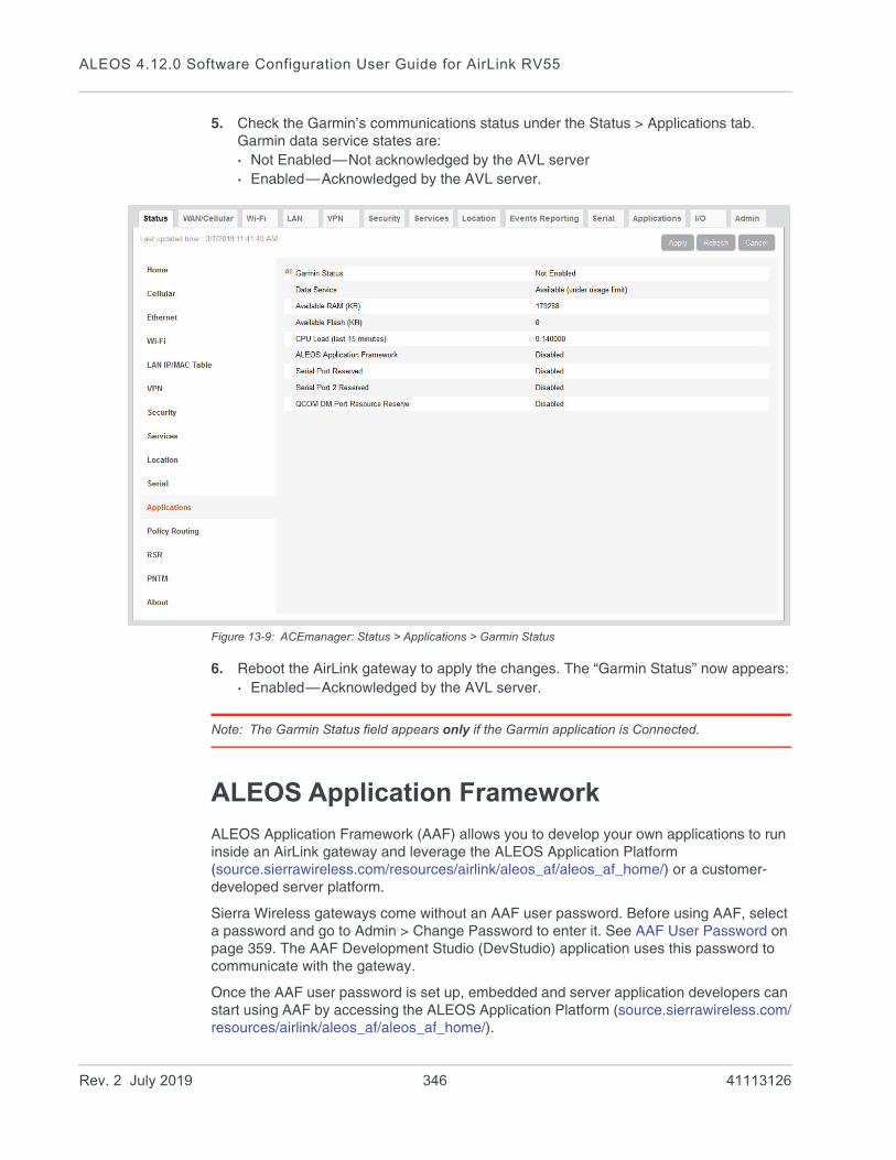
ALEOS 4.12.0 Software Configuration User Guide for AirLink RV55
5. Check the Garmin’s communications status under the Status > Applications tab. Garmin data service states are:· Not Enabled—Not acknowledged by the AVL server· Enabled—Acknowledged by the AVL server.
Figure 13-9: ACEmanager: Status > Applications > Garmin Status
6. Reboot the AirLink gateway to apply the changes. The “Garmin Status” now appears:· Enabled—Acknowledged by the AVL server.
Note: The Garmin Status field appears only if the Garmin application is Connected.
ALEOS Application Framework
ALEOS Application Framework (AAF) allows you to develop your own applications to run inside an AirLink gateway and leverage the ALEOS Application Platform (source.sierrawireless.com/resources/airlink/aleos_af/aleos_af_home/) or a customer-developed server platform.
Sierra Wireless gateways come without an AAF user password. Before using AAF, select a password and go to Admin > Change Password to enter it. See AAF User Password on page 359. The AAF Development Studio (DevStudio) application uses this password to communicate with the gateway.
Once the AAF user password is set up, embedded and server application developers can start using AAF by accessing the ALEOS Application Platform (source.sierrawireless.com/resources/airlink/aleos_af/aleos_af_home/).
Rev. 2 July 2019 346 41113126
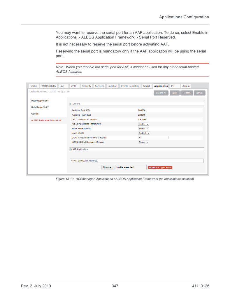
Applications Configuration
You may want to reserve the serial port for an AAF application. To do so, select Enable in Applications > ALEOS Application Framework > Serial Port Reserved.
It is not necessary to reserve the serial port before activating AAF.
Reserving the serial port is mandatory only if the AAF application will be using the serial port.
Note: When you reserve the serial port for AAF, it cannot be used for any other serial-related ALEOS features.
Figure 13-10: ACEmanager: Applications >ALEOS Application Framework (no applications installed)
Rev. 2 July 2019 347 41113126

ALEOS 4.12.0 Software Configuration User Guide for AirLink RV55
Figure 13-11: ACEmanager: Applications > ALEOS Application Framework (applications installed)
Field Description
General
Available RAM (KB) Available RAM in kilobytes (1000 bytes), updated every 30 seconds
Available Flash (KB) Available Flash on the user partition in kilobytes (1024 bytes), updated every 30 seconds
CPU Load (Last 15 minutes)
CPU load, averaged over the last 15 minutes and updated every 30 seconds
The CPU load relates to how many applications are attempting to execute in parallel over the 15-minute period. If the load is greater than 1, some applications are waiting for CPU capacity to become available and may be delayed in launching.
ALEOS Application Framework
Enable or disable (default) the ALEOS Application Framework (ALEOS AF). If enabled, ALEOS AF starts at boot time. When the Reset to Factory default button on the Admin > Advanced page is pressed, ALEOS AF is disabled.
Serial Port Reserved Select Enable to reserve the serial port for ALEOS AF. When this field is set to Enable, the serial port cannot be used for any other serial-related ALEOS features. The options are:
• Disable (default)
• Enable
UART Check This setting appears when Serial Port Reserved is enabled. The UART Check setting checks for UART errors and resets UART if an error occurs. The options are:
• Disabled (default)
• Enabled
UART Reset Time-Window (seconds)
This setting appears when UART Check is enabled. The UART Reset Time-Window setting configures when a UART reset will occur. After a baud rate change, if ALEOS detects a UART error within the time window, it triggers a UART reset.
Options are: 1–60, 4 default
Rev. 2 July 2019 348 41113126

Applications Configuration
QCOM DM Port Resource Reserve
Reserves the QCOM DM port for ALEOS AF applications. Options are: Enable (Reserve access for ALEOS AF) or Disable (Reserve access for ALEOS). Default: Disable
AAF Applications
Application NameAutostartVersionStatusActions
If there are no AAF applications enabled and started, one of the following messages is displayed:
• “AAF not activated”—AAF is not enabled
• “AAF not started”—AAF is not yet started
• “No AAF Application installed”
When AAF is enabled and started, you can install an application. To install an application:
1. Click Browse... and navigate to the application you want to install.
2. Click the Install AAF Application button.
For installed applications, the table shows the:
• Application name
• Autostart—true or false
• Version
• Status—started or stopped
Use the Stop/Start, Uninstall, and Details buttons to manage your applications. For more information on the Details button, refer to AAF—Customizing UI Elements on source.sierrawireless.com.
Field Description
Rev. 2 July 2019 349 41113126

14
14: I/O ConfigurationThe I/O tab in ACEmanager applies to all Sierra Wireless AirLink gateways or routers that feature I/O ports.
You can use the input/outputs on AirLink gateways to generate reports based on a threshold being crossed, a switch being opened or closed, or the number of times a switch has changed state.
Use the Events Reporting screen to configure reports. (See Events Reporting Configuration on page 293.) Use the I/O screen to view the current state of the analog and digital inputs, to turn the relays on and off, and to configure the units you want used in the reports based on analog inputs.
The AirLink RV55 has:• One pin (Pin 4 on the power connector) that can be configured as a digital input/
output, relay output, or analog input.• Pull-up is available for digital input.
More information
For more information, refer to the Hardware User Guide for the AirLink RV55.
Analog inputs
Analog inputs monitor a voltage range in small increments. This allows you to monitor equipment that reports status as an analog voltage. Examples include:• Power supply voltage• Temperature, weight, volume, flow represented as voltage• An incremental gauge with a voltage output• Vehicle battery voltage
The raw data for the changes being monitored is in volts, but you can use the I/O Configuration screen in ACEmanager to convert voltage to the desired units of measurement. See Transformed Analog on page 356.
Digital inputs
Digital inputs monitor contact closures on a switch. This allows you to monitor changes such as:• When a door or latch is open or closed• When a container is full or empty• When a switch or valve is opened or closed• The level of fuel in a vehicle (connected to an on/off sensor)• When the trunk of a vehicle is opened or closed
Rev. 2 July 2019 350 41113126
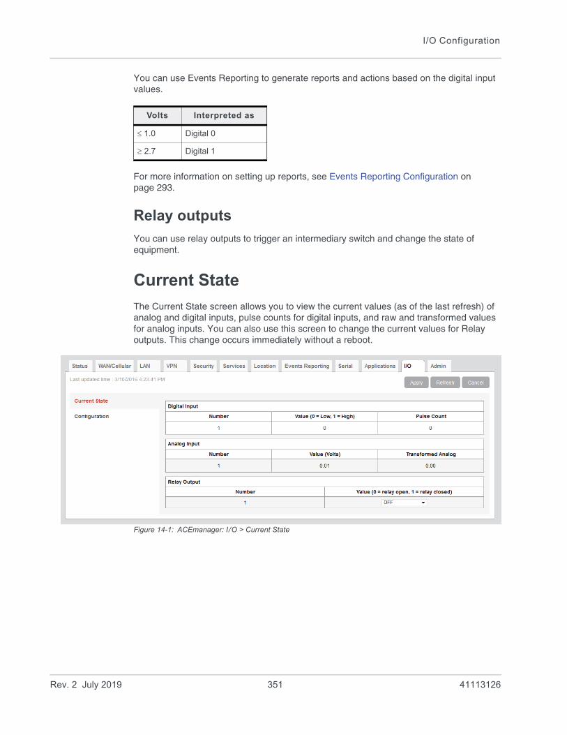
I/O Configuration
You can use Events Reporting to generate reports and actions based on the digital input values.
For more information on setting up reports, see Events Reporting Configuration on page 293.
Relay outputs
You can use relay outputs to trigger an intermediary switch and change the state of equipment.
Current State
The Current State screen allows you to view the current values (as of the last refresh) of analog and digital inputs, pulse counts for digital inputs, and raw and transformed values for analog inputs. You can also use this screen to change the current values for Relay outputs. This change occurs immediately without a reboot.
Figure 14-1: ACEmanager: I/O > Current State
Volts Interpreted as
1.0 Digital 0
2.7 Digital 1
Rev. 2 July 2019 351 41113126
ALEOS 4.12.0 Software Configuration User Guide for AirLink RV55
Table 14-1: I/O: Current State
Command Description
Digital Input
Number Displays the number of digital inputs. The corresponding hardware pins are:
Value Displays the current value for the digital input:
• 0 —Low
• 1 —High
You can also use an AT command to read these values. See *DIGITALIN[n]? on page 526.
Pulse Count The pulse count increments when the input value changes from high to low.
Note: To reset the pulse count to zero, reset the device to the factory defaults.
Analog Input
Number Displays the number of analog inputs. The corresponding hardware pins are:
Value (Volts) Shows the current state of the analog inputThe analog inputs report the voltage in volts. Range is 0–30 volts.
You can also use an AT command to read these values. See *ANALOGIN[n]? on page 526.
Transformed Analog The analog input expressed in the configured units. See Transformed Analog on page 356.
Relay Output Controls the internal current sink that you can use to drive a relay or for other use purposes where a switchable low side current sink is required. For more details refer to the hardware user guide.
Digital Input Corresponding hardware pin
1 Pin 4 on Power connector
Analog Input Corresponding hardware pin
1 Pin 4 on Power connector
Rev. 2 July 2019 352 41113126
I/O Configuration
Number Displays the number of relay outputs. The corresponding hardware pins are:
Value Options are:
• OFF (default)—Relay open.
• Drive Active Low—Relay closed.
Note: You cannot set this field to Drive Action Low if the I/O line is already being used for Standby mode.
You can also use an AT command (see *RELAYOUT1 on page 526), an SMS command (see [prefix]relay x y on page 535), or a RAP command (refer to the Remote Application Protocol User Guide) to configure this field.
Note: Changes to this field go into effect immediately. No reboot of the AirLink gateway is necessary.
Table 14-1: I/O: Current State
Command Description
Relay Output Corresponding hardware pin
1 Pin 4 on Power connector
Rev. 2 July 2019 353 41113126
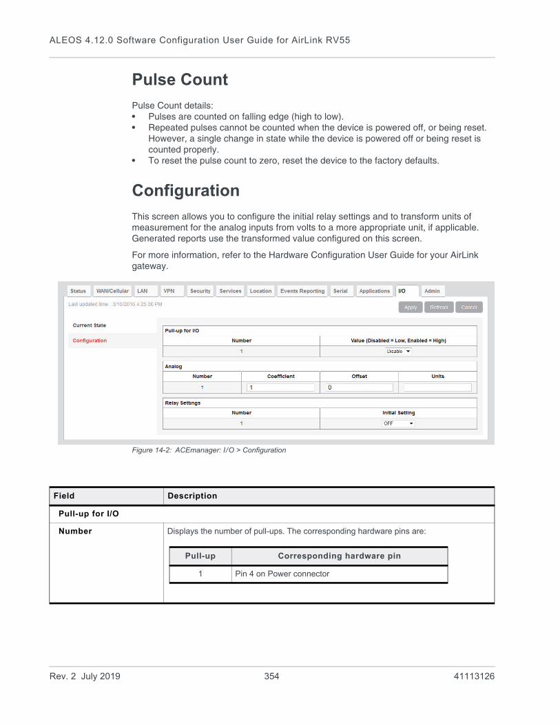
ALEOS 4.12.0 Software Configuration User Guide for AirLink RV55
Pulse Count
Pulse Count details:• Pulses are counted on falling edge (high to low). • Repeated pulses cannot be counted when the device is powered off, or being reset.
However, a single change in state while the device is powered off or being reset is counted properly.
• To reset the pulse count to zero, reset the device to the factory defaults.
Configuration
This screen allows you to configure the initial relay settings and to transform units of measurement for the analog inputs from volts to a more appropriate unit, if applicable. Generated reports use the transformed value configured on this screen.
For more information, refer to the Hardware Configuration User Guide for your AirLink gateway.
Figure 14-2: ACEmanager: I/O > Configuration
Field Description
Pull-up for I/O
Number Displays the number of pull-ups. The corresponding hardware pins are:
Pull-up Corresponding hardware pin
1 Pin 4 on Power connector
Rev. 2 July 2019 354 41113126
I/O Configuration
Value Controls the internal pull-up resistor on the I/O line. Options are:
• Disable—The pull-up is disabled. (Default)
• Enable—The pull-up is enabled.
The pull-up voltage is based on Vin. For details, refer to the Hardware User Guide.
Note: You cannot enable the Pull-up for I/O if the I/O line is already being used for Standby mode.
Note: During bootup, the I/O settings remain in their default state: the internal pull-up resistor is disabled, and output current sink switch is open. After bootup, any custom I/O settings are applied. This may take approximately 30 seconds after the gateway is restarted or powered on.
Analog
Number Displays the number of analog inputs. The corresponding hardware pins are:
Coefficient This value may be found in the user guide for the equipment you want to monitor, or you can calculate it from information in the user guide. If this information is not available in the documentation that came with the equipment you want to monitor, contact the manufacturer.
For an example of how to calculate the coefficient, see Transformed Analog on page 356.
Offset The offset (difference) between 0 volts and the equivalent value for the desired unit of measurement
Units The unit of measurement used in event reporting for the parameter being monitored by the analog input
For example: degrees Celsius, degrees Fahrenheit, liters, mm, etc.
Relay Settings
Number Displays the number of relay outputs. The corresponding hardware pins are:
Initial Setting The initial setting for the current sink when the AirLink gateway is powered onOptions are:
• ON
• OFF (default)
• Last Value (The value remains the same as it was before the AirLink gateway was powered down).
When you change this field, the corresponding digital input value on this screen reflects the change after a screen refresh.
Field Description
Analog Input Corresponding hardware pin
1 Pin 4 on Power connector
Relay Output Corresponding hardware pin
1 Pin 4 on Power connector
Rev. 2 July 2019 355 41113126
ALEOS 4.12.0 Software Configuration User Guide for AirLink RV55
Transformed Analog
The raw analog data is displayed in volts. However, that is not always the most convenient unit of measurement to view the data. The I/O Configuration screen enables you to transform the voltage readings to a more convenient unit of measurement, for example degrees Celsius or Fahrenheit for temperature, liters for volume, etc.
Step 1—Coefficient and Offset
Before you configure ACEmanager, you need to locate or calculate the coefficient and the offset values.
Consult the user documentation for the equipment you want to monitor. It should provide you with the coefficient to convert volts to the appropriate unit of measurement and the offset value (the difference between the equivalent value for 0 volts and 0), or provide information on equivalent values for voltage readings from which you can calculate the coefficient and offset. (If this information is not available in the user documentation, contact the manufacturer.)
For example, if the equipment monitors temperature, and has a scale from 0 volts to 30 volts, the equipment specifications should provide information similar to the following:
0 V is equivalent to –20°C
30 V is equivalent to 100°C
This is expressed algebraically as follows:
where:
a = coefficient
b = offset
For this example, you can calculate a as follows:
To calculate b, substitute a into the first equation above:
Step 2—Configure ACEmanager
For each of the analog inputs you want to configure:
1. In ACEmanager, go to I/O > Configuration.
a 0V b 20–=+ C
a 30V b 100C=+
a 30V b+ a 0V b+ 100C 20– –=–
a 30V 120V=
a 4=
4 0V b 20–=+
b 20–=
Rev. 2 July 2019 356 41113126

I/O Configuration
2. Enter the values for the coefficient and offset. (In this example, the coefficient is 4 and the offset is –20.)
3. Enter the desired unit of measurement. (In this example, the unit of measurement is C, for degrees Celsius).
ACEmanager shows the value of the transformed analog input as temperature in C.
Note: A reboot is required after configuring the transformed analog values.
Rev. 2 July 2019 357 41113126
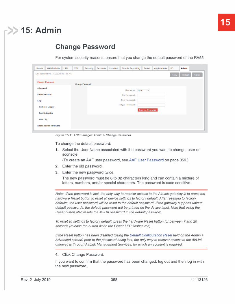
15
15: AdminChange Password
For system security reasons, ensure that you change the default password of the RV55.
Figure 15-1: ACEmanager: Admin > Change Password
To change the default password:
1. Select the User Name associated with the password you want to change: user or sconsole.
(To create an AAF user password, see AAF User Password on page 359.)
2. Enter the old password.
3. Enter the new password twice.
The new password must be 8 to 32 characters long and can contain a mixture of letters, numbers, and/or special characters. The password is case sensitive.
Note: If the password is lost, the only way to recover access to the AirLink gateway is to press the hardware Reset button to reset all device settings to factory default. After resetting to factory defaults, the user password will be reset to the default password. If the gateway supports unique default passwords, the default password will be printed on the device label. Note that using the Reset button also resets the M3DA password to the default password.
To reset all settings to factory default, press the hardware Reset button for between 7 and 20 seconds (release the button when the Power LED flashes red).
If the Reset button has been disabled (using the Default Configuration Reset field on the Admin > Advanced screen) prior to the password being lost, the only way to recover access to the AirLink gateway is through AirLink Management Services, for which an account is required.
4. Click Change Password.
If you want to confirm that the password has been changed, log out and then log in with the new password.
Rev. 2 July 2019 358 41113126
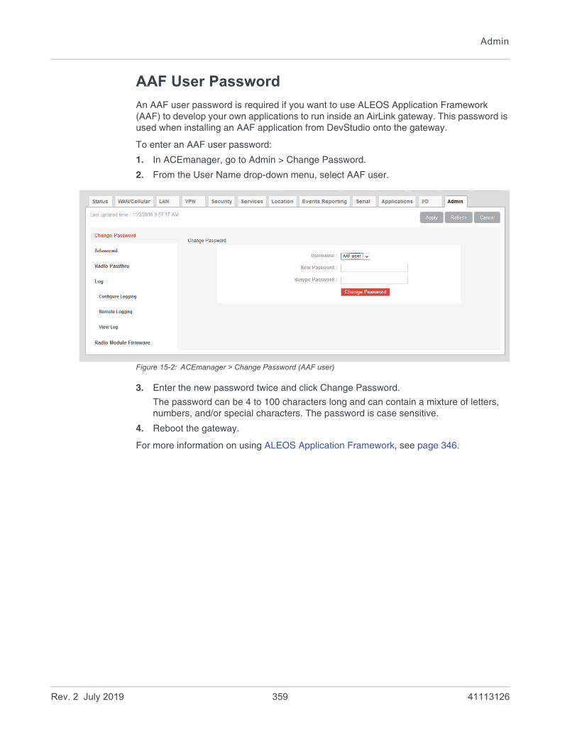
Admin
AAF User Password
An AAF user password is required if you want to use ALEOS Application Framework (AAF) to develop your own applications to run inside an AirLink gateway. This password is used when installing an AAF application from DevStudio onto the gateway.
To enter an AAF user password:
1. In ACEmanager, go to Admin > Change Password.
2. From the User Name drop-down menu, select AAF user.
Figure 15-2: ACEmanager > Change Password (AAF user)
3. Enter the new password twice and click Change Password.
The password can be 4 to 100 characters long and can contain a mixture of letters, numbers, and/or special characters. The password is case sensitive.
4. Reboot the gateway.
For more information on using ALEOS Application Framework, see page 346.
Rev. 2 July 2019 359 41113126

ALEOS 4.12.0 Software Configuration User Guide for AirLink RV55
Advanced
The Advanced screen presents features that should be rarely changed and will affect the operation of the device.
Figure 15-3: ACEmanager: Admin > Advanced
Rev. 2 July 2019 360 41113126

Admin
Field Description
Date and Time Queries the internal clock. The date and time are always specified in 24-hour notation (UTC).
• mm/dd/yyyy=date in month/day/year notation
• hh:mm:ss=time in 24-hour notation
Default Configuration Reset
Enables or disables the hardware Reset buttonSets the AirLink gateway to allow (or not allow) the hardware Reset button to reset the device to the factory default settings.
• Allowed—Pressing the hardware Reset button for 7–20 seconds reboots the device and resets it to the factory defaults. (When resetting the device to factory default settings, release the Reset button when the power LED flashes red.)
• Not Allowed—Pressing the hardware Reset button reboots the device, but does not reset it to the factory defaults.
Note: This field only affects the hardware Reset button on the device. You can always use the “Reset to Factory Default” button in ACEmanager to reset the device.
Note: If this field is set to “Not Allowed” and the login password is subsequently lost, the only way to regain access to the AirLink gateway is through AirLink Management Service (account required).
Status Update Address
Enter the device Name/Port. Name is the domain name or IP address, and Port is the port of the device where the device status updates (in XML format) will be sent. This report can be sent to a LAN connected device (e.g., 192.168.13.100/1122) or a remote location (e.g., newb.eairlink.com/17000).
Status Update Period (seconds)
The time interval (in seconds) when a status update should be sent
Power Input Voltage (volts)
Displays the power input voltage in volts. If the input voltage ground is connected to the AirLink gateway case (without serial connection), this value reads .3 V (approx.) less; if ground is connected (with serial connection), the value reads .3 V (approx.) more.
Board Temperature (Celsius)
Displays the board temperature in degrees (Celsius)
Radio Module Internal Temperature (Celsius)
Displays the temperature of the internal radio module in degrees (Celsius).
Number of System Resets
Count of the number of system resets over the life of the device or since the last configuration reset
Device Uptime Length of time since the gateway was last rebooted (in days, hours and minutes)
Number of core dumps present
Shows the number of core dumps stored on the system
A core dump is produced if a software component on the gateway crashes leading to a restart of the component or reboot of the system.
Rev. 2 July 2019 361 41113126
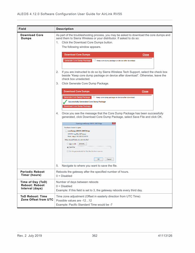
ALEOS 4.12.0 Software Configuration User Guide for AirLink RV55
Download Core Dumps
As part of the troubleshooting process, you may be asked to download the core dumps and send them to Sierra Wireless or your distributor. If asked to do so:
1. Click the Download Core Dumps button.
The following window appears.
2. If you are instructed to do so by Sierra Wireless Tech Support, select the check box beside “Keep core dump package on device after download”. Otherwise, leave the check box unselected.
3. Click Generate Core Dump Package.
4. Once you see the message that the Core Dump Package has been successfully generated, click Download Core Dump Package, select Save File and click OK.
5. Navigate to where you want to save the file.
Periodic Reboot Timer (hours)
Reboots the gateway after the specified number of hours.
0 = Disabled
Time of Day (ToD) Reboot: Reboot Interval (days)
Number of days between reboots
0 = Disabled
Example: If this field is set to 3, the gateway reboots every third day.
ToD Reboot: Time Zone Offset from UTC
Time zone adjustment (Offset in easterly direction from UTC Time)
Possible values are -12...12
Example: Pacific Standard Time would be -7
Field Description
Rev. 2 July 2019 362 41113126

Admin
ToD Reboot: Hour of day when Reboot occurs
The local hour of the day when the reboot occurs
Possible values are 0–23
Example: 4 is 4:00 am
NAT Helper Disable The NAT helper functions are used to parse traffic on well-known protocols/port combinations. In most cases, leave the default setting. However, if you are running a protocol on one of the well-known port that is not normally associated with that port, traffic may not be parsed properly, or may be dropped completely. In that case, use this field to disable the NAT helper functions.
The NAT helper functions are used to enable IP services that create temporary TCP or UDP ports. For example, FTP (TCP 21), SIP (UDP 5060) and SNMP (UDP 161). If you are running non-standard protocols on these ports, you may need to disable the NAT helper functions in order for the firewall to operate
The NAT helper functions are used to enable IP services that create temporary TCP or UDP ports. For example, FTP (TCP 21), SIP (UDP 5060) and SNMP (UDP 161). If you are running non-standard protocols on ports that use the NAT helper functions, you may need to disable the NAT helper functions in order for the firewall to operate.
Options are:
• Off—NAT helper functions are operational (default)
• On—NAT helper functions are disabled.
Minimum TLS Version Sets the minimum TLS version that can be used for secure connections. When set to TLS 1.2, for example, connection attempts using a lower version will be blocked.
By default (when set to TLS 1.0) the RV55 will make outbound connection attempts using the most secure layer (TLS 1.2) and fall back to other layers if the remote host does not support it.
Options are:
• TLS 1.0 (default)
• TLS 1.1
• TLS 1.2
Ping Use this button to confirm that a connected device is responding.
1. Click Ping.
2. In the pop-up window, enter the device IP address or DNS name and click Ping Now.
Field Description
Rev. 2 July 2019 363 41113126

ALEOS 4.12.0 Software Configuration User Guide for AirLink RV55
IP Logging IP Logging is used to troubleshoot issues such as:
• Problems with the LAN or WAN connection to an AirLink gateway
• Uncertainty about where a packet is coming from
• Issues with port forwarding not working properly
IP Logging enables you to log network traffic and save it in a form that can be analyzed by Sierra Wireless engineers. Before using IP Logging, contact your authorized AirLink reseller or Sierra Wireless representative to discuss the issue you are observing and obtain a .cmd file to capture the appropriate related IP traffic. When you receive the file, save it to your computer’s hard drive.
To use IP logging:
1. Obtain a command (.cmd) file from Sierra Wireless.
2. In ACEmanager, go to Admin > Advanced and click IP Logging.
3. In the pop-up window, click Browse and navigate to the command file you received from Sierra Wireless.
4. Click Open.
The file name appears in the field beside the Browse... button.
5. Click Upload File.
Field Description
Rev. 2 July 2019 364 41113126

Admin
IP Logging (continued)
6. Once you see a message at the bottom of the window saying that the file has been successfully uploaded, select a command from the drop-down menu, as advised by your support contact.
7. Click the Start button.
Note: If you are running more than one command, run each command sequentially and save the results before selecting the next command to run. Running a new command or re-running the same command wipes out the results from the previous run.
When the logging is complete, the log shows the number of packets captured, received, and dropped.
Note: If the log shows only “Got 0”, no logs were captured. Contact Sierra Wireless.
Field Description
Rev. 2 July 2019 365 41113126

ALEOS 4.12.0 Software Configuration User Guide for AirLink RV55
IP Logging (continued)
8. Once the logging is compete, click the Download IP Logging File button at the bottom of the screen, save the tarred gzip file (file extension .tgz) to your computer, and email it to your support contact.
Field Description
Rev. 2 July 2019 366 41113126
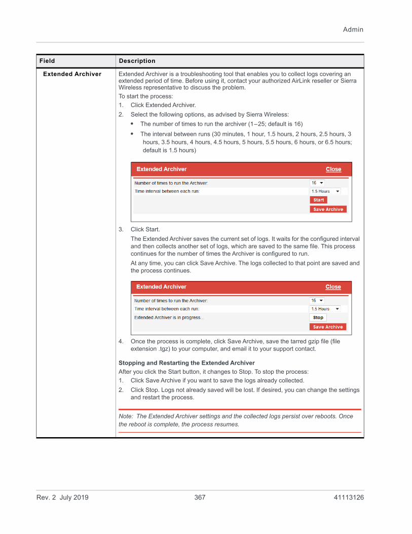
Admin
Extended Archiver Extended Archiver is a troubleshooting tool that enables you to collect logs covering an extended period of time. Before using it, contact your authorized AirLink reseller or Sierra Wireless representative to discuss the problem.
To start the process:
1. Click Extended Archiver.
2. Select the following options, as advised by Sierra Wireless:
• The number of times to run the archiver (1–25; default is 16)
• The interval between runs (30 minutes, 1 hour, 1.5 hours, 2 hours, 2.5 hours, 3 hours, 3.5 hours, 4 hours, 4.5 hours, 5 hours, 5.5 hours, 6 hours, or 6.5 hours; default is 1.5 hours)
3. Click Start.
The Extended Archiver saves the current set of logs. It waits for the configured interval and then collects another set of logs, which are saved to the same file. This process continues for the number of times the Archiver is configured to run.
At any time, you can click Save Archive. The logs collected to that point are saved and the process continues.
4. Once the process is complete, click Save Archive, save the tarred gzip file (file extension .tgz) to your computer, and email it to your support contact.
Stopping and Restarting the Extended Archiver
After you click the Start button, it changes to Stop. To stop the process:
1. Click Save Archive if you want to save the logs already collected.
2. Click Stop. Logs not already saved will be lost. If desired, you can change the settings and restart the process.
Note: The Extended Archiver settings and the collected logs persist over reboots. Once the reboot is complete, the process resumes.
Field Description
Rev. 2 July 2019 367 41113126
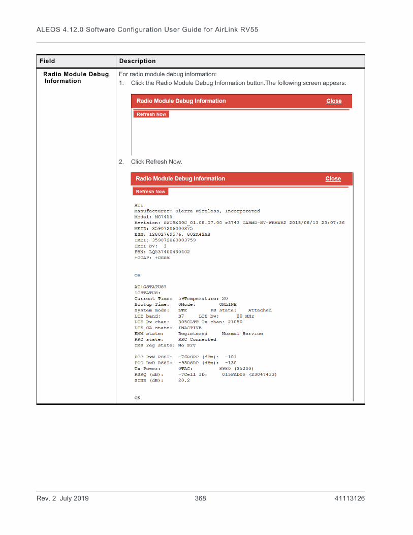
ALEOS 4.12.0 Software Configuration User Guide for AirLink RV55
Radio Module Debug Information
For radio module debug information:
1. Click the Radio Module Debug Information button.The following screen appears:
2. Click Refresh Now.
Field Description
Rev. 2 July 2019 368 41113126

Admin
Radio Module Actions This feature only applies to radio modules running on the Sprint Network. Use this button only if advised to do so by Sprint representative.
1. Click the Radio Module Actions button.
2. Select the desired option:
• RTN Reset—Resets the radio module to pre-activated state
• Update PRL—Updates the Preferred Roaming List
• Update Data Profile—Updates the data profile
3. Click Perform Action.
Reset to Factory Default
Erases all customer-defined settings, including custom APNs and resets all settings (passwords, LAN and WAN configuration, security settings, ALEOS Applications Framework, etc.) to the original factory settings. ALEOS AF is also reset to disabled.
Note: You can ensure that some settings are not affected by a reset to factory default. See Reset Mode on page 370.
Note: After resetting the device to full factory defaults (the Reset Mode is set to Reset All or Preserve Only User Password), if you are using a management service like ALMS or AMM, Sierra Wireless recommends synchronizing the device again via the management service. The re-synchronization enables the management tunnel to re-establish itself.
Field Description
Rev. 2 July 2019 369 41113126
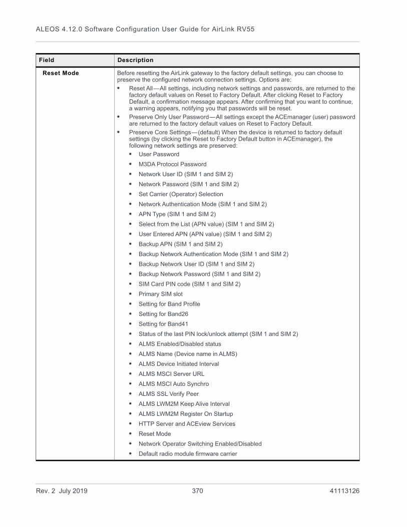
ALEOS 4.12.0 Software Configuration User Guide for AirLink RV55
Reset Mode Before resetting the AirLink gateway to the factory default settings, you can choose to preserve the configured network connection settings. Options are:
• Reset All—All settings, including network settings and passwords, are returned to the factory default values on Reset to Factory Default. After clicking Reset to Factory Default, a confirmation message appears. After confirming that you want to continue, a warning appears, notifying you that passwords will be reset.
• Preserve Only User Password—All settings except the ACEmanager (user) password are returned to the factory default values on Reset to Factory Default.
• Preserve Core Settings—(default) When the device is returned to factory default settings (by clicking the Reset to Factory Default button in ACEmanager), the following network settings are preserved:
• User Password
• M3DA Protocol Password
• Network User ID (SIM 1 and SIM 2)
• Network Password (SIM 1 and SIM 2)
• Set Carrier (Operator) Selection
• Network Authentication Mode (SIM 1 and SIM 2)
• APN Type (SIM 1 and SIM 2)
• Select from the List (APN value) (SIM 1 and SIM 2)
• User Entered APN (APN value) (SIM 1 and SIM 2)
• Backup APN (SIM 1 and SIM 2)
• Backup Network Authentication Mode (SIM 1 and SIM 2)
• Backup Network User ID (SIM 1 and SIM 2)
• Backup Network Password (SIM 1 and SIM 2)
• SIM Card PIN code (SIM 1 and SIM 2)
• Primary SIM slot
• Setting for Band Profile
• Setting for Band26
• Setting for Band41
• Status of the last PIN lock/unlock attempt (SIM 1 and SIM 2)
• ALMS Enabled/Disabled status
• ALMS Name (Device name in ALMS)
• ALMS Device Initiated Interval
• ALMS MSCI Server URL
• ALMS MSCI Auto Synchro
• ALMS SSL Verify Peer
• ALMS LWM2M Keep Alive Interval
• ALMS LWM2M Register On Startup
• HTTP Server and ACEview Services
• Reset Mode
• Network Operator Switching Enabled/Disabled
• Default radio module firmware carrier
Field Description
Rev. 2 July 2019 370 41113126
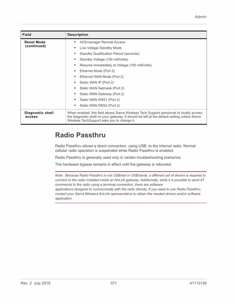
Admin
Radio Passthru
Radio Passthru allows a direct connection, using USB, to the internal radio. Normal cellular radio operation is suspended while Radio Passthru is enabled.
Radio Passthru is generally used only in certain troubleshooting scenarios.
The hardware bypass remains in effect until the gateway is rebooted.
Note: Because Radio Passthru is not USB/net or USB/serial, a different set of drivers is required to connect to the radio installed inside an AirLink gateway. Additionally, while it is possible to send AT commands to the radio using a terminal connection, there are software applications designed to communicate with the radio directly. If you need to use Radio Passthru, contact your Sierra Wireless AirLink representative to obtain the needed drivers and/or software application.
Reset Mode (continued)
• ACEmanager Remote Access
• Low Voltage Standby Mode
• Standby Qualification Period (seconds)
• Standby Voltage (100 milliVolts)
• Resume Immediately at Voltage (100 milliVolts)
• Ethernet Mode (Port 2)
• Ethernet WAN Mode (Port 2)
• Static WAN IP (Port 2)
• Static WAN Netmask (Port 2)
• Static WAN Gateway (Port 2)
• Static WAN DNS1 (Port 2)
• Static WAN DNS2 (Port 2)
Diagnostic shell access
When enabled, this field allows Sierra Wireless Tech Support personnel to locally access the diagnostic shell on your gateway. It should be left at the default setting unless Sierra Wireless TechSupport asks you to change it.
Field Description
Rev. 2 July 2019 371 41113126
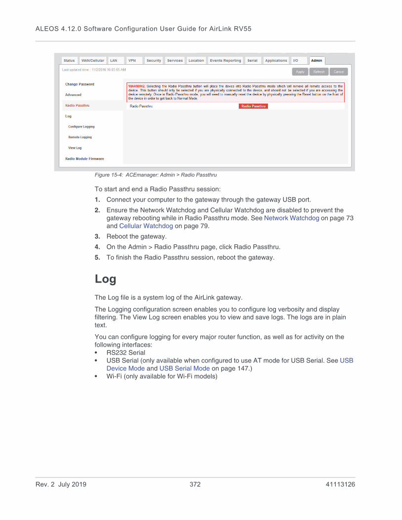
ALEOS 4.12.0 Software Configuration User Guide for AirLink RV55
Figure 15-4: ACEmanager: Admin > Radio Passthru
To start and end a Radio Passthru session:
1. Connect your computer to the gateway through the gateway USB port.
2. Ensure the Network Watchdog and Cellular Watchdog are disabled to prevent the gateway rebooting while in Radio Passthru mode. See Network Watchdog on page 73 and Cellular Watchdog on page 79.
3. Reboot the gateway.
4. On the Admin > Radio Passthru page, click Radio Passthru.
5. To finish the Radio Passthru session, reboot the gateway.
Log
The Log file is a system log of the AirLink gateway.
The Logging configuration screen enables you to configure log verbosity and display filtering. The View Log screen enables you to view and save logs. The logs are in plain text.
You can configure logging for every major router function, as well as for activity on the following interfaces:• RS232 Serial• USB Serial (only available when configured to use AT mode for USB Serial. See USB
Device Mode and USB Serial Mode on page 147.)• Wi-Fi (only available for Wi-Fi models)
Rev. 2 July 2019 372 41113126
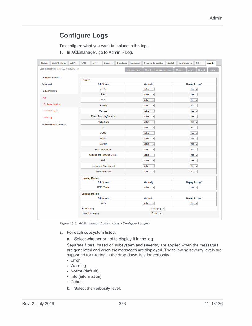
Admin
Configure Logs
To configure what you want to include in the logs:
1. In ACEmanager, go to Admin > Log.
Figure 15-5: ACEmanager: Admin > Log > Configure Logging
2. For each subsystem listed:
a. Select whether or not to display it in the log.
Separate filters, based on subsystem and severity, are applied when the messages are generated and when the messages are displayed. The following severity levels are supported for filtering in the drop-down lists for verbosity:· Error· Warning· Notice (default)· Info (information)· Debug
b. Select the verbosity level.
Rev. 2 July 2019 373 41113126

ALEOS 4.12.0 Software Configuration User Guide for AirLink RV55
Note: Some log messages are only displayed if you display Linux Syslog. For example, If you are debugging a VPN or LAN setup, the relevant information is only displayed in the Linux Syslog.
3. Optional: To display Linux Syslog in the View Logs screen:
a. Ensure that Display is selected in the drop-down menu beside Linux Syslog.
Note: At any point, you can click the buttons on the upper right portion of the screen to:
• Download logs to your computer
• Download a compressed version of the logs to your computer
• Refresh the screen
• Cancel the selected settings
• Return the screen to the Default settings.
4. Click Apply.
5. If you have changed any of the verbosity levels or the Linux syslog setting:
a. Reboot the AirLink gateway.
b. Log into ACEmanager, go to Admin > Log.
Trace Level Logging
Use this option only if you are specifically asked to do so by Sierra Wireless or an authorized distributor.
To enable trace level logging:
1. In the Trace level logging field at the bottom of the page, select Enable.
2. Click Apply.
3. On the left menu, click View Log.
Remote Logging
Remote logging enables you to send logs to a remote server.
To configure remote logging1:
1. In ACEmanager, go to Admin and from the menu on the left, select Remote Logging.
2. In the Remote Syslog field, select Enable.
1. You can also use an AT command to configure remote logging. See *REMOTELOG on page 532.
Rev. 2 July 2019 374 41113126
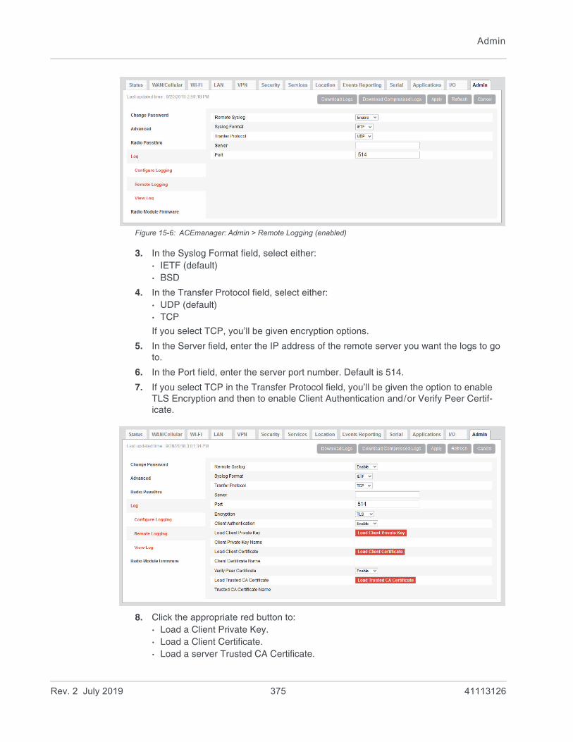
Admin
Figure 15-6: ACEmanager: Admin > Remote Logging (enabled)
3. In the Syslog Format field, select either:· IETF (default)· BSD
4. In the Transfer Protocol field, select either:· UDP (default)· TCP
If you select TCP, you’ll be given encryption options.
5. In the Server field, enter the IP address of the remote server you want the logs to go to.
6. In the Port field, enter the server port number. Default is 514.
7. If you select TCP in the Transfer Protocol field, you’ll be given the option to enable TLS Encryption and then to enable Client Authentication and/or Verify Peer Certif-icate.
8. Click the appropriate red button to:· Load a Client Private Key.· Load a Client Certificate.· Load a server Trusted CA Certificate.
Rev. 2 July 2019 375 41113126

ALEOS 4.12.0 Software Configuration User Guide for AirLink RV55
Once it is uploaded the file name appears on the screen.
Note: When enabled, this functionality persists over a reboot/power cycle.
View Logs
To view the logs:
1. Select View Logs from the menu on the left side of the page.
Figure 15-7: ACEmanager: Admin > Log, View Log
Note: VPN info and debug information uses the term racoon (rather than VPN).
Note: If you toggle the “Display in Log?” field, clear and refresh the View Log page. (You do not need to reboot the device.)
Tip: Use View Log for troubleshooting purposes (e.g., when setting up the IPsec configuration). The Log page allows you to establish the tunnel connection and monitor the results directly. To change the intervals at which the log is displayed, you can change the settings in Auto Refresh.
Rev. 2 July 2019 376 41113126

Admin
Actions on the View Log screen include:• Auto Refresh—The drop-down menu allows you to set up an automatic log page
refresh, and the interval between refreshes: 30 secs, 1 minute, or 2 minutes.• Refresh button—Clears the screen, reloads the log file, and display the point in the
log file you were viewing immediately prior to clicking Refresh. Any new log infor-mation is added to the bottom of the log.
• Clear button—Clears the screen• Mark button—Marks the start of a section in the device log and is typically used for
troubleshooting• Download Logs button—downloads the logs to your computer• The Download Compressed Logs button—downloads a compressed version of the
logs.
Figure 15-8: Download Logs buttons
Note: The logs you obtain using the Download Logs or the Download Compressed Logs buttons always include the Linux Syslog. The Linux Syslog setting on the Configure Logs page does not affect the contents of the downloaded logs.
If asked to do so:
1. Click the Mark button and enter the text you want to appear in the log file.
Alphanumeric characters, spaces, periods, commas, dashes, colons and semi-colons are allowed.
2. Click Mark Now.
3. Click Refresh.
The mark appears at the end of the log.
Rev. 2 July 2019 377 41113126

ALEOS 4.12.0 Software Configuration User Guide for AirLink RV55
Radio Module Firmware
Figure 15-9: ACEmanager: Admin > Radio Module Firmware
AirLink gateways come preloaded with multiple versions of radio module firmware (For details, see ). When the gateway is powered on, the gateway checks the stored radio module firmware versions and automatically loads the appropriate version for the installed SIM card onto the radio module.
This feature, which is intended for North American products, makes it easy to provision the gateway for a particular mobile network. To provision the gateway:
1. Obtain an account and SIM card for the mobile network you want to run the gateway on.
2. Insert the SIM card into the SIM card slot. (For instructions on installing the SIM card, refer to the Hardware User Guide for your gateway.)
3. Power on the gateway. It chooses the appropriate radio module firmware to use for the installed SIM card, provided it is stored on the gateway.
The following table indicates the pre-installed radio module firmware, based on the SKU:
If the appropriate firmware is not stored on the gateway, you can download it from source.sierrawireless.com and install it on the gateway. You can also:
Table 15-1: AirLink RV55 Pre-installed Radio Module Firmware based on SKU
SKU Verizon Wireless
AT&T Sprint Generic Telstra
North America
APAC
Rev. 2 July 2019 378 41113126
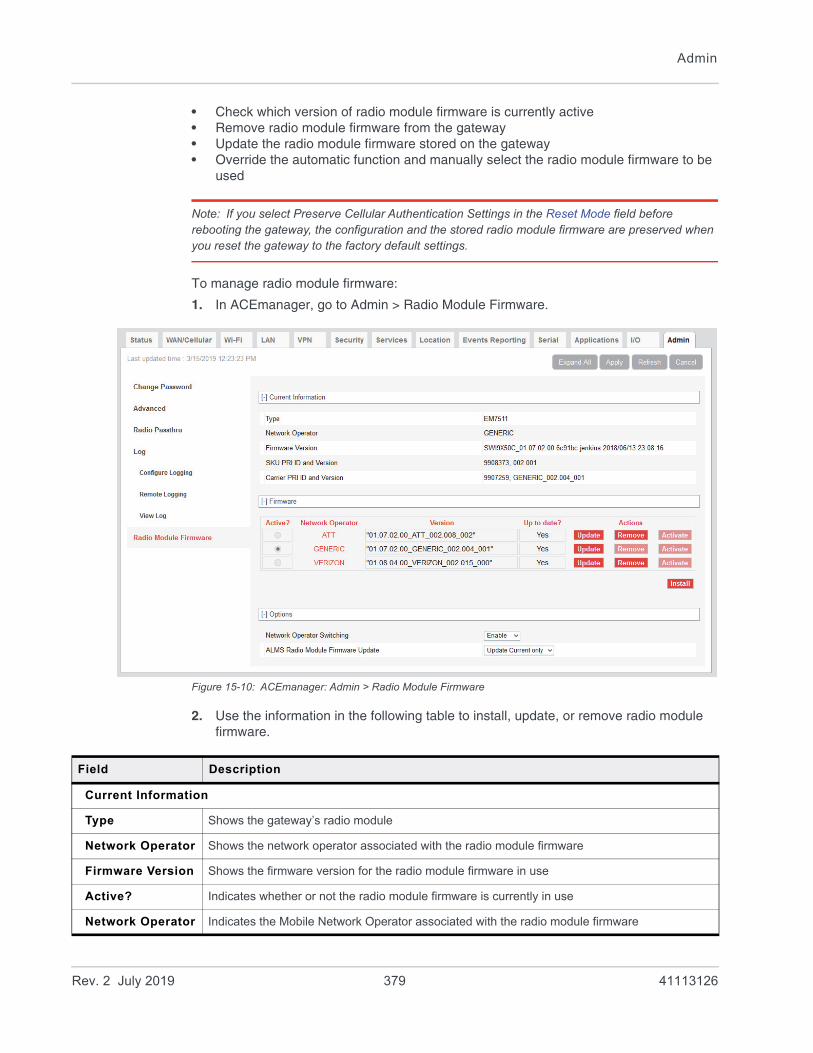
Admin
• Check which version of radio module firmware is currently active• Remove radio module firmware from the gateway• Update the radio module firmware stored on the gateway• Override the automatic function and manually select the radio module firmware to be
used
Note: If you select Preserve Cellular Authentication Settings in the Reset Mode field before rebooting the gateway, the configuration and the stored radio module firmware are preserved when you reset the gateway to the factory default settings.
To manage radio module firmware:
1. In ACEmanager, go to Admin > Radio Module Firmware.
Figure 15-10: ACEmanager: Admin > Radio Module Firmware
2. Use the information in the following table to install, update, or remove radio module firmware.
Field Description
Current Information
Type Shows the gateway’s radio module
Network Operator Shows the network operator associated with the radio module firmware
Firmware Version Shows the firmware version for the radio module firmware in use
Active? Indicates whether or not the radio module firmware is currently in use
Network Operator Indicates the Mobile Network Operator associated with the radio module firmware
Rev. 2 July 2019 379 41113126

ALEOS 4.12.0 Software Configuration User Guide for AirLink RV55
Version Indicates the version number of the radio module firmware
Up to date? Indicates if the firmware in use matches the ALEOS-referenced radio module firmware
Actions Action buttons beside each radio module firmware listed, enable you to:
• Update—Click to update the radio module firmware for that RMID. Updating the active radio module firmware updates the version in storage and also updates the firmware on the radio module at the next reboot. To reboot, click the Activate button or the reboot button on the top right side of the screen.
• Remove—Click to remove that radio module firmware from the gateway storageNote: The firmware cannot be removed if it is the active firmware.
• Activate—Click to select a radio module firmware to be the active firmware for the gateway. This option is only available if Network Operator Switching is set to Disable. See Manually Selecting the Radio Module Firmware. A reboot is only required if the gateway is in Radio Passthru mode. (See page 371.)
You can also:
• Install—Click to add an additional radio module firmware image to the gateway storage. When the maximum number of radio module firmware versions are stored on the gateway, the Install button is not available. To free up space to add another version, first remove one of the firmware versions on the gateway.
Network Operator Switching
Enable or disable Network Operator Switching
• Enable—When the gateway powers on or reboots, it automatically selects and uses the appropriate radio module firmware for the installed primary SIM card, if it is stored on the gateway. If there is no SIM card installed in the primary SIM card slot, the gateway switches to the SIM card in the secondary SIM card slot. (default)
• Disable—The gateway does not automatically select the appropriate radio module firmware when it is powered on or rebooted. You can manually select the firmware to use. See Manually Selecting the Radio Module Firmware.
ALMS Radio Module Firmware Update
Enables you to choose which radio module firmware ALMS will update when you update ALEOS:
• Update Current Only—Only the radio module firmware in use is updated, if required (default)
• Update All—All the radio module firmware stored on the gateway is updated, if required
Field Description
Rev. 2 July 2019 380 41113126

Admin
Manually Selecting the Radio Module Firmware
To manually select the radio module firmware to use:
1. In ACEmanager, go to Admin > Radio Module Firmware.
Figure 15-11: ACEmanager: Admin > Radio Module Firmware
2. Under Options > Network Operator Switching, select Disable.
3. Under Firmware, click Activate beside the firmware you want the gateway to use.
4. Click Apply.
5. Click Reboot or press and release the reset button on the gateway.
Rev. 2 July 2019 381 41113126
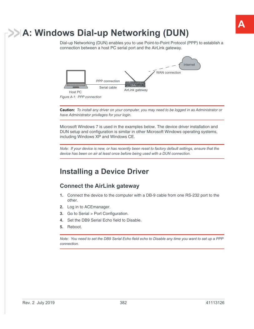
A
A: Windows Dial-up Networking (DUN)Dial-up Networking (DUN) enables you to use Point-to-Point Protocol (PPP) to establish a connection between a host PC serial port and the AirLink gateway.
Figure A-1: PPP connection
Caution: To install any driver on your computer, you may need to be logged in as Administrator or have Administrator privileges for your login.
Microsoft Windows 7 is used in the examples below. The device driver installation and DUN setup and configuration is similar in other Microsoft Windows operating systems, including Windows XP and Windows CE.
Note: If your device is new, or has recently been reset to factory default settings, ensure that the device has been on air at least once before being used with a DUN connection.
Installing a Device Driver
Connect the AirLink gateway
1. Connect the device to the computer with a DB-9 cable from one RS-232 port to the other.
2. Log in to ACEmanager.
3. Go to Serial > Port Configuration.
4. Set the DB9 Serial Echo field to Disable.
5. Reboot.
Note: You need to set the DB9 Serial Echo field echo to Disable any time you want to set up a PPP connection.
AirLink gatewayHost PC
Internet
Serial cable
PPP connection
WAN connection
Rev. 2 July 2019 382 41113126
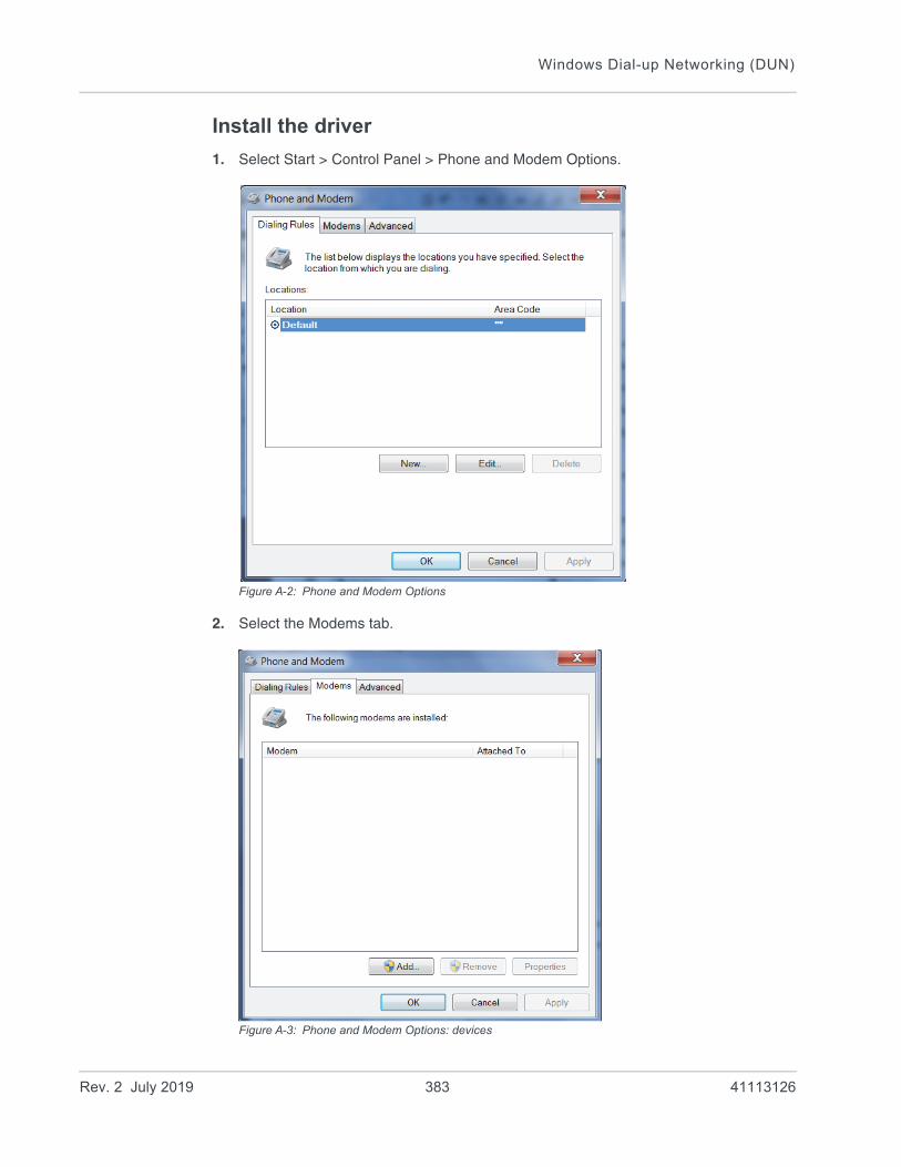
Windows Dial-up Networking (DUN)
Install the driver
1. Select Start > Control Panel > Phone and Modem Options.
Figure A-2: Phone and Modem Options
2. Select the Modems tab.
Figure A-3: Phone and Modem Options: devices
Rev. 2 July 2019 383 41113126

ALEOS 4.12.0 Software Configuration User Guide for AirLink RV55
3. Click Add.
Figure A-4: Add Hardware Wizard
4. Select Don’t detect my modem; I will select it from a list.
5. Click Next.
Rev. 2 July 2019 384 41113126

Windows Dial-up Networking (DUN)
Figure A-5: Add Hardware Wizard: Install New Modem
6. Under Manufacturer, select (Standard Modem Types).
7. Under Models, select Standard 33600 bps Modem.
Tip: If you have the speed for your device configured as something other than the default, use the Standard device that matches the speed you configured.
8. Click Next.
Rev. 2 July 2019 385 41113126

ALEOS 4.12.0 Software Configuration User Guide for AirLink RV55
Figure A-6: Add Hardware Wizard: Select Ports
9. Select Selected Ports.
10. Select the COM port the device is connected to (commonly COM1).
11. Click Next.
Rev. 2 July 2019 386 41113126

Windows Dial-up Networking (DUN)
Figure A-7: Add Hardware Wizard: Finish
12. Once the device driver is installed, click Finish.
When you return to the Phone and Modem Options page, you should see the newly installed device “attached to” the correct COM port.
Figure A-8: Phone and Modem Options > Modems
Rev. 2 July 2019 387 41113126
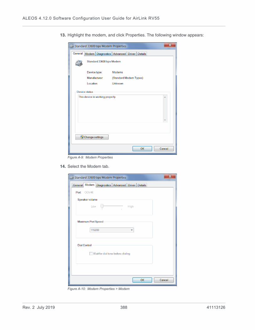
ALEOS 4.12.0 Software Configuration User Guide for AirLink RV55
13. Highlight the modem, and click Properties. The following window appears:
Figure A-9: Modem Properties
14. Select the Modem tab.
Figure A-10: Modem Properties > Modem
Rev. 2 July 2019 388 41113126

Windows Dial-up Networking (DUN)
15. Confirm that the Maximum Port Speed is set to 115200 (default).
16. Click OK to exit.
17. Click OK again to exit out of the Phone and Modem Options.
18. Go to Start > Control Panel > Device Manager.
Figure A-11: Device Manager
19. Under Modems, highlight Standard 33600 bps Modem. Right-click and select Update Driver Software....
Rev. 2 July 2019 389 41113126
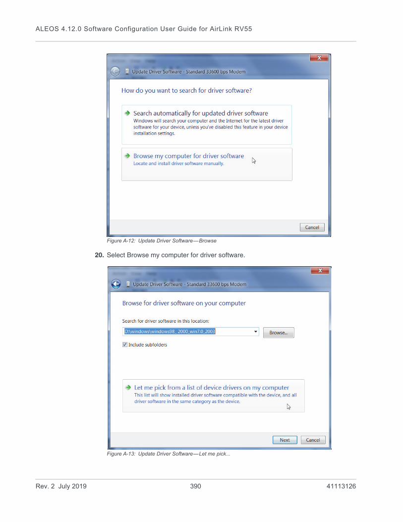
ALEOS 4.12.0 Software Configuration User Guide for AirLink RV55
Figure A-12: Update Driver Software—Browse
20. Select Browse my computer for driver software.
Figure A-13: Update Driver Software—Let me pick...
Rev. 2 July 2019 390 41113126
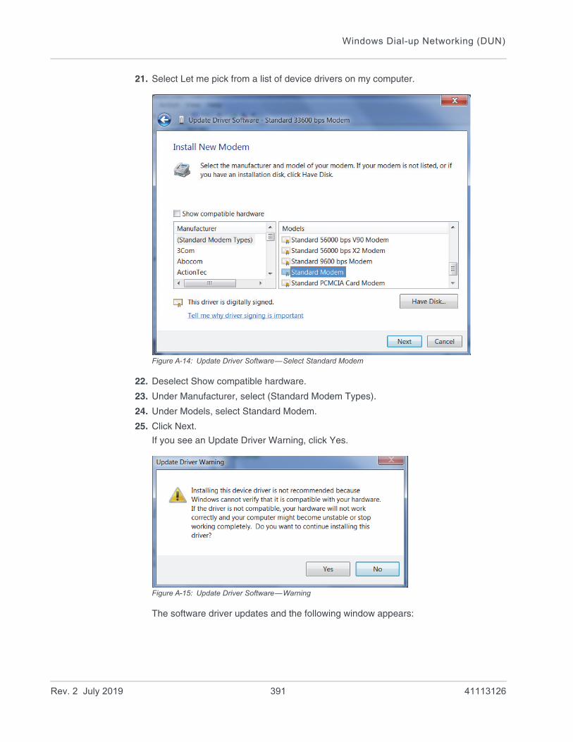
Windows Dial-up Networking (DUN)
21. Select Let me pick from a list of device drivers on my computer.
Figure A-14: Update Driver Software—Select Standard Modem
22. Deselect Show compatible hardware.
23. Under Manufacturer, select (Standard Modem Types).
24. Under Models, select Standard Modem.
25. Click Next.
If you see an Update Driver Warning, click Yes.
Figure A-15: Update Driver Software—Warning
The software driver updates and the following window appears:
Rev. 2 July 2019 391 41113126

ALEOS 4.12.0 Software Configuration User Guide for AirLink RV55
Figure A-16: Update Driver Software—Success
26. Click Close.
Creating a Dial-Up Networking (PPP) Connection
Once you have the driver for the modem installed on your computer, you can set up and configure Dial Up Networking (DUN).
Note: No other device or program can use the COM port (serial port) configured for the modem driver while the DUN session is active.
Caution: If you have an existing LAN connection, installing DUN for the AirLink gateway may interfere with the LAN connection. We recommend disconnecting your LAN connection before using a PPP connection with your AirLink gateway.
Once you have configured the DUN connection on your computer: • The DUN connection may be set as the default connection.• The computer may be configured to dial the DUN connection when it cannot detect
any network connection.
For instructions on changing these options, see Connection settings on page 400.
Rev. 2 July 2019 392 41113126

Windows Dial-up Networking (DUN)
If you are using a DUN connection with any other network connection (such as Ethernet or Wi-Fi), you may need to use the route command in Windows to set up a static route through the device to access the location remotely over the PPP link and the mobile network. This guide does not provide information on the route command. Consult your network administrator for information on properly configuring routing.
Create a new network connection.
1. Select Start > Control Panel > Network and Sharing Center.
Figure A-17: Network and Sharing Center Window
2. Select Set up a new connection or network.
Rev. 2 July 2019 393 41113126

ALEOS 4.12.0 Software Configuration User Guide for AirLink RV55
Figure A-18: Set up a Connection or Network
3. Select Set up a dial-up connection.
4. Click Next.
If you are asked which modem you want to use, select Standard Modem.
Figure 1-19: Create a Dial up Connection
Rev. 2 July 2019 394 41113126
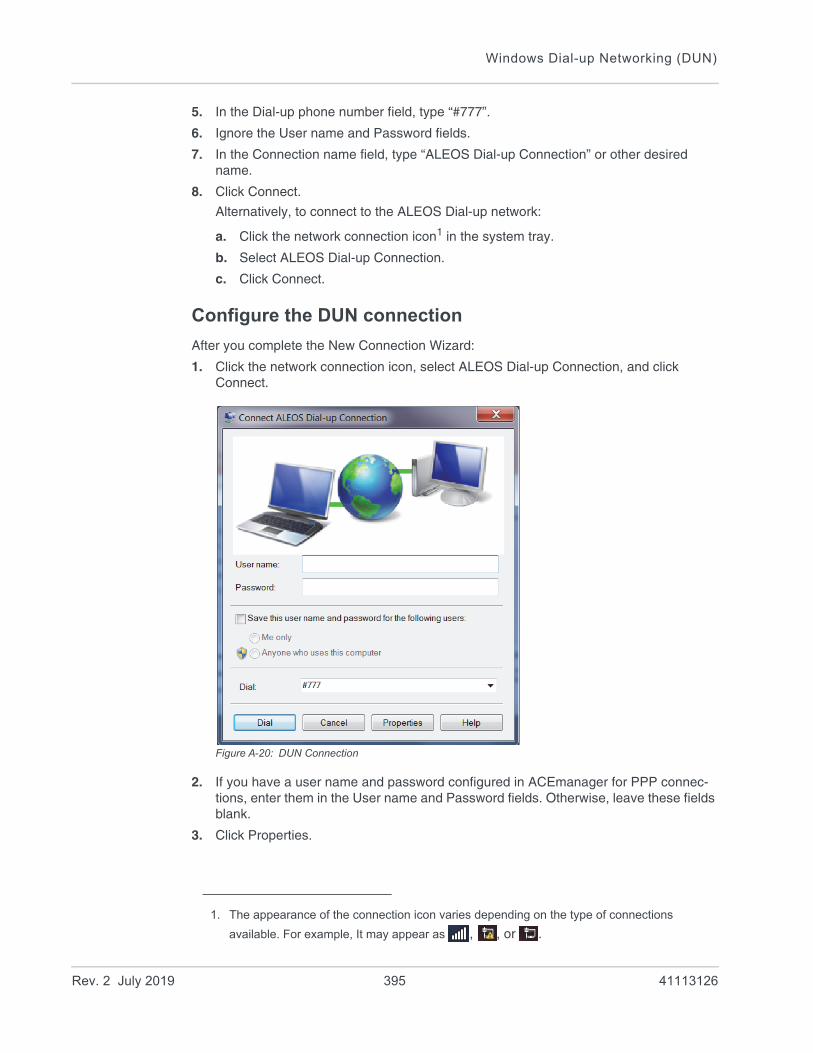
Windows Dial-up Networking (DUN)
5. In the Dial-up phone number field, type “#777”.
6. Ignore the User name and Password fields.
7. In the Connection name field, type “ALEOS Dial-up Connection” or other desired name.
8. Click Connect.
Alternatively, to connect to the ALEOS Dial-up network:
a. Click the network connection icon1 in the system tray.
b. Select ALEOS Dial-up Connection.
c. Click Connect.
Configure the DUN connection
After you complete the New Connection Wizard:
1. Click the network connection icon, select ALEOS Dial-up Connection, and click Connect.
Figure A-20: DUN Connection
2. If you have a user name and password configured in ACEmanager for PPP connec-tions, enter them in the User name and Password fields. Otherwise, leave these fields blank.
3. Click Properties.
1. The appearance of the connection icon varies depending on the type of connections
available. For example, It may appear as , , or .
Rev. 2 July 2019 395 41113126

ALEOS 4.12.0 Software Configuration User Guide for AirLink RV55
Figure A-21: DUN Properties
4. Confirm that the check box beside Use dialing rules is not selected.
5. Click Configure... (below the Connect using box).
Figure A-22: Modem Configuration
6. Confirm that the Maximum speed (bps) is set to 115200.
7. Confirm that Enable hardware flow control is selected. Do not select any other options.
8. Click OK.
Rev. 2 July 2019 396 41113126
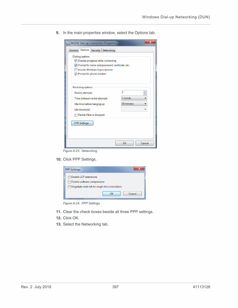
Windows Dial-up Networking (DUN)
9. In the main properties window, select the Options tab.
Figure A-23: Networking
10. Click PPP Settings.
Figure A-24: PPP Settings
11. Clear the check boxes beside all three PPP settings.
12. Click OK.
13. Select the Networking tab.
Rev. 2 July 2019 397 41113126

ALEOS 4.12.0 Software Configuration User Guide for AirLink RV55
Figure A-25: DUN Connection > Networking tab
14. Select Internet Protocol Version 4 (TCP/IPv4) and then select Properties.
Tip: For most configurations, getting the IP address and the DNS server address are automatic.
Rev. 2 July 2019 398 41113126
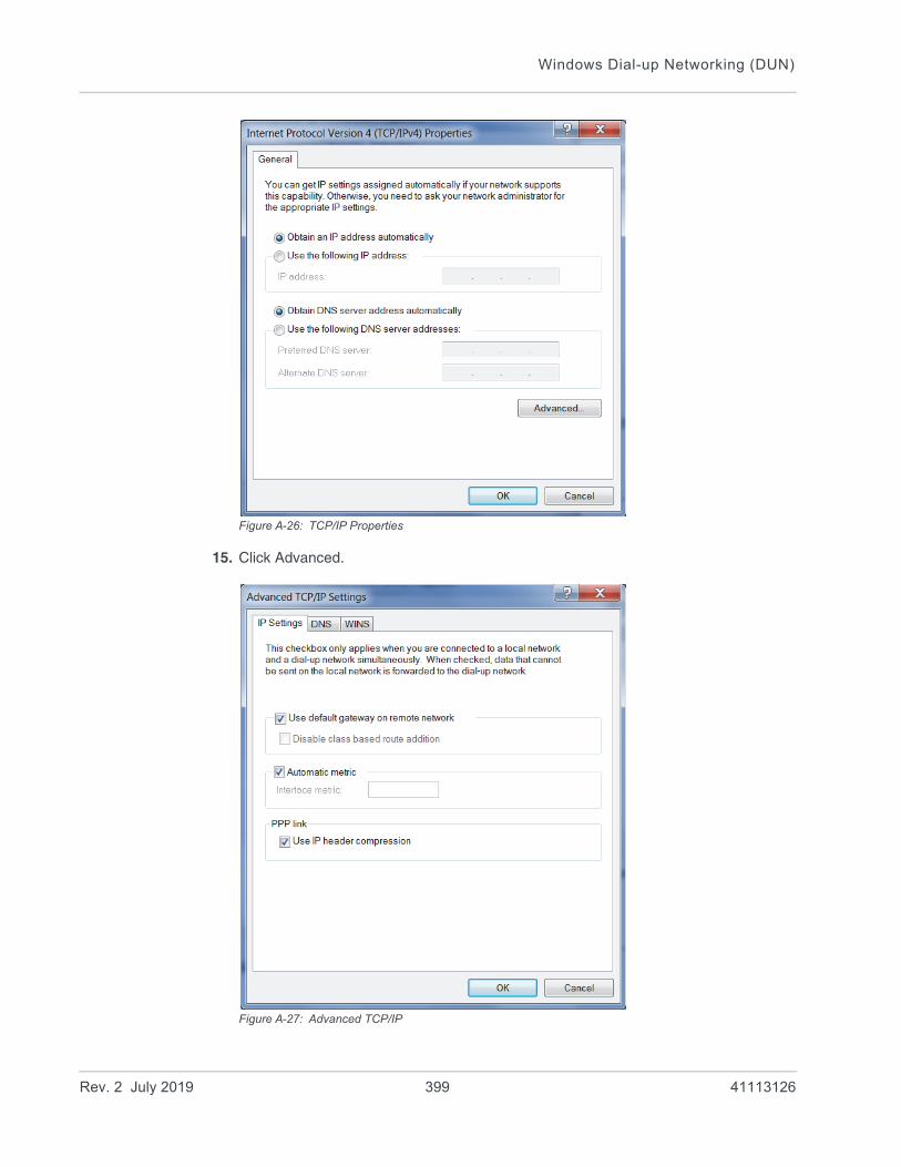
Windows Dial-up Networking (DUN)
Figure A-26: TCP/IP Properties
15. Click Advanced.
Figure A-27: Advanced TCP/IP
Rev. 2 July 2019 399 41113126

ALEOS 4.12.0 Software Configuration User Guide for AirLink RV55
16. Select Use default gateway on remote network.
17. Click OK.
Tip: You may want to check the Options tab and change the settings for applications you use. The default options are generally applicable for most uses.
Caution: Unless specifically directed to do so by Support or your network administrator, you do not need to make any changes to the options on the Security tab.
18. Click OK until you return to the Connect window.
19. Log in to ACEmanager and go to Serial > Port Configuration.
20. Under Port Configuration:
a. Set the Flow Control field to Hardware.
b. Set the DB9 Serial Echo field to Disable.
21. Click Apply and reboot the device.
Connection settings
1. To set the default connection:
2. Go to Start > Control Panel > Network and Sharing Center.
3. Select Change adapter settings.
4. Right-click the icon for the DUN connection.
If you want this to be your default connection, select Set as Default Connection.
If it is already the default connection and you do not want it as your default connection, select Cancel as Default Connection.
If you do not want the DUN connection to be dialed when there is no other connection:
1. Go to Start > Control Panel > Internet Options.
2. Select the Connections tab.
3. Highlight the DUN connection and select Never dial a connection.
4. Click Apply.
5. Click OK.
Rev. 2 July 2019 400 41113126

B
B: Modbus/BSAP ConfigurationThe AirLink router supports Modbus ASCII, Modbus RTU, and BSAP, and can also emulate other protocols (like DF1) using the Modbus Variable feature.
Modbus Overview
The Modbus Protocol provides for client-server (i.e., master-slave) communications between intelligent devices. As a de facto standard, it is the most widely used network protocol in the industrial manufacturing environment to transfer discrete/analog I/O and register data between control devices. Modbus, BSAP, and other Modbus variations are often used in conjunction with telemetry devices.
Tip: This section is just a brief overview of Modbus. For more information, refer to your Modbus equipment distributor or manufacturer or www.modbus.org.
Telemetry
Telemetry is an automated communications process by which data is collected from instruments located at remote or inaccessible points and transmitted to receiving equipment for measurement, monitoring, display, and recording. Transmission of the information may be over physical pairs of wires, telecommunication circuits, radios, or satellites.
Remote Terminal Unit (RTU)
Modbus was originally designed to be used in a radio environment where packets were broadcast from a central station (i.e., master or host) to a group of remote units. Each remote unit, or Remote Terminal Unit (RTU), has a hexadecimal identification number (ID). The first part of the broadcast packet contains an RTU ID which corresponds to the ID of one of the remote units. The Modbus host looks for the ID and only sends to the unit with the matching ID; the RTU then replies back to the central station.
The RTU connects to such physical equipment as switches, pumps, and other devices, and monitors and controls these devices. The RTU can be part of a network set up for Supervisory Control and Data Acquisition.
Supervisory Control and Data Acquisition (SCADA)
Supervisory Control and Data Acquisition (SCADA) describes solutions across a large variety of industries and is used in industrial and engineering applications to monitor and control distributed systems from a master location. SCADA encompasses multiple RTUs, a central control room with a host computer (or network), and some sort of communication infrastructure.
SCADA allows for “supervisory” control of remote devices as well as acquiring data from the remote locations. Programmable Logic Controllers allow for a higher degree of automated SCADA.
Rev. 2 July 2019 401 41113126
ALEOS 4.12.0 Software Configuration User Guide for AirLink RV55
Programmable Logic Controller (PLC)
A Programmable Logic Controller (PLC) is a small industrial computer which generally monitors several connected sensor inputs and controls attached devices (motor starters, solenoids, pilot lights/displays, speed drives, valves, etc.) according to a user-created program stored in its memory. Containing inputs and outputs similar to an RTU, PLCs are frequently used for typical relay control, sophisticated motion control, process control, Distributed Control System and complex networking.
Modbus TCP/IP
Modbus TCP/IP simply takes the Modbus instruction set and wraps TCP/IP around it. Since TCP/IP is the communications standard for the Internet and most networked computers, this provides a simpler installation. Modbus TCP/IP uses standard Ethernet equipment.
Modbus on UDP
When Sierra Wireless AirLink routers are used in place of radios, a AirLink router is connected to the central station (host) and an AirLink router is connected to each remote unit. When the AirLink router is configured for Modbus with UDP, the AirLink router connected to the host can store a list of IP addresses or names with matching IDs. When the host at the central station sends serial data as a poll request, the AirLink router at the host matches the RTU ID to a corresponding IP of a AirLink router at a remote unit. A UDP packet is assembled encapsulating the RTU ID and serial data transmitted from the host. The UDP packet is then transmitted to the specific AirLink router at the remote unit matching the RTU ID. The remote AirLink router then disassembles the packet before transmitting the RTU ID and serial data to the remote unit. The remote units operate in normal UDP mode and their data is sent to the host via the remote AirLink router and host AirLink router.
Configuring AirLink routers at the Polling Host for Modbus on UDP
This section covers a Polling Host with standard Modbus, variations may need additional AT commands.
1. Configure the ports.
The destination port for the device at the host needs to match the device port (*DPORT) in use on all the modems at the remote sites. For example, if the remote device’s device port (*DPORT) is “12345”, then the Modbus host device’s S53 destination port should be set to “12345”.
Take note of (or set) the Device Port setting in *DPORT to configure the destination port on the remote modems.
In ACEmanager, select UDP in the side menu. Select the appropriate MD mode from the drop down menu. • MD13: Modbus ASCII• MD23: Modbus RTU (Binary)
Rev. 2 July 2019 402 41113126
Modbus/BSAP Configuration
• MD33: BSAP• MD63: Variable Modbus — individual parameters are set up manually.
If you do not have a static IP, the host device should be configured to report its current IP to a Dynamic DNS (DDNS) server with Dynamic DNS.
In the Host device’s configuration, instead of an IP address for the Addr List (ATMLIST or ATMLISTX), substitute a single unique name for each device, i.e. remote1, remote2, etc.
When you configure Dynamic DNS for the host device, make note of your device name and domain setting in ACEmanager in the menu selection Dynamic IP to be used with the remote modems.
With names instead of IP addresses for the Address List, the host device queries the DNS server for the current IP address assigned to the specific name of a remote device to send a message corresponding to the ID.
When you use names instead of IP addresses, to ensure your modems are updated quickly with the correct IP addresses for the names, set the DNS settings as well. In ACEmanager, select DNS.
Configure *DNSUSER to the same IP address as the Dynamic DNS (*IPMANAGER1). If your modems have dynamic IP addresses and not static (the IP address can change when it is powered up), configure *DNSUPDATE to a low interval to allow frequent updates.
Configuring Remote AirLink routers for Modbus with UDP
This section covers standard Modbus settings for the AirLink router at the remote unit; variations may need additional commands.
1. Configure the ports
In ACEmanager, select Port Configuration in the side menu.
The destination port for the device at the host needs to match the device port in use on all the devices at the remote sites. For example, if the remote device’s device port (see below) is “12345”, then the Modbus host device’s S53 destination port should be set to “12345”.
Set the destination port (S53) to match the device port of the host device (*DPORT). Make sure the device port of the remote device (*DPORT) matches the destination port of the host device (S53).
Rev. 2 July 2019 403 41113126
ALEOS 4.12.0 Software Configuration User Guide for AirLink RV55
Configure IP Addresses for the Host
If the Host device has a static IP address, enter it in the Destination Address for S53.
Note: With a name instead of IPs for the host device, the remote devices query the DNS server for the current IP assigned to the host device before sending data back to the host.
If the device at the host has a dynamic IP and is using Dynamic DNS, instead of an IP address for S53, specify the name of the host device (**). If the remote devices are using a different DDNS than the host device, you need to specify the fully qualified domain name (**+*DOMAIN).
Note: Setting the Host device IP address as the S53 Destination Address provides a low level security. The device does not forward UDP traffic unless the source IP/port matches what is in S53. However, if you set *AIP=1, the device forwards UDP traffic from any source IP address as long as it is accessing the device on the configured *DPORT.
1. Configure the default mode for start-up.
Each device at the remote locations needs to be configured to communicate with the device at the host. In ACEmanager, select UDP in the side menu.
a. Enable S82, UDP answer.
b. Set S83 to the idle time-out applicable to your application, commonly 20.
2. Configure other RTU settings.
Other parameters may need to be changed, but this is dependent on the RTU type being used. At a minimum, this typically involves setting the proper serial settings to match your RTU.
3. Optional: Dynamic IP Address
If you do not have a static IP, the host device should be configured to report its current IP to a Dynamic DNS (DDNS) server with Dynamic DNS.
Match the name of the device to the names specified in the host device’s MLIST or MLISTX for the connected RTU.
When you configure Dynamic DNS for the host device, note your device name and domain setting in ACEmanager in the menu selection Dynamic IP to be used with the remote devices.
When you use names instead of IP addresses, to ensure your devices are updated quickly with the correct IP addresses for the names, set the DNS settings as well.
Configure *DNSUSER to the same IP address as the Dynamic DNS (*IPMANAGER1). If your devices have dynamic IP addresses and not static (the IP address can change when it is powered up), configure *DNSUPDATE to a low interval to allow frequent updates.
Rev. 2 July 2019 404 41113126
C
C: SNMP: Simple Network Management ProtocolManagement Information Base (MIB)
ALEOS includes a Management Information Base (MIB) that contains information specific to the AirLink RV55. Reports based on this database are sent in a form designed to be parsed by the NMS. The data is hierarchical with entries addressed through object identifiers.
The MIB complies with:• RFC 1213 and MIB-II• RFC 2665 — Ethernet-Like Interface Types• RFC 2863 — The Interfaces Group MIB
SNMP Traps
SNMP traps are alerts that can be sent from the managed device to the Network Management System when an event happens. Your AirLink RV55 is capable of sending traps when the network connection becomes available.
To send SNMP traps:
1. In ACEmanager, go to Services > Management (SNMP).
2. Configure the fields under Trap Server User. (For more information, see Management (SNMP) on page 255.)
3. Go to Events Reporting > Actions.
4. In the Action Type field select SNMP trap. (For more information, see SNMP TRAP on page 300.)
5. Go Events Reporting > Events and configure monitoring for the event type that will trigger the SNMP trap. For example, the event type could be RSSI, thresholds, network state, hardware temperature, etc.
Sierra Wireless MIB
This section shows the contents of the Sierra Wireless MIB file. When this file is loaded onto a remote SNMP client, you can query the Sierra Wireless specific objects listed in this file.
For a text copy of this MIB file, go to source.sierrawireless.com, and select your AirLink RV55.
Rev. 2 July 2019 405 41113126
ALEOS 4.12.0 Software Configuration User Guide for AirLink RV55
SIERRA-MIB DEFINITIONS ::= BEGIN
IMPORTS
OBJECT-TYPE, NOTIFICATION-TYPE, MODULE-IDENTITY, IpAddress,
Integer32, Opaque, enterprises, Counter32, Unsigned32
FROM SNMPv2-SMI
TEXTUAL-CONVENTION, DisplayString, TruthValue
FROM SNMPv2-TC;
sierrawireless MODULE-IDENTITY
LAST-UPDATED "201202290000Z"
ORGANIZATION "Sierra Wireless Inc"
CONTACT-INFO
"Sierra Wirelss Inc
"
DESCRIPTION
""
REVISION "201202290000Z"
DESCRIPTION
"This file defines the private Sierra MIB extensions."
::= { enterprises 20542 }
sharks OBJECT IDENTIFIER ::= { sierrawireless 9}
-- MIB versions
mibversion1 OBJECT IDENTIFIER ::= { sharks 1}
-- GUI Tabs for Sharks
statustab OBJECT IDENTIFIER ::= { mibversion1 1}
Rev. 2 July 2019 406 41113126

SNMP: Simple Network Management Protocol
cellulartab OBJECT IDENTIFIER ::= { mibversion1 2}
lantab OBJECT IDENTIFIER ::= { mibversion1 3}
vpntab OBJECT IDENTIFIER ::= { mibversion1 4}
securitytab OBJECT IDENTIFIER ::= { mibversion1 5}
servicestab OBJECT IDENTIFIER ::= { mibversion1 6}
gpstab OBJECT IDENTIFIER ::= { mibversion1 7}
eventsreportingtab OBJECT IDENTIFIER ::= { mibversion1 8}
serialtab OBJECT IDENTIFIER ::= { mibversion1 9}
iotab OBJECT IDENTIFIER ::= { mibversion1 10}
admintab OBJECT IDENTIFIER ::= { mibversion1 11}
snmpconfig OBJECT IDENTIFIER ::= { mibversion1 12}
-- status elements
home OBJECT IDENTIFIER ::= { statustab 1}
cellular OBJECT IDENTIFIER ::= { statustab 2}
lan OBJECT IDENTIFIER ::= { statustab 3}
vpn OBJECT IDENTIFIER ::= { statustab 4}
security OBJECT IDENTIFIER ::= { statustab 5}
services OBJECT IDENTIFIER ::= { statustab 6}
gps OBJECT IDENTIFIER ::= { statustab 7}
serial OBJECT IDENTIFIER ::= { statustab 8}
about OBJECT IDENTIFIER ::= { statustab 9}
-- io elements
currentstate OBJECT IDENTIFIER ::= { iotab 1}
configuration OBJECT IDENTIFIER ::= { iotab 2}
-- home status elements
phoneNumber OBJECT-TYPE
SYNTAX DisplayString (SIZE (10))
MAX-ACCESS read-only
STATUS current
Rev. 2 July 2019 407 41113126

ALEOS 4.12.0 Software Configuration User Guide for AirLink RV55
DESCRIPTION ""
::= { home 17 }
ipAddress OBJECT-TYPE
SYNTAX IpAddress
MAX-ACCESS read-only
STATUS current
DESCRIPTION ""
::= { home 301 }
networkState OBJECT-TYPE
SYNTAX DisplayString
MAX-ACCESS read-only
STATUS current
DESCRIPTION ""
::= { home 259 }
rssi OBJECT-TYPE
SYNTAX INTEGER(-125..-50)
MAX-ACCESS read-only
STATUS current
DESCRIPTION ""
::= { home 261 }
gprsnetworkOperator OBJECT-TYPE
SYNTAX DisplayString
MAX-ACCESS read-only
STATUS current
DESCRIPTION ""
::= { home 770 }
cdmanetworkOperator OBJECT-TYPE
SYNTAX DisplayString
MAX-ACCESS read-only
STATUS current
Rev. 2 July 2019 408 41113126
SNMP: Simple Network Management Protocol
DESCRIPTION ""
::= { home 644 }
gprsECIO OBJECT-TYPE
SYNTAX DisplayString
MAX-ACCESS read-only
STATUS current
DESCRIPTION ""
::= { home 772 }
cdmaECIO OBJECT-TYPE
SYNTAX DisplayString
MAX-ACCESS read-only
STATUS current
DESCRIPTION ""
::= { home 643 }
powerIn OBJECT-TYPE
SYNTAX DisplayString
MAX-ACCESS read-only
STATUS current
DESCRIPTION ""
::= { home 266 }
boardTemprature OBJECT-TYPE
SYNTAX INTEGER
MAX-ACCESS read-only
STATUS current
DESCRIPTION ""
::= { home 267 }
networkServiceType OBJECT-TYPE
SYNTAX DisplayString
MAX-ACCESS read-only
STATUS current
Rev. 2 July 2019 409 41113126

ALEOS 4.12.0 Software Configuration User Guide for AirLink RV55
DESCRIPTION ""
::= { home 264}
aleosSWVer OBJECT-TYPE
SYNTAX DisplayString
MAX-ACCESS read-only
STATUS current
DESCRIPTION ""
::= { home 4 }
netChannel OBJECT-TYPE
SYNTAX INTEGER
MAX-ACCESS read-only
STATUS current
DESCRIPTION ""
::= { home 260 }
cellularBytesSent OBJECT-TYPE
SYNTAX INTEGER
MAX-ACCESS read-only
STATUS current
DESCRIPTION ""
::= { home 283 }
cellularBytesRecvd OBJECT-TYPE
SYNTAX INTEGER
MAX-ACCESS read-only
STATUS current
DESCRIPTION ""
::= { home 284 }
deviceName OBJECT-TYPE
SYNTAX DisplayString
MAX-ACCESS read-only
Rev. 2 July 2019 410 41113126

SNMP: Simple Network Management Protocol
STATUS current
DESCRIPTION ""
::= { home 1154 }
-- cellular status elements
wanIP OBJECT-TYPE
SYNTAX IpAddress
MAX-ACCESS read-only
STATUS current
DESCRIPTION ""
::= { cellular 301 }
electronicID OBJECT-TYPE
SYNTAX DisplayString
MAX-ACCESS read-only
STATUS current
DESCRIPTION ""
::= { cellular 10 }
iccid OBJECT-TYPE
SYNTAX DisplayString
MAX-ACCESS read-only
STATUS current
DESCRIPTION ""
::= { cellular 771 }
cellid OBJECT-TYPE
SYNTAX DisplayString
MAX-ACCESS read-only
STATUS current
DESCRIPTION ""
::= { cellular 773 }
lac OBJECT-TYPE
Rev. 2 July 2019 411 41113126

ALEOS 4.12.0 Software Configuration User Guide for AirLink RV55
SYNTAX DisplayString
MAX-ACCESS read-only
STATUS current
DESCRIPTION ""
::= { cellular 774 }
imsi OBJECT-TYPE
SYNTAX DisplayString
MAX-ACCESS read-only
STATUS current
DESCRIPTION ""
::= { cellular 785 }
keepAliveIpAddress OBJECT-TYPE
SYNTAX IpAddress
MAX-ACCESS read-only
STATUS current
DESCRIPTION ""
::= { cellular 1105 }
keepAlivePingTime OBJECT-TYPE
SYNTAX INTEGER
MAX-ACCESS read-only
STATUS current
DESCRIPTION ""
::= { cellular 1104 }
dnsServer1 OBJECT-TYPE
SYNTAX DisplayString
MAX-ACCESS read-only
STATUS current
DESCRIPTION ""
::= { cellular 1082 }
dnsServer2 OBJECT-TYPE
Rev. 2 July 2019 412 41113126

SNMP: Simple Network Management Protocol
SYNTAX DisplayString
MAX-ACCESS read-only
STATUS current
DESCRIPTION ""
::= { cellular 1083 }
cellBand OBJECT-TYPE
SYNTAX DisplayString
MAX-ACCESS read-only
STATUS current
DESCRIPTION ""
::= { cellular 2056 }
apn OBJECT-TYPE
SYNTAX DisplayString
MAX-ACCESS read-only
STATUS current
DESCRIPTION ""
::= { cellular 2151 }
wanUseTime OBJECT-TYPE
SYNTAX INTEGER
MAX-ACCESS read-only
STATUS current
DESCRIPTION ""
::= { cellular 5046 }
rscp OBJECT-TYPE
SYNTAX INTEGER
MAX-ACCESS read-only
STATUS current
DESCRIPTION ""
::= { cellular 10249 }
errorRate OBJECT-TYPE
Rev. 2 July 2019 413 41113126

ALEOS 4.12.0 Software Configuration User Guide for AirLink RV55
SYNTAX INTEGER
MAX-ACCESS read-only
STATUS current
DESCRIPTION ""
::= { cellular 263 }
bytesSent OBJECT-TYPE
SYNTAX INTEGER
MAX-ACCESS read-only
STATUS current
DESCRIPTION ""
::= { cellular 283 }
bytesRecvd OBJECT-TYPE
SYNTAX INTEGER
MAX-ACCESS read-only
STATUS current
DESCRIPTION ""
::= { cellular 284 }
packetsSent OBJECT-TYPE
SYNTAX INTEGER
MAX-ACCESS read-only
STATUS current
DESCRIPTION ""
::= { cellular 281 }
packetsRecvd OBJECT-TYPE
SYNTAX INTEGER
MAX-ACCESS read-only
STATUS current
DESCRIPTION ""
::= { cellular 282 }
prlVersion OBJECT-TYPE
Rev. 2 July 2019 414 41113126
SNMP: Simple Network Management Protocol
SYNTAX INTEGER
MAX-ACCESS read-only
STATUS current
DESCRIPTION ""
::= { cellular 642 }
prlUpdateStatus OBJECT-TYPE
SYNTAX DisplayString
MAX-ACCESS read-only
STATUS current
DESCRIPTION ""
::= { cellular 646 }
sid OBJECT-TYPE
SYNTAX INTEGER
MAX-ACCESS read-only
STATUS current
DESCRIPTION ""
::= { cellular 648 }
nid OBJECT-TYPE
SYNTAX INTEGER
MAX-ACCESS read-only
STATUS current
DESCRIPTION ""
::= { cellular 649 }
pnOffset OBJECT-TYPE
SYNTAX DisplayString
MAX-ACCESS read-only
STATUS current
DESCRIPTION ""
::= { cellular 650 }
baseClass OBJECT-TYPE
Rev. 2 July 2019 415 41113126

ALEOS 4.12.0 Software Configuration User Guide for AirLink RV55
SYNTAX DisplayString
MAX-ACCESS read-only
STATUS current
DESCRIPTION ""
::= { cellular 651 }
rsrq OBJECT-TYPE
SYNTAX INTEGER
MAX-ACCESS read-only
STATUS current
DESCRIPTION ""
::= { cellular 10209 }
rsrp OBJECT-TYPE
SYNTAX INTEGER
MAX-ACCESS read-only
STATUS current
DESCRIPTION ""
::= { cellular 10210 }
sinr OBJECT-TYPE
SYNTAX DisplayString
MAX-ACCESS read-only
STATUS current
DESCRIPTION ""
::= { cellular 10211 }
-- LAN status elements
usbMode OBJECT-TYPE
SYNTAX DisplayString
MAX-ACCESS read-only
STATUS current
DESCRIPTION ""
::= { lan 1130 }
Rev. 2 July 2019 416 41113126

SNMP: Simple Network Management Protocol
vrrpEnabled OBJECT-TYPE
SYNTAX DisplayString
MAX-ACCESS read-only
STATUS current
DESCRIPTION ""
::= { lan 9001 }
lanpacketsSent OBJECT-TYPE
SYNTAX INTEGER
MAX-ACCESS read-only
STATUS current
DESCRIPTION ""
::= { lan 279 }
lanpacketsRecvd OBJECT-TYPE
SYNTAX INTEGER
MAX-ACCESS read-only
STATUS current
DESCRIPTION ""
::= { lan 280 }
wifipacketsSent OBJECT-TYPE
SYNTAX INTEGER
MAX-ACCESS read-only
STATUS current
DESCRIPTION ""
::= { lan 10405 }
wifipacketsRecvd OBJECT-TYPE
SYNTAX INTEGER
MAX-ACCESS read-only
STATUS current
DESCRIPTION ""
Rev. 2 July 2019 417 41113126

ALEOS 4.12.0 Software Configuration User Guide for AirLink RV55
::= { lan 10406 }
wifiBridgeEnabled OBJECT-TYPE
SYNTAX DisplayString
MAX-ACCESS read-only
STATUS current
DESCRIPTION ""
::= { lan 10401 }
wifiSecurityType OBJECT-TYPE
SYNTAX DisplayString
MAX-ACCESS read-only
STATUS current
DESCRIPTION ""
::= { lan 4509 }
wifiAPStatus OBJECT-TYPE
SYNTAX DisplayString
MAX-ACCESS read-only
STATUS current
DESCRIPTION ""
::= { lan 4506 }
wifiSSID OBJECT-TYPE
SYNTAX DisplayString
MAX-ACCESS read-only
STATUS current
DESCRIPTION ""
::= { lan 4507 }
wifiChannel OBJECT-TYPE
SYNTAX INTEGER
MAX-ACCESS read-only
STATUS current
DESCRIPTION ""
Rev. 2 July 2019 418 41113126

SNMP: Simple Network Management Protocol
::= { lan 4508 }
-- VPN status elements
incomingOOB OBJECT-TYPE
SYNTAX DisplayString
MAX-ACCESS read-only
STATUS current
DESCRIPTION ""
::= { vpn 3177 }
outgoingOOB OBJECT-TYPE
SYNTAX DisplayString
MAX-ACCESS read-only
STATUS current
DESCRIPTION ""
::= { vpn 3178 }
outgoingHostOOB OBJECT-TYPE
SYNTAX DisplayString
MAX-ACCESS read-only
STATUS current
DESCRIPTION ""
::= { vpn 3179 }
vpn1Status OBJECT-TYPE
SYNTAX DisplayString
MAX-ACCESS read-only
STATUS current
DESCRIPTION ""
::= { vpn 3176 }
vpn2Status OBJECT-TYPE
Rev. 2 July 2019 419 41113126

ALEOS 4.12.0 Software Configuration User Guide for AirLink RV55
SYNTAX DisplayString
MAX-ACCESS read-only
STATUS current
DESCRIPTION ""
::= { vpn 3205 }
vpn3Status OBJECT-TYPE
SYNTAX DisplayString
MAX-ACCESS read-only
STATUS current
DESCRIPTION ""
::= { vpn 3231 }
vpn4Status OBJECT-TYPE
SYNTAX DisplayString
MAX-ACCESS read-only
STATUS current
DESCRIPTION ""
::= { vpn 3257 }
vpn5Status OBJECT-TYPE
SYNTAX DisplayString
MAX-ACCESS read-only
STATUS current
DESCRIPTION ""
::= { vpn 3283 }
-- Security status elements
dmz OBJECT-TYPE
SYNTAX DisplayString
MAX-ACCESS read-only
STATUS current
DESCRIPTION ""
::= { security 5113 }
Rev. 2 July 2019 420 41113126

SNMP: Simple Network Management Protocol
portForwarding OBJECT-TYPE
SYNTAX DisplayString
MAX-ACCESS read-only
STATUS current
DESCRIPTION ""
::= { security 5112 }
portFilteringIn OBJECT-TYPE
SYNTAX DisplayString
MAX-ACCESS read-only
STATUS current
DESCRIPTION ""
::= { security 3505 }
portFilteringOut OBJECT-TYPE
SYNTAX DisplayString
MAX-ACCESS read-only
STATUS current
DESCRIPTION ""
::= { security 3506 }
trustedHosts OBJECT-TYPE
SYNTAX DisplayString
MAX-ACCESS read-only
STATUS current
DESCRIPTION ""
::= { security 1062 }
macFiltering OBJECT-TYPE
SYNTAX DisplayString
MAX-ACCESS read-only
STATUS current
DESCRIPTION ""
::= { security 3509 }
Rev. 2 July 2019 421 41113126

ALEOS 4.12.0 Software Configuration User Guide for AirLink RV55
badPasswdCount OBJECT-TYPE
SYNTAX INTEGER
MAX-ACCESS read-only
STATUS current
DESCRIPTION ""
::= { security 385 }
ipRejectCount OBJECT-TYPE
SYNTAX INTEGER
MAX-ACCESS read-only
STATUS current
DESCRIPTION ""
::= { security 386 }
ipRejectLog OBJECT-TYPE
SYNTAX DisplayString
MAX-ACCESS read-only
STATUS current
DESCRIPTION ""
::= { security 387 }
-- Services status elements
aceNet OBJECT-TYPE
SYNTAX DisplayString
MAX-ACCESS read-only
STATUS current
DESCRIPTION ""
::= { services 5026 }
aceManager OBJECT-TYPE
SYNTAX DisplayString
MAX-ACCESS read-only
STATUS current
Rev. 2 July 2019 422 41113126
SNMP: Simple Network Management Protocol
DESCRIPTION ""
::= { services 1149 }
dynamicDnsService OBJECT-TYPE
SYNTAX DisplayString
MAX-ACCESS read-only
STATUS current
DESCRIPTION ""
::= { services 5011 }
fullDomainName OBJECT-TYPE
SYNTAX DisplayString
MAX-ACCESS read-only
STATUS current
DESCRIPTION ""
::= { services 5007 }
-- GPS status elements
gpsFix OBJECT-TYPE
SYNTAX INTEGER
MAX-ACCESS read-only
STATUS current
DESCRIPTION ""
::= { gps 900 }
satelliteCount OBJECT-TYPE
SYNTAX INTEGER
MAX-ACCESS read-only
STATUS current
DESCRIPTION ""
::= { gps 901 }
latitude OBJECT-TYPE
SYNTAX DisplayString
Rev. 2 July 2019 423 41113126
ALEOS 4.12.0 Software Configuration User Guide for AirLink RV55
MAX-ACCESS read-only
STATUS current
DESCRIPTION ""
::= { gps 902 }
longitude OBJECT-TYPE
SYNTAX DisplayString
MAX-ACCESS read-only
STATUS current
DESCRIPTION ""
::= { gps 903 }
heading OBJECT-TYPE
SYNTAX DisplayString
MAX-ACCESS read-only
STATUS current
DESCRIPTION ""
::= { gps 904 }
speed OBJECT-TYPE
SYNTAX INTEGER
MAX-ACCESS read-only
STATUS current
DESCRIPTION ""
::= { gps 905 }
engineHours OBJECT-TYPE
SYNTAX INTEGER
MAX-ACCESS read-only
STATUS current
DESCRIPTION ""
::= { gps 906 }
-- Serial status elements
Rev. 2 July 2019 424 41113126

SNMP: Simple Network Management Protocol
serialPortMode OBJECT-TYPE
SYNTAX DisplayString
MAX-ACCESS read-only
STATUS current
DESCRIPTION ""
::= { serial 1043 }
tcpAutoAnswer OBJECT-TYPE
SYNTAX DisplayString
MAX-ACCESS read-only
STATUS current
DESCRIPTION ""
::= { serial 1048 }
udpAutoAnswer OBJECT-TYPE
SYNTAX DisplayString
MAX-ACCESS read-only
STATUS current
DESCRIPTION ""
::= { serial 1054 }
serialPacketsSent OBJECT-TYPE
SYNTAX INTEGER
MAX-ACCESS read-only
STATUS current
DESCRIPTION ""
::= { serial 273 }
serialPacketsRecvd OBJECT-TYPE
SYNTAX INTEGER
MAX-ACCESS read-only
STATUS current
DESCRIPTION ""
::= { serial 274 }
-- About status elements
Rev. 2 July 2019 425 41113126

ALEOS 4.12.0 Software Configuration User Guide for AirLink RV55
deviceModel OBJECT-TYPE
SYNTAX DisplayString
MAX-ACCESS read-only
STATUS current
DESCRIPTION ""
::= { about 7 }
radioModelType OBJECT-TYPE
SYNTAX DisplayString
MAX-ACCESS read-only
STATUS current
DESCRIPTION ""
::= { about 9 }
radioFirmwareVersion OBJECT-TYPE
SYNTAX DisplayString
MAX-ACCESS read-only
STATUS current
DESCRIPTION ""
::= { about 8 }
deviceID OBJECT-TYPE
SYNTAX DisplayString
MAX-ACCESS read-only
STATUS current
DESCRIPTION ""
::= { about 25 }
macAddress OBJECT-TYPE
SYNTAX DisplayString
MAX-ACCESS read-only
STATUS current
DESCRIPTION ""
Rev. 2 July 2019 426 41113126

SNMP: Simple Network Management Protocol
::= { about 66 }
aleosSWVersion OBJECT-TYPE
SYNTAX DisplayString
MAX-ACCESS read-only
STATUS current
DESCRIPTION ""
::= { about 4 }
deviceHwConfiguration OBJECT-TYPE
SYNTAX DisplayString
MAX-ACCESS read-only
STATUS current
DESCRIPTION ""
::= { about 5 }
msciVersion OBJECT-TYPE
SYNTAX DisplayString
MAX-ACCESS read-only
STATUS current
DESCRIPTION ""
::= { about 3 }
-- Read Write values
snmpenable OBJECT-TYPE
SYNTAX INTEGER {
disabled(0),
enabled(1)}
MAX-ACCESS read-write
STATUS current
DESCRIPTION ""
::= { snmpconfig 10040 }
snmpversion OBJECT-TYPE
Rev. 2 July 2019 427 41113126

ALEOS 4.12.0 Software Configuration User Guide for AirLink RV55
SYNTAX INTEGER {
snmpv2c(2),
snmpv3(3)}
MAX-ACCESS read-write
STATUS current
DESCRIPTION ""
::= { snmpconfig 10041 }
snmpport OBJECT-TYPE
SYNTAX INTEGER
MAX-ACCESS read-write
STATUS current
DESCRIPTION ""
::= { snmpconfig 10042 }
snmpContact OBJECT-TYPE
SYNTAX DisplayString
MAX-ACCESS read-write
STATUS current
DESCRIPTION ""
::= { snmpconfig 2730 }
snmpName OBJECT-TYPE
SYNTAX DisplayString
MAX-ACCESS read-write
STATUS current
DESCRIPTION ""
::= { snmpconfig 2731 }
snmpLocation OBJECT-TYPE
SYNTAX DisplayString
MAX-ACCESS read-write
STATUS current
DESCRIPTION ""
::= { snmpconfig 2732 }
Rev. 2 July 2019 428 41113126
SNMP: Simple Network Management Protocol
rocommunity OBJECT-TYPE
SYNTAX DisplayString
MAX-ACCESS read-write
STATUS current
DESCRIPTION ""
::= { snmpconfig 10063 }
rouser OBJECT-TYPE
SYNTAX DisplayString
MAX-ACCESS read-write
STATUS current
DESCRIPTION ""
::= { snmpconfig 10045 }
rosecuritylvl OBJECT-TYPE
SYNTAX INTEGER {
noauthnopriv(0),
authnopriv(1),
authpriv(2)}
MAX-ACCESS read-write
STATUS current
DESCRIPTION ""
::= { snmpconfig 10046 }
roauthtype OBJECT-TYPE
SYNTAX INTEGER {
md5(0),
sha(1) }
MAX-ACCESS read-write
STATUS current
DESCRIPTION ""
::= { snmpconfig 10047 }
roauthkey OBJECT-TYPE
Rev. 2 July 2019 429 41113126

ALEOS 4.12.0 Software Configuration User Guide for AirLink RV55
SYNTAX DisplayString
MAX-ACCESS read-write
STATUS current
DESCRIPTION ""
::= { snmpconfig 10048 }
roprivtype OBJECT-TYPE
SYNTAX INTEGER {
aes(0),
des(1) }
MAX-ACCESS read-write
STATUS current
DESCRIPTION ""
::= { snmpconfig 10049 }
roprivkey OBJECT-TYPE
SYNTAX DisplayString
MAX-ACCESS read-write
STATUS current
DESCRIPTION ""
::= { snmpconfig 10050 }
rwcommunity OBJECT-TYPE
SYNTAX DisplayString
MAX-ACCESS read-write
STATUS current
DESCRIPTION ""
::= { snmpconfig 10064 }
rwuser OBJECT-TYPE
SYNTAX DisplayString
MAX-ACCESS read-write
STATUS current
DESCRIPTION ""
Rev. 2 July 2019 430 41113126

SNMP: Simple Network Management Protocol
::= { snmpconfig 10051 }
rwsecuritylvl OBJECT-TYPE
SYNTAX INTEGER {
noauthnopriv(0),
authnopriv(1),
authpriv(2)}
MAX-ACCESS read-write
STATUS current
DESCRIPTION ""
::= { snmpconfig 10052 }
rwauthtype OBJECT-TYPE
SYNTAX INTEGER {
md5(0),
sha(1) }
MAX-ACCESS read-write
STATUS current
DESCRIPTION ""
::= { snmpconfig 10053 }
rwauthkey OBJECT-TYPE
SYNTAX DisplayString
MAX-ACCESS read-write
STATUS current
DESCRIPTION ""
::= { snmpconfig 10054 }
rwprivtype OBJECT-TYPE
SYNTAX INTEGER {
aes(0),
des(1) }
MAX-ACCESS read-write
STATUS current
Rev. 2 July 2019 431 41113126
ALEOS 4.12.0 Software Configuration User Guide for AirLink RV55
DESCRIPTION ""
::= { snmpconfig 10055 }
rwprivkey OBJECT-TYPE
SYNTAX DisplayString
MAX-ACCESS read-write
STATUS current
DESCRIPTION ""
::= { snmpconfig 10056 }
trapipAddress OBJECT-TYPE
SYNTAX IpAddress
MAX-ACCESS read-write
STATUS current
DESCRIPTION ""
::= { snmpconfig 1166 }
trapport OBJECT-TYPE
SYNTAX INTEGER
MAX-ACCESS read-write
STATUS current
DESCRIPTION ""
::= { snmpconfig 10043 }
engineid OBJECT-TYPE
SYNTAX DisplayString
MAX-ACCESS read-write
STATUS current
DESCRIPTION ""
::= { snmpconfig 10044 }
trapcommunity OBJECT-TYPE
SYNTAX DisplayString
MAX-ACCESS read-write
Rev. 2 July 2019 432 41113126
SNMP: Simple Network Management Protocol
STATUS current
DESCRIPTION ""
::= { snmpconfig 10065 }
trapuser OBJECT-TYPE
SYNTAX DisplayString
MAX-ACCESS read-write
STATUS current
DESCRIPTION ""
::= { snmpconfig 10057 }
trapsecuritylvl OBJECT-TYPE
SYNTAX INTEGER {
noauthnopriv(0),
authnopriv(1),
authpriv(2)}
MAX-ACCESS read-write
STATUS current
DESCRIPTION ""
::= { snmpconfig 10058 }
trapauthtype OBJECT-TYPE
SYNTAX INTEGER {
md5(0),
sha(1) }
MAX-ACCESS read-write
STATUS current
DESCRIPTION ""
::= { snmpconfig 10059 }
trapauthkey OBJECT-TYPE
SYNTAX DisplayString
MAX-ACCESS read-write
STATUS current
DESCRIPTION ""
Rev. 2 July 2019 433 41113126
ALEOS 4.12.0 Software Configuration User Guide for AirLink RV55
::= { snmpconfig 10060 }
trapprivtype OBJECT-TYPE
SYNTAX INTEGER {
aes(0),
des(1) }
MAX-ACCESS read-write
STATUS current
DESCRIPTION ""
::= { snmpconfig 10061 }
trapprivkey OBJECT-TYPE
SYNTAX DisplayString
MAX-ACCESS read-write
STATUS current
DESCRIPTION ""
::= { snmpconfig 10062 }
rebootmodem OBJECT-TYPE
SYNTAX INTEGER {
nop(0),
reboot(1) }
MAX-ACCESS read-write
STATUS current
DESCRIPTION ""
::= { snmpconfig 65001 }
digitalInput1 OBJECT-TYPE
SYNTAX DisplayString
STATUS current
DESCRIPTION "Digital Input 1 MSCIID 851"
::= { currentstate 851 }
Rev. 2 July 2019 434 41113126

SNMP: Simple Network Management Protocol
digitalInput2 OBJECT-TYPE
SYNTAX DisplayString
STATUS current
DESCRIPTION "Digital Input 2 MSCIID 852"
::= { currentstate 852 }
digitalInput3 OBJECT-TYPE
SYNTAX DisplayString
STATUS current
DESCRIPTION "Digital Input 3 MSCIID 853"
::= { currentstate 853 }
digitalInput4 OBJECT-TYPE
SYNTAX DisplayString
STATUS current
DESCRIPTION "Digital Input 4 MSCIID 854"
::= { currentstate 854 }
digitalInput5 OBJECT-TYPE
SYNTAX DisplayString
STATUS current
DESCRIPTION "Digital Input 5 MSCIID 867"
::= { currentstate 867 }
digitalInput6 OBJECT-TYPE
SYNTAX DisplayString
STATUS current
DESCRIPTION "Digital Input 6 MSCIID 868"
::= { currentstate 868 }
digitalOutput1 OBJECT-TYPE
SYNTAX DisplayString
STATUS current
DESCRIPTION "Digital Output 1 MSCIID 859"
::= { currentstate 859 }
Rev. 2 July 2019 435 41113126
ALEOS 4.12.0 Software Configuration User Guide for AirLink RV55
digitalOutput2 OBJECT-TYPE
SYNTAX DisplayString
STATUS current
DESCRIPTION "Digital Output 2 MSCIID 860"
::= { currentstate 860 }
digitalOutput3 OBJECT-TYPE
SYNTAX DisplayString
STATUS current
DESCRIPTION "Digital Output 3 MSCIID 863"
::= { currentstate 863 }
digitalOutput4 OBJECT-TYPE
SYNTAX DisplayString
STATUS current
DESCRIPTION "Digital Output 4 MSCIID 864"
::= { currentstate 864 }
digitalOutput5 OBJECT-TYPE
SYNTAX DisplayString
STATUS current
DESCRIPTION "Digital Output 5 MSCIID 865"
::= { currentstate 865 }
digitalOutput6 OBJECT-TYPE
SYNTAX DisplayString
STATUS current
DESCRIPTION "Digital Output 6 MSCIID 866"
::= { currentstate 866 }
digitalConfig1 OBJECT-TYPE
SYNTAX DisplayString
STATUS current
DESCRIPTION "Digital Configuration 1 MSCIID 861"
Rev. 2 July 2019 436 41113126

SNMP: Simple Network Management Protocol
::= { configuration 861 }
digitalConfig2 OBJECT-TYPE
SYNTAX DisplayString
STATUS current
DESCRIPTION "Digital Configuration 2 MSCIID 862"
::= { configuration 862 }
digitalConfig3 OBJECT-TYPE
SYNTAX DisplayString
STATUS current
DESCRIPTION "Digital Configuration 3 MSCIID 869"
::= { configuration 869 }
digitalConfig4 OBJECT-TYPE
SYNTAX DisplayString
STATUS current
DESCRIPTION "Digital Configuration 4 MSCIID 870"
::= { configuration 870 }
digitalConfig5 OBJECT-TYPE
SYNTAX DisplayString
STATUS current
DESCRIPTION "Digital Configuration 5 MSCIID 871"
::= { configuration 871 }
digitalConfig6 OBJECT-TYPE
SYNTAX DisplayString
STATUS current
DESCRIPTION "Digital Configuration 6 MSCIID 872"
::= { configuration 872 }
pulseAccumulator1 OBJECT-TYPE
SYNTAX DisplayString
Rev. 2 July 2019 437 41113126
ALEOS 4.12.0 Software Configuration User Guide for AirLink RV55
STATUS current
DESCRIPTION "Pulse Accumulator 1 MSCIID 4002"
::= { currentstate 4002 }
pulseAccumulator2 OBJECT-TYPE
SYNTAX DisplayString
STATUS current
DESCRIPTION "Pulse Accumulator 2 MSCIID 4003"
::= { currentstate 4003 }
pulseAccumulator3 OBJECT-TYPE
SYNTAX DisplayString
STATUS current
DESCRIPTION "Pulse Accumulator 3 MSCIID 4004"
::= { currentstate 4004 }
pulseAccumulator4 OBJECT-TYPE
SYNTAX DisplayString
STATUS current
DESCRIPTION "Pulse Accumulator 4 MSCIID 4005"
::= { currentstate 4005 }
pulseAccumulator5 OBJECT-TYPE
SYNTAX DisplayString
STATUS current
DESCRIPTION "Pulse Accumulator 5 MSCIID 4006"
::= { currentstate 4006 }
pulseAccumulator6 OBJECT-TYPE
SYNTAX DisplayString
STATUS current
DESCRIPTION "Pulse Accumulator 6 MSCIID 4007"
::= { currentstate 4007 }
analogInput1 OBJECT-TYPE
Rev. 2 July 2019 438 41113126

SNMP: Simple Network Management Protocol
SYNTAX DisplayString
STATUS current
DESCRIPTION "Analog Input 1 MSCIID 855"
::= { currentstate 855 }
analogInput2 OBJECT-TYPE
SYNTAX DisplayString
STATUS current
DESCRIPTION "Analog Input 2 MSCIID 856"
::= { currentstate 856 }
analogInput3 OBJECT-TYPE
SYNTAX DisplayString
STATUS current
DESCRIPTION "Analog Input 3 MSCIID 857"
::= { currentstate 857 }
analogInput4 OBJECT-TYPE
SYNTAX DisplayString
STATUS current
DESCRIPTION "Analog Input 4 MSCIID 858"
::= { currentstate 858 }
analogInput5 OBJECT-TYPE
SYNTAX DisplayString
STATUS current
DESCRIPTION "Analog Input 5 MSCIID 873"
::= { currentstate 873 }
analogInput6 OBJECT-TYPE
SYNTAX DisplayString
STATUS current
DESCRIPTION "Analog Input 6 MSCIID 874"
::= { currentstate 874 }
Rev. 2 July 2019 439 41113126

ALEOS 4.12.0 Software Configuration User Guide for AirLink RV55
analogInput7 OBJECT-TYPE
SYNTAX DisplayString
STATUS current
DESCRIPTION "Analog Input 7 MSCIID 875"
::= { currentstate 875 }
analogInput8 OBJECT-TYPE
SYNTAX DisplayString
STATUS current
DESCRIPTION "Analog Input 8 MSCIID 876"
::= { currentstate 876 }
coefficientAnalogInput1 OBJECT-TYPE
SYNTAX DisplayString
STATUS current
DESCRIPTION "Coefficient Analog Input 1 MSCIID 4011"
::= { currentstate 4011 }
coefficientAnalogInput2 OBJECT-TYPE
SYNTAX DisplayString
STATUS current
DESCRIPTION "Coefficient Analog Input 2 MSCIID 4012"
::= { currentstate 4012 }
coefficientAnalogInput3 OBJECT-TYPE
SYNTAX DisplayString
STATUS current
DESCRIPTION "Coefficient Analog Input 3 MSCIID 4013"
::= { currentstate 4013 }
coefficientAnalogInput4 OBJECT-TYPE
SYNTAX DisplayString
STATUS current
DESCRIPTION "Coefficient Analog Input 4 MSCIID 4014"
Rev. 2 July 2019 440 41113126
SNMP: Simple Network Management Protocol
::= { currentstate 4014 }
coefficientAnalogInput5 OBJECT-TYPE
SYNTAX DisplayString
STATUS current
DESCRIPTION "Coefficient Analog Input 5 MSCIID 4015"
::= { currentstate 4015 }
coefficientAnalogInput6 OBJECT-TYPE
SYNTAX DisplayString
STATUS current
DESCRIPTION "Coefficient Analog Input 6 MSCIID 4016"
::= { currentstate 4016 }
coefficientAnalogInput7 OBJECT-TYPE
SYNTAX DisplayString
STATUS current
DESCRIPTION "Coefficient Analog Input 7 MSCIID 4017"
::= { currentstate 4017 }
coefficientAnalogInput8 OBJECT-TYPE
SYNTAX DisplayString
STATUS current
DESCRIPTION "Coefficient Analog Input 8 MSCIID 4018"
::= { currentstate 4018 }
offsetAnalogInput1 OBJECT-TYPE
SYNTAX DisplayString
STATUS current
DESCRIPTION "Offset Analog Input 1 MSCIID 4021"
::= { currentstate 4021 }
offsetAnalogInput2 OBJECT-TYPE
SYNTAX DisplayString
STATUS current
Rev. 2 July 2019 441 41113126
ALEOS 4.12.0 Software Configuration User Guide for AirLink RV55
DESCRIPTION "Offset Analog Input 2 MSCIID 4022"
::= { currentstate 4022 }
offsetAnalogInput3 OBJECT-TYPE
SYNTAX DisplayString
STATUS current
DESCRIPTION "Offset Analog Input 3 MSCIID 4023"
::= { currentstate 4023 }
offsetAnalogInput4 OBJECT-TYPE
SYNTAX DisplayString
STATUS current
DESCRIPTION "Offset Analog Input 4 MSCIID 4024"
::= { currentstate 4024 }
offsetAnalogInput5 OBJECT-TYPE
SYNTAX DisplayString
STATUS current
DESCRIPTION "Offset Analog Input 5 MSCIID 4025"
::= { currentstate 4025 }
offsetAnalogInput6 OBJECT-TYPE
SYNTAX DisplayString
STATUS current
DESCRIPTION "Offset Analog Input 6 MSCIID 4026"
::= { currentstate 4026 }
offsetAnalogInput7 OBJECT-TYPE
SYNTAX DisplayString
STATUS current
DESCRIPTION "Offset Analog Input 7 MSCIID 4027"
::= { currentstate 4027 }
offsetAnalogInput8 OBJECT-TYPE
SYNTAX DisplayString
Rev. 2 July 2019 442 41113126
SNMP: Simple Network Management Protocol
STATUS current
DESCRIPTION "Offset Analog Input 8 MSCIID 4028"
::= { currentstate 4028 }
unitsAnalogInput1 OBJECT-TYPE
SYNTAX DisplayString
STATUS current
DESCRIPTION "Units Analog Input 1 MSCIID 4031"
::= { currentstate 4031 }
unitsAnalogInput2 OBJECT-TYPE
SYNTAX DisplayString
STATUS current
DESCRIPTION "Units Analog Input 2 MSCIID 4032"
::= { currentstate 4032 }
unitsAnalogInput3 OBJECT-TYPE
SYNTAX DisplayString
STATUS current
DESCRIPTION "Units Analog Input 3 MSCIID 4033"
::= { currentstate 4033 }
unitsAnalogInput4 OBJECT-TYPE
SYNTAX DisplayString
STATUS current
DESCRIPTION "Units Analog Input 4 MSCIID 4034"
::= { currentstate 4034 }
unitsAnalogInput5 OBJECT-TYPE
SYNTAX DisplayString
STATUS current
DESCRIPTION "Units Analog Input 5 MSCIID 4035"
::= { currentstate 4035 }
unitsAnalogInput6 OBJECT-TYPE
Rev. 2 July 2019 443 41113126

ALEOS 4.12.0 Software Configuration User Guide for AirLink RV55
SYNTAX DisplayString
STATUS current
DESCRIPTION "Units Analog Input 6 MSCIID 4036"
::= { currentstate 4036 }
unitsAnalogInput7 OBJECT-TYPE
SYNTAX DisplayString
STATUS current
DESCRIPTION "Units Analog Input 7 MSCIID 4037"
::= { currentstate 4037 }
unitsAnalogInput8 OBJECT-TYPE
SYNTAX DisplayString
STATUS current
DESCRIPTION "Units Analog Input 8 MSCIID 4038"
::= { currentstate 4038 }
scaledAnalogInput1 OBJECT-TYPE
SYNTAX DisplayString
STATUS current
DESCRIPTION "Scaled Analog Input 1 MSCIID 4041"
::= { currentstate 4041 }
scaledAnalogInput2 OBJECT-TYPE
SYNTAX DisplayString
STATUS current
DESCRIPTION "Scaled Analog Input 2 MSCIID 4042"
::= { currentstate 4042 }
scaledAnalogInput3 OBJECT-TYPE
SYNTAX DisplayString
STATUS current
DESCRIPTION "Scaled Analog Input 3 MSCIID 4043"
::= { currentstate 4043 }
Rev. 2 July 2019 444 41113126

SNMP: Simple Network Management Protocol
scaledAnalogInput4 OBJECT-TYPE
SYNTAX DisplayString
STATUS current
DESCRIPTION "Scaled Analog Input 4 MSCIID 4044"
::= { currentstate 4044 }
scaledAnalogInput5 OBJECT-TYPE
SYNTAX DisplayString
STATUS current
DESCRIPTION "Scaled Analog Input 5 MSCIID 4045"
::= { currentstate 4045 }
scaledAnalogInput6 OBJECT-TYPE
SYNTAX DisplayString
STATUS current
DESCRIPTION "Scaled Analog Input 6 MSCIID 4046"
::= { currentstate 4046 }
scaledAnalogInput7 OBJECT-TYPE
SYNTAX DisplayString
STATUS current
DESCRIPTION "Scaled Analog Input 7 MSCIID 4047"
::= { currentstate 4047 }
scaledAnalogInput8 OBJECT-TYPE
SYNTAX DisplayString
STATUS current
DESCRIPTION "Scaled Analog Input 8 MSCIID 4048"
::= { currentstate 4048 }
-- Notifications starting at 1000
Rev. 2 July 2019 445 41113126
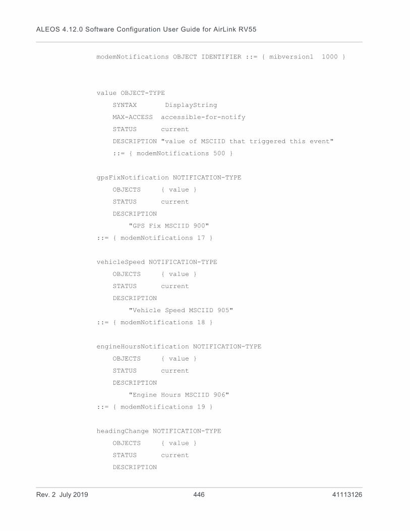
ALEOS 4.12.0 Software Configuration User Guide for AirLink RV55
modemNotifications OBJECT IDENTIFIER ::= { mibversion1 1000 }
value OBJECT-TYPE
SYNTAX DisplayString
MAX-ACCESS accessible-for-notify
STATUS current
DESCRIPTION "value of MSCIID that triggered this event"
::= { modemNotifications 500 }
gpsFixNotification NOTIFICATION-TYPE
OBJECTS { value }
STATUS current
DESCRIPTION
"GPS Fix MSCIID 900"
::= { modemNotifications 17 }
vehicleSpeed NOTIFICATION-TYPE
OBJECTS { value }
STATUS current
DESCRIPTION
"Vehicle Speed MSCIID 905"
::= { modemNotifications 18 }
engineHoursNotification NOTIFICATION-TYPE
OBJECTS { value }
STATUS current
DESCRIPTION
"Engine Hours MSCIID 906"
::= { modemNotifications 19 }
headingChange NOTIFICATION-TYPE
OBJECTS { value }
STATUS current
DESCRIPTION
Rev. 2 July 2019 446 41113126

SNMP: Simple Network Management Protocol
"Heading Change MSCIID 904"
::= { modemNotifications 20 }
rssiNotification NOTIFICATION-TYPE
OBJECTS { value }
STATUS current
DESCRIPTION
"RSSI MSCIID 261"
::= { modemNotifications 21 }
networkStateNotification NOTIFICATION-TYPE
OBJECTS { value }
STATUS current
DESCRIPTION
"Network State MSCIID 259"
::= { modemNotifications 22 }
networkService NOTIFICATION-TYPE
OBJECTS { value }
STATUS current
DESCRIPTION
"Network Service 264"
::= { modemNotifications 23 }
networkErrorRate NOTIFICATION-TYPE
OBJECTS { value }
STATUS current
DESCRIPTION
"Network Error Rate MSCIID 263"
::= { modemNotifications 24 }
periodicReports NOTIFICATION-TYPE
OBJECTS { value }
STATUS current
DESCRIPTION
Rev. 2 July 2019 447 41113126

ALEOS 4.12.0 Software Configuration User Guide for AirLink RV55
"Periodic Reports MSCIID 270"
::= { modemNotifications 25 }
powerInNotification NOTIFICATION-TYPE
OBJECTS { value }
STATUS current
DESCRIPTION
"Power In MSCIID 266"
::= { modemNotifications 26 }
boardTemp NOTIFICATION-TYPE
OBJECTS { value }
STATUS current
DESCRIPTION
"Board Temperature MSCIID 267"
::= { modemNotifications 27 }
cdmaTemp NOTIFICATION-TYPE
OBJECTS { value }
STATUS current
DESCRIPTION
"CDMA Temperature MSCIID 641"
::= { modemNotifications 28 }
dailyDataUsage NOTIFICATION-TYPE
OBJECTS { value }
STATUS current
DESCRIPTION
"Daily Data Usage MSCIID 25001"
::= { modemNotifications 29 }
monthlyDataUsage NOTIFICATION-TYPE
OBJECTS { value }
STATUS current
Rev. 2 July 2019 448 41113126

SNMP: Simple Network Management Protocol
DESCRIPTION
"Monthly Data Usage MSCIID 25002"
::= { modemNotifications 30 }
END
Rev. 2 July 2019 449 41113126

D
D: AT CommandsAT Command Set Summary
Note: If you are writing software to parse AT command responses, Sierra Wireless recommends that you design the software to be independent of the amount of whitespace. Whitespace is defined as ASCII space, tab, carriage return and linefeed characters and may appear in any combination, not necessarily containing all of the above.
Note: When using AT commands to change passwords or passphrases, the special character comma ‘,’ cannot be used in the new password or passphrase.
Using a terminal connection (Telnet) or SSH protocol, you can send AT commands to configure the device, command it to do something, or query a setting. • AT commands must always be terminated by a carriage return <CR> (ASCII
character 0x0D), i.e., pressing Enter on the keyboard. Some may also include a new line or line feed <LF>.
• If E=1 (Echo On), the AT command (including the terminating <carriage return>) is displayed (output) before any responses.
• Two settings affect the format of AT command output: V (Verbose) and Q (Quiet).• If Q=1 (Quiet On), no result codes are output whatsoever, so there is no response
generated by a (non-query) command. • If Q=0 (Quiet Off), result codes are output. The format of this output is then affected
by the Verbose setting.
If Quiet mode is off, the result code is affected as follows:
For V=1 (Verbose mode), the textual result code is surrounded by a carriage return and new line. Any AT query response is also surrounded by a carriage return and new line.
For V=0 (Terse mode), a numeric result code is output with a single trailing carriage return (no new line is output), while any AT query response is followed by a carriage return and new line (there is no preceding output).
• For example, possible output to the AT command “AT” with carriage return (assuming quiet mode is not on) is:
carriage return—if V=0
carriage return and new line OK another carriage return and new line—if V=1
Note: AT commands work for the port on which they are executed. For example, if the user types ATE1 and then AT&W using a USB/serial port connection, it sets the USB/serial port to Echo On, but not the telnet connection or the RS232 serial port.
If you need to change the port for Telnet (for example, you have the default port blocked on your firewall), the option is on the Services > Telnet/SSH tab. The default Telnet port is 2332. You can also change the Telnet timeout; if the connection is idle, default timeout is 2 minutes. This is the internal Telnet on the device to pass AT commands and not TCP PAD.
AT commands are shown in upper case, but they are not case sensitive.
Rev. 2 July 2019 450 41113126

AT Commands
This appendix organizes the commands into functional groups to allow you to more quickly locate a desired command when you know the operation but not the command. Commands under each topic are listed alphabetically.
Note: Some of the configuration commands listed here are only available as AT commands.
Reference Tables
Result codes are not shown in the command tables unless special conditions apply. Generally the result code OK is returned when the command has been executed. ERROR may be returned if parameters are out of range, and is returned if the command is not recognized or is not permitted in the current state or condition of the AirLink RV55.
Note: Unless otherwise stated, all commands are accessible locally and remotely.
AT command topics in this appendix:• Standard (Hayes) commands on page 519• Device Updates on page 452• Status on page 454• WAN/Cellular on page 459• LAN on page 476• Wi-Fi on page 478• VPN on page 487• Security on page 493• Services on page 494• Location on page 504• Serial on page 511• I/O on page 526• Applications on page 526• Admin on page 531
Rev. 2 July 2019 451 41113126
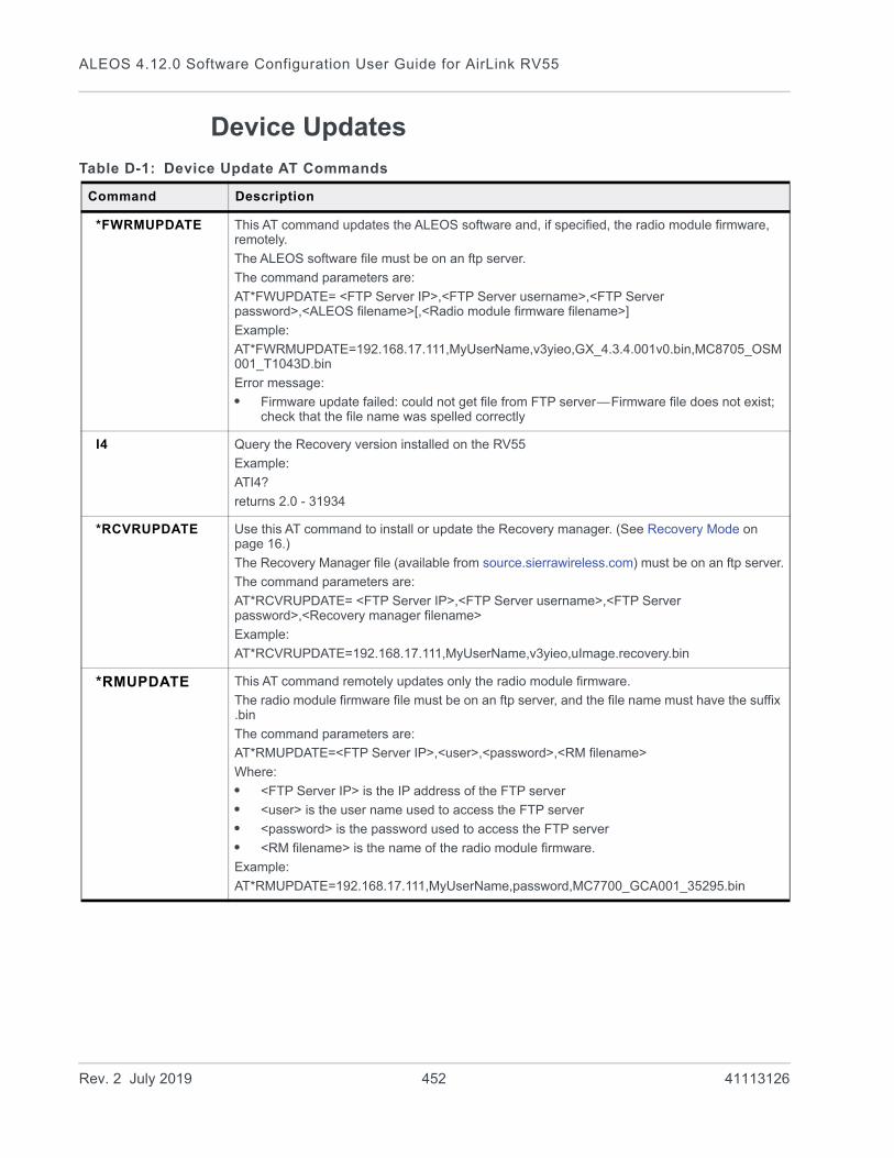
ALEOS 4.12.0 Software Configuration User Guide for AirLink RV55
Device Updates
Table D-1: Device Update AT Commands
Command Description
*FWRMUPDATE This AT command updates the ALEOS software and, if specified, the radio module firmware, remotely.
The ALEOS software file must be on an ftp server.
The command parameters are:
AT*FWUPDATE= <FTP Server IP>,<FTP Server username>,<FTP Server password>,<ALEOS filename>[,<Radio module firmware filename>]
Example:
AT*FWRMUPDATE=192.168.17.111,MyUserName,v3yieo,GX_4.3.4.001v0.bin,MC8705_OSM001_T1043D.bin
Error message:
• Firmware update failed: could not get file from FTP server—Firmware file does not exist; check that the file name was spelled correctly
I4 Query the Recovery version installed on the RV55
Example:
ATI4?
returns 2.0 - 31934
*RCVRUPDATE Use this AT command to install or update the Recovery manager. (See Recovery Mode on page 16.)
The Recovery Manager file (available from source.sierrawireless.com) must be on an ftp server.
The command parameters are:
AT*RCVRUPDATE= <FTP Server IP>,<FTP Server username>,<FTP Server password>,<Recovery manager filename>
Example:
AT*RCVRUPDATE=192.168.17.111,MyUserName,v3yieo,uImage.recovery.bin
*RMUPDATE This AT command remotely updates only the radio module firmware.
The radio module firmware file must be on an ftp server, and the file name must have the suffix .bin
The command parameters are:
AT*RMUPDATE=<FTP Server IP>,<user>,<password>,<RM filename>
Where:
• <FTP Server IP> is the IP address of the FTP server
• <user> is the user name used to access the FTP server
• <password> is the password used to access the FTP server
• <RM filename> is the name of the radio module firmware.
Example:
AT*RMUPDATE=192.168.17.111,MyUserName,password,MC7700_GCA001_35295.bin
Rev. 2 July 2019 452 41113126

AT Commands
*RMFWSWITCH This AT command switches the current radio module firmware to the radio module firmware specified by the AT command.
The radio module firmware file must be stored on the RV55. For more information, see Radio Module Firmware on page 378.
The command parameters are:
AT*RMFWSWITCH=<Network Operator>
Where:
• <Network Operator> is the network operator associated with the radio module firmware to which you want to switch. For example, att, generic, etc. (case insensitive).
Example:
AT*RMFWSWITCH=att
*TPLUPDATE This AT command updates the template (configuration file) remotely.
The template file must be accessible on an FTP server.
The command parameters are:
AT*TPLUPDATE=<Server_IP>,<USER_NAME>,<PASSWORD>,<FILE_NAME>
where:
• SERVER_IP is the IP address of the FTP server.
• USER_NAME is the user name used to access the FTP server.
• PASSWORD is the password used to access the FTP server.
• FILE_NAME is the name of the template file on the FTP server that you want to apply to the AirLink RV55. The template file must be stored on the FTP User_Name home, not in a sub-folder.
Example:
AT*TPLUPDATE=192.168.17.111,MyUserName,MyPassword,NewTemplate.xml
When the template is successfully applied, the message displayed is:
Template applied successfullyOK
Note: Configure the FTP server:
• As passive mode (not active mode)
• To listen to port 21
Table D-1: Device Update AT Commands
Command Description
Rev. 2 July 2019 453 41113126
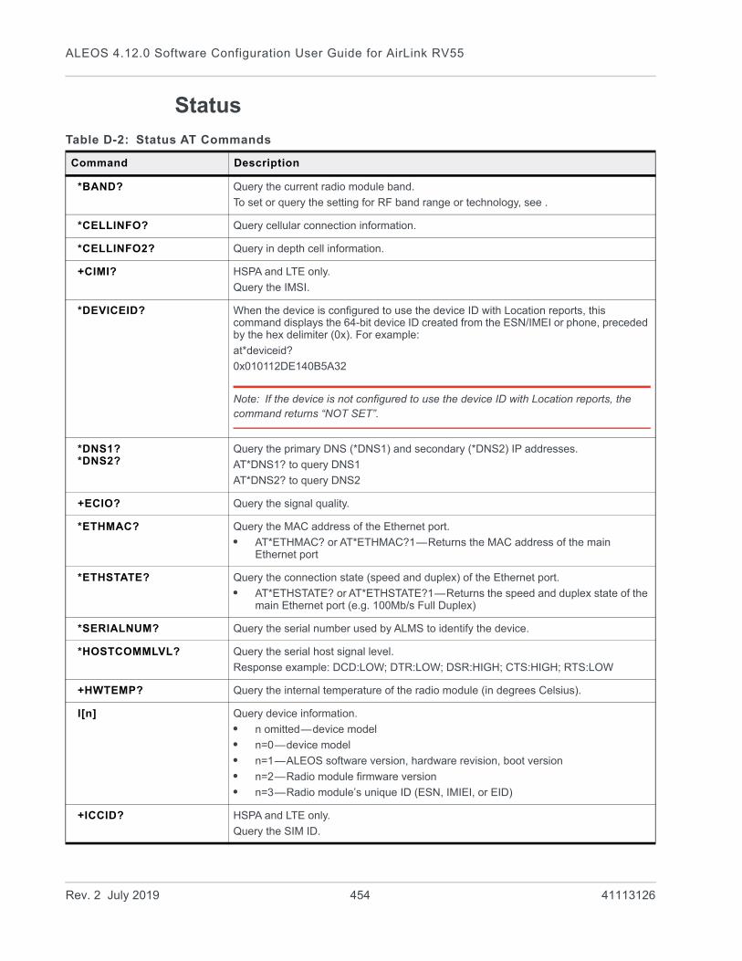
ALEOS 4.12.0 Software Configuration User Guide for AirLink RV55
Status
Table D-2: Status AT Commands
Command Description
*BAND? Query the current radio module band.
To set or query the setting for RF band range or technology, see .
*CELLINFO? Query cellular connection information.
*CELLINFO2? Query in depth cell information.
+CIMI? HSPA and LTE only.
Query the IMSI.
*DEVICEID? When the device is configured to use the device ID with Location reports, this command displays the 64-bit device ID created from the ESN/IMEI or phone, preceded by the hex delimiter (0x). For example:
at*deviceid?
0x010112DE140B5A32
Note: If the device is not configured to use the device ID with Location reports, the command returns “NOT SET”.
*DNS1?*DNS2?
Query the primary DNS (*DNS1) and secondary (*DNS2) IP addresses.
AT*DNS1? to query DNS1
AT*DNS2? to query DNS2
+ECIO? Query the signal quality.
*ETHMAC? Query the MAC address of the Ethernet port.
• AT*ETHMAC? or AT*ETHMAC?1—Returns the MAC address of the main Ethernet port
*ETHSTATE? Query the connection state (speed and duplex) of the Ethernet port.
• AT*ETHSTATE? or AT*ETHSTATE?1—Returns the speed and duplex state of the main Ethernet port (e.g. 100Mb/s Full Duplex)
*SERIALNUM? Query the serial number used by ALMS to identify the device.
*HOSTCOMMLVL? Query the serial host signal level.
Response example: DCD:LOW; DTR:LOW; DSR:HIGH; CTS:HIGH; RTS:LOW
+HWTEMP? Query the internal temperature of the radio module (in degrees Celsius).
I[n] Query device information.
• n omitted—device model
• n=0—device model
• n=1—ALEOS software version, hardware revision, boot version
• n=2—Radio module firmware version
• n=3—Radio module’s unique ID (ESN, IMIEI, or EID)
+ICCID? HSPA and LTE only.
Query the SIM ID.
Rev. 2 July 2019 454 41113126
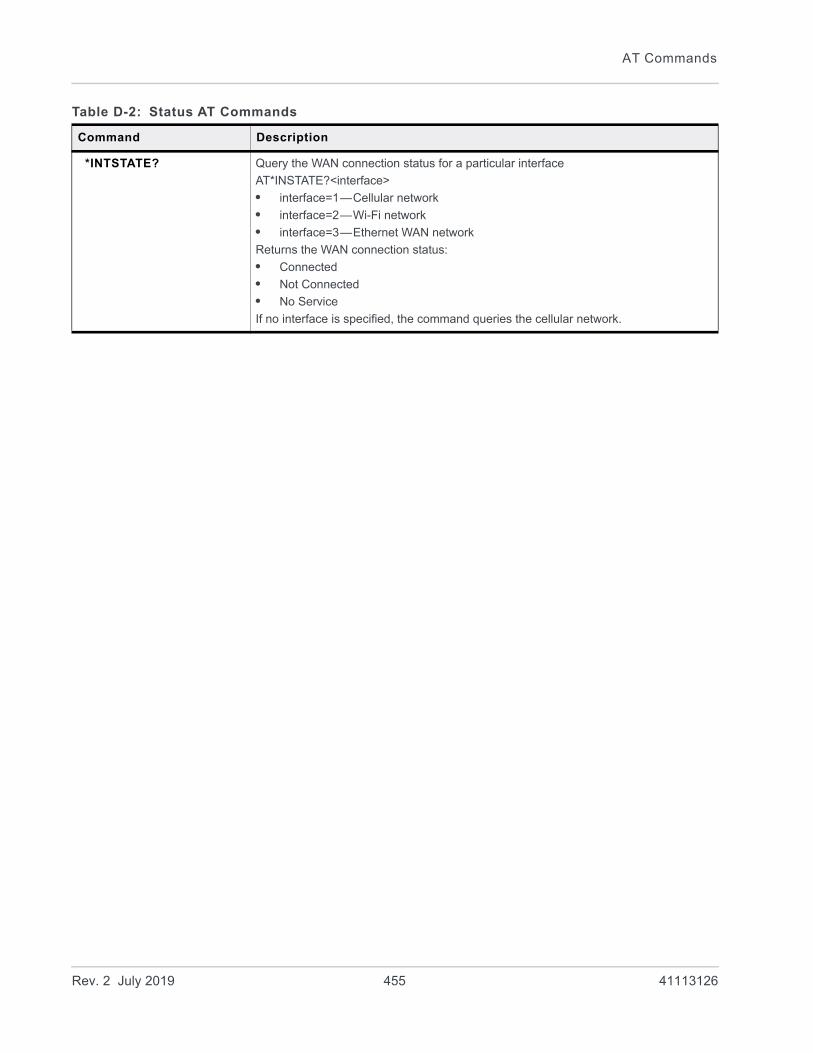
AT Commands
*INTSTATE? Query the WAN connection status for a particular interface
AT*INSTATE?<interface>
• interface=1—Cellular network
• interface=2—Wi-Fi network
• interface=3—Ethernet WAN network
Returns the WAN connection status:
• Connected
• Not Connected
• No Service
If no interface is specified, the command queries the cellular network.
Table D-2: Status AT Commands
Command Description
Rev. 2 July 2019 455 41113126
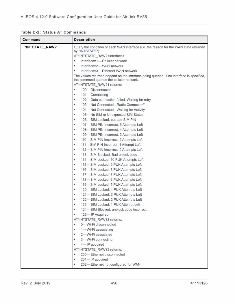
ALEOS 4.12.0 Software Configuration User Guide for AirLink RV55
*INTSTATE_RAW? Query the condition of each WAN interface (i.e. the reason for the WAN state returned by *INTSTATE?)
AT*INTSTATE_RAW?<interface>
• interface=1—Cellular network
• interface=2—Wi-Fi network
• interface=3—Ethernet WAN network
The values returned depend on the interface being queried. If no interface is specified, the command queries the cellular network.
AT*INTSTATE_RAW?1 returns:
• 100—Disconnected
• 101—Connecting
• 102—Data connection failed. Waiting for retry
• 103—Not Connected - Radio Connect off
• 104—Not Connected - Waiting for Activity
• 105—No SIM or Unexpected SIM Status
• 106—SIM Locked, but bad SIM PIN
• 107—SIM PIN Incorrect, 5 Attempts Left
• 108—SIM PIN Incorrect, 4 Attempts Left
• 109—SIM PIN Incorrect, 3 Attempts Left
• 110—SIM PIN Incorrect, 2 Attempts Left
• 111—SIM PIN Incorrect, 1 Attempt Left
• 112—SIM PIN Incorrect, 0 Attempts Left
• 113—SIM Blocked, Bad unlock code
• 114—SIM Locked: 10 PUK Attempts Left
• 115—SIM Locked: 9 PUK Attempts Left
• 116—SIM Locked: 8 PUK Attempts Left
• 117—SIM Locked: 7 PUK Attempts Left
• 118—SIM Locked: 6 PUK Attempts Left
• 119—SIM Locked: 5 PUK Attempts Left
• 120—SIM Locked: 4 PUK Attempts Left
• 121—SIM Locked: 3 PUK Attempts Left
• 122—SIM Locked: 2 PUK Attempts Left
• 123—SIM Locked: 1 PUK Attempt Left
• 124—SIM Blocked, unblock code incorrect
• 125— IP Acquired
AT*INTSTATE_RAW?2 returns:
• 0—Wi-Fi disconnected
• 1—Wi-Fi associating
• 2—Wi-Fi associated
• 3—Wi-Fi connecting
• 4—IP acquired
AT*INTSTATE_RAW?3 returns:
• 200—Ethernet disconnected
• 201—IP acquired
• 202—Ethernet not configured for WAN
Table D-2: Status AT Commands
Command Description
Rev. 2 July 2019 456 41113126
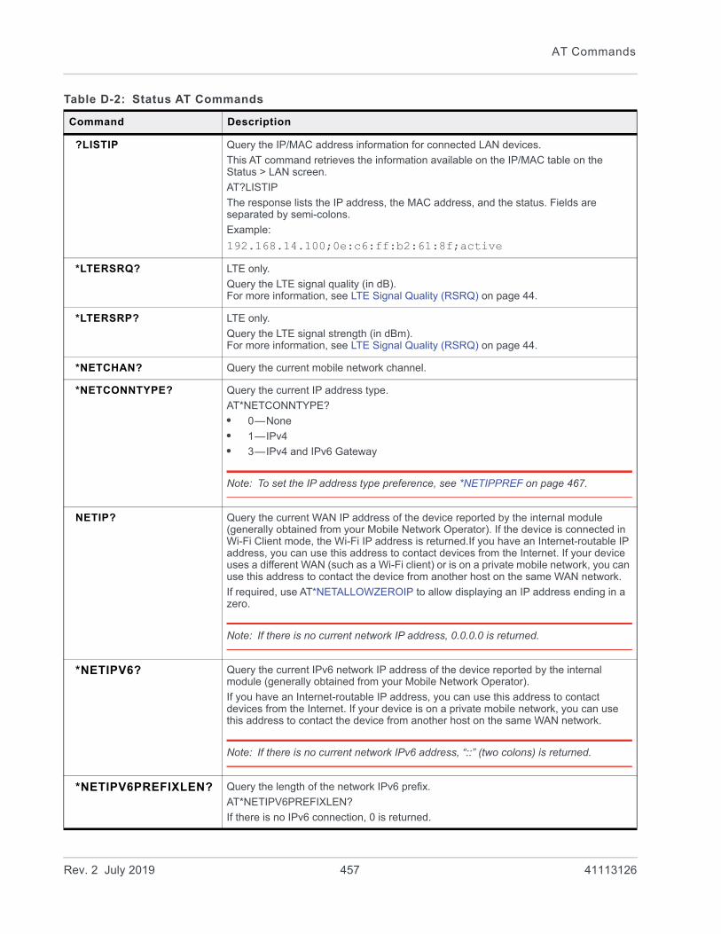
AT Commands
?LISTIP Query the IP/MAC address information for connected LAN devices.
This AT command retrieves the information available on the IP/MAC table on the Status > LAN screen.
AT?LISTIP
The response lists the IP address, the MAC address, and the status. Fields are separated by semi-colons.
Example:
192.168.14.100;0e:c6:ff:b2:61:8f;active
*LTERSRQ? LTE only.
Query the LTE signal quality (in dB).For more information, see LTE Signal Quality (RSRQ) on page 44.
*LTERSRP? LTE only.
Query the LTE signal strength (in dBm).For more information, see LTE Signal Quality (RSRQ) on page 44.
*NETCHAN? Query the current mobile network channel.
*NETCONNTYPE? Query the current IP address type.
AT*NETCONNTYPE?
• 0—None
• 1—IPv4
• 3—IPv4 and IPv6 Gateway
Note: To set the IP address type preference, see *NETIPPREF on page 467.
NETIP? Query the current WAN IP address of the device reported by the internal module (generally obtained from your Mobile Network Operator). If the device is connected in Wi-Fi Client mode, the Wi-Fi IP address is returned.If you have an Internet-routable IP address, you can use this address to contact devices from the Internet. If your device uses a different WAN (such as a Wi-Fi client) or is on a private mobile network, you can use this address to contact the device from another host on the same WAN network.
If required, use AT*NETALLOWZEROIP to allow displaying an IP address ending in a zero.
Note: If there is no current network IP address, 0.0.0.0 is returned.
*NETIPV6? Query the current IPv6 network IP address of the device reported by the internal module (generally obtained from your Mobile Network Operator).
If you have an Internet-routable IP address, you can use this address to contact devices from the Internet. If your device is on a private mobile network, you can use this address to contact the device from another host on the same WAN network.
Note: If there is no current network IPv6 address, “::” (two colons) is returned.
*NETIPV6PREFIXLEN? Query the length of the network IPv6 prefix.
AT*NETIPV6PREFIXLEN?
If there is no IPv6 connection, 0 is returned.
Table D-2: Status AT Commands
Command Description
Rev. 2 July 2019 457 41113126

ALEOS 4.12.0 Software Configuration User Guide for AirLink RV55
*NETOP? Query the Mobile Network Operator of the active connection. If you are roaming, the roaming operator is returned, if the home operator allows this.
*NETPHONE? Query the device's cellular phone number, if applicable or obtainable.
*NETRSSI? Query the current RSSI (Receive Signal Strength Indicator) for non-LTE cellular connections, as a negative dBm value.
*NETSERV? Query the current connection type (e.g., LTE, HSPA+, etc.).
*NETSERVICE_RAW? Query the numeric value for the network service type.
• 8—2G (GPRS)
• 10—2G roaming
• 16—3G (HSPA, HSPA+, UMTS)
• 18—3G roaming
• 64—4G
*NETSTATE? Query the network state of the current WAN connection.
AT*NETSTATE? returns:
• Network Ready—The RV55 is connected to the WAN network and ready to send data.
• Network Ready - Wi-Fi —The RV55 is connected to a Wi-Fi network in client mode.
• Network Ready - Ethernet —The RV55 is connected to an Ethernet WAN network.
• Network Link Down — The network link is not available.
• No Service—There is no mobile network detected.
*NETSTATE_RAW? Query the network state of the current WAN connection.
AT*NETSTATE_RAW? returns:
• 5—Network Ready (The RV55 is connected to the WAN network and ready to send data.)
• 29—Network Ready - Wi-Fi (The RV55 is connected to a Wi-Fi network in client mode.)
• 34—Network Ready - Ethernet (The RV55 is connected to an Ethernet WAN network.)
• 0—Network Link Down (The network link is not available.)
• 7—No Service (There is no mobile network detected.)
*USBNETSTATE? Query the status of the USB connection.
AT*USBNETSTATE? returns:
• None—There are no USB connections to the AirLink RV55.
• 8 MB/s Half Duplex—There is a USB connection to the device.
*WANUPTIME? Query the time in minutes from which the cellular IP is obtained from the mobile network.
AT*WANUPTIME?
Table D-2: Status AT Commands
Command Description
Rev. 2 July 2019 458 41113126

AT Commands
WAN/Cellular
A reboot is required before the WAN/Cellular AT Commands described in the following table take effect.
For a complete alphabetical list of WAN/Cellular AT Commands, see Table D-4. The following table provides a summary or SIM-card-related AT Commands for gateways with more than one SIM card slot. Click the AT Command for a detailed description.
Table D-3: Summary of SIM Card AT Commands
Command What it does
*NBSIMPRESENT? Queries the number of SIMs present
*SIM1PRESENT? Queries whether or not there is a SIM card in slot 1 (upper slot)
*SIM2PRESENT? Queries whether or not there is a SIM card in slot 2 (lower slot)
*PRIMARYSIM Queries or sets which slot contains the Primary SIM card
*ACTIVESIM? Queries which slot contains the active SIM
*SWITCHSIM Switches the Active SIM to the one in the other SIM slot
*NETPW Queries or sets the network password for the Active SIM
*NETPWSIM1 Queries or sets the network password for the SIM card in slot 1
*NETPWSIM2 Queries or sets the network password for the SIM card in slot 2
*NETUID Queries or sets the network user ID for the Active SIM
*NETUIDSIM1 Queries or sets the network user ID for the SIM card in slot 1
*NETUIDSIM2 Queries or sets the network user ID for the SIM card in slot 2
*NETAPN Queries or sets the user entered APN for the Active SIM
*SIM1NETAPN Queries or sets the user entered APN for the SIM card in slot 1
*SIM2NETAPN Queries or sets the user entered APN for the SIM card in slot 2
*SIMPINENABLE Queries, enables, or disables the ALEOS SIM PIN feature for the Active SIM. When enabled, ALEOS automatically enters the SIM PIN requested by the SIM card when the gateway starts up.
*SIM1PINENABLE Queries, enables, or disables the ALEOS SIM PIN feature for the SIM card in slot 1. When enabled, ALEOS automatically enters the SIM PIN requested by the SIM card when the gateway starts up.
*SIM2PINENABLE Queries, enables, or disables the ALEOS SIM PIN feature for the SIM card in slot 2. When enabled, ALEOS automatically enters the SIM PIN requested by the SIM card when the gateway starts up.
*SIMPIN Sets the SIM PIN that ALEOS automatically enters for the Active SIM if the ALEOS SIM PIN feature is enabled. This should match the SIM PIN set on the SIM card, either by the mobile network operator or by using *CHGSIMPIN.
Rev. 2 July 2019 459 41113126
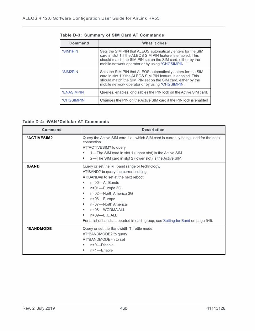
ALEOS 4.12.0 Software Configuration User Guide for AirLink RV55
*SIM1PIN Sets the SIM PIN that ALEOS automatically enters for the SIM card in slot 1 if the ALEOS SIM PIN feature is enabled. This should match the SIM PIN set on the SIM card, either by the mobile network operator or by using *CHGSIMPIN.
*SIM2PIN Sets the SIM PIN that ALEOS automatically enters for the SIM card in slot 1 if the ALEOS SIM PIN feature is enabled. This should match the SIM PIN set on the SIM card, either by the mobile network operator or by using *CHGSIMPIN.
*ENASIMPIN Queries, enables, or disables the PIN lock on the Active SIM card.
*CHGSIMPIN Changes the PIN on the Active SIM card if the PIN lock is enabled
Table D-3: Summary of SIM Card AT Commands
Command What it does
Table D-4: WAN / Cellular AT Commands
Command Description
*ACTIVESIM? Query the Active SIM card, i.e., which SIM card is currently being used for the data connection.
AT*ACTIVESIM? to query
• 1—The SIM card in slot 1 (upper slot) is the Active SIM.
• 2—The SIM card in slot 2 (lower slot) is the Active SIM.
!BAND Query or set the RF band range or technology.
AT!BAND? to query the current setting
AT!BAND=n to set at the next reboot.
• n=00—All Bands
• n=01—Europe 3G
• n=02—North America 3G
• n=06—Europe
• n=07—North America
• n=08—WCDMA ALL
• n=09—LTE ALL
For a list of bands supported in each group, see Setting for Band on page 545.
*BANDMODE Query or set the Bandwidth Throttle mode.
AT*BANDMODE? to query
AT*BANDMODE=n to set
• n=0—Disable
• n=1—Enable
Rev. 2 July 2019 460 41113126
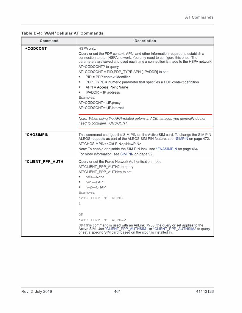
AT Commands
+CGDCONT HSPA only.
Query or set the PDP context, APN, and other information required to establish a connection to o an HSPA network. You only need to configure this once. The parameters are saved and used each time a connection is made to the HSPA network.
AT+CGDCONT? to query
AT+CGDCONT = PID,PDP_TYPE,APN [,IPADDR] to set
• PID = PDP context identifier
• PDP_TYPE = numeric parameter that specifies a PDP context definition
• APN = Access Point Name
• IPADDR = IP address
Examples:
AT+CGDCONT=1,IP,proxy
AT+CGDCONT=1,IP,internet
Note: When using the APN-related optons in ACEmanager, you generally do not need to configure +CGDCONT.
*CHGSIMPIN This command changes the SIM PIN on the Active SIM card. To change the SIM PIN ALEOS requests as part of the ALEOS SIM PIN feature, see *SIMPIN on page 472.
AT*CHGSIMPIN=<Old PIN>,<NewPIN>
Note: To enable or disable the SIM PIN lock, see *ENASIMPIN on page 464.
For more information, see SIM PIN on page 92.
*CLIENT_PPP_AUTH Query or set the Force Network Authentication mode.
AT*CLIENT_PPP_AUTH? to query
AT*CLIENT_PPP_AUTH=n to set
• n=0—None
• n=1—PAP
• n=2—CHAP
Examples:
*ATCLIENT_PPP_AUTH?1
OK*ATCLIENT_PPP_AUTH=2OKIf this command is used with an AirLink RV55, the query or set applies to the Active SIM. Use *CLIENT_PPP_AUTHSIM1 or *CLIENT_PPP_AUTHSIM2 to query or set a specific SIM card, based on the slot it is installed in.
Table D-4: WAN / Cellular AT Commands
Command Description
Rev. 2 July 2019 461 41113126

ALEOS 4.12.0 Software Configuration User Guide for AirLink RV55
*CLIENT_PPP_AUTHSIM1 Query or set the Force Network Authentication mode for the SIM card in Slot 1 (upper slot).
AT*CLIENT_PPP_AUTHSIM1? to query
AT*CLIENT_PPP_AUTHSIM1=n to set
• n=0—None
• n=1—PAP
• n=2—CHAP
Examples:
*ATCLIENT_PPP_AUTHSIM1?1
OK*ATCLIENT_PPP_AUTHSIM1=2OK
*CLIENT_PPP_AUTHSIM2 Query or set the Force Network Authentication mode for the SIM card in Slot 2 (lower slot).
AT*CLIENT_PPP_AUTHSIM2? to query
AT*CLIENT_PPP_AUTHSIM2=n to set
• n=0—None
• n=1—PAP
• n=2—CHAP
Examples:
*ATCLIENT_PPP_AUTHSIM2?1
OK*ATCLIENT_PPP_AUTHSIM2=0OK
Table D-4: WAN / Cellular AT Commands
Command Description
Rev. 2 July 2019 462 41113126
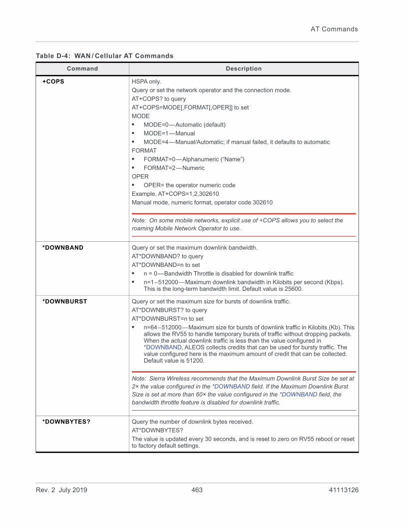
AT Commands
+COPS HSPA only.
Query or set the network operator and the connection mode.
AT+COPS? to query
AT+COPS=MODE[,FORMAT[,OPER]] to set
MODE
• MODE=0—Automatic (default)
• MODE=1—Manual
• MODE=4—Manual/Automatic; if manual failed, it defaults to automatic
FORMAT
• FORMAT=0—Alphanumeric (“Name”)
• FORMAT=2—Numeric
OPER
• OPER= the operator numeric code
Example, AT+COPS=1,2,302610
Manual mode, numeric format, operator code 302610
Note: On some mobile networks, explicit use of +COPS allows you to select the roaming Mobile Network Operator to use.
*DOWNBAND Query or set the maximum downlink bandwidth.
AT*DOWNBAND? to query
AT*DOWNBAND=n to set
• n = 0—Bandwidth Throttle is disabled for downlink traffic
• n=1–512000—Maximum downlink bandwidth in Kilobits per second (Kbps). This is the long-term bandwidth limit. Default value is 25600.
*DOWNBURST Query or set the maximum size for bursts of downlink traffic.
AT*DOWNBURST? to query
AT*DOWNBURST=n to set
• n=64–512000—Maximum size for bursts of downlink traffic in Kilobits (Kb). This allows the RV55 to handle temporary bursts of traffic without dropping packets. When the actual downlink traffic is less than the value configured in *DOWNBAND, ALEOS collects credits that can be used for bursty traffic. The value configured here is the maximum amount of credit that can be collected. Default value is 51200.
Note: Sierra Wireless recommends that the Maximum Downlink Burst Size be set at 2× the value configured in the *DOWNBAND field. If the Maximum Downlink Burst Size is set at more than 60× the value configured in the *DOWNBAND field, the bandwidth throttle feature is disabled for downlink traffic.
*DOWNBYTES? Query the number of downlink bytes received.
AT*DOWNBYTES?
The value is updated every 30 seconds, and is reset to zero on RV55 reboot or reset to factory default settings.
Table D-4: WAN / Cellular AT Commands
Command Description
Rev. 2 July 2019 463 41113126
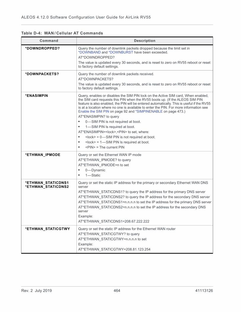
ALEOS 4.12.0 Software Configuration User Guide for AirLink RV55
*DOWNDROPPED? Query the number of downlink packets dropped because the limit set in *DOWNBAND and *DOWNBURST have been exceeded.
AT*DOWNDROPPED?
The value is updated every 30 seconds, and is reset to zero on RV55 reboot or reset to factory default settings.
*DOWNPACKETS? Query the number of downlink packets received.
AT*DOWNPACKETS?
The value is updated every 30 seconds, and is reset to zero on RV55 reboot or reset to factory default settings.
*ENASIMPIN Query, enables or disables the SIM PIN lock on the Active SIM card, When enabled, the SIM card requests this PIN when the RV55 boots up. (If the ALEOS SIM PIN feature is also enabled, the PIN will be entered automatically. This is useful if the RV55 is at a location where no one is available to enter the PIN. For more information see Enable the SIM PIN on page 92 and *SIMPINENABLE on page 473.)
AT*ENASIMPIN? to query
• 0—SIM PIN is not required at boot.
• 1—SIM PIN ls required at boot.
AT*ENASIMPIN=<lock>,<PIN> to set, where:
• <lock> = 0—SIM PIN is not required at boot.
• <lock> = 1—SIM PIN ls required at boot.
• <PIN> = The current PIN
*ETHWAN_IPMODE Query or set the Ethernet WAN IP mode
AT*ETHWAN_IPMODE? to query
AT*ETHWAN_IPMODE=n to set
• 0—Dynamic
• 1—Static
*ETHWAN_STATICDNS1*ETHWAN_STATICDNS2
Query or set the static IP address for the primary or secondary Ethernet WAN DNS server
AT*ETHWAN_STATICDNS1? to query the IP address for the primary DNS server
AT*ETHWAN_STATICDNS2? to query the IP address for the secondary DNS server
AT*ETHWAN_STATICDNS1=n.n.n.n to set the IP address for the primary DNS server
AT*ETHWAN_STATICDNS2=n.n.n.n to set the IP address for the secondary DNS server
Example:
AT*ETHWAN_STATICDNS1=208.67.222.222
*ETHWAN_STATICGTWY Query or set the static IP address for the Ethernet WAN router
AT*ETHWAN_STATICGTWY? to query
AT*ETHWAN_STATICGTWY=n.n.n.n to set
Example:
AT*ETHWAN_STATICGTWY=208.81.123.254
Table D-4: WAN / Cellular AT Commands
Command Description
Rev. 2 July 2019 464 41113126
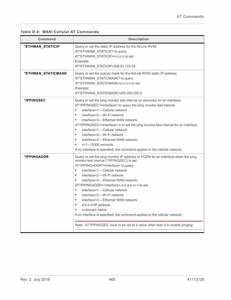
AT Commands
*ETHWAN_STATICIP Query or set the static IP address for the AirLink RV55
AT*ETHWAN_STATICIP? to query
AT*ETHWAN_STATICIP=n.n.n.n to set
Example:
AT*ETHWAN_STATICIP=208.81.123.34
*ETHWAN_STATICMASK Query or set the subnet mask for the AirLink RV55 static IP address
AT*ETHWAN_STATICMASK? to query
AT*ETHWAN_STATICMASK=n.n.n.n to set
Example:
AT*ETHWAN_STATICMASK=255.255.255.0
*IPPINGSEC Query or set the ping monitor test interval (in seconds) for an interface.
AT*IPPINGSEC?<interface> to query the ping monitor test interval
• interface=1—Cellular network
• interface=2—Wi-Fi network
• interface=3—Ethernet WAN network
AT*IPPINGSEC=<interface>,n to set the ping monitor test interval for an interface
• interface=1—Cellular network
• interface=2—Wi-Fi network
• interface=3—Ethernet WAN network
• n=1–15300 seconds
If no interface is specified, the command applies to the cellular network.
*IPPINGADDR Query or set the ping monitor IP address or FQDN for an interface when the ping monitor test interval (*IPPINGSEC) is set.
AT*IPPINGADDR?<interface> to query
• interface=1—Cellular network
• interface=2—Wi-Fi network
• interface=3—Ethernet WAN network
AT*IPPINGADDR=<interface>,d.d.d.d or n to set
• interface=1—Cellular network
• interface=2—Wi-Fi network
• interface=3—Ethernet WAN network
• d.d.d.d=IP address
• n=domain name
If no interface is specified, the command applies to the cellular network.
Note: AT*IPPINGSEC must to be set to a value other than 0 to enable pinging.
Table D-4: WAN / Cellular AT Commands
Command Description
Rev. 2 July 2019 465 41113126
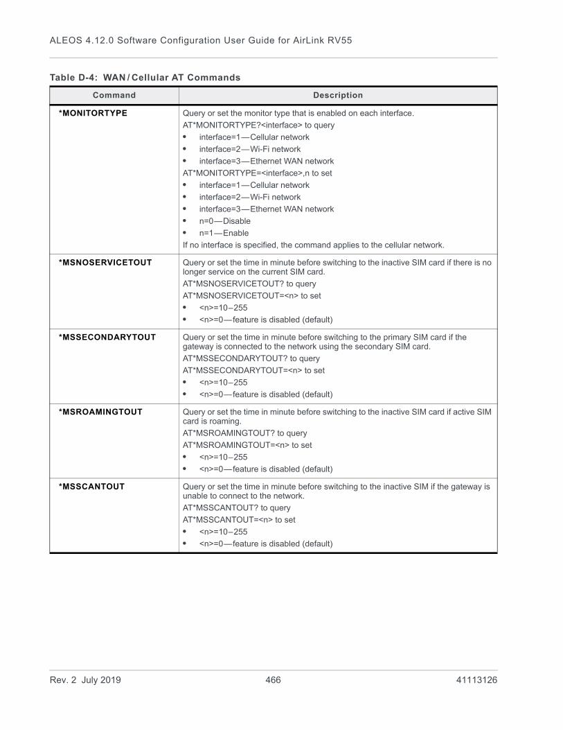
ALEOS 4.12.0 Software Configuration User Guide for AirLink RV55
*MONITORTYPE Query or set the monitor type that is enabled on each interface.
AT*MONITORTYPE?<interface> to query
• interface=1—Cellular network
• interface=2—Wi-Fi network
• interface=3—Ethernet WAN network
AT*MONITORTYPE=<interface>,n to set
• interface=1—Cellular network
• interface=2—Wi-Fi network
• interface=3—Ethernet WAN network
• n=0—Disable
• n=1—Enable
If no interface is specified, the command applies to the cellular network.
*MSNOSERVICETOUT Query or set the time in minute before switching to the inactive SIM card if there is no longer service on the current SIM card.
AT*MSNOSERVICETOUT? to query
AT*MSNOSERVICETOUT=<n> to set
• <n>=10–255
• <n>=0—feature is disabled (default)
*MSSECONDARYTOUT Query or set the time in minute before switching to the primary SIM card if the gateway is connected to the network using the secondary SIM card.
AT*MSSECONDARYTOUT? to query
AT*MSSECONDARYTOUT=<n> to set
• <n>=10–255
• <n>=0—feature is disabled (default)
*MSROAMINGTOUT Query or set the time in minute before switching to the inactive SIM card if active SIM card is roaming.
AT*MSROAMINGTOUT? to query
AT*MSROAMINGTOUT=<n> to set
• <n>=10–255
• <n>=0—feature is disabled (default)
*MSSCANTOUT Query or set the time in minute before switching to the inactive SIM if the gateway is unable to connect to the network.
AT*MSSCANTOUT? to query
AT*MSSCANTOUT=<n> to set
• <n>=10–255
• <n>=0—feature is disabled (default)
Table D-4: WAN / Cellular AT Commands
Command Description
Rev. 2 July 2019 466 41113126

AT Commands
*NBSIMPRESENT? Query the number of SIM cards installed in the gateway.
AT*NBSIMPRESENT? to query
Example:
AT*NBSIMPRESENT?<number of SIM cards present>
OKResponse:
• 1—One SIM card installed
• 2—Two SIM cards installed
*NETALLOWZEROIP Query or set allowing the device to get an IP address from the mobile network that has the last octet as 0 (zero).
AT*NETALLOWZEROIP? to query
AT*NETALLOWZEROIP=n to set
• n=0—Do not allow
• n=1—Allow Allows the device to use a WAN IP address that ends in zero (e.g. 192.168.1.0).
*NETAPN Query or set the user entered APN.
AT*NETAPN? to query
AT*NETAPN=<apn> to set (up to 80 characters)
Examples:
AT*NETAPN?<apn>
OKAT*NETAPN=<apn>OKWhen you set this command, the APN type is automatically set to User Entry so that the APN you enter with this AT command is used on reboot. If this command is used with an AirLink RV55, the query or set applies to the Active SIM. Use *SIM1NETAPN or *SIM2NETAPN to query or set a specific SIM card, based on the slot it is installed in.
*NETIPPREF Query or set the IP Address Preference.
Note: To use IPv6, it must be supported by your Mobile Network Operators and your account (SIM and APN).
AT*NETIPPREF? to query
AT*NETIPPREF=n to set
• n=0—IPv4
• n=1—IPv4 and IPv6 Gateway
To determine the current network IP type, see *NETCONNTYPE? on page 457.
Table D-4: WAN / Cellular AT Commands
Command Description
Rev. 2 July 2019 467 41113126

ALEOS 4.12.0 Software Configuration User Guide for AirLink RV55
*NETPW Query or set the mobile network account password.
AT*NETPW? to query
AT*NETPW=<password> to set (up to 128 characters)
Note: AT*NETPW? returns asterisks (****) for privacy.
Examples:
ATNETPW?*******
OKAT*NETPW=<password>OKIf this command is used with an AirLink RV55, the query or set applies to the Active SIM. Use *NETPWSIM1 or *NETPWSIM2 to query or set a specific SIM card, based on the slot it is installed in.
*NETPWSIM1 Query or set the mobile network account password for the SIM card in Slot 1 (upper slot).
AT*NETPWSIM1? to query
AT*NETPWSIM1=<password> to set (up to 128 characters)
Note: AT*NETPWSIM1? returns asterisks (****) for privacy.
Examples:
ATNETPWSIM1?*******
OKAT*NETPWSIM1=<password>OK
*NETPWSIM2 Query or set the mobile network account password for the SIM card in Slot 2 (lower slot).
AT*NETPWSIM2? to query
AT*NETPWSIM2=<password> to set (up to 128 characters)
Note: AT*NETPW? returns asterisks (****) for privacy.
Examples:
ATNETPWSIM2?*******
OKAT*NETPWSIM2=<password>OK
Table D-4: WAN / Cellular AT Commands
Command Description
Rev. 2 July 2019 468 41113126

AT Commands
*NETUID Query or set the mobile network account user ID, if required.
AT*NETUID? to query
• AT*NETUID=<uid>(up to 128 characters)
AT*NETUID?<uid>
OKAT*NETUID=<uid>OKIf this command is used with an AirLink RV55, the query or set applies to the Active SIM. Use *NETUIDSIM1 or *NETUIDSIM2 to query or set a specific SIM card, based on the slot it is installed in.
*NETUIDSIM1 Query or set the mobile network account user ID for the SIM card in Slot 1 (upper slot).
AT*NETUIDSIM1? to query
AT*NETUIDSIM1=<uid> (up to 128 characters)
Examples:
AT*NETUIDSIM1?<uid>
OKAT*NETUIDSIM1=<uid>OK
*NETUIDSIM2 Query or set the mobile network account user ID for the SIM card in Slot 2 (lower slot).
AT*NETUIDSIM2? to query
AT*NETUIDSIM2=<uid> (up to 128 characters)
Examples:
AT*NETUIDSIM2?<uid>
OKAT*NETUIDSIM2=<uid>OK
Table D-4: WAN / Cellular AT Commands
Command Description
Rev. 2 July 2019 469 41113126
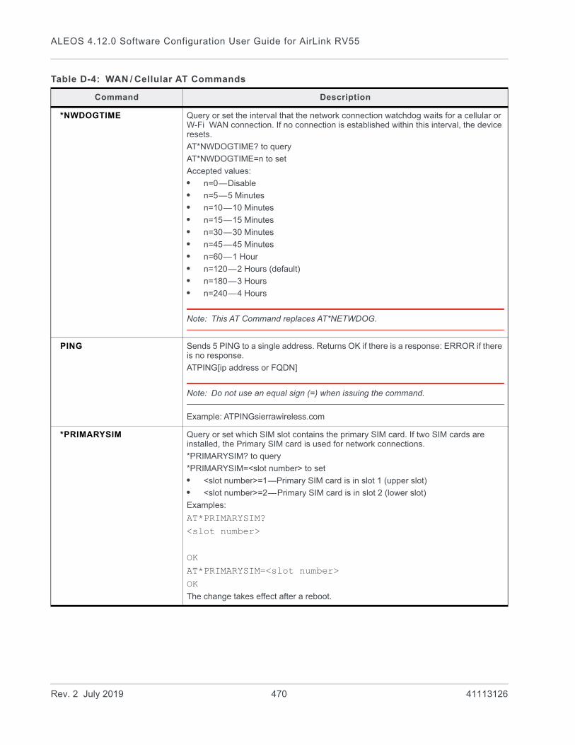
ALEOS 4.12.0 Software Configuration User Guide for AirLink RV55
*NWDOGTIME Query or set the interval that the network connection watchdog waits for a cellular or W-Fi WAN connection. If no connection is established within this interval, the device resets.
AT*NWDOGTIME? to query
AT*NWDOGTIME=n to set
Accepted values:
• n=0—Disable
• n=5—5 Minutes
• n=10—10 Minutes
• n=15—15 Minutes
• n=30—30 Minutes
• n=45—45 Minutes
• n=60—1 Hour
• n=120—2 Hours (default)
• n=180—3 Hours
• n=240—4 Hours
Note: This AT Command replaces AT*NETWDOG.
PING Sends 5 PING to a single address. Returns OK if there is a response: ERROR if there is no response.
ATPING[ip address or FQDN]
Note: Do not use an equal sign (=) when issuing the command.
Example: ATPINGsierrawireless.com
*PRIMARYSIM Query or set which SIM slot contains the primary SIM card. If two SIM cards are installed, the Primary SIM card is used for network connections.
*PRIMARYSIM? to query
*PRIMARYSIM=<slot number> to set
• <slot number>=1—Primary SIM card is in slot 1 (upper slot)
• <slot number>=2—Primary SIM card is in slot 2 (lower slot)
Examples:
AT*PRIMARYSIM?<slot number>
OKAT*PRIMARYSIM=<slot number>OKThe change takes effect after a reboot.
Table D-4: WAN / Cellular AT Commands
Command Description
Rev. 2 July 2019 470 41113126
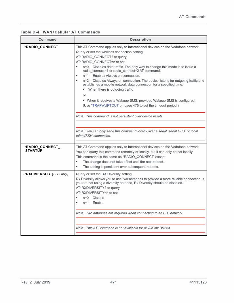
AT Commands
*RADIO_CONNECT This AT Command applies only to International devices on the Vodafone network.
Query or set the wireless connection setting.
AT*RADIO_CONNECT? to query
AT*RADIO_CONNECT=n to set
• n=0—Disables data traffic. The only way to change this mode is to issue a radio_connect=1 or radio_connect=2 AT command.
• n=1—Enables Always on connection.
• n=2—Disables Always on connection. The device listens for outgoing traffic and establishes a mobile network data connection for a specified time:
• When there is outgoing traffic
or
• When it receives a Wakeup SMS, provided Wakeup SMS is configured.
(Use *TRAFWUPTOUT on page 475 to set the timeout period.)
Note: This command is not persistent over device resets.
Note: You can only send this command locally over a serial, serial USB, or local telnet/SSH connection.
*RADIO_CONNECT_STARTUP
This AT Command applies only to International devices on the Vodafone network.
You can query this command remotely or locally, but it can only be set locally.
This command is the same as *RADIO_CONNECT, except
• The change does not take effect until the next reboot.
• The setting is persistent over subsequent reboots.
*RXDIVERSITY (3G Only) Query or set the RX Diversity setting.
Rx Diversity allows you to use two antennas to provide a more reliable connection. If you are not using a diversity antenna, Rx Diversity should be disabled.
AT*RXDIVERSITY? to query
AT*RXDIVERSITY=n to set
• n=0—Disable
• n=1—Enable
Note: Two antennas are required when connecting to an LTE network.
Note: This AT Command is not available for all AirLink RV55s.
Table D-4: WAN / Cellular AT Commands
Command Description
Rev. 2 July 2019 471 41113126

ALEOS 4.12.0 Software Configuration User Guide for AirLink RV55
*SIM1NETAPN Query or set the user entered APN for the SIM card in SIM slot 1 (upper slot).
*SIM1NETAPN? to query
*SIM1NETAPN=<apn> to set the user entered APN (up to 80 characters)
Examples:
AT*SIM1NETAPN?<apn>
OKAT*SIM1NETAPN=<apn>OK
Note: When you set this command, the APN type is automatically set to User Entry so that the APN you enter with this AT command is used on reboot.
*SIM2NETAPN Query or set the user entered APN for the SIM card in SIM slot 2 (lower slot).
*SIM2NETAPN? to query
*SIM2NETAPN=<apn> to set the user entered APN (up to 80 characters)
Examples:
AT*SIM2NETAPN?<apn>
OKAT*SIM2NETAPN=<apn>OK
Note: When you set this command, the APN type is automatically set to User Entry so that the APN you enter with this AT command is used on reboot.
*SIMPIN Sets the SIM PIN that ALEOS automatically entered if the ALEOS SIM PIN feature is enabled. This should match the SIM PIN set on the SIM card, either by the mobile network operator or by using *CHGSIMPIN. See *CHGSIMPIN on page 461.
AT*SIMPIN=<pin> to enter the SIM pin
Example:
AT*SIMPIN=<pin>OKFor the AirLink RV55, this command sets the Active SIM. Use *SIM1PIN or *SIM2PIN to set a specific SIM card, based on the slot it is installed in.
*SIM1PIN Sets the SIM PIN that ALEOS automatically entered for the SIM in slot 1 if the ALEOS SIM PIN feature is enabled. This should match the SIM PIN set on the Active SIM card, either by the mobile network operator or by using *CHGSIMPIN. See *CHGSIMPIN on page 461.
*SIM1PIN=<pin> to enter the SIM PIN
Example:
AT*SIM1PIN=<pin>OK
Table D-4: WAN / Cellular AT Commands
Command Description
Rev. 2 July 2019 472 41113126
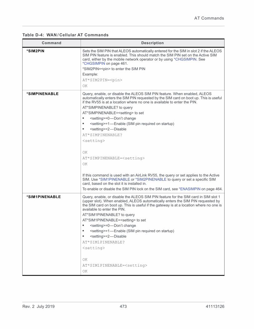
AT Commands
*SIM2PIN Sets the SIM PIN that ALEOS automatically entered for the SIM in slot 2 if the ALEOS SIM PIN feature is enabled. This should match the SIM PIN set on the Active SIM card, either by the mobile network operator or by using *CHGSIMPIN. See *CHGSIMPIN on page 461.
*SIM2PIN=<pin> to enter the SIM PIN
Example:
AT*SIM2PIN=<pin>OK
*SIMPINENABLE Query, enable, or disable the ALEOS SIM PIN feature. When enabled, ALEOS automatically enters the SIM PIN requested by the SIM card on boot up. This is useful if the RV55 is at a location where no one is available to enter the PIN.
AT*SIMPINENABLE? to query
AT*SIMPINENABLE=<setting> to set
• <setting>=0—Don’t change
• <setting>=1—Enable (SIM pin required on startup)
• <setting>=2—Disable
AT*SIMPINENABLE?<setting>
OKAT*SIMPINENABLE=<setting>OK
If this command is used with an AirLink RV55, the query or set applies to the Active SIM. Use *SIM1PINENABLE or *SIM2PINENABLE to query or set a specific SIM card, based on the slot it is installed in.
To enable or disable the SIM PIN lock on the SIM card, see *ENASIMPIN on page 464.
*SIM1PINENABLE Query, enable, or disable the ALEOS SIM PIN feature for the SIM card in SIM slot 1 (upper slot). When enabled, ALEOS automatically enters the SIM PIN requested by the SIM card on boot up. This is useful if the gateway is at a location where no one is available to enter the PIN.
AT*SIM1PINENABLE? to query
AT*SIM1PINENABLE=<setting> to set
• <setting>=0—Don’t change
• <setting>=1—Enable (SIM pin required on startup)
• <setting>=2—Disable
AT*SIM1PINENABLE?<setting>
OKAT*SIM1PINENABLE=<setting>OK
Table D-4: WAN / Cellular AT Commands
Command Description
Rev. 2 July 2019 473 41113126

ALEOS 4.12.0 Software Configuration User Guide for AirLink RV55
*SIM2PINENABLE Query, enable, or disable the ALEOS SIM PIN feature for the SIM card in SIM slot 2 (lower slot). When enabled, ALEOS automatically enters the SIM PIN requested by the SIM card on boot up. This is useful if the gateway is at a location where no one is available to enter the PIN.
AT*SIM2PINENABLE? to query
AT*SIM2PINENABLE=<setting> to set
• <setting>=0—Don’t change
• <setting>=1—Enable (SIM pin required on startup)
• <setting>=2—Disable
AT*SIM2PINENABLE?<setting>
OKAT*SIM2PINENABLE=<setting>OK
*SIM1PRESENT? Query whether or not there is a SIM card installed in SIM slot 1.
AT*SIM1PRESENT? to query
• 0—No SIM card in slot 1
• 1—SIM card present in slot 1
Examples:
AT*SIM1PRESENT?<Slot 1 SIM status>
OK
*SIM2PRESENT? Query whether or not there is a SIM card installed in SIM slot 2.
AT*SIM1PRESENT? to query
• 0—No SIM card in slot 2
• 1—SIM card present in slot 2
Examples:
AT*SIM2PRESENT?<Slot 2 SIM status>
OK
*SWITCHSIM Change which SIM card slot contains the active SIM card. If there is no SIM card in the inactive SIM card slot, an error message (“SIM Switching impossible, no SIM in inactive slot”) is returned.
A reboot is not required.
AT*SWITCHSIM switches the active SIM to the other SIM card slot
To determine whether or not there is a SIM card in the inactive SIM card slot, use *SIM2PRESENT? and *SIM1PRESENT?.
Table D-4: WAN / Cellular AT Commands
Command Description
Rev. 2 July 2019 474 41113126
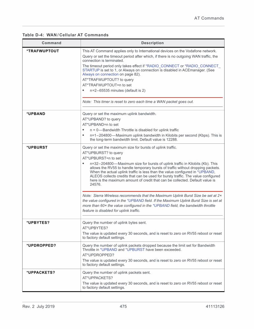
AT Commands
*TRAFWUPTOUT This AT Command applies only to International devices on the Vodafone network.
Query or set the timeout period after which, if there is no outgoing WAN traffic, the connection is terminated.
The timeout period only takes effect if *RADIO_CONNECT or *RADIO_CONNECT_ STARTUP is set to 1, or Always on connection is disabled in ACEmanager. (See Always on connection on page 82).
AT*TRAFWUPTOUT? to query
AT*TRAFWUPTOUT=n to set
• n=2–65535 minutes (default is 2)
Note: This timer is reset to zero each time a WAN packet goes out.
*UPBAND Query or set the maximum uplink bandwidth.
AT*UPBAND? to query
AT*UPBAND=n to set
• n = 0—Bandwidth Throttle is disabled for uplink traffic
• n=1–204800—Maximum uplink bandwidth in Kilobits per second (Kbps). This is the long-term bandwidth limit. Default value is 12288.
*UPBURST Query or set the maximum size for bursts of uplink traffic.
AT*UPBURST? to query
AT*UPBURST=n to set
• n=32–204800—Maximum size for bursts of uplink traffic in Kilobits (Kb). This allows the RV55 to handle temporary bursts of traffic without dropping packets. When the actual uplink traffic is less than the value configured in *UPBAND, ALEOS collects credits that can be used for bursty traffic. The value configured here is the maximum amount of credit that can be collected. Default value is 24576.
Note: Sierra Wireless recommends that the Maximum Uplink Burst Size be set at 2× the value configured in the *UPBAND field. If the Maximum Uplink Burst Size is set at more than 60× the value configured in the *UPBAND field, the bandwidth throttle feature is disabled for uplink traffic.
*UPBYTES? Query the number of uplink bytes sent.
AT*UPBYTES?
The value is updated every 30 seconds, and is reset to zero on RV55 reboot or reset to factory default settings.
*UPDROPPED? Query the number of uplink packets dropped because the limit set for Bandwidth Throttle in *UPBAND and *UPBURST have been exceeded.
AT*UPDROPPED?
The value is updated every 30 seconds, and is reset to zero on RV55 reboot or reset to factory default settings.
*UPPACKETS? Query the number of uplink packets sent.
AT*UPPACKETS?
The value is updated every 30 seconds, and is reset to zero on RV55 reboot or reset to factory default settings.
Table D-4: WAN / Cellular AT Commands
Command Description
Rev. 2 July 2019 475 41113126

ALEOS 4.12.0 Software Configuration User Guide for AirLink RV55
LAN
Note: A reboot is required before these commands take effect.
Table D-5: LAN AT Commands
Command Description
*DHCPHOSTEND Query or set the ending IP address for the Ethernet DHCP pool.
AT*DHCPHOSTEND? to query
AT*DHCPHOSTEND=d.d.d.d to set
• d.d.d.d=last IP address in Ethernet DHCP pool
*DHCPNETMASK Query or set the Ethernet DHCP subnet mask.
AT*DHCPNETMASK? to query
AT*DHCPNETMASK=d.d.d.d to set
• d.d.d.d=Ethernet DHCP subnet mask
*DHCPSERVER Query or set the Ethernet DHCP server.
AT*DHCPSERVER? to query
AT*DHCPSERVER=n to set the DHCP server mode
• n=0—Disable
• n=1—Server
• n=2—Auto
For a description of the settings, see DHCP Mode on page 144.
*DNS1?*DNS2?
Query the primary DNS (*DNS1) and secondary (*DNS2) IP addresses.
AT*DNS1? to query DNS1
AT*DNS2? to query DNS2
*DNSUSER Query or set the first alternate server for DNS override. (Applies only to primary DNS.)
AT*DNSUSER? to query
AT*DNSUSER=d.d.d.d
• d.d.d.d=IP address of domain server
*ETHMODE Query or set the Ethernet port mode
AT*ETHMODE? to query
AT*ETHMODE=n to set
• n = 0—Auto
• n = 1—LAN
• n = 2—WAN
*HOSTAUTH Query or set the Host Authentication mode for PPPoE only. (It does not set host authentication for PPP/DUN.)
AT*HOSTAUTH? to query
AT*HOSTAUTH=n to set
• n=0—None/Disables authentication for PPPoE (default).
• n=1—Authentication through PAP
• n=2—Authentication through PAP & CHAP
Rev. 2 July 2019 476 41113126

AT Commands
*HOSTPEERIP Query or set the IP address of the device’s Ethernet port. By default this is 192.168.13.31.
Note: Any connected LAN device can access this IP addresses, whether using a private or public IP address. This IP address must be in the same subnet as the Ethernet DHCP pool.
AT*HOSTPEERIP? to query
AT*HOSTPEERIP=d.d.d.d to set
• d.d.d.d=local or peer IP address of the device
*HOSTPRIVIP Query or set the starting IP for the Ethernet DHCP pool.
AT*HOSTPRIVIP? to query
AT*HOSTPRIVIP=d.d.d.d to set
• d.d.d.d=IP Address
*HOSTPRIVMODE Activate IP passthrough to the selected interface or query the IP passthrough setting.
AT*HOSTPRIVMODE? to query
AT*HOSTPRIMODE=n to activate IP Passthrough to the selected interface
• n=0— IP passthrough on Ethernet
• n=1— IP passthrough is disabled
• n=2—IP passthrough on USB
• n=3— IP passthrough on main serial port using DUN
*HOSTPW Query or set the host password for PPPoE only. (It does not set the password for PPP/DUN.)
AT*HOSTPW? to query
AT*HOSTPW=PASSWORD to set
Note: PASSWORD cannot be “password”.
*HOSTUID Query or set the Host user ID for PPPoE only. (It does not set the user ID for PPP/DUN.)
AT*HOSTUID? to query
AT*HOSTUID=USER ID to set (up to 64 bytes)
Note: USER ID cannot be “user”.
*USBDEVICE Query or set the startup mode for the USB port.
AT*USBDEVICE? to query
AT*USBDEVICE=n to set
• n=0— USB Serial
• n=1— USBNET
• n=2— Disabled
Table D-5: LAN AT Commands
Command Description
Rev. 2 July 2019 477 41113126
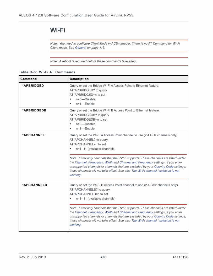
ALEOS 4.12.0 Software Configuration User Guide for AirLink RV55
Wi-Fi
Note: You need to configure Client Mode in ACEmanager. There is no AT Command for Wi-Fi Client mode. See General on page 116.
Note: A reboot is required before these commands take effect.
Table D-6: Wi-Fi AT Commands
Command Description
*APBRIDGED Query or set the Bridge Wi-Fi A Access Point to Ethernet feature.
AT*APBRIDGED? to query
AT*APBRIDGED=n to set
• n=0—Disable
• n=1—Enable
*APBRIDGEDB Query or set the Bridge Wi-Fi B Access Point to Ethernet feature.
AT*APBRIDGEDB? to query
AT*APBRIDGEDB=n to set
• n=0—Disable
• n=1—Enable
*APCHANNEL Query or set the Wi-Fi A Access Point channel to use (2.4 GHz channels only).
AT*APCHANNEL? to query
AT*APCHANNEL=n to set
• n=1–11 (available channels)
Note: Enter only channels that the RV55 supports. These channels are listed under the Channel, Frequency, Width and Channel and Frequency settings. If you enter unsupported channels or channels that are excluded by your Country Code settings, these channels will not take effect. See also The Wi-Fi channel I selected is not working.
*APCHANNELB Query or set the Wi-Fi B Access Point channel to use (2.4 GHz channels only).
AT*APCHANNELB? to query
AT*APCHANNELB=n to set
• n=1–11 (available channels)
Note: Enter only channels that the RV55 supports. These channels are listed under the Channel, Frequency, Width and Channel and Frequency settings. If you enter unsupported channels or channels that are excluded by your Country Code settings, these channels will not take effect. See also The Wi-Fi channel I selected is not working.
Rev. 2 July 2019 478 41113126
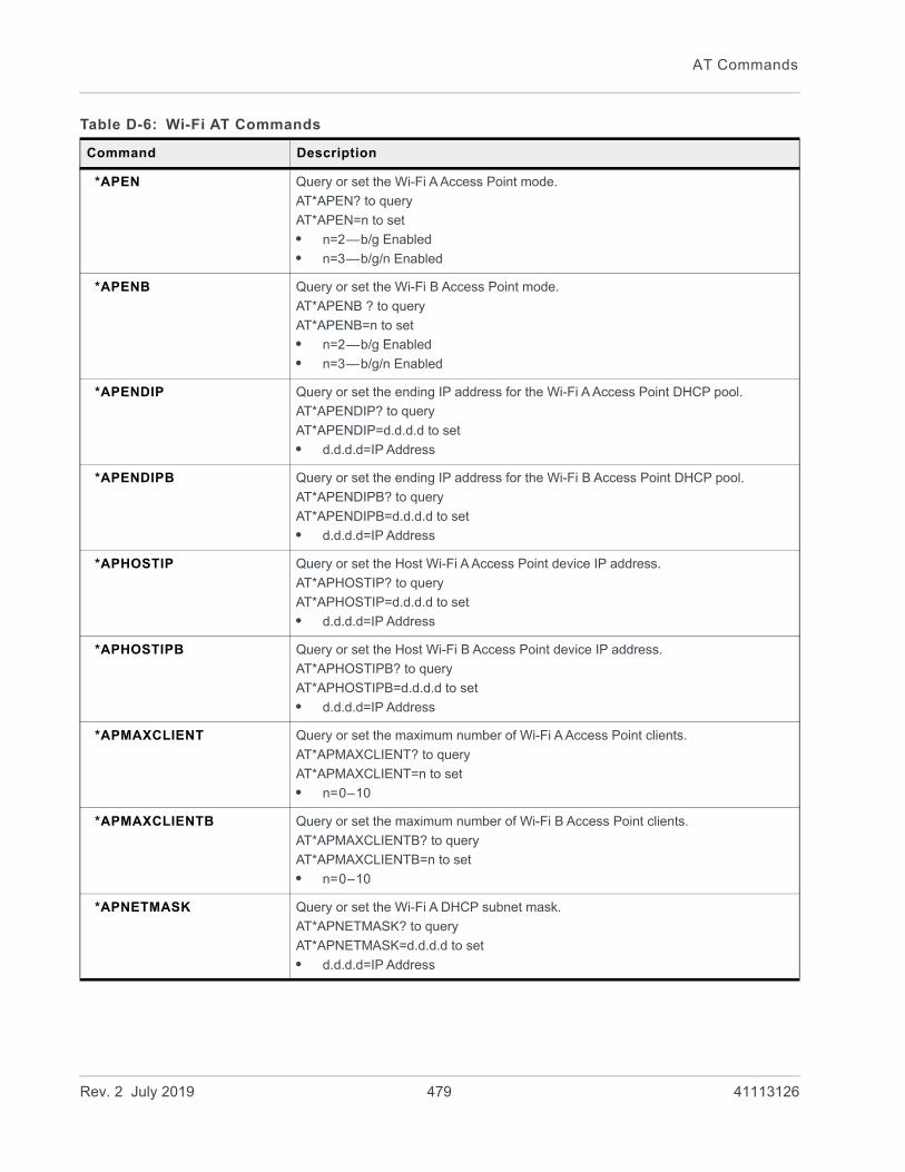
AT Commands
*APEN Query or set the Wi-Fi A Access Point mode.
AT*APEN? to query
AT*APEN=n to set
• n=2—b/g Enabled
• n=3—b/g/n Enabled
*APENB Query or set the Wi-Fi B Access Point mode.
AT*APENB ? to query
AT*APENB=n to set
• n=2—b/g Enabled
• n=3—b/g/n Enabled
*APENDIP Query or set the ending IP address for the Wi-Fi A Access Point DHCP pool.
AT*APENDIP? to query
AT*APENDIP=d.d.d.d to set
• d.d.d.d=IP Address
*APENDIPB Query or set the ending IP address for the Wi-Fi B Access Point DHCP pool.
AT*APENDIPB? to query
AT*APENDIPB=d.d.d.d to set
• d.d.d.d=IP Address
*APHOSTIP Query or set the Host Wi-Fi A Access Point device IP address.
AT*APHOSTIP? to query
AT*APHOSTIP=d.d.d.d to set
• d.d.d.d=IP Address
*APHOSTIPB Query or set the Host Wi-Fi B Access Point device IP address.
AT*APHOSTIPB? to query
AT*APHOSTIPB=d.d.d.d to set
• d.d.d.d=IP Address
*APMAXCLIENT Query or set the maximum number of Wi-Fi A Access Point clients.
AT*APMAXCLIENT? to query
AT*APMAXCLIENT=n to set
• n=0–10
*APMAXCLIENTB Query or set the maximum number of Wi-Fi B Access Point clients.
AT*APMAXCLIENTB? to query
AT*APMAXCLIENTB=n to set
• n=0–10
*APNETMASK Query or set the Wi-Fi A DHCP subnet mask.
AT*APNETMASK? to query
AT*APNETMASK=d.d.d.d to set
• d.d.d.d=IP Address
Table D-6: Wi-Fi AT Commands
Command Description
Rev. 2 July 2019 479 41113126

ALEOS 4.12.0 Software Configuration User Guide for AirLink RV55
*APNETMASKB Query or set the Wi-Fi B DHCP subnet mask.
AT*APNETMASKB? to query
AT*APNETMASKB=d.d.d.d to set
• d.d.d.d=IP Address
*APSECURITYTYPE? Query the Wi-Fi A Access Point Security Encryption type.
AT*APSECURITYTYPE?
• n=0—Open
• n=1—WEP
• n=2—WPA Personal
• n=3—WPA2 Personal
• n=4—WPA2 Enterprise
Note: WEP is not a recommended Wi-Fi Security protocol because of its vulnerabil-ities and because only alphanumeric characters can be used for the passphrase. Use WPA/WPA2 instead.
*APSECURITYTYPEB? Query the Wi-Fi B Access Point Security Encryption type.
AT*APSECURITYTYPEB?
• n=0—Open
• n=1—WEP
• n=2—WPA Personal
• n=3—WPA2 Personal
• n=4—WPA2 Enterprise
Note: WEP is not a recommended Wi-Fi Security protocol because of its vulnerabil-ities and because only alphanumeric characters can be used for the passphrase. Use WPA/WPA2 instead.
*APSSIDBCAST Query or set the broadcast Wi-Fi A Access Point SSID.
AT*APSSIDBCAST? to query
AT*APSSIDBCAST=n to set
• n=0—Disable
• n=1—Enable
*APSSIDBCASTB Query or set the broadcast Wi-Fi B Access Point SSID.
AT*APSSIDBCASTB? to query
AT*APSSIDBCASTB=n to set
• n=0—Disable
• n=1—Enable
*APSSIDVAL Query or set the Access Point SSID/Network name for Wi-Fi A.
AT*APSSIDVAL? to query
AT*APSSIDVAL=n to set
• n=ASCII SSID STRING
Table D-6: Wi-Fi AT Commands
Command Description
Rev. 2 July 2019 480 41113126

AT Commands
*APSSIDVALB Query or set the Access Point SSID/Network name for Wi-Fi B.
AT*APSSIDVALB? to query
AT*APSSIDVALB=n to set
• n=ASCII SSID STRING
*APSTARTIP Query or set the Query or set the Access Point DHCP start of IP address pool for Wi-Fi A.
AT*APSTARTIP? to query
AT*APSTARTIP=d.d.d.d to set
• d.d.d.d=IP Address
*APSTARTIPB Query or set the Query or set the Access Point DHCP start of IP address pool for Wi-Fi B.
AT*APSTARTIPB? to query
AT*APSTARTIPB=d.d.d.d to set
• d.d.d.d=IP Address
*APTXPWR Query or set the maximum transmit power (in dBm) going to the Wi-Fi A antenna when the router is in Access Point (LAN) mode.
AT*APTXPWR? to query
AT*APTXPWR=n to set
• n=1–30
*APTXPWRB Query or set the maximum transmit power (in dBm) going to the Wi-Fi B antenna when the router is in Access Point (LAN) mode.
AT*APTXPWRB? to query
AT*APTXPWRB=n to set
• n=1–30
*APWEPENCTYPE? Query the Wi-Fi A Access Point WEP encryption type.
AT*APWEPENCTYPE?
• n=0—Disabled (Open)
• n=1—WEP
Note: WEP is not a recommended Wi-Fi Security protocol because of its vulnerabil-ities and because only alphanumeric characters can be used for the passphrase. Use WPA/WPA2 instead.
*APWEPENCTYPEB? Query the Wi-Fi B Access Point WEP encryption type.
AT*APWEPENCTYPEB?
• n=0—Disabled (Open)
• n=1—WEP
Note: WEP is not a recommended Wi-Fi Security protocol because of its vulnerabil-ities and because only alphanumeric characters can be used for the passphrase. Use WPA/WPA2 instead.
Table D-6: Wi-Fi AT Commands
Command Description
Rev. 2 July 2019 481 41113126
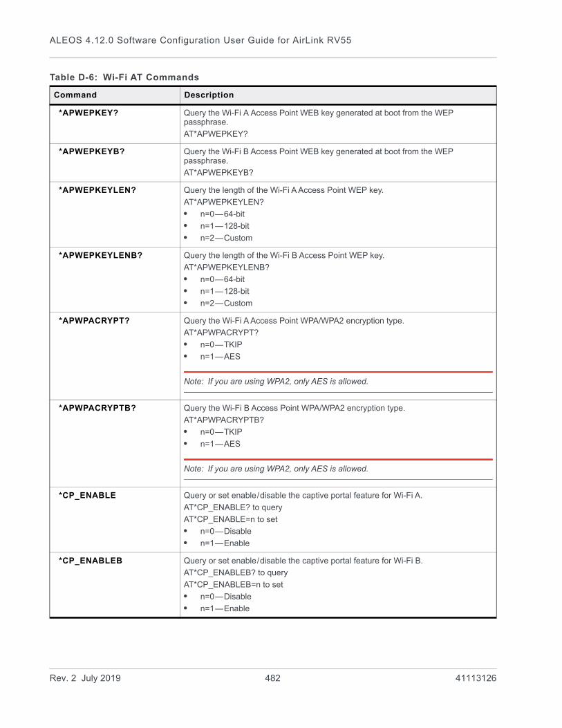
ALEOS 4.12.0 Software Configuration User Guide for AirLink RV55
*APWEPKEY? Query the Wi-Fi A Access Point WEB key generated at boot from the WEP passphrase.
AT*APWEPKEY?
*APWEPKEYB? Query the Wi-Fi B Access Point WEB key generated at boot from the WEP passphrase.
AT*APWEPKEYB?
*APWEPKEYLEN? Query the length of the Wi-Fi A Access Point WEP key.
AT*APWEPKEYLEN?
• n=0—64-bit
• n=1—128-bit
• n=2—Custom
*APWEPKEYLENB? Query the length of the Wi-Fi B Access Point WEP key.
AT*APWEPKEYLENB?
• n=0—64-bit
• n=1—128-bit
• n=2—Custom
*APWPACRYPT? Query the Wi-Fi A Access Point WPA/WPA2 encryption type.
AT*APWPACRYPT?
• n=0—TKIP
• n=1—AES
Note: If you are using WPA2, only AES is allowed.
*APWPACRYPTB? Query the Wi-Fi B Access Point WPA/WPA2 encryption type.
AT*APWPACRYPTB?
• n=0—TKIP
• n=1—AES
Note: If you are using WPA2, only AES is allowed.
*CP_ENABLE Query or set enable/disable the captive portal feature for Wi-Fi A.
AT*CP_ENABLE? to query
AT*CP_ENABLE=n to set
• n=0—Disable
• n=1—Enable
*CP_ENABLEB Query or set enable/disable the captive portal feature for Wi-Fi B.
AT*CP_ENABLEB? to query
AT*CP_ENABLEB=n to set
• n=0—Disable
• n=1—Enable
Table D-6: Wi-Fi AT Commands
Command Description
Rev. 2 July 2019 482 41113126

AT Commands
*CP_MACAUTHMODE Query or set the MAC address authorization mode for Wi-Fi A for the captive portal feature
AT*CP_MACAUTHMODE? to query
AT*CP_MACAUTHMODE=n to set
• n=0—Local MAC authentication
• n=1—Server MAC authentication
*CP_MACAUTHMODEB Query or set the MAC address authorization mode for Wi-Fi B for the captive portal feature
AT*CP_MACAUTHMODEB? to query
AT*CP_MACAUTHMODEB=n to set
• n=0—Local MAC authentication
• n=1—Server MAC authentication
*CP_RADIUSAUTHPORT Query or set the UDP port used for RADIUS authentication traffic for Wi-Fi A
*CP_RADIUSAUTHPORT? to query
*CP_RADIUSAUTHPORT=<port> to set
Default port is 1812.
*CP_RADIUSAUTHPORTB Query or set the UDP port used for RADIUS authentication traffic for Wi-Fi B
*CP_RADIUSAUTHPORT? to query
*CP_RADIUSAUTHPORT=<port> to set
Default port is 1812.
*CP_RADIUSACCTPORT Query or set the UDP port used for RADIUS accounting traffic for Wi-Fi A
*CP_RADIUSACCTPORT? to query
*CP_RADIUSACCTPORT=<port> to set
Default port is 1813.
*CP_RADIUSACCTPORTB Query or set the UDP port used for RADIUS accounting traffic for Wi-Fi B
*CP_RADIUSACCTPORT? to query
*CP_RADIUSACCTPORT=<port> to set
Default port is 1813.
*CP_STATUS? Query the current status of the captive portal feature for Wi-Fi A
AT*CP_STATUS?
Possible responses:
• Inactive
• Disable
• Idle
• Initializing
• Running
• Stopped
• Error
Table D-6: Wi-Fi AT Commands
Command Description
Rev. 2 July 2019 483 41113126

ALEOS 4.12.0 Software Configuration User Guide for AirLink RV55
*CP_STATUSB? Query the current status of the captive portal feature for Wi-Fi B
AT*CP_STATUSB?
Possible responses:
• Inactive
• Disable
• Idle
• Initializing
• Running
• Stopped
• Error
*CP_START Restarts captive portal on Wi-Fi A with the current configuration
AT*CP_START=1
Automatically resets to zero when the order is processed
*CP_STARTB Restarts captive portal on Wi-Fi B with the current configuration
AT*CP_STARTB=1
Automatically resets to zero when the order is processed
*CP_UAMSERVER Query or set the URL of the server you want to redirect clients to for Wi-Fi A
AT*CP_UAMSERVER? to query
AT*CP_UAMSERVER=<url> to set
*CP_UAMSERVERB Query or set the URL of the server you want to redirect clients to for Wi-Fi B
AT*CP_UAMSERVERB? to query
AT*CP_UAMSERVERB=<url> to set
*CP_UAMSECRET Query or set the shared secret between the router and the portal for Wi-Fi A
AT*CP_UAMSECRET? to query
AT*CP_UAMSECRET=<shared secret> to set
*CP_UAMSECRETB Query or set the shared secret between the router and the portal for Wi-Fi B
AT*CP_UAMSECRETB? to query
AT*CP_UAMSECRETB=<shared secret> to set
*CP_DNSMODE Query or set the DNS method for Wi-Fi A (Auto, Any DNS, User Defined)
AT*CP_DNSMODE? to query
AT*CP_DNSMODE=n to set
• n=0—Auto
• n=1—Any DNS
• n=2—User Defined
*CP_DNSMODEB Query or set the DNS method for Wi-Fi B (Auto, Any DNS, User Defined)
AT*CP_DNSMODEB? to query
AT*CP_DNSMODEB=n to set
• n=0—Auto
• n=1—Any DNS
• n=2—User Defined
Table D-6: Wi-Fi AT Commands
Command Description
Rev. 2 July 2019 484 41113126

AT Commands
*CP_DNSIP1 If the DNS mode for Wi-Fi A is set to User Defined (*CP_DNSMODE), use this AT Command to query or set the IP address for DNS 1.
AT*CP_DNSIP1? to query
AT*CP_DNSIP1=<ip> to set
*CP_DNSIP1B If the DNS mode for Wi-Fi B is set to User Defined (*CP_DNSMODEB), use this AT Command to query or set the IP address for DNS 1.
AT*CP_DNSIP1B? to query
AT*CP_DNSIP1B=<ip> to set
*CP_DNSIP2 If the DNS mode for Wi-Fi A is set to User Defined (*CP_DNSMODE), use this AT Command to query or set the IP address for DNS 2
AT*CP_DNSIP2? to query
AT*CP_DNSIP2=<ip> to set
*CP_DNSIP2B If the DNS mode for Wi-Fi B is set to User Defined (*CP_DNSMODEB), use this AT Command to query or set the IP address for DNS 2
AT*CP_DNSIP2B? to query
AT*CP_DNSIP2B=<ip> to set
*CP_NASID Query or set the RADIUS NAS Identifier for Wi-Fi A for each device accessing a portal
AT*CP_NASID? to query
AT*CP_NASID=<ID> to set
*CP_NASIDB Query or set the RADIUS NAS Identifier for Wi-Fi B for each device accessing a portal
AT*CP_NASIDB? to query
AT*CP_NASIDB=<ID> to set
*CP_RADIUSIP Query or set the IP address of the RADIUS server for Wi-Fi A
AT*CP_RADIUSIP? to query
AT*CP_RADIUSIP=<ip> to set
*CP_RADIUSIPB Query or set the IP address of the RADIUS server for Wi-Fi B
AT*CP_RADIUSIPB? to query
AT*CP_RADIUSIPB=<ip> to set
*CP_RADIUSSECRET Query or set the shared secret with the RADIUS server for Wi-Fi A
AT*CP_RADIUSSECRET? to query
AT*CP_RADIUSSECRET=<secret> to set
*CP_RADIUSSECRETB Query or set the shared secret with the RADIUS server for Wi-Fi B
AT*CP_RADIUSSECRETB? to query
AT*CP_RADIUSSECRETB=<secret> to set
*CP_RADIUSAUTHPORT Query or set the RADIUS authentication port for Wi-Fi A
AT*CP_RADIUSAUTHPORT? to query
AT*CP_RADIUSAUTHPORT=<port> to set
Table D-6: Wi-Fi AT Commands
Command Description
Rev. 2 July 2019 485 41113126

ALEOS 4.12.0 Software Configuration User Guide for AirLink RV55
*CP_RADIUSAUTHPORTB Query or set the RADIUS authentication port for Wi-Fi B
AT*CP_RADIUSAUTHPORTB? to query
AT*CP_RADIUSAUTHPORTB=<port> to set
*CP_RADIUSACCTPORT Query or set the RADIUS accounting port for Wi-Fi A
AT*CP_RADIUSACCTPORT? to query
AT*CP_RADIUSACCTPORT=<port> to set
*CP_RADIUSACCTPORTB Query or set the RADIUS accounting port for Wi-Fi B
AT*CP_RADIUSACCTPORTB? to query
AT*CP_RADIUSACCTPORTB=<port> to set
WCC? Query the Wi-Fi country code.
*WIFIMAC? Query the MAC address of the Wi-Fi A Access Point.
Note: Wi-Fi Client uses a different MAC address.
*WIFIMACB? Query the MAC address of the Wi-Fi B Access Point.
Note: Wi-Fi Client uses a different MAC address.
*WIFIMODE Query or set the WI-Fi A Mode.
AT*WIFIMODE? to query
AT*WIFIMODE=n to set
• n=0—Disabled
• n=1—AP (Access Point)
• n=2—Client
For more information, see Global DNS on page 152.
*WIFIMODEB Query or set the WI-Fi B Mode.
AT*WIFIMODEB? to query
AT*WIFIMODEB=n to set
• n=0—Disabled
• n=1—AP (Access Point)
• n=2—Client
Note: Both Wi-Fi A and Wi-Fi B cannot be set to Client mode.
For more information, see Global DNS on page 152.
Table D-6: Wi-Fi AT Commands
Command Description
Rev. 2 July 2019 486 41113126
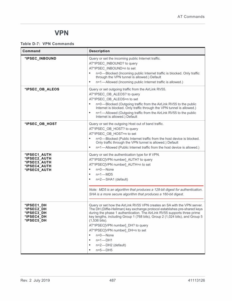
AT Commands
VPN
Table D-7: VPN Commands
Command Description
*IPSEC_INBOUND Query or set the incoming public Internet traffic.
AT*IPSEC_INBOUND? to query
AT*IPSEC_INBOUND=n to set
• n=0—Blocked (Incoming public Internet traffic is blocked. Only traffic through the VPN tunnel is allowed.) Default
• n=1—Allowed (Incoming public Internet traffic is allowed.)
*IPSEC_OB_ALEOS Query or set outgoing traffic from the AirLink RV55.
AT*IPSEC_OB_ALEOS? to query
AT*IPSEC_OB_ALEOS=n to set
• n=0—Blocked (Outgoing traffic from the AirLink RV55 to the public Internet is blocked. Only traffic through the VPN tunnel is allowed.)
• n=1—Allowed (Outgoing traffic from the AirLink RV55 to the public Internet is allowed.) Default
*IPSEC_OB_HOST Query or set the outgoing Host out of band traffic.
AT*IPSEC_OB_HOST? to query
AT*IPSEC_OB_HOST=n to set
• n=0—Blocked (Public Internet traffic from the host device is blocked. Only traffic through the VPN tunnel is allowed.) Default
• n=1—Allowed (Public Internet traffic from the host device is allowed.)
*IPSEC1_AUTH*IPSEC2_AUTH*IPSEC3_AUTH*IPSEC4_AUTH*IPSEC5_AUTH
Query or set the authentication type for # VPN.
AT*IPSEC[VPN number]_AUTH? to query
AT*IPSEC[VPN number]_AUTH=n to set
• n=0—None
• n=1—MD5
• n=2—SHA1 (default)
Note: MD5 is an algorithm that produces a 128-bit digest for authentication. SHA is a more secure algorithm that produces a 160-bit digest.
*IPSEC1_DH*IPSEC2_DH*IPSEC3_DH*IPSEC4_DH*IPSEC5_DH
Query or set how the AirLink RV55 VPN creates an SA with the VPN server. The DH (Diffie-Hellman) key exchange protocol establishes pre-shared keys during the phase 1 authentication. The AirLink RV55 supports three prime key lengths, including Group 1 (768 bits), Group 2 (1,024 bits), and Group 5 (1,536 bits).
AT*IPSEC[VPN number]_DH? to query
AT*IPSEC[VPN number]_DH=n to set
• n=0—None
• n=1—DH1
• n=2—DH2 (default)
• n=5—DH5
Rev. 2 July 2019 487 41113126

ALEOS 4.12.0 Software Configuration User Guide for AirLink RV55
*IPSEC1_ENCRYPT*IPSEC2_ENCRYPT*IPSEC3_ENCRYPT*IPSEC4_ENCRYPT*IPSEC5_ENCRYPT
Query or set the type/length of encryption key used to encrypt/decrypt ESP (Encapsulating Security Payload) packets for # VPN.
AT*IPSEC[VPN number]_ENCRYPT? to query
AT*IPSEC[VPN number]_ENCRYPT=n to set
• n=0—None
• n=1—DES
• n=2—3DES
• n=3—AES-128 (default)
• n=7—AES-256
Note: 3DES supports 168-bit encryption. AES (Advanced Encryption Standard) supports both 128-bit and 256-bit encryption.
*IPSEC1_GATEWAY*IPSEC2_GATEWAY*IPSEC3_GATEWAY*IPSEC4_GATEWAY*IPSEC5_GATEWAY
Query or set the IP address of the server that # VPN client connects to.
AT*IPSEC[VPN number]_GATEWAY? to query
AT*IPSEC[VPN number]_GATEWAY=[IP address] to set
*IPSEC1_IKE_AUTH*IPSEC2_IKE_AUTH*IPSEC3_IKE_AUTH*IPSEC4_IKE_AUTH*IPSEC5_IKE_AUTH
Query or set the IKE authentication type for # VPN.
AT*IPSEC[VPN number]_IKE_AUTH? to query
AT*IPSEC[VPN number]_IKE_AUTH=n to set
• n=1—MD5
• n=2—SHA1
Note: MD5 is an algorithm that produces a 128-bit digest for authentication. SHA is a more secure algorithm that produces a 160-bit digest.
*IPSEC1_IKE_DH*IPSEC2_IKE_DH*IPSEC3_IKE_DH*IPSEC4_IKE_DH*IPSEC5_IKE_DH
Query or set how the AirLink RV55 VPN creates an SA with the VPN server. The DH (Diffie-Hellman) key exchange protocol establishes pre-shared keys during the phase 1 authentication. The AirLink RV55 supports three prime key lengths, including Group 1 (768 bits), Group 2 (1,024 bits), and Group 5 (1,536 bits).
AT*IPSEC[VPN number]_IKE_DH? to query
AT*IPSEC[VPN number]_IKE_DH=n to set
• n=1—DH1
• n=2—DH2 (default)
• n=5—DH5
Table D-7: VPN Commands
Command Description
Rev. 2 July 2019 488 41113126

AT Commands
*IPSEC1_IKE_DPD*IPSEC2_IKE_DPD*IPSEC3_IKE_DPD*IPSEC4_IKE_DPD*IPSEC5_IKE_DPD
Query or set Dead Peer Detection (DPD).
AT*IPSEC[VPN number]_IKE_DPD? to query
AT*IPSEC[VPN number]_IKE_DPD=n to set
• n=0—Disabled (default)
• n=1—Enabled (When DPD is enabled, the AirLink RV55 checks to see if the server is still present if there has been no traffic for a configured interval. If it does not receive an acknowledgment, it retries at 5 second intervals. If there is no acknowledgment after 5 retries, the status of the VPN is set to Not Connected and the device attempts to renegotiate IPSEC security parameters with its peer.)
Note: Sierra Wireless recommends that you Enable IKE DPD. Otherwise the AirLink RV55 has no way of detecting that the connection to the VPN server is still available.
*IPSEC1_IKE_DPD_INTERVAL*IPSEC2_IKE_DPD_INTERVAL*IPSEC3_IKE_DPD_INTERVAL*IPSEC4_IKE_DPD_INTERVAL*IPSEC5_IKE_DPD_INTERVAL
Query or set the DPD interval (in seconds). If there has been no traffic for the period of time set in this field, the AirLink RV55 retries checking with the server, as described in *IPSEC[VPN Number]_IKE_DPD.
AT*IPSEC[VPN number]_IKE_DPD_INTERVAL? to query
AT*IPSEC[VPN number]_IKE_DPD_INTERVAL=n to set
• n=0–3600 (default is 1200)
If n=0, DPD monitoring is turned off (disabled), but the AirLink RV55 still responds to DPD requests from the server.
*IPSEC1_IKE_ENCRYPT*IPSEC2_IKE_ENCRYPT*IPSEC3_IKE_ENCRYPT*IPSEC4_IKE_ENCRYPT*IPSEC5_IKE_ENCRYPT
Query or set the type/length of IKE encryption key used to encrypt/decrypt ESP (Encapsulating Security Payload) packets for # VPN.
AT*IPSEC[VPN number]_IKE_ENCRYPT? to query
AT*IPSEC[VPN number]_IKE_ENCRYPT=n to set
• n=1—DES
• n=5—3DES
• n=7—AES-128 (default)
• n=9—AES-256
Note: 3DES supports 168-bit encryption. AES (Advanced Encryption Standard) supports both 128-bit and 256-bit encryption.
*IPSEC1_IKE_LIFETIME*IPSEC2_IKE_LIFETIME*IPSEC3_IKE_LIFETIME*IPSEC4_IKE_LIFETIME*IPSEC5_IKE_LIFETIME
Query or set how long the # VPN tunnel is active (in seconds).
AT*IPSEC[VPN number]_IKE_LIFETIME? to query
AT*IPSEC[VPN number]_IKE_LIFETIME=n to set
• n=180–86400 (default is 7200)
*IPSEC1_LIFETIME*IPSEC2_LIFETIME*IPSEC3_LIFETIME*IPSEC4_LIFETIME*IPSEC5_LIFETIME
Query or set how long the # VPN tunnel is active (in seconds).
AT*IPSEC[VPN number]_LIFETIME? to query
AT*IPSEC[VPN number]_LIFETIME=n to set
• n=180–86400 (default is 7200)
Table D-7: VPN Commands
Command Description
Rev. 2 July 2019 489 41113126
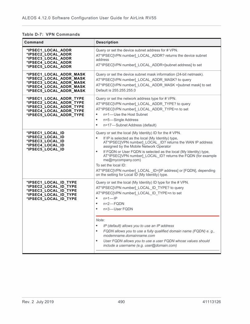
ALEOS 4.12.0 Software Configuration User Guide for AirLink RV55
*IPSEC1_LOCAL_ADDR*IPSEC2_LOCAL_ADDR*IPSEC3_LOCAL_ADDR*IPSEC4_LOCAL_ADDR*IPSEC5_LOCAL_ADDR
Query or set the device subnet address for # VPN.
AT*IPSEC[VPN number]_LOCAL_ADDR? returns the device subnet address
AT*IPSEC[VPN number]_LOCAL_ADDR=[subnet address] to set
*IPSEC1_LOCAL_ADDR_MASK*IPSEC2_LOCAL_ADDR_MASK*IPSEC3_LOCAL_ADDR_MASK*IPSEC4_LOCAL_ADDR_MASK*IPSEC5_LOCAL_ADDR_MASK
Query or set the device subnet mask information (24-bit netmask).
AT*IPSEC[VPN number]_LOCAL_ADDR_MASK? to query
AT*IPSEC[VPN number]_LOCAL_ADDR_MASK =[subnet mask] to set
Default is 255.255.255.0
*IPSEC1_LOCAL_ADDR_TYPE*IPSEC2_LOCAL_ADDR_TYPE*IPSEC3_LOCAL_ADDR_TYPE*IPSEC4_LOCAL_ADDR_TYPE*IPSEC5_LOCAL_ADDR_TYPE
Query or set the network address type for # VPN.
AT*IPSEC[VPN number]_LOCAL_ADDR_TYPE? to query
AT*IPSEC[VPN number]_LOCAL_ADDR_TYPE=n to set
• n=1—Use the Host Subnet
• n=5—Single Address
• n=17—Subnet Address (default)
*IPSEC1_LOCAL_ID*IPSEC2_LOCAL_ID*IPSEC3_LOCAL_ID*IPSEC4_LOCAL_ID*IPSEC5_LOCAL_ID
Query or set the local (My Identity) ID for the # VPN.
• If IP is selected as the local (My Identity) type, AT*IPSEC[VPN number]_LOCAL _ID? returns the WAN IP address assigned by the Mobile Network Operator
• If FQDN or User FQDN is selected as the local (My Identity) type, AT*IPSEC[VPN number]_LOCAL_ID? returns the FQDN (for example [email protected])
To set the local ID:
AT*IPSEC[VPN number]_LOCAL _ID=[IP address] or [FQDN], depending on the setting for Local ID (My Identity) type.
*IPSEC1_LOCAL_ID_TYPE*IPSEC2_LOCAL_ID_TYPE*IPSEC3_LOCAL_ID_TYPE*IPSEC4_LOCAL_ID_TYPE*IPSEC5_LOCAL_ID_TYPE
Query or set the local (My Identity) ID type for the # VPN.
AT*IPSEC[VPN number]_LOCAL_ID_TYPE? to query
AT*IPSEC[VPN number]_LOCAL_ID_TYPE=n to set
• n=1—IP
• n=2—FQDN
• n=3—User FQDN
Note:
• IP (default) allows you to use an IP address
• FQDN allows you to use a fully qualified domain name (FQDN) e. g., modemname.domainname.com
• User FQDN allows you to use a user FQDN whose values should include a username (e.g. [email protected])
Table D-7: VPN Commands
Command Description
Rev. 2 July 2019 490 41113126

AT Commands
*IPSEC1_NEG_MODE*IPSEC2_NEG_MODE*IPSEC3_NEG_MODE*IPSEC4_NEG_MODE*IPSEC5_NEG_MODE
Query or set the negotiation mode for # VPN.
AT*IPSEC[VPN number]_NEG_MODE? returns
AT*IPSEC[VPN number]_NEG_MODE=n to set
• n=1—Main
• n=2—Aggressive
Note: Aggressive mode offers increased performance at the expense of security.
*IPSEC1_PFS*IPSEC2_PFS*IPSEC3_PFS*IPSEC4_PFS*IPSEC5_PFS
Query or set the Perfect Forward Secrecy (PFS) setting for # VPN.
PFS provides additional security through a DH shared secret value. When this feature is enabled, one key cannot be derived from another. This ensures previous and subsequent encryption keys are secure even if one key is compromised.
AT*IPSEC[VPN number]_PFS? to query PFS
AT*IPSEC[VPN number]_PFS=n to set PFS
• n=0—Yes (default)
• n=1—No
*IPSEC1_REMOTE_ADDR*IPSEC2_REMOTE_ADDR*IPSEC3_REMOTE_ADDR*IPSEC4_REMOTE_ADDR*IPSEC5_REMOTE_ADDR
Query or set the IP address of the device behind the RV55 for # VPN.
AT*IPSEC[VPN number]_REMOTE_ADDR? to query
AT*IPSEC[VPN number]_REMOTE_ADDR=[IP address] to set
*IPSEC1_REMOTE_ADDR_MASK*IPSEC2_REMOTE_ADDR_MASK*IPSEC3_REMOTE_ADDR_MASK*IPSEC4_REMOTE_ADDR_MASK*IPSEC5_REMOTE_ADDR_MASK
Query or set the remote subnet mask information (24-bit netmask).
AT*IPSEC[VPN number]_REMOTE_ADDR_MASK? to query
AT*IPSEC[VPN number]_REMOTE_ADDR_MASK =[subnet mask] to set
Default is 255.255.255.0
*IPSEC1_REMOTE_ADDR_TYPE*IPSEC2_REMOTE_ADDR_TYPE*IPSEC3_REMOTE_ADDR_TYPE*IPSEC4_REMOTE_ADDR_TYPE*IPSEC5_REMOTE_ADDR_TYPE
Query or set network information of the IPsec server behind the IPsec RV55 for # VPN.
AT*IPSEC[VPN number]_REMOTE_ADDR_TYPE? to query
AT*IPSEC[VPN number]_REMOTE_ADDR_TYPE=n to set
• n=5—Single Address
• n=17—Subnet Address (default)
*IPSEC1_REMOTE_ID*IPSEC2_REMOTE_ID*IPSEC3_REMOTE_ID*IPSEC4_REMOTE_ID*IPSEC5_REMOTE_ID
Query or set the remote (Peer Identity) ID for the # VPN.
• If IP is selected as the remote (Peer Identity) type, AT*IPSEC[VPN number]_REMOTE_ID? returns the WAN IP address assigned by the Mobile Network Operator
• If FQDN or User FQDN is selected as the remote (Peer Identity) type, AT*IPSEC[VPN number]_REMOTE_ID? returns the FQDN (for example [email protected])
To set the remote ID:
AT*IPSEC[VPN number]_REMOTE _ID=[IP address] or [FQDN], depending on the setting for remote ID (Peer Identity) type.
Table D-7: VPN Commands
Command Description
Rev. 2 July 2019 491 41113126
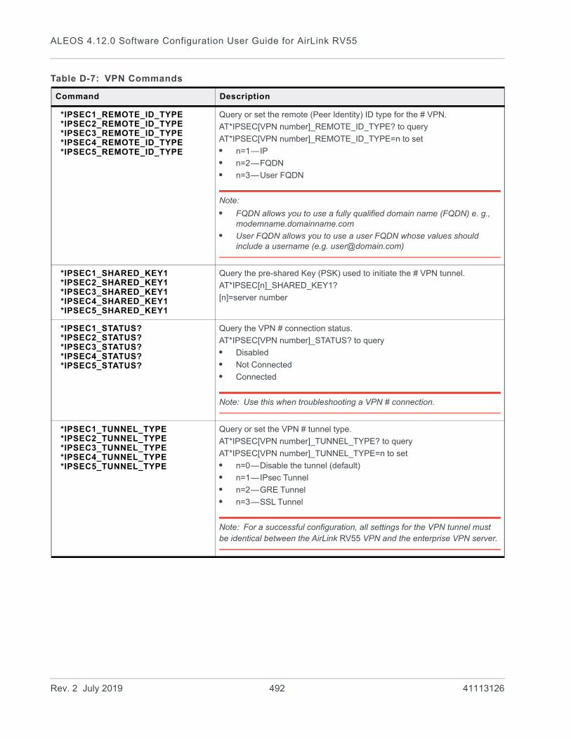
ALEOS 4.12.0 Software Configuration User Guide for AirLink RV55
*IPSEC1_REMOTE_ID_TYPE*IPSEC2_REMOTE_ID_TYPE*IPSEC3_REMOTE_ID_TYPE*IPSEC4_REMOTE_ID_TYPE*IPSEC5_REMOTE_ID_TYPE
Query or set the remote (Peer Identity) ID type for the # VPN.
AT*IPSEC[VPN number]_REMOTE_ID_TYPE? to query
AT*IPSEC[VPN number]_REMOTE_ID_TYPE=n to set
• n=1—IP
• n=2—FQDN
• n=3—User FQDN
Note:
• FQDN allows you to use a fully qualified domain name (FQDN) e. g., modemname.domainname.com
• User FQDN allows you to use a user FQDN whose values should include a username (e.g. [email protected])
*IPSEC1_SHARED_KEY1*IPSEC2_SHARED_KEY1*IPSEC3_SHARED_KEY1*IPSEC4_SHARED_KEY1*IPSEC5_SHARED_KEY1
Query the pre-shared Key (PSK) used to initiate the # VPN tunnel.
AT*IPSEC[n]_SHARED_KEY1?
[n]=server number
*IPSEC1_STATUS?*IPSEC2_STATUS?*IPSEC3_STATUS?*IPSEC4_STATUS?*IPSEC5_STATUS?
Query the VPN # connection status.
AT*IPSEC[VPN number]_STATUS? to query
• Disabled
• Not Connected
• Connected
Note: Use this when troubleshooting a VPN # connection.
*IPSEC1_TUNNEL_TYPE*IPSEC2_TUNNEL_TYPE*IPSEC3_TUNNEL_TYPE*IPSEC4_TUNNEL_TYPE*IPSEC5_TUNNEL_TYPE
Query or set the VPN # tunnel type.
AT*IPSEC[VPN number]_TUNNEL_TYPE? to query
AT*IPSEC[VPN number]_TUNNEL_TYPE=n to set
• n=0—Disable the tunnel (default)
• n=1—IPsec Tunnel
• n=2—GRE Tunnel
• n=3—SSL Tunnel
Note: For a successful configuration, all settings for the VPN tunnel must be identical between the AirLink RV55 VPN and the enterprise VPN server.
Table D-7: VPN Commands
Command Description
Rev. 2 July 2019 492 41113126
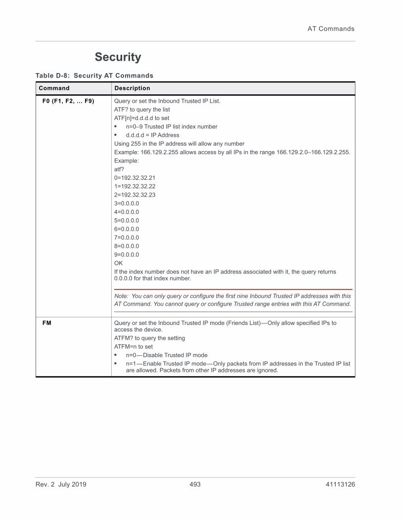
AT Commands
Security
Table D-8: Security AT Commands
Command Description
F0 (F1, F2, ... F9) Query or set the Inbound Trusted IP List.
ATF? to query the list
ATF[n]=d.d.d.d to set
• n=0–9 Trusted IP list index number
• d.d.d.d = IP Address
Using 255 in the IP address will allow any number
Example: 166.129.2.255 allows access by all IPs in the range 166.129.2.0–166.129.2.255.
Example:
atf?
0=192.32.32.21
1=192.32.32.22
2=192.32.32.23
3=0.0.0.0
4=0.0.0.0
5=0.0.0.0
6=0.0.0.0
7=0.0.0.0
8=0.0.0.0
9=0.0.0.0
OK
If the index number does not have an IP address associated with it, the query returns 0.0.0.0 for that index number.
Note: You can only query or configure the first nine Inbound Trusted IP addresses with this AT Command. You cannot query or configure Trusted range entries with this AT Command.
FM Query or set the Inbound Trusted IP mode (Friends List)—Only allow specified IPs to access the device.
ATFM? to query the setting
ATFM=n to set
• n=0—Disable Trusted IP mode
• n=1—Enable Trusted IP mode—Only packets from IP addresses in the Trusted IP list are allowed. Packets from other IP addresses are ignored.
Rev. 2 July 2019 493 41113126

ALEOS 4.12.0 Software Configuration User Guide for AirLink RV55
Services
Table D-9: Services AT Commands
Command Description
AirLink Management System
*AVMS_ENABLE Query or set the ALMS activation status.
AT*AVMS_ENABLE? to query
AT*AVMS_ENABLE=n to set
• n=0—Disable device initiated ALMS management
• n=1—Enable MSCI protocol for ALMS management
• n=2—Enable LWM2M protocol for ALMS management
• n=3—Enable LWM2M protocol for ALMS management, with an automatic Fallback to MSCI if communication fails
*AVMS_INTERVAL Query or set the ALMS communication (heartbeat) interval in minutes.
AT*AVMS_INTERVAL? to query
AT*AVMS_INTERVAL= n to set
• n=INTERVAL (in minutes)
*AVMS_NAME Assigns or queries the name to the AirLink RV55 as it appears in ALMS.
AT*AVMS_NAME? to query
AT*AVMS_NAME=n to set
• n=ALMS NAME
*AVMS_SERVER Query or set the ALMS server IP address or FQDN.
AT*AVMS_SERVER? to query
AT*AVMS_SERVER=n to set
• n=IP Address or FQDN of ALMS server
*AVMS_STATUS? Query the ALMS connection status.
*AVMS_AUTOSYNC Query or set ALMS autosynchronization of configuration parameters.
AT*AVMS_AUTOSYNC? to query
AT**AVMS_AUTOSYNC=n to set
• n=0—Disable ALMS autosynchronization
• n=1—Enable ALMS autosynchronization
*AVMS_VERIFYPEER Query or set peer certificate verification during SSL handshake.
AT*AVMS_VERIFYPEER? to query
AT*AVMS_VERIFYPEER=n to set
• n=0—Disable peer certificate verification during SSL handshake
• n=1—Enable peer certificate verification during SSL handshake
Low Power
*ENGHRS Query or set the number of hours the engine has been running.
AT*ENGHRS? to query
AT*ENGHRS=n to set
• n=HOURS
Maximum value is 65535.
Rev. 2 July 2019 494 41113126

AT Commands
*MSCISERVER Set or query the MSCI server setting
AT*MSCISERVER? to query
AT*MSCISERVER=n to set
• n=0—Access is disabled
• n=1—Access is LAN only
• n=2—Access is WAN and LAN
Dynamic DNS
*DOMAIN Query or set the domain name used for the IP Manager Dynamic DNS configuration.
AT*DOMAIN? to query
AT*DOMAIN=DOMAIN to set (up to 20 characters)
Example: AT*DOMAIN=eairlink.com
Tip: Only letters, numbers, hyphens, and periods can be used in a domain name.
Note: This AT command is only usable if the Dynamic DNS Service type is set to IP Manager.
*DYNDNS Query or set the Dynamic DNS Service type to use.
AT*DYNDNS? to query
AT*DYNDNS=n to set
• n=0—Disable (default)
• n=2—dyndns.org
• n=5—noip.org
• n=6—ods.org
• n=8—regfish.com
• n=9—tzo.org
• n=10—IP Manager
Note: Only IP Manager can be fully configured using AT Commands.
Table D-9: Services AT Commands
Command Description
Rev. 2 July 2019 495 41113126

ALEOS 4.12.0 Software Configuration User Guide for AirLink RV55
*IPMANAGER1*IPMANAGER2 Note: This AT command is only usable if the Dynamic DNS Service type is set to IP
Manager.
Query or set a FQDN or IP address of the IP server to send IP change notifications to. You can configure two independent IP Manager servers.
AT*IPMANAGER[n]? to query
AT*IPMANAGER[n]=SERVER to set.
• n=1—First IP Manager server
• n=2—Second IP Manager server
• SERVER=Server FQDN or IP address
Note: You can disable updates to a server by setting blank entry (e.g., “AT*IPMANAGER1=”).
*IPMGRKEY1*IPMGRKEY2 Note: This AT command is only usable if the Dynamic DNS Service type is set to IP
Manager.
Query or set the 128-bit password/key used to authenticate the IP update notifications. If the key's value is all zeros, a default key is used. If all the bytes in the key are set to FF, then no key is used (i.e., the IP change notifications will not be authenticated).
AT*IPMGRKEY[n]? to query
AT*IPMANAGER[n]=KEY to set
• n=1—First IP Manager server
• n=2—Second IP Manager server
• KEY=128-bit key in hexadecimal [32 hex characters]
*IPMGRUPDATE1*IPMGRUPDATE2 Note: This AT command is only usable if the Dynamic DNS Service type is set to IP
Manager.
Query or set the interval (in minutes) to send an IP update notification to the corresponding server. This occurs even if the IP address of the device does not change. If the value is set to 0, then periodic updates are not issued (i.e., IP change notifications is only be sent when the IP actually changes).
AT*IPMGRUPDATE[n] to query
AT*IPMGRUPDATE[n]=INTERVAL to set
• n=0—Disables the update interval (updates only on changes)
• n=1—First IP Manager server
• n=2—Second IP Manager server
• INTERVAL=1–255—interval (in minutes) to send an update
Table D-9: Services AT Commands
Command Description
Rev. 2 July 2019 496 41113126
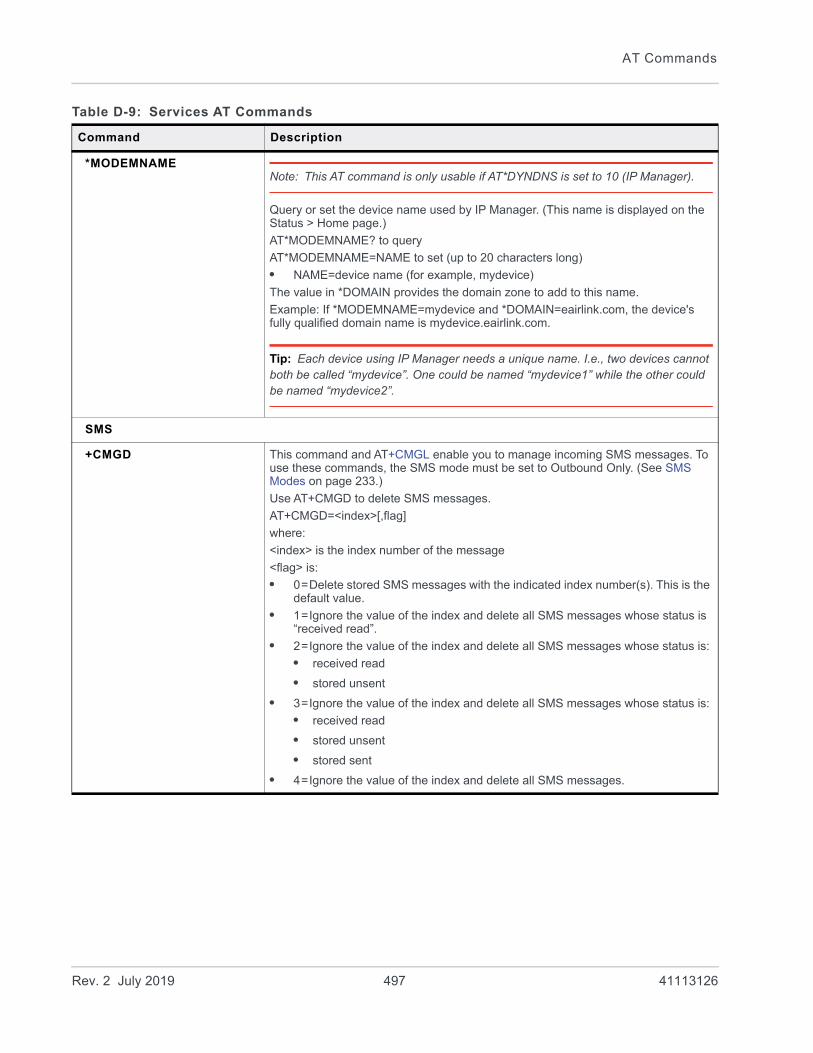
AT Commands
*MODEMNAMENote: This AT command is only usable if AT*DYNDNS is set to 10 (IP Manager).
Query or set the device name used by IP Manager. (This name is displayed on the Status > Home page.)
AT*MODEMNAME? to query
AT*MODEMNAME=NAME to set (up to 20 characters long)
• NAME=device name (for example, mydevice)
The value in *DOMAIN provides the domain zone to add to this name.
Example: If *MODEMNAME=mydevice and *DOMAIN=eairlink.com, the device's fully qualified domain name is mydevice.eairlink.com.
Tip: Each device using IP Manager needs a unique name. I.e., two devices cannot both be called “mydevice”. One could be named “mydevice1” while the other could be named “mydevice2”.
SMS
+CMGD This command and AT+CMGL enable you to manage incoming SMS messages. To use these commands, the SMS mode must be set to Outbound Only. (See SMS Modes on page 233.)
Use AT+CMGD to delete SMS messages.
AT+CMGD=<index>[,flag]
where:
<index> is the index number of the message
<flag> is:
• 0=Delete stored SMS messages with the indicated index number(s). This is the default value.
• 1=Ignore the value of the index and delete all SMS messages whose status is “received read”.
• 2=Ignore the value of the index and delete all SMS messages whose status is:
• received read
• stored unsent
• 3=Ignore the value of the index and delete all SMS messages whose status is:
• received read
• stored unsent
• stored sent
• 4=Ignore the value of the index and delete all SMS messages.
Table D-9: Services AT Commands
Command Description
Rev. 2 July 2019 497 41113126

ALEOS 4.12.0 Software Configuration User Guide for AirLink RV55
+CMGL Use this command to list/read SMS messages.
To use this command, the SMS mode must be set to Outbound Only. (See SMS Modes on page 233.)
AT+CMGL=<status>
where <status> is:
• ALL
• REC UNREAD—Received, unread
• REC READ—Received, read
*SMSM2M*SMSM2M_8*SMSM2M_u
You can only use these commands locally.
• AT*SMSM2M sends an SMS in ASCII text (requires quotation marks; maximum 140 characters)
• AT*SMSM2M_8 sends an 8-bit SMS (requires quotation marks; maximum 140 characters)
• AT*SMSM2M_U sends a unicode SMS (requires quotation marks; maximum 140 characters)
Format:
AT*SMSM2M=“[phone] [ascii message]”
AT*SMSM2M_8=“[phone] [hex message]”
AT*SMSM2M_U=“[phone] [hex message]”
• The phone number can only consist of numbers (NO spaces or other characters). The phone number should be as it appears in the Last Incoming Phone Number field.
• Example 1 (US): 14085551212 (including leading 1 and area code)
• Example 2 (US): 4085551212 (ignore leading 1, include area code)
• Example 3 (UK): 447786111717 (remove leading 0 and add country code)
Command Examples:
AT*SMSM2M=”18005551212 THIS IS A TEST” sends in ASCII.
AT*SMSM2M_8="17604053757 5448495320495320412054455354" sends the message “THIS IS A TEST” as 8-bit data.
AT*SMSM2M_U="17604053757 000102030405060708090a0b0c0d0e0f808182838485868788898A8b8c8d8e8f" sends the bytes:
00 01 02 03 04 05 06 07 08 09 0a 0b 0c 0d 0e 0f
80 81 82 83 84 85 86 87 88 89 8a 8b 8c 8d 8e 8f
Note: Not all cellular Mobile Network Operators support 8-bit or unicode SMS messages.
Table D-9: Services AT Commands
Command Description
Rev. 2 July 2019 498 41113126
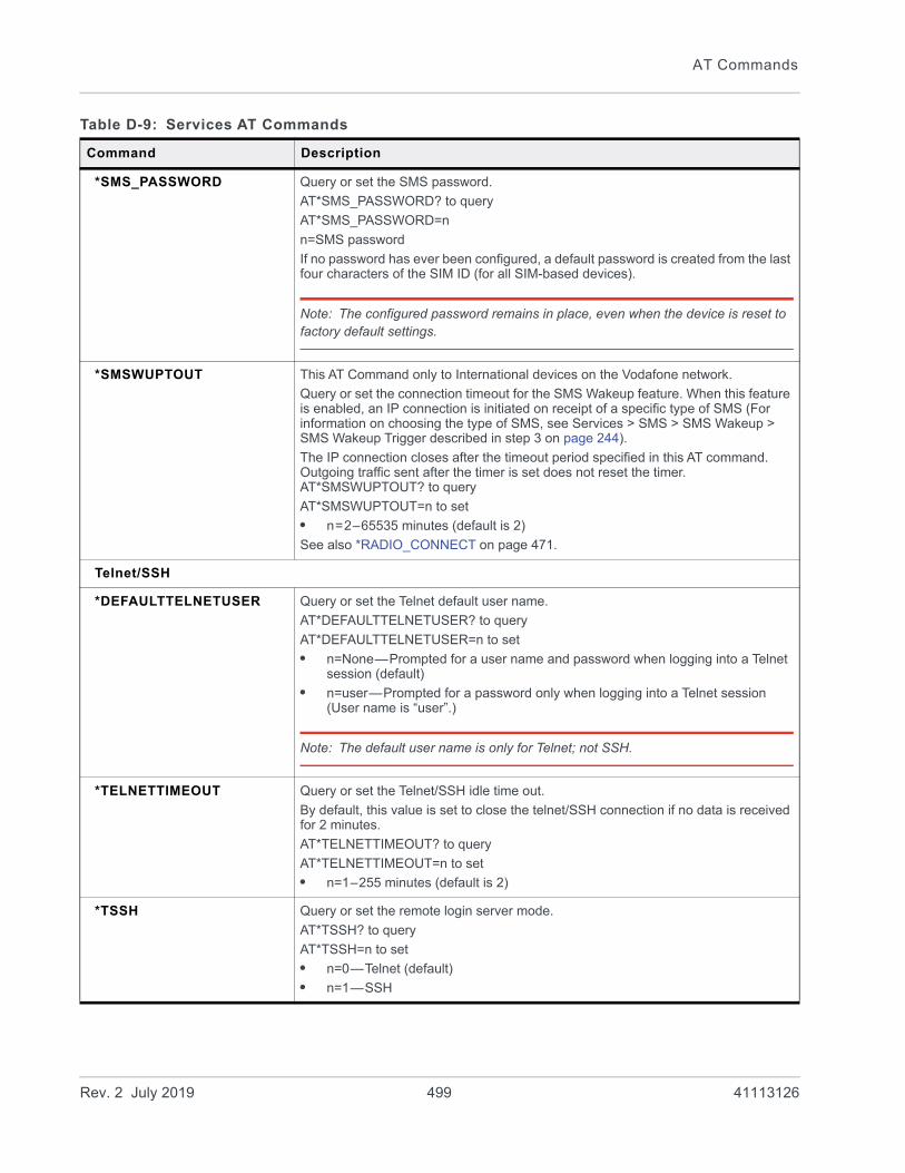
AT Commands
*SMS_PASSWORD Query or set the SMS password.
AT*SMS_PASSWORD? to query
AT*SMS_PASSWORD=n
n=SMS password
If no password has ever been configured, a default password is created from the last four characters of the SIM ID (for all SIM-based devices).
Note: The configured password remains in place, even when the device is reset to factory default settings.
*SMSWUPTOUT This AT Command only to International devices on the Vodafone network.
Query or set the connection timeout for the SMS Wakeup feature. When this feature is enabled, an IP connection is initiated on receipt of a specific type of SMS (For information on choosing the type of SMS, see Services > SMS > SMS Wakeup > SMS Wakeup Trigger described in step 3 on page 244).
The IP connection closes after the timeout period specified in this AT command. Outgoing traffic sent after the timer is set does not reset the timer. AT*SMSWUPTOUT? to query
AT*SMSWUPTOUT=n to set
• n=2–65535 minutes (default is 2)
See also *RADIO_CONNECT on page 471.
Telnet/SSH
*DEFAULTTELNETUSER Query or set the Telnet default user name.
AT*DEFAULTTELNETUSER? to query
AT*DEFAULTTELNETUSER=n to set
• n=None—Prompted for a user name and password when logging into a Telnet session (default)
• n=user—Prompted for a password only when logging into a Telnet session (User name is “user”.)
Note: The default user name is only for Telnet; not SSH.
*TELNETTIMEOUT Query or set the Telnet/SSH idle time out.
By default, this value is set to close the telnet/SSH connection if no data is received for 2 minutes.
AT*TELNETTIMEOUT? to query
AT*TELNETTIMEOUT=n to set
• n=1–255 minutes (default is 2)
*TSSH Query or set the remote login server mode.
AT*TSSH? to query
AT*TSSH=n to set
• n=0—Telnet (default)
• n=1—SSH
Table D-9: Services AT Commands
Command Description
Rev. 2 July 2019 499 41113126

ALEOS 4.12.0 Software Configuration User Guide for AirLink RV55
*TPORT Query or set the Telnet/SSH port.
AT*PORT? to query
AT*PORT=n to set
• n=1–65535 (default is 2332)
Many networks have the ports below 1024 blocked. It is recommended to use a higher numbered port.
*TQUIT AT*TQUIT which will kill an open telnet session.
Management (SNMP)
SNMP General Configuration
*SNMP Query or set the SNMP option.
AT*SNMP? to query
AT*SNMP=n to set
• n=0—Disable
• n=1—Enable
*SNMPCONTACT Add string contact information in SNMPv2 and SNMPv3.
AT*SNMPCONTACT=string
• string=email address (Example: [email protected])
*SNMPLOCATION Add string location information in SNMPv2 and SNMPv3.
AT*SNMPLOCATION=string
• string=location information (Example: Building 19–67B)
*SNMPNAME Add string name in SNMPv2 and SNMPv3.
AT*SNMPNAME=STRING
• STRING=name (Example: John Doe)
*SNMPPORT Query or set the port number in SNMPv2 and SNMPv3.
AT*SNMPPORT? to query
AT*SNMPPORT=n to set
• n=1–65535 (default is 161)
*SNMPVERSION Query or set the SNMP version.
AT*SNMPVERSION? to query
AT*SNMPVERSION=n to set
• n=2—version 2
• n=3—version 3
SNMP Read Only Configuration
*SNMPROCOMMUNITY Read-only community string in SNMPv2 and SNMPv3.(SNMP equivalent of a password; for example: public)
*SNMPROUSER Query or set a read only SNMP username string in SNMPv3.
Table D-9: Services AT Commands
Command Description
Rev. 2 July 2019 500 41113126
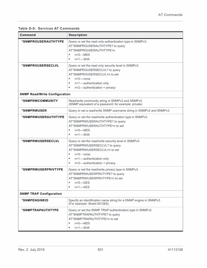
AT Commands
*SNMPROUSERAUTHTYPE Query or set the read only authentication type in SNMPv3.
AT*SNMPROUSERAUTHTYPE? to query
AT*SNMPROUSERAUTHTYPE=n
• n=0—MD5
• n=1—SHA
*SNMPROUSERSECLVL Query or set the read only security level in SNMPv3.
AT*SNMPROUSERSECLVL? to query
AT*SNMPROUSERSECLVL=n to set
• n=0—none
• n=1—authentication only
• n=2—authentication + privacy
SNMP Read/Write Configuration
*SNMPRWCOMMUNITY Read/write community string in SNMPv2 and SNMPv3.(SNMP equivalent of a password; for example: private)
*SNMPRWUSER Query or set a read/write SNMP username string in SNMPv2 and SNMPv3.
*SNMPRWUSERAUTHTYPE Query or set the read/write authentication type in SNMPv3.
AT*SNMPRWUSERAUTHTYPE? to query
AT*SNMPRWUSERAUTHTYPE=n to set
• n=0—MD5
• n=1—SHA
*SNMPRWUSERSECLVL Query or set the read/write security level in SNMPv3.
AT*SNMPRWUSERSECLVL? to query
AT*SNMPRWUSERSECLVL=n to set
• n=0—none
• n=1—authentication only
• n=2—authentication + privacy
*SNMPRWUSERPRIVTYPE Query or set the read/write privacy type in SNMPv3.
AT*SNMPRWUSERPRIVTYPE? to query
AT*SNMPRWUSERPRIVTYPE=n to set
• n=0—DES
• n=1—AES
SNMP TRAP Configuration
*SNMPENGINEID Specify an identification name string for a SNMP engine in SNMPv3.(For example: Shark-0012E8)
*SNMPTRAPAUTHTYPE Query or set the SNMP TRAP authentication type in SNMPv3.
AT*SNMPTRAPAUTHTYPE? to query
AT*SNMPTRAPAUTHTYPE=n to set
• n=0—MD5
• n=1—SHA
Table D-9: Services AT Commands
Command Description
Rev. 2 July 2019 501 41113126

ALEOS 4.12.0 Software Configuration User Guide for AirLink RV55
*SNMPTRAPCOMMUNITY SNMP TRAP community string in SNMPv2 and SNMPv3.(SNMP equivalent of a password)
*SNMPTRAPDEST Query or set the SNMP TRAP destination in SNMPv2 and SNMPv3.(for example: 192.168.13.33)
*SNMPTRAPPORT Query or set the SNMP TRAP port in SNMPv2 and SNMPv3.
• 1–65535 (default is 162)
*SNMPTRAPPRIVTYPE Query or set the SNMP TRAP privacy type in SNMPv3.
AT*SNMPTRAPPRIVTYPE? to query
AT*SNMPTRAPPRIVTYPE=n to set
• n=0—DES
• n=1—AES
*SNMPTRAPSECLVL Query or set the SNMP TRAP security level in SNMPv3.
AT*SNMPTRAPSECLVL? to query
AT*SNMPTRAPSECLVL=n to set
• n=0—none
• n=1—authentication only
• n=2—authentication + privacy
*SNMPTRAPUSER Query or set a SNMP TRAP username string in SNMPv3.
Email (SMTP) Commands
*SMTPADDR Query or set the mail server IP address or FQDN.
AT*SMTPADDR? to query
AT*SMTPADDR=[d.d.d.d] or [NAME] to set
• d.d.d.d=IP Address
• NAME=domain name (maximum: 40 characters)
*SMTPFROM Query or set the email address from which the SMTP message is being sent (required by some mail servers).
AT*SMTPFROM? to query
AT*SMTPFROM=EMAIL to set
• EMAIL=email address (maximum: 30 characters)
*SMTPSUBJ Query or set the email subject line to use for sending emails.
AT*SMTPSUBJ? to query
AT*SMTPSUBJ=STRING to set
*SMTPPW Query or set the email server password (required by some mail servers).
AT*SMTPPW? to query
AT*SMTPPW=PASSWORD to set
*SMTPUSER Query or set the email account username (required by some mail servers).
AT*SMTPUSER? to query
AT*SMTPUSER=USER to set (maximum: 40 characters)
Table D-9: Services AT Commands
Command Description
Rev. 2 July 2019 502 41113126

AT Commands
Time (SNTP) Commands
*SNTP Query or set daily SNTP updates of the system time.
AT*SNTP? to query
AT*SNTP=n to set
• n=0—Off
• n=1—On
*SNTPADDR SNTP Server IP address, or fully-qualified domain name, to use if *SNTP=1.
AT*SNTPADDR? to query
AT*SNTPADDR=[d.d.d.d] or [NAME]
• d.d.d.d=IP Address
• NAME=FQDN
Table D-9: Services AT Commands
Command Description
Rev. 2 July 2019 503 41113126
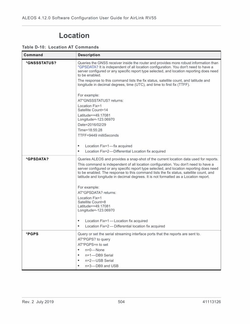
ALEOS 4.12.0 Software Configuration User Guide for AirLink RV55
Location
Table D-10: Location AT Commands
Command Description
*GNSSSTATUS? Queries the GNSS receiver inside the router and provides more robust information than *GPSDATA? It is independent of all location configuration. You don't need to have a server configured or any specific report type selected, and location reporting does need to be enabled.
The response to this command lists the fix status, satellite count, and latitude and longitude in decimal degrees, time (UTC), and time to first fix (TTFF).
For example:
AT*GNSSSTATUS? returns:
Location Fix=1Satellite Count=14
Latitude=+49.17081Longitude=-123.06970
Date=2016/02/29
Time=18:55:28
TTFF=9449 milliSeconds
• Location Fix=1—fix acquired
• Location Fix=2—Differential Location fix acquired
*GPSDATA? Queries ALEOS and provides a snap-shot of the current location data used for reports.
This command is independent of all location configuration. You don't need to have a server configured or any specific report type selected, and location reporting does need to be enabled. The response to this command lists the fix status, satellite count, and latitude and longitude in decimal degrees. It is not formatted as a Location report.
For example:
AT*GPSDATA? returns:
Location Fix=1Satellite Count=8Latitude=+49.17081Longitude=-123.06970
• Location Fix=1 — Location fix acquired
• Location Fix=2 — Differential location fix acquired
*PGPS Query or set the serial streaming interface ports that the reports are sent to.
AT*PGPS? to query
AT*PGPS=n to set
• n=0—None
• n=1—DB9 Serial
• n=2—USB Serial
• n=3—DB9 and USB
Rev. 2 July 2019 504 41113126
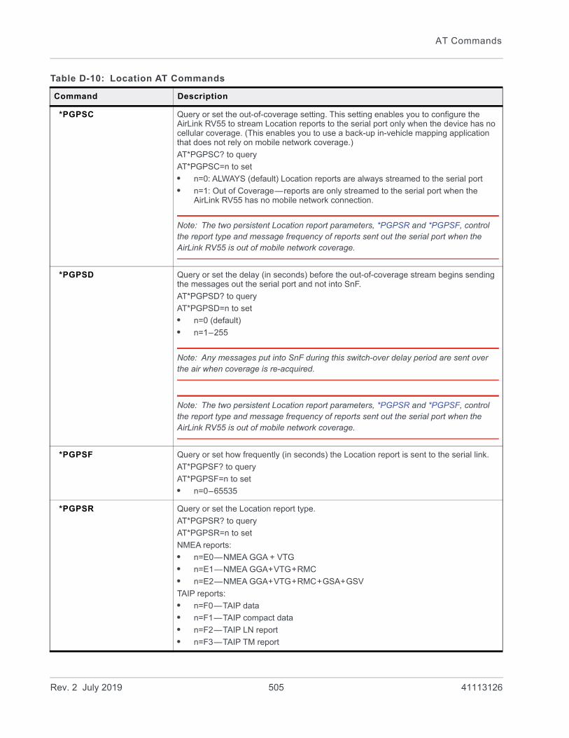
AT Commands
*PGPSC Query or set the out-of-coverage setting. This setting enables you to configure the AirLink RV55 to stream Location reports to the serial port only when the device has no cellular coverage. (This enables you to use a back-up in-vehicle mapping application that does not rely on mobile network coverage.)
AT*PGPSC? to query
AT*PGPSC=n to set
• n=0: ALWAYS (default) Location reports are always streamed to the serial port
• n=1: Out of Coverage—reports are only streamed to the serial port when the AirLink RV55 has no mobile network connection.
Note: The two persistent Location report parameters, *PGPSR and *PGPSF, control the report type and message frequency of reports sent out the serial port when the AirLink RV55 is out of mobile network coverage.
*PGPSD Query or set the delay (in seconds) before the out-of-coverage stream begins sending the messages out the serial port and not into SnF.
AT*PGPSD? to query
AT*PGPSD=n to set
• n=0 (default)
• n=1–255
Note: Any messages put into SnF during this switch-over delay period are sent over the air when coverage is re-acquired.
Note: The two persistent Location report parameters, *PGPSR and *PGPSF, control the report type and message frequency of reports sent out the serial port when the AirLink RV55 is out of mobile network coverage.
*PGPSF Query or set how frequently (in seconds) the Location report is sent to the serial link.
AT*PGPSF? to query
AT*PGPSF=n to set
• n=0–65535
*PGPSR Query or set the Location report type.
AT*PGPSR? to query
AT*PGPSR=n to set
NMEA reports:
• n=E0—NMEA GGA + VTG
• n=E1—NMEA GGA+VTG+RMC
• n=E2—NMEA GGA+VTG+RMC+GSA+GSV
TAIP reports:
• n=F0—TAIP data
• n=F1—TAIP compact data
• n=F2—TAIP LN report
• n=F3—TAIP TM report
Table D-10: Location AT Commands
Command Description
Rev. 2 July 2019 505 41113126
ALEOS 4.12.0 Software Configuration User Guide for AirLink RV55
*PPDIST*PP2DIST*PP3DIST*PP4DIST
Query or set the Location report distance interval in 100 meter units. For example, if you entered a value of 635, it would translate to 63,500 meters (63.5 kilometers).
AT*PP[Server number if other than server 1]DIST? to query
AT*PP[Server number if other than server 1]DIST=n to set
• n=0—Disabled
• n=1–65535—Distance in 100 meter units that the device moves before sending a Location report
*PPDISTM*PP2DISTM*PP3DISTM*PP4DISTM
Query or set the Location report distance Interval in meters.
AT*PP[Server number if other than server 1]DISTM? to query
AT*PP[Server number if other than server 1]DISTM=n to set
• n=0—Disabled
• n=40–65535—Distance in meters that the device moves before sending a Location report
Note: If you enter a value greater than zero, but less than 40, ALEOS rounds it up to 40.
*PPDEVID Query or set whether or not the RAP Location report includes device ID and if so, which type of device ID is included.
AT*PPDEVID? to query
AT*PPDEVID=n to set
• n=0—None
• n=1—Phone number
• n=2—ESN/IMEI
Note: The device ID in the RAP report is in hex, not plain text.
*PPFLUSHONEVT Query or set Send SnF Buffer Immediately on input. If this feature is enabled, any pending stored reports are sent if the I/O input changes, a stationary vehicle is moved, or a maximum speed is exceeded.
AT*PPFLUSHONEVT? to query
AT*PPFLUSHONEVT=n to set
• n=0—Disable
• n=1—Enable
Table D-10: Location AT Commands
Command Description
Rev. 2 July 2019 506 41113126
AT Commands
*PPGPSR*PP2GPSR*PP3GPSR*PP4GPSR
Query or set the Location report type.
AT*PP[Server number if other than server 1]GPSR? to query
AT*PP[Server number if other than server 1]GPSR=n to set
RAP reports:
• n=0—Use legacy reports specified in *MF value. Note: Must also have *PPDEVID=0.
• n=11—Standard Location Report
• n=12—Standard Location Report + UTC Date
• n=13—Standard Location Report + UTC Date + RF data
• n=14—Standard Location report + Location + Date + RF + EIO
Xora reports
• n=D0—Xora
NMEA reports
• n=E0—GGA and VTG NMEA reports
• n=E1—GGA, VTG and RMC NMEA reports
• n=E2—GGA, VTG, RMC, GSA and GSV NMEA reports
TAIP reports
• n=F0—TAIP data—TAIP Location report that contains position and velocity
• n=F1—TAIP Location report that contains the compact position
• n=F2—TAIP LN report—TAIP Location report that contains a long navigation message
• n=F3—TAIP TM report—TAIP Location report that contains the time and date
*PPINPUTEVT*PP2INPUTEVT*PP3INPUTEVT*PP4INPUTEVT
Query or set ability to send a special report for digital input changes.
AT*PP[Server number if other than server 1]INPUTEVT? to query
AT*PP[Server number if other than server 1]INPUTEVT=n to set
• n=0—Disable
• n=1—Enable
*PPIP*PP2IP*PP3IP*PP4IP
Query or set the IP address where Location reports are sent. See also *PPPORT on page 509.
AT*PP[Server number if other than server 1]IP? to query
AT*PP[Server number if other than server 1]IP=d.d.d.d to set
• d.d.d.d=IP address
Example:
AT*PPIP=192.100.100.100
*PPLATS Query or set the local reporting interval (in seconds).
AT*PPLATS? to query
AT*PPLATS=n to set
• n=0—Disable (default)
• n=1–255 (seconds)
Table D-10: Location AT Commands
Command Description
Rev. 2 July 2019 507 41113126

ALEOS 4.12.0 Software Configuration User Guide for AirLink RV55
*PPLATSEXTRA Query or set the number of additional consecutive ports that the local Location report is sent to.
AT*PPLATSEXTRA? to query
AT*PPLATSEXTRA=n to set
• n=0—Just the original report is sent (default).
• n=1–7—Send Location report copies to that number of ports.
Example: If AT*PPLATSEXTRA=7 and the port in S53 is 1000, then Location reports will be sent to ports 1000–1008.
*PPLATSR Query or set the Location report type that is sent to the local client (Ethernet, USB/net, or PPP).
AT*PPLATSR? to query
AT*PPLATSR=n to set
RAP reports:
• n=11—Data
• n=12—+ Date
• n=13—+ UTC + RF
• n=14—+ Date + RF + EIO
NMEA reports:
• n=E0—NMEA GGA + VTG
• n=E1—NMEA GGA + VTG + RMC
• n=E2—NMEA GGA + VTG + RMC + GSA + GSV
TAIP reports:
• n=F0—TAIP data—TAIP Location report that contains position and velocity
• n=F1—TAIP Location report that contains the compact position
• n=F2—TAIP LN report—TAIP Location report that contains a long navigation message
• n=F3—TAIP TM report—TAIP Location report that contains the time and date
*PPMAXRETRIES*PP2MAXRETRIES*PP3MAXRETRIES*PP4MAXRETRIES
Query or set maximum number retries when in Simple Reliable mode, UDP Sequence mode, and TCP transports.
AT*PP[Server number if other than server 1]MAXRETRIES? to query
AT*PP[Server number if other than server 1]MAXRETRIES=n to set
• n=0—Disabled
• n=1–255 retries (Maximum is 10.)
*PPMINTIME*PP2MINTIME*PP3MINTIME*PP4MINTIME
Query or set the minimum amount of time between report packets. Each packet can contain multiple reports. This is useful to limit network traffic and make more efficient use of bandwidth. You can also use it in conjunction with store and forward. The minimum value depends on the policies of the Mobile Network Operator.
AT*PP[Server number if other than server 1]MINTIME? to query
AT*PP[Server number if other than server 1]MINTIME=n to set
• n=0—Disable
• n=1–65535 seconds
Table D-10: Location AT Commands
Command Description
Rev. 2 July 2019 508 41113126

AT Commands
*PPODOM*PP2ODOM*PP3ODOM*PP4ODOM
Query or set including the current odometer reading in the RAP report.
AT*PP[Server number if other than server 1]ODOM? to query
AT*PP[Server number if other than server 1]ODOM=n to set
• n=0—Disabled (default) Do not include odometer reading in report.
• n=1—Enabled Include odometer reading in report.
*PPODOMVAL Query or set the odometer value (in meters). Maximum value is approximately 4.3 billion meters (2.7 million miles).
AT*PPODOMVAL? to query
AT*PPODOMVAL=n to set
• n=0–4294967295 meters
*PPPORT*PP2PORT*PP3PORT*PP4PORT
Query or set the port Location reports are sent to.
AT*PP[Server number if other than server 1]PORT? to query
AT*PP[Server number if other than server 1]PORT=n to set
• n=0—Disable
• n=1–65535
*PPREPORTINPUTS*PP2REPORTINPUTS*PP3REPORTINPUTS*PP4REPORTINPUTS
Query or set input reporting and including the current digital input value in RAP reports.
AT*PP[Server number if other than server 1]REPORTINPUTS? to query
AT*PP[Server number if other than server 1]REPORTINPUTS=n to set
• n=0—Disabled
• n=1—Enabled
*PPSIMPLETO*PP2SIMPLETO*PP3SIMPLETO*PP4SIMPLETO
Query or set the first retry interval for Simple Reliable, UDP Sequence mode, and TCP transports (in seconds).
AT*PP[Server number if other than server 1]SIMPLETO? to query
AT*PP[Server number if other than server 1]SIMPLETO=n to set
• n=0—Disable
• n=1–255 (default is 10)
*PPSNF*PP2SNF*PP3SNF*PP4SNF
Query or set the Store and Forward (SNF) setting. SNF causes Location reports to be stored if the device/vehicle goes outside the area of network coverage. Once the vehicle is in the coverage area, the Location reports are sent en masse to the server.
AT*PP[Server number if other than server 1]SNF? to query
AT*PP[Server number if other than server 1]SNF=n to set
• n=0—Disabled
• n=1—Enabled (default)
*PPSNFR*PP2SNFR*PP3SNFR*PP4SNFR
Query or set Transport /SNF mode. Location reports are retransmitted if not acknowledged by the server.
AT*PP[Server number if other than server 1]SNFR? to query
AT*PP[Server number if other than server 1]SNFR=n to set
• n=0—Disabled
• n=1—Reliable mode
• n=2—Simple Reliable mode
• n=3—UDP Sequence
• n=4—TCP Listen
• n=5—TCP
Table D-10: Location AT Commands
Command Description
Rev. 2 July 2019 509 41113126

ALEOS 4.12.0 Software Configuration User Guide for AirLink RV55
*PPTAIPID Query or set the four character alphanumeric TAIP ID.
AT*PPTAIPID? to query
AT*PPTAIPID=nnnn to set
• nnnn=alphnumeric characters
*PPTIME*PP2TIME*PP3TIME*PP4TIME
Query or set the Location report time interval (in seconds).
AT*PP[Server number if other than server 1]TIME? to query
AT*PP[Server number if other than server 1]TIME=n to set
• n=0–65535 seconds
Note: Your cellular Mobile Network Operator may impose a minimum transmit time.
See also *PPMINTIME, *PPTSV, +CTA.
Note: A report time of less than 30 seconds may keep an RF link up continuously, tying up an RF resource to transfer small amounts of data. Generally, the RF channel is released and goes dormant in 10–20 seconds if no data is sent or received.
*PPTCPPOLL Query or set the port to listen on for TCP Location report polling.
Note: The request to this port needs to come from the same IP address in *PPIP on page 507 and uses the report type configured for server 1.
AT*PPTCPPOLL? to query
AT*PPTCPPOLL=n to set
• n=0—Disabled
• n=1–65535 (default is 9494)
*PPTSV*PP2TSV*PP3TSV*PP4TSV
Query or set the time interval in minutes that the device sends in reports when it is stationary (Stationary vehicle timer).
AT*PP[Server number if other than server 1]TSV? to query
AT*PP[Server number if other than server 1]TSV=n to set
• n=0—Disabled
• n=1–255 minutes
For example, if *PPTIME=10, the device sends Location reports at least once every 10 seconds while it is moving; however, once it stops moving, it slows the reports down to this *PPTSV value.
Note: In order for the PPTSV (Stationary Vehicle timer) to take effect, the PPTIME value must be set to a value greater than 0 and less than the PPTSV value. The PPTSV timer checks for vehicle movement at the PPTIME interval, so if PPTIME is disabled, then PPTSV will also be disabled.
Table D-10: Location AT Commands
Command Description
Rev. 2 July 2019 510 41113126
AT Commands
Serial
Note: When the RV55 is in dual serial port mode, you can direct AT commands to query or set a specific port. Without specifying a port in the command, commands are applied to port 1 by default. Use AT<command>?,2 to query port 2 or AT<command>=[n],2 to set port 2. You can also use AT<command>?,0 to query port 1 or AT<command>=[n],0 to set port 1. The commands that may apply to dual serial mode settings are described in Table D-11.
Table D-11: Serial AT Commands
Command Description
AIP Query or set the option to allow IP addresses to communicate on UDP over serial.
Note: In dual serial port mode, use AIP,0 for port 1 and AIP,2 for port 2. For example, AT*AIP?,0 to query port 1, or AT*AIP=1,2 to set port 2.
AT*AIP? to query
AT*AIP=n to set
• n=0—Allow only the IP address specified in S53 to connect when UDP auto answer is enabled (S82=2)
• n=1—Allow any incoming IP address to connect when UDP auto answer is enabled (S82=2)
Always subject to any security filters that may be defined. (See Security on page 493.)
\APPP Initiates a PPP connection on serial terminal.
You can also initiate a PPP connection using the ADT command and one of the supported phone numbers.
*CTSE Query or set asserting Clear To Send (CTS) when there is a network coverage.
AT*CTSE? to query
AT*CTSE=n to set
• n=0—Disabled (default)
• n=1—Enable assertion of CTS when there is network coverage
DAE Query or set AT Escape Sequence detection.
ATDAE? to query
ATDAE=n to set
• n=0—Enable
• n=1—Disable (The escape sequence (+++) is ignored.)
*DPORT Query or set the device port that the device listens on for inbound packets/data/polls.
Note: In dual serial port mode, use *DPORT,0 for port 1 and *DPORT,2 for port 2 For example, AT*DPORT?,2 to query port 2, or AT*DPORT=12345,2 to set port 2.
AT*DPORT? to query
AT*DPORT=n to set
• n=1–65535
Rev. 2 July 2019 511 41113126
ALEOS 4.12.0 Software Configuration User Guide for AirLink RV55
*DU Query or set the dial command to only use UDP.
Note: In dual serial port mode, use *DU,0 for port 1 and *DU,2 for port 2. For example, AT*DU?,0 to query port 1, or AT*DU=1,2 to set port 2.
AT*DU? to query
AT*DU=n to set
• n=0—Dial using the means specified (default)
• n=1—Dial UDP always, even when using ATDT
When this parameter is set you cannot establish a TCP PAD connection by using the Dial command.
*ENQ Query or set the option to output an ENQ [0x05] after the TCP CONNECT, delayed by the Delay Connect Response time (S221).
AT*ENQ? to query
AT*ENQ=n to set
• n=0—Disable (default)
• n=1—Enable ENQ on TCP CONNECT
*HOSTMODE? Query the current host mode.
AT*HOSTMODE? returns:
• AT
• PPP
• TCP
• UDP
Note: If the device is not in AT mode, Telnet into the device to execute this command.
Table D-11: Serial AT Commands
Command Description
Rev. 2 July 2019 512 41113126

AT Commands
MDNote: Query or set the default startup mode for the serial port. When the device is power-cycled, the serial port enters the mode specified by this command after 5 seconds. On startup, typing ATMD0 within 5 seconds changes the mode to normal (AT command) mode.In dual serial port mode, use MD,0 for port 1 and MD,2 for port 2. For example, ATMD?,0 to query port 1, or ATMD<hh>,2 to set port 2. In dual serial port mode, startup mode can only be set to Normal, UDP, and TCP.
ATMD? to query
ATMD<hh> (hex byte) to set
• <hh>=00—Normal (AT Command mode)
• <hh>=02—PPP
• <hh>=03—UDP
• <hh>=04—TCP
• <hh>=08—reverse telnet/ssh
• <hh>=13—Modbus ASCII
• <hh>=23—Modbus RTU (Binary)
• <hh>=33—BSAP
• <hh>=63—Variable Modbus
• <hh>=83—UDP Multiple Unicast
MLIST Add IP addresses to the Modbus address list or query the Modbus address list, using decimal index values.
Format is MLISTIndex(decimal)=IP address
Example: ATMLIST10=123.123.123.123, where:
• 10 is the Index
• 123.123.123.123 is the IP address
MLISTIndex=IP to add an IP address to the list
Including the port number after the IP address is optional. If you include the port number, separate the port number and IP address by a colon.
For example: 10=123.123.123.123:11223
MLIST? to query the Modbus address list; returns the addresses in the list in the format Index=IP.
For example:
10=123.123.123.123
11=124.124.124.124
12=125.125.125.125
13=126.126.126.126
Range for index numbers is 0–65535. The Modbus address list accepts up to 100 entries.
Table D-11: Serial AT Commands
Command Description
Rev. 2 July 2019 513 41113126

ALEOS 4.12.0 Software Configuration User Guide for AirLink RV55
MLISTX Add IP addresses to the Modbus address list or query the Modbus address list, using hexadecimal index values.
Format is MLISTXIndex(hex)=IP address
Example: ATMLISTX000A=123.123.123.123, where:
• 000A is the Index
• 123.123.123.123 is the IP address
MLISTXIndex=IP to add an IP address to the list
Including the port number after the IP address is optional. If you include the port number, separate the port number and IP address by a colon.
For example: 0xA=123.123.123.123:11223
MLISTX? to query the Modbus address list returns; returns the addresses in the list in the format Index=IP.
For example:
000A=123.123.123.123
000B=124.124.124.124
000C=125.125.125.125
000D=126.126.126.126
Range for index numbers is 0–FFFF. The Modbus address list accepts up to 100 entries.
MVLEN Query or set the length of the Modbus Variant ID.
ATMVLEN? to query
ATMVLEN=[length of the RTU ID in bytes] to set
MVMSK Query or set the Modbus Variant ID Mask (byte hex mask to use when extracting the ID). This parameter is used when the when the Mode Default (MD on page 513) is set to hex 63.
ATMVMSK? to query
ATMVMSK=[byte hex mask] to set
MVOFF Query or set the Modbus (Variable mode) offset in the data where the Modbus ID starts.
ATMVOFF? to query
ATMOFF=n to set
• n= 0–255
MVTYP Query or set the Modbus Variant type (RTU ID data-type in a modbus-variant protocol). This parameter is used when MD on page 513 is set to 63. It defines the data-type of the RTU ID in Modbus-like protocol data packets.
ATMVTYP? to query
ATMVTYP=n to set
• n=0—Binary
• n=1—ASCII hex
• n=2—ASCII decimal
Table D-11: Serial AT Commands
Command Description
Rev. 2 July 2019 514 41113126
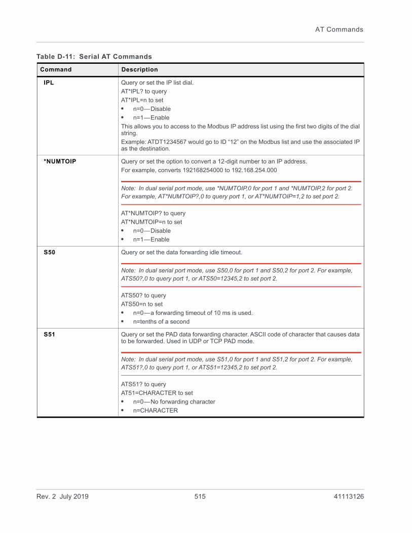
AT Commands
IPL Query or set the IP list dial.
AT*IPL? to query
AT*IPL=n to set
• n=0—Disable
• n=1—Enable
This allows you to access to the Modbus IP address list using the first two digits of the dial string.
Example: ATDT1234567 would go to ID “12” on the Modbus list and use the associated IP as the destination.
*NUMTOIP Query or set the option to convert a 12-digit number to an IP address.
For example, converts 192168254000 to 192.168.254.000
Note: In dual serial port mode, use *NUMTOIP,0 for port 1 and *NUMTOIP,2 for port 2. For example, AT*NUMTOIP?,0 to query port 1, or AT*NUMTOIP=1,2 to set port 2.
AT*NUMTOIP? to query
AT*NUMTOIP=n to set
• n=0—Disable
• n=1—Enable
S50 Query or set the data forwarding idle timeout.
Note: In dual serial port mode, use S50,0 for port 1 and S50,2 for port 2. For example, ATS50?,0 to query port 1, or ATS50=12345,2 to set port 2.
ATS50? to query
ATS50=n to set
• n=0—a forwarding timeout of 10 ms is used.
• n=tenths of a second
S51 Query or set the PAD data forwarding character. ASCII code of character that causes data to be forwarded. Used in UDP or TCP PAD mode.
Note: In dual serial port mode, use S51,0 for port 1 and S51,2 for port 2. For example, ATS51?,0 to query port 1, or ATS51=12345,2 to set port 2.
ATS51? to query
AT51=CHARACTER to set
• n=0—No forwarding character
• n=CHARACTER
Table D-11: Serial AT Commands
Command Description
Rev. 2 July 2019 515 41113126

ALEOS 4.12.0 Software Configuration User Guide for AirLink RV55
S53 Query or set the method (dial mode), destination IP address, and port used as defaults for the D (Dial) AT command.
Note: In dual serial port mode, use S53,0 for port 1 and S53,2 for port 2. For example, ATS53?,0 to query port 1, or ATS53=[method][d.d.d.d][/ppppp],2 to set port 2.
ATS53? to query
ATS53=[method][d.d.d.d][/ppppp] to set
[method] can be:
• P—UDP
• T—TCP
[d.d.d.d] is the destination IP address
[pppp] is the port number.
Example:
ATS53=P111.22.33.44/5555
where:
• The first character is the dial mode (P in this example)
• Followed by destination IP address (111.22.33.44 in this example)
• A slash
• Followed by the destination port (5555 in this example)
You can also use this command to set only the port. For example, AT53=/7777.
S60 Query or set the Telnet Client Echo Mode.
ATS60? to query
ATS60=n to set
• n=0—No Echo
• n=1—Local Echo (default)
• n=2—Remote Echo
S82 Query or set UDP auto answer.
Note: In dual serial port mode, use S82,0 for port 1 and S82,2 for port 2. For example, ATS82?,0 to query port 1, or ATS82=1,2 to set port 2.
ATS82? to query
ATS82=n to set
• n=0—Disable
• n=1—Enable
Table D-11: Serial AT Commands
Command Description
Rev. 2 July 2019 516 41113126

AT Commands
S83 Query or set the UDP auto answer idle timeout. If no data is sent or received before the timeout occurs, the current UDP session is terminated. While a session is active, packets from other IP addresses are discarded (unless *UALL is set).
ATS83? to query
ATS83=n to set
• n=0—No idle timeout (default)
• n=1–255—Timeout in seconds
Note: This AT command only takes effect if the UDP Auto Answer (S82) is set to Enable.
*SERIALLEDDISPLAY Query or set whether or not the Activity LED on the AirLink RV55 indicates traffic on the selected serial port.
AT*SERIALLEDDISPLAY? to query
AT*SERIALLEDDISPLAY=n to set
• n=0—LED display of serial traffic disabled (default)
• n=1—LED display of serial traffic enabled
For a description of the Activity LED when this parameter is enabled, see Display on page 335.
*SERIALLEDPORT Query or set the port for which the Activity LED will indicate traffic.
AT*SERIALLEDPORT? to query
AT*SERIALLEDPORT=n to set
• n=0—Primary serial port (default)
• n=1—I/O port, when configured for RS-485
TCPS Query or set the TCP connection timeout (TCPS) units. If there is no traffic through the TCP connection for the specified interval, the connection is terminated.
Note: In dual serial port mode, use TCPS,0 for port 1 and TCPS,2 for port 2. For example, ATTCPS?,0 to query port 1, or ATTCPS=1,2 to set port 2.
ATTCPS? to query
ATTCPS=n to set
• n=0—minutes
• n=1—seconds
TCPT Query or set the interval to terminate a TCP connection when there is no traffic. This value affects only the TCP connection in TCP PAD mode.
Note: In dual serial port mode, use TCPT,0 for port 1 and TCPT,2 for port 2. For example, ATTCPT?,0 to query port 1, or ATTCPT=1,2 to set port 2.
ATTCPT? to query
ATTCPT=n to set
• n=0–255
Table D-11: Serial AT Commands
Command Description
Rev. 2 July 2019 517 41113126

ALEOS 4.12.0 Software Configuration User Guide for AirLink RV55
*UALL Query or set the ability to accept UDP packets from any IP address when a UDP session is active. If there is no UDP session active, an incoming UDP packet will be treated according to the UDP auto answer and AIP settings.
Note: In dual serial port mode, use *UALL,0 for port 1 and *UALL,2 for port 2. For example, AT*UALL?,0 to query port 1, or AT*UALL=1,2 to set port 2.
AT*UALL? to query
AT*UALL=n to set
• n=0—No effect (default)
• n=1—Accept UDP data from all IP addresses when in a UDP session
*UDPLAST Query or set the option to set S53 to the last accepted IP address through UDP auto answer. This can be used in conjunction with MD3 so that when there is no UDP session, new Ethernet host data will cause a connection to be restored to the last IP accepted through UDP auto answer.
Note: In dual serial port mode, use *UDPLAST,0 for port 1 and *UDPLAST,2 for port 2. For example, AT*UDPLAST?,0 to query port 1, or AT*UDPLAST=1,2 to set port 2.
AT*UDPLAST? to query
AT*UDPLAST=n to set
• n=0—Does not change destination IP (default)
• n=1—Change destination IP to last received
*UDPPADMTU Query or set the size of serial MTU (PAD payload).
AT*UDPPADMTU? to query
AT*UDPPADMTU=n to set
• n=256–4096
*USD Query or set the specified delay before sending the UDP packets out the serial port.
Note: In dual serial port mode, use *USD,0 for port 1 and *USD,2 for port 2. For example, AT*USD?,0 to query port 1, or AT*USD=1,2 to set port 2.
AT*USD? to query
AT*USD=n to set
• n=0—No UDP packet delay (default)
• n=1–255—Delay in 100 ms units, from 100 ms to 25.5 sec.
Table D-11: Serial AT Commands
Command Description
Rev. 2 July 2019 518 41113126
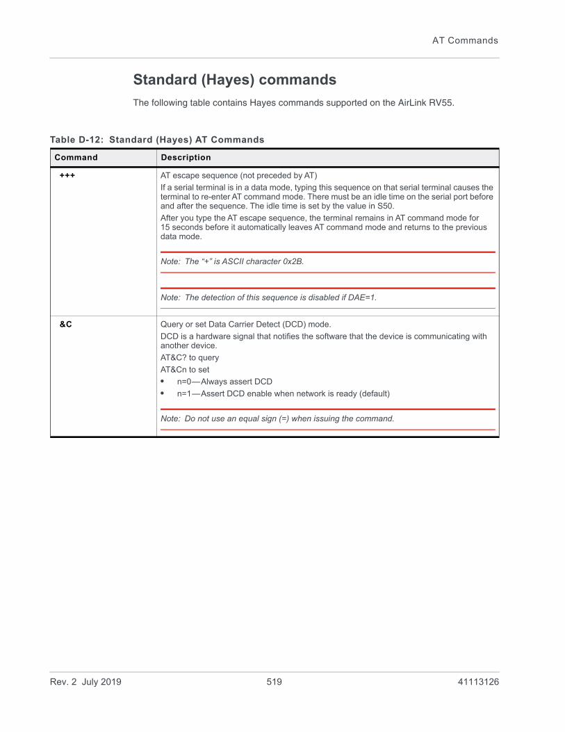
AT Commands
Standard (Hayes) commands
The following table contains Hayes commands supported on the AirLink RV55.
Table D-12: Standard (Hayes) AT Commands
Command Description
+++ AT escape sequence (not preceded by AT)
If a serial terminal is in a data mode, typing this sequence on that serial terminal causes the terminal to re-enter AT command mode. There must be an idle time on the serial port before and after the sequence. The idle time is set by the value in S50.
After you type the AT escape sequence, the terminal remains in AT command mode for 15 seconds before it automatically leaves AT command mode and returns to the previous data mode.
Note: The “+” is ASCII character 0x2B.
Note: The detection of this sequence is disabled if DAE=1.
&C Query or set Data Carrier Detect (DCD) mode.
DCD is a hardware signal that notifies the software that the device is communicating with another device.
AT&C? to query
AT&Cn to set
• n=0—Always assert DCD
• n=1—Assert DCD enable when network is ready (default)
Note: Do not use an equal sign (=) when issuing the command.
Rev. 2 July 2019 519 41113126

ALEOS 4.12.0 Software Configuration User Guide for AirLink RV55
D[method] [d.d.d.d] [/ppppp]orD[method] [[@]name] [/ppppp]
Dial a connection to a remote IP and Port using either UDP, TCP, or Telnet.
You can only use ATD#19788 and ATDT#19788 locally.
method =
P—Establish a UDP connectionT—Establish a TCP connectionN—Establish a Telnet connection
d.d.d.d = IP address to establish connection to
name = Domain name to establish connection to
ppppp = IP port to establish connection to
Examples:
ATD—Dial (establish) default connection per S53
ATDPnnn.nnn.nnn.nnn[/ppppp]—Dial (establish) UDP session to the specified IP address/port.
If the method, IP address, or port is omitted, the values from S53 are used. If a Telnet connection is requested (N) and the port is not supplied, port 23 will be used instead of the value from S53.
Several special dialing numbers exist to make it easy to establish a PPP connection with the device. ATD#19788 or ATDT#19788 will establish a PPP connection (see \APPP on page 511).
If a domain name is specified, the ‘@’ symbol can be used to explicitly indicate the start of the name. For example, if “ATDPHONY” is issued, this will be interpreted as dial a UDP connection to “HONY”. To dial using the default method to host “PHONY”, one would issue “ATD@PHONY”.
To end the connection, issue the +++ escape sequence or drop the DTR line (if Ignore DTR S211=0 or &D2).
Note: The source port of the session is the Device Port (set by *DPORT).
&D Query or set Data Terminal Ready (DTR) mode.
AT&D? to query
AT&Dn to set
• n=0—Devices ignores DTR, same effect as HW DTR always asserted (same as S211=1); DTD is assumed to be on.
• n=1—DRT drop causes the device to switch to AT command mode, but does not drop the connection.
• n=2—DTR drop causes the connection to drop.
• n=3—DTR drop causes the connection to reinitialize.
Note: Do not use an equal sign (=) when issuing the command.
Table D-12: Standard (Hayes) AT Commands
Command Description
Rev. 2 July 2019 520 41113126

AT Commands
*DATZ Query or set the option to block device reset using ATZ.
Note: In dual serial port mode, use *DATZ,0 for port 1 and *DATZ,2 for port 2. For example, AT*DATZ?,0 to query port 1, or AT*DATZ=1,2 to set port 2.
AT*DATZ? to query
AT*DATZ=n to set
• n=0—Off. Block is disabled—ATZ resets the device. (default)
• n=1—On. Block is enabled—ATZ does not reset the device.
E Toggle AT command echo mode.
Note: In dual serial port mode, use E,0 for port 1 and E,2 for port 2. For example, ATE?,0 to query port 1, or ATE1,2 to set port 2.
ATE? to query
ATEn to set
• n=0—Echo Off; does not echo commands to the computer
• n=1—Echo On; echoes commands to the computer (so you can see what you type)
Note: Do not use an equal sign (=) when issuing the command.
H ATH hangs up, immediately terminates the session (PAD or PPP).
HOR Half-Open Response—In UDP auto answer (half-open) mode.
Note: In dual serial port mode, use HOR,0 for port 1 and HOR,2 for port 2. For example, ATHOR?,0 to query port 1, or ATHOR=1,2 to set port 2.
ATHOR? to query
ATHOR=n to set
• n=0—No response codes when UDP session is initiated
• n=1—RING CONNECT response codes sent out serial link before the data from the first UDP packet
Note: Quiet Mode must be Off.
Table D-12: Standard (Hayes) AT Commands
Command Description
Rev. 2 July 2019 521 41113126
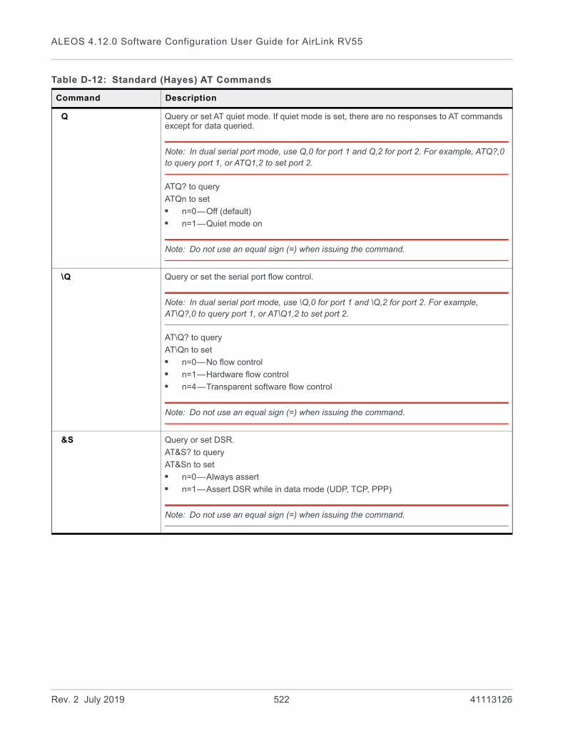
ALEOS 4.12.0 Software Configuration User Guide for AirLink RV55
Q Query or set AT quiet mode. If quiet mode is set, there are no responses to AT commands except for data queried.
Note: In dual serial port mode, use Q,0 for port 1 and Q,2 for port 2. For example, ATQ?,0 to query port 1, or ATQ1,2 to set port 2.
ATQ? to query
ATQn to set
• n=0—Off (default)
• n=1—Quiet mode on
Note: Do not use an equal sign (=) when issuing the command.
\Q Query or set the serial port flow control.
Note: In dual serial port mode, use \Q,0 for port 1 and \Q,2 for port 2. For example, AT\Q?,0 to query port 1, or AT\Q1,2 to set port 2.
AT\Q? to query
AT\Qn to set
• n=0—No flow control
• n=1—Hardware flow control
• n=4—Transparent software flow control
Note: Do not use an equal sign (=) when issuing the command.
&S Query or set DSR.
AT&S? to query
AT&Sn to set
• n=0—Always assert
• n=1—Assert DSR while in data mode (UDP, TCP, PPP)
Note: Do not use an equal sign (=) when issuing the command.
Table D-12: Standard (Hayes) AT Commands
Command Description
Rev. 2 July 2019 522 41113126

AT Commands
S0 Query or set TCP auto answer (the number of rings required before the device automatically answers a call).
Note: In dual serial port mode, use S0,0 for port 1 and S0,2 for port 2. For example, ATS0?,0 to query port 1, or ATS01,2 to set port 2.
ATS0? to query
ATS0n to set
• n=0—Disable
• n=1—Enable
Note: Do not use an equal sign (=) when issuing the command.
S7 Query or set the number or seconds to wait for connection completion.
Note: In dual serial port mode, use S7,0 for port 1 and S7,2 for port 2. For example, ATS7?,0 to query port 1, or ATS71,2 to set port 2.
ATS7? to query
ATS7n to set
• n=0–255
Table D-12: Standard (Hayes) AT Commands
Command Description
Rev. 2 July 2019 523 41113126
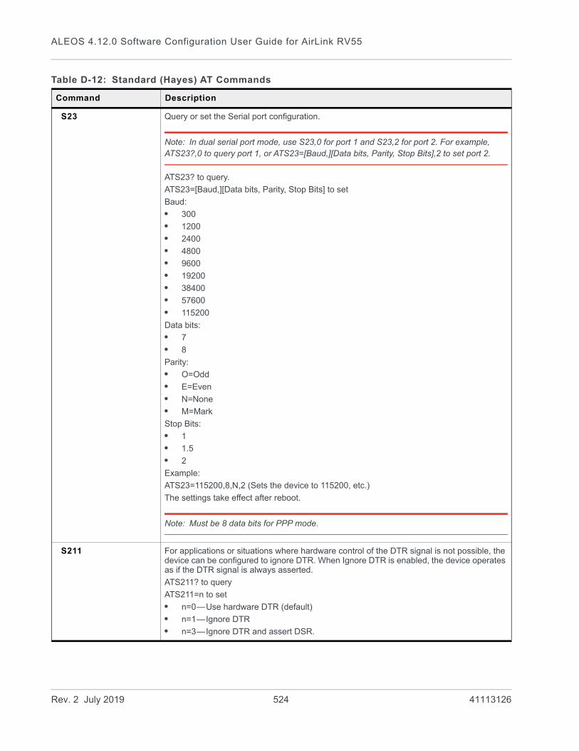
ALEOS 4.12.0 Software Configuration User Guide for AirLink RV55
S23 Query or set the Serial port configuration.
Note: In dual serial port mode, use S23,0 for port 1 and S23,2 for port 2. For example, ATS23?,0 to query port 1, or ATS23=[Baud,][Data bits, Parity, Stop Bits],2 to set port 2.
ATS23? to query.
ATS23=[Baud,][Data bits, Parity, Stop Bits] to set
Baud:
• 300
• 1200
• 2400
• 4800
• 9600
• 19200
• 38400
• 57600
• 115200
Data bits:
• 7
• 8
Parity:
• O=Odd
• E=Even
• N=None
• M=Mark
Stop Bits:
• 1
• 1.5
• 2
Example:
ATS23=115200,8,N,2 (Sets the device to 115200, etc.)
The settings take effect after reboot.
Note: Must be 8 data bits for PPP mode.
S211 For applications or situations where hardware control of the DTR signal is not possible, the device can be configured to ignore DTR. When Ignore DTR is enabled, the device operates as if the DTR signal is always asserted.
ATS211? to query
ATS211=n to set
• n=0—Use hardware DTR (default)
• n=1—Ignore DTR
• n=3—Ignore DTR and assert DSR.
Table D-12: Standard (Hayes) AT Commands
Command Description
Rev. 2 July 2019 524 41113126

AT Commands
S221 Query or set the Connect Delay—the number of seconds to delay the connect response when establishing a TCP connection.
Note: In dual serial port mode, use S221,0 for port 1 and S221,2 for port 2. For example, ATS221?,0 to query port 1, or ATS221=1,2 to set port 2.
ATS221? to query
ATS221=n to set
• n=0–255
V Query or set the AT command responses (verbosity).
Note: In dual serial port mode, use V,0 for port 1 and V,2 for port 2. For example, ATV?,0 to query port 1, or ATV1,2 to set port 2.
ATV? to query
ATVn to set
• n=0—Numeric (terse) command responses (The numeric responses follow the Hayes Standards for commands.)
• n=1—Text string (verbose) command responses (default)
Note: Do not use an equal sign (=) when issuing the command.
&V Lists most AT commands and their current values. If the parameter is not configured, the AT command returns “Not Set”.
&W Saves the settings for parameters that are temporarily set without being permanently written to the memory.
This command does not apply to ALEOS because once you issue an AT command or change a setting in ACEmanager and click Apply, the changes are saved in non-volatile memory and are persist across reboots.
X Query or set the Extended Call Progress Result mode.
Note: In dual serial port mode, use X,0 for port 1 and X,2 for port 2. For example, ATX?,0 to query port 1, or ATX1,2 to set port 2.
ATX? to query
ATXn to set
• n=0—No extended code (default)
• n=1—Adds the text 19200 to the connect response
Z Reboots the AirLink RV55.
Note: If *DATZ is set to 1, Z is blocked. See *DATZ on page 521.
Table D-12: Standard (Hayes) AT Commands
Command Description
Rev. 2 July 2019 525 41113126
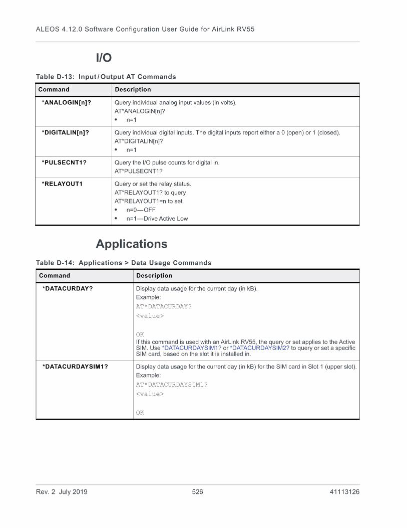
ALEOS 4.12.0 Software Configuration User Guide for AirLink RV55
I/O
Applications
Table D-13: Input / Output AT Commands
Command Description
*ANALOGIN[n]? Query individual analog input values (in volts).
AT*ANALOGIN[n]?
• n=1
*DIGITALIN[n]? Query individual digital inputs. The digital inputs report either a 0 (open) or 1 (closed).
AT*DIGITALIN[n]?
• n=1
*PULSECNT1? Query the I/O pulse counts for digital in.
AT*PULSECNT1?
*RELAYOUT1 Query or set the relay status.
AT*RELAYOUT1? to query
AT*RELAYOUT1=n to set
• n=0—OFF
• n=1—Drive Active Low
Table D-14: Applications > Data Usage Commands
Command Description
*DATACURDAY? Display data usage for the current day (in kB).
Example:
AT*DATACURDAY?<value>
OKIf this command is used with an AirLink RV55, the query or set applies to the Active SIM. Use *DATACURDAYSIM1? or *DATACURDAYSIM2? to query or set a specific SIM card, based on the slot it is installed in.
*DATACURDAYSIM1? Display data usage for the current day (in kB) for the SIM card in Slot 1 (upper slot).
Example:
AT*DATACURDAYSIM1?<value>
OK
Rev. 2 July 2019 526 41113126
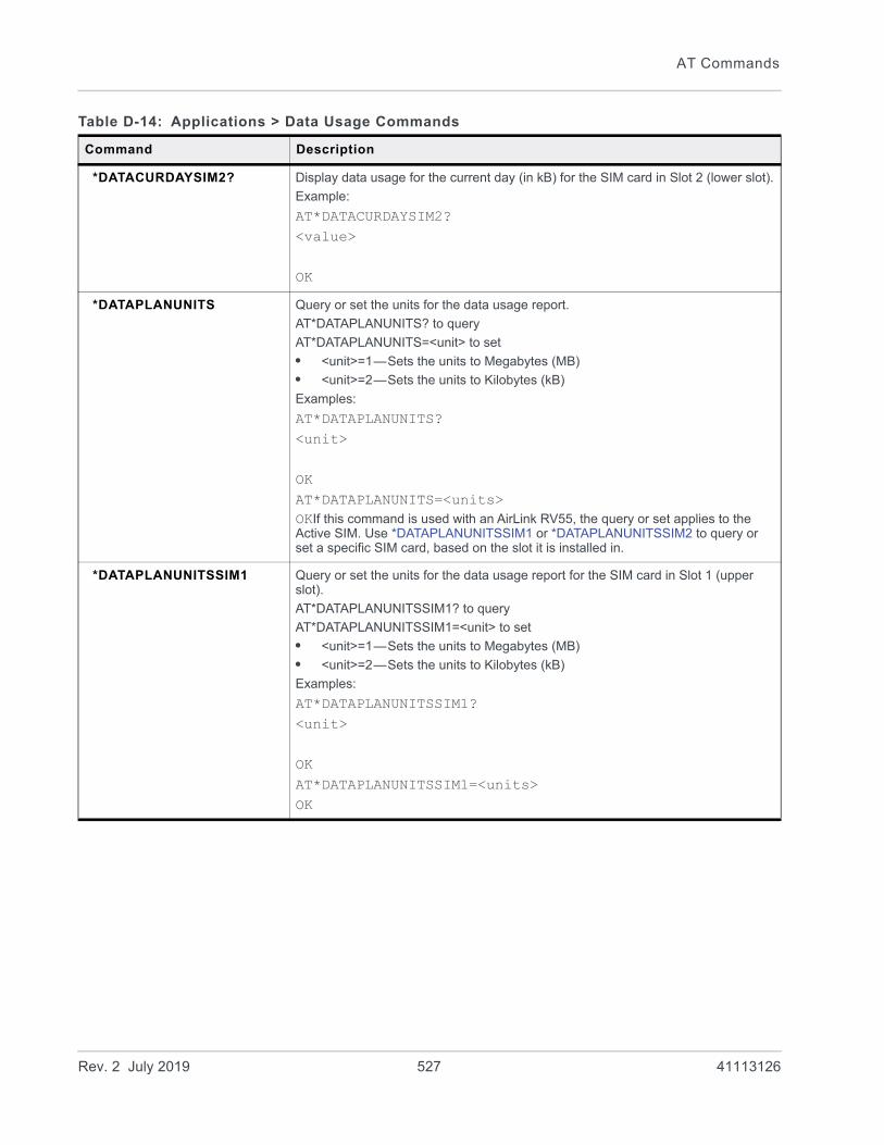
AT Commands
*DATACURDAYSIM2? Display data usage for the current day (in kB) for the SIM card in Slot 2 (lower slot).
Example:
AT*DATACURDAYSIM2?<value>
OK
*DATAPLANUNITS Query or set the units for the data usage report.
AT*DATAPLANUNITS? to query
AT*DATAPLANUNITS=<unit> to set
• <unit>=1—Sets the units to Megabytes (MB)
• <unit>=2—Sets the units to Kilobytes (kB)
Examples:
AT*DATAPLANUNITS?<unit>
OKAT*DATAPLANUNITS=<units>OKIf this command is used with an AirLink RV55, the query or set applies to the Active SIM. Use *DATAPLANUNITSSIM1 or *DATAPLANUNITSSIM2 to query or set a specific SIM card, based on the slot it is installed in.
*DATAPLANUNITSSIM1 Query or set the units for the data usage report for the SIM card in Slot 1 (upper slot).
AT*DATAPLANUNITSSIM1? to query
AT*DATAPLANUNITSSIM1=<unit> to set
• <unit>=1—Sets the units to Megabytes (MB)
• <unit>=2—Sets the units to Kilobytes (kB)
Examples:
AT*DATAPLANUNITSSIM1?<unit>
OKAT*DATAPLANUNITSSIM1=<units>OK
Table D-14: Applications > Data Usage Commands
Command Description
Rev. 2 July 2019 527 41113126

ALEOS 4.12.0 Software Configuration User Guide for AirLink RV55
*DATAPLANUNITSSIM2 Query or set the units for the data usage report for the SIM card in Slot 2 (lower slot).
AT*DATAPLANUNITSSIM2? to query
AT*DATAPLANUNITSSIM2=<unit> to set
• <unit>=1—Sets the units to Megabytes (MB)
• <unit>=2—Sets the units to Kilobytes (kB)
Examples:
AT*DATAPLANUNITSSIM2?<unit>
OKAT*DATAPLANUNITSSIM2=<units>OK
*DATAPREVDAY? Query the data usage for the previous day (in kB).
Example:
AT*DATAPREVDAY?<value>
OKIf this command is used with an AirLink RV55, the query or set applies to the Active SIM. Use *DATAPREVDAYSIM1? or *DATAPREVDAYSIM2? to query or set a specific SIM card, based on the slot it is installed in.
*DATAPREVDAYSIM1? Query the data usage for the previous day (in kB) for the SIM card in Slot 1 (upper slot).
Example:
AT*DATAPREVDAYSIM1?<value>
OK
*DATAPREVDAYSIM2? Query the data usage for the previous day (in kB) for the SIM card in Slot 2 (lower slot).
Example:
AT*DATAPREVDAYSIM2?<value>
OK
Table D-14: Applications > Data Usage Commands
Command Description
Rev. 2 July 2019 528 41113126
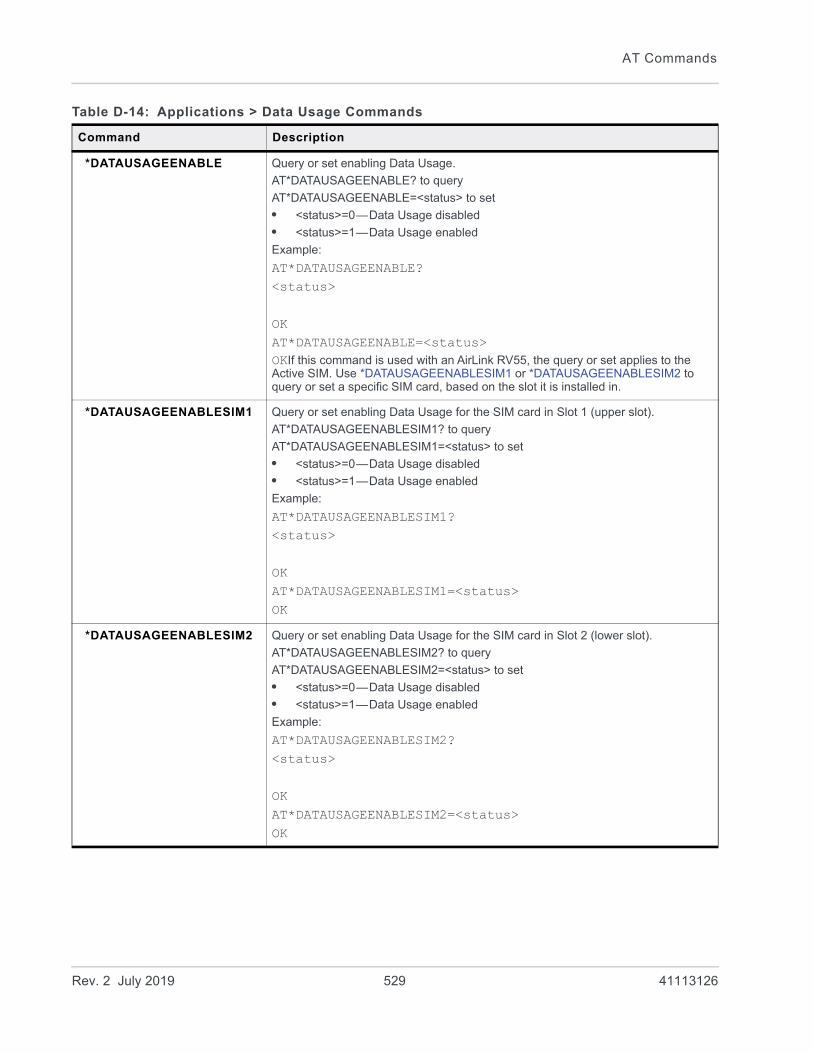
AT Commands
*DATAUSAGEENABLE Query or set enabling Data Usage.
AT*DATAUSAGEENABLE? to query
AT*DATAUSAGEENABLE=<status> to set
• <status>=0—Data Usage disabled
• <status>=1—Data Usage enabled
Example:
AT*DATAUSAGEENABLE? <status>
OKAT*DATAUSAGEENABLE=<status>OKIf this command is used with an AirLink RV55, the query or set applies to the Active SIM. Use *DATAUSAGEENABLESIM1 or *DATAUSAGEENABLESIM2 to query or set a specific SIM card, based on the slot it is installed in.
*DATAUSAGEENABLESIM1 Query or set enabling Data Usage for the SIM card in Slot 1 (upper slot).
AT*DATAUSAGEENABLESIM1? to query
AT*DATAUSAGEENABLESIM1=<status> to set
• <status>=0—Data Usage disabled
• <status>=1—Data Usage enabled
Example:
AT*DATAUSAGEENABLESIM1? <status>
OKAT*DATAUSAGEENABLESIM1=<status>OK
*DATAUSAGEENABLESIM2 Query or set enabling Data Usage for the SIM card in Slot 2 (lower slot).
AT*DATAUSAGEENABLESIM2? to query
AT*DATAUSAGEENABLESIM2=<status> to set
• <status>=0—Data Usage disabled
• <status>=1—Data Usage enabled
Example:
AT*DATAUSAGEENABLESIM2? <status>
OKAT*DATAUSAGEENABLESIM2=<status>OK
Table D-14: Applications > Data Usage Commands
Command Description
Rev. 2 July 2019 529 41113126
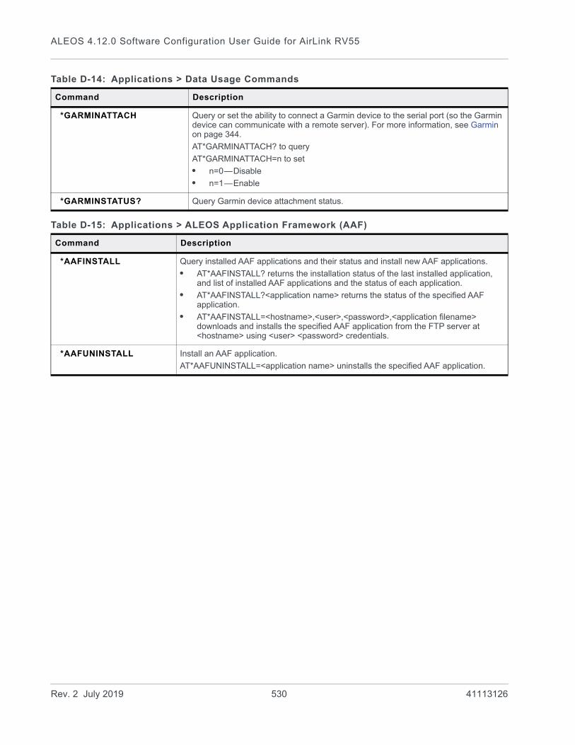
ALEOS 4.12.0 Software Configuration User Guide for AirLink RV55
*GARMINATTACH Query or set the ability to connect a Garmin device to the serial port (so the Garmin device can communicate with a remote server). For more information, see Garmin on page 344.
AT*GARMINATTACH? to query
AT*GARMINATTACH=n to set
• n=0—Disable
• n=1—Enable
*GARMINSTATUS? Query Garmin device attachment status.
Table D-15: Applications > ALEOS Application Framework (AAF)
Command Description
*AAFINSTALL Query installed AAF applications and their status and install new AAF applications.
• AT*AAFINSTALL? returns the installation status of the last installed application, and list of installed AAF applications and the status of each application.
• AT*AAFINSTALL?<application name> returns the status of the specified AAF application.
• AT*AAFINSTALL=<hostname>,<user>,<password>,<application filename> downloads and installs the specified AAF application from the FTP server at <hostname> using <user> <password> credentials.
*AAFUNINSTALL Install an AAF application.
AT*AAFUNINSTALL=<application name> uninstalls the specified AAF application.
Table D-14: Applications > Data Usage Commands
Command Description
Rev. 2 July 2019 530 41113126
AT Commands
Admin
Table D-16: Admin > Advanced Commands
Command Description
\ACEPW Set the ACEmanager user password remotely.AT\ACEPW=<password> to set
• <password>=character string
The password can be 8 to 32 characters long and can contain a mixture of letters, numbers, and/or special characters. The password is case sensitive.
Note: The special character comma ‘,’ cannot be used.
To change the password, send the AT Command. You will not be asked to re-enter or confirm the new password.
Note: If the password is lost, the only way to recover access to the AirLink gateway is to press the hardware Reset button to reset all device settings to factory default. After resetting to factory defaults, the user password will be reset to the default password. If the gateway supports unique default passwords, the default password will be printed on the device label. Note that using the Reset button also resets the M3DA password to the default password. For more infor-mation, see Change Password on page 358.
*BLOCK_RESET_CONFIG Query or set the ability to block resetting the device to factory default settings using the hardware Reset button.AT*BLOCK_RESET_CONFIG? to queryAT*BLOCK_RESET_CONFIG=n to set
• n=0—Reset button can be used to reset the device to factory default settings. (default).
• n=1—Device cannot be reset to factory default settings using the Reset button on the device.
Note: This command only blocks the ability to reset to defaults using the Reset button on the device. You can still reset the device to the factory default settings using the “Reset to Factory Default” button in ACEmanager or the *RESETCFG AT command.
*BOARDTEMP? Query the temperature of the internal hardware, in degrees Celsius.
*MSCIUPDADDR Query or set the IP address or FQDN and port that periodic device status updates are sent to.
AT*MSCIUPDADDR? to query
AT*MSCIUPDADDR=[IP address or FQDN][/port] to set
Examples: 192.168.14.100/3333
MyDevice.com/3333
Rev. 2 July 2019 531 41113126

ALEOS 4.12.0 Software Configuration User Guide for AirLink RV55
*MSCIUPDPERIOD Query or set the device status update interval (in seconds). This specifies how frequently the device status update is sent to the port configured in *MSCIUPDADDR.
AT*MSCIUPDPERIOD? to query
AT*MSCIUPDPERIOD=n to set
• n=0—Disabled
• n=1–255 seconds
NSLOOKUP Immediately performs an NSLookup on the supplied FQDN.
ATNSLOOKUP=[FQDN]
*POWERIN? Query the voltage input to the internal hardware.
*RESETCFG AT*RESTCFG resets the device to factory default settings according to the Reset Mode configured on the Admin > Advanced page. See Reset Mode on page 370.
Important: There is no confirmation requested. The AT command takes effect immediately.
*REMOTELOG Exports the log file to a remote destination (Syslog Server).
AT*REMOTELOG=<server>[,<port>,<format>,<protocol>,<encrypt>] where:
parameters between brackets are optional. If the port is not specified, the default port, 514, is used.
Note: This AT command is backwardly compatible with the existing AT command AT*REMOTELOG=<server>,<port>.
*SECUREMODE Query or set the secure mode that blocks most ports (and ICMP) for over-the-air (OTA) or OTA and local to prevent unwanted access to the device.
AT*SECUREMODE? to query
AT*SECUREMODE=n to set
• n=0 Off; normal behavior
• n=1 Disables:
• Web management ports (ACEmanager and ALMS access) from the OTA interface
• Internet Control Message Protocol (ICMP), used for PING, for OTA and Wi-Fi
• n=2 Disables:
• Web management ports from the Over-the-air (OTA) interface
• Internet Control Message Protocol (ICMP) for OTA and Wi-Fi
• ICMP for local ports (Ethernet, USB, and Serial)
Note: Telnet and SSH ALEOS ports remain open regardless of the secure mode setting. This enables you to connect an AT console to manage the device. DHCP and DNS ports also remain open to allow the device to provide IP addresses to hosts and relay the DNS service.
Table D-16: Admin > Advanced Commands
Command Description
Rev. 2 July 2019 532 41113126

AT Commands
*SYSRESETS? Query the number of resets since the device was reset to factory default settings.
*USBBYPASS Query or set Radio Passthru mode.
AT*USBBYPASS? to query
AT*USBBYPASS=n to set
• n=0—Disable
• n=1—Enable
Table D-16: Admin > Advanced Commands
Command Description
Rev. 2 July 2019 533 41113126
E
E: SMS CommandsSMS Command format
PW [Password] [Prefix][Command or Command parameter1] [Command parameter2 (if applicable)] [Command parameter n]
Note: There is no space between the prefix and the command (or the 1st command parameter in the case of multi-parameter commands). There must be a single space between all other fields to act as a delimiter.
The default password is the last 4 digits of the SIM ID number (for SIM-based devices) and the last 4 digits of the ESN (for non-SIM devices). If you do not know the SIM ID or ESN number, you can find it in ACEmanager on the Status > WAN/Cellular page.
The default prefix is “&&&”.
Whether or not a password and prefix are required varies depending on the SMS mode selected in ACEmanager.
When an SMS command is received, the AirLink RV55 performs the action requested and sends a response back to the phone number from which it received the SMS.
For more examples and detailed instructions, see SMS Overview on page 230.
SMS mode Password(configurable in all modes)
Prefix
Password Only Always required RequiredUse default (not configurable)
Control Only Required when sending from a non-trusted phone number
Prefix is configurable.
The prefix can be omitted if the ALEOS Command Prefix field in ACEmanager (Services > SMS) is configured to be blank.
Gateway Only Always required RequiredUse default (not configurable)
Control and Gateway
Required when sending from a non-trusted phone number
RequiredConfigurable, but cannot be blank
Rev. 2 July 2019 534 41113126

SMS Commands
List of SMS Commands
Command Action Result
Note: Some responses start with “reply from [device name]:” However, this feature is currently unavailable for the Enable and Provision commands.
[prefix]enable <value> Enable/disable the device(s) being managed by ALMS.
“AVMS enable set to status:” <value>
<value>=0 Disable
<value>=1 MSCI
<value>=2 LWM2M
<value>=3 Try LWM2M, Fallback to MSCI
[prefix]status None status IP
[Network IP] [Network Status]:
[technology type] RSS signaled
Lat = [Latitude]
Long = [Longitude]
Time = [hh:mm:ss]
Note: Location Service must be enabled to obtain Lat and Long data.
[prefix]reset Resets the device 30 seconds after the first response message is sent.
First message: Reset in 30 seconds
Second message: Status message when back up.
[prefix]relay x y Sets the I/O relay to the desired setting.
relay x set to y
x can be 1
y can be 0 or 1 (Off or Drive active low)
[prefix]relay x ? Queries the current value of the I/O relay.
relay x set at y
x can be 1
y is the current value of the I/O relay. (0 = Off; 1 = Drive active low)
[prefix]gps The device replies with its current location.
The device sends a link to a map showing its location. You can copy the link into a browser to view the location, or if the SMS is sent from a smartphone, you can click the link to view the map.
Note: Location Service must be enabled.
Rev. 2 July 2019 535 41113126
ALEOS 4.12.0 Software Configuration User Guide for AirLink RV55
[prefix]Provision <APN> <Network User ID> <Network Password> <Network Authentication Mode>
Note: You can omit any of the above parameters.
• To omit a parameter before the one you want to change, use a period (.) in place of the omitted parameter.Example: &&&provision . [email protected] . chap changes only the user ID and authen-tication mode.
• If you want to omit any parameters after the one you want to change, simply omit them. Example: &&&provision access.apn changes only the apn.
After the unit is installed and the SIM card inserted, you can use this command to provision the account.
Network Authentication Mode is optional. If used, enter one of the following:
• None
• PAP
• CHAP
These are not case sensitive.
If an unknown mode is entered or the field is omitted, None is used.
“provision”
“apn:” <APN>
“user ID” <Network User ID>
“PW” <Network Password>
“auth mode” <Network Authentication Mode>
Note: If a parameter is omitted, the response displays “Not Set” for that parameter.
[prefix]AVMS <server> <interval>
Note: All of the above must be on a single line. The interval must be greater than 0. Omitting any field results in a response of “not set” and the configuration parameter does not change.
Modifies the ALMS server’s URL and ALMS communication period (interval in minutes)
“AVMS”
“srv:” <Server>
“interval:” <Interval>
[prefix]AVMSCHECKIN Prompts the device to communicate with the ALMS server. Once AirLink Management Service receives the heartbeat message, it can respond and send an MSCI command to the device (i.e Write/Read/Firmware Update).
“AVMS connection requested”
Command Action Result
Rev. 2 July 2019 536 41113126

F
F: Q & A and TroubleshootingACEmanager Web UI
The ACEmanager page is not displaying properly.1. Ensure the you are using a supported browser. See page 15 for a list of supported
browsers.
2. Hold the Shift key + click the Refresh button. This reloads the page, while ignoring what is in the cache.
If the problem persists:• Clear the cache. The procedure varies, depending on the browser.• Restart the browser.• Restart your computer.
Templates
The template does not upload properly when I use Internet Explorer 9.
To resolve the problem:
1. In Internet Explorer 9, go to Tools > Internet Options.
2. Select the Security tab.
Figure F-1: Internet Explorer 9: Tools > Internet Options > Security tab
3. Click Custom level....
4. Scroll down until you see “Include local directory path when uploading files to a server”.
Rev. 2 July 2019 537 41113126
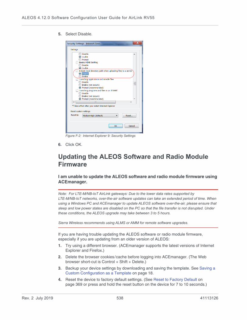
ALEOS 4.12.0 Software Configuration User Guide for AirLink RV55
5. Select Disable.
Figure F-2: Internet Explorer 9: Security Settings
6. Click OK.
Updating the ALEOS Software and Radio Module Firmware
I am unable to update the ALEOS software and radio module firmware using ACEmanager.
Note: For LTE-M/NB-IoT AirLink gateways: Due to the lower data rates supported by LTE-M/NB-IoT networks, over-the-air software updates can take an extended period of time. When using a Windows PC and ACEmanager to update ALEOS software over-the-air, please ensure that sleep and low power states are disabled on the PC so that the file transfer is not disrupted. Under these conditions, the ALEOS upgrade may take between 3 to 5 hours.
Sierra Wireless recommends using ALMS or AMM for remote software upgrades.
If you are having trouble updating the ALEOS software or radio module firmware, especially if you are updating from an older version of ALEOS:
1. Try using a different browser. (ACEmanager supports the latest versions of Internet Explorer and Firefox.)
2. Delete the browser cookies/cache before logging into ACEmanager. (The Web browser short-cut is Control + Shift + Delete.)
3. Backup your device settings by downloading and saving the template. See Saving a Custom Configuration as a Template on page 18.
4. Reset the device to factory default settings. (See Reset to Factory Default on page 369 or press and hold the reset button on the device for 7 to 10 seconds.)
Rev. 2 July 2019 538 41113126
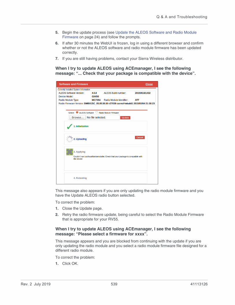
Q & A and Troubleshooting
5. Begin the update process (see Update the ALEOS Software and Radio Module Firmware on page 24) and follow the prompts.
6. If after 30 minutes the WebUI is frozen, log in using a different browser and confirm whether or not the ALEOS software and radio module firmware has been updated correctly.
7. If you are still having problems, contact your Sierra Wireless distributor.
When I try to update ALEOS using ACEmanager, I see the following message: “... Check that your package is compatible with the device”.
This message also appears if you are only updating the radio module firmware and you have the Update ALEOS radio button selected.
To correct the problem:
1. Close the Update page.
2. Retry the radio firmware update, being careful to select the Radio Module Firmware that is appropriate for your RV55.
When I try to update ALEOS using ACEmanager, I see the following message: “Please select a firmware for xxxx”.
This message appears and you are blocked from continuing with the update if you are only updating the radio module and you select a radio module firmware file designed for a different radio module.
To correct the problem:
1. Click OK.
Rev. 2 July 2019 539 41113126

ALEOS 4.12.0 Software Configuration User Guide for AirLink RV55
2. Select a radio module firmware file for the radio module in the AirLink RV55 you are updating and click update. (To check which radio module is in your device, in ACEma-nager, go to Status > About.)
Poor Wireless Network Connection
ACE manager indicates that my AirLink RV55 has a poor wireless connection. What can I do to improve it?
For GSM networks:
1. Check the RSSI value. If ACEmanager (Status screen) indicates a good RSSI value, go to step 2. If it indicates a poor RSSI value:· Check the antenna connection.· Make sure you have the correct antenna for the device.· You may be in an area with poor coverage. Check with your Mobile Network
Operator, or if possible, try moving the AirLink RV55 to a new location.
2. Check the Ec/Io value. If ACEmanager (Status screen) indicates a poor Ec/Io value:· This may be a temporary network problem caused by local interference.· A nearby laptop or other electronic equipment may be interfering with the signal. Try
moving the AirLink RV55 to a different location.
For LTE networks:
1. Check the RSSI value. If ACEmanager (Status screen) indicates a good RSSI value, go to step 2. If it indicates a poor RSSI value:· Check the antenna connection.· Make sure you have the correct antenna for the device.· Try moving the AirLink RV55 to a different location.
2. Check the RSRP value. If ACEmanager (Status screen) indicates a good RSRP value, go to step 3. If it indicates a poor RSRP value:· This may be a temporary network problem caused by local interference.· Check the antenna connection.· Make sure you have the correct antenna for the device.· You may be in an area with poor coverage. Check with your Mobile Network
Operator, or if possible, try moving the AirLink RV55 to a new location.
3. Check the RSRQ value. If ACEmanager (Status screen) indicates a poor RSRQ value:· A nearby laptop or other electronic equipment may be interfering with the signal. Try
moving the AirLink RV55 to a different location.
Connection not working
My RV55 appears to be connected to the host, but no data is being transferred.
1. Check to see if MAC filtering is enabled (Security > MAC Filtering).
2. If MAC filtering is enabled:· Ensure that the MAC Address for the host in question is on the Allowed List.· Ensure that there are no typos in the MAC Address.
Rev. 2 July 2019 540 41113126
Q & A and Troubleshooting
ist
– Or – · If it is not required, disable MAC Filtering and reboot the device.
My host device is unable to connect to the Internet, even when there is good mobile network coverage and ALEOS can Ping an external IP address.1. Check the DNS proxy setting described on page 153.
You may need to change this setting to Disable so that all connected devices acquire the Mobile Network Operator-defined DNS server as the first DNS server. The AirLink RV55 is not used as the DNS resolver.
Wi-Fi
The Wi-Fi channel I selected is not working.
Each country controls which Wi-Fi channels are allowed in that country. If the Wi-Fi channel you selected is not working:
1. In ACEmanager, go to Wi-Fi > General > Country Code, and ensure that it is set to the country in which the router is operating.
2. Go to Wi-Fi > Access Point (LAN) > Channel and Frequency (or Channel, Frequency, Width, depending on the Access Point Mode selected), and ensure that the channel you selected is permitted in the country selected.
If you are not sure:
a. Go to Admin > Log > View Log to generate a log file. If the Wi-Fi channel selected is not permitted in the country selected in the Country Code, you will see messages similar to the following in the log file:
3. If you see this in the log, select a channel that is permitted in the country the router is operating in. (If necessary, check online resources such as https://en.wikipedia.org/wiki/List_of_WLAN_channels/ to determine the permitted channels.)
Note: The Country Code settings configure a subset of the channels available in the default setting (United States). You cannot enable any channels beyond those available in the default setting.
4. Reboot the router.
LTE Networks
How do I obtain and interpret SINR values for LTE networks?
You can use the AT*CELLINFO? command to obtain an SINR (Signal to Interference plus Noise Ratio) value. (See *CELLINFO2? on page 454.)
Apr 26 01:10:40 info ALEOS_WIFI_CRD: hostapd: uap0: IEEE 802.11 Configured channel (149) not found from the channel lof current mode (2) IEEE 802.11a
Apr 26 01:10:40 info ALEOS_WIFI_CRD: hostapd: uap0: IEEE 802.11 Hardware does not support configured channel
Rev. 2 July 2019 541 41113126

ALEOS 4.12.0 Software Configuration User Guide for AirLink RV55
The values vary depending on the network characteristics and the AirLink RV55, but in general, a positive value provides usable throughput. The following table provides guidelines for interpreting SINR values.
If the SINR value indicates poor throughput:• Move the antenna away from noisy equipment.• Move closer to the nearest cell tower line of sight, or further away from the interfering
cell tower.
SIM Card is Blocked
My SIM card has a PIN number. I’ve entered the wrong PIN several times and now the SIM card is blocked.
AirLink products do not support Personal Unlocking Key (PUK) entry. However, if you need to unblock the SIM card:
1. Contact your Mobile Network Operator to obtain the PUK.
2. Remove the SIM card from the AirLink RV55 and insert it in a cell phone that accom-modates a MiniSIM (2FF) card.
3. Enter the PUK to unblock the SIM card and then return the SIM card to the AirLink RV55.
Note: Be careful when entering the PUK. You have a limited number of attempts to enter the correct PUK (generally 10) before the SIM card is permanently disabled and a new SIM card is required. If the PUK does not unblock the SIM card after the first few attempts, contact your Mobile Network Operator.
Remote connections
I cannot connect to the AirLink RV55 remotely over the Mobile Network Operator’s Private Network via the Web UI, although I can connect to it locally.
Some Mobile Network Operators' private networks have restrictions on the maximum transmission unit (MTU) size. This is more prevalent with LTE networks.
Possible solutions:• Use your Mobile Network Operator’s public network.
SINR Value Throughput
< 0 Poor
0 to 5 Fair
6 to 10 Good
> 10 Excellent
Rev. 2 July 2019 542 41113126
Q & A and Troubleshooting
• Ask your Mobile Network Operator to reduce the MTU size on the router or other equipment at their end of the private network. Setting the MTU value below 1500 bytes (for example 1326 bytes) has resolved the problem on some private networks.
Radio Band Selection
I set the radio band in the UI (WAN/Cellular > Setting the Band) or by using the AT!BAND AT command, but after I reboot the band setting reverts to its former value.
For some SIM cards, you need to set the band before inserting the SIM card.
To resolve this problem:
1. Remove the SIM card.
2. Set the band to the desired value.
3. Reboot the device.
4. Insert the SIM card.
Low Voltage Standby Mode
How do I get my RV55 out of Low Voltage Standby mode?
The problem: While configuring Low Voltage Standby mode, I inadvertently set the Resume Immediately Voltage too high (i.e. higher than the voltage available where the RV55 is installed). Now the RV55 is stuck in standby mode.
I connected the RV55 to a higher voltage source, and it resumed normal operation. I reset the Low Voltage Standby values, but the RV55 returned to Standby mode as soon as it was reconnected to the lower voltage source, even though the lower voltage source provided a higher voltage than the new value I just set in the Resume immediately at Voltage field.
The solution: Low Voltage Standby mode settings take effect as soon as you click Apply, but they are not permanently stored until the RV55 is rebooted. To bring a RV55 out of Low Voltage Standby mode if the Resume immediately at Voltage field is set too high:
1. Connect the RV55 to a power source and supply voltage that is greater than the value configured in the Resume immediately at Voltage field.
2. When the RV55 resumes normal operation, launch ACEmanager and reset the values in the Services > Power Management > Low Voltage Standby fields.
3. While still using the voltage applied in step 1, Click the Reboot button in ACEmanager to reboot the RV55.
The RV55 reboots.
4. Wait until the RV55 reboots itself a second time, or for at least 3 minutes, if you are not sure if the RV55 has done its automatic reboot.
Once the second reboot is complete, it is safe to disconnect the RV55 from the higher power source and return it to the original installation and power source.
Rev. 2 July 2019 543 41113126

ALEOS 4.12.0 Software Configuration User Guide for AirLink RV55
Reliable Static Routing (RSR)
I launched ACEmanager with Internet Explorer 9. I configured RSR, but after I enabled RSR and clicked Apply, all the values reverted to the defaults.
There is a known issue. If you configure and enable RSR with ACEmanager in Internet Explorer 9, and then click Apply, the values in the ACEmanager screen appear as default values.
This is an ACEmanager display issue only. The configuration is applied properly, but the configured values are not displayed. Click Refresh to view the configured values.
Inbound Ports Used by ALEOS
When I configure ports for an application on a LAN client such as a router or laptop, I want to ensure that the ports I use do not conflict with the inbound ports that ALEOS uses. Which ports does ALEOS use?
Table F-1 shows the inbound ports that are set in ALEOS and cannot be configured. Table F-2 show the default setting for ports you can configure and where to change the ports in ACEmanager.
Table F-1: ALEOS Non-configurable Inbound Ports
Port Use
9494 – 9497
17335
17345 – 17353
21000 – 21003
Used internally for Location and Events Reports
500
4500
Used internally for IPSec VPN
8088 Used internally for ALMS
Table F-2: ALEOS Configurable Inbound Ports
Default Port
Feature ACEmanager location
161 SNMP Port Services > Management (SNMP)
2332 SSH/Telnet Remote Login Server Port Services > Telnet/SSH
9191 ACEmanager Port Services > ACEmanager
9300 SSL tunnel Port VPN > SSL Tunnel
9443 ACEmanager SSL Port Services > ACEmanager
Rev. 2 July 2019 544 41113126
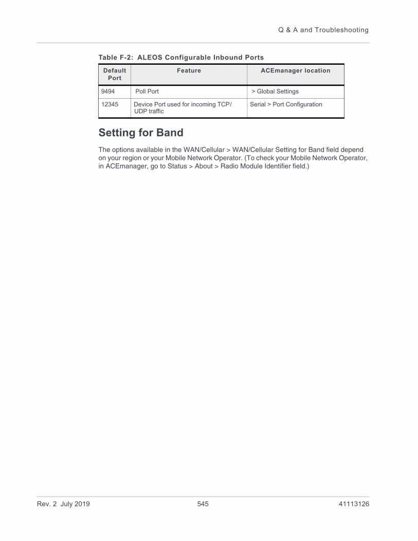
Q & A and Troubleshooting
Setting for Band
The options available in the WAN/Cellular > WAN/Cellular Setting for Band field depend on your region or your Mobile Network Operator. (To check your Mobile Network Operator, in ACEmanager, go to Status > About > Radio Module Identifier field.)
9494 Poll Port > Global Settings
12345 Device Port used for incoming TCP/UDP traffic
Serial > Port Configuration
Table F-2: ALEOS Configurable Inbound Ports
Default Port
Feature ACEmanager location
Rev. 2 July 2019 545 41113126
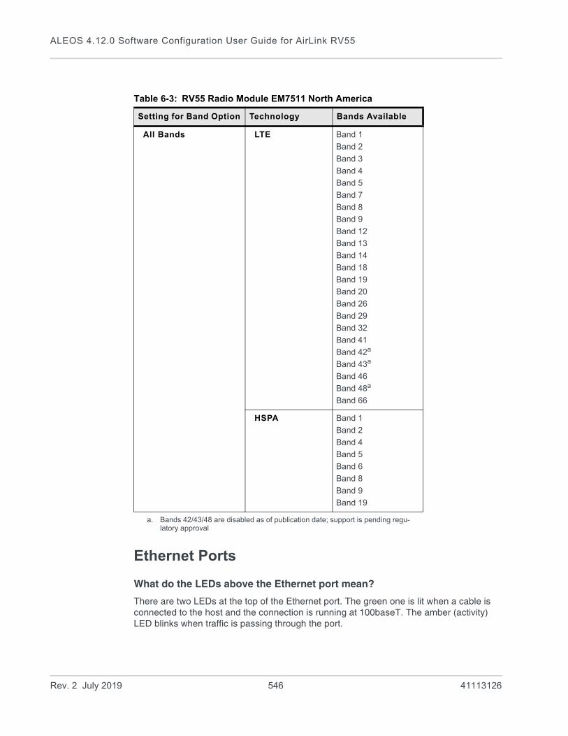
ALEOS 4.12.0 Software Configuration User Guide for AirLink RV55
Ethernet Ports
What do the LEDs above the Ethernet port mean?
There are two LEDs at the top of the Ethernet port. The green one is lit when a cable is connected to the host and the connection is running at 100baseT. The amber (activity) LED blinks when traffic is passing through the port.
Table 6-3: RV55 Radio Module EM7511 North America
Setting for Band Option Technology Bands Available
All Bands LTE Band 1
Band 2
Band 3
Band 4
Band 5
Band 7
Band 8
Band 9
Band 12
Band 13
Band 14
Band 18
Band 19
Band 20
Band 26
Band 29
Band 32
Band 41
Band 42a
Band 43a
Band 46
Band 48a
Band 66
a. Bands 42/43/48 are disabled as of publication date; support is pending regu-latory approval
HSPA Band 1
Band 2
Band 4
Band 5
Band 6
Band 8
Band 9
Band 19
Rev. 2 July 2019 546 41113126

Q & A and Troubleshooting
LAN Networks
The server on my LAN network is receiving data from some hosts on the network, but not others. What’s wrong?
If you have a network with multiple LAN devices that are sending data to the same server and the server is not receiving data from one (or more) of the devices, it may be because the Mobile Network Operator has a WAN firewall that is blocking the ports used by the NAT for over-the-air (OTA) destinations.
To correct this problem:
1. Launch ACEmanager.
2. Go to the LAN tab.
3. Select Ethernet.
4. Refer to the instructions for setting the Starting Ephemeral Port on page 83.
Rev. 2 July 2019 547 41113126

ALEOS 4.12.0 Software Configuration User Guide for AirLink RV55
Wi-Fi
My is configured to act as an access point, but I don’t see an option to use WEP encryption.1. Launch ACEmanager.
2. Go to the LAN/Wi-Fi tab.
3. Select Wi-Fi.
4. In the Enable Access Point field, change the value from “b/g/n Enabled” to “b/g Enabled”.
Once this change is made, an “Open WEP” section appears below the Wi-Fi Configu-ration section.
WEP encryption is only supported on 802.11b and 802.11g. It is not supported on 802.11n.
VPN
My VPN connection is not working. When I try to debug it using the logs on the Admin page, VPN information does not show up in the log.
VPN information is collected in the Linux logs. To view this information:
1. Log into ACEmanager as User and go to Admin > Log.
2. In the drop-down menu beside Linux Syslog, ensure that Display is selected.
If you change the setting:
a. Click Apply.
b. Reboot the device.
3. Click View Log.
4. On the View Log page, click Clear and then click Refresh.
VPN Troubleshooting
If you see the following lines in the log, it means the VPN Server is not answering.
Check the VPN Server status.
When I configure a VPN, my Internet connection stops working.
When you configure a VPN, outgoing traffic from the host to the public Internet is blocked by default, as a security measure. If you want to enable public Internet traffic from the host:
1. In ACEmanager, go to VPN > Split Tunnel.
2. Change the Outgoing Host Out of Band field to Allowed.
3. Click Apply.
notice openvpn[9199]: [UNDEF] Inactivity timeout (--ping-restart), restarting
notice openvpn[9199]: TCP/UDP: Closing socket
Rev. 2 July 2019 548 41113126

Q & A and Troubleshooting
Port Forwarding
I set up port forwarding rules. I did not receive an error message, but it seems that data is not being forwarded.
If the Public Start Port and Public End Port fields are not set up correctly, data is not forwarded.
1. In ACEmanager, go to Security > Port Forwarding.• If you are forwarding data to a single port:
· Ensure that the value in the Public Start Port field is not 0.· Ensure that the value in the Public End Port field is 0.· Ensure that the value in the Private Port start field is not 0.
• If you are forwarding data to a range of ports:· Ensure that the value in the Public Start Port field is not 0.· Ensure that the value in the Public End Port field is greater than the value in Public
Start Port field.· Ensure that the value in the Private Port Start field is not 0.
For complete instructions, see Port Forwarding on page 196.
SMS
I tried to send an SMS message, and received an error code. What does the error code mean?
The following acknowledgment error codes may appear if your message was not successfully sent:
Code: Explanation:
100 Not in coverage (no cellular service)
201 Parse Error on field #1 (Start Field)
202 Parse Error on field #2 (Phone number and separator)
203 Parse Error on field #3 (Data type and separator)
204 Parse Error on field #4 (Payload length and separator)
205 Parse Error on field #5 (Message and End Field)
301 No buffers available
302 SMS queue full
Supported SMS data types are ASCII, 8-bit, and Unicode, and are all case-sensitive. SMS messages being sent MUST be in ASCII hex format.
I tried to send an SMS command and received the error “not set”. The parameter was not changed.
Check the format of the SMS command. There should be no space between the prefix and the command (or the 1st command parameter in the case of multi-parameter commands), and a single space between all other fields to act as a delimiter. For more information, see SMS Commands on page 534 and SMS Overview on page 230.
Rev. 2 July 2019 549 41113126

ALEOS 4.12.0 Software Configuration User Guide for AirLink RV55
AirLink Management Service
I don’t understand the message that appears in the Status field in the Services > ALMS page.The error messages in the Services > ALMS > Status field can be due to a communication failure, a problem with the ALMS server, or a failure when parsing a valid ALMS server response. The following table describes the error messages and the corrective action.
Error message Meaning Corrective action
Communication Failure Errors
[HTTP] Initialization error The transfer object could not be initialized.
Contact ALMS support.
[HTTP] Unsupported protocol The ALMS server URL protocol is not supported.
In ACEmanager, check the ALMS URL in the Service > ALMS > Server URL field. The default value is https://na.m2mop.net/device/msci/com.
[HTTP] Failed initialization The transfer library could not be initialized.
Contact ALMS support.
[HTTP] URL using bad/illegal format or missing URL
The ALMS server URL is missing or not properly formatted.
In ACEmanager, check the ALMS URL in the Service > ALMS > Server URL field. The default value is https://na.m2mop.net/device/msci/com.
[HTTP] Couldn't resolve host name
The ALMS server URL could not be resolved.
In ACEmanager, check the ALMS URL in the Service > ALMS > Server URL field. The default value is https://na.m2mop.net/device/msci/com. Also check the cellular connectivity.
[HTTP] Couldn't connect to server
Connection to the ALMS server URL failed.
In ACEmanager, check the ALMS URL in the Service > ALMS > Server URL field. The default value is https://na.m2mop.net/device/msci/com. Also check the cellular connectivity.
[HTTP] Timeout was reached The transfer timeout (equal to the communication period if defined or 5 minutes) expired.
Check cellular connectivity.
[HTTP] Server returned nothing (no headers, no data)
No data was received from the ALMS server.
Check cellular connectivity.
[HTTP] Unrecognized or bad HTTP Content or Transfer-Encoding
The ALMS server HTTP response contains a malformed content or transfer-encoding header field.
Contact ALMS support.
[HTTP] Out of memory A memory allocation problem occurred.
Contact ALMS support.
Rev. 2 July 2019 550 41113126

Q & A and Troubleshooting
When I try to update the radio module using ALMS, I receive an error message.
The following table provides a brief explanation of the firmware update error messages.
[HTTP] SSL peer certificate or SSH remote key was not OK
This message appears if you are using an HTTPS server URL, the TLS Verify Peer Certificate field is set to Enable, and the server SSL certificate validation fails. If this happens, communication with the ALMS server is terminated.
If you see this error message:
1. Check to see that you have a valid URL in the Server URL field.
2. In ACEmanager, go to Admin > Advanced and check the Date and Time field to confirm
that the values are correct.a The SSL certifi-cates have a start and end date. If the device has a date and time outside of this interval, the certification check will fail.
3. Contact your IT Administrator, or if you want the traffic to go through without verifying the server certificate, change the setting in the Services > ALMS > TLS Verify Peer Certif-icate field (described on page 211) to Disable.
ALMS Server Errors
[AVMS] HTTP error '500' ALMS server reported error 500 in the HTTP response.
Refer to the available ALMS server documentation for a list of all possible error codes and their significance.
Error message indicating a failure when parsing a valid ALMS server response
XML processing error The content of a valid ALMS server response cannot be parsed.
ALMS server responses are malformatted. Contact ALMS support.
a. If the values are not correct and the device is not receiving date and time from the Mobile Network Operator or go to Services > Time (SNTP), and enable time update. For the SNTP Server, use the same service as the authenticating server.
Error message Meaning Corrective action
Error message Meaning Corrective action
Cannot Install Firmware The system has encountered errors from which it cannot recover and requires at least a reboot before trying to update again.
1. Reboot the device.
2. If the problem persists, press the reset button for 7–10 seconds to reset the device to the factory default settings (release the reset button when all four LEDs turn from red to yellow) and try again.
3. If it still does not work, contact ALMS support.
Link not up in 3 minutes...Exiting
The radio module was not able to establish the connection in 3 minutes. The update has been aborted, but can be relaunched as soon as the connection is OK.
Wait for network connectivity and then try again.
Unable to download JUD file from <url>
The URL is wrong, or the download failed (interruption, no space left...).
Contact ALMS support.
Rev. 2 July 2019 551 41113126

ALEOS 4.12.0 Software Configuration User Guide for AirLink RV55
Core version not found in JUD file
JUD file is not valid. Core Version is a mandatory field.
There is a problem with the package on the ALMS server. Contact ALMS support.
Required information (URL, Size or MD5) is missing from JUD file
JUD file is not valid. URL, Size, and MD5 sum of the firmware package are mandatory fields.
There is a problem with the package on the ALMS server. Contact ALMS support.
Cannot perform upgrade — No space left on device
Firmware is larger than available space for the download.
Contact ALMS support. The support team will need to access the device to clear space, or you can return the device to Sierra Wireless under an RMA.
Unable to download ALEOS firmware from <url>
Firmware URL is not valid, or the download failed.
Retry. If the download fails several times, contact ALMS support. The support team will need a log from the device.
Undefined ALEOS firmware URL
ALEOS firmware URL not specified, so firmware cannot be retrieved.
Contact ALMS support to confirm that there is not a problem with the service.
ALEOS firmware MD5 check failed
The downloaded firmware package failed the integrity check. The update is aborted.
There is a problem with the package on the device or the download may have failed. Restart the firmware download. If the problem persists, contact ALMS support. There may be a problem with the package on the ALMS server.
Unable to apply ALEOS firmware and Unable to apply ALEOS firmware (retry)
ALEOS firmware could not be applied. Check the ALEOS log messages to determine exactly why the update failed.
Retry. If the problem persists, contact ALMS support and provide them with the log messages.
Radio Module URL is missing from JUD file
JUD file is not valid. The Radio Module Firmware URL is a mandatory field.
There is a problem with the package on the ALMS server. Contact ALMS support.
Radio Module package MD5 sum is missing from JUD file
JUD file is not valid. The Radio Module Firmware MD5 sum is a mandatory field.
There is a problem with the package on the ALMS server. Contact ALMS supporta.
Radio Module firmware MD5 check failed
The downloaded firmware package failed the integrity check. The update is aborted.
There is a problem with the package on the device or the download may have failed. Try downloading the file again. If the problem persists, contact ALMS supporta. There may be a problem with the package on the ALMS server.
Radio Module backup failed The radio module was saved to prevent a power failure. If the firmware cannot be backed-up on persistent storage, the firmware update will not proceed because of the risk that the radio module update will not be able to finish if interrupted.
Contact ALMS supporta. The support team will need to access the device to clear space, or you can return the device to Sierra Wireless under an RMA.
Radio Module firmware download failed
Firmware URL is not valid, or download failed. Retry several times. If the problem persists, contact ALMS supporta. The support team will need a log from the device.
Error message Meaning Corrective action
Rev. 2 July 2019 552 41113126
Q & A and Troubleshooting
Location
I set the Location Reports Port field on the Location > Local Streaming page to stream Location data to a USB port, but I don't see Location data on the USB port.
The Location streaming feature works with serial devices. To stream data to a USB port, you must first configure the USB port to act as a serial device.
1. In ACEmanager, go to the LAN > USB tab.
2. In the USB Device Mode field, select USB Serial.
3. Click Apply.
If you have not already done so:
1. Go to Location > Local Streaming.
2. In the Location Reports port field, select one of the following:· USB Serial· DB9 and USB
3. Click Apply.
4. After you have made all the configuration changes, reboot the device.
Event Reporting
I set up ACEmanager to send an email/SMS report, but when I clicked the Test report button no report was sent.
After you set up the event reporting fields and click Apply, wait about a minute before you click the Test report button. The AirLink RV55 needs this time to apply the new configuration.
I configured event reporting, but I did not receive a report when I should have.• If the Action Type for the Event Reporting is Email or SNMP TRAP, be sure that these
services are also configured on the Services tab.
· To configure email, go to Services > Email (SMTP).
• To configure SNMP TRAP, go the Services > Management (SNMP).If the Action Type is SMS, you may need to change the default settings in the Advanced section of the Services > SMS page.
Undefined Radio Module firmware URL
The URL cannot be retrieved. The update is aborted.
Retry. If the problem persists, contact ALMS support.
Radio Module firmware update failed
Radio module firmware could not be applied. Check the ALEOS log messages to determine exactly why the update failed.
Retry. If the problem persists, contact ALMS support.
Error message Meaning Corrective action
Rev. 2 July 2019 553 41113126

ALEOS 4.12.0 Software Configuration User Guide for AirLink RV55
TCP Connections
I went to the TCP section of the Serial screen and configured ALEOS to include the Device ID in TCP connections, but I get the message “Device ID Not Set”.
Setting the TCP connection to include the Device ID is a two step process:
1. In ACEmanager, go to Serial > TCP and ensure that the Include Device ID on TCP Connect field is set to Enable.
(See Port Configuration on page 289.)
2. Go to Location > Global Settings > General and configure the Use Device ID in Location Reports field. (See Global Settings on page 271.)
To confirm that the Device ID is configured, check the Status > About screen. The Device ID, if set, appears in the /RAP Device ID field.
TCP/IP and UDP/IP Auto Answer
I configured TCP/UDP auto answer, but the packet contents are not being streamed over the serial port to the connected device.1. Try polling the device connected to the AirLink RV55’s serial port.
If you do not receive a response, confirm that the fields described in Configuring IP to Serial with Answer and Serial to IP on page 310 are set correctly.
2. In ACEmanager, go to Status > Serial and check the RS232 bytes sent field to confirm that packets are reaching the AirLink RV55 from the mobile network and the packet contents are being sent out the AirLink RV55’s serial port.
Figure F-3: ACEmanager: Status > Serial
Rev. 2 July 2019 554 41113126

Q & A and Troubleshooting
When you poll the AirLink RV55/connected device:• If the Serial bytes sent counter increases, the IP packets have reached the AirLink
RV55 from the mobile network, the AirLink RV55 has removed the header and sent the packet contents out its serial port to the connected device.
• If the Serial bytes sent counter does not increase, either:· The IP packet has not made it across the mobile network to the AirLink RV55.· The destination port for the TCP/IP or UDP/IP connection does not match the
configured Device Port on the ACEmanager Serial tab.
3. Once you have confirmed that the Serial bytes sent counter is increasing, check the Serial bytes received counter (also on the Status > Serial screen). · If the Serial bytes received counter is increasing, the connected device is
responding to the poll request and sending its response back to the AirLink RV55 across the serial connection.
· If the Serial bytes received counter is not increasing, the connected device is not responding to the poll request. Ensure that the serial cable is fully seated and properly connected to the AirLink RV55 and the host. Check that you have the correct type of serial cable connecting the AirLink RV55 to the connected device. The AirLink RV55 is a DCE device. If the connected device is also a DCE device, use a null modem serial cable. If the connected device is a DTE device, use a straight through serial cable.
4. If you have confirmed that both the Serial bytes sent and Serial bytes received counters are increasing when you send a poll to the connected device, but you are still not receiving the response back on your original sending application, the most common reason is that the incoming packets from the AirLink RV55 to your appli-cation are being blocked by a firewall on your network. The firewall may be blocking all traffic except packets destined for particular ports or arriving from particular ports.
Check with your firewall administrator. Ask the administrator to monitor the firewall when you poll the AirLink/connected device to see if any return packets from the Air-Link RV55 hit the firewall.
If you are still having problems, contact your Sierra Wireless distributor.
ALEOS Application Framework (AAF)
I’m unable to load an application from AAF.
1. In ACEmanager, go to Services > Telnet/SSH.
2. In the AT Server Mode field, select Telnet.
3. Click Apply.
4. Re-try loading the application from AAF.
Network Operator Switching
What happens to my Radio Module Firmware settings (Admin > Radio Module Firmware) when I reset the RV55 to the factory default settings?
Rev. 2 July 2019 555 41113126
ALEOS 4.12.0 Software Configuration User Guide for AirLink RV55
If the Reset Mode field on the Admin > Advanced screen is set to “Preserve Cellular Authentication Settings” (default setting), the Radio Module settings on the Admin > Radio Module Firmware screen are preserved over the reset, i.e. there is no change to the settings.
If the Reset Mode field on the Admin > Advanced screen is set to “Reset All”, then the settings on the Admin > Radio Module Firmware screen revert are reset. The Automatic option is reset to “Automatic” and the ALMS option is reset to “Update Current Only”. If you have previously selected a radio module firmware version manually that does not match the SIM card, “Reset All” may change the radio module firmware because once the RV55 reverts to “Automatic”, which SIM card is installed in the RV55 determines which radio module firmware is used. This could override a previous manual selection.
Rev. 2 July 2019 556 41113126

G
G:Glossary of TermsAcronym or Term Definition
3GPP 3rd Generation Partnership Project
3GPP unites 6 telecommunications standard development organizations (ARIB, ATIS, CCSA, ETSI, TTA, TTC), and provides their members with a stable environment to produce Reports and Specifications that define 3GPP technologies.
API Programming Interface
A protocol intended to be used as an interface by software components to communicate with each other.
AT A set of device commands, preceded by “AT” originally developed by Hayes, Inc. for their devices.
The structure (but not the specific commands, which vary greatly from manufacturer to manufacturer) is a de facto device industry standard.
CE, CE Label The CE label is a mandatory conformity marking for products placed on the market in the European Economic Area (EEA).
With the CE marking on a product, the manufacturer declares that the product conforms with the essential requirements of the applicable EC directives.
CnS Sierra Wireless’ proprietary Control and Status protocol interface
DCE Data Communications Equipment
A device that sits between the data terminal equipment (DTE) and a data transmission circuit. Usually the DCE is a modem.
Diversity Antenna diversity, also called space diversity, is a scheme that uses two or more antennas to improve the quality and reliability of a wireless link.
Often, especially in urban and indoor environments, there is no clear line-of-sight (LOS) between transmitter and receiver. Instead the signal is reflected along multiple paths before finally being received. Each bounce can introduce phase shifts, time delays, attenuations, and distortions that can destructively interfere with one another at the aperture of the receiving antenna.
DMNR Dynamic Mobile Network Routing
EIA Electronics Industry Association
EIA was a standards and trade organization composed as an alliance of trade associations for electronics manufacturers in the United States.
They developed standards to ensure the equipment of different manufacturers was compatible and interchangeable. The EIA ceased operations on February 11, 2011, but the former sectors continue to serve the constituencies of EIA.
EMC Electromagnetic Compatibility
The branch of electrical science which studies the unintentional generation, propagation and reception of electromagnetic energy with reference to the unwanted effects (Electromagnetic interference, or EMI) that such energy may induce.
EMI Electromagnetic Interference
The disturbance that affects an electrical circuit due to either electromagnetic induction or electromagnetic radiation emitted from an external source
Rev. 2 July 2019 557 41113126

ALEOS 4.12.0 Software Configuration User Guide for AirLink RV55
ERP Effective Radiated Power
A standardized theoretical measurement of radio frequency (RF) energy. It is determined by subtracting system losses and adding system gains.
ESN Electronic Serial Number
The unique first-generation serial number assigned to the Air Link devices for use on the wireless network. Compare to MEID.
Ethernet Computer networking technologies for local area networks (LANs).
EU The European Union Organization of European countries.
FCC Federal Communications Commission
The U.S. federal agency responsible for interstate and foreign communications. The FCC regulates commercial and private radio spectrum management, sets rates for communications services, determines standards for equipment, and controls broadcast licensing.
FW Firmware
Software stored in ROM or EEPROM; essential programs that remains even when the system is turned off. Firmware is easier to change than hardware but more permanent than software stored on disk.
GPRS General Packet Radio Service
A packet-oriented mobile data service on 2G and 3G cellular communication systems.
GPRS was originally standardized by European Telecommunications Standards Institute (ETSI) in response to the earlier CDPD and i-mode packet-switched cellular technologies. It is now maintained by the 3rd Generation Partnership Project (3GPP).
GPS Global Positioning System
A system that uses a series of 24 satellites to provide navigational data.
GSM Global System for Mobile Communications (originally Groupe Spécial Mobile)
GSM is a standard developed by the European Telecommunications Standards Institute (ETSI) to describe protocols for second generation (2G) digital mobile networks used by mobile phones
HSPA High Speed Packet Access
An amalgamation of two mobile telephony protocols: High Speed Downlink Packet Access (HSDPA) and High Speed Uplink Packet Access (HSUPA).
This extends and improves the performance of existing 3rd generation mobile telecommunication networks utilizing the WCDMA protocols.
HSPA+ Also called evolved HSPA
This allows bit-rates to reach as high as 168 Mbit/s in the downlink and 22 Mbit/s in the uplink. An improved 3GPP standard.
IC Industry Canada
The government department responsible for overseeing and regulating wireless and communication technologies in Canada.
IEC International Electrotechnical Commission
A non-governmental international standards organization that prepares and publishes International Standards for all electrical, electronic and related technologies—collectively known as “electro technology.”
IS Interim Standard
After receiving industry consensus, the TIA/EIA forwards the standard to ANSI for approval.
Acronym or Term Definition
Rev. 2 July 2019 558 41113126
Glossary of Terms
ISAKMP Internet Security Association and Key Management Protocol
A security protocol defined by RFC 2408 for establishing Security Associations (SA) and cryptographic keys in an Internet environment. ISAKMP only provides a framework for authentication and key exchange and is designed to be key exchange independent.
ITU International Telecommunication Union
A specialized agency of the United Nations responsible for issues that concern information and communication technologies.
The ITU coordinates the shared global use of the radio spectrum, promotes international cooperation in assigning satellite orbits, and assists in the development and coordination of worldwide technical standards.
kbps Kilobits per second
1000, not 1024, as used in computer memory size measurements of kilobytes.
LED Light Emitting Diode
A semiconductor diode that emits visible or infrared light.
LTE Long Term Evolution
High performance air interface for cellular mobile communication systems.
Mbps Millions of bits per second, or Megabits per second.
MEID Mobile Equipment IDentifier
The unique second-generation serial number assigned to the device for use on the wireless network. Compare to ESN.
MSCI Modem Status Configuration Interface
ALEOS internal configuration database
NAM Number Assignment Module
Semi-permanent information stored in the device’s non-volatile memory, including the device’s Mobile Identification Number, the station class mark, Mobile Network Operator code, and other cellular identifiers.
Essentially the phone number, it should be treated as confidential information and should not be disclosed to anyone other than the cellular service provider.
NV Non-Volatile (memory)
OEM Original Equipment Manufacturer
A company that manufactures a product and sells it to a reseller.
OTAPA Over the Air Parameter Administration
A way of distributing new software updates or configuration settings to devices like cellphones and set-top boxes.
OTASP Over the Air Service Provisioning. Also see OTAPA.
PAD Packet Assembly/Disassembly
PCS Personal Communications Services
A cellular communication infrastructure that uses a different frequency range than AMPS.
PPP Point to Point Protocol
An alternative communications protocol used between computers, or between computers and routers on the Internet. PPP is an enhanced SLIP. Also see SLIP.
Acronym or Term Definition
Rev. 2 July 2019 559 41113126

ALEOS 4.12.0 Software Configuration User Guide for AirLink RV55
PRI Product Release Instructions
A file containing the settings used to configure devices for a particular service provider, customer, or purpose.
RF Radio Frequency
RoHS Restriction of use of Hazardous Substances mandated by EU Directive 2002/95.
RS-232 A series of standards for serial binary single-ended data and control signals connecting between a DTE (Data Terminal Equipment) and a DCE (Data Circuit-terminating Equipment). It is commonly used in computer serial ports.
Rx Receive
SIM, SIM Card Subscriber identity module or subscriber identification module.
An integrated circuit which securely stores the international mobile subscriber identity (IMSI) and the related key used to identify and authenticate subscribers on mobile telephony devices (such as mobile phones and computers).
SINR Signal to Interference plus Noise Ratio (SINR) is an RF parameter that is directly proportional to throughput (the higher the number, the higher the throughput). It can help LTE radio installers gauge the signal quality between the cell tower and the radio module. For more information on interpreting the SINR values, see How do I obtain and interpret SINR values for LTE networks? on page 541.
SKU Stock Keeping Unit
Identifies an inventory item: a unique code, consisting of numbers or letters and numbers, assigned to a product by a retailer for purposes of identification and inventory control.
SLIP Serial Line Internet (or Interface) Protocol
An Internet Protocol designed to work over serial ports and modem connections.
On personal computers, SLIP has been largely replaced by the Point-to-Point Protocol (PPP), which has more features and does not require its IP address configuration to be set before it is established. On microcontrollers SLIP is still the preferred way of encapsulating IP packets due to its very small overhead.
Also see PPP.
SMS Short Message Service
A feature which allows users of a wireless device on a wireless network to receive or transmit short electronic alphanumeric messages (up to 160 characters, depending on the service provider).
TCH Traffic Channel
TIA / EIA Telecommunications Industry Association / Electronics Industry Association
A standards setting trade organization, whose members provide communications and information technology products, systems, distribution services and professional services in the United States and around the world.
Tx Transmit
UMTS Universal Mobile Telecommunications System (UMTS).
A third generation mobile cellular system for networks based on the GSM standard. Developed and maintained by the 3GPP (3rd Generation Partnership Project), UMTS is a component of the International Telecommunications Union IMT-2000 standard set.
Acronym or Term Definition
Rev. 2 July 2019 560 41113126

Glossary of Terms
USB Universal Serial Bus
An industry standard defining the cables, connectors and communications protocols used in a bus for connection, communication and power supply between computers and electronic devices.
VRRP Virtual Router Redundancy Protocol
X.509 A Public Key Infrastructure (PKI) and Privilege Management Infrastructure (PMI) are standards that specify formats for public key certificates, certificate revocation lists, attribute certificates, a certification path validation algorithm, etc.
Acronym or Term Definition
Rev. 2 July 2019 561 41113126
Index
A
Access points, maximum number configurable, 129ACEmanager, 213
Configuring, 18Description, 13Idle timeout, set, 214Login, 15Overview, 13
Active SIM, 84Admin
Advanced, 360Change AAF password, 359Change ALEOS password, 358Logs, 372Radio Module Firmware, 378Radio passthru, 371
AirLink Management Service See ALMS.ALEOS Application Framework
Troubleshooting, 555Unable to load application from, 555Using, 346
ALEOS software update, 24ALMS
Auto synchronize, 211Configuration, 208Error messages, 551
Always on connect, 82, 244Analog inputs
Channel configuration, 454Transformed values, 356Uses, 350
APNSIM 1, 91
Applications, 336ALEOS Application Framework, 346Data usage, 336Garmin, 344Status, 64
AT CommandsApplications > Data Usage, 526, 530I/O > Current State, 526LAN/Wi-Fi > DHCP/Addressing, 476Location, 504Security > Trusted IPs - Inbound, 487, 493Serial > Port Configuration, 511Services > Low Power, 494Status > Home, 452, 454, 519summary, 450Using, 450Wi-Fi, 478
AuthenticationGeneral information, 261LDAP, 262RADIUS, 264TACACS+, 265
Auto DHCP, 144Automatic SIM Switching, 85
B
Bandwidth Throttle, 74Browser support, 15
C
ConfigurationApplication, 336LAN, 136Logging, 372saving a custom configuration, 18Serial, 313Services, 208VPN, 168
Configuring the AirLink gateway, 18Connection not working, 540Core dump, 362Custom SSL certificate, 215
D
Data usage, 336Dead Peer Detection, 179, 185, 489Device status (about), 68Device Status Screen, configuring, 267DHCP Options, 140DHCP/Addressing, 136Dial-up Networking, 382Digital inputs
RV50, 350Uses, 350
DMNR, 108DMZ, 201DNS
Alternate port, 154Dynamic, 224Global, 152Override, 153
DNS proxyConfigure, 153
Documentation, 13Domain name, 229Dual SIM, 83DUN
Operating systems supported, 382Setting up, 382
Dynamic Mobile Network Routing See DMNR
E
EC/IO, 40Email (SMTP), 253Email test, 249Engine hours, 222, 310Ethernet
Static IP, 98Ethernet ports, 143
Troubleshooting, 546
Rev. 2 July 2019 562 41113126

Index
Events ReportingData groups, 305Email, 295Event types, 308Introduction, 293Location Reports, 300Protocol Reports, 302Relay Link, 299SMS, 297SNMP TRAP, 300Turn Off Services, 304
Extended Archiver, 367
F
Firmware update, 24
G
Garmin, 344Global DNS, 152Glossary, 557GPS See LocationGRE, 189
H
Host Interface Watchdog, 166Host port routing, 33, 150
I
I/OConfiguration, 350Current state, 351
Idle timeout, ACEmanager, 214Inbound ports used by ALEOS, 544Interface Priority, 72IP Logging, 364IP Manager, 227IPsec, 174, 175, 181IPv6
Configuring support for, 79Support, 89
L
LANConfiguration, 136Ethernet, 143Management, 32Status, 52
LDAP authentication, 262LED indicator for serial traffic, 313LEDs, above Ethernet port, 546Load Root Certificate, 194
Location, 553Global settings, 271Local IP report, 289, 292Status, 60Streaming, 553Troubleshooting, 553
LoggingConfiguration, 372Extended Archiver, 367IP logging, 364
Low Voltage Standby mode, 217LWM2M, 209
M
MAC filtering, 207, 540MIB (Management Information Base), 405Modbus
Address list, 330Details, 401TCP/IP, 402
MonitorCellular connection, 96Ethernet connection, 99WAN connections (overview), 70Wi-Fi, 119
N
Network connection, poor, 540Network credentials, 90Network Operator Switching, 380Network settings, retain over reset, 370Network State, 37NMEA, 268
O
Over the Air (OTA) connections, 34
P
PasswordChange AAF user password, 359Change ACEmanager password, 358
PCI compliance, 34Ping Response, 77Ping, on demand, 363PNTM configuration, 114Policy Routing, 105Port filtering
Inbound, 202Outbound, 203
Port forwarding, 196Error message, 549Troubleshooting, 549
Power management, 216PPP connection, configuring, 326PPPoE, 154Primary SIM, 84Programmable Logic Controller, 402Pulse count, 354
Rev. 2 July 2019 563 41113126

ALEOS 4.12.0 Software Configuration User Guide for AirLink RV55
R
Radio band, selecting, 543Radio module firmware
Install, update, remove, 378Select manually, 381
Radio module firmware update, 24Radio passthru, 371RADIUS authentication, 264RAP, 268Recovery mode, 16Redundant server, 285Relay outputs, 351Reliable Static Routing (RSR), 101Remote Terminal Unit, 401Reset device, retain network settings, 370Reset, periodic and time of day, 362Reverse telnet/SSH, 322RSCP, 43RSRP, 44RSRQ, 44RSSI, 40
S
SecurityConfiguration, 196DMZ, 201MAC filtering, 207Port filtering, inbound, 202Port filtering, outbound, 203Port forwarding, 196Solicited vs. Unsolicited, 196Status, 57Trusted IPs, inbound, 205Trusted IPs, outbound, 206
SerialConfiguration, 313LED indicator, 335Modbus address list, 330MTU, 318PPP, 326Status, 62
Serial portDisable, 314Port configuration, 314TCP, 318UDP, 320
ServicesACEmanager, 213ALMS, 208Authentication, 261Configuration, 208Device Status Screen, 267Dynamic DNS, 224Email (SMTP), 253IP Manager, 227Management (SNMP), 255Power Management, 216SMS, 230Status, 58Telnet/SSH, 251Time (SNTP), 261
Shutdown Delay after Ignition off, 216SIM PIN, 92SIM PIN, unblocking, 94SIM switching, automatic, 85SIM, active, 84SIM, Primary, 84Simple Network Management Protocol (SNMP), 255SINR, 541SLIP, 327SMS, 230
Advanced, 248Commands, 534Control Only mode, 235Error message, 549Gateway Only mode, 236M2M, 250Message error, 549Password, 247Password Only mode, 233Password, default, 248Quick Test, 249Security, 245Test, 249Troubleshooting, 549Trusted phone number, 246Wakeup, 243
SNMP traps, 405SNTP, 261Split tunnel, 171SSH, 251SSL tunnel, 191Standby Mode, 218
Rev. 2 July 2019 564 41113126

Index
StatusAbout, 68Applications, 64Cellular, 38Ethernet, 46GPS, 60Home, 36Location, 60PNTM, 67Policy Routing, 65RSR, 66RSR (Reliable Static Routing), 66Security, 57Serial, 62Services, 58VPN, 54Wi-Fi, 49
T
TACACS+ authentication, 265TAIP, 268TCP connection
Device ID Not Set, 554Troubleshooting, 551
Telemetry, 401Telnet, 251Template
Applying, 21Saving a custom configuration as, 18
Test button, SMS/email, 249Third party services, 225Time (SNTP), 261Troubleshooting
ALEOS AF, 555ALMS error messages, 551AVMS status messages, 550Ethernet ports, 546GPS, 553LAN network, 547Location, 553Port forwarding, 549Radio module firmware update, 538RSR, 544SMS, 549Software and radio firmware updates, 538TCP connections, 554VPN, 548Wi-Fi, 548Wireless connection, 540
Trusted IPsInbound, 205Outbound, 206
Trusted Phone Number, 246
U
UDPMultiple Unicast, 322
UpdateALEOS software, 24Radio module firmware, 24
USBDisable, 146Drivers, installing, 147Port, 146
V
VLAN, 160VPN
Configuration, 168Failover, 172GRE, 189IPsec, 175OpenVPN tunnel, 191Status, 54Troubleshooting, 548
VRRP, 161
W
WAN connections, monitor, 70WEP, 127WEP encryption, troubleshooting, 548Wi-Fi
Access Point Mode, 120Captive portal, 124Client Mode, 129Country Code, 118General, 116Modes, 116Troubleshooting, 548
WPA / WPA2 Personal, 128WPA2 Enterprise, 129
Rev. 2 July 2019 565 41113126