airworthiness limitations - regulations.gov
TRANSCRIPT

BD500-3AB48-11400-02
Page 12019-06-06
Master
Airworthiness limitations
BD500-3AB48-11400-02Issue No. 009.00
Copyright © 2019 Bombardier Inc.
All rights reserved. No part of this work may be reproduced or copied in any form or by any means without written permission of Bombardier Inc.
The Bombardier and CSeries logos are registered trademarks of Bombardier Inc.
The information, technical data and the designs disclosed herein are the exclusive property of Bombardier Inc. or contain proprietary rights ofothers and are not to be used or disclosed to others without the written consent of Bombardier Inc. The recipient of this document, by itsretention and use, agrees to hold in confidence the technical data and designs contained herein. The foregoing shall not apply to persons havingproprietary rights to such information, technical data or such designs to the extent that such rights exist.
Publication No.: BD500-3AB48-11400-02
Manufacturer:Bombardier Inc.Bombardier Aerospace Commercial AircraftCustomer Services123 Garratt Blvd., Toronto, OntarioCanada M3K 1Y5

BD500-3AB48-11400-02
Intentionally left blank
Page 22019-06-06

BD500-3AB48-11400-02Airworthiness limitations
Highlights
Issue 009.002019-06-06
Page 3
Data module code Issue number Task number Title Issue type Reason for update Applicability
BD500-A-J00-00-00-10AAA-028A-A 005 Critical design configuration controllimitations - General
Changed To revise CDCCL-39 All
BD500-A-J05-00-00-14AAA-030A-A 005 Deleted tasks - Technical data Changed To revise the list of deleted tasks All
BD500-A-J21-26-00-04AAA-281F-A 006 C21-26-00-04 AWL - Scheduled inspection Changed To revise the applicability (OptionC25310211or OptionC25310212 orOption C25310213or OptionC25310404)and Pre MS500T102402(Pre SBBD500-240008)
BD500-A-J24-21-01-01AAA-288P-A 004 24-21-01 AWL - Overhaul and retirementschedule
Changed To delete VFG PN C07500043-001 All
BD500-A-J24-30-00-02AAA-281F-A 002 C24-30-00-02 AWL - Scheduled inspection Changed To revise the applicabilityTo add remarks
Pre MS500T100404(Pre VSBHS5915794-24-1)
BD500-A-J27-11-01-01AAA-288P-A 006 27-11-01 AWL - Overhaul and retirementschedule
Changed To revise the Aileron PCU life limit All
BD500-A-J27-21-00-01AAA-288P-A 003 27-21-00 AWL - Overhaul and retirementschedule
Changed To delete Note A1 for the Rudderpedal system
All
BD500-A-J27-21-01-01AAA-288P-A 006 27-21-01 AWL - Overhaul and retirementschedule
Changed To revise the Rudder PCU life limit All
BD500-A-J27-21-07-01AAA-288P-A 003 AWL - Overhaul and retirementschedule
Deleted All
BD500-A-J27-21-09-01AAA-288P-A 003 AWL - Overhaul and retirementschedule
Deleted All
BD500-A-J27-31-01-01AAA-288P-A 006 27-31-01 AWL - Overhaul and retirementschedule
Changed To revise the Elevator PCU life limit All
BD500-A-J27-41-00-01AAA-288F-A 003 C27-41-00-01 AWL - Overhaul and retirementschedule
Changed To revise the applicability Pre MS500T100527(Pre SBBD500-274002)

BD500-3AB48-11400-02Airworthiness limitations
Highlights
Issue 009.002019-06-06
Page 4
Data module code Issue number Task number Title Issue type Reason for update Applicability
BD500-A-J27-41-01-01AAA-288P-A 005 27-41-01 AWL - Overhaul and retirementschedule
Changed To revise the HSTA life limit All
BD500-A-J28-21-30-01AAA-288P-A 004 28-21-30 AWL - Overhaul and retirementschedule
Changed To delete Note A1 for the Boostpump cartridge
All
BD500-A-J32-11-07-02AAA-288P-A 002 32-11-07 AWL - Overhaul and retirementschedule
Changed To revise the Bonding jumper partnumber
All
BD500-A-J32-21-03-01AAA-288P-A 006 32-21-03 AWL - Overhaul and retirementschedule
Changed To add NLG shock strut assy PN4124A0000-05
All
BD500-A-J32-21-03-02AAA-288P-A 002 32-21-03 AWL - Overhaul and retirementschedule
Changed To revise the remarks for the NLGshock strut bearing race ring
All
BD500-A-J53-11-03-01AAA-281G-A 005 A53-11-03-01 AWL - Scheduled inspection Changed To remove the remarks All
BD500-A-J53-11-03-02AAA-281G-A 003 A53-11-03-02 AWL - Scheduled inspection Changed To remove the remarks All
BD500-A-J53-11-03-03AAA-281G-A 002 AWL - Scheduled inspection Deleted All
BD500-A-J53-11-03-04AAA-281G-A 002 AWL - Scheduled inspection Deleted All
BD500-A-J53-11-04-01AAA-281G-A 005 A53-11-04-01 AWL - Scheduled inspection Changed To remove the remarks All
BD500-A-J53-11-04-02AAA-281G-A 002 AWL - Scheduled inspection Deleted All
BD500-A-J53-11-04-03AAA-281G-A 002 AWL - Scheduled inspection Deleted All
BD500-A-J53-11-06-01AAA-281G-A 005 A53-11-06-01 AWL - Scheduled inspection Changed To remove the remarks All
BD500-A-J53-11-06-02AAA-281G-A 005 A53-11-06-02 AWL - Scheduled inspection Changed To remove the remarks All
BD500-A-J53-11-06-04AAA-281G-A 002 AWL - Scheduled inspection Deleted All
BD500-A-J53-11-06-05AAA-281G-A 002 AWL - Scheduled inspection Deleted All
BD500-A-J53-11-06-06AAA-281G-A 002 AWL - Scheduled inspection Deleted All
BD500-A-J53-11-13-01AAA-281G-A 005 A53-11-13-01 AWL - Scheduled inspection Changed To remove the remarks All
BD500-A-J53-11-13-02AAA-281G-A 002 AWL - Scheduled inspection Deleted All
BD500-A-J53-11-13-03AAA-281G-A 002 AWL - Scheduled inspection Deleted All
BD500-A-J53-21-05-01AAA-281G-A 004 A53-21-05-01 AWL - Scheduled inspection Changed To remove the remarks All
BD500-A-J53-21-05-02AAA-281G-A 004 A53-21-05-02 AWL - Scheduled inspection Changed To remove the remarks All
BD500-A-J53-21-05-03AAA-281G-A 003 AWL - Scheduled inspection Deleted All
BD500-A-J53-21-07-01AAA-281G-A 004 A53-21-07-01 AWL - Scheduled inspection Changed To remove the remarks All
BD500-A-J53-21-07-02AAA-281G-A 004 A53-21-07-02 AWL - Scheduled inspection Changed To remove the remarks All
BD500-A-J53-21-07-03AAA-281G-A 003 AWL - Scheduled inspection Deleted All

BD500-3AB48-11400-02Airworthiness limitations
Highlights
Issue 009.002019-06-06
Page 5
Data module code Issue number Task number Title Issue type Reason for update Applicability
BD500-A-J53-21-08-01AAA-281G-A 004 A53-21-08-01 AWL - Scheduled inspection Changed To remove the remarks All
BD500-A-J53-21-08-02AAA-281G-A 003 AWL - Scheduled inspection Deleted All
BD500-A-J53-21-08-03AAA-281G-A 003 AWL - Scheduled inspection Deleted All
BD500-A-J53-21-09-01AAA-281G-A 004 A53-21-09-01 AWL - Scheduled inspection Changed To remove the remarks All
BD500-A-J53-21-09-02AAA-281G-A 003 AWL - Scheduled inspection Deleted All
BD500-A-J53-21-09-03AAA-281G-A 003 AWL - Scheduled inspection Deleted All
BD500-A-J53-21-80-01AAA-281G-A 005 A53-21-80-01 AWL - Scheduled inspection Changed To merge A53-21-80-01 andA53-21-80-02
Post MSBAS500T800078(OptionD56200002)or Post MSBAS500T800084(OptionD56200005)
BD500-A-J53-21-80-02AAA-281G-A 004 AWL - Scheduled inspection Deleted Post MSBAS500T800078(OptionD56200002)
BD500-A-J53-21-90-01AAA-281G-A 004 A53-21-90-01 AWL - Scheduled inspection Changed To revise the applicability All
BD500-A-J53-21-90-02AAA-281G-A 003 AWL - Scheduled inspection Deleted Post MSCCD500T100133
BD500-A-J53-21-90-03AAA-281G-A 003 AWL - Scheduled inspection Deleted Post MSCCD500T100133
BD500-A-J53-21-90-04AAA-281G-A 003 AWL - Scheduled inspection Deleted Post MSCCD500T100133
BD500-A-J53-31-02-01AAA-281G-A 004 A53-31-02-01 AWL - Scheduled inspection Changed To revise the task title anddescription
All
BD500-A-J53-31-02-02AAA-281G-A 004 A53-31-02-02 AWL - Scheduled inspection Changed To revise the task title anddescription
All
BD500-A-J53-31-02-03AAA-281G-A 003 AWL - Scheduled inspection Deleted All
BD500-A-J53-31-04-01AAA-281G-A 004 A53-31-04-01 AWL - Scheduled inspection Changed To remove the remarks All
BD500-A-J53-31-04-02AAA-281G-A 004 A53-31-04-02 AWL - Scheduled inspection Changed To remove the remarks All
BD500-A-J53-31-04-03AAA-281G-A 003 AWL - Scheduled inspection Deleted All
BD500-A-J53-31-06-01AAA-281G-A 004 A53-31-06-01 AWL - Scheduled inspection Changed To remove the remarks All

BD500-3AB48-11400-02Airworthiness limitations
Highlights
Issue 009.002019-06-06
Page 6
Data module code Issue number Task number Title Issue type Reason for update Applicability
BD500-A-J53-31-06-02AAA-281G-A 003 AWL - Scheduled inspection Deleted All
BD500-A-J53-31-06-03AAA-281G-A 003 AWL - Scheduled inspection Deleted All
BD500-A-J53-31-08-01AAA-281G-A 004 A53-31-08-01 AWL - Scheduled inspection Changed To revise the task title anddescriptionTo remove the remarks
All
BD500-A-J53-31-08-02AAA-281G-A 004 A53-31-08-02 AWL - Scheduled inspection Changed To revise the task title anddescriptionTo remove the remarks
All
BD500-A-J53-31-08-03AAA-281G-A 003 AWL - Scheduled inspection Deleted All
BD500-A-J53-31-08-04AAA-281G-A 003 AWL - Scheduled inspection Deleted All
BD500-A-J53-31-08-05AAA-281G-A 003 AWL - Scheduled inspection Deleted All
BD500-A-J53-31-10-02AAA-281G-A 001 A53-31-10-02 AWL - Scheduled inspection New All
BD500-A-J53-41-04-01AAA-281G-A 004 A53-41-04-01 AWL - Scheduled inspection Changed To remove the remarks All
BD500-A-J53-41-04-02AAA-281G-A 004 A53-41-04-02 AWL - Scheduled inspection Changed To remove the remarks All
BD500-A-J53-41-04-03AAA-281G-A 003 AWL - Scheduled inspection Deleted All
BD500-A-J53-41-05-01AAA-281G-A 004 A53-41-05-01 AWL - Scheduled inspection Changed To revise the repeat interval All
BD500-A-J53-41-05-02AAA-281G-A 004 A53-41-05-02 AWL - Scheduled inspection Changed To revise the repeat interval All
BD500-A-J53-41-08-01AAA-281G-A 005 A53-41-08-01 AWL - Scheduled inspection Changed To remove the remarks CS100
BD500-A-J53-41-08-02AAA-281G-A 004 A53-41-08-02 AWL - Scheduled inspection Changed To remove the remarks All
BD500-A-J53-41-08-03AAA-281G-A 003 AWL - Scheduled inspection Deleted All
BD500-A-J53-41-08-04AAA-281G-A 003 AWL - Scheduled inspection Deleted All
BD500-A-J53-41-09-01AAA-281G-A 004 A53-41-09-01 AWL - Scheduled inspection Changed To revise the task title anddescription
All
BD500-A-J53-41-09-02AAA-281G-A 004 A53-41-09-02 AWL - Scheduled inspection Changed To revise the task title anddescription
All
BD500-A-J53-41-10-01AAA-281G-A 004 A53-41-10-01 AWL - Scheduled inspection Changed To revise the task title anddescription
All
BD500-A-J53-41-10-02AAA-281G-A 004 A53-41-10-02 AWL - Scheduled inspection Changed To revise the task title anddescription
All
BD500-A-J53-41-11-01AAA-281G-A 004 A53-41-11-01 AWL - Scheduled inspection Changed To revise the task title anddescription
All

BD500-3AB48-11400-02Airworthiness limitations
Highlights
Issue 009.002019-06-06
Page 7
Data module code Issue number Task number Title Issue type Reason for update Applicability
BD500-A-J53-41-11-02AAA-281G-A 004 A53-41-11-02 AWL - Scheduled inspection Changed To revise the task title anddescription
All
BD500-A-J53-41-12-01AAA-281G-A 004 A53-41-12-01 AWL - Scheduled inspection Changed To revise the task title anddescription
All
BD500-A-J53-41-12-02AAA-281G-A 004 A53-41-12-02 AWL - Scheduled inspection Changed To revise the task title anddescription
All
BD500-A-J53-41-13-01AAA-281G-A 004 A53-41-13-01 AWL - Scheduled inspection Changed To revise the task title anddescription
All
BD500-A-J53-41-13-02AAA-281G-A 004 A53-41-13-02 AWL - Scheduled inspection Changed To revise the task title anddescription
All
BD500-A-J53-41-14-01AAA-281G-A 004 A53-41-14-01 AWL - Scheduled inspection Changed To remove the remarks All
BD500-A-J53-41-14-02AAA-281G-A 004 A53-41-14-02 AWL - Scheduled inspection Changed To remove the remarks All
BD500-A-J53-41-14-03AAA-281G-A 004 A53-41-14-03 AWL - Scheduled inspection Changed To remove the remarks All
BD500-A-J53-41-14-04AAA-281G-A 003 AWL - Scheduled inspection Deleted All
BD500-A-J53-41-15-01AAA-281G-A 004 A53-41-15-01 AWL - Scheduled inspection Changed To add new DET to A53-41-15-01(SDI moved to A53-41-15-02)
All
BD500-A-J53-41-15-02AAA-281G-A 001 A53-41-15-02 AWL - Scheduled inspection New All
BD500-A-J53-41-17-03AAA-281G-A 001 A53-41-17-03 AWL - Scheduled inspection New CS300
BD500-A-J53-41-20-01AAA-281G-A 004 A53-41-20-01 AWL - Scheduled inspection Changed To revise the threshold and repeatinterval (CS300)To revise the applicability
All
BD500-A-J53-41-20-02AAA-281G-A 003 AWL - Scheduled inspection Deleted All
BD500-A-J53-41-20-03AAA-281G-A 004 A53-41-20-03 AWL - Scheduled inspection Changed To revise the threshold and repeatinterval (CS300)To revise the applicability
All
BD500-A-J53-41-24-02AAA-281G-A 001 A53-41-24-02 AWL - Scheduled inspection New CS300
BD500-A-J53-41-27-01AAA-281G-A 004 A53-41-27-01 AWL - Scheduled inspection Changed To remove the remarks All
BD500-A-J53-41-27-02AAA-281G-A 004 A53-41-27-02 AWL - Scheduled inspection Changed To remove the remarks All
BD500-A-J53-41-27-03AAA-281G-A 003 AWL - Scheduled inspection Deleted All
BD500-A-J53-41-27-04AAA-281G-A 003 AWL - Scheduled inspection Deleted All
BD500-A-J53-41-28-01AAA-281G-A 004 A53-41-28-01 AWL - Scheduled inspection Changed To revise the task title anddescription
All
BD500-A-J53-41-30-01AAA-281G-A 001 A53-41-30-01 AWL - Scheduled inspection New All

BD500-3AB48-11400-02Airworthiness limitations
Highlights
Issue 009.002019-06-06
Page 8
Data module code Issue number Task number Title Issue type Reason for update Applicability
BD500-A-J53-41-31-01AAA-281G-A 001 A53-41-31-01 AWL - Scheduled inspection New All
BD500-A-J53-51-04-01AAA-281G-A 004 A53-51-04-01 AWL - Scheduled inspection Changed To remove the remarks All
BD500-A-J53-51-04-02AAA-281G-A 004 A53-51-04-02 AWL - Scheduled inspection Changed To remove the remarks All
BD500-A-J53-51-04-03AAA-281G-A 003 AWL - Scheduled inspection Deleted All
BD500-A-J53-51-06-01AAA-281G-A 004 A53-51-06-01 AWL - Scheduled inspection Changed To remove the remarks All
BD500-A-J53-51-06-02AAA-281G-A 004 A53-51-06-02 AWL - Scheduled inspection Changed To revise the task type, taskdescription and applicabilityTo remove the remarks
Post MSSHF500-011771(C01323100-N002 orC01323100-N004or C01323100-N005) or Post MSBAS500-023666(C00002100-N020) or Post MSSHF500T684907(C01323100-N006)
BD500-A-J53-51-06-03AAA-281G-A 002 AWL - Scheduled inspection Deleted CS300
BD500-A-J53-51-10-01AAA-281G-A 004 A53-51-10-01 AWL - Scheduled inspection Changed To revise the threshold and repeatinterval (CS300)To revise the applicability
All
BD500-A-J53-51-12-01AAA-281G-A 004 A53-51-12-01 AWL - Scheduled inspection Changed To revise the threshold (CS300)To revise the applicability
All
BD500-A-J53-51-12-02AAA-281G-A 004 A53-51-12-02 AWL - Scheduled inspection Changed To revise the threshold (CS300)To revise the applicability
All
BD500-A-J53-61-10-01AAA-281G-A 004 A53-61-10-01 AWL - Scheduled inspection Changed To remove the remarks All
BD500-A-J53-61-10-02AAA-281G-A 003 AWL - Scheduled inspection Deleted All
BD500-A-J53-61-10-03AAA-281G-A 003 AWL - Scheduled inspection Deleted All
BD500-A-J53-61-10-04AAA-281G-A 003 AWL - Scheduled inspection Deleted All
BD500-A-J53-61-10-05AAA-281G-A 003 AWL - Scheduled inspection Deleted All
BD500-A-J53-61-12-01AAA-281G-A 006 A53-61-12-01 AWL - Scheduled inspection Changed To revise the applicabilityTo remove the remarks
All
BD500-A-J53-61-12-02AAA-281G-A 005 AWL - Scheduled inspection Deleted CS100
BD500-A-J53-61-13-02AAA-281G-A 003 AWL - Scheduled inspection Deleted All

BD500-3AB48-11400-02Airworthiness limitations
Highlights
Issue 009.002019-06-06
Page 9
Data module code Issue number Task number Title Issue type Reason for update Applicability
BD500-A-J53-61-14-01AAA-281G-A 004 A53-61-14-01 AWL - Scheduled inspection Changed To remove the remarks All
BD500-A-J53-61-14-02AAA-281G-A 003 AWL - Scheduled inspection Deleted All
BD500-A-J53-61-14-03AAA-281G-A 003 AWL - Scheduled inspection Deleted All
BD500-A-J53-61-80-01AAA-281G-A 005 A53-61-80-01 AWL - Scheduled inspection Changed To merge A53-61-80-01 withA53-61-80-02To revise the applicability (optionnumber corrected)
Post MSBAS500T800081(OptionC56200003)or Post MSBAS500T800083(OptionC56200004)
BD500-A-J53-61-80-02AAA-281G-A 004 AWL - Scheduled inspection Deleted Post MSBAS500T800083(OptionD56200004)
BD500-A-J57-11-05-01AAA-281G-A 003 A57-11-05-01 AWL - Scheduled inspection Changed To revise the threshold and repeatinterval (CS300)To revise the applicability
All
BD500-A-J57-11-06-01AAA-281G-A 003 A57-11-06-01 AWL - Scheduled inspection Changed To revise the threshold and repeatinterval (CS300)To revise the applicability
All
BD500-A-J57-11-06-02AAA-281G-A 003 A57-11-06-02 AWL - Scheduled inspection Changed To revise the threshold and repeatinterval (CS300)To revise the applicability
All
BD500-A-J57-11-06-03AAA-281G-A 003 A57-11-06-03 AWL - Scheduled inspection Changed To revise the threshold and repeatinterval (CS300)To revise the applicability
All
BD500-A-J57-11-07-01AAA-281G-A 003 A57-11-07-01 AWL - Scheduled inspection Changed To revise the threshold and repeatinterval (CS300)To revise the applicability
All
BD500-A-J57-11-07-02AAA-281G-A 003 A57-11-07-02 AWL - Scheduled inspection Changed To revise the threshold and repeatinterval (CS300)To revise the applicability
All
BD500-A-J57-11-07-03AAA-281G-A 003 A57-11-07-03 AWL - Scheduled inspection Changed To revise the threshold and repeatinterval (CS300)To revise the applicability
All

BD500-3AB48-11400-02Airworthiness limitations
Highlights
Issue 009.002019-06-06
Page 10
Data module code Issue number Task number Title Issue type Reason for update Applicability
BD500-A-J57-11-08-01AAA-281G-A 003 A57-11-08-01 AWL - Scheduled inspection Changed To revise the threshold and repeatinterval (CS300)To revise the applicability
All
BD500-A-J57-11-08-02AAA-281G-A 003 A57-11-08-02 AWL - Scheduled inspection Changed To revise the threshold and repeatinterval (CS300)To revise the applicability
All
BD500-A-J57-11-08-03AAA-281G-A 003 A57-11-08-03 AWL - Scheduled inspection Changed To revise the threshold and repeatinterval (CS300)To revise the applicability
All
BD500-A-J57-11-09-01AAA-281G-A 003 A57-11-09-01 AWL - Scheduled inspection Changed To revise the threshold and repeatinterval (CS300)To revise the applicability
All
BD500-A-J57-11-09-02AAA-281G-A 003 A57-11-09-02 AWL - Scheduled inspection Changed To revise the threshold and repeatinterval (CS300)To revise the applicability
All
BD500-A-J57-11-09-03AAA-281G-A 003 A57-11-09-03 AWL - Scheduled inspection Changed To revise the threshold and repeatinterval (CS300)To revise the applicability
All
BD500-A-J57-21-06-01AAA-281G-A 004 A57-21-06-01 AWL - Scheduled inspection Changed To add new DET to A57-21-06-01(SDI moved to A57-21-06-02)
CS100 Post MSSHW500T040116or Post MSSHW503T605303or Post MSSHW503T605641or CS300Post MSSHW500T605542
BD500-A-J57-21-06-02AAA-281G-A 001 A57-21-06-02 AWL - Scheduled inspection New All
BD500-A-J57-21-08-01AAA-281G-A 005 A57-21-08-01 AWL - Scheduled inspection Changed To revise the applicability All
BD500-A-J57-21-10-01AAA-281G-A 004 A57-21-10-01 AWL - Scheduled inspection Changed To revise the threshold and repeatinterval (CS300)To revise the applicability
All
BD500-A-J57-21-11-01AAA-281G-A 005 A57-21-11-01 AWL - Scheduled inspection Changed To revise the applicability All
BD500-A-J57-21-12-01AAA-281G-A 004 A57-21-12-01 AWL - Scheduled inspection Changed To revise the applicability All
BD500-A-J57-21-13-01AAA-281G-A 004 A57-21-13-01 AWL - Scheduled inspection Changed To revise the applicability All
BD500-A-J57-21-18-01AAA-281G-A 005 A57-21-18-01 AWL - Scheduled inspection Changed To revise the threshold (CS100)To revise the applicability
All

BD500-3AB48-11400-02Airworthiness limitations
Highlights
Issue 009.002019-06-06
Page 11
Data module code Issue number Task number Title Issue type Reason for update Applicability
BD500-A-J57-21-24-01AAA-281G-A 004 A57-21-24-01 AWL - Scheduled inspection Changed To revise the applicability All
BD500-A-J57-21-27-01AAA-281G-A 001 A57-21-27-01 AWL - Scheduled inspection New All
BD500-A-J57-21-27-01AAA-288T-A 001 AWL - Overhaul and retirementschedule
Deleted All
BD500-A-J57-21-28-01AAA-281G-A 001 A57-21-28-01 AWL - Scheduled inspection New All
BD500-A-J57-21-29-01AAA-281G-A 001 A57-21-29-01 AWL - Scheduled inspection New All
BD500-A-J57-21-30-01AAA-281G-A 001 A57-21-30-01 AWL - Scheduled inspection New All
BD500-A-J57-31-01-01AAA-281G-A 001 AWL - Scheduled inspection Deleted All
BD500-A-J57-31-01-02AAA-281G-A 001 A57-31-01-02 AWL - Scheduled inspection New All
BD500-A-J57-51-05-01AAA-281G-A 004 A57-51-05-01 AWL - Scheduled inspection Changed To remove the remarks All
BD500-A-J57-51-05-02AAA-281G-A 003 AWL - Scheduled inspection Deleted All
BD500-A-J57-51-07-01AAA-281G-A 003 AWL - Scheduled inspection Deleted All
BD500-A-J79-21-00-01AAA-281F-A 004 C79-21-00-01 AWL - Scheduled inspection Changed To revise the task descriptionTo revise the applicability
Pre MS500T102160(Pre SBBD500-732003)
BD500-A-J79-21-00-02AAA-288F-A 001 C79-21-00-02 AWL - Overhaul and retirementschedule
New All

BD500-3AB48-11400-02Airworthiness limitations
Highlights
Intentionally left blank
Issue 009.002019-06-06
Page 12

BD500-3AB48-11400-02Airworthiness limitations
Change record
Issue 009.002019-06-06
Page 13
Change record
Issue number In work number Issue date
001 00 2015-11-24
002 00 2016-05-26
003 00 2016-07-21
004 00 2016-12-12
004 01 2017-02-16
005 00 2017-05-05
005 01 2017-06-15
005 02 2017-09-21
005 03 2017-10-19
006 00 2017-12-14
007 00 2018-05-31
007 01 2018-08-16
008 00 2018-11-29
008 01 2019-03-07
009 00 2019-06-06

BD500-3AB48-11400-02Airworthiness limitations
Change record
Intentionally left blank
Issue 009.002019-06-06
Page 14

BD500-3AB48-11400-02Airworthiness limitations
List of effective data modules
Issue 009.002019-06-06
Page 15
List of effective data modulesThe listed documents are included in Issue 009.00, dated 2019-06-06, of this publication.
Data module code Issue number Task number Title Applicability
BD500-A-J00-00-00-05AAA-018A-A 005 Airworthiness limitations - Introduction All
BD500-A-J00-00-00-06AAA-028A-A 005 Certification maintenance requirements - General All
BD500-A-J00-00-00-07AAA-028A-A 005 ALI structural inspections - General All
BD500-A-J00-00-00-09AAA-028A-A 004 Fuel system limitations - General All
BD500-A-J00-00-00-10AAA-028A-A 005 Critical design configuration control limitations - General All
BD500-A-J00-00-00-11AAA-028A-A 004 Power plant limitations - General All
BD500-A-J00-00-00-12AAA-028A-A 002 Structural repair limitations - General All
BD500-A-J00-00-00-17AAA-028A-A 007 Candidate CMR limitations - General All
BD500-A-J00-00-00-18AAA-028A-A 003 Limit of validity - General All
BD500-A-J00-00-00-22AAA-028A-A 001 Life limited parts (systems) - General All
BD500-A-J00-00-00-23AAA-028A-A 001 Life limited parts (structures) - General All
BD500-A-J05-00-00-11AAA-030A-A 002 List of abbreviations - Technical data All
BD500-A-J05-00-00-12AAA-030A-A 001 List of terms - Technical data All
BD500-A-J05-00-00-14AAA-030A-A 005 Deleted tasks - Technical data All
BD500-A-J21-20-00-01AAA-281F-A 001 C21-20-00-01 AWL - Scheduled inspection All
BD500-A-J21-20-00-02AAA-281F-A 001 C21-20-00-02 AWL - Scheduled inspection All
BD500-A-J21-26-00-02AAA-281F-A 001 C21-26-00-02 AWL - Scheduled inspection All
BD500-A-J21-26-00-03AAA-281F-A 001 C21-26-00-03 AWL - Scheduled inspection All
BD500-A-J21-26-00-04AAA-281F-A 006 C21-26-00-04 AWL - Scheduled inspection (Option C25310211 or OptionC25310212 or Option C25310213or Option C25310404) and Pre MS500T102402 (Pre SB BD500-240008)
BD500-A-J21-26-00-05AAA-281F-A 003 C21-26-00-05 AWL - Scheduled inspection Option C44000001 or OptionC44001001
BD500-A-J21-30-01-01AAA-281G-A 003 A21-30-01-01 AWL - Scheduled inspection All
BD500-A-J21-52-00-01AAA-281F-A 002 C21-52-00-01 AWL - Scheduled inspection All
BD500-A-J24-21-01-01AAA-288P-A 004 24-21-01 AWL - Overhaul and retirement schedule All
BD500-A-J24-21-41-01AAA-288P-A 003 24-21-41 AWL - Overhaul and retirement schedule All
BD500-A-J24-30-00-01AAA-281F-A 001 C24-30-00-01 AWL - Scheduled inspection All

BD500-3AB48-11400-02Airworthiness limitations
List of effective data modules
Issue 009.002019-06-06
Page 16
Data module code Issue number Task number Title Applicability
BD500-A-J24-30-00-02AAA-281F-A 002 C24-30-00-02 AWL - Scheduled inspection Pre MS 500T100404 (Pre VSBHS5915794-24-1)
BD500-A-J26-13-00-01AAA-281F-A 002 C26-13-00-01 AWL - Scheduled inspection All
BD500-A-J27-00-00-01AAA-288F-A 002 C27-00-00-01 AWL - Overhaul and retirement schedule All
BD500-A-J27-00-00-02AAA-288F-A 001 C27-00-00-02 AWL - Overhaul and retirement schedule All
BD500-A-J27-00-00-02AAA-288P-A 003 27-00-00 AWL - Overhaul and retirement schedule All
BD500-A-J27-00-00-02AAA-288T-A 002 27-00-00 AWL - Overhaul and retirement schedule All
BD500-A-J27-00-00-03AAA-281F-A 001 C27-00-00-03 AWL - Scheduled inspection All
BD500-A-J27-00-00-03AAA-288P-A 002 27-00-00 AWL - Overhaul and retirement schedule All
BD500-A-J27-04-00-01AAA-281F-A 001 C27-04-00-01 AWL - Scheduled inspection All
BD500-A-J27-04-15-01AAA-288P-A 004 27-04-15 AWL - Overhaul and retirement schedule All
BD500-A-J27-11-01-01AAA-288P-A 006 27-11-01 AWL - Overhaul and retirement schedule All
BD500-A-J27-15-01-01AAA-288T-A 002 27-15-01 AWL - Overhaul and retirement schedule All
BD500-A-J27-21-00-01AAA-288F-A 001 C27-21-00-01 AWL - Overhaul and retirement schedule All
BD500-A-J27-21-00-01AAA-288P-A 003 27-21-00 AWL - Overhaul and retirement schedule All
BD500-A-J27-21-00-02AAA-288P-A 002 27-21-00 AWL - Overhaul and retirement schedule All
BD500-A-J27-21-01-01AAA-288P-A 006 27-21-01 AWL - Overhaul and retirement schedule All
BD500-A-J27-31-01-01AAA-288P-A 006 27-31-01 AWL - Overhaul and retirement schedule All
BD500-A-J27-41-00-01AAA-288F-A 003 C27-41-00-01 AWL - Overhaul and retirement schedule Pre MS 500T100527 (Pre SBBD500-274002)
BD500-A-J27-41-01-01AAA-288P-A 005 27-41-01 AWL - Overhaul and retirement schedule All
BD500-A-J27-41-01-01AAA-288T-A 002 27-41-01 AWL - Overhaul and retirement schedule All
BD500-A-J27-50-00-02AAA-281F-A 002 C27-50-00-02 AWL - Scheduled inspection All
BD500-A-J27-50-00-03AAA-281F-A 001 C27-50-00-03 AWL - Scheduled inspection All
BD500-A-J27-51-30-01AAA-288P-A 005 27-51-30 AWL - Overhaul and retirement schedule All
BD500-A-J27-51-30-01AAA-288T-A 001 27-51-30 AWL - Overhaul and retirement schedule All
BD500-A-J27-51-40-01AAA-288P-A 004 27-51-40 AWL - Overhaul and retirement schedule All
BD500-A-J27-51-40-01AAA-288T-A 001 27-51-40 AWL - Overhaul and retirement schedule All
BD500-A-J27-53-12-01AAA-288P-A 002 27-53-12 AWL - Overhaul and retirement schedule All
BD500-A-J27-53-50-01AAA-288P-A 003 27-53-50 AWL - Overhaul and retirement schedule All

BD500-3AB48-11400-02Airworthiness limitations
List of effective data modules
Issue 009.002019-06-06
Page 17
Data module code Issue number Task number Title Applicability
BD500-A-J27-60-00-01AAA-281F-A 001 C27-60-00-01 AWL - Scheduled inspection All
BD500-A-J27-60-00-02AAA-281F-A 001 C27-60-00-02 AWL - Scheduled inspection All
BD500-A-J27-60-00-03AAA-281F-A 002 C27-60-00-03 AWL - Scheduled inspection All
BD500-A-J27-61-01-01AAA-288T-A 002 27-61-01 AWL - Overhaul and retirement schedule All
BD500-A-J27-64-01-01AAA-288T-A 002 27-64-01 AWL - Overhaul and retirement schedule All
BD500-A-J27-65-01-01AAA-288P-A 004 27-65-01 AWL - Overhaul and retirement schedule All
BD500-A-J27-66-01-01AAA-288P-A 003 27-66-01 AWL - Overhaul and retirement schedule All
BD500-A-J27-80-00-02AAA-281F-A 003 C27-80-00-02 AWL - Scheduled inspection All
BD500-A-J27-80-00-03AAA-281F-A 002 C27-80-00-03 AWL - Scheduled inspection All
BD500-A-J27-80-00-04AAA-281F-A 001 C27-80-00-04 AWL - Scheduled inspection All
BD500-A-J27-80-00-05AAA-281F-A 001 C27-80-00-05 AWL - Scheduled inspection All
BD500-A-J27-81-30-01AAA-288P-A 005 27-81-30 AWL - Overhaul and retirement schedule All
BD500-A-J27-81-30-01AAA-288T-A 002 27-81-30 AWL - Overhaul and retirement schedule All
BD500-A-J27-81-40-01AAA-288P-A 004 27-81-40 AWL - Overhaul and retirement schedule All
BD500-A-J27-81-40-01AAA-288T-A 001 27-81-40 AWL - Overhaul and retirement schedule All
BD500-A-J27-81-43-01AAA-288P-A 004 27-81-43 AWL - Overhaul and retirement schedule All
BD500-A-J27-81-43-01AAA-288T-A 001 27-81-43 AWL - Overhaul and retirement schedule All
BD500-A-J28-21-00-01AAA-281J-A 001 F28-21-00-01 AWL - Scheduled inspection FAA
BD500-A-J28-21-30-01AAA-288P-A 004 28-21-30 AWL - Overhaul and retirement schedule All
BD500-A-J28-23-00-01AAA-281J-A 001 F28-23-00-01 AWL - Scheduled inspection All
BD500-A-J28-41-00-01AAA-281J-A 001 F28-41-00-01 AWL - Scheduled inspection All
BD500-A-J28-41-20-01AAA-288P-A 003 28-41-20 AWL - Overhaul and retirement schedule All
BD500-A-J29-10-00-01AAA-288F-A 002 C29-10-00-01 AWL - Overhaul and retirement schedule All
BD500-A-J29-10-00-02AAA-281F-A 001 C29-10-00-02 AWL - Scheduled inspection All
BD500-A-J29-10-00-03AAA-288F-A 002 C29-10-00-03 AWL - Overhaul and retirement schedule All
BD500-A-J29-10-00-04AAA-281F-A 001 C29-10-00-04 AWL - Scheduled inspection All
BD500-A-J29-11-00-01AAA-288F-A 001 C29-11-00-01 AWL - Overhaul and retirement schedule All
BD500-A-J29-11-00-02AAA-288F-A 001 C29-11-00-02 AWL - Overhaul and retirement schedule All
BD500-A-J29-11-00-03AAA-281F-A 001 C29-11-00-03 AWL - Scheduled inspection All

BD500-3AB48-11400-02Airworthiness limitations
List of effective data modules
Issue 009.002019-06-06
Page 18
Data module code Issue number Task number Title Applicability
BD500-A-J29-11-30-01AAA-288P-A 003 29-11-30 AWL - Overhaul and retirement schedule All
BD500-A-J29-12-00-01AAA-288F-A 002 C29-12-00-01 AWL - Overhaul and retirement schedule All
BD500-A-J29-17-30-01AAA-288P-A 002 29-17-30 AWL - Overhaul and retirement schedule All
BD500-A-J29-17-65-01AAA-288P-A 004 29-17-65 AWL - Overhaul and retirement schedule All
BD500-A-J30-12-00-01AAA-288F-A 001 C30-12-00-01 AWL - Overhaul and retirement schedule All
BD500-A-J32-11-05-01AAA-288P-A 004 32-11-05 AWL - Overhaul and retirement schedule All
BD500-A-J32-11-05-01AAA-288T-A 001 32-11-05 AWL - Overhaul and retirement schedule All
BD500-A-J32-11-05-02AAA-288T-A 001 32-11-05 AWL - Overhaul and retirement schedule All
BD500-A-J32-11-06-01AAA-288T-A 001 32-11-06 AWL - Overhaul and retirement schedule CS100
BD500-A-J32-11-07-01AAA-288P-A 004 32-11-07 AWL - Overhaul and retirement schedule All
BD500-A-J32-11-07-01AAA-288T-A 001 32-11-07 AWL - Overhaul and retirement schedule All
BD500-A-J32-11-07-02AAA-288P-A 002 32-11-07 AWL - Overhaul and retirement schedule All
BD500-A-J32-11-27-01AAA-288P-A 004 32-11-27 AWL - Overhaul and retirement schedule All
BD500-A-J32-11-27-01AAA-288T-A 001 32-11-27 AWL - Overhaul and retirement schedule All
BD500-A-J32-12-15-01AAA-288P-A 003 32-12-15 AWL - Overhaul and retirement schedule All
BD500-A-J32-21-03-01AAA-288P-A 006 32-21-03 AWL - Overhaul and retirement schedule All
BD500-A-J32-21-03-01AAA-288T-A 001 32-21-03 AWL - Overhaul and retirement schedule All
BD500-A-J32-21-03-02AAA-288P-A 002 32-21-03 AWL - Overhaul and retirement schedule All
BD500-A-J32-21-05-01AAA-288P-A 003 32-21-05 AWL - Overhaul and retirement schedule All
BD500-A-J32-21-05-01AAA-288T-A 001 32-21-05 AWL - Overhaul and retirement schedule All
BD500-A-J32-22-01-01AAA-288P-A 003 32-22-01 AWL - Overhaul and retirement schedule All
BD500-A-J32-31-12-01AAA-288P-A 003 32-31-12 AWL - Overhaul and retirement schedule All
BD500-A-J32-32-00-01AAA-288P-A 001 32-32-00 AWL - Overhaul and retirement schedule All
BD500-A-J32-32-03-01AAA-288P-A 003 32-32-03 AWL - Overhaul and retirement schedule All
BD500-A-J32-32-03-01AAA-288T-A 001 32-32-03 AWL - Overhaul and retirement schedule All
BD500-A-J32-32-04-01AAA-288P-A 003 32-32-04 AWL - Overhaul and retirement schedule All
BD500-A-J32-32-04-01AAA-288T-A 001 32-32-04 AWL - Overhaul and retirement schedule All
BD500-A-J32-51-01-01AAA-288P-A 004 32-51-01 AWL - Overhaul and retirement schedule All
BD500-A-J32-51-20-01AAA-288P-A 004 32-51-20 AWL - Overhaul and retirement schedule All

BD500-3AB48-11400-02Airworthiness limitations
List of effective data modules
Issue 009.002019-06-06
Page 19
Data module code Issue number Task number Title Applicability
BD500-A-J32-51-30-01AAA-288P-A 003 32-51-30 AWL - Overhaul and retirement schedule All
BD500-A-J33-51-00-01AAA-281F-A 001 C33-51-00-01 AWL - Scheduled inspection All
BD500-A-J35-10-00-01AAA-281F-A 001 C35-10-00-01 AWL - Scheduled inspection All
BD500-A-J35-10-00-02AAA-281F-A 001 C35-10-00-02 AWL - Scheduled inspection All
BD500-A-J36-10-00-01AAA-281F-A 001 C36-10-00-01 AWL - Scheduled inspection All
BD500-A-J36-10-00-02AAA-281F-A 001 C36-10-00-02 AWL - Scheduled inspection All
BD500-A-J36-10-00-03AAA-281F-A 001 C36-10-00-03 AWL - Scheduled inspection All
BD500-A-J36-10-00-04AAA-281F-A 001 C36-10-00-04 AWL - Scheduled inspection All
BD500-A-J36-10-00-05AAA-288F-A 001 C36-10-00-05 AWL - Overhaul and retirement schedule All
BD500-A-J36-16-02-01AAA-288P-A 002 36-16-02 AWL - Overhaul and retirement schedule All
BD500-A-J36-16-05-01AAA-288P-A 002 36-16-05 AWL - Overhaul and retirement schedule All
BD500-A-J49-11-01-01AAA-288T-A 002 49-11-01 AWL - Overhaul and retirement schedule All
BD500-A-J50-11-00-01AAA-281F-A 001 C50-11-00-01 AWL - Scheduled inspection PN D762163-103
BD500-A-J52-11-02-01AAA-281G-A 003 A52-11-02-01 AWL - Scheduled inspection All
BD500-A-J52-11-03-01AAA-281G-A 003 A52-11-03-01 AWL - Scheduled inspection All
BD500-A-J52-11-03-02AAA-281G-A 003 A52-11-03-02 AWL - Scheduled inspection All
BD500-A-J52-11-04-01AAA-281G-A 003 A52-11-04-01 AWL - Scheduled inspection All
BD500-A-J52-11-05-01AAA-281G-A 003 A52-11-05-01 AWL - Scheduled inspection All
BD500-A-J52-12-02-01AAA-281G-A 003 A52-12-02-01 AWL - Scheduled inspection All
BD500-A-J52-12-03-01AAA-281G-A 003 A52-12-03-01 AWL - Scheduled inspection All
BD500-A-J52-12-03-02AAA-281G-A 003 A52-12-03-02 AWL - Scheduled inspection All
BD500-A-J52-12-04-01AAA-281G-A 003 A52-12-04-01 AWL - Scheduled inspection All
BD500-A-J52-12-05-01AAA-281G-A 003 A52-12-05-01 AWL - Scheduled inspection All
BD500-A-J52-21-00-01AAA-281F-A 001 C52-21-00-01 AWL - Scheduled inspection All
BD500-A-J52-21-02-01AAA-281G-A 004 A52-21-02-01 AWL - Scheduled inspection All
BD500-A-J52-21-02-02AAA-281G-A 004 A52-21-02-02 AWL - Scheduled inspection All
BD500-A-J52-21-03-01AAA-281G-A 003 A52-21-03-01 AWL - Scheduled inspection All
BD500-A-J52-21-03-02AAA-281G-A 003 A52-21-03-02 AWL - Scheduled inspection All
BD500-A-J52-22-01-01AAA-281G-A 003 A52-22-01-01 AWL - Scheduled inspection All

BD500-3AB48-11400-02Airworthiness limitations
List of effective data modules
Issue 009.002019-06-06
Page 20
Data module code Issue number Task number Title Applicability
BD500-A-J52-31-03-01AAA-281G-A 003 A52-31-03-01 AWL - Scheduled inspection All
BD500-A-J52-31-03-02AAA-281G-A 003 A52-31-03-02 AWL - Scheduled inspection All
BD500-A-J52-31-04-01AAA-281G-A 003 A52-31-04-01 AWL - Scheduled inspection All
BD500-A-J52-31-90-01AAA-281G-A 003 A52-31-90-01 AWL - Scheduled inspection All
BD500-A-J52-32-03-01AAA-281G-A 003 A52-32-03-01 AWL - Scheduled inspection All
BD500-A-J52-32-03-02AAA-281G-A 003 A52-32-03-02 AWL - Scheduled inspection All
BD500-A-J52-32-04-01AAA-281G-A 003 A52-32-04-01 AWL - Scheduled inspection All
BD500-A-J52-32-90-01AAA-281G-A 003 A52-32-90-01 AWL - Scheduled inspection All
BD500-A-J52-42-01-01AAA-281G-A 003 A52-42-01-01 AWL - Scheduled inspection All
BD500-A-J52-42-01-02AAA-281G-A 003 A52-42-01-02 AWL - Scheduled inspection All
BD500-A-J52-43-01-01AAA-281G-A 003 A52-43-01-01 AWL - Scheduled inspection All
BD500-A-J52-43-01-02AAA-281G-A 003 A52-43-01-02 AWL - Scheduled inspection All
BD500-A-J52-45-02-01AAA-281G-A 003 A52-45-02-01 AWL - Scheduled inspection All
BD500-A-J52-45-03-01AAA-281G-A 003 A52-45-03-01 AWL - Scheduled inspection All
BD500-A-J52-45-03-02AAA-281G-A 003 A52-45-03-02 AWL - Scheduled inspection All
BD500-A-J52-45-04-01AAA-281G-A 003 A52-45-04-01 AWL - Scheduled inspection All
BD500-A-J52-45-05-01AAA-281G-A 003 A52-45-05-01 AWL - Scheduled inspection All
BD500-A-J52-46-02-01AAA-281G-A 003 A52-46-02-01 AWL - Scheduled inspection All
BD500-A-J52-46-03-01AAA-281G-A 003 A52-46-03-01 AWL - Scheduled inspection All
BD500-A-J52-46-03-02AAA-281G-A 003 A52-46-03-02 AWL - Scheduled inspection All
BD500-A-J52-46-04-01AAA-281G-A 003 A52-46-04-01 AWL - Scheduled inspection All
BD500-A-J52-46-05-01AAA-281G-A 003 A52-46-05-01 AWL - Scheduled inspection All
BD500-A-J53-11-01-01AAA-281G-A 005 A53-11-01-01 AWL - Scheduled inspection All
BD500-A-J53-11-01-02AAA-281G-A 001 A53-11-01-02 AWL - Scheduled inspection All
BD500-A-J53-11-02-01AAA-281G-A 003 A53-11-02-01 AWL - Scheduled inspection All
BD500-A-J53-11-02-02AAA-281G-A 003 A53-11-02-02 AWL - Scheduled inspection All
BD500-A-J53-11-03-01AAA-281G-A 005 A53-11-03-01 AWL - Scheduled inspection All
BD500-A-J53-11-03-02AAA-281G-A 003 A53-11-03-02 AWL - Scheduled inspection All
BD500-A-J53-11-04-01AAA-281G-A 005 A53-11-04-01 AWL - Scheduled inspection All

BD500-3AB48-11400-02Airworthiness limitations
List of effective data modules
Issue 009.002019-06-06
Page 21
Data module code Issue number Task number Title Applicability
BD500-A-J53-11-05-01AAA-281G-A 004 A53-11-05-01 AWL - Scheduled inspection All
BD500-A-J53-11-05-02AAA-281G-A 004 A53-11-05-02 AWL - Scheduled inspection All
BD500-A-J53-11-06-01AAA-281G-A 005 A53-11-06-01 AWL - Scheduled inspection All
BD500-A-J53-11-06-02AAA-281G-A 005 A53-11-06-02 AWL - Scheduled inspection All
BD500-A-J53-11-08-01AAA-281G-A 004 A53-11-08-01 AWL - Scheduled inspection All
BD500-A-J53-11-08-02AAA-281G-A 004 A53-11-08-02 AWL - Scheduled inspection All
BD500-A-J53-11-09-01AAA-281G-A 003 A53-11-09-01 AWL - Scheduled inspection All
BD500-A-J53-11-10-01AAA-281G-A 003 A53-11-10-01 AWL - Scheduled inspection All
BD500-A-J53-11-10-02AAA-281G-A 002 A53-11-10-02 AWL - Scheduled inspection All
BD500-A-J53-11-11-01AAA-281G-A 003 A53-11-11-01 AWL - Scheduled inspection All
BD500-A-J53-11-12-01AAA-281G-A 003 A53-11-12-01 AWL - Scheduled inspection All
BD500-A-J53-11-13-01AAA-281G-A 005 A53-11-13-01 AWL - Scheduled inspection All
BD500-A-J53-11-14-01AAA-281G-A 003 A53-11-14-01 AWL - Scheduled inspection All
BD500-A-J53-11-14-02AAA-281G-A 002 A53-11-14-02 AWL - Scheduled inspection All
BD500-A-J53-11-15-01AAA-281G-A 004 A53-11-15-01 AWL - Scheduled inspection All
BD500-A-J53-11-15-02AAA-281G-A 002 A53-11-15-02 AWL - Scheduled inspection All
BD500-A-J53-11-16-01AAA-281G-A 004 A53-11-16-01 AWL - Scheduled inspection All
BD500-A-J53-11-16-02AAA-281G-A 004 A53-11-16-02 AWL - Scheduled inspection All
BD500-A-J53-21-01-01AAA-281G-A 003 A53-21-01-01 AWL - Scheduled inspection All
BD500-A-J53-21-02-01AAA-281G-A 003 A53-21-02-01 AWL - Scheduled inspection All
BD500-A-J53-21-03-01AAA-281G-A 003 A53-21-03-01 AWL - Scheduled inspection All
BD500-A-J53-21-04-01AAA-281G-A 003 A53-21-04-01 AWL - Scheduled inspection All
BD500-A-J53-21-05-01AAA-281G-A 004 A53-21-05-01 AWL - Scheduled inspection All
BD500-A-J53-21-05-02AAA-281G-A 004 A53-21-05-02 AWL - Scheduled inspection All
BD500-A-J53-21-06-01AAA-281G-A 004 A53-21-06-01 AWL - Scheduled inspection All
BD500-A-J53-21-06-02AAA-281G-A 004 A53-21-06-02 AWL - Scheduled inspection All
BD500-A-J53-21-07-01AAA-281G-A 004 A53-21-07-01 AWL - Scheduled inspection All
BD500-A-J53-21-07-02AAA-281G-A 004 A53-21-07-02 AWL - Scheduled inspection All
BD500-A-J53-21-08-01AAA-281G-A 004 A53-21-08-01 AWL - Scheduled inspection All

BD500-3AB48-11400-02Airworthiness limitations
List of effective data modules
Issue 009.002019-06-06
Page 22
Data module code Issue number Task number Title Applicability
BD500-A-J53-21-09-01AAA-281G-A 004 A53-21-09-01 AWL - Scheduled inspection All
BD500-A-J53-21-11-01AAA-281G-A 003 A53-21-11-01 AWL - Scheduled inspection All
BD500-A-J53-21-12-01AAA-281G-A 003 A53-21-12-01 AWL - Scheduled inspection All
BD500-A-J53-21-12-02AAA-281G-A 003 A53-21-12-02 AWL - Scheduled inspection All
BD500-A-J53-21-13-01AAA-281G-A 003 A53-21-13-01 AWL - Scheduled inspection All
BD500-A-J53-21-14-01AAA-281G-A 003 A53-21-14-01 AWL - Scheduled inspection All
BD500-A-J53-21-15-01AAA-281G-A 003 A53-21-15-01 AWL - Scheduled inspection All
BD500-A-J53-21-16-01AAA-281G-A 003 A53-21-16-01 AWL - Scheduled inspection All
BD500-A-J53-21-80-01AAA-281G-A 005 A53-21-80-01 AWL - Scheduled inspection Post MS BAS500T800078(Option D56200002) or Post MSBAS500T800084 (Option D56200005)
BD500-A-J53-21-90-01AAA-281G-A 004 A53-21-90-01 AWL - Scheduled inspection All
BD500-A-J53-31-01-01AAA-281G-A 003 A53-31-01-01 AWL - Scheduled inspection All
BD500-A-J53-31-02-01AAA-281G-A 004 A53-31-02-01 AWL - Scheduled inspection All
BD500-A-J53-31-02-02AAA-281G-A 004 A53-31-02-02 AWL - Scheduled inspection All
BD500-A-J53-31-03-01AAA-281G-A 004 A53-31-03-01 AWL - Scheduled inspection All
BD500-A-J53-31-03-02AAA-281G-A 004 A53-31-03-02 AWL - Scheduled inspection All
BD500-A-J53-31-04-01AAA-281G-A 004 A53-31-04-01 AWL - Scheduled inspection All
BD500-A-J53-31-04-02AAA-281G-A 004 A53-31-04-02 AWL - Scheduled inspection All
BD500-A-J53-31-05-01AAA-281G-A 003 A53-31-05-01 AWL - Scheduled inspection All
BD500-A-J53-31-05-02AAA-281G-A 003 A53-31-05-02 AWL - Scheduled inspection All
BD500-A-J53-31-06-01AAA-281G-A 004 A53-31-06-01 AWL - Scheduled inspection All
BD500-A-J53-31-08-01AAA-281G-A 004 A53-31-08-01 AWL - Scheduled inspection All
BD500-A-J53-31-08-02AAA-281G-A 004 A53-31-08-02 AWL - Scheduled inspection All
BD500-A-J53-31-09-01AAA-281G-A 004 A53-31-09-01 AWL - Scheduled inspection All
BD500-A-J53-31-09-02AAA-281G-A 004 A53-31-09-02 AWL - Scheduled inspection All
BD500-A-J53-31-10-01AAA-281G-A 003 A53-31-10-01 AWL - Scheduled inspection All
BD500-A-J53-31-10-02AAA-281G-A 001 A53-31-10-02 AWL - Scheduled inspection All
BD500-A-J53-41-01-01AAA-281G-A 003 A53-41-01-01 AWL - Scheduled inspection All
BD500-A-J53-41-02-01AAA-281G-A 003 A53-41-02-01 AWL - Scheduled inspection All

BD500-3AB48-11400-02Airworthiness limitations
List of effective data modules
Issue 009.002019-06-06
Page 23
Data module code Issue number Task number Title Applicability
BD500-A-J53-41-02-02AAA-281G-A 001 A53-41-02-02 AWL - Scheduled inspection CS300
BD500-A-J53-41-03-01AAA-281G-A 004 A53-41-03-01 AWL - Scheduled inspection All
BD500-A-J53-41-03-02AAA-281G-A 004 A53-41-03-02 AWL - Scheduled inspection All
BD500-A-J53-41-04-01AAA-281G-A 004 A53-41-04-01 AWL - Scheduled inspection All
BD500-A-J53-41-04-02AAA-281G-A 004 A53-41-04-02 AWL - Scheduled inspection All
BD500-A-J53-41-05-01AAA-281G-A 004 A53-41-05-01 AWL - Scheduled inspection All
BD500-A-J53-41-05-02AAA-281G-A 004 A53-41-05-02 AWL - Scheduled inspection All
BD500-A-J53-41-06-01AAA-281G-A 003 A53-41-06-01 AWL - Scheduled inspection All
BD500-A-J53-41-06-02AAA-281G-A 003 A53-41-06-02 AWL - Scheduled inspection All
BD500-A-J53-41-07-01AAA-281G-A 003 A53-41-07-01 AWL - Scheduled inspection All
BD500-A-J53-41-08-01AAA-281G-A 005 A53-41-08-01 AWL - Scheduled inspection CS100
BD500-A-J53-41-08-02AAA-281G-A 004 A53-41-08-02 AWL - Scheduled inspection All
BD500-A-J53-41-09-01AAA-281G-A 004 A53-41-09-01 AWL - Scheduled inspection All
BD500-A-J53-41-09-02AAA-281G-A 004 A53-41-09-02 AWL - Scheduled inspection All
BD500-A-J53-41-10-01AAA-281G-A 004 A53-41-10-01 AWL - Scheduled inspection All
BD500-A-J53-41-10-02AAA-281G-A 004 A53-41-10-02 AWL - Scheduled inspection All
BD500-A-J53-41-11-01AAA-281G-A 004 A53-41-11-01 AWL - Scheduled inspection All
BD500-A-J53-41-11-02AAA-281G-A 004 A53-41-11-02 AWL - Scheduled inspection All
BD500-A-J53-41-12-01AAA-281G-A 004 A53-41-12-01 AWL - Scheduled inspection All
BD500-A-J53-41-12-02AAA-281G-A 004 A53-41-12-02 AWL - Scheduled inspection All
BD500-A-J53-41-13-01AAA-281G-A 004 A53-41-13-01 AWL - Scheduled inspection All
BD500-A-J53-41-13-02AAA-281G-A 004 A53-41-13-02 AWL - Scheduled inspection All
BD500-A-J53-41-14-01AAA-281G-A 004 A53-41-14-01 AWL - Scheduled inspection All
BD500-A-J53-41-14-02AAA-281G-A 004 A53-41-14-02 AWL - Scheduled inspection All
BD500-A-J53-41-14-03AAA-281G-A 004 A53-41-14-03 AWL - Scheduled inspection All
BD500-A-J53-41-15-01AAA-281G-A 004 A53-41-15-01 AWL - Scheduled inspection All
BD500-A-J53-41-15-02AAA-281G-A 001 A53-41-15-02 AWL - Scheduled inspection All
BD500-A-J53-41-16-01AAA-281G-A 003 A53-41-16-01 AWL - Scheduled inspection All
BD500-A-J53-41-16-02AAA-281G-A 003 A53-41-16-02 AWL - Scheduled inspection All

BD500-3AB48-11400-02Airworthiness limitations
List of effective data modules
Issue 009.002019-06-06
Page 24
Data module code Issue number Task number Title Applicability
BD500-A-J53-41-17-01AAA-281G-A 003 A53-41-17-01 AWL - Scheduled inspection All
BD500-A-J53-41-17-02AAA-281G-A 003 A53-41-17-02 AWL - Scheduled inspection All
BD500-A-J53-41-17-03AAA-281G-A 001 A53-41-17-03 AWL - Scheduled inspection CS300
BD500-A-J53-41-18-01AAA-281G-A 003 A53-41-18-01 AWL - Scheduled inspection All
BD500-A-J53-41-18-02AAA-281G-A 003 A53-41-18-02 AWL - Scheduled inspection All
BD500-A-J53-41-20-01AAA-281G-A 004 A53-41-20-01 AWL - Scheduled inspection All
BD500-A-J53-41-20-03AAA-281G-A 004 A53-41-20-03 AWL - Scheduled inspection All
BD500-A-J53-41-21-01AAA-281G-A 003 A53-41-21-01 AWL - Scheduled inspection All
BD500-A-J53-41-22-01AAA-281G-A 003 A53-41-22-01 AWL - Scheduled inspection All
BD500-A-J53-41-22-02AAA-281G-A 003 A53-41-22-02 AWL - Scheduled inspection All
BD500-A-J53-41-23-01AAA-281G-A 003 A53-41-23-01 AWL - Scheduled inspection All
BD500-A-J53-41-23-02AAA-281G-A 003 A53-41-23-02 AWL - Scheduled inspection All
BD500-A-J53-41-24-01AAA-281G-A 003 A53-41-24-01 AWL - Scheduled inspection All
BD500-A-J53-41-24-02AAA-281G-A 001 A53-41-24-02 AWL - Scheduled inspection CS300
BD500-A-J53-41-25-01AAA-281G-A 003 A53-41-25-01 AWL - Scheduled inspection All
BD500-A-J53-41-26-01AAA-281G-A 003 A53-41-26-01 AWL - Scheduled inspection All
BD500-A-J53-41-27-01AAA-281G-A 004 A53-41-27-01 AWL - Scheduled inspection All
BD500-A-J53-41-27-02AAA-281G-A 004 A53-41-27-02 AWL - Scheduled inspection All
BD500-A-J53-41-28-01AAA-281G-A 004 A53-41-28-01 AWL - Scheduled inspection All
BD500-A-J53-41-29-01AAA-281G-A 003 A53-41-29-01 AWL - Scheduled inspection All
BD500-A-J53-41-29-02AAA-281G-A 003 A53-41-29-02 AWL - Scheduled inspection All
BD500-A-J53-41-30-01AAA-281G-A 001 A53-41-30-01 AWL - Scheduled inspection All
BD500-A-J53-41-31-01AAA-281G-A 001 A53-41-31-01 AWL - Scheduled inspection All
BD500-A-J53-51-01-01AAA-281G-A 003 A53-51-01-01 AWL - Scheduled inspection All
BD500-A-J53-51-02-01AAA-281G-A 003 A53-51-02-01 AWL - Scheduled inspection All
BD500-A-J53-51-03-01AAA-281G-A 004 A53-51-03-01 AWL - Scheduled inspection All
BD500-A-J53-51-03-02AAA-281G-A 004 A53-51-03-02 AWL - Scheduled inspection All
BD500-A-J53-51-04-01AAA-281G-A 004 A53-51-04-01 AWL - Scheduled inspection All
BD500-A-J53-51-04-02AAA-281G-A 004 A53-51-04-02 AWL - Scheduled inspection All

BD500-3AB48-11400-02Airworthiness limitations
List of effective data modules
Issue 009.002019-06-06
Page 25
Data module code Issue number Task number Title Applicability
BD500-A-J53-51-05-01AAA-281G-A 003 A53-51-05-01 AWL - Scheduled inspection All
BD500-A-J53-51-05-02AAA-281G-A 003 A53-51-05-02 AWL - Scheduled inspection All
BD500-A-J53-51-06-01AAA-281G-A 004 A53-51-06-01 AWL - Scheduled inspection All
BD500-A-J53-51-06-02AAA-281G-A 004 A53-51-06-02 AWL - Scheduled inspection Post MS SHF500-011771(C01323100-N002 or C01323100-N004 or C01323100-N005) or PostMS BAS500-023666 (C00002100-N020) or Post MS SHF500T684907(C01323100-N006)
BD500-A-J53-51-07-01AAA-281G-A 003 A53-51-07-01 AWL - Scheduled inspection All
BD500-A-J53-51-07-02AAA-281G-A 003 A53-51-07-02 AWL - Scheduled inspection All
BD500-A-J53-51-07-03AAA-281G-A 003 A53-51-07-03 AWL - Scheduled inspection All
BD500-A-J53-51-08-01AAA-281G-A 004 A53-51-08-01 AWL - Scheduled inspection All
BD500-A-J53-51-08-02AAA-281G-A 004 A53-51-08-02 AWL - Scheduled inspection All
BD500-A-J53-51-09-01AAA-281G-A 003 A53-51-09-01 AWL - Scheduled inspection All
BD500-A-J53-51-10-01AAA-281G-A 004 A53-51-10-01 AWL - Scheduled inspection All
BD500-A-J53-51-11-01AAA-281G-A 003 A53-51-11-01 AWL - Scheduled inspection All
BD500-A-J53-51-11-02AAA-281G-A 003 A53-51-11-02 AWL - Scheduled inspection All
BD500-A-J53-51-12-01AAA-281G-A 004 A53-51-12-01 AWL - Scheduled inspection All
BD500-A-J53-51-12-02AAA-281G-A 004 A53-51-12-02 AWL - Scheduled inspection All
BD500-A-J53-61-01-01AAA-281G-A 003 A53-61-01-01 AWL - Scheduled inspection All
BD500-A-J53-61-02-01AAA-281G-A 003 A53-61-02-01 AWL - Scheduled inspection All
BD500-A-J53-61-02-02AAA-281G-A 003 A53-61-02-02 AWL - Scheduled inspection All
BD500-A-J53-61-03-01AAA-281G-A 003 A53-61-03-01 AWL - Scheduled inspection All
BD500-A-J53-61-03-02AAA-281G-A 003 A53-61-03-02 AWL - Scheduled inspection All
BD500-A-J53-61-05-01AAA-281G-A 003 A53-61-05-01 AWL - Scheduled inspection All
BD500-A-J53-61-05-02AAA-281G-A 003 A53-61-05-02 AWL - Scheduled inspection All
BD500-A-J53-61-06-01AAA-281G-A 003 A53-61-06-01 AWL - Scheduled inspection All
BD500-A-J53-61-06-02AAA-281G-A 003 A53-61-06-02 AWL - Scheduled inspection All
BD500-A-J53-61-07-01AAA-281G-A 003 A53-61-07-01 AWL - Scheduled inspection All
BD500-A-J53-61-07-02AAA-281G-A 003 A53-61-07-02 AWL - Scheduled inspection All

BD500-3AB48-11400-02Airworthiness limitations
List of effective data modules
Issue 009.002019-06-06
Page 26
Data module code Issue number Task number Title Applicability
BD500-A-J53-61-09-01AAA-281G-A 003 A53-61-09-01 AWL - Scheduled inspection All
BD500-A-J53-61-09-02AAA-281G-A 003 A53-61-09-02 AWL - Scheduled inspection All
BD500-A-J53-61-10-01AAA-281G-A 004 A53-61-10-01 AWL - Scheduled inspection All
BD500-A-J53-61-11-01AAA-281G-A 002 A53-61-11-01 AWL - Scheduled inspection CS100
BD500-A-J53-61-12-01AAA-281G-A 006 A53-61-12-01 AWL - Scheduled inspection All
BD500-A-J53-61-13-01AAA-281G-A 003 A53-61-13-01 AWL - Scheduled inspection All
BD500-A-J53-61-14-01AAA-281G-A 004 A53-61-14-01 AWL - Scheduled inspection All
BD500-A-J53-61-15-01AAA-281G-A 003 A53-61-15-01 AWL - Scheduled inspection All
BD500-A-J53-61-16-01AAA-281G-A 003 A53-61-16-01 AWL - Scheduled inspection All
BD500-A-J53-61-16-02AAA-281G-A 003 A53-61-16-02 AWL - Scheduled inspection All
BD500-A-J53-61-17-01AAA-281G-A 003 A53-61-17-01 AWL - Scheduled inspection All
BD500-A-J53-61-80-01AAA-281G-A 005 A53-61-80-01 AWL - Scheduled inspection Post MS BAS500T800081(Option C56200003) or Post MSBAS500T800083 (Option C56200004)
BD500-A-J53-61-81-01AAA-281G-A 002 A53-61-81-01 AWL - Scheduled inspection Post MS BAS500T800267(Option C44300201) or Post MSBAS500T800283 (Option C44301201)or Post MS BAS500T800430 (OptionC44300210)
BD500-A-J53-61-81-02AAA-281G-A 002 A53-61-81-02 AWL - Scheduled inspection Post MS BAS500T800267(Option C44300201) or Post MSBAS500T800283 (Option C44301201)or Post MS BAS500T800430 (OptionC44300210)
BD500-A-J53-61-90-01AAA-281G-A 004 A53-61-90-01 AWL - Scheduled inspection All
BD500-A-J53-61-90-02AAA-281G-A 004 A53-61-90-02 AWL - Scheduled inspection All
BD500-A-J53-71-01-01AAA-281G-A 004 A53-71-01-01 AWL - Scheduled inspection All
BD500-A-J53-71-01-02AAA-281G-A 004 A53-71-01-02 AWL - Scheduled inspection All
BD500-A-J53-71-02-01AAA-281G-A 004 A53-71-02-01 AWL - Scheduled inspection All
BD500-A-J53-71-03-01AAA-281G-A 003 A53-71-03-01 AWL - Scheduled inspection All
BD500-A-J53-71-03-02AAA-281G-A 003 A53-71-03-02 AWL - Scheduled inspection All
BD500-A-J53-71-05-01AAA-281G-A 003 A53-71-05-01 AWL - Scheduled inspection All

BD500-3AB48-11400-02Airworthiness limitations
List of effective data modules
Issue 009.002019-06-06
Page 27
Data module code Issue number Task number Title Applicability
BD500-A-J53-71-06-01AAA-281G-A 003 A53-71-06-01 AWL - Scheduled inspection All
BD500-A-J53-71-07-01AAA-281G-A 003 A53-71-07-01 AWL - Scheduled inspection All
BD500-A-J53-71-08-01AAA-281G-A 003 A53-71-08-01 AWL - Scheduled inspection All
BD500-A-J53-71-08-02AAA-281G-A 003 A53-71-08-02 AWL - Scheduled inspection All
BD500-A-J53-71-09-01AAA-281G-A 003 A53-71-09-01 AWL - Scheduled inspection All
BD500-A-J53-71-10-01AAA-281G-A 004 A53-71-10-01 AWL - Scheduled inspection All
BD500-A-J53-71-11-01AAA-281G-A 003 A53-71-11-01 AWL - Scheduled inspection All
BD500-A-J53-71-12-01AAA-281G-A 003 A53-71-12-01 AWL - Scheduled inspection All
BD500-A-J53-71-13-01AAA-281G-A 003 A53-71-13-01 AWL - Scheduled inspection All
BD500-A-J53-71-14-01AAA-281G-A 003 A53-71-14-01 AWL - Scheduled inspection All
BD500-A-J53-71-15-01AAA-281G-A 004 A53-71-15-01 AWL - Scheduled inspection All
BD500-A-J53-71-16-01AAA-281G-A 004 A53-71-16-01 AWL - Scheduled inspection All
BD500-A-J53-71-17-01AAA-281G-A 004 A53-71-17-01 AWL - Scheduled inspection All
BD500-A-J53-84-01-01AAA-281G-A 005 A53-84-01-01 AWL - Scheduled inspection All
BD500-A-J53-84-02-01AAA-281G-A 004 A53-84-02-01 AWL - Scheduled inspection Pre MS SGT500T030051
BD500-A-J53-84-03-01AAA-281G-A 004 A53-84-03-01 AWL - Scheduled inspection Pre MS SGT500T030051
BD500-A-J53-84-04-01AAA-281G-A 005 A53-84-04-01 AWL - Scheduled inspection All
BD500-A-J53-84-04-02AAA-281G-A 005 A53-84-04-02 AWL - Scheduled inspection Pre MS SGT500T030051
BD500-A-J54-51-02-01AAA-281G-A 003 A54-51-02-01 AWL - Scheduled inspection All
BD500-A-J54-51-03-01AAA-281G-A 003 A54-51-03-01 AWL - Scheduled inspection All
BD500-A-J54-51-04-01AAA-281G-A 003 A54-51-04-01 AWL - Scheduled inspection All
BD500-A-J54-51-05-01AAA-281G-A 003 A54-51-05-01 AWL - Scheduled inspection All
BD500-A-J54-51-06-01AAA-281G-A 003 A54-51-06-01 AWL - Scheduled inspection All
BD500-A-J54-51-07-01AAA-281G-A 004 A54-51-07-01 AWL - Scheduled inspection All
BD500-A-J54-51-90-01AAA-281G-A 003 A54-51-90-01 AWL - Scheduled inspection All
BD500-A-J54-51-90-02AAA-281G-A 003 A54-51-90-02 AWL - Scheduled inspection All
BD500-A-J54-51-91-01AAA-281G-A 003 A54-51-91-01 AWL - Scheduled inspection All
BD500-A-J54-51-91-02AAA-281G-A 003 A54-51-91-02 AWL - Scheduled inspection All
BD500-A-J54-51-92-01AAA-281G-A 004 A54-51-92-01 AWL - Scheduled inspection All

BD500-3AB48-11400-02Airworthiness limitations
List of effective data modules
Issue 009.002019-06-06
Page 28
Data module code Issue number Task number Title Applicability
BD500-A-J55-11-01-01AAA-281G-A 003 A55-11-01-01 AWL - Scheduled inspection All
BD500-A-J55-11-03-01AAA-281G-A 003 A55-11-03-01 AWL - Scheduled inspection All
BD500-A-J55-11-04-01AAA-281G-A 003 A55-11-04-01 AWL - Scheduled inspection All
BD500-A-J55-11-04-02AAA-281G-A 003 A55-11-04-02 AWL - Scheduled inspection All
BD500-A-J55-11-05-01AAA-281G-A 003 A55-11-05-01 AWL - Scheduled inspection All
BD500-A-J55-11-06-01AAA-281G-A 003 A55-11-06-01 AWL - Scheduled inspection All
BD500-A-J55-11-08-01AAA-281G-A 003 A55-11-08-01 AWL - Scheduled inspection All
BD500-A-J55-11-09-01AAA-281G-A 003 A55-11-09-01 AWL - Scheduled inspection All
BD500-A-J55-11-09-02AAA-281G-A 002 A55-11-09-02 AWL - Scheduled inspection All
BD500-A-J55-11-10-01AAA-281G-A 003 A55-11-10-01 AWL - Scheduled inspection All
BD500-A-J55-11-10-02AAA-281G-A 003 A55-11-10-02 AWL - Scheduled inspection All
BD500-A-J55-11-11-01AAA-281G-A 003 A55-11-11-01 AWL - Scheduled inspection All
BD500-A-J55-11-11-02AAA-281G-A 003 A55-11-11-02 AWL - Scheduled inspection All
BD500-A-J55-11-12-01AAA-281G-A 003 A55-11-12-01 AWL - Scheduled inspection All
BD500-A-J55-11-15-01AAA-281G-A 003 A55-11-15-01 AWL - Scheduled inspection All
BD500-A-J55-21-01-01AAA-281G-A 003 A55-21-01-01 AWL - Scheduled inspection All
BD500-A-J55-21-02-01AAA-281G-A 003 A55-21-02-01 AWL - Scheduled inspection All
BD500-A-J55-21-02-02AAA-281G-A 003 A55-21-02-02 AWL - Scheduled inspection All
BD500-A-J55-21-04-01AAA-281G-A 003 A55-21-04-01 AWL - Scheduled inspection All
BD500-A-J55-21-06-01AAA-281G-A 003 A55-21-06-01 AWL - Scheduled inspection All
BD500-A-J55-31-01-01AAA-281G-A 003 A55-31-01-01 AWL - Scheduled inspection All
BD500-A-J55-31-01-02AAA-281G-A 003 A55-31-01-02 AWL - Scheduled inspection All
BD500-A-J55-31-02-01AAA-281G-A 003 A55-31-02-01 AWL - Scheduled inspection All
BD500-A-J55-31-02-02AAA-281G-A 003 A55-31-02-02 AWL - Scheduled inspection All
BD500-A-J55-31-06-01AAA-281G-A 003 A55-31-06-01 AWL - Scheduled inspection All
BD500-A-J55-31-07-01AAA-281G-A 003 A55-31-07-01 AWL - Scheduled inspection All
BD500-A-J55-31-09-01AAA-281G-A 003 A55-31-09-01 AWL - Scheduled inspection All
BD500-A-J55-31-09-02AAA-281G-A 003 A55-31-09-02 AWL - Scheduled inspection All
BD500-A-J55-31-10-01AAA-281G-A 003 A55-31-10-01 AWL - Scheduled inspection All

BD500-3AB48-11400-02Airworthiness limitations
List of effective data modules
Issue 009.002019-06-06
Page 29
Data module code Issue number Task number Title Applicability
BD500-A-J55-31-12-01AAA-281G-A 003 A55-31-12-01 AWL - Scheduled inspection All
BD500-A-J55-41-01-01AAA-281G-A 003 A55-41-01-01 AWL - Scheduled inspection All
BD500-A-J55-41-02-01AAA-281G-A 003 A55-41-02-01 AWL - Scheduled inspection All
BD500-A-J55-41-02-02AAA-281G-A 003 A55-41-02-02 AWL - Scheduled inspection All
BD500-A-J55-41-03-01AAA-281G-A 003 A55-41-03-01 AWL - Scheduled inspection All
BD500-A-J55-41-05-01AAA-281G-A 003 A55-41-05-01 AWL - Scheduled inspection All
BD500-A-J57-11-01-01AAA-281G-A 004 A57-11-01-01 AWL - Scheduled inspection All
BD500-A-J57-11-01-02AAA-281G-A 004 A57-11-01-02 AWL - Scheduled inspection All
BD500-A-J57-11-02-01AAA-281G-A 004 A57-11-02-01 AWL - Scheduled inspection All
BD500-A-J57-11-03-01AAA-281G-A 004 A57-11-03-01 AWL - Scheduled inspection All
BD500-A-J57-11-03-02AAA-281G-A 004 A57-11-03-02 AWL - Scheduled inspection All
BD500-A-J57-11-04-01AAA-281G-A 004 A57-11-04-01 AWL - Scheduled inspection All
BD500-A-J57-11-05-01AAA-281G-A 003 A57-11-05-01 AWL - Scheduled inspection All
BD500-A-J57-11-06-01AAA-281G-A 003 A57-11-06-01 AWL - Scheduled inspection All
BD500-A-J57-11-06-02AAA-281G-A 003 A57-11-06-02 AWL - Scheduled inspection All
BD500-A-J57-11-06-03AAA-281G-A 003 A57-11-06-03 AWL - Scheduled inspection All
BD500-A-J57-11-07-01AAA-281G-A 003 A57-11-07-01 AWL - Scheduled inspection All
BD500-A-J57-11-07-02AAA-281G-A 003 A57-11-07-02 AWL - Scheduled inspection All
BD500-A-J57-11-07-03AAA-281G-A 003 A57-11-07-03 AWL - Scheduled inspection All
BD500-A-J57-11-08-01AAA-281G-A 003 A57-11-08-01 AWL - Scheduled inspection All
BD500-A-J57-11-08-02AAA-281G-A 003 A57-11-08-02 AWL - Scheduled inspection All
BD500-A-J57-11-08-03AAA-281G-A 003 A57-11-08-03 AWL - Scheduled inspection All
BD500-A-J57-11-09-01AAA-281G-A 003 A57-11-09-01 AWL - Scheduled inspection All
BD500-A-J57-11-09-02AAA-281G-A 003 A57-11-09-02 AWL - Scheduled inspection All
BD500-A-J57-11-09-03AAA-281G-A 003 A57-11-09-03 AWL - Scheduled inspection All
BD500-A-J57-21-01-01AAA-281G-A 004 A57-21-01-01 AWL - Scheduled inspection All
BD500-A-J57-21-02-01AAA-281G-A 004 A57-21-02-01 AWL - Scheduled inspection All
BD500-A-J57-21-03-01AAA-281G-A 004 A57-21-03-01 AWL - Scheduled inspection All
BD500-A-J57-21-04-01AAA-281G-A 004 A57-21-04-01 AWL - Scheduled inspection All

BD500-3AB48-11400-02Airworthiness limitations
List of effective data modules
Issue 009.002019-06-06
Page 30
Data module code Issue number Task number Title Applicability
BD500-A-J57-21-05-01AAA-281G-A 003 A57-21-05-01 AWL - Scheduled inspection All
BD500-A-J57-21-06-01AAA-281G-A 004 A57-21-06-01 AWL - Scheduled inspection CS100 Post MS SHW500T040116 orPost MS SHW503T605303 or PostMS SHW503T605641 or CS300 PostMS SHW500T605542
BD500-A-J57-21-06-02AAA-281G-A 001 A57-21-06-02 AWL - Scheduled inspection All
BD500-A-J57-21-07-01AAA-281G-A 003 A57-21-07-01 AWL - Scheduled inspection All
BD500-A-J57-21-08-01AAA-281G-A 005 A57-21-08-01 AWL - Scheduled inspection All
BD500-A-J57-21-09-01AAA-281G-A 003 A57-21-09-01 AWL - Scheduled inspection All
BD500-A-J57-21-10-01AAA-281G-A 004 A57-21-10-01 AWL - Scheduled inspection All
BD500-A-J57-21-11-01AAA-281G-A 005 A57-21-11-01 AWL - Scheduled inspection All
BD500-A-J57-21-12-01AAA-281G-A 004 A57-21-12-01 AWL - Scheduled inspection All
BD500-A-J57-21-13-01AAA-281G-A 004 A57-21-13-01 AWL - Scheduled inspection All
BD500-A-J57-21-14-01AAA-281G-A 003 A57-21-14-01 AWL - Scheduled inspection All
BD500-A-J57-21-15-01AAA-281G-A 003 A57-21-15-01 AWL - Scheduled inspection All
BD500-A-J57-21-18-01AAA-281G-A 005 A57-21-18-01 AWL - Scheduled inspection All
BD500-A-J57-21-19-01AAA-281G-A 003 A57-21-19-01 AWL - Scheduled inspection All
BD500-A-J57-21-20-01AAA-281G-A 003 A57-21-20-01 AWL - Scheduled inspection All
BD500-A-J57-21-21-01AAA-281G-A 002 A57-21-21-01 AWL - Scheduled inspection All
BD500-A-J57-21-21-02AAA-281G-A 001 A57-21-21-02 AWL - Scheduled inspection All
BD500-A-J57-21-23-01AAA-281G-A 003 A57-21-23-01 AWL - Scheduled inspection All
BD500-A-J57-21-24-01AAA-281G-A 004 A57-21-24-01 AWL - Scheduled inspection All
BD500-A-J57-21-25-01AAA-281G-A 004 A57-21-25-01 AWL - Scheduled inspection All
BD500-A-J57-21-26-01AAA-288T-A 001 57-21-26 AWL - Overhaul and retirement schedule All
BD500-A-J57-21-27-01AAA-281G-A 001 A57-21-27-01 AWL - Scheduled inspection All
BD500-A-J57-21-28-01AAA-281G-A 001 A57-21-28-01 AWL - Scheduled inspection All
BD500-A-J57-21-29-01AAA-281G-A 001 A57-21-29-01 AWL - Scheduled inspection All
BD500-A-J57-21-30-01AAA-281G-A 001 A57-21-30-01 AWL - Scheduled inspection All
BD500-A-J57-21-37-01AAA-288T-A 001 57-21-37 AWL - Overhaul and retirement schedule All
BD500-A-J57-21-90-01AAA-281G-A 004 A57-21-90-01 AWL - Scheduled inspection All

BD500-3AB48-11400-02Airworthiness limitations
List of effective data modules
Issue 009.002019-06-06
Page 31
Data module code Issue number Task number Title Applicability
BD500-A-J57-31-01-02AAA-281G-A 001 A57-31-01-02 AWL - Scheduled inspection All
BD500-A-J57-31-02-01AAA-281G-A 003 A57-31-02-01 AWL - Scheduled inspection All
BD500-A-J57-41-01-01AAA-281G-A 003 A57-41-01-01 AWL - Scheduled inspection All
BD500-A-J57-41-01-02AAA-281G-A 003 A57-41-01-02 AWL - Scheduled inspection All
BD500-A-J57-41-02-01AAA-281G-A 003 A57-41-02-01 AWL - Scheduled inspection All
BD500-A-J57-41-03-01AAA-281G-A 003 A57-41-03-01 AWL - Scheduled inspection All
BD500-A-J57-41-03-02AAA-281G-A 003 A57-41-03-02 AWL - Scheduled inspection All
BD500-A-J57-41-04-01AAA-281G-A 003 A57-41-04-01 AWL - Scheduled inspection All
BD500-A-J57-41-05-01AAA-281G-A 003 A57-41-05-01 AWL - Scheduled inspection All
BD500-A-J57-41-05-02AAA-281G-A 003 A57-41-05-02 AWL - Scheduled inspection All
BD500-A-J57-41-06-01AAA-281G-A 003 A57-41-06-01 AWL - Scheduled inspection All
BD500-A-J57-41-07-01AAA-281G-A 003 A57-41-07-01 AWL - Scheduled inspection All
BD500-A-J57-41-07-02AAA-281G-A 003 A57-41-07-02 AWL - Scheduled inspection All
BD500-A-J57-41-08-01AAA-281G-A 003 A57-41-08-01 AWL - Scheduled inspection All
BD500-A-J57-42-01-01AAA-281G-A 003 A57-42-01-01 AWL - Scheduled inspection All
BD500-A-J57-42-02-01AAA-281G-A 003 A57-42-02-01 AWL - Scheduled inspection All
BD500-A-J57-42-03-01AAA-281G-A 003 A57-42-03-01 AWL - Scheduled inspection All
BD500-A-J57-42-04-01AAA-281G-A 003 A57-42-04-01 AWL - Scheduled inspection All
BD500-A-J57-42-05-01AAA-281G-A 003 A57-42-05-01 AWL - Scheduled inspection All
BD500-A-J57-42-06-01AAA-281G-A 003 A57-42-06-01 AWL - Scheduled inspection All
BD500-A-J57-42-07-01AAA-281G-A 003 A57-42-07-01 AWL - Scheduled inspection All
BD500-A-J57-42-08-01AAA-281G-A 003 A57-42-08-01 AWL - Scheduled inspection All
BD500-A-J57-42-09-01AAA-281G-A 003 A57-42-09-01 AWL - Scheduled inspection All
BD500-A-J57-42-09-02AAA-281G-A 003 A57-42-09-02 AWL - Scheduled inspection All
BD500-A-J57-42-10-01AAA-281G-A 003 A57-42-10-01 AWL - Scheduled inspection All
BD500-A-J57-42-10-02AAA-281G-A 003 A57-42-10-02 AWL - Scheduled inspection All
BD500-A-J57-42-11-01AAA-281G-A 003 A57-42-11-01 AWL - Scheduled inspection All
BD500-A-J57-42-11-02AAA-281G-A 003 A57-42-11-02 AWL - Scheduled inspection All
BD500-A-J57-42-12-01AAA-281G-A 003 A57-42-12-01 AWL - Scheduled inspection All

BD500-3AB48-11400-02Airworthiness limitations
List of effective data modules
Issue 009.002019-06-06
Page 32
Data module code Issue number Task number Title Applicability
BD500-A-J57-42-12-02AAA-281G-A 003 A57-42-12-02 AWL - Scheduled inspection All
BD500-A-J57-51-01-01AAA-281G-A 003 A57-51-01-01 AWL - Scheduled inspection All
BD500-A-J57-51-02-01AAA-281G-A 003 A57-51-02-01 AWL - Scheduled inspection All
BD500-A-J57-51-03-01AAA-281G-A 003 A57-51-03-01 AWL - Scheduled inspection All
BD500-A-J57-51-05-01AAA-281G-A 004 A57-51-05-01 AWL - Scheduled inspection All
BD500-A-J57-51-06-01AAA-281G-A 003 A57-51-06-01 AWL - Scheduled inspection All
BD500-A-J57-51-07-02AAA-281G-A 003 A57-51-07-02 AWL - Scheduled inspection All
BD500-A-J57-52-01-01AAA-281G-A 004 A57-52-01-01 AWL - Scheduled inspection All
BD500-A-J57-52-02-01AAA-281G-A 003 A57-52-02-01 AWL - Scheduled inspection All
BD500-A-J57-53-01-01AAA-281G-A 004 A57-53-01-01 AWL - Scheduled inspection All
BD500-A-J57-53-02-01AAA-281G-A 003 A57-53-02-01 AWL - Scheduled inspection All
BD500-A-J57-54-01-01AAA-281G-A 003 A57-54-01-01 AWL - Scheduled inspection All
BD500-A-J57-54-02-01AAA-281G-A 005 A57-54-02-01 AWL - Scheduled inspection All
BD500-A-J57-54-02-02AAA-281G-A 005 A57-54-02-02 AWL - Scheduled inspection All
BD500-A-J57-54-03-01AAA-281G-A 003 A57-54-03-01 AWL - Scheduled inspection All
BD500-A-J57-54-03-02AAA-281G-A 003 A57-54-03-02 AWL - Scheduled inspection All
BD500-A-J57-54-04-01AAA-281G-A 003 A57-54-04-01 AWL - Scheduled inspection All
BD500-A-J57-54-05-01AAA-281G-A 003 A57-54-05-01 AWL - Scheduled inspection All
BD500-A-J57-54-06-01AAA-281G-A 003 A57-54-06-01 AWL - Scheduled inspection All
BD500-A-J57-54-07-01AAA-281G-A 003 A57-54-07-01 AWL - Scheduled inspection All
BD500-A-J57-54-08-01AAA-281G-A 003 A57-54-08-01 AWL - Scheduled inspection All
BD500-A-J57-61-01-01AAA-281G-A 003 A57-61-01-01 AWL - Scheduled inspection All
BD500-A-J57-61-02-01AAA-281G-A 003 A57-61-02-01 AWL - Scheduled inspection All
BD500-A-J57-71-01-01AAA-281G-A 003 A57-71-01-01 AWL - Scheduled inspection All
BD500-A-J57-71-02-01AAA-281G-A 003 A57-71-02-01 AWL - Scheduled inspection All
BD500-A-J57-73-01-01AAA-281G-A 003 A57-73-01-01 AWL - Scheduled inspection All
BD500-A-J57-73-02-01AAA-281G-A 004 A57-73-02-01 AWL - Scheduled inspection All
BD500-A-J71-20-02-01AAA-281G-A 003 A71-20-02-01 AWL - Scheduled inspection All
BD500-A-J71-20-03-01AAA-281G-A 003 A71-20-03-01 AWL - Scheduled inspection All

BD500-3AB48-11400-02Airworthiness limitations
List of effective data modules
Issue 009.002019-06-06
Page 33
Data module code Issue number Task number Title Applicability
BD500-A-J71-20-05-01AAA-281G-A 003 A71-20-05-01 AWL - Scheduled inspection All
BD500-A-J78-31-00-01AAA-281F-A 001 C78-31-00-01 AWL - Scheduled inspection All
BD500-A-J78-31-00-02AAA-281F-A 001 C78-31-00-02 AWL - Scheduled inspection All
BD500-A-J78-31-03-01AAA-288T-A 001 78-31-03 AWL - Overhaul and retirement schedule All
BD500-A-J78-31-04-01AAA-288T-A 001 78-31-04 AWL - Overhaul and retirement schedule All
BD500-A-J78-36-00-01AAA-281F-A 001 C78-36-00-01 AWL - Scheduled inspection All
BD500-A-J79-21-00-01AAA-281F-A 004 C79-21-00-01 AWL - Scheduled inspection Pre MS 500T102160 (Pre SBBD500-732003)
BD500-A-J79-21-00-02AAA-288F-A 001 C79-21-00-02 AWL - Overhaul and retirement schedule All

BD500-3AB48-11400-02Airworthiness limitations
List of effective data modules
Intentionally left blank
Issue 009.002019-06-06
Page 34

BD500-3AB48-11400-02Airworthiness limitations
Applicability: All BD500-A-J00-00-00-05AAA-018A-A
2018-04-16 Page 35
Airworthiness limitations - Introduction
References
Table 1 References
Data Module/Technical Publication Title
BD500-3AB48-10200-00 Aircraft maintenance publication
BD500-A-J00-00-00-18AAA-028A-A Limit of validity - General
Description
1 GeneralThe Airworthiness Limitations (AWL) gives the mandatory scheduled maintenance requirementsapplicable to the CSeries aircraft.
Mandatory scheduled maintenance requirements that were generated as a result of the CSeriesaircraft certification activity are specified in this AWL publication.
The maintenance requirements identified in the AWL publication, include the following;
1 Introduction.
2 Certification Maintenance Requirements (CMR).
3 Candidate CMR limitations.
4 Airworthiness Limitation Item (ALI) structural inspections.
5 Life Limited Parts (LLP) (systems).
6 Life Limited Parts (LLP) (structures).
7 Fuel System Limitations (FSL).
8 Critical Design Configuration Control Limitations (CDCCL).
9 Power Plant Limitations (PPL).
10 Structural Repair Limitations (SRL).
11 Limit of Validity (LOV).
The airworthiness limitation requirements listed above must be incorporated into the operatorsapproved continuous airworthiness maintenance program. Any changes to those requirementsmust be approved by Transport Canada Civil Aviation (TCCA) National Aircraft Certification(NAC).
2 OrganizationRefer to the table below for a description of each data module included in the AWL publication.

BD500-3AB48-11400-02Airworthiness limitations
Applicability: All BD500-A-J00-00-00-05AAA-018A-A
2018-04-16 Page 36
Table 2 AWL organizationData module Content
Introduction The introduction contains a general overview aboutthe AWL. Includes the program rules and programnotes.
Certification Maintenance Requirements This data module contains task data about the aircraftsystems tasks that originate from one or more thanone of the following engineering sources; SystemsSafety Analysis (SSA), Design Compliance Report(DCR), or systems stress analysis report.
Candidate CMR limitations This data module contains the limitations associatedwith Candidate CMRs (CCMRs) that have beentransferred to the MRB Report and covered by anMSG-3 derived task.
ALI structural inspections This data module contains task data about the aircraftAirworthiness Limitation Item (ALI) structural inspectiontasks generated by Damage Tolerance Analysis(DTA) and/or fatigue testing of the Principal StructuralElements (PSE).
Life Limited Parts (systems) This data module contains discard times which makesure that systems parts are discarded before criticalfailure occurs.
Life Limited Parts (structures) This data module contains discard times which makesure that structural and fatigue critical systems partsare discarded before critical failure occurs.
Fuel System Limitations This data module contains task data about the aircraftfuel system maintenance tasks generated by the FuelTank Assessment Analysis (FTAA).
Critical Design Configuration ControlLimitations
This data module contains information about theCritical Design Configuration Control Limitations(CDCCL) generated by the Fuel Tank AssessmentAnalysis (FTAA).
Power Plant Limitations This data module contains instructions to obtain thepower plant limitations from the Pratt & WhitneyPW1500G Engine Airworthiness Limitations Manual(AWL).
Structural Repair Limitations This data module contains information about theStructural Deviation Inspection Requirements (SDIR)document which contains the mandatory inspectionrequirements related to structural repairs.
Limit of Validity This data module gives a Limit of Validity (LOV)for engineering data that supports the structuralmaintenance program applicable to the CSeriesaircraft.

BD500-3AB48-11400-02Airworthiness limitations
Applicability: All BD500-A-J00-00-00-05AAA-018A-A
2018-04-16 Page 37
3 Program notesThe program notes given below are published as part of the AWL task interval, where required.Operators are instructed to review the program note description and take appropriate action.
Airworthiness limitations note numbers include the prefix ‘A’ for airworthiness limitations.
Note A1 Temporary life limit. Limit to be removed upon successful completion ofcomponent qualification testing and analysis.
Note A2 Reserved.
Note A3 Non-serialized part.
Note A4 Interim value. Limit may be extended upon completion of testing and analysis.
4 Aircraft economic life (systems)The aircraft economic life is valid for the aircraft systems components and is shown in Table 3below.
Table 3 Aircraft economic lifeAircraft model number Aircraft economic life
BD-500-1A10 98000 FH or 80000 FC1
BD-500-1A11 98000 FH or 80000 FC1
1 whichever comes first
5 Aircraft life (structures)The aircraft structure life is valid for the airframe structural components and is controlled by theLimit of Validity (LOV).
Refer to BD500-A-J00-00-00-18AAA-028A-A for definition of LOV values.
6 Aircraft zone informationAircraft zone information is contained in the BD500-3AB48-10200-00 Aircraft maintenancepublication (AMP), SNS 06-30−00, Zones and areas.
7 ApplicabilityAircraft model number and applicability designation for the tasks contained in this data moduleare defined in Table 4 below.
Table 4 Aircraft applicability by modelAircraft model number Applicability
BD-500-1A10 CS100
BD-500-1A11 CS300
BD-500-1A10 and BD-500-1A11 All

BD500-3AB48-11400-02Airworthiness limitations
Applicability: All BD500-A-J00-00-00-05AAA-018A-A
2018-04-16 Page 38
8 Interval parametersSpecific flight hour, flight cycle, APU hour/cycle and calendar time intervals have been used inthis report. Task interval parameters are shown in Table 5 below.
Table 5 Task interval parametersInterval unit Acronym Definition
Flight hours FH Time period between aircraft liftoff and touchdown
Flight cycles FC A completed takeoff and landing sequence
APU hours APUH APU operating time period from startup to shutdown
APU cycles AC APU operating cycle from startup to shutdown
Elapsed hours HR A consecutive period of time
Months MO A period of 30 calendar days
Years YR A period of 12 calendar months
9 Task type codesTask inspection level or maintenance action is given a three-letter task type abbreviation (code).These codes appear in the AWL task tables under the task type column and are definedbelow.
DET Detailed inspection
DIS Discard
FNC Functional check
GVI General visual inspection
LUB Lubrication
OPC Operational check
RST Restoration
SDI Special detailed inspection
SVC Servicing
VCK Visual check
10 SNS numbers and titlesThe Standard Numbering System (SNS) system numbers and titles used in this AWLpublication are based on the S1000D international specification for technical publications andare listed below for information and reference only.
21 Environmental control
22 Auto flight

BD500-3AB48-11400-02Airworthiness limitations
Applicability: All BD500-A-J00-00-00-05AAA-018A-A
2018-04-16 Page 39
23 Communications
24 Electrical power
25 Equipment/furnishings
26 Fire protection
27 Flight controls
28 Fuel
29 Hydraulic power
30 Ice and rain protection
31 Indicating/recording systems
32 Landing gear
33 Lights
34 Navigation
35 Oxygen
36 Pneumatic
38 Water/waste
44 Cabin systems
46 Information systems
47 Liquid/gaseous nitrogen
49 Airborne auxiliary power
50 Cargo and accessory compartment
52 Doors
53 Fuselage
54 Nacelles/pylons
55 Stabilizers
56 Windows and canopies
57 Wings
71 Power plant
72 Engine
73 Engine fuel and control
74 Ignition
75 Air
76 Engine controls

BD500-3AB48-11400-02Airworthiness limitations
Applicability: All BD500-A-J00-00-00-05AAA-018A-AEnd of data module
2018-04-16 Page 40
77 Engine indicating
78 Exhaust
79 Oil
80 Starting

BD500-3AB48-11400-02Airworthiness limitations
Applicability: All BD500-A-J00-00-00-06AAA-028A-A
2017-02-27 Page 41
Certification maintenance requirements - General
References
Table 1 References
Data Module/Technical Publication Title
None
Description
1 GeneralThis data module gives a list of Certification Maintenance Requirement (CMR) tasks applicableto the CSeries aircraft.
2 ScopeThe Certification Maintenance Requirement (CMR) tasks are developed in accordancewith Transport Canada Airworthiness Manual (AWM) 525.1309 and FAA AC 25.19, and incompliance with the Bombardier CCMR Policy and Procedures Handbook (PPH).
A Certification Maintenance Requirement (CMR) is a required task that is established duringthe design certification of the aircraft as an operating limitation of the type certificate. TheCMR tasks are a subset of the tasks identified during the type certification process. A CMRtask usually results from a formal, numerical analysis conducted to show compliance withcatastrophic and hazardous failure conditions.
A CMR is intended to detect safety-significant latent failures that would, in combination with oneor more other specific failures or events, result in a hazardous or catastrophic failure condition.
3 CMR categoryCMRs are categorized as one star CMRs (1−Star) or two star CMRs (2−Star), and are definedas follows:
1-star (*) The task and interval are mandatory and cannot be changed, escalated ordeleted, without the concurrence of Transport Canada Civil Aviation (TCCA)National Aircraft Certification (NAC).
2-star (**) The task is mandatory, but the interval may be adjusted in accordance withan operator’s approved escalation practices or an approved reliability program.The task may not be changed or deleted without prior approval of TransportCanada Civil Aviation (TCCA) National Aircraft Certification (NAC).
The 1-star and 2-star CMR tasks with an assigned maintenance interval exceeding 3000 flighthours can, on an exceptional basis, be extended by 50 flight hours on a onetime basis. This isa single noncumulative extension and may only be applied on the occasion of an uncontrollableor unexpected situation. It is not to be used as a maintenance schedule escalation.
Applicability of these airworthiness limitations is based on the system or component. Eachlimiting interval and related maintenance requirement is applicable to all part numbers, unlessotherwise specified.

BD500-3AB48-11400-02Airworthiness limitations
Applicability: All BD500-A-J00-00-00-06AAA-028A-A
2017-02-27 Page 42
4 ApplicabilityAircraft model number and applicability designation for the tasks contained in this data moduleare defined in Table 2 below.
Table 2 Aircraft applicability by modelAircraft model number Applicability
BD-500-1A10 CS100
BD-500-1A11 CS300
BD-500-1A10 and BD-500-1A11 All
5 Task number formatCMR task number format is CAA-BC-DD-EE.
C Prefix C is used for CMR task
AA-BC Standard Numbering System (SNS) number (system/subsystem/sub-subsystemnumber)
DD 00 for all tasks
EE Sequential number (counter)
6 Task table formatThe certification maintenance requirements task data is given in table format. The tablecolumns are defined in Table 3 below.
Table 3 CMR task tableItem Explanation
Task number Task reference number.
Task number is defined in Para. 5, Task number format.
Task type Three-digit task code for the type of work to be done.
Task codes are defined in the AWL Introduction.
Description Task title (upper case).
Task description. A brief description of the task.
Threshold
Interval
T = threshold.
I = interval.
Numbered notes (Note 1, Note 2 etc.) and interval acronyms (FH for flight hours)are defined in the AWL Introduction.
For tasks that have more than one interval specified (e.g. I: 8500 FH, I: 36 MO),the task must be performed according to whichever comes first, unless stateddifferently, as applicable.

BD500-3AB48-11400-02Airworthiness limitations
Applicability: All BD500-A-J00-00-00-06AAA-028A-AEnd of data module
2017-02-27 Page 43
Item Explanation
Applicable to “All“ is shown for all aircraft models, otherwise, the specific aircraft model numberin combination with technical condition (option, modsum, service bulletin) oroperational condition (ETOPS) is shown.
CMR category CMR category 1-star or 2-star as defined in Para. 3.
Remarks Additional information about the task (as required).

BD500-3AB48-11400-02Airworthiness limitations
Intentionally left blank
Applicability: All BD500-A-J00-00-00-06AAA-028A-A
2017-02-27 Page 44

BD500-3AB48-11400-02Airworthiness limitations
CMR
Issue 009.002019-06-06
Page 45
Task number Task type Description Threshold interval Applicable to CMR category Remarks
C21-20-00-01 OPC DISTRIBUTIONOperational check of the forward and aft cargo compartment shut-off valves
I: 10000 FH All 1-star
C21-20-00-02 GVI DISTRIBUTIONGeneral visual inspection of the recirculation fan ducts
I: 8500 FH All 1-star
C21-26-00-02 FNC AVIONICS COOLING AND EXTRACTION SYSTEMFunctional check of the crew oxygen system componentsventilation
I: 25500 FH All 1-star
C21-26-00-03 GVI AVIONICS COOLING AND EXTRACTION SYSTEMGeneral visual inspection of the mid-fuselage extraction fans(EFAN 1 and EFAN 2) crossover duct
I: 17000 FH All 1-star
C21-26-00-04 OPC AVIONICS COOLING AND EXTRACTION SYSTEMOperational check of the galley chiller shutdown function
I: 1100 FH (Option C25310211 orOption C25310212 orOption C25310213 orOption C25310404) andPre MS 500T102402 (PreSB BD500-240008)
1-star Optional galleychiller
C21-26-00-05 OPC AVIONICS COOLING AND EXTRACTION SYSTEMOperational check of the equipment cooling panel INLET PushButton Annunciator (PBA)
I: 1100 FH Option C44000001 orOption C44001001
1-star Optional rearbarrel equipmentrack
C21-52-00-01 DET RAM AIR SYSTEMDetailed inspection of the emergency ram air valve supply duct
I: 5500 FH ETOPS 1-star
C21-52-00-01 DET RAM AIR SYSTEMDetailed inspection of the emergency ram air valve supply duct
I: 11000 FH Non-ETOPS 1-star
C24-30-00-01 OPC DC GENERATIONOperational check of the TRU 3 Line Contactor (TLC 3) auxiliarycontact
I: 4500 FH All 1-star
C24-30-00-02 OPC DC GENERATIONOperational check of the No. 1 and No. 2 battery chargers
I: 2000 FH Pre MS 500T100404 (PreVSB HS5915794-24-1)
1-star Batterycharger PNC07500017-001only
C26-13-00-01 FNC AVIONIC AND ELECTRICAL BAY SMOKE DETECTION SYSTEMFunctional check of the ducted smoke detector outlets air flow
I: 500 FH (Pre SB BD500-240004and Post SBBD500-260002) andETOPS
1-star FIDEX IHDCsoftware PNKTI50-4457-0004only

BD500-3AB48-11400-02Airworthiness limitations
CMR
Issue 009.002019-06-06
Page 46
Task number Task type Description Threshold interval Applicable to CMR category Remarks
C26-13-00-01 FNC AVIONIC AND ELECTRICAL BAY SMOKE DETECTION SYSTEMFunctional check of the ducted smoke detector outlets air flow
I: 850 FH (Pre SB BD500-240004and Post SBBD500-260002) and Non-ETOPS
1-star FIDEX IHDCsoftware PNKTI50-4457-0004only
C27-00-00-01 RST FLIGHT CONTROLSRestoration (functional check) of the slat and flap PDU brakes forreduced brake torque
I: 36000 FHI: 34000 FC
All 2-star
C27-00-00-02 RST FLIGHT CONTROLSRestoration (functional check) of the slat and flap RGA torquelimiter
I: 36000 FHI: 34000 FC
All 2-star
C27-00-00-03 FNC FLIGHT CONTROLSFunctional check (torque check) of the slat and flap OutboardBrake (OBB)
I: 36000 FHI: 34000 FC
All 1-star
C27-04-00-01 OPC ELECTRONIC FLIGHT CONTROL SYSTEMOperational check of the aileron trim switch in direct mode
I: 4000 FH All 1-star
C27-21-00-01 RST RUDDER CONTROL SYSTEMRestoration (internal leak check) of the rudder PCU
I: 12000 FH All 1-star
C27-41-00-01 RST HORIZONTAL STABILIZER AND TRIM ACTUATOR SYSTEMRestoration (functional check of tie rod latch/lock assembly) of theHSTA
I: 20000 FH Pre MS 500T100527 (PreSB BD500-274002)
1-star
C27-50-00-02 GVI FLAPS SYSTEMGeneral visual inspection of the flap track 1 rollers
I: 8500 FC All 1-star
C27-50-00-03 GVI FLAPS SYSTEMGeneral visual inspection of the flap track 2, 3 and 4 rollers
I: 2040 FC All 1-star
C27-60-00-01 OPC SPOILERS SYSTEMOperational check of the GSCM solenoid operated valves
I: 12000 FH All 1-star
C27-60-00-02 OPC SPOILERS SYSTEMOperational check of the MFS and GS panel lockdown mechanism
I: 12000 FH All 1-star
C27-60-00-03 OPC SPOILERS SYSTEMOperational check of the GSCM control valve inner piston
I: 55000 FH All 1-star
C27-80-00-02 FNC SLAT SYSTEMFunctional check (disconnect) of the slat Rotary Geared Actuator(RGA)
I: 8500 FC All 1-star
C27-80-00-03 SDI SLAT SYSTEMSpecial detailed inspection of the slat track rollers
I: 2040 FC All 1-star

BD500-3AB48-11400-02Airworthiness limitations
CMR
Issue 009.002019-06-06
Page 47
Task number Task type Description Threshold interval Applicable to CMR category Remarks
C27-80-00-04 SDI SLAT SYSTEMSpecial detailed inspection of slat rack pinions
I: 850 FC All 1-star
C27-80-00-05 SDI SLAT SYSTEMSpecial detailed inspection of the slat track fail-safe pins
I: 1700 FC All 1-star
C29-10-00-01 RST HYDRAULIC POWER - MAINRestoration (functional check) of the system No. 1, No. 2 and No.3 pressure relief valves
I: 49000 FH All 1-star
C29-10-00-02 FNC HYDRAULIC POWER - MAINFunctional check of the system No. 1, No. 2 and No. 3temperature transducers
I: 55000 FH All 1-star
C29-10-00-03 RST HYDRAULIC POWER - MAINRestoration (functional check) of the system No. 1, No. 2 and No.3 temperature switches
I: 35000 FH All 1-star
C29-10-00-04 OPC HYDRAULIC POWER - MAINOperational check of the PTU, EDP and ACMP2B/3A/3B checkvalves, and ICCP switches
I: 850 FH All 1-star
C29-11-00-01 RST HYDRAULIC SYSTEM NO. 1 AND NO. 2Restoration (functional check) of the engine hydraulic firewall shut-off valves for shaft failure
I: 8500 FH All 1-star
C29-11-00-02 DIS HYDRAULIC SYSTEM NO. 1 AND NO. 2Discard of the system No. 1 and No. 2 reservoir return checkvalve
I: 55000 FH All 1-star
C29-11-00-03 FNC HYDRAULIC SYSTEM NO. 1 AND NO. 2Functional check of the system No. 1 and No. 2 EDP case draincheck valves
I: 3000 FH All 1-star
C29-12-00-01 RST HYDRAULIC SYSTEM NO. 3Restoration (functional check) of the system No. 3 priority valve
I: 55000 FH All 1-star
C30-12-00-01 RST WING ANTI-ICE SYSTEMRestoration (functional check) of the wing anti-ice pressure sensorand sensing line
I: 11000 FH All 1-star
C33-51-00-01 GVI EMERGENCY LIGHTINGGeneral visual inspection of the passenger compartmentemergency exit location signs and markers for failed LEDs
I: 12000 FH All 1-star
C35-10-00-01 OPC CREW OXYGEN SYSTEMOperational check of the crew oxygen system to detect leakage
I: 9000 FH All 1-star
C35-10-00-02 OPC CREW OXYGEN SYSTEMOperational check of the nose fuselage drain valve, left side
I: 9000 FH All 1-star

BD500-3AB48-11400-02Airworthiness limitations
CMR
Issue 009.002019-06-06
Page 48
Task number Task type Description Threshold interval Applicable to CMR category Remarks
C36-10-00-01 GVI BLEED AIR SYSTEMGeneral visual inspection of the APU HP bleed air duct
I: 10000 FH All 1-star
C36-10-00-02 DET BLEED AIR SYSTEMDetailed inspection of the bleed system wing root blanketattachments
I: 42500 FH All 1-star
C36-10-00-03 GVI BLEED AIR SYSTEMGeneral visual inspection of the engine pylon HP bleed air ductshrouds
I: 10000 FH All 1-star
C36-10-00-04 DET BLEED AIR SYSTEMDetailed inspection of the APU check valve
I: 10000 FH All 1-star
C36-10-00-05 RST BLEED AIR SYSTEMRestoration (internal leak check) of the Cross Bleed Valve (CBV)
I: 49000 FH All 1-star
C50-11-00-01 GVI CARGO COMPARTMENTGeneral visual inspection of the forward and aft cargocompartment lights sealing tape
I: 100 FH PN D762163-103 1-star
C52-21-00-01 FNC OVERWING EMERGENCY EXIT DOORSFunctional check of the OWEED actuator damping
I: 12 MO All 1-star
C78-31-00-01 OPC THRUST REVERSER ACTUATION SYSTEMOperational check of the thrust reverser track locks integrity
I: 16000 FH All 1-star
C78-31-00-02 DET THRUST REVERSER ACTUATION SYSTEMDetailed inspection of the thrust reverser locking actuatorattachments
I: 16000 FH All 1-star
C78-36-00-01 OPC THRUST REVERSER FIXED SYSTEMOperational check of the pre cooler exhaust door
I: 1100 FH All 1-star
C79-21-00-01 FNC OIL DISTRIBUTION SYSTEMFunctional check (data analysis) of the engine fuel/oil heatexchanger bypass valve
I: 850 FH Pre MS 500T102160 (PreSB BD500-732003)
1-star FADEC softwarev2.9.6 or v2.10only
C79-21-00-02 RST OIL DISTRIBUTION SYSTEMRestoration (functional check) of the engine fuel/oil heat exchangerbypass valve
I: 8500 FH All 1-star

BD500-3AB48-11400-02Airworthiness limitations
Applicability: All BD500-A-J00-00-00-17AAA-028A-A
2018-09-27 Page 49
Candidate CMR limitations - General
References
Table 1 References
Data Module/Technical Publication Title
BD500-3AB48-11400-01 Maintenance review board report
BD500-3AB48-11400-02 Airworthiness limitations
MED-BA500-001 Maintenance program policy and procedures handbook
Description
1 GeneralThis data module gives a list of Candidate Certification Maintenance Requirements (CCMR)limitations that affect MSG-3 selected Maintenance Review Board Report (MRBR) and 2-starCertification Maintenance Requirement (CMR) tasks applicable to the CSeries aircraft.
2 Candidate CMR limitationsThe Candidate CMR (CCMR) limitations described below must be followed by the operator ofthis aircraft as they are Airworthiness Limitations (AWL).
These CCMR limitations are shown aligned with the corresponding MRBR or 2-star CMR tasknumber for ease of tracking by the operator to ensure that the CCMR limitation is followed bythe operator during operation of the aircraft and future evolution of the maintenance program.
CCMR limitations that cover an MRBR task with an assigned maintenance interval exceeding3000 flight hours may, on an exceptional basis, be extended by 50 flight hours on a onetimebasis. This is a non-accumulative extension, and may only be applied for an uncontrollable orunexpected situation. It is not to be used as a maintenance schedule escalation.
The MRBR task details and intervals are shown in BD500-3AB48-11400-01 Maintenance reviewboard report, which shows the MRBR approved tasks and task intervals that address the initialmaintenance program tasks and task intervals identified through MSG-3 analysis.
The 2-star CMR task details and intervals are shown in BD500-3AB48-11400-02 Airworthinesslimitations, which shows the CMR approved tasks and task intervals.
Changes to any of these CCMR limitations or their associated MRBR or 2-star CMR taskscannot be made without the approval of Transport Canada Civil Aviation (TCCA) NationalAircraft Certification (NAC).
NoteIn accordance with the CSeries MED-BA500-001 Maintenance program policy andprocedures handbook (PPH) and maintenance program evolution practices contained withinthe Maintenance Review Board (MRB), in conjunction with the operators and Bombardier,Bombardier Maintenance Engineering (ME) may evolve tasks and task intervals containedwithin the BD500-3AB48-11400-01 Maintenance review board report, in accordance withworld fleet operational experience.

BD500-3AB48-11400-02Airworthiness limitations
Applicability: All BD500-A-J00-00-00-17AAA-028A-A
2018-09-27 Page 50
Operators may, based on local regulatory authority approval, evolve task intervals containedwithin their individual fleet maintenance programs based on their own fleet experience.In either such case, where evolution of an MRBR selected task is proposed to beescalated beyond the corresponding CCMR limitation listed in Table 2, the operator isreminded that the corresponding CCMR limitation is an Airworthiness Limitation (AWL)which must not be exceeded by the operator.
Table 2 CCMR limitationsRBR-BA500-167 CCMR reference CCMR interval limitation MRBR or 2-star
CMR task number
RBR-BA500-281 ID 2305 9500 FH 21-31-00-01
RBR-BA500-281 ID 2307 35000 FH 21-31-00-03
RBR-BA500-281 ID 2312 33000 FH 21-31-00-05
RBR-BA500-281 ID 2313 33000 FH 21-31-00-06
RBR-BA500-280 ID 2028 1100 FH 21-50-00-02
RBR-BA500-530 ID 2031 4500 FH 24-23-00-01
RBR-BA500-530 ID 2031 4500 FH 24-23-00-02
RBR-BA500-530 ID 2031 4500 FH 24-23-00-03
RBR-BA500-530 ID 2031 4500 FH 24-23-00-04
RBR-BA500-430 ID 2222 44000 FH 25-11-00-01
RBR-BA500-430 ID 2239 55000 FH 25-11-00-03
RBR-BA500-423 ID 2248 12000 FH 25-17-00-01
RBR-BA500-252 ID 265 55000 FH 26-21-00-01
RBR-BA500-252 ID 262 33000 FH 26-21-00-03
RBR-BA500-252 ID 264
RBR-BA500-330 ID 2278
850 FH 26-21-00-04
RBR-BA500-252 ID 257 33000 FH 26-22-00-03
RBR-BA500-252 ID 259 2730 FH 26-22-00-04
RBR-BA500-252 ID 260 25000 FH 26-22-00-06
RBR-BA500-252 ID 2321 120 MO 26-24-00-01
RBR-BA500-252 ID 269 10000 FH 26-24-00-03
RBR-BA500-252 ID 2321 120 MO 26-24-00-07
RBR-BA500-252 ID 2321 120 MO 26-24-00-08

BD500-3AB48-11400-02Airworthiness limitations
Applicability: All BD500-A-J00-00-00-17AAA-028A-A
2018-09-27 Page 51
RBR-BA500-167 CCMR reference CCMR interval limitation MRBR or 2-starCMR task number
RBR-BA500-252 ID 270 10000 FH 26-24-00-09
RBR-BA500-252 ID 270 10000 FH 26-24-00-10
RBR-BA500-252 ID 271 10000 FH 26-24-00-12
RBR-BA500-252 ID 2322 55000 FH 26-25-00-01
RBR-BA500-252 ID 2322 55000 FH 26-25-00-02
RBR-BA500-310 ID 2341 1050 FH 27-04-00-01
RBR-BA500-310 ID 2340 950 FH 27-04-00-02
RBR-BA500-310 ID 2438 5800 FH 27-04-00-03
RBR-BA500-310 ID 2450 12000 FH 27-11-00-01
RBR-BA500-310 ID 2345 12000 FH 27-11-00-02
RBR-BA500-310 ID 2451 12000 FH or 36 MO1 27-11-00-03
RBR-BA500-310 ID 2346
RBR-BA500-310 ID 2595
12000 FH 27-11-00-05
RBR-BA500-310 ID 2456 12000 FH 27-21-00-01
RBR-BA500-310 ID 2550 12000 FH 27-21-00-02
RBR-BA500-310 ID 2457 12000 FH or 36 MO1 27-21-00-03
RBR-BA500-310 ID 2452 12000 FH 27-31-00-01
RBR-BA500-310 ID 2462 12000 FH 27-31-00-02
RBR-BA500-310 ID 2453 12000 FH or 36 MO1 27-31-00-03
RBR-BA500-310 ID 2461
RBR-BA500-310 ID 2597
12000 FH 27-31-00-05
RBR-BA500-DCR ID 2551 17000 FH 27-41-00-01
RBR-BA500-310 ID 2455 3000 FH or 12 MO1 27-41-00-02
RBR-BA500-310 ID 2606 20000 FH 27-41-00-03
RBR-BA500-310 ID 2350
RBR-BA500-310 ID 2493
9400 FH 27-41-00-05
RBR-BA500-310 ID 2458 12000 FH 27-41-00-06
RBR-BA500-340 ID 2205 33000 FH 27-50-00-03

BD500-3AB48-11400-02Airworthiness limitations
Applicability: All BD500-A-J00-00-00-17AAA-028A-A
2018-09-27 Page 52
RBR-BA500-167 CCMR reference CCMR interval limitation MRBR or 2-starCMR task number
RBR-BA500-340 ID 2211 10500 FH or 9000 FC1 27-50-00-10
RBR-BA500-340 ID 2206 9600 FH 27-50-00-11
RBR-BA500-340 ID 2206 9600 FH 27-80-00-11
RBR-BA500-230 ID 2032 10000 FH 28-12-00-01
RBR-BA500-230 ID 2304 10000 FH 28-12-00-02
RBR-BA500-252 ID 268 3000 FH 28-21-00-04
RBR-BA500-230 ID 2036 10000 FH 28-22-00-01
RBR-BA500-230 ID 2263 20000 FH 28-22-00-02
RBR-BA500-330 ID 1999 10000 FH 29-12-00-03
RBR-BA500-330 ID 2000 10000 FH 29-12-00-05
RBR-BA500-330 ID 2151 10000 FH 29-12-00-06
RBR-BA500-330 ID 2253 10000 FH 29-12-00-08
RBR-BA500-512 ID 2537
RBR-BA500-513 ID 2513
24000 FH 31-61-00-01
RBR-BA500-320 ID 2183 750 FC 32-10-00-05
RBR-BA500-320 ID 2266 2400 FH 32-33-00-01
RBR-BA500-360 ID 2005 10000 FH 32-43-00-01
RBR-BA500-417 ID 2358 3000 FH 35-10-00-01
RBR-BA500-417 ID 2427 3000 FH 35-10-00-02
RBR-BA500-417 ID 2123 18000 FH 35-10-00-03
RBR-BA500-417 ID 2129 15000 FH 35-10-00-04
RBR-BA500-416 ID 2464 40000 FH 35-21-00-02
RBR-BA500-260 ID 2428 72 MO 47-21-00-01
RBR-BA500-260 ID 2218 30000 FH 47-21-00-02
RBR-BA500-260 ID 2219 10000 FH 47-21-00-03
RBR-BA500-252 ID 273
RBR-BA500-280 ID 276
1000 FH 50-11-00-01
RBR-BA500-640 ID 2074 27000 FH 52-10-00-03

BD500-3AB48-11400-02Airworthiness limitations
Applicability: All BD500-A-J00-00-00-17AAA-028A-AEnd of data module
2018-09-27 Page 53
RBR-BA500-167 CCMR reference CCMR interval limitation MRBR or 2-starCMR task number
RBR-BA500-640 ID 2605 8900 FH 52-10-00-04
RBR-BA500-640 ID 2093 18000 FH 52-30-00-02
RBR-BA500-640 ID 2074 27000 FH 52-45-00-02
RBR-BA500-640 ID 2605 8900 FH 52-45-00-03
RBR-BA500-640 ID 2074 27000 FH 52-46-00-03
RBR-BA500-640 ID 2605 8900 FH 52-46-00-04
RBR-BA500-284 ID 2546 26000 FH 54-00-00-01
RBR-BA500-210 ID 2070 55000 FH 72-11-00-03
RBR-BA500-340 ID 2216 43300 FH or 34000 FC1 C27-00-00-01 (CMR)
RBR-BA500-340 ID 2208 43300 FH or 34000 FC1 C27-00-00-02 (CMR)
1 Whichever comes first

BD500-3AB48-11400-02Airworthiness limitations
Intentionally left blank
Applicability: All BD500-A-J00-00-00-17AAA-028A-A
2018-09-27 Page 54

BD500-3AB48-11400-02Airworthiness limitations
Applicability: All BD500-A-J00-00-00-07AAA-028A-A
2017-02-27 Page 55
ALI structural inspections - General
References
Table 1 References
Data Module/Technical Publication Title
None
Description
1 GeneralThis data module gives a list of Airworthiness Limitation Item (ALI) structural inspection tasksapplicable to the CSeries aircraft.
2 ScopeAirworthiness Limitation Item (ALI) structural inspection tasks are part of the Damage ToleranceAnalysis (DTA) and/or fatigue evaluation for Principal Structural Elements (PSE) conducted inaccordance with Transport Canada Airworthiness Manual (AWM) 525.571(a)(b)(c).
The identification of DTA Fatigue Damage (FD) inspection tasks of each Principal StructuralElement (PSE) is an integral part of certification for a damage tolerant aircraft. The structuralinspection tasks published in this data module are classified as Airworthiness Limitation Items(ALIs).
The ALI structural inspection tasks are applicable to the PSE of the primary structure, whichare identified in the description column of the ALI task tables shown in this data module.
The PSE title is shown in upper case (all capital letters) and the PSE number is formed bythe first three-digits of the ALI structural inspection task number. Refer to Para. 8 for the tasknumber format definition.
3 Program conceptIn a conventional structural inspection program, inspection intervals are expressed as asingle threshold and a single repeat interval. Transport Canada Civil Aviation (TCCA) has arequirement that damage tolerant PSE cannot go without inspection for more than half of theaircraft structural Design Service Goal (DSG). For the CSeries aircraft the mid-life thresholdis 30000 Flight Cycles (FC). Therefore, thresholds are limited to 30000 FC whenever thecalculated or tested threshold is greater than 30000 FC. After the threshold inspection, therepetitive inspection intervals are mandated by interval value.
The threshold and repetitive interval are determined by the damage tolerance evaluations. Inorder to optimize the DTA FD inspection workload and to take into account the mid-life limitof 30000 FC for the CSeries aircraft, an optimized program may be developed. The repetitiveintervals are effective after the second inspection that has been accomplished at the repeat cut-in time.
Since fatigue Damage Tolerance Analysis (DTA) of all PSE was not completed at the time ofaircraft type certification, interim threshold and repeat inspection intervals were determined asfollows:

BD500-3AB48-11400-02Airworthiness limitations
Applicability: All BD500-A-J00-00-00-07AAA-028A-A
2017-02-27 Page 56
1 If a PSE DTA was not completed at the time of aircraft type certification, an initial interimthreshold and repeat interval value of 2500 and 250 flight cycles, respectively, was used.
2 If a PSE DTA was completed at the time of aircraft type certification, the uncertaintyanalysis scatter factor was set to 2, an initial interim threshold and repeat interval value of12000 and 1200 flight cycles, respectively, was used.
NoteThese intervals will progressively increase as testing and further analysis is completed.
The ALI structural inspection tasks will remain on a conventional inspection program with asingle threshold and single repeat interval until the Damage Tolerance Analysis (DTA) and/orfatigue evaluations are completed, at which time, an optimized program will be developed. Untilthen, the repeat cut−in (column E) will remain blank.
4 Program rules
1 ALI structural inspections cannot be changed, escalated or deleted without the approval ofTransport Canada Civil Aviation (TCCA) National Aircraft Certification (NAC).
2 All aircraft shall be inspected in accordance with the external and internal inspectionrequirements of the program.
3 The results of the initial inspections, together with the results from the full scale fatigue testprogram, will be evaluated to determine necessary changes in the interval of subsequentinspections.
4 Fatigue inspections can be accomplished at any time prior to reaching the specifiedthreshold or subsequent inspection intervals. However, if a task is carried out prior to thespecified airworthiness limitation in the AWL publication, the next subsequent interval startscounting immediately.
5 All inspections are 100% inspections that must be accomplished as written on all aircraft ator before the intervals specified.
6 A crack found during a task with a PSE designation (DTA FD) must be assessed andrectified, as necessary, before further flight.
7 The threshold (initial) inspection shall be calculated from the time of aircraft manufacture(0 flight cycles). In cases where a Modification Summary (MS) is specified in column G(Applicable to), the threshold shall be calculated from the time of aircraft modificationincorporation, unless otherwise stated.
8 For aircraft that have already accomplished the threshold (initial) inspection, when anescalation of the threshold occurs, the operator can take credit for the increase in thresholdprior to accomplishment of the subsequent (repetitive) inspection.
5 Inspection techniquesThe task types, identified with every DTA FD task description, are based on the assessment ofthe structural analysis.
The final inspection method is selected from the available options and accepted by the MRBStructures Working Group (SWG) when the inspection procedure for that task has been issued.

BD500-3AB48-11400-02Airworthiness limitations
Applicability: All BD500-A-J00-00-00-07AAA-028A-A
2017-02-27 Page 57
6 Inspection type optionsWhere an option number is specified in the task remarks (e.g. Option 1, Option 2 etc.),the operator must select from one of the option numbers specified and accomplish the ALIstructural inspection according to the inspection technique and threshold/interval specified.
7 ApplicabilityAircraft model number and applicability designation for the tasks contained in this data moduleare defined in Table 2 below.
Table 2 Aircraft applicability by modelAircraft model number Applicability
BD-500-1A10 CS100
BD-500-1A11 CS300
BD-500-1A10 and BD-500-1A11 All
8 Task number formatALI task number format is ABB-CC-DD-EE.
A Prefix A is used for ALI task
BB-CC-DD Principal Structural Element (PSE) number (with prefix ‘P’ omitted)
EE Sequential number (counter)
9 Task table formatThe ALI structural inspections task data is given in table format. The table columns are definedin Table 3 below.
Table 3 ALI task tableItem Explanation
Task number Task reference number.
Task number is defined in Para. 8, Task number format.
Task type Three-digit task code for the type of work to be done.
Task codes are defined in the AWL Introduction.
Description Task title (upper case).
Task description. A brief description of the task.
Threshold
Interval
T = threshold.
I = interval.
Numbered notes (Note 1, Note 2 etc.) and interval acronyms (FH for flight hours)are defined in the AWL Introduction.
Repeat cut-in RC = repeat cut-in.

BD500-3AB48-11400-02Airworthiness limitations
Applicability: All BD500-A-J00-00-00-07AAA-028A-AEnd of data module
2017-02-27 Page 58
Item Explanation
Repeat cut-in is the time at which the second inspection is to be done. The nextand subsequent inspections are to be done in accordance with the value shown inthe ‘Interval’ column.
When the repeat cut-in requirement is not applicable, no value will be shown.
Applicable to “All“ is shown for all aircraft models, otherwise, the specific aircraft model numberin combination with technical condition (option, modsum, service bulletin) oroperational condition (ETOPS) is shown.
Remarks Additional information about the task (as required).

BD500-3AB48-11400-02Airworthiness limitations
ALI
Issue 009.002019-06-06
Page 59
Task number Tasktype
Description Threshold interval Repeatcut-in
Applicable to Remarks
A21-30-01-01 SDI CABIN PRESSURIZATION OUTFLOW VALVESpecial detailed inspection of the cabin pressurization outflow valve
T: 12000 FCI: 1200 FC
All
A52-11-02-01 DET FORWARD PASSENGER DOOR STOPS AND BACKUPSTRUCTUREDetailed inspection of the forward passenger door stop fittings andbackup structure
T: 12000 FCI: 1200 FC
All
A52-11-03-01 DET FORWARD PASSENGER DOOR HANDLE PRESSURE BOX ANDSKIN CUTOUTDetailed inspection of the forward passenger door handle pressurebox and skin cutout
T: 12000 FCI: 1200 FC
All
A52-11-03-02 SDI FORWARD PASSENGER DOOR HANDLE PRESSURE BOX ANDSKIN CUTOUTSpecial detailed inspection of the forward passenger door handlepressure box and skin cutout
T: 12000 FCI: 1200 FC
All
A52-11-04-01 DET FORWARD PASSENGER DOOR WINDOW FRAME AND SKINCUTOUTDetailed inspection of the forward passenger door window frameand skin cutout
T: 12000 FCI: 1200 FC
All
A52-11-05-01 DET FORWARD PASSENGER DOOR VENT FLAP CUTOUTDetailed inspection of the forward passenger door vent flap cutout
T: 12000 FCI: 1200 FC
All
A52-12-02-01 DET AFT PASSENGER DOOR STOPS AND BACKUP STRUCTUREDetailed inspection of the aft passenger door stop fittings andbackup structure
T: 12000 FCI: 1200 FC
All
A52-12-03-01 DET AFT PASSENGER DOOR HANDLE PRESSURE BOX AND SKINCUTOUTDetailed inspection of the aft passenger door handle pressure boxand skin cutout
T: 12000 FCI: 1200 FC
All
A52-12-03-02 SDI AFT PASSENGER DOOR HANDLE PRESSURE BOX AND SKINCUTOUTSpecial detailed inspection of the aft passenger door handlepressure box and skin cutout
T: 12000 FCI: 1200 FC
All
A52-12-04-01 DET AFT PASSENGER DOOR WINDOW FRAME AND SKIN CUTOUTDetailed inspection of the aft passenger door window frame andskin cutout
T: 12000 FCI: 1200 FC
All
A52-12-05-01 DET AFT PASSENGER DOOR VENT FLAP CUTOUTDetailed inspection of the aft passenger door vent flap cutout
T: 12000 FCI: 1200 FC
All

BD500-3AB48-11400-02Airworthiness limitations
ALI
Issue 009.002019-06-06
Page 60
Task number Tasktype
Description Threshold interval Repeatcut-in
Applicable to Remarks
A52-21-02-01 DET OVERWING EMERGENCY EXIT DOOR STOPS, ROLLERS ANDBACKUP STRUCTUREDetailed inspection of the OWEED stop fittings, rollers and backupstructure
T: 12000 FCI: 1200 FC
All
A52-21-02-02 SDI OVERWING EMERGENCY EXIT DOOR STOPS, ROLLERS ANDBACKUP STRUCTURESpecial detailed inspection of the OWEED stop fittings, rollers andbackup structure
T: 12000 FCI: 1200 FC
All
A52-21-03-01 DET OVERWING EMERGENCY EXIT DOOR EXTERNAL HANDLEBOXDetailed inspection of the OWEED external handle box
T: 12000 FCI: 1200 FC
All
A52-21-03-02 SDI OVERWING EMERGENCY EXIT DOOR EXTERNAL HANDLEBOXSpecial detailed inspection of the OWEED external handle box
T: 12000 FCI: 1200 FC
All
A52-22-01-01 DET PILOT EMERGENCY EXIT HATCHDetailed inspection of the pilot emergency exit hatch
T: 12000 FCI: 1200 FC
All
A52-31-03-01 DET FORWARD CARGO DOOR HANDLE PRESSURE BOX AND SKINCUTOUTDetailed inspection of the forward cargo door handle pressure boxand skin cutout
T: 12000 FCI: 1200 FC
All
A52-31-03-02 SDI FORWARD CARGO DOOR HANDLE PRESSURE BOX AND SKINCUTOUTSpecial detailed inspection of the forward cargo door handlepressure box and skin cutout
T: 12000 FCI: 1200 FC
All
A52-31-04-01 DET FORWARD CARGO DOOR VENT FLAP CUTOUTDetailed inspection of the forward cargo door vent flap cutout
T: 12000 FCI: 1200 FC
All
A52-31-90-01 DET FORWARD CARGO DOOR STOPS, ROLLERS AND BACKUPSTRUCTURE - DOOR SIDEDetailed inspection of the forward cargo door stops, rollers andbackup structure on the door side
T: 12000 FCI: 1200 FC
All
A52-32-03-01 DET AFT CARGO DOOR HANDLE PRESSURE BOX AND SKINCUTOUTDetailed inspection of the aft cargo door handle pressure box andskin cutout
T: 12000 FCI: 1200 FC
All

BD500-3AB48-11400-02Airworthiness limitations
ALI
Issue 009.002019-06-06
Page 61
Task number Tasktype
Description Threshold interval Repeatcut-in
Applicable to Remarks
A52-32-03-02 SDI AFT CARGO DOOR HANDLE PRESSURE BOX AND SKINCUTOUTSpecial detailed inspection of the aft cargo door handle pressurebox and skin cutout
T: 12000 FCI: 1200 FC
All
A52-32-04-01 DET AFT CARGO DOOR VENT FLAP CUTOUTDetailed inspection of the aft cargo door vent flap cutout
T: 12000 FCI: 1200 FC
All
A52-32-90-01 DET AFT CARGO DOOR STOPS, ROLLERS AND BACKUPSTRUCTURE - DOOR SIDEDetailed inspection of the aft cargo door stops, rollers and backupstructure on the door side
T: 12000 FCI: 1200 FC
All
A52-42-01-01 DET FORWARD AVIONICS COMPARTMENT DOORDetailed inspection of the forward avionics compartment doorstructure
T: 12000 FCI: 1200 FC
All
A52-42-01-02 SDI FORWARD AVIONICS COMPARTMENT DOORSpecial detailed inspection of the forward avionics compartmentdoor structure
T: 12000 FCI: 1200 FC
All
A52-43-01-01 DET MID AVIONICS COMPARTMENT DOORDetailed inspection of the mid avionics compartment door structure
T: 12000 FCI: 1200 FC
All
A52-43-01-02 SDI MID AVIONICS COMPARTMENT DOORSpecial detailed inspection of the mid avionics compartment doorstructure
T: 12000 FCI: 1200 FC
All
A52-45-02-01 DET FORWARD SERVICE DOOR STOPS AND BACKUP STRUCTUREDetailed inspection of the forward service door stop fittings andbackup structure
T: 12000 FCI: 1200 FC
All
A52-45-03-01 DET FORWARD SERVICE DOOR HANDLE PRESSURE BOX ANDSKIN CUTOUTDetailed inspection of the forward service door handle pressurebox and skin cutout
T: 12000 FCI: 1200 FC
All
A52-45-03-02 SDI FORWARD SERVICE DOOR HANDLE PRESSURE BOX ANDSKIN CUTOUTSpecial detailed inspection of the forward service door handlepressure box and skin cutout
T: 12000 FCI: 1200 FC
All
A52-45-04-01 DET FORWARD SERVICE DOOR WINDOW FRAME AND SKINCUTOUTDetailed inspection of the forward service door window frame andskin cutout
T: 12000 FCI: 1200 FC
All

BD500-3AB48-11400-02Airworthiness limitations
ALI
Issue 009.002019-06-06
Page 62
Task number Tasktype
Description Threshold interval Repeatcut-in
Applicable to Remarks
A52-45-05-01 DET FORWARD SERVICE DOOR VENT FLAP CUTOUTDetailed inspection of the forward service door vent flap cutout
T: 12000 FCI: 1200 FC
All
A52-46-02-01 DET AFT SERVICE DOOR STOPS AND BACKUP STRUCTUREDetailed inspection of the aft service door stop fittings and backupstructure
T: 12000 FCI: 1200 FC
All
A52-46-03-01 DET AFT SERVICE DOOR HANDLE PRESSURE BOX AND SKINCUTOUTDetailed inspection of the aft service door handle pressure boxand skin cutout
T: 12000 FCI: 1200 FC
All
A52-46-03-02 SDI AFT SERVICE DOOR HANDLE PRESSURE BOX AND SKINCUTOUTSpecial detailed inspection of the aft service door handle pressurebox and skin cutout
T: 12000 FCI: 1200 FC
All
A52-46-04-01 DET AFT SERVICE DOOR WINDOW FRAME AND SKIN CUTOUTDetailed inspection of the aft service door window frame and skincutout
T: 12000 FCI: 1200 FC
All
A52-46-05-01 DET AFT SERVICE DOOR VENT FLAP CUTOUTDetailed inspection of the aft service door vent flap cutout
T: 12000 FCI: 1200 FC
All
A53-11-01-01 DET WINDSHIELD FRAMES AND SIDE WINDOW SUPPORTSTRUCTURESDetailed inspection of the windshield and side window surroundstructure
T: 12000 FCI: 850 FC
All
A53-11-01-02 SDI WINDSHIELD FRAMES AND SIDE WINDOW SUPPORTSTRUCTURESSpecial detailed inspection of the windshield and side windowsurround structure
T: 12000 FCI: 850 FC
All
A53-11-02-01 DET NOSE LANDING-GEAR BOXDetailed inspection of the nose landing-gear box
T: 12000 FCI: 1200 FC
All
A53-11-02-02 SDI NOSE LANDING-GEAR BOXSpecial detailed inspection of the nose landing-gear box
T: 12000 FCI: 1200 FC
All
A53-11-03-01 DET FORWARD PRESSURE BULKHEAD AT FRAME 2 REGION 1Detailed inspection of the nose fuselage forward pressure bulkheadat FR2 region 1
T: 12000 FCI: 1200 FC
All
A53-11-03-02 SDI FORWARD PRESSURE BULKHEAD AT FRAME 2 REGION 1Special detailed inspection of the nose fuselage forward pressurebulkhead at FR2 region 1
T: 12000 FCI: 1200 FC
All

BD500-3AB48-11400-02Airworthiness limitations
ALI
Issue 009.002019-06-06
Page 63
Task number Tasktype
Description Threshold interval Repeatcut-in
Applicable to Remarks
A53-11-04-01 DET AFT PRESSURE BULKHEAD AT FRAME 15 REGION 1Detailed inspection of the nose fuselage aft pressure bulkhead atFR15 region 1
T: 12000 FCI: 1200 FC
All
A53-11-05-01 DET SKIN CUTOUT, LH, RH, FWD UPPERDetailed inspection of the nose fuselage skin cutouts, left and rightside and forward upper
T: 12000 FCI: 1200 FC
All
A53-11-05-02 SDI SKIN CUTOUT, LH, RH, FWD UPPERSpecial detailed inspection of the nose fuselage skin cutouts, leftand right side and forward upper
T: 12000 FCI: 1200 FC
All
A53-11-06-01 GVI CANOPY ASSEMBLYGeneral visual inspection of the nose fuselage canopy assembly
T: 12000 FCI: 1200 FC
All
A53-11-06-02 DET CANOPY ASSEMBLYDetailed inspection of the nose fuselage canopy assembly
T: 12000 FCI: 1200 FC
All
A53-11-08-01 DET NLG BOX FRAMES AND INTERCOSTALSDetailed inspection of the NLG box frames and intercostals
T: 12000 FCI: 1200 FC
All
A53-11-08-02 SDI NLG BOX FRAMES AND INTERCOSTALSSpecial detailed inspection of the NLG box frames and intercostals
T: 12000 FCI: 1200 FC
All
A53-11-09-01 DET FLOOR-TO-FRAME ATTACHMENTDetailed inspection of the nose fuselage floor beams-to-frameattachments
T: 12000 FCI: 1200 FC
All
A53-11-10-01 GVI FRAMES AND SKIN OVERALLGeneral visual inspection of the nose fuselage frames and skin(overall)
T: 12000 FCI: 1200 FC
All
A53-11-10-02 DET FRAMES AND SKIN OVERALLDetailed inspection of the nose fuselage frames and skin (overall)
T: 12000 FCI: 1200 FC
All
A53-11-11-01 SDI SKIN SPLICESSpecial detailed inspection of the nose fuselage skin splices
T: 12000 FCI: 1200 FC
All
A53-11-12-01 GVI INTERCOSTALSGeneral visual inspection of the nose fuselage skin splices
T: 12000 FCI: 1200 FC
All
A53-11-13-01 DET NLG TENSION FITTINGDetailed inspection of the NLG tension fitting
T: 12000 FCI: 1200 FC
All
A53-11-14-01 DET FORWARD PRESSURE BULKHEAD AT FRAME 2 REGION 2Detailed inspection of the nose fuselage forward pressure bulkheadat FR2 region 2
T: 12000 FCI: 1200 FC
All

BD500-3AB48-11400-02Airworthiness limitations
ALI
Issue 009.002019-06-06
Page 64
Task number Tasktype
Description Threshold interval Repeatcut-in
Applicable to Remarks
A53-11-14-02 SDI FORWARD PRESSURE BULKHEAD AT FRAME 2 REGION 2Special detailed inspection of the nose fuselage forward pressurebulkhead at FR2 region 2
T: 12000 FCI: 1200 FC
All
A53-11-15-01 DET AFT PRESSURE BULKHEAD AT FRAME 15 REGION 2Detailed inspection of the nose fuselage aft pressure bulkhead atFR15 region 2
T: 11300 FCI: 1200 FC
CS100
A53-11-15-01 DET AFT PRESSURE BULKHEAD AT FRAME 15 REGION 2Detailed inspection of the nose fuselage aft pressure bulkhead atFR15 region 2
T: 12000 FCI: 1200 FC
CS300
A53-11-15-02 SDI AFT PRESSURE BULKHEAD AT FRAME 15 REGION 2Special detailed inspection of the nose fuselage aft pressurebulkhead at FR15 region 2
T: 11300 FCI: 1200 FC
CS100
A53-11-15-02 SDI AFT PRESSURE BULKHEAD AT FRAME 15 REGION 2Special detailed inspection of the nose fuselage aft pressurebulkhead at FR15 region 2
T: 12000 FCI: 1200 FC
CS300
A53-11-16-01 DET NLG SKIN CUTOUTDetailed inspection of the NLG skin cutout
T: 12000 FCI: 1200 FC
All
A53-11-16-02 SDI NLG SKIN CUTOUTSpecial detailed inspection of the NLG skin cutout
T: 12000 FCI: 1200 FC
All
A53-21-01-01 GVI UPPER SKIN PANEL, FR15-FR30, STGR5L-STGR5RGeneral visual inspection of the forward fuselage upper skin panel,FR15 to FR30, STGR5L to STGR5R
T: 12000 FCI: 1200 FC
All
A53-21-02-01 GVI UPPER SKIN PANEL, FR15-FR30, STGR5L-STGR17L ANDSTGR5R-STGR17RGeneral visual inspection of the forward fuselage upper skin panel,FR15 to FR30, STGR5L to STGR17L and STGR5R to STGR17R
T: 12000 FCI: 1200 FC
All
A53-21-03-01 GVI LOWER SKIN PANEL, FR15-FR30, STGR17L-STGR30L ANDSTGR17R-STGR30RGeneral visual inspection of the forward fuselage lower skinpanel, FR15 to FR30, STGR17L to STGR30L and STGR17R toSTGR30R
T: 12000 FCI: 1200 FC
All
A53-21-04-01 GVI LOWER SKIN PANEL, FR15-FR30, STGR30L-STGR30RGeneral visual inspection of the forward fuselage lower skin panel,FR15 to FR30, STGR30L to STGR30R
T: 12000 FCI: 1200 FC
All

BD500-3AB48-11400-02Airworthiness limitations
ALI
Issue 009.002019-06-06
Page 65
Task number Tasktype
Description Threshold interval Repeatcut-in
Applicable to Remarks
A53-21-05-01 DET LONGITUDINAL BUTT JOINTS, FR15-FR30 AT STGR5L/5R,FR15-FR19 AT STGR17L, FR15-FR17 AT STGR17RDetailed inspection of the longitudinal butt joints, FR15 to FR30 atSTGR5L and STGR5R, FR15 to FR19 at STGR17L and FR15 toFR17 at STGR17R
T: 12000 FCI: 1200 FC
All
A53-21-05-02 SDI LONGITUDINAL BUTT JOINTS, FR15-FR30 AT STGR5L/5R,FR15-FR19 AT STGR17L, FR15-FR17 AT STGR17RSpecial detailed inspection of the longitudinal butt joints, FR15 toFR30 at STGR5L and STGR5R, FR15 to FR19 at STGR17L andFR15 to FR17 at STGR17R
T: 12000 FCI: 1200 FC
All
A53-21-06-01 DET LONGITUDINAL LAP JOINTS, FR22-FR30 AT STGR17L, FR20-FR30 AT STGR17R, FR15-FR30 AT STGR30L/30RDetailed inspection of the forward fuselage longitudinal lap joints,FR22 to FR30 at STGR17L, FR20 to FR30 at STGR17R, FR15 toFR30 at STGR30L and STGR30R
T: 12000 FCI: 1200 FC
All
A53-21-06-02 SDI LONGITUDINAL LAP JOINTS, FR22-FR30 AT STGR17L, FR20-FR30 AT STGR17R, FR15-FR30 AT STGR30L/30RSpecial detailed inspection of the forward fuselage longitudinallap joints, FR22 to FR30 at STGR17L and FR20 to FR30 atSTGR17R
T: 12000 FCI: 1200 FC
All
A53-21-07-01 DET CIRCUMFERENTIAL SKIN JOINT, FR30Detailed inspection of the forward fuselage circumferential skin jointat FR30
T: 12000 FCI: 1200 FC
All
A53-21-07-02 SDI CIRCUMFERENTIAL SKIN JOINT, FR30Special detailed inspection of the forward fuselage circumferentialskin joint at FR30
T: 12000 FCI: 1200 FC
All
A53-21-08-01 DET FORWARD PASSENGER DOOR SURROUND STRUCTURE ANDATTACHMENTS, FR17-FR24Detailed inspection of the forward passenger door surroundstructure and attachments, FR17 to FR24
T: 12000 FCI: 1200 FC
All
A53-21-09-01 DET FORWARD SERVICE DOOR SURROUND STRUCTURE ANDATTACHMENTS, FR15-FR22Detailed inspection of the forward service door surround structureand attachments, FR15 to FR22
T: 12000 FCI: 1200 FC
All
A53-21-11-01 DET FORWARD AVIONICS COMPARTMENT DOOR SURROUNDSTRUCTURE, FR17-FR20, STGR34L-STGR34RDetailed inspection of the forward avionics compartment doorsurround structure, FR17 to FR20, STGR34L to STGR34R
T: 12000 FCI: 1200 FC
All

BD500-3AB48-11400-02Airworthiness limitations
ALI
Issue 009.002019-06-06
Page 66
Task number Tasktype
Description Threshold interval Repeatcut-in
Applicable to Remarks
A53-21-12-01 DET CABIN WINDOW SURROUND STRUCTURE, FR24-FR30,STGR13-STGR16Detailed inspection of the forward fuselage cabin window surroundstructure, FR24 to FR30, STGR13L to STGR16L and STGR13R toSTGR16R
T: 12000 FCI: 1200 FC
All
A53-21-12-02 SDI CABIN WINDOW SURROUND STRUCTURE, FR24-FR30,STGR13-STGR16Special detailed inspection of the forward fuselage cabin windowsurround structure, FR24 to FR30, STGR13L to STGR16L andSTGR13R to STGR16R
T: 12000 FCI: 1200 FC
All
A53-21-13-01 SDI UPPER FUSELAGE PENETRATIONS, ABOVE WL151.5, FR15-FR30Special detailed inspection of the forward fuselage upper skinpenetrations, FR15 to FR30, above WL151.5
T: 12000 FCI: 1200 FC
All
A53-21-14-01 SDI LOWER FUSELAGE PENETRATIONS, BELOW WL151.5, FR15-FR30Special detailed inspection of the forward fuselage lower skinpenetrations, FR15 to FR30, below WL151.5
T: 12000 FCI: 1200 FC
All
A53-21-15-01 DET FLOOR CROSS BEAMS, FR17-FR30Detailed inspection of the floor cross beams, FR17 to FR30
T: 12000 FCI: 1200 FC
All
A53-21-16-01 SDI CIRCUMFERENTIAL SKIN JOINT, FR15Special detailed inspection of the forward fuselage circumferentialskin joint at FR15
T: 12000 FCI: 1200 FC
All
A53-21-80-01 DET FORWARD CABIN WINDOW PLUG - OPTIONDetailed inspection of the optional forward cabin window plug
T: 12000 FCI: 1200 FC
Post MS BAS500T800078(Option D56200002) orPost MS BAS500T800084(Option D56200005)
Optional cabin window plug
A53-21-90-01 DET FORWARD CARGO DOOR SURROUND STRUCTURE ANDATTACHMENTS, FR24-FR29, FUSELAGE SIDEDetailed inspection of the forward cargo door surround structureand attachments, FR24 to FR29, fuselage side
T: 12000 FCI: 1200 FC
All
A53-31-01-01 GVI UPPER SKIN PANEL, FRAMES AND STRINGERS, FR30-FR39,STGR5L-STGR5RGeneral visual inspection of the forward-mid fuselage upper skinpanel, frames and stringers, FR30 to FR39, STGR5L to STGR5R
T: 12000 FCI: 1200 FC
All

BD500-3AB48-11400-02Airworthiness limitations
ALI
Issue 009.002019-06-06
Page 67
Task number Tasktype
Description Threshold interval Repeatcut-in
Applicable to Remarks
A53-31-02-01 GVI SIDE SKIN PANEL, FRAMES AND STRINGERS, FR30-FR39,STGR5L-STGR5RGeneral visual inspection of the forward-mid fuselage side skinpanel, frames and stringers, FR30 to FR39, STGR5L to STGR5R,outside WTBF
T: 12000 FCI: 1200 FC
All
A53-31-02-02 DET SIDE SKIN PANEL, FRAMES AND STRINGERS, FR30-FR39,STGR5L-STGR5RDetailed inspection of the forward-mid fuselage side skin panel,frames and stringers, FR30 to FR39, STGR5L to STGR5R, outsideWTBF
T: 12000 FCI: 1200 FC
All
A53-31-03-01 DET LONGITUDINAL LAP JOINTS, FR30-FR39 AT STGR5L/STGR5RAND STGR17L/STGR17RDetailed inspection of the forward-mid fuselage longitudinal lapjoints, FR30 to FR39 at STGR5L and STGR5R, STGR17L andSTGR17R
T: 12000 FCI: 1200 FC
All
A53-31-03-02 SDI LONGITUDINAL LAP JOINTS, FR30-FR39 AT STGR5L/STGR5RAND STGR17L/STGR17RSpecial detailed inspection of the forward-mid fuselage longitudinallap joints, FR30 to FR39 at STGR5L and STGR5R, STGR17L andSTGR17R
T: 12000 FCI: 1200 FC
All
A53-31-04-01 DET CIRCUMFERENTIAL SKIN JOINT, FR39, ABOVE WL151.5Detailed inspection of the forward-mid fuselage circumferential skinjoint at FR39, above WL151.5
T: 12000 FCI: 1200 FC
All
A53-31-04-02 SDI CIRCUMFERENTIAL SKIN JOINT, FR39, ABOVE WL151.5Special detailed inspection of the forward-mid fuselagecircumferential skin joint at FR39, above WL151.5
T: 12000 FCI: 1200 FC
All
A53-31-05-01 DET CABIN WINDOW SURROUND STRUCTURE, FR30-FR39,STGR13-STGR16Detailed inspection of the forward-mid fuselage cabin windowsurround structure, FR30 to FR39, STGR13L to STGR16L andSTGR13R to STGR16R
T: 12000 FCI: 1200 FC
All
A53-31-05-02 SDI CABIN WINDOW SURROUND STRUCTURE, FR30-FR39,STGR13-STGR16Special detailed inspection of the forward-mid fuselage cabinwindow surround structure, FR30 to FR39, STGR13L to STGR16Land STGR13R to STGR16R
T: 12000 FCI: 1200 FC
All

BD500-3AB48-11400-02Airworthiness limitations
ALI
Issue 009.002019-06-06
Page 68
Task number Tasktype
Description Threshold interval Repeatcut-in
Applicable to Remarks
A53-31-06-01 DET UPPER FUSELAGE PENETRATIONS, ABOVE WL151.5, FR30-FR39Detailed inspection of the forward-mid fuselage upper skinpenetrations, FR30 to FR39, above WL151.5
T: 12000 FCI: 1200 FC
All
A53-31-08-01 GVI LOWER SKIN PANEL, FRAMES AND STRINGERS, FR30-FR39,STGR21L-STGR21RGeneral visual inspection of the forward-mid fuselage lower skinpanel, frames and stringers, FR30 to FR39, STGR21L-STGR21R,under WTBF
T: 12000 FCI: 1200 FC
All
A53-31-08-02 DET LOWER SKIN PANEL, FRAMES AND STRINGERS, FR30-FR39,STGR21L-STGR21RDetailed inspection of the forward-mid fuselage lower skin panel,frames and stringers, FR30 to FR39, STGR21L-STGR21R, underWTBF
T: 12000 FCI: 1200 FC
All
A53-31-09-01 DET LONGITUDINAL LAP JOINTS, FR30-FR39 AT STGR30L/STGR30RDetailed inspection of the forward-mid fuselage longitudinal lapjoints, FR30 to FR39 at STGR30L and STGR30R
T: 12000 FCI: 1200 FC
All
A53-31-09-02 SDI LONGITUDINAL LAP JOINTS, FR30-FR39 AT STGR30L/STGR30RSpecial detailed inspection of the forward-mid fuselage longitudinallap joints, FR30 to FR39 at STGR30L and STGR30R
T: 12000 FCI: 1200 FC
All
A53-31-10-01 DET LOWER FUSELAGE PENETRATIONS, BELOW WL151.5, FR30-FR39Detailed inspection of the forward-mid fuselage lower skinpenetrations, FR30 to FR39, below WL151.5
T: 12000 FCI: 1200 FC
All
A53-31-10-02 SDI LOWER FUSELAGE PENETRATIONS, BELOW WL151.5, FR30-FR39Special detailed inspection of the forward-mid fuselage lower skinpenetrations, FR30 to FR39, below WL151.5
T: 12000 FCI: 1200 FC
All
A53-41-01-01 GVI UPPER SKIN PANEL, FRAMES AND STRINGERS, FR39-FR51,STGR5L-STGR5RGeneral visual inspection of the center-mid fuselage upper skinpanel, frames and stringers, FR39 to FR51, STGR5L to STGR5R
T: 12000 FCI: 1200 FC
All
A53-41-02-01 GVI SIDE SKIN PANEL, FRAMES AND STRINGERS, FR39-FR51,STGR5L-STGR5R, ABOVE STGR21General visual inspection of the center-mid fuselage side skinpanel, frames and stringers, FR39 to FR51, STGR5L to STGR5R,above STGR21
T: 12000 FCI: 1200 FC
CS100

BD500-3AB48-11400-02Airworthiness limitations
ALI
Issue 009.002019-06-06
Page 69
Task number Tasktype
Description Threshold interval Repeatcut-in
Applicable to Remarks
A53-41-02-01 GVI SIDE SKIN PANEL, FRAMES AND STRINGERS, FR39-FR51,STGR5L-STGR5R, ABOVE STGR21General visual inspection of the center-mid fuselage side skinpanel, frames and stringers, FR39 to FR51, STGR5L to STGR5R,above STGR21
T: 10800 FCI: 1200 FC
CS300
A53-41-02-02 DET SIDE SKIN PANEL, FRAMES AND STRINGERS, FR39-FR51,STGR5L-STGR5R, ABOVE STGR21Detailed inspection of the center-mid fuselage side skin panel,frames and stringers, FR39 to FR51, STGR5L to STGR5R, aboveSTGR21
T: 10800 FCI: 1200 FC
CS300
A53-41-03-01 DET LONGITUDINAL LAP JOINTS, FR39-FR51 AT STGR5L/STGR5RAND STGR17L/STGR17RDetailed inspection of the center-mid fuselage longitudinal lapjoints, FR39 to FR51 at STGR5L and STGR5R, STGR17L andSTGR17R
T: 12000 FCI: 1200 FC
All
A53-41-03-02 SDI LONGITUDINAL LAP JOINTS, FR39-FR51 AT STGR5L/STGR5RAND STGR17L/STGR17RSpecial detailed inspection of the center-mid fuselage longitudinallap joints, FR39 to FR51 at STGR5L and STGR5R, STGR17L andSTGR17R
T: 12000 FCI: 1200 FC
All
A53-41-04-01 DET CIRCUMFERENTIAL SKIN JOINT, FR51Detailed inspection of the center-mid fuselage circumferential skinjoint at FR51
T: 12000 FCI: 1200 FC
All
A53-41-04-02 SDI CIRCUMFERENTIAL SKIN JOINT, FR51Special detailed inspection of the center-mid fuselagecircumferential skin joint at FR51
T: 12000 FCI: 1200 FC
All
A53-41-05-01 DET CABIN WINDOW SURROUND STRUCTURE, FR39-FR51,STGR13-STGR16Detailed inspection of the center-mid fuselage cabin windowsurround structure, FR39 to FR51, STGR13L to STGR16L andSTGR13R to STGR16R
T: 12000 FCI: 1200 FC
All
A53-41-05-02 SDI CABIN WINDOW SURROUND STRUCTURE, FR39-FR51,STGR13-STGR16Special detailed inspection of the center-mid fuselage cabinwindow surround structure, FR39 to FR51, STGR13L to STGR16Land STGR13R to STGR16R
T: 12000 FCI: 1200 FC
All

BD500-3AB48-11400-02Airworthiness limitations
ALI
Issue 009.002019-06-06
Page 70
Task number Tasktype
Description Threshold interval Repeatcut-in
Applicable to Remarks
A53-41-06-01 DET OWEED SURROUND STRUCTUREDetailed inspection of the OWEED surround structure andattachments
T: 12000 FCI: 1200 FC
All
A53-41-06-02 SDI OWEED SURROUND STRUCTURESpecial detailed inspection of the OWEED surround structure andattachments
T: 12000 FCI: 1200 FC
All
A53-41-07-01 SDI HEAVY MACHINED FRAMES, FR49 AND FR50, LOWERSpecial detailed inspection of the center mid-fuselage heavymachined frames, FR49 and FR50, lower
T: 12000 FCI: 1200 FC
All
A53-41-08-01 DET UPPER FUSELAGE PENETRATIONS, ABOVE WL151.5, FR39-FR51Detailed inspection of the center-mid fuselage upper skinpenetrations, FR39 to FR51, above WL151.5
T: 12000 FCI: 1200 FC
CS100
A53-41-08-02 SDI UPPER FUSELAGE PENETRATIONS, ABOVE WL151.5, FR39-FR51Special detailed inspection of the center-mid fuselage upper skinpenetrations, FR39 to FR51, above WL151.5
T: 12000 FCI: 1200 FC
All
A53-41-09-01 DET AFT PRESSURE FLOORDetailed inspection of the center-mid fuselage aft pressure floor
T: 12000 FCI: 1200 FC
All
A53-41-09-02 SDI AFT PRESSURE FLOORSpecial detailed inspection of the center-mid fuselage aft pressurefloor
T: 12000 FCI: 1200 FC
All
A53-41-10-01 DET AFT SEMI PRESSURE BULKHEADDetailed inspection of the center-mid fuselage aft semi pressurebulkhead, external
T: 12000 FCI: 1200 FC
All
A53-41-10-02 SDI AFT SEMI PRESSURE BULKHEADSpecial detailed inspection of the center-mid fuselage aft semipressure bulkhead, external
T: 12000 FCI: 1200 FC
All
A53-41-11-01 DET AFT SEMI PRESSURE BULKHEADDetailed inspection of the center-mid fuselage aft semi pressurebulkhead, internal
T: 12000 FCI: 1200 FC
All
A53-41-11-02 SDI AFT SEMI PRESSURE BULKHEADSpecial detailed inspection of the center-mid fuselage aft semipressure bulkhead, internal
T: 12000 FCI: 1200 FC
All
A53-41-12-01 DET FORWARD SEMI PRESSURE BULKHEADDetailed inspection of the center-mid fuselage forward semipressure bulkhead, external
T: 12000 FCI: 1200 FC
All

BD500-3AB48-11400-02Airworthiness limitations
ALI
Issue 009.002019-06-06
Page 71
Task number Tasktype
Description Threshold interval Repeatcut-in
Applicable to Remarks
A53-41-12-02 SDI FORWARD SEMI PRESSURE BULKHEADSpecial detailed inspection of the center-mid fuselage forward semipressure bulkhead, external
T: 12000 FCI: 1200 FC
All
A53-41-13-01 DET FORWARD SEMI PRESSURE BULKHEADDetailed inspection of the center-mid fuselage forward semipressure bulkhead, internal
T: 12000 FCI: 1200 FC
All
A53-41-13-02 SDI FORWARD SEMI PRESSURE BULKHEADSpecial detailed inspection of the center-mid fuselage forward semipressure bulkhead, internal
T: 12000 FCI: 1200 FC
All
A53-41-14-01 GVI LOWER SKIN PANEL, FRAMES AND STRINGERS, FR39-FR51,BELOW STGR21General visual inspection of the center-mid fuselage lower skinpanel, frames and stringers, FR39 to FR51, below STGR21
T: 12000 FCI: 1200 FC
All
A53-41-14-02 DET LOWER SKIN PANEL, FRAMES AND STRINGERS, FR39-FR51,BELOW STGR21Detailed inspection of the center-mid fuselage lower skin panel,frames and stringers, FR39 to FR51, below STGR21
T: 12000 FCI: 1200 FC
All
A53-41-14-03 SDI LOWER SKIN PANEL, FRAMES AND STRINGERS, FR39-FR51,BELOW STGR21Special detailed inspection of the center-mid fuselage lower skinpanel, frames and stringers, FR39 to FR51, below STGR21
T: 12000 FCI: 1200 FC
All
A53-41-15-01 DET AFT SEMI PRESSURE BULKHEADDetailed inspection of the center-mid fuselage aft semi pressurebulkhead, from cabin floor
T: 12000 FCI: 1200 FC
All
A53-41-15-02 SDI AFT SEMI PRESSURE BULKHEADSpecial detailed inspection of the center-mid fuselage aft semipressure bulkhead, from cabin floor
T: 12000 FCI: 1200 FC
All
A53-41-16-01 DET CREASE BEAM, FR39-FR51, STGR21Detailed inspection of the center-mid fuselage crease beam, FR39to FR51, STGR21
T: 12000 FCI: 1200 FC
All
A53-41-16-02 SDI CREASE BEAM, FR39-FR51, STGR21Special detailed inspection of the center-mid fuselage creasebeam, FR39 to FR51, STGR21
T: 12000 FCI: 1200 FC
All
A53-41-17-01 GVI KEEL BEAM, FR37-FR54General visual inspection of the center-mid fuselage keel beam,FR37 to FR54
T: 12000 FCI: 1200 FC
All

BD500-3AB48-11400-02Airworthiness limitations
ALI
Issue 009.002019-06-06
Page 72
Task number Tasktype
Description Threshold interval Repeatcut-in
Applicable to Remarks
A53-41-17-02 DET KEEL BEAM, FR37-FR54Detailed inspection of the center-mid fuselage keel beam, FR37 toFR54
T: 12000 FCI: 1200 FC
All
A53-41-17-03 SDI KEEL BEAM, FR37-FR54Special detailed inspection of the center-mid fuselage keel beam,FR37 to FR54
T: 12000 FCI: 1200 FC
CS300
A53-41-18-01 DET SWING-LINK ATTACHMENT FITTINGS, FR50-FR51Detailed inspection of the center-mid fuselage swing-linkattachment fittings, FR50 to FR51
T: 12000 FCI: 1200 FC
All
A53-41-18-02 SDI SWING-LINK ATTACHMENT FITTINGS, FR50-FR51Special detailed inspection of the center-mid fuselage swing-linkattachment fittings, FR50 to FR51
T: 12000 FCI: 1200 FC
All
A53-41-20-01 GVI AFT LONGERON, STRAPS, FITTING AND ASSOCIATED SKINGeneral visual inspection of the center-mid fuselage aft longerons,straps, fittings and associated skin
T: 12000 FCI: 1200 FC
All
A53-41-20-03 SDI AFT LONGERON, STRAPS, FITTING AND ASSOCIATED SKINSpecial detailed inspection of the center-mid fuselage aftlongerons, straps, fittings and associated skin
T: 12000 FCI: 1200 FC
All
A53-41-21-01 SDI REAR SPAR FRAME, LOWER MID FUSELAGESpecial detailed inspection of the center-mid fuselage rear sparframe, lower
T: 12000 FCI: 1200 FC
All
A53-41-22-01 DET FRONT SPAR FRAME, LOWER MID FUSELAGEDetailed inspection of the center-mid fuselage front spar frame,lower
T: 12000 FCI: 1200 FC
All
A53-41-22-02 SDI FRONT SPAR FRAME, LOWER MID FUSELAGESpecial detailed inspection of the center-mid fuselage front sparframe, lower
T: 12000 FCI: 1200 FC
All
A53-41-23-01 DET FORWARD LONGERON AND ASSOCIATED SKINDetailed inspection of the center-mid fuselage forward longeronsand associated skin
T: 12000 FCI: 1200 FC
All
A53-41-23-02 SDI FORWARD LONGERON AND ASSOCIATED SKINSpecial detailed inspection of the center-mid fuselage forwardlongerons and associated skin
T: 12000 FCI: 1200 FC
All
A53-41-24-01 DET OVERWING SKIN LONGITUDINAL JOINT AT CRUCIFORMDetailed inspection of the center-mid fuselage overwing skinlongitudinal joint at cruciform
T: 12000 FCI: 1200 FC
All

BD500-3AB48-11400-02Airworthiness limitations
ALI
Issue 009.002019-06-06
Page 73
Task number Tasktype
Description Threshold interval Repeatcut-in
Applicable to Remarks
A53-41-24-02 SDI OVERWING SKIN LONGITUDINAL JOINT AT CRUCIFORMSpecial detailed inspection of the center-mid fuselage overwingskin longitudinal joint at cruciform
T: 12000 FCI: 1200 FC
CS300
A53-41-25-01 DET OVERWING FRAMES AT CENTER WING BOX CONNECTION,BELOW CREASE BEAMDetailed inspection of the center-mid fuselage overwing frames atCWB connection, below crease beam
T: 12000 FCI: 1200 FC
All
A53-41-26-01 DET REAR PRESSURE FLOOR FRAMES, FR48-FR51Detailed inspection of the center-mid fuselage rear pressure floorframes, FR48 to FR51
T: 12000 FCI: 1200 FC
All
A53-41-27-01 DET FORWARD FLAT CANTED PRESSURE FLOOR BEAMSDetailed inspection of the center-mid fuselage forward flat cantedpressure floor beams
T: 12000 FCI: 1200 FC
All
A53-41-27-02 SDI FORWARD FLAT CANTED PRESSURE FLOOR BEAMSSpecial detailed inspection of the center-mid fuselage forward flatcanted pressure floor beams
T: 12000 FCI: 1200 FC
All
A53-41-28-01 SDI FORWARD SEMI PRESSURE BULKHEADSpecial detailed inspection of the center-mid fuselage forward semipressure bulkhead, from cabin floor
T: 12000 FCI: 1200 FC
All
A53-41-29-01 DET OWEED SURROUND STRUCTURE SKIN CORNERSDetailed inspection of the OWEED surround structure skin corners
T: 12000 FCI: 1200 FC
All
A53-41-29-02 SDI OWEED SURROUND STRUCTURE SKIN CORNERSSpecial detailed inspection of the OWEED surround structure skincorners
T: 12000 FCI: 1200 FC
All
A53-41-30-01 DET AFT PRESSURE FLOOR CURVED PANELS - FILLETSDetailed inspection of the center-mid fuselage aft pressure floorcurved panel fillets
T: 12000 FCI: 1200 FC
All
A53-41-31-01 DET APF COVER PANELS, CWB LUGS AND PINS, SEAT RAILS ANDANGLESDetailed inspection of the center-mid fuselage aft pressure floor,CWB lugs and pins, seat rails and angles
T: 12000 FCI: 1200 FC
All
A53-51-01-01 GVI UPPER SKIN PANEL, FRAMES AND STRINGERS, FR51-FR61,STGR5L-STGR5RGeneral visual inspection of the aft-mid fuselage upper skin panel,frames and stringers, FR51 to FR61, STGR5L to STGR5R
T: 12000 FCI: 1200 FC
All

BD500-3AB48-11400-02Airworthiness limitations
ALI
Issue 009.002019-06-06
Page 74
Task number Tasktype
Description Threshold interval Repeatcut-in
Applicable to Remarks
A53-51-02-01 GVI SIDE SKIN PANEL, FRAMES AND STRINGERS, FR51-FR61,STGR5L-STGR5R, ABOVE WL151.5General visual inspection of the aft-mid fuselage side skin panel,frames and stringers, FR51 to FR61, STGR5L to STGR5R, aboveWL151.5
T: 12000 FCI: 1200 FC
All
A53-51-03-01 DET LONGITUDINAL LAP JOINTS, FR51-FR61 AT STGR5L/STGR5RAND STGR17L/STGR17RDetailed inspection of the aft-mid fuselage longitudinal lapjoints, FR51 to FR61 at STGR5L and STGR5R, STGR17L andSTGR17R
T: 12000 FCI: 1200 FC
All
A53-51-03-02 SDI LONGITUDINAL LAP JOINTS, FR51-FR61 AT STGR5L/STGR5RAND STGR17L/STGR17RSpecial detailed inspection of the aft-mid fuselage longitudinal lapjoints, FR51 to FR61 at STGR5L and STGR5R, STGR17L andSTGR17R
T: 12000 FCI: 1200 FC
All
A53-51-04-01 DET CIRCUMFERENTIAL SKIN JOINT, FR61Detailed inspection of the aft-mid fuselage circumferential skin jointat FR61
T: 12000 FCI: 1200 FC
All
A53-51-04-02 SDI CIRCUMFERENTIAL SKIN JOINT, FR61Special detailed inspection of the aft-mid fuselage circumferentialskin joint at FR61
T: 12000 FCI: 1200 FC
All
A53-51-05-01 DET CABIN WINDOW SURROUND STRUCTURE, FR51-FR61,STGR13-STGR16Detailed inspection of the aft-mid fuselage cabin window surroundstructure, FR51 to FR61, STGR13L to STGR16L and STGR13R toSTGR16R
T: 12000 FCI: 1200 FC
All
A53-51-05-02 SDI CABIN WINDOW SURROUND STRUCTURE, FR51-FR61,STGR13-STGR16Special detailed inspection of the aft-mid fuselage cabin windowsurround structure, FR51 to FR61, STGR13L to STGR16L andSTGR13R to STGR16R
T: 12000 FCI: 1200 FC
All
A53-51-06-01 DET UPPER FUSELAGE PENETRATIONS, ABOVE WL151.5, FR51-FR61Detailed inspection of the aft-mid fuselage upper skin penetrations,FR51 to FR61, above WL151.5
T: 12000 FCI: 1200 FC
All

BD500-3AB48-11400-02Airworthiness limitations
ALI
Issue 009.002019-06-06
Page 75
Task number Tasktype
Description Threshold interval Repeatcut-in
Applicable to Remarks
A53-51-06-02 SDI UPPER FUSELAGE PENETRATIONS, ABOVE WL151.5, FR51-FR61Special detailed inspection of the aft-mid fuselage upper skinpenetrations, FR51 to FR61, above WL151.5
T: 12000 FCI: 1200 FC
Post MS SHF500-011771(C01323100-N002 orC01323100-N004 orC01323100-N005) orPost MS BAS500-023666(C00002100-N020) orPost MS SHF500T684907(C01323100-N006)
A53-51-07-01 GVI LOWER SKIN PANEL, FRAMES AND STRINGERS, FR51-FR61,BELOW WL151.5General visual inspection of the aft-mid fuselage lower skin panel,frames and stringers, FR51 to FR61, below WL151.5
T: 12000 FCI: 1200 FC
All
A53-51-07-02 DET LOWER SKIN PANEL, FRAMES AND STRINGERS, FR51-FR61,BELOW WL151.5Detailed inspection of the aft-mid fuselage lower skin panel,frames and stringers, FR51 to FR61, below WL151.5
T: 12000 FCI: 1200 FC
All
A53-51-07-03 SDI LOWER SKIN PANEL, FRAMES AND STRINGERS, FR51-FR61,BELOW WL151.5Special detailed inspection of the aft-mid fuselage lower skinpanel, frames and stringers, FR51 to FR61, below WL151.5
T: 12000 FCI: 1200 FC
All
A53-51-08-01 DET LONGITUDINAL LAP JOINTS, FR51-FR61 AT STGR30L/STGR30RDetailed inspection of the aft-mid fuselage longitudinal lap joints,FR51 to FR61 at STGR30L and STGR30R
T: 12000 FCI: 1200 FC
All
A53-51-08-02 SDI LONGITUDINAL LAP JOINTS, FR51-FR61 AT STGR30L/STGR30RSpecial detailed inspection of the aft-mid fuselage longitudinal lapjoints, FR51 to FR61 at STGR30L and STGR30R
T: 12000 FCI: 1200 FC
All
A53-51-09-01 DET LOWER FUSELAGE PENETRATIONS, BELOW WL151.5, FR51-FR61Detailed inspection of the aft-mid fuselage lower skin penetrations,FR51 to FR61, below WL151.5
T: 12000 FCI: 1200 FC
All
A53-51-10-01 DET MID AVIONICS COMPARTMENT DOOR SURROUNDSTRUCTURE, FR52-FR53Detailed inspection of the mid avionics compartment door surroundstructure, FR52 to FR53
T: 12000 FCI: 1200 FC
All
A53-51-11-01 DET FLAP TRACK ATTACHMENT FITTINGS AND BACKUPSTRUCTURE, FR51-FR53Detailed inspection of the aft-mid fuselage flap track attachmentfittings and backup structure, FR51 to FR53
T: 12000 FCI: 1200 FC
All

BD500-3AB48-11400-02Airworthiness limitations
ALI
Issue 009.002019-06-06
Page 76
Task number Tasktype
Description Threshold interval Repeatcut-in
Applicable to Remarks
A53-51-11-02 SDI FLAP TRACK ATTACHMENT FITTINGS AND BACKUPSTRUCTURE, FR51-FR53Special detailed inspection of the aft-mid fuselage flap trackattachment fittings and backup structure, FR51 to FR53
T: 12000 FCI: 1200 FC
All
A53-51-12-01 DET RAT CUTOUT, PRESSURE BOX AND SURROUND STRUCTUREDetailed inspection of the aft-mid fuselage RAT cutout, pressurebox and support structure
T: 12000 FCI: 1200 FC
All
A53-51-12-02 SDI RAT CUTOUT, PRESSURE BOX AND SURROUND STRUCTURESpecial detailed inspection of the aft-mid fuselage RAT cutout,pressure box and support structure
T: 12000 FCI: 1200 FC
All
A53-61-01-01 GVI UPPER SKIN PANEL, FRAMES AND STRINGERS, FR61-FR79,STGR5L-STGR5RGeneral visual inspection of the rear barrel upper skin panel,frames and stringers, FR61 to FR79, STGR5L to STGR5R
T: 12000 FCI: 1200 FC
All
A53-61-02-01 GVI SIDE SKIN PANEL, FRAMES AND STRINGERS, FR61-FR79,STGR5L-STGR5R, ABOVE WL151.5General visual inspection of the rear barrel side skin panel,frames and stringers, FR61 to FR79, STGR5L to STGR5R, aboveWL151.5
T: 12000 FCI: 1200 FC
All
A53-61-02-02 DET SIDE SKIN PANEL, FRAMES AND STRINGERS, FR61-FR79,STGR5L-STGR5R, ABOVE WL151.5Detailed inspection of the rear barrel side skin panel, frames andstringers, FR61 to FR79, STGR5L to STGR5R, above WL151.5
T: 12000 FCI: 1200 FC
All
A53-61-03-01 GVI LOWER SKIN PANEL, FRAMES AND STRINGERS, FR61-FR79,BELOW WL151.5General visual inspection of the rear barrel lower skin panel,frames and stringers, FR61 to FR79, below WL151.5
T: 12000 FCI: 1200 FC
All
A53-61-03-02 DET LOWER SKIN PANEL, FRAMES AND STRINGERS, FR61-FR79,BELOW WL151.5Detailed inspection of the rear barrel lower skin panel, frames andstringers, FR61 to FR79, below WL151.5
T: 12000 FCI: 1200 FC
All
A53-61-05-01 DET LONGITUDINAL LAP JOINTS, FR61-FR79 AT STGR5L/STGR5R,STGR17L/STGR17R AND STGR30L/STGR30RDetailed inspection of the rear barrel longitudinal lap joints, FR61to FR79 at STGR5L and STGR5R, STGR17L and STGR17R,STGR30L and STGR30R
T: 12000 FCI: 1200 FC
All

BD500-3AB48-11400-02Airworthiness limitations
ALI
Issue 009.002019-06-06
Page 77
Task number Tasktype
Description Threshold interval Repeatcut-in
Applicable to Remarks
A53-61-05-02 SDI LONGITUDINAL LAP JOINTS, FR61-FR79 AT STGR5L/STGR5R,STGR17L/STGR17R AND STGR30L/STGR30RSpecial detailed inspection of the rear barrel longitudinal lapjoints, FR61 to FR79 at STGR5L and STGR5R, STGR17L andSTGR17R, STGR30L and STGR30R
T: 12000 FCI: 1200 FC
All
A53-61-06-01 DET AFT PASSENGER DOOR SURROUND STRUCTURE ANDATTACHMENTS, FR74-FR76Detailed inspection of the aft passenger door surround structureand attachments, FR74 to FR76, STGR4L to STGR27L
T: 12000 FCI: 1200 FC
All
A53-61-06-02 SDI AFT PASSENGER DOOR SURROUND STRUCTURE ANDATTACHMENTS, FR74-FR76Special detailed inspection of the aft passenger door surroundstructure and attachments, FR74 to FR76, STGR4L to STGR27L
T: 12000 FCI: 1200 FC
All
A53-61-07-01 DET AFT SERVICE DOOR SURROUND STRUCTURE ANDATTACHMENTS, FR72-FR78Detailed inspection of the aft service door surround structure andattachments, FR72 to FR78, STGR4R to STGR27R
T: 12000 FCI: 1200 FC
All
A53-61-07-02 SDI AFT SERVICE DOOR SURROUND STRUCTURE ANDATTACHMENTS, FR72-FR78Special detailed inspection of the aft service door surroundstructure and attachments, FR72 to FR78, STGR4R to STGR27R
T: 12000 FCI: 1200 FC
All
A53-61-09-01 DET CABIN WINDOW SURROUND STRUCTURE, FR61-FR79,STGR13-STGR16Detailed inspection of the rear barrel cabin window surroundstructure, FR61 to FR79, STGR13L to STGR16L and STGR13R toSTGR16R
T: 12000 FCI: 1200 FC
All
A53-61-09-02 SDI CABIN WINDOW SURROUND STRUCTURE, FR61-FR79,STGR13-STGR16Special detailed inspection of the rear barrel cabin windowsurround structure, FR61 to FR79, STGR13L to STGR16L andSTGR13R to STGR16R
T: 12000 FCI: 1200 FC
All
A53-61-10-01 DET UPPER SKIN PANEL COVERED BY DORSAL FAIRING, FR74-FR79, STGR3L-STGR3RDetailed inspection of the rear barrel upper skin panel, FR74 toFR79, STGR3L to STGR3R, outer surfaces covered by the dorsalfairing
T: 12000 FCI: 1200 FC
All

BD500-3AB48-11400-02Airworthiness limitations
ALI
Issue 009.002019-06-06
Page 78
Task number Tasktype
Description Threshold interval Repeatcut-in
Applicable to Remarks
A53-61-11-01 DET LOWER SKIN PANEL COVERED BY WTBF, FR61-FR64,STGR27-STGR32Detailed inspection of the rear barrel lower skin panel, FR61 toFR64, STGR27L to STGR32L and STGR27R to STGR32R, outersurfaces covered by the WTBF
T: 12000 FCI: 1200 FC
CS100
A53-61-12-01 DET UPPER FUSELAGE PENETRATIONS, ABOVE STGR22, FR61-FR79Detailed inspection of the rear barrel upper skin penetrations,FR61 to FR79, above STGR22
T: 12000 FCI: 1200 FC
All
A53-61-13-01 DET LOWER FUSELAGE PENETRATIONS, BELOW WL151.5, FR61-FR76Detailed inspection of the rear barrel lower skin penetrations, FR61to FR76, below WL151.5
T: 12000 FCI: 1200 FC
All
A53-61-14-01 DET WASTE WATER ACCESS PANEL SURROUND STRUCTURE ANDATTACHMENTS, FR75-FR76Detailed inspection of the rear barrel waste water access panelsurround structure and attachments, FR75 to FR76
T: 12000 FCI: 1200 FC
All
A53-61-15-01 DET FLOOR CROSS BEAMS, FR62-FR67 AND FR72-FR78Detailed inspection of the rear barrel floor cross beams, FR62 toFR67 and FR72 to FR78
T: 12000 FCI: 1200 FC
All
A53-61-16-01 DET CIRCUMFERENTIAL SKIN JOINT, FR79Detailed inspection of the rear barrel circumferential skin joint atFR79
T: 12000 FCI: 1200 FC
All
A53-61-16-02 SDI CIRCUMFERENTIAL SKIN JOINT, FR79Special detailed inspection of the rear barrel circumferential skinjoint at FR79
T: 12000 FCI: 1200 FC
All
A53-61-17-01 SDI REAR PRESSURE BULKHEAD TITANIUM ANGLE, FR79Special detailed inspection of the rear pressure bulkhead titaniumangle, FR79
T: 12000 FCI: 1200 FC
All
A53-61-80-01 DET AFT CABIN WINDOW PLUG - OPTIONDetailed inspection of the optional aft cabin window plug
T: 12000 FCI: 1200 FC
Post MS BAS500T800081(Option C56200003) orPost MS BAS500T800083(Option C56200004)
Optional cabin window plug

BD500-3AB48-11400-02Airworthiness limitations
ALI
Issue 009.002019-06-06
Page 79
Task number Tasktype
Description Threshold interval Repeatcut-in
Applicable to Remarks
A53-61-81-01 DET REAR BARREL KU-BAND ANTENNA - OPTIONDetailed inspection of the optional Ku-band antenna upper skinpenetration
T: 12000 FCI: 1200 FC
Post MS BAS500T800267(Option C44300201) orPost MS BAS500T800283(Option C44301201) orPost MS BAS500T800430(Option C44300210)
Optional Ku-band connectivity system
A53-61-81-02 SDI REAR BARREL KU-BAND ANTENNA - OPTIONSpecial detailed inspection of the optional Ku-band antenna upperskin penetration
T: 12000 FCI: 1200 FC
Post MS BAS500T800267(Option C44300201) orPost MS BAS500T800283(Option C44301201) orPost MS BAS500T800430(Option C44300210)
Optional Ku-band connectivity system
A53-61-90-01 DET AFT CARGO COMPARTMENT DOOR SURROUND STRUCTUREAND ATTACHMENTS, FR62-FR67, FUSELAGE SIDEDetailed inspection of the aft cargo door surround structure andattachments, FR62 to FR67, fuselage side
T: 12000 FCI: 1200 FC
All
A53-61-90-02 SDI AFT CARGO COMPARTMENT DOOR SURROUND STRUCTUREAND ATTACHMENTS, FR62-FR67, FUSELAGE SIDESpecial detailed inspection of the aft cargo door surround structureand attachments, FR62 to FR67, fuselage side
T: 12000 FCI: 1200 FC
All
A53-71-01-01 GVI SKIN PANELS AND STRINGERS, FR79-FR85General visual inspection of the aft fuselage upper and lower skinpanels and stringers, FR79 to FR85
T: 12000 FCI: 12000 FC
All
A53-71-01-02 DET SKIN PANELS AND STRINGERS, FR79-FR85Detailed inspection of the aft fuselage upper and lower skin panelsand stringers, FR79 to FR85
T: 12000 FCI: 12000 FC
All
A53-71-02-01 GVI SKIN AND TITANIUM STRAP, FR79General visual inspection of the aft fuselage skin and titaniumstrap, FR79
T: 12000 FCI: 12000 FC
All
A53-71-03-01 DET UPPER FRAMES, FR80-FR84Detailed inspection of the aft fuselage upper frames, splices andattachments, FR80 to FR84
T: 12000 FCI: 1200 FC
All
A53-71-03-02 SDI UPPER FRAMES, FR80-FR84Special detailed inspection of the aft fuselage upper frames,splices and attachments, FR80 to FR84
T: 12000 FCI: 1200 FC
All

BD500-3AB48-11400-02Airworthiness limitations
ALI
Issue 009.002019-06-06
Page 80
Task number Tasktype
Description Threshold interval Repeatcut-in
Applicable to Remarks
A53-71-05-01 DET HSTAB ATTACHMENT FITTINGS AND SUPPORT STRUCTURE,FR85Detailed inspection of the HSTAB attachment fittings and supportstructure at FR85
T: 12000 FCI: 1200 FC
All
A53-71-06-01 DET VSTAB ATTACHMENT FITTINGS AND SUPPORT STRUCTURE,FR80, FR82 AND FR83Detailed inspection of the VSTAB attachment fittings and supportstructure at FR80, FR82 and FR83
T: 12000 FCI: 1200 FC
All
A53-71-07-01 DET HSTA ATTACHMENT FITTINGS AND SUPPORT STRUCTUREDetailed inspection of the HSTA attachment fittings and supportstructure
T: 12000 FCI: 1200 FC
All
A53-71-08-01 DET UPPER AND LOWER LONGERONS, FR82-FR85Detailed inspection of the aft fuselage upper and lower longerons,FR82 to FR85
T: 12000 FCI: 1200 FC
CS100
A53-71-08-01 DET UPPER AND LOWER LONGERONS, FR82-FR85Detailed inspection of the aft fuselage upper and lower longerons,FR82 to FR85
T: 10300 FCI: 1200 FC
CS300
A53-71-08-02 SDI UPPER AND LOWER LONGERONS, FR82-FR85Special detailed inspection of the aft fuselage upper and lowerlongerons, FR82 to FR85
T: 12000 FCI: 1200 FC
CS100
A53-71-08-02 SDI UPPER AND LOWER LONGERONS, FR82-FR85Special detailed inspection of the aft fuselage upper and lowerlongerons, FR82 to FR85
T: 10300 FCI: 1200 FC
CS300
A53-71-09-01 DET REAR PRESSURE BULKHEAD, FR79Detailed inspection of the rear pressure bulkhead, FR79
T: 30000 FCI: 30000 FC
All
A53-71-10-01 DET SIDE LONGITUDINAL SPLICESDetailed inspection of the aft fuselage side skin longitudinal splices
T: 12000 FCI: 12000 FC
All
A53-71-11-01 DET TAILCONE ATTACHMENT AND SUPPORT STRUCTURE, FR85Detailed inspection of the tailcone attachment and supportstructure, FR85
T: 12000 FCI: 1200 FC
All
A53-71-12-01 DET REAR PRESSURE BULKHEAD HP DUCT MANIFOLDDetailed inspection of the rear pressure bulkhead HP ductmanifold
T: 30000 FCI: 30000 FC
All
A53-71-13-01 DET LOWER FRAMES, FR80-FR84Detailed inspection of the aft fuselage lower frames, splices andattachments, FR80 to FR84
T: 12000 FCI: 1200 FC
All

BD500-3AB48-11400-02Airworthiness limitations
ALI
Issue 009.002019-06-06
Page 81
Task number Tasktype
Description Threshold interval Repeatcut-in
Applicable to Remarks
A53-71-14-01 SDI MOUNTING PLATESSpecial detailed inspection of the mounting plates at theattachment to the rear pressure bulkhead
T: 12000 FCI: 1200 FC
All
A53-71-15-01 DET LOWER SKIN AND STRINGERS, FR79-FR85, INTERNALSURFACEDetailed inspection of the aft fuselage lower skin and stringers,FR79 to FR85, internal surface
T: 12000 FCI: 12000 FC
All
A53-71-16-01 GVI LOWER SKIN AND STRINGERS, FR79-FR85, EXTERNALSURFACEGeneral visual inspection of the aft fuselage lower skin andstringers, FR79 to FR85, external surface
T: 12000 FCI: 12000 FC
All
A53-71-17-01 DET LOWER LONGITUDINAL SPLICESDetailed inspection of the aft fuselage lower skin longitudinalsplices
T: 12000 FCI: 12000 FC
All
A53-84-01-01 DET TAILCONE ATTACHMENTS WITH AFT FUSELAGE, PINS ANDTIE-RODSDetailed inspection of the tailcone attachments with aft fuselage,pins and tie-rods
T: 12000 FCI: 1200 FC
All
A53-84-02-01 DET TAILCONE ATTACHMENTS BACKUP STRUCTUREDetailed inspection of the tailcone attachments backup structure
T: 12000 FCI: 1200 FC
Pre MS SGT500T030051
A53-84-03-01 DET TAILCONE FR86 AND SPLICESDetailed inspection of the tailcone FR86 and splices
T: 12000 FCI: 1200 FC
Pre MS SGT500T030051
A53-84-04-01 GVI TAILCONE SKIN AND STRINGERS UP TO FR87General visual inspection of the tailcone skin and stringers up toFR87
T: 30000 FCI: 30000 FC
Pre MS SGT500T030051
A53-84-04-01 GVI TAILCONE SKIN AND STRINGERS UP TO FR87General visual inspection of the tailcone skin and stringers up toFR87
T: 12000 FCI: 1200 FC
Post MS SGT500T030051
A53-84-04-02 DET TAILCONE SKIN AND STRINGERS UP TO FR87Detailed inspection of the tailcone skin and stringers up to FR87
T: 30000 FCI: 30000 FC
Pre MS SGT500T030051
A54-51-02-01 DET UPPER SPARDetailed inspection of the upper spar
T: 12000 FCI: 1200 FC
All
A54-51-03-01 DET PYLON LHS/RHS SKIN CUTOUTSDetailed inspection of the pylon skin cutouts, left and right side
T: 12000 FCI: 1200 FC
All
A54-51-04-01 DET LOWER CHORD, WEB AND SKIN OF THE PYLONDetailed inspection of the lower chord, web and skin of the pylon
T: 12000 FCI: 1200 FC
All

BD500-3AB48-11400-02Airworthiness limitations
ALI
Issue 009.002019-06-06
Page 82
Task number Tasktype
Description Threshold interval Repeatcut-in
Applicable to Remarks
A54-51-05-01 DET AFT PYLON BULKHEAD AND R2 FITTINGDetailed inspection of the aft pylon bulkhead and R2 fitting
T: 12000 FCI: 1200 FC
All
A54-51-06-01 DET AFT ENGINE MOUNT BULKHEADDetailed inspection of the aft engine mount bulkhead
T: 12000 FCI: 1200 FC
All
A54-51-07-01 DET MID PYLON BULKHEAD AND R1 FITTING JOINTDetailed inspection of the mid pylon bulkhead and R1 fitting joint
T: 12000 FCI: 1200 FC
All
A54-51-90-01 DET FORWARD ENGINE MOUNT BEAM AND FWD MOUNTBULKHEADDetailed inspection of the forward engine mount beam and forwardmount bulkhead
T: 12000 FCI: 1200 FC
All
A54-51-90-02 SDI FORWARD ENGINE MOUNT BEAM AND FWD MOUNTBULKHEADSpecial detailed inspection of the forward engine mount beam andforward mount bulkhead
T: 12000 FCI: 1200 FC
All
A54-51-91-01 DET AFT ENGINE MOUNT BEAM AND AFT MOUNT BULKHEADDetailed inspection of the aft engine mount beam and aft mountbulkhead
T: 12000 FCI: 1200 FC
All
A54-51-91-02 SDI AFT ENGINE MOUNT BEAM AND AFT MOUNT BULKHEADSpecial detailed inspection of the aft engine mount beam and aftmount bulkhead
T: 12000 FCI: 1200 FC
All
A54-51-92-01 DET PYLON-TO-WING EXTERNAL JOINT FITTINGSDetailed inspection of the pylon-to-wing external joint fittings
T: 12000 FCI: 1200 FC
All
A55-11-01-01 DET HSTAB CENTER BOX UPPER AND LOWER SKIN PANELSDetailed inspection of the HSTAB center box upper and lower skinpanels
T: 15000 FCI: 15000 FC
All
A55-11-03-01 DET HSTAB CENTER BOX REAR SPARDetailed inspection of the HSTAB center box rear spar
T: 15000 FCI: 15000 FC
All
A55-11-04-01 DET HSTAB CENTER BOX UPPER AND LOWER T-CHORDDetailed inspection of the HSTAB center box upper and lower T-chord
T: 12000 FCI: 1200 FC
All
A55-11-04-02 SDI HSTAB CENTER BOX UPPER AND LOWER T-CHORDSpecial detailed inspection of the HSTAB center box upper andlower T-chord
T: 12000 FCI: 1200 FC
All
A55-11-05-01 DET HSTAB CENTER BOX UPPER AND LOWER PIVOT STRAPDetailed inspection of the HSTAB center box upper and lowerpivot strap
T: 12000 FCI: 1200 FC
All

BD500-3AB48-11400-02Airworthiness limitations
ALI
Issue 009.002019-06-06
Page 83
Task number Tasktype
Description Threshold interval Repeatcut-in
Applicable to Remarks
A55-11-06-01 DET HSTAB CENTER BOX MID SPARS AND OUTBOARD RIBSDetailed inspection of the HSTAB center box mid spars andoutboard ribs
T: 15000 FCI: 15000 FC
All
A55-11-08-01 DET HSTAB CENTER BOX TRIM ACTUATOR ATTACHMENT ANDFITTINGSDetailed inspection of the HSTAB center box trim actuatorattachment and fittings
T: 12000 FCI: 1200 FC
All
A55-11-09-01 DET HSTAB CENTER BOX PIVOT FITTING, PINS AND TERMINALFITTINGDetailed inspection of the HSTAB center box pivot fittings, pinsand terminal fittings
T: 12000 FCI: 1200 FC
All
A55-11-09-02 SDI HSTAB CENTER BOX PIVOT FITTING, PINS AND TERMINALFITTINGSpecial detailed inspection of the HSTAB center box pivot fittings,pins and terminal fittings
T: 12000 FCI: 1200 FC
All
A55-11-10-01 GVI HSTAB MULTI-SPAR BOX - EXTERNAL SURFACESGeneral visual inspection of the HSTAB multi-spar box, externalsurfaces
T: 15000 FCI: 15000 FC
All
A55-11-10-02 DET HSTAB MULTI-SPAR BOX - EXTERNAL SURFACESDetailed inspection of the HSTAB multi-spar box, external surfaces
T: 15000 FCI: 15000 FC
All
A55-11-11-01 GVI HSTAB TRAILING EDGE UPPER PANEL AT THE ROOTGeneral visual inspection of the HSTAB trailing edge upper panelat the root
T: 7500 FCI: 7500 FC
All
A55-11-11-02 DET HSTAB TRAILING EDGE UPPER PANEL AT THE ROOTDetailed inspection of the HSTAB trailing edge upper panel at theroot
T: 7500 FCI: 7500 FC
All
A55-11-12-01 DET HSTAB TRAILING EDGE HINGE FITTINGS AND PLATESDetailed inspection of the HSTAB trailing edge hinge fittings andplates
T: 12000 FCI: 1200 FC
All
A55-11-15-01 DET HSTAB MULTI-SPAR BOX - INTERNAL SURFACESDetailed inspection of the HSTAB multi-spar box, internal surfaces
T: 30000 FCI: 30000 FC
All
A55-21-01-01 GVI ELEVATOR BOX UPPER AND LOWER SKIN PANELS -EXTERNAL SURFACESGeneral visual inspection of the elevator box upper and lower skinpanels, external surfaces
T: 7500 FCI: 7500 FC
All

BD500-3AB48-11400-02Airworthiness limitations
ALI
Issue 009.002019-06-06
Page 84
Task number Tasktype
Description Threshold interval Repeatcut-in
Applicable to Remarks
A55-21-02-01 GVI ELEVATOR BOX FRONT SPAR AND HINGE RIBSGeneral visual inspection of the elevator box front spar and hingeribs
T: 30000 FCI: 30000 FC
All
A55-21-02-02 DET ELEVATOR BOX FRONT SPAR AND HINGE RIBSDetailed inspection of the elevator box front spar and hinge ribs
T: 30000 FCI: 30000 FC
All
A55-21-04-01 DET ELEVATOR BOX HINGE FITTINGS AND PINSDetailed inspection of the elevator box hinge fittings and pins
T: 12000 FCI: 1200 FC
All
A55-21-06-01 DET ELEVATOR BOX UPPER AND LOWER SKIN PANELS -INTERNAL SURFACESDetailed inspection of the elevator box upper and lower skinpanels, internal surfaces
T: 15000 FCI: 15000 FC
All
A55-31-01-01 GVI VSTAB TORQUE BOX COMPOSITE SKIN PANELSGeneral visual inspection of the VSTAB torque box composite skinpanels
T: 15000 FCI: 15000 FC
All
A55-31-01-02 DET VSTAB TORQUE BOX COMPOSITE SKIN PANELSDetailed inspection of the VSTAB torque box composite skinpanels
T: 15000 FCI: 15000 FC
All
A55-31-02-01 GVI VSTAB TORQUE BOX SPARS AND UPPER RIBSGeneral visual inspection of the VSTAB torque box front spar, rearspar, middle spar and upper ribs to tip rib
T: 30000 FCI: 30000 FC
All
A55-31-02-02 DET VSTAB TORQUE BOX SPARS AND UPPER RIBSDetailed inspection of the VSTAB torque box front spar, rear spar,middle spar and upper ribs to tip rib
T: 30000 FCI: 30000 FC
All
A55-31-06-01 DET VSTAB TORQUE BOX ROOT RIBDetailed inspection of the VSTAB torque box root rib
T: 30000 FCI: 30000 FC
All
A55-31-07-01 DET VSTAB TORQUE BOX ROOT ATTACHMENT FITTINGS, SIDELINK RODS AND PINSDetailed inspection of the VSTAB torque box root attachmentfittings, side link rods and pins
T: 12000 FCI: 1200 FC
All
A55-31-09-01 GVI VSTAB TRAILING EDGE SHEAR PANELSGeneral visual inspection of the VSTAB trailing edge shear panels
T: 15000 FCI: 15000 FC
All
A55-31-09-02 DET VSTAB TRAILING EDGE SHEAR PANELSDetailed inspection of the VSTAB trailing edge shear panels
T: 15000 FCI: 15000 FC
All
A55-31-10-01 DET VSTAB TRAILING EDGE HINGE RIBSDetailed inspection of the VSTAB trailing edge hinge ribs
T: 12000 FCI: 1200 FC
All

BD500-3AB48-11400-02Airworthiness limitations
ALI
Issue 009.002019-06-06
Page 85
Task number Tasktype
Description Threshold interval Repeatcut-in
Applicable to Remarks
A55-31-12-01 DET VSTAB TORQUE BOX LOWER RIBSDetailed inspection of the VSTAB torque box lower ribs
T: 15000 FCI: 15000 FC
All
A55-41-01-01 GVI VSTAB RUDDER BOX COMPOSITE SKIN PANELS - EXTERNALSURFACESGeneral visual inspection of the VSTAB rudder box composite skinpanels, external surfaces
T: 7500 FCI: 7500 FC
All
A55-41-02-01 GVI VSTAB RUDDER BOX FRONT SPAR AND RIBSGeneral visual inspection of the VSTAB rudder box front spar andribs
T: 30000 FCI: 30000 FC
All
A55-41-02-02 DET VSTAB RUDDER BOX FRONT SPAR AND RIBSDetailed inspection of the VSTAB rudder box front spar and ribs
T: 30000 FCI: 30000 FC
All
A55-41-03-01 DET VSTAB RUDDER BOX HINGE FITTINGSDetailed inspection of the VSTAB rudder box hinge fittings
T: 12000 FCI: 1200 FC
All
A55-41-05-01 DET VSTAB RUDDER BOX COMPOSITE SKIN PANELS - INTERNALSURFACESDetailed inspection of the VSTAB rudder box front spar and ribs
T: 15000 FCI: 15000 FC
All
A57-11-01-01 GVI UPPER SKIN ASSEMBLYGeneral visual inspection of the CWB upper skin panel assembly
T: 12000 FCI: 12000 FC
All
A57-11-01-02 DET UPPER SKIN ASSEMBLYDetailed inspection of the CWB upper skin panel assembly
T: 12000 FCI: 12000 FC
All
A57-11-02-01 GVI LOWER SKIN ASSEMBLYGeneral visual inspection of the CWB lower skin panel assembly
T: 12000 FCI: 12000 FC
All
A57-11-03-01 GVI FRONT SPAR ASSEMBLYGeneral visual inspection of the CWB front spar assembly
T: 12000 FCI: 12000 FC
All
A57-11-03-02 DET FRONT SPAR ASSEMBLYDetailed inspection of the CWB front spar assembly
T: 12000 FCI: 12000 FC
All
A57-11-04-01 GVI REAR SPAR ASSEMBLYGeneral visual inspection of the CWB rear spar assembly
T: 12000 FCI: 12000 FC
All
A57-11-05-01 DET RIB 3 ASSEMBLYDetailed inspection of the Rib 3 assembly
T: 12000 FCI: 1200 FC
All
A57-11-06-01 GVI CRUCIFORMGeneral visual inspection of the CWB cruciform fitting
T: 12000 FCI: 1200 FC
All
A57-11-06-02 DET CRUCIFORMDetailed inspection of the CWB cruciform fitting
T: 12000 FCI: 1200 FC
All

BD500-3AB48-11400-02Airworthiness limitations
ALI
Issue 009.002019-06-06
Page 86
Task number Tasktype
Description Threshold interval Repeatcut-in
Applicable to Remarks
A57-11-06-03 SDI CRUCIFORMSpecial detailed inspection of the CWB cruciform fitting
T: 12000 FCI: 1200 FC
All
A57-11-07-01 GVI TRIFORM AND BUTT STRAPSGeneral visual inspection of the CWB triform fitting and butt strap
T: 12000 FCI: 1200 FC
All
A57-11-07-02 DET TRIFORM AND BUTT STRAPSDetailed inspection of the CWB triform fitting and butt strap
T: 12000 FCI: 1200 FC
All
A57-11-07-03 SDI TRIFORM AND BUTT STRAPSSpecial detailed inspection of the CWB triform fitting and butt strap
T: 12000 FCI: 1200 FC
All
A57-11-08-01 GVI FRONT SPAR SPLICEGeneral visual inspection of the CWB front spar splice
T: 12000 FCI: 1200 FC
All
A57-11-08-02 DET FRONT SPAR SPLICEDetailed inspection of the CWB front spar splice
T: 12000 FCI: 1200 FC
All
A57-11-08-03 SDI FRONT SPAR SPLICESpecial detailed inspection of the CWB front spar splice
T: 12000 FCI: 1200 FC
All
A57-11-09-01 GVI REAR SPAR SPLICEGeneral visual inspection of the CWB rear spar splice
T: 12000 FCI: 1200 FC
All
A57-11-09-02 DET REAR SPAR SPLICEDetailed inspection of the CWB rear spar splice
T: 12000 FCI: 1200 FC
All
A57-11-09-03 SDI REAR SPAR SPLICESpecial detailed inspection of the CWB rear spar splice
T: 12000 FCI: 1200 FC
All
A57-21-01-01 DET LOWER SKIN, COMPOSITE STRUCTUREDetailed inspection of the outer wing lower skin compositestructure
T: 12000 FCI: 12000 FC
All
A57-21-02-01 DET FRONT SPAR, COMPOSITE STRUCTUREDetailed inspection of the outer wing front spar composite structure
T: 12000 FCI: 12000 FC
All
A57-21-03-01 DET REAR SPAR, COMPOSITE STRUCTUREDetailed inspection of the outer wing rear spar composite structure
T: 12000 FCI: 12000 FC
All
A57-21-04-01 DET UPPER SKIN, COMPOSITE STRUCTUREDetailed inspection of the outer wing upper skin compositestructure
T: 12000 FCI: 12000 FC
All
A57-21-05-01 SDI REAR SPAR JOINT FITTINGS AT RIB 10Special detailed inspection of the outer wing rear spar joint fittingsat Rib 10
T: 12000 FCI: 1200 FC
All

BD500-3AB48-11400-02Airworthiness limitations
ALI
Issue 009.002019-06-06
Page 87
Task number Tasktype
Description Threshold interval Repeatcut-in
Applicable to Remarks
A57-21-06-01 DET MAIN LANDING GEAR BEAMDetailed inspection of the MLG beam assembly
T: 12000 FCI: 1200 FC
CS100 Post MSSHW500T040116or Post MSSHW503T605303 or PostMS SHW503T605641or CS300 Post MSSHW500T605542
A57-21-06-02 SDI MAIN LANDING GEAR BEAMSpecial detailed inspection of the MLG beam assembly
T: 9900 FCI: 1200 FC
Post MSSHW500T040116(C01661001-N004 andC01661002-N005)
A57-21-06-02 SDI MAIN LANDING GEAR BEAMSpecial detailed inspection of the MLG beam assembly
T: 12000 FCI: 1200 FC
CS100 or Post MSSHW503T605303 or PostMS SHW503T605641or CS300 Post MSSHW500T605542
A57-21-07-01 SDI MLG BEAM INBOARD ATTACHMENT LINKSpecial detailed inspection of the MLG beam inboard attachmentlink
T: 12000 FCI: 1200 FC
All
A57-21-08-01 SDI MLG BEAM SUPPORT FITTINGS (MLG RIBS)Special detailed inspection of the MLG beam support fittings
T: 12000 FCI: 1200 FC
CS100
A57-21-08-01 SDI MLG BEAM SUPPORT FITTINGS (MLG RIBS)Special detailed inspection of the MLG beam support fittings
T: 9300 FCI: 1000 FC
CS300
A57-21-09-01 SDI MLG BEAM UPPER STABILIZER STRUTSpecial detailed inspection of the MLG beam upper stabilizer strut
T: 12000 FCI: 1200 FC
All
A57-21-10-01 SDI MLG BEAM LOWER STABILIZER STRUTSpecial detailed inspection of the MLG beam lower stabilizer strut
T: 12000 FCI: 1200 FC
All
A57-21-11-01 SDI MLG BEAM AFT SUPPORT FITTINGSpecial detailed inspection of the MLG beam aft support fitting
T: 12000 FCI: 1200 FC
All
A57-21-12-01 SDI PINTLE FITTING ASSEMBLYSpecial detailed inspection of the MLG pintle fitting assembly
T: 12000 FCI: 1200 FC
CS100
A57-21-12-01 SDI PINTLE FITTING ASSEMBLYSpecial detailed inspection of the MLG pintle fitting assembly
T: 10200 FCI: 1200 FC
CS300
A57-21-13-01 SDI SIDESTAY ASSEMBLYSpecial detailed inspection of the MLG sidestay assembly
T: 12000 FCI: 1200 FC
All

BD500-3AB48-11400-02Airworthiness limitations
ALI
Issue 009.002019-06-06
Page 88
Task number Tasktype
Description Threshold interval Repeatcut-in
Applicable to Remarks
A57-21-14-01 SDI MLG SUPPORT STRUCTURE ATTACHMENT PINSSpecial detailed inspection of the MLG support structureattachment pins
T: 12000 FCI: 1200 FC
All
A57-21-15-01 DET WING-TO-FUSELAGE JOINT, UPPER SKIN JOINT COMPONENTSDetailed inspection of the outer wing upper fuselage jointcomponents, BL67
T: 12000 FCI: 1200 FC
All
A57-21-18-01 DET FLAP TRACK 2 ATTACHMENT STRUCTURE AT RIB 8Detailed inspection of the outer wing flap track 2 attachmentstructure at Rib 8
T: 12000 FCI: 1200 FC
All
A57-21-19-01 DET FLAP TRACK 3 ATTACHMENT STRUCTURE AT RIB 13Detailed inspection of the outer wing flap track 3 attachmentstructure at Rib 13
T: 12000 FCI: 1200 FC
All
A57-21-20-01 DET FLAP TRACK 4 ATTACHMENT STRUCTURE AT RIB 18Detailed inspection of the outer wing flap track 4 attachmentstructure at Rib 18
T: 12000 FCI: 1200 FC
All
A57-21-21-01 DET RIB 28 JOINT ASSEMBLYDetailed inspection of the Rib 28 joint assembly
T: 12000 FCI: 1200 FC
All
A57-21-21-02 SDI RIB 28 JOINT ASSEMBLYSpecial detailed inspection of the Rib 28 joint assembly
T: 12000 FCI: 1200 FC
All
A57-21-23-01 SDI PINTLE FITTING BACKUP ASSEMBLYSpecial detailed inspection of the MLG pintle fitting backupassembly
T: 12000 FCI: 1200 FC
All
A57-21-24-01 SDI SIDESTAY FITTING BACKUP ASSEMBLYSpecial detailed inspection of the MLG sidestay fitting backupassembly
T: 12000 FCI: 1200 FC
All
A57-21-25-01 DET AUXILIARY SPAR ASSEMBLYDetailed inspection of the outer wing auxiliary spar assembly
T: 12000 FCI: 1200 FC
All
A57-21-27-01 SDI MLG BEAM UPPER STABILIZER STRUT PINSSpecial detailed inspection of the MLG beam upper stabilizer strutpins
T: 12000 FCI: 1200 FCI: Note A3
All Discard and replace pins, if removed
A57-21-28-01 SDI MLG BEAM LOWER STABILIZER STRUT PINSSpecial detailed inspection of the MLG beam lower stabilizer strutpins
T: 12000 FCI: 1200 FCI: Note A3
CS100 Discard and replace pins, if removed
A57-21-28-01 SDI MLG BEAM LOWER STABILIZER STRUT PINSSpecial detailed inspection of the MLG beam lower stabilizer strutpins
T: 9300 FCI: 800 FCI: Note A3
CS300 Discard and replace pins, if removed

BD500-3AB48-11400-02Airworthiness limitations
ALI
Issue 009.002019-06-06
Page 89
Task number Tasktype
Description Threshold interval Repeatcut-in
Applicable to Remarks
A57-21-29-01 SDI MLG SUPPORT STRUCTURE LOWER ATTACHMENT PINSpecial detailed inspection of the MLG support structure swing-linklower pin
T: 12000 FCI: 1200 FC
All
A57-21-30-01 DET MLG BEAM AFT SUPPORT FITTING (DET REGIONS)Detailed inspection of the MLG beam aft support fitting
T: 12000 FCI: 1200 FC
All
A57-21-90-01 DET PYLON-TO-WING INTERNAL JOINT FITTINGSDetailed inspection of the pylon-to-wing internal joint fittings
T: 12000 FCI: 1200 FC
All
A57-31-01-02 SDI WINGLET ROOT FITTINGSpecial detailed inspection of the winglet root fitting
T: 12000 FCI: 1200 FC
All
A57-31-02-01 GVI WINGLET COMPOSITE STRUCTUREGeneral visual inspection of the winglet composite structure
T: 30000 FCI: 30000 FC
All
A57-41-01-01 DET FIXED LEADING EDGE, SLAT 1, TRACK RIBSDetailed inspection of the fixed LE slat track ribs, slat 1
T: 12000 FCI: 1200 FC
All
A57-41-01-02 SDI FIXED LEADING EDGE, SLAT 1, TRACK RIBSSpecial detailed inspection of the fixed LE slat track ribs, slat 1
T: 12000 FCI: 1200 FC
All
A57-41-02-01 DET FIXED LEADING EDGE, SLAT 1, ROLLER PINS AND FAIL SAFEPINSDetailed inspection of the fixed LE slat track roller pins and failsafe pins, slat 1
T: 12000 FCI: 1200 FC
All
A57-41-03-01 DET FIXED LEADING EDGE, SLAT 2, TRACK RIBSDetailed inspection of the fixed LE slat track ribs, slat 2
T: 12000 FCI: 1200 FC
All
A57-41-03-02 SDI FIXED LEADING EDGE, SLAT 2, TRACK RIBSSpecial detailed inspection of the fixed LE slat track ribs, slat 2
T: 12000 FCI: 1200 FC
All
A57-41-04-01 DET FIXED LEADING EDGE, SLAT 2, ROLLER PINS AND FAIL SAFEPINSDetailed inspection of the fixed LE slat track roller pins and failsafe pins, slat 2
T: 12000 FCI: 1200 FC
All
A57-41-05-01 DET FIXED LEADING EDGE, SLAT 3, TRACK RIBSDetailed inspection of the fixed LE slat track ribs, slat 3
T: 12000 FCI: 1200 FC
All
A57-41-05-02 SDI FIXED LEADING EDGE, SLAT 3, TRACK RIBSSpecial detailed inspection of the fixed LE slat track ribs, slat 3
T: 12000 FCI: 1200 FC
All
A57-41-06-01 DET FIXED LEADING EDGE, SLAT 3, ROLLER PINS AND FAIL SAFEPINSDetailed inspection of the fixed LE slat track roller pins and failsafe pins, slat 3
T: 12000 FCI: 1200 FC
All

BD500-3AB48-11400-02Airworthiness limitations
ALI
Issue 009.002019-06-06
Page 90
Task number Tasktype
Description Threshold interval Repeatcut-in
Applicable to Remarks
A57-41-07-01 DET FIXED LEADING EDGE, SLAT 4, TRACK RIBSDetailed inspection of the fixed LE slat track ribs, slat 4
T: 12000 FCI: 1200 FC
All
A57-41-07-02 SDI FIXED LEADING EDGE, SLAT 4, TRACK RIBSSpecial detailed inspection of the fixed LE slat track ribs, slat 4
T: 12000 FCI: 1200 FC
All
A57-41-08-01 DET FIXED LEADING EDGE, SLAT 4, ROLLER PINS AND FAIL SAFEPINSDetailed inspection of the fixed LE stat track roller pins and failsafe pins, slat 4
T: 12000 FCI: 1200 FC
All
A57-42-01-01 SDI SLAT 1 TRACKSSpecial detailed inspection of the leading edge slat tracks, slat 1
T: 12000 FCI: 1200 FC
All
A57-42-02-01 SDI SLAT 2 TRACKSSpecial detailed inspection of the leading edge slat tracks, slat 2
T: 12000 FCI: 1200 FC
All
A57-42-03-01 SDI SLAT 3 TRACKSSpecial detailed inspection of the leading edge slat tracks, slat 3
T: 12000 FCI: 1200 FC
All
A57-42-04-01 SDI SLAT 4 TRACKSSpecial detailed inspection of the leading edge slat tracks, slat 4
T: 12000 FCI: 1200 FC
All
A57-42-05-01 DET LINKAGE SLAT 1 TRACKSDetailed inspection of the leading edge slat track links, slat 1
T: 12000 FCI: 1200 FC
All
A57-42-06-01 DET LINKAGE SLAT 2 TRACKSDetailed inspection of the leading edge slat track links, slat 2
T: 12000 FCI: 1200 FC
All
A57-42-07-01 DET LINKAGE SLAT 3 TRACKSDetailed inspection of the leading edge slat track links, slat 3
T: 12000 FCI: 1200 FC
All
A57-42-08-01 DET LINKAGE SLAT 4 TRACKSDetailed inspection of the leading edge slat track links, slat 4
T: 12000 FCI: 1200 FC
All
A57-42-09-01 DET SLAT BODY, SLAT 1Detailed inspection of the leading edge slat body, slat 1
T: 12000 FCI: 1200 FC
All
A57-42-09-02 SDI SLAT BODY, SLAT 1Special detailed inspection of the leading edge slat body, slat 1
T: 12000 FCI: 1200 FC
All
A57-42-10-01 DET SLAT BODY, SLAT 2Detailed inspection of the leading edge slat body, slat 2
T: 12000 FCI: 1200 FC
All
A57-42-10-02 SDI SLAT BODY, SLAT 2Special detailed inspection of the leading edge slat body, slat 2
T: 12000 FCI: 1200 FC
All
A57-42-11-01 DET SLAT BODY, SLAT 3Detailed inspection of the leading edge slat body, slat 3
T: 12000 FCI: 1200 FC
All

BD500-3AB48-11400-02Airworthiness limitations
ALI
Issue 009.002019-06-06
Page 91
Task number Tasktype
Description Threshold interval Repeatcut-in
Applicable to Remarks
A57-42-11-02 SDI SLAT BODY, SLAT 3Special detailed inspection of the leading edge slat body, slat 3
T: 12000 FCI: 1200 FC
All
A57-42-12-01 DET SLAT BODY, SLAT 4Detailed inspection of the leading edge slat body, slat 4
T: 12000 FCI: 1200 FC
All
A57-42-12-02 SDI SLAT BODY, SLAT 4Special detailed inspection of the leading edge slat body, slat 4
T: 12000 FCI: 1200 FC
All
A57-51-01-01 DET GROUND SPOILER - HINGE RIBSDetailed inspection of the trailing edge ground spoiler hinge ribs
T: 12000 FCI: 1200 FC
All
A57-51-02-01 DET GROUND SPOILER - HINGE PINSDetailed inspection of the trailing edge ground spoiler hinge pins
T: 12000 FCI: 1200 FC
All
A57-51-03-01 DET MULTI-FUNCTION SPOILERS 1-4 - HINGE RIBSDetailed inspection of the multi-function spoilers 1 to 4 hingefittings and ribs
T: 12000 FCI: 1200 FC
All
A57-51-05-01 DET AILERON - HINGE RIBS AND PCU FITTINGSDetailed inspection of the trailing edge aileron hinge ribs and PCUactuator fittings
T: 12000 FCI: 1200 FC
All
A57-51-06-01 DET AILERON - HINGE AND PCU PINSDetailed inspection of the trailing edge aileron hinge PCU actuatorfitting pins
T: 12000 FCI: 1200 FC
All
A57-51-07-02 SDI FLAP DRIVE SUPPORT STRUCTURE, INCLUDING FLAP DRIVEARMSSpecial detailed inspection of the trailing edge flap drive supportstructure, including flap drive arms
T: 12000 FCI: 1200 FC
All
A57-52-01-01 DET INBOARD FLAP - COMPOSITE STRUCTUREDetailed inspection of the inboard flap composite structure
T: 12000 FCI: 12000 FC
All
A57-52-02-01 DET INBOARD FLAP - RIBS, INTERFACE FITTINGS, SPIGOT TUBESAND PINSDetailed inspection of the inboard flap ribs, interface fittings, spigottubes and pins
T: 12000 FCI: 1200 FC
All
A57-53-01-01 DET OUTBOARD FLAP - COMPOSITE STRUCTUREDetailed inspection of the outboard flap composite structure
T: 12000 FCI: 12000 FC
All
A57-53-02-01 DET OUTBOARD FLAP - RIBS, INTERFACE FITTINGS AND PINSDetailed inspection of the outboard flap ribs, interface fittings andpins
T: 12000 FCI: 1200 FC
All
A57-54-01-01 SDI FLAP TRACK 1 HINGE BOXSpecial detailed inspection of the flap track 1 hinge box
T: 12000 FCI: 1200 FC
All

BD500-3AB48-11400-02Airworthiness limitations
ALI
Issue 009.002019-06-06
Page 92
Task number Tasktype
Description Threshold interval Repeatcut-in
Applicable to Remarks
A57-54-02-01 DET FLAP TRACK 2 AND 3 HINGE BOXDetailed inspection of the flap track 2 and track 3 hinge boxes
T: 12000 FCI: 1200 FC
All
A57-54-02-02 SDI FLAP TRACK 2 AND 3 HINGE BOXSpecial detailed inspection of the flap track 2 and track 3 hingeboxes
T: 12000 FCI: 1200 FC
All
A57-54-03-01 DET FLAP TRACK 4 HINGE BOXDetailed inspection of the flap track 4 hinge box
T: 12000 FCI: 1200 FC
All
A57-54-03-02 SDI FLAP TRACK 4 HINGE BOXSpecial detailed inspection of the flap track 4 hinge box
T: 12000 FCI: 1200 FC
All
A57-54-04-01 SDI FLAP TRACK 1Special detailed inspection of the flap track 1
T: 12000 FCI: 1200 FC
All
A57-54-05-01 SDI FLAP TRACK 2 AND 3Special detailed inspection of the flap track 2 and track 3
T: 12000 FCI: 1200 FC
All
A57-54-06-01 SDI FLAP TRACK 4Special detailed inspection of the flap track 4
T: 12000 FCI: 1200 FC
All
A57-54-07-01 DET FLAP TRACK 1 PINSDetailed inspection of the flap track 1 pins
T: 12000 FCI: 1200 FC
All
A57-54-08-01 DET FLAP TRACK 2, 3, 4 PINSDetailed inspection of the flap track 2, 3 and 4 pins
T: 12000 FCI: 1200 FC
All
A57-61-01-01 DET AILERON - COMPOSITE SKIN AND SPARSDetailed inspection of the aileron composite skin and spars
T: 30000 FCI: 30000 FC
All
A57-61-02-01 DET AILERON - HINGE FITTINGSDetailed inspection of the aileron hinge fittings
T: 12000 FCI: 1200 FC
All
A57-71-01-01 DET GROUND SPOILER - COMPOSITE STRUCTUREDetailed inspection of the ground spoiler composite structure
T: 7500 FCI: 7500 FC
All
A57-71-02-01 SDI GROUND SPOILER - HINGE FITTINGS AND PINSSpecial detailed inspection of the ground spoiler hinge fittings andpins
T: 12000 FCI: 1200 FC
All
A57-73-01-01 DET MULTI-FUNCTION SPOILER - COMPOSITE STRUCTUREDetailed inspection of the multi-function spoiler composite structure
T: 7500 FCI: 7500 FC
All
A57-73-02-01 SDI MULTI-FUNCTION SPOILER - HINGE FITTINGSSpecial detailed inspection of the multi-function spoiler hingefittings
T: 12000 FCI: 1200 FC
All

BD500-3AB48-11400-02Airworthiness limitations
ALI
Issue 009.002019-06-06
Page 93
Task number Tasktype
Description Threshold interval Repeatcut-in
Applicable to Remarks
A71-20-02-01 GVI ENGINE MOUNT - FORWARD MOUNT SIDE LINK AND BOLTSGeneral visual inspection of the engine mount forward mount sidelink and bolts
T: 12000 FCI: 1200 FC
All
A71-20-03-01 GVI ENGINE MOUNT - THRUST STRUT, AFT FITTING AND BOLTSGeneral visual inspection of the engine mount thrust strut, aftfitting and bolts
T: 12000 FCI: 1200 FC
All
A71-20-05-01 GVI ENGINE MOUNT - AFT MOUNT SIDE LINKS, WFS LINK ANDBOLTSGeneral visual inspection of the engine mount aft mount side links,WFS link and bolts
T: 12000 FCI: 1200 FC
All

BD500-3AB48-11400-02Airworthiness limitations
ALI
Intentionally left blank
Issue 009.002019-06-06
Page 94

BD500-3AB48-11400-02Airworthiness limitations
Applicability: All BD500-A-J00-00-00-22AAA-028A-A
2018-05-09 Page 95
Life limited parts (systems) - General
References
Table 1 References
Data Module/Technical Publication Title
BD500-3AB48-11300-00 Illustrated parts data publication
BD500-A-J00-00-00-05AAA-018A-A Airworthiness limitations - Introduction
BD500-A-J20-60-01-02AAA-913A-A Identification of aircraft parts and assemblies - Generalmaintenance procedure
Description
1 GeneralThis data module gives a list of the airframe life limited parts for systems components.
These systems life limits are imposed because the part numbers shown demonstrated a failureduring component qualification testing and/or have not completed qualification testing to aircrafteconomic life.
Refer to BD500-A-J00-00-00-05AAA-018A-A for definition of aircraft economic life values.
2 ScopeAirframe systems life limits are derived by component endurance qualification testing conductedin accordance with Transport Canada Airworthiness Manual (AWM) 525.1309.
Engine life limited parts are defined in the Pratt & Whitney PW1500G series AirworthinessLimitation Manual (AWL).
APU life limits are defined in the Honeywell Engine Manual (EM) 131-9(C), chapter 49-00-00.
3 Definitions
Table 2 DefinitionsUnit Acronym Definition
Flight hours FH Period between aircraft lift-off and touchdown
Flight cycles FC A completed take-off and landing sequence
Months MO A period of 30 calendar days
Years YR A period of 12 calendar months
4 Program rules
1 Life limit times cannot be changed, escalated or deleted without the approval of TransportCanada Civil Aviation (TCCA) National Aircraft Certification (NAC).

BD500-3AB48-11400-02Airworthiness limitations
Applicability: All BD500-A-J00-00-00-22AAA-028A-A
2018-05-09 Page 96
2 Component time shall be calculated in flight hours, flight cycles and/or calendar time (asapplicable) from the initial installation date the part is installed on-aircraft and include allelapsed on-aircraft installation time (time installed to time removed).
3 Life limited parts shall be discarded according to the time limit specified.
4 Life limits are applicable to the part number and applicability condition shown. The partnumber shown must be discarded at the time limit specified.
5 Some life limited parts are not serialized or the serial number is not visible in-service. Inthese cases, the operator may proceed according to either para 5.1 or 5.2 below:
5.1 Track the service life of the component according to its Next Higher Assembly (NHA),refer to the BD500-3AB48-11300-00 Illustrated parts data publication (IPDP) to locatethe NHA. It is permissible to mark the non-serialized component with a uniquetracking number by using a non-intrusive identification method in accordance withstandard practice BD500-A-J20-60-01-02AAA-913A-A.If the operator cannot positively identify the service time of the component using thetechnical records of the NHA (e.g. total flight hours or cycles since new), and thepart has remained within the operators fleet, then the service time of the highesttime aircraft in the operators fleet must be applied to this component. Otherwise, theservice time of the highest time aircraft in the global fleet must be applied to thiscomponent.
5.2 Discard the non-serialized part upon removal from the aircraft while not exceeding thelife limit specified for the unit.
6 In cases where a component has both a Bombardier part number and a vendor partnumber, only the Bombardier part number will be shown in the LLP table. To determinethe vendor part number, locate the Bombardier part number in the Illustrated Parts DataPublication (IPDP). The vendor part number will be shown in parenthesis in the componentdescription.
5 Program notesProgram note numbers appear in the life limit column of the life limits table (e.g. Note A1).
Each program note number is defined in the AWL introduction.
Refer to BD500-A-J00-00-00-05AAA-018A-A for program note definitions.
6 ApplicabilityAircraft model number and applicability designation for the tasks contained in this data moduleare defined in Table 3 below.
Table 3 Aircraft applicability by modelAircraft model number Applicability
BD-500-1A10 CS100
BD-500-1A11 CS300
BD-500-1A10 and BD-500-1A11 All
7 SNS number formatLife limited component SNS number format is AA-BC-DD

BD500-3AB48-11400-02Airworthiness limitations
Applicability: All BD500-A-J00-00-00-22AAA-028A-A
2018-05-09 Page 97
AA-BC-DD Standard Numbering System (SNS) number (System-Subsystem/Sub-Subsystem-Assembly Code) of the Illustrated Parts Data Publication (IPDP)primary figure that contains the subject part number
8 Systems LLP table formatThe life limited parts data is listed in table format. The table columns are defined in Table 4below.
Table 4 Life limited parts (systems)Item Explanation
SNS number SNS reference number defined in para 7, SNS number format.
Where the part number shown is located in many different IPDP figures, a singletop-level SNS reference number may be assigned (e.g. 32-11-00 or 52-00-00).In these cases, refer to the IPDP publication to locate all applicable figures thatcontain the affected part number.
Part number Part number of the life limited component.
For component effectivity and interchangeability information, refer to theBD500-3AB48-11300-00 Illustrated parts data publication (IPDP).
Name Name of the component.
Life limit I = interval (discard time).
Numbered notes (Note A1, Note A2 etc.) and interval acronyms (FH for flighthours) are defined in the AWL introduction.
For tasks that have more than one life limit value specified (e.g. 8500 FH, 36MO), the discard must be performed according to whichever comes first, unlessstated differently, as applicable.
Applicable to Life limit applicability. “All“ is shown for all aircraft models.
Remarks Additional information about the task (as required).
9 Systems life limitsRetirement and replacement of the systems life limited parts is mandatory upon reaching thelife limit value shown in the Life Limited Parts (LLP) table that follows this data module.
Temporary life limits are established from incomplete component qualification testing andanalysis and are identified with program note A1, as applicable. Upon successful completion ofthe required testing, the temporary life limit shall be removed.
If a component fails qualification, a permanent life limit may be assigned - depending on thefailure mode and effect - to maintain safety.
All systems components not specifically listed in the LLP table are considered to be qualifiedfor the full aircraft economic life.
In some cases, a component appears in both the systems and structures LLP tables. Whenthis occurs, the operator must discard the part according to the more restrictive limit (i.e. lowervalue). A remarks notation is included in the LLP table for these components.

BD500-3AB48-11400-02Airworthiness limitations
Applicability: All BD500-A-J00-00-00-22AAA-028A-AEnd of data module
2018-05-09 Page 98
Power plant and APU life limited parts are not listed in the AWL publication. The power plantand APU life limited parts are located in the chapter 5 or airworthiness limitations section ofthe engine and APU manufacturer's maintenance manual, as applicable. The life limits definedin these manuals must be incorporated into the operator's approved aircraft maintenanceschedule.

BD500-3AB48-11400-02Airworthiness limitations
LLP-Systems
Issue 009.002019-06-06
Page 99
SNS number Part number Name Life limit Applicable to Remarks
24-21-01 C07500043-003 Variable frequency generator I: 24500 FCI: Note A1
All
24-21-41 C07500034-001 Quick attach-detach bracket I: 24500 FCI: Note A1
All
27-00-00 TY3503-05 Power drive unit (slat, flap) I: 6667 FC All This component appears in both thesystems and structures LLP tables., Discard the part according to themore restrictive life limit.
27-00-00 TY3503-06 Power drive unit (slat, flap) I: 34000 FCI: Note A1
All This component appears in both thesystems and structures LLP tables., Discard the part according to themore restrictive life limit.
27-00-00 TY3505-03 Outboard brake (slat, flap) I: 8500 FC All
27-00-00 TY3505-04 Outboard brake (slat, flap) I: 34000 FCI: Note A1
All
27-04-15 C05500002-005C05500002-006C05500002-007C05500002-008
Side stick controller I: 40000 FCI: Note A1
All
27-11-01 C05500009-011C05500009-013
Aileron PCU (actuator) I: 20000 FCI: Note A1
All
27-21-00 C05500027-003C05500028-003
Rudder pedal system I: 12000 FC All
27-21-00 90004805-2 Rudder pedal position transducer I: 8500 FC All
27-21-01 C05500010-009C05500010-011
Rudder PCU (actuator) I: 40000 FCI: Note A1
All
27-31-01 C05500011-009C05500011-011
Elevator PCU (actuator) I: 40000 FCI: Note A1
All
27-41-01 C05500012-001 Horizontal stabilizer trim actuator I: 20000 FH All This component appears in both thesystems and structures LLP tables., Discard the part according to themore restrictive life limit.
27-41-01 C05500012-001C05500012-003
Horizontal stabilizer trim actuator I: 16000 FCI: Note A1
All This component appears in both thesystems and structures LLP tables., Discard the part according to themore restrictive life limit.

BD500-3AB48-11400-02Airworthiness limitations
LLP-Systems
Issue 009.002019-06-06
Page 100
SNS number Part number Name Life limit Applicable to Remarks
27-51-30 TY3521-04TY3522-03TY3524-03
Flap actuator (station 1, 2, 4) I: 34000 FCI: Note A1
All This component appears in both thesystems and structures LLP tables., Discard the part according to themore restrictive life limit.
27-51-30 TY3523-03 Flap actuator (station 3) I: 34000 FCI: Note A1
All
27-51-40 TY3525-03TY3526-03TY3527-03
Flap angle gearbox I: 34000 FCI: Note A1
All This component appears in both thesystems and structures LLP tables.,Discard the part according to themore restrictive life limit.
27-53-12 TY3515-01 SFECU ARINC mounting tray I: 21500 FH All
27-53-50 TY3530-02 Flap skew sensor (track 1) I: 8500 FC All
27-65-01 C05500014-011 Multi-function spoiler PCU (actuator) I: 40000 FCI: Note A1
All
27-66-01 C05500003-005 Flight spoiler control lever I: 28000 FCI: Note A1
All
27-81-30 TY3511-02TY3511-03
Slat rotary actuator (type 1) I: 20000 FCI: Note A1
All
27-81-30 TY3512-02TY3512-03
Slat rotary actuator (type 2) I: 34000 FCI: Note A1
All
27-81-30 TY3513-02TY3513-03
Slat rotary actuator (type 3) I: 24000 FCI: Note A1
All This component appears in both thesystems and structures LLP tables., Discard the part according to themore restrictive life limit.
27-81-40 TY3514-03 Slat angle gearbox I: 34000 FCI: Note A1
All This component appears in both thesystems and structures LLP tables.,Discard the part according to themore restrictive life limit.
27-81-43 TY3517-03 Slat offset T gearbox I: 34000 FCI: Note A1
All This component appears in both thesystems and structures LLP tables.,Discard the part according to themore restrictive life limit.
28-21-30 9C208-3 Boost pump cartridge I: 10000 FH All
28-41-20 367-517-002 Remote data concentrator I: 10000 FH All
29-11-30 910372-1 Thermal fuse, 291F - return line and reservoir (system 1,2)
I: 20000 FHI: Note A1
All Total of 4 fuses to be discarded.

BD500-3AB48-11400-02Airworthiness limitations
LLP-Systems
Issue 009.002019-06-06
Page 101
SNS number Part number Name Life limit Applicable to Remarks
29-17-30 AS648G-0144SEB Hydraulic hose assy (system 2) I: 8500 FCI: Note A3
All
29-17-65 C01630398-005C01630399-009C01630892-005C01630893-005
Hydraulic coil assy I: 30000 FCI: Note A3
All
32-11-05 4115A0000-034115A0000-044115B0000-014116A0000-034116A0000-044116B0000-01
MLG shock strut assy I: 25000 FCI: Note A1
CS100 This component appears in both thesystems and structures LLP tables.,Discard the part according to themore restrictive life limit.
32-11-05 5965A0000-025965B0000-015966A0000-025966B0000-01
MLG shock strut assy I: 25000 FCI: Note A1
CS300 This component appears in both thesystems and structures LLP tables.,Discard the part according to themore restrictive life limit.
32-11-07 4118A1000-044118A1000-054118A2000-044118A2000-05
MLG side brace equipped I: 25000 FCI: Note A1
CS100 This component appears in both thesystems and structures LLP tables.,Discard the part according to themore restrictive life limit.
32-11-07 5968A1000-035968A2000-035968B1000-015968B1000-025968B2000-015968B2000-02
MLG side brace equipped I: 25000 FCI: Note A1
CS300 This component appears in both thesystems and structures LLP tables.,Discard the part according to themore restrictive life limit.
32-11-07 M83413/8-H008NU Bonding jumper (upper side brace) I: 13400 FCI: Note A3
All
32-11-27 4137C0000-01 MLG unlock actuator assy I: 25000 FCI: Note A1
All This component appears in both thesystems and structures LLP tables., Discard the part according to themore restrictive life limit.
32-11-27 4137C0000-02 MLG unlock actuator assy I: 25000 FCI: Note A1
All
32-12-15 4121A0000-01 MLG door linkage assy I: 25000 FCI: Note A1I: Note A3
All

BD500-3AB48-11400-02Airworthiness limitations
LLP-Systems
Issue 009.002019-06-06
Page 102
SNS number Part number Name Life limit Applicable to Remarks
32-21-03 4124A0000-034124A0000-04
NLG shock strut assy I: 25000 FCI: Note A1
All This component appears in both thesystems and structures LLP tables., Discard the part according to themore restrictive life limit.
32-21-03 4124A0000-05 NLG shock strut assy I: 25000 FCI: Note A1
All
32-21-03 4124A0005-012000A3312K01
NLG shock strut bearing race ring I: 8500 FCI: Note A1I: Note A3
All This component is life limitedonly when installed in NLG shockstrut assy PN 4124A0000-03 or4124A0000-04 or 4124A0000-05
32-21-05 4125A0000-04 NLG drag brace equipped I: 25000 FCI: Note A1
All This component appears in both thesystems and structures LLP tables.,Discard the part according to themore restrictive life limit.
32-22-01 4128A0000-01 NLG door linkage assy I: 25000 FCI: Note A1I: Note A3
All
32-31-12 4134A0000-02 Landing gear control valve assy I: 25000 FCI: Note A1
All
32-32-00 4136A0000-03 Uplock equipped I: 25000 FCI: Note A1
All
32-32-03 4138A0000-024138A0000-03
NLG retraction actuator I: 25000 FCI: Note A1
All
32-32-04 4135A0000-024135A0000-03
MLG retraction actuator I: 25000 FCI: Note A1
All
32-51-01 4152A0000-03 Tiller I: 8500 FC All
32-51-20 4148A0000-014148A0000-02
Steering feedback sensor unit I: 40000 FCI: Note A1
All
32-51-30 4147A0000-03 Steering control valve assy I: 40000 FCI: Note A1
All
36-16-02 C08129003-005C08129003-006
Telescopic duct assy I: 8500 FH All
36-16-05 C08126008-001 Uroseal assy I: 40000 FC All

BD500-3AB48-11400-02Airworthiness limitations
Applicability: All BD500-A-J00-00-00-23AAA-028A-A
2018-04-16 Page 103
Life limited parts (structures) - General
References
Table 1 References
Data Module/Technical Publication Title
BD500-3AB48-11300-00 Illustrated parts data publication
BD500-A-J00-00-00-05AAA-018A-A Airworthiness limitations - Introduction
BD500-A-J00-00-00-18AAA-028A-A Limit of validity - General
BD500-A-J20-60-01-02AAA-913A-A Identification of aircraft parts and assemblies - Generalmaintenance procedure
Description
1 GeneralThis data module gives a list of the airframe life limited parts for structure Principal StructuralElements (PSEs) and fatigue critical systems components.
These structures life limits are imposed because the part numbers shown were determinedto have a life limit less than the airframe Limit of Validity (LOV) due to failure during fatiguetesting which may result in a catastrophic failure of the aircraft.
Refer to BD500-A-J00-00-00-18AAA-028A-A for definition of LOV values.
2 ScopeAirframe structures life limits are derived by safe-life fatigue substantiation for airframe structurePSEs and fatigue critical systems components conducted in accordance with Transport CanadaAirworthiness Manual (AWM) 525.571(c).
3 Definitions
Table 2 DefinitionsUnit Acronym Definition
Flight hours FH Period between aircraft lift-off and touchdown
Flight cycles FC A completed take-off and landing sequence
4 Program rules
1 Life limit times cannot be changed, escalated or deleted without the approval of TransportCanada Civil Aviation (TCCA) National Aircraft Certification (NAC).
2 Component time shall be calculated in flight hours, flight cycles and/or calendar time (asapplicable) from the initial installation date the part is installed on-aircraft and include allelapsed on-aircraft installation time (time installed to time removed).

BD500-3AB48-11400-02Airworthiness limitations
Applicability: All BD500-A-J00-00-00-23AAA-028A-A
2018-04-16 Page 104
3 Life limited parts shall be discarded according to the time limit specified.
4 Life limits are applicable to the part number and applicability condition shown. The partnumber shown must be discarded at the time limit specified.
5 Some life limited parts are not serialized or the serial number is not visible in-service. Inthese cases, the operator may proceed according to either para 5.1 or 5.2 below:
5.1 Track the service life of the component according to its Next Higher Assembly (NHA),refer to the BD500-3AB48-11300-00 Illustrated parts data publication (IPDP) to locatethe NHA. It is permissible to mark the non-serialized component with a uniquetracking number by using a non-intrusive identification method in accordance withstandard practice BD500-A-J20-60-01-02AAA-913A-A.If the operator cannot positively identify the service time of the component using thetechnical records of the NHA (e.g. total flight hours or cycles since new), and thepart has remained within the operators fleet, then the service time of the highesttime aircraft in the operators fleet must be applied to this component. Otherwise, theservice time of the highest time aircraft in the global fleet must be applied to thiscomponent.
5.2 Discard the non-serialized part upon removal from the aircraft while not exceeding thelife limit specified for the unit.
6 In cases where a component has both a Bombardier part number and a vendor partnumber, only the Bombardier part number will be shown in the LLP table. To determinethe vendor part number, locate the Bombardier part number in the Illustrated Parts DataPublication (IPDP). The vendor part number will be shown in parenthesis in the componentdescription.
5 Program notesProgram note numbers appear in the life limit column of the life limits table (e.g. Note A1).
Each program note number is defined in the AWL introduction.
Refer to BD500-A-J00-00-00-05AAA-018A-A for program note definitions.
6 ApplicabilityAircraft model number and applicability designation for the tasks contained in this data moduleare defined in Table 3 below.
Table 3 Aircraft applicability by modelAircraft model number Applicability
BD-500-1A10 CS100
BD-500-1A11 CS300
BD-500-1A10 and BD-500-1A11 All
7 SNS number formatLife limited component SNS number format is AA-BC-DD

BD500-3AB48-11400-02Airworthiness limitations
Applicability: All BD500-A-J00-00-00-23AAA-028A-A
2018-04-16 Page 105
AA-BC-DD Standard Numbering System (SNS) number (System-Subsystem/Sub-Subsystem-Assembly Code) of the Illustrated Parts Data Publication (IPDP)primary figure that contains the subject part number
8 Structures LLP table formatThe life limited parts data is listed in table format. The table columns are defined in Table 4below.
Table 4 Life limited parts (structures)Item Explanation
SNS number SNS reference number defined in para 7, SNS number format.
Where the part number shown is located in many different IPDP figures, a singletop-level SNS reference number may be assigned (e.g. 32-11-00 or 52-00-00).In these cases, refer to the IPDP publication to locate all applicable figures thatcontain the affected part number.
Part number Part number of the life limited component.
For component effectivity and interchangeability information, refer to theBD500-3AB48-11300-00 Illustrated parts data publication (IPDP).
Name Name of the component.
Life limit I = interval (discard time).
Numbered notes (Note A1, Note A2 etc.) and interval acronyms (FH for flighthours) are defined in the AWL introduction.
For tasks that have more than one life limit value specified (e.g. 8500 FH, 36MO), the discard must be performed according to whichever comes first, unlessstated differently, as applicable.
Applicable to Life limit applicability. “All“ is shown for all aircraft models.
Remarks Additional information about the task (as required).
9 Structures life limitsRetirement and replacement of the structures life limited parts is mandatory upon reaching thelife limit value shown in the Life Limited Parts (LLP) table that follows this data module.
Interim life limits are established from incomplete fatigue testing and analysis and are identifiedwith program note A4, as applicable. Upon completion of the required testing the discard timemay be extended.
In some cases, a component appears in both the systems and structures LLP tables. Whenthis occurs, the operator must discard the part according to the more restrictive limit (i.e. lowervalue). A remarks notation is included in the LLP table for these components.
For the rotable fatigue critical systems components (example; landing gear, HSTA), service lifetracking of all on-wing utilization (i.e. installed time) is mandatory.

BD500-3AB48-11400-02Airworthiness limitations
Applicability: All BD500-A-J00-00-00-23AAA-028A-AEnd of data module
2018-04-16 Page 106
NoteIndividual Main Landing Gear (MLG) and Nose Landing Gear (NLG) component utilizationmust be recorded from the time of initial installation on the aircraft.

BD500-3AB48-11400-02Airworthiness limitations
LLP Structures
Issue 009.002019-06-06
Page 107
SNS number Part number Name Life limit Applicable to Remarks
27-00-00 TY3503-05TY3503-06
Power drive unit (slat, flap) I: 14072 FCI: Note A4
All This component appears in both thesystems and structures LLP tables., Discard the part according to themore restrictive life limit.
27-15-01 C01662107-001C01662110-001
Aileron hinge pin (hinge 1 and 4) I: 12000 FCI: Note A4
All
27-15-01 C01615001-N0013C01615002-N0011
Aileron hinge pin (hinge 1 and 4) I: 12000 FCI: Note A4
CS100
27-15-01 C01662001-N0001C01662002-N0001
Aileron hinge pin (hinge 1 and 4) I: 12000 FCI: Note A4
CS300
27-41-01 C05500012-001C05500012-003
Horizontal stabilizer trim actuator I: 80000 FC All This component appears in both thesystems and structures LLP tables.,Discard the part according to themore restrictive life limit.
27-51-30 TY3521-04TY3522-03TY3524-03
Flap actuator (station 1, 2, 4) I: 15360 FCI: Note A4
All This component appears in both thesystems and structures LLP tables.,Discard the part according to themore restrictive life limit.
27-51-40 TY3525-03TY3526-03TY3527-03
Flap angle gearbox I: 16000 FCI: Note A4
All This component appears in both thesystems and structures LLP tables.,Discard the part according to themore restrictive life limit.
27-61-01 B0201080-7D31 Ground spoiler hinge pin (hinge 2 and 3) I: 12000 FCI: Note A3I: Note A4
CS100
27-61-01 B0201080-7D26B0201080-7D29
Ground spoiler hinge pin (hinge 2 and 3) I: 12000 FCI: Note A3I: Note A4
CS300
27-64-01 B0201080-7D33 Multi-function spoiler hinge pin (hinge 2 and 3) I: 12000 FCI: Note A3I: Note A4
CS100
27-64-01 B0201080-7D26B0201080-7D31
Multi-function spoiler hinge pin (hinge 2 and 3) I: 12000 FCI: Note A3I: Note A4
CS300
27-81-30 TY3513-02TY3513-03
Slat rotary actuator (type 3) I: 16000 FCI: Note A4
All This component appears in both thesystems and structures LLP tables., Discard the part according to themore restrictive life limit.

BD500-3AB48-11400-02Airworthiness limitations
LLP Structures
Issue 009.002019-06-06
Page 108
SNS number Part number Name Life limit Applicable to Remarks
27-81-40 TY3514-03 Slat angle gearbox I: 16000 FCI: Note A4
All This component appears in both thesystems and structures LLP tables.,Discard the part according to themore restrictive life limit.
27-81-43 TY3517-03 Slat offset T gearbox I: 16000 FCI: Note A4
All This component appears in both thesystems and structures LLP tables.,Discard the part according to themore restrictive life limit.
32-11-05 4115A0000-034115A0000-044115B0000-014116A0000-034116A0000-044116B0000-01
MLG shock strut assy I: 80000 FC CS100 This component appears in both thesystems and structures LLP tables.,Discard the part according to themore restrictive life limit.
32-11-05 5965A0000-025965B0000-015966A0000-025966B0000-01
MLG shock strut assy I: 80000 FC CS300 This component appears in both thesystems and structures LLP tables.,Discard the part according to themore restrictive life limit.
32-11-05 4115A0100-024116A0100-02
MLG main fitting assy I: 32000 FC CS100
32-11-05 5965A0100-015966A0100-01
MLG main fitting assy I: 32000 FC CS300
32-11-06 4115-8001 MLG forward pintle pin I: 25000 FC CS100 Pintle pin SN L0049 to L0069 only
32-11-07 4118A1000-044118A1000-054118A2000-044118A2000-05
MLG side brace equipped I: 80000 FC CS100 This component appears in both thesystems and structures LLP tables.,Discard the part according to themore restrictive life limit.
32-11-07 5968A1000-035968A2000-035968B1000-015968B1000-025968B2000-015968B2000-02
MLG side brace equipped I: 80000 FC CS300 This component appears in both thesystems and structures LLP tables.,Discard the part according to themore restrictive life limit.
32-11-27 4137C0000-01 MLG unlock actuator assy I: 50400 FC All This component appears in both thesystems and structures LLP tables.,Discard the part according to themore restrictive life limit.

BD500-3AB48-11400-02Airworthiness limitations
LLP Structures
Issue 009.002019-06-06
Page 109
SNS number Part number Name Life limit Applicable to Remarks
32-21-03 4124A0000-034124A0000-04
NLG shock strut assy I: 80000 FC All This component appears in both thesystems and structures LLP tables.,Discard the part according to themore restrictive life limit.
32-21-05 4125A0000-04 NLG drag brace equipped I: 80000 FC All This component appears in both thesystems and structures LLP tables.,Discard the part according to themore restrictive life limit.
32-32-03 4138A1000-02 NLG retraction actuator I: 17920 FC All
32-32-04 4135A1000-02 MLG retraction actuator I: 9200 FC All
49-11-01 C02181902-001C02181906-001C02181911-001C02181915-001
APU mount assy I: 60000 FCI: Note A4
All
57-21-26 C01637412-001 MLG pintle fuse pin I: 80000 FC CS100
57-21-26 C01677412-001 MLG pintle fuse pin I: 25400 FC CS300
57-21-37 C01637583-001 MLG beam fuse pin I: 80000 FC CS100
57-21-37 C01677583-001 MLG beam fuse pin I: 25400 FC CS300
78-31-03 999D5051-585 Hydraulic locking actuator I: 32000 FC All
78-31-04 999D5051-587 Hydraulic feedback actuator I: 32000 FC All

BD500-3AB48-11400-02Airworthiness limitations
LLP Structures
Intentionally left blank
Issue 009.002019-06-06
Page 110

BD500-3AB48-11400-02Airworthiness limitations
Applicability: All BD500-A-J00-00-00-09AAA-028A-A
2017-02-27 Page 111
Fuel system limitations - General
References
Table 1 References
Data Module/Technical Publication Title
None
Description
1 GeneralThis data module gives a list of Fuel System Limitation (FSL) tasks applicable to the CSeriesaircraft.
2 ScopeThe FSLs are defined as part of the Fuel Tank Assessment Analysis (FTAA) conducted inaccordance with Transport Canada Airworthiness Manual (AWM) 525.981(d).
3 Program rules
1 FSL tasks cannot be changed, escalated or deleted without the approval of TransportCanada Civil Aviation (TCCA) National Aircraft Certification (NAC).
2 FSL tasks specified in this Data Module (DM) are mandatory airworthiness limitations andmust be incorporated into the operators locally approved maintenance schedule.
3 Any future limitation related to fuel tank flammability will also be placed in this data moduleas required by FAA 14 CFR 26.33(f)
4 ApplicabilityAircraft model number and applicability designation for the tasks contained in this data moduleare defined in Table 2 below.
Table 2 Aircraft applicability by modelAircraft model number Applicability
BD-500-1A10 CS100
BD-500-1A11 CS300
BD-500-1A10 and BD-500-1A11 All
5 Task number formatFSL task number format is FAA-BC-DD-EE.
F Prefix F is used for FSL task

BD500-3AB48-11400-02Airworthiness limitations
Applicability: All BD500-A-J00-00-00-09AAA-028A-AEnd of data module
2017-02-27 Page 112
AA-BC Standard Numbering System (SNS) number (system/subsystem/sub-subsystemnumber)
DD 00 for all tasks
EE Sequential number (counter)
6 Task table formatThe fuel systems limitations task data is given in table format. The table columns are definedin Table 3 below.
Table 3 FSL task tableItem Explanation
Task number Task reference number.
Task number is defined in Para. 5, Task number format.
Task type Three-digit task code for the type of work to be done.
Task codes are defined in the AWL Introduction.
Description Task title (upper case).
Task description. A brief description of the task.
Threshold
Interval
T = threshold.
I = interval.
Numbered notes (Note 1, Note 2 etc.) and interval acronyms (FH for flight hours)are defined in the AWL Introduction.
For tasks that have more than one interval specified (e.g. I: 8500 FH, I: 36 MO),the task must be performed according to whichever comes first, unless stateddifferently, as applicable.
Applicable to “All“ is shown for all aircraft models, otherwise, the specific aircraft model numberin combination with technical condition (option, modsum, service bulletin) oroperational condition (ETOPS) is shown.
Remarks Additional information about the task (as required).

BD500-3AB48-11400-02Airworthiness limitationsFuel system limitations
Issue 009.002019-06-06
Page 113
Task number Task type Description Threshold interval Applicable to Remarks
F28-21-00-01 DET ENGINE AND APU FUEL FEED SYSTEMDetailed inspection of the AC boost pump housing and wing drybay structure
I: 8500 FH FAA Aircraft operating under FAArequirements only
F28-23-00-01 GVI REFUEL/DEFUEL SYSTEMGeneral visual inspection of the center fuel tank defuel tubeattachment clamps
I: 49000 FH All
F28-41-00-01 GVI FUEL INDICATING SYSTEMGeneral visual inspection of the Fuel Quantity Gauging System(FQGS) wiring inside the fuel tank
I: 20000 FH All

BD500-3AB48-11400-02Airworthiness limitationsFuel system limitations
Intentionally left blank
Issue 009.002019-06-06
Page 114

BD500-3AB48-11400-02Airworthiness limitations
Applicability: All BD500-A-J00-00-00-10AAA-028A-A
2019-03-07 Page 115
Critical design configuration control limitations - General
References
Table 1 References
Data Module/Technical Publication Title
BD500-3AB48-10200-00 Aircraft maintenance publication
Description
1 GeneralThis data module gives a list of Critical Design Configuration Control Limitations (CDCCL)applicable to the C Series aircraft.
2 ScopeThe CDCCL are defined as part of the Fuel Tank Safety Assessment Analysis (FTSA)conducted in accordance with Transport Canada Airworthiness Manual (AWM) 525.981(d).
3 Program rules
1 CDCCL cannot be changed, escalated or deleted without the approval of Transport CanadaCivil Aviation (TCCA) National Aircraft Certification (NAC).
2 The critical ignition source prevention features of the parts or components identified in thelist of CDCCL shown in Table 2 must be maintained in a configuration identical to theapproved type design for the C Series aircraft.
3 Any repairs or overhauls to the critical ignition source prevention features of the parts orcomponents identified in the list of CDCCL must be performed in accordance with the typedesign approval holder’s maintenance publication or with other acceptable repair or overhaulspecifications and parts approved by TCCA NAC specifically for that part.
4 Any alterations to the critical ignition source prevention features of the parts or componentsidentified in the list of CDCCL are considered major alterations and require approval byTCCA NAC.
5 In cases where the critical ignition source prevention features of a part or componentare designated, any test equipment or tooling utilized to repair or overhaul the part orcomponent must be in accordance with the Component Maintenance Manual (CMM) orotherwise comply with CAR 571.02 (1) and (2), or equivalent foreign National AirworthinessAuthority (NAA) regulation, and be substituted and documented as equivalent.
6 For each CDCCL feature, the associated mitigations describe how concerns regarding thepotential for fuel tank ignition sources within the fuel tank are addressed. Where a crossreference is made to another CDCCL feature, it is intended that the referenced CDCCLshould be read in conjunction with the mitigation step in question.
7 When reinstalling, or replacing a CDCCL feature, it is important that the protection featuresembodied in the Type Design are maintained in accordance with the mitigation listed forassociated CDCCL features.

BD500-3AB48-11400-02Airworthiness limitations
Applicability: All BD500-A-J00-00-00-10AAA-028A-A
2019-03-07 Page 116
4 Critical design configuration control limitationsThe CDCCL are established to preserve the critical ignition source prevention features ofthe fuel system design that are necessary to prevent the occurrence of an unsafe conditionidentified by the FTSA analysis.
The purpose of the CDCCL is to provide instructions to aircraft maintenance personnel to retainthe critical ignition source prevention features during the time of configuration change that maybe caused by alterations, repairs or maintenance actions.
Identification of the CDCCL design features, parts or components is provided within theapplicable task procedures of the Instructions for Continued Airworthiness (ICA), including theBD500-3AB48-10200-00 Aircraft maintenance publication (AMP).
The list of CDCCLs are specified in Table 2.
Table 2 Critical design configuration control limitationsCDCCLnumber
CDCCL feature Fuel tank ignition concern and mitigation features
CDCCL-01 Integrity of fuel tanksealant
Concern
‐ Incorrect application of sealant, or preparation of the surfacesbefore sealant is applied, could result in the potential for arcing orsparking to occur within the fuel tanks.
Mitigation
‐ Before the application of sealant, surfaces shall be suitablyprepared to ensure the long-term integrity of the applied sealant.
‐ For wet installation of fasteners:
• Application of sealant under the head of a fastener contributesto sealing at the fastener hole and encapsulates ignitionsources within the fastener hole.
• Application of sealant under the load bearing surface of afastener collar (or nut and washer) contributes to sealing at thefastener hole.
• Where applicable, wet installation prevents fluid ingress tobonding surfaces which could result in deterioration of anelectrical bond.
‐ Inter-fay sealant contributes to electrical isolation between structuralinterfaces while also contributing to preventing spark blowout.
‐ Fillet/gap sealant provides an additional means of encapsulatingignition sources at the fastener hole or within the interface. Thethickness of sealant shall not be less than 0.10 in. (2.54 mm) andevidence of correct surface preparation shall be visible extendingbeyond footprint of the sealant.
‐ Seal caps over a nut or collar ensures that any potential ignitionsources at interface and within fastener holes are encapsulated.Squeeze out should be visible around the seal cap installation.
‐ Brush/over sealant on fastener heads ensure that any potentialignition sources at interface and within fastener holes are

BD500-3AB48-11400-02Airworthiness limitations
Applicability: All BD500-A-J00-00-00-10AAA-028A-A
2019-03-07 Page 117
CDCCLnumber
CDCCL feature Fuel tank ignition concern and mitigation features
encapsulated. Sealant shall be a minimum of 0.10 in. (2.54 mm)thick.
• Manual over-sealing may be used in instances where it isimpractical to install seal caps. However, as the adherence ofthe sealant, the avoidance of voids, and the sealant depth areall critical pre-cured seal caps, they should be used whereverpossible.
CDCCL-02 Application of fueltank coating
Concern
‐ The absence of fuel tank coating between a metal to metalinterface could result in voltage breakdown across that interface.
‐ Excessive application of fuel tank coating on exposed surfaces mayallow for build up of electrostatic charge within the fuel tank.
Mitigation
‐ Fuel tank coating is applied between metal to metal interfaceswithin the fuel tank in order to prevent voltage breakdown fromoccurring at the mating surfaces.
‐ The thickness of the fuel tank coating should not exceed 0.16 in.(4.00 mm).
CDCCL-03 Presence of GlassFibre ReinforcedPlastic (GFRP)
Concern
‐ Absence of GFRP between a metal to Carbon Fibre ReinforcedPlastic (CFRP) interface could result in voltage breakdown acrossthat interface.
‐ Excessive thickness of GFRP on exposed surfaces may allow forbuild up of electrostatic charge within the fuel tank.
Mitigation
‐ GFRP is applied between metal to CFRP interfaces within thefuel tank to prevent voltage breakdown from occurring across thatinterface.
‐ The thickness of GFRP when co-cured into a composite componentis 0.005 in. (0.127 mm) or 1 ply, increasing to 0.010 in. (0.254mm) or 2 plies, at overlaps. The thickness of GFRP should notexceed 0.010 in. (0.254 mm).
CDCCL-04 Integrity of ExpandedCopper Foil (ECF)
Concern
‐ Damage to ECF on air-washed surface of the wing could result inincreased damage as a result of a direct arc lightning attachment.
‐ Damage to enhanced ECF at a fastener line could result inincreased current levels within the fuel tank as a result of a directarc lightning attachment.
Mitigation

BD500-3AB48-11400-02Airworthiness limitations
Applicability: All BD500-A-J00-00-00-10AAA-028A-A
2019-03-07 Page 118
CDCCLnumber
CDCCL feature Fuel tank ignition concern and mitigation features
‐ A thin layer of ECF on the air-washed surface of the wingpromotes current flow over the surface of the wing, reducingcurrent flow within the tank.
‐ A thicker layer of ECF along the fastener line promotes currenttransfer between the fastener and the skin, reducing the potentialcurrent flow within the internal tank structure.
CDCCL-05 Use of radiallyexpanding (sleeved)fasteners with collars
Concern
‐ Use of fasteners other than the radially expanding type fordiameters less than 0.50 in. (12.70 mm) may reduce thecurrent flow between fasteners and the structure, increasing thetemperature and pressure within the fastener hole.
‐ Use of alternate collars, or nuts in lieu of collars, may result indamage to the fuel tank coating, resulting in voltage breakdownbetween the nut and structure.
Mitigation
‐ Sleeved fasteners maximize the contact area between fasteners andthe structure, reducing electrical resistance between the structureand the fastener shank.
‐ Self-aligning swaged collars minimize the gap between the collarand the structure, and prevent damage to fuel tank coating.
‐ The quality of the hole and absence of debris are both critical.
CDCCL-06 Use of radiallyexpanding (sleeved)fasteners withisolation washersand nuts
Concern
‐ Use of fasteners other than the radially expanding type fordiameters less than 0.5 in. (12.70 mm) may reduce the current flowbetween fasteners and the structure, increasing the temperature andpressure within the fastener hole.
‐ The absence of an isolation washer under a nut could result involtage breakdown between the nut and metal interface, should fueltank coating be damaged when the nut is torqued.
Mitigation
‐ The presence of an isolation washer under the nut prevents voltagebreakdown between the nut and metal structure if the fuel tankcoating is damaged.
‐ The quality of the hole and absence of debris are both critical.
CDCCL-07 Use of Hi-Litefasteners withconductive finish
Concern
‐ Use of Hi-Lites with an alternate, less conductive finish increasesthe electrical resistance between the fastener and the structure,reducing the current flow and increasing the temperature andpressure within the fastener hole.
Mitigation

BD500-3AB48-11400-02Airworthiness limitations
Applicability: All BD500-A-J00-00-00-10AAA-028A-A
2019-03-07 Page 119
CDCCLnumber
CDCCL feature Fuel tank ignition concern and mitigation features
‐ A conductive finish on Hi-Lite fasteners ensures a low resistancepath between fasteners and the structure.
‐ The quality of the hole and absence of debris are both critical.
CDCCL-08 Use of isolationwashers
Concern
‐ The absence of an isolation washer under a nut could result in avoltage breakdown between the nut and metal interface, should thefuel tank coating be damaged when the nut is torqued.
‐ Use of an alternate washer could result in voltage breakdownbetween the washer and the structure, or between the collar/nutand the washer.
Mitigation
‐ The presence of an isolation washer under the nut prevents voltagebreakdown between the nut and metal structure if the fuel tankcoating is damaged.
CDCCL-09 Use of polyamideshims
Concern
‐ Gaps within shims could create voids resulting in heat and pressurebuild up in these areas.
Mitigation
‐ The application of sealant within the interface ensures that anypotential steps or gaps created by the use of shims do not resultin voids.
CDCCL-10 Metal bracketsbonded to metalstructure by fayingsurface
Concern
‐ Isolated metal components within the fuel tank could result inelectrostatic charge build up on the bracket before dischargeoccurs.
‐ Poor continuity between metal components could result in sparkingacross the interface surfaces.
Mitigation
‐ Bonding adjacent metal components by mating surfaces ensureselectrical continuity between parts with low electrical resistance.
‐ Fillet seals around interface surfaces protects electrical bonding(see CDCCL-01).
‐ Seal caps or brush sealant on fastener heads and tails protectselectrical bonding (see CDCCL-01).
CDCCL-11 Control of gaps Concern
‐ Reduced clearance between components could result in arcingacross the interface.
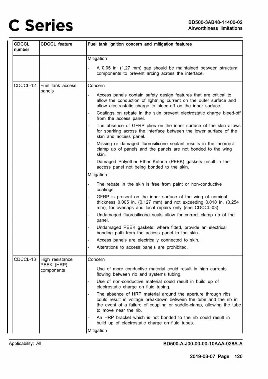
BD500-3AB48-11400-02Airworthiness limitations
Applicability: All BD500-A-J00-00-00-10AAA-028A-A
2019-03-07 Page 120
CDCCLnumber
CDCCL feature Fuel tank ignition concern and mitigation features
Mitigation
‐ A 0.05 in. (1.27 mm) gap should be maintained between structuralcomponents to prevent arcing across the interface.
CDCCL-12 Fuel tank accesspanels
Concern
‐ Access panels contain safety design features that are critical toallow the conduction of lightning current on the outer surface andallow electrostatic charge to bleed-off on the inner surface.
‐ Coatings on rebate in the skin prevent electrostatic charge bleed-offfrom the access panel.
‐ The absence of GFRP plies on the inner surface of the skin allowsfor sparking across the interface between the lower surface of theskin and access panel.
‐ Missing or damaged fluorosilicone sealant results in the incorrectclamp up of panels and the panels are not bonded to the wingskin.
‐ Damaged Polyether Ether Ketone (PEEK) gaskets result in theaccess panel not being bonded to the skin.
Mitigation
‐ The rebate in the skin is free from paint or non-conductivecoatings.
‐ GFRP is present on the inner surface of the wing of nominalthickness 0.005 in. (0.127 mm) and not exceeding 0.010 in. (0.254mm), for overlaps and local repairs only (see CDCCL-03).
‐ Undamaged fluorosilicone seals allow for correct clamp up of thepanel.
‐ Undamaged PEEK gaskets, where fitted, provide an electricalbonding path from the access panel to the skin.
‐ Access panels are electrically connected to skin.‐ Alterations to access panels are prohibited.
CDCCL-13 High resistancePEEK (HRP)components
Concern
‐ Use of more conductive material could result in high currentsflowing between rib and systems tubing.
‐ Use of non-conductive material could result in build up ofelectrostatic charge on fluid tubing.
‐ The absence of HRP material around the aperture through ribscould result in voltage breakdown between the tube and the rib inthe event of a failure of coupling or saddle-clamp, allowing the tubeto move near the rib.
‐ An HRP bracket which is not bonded to the rib could result inbuild up of electrostatic charge on fluid tubes.
Mitigation

BD500-3AB48-11400-02Airworthiness limitations
Applicability: All BD500-A-J00-00-00-10AAA-028A-A
2019-03-07 Page 121
CDCCLnumber
CDCCL feature Fuel tank ignition concern and mitigation features
‐ HRP components create a high resistance path between systemstubing and structure allowing bleed-off of electrostatic charge whichcould accumulate on the systems tubing while preventing highcurrents flowing from structure into the fuel tubing.
‐ HRP material around the aperture through ribs prevents voltagebreakdown between the tube and the rib in the event of the tubebeing unsecured.
‐ In the outer wing, use of conductive Hi-Lites, washers, and collarsprovides a bonding path from HRP brackets to the rib or compositestructure. Fasteners are dry installed in composite structure.
‐ In the Centre Wing Box (CWB), interference fit fasteners in the riband the tail/head of dry installed fasteners (without sealant) on HRPprovide an electrical bonding path.
‐ HRP brackets installed back-to-back are electrically connected viathe mating surfaces.
CDCCL-14 High ResistanceIsolator (HRI)components
Concern
‐ The absence of HRI components would allow high levels ofelectrical current to flow from structure to system tubing and/orcomponents.
‐ Isolators not electrically bonded to the rib would preventelectrostatic charge bleed-off from the tubing to structure.
Mitigation
‐ HRI components bonded to the rib limits current flow from structureto the tubing, while allowing electrostatic charge to bleed-off fromthe tubing.
‐ Where applicable, the isolator is electrically bonded to the rib andthe required O-ring prevents ingress of moisture to the bondingsurface.
‐ Fillet seals around the interface protects electrical bonding (seeCDCCL-01).
‐ Wet installation of fasteners protects electrical bonding (seeCDCCL-01).
CDCCL-15 Rivet-less domesealed anchor nuts
(Installation ofcollector tank andRib 8 access doors)
Concern
‐ Use of alternate anchor nuts would result in fastener tail not beingsealed and potential ignition sources not encapsulated.
‐ Access doors which are not electrically bonded to structure couldresult in arcing across interface.
Mitigation
‐ Swaging of anchor nuts ensures that there is no gap between theanchor nut and the hole.

BD500-3AB48-11400-02Airworthiness limitations
Applicability: All BD500-A-J00-00-00-10AAA-028A-A
2019-03-07 Page 122
CDCCLnumber
CDCCL feature Fuel tank ignition concern and mitigation features
‐ Sealed domes encapsulate any ignition sources at the fastenerinstallation.
‐ Access doors are electrically bonded via the attachment fasteners.
CDCCL-16 Fluorosilicone rubbergasket or inter-faysealant
(Installation ofcollector tank andRib 8 access doors)
Concern
‐ The absence of, or damage to, a gasket or sealant would allowcurrent flow between the access door and structure.
‐ The absence of, or damage to, gasket or sealant would allowpotential sparking across the interface.
Mitigation
‐ Fluorosilicone sealant prevents current flow across the interfaceand encapsulates potential ignition sources between bolts andstructure, while preventing the ingress of moisture which couldcause deterioration of the electrical bond.
CDCCL-17 National AdvisoryCommittee forAeronautics (NACA)scoop
Concern
‐ Incorrect surface preparation of the access panel prior to theapplication of inter-fay sealant prevents correct adhesion of sealant.
Mitigation
‐ Inter-fay sealant provides isolation between the access panel andthe scoop preventing current flow across the interface and providescontainment of sparking at the interface.
CDCCL-18 Bonding leads Concern
‐ Broken bonding leads or bonding leads which are not reattachedafter maintenance.
Mitigation
‐ Correctly sized and installed bonding leads provide a lowimpedance path for lightning and fault currents, reducing currentflow within the fuel tank composite structure.
CDCCL-19 Drain tubes Concern
‐ Incorrect material used in drain tubes allows current flow from theouter skin to the slat cans.
Mitigation
‐ Silicone rubber tubing provides isolation between the drainassembly and the slat can.
CDCCL-20 Pylon bonding points Concern

BD500-3AB48-11400-02Airworthiness limitations
Applicability: All BD500-A-J00-00-00-10AAA-028A-A
2019-03-07 Page 123
CDCCLnumber
CDCCL feature Fuel tank ignition concern and mitigation features
‐ Lightning attachment on the pylon could result in a large currentflow within the wing.
Mitigation
‐ Six ground points provide a low resistance path between the pylonand the metallic leading/trailing edges, reducing lightning currentsflowing in the wetted area of wing. This forms part of the LightningFault Current Return Network (LFCRN).
CDCCL-21 Refuel bondingpoints
Concern
‐ Build up of electrostatic charge during refuelling could result inelectrical discharge.
Mitigation
‐ Bonding lugs on the refuel deck are the bonding point providing adischarge path for electrostatic charge during refuelling.
CDCCL-22 Conductive saddleclamp
Concern
‐ The absence of conductive saddle clamps would remove the pathfor electrostatic charge to bleed-off from fuel tubing.
‐ The absence or relocation of saddle clamps could allow contactbetween the tubing and structure.
Mitigation
‐ Conductive saddle clamps provide a path from the fuel tube to therib via HRP brackets, to allow electrostatic charge to bleed-off.
‐ Saddle clamps maintain positive separation between the tubing andstructure.
CDCCL-23 Conductive couplings Concern
‐ The absence of conductive couplings between adjacent sectionsof tubing remove a path for bleed-off of accumulated electrostaticcharge.
‐ The absence of conductive couplings between the tubing and acomponent removes electrical continuity between the tubing and fuelsystem components.
Mitigation
‐ Conductive couplings provide a conductive path betweencomponents and tubing, and between adjacent sections of tubing.
CDCCL-24 Fuel tubing Concern
‐ High resistance interfaces between fuel tubing and structure isrequired to limit the flow of lightning currents while inhibiting thebuild up of electrostatic charge.

BD500-3AB48-11400-02Airworthiness limitations
Applicability: All BD500-A-J00-00-00-10AAA-028A-A
2019-03-07 Page 124
CDCCLnumber
CDCCL feature Fuel tank ignition concern and mitigation features
‐ Inadequate preparation for electrical bonding in way of saddleclamps or ferrules would result in the tube not being electricallybonded to structure or adjacent tubing, preventing bleed-off ofelectrostatic charge.
‐ Inadequate clamping could allow contact between the tubing andstructure, or other systems, causing arcing.
Mitigation
‐ The area under conductive saddle clamps and under ferrules areboth free from non-conductive coatings.
CDCCL-25 Hydraulic tubing Concern
‐ High resistance interfaces between hydraulic tubing and structureis required to limit the flow of lightning currents while inhibiting thebuild up of electrostatic charge.
‐ Swaged fittings are used to provide continuity between adjacentsections of tubing.
‐ Inadequate clamping could allow contact between tubing andstructure, or other systems, causing arcing.
Mitigation
‐ HRI installed between the tubing and structure are electricallybonded through faying surface directly to the metallic rib or viaattachment fasteners to the metal plate that interfaces between HRIand the composite spar (see CDCCL-14).
‐ HRI on the composite spar are electrically bonded via the tubing atthe first bulkhead connector to the current return network.
‐ Tubing is held in place where it passes through metal ribs by theuse of a clamp block, which ensures positive separation betweenthe tubing and the rib.
CDCCL-26 Fuel QuantityGauging System(FQGS) electricalharness
(within fuel tank)
Concern
‐ Incorrect cable clipping, or absence of an insulation sleeve, wouldallow the harness to come into close proximity of an adjacentharness or structure.
‐ Induced voltages enter the tank via the harness.
Mitigation
‐ As designed, harness clipping points are maintained so that nosingle failure allows the harness to come within 0.367 in. (9.322mm) of the wing structure or within 0.50 in. (12.70 mm) of anadjacent harness.
‐ Harness over-braid is bonded externally to the tank, reducing theinduced voltages entering the tank.

BD500-3AB48-11400-02Airworthiness limitations
Applicability: All BD500-A-J00-00-00-10AAA-028A-A
2019-03-07 Page 125
CDCCLnumber
CDCCL feature Fuel tank ignition concern and mitigation features
‐ HRP split sealing devices with rubber nitrile cushioning is usedwhere a harness passes through sealed ribs. This prevents chaffingand isolates the harness from metal ribs.
‐ Nylon grommets are fitted to rib apertures where a harness passesthrough. This prevents chaffing and isolates the harness from themetal rib.
‐ At locations where a harness is between 0.385 in. (9.779 mm) and0.625 in. (15.875 mm) of structure, an additional layer of protectivesleeve is used to provide additional protection in the event of afailure of the support.
‐ The harness is specifically routed to minimize induced voltages.Routing should not be altered.
‐ It is not permissible to rework the FQGS harness, other than at theconnection within the specified limits provided. In the event of afailure, it must be removed and replaced.
CDCCL-27 FQGS andAlternating Current(AC) pump electricalharnesses
(outside fuel tank)
Concern
‐ Electrical harness clipping points to structure need to ensure thatno single failure of a clipping point can result in the harnesscoming in contact with the wing structure.
Mitigation
‐ Clipping arrangements are designed such that FQGS harnessseparation from each adjacent harness will be no less than 0.50 in.(12.70 mm).
‐ Electrical harness separation from structure is no less than 0.25 in.(6.35 mm).
‐ Grounding of the Remote Data Concentrator (RDC) to the aircraftstructure provides a grounding path for gauging harnesses over-braid.
‐ Grounding of gauging harness over-braid ensures induced voltagesdo not enter tank at OWB and CWB spar locations.
‐ The FQGS harness includes a pink identification close to theconnector. This pink identification cannot be altered in any way.
‐ The FQGS harness and AC pump harness cannot be spliced and,if removed or replaced, need to be installed with the appropriateclipping.
CDCCL-28 FQGS sensors(includingcompensator)
Concern
‐ Incorrect installation of capacitance probes to measure fuel quantitycan result in a potential ignition source within the fuel tanks.
Mitigation
‐ Probe clearance to structure must be no less than 0.331 in. (8.407mm).

BD500-3AB48-11400-02Airworthiness limitations
Applicability: All BD500-A-J00-00-00-10AAA-028A-A
2019-03-07 Page 126
CDCCLnumber
CDCCL feature Fuel tank ignition concern and mitigation features
‐ Probes incorporate isolation clamps.‐ Plastic end caps isolate metallic sections in the event of a clamp
failure, therefore it is essential that these are installed correctly.‐ In-tank wire harnesses are terminated with lugs and are connected
to the probe terminal board using captive screw terminals. Theharness is attached to the tank unit with two nylon tie-wraps forredundancy. The upper tie-wrap functions as the primary strainrelief for the harness and the lower tie-wrap provides redundancy.Both tie-wraps limit the swing of the harness end if terminationsare disconnected. The shielded return wire is held in place to theterminal board with one screw and another screw is used for theexcitation.
‐ When removing a probe for repair, it is prohibited to disassembleand repair the probe.
‐ Gauging sensor tie-wraps cannot be replaced.‐ Metallic brackets attach the fuel probes to the ribs using Hi-Lite
fasteners with sealant caps on the collar side.‐ Wet installation of fasteners protects electrical bonding (see
CDCCL-01).‐ Sealant is applied on fastener heads and tails (see CDCCL-01).
CDCCL-29 FQGS electricalconnector
Concern
‐ Current flow from structure to the connector could result in ignitionsources within the tank.
Mitigation
‐ The HRP flange between the connector and the spar reducespotential current flow (see CDCCL-13).
‐ It is prohibited to change the in-tank wall electrical connector.
CDCCL-30 RDC Concern
‐ Incorrect operation of the RDC could result in induced voltages withsufficient energy to cause ignition within the fuel tank.
Mitigation
‐ It is prohibited to disassemble or repair the unit.‐ The RDC is bonded to a mounting bracket via faying surface
provided on the RDC and from the bracket to aircraft structureLFCRN via faying surface.
CDCCL-31 Refuel nozzles Concern
‐ Use of alternate material for tube mounting brackets could result inhigh currents flowing between ribs and systems tubing.

BD500-3AB48-11400-02Airworthiness limitations
Applicability: All BD500-A-J00-00-00-10AAA-028A-A
2019-03-07 Page 127
CDCCLnumber
CDCCL feature Fuel tank ignition concern and mitigation features
‐ Alteration to the geometry and positioning of refuel nozzles or ribmounted diffuser plates, where fitted, could result in increased buildup of electrostatic charge during refueling.
Mitigation
‐ HRP brackets are used (see CDCCL-13).‐ The geometry of nozzles and the distance from rib mounted
diffuser plates minimize build up of electrostatic charge duringrefueling and cannot be altered.
‐ Conductive finishing on fasteners and washers, and preparation ofthe area under fastener heads, allows for electrical bonding throughthe attachment fastener to dissipate electrostatic charge.
‐ Correct torquing of fasteners ensures correct clamp up at theinterface to ensure that an electrical bond is achieved.
‐ Seal cap or brush sealant on fastener heads and tails protectelectrical bonding (see CDCCL-01).
CDCCL-32 Optional left refuel/defuel installation
Concern
‐ Use of alternate material for tube mounting brackets could result inhigh currents flowing between ribs and systems tubing.
‐ Poor continuity between metal components could result in sparkingacross interface.
‐ Isolated metal components within the fuel tank could result inelectrostatic charge build up on the bracket before dischargeoccurs.
Mitigation
‐ HRP brackets are used (see CDCCL-13).‐ Bonding adjacent metal components by mating surfaces ensures
electrical continuity between parts with low electrical resistance(see CDCCL-10 for installation of the cap when the option is notinstalled and CDCCL-22, CDCCL-23, CDCCL-24 for when theoptional refuel/defuel assembly is installed).
‐ Fillet sealant around the interface protects electrical bonding (seeCDCCL-01).
CDCCL-33 Fuel Tank InertingSystem (FTIS)
Concern
‐ Isolated components within the fuel tank could result in a build upof electrostatic charge and subsequent discharge.
‐ Changes or modifications to system components are prohibited asthis may increase fuel tank flammability.
Mitigation
‐ For each of the components listed, material and finish providean electrical bonding path through the LFCRN: Distribution Check

BD500-3AB48-11400-02Airworthiness limitations
Applicability: All BD500-A-J00-00-00-10AAA-028A-A
2019-03-07 Page 128
CDCCLnumber
CDCCL feature Fuel tank ignition concern and mitigation features
Valve, Upstream Check Valve, Flame Arrester, Nitrogen EnrichedAir Distribution System (NEADS) coupling tube (self-locking bondingrigid coupling), elbow, dual flow shutoff valve, bonding jumper, heatexchanger, rack assembly.
‐ Fillet sealant around the interface protects electrical bonding (seeCDCCL-01).
CDCCL-34 NEADS tubing Concern
‐ Use of alternate material for tube mounting brackets could result inhigh currents flowing between ribs and systems tubing.
‐ Inadequate surface preparation for electrical bonding in way ofsaddle clamps or ferrules could result in the tube not beingelectrically bonded to structure or adjacent tubing, preventing bleed-off of electrostatic charge.
‐ Inadequate clamping could allow contact between tubing andstructure or other systems causing arcing.
Mitigation
‐ The tubing installation relies on high resistance attachments tothe fuel tank structure (see CDCCL-24), including the use of HRPbrackets (see CDCCL-13), HRI (see CDCCL-14), conductive saddleclamps (see CDCCL-22).
‐ Conductive couplings are used (see CDCCL-23).‐ The material and finish of bonding straps provide an electrical
bonding path.‐ Fillet sealant around the interface protects electrical bonding (see
CDCCL-01).
CDCCL-35 Confined space andlow oxygen contentmarkings/placards
Concern
‐ Integrity of the placards warning maintenance personnel regardingthe hazard of Nitrogen Enriched Air (NEA) in an enclosed area isrequired by regulation.
Mitigation
‐ The placard must remain legible throughout the service life of theaircraft.
CDCCL-36 Electric fuel pumpcanister and ACpump inlet snorkelscreen
Concern
‐ The fuel pump housing is electrically bonded to the mounting riband if it were to become isolated, hazard could result from thebuild up of electrostatic charge and subsequent discharge.
‐ Poor continuity between electrical components could result inelectrical sparking, in the event of lightning or fault current transferthrough the structure.
Mitigation

BD500-3AB48-11400-02Airworthiness limitations
Applicability: All BD500-A-J00-00-00-10AAA-028A-A
2019-03-07 Page 129
CDCCLnumber
CDCCL feature Fuel tank ignition concern and mitigation features
‐ The area of rib under the interface with a canister and underfastener heads is prepared for electrical bonding by removal ofnon-conductive coatings; thus creating two independent bondingpaths.
‐ The snorkel screen is also electrically bonded to a bracket via afaying surface electrical bond. Mating surfaces are free from non-conductive finishes to create an electrical bond between the pumpand the bracket.
‐ Conductive finishing on fasteners and associated washers ensure alow resistance path between the rib and pump canister.
‐ Correct torquing of fasteners ensures correct clamp up of theinterface, preventing gapping.
‐ Fillet sealant around the interface protects electrical bonding (seeCDCCL-01).
‐ Brush sealant on fastener heads protects electrical bonding (seeCDCCL-01).
‐ An O-ring seal protects the surface for electrical bonding and alsoencapsulates potential ignition sources at the canister interface.
‐ The boost pump (canister) is electrically bonded to the inlet tubevia the conductive coupling (see CDCCL-23).
‐ Wet installation of fasteners protects electrical bonding (seeCDCCL-01).
CDCCL-37 Electric fuel pumpcartridge
Concern
‐ The electric fuel pump cartridge contains safety design featuresthat are critical to avoid the possibility of generation of an ignitionsource by overheating or sparks caused by arcing and friction.
‐ The pump cartridge is mounted in the aircraft dry bay, adjacent tothe collector tank. The fastener interfaces within the wetted areaare encapsulated within the canister housing.
Mitigation
‐ Electrical bonding of the pump is achieved both via a fayingsurface and the attachment fasteners. Conductive finishing onfasteners and washers ensures the electrical bond.
‐ Fillet sealant around the interface protects electrical bonding (seeCDCCL-01).
‐ Brush sealant on fastener heads protects electrical bonding (seeCDCCL-01).
‐ Correct torquing of fasteners ensures correct clamp up of theinterface, preventing gapping.
‐ Disassembly or repair of the cartridge is prohibited. In the event ofa failure, it must be removed and replaced.

BD500-3AB48-11400-02Airworthiness limitations
Applicability: All BD500-A-J00-00-00-10AAA-028A-A
2019-03-07 Page 130
CDCCLnumber
CDCCL feature Fuel tank ignition concern and mitigation features
CDCCL-38 Fuel systemcomponents mountedon a metallicelement
‐ Float vent valves‐ Transfer float
valve‐ Pressure Relief
Valves (PRV)‐ Scavenge ejector‐ Vent float drain
valve
Concern
‐ Conducted lightning currents through the surface upon which acomponent is mounted constitutes a potential ignition source.
‐ Insufficient, or a degradation of, electrical continuity as a result ofimproper surface preparation, could result in the potential for arcingor sparking to occur within the fuel tanks.
‐ Non-conductive or electrically isolated components could accumulatehazardous levels of electrostatic charge which is considered apotential ignition source.
Mitigation
‐ Mating surfaces are free from non-conductive finishes to ensureproper electrical bonding between the valve and the mountingsurface.
‐ Fillet sealant around the interface protects electrical bonding (seeCDCCL-01).
‐ Brush sealant on fastener heads and seal cap installed overnuts and washers (where applicable) ensures that the interface isprotected (see CDCCL-01)
‐ An O-ring seal protects the bonding interface from ingress ofmoisture which could result in degradation of electrical bond.
‐ Correct torquing of fasteners ensures correct clamp up of theinterface, preventing gapping.
‐ Conductive finishing on fasteners and associated washers ensure alow resistance path between the metallic element and component.
‐ Conductive coupling are installed on mating in-line components (seeCDCCL-23).
‐ Hole quality is critical with respect to dimensions and absence ofdebris.
‐ For the main tank PRV, there is an electrical bond through itsattachment fasteners to the Fuel Tank Access Cover (FTAC). Brushsealant on fastener heads and tails protects electrical bonding (seeCDCCL-01).
CDCCL-39 Fuel systemcomponents mountedon a composite spar
‐ Engine andAuxiliary PowerUnit (APU)Shut-Off Valves(SOV)
‐ Refuel controlsolenoid
Concern
‐ Conducted lightning currents passing through the composite sparupon which each SOV is mounted could cause potential ignitionsources.
‐ Excessive fuel flow rates or the use of non-conductive materials inthe high fuel flow areas can lead to generation and accumulationof hazardous levels of electrostatic charge, which is considered apotential ignition source.
‐ Insufficient, or a degradation of, electrical continuity as a result ofimproper surface preparation, could result in the potential for arcingor sparking to occur within the fuel tanks.

BD500-3AB48-11400-02Airworthiness limitations
Applicability: All BD500-A-J00-00-00-10AAA-028A-A
2019-03-07 Page 131
CDCCLnumber
CDCCL feature Fuel tank ignition concern and mitigation features
Mitigation
‐ Mating surfaces between each fuel system component and thealuminum plate between the component and composite spar arefree from non-conductive finishing to ensure proper electricalbonding.
‐ The aluminum plate is isolated from the spar surface by a layer ofglass fibre that is co-cured with the spar.
‐ The SOV are electrically bonded to the tubing using conductivecouplings (see CDCCL-023).
‐ The valve body is electrically bonded to the actuator throughattachment fasteners.
‐ The actuator is electrically bonded to the LFCRN via a bondingjumper.
‐ Fillet sealant around the interface protects electrical bonding (seeCDCCL-01).
‐ Brush sealant on fastener heads protects electrical bonding (seeCDCCL-01).
‐ Disassembly or repair of the valve actuator and refuel controlsolenoid is prohibited.
‐ Inter-fay sealant between the plate and spar ensures any ignitionsources at the interface are encapsulated.
CDCCL-40 Refuel flangedadaptor installation
Concern
‐ Conducted lightning currents passing through the surface uponwhich a component is mounted constitutes a potential ignitionsource.
‐ Excessive fuel flow rates or the use of non-conductive materials inthe high fuel flow areas can lead to generation and accumulationof hazardous levels of electrostatic charge, which is considered apotential ignition source.
‐ The system tubing is always full of fuel which minimizes the hazardbut extra care needs to be taken during disassembly (maintenance)as no fuel will be in the line.
Mitigation
‐ The adaptor is electrically bonded to the LFCRN via a fayingsurface to the bonding plate.
‐ Wet installation of fasteners protects electrical bonding (seeCDCCL-01).
‐ Fillet seal around periphery of mating components (see CDCCL-01).‐ Brush sealant on fastener heads protects electrical bonding (see
CDCCL-01).

BD500-3AB48-11400-02Airworthiness limitations
Applicability: All BD500-A-J00-00-00-10AAA-028A-A
2019-03-07 Page 132
CDCCLnumber
CDCCL feature Fuel tank ignition concern and mitigation features
CDCCL-41 Refuel bellowsinstallation
Concern
‐ Conducted lightning currents passing through the surface uponwhich a component is mounted constitutes a potential ignitionsource.
‐ Excessive fuel flow rates or the use of non-conductive materials inthe high fuel flow areas can lead to generation and accumulationof hazardous levels of electrostatic charge, which is considered apotential ignition source.
‐ The system tubing is always full of fuel which minimizes the hazardbut extra care needs to be taken during disassembly (maintenance)as no fuel will be in the line.
Mitigation
‐ The bellows are electrically bonded to HRI via the attachmentfasteners.
‐ Conductive finishing on a nut and preparation of the area under anut allows for electrical bonding through the attachment fastener toprovide continuity between the bellows and the isolator.
‐ Brush sealant on fastener heads and seal cap installed overnuts and washers (where applicable) ensures that the interface isprotected (see CDCCL-01)
‐ Wet installation of fasteners protects electrical bonding (seeCDCCL-01).
CDCCL-42 Fuel systemcomponents mountedon HRP brackets
‐ Refuel SOV‐ Primary and
transfer ejectors
Concern
‐ Conducted lightning currents passing through the surface uponwhich a component is mounted constitutes a potential ignitionsource.
‐ Excessive fuel flow rates or the use of non-conductive materials inthe high fuel flow areas can lead to generation and accumulationof hazardous levels of electrostatic charge, which is considered apotential ignition source.
‐ Insufficient, or a degradation of, electrical continuity as a result ofimproper surface preparation, could result in the potential for arcingor sparking to occur within the fuel tanks.
Mitigation
‐ HRP brackets are used (see CDCCL-13).‐ The ejector and the screen are electrically bonded to the bracket
via a faying surface bond. Mating surfaces are free from non-conductive finishing to create an electrical bond between the ejectorpump and the bracket.
‐ Where a polyamide shim is required at the installation of theengine feed ejector pump, electrical bonding is achieved throughthe attachment fasteners.

BD500-3AB48-11400-02Airworthiness limitations
Applicability: All BD500-A-J00-00-00-10AAA-028A-A
2019-03-07 Page 133
CDCCLnumber
CDCCL feature Fuel tank ignition concern and mitigation features
‐ Brush sealant on fastener heads and seal cap installed overnuts and washers (where applicable) ensures that the interface isprotected (see CDCCL-01)
‐ Wet installation of fasteners protects electrical bonding (seeCDCCL-01).
‐ Fillet sealant around the interface protects electrical bonding (seeCDCCL-01).
‐ Correct torquing of fasteners ensures correct clamp up of theinterface, preventing gapping
CDCCL-43 Flame arrestorinstallation
Concern
‐ Conducted lightning currents passing through the surface uponwhich a component is mounted constitutes a potential ignitionsource.
‐ Use of non-conductive materials in the high fuel flow areas canlead to generation and accumulation of hazardous levels ofelectrostatic charge which is considered a potential ignition source.Fuel can flow via the flame arrester during failure cases on theground during refueling.
Mitigation
‐ Electrical bonding is achieved through faying surface bonds. Non-conductive finishing is removed from NACA under the footprintof the flame arrestor. Conductive finishing on mating interfacesensures electrical continuity between parts.
‐ Fillet sealant around the interface protects electrical bonding (seeCDCCL-01).
‐ Electrical bonding is achieved through attachment fasteners andassociated washers. Conductive finishing on mounting hardwarecreates, along with removal of non-conductive finishing on thearea of flange under the fastener head and dry installation of thefastener, an electrical bond through the attachment hardware.
‐ Brush sealant on fastener heads and seal cap installed overnuts and washers (where applicable) ensures that the interface isprotected (see CDCCL-01)
CDCCL-44 Fuel temperaturesensors (includingthe Thermowell)
Concern
‐ The Resistance Temperature Detector (RTD) must be properlycontained inside the sensor body, which is then installed inside aThermowell capsule.
‐ Conductive finishing on mating interfaces ensures electricalcontinuity.
‐ Conducted lightning currents through the surface upon which acomponent is mounted constitutes a potential ignition source.
Mitigation

BD500-3AB48-11400-02Airworthiness limitations
Applicability: All BD500-A-J00-00-00-10AAA-028A-A
2019-03-07 Page 134
CDCCLnumber
CDCCL feature Fuel tank ignition concern and mitigation features
‐ For fuel reaching the sensor, two structural failures are required.First, the capsule (Thermowell) needs to fail, which will leak outsidefrom the dry bay. Second, the temperature sensor housing needsto fail.
‐ Conductive finishing on mating interfaces ensures electricalcontinuity between parts.
‐ Wet installation of fasteners protects electrical bonding (seeCDCCL-01).
‐ Correct torquing of fasteners ensures correct clamp up of theinterface, preventing gapping
‐ Brush sealant on fastener heads and seal cap installed overnuts and washers (where applicable) ensures that the interface isprotected (see CDCCL-01)
‐ Fillet sealant around the interface protects electrical bonding (seeCDCCL-01).
CDCCL-45 Engine feed pressureswitch and flangedadaptor installation
Concern
‐ The pressure switch is mounted on the aluminum flanged adapter/fitting which is mounted on the wing aft spar and can conductsignificant current during an aircraft lightning strike.
‐ Transient lightning current may transfer from the spar to the bracketand then through the ground wire and the electrical connector over-braid.
‐ The lightning conducted current threat on the spar is considered apotential ignition source.
Mitigation
‐ The flanged adaptor is electrically bonded to the LFCRN via abonding lead from the pressure switch.
‐ The bonding lead provides a ground path for the harness over-braid and grounding of the tube from tank.
‐ Wet installation of fasteners protects electrical bonding (seeCDCCL-01).
‐ Brush sealant on fastener heads protects electrical bonding (seeCDCCL-01).
‐ Fillet sealant around the interface protects electrical bonding (seeCDCCL-01).
‐ The GFRP between the flanged adaptor and the composite sparprotects the electrical bonding (see CDCCL-03).
CDCCL-46 Water Drain Valve(WDV)
Concern
‐ Conducted lightning currents through the surface upon which acomponent is mounted constitutes a potential ignition source.

BD500-3AB48-11400-02Airworthiness limitations
Applicability: All BD500-A-J00-00-00-10AAA-028A-A
2019-03-07 Page 135
CDCCLnumber
CDCCL feature Fuel tank ignition concern and mitigation features
‐ The WDV are also subject to potential electrostatic discharge fromeither maintenance personnel or from in-flight P-static.
Mitigation
‐ WDV installation must be torqued per installation drawingrequirements.
‐ Make sure that there is no ECF between the WDV flange and thewing Outer Mold Line (OML).
‐ Ensuring that a minimum thickness of paint (by the application ofprimer only and omission of topcoat) between the valve flange andthe OML of the skin is critical.
‐ Hole quality is critical with respect to dimensions and absence ofdebris.
CDCCL-47 NEADS flowbalancing orifices
Concern
‐ Flow balancing orifices ensure that the required distribution ofNEA to both the main and center fuel tanks per the fuel tankflammability exposure, to comply with the Flammability ReductionMethodology requirements.
‐ The routing of the NEADS and location of in-tank distributionnozzles is critical to the distribution of NEA. Therefore, it cannot bealtered in any way.
Mitigation
‐ The location of the flow balancing orifice is critical for distribution ofNEA.
‐ The geometry and hole diameter is critical for the flow balancingorifice and cannot be modified.
‐ The orifice is electrically bonded to both the adjacent coupling andthe T-piece (see CDCCL-23).
‐ The location and size of NEA in-tank nozzles cannot be altered.‐ Adjacent sections of pipe are electrically bonded by swaged fittings
and isolated from structure where the tubes pass through ribs byinsulated clamp blocks.
‐ Conductive saddle clamps and HRP brackets are used wheresupport is required across a rib (see CDCCL-22 and CDCCL-13).
CDCCL-48 Gravity, defuelisolation and manualvalve
Concern
‐ Conducted lightning currents through the surface upon which acomponent is mounted constitutes a potential ignition source.
‐ Insufficient, or a degradation of, electrical continuity as a result ofimproper surface preparation, could result in the potential for arcingor sparking to occur within the fuel tanks.
Mitigation

BD500-3AB48-11400-02Airworthiness limitations
Applicability: All BD500-A-J00-00-00-10AAA-028A-A
2019-03-07 Page 136
CDCCLnumber
CDCCL feature Fuel tank ignition concern and mitigation features
‐ Conductive saddle clamps are used (see CDCCL-22).‐ HRP brackets are used (see CDCCL-13).‐ HRI components are used (see CDCCL-14).‐ Self-locking bonding rigid couplings provide an electrical bonding
path (see CDCCL-23).‐ The SOV body is electrically bonded through faying surface to the
aluminum plate.‐ The aluminum plate is isolated from the spar surface by a layer of
glass fibre (see CDCCL-03).‐ Valve studs (material & finish) provide an electrical bonding path
with the external bonding jumper to the LFCRN.‐ Correct torquing of fasteners ensures correct clamp up of the
interface, preventing gapping.‐ The electrical actuator and manual lever, mounted on the outside of
the tank on the spar fastened by valve studs, provide an electricalbonding path using a bonding jumper.
‐ Fillet sealant around the interface protects electrical bonding (seeCDCCL-01).
‐ Disassembly or repair of the valve actuator is prohibited.
CDCCL-49 Hydraulic heatexchanger
Concern
‐ Any component affecting the hydraulic system maximum fluidtemperature cannot be compromised in any way.
‐ Excessive fuel flow rates or the use of non-conductive materials inthe high fuel flow areas can lead to generation and accumulationof hazardous levels of electrostatic charge, which is considered apotential ignition source.
Mitigation
‐ The heat exchanger is electrically bonded to the HRP mountingbrackets via the mating surfaces (see CDCCL -013).
‐ The area on mounting brackets under the feet of the heatexchanger are free from non-conductive coatings.
‐ Fillet sealant around the interface protects electrical bonding (seeCDCCL-01).
CDCCL-50 Thrust ReverserActuation System(TRAS) IsolationControl Valve (ICV)mounting bracket
Concern
‐ Broken bonding leads break or bonding leads that are notreattached after maintenance can result in harness overheating inthe event of an ICV fault.
‐ Insufficient, or a degradation of, electrical continuity can occur asa result of improper surface preparation between the ICV and itsmounting bracket.

BD500-3AB48-11400-02Airworthiness limitations
Applicability: All BD500-A-J00-00-00-10AAA-028A-AEnd of data module
2019-03-07 Page 137
CDCCLnumber
CDCCL feature Fuel tank ignition concern and mitigation features
Mitigation
‐ Correctly sized and dual installation of bonding leads forredundancy provide a low impedance path for lightning and faultcurrents, reducing current flow within the fuel tank compositestructure.
‐ Electrical bonding is achieved through faying surface bonds. Non-conductive finishing is removed from the area of plank under thefootprint of bracket.
‐ Fillet sealant around the interface protects electrical bonding (seeCDCCL-01).
‐ Brush sealant on fastener heads and seal cap installed overnuts and washers (where applicable) ensures that the interface isprotected (see CDCCL-01)

BD500-3AB48-11400-02Airworthiness limitations
Intentionally left blank
Applicability: All BD500-A-J00-00-00-10AAA-028A-A
2019-03-07 Page 138

BD500-3AB48-11400-02Airworthiness limitations
Applicability: All BD500-A-J00-00-00-11AAA-028A-AEnd of data module
2016-10-25 Page 139
Power plant limitations - General
References
Table 1 References
Data Module/Technical Publication Title
PN 5305816 PW1500G Series Airworthiness Limitation Manual (AWL)
Description
1 GeneralThe CSeries aircraft is equipped with two Pratt & Whitney PurePower™ PW1500G seriesengines.
Service limits for the engine rotating/non-rotating Life Limited Parts (LLP) are specified in theengine manual shown in Table 2.
Operators must incorporate the PW engine limitations into their locally approved aircraftmaintenance schedule.
Table 2 Engine service limitsAircraft model Engine model Engine manual
BD-500-1A10 (CS100) Pratt & Whitney PW1519G
Pratt & Whitney PW1521G
Pratt & Whitney PW1524G
Pratt & Whitney PW1525G
BD-500-1A11 (CS300) Pratt & Whitney PW1521G-3
Pratt & Whitney PW1524G-3
Pratt & Whitney PW1525G-3
PN 5305816 PW1500G SeriesAirworthiness Limitation Manual (AWL)

BD500-3AB48-11400-02Airworthiness limitations
Intentionally left blank
Applicability: All BD500-A-J00-00-00-11AAA-028A-A 2016-10-25 Page 140

BD500-3AB48-11400-02Airworthiness limitations
Applicability: All BD500-A-J00-00-00-12AAA-028A-AEnd of data module
2016-06-10 Page 141
Structural repair limitations - General
References
Table 1 References
Data Module/Technical Publication Title
BD500-3AB48-11900-00 Structural deviation inspection requirements
Description
1 GeneralThe structural repair limitations applicable to the CSeries aircraft are specified in theBD500-3AB48-11900-00 Structural deviation inspection requirements (SDIR) document.

BD500-3AB48-11400-02Airworthiness limitations
Intentionally left blank
Applicability: All BD500-A-J00-00-00-12AAA-028A-A 2016-06-10 Page 142

BD500-3AB48-11400-02Airworthiness limitations
Applicability: All BD500-A-J00-00-00-18AAA-028A-A
2016-07-20 Page 143
Limit of validity - General
References
Table 1 References
Data Module/Technical Publication Title
None
Description
1 GeneralThis data module gives a Limit of Validity (LOV) for engineering data that supports thestructural maintenance program applicable to the CSeries aircraft.
2 ScopeThe LOV specified in this data module is developed in accordance with Transport CanadaAirworthiness Manual (AWM) 525.571(a)(b).
3 Limit of validityRegulation requires the establishment of an aircraft level Limit Of Validity (LOV) for theengineering data that supports the structural maintenance program that corresponds to theperiod of time, stated as a number of total accumulated flight hours and flight cycles, duringwhich it is demonstrated that widespread fatigue damage will not occur in the aircraft.
Structural modifications and inspections might be required to support the LOV. In such cases,Structural Modification Points (SMP) and Inspection Starting Points (ISP) are provided.
The candidate LOV for CSeries aircraft model numbers; BD-500-1A10 (CS100) andBD-500-1A11 (CS300), is 160000 Flight Hours (FH) or 80000 Flight Cycles (FC), whichevercomes first.
The approved LOV is not available because fatigue test cycling, residual strength test andteardown inspections are not completed. In the absence of an approved LOV, a TemporaryOperational Limit (TOL) is imposed, refer to Para. 4.
4 Temporary operational limitA Temporary Operational Limit (TOL) is imposed on the aircraft based on accumulated fatiguecycle testing.
The TOL for model CS100 and model CS300 is specified in Table 2 below.
The TOL is an airworthiness limitation. No aircraft shall operate beyond the TOL specified inTable 2.
A structural modification or inspection is not required to support this TOL.

BD500-3AB48-11400-02Airworthiness limitations
Applicability: All BD500-A-J00-00-00-18AAA-028A-AEnd of data module
2016-07-20 Page 144
Table 2 Temporary operational limitAircraft model number TOL
BD-500-1A10 (CS100) 25000 FH or 12500 FC, whichever comes first
BD-500-1A11 (CS300) 25000 FH or 12500 FC, whichever comes first
As additional testing is completed, the TOL will be adjusted accordingly.

BD500-3AB48-11400-02Airworthiness limitations
Appendices
Applicability: All BD500-A-J05-00-00-11AAA-030A-A
2017-10-06 Page 145
List of abbreviations - Technical data
References
Table 1 References
Data Module/Technical Publication Title
None
Description
1 List of abbreviations
AC Advisory Circular
AC Alternating Current
AC Auxiliary Power Unit Cycles
ACMP Alternating Current Motor Pump
ALI Airworthiness Limitation Item
AMP Aircraft Maintenance Publication
APU Auxiliary Power Unit
APUH Auxiliary Power Unit Hours
ARINC Aeronautical Radio, Incorporated
ASSY Assembly
AWL Airworthiness Limitation
BL Buttock Line
CAR Canadian Aviation Regulations
CBV Cross Bleed Valve
CCMR Candidate Certification Maintenance Requirement
CDCCL Critical Design Configuration Control Limitation
CFRP Carbon Fiber Reinforced Plastic
CMM Component Maintenance Manual
CMR Certification Maintenance Requirement
CRN Current Return Network
CWB Center Wing Box
CWT Center Wing Tank

BD500-3AB48-11400-02Airworthiness limitations
Appendices
Applicability: All BD500-A-J05-00-00-11AAA-030A-A
2017-10-06 Page 146
DET Detailed Inspection
DIS Discard
DM Data Module
DSG Design Service Goal
DTA Damage Tolerance Analysis
EASA European Aviation Safety Agency
EDP Engine Driven Pump
ETOPS Extended Range Twin-engine Operations
FAA Federal Aviation Administration
FBW Fly-By-Wire
FC Flight Cycles
FD Fatigue Damage
FH Flight Hours
FNC Functional Check
FR Frame
FSL Fuel System Limitation
FTAC Fuel Tank Access Cover
FWD Forward
FQGS Fuel Quantity Gauging System
GS Ground Spoiler
GSCM Ground Spoiler Control Module
GVI General Visual Inspection
HP High Pressure
HR Elapsed Hours
HSTA Horizontal Stabilizer Trim Actuator
HSTAB Horizontal Stabilizer
ICCP Integrated Cockpit Control Panel
IFE In-Flight Entertainment
IML Inner Mold Line
IPDP Illustrated Parts Data Publication
ISPSS In-Seat Power Supply System
LE Leading Edge

BD500-3AB48-11400-02Airworthiness limitations
Appendices
Applicability: All BD500-A-J05-00-00-11AAA-030A-A
2017-10-06 Page 147
LED Light Emitting Diode
LFCRN Lightning Fault Current Return Network
LH Left-Hand
LHS Left-Hand Side
LLP Life Limited Part
LOV Limit Of Validity
LUB Lubrication
LWR Lower
MFS Multi-Function Spoiler
MID Middle
MLG Main Landing Gear
MO Months
MRB Maintenance Review Board
MRBR Maintenance Review Board Report
MS Modification Summary
MSG-3 Maintenance Steering Group - 3rd Task Force
NAC National Aircraft Certification
NEA Nitrogen Enriched Air
NHA Next Higher Assembly
NLG Nose Landing Gear
OML Outer Mold Line
OPAS Outboard Position Asymmetry Sensor
OPC Operational Check
OWT Outer Wing Tank
OWEED Overwing Emergency Exit Door
PCU Power Control Unit
PDU Power Drive Unit
PN Part Number
PPH Policy and Procedures Handbook
PPL Power Plant Limitation
PRSOV Pressure Regulating Shut-Off Valve
PRV Pressure Relief Valve

BD500-3AB48-11400-02Airworthiness limitations
Appendices
Applicability: All BD500-A-J05-00-00-11AAA-030A-AEnd of data module
2017-10-06 Page 148
PSE Principal Structural Element
PTU Power Transfer Unit
RAT Ram Air Turbine
RGA Rotary Geared Actuator
RH Right-Hand
RHS Right-Hand Side
RPS Rudder Pedal System
RST Restoration
SB Service Bulletin
SDI Special Detailed Inspection
SDIR Structural Deviation Inspection Requirement
SFECU Slat/Flap Electronic Control Unit
SN Serial Number
SNS Standard Numbering System
SRL Structural Repair Limitation
STGR Stringer
SVC Servicing
SWG Structures Working Group
TCCA Transport Canada Civil Aviation
TE Trailing Edge
TLC TRU Line Contactor
TOL Temporary Operational Limit
TRU Transformer Rectifier Unit
UPR Upper
VCK Visual Check
VSTAB Vertical Stabilizer
WFS Waiting Fail-Safe
WL Water Line
WTBF Wing-To-Body Fairing
YR Years

BD500-3AB48-11400-02Airworthiness limitations
Appendices
Applicability: All BD500-A-J05-00-00-12AAA-030A-A
2016-10-14 Page 149
List of terms - Technical data
References
Table 1 References
Data Module/Technical Publication Title
CSDD Common source data dictionary
Description
1 List of termsAdditional terms may be found in the Airlines for America (A4A) CSDD Common source datadictionary.
Adverse effecton safety
Safety shall be considered as adversely affected if the consequence of thefailure condition would prevent the continued safe flight and landing of theaircraft and/or might cause serious or fatal injury to human occupants.
Airworthinesslimitations
A section of the Instructions for Continued Airworthiness (ICA) that containseach mandatory replacement time, structural inspection interval, and relatedinspection task. This section may also be used to define a threshold forthe fatigue-related inspections and the need to control corrosion to level 1or better. The information contained in the Airworthiness Limitations Section(ALS) may be changed to reflect service and/or test experience or newanalysis methods.
Airworthinesslimitation items
A required periodic task, established as a result of fatigue analysis ordamage tolerance analysis carried out on each PSE as part of thecertification of the aircraft as an operating limitation of the type certificate.
Approved Means accepted by a contracting state as suitable for a particular purpose.
Damagetolerant
A qualification standard for aircraft structure. An item is judged to be damagetolerant if it can sustain damage and the remaining structure can withstandreasonable loads without structural failure or excessive structural deformationuntil the damage is detected.
Data module A self-contained unit of data for the description, operation, identification ofparts or maintenance of the product and its support equipment. The unit ofdata consists of an identification and status section and contents section andis produced in such a form that it can be input into and retrieved from, adatabase using the data module code as the identifier.
Discard The removal from service of an item at a specified life limit.
Failure The inability of an item to perform within previously specified limits.
Fatiguedamage
The initiation of a crack or cracks due to cyclic loading and subsequentpropagation.

BD500-3AB48-11400-02Airworthiness limitations
Appendices
Applicability: All BD500-A-J05-00-00-12AAA-030A-A
2016-10-14 Page 150
Flight cycle A completed take-off and landing sequence (including touch-and-go). Alsoknown as aircraft operating cycle or landing cycle.
Functionalcheck
A quantitative check to determine if one or more functions of an itemperforms within specified limits.
Inspection -detailed
An intensive examination of a specific item, installation or assembly to detectdamage, failure or irregularity. Available lighting is normally supplemented witha direct source of good lighting at an intensity deemed appropriate. Inspectionaids such as mirrors, magnifying lenses, etc. may be necessary. Surfacecleaning and elaborate access procedures may be required.
Inspection -general visual
A visual examination of an interior or exterior area, installation or assemblyto detect obvious damage, failure or irregularity. This level of inspectionis made from within touching distance unless otherwise specified. A mirrormay be necessary to enhance visual access to all exposed surfaces in theinspection area. This level of inspection is made under normally availablelighting conditions such as daylight, hangar lighting, flashlight or drop-light andmay require removal or opening of access panels or doors. Stands ladders orplatforms may be required to gain proximity to the area being checked.
Inspection- specialdetailed
An intensive examination of a specific item, installation, or assembly to detectdamage, failure or irregularity. The examination is likely to make extensiveuse of specialized Inspection Techniques and/or equipment. Intricate cleaningand substantial access or disassembly procedure may be required.
Interval - initial Interval between the start of the service-life and the first taskaccomplishment.
Interval -repeat
Interval expressed in flight cycles, flight hours and/or calendar time, betweensuccessive accomplishments of a specific maintenance task.
Item Any level of hardware assembly (i.e. system, sub-system, module, accessory,component, unit, part, etc.).
Limit of validity The period of time - in flight hours and flight cycles - up to which it hasbeen demonstrated by test evidence, analysis and, if available, serviceexperience and tear down inspection results of high-time aircraft, thatwidespread fatigue damage will not occur in the aircraft structure.
Lubrication Any act of lubricating for the purpose of maintaining inherent designcapabilities.
Maintenanceschedule
Means a schedule required pursuant to CAR605.86 for the performance ofthe inspections and other maintenance required by the Regulations.
Operationalcheck
An operational check is a task to determine that an item is fulfilling itsintended purpose. Does not require quantitative tolerances. This is a failurefinding task.
Principalstructuralelement
Element of primary structure which contributes significantly to carrying flight,ground, pressurization or control loads, and whose failure could result incatastrophic failure of an aircraft. All Principal Structural Elements (PSEs) areaddressed by Structural Significant Items (SSIs). An SSI may have more thanone PSE within its boundaries and a PSE may appear in several SSIs.

BD500-3AB48-11400-02Airworthiness limitations
Appendices
Applicability: All BD500-A-J05-00-00-12AAA-030A-AEnd of data module
2016-10-14 Page 151
Restoration That work necessary to return the item to a specified standard. Restorationmay vary from cleaning or replacement of single parts up to a completeoverhaul.
Servicing Any act of servicing for the purpose of maintaining inherent designcapabilities.
Task -maintenance
An action or set of actions required to achieve a desired outcome whichrestores an item to, or maintains an item in, serviceable condition, includinginspection and determination of condition.
Temporaryoperationallimit
The period of time - in flight hours and flight cycles - up to which it hasbeen demonstrated by test evidence that the aircraft can be operated safely.
Threshold The specific value of a usage parameter (flight cycles, flight hours and/orcalendar time) at which the first task accomplishment shall be conducted.Refer also to ‘Interval - Initial’.
Visual check A visual check is an observation to determine that an item is fulfilling itsintended purpose. Does not require quantitative tolerances. This is a failurefinding task.

BD500-3AB48-11400-02Airworthiness limitations
Appendices
Intentionally left blank
Applicability: All BD500-A-J05-00-00-12AAA-030A-A
2016-10-14 Page 152

BD500-3AB48-11400-02Airworthiness limitations
Appendices
Applicability: All BD500-A-J05-00-00-14AAA-030A-A
2019-03-08 Page 153
Deleted tasks - Technical data
References
Table 1 References
Data Module/Technical Publication Title
None
Description
1 GeneralThis data module gives a complete listing of the tasks and Life Limited Parts (LLP) that havebeen deleted from the Airworthiness Limitations (AWL) since the initial release of the publication(i.e. Issue 001).
2 Deleted tasksRefer to Table 2 for the summary of deleted tasks and LLPs.
Table 2 Deleted tasksTask number /
SNS number
Task type Part name
Part number
AWLIssue
A53-11-03-03 DET 009
A53-11-03-04 SDI 009
A53-11-04-02 DET 009
A53-11-04-03 SDI 009
A53-11-06-03 SDI 006
A53-11-06-04 GVI 009
A53-11-06-05 DET 009
A53-11-06-06 SDI 009
A53-11-13-02 DET 009
A53-11-13-03 SDI 009
A53-21-05-03 SDI 009
A53-21-07-03 SDI 009
A53-21-08-02 DET 009
A53-21-08-03 SDI 009

BD500-3AB48-11400-02Airworthiness limitations
Appendices
Applicability: All BD500-A-J05-00-00-14AAA-030A-A
2019-03-08 Page 154
Task number /
SNS number
Task type Part name
Part number
AWLIssue
A53-21-09-02 DET 009
A53-21-09-03 SDI 009
A53-21-80-02 DET 009
A53-21-90-02 DET 009
A53-21-90-03 DET 009
A53-21-90-04 SDI 009
A53-31-02-03 SDI 009
A53-31-03-03 DET 006
A53-31-03-04 SDI 004
A53-31-03-05 DET 004
A53-31-04-03 SDI 009
A53-31-06-02 DET 009
A53-31-06-03 SDI 009
A53-31-08-03 SDI 009
A53-31-08-04 GVI 009
A53-31-08-05 SDI 009
A53-31-09-03 DET 006
A53-31-09-04 SDI 006
A53-41-03-03 DET 006
A53-41-03-04 SDI 004
A53-41-03-05 DET 004
A53-41-04-03 SDI 009
A53-41-08-03 DET 009
A53-41-08-04 SDI 009
A53-41-14-04 SDI 009
A53-41-20-02 DET 009
A53-41-27-03 DET 009

BD500-3AB48-11400-02Airworthiness limitations
Appendices
Applicability: All BD500-A-J05-00-00-14AAA-030A-A
2019-03-08 Page 155
Task number /
SNS number
Task type Part name
Part number
AWLIssue
A53-41-27-04 SDI 009
A53-51-03-03 DET 006
A53-51-03-04 SDI 006
A53-51-03-05 DET 006
A53-51-03-06 SDI 003
A53-51-04-03 SDI 009
A53-51-06-03 SDI 009
A53-51-08-03 DET 006
A53-51-08-04 SDI 006
A53-61-10-02 DET 009
A53-61-10-03 SDI 009
A53-61-10-04 DET 009
A53-61-10-05 SDI 009
A53-61-12-02 DET 009
A53-61-13-02 SDI 009
A53-61-14-02 DET 009
A53-61-14-03 SDI 009
A53-61-80-02 DET 009
A53-84-04-03 GVI 007
A54-51-04-02 SDI 008
A54-51-07-02 DET 008
A54-51-07-03 SDI 008
A55-11-12-02 SDI 008
A55-11-14-01 DET 008
A55-21-04-02 SDI 008
A57-21-22-01 SDI 004
A57-21-25-02 SDI 007

BD500-3AB48-11400-02Airworthiness limitations
Appendices
Applicability: All BD500-A-J05-00-00-14AAA-030A-A
2019-03-08 Page 156
Task number /
SNS number
Task type Part name
Part number
AWLIssue
A57-31-01-01 DET 009
A57-31-90-01 DET 007
A57-31-90-02 SDI 007
A57-51-05-02 SDI 009
A57-51-07-01 DET 009
C21-26-00-01 OPC 006
C21-50-00-01 SDI 003
C27-50-00-01 RST 006
C27-80-00-01 RST 006
C52-00-00-01 GVI 008
21-26-20 DIS Extraction duct, below floor (mid fuselage)
PN BWT37150-1
PN BWT37150-3
Temporary LLP
005
21-31-01 DIS Outflow valve
PN 88100B020101
006
24-01-01 DIS Circuit breaker panel
PN C07500032-001
PN C07500032-003
Temporary LLP
006
24-01-02 DIS Circuit breaker panel
PN C07500036-001
PN C07500036-003
Temporary LLP
006
24-01-11 DIS Control and distribution cabinet (CDC 5)
PN C07500023-001
Temporary LLP
004
24-01-11 DIS Control and distribution cabinet
PN C07500019-003
PN C07500020-003
PN C07500021-003
006

BD500-3AB48-11400-02Airworthiness limitations
Appendices
Applicability: All BD500-A-J05-00-00-14AAA-030A-A
2019-03-08 Page 157
Task number /
SNS number
Task type Part name
Part number
AWLIssue
PN C07500021-005
PN C07500022-003
PN C07500022-005
PN C07500023-003
Temporary LLP
24-02-01 DIS Bus power control unit
PN C07500018-001
PN C07500018-003
PN C07500018-005
Temporary LLP
006
24-02-05 DIS Electrical power center
PN C07500026-005
PN C07500026-007
PN C07500026-009
PN C07500027-005
PN C07500027-007
PN C07500028-007
PN C07500028-009
PN C07500028-011
Temporary LLP
006
24-21-11 DIS AC generator control unit
PN C07500031-001
PN C07500031-003
PN C07500031-005
Temporary LLP
006
24-21-15 DIS Overvoltage protection unit
PN C07500033-001
PN C07500033-003
PN C07500033-005
Temporary LLP
006
24-22-05 DIS AC generator control unit (auxiliary)
PN C07500031-001
PN C07500031-003
PN C07500031-005
006

BD500-3AB48-11400-02Airworthiness limitations
Appendices
Applicability: All BD500-A-J05-00-00-14AAA-030A-A
2019-03-08 Page 158
Task number /
SNS number
Task type Part name
Part number
AWLIssue
Temporary LLP
24-22-09 DIS Overvoltage protection unit (auxiliary)
PN C07500033-001
PN C07500033-003
PN C07500033-005
Temporary LLP
006
24-30-00 DIS Electrical system
PN C07500000-001
Temporary LLP
006
24-32-02 DIS Battery charger
PN C07500017-001
PN C07500017-003
Temporary LLP
006
24-33-01 DIS FBW power converter
PN C07500030-001
PN C07500030-003
Temporary LLP
006
27-00-00 DIS Torque disc (slat, flap)
PN CH3580A2130
PN CH3580A2230
007
27-00-00 DIS Outboard position asymmetry sensor (slat,flap)
PN TY3507-01
Temporary LLP
007
27-00-00 DIS Universal joint (slat, flap)
PN CH3580A1110
PN CH3580A1210
PN CH3580A1310
Temporary LLP
007
27-00-00 DIS Steady bearing (slat, flap)
PN CH3516A9610
PN CH3516A9710
PN CH3516A9810
PN CH3516A9910
007

BD500-3AB48-11400-02Airworthiness limitations
Appendices
Applicability: All BD500-A-J05-00-00-14AAA-030A-A
2019-03-08 Page 159
Task number /
SNS number
Task type Part name
Part number
AWLIssue
Temporary LLP
27-04-01 DIS Inceptor interface module
PN C05500004-001
PN C05500005-001
PN C05500006-001
Temporary LLP
006
27-04-17 DIS Alternate flight control unit
PN C05500008-001
PN C05500008-003
Temporary LLP
006
27-04-31 DIS Remote electronics unit
PN C05500026-001
PN C05500026-003
Temporary LLP
006
27-04-33 DIS Remote electronics unit
PN C05500026-001
PN C05500026-003
Temporary LLP
006
27-04-35 DIS Remote electronics unit
PN C05500026-001
PN C05500026-003
Temporary LLP
006
27-21-00 DIS Rudder pedal system
PN C05500027-001
PN C05500028-001
Temporary LLP
007
27-21-07 DIS RPS interconnect rod
PN C05500024-001
Temporary LLP
009
27-21-09 DIS RPS bellcrank assy
PN C03600002-001
Temporary LLP
009
27-40-00 DIS Diode shunt protection unit 004

BD500-3AB48-11400-02Airworthiness limitations
Appendices
Applicability: All BD500-A-J05-00-00-14AAA-030A-A
2019-03-08 Page 160
Task number /
SNS number
Task type Part name
Part number
AWLIssue
PN C06710010-001
PN C06710010-003
PN C06710020-001
PN C06710020-003
Temporary LLP
27-41-03 DIS HSTA motor control electronics
PN C05500013-001
PN C05500013-003
Temporary LLP
006
27-51-01 DIS Flap shaft assy
PN CH3529A0100
PN CH3529A0200
PN CH3529A0300
PN CH3529A0400
PN CH3529A0500
PN CH3529A0600
PN CH3529A0700
PN CH3529A0800
PN CH3529A0900
PN CH3529A1000
PN CH3529A1100
PN CH3529A1200
PN CH3529A5300
PN CH3529A6100
PN CH3529A6200
Temporary LLP
007
27-51-55 DIS Flap skew lever (track 1)
PN TY3532-01
PN TY3533-01
Temporary LLP
007
27-51-57 DIS Inboard flap assy
PN C01606020-001
PN C01606020-002
Temporary LLP
007

BD500-3AB48-11400-02Airworthiness limitations
Appendices
Applicability: All BD500-A-J05-00-00-14AAA-030A-A
2019-03-08 Page 161
Task number /
SNS number
Task type Part name
Part number
AWLIssue
27-51-59 DIS Outboard flap assy
PN C01616030-001
PN C01616030-002
Temporary LLP
007
27-53-01 DIS High lift selector lever
PN TY3501-02
Temporary LLP
003
27-53-15 DIS Flap OPAS shaft bearing housing
PN CH3516A9500
Temporary LLP
007
27-53-50 DIS Flap skew sensor (track 2, 3, 4)
PN TY3531-03
Temporary LLP
004
27-63-05 DIS Proximity sensor
PN 4155B0000-01
Temporary LLP
006
27-81-01 DIS Slat shaft assy
PN CH3519A0100
PN CH3519A0200
PN CH3519A0500
PN CH3519A0600
PN CH3519A0800
PN CH3519A0900
PN CH3519A1000
PN CH3519A1100
PN CH3519A1200
PN CH3519A1300
PN CH3519A1400
PN CH3519A1500
PN CH3519A1600
PN CH3519A1700
PN CH3519A1820
PN CH3519A5300
PN CH3519A6300
007

BD500-3AB48-11400-02Airworthiness limitations
Appendices
Applicability: All BD500-A-J05-00-00-14AAA-030A-A
2019-03-08 Page 162
Task number /
SNS number
Task type Part name
Part number
AWLIssue
Temporary LLP
27-81-09 DIS Slat pinion
PN C01612523-001
PN C01612524-001
PN C01612525-001
PN C01612526-001
Temporary LLP
006
27-81-09 DIS Slat pinion
PN C01612521-003
PN C01612522-001
Temporary LLP
007
28-23-30 DIS Refuel/defuel control panel
PN 366-230-002
Temporary LLP
006
28-41-15 DIS Fuel quantity computer
PN 367-516-002
Temporary LLP
006
29-17-65 DIS Hydraulic coil
PN C01630398-007
PN C01630399-011
PN C01630892-007
PN C01630893-007
Temporary LLP
008
30-21-01 DIS Upper PRSOV anti-ice valve
PN 999D0006-515
005
30-21-02 DIS Lower PRSOV anti-ice valve
PN 999D0006-517
005
30-42-05 DIS Wiper motor (pilot, copilot)
PN EM0910-1-10
PN EM0910-2-10
Temporary LLP
004
32-11-00 DIS Main fitting
PN 5965A0100-02
006

BD500-3AB48-11400-02Airworthiness limitations
Appendices
Applicability: All BD500-A-J05-00-00-14AAA-030A-A
2019-03-08 Page 163
Task number /
SNS number
Task type Part name
Part number
AWLIssue
PN 5966A0100-02
32-11-00 DIS Main fitting
PN 4115A0100-03
PN 4115B0100-01
PN 4116A0100-03
PN 4116B0100-01
PN 5965B0100-01
PN 5966B0100-01
006
32-11-00 DIS Forward pintle pin
PN 5965-0024
006
32-11-00 DIS Aft pintle pin
PN 4115-8002
PN 5965-0028
006
32-11-00 DIS Cross-bolt, forward pintle pin
PN 4115-0027
006
32-11-00 DIS Bracket, lock stay attach
PN 4115-0600
PN 4115A0600
006
32-11-00 DIS Bolt, lock stay attach bracket
PN 4115-0066
006
32-11-00 DIS Bracket, upper door
PN 4115-0070
PN 5965-1601
006
32-11-00 DIS Piston-Axle
PN 4115B0200-1
PN 5965A0200-01
006
32-11-00 DIS Upper torque link
PN 4115A0300-1
PN 5965A0300-01
006
32-11-00 DIS Lower torque link
PN 4115A0400-01
PN 5965A0400-01
006

BD500-3AB48-11400-02Airworthiness limitations
Appendices
Applicability: All BD500-A-J05-00-00-14AAA-030A-A
2019-03-08 Page 164
Task number /
SNS number
Task type Part name
Part number
AWLIssue
32-11-00 DIS Pin, upper torque link
PN 4115-0038
PN 5965-0038
006
32-11-00 DIS Pin, lower torque link
PN 4115-0041
PN 5965-0041
006
32-11-00 DIS Nut, shimmy damper piston
PN 4115-0051
PN 5965-0051
006
32-11-00 DIS Upper side brace
PN 4118A0100-03
PN 5968A0100-02
PN 5968B0100-01
006
32-11-00 DIS Lower side brace
PN 4118A0200-03
PN 5968A0200-02
PN 5968B0200-01
006
32-11-00 DIS Upper spindle, side brace
PN 4118A0500-04
PN 5968A0500-03
006
32-11-00 DIS Lower spindle, side brace
PN 4115A0500-02
PN 5965A0500-01
006
32-11-00 DIS Upper pin, side brace
PN 4118-8001
PN 5968-0001
006
32-11-00 DIS Lower pin, side brace
PN 4118-8001
PN 5968-0001
006
32-11-00 DIS Apex pin, side brace
PN 4118-8006
PN 5968-0006
006
32-11-00 DIS Upper lock link 006

BD500-3AB48-11400-02Airworthiness limitations
Appendices
Applicability: All BD500-A-J05-00-00-14AAA-030A-A
2019-03-08 Page 165
Task number /
SNS number
Task type Part name
Part number
AWLIssue
PN 4118A0300-03
32-11-00 DIS Lower lock link
PN 4118A0400-03
006
32-11-00 DIS Pin, lock stay to swivel
PN 4118-8010
006
32-11-00 DIS Apex pin, lock stay
PN 4118-8013
006
32-11-00 DIS Stop pin, lock stay
PN 4118-8034
006
32-11-00 DIS Pin, lock stay to side brace
PN 4118-8004
006
32-11-00 DIS Pin, upper lock link swivel to main fittingbracket
PN 4115-0036
006
32-11-00 DIS Bolt, retract actuator to aircraft
PN 4135-8801
006
32-11-00 DIS Bolt, retract actuator to main fitting
PN 4115-0062
006
32-11-00 DIS Head end assy
PN 4135A1001-01
006
32-11-00 DIS Piston rod
PN 4135-1008
006
32-11-00 DIS Barrel
PN 4135-1001
006
32-11-00 DIS End cap
PN 4135A1008-03
006
32-11-42 DIS Shimmy damper
PN 4117A0000-01
PN 5967A0000-01
Temporary LLP
006
32-21-00 DIS Main fitting
PN 4124A0100-03
006

BD500-3AB48-11400-02Airworthiness limitations
Appendices
Applicability: All BD500-A-J05-00-00-14AAA-030A-A
2019-03-08 Page 166
Task number /
SNS number
Task type Part name
Part number
AWLIssue
32-21-00 DIS Pintle pin, main fitting
PN 4124-0036
006
32-21-00 DIS Bolt, drag brace attach to main fitting
PN 4124-0057
006
32-21-00 DIS Bolt, retract actuator to main fitting
PN 4124-0062
006
32-21-00 DIS Inner tube, oleo
PN 4124-0001
006
32-21-00 DIS Nut, retaining, oleo
PN 4124-0003
006
32-21-00 DIS Piston-Axle
PN 4124A0200-1
006
32-21-00 DIS Rack, steering
PN 4124-0088
006
32-21-00 DIS Steering collar (cuff)
PN 4124-8501
006
32-21-00 DIS Upper torque link
PN 4124A0300-02
006
32-21-00 DIS Lower torque link
PN 4124A0400-02
006
32-21-00 DIS Upper pin, torque link
PN 4124-0043
006
32-21-00 DIS Lower pin, torque link
PN 4124-0046
006
32-21-00 DIS Apex pin, torque link
PN 4124-0049
006
32-21-00 DIS Upper drag brace
PN 4125A0100-03
006
32-21-00 DIS Lower drag brace
PN 4125A0200-03
006
32-21-00 DIS Pintle pin, drag brace 006

BD500-3AB48-11400-02Airworthiness limitations
Appendices
Applicability: All BD500-A-J05-00-00-14AAA-030A-A
2019-03-08 Page 167
Task number /
SNS number
Task type Part name
Part number
AWLIssue
PN 4125-0001
32-21-00 DIS Bolt, drag brace apex
PN 4125-0004
006
32-21-00 DIS Upper lock link
PN 4125A0300-03
006
32-21-00 DIS Lower lock link
PN 4125A0400-03
006
32-21-00 DIS Bolt, lock links to main fitting
PN 4124-0060
006
32-21-00 DIS Pin, lock link stop
PN 4125-0032
006
32-21-00 DIS Apex bolt, lock link
PN 4125-0015
006
32-21-00 DIS Barrel
PN 4138-1001
006
32-21-00 DIS Rod end, piston
PN 4138-1301
006
32-21-00 DIS End cap
PN 4138-1103
006
32-21-00 DIS Piston
PN 4138-1005
006
32-21-00 DIS Bolt, retract actuator to aircraft
PN 4138-1811
006
32-22-01 DIS NLG forward door rod 3
PN 4128A0005-01
006
32-31-07 DIS Landing gear control lever
PN 4143A0000-04
Temporary LLP
006
32-32-01 DIS Proximity sensor
PN 4155B0000-01
Temporary LLP
006

BD500-3AB48-11400-02Airworthiness limitations
Appendices
Applicability: All BD500-A-J05-00-00-14AAA-030A-A
2019-03-08 Page 168
Task number /
SNS number
Task type Part name
Part number
AWLIssue
32-51-01 DIS Tiller
PN 4152A0000-04
Temporary LLP
006
32-61-01 DIS Landing gear and steering control unit
PN 4142A0000-03
Temporary LLP
006
33-51-01 DIS Emergency power supply unit
PN 1005-200-001
Temporary LLP
004
35-15-03 DIS Pressure switch
PN CMK80-05
Temporary LLP
004
38-12-30 DIS Water heater
PN 38200-670
Temporary LLP
004
49-11-01 DIS APU mount assy
PN C02181901-001
PN C02181905-001
PN C02181910-001
008
52-00-00 DIS Proximity sensor
PN 4156A0000-01
Temporary LLP
006
52-30-00 DIS Cargo door actuator switch
PN C01559602-001
Temporary LLP
006
52-30-13 DIS Cargo door actuator
PN C01559601-105
Temporary LLP
006
52-30-33 DIS Cargo door actuator control panel
PN C01559603-001
Temporary LLP
006
57-00-00 DIS Wing assy torque box
PN C01620001-001
007

BD500-3AB48-11400-02Airworthiness limitations
Appendices
Applicability: All BD500-A-J05-00-00-14AAA-030A-A
2019-03-08 Page 169
Task number /
SNS number
Task type Part name
Part number
AWLIssue
PN C01620002-001
Temporary LLP
57-21-27 DIS MLG distribution plate fuse pin
PN C01637433-005
PN C01637433-N0001
PN C01637433-N0002
PN C01637433-N0003
009
57-40-00 DIS Wing leading edge assy
PN C01625001-001
PN C01625003-001
Temporary LLP
007
57-42-37 DIS Slat track assy
PN C01612077-005
PN C01612078-005
PN C01612079-001
PN C01612080-003
PN C01612081-003
Temporary LLP
005
57-42-37 DIS Slat track assy
PN C01612071-001
PN C01612072-003
PN C01612073-001
PN C01612074-005
PN C01612075-005
PN C01612076-003
Temporary LLP
007
57-54-02 DIS Flap track installation (station 1)
PN C01607001-001
PN C01607001-002
Temporary LLP
005
57-54-02 DIS Flap track assy (station 1)
PN C01607002-009
PN C01607002-010
Temporary LLP
005

BD500-3AB48-11400-02Airworthiness limitations
Appendices
Applicability: All BD500-A-J05-00-00-14AAA-030A-AEnd of data module
2019-03-08 Page 170
Task number /
SNS number
Task type Part name
Part number
AWLIssue
57-54-02 DIS Flap track installation (station 2, 3, 4)
PN C01617001-001
PN C01617001-002
PN C01617002-001
PN C01617002-002
PN C01617003-001
PN C01617003-002
Temporary LLP
007
57-54-02 DIS Flap track beam assy (station 2, 3, 4)
PN C01617007-007
PN C01617007-008
PN C01617009-007
PN C01617009-008
PN C01617011-007
PN C01617011-008
Temporary LLP
007
57-54-04 DIS Flap track carriage assy (station 1)
PN C01607006-009
PN C01607006-010
Temporary LLP
005
57-54-04 DIS Flap track carriage assy (station 2, 3, 4)
PN C01617010-005
PN C01617012-005
Temporary LLP
007
71-00-00 DIS Powerplant, turbo fan
PN C02900000-001-01
PN C02900000-002-01
Temporary LLP
003