afrl-va-wp-tp-2003-309 - enhancement of transonic airfoil
TRANSCRIPT

AFRL-VA-WP-TP-2003-309
ENHANCEMENT OF TRANSONIC AIRFOIL PERFORMANCE USING PULSED JETS FOR SEPARATION CONTROL Carl P. Tilmann
JANUARY 2001
I Approved for public release; distribution is unlimited.
This material is declared a work of the U.S. Government and is not subject to copyright protection in the United States.
AIR VEHICLES DIRECTORATE AIR FORCE RESEARCH LABORATORY AIR FORCE MATERIEL COMMAND WRIGHT-PATTERSON AIR FORCE BASE, OH 45433-7542

REPORT DOCUMENTATION PAGE Form Approved 0MB No. 0704-0188
=„,^?r LfhSlS , TT? ™"™y" 15 estimated to average 1 tiour per response, including the time tor reviewing instructions, searching exlstlnfl data sources, searching existing data sources gathenng and maintaining the data needed, and completing and reviewing the cdlection of information. Send comments regarding this burden estimate or any other aspect if ftis collection of information, induding suggestions for reduong this burden, to Department of Defense, Washington Headquarters Seivices, Directorate for Infomiation Operations and Reports (0704-0188) 1215 Jefferson Davis Highway Suite 1204 Arlington VA 22202-4302 Respondents should be aware ftat notwithstanding any other provision of law. no person shall bi subject to any plnalt; for faffing to ^mply Sfa collection of infomiation if it does not diqalay a currently valid 0MB control number. PLEASE DO NOT RETURN YOUR FORM TO THE ABOVE ADDRESS. M lu cuinpy wiin a
1. REPORT DATE (DD-MM-YY)
January 2001 2. REPORT TYPE
Conference Paper 4. TITLE AND SUBTITLE
ENHANCEMENT OF TRANSONIC AIRFOIL PERFORMANCE USING PULSED JETS FOR SEPARATION CONTROL
3. DATES COVERED {From - To)
AUTHOR(S)
Carl P. Tilmann
7. PERFORMING ORGANIZATION NAME(S) AND ADDRESS(ES)
Aerodynamic Configuration Branch (AFRL/VAAA) Aeronautical Sciences Division Air Vehicles Directorate Air Force Research Laboratory, Air Force Materiel Command Wright-Patterson Air Force Base, OH 45433-7542
9, SPONSORING/MONITORING AGENCY NAME(S) AND ADDRESS(ES)
Air Vehicles Directorate Air Force Research Laboratory Air Force Materiel Command Wright-Patterson Air Force Base, OH 45433-7542
5a. CONTRACT NUMBER
In-house 5b. GRANT NUMBER
5c. PROGRAM ELEMENT NUMBER 61102F
5d. PROJECT NUMBER
2304 5e. TASK NUMBER
N4 5f. WORK UNIT NUMBER
01 8. PERFORMING ORGANIZATION
REPORT NUMBER
AFRL-VA-WP-TP-2003-309
10. SPONSORING/MONITORING AGENCY ACRONYM(S)
AFRL/VAAA
11. SPONSORING/MONITORING AGENCY REPORT NUMBER(S)
AFRL-VA-WP-TP-2003-309 12. DISTRIBUTION/AVAILABILITY STATEMENT
Approved for public release; distribution is unlimited.
13, SUPPLEMENT/«Y NOTES
Presented at the 39th AIAA Aerospace Sciences Meeting & Exhibit, 8-11 January 2001, Reno, NV. This material is declared a work of the U.S. Government and is not subject to copyright protection in the United States.
14. ABSTRACT ~~~
Selected active and passive flow control devices have been investigated for their possible improvements to transonic airfoil performance. These investigations are part of co-operative effort between the U.S.'s Air Force Research Laboratory (AFRL) and the UK's Defense Evaluation & Research Agency (DERA) to explore flow control concepts. In particular, this manuscript reports on an experimental demonstration of pulsed vortex generator jets (PVGJs) conducted in DERA's High Speed Tunnel in Bedford. The primary goal of this test was to demonstrate the effectiveness of using PVGJs to suppress shock-induced separation of a transonic airfoil. It had yet to be demonstrated that this control technique would resuh in a net performance improvement. The influence of pulsing frequency on performance was evaluated over a range of lift conditions. The experiments were conducted at Mach numbers from 0.67 to 0.71, yielding chord Reynolds numbers of about 19 milUon.
15. SUBJECT TERMS
16. SECURITY CLASSIFICATION OF:
a. REPORT Unclassified
b. ABSTRACT Unclassified
c. THIS PAGE Unclassified
17. LIMITATION OF ABSTRACT:
SAR
18. NUMBER OF PAGES
18
19a. NAME OF RESPONSIBLE PERSON (Monitor) Carl P. Tilmann
19b. TELEPHONE NUMBER (Include Area Code) (937) 255-4077
standard Form 298 {Rev. 8-98) Prescribed by ANSI Std. Z39-18

AIAA-2001-0731
ENHANCEMENT OF TRANSONIC AIRFOIL PERFORMANCE USING PULSED JETS FOR SEPARATION CONTROL
Carl P. TUmann* Carl. Tilmann@qfrl. af.mil
Air Force Research Laboratory, Air Vehicles Directorate, Aeronautical Sciences Division 2130 g^ Street, Wright Patterson AFB, Ohio 45433-7542
Abstract Selected active and passive flow control devices have been investigated for their possible improvements to transonic airfoil performance. These investigations are part of co-operative effort between the US's Air Force Research Laboratory (AFRL) and the UK's Defense Evaluation & Research Agency (DERA) to explore flow control concepts. In particular, this manuscript reports on an acperimental demonstration of pulsed vortex generator Jets (PVGJs) conducted in DERA's High Speed Tunnel in Be^ord The primary goal of this test was to demonstrate the effectiveness of using PVGJs to suppress shock-induced separation on a transonic airfoil. It had yet to be demonstrated that this control technique would result in a net performance improvement. The irfiueme of pulsing frequen<y on performance was evaluated over a range of lift conditions. The experiments were conducted at Mach numbers from 0.67 to 0.71, yielding chord Reynold numbers of about 19 million
Nomenclature c = airfoil chord length CD = airfoil section drag coefficient CL = airfoil section lift coefficient C„ = airfoil section moment coefficient Cw = airfoil section normal force coefficient Cp = pressure coefficient dje, = diameter of (he jet F* = dimensionless frequency,/^ / C4 h = reference height or hei^t of fixed solid device t = reference length LID = lift-to-drag ratio m =ni^s m =dwi/d/ = OT,, = mass flow rate into flie system M = Mach number P = static pressure Pt - totol pressure q = dynamic pressure, Vz plf Re = fi^estream unit Reynolds number, pJJ^ I ^ Rcc = chord Reynolds number, p„u« e / n„ S = reference area T = temperature «* = inner turbulent velocity,«/«,; u^^Jp^ U = mean velocity vector u,v,w = mean Cartesian velocity components m = pulse velocity ratio, Fjet„^/F„ x,y,z = Cartesian coordinates y* = inner turbulent coordinate, yujv; u^^^p^
Research Aerospace Engineer, Senior Member AIAA.
This paper is declared work of the U.S. Government, and is not subject to copyright protection in the United States.
a = airfoil incidence or angle-of-attack (degrees) A = pulse duly cycle V = molecular kinematic viscosity, p/p p = density pvo = skew angle of jet or VG to fi^stream. p = viscosity
Subscripts Jet = jet condition or property t = total condition w = wall condition <o = fi'ee stream condition 0 = reference condition
1 Introduction This research was conducted as part of a co-operative program between AFRL and the UK's Defense Evaluation and Rese^ch Agency (DERA). The objective of this collaboration has been to develop and demonstrate each party's sub-boundary layer flow contol devices for fature application on military and civil aircraft wings. While p^t studies at DERA have been centered on p^sive solid sub-boundary layer flow control devices'*^, recent effoite at AFRL have been directed at active devices. The effi)rt presented here was also part of an AFRL program aimed at improving the aerodynamic performance of military transport aircraft. This program h^ been aimed at developing technologies to enable fiiture transports for the imminent 'Global Mobility' missions identified in the Air Force's New World Vistas (NWV) report.* This report advocates die research of ^vanced wing concepts that could pay off in significantly
1
American Institute of Aeronautics and Astronautics

AIAA-2001-0731
hi^er aircraft efficiencies. It is our belief that emeiiing technologies in active flow control may provide significant improvements in aircraft performance beyond the NWV goals, enabling new cteses of aircraft, and new mission capabilities. Therefore, many efforts are being directed at developing and validating flow control methods for future applications on military aircraft wings. Flow control development, device characterization, and integration assessment have become an important part of the Aeronautical Sciences Division's technical activities in flow control.*'* One objective of these activities is to develop and demonstrate computational tools and analytical methods required to design systems employing active flow control. This will probably require the use of analytical models for flow control devices that ats founded on a combiimtion of theoretical, experimental, and numerical investigations. One such investigation wm undertaken in an earlier AFRL-DERA collaboration'-* where the flov^elds around several active and passive flow control devices were surveyed. These experiments were dfrected at establishing an experimental database to use in modeling and analysis efforts, and also to use as a baseline for extended computational fluid dynamics analyses.
1.1 Boundary Layer Separation Control Separation control devices are used routinely on military, commercial, and general-aviation aircraft. The most common of these devices is the solid-vane vortex generator (VG), typically used on wings to improve flight characteristics during off-design operation. These surfece-mounted VGs create vortices that travel over the upper surfece bringmg high-energy fluid fix>m the fi-ee- stream into the boundary layer. This energizes the boundmy layer mddng it much more resistant to flow separation. The separation point is forced farther aft along the wing chord, or even eliminated. One operational benefit is that separation is delayed to higher angles of attack, incresaing the maximum available lift for maneuver, or permitting fli^t at lower airepeeds with improved control authority. While these devices are popular for the aerodynamic and handling improvements they provide, they are generally not an optimal solution. This is primarily due to their unalterable nature once they are installed, and their associated parasite drag. It would be advantageous to have a system that has the same benefits, but could be "deactivated" while not in use. Better yet would be a system that could be actively "tuned" to the specific operating condition to overcome whatever performance deficiency it is experiencing. One might also contemplate using separation to an advantage, if it could be reliably and predictably controlled in a closed-loop manner. These comiderations have led to the development of numerous varieties of pneumatic VGs.
IJ, Transonic Airfoil Performance Improvement This paper discusses a slightly different application that is also based fandamentally on the control of separation. As a transonic aircraft increases its cruise Mach number, shocks develop on the airfoil's upper surface. This shock becomes much stronger as the aircraft increases Mach number, escalating the ^sociated wave drag. In addition, the pressure jump through the shock imprinte itself on the boundary layer. This adverse pressure gradient ultimately leads to the boundary layer's separation. At this point, the lift produced by the airfoil is dramatically decreased, requiring the aircraft to fly at an increased angle of attack, and produce much more mduced drag. Either weakening the shock or suppressing the shock-induced separation could peatly improve cniise performance. However, methods to reduce one of these drag increments often has an adverse effect on the other.'*'" The challenge h^ been to identify and control methods for transonic winp that reduce the total cniise drag, considering both wave drag and shock-induced separation effects.
13 Related Experimenfa The effects of selected solid sub-boundary layer vortex generators (SBVGs) on the same airfoil are presented in the companion paper of Ashill, Fulker, mdHackett". In these experiments, solid sub-boundary layer vortex generator were placed as an array at the 46.5% chord location (approximately 70 device heights upstream of the presumed position of the shock). Two types of SBVGs were tested. The first type consisted of paire of counter- rotating vanes spaced at the trailing edge by one height, and the second type was a line of forwards feeing wedges. Each element of the second geometry is equivalent to a pair counter-rotating delta vanes joined at the trailing edges, and filled in the interior. The height of both devices was 0.76mm (equal to the boundary-layer displacement thickness expected at the position of the devices). The lateral spacing between each device (or vane pair) m the array WM 12 device heighte. The shapes, heights, and spacing of these devices were determined based on previous studies" conducted in a low-speed boimdary layer tunnel on a separation bump. This earlier study had indicated that properly designed and positioned SBVGs might provide improved maneuver performance of aircraft at high subsonic speeds. These types of SBVG devices work by generating "trailing vorticify" which brings high-energy fluid from the free-stream into the boundary layer much like traditional vortex generators. This leads to a fuller boimdary layer velocity profile that is resistant to flow separation. Ak jete also create trailing streamwise vorticify'*, but may also be pulsed to interact with the natural dynamic instabilities of the flow and greatly incre^e the resistance to separation. This was the motivation for the investigation reported here.
American Institute of Aeronautics and Astronautics

AIAA-2001-0731
1.4 Pulsed Vortex Generator Jefa The pulsed vortex generator jet (PVGJ) concept for separation control was initially based on a previously developed method of producing streamwise vortices using transveree air jete, usually called vortex generator jete (VGJs). Since first conceived in the early 50's"-'* , steady-blowing techniques have been sttidied extensively"* ,17,1«,19 and are still being investigated today^'^*-^^". Most of the recent investigations have been aimed at optimizing the jet orientations and orifice shapes for specific applications. In this method, steady jets are pitched to the surface md skewed to the freestream to generate vortices somewhat similar to those produced by solid VGs. Early research showed that blowing throu^ discrete jets located near tiie leading edge on the upper surface of an airfoil could impede separation. This is achieved by energizing the boundary layer through turbulent mixing of the hi^-speed external fluid into the low-speed boundary layer fluid, causing an mcrease in the boimdary layer momentum flux. It has been shown that this interaction causes the formation of longitudinal vortices similar to those produced by solid VGs, which are largely responsible for the mixing and increased resistance to separation, Johnston^ has recently published a thorough review paper of the progress made in this area. 1.4.1 Early PVGJ Efforts Pulsing the jet was first considered as a means to reduce the mass-flow requirements of the steady jet, while possibly enhancing the mixing process. The PVGJ concept has been developed in various places for several specific applications. Its developmental history at the Air Force Research Laboratory (AFRL) has primarily been aimed at separation control over wings and airfoils for enhanced maneuverability and off-desigi performance. Preliminary separation-control experiments were conducted under the Small Business Innovation Research propam by McManus," The primary objective of this ptoffsm was to develop and test tfje PVGJ separation control system over a broad range of flight conditions on repr^entative two- and three-dimensional aerodynamic surfaces. The aircraft application was control of the separation on a discontinuous leading edge flap. Preliminary separation control experiments were conducted at low speeds on very simple flat plate "afafoil" with a flat 15° leading edge fl^^'-". The effects of jet diameter and spacing were examined for single and counter-rotating jet paks located on the flap. The effects of pulsing amplitude and fi-equency, as well as the jet diameter spacing, were also evaluated. The time- dependent flow characteristics at the jet exit were characterized, but other diapiostics were limited to mean surfece pressure measurements on the flat plate and pressure surveys of the wake.
More low speed experiments were conducted on a NACA-4412 airfoil with a flat leading edge flap to determine optimum pulsed jet operating conditions for airfoil stall suppression^. In these experiments, PVGJs effectively delayed stall on airfoil over large range of leading edge flap deflection angles. Compressible flow experiments were also performed at free stream Mach numbers from 0.3-0.6 on an SP215 airfoil that was modified to 'bend' at 0.25 c to fom a leading edge flap. Results again indicated significant aerodynamic improvements at high angle-of-attock (a>12°) by reducing or eliminating separation. Lift w^ increased by up to 21% at M=0.4, and by as much m 14% at M=0.5. Lift-to-drag ratio (UD) was increased by up to 35%, Finally, low-speed tests were performed on a 7% scale iambda-wing-body configuration' fitted with embedded pneumatic jet actuators near the wing leading edge^. In these experiments, blowing coefficients (C,J of 0.007 were typical. Effectiveness was demonstrated for a range of flap settinp for high lift (15°^x<40°). The system incre^ed the maximum lift coefficient by as much as 7% and L/D by up to 17%. It was also demonsttated that asymmetric use of the pulsed jets could be used to produce substantial roll moment that incre^ed monotonically with pulse intensity. Experiments have since been conducted^" to study the use of PVGJs for dynamic stall. All of these earlv experiments, as well m the efforts of many others''-'*''-" have uidicated that there is significant potential for pulsed jets and other oscillatory blowing techniques to suppress sep»ation in a varied of environments. However, we have lunited knowledge of how the time-dependent flowfield induced by the jet actually behaves, or how it interacts with the boimdary layer to suppress separation more effectively than steady VGs, other than the flow visualizations of Johari & McManus'*, In these experiments, effectiveness was qumitified in terms of the de^e of penetration of the jet fluid into the flow based on fluorescent dye and laser sheet visualizations. 1.4.2 Recent PVGJ Efforts Most recently, the influence of a single PVGJ's jet velocity, pulsing frequency, and duty cycle on the mean characteristics of the flowfield on a toirbulent boundary layer was assessed. The results of tiiis experimental investigation of PVGJs in DERA's Boundary Layer Facility in Bedford have recently been reported in Reference 7, These experiments were part of an earlier co-operative effort between AFRL and DERA to survey flowfields created by numerous active and passive flow control devices. The experience and knowledge gained in these (and earlier) experiments was very useful when designing the PVGJ system for the transonic airfoil experiment that is the subject of this paj^r.
American Institute of Aeronautics and Astronautics
AIAA-2001-0731
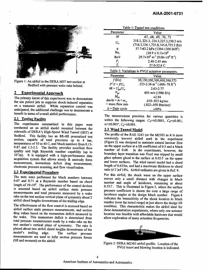
Figure 1: An airfoil in the DERA HST test section at Bedford with pressure wake rake behind.
2 Experimental Approach The primary intent of this experiment w^ to demonstrate the use pulsed jete to suppress shock-induced separation on a transonic airfoil. While separation control was anticipated, the additional challenge was to demonstrate a benefit in terms of overall airfoil performance. 2.1 Testing Facility The experiments summarized in this paper were conducted on an airfoil model mounted between the sidewalk of DERA's High-Speed Wind Tunnel (HST) at Bedford. This facility has an 8ftx8ft pressurized test section, capable of total pressures up to 4 bar, temperatures of 10 to 40 C, and Mach numbers from 0.13- 0.87 and 1.3-2.5. The fecility provides excellent flow quality and high Reynolds number capability (up to lO'/m). It is equipped with a high-performance data acquisition system that allows steady & unsteady foi«e measurement, momentum deficit drag measurement, electronic pressure scanning, and flow visualization.
2J Experimental Procedure The tests were performed for Mach numbers between 0.67 and 0.71 at a Reynolds number based on chord length of 19x10*. The perfomiance of the control devices is ^sessed based on airfoil surface static pressure measurements and total pressures measured by a wake rake on the test section vertical plane of symmetry about 2 airfoil chord lengflis downstream of the trailing edge. The effectiveness of the flow control is assessed based on airfoil surface static pressure measurements, and section drag values based on the momentum deficit measured in the wake. This momentum deficit is determined from total pressure measurements made by a wake rake on the test section's vertical plane of symmetry. The rake is placed about two airfoil chord lengths downstream of the model's trailing edge. The surface pressure measurements are used to infer section pressure forces (Uft and moment) on the airfoil.
Table 1: Tunnel test conditions. Parameter Value
M .67, .68, .69, .70, .71
I] 218.3,221.3,224.3,227.3,230.2 m/s (716.3,726.1,735.8,745.6,755.2 fl/s)
q 57.7-62.2 kPa (1204-1300 Ib/ft^) RCc (I8.9±0.1)xl0* Re/€ 29.7x10* m-'(9.06x10* ft-')
P, 2.40-2.45 atm T. 27.0-35.6 C
Table 2: Variations in PVGJ actuation parameters. Parameter Value
/(Hz) 50,150,200,300,400,500,573 F'li=flU„ .223-2.56 m-»(.068-.78ft-*) VR=U-^U^ 2.63-2.77
v-^ 605 m/s (1986 f^s) J^e. «2.94
AmlAt==m=m„ .010-.023 kg/sec = mass flow rate (.022-.050 Ibm/sec) A = Duty cycle »40%
The measurement precision for various quantities is within the following ranges: C£>=±0.0001, Qf=±0.001, a=±0M5°, q,=i^.001.
23 Wind Tunnel Model The profile of die RAE 5243 (or the M2303 as it is more commonly known) airfoil used in the experiment (Figure 2) was designed to maintain natural laminar flow on the upper surfece at a lift coefficient of 0.5 and a Mach number of 0.68. In the experiments, however, the boundary layer ti^nsition was fixed was fripped by small glass spheres glued to the surface at 0.05 c on the upper and lower surfeces. The wind tunnel model had a chord length of 0.635m, and had a maximum thickness to chord ratio (tfc )of 14%. Airfoil ordinates are given in Ref 9. For this airfoil, the shock wave on the upper surface moves only a small distance with changes in Mach numW and angle of incidence, remaining at about 0.55 c. This is illustrated in Figure 3, where the surface pressure coefficient is shown the over a tege range of incidence angles at the design Mach number. Figure 4 indicates the insensitivity of the shock location to Mach number (over the tested range) at just above the design lift condition. This characteristic makes the airfoil ideal for these demonstration experiments, where only one actuator location was feasible with affordable hardware that would allow exploration of many actuation frequencies.
Figure 2: DERA M2303 airfoil profile. Location of the PVGJ insert and blowing location is indicated.
American Institute of Aeronautics and Astronautics

AIAA-2001-0731
M=0.68; M=0.68; M=0.68; M=0.68; M=0.68; M=0.68; M=OM;
a=-1.998; o=MI.999; oNI.MO; 0=1.000; o=2.«M; a=3,WI2; 0=3.752; o=4.(»3;
CL=0.0087 CL=0.2013
CL=0,37$9 CL=0.5498 CL=0.7215 CL=0.8787 Ci=0.9«6 CL=0.9332
Figure 3: Surface pressures for M2303 airfoil at design Mach number and varying incidence.
M=0.67; 0=1.000; Ct=0,S4«0 M^.88; 0=1.000; <i=«.5498 M=0.69; oe=1.MO; <^^.^06 M=O.TO; «=1,000; Ci.=«.5e3S M=0.71; 0=1,000; CL=0.5530
Figure 4: Surface pressures for M2303 airfoil at fixed incidence and varying Mach number.
2.4 Integration of the PVGJ Hart ware A major challenge in the project was designing and constructing a device capable of providing the required airflow at frequencies and duty cycles identified as critical in previous studies. It was also necessary to do this on a relatively small budget for experimental hardware. An approach was devised that allowed an existing 'insert' in the M2303 airfoil model's upper surface to be used to accommodate the control devices. This insert, which had been originally used for passive flow control methods at DERA, was modified to include a single spanwise row of PVGJs. The insert runs almost the entire 8-foot span of the airfoil, and covers the upper surface of the airfoil from about 0.37c to 0,68c. The insert was also re-instrumented with one streamwise and two spanwise rows of surface pressure taps for and assessing three-dhnensional effecte. Modifying the existing hardware saved resources, and helped to ensure compatibility when matmg to the existing airfoil. The resulting test article had a single row of 19 co- rotating jets distributed along a large portion of the airfoil span at about 0.465 c (Figure 5). This is at the same location as the trailing edges of the fixed devices tested in the companion" DERA experiments. This is about 0,06- 0,08 c, or 38-51mm upstream of the expected shock
Figure 5: Outer surface of modified airfoil insert,
locations, Thejets were spaced at 60nun intervals. This is equivalent to about 0,095 c length, which nearly is twice the spacing used by Wallace" in his early steaiy-jet experiments (disciBsed in Reference 16). It is also 30 times the jet's surfece diameter (again, twice Wallace's factor), or 80 times the expected displacement thickness at the actuator location. Each jet was tilted 45'' to the surface, and skewed 90° to the freestream (chord) direction. The maximum instantaneous jet velocity was essentially fixed due to the nature of the supersonic jet geometry (provided the pressure was sufiBcient to produce the supersonic jet effect). The jets were designed to have an exit Mach number of 2,94, Each had a throat diameter of 1mm, and an exit diameter of 2mm. Assuming a perfect gas and an adiabatic expansion fixes the estunate of jet exit velocity at about 605m/s (1986ft/s). The jet pulse velocity ratio iUjJU„) then varies from 2,77 at M=0.67 to 2,63 at .fl^0,71. However, there is some uncertainty in the actual jet velocity that was produced, since measurements at the jet exit were not obtained. Borrowing empirical relationships from supereonic wind tunnel design , a total pressure of lOatm should be just enough to stert a M=2.94 jet against the l,75atm tunnel static pressure. The jete were fed sharp pulses of high-pressure air. This was achieved by rotating slotted shaft inside a fixed "pillow block" (Figure 6), As the shaft was rotated, each time one of the eight shaft holes lined up with the hole in the pillow block, air was rele^ed to die jet. Between each pillow block, the shaft was slotted to allow air to fi-eely flow into it. The shaft itself was a specialty item, and custom-machined by the manufacture. It had an outer diameter of %-inch, and was coated to form a bearing at each pillow block. Each air hole in the shaft had a 3mm diameter, setting the pulsing duty cycle of the system to something near 0.4. The insert was also modified to form a sealed cavity underneath (inside the airfoil). This cavity housed the pulsing device described above, except for one end of the shaft where the rotation was supplied by a speed-
American Institute of Aeronautics and Asfronautics

AIAA-2001-0731
controlled Minarik brashless motor. The motor was mounted on the outside of the test section and coupled to the end of the shaft with a double universal joint. To minimize leakage from the cavity chamber, a "main plenum seal" (Figure 8) was constructed that contained two standard pneumatic rotary seals. The mass flow rate to the system (m) was measured and confrolled by a regulator. While the line-pressure required to sustain the desired mean flow rate was recorded, it is not yet clear what the pressure and mass losses from the measurement locations to the jets were.
3 Results and Discussion The results of the transonic flow control demonstration using PVGJs have been encouraging. Steady and pulsed blowing both increased Q, by eliminating shock-mduced separation over a large range in angle of attack. Pressure distributions indicate a shock-induced separation bubble for the case without control. In most cases the addition of control either reduced the length of the separation bubble, or suppressed it entirely. However, at many conditions, steady blowing also increased the total airfoil drag. This drag incre^e seems to be largely mitigated by modulating the blowing in a pulsed manner. Below is a description of the baseline airfoil characteristics, followed by a discussion on the effects of steady and pulsed blowing parameters on airfoil performance at different Mach numbers and lift conditions.
3.1 Baseline Airfoil Characteristics Although this same M2303 airfoil model had been tested several times in the past in this fecility, it performance was reassessed for the present experiment at the relevant conditions. This allowed accurate condition notching to the actuated pulsed-jet experiments (Mach and Reynoltte numbers), and prevented any differences due to updates in the data acquisition system or data reduction methods since the tet time the airfoil was tested. These data were also used to preclude the possible passive effecte of the inactive devices (holes in the airfoil surface). For this pat of the experiment, the actuator shaft was rolled into a position that sealed the jet holes. The system flow rate w^ also monitored to assure that there was minimal ledcage through the jets. The measured performance of the b^eline airfoil is simunarired in Figure 9,
1,*1
1. _»■■■■ ^,rf^*-*
M< _«#^* CL ^J^HEI Ma^Nunlxr
M- jjJ^N^ -m-tjsn nO^^ —*—ft.«7S
tAi r -•-tMt _jjr -*-«.?«»
^^JT H^- -C*-».711
Fed to Supersonic Jet
Pillow Blodc
Rotating Shaft vrith 8 Ports
Figure 6: Detail of shaft and pillow block configuration.
Figure 7: Pillow block air valves on insert underside.
Figure 8: Underside of modified airfoil insert on the end where shaft was powered (motor not shown).
1 1. ■-
^h^ «.(' Mach Nunim -■-«.««»
Ci 0.8 ■ -♦—B.8T» -•-isms
0.4. -*-».T(»
d w^^^^ 0.2 ■ ■ ̂ ff"'^
mn j 0- «^
[a] Lift coeflHcient. [b] Drag polar. Figure 9: Baseline aerodynamic forces for test aufoil.
[c] Moment polar.
American Institute of Aeronautics and Astronautics

AIAA-2001-0731
3J Steady Blowing The effects of steady blowing were investigated at tiiree Mach numbers (0.67,0.69,0.71) by sweeping through a range of incidence angles. This was done at a single mass flow rate of 0.051b/sec, which required a very high line pressure, indicating sigiificant losses. Steady blowing had a very small detrimental effect on lift at low incidence, which continued to higher incidences at the lower Mach number. However, it had a large fevorable effect at high incidence (Figure 10[a]), This effect was seen at all Mach numbers tested, but became larger with increasing Mach number. Note that only the M=.67 case with no control was tested through maximum lift.
1.21
-•-M=.67;Dattim
-•-M=,69; Datum -O-M=.69;m^,0a> -♦~M=.71; Datum -0-M=.71; m^jam
[a] Lift coefficient vs. incidence. 0.04-1
0.035 c ̂ I 0.03 S ♦ ' J^rSP
0.025 / / ^ >0 0,02 s/ . ̂ s
fp4
O^M|j
0.005.
6-
f^ r ^u^H M=.87; Datam
-♦-M=.69;Damim
-2 i [b] Drag coefBcient vs. incidence.
801 -♦- M=.67; Datum -O-M=.67;m,r=.050
, -■-M=.69;DMum M=.69; mrfs.OSO M=.71; Datum M=.71; m^.or
[c] i/D VS. lift coefficient. Figure 10: Effect of steady blowing at m =0.50 lb/sec on
airfoil performance.
While the steady blovdng often incre^ed the lift coefficient at a given incidence angle, it also increased the total airfoil drag. This is especially true at low mcidence and high Mach number (Figure 10[b]). The ultimate result is a significant decrease in airfoil performance (£/D) at lower lift conditions (Figure 10[c]), The only benefits seen are the incre^e in C£m„ and extension of the sustained maneuver performance to higher loading. Another indicator that separation is being suppressed can be found in the surface pressure experienced on the upper surface after the shock. Looking at the surfece pressures for the uncontrolled c^e at the design condition in Figures, we see that the upper surface trailing edge pressure remains about constant (at Cp=.17) for most lift conditions. However, the pressure aft of the shock begins to diverge quickly m the airfoil incidence is incre^ed above dx)ut 2.5" (where Ci«,8). Above this point, separation quickly becomes evident, and causes the shock to move forward fix»m its otherwise unwavering location. This behavior is observed at all transonic conditions. When shock induced or trailing-edge separations occur, the pressure coefficient at the trailing edge location sharply rises with increased incidence (Figure 11). However, the steady jet control g-eatly delays the Cp drop ^sociated wifti separation to higher lift conditions, and reduces the rate at which the pressure diverges with lift (dCp/dCj,). The pulsed-blowing cases are discussed below.
o
0.6 0-
0.02'
0.04'
0,06'
0.08'
0,1-
0,12'
0.14
0.16
0,18
4J.05i
0.65 0.7 0,7S OJ O^S 0.9 0.95
—H-MHta; nu^.SIW
—O—f=3«K»fc; m^.«BO -6—fMMMz; m,p«.MO
[a] Mach 0.69
0.2 ■«
[b] Mach 0,71 Figure 11: Effect of steady and pulsed blowing on the
upper surfece pressure coefficient at 0.985 c.
American'Institute of Aeronautics and Astronautics

AIAA-2001^731
[a] M=0.69 Figure 12: Effect of pulsing frequency
3.3 Pulsed Blowing Pulsing experimente were only conducted at the two higher Mach numbers. While data were obtained at other m^s flow rates, the results obtained at the highest mass flow rate of 0.050 lb/sec are the focm of this analysis. Pulsed blowing incre^ed Q, and eliminated shock induced separation at high loading in a similar manner to steady blowing. However, the effect on the drag was significantly less detrimental. In particular, the drag increase experienced with steady blowing seems to be largely mitigated by modulating the blowing in a pulsed manner. This results in an overall increase in LID over a large range of high-lift conditions, even as compared to steady blowing at the same mass flow rate (Figure 12). Differences in frequency appear to have only mild effects on the lift improvement of the airfoil due to pulsed blowing. This can be seen in the tailing edge pressures of Figure 11, where only the very low frequency O^SOHz) case fells perceptibly out of line with the rest of the pulsed and steady cases. Still, the pulsing frequency does appear to have a significant mfluence on the overall airfoil performance due to its effect on the airfoil drag. 3.3.1 Effecte on Airfoil Performance It is constructive to look at two specific cases for a given Mach number. The firet is at an mcidence when the airfoil is near its maximum LID (cruise) condition, and the second is at the highest incidence tested in both uncontrolled and controlled configurations, 3.3.LI Near Cruise Conditions The reduction in LID^^ due to steady blowing was greatly reduced by pulsing. The LID was even sli^tly increased above the uncontrolled case at one low lift condition (see Ci,=0,2 in Figure I2[a]). Figure 13 illustates the effects of frequency at a typical cruise loading condition (o=5% d^OAi) and a Mach number of 0,71, Here, the effects of pulsed blowing on Q,, Q,, and LID are shown as a function of frequency. It is clearly seen that the mfluence of pulsing is related mostly to drag, and that the effect is only dependent on pulsing
m M=0.n on airfoil performance at m =0.50 lb/sec.
0,485
0.48
0,47S ■
0.47
0.017 1
I 0.016$
0.01S
Co 0,01 ss
0.01S
0.014S
32.S 1
32
31.5 .
31 .
30.8 .
LTOaoJ m5
25
28.5
28
06=0.5, M=.71
♦ NoBlowring -•- Pulsed m,r'.050#s ■ Steady m,r=.OS(Mtfs
iw 200 300 400 Frequency (Hz)
[a] Lift coefficient
0=0,5, M=.71
500 SOO
♦ No Blowing -•-Pulsed m,f=.05W«s ■ Steady mri=.OM«s
IM SM MO 400 Frequency (Hz)
P>] Drag coefficient
a=0.5, M=.71
500 SOO
♦ No Blowing -♦-Pulsed m,r=.OSMWs ■ Steady mrt=.05Wtfs
100 MO 300 400 Frequency (Hz)
«» 800
[c] Lift-to-drag ratio Figure 13: Effect of steady and pulsed blowing frequency
on airfoil properties at Af=0.7l & a=0.5°.
8
American Institute of Aeronautics and Astronautics

f 5
AIAA-2001-0731
frequency below/»200Hz, Sensitivities to blowing and pulsed blowing are very similar at Mach number 0.69. It should be noted that for all c^es tested, the airfoil never experienced an increase in ite maximiun LID due to any type of blowing. No conclusive statement should be made to tiiis effect however, since it was not the fociM of the experiment and very little data were obtained near this condition. 3.3.1.2 At High-Lift Conditiom Again, the lift enhancement provided by blowing is much stronger at high lift conditions but is still relatively independent of pulsuig fi«quency. The effects of pulsed blowuig frequency on Ci, Co, and UD are shown for
hi^-loading conditiom in Figure 14 and Figure 15 for Mach numbers of 0.69 and 0.71, respectively. Note that at a Mach number of 0.69, the hi^ lift condition w^ tested at two different mass flow rates. In contrast to tiie lower lift conditions, the pulsing frequency has a very strong influence on drag, even to the point of reducing drag very high frequencies (Figure 14[b). The combination of increased lift and decre^ed drag produces a significant performance benefit at these conditions, especially for higher frequency pulsed blowing, in comparison to both the uncontrolled and steady-blowmg cases.
0.8a <!
0.«7
0.8B '
CL
0.8S '
0.S4
0.83
0.031 1
0.03 .
0.029 '
0.028
a027 ■
0JI26
UO
34-1
33'
32.
311
30^
:»• n- 27
06=3.26, M=.69
♦ No Blowing ■^-Pulsed m^.041#s -•- Pulsed inrt=.OSMtfs ■ Steady m,r=.OSCM»s
100 »W 3M 4MI Frequency (Hz)
[a] Lift coefficient
a=3.25, M=.69
NoBlo^ng -*-Puls«l in^.041«s -•-Pulsed m4=.0S(Ms D Steady ni,t».OSOffs
100 200 300 400 Frequency (Hz)
[b] Drag coefficient
06=3.25, M=.69 ' No Blowing f-Pulsed mrt=.041«s •- Pulsed mrt=.OSOWs I Steady m4=.OSOWs
1W 200 3W> «M Frequency (Hz)
«w MO
«w 600
soo «w
[c] Lift-to-drag ratio
Figure 14: Effect of steady and pulsed blovdng frequency on airfoil properties at A#=0.69 & a=3.25°.
0.72-1
0.71
0.7
CL «■«•
0.08
0.87
0.68
0.0335 I
0.033 ■
0.032S'
0.032 Co
0.0315 ■
0,031 ■
0.030S
0,03
UD
06P2.6, M=.71
-• • •-
♦ No Blowing -•- Pulsed ffl.r'.OSWtfs ■ Stea% m,|B,0S0Ws
S» 3CW 400 Frequency (Hz)
[a] Lift coefficient
(w=2.5, M=.71
MM 600
- No Blowing - Pulsed mrf=.OMNWs
Steady m^J&S^Hs
100 200 300 «» Frequency (Hz)
WM eoo
WDrag coefficient 24i o»=2.5, M=.71 3.S .
23. >^-^ 2.S .
22^ N ♦ NoBlo^ng
1.5 1
21 ■
1 -•- Pulsed m^.05Wtfs ■ Steady m<=.05aws
0.S .
20.
100 ^MM 300 400 Frequency (Hz)
MO MO
[c] Lift-to-drag ratio
Figure 15: Effect of steady and pulsed blowing frequency on airfoil properties at M=0.71 & a=2.5^
American Institute of Aeronautics and Astronautics

AIAA-2001^731
-■-H=».»^ MME; m^Mi; ««1.(I0; Ct=(I.SMt —*—M=tMi 1'^lx; fn,^«.MO| o»1,IIO| Ci'SMtt —*—M=M9j^»Mte|illH=(l.(!S0;(»1.((a;Ci=9J»»l —♦—»W>.«»; MMME; m^,Mt; os1J(0| ^»(>.SgT» -0-M=(l.«»jl«aH»h;iB^il5»;<^1.MiCt=«J57i —O—Mm.«t; ^JOOHz; |||^.<IN; ar-iM; C-^Mti
i—M=«.«^ ^4M)Hz; DM^iW); a>1,W; Ct=*5SM >—M»«.»»; MdMlz; mj^imf, o»1,(K(i <^*(>JMa
0.4 0.5 0.6 x/c 0.' 0.8
[a]M=0.69,a=1.0'
0.9
M=».i»| MMz; fiiH:4I.MII; a»S.aS; ii.=0.»742
—»—M=((.6tj ^IWMh; in,,NI.(in; a=J.a; —C1-(W».»»; IsMWz; m^Jin; ort^ —O—IWI^ t<m<Mz; ni^.«M; wtM; —it-t^tM; IMSMIz; ni<=e,lin; ct=3,JS;
Ci.:«.S631 Ci.=a.!M« Ci.=OJ«M
-«—IWI.«»; »<OWb; iii^.<IS((; o«J.Wj !i«*.»717
[b] M=0.69, a=3.25=
Figure 16: Surface pressure coefficient measurements.
3.3.2 Effects on Surface Pressures The influence of PVGJ control on the aerodynamic forces can be underetood more thoroughly by examining the surface pressures at specific conditions. The control was seen to have some effect on the surface pressures throughout the conditions tested. However, at low incidences where the uncontrolled airfoil does not exhibit separation, the control's influence appears to be weak and local (Figure 16[a] & Figure 17[a]). That is, pressure changes are only indicated in the region very near the control and shock. TTie flow upstream of the shock (and even upstream of the jets located at 0,47 c) was altered in a way that increased the surface pressure. This appeare to weaken the shock, and results in more suction being retained in the region just behind the shock. These effects are g-eatest for steady blowing, and about half as strong for all of the pulsed c^es. Very similar effects are seen at both Mach numbers, but to a higher degree at tiie lower Mach number. At high lift conditions, where the stronger shock provokes separation, the control's impact m much more global (Figure 16[b] & Figure 17[b]). TTie surface suction is significantly increased over a very short distance upstream of the shock. The increased suction is also very pronounced downstream of the shock. Also, the pressure fiiUy recovere by the trailing edge, indicating that the
-■-•WI.71J W»tej m^t.M1; tnKIJOl (MM7«S —•—M=((.71; WWJ; m,^«.(IM; a-«,n; Ci-=tAni —•—«WI.?1; ^mwz; nM4.W(l: ai^M; C1=M?M —o-M=i>.Tii fmmr, iiM-aw»j e^gja; tk^tMJt
-A-MNI.71I tMOMte; m(«S.(IW; a=»J«; !k:«.47M —»—M=«.71j »>M«te| iil^.MD; sNIJO; d^tAJtt
0.4 0.5 0.835/5 0.7 0.8
[a] iJ^=0.71,0=0,5=
0.9
»=«.71j W»«z; m^Mt; a^-tM-, Ci.=0.««7» IWI.71; t=mr, m,Hl.im; a^M; Ci,=0,7117 •WI.T1; l»10Mtz; m,^,«5e; as2.Mr fk'Mim
-a-M=«.71; ^JDHb; mrf*. -<>-»WI.71| ^SOmz; m^, -6—M=».71; IMOMta; mam, —9—M=e.71j »«WNb; m^.
,M»;«rt.i«;<k«*.T11» 0«ejo»Me|Ct=«.7114 MO; a=aj«; ft.-0.71i1 MO; a=2J0; ft««.71J»
0.4 0.5 0£j^f. 0.7 0.8 0.9 1
[b]AM).71,0=2,5"
Figure 17: Surface pressure coefficient measurements.
separation is completely eliminated. While the separation control is complete at both Mach numbers, the suction increases appear more prevalently at the higher Mach number. While the influence of fi-equency on the surface pressures is mild, control at the higher fi-equencies approach the effectiveness of steady blowing. As discussed earlier, the tnie benefit of pulsing the jet at high lift conditions is seen m the reduction of drag,
4 Summary & Concluding Remarks The results of the transonic flow control demonstration using PVGJs have been encouraging. Steady and pulsed blowing both mcre^ed d, by eliminating shock-induced separation experienced at hi^ lift conditions. This effect is consistent with that observed by earlier by early steady- jet researchere that are discussed in Reference 16. However, at many conditions, steady blowing also increased the total airfoil drag, resulting in a lower ratio. This drag increase appears to be largely mitigated by modulating the blowing in a pulsed manner. At cruise lift conditions, the results did not improve much above a moderate fi-equency, and were never significantly better (in terms of £/D) than for the uncontrolled case. At high-lift conditions, the lift was substantially augmented by steady blowing and pulsed blowmg at all fi-equencies. This was apparently due to the complete suppression of the shock-induced separation. The results were best at the
10 American Institute of Aeronautics and Astronautics

4 ,
AIAA-2001-0731
highest frequencies tested, where significant lift enhancement and JJD improvements were seen at all Mach numbers. The pulsed blowing becomes most efifective at the hi^er Mach numbers where shock induced separation is more pronoimced on the uncontrolled airfoil. Here, UD improvemente were seen at all fl^quencies. Near the design Mach number at high- lift, only pulsing at the higher frequencies reduced the substantial incre^e in drag experienced with steady blowing and resulted in an overall increase in LID. This resulted in an overall increase in UD over a large range of high-lift conditions.
It is concluded that if methods become available to mechanize pulsed blowing in an efficient and simple way, it could have play an important role in controlling shock induced separations on airfoils.
Acknowledgements
The author wishes to recopii^ the Air Force Office of Scientific Research for supporting this work. He would also like to acknowledge the efforts of the many individuals whose efforts were indispensable. Bob Guyton desigied the air pulsing hardware that was used in the experiment, and the modification of the anfoil to accommodate it. David Seamarks of DERA was responsible for ensuring that the new hardware could be accommodated in the afrfoil and in the wind tunnel. Michael "Mick" Simmons and die entire Bedford HST wind tunnel staff did a superb job setting up and testing the equipment under all sorte of ^veree circumstances. Finally, John Fulker of DERA and Dudley Fields of AFRL were responsible for creating and managing the cooperative relationship that resulted in this effort.
Reference 'wheeler, G, O., "Means of maintaining attached flow of
a flow medium," US patent No 4455045,1984. ^Wheeler, G. O., "Low drag vortex generators," US Patent
No 5058837,1^1. ^LinJ.C, "Control of turt»ulent boundary-layer
separation iming micro-generators," AIAA-99-3404, J^* AIAA Fluid gnomics conference, June 1999.
'^Wew World Vistas —Air and Space Power for the 21" Century," USAF Scientific Advisory Board, 1995,
*Tilmann, C. P, & Osbom, R, F., "Active Flow Control for Drag Reduction at AFRL's Aerodynamic Configuration Branch," Proceedings of the 17* Canadian Congress of Applied Mechanics, Hamilton, Ontario, June 1999.
*Tihnann,C.P. & Osbom, R.F., "Active Control of Separation at AFRL's Aerodynamic Configuration Branch," Proceedings of the if" Canadian Congress of Applied Mechanics, Hamilton, Ontario, June 1999.
'Tihnann, C, P,, Langan,K, J., Betterton, J, G., & Wilson, M.J., "Characterization of Pulsed Vortex Generator Jets for Active Flow Control," RTO-AVT-
PSF-5, Symposium on "Active Control Technolo^for Enhanced Performance Operation Capabilities of Military Aircraft, Land Vehicles and Sea Vehicles," Braunschweig, Germany, 8-11 May 2000
"Betterton, J. G„ Hackett, K. C, Ashill,P.R., Wilson, M,J,, Woodcock. L J., Tilmann, C. P., & Langan, K. J., "Laser Doppler Anemometty Investi- gation on Sub Boundary Layer Vortex Generatore for flow conttol," /O'* International Symposium on Applications of Laser Techniques to Fluid Mechanics, Lisbon, Portugal, 10-13 July 2000.
•pulker, J. L., Simmons, M, J,, "An Experimental Investigation of Passive Shock/Bouncfary-Later Control on an Airfoil," in Notes on Numerical Fluid Mechanics, Vol 56, EUROSHOCK - Drag Reduction by Passive Flow Control, Eds. Stanewsky, Delery, Fulker, &. Geissler, pp. 379-400,1997.
'"Fulker, J. L„ "The EUROSHOCK Progamme (A European Progranme on Active tmi Passive Control of Shock Waves," AIAA 99-3174, June 1999.
"Ashill, P. R, Fulker, J. L., Hackett, K. C, "Research at DERA on Sub Boundary layer Vortex Generators (SBVGs)", AIAA 2001-0887, January 2001
'^Betterton, J. G., Hackett, K. C, Ashill, P. R., Wilson, M.J., Woodcock. I. J., Titeiann, C. P., & Langan, K.J,, "L^er Doppler Anemometry Investigation on Sub Boundary Layer Vortex Generators for flow control," /O* International Symposium on Applications of Laser Techniques to Fluid Mechanics, Lisbon. Portugal, 10-13 July 2000.
'^Wallis. R. A., "The Use of Au- Jets for Boundary Layer Control," Aero. Note 110, Aerodynamics Researoh Laboratories, Melbourne, Australia, Jan 1952.
'*Wallis,R,A., and Stuart,CM., "On the Control of Shock-Induced Boundary-Layer Separation with Discrete Air Jets," Aeronautical Research Council A.R.C. Report 19865,1952.
'*Wallis,R, .A., "A Preliminary Note on a Modified Type of Afr-Jet for Boundary Layer Contojl," Current Paper No. 513, Aeronautical Research Council, AiKtralia, 1960.
'*Pearcey, H. H., "Shock Induced Separation and ite Prevention," in Boundary Layer & Flow Control, Vol. 2, Ed. G.V Lachmann, Pergamon Press, New York, pp. 1170-1344,1961.
Johnston, J. P., & Nishi, M., "Vortex Generator Jets - A Means for Flow Separation Control," AIAA Journal, 28:989,1990,
'"Compton, D. A., & Johnston, J. P., "Streamwise Vortex Production by Pitched and Skewed Jets m a Turbulent Boundary Layer," AIAA Journal, 30:640,1992.
"Selby,G.V., Lin,J.C., & Howard, F.G., "Control of Low-Speed Turbulent Separated Flow Using Jet Vortex Generators," Experiments in Fluids, 12:394,1992.
17
11 American Institute of Aeronautics and Astronautics

AIAA-2001-0731
Zhang, X., Zhang, H-L, & Collins, M. W., "Some Aspects of Streamwise Vortex Production Using Air Jsts,'' AMA-96-0209,Jmmiy 1996.
"Peake, D.J., Heniy, F.S., & Pearcey, H.H., "Viscous Flow Control vdth Air-Jet Vortex Generators," AIAA- PP-J/7J, June 1999.
^Hasegawa, H., Matsuuchi, K., & Tanaka,J., "Development of an Active Separation Control System Using Vortex Generator Jete," 3'^ ASME/JSME Joint Fluid Engineering Conference, FEDSM99-6944, San Francisco, California, July 18-23 1999.
"Khan, Z. U. & Johnston, J. P., "On Vortex Generating Jets," f International Symposium on Turbulence and Shear Flow Phenomena, Santa Barbara, CA, Sept 1999,
^*Johmton, J. P., "Pitched and Skewed Vortex Generator Jete for Control of Turbulent Boundary Layer Separation: a Review," V* ASME/JSME Joint Fluids Engineering Conference, FEDSM99-6917, San Francisco, CA, July 18-22 1999.
^McManus, K., etal., "Pulsed Vortex Generator Jete for Active Control of Flow Separation," AFRL Technical Report AFRL-VA-WP-TR-1998-3082, November 1997.
^cManus, K., Joshi, P.B., Legner, H.H., & Davis, S.J., "Active Control of Aerodynamic Stall Using Pulsed Jet Actuatore," AIAA-95-2I87, June 1995.
"McManus, K., Ducharme, A., Goldley, C, & Magill, J., "Pulsed Jet Actuators for Suppressing Flow Separation," ^ii4-Ptf-0422, January 1996.
^McManus,K. & MagiII,J., "Sep^ation Control in Incompressible and Compressible Flows using Pulsed Jm," AIAA-96-1948,Jme 1996.
^cManus,K. & Magill, J,, "Airfoil Performance Enhancement Using Pulsed Jet Separation Control," ^M4P7-/97/, June 1997.
^"Magill, J, & McManus, K., "Control of Dynamic Stall using Pulsed Vortex Generator Jets," AIAA 98-0675, January 1998.
^'Seifert, A., Bachar, T., Koss, D., Shepshelovich, M., & Wygnanski, I., "Oscillatory Blowing, a Tool to Delay Boundary Layer Separation," AIAA Journal, 31:11, pp.2052-2060,1993.
'^Seifert, A., Darabi, A., & Wypianski, I., "On the Delay of Airfoil Stall by Periodic Excitation," Journal of Aircraft, 33:4, pp. 691-699,1996.
^'Seifert,A. & Pack,L.G., "Oscillatory Control of Separation at High Reynolds Numbers," AIAA Journal, 37:9, pp. 1062, Sep 1999.
^''Seifert, A, & Pack, L. G., "Active Control of Separated Flows on Generic Configurations at High Reynolds Numbere," AIAA 99-3403, June 1999.
%hari, H. & McManus, K., "Visualization of Pulsed Vortex Generator Jete for Active Control of Boundary Layer Separation," AIAA 97-2021, June 1997.
^*Pope,A. and Goin,K., "High-Speed Wind Tunnel Testing," John Wiley & Sons, New York, 1965.
12
American Institute of Aeronautics and Astronautics