aerodynamic lift -how airplanes fly
TRANSCRIPT

Aerodynamic Lift - How Airplanes FlyBernoulli Lift and Reaction Lift Usually both exist
Airplanes have been flying for around a hundred years. I have recently been surprised to find that there are VERY few people who actually know WHY and HOW airplanes are actually able to fly! At first, I assumed that many other sources had already provided complete and accurate explanations. I was somewhat shocked to discover that many such "correct explanations" were NOT correct or complete after all! The descriptions seem to always either entirely credit Bernoulli Lift OR Reaction Lift, while the reality is that both are acting, as calculable parts of an actual single process, which is extremely difficult to calculate! The amounts or proportions of Bernoulli Lift and Reaction Lift at any moment are each dependent on many variables. One of the most prominent is the LOADING of the aircraft. Aircraft which tend to be rather light for the size of their wings tend to show fairly accurate lift figures just from Bernoulli calculations, while heavily loaded aircraft such as cargo haulers tend to have most of their lift calculable primarily from Newton's Action-Reaction Formulas. Larger modern aircraft are designed to rely extremely heavily on Reaction Lift on takeoff and at low speeds and at least significantly on Bernoulli Lift during cruising
For the record, PAPER airplanes entirely use Reaction Lift and can never use Bernoulli Lift. Conventional kites use nearly entirely Reaction Lift but they use a small amount of Bernoulli Lift for creating some stability of flight. Some more sophisticated kites are designed to generate more Bernoulli Lift but all rely on a lot of Reaction Lift. You will learn below that Bernoulli Lift is a very stable process while Reaction Lift is at best meta-stable and can become unstable very quickly. This explains why paper airplanes generally require a small weight be attached, and most kites require a tail, to provide a moderate level of stability in the intrinsically unstable Reaction Lift flight process.
An Engineer can design devices which use INDEPENDENTLY designed processes and amounts of each of the two methods. It is beneficial to design glider aircraft to use nearly entirely Bernoulli Lift, in order to minimize the drag losses of the Reaction Lift process, since there is no engine to provide power! On the other hand, it is beneficial to design cargo-carrying aircraft to use a great deal of Reaction Lift, just for the bulk lifting capability of that process, as long as you have a powerful engine to drive it. Military Stealth aircraft generally have very flat exterior surfaces, to reduce the directions which enemy radar echoes can bounce, such that Bernoulli Lift is essentially impossible, but such aircraft then require extensive and sophisticated computer control to make constant corrections of control surfaces to provide acceptable stability, as no human could make all those corrections quickly enough and accurately enough to safely fly any Stealth aircraft. The result is that there are different aircraft and different flying devices which can have custom-Engineered amounts of both Bernoulli and Reaction Lift designed into them. Each process is wonderful by itself, but when an excellent Engineer creates an ideal combination of both processes, the results can be amazing. For the record, the Space Shuttle was nearly entirely a Reaction Lift system, which essentially had virtually

no Bernoulli Lift, but it was therefore incredibly unstable, where computer systems had to keep it safe to be inside!
In the early days of aviation, engines were not very powerful, so there was a tendency to rely more on Bernoulli Lift, because it is a more efficient process regarding causing less Aerodynamic Drag, up to certain limits. But in recent decades, extremely powerful (jet) engines have been developed, and aircraft have tended to be designed to rely very heavily on Reaction Lift. The results of this are far greater payload capacity, but also far greater Aerodynamic Drag.
It is almost hilarious regarding the OPINIONS of a lot of people who have NO organized education in Aerodynamics or Physics! It seems a lot like Politics where people hold intense passionate opinions, often without significant actual logical reason! Or religion, where at least three different (huge) groups of Christians each insist they KNOW what the future will be (Pre-Millennialists, Post-Millennialists, and Amillennialists) and they get into vicious arguments over screaming that the others are wrong! As far as I know, no one actually KNOWS the future, so each of their positions seems to have no actual basis (except for their INTERPRETATION of a few words in the Bible). WHY do they each feel it appropriate to scream insults at each other over a subject where NONE of them can actually know the absolute facts of the future? Hmmm!
Regarding this subject of why aircraft can fly, some people seem to remember a Grade School science book that said that it is because of Bernoulli Lift, and so they seem unwilling to tolerate any other viewpoint! Others have seen some TV program or web-site where someone has insisted that aircraft can fly because of Reaction Lift (also called Newtonian Lift) and they then seem willing to not tolerate any other view! It really is amazing! And then there are others who have become aware of more technical texts which refer to a concept (actually a theory) called Circulation, which is an immensely complex Differential Calculus concept, and actually beyond anyone's ability to actually solve the equations except for trivially simple examples (in other words the speaker does not actually understand Circulation except that it sounds impressive!) and so that speaker claims that all other ideas are dead wrong and only Circulation is valid!
Human nature on display!
I received my education in Physics at the University of Chicago. The University seems to have done a good job and I believe that I have a solid understanding of the physics of aerodynamics. This page is meant to aid in providing an understanding of the subject to others.
It continues to amaze me that people have so many deeply held beliefs, generally based on questionable assumptions, which they defend without limit regarding this subject. As a Theoretical Physicist, I truly do not understand why so much passion seems to always be invoked regarding something which seems as mundane as aerodynamic lift. Here is an interesting recent example. A man who informed me that he received both a Degree in Aerodynamics and one in Physics, finds nearly universal fault in everything on this web-page. He INSISTS that HE is an EXPERT and that I should shut up and listen

to him He has even written BOOKS bas4ed on his infinite knowledge! He emotionally insists that my attempts at describing Bernoulli Lift and Reaction Lift separately, which I have tried to do for reasons of clarity of concept and calculations, is all absolutely wrong! He repeatedly, repeatedly insists that ALL lift can be FULLY described and calculated with EITHER description. He even then gave me a specific example, explaining my stupidity regarding the 747 example I tried to use below. He agrees that I described the cruising speed as 550 mph. But he explained to me that I am absolutely wrong in my use of broadly accepted numbers where I calculated that the bulge of the top of the wing causes the air to pass over it at around 575 mph, and the calculations I then do below. Instead, he explained to me that he knows that the air above a 747 wing is moving at around FOUR TIMES the cruising airspeed. By then using that (alleged) airspeed, which he admits has never actually been experimentally measured, he says that the Bernoulli formula fully explains the 775,000 pounds of lift necessary to keep the 747 at constant altitude. He is quite insistent on this being true! But four times 550 mph is 2,200 mph airspeed, many times faster than the speed of sound (which is around 670 mph at 30,000 feet altitude)! So he claims to me that on top of EVERY airliner wing, airflow MUST BE going at extreme hypersonic velocities, in order to confirm his explanation of Bernoulli Lift (allegedly) providing 100% of all lift! He has even recently written a book about Aerodynamics, which he is very proud of. But from my knowledge as a Theoretical Physicist, air moving at hypersonic speed has weird characteristics regarding fluid compressibility and the Bernoulli Formula is not even valid! More than that, if constant and continuous sonic booms are constantly created on top of EVERY airliner wing, shouldn't all of us on the ground be complaining of the noise, as we once did when supersonic military craft flew over the US? It turns out that everyone (who is intelligent) knows that it is a bad idea to even APPROACH the speed of sound (670 mph at cruising altitude) very close, as such transonic speeds cause many additional structural problems. It seems to me that he has even (unintentionally) proven the accuracy of the 575 mph airspeed that I calculate below!I have no complaint that the man must be knowledgeable to have been employed by Boeing for several decades. But as a Theoretical Physicist, I expect that all descriptions and explanations comply with the laws of science! As soon as anyone claims that air above a wing is traveling at MUCH greater than the speed of sound, I lose all credibility in further claims! Basically, by simply applying REALITY to that man's own comments, it seems to me that his own example has proven that his claim that Bernoulli Lift can entirely explain 100% of lift, to be incorrect. In my opinion, IF he had simply done the simple math that he claims, he would have seen that his claim is not remotely credible. ANY airspeed above around 600 mph above any airfoil (wing) starts to have transonic fluid flow problems.
Back to the reality as a Theoretical Physicist understands it!It actually turns out that Bernoulli Lift IS a correct explanation, but only for PART of the lift at any instant. And Reaction Lift IS a correct explanation, but only for PART of the lift at any instant. And the Theory of Circulation IS a wonderful mathematical way of expressing THE COMBINATION, but that the Circulation equations are all advanced Calculus, which require many ASSUMPTIONS to be made in

order to try to solve them. So ALL are right and yet all are somewhat deficient! Bernoulli Lift and Reaction Lift are very handy because they are each calculated from relatively simple mathematical formulas (given below)
I feel that it is easiest to understand, and reasonably accurate to calculate, if BOTH Bernoulli Lift and Reaction Lift are calculated for any specific situation of any specific aircraft. This is informative because it then allows a reasonably accurate analysis of HOW MUCH of the Lift at any instant is Bernoulli and how much is Reaction.
I concede that the SEPARATE calculations do not have true physical reality, as Lift is a process which certainly includes both processes.
It is truly amazing that our modern technology has progressed as it has in so many ways. If one had not actually seen it happen, it would be difficult to accept a stranger claiming that it was possible to build a very large metal object, which weighed as much as 250 automobiles (775,000 pounds - a loaded Boeing 747) and get that huge object up around seven miles above the ground traveling at 500 miles per hour! And not just once, but thousands of times every day!Interestingly, there are a small group of people today who actually believe that there is no such thing as Bernoulli Lift! These extremely aggressive people clearly have no background in Engineering or Physics, and it is really strange that they believe such a thing. At first, it was amusing that people who think they are educated could be so misinformed. But they are certainly incredibly aggressive and annoying! For them, and anyone else who is curious, I suggest a very simple experiment. Get two standard sheets of typing paper (without fold creases) and hold them up in front of your face edgeways, about 3" apart, so you can see between the two hanging sheets. If you now gently blow air between them, what will happen? Doesn't it seem that the pressure of the air you blow should push them apart? But, instead, they move together! And, the harder you blow, the more they move together! It's a simple example of the Bernoulli effect, and Bernoulli Lift. (Critics have no explanation for this effect!)
Of course, many people in various sports KNOW the effects of the Bernoulli effect and how to cause it! If you play ping pong, and ever put spin (English) on the ball, you easily see the effects! If you put sidespin on a ping pong ball, it curves to the side, because the two sides of the ball are now moving at different speeds to the room's air. This effect is generally referred to as the Magnus Effect, which is actually a very complex variant of the Bernoulli Effect. It is primarily different because the rotation of the object CAUSES motions of the air immediately adjacent to the surface. This Magnus Effect is therefore enhanced by anything that increases the frictional coefficient, such as seams on a baseball or microscopic irregularities in the surface of a ping pong ball. When the ball/object has very low mass, such as a ping pong ball, the effects can be quite substantial. (This Effect turns out to be a rather complex calculation, though, because it necessarily includes some factors regarding the smoothness of the surface of the ball, frictional effects, turbulence effects, and some other advanced concepts!) An interesting detail is that the fact that the ROTATING ball CAUSES local air motion, which has the effect of making it appear that the effect superficially seems to be the opposite that which would be expected by a simple Bernoulli Effect! This is an indication that such subjects are often far more

complex than they first appear, and quite possibly might be a primary reason why many people seriously misunderstand the Bernoulli Effect.
There is also something called the Coanda Effect, which is also another complex variant of the Bernoulli Effect. Essentially the local low pressure caused by the Bernoulli Effect causes the surrounding fluid (air in this case) to follow around behind a curved surface, which then appears to have different effects. It is rather funny (and sad) when angry e-mailers tell me that this presentation is wrong in describing a Bernoulli Effect, as they claim that there is no such thing as a Bernoulli Effect and the Coanda Effect is operant instead! Such writers are ignorant of the fact that the Coanda Effect IS simply a type of Bernoulli Effect!
Long ago, when I was a little kid, there was a guy on Chicago PBS with a science show named Daniel Q. Posin. He was even a Physicist! One day he announced that there was NO SUCH THING as a curve ball in baseball! He insisted that the Bernoulli Effect was not big enough to cause any such measurable effect. However, just a couple weeks earlier, my cousin in AAA baseball had taught me how to throw a curve ball! I guarantee that it can be done! It is really rather cool to throw! Actually, the Bernoulli Effect also even more directly explains a different popular pitch, the Knuckleball. That pitch is thrown where the ball has no spin at all (actually, it works best when there is VERY slight spin!). As the ball proceeds the 60 feet to the plate, it encounters random natural tiny wind gusts, where a brief Bernoulli Effect to the left or to the right or up or down happens (mostly due to the position of some seam on the ball). The ball doesn't change very much, but for people familiar with the effect, it is often described as JUMPING one way or the other. Even though Knuckleballs are thrown rather slowly, and the batter thinks he has an easy solid hit, the fact that the ball CAN jump an inch or two in any direction in just the last few feet before the plate makes it a very difficult pitch to hit! The batter swings where he expects the ball to be, and it is not always there! It is also a psychological stress on a hitter to be WATCHING that slow-moving ball jumping back and forth and up and down on the way from the pitcher! (If the wind is nearly calm, knuckleballs have the greatest effect. On windy days, they tend to have very little effect. Even Pitchers seem not to be familiar with that, as many still try to throw Knuckleballs on relatively windy days!) Even the Pitcher has NO idea what a Knuckleball might do!
(Posin did not seem to understand the variants of the Bernoulli Effect which are called Magnus or Coanda, or else he would have both realized that it was real, and also then that he could have been able to have calculated how much effect there would or could be.)
Ping-pong players ALL know about spin and the things they can cause a very light ping-pong ball to do!
When I became a semi-pro volleyball player, like other good players, I often used these sorts of effects. I had a "smoke" serve, which could never have landed in bounds without the effect of substantial topspin. In fact, since I had also played a decent level of tennis, I knew about both the American Twist and the Australian Twist serves, which also put ping-pong-like sidespin on the ball as well. I figured out how to do the compound (down and to either side) action on my Smoke volleyball serve, where even excellent diggers sometimes totally whiffed my serve for an ace! (The sidespin caused a lot of physical

stress on my shoulder.) Even most really hard spikes generally are given some wrist-snap topspin to increase the chance that they will land inbounds. Knuckleball (floater) serves are popular in high-level volleyball, too. If you have watched Olympic play, many teams rarely wail on the ball on serves any more, but serve what appears to be easy and simple serves. They are like that because they are ALL knuckleball serves (or floaters, the name actually given them in the game). There are interesting psychological effects on the person waiting to receive such a serve, because you always know that it MIGHT suddenly jump a few inches one way or another and you will then look like a fool for shanking off such an easy-looking serve!
NASCAR and other racing USES the Bernoulli effect to create what they call Downforce. At racing speed, a 1200 pound vehicle can press downward on its tires with more than 3000 pounds of apparent vehicle weight! That effect allows the tires to stay in traction during a curve where the vehicle would otherwise have broken loose and gotten bent. The results are that they can drive around a curved track far faster than would actually be possible with the actual vehicle weight being on the tires. (Racing Vehicles DO often ALSO have angled Spoilers on top of the rear deck, which has a different effect, one essentially like the Reaction Lift discussed in this presentation, of forcing air UPWARD to cause a Reaction that is also a downforce. So such vehicles often use BOTH aerodynamic approaches.)
Sports-people rarely ever mention such effects, choosing instead to keep such things as secret as possible, in case some opponent is not aware of the advantages that can be had! But some (maybe a lot) of people who use such effects probably have no idea of the Physics behind what they are doing! They just do it because it helps them win and they know that if they don't use it, someone else who does WILL win!
If you have a standard ping pong ball and a vacuum cleaner, another quite popular demonstration is a lot of fun! In this case, the ball is not spinning, so it is the simple Bernoulli Effect and there are no Magnus Effects present. Take a standard vacuum cleaner and detach the hose and connect it instead to a different hole where air can come out (so it acts like a blower rather than a vacuum). Remove any nozzle and aim the hose straight up and turn it on. Air is ferociously blown upward toward the ceiling. (Kids LOVE this demo!) So, what would happen if you try to place the ping pong ball in (or near!) that airflow? Seems like the ball would instantly be blown to kingdom come? Nope! The ball quickly moves to (near) the very center of the airflow, no matter where you release it! It slightly dances around a little, due to slight differences in the local airflow coming out of the nozzle. But it is really quite obvious that the ball WANTS to stay there, in the very center of the flow. It really is amazing to watch, because it doesn't seem to make any sense! The ball SHOULD immediately be blown away! But it doesn't. In fact, if the vacuum is strong enough, you can even tilt the nozzle off to the side quite a bit, and the ball still stays near the middle of the airflow, seemingly defying everything we think we know! (It is actually quite a simple phenomena when Bernoulli Lift is considered, and it actually is easy to even calculate. For example, given the weight and size of the ping pong ball, and the velocity (DISTRIBUTION pattern) of the air coming out of the nozzle, it is fairly easy to calculate, by Bernoulli, just how far you can tilt that nozzle over before the ball falls out [due to its own weight]. The fact that any

school kid can do those calculations, to PREDICT that angle, shows not only that the Bernoulli Lift is valid, but that it is often quite a useful formula to use!)
A Great Possible Science Fair Experiment!The vacuum cleaner and ping pong ball is a great crowd pleaser. If you are a High School Geek and want an awesome Project, consider this:Weigh and measure a ping pong ball, and find some way to measure the velocity (distribution) of air coming out of the vacuum exit hose. With some math and some cute Posters, you have am impressive presentation!
It is even fairly easy to do, APPROXIMATELY. However, there are different things that you need to separately calculate.
First, you need to use simple applications of Newton's Action-Reaction Law to calculate the necessary air volume flow and therefore airspeed which is required to SUPPORT THE WEIGHT of the ping pong ball, under the initial assumption that it is EXACTLY STRAIGHT UP above the air source. This is actually a variant of the Reaction Lift discussed in this presentation. Pretty easy to calculate. Gravity, the weight of the ball, its area/diameter, and you are pretty much there.
IF the ball always remained EXACTLY straight up, no Bernoulli Effect would even be necessary! Pure Reaction Lift would support the ball! (That actually determines how HIGH the ball would be suspended above the end of the nozzle.)
When it is NOT directly straight up (EXACTLY in the middle of the airflow), which is ALWAYS, then it gets more interesting and you have to calculate the Bernoulli Effect. You have to try to determine how the airspeed slows down across the width of the pattern of the blower output, the distribution of air velocity across the actual airflow. Make an accurate graph of that! Depending on how high above the nozzle you measure, this pattern is likely to be four or six inches wide.
Let's see what we have now! Say that we hold the vacuum output hose tilted at an angle, maybe 10 degrees. Logically, it would seem that the ball should immediately fall off to the low side, due to gravity, and that would be the end of a very short demo! But that is NOT what happens! The ball SHOULD do that, meaning that you can use High School Physics (and geometry or trigonometry) to calculate the (sideways but slightly downward) gravitational force which certainly has to be working (since gravity does NOT stop just because you happen to want it to!)
This means that the Bernoulli Effect MUST NECESSARILY BE CREATING an inward-and-upward force to exactly balance what gravity is trying to do. When you look at the Bernoulli formula, you see that the local pressure is directly related to the velocity of the air there (which is actually what Bernoulli said and which was simply a specific way of saying Newton's laws and the Conservation of Energy in fluids.)
So now you have the size of the ball, and from your graph, you have the (faster) air velocity near the center of the airflow, and also know the (slower) air velocity at a distance of one-ball-diameter away. You can then calculate the Bernoulli Effect
(regarding the local air pressure) for EACH side of the ball. The side nearer the middle of the airflow is at the place of higher airspeed, and therefore Bernoulli shows that the local pressure there is lower. The HIGHER air pressure on the opposite side of the ball (AWAY FROM THE AIRFLOW) therefore has some extra pressure left after canceling out the lower (inner) pressure. Still with me??? This FORCES the ball to try to move TOWARD the middle of the airflow! Bernoulli is great!
You now have the area of the ball AND the calculated pressure differential, which means that you now have the TOTAL FORCE acting on the ball due to the Bernoulli Effect (toward the middle). WHICH you have CALCULATED, based on your air-velocity graph. Before, you had calculated the gravitational force which should cause the ball to (fall) outward, and so now you have calculated the opposing force which must be exactly the same, to keep the ball in the airflow!
Cool, or what?
Using the weight of the ball, and the blower airflow info, and the angle that you have tilted the blower output hose, you NOW HAVE A MATHEMATICAL PREDICTION (what would be called a Theory if Bernoulli hadn't beaten you to it by around 200 years!)
So then you do the ping pong ball demo, and the fans will cheer!
MORE, everyone is always impressed at when you tilt the airflow to maybe 30 degrees (depends on the power and airflow of the vacuum). Oohs and aahs!
BUT you have already calculated (by Bernoulli) that at specific tilt angles, the ball actually is not quite centered in the airflow, but at a specific fraction of an inch away WHICH YOU HAVE MATHEMATICALLY PREDICTED.
I do not want to do any more for you here, to leave YOU the ability to actually have YOUR OWN Science Fair Project! I may have already given you too much, to make it all a little too simple and easy!
A SECOND Science Fair Experiment! And Simpler!Get a standard piece of typing paper, a similar piece of the very thin onion skin paper, a similar-sized piece of shirt-cardboard, a similar-sized piece of a flat part of a corrugated cardboard box, and a very thin (and very flat) piece of light metal such as aluminum. Measure the dimensions so you know the surface area, and weigh each of them so you know how much Bernoulli Lift would be needed to lift each one up from a relatively flat table like a card table. Use the Bernoulli formula presented and discussed below, where you will then calculate the necessary air velocity (horizontally across the top of the sheet of material) which would produce the needed Bernoulli Lift (per Conservation of Energy).So now you will have calculated the predicted (UNIFORM) airspeed you will need to provide, which should provide sufficient Bernoulli Lift to raise that particular item up off the table. So you get an old furnace blower and a variable speed control compatible with it, and maybe an air velocity meter (some are not very expensive or you could borrow

one). So you show your guests your calculations of how fast the air SHOULD need to be, and then show them the experiment where your furnace blower blows air at a particular speed across the top of each sheet of material, that confirms your Bernoulli calculations are decently accurate. Not quite as impressive as the Project suggested above, but still impressive. Of course, you need to be explaining to Judges exactly what is happening in your calculations and then in the experimental confirmation! Those Judges will be housewives and truck drivers and anyone else who got talked into being a Judge! The fact that you are EXPLAINING a true science experiment to them, and showing them the page of math which confirms it, should impress even housewives!
The sheets of material can NOT be tight to the table they are laying on! It is NECESSARY that there be at least a tiny airspace UNDER the sheet of material. Why? Do you know? It is because the Bernoulli Effect you are creating is causing a slight REDUCTION in the local atmospheric pressure. Nothing could then happen UNLESS the NORMAL atmospheric pressure is acting against the UNDERSIDE of the sheet of material. Actually, for things like paper and cardboard, they are never tight to a table and so there is always some air underneath them (unless the table is wet where that air cannot exist). But it is still best for such a Project to either make sure the table is not absolutely smooth and not wet, or even place the sheets of material on tiny spacers, such as some poker chips.
There is an equally compelling fun experiment to prove that Bernoulli Lift exists. (It can be calculated by Bernoulli nearly as easily!) Just throw a boomerang! Too dangerous as a Science Fair Project, but fun! When a boomerang is thrown, it is held nearly vertically. The cross-sectional shape is asymmetric, that of an airfoil. As it is thrown, it spins. I suspect that right-handed people must make most boomerangs, as the side that is more "bulged" seems to always (personal observation) be the left side (as it is held). I do not know if boomerangs are made which are for "left-handed" people (opposite). But the ones I have thrown have all created a Bernoulli Lift which acted toward the left. This (nearly) horizontal force vector constantly acts to curve the path of the boomerang. If it is thrown well, it follows an entire horizontal circle and returns to the thrower. (Rarely, in my case, because I don't really have sufficient skill! But still, often only a few steps away.) For those critics, there is no possible other explanation for why a boomerang makes that constant turn to the left, except that it is due to a Bernoulli Lift. And, again, if the specific contour shape of the boomerang airfoil is carefully measured, and the rate of spin and weight of the boomerang are measured, it is not that hard to use the Bernoulli equation to calculate the radius of curvature that a specific boomerang should fly in. In other words, using the Bernoulli equation, it is actually possible to ENGINEER a boomerang to circle at specific diameter flight circle! Another clear proof of both the Bernoulli equation and Bernoulli Lift, and the boomerang has been around for many centuries!The boomerang is not actually held exactly vertical when throwing, but slightly tilted to the right. The rotational spin therefore creates the Bernoulli force vector that is slightly upward of being straight horizontal to the left. This small vertical component of the force vector overcomes the vertical weight Vector of the boomerang, which keeps it from crashing down. Eventually, as aerodynamic drag slows down the boomerang's spin, the

Bernoulli force Vector also reduces. Once the vertical component of it drops to less than the weight of the boomerang, it falls and crashes. In these two paragraphs is everything there is to say about the Physics of boomerangs, and it is entirely due to Bernoulli Lift!
The uninformed people who insist on denying that Bernoulli lift exists are apparently also unaware that a properly shaped airfoil wing still has POSITIVE LIFT even when angled slightly downward (technically called a negative Angle-of-Attack). Logically, when the airfoil is aimed downward, the Reaction force of air hitting the TOP of the wing and being deflected upward SHOULD be forcing the wing downward, and that happens. But the upward Bernoulli Lift counteracts that effect, and the sum can still be an upward lift. In the case of standard airliner wings (commonly NACA 4415 or NACA 4412 or NACA 4408 shape), they can have a negative Angle-of-Attack of more than 3° and still be creating upward lift. (See the graph just below.) (You can see from the graph that the limit for the NACA 4415 or 4412 shape is around -4° where the Net lift is zero, where upward Bernoulli lift exactly matches downward Reaction lift. For zero Angle-of-Attack, that specific wing shape has a sectional lift coefficient of +0.4) If you are ever confronted by anyone who insists that Bernoulli Lift doesn't exist, ask them to explain how and why the wings on airliners are still able to produce UPWARD lift when aimed 3° downward! According to their (partially correct but incomplete Reaction Lift) thinking, it should not just drop like a rock, but actually be accelerated downward FASTER than a rock! But they are definitely wrong! ANY Aerodynamicist could inform them about that, or they could look on page 490 or other pages of Theory of Wing Sections for the chart of the data for any NACA wing contour. We will briefly consider the NACA 4415 shape here.
Here is a copy of the NACA 4415 page in that book:

We will ignore the lowest line on this graph, as it presents an entirely different characteristic! The five other (angled) lines on the graph are as follows: The uppermost one only applies when near takeoff or landing where the airspeed is low, and the flaps are extended and tilted downward at 60°, which has the effect if increasing the lift but also tremendously increases the drag, requiring far more engine power. (The graph on the following page (491) in that book shows the drag coefficients, where it shows that extending the flaps nearly doubles the Sectional Drag Coefficient.)
The four other lines are nearly identical. They present the lift coefficients for different Reynold's Numbers, which essentially means different velocities of the aircraft.

This graph (and many others which are similar to it for other airfoil contour shapes) are actually a COMPOSITE of TWO graphs, for the Bernoulli Lift contribution and the Reaction Lift contribution!
We want to point out several details here. First, find the (horizontal) graph line of ZERO (Sectional Lift Coefficient). You can see that it intersects those four angled lines at around -4° angle-of-attack. This shows that this particular wing shape can be AIMED DOWNWARD by 4°, where it would have zero total lift. Any AOA HIGHER than -4° therefore has POSITIVE LIFT!
Now look at the (vertical) graph line of ZERO° AOA. It intersects the angled lines at around +0.4 Sectional Lift Coefficient. THIS actually identifies the AMOUNT of BERNOULLI LIFT that this wing shape has. In fact, if we could somehow separate the Bernoulli and Reaction Lift components, we would see a (nearly) HORIZONTAL LINE at +0.4 that would represent the Bernoulli Lift. This is due to the fact that the Bernoulli Lift is not very dependent on the angle of attack.
Given that fact, we can see that the Reaction Lift would therefore be exactly the angled lines, EXCEPT that the entire graph would be shifted DOWNWARD by that 0.4 if there were no Bernoulli lift. At an AOA of 0° (flat) the Reaction Lift Coefficient would therefore be zero. The straightness of that angled line then shows that the Reaction Lift is very close to being PROPORTIONAL to the angle of attack. (That is essentially true for the small angles actually used for AOA.)
We can therefore see BOTH effects in this graph! The Bernoulli Lift simply is an UPWARD SHIFT of the graph lines, and the Reaction Lift is the angle (slope) of the lines themselves.
Regarding the Reaction Lift, we might think that those lines are STRAIGHT at a constant slope. That is actually not quite true! The slope is actually a slight curve, actually a mathematical sine-squared curve. For the small angles that wings operate at, the sine is the nearly straight line graph we see.
We can also see that if we tilt the wing up above around +12° AOA, the lift curves rather suddenly drop off. This shows the effect of Stalling, where the wing rather quickly loses its lifting ability. The REASON this happens is a new effect! The Reaction Lift would continue to slope upward, and even the Bernoulli Lift would not change very much. But there develops a huge amount of TURBULENCE, above and behind the wing. That large turbulence has two major effects, of greatly increasing DRAG and of greatly counteracting the beneficial effects of both the Bernoulli and especially the Reaction Lift.
The word STALL became associated with this phenomenon in the 1920s and 1930s, when pilots who survived such events always said that the aircraft seemed to suddenly STOP moving forward! That was technically not true, but it certainly slowed down immensely, and very quickly.
The Graph refers to SECTIONAL Coefficients! That is because nearly all real wings have complex TWISTED shapes (for many technical reasons that we will not address here.) Our discussion has generally assumed that the wing has a constant shape and

constant AOA, for the simplicity of the discussion. Actual design of aircraft wings requires mathematically Integrating the Sectional Lift contributions for the entire surface area. There are also other adjustments that have to be made, regarding the ENDS of the wings, which have some odd characteristics, effects near the fuselage, etc.
(Down below, we will note and discuss the obvious fact that all modern airliners have wings that are clearly tilted upward. THAT has NOTHING to do with Bernoulli and actually hurts that effect a little! That is done by aircraft designers because all aircraft (except gliders) are now expected to carry the heaviest payloads possible within safety constraints, and as long as you have really powerful engines, the other, REACTION Lift process has far greater lifting benefits at the slow speeds of takeoffs and landings. Modern aircraft are therefore simply designed to take greatest benefit of BOTH methods of Lift, with the slanted wings being the most obvious factor of REACTION Lift and the airfoil shape of the wings themselves being the most obvious factor of BERNOULLI Lift. At SLOW speeds of takeoff and landing, nearly ONLY Reaction Lift commonly applies, even though it is immensely wasteful of fuel. At CRUISING speeds, as much of the load as possible is designed to be carried by Bernoulli Lift, as it is FAR more efficient regarding needed thrust and therefore fuel economy. So aircraft designers essentially have to design TWO separate wing concepts, for slow and cruising speeds, and then choose the best intermediate design to actually get built.
Conservation of EnergyThis is also called the First Law of Thermodynamics. Helmholtz showed us that energy cannot be created or destroyed, and it was soon established that there is a Conservation of Energy. This does NOT mean that energy cannot be CONVERTED from one form to another. If a (stationary) bowling ball falls out of a hot air balloon at 10,000 feet altitude, we generally say that it had POTENTIAL energy (of position in a gravitational field), but that energy was converted to KINETIC energy of motion as the ball accelerated downward. High School Physics students do problems to calculate how fast the ball must be going after it has fallen a certain number of feet, because the TOTAL of potential and kinetic energies must stay constant. That WOULD be exactly true IF there were only those two types of energy that existed! But there are several other types of energy, for example heat energy caused as the hurtling bowling ball causes turbulence through the air at high speeds, what is called frictional heating energy. That energy can also be calculated, although it is a little more complicated and is rarely dumped upon High School students! College Physics students get stuff like that!There is another form of energy, which is of importance here. It turns out that you can COMPRESS a gas such as air or carbon dioxide and in the process store some energy, which gets released when the compressed gas is released. In fact, that energy usually first converts to kinetic energy of the gas moving at high speed, whether from an air compressor hose nozzle or a fire extinguisher outlet nozzle. Those uses convert the energy stored in COMPRESSED gas into kinetic energy.
In fact, Helmholtz's Conservation of Energy allows us to calculate what the change of pressure is and what the resulting air or gas velocity will be. It is a very simple problem, simply keeping all other forms of energy constant and only considering the energy

present in a (stationary) compressed gas and the energy present in a moving gas. The first man to rigorously apply Newton's Laws to this situation was named Bernoulli, almost three hundred years ago.
Down below we will show and discuss the simple formula that Bernoulli derived directly from Newton's Laws, where he used the already known formula for kinetic energy and the other already known formula for the energy in a compressed gas. All Bernoulli did was to say that nothing else is allowed to be changed, so that the total of those two forms of energy must necessarily stay constant.
Presto! Bernoulli elegantly provided the math to prove it, but you can already see that if the kinetic energy increases (due to faster speed) then the energy-of-pressure must necessarily get less, which means that LOWER PRESSURE MUST THEREFORE OCCUR.
This is essentially a statement of what is called the Bernoulli Effect, where if air is made to move faster (such as over the top of a bulged-out top part of a wing) then that faster moving air must necessarily have LOWER INTERNAL PRESSURE when compared to air that is going slightly slower along a straighter (and therefore shorter) path under that same wing. This then results in NORMAL air pressure pressing against the bottom side of a wing, but a SLIGHTLY lower air pressure existing in the space just above the wing. Therefore, there is a PRESSURE DIFFERENTIAL, and that results in an UPWARD FORCE on the wing as a result, which is what we call Lift.
Since this is all based on Helmholtz's Conservation of Energy, and the equation is rather simple, this is very simple to calculate, at least approximately.
It seems that extremely few people are aware of how TINY the Bernoulli Effect actually is for things like aircraft wings! People, especially critics, seem to think that ferociously powerful upward force is claimed as Bernoulli Lift. Not even close! For an actual airplane wing, the SHAPE of the airfoil is designed such that the air going over the top of a wing generally only goes around THREE PERCENT FASTER than the air which goes under that wing! And below, we will see that results in a Bernoulli Lift which is less than 1% of atmospheric pressure. It is almost disappointing that the effect is so small!
Below, you will be shown how to calculate the actual pressure differences between below and above a wing. In Grade School, you learned that atmospheric pressure is 14.7 pounds per square inch. PER SQUARE INCH! Think about that! For a SQUARE FOOT, that is 2,100 POUNDS (as we will see and calculate below). A well-designed (small) airplane wing may have 10 pounds per square foot in design lift (at moderate cruising speed), where 200 square feet of wing surface would then be able to provide a total of (10 * 200) 2,000 pounds of total Bernoulli Lift which would then fully support a small aircraft.
Are you getting the main point here? Out of 2,100 pounds per square foot of natural atmospheric pressure pressing against the bottom side of that airplane's wings, the Bernoulli Effect for this small aircraft only has had the rather pitiful effect of reducing the top pressure to 2,090 pounds per square foot (to get the desired 10 pounds per square foot of actual net Bernoulli Lift of the wing). That is only

lowering the pressure along the top of the wing by less than HALF OF ONE PER CENT! (for that cruising speed)
Under normal conditions, it might be considered as too small an effect to even be worth the trouble! Except that it has allowed us to FLY for the past 100 years! So it is seen as quite remarkable. It really is. But the EFFICIENCY of using the Bernoulli Effect seems really disappointing, at only 0.5% (a little higher at higher cruising speeds, but still rather poor), and this after a hundred years of countless thousands of great minds trying to advance aviation! Interesting!
This disappointing performance caused me to build myself a very peculiar device in May 1999. In its one and only experimental flight, I had hoped to achieve 3% to 5% efficiency of the Bernoulli Effect, which would have been quite significant. When I later examined and studied the videotape I made that morning, it turned out to have had over 21% efficiency, and that from a VERY crudely made basement contraption! Well, prior to that morning, yes, I could see where some people might be skeptical about a physical process which only ever showed 0.5% performance when everything went as 100 years of Aeronautical Engineering had desired. But having seen that brief (10 second and uncontrolled) flight, I have since simply smiled when people who think they know what they are talking about claim that there is no such thing as Bernoulli Lift! (Only a very small area of the device was arranged to have this effect, which resulted in roughly a 1.0 G vertical acceleration (extremely briefly). The fact that my strange device only used a standard 3.5 hp lawnmower engine (unmodified) greatly restricted its rate of climb so that acceleration almost immediately ended, once the thing got up to a maximum vertical speed, within around a second! After that, the puny engine power limited it to roughly 3,000 feet-per-minute "rate- of-climb", which still was a lot better than virtually any aircraft can ever do. Not bad for an old lawnmower engine! Even such a crude device rose to slightly over 500 feet from my hands, in the ten seconds of gasoline I supplied it with, after which slight winds caused it to drift to land near the top of a tree! It took me nearly two hours to get it down and be able to go home!
And even though I was remarkably full-of-myself due to that truly cool experiment, and my head was probably somewhat larger for a couple weeks, I saw what I felt was a very dark side to the picture. I was not really sure whether my extremely peculiar device could ever have been converted into anything that would represent anything that could have been used as an aircraft, but I realized that others a lot smarter than me might have done that. But what I DID realize was the astounding performance of a very small aircraft that only used a non-modified standard 3.5 hp lawnmower engine for power. If I had FULLY prepared the entire surface of the thing with the modification, then a vertical acceleration of greater than 20 Gs seems possible and even likely. (No human could withstand such G forces!) Physicist friends of mine at the time had mentioned that DARPA and other government projects had long been trying to develop very small remote-controlled aircraft. One description of a goal that I was told about was that they hoped to develop a tiny aircraft which might fly in a house window at 200 mph, stop on a dime, fire a gun at people inside or drop a hand grenade, and then zoom out of a window again at 200 mph. If they are ever able to achieve that, the residents of that building would not even have one second to know that they were about to be killed.

I am a Peace-loving person, even prior to having become a Christian Pastor in 1996. I would NEVER, NEVER, NEVER want to have participated in providing what sounds like an ultimate killing machine, to anyone. And even if the US government insisted that THEY ALONE would protect such a device, as they have proven hundreds of times before that they cannot keep ANY secrets for more than a few years. So, IF DARPA or the others ever actually develops what they spend billions of our tax dollars to do, they might have some kind of strategic advantage for a few years, but soon every criminal gang would get the same capability. Well, my mind got tangled on the image of a peaceful family watching TV and being exterminated in a second by some irate neighbor who happened to have access to such a device, where I did not see how ANY person on Earth would then be safe.
Therefore, during June 1999, I dismantled and destroyed the strange device that I had made, and also burned and destroyed all the sketches, notes, videotape, and floppy diskettes that had anything related to it. UNLESS some dangerous adversary some day shows usage of such a device, I will have nothing to do with again making or advancing such a device. It just seems far too dangerous to me, something I had not realized in May 1999 when I was so puffed up about it. I do NOT believe the world should have such a device. From past experiences, I know that these comments, even 11 years later, will cause large numbers of people to send me vicious notes, where they will DEMAND that I provide THEM the capability of having such a device. THIS was actually the reason that I had chosen to never even mention my Spring Adventure for all these years. There is actually little value in doing so even now, EXCEPT that I happened to have had that personal experience regarding how spectacularly the Bernoulli Lift can actually perform. I guess I have gotten sick and tired of the irresponsible clowns constantly annoying me for many years in claiming that there is no such thing as Bernoulli Lift, while I had done an actual experiment to prove that they were fools! I guess I have sprung a leak now and have felt the need to vent some bile! I apologize for this ranting over a device which will never be confirmed, supported or defended! You are free to deny that any such device can or did ever exist!
Aerodynamic LiftWe can look at aerodynamic lift for modern aircraft as actually two separate simpler processes that create lift. Both of these processes of lift exist for nearly all winged flying objects and various flying circumstances. For some reason, even "experts" do not seem to understand that! We shall call one description Bernoulli lift and the other Reaction lift. They are quite different!From before powered flight actually occurred until about twenty years ago, the actual lift of an aircraft was generally popularly attributed to Bernoulli lift. Not among experts who knew better. Within the past twenty years, most descriptions now entirely discard Bernoulli lift and instead now totally credit Reaction lift. Both of those "explanations" are actually wrong! The reality is that both processes of Lift are always acting. Very large modern aircraft generally are designed to create about 4/5 Reaction Lift and 1/5 Bernoulli Lift, in order to carry the heaviest possible loads.

WHY that proportion? Because if the proportion was much more Bernoulli, then the payload capacity would not be economically competitive with other craft that had more Reaction! And if the proportion was much more Reaction, then the aircraft would be even more naturally unstable and therefore harder to fly. This last fact becomes extremely important near takeoffs and landings, as the proportion then becomes even MORE Reaction due to two added effects; (1) of increasing the A-O-A up to near the safe maximum angle (per the chart shown above); and especially on landings (2) of lowering flaps to also increase the Reaction Lift (as also shown in the chart above, the separate line to the left and above of the other lines). You have certainly noticed that virtually all airliner crashes occur during takeoffs and landings? Now you know WHY that is! At that time, the proportion of Bernoulli Lift is so small that even very small unexpected actions by pilot or weather or aircraft can quickly exceed stable flight parameters and a crash can then be nearly impossible to avoid. Aircraft designers MUST use the greatest amount of Reaction Lift possible, for greatest payload regarding profitability, but they approach a very fine line of getting so close to the limit that the aircraft can become very spooky to fly during takeoffs and landings. We will discuss below the military Stealth aircraft which are intentionally designed to create essentially no Bernoulli Lift whatever!
Smaller aircraft generally have a more even proportion, say 2/3 Reaction Lift and 1/3 Bernoulli Lift. There are probably three main reasons for this. (1) Such aircraft generally are not required to carry absolute maximum payloads; (2) the pilots of such craft are generally far less trained than the professional pilots of Airliners; and (3) such aircraft are expected to have optimal fuel economy, which generally means using as much Bernoulli Lift and as little Reaction Lift as is possible. So designers tend to create much more conservative smaller aircraft. These smaller aircraft also tend to have most of their accidents occur near takeoffs or landings, but generally the causes are mechanical failures in the aircraft or pilot error.
Birds, also, fly as a result of a combination of both types of lift. It is all far more complicated regarding birds as the flapping of the wings constantly changes everything!
Actually, there is an exception to this! Hummingbirds have shoulders which are unique among birds, where they can rotate to enable the wings to create Reaction Lift in both directions of wing motion! This enables a functional hovering. NO Bernoulli Lift exists at all when a Hummingbird is hovering. The wings essentially BLOW air downward during each half stroke, where the amount and velocity of the downward vertical motion of the air is able to create LIFT. If that lift is exactly the same as the WEIGHT of the hummingbird, then it hovers. If the lift is slightly greater than the weight, the hummingbird can fly directly upward. If it is slightly less, then the bird can fly directly downward with amazing precision.
We are not aware of any "pilot error" among birds, but they can have muscle cramps or tears.In both aircraft and birds, both types of lift are important, but for rather different reasons. Given the way modern aircraft are designed, the Reaction Lift is capable of far greater amounts of lift, but the phenomenon is naturally unstable (therefore potentially unsafe)

and it is also naturally wasteful of energy (therefore fuel). If you have ever seen video of a racing boat or a racing car have its nose slightly lift up, reaction lift starts acting on the underside of it. As the angle gets a little greater, the lift gets a LOT greater, and the angle quickly gets very large. The boat or car almost always quickly points straight up and all other directions, and extreme danger is involved. That is described as an unstable lifting effect, and that is the NORMAL situation with Reaction Lift. The graph reproduced in this presentation shows that Reaction Lift is strongly dependent on the A-O-A, and in fact that the graph always ends at around +12 degrees when it becomes extremely unstable. Actually, technically, it can usually be somewhat controlled, by VERY careful attention to the angle of the wings (called angle-of-attack or AOA) as during the flight of aircraft, and then it is called meta-stable. The Bernoulli Lift for practical aircraft wings does not produce such great amounts of lift, but that phenomenon is naturally stable (therefore far safer) because the amount of Bernoulli Lift created is fairly constant for various wing angles. This consistent and stable characteristic of Bernoulli Lift is also discussed with the graph we reproduced from page 490. Also, Bernoulli Lift generally creates far less turbulence in the air, so it is much less wasteful of energy and therefore is more efficient regarding fuel use.
Reaction Lift is the effect of the pressure of moving fluid (air, in this case) against the bottom of a TILTED surface. Newton described action and reaction, and this is an example. The air which hits the bottom of that TILTED surface is deflected downward (action), which creates an equal and opposite reaction, upward lift, in the wing itself. Each molecule of air is essentially REFLECTED off the angled surface (although the microscopic details of this are different and more complex). Any wave or object which gets REFLECTED from any angled surface rebounds off at exactly DOUBLE the angle. Note that this Reaction Lift is assuming a FLAT ANGLED surface. I have discovered that many people seem to make a serious logical blunder in thinking that water and air act identically! But water has much greater Kinematic Viscosity and Dynamic Viscosity than air does, which tends to cause the reflection of the water from a hose or faucet to tend to stick together. Air molecules can more reflect separately. But in BOTH cases, the Conservation of Energy and the Conservation of Momentum has to always apply, which ensures that AVERAGE of the angle of reflection being identical to the angle of incidence.
From a reference point on a wing (airfoil) on a moving aircraft, it is the air which appears to be moving, and it creates an equal pressure against any and all surfaces of an aircraft. If you stick your hand out the window of a moving car, you can feel this pressure. If you hold your hand vertically, where you are completely blocking the wind, you will feel the greatest pressure, what is technically called the stagnation pressure. The stagnation pressure is easy to calculate as it represents a simple example of Helmholtz's Conservation of Energy, in this case changing the kinetic energy of the air's motion into pressure energy. It is given by 1/2 * ρ * velocity2 where ρ is the density of the air.
In the case of your hand in the car, if the car is traveling at 60 mph (to the air and not necessarily the ground) (which is 88 ft/sec), then the stagnation pressure is: 1/2 * (1/13 pound/cu.ft) * (88)2 / 32, or about 9.3 pounds per square foot. (the 32

was necessary to convert the weight in the density into a mass unit, 32 being the acceleration due to gravity). The actual pressure on your hand is a little higher than that, because air that had hit the windshield also has to move past the area where your hand is, so more air is passing through that space and so it has to move faster than 60 mph, and so the actual pressure there is higher.
If, instead of holding your hand vertically, you tilt it forward, your hand will feel a Reaction Lift. Essentially, air that then hits your angled hand gets deflected downward, giving the air a new downward motion along with its remaining rearward motion. Newton's action-reaction (in an up-down direction) tells us that your hand experiences an UPWARD motion as a result. For small angles of your hand from horizontal, an analysis of the pressures involved is pretty simple. The available stagnation pressure is simply multiplied by the sine of the angle of the tilt from horizontal. For example, if your hand if angled 15° from horizontal out that car window, the Reaction Lift pressure on your hand would be about 9.3 pounds per square foot * (0.2588) or around 2.4 pounds per square foot vertical lift force.
If your hand and lower arm weigh less than this, you find it necessary to HOLD your hand down! But kids are able to find some particular angle, where there seems to be no arm force necessary upward or downward. At that angle, the UPWARD Reaction Lift is exactly equal to the DOWNWARD gravitational weight force on the hand and lower arm.
For an airplane flying at 500 mph (730 ft/sec), in the less dense air at 30,000 feet altitude, the stagnation pressure is easily calculated at around 260 pounds per square foot.
The process of Reaction Lift is naturally unstable. If you tilt your hand at more of an angle, there is both a lot more force now, especially due to a larger area presented to the wind, pressing against your hand, and it also has greater leverage angle, so it tends to want to both tilt and raise your hand even more. The fact that there are TWO different effects which both cause greater lift (each proportional to the sine of the angle of incidence) is the reason this process is unstable. You have to stiffen your arm muscles to keep that from happening. There actually IS one specific angle where your hand tends to be able to remain (called meta-stable) but a tiny wind gust or mis-estimate of the exact angle will quickly upset that temporary stability.
Therefore, for the range of relatively small angles which are actually practical for aviation, Reaction Lift is proportional to the square of the sine of the AOA (angle-of-attack).
Reaction Lift is sort of a "brute force" lift. It relies on the availability of a lot of (engine) power to create strong windspeeds, since it essentially creates Reaction Lift by deflecting that air downward, which uses up a lot of power. It is also naturally unstable. Because modern aircraft have very powerful engines, all

modern large aircraft primarily rely on Reaction Lift for the majority of their total aerodynamic lift.
You may have noticed that Reaction Lift does not depend at all on the actual shape of the wing. A flat board, tilted, creates Reaction Lift as well as any complicated curved airplane wing would. And, of course, the bottom surface of a wing using Reaction Lift MUST be tilted to get this Reaction lift effect.
It was realized that if really good computers had lots of sensors and could constantly monitor thousands of local air pressures, it is possible to design an aircraft which essentially has NO Bernoulli Lift at all! Because it is entirely dependent on Reaction Lift, it is incredibly unstable, and therefore both very dangerous and actually IMPOSSIBLE for any human to fly! It is also a very wasteful design which uses massive engine power to drive the aircraft through the air. The single real advantage of this approach is that the SURFACES of the aircraft can be extremely FLAT and ANGULAR. Why is this important? Well, all other aircraft, which rely on the Bernoulli Lift to provide some safety and stability have CURVED SURFACES. An enemy radar station requires receiving a REFLECTION of the radar beam from some portion of the body of the aircraft, and with curved surfaces, there are always many radar reflections to go back to the radar station and thereby display the exact position of the aircraft. However, if an aircraft had NO curved surfaces at all, then for MOST DIRECTIONS, any incoming radar beam CANNOT GET REFLECTED BACK TO ITS SOURCE. That means that NO RADAR BLIP would exist on that radar screen! STEALTH!!
Obviously, if the aircraft twisted and turned a lot, eventually there would be some position where a HUGE surface area all reflected signals back and there would be an instantaneously blip, but an instant later, and the aircraft has twisted or turned to a different position, and it would disappear. In general, this happens so fast that the rotating radar antenna is rarely pointed at that part of the sky when the enormous reflection would occur. In any case, THIS is the entire basis for the MILITARY aircraft that contain what is called Stealth Technology. In order to accomplish that radar-invisible goal, such aircraft intentionally design in two really terrible characteristics! One is an energy wastefulness that is staggering! The other is that because they ENTIRELY depend on Reaction Lift for flight, they are unstable beyond imagination. Without continuous computer control keeping meta-stable characteristics from instantly becoming unstable, they would ALWAYS immediately crash! Really impressive computers are able to overcome this problem and enable the Stealth Fighters and Bombers to fly. Extremely powerful engines give them performance which is fairly impressive, although not nearly as impressive as those powerful engines would give to a more aerodynamic-shaped aircraft!
(Yes, there are also anti-reflection coatings on all parts of the Stealth aircraft, but that is important mostly for the many small components of an aircraft which can cause undesirable specular reflection to be seen on radar. But few people seem to realize that the CENTRAL feature of Stealth aircraft is the very blocky shape of

the fuselage and wings, and many seem to (incorrectly) credit the anti-reflection coatings for all of the effect! Nope!)
You certainly note that NO commercial aircraft will ever have Stealth technology! It is all for a single function, to make the aircraft have a very blocky shape in order to defeat radar detection as described above. Military does not care if massive extra fuel must get consumed to fly such aircraft. And as long as computers do not make mistakes, pilots are relatively safe in the very, very, very expensive Stealth aircraft, much because of multiple redundancy of safety controls and extra duplicate computers.
Bernoulli Lift is entirely different. First, the wing does not need to be tilted! A perfectly horizontal wing (if shaped properly) creates upward Bernoulli Lift. Actually, the most common shapes of wings on modern airliners (called a NACA 4415 or 4412 or 4408 shape) creates some UPWARD lift (the upward Bernoulli lift is greater than the downward Reaction Lift) even if the wing is tilted DOWNWARD by several degrees! Second, Bernoulli Lift is not (directly) dependent on the tilt of the wing, and it is pretty constant up to a wing angle called the "stalling angle". The fact that Bernoulli Lift is so constant and so reliable, it represents a STABLE type of lift.
Bernoulli Lift is entirely created due to the SHAPE of the wing. The upper surface of the wing is always bulged out more than the lower surface is, which is what actually creates Bernoulli Lift. As described below, Helmholtz's Conservation of Energy causes any fluid flow to have (slightly) lower pressure if it is moving faster. The air molecules that are together before the front edge of a wing, but separate above and below, MUST get past it, to MEET UP AGAIN after the wing has gone by. (That statement is ONLY absolutely true for laminar flow, and when there is turbulence, as there usually is in real applications, they do not necessarily meet, and EITHER could be there before the other!) The bigger bulge of the top side of a wing (airfoil) means the air has to move a little faster, to cover the longer distance, than air that went under the wing where the path was straighter. Bernoulli Lift is simply the effect of this (slight) difference of pressure above and below a wing. It ONLY depends on the shape of the wing, the velocity of the air and the density of the air. It has no dependence on the angle of the wing to the air motion. Remember that the actual maximum Bernoulli Effect which exists in all aircraft is only on the order of around HALF OF ONE PERCENT of the available pressure (at moderate cruising speed), so the Bernoulli Effect is actually somewhat pitiful from a scientific perspective. And yet it has helped enable millions of very heavy metal aircraft to fly!
Bernoulli Lift does not require the massive engine power that is necessary for Reaction Lift. Gliders are designed to use nearly completely Bernoulli Lift because of this. But since large modern aircraft all have powerful engines, great reliance on Bernoulli Lift has otherwise faded. The discussion below shows that modern airliners commonly fly with 1/6 Bernoulli Lift and 5/6 Reaction Lift. At lower airspeeds, both types of lift become far less (both depending on the square

of the velocity of the air), but massive aircraft can remain in the air by extending "flaps" along the rear edge of the wings and tilting them downward, which greatly increases ONLY Reaction Lift. Slow speed performance of the very heavy airliners is therefore especially unstable, which explains why nearly all airliner accidents occur during takeoffs or landings.
Most people that do not want to believe that Bernoulli Lift even exists tend to claim that the ONLY way that anything could have Lift is if air is "thrown downward". They cite Newton's action-reaction reasoning, and are actually quite correct in describing how Reaction Lift occurs. However, Newton also described many other things to us! Specifically, that there is Energy in any "compressed fluid" which generally means to us either water or air. As small children, we learned that there is Atmospheric Pressure, of around 15 pounds per square inch. We generally never think about the fact that it is incredibly important that we also have air INSIDE us, which is also at that same pressure! Otherwise we would instantly squish! Some science teacher may have done a fun demo for you as a student where a (metal, for safety) (with a screw cap) can has a little water placed in it and it is placed on a (Bunsen burner) fire. The water boils, which drives much of the air out of the container. The cap is screwed on tightly and the fire turned off. Once the water vapor inside condenses into water again, there is no longer anything that can withstand the atmospheric pressure on the outside of the can, and it crumples up into a small mess!
Well, if you take a one-foot-square thin board, and just hold it up in the air horizontally, we therefore know that there is a total of 144 square inches times 14.7 pounds/square inch, or over 2,100 pounds of force pressing DOWN on top of that small board! But YOU are so strong you can hold it up! Impressive! Well, not really! Because pressure is such that it works equally in all directions, and there is actually also 2,100 pounds of force pressing UP on the bottom of that board due to atmospheric pressure. A guy named Pascal discovered that long ago. It works out that these two values are always the same! EXCEPT for when Bernoulli effects apply!
Do you see? Say that by some "magic" you are able to reduce that top downward force to 2099 instead of 2100 pounds, while the bottom force stays the original 2100 pounds, on that square board. There is now a NET UPWARD FORCE (of only one pound, granted). If that board weighed less than one pound, that board might then be able to HOVER (thinking about the ping pong ball and the vacuum yet?) We are NOT talking about making spectacular changes in the pressures on top and bottom of that board. In fact, for that situation, we would only be talking about (1/2100) * 15 or 0.007 PSI difference in pressure, (top to bottom) to have that board "hovering".
There is a related subject that can provide some insight into how and why Bernoulli Lift exists. Balloons! Few people seem to really understand the reason

why a hot air balloon or a hydrogen or helium filled balloon has lift. It is actually VERY closely related to the Bernoulli effect!
First, WHY is there the "atmospheric pressure" of 14.7 pounds per square inch or 2116 pounds per square foot pressing in on everything? Do you know? It is actually very simple! If you look exactly straight up, imagine a column of air, exactly one foot by one foot, all the way to the top of the atmosphere (hundreds of miles above). Wanna guess at how much all that air weighs inside that column? Yup, exactly 2116 pounds! That is all that atmospheric pressure actually is, the pressure due to that much weight of air stacked above!
Now, if I tell you that roughly 13 cubic feet of air weighs one pound, can you now figure out if I climbed up on a ladder and imagined the same column of air, but now starting 13 feet above before, how much air is above me? Yup, again, now 2115 pounds! We "passed up" 13 feet of the atmosphere, so we now have slightly less atmospheric pressure on us.
Now, one pound difference per square foot is a microscopic difference in the 14.7 PSI the way it is usually described, and we do not notice it. But in a rapid elevator ride, your ears might pop as a result of you passing up some of the atmosphere! Also, going to Pike's Peak or any high mountain, it is quite noticeable that it is harder to breathe enough, which is because there is less air pressure up there.
Getting back down to Earth, let us now consider a "box" (actually a balloon!) which is really sturdy but that does not have any weight, and which is one foot square and 13 feet tall. We first hold it up, vertically, filled normally with air. There is pressure against the top of the box, which is the 2115 pounds total downward force, as we discussed above. There is pressure against the bottom of the box (13 feet lower in the atmosphere) which totals 2116 pounds upward force.
This is starting to sound good, we apparently have a net upward force of 1 pound on our box! BUT, we have it filled with exactly one pound of air, remember! Since the upward force is therefore exactly the same as the (downward) weight of the air in the box, it doesn't go anywhere, it just stays there. We are actually just describing here why UNboxed air, even though having weight, does not all constantly fall!
NOW, imagine that we remove HALF the air inside the box. Well, we have 0.5 pound DOWNWARD weight and 1.0 pound net UPWARD atmospheric force, so it will rise. In fact, we could now even have our box weight anything up to 0.499 pound and it would still rise (but more slowly).
Unfortunately, nearly any box is too flimsy to withstand the enormous pressure of the atmosphere, so any REAL box like that would have to be extremely strong (and heavy).
However, it turns out that there are some gases, specifically Hydrogen and Helium, which have lower densities than air does. AND they still are able to have their own PRESSURE to withstand the crushing pressure of the atmosphere. So,

hundreds of years ago, people discovered that if they filled a balloon with Hydrogen gas, and if the balloon was not particularly heavy, the weight of the balloon and the hydrogen were still less than the air that used to take up that volume, and it would rise! A hundred-fifty years ago, Helium was discovered which did the same. It was actually earlier known that heated air also had lower density than cool air, which also enabled a balloon to rise, but not as well as with either Hydrogen or Helium.
Why is this important here? We are pointing out that the reason a balloon rises or not, and even how fast it would rise or fall, is easily calculated based on the TOTAL ATMOSPHERIC FORCE ON TOP PUSHING DOWN and the TOTAL ATMOSPHERIC FORCE ON THE BOTTOM PUSHING UP. The ONLY other fact needed is the actual total weight of the balloon and its contents, which needs to be less than the difference of forces so that it would rise. (This description is essentially exactly the same as for Bernoulli Lift).
OK. Now imagine our 13-foot tall, foot square box with some tubes inside and an airpump! (For complicated reasons, the following is far harder to actually do than it sounds!) Imagine that we have our airpump set up so that it SUCKS air from just above the box and sends it out just below it. In fact, we can calculate just how much air we would need to suck and blow, to create "differential pressures" both above and below our box. Say that we get an airpump set up so that it removes enough air above the box so that the pressure on the top of the box gives 2114 pounds total force rather than the normal 2115 pounds we have discussed. And at the same time, we are adding air underneath so that the pressure there is increased slightly so that the total upward force on the bottom is now 2117 pounds.
Remembering that our box has 1 pound of air in it, and maybe another pound due to our airpump and pipes. But we now have a NET upward force on the box now of THREE pounds, while the total weight is TWO pounds. The entire box would now rise!
The point being made here is that there is no downward air blast necessary to do this, and in fact there is an advantage in having the exiting air travel straight sideways! So Newton's Action-Reaction does not directly apply here! We are simply using properties of fluids that Bernoulli first discovered, shortly after Newton.
With such a box and airpump as described, we could rise, hover or sink as desired, simply by adjusting the speed of the airpump.
Well, as said earlier, it turns out that this approach is impractical and mechanically very difficult to do. But Bernoulli's Law and his equation provided a different way of creating that SLIGHTLY lower pressure above. The discussion above pointed out that in order to Conserve Energy, if a gas is sped up (more kinetic energy), its internal energy of pressure necessarily has to get less by the exact same amount. Voila, the airfoil wing shape! Air going over the top of the bulged surface NECESSARILY has to have a slightly lower pressure in it!

Our discussion with our box and balloons has shown us that we do not require MASSIVE changes in that pressure, that remarkably small pressure differentials are fine. For common aircraft wings that have an effective Bernoulli lift of around 10 pounds per square foot, that is only meaning that our 2116 got lowered to 2106, a remarkably small difference! (at moderate cruising speed) The real situation is that the NORMAL atmospheric pressure of 14.7 PSI might apply on the underside of a wing and one ounce less, 14.63 PSI local pressure applies above it. And that tiny difference is enough to produce ALL the Bernoulli Lift in all aircraft! It's sort of amazing!
It turns out that all real aircraft only have a Bernoulli Lift on the order of 10 pounds per square foot of wing surface (AT MODERATE CRUISING SPEED). (Therefore, 150 square feet of wing surface on a small airplane can provide around 1500 pounds of total lift, enough to entirely support the 1300 pound aircraft and have some lift left over for rising higher. (these are ball-park numbers, which are different for each Model of airplane, and which are all very dependent on the cruising speed).
We want you to note here that for a Bernoulli Lift to provide 10 pounds lift per square foot of wing surface, that is really saying that the total downward force on the top of a square foot of the wing was reduced from 2116 to 2106 pounds. This is actually just a local air pressure reduction above the wing which is 0.07 PSI less than the 14.7 PSI standard atmospheric pressure that is still pushing upward on the bottom of the wing. That tiny amount of pressure difference, is ALL that actually exists in the Cruising flight of nearly any modern aircraft!
The "magic" we required above is actually not much magic at all, of only finding a way to reduce the pressure above the wing by 0.07 PSI as compared to the bottom. And THAT is what Bernoulli showed us applies! That there was a way to cause that very minimal pressure differential, and Bernoulli showed us that all we need to have is (relative) airspeed!
By the way, at very low aircraft speed, Bernoulli Lift is minimal, as it is speed dependent. So during the very low speeds of takeoffs and landings, nearly all the lift is provided by Reaction Lift. In both cases, of takeoffs and landings, the nose of the aircraft is tilted upward, increasing the A-O-A such that we move higher up the Sectional Lift Graph above. This is ALSO why the vast majority of aircraft accidents occur during takeoffs and landings, because it is the one time when the most unstable form of Lift, Reaction Lift, is totally required.
We might examine the Specifications of a few common aircraft now. The discussion here has shown the importance of the WEIGHT of the aircraft, the WING SURFACE AREA and the CRUISING SPEED. We will consider these airfoils to be of common NACA shapes for those aircraft. We will assume that the two jet aircraft have NACA shapes which cause the resulting air velocity ABOVE the airfoil to be 3.3% higher than
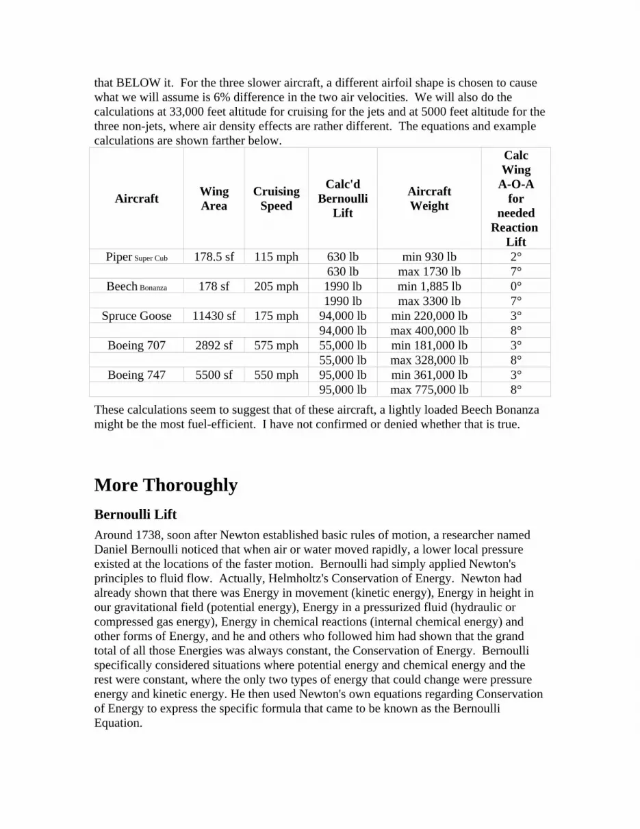
that BELOW it. For the three slower aircraft, a different airfoil shape is chosen to cause what we will assume is 6% difference in the two air velocities. We will also do the calculations at 33,000 feet altitude for cruising for the jets and at 5000 feet altitude for the three non-jets, where air density effects are rather different. The equations and example calculations are shown farther below.
Aircraft WingArea
CruisingSpeed
Calc'dBernoulli
Lift
AircraftWeight
CalcWing
A-O-Afor
neededReaction
LiftPiper Super Cub 178.5 sf 115 mph 630 lb min 930 lb 2°
630 lb max 1730 lb 7°Beech Bonanza 178 sf 205 mph 1990 lb min 1,885 lb 0°
1990 lb max 3300 lb 7°Spruce Goose 11430 sf 175 mph 94,000 lb min 220,000 lb 3°
94,000 lb max 400,000 lb 8°Boeing 707 2892 sf 575 mph 55,000 lb min 181,000 lb 3°
55,000 lb max 328,000 lb 8°Boeing 747 5500 sf 550 mph 95,000 lb min 361,000 lb 3°
95,000 lb max 775,000 lb 8°These calculations seem to suggest that of these aircraft, a lightly loaded Beech Bonanza might be the most fuel-efficient. I have not confirmed or denied whether that is true.
More ThoroughlyBernoulli LiftAround 1738, soon after Newton established basic rules of motion, a researcher named Daniel Bernoulli noticed that when air or water moved rapidly, a lower local pressure existed at the locations of the faster motion. Bernoulli had simply applied Newton's principles to fluid flow. Actually, Helmholtz's Conservation of Energy. Newton had already shown that there was Energy in movement (kinetic energy), Energy in height in our gravitational field (potential energy), Energy in a pressurized fluid (hydraulic or compressed gas energy), Energy in chemical reactions (internal chemical energy) and other forms of Energy, and he and others who followed him had shown that the grand total of all those Energies was always constant, the Conservation of Energy. Bernoulli specifically considered situations where potential energy and chemical energy and the rest were constant, where the only two types of energy that could change were pressure energy and kinetic energy. He then used Newton's own equations regarding Conservation of Energy to express the specific formula that came to be known as the Bernoulli Equation.

In order that the total energy of a mass of flowing fluid be constant (which Newton had proven), any increase in the speed of the fluid must therefore be matched by an appropriate decrease in the pressure. Newton had shown that the total energy is given by
E = mgh + 1/2mv2 + Ju + pv
the four terms being: potential energy; kinetic energy; internal (chemical) energy; and pressure energy. Once this total is known, it must remain constant, by Helmholtz's Conservation of Energy.
Bernoulli considered the situation where there is no chemical change occurring to an object (and no temperature change). This simplifies Newton's equation above, to:
E = 1/2mV2 + pv + mgh
Bernoulli knew that this equation is true for each of any two situations, and that for an incompressible fluid, volume does not change, so therefore:E = 1/2mV1
2 + p1 * v + mgh1 = 1/2mV22 + p2 * v + mgh2
Dividing all terms by mg and calling 'h', 'z', we get:V1
2/2g + p1 * v/mg + z1 = V22/2g + p2 * v/mg + z2
or, since the quantity mg/v is defined as Specific Weight (essentially density) (called either gamma γ, or rho ρ), this can be written:V1
2/2g + p1/γ + z1 = V22/2g + p2/γ + z2
In this form, the equation is called Bernoulli's Equation, and we have seen that it is simply Helmholtz's Conservation of Energy for a steady moving, frictionless, incompressible fluid. It turns out that this same equation can be derived in a different way, from an analysis of all the forces which apply to each tiny bit of the fluid, from what is called the Equation of Motion (by Differentiating it). For a given fluid (commonly air or water) this equation always applies since it really is just saying that Energy is Conserved as Newton said. Notice that, on either side, if the velocity increases, that term gets bigger, but the total must remain the same, which requires the pressure term to get smaller, which explains why the Bernoulli effect describes fast moving air or water creating lower local pressures. If the velocity is the same, then there is no pressure difference. But if either velocity is greater, then you can see that ITS pressure has to be a little less. (Real aircraft examples are below.)
Newton had established the Laws of Motion for discrete objects. Bernoulli applied those laws of motion to fluids and found (from above) that the (differential) pressure in a moving fluid P (where there is no significant height difference, so no difference in the z terms) is given by 1/2 * ρ * V2, where ρ is the density of the fluid. It's simply the Conservation of Energy as applied to fluid flow!
I must interject a comment here! There is that very small group of people who might believe that the Earth is Flat who keep harassing me in insisting that there is no such thing as a Bernoulli Effect or Bernoulli Lift. I am not entirely sure they would even accept that there was even really a Bernoulli person! This handful of people admit to

having no background in Engineering or in Physics, yet they insist they are experts on this subject! Interesting! And they are IMMENSELY aggressive in their insults!The Bernoulli Equation is simply a statement of the Conservation of Energy for a fluid. It is certainly real, and valid, and easily confirmed. Science Project!: If you weigh a sheet of paper lying on a desk, you can easily use this Bernoulli equation to calculate what speed air would have to pass over it to cause it to lift up off the (rough surface) desk. Simple Bernoulli Lift would counteract the gravitational weight of the paper! You would have used Bernoulli's Equation to PREDICT the Bernoulli Lift that would raise that weight of paper! (I said rough surface for a reason! Air has to be able to get UNDER the sheet in order for that 2,115 pound per square foot atmospheric pressure to be there to push upward on it. A glass-surfaced desk is so smooth that air may not be able to get under the paper, and the experiment will then NOT work! Slightly crumpling the sheet of paper also works!)
It is unfortunate that there are many, many, many alleged descriptions of the Bernoulli Effect or of Bernoulli Lift or about how airplanes fly, which are not accurately correct. Usually, the reasoning described in such descriptions contains misstatements and even logic flaws, and so I suppose that skeptics might see cause to doubt everything. Well, at various times, I discovered that commonly available descriptions of Ocean Tides, of the Earth's Precession, of how an automobile engine works, of aerodynamic lift, etc, seemed to need a Physicist's touch, and so I write these sorts of web-pages.
It is also true that for profit reasons, modern aircraft are intended to carry the heaviest payload possible, and that has resulted in a design usage of mostly Reaction Lift, ESPECIALLY at takeoff, but Bernoulli Lift, ESPECIALLY AT CRUISING SPEED (for far better fuel economy) still contributes!
As a thought experiment, which I hope no one ever actually tries, it WOULD be possible to replace the wings on a Cessna with simple slabs of constant thickness wood or aluminum or plastic. Such an aircraft would have NO possibility of creating any Bernoulli Lift! But it would still be able to fly, assuming its engine was strong enough. It would require SERIOUS AOA to always produce enough Reaction Lift to get off the ground!
Such an aircraft would be nearly impossible to fly, because it would be so unstable. The slightest wind gust would require that an instant major correction, up or down, regarding AOA would have to be made. Otherwise, once the AOA changed very much at all, the unstable aspects of pure Reaction Lift would cause an uncontrollable stall or nosedive.
In addition, such an aircraft, which would have to constantly be producing Reaction Lift during Cruising, would require several times as much fuel to do that, as compared to a standard Cessna that relies greatly on Bernoulli Lift at Cruising speed.
But it certainly would be physically possible. The pilot might have an extremely short life, very much like the countless accidents like those which occurred in the first years of powered flight, where many people did not yet know to need Bernoulli Lift and they made aircraft that were nearly entirely dependent on Reaction Lift. Movies of some

show that, yes, they were right that there was lift, but there was also no control whatever, and often the crash killed those pilots.
Powered flight really only became realistic once people like the Wright brothers realized that Bernoulli Lift provided some self-correcting characteristics, where it actually was safe to try to fly.
There are countless uses of the Bernoulli Effect in modern life. Automobile carburetors can only work because of it. Many other similar "Venturi Effect" applications also exist. Most air and water flow-meters work based on it. Nozzles of every sort rely on the Bernoulli Effect. Flush toilets work because of it! And have you ever "balanced" a ping pong ball above a vacuum cleaner's outlet hose? It can only stay there because of the Bernoulli Effect! The specific application we are considering here is regarding the flow of air past an airplane wing.An airplane wing is always bigger, curvier, on top and flatter on the bottom. There is a reason for this! Imagine two molecules of air that are right next to each other to begin with. And it is important to imagine that you are WITH the molecules (in THEIR reference frame, and not that of the wing which whizzes by). A wing (or a knife or any other object) comes by and separates them, but once it has completely gone by, they would again be right next to each other. We are discussing here a SMOOTH flow, which is called Laminar Flow. IF, instead, we sent a cubic block of wood through, there would be DRAG and TURBULENCE, and that WOULD cause some of the air to get PUSHED ahead of the block of wood. Laminar Flow can be thought of as extremely slippery, where the object was able to pass through without doing any permanent damage or effects.
Anything else (for Laminar Flow) would cause a net horizontal acceleration and massive energy transfer to ALL of the air above or below a seam where the wing had passed through, which would also give ALL that air (above) a new velocity where it would have to continue. Essentially, such an effect would TRANSFER kinetic energy to that air, and Conservation of Energy means it would have to come from somewhere, in what is called Aerodynamic Drag, and therefore from an engine. The very definition of Laminar Flow is that there is NO kinetic energy transferred to the surrounding fluid (air or water).
Such an effect of transferring that kinetic energy to the surrounding air (which many people insist on!) is simply not Physical, EXCEPT due to undesirable TURBULENCE, in essentially causing a TEAR in the air immediately behind the airfoil! It is easier to visualize this in water as a submerged (THIN) hydrofoil blade BRIEFLY zooms by. Could ALL the tons of water which happened to be above where that hydrofoil passed through all be shifted forward or rearward? Not a chance! That would require MASSIVE transfer of kinetic energy to the water just above where it passed through. It would also cause a TEAR in the water if such a thing happened. Simple calculations show the

immense amounts of kinetic energy which would have to ACCELERATE all that water very quickly to get it to a new location in a fraction of a second, for the water to have physically MOVED all the water above where the hydrofoil had passed through forward or rearward like that! Just because a skinny piece of material had whizzed by for an instant, the entire upper portion of an ocean or lake is NOT all moved forward or rearward! Those people might THINK they have a logical idea and they may even have seen one of the videos presented on the internet which APPEAR to show such a thing. (Such videos are valid, but they show the results of TURBULENCE and DRAG in providing the energy needed to move all that fluid (either water or air) and with that turbulence source for the energy, such videos are fully credible. In an amusing note, there are about an equal number of such videos which show the air above being moved FORWARD and being moved REARWARD! Yes, videos of this are credible, too, again, due to turbulence being the source of the power and energy to shift the air or water, and turbulence can certainly (sometimes) cause the air above an airfoil to be seen to shift forward. Again, ENTIRELY a turbulence effect! In fact, it is a PROOF that it is due to turbulence that the videos sometimes show forward movement and sometimes rearward movement of the air!
In Physics, we tend to rely a lot on Calculus, and it is very helpful here. We would do such calculations for an airfoil of thinner and thinner thickness, and we would quickly see that for an infinitely thin airfoil or hydrofoil, there can be NO transfer of energy to the surrounding fluid at all. Then we analyze the effects of making the foil shape thicker again, and we would see that, except for turbulence and frictional factors, the shape is still able to slide through the fluid smoothly and easily, with no kinetic energy transfer to the fluid.
A Physicist sometimes sees it as amusing that non-Physicists do not see the obviousness of such things! In general, non-Physicists seem to ASSUME that there is ONLY ONE reference point to view from, the wing itself. A Physicist knows that there are an infinite number of EQUIVALENT reference frames, as long as they are not accelerating in regard to each other. Specifically, we choose the reference frame of the molecule just below where the wing will pass through. The animation above demonstrates this (for really big molecules, but equally true of the tiny real molecules of air!)
An analogy might be useful here: Imagine that you are in an enormous crowd of 200,000 people, and you are in a hurry to get to the bathroom! You could try to RUN through the crowd, essentially like a football Running Back. You WOULD knock a lot of people down and drive many others along with you in the process! THAT is akin to what can happen in (fast motion) turbulent flow. However, most people would instead try to squeeze their way BETWEEN people, without knocking anyone down and without PUSHING anyone ahead of them! THAT is akin to Laminar Flow, and the point here is that THE CROWD IS ESSENTIALLY UNCHANGED after you have passed through it. Yes, you momentarily caused some individuals to have moved a few inches sideways as you passed, but as soon as you were past, they were able to go right back to where they were to start with. See the point? In this second case, you did NOT force a husband or wife to wind up ten feet ahead of the spouse, but in the first case, you MIGHT have caused that effect. They are quite different.

If the relative velocity is above a certain speed, the Reynold's Number indicates that any laminar flow will have changed into turbulent flow. (Even walking through a crowd of people!) In turbulent flow (nearly all of real situations), the wing unintentionally creates turbulence, which greatly complicates everything by causing such accelerations of EVERY INDIVIDUAL PORTION of the air, which is called Drag. That really complex situation drags the air along, BOTH above and below the wing, depending on how clean and smooth each surface is and the relative curvature present. We are examining HERE the situation called Laminar Flow where no turbulence and extremely little drag is created. Essentially by definition, laminar flow enables the airfoil to slip by without disturbing much, except for spreading the fluid apart for an instant so that it could slip by, but then the fluid returns to its original places once it has passed. Because the effects seen in such videos are due to that turbulence, they have about an equal chance of showing forward or rearward shifting of SOME of the air.
Now, since the two molecules begin together and end together, a requirement then exists: We will look at this from two different reference points. First, the reference point that is stationary with the molecules: The lower molecule does not move at all, and the upper molecule simply got pushed straight upward and then back downward, to permit the body of the wing to squeeze through. (we are simplifying by assuming absolutely no drag here which would have DRAGGED the top molecule FORWARD with the wing). The Bernoulli concept is really obvious in this rest-frame since the bottom molecules virtually does not move at all!
Now the second reference view, that of being on the wing: The path followed by the upper molecule must have been longer, because of having to have gone the longer path, higher and farther to get around the bigger upper part of the wing, than the shorter, more direct (nearly straight line) path followed by the bottom molecule. They both have to wind up next to each other again, (as is obvious when the first reference of the stationary-with-the-air view is considered) so they must take the same amount of time to make their trips! This means that the bigger size of the upper part of a wing guarantees that the air going OVER it must go a little faster than the air that goes UNDER the wing!
For sixty years, the length of the (laminar) path above and below every NACA airfoil shape have been known and used. We will use such data momentarily below.
Bernoulli's Equation, being an expression of the Conservation of Energy, says that the total energy in the (molecules of) air above and below the wing must be the same. The TOTAL cannot change for either of them, at any time. The air that went over the top had to go farther, in the same time, so its velocity was a little higher FOR A WHILE. The Bernoulli Equation then says that the air PRESSURE above the wing must be slightly less than the air pressure below the wing, because of this difference in the speeds, and because the total energy must be conserved.
Calculating Bernoulli Lift in the Wing's Reference FrameWe can apply some numbers now! An airliner flying at 550 mph can also be described to be flying at about 810 feet per second. For a common shape of wing used on airliners, the NACA data on the wing shape dimensions shows that the upper path is 1.0590 times as

long as the straight distance across the chord of the wing, so the air must go at an average speed of 810 * 1.0590 or about 858 feet per second past the top of the wing. The lower path is 1.0241 times the length of the straight wing chord, so that air must travel at an average speed of 810 * 1.0241 or about 830 feet per second past the bottom of the wing.The density of air ρ at around 33,000 feet altitude is around 1/1260 slug/cu.ft. (don't ask! It is also around 1/39 lb/cu.ft.) The difference in the pressure below and above the wing is therefore (by Bernoulli)
Punder - P over = 1/2 * ρ * Vover2 - 1/2 * ρ * Vunder
2 or 1/2 * ρ * (Vover2 - Vunder
2).
In our case, this is
Punder - P over = 1/2 * 1/1260 * (8582 - 8302)
or 1/2520 * (736164 - 688900) or about 18.75 pounds net lift per square foot.
Calculating Bernoulli Lift in the Air's Reference FrameIn case you are curious about that EQUIVALENT REFERENCE FRAME, we can do the same calculation in the rest-frame of the molecules! In this case, the lower molecule moves DOWN about 2.5 feet and the upper molecule moves around 5.5 feet UP and then each returns to its original spot (so each went a total distance of twice these numbers). And since the wing is traveling at around 810 feet per second, and the wing chord (effective) may be around 36.5 feet, and the wing passes by in about 1/22 or 0.045 second. Therefore we would have:Punder - P over = 1/2 * 1/1260 * ((11/.045)2 - (5/.045)2)
This is Punder - P over = 1/2 * 1/1260 * (2442 - 1112)
or 1/2520 * (59589 - 12312) or about 18.76 pounds net lift per square foot.
Please notice that doing the calculation in EITHER reference frame (the stationary molecules or the constant speed airfoil) gives the same net result of the Bernoulli Effect!
Notice that this calculation did NOT depend on the AOA at all! THIS is the reason that Bernoulli Lift is so stable. The amount of Bernoulli Lift present essentially does NOT change when the pilot or wind gusts cause changes in the AOA.
This is the amount of Bernoulli lift that exists, for that specific airliner and at that specific Cruising speed. Every square foot of wing surface creates that much Bernoulli lift (approximately, because the shape of a wing is complex). A Boeing 747 has around 5,500 square feet of wing area, so this creates a total (Bernoulli) lift, at that speed and at that altitude, of around 103,000 pounds.
If the 747 aircraft only weighed 103,000 pounds, we would have now shown that it was flying entirely due to Bernoulli lift! But remember that a fully loaded Boeing 747 weighs much more than that, as much as 775,000 pounds. This makes it obvious that we must now consider the SECOND source of aerodynamic lift!

I trust that you have noted that very few variables affect the amount of Bernoulli Lift. The big one is the airspeed. The second most significant is the non-symmetric shape of the wing, to cause the air to have to go farther, and therefore faster, in the time it takes the width of the wing (chord) to pass by. At extremely slow speeds, the bottom could be virtually flat, but at aircraft speeds, it turns out that it is important to give the bottom of the wing a convex curved shape as well, as long as the top surface has more of a bulge, again for the single reason of making the air molecules have to travel farther than the molecules passing under the wing do, so there is a greater velocity adjacent to the top of the wing, so that Bernoulli's Formula reduces the air pressure up there (a tiny bit!) There are actually some additional variables that slightly alter the Bernoulli Lift, such as the TEMPERATURE of the air and the PRESSURE in the air, and whether the aircraft is flying level or not.
The actual calculations by Bernoulli's Formula is generally slightly off, because the airspeed is ASSUMED to be smooth (Laminar) airflow and there is always some turbulence. Interestingly, Physics suggests that most of the effects of that turbulence regarding Bernoulli tends to cancel out! The Bernoulli effect does not matter WHAT DIRECTION the air is moving, just that it is moving at a particular speed, to determine the amount of pressure reduction which occurs. The existence of turbulence means that the air IS moving slightly faster, but the AVERAGE airflow has an AVERAGE airspeed that is not that different from when there is Laminar flow. (Turbulence DOES have many important effects, but interfering with Bernoulli Lift is not a particularly important one of them!)
The Outrageous Claim, of always 100% Bernoulli LiftWe can do the specific math here of that claim expressed above of the man who claims that Bernoulli Lift can always describe 100% of all lift. We have a 747 which is cruising at 30,000 feet altitude, in other words where the speed of sound is around 670 mph (or 995 ft/sec). We know that the Total Lift has to be at least 775,000 pounds, the weight of the loaded aircraft. We know that the 747 has around 5,500 square feet of wing surface area. Dividing, this would mean we must have around 140 pounds per square foot Total lift, which he demands to be explainable all by Bernoulli Lift. (Above, we had calculated only 18.75 pounds per square foot from Bernoulli Lift, but this man demands around 8 times as much for his claim of 100% Lift being all explainable by Bernoulli.)Given his claim, we have the 747 cruising at 550 mph (or 810 ft/sec) as above, and we can use the Bernoulli formula backwards to determine the necessary (average) air velocity above the 747 wing to supply this 140 pounds per square foot lift. This would require an AVERAGE airspeed above the entire wing of 1022 ft/second. This claim would then require that the air above the entire surface ALL aircraft wings was always breaking the sound barrier! Not quite the outlandish "four times 810 f/s or 3240 ft/second" that the man claimed but still somewhat FASTER THAN THE 995 ft/sec SPEED OF SOUND. He sees nothing wrong with this bizarre thinking!

In addition, this is only accounting for horizontal flight, and even more Lift is required for when the aircraft needs to climb, which would make the required numbers even more supersonic!
In other words, his comments were pure speculation and clearly totally wrong. I can only hope that the book that he has recently written on aerodynamics does not contain such serious errors!
Basically, his own example PROVES that his claim that Bernoulli Lift can always explain 100% of total lift is very wrong.
We can examine another situation for that aircraft that also shows how foolish he is! Near the end of this hypothetical trip, our 747 is required to stay in a Holding Pattern for an hour, waiting for its turn to land. So we now have a 747 which is flying at around 200 mph, at 5,000 feet altitude. We know that the Total Lift has to be at least 500,000 pounds, the weight of the nearly fuel-empty aircraft. We know that the 747 still has around 5,500 square feet of wing surface area. Dividing, this means he would now have to have around 90 pounds (of Bernoulli Lift) per square foot of wing surface. This is due to that man demanding that ALL lift be explainable by Bernoulli Lift, regarding his claim of 100% Lift always being explainable by Bernoulli.)
Continuing, he now would have the 747 now in that Holding Pattern at 200 mph (or 290 ft/sec), and we can use the Bernoulli formula backwards to determine the necessary (average) air velocity above the 747 wing to (allegedly) supply this entire 90 pounds per square foot of Bernoulli Lift. This would require an AVERAGE airspeed above the wing of 445 ft/second (or 305 mph), IF the claim was made that only Bernoulli Lift was explaining that aircraft's flight! So he makes the ludicrous claim that air is going UNDER the wing travels at 200 mph but OVER it at 305 mph. That would be an interesting achievement for human technology, but it is patently ridiculous as an idea! His claim would require that EVERY SECOND, roughly 100,000 pounds of air would have to immediately ACCELERATE by over 100 extra mph (in less than a thousandth of a second) as it started to go over the wing, whiz over the wing at very high airspeed for around one-tenth of a second, and then DECELERATE by that same 100 mph (in less than a thousandth of a second) as it left the region of the trailing edge. In Physics, we laugh at such foolish ideas and High School Physics students are given bad grades for that sort of thinking! To even try to Engineer any piece of equipment that could violently accelerate and decelerate such enormous amounts of air is beyond human achievement, but he claims that every airliner does it every day!
Extending his silly claim even further, to when the 747 slows to around 150 mph airspeed just prior to landing, his claim would result in an (alleged) airspeed above the wings of 275 mph! Not bad! Start out with air with relative movement of 150 mph and all those hundreds of tons of air magically nearly doubles in relative speed, but only for less than one-tenth of a second while the air is passing over the wing, only to then revert to its original airspeed a moment later!
It is disappointing that apparently intelligent people can believe such silly ideas, and with a passion that apparently causes their brain to stop working properly! Anyone who has

been around moving air KNOWS that if you start out with calm air at a speed such as 200 mph, and claim that in far under one thousandth of a second, immense amounts of such air all accelerate to 305 mph, and a thousandth of a second later, all that mass of air again decelerates to 200 mph, that is insanity! Air has momentum, and the process of trying to accelerate many tons of air that enormously would be quite an accomplishment! Even if we WANTED to do that, our technology is not able to!
Recognition that Reaction Lift is a valid and active process IS central to all modern aircraft, AS WELL as the process of Bernoulli Lift.
The calculations here correctly show that the 747 has wing shapes which provide around 18.75 pounds per square foot of Bernoulli Lift (at cruising speed), or a total of 103,000 pounds of total Bernoulli Lift. This is a simple fact of science. It may be slightly different depending on the specific shape of wings that are used on the 747, as we have used a relatively ancient wing shape because we presented the graphs for that particular wing shape up above.
The reality is that the Pilot chooses the correct tilt of the wings (AOA) so that Reaction Lift provides the remainder of the necessary total lift, for any given situation. Our various math examples show that in virtually all situations, the 747 necessarily uses a large enough AOA to provide around 4/5 of the total lift by Reaction Lift.
This math is NOT that complicated! Educated people SHOULD be able to reproduce it! Except that some seem to get so focused on some favorite idea of their own that logic no longer matters! Interesting!
I wonder what he thinks happens when an airplane flies upside down at an Air Show! Since he insists that Bernoulli Lift is always 100% of all Lift, he must think there is no problem in upside-down flying! Pilots know better! We will discuss that below.
Reaction LiftOne of Newton's other central rules of motion is that, for every action, there is an equal and opposite reaction. If you have ever ridden in a car with your hand out the window, you must have noticed that if you tilt your hand upward (while the car is traveling down a highway), your hand gets pushed up. That is Reaction lift, and it is exactly the same as this second source of aerodynamic lift for aircraft.For this effect to exist, the wing or your hand must be tilted upward, at an angle that is called the "angle of attack". Because of the high speed of the car or the airplane, a lot of air constantly hits the bottom surface of the wing or the palm (bottom) of your hand. The way this is analyzed is by keeping track of momentum. Say that your tilted hand intercepts 16 square inches of wind area, which is 1/9 square foot. And say the car is moving at 60 mph which is 88 feet per second. Your hand therefore intercepts around 10 cubic feet of air every second, which is about 3/4 pound of air. That air had MOMENTUM due to that MASS FLOW RATE times the relative airspeed, that 88 f/s again. Multiplying, we can see that each second of the airflow that we care about has about 66 ft-lb/sec. We CHANGED the direction of some of that air due to our slanted hand. Some of that HORIZONTAL momentum has now been deflected downward,

creating new VERTICAL momentum downward. THAT was an ACTION to Newton! And your hand and arm have a REACTION of wanting to move upward, which we might call LIFT. The calculation of it is a rather simple problem in Physics, of the Momentum and Energy, which is valid whether it is your hand or an airplane or a bird or a kite.
After that air has hit the angled surface, it REFLECTS (as described in Physics) and gets deflected downward, pretty much at TWICE the angle of the angle of attack. That is NOT very easy to see for a hand, as so much additional air is also going by the vehicle that a moment after the air gets deflected downward like that, the mass of other air around tends to force the air to seem to be going along the angle of the sloped surface. In Physics, we understand such things by starting off really simple, where only a few air molecules are around, and we then easily see the angle-of-reflection-equals-the-angle-of-incidence fact. We then add more air molecules, which complicates things but never contradicts those basic laws of science! Therefore, the air now has a new VERTICAL movement downward due to the (continuous) collision, which occurs due to a downward change of momentum having been given to the air. Newton said that there must therefore be an equal and opposite UPWARD reaction on the wing / hand.
Calculating Reaction Lift in the Air's Reference FrameKnowing the density of air and the velocity, it is possible, and pretty easy, to calculate these things!We will continue with our example of the Boeing 747 at standard cruising altitude and speed. For our discussion here, we will say that the wings of our Boeing 747 are tilted so the effective angle of attack is 4°. When air molecules BOUNCED OFF the bottom of that wing, we know by standard laws of Physics (Conservation of Momentum) that individual molecules have to have equal angles of incidence and reflection, so the air molecules actually get deflected downward at TWICE that wing angle, or 8°. (The observed airflow does not generally show this, because so much other nearby air is rushing by that it causes the reflected molecules to immediately be carried much closer to being along the surface of the wing, but the actual (microscopic) Physics is that each molecule definitely has to reflect off at that doubled angle (in order to Conserve Linear Momentum). Actually, Aerodynamicists confirm this by having charts that show that there is an experimental maximum angle in a wind tunnel for Reaction lift, which they proudly show as around 45 degrees. And the fact that our Reflection causes double that angle, that is then 90 degrees, which means that the air that started out moving horizontally toward the wing or slanted object is now entirely moving directly downward, for a MAXIMUM amount possible of Reaction Lift. (No one would fly any aircraft with an AOA of 45 degrees as that would be incredibly unstable and dangerous.)
The process has TRANSFERRED downward momentum to quite a lot of air. We will see shortly that our 747 has around 7500 kg of air passing the wings every second, and the slope of the wing deflects that air downward at around 35 meters/second. That is more than eight tons of air that is rather suddenly given a vertical downward velocity of around 75 mph! This is a significant change of momentum, done every second, where eight tons of air is deflected to have a new 75 mph downward velocity. This change of Momentum in the air therefore causes the UPWARD REACTION on the wing! We will focus on the

VERTICAL component of that change of momentum, because that changed quantity has to be causing the vertical upward effect on the wings in order to Conserve Momentum.
We will do this analysis in a traditional Physics method rather than the common Aerodynamics method, although they give the same results. We will also do this calculation in the metric system as that avoids some possible sources of confusion regarding some English units. (English has pounds and poundals and some other units that often get confused, where the metric system is better about that! We first need to determine the horizontal mass flow rate of air involved.
The "frontal area" of the bottom of the wing that was "visible" to the air ahead, would just be the total wing area time the sine of the 4° angle of attack. (We are simplifying here and not considering the variable curvature of all these surfaces.) However, the bottom of the fuselage of a 747 is designed to be nearly flat, so that it also provides the same Reaction Lift effects. Much of the 231 foot (70 m) length is 20 feet (6 m) wide, so we have an additional 4,600 square feet (430 m2) of Reaction Lift area. Therefore we have an actual total 10100 square feet (940 m2) of total underside area times that sine of 4°. This is 940 * .0697 or 66 square meters of effective frontal area exposed to the oncoming air.
This AREA of air is passing by the aircraft at 810 ft/sec (250 m/s) air speed, which means that 16,300 cubic meters of air is passing each second. At the altitude we are considering, the density of air is fairly low and this then calculated to be around 7,500 kilograms of air passing by every second. This air begins by passing the aircraft horizontally (at 250 m/s), but the tilted wing deflects it downward by that 8° angle, so that air is given a (vertical) downward velocity component of 35 m/sec due to that reflection effect. Multiplying the 7500 kg/sec mass flow rate by the newly given vertical downward velocity component of 35 m/s, we get a result of 260,000 kg-m/s2 We need to describe this in a rather careful way! We see that we have created downward vertical momentum of the air (kg-m/sec) of this amount, every second, which results in an upward created (Reaction) Lift of 260,000 kg (-m/s2). If we now convert this to English units, that is 575,000 pounds of Reaction Lift.
Those eight tons of air that is constantly thrown directly downward with that new 70 mph (an Action of deflecting the air) results in the Reaction Lift that our aircraft needs.
In our example then, we obtain a relatively constant 103,000 pounds of Bernoulli Lift PLUS 575,000 pounds of Reaction Lift due to the 4° slant of the bottom surfaces of the wings and fuselage, so we have the total lift of around 700,000 pounds needed by that fully loaded 747 aircraft. We could have increased or decreased the AOA to obtain more or less Reaction Lift (the amount of Bernoulli Lift is always relatively constant), as the flight proceeds.
Pilots all know that as a long flight proceeds, the controls are very gradually adjusted to slightly lower AOA, which then causes less obstructive interaction with the air for Reaction Lift, and which then also allows the engine throttles to be slightly eased back as the flight continues. In modern airliners, computers make these adjustments automatically, which slightly improves fuel consumption to save the airline some money!

Pilots are aware of these gradual changes during longer flights, but rarely have to actually do them any more.
So the entire point of Reaction Lift is that Newton taught that Momentum is Conserved, and when all those air molecules are given downward velocity, there is necessarily an UPWARD Reaction which gets applied to the wing (and fuselage) of the same exact amount.
The entire amount of lift acting on our Boeing 747 is the total of these two independent lift components, or, in our mathematical example, 103,000 + 575,000 or 678,000 total pounds of lift. If the Boeing 747 was nearly fully loaded with fuel and passengers and luggage, its total gross weight could be 710,000 pounds at the beginning of a flight, and the pilot or the computer would have selected a slightly greater angle than 4° to obtain the additional Reaction Lift needed. This situation would permit stable horizontal flight at constant speed, as long as the engines provided thrust to overcome air resistance (drag). During takeoff, at a flightpath angle of maybe 15° upward, with the four engines sometimes running flat out and each producing around 43,000 pounds of thrust, they could also be providing an UPWARD net force (4 * 43,000 * .2688) (the upward vertical component of those thrusts) of around 45,000 pounds of vertical lift. For a 747, that is not an enormous amount, but it helps improve the lift characteristics of an extremely heavily loaded aircraft, The engine Thrusts actually can provide most of the ability to gain altitude at that time! Airlines want to minimize fuel consumption, so they now tend to not have the engines run flat out, and again computers now commonly control the takeoff flightpath to be the most fuel efficient possible. This also tends to keep the flight deck more level for the Stewardesses, which sometime was not the case when cities ordered airliners to rise as fast as possible due to noise concerns.
We trust that you noticed that the 747 is therefore designed to commonly use around SIX TIMES as much Reaction Lift as Bernoulli Lift under those circumstances! During various parts of a flight, that proportion varies slightly. From the formulas above, you should now be able to calculate both the Bernoulli Lift and the Reaction Lift for the 747 for an entire flight!
For each vehicle weight, altitude and speed, there is some specific angle of attack that provides exactly the correct total amount of lift to enable horizontal flight. As an airliner continues on a long trip, fuel gets burned up and the total weight reduces significantly, and so the necessary angle-of-attack becomes less. The airliner actually flies more efficiently as the fuel is used up and a smaller angle-of-attack is necessary, since the total aerodynamic drag also reduces.
A 747 uses up fuel at about one gallon per second while cruising. That's about 3600 gallons per hour, around 7 gallons per mile. After a 5,000 mile long trip, that is around 35,000 gallons of fuel that is no longer carried in the airplane, around 210,000 pounds of fuel. So, near the end of a long trip, when the aircraft remaining weight might now be around 500,000 pounds, our situation is that we still have the 103,000 pounds of Bernoulli Lift but now we only need around 397,000 pounds of Reaction Lift.

The necessary AOA will now have dropped to around 2.5°. The airplane should have leveled out by around 1.5° during that ten-hour flight. Photos of a 747 while cruising seem to confirm this. Notice that the wings themselves are always attached to the fuselage of all aircraft at a positive angle. This is NOT due to any need regarding Bernoulli Lift, as it is actually a slight disadvantage regarding drag! But it DOES aid the creation of Reaction Lift nearly always being provided.
The calculations above are broadly applicable to all aircraft and under all circumstances other than supersonic and transonic flight. They are quite accurate.There is a popular simple formula that is commonly used to calculate an APPROXIMATE value of the total lift, which is based on an EXPERIMENTALLY MEASURED NUMBER for the Lift Coefficient, for that wing shape. There are graphs available for every one of the NACA wing shapes which show the relationship between the WIND-TUNNEL MEASURED lift against each angle of attack. Physicists would never use such formulas, as they are NOT based on any actual theoretical basis! They all have a Lift Coefficient in the formula, which was MEASURED in wind tunnels! They give acceptable numbers, but we Physicists consider such things as FORMULAS and not as THEORIES or LAWS of science!
Lift = CL * 1/2 * ρ * V2 * Area
If CL for a NACA 1408 wing at an AOA of 4° is 0.55, this formula gives a TOTAL lift of around 787,000 pounds for the situation we have discussed above. It gives a credibly accurate number, but remember that it is based on a number which was experimentally determined and not from any theory (as the previous discussions of Bernoulli Lift and Reaction Lift have been.) Our analysis above which is based on the SEPARATED theories of Bernoulli Lift and Reaction Lift gave us a THEORETICAL total value of around 700,000 pounds, which is in relatively good agreement.
Should an aircraft try to increase its angle of attack to a far larger angle, at some point, Bernoulli lift virtually instantly disappears, due to turbulence (called separation). The graphs of the wing shape performance all show that around 12° AOA, the smoothly increasing line indicating the lift coefficient suddenly drops off. This rather sudden and substantial change causes the aircraft to lose all the previous stability of Bernoulli Lift and become very unstable almost immediately. (Now, only Reaction Lift would exist, and that is very unstable). In early aviation, this was the cause of many sudden and serious crashes. Since a pilot's natural reaction to suddenly losing the Bernoulli lift was to try to increase the angle of attack even more, and the unstable characteristic of Reaction Lift naturally did the same, the nose of the aircraft would suddenly generally point way up. The wings essentially stopped creating much lift at all, and the now nearly vertical wings acted to very quickly slow the aircraft's forward speed due to massively increased air friction drag. This very noticeable immediate slowing of the aircraft just prior to crashing gave it the name of a stall.
Stalling Speed

If an aircraft attempts to fly extremely slowly, a pilot finds the need to increase the angle of attack to get enough Reaction Lift to remain flying. At some speed, the required angle of attack becomes a stall situation, so that is described as being the stalling speed of that particular aircraft. All aircraft have a stalling speed, and every pilot must be very aware of it, particularly during landings.All large aircraft have FLAPS and other mechanical devices on the rear and front edge of the wings, for the single purpose of increasing Reaction Lift during landings. They slightly help the stability, but only have the single purpose of reducing the chance of the aircraft of stalling and crashing.
Upside Down FlightIf you have ever gone to an airshow, you have seen airplanes briefly fly upside down. People who understand the logic behind Bernoulli lift immediately realize that an upside down wing cannot really produce any Bernoulli lift. They are correct! Watch carefully the next time you see such an upside down aircraft flying. They must depend entirely on Reaction Lift, and therefore they must keep the nose of the airplane noticeably higher than usual, to get the greater angle-of-attack they need. Their situation is actually rather dangerous, because of the natural instability of relying entirely on Reaction Lift.That sort of demonstration confirms everything we have described here. If ONLY Bernoulli Lift existed, no upside down flight would be possible. If ONLY Reaction Lift existed, then an aircraft could use the same angle-of-attack either shiny side up or upside down. The fact that maybe 1/3 greater angle-of-attack is necessary suggests that around 1/3 of the normal lift is probably provided by Bernoulli Lift (for that speed and altitude) while the other 2/3 is normally provided by Reaction Lift.
Some Comments on CirculationVery technical advanced textbooks often describe a Circulation Theory to explain aerodynamic lift. It probably was originally created by some Physicist! It is an interesting mathematical way of theoretically describing the total Lift at every tiny point (it constantly changes) and mathematically Integrates all those numbers for an entire path around the whole airfoil. If you enjoy pain, or happen to be excellent at advanced Calculus, you might check out Theory of Wing Sections from a local Public Library and study pages 35 to 65 to see the sequence of hundreds of Calculus equations which show the basic theory behind Circulation Theory. Possibly the most useful is the Figure on page 62 which shows the comparison between experimental findings and the Circulation Theory FOR A SIMPLE CYLINDRICAL SHAPED AIRFOIL! Because then, even more difficult math is involved in the Conformal Transformation of that simple cylindrical shape into the shape of a simple airfoil! Even Calculus experts will be challenged to follow along!However, actual USAGE of Circulation Theory to real airfoil shapes involves immensely complex mathematics, and many ASSUMPTIONS must be made in order to be able to solve even the simplest of problem sets!

It is wonderful that mathematicians have created the Circulation Theory, as it is a Theoretically based approach. Unfortunately, Circulation Theory is so complex and involves so many needed assumptions, that all actual design of airfoils has always been done based on massive amounts of experimental data. Circulation Theory is still useless except to please Physicists and some Mathematicians! Modern Aerodynamics uses impressive computers to refine massive experimental data, but all of their (very complex) formulas are actually based entirely on the observed experimental data and the patterns people have discovered in that data. Fluid Dynamics is a wonderful field of research, but very little of it is yet based on any theories! We have learned quite a bit, but we still have far more yet to learn. Some day, we MAY have theoretical bases and equations upon which future understanding of aerodynamics might be built. For now, we still have to rely on nearly all experimental data in wind-tunnels for the things that we have learned and the assortment of formulas that we now use to try to predict performance.
It is always quite amusing when someone sends an e-mail in that demands that all other descriptions be scrapped and ONLY Circulation Theory be presented! It seems a virtual certainty that those e-mailers have NO idea of what Circulation Theory actually is or the remotest capability of ever solving the extremely advanced Calculus equations.
(I had considered reproducing here some of the Circulation equations, but there really is no point! IF you happen to think that you can understand that and even solve those equations, you probably already own a copy of Theory of Wing Sections and otherwise, they probably would just seem like a bunch of funny-shaped symbols!
SummaryIt would certainly be possible to build and fly an aircraft that depended entirely on Bernoulli lift. Non-powered gliders are pretty close, being very light aircraft with long wings and large wing areas, and low airspeeds to try to maintain the most efficient Laminar airflow patterns. It is also possible to build an aircraft to fly based entirely on Reaction lift, as some Ground Effect (VERY low flying) aircraft do, and the military Stealth aircraft do, but there is inherent serious instability in relying exclusively on Reaction Lift.Because modern airliners are operated by companies that intend to make money, they try to operate the heaviest payload that is safe. This is why purely Bernoulli Lift aircraft are commercially impractical. It has been found by practice that a combination of Bernoulli Lift and Reaction Lift, where the Reaction Lift predominates, especially at low speeds, represents the most cost-effective and safe choice.
In a sense, Bernoulli Lift might be thought of as representing stability and consistency, while Reaction Lift might be thought of as more brute force lift that is less easily managed.
The equations used above apply for any situation as long as you don't get too near the speed of sound, where many complications develop. But they apply equally for Boeing 747s, for Cessnas and Piper Cubs, and for hang-gliders and kites, and sheets of paper on a desk! If you choose to use them, keep in mind that the density of air (ρ) changes greatly with altitude, being only around 1/3 as much at 33,000 feet as at sea level.

Assuming you fly, you certainly know that everyone agrees that the takeoff and landing are the most potentially dangerous parts of a flight. But you never knew WHY before! Now you do! The relatively slow speeds involved in both takeoffs and landings mean that very little Bernoulli Lift then occurs, which means that a far higher dependence on meta-stable Reaction Lift must be relied on and therefore you can have situations that are nearly completely Reaction Lift. We have discussed above that such pure Reaction Lift flight is extremely unstable (and therefore potentially dangerous). As long as no unexpected conditions arise (like micro-wind effects, or like pilot error), talented professional pilots can recover from nearly all situations. The fact that Reaction Lift is also far less efficient regarding usage of power (due primarily to truly massive turbulence created), the engines must be operated at very great power, but of course part of that is necessary anyway to accelerate such a large and heavy object up to flying speed! Once an airliner gets up near cruising speed, there is enough Bernoulli Lift to provide a good deal of stability, as well as then using up far less fuel with the engines running far easier.Ditto for small aircraft. Once cruising, the pilot COULD safely take his hands off the controls (but he shouldn't!) but during takeoffs and landings, his/her total attention and reactions are necessary. Again, if you have followed all of the above, you now know WHY that is!
The reality is that the Angle-of-Attack (AOA) at any instant is usually closely related to the instantaneous flying stability. At high (cruising) speeds, the AOA is usually minimal, as much Bernoulli Lift is then present. At low speeds of takeoffs and landings, very little Bernoulli Lift is present so the AOA must be greater in order to get higher Reaction Lift.
Some additional analysis of a Boeing 747 flight is in our Bird Flight - Scientific Analysis of the Efficiency.
The Physics described here has been used to Design and Engineer two very unique aircraft. A small prototype of the first of them was test-flown in May 1999. It used no Reaction Lift at all, and was purely a Bernoulli Lift device. As discussed above, conventional airfoil-based aircraft generally only have around 0.5% overall efficiency of that process, and as also described above, that bery peculiar prototype turned out to have an overall efficiency of around 21%.The second of these two odd aircraft was Designed and Engineered in 2012. It was actually initially Designed just as a curiosity, of whether the opposite sort of flying craft might be possible, one that used absolutely no Bernoulli Lift and only used Reaction Lift. It turned out that it IS possible, but it has two enormous limitations! First, because Reaction Lift has such inherent instability, no person could possibly fly it, and a computer is centrally important to be constantly re-adjusting the control surfaces of ailerons and elevator (and less critically, also rudder). As I was designing this thing, I realized that I was dealing with the same instability problems confronted by the designers of government Stealth aircraft, which are also so extremely unstable such that no human could safely control it.

But where Stealth aircraft are intended for very fast flight, where they need to have extremely powerful jet engines, I was Designing this thing for very SLOW flight! I chose that in order to have the most modest Aerodynamic Drag. This is an aircraft that flies, so it does not have the Tire Drag of wheeled vehicles, and so Aerodynamic Drag is virtually the only thing to overcome by an engine. I chose a 20 mph flying speed in order to be able to use a conventional 3.5 horsepower lawnmower engine as the power source. (I admit that I seem to have a fascination with lawnmower engines!)
A very small prototype has been built and flown, which only used an electric motor from a model aircraft, and it seemed to fly essentially as my Engineering had predicted. The next step is to build a 'full-sized' prototype with the lawnmower engine and which will be able to carry about 360 pounds at 20 mph.
A lawnmower engine uses minimal gasoline, and with a slightly larger gasoline tank of one gallon, a flight range of around 60 miles should be possible, with no pilot and only a remotely controlled (GPS) computer steering it. I plan to again use the same old laptop computer to control and fly it.
If this should work out, I imagine a 'flying delivery truck'! The idea of delivering 300 pounds of vegetables from a farm to a store 50 miles away, only using $4 of gasoline, would be a LOT more fuel-efficient than any wheeled truck could do (which would both require paying a driver and paying for $20 of gasoline or diesel fuel)!
I envision this craft flying at rather low altitude, so it would be important for it to not crash into transmitting towers or tall buildings, but if such problems could be avoided, this seems like a potential cheaper method of delivering furniture, produce, lumber, etc. Figures to be interesting!
A web-page exists on that Project, at Flying Delivery Truck which gets 60 miles per gallon I consider it to be Proprietary, so I am not yet willing to allow any company to build or sell any of them, without a conventional Written Contract.
This presentation was first placed on the Internet in April 2003.
Aircraft-Related presentations in our DomainAerodynamic Lift - How Airplanes Fly. The Physics of Aeronautic Lift; Bernoulli Lift and Reaction Lift, including the Equations and the Math. (April 2003)Non-Metal Airliners in Lightning Storms. Older airliners had metal bodies, where lightning bolts would remain OUTSIDE the aircraft due to the Faraday Cage effect. Modern airliners are not made of metal, to try to save weight. It may be a very dumb idea.. (Dec 2014)Flying Delivery Truck which gets 60 miles per gallon. Extremely Unstable Flight. (Aug 2012)Aircraft Tire Preservation - Inexpensive and Simple. Adding simple textured hubcaps to airliner wheels so they naturally upspin when the landing gear is

lowered. (Feb 1988)Food Delivery to Third World Areas. Using older General Aviation Aircraft to robotically deliver Food Aid to remote locations. (Aug 2011)Efficient Airfoil Flight - Active Surface - TURCAN. A Meta-Stable Method of Actively Reducing Turbulence and Drag around Airfoils. Excellent improvement in aircraft fuel efficiency. (summer 1998)Stealth Technology for Huge Ocean-Going Ships. Stealth Technology for Huge Ocean-Going Ships. (1990)600-mph Ocean-Going Fast Ships?. The Possibility of 600 mph sailing ships. (Sept 2012)Bird Flight - Scientific Analysis of the Efficiency. (Nov 2007)Making Airliners Safer with Password-Protected Instruments. Cockpit control blackouts. (Sept 12, 2001)Paper Airplane World Record - Using Natural Advantages. You can certainly beat my 10 minute flight of a paper airplane. (June 2013)
Energy-Related presentations in our Domain:Self-Sufficiency - Many Suggestions A thorough presentationGlobal Warming - The Physics of the Process. (June 2004, June 2008)Global Warming and Climate Change - The Physics (June 2004, Feb. 2007)Alternative GREEN Water Heater - Non-Fossil-Fueled HeatGreen - A Simple Water Heater, HG3a (biodecomposition) (March 2007)Alternative GREEN Furnace with no Fire - Non-Fossil-Fueled HeatGreen - A Simple, Home Heating Furnace, HG3a (biodecomposition) (March 2007)Solar Heating - Low-Tech Active System Low-tech, low cost approach (April 2007)Heat and Cool a House Naturally, without a Furnace or Air Conditioner (1977, Nov. 2000)Energy Supplies of the World - Petroleum, Coal, Gas, Uranium. Oil, Natural Gas, Uranium supplies and consumption (May 2010 Report)Asphalt Pavement - Black Surfaces and Sunlight Environmental Effects of Asphalt Pavements, Roofs, and Parking Lots (August 2007)Earth Spinning Energy - Perfect Energy Source From the Earth's Spinning (1990, Nov. 2002)Earth's Spinning - Perfect Energy Source (1990, Dec. 2009)Tornadoes - The Physics of How They Operate. Tornadoes, including How they Form. A potential energy source (Feb. 2000, May 2009)Electricity - Unlimited Source of Solar by an Artificial Tornado. Tornadoes, including How they Form. A potential energy source (Feb. 2000, May 2009)Survival Ark - 60-Acre Hexagonal Artificial Island, Floating Communities for Survival For Sealevel Rising (July 2008)Electric Power Plants - Climate EffectsGlobal Warming Effects of Carbon Dioxide

Hydrogen as a Fuel for Vehicles. (August 2003)Solar Heated House NorthWarm Totally 100% Solar Heated House - Version 1 (1979)Solar Cells Photovoltaic Cells, PV, Electricity from Sunlight (Jan 2002)Driverless Vehicles - High-Speed Transportation - A 200 mile per hour TRANS Super-Efficient Transportation System (invented in 1989)Electric Cars, Hybrid Cars, the Physics Battery-Powered, Hybrid Cars and Hydrogen-Powered Vehicles (April 2006)Wind Power, Wind Energy, Practical Windmills Practical Wind-Generated Electricity (Residential, some Watts) (1975 and April 1998)Tower Windmills and Electricity, Modest Efficiency Practical Large-Scale Wind-Generated Electricity, 1200 KiloWatts (Community, a thousand homes) (a million construction jobs and 12,000 MegaWatts of electricity Nationally) (June 2007)Earth Energy Flow Rates due to Precessional Effects (63,000 MegaWatts of Energy) (Sept 2006)Power Plant Wastes - Productive Usage of Nuclear Waste. Productive Disposal of Nuclear Power Plant Wastes (1980s, Sept 2005)Conserving Energy - Methods and ProcessesEnergy Storage - Methods - Efficiencies Various MethodsSolar Energy - How Much Energy Comes From the SunSun and Stars - How the Sun Works - Nuclear Fusion. Creating Light and HeatEnergy Inventions - Many Forms of Energy Supplies. Related to Energy CrisesSolar Energy - Generating Electricity From solar, wind or other sources nearly 24 Hours a Day (2001, tested 2003)Solar Energy - Generating Electricity, Improved A Unique Method of Using Solar Energy to Generate Electricity (late 2010)Alaska Pipeline - Alyeska - Physics. Pipeline Local Climate Effects (August 2005)Home Air Conditioning Natural, GREEN and FREE! (1978, December 2000)Hybrid Vehicle - An Improvement. An Entirely Different Approach to a Hybrid Vehicle (1992, May 2008)Woodburning Furnace - JUCA Fireplace, Woodstove - JUCA Super-Fireplaces (designed 1972, manufactured 1973 on, still not matched)Burning Wood for Heating - The Physics. Wood as a Heating Fuel (published 1978)North Pole is Heating Very Fast. Faster than anywhere else on Earth.Global Warming and Climate - Possible SolutionsAerodynamic Lift - How Airplanes Fly. Bernoulli Effect, Reaction Lift (April 2003)Efficient Airfoil Flight - Active Surface - TURCAN. Greatly Reducing Turbulence and Drag for Aircraft and Airfoils, TURCAN (summer 1998)Construction School for GREEN Technologies. My Concept of a GREEN Campus (1990, Dec 2008)Conservation of Angular Momentum - An Exception or Violation. A Violation of the Conservation of Angular Momentum (Sept 2006)Hurricanes, the Physics and Analysis A Credible Approach to Hurricane Reduction (Feb 2001)Automotive Engine - A More Efficient Approach. Significant Improvement (2001)Global Warming - The Politics and Business Why No Leaders Seem to See Urgency

in Global WarmingEnergy from the Moon - A Version of Tidal Energy Collection. (Artificial Tides) (1998, 2010)Energy from the Moon - Version of Tidal Energy Collection 2. (Energy Harvesting) (1975, 2010)Electricity from Solar, Wind, Water, More. Make All Your Own GREEN Electricity (2001, 2003, 2010)Woodstove Energy Production and Efficiency, from a Radiant Woodstove (published 1979)Firewood Ratings. Firewood Info Chart.
Carl W. Johnson, Theoretical Physicist, Physics Degree from University of Chicago