advances in cruciform biaxial testing of fibre-reinforced
TRANSCRIPT
�����������������
Citation: Horta Muñoz, S.; Serna
Moreno, M.d.C. Advances in
Cruciform Biaxial Testing of
Fibre-Reinforced Polymers. Polymers
2022, 14, 686. https://doi.org/
10.3390/polym14040686
Academic Editor: Marcin Masłowski
Received: 21 January 2022
Accepted: 8 February 2022
Published: 11 February 2022
Publisher’s Note: MDPI stays neutral
with regard to jurisdictional claims in
published maps and institutional affil-
iations.
Copyright: © 2022 by the authors.
Licensee MDPI, Basel, Switzerland.
This article is an open access article
distributed under the terms and
conditions of the Creative Commons
Attribution (CC BY) license (https://
creativecommons.org/licenses/by/
4.0/).
polymers
Review
Advances in Cruciform Biaxial Testing of Fibre-ReinforcedPolymersSergio Horta Muñoz * and María del Carmen Serna Moreno
Escuela de Ingeniería Industrial y Aeroespacial de Toledo, Instituto de Investigación Aplicada a la IndustriaAeronáutica, Universidad de Castilla-La Mancha, Av. Carlos III, Real Fábrica de Armas, 45004 Toledo, Spain;[email protected]* Correspondence: [email protected]
Abstract: The heterogeneity and anisotropy of fibre-reinforced polymer matrix composites resultsin a highly complex mechanical response and failure under multiaxial loading states. Among thedifferent biaxial testing techniques, tests with cruciform specimens have been a preferred option,although nowadays, they continue to raise a lack of consensus. It is therefore necessary to reviewthe state of the art of this testing methodology applied to fibre-reinforced polymers. In this context,aspects such as the specific constituents, the geometric design of the specimen or the application ofdifferent tensile/compressive load ratios must be analysed in detail before being able to establish asuitable testing procedure. In addition, the most significant results obtained in terms of the analytical,numerical and experimental analyses of the biaxial tests with cruciform specimens are collected.Finally, significant modifications proposed in literature are detailed, which can lead to variants oradaptations of the tests with cruciform specimens, increasing their scope.
Keywords: biaxial loading; fibre-reinforced polymer; cruciform specimen; tensile/compressiveloading; failure theories; multiaxial; testing facility; finite element method
1. Introduction
The large increase in the structural use of fibre-reinforced polymer (FRP) compositeshas generated great scientific interest in the study of its mechanical behaviour. They area versatile category of materials, including different dispositions and a range of fibrereinforcement, supporting matrices and arrangements of plies, whose combination provideflexibility in manufacturing and possibilities of optimisation in the design of structuralcomponents. In terms of mechanical properties, their high strength and low density havemade them a preferred option in sectors such as aerospace, sports or wind energy, in whichstructural efficiency is a priority [1].
Proper laboratory testing forms the basis for determining the mechanical response ofFRP. Many of the experimental methods have their origin in the testing of metals for which,due to their significant historical development, there are more types of testing than for therelatively new FRP. However, these tests often do not meet the particular requirements ofFRP because composites have an anisotropy and heterogeneity, which are not so significantin metals. The strength and stiffness in the different directions of the FRP can differ by eventwo orders of magnitude. The choice of an inappropriate testing methodology can alsolead to the determination of characteristic values with high dispersions.
Although for the uniaxial case, there are regulations for the characterisation of mostmaterials, and in particular for the FRPs, it is currently not possible to find a standard fortesting FRP under external loading in multiple directions. Furthermore, from a scientificpoint of view, the damage models and failure criteria of composite materials continue topose certain uncertainties. In the absence of failure criteria applied to composite materials,Hinton, Soden and Kaddour promoted in 1991 the initiative of the first world-wide failure
Polymers 2022, 14, 686. https://doi.org/10.3390/polym14040686 https://www.mdpi.com/journal/polymers
Polymers 2022, 14, 686 2 of 20
exercise (WWFE-I). This scientific collaboration aimed to create theoretical predictionsfor the damage and failure of composites, which were simultaneously validated withexperimental data obtained from multiaxial testing [2–5]. Analysing certain laminateconfigurations established by Hinton and Soden [2], recommendations were obtained forthe design and multiaxial characterisation of these materials [5]. The relevance of the topicof multiaxial damage and failure in FRP composites led the promoters of this exercise toextend it into two more stages, the WWFE-II and WWFE-III [1,6–11].
Among the conclusions of the WWFE-I, Soden et al. [5] emphasise that, despiteobtaining a large amount of experimental data, they found a limited number of studiesin which a wide range of different loading ratios were achieved in specific laminates. Inaddition, most of WWFE experimental results were obtained with tubular specimens,which present difficulties as obtaining a repetitive geometry or determining the initialfailure. Therefore, while numerous failure criteria have been developed analytically andnumerically validated, to this day it is still difficult to find experiments that reproducemultiaxial stress states, either biaxial or triaxial. This is because these tests are timeconsuming, costly, difficult to perform, and their results are complex to post process [12].
Structures in aerospace and wind energy industries using FRP composites, mainlycarbon (CFRP) and glass fibre reinforced polymers (GFRP), are frequently characterised bysmall thicknesses and submitted to multidirectional loads. Nevertheless, these structurescan be approached by a plane stress simplification, where the significant stresses are thetwo normal and the in-plane shear components (i.e., out-of-plane components of the stresstensor are negligible). Olsson [13] carried out a review of the types of tests that generatemultiaxial states in order to measure strength in laminates, both in-plane and out-of-plane.In the case of planar biaxial states, tests with cruciform and tubular specimens are described,which allow generating any plane stress state, as well as other methodologies that permitto achieve specific biaxial stress/strain states.
A similar classification of multiaxiality was proposed by Quaresimin and Carraro [14],in which the authors spoke of external multiaxiality as that achieved when loads areapplied in several directions (i.e., tests with tubular and cruciform specimens), whileinternal multiaxiality appears when the fibres form an angle with the loading directions.For instance, the well-known uniaxial off-axis test makes possible to achieve certain in-planebiaxial stress/strain states, depending on the angle formed between the load and the fibres,although it is not feasible to achieve every possible biaxial state [12,15,16]. Furthermore, theresults obtained with off-axis tests were proved by Cai et al. [17] not to be as representativeas those obtained with other biaxial testing techniques.
Focusing on external multiaxial tests, Smits et al. [16] pointed out how tests withtubular specimens may lead to certain inconveniences. Listing a number of these drawbacks,they are as follows: the presence of radial stresses could be not negligible, the propertiesof plane plates and tube shells are not directly comparable (e.g., this could be easilyrelated to the curvature of fibres), and specimens in the form of thin-walled tubes canexperience instability phenomena when subjected to compression or torsion. These tubularspecimens require a certain combination of tensile (by means of internal pressurisation),twisting loads and stacking sequences to reach different biaxial loading ratios [14], whilecompression may be achieved by means of external pressurisation, which is difficult toobtain in practice [12]. Currently, this type of test is postulated as a suitable solution inmultiaxial fatigue tests [14,18–20].
Following the WWFEs studies, cruciform specimens are used more frequently inbiaxial testing. Although biaxial testing has been performed for many years [21–23],in the last two decades, many improvements have been extensively proposed to assessmultiaxial mechanical characteristics. For instance, Smits et al. [24] made a short reviewof the biaxial tests on cruciform specimens carried out up to 2007, probing the existenceof a scientific community involved in the development of the biaxial characterisation ofFRP, but concluding with the need for further research in this domain. The existence ofa test methodology which establishes the geometry and dimensions of the specimen, the
Polymers 2022, 14, 686 3 of 20
properties to be measured and even the equipment and instrumentation to be appliedwould reduce the uncertainty. In addition, it would simplify the process of characterisingthe multiaxial response of the material to make it more attractive at the level of developmentand design of structures. This review will address the different approaches given to theseissues in recent years, highlighting the solutions achieved and the aspects that continue toraise debate.
2. Testing Facility: Advances in Testing Control and Data Acquisition
Biaxial testing with cruciform specimens consists in the direct application on thearms of the sample of tensile and/or compressive loads in the two in-plane perpendiculardirections so that it is possible to obtain the desired ratio of biaxial stress/strain, actingon the applied force/displacement in both directions. Even though the concept of biaxialtesting with cruciform specimen is simple to elucidate, the design of the testing facility andthe specimen is highly complex [25]. In this section, some of the solutions achieved relatingtesting equipments are discussed, as well as recommendations to take into account andpossible aspects of future improvement in the issues related to the testing methodology.
There is a certain synergy in the application of this experimental technique to differentcategories of materials, since the test with metallic alloys is the main source of progress.However, certain specific characteristics of composite materials, mainly due to their hetero-geneity and anisotropy, make it such that any extrapolation of the methodologies appliedto other materials must be rigorously analysed.
Some of the first designs of experimental facilities for biaxial characterisation usingcruciform specimens were developed more than 50 years ago [21], achieving significantadvances in the last decades of the 20th century [26–28]. Despite this long history, currentlybiaxial testing machines are still uncommon in laboratories for the basic characterisationof mechanical properties, although it is possible to find commercial equipment, generallyad hoc designs [29–31]. These biaxial machines are based on the design by Welsh andAdams [25], but consist of four actuators (hydraulic or electromechanical) faced by pairs inthe same plane.
It should be noted that a biaxial testing machine is a complex installation. Firstly, itshould be highlighted the cost and space necessary to apply tensile and compressive loadsin a controlled way in two perpendicular directions, added to the possible need to carryout measurements in those two load directions. Secondly, a control scheme is requiredto avoid the appearance of deflections or undesired shear loads, for which regulationschemes through closed loop and control of the midpoint displacement [30,32,33] arefrequently utilised.
2.1. Load Frame
The collaboration initiated by Welsh and Adams from the “Air Force Research Labo-ratory” and the University of Wyoming [25,34–37] was one of the pioneers in conductingbiaxial tests with cruciform specimens of FRP composites. These authors used an elec-tromechanical triaxial machine, whose development is detailed in [25]. The researchersdescribe the ability to apply uni-, bi- and triaxial loads on cruciform specimens, by meansof pairs of facing 94 kN actuators disposed in three orthogonal directions. In this work, themeasurement of the compliance of the machine and the electronic programming of the con-trol scheme and data acquisition are emphasised. It is worth highlighting the developmentof a tool that allows to ensure the alignment of the specimen with the load directions, acritical parameter to ensure the desired state of stress. Regarding the regulation control,the preferred solution was a master–slave scheme, in which a pair of actuators (masters)receive the set displacement/force rate, while the rest (slaves) try to maintain a ratio withrespect to the master. In this work, the authors noted the capacity to maintain stress ratioswithin 2% of the desired value.
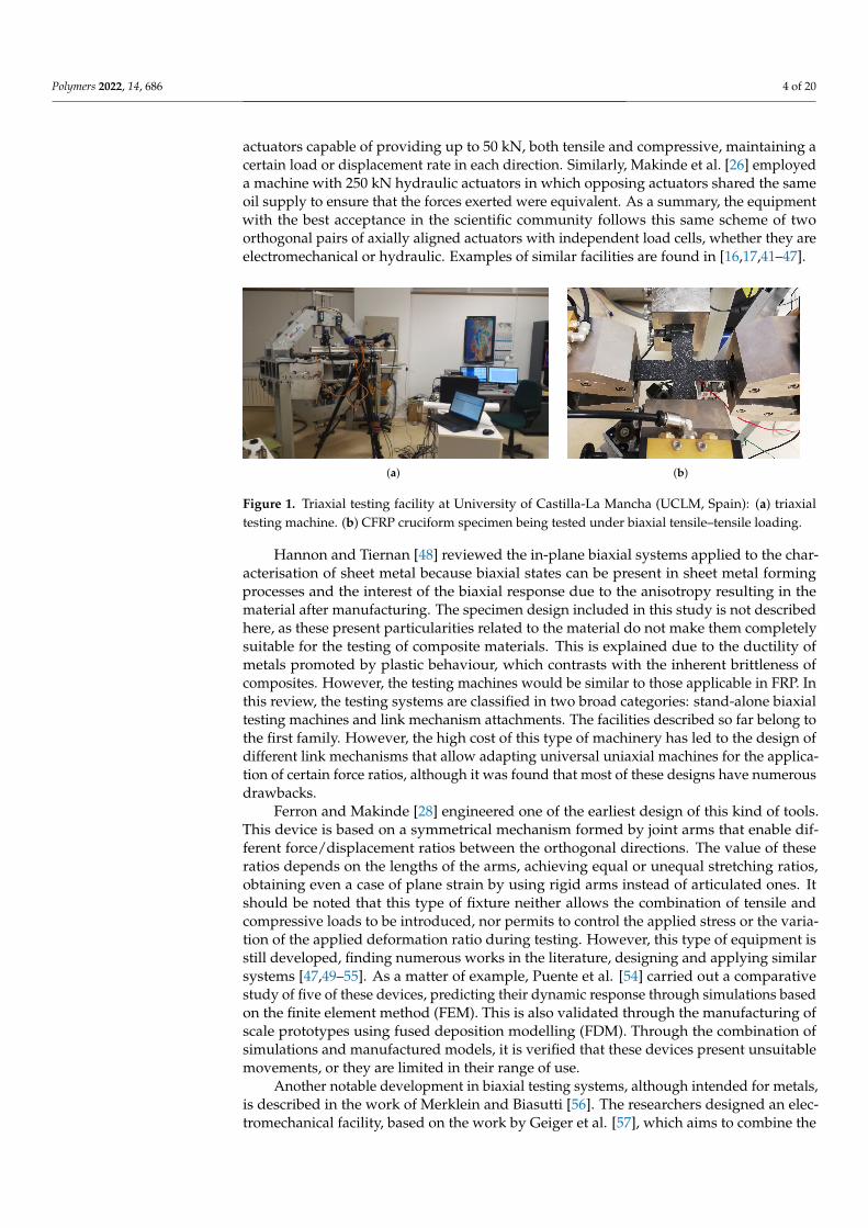
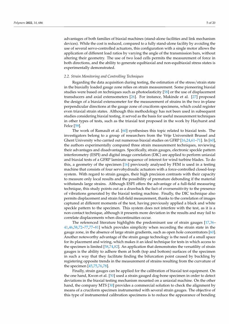
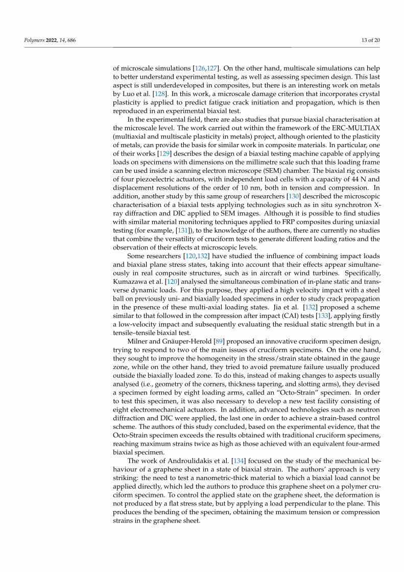
An installation very similar to the previous one was used in the works of Serna Morenoet al. [38–40], which is shown in Figure 1. This facility consists of six electromechanical
Polymers 2022, 14, 686 4 of 20
actuators capable of providing up to 50 kN, both tensile and compressive, maintaining acertain load or displacement rate in each direction. Similarly, Makinde et al. [26] employeda machine with 250 kN hydraulic actuators in which opposing actuators shared the sameoil supply to ensure that the forces exerted were equivalent. As a summary, the equipmentwith the best acceptance in the scientific community follows this same scheme of twoorthogonal pairs of axially aligned actuators with independent load cells, whether they areelectromechanical or hydraulic. Examples of similar facilities are found in [16,17,41–47].
(a) (b)
Figure 1. Triaxial testing facility at University of Castilla-La Mancha (UCLM, Spain): (a) triaxialtesting machine. (b) CFRP cruciform specimen being tested under biaxial tensile–tensile loading.
Hannon and Tiernan [48] reviewed the in-plane biaxial systems applied to the char-acterisation of sheet metal because biaxial states can be present in sheet metal formingprocesses and the interest of the biaxial response due to the anisotropy resulting in thematerial after manufacturing. The specimen design included in this study is not describedhere, as these present particularities related to the material do not make them completelysuitable for the testing of composite materials. This is explained due to the ductility ofmetals promoted by plastic behaviour, which contrasts with the inherent brittleness ofcomposites. However, the testing machines would be similar to those applicable in FRP. Inthis review, the testing systems are classified in two broad categories: stand-alone biaxialtesting machines and link mechanism attachments. The facilities described so far belong tothe first family. However, the high cost of this type of machinery has led to the design ofdifferent link mechanisms that allow adapting universal uniaxial machines for the applica-tion of certain force ratios, although it was found that most of these designs have numerousdrawbacks.
Ferron and Makinde [28] engineered one of the earliest design of this kind of tools.This device is based on a symmetrical mechanism formed by joint arms that enable dif-ferent force/displacement ratios between the orthogonal directions. The value of theseratios depends on the lengths of the arms, achieving equal or unequal stretching ratios,obtaining even a case of plane strain by using rigid arms instead of articulated ones. Itshould be noted that this type of fixture neither allows the combination of tensile andcompressive loads to be introduced, nor permits to control the applied stress or the varia-tion of the applied deformation ratio during testing. However, this type of equipment isstill developed, finding numerous works in the literature, designing and applying similarsystems [47,49–55]. As a matter of example, Puente et al. [54] carried out a comparativestudy of five of these devices, predicting their dynamic response through simulations basedon the finite element method (FEM). This is also validated through the manufacturing ofscale prototypes using fused deposition modelling (FDM). Through the combination ofsimulations and manufactured models, it is verified that these devices present unsuitablemovements, or they are limited in their range of use.
Another notable development in biaxial testing systems, although intended for metals,is described in the work of Merklein and Biasutti [56]. The researchers designed an elec-tromechanical facility, based on the work by Geiger et al. [57], which aims to combine the
Polymers 2022, 14, 686 5 of 20
advantages of both families of biaxial machines (stand-alone facilities and link mechanismdevices). While the cost is reduced, compared to a fully stand-alone facility by avoiding theuse of several servo-controlled actuators, this configuration with a single motor allows theapplication of different load ratios by varying the angle of the transmission bars, withoutaltering their geometry. The use of two load cells permits the measurement of force inboth directions, and the ability to generate equibiaxial and non-equibiaxial stress states isexperimentally demonstrated.
2.2. Strain Monitoring and Controlling Techniques
Regarding the data acquisition during testing, the estimation of the stress/strain statein the biaxially loaded gauge zone relies on strain measurement. Some pioneering biaxialstudies were based on techniques such as photoelasticity [58] or the use of displacementtransducers and axial extensometers [26]. For instance, Makinde et al. [27] proposedthe design of a biaxial extensometer for the measurement of strains in the two in-planeperpendicular directions at the gauge zone of cruciform specimens, which could registereven triaxial strain states. Although this methodology has not been used in subsequentstudies considering biaxial testing, it served as the basis for useful measurement techniquesin other types of tests, such as the triaxial test proposed in the work by Hayhurst andFelce [59].
The work of Ramault et al. [60] synthesises this topic related to biaxial tests. Theinvestigators belong to a group of researchers from the Vrije Universiteit Brussel andGhent University who carried out numerous biaxial studies on GFRP [16,24,61–71]. In [60],the authors experimentally compared three strain measurement techniques, reviewingtheir advantages and disadvantages. Specifically, strain gauges, electronic speckle patterninterferometry (ESPI) and digital image correlation (DIC) are applied to perform uniaxialand biaxial tests of a GFRP laminate sequence of interest for wind turbine blades. To dothis, a geometry of the specimen [16] previously analysed by FEM is used in a testingmachine that consists of four servohydraulic actuators with a force-controlled closed-loopsystem. With regard to strain gauges, their high precision contrasts with their capacityto measure only local results and the possibility of premature debonding if the materialwithstands large strains. Although ESPI offers the advantage of a full-field measuringtechnique, this study points out as a drawback the fact of oversensitivity to the presenceof vibrations generated by the biaxial testing machine. Finally, the DIC technique alsopermits displacement and strain full-field measurement, thanks to the correlation of imagescaptured at different moments of the test, having previously applied a black and whitespeckle pattern to the specimen. This system does not interfere with the test, as it is anon-contact technique, although it presents more deviation in the results and may fail tocorrelate displacements when discontinuities occur.
The referenced literature highlights the predominant use of strain gauges [17,36–41,46,58,72–77,77–81] which provides simplicity when recording the strain state in thegauge zone, in the absence of large strain gradients, such as open hole concentrators [60].Another noteworthy advantage of the strain gauge technology is the need of a small spacefor its placement and wiring, which makes it an ideal technique for tests in which access tothe specimen is limited [58,74,82]. An application that demonstrates the versatility of straingauges is the ability to adhere them at both (top and bottom) surfaces of the specimenin such a way that they facilitate finding the bifurcation point caused by buckling byregistering opposite trends in the measurement of strains resulting from the curvature ofthe specimen [45,75,76,78].
Finally, strain gauges can be applied for the calibration of biaxial test equipment. Onthe one hand, Kwon et al. [50] used a strain gauged dog-bone specimen in order to detectdeviations in the biaxial testing mechanism mounted on a uniaxial machine. On the otherhand, the company MTS [30] provides a commercial solution to check the alignment bymeans of a cruciform specimen instrumented with several strain gauges. The objective ofthis type of instrumented calibration specimens is to reduce the appearance of bending
Polymers 2022, 14, 686 6 of 20
caused by the application of loads misaligned with regard to the in-plane orthogonaldirections.
However, there is a consensus in the research field to prefer the use of full-fieldtechniques, emphasising the case of DIC, which has been applied, to date, in numerousbiaxial tests with cruciform specimens [44,46,60,61,65,67,69,71,78,81,83–88]. In addition tothe detailed visualisation of the strain contours in different directions at every point onthe surface, this technique provides numerous advantages. Among them, the ability toevaluate the homogeneity of the strain fields stands out [46,60,89].
Several researchers have been able to take advantage of DIC to provide new ap-proaches to the characterisation of material properties through biaxial tests. In the works ofPérié et al. [88,90], the acquired displacement fields are used as input data in a FEM analysisto obtain a damage law of an anisotropic material. Similarly, Lecompte et al. [91] estimatedthe orthotropic elastic properties of a GFRP lamina by using an inverse FEM technique,minimising the difference between the strains obtained experimentally and numerically.Other studies following a similar scheme are the ones carried out by Schemmann andLang et al. [32,33,92]. These works are among the few that focus on studying unreinforcedand continuous fibre-reinforced thermoplastic polymers. In particular, the Reference [92]detailed the inverse parameter identification in a long glass fibre-reinforced polypropylene.The strain fields obtained by DIC are compared with the numerical results from FEM simu-lations, and an optimisation algorithm is applied to minimise the difference between thesefields obtaining the anisotropic viscoelastic properties of the material. These properties arelater homogenised by means of common mean field homogenisation techniques, such asthe interaction direct derivative estimate and Mori-Tanaka.
Another interesting development of the DIC techniques was performed by Buscaet al. [93]. In order to characterise the fatigue behaviour of composite materials undermultiaxial loadings, the cyclic tests are monitored simultaneously with a system of twohigh-speed cameras combined with infrared thermography. The objective of using thehigh-speed stereo DIC system is to quantify local stiffness degradation, while temperaturefields allow a qualitative assessment of damage.
Additionally, the use of 3D DIC technology also helps in measuring the displacementsproduced in the direction perpendicular to the plane, which allows evaluating the presenceof misalignments or the appearance of buckling under compressive loads [78]. Finally, itshould be noted that this technology is not only used for test monitoring, but can alsointervene in testing control. Moncy et al. [46,94,95] highlighted the need to carry out straincontrol, which produces more adequate results than methodologies based on force ordisplacement control when studying crack growth. However, strain control requires takinginto account material stiffness degradation. To do this, these authors proposed a real-timedigital image point tracking system, which allows strain control to be carried out by meansof closed-loop regulation. They take into account strains recorded on live at the centralregion of the specimen by means of DIC cameras, in a similar way to a video extensometer.
3. Specimen Design
In addition to the complexity of the testing facility presented in the previous section,specimen design is addressed in the majority of literature for developing cruciform biaxialtesting. This issue poses the major challenge of achieving a uniform biaxial stress/strainstate in a sufficiently large area, while stress concentrations appear at the corners betweenadjacent arms, which may promote undesirable failure. This is added to the fact of in-troducing simultaneous tensile and compressive loads with different ratios and even ina cyclic manner for fatigue study. The practically inevitable presence of concentrationsleads most of the authors to perform thickness tapering. In spite of this, it is concluded thatat certain load states, it is concluded that the cruciform specimen test is not suitable as astrength determination test, but rather for the evaluation of the mechanical response priorto final failure [46,78].
Polymers 2022, 14, 686 7 of 20
Bearing in mind that this type of test is only standardised in the case of its applicationto metallic materials [96], any test proposal on unreinforced or reinforced polymers mustbe accompanied by the design or selection of a specimen. This section describes the workdone by numerous authors to solve problems in this aspect.
Numerous alternatives have been raised mainly in the past two decades, usuallyopting to analyse the geometry through numerical simulations based on FEM. Thesestudies may be initially classified in two groups: studies that try to devise geometries withparametric variations of certain dimensions and geometrical features [16,63,64,97], andworks focused on shape optimisation [65,98,99]. In any case, the geometries resulting fromthese studies share similar characteristics that are discussed throughout this section.
Previously, some main characteristics of the biaxial test were presented, which can besummarised in those collected in one of the pioneering works on biaxial characterisation ofcomposites [16]. Smits et al. proposed five requirements that the design of the specimenmust accomplish, which are reflected in a similar way in several of the following studies:
• Maximise the homogeneity of stresses and strains in the region of interest (ROI), thatis, in the biaxially loaded zone.
• Minimise the undesired in-plane shear stress/strains in the ROI. To this requirement, itcan be added to avoid the appearance of out-of-plane displacements due to geometricalimperfections of the specimen, as well as those due to instabilities under compressiveloadings.
• Achieve failure in the gauge zone. It should be taken into account that this requirementis given in those works that aim to strength characterisation, as well as those thatpropose the verification of failure theories (for example, works related to the WWFE).However, many researchers focus their biaxial studies on aspects other than failure,but they generally share the need to postpone failure outside the biaxial zone as muchas possible, for instance, in order to record most of the mechanical response underbiaxial load (including plasticity, damage, etc.).
• Repeatable and reproducible results.
More requirements are added to this list by other authors, such as the ability to obtaina wide range of stress/strain ratios in the central zone, including states combining tensionand compression in all their possibilities [33].
However, after decades of research in cruciform specimens with different families ofmaterials, works finding areas for improvement continue to appear. One of the concerns inthe case of biaxial tests is the quantification of the force (or stress) that reaches the centralzone. In this sense, Welsh [37] defined a bypass correction factor, obtained through themeasurement of strain in an uniaxially loaded cruciform specimen and taking into accountthe elastic modulus of the laminate calculated by means of the classical laminated platetheory. A similar strategy defining a factor relating the applied force and the central stressis employed by other authors. For instance, Serna Moreno and López Cela [38] defineda factor, which is dependent on the specimen geometry and force ratio applied, that iscomputed from numerical simulation. Cai et al. [100] agreed that the stress coefficientdepends on the specimen geometry, thickness ratio between the central zone and the arms,and the applied loading ratio. The drawback of this solution is that factors are obtained bymeans of linear elastic analysis, so the range of application is limited until the appearanceof material non-linearities. A similar result was reached in the work of Van Hemelrijck [70],where stresses were obtained from the measurement of strains in combination with theconstitutive equations of the material, which is also limited to the elastic behaviour.
Moncy [46] analysed some typical geometries and quantified the amount of loadsharing between adjacent arms, verifying numerically how the geometry of the centralzone significantly affects the amount of applied force needed to reach a certain level ofstrain in the gauge region. Furthermore, this author concluded that slotted arms maximisethe applied force reaching the central zone.
A more detailed approach to the analysis of loads reaching the gauge zone wascarried out by Nolan and McGarry [101]. In this work, they stated, based on analytical
Polymers 2022, 14, 686 8 of 20
developments and numerical simulations, that the measurement of forces applied by theactuators does not allow to estimate the stresses developed in the biaxial zone, due to thelack of estimation of shear forces in the clamps. Therefore, in the words of the authors, theuse of force correction factors for stress estimation in the biaxially loaded zone is highlyinaccurate. Then, they proposed to rely on inverse FEM analysis, although these entailthe need of previously knowing the material constitutive model. However, it should benoted that these factors are imprecise only if they are used uniformly for different appliedloading ratios and/or cruciform specimen geometries.
Continuing with the analysis of the force that crosses the gauge zone, and adding therequirement to maximise the stresses developed in the biaxially loaded zone, most studiesagree on the need to act on the geometrical features and dimensions of the central zone ofthe test specimen. In this sense, two main lines of action can be defined: soften the stressesin the regions surrounding the biaxially loaded zone (i.e., arms and corners), or increasethe stress produced in the central region by reducing the thickness. These two approachesare detailed in next subsections.
3.1. Mitigation of Stress Concentrations outside the Gauge Region
First of all, it is important to note that most cruciform specimens have filleted cornersbetween arms, as these are an important stress concentrator that promotes prematurefailure and can distort the stress/strain field obtained in the ROI. In addition, anotherpossibility that allows maximising the stresses in the gauge zone is the machining of slotsin the arms of the specimen. It should be noted that this option has traditionally beenapplied mainly in biaxial studies with metals [102,103], due to the difficulty in machiningcomposite materials, that usually results in delamination [46]. In fact, the standard forbiaxial characterisation of metal sheets [96] establishes the presence of slots in the arms ofthe standardised design of the cruciform specimen.
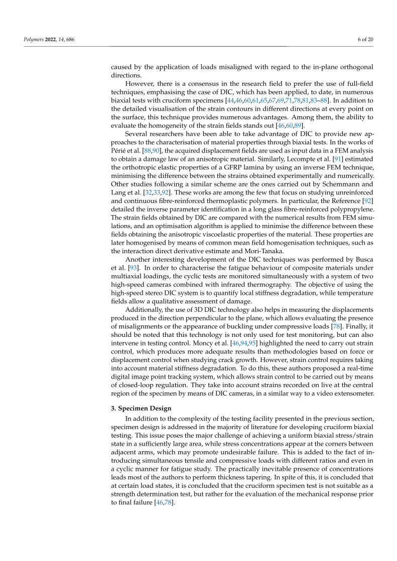
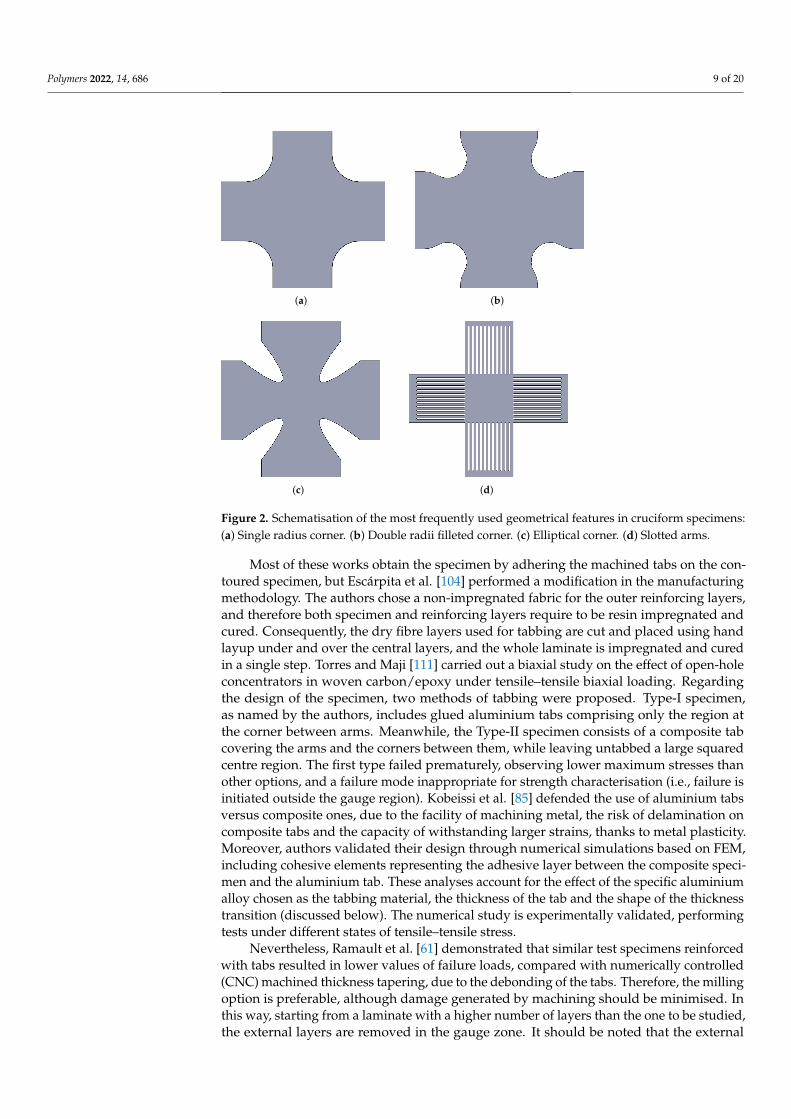
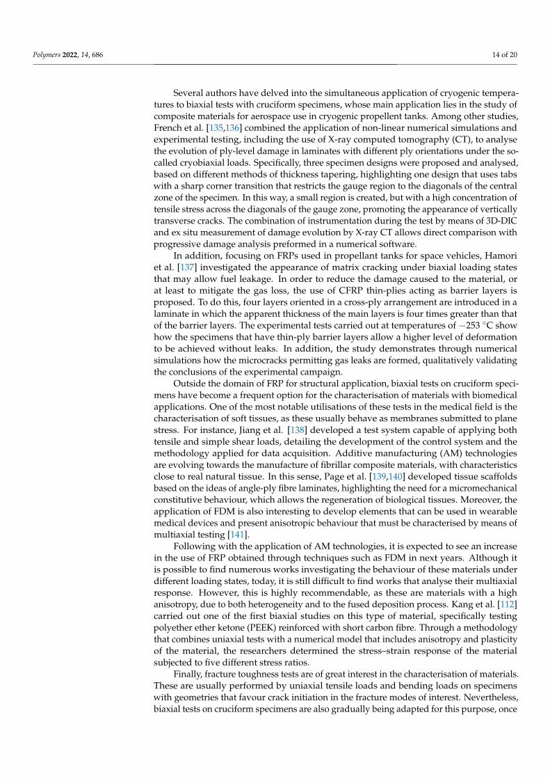
The geometry and dimensions of these filleted corners and slots have been discussedin numerous works, and there is still no clear consensus on the most appropriate option,so this review summarises the preferred choices by different researchers in Table 1. For abetter understanding of these designs, Figure 2 outlines those options frequently exposedin the literature.
Table 1. Preferred shape for corner between adjacent arms in experimental biaxial tests with cruci-form specimen.
Shape References
Single fillet radius [42,50,74,81,83,92,93,104,105]Double fillet radii [16,35–40,43,46,55,63,64,71,80,94,95,106–112]
Elliptical fillet [17,65,68,86,98,113,114]Slotted arms [33,74,79,112,115–119]
3.2. Maximisation of Stresses in the Gauge Region
Regarding the approach based on thickness reduction, it should be noted that it hasalso been the topic of numerous investigations, including both numerical simulations andexperimental tests. Despite that the literature usually recommends thickness tapering,two different approaches are proposed to implement the change in thickness. On the onehand, some authors suggest keeping the thickness constant throughout the specimen to betested, and reinforcing both the arms and the area near the corners between arms with tabs(generally made of composite material or aluminium). In this way, the material to be testedmust only be machined in its outer contour, and the tabs are machined in their central area,leaving the gauge zone accessible for measuring. This option is firstly described in theworks by Kumazawa and Huang et al. [42,81,120], and similarly reproduced in subsequentworks by other authors [44,83,85,87,104].
Polymers 2022, 14, 686 9 of 20
(a) (b)
(c) (d)
Figure 2. Schematisation of the most frequently used geometrical features in cruciform specimens:(a) Single radius corner. (b) Double radii filleted corner. (c) Elliptical corner. (d) Slotted arms.
Most of these works obtain the specimen by adhering the machined tabs on the con-toured specimen, but Escárpita et al. [104] performed a modification in the manufacturingmethodology. The authors chose a non-impregnated fabric for the outer reinforcing layers,and therefore both specimen and reinforcing layers require to be resin impregnated andcured. Consequently, the dry fibre layers used for tabbing are cut and placed using handlayup under and over the central layers, and the whole laminate is impregnated and curedin a single step. Torres and Maji [111] carried out a biaxial study on the effect of open-holeconcentrators in woven carbon/epoxy under tensile–tensile biaxial loading. Regardingthe design of the specimen, two methods of tabbing were proposed. Type-I specimen,as named by the authors, includes glued aluminium tabs comprising only the region atthe corner between arms. Meanwhile, the Type-II specimen consists of a composite tabcovering the arms and the corners between them, while leaving untabbed a large squaredcentre region. The first type failed prematurely, observing lower maximum stresses thanother options, and a failure mode inappropriate for strength characterisation (i.e., failure isinitiated outside the gauge region). Kobeissi et al. [85] defended the use of aluminium tabsversus composite ones, due to the facility of machining metal, the risk of delamination oncomposite tabs and the capacity of withstanding larger strains, thanks to metal plasticity.Moreover, authors validated their design through numerical simulations based on FEM,including cohesive elements representing the adhesive layer between the composite speci-men and the aluminium tab. These analyses account for the effect of the specific aluminiumalloy chosen as the tabbing material, the thickness of the tab and the shape of the thicknesstransition (discussed below). The numerical study is experimentally validated, performingtests under different states of tensile–tensile stress.
Nevertheless, Ramault et al. [61] demonstrated that similar test specimens reinforcedwith tabs resulted in lower values of failure loads, compared with numerically controlled(CNC) machined thickness tapering, due to the debonding of the tabs. Therefore, the millingoption is preferable, although damage generated by machining should be minimised. Inthis way, starting from a laminate with a higher number of layers than the one to be studied,the external layers are removed in the gauge zone. It should be noted that the external
Polymers 2022, 14, 686 10 of 20
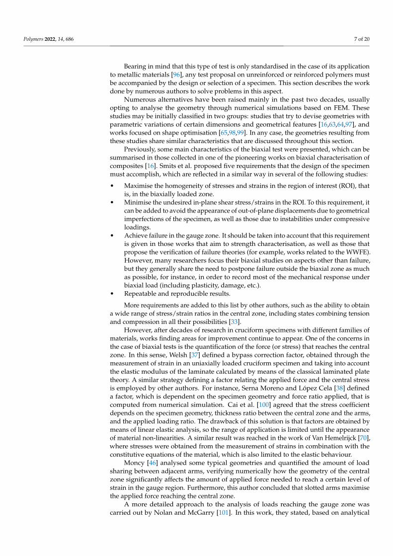
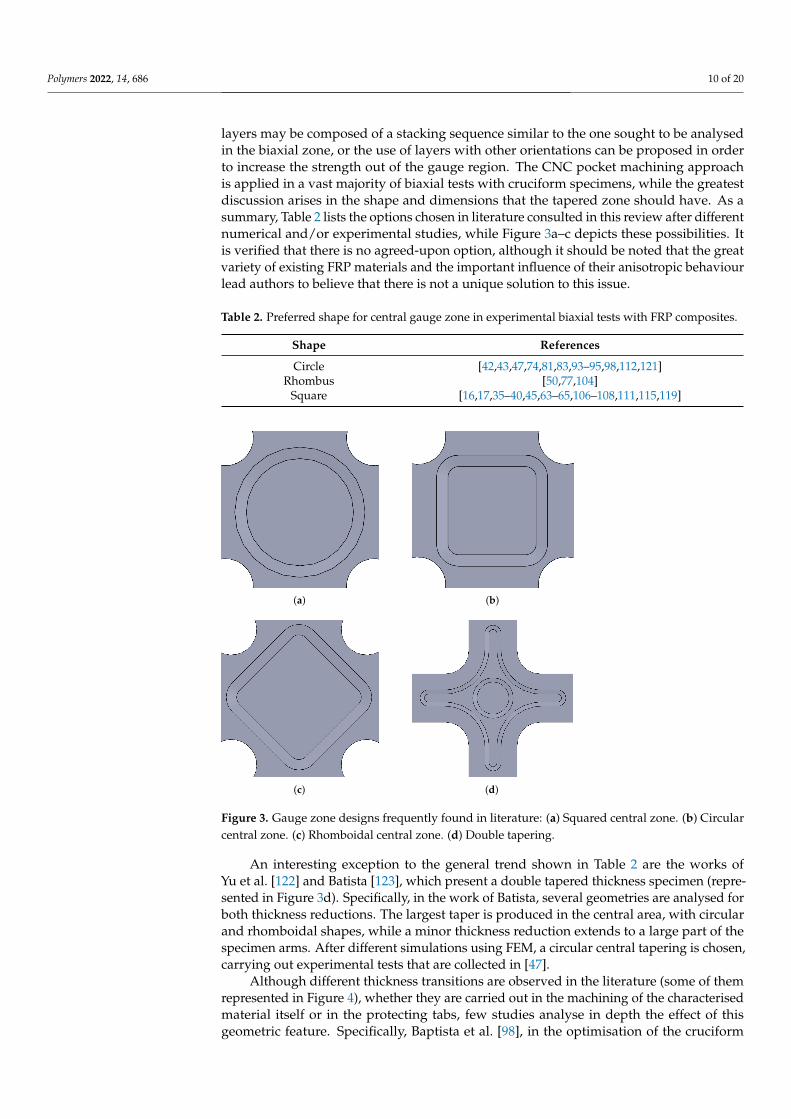
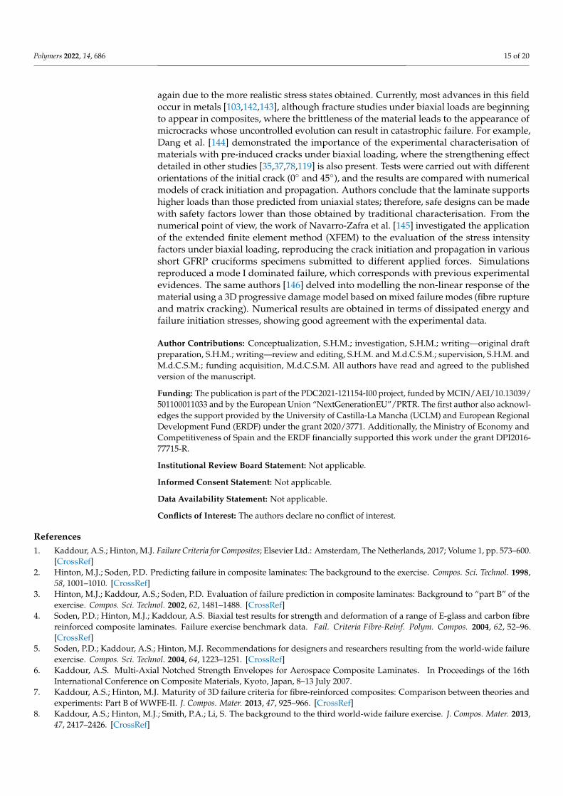
layers may be composed of a stacking sequence similar to the one sought to be analysedin the biaxial zone, or the use of layers with other orientations can be proposed in orderto increase the strength out of the gauge region. The CNC pocket machining approachis applied in a vast majority of biaxial tests with cruciform specimens, while the greatestdiscussion arises in the shape and dimensions that the tapered zone should have. As asummary, Table 2 lists the options chosen in literature consulted in this review after differentnumerical and/or experimental studies, while Figure 3a–c depicts these possibilities. Itis verified that there is no agreed-upon option, although it should be noted that the greatvariety of existing FRP materials and the important influence of their anisotropic behaviourlead authors to believe that there is not a unique solution to this issue.
Table 2. Preferred shape for central gauge zone in experimental biaxial tests with FRP composites.
Shape References
Circle [42,43,47,74,81,83,93–95,98,112,121]Rhombus [50,77,104]
Square [16,17,35–40,45,63–65,106–108,111,115,119]
(a) (b)
(c) (d)
Figure 3. Gauge zone designs frequently found in literature: (a) Squared central zone. (b) Circularcentral zone. (c) Rhomboidal central zone. (d) Double tapering.
An interesting exception to the general trend shown in Table 2 are the works ofYu et al. [122] and Batista [123], which present a double tapered thickness specimen (repre-sented in Figure 3d). Specifically, in the work of Batista, several geometries are analysed forboth thickness reductions. The largest taper is produced in the central area, with circularand rhomboidal shapes, while a minor thickness reduction extends to a large part of thespecimen arms. After different simulations using FEM, a circular central tapering is chosen,carrying out experimental tests that are collected in [47].
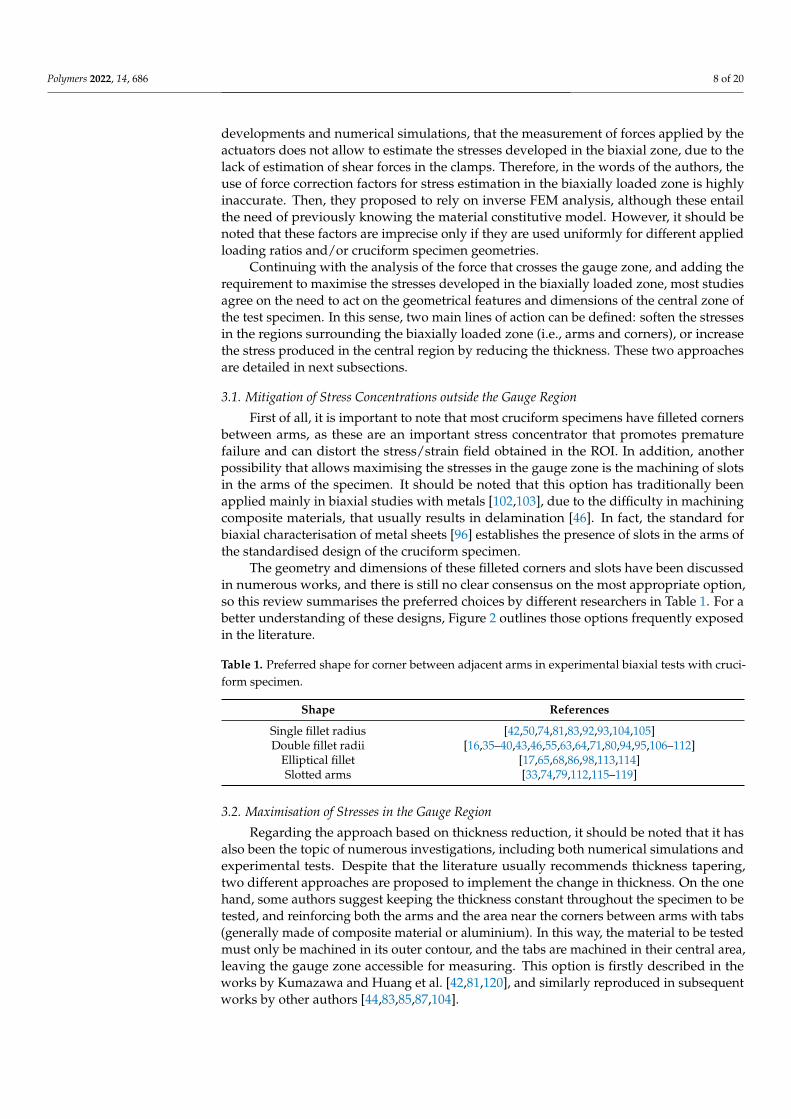
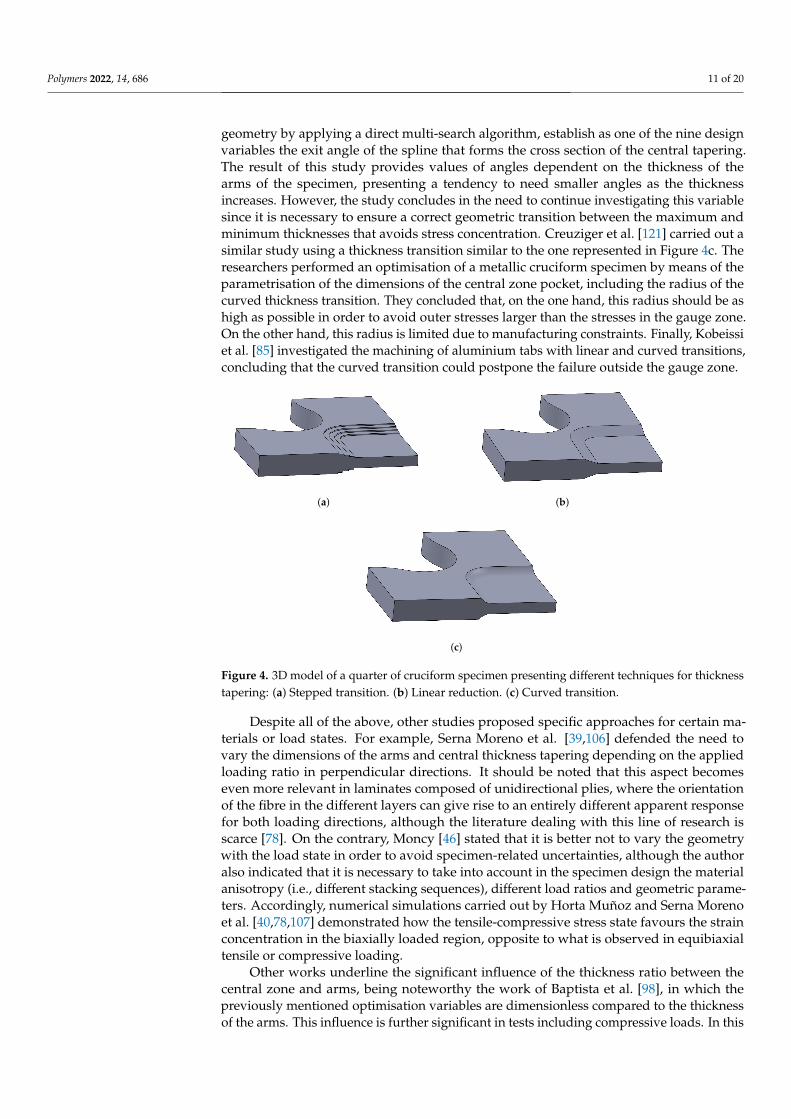
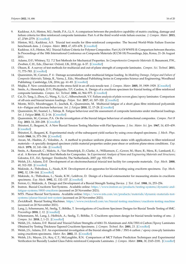
Although different thickness transitions are observed in the literature (some of themrepresented in Figure 4), whether they are carried out in the machining of the characterisedmaterial itself or in the protecting tabs, few studies analyse in depth the effect of thisgeometric feature. Specifically, Baptista et al. [98], in the optimisation of the cruciform
Polymers 2022, 14, 686 11 of 20
geometry by applying a direct multi-search algorithm, establish as one of the nine designvariables the exit angle of the spline that forms the cross section of the central tapering.The result of this study provides values of angles dependent on the thickness of thearms of the specimen, presenting a tendency to need smaller angles as the thicknessincreases. However, the study concludes in the need to continue investigating this variablesince it is necessary to ensure a correct geometric transition between the maximum andminimum thicknesses that avoids stress concentration. Creuziger et al. [121] carried out asimilar study using a thickness transition similar to the one represented in Figure 4c. Theresearchers performed an optimisation of a metallic cruciform specimen by means of theparametrisation of the dimensions of the central zone pocket, including the radius of thecurved thickness transition. They concluded that, on the one hand, this radius should be ashigh as possible in order to avoid outer stresses larger than the stresses in the gauge zone.On the other hand, this radius is limited due to manufacturing constraints. Finally, Kobeissiet al. [85] investigated the machining of aluminium tabs with linear and curved transitions,concluding that the curved transition could postpone the failure outside the gauge zone.
(a) (b)
(c)
Figure 4. 3D model of a quarter of cruciform specimen presenting different techniques for thicknesstapering: (a) Stepped transition. (b) Linear reduction. (c) Curved transition.
Despite all of the above, other studies proposed specific approaches for certain ma-terials or load states. For example, Serna Moreno et al. [39,106] defended the need tovary the dimensions of the arms and central thickness tapering depending on the appliedloading ratio in perpendicular directions. It should be noted that this aspect becomeseven more relevant in laminates composed of unidirectional plies, where the orientationof the fibre in the different layers can give rise to an entirely different apparent responsefor both loading directions, although the literature dealing with this line of research isscarce [78]. On the contrary, Moncy [46] stated that it is better not to vary the geometrywith the load state in order to avoid specimen-related uncertainties, although the authoralso indicated that it is necessary to take into account in the specimen design the materialanisotropy (i.e., different stacking sequences), different load ratios and geometric parame-ters. Accordingly, numerical simulations carried out by Horta Muñoz and Serna Morenoet al. [40,78,107] demonstrated how the tensile-compressive stress state favours the strainconcentration in the biaxially loaded region, opposite to what is observed in equibiaxialtensile or compressive loading.
Other works underline the significant influence of the thickness ratio between thecentral zone and arms, being noteworthy the work of Baptista et al. [98], in which thepreviously mentioned optimisation variables are dimensionless compared to the thicknessof the arms. This influence is further significant in tests including compressive loads. In this
Polymers 2022, 14, 686 12 of 20
way, Serna Moreno and Horta Muñoz numerically analysed the influence on the criticalbuckling load and the buckling mode in specimens with different thickness ratios [82].The authors concluded that certain thicknesses ratios significantly affect the bucklingload, and a change in buckling mode shape is expected. Recently, Giannella et al. [124]performed an analogous study, that is, numerically studying the stability of two differentgeometries of cruciform specimens under compressive loading, in this case, aiming forfracture characterisation. Authors agree on the special influence of the thickness of thecentral region, pointing out the contrast in the selection of this parameter, as it shouldbe high enough to avoid instabilities, but small enough to guarantee high stress valuesin the biaxially loaded zone. Another solution to the problem of instability in slenderarms of cruciform specimen is given similarly in the works by Manshadi et al. [75,76] andXu et al. [45], removing the arms of the cruciform specimen and applying the compressiveloadings directly over the central region. However, this could lead to increase stressconcentrations close to the gauge zone.
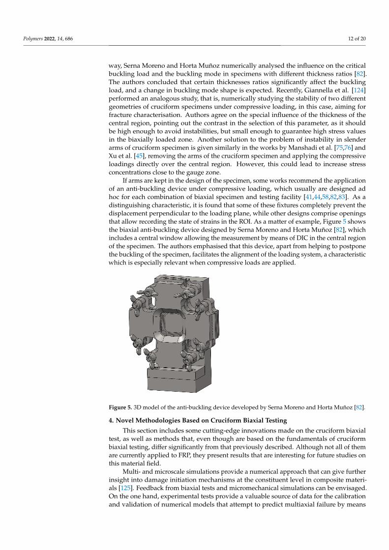
If arms are kept in the design of the specimen, some works recommend the applicationof an anti-buckling device under compressive loading, which usually are designed adhoc for each combination of biaxial specimen and testing facility [41,44,58,82,83]. As adistinguishing characteristic, it is found that some of these fixtures completely prevent thedisplacement perpendicular to the loading plane, while other designs comprise openingsthat allow recording the state of strains in the ROI. As a matter of example, Figure 5 showsthe biaxial anti-buckling device designed by Serna Moreno and Horta Muñoz [82], whichincludes a central window allowing the measurement by means of DIC in the central regionof the specimen. The authors emphasised that this device, apart from helping to postponethe buckling of the specimen, facilitates the alignment of the loading system, a characteristicwhich is especially relevant when compressive loads are applied.
Figure 5. 3D model of the anti-buckling device developed by Serna Moreno and Horta Muñoz [82].
4. Novel Methodologies Based on Cruciform Biaxial Testing
This section includes some cutting-edge innovations made on the cruciform biaxialtest, as well as methods that, even though are based on the fundamentals of cruciformbiaxial testing, differ significantly from that previously described. Although not all of themare currently applied to FRP, they present results that are interesting for future studies onthis material field.
Multi- and microscale simulations provide a numerical approach that can give furtherinsight into damage initiation mechanisms at the constituent level in composite materi-als [125]. Feedback from biaxial tests and micromechanical simulations can be envisaged.On the one hand, experimental tests provide a valuable source of data for the calibrationand validation of numerical models that attempt to predict multiaxial failure by means
Polymers 2022, 14, 686 13 of 20
of microscale simulations [126,127]. On the other hand, multiscale simulations can helpto better understand experimental testing, as well as assessing specimen design. This lastaspect is still underdeveloped in composites, but there is an interesting work on metalsby Luo et al. [128]. In this work, a microscale damage criterion that incorporates crystalplasticity is applied to predict fatigue crack initiation and propagation, which is thenreproduced in an experimental biaxial test.
In the experimental field, there are also studies that pursue biaxial characterisation atthe microscale level. The work carried out within the framework of the ERC-MULTIAX(multiaxial and multiscale plasticity in metals) project, although oriented to the plasticityof metals, can provide the basis for similar work in composite materials. In particular, oneof their works [129] describes the design of a biaxial testing machine capable of applyingloads on specimens with dimensions on the millimetre scale such that this loading framecan be used inside a scanning electron microscope (SEM) chamber. The biaxial rig consistsof four piezoelectric actuators, with independent load cells with a capacity of 44 N anddisplacement resolutions of the order of 10 nm, both in tension and compression. Inaddition, another study by this same group of researchers [130] described the microscopiccharacterisation of a biaxial tests applying technologies such as in situ synchrotron X-ray diffraction and DIC applied to SEM images. Although it is possible to find studieswith similar material monitoring techniques applied to FRP composites during uniaxialtesting (for example, [131]), to the knowledge of the authors, there are currently no studiesthat combine the versatility of cruciform tests to generate different loading ratios and theobservation of their effects at microscopic levels.
Some researchers [120,132] have studied the influence of combining impact loadsand biaxial plane stress states, taking into account that their effects appear simultane-ously in real composite structures, such as in aircraft or wind turbines. Specifically,Kumazawa et al. [120] analysed the simultaneous combination of in-plane static and trans-verse dynamic loads. For this purpose, they applied a high velocity impact with a steelball on previously uni- and biaxially loaded specimens in order to study crack propagationin the presence of these multi-axial loading states. Jia et al. [132] proposed a schemesimilar to that followed in the compression after impact (CAI) tests [133], applying firstlya low-velocity impact and subsequently evaluating the residual static strength but in atensile–tensile biaxial test.
Milner and Gnäuper-Herold [89] proposed an innovative cruciform specimen design,trying to respond to two of the main issues of cruciform specimens. On the one hand,they sought to improve the homogeneity in the stress/strain state obtained in the gaugezone, while on the other hand, they tried to avoid premature failure usually producedoutside the biaxially loaded zone. To do this, instead of making changes to aspects usuallyanalysed (i.e., geometry of the corners, thickness tapering, and slotting arms), they deviseda specimen formed by eight loading arms, called an “Octo-Strain” specimen. In orderto test this specimen, it was also necessary to develop a new test facility consisting ofeight electromechanical actuators. In addition, advanced technologies such as neutrondiffraction and DIC were applied, the last one in order to achieve a strain-based controlscheme. The authors of this study concluded, based on the experimental evidence, that theOcto-Strain specimen exceeds the results obtained with traditional cruciform specimens,reaching maximum strains twice as high as those achieved with an equivalent four-armedbiaxial specimen.
The work of Androulidakis et al. [134] focused on the study of the mechanical be-haviour of a graphene sheet in a state of biaxial strain. The authors’ approach is verystriking: the need to test a nanometric-thick material to which a biaxial load cannot beapplied directly, which led the authors to produce this graphene sheet on a polymer cru-ciform specimen. To control the applied state on the graphene sheet, the deformation isnot produced by a flat stress state, but by applying a load perpendicular to the plane. Thisproduces the bending of the specimen, obtaining the maximum tension or compressionstrains in the graphene sheet.
Polymers 2022, 14, 686 14 of 20
Several authors have delved into the simultaneous application of cryogenic tempera-tures to biaxial tests with cruciform specimens, whose main application lies in the study ofcomposite materials for aerospace use in cryogenic propellent tanks. Among other studies,French et al. [135,136] combined the application of non-linear numerical simulations andexperimental testing, including the use of X-ray computed tomography (CT), to analysethe evolution of ply-level damage in laminates with different ply orientations under the so-called cryobiaxial loads. Specifically, three specimen designs were proposed and analysed,based on different methods of thickness tapering, highlighting one design that uses tabswith a sharp corner transition that restricts the gauge region to the diagonals of the centralzone of the specimen. In this way, a small region is created, but with a high concentration oftensile stress across the diagonals of the gauge zone, promoting the appearance of verticallytransverse cracks. The combination of instrumentation during the test by means of 3D-DICand ex situ measurement of damage evolution by X-ray CT allows direct comparison withprogressive damage analysis preformed in a numerical software.
In addition, focusing on FRPs used in propellant tanks for space vehicles, Hamoriet al. [137] investigated the appearance of matrix cracking under biaxial loading statesthat may allow fuel leakage. In order to reduce the damage caused to the material, orat least to mitigate the gas loss, the use of CFRP thin-plies acting as barrier layers isproposed. To do this, four layers oriented in a cross-ply arrangement are introduced in alaminate in which the apparent thickness of the main layers is four times greater than thatof the barrier layers. The experimental tests carried out at temperatures of −253 ◦C showhow the specimens that have thin-ply barrier layers allow a higher level of deformationto be achieved without leaks. In addition, the study demonstrates through numericalsimulations how the microcracks permitting gas leaks are formed, qualitatively validatingthe conclusions of the experimental campaign.
Outside the domain of FRP for structural application, biaxial tests on cruciform speci-mens have become a frequent option for the characterisation of materials with biomedicalapplications. One of the most notable utilisations of these tests in the medical field is thecharacterisation of soft tissues, as these usually behave as membranes submitted to planestress. For instance, Jiang et al. [138] developed a test system capable of applying bothtensile and simple shear loads, detailing the development of the control system and themethodology applied for data acquisition. Additive manufacturing (AM) technologiesare evolving towards the manufacture of fibrillar composite materials, with characteristicsclose to real natural tissue. In this sense, Page et al. [139,140] developed tissue scaffoldsbased on the ideas of angle-ply fibre laminates, highlighting the need for a micromechanicalconstitutive behaviour, which allows the regeneration of biological tissues. Moreover, theapplication of FDM is also interesting to develop elements that can be used in wearablemedical devices and present anisotropic behaviour that must be characterised by means ofmultiaxial testing [141].
Following with the application of AM technologies, it is expected to see an increasein the use of FRP obtained through techniques such as FDM in next years. Although itis possible to find numerous works investigating the behaviour of these materials underdifferent loading states, today, it is still difficult to find works that analyse their multiaxialresponse. However, this is highly recommendable, as these are materials with a highanisotropy, due to both heterogeneity and to the fused deposition process. Kang et al. [112]carried out one of the first biaxial studies on this type of material, specifically testingpolyether ether ketone (PEEK) reinforced with short carbon fibre. Through a methodologythat combines uniaxial tests with a numerical model that includes anisotropy and plasticityof the material, the researchers determined the stress–strain response of the materialsubjected to five different stress ratios.
Finally, fracture toughness tests are of great interest in the characterisation of materials.These are usually performed by uniaxial tensile loads and bending loads on specimenswith geometries that favour crack initiation in the fracture modes of interest. Nevertheless,biaxial tests on cruciform specimens are also gradually being adapted for this purpose, once
Polymers 2022, 14, 686 15 of 20
again due to the more realistic stress states obtained. Currently, most advances in this fieldoccur in metals [103,142,143], although fracture studies under biaxial loads are beginningto appear in composites, where the brittleness of the material leads to the appearance ofmicrocracks whose uncontrolled evolution can result in catastrophic failure. For example,Dang et al. [144] demonstrated the importance of the experimental characterisation ofmaterials with pre-induced cracks under biaxial loading, where the strengthening effectdetailed in other studies [35,37,78,119] is also present. Tests were carried out with differentorientations of the initial crack (0◦ and 45◦), and the results are compared with numericalmodels of crack initiation and propagation. Authors conclude that the laminate supportshigher loads than those predicted from uniaxial states; therefore, safe designs can be madewith safety factors lower than those obtained by traditional characterisation. From thenumerical point of view, the work of Navarro-Zafra et al. [145] investigated the applicationof the extended finite element method (XFEM) to the evaluation of the stress intensityfactors under biaxial loading, reproducing the crack initiation and propagation in variousshort GFRP cruciforms specimens submitted to different applied forces. Simulationsreproduced a mode I dominated failure, which corresponds with previous experimentalevidences. The same authors [146] delved into modelling the non-linear response of thematerial using a 3D progressive damage model based on mixed failure modes (fibre ruptureand matrix cracking). Numerical results are obtained in terms of dissipated energy andfailure initiation stresses, showing good agreement with the experimental data.
Author Contributions: Conceptualization, S.H.M.; investigation, S.H.M.; writing—original draftpreparation, S.H.M.; writing—review and editing, S.H.M. and M.d.C.S.M.; supervision, S.H.M. andM.d.C.S.M.; funding acquisition, M.d.C.S.M. All authors have read and agreed to the publishedversion of the manuscript.
Funding: The publication is part of the PDC2021-121154-I00 project, funded by MCIN/AEI/10.13039/501100011033 and by the European Union “NextGenerationEU”/PRTR. The first author also acknowl-edges the support provided by the University of Castilla-La Mancha (UCLM) and European RegionalDevelopment Fund (ERDF) under the grant 2020/3771. Additionally, the Ministry of Economy andCompetitiveness of Spain and the ERDF financially supported this work under the grant DPI2016-77715-R.
Institutional Review Board Statement: Not applicable.
Informed Consent Statement: Not applicable.
Data Availability Statement: Not applicable.
Conflicts of Interest: The authors declare no conflict of interest.
References1. Kaddour, A.S.; Hinton, M.J. Failure Criteria for Composites; Elsevier Ltd.: Amsterdam, The Netherlands, 2017; Volume 1, pp. 573–600.
[CrossRef]2. Hinton, M.J.; Soden, P.D. Predicting failure in composite laminates: The background to the exercise. Compos. Sci. Technol. 1998,
58, 1001–1010. [CrossRef]3. Hinton, M.J.; Kaddour, A.S.; Soden, P.D. Evaluation of failure prediction in composite laminates: Background to “part B” of the
exercise. Compos. Sci. Technol. 2002, 62, 1481–1488. [CrossRef]4. Soden, P.D.; Hinton, M.J.; Kaddour, A.S. Biaxial test results for strength and deformation of a range of E-glass and carbon fibre
reinforced composite laminates. Failure exercise benchmark data. Fail. Criteria Fibre-Reinf. Polym. Compos. 2004, 62, 52–96.[CrossRef]
5. Soden, P.D.; Kaddour, A.S.; Hinton, M.J. Recommendations for designers and researchers resulting from the world-wide failureexercise. Compos. Sci. Technol. 2004, 64, 1223–1251. [CrossRef]
6. Kaddour, A.S. Multi-Axial Notched Strength Envelopes for Aerospace Composite Laminates. In Proceedings of the 16thInternational Conference on Composite Materials, Kyoto, Japan, 8–13 July 2007.
7. Kaddour, A.S.; Hinton, M.J. Maturity of 3D failure criteria for fibre-reinforced composites: Comparison between theories andexperiments: Part B of WWFE-II. J. Compos. Mater. 2013, 47, 925–966. [CrossRef]
8. Kaddour, A.S.; Hinton, M.J.; Smith, P.A.; Li, S. The background to the third world-wide failure exercise. J. Compos. Mater. 2013,47, 2417–2426. [CrossRef]
Polymers 2022, 14, 686 16 of 20
9. Kaddour, A.S.; Hinton, M.J.; Smith, P.A.; Li, S. A comparison between the predictive capability of matrix cracking, damage andfailure criteria for fibre reinforced composite laminates: Part A of the third world-wide failure exercise. J. Compos. Mater. 2013,47, 2749–2779. [CrossRef]
10. Hinton, M.J.; Kaddour, A.S. Triaxial test results for fibre-reinforced composites: The Second World-Wide Failure Exercisebenchmark data. J. Compos. Mater. 2013, 47, 653–678. [CrossRef]
11. Kaddour, A.S.; Hinton, M.J. Triaxial Failure Criteria for Polymer Composites: Part (A) Of WWFE-II: Comparison between theories.In Proceedings of the 18th International Conference on Composite Materials (ICCM-18) Proceedings, Jeju, Korea, 21–26 August2011.
12. Adams, D.F.; Whitney, T.J. 7.2 Test Methods for Mechanical Properties. In Comprehensive Composite Materials II; Beaumont, P.W.,Zweben, C.H., Eds.; Elsevier: Oxford, UK, 2018; pp. 4–37. [CrossRef]
13. Olsson, R. A survey of test methods for multiaxial and out-of-plane strength of composite laminates. Compos. Sci. Technol. 2011,71, 773–783. [CrossRef]
14. Quaresimin, M.; Carraro, P. 4 - Damage accumulation under multiaxial fatigue loading. In Modeling Damage, Fatigue and Failure ofComposite Materials; Talreja, R., Varna, J., Eds.; Woodhead Publishing Series in Composites Science and Engineering; WoodheadPublishing: Cambridge, UK, 2016; pp. 61–83. [CrossRef]
15. Mujika, F. New considerations on the stress field in an off-axis tensile test. J. Compos. Mater. 2005, 39, 1909–1929. [CrossRef]16. Smits, A.; Hemelrijck, D.V.; Philippidis, T.P.; Cardon, A. Design of a cruciform specimen for biaxial testing of fibre reinforced
composite laminates. Compos. Sci. Technol. 2006, 66, 964–975. [CrossRef]17. Cai, D.; Tang, J.; Zhou, G.; Wang, X.; Li, C.; Silberschmidt, V.V. Failure analysis of plain woven glass/epoxy laminates: Comparison
of off-axis and biaxial tension loadings. Polym. Test. 2017, 60, 307–320. [CrossRef]18. Monte, M.D.; Moosbrugger, E.; Jaschek, K.; Quaresimin, M. Multiaxial fatigue of a short glass fibre reinforced polyamide
6.6—Fatigue and fracture behaviour. Int. J. Fatigue 2010, 32, 17–28. [CrossRef]19. Quaresimin, M.; Susmel, L.; Talreja, R. Fatigue behaviour and life assessment of composite laminates under multiaxial loadings.
Int. J. Fatigue 2010, 32, 2–16. [CrossRef]20. Quaresimin, M.; Carraro, P.A. On the investigation of the biaxial fatigue behaviour of unidirectional composites. Compos. Part B
Eng. 2013, 54, 200–208. [CrossRef]21. Shiratori, E.; Ikegami, K. A New Biaxial Tension Testing Machine with Flat Specimens. J. Soc. Mater. Sci. Jpn. 1967, 16, 433–439.
[CrossRef]22. Shiratori, E.; Ikegami, K. Experimental study of the subsequent yield surface by using cross-shaped specimens. J. Mech. Phys.
Solids 1968, 16, 373–394. [CrossRef]23. Arcan, M.; Hashin, Z.; Voloshin, A. A method to produce uniform plane-stress states with applications to fiber-reinforced
materials—A specially designed specimen yields material properties under pure shear or uniform plane-stress conditions. Exp.Mech. 1978, 18, 141–146. [CrossRef]
24. Smits, A.; Ramault, C.; Makris, A.; Van Hemelrijck, D.; Clarke, A.; Williamson, C.; Gower, M.; Shaw, R.; Mera, R.; Lamkanfi, E.;et al. A Review of Biaxial Test Methods for Composites. In Experimental Analysis of Nano and Engineering Materials and Structures;Gdoutos, E.E., Ed.; Springer: Dordrecht, The Netherlands, 2007; pp. 933–934.
25. Welsh, J.S.; Adams, D.F. Development of an electromechanical triaxial test facility for composite materials. Exp. Mech. 2000,40, 312–320. [CrossRef]
26. Makinde, A.; Thibodeau, L.; Neale, K.W. Development of an apparatus for biaxial testing using cruciform specimens. Exp. Mech.1992, 32, 138–144. [CrossRef]
27. Makinde, A.; Thibodeau, L.; Neale, K.W.; Lefebvre, D. Design of a biaxial extensometer for measuring strains in cruciformspecimens. Exp. Mech. 1992, 32, 132–137. [CrossRef]
28. Ferron, G.; Makinde, A. Design and Development of a Biaxial Strength Testing Device. J. Test. Eval. 1988, 16, 253–256.29. Instron. Biaxial Cruciform Test Systems. Available online: https://www.instron.us/products/testing-systems/dynamic-and-
fatigue-systems/8800-cruciform (accessed on 20 November 2021).30. MTS. Planar Biaxial Test Systems. Available online: https://www.mts.com/en/products/materials/dynamic-materials-test-
systems/planar-biaxial-test-system (accessed on 20 November 2021).31. ZwickRoell. Biaxial Testing Machines. https://www.zwickroell.com/en/biaxial-testing-machines/cruciform-testing-machine
(accessed on 20 November 2021).32. Lang, J.; Schemmann, M.; Seelig, T.; Böhlke, T. Investigations of Cruciform Specimen Designs for Biaxial Tensile Testing of SMC.
Proceedings 2018, 2, 12. [CrossRef]33. Schemmann, M.; Lang, J.; Helfrich, A.; Seelig, T.; Böhlke, T. Cruciform specimen design for biaxial tensile testing of smc. J.
Compos. Sci. 2018, 2, 1–21. [CrossRef]34. Welsh, J.S.; Adams, D.F. Biaxial and Triaxial Failure Strengths of 6061-T6 Aluminum and AS4/3501-6 Carbon/Epoxy Laminates
Obtained by Testing Thickness-Tapered Cruciform Specimens. J. Compos. Technol. Res. 2001, 23. [CrossRef]35. Welsh, J.S.; Adams, D.F. An experimental investigation of the biaxial strength of IM6 / 3501-6 carbon / epoxy cross-ply laminates
using cruciform specimens. Mater. Res. 2002, 33. [CrossRef]36. Welsh, J.S.; Mayes, J.S.; Key, C.T.; McLaughlin, R.N. Comparison of MCT Failure Prediction Techniques and Experimental
Verification for Biaxially Loaded Glass Fabric-reinforced Composite Laminates. J. Compos. Mater. 2004, 38, 2165–2181. [CrossRef]
Polymers 2022, 14, 686 17 of 20
37. Welsh, J.S.; Mayes, J.S.; Biskner, A.C. 2-D biaxial testing and failure predictions of IM7/977-2 carbon/epoxy quasi-isotropiclaminates. Compos. Struct. 2006, 75, 60–66. [CrossRef]
38. Serna Moreno, M.C.; López Cela, J.J. Failure envelope under biaxial tensile loading for chopped glass-reinforced polyestercomposites. Compos. Sci. Technol. 2011, 72, 91–96. [CrossRef]
39. Serna Moreno, M.C.; Martínez Vicente, J.L.; López Cela, J.J. Failure strain and stress fields of a chopped glass-reinforced polyesterunder biaxial loading. Compos. Struct. 2013, 103, 27–33. [CrossRef]
40. Serna Moreno, M.C.; Martínez Vicente, J.L. In-plane shear failure properties of a chopped glass-reinforced polyester by means oftraction-compression biaxial testing. Compos. Struct. 2015, 122, 440–444. [CrossRef]
41. Williamson, C.; Cook, J.; Clarke, A. Investigation Into the Failure of Open Holes in CFRP Laminates Under Biaxial LoadingConditions. In Experimental Analysis of Nano and Engineering Materials and Structures; Gdoutos, E.E., Ed.; Springer: Dordrecht,The Netherlands, 2007; pp. 939–940.
42. Kumazawa, H.; Takatoya, T. Biaxial strength investigation of CFRP composite laminates by using cruciform specimens. InProceedings of the 17th International Conference on Composite Materials (ICCM-17), Edinburgh, UK, 27–31 July 2009.
43. Gower, M.R.L.; Shaw, R.M. Towards a Planar Cruciform Specimen for Biaxial Characterisation of Polymer Matrix Composites.Appl. Mech. Mater. 2010, 24–25, 115–120. [CrossRef]
44. Vankan, W.J.; Tijs, B.H.A.H.; de Jong, G.J.; de Frel, H.C.; Singh, N.K. Strength of Notched and Un-Notched Thermoplastic CompositeLaminate in Biaxial Tension and Compression; Technical Report NLR-TP-2015-019; Netherlands Aerospace Centre (NLR): Amsterdam,The Netherlands, 2017.
45. Xu, C.; Song, L.; Zhu, H.; Meng, S.; Xie, W.; Jin, H. Experimental investigation on the mechanical behaviour of 3D carbon/carboncomposites under biaxial compression. Compos. Struct. 2018, 188, 7–14. [CrossRef]
46. Moncy, A. Tunnelling Cracks in Composite Laminates under Planar Biaxial Strain Controlled Fatigue Loading. Ph.D. Thesis,Technical University of Denmark, Kongens Lyngby, Denmark, 2021.
47. Pereira, A.B.; Fernandes, F.A.; de Morais, A.B.; Maio, J. Biaxial testing machine: Development and evaluation. Machines 2020, 8,40. [CrossRef]
48. Hannon, A.; Tiernan, P. A review of planar biaxial tensile test systems for sheet metal. J. Mater. Process. Technol. 2008, 198, 1–13.[CrossRef]
49. Buet-Gautier, K.; Boisse, P. Experimental analysis and modeling of biaxial mechanical behavior of woven composite reinforce-ments. Exp. Mech. 2001, 41, 260–269. [CrossRef]
50. Kwon, H.; Jar, P.; Xia, Z. Characterization of Bi-axial fatigue resistance of polymer plates. J. Mater. Sci. 2005, 40, 965–972.[CrossRef]
51. Bhatnagar, N.; Bhardwaj, R.; Selvakumar, P.; Brieu, M. Development of a biaxial tensile test fixture for reinforced thermoplasticcomposites. Polym. Test. 2007, 26, 154–161. [CrossRef]
52. Sun, X.; Haris, A.; Tan, V.; Tay, T.; Narasimalu, S.; Della, C. A multi-axial fatigue model for fiber-reinforced composite laminatesbased on Puck’s criterion. J. Compos. Mater. 2012, 46, 449–469. [CrossRef]
53. Barroso, A.; Correa, E.; Freire, J.; Pérez, M.D.; París, F. Biaxial Testing of Composites in Uniaxial Machines: Manufacturing ofa Device , Analysis of the Specimen Geometry and Preliminary Experimental Results. In Proceedings of the 15th EuropeanConference on Composite Materials (ECCM15), Venice, Italy, 24–28 June 2012.
54. Puente Medellín, L.F.; Diosdado De La Peña, J.A.D. Design of a biaxial test module for uniaxial testing machine. Mater. TodayProc. 2017, 4, 7911–7920. [CrossRef]
55. Barroso, A.; Correa, E.; Freire, J.; París, F. A Device for Biaxial Testing in Uniaxial Machines. Design, Manufacturing andExperimental Results Using Cruciform Specimens of Composite Materials. Exp. Mech. 2018, 58, 49–53. [CrossRef]
56. Merklein, M.; Biasutti, M. Development of a biaxial tensile machine for characterization of sheet metals. J. Mater. Process. Technol.2013, 213, 939–946. [CrossRef]
57. Geiger, M.; van der Heyd, G.; Merklein, M.; Hussnätter, W. Novel Concept of Experimental Setup for Characterisation of PlasticYielding of Sheet Metal at Elevated Temperatures. Adv. Mater. Res. 2005, 6, 657–664. [CrossRef]
58. Hopgood, P.; Cook, J.; Clarke, A. Multi-axial testing of planar composite specimens. In Proceedings of the 12th InternationalConference on Composite Materials—ICCM12, Paris, France, 5–9 July 1999.
59. Hayhurst, D.; Felce, I. Creep rupture under tri-axial tension. Eng. Fract. Mech. 1986, 25, 645–664. [CrossRef]60. Ramault, C.; Makris, A.; Hemelrijck, D.V.; Lamkanfi, E.; Paepegem, W.V. Comparison of different techniques for strain monitoring
of a biaxially loaded cruciform specimen. Strain 2011, 47, 210–217. [CrossRef]61. Ramault, C.; Makris, A.; Hemelrijck, D.V.; Lamkanfi, E.; Paepegem, W.V. Effect of tab design on the strain distribution of a
biaxially loaded cruciform composite specimen. In Proceedings of the 17th International Conference on Composite Materials,Edinburgh, UK, 27–31 July 2009.
62. Ramault, C.; Makris, A.; Hemelrijck, D.V.; Lamkanfi, E.; Paepegem, W.V. Composite material characterization through biaxialtesting of cruciform specimens. In Proceedings of the ICEM 14—14th International Conference on Experimental Mechanics, ,Poitiers, France, 4–9 July 2010; EDP Sciences: Les Ulis, France, 2010; Volume 6. [CrossRef]
63. Lamkanfi, E.; Paepegem, W.V.; Degrieck, J.; Ramault, C.; Makris, A.; Hemelrijck, D.V. Strain distribution in cruciform specimenssubjected to biaxial loading conditions. Part 1: Two-dimensional versus three-dimensional finite element model. Polym. Test.2010, 29, 7–13. [CrossRef]
Polymers 2022, 14, 686 18 of 20
64. Lamkanfi, E.; Paepegem, W.V.; Degrieck, J.; Ramault, C.; Makris, A.; Hemelrijck, D.V. Strain distribution in cruciform specimenssubjected to biaxial loading conditions. Part 2: Influence of geometrical discontinuities. Polym. Test. 2010, 29, 132–138. [CrossRef]
65. Lamkanfi, E.; Paepegem, W.V.; Degrieck, J. Shape optimization of a cruciform geometry for biaxial testing of polymers. Polym.Test. 2015, 41, 7–16. [CrossRef]
66. Makris, A.; Ramault, C.; Hemelrijck, D.V.; Lamkanfi, E.; Paepegem, W.V. Biaxial fatigue testing using cruciform compositespecimens. In Proceedings of the 13th European Conference on Composite Materials, Stockholm, Sweden, 2–5 June 2008.
67. Makris, A.; Ramault, C.; Hemelrijck, D.V.; Lamkanfi, E.; Paepegem, W.V. Biaxial failure envelopes for glass fibre reinforcedcomposite laminates. In Proceedings of the SEM Annual Conference, Albuquerque, NM, USA, 1–4 June 2009.
68. Makris, A.; Vandenbergh, T.; Ramault, C.; Hemelrijck, D.V.; Lamkanfi, E.; Paepegem, W.V. Shape optimisation of a biaxiallyloaded cruciform specimen. Polym. Test. 2010, 29, 216–223. [CrossRef]
69. Makris, A.; Ramault, C.; Hemelrijck, D.V.; Zarouchas, D.; Lamkanfi, E.; Paepegem, W.V. An Investigation of the MechanicalBehavior of Carbon Epoxy Cross Ply Cruciform Specimens Under Biaxial Loading. Polym. Polym. Compos. 2010, 31, 1554–1561.[CrossRef]
70. Hemelrijck, D.V.; Makris, A.; Ramault, C.; Lamkanfi, E.; Paepegem, W.V.; Lecompte, D. Biaxial testing of fibre-reinforcedcomposite laminates. Proc. Inst. Mech. Eng. Part L J. Mater. Des. Appl. 2008, 222, 231–239. [CrossRef]
71. Ramault, C. Guidelines for Biaxial Testing of Fibre Reinforced Composites Using a Cruciform Specimen. Ph.D. Thesis, VrijeUniversiteit Brussel, Brussels, Belgium, 2012.
72. Quek, S.C.; Waas, A.M.; Shahwan, K.W.; Agaram, V. Compressive response and failure of braided textile composites: Part1—Experiments. Int. J. Non-Linear Mech. 2004, 39, 635–648. [CrossRef]
73. Quek, S.C.; Waas, A.M.; Shahwan, K.W.; Agaram, V. Compressive response and failure of braided textile composites: Part2—Computations. Int. J. Non-Linear Mech. 2004, 39, 649–663. [CrossRef]
74. Jackson, W.C.; Ratcliffe, J.G. Investigation of the Leak Response of a Carbon-Fiber Laminate Loaded in Biaxial Tension. InProceedings of the American Society for Composites—28th Technical Conference, State College, PA, USA, 9–11 September 2013.
75. Manshadi, B.D.; Vassilopoulos, A.P.; Keller, T. Shear Buckling Resistance of GFRP Plate Girders. J. Compos. Constr. 2011,15, 431–440. [CrossRef]
76. Manshadi, B.D.; Vassilopoulos, A.P.; de Castro, J.; Keller, T. Modeling of Buckling and Wrinkling Behavior in GFRP Plate andSandwiches Subjected to Biaxial Compression–Tension Loading. J. Compos. Constr. 2011, 16, 477–487. [CrossRef]
77. Gutiérrez, J.; Lozano, A.; Manzano, A.; Flores, M. Numerical and Experimental Analysis for Shape Improvement of a CruciformComposite Laminates Specimen. Fibres Text. East. Eur. 2016, 24, 89–94. [CrossRef]
78. Horta Muñoz, S. Complexity of the Structural Response of Fibre Reinforced Polymer Matrix Composites. Ph.D. Thesis, Universityof Castilla-La Mancha, Toledo, Spain, 2020. Available online: http://hdl.handle.net/10578/28223 (accessed on 20 January 2022).
79. Chen, W.; Gao, C.; Zhang, D.; Wang, L.; Qiu, Z. A new biaxial tensile shear test method to measure shear behaviour of coatedfabrics for architectural use. Compos. Struct. 2018, 203, 943–951. [CrossRef]
80. Antoniou, A.E.; Hemelrijck, D.V.; Philippidis, T.P. Failure prediction for a glass/epoxy cruciform specimen under static biaxialloading. Compos. Sci. Technol. 2010, 70, 1232–1241. [CrossRef]
81. Huang, Y.; Ha, S.K.; Koyanagi, J.; Melo, J.D.D.; Kumazawa, H.; Susuki, I. Effects of an open hole on the biaxial strengths ofcomposite laminates. J. Compos. Mater. 2010, 44, 2429–2445. [CrossRef]
82. Serna Moreno, M.C.; Horta Muñoz, S. Elastic stability in biaxial testing with cruciform specimens subjected to compressiveloading. Compos. Struct. 2020, 234, 17–18. [CrossRef]
83. Vankan, W.J.; Tijs, B.H.A.H.; De Jong, G.J.; de Frel, H.C.; Singh, N.K. Strength of notched and un-notched thermoplastic compositelaminate in biaxial tension and compression. J. Compos. Mater. 2016, 50, 3477–3500. [CrossRef]
84. Hartmann, S.; Gilbert, R.R.; Sguazzo, C. Basic studies in biaxial tensile tests. GAMM Mitteilungen 2018, 41, 1–14. [CrossRef]85. Kobeissi, A.; Rahme, P.; Leotoing, L.; Guines, D. Strength characterization of glass/epoxy plain weave composite under different
biaxial loading ratios. J. Compos. Mater. 2020, 54, 2549–2563. [CrossRef]86. Skinner, T.; Datta, S.; Chattopadhyay, A.; Hall, A. Fatigue damage behavior in carbon fiber polymer composites under biaxial
loading. Compos. Part Eng. 2019, 174, 106942. [CrossRef]87. Kureemun, U.; Ridha, M.; Tay, T.E. Biaxial tensile-compressive loading of unnotched and open-hole carbon epoxy crossply
laminates. J. Compos. Mater. 2015, 49, 2817–2837. [CrossRef]88. Périé, J.; Leclerc, H.; Roux, S.; Hild, F. Digital image correlation and biaxial test on composite material for anisotropic damage law
identification. Int. J. Solids Struct. 2009, 46, 2388–2396. [CrossRef]89. Milner, J.L.; Gnäupel-Herold, T. Design of an octo-strain specimen for biaxial tension testing. In Proceedings of the ASME 2018
International Manufacturing Science and Engineering Conference, College Station, TX, USA, 18–22 June 2018.90. Périé, J.; Calloch, S.; Cluzel, C. Using Digital Image Correlation and a Damage Model. Exp. Mech. 2002, 42, 318–328. [CrossRef]91. Lecompte, D.; Smits, A.; Sol, H.; Vantomme, J.; Hemelrijck, D.V. Mixed numerical-experimental technique for orthotropic
parameter identification using biaxial tensile tests on cruciform specimens. Int. J. Solids Struct. 2007, 44, 1643–1656. [CrossRef]92. Schemmann, M.; Brylka, B.; Müller, V.; Kehrer, M.L.; Böhlke, T. Mean Field Homogenization of discontinous fiber reinforced
polymers and parameter identification of biaxial tensile tests through inverse modelling. In Proceedings of the 20th InternationalConferences on Composite Materials (ICCM20), Copenhagen, Denmark, 19–24 July 2015.
Polymers 2022, 14, 686 19 of 20
93. Busca, D.; Fazzini, M.; Lorrain, B.; Mistou, S.; Karama, M.; Pastor, M.L. High-Speed Stereo Digital Image Correlation: Applicationto Biaxial Fatigue. Strain 2014, 50, 417–427. [CrossRef]
94. Moncy, A.; Castro, O.; Berggreen, C.; Stang, H. Understanding the effect of anisotropy in composite materials on the performanceof cruciform specimens. Compos. Struct. 2021, 273, 114225. [CrossRef]
95. Moncy, A.; Waldbjørn, J.P.; Berggreen, C. Biaxial Strain Control Fatigue Testing Strategies for Composite Materials. Exp. Mech.2021, 61, 1193–1208. [CrossRef]
96. ISO 16842:2014; Metallic Materials—Sheet and Strip—Biaxial Tensile Testing Method Using a Cruciform Test Piece. InternationalOrganization for Standarization: Geneva, Switzerland, 2014.
97. Bauer, J.; Priesnitz, K.; Schemmann, M.; Brylka, B.; Böhlke, T. Parametric shape optimization of biaxial tensile specimen. Proc.Appl. Math. Mech. 2016, 16, 159–160. [CrossRef]
98. Baptista, R.; Claudio, R.A.; Reis, L.; Madeira, J.F.; Guelho, I.; Freitas, M. Optimization of cruciform specimens for biaxial fatigueloading with direct multi search. Theor. Appl. Fract. Mech. 2015, 80, 65–72. [CrossRef]
99. Bertin, M.B.; Hild, F.; Roux, S. Optimization of a Cruciform Specimen Geometry for the Identification of Constitutive ParametersBased Upon Full-Field Measurements. Strain 2016, 52, 307–323. [CrossRef]
100. Cai, D.; Zhou, G.; Xiaopei, W. Influence of geometry of composite cruciform specimen under biaxial loading on coefficients ofcentral testing zone. Fuhe Cailiao Xuebao/Acta Mater. Compos. Sin. 2015, 32, 1138–1144. [CrossRef]
101. Nolan, D.R.; McGarry, J.P. On the correct interpretation of measured force and calculation of material stress in biaxial tests. J.Mech. Behav. Biomed. Mater. 2016, 53, 187–199. [CrossRef]
102. Hanabusa, Y.; Takizawa, H.; Kuwabara, T. Numerical verification of a biaxial tensile test method using a cruciform specimen. J.Mater. Process. Technol. 2013, 213, 961–970. [CrossRef]
103. Zhang, R.; Shao, Z.; Shi, Z.; Dean, T.A.; Lin, J. Effect of cruciform specimen design on strain paths and fracture location inequi-biaxial tension. J. Mater. Process. Technol. 2021, 289, 116932. [CrossRef]
104. Escárpita, D.A.A.; Cárdenas, D.; Elizalde, H.; Ramirez, R.; Probst, O. Biaxial Tensile Strength Characterization of Textile CompositeMaterials. In Composites and Their Properties; IntechOpen: London, UK, 2012; pp. 83–106. [CrossRef]
105. Rashedi, A.; Sridhar, I.; Tseng, K.J. Fracture characterization of glass fiber composite laminate under experimental biaxial loading.Compos. Struct. 2016, 138, 17–29. [CrossRef]
106. Serna Moreno, M.C.; Curiel-Sosa, J.L.; Navarro-Zafra, J.; Martínez Vicente, J.L.; López Cela, J.J. Crack propagation in a choppedglass-reinforced composite under biaxial testing by means of XFEM. Compos. Struct. 2014, 119, 264–271. [CrossRef]
107. Horta Muñoz, S.; Serna Moreno, M.C. Numerical modelling of the pseudo-ductility effect in ±45° angle-ply laminates underbiaxial loading. In Proceedings of the 18th European Conference on Composite Materials (ECCM18), Athens, Greece, 24–28 June2018; Applied Mechanics Laboratory: New York, NY, USA, 2020.
108. Welsh, J.; Biskner, A.C.; Nelson, E. Experimental and Numerical Failure Predictions of Biaxially-Loaded Unidirectional CarbonComposite Laminates. In Proceedings of the 17th International Conference on Composite Materials, Edinburgh, UK, 27–31 July2009.
109. Correa, E.; Barroso, A.; Pérez, M.D.; París, F. Design for a cruciform coupon used for tensile biaxial transverse tests on compositematerials. Compos. Sci. Technol. 2017, 145, 138–148. [CrossRef]
110. Guptha, V.L.; Sharma, R.S. Experimental Studies on Strength Behaviour of Notched Glass/Epoxy Laminated Composites underUni-axial and Bi-axial Loading. J. Inst. Eng. (India) Ser. C 2019, 100, 75–81. [CrossRef]
111. Torres, A.S.; Maji, A.K. The development of a modified bi-axial composite test specimen. J. Compos. Mater. 2013, 47, 2385–2398.[CrossRef]
112. Kang, H.; Qi, L.; Dang, H.; Jin, K.; Thomson, D.; Cui, H.; Li, Y. Biaxial tensile failure of short carbon-fibre-reinforced PEEKcomposites. Compos. Sci. Technol. 2021, 208, 108764. [CrossRef]
113. Skinner, T.; Datta, S.; Chattopadhyay, A.; Hall, A. Biaxial fatigue damage behavior in carbon fiber reinforced polymer composites.In Proceedings of the AIAA Scitech 2019 Forum, San Diego, CA, USA, 7–11 January 2019; American Institute of Aeronautics andAstronautics Inc., AIAA: Reston, VA, USA, 2019. [CrossRef]
114. Skinner, T.; Datta, S.; Chattopadhyay, A.; Hall, A. Biaxial fatigue damage in quasi isotropic laminates. In Proceedings of theAIAA Scitech 2020 Forum, Orlando, FL, USA, 6–10 January 2020; American Institute of Aeronautics and Astronautics Inc., AIAA:Reston, VA, USA, 2020. [CrossRef]
115. Youssef, Y.; Labonté, S.; Roy, C.; Lefebvre, D. Specimen design, manufacturing and testing procedures for flat carbon fiberreinforced plastic laminates under biaxial loading. Polym. Compos. 1998, 19, 257–263. [CrossRef]
116. Mailly, L.; Wang, S.S. Recent development of planar cruciform experiment on biaxial tensile deformation and failure ofunidirectional glass/epoxy composite. J. Compos. Mater. 2008, 42, 1359–1379. [CrossRef]
117. Qiu, Z.; Chen, W.; Gao, C.; Hu, Y. Experimental and numerical study on nonlinear mechanical properties of laminated wovenfabrics. Constr. Build. Mater. 2018, 164, 672–681. [CrossRef]
118. Shi, T.; Chen, W.; Gao, C.; Hu, J.; Zhao, B.; Zhang, D.; Qiu, Z. Shear behavior of architectural coated fabrics under biaxialbias-extension. Constr. Build. Mater. 2018, 187, 964–973. [CrossRef]
119. Qu, Z.; Xiao, H.; Lv, M.; Wang, X.; Wang, P.; Xu, L. Influence of strengthening material behavior and geometry parameters onmechanical behavior of biaxial cruciform specimen for envelope material. Materials 2019, 12, 2680. [CrossRef]
Polymers 2022, 14, 686 20 of 20
120. Kumazawa, H.; Susuki, I.; Hasegawa, O.; Kasano, H. Influence of biaxial loads on impact fracture of high-strength membranematerials. Adv. Compos. Mater. 2009, 18, 395–413. [CrossRef]
121. Creuziger, A.; Iadicola, M.; Foecke, T. Insights into Cruciform Sample Design. JOM 2017, 69, 902–906. [CrossRef]122. Yu, Y.; Wan, M.; Wu, X.D.; Zhou, X.B. Design of a cruciform biaxial tensile specimen for limit strain analysis by FEM. J. Mater.
Process. Technol. 2002, 123, 67–70. [CrossRef]123. Batista, P.M.R. Conceção de Amostras para Ensaios Biaxiais. Master’s Thesis, Universidade de Aveiro, Aveiro, Portugal, 2016.124. Giannella, V.; Amato, D.; Perrella, M. Stability of cruciform specimens for fracture tests under compression. Eng. Fract. Mech.
2022, 261, 108247. [CrossRef]125. Van Paepegem, W. Multi-Scale Continuum Mechanics Modelling of Fibre-Reinforced Polymer Composites; Woodhead Publishing Series
in Composites Science and Engineering; Elsevier Ltd.: Amsterdam, The Netherlands, 2020. [CrossRef]126. Sharma, A.; Daggumati, S.; Gupta, A.; Van Paepegem, W. On the prediction of the bi-axial failure envelope of a UD CFRP
composite lamina using computational micromechanics: Effect of microscale parameters on macroscale stress–strain behavior.Compos. Struct. 2020, 251, 112605. [CrossRef]
127. Chen, J.; Wan, L.; Ismail, Y.; Hou, P.; Ye, J.; Yang, D. Micromechanical analysis of UD CFRP composite lamina under multiaxialloading with different loading paths. Compos. Struct. 2021, 269, 114024. [CrossRef]
128. Luo, C.; Mohanty, S.; Chattopadhyay, A. Fatigue damage prediction of cruciform specimen under biaxial loading. J. Intell. Mater.Syst. Struct. 2013, 24, 2084–2096. [CrossRef]
129. Van Petegem, S.; Guitton, A.; Dupraz, M.; Bollhalder, A.; Sofinowski, K.; Upadhyay, M.; Van Swygenhoven, H. A MiniaturizedBiaxial Deformation Rig for in Situ Mechanical Testing. Exp. Mech. 2017, 57, 569–580. [CrossRef]
130. Hsu, W.N.; Polatidis, E.; Šmíd, M.; Casati, N.; Van Petegem, S.; Van Swygenhoven, H. Load path change on superelastic NiTialloys: In situ synchrotron XRD and SEM DIC. Acta Mater. 2018, 144, 874–883. [CrossRef]
131. Chevalier, J.; Camanho, P.; Lani, F.; Pardoen, T. Multi-scale characterization and modelling of the transverse compression responseof unidirectional carbon fiber reinforced epoxy. Compos. Struct. 2019, 209, 160–176. [CrossRef]
132. Jia, W.; Wen, W.; Fang, L. Low-velocity impact and post-impact biaxial residual strength tests and simulations of compositelaminates. Compos. Struct. 2020, 235, 111758. [CrossRef]
133. ASTM D7137/D7137M-17; Standard Test Method for Compressive Residual Strength Properties of Damaged Polymer MatrixComposite Plates. ASTM International: West Conshohocken, PA, USA 2017.
134. Androulidakis, C.; Koukaras, E.N.; Parthenios, J.; Kalosakas, G.; Papagelis, K.; Galiotis, C. Graphene flakes under controlledbiaxial deformation. Sci. Rep. 2015, 5, 18219. [CrossRef] [PubMed]
135. French, J.; Christensen, J.; Hallett, S.; Mollenhauer, D.; Czabaj, M. Numerical and Experimental Design of a Cruciform Specimenfor a Novel Cryobiaxial Experiment. In Proceedings of the American Society for Composites—32nd Technical Conference, WestLafayette, IN, USA, 23–25 October 2017. [CrossRef]
136. French, J.; Christensen, J.; Mollenhauer, D.; Czabaj, M. A combined experimental and numerical approach for characterizingply-level damage in tape-laminate composites subjected to biaxial loading. Compos. Struct. 2019, 224, 111062. [CrossRef]
137. Hamori, H.; Kumazawa, H.; Higuchi, R.; Yokozeki, T. Gas permeability of CFRP cross-ply laminates with thin-ply barrier layersunder cryogenic and biaxial loading conditions. Compos. Struct. 2020, 245, 112326. [CrossRef]
138. Jiang, M.; Sridhar, R.L.; Robbins, A.B.; Freed, A.D.; Moreno, M.R. A versatile biaxial testing platform for soft tissues. J. Mech.Behav. Biomed. Mater. 2021, 114, 104144. [CrossRef] [PubMed]
139. Page, M.; Baer, K.; Schon, B.; Mekhileri, N.; Woodfield, T.; Puttlitz, C. Biaxial mechanics of 3D fiber deposited ply-laminatescaffolds for soft tissue engineering part I: Experimental evaluation. J. Mech. Behav. Biomed. Mater. 2019, 98, 317–326. [CrossRef]
140. Page, M.; Puttlitz, C. Biaxial mechanics of 3D fiber deposited ply-laminate scaffolds for soft tissue engineering part II: Finiteelement analyses. J. Mech. Behav. Biomed. Mater. 2019, 100, 103395. [CrossRef] [PubMed]
141. Putra, K.B.; Tian, X.; Plott, J.; Shih, A. Biaxial test and hyperelastic material models of silicone elastomer fabricated by extrusion-based additive manufacturing for wearable biomedical devices. J. Mech. Behav. Biomed. Mater. 2020, 107, 103733. [CrossRef]
142. Shlyannikov, V.N.; Tumanov, A.V.; Zakharov, A.P. The mixed mode crack growth rate in cruciform specimens subject to biaxialloading. Theor. Appl. Fract. Mech. 2014, 73, 68–81. [CrossRef]
143. Giannella, V.; Dhondt, G.; Kontermann, C.; Citarella, R. Combined static-cyclic multi-axial crack propagation in cruciformspecimens. Int. J. Fatigue 2019, 123, 296–307. [CrossRef]
144. Dang, N.H.; Idapalapati, S.; Srikanth, N. Fracture behavior of cross-ply fibre reinforced composite laminates with cracks underbiaxial loading conditions. In Proceedings of the 20th International Conferences on Composite Materials (ICCM20), Copenhagen,Denmark, 19–24 July 2015.
145. Navarro-Zafra, J.; Curiel-Sosa, J.L.; Serna Moreno, M.C. Mixed-mode damage into a CGRP cruciform subjected to biaxial loading.Compos. Struct. 2015, 133, 1093–1100. [CrossRef]
146. Navarro-Zafra, J.; Curiel-Sosa, J.L.; Serna Moreno, M.C. Three-Dimensional Static and Dynamic Analysis of a CompositeCruciform Structure Subjected to Biaxial Loading: A Discontinuum Approach. Appl. Compos. Mater. 2016, 23, 139–154. [CrossRef]