advanced textile design
TRANSCRIPT


ADVANCED TEXTILE DESIGN
BY THE SAME AUTHORI
TEXTILE DESIGN AND COLOURi
i
ELEMENTARY WEAVES AND FIGURED FABRICS
I
WITH 413 DIAGRAMS. 8vo. ys. 6d. NET
LONGMANS, GREEN & CO.
LONDON, NEW YORK, BOMBAY, AND CALCUTTA
ADVANCED
TEXTILE DESIGN
BY
WILLIAM WATSONSUPERINTENDENT AND LECTURER IN TEXTILE MANUFACTURE, THE ROYAL
TECHNICAL COLLEGE, GLASGOW;
FORMERLY HEADMASTER OF THETEXTILE DEPARTMENTS OF THE ROYAL TECHNICAL INSTITUTE,
SALFORD, AND THE TECHNICAL SCHOOL, SHIPLEY
WITH DIAGRAMS
LONGMANS, GREEN AND CO.
39 PATERNOSTER ROW, LONDONNEW YORK, BOMBAY, AND CALCUTTA
I9!3
All rights reserved
PREFACE
THE designing and colouring of cloths, which are composed of one series
of warp and one series of weft threads, are exhaustively treated in the
accompanying book, entitled"Textile Design and Colour, Elementary
Weaves and Figured Fabrics." This book forms a continuation of the
subject, and deals in an equally complete manner with compound and
special cloths in which two or more series of threads are employed in
one or both directions, or which are produced in special methods. There
is no separate section on colour, but the principles upon which colours
are applied to the various classes of cloths are described and illustrated.
Many branches of Textile Design need specialisation, and with this
object in view, and as an aid to the adequate treatment of each branch,
a large proportion of the matter contained in this work has been specially
prepared in the form of separate serial articles which have appeared in
textile journals. The chapters on double cloths, special classes of double
cloths, wadded and centre-stitched double cloths and treble cloths, on
lappet and swivel weaving and designing, and on plain and figured warp
pile fabrics, and book-harness muslins, have been published in the
Textile Manufacturer ; the sections on extra weft and extra warp figuring,
and gauze and leno fabrics in the Textile Recorder ; while portions of
the chapters on weft pile fabrics and Turkish towelling structures have
appeared in Cotton (U.S.A.). In re-issuing the matter in book form,
most of the original illustrations have been used, but new examples
have been introduced and the text has been carefully revised. Further,
in order to make the book a complete work on the design and structure
of compound and special cloths, chapters have been added on weft and
warp-backed cloths, imitation backed fabrics, and backed cloths with
wadding threads;on damasks, tapestry and upholstery cloths, ingrain
carpets, fancy toilet and quilt fabrics, Brussels, Wilton, Tapestry, and
Axminster pile carpets, etc.
Special jacquard and harness mountings, such as sectional jacquard
arrangements, pressure and split harness mountings, self-twilling, double-
A O rr
vi PREFACE
cloth, twin, and pile carpet jacquards, inverted hook machines, jacquards
with working comber-boards, and gauze and Madras mountings, are
fully described and illustrated, as are also the special mechanisms used
in weaving lappet, swivel, and Turkish towelling fabrics. The book
contains 461 figures, which embody over 2,000 designs, diagrams, and
representations of woven fabrics.
The writer wishes to express his indebtedness to several textile
engineering firms and many friends for the willingness with which they
have placed information at his disposal, and to the publishers and
printers for their attention to his wishes in the preparation of the book.
W. W.
(LAST.OW, December, 1912.
CONTENTS
CHAPTER I
BACKED CLOTHSPAGES
Introduction of Extra Threads Principles of Tying or Stitching. Weft- Backed Cloths
Method of Designing Reversible Weft-backed Weaves Methods of Weft-
Backing Standard Twill and Hopsack Weaves Warp-Face Weaves Backedwith Weft Method of Selecting Weft Ties Special Examples of Weft -Backing.Warp- Backed Cloths Method of Designing Reversible Warp-Backed Weaves
Beaming and Drafting Warp-Backed Designs Methods of Warp-BackingStandard Weaves Method of Selecting Warp Ties Special Examples of Warp-Backing Comparative Setting of Backed Cloths. Imitation or Psendo-Backed
Cloths Imitation Weft Backing Imitation Warp Backing. Backed Cloths with
Wadding Threads Weft-Backed and Warp-Wadded Designs Warp-Backedand Weft-Wadded Designs, 1-24
CHAPTER II
DOUBLE CLOTHS
Double-Cloth Structure Relative Proportions and Thicknesses of the Face and BackingThreads Origination or Selection of the Face and Backing Weaves Tying or
Stitching Construction of the Point-Paper Design Construction of Double-
Cloth Designs for Looms with Changing Boxes at one End only Double-Cloth
Beaming, Drafting, arid Pegging Effect of the System of Tying upon the
Number of Healds Special Features in Double-Cloth Designing Position of the
Backing Weave Systematic Construction of Double-Cloth Designs Reversible
Double Weaves Double-Cloths with Compound Face Weaves, . . . 24-63
CHAPTER III
SPECIAL CLASSES or DOUBLE CLOTHS
Double Cloths in which the Threads Interchange. Cut Double Cloths Cut Effects pro-
duced by Interchanging the Threads Designs in which the Cut is produced by
interweaving the Threads in 3-and-3 order. Double Plain Cloths Styles arranged1-and-l as to Colour Correct Joining of Double Plain Weaves Double Plain
Horizontal Hairline Intermingled Double Plain Effects Specially arrangedDouble Plain Stripes Double Plain Spotting Broad Double Plain .Stripes
Double Plain Cloths Specially Coloured in the Warp Comparison with the
First System Cutting and Joining the Weaves Methods of Colouring the
Backing Ends Method of Designing Stripe Patterns Construction of Double
Plain Check Patterns Double Plain Effects in Three of Four Colours Four-
Shade Effects Coloured 1-and-l in the Warp Three-Colour Patterns arranged1 Face, 1 Back in the Warp Four-Colour Patterns arranged 1 Face, 1 Back in
the Warp. Double Twill and Sateen Stripe Designs, 63-88
viii CONTENTS
CHAPTER IV
WADDED AND CENTRE-STITCHED DOUBLE CLOTHS AND TREBLE CLOTHSJrAGES
Wadded Double Cloths Weft-Wadded Double Cloths Warp-Wadded Double Cloths.
Centre -Stitched Double-Cloth Designs Centre Warp Stitching Centre Weft
Stitching. Treble Cloths Systems of Stitching Treble Cloth Designing in
Stages Construction of Drafts and Pegging Plans Systematic Construction of
Treble-Cloth Designs Use of Centre Fabric as Wadding, 88-106
CHAPTER V
EXTRA WEFT FIGURING
Principles of Figuring with Extra Materials Methods of Introducing Extra Figuring
Threads Methods of Disposing of the Surplus Extra Threads. FIGURING WITH
EXTRA WEFT Continuous Figuring in one Extra Weft One-and-One Wefting
Two-and-Two Wefting One-and-Two Wefting Two-and-Four Wefting
Selection of Suitable Positions for the Figuring Floats Extra Material Cut
Away Extra Weft Stitched In Modification of Ground Weave Intermittent
Extra Weft Figuring Combination of Ground Weft Figure and Extra Weft
Figure Stitching by means of Special Ends Figuring with Two or More Colours
of Extra Weft Pick-and-Pick Figuring Methods of indicating Pick-and-Pick
Ground \Veaves Pick-and-Pick Weave Shading Pick-and-Pick Reversible
Tapestry Style Multiple Weft Persian Style of Figuring Chintzing Reversible
Weft-Face Figured Fabrics Simplified Methods of Designing Treble-Weft eel
Reversible Fabrics, 106-131
CHAPTER VI
EXTRA WARP FIGURING
Comparison with Extra Weft Figuring Continuous Figuring in one Extra WarpHeald and Harness Mounting Alhambra Quilts Binding in Extra Endsbetween Face Floats Intermittent Figuring in One Extra Warp Drafting and
Denting Extra Warp Stripes Figuring with Two Extra Warps Stitching bymeans of Special Picks Extra Warp Planting End-and-End FiguringReversible Warp-Face Figured Fabrics, . . . . .131-147
CHAPTER VII
FIGURING WITH EXTRA WEFT AND EXTRA WARP
Economical Use of Extra Materials Extra WT
arp and Extra Weft Spotting. DOUBLEWEAVE COMBINATIONS Designs Produced in Double-Plain Weaves DoubleTwill Weaves Combination of Fine and Coarse Fabrics Combinations ofDouble Weaves and Warp and Weft Float Crepon Structures Double Weaveand Weft Figure on Warp-Rib Ground, .... 148 J5g
CHAPTER VIII
SPECIAL JACQUARD AND HARNESS MOUNTINGS AND SYSTEMS OF DESIGNING
Comparison with Ordinary Jacquard and Harness Mounts. Sectional Jacquard andHarness A rrangements Sectional Harness Ties Special Connection of Hooks
CONTENTS IX
and Needles Special Draft of the Warp Threads Designing and Card-Cutting PAGES
for Sectional Arrangements. Methods of Increasing the Figuring Capacity of
Jacquards Inverted Hook Jacquards Combinations of Healds with Harnesses
Combinations of Lifting Rods or Bars with Jacquard Machines. The Split
Harness or Shaft Monture Operation of the Lifting Rods System of Designing.
Working Comber-Boards, . . . . . . . . . . . 156-168
CHAPTER IX
FIGURED MUSLIN AND DAMASK FABRICS
Figured Muslin Fabrics. FIGURED BOOK MUSLIN FABRICS System of Loom Mountingand Structure of the Cloth Features in Painting-out Designs Ground WeaveVariation Introduction of Ground-Weft Cords Weaving Particulars of Book-
Muslins Book-Muslin Loom. DAMASK FABRICS Reversible and Non-Revers-
ible Damasks The Pressure Harness Form of the Healds Operation of the
Harness and Healds Method of Designing The Self-Twilling Jacquard
Arrangement of Needles, Hooks, and Lifting Bars Operation of Twilling Needles
Proportions of Hooks to Needles Operation of Card Cylinder Changing the
Capacity and Sett System of Designing Production of Diversity of Effect, . 169-186
CHAPTER X
TAPESTRY AND UPHOLSTERY CLOTHS AND INGRAIN CARPETS
TAPESTRY AND UPHOLSTERY CLOTHS Figured Double and Treble Plain Cloths
Combinations of Double Plain and Weft or Warp Figure Weft-Face TapestryCloths Figuring with the Harness Threads Diversity produced by Mixing the
Wefts Specially Stitched Weft Tapestry Cloth Special Weft Tapestry Mounting
Warp-Face Tapestry Cloth. SCOTCH, KIDDERMINSTER, OR INGRAIN CARPETS
Double Plain Cloth Jacquard Operation of the Jacquard and Comber-Boards
Method of Designing Limitation of the Mounting Weft-Face Ingrain Carpets
Reversible Four-Ply Weft Structure Methods of Producing Variety, . . 186-208
CHAPTER XI
FANCY TOILET AND QUILT FABRICS
Fancy Toilet Cloths Classification of the Fabrics Loose-Back Toilets. Fast-Back
Toilets and Marseilles Quilts Method of Designing System of Loom MountingFour-Pick Structure Five-Pick Structure Special Five-Pick Cloth. Mitchel-
ine or Patent-Satin Quilts Method of Loom Mounting Method of Designingand Structure of the Cloth Other Varieties of Quilts. 208-220
CHAPTER XII
GAUZE AND LENO FABRICS
Structure of the Cloths. Gauze Mounting The Doup Bottom and Top DoupingGauze and Leno Drafting Relative Position of Healds The Baser or Slackener
CONTENTS
Sheds formed in Doup Weaving Construction of Lifting Plans The Shaker
Motion Gauze and Leno Compared Modifications of Pure Gauze and Leno.
Comltination* of Uau:c and other Wen res Stripe Patterns Cellular Tennis
Shirtings Russian Cords Simple Cross-over and Check Gauze Effects. Simple' Xet"'Lfno* Comparison of Top and Bottom Doup Pegging Plans Denting
Net Lenos Designing Net Lenos and Features to Note Production of Pattern
by Varying the Lifts of the Standard Ends Bead Mounting for Net Lenos.
Combination* of (>'au:e and Itno with Extra Warp and Extra Weft Effect*. Two
or Mon l>oi<i> Pattern*. Pattern* produced by one Doup and two or more Back
Crotuiwj lleald* Comparison with Two-Doup Style Construction of Heald-
Knitting Plans for Gauze Stripes Fancy One-Doup Net Leno Distorted Weft
Stvles Gauze and Figure Weave Combinations,
CHAPTER XI II
JACQUARD GAUZE AND LENO FABRICS
Ordinary Jac'iuard and Donp-Heald Mounting* Styles of Cloth Combinations of Gauze,
Plain Weave, and Warp (or Weft) Figure One-crossing-one Styles Special
Ground Weaves One-crossing-two Styles Use of Two Doups Modification
of Gauze Ground Net -Leno Figured Styles One-crossing-three Patterns
Combinations of Twill and Gauze. The Special Gauze Jacquard and Harness
Arrangement of Harness, Hooks, and Needles System of Drafting Method of
Douping and Easing Construction of Gauze Ground Weaves Designing of
Figures System of Card-cutting Top Douping in the Gauze Harness. MADRAS
GAUZE FABKICS Structure of the Cloth The Madras Loom System of Drafting
Method of Crossing the Ends Method of Easing Arrangement of Shuttle
Boxes Operation of the Gauze Reed Operation of the Easing Bar Operation
of the Tug Reed The Picking Motion The Up-take Motion Madras Designing
Modifications of the Structure Single Cover Chintzed Design Gauze Figure
on Opaque Ground Complex Three-colour Fabric System of Card-cutting,
CHAPTER XIV
LAPPET WEAVING AND DESIGNING
Features of Lappet Figuring Scotch Lappet Wheel Loom. Common Wheel Lappet
System Rotation of the Pattern Wheel Vertical Movement of the Pin andNeedle Bars Method of making the Needle Bars Inoperative Lateral Move-ment of the Needle Bars Relation of Movement of Shifter Frames to Rotationof Pattern Wheel Construction of a
" Common "Lappet Wheel Methods of
Indicating Lappet Designs Method of Indicating a Pattern Groove. Con-tinuous Two-framo Lappet Design Relative Positions of the Needle Bars andPecks. Intermittent Three-frame Lappet Style Continuous All-over Three-frame Lappet Design. Crossing the Needle Bars. To find the Diameter of a
Wheel The Length of Repeat. Methods of Diversifying Lappet DesignsSpacing the Needles in the Bars. Presser Wheel System Construction of aPresser Wheel To find the Length of Whip Warp Lappet Styles in Imitationof Net Leno Waved Russian Cords. Imitation Lace. Patterns produced byvarying the Order of Lifting the Needle Bars, 296-334
CONTENTS xi
CHAPTER XV
SWIVEL WEAVING AND DESIGNINGPAGES
Purpose of Swivel Mechanism Swivel Ornamentation and Embroidery comparedGeneral Description of Swivel Mechanism Relation of Pitch of Shuttles to
Repeat of Jacquard. Detached Swivel Figures Imitation Embroidery
Special Swivel Style Figuring with two or more Swivel Wefts Combination
of Swivel and Ordinary Figures Production of Detached Figures in One Kind
of Weft by Two Shuttles All-over Swivel Figures. Power Swivel Mechanisms
All-over Figuring Swivel Loom Rack and Pinion Swivel Loom Circular-Swivel
Mechanism, . . . . . . . . . . . 33*-362
CHAPTER XVI
WEFT PILE FABRICS
Formation of Weft Pile. Plain Velveteens Tabby or Plain-back Velveteens Lengthof the Pile Density of the Pile Changing the Density of the Pile Fastness of
the Pile Twill-back Velveteens Designs which simplify the Cutting Operation.
Corded Velveteens Corded Velveteen Cutting Corded Velveteens from Plain
Velveteen Weaves Particulars of Weft Pile Fabrics. Weft Plushes. Figured
Weft Pile Fabrics Figured Velveteens Figured Cords. Imitation Weft Pile
Fabrics 362-382
CHAPTER XVII
TURKISH TOWELLING FABRICS
Formation of the Pile Turkish Towelling Weaves Methods of Drafting and Denting
Terry Motions. Terry Ornamentation Stripe and Check Dobby Patterns
Figured Terry Pile Fabrics Mixed Colour Effects, 382-395
CHAPTER XVIII
WARP PILE FABRICS
Formation of Warp Pile Form of the Pile Wires Structure of Warp Pile. Plain
Warp Pile Fabrics All the Pile over each Wire Two Picks to each Wire
Three Picks to each Wire Fast Warp Pile Designing Method of Heald Drafting
Four Picks to each Wire One-half the Pile over each Wire Backed and
Double Foundation Cloths Warp Pile Astrakhan Textures Reversible WarpPile Structures Double Plush Weaving Ornamentation of Plain Warp Pile
Fabrics. Stripe and Check Designs, 395-407
CHAPTER XIX
FIGURED WARP PILE FABRICS
Figuring with Cut and Looped Pile. Warp Pile Figuring on Ordinary Weave Grounds
Pile Figuring with Extra Threads Figuring with Pile Threads which inter-
weave in the Ground Combinations of Pile and Figured Warp Rib. Com-
binations of Pile and Double Plain Cloth. Combination of Pile and Weft Figure.
Looped Pile and Warp Rib Figure on Cut Pile Ground, 408-425

xii CONTENTS
CHAPTER XX
FIGURED PILE FABRICS IN WHICH THE DESIGN is DUE TO COLOURPAGES
Wilton and Brussels Structures Comparison of the Cloths Distinguishing Feature of
the Clot hs Planting Method of Designing System of Loom Mounting
Card-cutting Six-frame Mounting Structure of Wilton Pile Structure of
Brussels Pile Two-pick Wilton Pile Structure Moresque Effects Develop-ment of the Colours in both Cut and Looped Pile. Tapestry Pile Carpets
Comparison with Brussels and Wilton Structures Tapestry Pile Designing
Preparation of the Pile Yarn for Printing The Printing Drum The Printing
Pulley The Scale Board Operation of Printing Beaming the Pile WarpStructure of Tapestry Pile Tapestry Pile Weaving. Chenille or Patent Axminster
Pile Comparison with Tapestry Pile Chenille Pile Designing Formation of
the Chenille Setting Structure of the Fabric. Moquette or Royal Axminster
Pile, . ... 426-449
INDEX, . 451-461
ADVANCED TEXTILE DESIGNCHAPTER I
BACKED CLOTHSIntroduction of Extra Threads Principles of Tying or Stitching. Weft Backed Cloths Method
of Designing Reversible Weft-backed Weaves Methods of Weft-Backing Standard
Twill and Hopsack Weaves Warp-Face Weaves Backed with Weft Method of Selecting
Weft Ties Special Examples of Weft - Backing. Warp - Backed Cloths Method of
Designing Reversible Warp-Backed Weaves Beaming and Drafting Warp-Backed
Designs Methods of Warp-Backing Standard Weaves Method of Selecting Warp Ties
Special Examples of Warp-Backing Comparative Setting of Backed Cloths. Imitation
or Pseudo-Backed Cloths Imitation Weft Backing Imitation Warp Backing. Backed
Cloths with Wadding Threads Weft-Backed and Warp-Wadded Designs Warp-Backedand Weft-Wadded Designs.
Introduction of Extra Threads. The backed, double, treble, etc., principles of
construction are employed for the purpose of increasing the warmth-retaining
qualities of a cloth, and in order to secure greater weight and substance than can be
acquired in a single structure which is equally fine on the surface. A heavy single
cloth can only be made by using thick yarns, in conjunction with which it is necessary
to employ only a comparatively few threads per unit space. A heavy single texture
is therefore obliged to be somewhat coarse in appearance. By interweaving extra
weft, or extra warp, or both extra weft and extra warp threads on the underside of
a cloth, it is possible to obtain any desired weight combined with the fine surface
appearance of a light single fabric.
In addition to being employed for the sole purpose of giving greater weight and
substance, to a cloth, extra threads are very frequently introduced for ornamental
purposes only, the additional weight of the threads being of no account, while 'in
other cases they are introduced both for weight and ornamentation. In order that
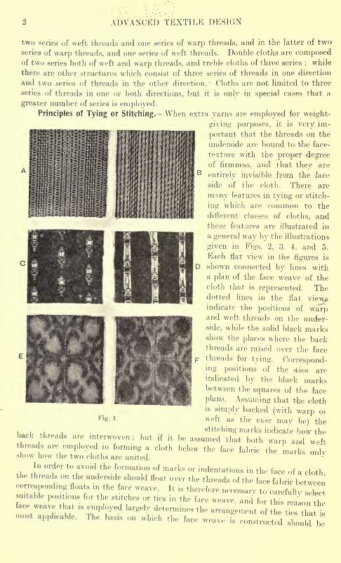
comparisons may be made, three classes of cloths are represented in Fig. 1, which are
illustrative of the three reasons for introducing extra threads. A shows the face
and B the underside of a warp-backed trousering fabric, in which the extra threads
are introduced only to give additional weight and substance ;C shows the face, and
D the underside of an extra-warp figured dress texture, in which the extra threads
are solely for the purpose of ornamentation;
while E and F show the two sides
of a figured double-cloth reversible rug structure, in which the extra threads serve
both for weight and ornamentation.
When the extra threads are inserted solely to give additional weight, the idea
is to employ them in forming a back to a face fabric;and one of the advantages of
the backed, double, treble, etc., systems of construction is that the extra weight can
be obtained in an economical manner, since material which is inferior to the face
yarns may be used on the underside. Backed cloths are constructed on both the
extra weft and the extra warp principle ;a cloth consisting in the former case of
ADVANCED TEXTILE DESIGN
two series of weft threads and one series of warp threads, and in the latter of two
series of warp threads, and one series of weft threads. Double cloths are composedof two series both of weft and warp threads, and treble cloths of three series
;while
there are other structures which consist of three series of threads in one direction
and two series of threads in the other direction. Cloths are not limited to three
series of threads in one or both directions, but it is only in special cases that a
greater number of series is employed.
Principles of Tying or Stitching. -When extra yarns are employed for weight-
giving purposes, it is very im-
portant that the threads on the
underside are bound to the face-
texture with the proper degreeof firmness, and that they are
entirely invisible from the face
side of the cloth. There are
many features in tying or stitch-
ing which are common to the
different classes of cloths, andthese features are illustrated in
a general way by the illustrations
given in Figs. 2, 3;
4. and 5.
Each flat view in the figures is
shown connected by lines witha plan of the face weave of the
cloth that is represented. Thedotted lines in the flat vie\pindicate the positions of warpand weft threads on the under-
side, while the solid black marksshow the places where the backthreads are raised over the face
threads for tying. Correspond-ing positions of the .ties are
indicated by the black marksbetween the squares of the face
plans. Assuming that the clothis simply backed (with warp orweft as the case may be) the
stitching marks indicate how thethreads are interwoven; but if it be assumed that both warp and weftthreads are employed m forming a cloth below the face fabric the marks onlvshow how the two cloths are united.
In order to avoid the formation of marks or indentations in the face of a cloththe threads on the underside should float over the threads of the face fabric betweencorresponding floats in the face weave. It is therefore necessary to care ully sic"suitable positions for the stitches or ties in the face weave, and for this reaLn thethat is employed largely determines the arrangement of the ties that i-most applicable. The basis on which the face weave is constructed should be
PRINCIPLES OF TYING OR STITCHING 3
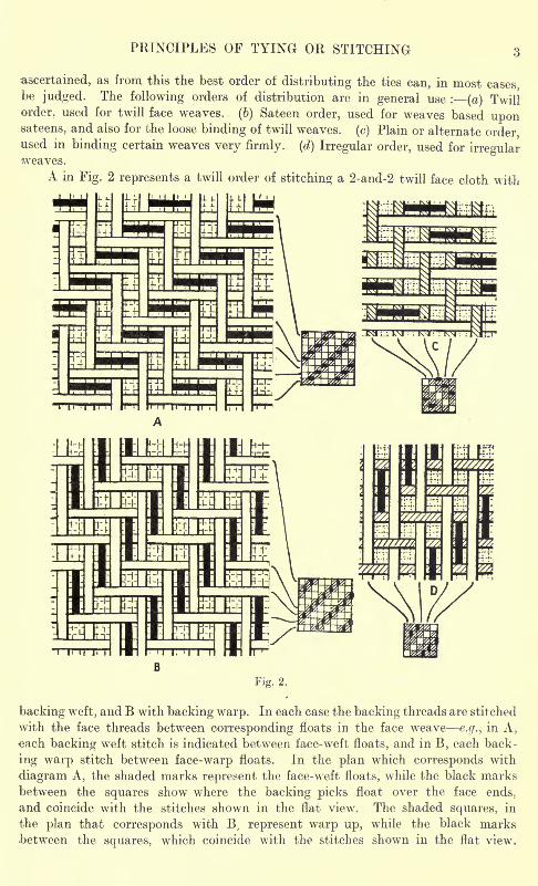
ascertained, as from this the best order of distributing the ties can, in most casesbe judged. The following orders of distribution are in general use : (a) Twillorder, used for twill face weaves, (b) Sateen order, used for weaves based uponsateens, and also for the loose binding of twill weaves, (c) Plain or alternate orderused in binding certain weaves very firmly, (d) Irregular order, used for irregularweaves.
A in Fig. 2 represents a twill order of stitching a 2-and-2 twill face cloth with
Fig. 2.
backing weft, and B with backing warp. In each case the backing threads are stitched
with the face threads between corresponding floats in the face wreave e.g., in A,each backing weft stitch is indicated between face-weft floats, and in B, each back-
ing warp stitch between face-warp floats. In the plan which corresponds with
diagram A, the shaded marks represent the face-weft floats, while the black marks
between the squares show where the backing picks float over the face ends,
and coincide with the stitches shown in the flat view. The shaded squares, in
the plan that corresponds with B. represent warp up, while the black marks
between the squares, which coincide with the stitches shown in the flat view,
ADVANCED TEXTILE DESIGN
indicate where the backing ends float over the face picks. Similarly, C in Fig. 2
represents a 4 weft-and-1 warp twill face cloth, the ends of which are stitched
in twill order by the backing picks ; while D shows a 4 warp-and-1 weft twill
in which the backingends are raised in twill
order over the face
picks.
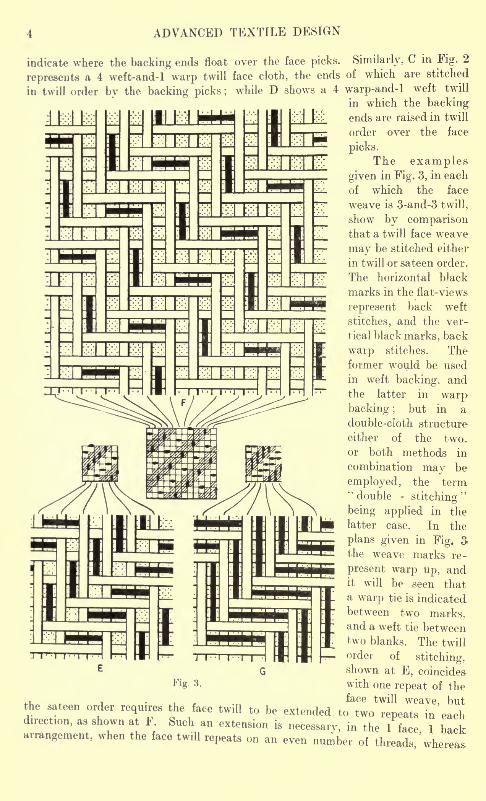
The examplesgiven in Fig. 3, in each
of which the face
weave is 3-and-3 twill,
show by comparisonthat a twill face weave
may be stitched either
in twill or sateen order.
The horizontal black
marks in the flat-views
represent back weft
stitches, and the ver-
tical black marks, back
warp stitches. Theformer would be used
in weft backing, andthe latter in warpbacking ; but in a
double-cloth structure
either of the two,
or both methods in
combination may be
employed, the term"double -
stitching"
being applied in the
latter case. In the
plans given in Fig. 3-
the weave marks re-
present warp up, andit will be seen thata warp tie is indicated
between two marks,and a weft tie betweentwo blanks. The twill
order ofstitching,
shown at E, coincides
with one repeat of theface twill weave, but
Fig. 3.
i il weave, IJUL
the sateen order requ.res the face twill to be extended to two repeats in eachd,rect,on, as shown at F. Such an extension is
necessary, in the 1 face I btckarrangement, when the face twill repeats on an even number of threads wherea*
PRINCIPLES OF TYING OR STITCHING
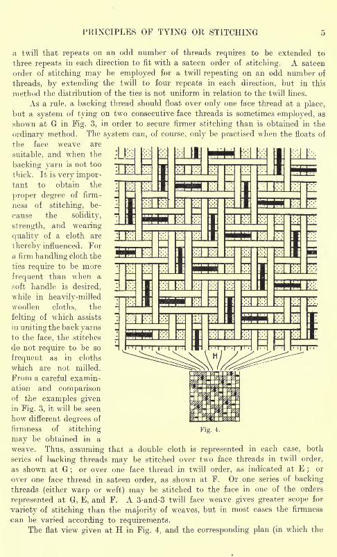
a twill that repeats on an odd number of threads requires to be extended to
three repeats in each direction to fit with a sateen order of stitching. A sateen
order of stitching may be employed for a twill repeating on an odd number of
threads, by extending the twill to four repeats in each direction, but in this
method the distribution of the ties is not uniform in relation to the twill lines.
As a rule, a backing thread should float over only one face thread at a place,
but a system of tying on two consecutive face threads is sometimes employed, as
shown at G in Fig. 3, in order to secure firmer stitching than is obtained in the
ordinary method. The system can, of course, only be practised when the floats of
the face weave are
suitable, and when the
backing yarn is not too
thick. It is very impor-tant to obtain the
proper degree of firm-
ness of stitching, be-
cause the solidity,
strength, and wearing
quality of a cloth are
thereby influenced. For
a firm handling cloth the
ties require to be more
frequent than when a
soft handle is desired,
while in heavily-milledwoollen cloths. the
felting of which assists
in uniting the back yarnsto the face, the stitches
do not require to be so
frequent as in cloths
which are not milled.
From a careful examin-
ation and comparisonof the examples givenin Fig. 3, it will be seen
how different degrees of
firmness of stitching
may be obtained in a
weave. Thus, assuming that a double cloth is represented in each case, both
series of backing threads may be stitched over two face threads in twill order,
as shown at G;
or over one face thread in twill order, as indicated at E; or
over one face thread in sateen order, as shown at F. Or one series of backingthreads (either warp or weft) may be stitched to the face in one of the orders
represented at G, E, and F. A 3-and-3 twill face weave gives greater scope for
variety of stitching than the majority of weaves, but in most cases the firmness
can be varied according to requirements.The flat view given at H in Fig. 4, and the corresponding plan (in which the
Fig. 4.
6 ADVANCED TEXTILE DESIGN
weave marks indicate warp up), illustrate both the backing-warp and the backing-
wett methods of stitehing a sateen derivative face weave, the basis of which is the
12-thread regular sateen. A 12-sateen order of stitching to correspond is employed,
and it will be seen that when one tying position has been selected the others follow
in regular order according to the basis of construction of the tace weave.
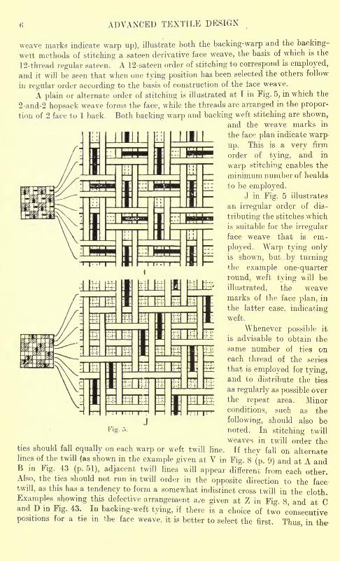
A plain or alternate order of stitching is illustrated at I in Fig. 5, in which the
2-and-2 hopsack weave forms the face, while the threads are arranged in the propor-
tion of 2 face to 1 back. Both backing warp and backing weft stitching are shown,.
and the weave marks in
the face plan indicate warp
up. This is a very firm
order of tying, and in
warp stitching enables the
minimum number of healds-
to be employed.J in Fig. 5 illustrates
an irregular order of dis-
tributing the stitches which
is suitable for the irregular
face weave that is em-
ployed. Warp tying onlyis shown, but . by turningthe example one-quarter
round, weft tying will be
illustrated, the weavemarks of the face plan, in
the latter case, indicatingweft.
Whenever possible it
is advisable to obtain the
same number of ties oneach thread of the series
that is employed for tying,and to distribute the ties-
as regularly as possible over
the repeat area. Minor
conditions, such as the
following, should also benoted. In stitching twill
weaves in twill order theties should fall equally on each warp or weft twill line. If they fall on alternatelines of the twill (as shown in the example given at V in Fig. 8 (p. 9) and at A andB in Fig. 43 (p. 51), adjacent twill lines will appear different from each other.Also, the ties should not run in twill order in the opposite direction to the facetwill, as this has a tendency to form a somewhat indistinct cross twill in the cloth.
Examples showing this defective arrangement a/e given at Z in Fig. 8, and at Cand D in Fig. 43. In backing-weft tying, if there is a choice of two consecutivepositions for a tie in the face weave, it is better to select the first. Thus, in the
Fig. .1.
WEFT-BACKED CLOTHS 7
examples given at E and F in Fig. 3, and at H in Fig. 4. each weft tie would have
been situated between face weft floats if it had been placed on the same face end
one pick later, but the position indicated is the better, because the beating up of
two succeeding covering picks conceals the tie more effectively.
In weft and warp-backed cloths the order of stitching determines the weave on
the underside, and for certain kinds of face weaves the back weave may be of two
classes viz. (a) The same weave as, or a weave similar to the face weave, the cloth
then having very much the appearance of a single structure. (6) A loose back
weave which is soft in the handle.
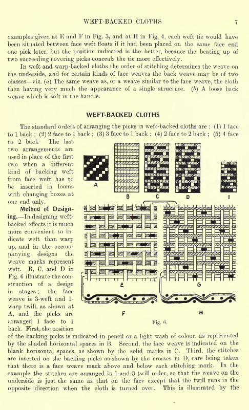
WEFT-BACKED CLOTHS
The standard orders of arranging the picks in weft-backed cloths are : (1) 1 face
to 1 back; (2) 2 face to 1 back ; (3) 3 face to 1 back ; (4) 2 face to 2 back
; (5) 4 face
to 2 back The last
two arrangements are
used in place of the first
two when a different
kind of backing weft
from face weft has to
be inserted in looms
with changing boxes at
one end only.
Method of Design-
ing. In designing weft-
backed effects it is muchmore convenient to in-
dicate weft than warp
up, and in the accom-
panying designs the
weave marks representweft. B, C, and D in
Fig. 6 illustrate the con-
struction of a designin stages ; the face
weave is 3-weft and 1-
warp twill, as shown at
A, and the picks are F H
arranged 1 face to 1 Fig. 0.
back. First, the positionof the backing picks is indicated in pencil or a light wash of colour, as represented
by the shaded horizontal spaces in B. Second, the face weave is indicated on the
blank horizontal spaces, as shown by the solid marks in C. Third, the stitches
are inserted on the backing picks as shown by the crosses in D, care being taken
that there is a face weave mark above and below each stitching mark. In the
example the stitches are arranged in l-and-3 twill order, so that the weave on the
underside is just the same as that on the face except that the twill runs in the
opposite direction when the cloth is turned over. This is illustrated by the
ADVANCED TEXTILE DESIGN
diagrams E, F, G, and H in Fig. 6;E shows the face side, and G the underside,
assuming that the cloth is turned over from left to right, while F and H represent
the interlacing of the first two picks of the respective flat views.
The design I in Fig. 6 will produce a 4-weft and 1-warp twill weave-runningto the left on the face side, and to the right on the reverse side when the cloth
is turned over. This example corresponds as regards the face weave and the order
of stitching with the example given at C in Fig. 2 (p. 3).
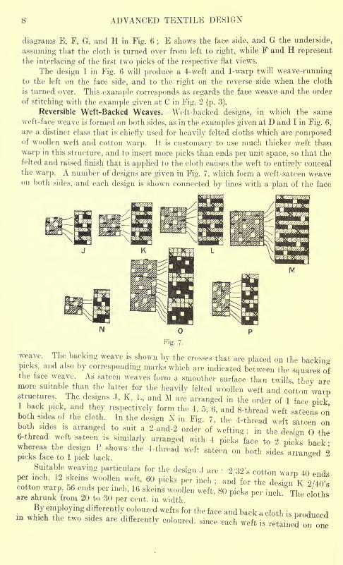
Reversible Weft-Backed Weaves. AVeft-backed designs, in which the sameweft-face weave is formed on both sides, as in the examples given at D and I in Fig. 6,
are a distinct class that is chiefly used for heavily felted cloths which are .composedof woollen weft and cotton warp. It is customary to use much thicker weft than
warp in this structure, and to insert more picks than ends per unit space, so that the
felted and raised finish that is applied to the cloth causes the weft to entirely conceal
the warp. A number of designs are given in Fig. 7, which form a weft-sateen weaveon both sides, and each design is shown connected by lines with a plan of the face
N
weave. The backing weave is shown by the crosses that are placed on the backino-picks, and also by corresponding marks which are indicated between the squares ofthe face weave. As sateen weaves form a smoother surface than twills thev aremore suitable than the latter for the heavily felted woollen weft and cotton "warpThe designs J, K, L, and M are arranged in the order of 1 face pickback pick and they respectively form the 4, 5, 6, and 8-thread weft sateens onboth rides of the cloth In the design N in Fig. 7, the 4-thread weft sateen onboth sides is arranged to suit a 2-and-2 order of wetting; in the design the6-thread weft sateen is similarly arranged with 4 picks face to 2 picks back
2
Suitable weaving particulars for the design J are : 2/32's cotton warp 40 endsper inch, 12 skeins woollen weft, 60 picks per inch
; and for the design K 2/40'scotton warp 06 ends per inch, 16 skeins woollen weft, 80 picks per inch. The clothare shrunk from 20 to 30 per cent, in width.
By employing differently coloured wefts for the face and back a cloth is produceda winch the two sules are differently coloured, since each weft is retained on one
WEFT-BACKED CLOTHS 9
side, while by interchanging the wefts, elaborate designs for dressing gowns, motor-
coats; carriage rugs, etc., are woven. (See Figs. 141 to 144.)
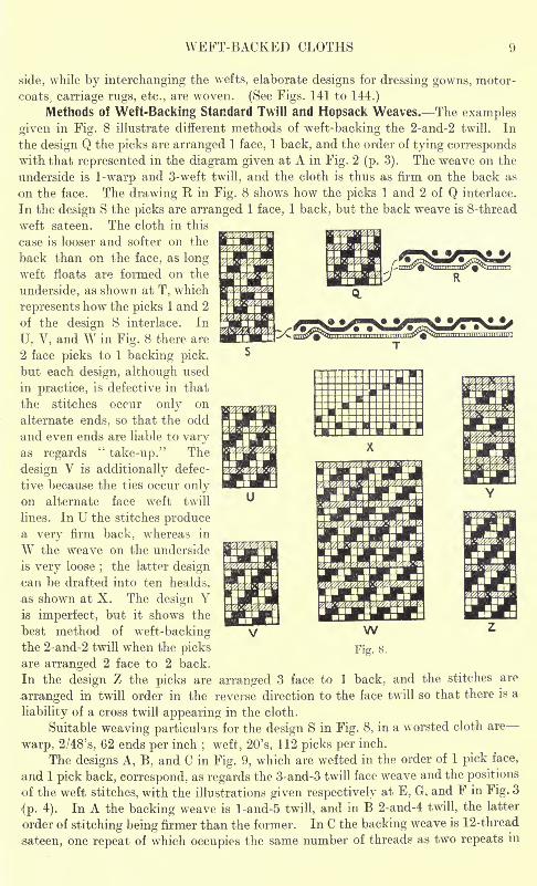
Methods of Weft-Backing Standard Twill and Hopsack Weaves. The examples
given in Fig. 8 illustrate different methods of weft-backing the 2-and-2 twill. In
the design Q the picks are arranged 1 face, 1 back, and the order of tying correspondswith that represented in the diagram given at A in Fig. 2 (p. 3). The weave on the
underside is 1-warp and 3-weft twill, and the clobh is thus as firm on the back as
on the face. The drawing H in Fig. 8 shows how the picks 1 and 2 of Q interlace.
In the design S the picks are arranged 1 face, 1 back, but the back weave is 8-thread
weft sateen. The cloth in this
case is looser and softer on the
back than on the face, as longweft floats are formed on the
underside, as shown at T, which
represents how the picks 1 and 2
of the design S interlace. In
U. V, and W in Fig. 8 there are
2 face picks to 1 backing pick,
but each design, although used
in practice, is defective in that
the stitches occur only on
alternate ends, so that the odd
and even ends are liable to varyas regards
"take-up." The
design V is additionally defec-
tive because the ties occur onlyon alternate face weft twill
lines. In U the stitches producea very firm back, whereas in
W the weave on the underside
is very loose;
the latter designcan be drafted into ten healds,
as shown at X. The design Yis imperfect, bub it shows the
best method of weft-backingthe 2-and-2 twill when the picksare arranged 2 face to 2 back.
In the design Z the picks are arranged 3 face to ] back, and the stitches are
arranged in twill order in the reverse direction to the face twill so that there is a
liability of a cross twill appearing in the cloth.
Suitable weaving particulars for the design S in Fig. 8, in a worsted cloth are-
warp, 2/48's, 62 ends per inch; weft, 20's, 112 picks per inch.
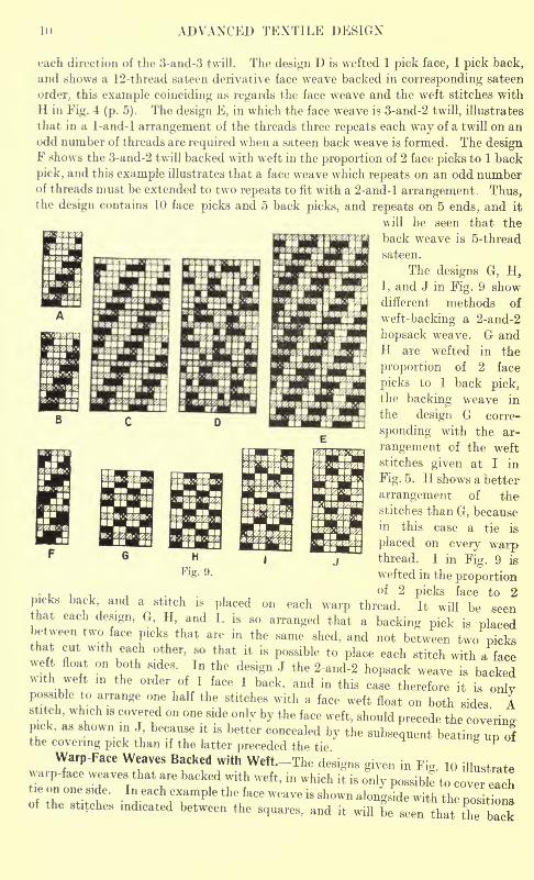
The designs A, B, and C in Fig. 9, which are wefted in the order of 1 pick face,
and 1 pick back, correspond, as regards the 3-and-3 twill face weave and the positions
of the weft stitches, with the illustrations given respectively at E, G, and F in Fig. 3
{p. 4). In A the backing weave is l-and-5 twill, and in B 2-and-4 twill, the latter
order of stitching being firmer than the former. In C the backing weave is 12-thread
sateen, one repeat of which occupies the same number of threads as two repeats in
ADVANCED TEXTILE DESIGN
each direction of the 3-and-3 twill. The design D is wefted 1 pick face, 1 pick back,
and shows a 12-thread sateen derivative face weave backed in corresponding sateen
order, this example coinciding as regards the face weave and the weft stitches with
H in Fig. 4 (p. 5). The design E, in which the face weave is 3-and-2 twill, illustrates
that in a 1-and-l arrangement of the threads three repeats each way of a twill on anodd number of threads are required when a sateen back weave is formed. The designF shows the 3-and-2 twill backed with weft in the proportion of 2 face picks to 1 back
pick, and this example illustrates that a face weave which repeats on an odd numberof threads must be extended to two repeats to fit with a 2-and-l arrangement Thus,the design contains 10 face picks and 5 back picks, and repeats on 5 ends, and it
will be seen that the
back weave is 5-thread
sateen.
The designs G, H,I, and J in Fig. 9 showdifferent methods of
weft-backing a 2-and-2
hopsack weave. G andH are wefted in the
proportion of 2 face
picks to 1 back pick,the backing weave in
the design G corre-
sponding with the ar-
rangement of the weft
stitches given at I in
Fig. 5. H shows a better
arrangement of the
stitches than G, becausein this case a tie is
placed on every warpthread. I in Fig. 9 is
wefted in the proportionof 2 picks face to 2
back, and a stitch is placed on each warp thread. It will be *eenthat each design, G H, and I, is so arranged that a backing pick is placed'tween two face picks that are in the same shed, and not between two pickshat cut with each other, so that it is possible to place each stitch with a face
float on both sides. In the design J the 2-and-2 hopsack weave is backedwith weft in the order o 1 face 1 back, and in this case therefore it is onlyBible to arrange one half the stitches with a face weft float on both sides A,ch, which is covered on one side only by the face weft, should precede the covering
pick, as shown in J because it is better concealed by the subsequent beating up ofthe covering pick than if the latter preceded the tie
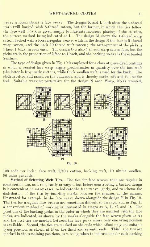
Warp-Face Weaves Backed with Weft-The designs given in Fig. 10 illustratewarp-face weaves that are backed with weft, in which it is only possibl! to cover eachtie on one side. In each example the face weave is shown alongside with th positionsof the stitches indicated between the squares, and it will be seen that the back
WEFT-BACKED CLOTHS II
weave is looser than the face weave. The designs K and L both show the 4-thread
warp twill backed with 8-thread sateen, but the former, in which the ties follow
the face weft floats, is given simply to illustrate incorrect placing of the stitches,
the correct method being indicated at L. The design M shows the 4-thread warpsateen backed with a loose irregular weave, while in the design N the face is 5-thread
warp sateen, and the back 10-thread weft sateen; the arrangement of the picks is
1 face, 1 back, in each case. The design is also 5-thread warp sateen face, but the
picks are in the proportion of 2 face to 1 back, and the backing weave is the extended
5-sateen.
The type of design given in Fig. 10 is employed for a class of piece-dyed coatingsin which a worsted face warp largely predominates in quantity over the face weft
(the latter is frequently cotton), while thick woollen weft is used for the back. Thecloth is felted and raised on the underside, and is thereby made soft and full to the
feel. Suitable weaving particulars for the design N are : Warp, 2/50's worsted,
Fig. 10.
102 ends per inch;
face weft, 2/40's cotton, backing weft, 10 skeins woollen,
96 picks per inch.
Method of Selecting Weft Ties. The ties for face weaves that are regular in
construction are, as a rule, easily arranged, but before constructing a backed designit is convenient, in many cases, to indicate the face weave lightly, and to scheme the
distribution of the ties by inserting marks between the squares, in the manner
illustrated for example, in the face weave shown alongside the design M in Fig. 10.
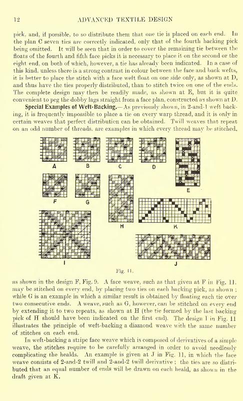
The ties for irregular face weaves are sometimes difficult to arrange, and in Fig. 11
a convenient method of working is illustrated in stages at A, B, C, and D. The
positions of the backing picks, in the order in which they are inserted with the lace
picks, are indicated, as shown by the marks alongside the face weave given at A ;
and the first ties are marked between the face picks where only one tying position
is available. Second, the ties are marked on the ends which afford only one suitable
tying position, as shown at B on the third and seventh ends. Third, the ties are
marked in the remaining positions, care being taken to indicate one for each backing
12 ADVANCED TEXTILE DESIGN
pick, and, if possible, to so distribute them that one tie is placed on each end. In
the plan C seven ties are correctly indicated, only that of the fourth backing pick
being omitted. It will be seen that in order to cover the remaining tie between the
floats of the fourth and fifth face picks it is necessary to place it on the second or the
eight end, on both of which, however, a tie has already been indicated. In a case of
this kind, unless there is a strong contrast in colour between the face and back wefts,
it is better to place the stitch with a face weft float on one side only, as shown at D,and thus have the ties properly distributed, than to stitch twice on one of the ends.
The complete design may then be readily made, as shown at E, but it is quite
convenient to peg the dobby lags straight from a face plan, constructed as shown at D.
Special Examples of Weft-Backing. As previously shown, in 2-and-l weft back-
ing, it is frequently impossible to place a tie on every warp thread, and it is only in
certain weaves that perfect distribution can be obtained. Twill weaves that repeaton an odd number of threads, are examples in which every thread may be stitched,
2
WARP-BACKED CLOTHS 13
WARP-BACKED CLOTHS
The arrangement of two series of warp threads to one series of weft threads
enables a considerable saving in the cost of production to be effected, as comparedwith the weft-backed principle, and also permits of the formation of stripe patternson the underside of the cloth which is impossible in weft-backed textures. Because
of the greater strain in weaving, however, such a low quality of backing yarn cannot
be used as in weft backing ;the drafts are usually more complicated, and a greater
number of healds are
required in producingsimilar effects.
The standardorders of arranging the
ends in warp - backed
cloths are : 1 face to
1 back. 2 face to 1 back,
and 3 face to 1 back
(there is no necessity to
arrange the ends in
2 -and -2, or 4 -and -2
order) ;while in some
cases a backed weave is
combined in stripe or
check form with a single
weave.
Method of Design-
ing. In constructing
warp-backed designs it
is convenient to indicate
warp up, and in the
accompanying plans the
weave marks indicate
warp. If the foregoingillustrations of weft-
backed designs are
turned one -quarterround, and the marks
are taken to indicate
warp, they will repre-
sent warp - backed
effects; the following examples are given chiefly in order to enable the two
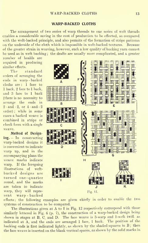
systems of construction to be compared.The illustrations given at A to I in Fig. 12 respectively correspond with those
similarly lettered in Fig. 6 (p. 7), the construction of a warp-backed design being
shown in stages at B, C, and D. The face weave is 3-warp and 1-weft twill as
indicated at A, and the ends are arranged 1 face, 1 back. The position of the
backing ends is first indicated lightly, as shown by the shaded squares in B;then
the face weave is inserted on the blank vertical spaces, as shown by the solid marks in
14 ADVANCED TEXTILE DESIGN
C. Afterwards the stitches are marked in, as shown by the crosses in D; and, in
this case, there should be a face weave mark at both sides of each stitching mark.The order of tying in bhe example produces a 3-warp and 1-weft twill on the underside
so that the cloth is perfectly reversible except for the difference in the direction of
the twill lines, as is illustrated by the corresponding diagrams. The flat view, givenat E, represents the structuie as viewed from the tace side, and that shown at G, as
viewed from the back, assuming that the cloth has been turned over vertically,while F and H show how the first two ends of the respective flat views interlace.
Reversible Warp-Backed Weaves. The design given at I in Fig. 12, in whichthe face weave and the order of stitching correspond with the diagram D in Fio-. 2
(p. 3), will produce a reversible 4-warp and 1-weft twill weave. Warp sateen weaveson both sides of the cloth are constructed in a similar manner, and J and K in Fig. 12
respectively represent the 4 and 5-thread sateen weaves made reversible. (These
WAEP-BACKED CLOTHS 15
designs correspond with J and K in Fig. 7.) The cloths may also be made reversible
as regards the colouring, or different colour patterns may be formed on the two sides
by employing different schemes of colouring for the two series of warp threads.
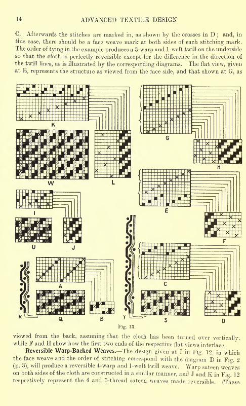
Beaming and Drafting Warp-Backed Designs. Fig. 13 shows various methods
of warp-backing a 2-and-2 twill face weave, and also illustrates different systems of
drafting warp-backed designs. (Q, R, S, T, U, and W in Fig. 13 correspond with
the examples that are similarly lettered in Fig. 8.) The designs Q and S are arranged1 face end, 1 backing end. The order of stitching in Q corresponds with that shown
at B in Fig. 2 (p. 3), while R represents the interlacing of the first and second ends
of the design. A 3-warp and 1-weft twill is formed on the underside, and the cloth
is therefore as firm on the back as on the face. In the design S a loose sateen weave
is formed on the underside, as shown at T, which indicates how the first and second
ends of S interlace.
In the designs U and W in Fig. 13 there are two face ends to each backing end,
but a commencement is made with one face end in order that the backing ends maybe readily dented in the reed with a face end on each side. In the design U a plain
or alternate order of stitching on the odd face picks is employed, and in W a sateen
order is similarly arranged, the ties thus occurring on only half the face picks.
For the design S the following are suitable weaving particulars in a worsted
cloth : Face and back warp, 2/40's, 19 splits per inch with 6 ends per split ; weft,
20's, 60 picks per inch. The design U might be woven in a woollen cloth with 30
skeins face warp, 20 skeins backing warp, 10 splits per inch with 6 ends per split :
weft 30 skeins, 40 picks per inch.
In beaming the warp tor a warp-backed cloth all the threads may be placed on
one warp beam, so long as the face and back yarns are similar, and the face and back
weaves are equal in firmness, as in the design given at Q in Fig. 13. As a general rule,
however, the two series of threads are placed on separate beams, in order that they
may be independently tensioned, and there is then no restriction as to the com-
parative firmness of the weaves or thickness of the threads.
In drafting warp-backed designs simple patterns may be drawn straight over,
as shown at A in Fig. 13, which is the draft for the design given at Q. The corres-
ponding pegging plan, given at B. is exactly the same as the design Q. In the draft
A the healds which carry the backing ends are intermingled with those upon which
the face ends are drawn, and a similar order of drafting upon 16 healds can be em-
ployed for the design S, the latter then forming the pegging plan. In cases, however,
where there is difference in thickness or material between the face and backing ends,
or if different warp patterns for the two sides of the cloth are employed, or if the
face weave requires a special draft, it is better to draw each series through a separate
set of healds. The healds through which the weaker yarn is passed should be placedat the front, and under ordinary circumstances these are the backing healds, as the
backing yarn is usually inferior to the face yarn. If, however, the face and backing
yarns are similar the more crowded set of healds may be placed at the front. The
two positions of the face and backing healds are illustrated at C and E in Fig. 13, which
show two methods of drafting the design S upon the smallest number of healds.
while the respective pegging plans are given at D and F. In the draft C the backinghealds are shown in front of the face healds, and in E behind them.
The use of only four healds for the face weave, as shown at C and E in Fig. 13,
gives very little scope for producing different weaves in the same draft, whereas if
16 ADVANCED TEXTILE DESIGN
eight face healds are employed, as shown in the draft given at G, any face weave
that repeats on four or eight threads may be woven. H shows the corresponding
pegging plan for the design S.
The draft and pegging plan for the design U in Fig. 13 are given respectively
at I and J, and for the design W at K and L;the backing healds in each case being
placed in front ol the face healds. Fewer healds are required in forming a firm back
than a loose back, as will be seen from a comparison of the drafts I and K.
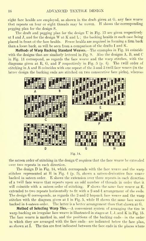
Methods of Warp Backing Standard Weaves. The examples in Fig. 14 coincide
with the designs that are similarly lettered in Fig. 9. Also the designs A, B, and C
in Fig. 14 correspond, as regards the face weave and the warp stitches, with the
diagrams given at E, G, and F respectively in Fig. 3 (p. 4). The twill order of
stitching in A and B coincides with one repeat of the 3-and-3 twill face weave (in the
latter design the backing ends are stitched on two consecutive face picks), whereas
Fig. 14.
the sateen order of stitching in the design C requires that the face weave be extended
over two repeats in each direction.
The design D in Fig. 14, which corresponds with the face weave and the warpstitches represented at H in Fig. 4 (p. 5), shows a sateen-derivative face weavebacked in sateen order. E shows the extension over three repeats in each direction
of a twill face weave that repeats upon an odd number of threads in order that it
will coincide with a sateen order of stitching. F shows the same face weave as E,extended to two repeats horizontally to fit with a 2-and-l arrangement of the ends.
The design G corresponds, as regards the 2-and-2 hopsack face weave and the warpstitches with the diagram given at I in Fig. 5, while H shows the same face weavebacked in 4-sateen order. The latter is a better arrangement than that shown at G.
Method of Selecting Warp Ties. A convenient system of arranging the ties in
warp-backing an irregular face weave is illustrated in stages at I, J, and K in Fig. 15.
The face weave is marked in, and the positions of the backing ends in the order
in which they are arranged with the face ends are indicated below the face plan,as shown at I. The ties are first indicated between the face ends in the places where
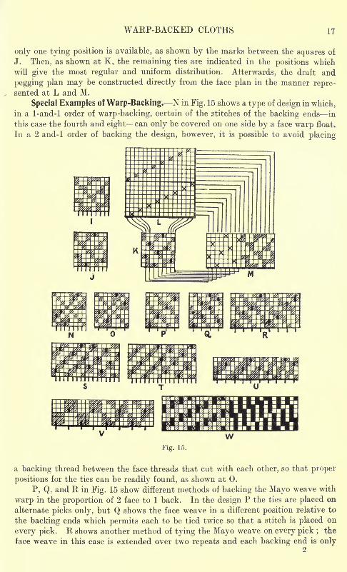
WARP-BACKED CLOTHS 17
only one tying position is available, as shown by the marks between the squares of
J. Then, as shown at K, the remaining ties are indicated in the positions which
will give the most regular and uniform distribution. Aiterwards, the draft and
pegging plan may be constructed directly from the face plan in the manner repre-sented at L and M.
Special Examples of Warp-Backing. N in Fig. 15 shows a type of design in which,in a 1-and-l order of warp-backing, certain of the stitches of the backing ends in
this case the fourth and eight can only be covered on one side by a face warp float.
In a 2 and-1 order of backing the design, however, it is possible to avoid placing
Fig. 15.
a backing thread between the face threads that cut with each other, so that proper
positions for the ties can be readily found, as shown at 0.
P, Q, and R in Fig. 15 show different methods of backing the Mayo weave with
warp in the proportion of 2 face to 1 back. In the design P the ties are placed on
alternate picks only, but Q shows the face weave in a different position relative to
the backing ends which permits each to be tied twice so that a stitch is placed on
every pick. R shows another method of tying the Mayo weave on every pick ; the
face weave in this case is extended over two repeats and each backing end is only
18 ADVANCED TEXTILE DESIGN
stitched once, hence the backing weave is as loose as in the design P. An examina-
tion will show, however, that the design R requires twice as many backing healds as
either P or Q.
The designs S and T in Fig. 15 show two arrangements of the stitches in a 1-and-l
warp-backed weave, which is composed of 2-and-2 twill and twilled hopsack. In
both designs the stitches are correctly placed as regards being covered on both sides
by face warp floats, but in S the distribution is not so good as in T. Further, a com-
plicated draft of the backing ends is required in the former, whereas in the latter the
draft of these ends is quite regular.
The design U in Fig. 15 shows a stripe face weave, composed of 3-and-2 twill
and Venetian, which is backed in 2-and-l order. In the twill section of the face
weave the ties are arranged in sateen order with the picks, and in the Venetian
section in twill order, so that in this case both the face and the backing threads
require to be specially drafted.
The design V in Fig. 15 shows a stripe weave composed of 3-and-3 hopsack and
3-and-3 twill derivative that is backedwith warp in the proportion of 3 face to 1 back.
The 3-and-l arrangement of the threads is particularly suited to the face weave, and
the ties are so distributed that only two backing healds are required.
W in Fig. 15 illustrates the combination of a warp-backed 2-and-2 twill with
a single weave consisting of an 8-shaft warp corkscrew. The proper ratio of setting
the two sections is four ends per split in the backed 2-and-2 twill to three ends per
split in the corkscrew.
Comparative Setting of Backed Cloths. - In both warp and weft-backed cloths
in which there are two or three face threads to each backing thread, it is customaryto use a thicker and poorer quality of backing yarn than face yarn ;
and the count
number of the backing yarn may be from one-half to two-thirds that of the corres-
ponding face series of threads. The face texture of a backed cloth should generallyhave rather fewer picks or ends per unit space (according to whether it is weft or
warp-backed) than a well-built similar single cloth, this being particularly the case
in the 1-and-l order of backing. For instance, a 2-and-2 twill single worsted cloth
made in 2/40's warp and 20's weft, with 60 ends and 60 picks per inch, if backed
in 1-and-l order with weft should have about 60 ends and 112 picks per inch;and
if with warp, about 112 ends and 60 picks per inch.
IMITATION OR PSEUDO-BACKED CLOTHS
Nearly any ordinary weave can be so modified as to produce a structure which
very closely resembles a weft or a warp-backed texture, but in which each thread
interweaves regularly on both sides of the cloth. The system has the advantagesthat a heavy single cloth is produced which has a fine surface appearance, and is
elastic and soft in the handle, while the threads sustain an equal amount of friction
in the manufacture and wear of the cloth. An interior quality of yarn cannot,
however, be introduced on the back, since each end and pick is interwoven on
both sides, while colours cannot be so effectively applied to the surface as in properbacked cloths. For piece-dyed fabrics, however, the principle of construction is
very useful. The designs may be made in imitation of either the 1-and-l, or the
2-and-l order of backing.Imitation Weft Backing. The method of constructing imitation weft-backed
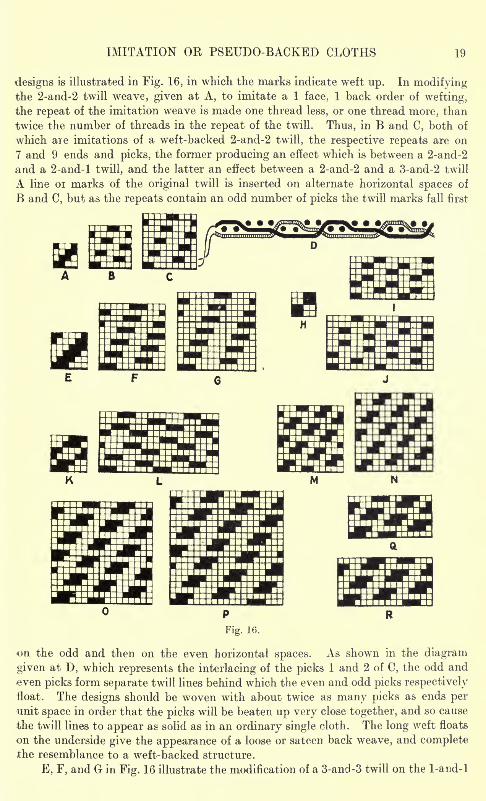
IMITATION OR PSEUDO-BACKED CLOTHS 19
designs is illustrated in Fig. 16, in which the marks indicate weft up. In modifyingthe 2-and-2 twill weave, given at A, to imitate a 1 face, 1 back order of wefting,the repeat of the imitation weave is made one thread less, or one thread more, than
twice the number of threads in the repeat of the twill. Thus, in B and C, both of
which aie imitations of a weft-backed 2-and-2 twill, the respective repeats are on
7 and 9 ends and picks, the former producing an effect which is between a 2-and-2
and a 2-and-l twill, and the latter an effect between a 2-and-2 and a 3-and-2 twill
A line 01 marks of the original twill is inserted on alternate horizontal spaces of
B and C, but as the repeats contain an odd number of picks the twill marks fall first
on the odd and then on the even horizontal spaces. As shown in the diagram
given at D, which represents the interlacing of the picks 1 and 2 of C, the odd and
even picks form separate twill lines behind which the even and odd picks respectively
"float. The designs should be woven with about twice as many picks as ends perunit space in order that the picks will be beaten up very close together, and so cause
the twill lines to appear as solid as in an ordinary single cloth. The long weft floats
on the underside give the appearance of a loose or sateen back weave, and completethe resemblance to a weft-backed structure.
E, F, and G in Fig. 16 illustrate the modification of a 3-and-3 twill on the 1-and-l
20 ADVANCED TEXTILE DESIGN
principle ; the design F being between a 3-and-3, and a 3-and-2 twill, and the designG between a 3-and-3, and a 3-and-4 twill
;the larger weave, of course, allowing of
finer setting than the smaller. In the same manner, H, I, and J in Fig. 16 illustrate
the modification of 2-and-2 hopsack weave, and K and L of a 3-and-3 twill derivative.
In constructing imitation designs that are not twill weaves, a series of floats of the
original weave is inserted on the odd horizontal spaces, then a second series is runin on the even spaces, at such a distance from the first series as will give the nearest
resemblance to the weave when the picks are beaten close together. In some cases,as shown at J and L. it is necessarv to insert several lines of the floats in order to
Fig. 17.
complete the design, each line being placed in the same relative position to its
neighbours as the first two lines are to each other.
In re-arranging twill weaves in imitation of the 2-and-l order of weft backing,the repeat is made one thread less or one more than three times the number of threadsin the repeat of the twill. For instance
;a 2-and-2 twill imitation weave may be
made on 11 or 13 threads as shown at M and N respectively in Fig. 16; and a 3-and-3
twill imitation weave on 17 or 19 threads, as represented at and P respectively.A design in imitation of a twill that repeats on an odd number of threads is completeon twice as many threads in one direction as the other, as shown at Q and R in Fig. 16.
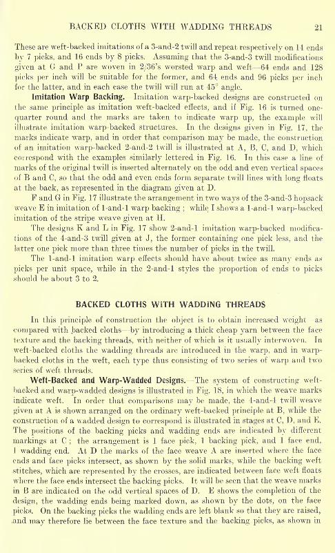
BACKED CLOTHS WITH WADDING THREADS 21
These are weft-backed imitations of a 3-and-2 twill and repeat respectively on 14 ends
by 7 picks, and 16 ends by 8 picks. Assuming that the 3-and-3 twill modifications
given at G and P are woven in 2/36's worsted warp and weft 64 ends and 128
picks per inch will be suitable for the former, and 64; ends and 96 picks per inch
for the latter, and in each case the twill will run at 45 angle.
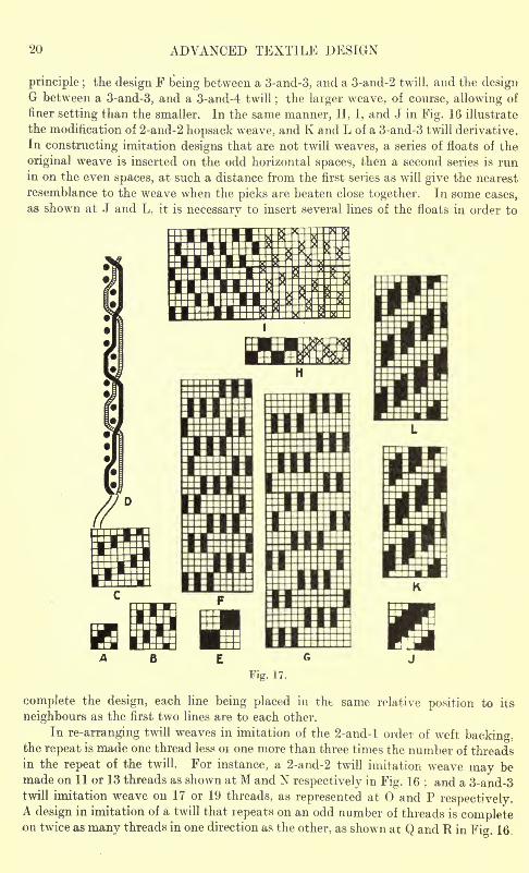
Imitation Warp Backing. Imitation warp-backed designs are constructed on
the same principle as imitation weft-backed effects, and if Fig. 16 is turned one-
quarter round and the marks are taken to indicate warp up, the example will
illustrate imitation warp-backed structures. In the designs given in Fig. 17, the
marks indicate warp, and in order that comparison may be made, the construction
of an imitation warp-backed 2-and-2 twill is illustrated at A, B, C, and D, which
correspond with the examples similarly lettered in Fig. 16. In this case a line of
marks of the original twill is inserted alternately on the odd and even vertical spacesof B and C, so that the odd and even ends form separate twill lines with long floats
at the back, as represented in the diagram given at D.
F and G in Fig. 17 illustrate the arrangement in two ways of the 3-and-3 hopsackweave E in imitation of 1-and-l warp backing ;
while I shows a 1-and-l wr
arp-backedimitation of the stripe weave given at H.
The designs K and L in Fig. 17 show 2-and-l imitation warp-backed modifica-
tions of the 4-and-3 twill given at J, the former containing one pick less, and the
latter one pick more than three times the number of picks in the twill.
The 1-and-l imitation warp effects should have about twice as many ends as
picks per unit space, while in the 2-and-l styles the proportion of ends to picksshould be about 3 to 2.
BACKED CLOTHS WITH WADDING THREADS
In this principle of construction the object is to obtain increased weight as
compared with backed cloths by introducing a thick cheap yarn between the face
texture and the backing threads, with neither of which is it usually interwoven. In
weft-backed cloths the wadding threads are introduced in the warp, and in warp-backed cloths in the weft, each type thus consisting of two series of warp and two
series of weft threads.
Weft-Backed and Warp-Wadded Designs. The system of constructing weft-
backed and warp-wadded designs is illustrated in Fig. 18, in which the weave marks
indicate weft. In order that comparisons may be made, the 4-and-4 twill weave
given at A is shown arranged on the ordinary weft-backed principle at B, while the
construction of a wadded design to correspond is illustrated in stages at C, D, and E.
The positions of the backing picks and wadding ends are indicated by different
markings at C;
the arrangement is 1 face pick, 1 backing pick, and 1 face end,
1 wadding end. At D the marks of the face weave A are inserted where the face
ends and face picks intersect, as shown by the solid marks, while the backing weft
stitches, which are represented by the crosses, are indicated between face weft floats
where the face ends intersect the backing picks. It will be seen that the weave marks
in B are indicated on the odd vertical spaces of D. E shows the completion of the
design, the wadding ends being marked down, as shown by the dots, on the face
picks. On the backing picks the wadding ends are left blank so that they are raised,
.and may therefore lie between the face texture and the backing picks, as shown in
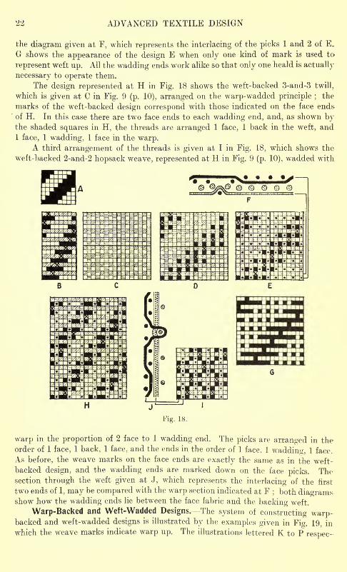
22 ADVANCED TEXTILE DESIGN
the diagram given at F, which represents the interlacing of the picks 1 and 2 of E,
G shows the appearance of the design E when only one kind of mark is used to-
represent weft up. All the wadding ends work alike so that only one heald is actually
necessary to operate them.
The design represented at H in Fig. 18 shows the weft-backed 3-and-3 twill,
which is given at C in Fig. 9 (p. 10), arranged on the warp-wadded principle ;the
marks of the weft-backed design correspond with those indicated on the face end&
of H. In this case there are two face ends to each wadding end, and, as shown bythe shaded squares in H, the threads are arranged 1 face, 1 back in the weft, and1 face, 1 wadding, 1 face in the warp.
A third arrangement of the threads is given at I in Fig. 18, which shows the
weft-backed 2-and-2 hopsack weave, represented at H in Fig. 9 (p. 10), wadded with
warp in the proportion of 2 face to 1 wadding end. The picks are arranged in theorder of 1 face, 1 back, 1 face, and the ends in the order of 1 face, 1 wadding, 1 face.
As before, the weave marks on the face ends are exactly the same as in the weft-
backed design, and the wadding ends are marked down on the face picks. Thesection through the weft given at J, which represents the interlacing of the first
two ends of I, may be compared with the warp section indicated at F; both diagrams
show how the wadding ends lie between the face fabric and the backing weft,
Warp-Backed and Weft-Wadded Designs. The system of constructing warp-backed and weft-wadded designs is illustrated by the examples given in Fig. 19, in
which the weave marks indicate warp up. The illustrations lettered K to P respec-
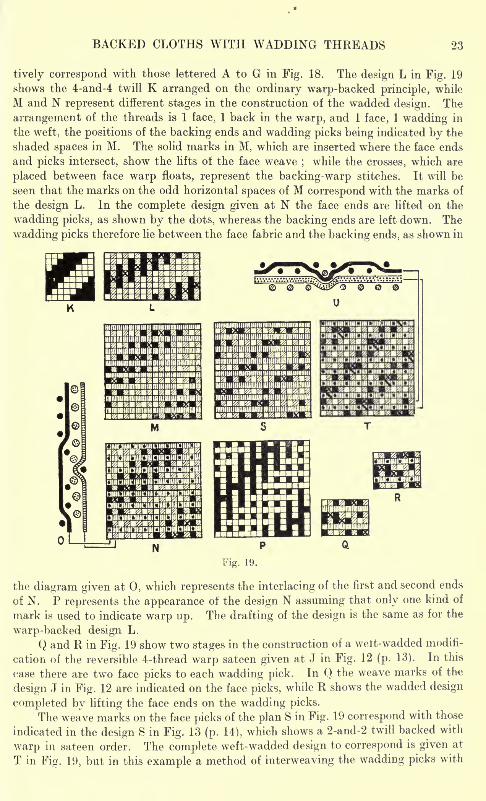
BACKED CLOTHS WITH WADDING THREADS 23
tively correspond with those lettered A to G in Fig. 18. The design L in Fig. 19
shows the 4-and-4 twill K arranged on the ordinary warp-backed principle, while
M and N represent different stages in the construction of the wadded design. The
arrangement of the threads is 1 face. 1 back in the warp, and 1 face, 1 wadding in
the weft, the positions of the backing ends and wadding picks being indicated by the
shaded spaces in M. The solid marks in M, which are inserted where the face ends
and picks intersect, show the lifts of the face weave;while the crosses, which are
placed between face warp floats, represent the backing-warp stitches. It will be
seen that the marks on the odd horizontal spaces of M correspond with the marks of
the design L. In the complete design given at N the face ends are lifted on the
wadding picks, as shown by the dots, whereas the backing ends are left down. The
wadding picks therefore lie between the face fabric and the backing ends, as shown in
Fig. 19.
the diagram given at 0, which represents the interlacing of the first and second ends
of N. P represents the appearance of the design N assuming that only one kind of
mark is used to indicate warp up. The drafting of the design is the same as for the
warp-backed design L.
Q and R in Fig. 19 show two stages in the construction of a welt-wadded modifi-
cation of the reversible 4-thread warp sateen given at J in Fig. 12 (p. 13). In this
case there are two face picks to each wadding pick. In Q the weave marks of the
design J in Fig. 12 are indicated on the face picks, while R shows the wadded design
completed by lifting the face ends on the wadding picks.
The weave marks on the face picks of the plan S in Fig. 19 correspond with those
indicated in the design S in Fig. 13 (p. 14), which shows a 2-and-2 twill backed with
warp in sateen order. The complete weft-wadded design to correspond is given at
T in Fig. 19, but in this example a method of interweaving the wadding picks with
24 ADVANCED TEXTILE DESIGN
the backing ends, which is sometimes practised, is illustrated. The diagonal strokes
which precede the crosses in T, Fig. 19, indicate the lifts of the backing ends over the
wadding picks ;it is necessary for these lifts to be made either immediately before
or immediately after the backing-warp stitches, in order to avoid breaking the
backing-warp floats on the underside of the cloth. The diagram given at U, which
represents the interlacing of the picks 2 and 3 of T. shows how the wadding picks lie
between the face fabric and the backing ends, except where they pass under the
latter at a stitching place. In the design T the wadding picks and backing ends
interweave in 8-sateen order with each other and really form a loosely-woven fabric
below the face fabric;the former being united to the latter where the backing ends
are raised over the face picks.
CHAPTER II
DOUBLE CLOTHSDouble-Cloth Structure Relative Proportions and Thicknesses of the Face and Backing Threads
Origination or Selection of the Face and Backing Weaver Tying or Stitching Con-
struction of the Point-Paper Design Construction of Double-Cloth Designs for Looms
with Changing Boxes at one End only Double-Cloth Beaming, Drafting, and PeggingEffect of the Sj'stem of Tying upon the Number of Healds Special Features in Double-
Cloth Designing Position of the Backing Weave Systematic Construction of Double-
Cloth Designs Reversible Double Weaves Double-Cloths with Compound Face Weaves.
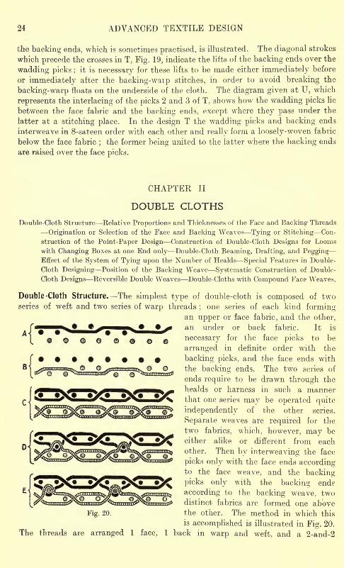
Double -Cloth Structure. The simplest type of double-cloth is composed of twoseries of weft and two series of warp threads
;one series of each kind forming
an upper or face fabric, and the other,
an under or back fabric. It is
necessary for the face picks to be
arranged in definite order with the
backing picks, and the face ends with
the backing ends. The two series of
ends require to be drawn through the
healds or harness in such a mannerthat one series may be operated quite
independently of the other series.
Separate weaves are required for the
two fabrics, which, however, may be
either alike or different from each
other. Then by interweaving the face
picks only with the face ends accordingto the face weave, and the backing
picks only with the backing end?
according to the backing weave, twodistinct fabrics are formed one above
Fig. 20. the other. The method in which this
is accomplished is illustrated in Fig. 20.
The threads are arranged 1 face, 1 back in warp and weft, and a 2-and-2
DOUBLE-CLOTHS 25
weft rib weave is employed for both the face and back textures. A representsthe position of the warp threads when the first face pick is inserted. All the
backing ends are left down in order that they will be out of the way of theface weft, and half the face ends are raised in forming the face weave. B showsthe position of the warp threads when the first backing pick is inserted. Inthis instance all the face ends are raised in order that they will be clear of
the backing weft;also half the backing ends are raised in forming the backing
weave. By allowing each series of weft picks to thus interweave only withits own series of warp threads, two fabrics are produced which are quite separateand detached from each other, as shown at C. If, however, a proportion of the
face warp threads be left down when a backing pick is inserted, as shown at D in
Fig. 20, or if a proportion of the backing warp threads be raised when a face pickis inserted, as indicated at E, the threads of one fabric interweave with the threads
of the other fabric;and although there are still two distinct fabrics formed one
above the other, they may be so closely united that only one cloth is produced which
is equal in thickness and weight to the two single fabrics. The tying or stitching
together of the two fabrics forms one of the principal features of ordinary double-
cloth designing. If a cloth is not soundly stitched, the two fabrics are liable to
become separated from each other during wear, particularly if the back fabric is
heavier than the face. Diversity of design and colouring can be applied to both
sides of a double-cloth, and at the same time a more perfect structure is obtained
than in the case of single fancy cloths or backed cloths.
The construction of double cloths may be considered under the following heads :
The relative proportions and thicknesses of the face and backing threads;the origina-
tion or the selection of the face and backing weaves;the tying or stitching together
of the two fabrics so as to form one cloth;the construction of the point-paper design ;
the beaming, the drafting, and the construction of the pegging plan.
Relative Proportions and Thicknesses of the Face and Backing Threads. These
are decided mainly by the weight to be added to the face texture, but the order of
arrangement of the threads is determined partly by the boxing capacity of the loom.
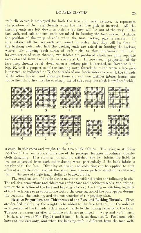
The most common varieties of double cloths are arranged in warp and weft 1 face,
1 back, as shown at F in Fig. 21, and 2 face. 1 back, as shown at G. For looms with
boxes at one end only, and when the backing weft is different from the face weft,
26 ADVANCED TEXTILE DESIGN
similar effects may be obtained in many weaves by changing the wefting to 2 face,
2 back and 4 face, 2 back, respectively, as shown at H and I. Cloths which require
a very fine face are sometimes arranged 3 face, 1 back in warp and weft, as shown
at J. The threads may also be arranged in a mixed order, as, for example, 1 face,
1 back in the warp, and 2 face, 1 back in the weft, and vice versa, as shown at Kand L respectively, or 2 face, 1 back in the warp, and 2 face, 2 back in the weft, as
shown at M. Irregular arrangements such as 5 face to 4 back (shown at N), and
7 face to 5 back (shown at 0), are also employed, and these are useful as theyadmit of relative proportions of face and backing threads being used which cannot
be obtained in any of the regular bases. In addition, special arrangements of
threads are employed in the construction of cut double cloths, double plain styles r
wadded double cloths, and centre stitched double cloths.
In deciding on the relative thicknesses of the face and backing yarns, a goodrule to follow is to have the relative counts about proportionate to the relative
numbers of the threads per unit space. Thus, in a 1-and-l double cloth the backing-
yarn should be similar to, or not much thicker than the face yarn ;the finest qualities
of the structures being usually made the same on both sides. If arranged 2 face to
1 back, the backing yarn may be proportionately thicker, or say, from two-thirds
to one-half the corresponding counts of the face yarn ;the back being made
coarser than the face, particularly when worsted yarns are used for the latter, and
woollen yarns for the former. The proportionate counts of the threads, however,
depend upon the relative firmness of the face and backing weaves, and the
preceding proportions apply to the 2-and-l arrangement when the backing weaveis firmer than the face weave, as described in the next paragraph. If the same
weave is used on both sides of the cloth the backing threads may be three or four
times as heavy as the face threads in the 2-and-l arrangement, especially whencentre threads are employed for stitching.
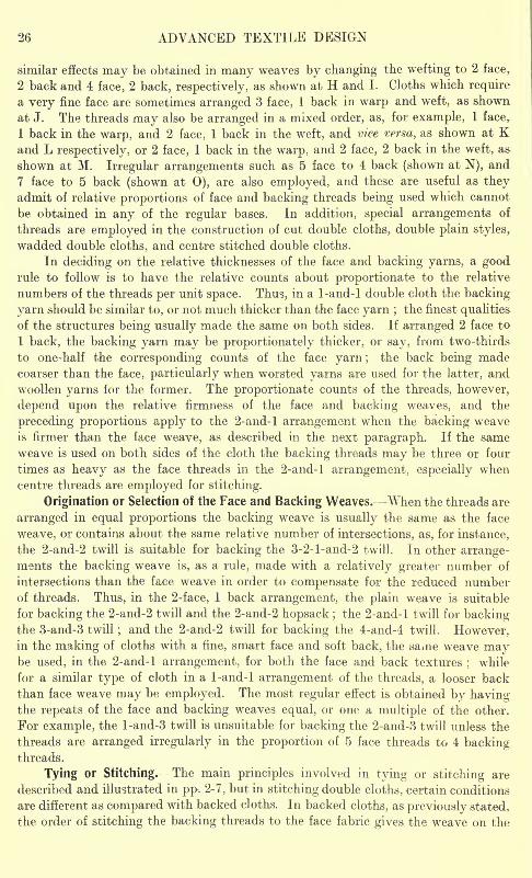
Origination or Selection of the Face and Backing Weaves. When the threads are
arranged in equal proportions the backing weave is usually the same as the face
weave, or contains about the same relative number of intersections, as, for instance,
the 2-and-2 twill is suitable for backing the 3-2-l-and-2 twill. In other arrange-ments the backing weave is, as a rule, made with a relatively greater number of
intersections than the face weave in order to compensate for the reduced numberof threads. Thus, in the 2-face, 1 back arrangement, the plain weave is suitable
for backing the 2-and-2 twill and the 2-and-2 hopsack ; the 2-and-l twill for backingthe 3-and-3 twill ; and the 2-and-2 twill for backing the 4-and-4 twill. However,in the making of cloths with a fine, smart face and soft back, the same weave maybe used, in the 2-and-l arrangement, for both the face and back textures
;while
for a similar type of cloth in a 1-and-l arrangement of the threads, a looser back
than face weave may be employed. The most regular effect is obtained by havingthe repeats of the face and backing weaves equal, or one a multiple of the other.
For example, the l-and-3 twill is unsuitable for backing the 2-and-3 twill unless the
threads are arranged irregularly in the proportion of 5 face threads to 4 backingthreads.
Tying or Stitching. The main principles involved in tying or stitching are
described and illustrated in pp. 2-7, but in stitching double cloths, certain conditions
are different as compared with backed cloths. In backed cloths, as previously stated,
the order of stitching the backing threads to the face fabric gives the weave on the
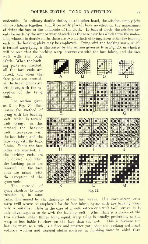
DOUBLE CLOTHSTYING OR STITCHING 27
underside. In ordinary double cloths, on the other hand, the stitches simply join
the two fabrics together, and, if correctly placed, have no effect on the appearanceof either the face or the underside of the cloth. In backed cloths the stitches can
only be made by the weft or warp threads (as the case may be) which form the under-
side, whereas in double cloths there are two methods of tying, since either the backingends or the backing picks may be employed. Tying with the backing warp, which
is termed warp tying, is illustrated by the section given at E in Fig. 20, in which it
will be seen that the backing warp interweaves with the face fabric, and the face
weft with the back
fabric. When the back-
ing picks are inserted,
all the face ends are
raised, and when the
face picks are inserted,
all the backing ends are
left down, with the ex-
ception of the tyingends.
The section givenat D in Fig. 20, illus-
trates the method of
tying with the backing
weft, which is termed
weft tying ;in thisin
method the backingweft interweaves with
the face fabric, and the
face warp with the back
fabric. When the face
picks are inserted; all
the backing ends are
left down;
and whenthe backing picks are
inserted, all the face
ends are raised, with
the exception of the
tying ends.
The method of
tying which is the moresuitable is, in some
cases, determined by the character of the face weave. If a warp sateen, or a
warp twill weave be employed for the face fabric, tying with the backing warp
only is suitable;while in the case of a weft sateen or a weft twill weave, it is
only advantageous to tie with the backing weft. When there is a choice of the
two methods, other things being equal, warp tying is usually preferable, as the
warp is less liable to show on the face than the weft. This is because the
backing warp, as a rule, is a finer and smarter yarn than the backing weft, and
ordinary woollen and worsted cloths contract in finishing more in width than
28 ADVANCED TEXTILE DESIGN
in length. In some cases both methods of tying are employed in combination,
as previously explained (p. 4), the cloth being then termed double-stitched.
Construction of the Point-Paper Design. In constructing backed designs it is
clearly advantageous to indicate weft in weft-backing and warp in warp-backing,but in double cloths either wett or warp may be marked with equal facility, and in
the following examples both methods are illustrated. Figs. 22 to 33 simply show the
construction of designs from given particulars ;various factors, which require to
be considered before a double weave is commenced, are fully dealt with in reference
to subsequent examples. It is sufficient at this stage to assume that in each examplethe face weave, the backing weave, and the ties, are placed in such positions relative
to one another as will ensure that the ties are covered on each side of the cloth as
effectively as possible by the adjacent floats.
In order to prevent confusion the different stages in working out a double-cloth
design should be represented by different kinds of marks, as shown in Fig. 22, which
illustrates, step by step, the construction of a double 4-and-4 twill structure in which
the ends and picks are arranged 1 face, 1 back. In this example marking for weft is
illustrated, and both the warp and the weft method of tying are shown. A is the
plan of the face weave, B of the backing weave, C of the warp ties (the circles indi-
cating the order in which the backing ends are raised over the face picks), and D of
the weft ties (the crosses indicating the order in which the backing picks are passedover the face ends). The ties are distributed in 8-thread twill order to correspondwith the face and backing weaves. The different stages in the construction of the
double-cloth plan are shown separately at E to K.
E shows the arrangement of the backing threads with the face threads, the
backing ends and picks being represented by the shaded lines. In practice, trans-
parent colour or pencil may be employed.F shows the face weave inserted. The weave marks are copied from A, and are
indicated in the prescribed order on the squares where the face ends intersect with
the face picks, as shown by the solid marks.
G shows the insertion of the ties, assuming that warp tying is employed. Eachmark (a circle) is placed where a backing end intersects a face pick, and between
two blanks alongside each other i.e., two face warp floats in the face weave.
H shows the insertion of the ties, assuming that weft tying is employed. In
this case each mark (a cross) is placed where a backing pick intersects a face end,
and between two marks, one above the other i.e., two face weft floats in the face
weave.
I shows the backing weave inserted (the warp method of tying being em-
ployed). The weave marks are copied from B, and are indicated on the squareswhere the backing ends intersect with the backing picks as shown by the
diagonal strokes.
J shows the completion of the point-paper plan for warp tying. Backing ends
.are marked down on face picks (except those which are raised for tying) in order that
they will be out of the way when face picks are inserted, as shown by the dots. All
the face ends are left blank on the backing picks in order that they will be raised
out of the way when the backing picks are inserted.
K shows the completion of the point-paper plan for weft tying. In this case
all the backing ends are marked down on the face picks, and all the face ends are
left blank on the backing picks, except where the ties occur.
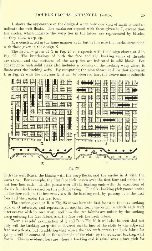
DOUBLE CLOTHS ARRANGED I-AND-! 29
L shows the appearance of the design J when only one kind of mark is used to
indicate the weft floats. The marks correspond with those given in J, except that
the circles, which indicate the warp ties in the latter, are represented by blanks,as they show warp up.
M is constructed in the same manner as L, but in this case the marks correspondwith those given in the design K.
The flat view given at Q in Fig. 23 corresponds with the design shown at J in
Fig. 22. The interlacings of both the face and the backing series of threads
are shown, and the positions of the warp ties are indicated in solid black. Forconvenience each solid mark also includes a portion of the backing warp where it
floats over the backing weft. By comparing the plan shown at J, or that shown at
L in Fig. 22 with the diagram Q, it will be observed that the weave marks coincide
Fig. 23.
with the weft floats, the blanks with the warp floats, and the circles in J with the
warp ties. For example, the first face pick passes over the first four and under the
last four face ends. It also passes over all the backing ends with the exception of
the sixth, which is raised on this pick for tying. The first backing pick passes under
all the face ends, but it interweaves with the backing ends by passing over the first
four and then under the last four.
The section given at R in Fig. 23 shows how the first face and the first backing-
pick of Q interlace, and represents in another form the order in which each weft
interweaves with its own warp, and how the two fabrics are united by the backing
warp entering the face fabric, and the face weft the back fabric.
From a careful examination of Q and R in Fig. 23 it will also be seen that not
only will the backing warp ties be covered on the face of the cloth by the adjacentface warp floats, but in addition that where the face weft enters the back fabric for
tying it will be concealed on the underside of the cloth by the adjacent backing weft
floats. This is evident, because where a backing end is raised over a face pick for
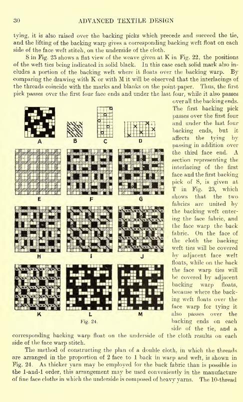
30 ADVANCED TEXTILE DESIGN
tying, it is also raised over the backing picks which precede and succeed the tie,
and the lifting of the backing warp gives a corresponding backing weft float on each
side of the face weft stitch, on the underside of the cloth.
S in Fig. 23 shows a flat view of the weave given at K in Fig. 22, the positionsof the weft ties being indicated in solid black. In this case each solid mark also in-
cludes a portion of the backing weft where it floats over the backing warp. Bycomparing the drawing with K or with M it will be observed that the interlacings of
the threads coincide with the marks and blanks on the point paper. Thus, the first
pick passes over the first four face ends and under the last four, while it also passes
over all the backing ends.
The first backing pick
passes over the first four
and under the last four
backing ends, but it
affects the tying by
passing in addition over
the third face end. Asection representing the
interlacing of the first
face and the first backing
pick of S, is given at
T in Fig. 23, which
shows that the two
fabrics are united bythe backing weft enter-
ing the face fabric, and
the face warp the back
fabric. On the face of
the cloth the backingweft ties will be covered
by adjacent face weft
floats, while on the back
the face warp ties will
be covered by adjacent
backing warp floats,
because where the back-
ing weft floats over the
face warp for tying it
also passes over the
backing ends on each
side of the tie, and a
corresponding backing warp float on the underside of the cloth results on each
side of the face warp stitch.
The method of constructing the plan of a double cloth, in which the threads
are arranged in the proportion of 2 face to 1 back in warp and weft, is shown in
Fig. 24. As thicker yarn may be employed for the back fabric than is possible in
the 1-and-l order, this arrangement may be used conveniently in the manufactureof fine face cloths in which the underside is composed of heavy yarns. The 10-thread
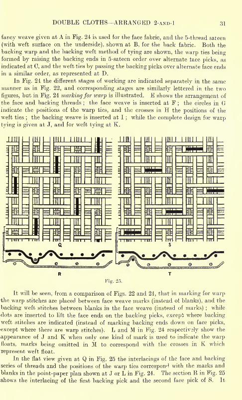
DOUBLE CLOTHS ARRANGED 2-AND-l 31
fancy weave given at A in Fig. 24 is used for the face fabric, and the 5-thread sateen
(with weft surface on the underside), shown at B, for the back fabric. Both the
backing warp and the backing weft method of tying are shown, the warp ties beingformed by raising the backing ends in 5-sateen order over alternate lace picks, as
indicated at C, and the weft ties by passing the backing picks over alternate face ends
in a similar order, as represented at D.
In Fig. 24 the different stages of working are indicated separately in the samemanner as in Fig. 22, and corresponding stages are similarly lettered in the two
figures, but in Fig. 24 marking for warp is illustrated. E shows the arrangement of
the face and backing threads;
the face weave is inserted at F;
the circles in Gindicate the positions of the warp ties, and the crosses in H the positions of the
weft ties;the backing weave is inserted at I
;while the complete design for warp
tying is given at J, and for weft tying at K.
HIM I
Fig. 25.
It will be seen, from a comparison of Figs. 22 and 24, that in marking for warpthe warp stitches are placed between face weave marks (instead of blanks), and the
backing weft stitches between blanks in the face weave (instead of marks) ;while
dots are inserted to lift the face ends on the backing picks, except where backingweft stitches are indicated (instead of marking backing ends down on face picks,
except where there are warp stitches). L and M in Fig. 24 respectively show the
appearance of J and K when only one kind of mark is used to indicate the warpfloats, marks being omitted in M to correspond with the crosses in K which
represent weft float.
In the flat view given at Q in Fig. 25 the interlacings of the face and backingseries of threads and the positions of the warp ties correspond with the marks and
blanks in the point-paper plan shown at J or L in Fig. 24. The section R in Fig. 25
shows the interlacing of the first backing pick and the second face pick of S. It
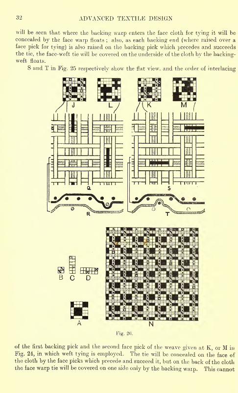
32 ADVANCED TEXTILE DESIGN
will be seen that where the backing warp enters the face cloth for tying it will be
concealed by the face warp floats; also, as each backing end (where raised over a
face pick for tying) is also raised on the backing pick which precedes and succeeds
the tie, the face-weft tie will be covered on the underside of the cloth by the backing-weft floats.
S and T in Fig. 25 respectively show the flat view, and the order of interlacing
i i I I I r~i I i i I nsn I I I i i ^ i i
iXmrnSmnBtfl
6 C
Fig. 2(5.
of the first backing pick and the second face pick of the weave given at K, or M in
Fig. 24, in which weft tying is employed. The tie will be concealed on the face ofthe cloth by the face picks which precede and succeed it, but on the back of the cloth
the face warp tie will be covered on one side only by the backing waip. This cannot
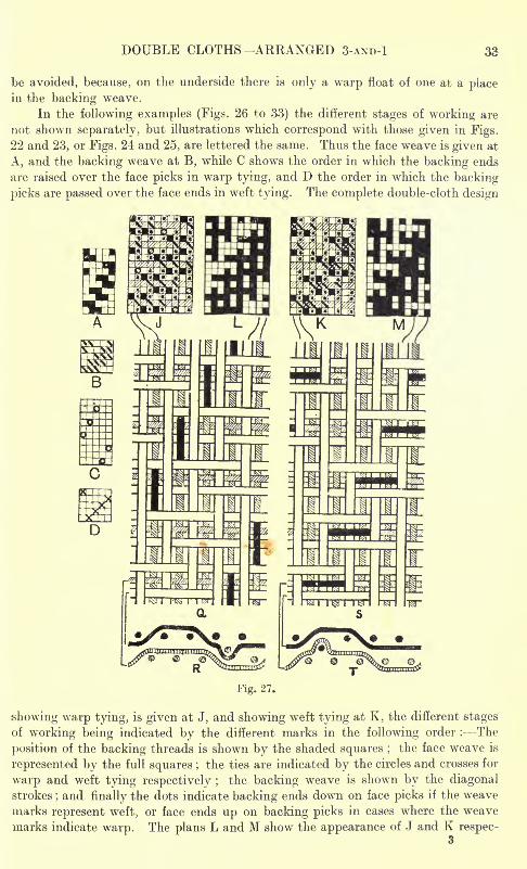
DOUBLE CLOTHS ARRANGED S-AND-! 33
be avoided, because, on the underside there is only a warp float of one at a placein the backing weave.
In the following examples (Figs. 26 to 33) the different stages of working are
not shown separately, but illustrations which correspond with those given in Figs.
22 and 23, or Figs. 24 and 25, are lettered the same. Thus the face weave is given at
A, and the backing weave at B, while C shows the order in which the backing ends
are raised over the face picks in warp tying, and D the order in which the backing
picks are passed over the face ends in weft tying. The complete double-cloth design
Fig. 27.
showing warp tying, is given at J, and showing weft tying at K, the different stages
of working being indicated by the different marks in the following order : The
position of the backing threads is shown by the shaded squares ;the face weave is
represented by the full squares ; the ties are indicated by the circles and crosses for
warp and weft tying respectively ;the backing weave is shown by the diagonal
strokes; and finally the dots indicate backing ends down on face picks if the weave
marks represent weft, or face ends up on backing picks in cases where the weave
marks indicate warp. The plans L and M show the appearance of J and K respec-3
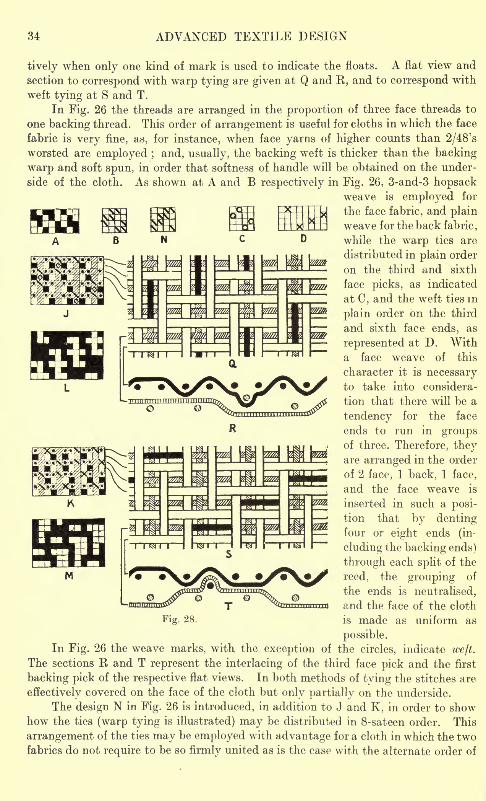
34 ADVANCED TEXTILE DESIGN
tively when only one kind of mark is used to indicate the floats. A flat view and
section to correspond with warp tying are given at Q and R, and to correspond with
weft tying at S and T.
In Fig. 26 the threads are arranged in the proportion of three face threads to
one backing thread. This order of arrangement is useful for cloths in which the face
fabric is very fine, as, for instance, when face yarns of higher counts than 2/48's
worsted are employed ; and, usually, the backing weft is thicker than the backing
warp and soft spun, in order that softness of handle will be obtained on the under-
side of the cloth. As shown at A and B respectively in Fig. 26, 3-and-3 hopsackweave is employed for
the face fabric, and plainweave for the back fabric
,
while the warp ties are
distributed in plain order
on the third and sixth
face picks, as indicated
at C, and the weft ties in
plain order on the third
and sixth face ends, as
represented at D. Witha face weave of this
character it is necessaryto take into considera-
tion that there will be a
tendency for the face
ends to run in groupsof three. Therefore, theyare arranged in the order
of 2 face, 1 back, 1 face,
and the face weave is
inserted in such a posi-
tion that by dentingfour or eight ends (in-
cluding the backing ends)
through each split of the
reed, the grouping of
the ends is neutralised,
and the face of the cloth
Fig. 28. is made as uniform as
possible.
In Fig. 26 the weave marks, with the exception of the circles, indicate welt.
The sections R and T represent the interlacing of the third face pick and the first
backing pick of the respective flat views. In both methods of tying the stitches are
effectively covered on the face of the cloth but only partially on the underside.
The design N in Fig. 26 is introduced, in addition to J and K, in order to showhow the ties (warp tying is illustrated) may be distributed in 8-sateen order. This
arrangement of the ties may be employed with advantage for a cloth in which the twofabrics do not require to be so firmly united as is the case with the alternate order of
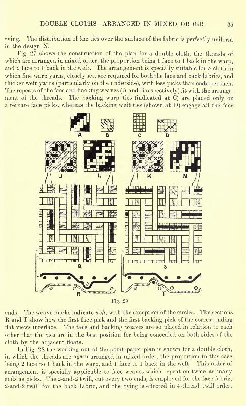
DOUBLE CLOTHS ARRANGED IN MIXED ORDER 35
tying. The distribution of the ties over the surface of the fabric is perfectly uniform
in the design N.
Fig. 27 shows the construction of the plan for a double cloth, the threads of
which are arranged in mixed order, the proportion being 1 face to 1 back in the warp,and 2 face to 1 back in the weft. The arrangement is specially suitable for a cloth in
which fine warp yarns, closely set, are required for both the face and back fabrics, andthicker weft yarns (particularly on the underside), with less picks than ends per inch.
The repeats of the face and backing weaves (A and B respectively) fit with the arrange-ment of the threads. The backing warp ties (indicated at C) are placed only on
alternate face picks, whereas the backing weft ties (shown at D) engage all the face
ends. The weave marks indicate weft, with the exception of the circles. The sections
R and T show how the first face pick and the first backing pick of the correspondingflat views interlace. The face and backing weaves are so placed in relation to each
other that the ties are in the best position for being concealed on both sides of the
cloth by the adjacent floats.
In Fig. 28 the working out of the point-paper plan is shown for a double cloth,
in which the threads are again arranged in mixed order, the proportion in this case
being 2 face to 1 back in the warp, and 1 face to 1 back in the weft. This order of
arrangement is specially applicable to face weaves which repeat on twice as manyends as picks. The 2-and-2 twill, cut every two ends, is employed for the face fabric,
2-and-2 twill for the back fabric, and the tying is effected in 4-thread twill order.
36 ADVANCED TEXTILE DESIGN
The weave marks indicate warp, with the exception of the crosses which represent
backing weft stitches. This is an example in which the back weave is looser than
the face weave, taking into account that there are fewer ends on the underside than
on the face. In order to enable suitable positions to be selected for warp tying, the
face weave is so placed that a backing end comes between the two ends which twill
with each other, and not between two which cut. In warp tying the ties are effec-
tively covered on both sides of the cloth by the adjacent floats, but in weft tying, in
order that the ties will be peifectly covered on the back of the cloth as well as on
the face, it has been necessary to change the position of the backing weave to that
shown at N in Fig. 28.
Fig. 29 shows the working out of the plan of a double cloth, in which the threads
are arranged irregularly in the proportion of 6 face ends and picks to 4 backing ends
and picks. In this principle the face fabric may be made finer than the back fabric
in almost any required proportion. The chiet point to note is that suitable weaves
are selected for the lace and back fabrics respectively. Thus, if the threads are
arranged 5 face to 4 back, a 5-shatt face weave should be combined with a 4-shaft
backing weave ;if 4-face to 3 back, a 4-shaft weave with a 3-shaft weave, or an 8 shaft
weave with a 6-shaft weave ;if 9 face to 7 back, a 9-shaft weave with a 7-shaft weave,
etc. In the example 3-and-3 twill is employed for the face fabric, and 2-and-2 twill
for the back fabric, and as the face fabric is finer than the back fabric in the propor-tion of 6 threads to 4, the 3-and-3 twill face will be similar in appearance to the
2-and-2 twill back. The cloth will therefore have the semblance of a double 2-and-2
twill, but its wearing property will be superior on account of the greater fineness of
the face fabric. In the warp method of tying, illustrated in Fig. 29, no tie is placed on
the second and fifth face pick, but in the weft method a slight deviation from the
ordinary system is illustrated. The even backing picks pass over two face ends,
while the odd backing picks only pass over one. They are arranged in this way in
order that all the face ends will be intersected by the backing picks, and to show one
method of obviating the difficulty which frequently arises in weaving when onlya portion of one series of ends is employed for tying. If, however, there is any
liability of the ties showing on the surface of the cloth, such a method should not be
employed.Construction of Double-Cloth Designs for Looms with Changing Boxes at One
End Only. If the same kind of weft yarn be used for both the face and back fabrics,
the method of constructing the point-paper plan is not affected by the limitation in
the boxing capacity of the loom, even though, as is sometimes the case, two or moreshuttles are employed for the purpose of obtaining a more regular cloth. If, however,the backing weft is different fiom the face weft, it is necessary for the face and
backing picks to be arranged on the point-paper to alternate with each other in even
numbers acording to the relative proportions required. The arrangement of the
face and backing ends may be the same as in ordinary double-cloths, and it is better
that it should be the same, for if the backing warp be employed for tying, the placingof the ties is then not influenced by the order in which the picks are inserted, so far
as the face of the cloth is concerned. The covering of the corresponding face weft
ties on the underside of the cloth is, however, not so easily effected when the picks-
are arranged in even numbers. The backing weft should only be employed for tyingwhen absolutely necessary, as the insertion of the picks in even numbers not onlyrenders it more difficult for suitable tying positions to be selected in the majority
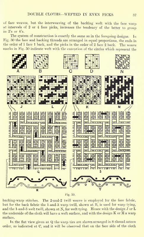
DOUBLE CLOTHS- WEFTED IN EVEN PICKS 37
of face weaves, but the interweaving of the backing weft with the face warpat intervals of 2 or 4 face picks, increases the tendency of the latter to groupin 2's or 4's.
The system of construction is exactly the same as in the foregoing designs. In
Fig. 30 the face and backing threads are arranged in equal proportions, the ends in
the order of 1 face 1 back, and the picks in the order of 2 face 2 back. The weavemarks in Fig. 30 indicate weft with the exception of the circles Which represent the
Fig. 30.
backing-warp stitches. The 2-and-2 twill weave is employed tor the face fabric,
but for the back fabric the l-and-3 warp twill, shown at B, is used for warp tying,
and the l-and-3 weft twill, shown at N, for weft tying. Hence with the design J or Lthe underside of the cloth will have a weft surface, and with the design K or M a warpsurface.
In the flat view given at Q the warp ties are shown arranged in 8-thread sateen
order, as indicated at C, and it will be observed that on the face side of the cloth
38 ADVANCED TEXTILE DESIGN
each tie is placed between two face warp floats. Also each backing end is raised
on the backing picks which precede and succeed a tie, hence on the underside of
the cloth each face weft tie occurs between two backing-weft floats. R in Fig. 30
represents the interlacing oi the second face pick and the first backing pick, from
which it will be seen that the face ends and the backing picks are quite separate and
distinct from each other, while the face picks interweave at intervals with the backingends (in this case the eighth backing end) for the purpose of uniting the two fabrics.
In the weft method of tying, illustrated in the flat view S in Fig. 30, on account
of the picks being inserted in pairs, there are no positions available for passing the
backing picks over the even face ends with a face weft float on both sides. The
ties can therefore only be placed on the odd face ends, and though they are equallyas well covered on both sides of the cloth a comparison with Q will show that the
distribution is less perfect in this system than when the backing warp is employedfor tying. Because of the difference in the arrangement of the ties the design J
repeats upon twice as many picks as the design K, of which two repeats are shown.
In the section given at T the face picks and the backing ends are shown quite separatefrom each other, the union of the two fabrics being effected by the backing weft
interweaving at intervals with the face ends.
The threads in Fig. 31 are arranged in the proportion of 2 face to 1 back in warpand weft, the ends in the order of 1 face, 1 back, 1 face, and the picks in the order of
4 face, 2 back. In this case also weft is indicated, and for the face fabric the
5-thread weft Venetian weave A is employed for both warp and weft tying. For
the back fabric the 5-thread twill given at B is employed for warp tying, and the
5-thread Venetian (with the warp on the underside) given at N for weft tying. Theformer backing weave is firmer than the latter, and also than the face weave, and
may therefore be used when the back tabric is composed ot fine yarns. On the other
hand, the fewer intersections of the backing weave shown at N render it suitable
for a cloth in which thicker backing than face yarns are employed. It should be
noted that on account oi the backing picks being inserted in pairs it is necessaryfor the 5-pick backing weave to extend over 10 backing picks, hence 20 face picksare required. The complete design therefore repeats on 30 picks. In both methodsof tying, the ties are placed between corresponding face floats, but on the underside
of the cloth some ot the ties have a corresponding float on one side only. Thus, from
an examination of the flat view S in Fig. 31, it will be seen that the face ends, which
are passed over by the even backing picks, have a backing warp float on one side,
and a backing weft float on the other side.
In Fig. 32 the threads are arranged in mixed order, the proportions being 2 face
to 1 back in the warp, and 2 face to 2 back in the weft. Warp is indicated in the
plans, and the 5-thread warp-face Venetian weave A is employed for the face fabric,
and the 5-thread sateen, with the weft on the underside, for the back fabric. Weft
tying is not illustrated in the figure, but two methods of distributing the warp ties
are given at C and N. The corresponding complete plans are shown at J and 0,while the design given at L corresponds with J . With the ties distributed as shownat C and J, the alternate face picks only are passed over by the backing ends, and
although this is a standard method of distributing the ties for cloths in which the
face and backing ends are in the proportion of 2 to 1, in many cases it is found that
a more even cloth is formed if all the face picks are employed for tying, as then the
shrinkage of each is the same. The diagrams Q and R correspond with the design J.
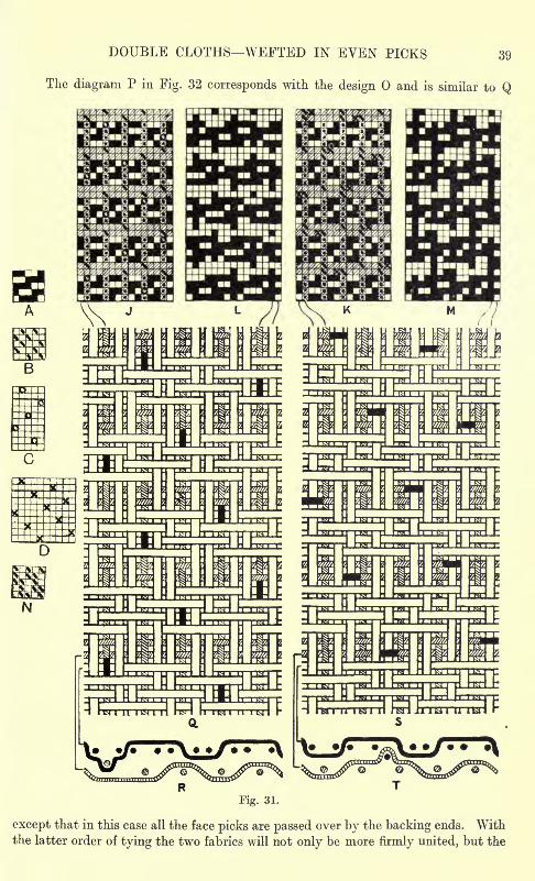
DOUBLE CLOTHS WEFTED IN EVEN PICKS 39
The diagram P in Fig. 32 corresponds with the design and is similar to Q
Fig. 31.
except that in this case all the face picks are passed over by the backing ends. Withthe latter order of tying the two fabrics will not only be more firmly united, but the
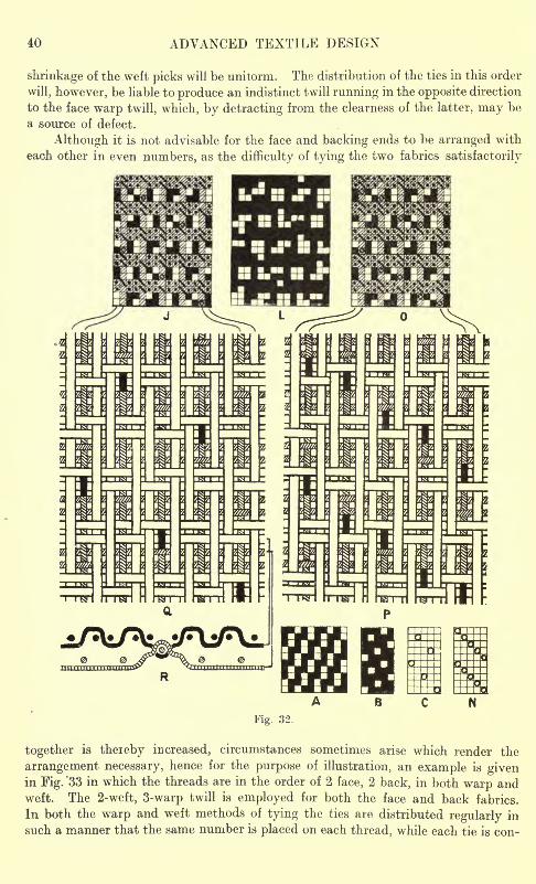
40 ADVANCED TEXTILE DESIGN
shrinkage of the weft picks will be unitorm. The distribution of the ties in this order
will, however, be liable to produce an indistinct twill running in the opposite direction
to the face warp twill, which, by detracting from the clearness of the latter, may be
a source of defect.
Although it is not advisable for the face and backing ends to be arranged with
each other in even numbers, as the difficulty of tying the two fabrics satisfactorily
Fig. 32.
together is theieby increased, circumstances sometimes arise which render the
arrangement necessary, hence for the purpose of illustration, an example is givenin Fig. "33 in which the threads are in the order of 2 face, 2 back, in both warp andweft. The 2-weft, 3-warp twill is employed for both the face and back fabrics.
In both the warp and weft methods of tying the ties are distributed regularly in
such a manner that the same number is placed on each thread, while each tie is con-
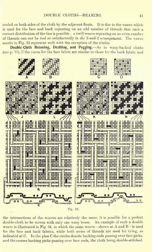
DOUBLE CLOTHS BEAMING 41
cealed on both sides of the cloth by the adjacent floats. It is due to the weave which
is used for the face and back repeating on an odd number of threads that such a
correct distribution of the ties is possible ;a twill weave repeating on an even number
of threads can not be tied so satisfactorily in the 2-and-2 arrangement. The weavemarks in Fig. 33 represent weft with the exception of the circles.
Double-Cloth Beaming, Drafting, and Pegging. As in warp-backed cloths
(see p. 15), if the yarns for the face fabric are similar to those for the back fabric, and
Fig. 33
the intersections of the weaves are relatively the same, it is possible for a perfect
double-cloth to be woven with only one warp beam. An example of such a double
weave is illustrated in Fig. 34, in which the same weave shown at A and B is used
for the face and back fabrics, while both series of threads are used for tying, as
indicated at C. In the plan C the circles denote backing ends passing over face picks,
and the crosses backing picks passing over face ends, the cloth being double-stitched.
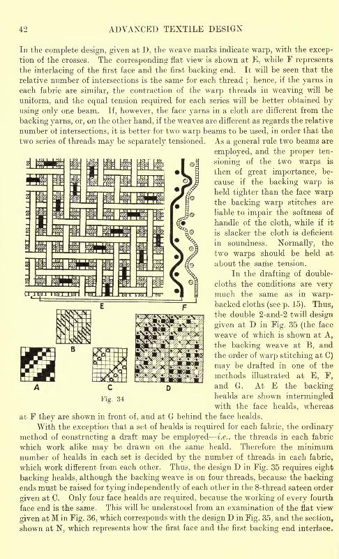
42 ADVANCED TEXTILE DESIGN
In the complete design, given at D, the weave marks indicate warp, writh the excep-tion of the crosses. The corresponding flat view is shown at E, while F represents
the interlacing of the first face and the first backing end. It will be seen that the
relative number of intersections is the same for each thread; hence, if the yarns in
each fabric are similar, the contraction of the warp threads in weaving will be
uniform, and the equal tension required for each series will be better obtained by
using only one beam. If, however, the face yarns in a cloth are different from the
backing yarns, or, on the other hand, if the weaves are different as regards the relative
number ot intersections, it is better for two wr
arp beams to be used, in order that the
two series of threads may be separately tensioned. As a general rule two beams are
employed, and the proper fcen-
sioning of the two warps is
then of great importance, be-
cause if the backing warp is
held tighter than the face warpthe backing warp stitches are
liable to impair the softness of
handle of the cloth, while if it
is slacker the cloth is deficient
in soundness. Normally, the
two warps should be held at
about the same tension.
In the drafting of double-
cloths the conditions are verymuch the same as in warp-backed cloths (see p. 15). Thus,the double 2-and-2 twill design
given at D in Fig. 35 (the face
weave of which is shown at A,
the backing weave at B, and
the order of warp stitching at C)
may be drafted in one of the
methods illustrated at E, F,
and G. At E the backinghealds are shown intermingledwith the face healds, whereas
at F they are shown in front of, and at G behind the face healds.
With the exception that a set of healds is required for each fabric, the ordinarymethod of constructing a draft may be employed i.e., the threads in each fabric
which work alike may be drawn on the same heald. Therefore the minimumnumber of healds in each set is decided by the number of threads in each fabric,
which work different from each other. Thus, the design D in Fig. 35 requires eight
backing healds, although the backing weave is on four threads, because the backingends must be raised for tying independently of each other in the 8-thread sateen order
given at C. Only four face healds are required, because the working of every fourth
face end is the same. This will be understood from an examination of the flat view
given at M in Fig. 36, which corresponds with the design D in Fig. 35, and the section,
shown at N, which represents how the first face and the first backing end interlace.
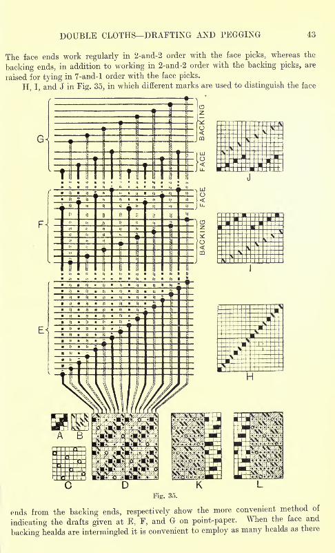
DOUBLE CLOTHS DKAFTING AND PEGGING
The face ends work regularly in 2-and-2 order with the face picks, whereas the
backing ends, in addition to working in 2-and-2 order with the backing picks, are
raised for tying in 7-and-l order with the face picks.
H, I, and J in Fig. 35, in which different marks are used to distinguish the face
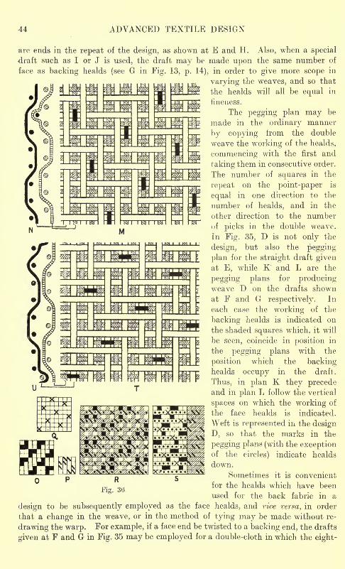
44 ADVANCED TEXTILE DESIGN
are ends in the repeat of the design, as shown at E and H. Also, when a special
draft such as I or J is used, the draft may be made upon the same number of
face as backing healds (see G in Fig. 13, p. 14), in order to give more scope in
varying the weaves, and so that
the healds will all be equal in
fineness.
The pegging plan may be
made in the ordinary manner
by copying from the double
weave the working of the healds,
commencing with the first and
taking them in consecutive order.
The number of squares in the
repeat on the point-paper is
equal in one direction to the
number of healds, and in the
other direction to the numberof picks in the double weave.
In Fig. 35, D is not only the
design, but also the pegging
plan for the straight draft givenat E, while K and L are the
pegging plans for producingweave D on the drafts shown
at F and G respectively. In
each case the working of the
backing healds is indicated on
the shaded squares which, it will
be seen, coincide in position in
the pegging plans with the
position which the backinghealds occupy in the draft.
Thus, in plan K they precedeand in plan L follow the vertical
spaces on which the working of
the face healds is indicated.
Weft is represented in the design
D, so that the marks in the
pegging plans (with the exceptionof the circles) indicate healds
down.
Sometimes it is convenient
for the healds which have been
used for the back fabric in a
design to be subsequently employed as the face healds, and vice versa, in order
that a change in the weave, or in the method of tying may be made without re-
drawing the warp. For example, if a face end be twisted to a backing end, the drafts
given at F and G in Fig. 35 may be employed for a double-cloth in which the eight-
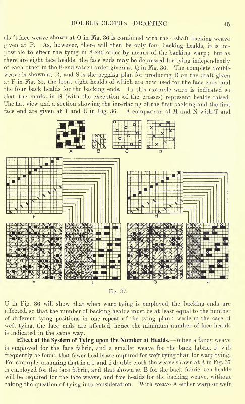
DOUBLE CLOTHS DRAFTING 45
shaft face weave shown at in Fig. 36 is combined with the 4-shaft backing weave
given at P. As, however, there will then be only four backing healds, it is im-
possible to effect the tying in 8-end order by means of the backing warp ; but a&
there are eight face healds, the face ends may be depressed for tying independentlyof each other in the 8-end sateen order given at Q in Fig. 36. The complete doubleweave is shown at R, and S is the pegging plan for producing R on the draft givenat F in Fig. 35, the front eight healds of which are now used for the face ends, andthe four back healds for the backing ends. In this example warp is indicated so
that the marks in S (with the exception of the crosses) represent healds raised.
The flat view and a section showing the interlacing of the first backing and the first
face end are given at T and U in Fig. 36. A comparison of M and N with T and
Fig. 37.
U in Fig. 36 will show that when warp tying is employed, the backing ends are
affected, so that the number of backing healds must be at least equal to the numberof different tying positions in one repeat of the tying plan ;
while in the case of
weft tying, the face ends are affected, hence the minimum number of face healds
is indicated in the same way.Effect of the System of Tying upon the Number of Healds. When a fancy weave
is employed for the face fabric, and a smaller weave for the back fabric, it will
frequently be found that fewer healds are required for weft tying than for warp tying.
For example, assuming that in a 1-and-l double-cloth the weave shown at A in Fig. 37
is employed for the face fabric, and that shown at B for the back fabric, ten healds
will be required for the face weave, and five healds for the backing weave, without
taking the question of tying into consideration. With weave A either warp or weft
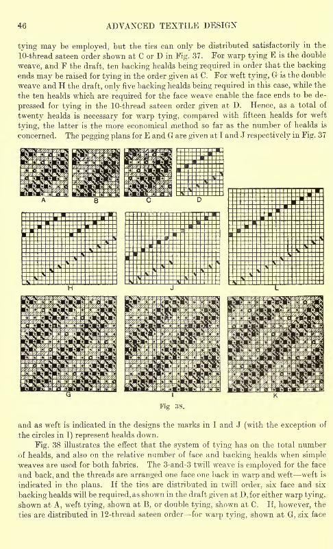
46 ADVANCED TEXTILE DESIGN
tying may be employed, but the ties can only be distributed satisfactorily in the
10-thread sateen order shown at C or D in Fig. 37. For warp tying E is the double
weave, and F the draft, ten backing healds being required in order that the backingends may be raised for tying in the order given at C. For weft tying, G is the double
weave and H the draft, only five backing healds being required in this case, while the
the ten healds which are required for the face weave enable the face ends to be de-
pressed for tying in the 10-thread sateen order given at D. Hence, as a total of
twenty healds is necessary for warp tying, compared with fifteen healds for weft
tying, the latter is the more economical method so far as the number of healds is
concerned. The pegging plans for E and G are given at I and J respectively in Fig. 37
Fig 38.
and as weft is indicated in the designs the marks in I and J (with the exception of
the circles in I) represent healds down.
Fig. 38 illustrates the effect that the system of tying has on the total number
of healds, and also on the relative number of face and backing healds when simpleweaves are used for both fabrics. The 3-and-3 twill weave is employed for the face
and back, and the threads are arranged one face one back in warp and weft weft is
indicated in the plans. If the ties are distributed in twill order, six face and six
backing healds will be required, as shown in the draft given at D, for either warp tying,
shown at A, weft tying, shown at B, or double tying, shown at C. If, however, the
ties are distributed in 12-thread sateen order for warp tying, shown at G, six face
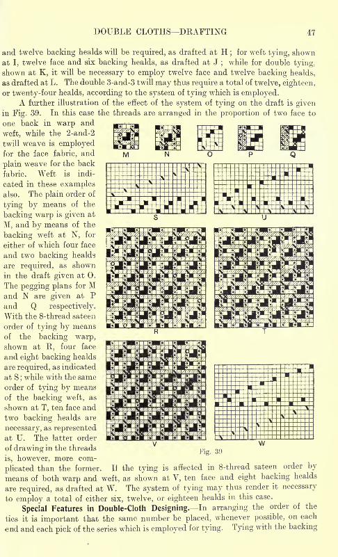
DOUBLE CLOTHS DRAFTING 47
and twelve backing healds will be required, as drafted at H;for weft tying, shown
at I, twelve face and six backing healds, as drafted at J;
while for double tying,
shown at K, it will be necessary to employ twelve face and twelve backing healds,
as drafted at L. The double 3-and-3 twill may thus require a total of twelve, eighteen ,
or twenty-four healds, according to the system of tying which is employed.A further illustration of the effect of the system of tying on the draft is given
in Fig. 39. In this case the threads are arranged in the proportion of two face to
one back in warp and
weft, while the 2-and-2
twill weave is employedfor the face fabric, and
plain weave for the back
fabric. Weft is indi-
cated in these examplesalso. The plain order of
tying by means of the
backing warp is given at
M, and by means of the
backing weft at N, for
either of which four face
and two backing healds
are required, as shown
in the draft given at 0.
The pegging plans for Mand N are given at Pand Q respectively.
With the 8-thread sateen
order of tying by means
of the backing warp,shown at R, four face
and eight backing healds
are required, as indicated
at S ;while with the same
order of tying by means
of the backing weft, as
shown at T, ten face and
two backing healds are
necessary, as representedat U. The latter order
of drawing in the threads
is, however, more com-
plicated than the former.
Fig. 39
If the tying is affected in 8-thread sateen order by
means of both warp and weft, as shown at V, ten face and eight backing healds
are required, as drafted at W. The system of tying may thus render it necessary
to employ a total of either six, twelve, or eighteen healds in this case.
Special Features in Double-Cloth Designing. In arranging the order of the
ties it is important that the same number be placed, whenever possible, on each
end and each pick of the series which is employed for tying. Tying with the backing
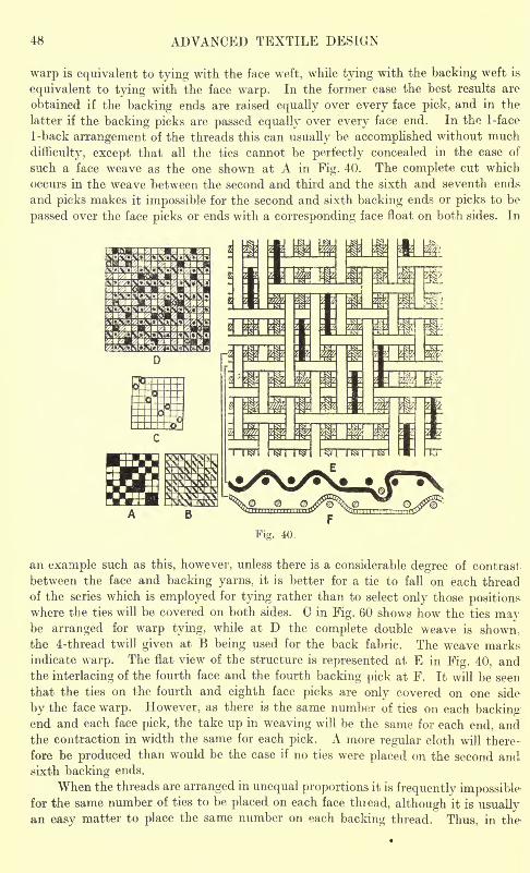
48 ADVANCED TEXTILE DESIGN
warp is equivalent to tying with the face weft, while tying with the backing weft is
equivalent to tying with the face warp. In the former case the best results are
obtained if the backing ends are raised equally over every face pick, and in the
latter if the backing picks are passed equally over every face end. In the 1-face
1-back arrangement of the threads this can usually be accomplished without much
difficulty, except that all the ties cannot be perfectly concealed in the case of
such a face weave as the one shown at A in Fig. 40. The complete cut which
occurs in the weave between the second and third and the sixth and seventh ends
and picks makes it impossible for the second and sixth backing ends or picks to be
passed over the face picks or ends with a corresponding face float on both sides. In
Fig. 40.
an example such as this, however, unless there is a considerable degree of contrast
between the face and backing yarns, it is better for a tie to fall on each thread
of the series which is employed for tying rather than to select only those positionswhere the ties will be covered on both sides. C in Fig. 60 shows how the ties maybe arranged for warp tying, while at D the complete double weave is shown,the 4-thread twill given at B being used for the back fabric. The weave marksindicate warp. The flat view of the structure is represented at E in Fig. 40, andthe interlacing of the fourth face and the fourth backing pick at F. It will be seen
that the ties on the fourth and eighth face picks are only covered on one side
by the face warp. However, as there is the same number of ties on each backingend and each face pick, the take up in weaving will be the same for each end, and
the contraction in width the same for each pick. A more regular cloth will there-
fore be produced than would be the case if no ties were placed on the second andsixth backing ends.
When the threads are arranged in unequal proportions it is frequently impossiblefor the same number of ties to be placed on each face thiead, although it is usuallyan easy matter to place the same number on each backing thread. Thus, in the
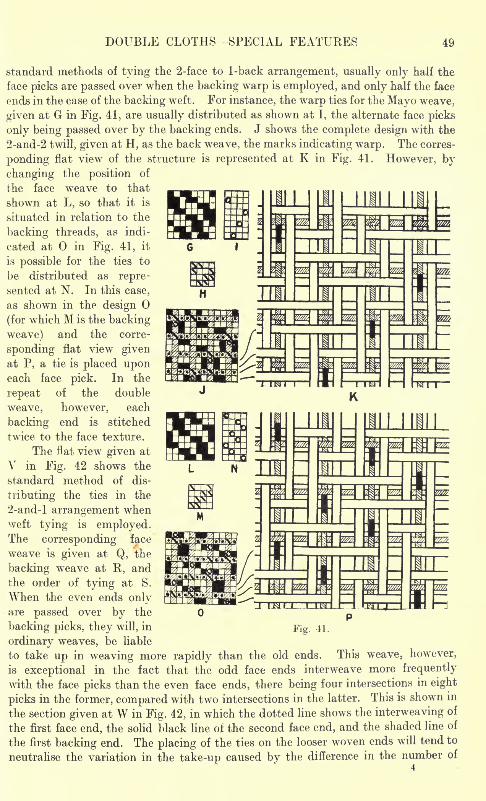
DOUBLE CLOTHS- SPECIAL FEATURES 49
standard methods of tying the 2-face to 1-back arrangement, usually only half the
face picks are passed over when the backing warp is employed, and only half the face
ends in the case of the backing weft. For instance, the warp ties for the Mayo weave,
given at G in Fig. 41, are usually distributed as shown at I, the alternate face picks
only being passed over by the backing ends. J shows the complete design with the
2-and-2 twill, given at H, as the back weave, the marks indicating warp. The corres-
ponding flat view of the structure is represented at K in Fig. 41. However, by
changing the position of
the face weave to that
shown at L, so that it is
situated in relation to the
backing threads, as indi-
cated at in Fig. 41, it
is possible for the ties to
be distributed as repre-
sented at N. In this case,
as shown in the design
(for which M is the backing
weave) and the corre-
sponding flat view givenat P, a tie is placed uponeach face pick. In the
repeat of the double
weave, however, each
backing end is stitched
twice to the face texture.
The flat view given at
V in Fig. 42 shows the
standard method of dis-
tributing the ties in the
2-and-l arrangement whenweft tying is employed.The corresponding face
weave is given at Q, the
backing weave at R, and
the order of tying at S.
When the even ends onlyare passed over by the
backing picks, they will, in
ordinary weaves, be liable
to take up in weaving more rapidly than the old ends. This weave, however,
is exceptional in the fact that the odd face ends interweave more frequently
with the face picks than the even face ends, there being four intersections in eight
picks in the former, compared with two intersections in the latter. This is shown in
the section given at W in Fig. 42, in which the dotted line shows the interweaving of
the first face end, the solid black line of the second face end, and the shaded line of
the first backing end. The placing of the ties on the looser woven ends will tend to
neutralise the variation in the take-up caused by the difference in the number of
Fig. 41
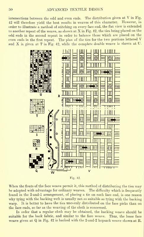
50 ADVANCED TEXTILE DESIGN
intersections between the odd and even ends. The distribution given at V in Fig.
42 will therefore yield the best results in weaves of this character. However, in
order to illustrate a method of stitching on every face end, the flat view is extended
to another repeat of the weave, as shown at X in Fig. 42, the ties being placed on the
odd ends in the second repeat in order to balance those which are placed on the
even ends in the first repeat. The plan of the ties for the two portions lettered Vand X is. given at T in Fig. 42, while the complete double weave is shown at U.
Mill
Fig. 42.
When the floats of the face weave permit it, this method of distributing the ties maybe adopted with advantage for ordinary weaves. The difficulty which is frequentlyfound in the 2-and-l arrangement, of placing a tie on each face end, is one reason
why tying with the backing weft is usually not so suitable as tying with the backing
warp. It is better to have the ties unevenly distributed on the face picks than on
the face ends, so far as the weaving of the cloth is concerned.
In order that a regular cloth may be obtained, the backing weave should be
suitable for the back fabric, and similar to the face weave. Thus, the loose face
weave given at Q in Fig. 42 is backed with the 2-and-2 hopsack weave shown at R.
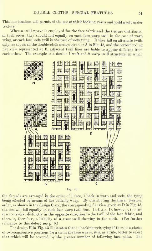
DOUBLE CLOTHS- SPECIAL FEATURES 51
This combination will permit of the use of thick backing yarns and yield a soft undertexture.
When a twill weave is employed for the face fabric and the ties are distributed
in twill order, they should fall equally on each face warp twill in the case of warptying, or each face weft twill in the case of weft tying. If they fall on alternate twills
only, as shown in the double-cloth design given at A in Fig. 43, and the correspondingflat view represented at B, adjacent twill lines are liable to appear different fromeach other. The example is a double l-weft-and-2 warp twill structure, in which
Fig. 43.
the threads are arranged in the order of 1 face, 1 back in warp and weft, the tying
being effected by means of the backing warp. By distributing the ties in 9-sateen
order, as shown in the design C and the corresponding flat view given at D in Fig. 43,
the ties will fall equally on each face warp twill line. In C and D, however, the ties
run somewhat distinctly in the opposite direction to the twill of the face fabric, and
there is, therefore, a liability of a cross-twill showing in the cloth. (For further
reference to this defect see p. 6.)
The design H in Fig. 43 illustrates that in backing weft tying if there is a choice
of two consecutive positions for a tie in the face weave, it is, as a rule, better to select
that which will be covered by the greater number of following face picks. The
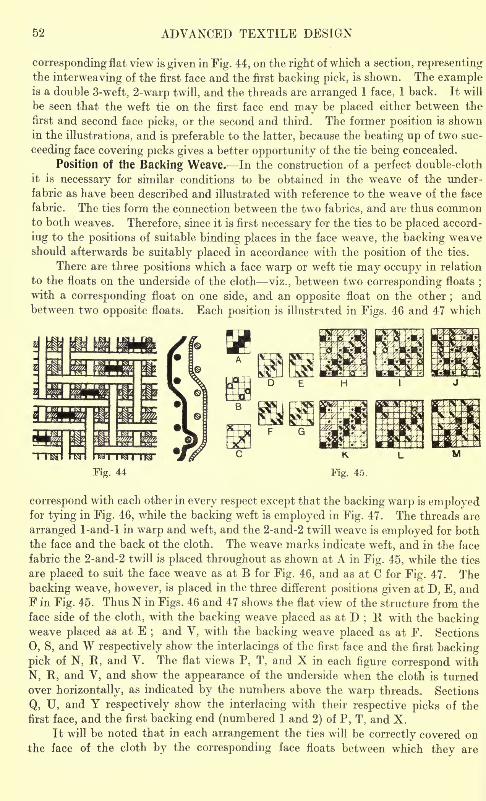
52 ADVANCED TEXTILE DESIGN
corresponding flat view is given in Fig. 44, on the right of which a section, representingthe interweaving of the first face and the first backing pick, is shown. The exampleis a double 3-weft, 2-warp twill, and the threads are arranged 1 face, 1 back. It will
be seen that the weft tie on the first face end may be placed either between the
first and second face picks, or the second and third. The former position is shownin the illustrations, and is preferable to the latter, because the beating up of two suc-
ceeding face covering picks gives a better opportunity of the tie being concealed.
Position of the Backing Weave. In the construction of a perfect double-cloth
it is necessary for similar conditions to be obtained in the weave of the under-
fabric as have been described and illustrated with reference to the weave of the face
fabric. The ties form the connection between the two fabrics, and are thus commonto both weaves. Therefore, since it is first necessary for the ties to be placed accord-
ing to the positions of suitable binding places in the face weave, the backing weaveshould afterwards be suitably placed in accordance with the position of the ties.
There are three positions which a face warp or weft tie may occupy in relation
to the floats on the underside of the cloth viz., between two corresponding floats;
with a corresponding float on one side, and an opposite float on the other;and
between two opposite floats. Each position is illustrated in Figs. 46 and 47 which
correspond with each other in every respect except that the backing warp is employedfor tying in Fig. 46, while the backing weft is employed in Fig. 47. The threads are
arranged 1-and-l in warp and weft, and the 2-and-2 twill weave is employed for boththe face and the back ot the cloth. The weave marks indicate weft, and in the face
fabric the 2-and-2 twill is placed throughout as shown at A in Fig. 45, while the ties
are placed to suit the face weave as at B for Fig. 46, and as at C for Fig. 47. The
backing weave, however, is placed in the three different positions given at D, E, andF in Fig. 45. Thus N in Figs. 46 and 47 shows the flat view of the structure from the
face side of the cloth, with the backing weave placed as at D;R with the backing
weave placed as at E;and V, with the backing weave placed as at F. Sections
0, S, and W respectively show the interlacings of the first face and the first backing
pick of N, R, and V. The flat views P, T, and X in each figure correspond with
N, R, and V, and show the appearance of the underside when the cloth is turned
over horizontally, as indicated by the numbers above the warp threads. Sections
Q, U, and Y respectively show the interlacing with their respective picks of the
first face, and the first backing end (numbered 1 and 2) of P, T, and X.
It will be noted that in each arrangement the ties will be correctly covered onthe face of the cloth by the corresponding face floats between which thev are
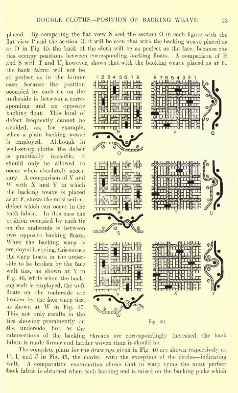
DOUBLE CLOTHS POSITION OF BACKING WEAVE
placed. By comparing the flat view N and the section in each figure with the
flat view P and the section Q, it will be seen that with the backing weave placed as
at D in Fig. 45, the back of the cloth will be as perfect as the face, because the
ties occupy positions between corresponding backing floats. A comparison of Rand S with T and U, however, shows that with the backing weave placed as at E,
the back fabric will not be
so perfect as in the former 12345678case, because the position
occupied by each tie on the
underside is between a corre-
sponding and an opposite
backing float. This kind of
defect frequently cannot be
avoided, as, for example,when a plain backing weave
is employed. Although in
well-set-up cloths the defect-
is practically invisible, it
should only be allowed to
occur when absolutely neces-
sary. A comparison of V andW with X and Y in which
the backing weave is placedas at F, shows the most serious
defect which can occur in the
back fabiic. In this case the
position occupied by each tie
on the underside is between
two opposite backing floats.
When the backing warp is
employed for tying, this causes
the warp floats in the under-
.side to be broken by the face
weft ties, as shown at Y in
Fig. 46, while when the back-
ing weft is employed, the weft
floats on the underside are
broken by the face warp ties,
as shown at W in Fig. 47
This not only results in the
ties showing prominently on
the underside, but as the
intersections of the backing threads are correspondingly increased, the back
fabric is made firmer and harder woven than it should be.
The complete plans for the drawings given in Fig. 46 are shown respectively at
H, I, and J in Fig. 45, the marks with the exception of the circles indicatingweft. A comparative examination shows that in warp tying the most perfectiback fabric is obtained when each backing end is raised on the backing picks which
Fig. 46.
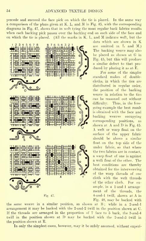
54 ADVANCED TEXTILE DESIGN
precede and succeed the face pick on which the tie is placed. In the same waya comparison of the plans given at K, L, and M in Fig. 45, with the corresponding-
diagrams in Fig. 47, shows that in weft tying the most regular back fabrics results
when each backing pick passes over the backing end on each side of the face end
on which the tie is placed. (All the marks in K, L, and M indicate weft, but the
dots which are shown in Kare omitted in L and M.)The backing weave may also
be placed as shown at G in
Fig. 45, but this will producea similar defect to that pro-duced by placing it as at E.
For some of the simplerstandard makes of double-
cloths, in which the ties are
distributed in regular order,
the position of the backingweave in relation to the ties
can be reasoned out without
difficulty. Thus, in the fore-
going example the best result
is obtained with the face and
backing weaves occupying
corresponding positions, as
shown at A and D in Fig. 45.
A weft or warp float on the
surface of the upper fabric-
should be above a similar
float on the top side of the
under fabric, so that where
the two fabrics are in contact,
a warp float of one is againsta weft float of the other. Thebest conditions are therebyobtained for the interweavingof the warp threads of one
cloth with the weft threads
of the other cloth. For ex-
ample, in a 1-and-l arrangement of the threads, the
4-and-4 twill, shown at A in
Fig. 48, may be backed with
the same weave in a similar position, as shown at B;
while in a 2-and-l
arrangement it may be backed with the 2-and-2 twill in the position shown at C.
If the threads are arranged in the proportion of 7 face to 5 back, the 3-and-4
twill in the position shown at D may be backed with the 2-and-3 twill in
the position shown at E.
In only the simplest cases, however, may it be safely assumed, without experi-
47.
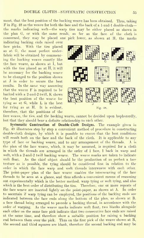
DOUBLE CLOTHS -SYSTEMATIC CONSTRUCTION 55
Fig. 48.
ment, that the best position of the backing weave has been obtained. Thus, takingF in Fig. 48 as the weave for both the face and the back of a 1-and-l double-cloth
the marks indicating weft the warp ties may be either placed as shown in
the plan G, or with the same result, so far as the face of the cloth is
concerned, they may be placed one pick lower, as shown at H, the marks
indicating backing ends raised over
face picks. With the ties placedas at G, the most perfect under-
fabric will be obtained by commenc-
ing the backing weave exactly like
the face weave, as shown at I, but
with the ties placed as at H, it will
be necessary for the backing weave
to be changed to the position shownat J in order to secure the best
results. In the same way assumingthat the weave F is required to be
backed with a 2-and-2 twill. K shows
the best position of the weave for
tying as at G, while L is the best
for tying as at H. It is evident,
therefore, that the positions of the
face weave, the ties, and the backing weave, cannot be decided upon haphazardly,but that they should bear a definite relationship to each other.
Si'stematic Construction of Double -Cloth Designs.- The example given in
Fig. 49 illustrates step by step a convenient method of procedure in constructingdouble-cloth designs, by which it is possible to ensure that the best conditions
will result both on the face and the back of the cloth. It is applicable to any
type of face or backing weave, and to any arrangement of the threads. A is
the plan of the face weave, which, it may be assumed, is required for a cloth
in which the threads are arranged in the order of 1 face, 1 back in warp and
weft, with a 2-and-2 twill backing weave. The weave marks are taken to indicate
weft float. As the chief object should be the production of as perfect a face
texture as is possible, the tying should be considered first in relation to the
order in which the face warp and weft threads interweave with each other.
The point-paper plan of the face weave enables the interweaving of the face
threads to be seen at a glance, and thus affords a convenient means of reasoningout experimentally which is the better method, warp tying or weft tying, and also
which is the best order of distributing the ties. Therefore, one or more repeats of
the face weave are inserted lightly on the point-paper, as shown at A. In order
to ascertain if warp tying can be employed, the positions of the backing ends are
indicated between the face ends along the bottom of the plan, as shown at B,
a face thread being arranged to precede a backing thread, in accordance with the
order of warping. As the weave marks indicate weft float, two blanks alongsideeach other on the same face pick indicate that two consecutive face ends are raised
at the same time, and therefore show a suitable position for raising -a backingend between them over the pick. Thus on the first pick of the weave shown at B,
the second and third squares are blank, therefore the second backing end may be
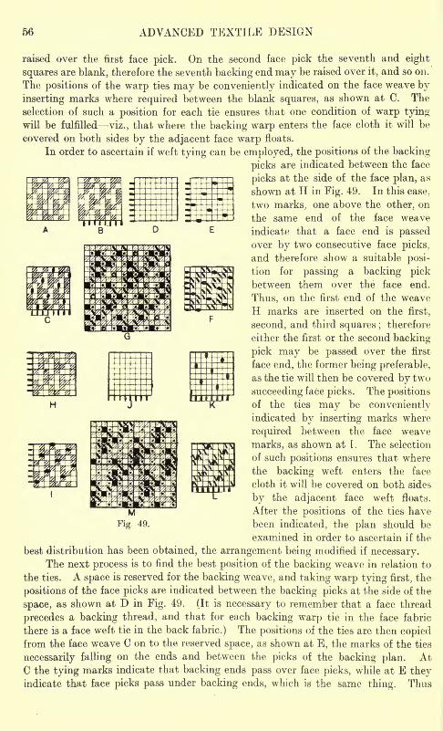
56 ADVANCED TEXTILE DESIGN
raised over the first face pick. On the second face pick the seventh and eight
squares are blank, therefore the seventh backing end may be raised over it, and so on.
The positions of the warp ties may be conveniently indicated on the face weave by
inserting marks where required between the blank squares, as shown at C. The
selection of such a position for each tie ensures that one condition of warp tyingwill be fulfilled viz., that where the backing warp enters the face cloth it will be
covered on both sides by the adjacent face warp floats.
In order to ascertain if weft tying can be employed, the positions of the backing
picks are indicated between the face
picks at the side of the face plan, as
shown at H in Fig. 49. In this case,
two marks, one above the other, on
the same end of the face weave
indicate that a face end is passedover by two consecutive face picks,
and therefore show a suitable posi-
tion for passing a backing pickbetween them over the face end.
Thus, on the first end of the weave
H marks are inserted on the first,
second, and third squares ;therefore
either the first or the second backing-
pick may be passed over the first
face end, the former being preferable,
as the tie will then be covered by two
succeeding face picks. The positions
of the ties may be convenientlyindicated by inserting marks where
required between the face weave
marks, as shown at T. The selection
of such positions ensures that where
the backing weft enters the face
cloth it will be covered on both sides
by the adjacent face weft floats.
After the positions of the ties have
been indicated, the plan should be
examined in order to ascertain if the
best distribution has been obtained, the arrangement being modified if necessary.The next process is to find the best position of the backing weave in relation to
the ties. A space is reserved for the backing weave, and taking warp tying first, the
positions of the face picks are indicated between the backing picks at the side of the
space, as shown at D in Fig. 49. (It is necessary to remember that a face thread
precedes a backing thread, and that for each backing warp tie in the face fabric
there is a face weft tie in the back fabric.) The positions of the ties are then copiedfrom the face weave C on to the reserved space, as shown at E, the marks of the ties
necessarily falling on the ends and between the picks of the backing plan. AtC the tying marks indicate that backing ends pass over face picks, while at E theyindicate that face picks pass under backing ends, which is the same thing. Thus
MFig 49.
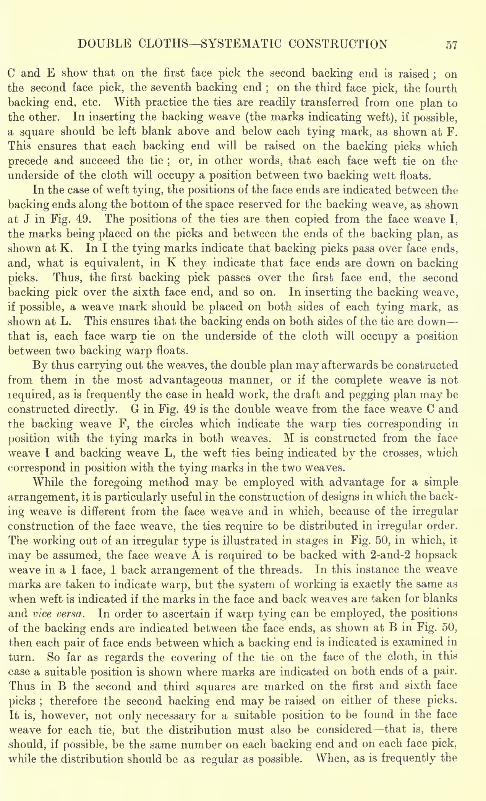
DOUBLE CLOTHS SYSTEMATIC CONSTRUCTION 57
C and E show that on the first face pick the second backing end is raised;on
the second face pick, the seventh backing end;on the third face pick, the fourth
backing end, etc. With practice the ties are readily transferred from one plan to
the other. In inserting the backing weave (the marks indicating weft), if possible,
a square should be left blank above and below each tying mark, as shown at F.
This ensures that each backing end will be raised on the backing picks which
precede and succeed the tie; or, in other words, that each face weft tie on the
underside of the cloth will occupy a position between two backing welt floats.
In the case of weft tying, the positions of the face ends are indicated between the
backing ends along the bottom of the space reserved for the backing weave, as shown
at J in Fig. 49. The positions of the ties are then copied from the face weave I.
the marks being placed on the picks and between the ends of the backing plan, as
shown at K. In I the tying marks indicate that backing picks pass over face ends,
and, what is equivalent, in K they indicate that face ends are down on backing
picks. Thus, the first backing pick passes over the first face end, the second
backing pick over the sixth face end, and so on. In inserting the backing weave,if possible, a weave mark should be placed on both sides of each tying mark, as
shown at L. This ensures that the backing ends on both sides of the tie are downthat is, each face warp tie on the underside of the cloth will occupy a position
between two backing warp floats.
By thus carrying out the weaves, the double plan may afterwards be constructed
from them in the most advantageous manner, or if the complete weave is not
lequired, as is frequently the case in heald work, the draft and pegging plan may be
constructed directly. G in Fig. 49 is the double weave from the face weave C and
the backing weave F, the circles which indicate the warp ties corresponding in
position with the tying marks in both weaves. M is constructed from the face
weave I and backing weave L, the weft ties being indicated by the crosses, which
correspond in position with the tying marks in the two weaves.
While the foregoing method may be employed with advantage for a simple
arrangement, it is particularly useful in the construction of designs in which the back-
ing weave is different from the face weave and in which, because of the irregular
construction of the face weave, the ties require to be distributed in irregular order.
The working out of an irregular type is illustrated in stages in Fig. 50, in which, it
may be assumed, the face weave A is required to be backed with 2-and-2 hopsackweave in a 1 face, 1 back arrangement of the threads. In this instance the weave
marks are taken to indicate warp, but the system of working is exactly the same as
when weft is indicated if the marks in the face and back weaves are taken for blanks
and vice versa. In order to ascertain if warp tying can be employed, the positions
of the backing ends are indicated between the face ends, as shown at B in Fig. 50,
then each pair of face ends between which a backing end is indicated is examined in
turn. So far as regards the covering of the tie on the face of the cloth, in this
case a suitable position is shown where marks are indicated on both ends of a pair.
Thus in B the second and third squares are marked on the first and sixth face
picks ;therefore the second backing end may be raised on either of these picks.
It is, however, not only necessary for a suitable position to be found in the face
weave for each tie, but the distribution must also be considered that is, there
.should, if possible, be the same number on each backing end and on each face pick,
\vhile the distribution should be as regular as possible. When, as is frequently the
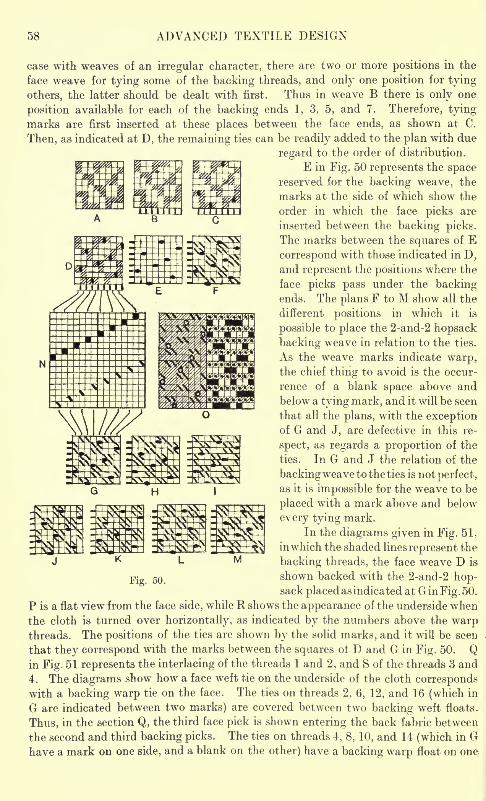
58 ADVANCED TEXTILE DESIGN
case with weaves of an irregular character, there are two or more positions in the
face weave for tying some of the backing threads, and only one position for tying
others, the latter should be dealt with first. Thus in weave B there is only one
position available for each of the backing ends 1, 3, 5, and 7. Therefore, tying
marks are first inserted at these places between the face ends, as shown at C.
Then, as indicated at D, the remaining ties can be readily added to the plan with due
regard to the order of distribution.
E in Fig. 50 represents the spacereserved for the backing weave, the
marks at the side of which show the
order in which the face picks are
inserted between the backing picks.
The marks between the squares of Ecorrespond with those indicated in D,and represent the positions where the
face picks pass under the backingends. The plans F to M show all the
different positions in which it is
possible to place the 2-and-2 hopsack
backing weave in relation to the ties.
As the weave marks indicate warp,the chief thing to avoid is the occur-
rence of a blank space above and
below a tying mark, and it will be seen
that all the plans, with the exceptionof G and J, are defective in this re-
spect, as regards a proportion of the
ties. In G and J the relation of the
backing weave to the ties is not perfect,
as it is impossible for the weave to be
placed with a mark above and below
every tying mark.
In the diagrams given in Fig. 51,
inwhich the shaded lines represent the
backing threads, the face weave D is
shown backed with the 2-and-2 hop-sack placed as indicated at Gin Fig. 50.
P is a flat view from the face side, while R shows the appearance of the underside when
the cloth is turned over horizontally, as indicated by the numbers above the warpthreads. The positions of the ties are shown by the solid marks, and it will be seen
that they correspond with the marks between the squares of D and G in Fig. 50. Qin Fig. 51 represents the interlacing of the threads 1 and 2, and S of the threads 3 and
4. The diagrams show how a face weft tie on the underside of the cloth correspondswith a backing warp tie on the face. The ties on threads 2, 6, 12, and 16 (which in
G are indicated between two marks) are covered between two backing weft floats.
Thus, in the section Q, the third face pick is shown entering the back fabric between
the second and third backing picks. The ties on threads 4, 8, 10, and 14 (which in Ghave a mark on one side, and a blank on the other) have a backing warp float on one
M
Fig. 50.
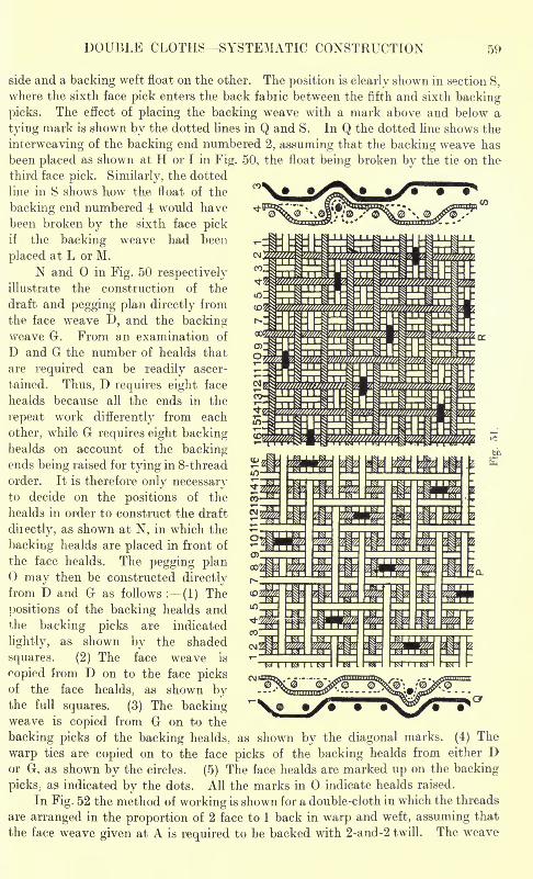
DOUBLE CLOTHS SYSTEMATIC CONSTRUCTION 59
side and a backing weft float on the other. The position is clearly shown in section S,
where the sixth face pick enters the back fabiic between the fifth and sixth backing
picks. The effect of placing the backing weave with a mark above and below a
tying mark is shown by the dotted lines in Q and S. In Q the dotted line shows the
interweaving of the backing end numbered 2, assuming that the backing weave has
been placed as shown at H or I in Fig. 50, the float being broken by the tie on the
third face pick. Similarly, the dotted
line in S shows how the float of the
backing end numbered 4 would have
been broken by the sixth face pickif the backing weave had been
placed at L or M.
N and in Fig. 50 respectivelyillustrate the construction of the
draft and pegging plan directly from
the face weave D, and the backingweave G. From an examination of
D and G the number of healds that
are required can be readily ascer-
tained. Thus, D requires eight face
healds because all the ends in the
repeat work differently from each
other, while G requires eight backinghealds on account of the backingends being raised for tying in 8-thread
order. It is therefore only necessaryto decide on the positions of the
healds in order to construct the draft
directly, as shown at N, in which the
backing healds are placed in front of
the face healds. The pegging plan
may then be constructed directlyfrom D and G as follows : (1) The
positions of the backing healds andthe backing picks are indicated
lightly, as shown by the shaded
squares. (2) The face weave is
Copied from D on to the face picksof the face healds, as shown bythe full squares. (3) The backingweave is copied from G on to the
backing picks of the backing healds, as shown by the diagonal marks. (4) The
warp ties are copied on to the face picks of the backing healds from either Dor G, as shown by the circles. (5) The face healds are marked up on the backing
picks, as indicated by the dots. All the marks in indicate healds raised.
In Fig. 52 the method of working is shown for a double-cloth in which the threads
are arranged in the proportion of 2 face to 1 back in warp and weft, assuming that
the face weave given at A is required to be backed with 2-and-2 twill. The weave
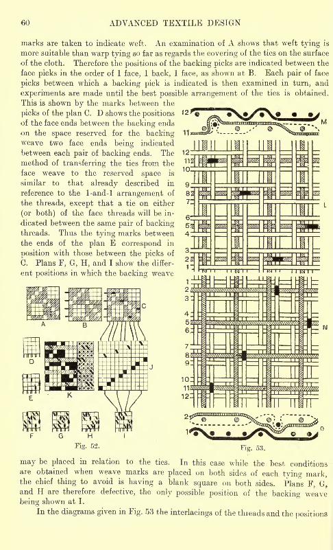
60 ADVANCED TEXTILE DESIGN
marks are taken to indicate weft. An examination of A shows that weft tying is
more suitable than warp tying so far as regards the covering of the ties on the surface
of the cloth. Therefore the positions of the backing picks are indicated between the
face picks in the order of 1 face, 1 back, 1 face, as shown at B. Each pair of face
picks between which a backing pick is indicated is then examined in turn, and
experiments are made until the best possible arrangement of the ties is obtained.
This is shown by the marks between the
picks of the plan C. D shows the positionsof the face ends between the backing ends
on the space reserved for the backingweave two face ends being indicated
between each pair of backing ends. The
method of transferring the ties from the
face weave to the reserved space is
similar to that already described in
reference to the 1-and-l arrangement of
the threads, except that a tie on either
(or both) of the face threads will be in-
dicated between the same pair of backingthreads. Thus the tying marks between
the ends of the plan E correspond in
position with those between the picks of
C. Plans F, G, H, and I show the differ-
ent positions in which the backing weave
Fig. 53.
may be placed in relation to the ties. In this case while the best conditionsare obtained when weave marks are placed on both sides of each tying mark,the chief thing to avoid is having a blank square on both sides. Plans F, G',
and H are therefore defective, the only possible position of the backing weavebeing shown at I.
In the diagrams given in Fig. 53 the interlacings of the threads and the positions
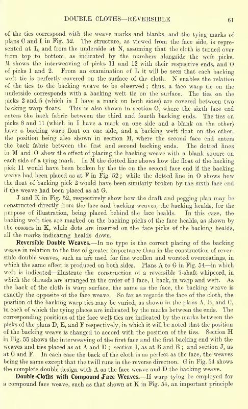
DOUBLE CLOTHS REVERSIBLE 61
of the ties correspond with the weave marks and blanks, and the tying marks of
plans C and I in Fig. 52. The structure, as viewed from the face side, is repre-sented at L, and from the underside at N, assuming that the cloth is turned overfrom top to bottom, as indicated by the numbers alongside the weft picks.M shows the interweaving of picks 11 and 12 with their respective ends, andof picks 1 and 2. From an examination of L it will be seen that each backingweft tie is perfectly covered on the surface of the cloth. N enables the relation
of the ties to the backing weave to be observed; thus, a face warp tie on the
underside corresponds with a backing welt tic on the surface. The ties on the
picks 2 and 5 (which in I have a mark on both sides) are covered between two
backing warp floats. This is also shown in section 0, where the sixth face endenters the back fabric between the third and fourth backing ends. The ties on
picks 8 and 11 (which in I have a mark on one side and a blank on the other)have a backing warp float on one side, and a backing weft float on the other,
the position being also shown in section M, where the second face end enters
the back fabric between the fiist and second backing ends. The dotted lines
in M and show the effect of placing the backing weave with a blank square oneach side of a tying mark. In M the dotted line shows how the float of the backing
pick 11 would have been broken by the tie on the second face end if the backingweave had been placed as at F in Fig. 52
;while the dotted line in shows how
the float of backing pick 2 would have been similarly broken by the sixth face endif the weave had been placed as at G.
J and K in Fig. 52, respectively show how the draft and pegging plan may be
constructed directly from the face and backing weaves, the backing healds, for the
purpose of illustration, being placed behind the face healds. In this case, the
backing weft ties are marked on the backing picks of the face healds, as shown bythe crosses in K, while dots are inserted on the face picks of the backing healds,
all the marks indicating healds down.
Reversible Double Weaves. In no type is the correct placing of the backingweave in relation to the ties of greater importance than in the construction of rever-
sible double weaves, such as are used for fine woollen and worsted overcoatings, in
which the same effect is produced on both sides. Plans A to G in Fig. 54 in which
weft is indicated illustrate the construction of a reversible 7-shaft whipcord, in
which the threads are arranged in the order of 1 face, 1 back, in warp and weft. Asthe back of the cloth is warp surface, the same as the face, the backing weave is
exactly the opposite of the face weave. So far as regards the face of the cloth, the
position of the backing warp ties may be varied, as shown in the plans A, B, and C,
in each of which the tying places are indicated by the marks between the ends. The
corresponding positions of the face weft ties are indicated by the marks between the
picks of the plans D, E, and F respectively, in which it will be noted that the positionof the backing weave is changed to accord with the position of the ties. Section Hin Fig. 55 shows the interweaving of the first face and the first backing end with the
weaves and ties placed as at A and D;section I, as at B and E
;and section J, as
at C and F. In each case the back of the cloth is as perfect as the face, the weaves
being the same except that the twill runs in the reverse direction. G in Fig. 54 shows
the complete double design with A as the face weave and D the backing weave.
Double -Cloths with Compound Face Weaves. If warp tying be employed for
a compound face weave, such as that shown at K in Fig. 54, an important principle
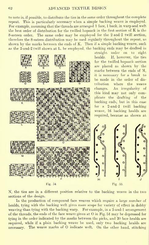
ADVANCED TEXTILE DESIGN
to note is, if possible, to distribute the ties in the same order throughout the complete
repeat. This is particularly necessary when a simple backing weave is employed.For example, assuming that the threads are arranged 1 face, 1 back, in warp and weft
the best order of distribution for the twilled hopsack in the first section of K is the
8-sateen order. The same order may be employed for the 2-and-2 twill section,
therefore the 8-sateen distribution may be used regularly throughout the repeat, as
shown by the marks between the ends of K. Then if a simple backing weave, such
as the 2-and-2 twill shown at L, be employed, the backing ends may be drafted in
straight order on to eight
healds. If, however, the ties
for the twilled hopsack section
are placed as shown by the
marks between the ends of M,it is necessary for a break to
be made in the order of dis-
tribution where the weave
changes. An irregularity of
this kind may not only com-
plicate the drafting of the
backing ends, but in this case
for a 2-and-2 twill backing
weave, 16 backing healds are
IPJ required, because as shown at
Fig. 34 Fig. 55.
N, the ties are in a different position relative to the backing weave in the two
sections of the design.
In the production of compound face weaves which require a large number of
healds, tying with the backing weft gives more scope for variety of effect in dobbyweaving than tying with the backing warp. For example, in a 2-and-l arrangementof the threads, the ends of the face weave given at in Fig. 54 may be depressed for
tying in the order indicated by the marks between the picks, and 20 face healds are
required, while if a plain backing weave be used, only two backing healds are
necessary. The weave marks of indicate weft. On the other hand, stitching
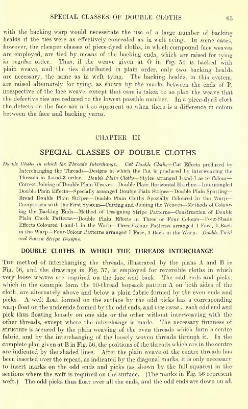
SPECIAL CLASSES OF DOUBLE CLOTHS 63
with the backing warp would necessitate the use of a large number of backinghealds if the ties were as effectively concealed as in weft tying. In some cases,
however, the cheaper classes of piece-dyed cloths, in which compound face weavesare employed, are tied by means of the backing ends, which are raised for tyingin regular order. Thus, if the weave given at in Fig. 54 is backed with
plain weave, and the ties distributed in plain order, only two backing healds
are necessary, the same as in weft tying. The backing healds, in this system,are raised alternately for tying, as shown by the marks between the ends of P.
irrespective of the face weave, except that care is taken to so plan the weave that
the defective ties are reduced to the lowest possible number. In a piece-dyed cloth
the defects on the face are not so apparent as when there is a difference in colour
between the face and backing yarns.
CHAPTER III
SPECIAL CLASSES OF DOUBLE CLOTHSDouble Cloths in which the Threads Interchange. Cut Double Cloths Cut Effects produced by
Interchanging the Threads Designs in which the Cut is produced by interweaving the
Threads in 3-and-3 order. Double Plain Cloths Styles arranged 1-and-l as to Colour
Correct Joining of Double Plain Weaves Double Plain Horizontal Hairline IntermingledDouble Plain Effects Specially arranged Doubje Plain Stripes Double Plain SpottingBroad Double Plain Stripes Double Plain Cloths Specially Coloured in the WarpComparison with the First System Cutting and Joining the Weaves Methods of Colour-
ing the Backing Ends Method of Designing Stripe Patterns Construction of DoublePlain Check Patterns Double Plain Effects in Three or Four Colours Four-ShadeEffects Coloured 1-and-l in the Warp Three-Colour Patterns arranged 1 Face, 1 Backin the Warp Four-Colour Patterns arranged 1 Face, 1 Back in the Warp. Double Twill
and Sateen Stripe
DOUBLE CLOTHS IN WHICH THE THREADS INTERCHANGE
THE method of interchanging the threads, illustrated by the plans A and B in
Fig. 56, and the drawings in Fig. 57, is employed for reversible cloths in which
very loose weaves are required on the face and back. The odd ends and picks,
which in the example form the 10-thread hopsack pattern A on both sides of the
cloth, are alternately above and below a plain fabric formed by the even ends and
picks. A weft float formed on the surface by the odd picks has a corresponding
warp float on the underside formed by the odd ends, and vice versa ; each odd end and
pick thus floating loosely on one side or the other without interweaving with the
other threads, except where the interchange is made. The necessary firmness of
structure is secured by the plain weaving of the even threads which form a centre
fabric, and by the interchanging of the loosely woven threads through it. In the
complete plan given at B in Fig. 56, the positions of the threads which are in the centre
are indicated by the shaded lines. After the plain weave of the centre threads has
been inserted over the repeat, as indicated by the diagonal marks, it is only necessaryto insert marks on the odd ends and picks (as shown by the full squares) in the
sections where the weft is required on the surface. (The marks in Fig. 56 represent
weft.) The odd picks thus float over all the ends, and the odd ends are down on all
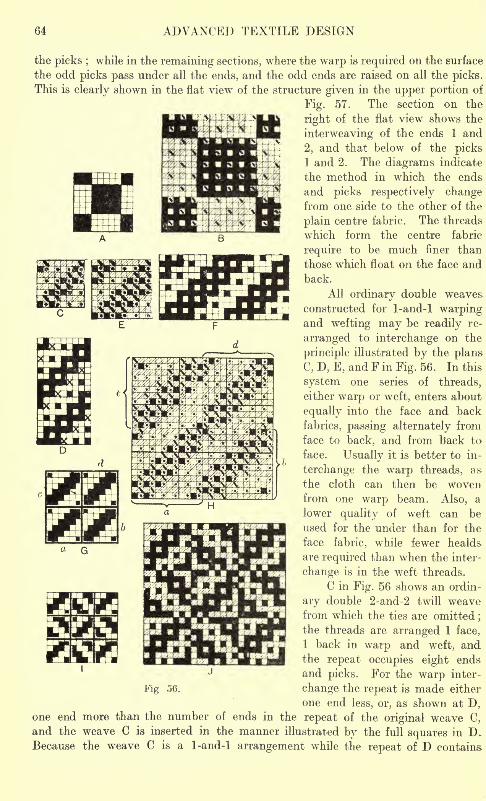
64 ADVANCED TEXTILE DESIGN
the picks ;while in the remaining sections, where the warp is required on the surface
the odd picks pass under all the ends, and the odd ends are raised on all the picks.
This is clearly shown in the flat view of the structure given in the upper portion of
Fig. 57. The section on the
right of the flat view shows the
interweaving of the ends 1 and
2, and that below of the picks1 and 2. The diagrams indicate
the method in which the ends
and picks respectively changefrom one side to the other of the
plain centre fabric. The threads
which form the centre fabric
require to be much finer than
those which float on the face andback.
All ordinary double weaves
constructed for 1-and-l warpingand wefting may be readily re-
arranged to interchange on the
principle illustrated by the plans
C, D, E, and Fin Fig. 56. In this
system one series of threads,
either warp or weft, enters about
equally into the face and back
fabrics, passing alternately from
face to back, and from back to
face. Usually it is better to in-
terchange the warp threads, as
the cloth can then be wovenfrom one warp beam. Also,one warp Deam. Also, a
lower quality of weft can be
used for the under than for the
face fabric, while fewer healds
are required than when the inter-
change is in the weft threads.
C in Fig. 56 shows an ordin-
ary double 2-and-2 twill weavefrom which the ties are omitted ;
the threads are arranged 1 face,
1 back in warp and weft, andthe repeat occupies eight ends
and picks. For the warp inter-
Fig 56. change the repeat is made either
one end less, or, as shown at D,one end more than the number of ends in the repeat of the original weave C,
and the weave C is inserted in the manner illustrated by the full squares in D.Because the weave C is a 1-and-l arrangement while the repeat of D contains
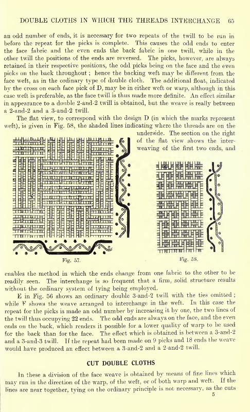
DOUBLE CLOTHS IN WHICH THE THREADS INTERCHANGE 65
an odd number of ends, it is necessary for two repeats of the twill to be run in
before the repeat for the picks is complete. This causes the odd ends to enter
the face fabric and the even ends the back fabric in one twill, while in the
other twill the positions of the ends are reversed. The picks, however, are alwaysretained in their respective positions, the odd picks being on the face and the even
picks on the back throughout ; hence the backing weft may be different from the
face weft, as in the ordinary type of double cloth. The additional float, indicated
by the cross on each face pick of D, may be in either weft or warp, although in this
case weft is preferable, as the face twill is thus made more definite. An effect similar
in appearance to a double 2-and-2 twill is obtained, but the weave is really between
a 2-and-2 and a 3-and-2 twill.
The flat view, to correspond with the design D (in which the marks represent
weft), is given in Fig. 58, the shaded lines indicating where the threads are on the
underside. The section on the right
of the flat view shows the inter-
weaving of the first two ends, and
Fig. 58.
enables the method in which the ends change from one fabric to the other to be
readily seen. The interchange is so frequent that a firm, solid structure results
without the ordinary system of tying being employed.E in Fig. 56 shows an ordinary double 3-and-2 twill with the ties omitted ;
while F shows the weave arranged to interchange in the weft. In this case the
repeat for the picks is made an odd number by increasing it by one, the two lines of
the twill thus occupying 22 ends. The odd ends are always on the face, and the even
ends on the back, which renders it possible for a lower quality of warp to be used
for the back than for the face. The effect which is obtained is between a 3-and-2
and a 3-and-3 twill. If the repeat had been made on 9 picks and 18 ends the weave
would have produced an effect between a 3-and-2 and a 2-and-2 twill.
CUT DOUBLE CLOTHS
In these a division of the face weave is obtained by means of fine lines which
may run in the direction of the warp, of the weft, or of both warp and weft. If the
lines are near together, tying on the ordinary principle is not necessary, as the cuts
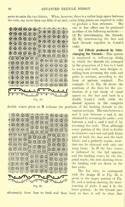
66 ADVANCED TEXTILE DESIGN
serve to unite the two fabrics. When, however, there is a rather large space between
the cuts, say more than one-fifth of an inch, extra tying places are required in order
to produce a fiim structure. The
cut or line effect can be producedin either of the following methods :
(1) By interchanging the threads.
(2) By interweaving the face and
back threads together in 3-and-3
order.
Cut Effects produced by Inter-
changing the Threads. This systemis employed in well-set-ujp__jclQths
in which the threads are arrangedin the proportion of 1 face to 1 back
in warp and weft, neat designs re-
sulting from reversing the ends and
picks in sections, according to the
form of pattern required. For
example, G in Fig. 56 shows the
positions of the lines for the pro-duction of a cut check of equal
spaces on the face and back in a
Fig. 59. double 3-and-3 twill, while the
shaded squares in the completedouble weave given at H indicate the positions of the backing threads in the
various sections. The cuts between a
and b, and between c and d, are
obtained by reversing the picks ; andbetween a and c, and b and d, by
reversing the ends. Thus, although
every portion of the cloth is double
in structure, each end and pick forms
part of both the face and the back
fabric, and a perfectly regula^. struc-
ture can be obtained with only one
warp beam. In H the face weaveis indicated by the full squares,and the backing weave by the dia-
gonal marks, the dots showing where
the backing ends are down on the
face picks.
The flat view, to correspondwith the design H in Fig. 56, is
given in the upper portion of Fig59, and a section showing the inter-
Fig. 60. weaving of picks 3 and 4 in the
lower portion. As the threads pa?salternately from face to back and from back to face, it will be clear that
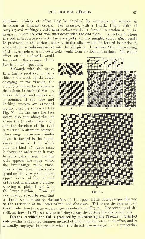
CUT DOUBLE CLOTHS 67
additional variety of effect may be obtained by arranging the threads as
to colour in different orders. For example, with a 1-dark, 1 -light order of
warping and we fting, a solid dark surface would be formed in section a of the
design H, where the odd ends interweave with the odd picks. In section b, where
the odd ends interweave with the even picks, an intermingled colour effect would
be produced on the surface, while a similar effect would be formed in section c.
where the even ends interweave with the odd picks. In section d the interweavingof the even ends with the even picks would form a solid light surface. The colour
effect on the underside would
be exactly the reverse of the
face in the solid portions.
Although with the weave
H a line is produced on both
sides of the cloth by the inter-
changing of the threads, the
3-and-3 twill is really continuous
throughout in both fabrics. Abetter denned and deeper cut
is obtained if the face and
backing weaves are arrangedon the principle shown at I in
Fig. 56. In this case the face
weave also cuts along the line
where the threads interchange,and the direction of the twill
is reversed in alternate sections.
The arrangement causes a similar
c-ut to be formed in the double
weave given at J, in which
only one kind of wreave markis shown, in order that it maybe more clearly seen how the
weft opposes the warp where
the interchange takes place.
This is also shown in the corre-
sponding flat view given in the
upper portion of Fig. 60, and
in the section showing the inter-
weaving of picks 1 and 2 in
the lower portion. From an Fig- 51.
examination it will be seen that
a thread which floats on the surface of the upper fabric interchanges directly
to the underside of the lower fabric, and vice versa. This is not the case with all
the threads when the weave is arranged as indicated in Fig. 59. The reversing of the
twill, as shown in Fig. 60, assists in bringing out the cutting line sharp and clear.
Designs in which the Cut is produced by interweaving the Threads in 3-and-3
order. This is the more common method of producing the cut or sunk effect, and it
is usually employed in cloths in which the threads are arranged in the proportion
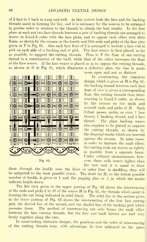
68 ADVANCED TEXTILE DESIGN
of 2 face to 1 back in warp and weft. In this system both the face and the backingthreads assist in forming the line, and it is necessary for the weaves to be arrangedin precise order in relation to the threads 'to obtain the best results. In the first
place at each cut two face threads between a pair of backing threads are arranged to
weave in 2-and-2 order with the face picks, and to oppose each other with their
floats, as shown by the crosses on the fourth and fifth ends and picks ot the face plan
given at F in Fig. 61. Also each face float of 2 is arranged to include a face end or
pick on each side of a backing end or pick. The face weave is then placed, as far
as possible, to support the cutting threads. Thus in F the float of one cuttingthread is a continuation of the twill, while that of the other increases the float
of the face weave. If the face weave is placed so as to oppose the cutting threads,as shown at G in Fig. 61, which illustrates a defective plan, the line is made
more open and not so distinct.
In constructing the complete
design, which is given at H in Fig. 61 ,
the backing thread between each face
float of two is given a correspondingfloat, the cutting threads thus inter-
weaving in 3-and-3 order, as shown
by the crosses on the sixth andseventh ends and picks of H. Each3-float passes under, or over, 1 face
thread, 1 backing thread, and 1 face
thread. The plain backing weavealso requires to be placed to supportthe cutting threads, as shown bythe diagonal marks which are inserted
against the crosses. In some cases,
in order to increase the sunk effect,
the cutting ends are woven as tightlyas possible from a separate beam.Under ordinary circumstances, how-
Fig. 62. ever, these ends weave tighter thanthe rest, and it is usual to draw
them through the healds near the front in order that, in shedding, they willbe subjected to the least possible strain. The draft for H, on the lowest possiblenumber of healds, is given at I, and the pegging plan at J, in which the marksindicate heajds down.
The flat view given in the upper portion of Fig. 62 shows the interweavingof the ends and picks 1 to 18 of the weave H in Fig. 61, the threads which assist in
forming the cut being indicated in solid black. The solid line in the section givenin the lower portion of Fig. 62 shows the interweaving of the first face cuttingpick, the dotted line of the second, and the shaded line of the backing pick whichprecedes them. The method of interweaving not only forms the sunk effectbetween the face cutting threads, but the face and back fabrics are tied veryfirmly together along the cuts.
In constructing elaborate designs, the positions and the order of interweavingof the cutting threads may, with advantage, be first indicated on the space-
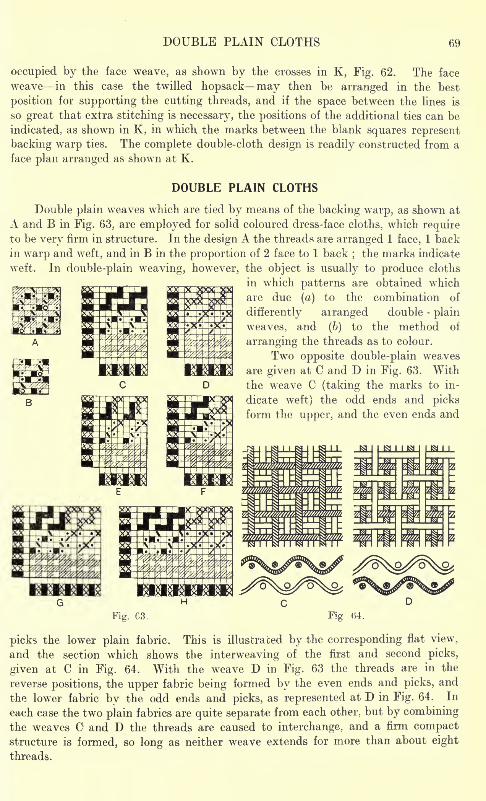
DOUBLE PLAIN CLOTHS 69
occupied by the face weave, as shown by the crosses in K, Fig. 62. The face
weave in this case the twilled hopsack may then be arranged in the best
position for supporting the cutting threads, and if the space between the lines is
so great that extra stitching is necessary, the positions of the additional ties can be
indicated, as shown in K, in which the marks between the blank squares represent
backing warp ties. The complete double-cloth design is readily constructed from a
face plan arranged as shown at K.
DOUBLE PLAIN CLOTHS
Double plain weaves which are tied by means of the backing warp, as shown at
A and B in Fig. 63, are employed for solid coloured dress-face cloths, which requireto be very firm in structure. In the design A the threads are arranged 1 face, 1 back
in warp and weft, and in B in the proportion of 2 face to 1 back;the marks indicate
wr
eft. In double-plain weaving, however, the object is usually to produce cloths
in which patterns are obtained which
are due (a) to the combination of
differently arranged double -plain
weaves, and (b) to the method of
arranging the threads as to colour.
Two opposite double-plain weaves
are given at C and D in Fig. 63. With
the weave C (taking the marks to in-
dicate weft) the odd ends and picks
form the upper, and the even ends and
_&
Fig. C3. Fig 04.
picks the lower plain fabric. This is illustrated by the corresponding flat view,
and the section which shows the interweaving of the first and second picks,
given at C in Fig. 64. With the weave D in Fig. 63 the threads are in the
reverse positions, the upper fabric being formed by the even ends and picks, and
the lower fabric by the odd ends and picks, as represented at D in Fig. 64. In
each case the two plain fabrics are quite separate from each other, but by combining
the weaves C and D the threads are caused to interchange, and a firm compactstructure is formed, so long as neither weave extends for more than about eight
threads.
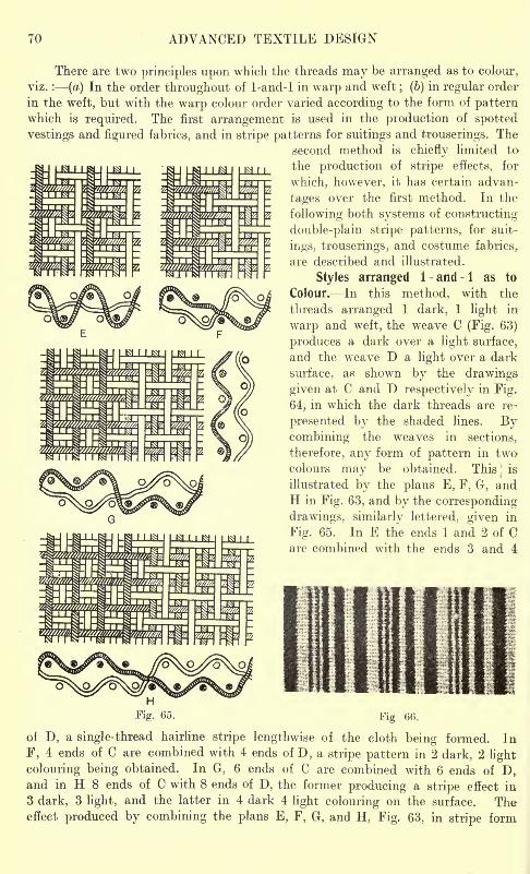
70 ADVANCED TEXTILE DESIGN
M 1 1
There are two principles upon which the threads may be arranged as to colour,
viz. : (a) In the order throughout of 1-and-l in warp and weft; (b) in regular order
in the weft, but with the warp colour order varied according to the form of patternwhich is required. The first arrangement is used in the production of spotted
vestings and figured fabrics, and in stripe patterns for suitings and trouserings. The
second method is chiefly limited to
the production of stripe effects, for
which, however, it has certain advan-
tages over the first method. In the
following both systems of constructing
double-plain stripe patterns, for suit-
ings, trouserings, and costume fabrics,
are described and illustrated.
Styles arranged 1-and-l as to
Colour. In this method, with the
threads arranged 1 dark, 1 light in
warp and weft, the weave C (Fig. 63)
produces a dark over a light surface,
and the weave D a light over a dark
surface, as shown by the drawings
given at C and D respectively in Fig.
64, in which the dark threads are re-
presented by the shaded lines. Bycombining the weaves in sections,
therefore, any form of pattern in twocolours may be obtained. ThisJ is
illustrated by the plans E, F, G, andH in Fig. 63, and by the corresponding-
drawings, similarly lettered, given in
Fig. 65. In E the ends 1 and 2 of Care combined with the ends 3 and 4
Fig (56.
of D, a single-thread hairline stripe lengthwise of the cloth being formed. In
F, 4 ends of C are combined with 4 ends of D, a stripe pattern in 2 dark. 2 light
colouring being obtained. In G, 6 ends of C are combined with 6 ends of D,and in H 8 ends of C with 8 ends of D, the former producing a stripe effect in
3 dark, 3 light, and the latter in 4 dark 4 light colouring on the surface. Theeffect produced by combining the plans E, F, G, and H, Fig. 63, in stripe form
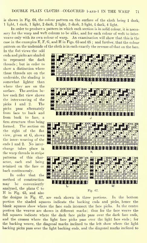
DOUBLE PLAIN CLOTHS COLOURED I-AND-! IN THE WARP 71
1 and 2. The
pass alternately
is shown in Fig. 66, the colour pattern on the surface of the cloth being 1 dark,1 light, 1 dark, 1 light, 2 dark, 2 light, 3 dark, 3 light, 4 dark, 4 light.
In order to produce a pattern in which each section is in solid colour, it is neces-
sary for the warp and weft colours to be alike, and for each colour of weft to inter-
weave only with its own colour of warp. An examination will show that this is the
case in the examples E, F, G, and H in Figs. 63 and 65; and further, that the colour
pattern on the underside of the cloth is in each exactly the reverse of that on the face.
In the flat views the odd
ends and picks are shaded
to represent the dark
threads;but in order to
show a distinction where
these threads are on the
underside, the shading is
somewhat lighter than
where they are on the
surface. The section be-
low each flat view shows
the interweaving of the
picks
picksfrom face to back and
from back to face, a
firm structure thus beingformed. The section on
the right of the flat
view, given at G, shows
the inter- weaving of the
ends 1 and 2. No inter-
change takes place in
the warp threads in stripe
patterns of this char-
acter, each end beingretained on the face or
back continuously.In order that the
method of construction
may be conveniently
analysed, the plans C to _.
H in Fig. 63, and also
the designs in Fig. 67, are each shown in three portions. In the bottom
portion the shaded squares indicate the backing ends and picks, hence the
blank squares show where the face ends intersect the face picks. In the centre
portion the weaves are shown in different marks; thus for the face weave the
full squares indicate where the dark face picks pass over the dark face ends,
and the crosses where the light face picks pass over the light face ends;
for
the backing weave, the diagonal marks inclined to the left show where the light
backing picks pass over the light backing ends, and the diagonal marks inclined to
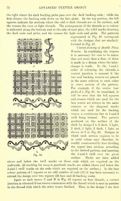
72 ADVANCED TEXTILE DESIGN
the right where the dark backing picks pass over the dark backing ends;while the
dots denote the backing ends down on the face picks. In the top portion, the full
squares indicate the sections where the odd or dark threads are on the surface, and
the crosses the even or light threads. The arrangement of the threads as to colour-
is indicated along the bottom and at the side of each plan, the solid marks denotingthe dark ends and picks, and the crosses the light ends and picks. The patterns
represented in Fig. 69 correspondwith the designs that are similarly
lettered in Fig. 67.
Correct Joining of Double Plain
Weaves. In combining the weaves
it is necessary for care to be taken
that not more than a float of three
is made in a design where the inter-
change is made. In the 1-and-l
order of colouring the threads, a
correct junction is assured if the
face and backing weaves are placedin the same relation to each other
in every section of the pattern.
For example, if the centre four
picks of I, Fig. 67, be examined; it
will be seen that the full squaresand crosses which are used for the
face weave are always in the same
relation to the diagonal marks
which are used for the backing
weave, a continuous line in l-and-3
twill being formed. The pattern
produced on the surface of the
cloth by design I is 2 dark, 3 light,
2 dark, 1 light, 2 dark, 1 light, as
shown at I in Fig. 69. Designs in
which each section requires to be
in solid colour may therefore be
readily constructed by first dividingthe repeat into sections accordingto the desired pattern, and insertingthe l-and-3 twill over the givensurface. Marks are then added
above and below the twill marks on those ends which are required on the
underside. (If marking for warp is practised, marks are added above and below the
3-and-l twill marks on the ends which are required on the surface.) As the face
colour pattern of I repeats on an odd number of ends (11) it has been necessary to
extend the design over two repeats (22 face and 22 backing ends).
Again as each weave C and D in Fig. 63 repeats on four threads, a correct
junction is obtained if one weave commences with the thread which is next in number
to the thread with which the other weave finished. Thus, in the design I the first
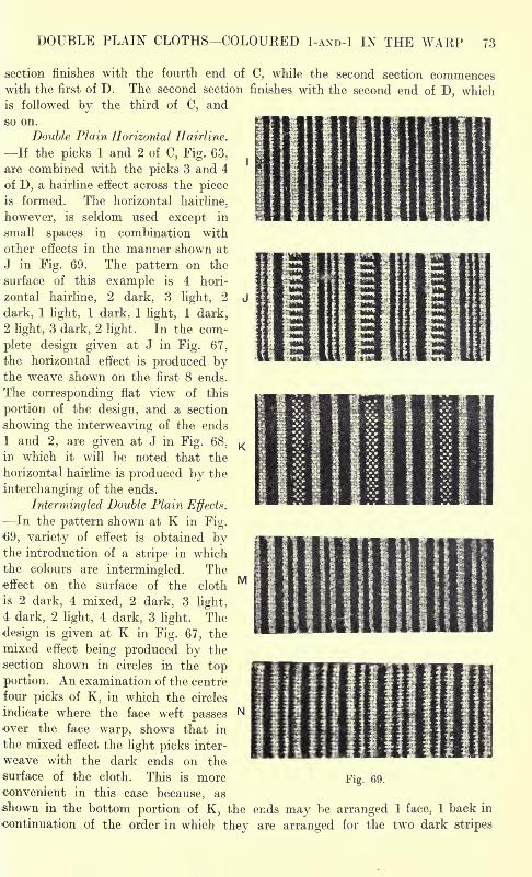
DOUBLE PLAIN CLOTHS COLOURED I-AND-! IN THE WARP 73
section finishes with the fourth end of C, while the second section commenceswith the first of D. The second section finishes with the second end of D, whichis followed by the third of C, and
so on.
Double Plain Horizontal Hairline.
If the picks 1 and 2 of C, Fig. 63,
are combined with the picks 3 and 4
of D, a hairline effect across the piece
is formed. The horizontal hairline,
however, is seldom used except in
small spaces in combination with
other effects in the manner shown at
J in Fig. 69. The pattern on the
surface of this example is 4 hori-
zontal hairline, 2 dark, 3 light, 2
dark, 1 light, 1 dark, 1 light, 1 dark,
2 light, 3 dark, 2 light, In the com-
plete design given at J in Fig. 67,
the horizontal effect is produced bythe weave shown on the first 8 ends.
The corresponding flat view of this
portion of the design, and a section
showing the interweaving of the ends
1 and 2, are given at J in Fig. 68.
in which it will be noted that the
horizontal hairline is produced by the
interchanging of the ends.
Intermingled Double Plain Effects.
In the pattern shown at K in Fig.
69, variety of effect is obtained bythe introduction of a stripe in which
the colours are intermingled. Theeffect on the surface of the cloth
is 2 dark, 4 mixed, 2 dark, 3 light,
4 dark, 2 light, 4 dark, 3 light. The
design is given at K in Fig. 67, the
mixed effect being produced by the
section shown in circles in the top
portion. An examination of the centre
four picks of K, in which the circles
indicate where the face weft passesover the face warp, shows that in
the mixed effect the light picks inter-
weave with the dark ends on the
surface of the cloth. This is more Fig. 69.
convenient in this case because, as
shown in the bottom portion of K, the ends may be arranged 1 face, 1 back in
continuation of the order in which they are arranged for the two dark stripes
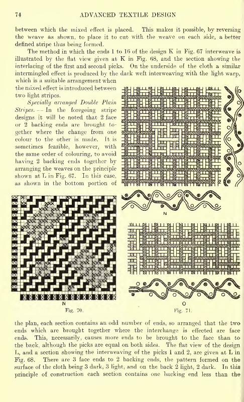
ADVANCED TEXTILE DESIGN
between which the mixed effect is placed. This makes it possible, by reversingthe weave as shown, to place it to cut with the weave on each side, a better
denned stripe thus being formed.
The method in which the ends 1 to 16 of the design K in Fig. 67 interweave is
illustrated by the flat view given at K in Fig. 68. and the section showing the
interlacing of the first and second picks. On the underside of the cloth a similar
intermingled effect is produced by the dark weft interweaving with the light warp,which is a suitable arrangement whenthe mixed effect is introduced between
two light stripes.
Specially arranged Double Plain
Stripes. In the foregoing stripe
designs it will be noted that 2 face
or 2 backing ends are brought to-
gether where the change from one
colour to the other is made. It is
sometimes feasible, however, with
the same order of colouring, to avoid
having 2 backing ends together by
arranging the weaves on the principle
shown at L in Fig. 67. In this case,
as shown in the bottom portion of
Fig. 70.
the plan, each section contains an odd number of ends, so arranged that the two-
ends which are brought together where the interchange is effected are face
ends. This, necessarily, causes more ends to be brought to the face than to
the back; although the picks are equal on both sides. The flat view of the design
L, and a section showing the interweaving of the picks 1 and 2, are given at L in
Fig. 68. There are 3 face ends to 2 backing ends, the pattern formed on the
surface of the cloth being 3 dark, 3 light, and on the back 2 light, 2 dark. In this
principle of construction each section contains one backing end less than the-
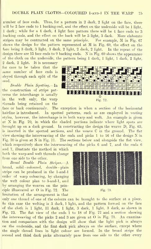
DOUBLE PLAIN CLOTHS COLOURED I-AND-! IN THE WARP 75
number of face ends. Thus, for a pattern in 2 dark, 2 light on the face, there
will be 2 face ends to 1 backing end, and the effect on the underside will be 1 light,
1 dark ;while for a 4 dark, 4 light face pattern there will be 4 face ends to 3
backing ends, and the effect on the back will be 3 light, 3 dark. More elaborate
stripes may be contructed on the same principle. For example, M in Fig. 67
shows the design for the pattern represented at M in Fig. 69, the effect on the
face being 3 dark, 3 light, 3 dark, 2 light, 2 dark, 2 light. In the repeat of the
design there are 15 face ends to 9 backing ends. N in Fig. 69 shows the appearanceof the cloth on the underside, the pattern being 1 dark, 1 light, 1 dark, 2 light,
2 dark, 2 light. It is necessaryfor care to be taken that the
same number of face ends is
sieyed through each split of the
reed.
Double Plain Spotting. In
the construction of stripe pat-terns the interchange is usually Qin the weft only, the warp Fi g> 72.
threads being retained on the
face or back continuously. The exception is when a section of the horizontal
hairline is introduced. In spotted patterns, such as are employed in vesting
styles, however, the interchange is in both warp and weft. An example is givenat N in Fig. 70, in which the shaded portions indicate where light spots are
brought up on a dark ground. In constructing the design the weave D, Fig. 63,
is inserted in the spotted sections, and the weave C in the ground. The flat
view showing the interweaving of the ends and picks 1 to 16 of the design N in
Fig. 70 is given at N in Fig. 71. The sections below and alongside the flat view,
which respectively show the interweaving of the picks 6 and 7, and the ends 6
, and 7, illustrate the method in which
j
both the warp and weft threads changefrom one side to the other.
Broad Double Plain Stripes. Abroad, solid - coloured, double -
plain
stripe can be produced in the 1-and-l
'order of warp colouring, by changingIthe weft colour plan to 3-and-l, and
by arranging the weaves on the prin-
ciple illustrated at in Fig. 72. The Fig. 73.
limitation of the arrangement is that
only one thread of one of the colours can be bi ought to the surface at a place.
In this case the wefting is 3 dark, 1 light, and the pattern formed on the face
of the cloth is 1 light, 11 dark, 1 light, 3 dark, 1 light. 3 dark, as shown in
Fig. 73. The flat view of the ends 1 to 18 of Fig. 72 and a section showingthe interweaving of the picks 2 and 3 are given at in Fig. 71. An examina-
tion and comparison with the design will show that the light pick is alwayson the underside, and the first dark pick always on the surface, except where
the single thread lines in light colour are formed. In the broad stripe the
second and third dark picks alternately pass from one side to the other every
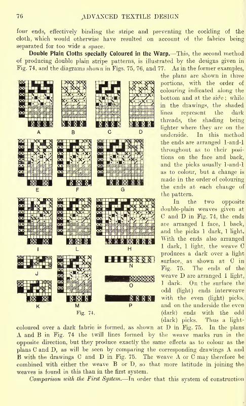
76 ADVANCED TEXTILE DESIGN
four ends, effectively binding the stripe and preventing the cockling of the
cloth, which would otherwise have resulted on account of the fabrics being
separated for too wide a space.Double Plain Cloths specially Coloured in the Warp. This, the second method
of producing double plain stripe patterns, is illustrated by the designs given in
Fig. 74, and the diagrams shown in Figs. 75, 76, and 77. As in the former examples,the plans are shown in three
portions, with the order of
colouring indicated along the
bottom and at the side ; while
in the drawings, the shaded
lines represent the dark
threads, the shading being
lighter where they are on the
underside. In this method
the ends are arranged 1-and-l
throughout as to their posi-
tions on the face and back,
and the picks usually 1-and-l
as to colour, but a change is
made in the order of colouringthe ends at each change of
the pattern.In the two opposite
double-plain weaves given at
C and D in Fig. 74, the ends
are arranged 1 face, 1 back,
and the picks 1 dark, 1 light.
With the ends also arranged1 dark, 1 light, the weave C
produces a dark over a light
surface, as shown at C in
Fig. 75. The ends of the
weave D are arranged 1 light,
1 dark. On the surface the
odd (light) ends interweave
with the even (light) picks,
and on the underside the even
(dark) ends with the odd
(dark) picks. Thus a light-
coloured over a dark fabric is formed, as shown at D in Fig. 75. In the plans
A and B in Fig. 74 the twill lines formed by the weave marks run in the
opposite direction, but they produce exactly the same effects as to colour as the
plans C and D, as will be seen by comparing the corresponding drawings A and
B with the drawings C and D in Fig. 75. The weave A or C may therefore be
combined with either the weave B or D, so that more latitude in joining the
weaves is found in this than in the first system.
Comparison with the First System. In order that this system of construction
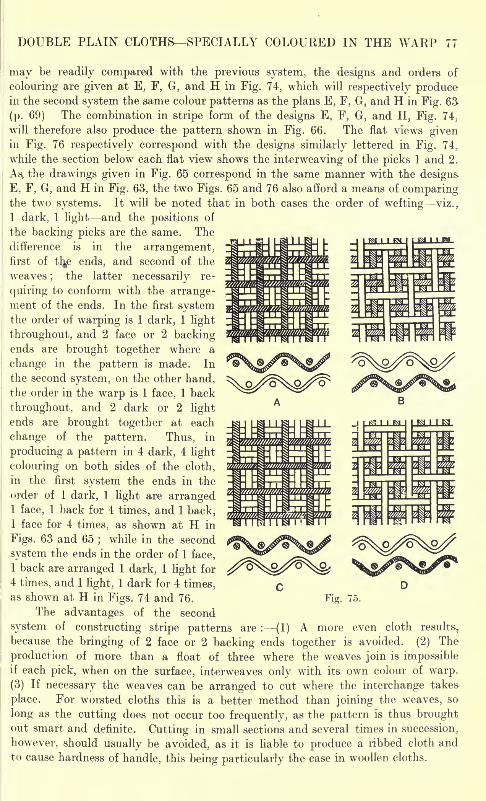
DOUBLE PLAIN CLOTHS SPECIALLY COLOURED IN THE WARP 77
may be readily compared with the previous system, the designs and orders of
colouring are given at E, F, G, and H in Fig. 74, which will respectively producein the second system the same colour patterns as the plans E, F, G, and H in Fig. 63
(p. 69) The combination in stripe form of the designs E, F, G, and H, Fig. 74;
will therefore also produce the pattern shown in Fig. 66. The flat views givenin Fig. 76 respectively correspond with the designs similarly lettered in Fig. 74,
while the section below each flat view shows the interweaving of the picks 1 and 2.
As, the drawings given in Fig. 65 correspond in the same manner with the designs
E, F, G, and H in Fig. 63, the two Figs. 65 and 76 also afford a means of comparingthe two systems. It will be noted that in both cases the order of wefting viz. r
1 dark, 1 light and the positions of
the backing picks are the same. The
difference is in the arrangement,first of ttys ends, and second of the
weaves;
the latter necessarily re-
quiring to conform with the arrange-ment of the ends. In the first systemthe order of warping is 1 dark, 1 light
throughout, and 2 face or 2 backingends are brought together where a
change in the pattern is made. In
the second system, on the other hand,
the order in the warp is 1 face, 1 back
throughout, and 2 dark or 2 light
ends are brought together at each
change of the pattern. Thus, in
producing a pattern in 4 dark, 4 light
colouring on both sides of the cloth,
in the first system the ends in the
order of 1 dark, I light are arranged1 face, 1 back for 4 times, and 1 back,1 face for 4 times, as shown at H in
Figs. 63 and 65;while in the second
system the ends in the order of 1 face,
1 back are arranged 1 dark, 1 light for
4 times, and 1 light, 1 dark for 4 times,
as shown at H in Figs. 74 and 76. Fig. 75.
The advantages of the second
system of constructing stripe patterns are : (1) A more even cloth results.,
because the bringing of 2 face or 2 backing ends together is avoided. (2) The
production of more than a float of three where the weaves join is impossibleif each pick, when on the surface, interweaves only with its own colour of warp.
(3) If necessary the weaves can be arranged to cut where the interchange takes
place. For worsted cloths this is a better method than joining the weaves, so
long as the cutting does not occur too frequently, as the pattern is thus broughtout smart and definite. Cutting in small sections and several times in succession,
however, should usually be avoided, as it is liable to produce a ribbed cloth andto cause hardness of handle, this being particularly the case in woollen cloths.
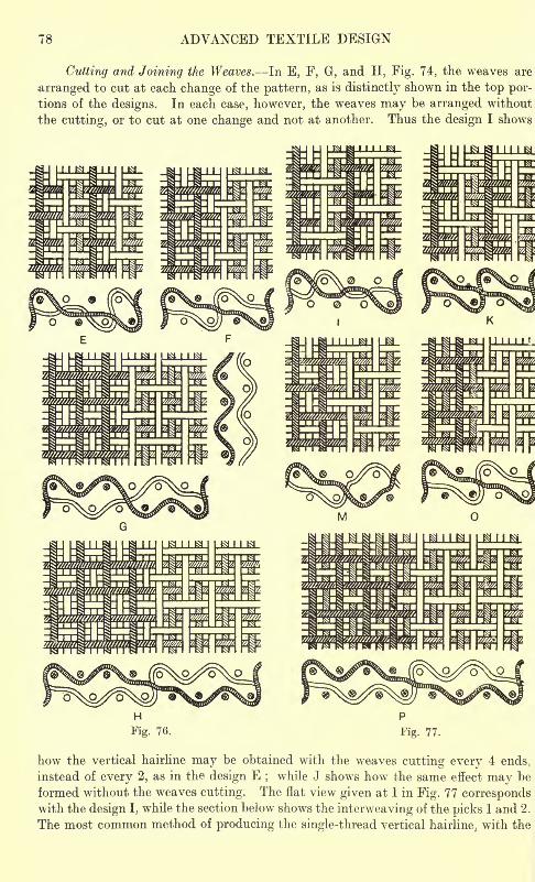
78 ADVANCED TEXTILE DESIGN
Cutting and Joining the Weaves. In E, F, G, and H, Fig. 74, the weaves are
arranged to cut at each change of the pattern, as is distinctly shown in the top por-
tions of the designs. In each case, however, the weaves may be arranged without
the cutting, or to cut at one change and not at another. Thus the design I shows
how the vertical hairline may be obtained with the weaves cutting every 4 ends,
instead of every 2, as in the design E ;while J shows how the same effect may be
formed without the weaves cutting. The flat view given at I in Fig. 77 correspondswith the design I, while the section below shows the interweaving of the picks 1 and 2.
The most common method of producing the single-thread vertical hairline;with the
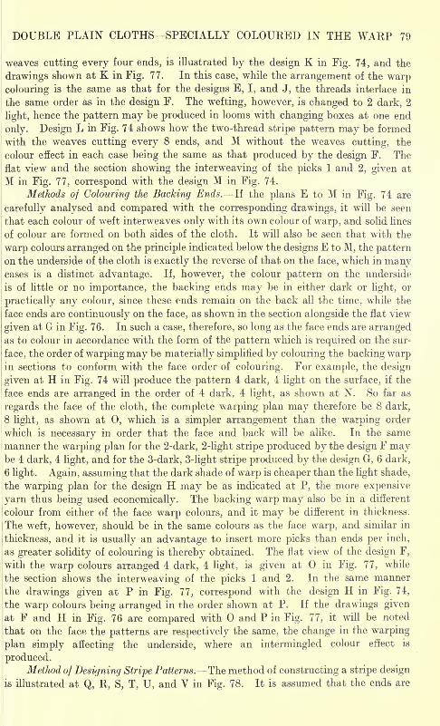
DOUBLE PLAIN CLOTHS SPECIALLY COLOURED IN THE WARP 79
weaves cutting every four ends, is illustrated by the design K in Fig. 74, and the
drawings shown at K in Fig. 77. In this case, while the arrangement of the warpcolouring is the same as that for the designs E, I, and J, the threads interlace in
the same order as in the design F. The wefting, however, is changed to 2 dark, 2
light, hence the pattern may be produced in looms with changing boxes at one end
only. Design L in Fig. 74 shows how the two-thread stripe pattern may be formed
with the weaves cutting every 8 ends, and M without the weaves cutting, the
colour effect in each case being the same as that produced by the design F. The
flat view and the section showing the interweaving of the picks 1 and 2, given at
M in Fig. 77, correspond with the design M in Fig. 74.
Methods of Colouring the Backing Ends. If the plans E to M in Fig. 74 are
carefully analysed and compared with the corresponding drawings, it will be seen
that each colour of weft interweaves only with its own colour of warp, and solid lines
of colour are formed on both sides of the cloth . It will also be seen that with the
warp colours arranged on the principle indicated below the designs E to M, the patternon the underside of the cloth is exactly the reverse of that on the face, which in manycases is a distinct advantage. If, however, the colour pattern on the underside
is of little or no importance, the backing ends may be in either dark or light, or
practically any colour, since these ends remain on the back all the time, while the
face ends are continuously on the face, as shown in the section alongside the flat view
given at G in Fig. 76. In such a case, therefore, so long as the face ends are arrangedas to colour in accordance with the form of the pattern which is required on the sur-
face, the order of warping may be materially simplified by colouring the backing warpin sections to conform with the face order of colouring. For example, the design
given at H in Fig. 74 will produce the pattern 4 dark. 4 light on the surface, if the
face ends are arranged in the order of 4 dark, 4 light, as shown at N. So far as
regards the face of the cloth, the complete warping plan may therefore be 8 dark,
18 light; as shown at 0, which is a simpler arrangement than the warping order
which is necessary in order that the face and back will be alike. In the same
manner the warping plan for the 2-dark, 2-light stripe produced by the design F maybe 4 dark, 4 light, and for the 3-dark, 3-light stripe produced by the design G, 6 dark,
6 light. Again, assuming that the dark shade of warp is cheaper than the light shade,
the warping plan for the design H may be as indicated at P, the more expensivei yarn thus being used economically. The backing warp may also be in a different
! colour from either of the face warp colours, and it may be different in thickness.
i The weft, however, should be in the same colours as the face warp, and similar in
i thickness, and it is usually an advantage to insert more picks than ends per inch,
as greater solidity of colouring is thereby obtained. The flat view of the design F,
with the warp colours arranged 4 dark, 4 light, is given at in Fig. 77, while
the section shows the interweaving of the picks 1 and 2. In the same manner
ithe drawings given at P in Fig. 77, correspond with the design H in Fig. 74,
the warp colours being arranged in the order shown at P. If the drawings givenat F and H in Fig. 76 are compared with and P in Fig. 77, it will be noted
that on the face the patterns are respectively the same, the change in the warping
plan simply affecting the underside, where an intermingled colour effect is
produced.Method of Designing Stripe Patterns. The method of constructing a stripe design
is illustrated at Q, R, S, T, U, and V in Fig. 78. It is assumed that the ends are
80 ADVANCED TEXTILE DESIGN
arranged 1 face, 1 back, the picks 1 dark, 1 light, and that the pattern to be formed
on the surface of the cloth is 3 dark, 2 light, 3 dark, 1 light, 2 dark, 1 light. The posi-
tion of the backing ends, the order of wefting at the side, and the face warping plan
below the ends, are first indicated, as shown at Q. The complete order of colouring
the ends may afterwards be arranged, as described with reference to the weave H,
Fig. 78.
Fig. 74 ; according to the effect which is required on the underside. R shows the
positions of the backing picks which are indicated in the dark sections on the
light picks, and in the light sections on the dark picks. The blank squares show
where the face ends and face picks intersect, and it will be noted that a dark end
intersects a dark pick, and a light end a light pick. Each colour of weft is thus
arranged to interweave on the face only with its own colour of warp ; and, if the
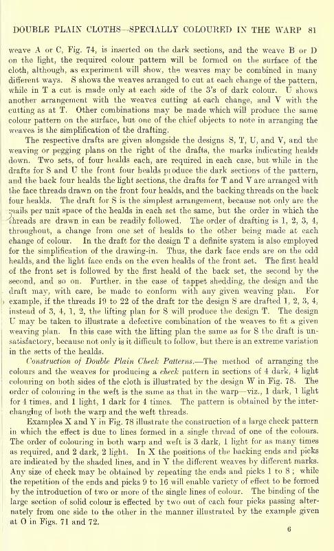
DOUBLE PLAIN CLOTHS SPECIALLY COLOURED IN THE WARP 81
weave A or C, Fig. 74, is inserted on the dark sections, and the weave B or Don the light, the required colour pattern will be formed on the surface of the
cloth, although, as experiment will show, the weaves may be combined in manydifferent ways. S shows the weaves arranged to cut at each change of the pattern,while in T a cut is made only at each side of the 3's of dark colour. U shows
another arrangement with the weaves cutting at each change, and V with the
cutting as at T. Other combinations may be made which will produce the same
colour pattern on the surface, but one of the chief objects to note in arranging the
weaves is the simplification of the drafting.
The respective drafts are given alongside the designs S, T, U, and V, and the
weaving or pegging plans on the right of the drafts, the marks indicating healds
down. Two sets, of four healds each, are required in each case, but while in the
drafts for S and U the front four healds produce the dark sections of the pattern,
and the back four healds the light sections, the drafts for T and V are arranged with
the face threads drawn on the front four healds, and the backing threads on the back
four healds. The draft for S is the simplest arrangement, because not only are the
rnails per unit space of the healds in each set the same, but the order in which the
chreads are drawn in can be readily followed. The order of drafting is 1, 2, 3, 4,
throughout, a change from one set of healds to the other being made at each
change of colour. In the draft for the design T a definite system is also employedfor the simplification of the drawing-in. Thus, the dark face ends are on the odd
healds, and the light face ends on the even healds of the front set. The first heald
of the front set is followed by the first heald of the back set, the second by the
second, and so on. Further, in the case of tappet shedding, the design and the
draft may, with care, be made to conform with any given weaving plan. For
r example, if the threads 19 to 22 of the draft for the design S are drafted 1, 2, 3, 4,
instead of 3, 4, 1, 2, the lifting plan for S will produce the design T. The design
U may be taken to illustrate a defective combination of the weaves to fit a given
weaving plan. In this case with the lifting plan the same as for S the draft is un-
satisfactory, because not only is it difficult to follow, but there is an extreme variation
in the setts of the healds.
Construction of Double Plain Check Patterns. The method of arranging the
colours and the weaves for producing a check pattern in sections of 4 dark, 4 light
colouring on both sides of the cloth is illustrated by the design W in Fig. 78. The
order of colouring in the weft is the same as that in the warp viz., 1 dark, 1 light
for 4 times, and 1 light, 1 dark for 4 times. The pattern is obtained by the inter-
changing of both the warp and the weft threads.
Examples X and Y in Fig. 78 illustrate the construction of a large check pattern
in which the effect is due to lines formed in a single thread of one of the colours.
The order of colouring in both warp and weft is 3 dark, 1 light for as many times
as required, and 2 dark, 2 light. In X the positions of the backing ends and picks
are indicated by the shaded lines, and in Y the different weaves by different marks.
Any size of check may be obtained by repeating the ends and picks 1 to 8 ;while
the repetition of the ends and picks 9 to 16 will enable variety of effect to be formed
by the introduction of two or more of the single lines of colour. The binding of the
large section of solid colour is effected by two out of each four picks passing alter-
nately from one side to the other in the manner illustrated by the example given
at in Figs. 71 and 72.6
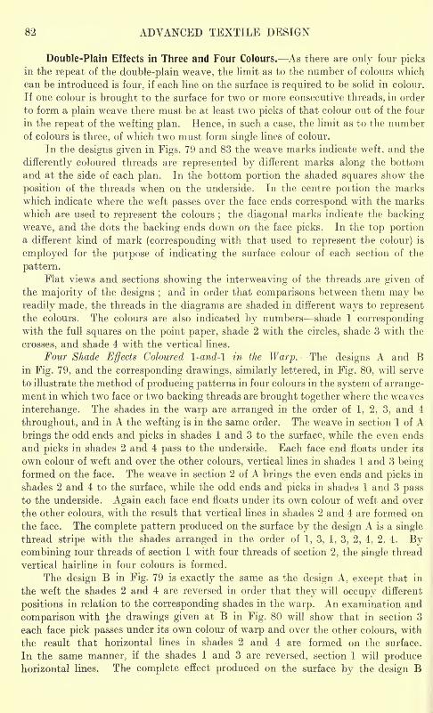
82 ADVANCED TEXTILE DESIGN
Double-Plain Effects in Three and Four Colours. As there are only four picksin the repeat of the double-plain weave, the limit as to the number of colours which
can be introduced is four, if each line on the surface is required to be solid in colour.
If one colour is brought to the surface for two or more consecutive threads, in order
to form a plain weave there must be at least two picks of that colour out of the four
in the repeat of the wefting plan. Hence, in such a case, the limit as to the numberof colours is three, of which two must form single lines of colour.
In the designs given in Figs. 79 and 83 the weave marks indicate weft, and the
differently coloured threads are represented by different marks along the bottom
and at the side of each plan. In the bottom portion the shaded squares show the
position of the threads when on the underside. In the centre portion the marks
which indicate where the weft passes over the face ends correspond with the marks
which are used to represent the colours;
the diagonal marks indicate the backing
weave, and the dots the backing ends down on the face picks. In the top portiona different kind of mark (corresponding with that used to represent the colour) is
employed for the purpose of indicating the surface colour of each section of the
pattern.
Flat views and sections showing the interweaving of the threads are given of
the majority of the designs ;and in order that comparisons between them may be
readily made, the threads in the diagrams are shaded in different ways to representthe colours. The colours are also indicated by numbers shade 1 correspondingwith the full squares on the point paper, shade 2 with the circles, shade 3 with the
crosses, and shade 4 with the vertical lines.
Four Shade Effects Coloured l-and-l in the Warp. The designs A and Bin Fig. 79, and the corresponding drawings, similarly lettered, in Fig. 80, will serve
to illustrate the method of producing patterns in four colours in the system of arrange-ment in which two face or two backing threads are brought together where the weaves
interchange. The shades in the warp are arranged in the order of 1, 2, 3, and 4
throughout, and in A the wefting is in the same order. The weave in section 1 of Abrings the odd ends and picks in shades 1 and 3 to the surface, while the even ends
and picks in shades 2 and 4 pass to the underside. Each face end floats under its
own colour of weft and over the other colours, vertical lines in shades 1 and 3 beingformed on the face. The weave in section 2 of A brings the even ends and picks in
shades 2 and 4 to the surface, while the odd ends and picks in shades 1 and 3 passto the underside. Again each face end floats under its own colour of weft and over
the other colours, with the result that vertical lines in shades 2 and 4 are formed on
the face. The complete pattern produced on the surface by the design A is a single
thread stripe with the shades arranged in the order of 1, 3, 1, 3, 2, 4, 2, 4. Bycombining lour threads of section 1 with four threads of section 2, the single thread
vertical hairline in four colours is formed.
The design B in Fig. 79 is exactly the same as the design A, except that in
the weft the shades 2 and 4 are reversed in order that they will occupy different
positions in relation to the corresponding shades in the warp. An examination and
comparison with the drawings given at B in Fig. 80 will show that in section 3
each face pick passes under its own colour of warp and over the other colours, with
the result that horizontal lines in shades 2 and 4 are formed on the surface.
In the same manner, if the shades 1 and 3 are reversed, section 1 will producehorizontal lines. The complete effect produced on the surface by the design B
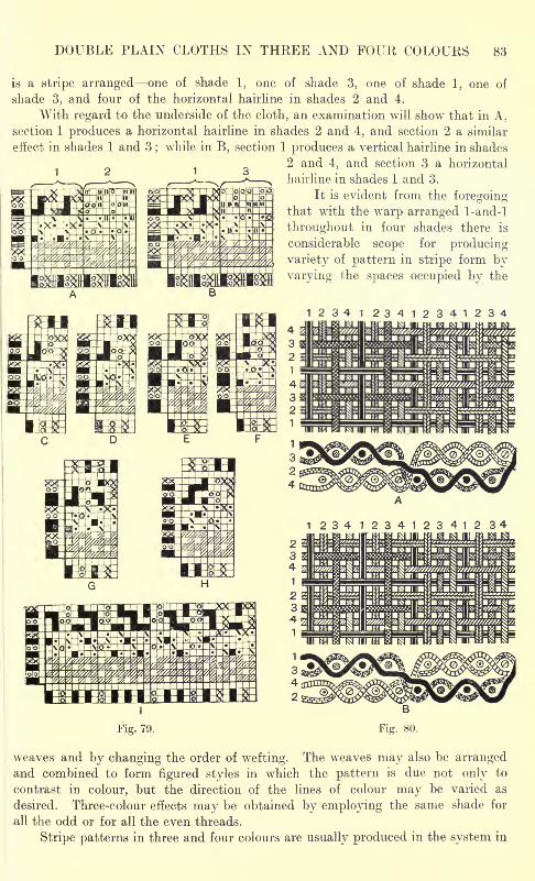
DOUBLE PLAIN CLOTHS IN THREE AND FOUR COLOURS 83
is a stripe arranged one of shade 1, one of shade 3, one of shade 1, one of
shade 3, and four of the horizontal hairline in shades 2 and 4.
With regard to the underside of the cloth, an examination will show that in A.
section 1 produces a horizontal hairline in shades 2 and 4, and section 2 a similar
effect in shades 1 and 3;while in B, section 1 produces a vertical hairline in shades
2 and 4, and section 3 a horizontal
hairline in shades 1 and 3.
It is evident from the foregoingthat with the warp arranged 1-and-l
throughout in four shades there is
considerable scope for producing
variety of pattern in stripe form by
varying the spaces occupied by the
1234123412341234
1234723412341234
Fig. 79.
weaves and by changing the order of wefting. The weaves may also be arrangedand combined to form figured styles in which the pattern is due not only to
contrast in colour, but the direction of the lines of colour may be varied as
desired. Three-colour effects may be obtained by employing the same shade for
-all the odd or for all the even threads.
Stripe patterns in three and four colours are usually produced in the system in
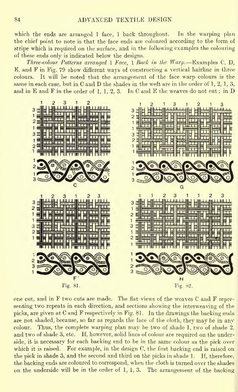
84 ADVANCED TEXTILE DESIGN
which the ends are arranged 1 face, 1 back throughout. In the warping planthe chief point to note is that the face ends are coloured according to the form of
stripe which is required on the surface, and in the following examples the colouringof these ends only is indicated below the designs.
Three-colour Patterns arranged 1 Face, 1 Back in the Warp. Examples C, D,
E, and F in Fig. 79 show different ways of constructing a vertical hairline in three
colours. It will be noted that the arrangement of the face warp colours is the
same in each case, but in C and D the shades in the weft are in the order of 1, 2. 1, 3,
and in E and F in the order of 1, 1, 2, 3. In C and E the weaves do not cut;in D
2312 2131213
1 231123
one cut, and in F two cuts are made. The flat views of the weaves C and F repre-
senting two repeats in each direction, and sections showing the interweaving of the
picks, are given at C and F respectively in Fig. 81 . In the drawings the backing ends
are not shaded, because, so far as regards the face of the cloth, they may be in anycolour. Thus, the complete warping plan may be two of shade 1, two of shade 2,
and two of shade 3, etc. If, however, solid lines of colour are required on the under-
side, it is necessary for each backing end to be in the same colour as the pick over
which it is raised. For example, in the design C, the first backing end is raised on
the pick in shade 3, and the second and third on the picks in shade 1. If, therefore,
the backing ends are coloured to correspond, when the cloth is turned over the shades
on the underside will be in the order of 1, 1, 3. The arrangement of the backing
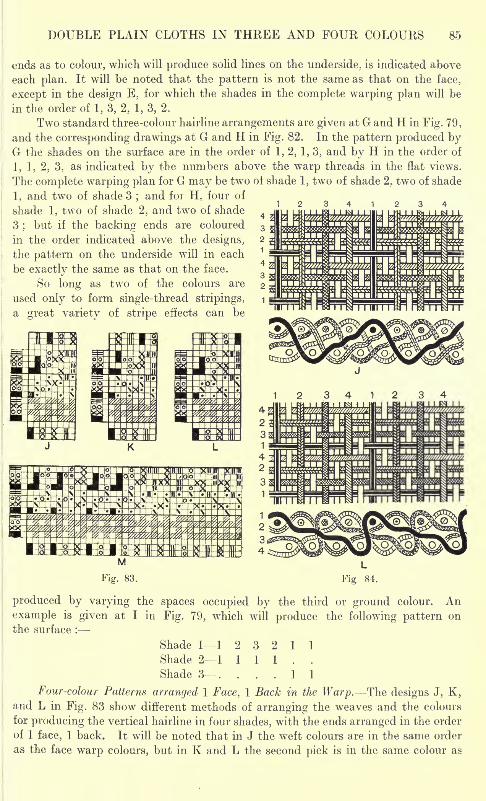
DOUBLE PLAIN CLOTHS IN THREE AND FOUR COLOURS 85
ends as to colour, which will produce solid lines on the underside, is indicated above
each plan. It will be noted that the pattern is not the same as that on the face,
except in the design E, for which the shades in the complete warping plan will be
in the order of 1, 3, 2. 1, 3, 2.
Two standard three-colour hairline arrangements are given at G and H in Fig. 79,
and the corresponding drawings at G and H in Fig. 82. In the pattern produced byG the shades on the surface are in the order of 1, 2, 1, 3, and by H in the order of
1, 1, 2, 3, as indicated by the numbers above the warp threads in the flat views.
The complete warping plan for G may be two ot shade 1, two of shade 2, two of shade
1, arid two of shade 3;and for H. four of
shade 1, two of shade 2, and two of shade
3;but if the backing ends are coloured
in the order indicated above the designs,
the pattern on the underside will in each
be exactly the same as that on the face.
So long as two of the colours are
used only to form single-thread stripings,
a great variety of stripe effects can be
produced by varying the spaces occupied by the third or ground colour. An
example is given at I in Fig. 79, which will produce the following pattern on
the surface :
Shade 11 232Shade 21 1 1 1
Shade 3. . . .
Four-colour Patterns arranged I Face, 1 Backand L in Fig. 83 show different methods of arranging the weaves and the colours
for producing the vertical hairline in four shades, with the ends arranged in the order
of 1 face, 1 back. It will be noted that in J the weft colours are in the same order
as the face wr
arp colours, but in K and L the second pick is in the same colour as
1 1
1 1
the Warp. The designs J, K,
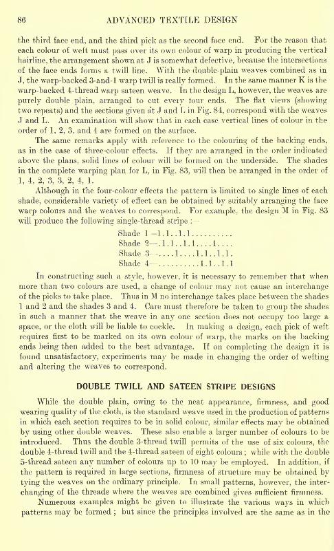
86 ADVANCED TEXTILE DESIGN
the third face end, and the third pick as the second face end. For the reason that
each colour of weft must pass over its own colour of warp in producing the vertical
hairline, the arrangement shown at J is somewhat defective, because the intersections
of the face ends forms a twill line. With the do.uble-plain weaves combined as in
J, the warp-backed 3-and-l warp twill is really formed. In the same manner K is the
warp-backed 4-thread warp sateen weave. In the design L, however, the weaves are
purely double plain, arranged to cut every tour ends. The flat views (showingtwo repeats) and the sections given at J and L in Fig. 84, correspond with the weaves
J and L. An examination will show that in each case vertical lines of colour in the
order of 1, 2, 3, and 4 are formed on the surface.
The same remarks apply with reference to the colouring of the backing ends,
as in the case of three-colour effects. If they are arranged in the order indicated
above the plans, solid lines of colour will be formed on the underside. The shades
in the complete warping plan for L, in Fig. 83, will then be arranged in the order of
1, 4, 2, 3, 3, 2, 4, 1.
Although in the four-colour effects the pattern is limited to single lines of each
shade, considerable variety of effect can be obtained by suitably arranging the face
warp colours and the weaves to correspond. For example, the design M in Fig. 83
will produce the following single-thread stripe :
Shade 11.1.. 1.1
Shade 2 .1 J . .1 .1. . . .1
Shade 3 ....1 1.1.. 1.1.
Shade 4- 1.1.. 1.1
In constructing such a style, however, it is necessary to remember that whenmore than two colours are used, a change of colour may not cause an interchangeof the picks to take place. Thus in M no interchange takes place between the shades
1 and 2 and the shades 3 and 4. Care must therefore be taken to group the shades
in such a manner that the weave in any one section does not occupy too large a
space, or the cloth will be liable to cockle. In making a design, each pick of weft
requires first to be marked on its own colour of warp, the marks on the backingends being then added to the best advantage. If on completing the design it is
found unsatisfactory, experiments may be made in changing the order of weftingand altering the weaves to correspond.
DOUBLE TWILL AND SATEEN STRIPE DESIGNS
While the double plain, owing to the neat appearance, firmness, and good
wearing quality of the cloth, is the standard weave used in the production of patternsin which each section requires to be in solid colour, similar effects may be obtained
by using other double weaves. These also enable a larger number of colours to be
introduced. Thus the double 3-thread twill permits of the use of six colours, the
double 4-thread twill and the 4-thread sateen of eight colours; while with the double
5-thread sateen any number of colours up to 10 may be employed. In addition, if
the pattern is required in large sections, firmness of structure may be obtained by
tying the weaves on the ordinary principle. In small patterns, however, the inter-
changing of the threads where the weaves are combined gives sufficient firmness.
Numerous examples might be given to illustrate the various ways in which
patterns may be formed;but since the principles involved are the same as in the
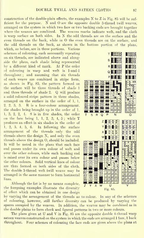
DOUBLE TWILL AND SATEEN CLOTHS 87
construction of the double-plain effects, the examples N to Z in Fig. 85 will be suf-
ficient for the purpose. N and are the opposite double 3-thread twill weaves,
arranged on the system in which two face or two backing ends are brought togetherwhere the weaves are combined. The weaves marks indicate weft, and the cloth
is warp surface on both sides. In N the odd threads are on the surface and the
even threads on the back, while in the even threads are on the surface, and
the odd threads on the back, as shown in the bottom portion of the plans,
which, as before, are in three portions. Various
schemes of colouring, each necessarily repeatingon six threads, are indicated above and along-side the plans, each shade being represented
by a different kind of mark. At P the order
of colouring in warp and weft is 1-and-l
throughout ;and assuming that six threads
of each weave are combined in stripe form,
as shown in Fig. 85, the pattern formed on
the surface will be three threads of shade 1
and three threads of shade 2. Q will producea solid coloured stripe pattern in three shades,
arranged on the surface in the order of 1, 1,
2, 2, 3, 3. R is a four-colour arrangement,the shades being brought up in the order of 1,
1, 3, 2, 2, 4. S is in five shades, the order
on the face being 1, 1, 2, 3, 4, 5;
while T
produces an effect in six shades in the order of
1, 2, 3, 4, 5, 6. In following the surface
arrangement of the threads only the oddthreads above the design N, and only the even
threads above the design 0, should be included.
It will be noted in the plans that each face
end passes under its own colour of weft andover the other colours, while each backing end
is raised over its own colour and passes below
the other colours. Solid vertical lines of colour
are thus formed on both sides of the cloth.
The double 3-thread weft twill weave may be
arranged in the same manner to form horizontal
lines.
Although the list is by no means complete,the foregoing examples illustrate the diversityof effect which can be obtained in one design
by varying the arrangement of the threads as to colour. In any of the schemes
of colouring, however, still further diversity can be produced by varying the
spaces occupied by the weaves. In addition, the weaves may be combined as in
the double plains to form check and figured patterns in two or more colours.
The plans given at U and V in Fig. 85 are the opposite double 4-thread warpsateen weaves constructed on the system in which the ends are arranged 1 face, 1 back
throughout. Four schemes of colouring the face ends are given above the plans at
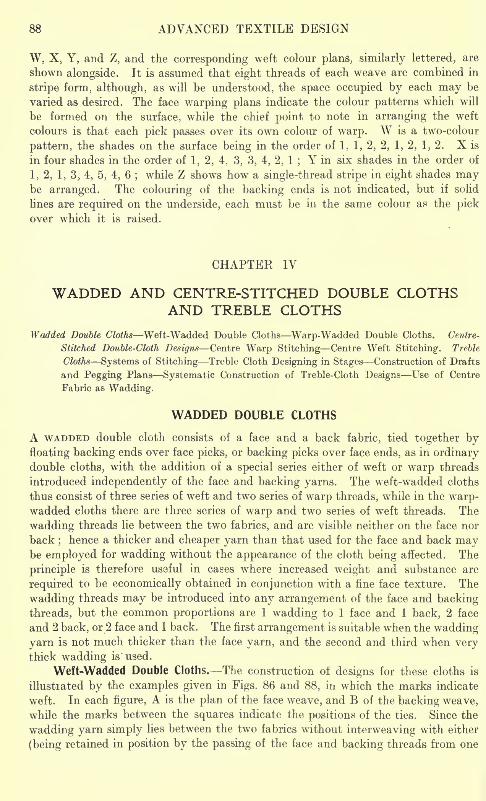
88 ADVANCED TEXTILE DESIGN
W, X. Y, and Z, and the corresponding weft colour plans, similarly lettered, are
shown alongside. It is assumed that eight threads of each weave are combined in
stripe form, although, as will be understood, the space occupied by each may be
varied as desired. The face warping plans indicate the colour patterns which will
be formed on the surface, while the chief point to note in arranging the weft
colours is that each pick passes over its own colour of warp. W is a two-colour
pattern, the shades on the surface being in the order of 1. 1, 2, 2, 1, 2. 1, 2. X is
in four shades in the order of 1, 2, 4, 3, 3, 4, 2, 1;Y in six shades in the order of
1, 2, 1, 3, 4, 5, 4, 6;while Z shows how a single-thread stripe in eight shades may
be arranged. The colouring of the backing ends is not indicated, but if solid
lines are required on the underside, each must be in the same colour as the pickover which it is raised.
CHAPTER IV
WADDED AND CENTRE-STITCHED DOUBLE CLOTHSAND TREBLE CLOTHS
Wadded Double Cloths Weft-Wadded Double Cloths Warp-Wadded Double Cloths. Centre-
Stitched Double-Cloth Designs Centre Warp Stitching Centre Weft Stitching. Treble
Cloths Systems of Stitching Treble Cloth Designing in Stages Construction of Drafts
and Pegging Plans Systematic Construction of Treble-Cloth Designs Use of Centre
Fabric as Wadding.
WADDED DOUBLE CLOTHS
A WADDED double cloth consists of a face and a back fabric, tied together byfloating backing ends over face picks, or backing picks over face ends, as in ordinarydouble cloths, with the addition of a special series either of weft or warp threads
introduced independently of the face and backing yarns. The weft-wadded cloths
thus consist of three series of weft and two series of warp threads, while in the warp-wadded cloths there are three series of warp and two series of weft threads. The
wadding threads lie between the two fabrics, and are visible neither on the face nor
back;hence a thicker and cheaper yarn than that used for the face and back may
be employed for wadding without the appearance of the cloth being affected. The
principle is therefore useful in cases where increased weight and substance are
required to be economically obtained in conjunction with a fine face texture. The
wadding threads may be introduced into any arrangement of the face and backing
threads, but the common proportions are 1 wadding to 1 face and 1 back, 2 face
and 2 back, or 2 face and 1 back. The first arrangement is suitable when the wadding
yarn is not much thicker than the face yarn, and the second and third when verythick wadding is' used.
Weft-Wadded Double Cloths. The construction of designs for these cloths is
illustrated by the examples given in Figs. 86 and 88, in which the marks indicate
weft. In each figure, A is the plan of the face weave, and B of the backing weave,
while the marks between the squares indicate the positions of the ties. Since the
wadding yarn simply lies between the two fabrics without interweaving with either
(being retained in position by the passing of the face and backing threads from one
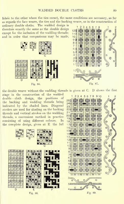
WADDED DOUBLE CLOTHS 89
fabric to the other where the ties occur), the same conditions are necessary, so far
as regards the face weave, the ties and the backing weave, as in the construction of
ordinary double cloths. The wadded design is 12345678therefore exactly the same as the double design _
except for the inclusion of the wadding threads; 1 1 z
and in order that comparisons may be made, 1019
1 2 3 910
i
the double weave without the wadding threads is given at C. D shows
stage in the construction of the wadded
double - cloth design, the positions of
the backing and wadding threads being
indicated by the shaded lines. Diagonalstrokes are used for shading on the backingthreads and vertical strokes on the wadding
threads, a convenient method in practice
consisting of using different colours. In
the complete design, given at E the full
the first
1 2
Fig. 88.
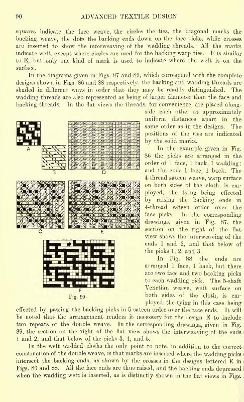
90 ADVANCED TEXTILE DESIGN
squares indicate the face weave, the circles the ties, the diagonal marks the
backing weave, the dots the backing ends down on the face picks, while crosses
are inserted to show the interweaving of the wadding threads. All the marksindicate weft, except where circles are used for the backing warp ties. F is similar
to E, but only one kind of mark is used to indicate where the weft is on the
surface.
In the diagrams given in Figs. 87 and 89, which correspond with the complete
designs shown in Figs. 86 and 88 respectively, the backing and wadding threads are
shaded in different ways in order that they may be readily distinguished. The
wadding threads are also represented as being of larger diameter than the face and
backing threads. In the flat views the threads, for convenience, are placed along-side each other at approximatelyuniform distances apart in the
same order as in the designs. The
positions of the ties are indicated
by the solid marks.
In the example given in Fig.86 the picks are arranged in the
order of 1 face, 1 back, 1 wadding;and the ends 1 face, 1 back. The4-thread sateen weave, warp surface
on both sides of the cloth, is em-
ployed, the tying being effected
by raising the backing ends in
4-thread sateen order over the
face picks. In the corresponding
drawings, given in Fig. 87, the
section on the right of the flat
view shows the interweaving of the
ends 1 and 2, and that below of
the picks 1; 2, and 3.
In Fig. 88 the ends are
arranged 1 face, 1 back, but there
are two face and two backing picksto each wadding pick. The 5-shaft
Venetian weave, weft surface on
both sides of the cloth, is em-
ployed, the tying in this case beingeffected by passing the backing picks in 5-sateen order over the face ends. It will
be noted that the arrangement renders it necessary for the design E to include
two repeats of the double weave. In the corresponding drawings, given in Fig.
89, the section on the right of the flat view shows the interweaving of the ends
1 and 2, and that below of the picks 3, 4, and 5.
In the weft wadded cloths the only point to note, in addition to the correct
construction of the double weave, is that marks are inserted where the wadding picksintersect the backing ends, as shown by the crosses in the designs lettered E in
Figs. 86 and 88. All the face ends are thus raised, and the backing ends depressedwhen the wadding weft is inserted, as is distinctly shown in the flat views in Figs.
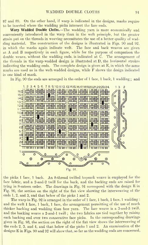
WADDED DOUBLE CLOTHS 91
1
87 and 89. On the other hand, if warp is indicated in the designs, marks requireto be inserted where the wadding picks intersect the face ends.
Warp Wadded Double Cloths. The wadding yarn is more economically and
conveniently introduced in the warp than in the weft principle, but the greater
strain put on the threads in weaving necessitates the use of a better quality of wad-
ding material. The construction of the designs is illustrated in Figs. 90 and 92 y
in which the marks again indicate weft. The face and back weaves are givenat A and B respectively in each figure, while for the purpose of comparison the
double weave, without the wadding ends, is indicated at C. The arrangement of
the threads in the warp-wadded design is illustrated at D, the horizontal strokes
indicating the wadding ends. The complete design is given at E, in which the same
marks are used as in the weft-wadded designs, while F shows the design indicated
in one kind of mark.
In Fig. 90 the ends are arranged in the order of 1 face, 1 back, 1 wadding ; and
2 3. 4. 5. 6. 7 8. 9.10.11.1 2. 13.14.15.16.17.18.1920.21.22.2a24. 1 3 2
Fig. 91.
the picks 1 face, 1 back. An 8-thread twilled hopsack weave is employed for the
face fabric, and a 2-and-2 twill for the back, and the backing ends are raised for
tying in 8-sateen order. The drawings in Fig. 91 correspond with the design E in
Fig. 90, the section on the right of the flat view showing the interweaving of the
ends 1, 2, and 3, and that below of the picks 1 and 2.
The warp in Fig. 92 is arranged in the order of 1 face, 1 back, 1 face, 1 wadding ;.
and the weft 1 face, 1 back, 1 face, the arrangement permitting of the use of much
thicker backing and wadding than face yarn. The face weave is a 3-and-3 twill,
and the backing weave a 2-and-l twill;the two fabrics are tied together by raising
each backing end over two consecutive face picks. In the corresponding drawings
given in Fig. 93, the section on the right of the flat view shows the interweaving of
the ends 2, 3, and 4, and that below of the picks 1 and 2. An examination of the
designs E in Figs. 90 and 92 will show that, so far as the wadding ends are concerned.
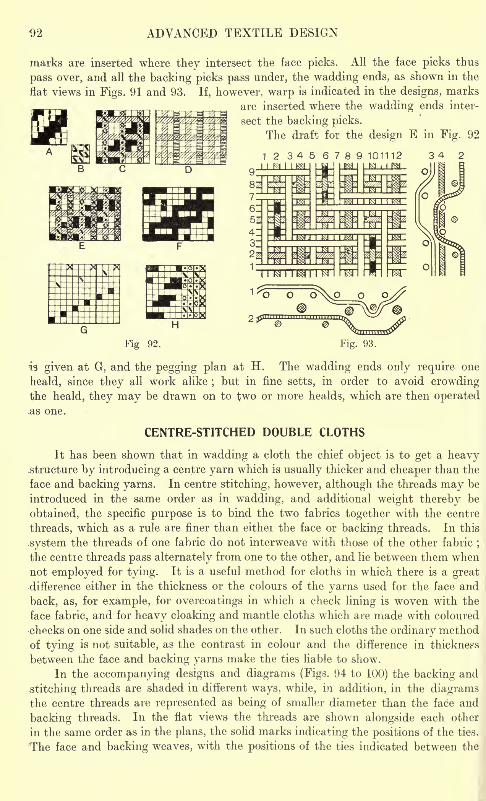
ADVANCED TEXTILE DESIGN
marks are inserted where they intersect the face picks. All the face picks thus
pass over, and all the backing picks pass under, the wadding ends, as shown in the
flat views in Figs. 91 and 93. If, however, warp is indicated in the designs, marks
are inserted where the wadding ends inter-
sect the backing picks.
The draft for the design E in Fig. 92
123456789 101112I I M I
Fig 92. Fig. 93.
is given at G. and the pegging plan at H. The wadding ends only require one
heald, since they all work alike;but in fine setts, in order to avoid crowding
the heald, they may be drawn on to two or more healds, which are then operated.as one.
CENTRE-STITCHED DOUBLE CLOTHS
It has been shown that in wadding a cloth the chief object is to get a heavy.structure by introducing a centre yarn which is usually thicker and cheaper than the
face and backing yarns. In centre stitching, however, although the threads may be
introduced in the same order as in wadding, and additional weight thereby be
obtained, the specific purpose is to bind the two fabrics together with the centre
threads, which as a rule are finer than either the face or backing threads. In this
.system the threads of one fabric do not interweave with those of the other fabric;
the centre threads pass alternately from one to the other, and lie between them when
not employed for tying. It is a useful method for cloths in which there is a greatdifference either in the thickness or the colours of the yarns used for the face and
back, as, for example, for overcoatings in which a check lining is woven with the
face fabric, and for heavy cloaking and mantle cloths which are made with coloured
checks on one side and solid shades on the other. In such cloths the ordinary method
of tying is not suitable, as the contrast in colour and the difference in thickness
between the face and backing yarns make the ties liable to show.
In the accompanying designs and diagrams (Figs. 94 to 100) the backing and
.stitching threads are shaded in different ways, while, in addition, in the diagramsthe centre threads are represented as being of smaller diameter than the face and
backing threads. In the flat views the threads are shown alongside each other
in the same order as in the plans, the solid marks indicating the positions of the ties.
The face and backing weaves, with the positions of the ties indicated between the
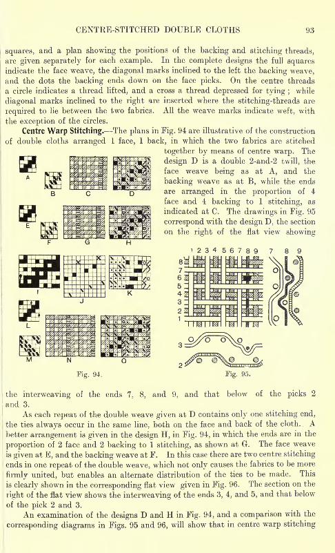
CENTRE-STITCHED DOUBLE CLOTHS
squares, and a plan showing the positions of the backing and stitching threads,
are given separately for each example. In the complete designs the full squaresindicate the face weave, the diagonal marks inclined to the left the backing weave,and the dots the backing ends down on the face picks. On the centre threads
a circle indicates a thread lifted, and a cross a thread depressed for tying ; while
diagonal marks inclined to the right are inserted where the stitching-threads are
required to lie between the two fabrics. All the weave marks indicate weft, with
the exception of the circles.
Centre Warp Stitching. The plans in Fig. 94 are illustrative of the construction
of double cloths arranged 1 face, 1 back, in which the two fabrics are stitched
together by means of centre warp. The
SB design D is a double 2-and-2 twill, then WK*ffiffiiB& face weave being as at A, and the
backing weave as at B, while the ends
are arranged in the proportion of 4
face and 4 backing to 1 stitching, as
indicated at C. The drawings in Fig. 95
correspond with the design D, the section
on the right of the flat view showing
1234
Fig. 94. Fig. 95.
the interweaving of the ends 7, 8, and 9, and that below of the picks 2
and 3.
As each repeat of the double weave given at D contains only one stitching end,
the ties always occur in the same line, both on the face and back of the cloth. . Abetter arrangement is given in the design H, in Fig. 94, in which the ends are in the
proportion of 2 face and 2 backing to 1 stitching, as shown at G. The face weave
is given at E, and the backing weave at F. In this case there are two centre stitching
ends in one repeat of the double weave, which not only causes the fabrics to be more
firmly united, but enables an alternate distribution of the ties to be made. This
is clearly shown in the corresponding flat view given in Fig. 96. The section on the
right of the flat view shows the interweaving of the ends 3, 4, and 5, and that below
of the pick 2 and 3.
An examination of the designs D and H in Fig. 94, and a comparison with the
corresponding diagrams in Figs. 95 and 96, will show that in centre warp stitching
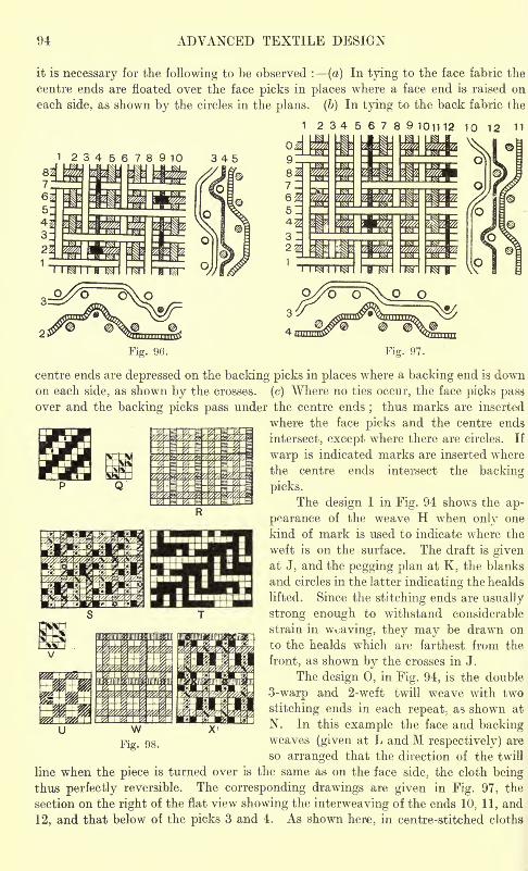
ADVANCED TEXTILE DESIGN
it is necessary for the following to be observed : (a) In tying to the face fabric the
centre ends are floated over the face picks in places where a face end is raised on
each side, as shown by the circles in the plans. (6) In tying to the back fabric the
1 23456789 101112 10 12 11
Fig. 96. Fig. 97.
centre ends are depressed on the backing picks in places where a backing end is downon each side, as shown by the crosses, (c) Where no ties occur, the face picks passover and the backing picks pass under the centre ends
;thus marks are inserted
where the face picks and the centre ends
intersect, except where there are circles. If
warp is indicated marks are inserted where
the centre ends intersect the backing
picks.
The design I in Fig. 94 sho\vs the ap-
pearance of the weave H when only one
kind of mark is used to indicate where the
weft is on the surface. The draft is givenat J, and the pegging plan at K, the blanks
and circles in the latter indicating the healds
lifted. Since the stitching ends are usually
strong enough to withstand considerable
strain in weaving, they may be drawn on
to the healds which are farthest from the
front, as shown by the crosses in J.
The design 0, in Fig. 94, is the double
3-warp and 2-weft twill weave with two
stitching ends in each repeat; as shown at
N. In this example the face and backingweaves (given at L and M respectively) are
so arranged that the direction of the twill
line when the piece is turned over is the same as on the face side, the cloth beingthus perfectly reversible. The corresponding drawings are given in Fig. 97, the
section on the right of the flat view showing the interweaving of the ends 10, 11, and
12, and that below of the picks 3 and 4. As shown here, in centre-stitched cloths
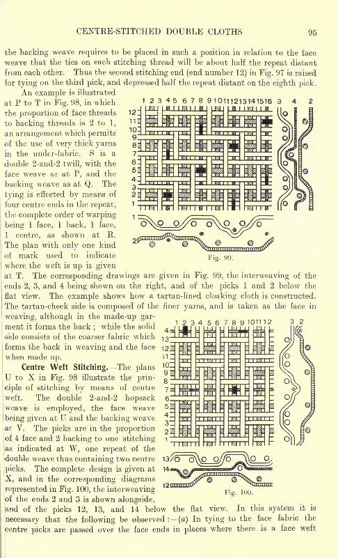
CENTRE-STITCHED DOUBLE CLOTHS 95
Fig. 99.
the backing weave requires to be placed in such a position in relation to the face
weave that the ties on each stitching thread will be about half the repeat distant
from each other. Thus the second stitching end (end number 12) in Fig. 97 is raised
for tying on the third pick, and depressed half the repeat distant on the eighth pick.
An example is illustrated
at P to T in Fig. 98, in which 12345678 910111213141516 342the proportion of face threads
to backing threads is 2 to 1,
an arrangement which permitsof the use of very thick yarnsin the under-fabric. S is a
double 2-and-2 twill, with the
face weave as at P, and the
backing weave as at Q. The
tying is effected by means of
I
four centre ends in the repeat,
; the complete order of warping
being 1 face, 1 back, 1 face,
1 centre, as shown at II .
The plan with only one kind
of mark used to indicate
where the weft is up is givenat T. The corresponding drawings are given in Fig. 99, the interweaving of the
ends 2, 3, and 4 being shown on the right, and of the picks 1 and 2 below the
flat view. The example shows how a tartan-lined cloaking cloth is constructed.
The tartan-check side is composed of the finer yarns, and is taken as the face in
weaving, although in the made-up gar-
ment it forms the back;while the solid
side consists of the coarser fabric which
forms the back in weaving and the face 122when made up.
Centre Weft Stitching. The plansU to X in Fig. 98 illustrate the prin-
ciple of stitching by means of centre
weft. The double 2-and-2 hopsackweave is employed, the face weave
being given at U and the backing weave
at V. The picks are in the proportionof 4 face and 2 backing to one stitching
indicated at W, one repeat of the
double weave thus containing two centre 13/O
picks. The complete design is given at Hi
X, and in the corresponding diagrams
represented in Fig. 100, the interweavingof the ends 2 and 3 is shown alongside,and of the picks 12, 13, and 14 below the flat view. In this system it is
necessary that the following be observed : (a) In tying to the face fabric the
centre picks are passed over the face ends in places where there is a face weft
Fig. 100.
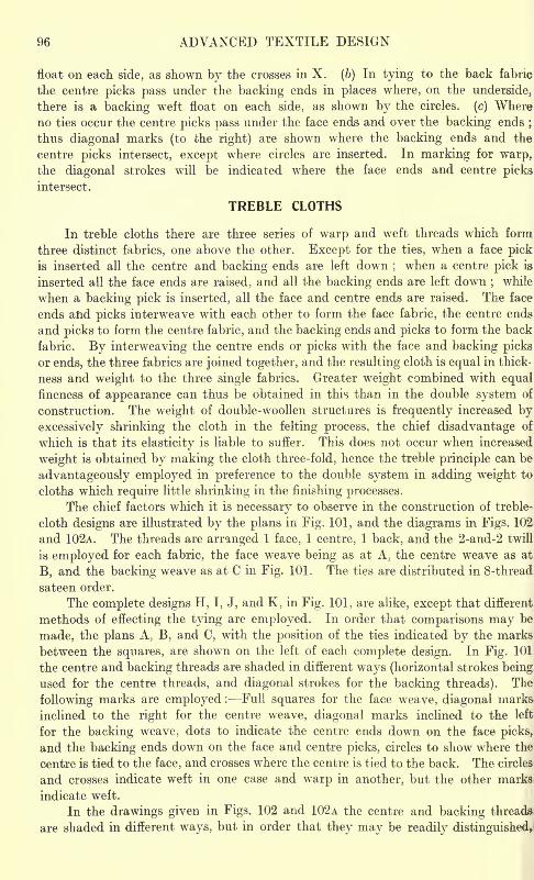
96 ADVANCED TEXTILE DESIGN
float on each side, as shown by the crosses in X. (b) In tying to the back fabric
the centre picks pass under the backing ends in places where, on the underside,
there is a backing weft float on each side, as shown by the circles, (c) Whereno ties occur the centre picks pass under the face ends and over the backing ends
;
thus diagonal marks (to the right) are shown where the backing ends and the
centre picks intersect, except where circles are inserted. In marking for warp,the diagonal strokes will be indicated where the face ends and centre picks
intersect.
TREBLE CLOTHS
In treble cloths there are three series of warp and weft threads which form,
three distinct fabrics, one above the other. Except for the ties, when a face pickis inserted all the centre and backing ends are left down
;when a centre pick is
inserted all the face ends are raised, and all the backing ends are left down;
while
when a backing pick is inserted, all the face and centre ends are raised. The face
ends and picks interweave with each other to form the face fabric, the centre ends
and picks to form the centre fabric, and the backing ends and picks to form the back
fabric. By interweaving the centre ends or picks with the face and backing picks
or ends, the three fabrics are joined together, and the resulting cloth is equal in thick-
ness and weight to the three single fabrics. Greater weight combined with equalfineness of appearance can thus be obtained in this than in the double system of
construction. The weight of double-woollen structures is frequently increased by
excessively shrinking the cloth in the felting process, the chief disadvantage of
which is that its elasticity is liable to suffer. This does not occur when increased
weight is obtained by making the cloth three-fold, hence the treble principle can be
advantageously employed in preference to the double system in adding weight to
cloths which require little shrinking in the finishing processes.
The chief factors which it is necessary to observe in the construction of treble-
cloth designs are illustrated by the plans in Fig. 101, and the diagrams in Figs. 102
and 102A. The threads are arranged 1 face, 1 centre, 1 back, and the 2-and-2 twill
is employed for each fabric, the face weave being as at A, the centre weave as at
B, and the backing weave as at C in Fig. 101. The ties are distributed in 8-thread
sateen order.
The complete designs H, I, J, and K, in Fig. 101, are alike, except that different
methods of effecting the tying are employed. In order that comparisons may be
made, the plans A, B, and C, with the position of the ties indicated by the marks
between the squares, are shown on the left of each complete design. In Fig. 101
the centre and backing threads are shaded in different ways (horizontal strokes being
used for the centre threads, and diagonal strokes for the backing threads). The
following marks are employed : Full squares for the face weave, diagonal marks
inclined to the right for the centre weave, diagonal marks inclined to the left
for the backing weave, dots to indicate the centre ends down on the face picks,
and the backing ends down on the face and centre picks, circles to show where the
centre is tied to the face, and crosses where the centre is tied to the back. The circles-
and crosses indicate weft in one case and warp in another, but the other marks
indicate weft.
In the drawings given in Figs. 102 and 102A the centre and backing threads
are shaded in different ways, but in order that they may be readily distinguished.
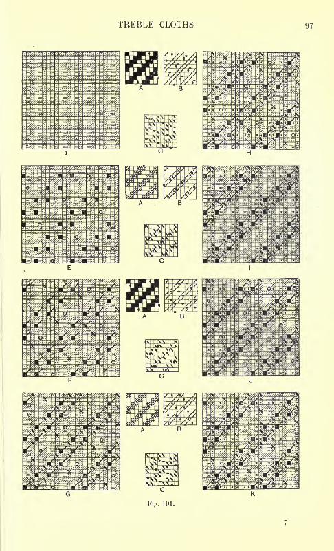
TREBLE CLOTHS 97
Fig. 101.
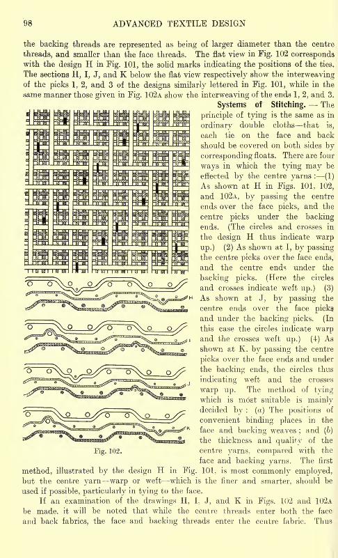
98 ADVANCED TEXTILE DESIGN
the backing threads are represented as being of larger diameter than the centre
threads, and smaller than the face threads. The flat view in Fig. 102 correspondswith the design H in Fig. 101, the solid marks indicating the positions of the ties.
The sections H, I, J, and K below the flat view respectively show the interweavingof the picks 1, 2, and 3 of the designs similarly lettered in Fig. 101, while in the
same manner those given in Fig. 102A show the interweaving of the ends 1, 2, and 3.
Systems of Stitching. The
principle of tying is the same as in
ordinary double cloths that is,
each tie on the face and back
should be covered on both sides by
corresponding floats. There are four
ways in which the tying may be
effected by the centre yarns : (1)
As shown at H in Figs. 101, 102,
and 102A, by passing the centre
ends over the face picks, and the
centre picks under the backingends. (The circles and crosses in
the design H thus indicate warp
up.) (2) As shown at I, by passingthe centre picks over the face ends,
and the centre ends under the
backing picks. (Here the circles
and crosses indicate weft up.) (3)
As shown at J, by passing the
centre ends over the face picks
and under the backing picks. (In
this case the circles indicate warpand the crosses weft up.) (4) As
shown at K. by passing the centre
picks over the face ends and under
the backing ends, the circles thus
indicating weft and the crosses
warp up. The method of tyingwhich is m6st suitable is mainlydecided by : (a) The positions of
convenient binding places in the
face and backing weaves;and (b)
the thickness and quality of the
Fig. 102. centre yarns, compared with the
face and backing yarns. The first
method, illustrated by the design H in Fig. 101. is most commonly employed,but the centre yarn warp or weft which is the finer and smarter, should be
used if possible, particularly in tying to the face.
If an examination of the drawings H, I. J, and K in Figs. 102 and 102A
be made, it will be noted that while the centre threads enter both the face
and back fabrics, the face and backing threads enter the centre fabric. Thus
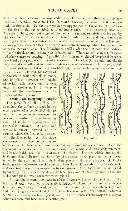
TEEBLE CLOTHS 99
in H the face picks and backing ends tie with the centre fabric, in I the face
ends and backing picks, in J the face and backing picks, and in K the face
and backing ends. So far as regards the appearance of the cloth, the positionof the ties in the centre fabric is of no importance. It is necessary, however,for care to be taken that none of the floats in the centre fabric are broken bythe ties, as this results in the cloth being harder woven, and may cause the
wefting capacity of the fabric to be seriously affected. The most perfect con-
ditions prevail when the ties in the centre are between corresponding floats, the sameas in the face and back. The following rule will enable the best possible conditions
to be obtained, assuming that weft is indicated : Where an end is raised for tying
(whether centre or backing), if possible the tying mark should be placed between
two blanks alongside each other of the weave to which the tie is made, and should
be preceded and followed by blanks on its own picks, as shown in H. Where a pickis floated for tying (whether centre or backing), if possible the tying mark should be
preceded and followed by marks of
the weave to which the tie is made,and be placed between two marks
alongside each other, on its own
ends, as shown in I. If warp is
indicated the conditions are the
reverse of the foregoing.
Treble Cloth Designing in Stages.
-The plans D to H in Fig. 101
show how the different stages in the
construction of a treble-cloth design
may be conveniently arranged in
working according to the foregoingrule. At D the arrangement of the
threads is indicated. At E the face
weave is shown inserted on the
squares where the face ends intersect
with the face picks. At this stagethe positions of the centre ties in
relation to the face weave are indicated, as shown by the circles,
centre weave is inserted on the squares where the centre ends and picks intersect,
and in a suitable position in relation to the circles. The ties which bind to the
back are then indicated as shown by the crosses, their positions being deter-
mined by the positions of suitable binding places in the centre weave. At G the
backing weave is inserted on the squares where the backing ends and picks intersect,
and in a suitable position in relation to the crosses. At H the design is completed
by marking down the centre ends on the face picks, and the backing ends on the face
and centre picks, except where ties are placed.An examination and comparison of the designs will show that in tying to the
face, in H and J each centre warp tie is indicated where a centre end intersects a
face pick, and in I and K each centre weft tie where a centre pick intersects a face
end. In tying to the back, in H and K each centre weft tie is indicated where a
centre pick intersects a backing end, and in I and J each centre warp tie is shown
where a centre end intersects a backing pick.
At F the
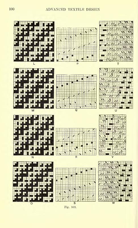
100 ADVANCED TEXTILE DESIGN
w
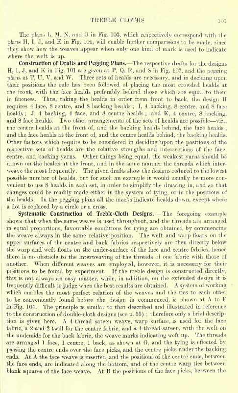
TREBLE CLOTHS 101
The plans L, M, N, and in Fig. 103, which respectively correspond with the
plans H, I, J, and K in Fig. 101, will enable further comparisons to be made, since
they show how the weaves appear when only one kind of mark is used to indicate
where the weft is up.
Construction of Drafts and Pegging Plans. The respective drafts for the designs
H, I, J, and K in Fig. 101 are given at P, Q, R, and S in Fig. 103, and the pegging
plans at T, U, V, and W. Three sets of healds are necessary, and in deciding upontheir positions the rule has been followed of placing the most crowded healds at
the front, with the face healds preferably behind those which are equal to themin fineness. Thus, taking the healds in order from front to back, the design Hrequires 4 face, 8 centre, and 8 backing healds
; I, 4 backing, 8 centre, and 8 face
healds; J, 4 backing, 4 face, and 8 centre healds
;and K, 4 centre, 8 backing,
and 8 face healds. Two other arrangements of the sets of healds are possible viz.,
the centre healds at the front of, and the backing healds behind, the face healds;
and the face healds at the front of, and the centre healds behind, the backing healds.
Other factors which require to be considered in deciding 'upon the positions of the
respective sets of healds are the relative strengths and intersections of the face,
centre, and backing yarns. Other things being equal, the weakest yarns should be
drawn on the healds at the front, and in the same manner the threads which inter-
weave the most frequently. The given drafts show the designs reduced to the lowest
possible number of healds, but for such an example it would usually be more con-
venient to use 8 healds in each set, in order to simplify the drawing in, and so that
changes could be readily made either in the system of tying, or in the positions of
the healds. In the pegging plans all the marks indicate healds down, except where
a dot is replaced by a circle or a cross.
Systematic Construction of Treble-Cloth Designs. The foregoing exampleshows that when the same weave is used throughout, and the threads are arrangedin equal proportions, favourable conditions for tying are obtained by commencingthe weave always in the same relative position. The weft and warp floats on the
upper surfaces of the centre and back fabrics respectively are then directly below
the warp and weft floats on the under-surface of the face and centre fabrics, hence
there is no obstacle to the interweaving of the threads of one fabric with those of
another. When different weaves are employed, however, it is necessary for their
positions to be found by experiment. If the treble design is constructed directly,
this is not always an easy matter, while, in addition, on the extended design it is
frequently difficult to judge when the best results are obtained. A system of workingwhich enables the most perfect relation of the weaves and the ties to each other
to be conveniently found before the design is commenced, is shown at A to Fin Fig. 104. The principle is similar to that described and illustrated in reference
to the construction of double-cloth designs (see p. 55) ;therefore only a brief descrip-
tion is given here. A 4-thread sateen weave, warp surface, is used for the face
fabric, a 2-and-2 twill for the centre fabric, and a 4-thread sateen, with the weft on
the underside for the back fabric, the weave marks indicating weft up. The threads
are arranged 1 face, 1 centre, 1 back, as shown at G, and the tying is effected by
passing the centre ends over the face picks, and the centre picks under the backingends. At A the face weave is inserted, and the positions of the centre ends, between
the face ends, are indicated along the bottom, and of the centre warp ties between
blank squares of the face weave. At B the positions of the face picks, between the
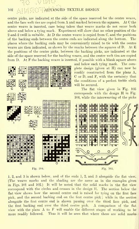
102 TEXTILE DESIGN
centre picks, are indicated at the side of the space reserved for the centre weave,
and the face weft ties are copied from A and marked between the squares. At C the
centre weave is inserted, care being taken that weave marks do not occur both
above and below a tying mark. Experiment will show that no other position of the
2-and-2 twill is suitable. At D the centre weave is copied from C, and the positions
of the backing ends between the centre ends are indicated along the bottom. The
places where the backing ends may be conveniently raised to tie with the centre
weave are then indicated, as shown by the marks between the squares of D. At Ethe positions of the centre picks, between the backing picks, are indicated at the
side of the space reserved for the backing weave, and the centre weft ties are copiedfrom D. At F the backing weave is inserted, if possible with a blank square above
and below each tying mark. The com-
plete design (given at H) can now be
readily constructed from the plans A,
C or D, and F, with the certainty that
the conditions of a perfect treble cloth
will be secured.
The flat view given in Fig. 105
corresponds with the design H in Fig.
104, while the interweaving of the picks
Fig. 104. Fig. 105.
1, 2, and 3 is shown below, and of the ends 1, 2, and 3 alongside the flat view.
(The weave marks and the shading are the same as in the examples givenin Figs. 101 and 102.) It will be noted that the solid marks in the flat view
correspond with the circles and crosses in the design H. The section below the
flat view shows howT the second centre end is raised for tying on the first face
pick, and the second backing end on the first centre pick ; while in the section
alongside the first centre end is shown passing over the third face pick, and
the first backing end over the third centre pick. A comparison of the flat
view with the plans A to F will enable the different stages of working to be
more readily followed. Thus it will be seen that where there are solid marks
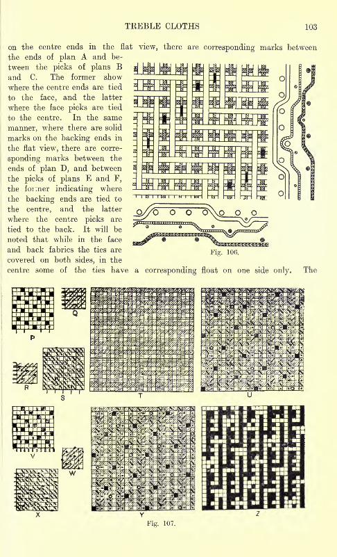
TREBLE CLOTHS 103
on the centre ends in the flat view, there are corresponding marks between
the ends of plan A and be-
tween the picks of plans Band C. The former show
where the centre ends are tied
to the face, and the latter
where the face picks are tied
to the centre. In the same
manner, where there are solid
marks on the backing ends in
the flat view, there are corre-
sponding marks between the
ends of plan D, and between
the picks of plans E and F,
the former indicating where
the backing ends are tied to
the centre, and the latter
where the centre picks are
tied to the back. It will be
noted that while in the face
and back fabrics the ties are
covered on both sides, in the
centre some of the ties have a corresponding float on one side only. The
Fig. 107.
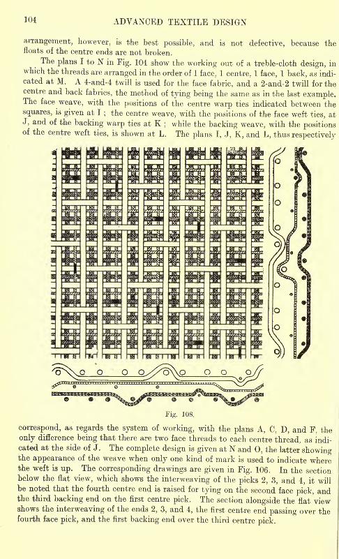
104 ADVANCED TEXTILE DESIGN
arrangement, however, is the best possible, and is not defective, because thefloats of the centre ends are not broken.
The plans I to N in Fig. 104 show the working out of a treble-cloth design, inwhich the threads are arranged in the order of 1 face, 1 centre.. 1 face, 1 back, as indi-
cated at M. A 4-and-4 twill is used for the face fabric, and a 2-and-2 twill for thecentre and back fabrics, the method of tying being the same as in the last example.The face weave, with the positions of the centre warp ties indicated between the
squares, is given at I ; the centre weave, with the positions of the face weft ties, at
J, and of the backing warp ties at K;while the backing weave, with the positions
of the centre weft ties, is shown at L. The plans I, J, K, and L, thus respectively
Fig. 108.
correspond, as regards the system of working, with the plans A, C, D, and F, the
only difference being that there are two face threads to each centre thread, as indi-
cated at the side of J. The complete design is given at N and 0, the latter showingthe appearance of the weave when only one kind of mark is used to indicate wherethe weft is up. The corresponding drawings are given in Fig. 106. In the sectionbelow the flat view, which shows the interweaving of the picks 2, 3, and 4, it will
be noted that the fourth centre end is raised for tying on the second face pick, andthe third backing end on the first centre pick. The section alongside the flat viewshows the interweaving of the ends 2, 3, and 4, the first centre end passing over thefourth face pick, and the first backing end over the third centre pick.
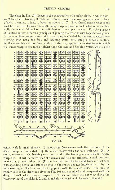
TREBLE CLOTHS 105
The plans in Fig. 107 illustrate the construction of a treble cloth, in which there
are 2 face and 2 backing threads to 1 centre thread, the arrangement being 1 face,
1 back, 1 centre, 1 face, 1 back, as shown at T. Five-thread sateen weaves are
used for the three fabrics, the cloth being warp surface on both sides, or reversible,
while the centre fabric has the weft float on the upper surface. For the purposeof illustration two different principles of joining the three fabrics together are given.
In the complete design, shown at U, the tying is effected by the centre ends inter-
weaving with both the face and backing wefts, this being a suitable method
for the reversible warp surface, while it is also very applicable to structures in which
the centre warp is not much thicker than the face and backing yarns, whereas the
centre weft is much thicker. P. shows the face weave with the positions of the
centre warp ties indicated; Q, the centre weave with the lace weft ties
; R, the
centre weave with the backing weft ties;and S, the backing weave with the centre
warp ties. It will be noted that the weaves and ties are arranged in such positions
in relation to each other that (1) the ties both on the face and back are between
corresponding floats, and (2) the floats in the centre are not interfered with by the
interweaving of the face and backing picks with the centre ends. This may be
readily seen if the drawings given in Fig. 108 are examined and compared with the
design U with which they correspond. The section below the flat view shows the
interweaving of the picks 1, 2, and 3, and that alongside of the ends 1, 2, and 3.
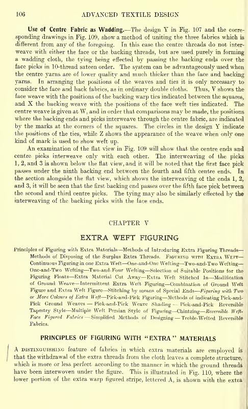
106 ADVANCED TEXTILE DESIGN
Use of Centre Fabric as Wadding. The design Y in Fig. 107 and the corre-
sponding drawings in Fig. 109, show a method of uniting the three fabrics which is
different from any of the foregoing. In this case the centre threads do not inter-
weave with either the face or the backing threads, but are used purely in forminga wadding cloth, the tying being effected by passing the backing ends over the
face picks in 10-thread sateen order. The system can be advantageously used whenthe centre yarns are of lower quality and much thicker than the face and backing
yarns. In arranging the positions of the weaves and ties it is only necessary to
consider the face and back fabrics, as in ordinary double cloths. Thus, V shows the
face weave with the positions of the backing warp ties indicated between the squares,and X the backing weave with the positions of the face weft ties indicated. Thecentre weave is given at W, and in order that comparisons may be made, the positionswhere the backing ends and picks interweave through the centre fabric, are indicated
by the marks at the corners of the squares. The circles in the design Y indicate
the positions of the ties, while Z shows the appearance of the weave when only one
kind of mark is used to show weft up.An examination of the flat view in Fig. 109 will show that the centre ends and
centre picks interweave only with each other. The interweaving of the picks
1, 2, and 3 is shown below the flat view, and it will be noted that the first face pick
passes under the ninth backing end between the fourth and fifth centre ends. In
the section alongside the flat view, which shows the interweaving of the ends 1, 2,
and 3, it will be seen that the first backing end passes over the fifth face pick betweenthe second and third centre picks. The tying may also be similarly effected by the
interweaving of the backing picks with the face ends.
CHAPTER V
EXTRA WEFT FIGURING
Principles of Figuring with Extra Materials Methods of Introducing Extra Figuring Threads
Methods of Disposing of the Surplus Extra Threads. FIGURING WITH EXTRA WEFTContinuous Figuring in one Extra Weft One-and-One Wefting Two-and-Two WeftingOne-and-Two Wefting Two-and-Four Wefting Selection of Suitable Positions for the
Figuring Floats Extra Material Cut Away Extra Weft Stitched In Modification
of Ground Weave Intermittent Extra Weft Figuring Combination of Ground Weft
Figure and Extra Weft Figure Stitching by means of Special Ends Figuring with Twoor More Colours of Extra Weft Pick-and-Pick Figuring Methods of indicating Pick-and-
Pick Ground Weaves Pick-and-Pick Weave Shading Pick-and-Pick Reversible
Tapestry Style Multiple Weft Persian Style of Figuring Chiaizing Reversible Weft-Face Fiyured Fabrics Simplified Methods of Designing Treble-Wefted Reversible
Fabrics.
PRINCIPLES OF FIGURING WITH "EXTRA" MATERIALS
A DISTINGUISHING feature of fabrics in which extra materials are employed is
that the withdrawal of the extra threads from the cloth leaves a complete structure,
which is more or less perfect according to the manner in which the ground threads
have been interwoven under the figure. This is illustrated in Fig. 110, where the
lower portion of the extra warp figured stripe, lettered A, is shown with the extra
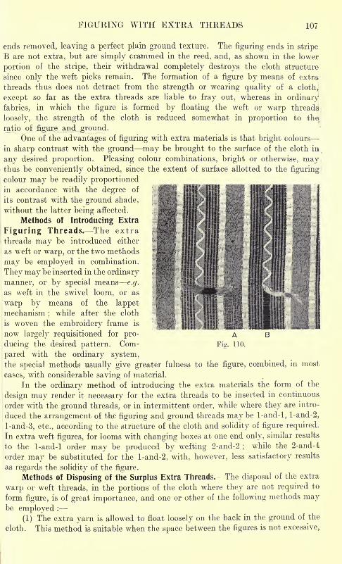
FIGURING WITH EXTRA THREADS 107
ends removed, leaving a perfect plain ground texture. The figuring ends in stripe
B are not extra, but are simply crammed in the reed, and, as shown in the lower
portion of the stripe, their withdrawal completely destroys the cloth structure
since only the weft picks remain. The formation of a figure by means of extra
threads thus does not detract from the strength or wearing quality of a cloth,
except so far as the extra threads are liable to fray out, whereas in ordinary
fabrics, in which the figure is formed by floating the weft or warp threads
loosely, the strength of the cloth is reduced somewhat in proportion to the
ratio of figure and ground.One of the advantages of figuring with extra materials is that bright colours -
in sharp contrast with the ground may be brought to the surface of the cloth in
any desired proportion. Pleasing colour combinations, bright or otherwise, maythus be conveniently obtained, since the extent of surface allotted to the figuring
colour may be readily proportionedin accordance with the degree of
its contrast with the ground shade,
without the latter being affected.
Methods of Introducing Extra
Figuring Threads. The extra
threads may be introduced either
as weft or warp, or the two methods
may be employed in combination.
They may be inserted in the ordinary
manner, or by special means e.g.
as weft in the swivel loom, or as
warp by means of the lappetmechanism
;while after the cloth
is woven the embroidery frame is
now largely requisitioned for pro-
ducing the desired pattern. Com-
pared with the ordinary system,the special methods usually give greater fulness to the figure, combined, in most
cases, with considerable saving of material.
In the ordinary method of introducing the extra materials the form of the
design may render it necessary for the extra threads to be inserted in continuous
order with the ground threads, or in intermittent order, while where they are intro-
duced the arrangement of the figuring and ground threads may be 1-and-l, l-and-2,
l-and-3, etc., according to the structure of the cloth and solidity of figure required.
In extra wreft figures, for looms with changing boxes at one end only, similar results,
to the 1-and-l order may be produced by wefting 2-and-2 ;while the 2-and-4
order may be substituted for the l-and-2, with, however, less satisfactory results
as regards the solidity of the figure.
Methods of Disposing of the Surplus Extra Threads. The disposal of the extra
warp or weft threads, in the portions of the cloth where they are not required to
form figure, is of great importance, and one or other of the following methods maybe employed :
(1) The extra yarn is allowed to float loosely on the back in the ground of the
cloth. This method is suitable when the space between the figures is not excessive,.
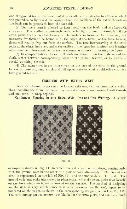
108 ADVANCED TEXTILE DESIGN
and the ground texture is dense, but it is usually not applicable to cloths in which
the ground is so light and transparent that the positions of the extra threads on
the back can be perceived from the face side.
(2) The extra yarn is allowed to float loosely on the back, and is afterwards
cut away. This method is eminently suitable for light ground textures, but it the
extra picks float somewhat loosely on the surface in forming the ornament, it is
necessary for them to be bound in at the edges of the figure, or the loose figuringfloats will readily fray out from the surface. The firm interweaving of the extra
picks at the edges, however, makes the outline of the figure less distinct, and is rather
objectionable unless employed in such a manner as to assist in forming the figure.
(3) In compact fabrics the extra threads are bound in on the underside of the
cloth, either between corresponding floats in the ground texture, or by means of
special stitching threads.
(4) The extra threads are interwoven on the face of the cloth in the groundfor the purpose of giving a rich and full appearance to what would otherwise be a
bare ground texture.
FIGURING WITH EXTRA WEFT
Extra weft figured fabrics nay be formed with one, two, or more extra wefts;
thus, including the ground threads, they consist of two or more series of weft threads
one series of warp threads.
Continuous Figuring in one Extra Weft~0ne-and-0ne Welting. A simple
Fig. 111.
example is shown in Fig. Ill in which one extra weft is introduced continuouslywith the ground weft in the order of a pick of each alternately. The face of the
cloth is represented on the left of Fig. Ill, and the underside on the right. The
ground ends and picks interweave in plain order, while the extra picks float loosely
on the back where no figure is formed on the surface. The method of designingfor the style is very simple, since it is only necessary for the weft figure to be-
indicated on the paper, as shown in the corresponding design given at C in Fig. 112.
The card-cutting particulars are cut blanks for the extra picks, and cut the ground
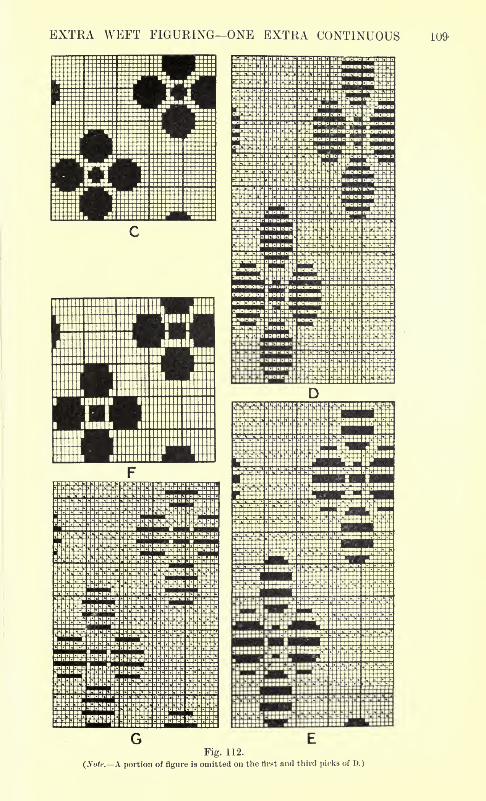
EXTRA WEFT FIGURING ONE EXTRA CONTINUOUS 109-
G EFig. 112.
(Sole. A portion of figure is omitted on the first and third picks of D.)
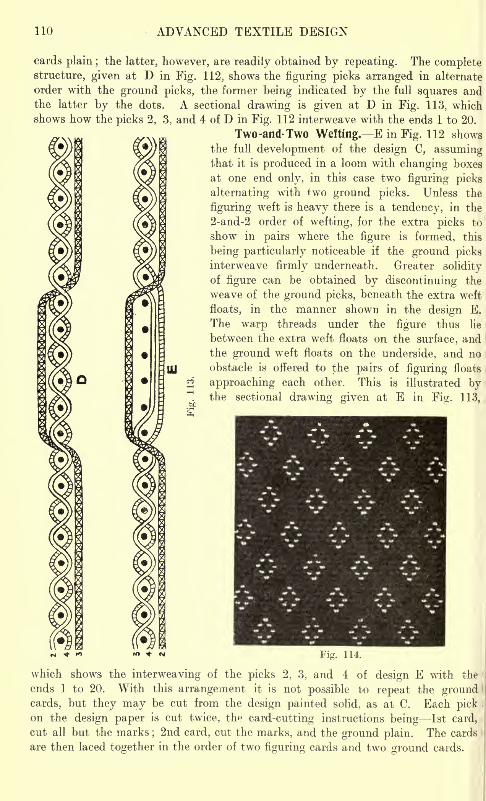
110 ADVANCED TEXTILE DESIGN
cards plain ; the latter, however, are readily obtained by repeating. The completestructure, given at D in Fig. 112, shows the figuring picks arranged in alternate
order with the ground picks, the former being indicated by the full squares andthe latter by the dots. A sectional drawing is given at D in Fig. 113, whichshows how the picks 2, 3, and 4 of D in Fig. 112 interweave with the ends 1 to 20.
Two -and-Two Wetting. E in Fig. 112 shows
the full development of the design C, assumingthat it is produced in a loom with changing boxes
at one end only, in this case two figuring picks
alternating with two ground picks. Unless the
figuring weft is heavy there is a tendency, in the
2-and-2 order of wefting, for the extra picks to
show in pairs where the figure is formed, this
being particularly noticeable if the ground picksinterweave firmly underneath. Greater solidity
of figure can be obtained by discontinuing the
weave of the ground picks, beneath the extra weft
floats, in the manner shown in the design E.
The warp threads under the figure thus lie
between the extra weft floats on the surface, andthe ground weft floats on the underside, and no
obstacle is offered to the pairs of figuring floats
^approaching each other. This is illustrated by
"~! the sectional drawing given at E in Fig. 113,
fto
" * " Fig. 114.
which shows the interweaving of the picks 2, 3, and 4 of design E with the
ends 1 to 20. With this arrangement it is not possible to repeat the groundcards, but they may be cut from the design painted solid, as at C. Each pickon the design paper is cut twice, the card-cutting instructions being 1st card,
cut all but the marks;2nd card, cut the marks, and the ground plain. The cards
are then laced together in the order of two figuring cards and two ground cards.
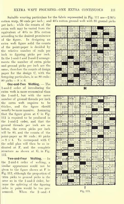
EXTRA WEFT FIGURING ONE EXTRA CONTINUOUS 111
Suitable weaving particulars for the fabric represented in Fig. Ill are 2/80's
cotton warp, 80 ends per inch;and 40's cotton ground weft with 80 ground picks
per inch;
while the counts of the
extra weft may be varied from the
equivalent of 40's to 20's cotton
according to the desired prominenceof the figure. In designing an
extra weft figure solid the counts
of the point-paper is decided bythe relative number of ends per
inch to figuring picks per inch.
In the 1-and-l and 2-and-2 arrange-
ments the number of extra picks
and ground picks per inch are the
same, therefore the counts of design
paper for the design C, with the
foregoing particulars, is as 80 ends :
80 picks= 8x8.
One-and-Two Wetting. The
l-and-2 order of introducing the
extra weft is more economical than
the 1-and-l, but with the same
number of ground threads per inch
the extra weft requires to be
thicker, and the figure should
usually be more massive. Assumingthat the figure given at C in Fig.
;112 is required to be produced in
the l-and-2 order, and that the
ground threads per inch are as
before, the extra picks per inch
will be 40, and the counts of the
point-paper as 80 ends : 40 picks= 8x4. To correspond with Cthe solid plan will then be as in-
dicated at F, and the completestructure as shown at G, in Fig.
112.
Two-and-Four Wetting. In
the 2-and-4 order of wefting, a
similar appearance could not be
given to the figure shown at F in
Fig. 112, although the proportion of
3xtra picks to ground picks is the
>ame as in the l-and-2 order, be-
cause the splitting of the figuring
picks in pairs would be too pro-lounced. When the 2 -and -4 Fig. 115.
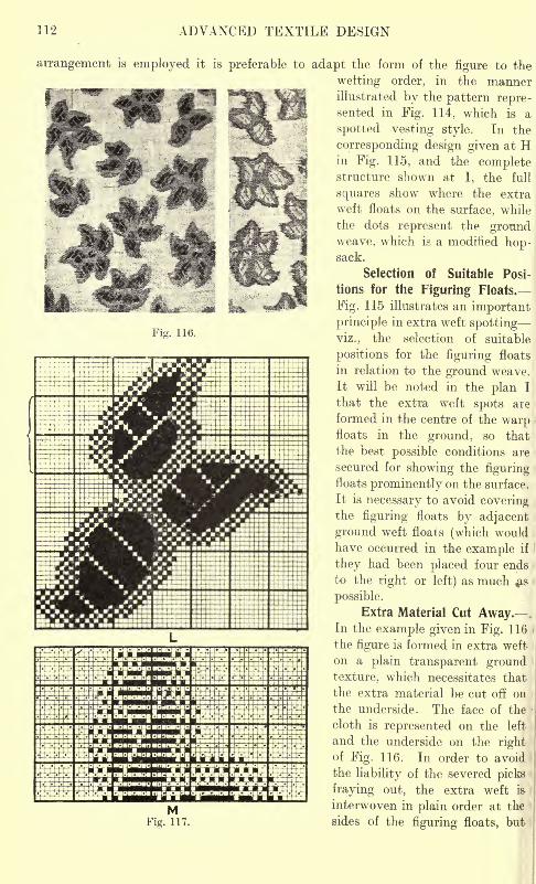
312 ADVANCED TEXTILE DESIGN
Fig. 116.
arrangement is employed it is preferable to adapt the form of the figure to the
wetting order, in the mannerillustrated by the pattern repre-sented in Fig. 114, which is a
spotted vesting style. In the
corresponding design given at Hin Fig. 115, and the complete
'
^^P^ -^PBI: structure shown at I, the full
S(luares snow where the extra
^(P"~^
j^^^*^^ll we^ floats on the surface, while
the dots represent the groundweave, which is a modified hop-sack.
Selection of Suitable Posi-
tions for the Figuring Floats.
Fig. 115 illustrates an important
principle in extra weft spotting
viz., the selection of suitable
positions for the figuring floats
in relation to the ground weave.
It will be noted in the plan I
that the extra weft spots are
formed in the centre of the warpfloats in the ground, so that
the best possible conditions are
secured for showing the figuringfloats prominently on the surface.
It is necessary to avoid coveringthe figuring floats by adjacent
ground weft floats (which would
have occurred in the example if
they had been placed four ends
to the right or left) as much $&
possible.
Extra Material Cut Away.In the example given in Fig. 116 i
the figure is formed in extra weft
on a plain transparent groundtexture, which necessitates that
the extra material be cut off on i
the underside. The face of the -
cloth is represented on the left
and the underside on the rightof Fig. 116. In order to avoid
the liability of the severed picks
fraying out, the extra weft is I
interwoven in plain order at the !
sides of the figuring floats, but
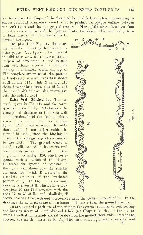
EXTRA WEFT FIGURING ONE EXTRA CONTINUOUS 113
as this causes the shape of the figure to be modified, the plain interweaving is
shown extended completely round so as to produce an opaque outline between
the weft figure and the thin ground texture. More plain weave is shown than
is really necessary to bind the figuring floats, the idea in this case having been
to form distinct shapes upon which to
develop the figure.
The plan L in Fig. 117 illustrates
the method of indicating the design upon
point-paper. The figure is first paintedin solid, then weaves are inserted for the
purpose of developing it, and to stop
long weft floats, after which the plain
binding is indicated round the figure.
The complete structure of the portionof L indicated between brackets is shown
at M in Fig. 117 ;while N in Fig. 118
shows how the last extra pick of M and
the ground pick on each side interweave
with the ends 15 to 34.
Extra Weft Stitched In. The ex-
ample given in Fig. 119 and the corre-
sponding plans in Fig. 120 illustrate the
principle of stitching in the extra weft
on the underside of the cloth in places
where it is not required for forming-
figure. For fabrics in which the addi-
tional weight is not objectionable, the
method is useful, since the binding in
of the extra weft gives greater substance
to the cloth. The ground weave is
2-and-2 twill, and the picks are inserted
continuously in the order of 1 extra,
1 ground. Q in Fig. 120, which corre-
sponds with a portion of the design,
illustrates the system of painting in
the figure, and shows how the stitches
are indicated;
while R represents the
complete structure of the bracketed
portion of Q. In Fig. 118 a sectional
drawing is given at S, which shows howthe picks 20 and 21 interweave with the
ends 17 to 36 of R; and, similarly, T
shows how the twentieth end interweaves with the picks 17 to 32 of R. In the
drawings the extra picks are shown larger in diameter than the ground threads.
In arranging the positions of the stitches the system is similar to constructingthe backing weave of a weft-backed fabric (see Chapter I) that is, the end on
which a weft stitch is made should be down on the ground picks which precede and
succeed the stitch. Thus in R, Fig. 120, each stitching mark is preceded and8
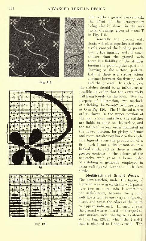
114 ADVANCED TEXTILE DESIGN
Fig. 119.
followed by a ground weave mark,the effect of the arrangement
being clearly shown in the sec-
tional drawings given at S and Tin Fig. 118.
Generally the ground weft
floats will close together and effec-
tively conceal the binding points,but if the figuring weft is muchthicker than the ground weft
there is a liability of the stitches
forcing the ground picks apart and
showing on the surface, particu-
larly if there is a strong colour
contrast between the figuring weft
and the ground. In such a case
the stitches should be as infrequent as
possible, in order that the extra pickswill hang loosely on the back. For the
purpose of illustration, two methodsof stitching the 2-and-2 twill are givenat Q in Fig. 120. The 16-thread sateen
order, shown in the upper portion of
the plan is more suitable if the stitches
are liable to show on the surface, andthe 8-thread sateen order indicated in
the lower portion, for giving a firmer
and more satisfactory back to the cloth.
In a figured fabric the production of a
firm back is not so important as in a
backed cloth, and as there is usually
greater contrast in the colours of the
respective weft yarns, a looser order
of stitching is generally employed in
extra weft-figured cloths than in backed
cloths.
Modification of Ground Weave.The continuation, under the figure, of
a ground weave in which the weft passesover two or more ends, is sometimes
not satisfactory, because the groundweft floats tend to cover up the figuring
floats, and cause the edges of the figureto appear indistinct. In such a case
the ground weave should be changed to
warp surface under the figure, as shownat K in Fig. 120, in which the 2-and-2
twill is changed to l-and-3 twill. The
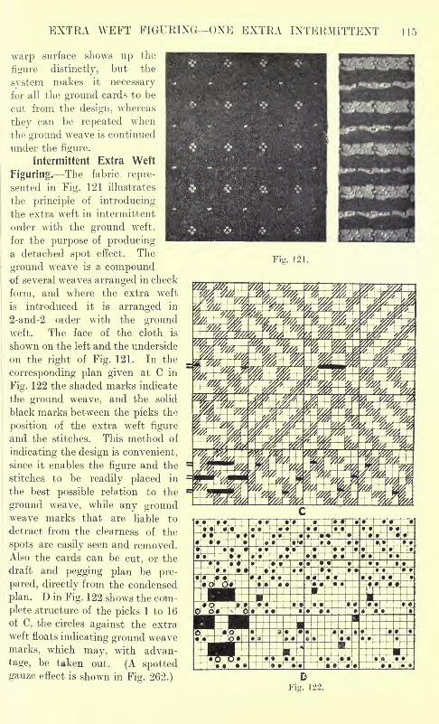
EXTRA WEFT FIGURING ONE EXTRA INTERMITTENT 115
warp surface shows up the
figure distinctly, but the
system makes it necessary
for all the ground cards to be
cut from the design, whereas
they can be repeated when
the ground weave is continued
under the figure.
Intermittent Extra Weft
Figuring. The fabric repre-
sented in Fig. 121 illustrates
the principle of introducing
the extra weft in intermittent
order with the ground weft,
for the purpose of producinga detached spot effect. The
ground weave is a compoundof several weaves arranged in check
form, and where the extra weft
is introduced it is arranged in
2-and-2 order with the groundweft. The face of the cloth is
shown on the left and the underside
on the right of Fig. 121. In the
corresponding plan given at C in
Fig. 122 the shaded marks indicate
the ground weave, and the solid
black marks between the picks the
position of the extra weft figure
and the stitches. This method of
indicating the design is convenient,
since it enables the figure and the
stitches to be readily placed in
the best possible relation to the
ground weave, while any groundweave marks that are liable to
detract from the clearness of the
spots are easily seen and removed.Also the cards can be cut, or the
draft and pegging plan be pre-
pared, directly from the condensed
plan. D in Fig. 122 shows the com-
plete structure of the picks 1 to 16
of C, the circles against the extra
weft floats indicating ground weave
marks, which may, with advan-
tage, be taken out. (A spottedgauze effect is shown in Fig. 262.)
Fig. 121.
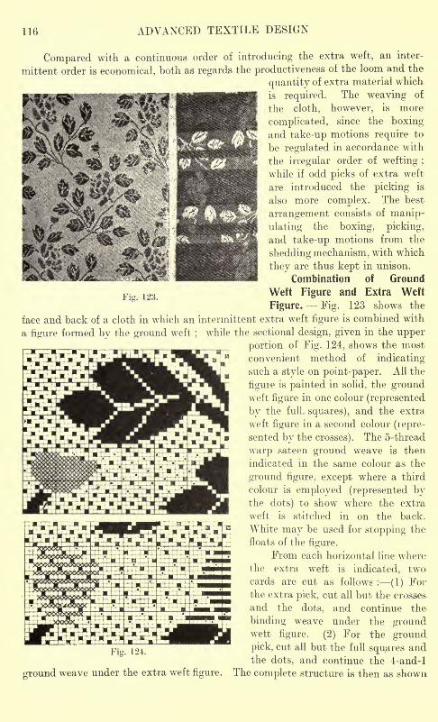
116 ADVANCED TEXTILE DESIGN
Fig. 123.
Compared with a continuous order of introducing the extra weft, an inter-
mittent order is economical, both as regards the productiveness of the loom and the
quantity of extra material which
is required. The weaving of
the cloth, however, is more
complicated, since the boxingand take-up motions require to
be regulated in accordance with
the irregular order of wefting ;
while if odd picks of extra weft
are introduced the picking is
also more complex. The best
arrangement consists of manip-
ulating the boxing, picking,
and take-up motions from the
shedding mechanism, with which
they are thus kept in unison.
Combination of Ground
Weft Figure and Extra Weft
Figure. Fig. 123 shows the
face and back of a cloth in which an intermittent extra weft figure is combined with
a figure formed by the ground weft;
while the sectional design, given in the upper
portion of Fig. 124, shows the most
convenient method of indicating
such a style on point-paper. All the
figure is painted in solid, the groundweft figure in one colour (represented
by the full, squares), and the extra
weft figure in a second colour (lepre-
sented by the crosses). The 5-thread
warp sateen ground weave is then
indicated in the same colour as the
ground figure, except where a third
colour is employed (represented bythe dots) to show where the extra
weft is stitched in on the back.
White may be used for stopping the
floats of the figure.
From each horizontal line where
the extra weft is indicated, twocards are cut as follows : (1) Forthe extra pick, cut all but the crosses.
and the dots, and continue the
binding weave under the groundwett figure. (2) For the ground
Fi 124 pick* cut all but the full squares andthe dots, and continue the 4-and-l
ground weave under the extra weft figure. The complete structure is then as shown
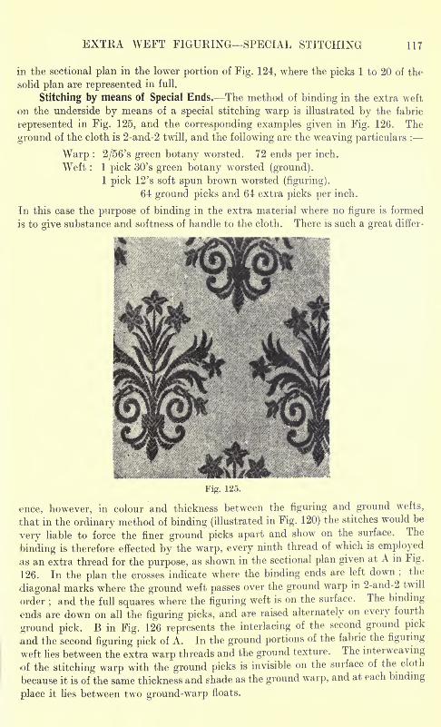
EXTRA WEFT FIGURING SPECIAL STITCHING 117
in the sectional plan in the lower portion of Fig. 124, where the picks 1 to 20 of the
solid plan are represented in full.
Stitching by means of Special Ends. The method of binding in the extra weft
on the underside by means of a special stitching warp is illustrated by the fabric
represented in Fig. 125, and the corresponding examples given in Fig. 126. The
ground of the cloth is 2-and-2 twill, and the following are the weaving particulars :
Warp : 2/56's green botany worsted. 72 ends per inch.
Weft : 1 pick 30's green botany worsted (ground).
1 pick 12's soft spun brown worsted (figuring).
64 ground picks and 64 extra picks per inch.
In this case the purpose of binding in the extra material where no figure is formed
is to give substance and softness of handle to the cloth. There is such a great differ-
BBHBMHB
Fig. 125.
ence, however, in colour and thickness between the figuring and ground wefts,
that in the ordinary method of binding (illustrated in Fig. 120) the stitches would be
very liable to force the finer ground picks apart and show on the surface. The
binding is therefore effected by the warp, every ninth thread of which is employed
.as an extra thread for the purpose, as shown in the sectional plan given at A in Fig.
126. In the plan the crosses indicate where the binding ends are left down ;the
diagonal marks where the ground weft passes over the ground warp in 2-and-2 twill
order;and the full squares where the figuring weft is on the surface. The binding
ends are down on all the figuring picks, and are raised alternately on every fourth
ground pick. B in Fig. 126 represents the interlacing of the second ground pick
and the second figuring pick of A. In the ground portions of the fabric the figuring
weft lies between the extra warp threads and the ground texture. The interweaving
of the stitching warp with the ground picks is invisible on the surface of the cloth
because it is of the same thickness and shade as the ground warp, and at each binding
place it lies between two ground-warp floats.
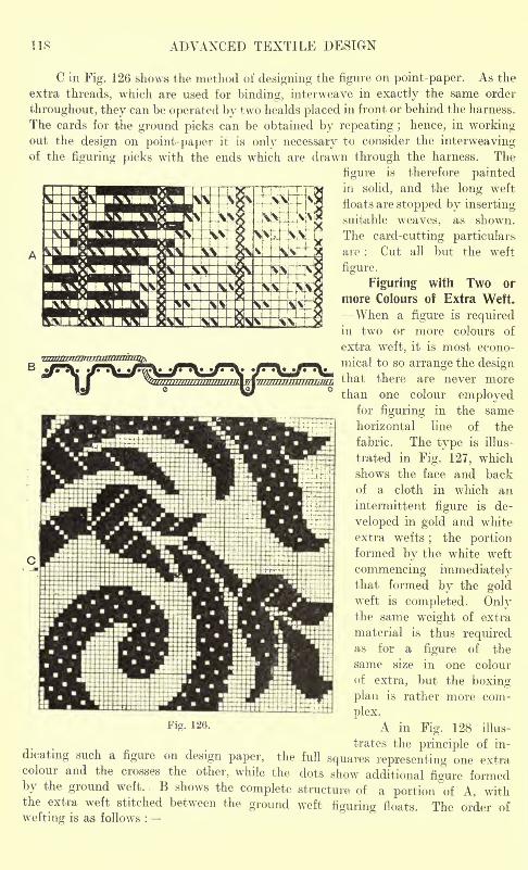
118 ADVANCED TEXTILE DESIGN
C in Fig. 126 shows the method of designing the figure on point-paper. As the
extra threads, which are used for binding, interweave in exactly the same order
throughout, they can be operated by two healds placed in front or behind the harness.
The cards for the ground picks can be obtained by repeating ; hence, in workingout the design on point-paper it is only necessary to consider the interweavingof the figuring picks with the ends which are drawn through the harness. The
figure is therefore paintedin solid, and the long weft
floats are stopped by insertingsuitable weaves, as shown.
The card-cutting particularsare : Cut all but the weft
figure.
Figuring with Two or
more Colours of Extra Weft.
When a figure is requiredin two or more colours of
extra weft, it is most econo-
mical to so arrange the designthat there are never morethan one colour employed
for figuring in the same
horizontal line of the
fabric. The type is illus-
trated in Fig. 127, which
shows the face and back
of a cloth in which an
intermittent figure is de-
veloped in gold and white
extra wefts;
the portionformed by the white weft
commencing immediatelythat formed by the goldweft is completed. Onlythe same weight of extra
material is thus requiredas for a figure of the
same size in one colour
of extra, but the boxing-
plan is rather more com-
plex.Fi - 12(i - A in Fig. 128 illus-
trates the principle of in-
dicating such a figure on design paper, the full squares representing one extracolour and the crosses the other, while the dots show additional figure formedby the ground weft. B shows the complete structure of a portion of A, withthe extra weft stitched between the ground weft figuring floats. The order of
wefting is as follows :
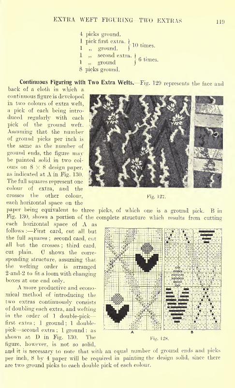
EXTRA WEFT FIGURING TWO EXTRAS 119
4 picks ground.1 pick first extra. ) .,
1 ground. fl1 second extra.
|
1 ,, ground j
8 picks ground.
times.
Continuous Figuring with Two Extra Wefts. Fig. 129 represents the face andback of a cloth in which a
continuous figure is developedin two colours of extra weft,
a pick of each being intro-
duced regularly with each
pick of the ground weft.
Assuming that the numberof ground picks per inch is
the same as the number of
ground ends, the figure maybe painted solid in two col-
ours on 8 X 8 design paper,as indicated at A in Fig. 130.
The full squares represent one
colour of extra, and the
crosses the other colour, Fig. 127.
each horizontal space on the
paper being equivalent to three picks, of which one is a ground pick. B in
Fig. 130, shows a portion of the complete structure which results from cuttingeach horizontal space of A as
follows : First card, cut all butthe full squares ; second card, cut
all but the crosses;third card,
cut plain. C shows the corre-
sponding structure, assuming that
the wefting order is arranged2-and-2 to fit a loom with changingboxes at one end only.
A more productive and econo-
mical method of introducing the
two extras continuously consists
of doubling each extra, and weftingin the order of 1 double-pickfirst extra
;1 ground ;
1 double-
pick second extra;
1 ground ;as
shown at D in Fig. 130. The Fig . 128.
figure, however, is not so solid,
and it is necessary to note that with an equal number of ground ends and picks
per inch, 8 by 4 paper will be required in painting the design solid, since there
are two ground picks to each double pick of each colour.
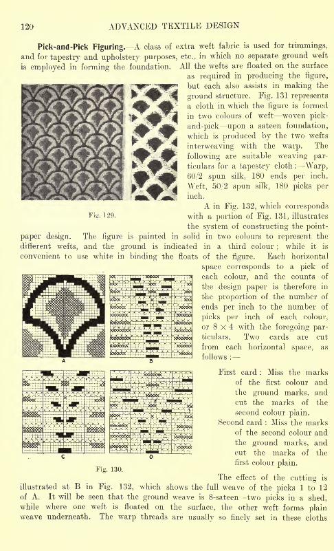
120 ADVANCED TEXTILE DESIGN
Pick-and-Pick Figuring. A class of extra weft fabric is used for trimmings,
and for tapestry and upholstery purposes, etc., in which no separate ground weft
is employed in forming the foundation. All the wefts are floated on the surface
as required in producing the figure,
but each also assists in making the
ground structure. Fig. 131 represents
a cloth in which the figure is formed
in two colours of weft woven pick-
and-pick upon a sateen foundation,
which is produced by the two wefts
interweaving with the warp. The
following are suitable weaving par-
ticulars for a tapestry cloth : -Warp,
60/2 spun silk, 180 ends per inch.
Weft, 50/2 spun silk, 180 picks perinch.
A in Fig. 132, which correspondsFig. 129. with a portion of Fig. 131, illustrates
the system of constructing the point-
paper design. The figure is painted in solid in two colours to represent the
different wefts, and the ground is indicated in a third colour;
while it is
convenient to use white in binding the floats of the figure. Each horizontal
space corresponds to a pick of
each colour, and the counts of
the design paper is therefore in
the proportion of the number of
ends per inch to the number of
picks per inch of each colour,
or 8 X 4 with the foregoing par-ticulars. Two cards are cut
from each horizontal space, as
follows :
First card : Miss the marks
of the first colour and
the ground marks, and
cut the marks of the
second colour plain.
Second card : Miss the marksof the second colour and
the ground marks, and
cut the marks of theLJ
first colour plain.Fig. 130.
The effect of the cutting is
illustrated at B in Fig. 132, which shows the full weave of the picks 1 to 12
of A. It will be seen that the ground weave is 8-sateen two picks in a shed,while where one weft is floated on the surface, the other weft forms plainweave underneath. The warp threads are usually so finely set in these cloths
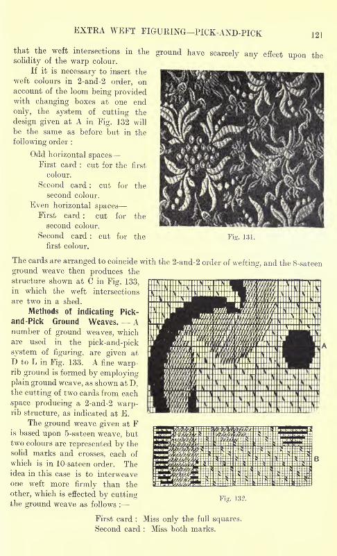
EXTRA WEFT FIGURING PICK-AND-PICK 121
that the weft intersections in the ground have scarcely any effect upon thesolidity of the warp colour.
If it is necessary to insert the
weft colours in 2-and-2 order, onaccount of the loom being providedwith changing boxes at one end
only, the system of cutting the
design given at A in Fig. 132 will
be the same as before but in the
following order :
Odd horizontal spacesFirst card : cut for the first
colour.
Second card : cut for the
second colour.
Even horizontal spacesFirst card : cut for the
second colour.
Second card : cut for the Ficr. 131.
first colour.
The cards are arranged to coincide with the 2-and-2 order of wefting, and the 8-sateen
ground weave then produces the
structure shown at C in Fig. 133,
in which the weft intersections
are two in a shed.
Methods of indicating Pick-
and-Pick Ground Weaves. Anumber of ground weaves, whichare used in the pick-and-pick
system of figuring, are given at
D to L in Fig. 133. A fine warp-rib ground is formed by employingplain ground weave, as shown at D,the cutting of two cards from each
space producing a 2-and-2 warp-rib structure, as indicated at E.
The ground weave given at Fis based upon 5-sateen weave, but
two colours are represented by the
solid marks and crosses, each of
which is in 10-sateen order. Theidea in this case is to interweave
one weft more firmly than the
other, which is effected by cuttingthe ground weave as follows :
Fig. 13?.
First card : Miss only the full squares.
Second card : Miss both marks.
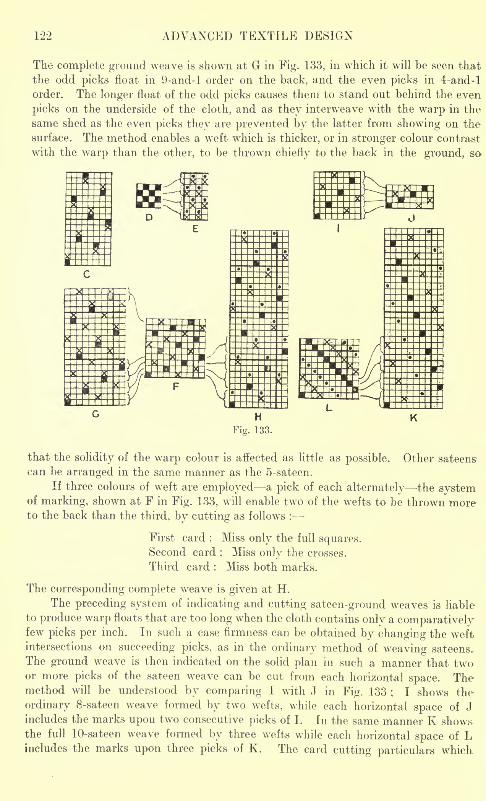
122 ADVANCED TEXTILE DESIGN
The complete ground weave is shown at G in Fig. 133, in which it will be seen that
the odd picks float in 9-and-l order on the back, and the even picks in 4-and-l
order. The longer float of the odd picks causes them to stand out behind the even
picks on the underside of the cloth, and as they interweave with the warp in the
same shed as the even picks they are prevented by the latter from showing on the
surface. The method enables a weft which is thicker, or in stronger colour contrast
with the warp than the other, to be thrown chiefly to the back in the ground, so
that the solidity of the warp colour is affected as little as possible. Other sateens
can be arranged in the same manner as the 5-sateen.
If three colours of weft are employed a pick of each alternately the systemof marking, shown at F in Fig. 133, will enable two of the wefts to be thrown moreto the back than the third, by cutting as follows :
First card : Miss only the full squares.Second card : Miss only the crosses.
Third card : Miss both marks.
The corresponding complete wreave is given at H.
The preceding system of indicating and cutting sateen-ground weaves is liable
to produce warp floats that are too long when the cloth contains only a comparativelyfew picks per inch. In such a case firmness can be obtained by changing the weftintersections on succeeding picks, as in the ordinary method of weaving sateens.
The ground weave is then indicated on the solid plan in such a manner that twoor more picks of the sateen weave can be cut from each horizontal space. Themethod will be understood by comparing I with J in Fig. 133 ; I shows the
ordinary 8-sateen weave formed by two wefts, while each horizontal space of Jincludes the marks upon two consecutive picks of I. In the same manner K show&the full 10-sateen weave formed by three wefts while each horizontal space of Lincludes the marks upon three picks of K. The card cutting particulars which.
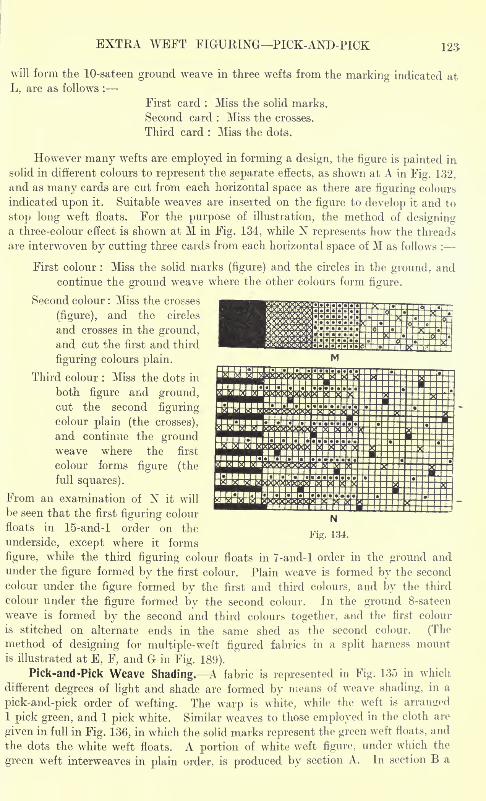
EXTRA WEFT FIGURING PICK-AND-PICK 123
will form the 10-sateen ground weave in three wefts from the marking indicated at
L, are as follows :
First card : Miss the solid marks.
Second card : Miss the crosses.
Third card : Miss the dots.
However many wefts are employed in forming a design, the figure is painted in
solid in different colours to represent the separate effects, as shown at A in Fig. 132.
and as many cards are cut from each horizontal space as there are figuring colours
indicated upon it. Suitable weaves are inserted on the figure to develop it and to
stop long weft floats. For the purpose of illustration, the method of designinga three-colour effect is shown at M in Fig. 134, while N represents how the threads
are interwoven by cutting three cards from each horizontal space of M as follows :
First colour : Miss the solid marks (figure) and the circles in the ground, andcontinue the ground weave where the other colours form figure.
Second colour : Miss the crosses
(figure), and the circles
and crosses in the ground,and cut the first and third
figuring colours plain.
Third colour : Miss the dots in
both figure and ground,cut the second figuring
colour plain (the crosses),
and continue the groundweave where the first
colour forms figure (the
full squares).
From an examination of N it will
be seen that the first figuring colour
floats in 15-and-l order on the
underside, except where it forms
figure, while the third figuring colour floats in 7-and-l order in the ground andunder the figure formed by the first colour. Plain weave is formed by the second
colour under the figure formed by the first and third colours, and by the third
colour under the figure formed by the second colour. In the ground 8-sateen
weave is formed by the second and third colours together, and the first colour
is stitched on alternate ends in the same shed as the second colour. (Themethod of designing for multiple-weft figured fabrics in a split harness mountis illustrated at E, F, and G in Fig. 189).
Pick-and-Pick Weave Shading. A fabric is represented in Fig. 135 in which
different degrees of light and shade are formed by means of weave shading, in a
pick-and-pick order of wefting. The warp is white, while the weft is arranged1 pick green, and 1 pick white. Similar weaves to those employed in the cloth are
given in full in Fig. 136, in which the solid marks represent the green weft floats, and
the dots the white weft floats. A portion of white weft figure, under which the
green weft interweaves in plain order, is produced by section A. In section B a
EWKMSgSSSSSSSgggSgggSgBBK!!
N
Fig. 134.
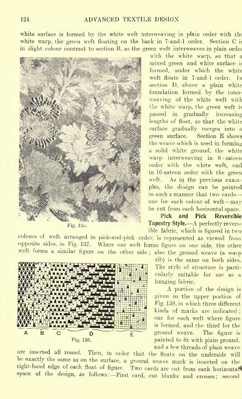
124 ADVANCED TEXTILE DESIGN
white surface is formed by the white weft interweaving in plain order with the
white warp, the green weft floating on the back in 7-and-l order. Section C is
in slight colour contrast to section B, as the green weft interweaves in plain ordei
*~ . -.. <-^._. .__. ^ * ,-~^~. -. with the white warp, so that a3c "' X -*'? .:'..-
' ''
'-
?
JB
^mixed green and white surface is
formed, under which the white
"7 weft floats in 7-and-l order. In
section D, above a plain white
foundation formed by the inter-
weaving of the white weft with
the white warp, the green weft is
passed in gradually increasing
lengths of float, so that the white
surface gradually merges into a
green surface. Section E shows
the weave which is used in forminga solid white ground, the white
warp interweaving in 8 - sateen
order with the white weft, andin 16-sateen order with the greenweft. As in the previous exam-
ples, the design can be paintedin such a manner that two cards
one for each colour of weft maybe cut from each horizontal space.
Pick and Pick Reversible
Tapestry Style. A perfectly revers-
ible fabric, which is figured in twocolours of weft arranged in pick-and-pick order, is represented as viewed from
opposite sides, in Fig. 137. Where one weft forms figure on one side, the otherweft forms a similar figure on the other side
;also the ground weave (a warprib) is the same on both sides.
The style of structure is parti-
cularly suitable for use as a
hanging fabric.
A portion of the design is
given in the upper portion of
Fig. 138, in which three different
kinds of marks are indicated;
one for each weft where figureis formed, and the third for the
ground weave. The figure is
painted to fit with plain ground,
Fig. 13o.
B CDFig. 136.
and a few threads of plain weaveare inserted all round. Then, in order that the floats on the underside willbe exactly the same as on the surface, a ground weave mark is inserted on theright-hand edge of each float of figure. Two cards are cut from each horizontal*space of the design, as follows : First card, cut blanks and crosses; second
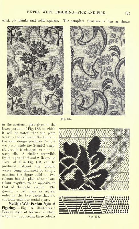
EXTRA WEFT FIGURING PICK-AND-PICK 125
card, cut blanks and solid squares. The complete structure is then as shown
Fig. 137.
in the sectional plan given in the
lower portion of Fig. 138, in which
it will be noted that the plainweave at the edges of the figure in
the solid design produces 2-and-2
warp rib, while the 2-and-2 warp-rib ground is changed to 4-and-4
warp rib. A similar reversible
figure, upon the 2-and-2 rib groundshown at E in Fig. 133, can be
produced without the groundweave being indicated by simply
painting the figure solid in two
colours, but the plain edge of one
colour requires to be opposite to
that of the other colour. The
ground is cut plain in reverse
order on the two cards that are
cut from each horizontal space.
Multiple Weft Persian Style of
Figuring. Fig. 139 illustrates a
Persian style of texture in whicha figure is produced in three colours
:
Fig. 138.
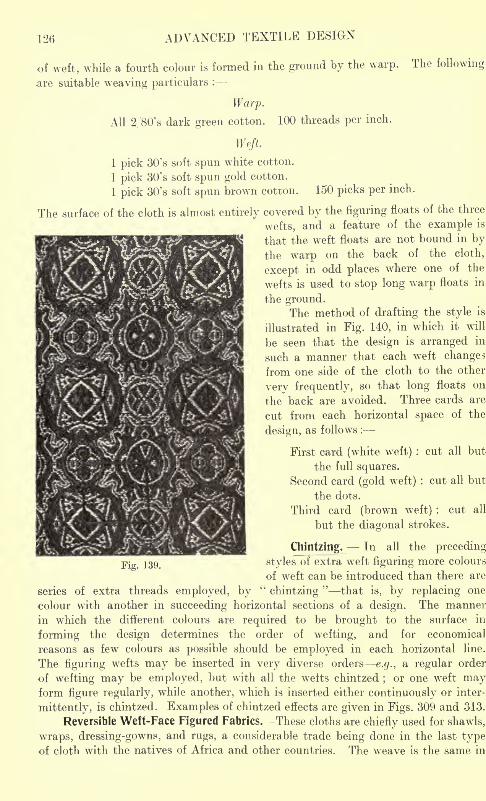
126 ADVANCED TEXTILE DESIGN
150 picks per inch.
of weft, while a fourth colour is formed in the ground by the warp. The following
are suitable weaving particulars :
Warp.
All 2/80's dark green cotton. 100 threads per inch.
Weft.
1 pick 30's soft spun white cotton.
1 pick 30's soft spun gold cotton.
1 pick 30' s soft spun brown cotton.
The surface of the cloth is almost entirely covered by the figuring floats of the three
wefts, and a feature of the example is
that the weft floats are not bound in by
the warp on the back of the cloth,
except in odd places where one of the
wefts is used to stop long warp floats in
the ground.The method of drafting the style is
illustrated in Fig. 140, in which it will
be seen that the design is arranged in
such a manner that each weft changes
from one side of the cloth to the other
very frequently, so that long floats on
the back are avoided. Three cards are
cut from each horizontal space of the
design, as follows :
First card (white weft) : cut all but
the full squares.
Second card (gold weft) : cut all but
the dots.
Third card (brown weft) : cut all
but the diagonal strokes.
Chintzing. In all the preceding-
Fig. 139. styles of extra weft figuring more colours
of weft can be introduced than there are
series of extra threads employed, by"chintzing
"that is, by replacing one
colour with another in succeeding horizontal sections of a design. The manner
in which the different colours are required to be brought to the surface in
forming the design determines the order of wefting, and for economical
reasons as few colours as possible should be employed in each horizontal line.
The figuring wefts may be inserted in very diverse orders e.g., a regular order
of wefting may be employed, but with all the wefts chintzed;or one weft may
form figure regularly, while another, which is inserted either continuously or inter-
mittently, is chintzed. Examples of chintzed effects are given in Figs. 309 and 313.
Reversible Weft-Face Figured Fabrics. These cloths are chiefly used for shawls,
wraps, dressing-gowns, and rugs, a considerable trade being done in the last typeof cloth with the natives of Africa and other countries. The weave is the same in
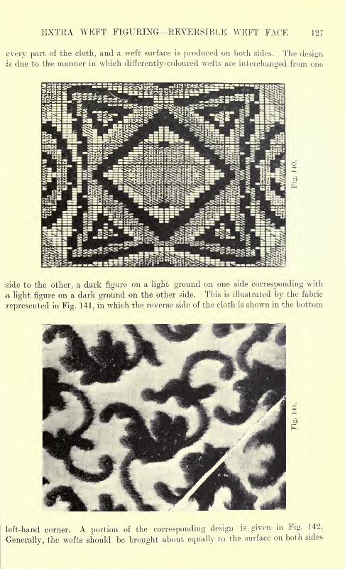
EXTRA WEFT FIGURING REVERSIBLE WEFT FACE 127
every part of the cloth, and a weft surface is produced on both sides. The designis due to the manner in which differently-coloured wefts are interchanged from one
side to the other;a dark figure on a light ground on one side corresponding with
a light figure on a dark ground on the other side. This is illustrated by the fabric
represented in Fig. 141, in which the reverse side of the cloth is shown in the bottom
left-hand corner. A portion of the corresponding design is given in Fig. 1
Generally, the wefts should be brought about equally to the surface on both sides
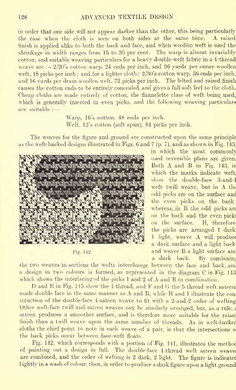
128 ADVANCED TEXTILE DESIGN
in order that one side will not appear darker than the other, this being particularly
the case when the cloth is seen on both sides at the same time. A raised
finish is applied alike to both the back and face, and when woollen weft is used the
shrinkage in width ranges from 15 to 30 per cent. The warp is almost invariably
cotton, and suitable weaving particulars for a heavy double-weft fabric in a 4-thread
weave are : 2/20's cotton warp, 24 ends per inch, and 96 yards per ounce woollen
weft, 48 picks per inch;and for a lighter cloth : 2/30's cotton warp, 36 ends per inch,
and 16 yards per dram woollen weft, 72 picks per inch. The felted and raised finish
causes the cotton ends to be entirely concealed, and gives a full soft feel to the cloth.
Cheap cloths are made entirely of cotton, the flannelette class of weft being used,
which is generally inserted in even picks, and the following weaving particulars
are suitable :
Warp, 16's cotton, 48 ends per inch.
Weft, 12's cotton (soft spun), 84 picks per inch.
The weaves for the figure and ground are constructed upon the same principle
as the weft-backed designs illustrated in Figs. 6 and 7 (p. 7), and as shown in Fig. 143,
in which the most commonlyused reversible plans are given.
Both A and B in Fig. 143, in
which the marks indicate weft,
show the double-face 3-and-l
weft twill weave, but in A the
odd picks are on the surface and
the even picks on the back;
whereas, in B the odd picks are
on the back and the even pickson the surface. If, therefore,
the picks are arranged 1 dark.
1 light, weave A will producea dark surface and a light back.
Fig. 142. and weave B a light surface and
a dark back. By combining
the two weaves in sections the wefts interchange between the face and back, arid
a design in two colours is formed, as represented in the diagram C in Fig. 143
which shows the interlacing of the picks 1 and 2 of A and B in combination.
D and E in Fig. 143 show the 4-thread, and F and G the 5-thread weft sateens
made double face in the same manner as A and B, while H and I illustrate the con-
struction of the double-face 4-sateen weave to fit with a 2-and-2 order of weftingOther weft-face twill and sateen weaves can be similarly arranged, but, as a rule,
sateen produces a smoother surface, and is therefore more suitable for the raisec
finish than a twill weave upon the same number of threads. As in weft-backec
cloths the chief point to note in each weave of a pair, is that the intersections o:
the back picks occur between face-weft floats.
Fig. 142, which corresponds with a portion of Fig. 141, illustrates the methocof painting out a design in full. The double-face 4-thread weft sateen weaves
are combined, and the order of wefting is 2 dark, 2 light. The figure is indicated
1 ightly in a wash of colour, then, in order to produce a dark figure upon a light ground
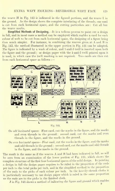
EXTRA WEFT FIGURING REVERSIBLE WEFT FACE 129
the weave H in Fig. 143 is indicated in the figured portions, and the weave I in
the ground. As the design shows the complete interlacing of the threads, one card
is cut from each horizontal space, and the cutting particulars are : Cut all but
the weave marks.
Simplified Methods of Designing. It is a tedious process to paint out a designin full, and in most cases a method can be employed which enables a card for each
colour of weft to be cut from each horizontal space, the designing of a figure beingthen much simpler. For instance, in combining the weaves given at A and B in
Fig. 143, the method illustrated in the upper portion in Fig. 144 can be adopted.The figure is indicated by a wash of colour, and l-and-3 twill is inserted upon both
the figure and the ground ;or design paper with the l-and-3 twill printed upon it
is used, in which case the twill marking is not required. Two cards are then cut
from each horizontal space as follows :
Fig. 143.
On- odd horizontal spaces First card, cut the marks in the figure, and the marks
and even threads in the ground ; second card, cut the marks and even
threads in the figure, and the marks in the ground.
On eren horizontal spaces First card, cut the marks in the figure, and the marks
and odd threads in the ground ;second card, cut the marks and odd threads
in the figure, and the marks in the ground.
The result is the same as if the weaves A and B had been indicated in full, as will
be seen from an examination of the lower portion of Fig. 144, which shows the
complete structure of the first four horizontal spaces of the solid design. In painting
a design in full the design paper requires to be ruled in the proportion of the ends
per inch to the total picks per inch, and in the simplified method in the proportion
of the ends to the picks of each colour per inch. In the heavily-shrunk cloths it
is particularly necessary to use design paper which is ruled in the same proportion
as the ends are to the picks in the finished cloth.
J in Fig. 143 shows a method of indicating the figure and ground which enables
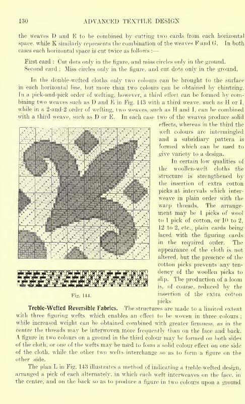
130 ADVANCED TEXTILE DESIGN
the weaves D and E to be combined by cutting two cards from each horizontal
space, while K similarly represents the combination of the weaves F and G. In both
cases each horizontal space is cut twice as follows :
First card : Cut dots only in the figure, and miss circles only in the ground.Second card
;Miss circles only in the figure, and cut dots only in the ground.
In the double-wefted cloths only two colours can be brought to the surface
in each horizontal line, but more than two colours can be obtained by chintzing.In a pick-and-pick order of wefting, however, a third effect can be formed by com-
bining two weaves such as D and E in Fig. 143 with a third weave, such as H or I,
while in a 2-and-2 order of wefting, two weaves, such as H and I, can be combinedwith a third weave, such as D or E. In each case two of the weaves produce solid
effects, whereas in the third the
weft colours are intermingledand a subsidiary pattern is
formed which can be used to
give variety to a design.
In certain low qualities of
the woollen-weft cloths the
structure is strengthened bythe insertion of extra cotton
picks at intervals which inter-
weave in plain order with the
warp threads. The arrange-ment may be 4 picks of wool
to 1 pick of cotton, or 10 to 2,
12 to 2, etc.; plain cards being-
laced with the figuring cards
in the required order. The
appearance of the cloth is not
altered, but the presence of the
cotton picks prevents any ten-
dency of the woollen picks to
slip. The production of a loom
is, of course, reduced by the
Fig. 144. insertion of the extra cotton
picks.
Treble-Wetted Reversible Fabrics. The structures are made to a limited extent
with three figuring wefts, which enables an effect to be woven in three colours;
while increased weight can be obtained combined with greater firmness, as in the
centre the threads may be interwoven more frequently than on the face and back.
A figure in two colours on a ground in the third colour may be formed on both sides
of the cloth, or one of the wefts may be used to form a solid colour effect on one side
of the cloth, while the other two wefts interchange so as to form a figure on the
other side.
The plan L in Fig. 143 illustrates a method of indicating a treble-wefted design,
arranged a pick of each alternately, in which each weft interweaves on the face, in
the centre, and on the back so as to produce a figure in two colours upon a ground
EXTRA WARP FIGURING 131
in the other colour, on both sides of the cloth. The weave on the face and backis 4-sateen, and in the centre plain. Three cards are cut from each horizontal
space of the plan L, as follows :
First card : Cut the dots in the first figuring colour;cut the second figuring
colour plain ;and cut all but the circles in the ground.
Second card : Cut all but the circles in the first figuring colour;cut the dots
in the second figuring colour;and cut the ground plain.
Third card : Cut the first figuring colour plain ;cut all but the circles in the
second figuring colour;and cut the dots in the ground.
The complete weaves to correspond are shown separately at M, N and in Fig. 143
in which it will be seen that in M the first weft floats 3-and-l on the face, the second
weft floats 3-and-l on the back, and the third weft weaves plain in the centre. In
N the first weft weaves plain in the centre, the second weft floats 3-and-l on the face,
and the third weft floats 3-and-l on the back. In;the first weft floats 3-and-l
on the back, the second weft interweaves plain in the centre, while the third weft
floats 3 and-1 on the face. A figure formed by the first and second wefts on the
face is similarly formed by the second and third wefts respectively on the back,
while the third weft forms the ground on the face and the first weft the ground on
the back. The plain centre weave gives the cloth great firmness, and may be too
firm for a heavily-wefted cloth, and in such a case another weave may be used,
such as 2-and-2 twill, or 2-and-2 weft rib. The floats in the centre require to be
shorter than those on the face and back in order that they will be invisible on both
sides.
CHAPTER VI
EXTRA WARP FIGURING
Comparison with Extra Weft Figuring Continuous Figuring in one Extra WT
arp Heald and
Harness Mounting Alhambra Quilts Binding in Extra Ends between Face Floats
Intermittent Figuring in One Extra Warp Drafting and Denting Extra Warp Stripes
Figuring with Two Extra Warps Stitching by means of Special Picks Extra Warp
Planting End-and-End Figuring Reversible Warp-Face Figured Fabrics.
Comparison with Extra Weft Figuring. In extra warp figuring there are two or
more series of warp threads to one series of weft threads, and the method has
the following advantages and disadvantages, as compared with the extra weft
principle :
Advantages : (I) The productiveness of a loom is greater because only one
series of picks is inserted, and a quicker running loom can be used. (2) No special
picking, box, and uptake motions are required. (3) There is practically no limit
to the number of colours that can be introduced. (4) In an intermittent arrange-
ment of the extra ends either spotted or stripe patterns can be formed, whereas
a similar arrangement in the weft can only be used to form spots (except in special
cases) because of the objectionable appearance of horizontal lines.
Disadvantages : (1) Two or more warp beams may be required instead of one.
(2) If an ordinary jacquard and harness are employed the point-paper designing
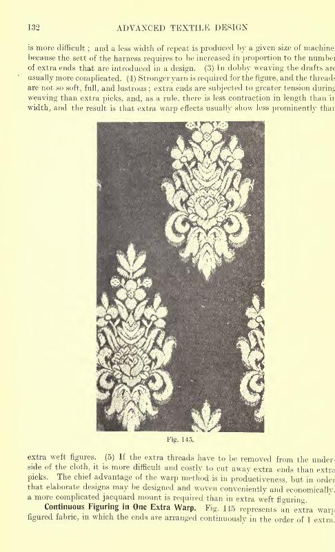
132 ADVANCED TEXTILE DESIGN
is more difficult;and a less width of repeat is produced by a given size of machine,
because the sett of the harness requires to be increased in proportion to the numbeiof extra ends that are introduced in a design. (3) In dobby weaving the drafts arc
usually more complicated. (4) Stronger yarn is required for the figure, and the threads-
are not so soft, full, and lustrous;extra ends are subjected to greater tension during
weaving than extra picks, and, as a rule, there is less contraction in length than in
width, and the result is that extra warp effects usually show less prominently than
Fig. 145.
extra weft figures. (5) If the extra threads have to be removed from the under-side of the cloth, it is more difficult and costly to cut away extra ends than extra
picks. The chief advantage of the warp method is in productiveness, but in orderthat elaborate designs may be designed and woven conveniently and economically,a more complicated jacquard mount is required than in extra weft fWrino.
Continuous Figuring in One Extra Warp. -Fig. 145 represents an extra war],figured fabric, in which the ends are arranged continuously in the order of 1 extra.
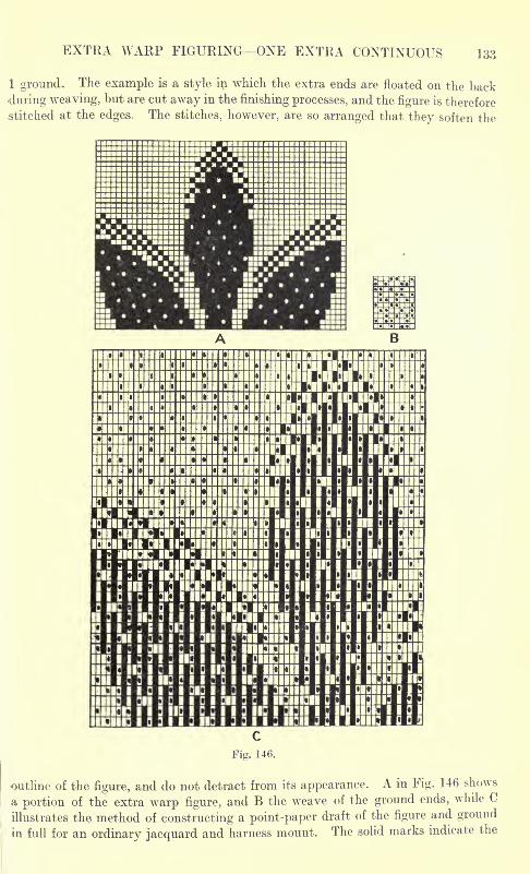
EXTRA WARP FIGURING ONE EXTRA CONTINUOUS 133
1 ground. The example is a style in which the extra ends are floated on the back
during weaving, but are cut away in the finishing processes, and the figure is therefore
stitched at the edges. The stitches, however, are so arranged that they soften the
Tj i ]i
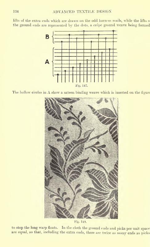
134 ADVANCED TEXTILE DESIGN
lifts of the extra ends which are drawn on the odd harness mails, while the lifts o
the ground ends are represented by the dots, a crepe ground weave being formed
B
Fig. 147.
The hollow circles in A show a sateen binding weave which is inserted on the figure
to stop the long warp floats. In the cloth the ground ends and picks per unit space'are equal, so that, including the extra ends, there are twice as many ends as picks
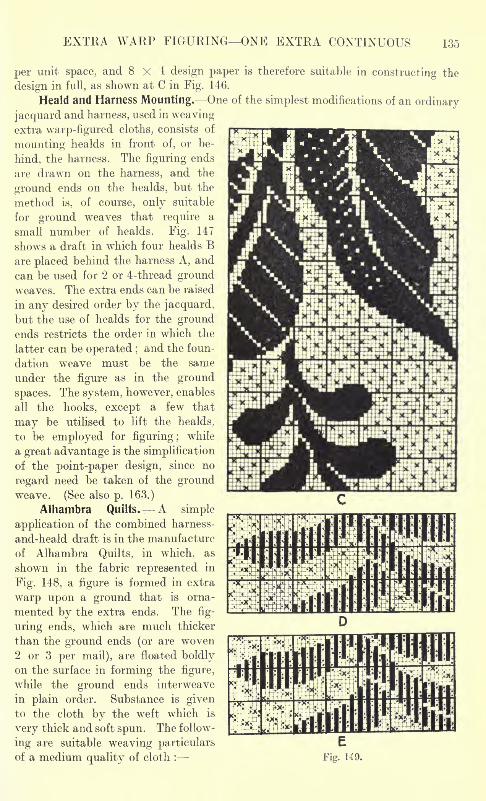
EXTRA WARP FIGURING ONE EXTRA CONTINUOUS 135
per unit space, and 8x4 design paper is therefore suitable in constructing the
design in full, as shown at C in Fig. 146.
Heald and Harness Mounting. One of the simplest modifications of an ordinary
jacquard and harness, used in weavingextra warp-figured cloths, consists of
mounting healds in front of, or be-
hind, the harness. The figuring ends
are drawn on the harness, and the
ground ends on the healds, but the
method is, of course, only suitable
for ground weaves that require a
small number of healds. Fig. 147
shows a draft in which four healds Bare placed behind the harness A, and
can be used for 2 or 4-thread groundweaves. The extra ends can be raised
in any desired order by the jacquard,
but the use of healds for the groundends restricts the order in which the
latter can be operated ;and the foun-
dation weave must be the same
under the figure as in the ground
spaces. The system, however, enables
all the hooks, except a few that
may be utilised to lift the healds,
to be employed for figuring ;while
a great advantage is the simplification
of the point-paper design, since no
regard need be taken of the groundweave. (See also p. 163.)
Alhambra Quilts. A simple
application of the combined harness-
and-heald draft is in the manufacture
of Alhambra Quilts, in which, as
shown in the fabric represented in
Fig. 148, a figure is formed in extra
warp upon a ground that is orna-
mented by the extra ends. The fig-
uring ends, which are much thicker
than the ground ends (or are woven2 or 3 per mail), are floated boldlyon the surface in forming the figure,
while the ground ends interweave
in plain order. Substance is givento the cloth by the weft which is
very thick and soft spun. The follow-
ing are suitable weaving particulars
of a medium quality of cloth :
EFig. 149.
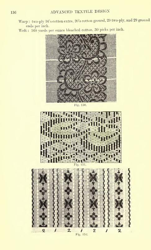
136 ADVANCED TEXTILE DESIGN
Warp : two-ply 16's cotton extra, 20's cotton ground, 29 two-ply, and 29 ground
ends per inch.
Weft : 160 yards per ounce bleached cotton, 30 picks per inch.
Fig. 150.
Fig. 151.
4-4
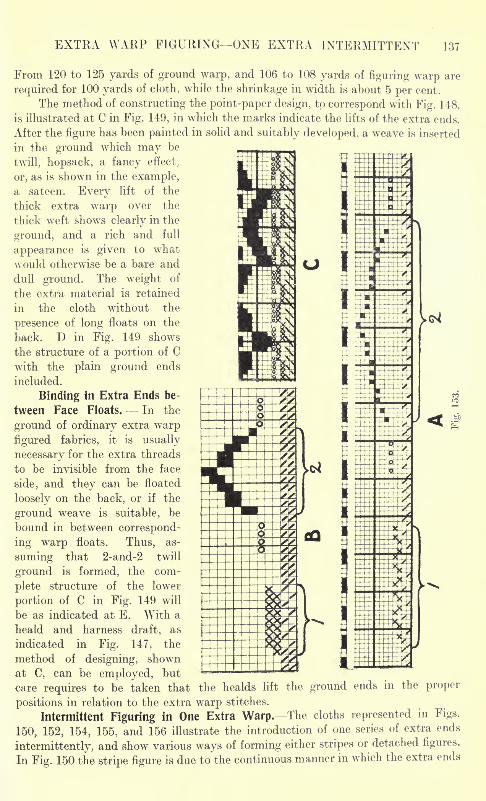
EXTRA WARP FIGURING ONE EXTRA INTERMITTENT 137
From 120 to 125 yards of ground warp, and 106 to 108 yards of figuring warp are
required for 100 yards of cloth, while the shrinkage in width is about 5 per cent.
The method of constructing the point-paper design, to correspond with Fig. 148,
is illustrated at C in Fig. 149, in which the marks indicate the lifts of the extra ends.
After the figure has been painted in solid and suitably developed, a weave is inserted
in the ground which may be
twill, hopsack, a fancy effect,
or, as is shown in the example,a sateen. Every lift of the
thick extra warp over the
thick weft shows clearly in the
ground, and a rich and full
appearance is given to what
would otherwise be a bare and
dull ground. The weight of
the extra material is retained
in the cloth without the
presence of long floats on the
back. D in Fig. 149 shows
the structure of a portion of C
with the plain ground ends
included.
Binding in Extra Ends be-
tween Face Floats. In the
ground of ordinary extra warp
figured fabrics, it is usually
necessary for the extra threads
to be invisible from the face
side, and they can be floated
loosely on the back, or if the
ground weave is suitable, be
bound in between correspond-
ing warp floats. Thus, as-
suming that 2-and-2 twill
ground is formed, the com-
plete structure of the lower
portion of C in Fig. 149 will
be as indicated at E. With a
heald and harness draft, as
indicated in Fig. 147, the
method of designing, shownat C, can be employed, but
care requires to be taken that properthe healds lift the ground
positions in relation to the extra warp stitches.
Intermittent Figuring in One Extra Warp. The cloths represented in Figs.
150, 152, 154, 155, and 156 illustrate the introduction of one series of extra ends
intermittently, and show various ways of forming either stripes or detached figures.
In Fig. 150 the stripe figure is due to the continuous manner in which the extra ends
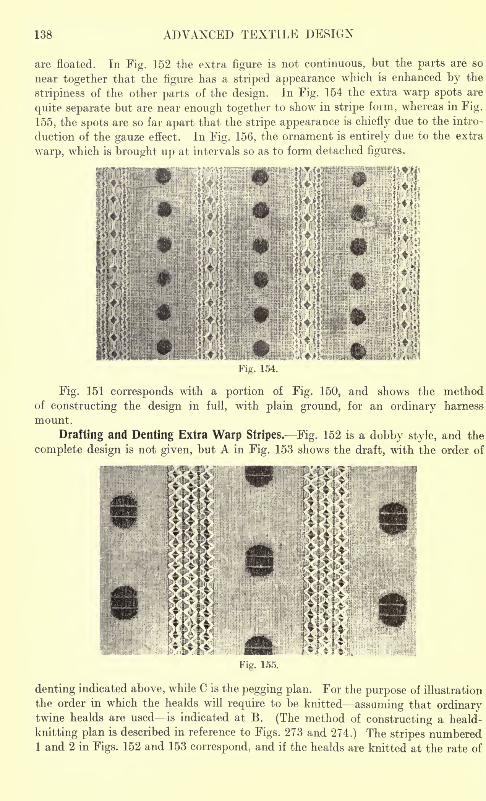
138 ADVANCED TEXTILE DESIGN
are floated. In Fig. 152 the extra figure is not continuous, but the parts are so
near together that the figure has a striped appearance which is enhanced by the
stripiness of the other parts of the design. In Fig. 154 the extra warp spots are
quite separate but are near enough together to show in stripe form, whereas in Fig.
155, the spots are so far apart that the stripe appearance is chiefly due to the intro-
duction of the gauze effect. In Fig. 156, the ornament is entirely due to the extra
warp, which is brought up at intervals so as to form detached figures.
mKtirofJ
19
r. lf>4.
Fig. 151 corresponds with a portion of Fig. 150, and shows the methodof constructing the design in full, with plain ground, for an ordinary harness
mount.
Drafting and Denting Extra Warp Stripes. Fig. 152 is a dobby style, and the
complete design is not given, but A in Fig. 153 shows the draft, with the order of
:
ii f
MM>Fig. 155.
denting indicated above, while C is the pegging plan. For the purpose of illustration
the order in which the healds will require to be knitted assuming that ordinarytwine healds are used is indicated at B. (The method of constructing a heald-
knitting plan is described in reference to Figs. 273 and 274.) The stripes numbered1 and 2 in Figs. 152 and 153 correspond, and if the healds are knitted at the rate of
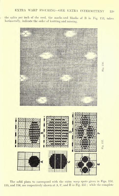
EXTRA WARP FIGURING ONE EXTRA INTERMITTENT 139
the splits per inch of the reed, the marks and blanks of B in Fig. 153, taken
horizontally, indicate the order of knitting and missing.
The solid plans to correspond with the extra warp spots given in Figs. 154,
155, and 156, are respectively shown at A, C, and E in Fig. 157;while the complete
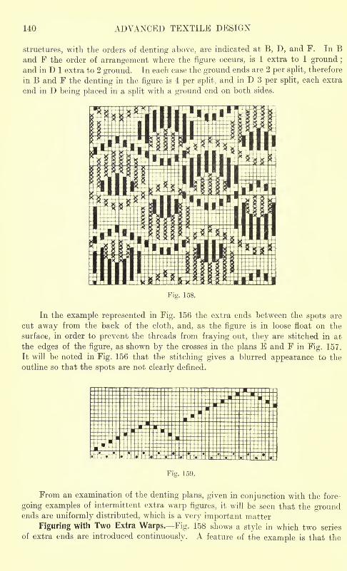
140 ADVANCED TEXTILE DESIGN
structures, with the orders of denting above, are indicated at B, D, and F. In Band F the order of arrangement where the figure occurs, is 1 extra to 1 ground ;
and in D 1 extra to 2 ground. In each case the ground ends are 2 per split, therefore
in B and F the denting in the figure is 4 per split, and in D 3 per split, each extra
end in D being placed in a split with a ground end on both sides.
Fig. 158,
In the example represented in Fig. 156 the extra ends between the spots are
cut away from the back of the cloth, and, as the figure is in loose float on the
surface, in order to prevent the threads from fraying out, they are stitched in at
the edges of the figure, as shown by the crosses in the plans E and F in Fig. 157.
It will be noted in Fig. 156 that the stitching gives a blurred appearance to the
outline so that the spots are not clearly defined.
Fig. 159.
From an examination of the denting plans, given in conjunction with the fore-
going examples of intermittent extra warp figures, it will be seen that the groundends are uniformly distributed, which is a very important matter
Figuring with Two Extra Warps. Fig. 158 shows a style in which two series
of extra ends are introduced continuously. A feature of the example is that the
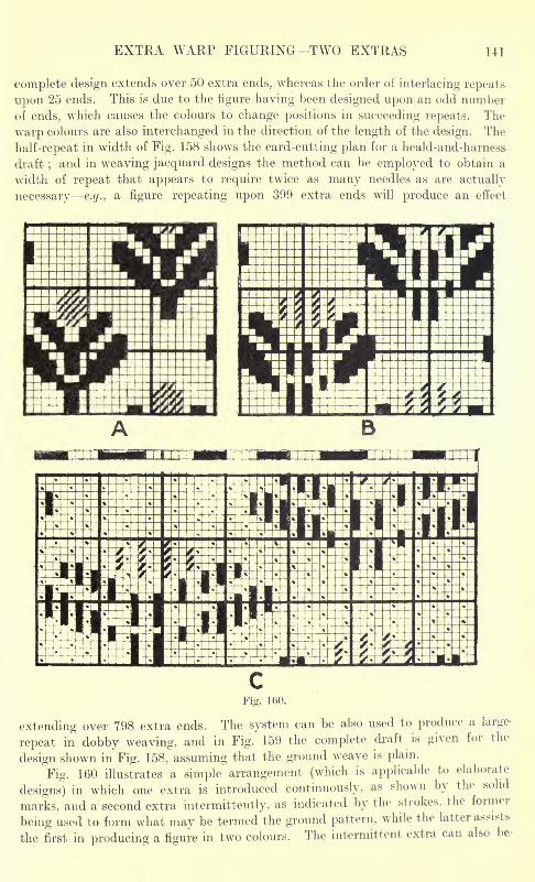
EXTRA WARP FIGURING TWO EXTRAS 141
complete design extends over 50 extra ends, whereas the order of interlacing repeats-
upon 25 ends. This is due to the figure having been designed upon an odd num her
of ends, which causes the colours to change positions in succeeding repeats. The-
warp colours are also interchanged in the direction of the length of the design. The
half-repeat in width of Fig. 158 shows the card-cutting plan for a heald-and-harness-
draft;and in weaving jacquard designs the method can be employed to obtain a
width of repeat that appears to require twice as many needles as are actually
necessary e.g.. a figure repeating upon 399 extra ends will produce an effect
CFig. 160.
extending over 798 extra ends. The system can be also used to produce a large-
repeat in dobby weaving, and in Fig. 159 the complete draft is given for the
design shown in Fig. 158, assuming that the ground weave is plain.
Fig. 160 illustrates a simple arrangement (which is applicable to elaborate
designs) in which one extra is introduced continuously, as shown by the solid
marks, and a second extra intermittently, as indicated by the strokes, the former
being used to form what may be termed the ground pattern, while the latter assists
the first in producing a figure in two colours. The intermittent extra can also be-
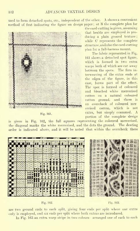
142 ADVANCED TEXTILE DESIGN
V"* [tf^Vviairiinn^^
used to form detached spots, etc., independent of the other. A shows a convenient
method of first indicating the figure on design paper ;at B the complete plan for
the card-cutting is given, assumingthat healds are employed in pro-
ducing a plain ground texture;
while C represents the complete
structure, and also the card-cutting
plan for a full-harness mount.
The fabric represented in Fig.
161 shows a detached spot figure,
which is formed in two extra
warps both of which are cut awaybetween the spots. The firm in-
terweaving of the extra ends at
the edges of the figure, in this
case, forms part of the effect.
The spot is formed of coloured
and bleached white mercerised
cotton on a natural coloured
cotton ground, and there is
an overcheck of coloured mer
cerised cotton, which is not
p. jg} extra, but simply crammed. A
portion of the complete design
is given in Fig. 162, the full squares representing the coloured mercerised,
the diagonal marks the white mercerised, and the dots the ground. The denting
order is indicated above, and it will be noted that within the overcheck there
Fig. 162. Fia. 163.
are two ground ends to each split, giving four ends per split where one extra
only is employed, and six ends per split where both extras are introduced.
In Fig. 163 an extra warp stripe in two colours arranged one of each to each
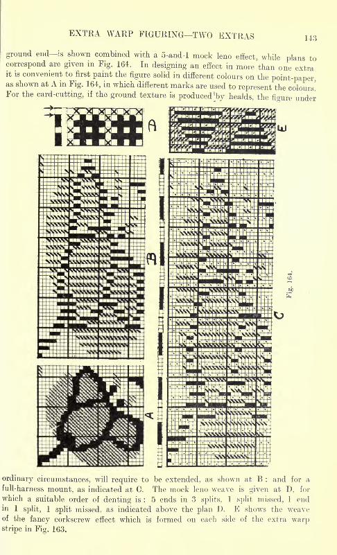
EXTRA WARP FIGURING TWO EXTRAS 143
ground end is shown combined with a 5-and-l mock leno effect, while plans tocorrespond are given in Fig. 164. In designing an effect in more than one extrait is convenient to first paint the figure solid in different colours on the point-paper,as shown at A in Fig. 164, in which different marks are used to represent the colours!For the card-cutting, if the ground texture is produced ^by healds, the figure under
ordinary circumstances, will require to be extended, as shown at B : and for a
full-harness mount, as indicated at G. The mock leno weave is given at D, for
which a suitable order of denting is : 5 ends in 3 splits, 1 split missed, 1 endin 1 split, 1 split missed, as indicated above the plan D. E shows the weaveof the fancy corkscrew effect which is formed on each side of the extra warpstripe in Fig. 163.
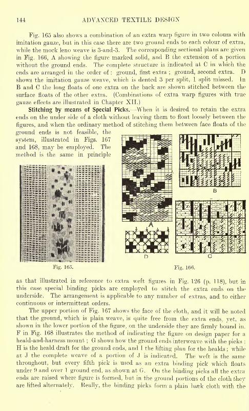
144 ADVANCED TEXTILE DESIGN
Fig. 165 also shows a combination of an extra warp figure in two colours with
imitation gauze, but in this case there are two ground ends to each colour of extra,
while the mock leno weave is 3-and-3. The corresponding sectional plans are given
in Fig. 166, A showing the figure marked solid, and B the extension of a portion
without the ground ends. The complete structure is indicated at C in which the
ends are arranged in the order of : ground, first extra; ground, second extra. D
shows the imitation gauze weave, which is dented 3 per split, 1 split missed. In
B and C the long floats of one extra on the back are shown stitched between the
surface floats of the other extra. (Combinations of extra warp figures with true
gauze effects are illustrated in Chapter XII.)
Stitching by means of Special Picks. When it is desired to retain the extra
ends on the under side of a cloth without leaving them to float loosely between the
figures, and when the ordinary method of stitching them between face floats of the
ground ends is not feasible, the
system, illustrated in Figs. 167
and 168, may be employed. The
method is the same in principle
:rir?:*:
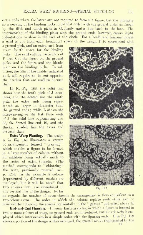
EXTRA WARP FIGURING SPECIAL STITCHING 145
extra ends where the latter are not required to form the figure, but the alternate
interweaving of the binding picks in 9-and-l order with the ground ends, as shown
by the fifth and tenth picks in G, firmly unites the back to the face. The
interweaving of the binding picks with the ground ends, however, causes slight
indentations to show in the face of the cloth. For a heald and harness mounta card is cut from each horizontal space of the design F to correspond with
a ground pick, and an extra card from
every fourth space for the binding
picks. The card cutting particulars of
F are : Cut the figure on the ground
picks, and the figure and the blanks
plain on the binding picks. In ad-
dition, the lifts of the healds, indicated
at I, will require to be cut opposite
the needles that are used to operatethem.
In K, Fig. 168, the solid line
shows how the tenth pick of J inter-
laces, and the dotted line the ninth
pick, the extra ends being repre-
sented as larger in diameter than
the ground ends;while L shows the
interweaving of the last three ends
of J, the solid line representing end
38, the dotted line end 40, and the
thicker shaded line the extra end
between them.
Extra Warp Planting. The designA in Fig. 169 illustrates a systemof arrangement termed
"planting,"
which enables a figure to be formed
in a large number of colours without
an addition being actually made to
the series of extra threads. (Themethod corresponds to "chintzing"the weft, previously referred to
p. 126). In the example 5 colours
(represented by different marks) are
employed, but it will be noted that
two colours only are introduced in
any vertical line of the design. So far
as regards the number of extra threads the arrangement is thus equivalent to a
two-colour extra. The order in which the colours replace each other can be
observed by following the spaces horizontally in the"gamut
"indicated above A.
End-and-End Figuring. In some Eastern styles, in which a figure is formed in
two or more colours of warp, no ground ends are introduced, but a dark weft is em-
ployed which interweaves in a simple order with the figuring ends. B in Fig. 169
shows a portion of the design A thus arranged, the ground weave (represented by the
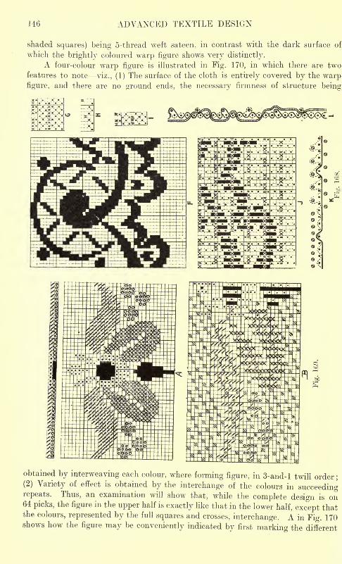
146 ADVANCED TEXTILE DESIGN
shaded squares) being 5-thread weft sateen, in contrast with the dark surface of
which the brightly coloured warp figure shows very distinctly.
A four-colour warp figure is illustrated in Fig. 170, in which there are two
features to note viz., (1) The surface of the cloth is entirely covered by the warpfigure, and there are no ground ends, the necessary firmness of structure being
obtained by interweaving each colour, where forming figure, in 3-and-l twill order;
(2) Variety of effect is obtained by the interchange of the colours in succeedingrepeats. Thus, an examination will show that, while the complete design is on64 picks, the figure in the upper half is exactly like that in the lower half, except thatthe colours, represented by the full squares and crosses, interchange. A in Fig. 170shows how the figure may be conveniently indicated by first marking the different
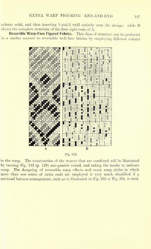
EXTRA WARP FIGURING END-AND-END 147
colours solid, and then inserting l-and-3 twill entirely over the design; while Bshows the complete structure of the first eight ends of A.
Reversible Warp-Face Figured Fabrics. This class of structure can be producedin a similar manner to reversible weft-face fabrics by employing different colours
B
Fig. 170.
in the warp. The construction of the weaves that are combined will be illustrated
by turning Fig. 143 (p. 129) one-quarter round, and taking the marks to indicate
warp. The designing of reversible warp effects and extra warp styles in which
more than one series of extra ends are employed is very much simplified if a
sectional harness arrangement, such as is illustrated in Fig. 183 or Fig. 184, is used.
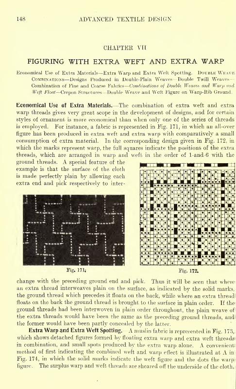
148 ADVANCED TEXTILE DESIGN
CHAPTER VII
FIGURING WITH EXTRA WEFT AND EXTRA WARPEconomical Use of Extra Materials Extra Warp and Extra Weft Spotting. DOUBLE WEAVE
COMBINATIONS Designs Produced in Double-Plain Weaves Double Twill Weaves
Combination of Fine and Coarse Fabrics Combinations of Double Weaves and Warp and
Weft Float Crepon Structures Double Weave and Weft Figure on Warp-Rib Ground.
Economical Use of Extra Materials. The combination of extra weft and extra
warp threads gives very great scope in the development of designs, and for certain
styles of ornament is more economical than when only one of the series of threads
is employed. For instance, a fabric is represented in Fig. 171, in which an all-over
figure has been produced in extra weft and extra warp with comparatively a small
consumption of extra material. In the corresponding design given in Fig. 172, in
which the marks represent warp, the full squares indicate the positions of the extra
threads, which are arranged in warp and weft in the order of l-and-6 with the
ground threads. A special feature of the
example is that the surface of the cloth
is made perfectly plain by allowing each
extra end and pick respectively to inter-
Fig. 171; Fig. 172.
change with the preceding ground end and pick. Thus it will be seen that wherean extra thread interweaves plain on the surface, as indicated by the solid marks,the ground thread which precedes it floats on the back, while where an extra thread
floats on the back the ground thread is brought to the surface in plain order. If the
ground threads had been interwoven in plain order throughout, the plain weave of
the extra threads would have been the same as the preceding ground threads, andthe former would have been partly concealed by the latter.
Extra Warp and Extra Weft Spotting. A muslin fabric is represented in Fig. 173,which shows detached figures formed by floating extra warp and extra weft threads
in combination, and small spots produced by the extra warp alone. A convenient'
method of first indicating the combined weft and warp effect is illustrated at A in
Fig. 174, in which the solid marks indicate the weft figure and the dots fhe warpfigure. The surplus warp and weft threads are sheared off the underside of the cloth,
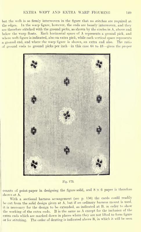
EXTRA WEFT AND EXTRA WARP FIGURING 149
but the weft is so firmly interwoven in the figure that no stitches are required at
the edges. In the warp figure, however, the ends are loosely interwoven, and theyare therefore stitched with the ground picks, as shown by the circles in A, above and
below the warp floats. Each horizontal space of A represents a ground pick, and
where weft figure is indicated, also an extra pick, while each vertical space represents
a ground end, and where the warp figure is shown, an extra end also. The ratio
of ground ends to ground picks per inch in this case 64 to 48 gives the proper
Fig. 173.
counts of point-paper in designing the figure solid, and 8 X 6 paper is therefore
shown at A.
With a sectional harness arrangement (see p. 156) the cards could readily
be cut from the solid design given at A, but if an ordinary harness mount is used,
it is necessary for the design to be extended, as indicated at B, in order to show
the working of the extra ends. B is the same as A except for the inclusion of the
extra ends which are marked down in places where they are not lifted to form figure
or for stitching. The order of denting is indicated above B, in which it will be seen
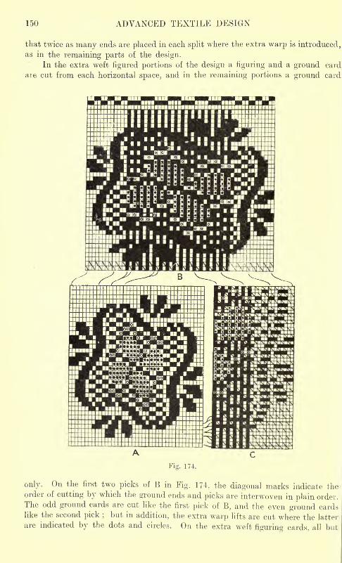
150 ADVANCED TEXTILE DESIGN
that twice as many ends are placed in each split where the extra warp is introduced,as in the remaining parts of the design.
In the extra weft figured portions of the design a figuring and a ground card
are cut from each horizontal space, and in the remaining portions a ground card
only. On the first two picks of B in Fig. 174, the diagonal marks indicate theorder of cutting by which the ground ends and picks are interwoven in plain order.
The odd ground cards are cut like the first pick of B, and the even ground cardslike the second pick ; but in addition, the extra warp lifts are cut where the latter
are indicated by the dots and circles. On the extra weft figuring cards, all but
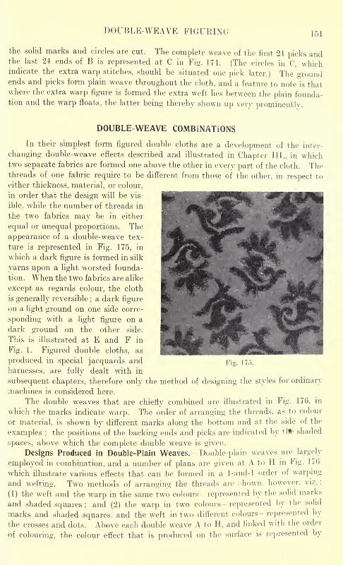
DOUBLE-WEAVE FIGURING 151
the solid marks and circles are cut. The complete weave of the first 24 picks andthe last 24 ends of B is represented at C in Fig. 174. (The circles in C, whichindicate the extra warp stitches, should be situated one pick later.) The 'groundends and picks form plain weave throughout the cloth, and a feature to note is thatwhere the extra warp figure is formed the extra weft lies between the plain founda-tion and the warp floats, the latter being thereby shown up very prominently.
DOUBLE WEAVE COMBINATIONS
In their simplest form figured double cloths are a development of the inter-
changing double-weave effects described and illustrated in Chapter III., in whichtwo separate fabrics are formed one above the other in every part of the cloth. Thethreads of one fabric require to be different from those of the other, in respect to
either thickness, material, or colour,
in order that the design will be vis-
ible. while the number of threads in
the two fabrics may be in either
equal or unequal proportions. The
appearance of a double-weave tex-
ture is represented in Fig. 175, in
which a dark figure is formed in silk
yarns upon a light worsted founda-
tion. When the two fabrics are alike
except as regards colour, the cloth
is generally reversible;a dark figure
on a light ground on one side corre-
sponding with a light figure on a
dark ground on the other side.
This is illustrated at E and F in
Fig. 1. Figured double cloths, as
produced in special jacquards and
harnesses, are fully dealt with in
subsequent chapters, therefore only the method of designing the styles for ordinary
machines is considered here.
The double weaves that are chiefly combined are illustrated in Fig. 176, in
which the marks indicate warp. The order of arranging the threads, as to colour
or material, is shown by different marks along the bottom and at the side of the
examples ;the positions of the backing ends and picks are indicated by tlfe shaded
spaces, above which the complete double weave is given.
Designs Produced in Double-Plain Weaves. Double-plain weaves are largely
employed in combination, and a number of plans are given at A to H in Fig. 17(>
which illustrate various effects that can be formed in a 1-and-l order of warping
and wefting. Two methods of arranging the threads are ;-hown. however, viz.
(1) the weft and the warp in the same two colours- represented by the solid marks
and shaded squares ;and (2) the warp in two colours represented by the solid
marks and shaded squares, and the weft in two different colours- represented by
the crosses and dots. Above each double weave A to H, and linked with the order
of colouring, the colour effect that is produced on the surface is represented by
Fig. IT,!.
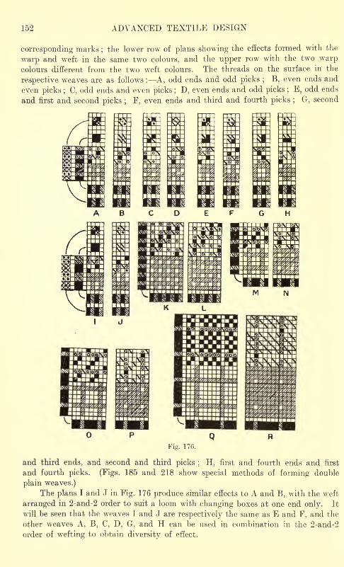
152 ADVANCED TEXTILE DESIGN
corresponding marks;the lower row of plans showing the effects formed with the
warp and weft in the same two colours, and the upper row with the two warpcolours different from the two weft colours. The threads on the surface in the
respective weaves are as follows : A, odd ends and odd picks ; B, even ends and
even picks ; C, odd ends and even picks ; D, even ends and odd picks ; E, odd ends
and first and second picks ; F, even ends and third and fourth picks ; G, second
Fig. 176.
and third ends, and second and third picks ; H, first and fourth ends and first
and fourth picks. (Figs. 185 and 218 show special methods of forming double
plain weaves.)
The plans I and J in Fig. 176 produce similar effects to A and B, with the weft
arranged in 2-and-2 order to suit a loom with changing boxes at one end only. It
will be seen that the weaves I and J are respectively the same as E and F, and the
other weaves A, B, C, D. G, and H can be used in combination in the 2-and-2
order of wefting to obtain diversity of effect.
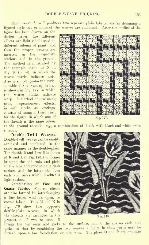
DOUBLE-WEAVE FIGURING 153
Fig. 177.
Each weave A to J produces two separate plain fabrics, and in designing a
figured style two or more of the weaves are combined. After the outline of the
figure has been drawn on theO
design paper, the different
effects are lightly indicated in
different colours of paint, and
then the proper weaves are
inserted in the respective
sections and in the ground.The method is illustrated bythe example given at N in
Fig. 70 (p 74), in which the
weave marks indicate weft.
Also a simple geometric style,
suitable for a vesting fabric,
is shown in Fig. 177, in which
the weave marks indicate
warp. A method of producingneat
; unpronounced effects,
in such cloths as vestings,
consists of using a twist yarnfor the figure, in which one of
the threads is the same colour
as the ground threads e.g., a combination of black with black-and-white twist
threads.
Double -Twill Weaves.Double-twill weaves can be readily
arranged and combined in the
same manner as the double-plain.
The double 2-and-2 twill is shown
at K and L in Fig. 176, the former
bringing the odd ends and picks
to the face and producing a dark
surface, and the latter the even
ends and picks which produce a
light surface.
Combination of Fine and
Coarse Fabrics. Figured effects
are also formed by interchanginga fine fabric with an open, or
coarse fabric. Thus M and N in
Fig. 176 show two opposite
double-plain weaves, in which
the threads are arranged in the
proportion of two to one. Mbrings the fine ends and picks to the surface, and N the coarser ends and
picks, so that by combining the two weaves a figure in thick yarns may be
formed upon a fine foundation, or vice versa. The plans and P are opposite
Fig. 178.
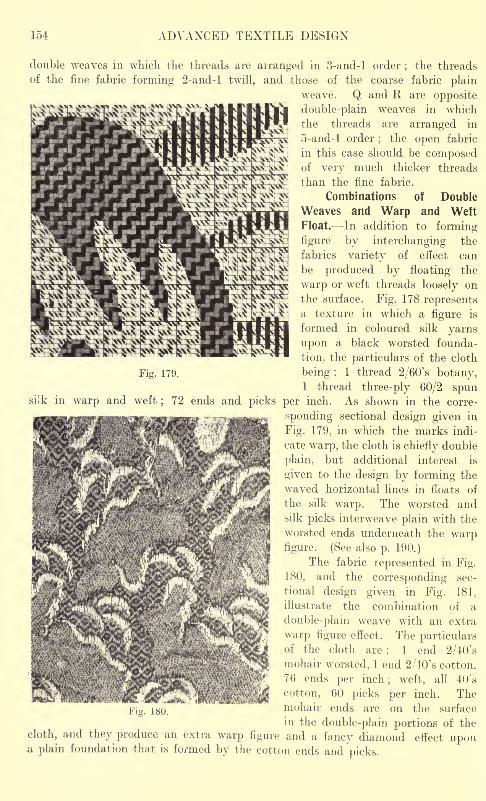
154 ADVANCED TEXTILE DESIGN
double weaves in which the threads are arranged in 3-and-l order;the threads
of the fine fabric forming 2-and-l twill, and those of the coarse fabric plainweave. Q and R are opposite
double-plain weaves in which
the threads are arranged in
5-and-l order;
the open fabric
in this case should be composedof very much thicker threads
than the fine fabric.
Combinations of Double
Weaves and Warp and Weft
Float. In addition to forming-
figure by interchanging the
fabrics variety of effect can
be produced by floating the
warp or weft threads loosely on
the surface. Fig. 178 representsa texture in which a figure is
formed in coloured silk yarns
upon a black worsted founda-
tion, the particulars of the cloth
Fig. 179. being : 1 thread 2/60's botany,1 thread three-ply 60/2 spun
warp and weft; 72 ends and picks per inch. As shown in the corre-
sponding sectional design given in
Fig. 179, in which the marks indi-
cate warp, the cloth is chiefly double
plain, but additional interest is
given to the design by forming the
waved horizontal lines in floats of
the silk warp. The worsted andsilk picks interweave plain with the
worsted ends underneath the warpfigure. (See also p. 190.)
The fabric represented in Fig.
180, and the corresponding sec-
tional design given in Fig. 181.
illustrate the combination of a
double-plain weave with an extra
warp figure effect. The particularsof the cloth are : 1 end 2/40's
mohair worsted, 1 end 2/4-0's cotton,
76 ends per inch; weft, all 40's
cotton, 60 picks per inch. The
1HO.mohair ends are on the surface
in the double-plain portions of the
cloth, and they produce an extra warp figure and a fancy diamond effect upona plain foundation that is formed by the cotton ends and picks.
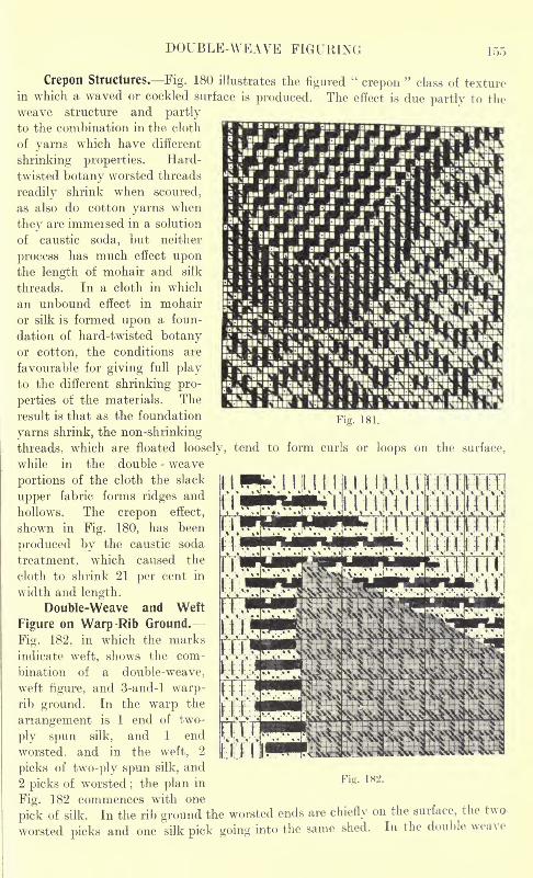
DOUBLE-WEAVE FIGURING 155
WXrjwwfflmHHHf^4n$]kHftl1 2
.5 , * u-! nil ,! sdLgSS i *;; t
Fig. 181.
Crepon Structures. Fig. 180 illustrates the figured"crepon
"class of texture
in which a waved or cockled surface is produced. The effect is due partly to theweave structure and partly
to the combination in the cloth
of yarns which have different
shrinking properties. Hard-
twisted botany worsted threads
readily shrink when scoured,
as also do cotton yarns when
they are immeised in a solution
of caustic soda, but neither
process has much effect uponthe length of mohair and silk
threads. In a cloth in which
an unbound effect in mohair
or silk is formed upon a foun-
dation of hard-twisted botanyor cotton, the conditions are
favourable for giving full playto the different shrinking pro-
perties of the materials. The
result is that as the foundation
yarns shrink, the non-shrinking
threads, which are floated loosely, tend to form curls or loops on the surface,
while in the double - weave
portions of the cloth the slack
upper fabric forms ridges and
hollows. The crepon effect,
shown in Fig. 180, has been
produced by the caustic soda
treatment, which caused the
cloth to shrink 21 per cent in
width and length.
Double-Weave and Weft
Figure on Warp -Rib Ground.
Fig. 182, in which the marks
indicate weft, shows the com-
bination of a double-weave,
weft figure, and 3-and-l warp-rib ground. In the warp the
arrangement is 1 end of two-
ply spun silk, and 1 end
worsted, and in the weft, 2
picks of two-ply spun silk, and
2 picks of worsted;the plan in
Fig. 182 commences with one
pick of silk. In the rib ground the worsted ends are chiefly on the surface, the two
worsted picks and one silk pick going into the same shed. In the double weave
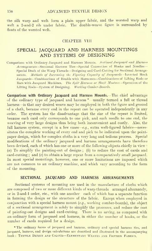
15(5 ADVANCED TEXTILE DESIGN
the silk warp and weft form a plain upper fabric, and the worsted warp and
weft a 2-and-2 rib under fabric. The double-weave figure is surrounded byfloats of the worsted weft.
CHAPTEK VIII
SPECIAL JACQUARD AND HARNESS MOUNTINGSAND SYSTEMS OF DESIGNING
Comparison with Ordinary Jacquard and Harness Mounts. Sectional Jacqitard and Harness
Arrangements Sectional Harness Ties Special Connection of Hooks and Needles
Special Draft of the Warp ThreadsDesigning and Card-Cutting for Sectional Arrange-
ments. Methods of Increasing the Figuring Capacity of Jacqiiards Inverted Hook
Jacquards Combinations of Healds with Harnesses Combinations of Lifting Rods or
Bars with Jacquard Machines. The Split Harness or Shaft Monture Operation of the
Lifting Rods System of Designing. Working Comber-Boards.
Comparison with Ordinary Jacquard and Harness Mounts. The chief advantageof the ordinary type of Jacquard and harness *
usually termed a full or thread
harness is that any desired weave may be employed in both the figure and groundof a cloth, because every end in the repeat can be operated independently in anyorder. The system has the disadvantage that the size of the repeat is limited,
because each card only corresponds to one pick, and each needle to one end, the
weaving of very large designs thus being both inconvenient and costly. Also, the
full harness system, except in a few cases e.g., extra weft-figured fabrics neces-
sitates the complete working of every end and pick to be indicated upon the point-
paper design, which for complex cloths is a very long and tedious process. Special
modifications of the ordinary Jacquard and harness arrangements have therefore
been devised, each of which has one or more of the following objects chiefly in view :
(a) To simplify the painting-out of designs ; (b) to reduce the cost of cards and
card-cutting ;and (c) to obtain a large repeat from a comparatively small Jacquard.
In most special mountings, however, one or more limitations are imposed which
.are not common to an ordinary machine, and which vary according to the form
of the mounting.
SECTIONAL JACQUARD AND HARNESS ARRANGEMENTS
Sectional systems of mounting are used in the manufacture of cloths which
.are composed of two or more different kinds of warp threads arranged alternately,
or in 2-and-l order, etc., with one another each of which has a separate function
in forming the design or the structure of the fabric. Except when employed in
conjunction with a special harness mount (e.g., working comber-boards), the objectof a sectional arrangement is solely to simplify the processes, and reduce the cost
of painting-out designs and card-cutting. There is no saving, as compared with
;an ordinary form of Jacquard and harness, in either the number of hooks, or the
number of cards required for a design.
* The ordinary forms of Jacquard and harness, ordinary and special harness ties, and
j'acquard, harness, and design calculations are described and illustrated in the accompanying.book : TEXTILE DESIGN AND COLOUR ELEMENTARY WEAVES AND FIGURED FABRICS.
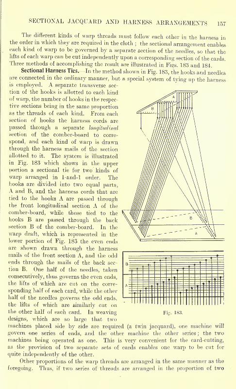
SECTIONAL JACQUARD AND HARNESS ARRANGEMENTS 157
The different kinds of warp threads must follow each other in the harness inthe order in which they are required in the cloth
; the sectional arrangement enableseach kind of warp to be governed by a separate section of the needles, so that thelifts of each warp can be cut independently upon a corresponding section of the cards.Three methods of accomplishing the result are illustrated in Figs. 183 and 184.
Sectional Harness Ties. In the method shown in Fig. 183, the hooks and needlesare connected in the ordinary manner, but a special system of tying up the harnessis employed. A separate transverse sec-
tion of the hooks is allotted to each kindof wT
arp, the number of hooks in the respec-tive sections being in the same proportionas the threads of each kind. From each
section of hooks the harness cords are
passed through a separate longitudinalsection of the comber-board to corre-
spond, and each kind of warp is drawn
through the harness mails of the section
allotted to it. The system is illustrated
in Fig. 183 which shows in the upperportion a sectional tie for two kinds of
warp arranged in 1-and-l order. Thehooks are divided into two equal parts,A and B, and the harness cords that are
tied to the hooks A are passed throughthe front longitudinal section A of the
comber-board, while those tied to the
hooks B are passed through the backsection B of the comber-board. In the
warp draft, which is represented in the
lower portion of Fig. 183 the even ends
are shown drawn through the harness
mails of the front section A, and the oddends through the mails of the back sec-
tion B. One half of the needles, taken
consecutively, thus governs the even ends,the lifts of which are cut on the corre-
sponding half of each card, while the other
half of the needles governs the odd ends,the lifts of which are similarly cut onthe other half of each card. In weaving Fig. 183.
designs, which are so large that twomachines placed side by side are required (a twin jacquard), one machine will
govern one series of ends, and the other machine the other series ;the two
machines being operated as one. This is very convenient for the card-cutting,as the provision of two separate sets of cards enables one warp to be cut for
quite independently of the other.
Other proportions of the warp threads are arranged in the same manner as the
foregoing. Thus, if two series of threads are arranged in the proportion of two
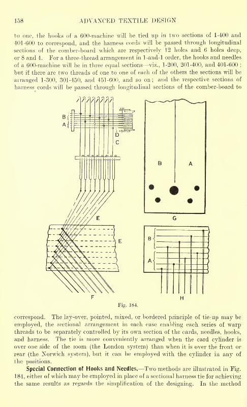
158 ADVANCED TEXTILE DESIGN
to one, the hooks of a 600-machine will be tied up in two sections of 1-400 and
401-600 to correspond, and the harness cords will be passed through longitudinal
sections of the comber-board which are respectively 12 holes and 6 holes deep,
or 8 and 4. For a three-thread arrangement in 1-and-l order, the hooks and needles
of a 600-machine will be in three equal sections viz., 1-200, 201-400, and 401-600;
but if there are two threads of one to one of each of the others the sections will be
arranged 1-300, 301-450, and 451-600, and so on; and the respective sections of
harness cords will be passed through longitudinal sections of the comber-board to
Fig. 184.
correspond. The lay-over, pointed, mixed, or bordered principle of tie-up may be
employed, the sectional arrangement in each case enabling each series of warpthreads to be separately controlled by its own section of the cards, needles, hooks,
and harness. The tie is more conveniently arranged when the card cylinder is
over one side of the loom (the London system) than when it is over the front or
rear (the Norwich system), but it can be employed with the cylinder in any of
the positions.
Special Connection of Hooks and Needles. Two methods are illustrated in Fig.
184, either of which may be employed in place of a sectional harness tie for achievingthe same results as regards the simplification of the designing. In the method
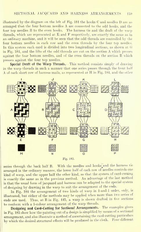
SECTIONAL JACQUARD AND HARNESS ARRANGEMENTS 159
illustrated by the diagram on the left of Fig. 184 the hooks C and needles D are so
arranged that the four bottom needles A are connected to the odd hooks, and the
four top needles B to the even hooks. The harness tie and the draft of the warpthreads, which are represented at E and F respectively, are exactly the same as in
an ordinary machine, and it will be seen that the odd threads are controlled by the
four bottom needles in each row and the even threads by the four top needles.
In this system each card is divided into two longitudinal sections, as shown at Gin Fig. 184, and the lifts of the odd threads are cut on the section A which presses
against the four bottom needles, and of the even threads on the section B which
presses against the four top needles.
Special Draft of the Warp Threads. This method consists simply of drawing
in the warp threads in such a manner that one series passes through the front half
A of each short row of harness mails, as represented at H in Fig. 184, and the other
M
Fig. 185.
series through the back half B. With the needles and hooksjind the harness tie
arranged in the ordinary manner, the lower half of each row of needles controls one
kind of warp, and the upper half the other kind, so that the system of card-cutting
is exactly the same as in the previous method. An advantage of the last method
is that the usual form of jacquard and harness can be adapted to the special system
of designing by drawing in the warp to suit the arrangement of the ends.
In Fig. 184 the arrangement of two kinds of warp in 1-and-l order, only, is
illustrated, but either of the methods may be applied when more than two series of
ends are used. Thus, at B in Fig. 445, a warp is shown drafted in five sections
to conform with a 5-colour arrangement of the warp threads.
Designing and Card-Cutting for Sectional Arrangements.- The examples given
in Fig. 185 show how the painting out of a design is simplified by means of a sectional
arrangement, and also illustrate a method of ascertaining the card-cutting particulars
by which the desired structural effects will be produced in the cloth. Four different
160 ADVANCED TEXTILE DESIGN
double-plain weaves are given in full at A, B, C, and D (these correspond with the
examples similarly lettered in Fig. 176, p. 152), which, it may be assumed, are
required to be combined in a design. Two series of ends and picks, in the order of
a thread of each alternately, are employed, and a jacquard and harness arrangementin two equal sections, as illustrated in Fig. 183 or Fig. 184, is therefore suitable
for the arrangement in the warp. The lifts of the odd ends of the respective double-
plain weaves, which are shown separately at E, F, G, and H in Fig. 185, will be
cut on one section of the cards, and those of the even ends, which are shown separatelyat I, J, K, and L on the other section of the cards. On the left of each plan E to Lthe lifts of the odd picks are shown apart, and on the right the lifts of the even picks.
The small plans on the left and right of the examples lettered E to L thus indicate
the interweaving of each kind of warp with each kind of weft in the respectiveweaves A, B, C, and D.
To represent the effects shown at A, B, C, and D a design would be paintedsolid in four different colours (or in three colours, the fourth effect being repre-sented by the paper), as indicated by the different marks shown at M, N, 0, and Pin Fig. 185. As there are two series of threads in both warp and weft, each vertical
space in the design then corresponds to two ends, and each horizontal space to two
picks. Two cards are therefore cut from each horizontal space, and further, the
design is cut twice first, for the section governing the odd ends, and then for the
section that governs the even ends. The plans on the left and right of the
examples E to L indicate the exact order in which the cards require to be cut from
the plans M, N, 0, and P, and in order to enable comparisons to be readily made,bracketed references are made to the respective plans in the following list in whichthe card-cutting particulars are given.
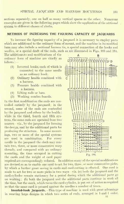
SPECIAL JACQUARD AND HARNESS MOUNTINGS 161
sections separately, one on half as many vertical spaces as the other. Numerous
examples are given in the following pages which show the application of the sectional
system to different classes of cloths.
METHODS OF INCREASING THE FIGURING CAPACITY OF JACQUARDS
To increase the figuring capacity of a jacquard it is necessary to employ partswhich are additional to the ordinary form of mount, and the machine in its modified
form may also include a sectional harness tie, a special connection of the hooks and
needles, or a special draft of the ends, such as are illustrated in Figs. 183 and 184.
The additions .to and modifications of the A B
ordinary form of machine are chiefly as
follows :
(1) Inverted hooks, each of which is
connected to the same needle
as an ordinary hook.
(2) Ordinary healds combined with
a harness.
(3) Pressure healds combined with
a harness.
(4) Lifting rods or bars.
(5) Working combei -boards.
In the first modification the ends are con-
trolled entirely by the jacquard ;in the
second, some of the ends are controlled
by the jacquard and others by the healds;
while in the third, fourth and fifth sys-
tems, the same ends are operated from two
sources viz., by the jacquard for formingthe design, and by the additional parts for
producing the structure. In some mount-
ings, two or more of the special systemsare used in combination. For everyneedle in the jacquard the cloth may con-
tain two, three, or more consecutive warpthreads, and compared with an ordinary
mounting, the time occupied in cuttingthe cards and the weight ot card paper
required are correspondingly reduced. In addition many of the special modifications
are devised so as to enable one card to act for two, three, or more consecutive picks,
by which a further great saving in cards and card-cutting is effected. One card is
made to act for two or more picks in two ways viz. (a) both the jacquard and the
card-cylinder remain stationary for a period during which the additional parts go
on working ; (b) both the jacquard and the additional parts continue in work all
the time, but the sneck, which turns the card-cylinder, is put out of action as required
so that the same card is pressed against the needles a number of times.
Inverted-hook Jacquards.^This type of machine is used with great advantage
in weaving large designs in which two series of ends, arranged in 1-and-l order.
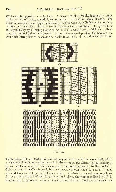
162 ADVANCED TEXTILE DESIGN
work exactly opposite to each other. As shown in Fig. 186 the jacquard is made
with two sets of hooks, A and B, to correspond with the two series of ends. The
hooks A have their bent upper ends turned towards the card-cylinder in the ordinary
manner, whereas those of B are turned towards the spring-box. One griffe D is
employed carrying 16 lifting blades in two sets of 8 blades each, which are inclined
towards the hooks that they govern. When in the normal position the hooks A are
over their lifting blades, whereas the hooks B are clear of the other set of blades.
The harness cords are tied up in the ordinary manner, but in the warp draft, which
is represented at E, one series of ends is drawn upon the harness cords connected
to the hooks A, and the other series upon the cords connected to the hooks B.
Only one set of needles is used, but each needle is connected to a hook of each
set, and thus controls an end of each series. A blank in a card presses a hookA away from the path of its lifting blade, and places the corresponding hook B in
position for being raised, while a hole in a card leaves a hook A in position for
SPECIAL JACQUARD AND HARNESS MOUNTINGS 163
being lifted, and a hook B out of action. Therefore, where ends of one series are
raised, corresponding ends of the other series are left down, and vice versa.
A class of fabric for which the arrangement is particularly useful is a reversible
warp rib structure, in which a warp figure is produced in two colours upon plainor rib ground on both sides of the cloth. In order to show the special use of aninverted hook jacquard plans are given at A, B, C, and D in Fig. 187, which illus-
trate the development of a portion of a design from the solid system of markingto the complete reversible rib structure. The figure formed by each colour of warpis painted solid, as shown by the different marks in A, each vertical space of which
represents an end of both series, and each horizontal space two picks. Assumingthat the dark figure is required to be produced by the ends which are controlled
by the ordinary hooks, two cards are cut from each horizontal space, as follows :
First Card. Cut all except the marks of the light figure.
Second Card. Cut only the marks of the dark figure.
B in Fig. 187 shows the lifts that are cut on the cards and are formed by the
ordinary hooks, while C, which is exactly opposite to B, shows how the other threads
ore raised by the inverted hooks. As the ends are drawn through the harness
in 1-and-l order, an end of B is followed by an end of C, and the complete weave
is, therefore, as indicated at D.
The inverted hook arrangement, illustrated in Fig. 186, not only enables a
very simple method of designing to be employed, but a design is produced that
repeats upon twice as many ends as there are needles in the machine. If, however,;in increase in the figuring capacity of the jacquard is not desired, one of the sectional
arrangements, previously described, will enable the same method of designing to
be employed for a reversible warp rib cloth, two cards being cut from each hori-
zontal space ot the design A in Fig. 187, as follows :
Dark Warp Section. First card, cut blanks and solid marks;
second card,
cut solid marks.
Light Warp Section. First card, cut diagonal marks;second card, cut blanks
and diagonal marks.
To correspond with the design A in Fig. 187, B then shows the lifts cut on the dark
warp section, and C those cut on the light warp section.
Combination of Healds with Harnesses. -When ordinary healds are employedin conjunction with a jacquard harness the threads which they operate in regular
order are not passed through the harness mails, but are in addition to the figuring
threads. The position of the healds at the back or front of the harness is largely
ii matter of convenience a^ regards space and depth of shed, but a determining
factor is the relative strength of the threads, as the weaker yarn should be operated
by the shedding mechanism at the front. Certain of the jacquard hooks may be
used in raising the healds, but this prevents a card from acting for more than one
pick. Either tappets or a dobby may be employed to work the healds indepen-
dently of the jacquard (positive shedding motions being most serviceable when
the threads controlled by the healds are heavily tensioned), and these motions
enable each card to act for any desired number of picks.
A heald-and-harness mount has been previously referred to in connection
with extra warp figuring (see Fig. 147), and in the following pages different classes
of cloths are illustrated for which the system is employed. One-half, two-thirds,
164 ADVANCED TEXTILE DESIGN
etc., of the warp threads are drawn upon the healds, so that the figuring capacity
of the jacquard is increased two or three-fold, etc. The limitation in the arrange-
ment is in the weave of the ends that are operated by the healds, but it will be
understood that the ends controlled by the jacquard may be operated as desired.
In the "pressure-harness" system (see Fig. 201) the healds that are used in
conjunction with the harness are special in form, and in this case the same ends are
drawn through both the harness and the healds, and are operated from the two
sources, which results in the weave being limited in both the figure and the ground.
Combinations of Lifting Rods or Bars with Jacquard Machines. This systemenables the harness cords to be operated in longitudinal rows quite indepen-
dently of the figuring hooks, and at the same time does not prevent the cords
from being operated by the jacquard. The method is employed, on the one hand,
in order that each needle of the jacquard may control two, three, or more con-
secutive warp threads, as in the split-harness mounting (described in the following),
and the twilling jacquard (see Fig. 204) ; and, on the other hand, it is used for the
purpose of enabling warp threads to be lifted in a definite order without the lifts
being cut on the figuring cards, as in certain classes of tapestry (see Fig. 216).
THE SPLIT HARNESS OR SHAFT MONTURE
The split harness or shaft monture (also known as the scale or bannister
harness) is used in weaving fabrics which are very finely set in the warp in order
to double, treble, or quadruple the width of repeat of the jacquard. Rich silk
tabrics, or the non-reversible damask and other types, are frequently woven with
only a comparatively few picks per inch, but contain a very large number of ends
per inch (400 and upwards in some cases), so that with an ordinary full harness
mount a very large machine is required in weaving a wide repeat. In the most
common form of split harness, which is illustrated in Fig. 188, an ordinary single-
lift jacquard is used, but some distance above the comber-board C each single
cord D from the neck cords is connected to two or more double harness cords E.
each of which is passed through a separate hole in the comber-board. A knot Fis tied in each double harness cord, so as to form, above the mail, a loop G which
is sufficiently long to allow the proper depth of shed to be made. Also, the comber-
board is placed high enough above the knots F to permit the cords to be lifted the
proper height without obstruction. The diagram on the left of Fig. 188 representsan 8-row machine, in which the scale is doubled i.e., two looped harness cords.
are connected to each single cord D, giving 16 rows of harness cords in the comber-
board C. On the right of Fig. 188 three looped harness cords are shown connected
do each single cord, which, in an 8-row machine, gives 24 rows in the comber-board.
Operation of the Lifting Rods. A bannister shaft or rod H (Fig. 188), which is.
rather longer than the width of the harness, is passed loosely through the loops of
each long row of harness cords, so that each rod is capable of lifting one end in
every sixteen or every twenty-four, etc., according to the number of rods employed,
quite independently of the figuring cards. The arrangement does not preventthe jacquard from lifting the ends in forming the desired figure, but they are
necessarily raised by the hooks in groups of two or more to correspond with the
scale of the harness. By lifting the rods, the ends that are left down by the jacquard
may be raised singly and produce any ground weave (plain, twill, sateen, etc.),
which repeats upon a number of ends that is a measure of the number of rods.
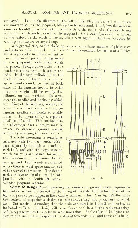
SPECIAL JACQUARD AND HARNESS MOUNTINGS 165
employed. Thus, in the diagram on the left of Fig. 188, the hooks 1 to 4, whichare shown raised by the jacquard, lift up the harness mails 1 to 8, but the rods areraised in l-and-3 order, and lift up one-fourth of the mails viz., the twelfth andsixteenth which are left down by the jacquard. Only warp figures can be formedon the surface as the cloth is woven, and a weft figure is therefore produced byweaving the texture wrong side up.
As a general rule, as the cloths do not contain a large number of picks, eachcard acts for only one pick. The rods H may be operated by means of a dobby,but it is generally found convenient to
use a number of specially strong hooks
in the jacquard, cords from which
are passed through guide holes in the
comber-board to near each end of the
rods. If the card cylinder is at the
back or front of the loom a row of
special hooks should be used at both
sides of the figuring hooks, in order
that the weight will be evenly dis-
tributed on the machine. In somecases the needles and hooks, by which
the lifting of the rods is governed, are
situated a sufficient distance from the
figuring needles and hooks to enable
them to be operated by a separatesmall set of cards. This method has
the advantage that a design may be
woven in different ground weaves
simply by changing the small cards.
The split mounting is sometimes
arranged with two neck-cords (which
pass separately through a board) to
each hook, and with the loops, through
-D
li
-G-H
which the rods are passed, formed in
the neck-cords. It is claimed for the
arrangement that the rods are situated
where there is most space and are out
of the way of the weaver. The double
neck-cord system is also used in con-
junction with a double-lift single-Fi - 188 -
cylinder jacquard machine.
System of Designing. In painting out designs no ground weave requires to
be filled in, as this is produced by the lifting of the rods, but the long floats of the
figure require to be stopped in the ordinary manner. Thus, A in Fig. 189 illustrates
the method of preparing a design for the card-cutting, the particulars of which
are : Cut marks. Assuming that the rods are raised in l-and-3 twill order, as
indicated at B, the full design will be as shown at C in a double-scale mounting,and as represented at D in a treble-scale mounting. At the edge of the figure each
step of one end in A corresponds to a step of two ends in C, and three ends in D ;
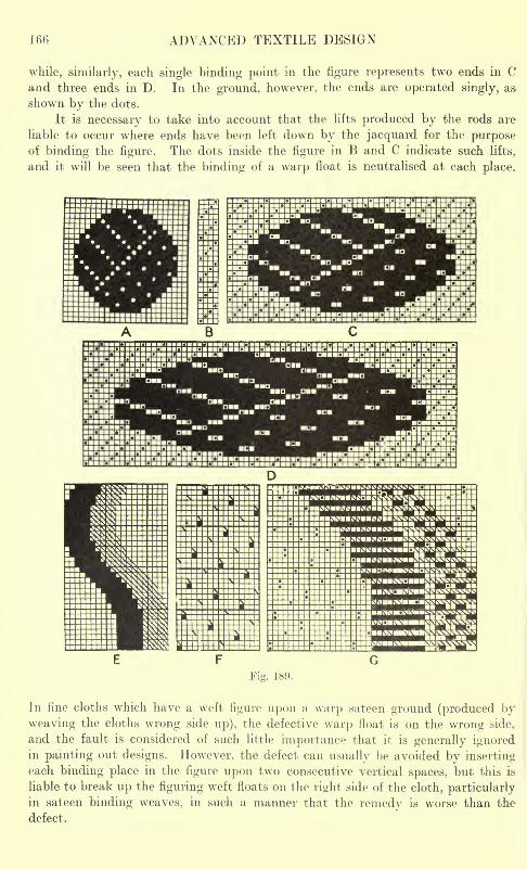
166 ADVANCED TEXTILE DESIGN
while, similarly, each single binding point in the figure represents two ends in Cand three ends in D. In the ground, however, the ends are operated singly, as
shown by the dots.
It is necessary to take into account that the lifts produced by the rods are
liable to occur where ends have been left down by the jacquard for the purposeof binding the figure. The dots inside the figure in B and C indicate such lifts,
and it will be seen that the binding of a warp float is neutralised at each place.
|lN
1
SPECIAL JACQUARD AND HARNESS MOUNTINGS 167
The split harness system greatly simplifies the processes of drafting and cuttingdesigns, and there is scarcely any limit to the diversity of weave developmentthat can be obtained in a design, nor to the variety of ground weave that may beused. The outline and binding lines of a figure, however, are rather steppy, butthe figure shows up very bold and clear upon the fine ground effect that is generallyiormed. The system is readily applied to elaborately-figured multiple-weft fabrics,
and E in Fig. 189 illustrates the method of designing a figure in two wefts, whichare inserted in pick-and-pick order. Two cards are cut from each horizontal spaceof E as follows .
First Card. Cut the marks of the first colour and those of the second colour
plain.
Second Card. Cut the marks of the second colour and those of the first colour
plain.
Assuming that the scale of the harness is doubled, and that the rods are raised in
the order indicated at F (by which one of the wefts is interwoven in 8-sateen and the
other in 16-sateen order in the ground), the full weave to correspond with the lower
portion of E will be as indicated at G. It will be seen that the plain cutting of the
figure produces a 2-and-2 weft rib weave under each kind of weft float. This
example may be compared with that given in Fig. 132 (p. 121).
WORKING COMBER-BOARDS
In this system each harness cord is knotted in such a position that the knot
rests on the comber-board when the harness mail is at the bottom line of the shed.
The knots do not prevent the cords from being raised individually by the jacquardin the ordinary manner, whereas by lifting the comber-board all the cords, whose
knots rest upon it, are raised together. In the manufacture of Brussels and Wilton
carpets (see Fig. 445) only one board is employed, but for Marseilles quilts (see Figs.
23C and 231) and satin quilts (Fig. 234) the board is in two longitudinal sections,
and for Kidderminster carpets (Fig. 218) in four longitudinal sections, which
enable the ends to be raised in groups separately.
In weaving Marseilles and satin quilts, working comber-boards are used in
conjunction with ordinary healds, and in Fig. 190 a form of the mounting (as made
by Messrs. Robert Hall & Sons) is illustrated. There are two knotted comber-
boards A, and two healds B (one of each is shown partly raised), which are operated
by means of four tappets C. Cords D, straps E, levers F, and cords G, connect
the tappets with the top of the comber-boards and healds. while through levers
H similar connections are made with the bottom staves of the healds. Spiral
springs I are employed to assist the downward movement of the comber-boards.
The tappets C are rotated at the proper speed by the wheel J on the end of the
crank shaft gearing into the wheel K connected to the tappets. The jacquard is
operated once in every group of picks by means of a positive tappet L, which is
driven by a wheel on the crank shaft. Through connecting levers the vertical rod
M, which is connected to the jacquard griffe, is made to fall and rise and remain
stationary as required, by the tappet L.
Special forms of jacquard and harness mounts are further described and illus-
trated in the following pages, along with the particular classes of cloths for which
they are used. They include the book-harness mounting, pressure harness, self-
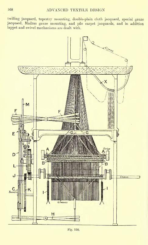
168 ADVANCED TEXTILE DESIGN
twilling jacquard, tapestry mounting, double-plain cloth jacquard, special gauzejacquard, Madras gauze mounting, and pile carpet jacquards, and in addition
lappet and swivel mechanisms are dealt with.
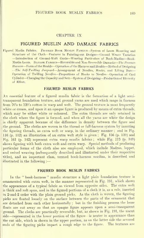
FIGURED BOOK MUSLIN FABRICS 169
CHAPTER IX
FIGURED MUSLIN AND DAMASK FABRICS
Figured Muslin Fabrics. FIGURED BOOK MUSLIN FABRICS System of Loom Mounting andStructure of the Cloth Features in Painting-out Designs Ground Weave Variation
Introduction of Ground-Weft Cords Weaving Particulars of Book-Muslins Book-
Muslin Loom. DAMASK FABRICS Reversible and Non-Reversible Damasks The Pressure
Harness Form of the Healds Operation of the Harness and Healds Method of DesigningThe Self-Twilling Jacquard Arrangement of Needles, Hooks, and Lifting Bars
Operation of Twilling Needles Proportions of Hooks to Needles Operation of Card
Cylinder Changing the Capacity and Sett System of Designing Production of Diversityof Effect.
FIGURED MUSLIN FABRICS
AN essential feature of a figured muslin fabric is the formation of a light semi-
transparent foundation texture, and ground yarns are used which range in fineness
from 70's to 120's cotton in warp and weft. The ground texture is most frequentlywhite or cream, and upon it an opaque figure is produced by means of extra threads,
which may be either white or coloured. The extra threads are only retained in
the cloth where the figure is formed, and when all the yarns are white the design
is chiefly apparent because of the difference in density between the figure and
the ground. The cloths are woven in the thread or full-harness system by inserting
the figuring threads, as extra weft or warp, in the ordinary manner ;and in Fig.
116 (p. 112) an illustration of an extra weft style is given ; Fig. 156 (p. 139) and
Fig. 161 (p. 142) represent extra warp muslin fabrics;
while Fig. 173 (p. 149)
shows figuring with both extra weft and extra warp. Special methods of producing
particular forms of the cloth also are employed, which include Madras, lappet,
and swivel weaving (subsequently described and illustrated under their respective
jtitles), and an important class, termed book-harness muslins, is described and
illustrated in the following :
FIGURED BOOK MUSLIN FABRICS
In the"book-harness
"muslin structure a light plain foundation texture is
ornamented with extra weft, in the manner represented in Fig. 191, which shows
the appearance of a typical fabric as viewed from opposite sides. The extra weft
is thick and soft spun, and in the figured portions of a cloth it is, as a rule, inserted
in 2-and-2 order with the plain ground picks. As the cloth is woven, the figuring
: picks are floated loosely on the surface between the parts of the ornament that
I
are detached from each other horizontally ;but in the finishing process the loose
floats are cut away so that an opaque figure appears upon a semi-transparent
i ground. The cloths are practically reversible, but, as shown in Fig. 191, the uncut
|
side represented in the lower portion of the figure is neater in appearance than
the cut side, which is shown in the upper portion, as on the latter side the severed
lends of the figuring picks impart a rough edge to the figure. The textures are
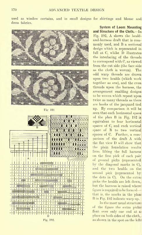
170 ADVANCED TEXTILE DESIGN
191
used as window curtains, and in small designs for skirtings and blouse anddress fabrics.
System of Loom Mountingand Structure of the Cloth. In
Fig. 192, A shows the heald-
and-harness draft that is com-
monly used, and B a sectional
design which is represented in
full at C, whilst D illustrates
the interlacing of the threads
to correspond with C, as viewed
from the cut side (the face side
as the cloth is woven). Theodd warp threads are drawn
upon two healds (which work
together as one), and the even
threads upon the harness, the
arrangement enabling designsto be woven which repeat upontwice as many threads as there
are hooks of the jacquard tied
up. By comparison it will be
seen that each horizontal spaceof the plan B in Fig. 192 is
equivalent to four horizontal
spaces of C, and each vertical
space of B to two vertical
spaces of C. Further, a com-
parison of the draft A with
the flat view D will show that
the plain foundation results
from lifting the full harness
on the first pick of each pairof ground picks (represented
by the diagonal marks in C),
and the two healds on the
second pick (represented bythe dots in C). On the extra i
picks the healds are left down, .
but the harness is raised where
figure is required to be formed-that is, the marks in the planB in Fig. 192 indicate warp up.
In the most usual structure
of the figure the extra picksfloat over only one end at a
place on both sides of the cloth,
as shown in the spot on the left'
L|J_|J_ j^\tffi^%&\ l I l__L|jLLLI I I I I
i i~' I ill I i__I
i l_ I I I __ j | ~ir_I I I I I I III I
y''\ '""'"''"!!!"' I'""f"^^.' i- I I ...| <,<,<,,iuiiih\>iitninfcnzm
J.J_|_L|_|J^^^^^^L|J_|JJ J JII
i I |*532?l I I I \w\yM/r/f'\MMj'jjj*9A\~~ jI iazi3np|J'~~~ I I |~-L
|-Upg|_L| JL.Rjf. .'!!l
'
iFj^rqggg |_L|5p|J L|_L
Fig. 192.
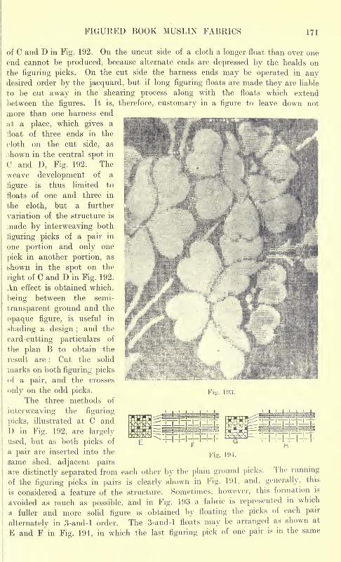
FIGURED BOOK MUSLIN FABRICS 171
of C and D in Fig. 192. On the uncut side of a cloth a longer float than over one
end cannot be produced, because alternate ends are depressed by the healds on
the figuring picks. On the cut side the harness ends may be operated in anydesired order by the jacquard, but if long figuring floats are made they are liable
to be cut away in the shearing process along with the floats which extend
between the figures. It is, therefore, customary in a figure to leave down not
more than one harness end
at a place, which gives a
float of three ends in the
cloth on the cut side, as
;;hown in the central spot in
C and D, Fig. 192. The
weave development of a
figure is thus limited tojd
floats of one and three in
the cloth, but a further
variation of the structure is
made by interweaving both
figuring picks of a pair in "5
one portion and only one
pick in another portion, as
shown in the spot on the
right of C and D in Fig. 192.
An effect is obtained which, gbeing between the semi-
transparent ground and the f
opaque figure, is useful in
shading a design ;and the
card-cutting particulars of
the plan B to obtain the
result are : Cut the solid
marks on both figuring picksof a pair, and the crosses
only on the odd picks.
The three methods of
interweaving the figuring
picks, illustrated at C and
D in Fig. 192, are largely
used, but as both picks of
a pair are inserted into the
same shed, adjacent pairs
are distinctly separated from each other by the plain ground picks. The running
of the figuring picks in pairs is clearly shown in Fig. 191, and, generally, this
is considered a feature of the structure. Sometimes, however, this formation is
avoided as much as possible, and in Fig. 193 a fabric is represented in which
a fuller and more solid figure is obtained by floating the picks of each pair
alternately in .3-and-l order. The 3-and-l floats may be arranged as shown at
E and F in Fig. 194, in which the last figuring pick of one pair is in the same
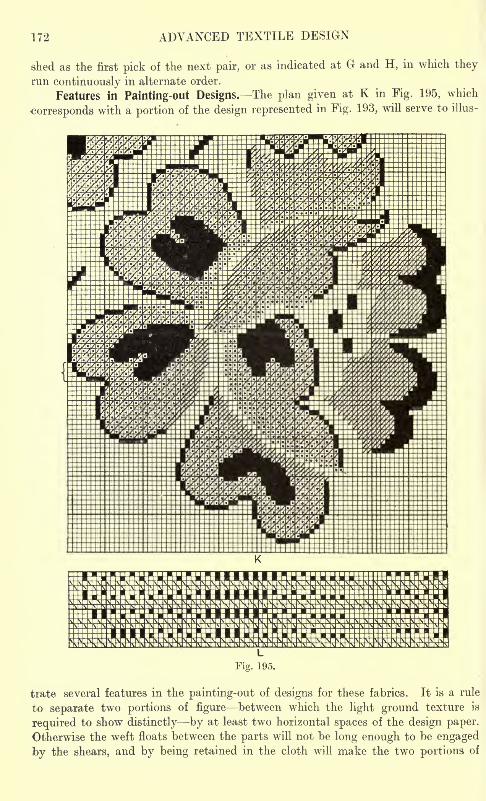
172 ADVANCED TEXTILE DESIGN
shed as the first pick of the next pair, or as indicated at G and H, in which they
run continuously in alternate order.
Features in Painting-out Designs. The plan given at K in Fig. 195, which
corresponds with a portion of the design represented in Fig. 193, will serve to illus-
trate several features in the painting-out of designs for these fabrics. It is a rule
to separate two portions of figure between which the light ground texture is
required to show distinctly by at least two horizontal spaces of the design paper.
Otherwise the weft floats between the parts will not be long enough to be engaged
by the shears, and by being retained in the cloth will make the two portions of
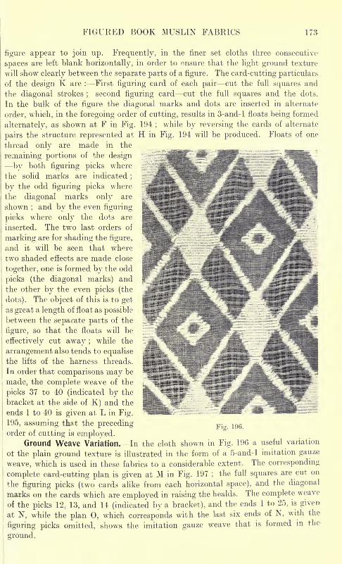
FIGURED BOOK MUSLIN FABRICS
figure appear to join up. Frequently, in the finer set cloths three consecutive-
spaces are left blank horizontally, in order to ensure that the light ground texture
will show clearly between the separate parts of a figure. The card-cutting particulars
of the design K are : -First figuring card of each pair cut the full squares and
the diagonal strokes;
second figuring card cut the full squares and the dots.
In the bulk of the figure the diagonal marks and dots are inserted in alternate
order, which, in the foregoing order of cutting, results in 3-and-l floats being formed
alternately, as shown at F in Fig. 194;
while by reversing the cards of alternate
pairs the structure represented at H in Fig. 194 will be produced. Floats of one
thread only are made in the
remaining portions of the design
by both figuring picks where
the solid marks are indicated;
by the odd figuring picks where
the diagonal marks only are
shown ;and by the even figuring
picks where only the dots are
inserted. The two last orders of
marking are for shading the figure,
and it will be seen that where
two shaded effects are made close
together, one is formed by the odd
picks (the diagonal marks) and
the other by the even picks (the
dots). The object of this is to getas great a length of float as possible
between the separate parts of the
figure, so that the floats will be
effectively cut away ;while the
arrangement also tends to equalisethe lifts of the harness threads.
In order that comparisons may be
made, the complete weave of the
picks 37 to 40 (indicated by the
bracket at the side of K) and the
ends 1 to 40 is given at L in Fig.
Fig. 196.195, assuming that the precedingorder of cutting is employed.
Ground Weave Variation. In the cloth shown in Fig. 196 a useful variation
ot the plain ground texture is illustrated in the form of a 5-and-l imitation gauze
weave, which is used in these fabrics to a considerable extent. The corresponding
complete card-cutting plan is given at M in Fig. 197;
the full squares are cut on
the figuring picks (two cards alike from each horizontal space), and the diagonal
marks on the cards which are employed in raising the healds. The complete weave
of the picks 12, 13, and 14 (indicated by a bracket), and the ends 1 to 25, is given-
at N, while the plan 0, which corresponds with the last six ends of N, with the
figuring picks omitted, shows the imitation gauze weave that is formed in the-
ground.
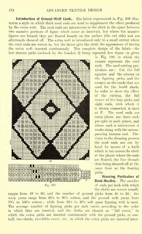
174 ADVANCED TEXTILE DESIGN
Introduction of Ground-Weft Cords. The fabric represented in Fig. 198 illus-
trates a style in which thick cord ends are used to supplement the effect produced
by the extra weft. The cord ends are interwoven in the cloth in the space between
two massive portions of figure which occur at intervals, but where the massive
figures are formed they are floated loosely on the surface (the cut side) and are
afterwards sheared off. The extra weft is introduced only to a small extent where
the cord ends are woven in, but the latter give the cloth the appearance of havingthe extra weft inserted continuously. The complete design of the fabric the
last sixteen picks enclosed by the bracket Q being repeated five times is givenin Fig. 199, in which the
crosses represent the cord
ends The card-cutting par-ticulars are : Cut the full
squares and the crosses on
the figuring picks, and the
crosses on the cards that are
used for the heald sheds.
In order to show the effect
of the cutting, the full
weave of the four picks and
eight ends, with which it
is shown connected, is inset
at P. The cord ends are
extra (there are three ends
per split at each place), and
where each is interwoven it
works along with the accom-
panying harness end. Pre-
vious to the shearing processthe cord ends are cut byhand by means of a knife
which is run across the cloth
at the places where the ends
are floated, the free threads
then being sheared off at the
same time as the floating-
picks.
Weaving Particulars of
Book Muslins. The numberof ends per inch with which
the cloths are woven usually
ranges from 48 to 60, and the number of ground picks from 40 to 56;
the
warp yarns range from 60's to 80's cotton, and the ground weft yarns from
70's to 100's cotton;
while from 16's to 20's soft spun figuring weft is used.
The average number of figuring picks per inch varies according to the order
in which they are inserted, and the cloths are classed as"
full cover," in
which the extra picks are inserted continuously with the ground picks, or one-
half, two-thirds, two-fifths cover, etc., in which the extra picks are inserted inter-
Fig. 197.
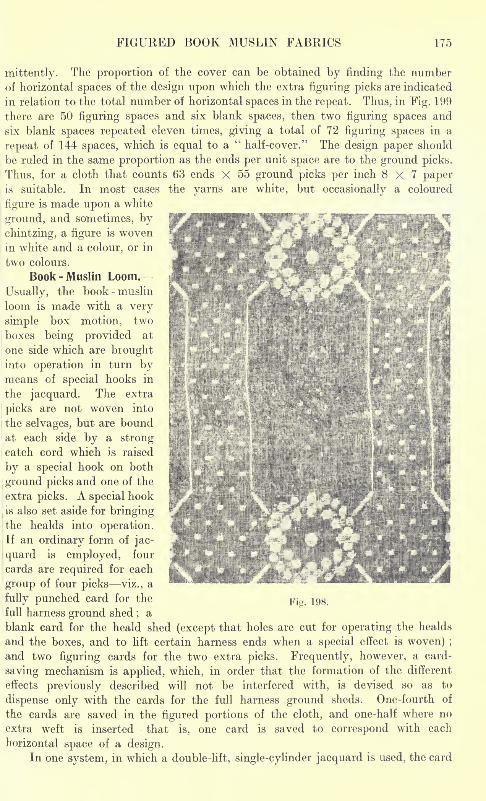
FIGURED BOOK MUSLIN FABRICS 175
mittently. The proportion of the cover can be obtained by finding the numberof horizontal spaces of the design upon which the extra figuring picks are indicated
in relation to the total number of horizontal spaces in the repeat. Thus, in Fig. 199
there are 50 figuring spaces and six blank spaces, then two figuring spaces and
six blank spaces repeated eleven times, giving a total of 72 figuring spaces in a
repeat of 144 spaces, which is equal to a"half-cover." The design paper should
be ruled in the same proportion as the ends per unit space are to the ground picks.
Thus, for a cloth that counts 63 ends X 55 ground picks per inch 8x7 paperis suitable. In most cases the yarns are white, but occasionally a coloured
figure is made upon a white
ground, and sometimes, by
chintzing, a figure is woven
in white and a colour, or in
two colours.
Book - Muslin Loom.
Usually, the book - muslin
loom is made with a very
simple box motion, two
boxes being provided at
one side which are broughtinto operation in turn bymeans of special hooks in
the jacquard. The extra
picks are not woven into
the selvages, but are bound
at each side by a strongcatch cord which is raised
by a special hook on both
ground picks and one of the
extra picks. A special hook
is also set aside for bringingthe healds into operation.If an ordinary form of jac-
quard is employed, four
cards are required for each
group of four picks viz., a
fully punched card for the ^ja ^full harness ground shed
;a
blank card for the heald shed (except that holes are cut for operating the healds
and the boxes, and to lift certain harness ends when a special effect is woven) ;
and two figuring cards for the two extra picks. Frequently, however, a card-
saving mechanism is applied, which, in order that the formation of the different
effects previously described will not be interfered with, is devised so as to
dispense only with the cards for the full harness ground sheds. One-fourth of
the cards are saved in the figured portions of the cloth, and one-half where no
extra weft is inserted that is, one card is saved to correspond with each
horizontal space of a design.In one system, in which a double-lift, single-cylinder jacquard is used, the card
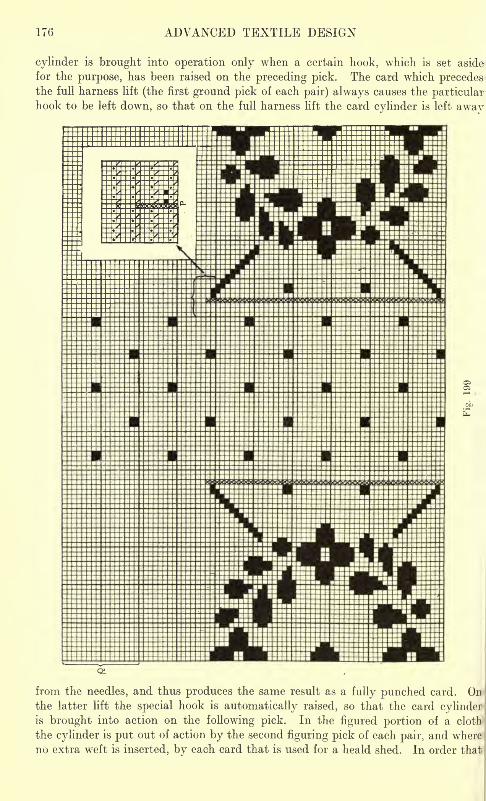
176 ADVANCED TEXTILE DESIGN
cylinder is brought into operation only when a certain hook, which is set aside
for the purpose, has been raised on the preceding pick. The card which precedesthe full harness lift (the first ground pick of each pair) always causes the particularhook to be left down, so that on the full harness lift the card cylinder is left away
from the needles, and thus produces the same result as a fully punched card. Onthe latter lift the special hook is automatically raised, so that the card cylinderis brought into action on the following pick. In the figured portion of a cloth
the cylinder is put out of action by the second figuring pick of each pair, and where
no extra weft is inserted, by each card that is used for a heald shed. In order that
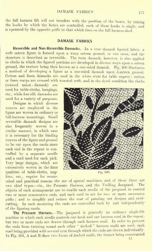
DAMASK FABRICS 177
the full harness lift will not interfere with the position of the boxes, by raisingthe hooks by which the boxes are controlled, each of these hooks is single, andis operated by the opposite griffe to that which rises on the full harness shed.
DAMASK FABRICS
Reversible and Non-Reversible Damasks. In a true damask figured fabric, aweft sateen figure is formed upon a warp sateen ground, or vice versa, and thestructure is described as reversible. The term damask, however, is also appliedto cloths in which the figured portions are developed in diverse ways upon a sateen
ground, the texture being then known as a one-sided damask. Fig. 200 illustrates
a method of developing a figure as a one-sided damask upon 5-sateen ground.Cotton and linen damasks are used in the white state for table napery ; cottonor linen warps are crossed with worsted weft, and in the dyed condition the cloths
(termed union - damask) are
used for table-cloths, hangings,
etc., while fine silk damasks are
used for a variety of purposes.
Designs in which diverse
weaves are employed in the
figure are woven in ordinary or
full-harness mountings. Small
reversible damask designs are
also frequently woven in a
similar manner, in which case
it is necessary for the binding-
weaves of the figure and groundto be cut upon the cards since
each end in the repeat is con-
trolled by a separate needle
and a card used for each pick.
Very large designs, which are
extensively woven in the finer
qualities of table-cloths, nap-
kins, etc., require for econo-
mical and practical reasons the use of special machines, and of these there are
two chief types viz., the Pressure Harness, and the Twilling Jacquard. The
objects of each arrangement are to enable each needle of the jacquard to control
two or more consecutive ends, and each card to act for two or more successive
picks ;and to simplify and reduce the cost of painting out designs and card-
cutting. In each mounting the ends are controlled both by and independently
of the figuring cards.
The Pressure Harness. The jacquard is generally an ordinary single-lift
machine in which each needle controls one hook and one harness cord in the repeat,
but two or more ends are drawn through each harness mail. In order to prevent
the ends from twisting round each other" decked
"harness mails are used, each
mail being provided with several eyes through which the ends are drawn individually.
In Fig. 201, A and B show two forms of decked mails, the former being constructed
Fig. 200.
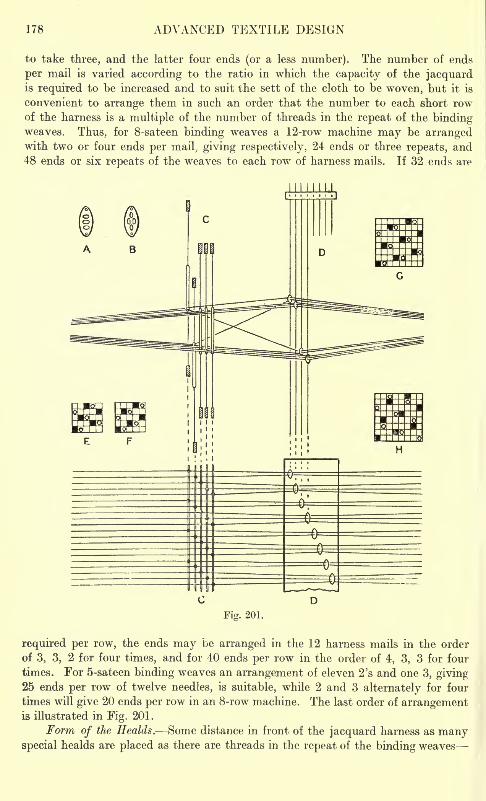
178 ADVANCED TEXTILE DESIGN
to take three, and the latter four ends (or a less number). The number of ends
per mail is varied according to the ratio in which the capacity of the jacquardis required to be increased and to suit the sett of the cloth to be woven, but it is
convenient to arrange them in such an order that the number to each short rowof the harness is a multiple of the number of threads in the repeat of the bindingweaves. Thus, for 8-sateen binding weaves a 12-row machine may be arrangedwith two or four ends per mail, giving respectively, 24 ends or three repeats, and48 ends or six repeats of the weaves to each row of harness mails. If 32 ends are
Fig. 201.
required per row, the ends may be arranged in the 12 harness mails in the order
of 3, 3, 2 for four times, and for 40 ends per row in the order of 4, 3, 3 for four
times. For 5-sateen binding weaves an arrangement of eleven 2's and one 3, giving25 ends per row of twelve needles, is suitable, while 2 and 3 alternately for four
times will give 20 ends per row in an 8-row machine. The last order of arrangementis illustrated in Fig. 201.
Form of the Healds. Some distance in front of the jacquard harness as manyspecial healds are placed as there are threads in the repeat of the binding weaves
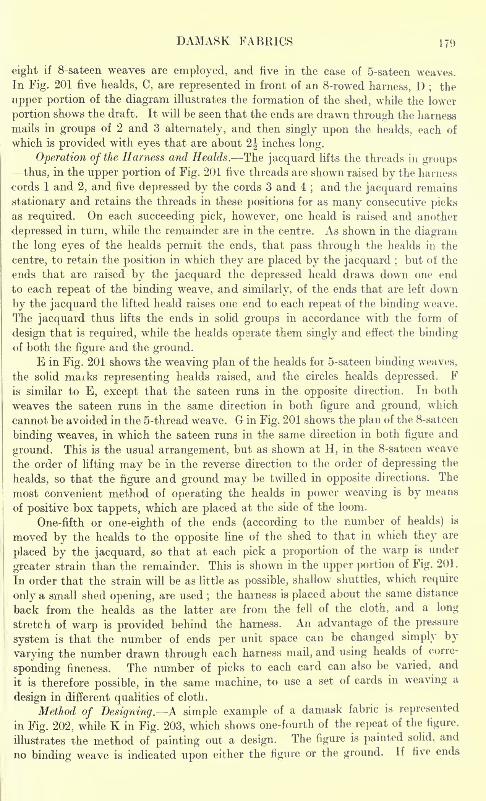
DAMASK FABRICS 171)
eight if 8-sateen weaves are employed, and five in the case of 5-sateen weaves.
In Fig. 201 five healds, C, are represented in front of an 8-rowed harness, D ; the
upper portion of the diagram illustrates the formation of the shed, while the lower
portion shows the draft. It will be seen that the ends are drawn through the harness
mails in groups of 2 and 3 alternately, and then singly upon the healds, each of
which is provided with eyes that are about 2J inches long.
Operation of the Harness and Healds. The jacquard lifts the threads in groupsthus, in the upper portion of Fig. 201 five threads are shown raised by the harness
cords 1 and 2, and five depressed by the cords 3 and 4;and the jacquard remains
stationary and retains the threads in these positions for as many consecutive picksas required. On each succeeding pick, however, one heald is raised and another
depressed in turn, while the remainder are in the centre. As shown in the diagramthe long eyes of the healds permit the ends, that pass through the healds in the
centre, to retain the position in which they are placed by the jacquard ;but of the
ends that are raised by the jacquard the depressed heald draws down one end
to each repeat of the binding weave, and similarly, of the ends that are left down
by the jacquard the lifted heald raises one end to each repeat of the binding weave.
The jacquard thus lifts the ends in solid groups in accordance with the form of
design that is required, while the healds operate them singly and effect the bindingof both the figure and the ground.
E in Fig. 201 shows the weaving plan of the healds for 5-sateen binding weaves,
the solid maiks representing healds raised, and the circles healds depressed. Fis similar to E, except that the sateen runs in the opposite direction. In both
weaves the sateen runs in the same direction in both figure and ground, which
cannot be avoided in the 5-thread weave. G in Fig. 201 shows the plan of the 8-sateen
binding weaves, in which the sateen runs in the same direction in both figure and
ground. This is the usual arrangement, but as shown at H, in the 8-sateen weave
the order of lifting may be in the reverse direction to the order of depressing the
healds, so that the figure and ground may be twilled in opposite directions. The
most convenient method of operating the healds in power weaving is by means
of positive box tappets, which are placed at the side of the loom.
One-fifth or one-eighth of the ends (according to the number of healds) is
moved by the healds to the opposite line of the shed to that in which they are
placed by the jacquard, so that at each pick a proportion of the warp is under
greater strain than the remainder. This is shown in the upper portion of Fig. 201 .
In order that the strain will be as little as possible, shallow shuttles, which require
only a small shed opening, are used;the harness is placed about the same distance
back from the healds as the latter are from the fell of the cloth, and a long
stretch of warp is provided behind the harness. An advantage of the pressure
system is that the number of ends per unit space can be changed simply by
varying the number drawn through each harness mail, and using healds of corre-
sponding fineness. The number of picks to each card can also be varied, and
it is therefore possible, in the same machine, to use a set of cards in weaving a
design in different qualities of cloth.
Method of Designing. A simple example of a damask fabric is represented
in Fig. 202, while K in Fig. 203, which shows one-fourth of the repeat of the figure,
illustrates the method of painting out a design. The figure is painted solid, and
no binding weave is indicated upon either the figure or the ground. If five ends
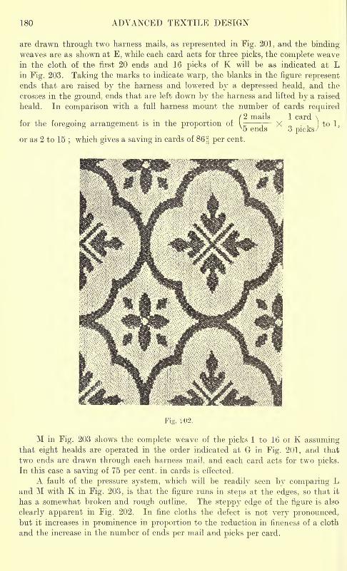
180 ADVANCED TEXTILE DESIGN
are drawn through two harness mails, as represented in Fig. 201, and the bindingweaves are as shown at E, while each card acts for three picks, the complete weave
in the cloth of the first 20 ends and 16 picks of K will be as indicated at Lin Fig. 203. Taking the marks to indicate warp, the blanks in the figure representends that are raised by the harness and lowered by a depressed heald, and the
crosses in the ground, ends that are left down by the harness and lifted by a raised
heald. In comparison with a full harness mount the number of cards required/2 mails 1 card \
for the foregoing arrangement is in the proportion of --, X rr: )
to 1 3
ends
or as 2 to 15;which gives a saving in cards of 86 H per cent.
3 picks
SSS&-.Fig. 1-02,
M in Fig. 203 shows the complete weave of the picks 1 to 16 or K assumingthat eight healds are operated in the order indicated at G in Fig. 201, and that
two ends are drawn through each harness mail, and each card acts for two picks.
In this case a saving of 75 per cent, in cards is effected.
A fault of the pressure system, which will be readily seen by comparing Land M with K in Fig. 203, is that the figure runs in steps at the edges, so that it
has a somewhat broken and rough outline. The steppy edge of the figure is also
clearly apparent in Fig. 202. In fine cloths the defect is not very pronounced,but it increases in prominence in proportion to the reduction in fineness of a cloth
and the increase in the number of ends per mail and picks per card.
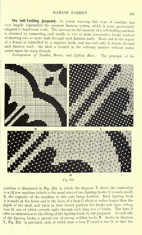
DAMASK FABRICS 181
The Self-Twilling Jacquard. In power weaving this type of machine hasvery largely superseded the pressure harness system which 'is more
particularlyadapted to hand-loom work. The increase in the capacity of a
self-twilling machineis obtained by connecting each needle to two or more consecutive hooks (insteadof drawing two or more ends through each harness mail). Each end in the repeatof a design is controlled by a separate hook, and one end only is drawn througheach harness mail
;the shed is formed in the ordinary manner without undue
strain upon the warp threads.
Arrangement of Needles, Hooks, and Lifting Bars. The principle of the
machine is illustrated in Fig. 204, in which the diagram X shows the connection
in a 12 row machine (which is the usual size) of two figuring hooks A to each needle
B, the capacity of the machine in this case being doubled. Each figuring hook
A is made at the lower end in the form of a loop C which is rather longer than the
depth of the shed, and when in their lowest position the hooks rest upon oblong
bars D, one of which extends right through each long row of hooks. The bars Doffer no obstruction to the lifting of the figuring hooks by the jacquard. At each side
of the figuring hooks, a special row of strong twilling hooks E shown in diagram
Y, Fig. 204 is provided, each of which form a loop F round a bar D, so that the

182 ADVANCED TEXTILE DESIGN
bars are supported at both ends. A plate G at each side serves as a rest for the
twilling hooks E when the latter are in their lowest position, and the plates are
1
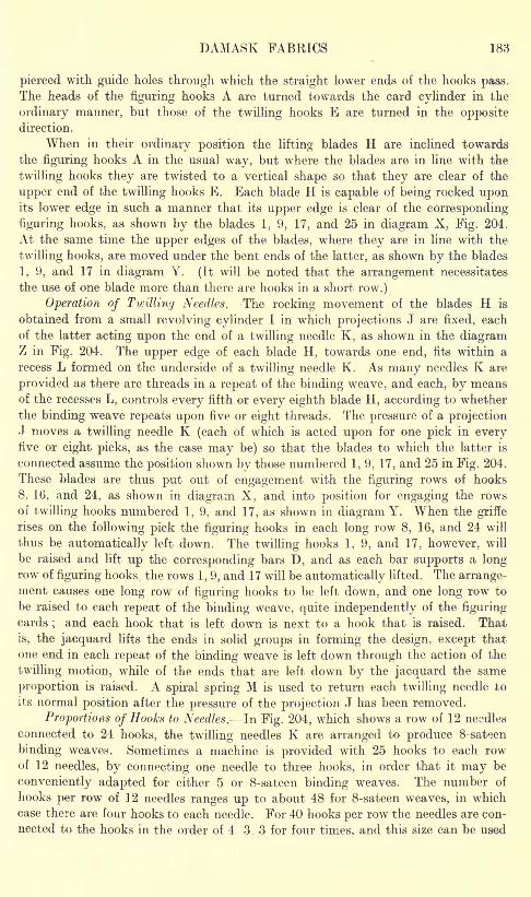
DAMASK FABRICS 183
pierced with guide holes through which the straight lower ends of the hooks pass.
The heads of the figuring hooks A are turned towards the card cylinder in the
ordinary manner, but those of the twilling hooks E are turned in the oppositedirection.
When in their ordinary position the lifting blades H are inclined towards
the figuring hooks A in the usual way, but where the blades are in line with the
twilling hooks they are twisted to a vertical shape so that they are clear of the
upper end of the twilling hooks E. Each blade H is capable of being rocked uponits lower edge in such a manner that its upper edge is clear of the corresponding
figuring hooks, as shown by the blades 1, 9, 17, and 25 in diagram X, Fig. 204.
At the same time the upper edges of the blades, where they are in line with the
twilling hooks, are moved under the bent ends of the latter, as shown by the blades
1, 9, and 17 in diagram Y. (It will be noted that the arrangement necessitates
the use of one blade more than there are hooks in a short row.)
Operation of Twilling Needles. The rocking movement of the blades H is
obtained from a small revolving cylinder I in which projections J are fixed, each
of the latter acting upon the end of a twilling needle K, as shown in the diagramZ in Fig. 204. The upper edge of each blade H, towards one end, fits within a
recess L formed on the underside of a twilling needle K. As many needles K are
provided as there are threads in a repeat of the binding weave, and each, by meansof the recesses L, controls every fifth or every eighth blade H, according to whether
the binding weave repeats upon five or eight threads. The pressure of a projectionJ moves a twilling needle K (each of which is acted upon for one pick in everyfive or eight picks, as the case may be) so that the blades to which the latter is
connected assume the position shown by those numbered 1, 9, 17, and 25 in Fig. 204.
These blades are thus put out of engagement with the figuring rows of hooks
8, 16, and 24, as shown in diagram X, and into position for engaging the rows
or twilling hooks numbered 1, 9, and 17, as shown in diagram Y. When the griffe
rises on the following pick the figuring hooks in each long row 8, 16, and 24 will
thus be automatically left down. The twilling hooks 1, 9, and 17, however, will
be raised and lift up the corresponding bars I), and as each bar supports a longrow of figuring hooks, the rows 1, 9, and 17 will be automatically lifted. The arrange-ment causes one long row of figuring hooks to be left down, and one long row to
be raised to each repeat of the binding weave, quite independently of the figuringcards
; and each hook that is left down is next to a hook that is raised. That
is, the jacquard lifts the ends in solid groups in forming the design, except that
one end in each repeat of the binding weave is left down through the action of the
twilling motion, while of the ends that are left down by the jacquard the same
proportion is raised. A spiral spring M is used to return each twilling needle to
its normal position after the pressure of the projection J has been removed.
Proportions of Hooks to Needles. In Fig. 204, which shows a row of 12 needles
connected to 24 hooks, the twilling needles K are arranged to produce 8-sateen
binding weaves. Sometimes a machine is provided with 25 hooks to each rowof 12 needles, by connecting one needle to three hooks, in order that it may be
conveniently adapted for either 5 or 8-sateen binding weaves. The number of
hooks per row of 12 needles ranges up to about 48 for 8-sateen weaves, in which
case there are four hooks to each needle. For 40 hooks per row the needles are con-
nected to the hooks in the order of 4 3, 3 for four times, and this size can be used
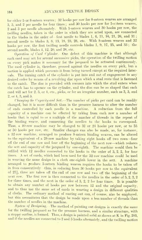
184 ADVANCED TEXTILE DESIGN
for either 5 or 8-sateen weaves ;32 hooks per row for 8-sateen weaves are arranged
3, 3, and 2 per needle for four times;and 30 hooks per row for 5-s?,teen weaves,
2 and 3 per needle alternately. With 5-sateen weaves and 30 hooks per row, the
twilling needles, taken in the order in which they are acted upon, are connected
to the blades in the order of first needle to blades 1, 6, 11, 16, 21, 26, and 31 ;
second needle to blades 3, 8, 13, 18, 23, 28, etc. With 8-sateen weaves and 32
hooks per row, the first twilling needle controls blades 1, 9, 17, 25, and 33;
the
second needle, blades 4, 12, 20, and 28, etc.
Operation of Card Cylinder. One defect of this machine is that although
each card may act for several successive picks, the operation of the twilling motion
on every pick makes it necessary for the jacquard to be actuated continuously.
The card cylinder is, therefore, pressed against the needles on every pick, but a
motion is applied which prevents it from being turned except at the required inter-
vals. The turning catch of the cylinder is put into and out of engagement in anydesired order by means of a revolving disc upon which a stud rests that is fastened
to the catch. The disc is provided with recesses into which the stud enters when
the catch has to operate on the cylinder, and the disc can be so shaped that each
card will act for 2, 3, or 4, etc., picks, or for an irregular number, such as 3, 3, and
2, or 4, 3, and 3.
Changing the Capacity and Sett. The number of picks per card can be readily
changed, but it is more difficult than in the pressure harness to alter the numberof ends controlled by each needle in a machine. A reduction from the full
capacity of a machine can be effected by taking from each row a number of
hooks that is equal to or a multiple of the number of threads in the repeat of
the binding weave, and connecting the needles to the hooks to correspond.
Thus, a 40-row machine may be changed to 32 or 24 hooks per row, or to 35
or 30 hooks per row, etc. Smaller changes can also be made, as, for instance,
a 32-row machine, arranged to produce 8-sateen binding weaves, can be altered
to the equivalent of a 28-row machine by taking eight hooks off two rows four
off the end of one row and four off the beginning of the next row which reduces
the sett and capacity of the jacquard by one-eighth. The machine would then berefilled with 12 needles connected to the hooks in the order of 3, 2, 2, for four
times. A set of cards, which had been used for the 32-row machine could be usedin weaving the same design in a cloth one-eighth lower in the sett. A machine
arranged to produce 5-sateen binding weaves requires the hooks to be taken off
in fives consecutively thus, in reducing from 30 hooks per row to the equivalentof 27 J, three are taken off the end of one row and two off the beginning of thenext row. The first row is then connected to the needles in the order of 3, 2, 2, 2
for three times, and the next in the order of 3, 2, 2 for four times. It is possibleto obtain any number of hooks per row between 12 and the original capacity,and to thus use the same set of cards in weaving a design in different qualitiesof cloths. The ordinary method of casting out can, of course, also be employed,but this necessitates that the design be made upon a less number of threads thanthe number of needles in the machine.
System of Designing.The method of painting out designs is exactly the samefor the twilling jacquard as for the pressure harness, and a similar structure, witha steppy outline, is formed. Thus, a design is painted solid as shown at K in Fig. 203,and if the needles are connected to 2 and 3 hooks alternately, and the twillin^ motion
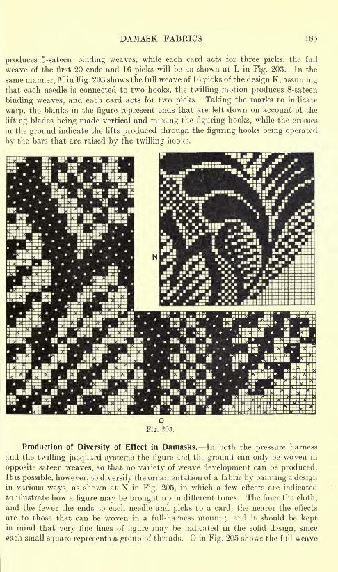
DAMASK FABKICS 185
produces 5-sateen binding weaves, while each card acts for three picks, the full
weave of the first 20 ends and 16 picks will be as shown at L in Fig. 203. In the
same manner, M in Fig. 203 shows the full weave of 16 picks of the design K, assumingthat each needle is connected to two hooks, the twilling motion produces 8-sateen
binding weaves, and each card acts for two picks. Taking the marks to indicate
warp, the blanks in the figure represent ends that are left down on account of the
lifting blades being made vertical and missing the figuring hooks, while the crosses
in the ground indicate the lifts produced through the figuring hooks being operated
by the bars that are raised by the twilling hcoks.
Production of Diversity of Effect in Damasks. In both the pressure harness
and the twilling jacquard systems the figure and the ground can only be woven in
opposite sateen weaves, so that no variety of weave development can be produced.It is possible, however, to diversify the ornamentation of a fabric by painting a designin various ways, as shown at N in Fig. 205, in which a few effects are indicated
to illustrate how a figure may be brought up in different tones. The finer the cloth,
and the fewer the ends to each needle and picks to a card, the nearer the effects
are to those that can be woven in a full-harness mount;and it should be kept
in mind that very fine lines of figure may be indicated in the solid dasign, since
each small square represents a group of threads. in Fig. 205 shows the full weave
186 ADVANCED TEXTILE DESIGN
of a portion of the design N, assuming that the hooks are connected to the needles
in the order of 3, 3, 2;
successive cards act for 3, 3, and 2 picks ;and 8-sateen
binding weaves are formed._ e
In designing for the twilling jacquard the counts of the design paper is in
the proportion of
ends per inch. picks per inch
hooks per needle picks per card
For example, assuming that a cloth contains 96 ends and 140 picks per inch,
and that 32 hooks are connected to 12 needles, and there are 10 picks to three
cards
96 ends 140 picks .
: =12xU design paper -
The best qualities of damask cloths are generally woven with more picks
than ends per inch, and the following are typical weaving particulars : Warp50's lea linen, 90 ends per inch
;weft 70's lea linen, 130 picks per inch. 5-sateen
binding weaves are only employed in the lower and cheaper qualities of cloths.
CHAPTER X
TAPESTRY AND UPHOLSTERY CLOTHS ANDINGRAIN CARPETS
TAPESTRY AND UPHOLSTERY CLOTHS- Figured Double and Treble Plain Cloths Combinations of
Double Plain and Weft or Warp Figure Weft-Face Tapestry Cloths Figuring with the
Harness Threads Diversity produced by Mixing the Wefts Specially Stitched Weft
Tapestry Cloth Special Weft Tapestry Mounting -Warp-Face Tapestry Cloth. SCOTCH,
KIDDERMINSTER, OR INGRAIN CARPETS Double Plain Cloth Jacquard Operation of the
Jacquard and Comber-Boards Method of Designing Limitation of the Mounting Weft-
Face Ingrain Carpets Reversible Four-Ply Weft Structure Methods of Producing Variety.
TAPESTRY AND UPHOLSTERY CLOTHS
ALMOST every class of fabric structure is used for tapestry and upholstery purposes
ranging from cloths composed of one warp and one weft to those in which two
or more series of threads are introduced in one or both directions. Some of the
textures are mono-coloured, and the designs range from simple but striking effects
to the boldest and most intricately developed styles of figures. Elaborate figure
ornamentation is also combined with diversity of colour, whilst in certain textures
the design is entirely due to colour the figure being formed chiefly for the purposeof displaying different hues and tones.
Illustrations of various classes of the fabrics are included in the foregoing.
Thus, extra warp structures are shown in Fig. 145 (p. 132), and Fig. 167 (p. 145),
and an extra weft cloth is represented in Fig. 125 (p. 117). Multiple weft figured
fabrics, woven on the principle illustrated by Figs. 131 to 138 (pp. 121-125),and Fig. 189 (p. 166). form an important class, and warp pile figuring (see ChaptersXIX and XX) is largely employed ; while certain special classes of the textures
and the systems of loom mounting are described and illustrated in the following :
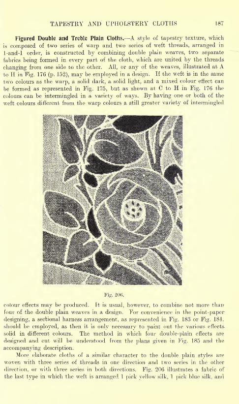
TAPESTRY AND UPHOLSTERY CLOTHS 187
Figured Double and Treble Plain Cloths. A style of tapestry texture, which
is composed of two series of warp and two series of weft threads, arranged in
1-and-l order, is constructed by combining double plain weaves, two separate
fabrics being formed in every part of the cloth, which are united by the threads
changing from one side to the other. All, or any of the weaves, illustrated at Ato H in Fig. 176 (p. 152). may be employed in a design. If the weft is in the same
two colours as the warp, a solid dark, a solid light, and a mixed colour effect can
be formed as represented in Fig. 175, but as shown at C to H in Fig. 176 the
colours can be intermingled in a variety of ways. By having one or both of the
weft colours different from the warp colours a still greater variety of intermingled
Fig. 200.
colour effects may be produced. It is usual, however, to combine not more than
four of the double plain weaves in a design. For convenience in the point-paper
designing, a sectional harness arrangement, as represented in Fig. 183 or Fig. 184.
should be employed, as then it is only necessary to paint out the various effects
solid in different colours. The method in which four double-plain effects are
designed and cut will be understood from the plans given in Fig. 185 and the
accompanying description.
More elaborate cloths of a similar character to the double plain styles are
woven with three series of threads in one direction and two series in the other
direction, or with three series in both directions. Fig. 206 illustrates a fabric of
the last type in which the w^eft is arranged 1 pick yellow silk, 1 pick blue silk, and
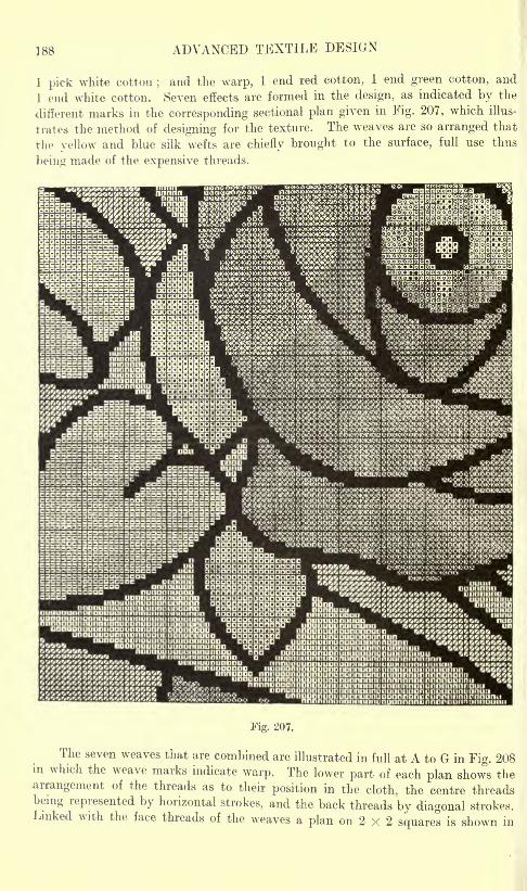
188 ADVANCED TEXTILE DESIGN
1 pick white cotton;and the warp, 1 end red cotton, 1 end green cotton, and
1 end white cotton. Seven effects are formed in the design, as indicated by the
different marks in the corresponding sectional plan given in Fig. 207, which illus-
trates the method of designing for the texture. The weaves are so arranged that
the yellow and blue silk wefts are chiefly brought to the surface, full use thus
being made of the expensive threads.
Fig. 207.
The seven weaves that are combined are illustrated in full at A to G in Fig. 208in which the weave marks indicate warp. The lower part of each plan shows the
arrangement of the threads as to their position in the cloth, the centre threadsbeing represented by horizontal strokes, and the back threads by diagonal strokes.Linked with the face threads of the weaves a plan on 2 x 2 squares is shown in
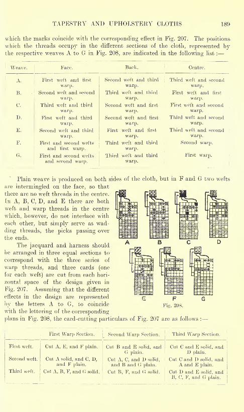
TAPESTRY AND UPHOLSTERY CLOTHS
which the marks coincide with the corresponding effect in Fig. 207. The positions-
which the threads occupy in the different sections of the cloth, represented byi lie icsuc^tivc w ca. v co .n. uvj vj in x sv zjv/u, cue iiiu.ieo/ ucu. 111 unc luiiuwmg iiou .
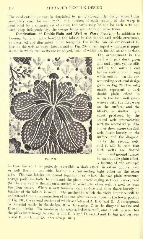
190 ADVANCED TEXTILE DESIGN
The card-cutting process is simplified by going through the design three times
sepaiately, once for each weft; and, further, if each section of the warp is
controlled by a separate set of cards, the cards may be cut for each weft and
each warp independently, the design being gone through nine times.
Combinations of Double Plain and Weft or Warp Figure. In addition to
forming figure by interchanging the fabrics in the double and treble structures,
as described and illustrated in the foregoing, the cloths can be ornamented byfloating the weft or warp threads, and in Fig. 209 a rich tapestry texture is repre-
sented in which two wefts are employed, both of which are floated on the surface.
The arrangement in the
weft is 1 pick dark greensilk and 1 pick yellow silk,
and in the warp, 1 end
brown cotton and 1 end
white cotton. In the cor-
responding sectional design
given in Fig. 210 the solid
marks represent a dark
double -plain effect in
which the first weft inter-
weaves with the first warpon the surface, and the
blanks, a similar light
effect produced by the
second weft interweavingwith the second warp. The
circles show where the first
weft floats loosely on the
surface, and the diagonalmarks the second weft,
and it will be seen that
Fig. 209. by each double-plain effect.
A feature of the exampleis that the cloth is perfectly reversible, a dark effect, in either double plainor weft float, on one side, having a corresponding light effect on the otherside. The two fabrics are bound together : (a) where the two plain structures
change positions, both the ends and the picks interchanging at these places ;and
(b) where a weft is floated on a surface in which the other weft is used to formthe plain weave. Win-re a wett forms a plain surface and then floats loosely nobinding of the fabrics is made. The method in which the picks interlace will beunderstood from an examination of the complete weaves given in the lower portionof Fig. 210, the several sections of which are lettered A, B, C, and D. A correspondsto the solid marks in the design, B to the circles, C to the diagonal marks, andUo the blanks. The marks in the weaves indicate weft, and it will be seen that
the picks interchange between A and C, A and D, and B and D, but not betweenA and B, nor C and D. (See also p. 154.)
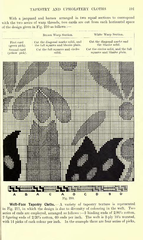
TAPESTRY AND UPHOLSTERY CLOTHS 191
With a jacquard and harnes arranged in two equal sections to correspond
with the two series of warp threads, two cards are cut from each horizontal space
of the design given in Fig. 210 as follows :
First card
(green pick).
Second card
(yellow pick).
Brown Warp Section. White Warp Section.
Cut the diagonal marks solid, andj
the full squares and blanks plain. ;
Cut the full squares and circles
solid.
Cut the diagonal marks andthe blanks solid.
Cut the circles solid, and the full
squares and blanks plain.
ABA C AOCDFig. 210.
Weft-Face Tapestry Cloths. A variety of tapestry texture is represented
in Fig. 211, in which the design is due to diversity of colouring in the weft. Twoseries of ends are employed, arranged as follows : 2 binding ends of 2/80's cotton,
2 figuring ends of 2/20's cotton, 60 ends per inch. The weft is 2-ply 10's worsted,
with 14 picks of each colour per inch. In the example there are four series of picks,
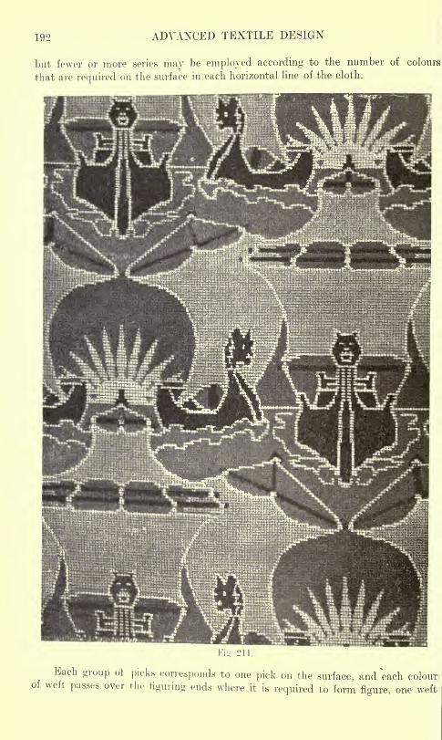
192 ADVANCED TEXTILE DESIGN
but fewer or more series may be employed according to the number of colours
that are required on the surface in each horizontal line of the cloth.
Each group ot picks corresponds to one pick on the surface, and each colourof weft passes over rlu- figuring ends where it is required to form figure, one weto
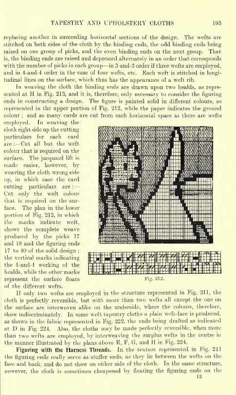
TAPESTRY AND UPHOLSTERY CLOTHS 193
iHXkGC K. 'ffi'fffeefetfi'fff.K&%Wi
iimmiiim iiiiiiiiiimiiii
replacing another in succeeding horizontal sections of the design. The wefts are
stitched on both sides of the cloth by the binding ends, the odd binding ends beingraised on one group of picks, and the even binding ends on the next group. That
is, the binding ends are raised and depressed alternately in an order that correspondswith the number of picks in each group in 3-and-3 order if three wefts are employed,and in 4-and-4 order in the case of four wefts, etc. Each weft is stitched in longi-
tudinal lines on the surface, which thus has the appearance of a weft rib.
In weaving the cloth the binding ends are drawn upon two healds, as repre-sented at H in Fig. 213, and it is, therefore, only necessary to consider the figuring
ends in constructing a design. The figure is painted solid in different colours, as
represented in the upper portion of Fig. 212, while the paper indicates the groundcolour
;and as many cards are cut from each horizontal space as there are wefts
employed. In weaving the
cloth right side up the cutting
particulars for each card
are : Cut all but the weft
colour that is required on the
surface. The jacquard lift is
made easier, however, by
weaving the cloth wrong side
up, in which case the card
cutting particulars are :
Cut only the weft colour
that is required on the sur-
face. The plan in the lower
portion of Fig. 212, in which
the marks indicate weft,
shows the complete weave
produced by the picks 17
and 18 and the figuring ends
17 to 40 of the solid design ;
the vertical marks indicatingthe 4-and-4 working of the
healds, while the other marks
represent the surface floats
of the different wefts.
If only two wefts are employed in the structure represented in Fig. 211, the
cloth is perfectly reversible, but with more than two wefts all except the one on
the surface are interwoven alike on the underside, where the colours, therefore,
show indiscriminately. In some weft tapestry cloths a plain weft-face is produced,
as shown in the fabric represented in Fig. 222, the ends being drafted as indicated
at D in Fig. 224. Also, the cloths may be made perfectly reversible, when more
than two wefts are employed, by interweaving the surplus wefts in the centre in
the manner illustrated by the plans above E, F, G, and H in Fig. 224.
Figuring with the Harness Threads. In the texture represented in Fig. 211
the figuring ends really serve as stuffer ends, as they lie between the wefts on the
face and back, and do not show on either side of the cloth. In the same structure,
nowever, the cloth is sometimes cheapened by floating the figuring ends on the
13
nil i inn::j iiiiiimimiiiiiiiiiiiiii iiiiiiiiiin
II III
::i:; :::::: iiiiiiimiiiiiiimiiiiiii :.: nila::3::3 MS:: iiiiiimiiiiiiiniiiiiiii ::
^i gs ?i i in;;,:......>. ..... IHIIIIIIIIIIIIIIIIIIIIIIII
Fi. 212.
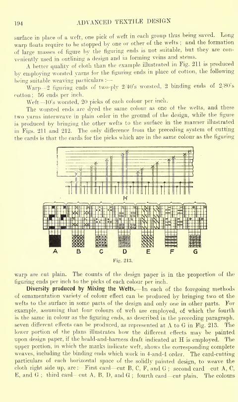
194 ADVANCED TEXTILE DESIGN
surface in place of a weft, one pick of weft in each group thus being saved. Long
warp floats require to be stopped by one or other of the wefts;and the formation
of large masses of figure by the figuring ends is not suitable, but they are con-
veniently used in outlining a design and in forming veins and stems.
A better quality of cloth than the example illustrated in Fig. 211 is produced
by employing worsted yarns for the figuring ends in place of cotton, the following
being suitable weaving particulars :
Warp 2 figuring ends of two-ply 2/40's worsted, 2 binding ends of 2/80's
cotton ; 56 ends per inch.
Weft 10's worsted, 20 picks of each colour per inch.
The worsted ends are dyed the same colour as one ot the wefts, and these
two yarns interweave in plain order in the ground of the design, while the figure
is produced by bringing the other wefts to the surface in the manner illustrated
in Figs. 211 and 212. The only difference from the preceding system of cutting
the cards is that the cards for the picks which are in the same colour as the figuring
warp are cut plain. The counts of the design paper is in the proportion of the
figuring ends per inch to the picks of each colour per inch.
Diversity produced by Mixing the Wefts. In each of the foregoing methods
of ornamentation variety of colour effect can be produced by bringing two ot the
wefts to the surface in some parts of the design and only one in other parts. For
example, assuming that four colours of weft are employed, of which the fourth
is the same in colour as the figuring ends, as described in the preceding paragraph,seven different effects can be produced, as represented at A to G in Fig. 213. Thelower portion of the plans illustrates how the different effects may be painted
upon design paper, if the heald-and-harness draft indicated at H is employed. The
upper portion, in which the marks indicate weft, shows the corresponding completeweaves, including the binding ends which work in 4-and-4 order. The card-cutting
particulars of each horizontal space of the solidly painted design, to weave the
cloth right side up, are : First card cut B, C, F, and G;second card cut A, C,
E, and G;
third card cut A, B, D, and G;fourth card cut plain. The colours
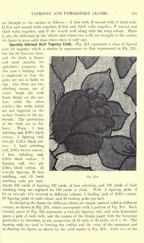
TAPESTRY AND UPHOLSTERY CLOTHS 195
are brought to the surface as follows : A first weft, B second weft, C third weft,
D first and second wefts together, E first and third wefts together, F second and
third wefts together, and G the fourth weft along .with the warp colour. There
is also the difference in the effects that where two wefts are brought to the surface
the figure is more solid than where there is only one.
Specially Stitched Weft Tapestry Cloth. Fig. 214 represents a class of figured
wett rib tapestry which is similar in appearance to that represented in Fig. 211,
but the rib lines are finer,
and the cloth is firmer
and more suitable for
upholstery purposes. In
this case a binding weft
is employed, so that the
picks are not so liable to
slip. Also there are two
stitching warps, one of
which binds the weft
floats firmly on the sur-
face, while the other
stitches the wefts which
are not required on the
surface loosely to the un-
derside. The particulars
of the cloth are as fol-
lows : Warp 1 face
stitching end, 2/80' s black
cotton;
1 figuring end,
two-ply 2/24's black cot-
ton;
1 back stitching
end, 2/80's brown cotton;
1 face stitching end,
2/80's black cotton;
1
figuring end, two ply
2/24's black cotton. 24
two-ply figuring, 24 face
stitching, and 12 back P'ig. 2H.
stitching ends per inch.
About 103 yards of figuring, 127 yards of lace stitching, and 108 yards of back
stitching warp are required for 100 yards of cloth. Weft 3 figuring picks of
9's or two-ply io's worsted in different colours, 1 binding pick of 2/80's cotton,
30 figuring picks of each colour, and 30 binding picks per inch.
In designing the figure the different effects are simply painted solid in different
colours, as shown in Fig. 215, which corresponds with a portion of Fig. 214. Each
vertical space of Fig. 215 represents a two-ply figuring end, and each horizontal
space a pick of each weft, and the counts of the design paper with the foregoing
particulars is, therefore, in the propoition of 24 ends to 30 picks, or 8 X 10. The
figuring ends are used in forming the outline and the veins of the ornament and
in shading the figure, as shown by the solid marks in Fig. 215;
while two of the
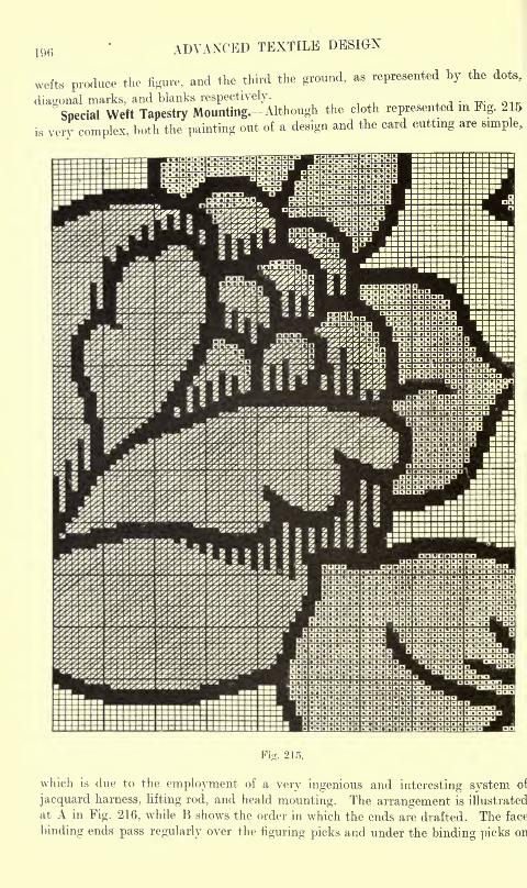
1% ADVANCED TEXTILE DESIGN
wefts produce the figure, and the third the ground, as represented by the dots,
diagonal marks, and blanks respectively.
"Special Weft Tapestry Mounting.-Although the cloth represented in Fig. 215
is very complex, both the painting out of a design and the card cutting are simple,
Fig. 215.
which is due to the employment of a very ingenious and interesting system of
jacquard harness, lifting rod, and heald mounting. The arrangement is illustrated
at A in Fig. 216, while B shows the order in which the ends are drafted. The face
binding ends pass regularly over the figuring picks and under the binding picks on
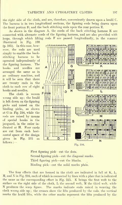
TAPESTRY AND UPHOLSTERY CLOTHS 197
the right side of the cloth, and are, therefore, conveniently drawn upon a heald C.
The harness is in two longitudinal sections, the figuring ends being drawn uponthe front portion D, and the back stitching ends upon the rear portion E.
As shown in the diagram A, the cords of the back stitching harness E are
connected with alternate cords of the figuring harness, and are also provided with
loops, through which lifting rods F are passed longitudinally, in the manner
illustrated in Fig. 188
(p. 165). In this case, how- i !."!*!?.' ("if! .!"!*! PWW 1*1 i i'i i'i
ever, the rods are used
simply to enable the back-
stitching harness to be
operated independently of
the figuring harness. The
hooks and needles are
arranged the same as in
an ordinary machine, and
it will be seen that there
-are twenty ends in the
cloth to each row of eight
hooks and needles.
The cloth is woven
wrong side up; the heald
is left down on the figuring
picks and raised on the
binding picks, as shownat G in Fig. 216, while the
rods are raised by meansof special hooks in the
jacquard, in the order in-
dicated at H. Four cards
are cut from each hori-
zontal space of the design
given in Fig. 215 as
follows :
Fig. 216.
First figuring pick cut the dots.
Second figuring pick cut the diagonal marks.
Third figuring pick cut the blanks.
Binding pick cut the solid marks plain.
The four effects that are formed in the cloth are indicated in full at K, L,
M, and N in Fig. 216, each of which is connected by lines with a plan that is indicated
.the same as the corresponding effect in Fig. 215. K brings the first weft to the
surface on the right side of the cloth, L the second weft, M the third weft, while
N produces the warp figure. The marks indicate ends raissd in weaving the
cloth wrong side up ;the crosses show the lifts produced by the rods, the vertical
marks the heald lifts, while the other marks represent the lifts produced by the
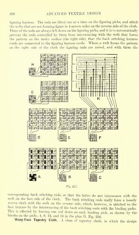
198 ADVANCED TEXTILE DESIGN
figuring harness. The rods are lifted one at a time on the figuring picks, and stitch
the wefts that are not forming figure in 4-sateen order on the reverse side of the cloth.
Three of the rods are always left down on the figuring picks, and it is to automatically
prevent the ends controlled by them from interweaving with the weft that forms
the pattern on the under surface (the right side), that the back stitching harness
cords are connected to the figuring harness cords. Where a weft forms the patternon the right side of the cloth the figuring ends are raised, and with them the
Fig. 217.
corresponding back stitching ends, so that the latter do not interweave with theweft on the face side of the cloth. The back stitching ends really form a looselywoven cloth with the weft on the reverse side, which, however, is stitched to theface texture by the interweaving of the back stitching ends with the binding picks.This is effected by leaving one rod down on each binding pick, as shown, by theblanks on the picks, 4, 8, 12, and 16 in the plan H, Fig. 216.
Warp-Face Tapestry Cloth. A class of tapestry cloth, in which the design
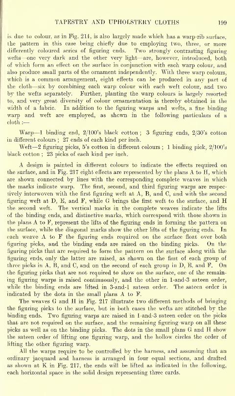
TAPESTRY AND UPHOLSTERY CLOTHS 199
is due to colour, as in Fig. 214, is also largely made which has a warp-rib surface,
the pattern in this case being chiefly due to employing two, three, or more
differently coloured series of figuring ends. Two strongly contrasting figuringwefts one very dark and the other very light are, however, introduced, both
of which form an effect on the surface in conjunction with each warp colour, andalso produce small parts of the ornament independently. With three warp colours,
which is a common arrangement, eight effects can be produced in any part of
the cloth six by combining each warp colour with each weft colour, and two
by the wefts separately. Further, planting the warp colours is largely resorted
to, and very great diversity of colour ornamentation is thereby obtained in the
width of a fabric. In addition to the figuring warps and wefts, a fine binding
warp and weft are employed, as shown in the following particulars of a
cloth :
Warp 1 binding end, 2/100's black cotton;
3 figuring ends, 2/30's cotton
in different colours;27 ends of each kind per inch.
Weft -2 figuring picks, 5's cotton in different colours;
1 binding pick ; 2/100'sblack cotton
;23 picks of each kind per inch.
A design is painted in different colours to indicate the effects required on
the surface, and in Fig. 217 eight effects are represented by the plans A to H, which
are shown connected by lines with the corresponding complete weaves in which
the marks indicate warp. The first, second, and third figuring warps are respec-
tively interwoven with the first figuring weft at A, B, and C, and with the second
figuring weft at D, E, and F, while G brings the first weft to the surface, and Hthe second weft. The vertical marks in the complete weaves indicate the lifts
of the binding ends, and distinctive marks, which correspond with those shown in
the plans A to F, represent the lifts of the figuring ends in forming the pattern on
the surface, while the diagonal marks show the other lifts of the figuring ends. In
each weave A to F the figuring ends required on the surface float over both
figuring picks, and the binding ends are raised on the binding picks. On the
figuring picks that are required to form the pattern on the surface along with the
figuring ends, only the latter are raised, as shown on the first of each group of
three picks in A, B, and C, and on the second of each group in D, E, and F. Onthe figuring picks that are not required to show on the surface, one of the remain-
ing figuring warps is raised continuously, and the other in l-and-3 sateen order,
while the binding ends are lifted in 3-and-l sateen order. The sateen order is
indicated by the dots in the small plans A to F.
The weaves G and H in Fig. 217 illustrate two different methods of bringingthe figuring picks to the surface, but in both cases the wefts are stitched by the
binding ends. Two figuring warps are raised in l-and-3 sateen order on the picksthat are not required on the surface, and the remaining figuring warp on all these
picks as well as on the binding picks. The dots in the small plans G and H show
the sateen order of lifting one figuring warp, and the hollow circles the order of
lifting the other figuring warp.All the warps require to be controlled by the harness, and assuming that an
ordinary jacquard and harness is arranged in four equal sections, and drafted
as shown at K in Fig. 217, the ends will be lifted as indicated in the following,
each horizontal space in the solid design representing three cards.
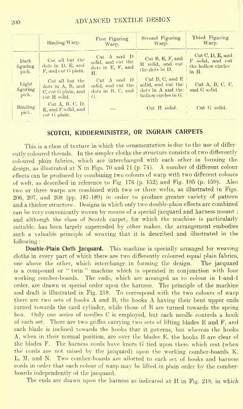
200 ADVANCED TEXTILE DESIGN
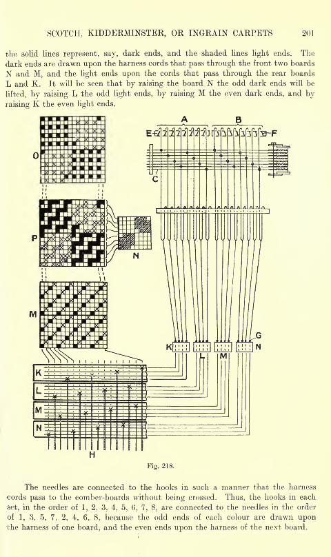
SCOTCH, KIDDERMINSTER, OR INGRAIN CARPETS 201
the solid lines represent, say, dark ends, and the shaded lines light ends. The
dark ends are drawn upon the harness cords that pass through the front two boards
N and M, and the light ends upon the cords that pass through the rear boards
L and K. It will be seen that by raising the board N the odd dark ends will be
lifted, by raising L the odd light ends, by raising M the even dark ends, and by
raising K the even light ends.
Fig. 218.
The needles are connected to the hooks in such a manner that the harness
cords pass to the comber-boards without being crossed. Thus, the hooks in each
set, in the order of 1, 2, 3, 4, 5, 6, 7, 8, are connected to the needles in the order
of 1, 3, 5, 7, 2, 4, 6, 8, because the odd ends of each colour are drawn uponthe harness of one board, and the even ends upon the harness of the next board.
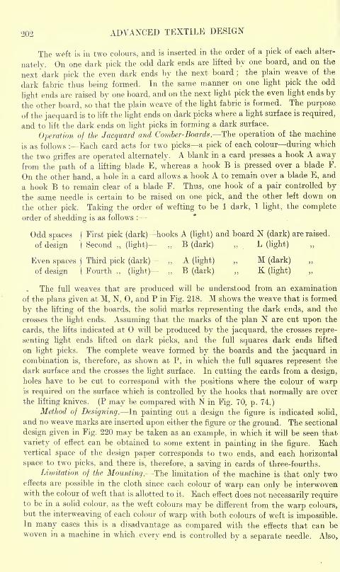
202 ADVANCED TEXTILE DESIGN
The weft is in two colours, and is inserted in the order of a pick of each alter-
nately. On one dark pick the odd dark ends are lifted by one board, and on the
next dark pick the even dark ends by the next board;
the plain weave of the
dark fabric thus being formed. In the same manner on one light pick the odd
light ends are raised by one board, and on the next light pick the even light ends by
the other board, so that the plain weave of the light fabric is formed. The purpose
of the jacquard is to lift the light ends on dark picks where a light surface is required,
and to lift the dark ends on light picks in forming a dark surface.
Operation of the Jacquard and Comber-Boards. The operation of the machine
is as follows : Each card acts for two picks a pick of each colour during which
the two griffes are operated alternately. A blank in a card presses a hook A awayfrom the path of a lifting blade E, whereas a hook B is pressed over a blade F.
On the other hand, a hole in a card allows a hook A to remain over a blade E, and
a hook B to remain clear of a blade F. Thus, one hook of a pair controlled bythe same needle is certain to be raised on one pick, and the other left down on
the other pick. Taking the order of wefting to be 1 dark, 1 light, the complete
order of shedding is as follows :
Odd spaces (First pick (dark) hooks A (light) and board N (dark) are raised,
of design "( Second (light) B (dark) L (light)
Even spaces |Third pick (dark) ,,
A (light) ,, M (dark)
of design ( Fourth (light) B (dark) K (light)
The full weaves that are produced will be understood from an examination
of the plans given at M, N, 0, and P in Fig. 218. M shows the weave that is formed
by the lifting of the boards, the solid marks representing the dark ends, and the
crosses the light ends. Assuming that the marks of the plan N are cut upon the
cards, the lifts indicated at will be produced by the jacquard, the crosses repre-
senting light ends lifted on dark picks, and the full squares dark ends lifted
on light picks. The complete weave formed by the boards and the jacquard in
combination is, therefore, as shown at P, in which the full squares represent the
dark surface and the crosses the light surface. In cutting the cards from a design,holes have to be cut to correspond with the positions where the colour of warpis required on the surface which is controlled by the hooks that normally are over
the lifting knives. (P may be compared with N in Fig. 70, p. 74.)
Method of Designing. In painting out a design the figure is indicated solid,
and no weave marks are inserted upon either the figure or the ground. The sectional
design given in Fig. 220 may be taken as an example, in which it will be seen that
variety of effect can be obtained to some extent in painting in the figure. Eachvertical space of the design paper corresponds to two ends, and each horizontal
space to two picks, and there is, therefore, a saving in cards of three-fourths.
Limitation of the Mounting. The limitation of the machine is that only twoeffects are possible in the cloth since each colour of warp can only be interwovenwith the colour of weft that is allotted to it. Each effect does not necessarily requireto be in a solid colour, as the weft colours may be different from the warp colours,but the interweaving of each colour of warp with both colours of weft is impossible.In many cases this is a disadvantage as compared with the effects that can bewoven in a machine in which every end is controlled by a separate needle. Also,
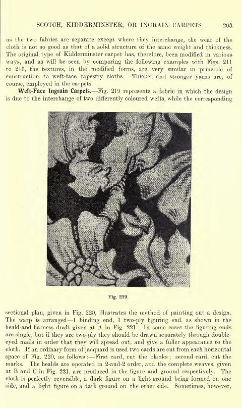
SCOTCH, KIDDERMINSTER, OR INGRAIN CARPETS 203
as the two fabrics are separate except where they interchange, the wear of the
cloth is not so good as that of a solid structure of the same weight and thickness.
The original type of Kidderminster carpet has, therefore, been modified in various
ways, and as will be seen by comparing the following examples with Figs. 211
to 216, the textures, in the modified forms, are very similar in principle of
construction to weft-face tapestry cloths. Thicker and stronger yarns are, of
course, employed in the carpets.
Weft-Face Ingrain Carpets. Fig. 219 represents a fabric in which the designis due to the interchange of two differently coloured wefts, while the corresponding
Fig. 219.
sectional plan, given in Fig. 220, illustrates the method of painting out a design.The warp is arranged 1 binding end, 1 two-ply figuring end, as shown in the
heald-and-harness draft given at A in Fig. 221. In some cases the figuring ends
are single, but if they are two-ply they should be drawn separately through double-
eyed mails in order that they will spread out. and give a fuller appearance to the
cloth. If an ordinary form of jacquard is used two cards are cut from each horizontal
space of Fig. 220, as follows : First card, cut the blanks;
second card, cut the
marks. The healds are operated in 2-and-2 order, and the complete weaves, givenat B and C in Fig. 221, are produced in the figure and ground respectively. Thecloth is perfectly reversible, a dark figure on a light ground being formed on one
side, and a light figure on a dark ground on the other side. Sometimes, however,
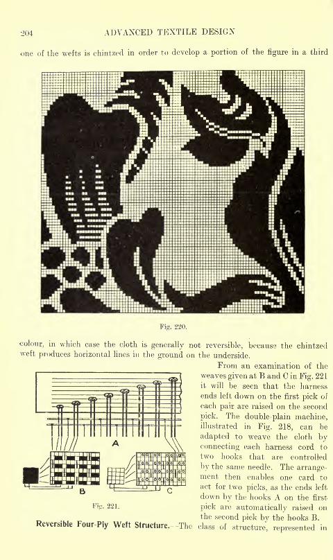
204 ADVANCED TEXTILE DESIGN
one of the wefts is chintzed in order to develop a portion of the figure in a third
Fig. 220.
colour, in which case the cloth is generally not reversible, because the chintzedweft produces horizontal lines in the ground on the underside.
From an examination of the
weaves given at B and C in Fig. 221
it will be seen that the harness
ends left down on the first pick of
each pair are raised on the second
pick. The double-plain machine,illustrated in Fig. 218, can be
adapted to weave the cloth byconnecting each harness cord to
two hooks that are controlled
by the same needle. The arrange-ment then enables one card to
act for two picks, as the ends left
down by the hooks A on the first
Fig- 221. pick are automatically raised onthe second pick by the hooks B.
Reversible Four-Ply Weft Structure, -The class of structure, represented in
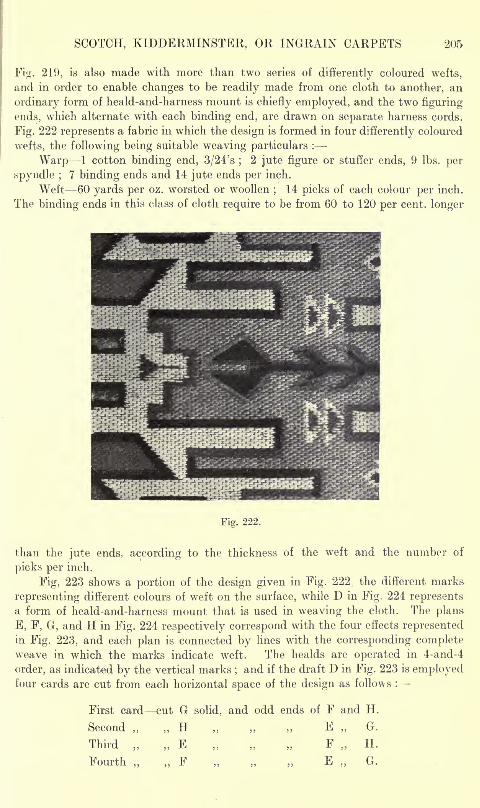
SCOTCH, KIDDERMINSTER, OR INGRAIN CARPETS 205
Fig. 219, is also made with more than two series of differently coloured wefts,
and in order to enable changes to be readily made from one cloth to another, an
ordinary form of heald-and-harness mount is chiefly employed, and the two figuring
ends, which alternate with each binding end, are drawn on separate harness cords.
Fig. 222 represents a fabric in which the design is formed in four differently coloured
wefts, the following being suitable weaving particulars :
Warp 1 cotton binding end, 3/24's ;2 jute figure or stuffer ends, 9 Ibs. per
spyndle ;7 binding ends and 14 jute ends per inch.
Weft 60 yards per oz. worsted or woollen;
14 picks of each colour per inch.
The binding ends in this class of cloth require to be from 60 to 120 per cent, longer
Fig. 222.
than the jute ends, according to the thickness of the weft and the number of
picks per inch.
Fig, 223 shows a portion of the design given in Fig. 222;the different marks
representing different colours of weft on the surface, while D in Fig. 224 represents
a form of heald-and-harness mount that is used in weaving the cloth. The plans
E, F, G, and H in Fig. 224 respectively correspond with the four effects representedin Fig. 223, and each plan is connected by lines with the corresponding completeweave in which the marks indicate weft. The healds are operated in 4-and-4
order, as indicated by the vertical marks;and if the draft D in Fig. 223 is employed
four cards are cut from each horizontal space of the design as follows :
First card cut G solid, and odd ends of F and H.
Second H E G.
Third E F H.
Fourth , F E ,. G.
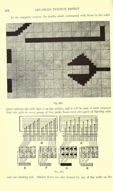
206 ADVANCED TEXTILE DESIGN
In the complete weaves, the marks which correspond with those in the solid
Fig. 223.
plans indicate the weft that is on the surface, and it will be seen in each example
that one pick in every group of four picks floats over two pairs of figuring ends
E F G H
Fig. 224.
and one binding end Similar floats are also formed by one of the wefts on the
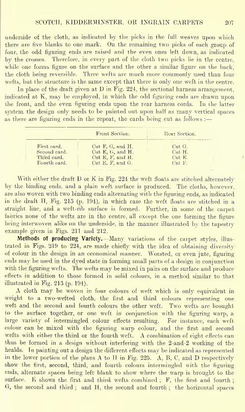
SCOTCH, KIDDERMINSTER, OR INGRAIN CARPETS 207
underside of the cloth, as indicated by the picks in the full weaves upon which
there are five blanks to one mark. On the remaining two picks of each group of
four, the odd figuring ends are raised and the even ones left down, as indicated
by the crosses. Therefore, in every part of the cloth two picks lie in the centre,
while one forms figure on the surface and the other a similar figure on the back,
the cloth being reversible. Three wefts are much more commonly used than four
wefts, but the structure is the same except that there is only one weft in the centre.
In place of the draft given at D in Fig. 224, the sectional harness arrangement,indicated at K, may be employed, in which the odd figuring ends are drawn uponthe front, and the even figuring ends upon the rear harness cords. In the latter
system the design only needs to be painted out upon half as many vertical spacesas there are figuring ends in the repeat, the cards being cut as follows :
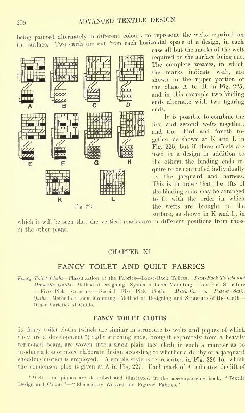
208 ADVANCED TEXTILE DESIGN
being painted alternately in different colours to represent the wefts required on
the surface. Two cards are cut from each horizontal space of a design, in each
case all but the marks of the weft
required on the surface being cut.
The complete weaves, in which
the marks indicate weft, are
shown in the upper portion of
the plans A to H in Fig. 225,
and in this example two bindingends alternate with two figuring
ends.
It is possible to combine the
first and second wefts together,
and the third and fourth to-
gether, as shown at K and L in
Fig. 225, but if these effects are
used in a design in addition to
the others, the binding ends re
quire to be controlled individually
by the jacquard and harness.
This is in order that the lifts of
the binding ends may be arrangedto fit with the order in which
the wefts are brought to the
surface, as shown in K and L, in
which it will be seen that the vertical marks are in different positions from those
in the other plans.
CHAPTER XI
FANCY TOILET AND QUILT FABRICS
Fancy Toilet Cloths Classification of the Fabrics Loose-Back Toilets. Fast- Back Toilets and
Marseilles Quilts Method of Designing System of Loom Mounting Four-Pick Structure
Five -Pick Structure Special Five - Pick Cloth. Mitcheline or Patent -Satin
Quilts Method of Loom Mounting Method of Designing and Structure of the Cloth
Other Varieties of Quilts.
FANCY TOILET CLOTHS
Ix fancy toilet cloths (which are similar in structure to welts and piques of which
they are a development *) tight stitching ends, brought separately from a heavilytensioned beam, are woven into a slack plain face cloth in such a manner as to
produce a less or more elaborate design according to whether a dobby or a jacquard
shedding motion is employed. A simple style is represented in Fig. 226 for which
the condensed plan is given at A in Fig. 227. Each mark of A indicates the lift of
* Welts and piques are described and illustrated in the accompanying book,"Textile
Design and Colour" "Elementary Weaves and Figured Fabrics."
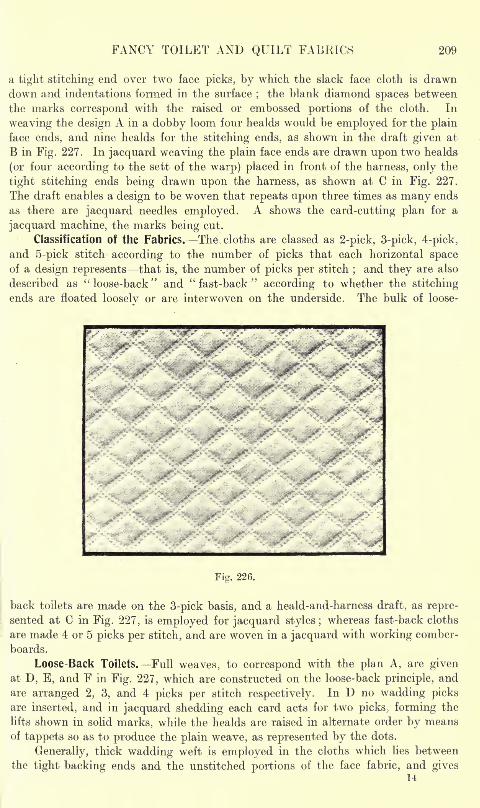
FANCY TOILET AND QUILT FABRICS 209
a tight stitching end over two face picks, by which the slack face cloth is drawn
down and indentations formed in the surface;
the blank diamond spaces between
the marks correspond with the raised or embossed portions of the cloth. In
weaving the design A in a dobby loom four healds would be employed for the plain
face ends, and nine healds for the stitching ends, as shown in the draft given at
B in Fig. 227. In jacquard weaving the plain face ends are drawn upon two healds
(or four according to the sett of the warp) placed in front of the harness, only the
tight stitching ends being drawn upon the harness, as shown at C in Fig. 227.
The draft enables a design to be woven that repeats upon three times as many ends
as there are jacquard needles employed. A shows the card-cutting plan for a
jacquard machine, the marks being cut.
Classification of the Fabrics. The cloths are classed as 2-pick, 3-pick, 4-pick,
and 5-pick stitch according to the number of picks that each horizontal spaceof a design represents that is, the number of picks per stitch
;and they are also
described as "loose-back" and "fast-back" according to whether the stitching
ends are floated looselv or are interwoven on the underside. The bulk of loose-
Fig. 226.
back toilets are made on the 3-pick basis, and a heald-and-harness draft, as repre-
sented at C in Fig. 227, is employed for jacquard styles ;whereas fast-back cloths
are made 4 or 5 picks per stitch, and are woven in a jacquard with working comber-
boards.
Loose-Back Toilets. Full weaves, to correspond with the plan A, are givenat D, E, and F in Fig. 227, which are constructed on the loose-back principle, and
are arranged 2, 3, and 4 picks per stitch respectively. In D no wadding picksare inserted, and in jacquard shedding each card acts for two picks, forming the
lifts shown in solid marks, while the healds are raised in alternate order by meansof tappets so as to produce the plain weave, as represented by the dots.
Generally, thick wadding weft is employed in the cloths which lies between
the tight backing ends and the unstitched portions of the face fabric, and gives14
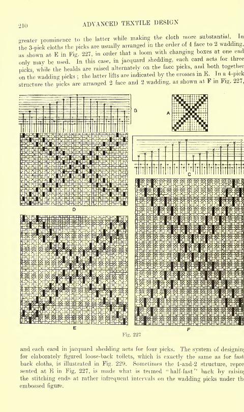
210 ADVANCED TEXTILE DESIGN
areater prominence to the latter while making the cloth more substantial In
the 3-pick cloths the picks are usually arranged in the order of 4 face to 2 wadding,
as shown at E in Fig. 227, in order that a loom with changing boxes at one end
only may be used. In this case, in jacquard shedding, each card acts for three
picks while the healds are raised alternately on the face picks, and both together
on the wadding picks ;the latter lifts are indicated by the crosses in E. In a 4-pick
structure the picks are arranged 2 face and 2 wadding, as shown at F in Fig. 227,
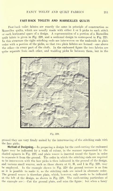
FANCY TOILET AND QUILT FABRICS 211
FAST BACK TOILETS AND MARSEILLES QUILTS
Fast-back toilet fabrics are exactly the same in principle of construction as
Marseilles quilts, which are usually made with either 4 or 5 picks to each stitch
or each horizontal space of a design. A representation of a portion of a Marseilles
quilt fabric is given in Fig. 228, and a sectional design to correspond in Fig. 229.
In this structure the tight stitching ends are interwoven on the underside in plain
order with a portion of the picks, so that two plain fabrics are formed one above
the other in every part of the cloth. In the embossed figure the two fabrics are
quite separate from each other, and wadding picks lie between them, but in the
V^R.-- |
Fig. 228.
ground they are very firmly united by the interweaving of the stitching ends with
the face picks.
Method of Designing. In preparing a design for the card-cutting the embossed
figure may be indicated by a wash of colour, in the manner represented by the
shaded squares in Fig. 229, and plain weave is inserted round the figure in order
to separate it from the ground. The order in which the stitching ends are requiredto be interwoven with the face picks is then indicated in the ground of the design,
and various small weaves, such as those shown at G, H, and I in Fig. 229, maybe employed. In the example shown in Fig. 228 the ground texture is as firm
as it is possible to make it, as the stitching ends are raised in alternate order.
The ground weave is therefore plain, which, however, only needs to be indicated
at the left of the design, as shown in Fig. 229. The card-cutting particulars of
the example are : Cut the ground plain, and miss the figure ;but when a fancy
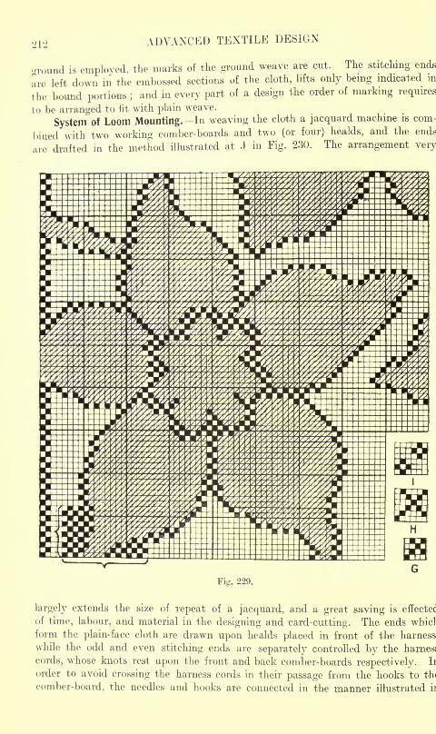
212 ADVANCED TEXTILE DESIGN
"round is employed, the marks of the ground weave are cut. The stitching ends
are left down in the embossed sections of the cloth, lifts only being indicated in
the bound portions ;and in every part of a design the order of marking requires
to be arranged to fit with plain weave.
System Of Loom Mounting. In weaving the cloth a jacquard machine is com-
bined with two working comber-boards and two (or four) healds, and the ends
are drafted in the method illustrated at J in Fig. 230. The arrangement very
Fig. 229.
largely extends the size of repeat of a jacquard, and a great saving is effectec
of time, labour, and material in the designing and card-cutting. The ends whicl
form the plain-face cloth are drawn upon healds placed in front of the harness
while the odd and even stitching ends are separately controlled by the harness
cords, whose knots rest upon the front and back comber-boards respectively. Ii
order to avoid crossing the harness cords in their passage from the hooks to th<
comber-board, the needles and hooks are connected in the manner illustrated ii
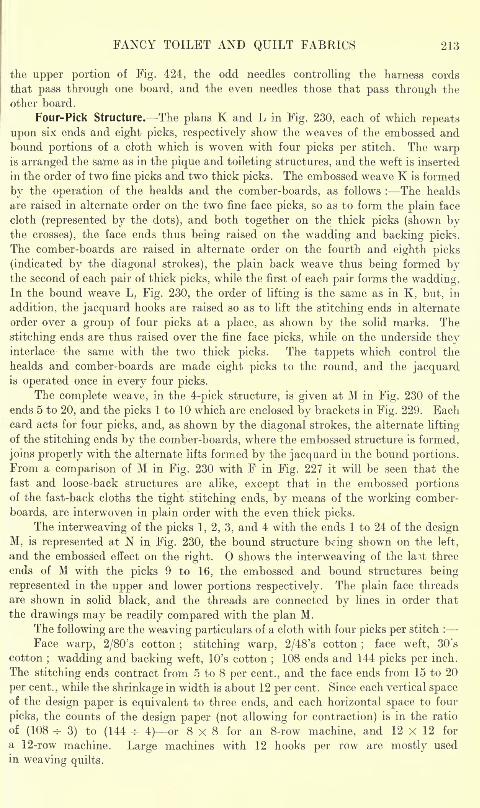
FANCY TOILET AND QUILT FABRICS 213
the upper portion of Fig. 424, the odd needles controlling the harness cords
that pass through one board, and the even needles those that pass through the
other board.
Four-Pick Structure. The plans K and L in Fig. 230, each of which repeats
upon six ends and eight picks, respectively show the weaves of the embossed and
bound portions of a cloth which is woven with four picks per stitch. The warpis arranged the same as in the pique and toileting structures, and the weft is inserted
in the order of two fine picks and two thick picks. The embossed weave K is formed
by the operation of the healds and the comber-boards, as follows : The healds
are raised in alternate order on the two fine face picks, so as to form the plain face
cloth (represented by the dots), and both together on the thick picks (shown bythe crosses), the face ends thus being raised on the wadding and backing picks.
The comber-boards are raised in alternate order on the fourth and eighth picks
(indicated by the diagonal strokes), the plain back weave thus being formed bythe second of each pair of thick picks, while the first of each pair forms the wadding.In the bound weave L, Fig. 230, the order of lifting is the same as in K, but, in
addition, the jacquard hooks are raised so as to lift the stitching ends in alternate
order over a group of four picks at a place, as shown by the solid marks. The
stitching ends are thus raised over the fine face picks, while on the underside theyinterlace the same with the two thick picks. The tappets which control the
healds and comber-boards are made eight picks to the round, and the jacquardis operated once in every four picks.
The complete weave, in the 4-pick structure, is given at M in Fig. 230 of the
,
ends 5 to 20, and the picks 1 to 10 which are enclosed by brackets in Fig. 229. Eachcard acts for four picks, and, as shown by the diagonal strokes, the alternate lifting
of the stitching ends by the comber-boards, where the embossed structure is formed,
joins properly with the alternate lifts formed by the jacquard in the bound portions.From a comparison of M in Fig. 230 with F in Fig. 227 it will be seen that the
fast and loose-back structures are alike, except that in the embossed portionsof the fast-back cloths the tight stitching ends, by means of the working comber-
boards, are interwoven in plain order with the even thick picks.
The interweaving of the picks 1, 2, 3, and 4 with the ends 1 to 24 of the design
M, is represented at N in Fig. 230, the bound structure being shown on the left,
and the embossed effect on the right. shows the interweaving of the la~vfc three
ends of M with the picks 9 to 16, the embossed and bound structures being
represented in the upper and lower portions respectively. The plain face threads
are shown in solid black, and the threads are connected by lines in order that
the drawings may be readily compared with the plan M.
The following are the weaving particulars of a cloth with four picks per stitch :
Face warp, 2/80's cotton; stitching warp, 2/48's cotton
;face weft, 30's
cotton; wadding and backing weft, 10's cotton
;108 ends and 144 picks per inch.
The stitching ends contract from 5 to 8 per cent., and the face ends from 15 to 20
per cent., while the shrinkage in width is about 12 per cent. Since each vertical spaceof the design paper is equivalent to three ends, and each horizontal space to four
picks, the counts of the design paper (not allowing for contraction) is in the ratio
of (108 -v- 3) to (144 -r- 4) or 8x8 for an 8-row machine, and 12 x 12 for
a 12-row machine. Large machines with 12 hooks per row are mostly used
in weaving quilts.
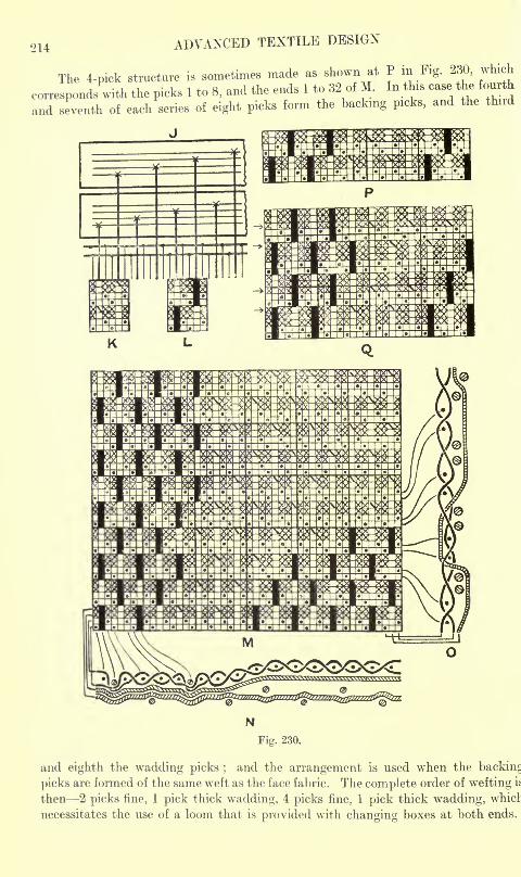
214 ADVANCED TEXTILE DESIGN
co:
The 4-pick structure is sometimes made as shown at P m Fig. 230, which
correspond/with the picks 1 to 8, and the ends 1 to 32 of M. In this case the fourth
and seventh of each series of eight picks form the backing picks, and the third
Ste
N
Fig. 230.
and eighth the wadding picks ;and the arrangement is used when the backing
picks are formed of the same weft as the face fabric. The complete order of wefting if
then 2 picks fine, 1 pick thick wadding, 4 picks fine, 1 pick thick wadding, whicl
necessitates the use of a loom that is provided with changing boxes at both ends.
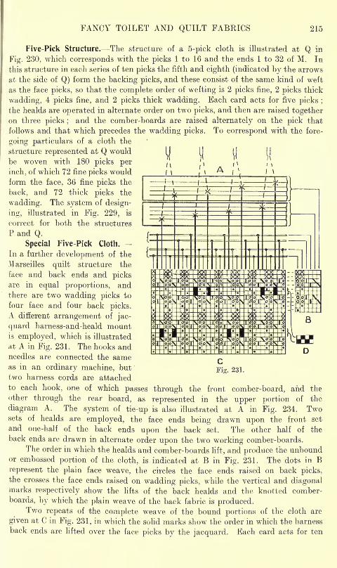
FANCY TOILET AND QUILT FABRICS 215
Five-Pick Structure. The structure of a 5-pick cloth is illustrated at Q in
Fig. 230, which corresponds with the picks 1 to 16 and the ends 1 to 32 of M. In
this structure in each series of ten picks the fifth and eighth (indicated by the arrows
at the side of Q) form the backing picks, and these consist of the same kind of weft
as the face picks, so that the complete order of wefting is 2 picks fine, 2 picks thick
wadding, 4 picks fine, and 2 picks thick wadding. Each card acts for five picks ;
the healds are operated in alternate order on two picks, and then are raised togetheron three picks ;
and the comber-boards are raised alternately on the pick that
follows and that which precedes the wadding picks. To correspond with the fore-
going particulars of a cloth the
structure represented at Q would \\ M
be woven with 180 picks per j
"
inch, of which 72 fine picks would Mform the face, 36 fine picks the
back, and 72 thick picks the
wadding. The system of design-
ing, illustrated in Fig. 229, is
correct for both the structures
P and Q.
Special Five Pick Cloth. -
In a further development of the
Marseilles quilt structure the
face and back ends and picksare in equal proportions, andthere are two wadding picks to
four face and four back picks.A different arrangement of jac-
quard harness-and-heald mountis employed, which is illustrated
at A in Fig. 231. The hooks andneedles are connected the sameas in an ordinary machine, but
two harness cords are attached
to each hook, one of which passes through the front comber-board, and the
other through the rear board, as represented in the upper portion of the
diagram A. The system of tie-up is also illustrated at A in Fig. 234. Twosets of healds are employed, the face ends being drawn upon the front set
and one-half of the back ends upon the back set. The other half of the
back ends are drawn in alternate order upon the two working comber-boards.
The order in which the healds and comber-boards lift, and produce the unboundor embossed portion of the cloth, is indicated at B in Fig. 231. The dots in Brepresent the plain face weave, the circles the face ends raised on back picks,the crosses the face ends raised on wadding picks, while the vertical and diagonalmarks respectively show the lifts of the back healds and the knotted comber-
boards, by which the plain weave of the back fabric is produced.Two repeats of the complete weave of the bound portions of the cloth are
given at C in Fig. 231, in which the solid marks show the order in which the harness
back ends are lifted over the face picks by the jacquard. Each card acts for ten
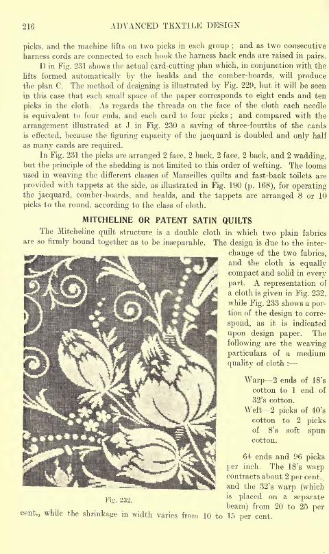
216 ADVANCED TEXTILE DESIGN
picks, and the machine lifts on two picks in each group ;and as two consecutive
harness cords are connected to each hook the harness back ends are raised in pairs.
D in Fig. 231 shows the actual card-cutting plan which, in conjunction with the
lifts formed automatically by the healds and the comber-boards, will producethe plan C. The method of designing is illustrated by Fig. 229, but it will be seen
in this case that each small space of the paper corresponds to eight ends and ten
picks in the cloth. As regards the threads on the face of the cloth each needle
is equivalent to four ends, and each card to four picks ;and compared with the
arrangement illustrated at J in Fig. 230 a saving of three-fourths of the cards
is effected, because the figuring capacity of the jacquard is doubled and only half
as many cards are required.
In Fig. 231 the picks are arranged 2 face, 2 back, 2 face, 2 back, and 2 wadding,but the principle of the shedding is not limited to this order of wefting. The loomsused in weaving the different classes of Marseilles quilts and fast-back toilets are
provided with tappets at the side, as illustrated in Fig. 190 (p. 168), for operatingthe jacquard, comber-boards, and healds, and the tappets are arranged 8 or 10
picks to the round, according to the class of cloth.
MITCHELINE OR PATENT SATIN QUILTSThe Mitcheline quilt structure is a double cloth in which two plain fabrics
are so firmly bound together as to be inseparable. The design is due to the inter-
change of the two fabrics,
and the cloth is equally
compact and solid in every
part. A representation of
a cloth is given in Fig. 232,
while Fig. 233 shows a por-tion of the design to corre-
spond, as it is indicated
upon design paper. The
following are the weaving
particulars of a medium
quality of cloth :
Warp 2 ends of 18's
cotton to 1 end of
32's cotton.
Weft 2 picks of 40's
cotton to 2 picksof 8's soft spuncotton.
64 ends and 96 picks
per inch. The 18's warpcontracts about 2 per cent.,
and the 32's warp (which
p- 232is P^ced on a separate
beam) from 20 to 25 percent., while the shrinkage in width varies from 10 to 15 per cent.
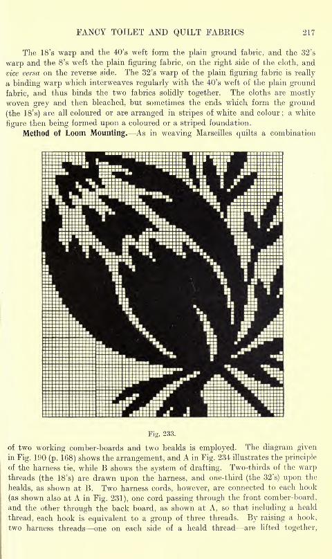
FANCY TOILET AND QUILT FABRICS 217
The 18's warp and the 40's weft form the plain ground fabric, and the 32's
warp and the 8's weft the plain figuring fabric, on the right side of the cloth, and
vice versa on the reverse side. The 32's warp of the plain figuring fabric is really
a binding warp which interweaves regularly with the 40's weft of the plain ground
fabric, and thus binds the two fabrics solidly together. The cloths are mostlywoven grey and then bleached, but sometimes the ends which form the ground
(the 18' s) are all coloured or are arranged in stripes of white and colour;a white
figure then being formed upon a coloured or a striped foundation.
Method of Loom Mounting. As in weaving Marseilles quilts a combination
Fig. 233.
of two working comber-boards and two healds is employed. The diagram givenin Fig. 190 (p. 168) shows the arrangement, and A in Fig. 234 illustrates the principle
of the harness tie, while B shows the system of drafting. Two-thirds of the warpthreads (the 18's) are drawn upon the harness, and one-third (the 32's) upon the
healds, as shown at B. Two harness cords, however, are connected to each hook
(as shown also at A in Fig. 231), one cord passing through the front comber-board,
and the other through the back board, as shown at A, so that including a heald
thread, each hook is equivalent to a group of three threads. By raising a hook,
two harness threads one on each side of a heald thread are lifted together,
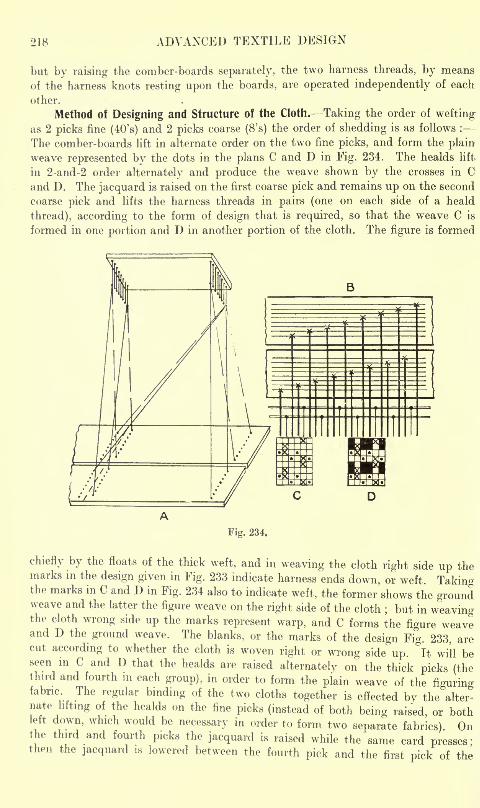
218 ADVANCED TEXTILE DESIGN
but by raising the comber-boards separately, the two harness threads, by means
of the harness knots resting upon the boards, are operated independently of each
other.
Method of Designing and Structure of the Cloth. Taking the order of weftingas 2 picks fine (40's) and 2 picks coarse (8's) the order of shedding is as follows :
The comber-boards lift in alternate order on the two fine picks, and form the plain
weave represented by the dots in the plans C and D in Fig. 234. The healds lift
in 2-and-2 order alternately and produce the weave shown by the crosses in Cand D. The jacquard is raised on the first coarse pick and remains up on the second
coarse pick and lifts the harness threads in pairs (one on each side of a heald
thread), according to the form of design that is required, so that the weave C is
formed in one portion and D in another portion of the cloth. The figure is formed
Fig. 234.
chiefly by the floats of the thick weft, and in weaving the cloth right side up themarks in the design given in Fig. 233 indicate harness ends down, or weft. Takinothe marks in C and D in Fig. 234 also to indicate weft, the former shows the groundweave and the latter the figure weave on the right side of the cloth
;but in weaving
the cloth wrong side up the marks represent warp, and C forms the figure weaveand D the ground weave. The blanks, or the marks of the design Fig. 233. arecut according to whether the cloth is woven right or wrong side up.
&
It will beseen in C and D that the healds are raised alternately on the thick picks (thethird and fourth in each group), in order to form the plain weave of the figuringfabric. The regular binding of the two cloths together is effected by the alter-nate lifting of the healds on the fine picks (instead of both being raised, or bothleft down, which would be necessary in order to form two separate fabrics). Onthe third and fourth picks the jacquard is raised while the same card presses'then the jacquard is lowered between the fourth pick and the first pick of the
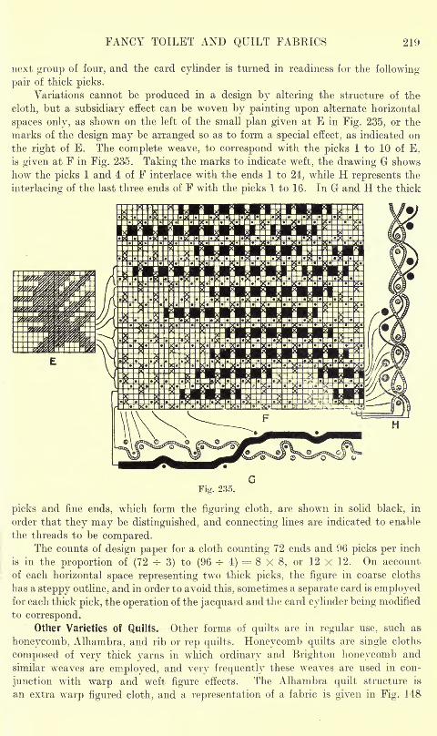
FANCY TOILET AND QUILT FABRICS 219
next group of four, and the card cylinder is turned in readiness for the following-
pair of thick picks.
Variations cannot be produced in a design by altering the structure of the
cloth, but a subsidiary effect can be woven by painting upon alternate horizontal
spaces only, as shown on the left of the small plan given at E in Fig. 235, or the
marks of the design may be arranged so as to form a special effect, as indicated on
the right of E. The complete weave, to correspond with the picks 1 to 10 of E,
is given at F in Fig. 235. Taking the marks to indicate weft, the drawing G shows
how the picks 1 and 4 of F interlace with the ends 1 to 24, while H represents the
interlacing of the last three ends of F with the picks 1 to 16. In G and H the thick
Fig. 235.
picks and fine ends, which form the figuring cloth, are shown in solid black, in
order that they may be distinguished, and connecting lines are indicated to enable
the threads to be compared.The counts of design paper for a cloth counting 72 ends and 96 picks per inch
is in the proportion of (72 -r- 3) to (96 4- 4) = 8 X 8, or 12 X 12. On account
of each horizontal space representing two thick picks, the figure in coarse cloths
has a steppy outline, and in order to avoid this, sometimes a separate card is employedfor each thick pick, the operation of the jacquard and the card cylinder being modified
to correspond.Other Varieties of Quilts. Other forms of quilts are in regular use, such as-
honeycomb, Alhambra, and rib or rep quilts. Honeycomb quilts are single cloths
composed of very thick yarns in which ordinary and Brighton honeycomb and
similar weaves are employed, and very frequently these weaves are used in con-
junction with warp and weft figure effects. The Alhambra quilt structure is-
an extra warp figured cloth, and a representation of a fabric is given in Fig. 148
220 ADVANCED TEXTILE DESIGN
(p. 134), while Fig. 147 illustrates a heald and harness mount that is employed.In a rib or rep quilt the threads are arranged the same as in an Alhambra quilt,
and one form of the structure is woven in an Alhambra quilt loom. In this typeall the figuring ends are raised on one pick, and all the ground ends (by lifting the
healds together) on the next pick. Also, on the picks on which the ground ends
are lifted, the harness ends are raised where the figure is formed, the lifting of both
series of ends causing long weft floats to be produced under the figure. In another
form of rib quilt a warp figure is produced on both sides of the cloth on a plain rib
ground. The inverted hook type of jacquard, illustrated in Fig. 186 (p. 161) is
used, and the cloth is similar in structure to the example given in Fig. 187 (p. 162),but on account of the thick weft and small number of picks per inch that are
employed in the structure, it is customary to use a separate card for each pick. In
addition, a cloth is largely used for bed mats that consists of a plain foundation
which is figured with coloured extra weft, the surface being almost entirely covered
by the figuring floats.
CHAPTER XII
GAUZE AND LENO FABRICS
Structure of the Cloths. Gauze Mounting The Doup Bottom and Top Douping Gauze andLeno Drafting Relative Position of Healds The Easer or Slackener Sheds formedin Doup Weaving Construction of Lifting Plans The Shaker Motion Gauze and Leno
Compared Modifications of Pure Gauze and Leno. Combinations of Gauze and other
Weaves Stripe Patterns Cellular Tennis Shirtings Russian Cords Simple Cross-overand Check Gauze Effects. Simple "Net" Lenos Comparison of Top and BottomDoup Pegging Plans Denting Net Lenos Designing Net Lenos and Features to Note-Production of Pattern by Varying the Lifts of the Standard Ends Bead Mounting forNet Lenos. Combinations of Gauza and Leno with Extra Warp and Extra Weft Effects.Two or More Doup Patterns. Patterns produced by one Doup and two or more BackCrossing Healds Comparison with Two-Doup Style Construction of Heald-KnittingPlans for Gauze Stripes Fancy One-Doup Net Leno Distorted Weft Styles Gauzeand Figure Weave Combinations.
Structure of the Cloths. In gauze and leno weaving certain ends termed crossingends are passed from side to side of what are termed standard ends, and arebound in by the weft in these positions. The crossing and standard ends maybe arranged with each other in various proportions, as 1-and-l, l-and-2, l-and-3,2-and-2, 2-and-3, etc., but an essential condition is that each group of crossingand standard ends must be placed in one split of the reed. A crossed system of
interlacing can be obtained when all the warp is brought from one beam, and insome cases this is essential in order to produce the desired effect. Very frequently,however, there is such a difference in the take up that it is necessary for the twoseries of ends to be brought from separate beams. The warp may consist entirelyof crossing and standard ends, or stripes of these may be combined with stripesin which the ends interlace in the ordinary manner so as to form plain, twill, figure,etc. It is also possible for the crossing and standard ends to form the crossed inter-
lacing alternately with straight interlacing in any required order. There is, therefore,
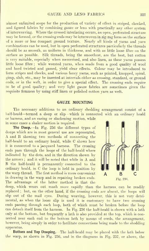
GAUZE AND LENO FABRICS 221
almost unlimited scope for the production of variety of effect in striped, checked,and figured fabrics by combining gauze or leno with practically any other systemof interweaving. Where the crossed interlacing occurs, an open, perforated structure
may be formed, or the crossing ends may be interwoven in zig-zag form on the surface
of a more or less Compact ground texture. Nearly all kinds of yarns and yarncombinations can be used, but in open perforated structures particularly the threads
should be as smooth, as uniform in thickness, and with as little loose fibre on the
surface as possible. Silk threads, being the smoothest, are the best, but cotton
is very suitable, especially when mercerised, and also linen, as these yarns possesslittle loose fibre
;while worsted yarns, when made from a good quality of wool
and hard twisted and gassed, yield clear effects. Colour may be introduced to
form stripes and checks, and various fancy yarns, such as printed, knopped, spiral,
gimp, slub, etc., may be inserted at intervals either as crossing, standard, or groundends, or in the weft, in order to give a special effect. The crossing ends requireto be of good quality ; and very light gauze fabrics are sometimes given the
requisite firmness by using stiff linen or polished cotton yarn as weft.
GAUZE MOUNTING
The necessary additions to an ordinary shedding arrangement consist of a
half-heald termed a doup or slip which is connected with an ordinary heald
or harness, and an easing or slackening motion, while
in some cases a shaker motion is required.The Doup. In Fig. 236 the different types of
doups which are in most general use are represented,A and B showing two methods of connecting the
half-heald to an ordinary heald, while C shows howit is connected to a jacquard harness. The crossing-
ends pass through the loops of the half-heald where
indicated by the dots, and in the direction shown bythe arrows
;and it will be noted that while in A and
B the half-heald is permanently connected to the
ordinary heald, in C the loop is held in position bythe warp thread. The first method is more convenient
in drawing in the warp and in repairing broken ends.
The advantage of the latter method is that the
doup, which wears out much more rapidly than the harness, can be readily
replaced ; but, on the other hand, if the crossing ends are absent, the loops will
slip out of the mail eyes. During weaving, however, this is not very detri-
mental, as when the loose slip is used it is customary to have two crossingends passing through each loop, both of which must be broken before the loopcan detach itself from the harness. In Fig. 236 the half-heald is shown with a lath
only at the bottom, but frequently a lath is also provided at the top> which is con-
nected near each end to the bottom lath by means of cords, the arrangement,however, being simply in order to facilitate connections being made to the shedding
apparatus.Bottom and Top Douping. The half-heald may be placed with the lath below
the warp, as shown in Fig. 236, and in the diagrams in Fig. 237, or above, the
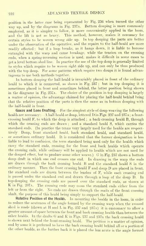
222 ADVANCED TEXTILE DESIGN
position in the latter case being represented by Fig. 236 when turned the other
way up, and by the diagrams in Fig. 237A. Bottom douping is more commonly
employed, as it is simpler to follow, is more conveniently applied in the loom,
and the lift is not so heavy. This method, however, makes it necessary for
certain styles to be woven wrong side up. In top douping the parts are better
under the observation of the operative, and the repairs to the half-heald are more
readily effected ; but if a loop breaks, as it hangs down, it is liable to become
entangled with the warp and cause breakage, while the tension on the crossing-
ends, when a spring-reversing motion is used, makes it difficult in some cases to
get a level bottom shed line. In practice the use of the top doup is generally limited
to styles which require to be woven right side up, and can only be thus producedwith the top doup. For some patterns which require two doups it is found advan-
tageous to use both methods together.
In bottom douping the half-heald is invariably placed in front of the ordinary
heald to which it is connected, as shown in Fig. 237;but in top douping it is
sometimes placed in front and sometimes behind, the latter position being shown
in the diagrams in Fig. 237A. The choice of the position in top douping is largely
a matter of opinion, the advantage claimed for placing the half-heald behind beingthat tin-, relative position of the parts is then the same as in bottom douping with
the half-heald in front.
Gauze and Leno Drafting.- -For the simplest style of doup weaving the followinghealds are necessary : A half-heald or doup, lettered D in Figs. 237 and 237A
;a front-
crossing heald F, to which the doup is attached;a back-crossing heald B, through
which the crossing ends are drawn;
and a standard heald S, which carries the
standard ends. (In practice the terms very largely used for the healds are respect-
ively- -Doup, front standard heald, back standard heald, and standard heald,
or sometimes ordinary heald. It is considered that the former designation is less
liable to lead to confusion, the term standard being used only for the healds which
cany the standard ends, crossing for the front and back healds which operatethe crossing ends, while ordinary will be applied to healds which are not used for
the douped effect, but to produce some other weave.) G in Fig. 237 shows a bottom
doup draft in which one end crosses one end. In drawing in the waip the endsare drawn through the back crossing heald B and the standard heald S in the
ordinary manner. Then the front crossing heald F and doup D are placed in front,
the standard ends are drawn between the leashes of F, while each crossing endis passed under the standaid end and drawn through a loop of the doup D. In
top-douping the crossing ends are passed over the standard ends, as shown at
K in Fig. 237A. The crossing ends may cioss the standard ends either from theleft or from the right. No ends are drawn through the mails of the front crossingshaft, the purpose of this heald being simply to support the half-heald.
Relative Position of the Healds. -In mounting the healds in the loom, in orderto reduce the acuteness of the angle formed by the crossing warp when the crossedshed is made (shown at H and L in Fig. 237 and 237A) it is customary to allow a
greater amount of space between the front and back crossing healds than between theother healds. In the drafts G and K in Figs. 237 and 237A the back crossing healdis shown next behind the front crossing heald. The position is a matter of opinion,and by some it is preferred to have the back crossing heald behind all or a portion ofthe other healds, as the further back it is placed the less acute is the angle formed
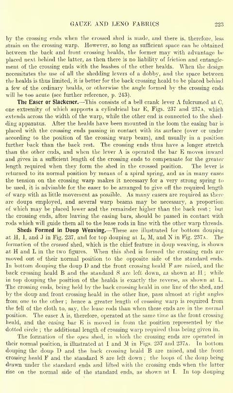
GAUZE AND LENO FABRICS 223
by the crossing ends when the crossed shed is made, and there is, therefore, less
strain on the crossing warp. However, so long as sufficient space can be obtained
between the back and front crossing healds, the former may with advantage be
placed next behind the latter, as then there is no liability of friction and entangle-
ment of the crossing ends with the leashes of the other healds. When the designnecessitates the use of all the shedding levers of a dobby, and the space between
the healds is thus limited, it is better for the back crossing heald to be placed behind
a few of the ordinary healds, or otherwise the angle formed by the crossing ends
will be too acute (see further reference, p. 243).
The Easer or Slackener. This consists of a bell crank lever A fulcrumed at C.
one extremity of which supports a cylindrical bar E, Figs. 237 and 237A, which
extends across the width of the warp, while the other end is connected to the shed-
ding apparatus. After the healds have been mounted in the loom the easing bar is
placed with the crossing ends passing in contact with its surface (over or under
according to the position of the crossing warp beam), and usually in a position
further back than the back rest. The crossing ends thus have a longer stretch
than the other ends, and when the lever A is operated the bar E moves inward
and gives in a sufficient length of the crossing ends to compensate for the greater
length required when they form the shed in the crossed position. The lever is
returned to its normal position by means of a spiral spring, and as in many cases
the tension on the crossing warp makes it necessary for a very strong spring to
be used, it is advisable for the easer to be arranged to give off the required lengthof warp with as little movement as possible. As many easers are required as there
are doups employed, and several warp beams may be necessary, a proportionof which may be placed lower and the remainder higher than the back rest
;but
the crossing ends, after leaving the easing bars, should be passed in contact with
rods which will guide them all to the lease rods in line with the other warp threads.
Sheds Formed in Doup Weaving. These are illustrated for bottom doupingat H, I, and J in Fig. 237, and for top douping at L, M, and N in Fig. 237A. The
formation of the crossed shed, which is the chief feature in doup weaving, is shown
at H and L in the two figures. When this shed is formed the crossing ends are
moved out of their normal position to the opposite side of the standard ends.
In bottom douping the doup D and the front crossing heald F are raised, and the
back crossing heald B and the standard S are left down, as shown at H;
while
in top douping the position of the healds is exactly the reverse, as shown at L.
The crossing ends, being held by the back crossing heald in one line of the shed, and
by the doup and front crossing heald in the other line, pass almost at right anglesfrom one to the other
;hence a greater length of crossing warp is required from
the fell of the cloth to, say, the lease rods than when these ends are in the normal
position. The easer A is, therefore, operated at the same time as the front crossing
heald, and the easing bar E is moved in from the position represented by the
dotted circle;the additional length of crossing warp required thus being given in.
The formation of the open shed, in which the crossing ends are operated in
their normal position, is illustrated at I and M in Figs. 237 and 237A. In bottom
douping the doup D and the back crossing heald B are raised, and the front
crossing heald F and the standard S are left down ;the loops of the doup being-
drawn under the standard ends and lifted with the crossing ends when the latter
rise on the normal side of the standard ends, as shown at I. In top douping
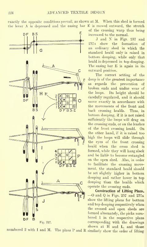
224 ADVANCED TEXTILE DESIGN
G
exactly the opposite conditions prevail, as shown at M. When this shed is formed
the lever A is depressed and the easing bar E is moved outward, the stretch
of the crossing warp thus beingD F B 5 increased to the normal.
J and N in Figs. 237 and
237A show the formation of
an ordinary shed in which the
standard heald only is raised in
bottom douping, while only that
heald is depressed in top douping.The easing bar E is again in its
outward position.
The correct setting of the
doup is of the greatest importanceas regards the prevention of
broken ends and undue wear of
the loops. Its height should be
carefully regulated, and it should
move exactly in accordance with
the movements of the front andback crossing healds. Thus, in
bottom douping, if it is not raised
sufficiently the loops will drag onthe crossing ends, or on the leashes
of the front crossing heald. Onthe other hand, if it is raised too-
high the loops will slide throughthe eyes of the front crossingheald when the cross shed is
formed, while they will hang slack
and be liable to become entangledon the open shed. Also, in order
to facilitate the crossing move-
ment, the standard heald should
be set slightly higher in bottom
douping and rather lower in top
douping than the healds which
operate the crossing ends.
Construction of Lifting Plans.
and Q in Figs. 237 and 237Ashow the lifting plans for bottomand top douping respectively whenthe crossed and open sheds are
formed alternately, the picks num-bered 1 in the respective plans
corresponding with the drawingsshown at H and L, and those
BFig. 237.
numbered 2 with I and M. The plans P and R similarly show the order of lifting
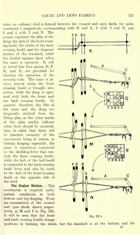
GAUZE AND LENO FABRICS 225
K
when an ordinary shed is formed between the crossed and open sheds, the picks
numbered 1 respectively corresponding with H and L, 3 with I and M, and
2 and 4 with J and N. The
crosses represent the lifts of the
doup, the dots of the front cross-
ing heald, the circles of the back
crossing heald. and the diagonal
strokes of the standard, while
the shaded squares show when
the easer is operated. It will
be noted that four spaces, D, F,
B, and E, are provided for
showing the operation of the
crossing ends. The easer is al-
ways moved when the front
crossing heald is brought into
action, while the doup is oper-
ated with both the front and
the back crossing healds. In
practice, therefore, the lifts of
the easer and the doup are
frequently omitted from the
lifting plan, as the other marks
of the plan readily indicate
when these should be operated.
Also, in order that there will
be absolute certainty of the
movements being in unison, in
bottom douping especially, the
easer is sometimes connected
to the shedding lever that con-
trols the front crossing heald;
while the lath of the half-heald
is connected to the back crossing
heald lever, and also by cords
to the lath of the front crossing
heald on the opposite side of
the shed.
The Shaker Motion. This
mechanism is required under
certain conditions in both
bottom and top douping. Froman examination of the crossed
and open sheds, shown respec-
tively at H and I in Fig. 237,
it will be seen that the front
and back crossing healds changeFig. 237A.
positions in forming the sheds, but the standaid is at the bottom and the15
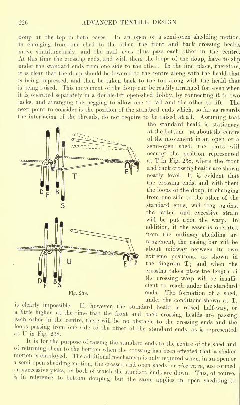
226 ADVANCED TEXTILE DESIGN
doup at the top in both cases. In an open or a semi-open shedding motion.
in changing from one shed to the other, the front and back crossing healds
move simultaneously, and the mail eyes thus pass each other in the centre.
At this time the crossing ends, and with them the loops of the doup, have to slip
under the standard ends from one side to the other. In the first place, therefore,
it is clear that the doup should be lowered to the centre along with the heald that
is being depressed, and then be taken back to the top along with the heald that
is being raised. This movement of the doup can be readily arranged for, even whenit is operated separately in a double-lift open-shed dobby, by connecting it to two
jacks, and arranging the pegging to allow one to fall and the other to lift. Thenext point to consider is the position of the standard ends which, so far as regardsthe interlacing of the threads, do not require to be raised at all. Assuming that
the standard heald is stationaryat the bottom at about the centre
of the movement in an open or a
semi-open shed, the parts will
occupy the position representedat T in Fig. 238, where the front
and back crossing healds are shown
nearly level. It is evident that
the crossing ends, and with themthe loops of the doup, in changingfrom one side to the other of the
standard ends, will drag againstthe latter, and excessive strain
will be put upon the warp. In
addition, if the easer is operatedfrom the ordinary shedding ar-
rangement, the easing bar will be
about midway between its twoextreme positions, as shown in
the diagram T;and when the
crossing takes place the length of
the crossing warp will be insuffi-
cient to reach under the standard
Fig. 238. ends. The formation of a shed,
under the conditions shown at T,s clearly impossible. If, however, the standard heald is raised half-way, ora little higher, at the time that the front and back crossing healds are passingeach other in the centre, there will be no obstacle to the crossing ends and theloops passing from one side to the other of the standard ends, as is representedat U in Fig. 238.
It is for the purpose of raising the standard ends to the centre of the shed andI returning them to the bottom when the crossing has been effected that a shaker
motion is employed. The additional mechanism is only required when, in an open ora semi-open shedding motion, the crossed and open sheds, or vice versa are formedon successive picks, on both of which the standard ends are down. This of coursem reference to bottom douping, but the same applies in open shedding to
GAUZE AND LENO FABRICS 227
top douping, except that the standard ends require to be moved from the topto the centre and back again by the shaker. The shaker motion may be dispensedwith (1) when one or more picks separate the crossed and open sheds, because
then the doup and the front and back crossing healds are level before the crossingcommences ; (2) when the crossed and open sheds succeed each other so long as
the healds, which govern the crossing and standard ends, are all level between
the picks. The latter condition may be due either to the type of shedding motion
employed or to the order in which the standard ends interlace. Thus no shaker
is necessary (a) in closed shedding, as all the healds are level between the picks ;
(b) in top douping in double-lift semi-open shedding, as the shafts required up on
successive picks are lowered to the centre between the picks ; (c) in double-lift
open and semi-open shedding, when in each group there are two or more standard
ends which work plain, as in this case the two standard healds are in the centre at
the same time as the front and back crossing healds. Sometimes, however, and
particularly when the standard ends are somewhat crowded, shaking, in a modified
form, is employed when not absolutely necessary ;but the idea here is not so
much to move the standard ends half the height of the shed as to shake them
sufficiently to enable the crossing from one side to the other to be more readilyeffected.
The half-lift of the standard ends is obtained in various ways, but usuallya motion is more readily applied to bottom than to top douping. It is necessary to
keep in mind that the standard ends, in addition to being moved by the shaker, mayrequire to be operated by the ordinary shedding mechanism. As a general rule,
in order to simplify the mechanism, the shaking is effected on every pick, whether
required or not, and the standard ends may thus receive an undue amount of vibra-
tion. In tappet weaving the half-lift is obtained from a specially shaped double-
winged tappet, and in dobby weaving the loom is sometimes fitted with a shaker
tappet and the necessary connections. In another method the shaking movementis obtained by means of suitable connections from the crank arm of the loom
;
whilst most makers now provide special attachments to double-lift dobbies for
the purpose. In top douping in a double-lift open shed dobby, a simple arrangementconsists of connecting the standard heald to two contiguous jacks, both of which
are pegged to lift when the standard is required to remain at the top, while whenthe half-movement is necessary, one is pegged to fall and the other to rise, the
shaking thus being done only when required.Gauze and Leno Compared. The terms gauze and leno are frequently used
synonymously to designate any fabric in which the doup principle of weaving is
employed. Sometimes, however, the term gauze is applied to fabrics in which
the crossed interweaving produces a light perforated fabric, while leno is used to
distinguish heavier styles in which the crossing ends form a distinct zig-zag effect
on the surface of the cloth. Again, the term gauze is sometimes applied to those
fabrics in which the crossing ends pass from one side to the other of the standard
ends on succeeding picks, in contradistinction to which the term leno is used for
styles in which one or more picks are inserted between the successive movementsof the crossing ends. The last system of classification is useful, since it very
largely serves to distinguish doup fabrics which, when produced on the double lift
shedding principle, require a shaker motion, from those for which such a mechan-
ism is unnecessary.
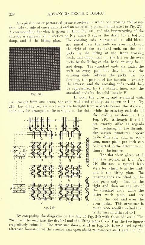
228 ADVANCED TEXTILE DESIGN
Fig. 239.
A typical open or perforated gauze structure, in which one crossing end passes
from side to side of one standard end on succeeding picks, is illustrated in Fig. 239.
A corresponding flat view is given at H in Fig. 240, and the interweaving of the
threads is represented in section at K;
while G shows the draft for a bottom
doup, and the lifting plan. The crossing ends, represented in solid black,
are raised over the weft on every pick on
the right of the standard ends on the odd
picks by the lifting of the front crossing
heald and doup, and on the left on the even
picks by the lifting of the back crossing heald
and doup. The standard ends are under the
weft on every pick, but they lie above the
crossing ends between the picks. In top
douping, the positon of the threads is exactlythe reverse, and the crossing ends would then
be represented by the shaded lines, and the
standard ends by the solid lines in H.
If both the crossing and standard ends-
are brought from one beam, the ends will bend equally, as shown at H in Fig.
240;but if the two series of ends are brought from separate beams, the standard
ends may be arranged to lie straight in the cloth while the crossing ends do all
the bending, as shown at I in
Fig. 240. Although H and I
are exactly alike as regardsthe interlacing of the threads,
the woven structures appear
quite different, and, in addi-
tion, more picks per inch can
be inserted in the latter methodthan in the former.
The flat view given at J
and the section at L in Fig.240 illustrate a typical leno
style for which G is the draft
and P the lifting plan. The
crossing ends are lifted on the
odd picks only first on the
right and then on the left of
the standard ends while the
latter work plain, and are
under the odd and over the
even picks. This structure is
nrnch more readily wefted than
is the case in either H or I.
By comparing the diagrams on the left of Fig. 240 with those shown in Fig.237, it will be seen that the draft G and the lifting plans and P in the two figuresrespectively coincide. The structure shown at H in Fig. 240 is produced by thealternate formation of the crossed and open sheds represented at H and I in Fig.
r >-
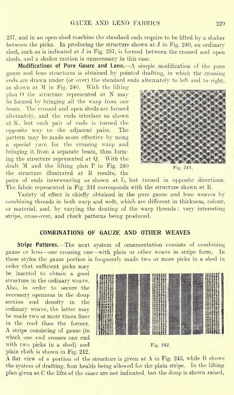
GAUZE AND LENO FABRICS 229
"237, and in an open-shed machine the standard ends require to be lifted by a shaker
between the picks. In producing the structure shown at J in Fig. 240, an ordinary
shed, such as is indicated at J in Fig. 237, is formed between the crossed and opensheds, and a shaker motion is unnecessary in this case.
Modifications of Pure Gauze and Leno. A simple modification of the pure
gauze and leno structuies is obtained by painted drafting, in which the crossingends are drawn under (or over) the standard ends alternately to left and to right,
as shown at M in Fig. 240. With the lifting
plan the structure represented at N maybe formed by bringing all the warp from one
beam. The crossed and open sheds are formed
alternately, and the ends interlace as shown
at K, but each pair of ends is turned the
opposite way to the adjacent pairs. The
pattern may be made more effective by usinga special yarn for the crossing warp and
bringing it from a separate beam, thus form-
ing the structure represented at Q. With the
draft M and the lifting plan P in Fig. 240
the structure illustrated at R results, theFig. 241,
pairs of ends interweaving as shown at L, but turned in opposite directions.
The fabric represented in Fig. 241 corresponds with the structure shown at R.
Variety of effect is chiefly obtained in the pure gauze and leno weaves by
combining threads in both warp and weft, which are different in thickness, colour,
or material, and, by varying the denting of the warp threads; very interesting
stripe, cross-over, and check patterns being produced.
COMBINATIONS OF GAUZE AND OTHER WEAVES
Stripe Patterns. The next system of ornamentation consists of combining
gauze or leno one crossing one -with plain or other weave in stripe form. In
these styles the gauze portion is frequently made two or more picks in a shed in
order that sufficient picks maybe inserted to obtain a goodstructure in the ordinary weave.
Also, in order to secure the
necessary openness in the doupsection and density in the
ordinary weave, the latter maybe made two or more times finer
in the reed than the former.
A stripe consisting of gauze (in
which one end crosses one endwith two picks in a shed) and Fig. 242.
plain cloth is shown in Fig. 242.
A flat view of a portion of the structure is given at A in Fig. 243, while B shows
the system of drafting, four healds being allowed for the plain stripe. In the lifting
plan given at C the lifts of the easer are not indicated; but the doup is shown raised,
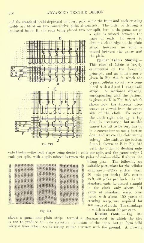
230 ADVANCED TEXTILE DESIGN
and the standard heald depressed on every pick, while the front and back crossing
healds are lifted on two consecutive picks alternately. The order of denting is
indicated below B, the ends being placed two per split, but in the gauze stripe
a split is missed between the
pairs of ends. In order to
obtain a clear edge to the plain
stripe, however, no split is
missed between the gauze and
the plain.
Cellular Tennis Shirting.
This class of fabric is largely
ornamented on the foregoing
principle, and an illustration is
given in Fig. 244 in which the
typical cellular structure is com-
bined with a 3-and-l warp twill
stripe. A sectional drawing,
corresponding with the pattern,
is given at D in Fig. 243, which
shows how the threads inter-
weave as viewed from the wrongside of the cloth. To weave
the cloth right side up, a top
doup is necessary ;but as this
causes the lift to be very heavy,it is convenient to use a bottom
doup and weave the cloth wrong-side up. The draft for the bottom
doup is shown at E in Fig. 243
with the order of denting indi-
cated below the twill stripe being dented 4 ends per split, and the gauze stripe 2
ends per split, with a split missed between the pairs of ends while F shows the
lifting plan. The following are
l!::U::;:::::: ;: ::::^ :::* : :: \\
suitable particulars for the cellular
!' structure : 2/20's cotton warp,30 ends per inch
;18's cotton
weft, 40 picks per inch. As the
standard ends lie almost straightin the cloth only about 104
yards of standard warp, com-
pared with about 150 yards of
crossing warp, are required for
100 yards of cloth. The shrinkagein width is about 10 per cent.
Russian Cords. Fig. 245shows a gauze and plain stripe termed a Russian cord in which the ideais not to produce an open structure by means of the doup, but to form solid
vertical lines which are in strong colour contrast with the ground. A crossing
Fig. 243.
*-.:
244
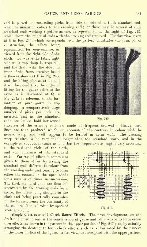
GAUZE AND LENO FABRICS 231
end is passed on succeeding picks from side to side of a thick standard end,
which is similar in colour to the crossing end;
or there may be several of such
standard ends working together as one, as represented on the right of Fig. 245,
which shows the standard ends with the crossing end removed. The flat view given
at G in Fig. 246, which corresponds with the pattern, illustrates the principle of
construction, the effect being-
represented, for convenience, as
viewed from the right side of the
cloth. To weave the fabric right
side up a top doup is required,
and the draft with the doup in
front of the front crossing heald
is then as shown at H in Fig. 246,
and the lifting plan as at I;and
it will be noted that the order of
lifting for the gauze effect is the
same as is illustrated at Q in
Fig. 237A in reference to the for-
mation of pure gauze in top
douping. A comparatively large
number of picks per inch are
inserted, and as the standard
ends are bulky, bold horizontal
traverses of the crossing ends are made at frequent intervals. Heavy cord
lines are thus produced which, on account of the contrast in colour with the
ground warp and weft, appear to be formed in extra weft. The crossing
warp requires to be very much longer than the standard warp, and in the
example is about four times as long, but the proportionate lengths vary accordingto the reed and picks of the cloth,
and the bulkiness of the standard
ends. Variety of effect is sometimes
given to these styles by having the
standard ends different in colour from
the crossing ends, and ceasing to form
either the crossed or the open sheds
for a number of times in succession.
The thick standard ends are thus left
uncovered by the crossing ends for a
space, the latter lying straight in the
cloth and being practically concealed
by the former, hence the continuity of
the coloured line is broken by spots of
another colour.
Fig. 245.
Fig. 246.
Simple Cross-over and Check Gauze Effects. The next development, on the
draft-one crossing one, is the combination of gauze and plain weave to form cross-
over effects, as shown in the pattern in the upper portion of Fig. 247; or, by suitably
arranging the denting, to form check effects, such as is illustrated by the patternin the lower portion of the figure. A flat view, to correspond with the upper pattern,
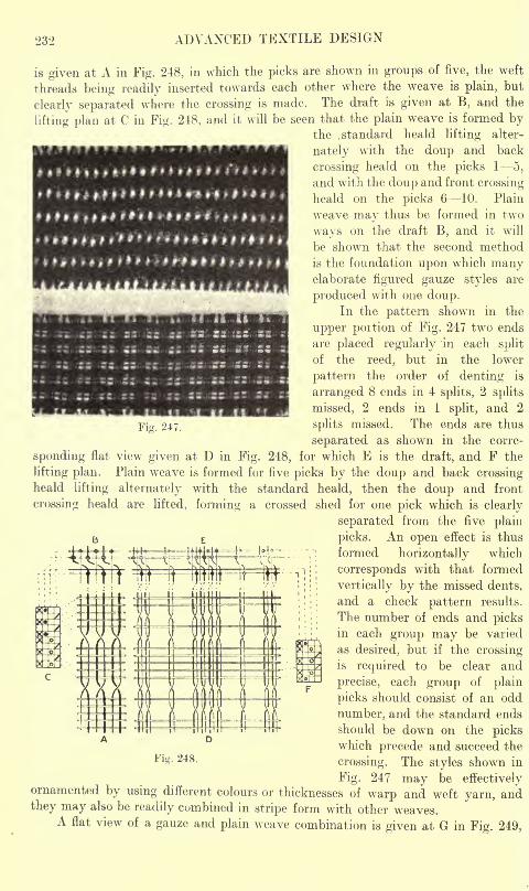
232 ADVANCED TEXTILE DESIGN
* * I 9 * f f M * ' * *M* *>*
is given at A in Fig. 248, in which the picks are shown in groups of five, the weft
threads being readily inserted towards each other where the weave is plain, but
clearly separated where the crossing is made. The draft is given at B, and the
lifting plan at C in Fig. 248, and it will be seen that the plain weave is formed bythe .standard heald lifting alter-
nately with the doup and back
crossing heald on the picks 1 5,
and with the doup and front crossing
heald on the picks 6 10. Plain
weave may thus be formed in two
ways on the- draft B, and it will
be shown that the second method
is the foundation upon which manyelaborate figured gauze styles are
produced with one doup.In the pattern shown in the
upper portion of Fig. 247 two ends
are placed regularly in each split
of the reed, but in the lower
Fig. 247.
pattern the order of denting is
arranged 8 ends in 4 splits, 2 splits
missed, 2 ends in 1 split, and 2
splits missed. The ends are thus
separated as shown in the corre-
sponding flat view given at D in Fig. 248, for which E is the draft, and F the
lifting plan. Plain weave is formed for five picks by the doup and back crossingheald lifting alternately with the standard heald, then the doup and front
crossing heald are lifted, forming a crossed shed for one pick which is clearly
separated from the five plain
picks. An open effect is thus
formed horizontally which
corresponds with that formed
vertically by the missed dents,
and a check pattern results.
The number of ends and picksin each group may be varied
as desired, but if the crossingis required to be clear and
precise, each group of plain
picks should consist of an odd
number, and the standard ends
should be down on the pickswhich precede and succeed the
crossing. The styles shown in
Fig. 247 may be effectivelyornamented by using different colours or thicknesses of warp and weft yarn, andthey may also be readily combined in stripe form with other weaves.
A flat view of a gauze and plain weave combination is given at G in Fig. 249,
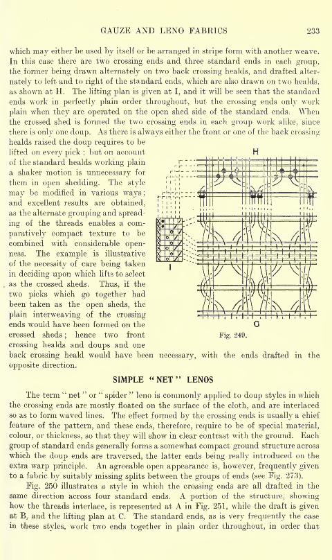
GAUZE AND LEND FABRICS 233
r
r-r -i
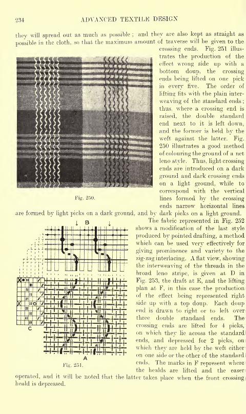
234 ADVANCED TEXTILE DESIGN
they will spread out as much as possible ; and they are also kept as straight as
possible in the cloth, so that the maximum amount of traverse will be given to the
crossing ends. Fig. 251 illus-
trates the production of the
effect wrong side up with a
bottom doup, the crossingends being lifted on one pickin every five. The order of
lifting fits with the plain inter-
weaving of the standard ends;
thus, where a crossing end is
raised, the double standard
end next to it is left down,and the former is held by the
weft against the latter. Fig.
250 illustrates a good methodof colouring the ground of a net
leno style. Thus, light crossing
ends are introduced on a dark
ground and dark crossing ends
on a light ground, while to
correspond with the vertical
Fig. 250. lines formed by the crossing
ends narrow horizontal lines
are formed by light picks on a dark ground, and by dark picks on a light ground.The fabric represented in Fig. 252
shows a modification of the last style
produced by pointed drafting, a methodwhich can be used very effectively for
giving prominence and variety to the
zig-zag interlacing. A flat view, showingthe interweaving of the threads in the
broad leno stripe, is given at D in
Fig. 253, the draft at E, and the lifting
plan at F, in this case the productionof the effect being represented rightside up with a top doup. Each doupend is drawn to right or to left over
three double standard ends. The
crossing ends are lifted for 4 picks,on which they lie across the standard
ends, and depressed for 2 picks, on
which they are held by the weft either
on one side or the other of the standard
ends. The marks in F represent where
the healds are lifted and the easerFig. 251.
operated, and it will be noted that the latter takes place when the front crossingheald is depressed.
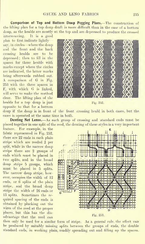
GAUZE AND LENO FABRICS 235
Fig. 252.
Comparison of Top and Bottom Doup Pegging Plans. The construction of
the lifting plan for a top doup draft is more difficult than in the case of a bottom
doup, as the healds are mostly at the top and are depressed to produce the crossed
interweaving. It is a good
plan to first indicate lightly
say, in circles where the doupand the front and the back
crossing healds are to be
depressed ;then to fill in the
spaces for these healds with
marks except where the circles
are indicated, the latter marks
being afterwards rubbed out.
A comparison of G in Fig.
253 with the three spaces in
F, with which G is linked,
will serve to make the methodclear. The lifting plan of the
healds for a top doup is just
opposite to that for a bottom
doup if the doup is in front of the front crossing heald in both cases, but the
easer is operated at the same time in both.
Denting Net Lenos. As each group of crossing and standard ends must be
placed together in one split of the reed, the denting of these styles is a very importantfeature. For example, in the
fabric represented in Fig. 252,
there are 22 ends in each plain
stripe which are reeded 2 per
split, while in the narrow doupstripe there are 2 groups of
ends which must be placed in
two splits, and in the broad
doup stripe 5 groups, which
must be placed in 5 splits.
The narrow doup stripe, how-
ever, occupies the width of 12
ends, or 6 splits of the plain
stripe, and the broad doupstripe the width of 26 ends or
13 splits. Sometimes the re-
quired spacing of the ends is
obtained by plucking out the
wires of the reed at the proper
places, but this has the dis-
advantage that the reed can
then only be used for a similar form of stripe. As a general rule, the effect can
be produced by suitably missing splits between the groups of ends, the double
standard ends, in working plain, readily spreading out and filling up the spaces.
UUI1 III! IIITIIUIIIIMIIIIK HHHT MUmM*.ilFjM
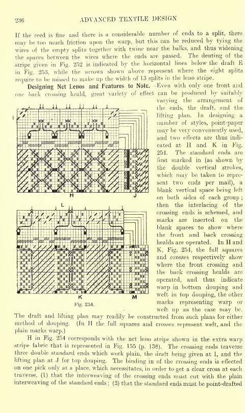
236 ADVANCED TEXTILE DESIGN
If the reed is fine and there is a considerable number of ends to a split, there
may be too much friction upon the warp, but this can be reduced by tying the
wires of the empty splits together with twine near the balks, and thus widening
the spaces between the wires where the ends are passed. The denting of the
stripe given in Fig. 252 is indicated by the horizontal lines below the draft E
in Fig. 253, while the arrows shown above represent where the eight splits
require to be missed to make up the width of 13 splits in the leno stripe.
Designing Net Lenos and Features to Note. Even with only one front and
one back crossing heald, great variety of effect can be produced by suitably
varying the arrangement of
ii ii ii U . 4 the' ends, the draft, and the
lifting plan. In designing a
number of styles, point-paper
may be very conveniently used,
and two effects are thus indi-
cated at H and K in Fig.
254. The standard ends are
first marked in (as shown bythe double vertical strokes,
which may be taken to repre-
sent two ends per mail), a
blank vertical space being left
on both sides of each group ;
then the interlacing of the
crossing ends is schemed, and
marks are inserted on the
blank spaces to show where
the front and back crossing
healds are operated. In H and
K, Fig. 254, the full squaresand crosses respectively show
where the front crossing and
the back crossing healds are
operated, and thus indicate
warp in bottom douping and
weft in top douping, the other
marks representing warp or
weft up as the case may be.
The draft and lifting plan may readily be constructed from such plans for either
method of douping. (In H the full squares and crosses represent weft, and the
plain marks warp.)H in Fig. 254 corresponds with the net leno stripe shown in the extra warp
stripe fabric that is represented in Fig. 155 (p. 138). The crossing ends traverse
three double standard ends which work plain, the draft being given at I, and the
lifting plan at J for top douping. The binding in of the crossing ends is effected
on one pick only at a place, which necessitates, in order to get a clear cross at each
traverse, (1) that the interweaving of the crossing ends must cut with the plain
interweaving of the standard ends; (2) that the standard ends must be point-drafted
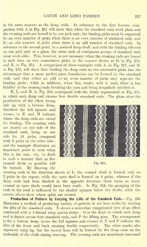
GAUZE AND LENO FABRICS 237
in the same manner as the doup ends. In reference to the first feature, com-
parison with A in Fig. 251 will show that when the standard ends work plain andthe crossing ends are bound in by one pick only, the binding picks must be separated
by an even number of picks when there is an even number of standard ends, and
by an odd number of picks when there is an odd number of standard ends. In
reference to the second point, in a pointed doup draft, and with the binding effected
on one pick only at a place, the outer ends of contiguous groups of standard ends
must work alike. This, however, is not necessary when the crossing ends are boundin each time on two consecutive picks, in the manner shown at D, in Fig. 253,
and K, in Fig. 254. A comparison of these examples with A, in Fig. 251, and H,in Fig. 254, will show that binding the doup ends on two successive picks has the
advantages that a more perfect plain foundation can be formed by the standard
ends, and that either an odd or an even number of picks may separate the
binding picks; while in addition, when fine, tender weft is used, there is less
liability of the crossing ends breaking the yarn and being irregularly stitched in.
K, L, and M, in Fig. 254, correspond with the fabric represented in Fig. 255,
in which each doup end crosses four double standard ends. The plans show the
production of the effect wrongside up with a bottom doup,therefore the full squares and
crosses in K and M indicate
where the doup ends are raised
for binding. The crossing ends
are mostly on one side of the
standard ends, being on one
side for 14 picks, comparedwith 2 picks on the other side
;
and the example illustrates an
important point to note whenthis is the case, viz., to draft
in such a manner that as few
crossed sheds as possible will
be formed. By drawing the
crossing ends in the direction shown at L, the crossed shed is formed only on
2 picks in the repeat, while the open shed is formed on 6 picks ;whereas if the
doup ends had been drafted in the opposite direction, three times as manycrossed as open sheds would have been made. In Fig. 254, the grouping of the
ends in the reed is indicated by the shaded squares below the drafts, while the
arrows above show where splits are missed.
Production of Pattern by Varying the Lifts of the Standard Ends. Fig. 256
illustrates a method of producing variety of pattern in net leno styles by varyingthe lifts of the standard ends. N shows a somewhat exaggerated view of an effect
combined with a 4-thread warp sateen stripe ;CKis the draft in which each doup
end is drawn across four standard ends, and P the lifting plan. The arrangementis for a bottom doup, hence the full squares and crosses in N and P indicate the
lifts of the front and back crossing healds respectively. The other marks also
represent warp up, but the waved lines will be formed by the doup ends on the
underside of the cloth during weaving. The crossing ends are sometimes traversed
Fig. 255.
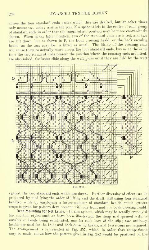
-238 ADVANCED TEXTILE DESIGN
across the four standard ends under which they are drafted, but at other times
only across two ends ;and in the plan N a space is left in the centre of each group
of standard ends in order that the intermediate position may be more conveniently
shown. When in the latter position, two of the standard ends are lifted, and two
are left down, but as shown in P, the front crossing heald, or the back crossing
heald as the case may be is lifted as usual. The lifting of the crossing ends
will cause them to actually move across the four standard ends, but as at the same
time the two standard ends nearest the position where the crossing ends are lifted,
are also raised, the latter slide along the weft picks until they are held by the weft
Fig. 256.
against the two standard ends which are down. Further diversity of effect can be
produced by modifying the order of lifting and the draft, still using four standardhealds
; while by employing a larger number of standard healds, much greater
scope is given for pattern development with one front and one back crossing heald.
Bead Mounting for Net Lenos. In this system, which may be readily employedfor net leno styles such as have been illustrated, the doup is dispensed with, a
number of beads being substituted, one for each loop of the slip; two ordinaryhealds are used for the front and back crossing healds, and two easers are required.The arrangement is represented in Fig. 257, which, in order that comparisonsmay be made, shows how the pattern given in Fig. 252 would be produced on the
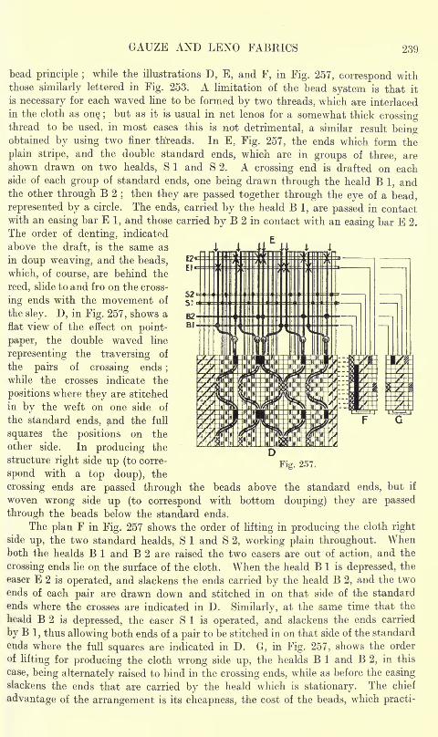
GAUZE AND LENO FABRICS 239
bead principle ;while the illustrations D, E, and F, in Fig. 257, correspond with
those similarly lettered in Fig. 253. A limitation of the bead system is that it
is necessary for each waved line to be formed by two threads, which are interlaced
in the cloth as on$ ;but as it is usual in net lenos for a somewhat thick crossing
thread to be used, in most cases this is not detrimental, a similar result beingobtained by using two finer threads. In E, Fig. 257, the ends which form the
plain stripe, and the double standard ends, which are in groups of three, are
shown drawn on two healds, S 1 and S 2. A crossing end is drafted on eachside of each group of standard ends, one being drawn through the heald B 1, andthe other through B 2
;then they are passed together through the eye of a bead,
represented by a circle. The ends, carried by the heald B 1, are passed in contactwith an easing bar E 1, and those carried by B 2 in contact with an easing bar E 2.
The order of denting, indicated
above the draft, is the same as 1 UrU i
in doup weaving, and the beads,
which, of course, are behind the
reed, slide to and fro on the cross-
ing ends with the movement of
the sley. D, in Fig. 257, shows a
flat view of the effect on point-
paper, the double waved line
representing the traversing of
the pairs of crossing ends;
while the crosses indicate the
positions where they are stitched
in by the weft on one side of
the standard ends, and the full
squares the positions on the
other side. In producing the
structure right side up (to corre-
spond with a top doup), the
G
Fig. 257.
crossing ends are passed through the beads above the standard ends, but if
woven wrong side up (to correspond with bottom douping) they are passed
through the beads below the standard ends.
The plan F in Fig. 257 shows the order of lifting in producing the cloth right
side up, the two standard healds, S 1 and S 2, working plain throughout. Whenboth the healds B 1 and B 2 are raised the two easers are out of action, and the
crossing ends lie on the surface of the cloth. When the heald B 1 is depressed, the
easer E 2 is operated, and slackens the ends carried by the heald B 2, and the two
ends of each pair are drawn down and stitched in on that side of the standard
ends where the crosses are indicated in D. Similarly, at the same time that the
heald B 2 is depressed, the easer S 1 is operated, and slackens the ends carried
by B 1, thus allowing both ends of a pair to be stitched in on that side of the standard
ends where the full squares are indicated in D. G, in Fig. 257, shows the order
oflifting for producing the cloth wrong side up, the healds B 1 and B 2, in this
case, being alternately raised to bind in the crossing ends, while as before the easing
slackens the ends that are carried by the heald which is stationary. The chief
advantage of the arrangement is its cheapness, the cost of the beads, which practi-
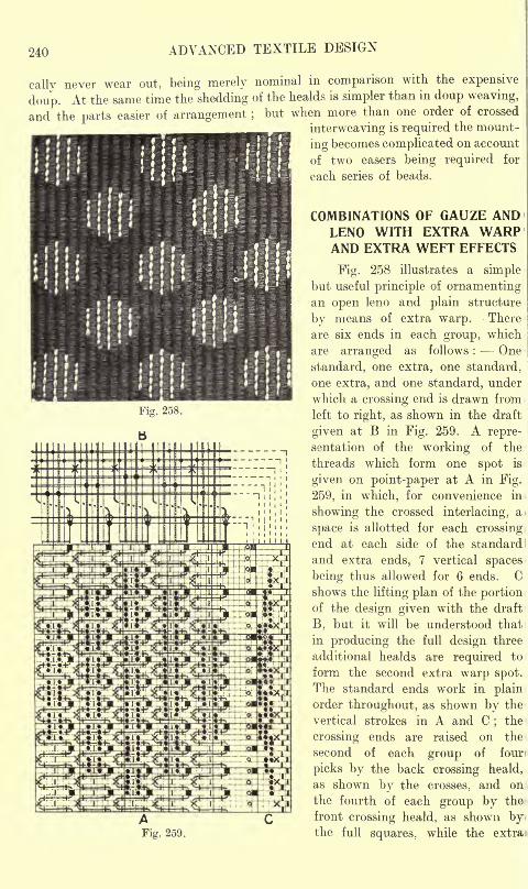
240 ADVANCED TEXTILE DESIGN
cally never wear out, being merely nominal in comparison with the expensive
doup. At the same time the shedding of the healds is simpler than in doup weaving,
and the parts easier of arrangement ;but when more than one order of crossed
interweaving is required the mount-
ing becomes complicated on account
of two easers being required for
each series of beads.11
','',i r > 21
! !'
Fig. 258.
COMBINATIONS OF GAUZE ANDLENO WITH EXTRA WARPAND EXTRA WEFT EFFECTS
Fig. 258 illustrates a simplebut useful principle of ornamentingan open leno and plain structure
by means of extra warp. There
are six ends in each group, which
are arranged as follows : One
standard, one extra, one standard,
one extra, and one standard, under
which a crossing end is drawn from
left to right, as shown in the draft
given at B in Fig. 259. A repre-
sentation of the working of the
threads which form one spot is
given on point-paper at A in Fig.
259, in which, for convenience in
showing the crossed interlacing, at
space is allotted for each crossing
end at each side of the standard
and extra ends, 7 vertical spaces
being thus allowed for 6 ends. Cshows the lifting plan of the portionof the design given with the draft
B, but it will be understood that
in producing the full design three
additional healds are required to
form the second extra warp spot.
The standard ends work in plainorder throughout, as shown by the
vertical strokes in A and C;the
crossing ends are raised on the
second of each group of four
picks by the back crossing heald,
as shown by the crosses, and on
the fourth of each group by the
front crossing heald, as shown bythe full squares, while the extra
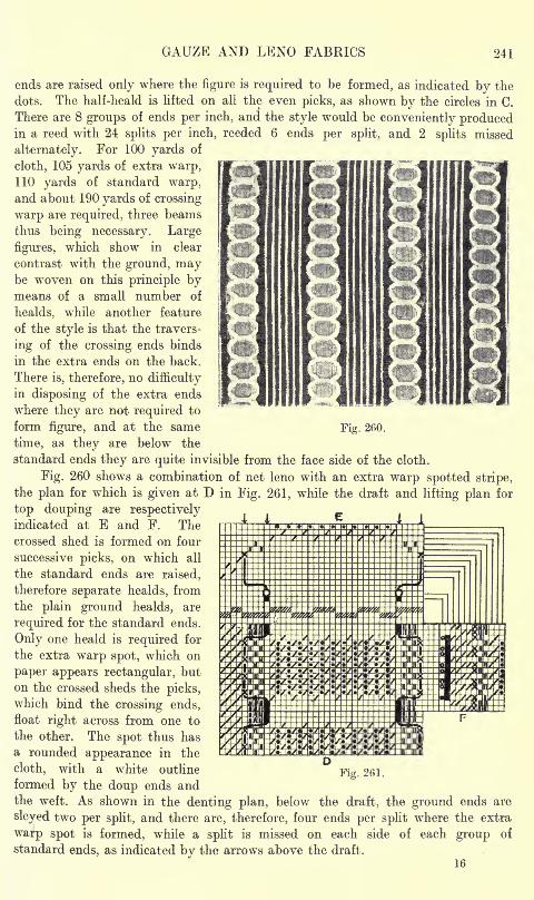
GAUZE AND LENO FABRICS 241
Fig. 260.
ends are raised only where the figure is required to be formed, as indicated by the
dots. The half-heald is lifted on all the even picks, as shown by the circles in C.
There are 8 groups of ends per inch, and the style would be conveniently producedin a reed with 24 splits per inch, reeded 6 ends per split, and 2 splits missed
alternately. For 100 yards of
cloth, 105 yards of extra warp,110 yards of standard warp,and about 190 yards of crossing
warp are required, three beams
thus being necessary. Large
figures, which show in clear
contrast with the ground, maybe woven on this principle bymeans of a small number of
healds, while another feature
of the style is that the travers-
ing of the crossing ends binds
in the extra ends on the back.
There is, therefore, no difficulty
in disposing of the extra ends
where they are not required to
form figure, and at the same
time, as they are below the
standard ends they are quite invisible from the face side of the cloth.
Fig. 260 shows a combination of net leno with an extra warp spotted stripe,
the plan for which is given at D in Fig. 261, while the draft and lifting plan for
top douping are respectivelyindicated at E and F. Thecrossed shed is formed on four
successive picks, on which all
the standard ends are raised,
therefore separate healds, from
the plain ground healds, are
required for the standard ends.
Only one heald is required for
the extra warp spot, which on
paper appears rectangular, but
on the crossed sheds the picks,which bind the crossing ends,
float right across from one to
the other. The spot thus has
a rounded appearance in the
cloth, with a white outline
formed by the doup ends andthe weft. As shown in the denting plan, below the draft, the ground ends are
sleyed two per split, and there are, therefore, four ends per split where the extra
warp spot is formed, while a split is missed on each side of each group of
standard ends, as indicated by the arrows above the draft.
16
Fig. 261.
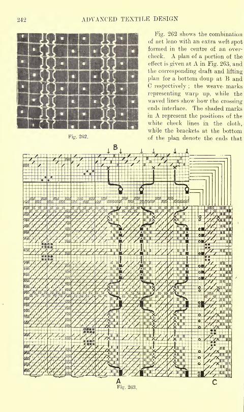
242 AD\7ANCED TEXTILE DESIGN
Fig. 262.
Fig. 262 shows the combination
of net leno with an extra weft spotformed in the centre of an over-
check. A plan of a portion of the
effect is given at A in Fig. 263, andthe corresponding draft and lifting
plan for a bottom doup at B andC respectively ;
the weave- marks
representing warp up, while the
waved lines show how the crossingends interlace. The shaded marksin A represent the positions of the
white check lines in the cloth,
while the brackets at the bottomof the plan denote the ends that
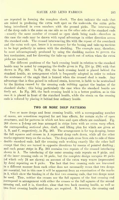
GAUZE AND LENO FABEICS 243
are repeated in forming the complete check. The dots indicate the ends that
are raised in producing the extra weft spot on the underside, the extra picks
being introduced in even numbers with the ground picks. The interweavingof the doup ends is the same on one side as on the other side of the standard ends
exactly the same number of crossed as open sheds being made therefore in
this case the ends may be drawn with equal advantage in either direction across
the standard ends. The crossed interweaving fits with the repeat of the overcheck
and the extra weft spot, hence it is necessary for the boxing and take-up motions
to be kept perfectly in unison with the shedding. The example may, therefore,
be most advantageously produced by using the shedding motion to govern the
box mechanism, and for throwing the take-up catch out of action when the extra
picks are inserted.
The different positions of the back crossing heald in relation to the standard
healds may be noted by comparing the drafts given in Fig. 254 (p. 236) with that
shown in Fig. 263. In Fig. 254, the back crossing heald is placed behind the
standard healds, an arrangement which is frequently adopted in order to reduce
the acuteness of the angle that is formed when the crossed shed is made. Anyadvantage that is thus gained in reduced strain, however, is liable to be neutralised
by the friction caused by the crossing ends rubbing against the leashes of the
standard shafts;
this being particularly the case when the standard healds are
finely set. In Fig. 263, the back crossing heald is in a better position, as in this
case it is placed in front of the standard healds, while the strain on the crossingends is reduced by placing it behind four ordinary healds.
TWO OR MORE DOUP PATTERNS
Two or more doups and front crossing healds, with a corresponding numberof easers, are sometimes required for net leno effects, for certain styles of openstructures, and for patterns in which net leno and open effects are combined. Fig.264 shows a 2-doup net leno arranged in stripe form with an extra warp effect,
the corresponding sectional plan, draft, and lifting plan for which are given at
A, B, and C, respectively, in Fig. 265. The arrangement is for top douping, hence
the full squares and crosses in A represent doup ends down, while all the other
marks represent warp on the suiface. The doup ends cross from side to side of three
double standard ends, half the crossing ends working exactly like the other half
except that they are turned in opposite diiections by means of pointed drafting ;
and each gauze stripe in Fig. 264 contains two repeats of the crossed interlacingshown in A. The interlacing of the outer crossing ends repeats on 8 picks, andof the inner crossing ends on 16 picks, but the complete design occupies 48 picks
(of which only 24 are shown) on account of the extra warp weave (represented
by dots) repeating on 6 picks. The fact that two crossing ends are traversed
in a different manner from each other does not necessarily mean that two doupsare essential, but in this case it will be apparent from an examination of the marksin A, which show the binding in of the first two crossing ends, that two doups mustbe used. Thus, neither the crosses nor the full squares of the first crossing end
correspond in arrangement with either the crosses or the full squares of the second
crossing end, and it is, therefore, clear that two back crossing healds, as well as
two front crossing healds and doups, are required. If, however, the crossing end
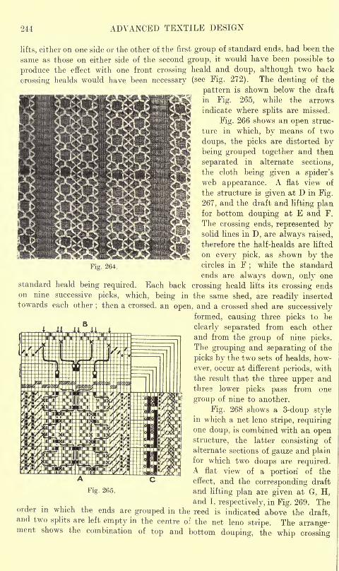
244 ADVANCED TEXTILE DESIGN
Fig. 264.
lifts, either on one side or the other of the first group of standard ends, had been the
same as those on either side of the second group, it would have been possible to
produce the effect with one front crossing heald and doup, although two back
crossing healds would have been necessary (see Fig. 272). The denting of the
pattern is shown below the draft
in Fig. 265, while the arrows
indicate where splits are missed.
Fig. 266 shows an open struc-
ture in which, by means of two
doups, the picks are distorted bybeing grouped together and then
separated in alternate sections,
the cloth being given a spider's
web appearance. A flat view of
the structure is given at D in Fig.
267, and the draft and lifting planfor bottom douping at E and F.
The crossing ends, represented bysolid lines in D, are always raised,
therefore the half-healds are lifted
on every pick, as shown by the
circles in F;
while the standard
ends are always down, only onestandard heald being required. Each back crossing heald lifts its crossing endson nine successive picks, which, being in the same shed, are readily inserted
towards each other; then a crossed, an open, and a crossed shed are successively
formed, causing three picks to be
clearly separated from each other
and from the group of nine picks.The grouping and separating of the
picks by the two sets of healds, how-
ever, occur at different periods, with
the result that the three upper andthree lower picks pass from one
group of nine to another.
Fig. 268 shows a 3-doup stylein which a net leno stripe, requiringone doup, is combined with an openstructure, the latter consisting of
alternate sections of gauze and plainfor which two doups are required.A flat view of a portion of the
effect, and the corresponding draft
and lifting plan are given at G, H,and I, respectively, in Fig. 269. The
order in which the ends are grouped in the reed is indicated above the draft,and two splits are left empty in the centre of the net leno stripe. The arrange-ment shows the combination of top and bottom douping, the whip crossing
265.
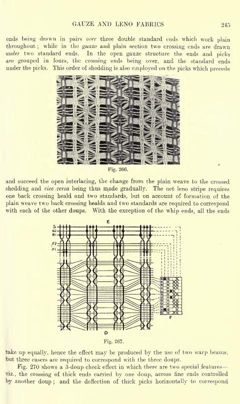
GAUZE AND LENO FABRICS 245
ends being drawn in pairs over three double standard ends which work plain
throughout ;while in the gauze and plain section two crossing ends are drawn
wid,er two standard ends. In the open gauze structure the ends and picksare grouped in fours, the crossing ends being over, and the standard ends
under the picks. This order of shedding is also employed on the picks which precede
Fig. 266.
and succeed the open interlacing, the change from the plain weave to the crossed
shedding and vice versa being thus made gradually. The net leno stripe requiresone back crossing heald and two standards, but on account of formation of the
plain weave two back crossing healds and two standards are required to correspondwith each of the other doups. With the exception of the whip ends, all the ends
take up equally, hence the effect may be produced by the use of two warp beams,
but three easers are required to correspond with the three doups.
Fig. 270 shows a 3-doup check effect in which there are two special features
viz., the crossing of thick ends carried by one doup, across fine ends controlled
by another doup ;and the deflection of thick picks horizontally to correspond
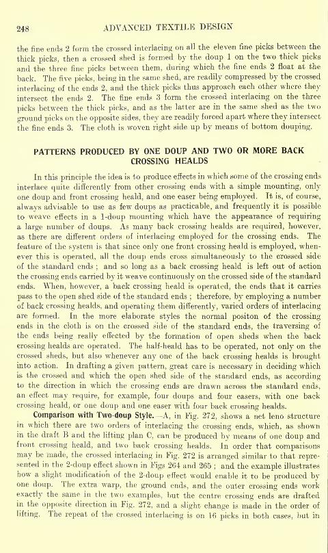
248 ADVANCED TEXTILE DESIGN
the fine ends 2 form the crossed interlacing on all the eleven fine picks between the
thick picks, then a crossed shed is formed by the doup 1 on the two thick picks
and the three fine picks between them, during which the fine ends 2 float at the
back. The five picks, being in the same shed, are readily compressed by the crossed
interlacing of the ends 2, and the thick picks thus approach each other where they
intersect the ends 2. The fine ends 3 form the crossed interlacing on the three
picks between the thick picks, and as the latter are in the same shed as the two
ground picks on the opposite sides, they are readily forced apart where they intersect
the fine ends 3. The cloth is woven right side up by means of bottom douping.
PATTERNS PRODUCED BY ONE DOUP AND TWO OR MORE BACKCROSSING HEALDS
In this principle the idea is to produce effects in which some of the crossing ends
interlace quite differently from other crossing ends with a simple mounting, only
one doup and front crossing heald, and one easer being employed. It is, of course,
always advisable to use as few doups as practicable, and frequently it is possible
to weave effects in a 1-doup mounting which have the appearance of requiring
a large number of doups. As many back crossing healds are required, however,
as there are different orders of interlacing employed for the crossing ends. The
feature of the system is that since only one front crossing heald is employed, when-
ever this is operated, all the doup ends cross simultaneously to the crossed side
of the standard ends;and so long as a back crossing heald is left out of action
the crossing ends carried by it weave continuously on the crossed side of the standard
ends. When, however, a back crossing heald is operated, the ends that it carries
pass to the open shed side of the standard ends; therefore, by employing a number
of back crossing healds, and operating them differently, varied orders of interlacing
are formed. In the more elaborate styles the normal positon of the crossingends in the cloth is on the crossed side of the standard ends, the traversing of
the ends being really effected by the formation of open sheds when the back
crossing healds are operated. The half-heald has to be operated, not only on the
crossed sheds, but also whenever any one of the back crossing healds is broughtinto action. In drafting a given pattern, great care is necessary in deciding which
is- the crossed and which the open shed side of the standard ends, as accordingto the direction in which the crossing ends are drawn across the standard ends,an effect may require, for example, four doups and four easers, with one back
crossing heald, or one doup and one easer with four back crossing healds.
Comparison with Two-doup Style. A, in Fig. 272, shows a net leno structure
in which there are two orders of interlacing the crossing ends, which, as shownin the draft B and the lifting plan C, can be produced by means of one doup andfront crossing heald, and two back crossing healds. In order that comparisonsmay be made, the crossed interlacing in Fig. 272 is arranged similar to that repre-sented in the 2-doup effect shown in Figs 264 and 265
;and the example illustrates
how a slight modification of the 2-doup effect would enable it to be produced byone doup. The extra warp, the ground ends, and the outer crossing ends work
exactly the same in the two examples, but the centre crossing ends are draftedin the opposite direction in Fig. 272, and a slight change is made in the order of
lifting. The repeat of the crossed interlacing is on 16 picks in both cases, but in
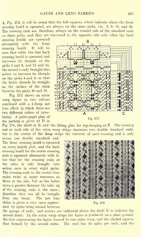
GAUZE AND LENO FABKICS 249
A, Fig. 272, it will be noted that the full squares, which indicate where the front
crossing heald is operated, are always on the same picks, viz., 2, 8, 10, and 16.
The crossing ends are, therefore, always on the crossed side of the standard ends
on these picks, and they are traversed to the opposite side only when the back
crossing healds are operated
alternately with the front
crossing heald. It will be
seen that while the first back
crossing heald is operated and
traverses its threads on the
picks 4 and 6, and 12 and 14,
the second is only brought into
action to traverse its threads
on the picks 4 and 6, so that
the latter threads lie straight
on the surface of the cloth
between the picks 10 and 16.
Fig. 273 shows an extra
warp figure in two colours
combined with a 1-doup net
leno effect in which there are
two different orders of inter-
Fig. 272.lacing. A point-paper plan of
the pattern is given at D in
Fig. 274, the draft at E, and the lifting plan for top-douping at F. The crossing
end at each side of the extra warp stripe traverses two double standard ends,
but in the centre of the doup stripe the traverse of each crossing end is only
across one double standard end.
The front crossing heald is operatedon every fourth pick, and the back
crossing heald for the centre crossing
ends is operated alternately with it,
but that for the crossing ends at
the sides is only brought into
action once in every eight picks.
The crossing ends in the centre thus
make twice as many traverses as
those at the side, but as the latter
move a greater distance the take upof the crossing ends is the same
;
therefore they can all be broughtfrom one beam. The net leno
stripe is given a very open appear-ance by splits being missed between
the groups of ends;and arrows are indicated above the draft E to indicate the
missed dents. In the extra warp stripe the figure is produced on a plain ground,
the dots representing the figure formed by one extra warp, and the shaded squares
that formed by the second extra. The reed has 44 splits per inch, and the
Fig. 273.
248 ADVANCED TEXTILE DESIGN
the fine ends 2 form the crossed interlacing on all the eleven fine picks between the
thick picks, then a crossed shed is formed by the doup 1 on the two thick picks
and the three fine picks between them, during which the fine ends 2 float at the
back. The five picks, being in the same shed, are readily compressed by the crossed
interlacing of the ends 2, and the thick picks thus approach each other where theyintersect the ends 2. The fine ends 3 form the crossed interlacing on the three
picks between the thick picks, and as the latter are in the same shed as the two
ground picks on the opposite sides, they are readily forced apart where they intersect
the fine ends 3. The cloth is woven right side up by means of bottom douping.
PATTERNS PRODUCED BY ONE DOUP AND TWO OR MORE BACKCROSSING HEALDS
In this principle the idea is to produce effects in which some of the crossing ends
interlace quite differently from other crossing ends with a simple mounting, onlyone doup and front crossing heald, and one easer being employed. It is, of course,
always advisable to use as few doups as practicable, and frequently it is possible
to weave effects in a 1-doup mounting which have the appearance of requiringa large number of doups. As many back crossing healds are required, however,as there are different orders of interlacing employed for the crossing ends. The
feature of the system is that since only one front crossing heald is employed, when-
ever this is operated, all the doup ends cross simultaneously to the crossed side
of the standard ends;and so long as a back crossing heald is left out of action
the crossing ends carried by it weave continuously on the crossed side of the standard
ends. When, however, a back crossing heald is operated, the ends that it carries
pass to the open shed side of the standard ends; therefore, by employing a number
of back crossing healds, and operating them differently, varied orders of interlacing
are formed. In the more elaborate styles the normal positon of the crossing
ends in the cloth is on the crossed side of the standard ends, the traversing of
the ends being really effected by the formation of open sheds when the back
crossing healds are operated. The half-heald has to be operated, not only on the
crossed sheds, but also whenever any one of the back crossing healds is broughtinto action. In drafting a given pattern, great care is necessary in deciding which
is the crossed and which the open shed side of the standard ends, as accordingto the direction in which the crossing ends are drawn across the standard ends,
an effect may require, for example, four doups and four easers, with one back
crossing heald, or one doup and one easer with four back crossing healds.
Comparison with Two-doup Style. A, in Fig. 272, shows a net leno structure
in which there are two orders of interlacing the crossing ends, which, as shownin the draft B and the lifting plan C, can be produced by means of one doup and
front crossing heald, and two back crossing healds. In order that comparisons
may be made, the crossed interlacing in Fig. 272 is arranged similar to that repre-
sented in the 2-doup effect shown in Figs 264 and 265;and the example illustrates
how a slight modification of the 2-doup effect would enable it to be produced byone doup. The extra warp, the ground ends, and the outer crossing ends work
exactly the same in the two examples, but the centre crossing ends are drafted
in the opposite direction in Fig. 272, and a slight change is made in the order of
lifting. The repeat of the crossed interlacing is on 16 picks in both cases, but in
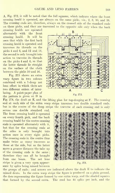
GAUZE AND LENO FABRICS 21!)
A, Fig. 272, it will be noted that the full squares, which indicate where the front
crossing heald is operated, are always on the same picks, viz., 2, 8, 10, and 16.
The crossing ends are, therefore, always on the crossed side of the standard endson these picks, and they are traversed to the opposite side only when the back
crossing healds are operated
alternately with the front
crossing heald. It will be
seen that while the first back
crossing heald is operated and
traverses its threads on the
picks 4 and 6, and 12 and 14,
the second is only brought into
action to traverse its threads
on the picks 4 and 6, so that
the latter threads lie straight
on the surface of the cloth
between the picks 10 and 16.
Fig. 273 shows an extra
warp figure in two colours
combined with a 1-doup net
leno effect in which there are
two different orders of inter-
lacing. A point-paper plan of
the pattern is given at D inFig. 272.
Fig. 274, the draft at E, and thelifting plan for top-douping at F. The crossing
end at each side of the extra warp stripe traverses two double standard ends,
but in the centre of the doup stripe the traverse of each crossing end is onlyacross one double standard end.
The front crossing heald is operatedon every fourth pick, and the back
crossing heald for the centre crossingends is operated alternately with it,
but that for the crossing ends at
the sides is only brought into
action once in every eight picks.
The crossing ends in the centre thus
make twice as many traverses as
those at the side, but as the latter
move a greater distance the take upof the crossing ends is the same; A 'm?-?^^therefore they can all be brought fp
!
'J-f!^ "J?..4?; ?/"] |iC
from one beam. The net leno ii'lLT-RftfcSi^iK?' J'^'t r*MW.*
stripe is given a very open appear- Fig. 273.
ance by splits being missed between
the groups of ends;and arrows are indicated above the draft E to indicate the
missed dents. In the extra warp stripe the figure is produced on a plain ground,
the dots representing the figure formed by one extra warp, and the shaded squares
that formed by the second extra. The reed has 44 splits per inch, and the
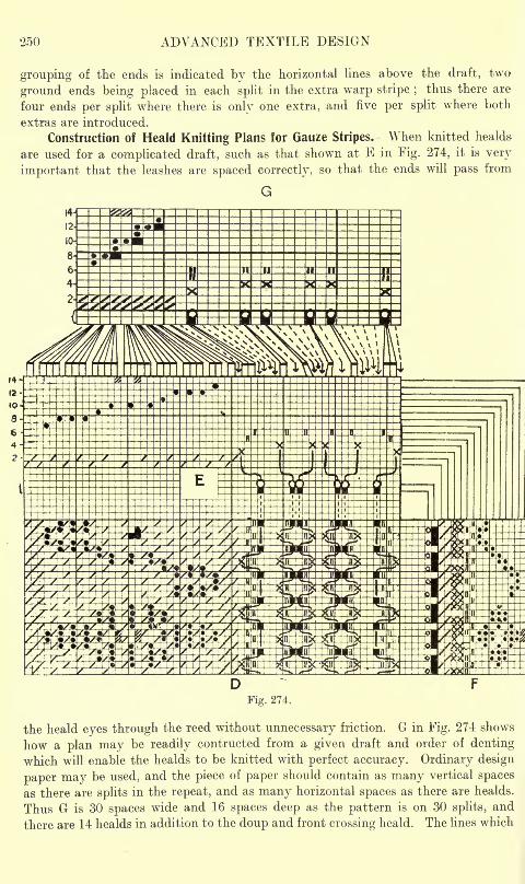
250 ADVANCED TEXTILE DESIGN
grouping of the ends is indicated by the horizontal lines above the draft, two
ground ends being placed in each split in the extra warp stripe ;thus there are
four ends per split where there is only one extra, and five per split where both
extras are introduced.
Construction of Heald Knitting Plans for Gauze Stripes. When knitted healds
are used for a complicated draft, such as that shown at E in Fig. 274, it is very
important that the leashes are spaced correctly, so that the ends will pass from
G
Fig. 274.
the heald eyes through the reed without unnecessary friction. G in Fig. 274 shows
how a plan may be readily contructed from a given draft and order of denting
which will enable the healds to be knitted with perfect accuracy. Ordinary design
paper may be used, and the piece of paper should contain as many vertical spaces
as there are splits in the repeat, and as many horizontal spaces as there are healds.
Thus G is 30 spaces wide and 16 spaces deep as the pattern is on 30 splits, and
there are 14 healds in addition to the doup and front crossing heald. The lines which
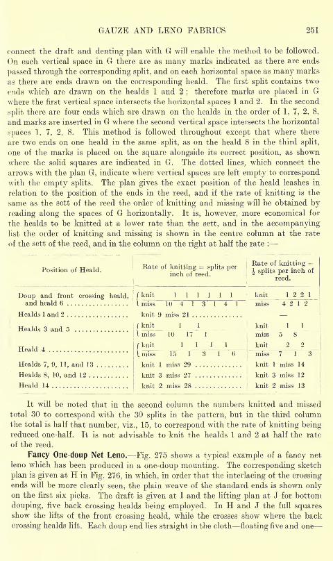
GAUZE AND LENO FABRICS 251
connect the draft and denting plan with G will enable the method to be followed.
On each vertical space in G there are as many marks indicated as there are ends-
passed through the corresponding split, and on each horizontal space as many marks
as there are ends drawn on the corresponding heald. The first split contains two
ends which are drawn on the healds 1 and 2;
therefore marks are placed in Gwhere the first vertical space intersects the horizontal spaces 1 and 2. In the second
split there are four ends which are drawn on the healds in the order of 1, 7, 2, 8,
and marks are inserted in G where the second vertical space intersects the horizontal
spaces 1, 7, 2, 8. This method is followed throughout except that where there
are two ends on one heald in the same split, as on the heald 8 in the third split,
one of the marks is placed on the square alongside its correct position, as shown
where the solid squares are indicated in G. The dotted lines, which connect the
arrows with the plan G, indicate where vertical spaces are left empty to correspondwith the empty splits. The plan gives the exact position of the heald leashes in
relation to the position of the ends in the reed, and if the rate of knitting is the
same as the sett of the reed the order of knitting and missing will be obtained by
reading along the spaces of G horizontally. It is, however, more economical for
the healds to be knitted at a lower rate than the sett, and in the accompanyinglist the order of knitting and missing is shown in the centre column at the rate
of the sett of the reed, and in the column on the right at half the rate :
Position of Heald.
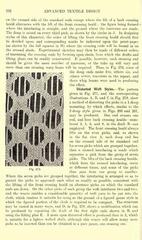
252 ADVANCED TEXTILE DESIGN
on the crossed side of the standard ends except where the lift of a back crossingheald alternates with the lift of the front crossing heald
;the figure being formed
where the interlacing is straight, and the ground where the traverses are made.The doup is raised on every third pick, as shown by the circles in J. In designing
styles of this character, the order of lifting the front crossing heald should first
be decided upon, and corresponding marks be indicated upon the point-paper
(as shown by the full squares in H) where the crossing ends will be bound in onthe crossed sheds. Experimental sketches may then be made of different orders
of traversing the crossing ends by forming open sheds, from which the drafts and
lifting plans can be readily constructed. If possible, however, each crossing endshould be given the same number of traverses, or the take up will vary andmore than one crossing warp beam will be required. Thus, in Fig. 276, some of
the doup en<ls make five, others six, and
others seven, traverses in the repeat, and
three whip beams were used in producingthe effect.
Distorted Weft Styles. The pattern
given in Fig. 277, and the correspondingillustrations A, B, and C in Fig. 278, showa method of distorting the picks in a 1-doup
mounting, by which effects, similar to the
2-doup style given in Figs. 266 and 267,
may be produced. One end crosses one
end, and four back crossing healds num-bered 2, 4, 6, and 8, in the draft B are
employed. The front crossing heald alwayslifts on the even picks, and, as shownin the flat view A, each doup end lies
on the crossed side of its standard end
for seven picks which are grouped together,
then a crossed interlacing is made which
separates a pick from the group of seven
picks. The lifts of the back crossing healds.
which form the crossed interlacing, occur
at different times, and some of the picksthus pass from one group to another.
Where the seven picks are grouped together, the interlacing is arranged so as to
permit the picks to approach each other as readily as possible, consistent with
the lifting of the front crossing heald on alternate picks, on which the standard
ends are down. On the other picks of each group the weft interlaces two-and-two,and the weave enables a considerable quantity of weft yarn to be put into the
cloth, which renders it suitable for using as the ground of a figured gauze style in
which the figured portion of the cloth is required to be compact. The structure
may be varied in many ways, and D, in Fig. 278, shows a modification which can
be produced by repeating the draft of the first eight ends shown in B, and
using the lifting plan E. A more open distorted effect is produced than in A, which
is suitable for a lighter wefted cloth, although this weave will allow many more
picks to be inserted than can be obtained in a pure gauze, one crossing one.
I
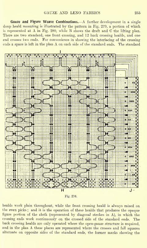
GAUZE AND LENO FABRICS 253
Gauze and Figure Weave Combinations. A further development in a single
doup heald mounting is illustrated by the pattern in Fig. 279, a portion of which
is represented at A in Fig. 280, while B shows the draft and C the lifting plan.There are two standard, one front crossing, and 12 back crossing healds, and one
end crosses two ends. For convenience in showing the interlacing of the crossingends a space is left in the plan A on each side of the standard ends. The standard
H
Fig. 276.
healds work plain throughout, while the front crossing heald is always raised onthe even picks ;
and it is the operation of these healds that produces the opaquefigure portion of the cloth (represented by diagonal strokes in A), in which the
crossing ends work continuously on the crossed side of the standard ends. Theback crossing healds are only operated where the open-gauze structure is required,and in the plan A these places are represented where the crosses and full squares,alternate on opposite sides of the standard ends, the former marks showing the
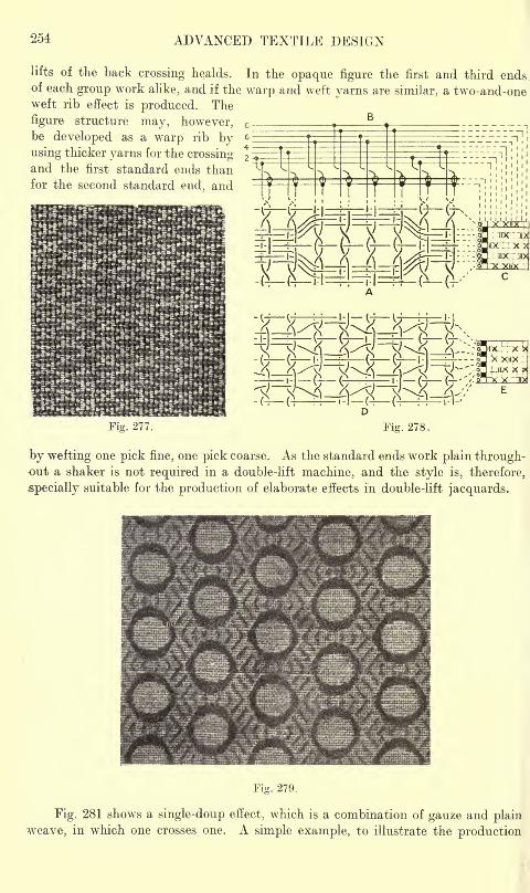
254 ADVANCED TEXTILE DESIGN
lifts of the back crossing healds. In the opaque figure the first and third endsof each group work alike, and if the warp and weft yarns are similar, a two-and-oneweft rib effect is produced. The
figure structure may, however,be developed as a warp rib byusing thicker yarns for the crossingand the first standard ends thanfor the second standard end, and
-IT (7 l:|=H=l=T- I/ ("5
Fig. 277. Fig. 278.
by wefting one pick fine, one pick coarse. As the standard ends work plain through-out a shaker is not required in a double-lift machine, and the style is, therefore,
specially suitable for the production of elaborate effects in double-lift jacquards.
Fig. 279.
Fig. 281 shows a single-doup effect, which is a combination of gauze and plain
weave, in which one crosses one. A simple example, to illustrate the production
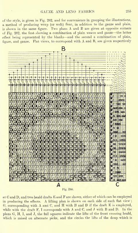
GAUZE AND LENO FABRICS 255
of the style, is given in Fig. 282, and for convenience in grouping the illustrations,
a method of producing waip (or weft) float, in addition to the gauze and plain,
is shown in the same figure. Two plans A and B are given at opposite corners
of Fig. 282, the first showing a combination of plain weave and gauze the latter
effect being represented by the blanks and the second a combination of plain,
figure, and gauze. Flat views, to correspond with A and B, are given respectively
ffflR Ftfflft^-WfW-W < H
Fig. 280.
at C and D, and two heald drafts E and F are shown, either of which can be employedin producing the effects. A lifting plan is shown on each side of each flat view
;
G, corresponding with A and C, and H with B and D if the draft E is employed,
while with the draft F, I corresponds with A and C, and J with B and D. In the
plans G, H, I, and J, the full squares indicate the lifts of the front crossing heald,
which is raised on alternate picks, and the circles the lifts of the doup which is
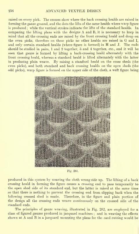
256 ADVANCED TEXTILE DESIGN
raised on every pick. The crosses show where the back crossing healds are raised in
forming the gauze ground, and the dots the lifts of the same healds where warp figure
is produced ;while the vertical strokes indicate the lifts of the standard healds. In
comparing the lifting plans with the designs A and B, it is necessary to keep in
mind that all the crossing ends are raised by the front crossing heald and doup on
the even picks, therefore on these picks no other healds are raised in G and I,
and only certain standard healds (where figure is formed) in H and J. The ends
should be studied in pairs, 1 and 2 together, 3 and 4: together, etc., and it will be
seen that gauze is formed by lifting a back-crossing heald alternately with the
front crossing heald, whereas a standard heald is lifted alternately with the latter
in producing plain weave. By raising a standard heald on the cross sheds (the
even picks), and both standard and back crossing healds on the open sheds (the
odd picks), warp figure is formed on the upper side of the cloth, a weft figure being
Fig. 281.
produced in this system by weaving the cloth wrong side up. The lifting of a back
crossing heald in forming the figure causes a crossing end to pass temporarily to
the open shed side of its standard end, but the latter is raised at the same time
so that there is nothing to prevent the crossing end from slipping back when the
following crossed shed is made. Therefore, in the figure and plain portion of
the design all the crossing ends weave continuously on the crossed side of the
standard ends.
The principles of gauze weaving, illustrated in Fig. 282, are employed for aclass of figured gauzes produced in jacquard machines
;and in weaving the effects
shown at A and B in a jacquard mounting the plans for the card cutting would be
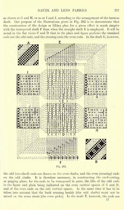
GAUZE AND LENO FABRICS 257
as shown at G and H, or as at 1 and J, according to the arrangement of the harness
draft. One purpose of the illustrations given in Fig. 282 is to demonstrate that
the construction of the design or lifting plan for a given effect is much simplerwith the transposed draft F than when the straight draft E is employed. It will be
noted in the flat views C and D that in the plain and figure portions the standard
ends are fche odd ends, and the crossing ends the even ends. In the draft E, however,
F
the odd (standard) ends are drawn on the even shafts, and the even (crossing) ends
on the odd shafts. It is therefore necessary, in constructing the card-cuttingor pegging plans, for the ends to be transposed in pairs, the lifts of the odd ends
in the figure and plain being indicated on the even vertical spaces of G and H,and of the even ends on the odd vertical spaces. At the same time it has to be
taken into account that the back crossing healds (the odd shafts) must not be
raised on the cross sheds (the even picks). In the draft F, however, the ends are
17
258 ADVANCED TEXTILE DESIGN
transposed in pairs in the healds, the odd (standard) ends being drawn on the odd
shafts and the even (crossing) ends on the even shafts.<Therefore, in this case, the
plans I and J exactly correspond with the designs A and B, except that the lifts,
obtained by raising the front crossing heald, are omitted, and marks are inserted, as
shown by the crosses, in the gauze ground,
CHAPTER XIII
JACQUARD GAUZE AND LENO FABRICS
Ordinary Jacquard and D&up-Heald Mountings Styles of Cloth Combinations of Gauze, Plain
Weave, and Warp (or Weft) Figure One-crossing-one Styles Special Ground Weaves
One-crossing-two Styles Use of Two Doups Modification of Gauze Ground Net-
Leno Figured Styles One-crossing-three Patterns Combinations of Twill and Gauze.
The Special Gauze Jacquard and Harness Arrangement of Harness, Hooks, and Needles
System of Drafting Method of Douping and Easing Construction of Gauze Ground
Weaves Designing of Figures System of Card-cutting Top Douping in the Gauze
Harness. MADRAS GAUZE FABRICS Structure of the Cloth The Madras Loom Systemof Drafting Method of Crossing the Ends Method of Easing Arrangement of Shuttle
Boxes Operation of the Gauze Reed Operation of the Easing Bar Operation of the
Tug Reed The Picking Motion The Up-take Motion Madras Designing Modifications
of the Structure Single Cover Chintzed Design Gauze Figure on Opaque Ground-
Complex Three-colour Fabric System of Card-cutting.
THERE are three chief systems of mounting for jacquard gauze effects, viz. :
(1) An ordinary jacquard and harness working in combination with one or more
doup healds; (2) a special jacquard and harness in which there are extra needles,
hooks, and cords for effecting the douping and easing ; (3) a Madras jacquardand harness in which the crossing of the ends is effected by means of a special gauzereed.
ORDINARY JACQUARD AND DOUP HEALD MOUNTINGS
The alterations and additions, required in changing from straight interlacing
to gauze, are practically the same in an ordinary jacquard and harness as in heald
work. The doup and doup heald are placed in front of the harness, which is moveda sufficient distance back from its usual position to allow the shafts to be operatedin front of the comber-board. The healds may be operated by tappets, but it is
usually more convenient to make use of special front hooks at each side of the
jacquard, in order to give a straight lift to the healds. In the case of a heavy douplift, several hooks at each side may be employed to lift the doup heald, duplicate
holes being cut in the cards to correspond. In many cases the lifting ot the healds
may be simplified by connections being made from them to the jacquard griffes.
Thus, in a single-lift machine, if the half heald is required to be raised on every
pick, it may be connected to the griffe, whereas in a double-lift jacquard, if the
doup heald is required up on alternate picks, it may be connected to one griffe,
and the half-heald to both griffes. In the latter case, the half-heald is lowered to
the centre of the shed for the crossing at each pick. Spiral springs are used to
draw down the healds, while the easing is effected by means of a transverse bar,
as in heald work, the extremity of the easing lever being connected to the same
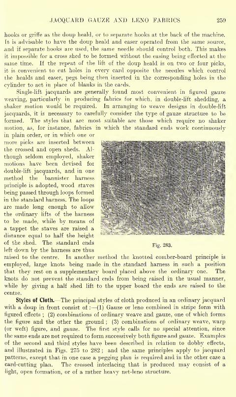
JACQUARD GAUZE AND LENO FABRICS 259
hooks or griffe as the doup heald, or to separate hooks at the back of the machine.
It is advisable to have the doup heald and easer operated from the same source,
and if separate hooks are used, the same needle should control both. This makes
it impossible for a cross shed to be formed without the easing being effected at the
same time. If the repeat of the lift of the doup heald is on two or four picks,
it is convenient to cut holes in every card opposite the needles which control
the healds and easer, pegs being then inserted in the corresponding holes in the
cylinder to act in place of blanks in the cards.
Single-lift jacquards are generally found most convenient in figured gauze
weaving, particularly in producing fabrics for which, in double-lift shedding, a
shaker motion would be required. In arranging to weave designs in double-lift
jacquards, it is necessary to carefully consider the type of gauze structure to be
formed. The styles that are most suitable are those which require no shaker
motion, as, for instance, fabrics in which the standard ends work continuouslyin plain order, or in which one or
more picks are inserted between
the crossed and open sheds. Al-
though seldom employed, shaker
motions have been devised for
double-lift jacquards, and in one
method the bannister harness
principle is adopted, wood staves
being passed through loops formed
in the standard harness. The loops
are made long enough to allow
the ordinary lifts of the harness
to be made, while by means of
a tappet the staves are raised a
distance equal to half the heightof the shed. The standard ends
left down by the harness are thus
raised to the centre. In another method the knotted comber-board principle is
employed, large knots being made in the standard harness in such a position
that they rest on a supplementary board placed above the ordinary one. The
knots do not prevent the standard ends from being raised in the usual manner,while by giving a half shed lift to the upper board the ends are raised to the
centie.
Styles of Cloth. The principal styles of cloth produced in an ordinary jacquardwith a doup in front consist of : (1) Gauze or leno combined in stripe form with
figured effects; (2) combinations of ordinary weave and gauze, one of which forms
the figure and the other the ground ; (3) combinations of ordinary weave, warp(or weft) figure, and gauze. The first style calls for no special attention, since
the same ends are not required to form successively both figure and gauze. Examplesof the second and third styles have been described in relation to dobby effects,
and illustrated in Figs. 275 to 282;and the same principles apply to jacquard
patterns, except that in one case a pegging plan is required and in the other case a
card-cutting plan. The crossed interlacing that is produced may consist of a
light, open formation, or of a rather heavy net-leno structure.
Fig. 283.

260 ADVANCED TEXTILE DESIGN
Combinations of Gauze, Plain Weave, and Warp (or Weft) Figure. Examplesof this type of structure are given in Figs. 283 and 284, the former illustration
representing a combination of gauze and plain weave, while in the latter, weft
figure on the right side of the cloth is also included.
One-crossing-one Styles. The method of designing for structures in which
one end crosses one end is illustrated in Fig. 285. (These examples show the jacquard
development of the styles given in Fig. 282.) A in Fig. 285 represents a harness
and doup-heald draft, in which the ends are transposed in pairs 2, 1, 4, 3, etc.
in order that the standard and crossing ends, which respectively form the oddand even ends in the plain and figure portions of the cloth, will correspond with
the odd and even spaces respectivelyof the design paper. The plans B,
C, and D illustrate the designing of
a plain weave figure on gauze ground,such as is represented in Fig. 283,
while E, F, and G show the designingof a warp (or weft) figure sur-
rounded by plain weave on gauze
ground ;this style corresponding
with Fig. 284. The lifts of the doupand doup heald are indicated at the
side of the plans, and in both styles,
on the even picks, all the crossingends are raised by the doup heald
on the right-hand side of the stan-
dard ends. The picks odd or even
on which to form the crossed
sheds is determined by the positionof the plain marks on the even
ends; thus, if the plain weave had
been indicated in the reverse positionin the plans B and E, the lift of
the doup heald would have occurred
on the odd picks.
The plan B in Fig. 285 repre-sents the form of a plain weave figure as actually required in the cloth, while Cshows the effect indicated in full for the card-cutting. Since the doup heald, on
the even picks, lifts all the crossing ends on the right of the standard ends, no
ends are raised by the harness on these picks, the cards for which are blank
except where holes are cut for the purpose of lifting the doup heald. On the
odd picks the standard harness lifts the standard ends where the plain figure
is required, as shown by the full squares in C;
while the crossing harness lifts
the crossing ends in the gauze ground, as indicated by the crosses. The blank
picks need not, however, be included in the design, as the cards for these
can be obtained by repeating, hence the drafting of a gauze and plain combination
may be simplified by designing for the open sheds only, as shown at D. In this-
case the outline of the figure is first drawn in the ordinary manner on design paper,the counts of which is in the proportion of the ends per inch to the picks per inch
Fig. 284.
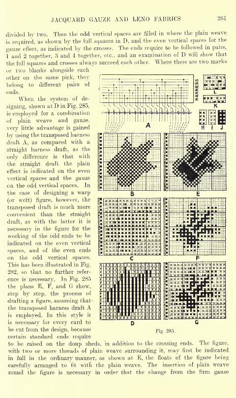
JACQUARD GAUZE AND LENO FABRICS 261
divided by two. Then the odd vertical spaces are filled in where the plain weave
is required, as shown by the full squares in D, and the even vertical spaces for the
gauze effect, as indicated by the crosses. The ends require to be followed in pairs,
1 and 2 together, 3 and 4 together, etc., and an examination of D will show that
the full squares and crosses always succeed each other. Where there are two marks
or two blanks alongside each
other on the same pick, they
belong to different pairs of
ends.
When the system of de-
signing, shown at D in Fig. 285,
is employed for a combination
of plain weave and gauze,
very little advantage is gained
by using the transposed harness
draft A, as compared with a
straight harness draft, as the
only difference is that with
the straight draft the plain
effect is indicated on the even
vertical spaces and the gauzeon the odd vertical spaces. In
the case of designing a warp
(or weft) figure, however, the
transposed draft is much more
convenient than the straight
draft, as with the latter it is
necessary in the figure for the
working of the odd ends to be
indicated on the even vertical
.spaces, and of the even ends
on the odd vertical spaces.
This has been illustrated in Fig.
282, so that no further refer-
ence is necessary. In Fig. 285
the plans E, F, and G show,
step by step, the process of
drafting a figure, assuming that
the transposed harness draft Ais employed. In this style it
liriiiHiSIi
is necessary for every card to
be cut from the design, because-gig. 285.
certain standard ends require
to be raised on the doup sheds, in addition to the crossing ends. The figure,
with two or more threads of plain weave surrounding it, may first be indicated
in full in the ordinary manner, as shown at E, the floats of the figure being
carefully arranged to fit witn the plain weave. The insertion of plain weave
round the figure is necessary in order that the change from the firm gauze
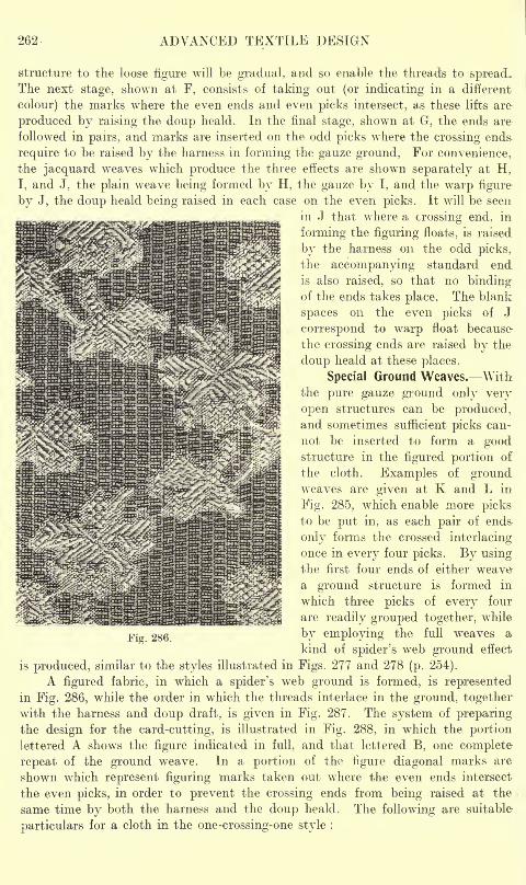
262- ADVANCED TEXTILE DESIGN
structure to the loose figure will be gradual, and so enable the threads to spread.The next stage, shown at F, consists of taking out (or indicating in a different
colour) the marks wrhere the even ends and even picks intersect, as these lifts are
produced by raising the doup heald. In the final stage, shown at G, the ends are
followed in pairs, and marks are inserted on the odd picks where the crossing ends-
require to be raised by the harness in forming the gauze ground, For convenience,
the jacquard weaves which produce the three effects are shown separately at H,
I, and J, the plain weave being formed by H, the gauze by I, and the warp figure
by J, the doup heald being raised in each case on the even picks. It will be seen
in J that where a crossing end, in
forming the figuring floats, is raised
by the harness on the odd picks,
the accompanying standard endis also raised, so that no bindingof the ends takes place. The blank
spaces on the even picks of J
correspond to warp float because
the crossing ends are raised by the
doup heald at these places.
Special Ground Weaves. Withthe pure gauze ground only very
open structures can be produced,and sometimes sufficient picks can-
not be inserted to form a goodstructure in the figured portion of
the cloth. Examples of groundweaves are given at K and L in
Fig. 285, which enable more picksto be put in, as each pair of ends-
only forms the crossed interlacing
once in every four picks. By usingthe first four ends of either weavea ground structure is formed in
which three picks of every four
are readily grouped together, while
by employing the full weaves a
kind of spider's web ground effect
is produced, similar to the styles illustrated in Figs. 277 and 278 (p. 254).
A figured fabric, in which a spider's web ground is formed, is representedin Fig. 286, while the order in which the threads interlace in the ground, togetherwith the harness and doup draft, is given in Fig. 287. The system of preparingthe design for the card-cutting, is illustrated in Fig. 288, in which the portion
lettered A shows the figure indicated in full, and that lettered B, one complete
repeat of the ground weave. In a portion of the figure diagonal marks are
shown which represent figuring marks taken out where the even ends intersect
the even picks, in order to prevent the crossing ends from being raised at the
same time by both the harness and the doup heald. The following are suitable
particulars for a cloth in the one-crossing-one style :
Fig. 286.
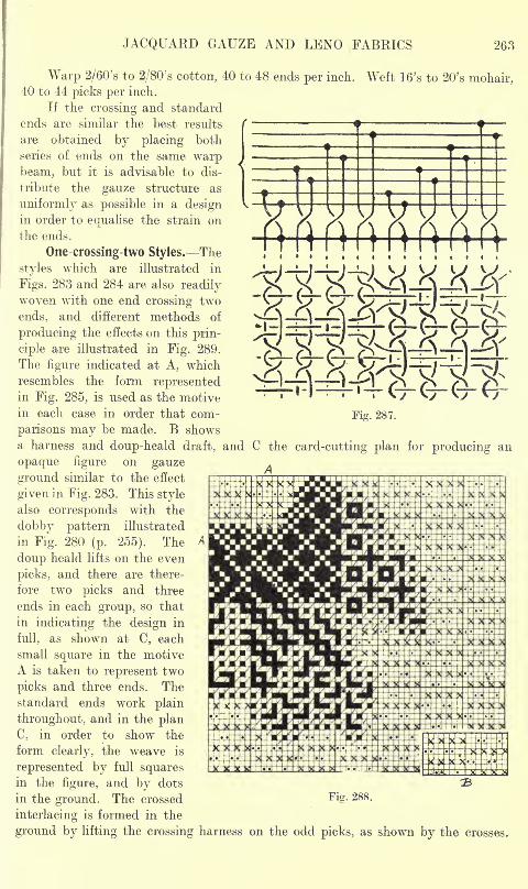
JACQUARD GAUZE AND LENO FABRICS 263
Weft 16's to 20's mohair,
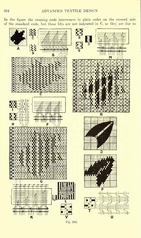
264 ADVANCED TEXTILE DESIGN
In the figure the crossing ends interweave in plain order on the crossed side
of the standard ends, but these lifts are not indicated in C, as they are due to
ffiVTTOB
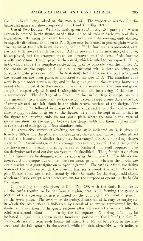
JACQUARD GAUZE AND LENO FABRICS 265
the doup heald being raised on the even picks. The respective weaves for the
figure and gauze are shown separately at D and E in Fig. 289.
Use of Two Doups. With the draft given at B in Fig. 289 pure plain weave
cannot be formed in the figure, as the first and third ends of each group of three
work alike. By using two doup healds, however, with the crossing ends drafted
in opposite directions, as shown at F, a figure may be formed in perfect plain weave.
The repeat of the draft is on six ends, and in F the harness is represented with
the two back rows of cords cast out. All the rows of the harness may, of course,
be employed, but the arrangement shown is convenient if the sett of the harness
is sufficiently fine. Design paper is then used, which is ruled to correspond. Thus,
in G, which shows the complete card-cutting plan to coincide with the motive A,
the counts of the paper is 6 by 4 to correspond with a cloth counting, say,
66 ends and 44 picks per inch. The first doup heald lifts on the odd picks, and
the second on the even picks, as indicated at the side of G. The standard ends
work in plain order continuously, and in the gauze ground the crossing harness is
raised where indicated by the crosses. The separate weaves for the plain and gauzeare given respectively at H and I, alongside which the interlacing of the threads
is represented. The drafting of a design for the card-cutting is simple, as it is
only necessary to indicate plain on the design paper, except where the centre two
of every six ends are left blank in the plain weave sections of the design. The
threads should be followed in groups of three ends and two picks, and a some-
what steppy outline is given to the figure. It should be kept in mind that in
the figure the crossing ends do not work plain where the two blank vertical
spaces are shown in the design, because the doup healds lift them in plain order
in the centre of each group of four standard ends.
An alternative system of drafting, for the style indicated at G, is given at
K in Fig. 289, where the plain standard ends are shown drawn on two healds placedbehind the harness. A similar draft may be arranged for the single-doup design
given at C. An advantage of this arrangement is that, as only the crossing ends
are drawn on the harness, a large figure can be produced in a small jacquard ;also
the designing and card-cutting are very much simplified. Thus, for the style givenat C, a figure may be designed solid, as shown in the motive A. The blanks are
then cut if an opaque figure is required on gauze ground, whereas the marks are
cut in producing a gauze figure on an opaque ground. The cards cut from the design
represent the picks on which the crossing harness is raised (the odd picks in the
plan C), and these are laced alternately with the cards for the doup-heald sheds,
which are blank, except where holes are cut for the purpose or operating the healds
and easer.
In producing the style given at G in Fig. 289, with the draft K, however,all the cards require to be cut from the plan, because in forming the gauze a
portion of the crossing harness is raised on the odd picks, and another portionon the even picks. The system of designing, illustrated at L, may be employed,in which the plain effect is indicated by a wash of colour, as represented by the
shaded squares ;then in the gauze sections alternate vertical spaces are filled in
solid in a second colour, as shown by the full squares. The doup lifts may be
indicated alongside, as shown in the bracketed portion on the left of the plan L.
Two cards are cut from each horizontal space, the blanks being cut in the first
card, and the full squares in the second, while the dots alongside, which indicate
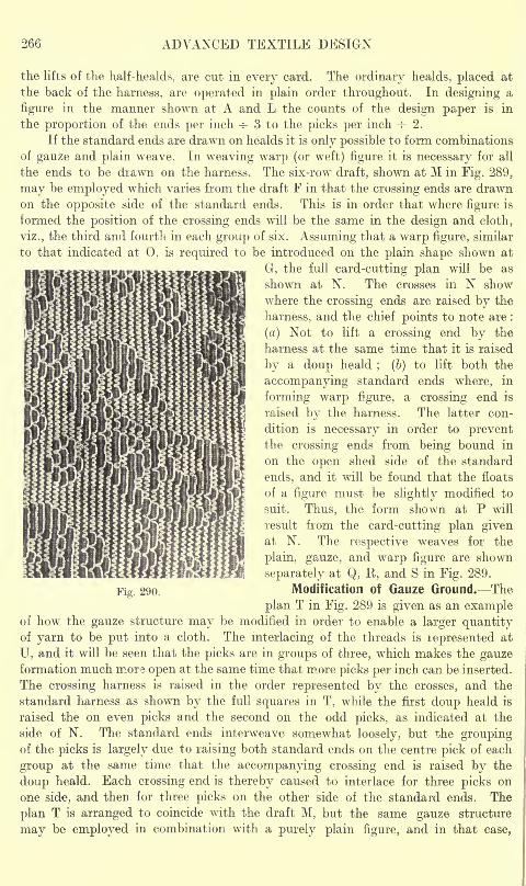
266 ADVANCED TEXTILE DESIGN
the lifts of the half-healds, are cut in every card. The ordinary healds, placed at
the back of the harness, are operated in plain order throughout. In designing a
figure in the manner shown at A and L the counts of the design paper is in
the proportion of the ends per inch -=- 3 to the picks per inch -=- 2.
If the standard ends are drawn on healds it is only possible to form combinations
of gauze and plain weave. In weaving warp (or weft) figure it is necessary for all
the ends to be drawn on the harness. The six-row draft, shown at M in Fig. 289,
may be employed w^hich varies from the draft F in that the crossing ends are drawnon the opposite side of the standard ends. This is in order that where figure is
formed the position of the crossing ends will be the same in the design and cloth,
viz., the third and fourth in each group of six. Assuming that a warp figure, similar
to that indicated at 0, is required to be introduced on the plain shape shown at
G, the full card-cutting plan will be as
shown at N. The crosses in N show
where the crossing ends are raised by the
harness, and the chief points to note are :
(a) Not to lift a crossing end by the
harness at the same time that it is raised
by a doup heald; (b) to lift both the
accompanying standard ends where, in
forming warp figure, a crossing end is
raised by the harness. The latter con-
dition is necessary in order to preventthe crossing ends from being bound in
on the open shed side of the standard
ends, and it will be found that the floats
of a figure must be slightly modified to
suit. Thus, the form shown at P will
result from the card-cutting plan givenat N. The respective weaves for the
plain, gauze, and warp figure are shown
separately at Q, R, and S in Fig. 289.
Modification of Gauze Ground. The
plan T in Fig. 289 is given as an exampleof how the gauze structure may be modified in order to enable a larger quantityof yarn to be put into a cloth. The interlacing of the threads is lepresented at
U, and it will be seen that the picks are in groups of three, which makes the gauzeformation much more open at the same time that more picks per inch can be inserted.
The crossing harness is raised in the order represented by the crosses, and the
standard harness as shown by the full squares in T, while the first doup heald is
raised the on even picks and the second on the odd picks, as indicated at the
side of N. The standard ends interweave somewhat loosely, but the groupingof the picks is largely due to raising both standard ends on the centre pick of each
group at the same time that the accompanying crossing end is raised by the
doup heald. Each crossing end is thereby caused to interlace for three picks on
one side, and then for three picks on the other side of the standard ends. The
plan T is arranged to coincide with the draft M, but the same gauze structure
may be employed in combination with a purely plain figure, and in that case,
Fig. 290.
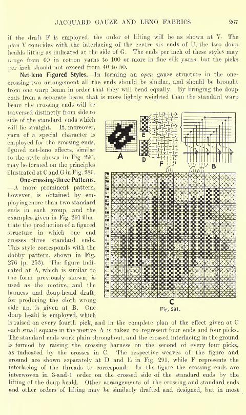
JACQUARD GAUZE AND LENO FABRICS 267
if the draft F is employed, the order of lifting will be as shown at V- The
plan V coincides with the interlacing of the centre six ends of U, the two douphealds lifting as indicated at the side of G. The ends per inch of these styles mayrange from 60 in cotton yarns to 100 or more in fine silk yarns, but the picks
per inch should not exceed from 40 to 50.
Net-leno Figured Styles. In forming an open gauze structure in the one-
crossing-two arrangement all the ends should be similar, and should be brought
from one warp beam in order that they will bend equally. By bringing the doupends from a separate beam that is more lightly weighted than the standard warpbeam the crossing ends will be
traversed distinctly from side to
side of the standard ends which
will lie straight. If, moreover,
yarn of a special character is
employed for the crossing ends,
figured net-leno effects, similar
to the style shown in Fig. 290,
may be formed on the principles
illustrated at C and G in Fig. 289.
One-crossing-three Patterns.
A more prominent pattern,
however, is obtained by em-
ploying more than two standard
ends in each group, and the
examples given in Fig. 291 illus-
trate the production of a figured
structure in which one end
crosses three standard ends.
This style corresponds with the
dobby pattern, shown in Fig.
276 (p. 253). The figure indi-
cated at A, which is similar to
the form previously shown, is
used as the motive, and the
harness and doup-heald draft,
for producing the cloth wrongside up, is given at B. One
doup heald is employed, which
is raised on every fourth pick, and in the complete plan of the effect given at Ceach small square in the motive A is taken to represent four ends and four picks.
The standard ends work plain throughout, and the crossed interlacing in the groundis formed by raising the crossing harness on the second of every four picks,
as indicated by the crosses in C. The respective weaves of the figure and
ground are shown separately at D and E in Fig. 291, while F represents the
interlacing of the threads to correspond. In the figure the crossing ends are
interwoven in 3-and-l order on the crossed side of the standard ends by the
lifting of the doup heald. Other arrangements of the crossing and standard ends
and other orders of lifting may be similarly drafted and designed, but in most
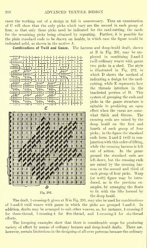
-268 ADVANCED TEXTILE DESIGN
I'l-i^i i i
y l''|| L|_IJ_L|. !_|_
~ f" ' ^ '
cases the working out of a design in full is unnecessary. Thus an examination
of C will show that the only picks which vary are the second in each group of
four, so that only these picks need be indicated for the card-cutting, the cards
for the remaining picks being obtained by repeating. Further, it is possible for
the plain standard ends to be drawn on healds, in which case the figure would be
indicated solid, as shown in the motive A.
Combinations of Twill and Gauze.- The harness and doup-heald draft, shown
at B in Fig. 291, may be ejn-
ployed in combining 2-and-2
twill ordinary weave with gauzetwo picks in a shed. The style
is illustrated in Fig. 292, in
which D shows the method of
indicating a design for the card-
cutting, while E represents howthe threads interlace in the
bracketed portion of D. -This
system of grouping the ends and
picks in the gauze structure is
suitable in producing an openeffect when the yarns are some-
what thick and fibrous. The
crossing ends are raised by the
doup heald on the first and
fourth of each group of four
picks ;in the figure the standard
ends form 2-and-2 twill in con-
junctionwith this order of lifting,
while the crossing harness is left
out of action. In the gauze
ground the standard ends are
left down, but the crossing ends
are raised by the crossing har-
ness on the second and third of
each group of four picks. Warp(or weft) figure may be intro-
duced, as in the previous ex-
amples, by arranging the floats
to fit with the lifts formed bythe doup heald.
The draft, l-crossing-3, given at B in Fig. 291, may also be used for combinations
of l-and-3 twill weave with gauze in which the picks are grouped l-and-3. In
addition, drafts may be arranged to suit other weaves, as, for instance, l-crossing-2
for three-thread, l-crossing-4 for five-thread, and l-crossing-5 for six-thread
effects.
The foregoing examples show that there is considerable scope for producing
variety of effect by means of ordinary harness and doup-heald drafts. There are,
however, certain limitations in the designing of all-over patterns because the ordinary
I??*"! 738588" 88* 85" ?8S5*S5SSS" 88" 88" BBT ?S8S"S8S
DFig. 292.
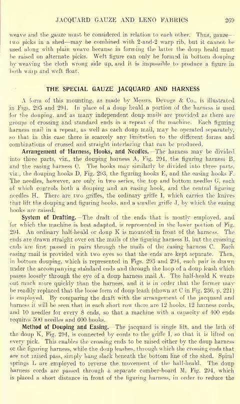
JACQUARD GAUZE AND LENO FABRICS
weave and the gauze must be considered in relation to each other. Thus, gauzetwo picks in a shed may be combined with 2-and-2 warp rib, but it cannot be
used along with plain wreave because in forming the lattei the doup heald must
be raised on alternate picks. Weft figure can only be formed in bottom douping
by weaving the cloth wrong side up, and it is impossible to produce a figure in
both waip and weft float.
THE SPECIAL GAUZE JACQUARD AND HARNESS
A form of this mounting, as made by Messrs. Devoge & Co., is illustrated
in Figs. 293 and 294. In place of a doup heald a portion of the harness is used
for the douping, and as many independent doup mails are provided as there are
groups of crossing and standard ends in a repeat of the machine. Each figuring
harness mail in a repeat, as well as each doup mail, may be operated separately,
so that in this case there is scarcely any limitation to the different forms and
combinations of crossed and straight interlacing that can be produced.
Arrangement of Harness, Hooks, and Needles. The harness may be divided
into three parts, viz., the douping harness A, Fig. 294, the figuring harness B,
and the easing harness C. The hooks may similarly be divided into three parts,
viz., the douping hooks D, Fig. 293, the figuring hooks E, and the easing hooks F.
The needles, however, are only in two series, the top and bottom needles G, each
of which controls both a douping and an easing hook, and the central figuring
needles H. There are two griffes, the ordinary griffe I, which carries the knives
that lift the douping and figuring hooks, and a smaller griffe J, by which the easing
hooks are raised.
System of Drafting. The draft of the ends that is mostly employed, and
for which the machine is best adapted, is represented in the lower portion of Fig.
294. An ordinary half-heald or doup K is mounted in front of the harness. Theends are drawn straight over on the mails of the figuring harness B, but the crossing-
ends are first passed in pairs through the mails of the easing harness C. Each
easing mail is provided with two eyes so that the ends are kept separate. Then,in bottom douping, which is represented in Figs. 293 and 294, each pair is drawn
under the accompanying standard ends and through the loop of a doup leash which
passes loosely through the eye of a doup harness mail A. The half-heald K wears
out much more quickly than the harness, and it is in order that the former maybe readily replaced that the loose form of doup leash (shown at C in Fig. 236, p. 221)
is employed. By comparing the draft with the arrangement of the jacquard and
harness it will be seen that in each short row there are 12 hooks, 12 harness cords,
and 10 needles for every 8 ends, so that a machine with a capacity of 400 ends
requires 500 needles and 600 hooks.
Method of Douping and Easing. The jacquard is single lilt, and the lath of
the doup K, Fig. 294, is connected by cords to the griffe I, so that it is lifted on
every pick. This enables the crossing ends to be raised either by the doup harness
or the figuring harness, while the doup leashes, through which the crossing ends that
are not raised pass, simply hang slack beneath the bottom line of the shed. Spiral
springs L are employed to reverse the movement of the half-heald. The doupharness cords are passed through a separate comber-board M, Fig. 294, which
is placed a short distance in front of the figuring harness, in order to reduce the
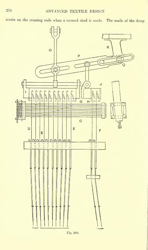
270 ADVANCED TEXTILE DESIGN
strain on the crossing ends when a crossed shed is made. The mails of the doup
Fig. 293.
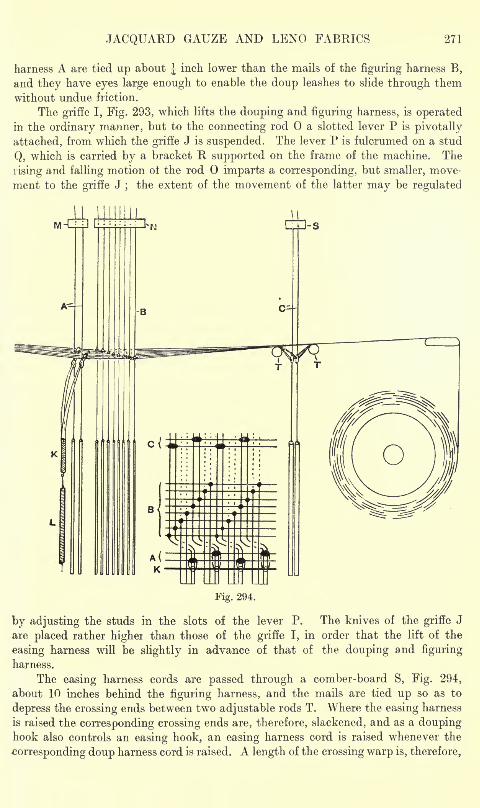
JACQUARD GAUZE AND LEND FABRICS 271
harness A are tied up about J inch lower than the mails of the figuring harness B,
and they have eyes large enough to enable the doup leashes to slide through them
without undue friction.
The grifTe I, Fig. 293, which lifts the douping and figuring harness, is operatedin the ordinary manner, but to the connecting rod a slotted lever P is pivotally
attached, from which the grifTe J is suspended. The lever P is fulcrumed on a stud
Q, which is carried by a bracket R supported on the frame of the machine. The
rising and falling motion of the rod imparts a corresponding, bub smaller, move-
ment to the grifTe J;
the extent of the movement of the latter may be regulated
M
A--
J-S
Fig. 294.
by adjusting the studs in the slots of the lever P. The knives of the grifTe J
are placed rather higher than those of the grifTe I, in order that the lift of the
easing harness will be slightly in advance of that of the douping and figuring
harness.
The easing harness cords are passed through a comber-board S, Fig. 294,
about 10 inches behind the figuring harness, and the mails are tied up so as to
depress the crossing ends between two adjustable rods T. Where the easing harness
is raised the corresponding crossing ends are, therefore, slackened, and as a doupinghook also controls an easing hook, an easing harness cord is raised whenever the
corresponding doup harness cord is raised. A length of the crossing warp is, therefore,
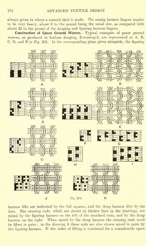
272 ADVANCED TEXTILE DESIGN
always given in where a crossed shed is made. The easing harness lingoes requireto be very heavy, about 8 to the pound being the usual size, as compared with
about 25 to the pound of the douping and figuring harness lingoes.
Construction of Gauze Ground Weaves. Typical examples of gauze ground
weaves, as produced in bottom douping, 2-crossing-2, are represented at A, B,
C, D, and E in Fig. 295. In the corresponding plans given alongside, the figuring
K *fcffi=HSk>8
rp-fffl=ff^MNS- -==
yK-suK..=Sz-
J Fig. 295. K
harness lifts are indicated by the full squares, and the doup harness lifts by the
dots. The crossing ends, which are shown in thicker lines in the drawings, are
raised by the figuring harness on the left of the standard ends, and by the doupharness on the right. When raised by the doup harness the crossing ends must 1
be lifted in pairs ;in the drawing A these ends are also shown raised in pairs by
the figuring harness. If this order of lifting is continued for a considerable space
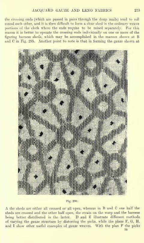
JACQUARD GAUZE AND LENO FABRICS 273
the crossing ends (which are passed in pairs through the doup mails) tend to roll
round each other, and it is then difficult to form a clear shed in the ordinary weave
portions of the cloth where the ends require to be raised separately. For this
reason it is better to operate the crossing ends individually on one or more of the
figuring harness sheds, which may be accomplished in the manner shown at Band C in Fig. 295. Another point to note is that in forming the gauze shown at
Fig. 296.
A the sheds are either all crossed or all open, whereas in B and C one half the
sheds are crossed and the other half open, the strain on the warp and the harness
being better distributed in the latter. D and E illustrate different methods
of varying the gauze structure by distorting the picks, while the plans F, G, H,
and I show other useful examples of gauze weaves. With the plan F the picks18
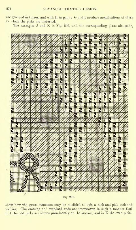
274 ADVANCED TEXTILE DESIGN
are grouped in threes, and with H in pairs ;G and I produce modifications of these
in which the picks are distorted.
The examples J and K in Fig. 295, and the corresponding plans alongside.
Fig. 297.
show how the gauze structure may be modified to suit a pick-and-pick order of
wefting. The crossing and standard ends are interwoven in such a manner that
in J the odd picks are .shown prominently on the surface, and in K the even picks.
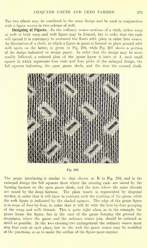
JACQUAED GAUZE AND LENO FABRICS 275
The two effects may be combined in the same design and be used in conjunctionwith a figure woven in two colours of weft.
Designing of Figures. In the ordinary weave sections of a cloth, either warpor weft or both warp and weft figure may be formed, but in order that the ends
will spread it is customary to surround the floats with plain or other firm weave.
An illustration of a cloth, in which a figure in gauze is formed on plain ground with
weft spots on the latter, is given in Fig. 296, while Fig. 297 shows a portionof the design indicated on design paper. In order that the design may be more
readily followed, a reduced plan of the gauze figure is inset at A, each small
square in which represents four ends and four picks of the enlarged design, the
full squares indicating the open gauze sheds, and the dots the crossed sheds.
Fig. 298.
The gauze interlacing is similar to that shown at B in Fig. 295, and in the
enlarged design the full squares show where the crossing ends are raised by the
figuring harness on the open gauze sheds, and the dots where the same threads
are raised by the doup harness. The plain weave is represented by diagonal
strokes, in order that it will show in contrast with the marking of the gauze, while
the weft figure is indicated by the shaded squares. The edge of the gauze figureis in steps of four-by-four, in order that it will fit with the four-by-four groupingof the warp and weft threads. This is quite right when, as in the example, the
gauze forms the figure, but in the case of the gauze forming the ground the
steppiness, where the gauze and the ordinary weave join, should be reduced as
much as possible. In the fcwo-crossing-two arrangement the ordinary weave must
step four ends at each plac&, but in the weft the gauze weave may be modified
at the junctions, so as to make the outline of the figure more regular.
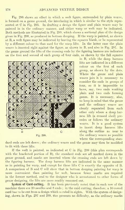
276 ADVANCED TEXTILE DESIGN
Fig. 298 shows an effect in which a weft figure, surrounded by plain weave,
is formed on a gauze ground, the interlacing in which is similar to the style repre-
sented at C in Fig. 295. In drafting a design the figure and plain weave may be
painted in in the ordinary manner, and either warp or weft may be indicated.
Both methods are illustrated in Fig. 299, which shows a sectional plan of the design
given in Fig. 298, as produced in bottom douping. If the warp is painted, as shown
at B, a weft figure may be indicated by leaving the squares blank, or be represented
by a different colour to that used for the warp lifts. In the latter case the plain
weave is inserted right against the figure, as shown in B, and also in Fig. 297. In
the gauze ground the lifts of the crossing ends by the figuring harness are indicated
on the first and second of each group of four ends, as shown by the full squaresin B, while the doup harness
lifts are indicated in a different
colour on the first of each
group, as shown by the dots.
Where the gauze and plain
weave join it is necessary to
consider the ends in groups of
four, as it is impossible to
have, say, two ends working
plain and two ends forming-
gauze. It is necessary, also,
to keep in mind that the gauzeand the ordinary weave are
clearly separated from each
other only where a doup har-
ness lift (a crossed shed) pre-
cedes or follows the ordinaryweave. It is a good systemto insert doup harness lifts
along the outline as near to
Fig. 299. the ordinary weave as possible
where the corresponding stan-
dard ends are left down;the oidinary weave and the gauze may then be modified
to fit with these lifts.
If the weft is painted, as indicated at C in Fig. 299 (this plan correspondswith the bracketed portion of B), the standard ends are all marked down in the
gauze ground, and marks are inserted where the crossing ends are left down bythe figuring harness. The doup harness lifts are indicated in the same manneras in painting for warp, and except for these lifts C is exactly the opposite of B.
A comparison of B and C will show that in bottom douping painting for warp is
more convenient than painting for weft, because fewer marks are requiredin the former method, and to the designer who is accustomed to other forms of
gauze designing, the lifts are more readily reasoned out.
System of Card-cutting.^It has been previously noted that in each row of the
machine there are 10 needles and 8 ends;
in the card-cutting, therefore, a 10-rowed
card has to be cut from a design which is ruled in eights. With the system of design-
ing, shown in Figs. 297 and 299, this presents no dilficulty, as the ordinary marks
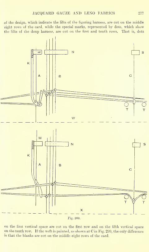
JACQUARD GAUZE AND LENO FABRICS 277
of the design, which indicate the lifts of the figuring harness, are cut on the middle
eight rows of the card, while the special marks, represented by dots, which show
the lifts of the doup harness, are cut on the first and tenth rows. That is, dots
!
Fig. 300.
on the first vertical space are cut on the first row and on the fifth vertical spaceon the tenth row. If the weft is painted, as shown at C in Fig. 299, the only difference
is that the blanks are cut on the middle eight rows of the card.
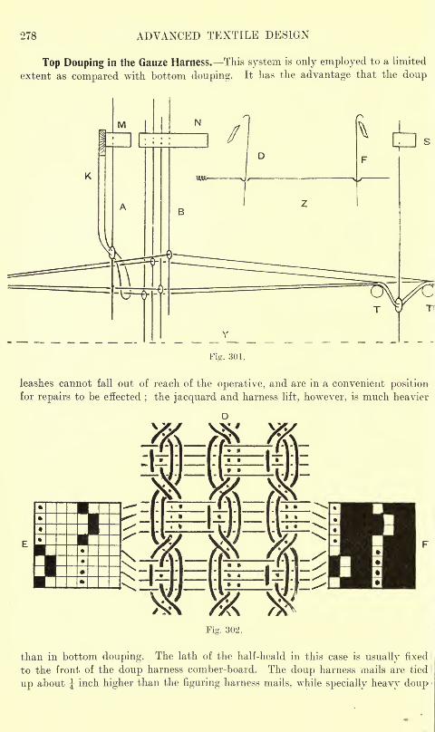
278 ADVANCED TEXTILE DESIGN
Top Douping in the Gauze Harness. This system is only employed to a limited
extent as compared with bottom douping. It has the advantage that the doup
Fig. 301.
leashes cannot fall out of reach of the operative, and are in a convenient positionfor repairs to be effected
;the jacquard and harness lift, however, is much heavier
than in bottom douping. The lath of the half-heald in this case is usually fixed
to the front of the doup harness comber-board. The doup harness mails are tied
up about J inch higher than the figuring harness mails, while specially heavy doup
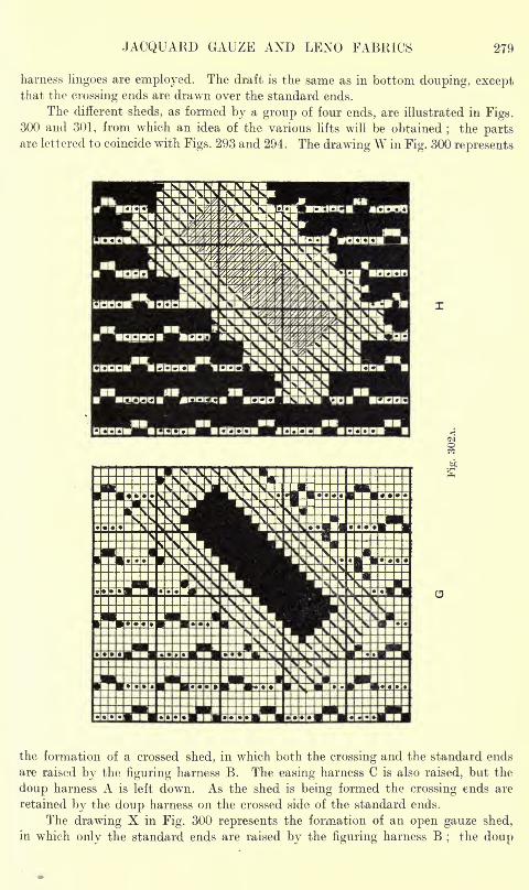
JACQUARD GAUZE AND LEND FABRICS 279
harness lingoes are employed. The draft is the same as in bottom douping, exceptthat the crossing ends are drawn over the standard ends.
The different sheds, as formed by a group of four ends, are illustrated in Figs.300 and 301, from which an idea of the various lifts will be obtained
;the parts
are lettered to coincide with Figs. 293 and 294. The drawing W in Fig. 300 represents
wti.
the formation of a crossed shed, in which both the crossing and the standard ends
are raised by the figuring harness B. The easing harness C is also raised, but the
cloup harness A is left down. As the shed is being formed the crossing ends are
retained by the doup harness on the crossed side of the standard ends.
The drawing X in Fig. 300 represents the formation of an open gauze shed,
in which only the standard ends are raised by the figuring harness B;
the doup
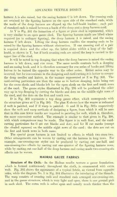
280 ADVANCED TEXTILE DESIGN
harness A is also raised, but the easing harness C is left down. The crossing ends
are retained by the figuring harness on the open side of the standard ends, while
the mails of the doup harness are slipped up the half-heald leashes;
each pair
of standard ends is raised between a leash of the doup and a doup harness cord.
At Y in Fig. 301 the formation of a figure or plain shed is represented, which
is very similar to an open gauze shed. The figuring harness mails are lifted where
required (as in ordinary figuring), the doup harness A is raised, and the easing
harness C left down. Lifting the doup harness enables the crossing ends to be
raised by the figuring harness without obstruction. If one crossing end of a pair
is required down and the other up, the latter slides within a loop of the half-
heald, as shown in Y, but if both crossing ends are raised the loop is carried to the
upper line of the shed.
It will be noted in top douping that when the doup harness is raised the easing
harness is left down, and vice versa. The same needle controls both a doupingand an easing hook, and it is therefore necessary for one series of hook? and lifting
knives to be turned the opposite way to the other series. Either series may be
inverted, but for convenience in the designing and card-cutting it is better to reverse
the doup needles and knives, in the manner represented at Z in Fig. 301. The
card-cutting particulars are then the same as in bottom douping, holes being cut
for the cross sheds, and blanks left for the open sheds on the first and tenth rows
of the card. The gauze styles illustrated in Fig. 295 will be produced the other
way up in top douping by cutting the blanks and dots on the middle eight rows of
the card, and the dots on the first and tenth row.
D in Fig. 302 represents a top doup gauze effect, which corresponds with
the structure given at C in Fig. 295. The plan E shows how the weave is indicated
if weft is painted, and F if warp is painted. G and H in Fig. 302A respectively
show the weft and warp methods of designing a figure, from which it will be seen
that in this case fewer marks are required in painting for weft, which is, therefore,
the more convenient method. The example is similar to that given in Fig. 299,
with which comparisons may be made. The figure is in weft float, and the card-
cutting particulars for G are cut blanks and dots, and for H cut marks (except
the shaded squares) on the middle eight rows of the card;the dots are cut on
the first and tenth rows in both cases.
The special gauze harness is not limited to effects in which two cross two.
Other arrangements can be woven by casting out the harness in long rows. For
example, one-crossing-one styles can be produced by casting out one-half, and
one-crossing-two effects by casting out one-quarter of the figuring harness rows,
while by casting out one-half of the doup harness and easing mails two-crossing-six
effects can be woven.
MADRAS GAUZE FABRICS
Structure Of the Cloth. In the Madras muslin texture a gauze foundation,
which is formed continuously throughout the cloth, is ornamented with extra
weft. Fig. 303 shows the appearance of a typical fabric, as viewed from opposite
sides, while the diagram No. 1 in Fig. 304 illustrates the interlacing of the threads.
The warp consists of crossing ends and standard ends arranged one-crossing-one,
and in the gauze structure, which is very light and open, there is one ground pickin each shed. The extra weft is softer spun and usually much thicker than the
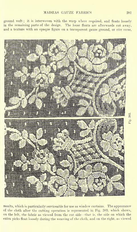
MADRAS GAUZE FABRICS 281
ground weft;
it is interwoven with the warp where required, and floats looselyin the remaining parts of the design. The loose floats are afterwards cut away,and a texture with an opaque figure on a transparent gauze ground, or vice versa,
results, which is particularly serviceable for use as window curtains. The appearanceof the cloth after the cutting operation is represented in Fig. 303, which shows,
on the left, the fabric as viewed from the cut side that is, the side on which the
extra picks float loosely during the weaving of the cloth, and on the right, as viewed
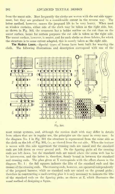
282 ADVANCED TEXTILE DESIGN
from the uncut side. Most frequently the cloths are woven with the cut side upper-
most, but they are produced to a considerable extent in the reverse way. The
latter method, however, causes the jacquard lift to be very heavy. When used
as window curtains, either side of the cloth may be taken as the right side, but,
as shown in Fig. 303, the ornament has a bolder outline on the cut than on the
uncut surface, hence for certain purposes the cut side is taken as the right side.
The uncut surface, however, is neater, and for such cloths as dress fabrics, for which
the structure is to some extent adapted, this is mostly taken as the right side.
The Madras Loom. Special types of looms have been built for weaving the
cloth. The following illustrations and description correspond with one of the
*:\ :\ \ :
U4EOT
Fig. 304.
most recent systems, and, although the motion dealt with may differ in details
from others that are in regular use, the principles are the same in every case. In
the diagram No. 1 in Fig. 304 the structure is represented from the same side as
the cloth on the left of Fig. 303, i.e., as viewed from the cut side. When the texture
is woven with this side uppermost the crossing ends are raised and the standard
ends are left down on every ground pick. On the figuring picks all the crossing
ends are left down, but the standard ends are raised where the extra weft has to
be interwoven, and the latter is, therefore, firmly bound in between the standard
and crossing ends. The plan given at Y corresponds with the effect shown in the
diagram No. 1;
the full squares indicate the lifts of the standard ends and the
crosses of the crossing ends. The crossing ends, however, are operated independentlyof the jacquard harness, while no standard ends are raised on the ground picks ;
therefore in constructing a card-cutting plan it is only necessary to indicate the lifts
of the standard ends on the figuring picks, as shown at Z, which illustrates the
usual method of designing a figure.
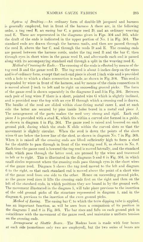
MADRAS GAUZE FABRICS 283
System of Drafting. An ordinary form of double-lift jacquard and harness
is generally employed, but in front of the harness A there are, in the following
order, a tug reed B, an easing bar C, a gauze reed D, and an ordinary weavingreed E. These are represented in the diagrams given in Figs. 304 and 305, while
the draft of the ends is indicated in the upper portion of No. 1 in Fig. 304. Thestandard ends are drawn through the harness mails, and then are passed throughthe reed B, above the bar C, and through the reeds D and E. The crossing ends
are passed between the harness cords, under the tug reed B and the bar C, then
through eyes in short wires in the gauze reed D, and afterwards each end is passed
along with its accompanying standard end through a split in the weaving reed E.
Method of Crossing the Ends. The crossing of the ends is effected by means of the
tug reed B and the gauze reed D. The tug reed is about 5 inches deep on the wires
and is of ordinary form, except that each end piece is about 1 inch wide and is providedwith a hole to which a chain connection is made, as shown in Fig. 306. This reed is
suspended by wires in front of the harness, and by means of the chain connections it
is moved about f inch to left and to right on succeeding ground picks. The form
of the gauze reed is shown separately in the diagrams 2 and 3 in Fig. 304. Between
each pair of long wires F there is a short, pointed wire G which is slightly inclined,
and is provided near the top with an eye H through which a crossing end is drawn.
The baulks of the reed are slided within close-fitting metal cases I, and at each
side the latter are secured by pins inside holes bored in a metal end piece J.
The arrangement of the parts makes the reed very strong and rigid. Each end
piece J is provided with a stud K, which fits within a curved slot formed in a guide,
as shown in diagram 4 in Fig. 304. The gauze reed is raised and lowered on each
ground pick, during which the studs K slide within the curved slots so that the
movement is slightly circular. When the reed is down the points of the short
wires G are below the lower line of the shed, as shown in diagram No. 7 in Fig. 305.
When it is raised all the crossing ends are lifted sufficiently high to form a shed
for the shuttle to pass through in front of the weaving reed E, as shown in No. 8.
Each time the gauze reed is lowered the tug reed is moved laterally, and the standard
ends, which pass through the latter reed, are pressed by the wires and traversed
to left or to right. This is illustrated in the diagrams 5 and 6 in Fig. 304, in which
small circles represent where the crossing ends pass through eyes in the short wires
of the gauze reed. Diagram 5 shows the tug reed moved to the left and diagram6 to the right, so that each standard end is moved above the point of a short wire
of the gauze reed from one side to the other. Hence on succeeding ground picks,
as the gauze reed rises it lifts the crossing ends first on the right and then on the
left of the standard ends, in which positions they are bound in by the ground weft.
The movement illustrated in the diagram 5, will take place previous to the insertion
of the odd ground picks of the structure represented in diagram 1, and in the
diagram 6, previous to the insertion of the even ground picks.
Method of Easing. The easing bar C, to which the term dipping tube is applied,
has an important function, as will be seen from a comparison of its position in
the diagrams 7 and 8 in Fig. 305. The bar rises and falls on each ground pick in
coincidence with the movement of the gauze reed, and maintains a uniform tension
on the crossing ends.
Arrangement of Shuttle Boxes.- The Madras loom is made with four boxes
at each side (sometimes only two are employed), but the two series of boxes are
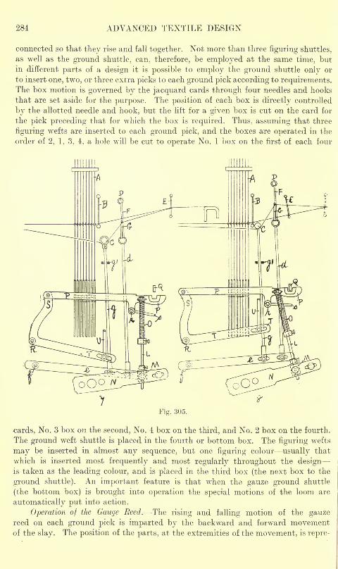
284 ADVANCED TEXTILE DESIGN
connected so that they rise and fall together. Not more than three figuring shuttles,
as well as the ground shuttle, can, therefore, be employed at the same time, but
in different parts of a design it is possible to employ the ground shuttle only or
to insert one, two, or three extra picks to each ground pick according to requirements.The box motion is governed by the jacquard cards through four needles and hooks
that are set aside for the purpose. The position of each box is directly controlled
by the allotted needle and hook, but the lift for a given box is cut on the card for
the pick preceding that for which the box is required. Thus, assuming that three
figuring wefts are inserted to each ground pick, and the boxes are operated in the
order of 2, 1, 3, 4, a hole will be cut to operate No. 1 box on the first of each four
Fig. 305.
cards, No. 3 box on the second, No. 4 box on the third, and No. 2 box on the fourth.
The ground weft shuttle is placed in the fourth or bottom box. The figuring wefts
may be inserted in almost any sequence, but one figuring colour usually that
which is inserted most frequently and most regularly throughout the designis taken as the leading colour, and is placed in the third box (the next box to the
ground shuttle). An important feature is that when the gauze ground shuttle
(the bottom box) is brought into operation the special motions of the loom are
automatically put into action.
Operation of the Gauge Reed. The rising and falling motion of the gauzereed on each ground pick is imparted by the backward and forward movementof the slay. The position of the parts, at the extremities of the movement, is repre-
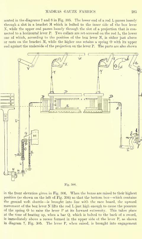
MADRAS GAUZE FABRICS 285
sented in the diagrams 7 and 8 in Fig. 305. The lower end of a rod L passes loosely
through a slot in a bracket M which is bolted to the inner side of the box lever
N, while the upper end passes loosely through the slot of a projection that is con-
nected to a horizontal lever P. Two collars are set-screwed on the rod L, the lower
one of which, according to the position of the box lever N, is either just above
or rests on the bracket M, while the higher one retains a spring with its upperend against the underside of the projection on the lever P. The parts are also shown
Fig. 306.
in the front elevation given in Fig. 306. When the boxes are raised to their highest
position (as shown on the left of Fig. 306) so that the bottom box which contains
the ground weft shuttle is brought into line with the race board, the upwardmovement of the box lever N lifts the rod L just high enough to cause the pressureof the spring to raise the lever P at its forward extremity. This takes placeat the time of beating up, when a bar Q, which is bolted to the back of a sword,is immediately above a recess formed in the upper side ot the lever P, as shownin diagram 7, Fig. 305. The lever P, when raised, is brought into engagement
286 ADVANCED TEXTILE DESIGN
with the bar Q, as shown in diagram 8, and as the latter moves backward andforward with the sword, a similar movement is imparted to the lever P. A bell-
crank lever, which is fulcrumed on a stud R, has its upper arm S pivotally connected
to the rear of the lever P, hence the movement of the latter causes the forward
end of the lower arm T to rise and fall. This movement, by means of a rod U,is imparted to the lower arm of a bell-crank lever V (shown in Fig. 306), the upperarm of which transmits a motion to right and to left alternately to a horizontal
bar W. The lateral movement of the bar W, through the segment levers X, andthe chain connections Y, causes the gauze reed to rise and fall
;and this takes
place with each backward and forward movement of the sword so long as the gauze
ground weft only is inserted. On the insertion of a figuring pick, however, the
the lowering of the box lever N releases the pressure of the spring against the
projection on the lever P, the forward end of which then falls out of engagementwith the bar Q, as shown in the diagram 7. The gauze reed then remains in its
lowered position while the required number of figuring picks is inserted. The distance
that the gauze reed rises and falls can be adjusted by altering the leverage ;it
is prevented from falling too far by the upper arm of a bell-crank lever a, Fig. 306,
coming in contact with a stud b carried by an adjustable bracket c. The latter
is set so as to allow the horizontal bar w to move the necessary distance before
it is checked.
Operation of the Easing Bar. A connection is made from each end piece of
the gauze reed by means of a rod d to a lever e which is fulcrumed on a stud/, as
shown in the diagrams 7 and 8 in Fig. 305. A rod g, which passes between the
forks of a guide gl
,connects each lever e with an end of the easing bar C. The
latter, therefore, through the levers e, receives a rising and falling motion which
coincide with the movement of the gauze reed. Slots are provided in the levers e
in order that the extent of the movement may be regulated.
Operation of the Tug Reed. The lateral movement of the tug reed is obtained
from the same source as the vertical movement of the gauze reed. The lower armof the bell-crank lever a (shown on the right of Fig. 306) is connected by means of
a rod h, with a stud i, on which a catch j is fulcrumed. The catch j engages the
teeth of a six-sided star wheel k on the face of which there is a cam I that has three
projections and three recesses arranged alternately. The cam I engages an anti-
friction bowl m which is carried by the upper arm of a lever n, the lower arm of
which, through a chain passing over a guide pulley o, is connected with one end
of the tug reed B. At the opposite side of the tug reed a similar connection is madeto a spiral spring p, the tension of which retains the bowl m in constant contact
with the face of the cam I. At each downward movement of the gauze reed (whichfollows the insertion of a ground pick) the lower arm of the lever a is raised and
the catch j turns the star wheel k one-sixth of a revolution. At one movementthe anti-friction bowl m is engaged by a projection on the cam I so that it is pressed
back, as shown in Fig. 306, the tug reed being thus drawn to the right againstthe tension of the spring p. At the next movement the bowl m enters a recess
in the cam I when the tension of the spring p causes the tug reed to move to the
left. The direction of the movement is the same as that of the preceding ground I
pick. (In an older motion, in place of the tug reed, a horizontal reed or ravel is
employed, and between each pair of wires a short row of harness cords is passed.The comber-board is placed well above the ravel, and the latter is given a latitudinal
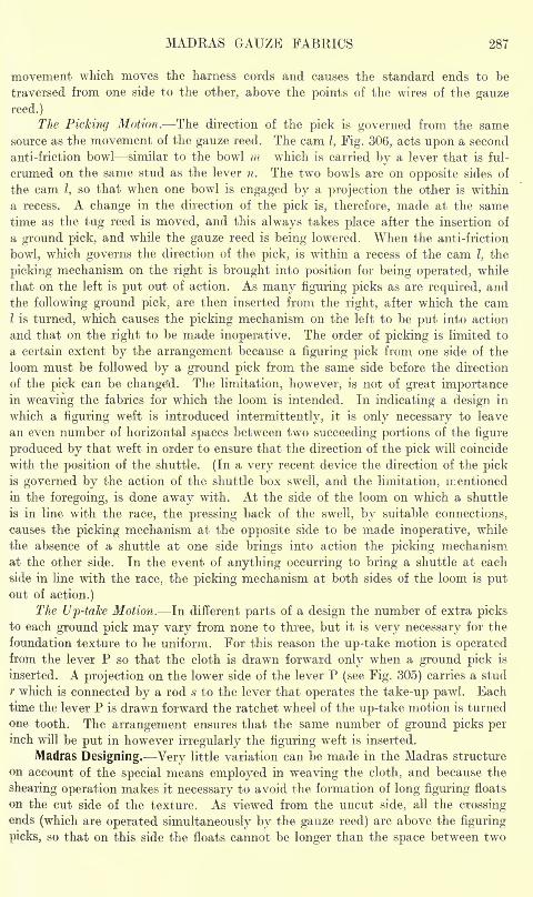
MADRAS GAUZE FABRICS 287
movement which moves the harness cords and causes the standard ends to be
traversed from one side to the other, above the points of the wires of the gauze
reed.)
The Picking Motion. The direction of the pick is governed from the same
source as the movement of the gauze reed. The cam I, Fig. 306, acts upon a second
anti-friction bowl similar to the bowl m which is carried by a lever that is ful-
crumed on the same stud as the lever n. The two bowls are on opposite sides of
the cam I, so that when one bowl is engaged by a projection the other is within
a recess. A change in the direction of the pick is, therefore, made at the same
time as the tug reed is moved, and this always takes place after the insertion of
a ground pick, and while the gauze reed is being lowered. When the anti-friction
bowl, which governs the direction of the pick, is within a recess of the cam I, the
picking mechanism on the right is brought into position for being operated, while
that on the left is put out of action. As many figuring picks as are required, and
the following ground pick, are then inserted from the right, after which the camI is turned, which causes the picking mechanism on the left to be put into action
and that on the right to be made inoperative. The order of picking is limited to
a certain extent by the arrangement because a figuring pick from one side of the
loom must be followed by a ground pick from the same side before the direction
of the pick can be changed. The limitation, however, is not of great importancein weaving the fabrics for which the loom is intended. In indicating a design in
which a figuring weft is introduced intermittently, it is only necessary to leave
an even number of horizontal spaces between two succeeding portions of the figure
produced by that weft in order to ensure that the direction of the pick will coincide
with the position of the shuttle. (In a very recent device the direction of the pickis governed by the action of the shuttle box swell, and the limitation, mentioned
in the foregoing, is done away with. At the side of the loom on which a shuttle
is in line with the race, the pressing back of the swell, by suitable connections,
causes the picking mechanism at the opposite side to be made inoperative, while
the absence of a shuttle at one side brings into action the picking mechanism
at the other side. In the event of anything occurring to bring a shuttle at each
side in line with the race, the picking mechanism at both sides of the loom is putout of action.)
The Up-take Motion. In different parts of a design the number of extra picksto each ground pick may vary from none to three, but it is very necessary for the
foundation texture to be uniform. For this reason the up-take motion is operatedfrom the lever P so that the cloth is drawn forward only when a ground pick is
inserted. A projection on the lower side of the lever P (see Fig. 305) carries a stud
r which is connected by a rod s to the lever that operates the take-up pawl. Eachtime the lever P is drawn forward the ratchet wheel of the up-take motion is turned
one tooth. The arrangement ensures that the same number of ground picks perinch will be put in however irregularly the figuring weft is inserted.
Madras Designing. Very little variation can be made in the Madras structure
on account of the special means employed in weaving the cloth, and because the
shearing operation makes it necessary to avoid the formation of long figuring floats
on the cut side of the texture. As viewed from the uncut side, all the crossingends (which are operated simultaneously by the gauze reed) are above the figuring
picks, so that on this side the floats cannot be longer than the space between two
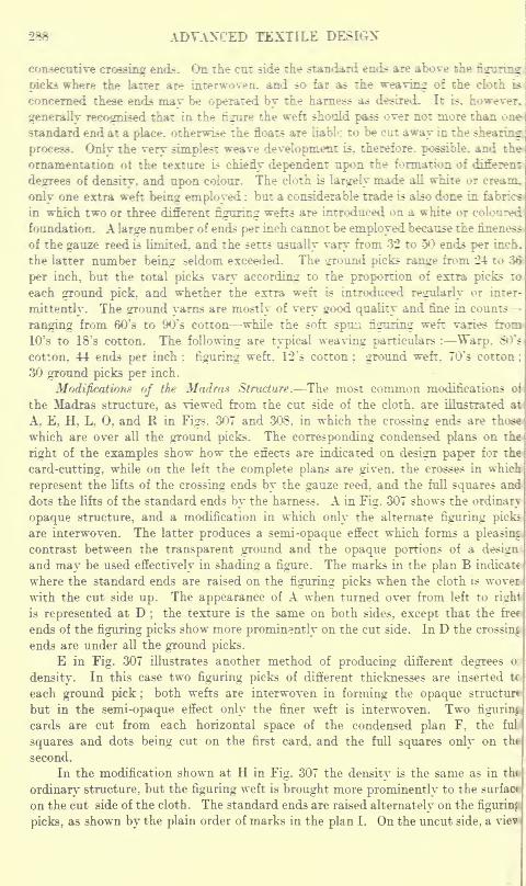
288 ADVANCED TEXTILE DESIGN
consecutive crossing ends. On the cut side the standard ends are above the figuring
picks where the latter are interwoven, and so far as the weaving of the elofch is
concerned these ends may be operated by the harness as desired. It is. however.
generally recognised that in the figure the weft should pass over not more than one-
standard end at a place, otherwise the floats are liable to be cut away in the shearing:
process. Only the very simplest weave development is, therefore, possible, and the
ornamentation of the texture is chiefly dependent upon the formation of different
degrees of density, and upon colour. The cloth is largely made all white or cream,
only one extra weft being employed : but a considerable trade is also done in fabrics
in which two or three different figuring wefts are introduced on a white or coloured
foundation. A large number of ends per inch cannot be employed because the fineness
of the gauze reed is limited, and the setts usually vary from 32 to 50 ends per inch,
the latter number being seldom exceeded. The ground picks range from 24 to
per inch, but the total picks vary according to the proportion of extra picks to
each ground pick, and whether the extra weft is introduced regularly or inter-
mittently. The ground yarns are mostly of very good quality and fine in counts
ranging from 60's to 90?
s cotton while the soft spun figuring weft varies from
10's to 18's cotton. The following are typical weaving particulars : Warp, 80?s
cotton, 44 ends per inch; figuring weft. 12
7
s cotton; ground weft, 70
?
s cotton ;
30 ground picks per inch.
Modifications of the Madras Structure. The most common modifications oi
the Madras structure, as viewed from the cut side of the cloth, are illustrated at
A, E, H, L, 0, and R in Figs. 307 and 308, in which the crossing ends are th<
which are over all the ground picks. The corresponding condensed plans on the
right of the examples show how the effects are indicated on design paper for the
card-cutting, while on the left the complete plans are given, the crosses in which
represent the lifts of the crossing ends by the gauze reed, and the full squares and
dots the lifts of the standard ends by the harness. A in Fig. 307 shows the ordinary
opaque structure, and a modification in which only the alternate figuring picks
are interwoven. The latter produces a semi-opaque effect which forms a pleasing
contrast between the transparent ground and the opaque portions of a design
and may be used effectively in shading a figure. The marks in the plan B indicate
where the standard ends are raised on the figuring picks when the cloth is wover
with the cut side up. The appearance of A when turned over from left to right
is represented at D;
the texture is the same on both sides, except that the free
ends of the figuring picks show more prominently on the cut side. In D the crossing
ends are under all the ground picks.
E in Fig. 307 illustrates another method of producing different degrees o:
density. In this case two figuring picks of different thicknesses are inserted tc
each ground pick ;both wefts are interwoven in forming the opaque structur*
but in the semi-opaque effect only the finer weft is interwoven. Two figuring
cards are cut from each horizontal space of the condensed plan F, the fuL
squares and dots being cut on the first card, and the full squares only on thf
second.
In the modification shown at H in Fig. 307 the density is the same as in tht
ordinary structure, but the figuring weft is brought more prominently to the surfac*
on the cut side of the cloth. The standard ends are raised alternately on the figuring
picks, as shown by the plain order of marks in the plan I. On the uncut side, a viev
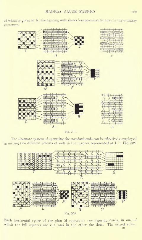
>L\I>RAS GAUZE FABRICS 2^>
35 ,dvffi atr K. fine i^min^ weft $$M>WS fcess jMonucbNuiiy n&*^i in 55* K>r\Unaurv
Fig. 3l>7.
The alternate system of operating the standard ends can be effectively
in mixing two different colours of weft in the manner represented at L in Fig.
Fie. 308.
Each horizontal space of the plan M represents two nguring cards, in one of
which the full squares are cut, and in the other the dots. The mixed colour
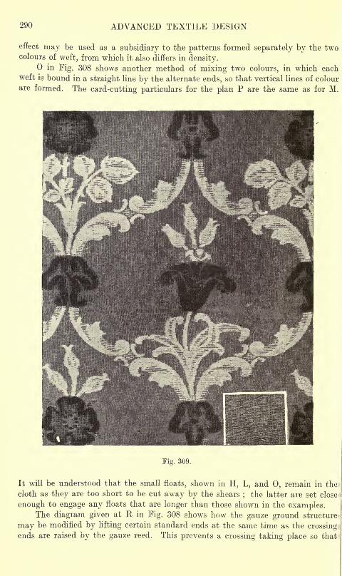
290 ADVANCED TEXTILE DESIGN
effect may be used as a subsidiary to the patterns formed separately by the twocolours of weft, from which it also differs in density.
in Fig. 308 shows another method of mixing two colours, in which eachweft is bound in a straight line by the alternate ends, so that vertical lines of colour
are formed. The card-cutting particulars for the plan P are the same as for M.
Fig. 309.
It will be understood that the small floats, shown in H, L, and 0, remain in the*
cloth as they are too short to be cut away by the shears;the latter are set close-
enough to engage any floats that are longer than those shown in the examples.The diagram given at K in Fig. 308 shows how the gauze ground structure
may be modified by lifting certain standard ends at the same time as the crossingends are raised by the gauze reed. This prevents a crossing taking place so that
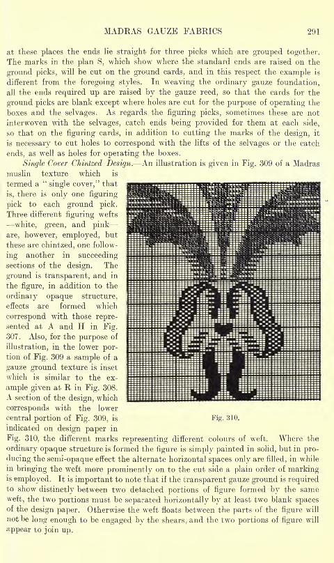
MADEAS GAUZE FABRICS 291
at these places the ends lie straight for three picks which are grouped together.
The marks in the plan S, which show where the standard ends are raised on the
ground picks, will be cut on the ground cards, and in this respect the example is
different from the foregoing styles. In weaving the ordinary gauze foundation,
all the ends required up are raised by the gauze reed, so that the cards for the
ground picks are blank except where holes are cut for the purpose of operating the
boxes and the selvages. As regards the figuring picks, sometimes these are not
interwoven with the selvages, catch ends being provided for them at each side,
so that on the figuring cards, in addition to cutting the marks of the design, it
is necessary to cut holes to correspond with the lifts of the selvages or the catch
ends, as well as holes for operating the boxes.
Single Cover Chintzed Design. An illustration is given in Fig. 309 of a Madras
muslin texture which is
termed a"single cover," that
is, there is only one figuring
pick to each ground pick.
Three different figuring wefts
white, green, and pink
are, however, employed, but
these are chintzed, one follow-
ing another in succeedingsections of the design. The
ground is transparent, and in
the figure, in addition to the
ordinary opaque structure,
effects are formed which
correspond with those repre-
sented at A and H in Fig.
307. Also, for the purpose of
illustration, in the lower por-tion of Fig. 309 a sample of a
gauze ground texture is inset
which is similar to the ex-
ample given at R in Fig. 308.
A section of the design, which
corresponds with the lower
central portion of Fig. 309, is Fig. 310.
indicated on design paper in
Fig. 310, the different marks representing different colours of weft. Where the
ordinary opaque structure is formed the figure is simply painted in solid, but in pro-
ducing the semi-opaque effect the alternate horizontal spaces only are filled, in while
in bringing the weft more prominently on to the cut side a plain order of markingis employed. It is important to note that if the transparent gauze ground is requiredto show distinctly between two detached portions of figure formed by the same
weft, the two portions must be separated horizontally by at least two blank spacesof the design paper. Otherwise the weft floats between the parts of the figure will
not be long enough to be engaged by the shears, and the two portions of figure will
appear to join up.
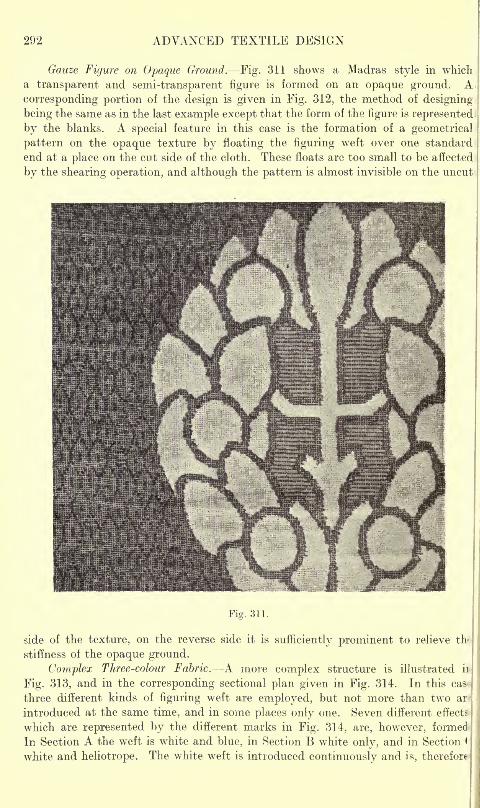
292 ADVANCED TEXTILE DESIGN
Gauze Figure on Opaque Ground. Fig. 311 shows a Madras style in which,
a transparent and semi-transparent figure is formed on an opaque ground,
corresponding portion of the design is given in Fig. 312, the method of designing
being the same as in the last example except that the form of the figure is represente(
by the blanks. A special feature in this case is the formation of a geometrica
pattern on the opaque texture by floating the figuring weft over one standarc
end at a place on the cut side of the cloth. These floats are too small to be affectet
by the shearing operation, and although the pattern is almost invisible on the uncul
Fig. 311.
side of the texture, on the reverse side it is sufficiently prominent to relieve th<
stiffness oi the opaque ground.
Complex Three-colour Fabric. A more complex structure is illustrated ii>
Fig. 313, and in the corresponding sectional plan given in Fig. 314. In this cas>
three different kinds of figuring weft are employed, but not more than two ar
introduced at the same time, and in some places only one. Seven different effects
which are represented by the different marks in Fig. 314, are, however, formed
In Section A the weft is white and blue, in Section B white only, and in Section
white and heliotrope. The white weft is introduced continuously and is, therefore
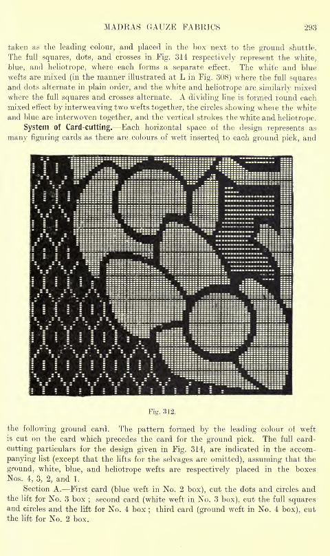
MADRAS GAUZE FABRICS 293
taken as the leading colour, and placed in the box next to the ground shuttle.
The full squares, dots, and crosses in Fig. 314 respectively represent the white,
blue, and heliotrope, where each forms a separate effect. The white and blue
wefts are mixed (in the manner illustrated at L in Fig. 308) where the full squaresand dots alternate in plain order, and the white and heliotrope are similarly mixedwhere the full squares and crosses alternate. A dividing line is formed round each
mixed effect by interweaving two wefts together, the circles showing where the white
and blue are interwoven together, and the vertical strokes the white and heliotrope.
System of Card-cutting. Each horizontal space of the design represents as
many figuring cards as there are colours of weft inserted to each ground pick, and
Fig. 312.
the following ground card. The pattern formed by the leading colour of weft
is cut on the card which precedes the card for the ground pick. The full card-
cutting particulars for the design given in Fig. 314, are indicated in the accom-
panying list (except that the lifts for the selvages are omitted), assuming that the
ground, white, blue, and heliotrope wefts are respectively placed in the boxes
Nos. 4, 3, 2, and 1.
Section A. First card (blue weft in No. 2 box), cut the dots and circles andthe lift for No. 3 box
;second card (white weft in No. 3 box), cut the full squares
and circles and the lift for No. 4 box;
third card (ground weft in No. 4 box), cut
the lift for No. 2 box.
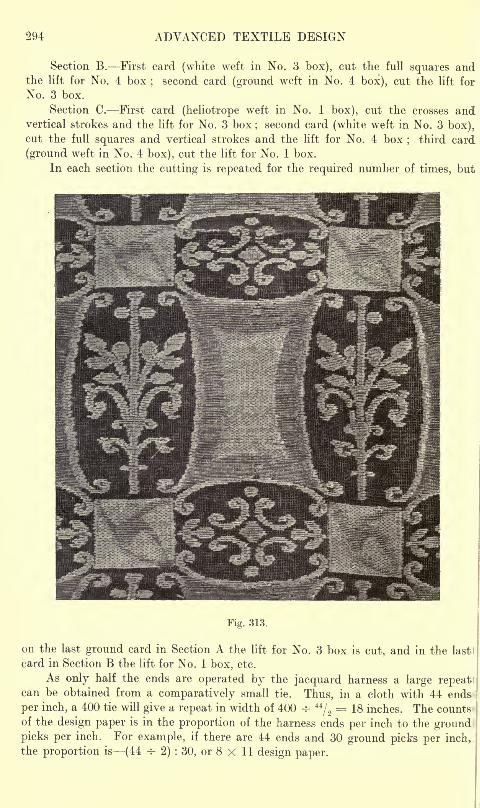
294 ADVANCED TEXTILE DESIGN
Section B. First card (white weft in No. 3 box), cut the full squares andthe lift for No. 4 box
;second card (ground weft in No. 4 box), cut the lift for
No. 3 box.
Section C. First card (heliotrope weft in No. 1 box), cut the crosses andvertical strokes and the lift for No. 3 box
;second card (white weft in No. 3 box),
cut the full squares and vertical strokes and the lift for No. 4 box; third card
(ground weft in No. 4 box), cut the lift for No. 1 box.
In each section the cutting is repeated for the required number of times, but
Fig. 313.
on the last ground card in Section A the lift for No. 3 box is cut, and in the last
card in Section B the lift for No. 1 box, etc.
As only half the ends are operated by the jacquard harness a large repeatscan be obtained from a comparatively small tie. Thus, in a cloth with 44 ends
per inch, a 400 tie will give a repeat in width of 400 -r-44/2= 18 inches. The counts;
of the design paper is in the proportion of the harness ends per inch to the groundpicks per inch. For example, if there are 44 ends and 30 ground picks per inch,
the proportion is (44 -r- 2) : 30, or 8 x 11 design paper.
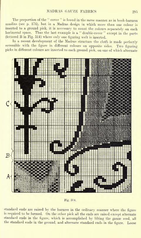
MADRAS GAUZE FABRICS 295
The proportion of the"cover
"is found in the same mannei as in book-harness
muslins (see p. 174), but in a Madras design in which more than one colour is
inserted to a ground pick, it is necessary to count the colours separately on eachhorizontal space. Thus the last example is a
"double-cover
"except in the parts
(lettered B in Fig. 314) where only one figuring weft is inserted.
In a recent development of the Madras structure the cloth is made perfectlyreversible with the figure in different colours on opposite sides. Two figuring
picks in different colours are inserted to each ground pick, on one of which alternate
Fig. 314.
standard ends are raised by the harness in the ordinary manner where the figureis required to be formed. On the other pick all the ends are raised except alternatestandard ends in the figure, which is accomplished by lifting the gauze reed, all
the standard ends in the ground, and alternate standard ends in the figure. Loose
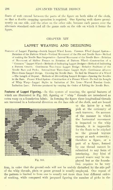
296 ADVANCED TEXTILE DESIGN
floats of weft extend between the parts of the figure on both sides of the cloth,
so that a double cropping operation is required. One figuring weft shows promi-
nently on one side, and the other on the other side, because each passes over the
alternate standard ends and all the gauze ends on the side on which it forms the
figure.
CHAPTER XIV
LAPPET WEAVING AND DESIGNING
Features of Lappet Figuring Scotch Lappet Wheel Loom. Common Wheel Lappet SystemRotation of the Pattern Wheel Vertical Movement of the Pin and Needle Bars Method
of making the Needle Bars Inoperative Lateral Movement of the Needle Bars Relation
of Movement of Shifter Frames to Rotation of Pattern Wheel Construction of a" Common "
Lappet Wheel Methods of Indicating Lappet Designs Method of Indicatinga Pattern Groove. Continuous Two-frame Lappet Design Relative Positions of the
Needle Bars and Pecks. Intermittent Three-frame Lappet Style Continuous All-over
Three-frame Lappet Design. Crossing the Needle Bars. To find the Diameter of a Wheel
The Length of Repeat. Methods of Diversifying Lappet Designs Spacing the Needles
in the Bars. Presser Wheel System Construction of a Presser Wheel To find the Lengthof Whip Warp Lappet Styles in Imitation of Net Leno Waved Russian Cords.
Imitation Lace. Patterns produced by varying the Order of Lifting the Needle Bars.
Features of Lappet Figuring. In this system of weaving, the special features of
which are illustrated in Fig. 315, figuring or"whip
"threads are introduced as
extra warp on a foundation fabric. In forming the figure these longitudinal threads
are traversed in a horizontal direction on the face side of the cloth, and are bound
to the latter by a weft
pick at the extremity of
each traverse. On account
of the manner in which
the horizontal movementis imparted to the whip
threads, it is impossiblefor the floats to be stitched
to the ground texture
except at each extremity;therefore a figure, or a
part of a figure, formed
by one thread cannot be
submitted to any form of
interlacing. Any kind of
ground weave may be em-
ployed but as the founda-
tion requires to be very
firm, in order that the ground ends will not be unduly disturbed by the side pull
of the whip threads, plain or gauze ground is usually employed. One repeat of
the pattern is limited to from one to usually not more than four different orders
of working, while compared with jacquard figuring the number of picks in the.
- 315 -
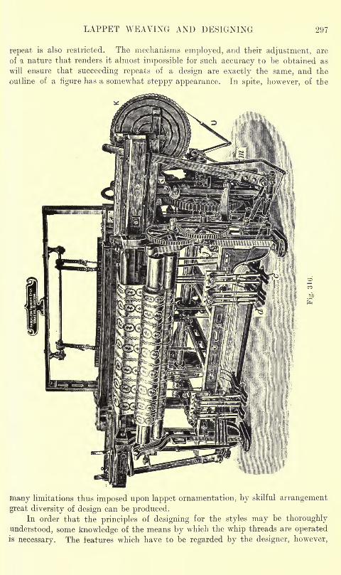
LAPPET WEAVING AND DESIGNING 297
repeat is also restricted. The mechanisms employed, and their adjustment, are
of a nature that renders it almost impossible for such accuracy to be obtained as
will ensure that succeeding repeats of a design are exactly the same, and the
outline of a figure has a somewhat steppy appearance. In spite, however, of the
many limitations thus imposed upon lappet ornamentation, by skilful arrangement
great diversity of design can be produced.In order that the principles of designing for the styles may be thoroughly
understood, some knowledge of the means by which the whip threads are operatedis necessary. The features which have to be regarded by the designer, however,
298 ADVANCED TEXTILE DESIGN
vary somewhat according to the class of lappet mechanism which is employed.The Scotch lappet wheel system is most commonly used, and this type of loom,and the styles produced upon it are, therefore, described and illustrated. Manyof the parts of this motion are common to all lappet mechanisms, the differences
between which are chiefly due to the method in which the horizontal movementsare imparted to the whip threads.
Scotch Lappet Wheel Loom. Fig. 316 gives a general view of a four-frame
left-hand lappet wheel loom (as constructed by the Anderston Foundry Company,Limited, Glasgow), in which some of the parts are lettered to correspond with
the drawings in Figs. 317 and 318 in order that their position and method of operation
may be compared. Various parts of the mechanism are represented in side elevation
in Fig. 317 ; also in front elevation in the upper portion of Fig. 317, and in planin the lower portion. The parts are to scale, except that certain features are accen-
tuated, and while the description is of a four-frame loom the duplication of the
mechanism, in all cases, is not shown.
The lappet wheel system has obtained its name from the use of a wheel K as
the means of governing the horizontal movements of the whip threads in forming the
pattern. There are two kinds of these pattern wheels viz., (1) A " common "
wheel used for styles in which the whip threads are moved alternately to the left andto the right on succeeding picks, and produce figures which are more or less massive.
(2) A"presser
"wheel which is employed when in some part of a design a whip
thread is required to move in the same direction on succeeding picks -as, for example,in forming a fine line of figure running moie or less in a diagonal direction across
the cloth. The latter is less extensively employed than the former, and as its use
necessitates certain modifications of the loom to be made, the ordinary or" common "
wheel lappet system will be considered first.
"COMMON" WHEEL LAPPET SYSTEM
Fig. 315 illustrates the style of lappet design produced by a common wheel.
The figure, which is represented as being formed upon a plain foundation, results
from the combination of two orders of working, one of which produces a continuous-
waved line effect, and the other a spot effect. The manner in which the whipthreads are stitched in by the picks, and exert a side pull on the ground ends, mindicated, and it will be noted that in plain ground the effective distance traversed
by a whip thread is always equal to the space occupied by an even number of groundends. A traverse of an odd number, in plain ground, is impossible, as in such a
case the interlacing of the ground ends will permit the whip thread to slip over
one end;and for this reason, on a plain foundation, the moves at the edge of a
figure are always in even numbers.
The whip threads are carried by eyed needles A (Figs. 317 and 318) fixed
in the needle bars B, each of which is separately supported by a shifter frame C.
Although a loom is usually fitted with four needle bars and shifter frames,
only as many are employed as are necessary in forming a design, the remainder
being left out of action. The distance that the needles project varies with the
position of a bar, and may be 3 inches in the first bar, and project | inch farther
at each succeeding bar, in order that they will conform with the line of the shed.
The needle bars are below the ground warp threads the cloth being woven wrong:side up, and each bar, when in action, has a sequence of the following movements:
LAPPET WEAVING AND DESIGNING 299
(1) A rising movement to bring the needle eyes about level with the top line of groundthreads, in which position they are retained while a weft pick is inserted to stitch
the whip threads into the ground fabric. During this movement the reed is moving-back from the edge of the cloth. (2) A falling movement, during which the reed
is moving forward, which brings the needles below the lower line of warp. (3)
A horizontal movement to the left, by which the whip threads are traversed for
the required distance in forming the pattern. The rising movement is then repeated,and the whip threads are stitched in by the second pick in their new position ;
the needles fall again, and this is followed by a fourth movement in which the bar
is traversed to the right.
As the needle bars B are required to raise the needles into the shed openingin front of the reed, it is necessary for the latter to be placed back from the race-
board. The lower part of the reed is, therefore, carried in a semi-circular trough
D, Fig. 317, which is supported by brackets, one at each side of the reed space.
The brackets are secured by bolts to the slay, while the slay cap E, which holds
the upper part of the reed, is also fixed behind the slay by means of bolts. The
position of the reed necessitates the provision of a bar F, Fig. 317, termed a pin
bar, that carries a number of vertical pointed pins placed about 1J inches apart,
which, at every pick of weft, are projected into the shed opening in close touch
with the back edge of the race-board. The pin bar simply rises and falls, and has
no part in the formation of the pattern. The function of the pins is to serve as
a false reed, in place of the ordinary reed, in guiding the shuttle in its passage across.
The pin and needle bars move to and fro with the slay ;and in Fig. 317 they and
their supports are represented in their most backward position by the solid lines.
The dotted lines show their position when the reed is in contact with the cloth.
On account of the reed being placed back, a much longer sweep of the slay about
8 inches is necessary than in ordinary looms. Instead of the ordinary cranks,
the fast pulley and the gear-wheel to the bottom shaft are placed at oppositeextremities of the driving shaft, and are provided with bolt holes, the bolts in
which form the fulcra of the connecting arms.
The threads for each needle bar are wound on a separate small beam, and
in mounting the loom the rolls are placed in suitable supports G, Fig. 317, bolted
to the loom framing. The whip threads from each roll are passed in Iront of the
lower and behind the upper cord of a tensioning arrangement H, between the
heald cords, then under the reed casing, and finally are drawn through the eyesof the corresponding needles. A separate tension device H is required for each
needle bar, because the length of the whip thread, from the cloth to the roll, varies
with the rise and fall of the bar. Delicate adjustment of the tension is necessaryin keeping the whip threads sufficiently tight to prevent them from curling on
the face of the cloth, while at the same time the ground texture is disturbed as
little as possible. The parallel cords of H, which extend across the warp, are attached
to wooden end pieces, and are given the necessary spring as follows : The ends
of a strong cord are passed inward through two holes equidistant from the centre
of each end piece, and are secured. The looped end of each cord is then passed
through a hole in a bracket, and a small piece of wood is inserted in the loop. Byturning the pieces of wood round, twist is put into the cords, the amount of twist
being varied according to the degree of tension required. The spring cords readily giveoff and take up the whip warp in accordance with the movements of the needle bars.
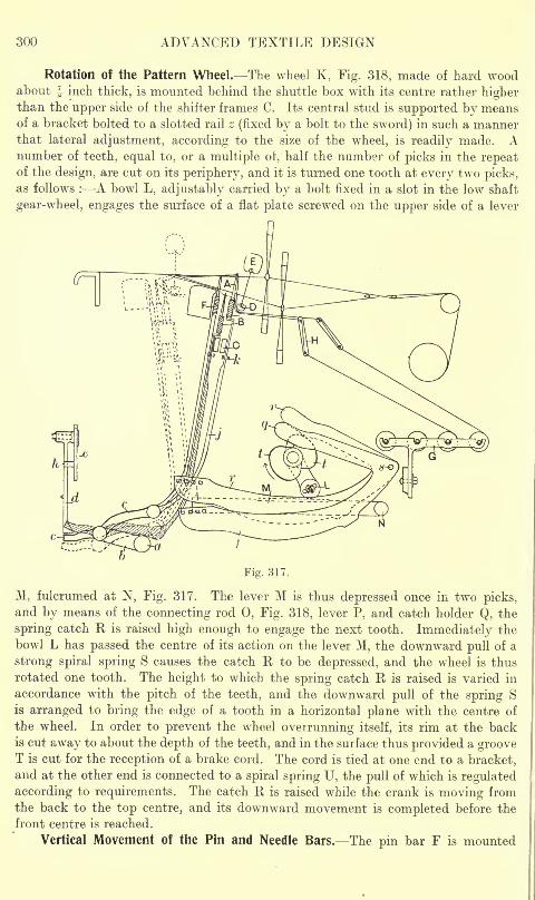
300 ADVANCED TEXTILE DESIGN
Rotation of the Pattern Wheel. The wheel K, Fig. 318, made of hard woodabout ^ inch thick, is mounted behind the shuttle box with its centre rather higherthan the upper side of the shifter frames C. Its central stud is supported by meansof a bracket bolted to a slotted rail z (fixed by a bolt to the sword) in such a mannerthat lateral adjustment, according to the size of the wheel, is readily made. Anumber of teeth, equal to, or a multiple of, half the number of picks in the repeatof the design, are cut on its periphery, and it is turned one tooth at every two picks,as follows : A bowl L, adjustably carried by a bolt fixed in a slot in the low shaft
gear-wheel, engages the surface of a flat plate screwed on the upper side of a lever
Fig. 317.
M, fulcrumed at N, Fig. 317. The lever M is thus depressed once in two picks,and by means of the connecting rod 0, Fig. 318, lever P, and catch holder Q, the
spring catch R is raised high enough to engage the next tooth. Immediately the
bowl L has passed the centre of its action on the lever M, the downward pull of a
strong spiral spring S causes the catch R to be depressed, and the wheel is thus
rotated one tooth. The height to which the spring catch R is raised is varied in
accordance with the pitch of the teeth, and the downward pull of the spring S
is arranged to bring the edge of a tooth in a horizontal plane with the centre of
the wheel. In order to prevent the wheel overrunning itself, its rim at the backis cut away to about the depth of the teeth, and in the surface thus provided a grooveT is cut for the reception of a brake cord. The cord is tied at one end to a bracket,and at the other end is connected to a spiral spring U, the pull of which is regulated
according to requirements. The catch R is raised while the crank is moving fromthe back to the top centre, and its downward movement is completed before the
front centre is reached.
Vertical Movement of the Pin and Needle Bars. The pin bar F is mounted
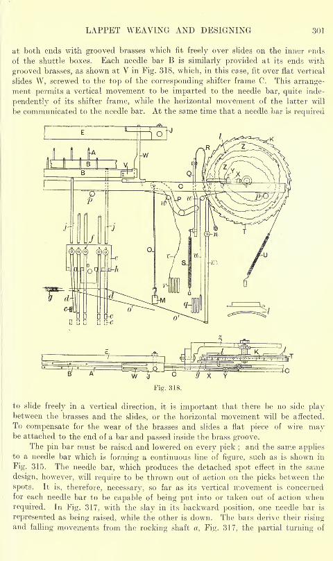
LAPPET WEAVING AND DESIGNING 301
at both ends with grooved brasses which fit freely over slides on the inner ends
of the shuttle boxes. Each needle bar B is similarly provided at its ends with
grooved brasses, as shown at V in Fig. 318, which, in this case, fit over flat vertical
slides W, screwed to the top of the corresponding shifter frame C. This arrange-ment permits a vertical movement to be imparted to the needle bar, quite inde-
pendently of its shifter frame, while the horizontal movement of the latter will
be communicated to the needle bar. At the same time that a needle bar is required
Fig. 318.
to slide freely in a vertical direction, it is important that there be no side playbetween the brasses and the slides, or the horizontal movement will be affected.
To compensate for the wear of the brasses and slides a flat piece of wire maybe attached to the end of a bar and passed inside the brass groove.
The pin bar must be raised and lowered on every pick ;and the same applies
to a needle bar which is forming a continuous line of figure, such as is shown in
Fig. 315. The needle bar, which produces the detached spot effect in the same
design, however, will require to be thrown out of action on the picks between the
spots. It is, therefore, necessary, so far as its vertical movement is concerned
for each needle bar to be capable of being put into or taken out of action when
required. In Fig. 317, with the slay in its backward position, one needle bar is
represented as being raised, while the other is down. The bars derive their risingand falling movements from the rocking shaft a, Fig. 317, the partial turning of
302 ADVANCED TEXTILE DESIGN
which causes the lever 6, fixed to it, to rise and fall at its forward end. This endof the lever b carries a stud upon which five levers c are fulcrumed, the central
lever being used for the pin bar, and the two on each side of it for the four needle
bars. Above the front edge of each lever c there is a pendant d, carried by a slotted
bracket e, which is bolted to the loom framing. The pendants are fulcrumed at the
top, and while that for the pin bar is always over the front edge of a lever c, those
for the needle bars are retained in their normal position by a cord connected to a
spiral spring g, shown in Fig. 318. Projections h are cast on the bracket e in order
to limit the lateral movement of the lower ends of the pendants. At the rear end of
each lever c the extremity of a round rod j is fulcrumed, each rod passing through
guide slots k to the underside of a bar. The rod, which controls the pin bar, does
not need to be specially shaped at the top, but on account of the shifter frames
being below the needle bars, the other rods are made flat towards the top, and are
bent at right angles where they are in contact with the bars. A set of five pendantsand connections is provided at each side of the loom, as shown in Fig. 316, anda flat piece of metal is screwed to the underside of each bar where a rod j is in
contact with it.
For convenience, in Figs. 317 and 318 the levers c are represented in three
positions. When a bar is down, the rear end of the corresponding lever c rests
with its underside on the rocking shaft a. As the slay moves back from the cloth
the lever b rises at its forward end, and thus raises the fulcrum of the levers c, the
front arms of which, therefore, press against, and are held down by, the pendantsd (which are in the normal position), with the result that the rear ends rise and
push up the corresponding bars by means of the rods j. As the slay approachesthe cloth the forward end of lever b falls, and all the levers c assume the positions
represented by the dotted lines, the pin and needle bars moving below the underside
of the cloth. The bars should complete the downward movement when the reed
is some distance from the edge of the cloth, and before the horizontal movementcommences. With smooth working the deadweight of the parts is sufficient to
bring the bars down, but in order to avoid all liability of a bar sticking, it is cus-
tomary to attach one end of a light spring to the framework underneath, and connect
the other end by a separate cord to each bar. The vertical distance moved by the
bars can be adjusted collectively by turning the lever b on the rocking shatt a,
and individually by raising or lowering the fulcrum of a pendant in a slot/ providedin the bracket e.
Method of Making the Needle Bars Inoperative. A needle bar is left out of
action by withdrawing the corresponding pendant d from above the forward end
of a lever c, which, therefore, rises as the slay recedes from the cloth. The weightof the needle bar and connecting rod keeps the rear end of the lever c resting on
the rocking shaft, and the parts thus assume the position represented by the shaded
lines in Fig. 317, the needle eyes remaining below the lower line of the warp. Themanner in which a pendant is withdrawn is illustrated in Fig. 318. On the hind
face of the wheel K a ring groove is cut, into which one or more curved pieces of
metal I, projecting about J inch, are fixed. The circumferential distance covered
by a"dropper
"(the shape of which is represented below the wheel in Fig. 318)
is arranged to coincide with a number of teeth in the wheel, and corresponds with
the period during which a needle bar will remain out of action. As the wheel Krevolves, the edge of the
"dropper
"comes in contact with, and presses back the
LAPPET WEAVING AND DESIGNING 303
head of a hooked lever m, fulcrumed at n, and the lower end, by means of a cord o,
draws a pendant away from a lever c. The upper end of the lever m is in the form
of a hook, in order that it can immediately slip over the edge of a metal piece when
the stationary period of a needle bar is completed. If two or more needle bars
have to be put out of action at the same time, only one set of curved pieces I,
and one lever m, are necessary ;but if more than one bar have to be operated
intermittently at different periods, a corresponding number of ring grooves is
provided ab the back ot the wheel, each with curved metal pieces I and a separate
hooked lever m and cord connection o. The curved pieces for the different ring
grooves stand out the same distance from the surface of the wheel, and all the
levers m, except the first, are bent sideways at the top towards the wheel, in order
that each will be engaged only by the corresponding dropper. The distance
between two ring grooves requires to be large enough to allow space for the hooked
head of a lever m to work without obstruction.
Lateral Movement of the Needle Bars. From one to four grooves Z, Fig. 318,
according to the number of needle bars employed in the formation of the pattern,
are cut in the face of the wheel K. A groove is aboutf-inch deep, and it is shaped
in accordance with the desired movement of the corresponding needle bar. A"
feeler,""pike," or
"peck
" X is adjustably fixed by a set-screw Y between
the flanges of a metal plate fastened on the upper surface of each shifter frame.
At one end a peck is made cylindrical, and is bent at right angles in order that
the cylindrical end will enter a groove in the wheel. The diameter of a peck where
it enters a groove is about J inch, and the length of the bent portion varies accordingto the position of a shifter frame
;that for the back frame having a short bend,
while that for the front frame is much longer. The bent portions of the pecks are
supported by and slide upon a smooth steel rod y placed between the back frame
and the wheel. As the positions of the pecks are fixed by the grooves in the wheel,
the relative position of the needles in the different bars is regulated by moving the
shifter frames, the screw Y being released for the purpose. Very fine adjustmentto the space occupied by half a split of the reed is possible, while if considerable
adjustment is necessary the flanged plate on the top of a shifter frame may be
unscrewed and its position changed.The bent end of each peck X is moved alternately to left and right within
a groove Z by the downward pull of two weighted levers q and r, fulcrumed at s,
Fig. 317. Two tappets t, set opposite to each other on the low shaft, act alternately
on the short upper arms of the levers;thus one is raised while the other is allowed
to fall. The face of each tappet t is wide enough for four levers to rest upon it.
Straps u and v, Fig. 318, from the ends of the lower arms of the levers q and r, are
passed over guide pulleys w, strap u passing from its guide pulley to the right, and
strap v to the left. A tappet t, raising the lever r, causes a strap v to hang slack,
and as at this time the other tappet allows the lever q to fall, the strap u is tightened,and the shifter frame is moved to the left. At the next revolution of the drivingshaft the lever q is raised by the other tappet, and the lever r is allowed to drop ;
thus the strap u hangs slack and the strap v is tightened, causing the shifter frame
to move to the right. The upper arm of a lever q and r, when in its lower position,
does not necessarily rest on the thin part of a tappet, the weight of a lever beingsustained by the strap from which it is suspended. Each strap is in two partsconnected by a buckle which enables the length of the strap to be conveniently
304 ADVANCED TEXTILE DESIGN
regulated. The shifter frames slide on a number of small bowls p, a flat piece oJ
metal being screwed to the underside of each frame where contact takes place.
The to-and-fro movement of a peck is in a line with the centre of the wheel
and its extent is limited by the width of a groove ;but the position of a peck anc
the corresponding shifter frame changes as the groove approaches or recedes frorr
the centre of the wheel. The movements of the shifter frames are communicatec
to the needle bars by means of the vertical slides W, which move within separat(
slots in plates J, one of which is fixed at each side to the front of the slay cap. Th<
needle bars taken from front to back are respectively operated from the grooves
taken from the outside to the inside of the wheel. A shoulder is provided uporeach slide W, in order to neutralise any tendency of a shifter frame to rise. Tht
width of the area over which a thread can be traversed by one bar is limited b)the slots in the plate J, and taking the length of a slob as 4^- inches and th<
breadth of a slide as f *,T inch, which are standard dimensions, the maximum wridtl
=(4TV-T6) = -3f inches.
In order that the whip threads will offer as little obstruction as possible to tht
shuttle in its passage across, the tappets t and the picking tappets are set in con
junction with each other in such a manner that the direction of the movement o
the frames is the same as that of the pick which follows. Thus, the pick from tin
right follows the movement of the frames from the right, and vice versa, th<
inclination of the whip threads, when the shed is open, being in the same directioi
as the shuttle is travelling. The bowl L and the tappets t are timed with eacl
other so that the latter are midway of their lift at about the centre of the downward movement of the catch R. The turning of the wheel K thus takes plac<
while all the straps connected to the shifter frames are slack, and there is n<
tension on the pecks.
Relation of Movement of Shifter Frames to Rotation of Pattern Wheel. Th<
low shaft gear wheel is provided at opposite sides with slots, in which the bolt;
which carry the bowl L, Fig. 317, may be fixed. The turning of the pattern wheel
which occurs only once in two picks, may thus be arranged to coincide with th<
movement of the shifter frames, either to the right or to the left. In most designs
however, it must agree definitely with one of the movements, according t<
the way in which the pattern grooves have been cut. There is no hard-and-fas
rule; thus, a system may be followed, for both right and left-hand looms, of havinj
the rotation of the wheel coinciding with the movement of the pecks (1) from lef
to right, or (2) from the outside to the inside of the grooves. Each system has ai
advantage over the other; thus, in the first method, a wheel can be used for eithe
a right or left-hand loom without the timing of its rotation being changed, whil
in the second method the pressure on the p^ck, as the wheel is turning, is from th
side of the groove which is farthest from the centre, and the small catches (A
Fig. 322), which it is sometimes necessary to use, are fastened on the side whic] ;
is nearer the edge of the wheel. In subsequent examples it will be assumed, fo I
convenience, that the turning of the wheel coincides with the movement of a bajfrom left to right.
Fig. 319 illustrates how necessary it is, in certain patterns, for the rotatio:
of the wheel, the movements of a shifter frame, and the manner in which a patter
groove is cut, to coincide with each other. In A, which illustrates the traversin
of a whip thread, as viewed from the upper or wrong side of the cloth, the vertics
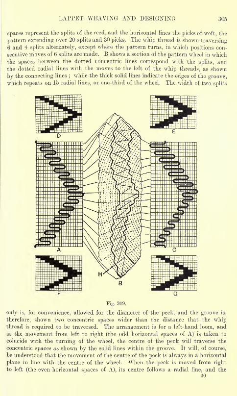
LAPPET WEAVING AND DESIGNING 305
spaces represent the splits of the reed, and the horizontal lines the picks of weft, the
pattern extending over 20 splits and 30 picks. The whip thread is shown traversing6 and 4 splits alternately, except where the pattern turns, in which positions con-
secutive moves of 6 splits are made. B shows a section of the pattern wheel in which
the spaces between the dotted concentric lines correspond with the splits, and
the dotted radial lines with the moves to the left of the whip threads, as shown
by the connecting lines;while the thick solid lines indicate the edges of the groove,
which repeats on 15 radial lines, or one-third of the wheel. The width of two splits
Fig. 319.
only is, for convenience, allowed for the diameter of the peck, and the groove is,
therefore, shown two concentric spaces wider than the distance that the whipthread is required to be traversed. The arrangement is for a left-hand loom, andas the movement from left to right (the odd horizontal spaces of A) is taken to
coincide with the turning of the wheel, the centre of the peck will traverse the
concentric spaces as shown by the solid lines within the groove. It will, of course,
be understood that the movement of the centre of the peck is always in a horizontal
plane in line with the centre of the wheel. When the peck is moved from rightto left (the even horizontal spaces of A), its centre follows a radial line, and the
20
306 ADVANCED TEXTILE DESIGN
lateral distance traversed by a whip thread is equal to the width of the grooveminus the diameter of the peck, or 6 2 = 4 splits in the lower portion, and8 2 = 6 splits in the upper portion of B. This does not apply to the movementfrom left to right, as while this is about to take place the wheel turns, and the
peck, therefore, moves opposite a new position in the groove ;the distance traversed
being greater in this case where the inner edge is approaching the centre of the
wheel, and less where it is receding from the centre. It will thus be noted that
in order to obtain the alternate movements of 6 and 4 splits in each half of the
pattern, the groove is narrower in the lower than in the upper portion of B;and a
representation of the form of the groove (leaving out of account the diameter of
the peck), in solid marks on design paper, will not be as indicated at D or E in
Fig. 319, but as shown at F.
C, in Fig. 319, shows how the pattern would be affected if the rotation of the
wheel took place at the opposite movement of the shifter frame to what the groovehas been cut for. In that case the turning of the wheel would coincide with the
movement of the peck from right to left, and, compared with A, the traverse of the
whip threads would be curtailed by the lower portion of the groove, and increased
by the upper portion. With the latter timing of the rotation of the whesl, in order
to produce the effect given at A, the groove would require to be cut according to
the plan indicated at G. Further comparison will show that, leaving Out of account
the diameter of the peck, the width of a groove is determined by the distance to
be traversed at the opposite movement to that which coincides with the turningof the wheel. By noting the position of the shuttle when the catch is at its highest
point, the timing of the movements can be readily determined. Thus, if the shuttle
is in the left box when the catch is raised, the turning of the wheel coincides with
the movement from the left, and vice versa.
In giving instructions for the cutting of a wheel, it is necessary for the hand of
the loom to be stated, in order that the teeth may be shaped accordingly. It will
be noted in Fig. 316 that the wheel is at the opposite side of the loom to the driving
pulley, and the turning catch acts upon the inner edge. Frequently, however, it is
necessary to use a wheel for a loom of the opposite hand to that for which the teeth
have been cut. The wheel is then modified to suit by driving in staples in close
contact with the edges of the teeth, as shown at H in Fig. 319. The turning catch
then acts upon the projecting portions of the staples. By turning the illustration
round from top to bottom, it will be seen that if the rotation of the wheel againcoincides with the movement of the peck from left to right, the pattern will be
exactly the same as is produced in a left-hand loom, but the peck will be againstthe inner edge of the groove when the wheel commences to turn. The usual effect
of changing a wheel is simply to turn the figure the opposite way up.Construction of a " Common "
Lappet Wheel. A lappet wheel is made of hard
wood which is close in the grain, and well seasoned in order that it will resist atmos-
pheric changes. Its thickness is from | to 1 inch, and its diameter varies from about
8 to 25 inches, according to the number of picks in the repeat, and number of frames
employed in forming a pattern. A hole is bored, about the centre of a piece of
wood of suitable size, to fit the socket of a lathe, in which it is turned to the properdiameter. On the side of the wheel where the groove or grooves are to be cut,
a steel comb is pressed while the disc is revolving, a number of concentric lines
thus being made, the space between which corresponds with the pitch of the ccmb.
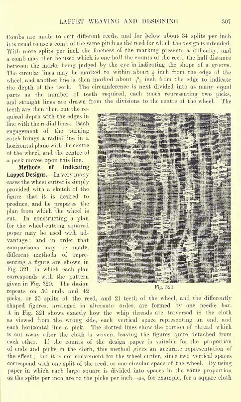
LAPPET WEAVING AND DESIGNING 307
Combs are made to suit different reeds, and for below about 34 splits per inch
it is usual to use a comb of the same pitch as the reed for which the design is intended.
With more splits per inch the fineness of the marking presents a difficulty, and
a comb may then be used which is one-half the counts of the reed, the half distance
between the marks being judged by the eye in indicating the shape of a groove.
The circular lines may be marked to within about J inch from the edge of the
wheel, and another line is then marked about ^ inch fiom the edge to indicate
the depth of the teeth. The circumference is next divided into as many equal
parts as the number of teeth required, each tooth representing two picks,
and straight lines are drawn from the divisions to the centre of the wheel. The
teeth are then then cut the re-
quired depth with the edges in
line with the radial lines. Each
engagement of the turning
catch brings a radial line in a
horizontal plane with the centre
of the wheel, and the centre of
a peck moves upon this line.
Methods of Indicating
Lappet Designs. In very manycases the wheel cutter is simply
provided with a sketch of the
figure that it is desired to
produce, and he prepares the
plan from which the wheel is
cut. In constructing a planfor the wheel-cutting squared
paper may be used with ad-
vantage ;and in order that
comparisons may be made,different methods of repre-
senting a figure are shown in
Fig. 321, in which each plan
corresponds with the pattern
given in Fig. 320. The design
repeats on 50 ends and 42Fig. 320.
picks, or 25 splits of the reed, and 21 teeth of the wheel, and the differently
shaped figures, arranged in alternate order, are formed by one needle bar.
A in Fig. 321 shows exactly how the whip threads are traversed in the cloth
as viewed from the wrong side, each vertical space representing an end, and
each horizontal line a pick. The dotted lines show the portion of thread which
is cut away after the cloth is woven, leaving the figures quite detached from
each other. If the counts of the design paper is suitable for the proportionof ends and picks in the cloth, this method gives an accurate representation of
the effect;but it is not convenient for the wheel cutter, since two vertical spaces
correspond with one split of the reed, or one circular space of the wheel. By using
paper in which each large square is divided into spaces in the same proportionas the splits per inch are to the picks per inch as, for example, for a square cloth
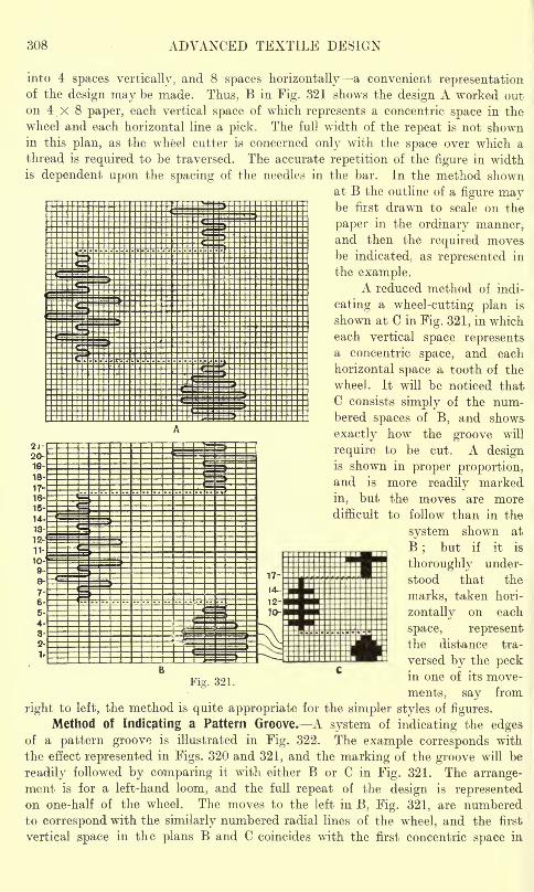
308 ADVANCED TEXTILE DESIGN
into 4 spaces vertically, and 8 spaces horizontally a convenient representationof the design may be made. Thus, B in Fig. 321 shows the design A worked out
on 4 x 8 paper, each vertical space of which represents a concentric space in the
wheel and each horizontal line a pick. The full width of the repeat is not shownin this plan, as the wheel cutter is concerned only with the space over which athread is required to be traversed. The accurate repetition of the figure in widthis dependent upon the spacing of the needles in the bar. In the method shown
at B the outline of a figure maybe first drawn to scale on the
paper in the ordinary manner,and then the required moves-
be indicated, as represented in
the example.A reduced method of indi-
cating a wheel-cutting plan is
shown at C in Fig. 321, in which
each vertical space representsa concentric space, and each
horizontal space a tooth of the
wheel. It will be noticed that
C consists simply of the num-bered spaces of B, and shows
exactly how the groove will
require to be cut. A designis shown in proper proportion,and is more readily marked
in, but the moves are moredifficult to follow than in the
system shown at
B;
but if it is
thoroughly under-
stood that the
marks, taken hori-
zontally on each
space, representthe distance tra-
versed by the peckin one of its move-
ments, say from
right to left, the method is quite appropriate for the simpler styles of figures.
Method of indicating a Pattern Groove. A system of indicating the edgesof a pattern groove is illustrated in Fig. 322. The example corresponds with
the effect represented in Figs. 320 and 321, and the marking of the groove will be
readily followed by comparing it with either B or C in Fig. 321. The arrange-ment is for a left-hand loom, and the full repeat of the design is representedon one-half of the wheel. The moves to the left in B, Fig. 321, are numberedto correspond with the similarly numbered radial lines of the wheel, and the first
vertical space in the plans B and C coincides with the first concentric space in
Fiz. 321.
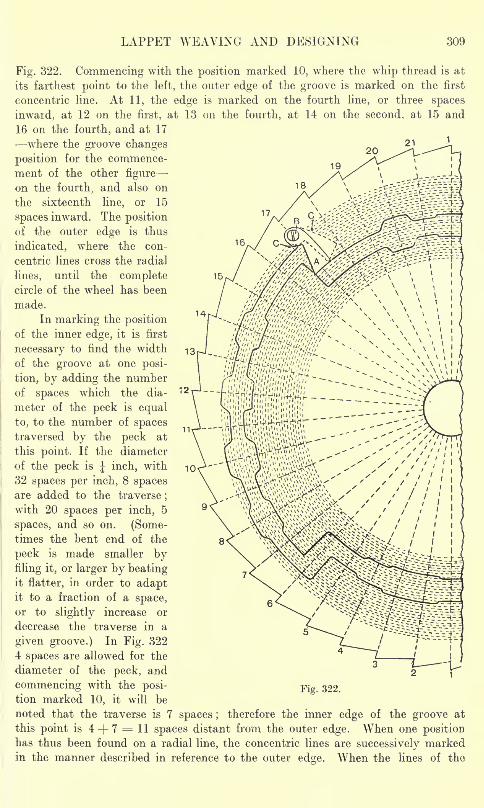
LAPPET WEAVING AND DESIGNING 309
Fig. 322. Commencing with the position marked 10, where the whip thread is at
its farthest point to the left, the outer edge of the groove is marked on the first
concentric line. At 11, the edge is marked on the fourth line, or three spaces
inward, at 12 on the first, at 13 on the fourth, at 14 on the second, at 15 and
16 on the fourth, and at 17
where the groove changes
position for the commence-
ment of the other figure
on the fourth, and also on
the sixteenth line, or 15
spaces inward. The position
of the outer edge is thus
indicated, where the con-
centric lines cross the radial
lines, until the completecircle of the wheel has been
made.
In marking the positionof the inner edge, it is first
necessary to find the width
of the groove at one posi-
tion, by adding the numberof spaces which the dia- T2
meter of the peck is equal
to, to the number of spacestraversed by the peck at
this point. If the diameter
of the peck is J inch, with
32 spaces per inch, 8 spacesare added to the traverse
;
with 20 spaces per inch, 5
spaces, and so on. (Some-times the bent end of the
peck is made smaller byfiling it, or larger by beatingit flatter, in order to adaptit to a fraction of a space,or to slightly increase or
decrease the traverse in a
given groove.) In Fig. 322
4 spaces are allowed for the
diameter of the peck, and
commencing with the posi- Fig 322.
tion marked 10, it will be
noted that the traverse is 7 spaces ;therefore the inner edge of the groove at
this point is 4 + 7 = 11 spaces distant from the outer edge. When one positionhas thus been found on a radial line, the concentric lines are successively markedin the manner described in reference to the outer edge. When the lines of the
310 ADVANCED TEXTILE DESIGN
groove have been completed, the wood between them is carefully bored out to
the required depth say | inch.
In an ordinary groove two concentric lines are sloped towards each other
intermediate between two radial lines, but when the groove changes abruptlytowards the centre of the wheel, as shown on the radial line numbered 17 in Fig. 322,
the peck is liable to catch against the approaching edge of the groove as the wheel
revolves. This will be understood if the moves of the peck, in relation to the turningof the wheel, are followed. Thus, taking the radial line 16, the peck moves from
the inner to the outer edge of the groove, then the wheel turns, and while this is
taking place the peck is really in easy contact with the outer edge. After the rotation
of the wheel the peck moves on the line 17 against the inner edge, then it movesback on the line 17, and this is followed by another rotation of the wheel. If allowed
to pass the corner of the outer edge in moving back, the peck would lock the wheel,
and in order to avoid this a small catch A, centred freely at B, is provided. Whenthe peck is moving on the line 17 from the outer to the inner edge of the groove,it pushes up the catch A to the position shown by the dotted lines
;but when
the return movement takes place the catch has dropped and the peck moves againstits edge. The catch is shaped in conformity with the edge of the groove, and two
pins C are driven into the wheel to limit the extent of its movement.
There is a similar abrupt change in the position of the groove on the radial
line 6, but as the move is away from the centre of the wheel no catch A is necessary.
Thus, on the radial line 5 the peck moves from the inside to the outside of the
groove ;the wheel turns, and the peck moves against the inside on the line 6, then
on the same line against the outside, and while it is in this position the wheel turns
again. The catch A requires to be placed on the side of the groove that the peckis in contact with when the wheel commences to turn. Thus, in the case of adaptingthe wheel represented in Fig. 322 to a right-hand loom, it would be necessary to
change the position of the catch to the inside of the groove.A feature to note in Figs. 319 to 322 is that each design repeats on an odd
number of teeth of the wheel. This is frequently necessary when a perfectlybalanced or symmetrical effect is equired. Thus, in Fig. 319, in order that both
turning points of the waved line will be exactly the same, it is necessary for the
half repeat to be made on an odd number of picks, while in Fig. 321, in obtainingthe moves from one spot to the other without the needle bar dropping, it is necessaryfor an odd number of picks to be employed for each figure. An even number of
teeth could be employed for a style such as the latter by making one figure 2, or
6, etc., picks longer than the other.
Continuous Two-frame Lappet Design. The pattern in Fig. 323 shows a style
of ornament produced by two frames working in combination, which are continuouslyin action. The corresponding plan is given at A in Fig. 324, as viewed from the
wrong side of the cloth, the vertical spaces representing the splits of the reed, and
the horizontal lines the picks. The repeat is on 32 splits, and 70 picks, or 35 teeth
an odd number of the latter being arranged for on account of the figure being sym-metrical. The full squares show the moves of the first needle bar, and the dots,
of the second, while the circles indicate the moves of both bars. The marks on
the odd horizontal spaces represent the moves from right to left, which decide
the widths of the grooves. There are three features to note in this example. (1)
Where two whip threads unite to form a solid portion of figure it is necessary for
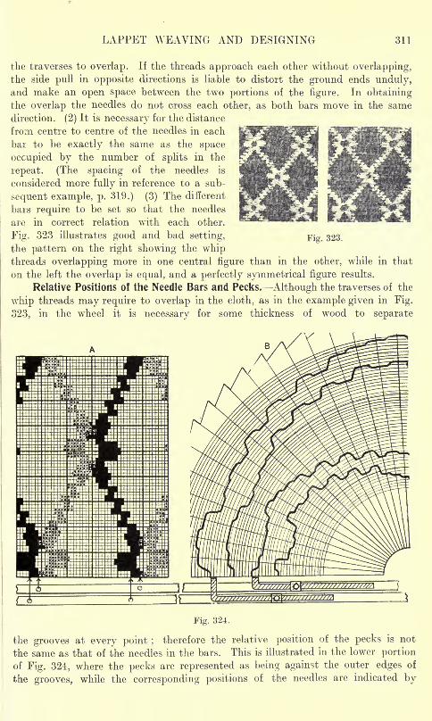
LAPPET WEAVING AND DESIGNING 311
the traverses to overlap. If the threads approach each other without overlapping,the side pull in opposite directions is liable to distort the ground ends unduly,and make an open space between the two portions of the figure. In obtainingthe overlap the needles do not cross each other, as both bars move in the same
direction. (2) It is necessary for the distance
from centre to centre of the needles in each
bar to be exactly the same as the space
occupied by the number of splits in the
repeat. (The spacing of the needles is
considered more fully in reference to a sub-
sequent example, p. 319.) (3) The different
bars require to be set so that the needles
are in correct relation with each other.
Fig. 323 illustrates good and bad setting, Fig. 323.
the pattern on the right showing the whipthreads overlapping more in one central figure than in the other, while in that
on the left the overlap is equal, and a perfectly symmetrical figure results.
Relative Positions of the Needle Bars and Pecks. Although the traverses of the
whip threads may require to overlap in the cloth, as in the example given in Fig.
323, in the wheel it is necessary for some thickness of wood to separate
Fig. 324.
the grooves at every point ;therefore the relative position of the pecks is not
the same as that of the needles in the bars. This is illustrated in the lower portion
of Fig. 324, where the pecks are represented as being against the outer edges of
the grooves, while the corresponding positions of the needles are indicated by
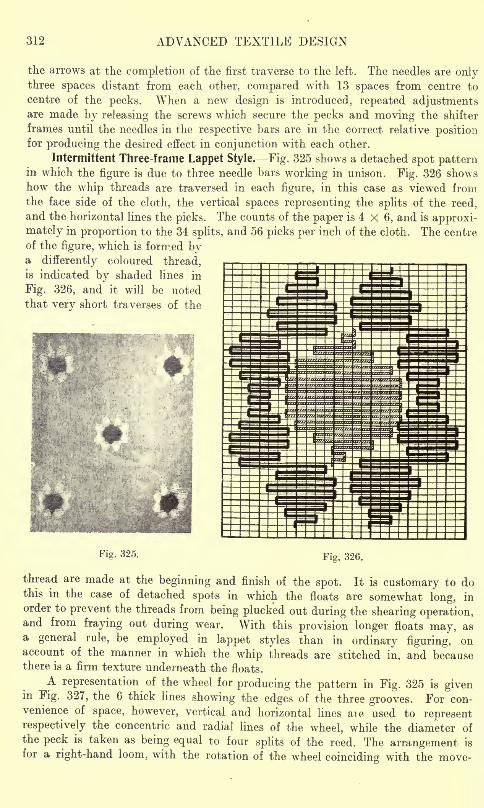
312 ADVANCED TEXTILE DESIGN
the arrows at the completion of the first traverse to the left. The needles are onlythree spaces distant from each other, compared with 13 spaces from centre to
centre of the pecks. When a new design is introduced, repeated adjustmentsare made by releasing the screws which secure the pecks and moving the shifter
frames until the needles in the respective bars are in the correct relative positionfor producing the desired effect in conjunction with each other.
Intermittent Three-frame Lappet Style. Fig. 325 shows a detached spot patternin which the figure is due to three needle bars working in unison. Fig. 326 shows
how the whip threads are traversed in each figure, in this case as viewed fromthe face side of the cloth, the vertical spaces representing the splits of the reed,
and the horizontal lines the picks. The counts of the paper is 4 X 6, and is approxi-
mately in proportion to the 34 splits, and 56 picks per inch of the cloth. The centre
of the figure, which is formed bya differently coloured thread,is indicated by shaded lines in
Fig. 326, and it will be noted
that very short traverses of the
Fig. 325.Fig. 326.
thread are made at the beginning and finish of the spot. It is customary to dothis in the case of detached spots in which the floats are somewhat long, in
order to prevent the threads from being plucked out during the shearing operation,and from fraying out during wear. With this provision longer floats may, asa general rule, be employed in lappet styles than in ordinary figuring, onaccount of the manner in which the whip threads are stitched in, and becausethere is a firm texture underneath the floats.
A representation of the wheel for producing the pattern in Fig. 325 is givenin Fig. 327, the 6 thick lines showing the edges of the three grooves. For con-venience of space, however, vertical and horizontal lines aie used to representrespectively the concentric and radial lines of the wheel, while the diameter of
the peck is taken as being equal to four splits of the reed. The arrangement is
for a right-hand loom, with the rotation of the wheel coinciding with the move-
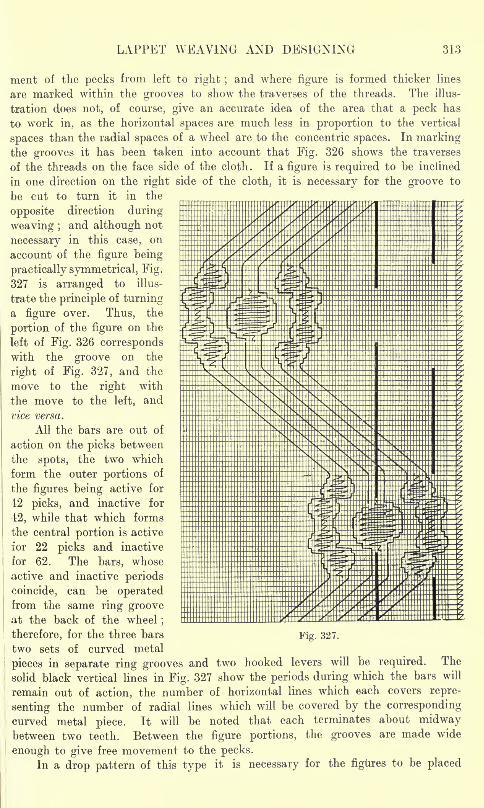
LAPPET WEAVING AND DESIGNING 313
merit of the pecks from left to right ;and where figure is formed thicker lines
are marked within the grooves to show the traverses of the threads. The illus-
tration does not, of course, give an accurate idea of the area that a peck has
to work in, as the horizontal spaces are much less in proportion to the vertical
spaces than the radial spaces of a wheel are to the concentric spaces. In markingthe grooves it has been taken into account that Fig. 326 shows the traverses
of the threads on the face side of the cloth. If a figure is required to be inclined
in one direction on the right side of the cloth, it is necessary for the groove to
be cut to turn it in the
opposite direction during
weaving ;and although not
necessary in this case, on
account of the figure being
practically symmetrical, Fig.
327 is arranged to illus-
trate the principle of turninga figure over. Thus, the
portion of the figure on the
left of Fig. 326 correspondswith the groove on the
right of Fig. 327, and the
move to the right with
the move to the left, and
vice versa.
All the bars are out of
action on the picks between
the spots, the two which
form the outer portions of
the figures being active for
42 picks, and inactive for
12, while that which forms
the central portion is active
for 22 picks and inactive
for 62. The bars, whose
active and inactive periods
coincide, can be operatedfrom the same ring grooveat the back of the wheel
;
therefore, for the three bars
two sets of curved metal
pieces in separate ring grooves and two hooked levers will be required. The
solid black vertical lines in Fig. 327 show the periods during which the bars will
remain out of action, the number of horizontal lines which each covers repre-
senting the number of radial lines which will be covered by the corresponding
curved metal piece. It will be noted that each terminates about midwaybetween two teeth. Between the figure portions, the grooves are made wide
enough to give free movement to the pecks.
In a drop pattern of this type it is necessary for the figures to be placed
Fig. 327.
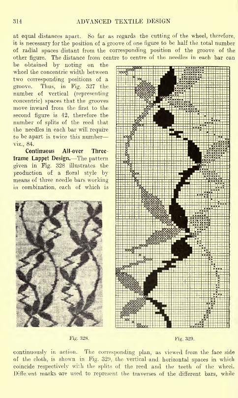
314 ADVANCED TEXTILE DESIGN
at equal distances apart. So far as regards the cutting of the wheel, therefore,
it is necessary for the position of a groove of one figure to be half the total numberof radial spaces distant from the corresponding position of the groove of the
other figure. The distance from centre to centre of the needles in each bar can
be obtained by noting on the
wheel the concentric width between
two corresponding positions of a
groove. Thus, in Fig. 327 the
number of vertical (representing
concentric) spaces that the groovesmove inward from the first to the
second figure is 42, therefore the
number of splits of the reed that
the needles in each bar will requireto be apart is twice this number
viz., 84.
Continuous All-over Three-
frame Lappet Design. The pattern
given in Fig. 328 illustrates the
production of a floral style bymeans of three needle bars workingin combination, each of which is
Fig. 328. Fig. 329.
continuously in action. The corresponding plan, as viewed from the face side
of the cloth, is shown in Fig. 329, the vertical and horizontal spaces in which
coincide respectively with the splits of the reed and the teeth of the wheel.
Different marks -are used to represent the traverses of the different bars, while
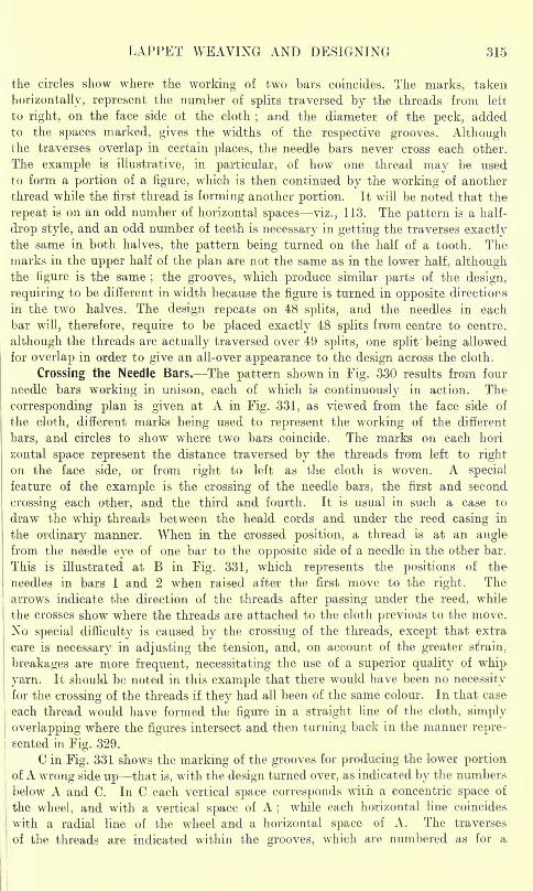
LAPPET WEAVING AND DESIGNING 315
the circles show where the working of two bars coincides. The marks, taken
horizontally, represent the number of splits traversed by the threads from left
to right, on the face side ot the cloth; and the diameter of the peck, added
to the spaces marked, gives the widths of the respective grooves. Althoughthe traverses overlap in certain places, the needle bars never cross each other.
The example is illustrative, in particular, of how one thread may be used
to form a portion of a figure, which is then continued by the working of another
thread while the first thread is forming another portion. It will be noted that the
repeat is on an odd number of horizontal spaces viz., 113. The pattern is a half-
drop style, and an odd number of teeth is necessary in getting the traverses exactlythe same in both halves, the pattern being turned on the half of a tooth. Themarks in the upper half of the plan are not the same as in the lower half, althoughthe figure is the same
;the grooves, which produce similar parts of the design,
requiring to be different in width because the figure is turned in opposite directions
in the two halves. The design repeats on 48 splits, and the needles in each
bar will, therefore, require to be placed exactly 48 splits from centre to centre,
although the threads are actually traversed over 49 splits, one split being allowed
for overlap in order to give an all-over appearance to the design across the cloth.
Crossing the Needle Bars. The pattern shown in Fig. 330 results from four
needle bars working in unison, each of which is continuously in action. The
corresponding plan is given at A in Fig. 331, as viewed from the face side of
the cloth, different marks being used to represent the working of the different
bars, and circles to show where two bars coincide. The marks on each hori
zontal space represent the distance traversed by the threads from left to right
on the face side, or from right to left as the cloth is woven. A special
feature of the example is the crossing of the needle bars, the first and second
crossing each other, and the third and fourth. It is usual in such a case to
draw the whip threads between the heald cords and under the reed casing in
the ordinary manner. When in the crossed position, a thread is at an anglefrom the needle eye of one bar to the opposite side of a needle in the other bar.
This is illustrated at B in Fig. 331, which represents the positions of the
needles in bars 1 and 2 when raised after the first move to the right. The
arrows indicate the direction of the threads after passing under the reed, while
the crosses show where the threads are attached to the cloth previous to the move.
No special difficulty is caused by the crossing of the threads, except that extra
care is necessary in adjusting the tension, and, on account of the greater strain,
breakages are more frequent, necessitating the use of a superior quality of whip
yarn. It should be noted in this example that there would have been no necessity
for the crossing of the threads if they had all been of the same colour. In that case
each thread would have formed the figure in a straight line of the cloth, simply
overlapping where the figures intersect and then turning back in the manner repre-
sented in Fig. 329.
C in Fig. 331 shows the marking of the grooves for producing the lower portion
of A wrong side up that is, with the design turned over, as indicated by the numbers,
below A and C. In C each vertical space corresponds with a concentric space of
the wheel, and with a vertical space of A;
while each horizontal line coincides
with a radial line of the wheel and a horizontal space of A. The traverses
of the threads are indicated within the grooves, which are numbered as for a
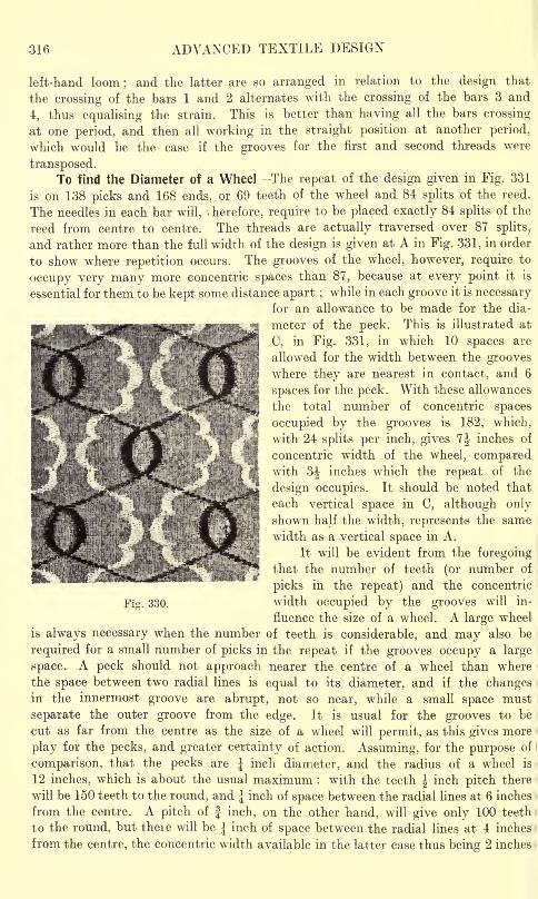
316 ADVANCED TEXTILE DESIGN
left-hand loom; and the latter are so arranged in relation to the design that
the crossing of the bars 1 and 2 alternates with the crossing of the bars 3 and
4, thus equalising the strain. This is better than having all the bars crossing
at one period, and then all working in the straight position at another period,
which would be the case if the grooves for the first and second threads were
transposed.To find the Diameter of a Wheel The repeat of the design given in Fig. 331
is on 138 picks and 168 ends, or 69 teeth of the wheel and 84 splits of the reed.
The needles in each bar will, , herefore, require to be placed exactly 84 splits of the
reed from centre to centre. The threads are actually traversed over 87 splits,
and rather more than the full width of the design is given at A in Fig. 331, in order
to show where repetition occurs. The grooves of the wheel, however, require to
occupy very many more concentric spaces than 87, because at every point it is
essential for them to be kept some distance apart ;while in each groove it is necessary
for an allowance to be made for the dia-
meter of the peck. This is illustrated at
C, in Fig. 331, in which 10 spaces are
allowed for the width between the grooveswhere they are nearest in contact, and 6
spaces for the peck. With these allowances
the total number of concentric spaces
occupied by the grooves is 182, which,
with 24 splits per inch, gives 7J inches of
concentric width of the wheel, comparedwith 3J inches which the repeat of the
design occupies. It should be noted that
each vertical space in C, although onlyshown half the width, represents the same
width as a vertical space in A.
It will be evident from the foregoingthat the number of teeth (or number of
picks in the repeat) and the concentric
width occupied by the grooves will in-
fluence the size of a wheel. A large wheel
is always necessary when the number of teeth is considerable, and may also be
required for a small number of picks in the repeat if the grooves occupy a large
space. A peck should not approach nearer the centre of a wheel than where
the space between two radial lines is equal to its diameter, and if the changesin the innermost groove are abrupt, not so near, while a small space must
separate the outer groove from the edge. It is usual for the grooves to be
cut as far from the centre as the size of a wheel will permit, as this gives more
play for the pecks, and greater certainty of action. Assuming, for the purpose of
comparison, that the pecks are J inch diameter, and the radius of a wheel is
12 inches, which is about the usual maximum : with the teeth \ inch pitch there
will be 150 teeth to the round, and J inch of space between the radial lines at 6 inches
from the centre. A pitch of f inch, on the other hand, will give only 100 teeth
to the round, but there will be J inch of space between the radial lines at 4 inches
from the centre, the concentric width available in the latter case thus being 2 inches
Fie. 330.
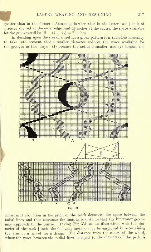
LAPPET WEAVING AND DESIGNING 317
greater than in the former. Assuming, further, that in the latter case J inch of
space is allowed at the outer edge, and 4J inches at the centre, the space available
for the grooves will be 12 (| + 4-J)= 7 inches.
In deciding upon the size of wheel for a given pattern it is therefore necessaryto take into account that a smaller diameter reduces the space available for
the grooves in two ways : (1) because the radius is smaller, and (2) because the
consequent reduction in the pitch of the teeth decreases the space between the
radial lines, and thus increases the limit as to distance that the innermost groove
may approach to the centre. Taking Fig. 331 as an illustration, with the dia-
meter of the peck J inch, the following method may be employed in ascertaining
the size of a wheel for a design. The distance from the centre of the wheel,
where the space between the radial lines is equal to the diameter of the peck, is
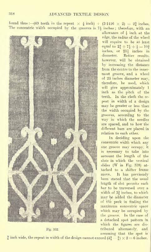
318 ADVANCED TEXTILE DESIGN
found thus : (69 teeth in the repeat x J inch) -f- (3' 1416 x 2)= 2| inches.
The concentric width occupied by the grooves is 7J inches; therefore, with an
allowance of J inch at the
edge, the radius of the wheel
will require to be at least
equal to 2J + 7J + |-= 10f
inches, or 21J inches in
diameter. Better results,
however, will be obtained
by increasing the distance
from the centre to the inner-
most groove, and a wheel
of 23 inches diameter may,therefore, be used, which
will give approximately 1
inch as the pitch of the
teeth. In the cloth the re-
peat in width of a design
may be greater or less than
the width occupied by the
grooves, according to the
way in which the needles
are spaced, and to how the
different bars are placed in
relation to each other.
In deciding upon the
concentric width which anyone groove may occupy, it
is necessary to take into
MJ v, account the length of the
:?:,.
""'": slots in which the vertical
f| |slides (\V in Fir. 318) <it-
Jlllm tached to a shifter frame
move. It has previouslybeen stated that the usual
length of slot permits each
bar to be traversed over a
width of 3| inches, to which
may b added the diameter
of the peck in finding the
maximum concentric spacewhich may be occupied bythe groove. In the case of
a detached spot pattern in
which the figures are dis-
Fig. 332. tributed alternately, and
assuming that the spot is
J inch wide, the repeat in width of the design cannot exceed (3| f ) X 2 = 6 inches.
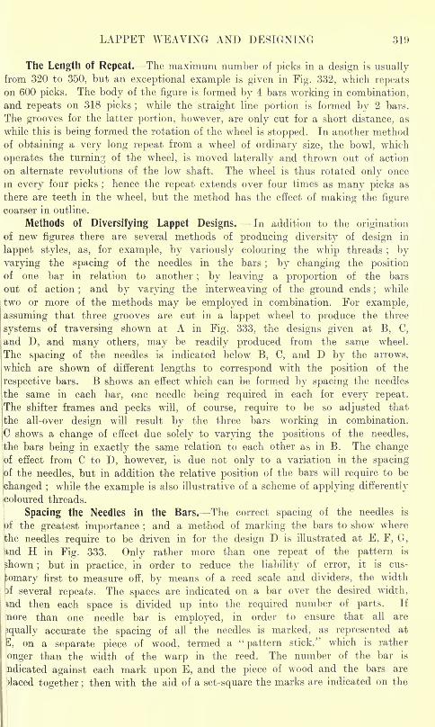
LAPPET WEAVING AND DESIGNING 319
The Length of Repeat. The maximum number of picks in a design is usuallyfrom 320 to 350, but an exceptional example is given in Fig. 332, which repeatson 600 picks. The body of the figure is formed by 4 bars working in combination,and repeats on 318 picks ;
while the straight line portion is formed by 2 bars.
The grooves for the latter portion, however, are only cut for a short distance, as
while this is being formed the rotation of the wheel is stopped. In another methodof obtaining a very long repeat from a wheel of ordinary size, the bowl, which
operates the turning of the wheel, is moved laterally and thrown out of action
on alternate revolutions of the low shaft. The wheel is thus rotated only once
in every four picks ;hence the repeat extends over four times as many picks as
there are teeth in the wheel, but the method has the effect of making the figure
coarser in outline.
Methods of Diversifying Lappet Designs. In addition to the originationof new figures there are several methods of producing diversity of design in
lappet styles, as, for example, by variously colouring the whip threads; by
varying the spacing of the needles in the bars; by changing the position
of one bar in relation to another; by leaving a proportion of the bars
out of action;
and by varying the interweaving of the ground ends;
while
two or more of the methods may be employed in combination. For example,
assuming that three grooves are cut in a lappet wheel to produce the three
systems of traversing shown at A in Fig. 333, the designs given at B, C,
and D, and many others, may be readily produced from the same wheel.
The spacing of the needles is indicated below B, C, and D by the arrows,
which are shown of different lengths to correspond with the position of the
respective bars. B shows an effect which can be formed by spacing the needles
the same in each bar, one needle being required in each for every repeat.
The shifter frames and pecks will, of course, require to be so adjusted that
the all-over design will result by the three bars working in combination.
C shows a change of effect due solely to varying the positions of the needles,
the bars being in exactly the same relation to each other as in B. The changeof effect from C to D, however, is due not only to a variation in the spacing
jof the needles, but in addition the relative position of the bars will require to be
changed ;while the example is also illustrative of a scheme of applying differently
coloured threads.
Spacing the Needles in the Bars. The correct spacing of the needles is
of the greatest importance ;and a method of marking the bars to show where
^he needles require to be driven in for the design D is illustrated at E, F, G,
and H in Fig. 333. Only rather more than one repeat of the pattern is
shown;
but in practice, in order to reduce the liability of error, it is cus-
tomary first to measure off, by means of a reed scale and dividers, the width
}f several repeats. The spaces are indicated on a bar over the desired width,
md then each space is divided up into the required number of parts. If
nore than one needle bar is employed, in order to ensure that all are
3qually accurate the spacing of all the needles is marked, as represented at
3, on a separate piece of wood, termed a "pattern stick," which is rather
onger than the width of the warp in the reed. The number of the bar is
ndicated against each mark upon E, and the piece of wood and the bars are
)laced together ;then with the aid of a set-square the marks are indicated on the
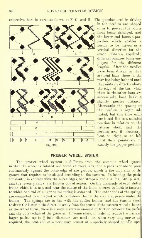
320 ADVANCED TEXTILE DESIGN
respective bars in turn, as shown at F, G, and H.
1 1H
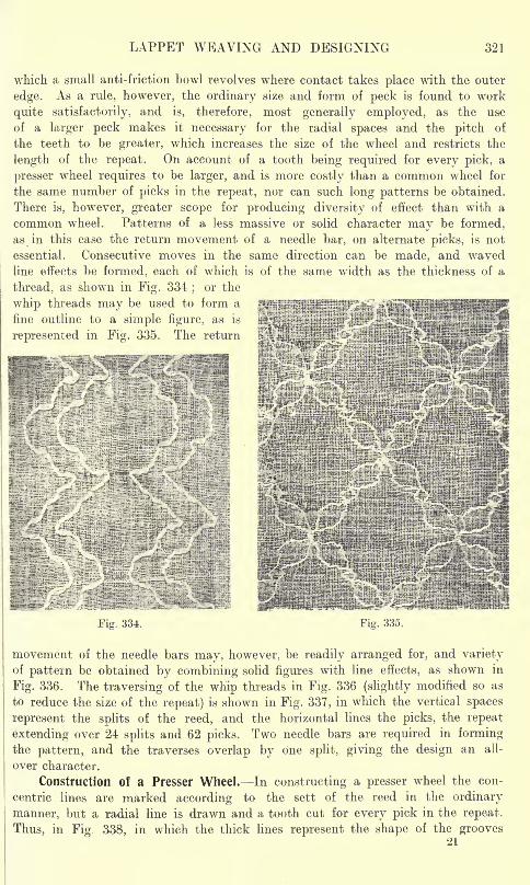
LAPPET WEAVING AND DESIGNING 321
which a small anti-friction bowl revolves where contact takes place with the outer
edge. As a rule, however, the ordinary size and form of peck is found to work
quite satisfactorily, and is, therefore, most generally employed, as the use
of a larger peck makes it necessary for the radial spaces and the pitch of
the teeth to be greater, which increases the size of the wheel and restricts the
length of the repeat. On account of a tooth being required for every pick, a
presser wheel requires to be larger, and is more costly than a common wheel for
the same number of picks in the repeat, nor can such long patterns be obtained.
There is, however, greater scope for producing diversity of effect than with a
common wheel. Patterns of a less massive or solid character may be formed,
as in this case the return movement of a needle bar, on alternate picks, is not
essential. Consecutive moves in the same direction can be made, and wavedline effects be formed, each of which is of the same width as the thickness of a
thread, as shown in Fig. 334;
or the
whip threads maybe used to form a^fiflljiilnlW:'
1
fine outline to a simple figure, as isi;:?;;^;lH
i; ^
represented in Fig. 335. The return i^-ilfei;
^^^^^&^^^^--^IU;iIKIii::> -':::. -fHli-li^f
" ::'
;: '
'
S^SiiiiftPpSlHIi;!;;;^^^SBHHNHHIFig. 334. Fig. 335.
movement of the needle bars may, however, be readily arranged for, and varietyof pattern be obtained by combining solid figures with line effects, as shown in
Fig. 336. The traversing of the whip threads in Fig. 336 (slightly modified so as
to reduce the size of the repeat) is shown in Fig. 337, in which the vertical spaces
represent the splits of the reed, and the horizontal lines the picks, the repeat
extending over 24 splits and 62 picks. Two needle bars are required in formingthe pattern, and the traverses overlap by one split, giving the design an all-
over character.
Construction of a Presser Wheel. In constructing a presser wheel the con-
centric lines are marked according to the sett of the reed in the ordinary
manner, but a radial line is drawn and a tooth cut for every pick in the repeat.
Thus, in Fig. 338, in which the thick lines represent the shape of the grooves
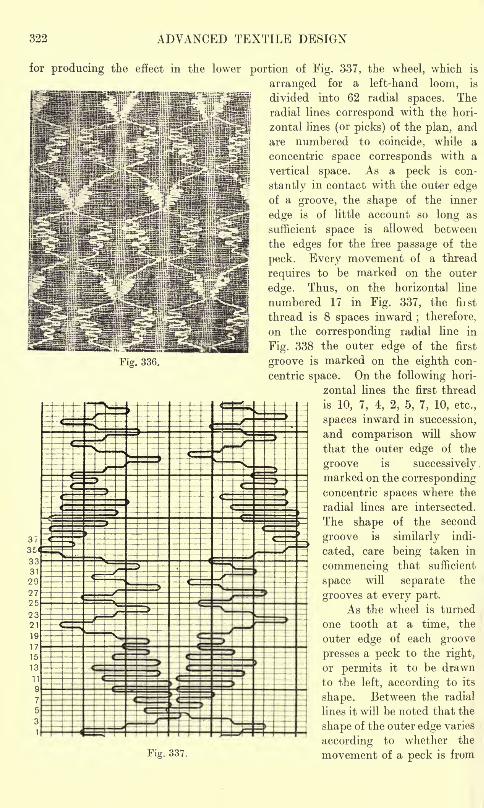
322 ADVANCED TEXTILE DESIGN
Fig. 336.
for producing the effect in the lower portion of Fig. 337, the wheel, which is
arranged for a left-hand loom, is
divided into 62 radial spaces. Theradial lines correspond with the hori-
zontal lines (or picks) of the plan, and
are numbered to coincide, while a
concentric space corresponds with a
vertical space. As a peck is con-
stantly in contact with the outer edgeof a groove, the shape of the inner
edge is of little account so long as
sufficient space is allowed between
the edges for the free passage of the
peck. Every movement of a thread
requires to be marked on the outer
edge. Thus, on the horizontal line
numbered 17 in Fig. 337, the fiist
thread is 8 spaces inward; therefore,
on the corresponding radial line in
Fig. 338 the outer edge of the first
groove is marked on the eighth con-
centric space. On the following hori-
zontal lines the first thread
is 10, 7, 4, 2, 5, 7, 10, etc.,
spaces inward in succession,
and comparison will show
that the outer edge of the
groove is successivelymarked on the correspondingconcentric spaces where the
radial lines are intersected.
The shape of the second
groove is similarly indi-
cated, care being taken in
commencing that sufficient
space will separate the
grooves at every part.
As the wheel is turned
one tooth at a time, the
outer edge of each groove
presses a peck to the right,
or permits it to be drawn
to the left, according to its
shape. Between the radial
lines it will be noted that the
shape of the outer edge varies
according to whether the
movement of a peck is fromFig. 337.
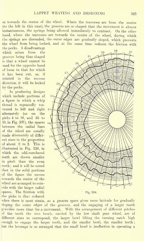
LAPPET WEAVING AND DESIGNING 323
25
or towards the centre of the wheel. Where the traverses are from the centre
(to the left in this case), the grooves are so shaped that the movement is almost
instantaneous, the springs being allowed immediately to contract. On the other
hand, where the traverses are towards the centre of the wheel, during whichthe springs are distended, the outer edges are gradually sloped, which preventsthe wheel from being locked, and at the same time reduces the friction withthe pecks. A disadvantagewhich arises from the 33 ^ ^ _ 3?
grooves being thus shapedis that a wheel cannot be
used for the opposite hand
of loom to that for which
it has been cut, as, if
rotated in the reverse
direction, it will be locked
by the pecks.
In producing designswhich include portions of
a figure in which a whipthread is repeatedly tra-
versed to left and right
alternately (as on the
picks 4 to 18, and 35 to
49, in Fig. 337), the spacesbetween the radial lines
of the wheel are usuallymade alternately of differ-
ent sizes in the proportionof about 3 to 2. This is
illustrated in Fig. 338, in
which the odd-numbered
teeth are shown smaller
in pitch than the even
teeth;and it will be noted
that in the solid portionsof the figure the movestowards the centre of the
wheel are arranged to coin-
i cide with the larger radial
! spaces. The friction with
'the picks is thus reduced
when there is most strain, ,
as a greater space gives more latitude for gradually
sloping the outer edges of the grooves, and the engaging of a larger tooth
provides more time for a movement. With the arrangement of different pitchesof the teeth the two bowls, carried by the low shaft gear wheel, are of
different sizes to correspond, the larger bowl lifting the turning catch high
onough to engage the larger teeth, and the smaller bowl, the smaller teeth;
I
but the leverage is so arranged that the small bowl is ineffective in operating a
Fig. 338.
324 ADVANCED TEXTILE DESIGN
large tooth. If, therefore, the wheel gets an odd number of teeth out of proper
rotation, it will remain stationary for a pick, and this gives the advantage that
in the solid figure the to-and-fro movements of the needle bars are retained in
correct time with the picking an important point which has previously been
mentioned. It is, of course, only in the parts of a design where the traverses are
alternately to left and right that each movement of a bar can be definitely arrangedto correspond in direction with the pick that follows. In the other parts of a patternthe direction of a traverse may or may not coincide with the direction of the following
pick ;and care is necessary here in arranging the moves, or undue friction may
be caused. Thus, long moves may be more readily made if they correspond with
the engaging of the larger teeth, and if each is in the same direction as the
pick that follows.
To find the Length of Whip Warp. A whip thread usually requires to be
very much longer than the ground warp, the length of the former varying accordingto the average of the distance traversed at a movement
; thus, in the same pattern,if the traverses of the threads vary, different lengths will be required for the different
whip warps. Assuming that the average length of the traverses of a thread is
5 splits, and there are 20 splits per inch, ^ or J inch of whip warp will be requiredat every pick ;
and if 32 picks per inch are inserted, J inch x 32 = 8 inches of
whip warp will be required for each inch of ground warp. Calculations may be
conveniently wrorked by the following rule, which gives an idea of the proportional
lengths of the wr
hip and ground warps :
Total splits traversed in repeat X picks per inch
picks in repeat X splits per inch
number of times the whip warp is longer than the ground warp.In finding the total number of splits traversed by a thread it is necessary
to note the moves in succession and add them together as, for example, in Fig. 337
the first eight moves of the thread on the left are 4, 3, 2, 3, 2, 3, 3, 5 splits,
which, added together, total 25. By continuing in this manner it will be found
that the number of splits traversed in the full repeat by the first thread = 206.
The picks in the repeat == 62. and assuming that there are 24 splits and 44 picks
per inch the calculation wrill be :
206 total splits X 44 picks per inch
62 picks in repeat x 24 spiits~pe7inch
== 6'
9 f whip war? to l o ground wai'P'
The calculation is more applicable to common wheel lappet designs than presserwheel styles, and at the best only gives approximately the length of whip warpthat is required, as the length can be varied by the tension that is put upon the
whip threads.
Lappet Styles in Imitation of Net Leno. The presser wheel system is con-j
veniently adapted to the production of such styles as are shown in Figs. 339j
to 345, which are similar in appearance to effects produced on the gauze or lenoj
principle. With the lappet wheel, however, there are no restrictions as regards |
the denting of the warp threads, as a whip thread, not being passed through |
the reed, may be readily made to cross a large number of splits, while one whipj
thread may cross another. Fig. 339 shows a style produced by two frames in|
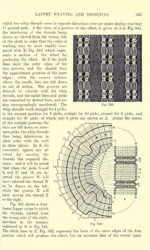
LAPPET WEAVING AND DESIGNING 325
Fig. 339.
which two whip threads cross in opposite directions over (or under during weaving)11 ground ends. A flat view, of a portion of the effect, is given at A in Fig. 340,
the interlacing of the threads beingshown as viewed from the wrong side
of the cloth in order that the order of
working may be more readily com-
pared with E, Fig. 340, which repre-
sents a section of the wheel for
producing the effect. In E the thick
lines show the outer edges of the
two grooves, and the shaded lines
the approximate position of the inner
edges ;while the crosses indicate
where the needle bars are left downor out of action. The grooves are
lettered to coincide with the whipthreads, and the radial lines and picks
are connected by dotted lines, and are
also correspondingly numbered. The
whip threads work straight for 4 picks,
in the crossed position for 2 picks, straight for 10 picks, crossed for 2 picks, and
straight for 30 picks, of which only 6 picks are shown at A. About the centre
of the straight portions the
bars are left down on alter-
nate picks, the whip threads
thus being interwoven in
plain order with the weft
at these places. In E six
concentric spaces are al-
lowed for moving the
threads the required dis-
tance;and it will be noted
that when the picks 5 and
6, and 17 and 18, are in-
serted, the groove W will
have allowed the thread Wto be drawn to the left,
while the groove X will
have moved the thread Xto the right.
Fig. 341 shows a four-
frame lappet stripe in which
the threads, viewed from
the wrong side of the cloth,
interlace in the mannerindicated at B in Fig. 342.
The thick lines in F, Fig. 342, represent the form of the outer edges of the four
grooves which will produce the effect, but an accurate idea of the actual space
18
W
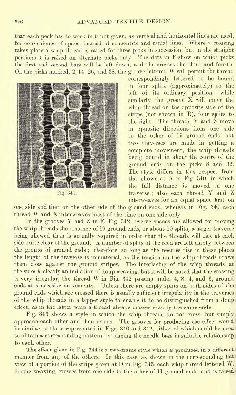
326 ADVANCED TEXTILE DESIGN
that each peck has to work in is not given, as vertical and horizontal lines are used,
for convenience of space, instead of concentric and radial lines. Where a crossing
takes place a whip thread is raised for three picks in succession, but in the straight
portions it is raised on alternate picks only. The dots in F show on which picksthe first and second bars will be left down, and the crosses the third and fourth.
On the picks marked, 2, 14, 26, and 38, the groove lettered W will permit the thread
correspondingly lettered to be bound
in four splits (approximately) to the
left of its ordinary position ;while
similarly the groove X will move the
whip thread on the opposite side of the
stripe (not shown in B), four splits to
the right. The threads Y and Z movein opposite directions from one side
to the other of 19 ground ends, but
two traverses are made in getting a
complete movement, the whip threads
being bound in about the centre of the
ground ends on the picks 8 and 32.
The style differs in this respect from
that shown at A in Fig. 340, in which
the full distance is moved in one
traverse;
also each thread Y and Z
interweaves for an equal space first on
one side and then on the other side of the ground ends, whereas in Fig. 340 each
thread W and X interweaves most of the time on one side only.In the grooves Y and Z in F, Fig. 342, twelve spaces are allowed for moving
the whip threads the distance of 19 ground ends, or about 10 splits, a larger traverse
being allowed than is actually required in order that the threads will rise at each
side quite clear of the ground. A number of splits of the reed are left empty between
the groups of ground ends; therefore, so long as the needles rise in these places
the length of the traverse is immaterial, as the tension on the whip threads draws
them close against the ground stripes. The interlacing of the whip threads at
the sides is clearly an imitation of doup weaving, but it will be noted that the crossing
is very irregular, the thread W in Fig. 342 passing under 4, 8, 4, and 6, groundends at successive movements. Unless there, are empty splits on both sides of the
ground ends which are crossed there is usually sufficient irregularity in the traverses
of the whip threads in a lappet style to enable it to be distinguished from a doupeffect, as in the latter whip a thread always crosses exactly the same ends.
Fig. 343 shows a style in which the whip threads do not cross, but simply
approach each other and then return. The grooves for producing the effect would
be similar to those represented in Figs. 340 and 342, either of which could be used i
to obtain a corresponding pattern by placing the needle bars in suitable relationship
to each other.
The effect given in Fig. 344 is a two-frame style which is produced in a different
manner from any of the others. In this case, as shown in the corresponding flat
view of a portion of the stripe given at D in Fig. 345, each whip thread lettered W,
during weaving, crosses from one side to the other of 11 ground ends, and is raised
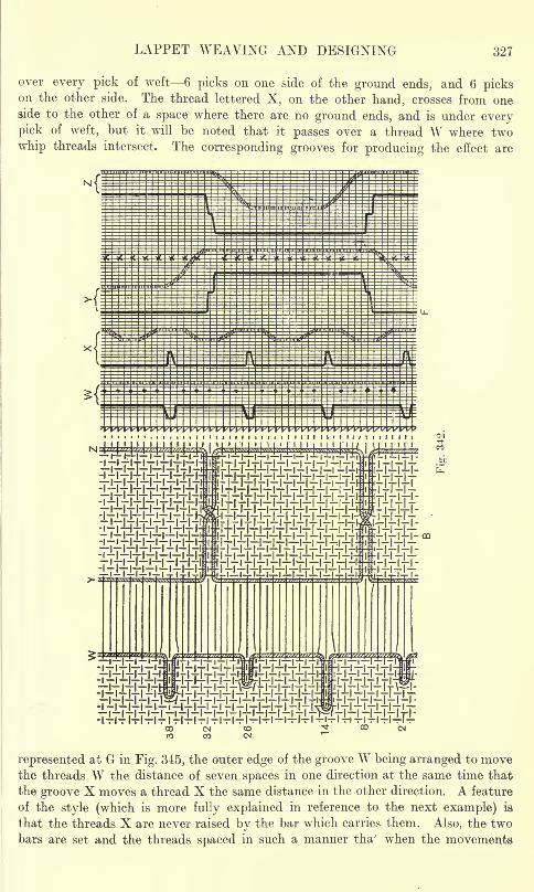
LAPPET WEAVING AND DESIGNING 327
over every pick of weft 6 picks on one side of the ground ends, and 6 pickson the other side. The thread lettered X, on the other hand, crosses from oneside to the other of a space where there are no ground ends, and is under everypick of weft, but it will be noted that it passes over a thread W where two
whip threads intersect. The corresponding grooves for producing the effect are
represented at G in Fig. 345, the outer edge of the groove W being arranged to movethe threads W the distance of seven spaces in one direction at the same time that
the groove X moves a thread X the same distance in the other direction. A feature
of the style (which is more fully explained in reference to the next example) is
that the threads X are never raised by the bar which carries them. Also, the two
bars are set and the threads spaced in such a manner tha' when the movements
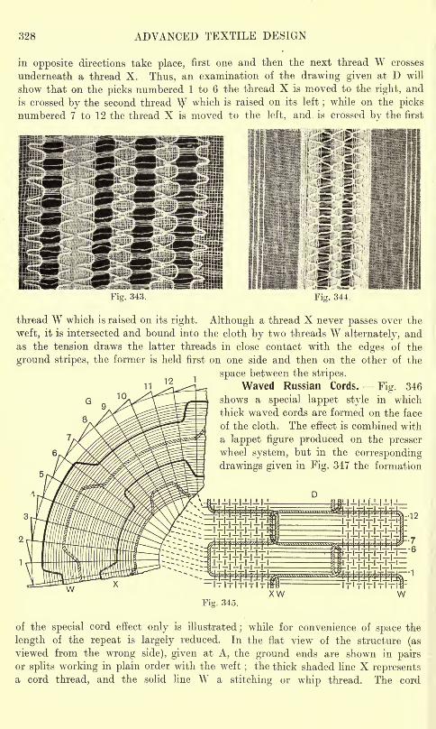
328 ADVANCED TEXTILE DESIGN
in opposite directions take place, first one and then the next thread W crosses
underneath a thread X. Thus, an examination of the drawing given at D will
show that on the picks numbered 1 to 6 the thread X is moved to the right, and
is crossed by the second thread \y which is raised on its left;while on the picks
numbered 7 to 12 the thread X is moved to the left, and. is crossed bv the first
Fig. 343. Fig. 344.
thread W which is raised on its right. Although a thread X never passes over the
weft, it is intersected and bound into the cloth by two threads W alternately, andas the tension draws the latter threads in close contact with the edges of the
ground stripes, the former is held first on one side and then on the other of the
space between the stripes.I V I
11
10Waved Russian Cords. Fig. 346
shows a special lappet style in which
thick waved cords are formed on the face
of the cloth. The effect is combined with
lappet figure produced on the presserwheel system, but in the corresponding
drawings given in Fig. 347 the formation
-12
XWFig. 345.
of the special cord effect only is illustrated;while for convenience of space the
length of the repeat is largely reduced. In the flat view of the structure (as
viewed from the wrong side), given at A, the ground ends are shown in pairsor splits working in plain order with the weft
;the thick shaded line X represents
a cord thread, and the solid line W a stitching or whip thread. The cord
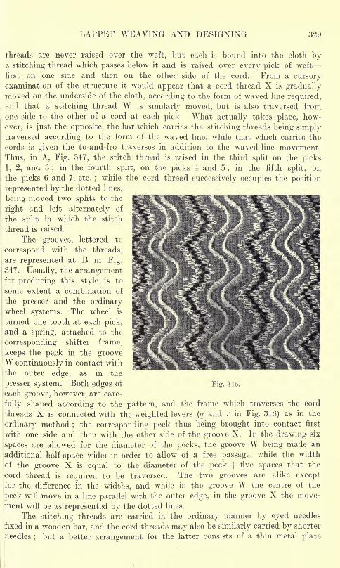
LAPPET WEAVING AND DESIGNING 329
threads are never raised over the weft, but each is bound into the cloth bya stitching thread which passes below it and is raised over every pick of weft
first on one side and then on the other side of the cord. From a cursoryexamination of the structuie it would appear that a cord thread X is graduallymoved on the underside of the cloth, according to the form of waved line required,
|
and that a stitching thread W is similarly moved, but is also traversed from
one side to the other of a cord at each pick. What actually takes place, how-
ever, is just the opposite, the bar which carries the stitching threads being simplytraversed according to the form of the waved line, while that which carries the
cords is given the to-and-fro traverses in addition to the waved-line movement.
Thus, in A, Fig. 347, the stitch thread is raised in the third split on the picks
1, 2, and 3;
in the fourth split, on the picks 4 and 5;
in the fifth split, on
I the picks 6 and 7, etc.;while the cord thread successively occupies the position
represented by the dotted lines,
being moved two splits to the
right and left alternately of
i the split in which the stitch
thread is raised.
The grooves, lettered to
i correspond with the threads,
are represented at B in Fig.
347. Usually, the arrangement
(for producing this style is to
some extent a combination of
the presser and the ordinarywheel systems. The wheel is
turned one tooth at each pick,
and a spring, attached to the
corresponding shifter frame,
keeps the pe.ck in the grooveW continuously in contact with
the outer edge, as in the
presser system. Both edges of
each groove, however, are care-
fully shaped according to the pattern, and the frame which traverses the cord
threads X is connected with the weighted levers (q and r in Fig. 318) as in the
ordinary method;the corresponding peck thus being brought into contact first
with one side and then with the other side of the groove X. In the drawing six
spaces are allowed for the diameter of the pecks, the groove W being made an
additional half-space wider in order to allow of a free passage, while the width
of the groove X is equal to the diameter of the peck -f five spaces that the
cord thread is required to be traversed. The two grooves are alike exceptfor the difference in the widths, and while in the groove W the centre of the
peck will move in a line parallel with the outer edge, in the groove X the move-
ment will be as represented by the dotted lines.
The stitching threads are carried in the ordinary manner by eyed needles
fixed in a wooden bar, and the cord threads may also be similarly carried by shorter
needles;
but a better arrangement for the latter consists of a thin metal plate
Fig. 346.
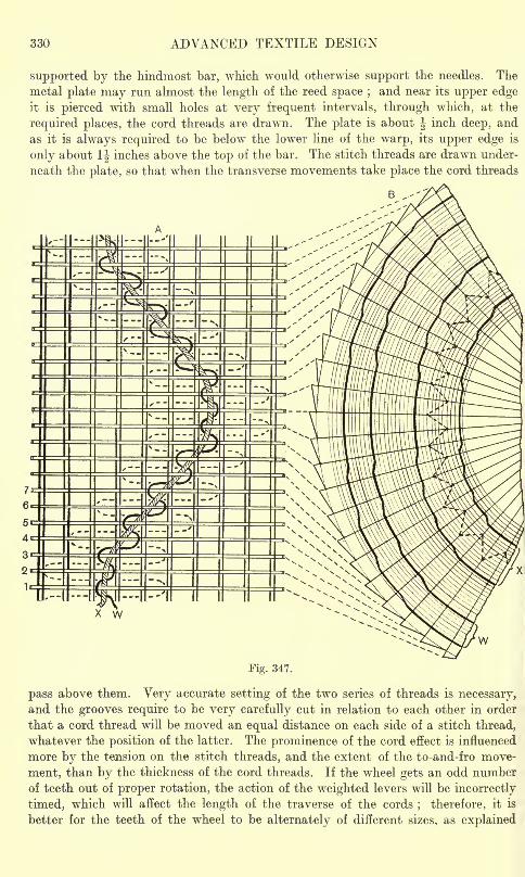
330 ADVANCED TEXTILE DESIGN
supported by the hindmost bar, which would otherwise support the needles. The
metal plate may run almost the length of the reed space ;and near its upper edge
it is pierced with small holes at very frequent intervals, through which, at the
required places, the cord threads are drawn. The plate is about f inch deep, and
as it is always required to be below the lower line of the warp, its upper edge is
only about 1J inches above the top of the bar. The stitch threads are drawn under-
neath the plate, so that when the transverse movements take place the cord threads
W
Fig. 347.
pass above them. Very accurate setting of the two series of threads is necessary,
and the grooves require to be very carefully cut in relation to each other in order
that a cord thread will be moved an equal distance on each side of a stitch thread,
whatever the position of the latter. The prominence of the cord effect is influenced
more by the tension on the stitch threads, and the extent of the to-and-fro move-
ment, than by the thickness of the cord threads. If the wheel gets an odd numberof teeth out of proper rotation, the action of the weighted levers will be incorrectly
timed, which will affect the length of the traverse of the cords; therefore, it is
better for the teeth of the wheel to be alternately of different sizes, as explained
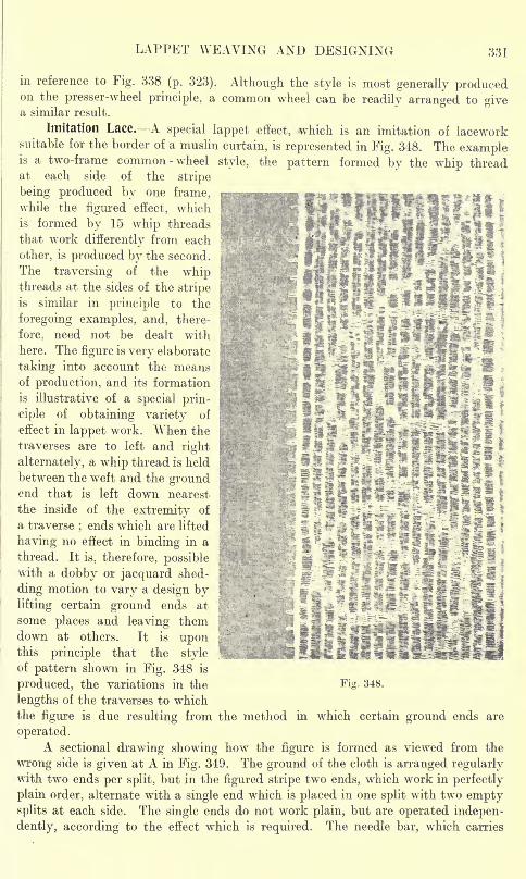
LAPPET WEAVING AND DESIGNING! 331
in reference to Fig. 338 (p. 323). Although the style is most generally producedon the presser-wheel principle, a common wheel can be readily arranged to givea similar result.
Imitation Lace. A special lappet effect, which is an imitation of laceworksuitable for the border of a muslin curtain, is represented in Fig. 348. The exampleis a two-frame common -wheel style, the pattern formed by the whip threadat each side of the stripe
being produced by one frame,while the figured effect, whichis formed by 15 whip threads
that work differently from each
other, is produced by the second.
The traversing of the whipthreads at the sides of the stripeis similar in principle to the
foregoing examples, and, there-
fore; need not be dealt with
here. The figure is very elaborate
taking into account the meansof production, and its formation
is illustrative of a special prin-
ciple of obtaining variety of
effect in lappet work. When the
traverses are to left and right
alternately, a whip thread is held
between the weft and the groundend that is left down nearest
the inside of the extremity of
a traverse;ends which are lifted
having no effect in binding in a
thread. It is, therefore, possiblewith a dobby or jacquard shed-
ding motion to vary a design bylifting certain ground ends at
some places and leaving themdown at others. It is uponthis principle that the styleof pattern shown in Fig. 348 is
produced, the variations in the Fig. 348.
lengths of the traverses to which
the figure is due resulting from the method in which certain ground ends are
operated.A sectional drawing showing how the figure is formed as viewed from the
wrong side is given at A in Fig. 349. The ground of the cloth is arranged regularlywith two ends per split, but in the figured stripe two ends, which work in perfectly
plain order, alternate with a single end which is placed in one split with two emptysplits at each side. The single ends do not work plain, but are operated indepen-
dently, according to the effect which is required. The needle bar, which carries
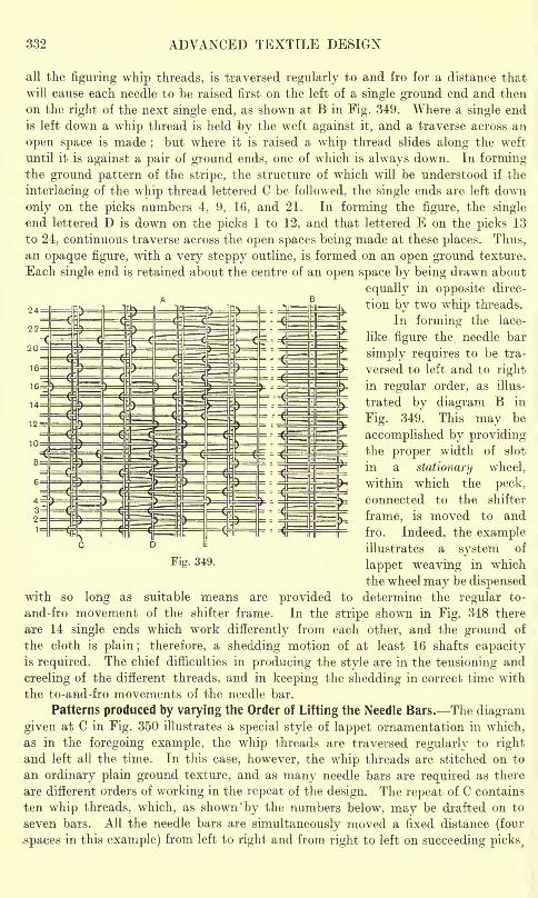
332 ADVANCED TEXTILE DESIGN
all the figuring whip threads, is traversed regularly to and fro for a distance that
will cause each needle to be raised first on the left of a single ground end and then
on the right of the next single end, as shown at B in Fig. 349. Where a single end
is left down a whip thread is held by the weft against it, and a traverse across an
open space is made;but where it is raised a whip thread slides along the weft
until it is against a pair of ground ends, one of which is always down. In formingthe ground pattern of the stripe, the structure of which will be understood if the
interlacing of the whip thread lettered C be followed, the single ends are left down
only on the picks numbers 4, 9, 16, and 21. In forming the figure, the single
end lettered D is down on the picks 1 to 12, and that lettered E on the picks 13
to 24, continuous traverse across the open spaces being made at these places. Thus,an opaque figure, with a very steppy outline, is formed on an open ground texture.
Each single end is retained about the centre of an open space by being drawn about
equally in opposite direc-
tion by two whip threads.
In forming the lace-
like figure the needle bar
simply requires to be tra-
versed to left and to right
in regular order, as illus-
trated by diagram B in
Fig. 349. This may be
accomplished by providingthe proper width of slot
in a stationary wheel,
within which the peck,
connected to the shifter
frame, is moved to and
fro. Indeed, the exampleillustrates a system of
Fig. 349.lappet weaving in which
the wheel may be dispensedwith so long as suitable means are provided to determine the regular to-
and-fro movement of the shifter frame. In the stripe shown in Fig. 348 there
are 14 single ends which work differently from each other, and the ground of
the cloth is plain; therefore, a shedding motion of at least 16 shafts capacityis required. The chief difficulties in producing the style are in the tensioning and
creeling of the different threads, and in keeping the shedding in correct time with
the to-and-fro movements of the needle bar.
Patterns produced by varying the Order of Lifting the Needle Bars. The diagram
given at C in Fig. 350 illustrates a special style of lappet ornamentation in which,
as in the foregoing example, the whip threads are traversed regularly to right
and left all the time. In this case, however, the whip threads are stitched on to
an ordinary plain ground texture, and as many needle bars are required as there
are different orders of working in the repeat of the design. The repeat of C contains
ten whip threads, which, as shown 'by the numbers below, may be drafted on to
seven bars. All the needle bars are simultaneously moved a fixed distance (four
.spaces in this example) from left to right and from right to left on succeeding picks t
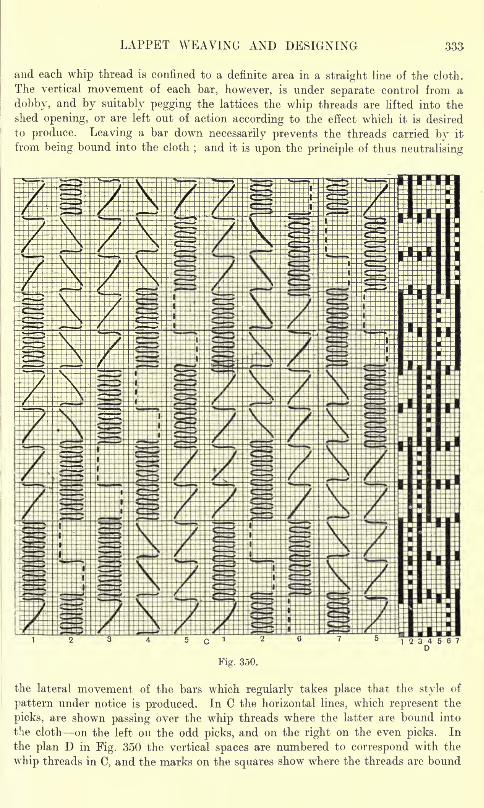
LAPPET WEAVING AND DESIGNING 333
and each whip thread is confined to a definite area in a straight line of the cloth.
The vertical movement of each bar, however, is under separate control from a
dobby, and by suitably pegging the lattices the whip threads are lifted into the
shed opening, or are left out of action according to the effect which it is desired
to produce. Leaving a bar down necessarily prevents the threads carried by it
from being bound into the cloth;and it is upon the principle of thus neutralising
Fig. 350.
the lateral movement of the bars which regularly takes place that the style of
pattern under notice is produced. In C the horizontal lines, which represent the
picks, are shown passing over the whip threads where the latter are bound into
the cloth on the left on the odd picks, and on the right on the even picks. In
the plan D in Fig. 350 the vertical spaces are numbered to correspond with the
whip threads in C, and the marks on the squares show where the threads are bound
334 ADVANCED TEXTILE DESIGN
in i.e., where the needle bars are raised during weaving. A solid portion of whip
figure is formed where a bar is lifted for a number of picks in succession, as shown
by the thread 1 on the picks 8 to 25. By raising a bar on an odd pick, and leaving it
out of action for a time before lifting it in on an even pick, the whip forms a diagonalline from left to right (on the face of the cloth), as shown by the thread number 1
on the picks 1 to 8. If, however, a bar is lifted on an even pick, and is then inactive
before being lifted on an odd pick, a diagonal line from right to left is formed,
as shown by the thread 4 on the picks 2 to 9. If a bar is lifted only on the even
picks, it will form a straight line on the right, and if only on the odd picks a straight
line on the left, as shown by the thread 2 on the picks 10 to 16, and 17 to 25
respectively. Each whip thread can thus be made to form two kinds of horizontal,
vertical, and diagonal lines simply from the manner in which the bar is lifted.
As it is only in a vertical direction that the bars require to be moved independentlyof each other they may be made thinner than is ordinarily the case, and a larger
number can thus be placed in the space between the pin-bar and the reed. The
system, combined with careful drafting of the whip threads on the bars, gives great
scope for the production of comparatively elaborate effects which are different
in character from the ordinary lappet styles.
Very many ingenious modifications of and additions to the Scotch lappetwheel loom have been made by different manufacturers, who purchase the loom
in its standard form and adapt it to meet their special requirements.
CHAPTEK XV
SWIVEL WEAVING AND DESIGNING
Purpose of Swivel Mechanism Swivel Ornamentation and Embroidery compared General
Description of Swivel Mechanism Relation of Pitch of Shuttles to Repeat of Jacquard.Detached Swivel Figures Imitation Embroidery Special Swivel Style Figuring with
two or more Swivel Wefts Combination of Swivel and Ordinary Figures. Production
of Detached Figures in One Kind of Weft by Two Shuttles All-over Swivel Figures.
Power Swivel Mechanisms All-over-Figuring Swivel Loom Rack and Pinion Swivel
Loom Circular-Swivel Mechanism.
Purpose of Swivel Mechanism. The term "swivel" was formerly applied to the
type of loom in which several narrow fabrics, such as hat-bands, ribbons, tapes,
etc., were independently formed alongside each other. In this machine a separateshuttle is employed for each fabric, but there is no fly shuttle, and the goods are
now generally described as smallwares. In swivel weaving as at present understood,
a number of small shuttles work in conjunction with an ordinary fly shuttle, the
latter inserting a ground weft which forms with the warp a foundation cloth uponwhich the swivel shuttles produce figures in extra weft. The chief purpose of the
swivel arrangement is to produce the ornament with the least possible waste of
the extra yarn. Each figure, and in some cases each part of a figure, in a horizontal
line of the cloth, is formed by a separate shuttle;the extra weft thus being intro-
duced only where required, with little or no material extending between the figures
on the reverte side of the cloth. In addition to the great saving of the extra, and
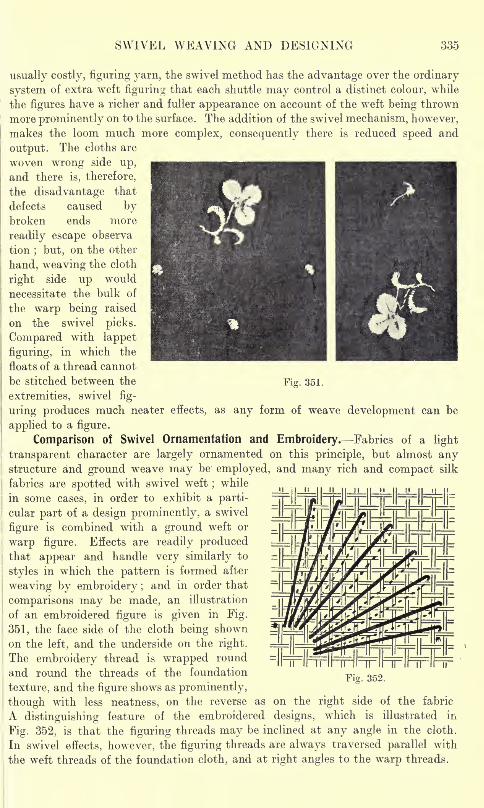
SWIVEL WEAVING AND DESIGNING 335
usually costly, figuring yarn, the swivel method has the advantage over the ordinary
system of extra weft figuring that each shuttle may control a distinct colour, while
the figures have a richer and fuller appearance on account of the weft being thrown
more prominently on to the surface. The addition of the swivel mechanism, however,
makes the loom much more complex, consequently there is reduced speed and
output. The cloths are
woven wrong side up,
and there is, therefore,
the disadvantage that
defects caused bybroken ends more
i readily escape observa
i tion; but, on the other
hand, weaving the cloth
i right side up would- necessitate the bulk of
the warp being raised
on the swrivel picks.
Compared with lappet
figuring, in which the
|
floats of a thread cannot
i be stitched between the Fig. 351.
extremities, swivel fig-
uring produces much neater effects, as any form of weave development can be
applied to a figure.
Comparison of Swivel Ornamentation and Embroidery. Fabrics of a light
transparent character are largely ornamented on this principle, but almost anystructure and ground weave may be employed, and many rich and compact silk
fabrics are spotted with swivel weft;while
in some cases, in order to exhibit a parti-
cular part of a design prominently, a swivel
figure is combined with a ground weft or
warp figure. Effects are readily producedthat appear and handle very similarly to
styles in which the pattern is formed after
' weaving by embroidery ;and in order that
i comparisons may be made, an illustration
of an embroidered figure is given in Fig.
351, the face side of the cloth being shown
on the left, and the underside on the right.
The embroidery thread is wrapped round
and round the threads of the foundation
texture, and the figure shows as prominently,
n |t
d^'
Fig. 352.
though with less neatness, on the reverse as on the right side of the fabric
A distinguishing feature of the embroidered designs, which is illustrated in
Fig. 352, is that the figuring threads may be inclined at any angle in the cloth.
In swivel effects, however, the figuring threads are always traversed parallel with
the weft threads of the foundation cloth, and at right angles to the warp threads.
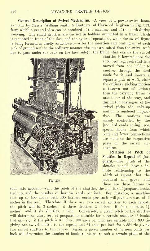
336 ADVANCED TEXTILE DESIGN
General Description of Swivel Mechanism. A view of a power swivel loom,
as made by Messrs. William Smith & Brothers, of Heywood, is given in Fig. 353,
from which a general idea can be obtained of the machine, and of the cloth during
weaving. The small shuttles are carried in holders suppoited in a frame which
is mounted in front of the slay, and the cycle of operations, while the swivel figure
is being formed, is briefly as follows : After the insertion and beating up of each
pick of ground weft in the ordinary manner, the ends are raised that the swivel weft
has to pass under (or over on the face side) ;the frame that carries the swivel
shuttles is lowered into the
shed opening, each shuttle is
moved from one holder to
another through the shed
made for it, and inserts a
separate pick of weft, while
the ordinary picking motion
is thrown out of -action;
then the carrying frame is
raised out of the way, and
during the beating-up of the
swivel picks the take-upmotion is rendered inopera-tive. The motions are
mainly controlled by the
jacquard cards acting upon
special hooks from which
cord and lever connections
are made to the respective
parts of the swivel me-
chanism.
Relation of Pitch of
Shuttles to Repeat of Jac-
quard. The pitch of the
shuttles should bear a de-
finite relationship to the
width of repeat that the
jacquard will give ;and
there are three factors to
take into account viz., the pitch of the shuttles, the number of jacquard hooks
tied up, and the number of harness cords per inch. For instance, a machine
tied up bo 600 hooks with 100 harness cords per inch will give a repeat of 6
inches in the reed. Therefore, if there are two swivel shuttles to each repeat,
the pitch will be 3 inches;
if three shuttles, 2 inches;
if four shuttles, 1J
inches;and if six shuttles, 1 inch. Conversely, a given pitch of the shuttles
will determine what sett of jacquard is suitable for a certain number of hooks
tied up e.g., if the pitch is 3 inches, 100 ends per inch are suitable for a 300 tie
giving one swivel shuttle to the repeat, and 64 ends per inch for a 384 tie giving
two swivel shuttles to the repeat. Again, a given number of harness cords perinch will determine the number of hooks to tie up to suit a certain pitch of the
Fig. 353.
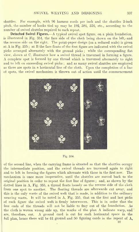
SWIVEL WEAVING AND DESIGNING 337
shuttles. For example, with 96 harness cords per inch and the shuttles 2-inch
pitch, the number of hooks tied up may be 192, 384, 576, etc., according to the
number of swivel shuttles required to each repeat.Detached Swivel Figures. A typical swivel spot figure, on a plain foundation,
is illustrated in Fig. 354, the face side of the cloth being shown on the left,, andthe reverse side on the right. The point-paper design (on a reduced scale) is givenat A in Fig. 355
;at B the face floats of the first figure are indicated with the swivel
picks arranged alternately with the ground picks ;while the corresponding flat
view, shown at C, illustrates how a swivel thread is traversed in forming a figure.
A complete spot is formed by one thread which is traversed alternately to right
and to left on succeeding swivel picks ;and as many swivel shuttles are employed
as there are spots in a horizontal line of the cloth. Upon the completion of a line
of spots, the swivel mechanism is thrown out of action until the commencement
Fig. 354.
of the second line, when the carrying frame is situated so that the shuttles occupythe intermediate position, and the swivel threads are traversed again to right
and to left in forming the figures which alternate with those in the first row. The
mechanism is once more inoperative, until the shuttles are moved back to the
original position in order to repeat the fiist line of figures ; and, as shown by the
dotted lines in A, Fig. 355, a thread floats loosely on the reverse side of the cloth
from one spot to another. The floating threads are afterwards cut away, and
this is the only waste of the swivel weft that is made, in addition to the ordinary
weaving waste. It will be noted in A, Fig. 355, that on the first and last picksof each figure the swivel weft is firmly interwoven. This is in order that the
free ends of the threads will not be liable to fray out of the foundation. As
the cloth is woven wrong side up, the marks of the plan A indicate warp, and
are, therefore, cut. A ground card is cut for each horizontal space in the
full plan, hence there will be 64 ground and 50 figuring cards in the repeat of A,
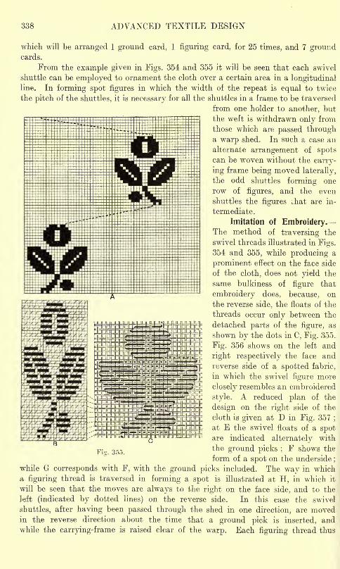
338 ADVANCED TEXTILE DESIGN
which will be arranged 1 ground card, 1 figuring card, for 25 times, and 7 groundcards.
From the example given in Figs. 354 and 355 it will be seen that each swivel
shuttle can be employed to ornament the cloth over a certain area in a longitudinalline. In forming spot figures in which the width of the repeat is equal to twice
the pitch of the shuttles, it is necessary for all the shuttles in a frame to be traversed
from one holder to another, but
the weft is withdrawn only from
those which are passed througha warp shed. In such a case an
alternate arrangement of spotscan be woven without the carry-
ing frame being moved laterally,
the odd shuttles forming one
row of figures, and the even
shuttles the figures vhat are in-
termediate.
Imitation of Embroidery.The method of traversing the
swivel threads illustrated in Figs.
354 and 355, while producing a
prominent effect on the face side
of the cloth, does not yield the
same bulkiness of figure that
embroidery does, because, on
the reverse side, the floats of the
threads occur only between the
detached parts of the figure, as
shown by the dots in C, Fig. 355.
Fig. 356 shows on the left and
right respectively the face and
reverse side of a spotted fabric,
in which the swivel figure more
closely resembles an embroidered
style. A reduced plan of the
design on the right side of the
cloth is given at D in Fig. 357 ;
at E the swivel floats of a spotare indicated alternately with
the ground picks ;F shows the
form of a spot on the underside;
while G corresponds with F, with the ground picks included. The way in which
a figuring thread is traversed in forming a spot is illustrated at H, in which it
will be seen that the moves are always to the right on the face side, and to the
left (indicated by dotted lines) on the reverse side. In this case the swivel
shuttles, after having been passed through the shed in one direction, are movedin the reverse direction about the time that a ground pick is inserted, and
while the carrying-frame is raised clear of the warp. Each figuring thread thus
Fig. 355.
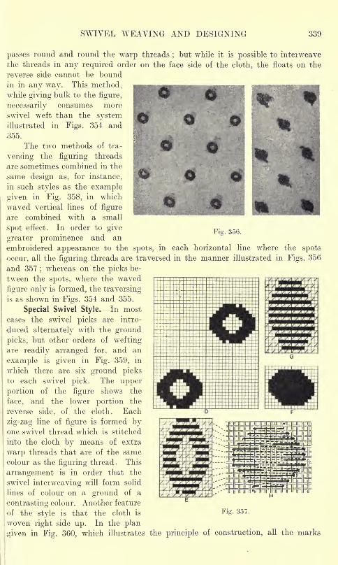
SWIVEL WEAVING AND DESIGNING 339
Fi
passes round and round the warp threads ; but while it is possible to interweave
the threads in any required order on the face side of the cloth, the floats on the
reverse side cannot be boundin in any way. This method,while giving bulk to the figure,
necessarily consumes more
swivel weft than the systemillustrated in Figs. 354 and
355.
The two methods of tra-
versing the figuring threads
are sometimes combined in the
same design as, for instance,
in such styles as the example
given in Fig. 358, in which
waved vertical lines of figure
are combined with a small
spot effect. In order to give
greater prominence and an
embroidered appearance to the spots, in each horizontal line where the spots
occur, all the figuring threads are traversed in the manner illustrated in Figs. 356
and 357;whereas on the picks be-
tween the spots, where the waved
figure only is formed, the traversingis as shown in Figs. 354 and 355.
Special Swivel Style. In most
cases the swivel picks are intro-
duced alternately with the ground
picks, but other orders of weftingare readily arranged for, and an
example is given in Fig. 359, in
which there are six ground picksto each swivel pick. The upper
portion of the figure shows the
face, and the lower portion the
reverse side, of the cloth. Each
zig-zag line of figure is formed byone swivel thread which is stitched
into the cloth by means of extra
warp threads that are of the same
colour as the figuring thread. This
arrangement is in order that the
swivel interweaving will form solid
lines of colour on a ground of a
contrasting colour. Another feature
of the style is that the cloth is Fig- 357 -
woven right side up. In the plan
given in Fig. 360, which illustrates the principle of construction, all the marks
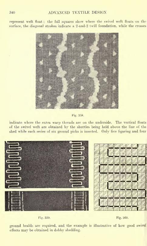
340 ADVANCED TEXTILE DESIGN
represent weft float; the full squares show where the swivel weft floats on the
surface, the diagonal strokes indicate a 2-and-2 twill foundation, while the crosses
Fig. 358.
indicate where the extra warp threads are on the underside. The vertical floats
of the swivel weft are obtained by the shuttles being held above the line of the
shed while each series of six ground picks is inserted. Only five figuring and four
Fig. 359. Fig. 360.
ground healds are required, and the example is illustrative of how good swivel
effects may be obtained in dobby shedding.
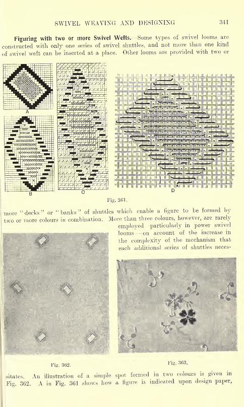
SWIVEL WEAVING AND DESIGNING 341
Figuring with two or more Swivel Wefts. Some types of swivel looms are
constructed with only one series of swivel shuttles, and not more than one kind
of swivel weft can be inserted at a place. Other looms are provided with two or
Fig. 361.
more "decks" or "banks" of shuttles which enable a figure to be formed by
two or more colours in combination. More than three colours, however, are rarely
employed particularly in power swivel
, w^nwrei looms on account of the increase in
the complexity of the mechanism that
each additional series of shuttles neces-
Fig. 362. Fig. 363.
o.u-^0. An illustration of a simple spot formed in two colours is given in
Pig. 362. A in Fig. 361 shows how a figure is indicated upon design paper,
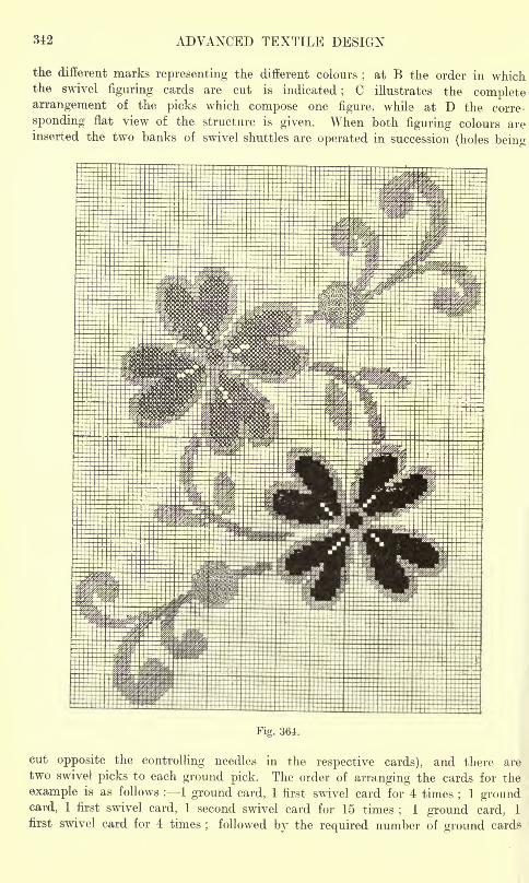
342 ADVANCED TEXTILE DESIGN
the different marks representing the different colours;
at B the order in whichthe swivel figuring cards are cut is indicated
;C illustrates the complete
arrangement of the picks which compose one figure, while at D the corre-
sponding flat view of the structure is given. When both figuring colours areinserted the two banks of swivel shuttles are operated in succession (holes being
Fig. 364.
cut opposite the controlling needles in the respective cards), and there are
two swivel picks to each ground pick. The order of arranging the cards for the
example is as follows : 1 ground card, 1 first swivel card for 4 times;
1 groundcard, 1 first swivel card, 1 second swivel card for 15 times
;1 ground card, 1
first swivel card for 4 times; followed by the required number of ground cards
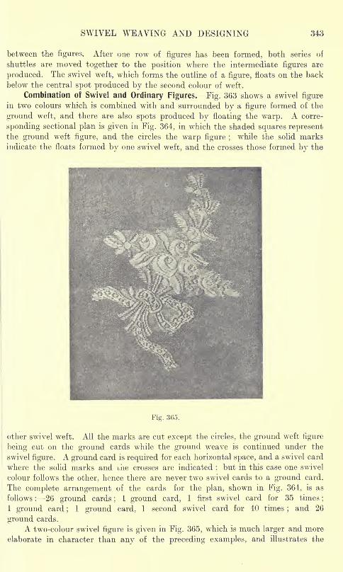
SWIVEL WEAVING AND DESIGNING 343
between the figures. After one row of figures has been formed, both series of
shuttles are moved together to the position where the intermediate figures are
produced. The swivel weft, which forms the outline of a figure, floats on the back
below the central spot produced by the second colour of weft.
Combination of Swivel and Ordinary Figures. Fig. 363 shows a swivel figure
in two colours which is combined with and surrounded by a figure formed of the
ground weft, and there are also spots produced by floating the warp. A corre-
sponding sectional plan is given in Fig. 364, in which the shaded squares representthe ground weft figure, and the circles the warp figure ;
while the solid marks
indicate the floats formed by one swivel weft, and the crosses those formed by the
Fig. 365.
other swivel weft. All the marks are cut except the circles, the ground weft figure
being cut on the ground cards while the ground weave is continued under the
swivel figure. A ground card is required for each horizontal space, and a swivel card
where the solid marks and uhe crosses are indicated ;but in this case one swivel
colour follows the other, hence there are never two swivel cards to a ground card.
The complete arrangement of the cards for the plan, shown in Fig. 364, is as
follows : 26 ground cards;
1 ground card, 1 first swivel card for 35 times ;
1 ground card;
1 ground card, 1 second swivel card for 40 times;and 26
ground cards.
A two-colour swivel figure is given in Fig. 365, which is much larger and more
elaborate in character than any of the preceding examples, and illustrates the
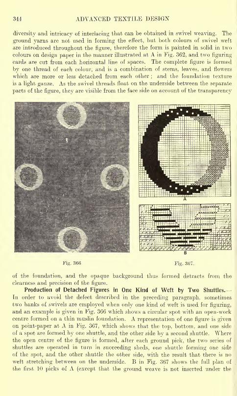
344 ADVANCED TEXTILE DESIGN
diversity and intricacy of interlacing that can be obtained in swivel weaving. The
ground yarns are not used in forming the effect, but both colours of swivel weft
are introduced throughout the figure, therefore the form is painted in solid in two
colours on design paper in the manner illustrated at A in Fig. 362, and two figuring
cards are cut from each horizontal line of spaces. The complete figure is formed
by one thread of each colour, and is a combination of stems, leaves, and flowers
which are more or less detached from each other;and the foundation texture
is a light gauze. As the swivel threads float on the underside between the separate
parts of the figure, they are visible from the face side on account of the transparency
Fig. 366
of the foundation, and the opaque background thus formed detracts from the
clearness and precision of the figure.
Production of Detached Figures in One Kind of Weft by Two Shuttles.
In order to avoid the defect described in the preceding paragraph, sometimes
two banks of swivels are employed when only one kind of weft is used for figuring,
and an example is given in Fig. 366 which shows a circular spot with an open-workcentre formed on a thin muslin foundation. A representation of one figure is givenon point-paper at A in Fig. 367, which shows that the top, bottom, and one side
of a spot are formed by one shuttle, and the other side by a second shuttle. Wherethe open centre of the figure is formed, after each ground pick, the two series of
shuttles are operated in turn in succeeding sheds, one shuttle forming one side
of the spot, and the other shuttle the other side, with the result that there is no
weft stretching between on the underside. B in Fig. 367 shows the full plan of
the first 10 picks of A (except that the ground weave is not inserted under the
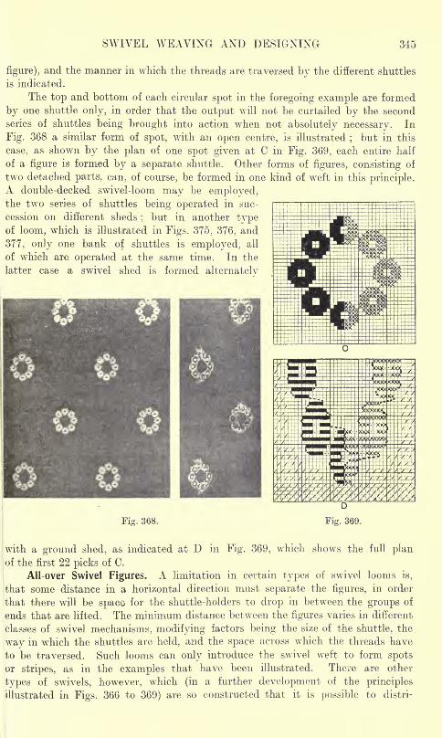
SWIVEL WEAVING AND DESIGNING 345
figure), and the manner in which the threads are traversed by the different shuttles
is indicated.
The top and bottom of each circular spot in the foregoing example are formed
by one shuttle only, in order that the output will not be curtailed by the second
series of shuttles being brought into action when not absolutely necessary. In
Fig. 368 a similar form of spot, with an open centre, is illustrated;
but in this
case, as shown by the plan of one spot given at C in Fig. 369, each entire half
of a figure is formed by a separate shuttle. Other forms of figures, consisting of
two detached parts, can, of course, be formed in one kind of weft in this principle.A double-decked swivel-loom may be employed,the two series of shuttles being operated in suc-
cession on different sheds;but in another type
of loom, which is illustrated in Figs. 375, 376, and
377, only one bank of shuttles is employed, all
of which are operated at the same time. In the
latter case a swivel shed is formed alternately
Fig. 368.
with a ground shed, as indicated at D in Fig. 369, which shows the full planof the first 22 picks of C.
All-over Swivel Figures. A limitation in certain types of swivel looms is,
that some distance in a horizontal direction must separate the figures, in order
that there will be spaco for the shuttle-holders to drop in between the groups of
ends that are lifted. The minimum distance between the figures varies in different
classes of swivel mechanisms, modifying factors being the size of the shuttle, the
way in which the shuttles are held, and the space across which the threads have
to be traversed. Such looms can only introduce the swivel weft to form spots
or stripes, as in the examples that have been illustrated. There are other
types of swivels, however, which (in a further development of the principles
illustrated in Figs. 366 to 369) are so constructed that it is possible to distri-
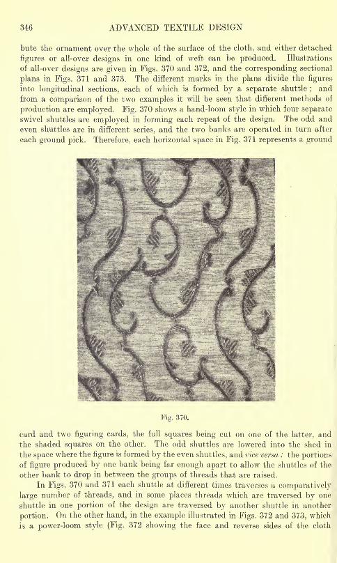
346 ADVANCED TEXTILE DESIGN
bute the ornament over the whole of the surface of the cloth, and either detached
figures or all-over designs in one kind of weft can be produced. Illustrations
of all-over designs are given in Figs. 370 and 372, and the corresponding sectional
plans in Figs. 371 and 373. The different marks in the plans divide the figures
into longitudinal sections, each of which is formed by a separate shuttle;and
from a comparison of the two examples it will be seen that different methods of
production are employed. Fig. 370 shows a hand-loom style in which four separate
swivel shuttles are employed in forming each repeat of the design. The odd and
even shuttles are in different series, and the two banks are operated in turn after
each ground pick. Therefore, each horizontal space in Fig. 371 represents a ground
I
Fig. 370.
card and two figuring cards, the full squares being cut on one of the latter, and
the shaded squares on the other. The odd shuttles are lowered into the shed in
the space where the figure is formed by the even shuttles, and vice versa ; the portionsof figure produced by one bank being far enough apart to allow the shuttles of the
other bank to drop in between the groups of threads that are raised.
In Figs. 370 and 371 each shuttle at different times traverses a comparatively
large number of threads, and in some places threads which are traversed by one
shuttle in one portion of the design are traversed by another shuttle in another
portion. On the other hand, in the example illustrated in Figs. 372 and 373, which
is a power-loom style (Fig. 372 showing the face and reverse sides of the cloth
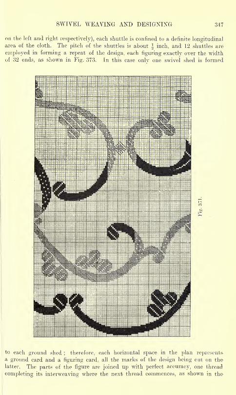
SWIVEL WEAVING AND DESIGNING 347
on the left and right respectively), each shuttle is confined to a definite longitudinalarea of the cloth. The pitch of the shuttles is about J inch, and 12 shuttles are
employed in forming a repeat of the design, each figuring exactly over the width
of 32 ends, as shown in Fig. 373. In this case only one swivel shed is formed
to each ground shed; therefore, each horizontal space in the plan represents.
a ground card and a figuring card, all the marks of the design being cut on the
latter. The parts of the figure are joined up with perfect accuracy, one thread
completing its interweaving where the next thread commences, as shown in the-
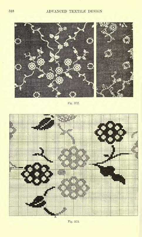
348 ADVANCED TEXTILE DESIGN
Fig. 372.
Fig. 373.
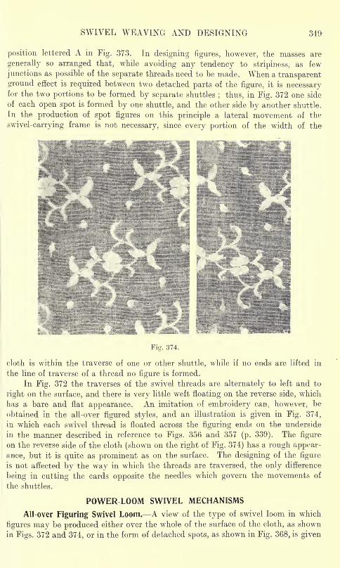
SWIVEL WEAVING AND DESIGNING
position lettered A in Fig. 373. In designing figures, however, the masses are
generally so arranged that, while avoiding any tendency to stripiness, as few
junctions as possible of the separate threads need to be made. When a transparent
ground effect is required between two detached parts of the figure, it is necessaryfor the two portions to be formed by separate shuttles
; thus, in Fig. 372 one side
of each open spot is formed by one shuttle, and the other side by another shuttle.
In the production of spot figures on this principle a lateral movement of the
swivel-carrying frame is not necessary, since every portion of the width of the-
Fig. 374.
cloth is within the traverse of one or other shuttle, while if no ends are lifted in
the line of traverse of a thread no figure is formed.
In Fig. 372 the traverses of the swivel threads are alternately to left and to
right on the surface, and there is very little weft floating on the reverse side, which
has a bare and flat appearance. An imitation of embroidery can, however, be
obtained in the all-over figured styles, and an illustration is given in Fig. 374,
in which each swivel thread is floated across the figuring ends on the underside
in the manner described in reference to Figs. 356 and 357 (p. 339). The figure
on the reverse side of the cloth (shown on the right of Fig. 374) has a rough appear-
ance, but it is quite as prominent as on the surface. The designing of the figure
is not affected by the way in which the threads are traversed, the only difference
being in cutting the cards opposite the needles which govern the movements of
the shuttles.
POWER LOOM SWIVEL MECHANISMS
All-over Figuring Swivel Loom. A view of the type of swivel loom in which
figures may be produced either over the whole of the surface of the cloth, as shown
in Figs. 372 and 374, or in the form of detached spots, as shown in Fig. 368, is given
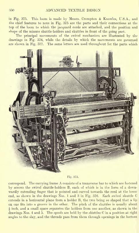
350 ADVANCED TEXTILE DESIGN
in Fig. 375. This loom is made by Messrs. Crompton Knowles, U.S.A., and
the chief features to note in Fig. 375 are the parts and their connections at the
top of the loom to which the jacquard cords are attached, and the position and
shape of the minute shuttle-holders and shuttles in front of the going part.
The principal movements of the swivel mechanism are illustrated by the
drawings in Fig. 376, while the details by which the movements are governedare shown in Fig. 377. The same letters are used throughout for the parts which
correspond. The carrying frame A consists of a transverse bar to which are fastened
by screws the swivel shuttle-holders B, each of which is in the form of a down-
wardly extending finger that is pointed and curved towards the reed at the lower
end, as shown in the drawings Nos. 1 and 3 in Fig. 376. Each swivel shuttle C
extends in a horizontal plane from a holder B, the two being so shaped that a lip
on one fits into a groove in the other. The pitch of the shuttles is usually about
J inch, and a small space separates the holders from one another, as shown in the
drawings Nos. 4 and 5. The spools are held by the shuttles C in a position at right
angles to the slay, and the threads pass from them through openings in the bottom
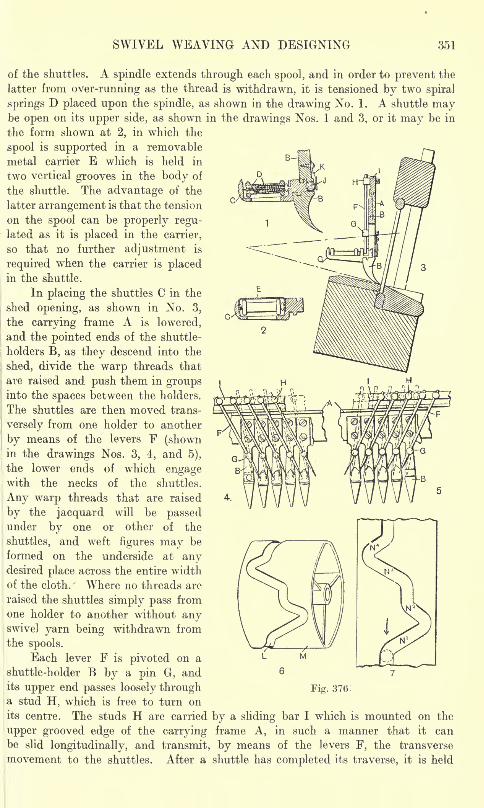
SWIVEL WEAVING AND DESIGNING 351
of the shuttles. A spindle extends through each spool, and in order to prevent the
latter from over-running as the thread is withdrawn, it is tensioned by two spiral
springs D placed upon the spindle, as shown in the drawing No. 1. A shuttle maybe open on its upper side, as shown in the drawings Nos. 1 and 3, or it may be in
the form shown at 2, in which the
spool is supported in a removable
metal carrier E which is held in
two vertical grooves in the body of
the shuttle. The advantage of the
latter arrangement is that the tension
on the spool can be properly regu-lated as it is placed in the carrier,
so that no further adjustment is
required when the carrier is placedin the shuttle.
In placing the shuttles C in the
shed opening, as shown in No. 3,
the carrying frame A is lowered,
and the pointed ends of the shuttle-
holders B, as they descend into the
shed, divide the warp threads that
are raised and push them in groupsinto the spaces between the holders.
The shuttles are then moved trans-
;
versely from one holder to another
by means of the levers F (shownin the drawings Nos. 3, 4, and 5),
the lower ends of which engagewith the necks of the shuttles.
Any warp threads that are raised
by the jacquard will be passedunder by one or other of the
shuttles, and weft figures may be
formed on the underside at anydesired place across the entire width
of the cloth. Where no threads are
raised the shuttles simply pass from
one holder to another without anyswivel yarn being withdrawn from
the spools.
Each lever F is pivoted on a
shuttle-holder B by a pin G, andits upper end passes loosely through Fig. 376 :
a stud H, which is free to turn on
its centre. The studs H are carried by a sliding bar I which is mounted on the
upper grooved edge of the carrying frame A, in such a manner that it can
be slid longitudinally, and transmit, by means of the levers F, the transverse
movement to the shuttles. After a shuttle has completed its traverse, it is held
352 ADVANCED TEXTILE DESIGN
firmly in position by a ball J (shown in the drawing No. 1), which is pressed
into a depression at the rear of the shuttle by means of a spring K.
At the time of lowering and raising the carrying frame A, the levers F require
to occupy one of the positions shown in dotted lines in the drawings Nos. 4 and 5,
in order thafethey will not obstruct the warp threads;while in traversing the shuttles
the levers are moved from the dotted position shown in one drawing to the position
shown in full lines in the other drawing. The complete round of movements oi
the levers F, during which two swivel picks are inserted, is as follows :
1. From the dotted position shown in No. 4, to the full line position shown in No. 5.
2. From the full line position shown in No. 5, to the dotted position shown in No. 5.
3. From the dotted position shown in No. 5, to the full line position shown in No. 4.
4. From the full line position shown in No. 4, to the dotted position shown in No. 4.
The swivel shuttles are traversed to the left at the first movement, and to
the right at the third movement. Between the second and third, and the fourth
and first movements, the carrying frames is raised, and remains up while a ground
pick is inserted;
the frame is then lowered. The movements are governed by a
cam groove L cut in the periphery of a drum M (shown in the drawing No. 6), which
is turned one-sixth of a revolution at each swivel pick. An anti-friction bowl N.
carried at the end of a lever (shown in the drawings Nos. 12 and 13 in Fig. 377),
travels within the cam groove, and the drawing No. 7 in Fig. 376 shows in plan
the portion of the groove by which the complete round of movements of the levers
F is obtained;the arrow indicates the direction of revolution. The first movement
is obtained by the bowl travelling along the long portion of the groove marked N1,
while the short portion marked N2produces the second movement
;there is sub-
sequently an intermission of the rotation of the drum during which the carrying
frame is raised and again lowered. The third movement is produced by the long
portion of the groove marked N3,and the fourth movement by the short portion
marked N4,after which the drum is again at rest while the carrying frame is raised
and lowered. The drum M is stationary all the time that no swivel weft is being
inserted.
The mechanisms which govern the picking of the fly shuttle, raise and lowei
the carrying frame A, and give the longitudinal movement to the sliding bar I,
are illustrated in Fig. 377. Certain hooks in the jacquard are employed for controlling
the motions, and the drawings Nos. 8 and 9 (the latter on an enlarged scale) show
the parts which communicate the movement from the jacquard to the loom. Cords
P, from the jacquard hooks, are connected to two arms which form an extension
from a cam Q (see drawing No. 9) fulcrumed on a stud R that passes through a
horizontal slot in a rocking lever S. At the sides of the slot pins T are fixed to the
lever S in a position to be engaged by the cam Q. The stud R is fixed to a bracket
U on which the rocking lever S is pivoted at its lower end, and from the uppei
end of S a cord V passes either over a guide pulley or is connected to the uppei
arm of an angle lever W, as shown in No. 8. Lifting a cord P causes the cam Q
to turn on the stud R and engage a pin T connected to the rocking lever S, the
upper end of which, therefore, moves to the left if the right-hand cord P is raisedj
and to the right in the case of the left-hand cord. A lever, fulcrumed on the uppei
central part of the cam Q, serves, by means of the springs that are connected to
it, to lock the cam in either position to which it is moved by the cords P.
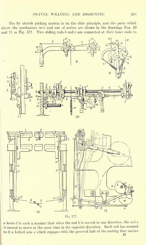
SWIVEL WEAVING AND DESIGNING 353
The fly shuttle picking motion is on the slide principle, and the parts which
throw the mechanism into and out of action are shown in the drawings Nos. 10
and 11 in Fig. 377. Two sliding rods 6 and c are connected at their inner ends to
Fig. 377.
a lever d in such a manner that when the rod 6 is moved in one direction, the rod c
is caused to move at the same time in the opposite direction. Each rod has secured
to it a forked arm e which engages with the grooved hub of the casting that carries
354 ADVANCED TEXTILE DESIGN
the picking rolls /, and according to the direction of the movement of the rod 6,
the picking rolls are slid along the bottom shaft a into or out of engagement with
the picking shoes y. The arrangement by which the sliding movement is impartedto the rod 6 is shown in plan in the drawing No. 11. The rod b extends throughthe framing of the loom, and carries on its outer end a stud h which enters a diagonalslot in an arm i. A cord from the lower arm of the lever W (shown in the drawingNo. 8) is attached to a lever x, the raising and lowering of which bring in turn
two fingers Y and Z connected to the arm i in the path of a tappet j which
is keyed on the low shaft a. The tappet j, in engaging a finger Y or Z, gives a longi-
tudinal movement to the arm i, and by means of the slot moves the stud h, and
thereby transmits the sliding movement to the rod b.
The carrying frame A is lowered into the shed opening, as shown by the dotted
lines in the drawing No. 13, as the going part recedes from the cloth, and is raised
out of the way during the forward movement of the slay. The vertical movementof the frame A is effected by a cam k (shown in the drawing No. 13) on the bottom
shaft a, which engages an anti-friction bowl I carried at the rear end m of a lever
that is fulcrumed on a rocking shaft n. The weight of the parts is sufficient to
keep the bowl I in contact with the cam k (if necessary a spring may be used in
addition), and as the cam revolves the shaft n is rocked and the forward end o
of the lever lowered and raised. The shaft n extends the width of the loom, andat the opposite side there is another lever o fulcrumed on the shaft. Two uprightrods p connect the extremities of the levers o with the ends of the carrying frame
A (as shown in the drawings Nos. 12 and 13), which, therefore, at each swivel pickis lowered into the shed opening and is then raised. To each end of the lay an
upright slotted stand is fixed in which the carrying frame slides up and down.
When the carrying frame is lowered for the insertion of a swivel pick, the
ordinary picking motion is inoperative, and it is very necessary to avoid any possi-
bility of the fly shuttle and the swivel shuttles coming in contact with each other.
For this purpose the rear end of the lever m is extended, as shown at q in the drawingNo. 13, and whenever the fly shuttle is operated the lower arm of an angle lever r
is moved in contact with the upper side of the extension q in the following manner :
The sliding rod 6 carries a slotted arm s (shown in the drawing No. 10), and into
the slot a stud, fixed to the upper arm of the angle lever r, projects. Therefore,
when the rod b is moved to the left to bring the picking rolls/into position to engagethe picking shoes g (as shown by the dotted lines in the drawing No. 10), the slotted
arm s is also moved to the left, and the angle lever r is rocked so that its lower
arm engages the extension q of the lever m. The latter is thus prevented from
rising, and the carrying frame A from descending, so long as the fly shuttle mechanismis in operation.
*
The drum M, by which the longitudinal movement of the sliding bar I is
governed, is rotated by a pin-wheel t (shown in the drawing No. 10) that engagesa six-sided star-wheel u fixed on the hub of the drum. The pin-wheel t is keyedon a sleeve fixed to the bottom shaft a, and the upper forked arm of a lever v is
provided with studs which extend into a groove in the boss of the pin-wheel. The
lower arm of the lever v is connected by a spring w to the floor, and by a cord that
passes upwards over a pulley to a rocking lever S. Lifting the left-hand jacquardcord P causes the pin-wheel t to engage with the star wheel u, and the drum Mis turned one-sixth of a revolution. When the right-hand cord P is raised, the
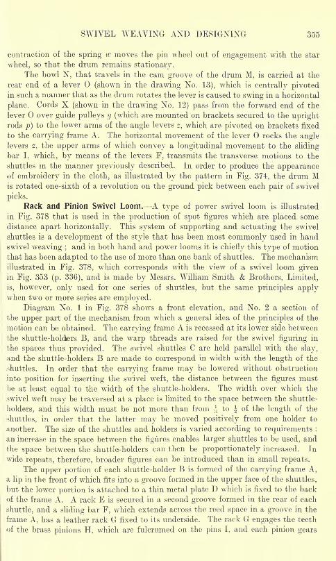
SWIVEL WEAVING AND DESIGNING 355
contraction of the spring w moves the pin wheel out of engagement with the star
wheel, so that the drum remains stationary.The bowl N, that travels in the cam groove of the drum M, is carried at the
rear end of a lever (shown in the drawing No. 13), which is centrally pivotedin such a manner that as the drum rotates the lever is caused to swing in a horizontal
plane. Cords X (shown in the drawing No. 12) pass from the forward end of the
lever over guide pulleys y (which are mounted on brackets secured to the uprightrods p) to the lower arms of the angle levers z, which are pivoted on brackets fixed
to the carrying frame A. The horizontal movement of the lever rocks the anglelevers z, the upper arms of which convey a longitudinal movement to the sliding
bar I, which, by means of the levers F, transmits the transverse motions to the
shuttles in the manner previously described. In order to produce the appearanceof embroidery in the cloth, as illustrated by the pattern in Fig. 374, the drum Mis rotated one-sixth of a revolution on the ground pick between each pair of swivel
picks.
Rack and Pinion Swivel Loom. A type of power swivel loom is illustrated
in Fig. 378 that is used in the production of spot figures which are placed somedistance apart horizontally. This system of supporting and actuating the swivel
shuttles is a development of the style that has been most commonly used in handswivel weaving ;
and in both hand and power looms it is chiefly this type of motion
that has been adapted to the use of more than one bank of shuttles. The mechanism
illustrated in Fig. 378, which corresponds with the view of a swivel loom givenin Fig. 353 (p. 336), and is made by Messrs. William Smith & Brothers, Limited,
is, however, only used for one series of shuttles, but the same principles applywhen two or more series are employed.
Diagram No. 1 in Fig. 378 shows a front elevation, and No. 2 a section of
the upper part of the mechanism from which a general idea of the principles of the
motion can be obtained. The carrying frame A is recessed at its lower side between
the shuttle-holders B, and the warp threads are raised for the swivel figuring in
the spaces thus provided. The swivel shuttles C are held parallel with the slay,
and the shuttle-holders B are made to correspond in width with the length of the
shuttles. In order that the carrying frame may be lowered without obstruction
into position for inserting the swivel weft, the distance between the figures mustbe at least equal to the width of the shuttle-holders. The width over which the
swivel weft may be traversed at a place is limited to the space between the shuttle-
holders, and this width must be not more than from -* to J of the length of the
shuttles, in order that the latter may be moved positively from one holder to
another. The size of the shuttles and holders is varied according to requirements ;
an increase in the space between the figures enables larger shuttles to be used, and
the space between the shuttle-holders can then be proportionately increased. In
wide repeats, therefore, broader figures can be introduced than in small repeats.
The upper portion of each shuttle-holder B is formed of the carrying frame A,
a lip in the front of which fits into a groove formed in the upper face of the shuttles,
but the lower portion is attached to a thin metal plate D which is fixed to the back
of the frame A. A rack E is secured in a second groove formed in the rear of each
shuttle, and a sliding bar F, which extends across the reed space in a groove in the
frame A, has a leather rack G fixed to its underside. The rack G engages the teeth
of the brass pinions H, which are fulcrumed on the pins I, and each pinion gears
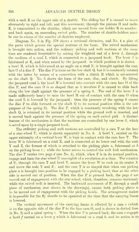
356 ADVANCED TEXTILE DESIGN
with a rack E on the upper side of a shuttle. The sliding bar F is caused to move
alternately to right and left, and this movement, through the pinions H and racks
E, is transmitted to the shuttles, which are moved from one holder B to another,
and back again, on succeeding swivel picks. The number of shuttle-holders must
be one in excess of the number of shuttles employed.
Diagram No. 3 in Fig. 378 shows a sectional elevation, and No. 4 a plan of
the parts which govern the special motions of the loom. The swivel mechanism
is brought into action, and the oidinary picking and weft motions at the same
time are rendered inoperative by raising the weighted end of a lever J, throughthe medium of a cord L which is connected to a jacquard hook. The lever J is
fulcrumed at K, and when raised by the jacquard in which position it is shown
a bowl M, which is fulcrumed at an angle on a stud N, is brought against the cam
face of a disc P. The disc P is loose on the low shaft Q, but it is constantly rotated
with the latter by means of a connection with a clutch R which is set-screwed
on the shaft Q. No. 5 shows the form of the cam, disc, and clutch. By lifting
the jacquard cord L the bowl M is lowered into contact with the cam face of the
disc P, and the cam is so shaped that as it revolves P is caused to slide back
along the low shaft against the pressure of a spring S. The end of the lever J is
made sufficiently heavy to raise the bowl M out of contact with the cam when
the cord L is lowered by the jacquard ;then the pressure of the spring S causes
the disc P to slide forward on the shaft Q to its normal position (this is the sole
purpose of the spring S). The disc P, which is constantly revolving with the low
shaft Q, is retained in its normal position while the ground weft is inserted, and
is moved back against the pressure of the spring on each swivel pick. A distinct
feature of the mechanism is that the motions are controlled by one lever J. which
is acted upon by a single jacquard hook.
The ordinary picking and weft motions are controlled by a cam T on the face
of a star-wheel U, which is shown separately in No. 6. A bowl V, carried on the
upper extremity of a vertical lever W, is kept in contact with the cam face T. The
lever W is fulcrumed on a stud X, and is connected at its lower end with the rods
Y and Z, the former of which is attached to the picking plate a, fulcrumed at b
on the picking lever c;while the latter serves to control the weft fork mechanism.
The disc P carries two pegs d (see No. 4), which, when P is in its normal position,
engage and turn the star-wheel U one-eighth of a revolution at a time. The rotation
of U, through the cam T and bowl V, causes the lever W to rock on its centre Xand move the rods Y and Z
;and the cam T is so shaped that when one picking
plate a is brought into position to be engaged by a picking bowl, that at the other
side is moved out of position. When the disc P is pressed back, the pegs d are
moved out of engagement with the star-wheel, which, therefore, remains stationary
while the swivel weft is inserted. The backward movement of P, through a small
piece of mechanism (not shown in the drawings), causes both picking plates a
to be moved out of engagement with the picking bowls. The arrangement makes
it impossible for the fly shuttle to be operated at the time that the carrying frame
is lowered.
The vertical movement of the carrying frame is effected by a cam e (which
is on the opposite side of the disc P to the face cam 0, and is shown in dotted lines
in No. 3) and a spiral spring i. When the disc P is pressed back, the cam e engages
a bowl / carried on a lever g which is fulcrumed on a stud h, and its action is to
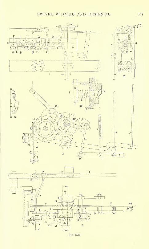
SWIVEL WEAVING AND DESIGNING 357
Fig. 378.
358 ADVANCED TEXTILE DESIGN
depress the lever g against the tension of the spring i;
while the purpose of the
latter is to keep the bowl / in contact with the cam e, and to raise the lever g whenthe pressure of the cam is removed. A rod j, which is connected to the end of the
lever g, has resting upon its upper extremity a lever k which is fulcrumed on a rockingshaft I. The shaft I extends across the reed space, and supports at each side a
lever m, which carries a stud n on which the upper end of a pendant arm o is ful-
crumed;while the lower end of the arm o is secured to the carrying frame A. The
weight of the parts is sufficient to keep the lever k in contact with the end of the
vertical rod j, so that when the lever g is depressed by the action of the cam e the
carrying frame A is lowered into the shed opening. When the downward pressureof the cam e is removed, the contraction of the spring i causes the vertical rod jto push the lever k upwards, and the carrying frame is raised. During the rising
and falling movement the frame is steadied at each side by a stud which enters
a brass guide p. A lever pl
,which is fixed to the rocking shaft I, is placed directly
over and rests upon each guide, and this lever can be adjusted so as to regulate
the distance that the frame descends.
The transverse movement of the swivel shuttles is obtained as follows : Whenthe disc P is moved back, the teeth q, secured to P by a setscrew, are brought into
the path of a star-wheel r, which is compounded with an eccentric plate s, as shown
in drawings Nos. 3 and 4. The star-wheel r and the plate s, which are loose on
a stud s1
,are turned one-half of a revolution
;and the stud t, carried by the eccentric
plate s, is moved from the bottom to the top on one swivel pick, and from the
top to the bottom on the following swivel pick. The stud t is connected by the
rod u to a lever v, which is fulcrumed at vl
,and the rotation of the eccentric s causes
a vertical rod iv to be alternately lowered and raised. The rod w is connected
to the lower arm of a bell-crank lever x, to the upper arm of which a rod y is connected,
while a pendant z, from the rod y, is secured through a slot in the front of the carryingframe with the sliding bar F. The falling and rising movement of the vertical
rod w therefore transmits a horizontal motion to the sliding bar F, and the shuttles
are caused to move from one holder to another, and back again, on succeedingswivel picks in the manner previously described.
A motion (not shown in Fig. 378) is provided at the driving side of the loom
for moving the carrying frame horizontally, so that intermediate figures may be
formed. A star-wheel is caused to turn when required by means of suitable con-
nections from the jacquard, and on the boss of the star-wheel a chain barrel is-
secured which carries a cast-iron chain. This chain is composed of two heightsof links, and above in contact with it there is a bowl which is supported by a
lever fulcrumed at the back of the loom. A high link lifts the front end of the
lever, and by means of suitable connections a sliding motion is transmitted to
the carrying frame. The next rotation of the star-wheel will bring a small link
under the bowl so that the lever will fall and cause the frame to slide in the oppositedirection.
Circular-Swivel Mechanism. A view of a third type of power swivel loom
is given in Fig. 379, which, like the last example, is used in producing figures that
are placed some distance apart horizontally. As full explanations have alreadybeen given of two motions, only certain special features are considered in this
case. The loom is made by Schroers, of Krefeld, who have adopted the principle
of the American dobby motion for obtaining the principal swivel movements, and
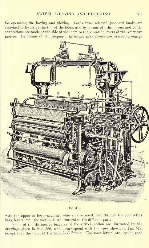
SWIVEL WEAVING AND DESIGNING 359
for operating the boxing and picking. Cords from selected jacquard hooks are
attached to levers at the top of the loom, and by means of other levers and cords,
connections are made at the side of the loom to the vibrating levers of the American
motion. By means of the jacquard the centre gear wheels are caused to engage
Fig. 379.
with the upper or lower segment wheels as required, and through the connecting
bars, levers, etc., the motion is transmitted to the different parts.
Some of the distinctive features of the swivel motion are illustrated by the
drawings given in Fig. 380, which correspond with the view shown in Fig. 379,
except that the hand of the loom is different. The same letters are used in each
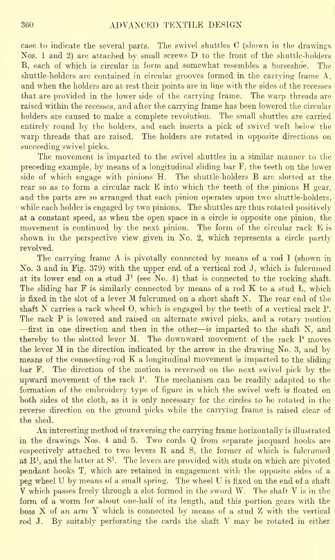
360 ADVANCED TEXTILE DESIGN
case to indicate the several parts. The swivel shuttles C (shown in the drawingsNos. 1 and 2) are attached by small screws D to the front of the shuttle-holders
B, each of which is circular in form and somewhat resembles a horseshoe. The
shuttle-holders are contained in circular grooves formed in the carrying frame A,
and when the holders are at rest their points are in line with the sides of the recesses
that are provided in the lower side of the carrying frame. The warp threads are
raised within the recesses, and after the carrying frame has been lowered the circular
holders are caused to make a complete revolution. The small shuttles are carried
entirely round by the holders, and each inserts a pick of swivel weft below the
warp threads that are raised. The holders are rotated in opposite directions on
succeeding swivel picks.
The movement is imparted to the swivel shuttles in a similar manner to the
preceding example, by means of a longitudinal sliding bar F, the teeth on the lower
side of which engage with pinions H. The shuttle-holders B are slotted at the
rear so as to form a circular rack E into which the teeth of the pinions H gear,
and the parts are so arranged that each pinion operates upon two shuttle-holders,
while each holder is engaged by two pinions. The shuttles are thus rotated positively
at a constant speed, as when the open space in a circle is opposite one pinion, the
movement is continued by the next pinion. The form of the circular rack E is
shown in the perspective view given in No. 2, which represents a circle partlyrevolved.
The carrying frame A is pivotally connected by means of a rod I (shown in
No. 3 and in Fig. 379) with the upper end of a vertical rod J, which is fulcrumed
at its lower end on a stud J 1
(see No. 4) that is connected to the rocking shaft.
The sliding bar F is similarly connected by means of a rod K to a stud L, which
is fixed in the slot of a lever M fulcrumed on a short shaft N. The rear end of the
shaft N carries a rack wheel 0, which is engaged by the teeth of a vertical rack P.
The rack P is lowered and raised on alternate swivel picks, and a rotary motion
first in one direction and then in the other is imparted to the shaft N, and
thereby to the slotted lever M. The downward movement of the rack P movesthe lever M in the direction indicated by the arrow in the drawing No. 3, and bymeans of the connecting-rod K a longitudinal movement is imparted to the sliding
bar F. The direction of the motion is reversed on the next swivel pick by the
upward movement of the rack P. The mechanism can be readily adapted to the
formation of the embroidery type of figure in which the swivel weft is floated on
both sides of the cloth, as it is only necessary for the circles to be rotated in the
reverse direction on the ground picks while the carrying frame is raised clear of
the shed.
An interesting method of traversing the carrying frame horizontally is illustrated
in the drawings Nos. 4 and 5. Two cords Q from separate jacquard hooks are
respectively attached to two levers R and S, the former of which is fulcrumed
at B 1,and the latter at S1
. The levers are provided with studs on which are pivoted
pendant hooks T, which are retained in engagement with the opposite sides of a
peg wheel U by means of a small spring. The wheel U is fixed on the end of a shaft
V which passes freely through a slot formed in the sword W. The shaft V is in the
form of a worm for about one-half of its length, and this portion gears with the
boss X of an arm Y which is connected by means of a stud Z with the vertical
rod J. By suitably perforating the cards the shaft V may be rotated in either
SWIVEL WEAVING AND DESIGNING 361
direction at any interval through the medium of the levers R and S, the pendanthooks T, and the peg wheel U. According to the direction in which the shaft Vis turned, the rod J (which is fulcrumed at J 1
)is moved to the left or to the right
at its upper end, and through the rod I a similar horizontal movement is transmitted
to the carrying frame. The distance that the frame is moved at each lift of a harness
cord varies chiefly according to the pitch of the worm on the shaft V, which is
generally arranged to impart a movement ranging from ^ to-^
inch.
The chief advantage of this method of traversing the carrying frame is that
it enables inclined figures to be formed which extend over a greater space than
the width of the recesses in which the warp threads are raised. An illustration
362 ADVANCED TEXTILE DESIGN
of the form of figure referred to is given in the diagram No. 6 in Fig. 380, in which
the bracketed spaces between the vertical lines represent the width of the recesses.
Each step of the vertical lines represents a horizontal movement of the carryingframe produced by one lift of a harness cord, and it will be seen that the spacebetween the lines show a slight clearance over the width of the figure in every
part. The design is arranged to coincide with the pitch of the circles shown in the
drawing No. 1, the width of the repeat being equal to the space occupied by two
circles. Each figure is represented as being formed by a separate shuttle, in which
case, although all the circles will be rotated at the same time, the swivel yarn will
be withdrawn from alternate shuttles only. The frame may, however, be traversed,
as shown by the dotted lines, so that the same shuttles may be employed to form
intermediate figures.
The diameter of the circles may be varied from 1 to 4 inches and upwards,and the horizontal space between the figures is generally rather less than half the
pitch of the circles. As compared with the rack-and-pinion motion, in which the
shuttles are moved longitudinally through the shed, the circular type gives greater
scope for figuring, as the swivel spots can be formed with less space between;
but there is the disadvantage that only one deck of shuttles can be employed.In both systems the swivel weft is withdrawn through the holes in the front of
the shuttles, and an important factor, which is common to all types of swivels,
is the proper tensioning of the weft so that the formation of curls at the sides of
the figures will be avoided. A length of yarn is withdrawn from each shuttle everytime the carrying frame is raised above the level of the shed, but by means of a
spiral spring (placed on the spindle) upon which the spool exerts pressure as iti
revolves, the slack yarn is rewound on the spool as the frame descends. The springis capable of rewinding a length of several inches, and there is, therefore, alwaysa certain amount of tension on the yarn.
CHAPTER XVI
WEFT PILE FABRICS
Formation of Weft Pile. Plain Velveteens Tabby or Plain-back Velveteens Length of thet
Pile Density of the Pile Changing the Density of the Pile Fastness of the Pile
Twill-back Velveteens Designs which simplify the Cutting Operation. Corded Velveteens
Corded Velveteen Cutting Corded Velveteens from Plain Velveteen Weaves Parti-
culars of Weft Pile Fabrics. Weft Plushes. Figured Weft Pile Fabrics Figured Velveteens
Figured Cords. Imitation Weft Pile Fabrics.
IN pile or plush fabrics a proportion of the threads termed pile threads proj<
from a foundation texture and form a nap or pile on the surface. In some classes
of the cloths the pile threads are cut and the surface of the cloth is then composed,where the pile is formed, of the free ends of the fibres which, in many cases, gives
an appearance closely resembling fur. In other plush fabrics the pile threads
are not cut, and the pile surface then consists of small loops or curls. The pile
threads may be introduced as weft forming weft pile fabrics, in which the pile
is invariably cut, or as warp forming warp pile fabrics, in some of which all the
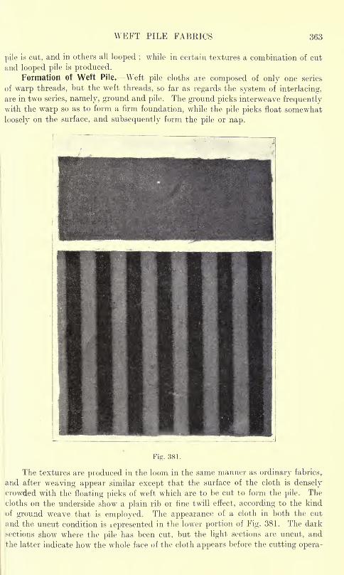
WEFT PILE FABRICS 363
pile is cut, and in others all looped ;while in certain textures a combination of cut
and looped pile is produced.Formation of Weft Pile. Weft pile cloths are composed of only one series
of warp threads, but the weft threads, so far as regards the system of interlacing,
are in two series, namely, ground and pile. The ground picks interweave frequentlywith the warp so as to form a firm foundation, while the pile picks float somewhat
loosely on the surface, and subsequently form the pile or nap.
Fig. 381.
The textures are produced in the loom in the same manner as ordinary fabrics,,
and after weaving appear similar except that the surface of the cloth is denselycrowded with the floating picks of weft which are to be cut to form the pile. The
cloths on the underside show a plain rib or fine twill effect, according to the kind
of ground weave that is employed. The appearance of a cloth in both the cut
and the uncut condition is icpresented in the lower portion of Fig. 381. The dark
sections show where the pile has been cut, but the light sections are uncut, andthe latter indicate how the whole face of the cloth appears before the cutting opera-
362 ADVANCED TEXTILE DESIGN
of the form of figure referred to is given in the diagram No. 6 in Fig. 380, in which
the bracketed spaces between the vertical lines represent the width of the recesses.
Each step of the vertical lines represents a horizontal movement of the carrying
frame produced by one lift of a harness cord, and it will be seen that the space
between the lines show a slight clearance over the width of the figure in every
part. The design is arranged to coincide with the pitch of the circles shown in the
drawing No. 1, the width of the repeat being equal to the space occupied by two
circles. Each figure is represented as being formed by a separate shuttle, in which
case, although all the circles will be rotated at the same time, the swivel yarn will
be withdrawn from alternate shuttles only. The frame may, however, be traversed,
as shown by the dotted lines, so that the same shuttles may be employed to form
intermediate figures.
The diameter of the circles may be varied from 1 to 4 inches and upwards,and the horizontal space between the figures is generally rather less than half the
pitch of the circles. As compared with the rack-and-pinion motion, in which the
shuttles are moved longitudinally through the shed, the circular type gives greater
scope for figuring, as the swivel spots can be formed with less space between;
but there is the disadvantage that only one deck of shuttles can be employed.In both systems the swivel weft is withdrawn through the holes in the front of
the shuttles, and an important factor, which is common to all types of swivels,
is the proper tensioning of the weft so that the formation of curls at the sides of
the figures will be avoided. A length of yarn is withdrawn from each shuttle everytime the carrying frame is raised above the level of the shed, but by means of a
spiral spring (placed on the spindle) upon which the spool exerts pressure as it
revolves, the slack yarn is rewound on the spool as the frame descends. The springis capable of rewinding a length of several inches, and there is, therefore, alwaysa certain amount of tension on the yarn.
CHAPTER XVI
WEFT PILE FABRICS
Formation of Weft Pile. Plain Velveteens Tabby or Plain-back Velveteens Length of the
Pile Density of the Pile Changing the Density of the Pile Fastness of the Pile-Twill-back Velveteens Designs which simplify the Cutting Operation. Corded Velveteens
Corded Velveteen Cutting Corded Velveteens from Plain Velveteen Weaves Parti-
culars of Weft Pile Fabrics. Weft Plushes. Figured Weft Pik Fabrics Figured Velveteens
Figiired Cords. Imitation Weft Pile Fabrics.
IN pile or plush fabrics a proportion of the threads termed pile threads projectfrom a foundation texture and form a nap or pile on the surface. In some classes
of the cloths the pile threads are cut and the surface of the cloth is then composed,where the pile is formed, of the free ends of the fibres which, in many cases, givesan appearance closely resembling fur. In other plush fabrics the pile threads
are not cut, and the pile surface then consists of small loops or curls. The pilethreads may be introduced as weft forming weft pile fabrics, in which the pileis invariably cut, or as warp forming warp pile fabrics, in some of which all the
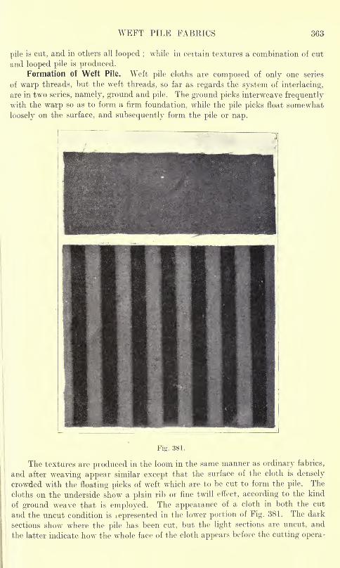
WEFT PILE FABRICS 363
pile is cut, and in others all looped ;while in certain textures a combination of cut
and looped pile is produced.Formation of Weft Pile. Weft pile cloths are composed of only one series
of warp threads, but the weft threads, so far as regards the system of interlacing,
are in two series, namely, ground and pile. The ground picks interweave frequentlywith the warp so as to form a firm foundation, while the pile picks float somewhat
loosely on the surface, and subsequently form the pile or nap.
Fig. 381.
The textures are produced in the loom in the same manner as ordinary fabrics,
and after weaving appear similar except that the surface of the cloth is densely
crowded with the floating picks of weft which are to be cut to form the pile. The
cloths on the underside show a plain rib or fine twill effect, according to the kind
of ground weave that is employed. The appearance of a cloth in both the cut
and the uncut condition is icpresented in the lower portion of Fig. 381. The dark
sections show where the pile has been cut, but the light sections are uncut, and
the latter indicate how the whole face of the cloth appears before the cutting opera-
366 ADVANCED TEXTILE DESIGN
the foundation will be the proper shade, but in order to get a rich bloom in the pile
this is followed by a process which more resembles printing. The pile side of the
cloth is passed in contact with the upper edge of a finely engraved roller which
revolves partly immersed in the dye solution. The amount carried up by the
roller is regulated by a doctor knife. The colour is transferred to the pile, and
as the cloth passes forward it is acted upon by revolving brushes which spreadthe dye over the surface. After drying, brushing again follows, and in some cases,
the cloth is also briskly rubbed by hand with an emery covered piece of wood.
The fabrics are usually classified as plain velveteen and corded velveteen
which are mostly made of cotton yarns. When the pile is very long, however,the term weft plush is used, and in this type the pile is frequently developed in
woollen or worsted yarns.
PLAIN VELVETEENS
This class of velveteen has a perfectly uniform surface, the foundation texture
being entirely covered by a short pile in which the projecting fibres are of equal
length. In constructing designs for the fabrics the chief points to note are:
(1) The weaves that are used for the ground and pile respectively; and (2) the
ratio of pile picks to ground picks. These factors, together with the ends and
picks per inch of the cloth, influence the length, density, and fastness of the pile.
The foundation weaves mostly used are plain, l-and-2 twill, and 2-and-2
twill, the last weave being employed for very heavy structures. The interlacingof the pile is almost invariably based either on the plain weave, a simple twill,
a sateen, or a sateen derivative. The pile and ground picks may be arranged in
any reasonable proportion, but generally a particular ratio is most suitable for
a given weave.
Tabby or Plain-back Velveteens. Examples A, B, C, D, and E in Fig. 383
are designs for standard velveteens, with the plain foundation weave. The latter
is represented by the crosses, and the base weaves for the pile interfacings are
shown at the left of the plans. In each design the number of pile picks to each
ground pick is equal to the number of picks in the repeat of the pile base weave.
This is a convenient ratio, but other proportions of pile to ground picks are quite
-easily arranged in the same weave.
A distinct feature to be noted in the designs is that the pile base weaves are
indicated only on alternate ends; thus each plan is on twice as many ends as
the base weave. Design A is arranged two pile picks to one ground pick, andthe pile weave is based on the plain weave which yields a weft float of three. In
a finely set cloth the pile from this design is short and poor, but if there are not
many ends per inch, a fairly good result is obtained.
In design B, the pile weave is based on the l-and-2 twill which yields a weft
float of five, and there are three pile picks to each ground pick. This design producesa fine and rich effect, and is very extensively employed. Designs C and D are
each arranged four pile picks to one ground pick, but whereas in design C the
pile interlacing is based on the l-and-3 twill, in design D it is based on the 4-sateen
weave. Both of these yield a float of seven, and produce exactly similar results
an the finished cloth. Design E is arranged five pile to one ground, and the base
for the pile interlacing is T-and-4 sateen, which gives a float of nine.
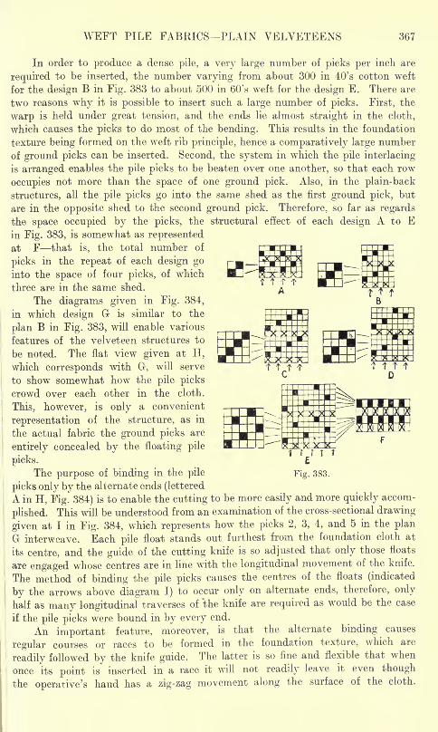
WEFT PILE FABRICS PLAIN VELVETEENS 367
In order to produce a dense pile, a very large number of picks per inch are
required to be inserted, the number varying from about 300 in 40's cotton weft
for the design B in Fig. 383 to about 500 in 60's weft for the design E. There are
two reasons why it is possible to insert such a large number of picks. First, the
warp is held under great tension, and the ends lie almost straight in the cloth,
which causes the picks to do most of the bending. This results in the foundation
texture being formed on the weft rib principle, hence a comparatively large number
of ground picks can be inserted. Second, the system in which the pile interlacing
is arranged enables the pile picks to be beaten over one another, so that each row
occupies not more than the space of one ground pick. Also, in the plain-back
structures, all the pile picks go into the same shed as the first ground pick, but
are in the opposite shed to the second ground pick. Therefore, so far as regards
the space occupied by the picks, the structural effect of each design A to Ein Fig. 383, is somewhat as represented
at F that is, the total number of
picks in the repeat of each design gointo the space of four picks, of which
three are in the same shed.
The diagrams given in Fig. 384,
in which design G is similar to the
plan B in Fig. 383, will enable various
features of the velveteen structures to
be noted. The flat view given at H,which corresponds with G, will serve
to show somewhat how the pile picks
crowd over each other in the cloth.
This, however, is only a convenient
representation of the structure, as in
the actual fabric the ground picks are
entirely concealed by the floating pile
picks.
The purpose of binding in the pile Fig. 383.
picks only by the alternate ends (lettered
A in H, Fig. 384) is to enable the cutting to be more easily and more quickly accom-
plished. This will be understood from an examination of the cross-sectional drawing
given at I in Fig. 384, which represents how the picks 2, 3, 4, and 5 in the plan
G interweave. Each pile float stands out furthest from the foundation cloth at
its centre, and the guide of the cutting knife is so adjusted that only those floats
are engaged whose centres are in line with the longitudinal movement of the knife.
The method of binding the pile picks causes the centres of the floats (indicated
by the arrows above diagram I) to occur only on alternate ends, therefore, only
half as many longitudinal traverses of the knife are required as would be the case
if the pile picks were bound in by every end.
An important feature, moreover, is that the alternate binding causes
regular courses or races to be formed in the foundation texture, which are
readily followed by the knife guide. The latter is so fine and flexible that when
! once its point is inserted in a race it will not readily leave it even though
the operative's hand has a zig-zag movement along the surface of the cloth.
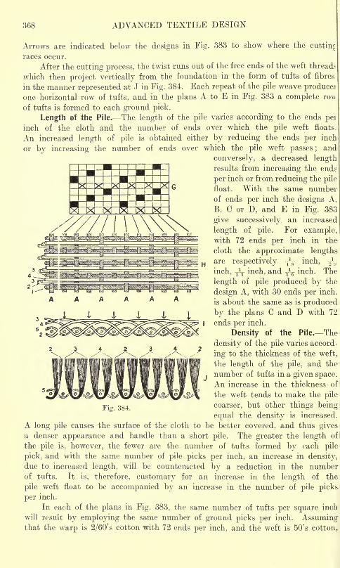
368 ADVANCED TEXTILE DESIGN
Arrows are indicated below the designs in Fig. 383 to show where the cutting
races occur.
After the cutting process, the twist runs out of the free ends of the weft threads
which then project vertically from the foundation in the form of tufts of fibres
in the manner represented at J in Fig. 384. Each repeat of the pile weave produces
one horizontal row of tufts, and in the plans A to E in Fig. 383 a complete ro\\
of tufts is formed to each ground pick.
Length of the Pile. The length of the pile varies according to the ends pei
inch of the cloth and the number of ends over which the pile weft floats.
An increased length of pile is obtained either by reducing the ends per inch
or by increasing the number of ends over which the pile weft passes ; and
conversely, a decreased lengthresults from increasing the ends
per inch or from reducing the pile
float. With the same numbeiof ends per inch the designs A,
B, C or D, and E in Fig. 383
give successively an increased
length of pile. For examplewith 72 ends per inch in the
cloth the approximate lengthsare respectively T
*
F inch, -^inch, ^V inch, and -^ inch. The
length of pile produced by the
design A, with 30 ends per inch,
is about the same as is produced
by the plans C and D with 72
ends per inch.
Density of the Pile. The
density of the pile varies accord-
ing to the thickness of the weft,
the length of the pile, and the
number of tufts in a given space.
An increase in the thickness of
the weft tends to make the pile
coarser, but other things being
equal the density is increased.
A long pile causes the surface of the cloth to be better covered, and thus gives-
a denser appearance and handle than a short pile. The greater the length ofi
the pile is, however, the fewer are the number of tufts formed by each pile
pick, and with the same number of pile picks per inch, an increase in density,due to increased length, will be counteracted by a reduction in the numberof tufts. It is, therefore, customary for an increase in the length of the
pile weft float to be accompanied by an increase in the number of pile picks
per inch.
In each of the plans in Fig. 383, the same number of tufts per square inch
will result by employing the same number of ground picks per inch. Assumingthat the warp is 2/60' s cotton with 72 ends per inch, and the weft is 50's cotton,
Fig. 384.
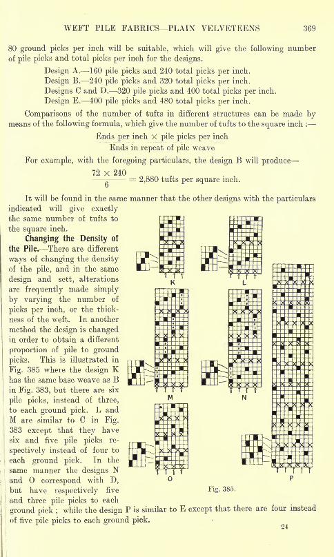
WEFT PILE FABKICS PLAIN VELVETEENS 369
80 ground picks per inch will be suitable, which will give the following number
of pile picks and total picks per inch for the designs.
Design A. 160 pile picks and 240 total picks per inch.
Design B. 240 pile picks and 320 total picks per inch.
Designs C and D. 320 pile picks and 400 total picks per inch.
Design E. 400 pile picks and 480 total picks per inch.
Comparisons of the number of tufts in different structures can be made bymeans of the following formula, which give the number of tufts to the square inch :
Ends per inch X pile picks per inch
Ends in repeat of pile weave
For example, with the foregoing particulars, the design B will produce
72 x 240
G= 2,880 tufts per square inch.
It will be found in the same manner that the other designs with the particulars
indicated will give exactlythe same number of tufts to
the square inch.
Changing the Density of
the Pile. There are different
ways of changing the densityof the pile, and in the same
design and sett, alterations
are frequently made simply
by varying the number of
picks per inch, or the thick-
ness of the weft. In another
method the design is changedin order to obtain a different
proportion of pile to ground
picks. This is illustrated in
Fig. 385 where the design Khas the same base weave as Bin Fig. 383, but there are six
pile picks, instead of three,
to each ground pick. L and
M are similar to C in Fig.
383 except that they have
six and five pile picks re-
spectively instead of four to
each ground pick. In the
same manner the designs Nand correspond with D,but have respectively five Fig. 385.
and three pile picks to each
ground pick ;while the design P is similar to E except that there are four instead
of five pile picks to each ground pick.
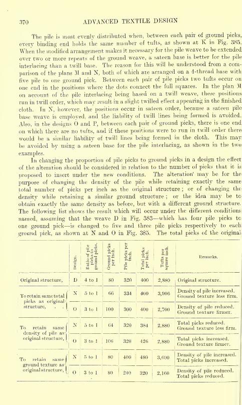
370 ADVANCED TEXTILE DESIGN
The pile is most evenly distributed when, between each pair of ground picks,
every binding end holds the same number of tufts, as shown at K in Fig. 385.
When the modified arrangement makes it necessary for the pile weave to be extended
over two or more repeats of the ground weave, a sateen base is better for the pile
interlacing than a twill base. The reason for this will be understood from a com-
parison ofthe plans M and N, both of which are arranged on a 4-thread base with
five pile to one ground pick. Between each pair of pile picks two tufts occur on
one end in the positions where the dots connect the full squares. In the plan Mon account of the pile interlacing being based on a twill weave, these positions
run in twill order, which may result in a slight twilled effect appearing in the finished
cloth. In N, however, the positions occur in sateen order, because a sateen pile
base weave is employed,, and the liability of twill lines being formed is avoided.
Also, in the designs 6 and P, between each pair of ground picks, there is one end
on which there are no tufts, and if these positions were to run in twill order there
would be a similar liability of twill lines being formed in the cloth. This maybe avoided by using a sateen base for the pile interlacing, as shown in the two
examples.In changing the proportion of pile picks to ground picks in a design the effect
of the alteration should be considered in relation to the number of. picks that it is
proposed to insert under the new conditions. The alteration' may be for the
purpose of changing the density of the pile while retaining exactly the same
total number of picks per inch as the original structure;
or of changing the
density while retaining a similar ground structure;
or the idea may be to
obtain exactly the same density as before, but with a different ground structure.
The following list shows the result which will occur under the different conditions
named, assuming that the weave D in Fig. 383 which has four pile picks tc
one ground pick is changed to five and three pile picks respectively to each
ground pick, as shown at N and in Fig. 385. The total picks of the original
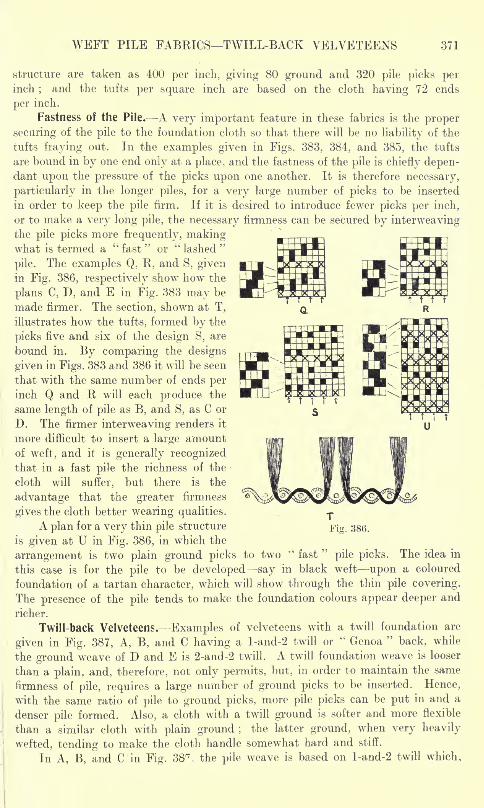
WEFT PILE FABRICS TWILL-BACK VELVETEENS 371
structure are taken as 400 per inch, giving 80 ground and 320 pile picks perinch
;and the tufts per square inch are based on the cloth having 72 ends
per inch.
Fastness of the Pile. A very important feature in these fabrics is the proper
securing of the pile to the foundation cloth so that there will be no liability of the
tufts fraying out. In the examples given in Figs. 383, 384, and 385, the tufts
are bound in by one end only at a place, and the fastness of the pile is chiefly depen-dant upon the pressure of the picks upon one another. It is therefore necessary,
particularly in the longer piles, for a very large number of picks to be inserted
in order to keep the pile firm. If it is desired to introduce fewer picks per inch,
or to make a very long pile, the necessary firmness can be secured by interweavingthe pile picks more frequently, makingwhat is termed a "fast" or '"lashed"
pile. The examples Q, R, and S, givenin Fig. 386, respectively show how the
plans C, D, and E in Fig. 383 may be
made firmer. The section, shown at T,
illustrates how the tufts, formed by the
picks five and six of the design S, are
bound in. By comparing the designs
given in Figs. 383 and 386 it will be seen
that with the same number of ends perinch Q and R will each produce the
same length of pile as B, and S, as C or
D. The firmer interweaving renders it
more difficult to insert a large amountof weft, and it is generally recognizedthat in a fast pile the richness of the
cloth will suffer, but there is the
advantage that the greater firmness
gives the cloth better wearing qualities.
A plan for a very thin pile structure
is given at U in Fig. 386, in which the
arrangement is two plain ground picks to two "fast
"pile picks. The idea in
this case is for the pile to be developed say in black weft upon a coloured
foundation of a tartan character, which will show through the thin pile covering.
The presence of the pile tends to make the foundation colours appear deeper and
richer.
Twill-back Velveteens. Examples of velveteens with a twill foundation are
given in Fig. 387, A, B, and C having a l-and-2 twill orkt
Genoa"
back, while
the ground weave of D and E is 2-and-2 twill. A twill foundation weave is looser
than a plain, and, therefore, not only permits, but, in order to maintain the same
firmness of pile, requires a large number of ground picks to be inserted. Hence,
with the same ratio of pile to ground picks, more pile picks can be put in and a
denser pile formed. Also, a cloth with a twill ground is softer and more flexible
than a similar cloth with plain ground ;the latter ground, when very heavily
wefted, tending to make the cloth handle somewhat hard and stiff.
In A, B, and C in Fig. 3Sn . the pile weave is based on l-and-2 twill which,
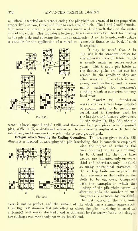
372 ADVANCED TEXTILE DESIGN
as before, is marked on alternate ends;the pile picks are arranged in the proportion
respectively of two, three, and four to each ground pick. The l-and-2 twill founda-
tion weave of these designs is invariably made with the weft float on the under
side of the cloth. This provides a better surface than a warp twill back for bindingin the pile picks and covering them on the underside. Also, the 2-and-l weft surface
is suitable for the application of a raised or flannelette finish to the back if such
is required.It may be noted that A in
Fig. 387 is the standard design for
the moleskin class of fabric, which
is usually made in coarse cotton
yarns. This is not a pile fabric, as.
the floating picks are not cut but
remain in the condition they are
after weaving. The cloth is very
strong and leathery, and is emi-
nently suitable for workmen's
clothing which is subjected to veryhard wear.
A 2-and-2 twill foundation
weave enables a very large numberof ground picks to be readily in-
serted, and is therefore used for
Fig. 387. the heaviest and densest velveteens.
In the design D, Fig. 387, the pileweave is based upon l-and-3 twill, and there are four pile picks to each groundpick, while in E, a six-thread sateen pile base weave is employed with the pilemade fast, and there are three pile picks to each ground pick.
Designs which Simplify the Cutting Operation. The designs given in Fig. 388
illustrate a method of arranging the pile interlacing that is sometimes employedwith the object of reducing the
time occupied in the pile cutting.
In F, G, and H, the pile base
weaves are indicated only on everythird end, therefore, only one-third
as many longitudinal traverses of I
the cutting knife are required, as
there are ends in the width of the
cloth to be cut over. Comparedwith the examples in which the
binding of the pile picks occurs on i
alternate ends, the number of cut-
Fig. 388. ting races is reduced by one-third.
The distribution of the pile, how-
ever, is not so perfect, and the surface of the cloth has a coarser appearance.I in Fig. 388 shows a fast pile effect in which the pile interlacing is based on i
a l-and-2 twill weave doubled;and as indicated by the arrows below the design,
the cutting races occur only on every fourth end.
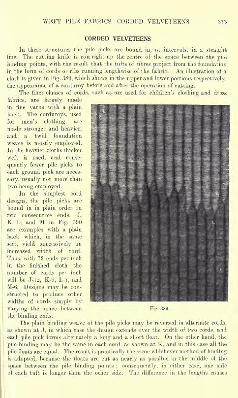
WEFT PILE FABRICS- CORDED VELVETEENS 373
CORDED VELVETEENS
In these structures the pile picks are bound in, at intervals, in a straight
line. The cutting knife is run right up the centre of the space between the pile
binding points, with the result that the tufts of fibres project from the foundation
in the form of cords or ribs running lengthwise of the fabric. An illustration of a
cloth is given in Fig. 389, which shows in the upper and lower portions respectively,
the appearance of a corduroy before and after the operation of cutting.
The finer classes of cords, such as are used for children's clothing and dress
fabrics, are largely madein fine yarns with a plain
back. The corduroys, used
for men's clothing, are
made stronger and heavier,
and a twill foundation
weave is mostly employed.In the heavier cloths thicker ? '*' JR" M 9.
weft is used, and conse-
quently fewer pile picks to
each ground pick are neces-
sary, usually not more than
two being employed.In the simplest cord
designs, the pile picks are
bound in in plain order on
two consecutive ends. J,
K, L, and M in Fig. 390
are examples with a plain
back which, in the same
sett, yield successively an
increased width of cord.
Thus, with 72 ends per inch
in the finished cloth the
number of cords per inch
will be J-12, K-9, L-7, and
M-6. Designs may be con-
structed to produce other
widths of cords simply by
varying the space between Fig. 389.
the binding ends.
The plain binding weave of the pile picks may be reversed in alternate cords,
as showrn at J, in which case the design extends over the width of two cords, and
each pile pick forms alternately a long and a short float. On the other hand, the
pile binding may be the same in each cord, as shown at K, and in this case all the
pile floats are equal. The result is practically the same whichever method of bindingis adopted, because the floats are cut as nearly as possible in the middle of the
space between the pile binding points ; consequently, in either case, one side
of each tuft is longer than the other side. The difference in the lengths causes
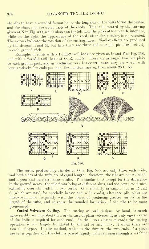
374 ADVANCED TEXTILE DESIGN
the ribs to have a rounded formation, as the long side of the tufts forms the centre,
and the short side the outer parts of the cords. This is illustrated by the drawing-
given at N in Fig. 390, which shows on the left how the picks of the plan K interlace,
while on the right the appearance of the cord, after the cutting, is represented.
The arrows indicate the position of the cutting races. Similar effects are produced
by the designs L and M, but here there are three and four pile picks respectively
to each ground pick.
Examples of cords with a l-and-2 twill back are given at and P in Fig. 390,
and with a 2-and-2 twill back at Q, R, and S. These are arranged two pile picks
to each ground pick, and in producing very heavy structures they are woven with
comparatively few ends per inch, the number varying from about 28 to 36.
*MI IxB
i
The cords, produced by the design in Fig. 390, are only three ends wide,
and both sides of the tufts are of equal length ; therefore, the ribs are not rounded,
and a poor and bare structure results. P is similar to J except for the difference
in the ground weave, the pile floats being of different sizes, and the complete design
extending over the width of two cords. Q is similarly arranged, but in R and
S (which are used for specially heavy and wide cords), alternate pile picks are
interwoven more frequently with the object of producing greater variety in the
length of the tufts, and so cause the rounded formation of the ribs to be more
pronounced.Corded Velveteen Cutting. The cutting of cord designs, by hand, is much
more readily accomplished than in the case of plain velveteens, as only one traverse
of the knife is required for each cord. In the lower classes of cords the cutting
operation is now largely facilitated by the aid of machinery, of which there are
two chief types. In one method, which is the simpler, the two ends of a piece
are sewn together and the cloth is passed rapidly under tension through a machine
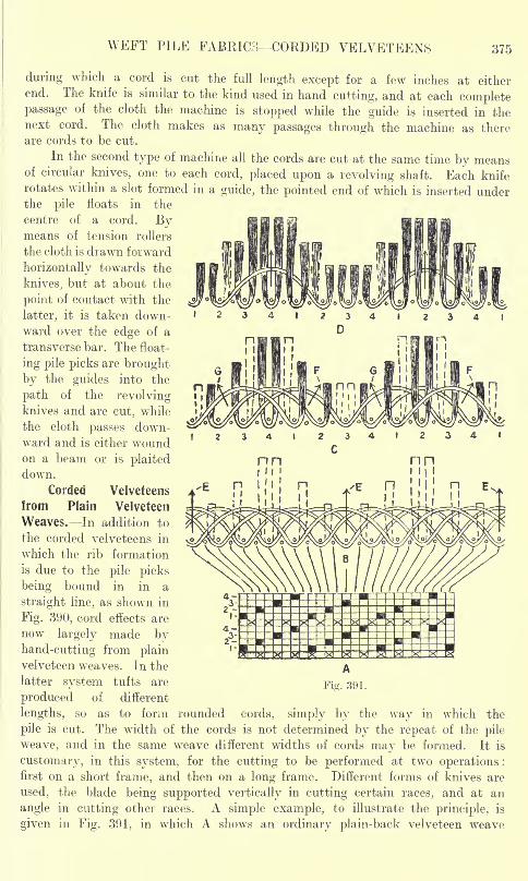
WEFT PILE FABRIC;!- CORDED VELVETEENS 375
during which a cord is cut the full length except for a few inches at either
end. The knife is similar to the kind used in hand cutting, and at each completepassage of the cloth the machine is stopped while the guide is inserted in thenext cord. The cloth makes as many passages through the machine as thereare cords to be cut.
In the second type of machine all the cords are cut at the same time by meansof circular knives, one to each cord, placed upon a revolving shaft. Each kniferotates within a slot formed in a guide, the pointed end of which is inserted underthe pile floats in the
centre of a cord. Bymeans of tension rollers
the cloth is drawn forward
horizontally towards the
knives, but at about the
point of contact with the
latter, it is taken down-
ward over the edge of a
transverse bar. The float-
ing pile picks are brought
by the guides into the
path of the revolvingknives and are cut, while
the cloth passes down-ward and is either woundon a beam or is plaiteddown.
Corded Velveteens
from Plain Velveteen
Weaves. In addition to
the corded velveteens in
which the rib formation
is due to the pile picks
being bound in in a
straight line, as shown in
Fig. 390, cord effects are
now largely made by
hand-cutting from plainvelveteen weaves. In the
latter system tufts are
produced of different
lengths, so as to form rounded cords, simply by the way in which the.
pile is cut. The width of the cords is not determined by the repeat of the pile
weave, and in the same weave different widths of cords may be formed. It is
customary, in this system, for the cutting to be performed at two operations :
first on a short frame, and then on a long frame. Different forms of knives are
used, the blade being supported vertically in cutting certain races, and at an
angle in cutting other races. A simple example, to illustrate the principle, is
given in Fig. 391, in which A shows an ordinary plain-back velveteen weave
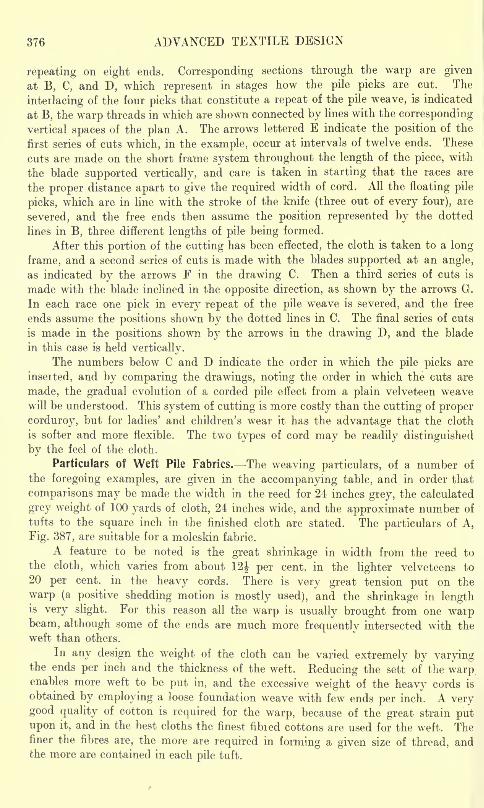
376 ADVANCED TEXTILE DESIGN
repeating on eight ends. Corresponding sections through the warp are given
at B, C, and D, which represent in stages how the pile picks are cut. The
interlacing of the four picks that constitute a repeat of the pile weave, is indicated
at B, the warp threads in which are shown connected by lines with the corresponding
vertical spaces of the plan A. The arrows lettered E indicate the position of the
first series of cuts which, in the example, occur at intervals of twelve ends. These
cuts are made on the short frame system throughout the length of the piece, with
the blade supported vertically, and care is taken in starting that the races are
the proper distance apart to give the required width of cord. All the floating pile
picks, which are in line with the stroke of the knife (three out of every four), are
severed, and the free ends then assume the position represented by the dotted
lines in B, three different lengths of pile being formed.
After this portion of the cutting has been effected, the cloth is taken to a long
frame, and a second series of cuts is made with the blades supported at an angle,
as indicated by the arrows F in the drawing C. Then a third series of cuts is
made with the blade inclined in the opposite direction, as shown by the arrows G.
In each race one pick in every repeat of the pile weave is severed, and the free
ends assume the positions shown by the dotted lines in C. The final series of cuts
is made in the positions shown by the arrows in the drawing D, and the blade
in this case is held vertically.
The numbers below C and D indicate the order in which the pile picks are
inserted, and by comparing the drawings, noting the order in which the cuts are
made, the gradual evolution of a corded pile effect from a plain velveteen w^eave
will be understood. This system of cutting is more costly than the cutting of proper
corduroy, but for ladies' and children's wear it has the advantage that the cloth
is softer and more flexible. The two types of cord may be readily distinguished
by the feel of the cloth.
Particulars of Weft Pile Fabrics. The weaving particulars, of a number of
the foregoing examples, are given in the accompanying table, and in order that
comparisons may be made the width in the reed for 24 inches grey, the calculated
grey weight of 100 yards of cloth, 24 inches wide, and the approximate number of
tufts to the square inch in the finished cloth are stated. The particulars of A,
Fig. 387, are suitable for a moleskin fabric.
A feature to be noted is the great shrinkage in width from the reed to
the cloth, which varies from about 12\ per cent, in the lighter velveteens to
20 per cent, in the heavy cords. There is very great tension put on the
warp (a positive shedding motion is mostly used), and the shrinkage in lengthis very slight. For this reason all the warp is usually brought from one warpbeam, although some of the ends are much more frequently intersected with the
weft than others.
In any design the weight of the cloth can be varied extremely by varyingthe ends per inch and the thickness of the weft. Reducing the sett of the warpenables more weft to be put in, and the excessive weight of the heavy cords is
obtained by employing a loose foundation weave with few ends per inch. A verygood quality of cotton is required for the warp, because of the great strain putupon it, and in the best cloths the finest fibied cottons are used for the weft. Thefiner the fibres are, the more are required in forming a given size of thread, andthe more are contained in each pile tuft.
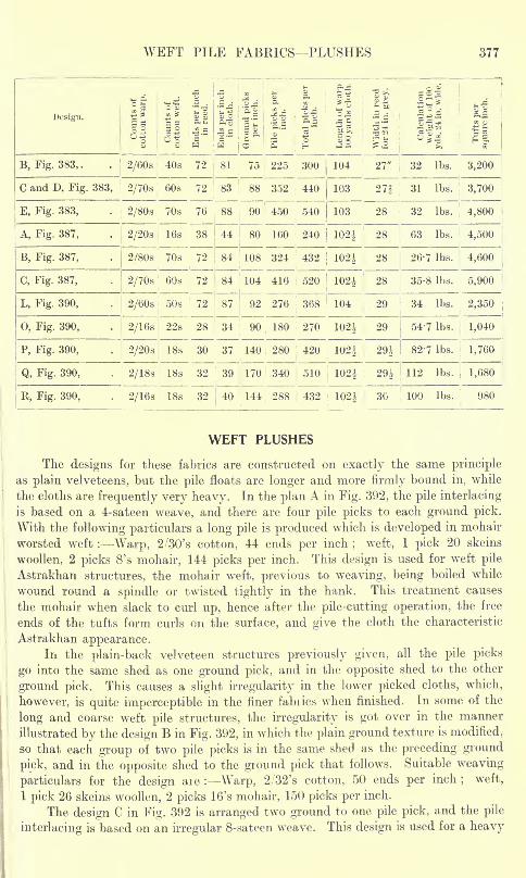
WEFT PILE FABRICS PLUSHES 377
Design.
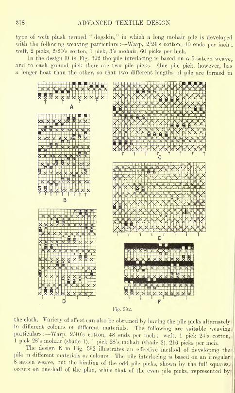
378 ADVANCED TEXTILE DESIGN
type of weft plush termed' ;
dogskin," in which a long mohair pile is developedwith the following weaving particulars : Warp, 2/24's cotton, 40 ends per inch ;
weft, 2 picks, 2/20's cotton, 1 pick, 3's mohair, 60 picks per inch.
In the design D in Fig. 392 the pile interlacing is based on a 5-sateen weave,and to each ground pick there are two pile picks. One pile pick, however, has
a longer float than the other, so that two different lengths of pile are formed in
i
T I
?H5S?i?ie
5
the cloth. Variety of effect can also be obtained by having the pile picks alternately,in different colours or different materials. The following are suitable weavingparticulars : Warp, 2/40's cotton, 48 ends per inch
; weft, 1 pick 24's cotton,1 pick 28's mohair (shade 1), 1 pick 28's mohair (shade 2), 216 picks per inch.
The design E in Fig. 392 illustrates an effective method of developing the
pile in different materials or colours. The pile interlacing is based on an irregular !
8-sateen weave, but the binding of the odd pile picks, shown by the full squares,occurs on one-half of the plan, while that of the even pile picks, represented by
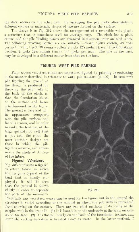
FIGURED WEFT PILE FABRICS 379
the dots, occurs on the other half. By arranging the pile picks alternately mdifferent colours or materials, stripes of pile are formed on the surface.
The design F in Fig. 392 shows the arrangement of a reversible weft plush,
a structure that is sometimes used for carriage rugs. The cloth has a plain
centre, and the pile binding places are arranged in 6-sateen order on both sides.
The following weaving particulars are suitable : Warp, 2/30's cotton, 48 ends
per inch; weft, 1 pick 30 skeins woollen, 2 picks 12's mohair (face), 1 pick 30 skeins
woollen, 2 picks 12's mohair (back), 144 picks per inch. The pile on the back
may be developed in a different colour from that on the face.
FIGURED WEFT PILE FABRICS
Plain woven velveteen cloths are sometimes figured by printing or embossingin the manner described in reference to warp pile textures (p. 405). In true weft
pile figuring the ground of
the design is produced bythrowing the pile picks to
the back of the cloth, so
that the foundation showu
on the surface and forms
a background to the figure.
The ground is bare and dull
in appearance comparedwith the pile surface, and
for this reason, and in order
to make the best use of the
large quantity of weft that
is put into the cloth, the
most suitable designs are
those in which the pile
figure is massive, and covers
nearly the whole of the face
of the fabric.
Figured Velveteens.
Fig. 393 represents a figured
velveteen fabric in which
the design is typical of the
kind that is mostly em-
ployed ;it will be seen
that the ground is shown
chiefly in order to separate Fig. 393.
the parts of the ornament.
Practically any velveteen weave can be used for the figure, but in the ground the
structure is varied according to the method in which the pile weft is prevented
from showing on the surface. There are two chief methods of disposing of the
surplus weft in the ground :-(!) It is bound in on the underside in the same manner
as on the face. (2) It is floated loosely on the back of the foundation texture, and
after the cutting operation is brushed away as waste. In the latter method, if
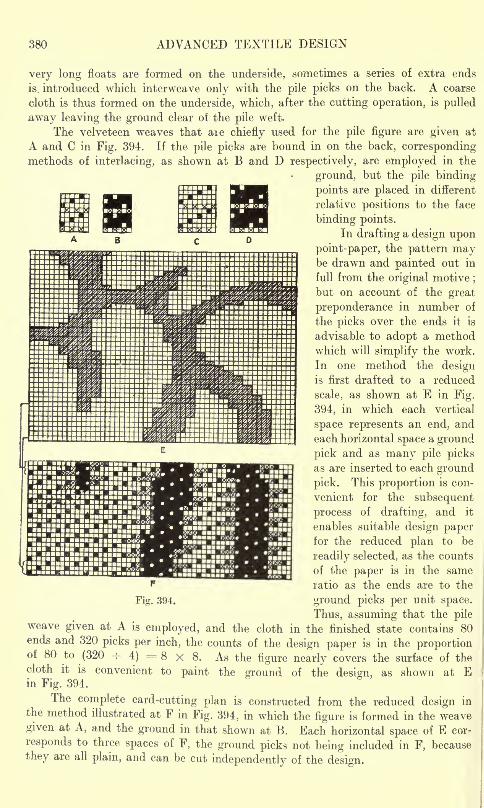
380 ADVANCED TEXTILE DESIGN
very long floats are formed on the underside, sometimes a series of extra ends
is. introduced which interweave only with the pile picks on the back. A coarse
cloth is thus formed on the underside, which, after the cutting operation, is pulled
away leaving the ground clear of the pile weft.
The velveteen weaves that aie chiefly used for the pile figure are given at
A and C in Fig. 394. If the pile picks are bound in on the back, correspondingmethods of interlacing, as shown at B and D respectively, are employed in the
ground, but the pile binding
points are placed in different
relative positions to the face
binding points.
In drafting a design upon
point-paper, the pattern maybe drawn and painted out in
full from the original motive;
but on account of the great
preponderance in number of
the picks over the ends it is
advisable to adopt a methodwhich will simplify the work.
In one method the designis first drafted to a reduced
scale, as shown at E in Fig.
394, in which each vertical
space represents an end, and
each horizontal space a ground
pick and as many pile picksas are inserted to each ground
pick. This proportion is con-
venient for the subsequent
process of drafting, and it
enables suitable design paperfor the reduced plan to be
readily selected, as the counts
of the paper is in the same
ratio as the ends are to the
ground picks per unit space.
Thus, assuming that the pileweave given at A is employed, and the cloth in the finished state contains 80ends and 320 picks per inch, the counts of the design paper is in the proportionof 80 to (320
-=-4) = 8 x 8. As the figure nearly covers the surface of the
cloth it is convenient to paint the ground of the design, as shown at Ein Fig. 394.
The complete card-cutting plan is constructed from the reduced design in
the method illustrated at F in Fig. 394, in which the figure is formed in the weavegiven at A, and the ground in that shown at B. Each horizontal space of E cor-
responds to three spaces of F, the ground picks not being included in F, because
they are all plain, and can be cut independently of the design.
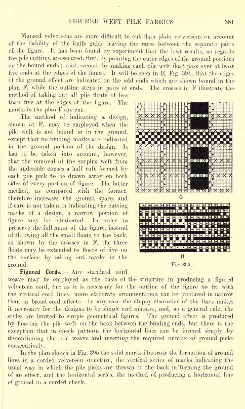
FIGURED WEFT PILE FABRICS 381
QBCBDBC BD mnmamaIGBDBD
Figured velveteens are more difficult to cut than plain velveteens on account
of the liability of the knife guide leaving the races between the separate partsof the figure. It has been found by experiment that the best results, as regardsthe pile cutting, are secured, first, by painting the outer edges of the ground portionson the bound ends
; and, second, by making each pile weft float pass over at least
five ends at the edges of the figure. It will be seen in E, Fig. 394, that thn edgesof the ground effect are indicated on the odd ends which are shown bound in the
plan F, while the outline steps in pairs of ends. The crosses in F illustrate the
method of taking out all pile floats of less
than five at the edges of the figure. Themarks in the plan F are cut.
The method of indicating a design,shown at F, may be employed when the
pile weft is not bound in in the ground,
except that no binding marks are indicated
in the ground portion of the design. It
has to be taken into account, however,that the removal of the surplus weft from
the underside causes a half tuft formed byeach pile pick to be drawn away on both
sides of every portion of figure. The latter
method, as compared with the former,
therefore increases the ground space, and
if care is not taken in indicating the cuttingmarks of a design, a narrow portion of
figure may be eliminated. In order to
preserve the full mass of the figure, instead
of throwing all the small floats to the back,
as shown by the crosses in F, the three
floats may be extended to floats of five on
the surface by taking out marks in the
ground.
Figured Cords. Any standard cord
weave may be employed as the basis of the structure in producing a figuredvelveteen cord, but as it is necessary for the outline of the figure to fit with
the vertical cord lines, more elaborate ornamentation can be produced in narrow
than in broad cord effects. In any case the steppy character of the lines makesit necessary for the designs to be simple and massive, and, as a general rule, the
styles are limited to simple geometrical figures. The ground effect is produced
by floating the pile weft on the back between the binding ends, but there is the
exception that in check patterns the horizontal lines can be formed simply by
discontinuing the pile weave and inserting the required number of ground picks
consecutively.In the plan shown in Fig. 395 the solid marks illustrate the formation of ground
lines in a corded velveteen structure, the vertical series of marks indicating the
usual way in which the pile picks are thrown to the back in 'forming the groundof an effect, and the horizontal series, the method of producing a horizontal line
of ground in a corded check.
mamamamamnmcmanomnmamamcuamza
DInBDBGBOB
H
Fig. 395.
382 ADVANCED TEXTILE DESIGN
IMITATION OF WEFT PILE FABRICS
A form of weft curl pile is produced by combining a shrinking with a non-
shrinking weft, and submitting the cloth to very great contraction in the finishing
processes. Woollen and mohair wefts may be used, inserted one or two picks
of each alternately, and a cotton warp. The woollen weft is interwoven in perfectly
plain order with the warp, while the mohair weft is interwoven in plain order for
a number of threads, and is then floated loosely on the surface. The method is
illustrated by the plan given at H in Fig. 395, in which the dots represent the woollen
picks, and the solid marks the mohair picks. The cloth is heavily milled, and
shrinks excessively in width, but the mohair floats do not contract, and are, therefore,
caused to form loops or curls on the surface.
In another form of imitation weft pile a fabric is produced with a fibrous surface
which, to some extent, resembles various skin and plush textures. The cloth is
woven with cotton warp, and a weft that consists of a mixture of cow's or calf's
hair and a low quality of wool. The weave is usually an ordinary four- or five-
thread weft-sateen, but sometimes a reversible weft-face weave (as shown in
Fig. 7, p. 8) is used in order that the cloth will be the same on both sides. The
pile effect is produced in the finishing operation by submitting the cloth to verysevere processes of milling and raising. In the dyed or printed condition the
fabrics are used for such purposes as curtains, upholsteries, and carriage rugs.
CHAPTER XVII
TURKISH TOWELLING FABRICS
Formation of the Pile Turkish Towelling Weaves Methods of Drafting and Denting TerryMotions. Terry Ornamentation Stripe and Check Dobby Patterns Figured Terry Pile
Fabrics Mixed Colour Effects.
THE Turkish towelling structure forms a class of warp pile termed"terry
"
pile in which certain warp threads form loops or curls on the face of the cloth.
Only one kind of weft may be used, but two series of warp threads, placed on
separate beams, are necessary for the production of the cloths viz., ground threads
-and pile threads. The former produce with the weft a foundation texture fromwhich the loops, formed by the pile threads, project.
The distinguishing feature of this class of pile, as compared with true warppile, is that the looped structure is produced, not by the aid of wires, but by employ-
ing a special reed motion and warp easing arrangement which enable the loopsto be formed on the upper or lower, or both upper and lower, surface of the cloth.
Turkish towels may be made in either linen or cotton yarns, and in cotton yarnsthe structure is applied, in addition to towels, to such fabrics as counterpanes,mats, dressing gowns, and toiletings. The principle has also been employed in
the manufacture of cheap mantle cloths in which the pile is developed in yarnsmade from wool.
Formation of the Pile.- In forming the looped pile without the aid of wires,
many different kinds of terry motions are used, but in every case the object is
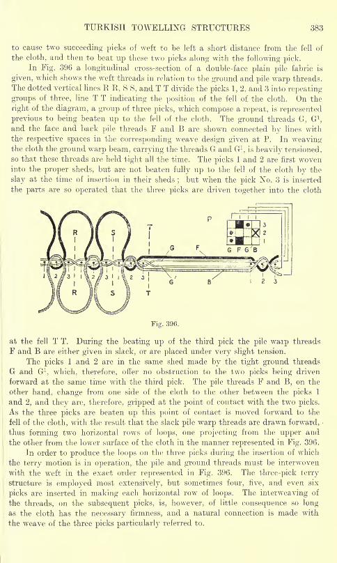
TURKISH TOWELLING STRUCTURES 383
to cause two succeeding picks of weft to be left a short distance from the fell of
the cloth, and then to beat up these two picks along with the following pick.In Fig. 396 a longitudinal cross-section of a double-face plain pile fabric is
given, which shows the weft threads in relation to the ground and pile warp threads.
The dotted vertical lines R R, S S, and T T divide the picks 1, 2, and 3 into repeating
groups of three, line T T indicating the position of the fell of the cloth. On the
right of the diagram, a group of three picks, which compose a repeat, is represented
previous to being beaten up to the fell of the cloth. The ground threads G, G 1,
and the face and back pile threads F and B are shown connected by lines with
the respective spaces in the corresponding weave design given at P. In weavingthe cloth the ground warp beam, carrying the threads G and G 1
,is heavily tensioned,
so that these threads are held tight all the time. The picks 1 and 2 are first woveninto the proper sheds, but are not beaten fully up to the fell of the cloth by the
slay at the time of insertion in their sheds;
but when the pick No. 3 is inserted
the parts are so operated that the three picks are driven together into the cloth
I 2 3
Fig. 396.
at the fell T T. During the beating up of the third pick the pile warp threads
F and B are either given in slack, or are placed under very slight tension.
The picks 1 and 2 are in the same shed made by the tight ground threads
G and G 1, which, therefore, offer no obstruction to the two picks being driven
forward at the same time with the third pick. The pile threads F and B, on the
other hand, change from one side of the cloth to the other between the picks 1
and 2, and they are, therefore, gripped at the point of contact with the two picks.
As the three picks are beaten up this point of contact is moved forward to the
fell of the cloth, with the result that the slack pile warp threads are drawn forward,
thus forming two horizontal rows of loops, one projecting from the upper and
the other from the lower surface of the cloth in the manner represented in Fig. 396.
In order to produce the loops on the three picks during the insertion of which
the terry motion is in operation, the pile and ground threads must be interwoven
with the weft in the exact order represented in Fig. 396. The three-pick terry
structure is employed most extensively, but sometimes four, five, and even six
picks are inserted in making each horizontal row of loops. The interweaving of
the threads, on the subsequent picks, is, however, of little consequence so longas the cloth has the necessary firmness, and a natural connection is made with
the weave of the three picks particularly referred to.

384 ADVANCED TEXTILE DESIGN
Turkish Towelling Weaves. A number of standard designs for producingthe fabrics are given in Fig. 397. These designs have been grouped so that com-
parisons can be readily made. The dots in the designs represent the interfacings
of the ground warp threads ;the full squares show the interweaving of the face
pile threads, and the crosses of the back pile threads. Designs A, B, C, D, and
E form the loops uniformly on the face side of the cloth only, whereas the remaining
designs are for producing a pile surface on both sides of the cloth. In the designs
A, B, C, D, and E, the warp threads are arranged 1 ground, 1 face pile, and
in F, G, H, I, J, and K, 1 ground, 1 face pile, 1 ground, 1 back pile. The designs
L, M, N, 0, P, and Q produce corresponding effects to the designs F to Krespectively, but they are arranged 1 ground, 1 face pile, 1 back pile, 1 ground.
In each design A to E in Fig. 397, there is a pile thread on the surface to each
ground thread, but in the remaining
designs F to Q, the proportion is one
pile thread on each side of the cloth
to two ground threads. The single-face
pile cloths can, however, be made with
one pile to two ground by leaving out
the last thread in each of the designs Ato E. The plans A, F, and L are for
producing the pile effect on three picks ;
B, G, and M on four picks; C, H, N,
D, I, 0, J, and P on five picks ;and E,
K, and Q on six picks.
The five-pick effects, C, H, and N,are respectively similar to D, I, and 0,
except that the pile threads interweave
more frequently in the latter three, while
J and P show a further modification in
which the face pile threads interweave
more frequently than those which form
the back pile. Less weft yarn can be
introduced into the cloth with the more
firmly interwoven designs, and at the
same time the resulting structure is stronger and more durable.
In the six-pick effects E, K, and Q, the ends interlace with the picks in exactlythe same manner as in A, F, and L respectively, but in producing the loops at
every six picks, the weft is beaten up to the fell of the cloth on four picks in succes-
sion. This structure, which is known as the"Osman," is much firmer than the
three-pick terry, on account of the greater number of intersections that are madefor each horizontal row of loops ;
and with finer yarns and more picks per inch,
the cloth is made very strong and durable.
Every plan in Fig. 397 is constructed for the first and second picks to remainback from the edge of the cloth when they are first inserted, and for the reed
to beat up firmly on the third and subsequent picks in the repeat. A comparisonof the designs will show that in each case the interweaving of the respective threads
is exactly the same on the picks 1, 2, and 3, and corresponds with the order of
interlacing illustrated in Fig. 396. Thus, on the picks 1 and 2, the odd ground
U wFig. 397.
TURKISH TOWELLING FABRICS 385
threads are raised and the even ground threads depressed, while on the third
pick they are in the reverse positions. The face pile threads are raised on the
picks 1 and 3, and depressed on the second pick ;the back pile threads being
operated in the reverse order.
Methods of Drafting and Denting. In drawing in the two warps for weaving,the pile threads are drawn on two healds at the front, and the ground threads
(if the looped formation is to be continuous) on two healds at the back, as shownat R in Fig. 397 for the 1 ground, 1 pile order of airangement, and as indicated
at S for the 2-and-2 order. When, however, the cloths are made in short lengthswith a cross-border at each end, the drafts given at T and U are frequently employed.This arrangement enables a weave with a wr
eft float over seven warp threads to
be obtained by the alternate lifting of the third and fifth heald, the remaininghealds being left down in forming the float on the face, and lifted in forming the
float on the reverse side, as shown respectively at V and W. In dobby shedding
specially crammed and coloured cross-over effects (headings) can be readily formed
in the borders in this manner.
Usually two threads are placed in each split of the reed, and in the 1 ground,1 pile order, one of each series is placed in the same split, as shown above R in
Fig. 397. In the 2 ground, 2 pile order, however, two ends of the same series are
placed together, as shown above S. The two arrangements produce practically
identical results, but the 2-and-2 structure has the advantage that by reedingas described, the threads in each split work opposite to each other, and at the
same time the pile and ground threads, which on some picks work alike, are
separated by the wires of the reed, so that a clear shed is more readily obtained.
The loom particulars of a good quality of cotton terry cloth are as follows :
Pile warp, two ply 2/20's ; ground warp, 2/18's ; weft, 16's;ends per inch,
50; picks per inch, 58. 500 yards of pile warp and 102 yards of ground warp
are required for producing 100 yards of terry. The shrinkage in width is about
12 per cent. In cheaper cloths the weft may be 20's, and the picks 36 per inch
and upwards ;the pile warp 16's and the ground warp 14's
;300 yards and upwards
of pile warp for 100 yards of cloth. The ground ends are usually rather thicker
than the pile ends. For a soft cloth the pile yarns should be soft spun, and for
a crisp handle, moderately hard spun ;but the feel of the texture varies according
to the depth of the pile loops, a deep pile handling softer than a short pile. The
depth of the pile is determined by the distance that the two picks are left awayirom the fell of the cloth, which is usually about \ inch.
Terry Motions. Different systems have 'been devised to enable two successive
picks of weft to be left back from the edge of the cloth at will. In one method,in which a fast reed is employed, the going part is moved forward for a shorter
distance on the two"loose
"picks ;
while in another fast reed type, movable
front and back rails are provided, which enable the edge of the cloth to be traversed,
when required, in advance of the stroke of the reed for the necessary distance.
In the system which meets with the greatest favour, however, a loose reed is used
which is caused to move backwardly at the bottom, the upper edge of the reed
acting as the fulcrum.
An end view in partial cross-section of this type of terry motion (as made byMessrs. Butterworth & Dickinson, Ltd., Burnley) is given in Fig. 398, in which
the mechanism is under the control of a dobby or jacquard. However, in weaving25
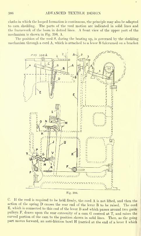
386 ADVANCED TEXTILE DESIGN
cloths in which the looped formation is continuous, the principle may also be adaptedto cam shedding. The parts of the reed motion are indicated in solid lines andthe framework of the loom in dotted lines. A front view of the upper part of the
mechanism is shown in Fig. 398, A.
The position of the reed S, during the beating up, is governed by the sheddingmechanism through a cord A, \vhich is attached to a lever B fulcrumed on a bracket
Fig. 398.
C. If the reed is required to be held firmly, the cord A is not lifted, and then theaction of the spring D causes the rear end of the lever B to be raised. The cordE, which is connected to this end of the lever B and which passes around two guidepulleys F, draws upon the rear extremity of a cam G centred at T, and raises thecurved portion of the cam to the position shown in solid lines. Then, as the goingpart moves forward, an anti-friction bowl H (carried at the end of a lever I which
TURKISH TOWELLING FABRICS 387
is fulcrumed at V on a bracket attached to a sword U) passes below without touchingthe cam G, and the lever K, to which the link J is connected, occupies its normal
position. The lever K is fixed to the stop-rod L, as are also the lever M (which
presses against the lower edge of the reed) and the duck-bill N. In beating upthe weft this duck-bill engages the underside of the heater 0, and the reed is held
firmly in the usual manner.
When the reed is required to fall back on the first two picks, the cord A is
raised which lowers the rear end of the lever B. . This action releases a sufficient
length of the cord E to allow the curved portion of the cam G to fall by its own
weight to the position indicated by the dotted and shaded lines. Then, as the
sword U moves forward, the bowl H comes in contact with and rises on the face
of the cam G. By means of the link J, this upward motion is transmitted to the
lever K, which partially rotates the stop-rod L. The forward end of the duck-bill
N, therefore, rises above the heater 0, while the upper end of the lever M falls
back, with the result that the lower edge of the reed moves backwardly, and the
pick of weft is left a short distance from the fell of the cloth.
The extent of the backward movement of the reed may be regulated by movingthe ends of the link J nearer to or further from the extremities of the levers I and
K. Projections P and Q are used for the purpose of limiting the movement of the
cam G. One or more springs R may be inserted in the length of the cord E in order
to take up any excess movement of the shedding mechanism.
It is usually convenient to place a large quantity of yarn on the pile warpbeam in order to compensate for its rapid delivery. This beam is supported bybrackets at a considerable height above the line of the shed. During the productionof the terry effect the pile warp is lightly tensioned, as shown in Fig. 398, by means
of adjustable weight 1, but provision is made for increasing the tension whenever
the looped formation is required to be discontinued. Thus, when the cord 2 is
raised by the shedding mechanism the other extremity of the lever 3, to which the
cord 4 is attached, is depressed; therefore, the beam-lever 5, to which the opposite end
of the cord 4 is connected, is lowered, and additional weight is put on the pile warpbeam. In the case of a towel with a border at each end, the cord 2 is left downwhile the terry centre is being woven, and the action of the spring 6 causes the
beam-lever 5 to be raised, the additional weight thus being taken off. Duringthe formation of the borders, however, in which the pile warp requires to be practi-
cally as heavily tensioned as the ground warp, the cord 2 is raised and the beam-
lever 5 lowered all the time to produce the extra tension necessary.
TERRY ORNAMENTATION
When simple terry weaves are used, such as those given in Fig. 397, the only
possible form of ornamentation consists of introducing coloured pile threads to
form stripes, but if the loops are formed on both sides of the cloth one side maybe coloured independently of the other. In producing more elaborate ornamenta-
tion the pile yarns are caused to form loops first on one side and then on the other
side of the cloth in the manner represented in Fig. 399. This system may be
employed either with one or two series of pile threads, and styles be produced
ranging from simple checks to complex figures. The principle of ornamentation,
in which certain pile threads form loops while others lie straight in the cloth, cannot
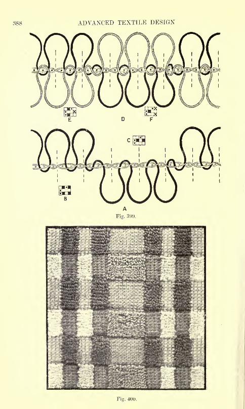
388 ADVANCED TEXTILE DESIGN
Fig. 400.
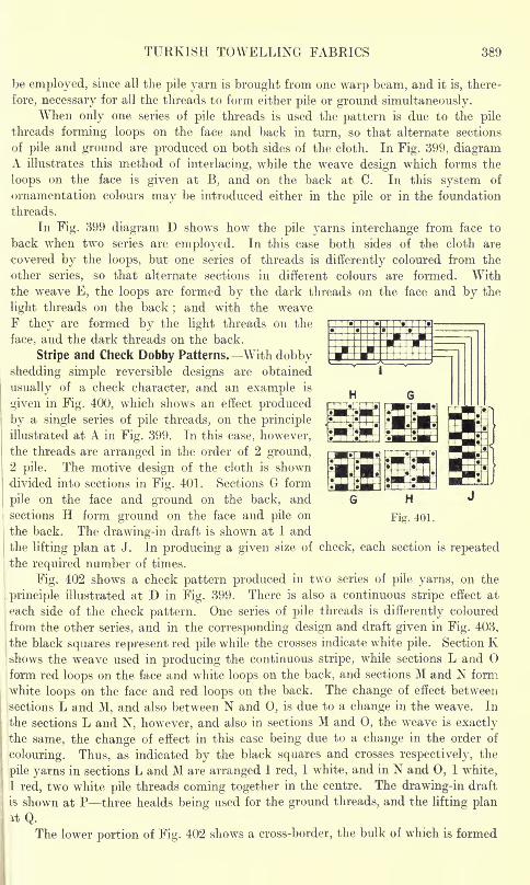
TURKISH TOWELLING FABRICS 389
be employed, since all the pile yarn is brought from one warp beam, and it is, there-
fore, necessary for all the threads to form either pile or ground simultaneously.When only one series of pile threads is used the pattern is due to the pile
threads forming loops on the face and back in turn, so that alternate sections
of pile and ground are produced on both sides of the cloth. In Fig. 399, diagramA illustrates this method of interlacing, while the weave design which forms the
loops on the face is given at B, and on the back at C. In this system of
ornamentation colours may be introduced either in the pile or in the foundation
threads.
In Fig. 399 diagram D shows how the pile yarns interchange from face to
back when two series are employed. In this case both sides of the cloth are
covered by the loops, but one series of threads is differently coloured from the
other series, so that alternate sections in different colours are formed. Withthe weave E, the loops are formed by the dark threads on the face and by the
light threads on the back;and with the weave
F they are formed by the light threads on the
face, and the dark threads on the back.
Stripe and Check Dobby Patterns. With dobbyshedding simple reversible designs are obtained
usually of a check character, and an example is
given in Fig. 400, which shows an effect produced
by a single series of pile threads, on the principle
illustrated at A in Fig. 399. In this case, however,
the threads are arranged in the order of 2 ground,2 pile. The motive design of the cloth is shown
divided into sections in Fig. 401. Sections Gr form
pile on the face and ground on the back, and
|
sections H form ground on the face and pile on
|
the back. The drawing-in draft is shown at I and
the lifting plan at J. In producing a given size of check, each section is repeatedthe required number of times.
Fig. 402 shows a check pattern produced in two series of pile yarns, on the
i principle illustrated at D in Fig. 399. There is also a continuous stripe effect at
1-each side of the check pattern. One series of pile threads is differently coloured
from the other series, and in the corresponding design and draft given in Fig. 403,
ithe black squares represent red pile while the crosses indicate white pile. Section Kshows the weave used in producing the continuous stripe, while sections L and
form red loops on the face and white loops on the back, and sections M and N form
white loops on the face and red loops on the back. The change of effect between
sections L and M, and also between N and 0, is due to a change in the weave. In
the sections L and N, however, and also in sections M and 0, the weave is exactlythe same, the change of effect in this case being due to a change in the order of
colouring. Thus, as indicated by the black squares and crosses respectively, the
pile yarns in sections L and M are arranged 1 red, 1 white, and in N and 0, 1 white,
1 red, two white pile threads coming together in the centre. The drawing-in draft
is shown at P three healds being used for the ground threads, and the lifting planit Q.
The lower portion of Fig. 402 shows a cross-border, the bulk of which is formed
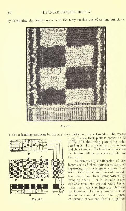
390 ADVANCED TEXTILE DESIGN
by continuing the centre weave with the terry motion out of action, but there
Fig. 402.
is also a heading produced by floating thick picks over seven threads. The weave >
design for the thick picks is shown at Hi
in Fig. 403, the lifting plan being indi-
cated at S. Three picks float on the face-
and then three on the back, in order that
the border will be reversible similar to
the centre.
An interesting modification of the
latter style of check pattern consists of:
separating the rectangular spaces from
each other by narrow lines of ground,
the longitudinal lines being formed by:
bringing about 6 or 8 threads conse-
cutively from the ground warp beam,
while the transverse lines are obtained !
by throwing the terry motion out of
action for about 6 picks. This system I
Fig. 403. of forming checks can also be employed
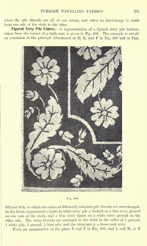
TURKISH TOWELLING FABRICS 391
when the pile threads are all of one colour, and when no interchange is madefrom one side of the cloth to the other.
Figured Terry Pile Fabrics. A representation of a figured terry pile texture,
taken from the corner of a bath mat, is given in Fig. 404. The example is simplyan extension of the principle (illustrated at D, E, and F in Fig. 399 and in Figs.
Fig. 404.
402 and 403), in which two series of differently coloured pile threads are interchanged.
In the fabric represented a figure in white terry pile is formed on a blue terry groundon one side of the cloth, and a blue terry figure on a white terry ground on the
other side. The warp threads are arranged in the cloth in the order of 1 ground,
1 white pile, 1 ground, 1 blue pile, and the structure is a three-pick terry.
From an examination of the plans E and F in Fig. 399, and L and M, or N
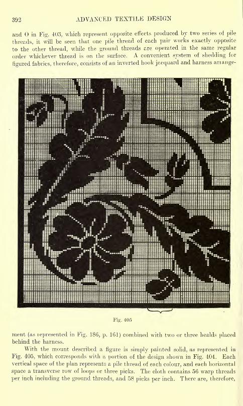
392 ADVANCED TEXTILE DESIGN
and in Fig. 403, which represent opposite effects produced by two series of pile
threads, it will be seen that one pile thread of each pair works exactly opposite
to the other thread, while the ground threads are operated in the same regular
order whichever thread is on the surface. A convenient system of shedding for
figured fabrics, therefore, consists of an inverted hook jacquard and harness arrange-
Fig. 405
ment (as represented in Fig. 18G, p. 161) combined with two or three healds placedbehind the harness.
With the mount described a figure is simply painted solid, as represented in
Fig. 405, which corresponds with a portion of the design shown in Fig. 404. Eachvertical space of the plan represents a pile thread of each colour, and each horizontal
space a transverse row of loops or three picks. The cloth contains 56 warp threads
per inch including the ground threads, and 58 picks per inch. There are, therefore,
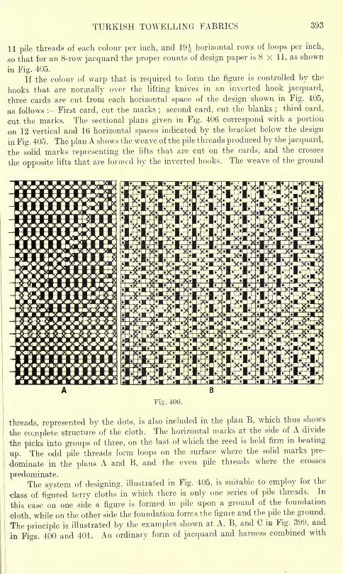
TURKISH TOWELLING FABRICS 393
14 pile threads of each colour per inch, and 19^ horizontal rows of loops per inch,
so that for an 8-row jacquard the proper counts of design paper is 8 X 11, as shown
in Fig. 405.
If the colour of warp that is required to form the figure is controlled by the
hooks that are normally over the lifting knives in an inverted hook jacquard,
three cards are cut from each horizontal space of the design shown in Fig. 405,
as follows : First card, cut the marks;second card, cut the blanks
;third card,
cut the marks. The sectional plans given in Fig. 406 correspond with a portion
on 12 vertical and 16 horizontal spaces indicated by the bracket below the design
in Fig. 405. The plan A shows the weave of the pile threads produced by the jacquard,
the solid marks repiesenting the lifts that are cut on the cards, and the crosses
the opposite lifts that are formed by the inverted hooks. The weave of the ground
in mmo mmn ran mmn mmn mmn mma no mmn mmn
Fig. 406.
threads, represented by the dots, is also included in the plan B, which thus shows
the complete structure of the cloth. The horizontal marks at the side of A divide
the picks into groups of three, on the last of which the reed is held firm in beating
up. The odd pile threads form loops on the surface where the solid marks pre-
dominate in the plans A and B, and the even pile threads where the crosses
predominate.The system of designing, illustrated in Fig. 405, is suitable to employ for the
class of figured terry cloths in which there is only one series of pile threads. In
this case on one side a figure is formed in pile upon a ground of the foundation
cloth, while on the other side the foundation forms the figure and the pile the ground.
'The principle is illustrated by the examples shown at A, B, and C in Fig. 399, and
In Figs. 400 and 401. An ordinary form of jacquard and harness combined with
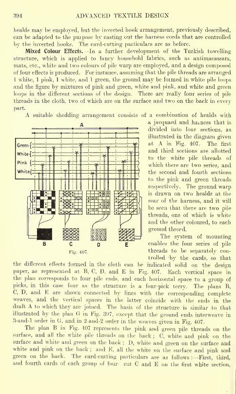
394 ADVANCED TEXTILE DESIGN
healds may be employed, but the inverted hook arrangement, previously described,
can be adapted to the puipose by casting out the harness cords that are controlled
by the inverted hooks. The card-cutting particulars are as before.
Mixed Colour Effects. In a further development of the Turkish towelling
structure, which is applied to fancy household fabrics, such as antimacassars,
mats, etc., white and two colours of pile warp are employed, and a design composedof four effects is produced. For instance, assuming that the pile threads are arranged1 white, 1 pink, 1 white, and 1 green, the ground may be formed in white pile loops
and the figure by mixtures of pink and green, white and pink, and white and green
loops in the different sections of the design. There are really four series of pile
threads in the cloth, two of which are on the surface and two on the back in every
part.
A suitable shedding arrangement consists of a combination of healds with
a jacquard and harness that is
divided into four sections, as
illustrated in the diagram givenat A in Fig. 407. The first
and third sections are allotted
to the white pile threads of
which there are two series, andthe second and fourth sections
to the pink and green threads
respectively. The ground warpis drawn on two healds at the
rear of the harness, and it will
be seen that there are two pile
threads, one of which is white
and the other coloured, to each
ground thre?d.
The system of mountingenables the four series of pile
threads to be separately con-
trolled -by the cards, so thatthe different effects formed in the cloth can be indicated solid on the designpaper, as represented at B, C, D, and E in Fig. 407. Each vertical space in
the plan corresponds to four pile ends, and each horizontal space to a group of
picks, in this case four as the structure is a four-pick terry. The plans B,C, D, and E are shown connected by lines with the corresponding completeweaves, and the vertical spaces in the latter coincide with the ends in thedraft A to which they are joined. The basis of the structure is similar to thatillustrated by the plan G in Fig. 397, except that the ground ends interweave in
3-and-l order in G, and in 2-and-2 order in the weaves given in Fig. 407.
The plan B in Fig. 407 represents the pink and green pile threads on the
surface, and all the white pile threads on the back; C, white and pink on the
surface and white and green on the back; D, white and green on the surface and
white and pink on the back;and E, all the white on the surface and pink and
green on the back. The card-cutting particulars are as follows : First, third,and fourth cards of each group of four cut C and E on the first white section,
WARP PILE FABRICS 395
B and C on the pink section, D and E on the second white section, and B and D onthe green section. Second card cut B and D on the first white section, D andand E on the pink section, B and C on the second white section, and C and E onthe green section.
CHAPTER XVIII
WARP PILE FABRICS
Formation of Warp Pile Form of the Pile Wires Structure of Warp Pile. Plain Warp Pile
Fabrics All the Pile over each Wire Two Picks to each Wire Three Picks to each
Wire Fast Warp Pile Designing Method of Heald Drafting Four Picks to each WireOne-half the Pile over each Wire Backed and Double Foundation Cloths Warp
Pile Astrakhan Textures Reversible Warp Pile Structures Double Plush WeavingOrnamentation of Plain Warp Pile Fabrics. Stripe and Check Designs.
Formation of Warp Pile. In the manufacture of true warp pile structures onlyone kind of weft is essential, but two series of warp threads, separately tensioned,are required viz., ground threads and pile threads
;the former produce with
the weft a foundation texture from which the pile threads project. The cloths
are of two kinds viz., looped pile, to which the terms terry, boucle, or frise are
applied ;and cut pile, which is termed velvet. The
"Turkish towelling
"structure
represents a class of looped or terry pile which, as previously shown, is convenientlyand economically produced by means of a special reed motion and warp-easing
arrangement. In the better classes of warp pile textures, however, such as dress
and mantle fabrics, hangings, chair coverings, Brussels and Wilton carpets, etc.,
the pile is formed with the aid of wires. In this system a wire is inserted, instead
of a pick of weft, in a special shed on which only those warp threads are raised
that have to form the pile, the threads thus being looped over the wires. Sub-
sequently the wires are withdrawn from the cloth, and the pile thieads then projectfrom the foundation either in the form of loops (forming uncut or terry pile) or
in the form of tufts of fibres (forming cut or velvet pile), according to the kind of
wire that is used. Compared with the terry towelling structure, the pile formed
on the wire principle is much superior as regards both firmness and regularity ;
also there is greater scope for producing diversity of design. A cloth may have
a perfectly uniform surface composed of either terry or cut pile, or the two structures
may be used in combination, while one or both classes of pile may be used in con-
junction with other weaves to form stripes, checks, spots, and elaborately figured
styles. The ornamentation may also include the use of extra warp and weft. The
looped pile structure, however, is not employed alone to a great extent exceptin the case of Brussels and tapestry pile carpets, in which diversity of colour is
the predominant feature;
its chief use in other textures is to produce variety
of pattern in conjunction with cut pile or other effects.
The materials used vary according to the class of texture and the purposefor which the cloth is intended ; mohair, lustre, demi-lustre, and cross-bred worsted,
woollen spun silk, tussah or wild silk, and artificial silk yarns, are largely used for
the pile. Cotton, flax, and wool are used for the weft, and cotton, flax, and jute
for the ground warp.
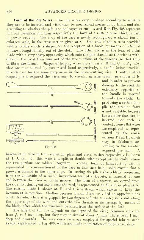
396 ADVANCED TEXTILE DESIGN
Form of the Pile Wires. The pile wires vary in shape according to whether
they are to be inserted and withdrawn by mechanical means or by hand, and also
according to whether the pile is to be looped or cut. A and B in Fig. 408 representin front elevation and plan respectively the form of a cutting wire which is used
in power weaving. The body of the wire is nearly rectangular, as shown (on an
enlarged scale) in the cross-section given at C. One end of the wire is providedwith a handle which is shaped for the reception of a hook, by means of which it
is drawn longitudinally out of the cloth. The other end is in the form of a flat
blade with a very sharp upper edge which cuts the pile threads as the wire is with-
drawn;
the twist then runs out of the free portions of the threads, so that tufts
of fibres are formed. Shapes of looping wires are shown at D and G in Fig. 408,
that are manipulated by power and hand respectively, a handle being providedin each case for the same purpose as in the power-cutting wire. If only a short
looped pile is required the wires may be circular in cross-section as shown at E,
and in order to prevent
Fig. 408.
damage to the reed the
extremity opposite to
the handle is taperedtowards the cloth. In
producing a rather long
pile the circular form
is not suitable, because
the number that can be
inserted per inch is
limited;hence flat wires
are employed, as repre-
sented by the cross-
sections F and H, which
vary in thickness ac-
cording to the number
required per inch. Ahand-cutting wire in front elevation, plan, and cross-section respectively is shownat I, J, and K
;this wire is a split or double wire except at the ends, where
the two portions are soldered together. Another form of hand-cutting wire is
represented in cross-section at L, the wire in this case being solid except that a
groove is formed in the upper edge. In cutting the pile a sharp blade, projectingfrom the underside of a small instrument termed a trevete, is inserted at oneend between the wires or in the groove. The form of a trevete, as viewed fromthe side that during cutting is near the reed, is represented at M, and in plan at N.The cutting blade is shown at R, and S is a flange which serves to keep theinstrument in position. Shallow recesses T and U are provided on opposite sides
of the trevete, where it is giipped by two fingers and the thumb;
it is slid alongthe upper edge of the wire, and cuts the pile threads in its passage by means of
the blade, after which the wire may be lifted from the surface of the cloth.
The length of the pile depends on the depth of the wire; common sizes are
from T\- to i inch deep, but they vary in sizes of about ^V inch difference to 1 inch
deep and upwards. The very deep wires are employed for special fabrics, suchas that represented in Fig 409, which are made in imitation of long-haired skins.
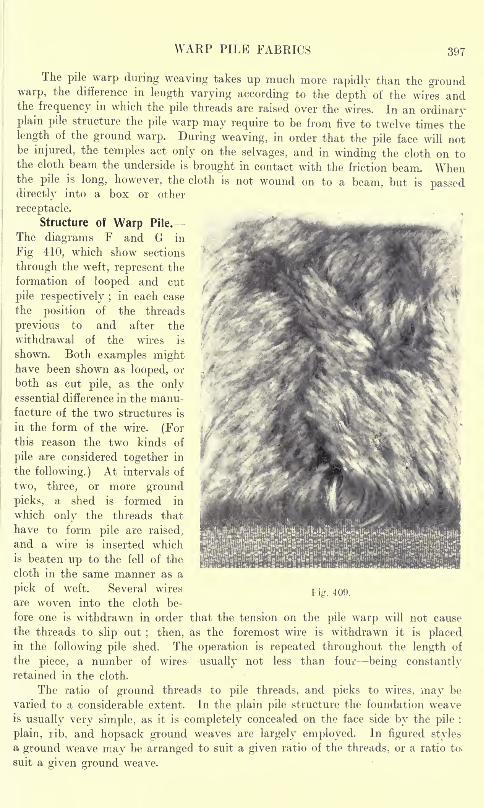
WARP PILE FABRICS 397
The pile warp during weaving takes up much more rapidly than the groundwarp, the difference in length varying according to the depth of the wires andthe frequency in which the pile threads are raised over the wires. In an ordinaryplain pile structure the pile warp may require to be from five to twelve times the
length of the ground warp. During weaving, in order that the pile face will notbe injured, the temples act only on the selvages, and in winding the cloth on tothe cloth beam the underside is brought in contact with the friction beam. Whenthe pile is long, however, the cloth is not wound on to a beam, but is passeddirectly into a box or other
receptacle.
Structure of Warp Pile.
The diagrams F and G in
Fig 410, which show sections
through the weft, represent the
formation of looped and cut
pile respectively ;in each case
the position of the threads
previous to and after the
withdrawal of the wires is
shown. Both examples mighthave been shown as looped, or
both as cut pile, as the onlyessential difference in the manu-facture of the two structures is
in the form of the wire. (Forthis reason the two kinds of
pile are considered together in
the following.) At intervals of
two, three, or more ground
picks, a shed is formed in
which only the threads that
have to form pile are raised,
and a wire is inserted which
is beaten up to the fell of the
cloth in the same manner as a
pick of weft. Several wiresrig 409
are woven into the cloth be-
fore one is withdrawn in order that the tension on the pile warp will not cause
the threads to slip out; then, as the foremost wire is withdrawn it is placed
in the following pile shed. The operation is repeated throughout the length of
the piece, a number of wires usually not less than four being constantlyretained in the cloth.
The ratio of ground threads to pile threads, and picks to wires, may be
varied to a considerable extent. In the plain pile structure the foundation weaveis usually very simple, as it is completely concealed on the face side by the pile :
plain, rib, and hopsack ground weaves are largely employed. In figured stylesa ground weave may be arranged to suit a given ratio of the threads, or a ratio to.
suit a given ground weave.
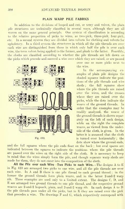
398 ADVANCED TEXTILE DESIGN
PLAIN WARP PILE FABRICS
In addition to the divisions of looped and cut, or terry and velvet, the plain
pile structures are technically classified in several ways, although they are all
woven on the same general principle. One system of classification is accordingto the relative proportion of picks to wires, as two-pick, three-pick, four-pick,
etc. In a second system they are divided into velvets for clothing and velvets for
upholstery. In a third system the structures in which all the pile threads are over
each wire are distinguished from those in which only half the pile is over each
wire, the term velvet being applied to the former, and plush to the latter. Fourthly,the cloths are classified according to whether the pile threads are left down on
the picks which precede and succeed a wire over which they are raised, or are passedover one or more picks next to
the wire.
In the accompanying ex-
amples of plain pile designs the
shaded squares indicate the posi-
tions of the pile threads and wire
sheds;
the full squares show
where the pile threads are raised
over the wires, and the crosses
where they are raised over the
picks, while the dots indicate the
weave of the ground threads. In
order that the examples may be
readily analysed, the weave of
the ground threads is shown separ-
ately on the left of each design,
while on the right the complete
weave, as viewed from the under-
side of the cloth, is given. In the
latter it is assumed that the cloth
Fig. 410. is turned over horizontally ;the
dots show where the ground ends,and the full squares where the pile ends float on the back
;but oval spaces are
indicated between the squares to indicate the positions where the pile threads
are passed over the wires on the right side of the cloth. It is necessary to keepin mind that the wires simply form the pile, and though separate warp sheds are
made for them, they do not enter into the composition of the cloth.
All the Pile over each WireTwo Picks to each Wire. The designs A to Ein Fig. 410 are arranged two picks to one wire, and all the pile threads are overeach wire. In A and B there is one pile thread to each ground thread
;in the
former the ground threads form plain weave, and in the latter 2-and-2 warprib. These examples are used only to a limited extent. The designs C, D, andE are arranged two ground threads to one pile thread, and the respective groundweaves are 2-and-2 hopsack, plain, and 2-and-2 warp rib. In each design A to Dthe pile threads pass under all the picks, but in E they are raised over the pickthat precedes a wire. The drawings F and G, which respectively correspond with
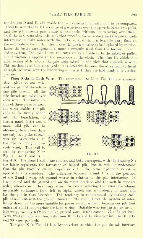
WARP PILE FABRICS 399
the designs D and E, will enable the two systems of construction to be compared.It will be seen that in F the centre of a wire rests over the space between two picks,and the pile threads pass under all the picks without interweaving with them.In G the wire rests above the pick that precedes the wire shed, and the pile threadsinterweave in plain order with the picks, so that there is less pile warp float onthe underside of the cloth. This makes the pile less liable to be displaced by friction,
hence the latter arrangement is more commonly used than the former;
but in
either system, if the pile is cut, the tufts are very liable to be disturbed or pulledout if friction is applied to the underside of the cloth. The plan H, which is a
modification of E, shows the pile ends raised on the pick that succeeds a wire.
This method is seldom employed ;it is defective because the wires tend to lie at
an angle, whereas with the interlacing shown at E they are held firmly in a vertical
position.
Three Picks to Each Wire. The examples I to M in Fig. 411 are arrangedthree picks to one wire,
and two ground threads to
one pile thread;
all the
pile threads are raised over
each wire. The introduc-
tion of three picks between
the wires enables the pile
ends to be firmly boundinto the foundation, so
that a much faster and a
more solid pile can be
obtained than when there
are only two picks to each
wire (in cases where all
the pile is brought over
each wire). This will be
seen by comparing N in
Fig. 411 to F and G inFig. 411
Fig. 410. The plans I and J are similar, and both correspond with the drawing N ;
the latter represents the formation of looped pile, but it will be understood
that the pile may be either looped or cut. The term "panne" velvet is
applied to this structure. The difference between I and J is in the positionof the 2-and-l warp rib ground weave in relation to the pile interlacing. In
I a pile end and the ground end on the right interlace with the weft in opposite
order, whereas in J they wrork alike. In power weaving the wires are almost
invariably withdrawn from left to right, which has a tendency to draw and
lay the pile in that direction. This tendency is counteracted by making each
pile thread cut with the ground thread on the right, hence the system of inter-
lacing shown at I is more suitable for power wiring, while in forming cut pile that
indicated at B is appropriate for hand wiring. Suitable weaving particulars are :
Pile warp, two-ply 60/2 spun silk; ground warp, 2/60's cotton
;72 ends per inch.
Weft, 2/40's to 2/60's cotton, with from 48 picks and 16 wires per inch, to 90 picksand 30 wires per inch.
The plan K in Fig. 411 is a Lyons velvet in which the pile threads interlace
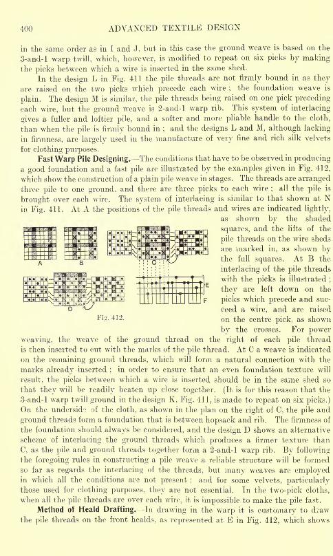
400 ADVANCED TEXTILE DESIGN
in the same order as in I and J, but in this case the ground weave is based on the
3-and-l warp twill, which, however, is modified to repeat on six picks by makingthe picks between which a wire is inserted in the same shed.
In the design L in Fig. 411 the pile threads are not firmly bound in as they
are raised on the two picks which precede each wire;
the foundation weave is
plain. The design M is similar, the pile threads being raised on one pick preceding
each wire, but the ground weave is 2-and-l warp rib. This system of interlacing
sives a fuller and loftier pile, and a softer and more pliable handle to the cloth,
than when the pile is firmly bound in;and the designs L and M, although lacking
in firmness, are largely used in the manufacture of very fine and rich silk velvets
for clothing purposes.Fast Warp Pile Designing. The conditions that have to be observed in producing
a good foundation and a fast pile are illustrated by the examples given in Fig. 412,
which show the construction of a plain pile weave in stages. The threads are arranged
three pile to one ground, and there are three picks to each wire;
all the pile is
brought over each wire. The system of interlacing is similar to that shown at Nin Fig. 411. At A the positions of the pile threads and wires are indicated lightly,
as shown by the shaded
squares, and the lifts of the
pile threads on the wire sheds
are marked in, as shown bythe full squares. At B the
interlacing of the pile threads
with the picks is illustrated;
they are left down on the
picks which precede and suc-
ceed a wire, and are raised
on the centre pick, as shown
by the crosses. For power
weaving, the weave of the ground thread on the right of each pile thread
is then inserted to cut with the marks of the pile thread. At C a weave is indicated
on the remaining ground threads, which ,will form a natural connection with the
marks already inserted;
in order to ensure that an even foundation texture will
result, the picks between which a wire is inserted should be in the same shed so
that they will be readily beaten up close together. (It is for this reason that the
3-and-l warp twill ground in the design K, Fig. 411, is made to repeat on six picks.)
On the underside of the cloth, as shown in the plan on the right of C, the pile and
ground threads form a foundation that is between hopsack and rib. The firmness of
the foundation should always be considered, and the design D shows an alternative
scheme of interlacing the ground threads which produces a firmer texture than
C, as the pile and ground threads together form a 2-and-l warp rib. By followingthe foregoing rules in constructing a pile weave a reliable structure will be formed
so far as regards the interlacing of the threads, but many weaves are employedin which all the conditions are not present ;
and for some velvets, particularlythose used for clothing purposes, they are not essential. In the two-pick cloths,
when all the pile threads are over each wire, it is impossible to make the pile fast.
Method of Heald Drafting. In drawing in the warp it is customary to draw
the pile threads on the front healds, as represented at E in Fig. 412, which shows
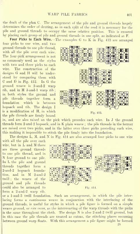
WARP PILE FABRICS 401
the draft of the plan C. The arrangement of the pile and ground threads largelydetermines the order of denting, as in each split of the reed it is necessary for the
pile and ground threads to occupy the same relative position. This is ensured
by placing each group of pile and ground threads in one split, as indicated at F.
Four Picks to Each Wire. The examples G to K in Fig. 413 are arrangedfour picks to one wire, and two
ground threads to one pile thread,
with all the pile over each wire.
The four-pick arrangement is not
so commonly used as the styles
with two and three picks to each
wire. The construction of the
designs G and H will be under-
stood by comparing them with
C and D in Fig. 412. In G the
ground weave is 2-and-2 warprib, and in H 3-and-l warp rib
;
in both styles the ground and
pile threads together form a
foundation which is between
hopsack and rib. The design I
is a modification of H, in which
the pile threads are firmly bound
in, and are also raised on the pick which precedes each wire. In J the groundthreads form 2-and-2 hopsack, and in K plain weave ;
the pile threads in the former
are raised over two picks, and in the latter over three picks preceding each wire,
this making it impossible to stitch the pile firmly into the foundation.
The designs L, M, and N in Fig. 414 are also arranged four picks to one wire
with all the pile over each
wire, but in L and M there
are three ground threads
to one pile thread, and in
N four ground to one pile.
In L the pile and groundthreads together form a
2-and-2 hopsack founda-
tion, and in M 2-and-2
twill;
the weave of the
ground and pile threads
could also be arranged to Fig. 414.
form a 2-and-2 warp rib,
or a l-and-3 twill foundation. Such an arrangement, in which the pile inter-
lacing forms a continuous weave in conjunction with the interlacing of the
ground threads, is useful for styles in which a pile figure is formed on a simpleweave ground, or vice versa, as the interweaving of the warp threads with the picks
is the same throughout the cloth. The design N is also 2-and-2 twill ground, but
in this case the pile threads are treated as extras, the stitching places occurringbetween ground warp floats. With this arrangement a pile figure might be formed
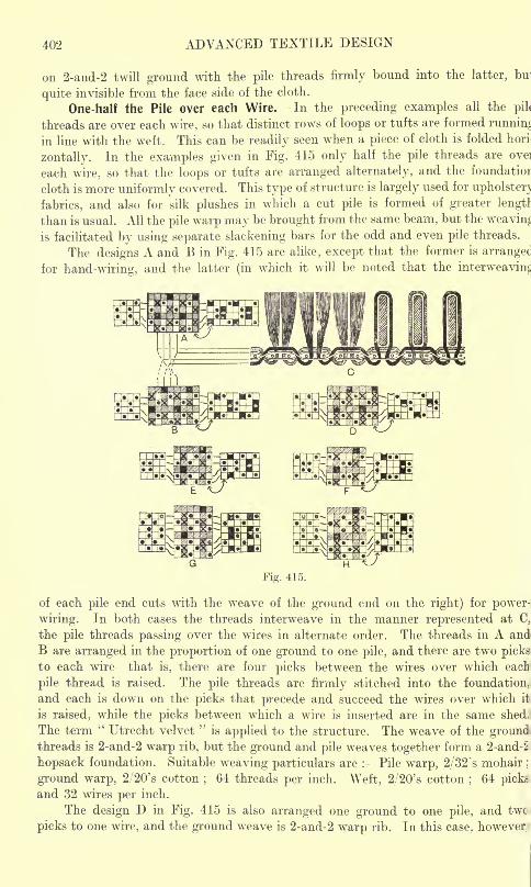
402 ADVANCED TEXTILE DESIGN
on 2-and-2 twill ground with the pile threads firmly bound into the latter, bui
quite invisible from the face side of the cloth.
One-half the Pile over each Wire. In the preceding examples all the pil<
threads are over each wire, so that distinct rows of loops or tufts are formed running
in line with the weft. This can be readily seen when a piece of cloth is folded hori
zontally. In the examples given in Fig. 415 only half the pile threads are ove]
each wire, so that the loops or tufts are arranged alternately, and the foundatior
cloth is more uniformly covered. This type of structure is largely used for upholster)
fabrics, and also for silk plushes in which a cut pile is formed of greater length
than is usual. All the pile warp may be brought from the same beam, but the weaving
is facilitated by using separate slackening bars for the odd and even pile threads.
The designs A and B in Fig. 415 are alike, except that the former is arrangec
for hand-wiring, and the latter (in which it will be noted that the interweaving
Fig. 415.
of each pile end cuts with the weave of the ground end on the right) for power-
wiring. In both cases the threads interweave in the manner represented at C,
the pile threads passing over the wires in alternate order. The threads in A and
B are arranged in the proportion of one ground to one pile, and there are two picks
to each wire that is, there are four picks between the wires over which each
pile thread is raised. The pile threads are firmly stitched into the foundation,
and each is down on the picks that precede and succeed the wires over which it
is raised, while the picks between which a wire is inserted are in the same shed.
The term"Utrecht velvet
"is applied to the structure. The weave of the ground
threads is 2-and-2 warp rib, but the ground and pile weaves together form a 2-and-2
hopsack foundation. Suitable weaving particulars are : Pile warp, 2/32 's mohair;
ground warp, 2/20's cotton;64 threads per inch. Weft, 2/20's cotton
;64 picks
and 32 wires per inch.
The design D in Fig. 415 is also arranged one ground to one pile, and twc
picks to one wire, and the ground weave is 2-and-2 warp rib. In this case, however
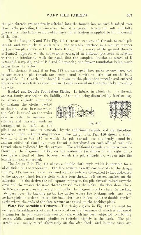
WARP PILE FABRICS 403
the pile threads are not firmly stitched into the foundation, as each is raised over
three picks preceding the wire over which it is passed. A very full, soft, and lofty
pile results, which, however, readily frays out if friction is applied to the underside
of the cloth.
In the designs E and F in Fig. 415 there are two ground threads to each pile
thread, and two picks to each wire;
the threads interlace in a similar manner
to the example shown at C. In both E and F the weave of the ground threads
is 2-and-2 hopsack, which, however, is arranged in different positions in relation
to the pile interlacing, with the result that the complete foundation weave of Eis 2-and-2 warp rib, and of F 3-and-2 hopsack ;
the former foundation being muchfirmer than the latter.
The designs G and H in Fig. 415 are arranged three picks to one wire, and
in each case the pile threads are firmly bound in with as little float on the back
as possible. In G each pile thread is down on the picks that precede and succeed
the wire over which it is raised, but in H each is raised on the three picks precedingthe wire.
Backed and Double Foundation Cloths. In fabrics in which the pile threads
are not firmly stitched in, the liability of the pile being disturbed by friction maybe almost entirely eliminated
by making the cloths backed
or double. Also, in cases where
the cloth is raised on the under
side in order to increase its
softness and w^armth, such an
arrangement is useful, as the
tj t t
Fig. 416.
pile floats on the back are concealed by the additional threads, and are, therefore,
not acted upon in the raising process. The design I in Fig. 416 shows a modi-
fication of E in Fig. 415 in which the pile threads are not firmly bound in;
and an additional (backing) warp thread is introduced on each side of each pile
thread where indicated by the arrows. The additional threads are interwoven as
shown by the diagonal marks;on the underside (as shown on the right of I)
they have a float of three between which the pile threads are woven into the
foundation and concealed.
The design J in Fig. 416 shows a double cloth style which is suitable for a
:aised finish on the underside. The face texture exactly corresponds to the designB in Fig. 415, but additional warp and weft threads are introduced (where indicated
)y the arrows) wThich form a cloth with a four-thread weft sateen surface on the
mderside. In the design the full squares represent the pile threads raised over the
vires, and the crosses the same threads raised over the picks ;the dots show where
he face ends pass over the face ground picks, the diagonal marks where the backingnds pass over the backing picks, the circles where the backing ends pass over
he face picks in order to stitch the back cloth to the face, and the double vertical
narks where the ends of the face texture are raised on the backing picks.
Warp Pile Astrakhan Textures. The designs given in Fig. 417 are used forT
arp pile Astrakhan structures, the typical curly appearance of which is enhanced
y using for the pile warp thick worsted yarn which has been subjected to a boilingrocess while wound round spindles or twitched tightly in the hank. The pile
dreads are usually raised alternately on the wire sheds, and in most cases are
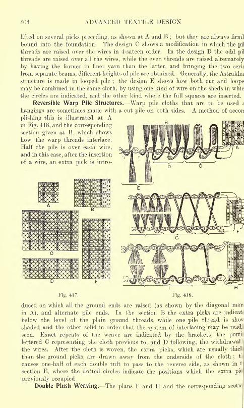
404 ADVANCED TEXTILE DESIGN
Hfted on several picks preceding, as shown at A and B;but they are always firml
bound into the foundation. The design C shows a modification in which the pil
threads are raised over the wires in 4-sateen order. In the design D the odd pi]
threads are raised over all the wires, while the even threads are raised alternately
by having the former in finer yarn than the latter, and bringing the two serit
from separate beams, different heights of pile are obtained. Generally, the Astrakha
structure is made in looped pile ;the design E shows how both cut and loope
may be combined in the same cloth, by using one kind of wire on the sheds in whic
the circles are indicated, and the other kind where the full squares are inserted.
Reversible Warp Pile Structures. Warp pile cloths that are to be used i
hangings are sometimes made with a cut pile on both sides. A method of accon
plishing this is illustrated at Ain Fig. 418, and the correspondingsection given at B, which shows
how the warp threads interlace.
Half the pile is over each wire,
and in this case, after the insertion
of a wire, an extra pick is intro-
Fig. 417. Fig. 418.
duced on which all the ground ends are raised (as shown by the diagonal mar
in A), and alternate pile ends. In the section B the extra picks are indicat
below the level of the plain ground threads, while one pile thread is sho^
shaded and the other solid in order that the system of interlacing may be read:
seen. Exact repeats of the weave are indicated by the brackets, the porti
lettered C representing the cloth previous to, and D following, the withdrawal
the wires. After the cloth is woven, the extra picks, which are usually thicl
than the ground picks, are drawn away from the underside of the cloth;
t
causes one-half of each double tuft to pass to the reverse side, as shown in 1
section E, where the dotted circles indicate the positions which the extra pi<
previously occupied.Double Plush Weaving. The plans F and H and the corresponding secti<
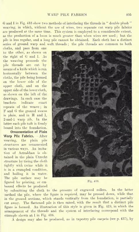
WARP PILE FABRICS 405
G and I in Fig. 418 show two methods of interlacing the threads in"double plush
"
weaving, in which, without the use of wires, two separate cut warp pile fabrics
are produced at the same time. This system is employed to a considerable extent,
as the production of a loom is much greater than when wires are used ;but the
pile is less regular, and a long pile cannot be obtained. Each cloth has a distinct
series of ground warp and weft threads;
the pile threads are common to both
cloths, and pass from one
to the other, as shown on
the right of G and I. As
the weaving proceeds the
pile threads are cut bymeans of a knife which is run
horizontally between the
cloths, the pile being formed
on the lower side of the
upper cloth, and on the
upper side of the lower cloth,
as shown on the left of the
drawings. In each case the
brackets indicate exact
repeats of the weave;
in
F and G the ground weave
is plain, and in H and I,
2-and-l warp rib. In the
latter each pile tuft is firmly
bound into the foundation.
Ornamentation of Plain
Warp Pile Fabrics. After
weaving, the plain pile
structures are ornamented
in various ways. An imita-
tion of Astrakhan is ob-
tained in the plain Utrecht
structure by tieing the cloth
tightly with twine while it
is in a crumpled condition,
and boiling it in water.
The pile surface may be
figured by printing, or em-
bossed effects be produced
by submitting the cloth to the pressure of engraved rollers. In the latter
method the pile, where the figure is required, may be pressed down, while that
in the ground sections, which stands vertically from the foundation, is partially
cut away. The flattened pile is then raised, with the result that a distinct pile
figure is formed. An illustration of this style is given in Fig. 419, in which the
arrangement of the threads and the system of interlacing correspond with the
example shown at I in Fig. 416.
A design may also be produced, as in tapestry pile carpets (see p. 437), by
Fig. 419.
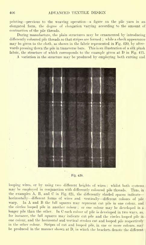
406 ADVANCED TEXTILE DESIGN
printing previous to the weaving operation a figure on the pile yarn in an
elongated form, the degree of elongation varying according to the amount of
contraction of the pile threads.
During manufacture, the plain structures may be ornamented by introducing
differently coloured pile threads so that stripes are formed;while a check appearance
may be given to the cloth, as shown in the fabric represented in Fig. 420, by after-
wards pressing down the pile in transverse bars. This is an illustration of a silk plush
fabric, the structure of which corresponds to the example given at D in Fig. 415.
A variation in the structure may be produced by employing both cutting and
Fig. 420.
looping wires, or by using two different heights of wires; whilst both systems
may be employed in conjunction with differently coloured pile threads. Thus, in
the examples A, B, and C in Fig. 421, the differently shaded spaces indicate-
horizontally different forms of wires and vertically different colours of pile
warp. In A and B the full squares may represent cut pile in one colour, andthe circles looped pile in another colour
;or one colour may be developed in a
longer pile than the other. In C each colour of pile is developed in two ways, as,
for instance, the full squares may indicate cut pile and the circles looped pile in
one colour, and the horizontal and vertical strokes cut and looped pile respectivelyin the other colour. Stripes of cut and looped pile, in one or more colours, maybe produced in the manner shown at D, in which the brackets denote the different
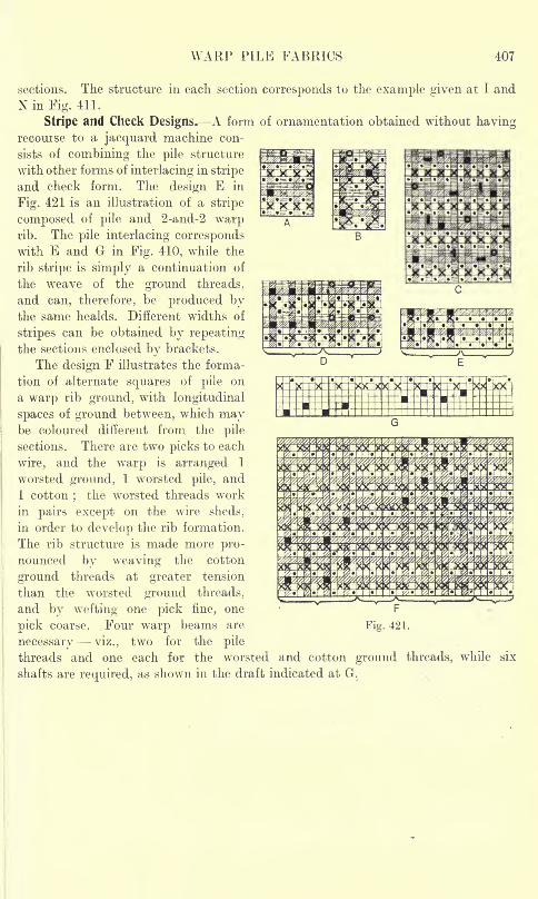
WARP PILE FABRICS 407
sections. The structure in each section corresponds to the example given at I and
N in Fig. 411.
Stripe and Check Designs. A form of ornamentation obtained without havingrecourse to a jacquard machine con-
sists of combining the pile structure
with other forms of interlacing in stripe
and check form. The design E in
Fig. 421 is an illustration of a stripe
composed of pile and 2-and-2 warprib. The pile interlacing correspondswith E and G in Fig. 410, while the
rib stripe is simply a continuation of
the weave of the ground threads,
and can, therefore, be produced bythe same healds. Different widths of
stripes can be obtained by repeating
the sections enclosed by brackets.
The design F illustrates the forma-
tion of alternate squares of pile on
a warp rib ground, with longitudinal
spaces of ground between, which maybe coloured different from the pile
sections. There are two picks to each
wire, and the warp is arranged 1
worsted ground, 1 worsted pile, and
1 cotton;
the worsted threads work
in pairs except on the wire sheds,
in order to develop the rib formation.
The rib structure is made more pro-
nounced by weaving the cotton
ground threads at greater tension
than the worsted ground threads,
and by wefting one pick fine, one F
pick coarse..Four warp beams are Fig. 421.
necessary -viz., two for the pile
threads and one each for the worsted and cotton ground threads, while six
shafts are required, as shown in the draft indicated at G.
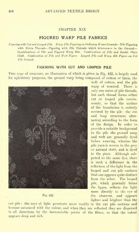
408 ADVANCED TEXTILE DESIGN
CHAPTEK XIX
FIGURED WARP PILE FABRICS
Figuring with Cut and Looped Pile. Warp Pile Figuring on Ordinary Weave Grounds' Pile Figuringwith Extra Threads Figuring with Pile Threads which interweave in the Ground
Combinations of Pile and Figured Warp Rib. Combinations of Pile and Double Plain
Cloth. Combination of Pile and Weft Figure. Looped Pile and Warp Rib Figure on Cut
Pile Ground.
FIGURING WITH CUT AND LOOPED PILE
THIS type of structure, an illustration of which is given in Fig. 422, is largely used
for upholstery purposes, the ground warp being composed of cotton or linen, the
weft of cotton, and the pile
warp of worsted. There is
only one series of pile threads,
but each thread forms either
cut or looped pile contin-
uously, so that the surface
of the foundation is entirely
covered by the pile the cut
and loop structures alter-
nating according to the form
of the design. In order to
provide a suitable backgroundto the pile the ground warpand weft are generally dyedbefore weaving, whereas the
pile yarn is woven in the greyor natural state, and is dyedin the piece. Although sub-
jected to the same dye, there
is such a difference in the
reflection of the light from the
looped and cut pile surfaces
that one appears quite distinct
from the other. The looped
pile, which generally forms
the figure, reflects the light
more directly to the eye of
Fig. 422. the observer, and appears
lighter and brighter than the
cut pile ;the rays of light penetrate more readily in the cut pile sections and
bocome saturated with the colour, and when they are reflected they are dispersedin all directions by the innumerable points of the fibres, so that the colour
appears deep and rich.
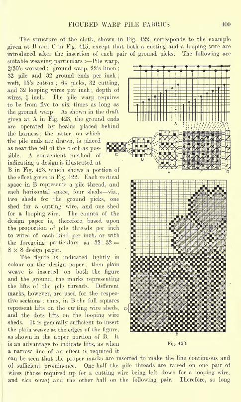
FIGURED WARP PILE FABRICS 409
The structure of the cloth, shown in Fig. 422, corresponds to the example
given at B and C in Fig. 415, except that both a cutting and a looping wire are
introduced after the insertion of each pair of ground picks. The following are
suitable weaving particulars : Pile warp,
2/30's worsted ; ground warp, 22's linen;
32 pile and 32 ground ends per inch;
weft, 15's cotton;64 picks, 32 cutting,
and 32 looping wires per inch; depth of
wires, J-inch. The pile warp requires
to be from five to six times as long as
the ground warp. As shown in the draft
given at A in Fig. 423, the ground ends
are operated by healds placed behind
the harness;the latter, on which
the pile ends are drawn, is placedas near the fell of the cloth as pos-
sible. A convenient method of
indicating a design is illustrated at
B in Fig. 423, which shows a portion of
the effect given in Fig. 422. Each vertical
space in B represents a pile thread, and
each horizontal space, four sheds viz.,
two sheds for the ground picks, one
shed for a cutting wire, and one shed
for a looping wire. The counts of the
design paper is, therefore, based uponthe proportion of pile threads per inch
to wires of each kind per inch, or with
the foregoing particulars as 32 : 32 =
8x8 design paper.The figure is indicated lightly in
colour on the design paper ;then plain
weave is inserted on both the figure
and the ground, the marks representingthe lifts of the pile threads. Different
marks, however, are used for the respec-
tive sections; thus, in B the full squares
represent lifts on the cutting wire sheds,
and the dots lifts on the looping wire
sheds. It is generally sufficient to insert
the plain weave at the edges of the figure,
as shown in the upper portion of B. It
is an advantage to indicate lifts, as whena narrow line of an effect is required it
can be seen that the proper marks are inserted to make the line continuous and
of sufficient prominence. One-half the pile threads are raised on one pair of
wires (those required up for a cutting wire being left down for a looping wire,
and vice versa) and the other half on the following pair. Therefore, so long
B
Fig. 423.
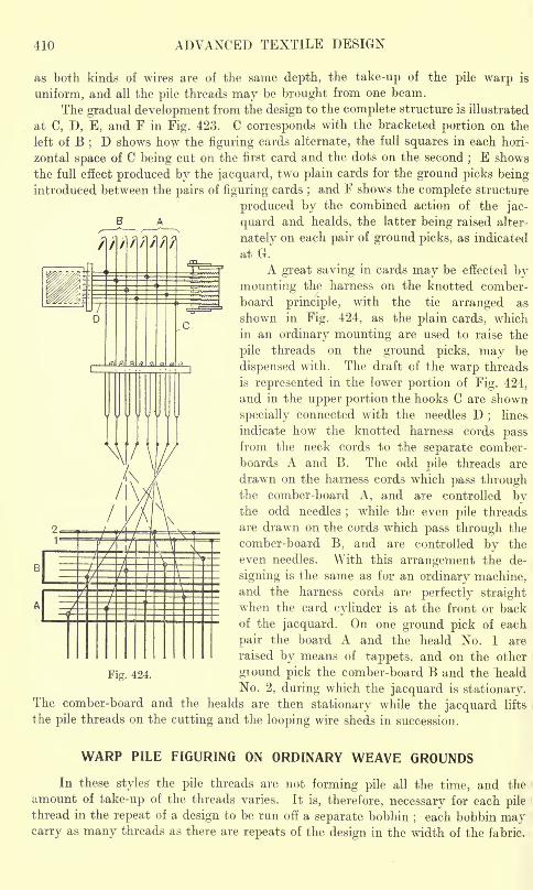
410 ADVANCED TEXTILE DESIGN
as both kinds of wires are of the same depth, the take-up of the pile warp is
uniform, and all the pile threads may be brought from one beam.
The gradual development from the design to the complete structure is illustrated
at C, D, E, and F in Fig. 423. C corresponds with the bracketed portion on the
left of B; D shows how the figuring cards alternate, the full squares in each hori-
zontal space of C being cut on the first card and the dots on the second;E shows
the full effect produced by the jacquard, two plain cards for the ground picks beingintroduced between the pairs of figuring cards
;and F shows the complete structure
produced by the combined action of the jac-
quard and healds, the latter being raised alter-
nately on each pair of ground picks, as indicated
at G.
A great saving in cards may be effected bymounting the harness on the knotted comber-
board principle, with the tie arranged as
shown in Fig. 424, as fche plain cards, which
in an ordinary mounting are used to raise the
pile threads on the ground picks, may be
dispensed with. The draft of the warp threads
is represented in the lower portion of Fig. 424,
and in the upper portion the hooks C are shown
specially connected with the needles D;
lines
indicate how the knotted harness cords passfrom the neck cords to the separate comber-
boards A and B. The odd pile threads are
drawn on the harness cords which pass throughthe comber-board A, and are controlled bythe odd needles
;while the even pile threads
are drawn on the cords which pass through the
comber-board B, and are controlled by the
even needles. With this arrangement the de-
signing is the same as for an ordinary machine,and the harness cords are perfectly straightwhen the card cylinder is at the front or back
_JL__ __________ o ^ejacquarc[ Qn one grouncl pick of each
pair the board A and the heald No. 1 are
raised by means of tappets, and on the other
Fig. 424. ground pick the comber-board B and the Tieald
No. 2, during which the jacquard is stationary.The comber-board and the healds are then stationary while the jacquard lifts
the pile threads on the cutting and the looping wire sheds in succession.
WARP PILE FIGURING ON ORDINARY WEAVE GROUNDS
In these styles the pile threads are not forming pile all the time, and the
amount of take-up of the threads varies. It is, therefore, necessary for each pile
thread in the repeat of a design to be run off a separate bobbin;each bobbin may
carry as many threads as there are repeats of the design in the width of the fabric.
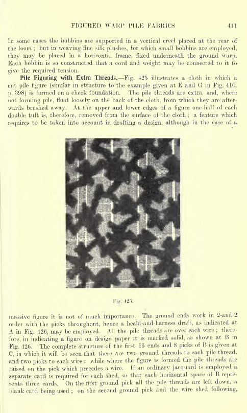
FIGURED WARP PILE FABRICS 411
In some cases the bobbins are supported in a vertical creel placed at the rear of
the loom;but in weaving fine silk plushes, for which small bobbins are employed,
they may be placed in a horizontal frame, fixed underneath the ground warp.Each bobbin is so constructed that a cord and weight may be connected to it to
give the required tension.
Pile Figuring with Extra Threads. Fig. 425 illustrates a cloth in which a
cut pile figure (similar in structure to the example given at E and G in Fig. 410,
p. 398) is formed on a check foundation. The pile threads are extra, and, where
not forming pile, float loosely on the back of the cloth, from which they are after-
wards brushed away. At the upper and lower edges of a figure one-half of each
double tuft is, therefore, removed from the surface of the cloth;
a feature which
requires to be taken into account in drafting a design, although in the case of a
Fig. 425.
massive figure it is not of much importance. The ground ends work in 2-and-2
order with the picks throughout, hence a heald-and-harness draft, as indicated at
A in Fig. 426, may be employed. All the pile threads are over each wire;there-
fore, in indicating a figure on design paper it is marked solid, as shown at B in
Fig. 426. The complete structure of the first 16 ends and 8 picks of B is given at
C, in which it will be seen that there are two ground threads to each pile thread,
and two picks to each wire;
while where the figure is formed the pile threads are
raised on the pick which precedes a wire. If an ordinary jacquard is employed a
separate card is required for each shed, so that each horizontal space of B repre-
sents three cards. On the first ground pick all the pile threads are left down, a
blank card being used ;on the second ground pick and the wire shed following,
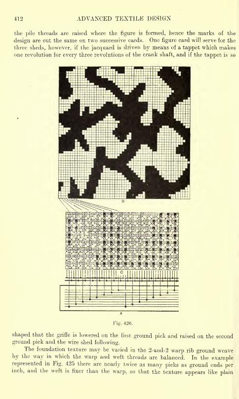
412 ADVANCED TEXTILE DESIGN
the pile threads are raised where the figure is formed, hence the marks of the
design are cut the same on two successive cards. One figure card will serve for the
three sheds, however, if the jacquard is driven by means of a tappet which makesone revolution for every three revolutions of the crank shaft, and if the tappet is so
Fig. 426.
shaped that the griffe is lowered on the first ground pick and raised on the second
ground pick and the wire shed following.The foundation texture may be varied in the 2-and-2 warp rib ground weave
by the way in which the warp and weft threads are balanced. In the examplerepresented in Fig. 425 there are nearly twice as many picks as ground ends perinch, and the weft is finer than the warp, so that the texture appears like plain
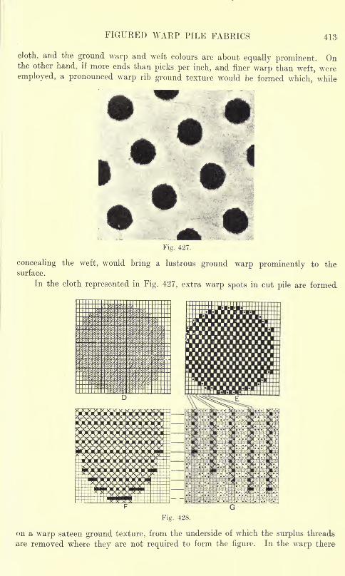
FIGURED WARP PILE FABRICS 413-
cloth, and the ground warp and weft colours are about equally prominent. Onthe other hand, if more ends than picks per inch, and finer warp than weft, wereemployed, a pronounced warp rib ground texture would be formed which, while
Fig. 427.
concealing the weft, would bring a lustrous ground warp prominently to thesurface.
In the cloth represented in Fig. 427, extra warp spots in cut pile are formed
Fig. 428.
on a warp sateen ground texture, from the underside of which the surplus threads
are removed where they are not required to form the figure. In the warp there
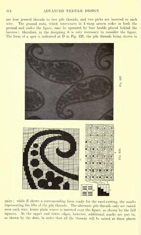
414 ADVANCED TEXTILE DESIGN
are four ground threads to two pile threads, and two picks are inserted to each
wire. The ground ends, which interweave in 4-warp sateen order in both the
ground and under the figure, may be operated by four healds placed behind the
harness; therefore, in the designing it is only necessary to consider the figure.
The form of a spot is indicated at D in Fig. 428, the pile threads being shown in
pairs ;while E shows a corresponding form ready for the card-cutting, the marks
representing the lifts of the pile threads. The alternate pile threads only are raisedover each wire, hence plain weave is inserted over the figure, as shown by the full
squares. At the upper and lower edges, however, additional marks are put in,
as shown by the dots, in order that all the threads will be raised at these places
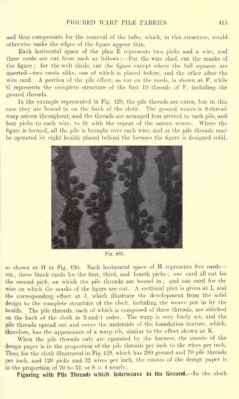
FIGURED WARP PILE FABRICS 415
and thus compensate for the removal of the tufts, which, in this structure, would
otherwise make the edges of the figure appear thin.
Each horizontal space of the plan E represents two picks and a wire, and
three cards are cut from each as follows : For the wire shed, cut the marks of
the figure ;for the weft sheds, cut the figure except where the full squares are
inserted two cards alike, one of which is placed before, and the other after the
wire card. A portion of the pile effect, as cut on the cards, is shown at F, while
G repiesents the complete structure of the first 10 threads of F, including the
ground threads.
In the example represented in Fig. 429, the pile threads are extra, but in this
case they are bound in on the back of the cloth. The ground weave is 8-thread
warp sateen throughout, and the threads are arranged four ground to each pile, and
four picks to each wire, to fit with the repeat of the sateen weave. Where the
figure is formed, all the pile is brought over each wire, and as the pile threads maybe operated by eight healds placed behind the harness the figure is designed solid,
Fig. 431.
as shown at H in Fig. 430. Each horizontal space of H represents five cards
viz., three blank cards for the first, third, and fourth picks ;one card all cut for
the second pick, on which the pile threads are bound in;and one card for the
wire on which the marks of the figure are cut. A sectional plan is given at I, and
the corresponding effect at J, which illustrate the development from the solid
design to the complete structure of the cloth, including the weave put in by the
healds. The pile threads, each of which is composed of three threads, are stitched
on the back of the cloth in 3-and-l order. The warp is very finely set, and the
pile threads spread out and cover the underside of the foundation texture, which,
therefore, has the appearance of a warp rib, similar to the effect shown at K.
When the pile threads only are operated by the harness, the counts of the
design paper is in the proportion of the pile threads per inch to the wires per inch.
Thus, for the cloth illustrated in Fig. 429, which has 280 ground and 70 pile threads
per inch, and 128 picks and 32 wires per inch, the counts of the design paper is
in the proportion of 70 to 32, or 8 X 4 nearly.
Figuring with Pile Threads which Interweave in the Ground. In the cloth
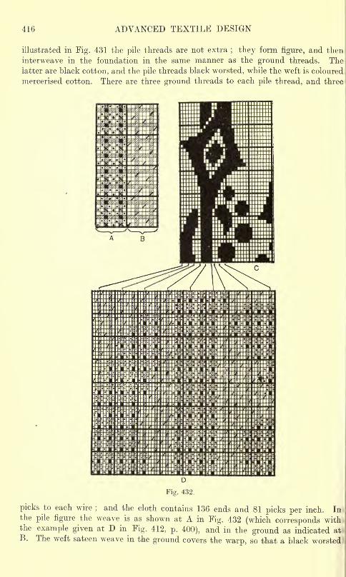
416 ADVANCED TEXTILE DESIGN
illustrated in Fig. 431 the pile threads are not extra; they form figure, and then
interweave in the foundation in the same manner as the ground threads. The;
latter are black cotton, and the pile threads black worsted, while the weft is coloured i
mercerised cotton. There are three ground threads to each pile thread, and three
picks to each wire;and the cloth contains 136 ends and 81 picks per inch. In
the pile figure the weave is as shown at A in Fig. 432 (which corresponds withthe example given at D in Fig. 412, p. 400), and in the ground as indicated at)
B. The weft sateen weave in the ground covers the warp, so that a black worsted
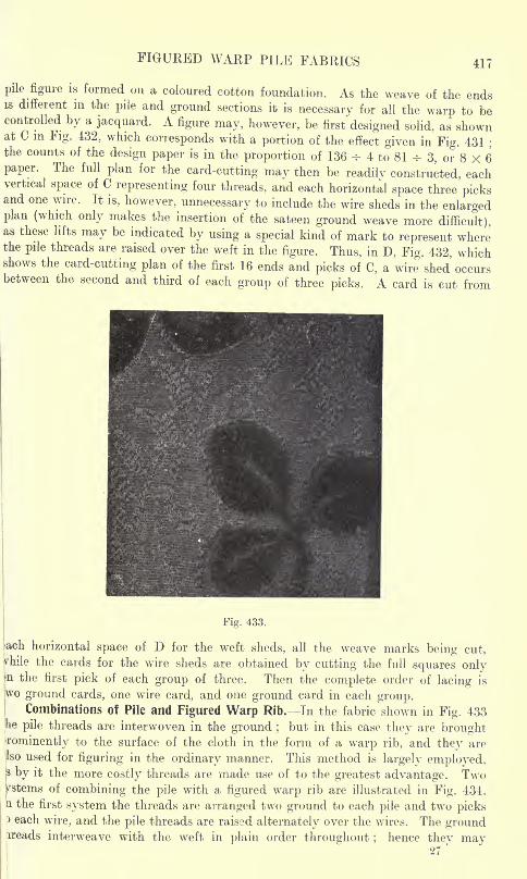
FIGURED WARP PILE FABRICS 417
pile figure is formed on a coloured cotton foundation. As the weave of the endsis different in the pile and ground sections it is necessary for all the warp to becontrolled by a jacquard. A figure may, however, be first designed solid, as shownat C m Fig. 432, which corresponds with a portion of the effect given in Fig. 431
;
the counts of the design paper is in the proportion of 136 -^ 4 to 81 -^ 3, or 8 X 6paper. The full plan for the card-cutting may then be readily constructed, eachvertical space of C representing four threads, and each horizontal space three picksand one wire. It is, however, unnecessary to include the wire sheds in the enlargedplan (which only makes the insertion of the sateen ground weave more difficult),as these lifts may be indicated by using a special kind of mark to represent wherethe pile threads are raised over the weft in the figure. Thus, in D, Fig. 432, whichshows the card-cutting plan of the first 16 ends and picks of C, a wire shed' occursbetween the second and third of each group of three picks. A card is cut from
Fig. 433.
;ach horizontal space of D for the weft sheds, all the weave marks being cut,frhile the cards for the wire sheds are obtained by cutting the full squares only
}nthe first pick of each group of three. Then the complete order of lacing is
wo ground cards, one wire card, and one ground card in each group.Combinations of Pile and Figured Warp Rib. In the fabric shown in Fig. 433
he pile threads are interwoven in the ground ;but in this case they are brought
rominently to the surface of the cloth in the form of a warp rib, and they are
Iso used for figuring in the ordinary manner. This method is largely employed,js by it the more costly threads are made use of to the greatest advantage. Twoyrstems of combining the pile with a figured warp rib are illustrated in Fig. 434.
a the first system the threads are arranged two ground to each pile and two pickseach wire, and the pile threads are raised alternately over the wires. The ground
ireads interweave with the weft in plain order throughout ;hence they may
27'
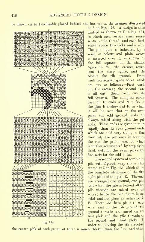
418 ADVANCED TEXTILE DESIGN
be drawn on to two healds placed behind the harness in the manner illustrated
at A in Fig. 426. A design is then
drafted as shown at E in Fig. 434.
in which each vertical space repre-
sents a pile thread, and each hori-
zontal space two picks and a wire
The pile figure is indicated bywash of colour, and plain weavt
is inserted over it, as shown b)
the full squares on the shadec
figure in E;
the crosses repre
sent the warp figure, and the
blanks the rib ground. Fron
each horizontal space three card
are cut as follows : First card
cut the crosses;
the second care
is all cut;
third card, cut thi
full squares. The complete struc
ture of 16 ends and 8 picks o
the plan E is shown at F, in whicl
it will be seen that on the eve]
picks the odd ground ends ar
always raised along with the pil
ends. These ends are given in mor
rapidly than the even ground ends
which are held very tight, so tha-
they help the pile ends in formin
the rib, the prominence of whic
is further accentuated by employinthick weft for the even picks an^
fine weft for the odd picks.
The second system of combinin
pile with figured warp rib is illus
trated at G in Fig. 434, which sho\\
the complete structure of the firs
eight picks of the plan E. The eno|
are arranged one ground, one pil<
and where the pile is formed all th
pile threads are raised over tl
wires;hence the pile figure is ci
solid and not plain as indicated i
E. There are three picks to eac
wire, and in the rib ground tl
ground threads are raised on tl
first pick and the pile threads c
p. 434the second and third picks. 1
order to develop the rib struct^
the centre pick of each group of three is much thicker than the first and thir<
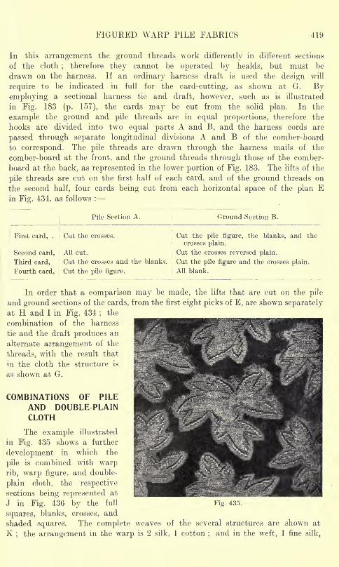
FIGURED WARP PILE FABRICS 419
In this arrangement the ground threads work differently in different sections
of the cloth;
therefore they cannot be operated by healds, but must be
drawn on the harness. If an ordinary harness draft is used the design will
require to be indicated in full for the card-cutting, as shown at G. Byemploying a sectional harness tie and draft, however, such as is illustrated
in Fig. 183 (p. 157), the cards may be cut from the solid plan. In the
example the ground and pile threads are in equal proportions, therefore the
hooks are divided into two equal parts A and B, and the harness cords are
passed through separate longitudinal divisions A and B of the comber-board
to correspond. The pile threads are drawn through the harness mails of the
comber-board at the front, and the ground threads through those of the comber-
board at the back, as represented in the lower portion of Fig. 183. The lifts of the
pile threads are cut on the first half of each card, and of the ground threads on
the second half, four cards being cut from each horizontal space of the plan Ein Fig. 434, as follows :
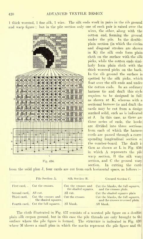
420 ADVANCED TEXTILE DESIGN
1 thick worsted, 1 fine silk. 1 wire. The silk ends work in pairs in the rib groundand warp figure ;
but in the pile section only one of each pair is raised over the
wires, the other, along with the
cotton end, forming the groundunder the pile. In the double-
plain section (in which the circles
and diagonal strokes are shownin K) the silk ends form plaincloth on the surface with the silk
picks, while the cotton ends simi-
larly form plain cloth with the
thick worsted picks on the back.
In the rib ground the surface is
spotted by the silk picks, which
float over the silk ends and under
the cotton ends. In an ordinaryharness tie and draft this style
requires to be designed in full.
as shown at K, whereas with a
sectional harness tie and draft the
cards may be cut from a design
marked solid, such as is indicated
at J. In this case, as there are|
three series of ends, the hooksj
are divided into three sections
from each of which the harness
cords are passed through a corre^
spending longitudinal section o:
the comber-board. The draft if
then as shown at L in Fig. 436*
in which A represents the pil(
waip section, B the silk warj
Fig. 436. section, and C the ground warjsection. In cutting the cards
from the solid plan J, four cards are cut from each horizontal space, as follows :
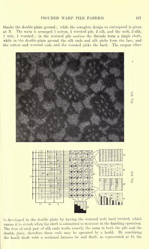
FIGURED WARP PILE FABRICS 421
blanks the double-plain ground ;while the complete design to correspond is given
at N. The warp is arranged 1 cotton, 1 worsted pile, 2 silk, and the weft, 2 silk,
1 wire, 1 worsted;
in the worsted pile section the threads form a single cloth,
while in the double-plain ground the silk ends and silk picks form the face, and
the cotton and worsted ends and the worsted picks the back. The crepon effect
is developed in the double plain by having the worsted weft hard twisted, which
causes it to shrink when the cloth is submitted to moisture in the finishing operation.
The first of each pair of silk ends works exactly the same in both the pile and the
double plain, therefore these ends may be operated by a heald. By combining
the heald draft with a sectional harness tie and draft, as lepresented at 0, the
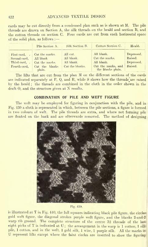
422 ADVANCED TEXTILE DESIGN
cards may be cut directly from a condensed plan such as is shown at M. The pile
threads are drawn on Section A, the silk threads on the heald and section B, and
the cotton threads on section C. Four cards are cut from each horizontal space
of the solid plan, as follows :
Pile Section A.
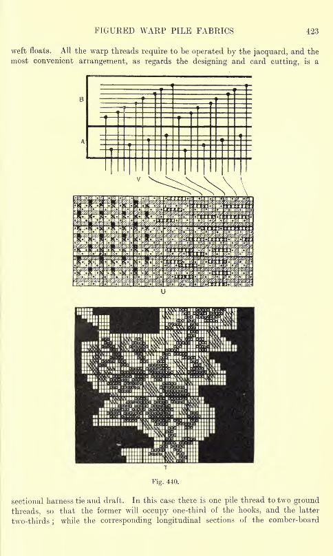
FIGURED WARP PILE FABRICS 423
weft floats. All the warp threads require to be operated by the jacquard, and the
most convenient arrangement, as regards the designing and card cutting, is a
Si*, iv"'!"' SS
:;::;:;!;! ;,,.!
iiiiiiii ii*
!! S!S
T
Fig. 440.
sectional harness tie and draft. In this case there is one pile thread to two ground
threads, so that the former will occupy one-third of the hooks, and the latter
two-thirds ;while the corresponding longitudinal sections of the comber-board
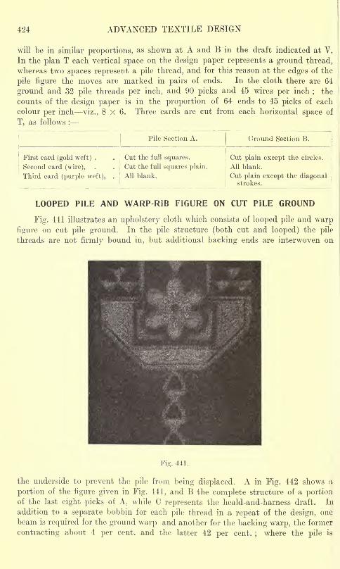
424 ADVANCED TEXTILE DESIGN
will be in similar proportions, as shown at A and B in the draft indicated at V.
In the plan T each vertical space on the design paper represents a ground thread,
whereas two spaces represent a pile thread, and for this reason at the edges of the
pile figure the moves are marked in pairs of ends. In the cloth there are 64
ground and 32 pile threads per inch, and 90 picks and 45 wires per inch; the
counts of the design paper is in the proportion of 64 ends to 45 picks of each
colour per inch viz., 8x6. Three cards are cut from each horizontal space of
T, as follows :
Pile Section A. Ground Section B.
First card (gold weft) .
Second card (wire),
Third card (purple weft),
Cut the full squares.
Cut the full squares plain.1
All blank.
Cut plain except the circles.
All blank.
Cut plain except the diagonalstrokes.
LOOPED PILE AND WARP-RIB FIGURE ON CUT PILE GROUND
Fig. 441 illustrates an upholstery cloth which consists of looped pile and warp
figure on cut pile ground. In the pile structure (both cut and looped) the pile
threads are not firmly bound in, but additional backing ends are interwoven on
Fig. 441.
the underside to prevent the pile from being displaced. A in Fig. 442 shows a
portion of the figure given in Fig. 441, and B the complete structure of a portionof the last eight picks of A, while C represents the heald-and-harness draft. In
addition to a separate bobbin for each pile thread in a repeat of the design, one
beam is required for the ground warp and another for the backing warp, the former
contracting about 4 per cent, and the latter 42 per cent.;
where the pile is
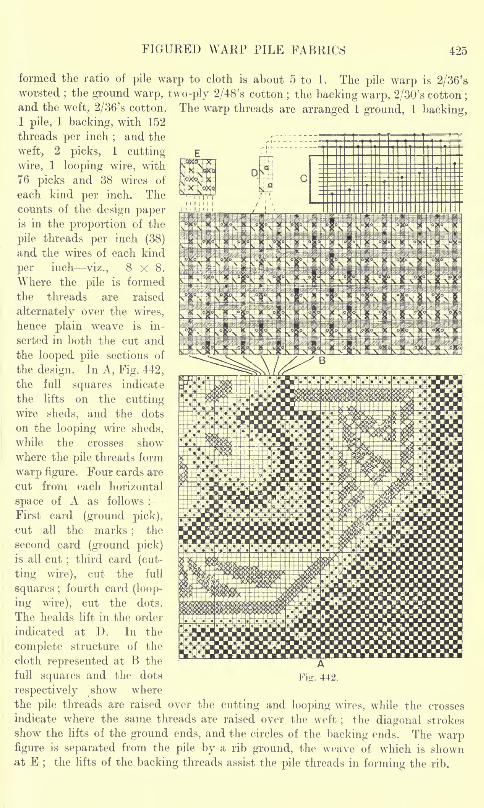
FIGURED WARP PILE FABRICS 425
formed the ratio of pile warp to cloth is about 5 to 1. The pile warp is 2/36'sworsted
;the ground warp, two-ply 2/48's cotton
;the backing warp, 2/30's cotton
;
and the weft, 2/36's cotton. The warp threads are arranged 1 ground, 1 backing,1 pile, 1 backing, with 152
threads per inch;and the
weft, 2 picks, 1 cutting
wire, 1 looping wire, with
76 picks and 38 wires of
each kind per inch. Thecounts of the design paperis in the proportion of the
pile threads per inch (38)
and the wires of each kind
per inch viz., 8x8.Where the pile is formed
the threads are raised
alternately over the wires,
hence plain weave is in-
serted in both the cut and
the looped pile sections of
the design. In A, Fig. 442,
the full squares indicate
the lifts on the cutting-
wire sheds, and the dots
on the looping wire sheds,
while the crosses showwhere the pile threads form
warp figure. Four cards are
cut from each horizontal
space of A as follows :
First card (ground pick),
cut all the marks;
the
second card (ground pick)is all cut
;third card (cut-
ting wire), cut the full
squares ;fourth card (loop-
ing wire), cut the dots.
The healds lift in the order
indicated at D. In the
complete structure of the
cloth represented at B the
full squares and the dotsFig. 442.
respectively |show where
the pile threads are raised over the cutting and looping wires, while the crosses
indicate where the same threads are raised over the weft; the diagonal strokes
show the lifts of the ground ends, and the circles of the backing ends. The warpfigure is separated from the pile by a rib ground, the weave of which is shownat E
;the lifts of the backing threads assist the pile threads in forming the rib.
426 ADVANCED TEXTILE DESIGN
CHAPTER XX
FIGURED PILE FABRICS IN WHICH THE DESIGNIS DUE TO COLOUR
Wilton and Brussels Structures Comparison of the Cloths Distinguishing Feature of the Cloths
Planting Method of Designing System of Loom Mounting Card-cutting Six-frame
Mounting Structure of Wilton Pile Structure of Brussels Pile Two-pick Wilton
Pile Structure Moresque Effects Development of the Colours in both Cut and LoopedPile. Tapestry Pile Carpets Comparison with Brussels and Wilton Structures Tapestry
Pile Designing Preparation of the Pile Yarn for Printing The Printing Drum The
Printing Pulley The Scale Board Operation of Printing Beaming the Pile WarpStructure of Tapestry Pile Tapestry Pile Weaving. Chenille or Patent Axminster
Pile Comparison with Tapestry Pile Chenille Pile Designing Formation of the Chenille
Setting Structure of the Fabric. Moquette or Royal Axminster Pile.
SEVERAL important classes of pile textures, which include Wilton, Brussels, Tapestry,
and Axminster carpets, and similar but lighter fabrics that are used for hangingand upholstery purposes, are woven with a uniform surface of either cut or looped
pile. The chief purpose of the form or figure in these cloths is to serve as a mediumfor the display of colour. Special machines and processes are employed in their
production, which enable the designs to be composed without regard to the method
in which the threads interlace. It is only in the Wilton and Brussels structures
that the use of a jacquard machine is required in forming the figure.
WILTON AND BRUSSELS PILE STRUCTURES
Comparison of the Cloths. The principles of designing for Wilton and Brussels
carpets, and corresponding hanging and upholstery cloths, are practically the
same, while the cloths are very similar in structure. The chief differences between
them are that in a typical Wilton carpet the pile is cut and there are three picksto each wire, whereas in a Brussels carpet the pile is looped and there are two picksto each wire. Wilton pile carpets require the insertion of three picks to each wire
in order to ensure that the tufts will be held firm enough to resist the friction that
is applied to the cloth, but cut pile hangings, in which the tufts are not so liable
to be disturbed, are very largely made with two picks to each wire. A Wilton pile
is generally composed of finer material, and is deeper than a Brussels pile ;and
both structures, when used for hanging and upholstery purposes, are made lighter,
finer, softer, and more flexible than when they are employed as carpets. Flax
and jute yarns, made very stiff by sizing, are used for the foundation of carpetsin order that the back will be firm and unyielding, whereas cotton yarns of a pliablenature enter into the foundation of hanging and upholstery cloths.
Distinguishing Feature of the Cloths. In each longitudinal line of the Brussels
and Wilton structures as many differently coloured pile threads are employedas there are different colours brought to the surface in the line. The pile threads
are thus in sets or groups in which, so far as regards the pile structure, each thread
is a duplicate of the otheis;one thread in each group, of the proper colour according
WILTON AND BRUSSELS PILE FABRICS 427
to the design, is raised over each wire. The cloths are classified according to the
number of pile threads in each group, and technically the term"frame
"is applied ;
thus, three-frame, four-frame, and five-frame are respectively applied to cloths-
in which there are three, four, and five duplicate, but differently coloured pile
threads in each longitudinal line. The textures mostly range from two to five
frames, but six frames are employed to some extent. In a five-frame cloth there
are always four pile threads lying in the foundation to one thread on the surface,
while in a four-frame three pile threads are in the foundation for each thread
on the surface, and so on. Therefore the higher the number of the frame the greateris the consumption of the pile yarns, but (if other things are equal) this is accom-
panied by no improvement in the texture, except that the greater number of colours
gives moie scope to the designer, and the foundation is better as regards bulkiness
and elasticity. The quantity of pile yarn used is not in direct proportion to the
number of the frames, because, however many frames are employed, there is alwaysone, but never more than one, thread of each group taken up rapidly by beingraised over the wires. For example, assuming that the contraction of the pile
threads in forming the pile is from 300 to 100, and in the foundation from 104 to-
100 : for 100 yards of cloth each group of threads in a six-frame effect will require
(1 X 300) + (5 X 10⁴) = 820 yards of pile yarn, whereas a three-frame patternwill lequire (1 X 300) + (2 X 10⁴) = 508 yards of yarn, or about five-eighths the
length that the pattern with twice as many colours requires.
Each pile thread is on a separate bobbin, and the bobbins are arrangedin a creel behind the loom in layers to correspond with the frames. As many groupsof threads are required in the width of a cloth as there are loops or tufts formed
in each transverse line. In Brussels and Wilton carpets the number of groupsin the standard width of 27 inches ranges from 260, or about 10 per inch, to as
few as 130, or about 5 per inch, very thick pile yarns being employed for the latter;
while the number of wires per inch ranges from 13 in the finest Wilton structures
to about 7 in the cheapest qualities of Brussels. On the other hand, hanging and
upholstery cloths are made finer, and from 18 to 14 groups of pile threads per inch,
and from 18 to 14 wires per inch are employed.
Planting. The number of colours in the width of a fabric is not limited to
the number of frames employed ;the threads in different groups may be differently
coloured, in which case one, two, or more of the frames each contains more than
one colour of pile. Thus, in a five-frame structure one portion of a design mayrequire the colours 1, 2, 3, 4, and 5, and another portion the colours 1, 2, 3, 6, and
7, and yet another portion the colours 1, 2, 3, 8, and 7 ;the colours 1, 2, and 3
being constant, while the colours 4 and 5 are replaced by the colours 6 and 7, and
then the colour 6 by the colour 8. The substitution of one colour for another is
termed"planting," and if this is judiciously performed a design may be produced
in a four or five-frame cloth which contains as many as say -twenty colours. In
the same quality the higher the number of the frame is the more costly is the cloth,
on account of the greater quantity of pile yarn required, and frequently a cloth,
by successful planting, is given the appearance of being produced in a higher frame,
and, therefore, more costly than is actually the case. The chief point to note in
planting is to avoid the formation of stripes in the woven design, and for this
reason a planted colour is sometimes graduated at both sides towards the adjacent
colours in the frame.
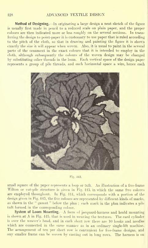
428 ADVANCED TEXTILE DESIGN
Method of Designing. In originating a large design a neat sketch of the figure
is usually first made in pencil to a reduced scale on plain paper, and the propercolours are then indicated more or less roughly on the several sections. In trans-
ferring the design to point-paper it is customary to use paper that is ruled accordingto the pitch of the cloth, so that in drawing and painting the figure it is shown
exactly the size it will appear when woven. Also, it is usual to paint in the several
parts of the ornament in the exact colours that it is intended to employ in the
cloth, although subsequently the colours of the woven design may be changed
by substituting other threads in the loom. Each vertical space of the design paper
represents a group of pile threads, and each horizontal space a wire, hence each
Fig. 443.
small square of the paper represents a loop or tuft. An illustration of a five-frame
Wilton or cut-pile structure is given in Fig. 443, in which the same five colours
are employed throughout. In Fig. 444, which corresponds with a portion of the
design given in Fig. 443, the five colours are represented by different kinds of marks,as shown in the
"gamut
"below the plan ;
each mark in the plan indicates a piletuft formed in the corresponding colour.
System of Loom Mounting. A form of jacquard-harness and heald mountingis shown at A in Fig. 445, that is used in weaving the textures. The card cylinderis over the weaver's head, and in each short row there are 10 hooks and needles
which are connected in the same manner as in an ordinary single-lift machine.The arrangement of ten per short row is convenient for five-frame designs, and
any smaller frame can be woven by casting out in long rows. The harness is on
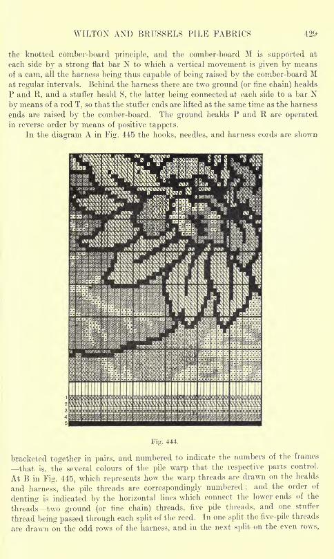
WILTON AND BRUSSELS PILE FABRICS 429-
the knotted comber-board principle, and the comber-board M is supported at
each side by a strong flat bar N to which a vertical movement is given by means-
of a cam, all the harness being thus capable of being raised by the comber-board Mat regular intervals. Behind the harness there are two ground (or fine chain) healds
P and R, and a stuffer heald S, the latter being connected at each side to a bar Nby means of a rod T, so that the stuffer ends are lifted at the same time as the harness
ends are raised by the comber-board. The ground healds P and R are operatedin reverse order by means of positive tappets.
In the diagram A in Fig, 445 the hooks, needles, and harness cords are shown-
Fig. 444.
bracketed together in pairs, and numbered to indicate the numbers of the frames
that is, the several colours of the pile warp that the respective parts control.
At B in Fig. 445, which represents how the warp threads are drawn on the healds
and harness, the pile threads are correspondingly numbered ;and the order of
denting is indicated by the horizontal lines which connect the lower ends of the
threads two ground (or fine chain) threads, five pile threads, and one stuffer
thread being passed through each split of the reed. In one split the five-pile threads
are drawn on the odd rows of the harness, and in the next split on the even rows,
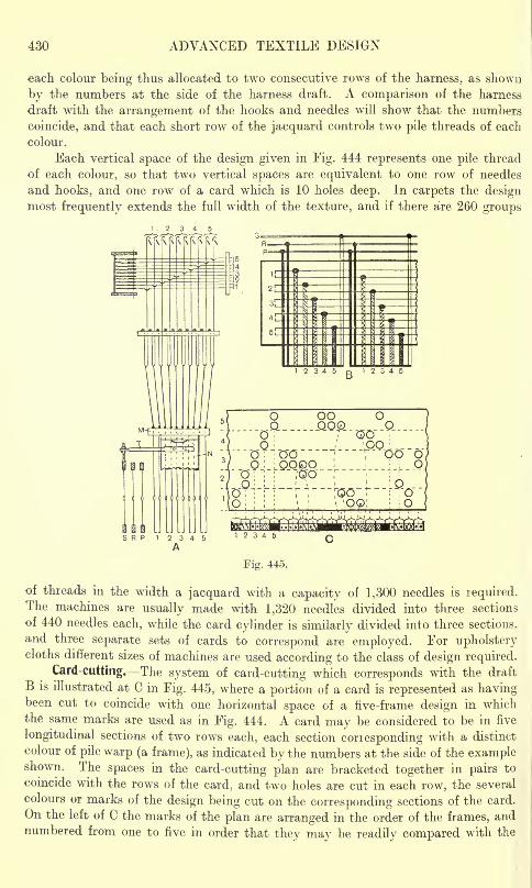
430 ADVANCED TEXTILE DESIGN
each colour being thus allocated to two consecutive rows of the harness, as shown
by the numbers at the side of the harness draft. A comparison of the harness
draft with the arrangement of the hooks and needles will show that the numbers
coincide, and that each short row of the jacquard controls two pile threads of each
colour.
Each vertical space of the design given in Fig. 444 represents one pile thread
of each colour, so that two vertical spaces are equivalent to one row of needles
and hooks, and one row of a card which is 10 holes deep. In carpets the designmost frequently extends the full width of the texture, and if there are 260 groups
oo_QO
O
1 c
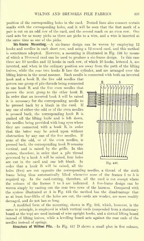
WILTON AND BRUSSELS PILE FABRICS 431
position of the corresponding holes in the card. Dotted lines also connect certain
marks with the corresponding holes, and it will be seen that the first mark of a
pair is cut on an odd row of the card, and the second mark on an even row. Onecard acts for as many picks as there are picks to a wire, and a wire is inserted at
the same time as one of the picks.
Six-frame Mounting. A six-frame design can be woven by employing 12
hooks and needles in each short row, and using a 12-rowed card, and this method
is sometimes adopted. However, a mounting is illustrated in Fig. 446 by means
of which a 10-rowed card can be used to produce a six-frame design. In this case
there are 10 needles and 12 hooks in each row, of which 10 hooks, lettered A, are
inverted, and when in the ordinary position are away from the path of the lifting
knives, while the rear two hooks B face the cylinder, and are arranged over the
lifting knives in the usual manner. Each needle is connected with both an inverted
hook and a hook B, the five odd needles that
govern one group of pile threads being connected
to one hook B. and the five even needles that
govern the next group to the other hook B.
In order that an inverted hook A will be raised
it is necessary for the corresponding needle to
be pressed back by a blank in the card. If
any one of either the odd or of the even needles
is pressed back, the corresponding hook B is
pushed off the lifting knife and is left down,
the needles being provided with long eyes where
they are connected with a hook B, in order
that the latter may be acted upon without
obstruction by any one of the five needles. If
none of the odd, or of the even needles, is
pressed back, the corresponding hook B remains
vertical, and is raised by the griffe. In this
system, therefore, in order that a pile thread
governed by a hook A will be raised, four holes
are cut in the card and one left blank. In
order that a hook B will be raised, all theFig. 446.
holes (five) are cut opposite the corresponding needles, a thread of the sixth
frame being thus automatically lifted whenever none of the frames 1 to 5 is
required up. In the card-cutting, therefore, all the card is cut except where
the colours of the frames 1 to 5 are indicated. A five-frame design can be
woven simply by casting out the rear two rows of the harness. Compared with
the system illustrated at A in Fig. 445 the method has the disadvantage that
as at least four-fifths of the holes are cut, the cards are weaker, are more readily
damaged, and do not last so long.
A modified form of the mounting, shown in Fig. 446, which, however, is the
same in principle, is employed in which vertical cords (suspended from a stationaryboard at the top) are used instead of wire upright hooks, and a slotted lifting board
instead of lifting knives, while a levelling board acts against the rear ends of the
needles instead of springs.
Structure of Wilton Pile. In Fig. 447 D shows a small plan in five colours,
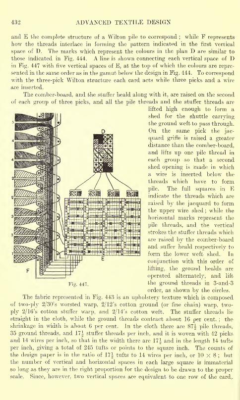
432 ADVANCED TEXTILE DESIGN
and E the complete structure of a Wilton pile to correspond ;while F represents
how the threads interlace in forming the pattern indicated in the first vertical
space of D. The marks which represent the colours in the plan D are similar to
those indicated in Fig. 444. A line is shown connecting each vertical space of Din Fig. 447 with five vertical spaces of E, at the top of which the colours are repre-sented in the same order as in the gamut below the design in Fig. 444. To correspondwith the three-pick Wilton structure each card acts while three picks and a wire
are inserted.
The comber-board, and the stuffer heald along with it, are raised on the second
of each group of three picks, and all the pile threads and the stuffer threads are
lifted high enough to form a
shed for the shuttle carryingthe ground weft to pass through.On the same pick the jac-
quard griffe is raised a greaterdistance than the comber-board,and lifts up one pile thread in
each group so that a second
shed opening is made in which
a wire is inserted below the
threads which have to form
pile. The full squares in Eindicate the threads which are
raised by the jacquard to form
the upper wire shed; while the
horizontal marks represent the
pile threads, and the vertical
strokes the stuffer threads which
are raised by the comber-board
and suffer heald respectively to
form the lower weft shed. In
conjunction with this order of
lifting, the ground healds are
operated alternately, and lift
Fig. 447. the ground threads in 3-and-3
order, as shown by the circles.
The fabric represented in Fig. 443 is an upholstery texture which is composedof two-ply 2/30's worsted warp, 2/12's cotton ground (or fine chain) warp, two-
ply 2/16's cotton stuffer warp, and 2/14's cotton weft. The stuffer threads lie
straight in the cloth, while the ground threads contract about 16 per cent.;
the
shrinkage in width is about 6 per cent. In the cloth there are 87f pile threads,
35 ground threads, and 17J stuffer threads per inch, and it is woven with 42 picksand 14 wires per inch, so that in the width there are 17| and in the length 14 tufts
per inch, giving a total of 245 tufts or points bo the square inch. The counts of
the design paper is in the ratio of 17J tufts to 14 wires per inch, or 10 X 8;but
the number of vertical and horizontal spaces in each large square is immaterial
so long as they are in the right proportion for the design to be drawn to the properscale. Since, however, two vertical spaces are equivalent to one row of the card.
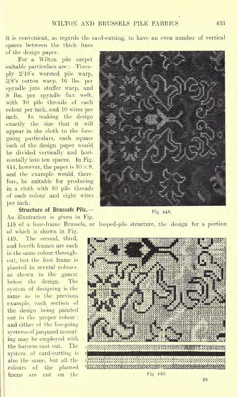
WILTON AND BRUSSELS PILE FABRICS 433
it is convenient, as regards the card-cutting, to have an even number of vertical
spaces between the thick lines
of the design paper.For a Wilton pile carpet
suitable particulars are : Three-
ply 2/18's worsted pile warp,
3/8's cotton warp, 16 Ibs. per
spyndle jute stuffer warp, and
8 Ibs. per spyndle flax weft,
with 10 pile threads of each
colour per inch, and 10 wires perinch. In making the design
exactly the size that it will
appear in the cloth to the fore-
going particulars, each squareinch of the design paper would
be divided vertically and hori-
zontally into ten spaces. In Fig.
444, however, the paper is 10 x 8.
and the example would, there-
fore, be suitable for producingin a cloth with 10 pile threads
of each colour and eight wires
per inch.
Structure of Brussels Pile.
An illustration is given in Fig.
448 of a four-frame Brussels, or looped-pile structure, the design for a portion
of which is shown in Fig.
449. The second, third,
and fourth frames are each
in the same colour through-
out, but the first frame is
planted in several colours,
as shown in the gamutbelow the design. The
system of designing is the
same as in the previous
example, each section of
the design being paintedout in the proper colour
;
and either of the foregoing
systems of jacquard mount
ing may be employed with
the harness cast out. The
system of card-cutting is
also the same, but all the
colours of the plantedframe are cut on the
Fig. 448.
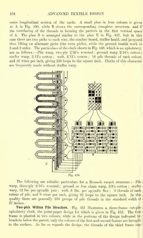
434 ADVANCED TEXTILE DESIGN
same longitudinal section of the cards. A small plan in four colours is givenat A in Fig. 450, while B shows the corresponding complete structure, and Cthe interlacing of the threads in forming the pattern in the first vertical spaceof A. The plan B is arranged similar to the plan E in Fig. 447, but in this
case there are two picks to each wire, the comber-board, stuffer heald, and jacquardthus lifting on alternate picks (the even picks), while the ground healds work in
2-and-2 order. The particulars of the cloth shown in Fig. 448, which is an upholstery,are as follows: Pile warp, two-ply 2/36's worsted; ground warp 2/16's cotton;
stuffer warp, 2/12's cotton ; weft, 2/12's cotton;
16 pile threads of each colour,
and 16 wires per inch, giving 256 loops to the square inch. Cloths of this character
are frequently made without stuffer warp.
Fig. 450.
The following are suitable particulars for a Brussels carpet structure : Pile
warp, three-ply 2/16's worsted; ground or fine chain warp, 3/8's cotton
;stuffer
warp, 12 Ibs. per spyndle jute ; weft, 8 Ibs. per spyndle flax;
9 threads of each
colour of pile, and 9 wires per inch, giving 81 loops to the square inch. In this
quality there are generally 234 groups of pile threads in the standard width of
27 inches.
Two-pick Wilton Pile Structure. Fig. 451 illustrates a three-frame cut-pile
upholstery cloth, the point-paper design for which is given in Fig. 452. The first
frame is planted in two colours, while in the portions of the design indicated bybrackets below the gamut, only the colours of the first and second frames are broughtto the surface. As far as regards the design, the threads of the third frame can
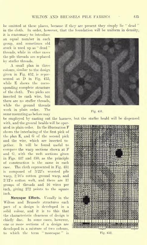
WILTON AND BRUSSELS PILE FABRICS 435
Fig. 451.
be omitted at these places, because if they are present they simply lie"dead
"
in the cloth. In order, however, that the foundation will be uniform in density,
it is customary to introduce
an equal number in each
group, and sometimes old
stock is used up as"dead
"
threads, while in other cases
the pile threads are replaced
by stuffer threads.
A small plan in three
colours, similar to the design
given in Fig. 452, is repre-
sented at D in Fig. 453,
while E shows the corre-
sponding complete structure
of the cloth. Two picks are
inserted to each wire, but
there are no stuffer threads,
while the ground threads
work in plain order. The
same mounting as before maybe employed by casting out the harness, but the stuffer heald will be dispensed
with, and the ground healds will be oper-ated in plain order. In Ihe illustration Fshows the interlacing of the first pick of
the plan E, and G of the second pickand the wire, which are inserted to-
gether. It will be found useful to
compare the warp sections shown at Fand G-, with the weft sections givenin Figs. 447 and 450, as the principle
of construction is the same in each
case. The cloth represented in Fig. 451
is composed of 3/22's worsted pile
warp, 2/10's cotton ground warp, and
2/12's cotton weft, and there are 17
groups of threads and 16 wires per
inch, giving 272 points to the squareinch.
Moresque Effects. Usually in the
Wilton and Brussels structures each
part of a design is developed in a
solid colour, and it is to this that
the characteristic clearness of design is
chiefly due. In some cases, however,
one or more sections of a design are
developed in a mixture of two colours,
to which the term"moresque
"is Fig. 452.
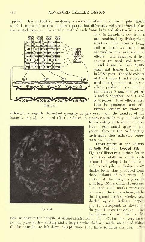
436 ADVANCED TEXTILE DESIGN
Fig. 453.
applied. One method of producing a moresque effect is to use a pile thread
which is composed of two or more separate but differently coloured threads that
are twisted together. In another method each frame is in a distinct solid colour,
but the threads of two frames
are combined by lifting them
together, such threads beinghalf as thick as those that
are used to form solid-coloured
effects. For example, if five
frames are used, and frames
1 and 2 are in 3-ply 2/18's
yarn, and frames 3, 4, and 5in 3/18's yarn the solid colours-
of the frames 1 and 2 may be
used in conjunction with mixed
effects produced by combiningthe frames 3 and 4 together,
3 and 5 together, and 4 and5 together. Five effects maythus be produced, and still
further variety by planting,
although, as regards the actual quantity of pile yarn used, the number of the
frame is only 3J. A mixed effect produced in separate threads may be designed
by indicating each colour on one-
half of each small space of the
paper ;then in the card-cutting
each space thus indicated repre-
sents two holes.
Development of the Colours
in both Cut and Looped Pile.
Fig. 454 illustrates a three-frame
upholstery cloth in which each
colour is developed in both cut
and looped pile, a design in six
shades being thus produced from
three colours of pile warp. Aportion of the design is given at
A in Fig. 455, in which the crosses,
dots, and solid marks representcut pile in the three colours, while
the diagonal strokes, circles, and
shaded squares indicate looped
pile to correspond, as shown in
Fi8- 454 - the gamut below the design. The
foundation of the cloth is the
same as that of the cut-pile structure illustrated in Fig. 447, but for every three
ground picks both a cutting and a looping wire shed are made, on one of which
all the threads are left down except those that have to form the pile.Two
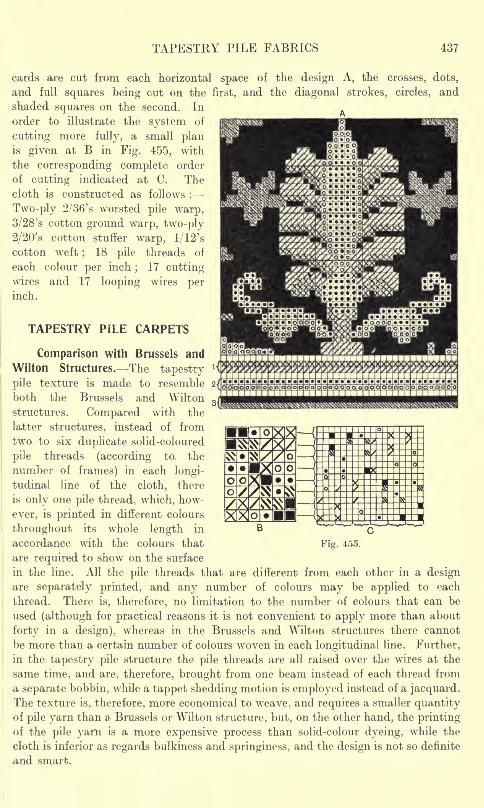
TAPESTRY PILE FABRICS 437
cards are cut from each horizontal space of the design A, the crosses, dots,
and full squares being cut on the first, and the diagonal strokes, circles, and
shaded squares on the second. In
order to illustrate the system of
cutting more fully, a small planis given at B in Fig. 455, with
the corresponding complete order
of cutting indicated at C. The
cloth is constructed as follows :
Two-ply 2/36's worsted pile warp,
3/28's cotton ground warp, two-ply
2/20's cotton stuffer warp, 1/12's
cotton weft ; 18 pile threads of
each colour per inch;
17 cuttingwires and 17 looping wires perinch.
TAPESTRY PILE CARPETS
Comparison with Brussels and
Wilton Structures. The tapestry
pile texture is made to resemble
both the Brussels and Wilton
structures. Compared with the
latter structures, instead of from
two to six duplicate solid-coloured
pile threads (according to, the
number of frames) in each longi-
tudinal line of the cloth, there
is only one pile thread, which, how-
ever, is printed in different colours
throughout its whole length in
accordance with the colours that Fig. 455.
are required to show on the surface
in the line. All the pile threads that are different from each other in a designare separately printed, and any number of colours may be applied to each
thread. There is, therefore, no limitation to the number of colours that can be
used (although for practical reasons it is not convenient to apply more than about
forty in a design), whereas in the Brussels and Wilton structures there cannot
be more than a certain number of colours woven in each longitudinal line. Further,
in the tapestry pile structure the pile threads are all raised over the wires at the
same time, and are, therefore, brought from one beam instead of each thread from
a separate bobbin, while a tappet shedding motion is employed instead of a jacquard.The texture is, therefore, more economical to weave, and requires a smaller quantityof pile yarn than a Brussels or Wilton structure, but, on the other hand, the printingof the pile yarn is a more expensive process than solid-colour dyeing, while the
cloth is inferior as regards bulkiness and springiness, and the design is not so definite
and smart.
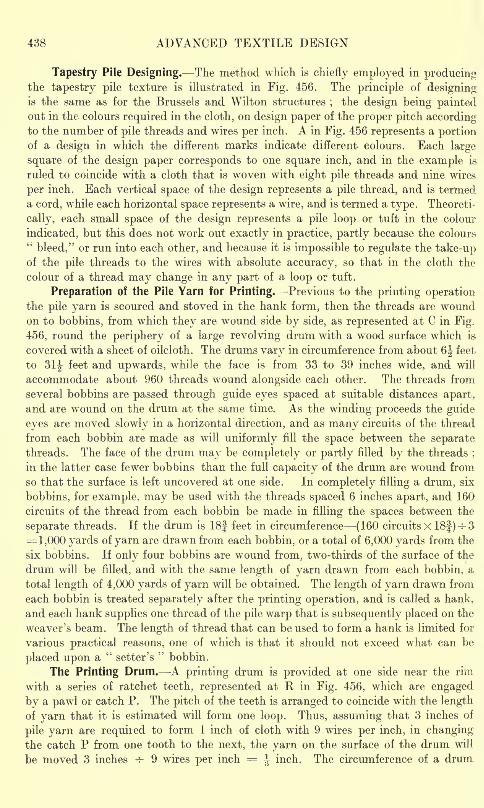
438 ADVANCED TEXTILE DESIGN
Tapestry Pile Designing. The method which is chiefly employed in producingthe tapestry pile texture is illustrated in Fig. 456. The principle of designing-
is the same as for the Brussels and Wilton structures;
the design being paintedout in the colours required in the cloth, on design paper of the proper pitch accordingto the number of pile threads and wires per inch. A in Fig. 456 represents a portionof a design in which the different marks indicate different colours. Each large
square of the design paper corresponds to one square inch, and in the example is
ruled to coincide with a cloth that is woven with eight pile threads and nine wires
per inch. Each vertical space of the design represents a pile thread, and is termed
a cord, while each horizontal space represents a wire, and is termed a type. Theoreti-
cally, each small space of the design represents a pile loop or tuft in the colour
indicated, but this does not work out exactly in practice, partly because the colours"bleed," or run into each other, and because it is impossible to regulate the take-up
of the pile threads to the wires with absolute accuracy, so that in the cloth the
colour of a thread may change in any part of a loop or tuft.
Preparation of the Pile Yarn for Printing. Previous to the printing operationthe pile yarn is scoured and stoved in the hank form, then the threads are woundon to bobbins, from which they are wound side by side, as represented at C in Fig.
456, round the periphery of a large revolving drum with a wood surface which is
covered with a sheet of oilcloth. The drums vary in circumference from about 6J feet
to 31J feet and upwards, while the face is from 33 to 39 inches wide, and will
accommodate about 960 threads wound alongside each other. The threads from
several bobbins are passed through guide eyes spaced at suitable distances apart,
and are wround on the drum at the same time. As the winding proceeds the guide
eyes are moved slowly in a horizontal direction, and as many circuits of the thread
from each bobbin are made as will uniformly fill the space between the separatethreads. The face of the drum may be completely or partly filled by the threads
;
in the latter case fewer bobbins than the full capacity of the drum are wound from
so that the surface is left uncovered at one side. In completely filling a drum, six
bobbins, for example, may be used with the threads spaced 6 inches apart, and 160
circuits of the thread from each bobbin be made in filling the spaces between the
separate threads. If the drum is 18| feet in circumference {160 circuits X 18|) -s- 3= 1,000 yards of yarn are drawn from each bobbin, or a total of 6,000 yards from the
six bobbins. If only four bobbins are wound from, two-thirds of the surface of the
drum will be filled, and with the same length of yarn drawn from each bobbin, a
total length of 4,000 yards of yarn will be obtained. The length of yarn drawn from
each bobbin is treated separately after the printing operation, and is called a hank,
and each hank supplies one thread of the pile warp that is subsequently placed on the
weaver's beam. The length of thread that can be used to form a hank is limited for
various practical reasons, one of which is that it should not exceed what can be
placed upon a"
setter's"
bobbin.
The Printing Drum. A printing drum is provided at one side near the rim
with a series of ratchet teeth, represented at R in Fig. 456, which are engaged
by a pawl or catch P. The pitch of the teeth is arranged to coincide with the length
of yarn that it is estimated will form one loop. Thus, assuming that 3 inches of
pile yarn are required to form 1 inch of cloth with 9 wires per inch, in changingthe catch P from one tooth to the next, the yarn on the surface of the drum will
be moved 3 inches -?- 9 wires per inch = ^ inch. The circumference of a drum
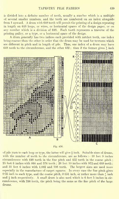
TAPESTRY PILE FABRICS 439
is divided into a definite number of teeth, usually a number which is a multipleof several smaller numbers, and the teeth are numbered on an index alongsidefrom 1 upward. A drum with 648 teeth will permit the printing of a design repeatingin length on 648 loops, or wires, or horizontal spaces of the design paper, or on
any number which is a division of 648. Each tooth represents a traverse of the
printing pulley, or a type, or a horizontal space of the design.A drum generally has two indices each provided with ratchet teeth, one index
being coarser than the other in order that the drum may be used for textures which
are different in pitch and in length of pile. Thus, one index of a drum may have
648 teeth to the circumference, and the other 432;then if the former gives ^ inch
of pile yarn to each loop or type, the latter will give -|inch. Suitable sizes of drums,
with the number of teeth to the circumference, are as follows : 18 feet 9 inches
circumference with 648 teeth in the fine pitch and 432 teeth in the coarse pitch ;
25 feet 6 inches with 864 and 576 teeth;28 feet 10 inches with 972 and 648 teeth
;
and 31 feet 6 inches with 1,062 and 708 teeth. The largest sizes are used more
especially in the manufacture of carpet squares. In every case the fine pitch gives0'35 inch to each type, and the coarse pitch, 0*534 inch, or rather more than ^ inch
and J inch respectively. A small drum is also used which is 6 feet 5 inches in cir-
cumference, with 216 teeth, the pitch being the same as the fine pitch of the largedrums.
440 ADVANCED TEXTILE DESIGN
The Printing Pulley. Situated immediately underneath the drum is a metal
carriage which is provided with four grooved wheels that rest on a pair of rails
running the width of the drum. The carriage is so constructed that a colour box
can be readily put in or taken out;and as many colour boxes are employed as
there are different colours in the design to be printed. Each colour box contains
a supply of the proper dye solution, and the colour is applied to the pile yarn,while it is wound round the drum, by means of a printing pulley which is partlyimmersed in the liquid. The width of the face of the printing pulley is approximately,
equal to the distance that the yarn is moved by the drum when the latter is turned
one tooth. The carriage is made to traverse the breadth of the drum, and the
printing pulley revolves in the dye solution and runs with its upper surface in
contact with the yarn, thus printing on the threads the colour which is contained
in the colour box. The width of colour printed at each traverse is equal, theo-
retically, to the length of yarn required to form one loop or tuft, and correspondsto one wire or one horizontal space of the design paper. If only part of the width
of the drum is covered with yarn the printing pulley is automatically"dipped
"
or lowered out of contact with the surface which is uncovered.
The Scale Board. -A large design is divided longitudinally into sections each
of such a width that it can be conveniently handled during printing, and each
portion is pasted to a separate board and then varnished. If the time available
for printing a design is limited two or more of the separate sections may be printed
simultaneously at different drums. As shown in A Fig. 456, the spaces of the
design are numbered along the bottom to indicate the number of each pile thread
in the design, and at the side, to correspond with the numbering of the teeth of
the drum. The printer uses as a guide a narrow piece of wood with a bevelled edge,
termed a scale board, which is divided by horizontal lies to suit the pitch of the
design paper, as shown at B in Fig. 456;and the horizontal spaces of the scale
board are also numbered to correspond with the numbering of the teeth of the
drum. The scale board is placed on the design with the bevelled edge alongsidethe vertical cord (or thread) to be printed No. 30 in Fig. 456 with the numbers
on the board and at the side of the design coinciding.'
Operation of Printing. Each colour of the design is indicated by a letter
or number, and the colour box which contains the corresponding colour is similarly
indicated in order to avoid trouble in selecting the colours. The colour, which is
judged to be the most suitable to print first, is selected, and assuming that this
is represented by the solid marks, which, in the cord numbered 30 in Fig. 456,
are indicated on the spaces numbered 4, 10, 22, 23, etc., the drum is turned bymeans of a hand wheel so that the pawl P engages in succession the teeth that
are correspondingly numbered. At each engagement the printing carriage, containingthe proper colour box, is traversed with the scroll pulley in contact with the threads.
When all the types of the cord 30, which correspond with the spaces on which
the first colour is indicated, have been printed round the entire circuit of the drum,
the colour box is changed for one containing another colour. Assuming that
this is represented by the vertical marks in the cord No. 30 in Fig. 456, the drumis then turned so that the pawl P engages the teeth numbered 2, 3, 7, 8, 9, etc.,
in succession. The printing of each colour is completed round the circumference
of the drum before another colour is commenced, and the process is continued
nntil the last coloui has been applied and every portion of the threads has been
TAPESTRY PILE FABRICS 441
printed the proper hue. C in Fig. 456 represents a portion of a drum covered
with threads which are printed to coincide with the types 1 to 23 of the vertical
cord numbered 30;and a few connecting lines are shown between the horizontal
spaces of the cord and the teeth that are correspondingly numbered. The drum is
rotated in the direction shown by the arrow.
If a design repeats in length on J, -|,or J, of the number of teeth of the drum,
each colour is carried forward round the drum for a corresponding number of repeatsbefore the colour box is changed. Thus, assuming that the design shown at Ain Fig. 456 repeats on 216 horizontal spaces or types, and that the drum has 648
teeth, the design will be repeated three times in the circumference, and the first
colour (indicated by the solid marks) will be printed with the pawl engaging the
teeth 4, 10, 22, 23, etc., then the teeth 220, 226, 238, 239, etc., and then the
teeth 436, 442, 454, 455, etc., and so on. In such a case a scale board would be
used which is divided vertically into three portions, the first numbered from 1 to
216, the second from 217 to 432, and the third from 433 to 648.
If all the threads in a design are different from each other each vertical cord
represents one filling of the drum and one operation of printing ; thus, if there
are 216 different threads in the repeat the printing process is repeated 216 times.
The printer works at two drums alternately printing at one while the yarn is
prepared at the other. In the case of"centred," or
"wheel," designs, in which
one-half of the design is like the other half, but turned over or round, each filling
of the drum and process of printing enables two threads to be obtained, so that
216 threads of such a design can be produced by repeating the process 108 times.
In small repeating designs the number of printing processes may be reduced to
one-third, one-fourth, etc., the number of pile threads in the width of the cloth.
Carpet"squares" are made up to 144 inches wide, but they are generally designed
on the centred or wheel principle ;and from 288 to 576 separate processes of printing
are necessary (according to the pitch of the cloth and the form of the design) in
producing a"square
"72 inches to the half width.
The operation of printing a design is, therefore, a long and tedious process
(occupying from two or three weeks for an ordinary design to eight or ten weeks
for a large square if only one printer is employed), but a very large number of repeatsof the design can be produced at one printing operation. For instance, if a drumhas 648 teeth, and there are 648 wires in the repeat of the design, as many repeatsare printed at the same time as there are threads alongside each other on the drum
;
while three times as many repeats as threads are printed, if the design occupiesone-third of the number of teeth, or 216 wires. Thus, if 160 circuits are madefrom each of six bobbins, 960 repeats are obtained if there is only one repeat to the
complete circle of the drum, and 2,880 repeats if there are three repeats to the
circumference. With nine wires per inch the approximate length of carpet produced
by one complete operation of printing will be : (648 types X 960 threads) -r- 9
wires = 69,120 inches or 1,920 yards.
Processes that Follow Printing. Following the complete printing of each
drumful, the next process is"rubbing," in which a piece of wood with a flat end
is rubbed over the surface of the yarn on the drum, each colour being treated in
succession. This process causes the colouring matter to more completely penetratethe threads, and at the same time superfluous colour is removed. The drum is
then stripped by lifting the sheet of oilcloth clear away along with the thieads,
442 ADVANCED TEXTILE DESIGN
and to the latter a ticket is attached that is numbered to coincide with the numberof the vertical cord in the design, and each hank (or thread from a separate bobbin)is tied separately.
The processes of steaming (to fix the colours), washing, and drying follow,
then the thread from each hank is wound on to a setter's bobbin, which is numberedto correspond with the number of the thread. After all the threads of a designhave been wound, the bobbins, by means of the numbers upon them, are placedin proper order in a bank or creel in readiness for the beaming. Assuming that
six hanks (previously wound from six bobbins) have been printed at eachfilling
of the drum, the creel will be filled six times if all the threads in the design are
different from each other, and three times if the design is centred or on the wheel
principle. Each filling of the creel with setter's bobbins usually supplies the yamfor one pile warp.
Beaming the Pile Warp. The winding of the pile threads on to the weaver's
beam requires to be very carefully performed, and is done in a special manneras in this process the printed threads have to be so placed alongside each other
that the colours are brought in correct relative position horizontally accordingto the design. In front of the bobbin creel there is a carriage with two rack wheels-
at each side, the teeth of which fit into the teeth of two rack rails fixed to the
floor. The pile threads are passed from the bobbins through a reed at the rear of
the carriage, then between a pair of flat bars which can be clasped together, andover a setting board (at the front of the carriage) that has grooved horizontal lines
on its surface There is also a pair of clasp bars in front of the warp beam stand
at the other end of the rack rails. The warp is run on to the beam in short lengthsat a time, the threads being first compared with and set to the design with the aid of
the grooved lines on the setting board, then held firmly by the clamps connected
to the carriage while the threads are wound on to the beam, during which the
carriage is moved forward on the rack rails. The clamps in front of the warp beamstand are then closed and those in front of the carriage opened while the latter
is run back on the rails, when the pile threads are again adjusted to the designon the setting board. The process is repeated, the carriage being run to and fro-
between the creel and the warp beam, throughout the length of the warp. The
design shows in an elongated form on the threads as they are wound on to the beam.
Structure of Tapestry Pile. The structure of a looped pile tapestry carpetis illustrated in Fig. 457, in which E shows a small design, and F the corresponding;
complete plan of the cloth. Each group of threads consists of two ground or fine
chain threads, one pile thread, and three stuffer threads, which are passed throughone split of the reed. G shows how the threads in the first group interlace with
the picks, the pile thread changing colour, as represented by the different markings,to correspond with the different marks shown in the first vertical space of E. The
similarity of the structure to that of the Brussels pile will be seen by comparingG with C in Fig. 450. A large quantity of stuffer yarn is introduced in the tapestry-
cloths in place of the pile threads, which, in the Brussels structure, lie in the
foundation.
Tapestry Pile Weaving. There are two picks to each wire, and the same as-
in Brussels pile weaving, a double shed is formed and a wire is inserted at the same
time as each alternate pick of weft. The pile and the stuffer threads, which are
lifted on the even picks in the plan F, Fig. 457, are drawn on the same heald. This.
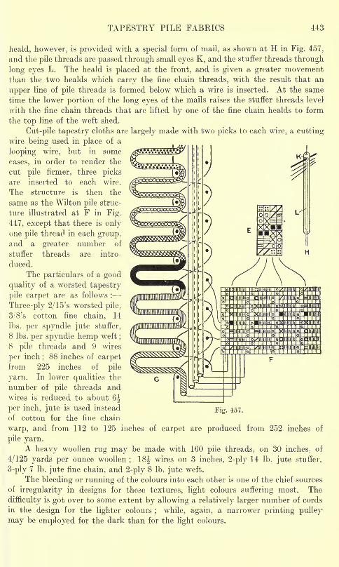
TAPESTRY PILE FABRICS 443
heald, however, is provided with a special form of mail, as shown at H in Fig. 457,
and the pile threads are passed through small eyes K, and the staffer threads through
long eyes L. The heald is placed at the front, and is given a greater movementthan the two healds which carry the fine chain threads, with the result that an
upper line of pile threads is formed below which a wire is inserted. At the same
time the lower portion of the long eyes of the mails raises the stuffer threads level
with the fine chain threads that are lifted by one of the fine chain healds to form
the top line of the weft shed.
Cut-pile tapestry cloths are largely made with two picks to each wire, a cuttingwire being used in place of a
looping wire, but in some
cases, in order to render the
cut pile firmer, three picksare inserted to each wire.
The structure is then the
same as the Wilton pile struc-
ture illustrated at F in Fig.
447, except that there is onlyone pile thread in each group,and a greater number of
stuffer threads are intro-
duced.
The particulars of a good
quality of a worsted tapestry
pile carpet are as follows :
Three-ply 2/15's worsted pile,
3/'8's cotton fine chain, 14
Ibs. per spyndle jute stuffer,
8 Ibs. per spyndle hemp weft;
8 pile threads and 9 wires
per inch;88 inches of carpet
from 225 inches of pile
yarn. In lower qualities the
number of pile threads and
wires is reduced to about 6J
per inch, jute is used instead
of cotton for the fine chain
warp, and from 112 to 125 inches of carpet are produced from 252 inches of
pile yarn.A heavy woollen rug may be made with 160 pile threads, on 30 inches . of
4/125 yards per ounce woollen;
18J wires on 3 inches, 2-ply 14 Ib. jute stuffer,
3-ply 7 Ib. jute fine chain, and 2-ply 8 Ib. jute weft.
The bleeding or running of the colours into each other is one of the chief sources
of irregularity in designs for these textures, light colours suffering most. The
difficulty is got over to some extent by allowing a relatively larger number of cords
in the design for the lighter colours; while, again, a narrower printing pulley
may be employed for the dark than for the light colours.
Fig. 457.
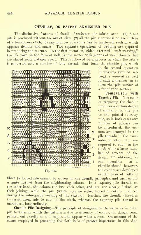
444 ADVANCED TEXTILE DESIGN
CHENILLE, OR PATENT AXMINSTER PILE
The distinctive features of chenille Axminster pile fabrics are : (1) A cut
pile is produced without the aid of wires, (2) all the pile material is on the surface
of a foundation cloth, (3) any number of colours can be employed, each of which
appears definite and smart. Two separate operations of weaving are requiredin producing the texture. In the first operation, which is termed
"weft weaving,"
the pile yarn, in the form of weft, is interwoven with groups of warp threads that
are placed some distance apait. This is followed by a process in which the fabric
is converted into a number of long threads that form the chenille pile, which
in the second operationof weaving (termed set-
ting) is inserted as weft
in such a manner as to
form the pile surface of
a foundation texture.
Comparison with
Tapestry Pile. The modeof preparing the chenille
produces a certain degreeof similarity in the pile
to the printed tapestry
pile, as in both cases anynumber of colours can
be introduced, the col-
ours are arranged in the
pile threads in the exact
7 order in which they are
required to show in the
cloth, while a large num-
o ber of repeats of the
design are obtained at
|one operation. In a
chenille thread, however,
9
m$$ i ' '
mm*wmmmwm i SSS
Fig. 458. the colours are developedin the form of tufts of
fibres (a looped pile cannot be woven on the chenille principle), and each colour
is quite distinct from the neighbouring colours. In a tapestry pile thread, on
the other hand, the colours run into each other, and are not clearly defined at
their joinings, while the pile (which may be either looped or cut) is produced
during the subsequent weaving of the texture. Further, the chenille thread is
traversed from side to side of the cloth, whereas the tapestry pile thread is
introduced longitudinally.
Chenille Pile Designing. The principle of designing is the same as in other
pile textures in which the pattern is due to diversity of colour, the design being
painted out exactly as it is required to appear when woven. On account of the
means employed in producing the cloth it is of greater importance in this than
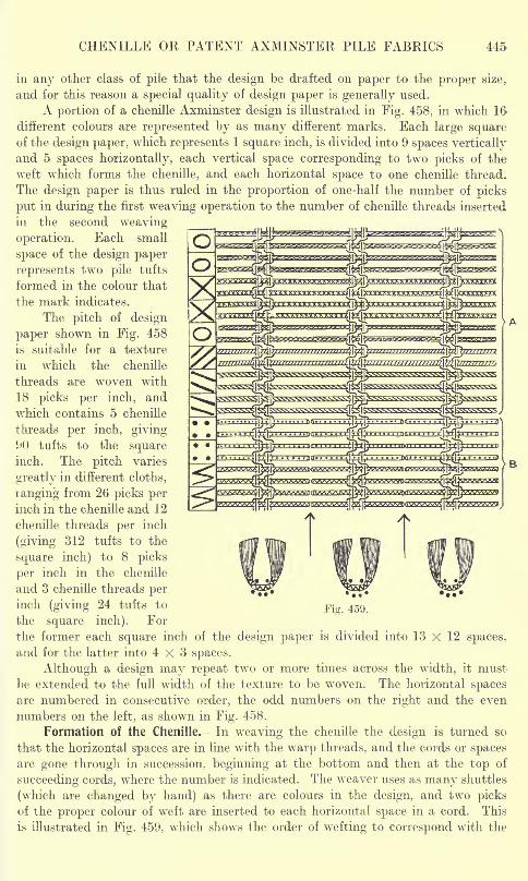
CHENILLE OR PATENT AXMINSTER PILE FABRICS 445
in any other class of pile that the design be drafted on paper to the proper size,
and for this reason a special quality of design paper is generally used.
A portion of a chenille Axminster design is illustrated in Fig. 458, in which 16
different colours are represented by as many different marks. Each large squareof the design paper, which represents 1 square inch, is divided into 9 spaces vertically
and 5 spaces horizontally, each vertical space corresponding to two picks of the
weft which forms the chenille, and each horizontal space to one chenille thread.
The design paper is thus ruled in the proportion of one-half the number of picks
put in during the first weaving operation to the number of chenille threads inserted
in the second weaving
operation. Each small
space of the design paper
represents two pile tufts
formed in the colour that
the mark indicates.
The pitch of design
paper shown in Fig. 458
is suitable for a texture
in which the chenille
threads are woven with
18 picks per inch, and
which contains 5 chenille
threads per inch, giving90 tufts to the squareinch. The pitch varies
greatly in different cloths,
ranging from 26 picks perinch in the chenille and 12
chenille threads per inch
(giving 312 tufts to the
square inch) to 8 picks
per inch in the chenille
and 3 chenille threads perinch (giving 24 tufts to
the square inch). For
the former each square inch of the design paper is divided into 13 X 12 spaces,
and for the latter into 4x3 spaces.
Although a design may repeat two or more times across the width, it must
be extended to the full width of the texture to be woven. The horizontal spacesare numbered in consecutive order, the odd numbers on the right and the even
numbers on the left, as shown in Fig. 458.
Formation of the Chenille. In weaving the chenille the design is turned so
that the horizontal spaces are in line with the warp threads, and the cords or spacesare gone through in succession, beginning at the bottom and then at the top of
succeeding cords, where the number is indicated. The weaver uses as many shuttles
(which are changed by hand) as there are colours in the design, and two picksof the proper colour of weft are inserted to each horizontal space in a cord. This
is illustrated in Fig. 459, which shows the order of wefting to correspond with the
446 ADVANCED TEXTILE DESIGN
bracketed portion of the first horizontal space of Fig. 458, an enlarged plan of which
is given on the left of Fig. 459. The different colours are inserted in the order
indicated in the design until the given longitudinal cord is completed, then a
small space may be left without weft in order that in the setting the chenille thread
will more readily turn at the sides of the cloth. Afterwards, the next longitudinalcord is gone through in the same manner, but in the opposite direction, and the
process is continued until every cord in the repeat has been gone over.
The total length of chenille thread required to produce a design is equal to
the length of a cord (originally a horizontal space) multiplied by the number of
cords. Assuming that in the repeat of a design there are 120 chenille threads which
are different from each other, and that 216 double weft picks are inserted in weavingeach chenille thread the width of the cloth, there will be 120 x 216 X 2 = 51,840
picks inserted in producing the chenille for the full design. However, a large
number of chenille threads may be woven alongside each other at the same time,
so that one operation of chenille weaving enables very many repeats of the designto be obtained. Moreover, in the case of wheel designs and designs which are
centred horizontally, it is only necessary to weave one-half of the chenille threads
in the repeat in order to produce the full pattern.For convenience in selecting the shuttles in the \veft weaving each colour
in the design may be indicated by a number, and the shuttles containing the corre-
sponding colours be numbered to coincide. Two methods are employed by which
the weaver is enabled to compare the distances woven in the different colours
with the spaces occupied by the respective colours in the design. In a recent systemthe design is suspended vertically, and is made to travel up and down at the rate
that the fabric is drawn forward in the loom, while from the position of a pointer,
which can be slid laterally from one vertical space to the next as each is completed,it can be seen when the proper number of picks of each colour have been inserted.
In an older system, which is still largely used, the design is cut into strips, each
two cords wide, and each strip is in turn attached to the cloth, passed througha wide space in the reed, and lightly weighted at the other end. The strip is drawnforward with the fabric, and as each colour in a cord reaches the edge the shuttle,
with the corresponding colour, is inserted. After the first cord is completed the
strip is turned round and the second space is similarly gone through.The chenille is woven in a plain loom which is fitted with a gauze mounting.
The warp threads are arranged one end crossing two standard ends, and two groupsof threads are reeded into consecutive splits of the reed with a space between them
and the next two groups. Frequently, an ordinary form of reed is used, a number
of splits being left empty between the groups of warp threads, but in some cases
the reed contains splits only where the groups of threads are required to pass through.The space between the groups is varied according to the length of pile required,
the pitch ranging from about I inch for a short pile to 1 inch and over for a very
deep pile.
Fig. 459 shows how the threads interlace, as viewed from the side that is under-
neath during the weaving of the chenille. A texture is produced across which
the variously coloured picks of weft extend, being firmly bound in at intervals
by the gauze interlacing, as shown in the portion lettered A in Fig. 459. The next
process consists of cutting the picks in the centre of the space between the groupsof gauze threads, as represented at B. This is followed by a process in which the
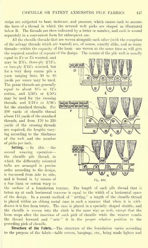
CHENILLE OR PATENT AXMINSTER PILE FABRICS 447
strips are subjected to heat, moisture, and pressure, which causes each to assume
the form of a thread in which the severed weft picks are shaped as illustrated
below B. The threads are then indicated by a letter or number, and each is wound
separately in a convenient form for subsequent use.
All the chenille threads that are woven alongside each other (with the exceptionof the selvage threads which are wasted) are, of course, exactly alike, and as manythreads within the capacity of the loom are woven at the same time as will givethe required number of repeats of the design. The counts of the pile weft is usually
equal to 2's or 3's worsted, and
may be 2/4's, three-ply 2/12's,
or two-ply 2/12's worsted, but
for a very deep coarse pile a
yarn ranging from 30 to 40
yards per ounce may be used.
The gauze threads are generally
equal to about 10's or 12's
cotton, and 3/30's or 4/50's
may be used for the crossing
threads, and 2/24's or 3/36's
for the standard threads. For
100 yards of chenille thread
about 115 yards of the standard
threads, and from 170 to 220
yards of the crossing threads
are required, the lengths vary-
ing according to the thickness
of the weft and the numberof picks per inch.
Setting. In this the
second weaving operationthe chenille pile thread, in
which the differently coloured
tufts are arranged in precise
order according to the design,
is traversed from side to side,
and is bound in by means of
a fine linen or cotton warp to
the surface of a foundation texture. The length of each pile thread that is
taken up at each horizontal traverse is equal to the width of a horizontal spaceof the design. In a recent method of
"setting," a length of the chenille thread
is placed within an oblong metal case in such a manner that when it is with-
drawn it is free from twists. The case is placed in a specially shaped shuttle, andthe chenille is woven into the cloth in the same way as weft, except that the
loom stops after the insertion of each pick of chenille while the weaver combsthe thread forward and
"sets
"it in the proper relative position to the
preceding pick of chenille.
Structure of the Fabric. The structure of the foundation varies accordingto the purpose of the fabric table covers, hangings, etc., being made lighter and
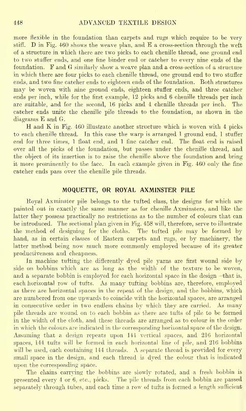
448 ADVANCED TEXTILE DESIGN
more flexible in the foundation than carpets and rugs which require to be verystiff. D in Fig. 460 shows the weave plan, and E a cross-section through the weft
of a structure in which there are two picks to each chenille thread, one ground end
to two stuffer ends, and one fine binder end or catcher to every nine ends of the
foundation. F and G similarly show a weave plan and a cross-section of a structure
in which there are four picks to each chenille thread, one ground end to two stuffer
ends, and two fine catcher ends to eighteen ends of the foundation. Both structures
may be woven with nine ground ends, eighteen stuffer ends, and three catcher
ends per inch, while for the first example, 12 picks and 6 chenille threads per inch
are suitable, and for the second, 16 picks and 4 chenille threads per inch. The
catcher ends unite the chenille pile threads to the foundation, as shown in the
diagrams E and G.
H and K in Fig. 460 illustrate another structure which is woven with 4 picksto each chenille thread. In this case the warp is arranged 1 ground end, 1 stuffer
end for three times, 1 float end, and 1 fine catcher end. The float end is raised
over all the picks of the foundation, but passes under the chenille thread, and
the object of its insertion is to raise the chenille above the foundation and bringit more prominently to the face. In each example given in Fig. 460 only the fine
catcher ends pass over the chenille pile threads.
MOQUETTE, OR ROYAL AXMINSTER PILE
Eoyal Axminster pile belongs to the tufted class, the designs for which are
painted out in exactly the same manner as for chenille Axminsters, and like the
latter they possess practically no restrictions as to the number of colours that can
be introduced. The sectional plan given in Fig. 458 will, therefore, serve to illustrate
the method of designing for the cloths. The tufted pile may be formed byhand, as in certain classes of Eastern carpets and rugs, or by machinery, the
latter method being now much more commonly employed because of its greater
productiveness and cheapness.In machine tufting the differently dyed pile yarns are first wound side by
side on bobbins which are as long as the width of the texture to be woven,and a separate bobbin is employed for each horizontal space in the design that is,
each horizontal row of tufts. As many tufting bobbins are, therefore, employedas there are horizontal spaces in the repeat of the design, and the bobbins, which
are numbered from one upwards to coincide with the horizontal spaces, are arrangedin consecutive order in two endless chains by which they are carried. As manypile threads are wound on to each bobbin as there are tufts of pile to be formed
in the width of the cloth, and these threads are arranged as to colour in the order
in which the colours are indicated in the corresponding horizontal space of the design.
Assuming that a design repeats upon 144 vertical spaces, and 216 horizontal
spaces, 144 tufts will be formed in each horizontal line of pile, and 216 bobbins
will be used, each containing 144 threads. A separate thread is provided for everysmall space in the design, and each thread is dyed the colour that is indicated
upon the corresponding space.
The chains carrying the bobbins are slowly rotated, and a fresh bobbin is
presented every 4 or 6, etc., picks. The pile threads from each bobbin are passed
separately through tubes, and each time a row of tufts is formed a length sufficient
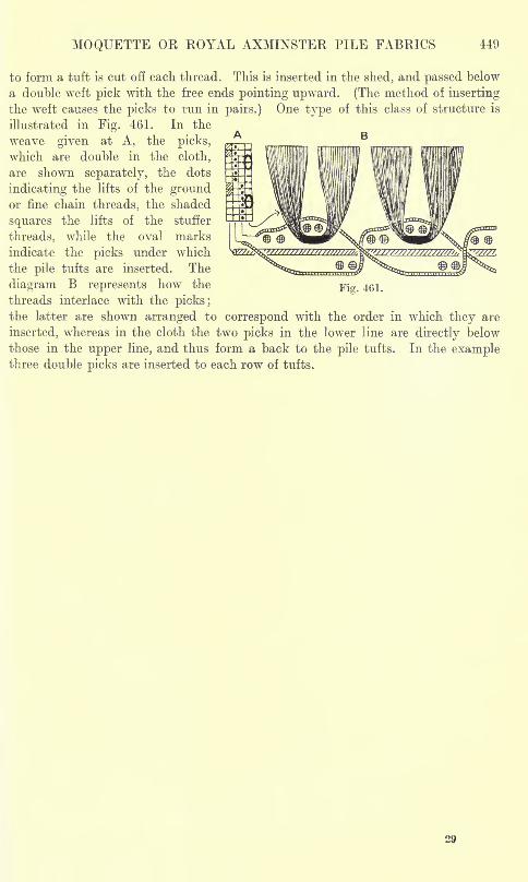
MOQUETTE OR KOYAL AXMINSTER PILE FABRICS 449
to form a tuft is cut off each thread. This is inserted in the shed, and passed below
a double weft pick with the free ends pointing upward. (The method of inserting
the weft causes the picks to run in pairs.) One type of this class of structure is
illustrated in Fig. 461. In the
weave given at A, the picks,
which are double in the cloth,
are shown separately, the dots
indicating the lifts of the groundor fine chain threads, the shaded
squares the lifts of the stuffer
threads, while the oval marks
indicate the picks under which
the pile tufts are inserted. The
diagram B represents how the
threads interlace with the picks;the latter are shown arranged to correspond with the order in which they are
inserted, whereas in the cloth the two picks in the lower line are directly below
those in the upper line, and thus form a back to the pile tufts. In the examplethree double picks are inserted to each row of tufts.
Fig. 461.

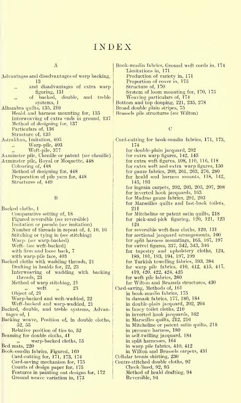
INDEX
Advantages and disadvantages of warp backing,13
,, and disadvantages of extra warpfiguring, 131
of backed, double, and treble
systems, 1
Alhambra quilts, 135, 219Heald and harness mounting for, 135
Interweaving of extra ends in ground. 137Method of designing for, 137
Particulars of, 136
Structure of, 135
Astrakhan, Imitation, 405
Warp-pile, 403
Weft-pile, 377Axminster pile, Chenille or patent (see chenille)Axminster pile, Royal or Moquette, 448
Colouring of, 448Method of designing for, 448
Preparation of pile yarn for, 448Structures of, 449
Backed cloths, 1
Comparative setting of, 18
Figured reversible (see reversible)Imitation or pseudo (see imitation)Number of threads in repeat of, 4, 10, 16
Stitching or tying in (see stitching)
Warp- (see warp-backed)Weft- (see weft-backed)with firm and loose back, 7
with warp-pile face, 403Backed cloths with wadding threads, 21
Drafting in healds for, 22, 23
Interweaving of wadding with backingthreads, 23
Method of warp stitching, 21
weft 23
Object of, 21
Warp-backed and weft-wadded, 22Weft-backed and warp-wadded, 21
Backed, double, and treble systems, Advan-
tages of, 1
Backing weave, Position of, in double cloths,
52, 55Relative position of ties to, 52
Beaming for double cloths, 41
,, warp-backed cloths, 15Bed mats, 220Book-muslin fabrics, Figured, 169
Card-cutting for, 171, 173, 174
Card-saving mechanism for, 175Counts of design paper for, 175Features in painting out designs for, 172Ground weave variation in, 173
Book-muslin fabrics, Ground weft cords in, 174
Limitations in, 171
Production of variety in, 171
Proportion of cover in, 175
Structure of, 170
System of loom mounting for, 170, 175
Weaving particulars of, 174Bottom and top douping, 221, 235, 278Broad double plain stripes, 75Brussels pile structures (see Wilton)
Card-cutting for book-muslin fabrics, 171, 173,
174for double-plain jacquard, 202for extra warp figures, 142. 145
for extra weft figures, 108, 110, 116, 118
for extra weft and extra warp figures, 150
for gauze fabrics, 260, 261, 263, 276, 280for heald and harness mounts, 118, 142,
145, 193for ingrain carpets, 202, 203, 205, 207, 208for inverted hook jacquards, 163
for Madras gauze fabrics, 291, 293
for Marseilles quilts and fast-back toilets,
211for Mitcheline or patent satin quilts, 218
for pick-and-pick figuring, 120, 121, 123
124for reversible weft-face cloths, 129, 131
for sectional jacquard arrangements, 160
for split harness mountings, 165, 167, 197
for swivel figures, 337, 342, 343, 346
for tapestry and upholstery cloths, 124,
189, 191, 193, 194, 197, 199
for Turkish towelling fabrics, 393, 394for warp pile fabrics, 410, 412, 415, 417,
419, 420, 422, 424, 425for weft pile fabrics, 380for Wilton and Brussels structures, 430
Card-saving, Methods of, 161
in book-muslin fabrics, 175
in damask fabrics, 177, 180, 184
in double-plain jacquard, 202, 204
in fancy toilet cloths, 210in inverted hook jacquards, 162
in Marseilles quilts, 212, 216
in Mitcheline or patent satin quilts, 218
in pressure harness, 180in self-twilling jacquard, 184
in split harnesses, 164in warp pile fabrics, 410, 412in Wilton and Brussels carpets, 431
Cellular tennis shirting, 230Centre-stitched double cloths, 92
Check-lined, 92, 95Method of heald drafting, 94
Reversible, 94
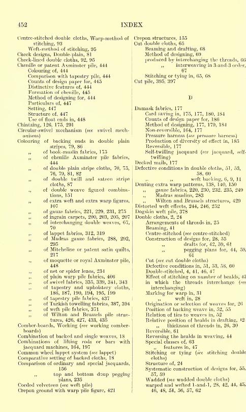
452 INDEX
Centre-stitched double cloths, Warp-method of
stitching, 93Weft-method of stitching, 95
Check designs, Double-plain, 81Check-lined double cloths, 92, 95Chenille or patent Axminster pile, 444
Colouring of, 444
Comparison with tapestry pile, 444Counts of design paper for, 445Distinctive features of, 444Formation of chenille, 445Method of designing for, 444Particulars of, 447
Setting, 447Structure of, 447Use of float ends in, 448
Chintzing, 126.. 175, 291
Circular-swivel mechanism (see swivel mech-
anisms)
Colouring of backing ends in double plain
stripes, 79, 86of book-muslin fabrics, 175
,, of chenille Axminster pile fabrics,
444of double plain stripe cloths, 70, 75,
76, 79, 81, 82
,, of double twill and sateen stripe
cloths, 87
., of double weave figured combina-
tions, 151
,, of extra weft and extra warp figures,107
of gauze fabrics, 221, 229, 231, 275of ingrain carpets, 200, 203, 205, 207
,. of interchanging double weaves, 67,70
of lappet fabrics, 312, 319of Madras gauze fabrics, 288, 292,
295
,, of Mitcheline or patent satin quilts,217
,, of moquette or royal Axminster pile,448
,, of net or spider lenos, 234
,, of plain warp pile fabrics, 406of swivel fabrics, 335, 339, 341, 343of tapestry and upholstery cloths,
186, 187, 190, 194, 195, 199
,, of tapestry pile fabrics, 437of Turkish towelling fabrics, 387, 394
,, of weft pile fabrics, 371
,, of Wilton and Brussels pile struc-
tures, 426, 427, 433, 435
Comber-boards, Working (see working comber-
boards)Combination of backed and single weaves, 18
Combinations of lifting rods or bars with
jacquard machines, 164, 197Common wheel lappet system (see lappet)
Comparative setting of backed cloths, 18
Comparison of ordinary and special jacquards,156
top and bottom doup peggingplans, 235
Corded velveteen (see weft pile)
Crepon ground with warp pile figure, 421
Crepon structures, 155Cut double cloths, 65
Beaming and drafting, 68Method of designing, 69
produced by interchanging the threads, 66
,, interweaving in 3-and-3 order,67
Stitching or tying in, 65, 68Cut pile, 395 ; 397
I)
Damask fabrics, 177
Card saving in, 175, 177, 180, 184Counts of design paper for, 186Method of designing, 177, 179, 184
Non-reversible, 164, 177Pressure harness (see pressure harness)Production of diversity of effect in, 185
Reversible, 177
Self-twilling jacquard (see jacquard, self-
twilling)Decked mails, 177Defective conditions in double cloths, 51, 53,
58, 60
,. ,, weft backing, 6, 9, 11
Denting extra warp patterns, 138, 140, 150
gauze fabrics, 220, 230, 232, 235, 249
,, Madras muslins, 283
,, Wilton and Brussels structures, 429Distorted weft effects, 244, 246, 252
Dogskin weft pile, 378Double cloths, 2, 24
Arrangements of threads in, 25
Beaming, 41Centre-stitched (see centre-stitched)Construction of designs for, 28, 55
drafts for, 42, 59, 61
,, pegging plans for, 44, 59,
61
Cut (see cut double cloths)Defective conditions in, 51, 53, 58, 60
Double-stitched, 4, 41, 46, 47Effect of stitching on number of healds, 45
in which the threads interchange (see
interchanging)
Marking for warp in, 31'
weft in, 28
Origination or selection of weaves for, 26
Position of backing weave in, 52, 55Relation of ties to weaves in, 52Relative position of healds in drafting, *2
thickness of threads in, 26, 30
Reversible, 61
Reversing the healds in weaving, 44
Special classes of, 63features in, 47
Stitching or tying (see stitching double
cloths)Structure of, 24
Systematic construction of designs for, 55,
57, 59Wadded (see wadded double cloths)
warped and wefted 1-and-l, 28, 42, 44, 45,
46, 48, 51, 56, 57, 62
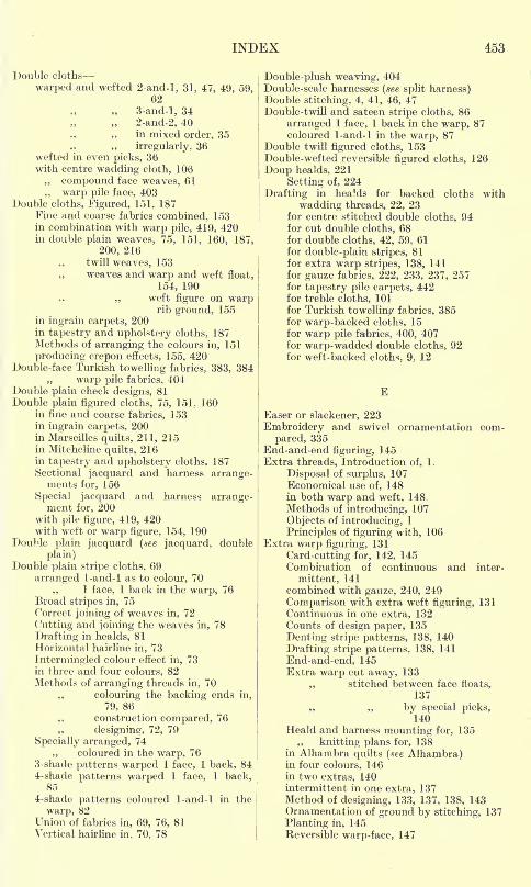
INDEX 453
Double cloths
warped and wefted 2-and-l, 31, 47, 49, 59,62
3-and-l, 34
2-and-2, 40
,, ,, in mixed order, 35,. irregularly, 36
wefted in even picks, 36with centre wadding cloth, 106
,, compound face weaves, 61
,, warp pile face, 403Double cloths, Figured, 151, 187
Fine and coarse fabrics combined, 153in combination with warp pile, 419, 420in double plain weaves, 75, 151, 160. 187,
200, 216twill weaves, 153
,, weaves and warp and weft float,
154, 190
,, weft figure on warprib ground, 155
in ingrain carpets, 200in tapestry and upholstery cloths, 187Methods of arranging the colours in, 151
producing crepon effects, 155, 420Double-face Turkish towelling fabrics, 383, 384
warp pile fabrics, 404Double plain check designs, 81
Double plain figured cloths, 75, 151, 160in fine and coarse fabrics, 153in ingrain carpets, 200in Marseilles quilts, 211, 215in Mitcheline quilts, 216in tapestry and upholstery cloths, 187Sectional jacquard and harness arrange-ments for, 156
Special jacquard and harness arrange-ment for, 200
with pile figure, 419, 420with weft or warp figure, 154, 190
Double plain jacquard (we jacquard, double
plain)Double plain stripe cloths, 69
arranged 1-and-l as to colour, 70
,, 1 face, 1 back in the warp, 76Broad stripes in, 75Correct joining of weaves in, 72
Cutting and joining the weaves in, 78
Drafting in healds, 81
Horizontal hairline in, 73
Intermingled colour effect in, 73in three and four colours, 82Methods of arranging threads in, 70
,, colouring the backing ends in,
79, 86
,, construction compared, 76
,, designing, 72, 79
Specially arranged, 74
,, coloured in the warp, 763-shade patterns warped 1 face, 1 back, 844-shade patterns warped 1 face, 1 back,
854-shade patterns coloured 1-and-l in the
warp, 82Union of fabrics in, 69, 76, 81
Vertical hairline in, 70, 78
Double-plush weaving, 404Double-scale harnesses (see split harness)Double stitching, 4, 41, 46, 47Double-twill and sateen stripe cloths, 86
arranged 1 face, 1 back in the warp, 87coloured 1-and-l in the warp, 87
Double twill figured cloths, 153Double-wefted reversible figured cloths, 126
Doup healds, 221
Setting of, 224
Drafting in healds for backed cloths with
wadding threads, 22, 23for centre stitched double cloths, 94for cut double cloths, 68for double cloths, 42, 59, 61
for double-plain stripes, 81
for extra warp stripes, 138, 141for gauze fabrics, 222, 233, 237, 257for tapestry pile carpets, 442for treble cloths, 101for Turkish towelling fabrics, 385for warp-backed cloths, 15
for warp pile fabrics, 400, 407for warp-wadded double cloths, 92for weft-backed cloths, 9, 12
E
Easer or slackener, 223
Embroidery and swivel ornamentation com-
pared, 335End-and-end figuring, 145Extra threads, Introduction of, 1.
Disposal of surplus, 107Economical use of, ] 48in both warp and weft, 148.
Methods of introducing, 107
Objects of introducing, 1
Principles of figuring with, 106Extra warp figuring, 131
Card-cutting for, 142, 145Combination of continuous and inter-
mittent, 141
combined with gauze, 240, 249
Comparison with extra weft figuring, 131Continuous in one extra, 132Counts of design paper, 135
Denting stripe patterns, 138, 140
Drafting stripe patterns, 138, 141
End-and-end, 145Extra warp cut away, 133
,, stitched between face floats,
137
by special picks,140
Heald and harness mounting for, 135
,, knitting plans for, 138in Alhambra quilts (see Alhambra)in four colours, 146in two extras, 140intermittent in one extra, 137Method of designing, 133, 137, 138, 143Ornamentation of ground by stitching, 137
Planting in, 145Reversible warp-face, 147
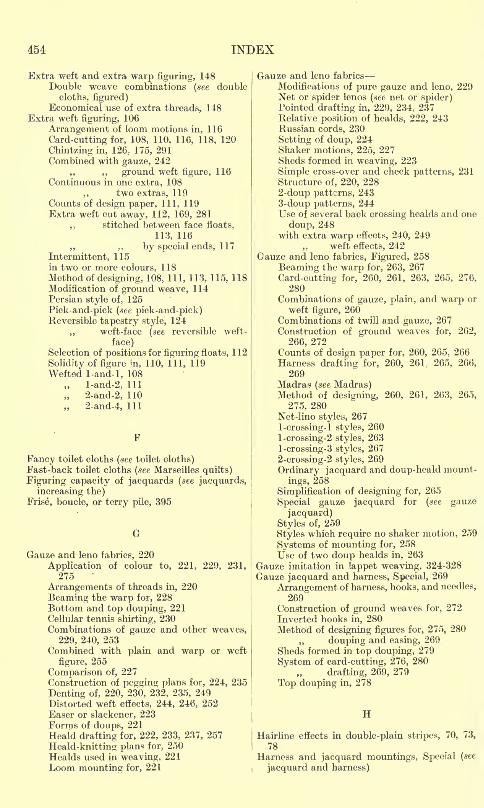
454 INDEX
Extra weft and extra warp figuring, 148Double weave combinations (see double
cloths, figured)Economical use of extra threads, 148
Extra weft figuring, 106
Arrangement of loom motions in, 116
Card-cutting for, 108, 110, 116, 118, 120
Chintzing in, 126; 175, 291Combined with gauze, 242
,, ,, ground weft figure, 116Continuous in one extra, 108
., two extras, 119Counts of design paper, 111, 119Extra weft cut away, 112, 169, 281
,, stitched between face floats,
113, 116
,, ,, by special ends, 117
Intermittent, 115in two or more colours, 118Method of designing, 108, 111, 113, 115. 118Modification of ground weave, 114Persian style of, 125
Pick-and-pick (see pick-and-pick)Reversible tapestry style, 124
,, weft-face (see reversible weft-
face)Selection of positions for figuring floats, 112
Solidity of figure in, 110, 111, 119Wefted 1-and-l, 108
l-and-2, 111
2-and-2, 110
2-and-4, 111
Fancy toilet cloths (see toilet cloths)Fast-back toilet cloths (see Marseilles quilts)
Figuring capacity of jacquards (see jacquards,
increasing the)Frise, boucle, or terry pile, 395
G
Gauze and leno fabrics, 220
Application of colour to, 221, 229, 231,275
Arrangements of threads in, 220
Beaming the warp for, 228Bottom and top douping, 221Cellular tennis shirting, 230Combinations of gauze and other weaves,
229, 240, 253Combined with plain and warp or weft
figure, 255
Comparison of, 227Construction of pegging plans for, 224, 235
Denting of, 220, 230, 232, 235, 249Distorted weft effects, 244, 246, 252
Baser or slackener, 223Forms of doups, 221
Heald drafting for, 222, 233, 237, 257
Heald-knitting plan* for. 250Healds used in weaving. 221
Loom mounting for, 221
Gauze and leno fabrics
Modifications of pure gauze and leno, 229Net or spider lenos (see net or spider)Pointed drafting in, 229, 234, 237Relative position of hcalds, 222, 243Russian cords, 230
Setting of doup, 224Shaker motions, 225, 227Sheds formed in weaving, 223
Simple cross-over and check patterns, 231
Structure of, 220, 228
2-doup patterns, 2433-doup patterns, 244Use of several back crossing healds and one
doup, 248with extra warp effects, 240, 249
,, weft effects, 242Gauze and leno fabrics, Figured, 258
Beaming the warp for, 263, 267
Card-cutting for, 260, 261, 263, 265, 276,280
Combinations of gauze, plain, and warp or
weft figure, 260Combinations of twill and gauze, 267
Construction of ground weaves for, 262,
266, 272Counts of design paper for, 260, 265, 266Harness drafting for, 260, 261- 265, 266,
269Madras (see Madras)Method of designing, 260, 261, 263, 265,
275, 280Net-lino styles, 2671 -crossing- 1 styles, 260
l-crossing-2 styles, 263
l-crossing-3 styles, 267
2-crossing-2 styles, 269
Ordinary jacquard and doup-heald mount-
ings, 258
Simplification of designing for, 265
Special gauze jacquard for (see gauze
jacquard)
Styles of, 259
Styles which require no shaker motion, 259
Systems of mounting for, 258
Use of two doup healds in, 263
Gauze imitation in lappet weaving, 324-328
Gauze jacquard and harness, Special, 269
Arrangement of harness, hooks, and needles,
269Construction of ground weaves for, 272
Inverted hooks in, 280Method of designing figures for, 275, 280
douping and easing, 269
Sheds formed in top douping, 279
System of card-cutting, 276, 280
drafting, 269, 279
Top douping in, 278
H
Hairline effects in double-plain stripes, 70, 73,
78Harness and jacquard mountings, Special (see
jacquard and harness)
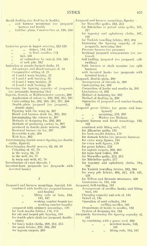
INDEX 455
Heald drafting (see drafting in healds)
,, and harness mountings (.see jacquardharness and heald)
knitting plans, Construction of, 138, 250
Imitation gauze in lappet weaving, 324-328
stripes, 143, 144"
,, ,, in book muslins, 173
lace, 331
,, of embroidery by swivel, 338, 349of weft pile, 382
Imitation or pseudo-backed cloths, 18
Advantages and disadvantages of 18
Comparative setting of, 21
of 1-and-l warp backing, 21
of 1-and-l weft backing, 18
of 2-and-l warp backing, 21
of 2-and-l weft backing, 20
Increasing the figuring capacity of jacquards(see jacquards, increasing the)
Ingrain, Scotch, or Kidderminster carpets, 200
Application of colour to, 200, 203, 205, 207
Card-cutting for, 202, 203, 205, 207, 208
Double-plain jacquard (see jacquard,double plain)
Figuring with the warp in, 207Heald and harness draft for, 203, 205
Intermingling the colours in, 207Methods of designing for, 202, 203Methods of producing variety in, 207
produced in double-plain weaves, 200Sectional harness tie for, 207Reversible 4-ply, 204Weft -face, 203
Interchanging double-weave figuring (.see double
cloths, figured)
Interchanging double weaves, 63, 66, 69
Colouring of, 67, 70in the warp, 64, 73in the weft, 65, 71
in warp and weft, 67, 70Introduction of extra threads, 1
Inverted-hook jacquards (see jacquards withinverted hooks)
Jacquard and harness mountings, Special, 156combined with healds (see jacquard harness
and healds),, lifting rods or bars, 164,
181, 197
,, working comber-boards (see
working comber-boards)compared with ordinary mountings, 156for book-muslin fabrics, 170, 175for cut and looped pile figuring, 410for double-plain cloth (see jacquard, double-
plain)for fancy toilet cloths, 209, 212, 215for gauze fabrics, 259, 269, 283for ingrain carpets, 200
Jacquard and harness mountings, Specialfor Marseilles quilts, 212, 215for Mitcheline or patent satin quilts, 167,
217for tapestry and upholstery cloths, 197,
199for Turkish towelling fabrics, 392, 394
Increasing the figuring capacity of (see
jacquards, increasing the)Pressure harness (see pressure)Sectional jacquard arrangements (see sec-
tional)
Self-twilling jacquard (see jacquard, self-
twilling)
Split harness or shaft monture (see split
harness)with inverted hooks (see jacquards with
inverted hooks)
Jacquard, Double-plain, 200
Arrangement of threads in, 200
Card-cutting for, 202Connection of hooks and needles in, 201Limitations of, 202Method of designing for, 202Method of drafting in, 200
Operation of jacquard and comber-boards,202
Jacquard gauze fabrics (see gauze and leno-
figured)
mounting, 258, 269
,, Madras (see Madras)Jacquard harness and heald mountings, 135,
163combined with lifting rods, 197for Alhambra quilts, 135for book-muslin fabrics, 170for damask fabrics (see pressure harness)for extra warp figures, 135for extra weft figures, 118for gauze fabrics, 258for ingrain carpets, 203, 205for loose-back toilets. 209for Marseilles quilts, 212, 215for Mitcheline quilts, 217for tapestry and upholstery cloths, 194,
196for Turkish towelling fabrics, 392, 394for warp pile fabrics, 409, 411, 418, 421,
428for Wilton and Brussels structures, 428Limitations in, 135, 164
Jacquard, Self-twilling, 181
Arrangement of needles, hooks, and lifting
bars, 181
Changing capacity and sett of, 184Defect of, 184
Operation of card cylinder, 184
twilling needles, 183
Proportions of hooks to needles, 183
System of designing for, 184
Jacquards, Increasing the figuring capacity of,
161
by combining with a gauze reed, 282
,, inverted hooks, 143,161
lifting rods, 164, 197
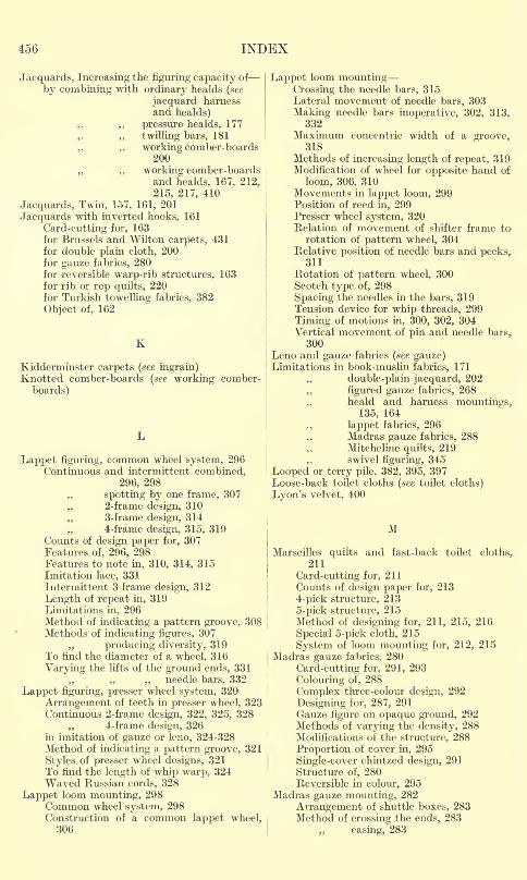
456 INDEX
Jacquards, Increasing the figuring capacity of
by combining with ordinary healds (see
jacquard harnessand healds)
pressure healds, 177
,. ,, twilling bars, 181
,. ,, working comber-boards200
,, working comber-boardsand healds, 167, 212,
215, 217, 410
Jacquards, Twin, 157, 161, 201
Jacquards with inverted hooks, 161
Card-cutting for, 163for Brussels and Wilton carpets, 431for double plain cloth, 200for gauze fabrics, 280for reversible warp-rib structures, 163for rib or rep quilts, 220for Turkish towelling fabrics, 382
Object of, 162
K
Kidderminster carpets (see ingrain)Knotted comber-boards (see working comber-
boards)
Lappet figuring, common wheel system, 296Continuous and intermittent combined,
296, 298
spotting by one frame, 307
,, 2-frame design, 310
,, 3-frame design, 3144-frame design, 315, 319
Counts of design paper for, 307Features of, 296, 298Features to note in, 310, 314, 315Imitation lace, 331Intermittent 3-frame design, 312
Length of repeat in, 319Limitations in, 296Method of indicating a pattern groove, 308Methods of indicating figures, 307
,, producing diversity, 319To find the diameter of a wheel, 316
Varying the lifts of the ground ends, 331needle bars, 332
Lappet figuring, presser wheel system, 320
Arrangement of teeth in presser wheel, 323Continuous 2-frame design, 322, 325, 328
,, 4-frame design, 326in imitation of gauze or leno, 324-328Method of indicating a pattern groove, 321
Styles of presser wheel designs, 321To find the length of whip warp, 324Waved Russian cords, 328
Lappet loom mounting, 298Common wheel system, 298Construction of a common lappet wheel,306
Lappet loom mounting-Crossing the needle bars, 315Lateral movement of needle bars, 303
Making needle bars inoperative, 302, 313,332
Maximum concentric width of a groove,318
Methods of increasing length of repeat, 319Modification of wheel for opposite hand of
loom, 306, 310Movements in lappet loom, 299Position of reed in, 299Presser wheel system, 320Relation of movement of shifter frame to
rotation of pattern wheel, 304Relative position of needle bars and pecks,
311Rotation of pattern wheel, 300Scotch type of, 298
Spacing the needles in the bars, 319Tension device for whip threads, 299
Timing of motions in, 300, 302, 304Vertical movement of pin and needle bars,
300Leno and gauze fabrics (see gauze)Limitations in book-muslin fabrics, 171
,, double-plain jacquard, 202
figured gauze fabrics, 268
,, heald and harness mountings,135, 164
lappet fabrics, 296
,, Madras gauze fabrics, 288Mitcheline quilts, 219
,, swivel figuring, 345
Looped or terry pile, 382, 395, 397Loose-back toilet cloths (see toilet cloths)
Lyon's velvet, 400
M
Marseilles quilts and fast-back toilet cloths,211
Card-cutting for, 211
Counts of design paper for, 213
4-pick structure, 213
5-pick structure, 215Method of designing for, 211, 215, 216
Special 5-pick cloth, 215
System of loom mounting for, 212, 215Madras gauze fabrics, 280
Card-cutting for, 291. 293
Colouring of, 288
Complex three-colour design, 292
Designing for, 287, 291
Gauze figure on opaque ground, 292Methods of varying the density, 288Modifications of the structure, 288
Proportion of cover in, 295
Single-cover chintzed design, 291
Structure of, 280Reversible in colour, 295
Madras gauze mounting, 282
Arrangement of shuttle boxes, 283Method of crossing the ends, 283
easing, 283
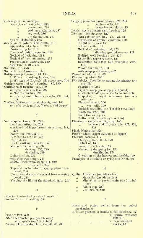
INDEX 457
Madras gauze mountingOperation of easing bar, 286
gauze reed, 284
,, picking mechanism, 287
tug reed, 286
,, uptake motion, 287
System of drafting, 283Mitcheline or patent satin quilts, 216
Application of colour to, 217
Card-cutting for, 218Counts of design paper for, 219Method of designing, 218Method of loom mounting, 217Production of variety in, 219Structure of, 217, 219
Moleskin, 372, 376
Moquette (see Axminster pile)
Multiple warp figuring, 146, 198in Turkish towelling fabrics, 394in Wilton and Brussels pile structures, 394
Multiple warp and weft figuring, 187, 190
Multiple weft figuring, 125, 130in ingrain carpets, 205, 207in Madras muslins, 292in tapestry and upholstery cloths, 191, 194,
195
Muslins, Methods of producing figured, 169
(see also book- muslin, Madras, and lappet)
X
Net or spider lenos, 233, 266Bead mounting for, 238combined with perforated structures, 244,
246
Fancy one-doup, 251Features to note in, 236
Figured, 267Heald knitting plans for, 250Method of colouring, 234
denting, 235, 249
,, designing, 236
Point-drafted, 234
requiring two doups, 243
spotted with extra warp, 241, 249extra weft, 242
Top and bottom-doup pegging plans com-
pared, 235Use of one doup and several back-crossing
healds, 248
Varying the lifts of the standard ends, 237
Objects of introducing extra threads, 1
Osman Turkish towelling, 384
Panne velvet, 399Patent Axminster pile (see chenille)
satin quilts (see Mitcheline)
Pegging plans for double cloths, 44, 59, 61
Pegging plans for gauze fabrics, 224, 225treble cloths, 101
,, warp-backed cloths, 15Persian style of extra weft figuring, 125
Pick-and-pick figuring, 120
Card-cutting for, 120, 121, 123, 124Formation of ground weave in, 120in split harnesses, 167in three wefts, 123Method of designing, 120, 123
indicating ground weaves, 121
Multiple weft Persian style, 125Reversible tapestry style, 124Reversible weft-face (see reversible weft-
face)Weave shading in, 123with warp pile figuring, 422
Piece-dyed cloths, 11, 63Pile cutting wires, 396Pile fabrics, Chenille or patent Axminster (see
chenille)Features of, 362
Figured warp (see warp pile figured)in which the design is due to colour, 426
Moquette, or royal Axminster (see Ax-
minster)Plain velveteen, 366
warp pile, 399Turkish towelling (see Turkish towelling)
Warp (see warp pile)Weft (see weft pile)Wilton and Brussels (see Wilton)
Planting in extra warp figuring, 145Wilton and Brussels pile, 427, 433,
434Plush fabrics (see pile)Presser wheel lappet system (see lappet)Pressure harness, 177
Changing the sett of, 179Defect of, 180Form of the healds, 178Method of designing for, 179
,, drafting in, 179
Operation of the harness and healds, 179
Principles of stitching or tying (see stitching)
Q
Quilts, Alhambra (see Alhambra),, Marseilles (see Marseilles)
,, Mitcheline or patent satin (see Mitchel-
ine)Rib or rep, 220Varieties of, 219
R
Rack and pinion swivel loom (see swivel
mechanisms)Relative position of healds in double cloths, 42
., ,, in gauze weaving,222, 243
,, in warp-backedcloths, 15
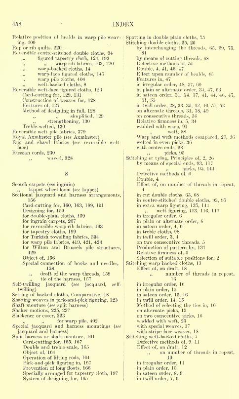
458 INDEX
Relative position of healds in warp pile weav-
ing, 400
Rep or rib quilts, 220Reversible centre-stitched double cloths, 94
figured tapestry cloth, 124, 193
warp-rib fabrics, 163, 220
warp-backed cloths, 14
warp-face figured cloths, 147
warp pile cloths, 404weft-backed cloths, 8
Reversible weft-face figured cloths, 1 26
Card-cutting for, 129, 131Construction of weaves for, 128Features of, 127Method of designing in full, 128
simplified, 129
strengthening, 130Treble-wefted, 130
Reversible weft pile fabrics, 379
Royal Axminster pile (see Axmiiister)
Rug and shawl fabrics (see reversible weft-
face)Russian cords, 230
waved, 328
Scotch carpets (see ingrain)
lappet wheel loom (see lappet)Sectional jacquard and harness arrangements,
156
Card-cutting for, 160, 163, 189, 191
Designing for, 159for double-plain cloths, 159for ingrain carpets, 207for reversible warp-rib fabrics, 163for tapestry cloths, 199for Turkish towelling fabrics, 394for warp pile fabrics, 419, 421, 423for Wilton and Brussels pile structures,
429
Object of, 156
Special connection of hooks and needles,158
draft of the warp threads, 159
,, tie of the harness, 157Self-twilling jacquard (see jacquard, self-
twilling)
Setting of backed cloths, Comparative, 18
Shading weaves in pick-and-pick figuring, 123Shaft monture (see split harness)Shaker motions, 225, 227Slackener or easer, 223
,, ,, for warp pile, 402
Special jacquard and harness mountings (see
jacquard and harness)
Split harness or shaft monture, 164
Card-cutting for, 165, 167
Double and treble-scale, 165
Object of, 164
Operation of lifting rods, 164
Pick-and-pick figuring in, 167
Prevention of long floats, 166
Specially arranged for tapestry cloth, 197
System of designing for, 165
Spotting in double plain cloths, 75
Stitching double cloths, 25, 26
by interchanging the threads. 65, 69, 75,81
by means of cutting threads. 68Defective methods of, 51
Double, 4, 41, 46, 47Effect upon number of healds, 45Features in, 47in irregular order, 48, 57, 60in plain or alternate order, 34, 47, 63in sateen order, 31, 34, 37, 41, 44, 46, 47,
51, 55in twill order, 28, 33, 35, 42, 46, 51, 52on alternate threads, 31, 38, 49on consecutive threads, 36Relative firmness in, 5, 34wadded with warp, 91
weft, 88
Warp and weft methods compared, 27, 36wefted in even picks, 36with centre ends, 93
,, picks, 95
Stitching or tying, Principles of, 2, 26
by means of special ends, 93, 117
,. picks, 95, 144Defective methods of, 6
Double, 4Effect of, on number of threads in repeat,
4
in cut double cloths, 65, 68in centre-stitched double cloths, 93, 95in extra warp figuring, 137, 144
weft figuring, 113, 116, 117
in irregular order, 6
in plain or alternate order, 6
in sateen order, 4, 6
in treble cloths, 98in twill order, 3, 4on two consecutive threads, 5Production of pattern by, 137Relative firmness of, 5
Selection of suitable positions for, 2
Stitching warp-backed cloths, 13
Effect of, on draft, 18
,, number of threads in repeat,16
in irregular order, 16in plain order, 15
in sateen order, 15, 16
in twill order, 14, 15
Method of selecting the ties in, 16
on alternate picks, 15
on two consecutive picks, 16
wadded with weft, 23with special weaves, 17
with stripe face weaves, 18
Stitching weft-backed cloths, 7
Defective methods of, 9;11
Effect of, on draft, 12
,, on number of threads in repeat,10
in irregular order, 11
in plain order, 10in sateen order, 8, 9in twill order, 7, 9
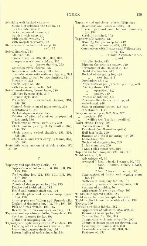
INDEX 459
Stitching weft-backed cloths-Method of selecting the ties in, 11
on alternate ends, 9
on two consecutive ends, 9
wadded with warp, 21
with special weaves, 12
with warp-face weaves, 10
Stripe weaves backed with warp, 18
weft, 12
Swivel figuring, 334
All-over, 345
Card-cutting for, 337, 342, 343, 340
Comparison with embroidery, 335
,, ,, lappet figuring, 335Detached swivel figures, 337Imitation of embroidery, 338, 349in combination with ordinary figurine;, 343in one kind of weft by two shuttles, 344
Purpose of, 334
Special style of, 339with two or more wefts, 341
Swivel mechanisms, Power loom, 349All-over figuring style, 349Circular style, 358Formation of intermediate figures, 337,
358, 360General description of movements, 336Limitations of, 345
Rack-and-pinion style, 355Relation of pitch of shuttles to repeat of
jacquard, 336
Tensioning of swivel weft, 351, 362which govern picking of fly shuttle, 353,
354, 356which operate swivel shuttles^ 351, 354,
358, 360which raise and lower carrying frame, 351,
354, 356
Systematic construction of double cloths, 55,
57, 59
Tapestry and upholstery cloths, 186
Application of colour to, 186, 187, 190, 194,
195, 199
Card-cutting for, 124, 189, 191, 193, 194,
197, 199Classes of, 186Counts of design paper for, 194, 195Double and treble-plain, 187Heald and harness draft for, 194in double plain and weft or warp figure,
154, 190in warp pile (see Wilton and Brussels pile)Method of designing for, 193, 194, 195, 199
Pick-and-pick wefted, 120, 167
Reversible, in pick-and-pick wefting, 124
Tapestry and upholstery cloths, Warp-face, 198Sectional harness tie for, 199Method of designing for, 199
Tapestry and upholstery cloths, Weft-face, 191
Figuring with the harness threads in, 193Heald and harness draft for, 194
Intermingling of weft colours in, 194
Tapestry and upholstery cloths, Weft -face
Reversible and non-reversible, 193
Special jacquard and harness mountingfor, 196
Specially stitched, 195
Tapestry pile carpets, 437
Beaming the pile warp for, 442
Bleeding of colours in, 438, 443
Comparison with Brussels and Wilton struc-
tures, 437
,, ,, chenille Axminster struc-
ture, 444Cut pile cloths, 443
Dipping the printing pulley, 440Formation of double shed in, 443Heald drafting for, 442Method of designing for, 438
weaving, 443Particulars of, 443
Preparation of pile yarn for printing, 438
Printing drum, 438
operation, 440
pulley, 440Process of rubbing, 441Processes that follow printing, 441
Scale-board, 440Sizes of printing drums, 438, 439Structure of, 442
Terry or looped pile, 382, 395, 397
motions, 385
,, towelling (see Turkish towelling)Toilet cloths, Fancy, 208
Classification of, 209Fast-back (see Marseilles quilts)Half-fast back, 210Harness and heald mounting for, 209
Loose-back, 209Method of designing for, 209
2-pick structure, 2093 and 4-pick structures, 210
Top and bottom doupin<r, 221, 235, 278Treble cloths, 2, 96
Advantages of, 96
arranged 1 face, 1 back, 1 centre; 96, 101
,. 1 face, 1 centre, 1 face, 1 back,104
., 2 face, 2 back to 1 centre, 105Construction of drafts and pegging plans
for, 101
Methods of designing for, 99, 101
Stitched by means of backing ends, 106
Systems of stitching, 98with centre fabric as wadding, 106
Treble -plain figured cloths, 187
Treble-scale hainess (see split harness)Treble-wefted figured reversible cloths, 130
Trevete, 396Turkish towelling fabrics, 382
Application of colour to, 387, 389, 391
Beaming the warps for, 387
Card-cutting for, 393, 394
Comparison with true warp pile, 395Counts of design paper for figured, 393
Designing for figured, 392, 393Double-face weaves, 383, 384, 391Features of, 382
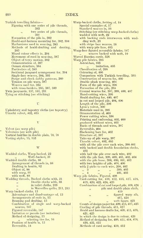
460 INDEX
Turkish towelling fabrics
Figuring with one series of pile threads,393
two series of pile threads,391
Formation of the pile in, 382Heald-and-harness mounting for, 392, 394Mechanisms used in weaving, 385Methods of heald-drafting and denting,
385Mixed colour effects in, 394Movement of reed in weaving, 387
Object of terry motion, 382Ornamentation of, 387Osman structure, 384Particulars of, 385Sectional jacquard arrangement for, 394
Single-face weaves, 384, 393
Stripe and check dobby patterns, 389Tension on pile warp, 387Weaves used for. 384with cross-borders, 385, 387, 389
Twin jacquards, 157, 161, 201
Tying or stitching (see stitching)
U
Upholstery and tapestry cloths (see tapestry)Utrecht velvet, 402, 405
Velvet (see warp pile)
Velveteen (see weft pile)
Vertical hairline in double plain, 70, 78
Vesting styles, 75, 153
WWadded cloths, Warp-backed, 22
Weft-backed, 21
Wadded double cloths, 88
Arrangement of threads in, 88
Drafting in healds, 92
Object of, 88with warp, 91with weft, 88
Wadding threads, Backed cloths with, 21
Double cloths with, 88in toilet cloths, 209in Marseilles quilts, 211, 215
Warp-backed cloths, 13
Advantages and disadvantages of, 13
Arrangements of ends in, 13
Beaming and drafting, 15
Combination of single and warp-backedweaves, 147
Figured reversible, 147Imitation or pseudo (see imitation)Method of designing, 13
selecting ties for, 16Position of healds in, 15
Reversible, 14
Warp-backed cloths, Setting of, 18
Special examples of, 17
Standard weaves in, 16
Stitching (see stitching warp-backed cloths)wadded with weft, 22with backing ends interwoven with wad-
ding weft, 23.
with stripe face weaves, 18with warp pile face, 403
Warp-face figured reversible fabrics, 147weaves backed with weft, 10
Waved Russian cords, 328
Warp pile fabrics, 395
Astrakhan, 403
,, imitation, 405Classification of, 398
Colouring of, 406
Comparison with Turkish towelling, 395Construction of weaves for. 400
Double-plush weaving, 404Form of the pile wires, 396Formation of the pile, 395Ground weaves for, 397, 399, 400, 407
Hand-cutting wires, 396
Heald-drafting for, 400, 407in cut and looped pile, 404, 406
Length of the pile, 396
Lyon's velvet, 400Materials used in, 395Ornamentation of, 405Power cutting wires, 396
Printing and embossing, 405, 406
produced without wires, 405Ratio of threads and wires, 397
Reversible, 404
Slackening bars for, 402Structure of, 397
Take-up of pile warp, 397Utrecht velvet, 402, 405with all the pile over each wire, 398-401
with backed and double foundation cloths,
403with half the pile over each wire, 402with the pile fast, 399, 400, 401, 402, 404with the pile loose, 398, 400, 401, 403with two heights of pile, 404, 406with 2 picks to each wire, 398, 402
3 399, 4034 401, 403
Warp pile fabrics, Figured, 408
Card-cutting for, 410, 412, 415, 417, 418,
419, 420, 422, 424, 425Combination of cut and looped pile, 408, 424
pile and double plain cloth,
419
,, ,, figured warp rib,
417, 424
,, weft figure, 423
Counts of design paper for, 409, 415, 417, 425
Creeling of pile threads, 411, 427Heald and harness drafts for, 409, 411, 418,
421, 425in which the design is due to colour, 426Method of designing for, 409, 411, 414, 418,
420, 422, 425Methods of card saving, 410, 412
INDEX 461
Warp pile fabrics, Figuredon ordinary weave ground, 410on double-plain silk crepon ground, 420Reflection of light from cut and looped
surfaces, 408Sectional jacquard arrangements for, 419,
421, 423
Tapestry pile carpets (see tapestry pile)
Variation of ground structure in, 412
Wilton and Brussels pile structures (see i
Wilton)with pile threads bound in on back, 415
extra, 411
,, ,, interweaving in ground,J
415, 417
Working comber-boards for, 410, 429
Warp pile fabrics, Stripe and check, 406, 407
Weft-backed cloths, 7
Arrangements of picks in, 7
Defective conditions in, 6, 9, 11
Figured reversible (see reversible weft-
face)Heald drafting for, 9, 12
Imitation or pseudo (see imitation)Method of designing, 7
selecting the ties for, 11
Piece-dyed coatings. 11
Reversible, 8
Setting of, 18
Special examples of, 12
Stitching (see stitching weft-backed cloths)with standard twill and hopsack weaves, 9
with stripe face weaves, 12
with wadding ends, 21
with warp-face weaves, 10
Weft-face figured reversible fabrics (see revers-
ible weft-face)Weft pile fabrics, 362
Astrakhan, 377
Changing the density of the pile, 369
Colouring of, 371Corded velveteen, 373
cutting, 374, 376
,, ,, from plain velveteen
weaves, 375
Cutting by hand, 365, 374, 376
machinery, 375
Density of the pile :)368
developed in different colours, 378
Dogskin, 378Fastness of the pile, 371Form of cutting knife, 364Formation of courses or races in. 367
pile in, 363
., rounded cords in, 374, 375Imitation of, 382
Length of the pile, 368Modification of ground weave, 377
Moleskin, 372, 376Number of tufts per square inch, 361)
Weft pile fabrics, Particulars of, 376Plain velveteen, 366
Preparation of the cloth for cutting, 365Processes of finishing and dyeing, 365
Purpose of alternate binding of ends, 367
Reversible. 379
Tabby or plain-back.. 366
Twill-back, 371, 374Weaves which simplify the cutting opera-
tion, 372Weft plushes, 377with coloured check foundation, 371
with 2-and-2 twill foundation, 372, 374Weft pile fabrics. Figured, 379
Card-cutting for, 380Counts of design paper for, 380
Disposal of surplus weft in, 379
Figured cords, 381
,, velveteens, 379Methods of drafting designs, 380, 381
Styles of design suitable for, 379, 381
Wilton and Brussels pile structures, 426
Card-cutting for, 430
Carpet and upholstery cloths compared,426, 427
Comparison of, 426
Comparison with tapestry pile, 437
Counts of design paper for, 432
Creeling of pile threads, 427Dead threads in. 435
Development of colours in cut and looped
pile, 436
Distinguishing features of, 426
Formation of double-shed, 432Heald-and-harncss mounting for, 429
Inverted hooks in jacquard, 431
Length of pile threads in. 427
Method of designing for, 428, 433
Moresque effects in, 435Order of denting for, 429
shedding for, 432Particulars of, 432, 433, 434, 435, 437
Planting, 427, 433, 434Sectional jacquard arrangement for, 429
Sizes of machines used, 430Structure of Brussels pile, 432
Wilton pile, 431
System of loom mounting for, 4283-frame Wilton cloth, 4344-frame Brussels cloth, 4325-frame Wilton cloth, 4286-frame mounting, 431
Working comber- boards, 167
for Brussels and Wilton pile fabrics. 429for looped and cut pile figuring, 410for Marseilles quilts, 212, 215for Mitcheline or patent satin quilts, 217in conjunction with healds, 212, 215, 217,
410, 429in double plain jacquard, 200
BELL AND BAIN, LIMITKD, PRINTERS, MITCHELL STREET, GLASGOW


UNIVERSITY OF CALIFORNIA LIBRARY
This book is DUE on the last date stamped below.
OCT29 1947
MAR 12
HB231956UI
MAY5- 1956 U
RtC'D LD
1 5 1957
f t ^
NJAY2 8 1958
REC'D LD ;
MAY
958 JO!'D L
H
OEC3U938
LD 21-100m-12,'46(A2012sl6)4120
IlApr'61RC
MAY
RECTO LD
APR 2 9 1961
196t
REC'D LD
CT 17 '63-7PM
504-
4-05721
THE UNIVERSITY OF CALIFORNIA LIBRARY