advanced numerical system simulations for navaids and
TRANSCRIPT
0/12
1/12
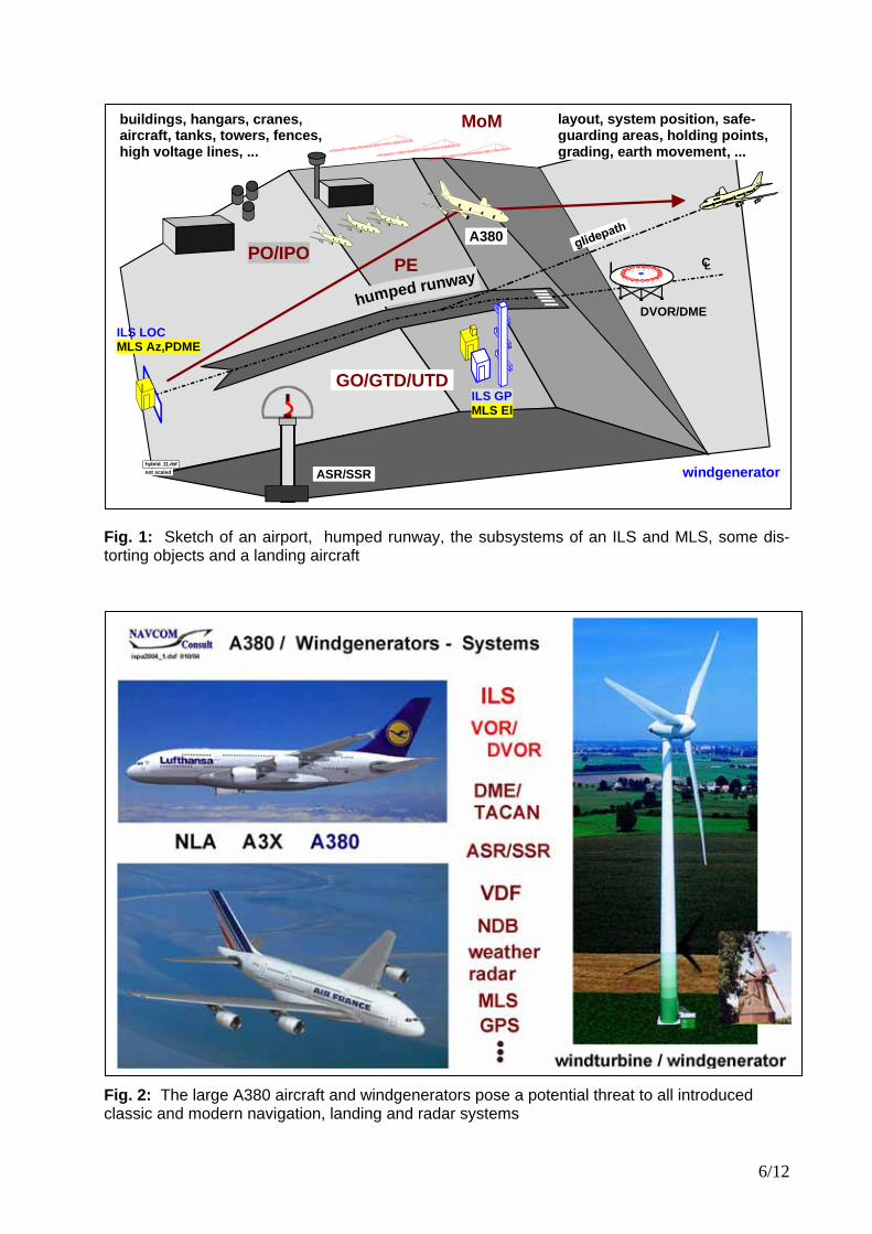
Modern Threats to Precision Approach and Landing - The A380 and Windgenerators and their Adequate Numerical Analysis Gerhard Greving NAVCOM Consult Ziegelstr. 43 D-71672 Marbach/Germany [email protected] http://www.navcom.de ABSTRACT Classical and modern navigation, landing and radar systems rely on the radio trans-mission and reception. Relevant objects in the radiation field can harm the intended characteristics of these systems. Modern state-of-the-art simulation can predict in an increasing number of complicated cases the electrical performance in the presence of these objects. Countermeasures can be de-signed from this knowledge. This paper deals with the "threat" (potentially un-acceptable distortions) on these systems by the forthcoming new large aircraft A380 and by the windgenerators which are con-structed in an increasing number sometimes close to the systems. The mathematical and numerical analyses are outlined and some results are presented. It is in particular em-phasized to apply three-dimensional and sophisticated state-of-the-art methods which are adapted to the three-dimensional char-acteristics of the objects in contrast to inade-quately simple methods. 3D-modeling examples for the A380 and windgenerators and some principle results are presented. INTRODUCTION Almost all classic and modern navigation landing and radar systems rely on radio transmission and reception. In a clean en-vironment these systems may work pretty well, but the real life is different. More and more complex distortion and interference problems for navaids, landing and radar systems are encountered today (Fig. 1). These so-called “problems” are caused by major objects around and in the vicinity of these systems, creating additional reflections and scattering signals (“multipath signals”) by the principally unavoidable illumination of
these objects by the systems themselves. These objects can be terminals, hangars, large buildings, windgenerators and power lines as well as the aircraft itself. A reliable prediction of the potential “threat”, i.e. the unacceptable effects on the systems in question is required in advance before the objects are built or before the objects appear. This task can be solved today by system simulations using state of the art numerical methods. Quite a number of publications have been released by the author in the past /2-12/ on the subject of numerical system simulations. This paper highlights two types of objects somewhat more fully, namely the A380 and the windgenerators (Fig. 2). This paper is not intended to present rules and definitions for dimensions of safeguarding areas or safety distances. MODELING AND SYSTEM SIMULATION The modeling and simulation process (Fig. 3 and 4) must accomplish the following basic tasks • Sufficiently realistic modeling of the object
having in mind that the subsequent simulation is treating the model and not the reality. The form, the shape and the materials of the object as well as the ex-citing field above ground have to be modeled sufficiently. The basic way of modeling depends also on the numerical method used in the next steps.
• Detailed modeling of the system in ques-tion which is generating the undistorted signal.
• Simulations of the reflection and scatter-ing process by the application of ade-quately state-of-the-art numerical me-thods. The most accurate method should be generally used; approximations may be used only if the results are sufficiently accurate.

2/12
• Evaluation of the decisive system pa-rameter which the aircraft uses for navi-gation or landing.
The two objects of this paper (Fig. 2; A380, windgenerator) are highly three-dimensional and therefore a two-dimensional approach and model is neither sufficient nor "state-of-the-art". It is obvious that a three-dimen-sional approach is not only necessary to apply, but also requires a lot more modeling and computation work. No trade-off is ac-ceptable between the accuracy and the effort to be invested due to the safety issue in-volved. A simple 2D-treatment which re-duces a 3D-A380-aircraft to one rectangular plate in the most extreme simplification, or several composed rectangular flat plates, can be up to many orders of magnitude faster, but can also yield wrong and unpre-dictable results /12/. Such kind of simple approaches cannot be cured by "some measurements" at a few points under some conditions. The simulation of the system must take into account all relevant details which affects the so-called "system-parameter" of that particu-lar system, i.e. the DDM (Difference of Depth of Modulation) for the ILS (Instrument Land-ing System) or the "bearing error" for the VOR/DVOR (Very high frequency Omnidi-rectional Range; Doppler-VOR). These de-tails comprise as an example (see for more details Fig. 3) • the correct geometrical and electrical set-
ting and numerical installation of the ac-tual system in the pre-processing section
• the signal processing, the filtering, the sampling, and the receiving antennas in the post-processing section.
Other field quantities (e.g. "field distortions") cannot describe in general sufficiently the system effects. "Field distortions" are neces-sary effects for system distortions, but are not a sufficient parameter to quantify the system distortions. The verification of the correctness and the reliability of the system results is a particular challenging task as discussed in /12/. A sin-gle or “some measurements” are not suffi-cient. Each result has to be verified in princi-ple. Fig. 4 shows the overall flow-chart of the applied IHSS (Integrated Hybrid System Simulation). The best suited numerical method is taken for the particular problem, i.e. the A380 and the windgenerators. In
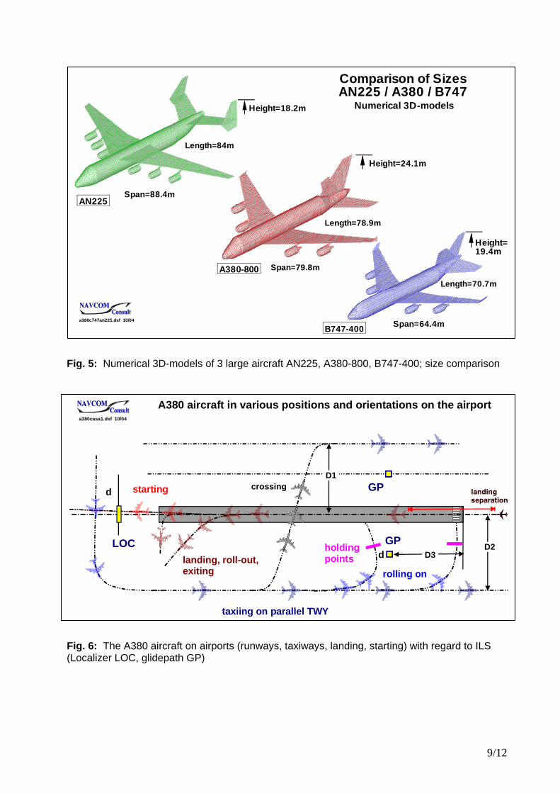
certain cases cross checks can be made for approval by comparing the results of the preferred approximative IPO-method (im-proved physical optics) with the results from the rigorous MoM- or ML-FMM-methods (method of moments, multi-level fast mul-tipole method). The latter family cannot be applied efficiently for large aircraft and windgenerators due to the "exploding" stor-age requirements and/or the excessive com-puter time for systematic simulations. Moreover, the ML-FMM has the general problem of a questionable convergence of the iterative solution of the integral equation. Cases have been experienced where the defined convergence criterion, e.g. 10-3, has not been achieved after 500 iterations for an aircraft. The GTD/UTD method is not the preferred numerical method for the discussed applica-tions and three-dimensional curved objects due to the general caustic problem and the generally unavoidable discontinuities of the solution, which results in problematic discon-tinuities in the DDM-results for ILS. For both cases (A380, windgenerator) the structure is subdivided into a large number of metallic triangles (Fig. 7 and 10) where the real exciting field is applied. Worst case principles may be applied as an example for the dielectric blades by assuming the metal material. Great care and knowhow has to be applied when carrying out these sophisticated meth-ods and interpreting the results in each case, because each of the methods can fail in certain situations /12/. Conclusions on the basis of incorrect results can yield a waste of money or can be the reason for hardly ac-ceptable, in fact unnecessary consequences, such as the closure of a taxiway for A380 taxiing /12/. PRACTICAL PROBLEMS The A380 on Airports and ILS The future A380 is currently the largest civil-ian aircraft (Fig. 5,7) which will appear in some years on the airports. Compared to the other large aircraft, this aircraft has a maxi-mum height of the tail-fin of 24.1m. Due to the horizontal polarization of the ILS-fields the higher parts of the aircraft may have stronger effects compared to the lower parts. However that does not mean that the tail-fin
3/12
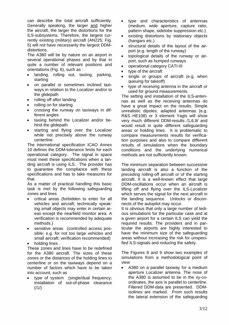
can describe the total aircraft sufficiently. Generally speaking, the larger and higher the aircraft, the larger the distortions for the ILS-subsystems. Therefore, the largest cur-rently existing (military) aircraft (AN225; Fig. 5) will not have necessarily the largest DDM-distortions. The A380 will be by nature on an airport in several operational phases and by that in quite a number of relevant positions and orientations (Fig. 6), such as : • landing, rolling out, taxiing, parking,
starting • on parallel or sometimes inclined taxi-
ways in relation to the Localizer and/or to the glidepath
• rolling off after landing • rolling on for starting • crossing the runway on taxiways in dif-
ferent angles • taxiing behind the Localizer and/or be-
hind the glidepath • starting and flying over the Localizer
while not precisely above the runway centerline
The international specification ICAO Annex 10 defines the DDM-tolerance limits for each operational category. The signal in space must meet these specifications when a lan-ding aircraft is using ILS. The provider has to guarantee the compliance with these specifications and has to take measures for that. As a matter of practical handling this basic task is met by the following safeguarding zones and lines • critical areas (forbidden to enter for all
vehicles and aircraft; technically speak-ing small objects may enter in certain ar-eas except the nearfield monitor area. A verification is recommended by adequate methods.)
• sensitive areas (controlled access pos-sible; e.g. for not too large vehicles and small aircraft; verification recommended)
• holding lines . These zones and lines have to be redefined for the A380 aircraft. The sizes of these zones or the distances of the holding lines to centerline or on the taxiways depend on a number of factors which have to be taken into account, such as • type of system (single/dual frequency;
installation of out-of-phase clearance (/1/)
• type and characteristics of antennas (medium, wide aperture, capture ratio, pattern shape, sidelobe suppression etc.)
• existing distortions by stationary objects (hangars etc.)
• structural details of the layout of the air-port (e.g. length of the runway)
• topological details of the runway or air-port, such as humped runways
• operational category CATI-III • type of the aircraft • single or groups of aircraft (e.g. when
queuing for takeoff) • type of receiving antenna in the aircraft or
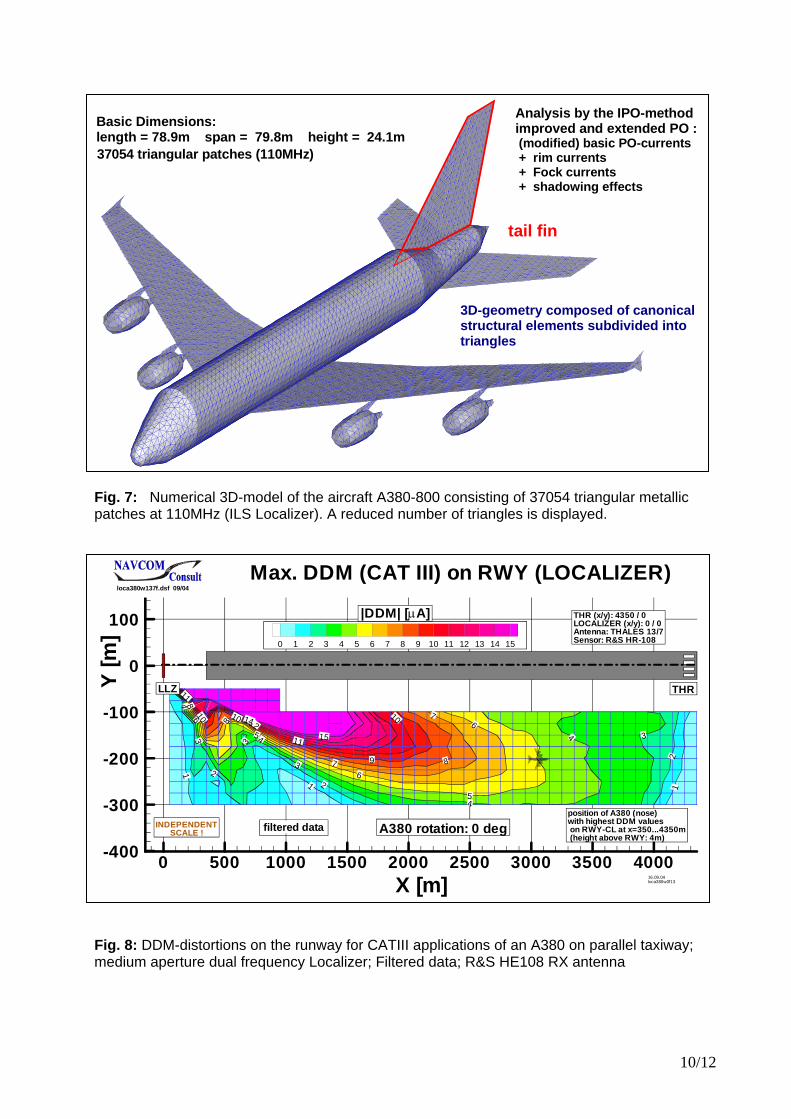
used for ground measurements. The setting and installation of the ILS-anten-nas as well as the receiving antennas do have a great impact on the results. Simple unrealistic dipoles, adapted antennas (e.g. R&S HE108) or 3 element Yagis will show very much different DDM-results /1,6,9/ and would result in quite different safeguarding areas or holding lines. It is problematic to compare measurements results for verifica-tion purposes and also to compare different results of simulations when the boundary conditions and the underlying numerical methods are not sufficiently known. The minimum separation between successive landing aircraft is also a function of the preceding rolling-off aircraft or of the starting aircraft. It is a well-known effect that large DDM-oscillations occur when an aircraft is lifting off and flying over the ILS-Localizer which serves the signal for the next aircraft in the landing sequence. Unlocks or discon-nects of the autopilot may occur. It is obvious that only a large number of tedi-ous simulations for the particular case and at a given airport for a certain ILS can yield the required results. The providers and in par-ticular the airports are highly interested to have the minimum size of the safeguarding areas without increasing the risk for unspeci-fied ILS-signals and reducing the safety. The Figures 8 and 9 show two examples of simulations from a methodological point of view • A380 on a parallel taxiway for a medium
aperture Localizer antenna. The nose of the A380 is assumed to be in the xy-co-ordinates, the axis is parallel to centerline. Filtered DDM-data are presented. DDM-isolines are marked. From such results the lateral extension of the safeguarding
4/12
areas can be defined taking into account the locus of the maximum DDM and the related maximum tolerance limits at this point. Holding points result from similar simula-tions where the aircraft is inclined ac-cording to the angle of the rollon taxi-ways. It is noted that the safeguarding areas ("critical, sensitive areas") cannot be de-fined on the basis of the maximum DDM-limits. Some margin for existing distor-tions, stationary objects and superposing aircraft has to be provided. Also, the DDM-distortions increase drastically when the aircraft is positioned in an in-clined orientation to the centerline. This is operationally the case when the air-craft is turning towards the runway on the rollon taxiway.
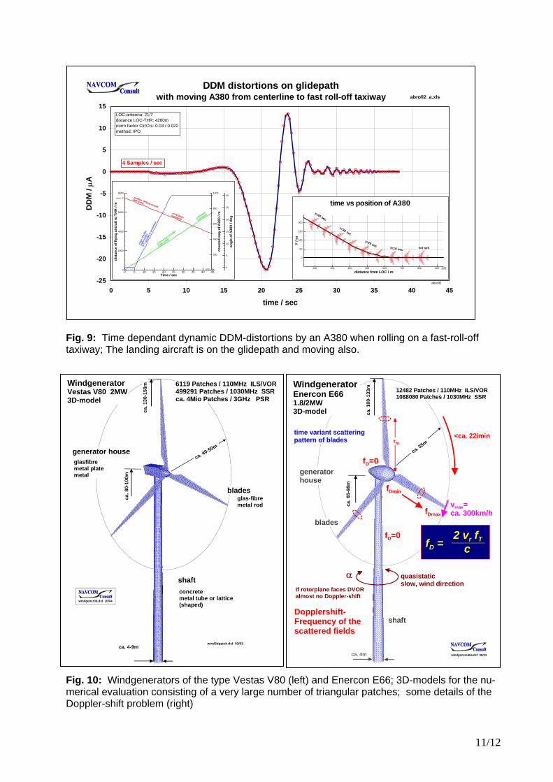
• A380 rolling off on a high speed taxiway. Time dependant DDM-data are pre-sented. From these results the longitudi-nal extension of the critical area can be defined.
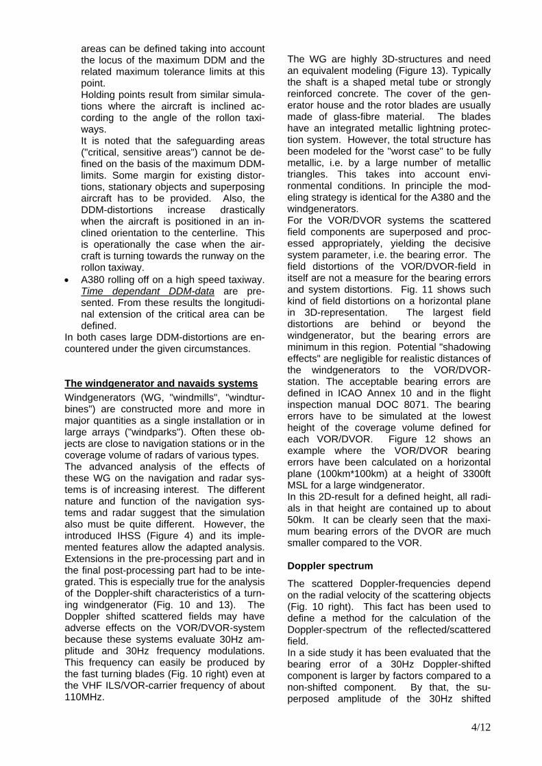
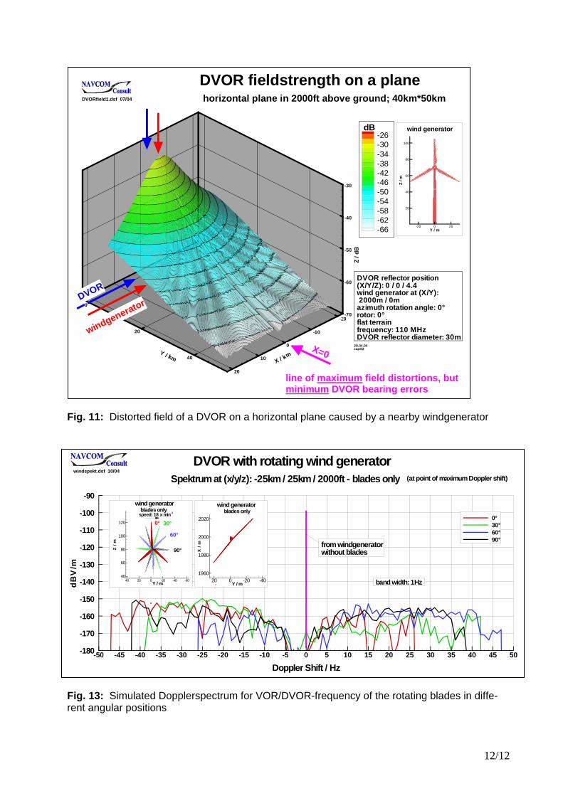
In both cases large DDM-distortions are en-countered under the given circumstances. The windgenerator and navaids systems Windgenerators (WG, "windmills", "windtur-bines") are constructed more and more in major quantities as a single installation or in large arrays ("windparks"). Often these ob-jects are close to navigation stations or in the coverage volume of radars of various types. The advanced analysis of the effects of these WG on the navigation and radar sys-tems is of increasing interest. The different nature and function of the navigation sys-tems and radar suggest that the simulation also must be quite different. However, the introduced IHSS (Figure 4) and its imple-mented features allow the adapted analysis. Extensions in the pre-processing part and in the final post-processing part had to be inte-grated. This is especially true for the analysis of the Doppler-shift characteristics of a turn-ing windgenerator (Fig. 10 and 13). The Doppler shifted scattered fields may have adverse effects on the VOR/DVOR-system because these systems evaluate 30Hz am-plitude and 30Hz frequency modulations. This frequency can easily be produced by the fast turning blades (Fig. 10 right) even at the VHF ILS/VOR-carrier frequency of about 110MHz.
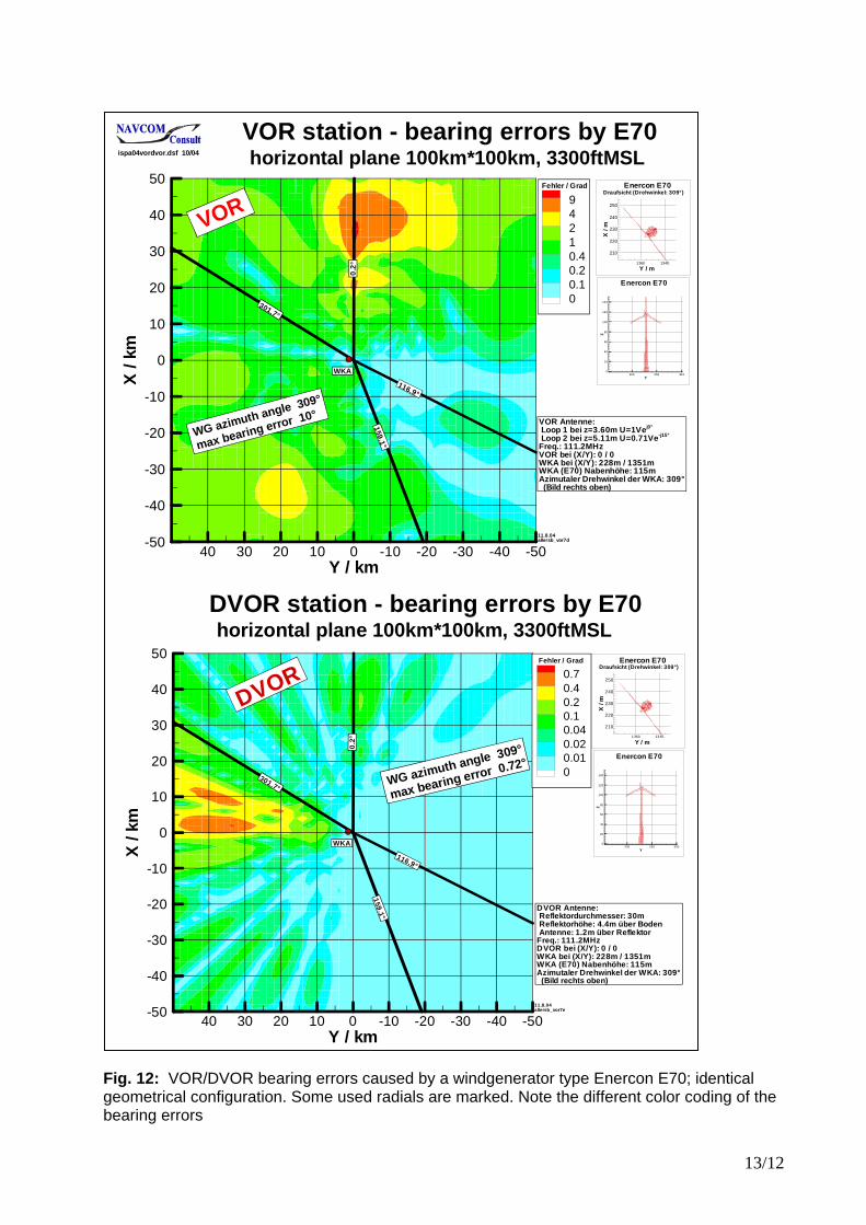
The WG are highly 3D-structures and need an equivalent modeling (Figure 13). Typically the shaft is a shaped metal tube or strongly reinforced concrete. The cover of the gen-erator house and the rotor blades are usually made of glass-fibre material. The blades have an integrated metallic lightning protec-tion system. However, the total structure has been modeled for the "worst case" to be fully metallic, i.e. by a large number of metallic triangles. This takes into account envi-ronmental conditions. In principle the mod-eling strategy is identical for the A380 and the windgenerators. For the VOR/DVOR systems the scattered field components are superposed and proc-essed appropriately, yielding the decisive system parameter, i.e. the bearing error. The field distortions of the VOR/DVOR-field in itself are not a measure for the bearing errors and system distortions. Fig. 11 shows such kind of field distortions on a horizontal plane in 3D-representation. The largest field distortions are behind or beyond the windgenerator, but the bearing errors are minimum in this region. Potential "shadowing effects" are negligible for realistic distances of the windgenerators to the VOR/DVOR-station. The acceptable bearing errors are defined in ICAO Annex 10 and in the flight inspection manual DOC 8071. The bearing errors have to be simulated at the lowest height of the coverage volume defined for each VOR/DVOR. Figure 12 shows an example where the VOR/DVOR bearing errors have been calculated on a horizontal plane (100km*100km) at a height of 3300ft MSL for a large windgenerator. In this 2D-result for a defined height, all radi-als in that height are contained up to about 50km. It can be clearly seen that the maxi-mum bearing errors of the DVOR are much smaller compared to the VOR. Doppler spectrum
The scattered Doppler-frequencies depend on the radial velocity of the scattering objects (Fig. 10 right). This fact has been used to define a method for the calculation of the Doppler-spectrum of the reflected/scattered field. In a side study it has been evaluated that the bearing error of a 30Hz Doppler-shifted component is larger by factors compared to a non-shifted component. By that, the su-perposed amplitude of the 30Hz shifted

5/12
component at some field point yields the potential bearing error. It can be easily understood that for the turn-ing blades, the Doppler spectrum must be symmetrical in principle around the un-shifted zero line caused by the stationary subparts of the windgenerator, i.e. the shaft and the machine house. Fig. 13 shows such an example of the Dop-pler amplitude spectrum of a windgenerator in some geometrical configuration. The spectrum is calculated and plotted for sev-eral angular positions of the blades. It can be seen and understood that the spectral amplitudes for a certain frequency are time periodic and time dependant. The ampli-tudes are small compared to the static zero-line. The results so far indicate that this Doppler-spectrum does not seem to be a problem for the VOR/DVOR . CONCLUSION Large objects close to navigation, landing and radar systems can distort the electrical characteristics of these systems. The new large aircraft A380 will appear relatively soon on the airports. An increasing number of windgenerators are constructed often close to these systems. The numerical 3D-treatment using "state-of-the-art-principles" of these objects has been outlined and contrasted to simplified 2D-approaches. A380 aircraft will be present in many differ-ent positions, in many orientations and op-erational phases on the airports. Safe-guarding areas ("critical and sensitive ar-eas", holding lines) have to be defined and installed to protect the ILS. The case of the "parallel taxiway" is a relatively simple case in terms of the amplitudes of the DDM-dis-tortions. Some principle results for the A380 have been presented, one for a parallel taxi-way and one for the dynamic rolloff case. As expected, these results and further results show that the ILS-distortions by the A380 are remarkably larger than for the B747. By systematic simulations for the individual situation on a given airport the adapted and minimized safeguarding areas can be de-termined. The numerical treatment of the windgenera-tor with respect to a VOR/DVOR navigation system has been outlined. Some principle results have been presented, showing the bearing errors for a large windgenerator on a
horizontal plane in some minimum coverage height. The Doppler spectrum of the windgenerator has been discussed with re-spect to the VOR/DVOR. A numerical result has been presented showing the time variant spectrum of small amplitudes for several blade positions. REFERENCES
Not all references are explicitly cited in this paper. The references are sequenced according to the time of appearance. /1/ GREVING G. ILS CATIII site problems - A new verified system solution, 7th Intern. flight inspection symposium, London 1992, p.224-236 /2/ GREVING G. Computer aided site analysis and site adapted installation - Efficient commissioning of landing systems, 8th IFIS International flight inspection symposium, Denver USA, June 1994 /3/ GREVING G. Numerical system-simulations in-cluding antennas and propagation exemplified for a radio navigation system, AEÜ, Inter, J. of Electronics and Communications, Vol. 54 (2000) No.3, pp. 183-189 /4/ GREVING G. Hybrid-Methods in Antennas and 3D-Scattering for Navaids and Radar System Simu-lations; Antenna and Propagation Conference AP2000, April 2000, Davos Switzerland /5/ GREVING G. Recent Advances and New Results of Numerical Simulations for Navaids and Landing Systems, 11th IFIS International Flight Inspection Conference, Santiago Chile, June 2000 /6/ G. GREVING, N. SPOHNHEIMER Problems and Solutions for ILS Category III Airborne and Ground Measurements - European and US Views and Per-spectives, 11th IFIS International Flight Inspection Symposium, Chile 2000, Proc. pp. 51-62 /7/ GREVING G. Application of Modern Numerical Methods for Navaids and Landing Systems - Theory and Results, ISPA 2000, International Symposium on Precision Approach and Landing, DGON, Munich, Proc. pp.49-61 /8/ GREVING G. Latest Advances and Results of Complex Numerical Simulations for Navaids and Landing Systems, 12th IFIS International Flight In-spection Symposium, Rome/Italy 2002, Proc. pp. 152-162 /9/ G. GREVING, N. SPOHNHEIMER Problems and Solutions for Navaids Airborne and Ground Measure-ments – Focus on receiver Sampling and TCH; 12th IFIS International Flight Inspection Symposium, Rome/Italy 2002, Proc. pp. 90-99 /10/ G. GREVING, H. WIPF Flight Inspection Aircraft in Multipath Environment; 12th IFIS International Flight Inspection Symposium, Rome/Italy 2002 Proc. pp. 198-207 /11/ GREVING G. Status and experiences of advan-ced threedimensional system simulations for navaids and radar, Aviation World Conference, Kiew/Ukraine, September 2003, pp. 5.1-5.5 /12/ GREVING G. Advanced Numerical System Simulations for Navaids and Surveillance Radar - The Verification Problem, 13th IFIS, June 2004, Mont-real/Canada, pp.173-186
6/12
Fig. 1: Sketch of an airport, humped runway, the subsystems of an ILS and MLS, some dis-torting objects and a landing aircraft
Fig. 2: The large A380 aircraft and windgenerators pose a potential threat to all introduced classic and modern navigation, landing and radar systems
CL
hybrid_11.dsf
PE
MoM
GO/GTD/UTD
buildings, hangars, cranes,aircraft, tanks, towers, fences, high voltage lines, ...
ILS LOCMLS Az,PDME
PO/IPO
ILS GPMLS El
humped runway
not scaled
layout, system position, safe-guarding areas, holding points,grading, earth movement, ...
DVOR/DME
ASR/SSR windgenerator
A380

7/12

8/12
Fig. 3: General process flow and aspects for the modeling and the numerical treatment of the A380 and the windgenerator
Fig. 4: Process flow of the IHSS (Integrated Hybrid System Simulation)
System results, System parameter
GO/GTD/UTD
System Post-processingFiltering, sampling, RX-antenna, ...
Multilayer, Greensnow,rain,glas, ...
PEhumped runways, ...
PO, IPO, EPOmedium objects, aircraft, windmills, ...
Hybrid combinations
large objects, ground, ...
Theoretical analysis - Selection processsystem related pre-processing, modeling, approximations
Details
ML-FMM MoM, wire/patchcranes, aircraft ...
inthybsim4c.dsf
Annex 10; DDM, bearing error, mod%, PFE,CMN ,range error, monopulse error, false target, ...
data basesA/C,cranes,materials,...
design,installationproposals, actions
The real life problem, System + Environment - in advanceairport, enroute; ILS-LOC/GP, VOR/DVOR, MLS, DME/TACAN, ASR,SSR, weather radar, comm ...
Superpositions
System pre-processingLanding Systems,Navaids, RadarModeling
Numerical MethodsAntennas,scattering objectsground effects,wave propagation
System post-processingSystem parameter
convergence?
"State-of-the-art" system analysis
reality model
"tool", math engine
best adapted for the model/realityleast approximationsmost advancedbest approved/verified highest accuracy promisingno compromise for speedlatest scientific results
3Dnumerical method
MoM, ML-FMM, GTD/UTD, PE, PO/IPO,...
IHSSIntegrated Hybrid System Simulation
ispa04sota.dsf 10/04
geometrical, electrical aspects3D, curved surfacesmaterialsfield excitation (amplitude, phases)finite distancesas realistic as possibleas realistic as needed
"reflections, scattering"
Sys
tem
9/12
Height=18.2m
Height=19.4m
Height=24.1m
Length=84m
Length=70.7m
Span=64.4m
Span=88.4m
Span=79.8m
Length=78.9m
Comparison of SizesAN225 / A380 / B747
Numerical 3D-models
A380-800
B747-400
AN225
a380c747an225.dsf 10/04
Fig. 5: Numerical 3D-models of 3 large aircraft AN225, A380-800, B747-400; size comparison
Fig. 6: The A380 aircraft on airports (runways, taxiways, landing, starting) with regard to ILS (Localizer LOC, glidepath GP)
GP
LOC
D1
d
d D2
D3 landing, roll-out,exiting
starting
taxiing on parallel TWY
rolling on
holdingpoints
crossing
A380 aircraft in various positions and orientations on the airport
GP
a380casa1.dsf 10/04
10/12
Fig. 7: Numerical 3D-model of the aircraft A380-800 consisting of 37054 triangular metallic patches at 110MHz (ILS Localizer). A reduced number of triangles is displayed.
Fig. 8: DDM-distortions on the runway for CATIII applications of an A380 on parallel taxiway; medium aperture dual frequency Localizer; Filtered data; R&S HE108 RX antenna
Basic Dimensions:length = 78.9m span = 79.8m height = 24.1m37054 triangular patches (110MHz)
Analysis by the IPO-method improved and extended PO : (modified) basic PO-currents + rim currents + Fock currents + shadowing effects
3D-geometry composed of canonical structural elements subdivided into triangles
tail fin
1
1 1
22
2
3
3 3
3
4
4 45
5
6
6
6
7
7
8
89
10 10 10
11
121314
15
4 8
11THR
position of A380 (nose)with highest DDM valueson RWY-CL at x=350...4350m(height above RWY: 4m)
LLZ
X [m]
Y[m
]
0 500 1000 1500 2000 2500 3000 3500 4000-400
-300
-200
-100
0
1000 1 2 3 4 5 6 7 8 9 10 11 12 13 14 15
THR (x/y): 4350 / 0LOCALIZER (x/y): 0 / 0Antenna: THALES 13/7Sensor: R&S HR-108
16.09.04loca380w0f13
A380 rotation: 0 degINDEPENDENTSCALE !
|DDM| [µA]
filtered data
Max. DDM (CAT III) on RWY (LOCALIZER)loca380w137f.dsf 09/04
11/12
Fig. 9: Time dependant dynamic DDM-distortions by an A380 when rolling on a fast-roll-off taxiway; The landing aircraft is on the glidepath and moving also.
Fig. 10: Windgenerators of the type Vestas V80 (left) and Enercon E66; 3D-models for the nu-merical evaluation consisting of a very large number of triangular patches; some details of the Doppler-shift problem (right)
wind3dpatch.dsf 03/03
6119 Patches / 110MHz ILS/VOR499291 Patches / 1030MHz SSRca. 4Mio Patches / 3GHz PSR
shaftconcretemetal tube or lattice(shaped)
generator house
bladesglas-fibremetal rod
glasfibremetal platemetal
Windgenerator Vestas V80 2MW3D-model
ca. 1
30-1
50m
ca. 8
0-10
0m
ca. 4-9m
ca. 40-50m
windgener3b.dsf 10/04
ca. 4m
12482 Patches / 110MHz ILS/VOR1088080 Patches / 1030MHz SSR
shaft
blades
Windgenerator Enercon E661.8/2MW3D-model ca
. 100
-133
m
ca. 6
5-98
m
ca. 35m
fD=0
fD=0
fDmin
fDmax
Dopplershift-Frequency of thescattered fields
<ca. 22/min
quasistaticslow, wind direction
vmax=ca. 300km/h
αIf rotorplane faces DVORalmost no Doppler-shift
time variant scatteringpattern of blades
windgenere66a.dsf 06/04
fD = 2 vr fT
c
rfD
generatorhouse
DDM distortions on glidepathwith moving A380 from centerline to fast roll-off taxiway
-25
-20
-15
-10
-5
0
5
10
15
0 5 10 15 20 25 30 35 40 45
time / sec
DD
M / µA
abroll2
LOC-antenna: 21/7distance LOC-THR: 4260mnorm factor Clr/Crs: 0.03 / 0.022method: IPO
4 Samples / sec
Time / sec
dist
ance
offly
ing
airc
raft
toTH
R/m
cove
red
way
ofA
380
/m
angl
eof
A38
0/d
eg
0 5 10 15 20 25 30 35 40 450
2000
4000
6000
8000
0
200
400
600
800
1000
0
5
10
15
20
25
30
angl
eof
A380
(righ
t sca
le)
0°=
para
llel t
oce
nter
line)
v=300km/h(constant) v=60km/h
(constant)
4.10.04abroll2
covered way of A380
(right scale)
point "A" position of flying aircraft
(left scale)
distance from LOC / m
Y/m
200 300 400 500 600 700 800 900
0
50
100
150
200
time vs position of A380t=40 sec
t=0 sect=10 sec
t=20 sec
t=30 sec
abroll3b8.10.04
abroll2_a.xls
12/12
Fig. 11: Distorted field of a DVOR on a horizontal plane caused by a nearby windgenerator
Fig. 13: Simulated Dopplerspectrum for VOR/DVOR-frequency of the rotating blades in diffe-rent angular positions
Y / m
Z/m
-20 0 20
20
40
60
80
100
wind generator
X / km
-20
-10
10
20
Y / km
20
40Z
/dB
-70
-60
-50
-40
-30
-26-30-34-38-42-46-50-54-58-62-66
DVOR reflector position(X/Y/Z): 0 / 0 / 4.4wind generator at (X/Y):2000m / 0mazimuth rotation angle: 0°rotor: 0°flat terrainfrequency: 110 MHzDVOR reflector diameter: 30m
dB
29.04.04zapel2
horizontal plane in 2000ft above ground; 40km*50km DVOR fieldstrength on a plane
windgeneratorDVOR0
DVORfield1.dsf 07/04
0
line of maximum field distortions, but minimum DVOR bearing errors
X=0
Doppler Shift / Hz
dBV
/m
-50 -45 -40 -35 -30 -25 -20 -15 -10 -5 0 5 10 15 20 25 30 35 40 45 50-180
-170
-160
-150
-140
-130
-120
-110
-100
-90
0°30°60°90°
band width:1Hz
from windgeneratorwithout blades
DVOR with rotating wind generatorSpektrumat (x/y/z): -25km/ 25km/ 2000ft - blades only (at point of maximumDoppler shift)
Y / m
X/m
-40-200201960
1980
2000
2020blades only
wind generator
Y / m
Z/m
-60-40-200204040
60
80
100
120
speed: 18 x min-1blades only
wind generator
60°
0°
90°
30°
windspekt.dsf 10/04
13/12
Fig. 12: VOR/DVOR bearing errors caused by a windgenerator type Enercon E70; identical geometrical configuration. Some used radials are marked. Note the different color coding of the bearing errors
Y / km
X/k
m
-50-40-30-20-10010203040-50
-40
-30
-20
-10
0
10
20
30
40
500.70.40.20.10.040.020.010
11.8.04allersb_vor7e
301.7°
Fehler / Grad
DVOR Antenne:Reflektordurchmesser: 30mReflektorhöhe: 4.4m über BodenAntenne: 1.2m über Reflektor
Freq.: 111.2MHzDVOR bei (X/Y): 0 / 0WKA bei (X/Y): 228m / 1351mWKA (E70) Nabenhöhe: 115mAzimutaler Drehwinkel der WKA: 309°
(Bild rechts oben)
DVOR
WKA
0.2°
116.9°
159.1°
Y / m
X/m
13401360
210
220
230
240
250
Enercon E70Draufsicht (Drehwinkel: 309°)
Y
Z
200 250 3000
20
40
60
80
100
120
140
Enercon E70
Y / km
X/k
m
-50-40-30-20-10010203040-50
-40
-30
-20
-10
0
10
20
30
40
5094210.40.20.10
11.8.04allersb_vor7d
301.7°
Fehler / Grad
VOR Antenne:Loop 1 bei z=3.60m U=1Vej0°
Loop 2 bei z=5.11m U=0.71Ve-j15°
Freq.: 111.2MHzVOR bei (X/Y): 0 / 0WKA bei (X/Y): 228m / 1351mWKA (E70) Nabenhöhe: 115mAzimutaler Drehwinkel der WKA: 309°(Bild rechts oben)
WKA
0.2 °
116.9°
159 .1 °
Y / m
X/m
13401360
210
220
230
240
250
Enercon E70Draufsicht (Drehwinkel: 309°)
Y
Z
200 250 30 00
20
40
60
80
100
120
140
Enercon E70
VOR station - bearing errors by E70 ispa04vordvor.dsf 10/04 horizontal plane 100km*100km, 3300ftMSL
DVOR station - bearing errors by E70 horizontal plane 100km*100km, 3300ftMSL
VOR
WG azimuth angle 309°
max bearing error 10°
WG azimuth angle 309°
max bearing error 0.72°