accepted manuscript title: the iron anchors from the tantura f shipwreck: typological and...
TRANSCRIPT
Accepted Manuscript
Title: The iron anchors from the Tantura F shipwreck: typological and metallurgicalanalyses
Authors: M. Eliyahu, O. Barkai, Y. Goren, N. Eliaz, Y. Kahanov, D. Ashkenazi
PII: S0305-4403(10)00306-7
DOI: 10.1016/j.jas.2010.08.023
Reference: YJASC 2613
To appear in: Journal of Archaeological Science
Received Date: 10 March 2010
Revised Date: 18 August 2010
Accepted Date: 21 August 2010
Please cite this article as: Eliyahu, M., Barkai, O., Goren, Y., Eliaz, N., Kahanov, Y., Ashkenazi, D.The iron anchors from the Tantura F shipwreck: typological and metallurgical analyses, Journal ofArchaeological Science (2010), doi: 10.1016/j.jas.2010.08.023
This is a PDF file of an unedited manuscript that has been accepted for publication. As a service toour customers we are providing this early version of the manuscript. The manuscript will undergocopyediting, typesetting, and review of the resulting proof before it is published in its final form. Pleasenote that during the production process errors may be discovered which could affect the content, and alllegal disclaimers that apply to the journal pertain.
MANUSCRIP
T
ACCEPTED
ACCEPTED MANUSCRIPT
1
The iron anchors from the Tantura F shipwreck: typological and
metallurgical analyses
M. Eliyahu(1), O. Barkai(2), Y. Goren(3), N. Eliaz(1), Y. Kahanov(2), D. Ashkenazi(1) *
(1) Faculty of Engineering, Tel Aviv University, Ramat Aviv 69978, Israel
(2) Leon Recanati Institute for Maritime Studies, University of Haifa, Haifa 31905, Israel
(3) Laboratory for Comparative Microarchaeology, Department of Archaeology and Ancient
Near Eastern Civilizations, Tel Aviv University, Ramat Aviv 69978, Israel
* Corresponding author e-mail: [email protected]
Abstract
The Tantura F shipwreck was discovered in 1995 in Dor (Tantura) lagoon, about 70 m
offshore. It was a coaster that plied the Levant coast during the local early Islamic period.
Among the finds exposed in the wreck site were two iron anchors of the T-shaped type. This
type of anchor, dated to between the second half of the fourth and the thirteenth centuries
AD, is found throughout the Mediterranean. The anchors were analyzed by typological and
archaeometallurgical methods, including radiography, metallographic cross-sections,
microhardness tests, SEM/EDS analysis and Optical Emisson Spectroscopy (OES) analysis.
Light microscopy revealed heterogeneous microstructure consisting of ferrite, Widmanstätten
ferrite-pearlite or pearlite, which is typical of wrought iron made by bloomery. The
metallographic and microhardness results revealed that decarburization had occurred,
probably during the final hot-working process. The OES analysis, supported by SEM/EDS
data, showed that the anchors are similar in composition. Soda-blast cleaning followed by
chemical etching revealed the forge-welding lines, clarifying the manufacturing process,
which is similar in the two anchors. Thus, it is likely that both anchors belonged to the same
ship and, hence, were in situ. This information extends the limited knowledge of technologies
and materials used, specifically for the development of metallurgy in the Eastern
Mediterranean during the early Islamic period, and enlarges the database of the typology of
anchors of that period.
MANUSCRIP
T
ACCEPTED
ACCEPTED MANUSCRIPT
2
Keywords: Ancient anchor; Archaeometallurgy; Blacksmith; Tantura F; Wrought Iron.
INTRODUCTION
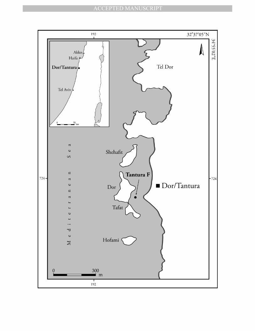
The Tantura F shipwreck is the remains of a small coaster that plied the Levant coast
during the local early Islamic period. It was discovered in Dor (Tantura) lagoon (Fig. 1) in
1995, about 70 m offshore in about 1 m depth of water, under a sand layer mixed with shells
and stones. The archaeological site spread over an area of 12 m × 4 m on the seabed, with a
maximum depth of 2.5 m (Barkai and Kahanov, 2007: 21). Based on 14C tests, some by
accelerator mass spectrometry (AMS) of short-living organic materials, and ceramic
typological analysis, the wreck was dated to between the mid-7th and the end of the 8th
centuries AD, which is the local Early Islamic period (Barkai et al., 2010: 88–101). Among
the finds exposed in the wreck site were two T-shaped iron anchors.
Although iron anchors are well known from the archaeological material culture
throughout the Mediterranean, there is limited information concerning their characteristics
and manufacturing process. Therefore, this study extends the typological information and
enlightens the technological aspects of manufacturing the anchors, including the materials
and processes used.
THE ANCHORS OF TANTURA F
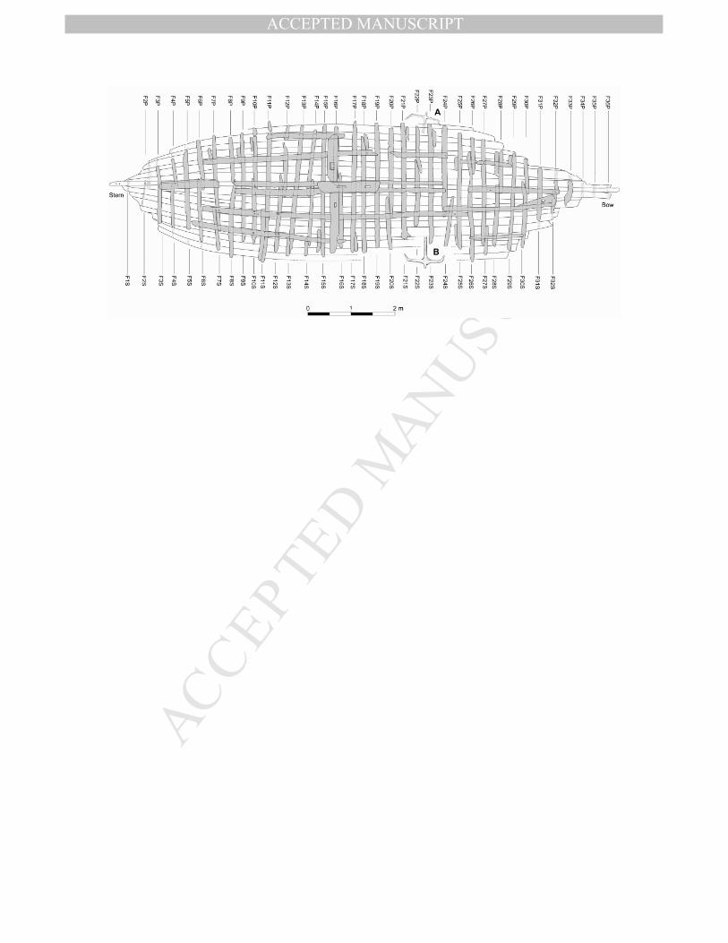
Two iron anchors were found at the wreck site of the Tantura F: one on the starboard
side and the other on the port side, close to the bow (Fig. 2). Both were found broken at the
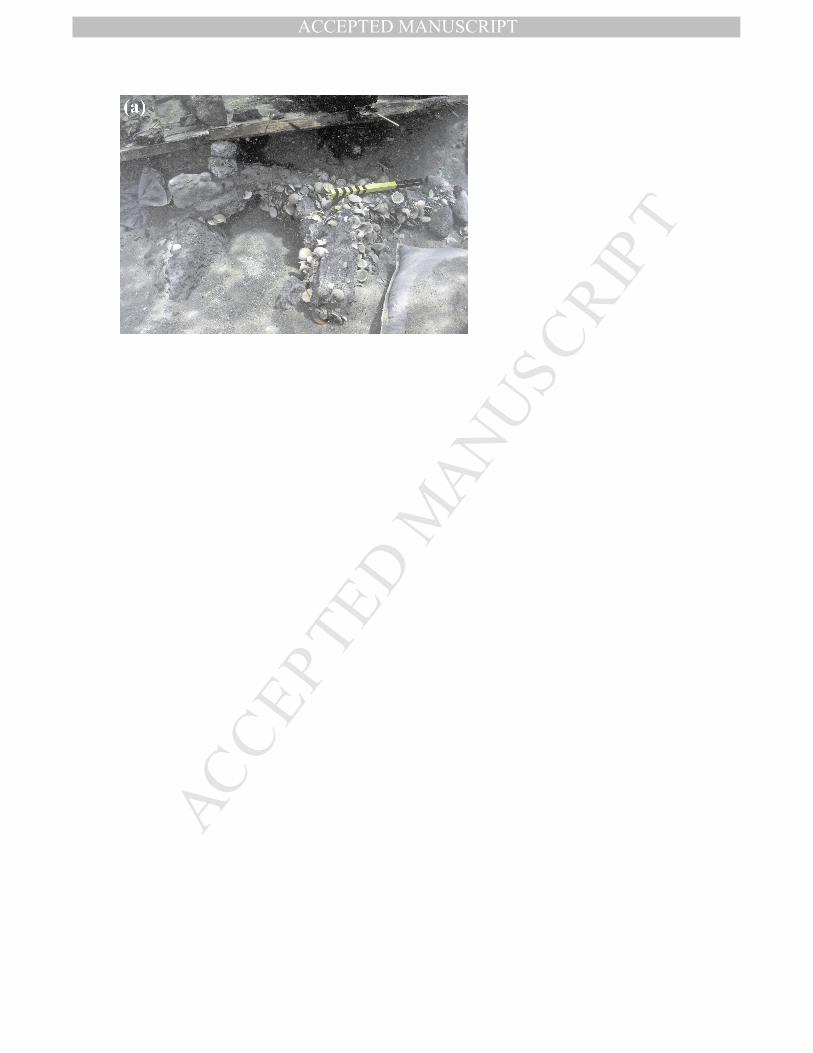
shank, with part of the shank and the anchor cable ring missing. Anchor A was found just
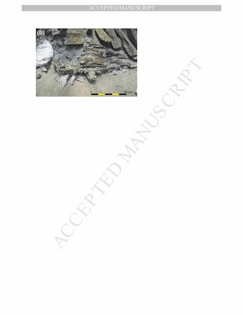
under the hull, touching it (Fig. 3a), while Anchor B was found concreted to the outside of
the planking below the hull (Fig. 3b). Both anchors were retrieved from the seabed covered
by a 4 cm thick grey layer of encrustation and concretion composed of sea sand, shells and
small stones. Anchor A was removed from the sea in the third excavation season (2006),
while anchor B was retrieved during the fourth (2007). Once in the laboratory, optical
macrographs and X-ray images were obtained, and the concretions were subsequently
removed with minimum harm to the external layers of the anchors, which had been oxidized
MANUSCRIP
T
ACCEPTED
ACCEPTED MANUSCRIPT
3
with the concretions. Despite the oxidation process, the metal remained in a good state of
preservation.
The archaeological context and the maritime aspect of the wreck site raise some
difficulties as to the anchors being in situ. The shipwreck was located southeast of Dor
Island, as if the ship had almost been beached on the shore of the island. Anchors from other
shipwrecks are expected to be found there; in fact, another shipwreck was discovered a few
meters southeast of Tantura F. This was Tantura B, dated to the beginning of the 9th century
AD (Wachsmann et al., 1997 [Trench XIII]). In the case of Tantura F the shanks were
broken, and the cable rings missing, which makes it possible that the anchors did not belong
to the shipwreck. Of the 68 anchors with shanks mentioned in the next section, 36 were
discovered with broken shanks. The fracture zone always occurs at the weakest point of the
objects, where maximum stress is present. The fractures of all 36 anchors, including those
found with Tantura F, could have been a result of poor welding. It should be noted, however,
that some of the anchors that were in situ were broken while others that were not in situ were
found intact.
The connection of the anchors to the wreck of Tantura F is based on their location at
the site, and partially on their typology, considering the date of the shipwreck. The anchors
were under the ship, which rules out the possibility that they were dropped after the wrecking
of Tantura F. If the anchors had been dropped by a vessel earlier than the Tantura F, they
would probably have sunk deeper into the sand, as a result of the conditions inside the
lagoon. The locations of the anchors, on both sides of the hull between frames F21 and F24,
touching the timbers of the hull, as shown in Fig. 2, seem unlikely to have been a
coincidence. A thick rope found under the ship may have been the ship's anchor cable. The
metallurgical examinations (see below) show that both anchors have a similar composition
and manufacture process. Thus, it is very likely that the anchors belonged to the ship.
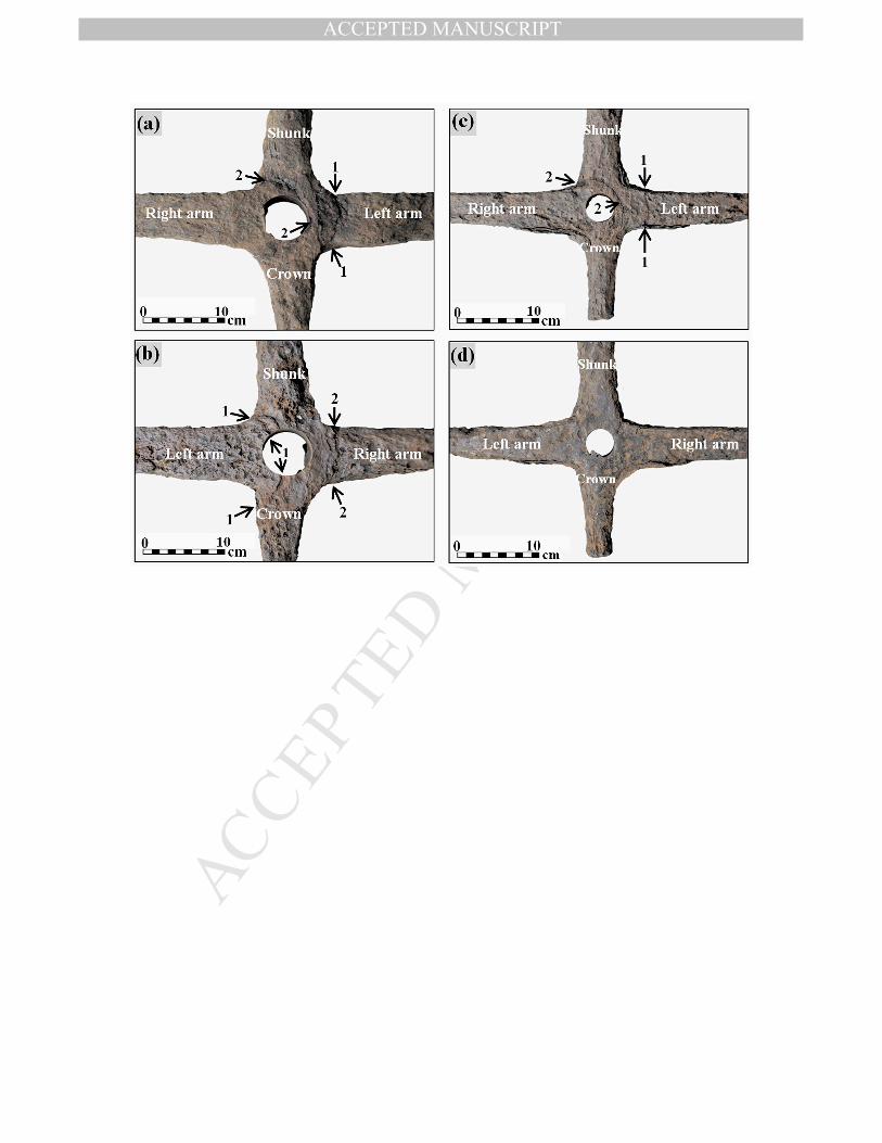
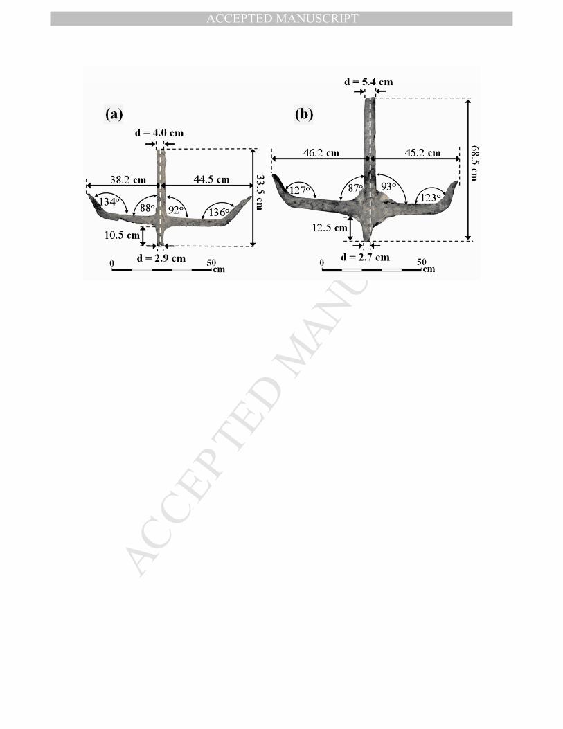
The anchors were T-shaped (see below) but the arms were not precisely perpendicular
to the shank. The angles between the right and left arms and the shank, and the angles of the
right and left tips relative to the arm in each anchor were not the same. This apparent
distortion could have resulted from the forces imposed on the anchors in use. The cross-
sections of both shanks are circular; although this is unusual for a wrought iron object, it is
typical of T-shape iron anchors. The tips of the arms were flattened. The dimensions of both
anchors after the removal of the external concretion layers are given in Fig. 4.
MANUSCRIP
T
ACCEPTED
ACCEPTED MANUSCRIPT
4
ANCHORS IN LATE ANTIQUITY AND MEDIEVAL TIMES
General
The purpose of the anchor is to hold a vessel in position in various conditions of water.
A wide variety of anchor shapes and characteristics were developed, and they were used in
combination with other measures, for example when mooring to a wharf. The anchor's shape
was the result of technological knowledge, technical capabilities, and experience. The anchor
requirements depended on the size of the vessel, type of anchorage, and nature of the ground
(Kemp, 1976: 21).
The earliest forms of anchors were large stones that held a vessel by their weight only.
In later periods, wooden flukes through the stone gripped the seabed. At the same time, the
stone anchor developed into a two-armed wooden anchor with a perpendicular stone or lead-
weighted stock. Iron anchors came into use in parallel with the use of wood and lead anchors;
their shape was most probably adapted from that of the latter (Frost 1963; Kapitän, 1984: 34,
fig. 2).
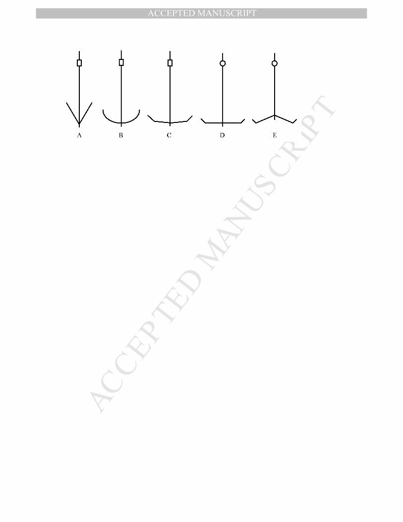
A typological-chronological analysis of iron anchors was made by Kapitän (Fig. 5),
based on anchors discovered up to the 1980s (Kapitän, 1984: 42). In this classification, iron
anchors were first used in the Roman Republican period, and were V-shaped with a
rectangular stock. These anchors were similar in their shape to the wood and lead anchors,
with the flukes of the anchors barely distinguishable. In the early Roman Imperial period, the
arms were rounded with scarcely distinguishable tips and the stock was rectangular. In the
later Roman Imperial period the arms were more horizontal and straightened, and the flukes
were slightly raised, while the cross-section of the stock remained rectangular. At the end of
the Late Roman period and during the local Byzantine and Islamic periods, T-shaped anchors
were introduced: the arms were straight and at right angles to the shank, and the flukes were
inclined upwards, with the cross-section of the shank being circular. Later, Y-shaped anchors
were introduced, as is evidenced by the anchors from the Serçe Limanı shipwreck, dated to
AD 1025 (Van Doorninck, 2004: 189). Their arms inclined downwards at obtuse angles, and
the flukes pointed upwards at right angles to the arms. In Kapitän's opinion, the obtuse angle
of the arms of the Y-shaped anchors attests to a technological advance, as compared with the
right angle found in the T-shaped anchors, since there was less chance that a Y-angled anchor
would break, as there was less force on the connection points between the shank and the arms
MANUSCRIP
T
ACCEPTED
ACCEPTED MANUSCRIPT
5
(Kapitän, 1978: 4). However Y-shaped anchors have been known from the 10th century as is
evidenced by the anchors of Yenikapı 1 (Pulak, 2007: 132).
Haldane (1990: 22) suggested that the anchors of the Roman Imperial period, which are
one type, C, in the typology of Kapitän, should be divided into two categories: the anchors of
Dramont D (first century AD) being the earlier type, and those of Dramont F the later type.
T-shaped anchors
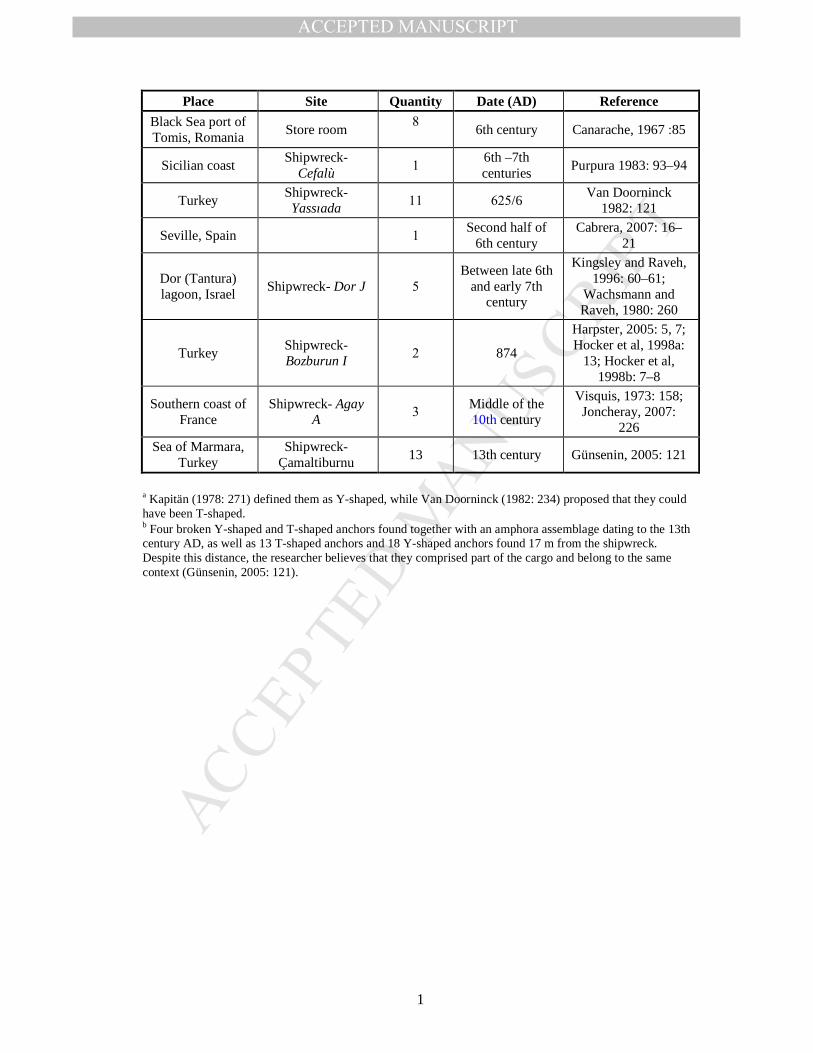
The earliest finds of T-shaped anchors from a dated archaeological context were
excavated in the Dramont F shipwreck, which is dated to the second half of the 4th century
AD. This anchor represents the transition phase from anchors with curved arms as were
discovered in Dramont D and Dramont F, to T-shaped anchors. Four iron anchors were found
in Dramont F: two had slightly curved arms—characteristic of an earlier type from the late
Roman Imperial period, and two were T-shaped with short straight arms and straight flukes,
which are bent slightly upwards (Joncheray, 1975: 116–118; 1977: 7). Later evidence of T-
shaped anchors was found as is described in Table 1.
T-shaped anchors from undated archaeological contexts have been found on the island
of Melita on the Dalmatian coast (Vrsalović, 1974: 138 fig. 82, 83); Valencia, Spain (Martin
and Saludes, 1966: LAM.IL:B); Cervia, Italy (Bonino, 1971: 320); Capo Graziano, Filicudi,
Italy (Kapitän, 1978: 269); Sicily (Gargallo, 1961: 35, Fig. 11); Cilicia, Turkey (Marten,
2005: 59); Cape Andreas, Cyprus (Green, 1973: 168) and several in Israel: Haifa (Kapitän,
1969–1971: 54); Dor (Kingsley and Raveh,1996: 23; Raveh and Kingsley, 1991: 200);
Netanya (observed by the authors, 2010); and Yavne Yam (Galili et al., 1993: 62).
In Kapitän's opinion (Kapitän, 1973: 285; 1978: 374), typological-chronological
development can be noted in T-shaped anchors. The oldest T-shaped type seems to be a
transition between the Roman and the Byzantine types. It was T-shaped with a stock of
rectangular cross-section. Anchors of this type have been found near Yavne Yam (Galili et
al., 1993: 62), Haifa and off the Spanish coast, but not in archaeological contexts (Kapitän,
1973: 285). The second type is represented by the early anchors from the Dramont F
shipwreck, characterized by relatively short arms and long straight flukes which are only bent
slightly upwards. The latest type is from the Yassiada shipwreck, which is characterized by
longer arms with upward-curved flukes bent outwards. Common to the last two types is a
round hole in the shank for a detachable stock. In the Çamaltiburnu shipwreck, which is
MANUSCRIP
T
ACCEPTED
ACCEPTED MANUSCRIPT
6
dated to the 13th century, T-shaped anchors of different arm shapes were found in the same
assemblage, but without evidence of the shape (round or square) of the stock, as this section
of the anchor did not survive. Further evidence of T-shaped anchors appears in a church in
Italy, dated to the same period (Bonino, 1971: 325). Anchors were used in Christianity as a
symbol of the cross and of hope (Beckmann, 1967: 486); therefore, this cannot provide
confirmation of the use of T-shaped anchors at that time.
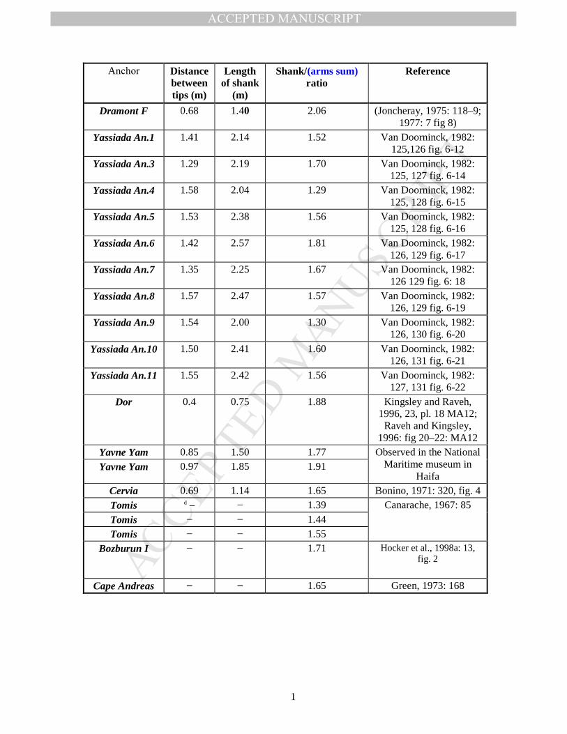
Arms/shank ratio of different T-shaped anchors (Dramont F, Yassiada An.1, Yassiada
An.3, Yassiada An.4, Yassiada An.5, Yassiada An.6, Yassiada An.7, Yassiada An.8,
Yassiada An.9, Yassiada An.10, Yassiada An.11, Dor, Yavne Yam, Cervia, Tomis, Bozburun
I, Cape Andreas) is summarized in Table 2, where arms (sum) is the distance between the two
arm tips.
As at least part of the typological sequence is based on anchors which are out of
archaeological context, it seems that further data and research are needed.
In summary, the use of T-shaped iron anchors was common throughout the
Mediterranean, Marmara and Black Seas over a period of approximately 900 years, starting
from the second half of the 4th century and lasting to the 13th century. At the beginning of this
period, they were present in parallel to curved armed anchors, while from the 10th century
they appeared together with Y-shaped anchors. However, it is difficult to establish a detailed
typological development.
BACKGROUND OF THE METALLURGICAL ANALYSIS
At a relatively low temperature (800oC), the reduction of iron is possible in the solid
state, but only at about 1150°C is the viscous slag capable of removing the unwanted gangue
minerals of the ore (Tylecote, 1992: 46-57). This high temperature is not hot enough to melt
iron with low carbon content, instead, the process produces a spongy mass called bloom,
whose pores are filled with slag. After the reduction step, the bloom needs to be repeatedly
hammered in order to remove the viscous slag and compact the metallic particles. This
consolidation process, called primary forging, results in a nearly pure iron. In order to join
two or more pieces of wrought iron made by the direct process, forge-welding is required.
This is a hot-working process which requires a temperature below the melting point, Tm,
usually > 1/2 Tm (Murray and Cliff, 1993: 156). At this temperature, the austenite phase is
MANUSCRIP
T
ACCEPTED
ACCEPTED MANUSCRIPT
7
ductile and, hence, can be joined by hammering, following a solid-state diffusion under
pressure mechanism.
Analysis of one sample anchor from the Yassiada shipwreck (Delwiche, 1982: 322)
demonstrated that the anchor was forged. Although the exact number of forge-welded pieces
is difficult to determine, it is suggested that "there were 4 pieces in either arm and perhaps as
many as10 pieces in the shank" (Van Doorninck, 1984: 3–7). The material was almost clear
of slag, with a carbon content of 0.07 wt.%, with irregularly shaped grains in a wide size
range. The other elements in the anchor material, aside from iron (all elements were analyzed
by wet chemical and spectrographic analysis), were potassium (0.06 wt.%), sulphur (0.008
wt.%), silicon (0.14 wt.%), sodium (0.005 wt.%), magnesium (0.005 wt.%), aluminium (0.05
wt.%), calcium (0.005 wt.%), titanium (0.005 wt.%), vanadium (0.01 wt.%), chromium (0.1
wt.%), manganese (0.007 wt.%), cobalt (1.0 wt.%), nickel (0.5 wt.%), copper (0.005 wt.%),
zirconium (0.5 wt.%) and silver (0.0005 wt.%). The forging of the anchor was carried out at a
temperature of about 1100–1150°C. The location at which the iron was smelted was not
identified (Delwiche, 1982: 322–324). This manufacturing method was also used to produce
Y-shaped anchors, as in the anchors from Serçe Limanı. These anchors weighed between 47.5
and 67.4 kg, and were made of 17 forged pieces (including the ring) which were forged
together, each weighing between 4 and 5 kg (Stech and Maddin, 2004: 193).
Recent archaeometallurgical studies (Stech and Maddin, 2004:193, Kocabaş, 2009:
227–237) demonstrate clearly that artifacts such as anchors are made by forge welding of
different semi-products, which have been obtained from different consolidated blooms. The
goal of the present investigation is to answer questions such as how many blooms were used
and what the welding operations to produce the anchor were. Since little information is
available in the literature about the manufacturing processes of iron anchors in the in the Late
Antique and early Medieval period, during which no hydraulic hammers were was used to
form wrought iron, this article presents useful information about these kinds of large artifacts,
clarifying questions such as whether both anchors were manufactured in the same workshop
and whether the same raw material was used in both smelting processes.
EXPERIMENTAL METHODS AND TESTS
MANUSCRIP
T
ACCEPTED
ACCEPTED MANUSCRIPT
8
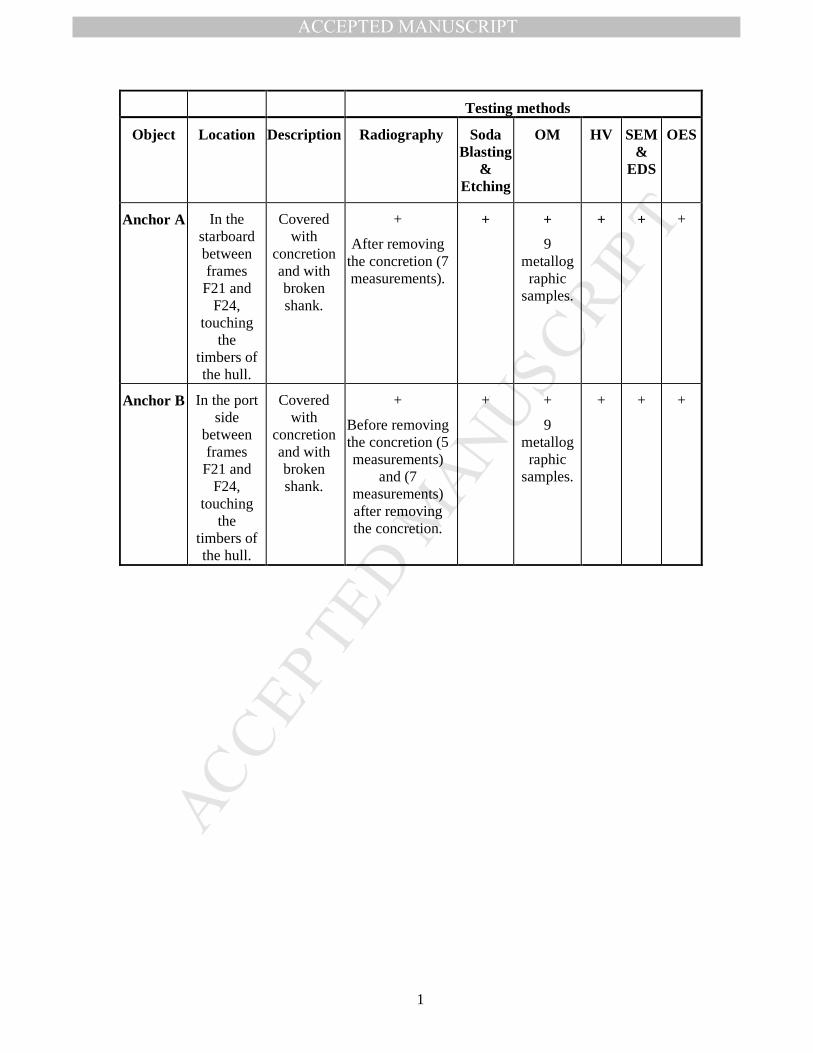
Both anchors were analyzed by their typology and by archaeometallurgical methods,
including: radiography, metallurgical optical microscope (OM), Vickers microhardness test,
SEM/EDS analysis and OES chemical analysis, as shown in Table 3.
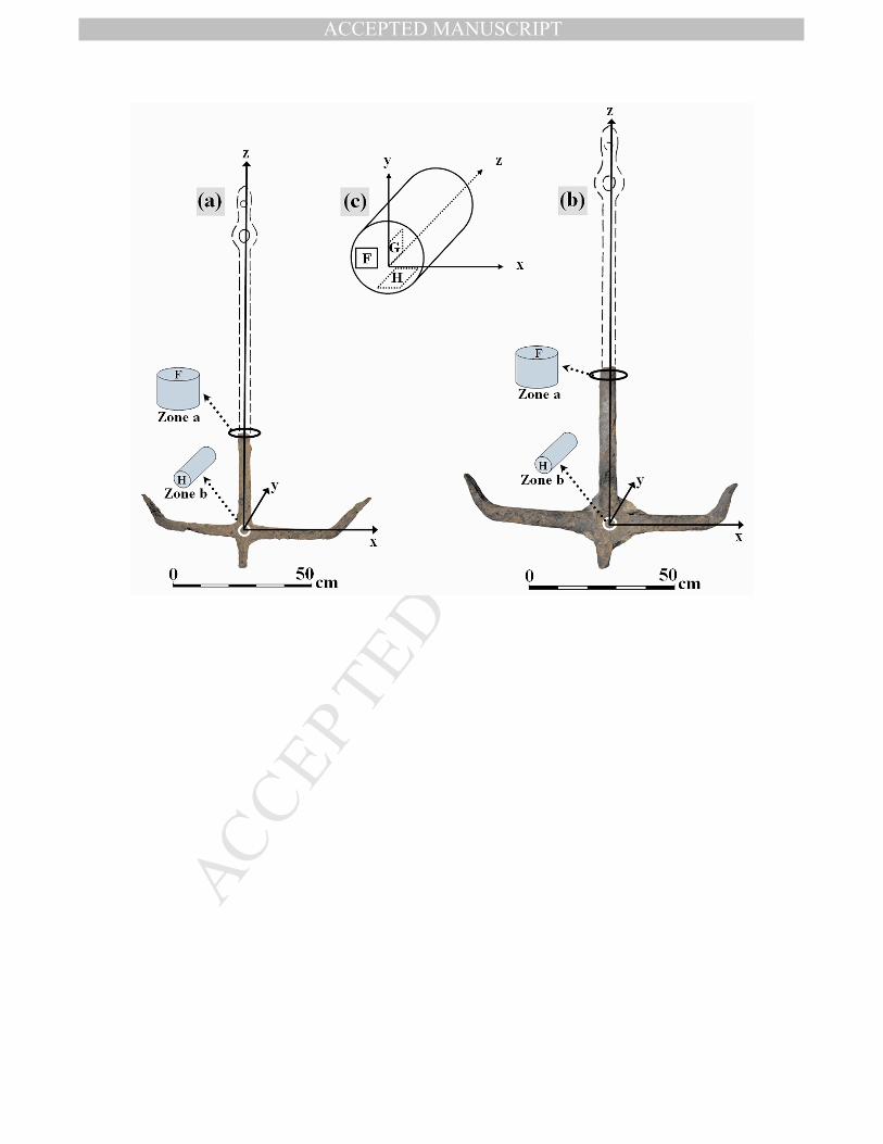
Three metallographic cross-sections, marked F, G and H, were taken from two different
zones of Anchors A and B. These sections were perpendicular to axes z, x and y,
respectively, as suggested by ASTM E3-01 and shown in Fig. 6. In order to cause minimal
damage to both anchors, the metallographic samples were cut from only two cylindrical
slices. The first slice was cut from the top of the shank (Zone a), while the second slice was
cut and pulled out from the joint area (Zone b). From the first slice, 4 samples were cut – two
parallel F sections (from both side of the slice, along the entire diameter), one G section, and
one H section. From the second slice, 5 samples were cut – three parallel H sections (from
different depths along the extruded drilled cylinder), one F section, and one G section. The
samples were cut with a water-cooled steel disc and then hot-mounted in Bakelite (at a
temperature of 180oC and pressure of 180 psi). The preparation of the surface consisted of
grinding with silicon carbide papers (240 to 600 grit), then polishing with alumina paste from
5 to 0.05 µm, and finally polishing with 0.05 µm colloidal silica suspension pastes. The
samples were cleaned in an ultrasonic bath to remove any contaminants, then cleaned with
ethanol and dried. They were then etched using Nital (97 mL ethyl alcohol and 3 mL nitric
acid). The metallographic samples were examined under an OM (ZEISS, AXIO-Scope A.1)
up to ×1000 magnification. Vickers microhardness tests were performed along the diameter
of the slice cut from the shanks of both anchors (Section F, Zone a), using a load of 100
gram-force (gf). Measurements were conducted at 0.5 mm intervals using a Future-Tech
Model FM-700e microhardness tester.
Chemical analysis was performed using the Optical Emission Spectroscopy (OES)
(Pollard et al., 2007) technique with a Spectrolab Model M instrument, which has a detection
limit < 1%. Each sample area analysed was 1×1 cm2. The surface of the sample was ground
and cleaned in an ultrasonic bath prior to this test. Two clean samples per anchor were
analyzed.
SEM examination was performed in combination with EDS analysis. Imaging was done
with a FEI Quanta 200FEG Environmental Scanning Electron Microscope (ESEM), under
high vacuum mode, using the Everhart-Thonley secondary electron (SE) detector. Several
zones with different surface morphologies were characterized. The chemical elemental
MANUSCRIP
T
ACCEPTED
ACCEPTED MANUSCRIPT
9
composition was determined locally by energy dispersive spectroscopy (EDS) using Si(Li)
liquid-cooled Oxford X-ray detector.
Non-destructive testing (NDT), namely radiography, was performed on both anchors
using X-ray radiation, Eresco 200 machine, 200 kV, 4.5 mA, with 5 to 12 min of exposure
time, on D7 Agfa film. Finally, the samples were cleaned by soda-blasting and then
chemically etched in Nital to reveal the forge-welding lines.
RESULTS
Reconstruction of the original dimensions and weights of the anchors of Tantura F
A reconstruction of the anchors from Tantura F was achieved by comparing the ratio
between the dimensions of the arms and the shanks in twenty similar T-shaped iron anchors
shown in Table 2. The average shank/(arms sum) ratio for these specimens is 1.63±0.19. The
original weights of both anchors were calculated by multiplying the volume of the
reconstructed shanks by the density of pure iron (ρ = 7.8 g/cm3), since larger error is caused
by the measurements of the anchor volume than by the variation of iron density caused by
minor elements. Considering the good state of preservation, the calculation of the volume is
based on the existing metal remains, ignoring loss due to corrosion. The estimated lengths
were calculated by multiplying the average arm/shank ratio by the measured length of both
arms (Fig. 6). The error of the measured values is negligible. The estimated weights were
calculated using the following equation: ananrecrec WLLd
W +−⋅
⋅⋅= )(2
2
πρ , where Wrec is
the reconstructed weight, ρ is the density of pure iron, d is the diameter of the shank, Lan is
the anchor (artifact) length, Lrec is the reconstructed length, and Wan is the anchor (artifact)
weight. The estimated lengths and weights for the reconstructed Anchor A are 134.9±15.9 cm
and 20.4±1.6 kg, respectively, and for Anchor B: 152.8±18.0 cm and 35.7±3.2 kg.
Metallurgical analysis
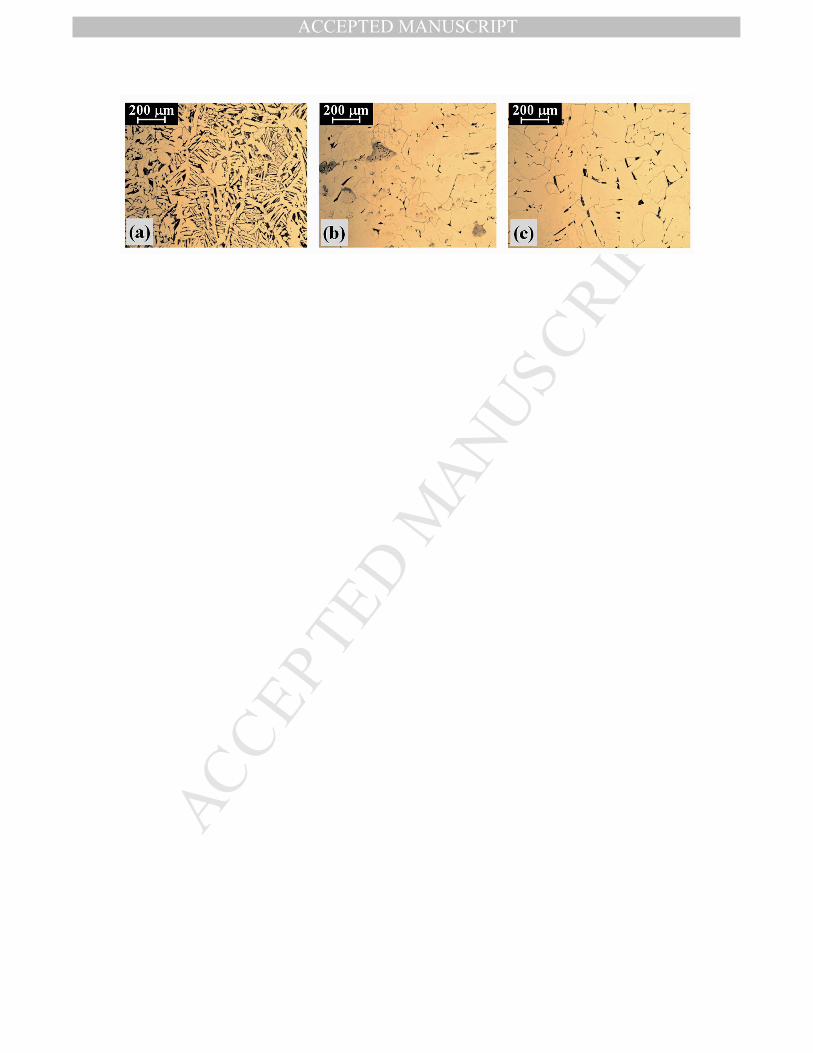
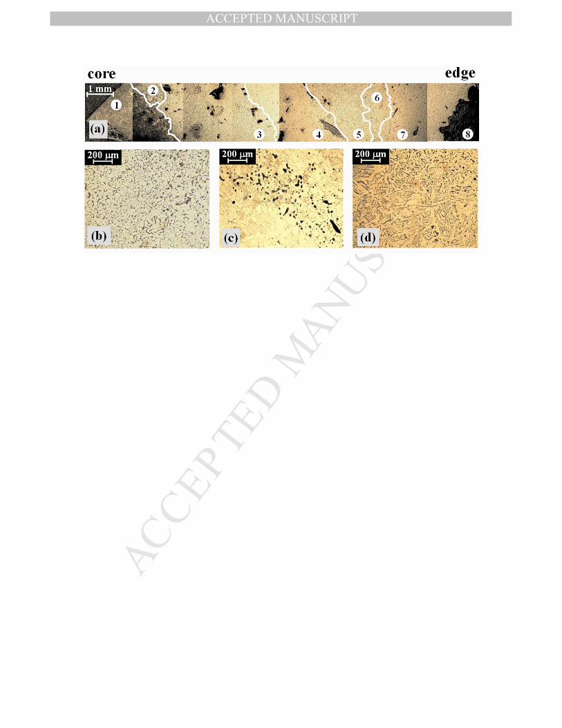
Observation of the metallographic samples of Section F, from Zone a (in both anchors),
from the core to the edge of the specimen, using ×50 magnification, revealed a heterogeneous
microstructure relatively pure of slag inclusions and porosity, with only 3.4 area% of
inclusions present for the measured surface of anchor A (Fig. 7) and 4.8% inclusions for the
measured surface of anchor B (Fig. 8). The repetitiveness of these results was clarified, for
MANUSCRIP
T
ACCEPTED
ACCEPTED MANUSCRIPT
10
both anchors, from both sides (upper and lower) of the cylindrical slices (cut from Zone a).
Observation in sections G and H showed an equiaxed grain structure in both anchors. This
result is expected, because oriented grain structure may be expected in these sections if force
was applied in the z-direction, which is not reasonable unless this kind of force was used for
lap joint welding of the reconstructed shank to the artifact. Nevertheless, forge welding might
not leave orientation traces because the temperature needed for this process is sufficient for
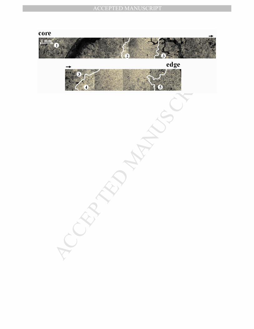
recrystallization. Figure 7a shows eight areas of different microstructures starting with pure
pearlite at the core (Area 1), then pearlite matrix with Widmanstätten (thin plates or lamellas)
ferrite (Area 2), fine ferrite grains with pearlite at grain boundaries (Area 3), large ferrite
grains (Area 4), Widmanstätten ferrite growth and pearlite phase (Area 5), fine ferrite (Area
6), large ferrite grains (Area 7) and finally the corrosion layer (Area 8). Small cracks and
pores are evident. Figure 7b shows a higher magnification of Area 3, emphasizing the variety
in grain size, typical of hand-forged iron (Delwiche, 1982: 323). Figure 7c shows Area 4,
associated with slag inclusions lightly oriented, whereas Figs. 7d shows a higher
magnification of Area 5. Figure 8 shows five areas of different microstructures, in the
following order: large pearlite grains with a small amount of Widmanstätten ferrite at the
core, Widmanstätten ferrite growth and pearlite phase, large pearlite grains with a small
amount of Widmanstätten ferrite, Widmanstätten ferrite growth and pearlite phase, and large
pearlite grains with a small amount of Widmanstätten ferrite. Slag inclusions, cracks and
pores are shown in Fig. 8. An equiaxed grain structure is seen in all three sections of Zone b
in both Anchor A (Fig. 9a for section F; Fig. 9b for section G; and Fig. 9c for section H;) and
Anchor B (Fig. 10a for section F; Fig. 10b for section G; and Fig. 10c for section H),
meaning that the anchors were hot-worked, followed by recrystallization of the metallic
grains in the forge-welding process. In Zone b, sections F and G are expected to present
oriented grain structure if a force was applied in the y-direction, which is reasonable in the
case of welding the shank to the arms, but again only in a cold-work process. The other two
parallel H sections showed the same results in both anchors. In addition, the metallographic
images shown in Figs. 9 and 10 are almost 100% free of slag inclusions and porosity
suggesting that this area (Zone b), in both anchors was well hammered, probably during the
forge-welding process.
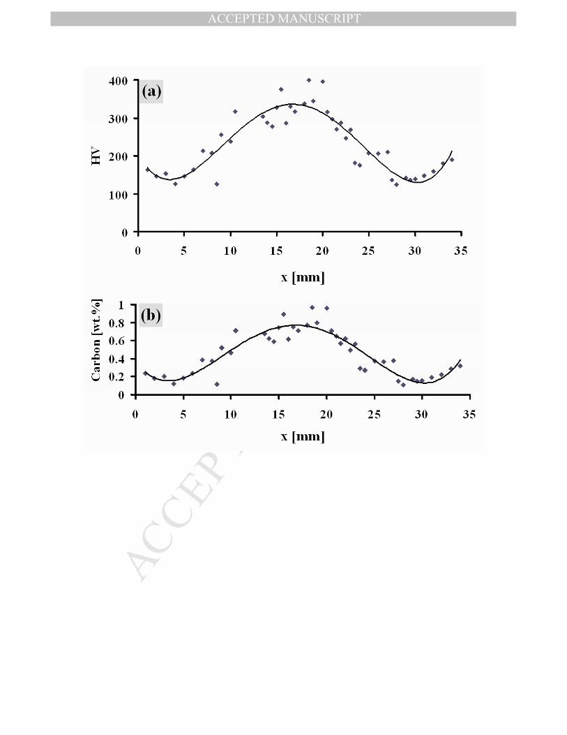
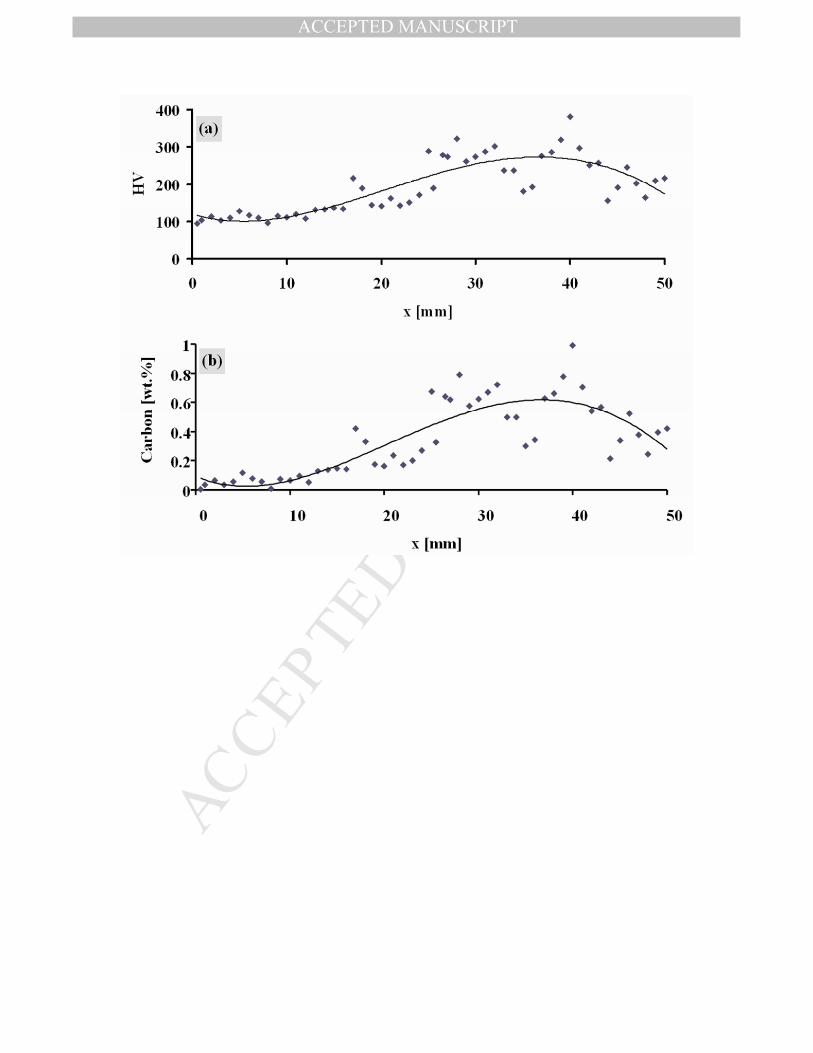
Vickers microhardness values acquired in Anchors A and B are presented in Figs. 11a
and 12a, respectively. Because it is obvious from Figs. 7 and 8 that the core of the shank of
both anchors contain the largest amount of a pearlite phase, which decreases at the edges (a
repetition of this result was assured for both anchors, as previously mentioned), an attempt
MANUSCRIP
T
ACCEPTED
ACCEPTED MANUSCRIPT
11
was made to present those decarburization profiles, using microhardness data, while
assuming that the hardness was mostly affected by the chemical composition (particularly for
iron with low contents of other elements and a uniform mechanical and heat treatment
history). In addition, when inclusions or corrosion products appeared along the diameter line,
the microhardness test was conducted in a separate area nearby. For this purpose a linear
calibration function (using least-square fitting) was employed for each anchor, describing the
microhardness test results as a function of the carbon weight percentage, according to the
lever rule in hypoeutectic steel. In order to obtain the calibration function, Vickers
microhardness tests were made in areas of either pure ferrite or pure pearlite in both anchors.
The corresponding values were 128±5 VHN (ferrite) and 332±10 VHN (pearlite) for Anchor
A; 106±7 VHN (ferrite) and 292±18 VHN (pearlite) for Anchor B. The microhardness values
as a function of the distance were substituted into the calibration function in order to obtain
the carbon wt.% as a function of distance. The results are shown in Figs. 11b and 12b, for
Anchors A and B, respectively.
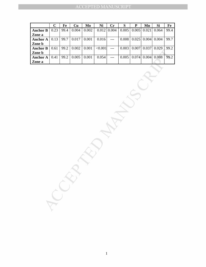
The results of the chemical analysis (OES) are shown in Table 4. Their relation to the
analysis of the T-shaped iron anchor from Yassiada is discussed in the next section.
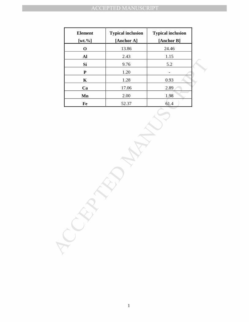
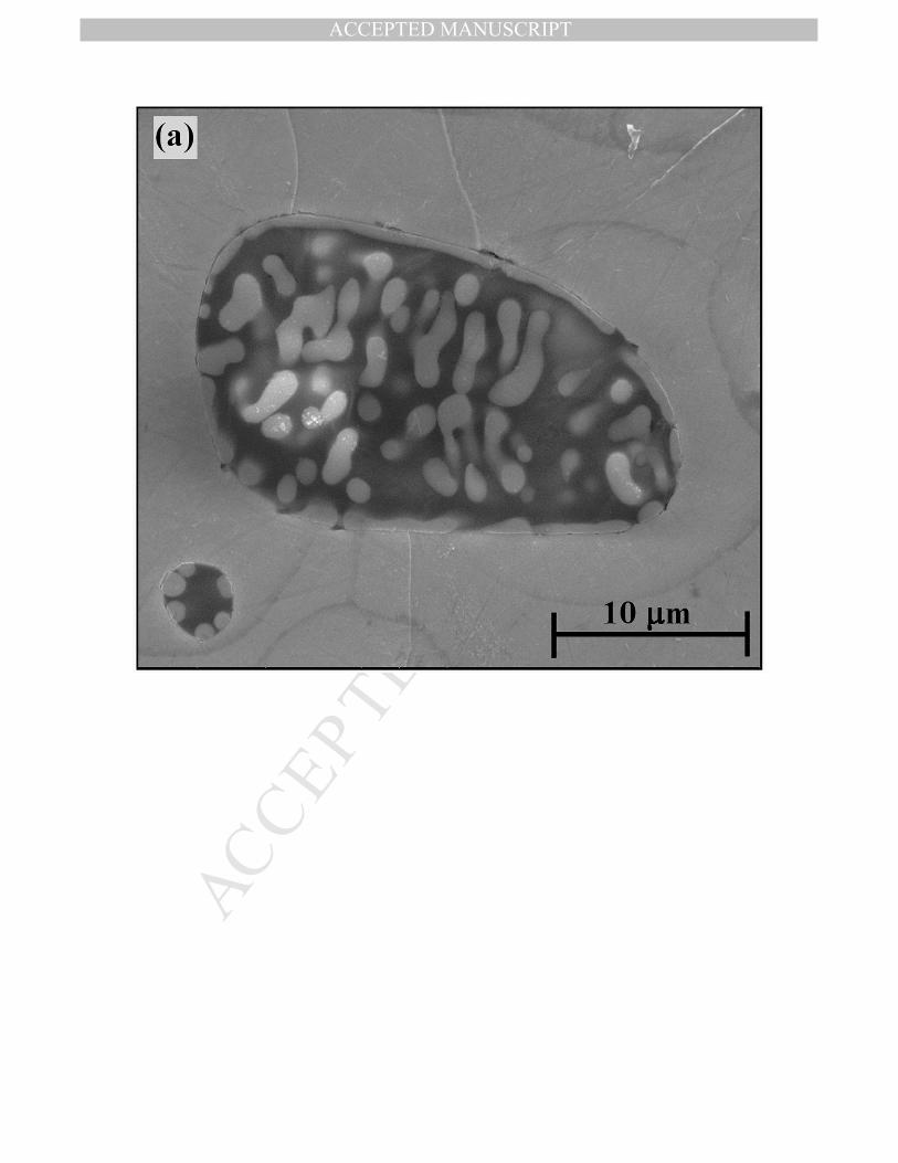
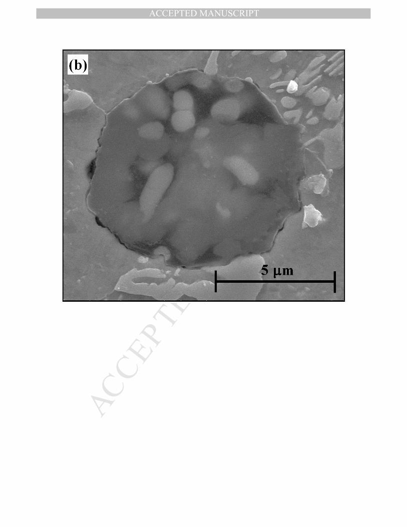
Moreover, in order to better determine whether both anchors were manufactured, from the
same ore, SEM images and EDS analysis of typical slag inclusions were acquired for both
anchors, Zones a, section F (Fig. 13 and Table 5). Since there is very little phosphorus in the
samples, as shown in Table 4, the iron is likely to be purely ferritic and a bog ore was
probably used in the manufacturing. Figure 13 shows an identical morphology of both slag
inclusions. This morphology is typical of wüstite (FeO) trapped in a glassy matrix
(Buchwald, 1998:75).
Since no forge welding lines were observed in the radiography test, we searched for
forge weld trace lines at the surface. Soda-blast cleaning followed by chemical etching
revealed the forge-welding lines, as shown in Fig. 14. It should be mentioned that while these
macro observations were made on the entire anchors, we present here only the area in which
forge welding lines did appear. This approach has made it possible to suggest an
interpretation for the manufacturing process of the anchors.
DISCUSSION
The metallurgical aspect
MANUSCRIP
T
ACCEPTED
ACCEPTED MANUSCRIPT
12
The heterogeneous microstructure of almost pure ferrite through Widmanstätten ferrite and
Widmanstätten ferrite-pearlite to pure pearlite shown in Figs. 7 and 8 is a result of high
separation in the carbon content, and is typical of wrought iron made in ancient bloomeries
(Buchwald, 2005: 296; Friede, 1979: 372; Tylecote, 1968; Stech and Maddin, 2004: 192).
This heterogeneous microstructure probably results from the heterogeneous conditions inside
the furnace (temperature, gas concentration, etc.)
All slag inclusions observed in all the metallographic samples of Anchors A and B,
Zones a and b, sections F, G, H (as shown, for example, in Fig. 7c), were in very low
concentration, compared to wrought iron made in ancient bloomeries (Dillmann, 2006: 1810).
This fact, which will be further supported by the chemical analysis, is evidence of a highly
skilled blacksmith. The slag inclusions located in section F (Fig. 7a) are relatively equiaxed
since a relatively isostatic force was applied on the rod during consolidation.
The carbon-rich areas present in all of the metallurgical samples could be the result of
natural carburization at relatively high temperatures and the strong reducing power of the
CO/CO2 gas. This could have occurred either in the smelting step, when carbon was absorbed
and diffused into the reduced iron from the hot charcoal bed, or by absorption and diffusion
into the metal close to the tuyères; or in the forging step, when it was trapped in the pores of
the bloom when the slags were hammered out (Friede, 1979: 372). The presence of a
Widmanstätten ferrite structure is an indication of prolonged heating of the austenitic phase
and rapid air-cooling (Garagnani et al., 1996: 83; Bhadeshia, 1985: 321). From Fig. 11b it is
clearly evident that a decarburization process had probably occurred during prolonged
heating before forge-welding. From Fig. 12b it is also apparent that a decarburization process
had occurred, although not a uniform one.
The chemical analysis presented in Table 4 supports the metallurgical observation that
both anchors contain a larger amount of carbon than wrought iron made in ancient
bloomeries, and especially with respect to the T-shaped iron anchor from the Yassiada
shipwreck (0.07%). The low content of manganese indicates that no deliberate attempt was
made to harden the iron by adding a manganese ore to the furnace. The purity of the iron is
clearly very high, indicating high quality manufacturing. The similar chemical compositions
of the two anchors, compared with those of the Yassiada shipwreck, suggest that the Tantura
F anchors were made in the same type of furnace. From Table 4 it is clear that both
inclusions have the same minor elements, except for phosphorous that appears in the
inclusions from Anchor A only. Because an analysis of minor and trace elements present in
MANUSCRIP
T
ACCEPTED
ACCEPTED MANUSCRIPT
13
individual inclusions should reflect the elements present in the original ore, it is very likely
that the same process and ore were used for the manufacturing of both anchors. Nevertheless,
in order to compare the origin of both anchors in a more profound way, an extended element
slag inclusion study is necessary, like the work of Dillmann and L'Heritier (2007) and
Blakelock et al. (2009). Further metallographic examination, including more sections on both
anchors, will be done in the future, but only after performing radiographic CT analyses to
both anchors. That, however, is beyond the scope of this paper.
Reconstruction of the manufacture of ancient iron anchors
The quality of forge welds is much dependent on the blacksmith's skills, since, at the
working temperature mentioned, iron oxides are readily formed on the surface and their
presence decreases the weld strength. So their formation should be prevented in advance.
This can be done by welding two bloom pieces during their own consolidation, while
removing the slag. In this process, welding lines are not expected to be seen at all. Another
option is to remove the oxide film mechanically before hammering the two shaped pieces, or
by using flux. In the later process, forge welding lines are expected to be noticeable only as
iron oxide inclusions (without any glassy phases) in the case of mechanical cleaning, or as
iron oxide inclusions including glassy phases or at least silicate phases in the case of using
flux. Nevertheless, the probability of locating them in radiography or in OM is highly
dependent on the quality of the work. Poor forge welds are expected to break under relatively
low force, as in the case of the Serçe Limanı anchors (Stech and Maddin, 2004: 193). A very
poor weld quality could probably be detected by radiography, since the density of the oxides
is much lower than that of iron. Then, a black line would appear in the radiography film
(similar to fracture), as in the case of the Çamaltiburnu shipwreck (Kocabaş, 2009: 227–237).
A good forge weld might leave recrystallized ferrite or pearlite grains with very few iron
oxide inclusions and very few voids (Murray and Cliff, 1993: 156). Hence, it might not be
easily observed, surely not by radiography, but neither by OM nor by SEM. As in the present
case, it may only be evident on the metal surface, enhanced through slightly etching. Since
the radiography images showed no sign of welding lines in Zones B of both anchors, and
since the representative metallographic images from Figs. 9 and 10 showed no forge welding
lines, and no unique amount of oxide or glassy inclusions in all 5 sections for each anchor, it
is concluded that the T joints were probably welded very professionally, by a very highly
skilled blacksmith who was able to avoid bulk defects in the forge welding process. However,
MANUSCRIP
T
ACCEPTED
ACCEPTED MANUSCRIPT
14
further work, including detailed CTs of both anchors followed by extended metallographic
analysis of both anchors, may reveal more information and result in a better understanding of
this behavior. The chemical etching that revealed the forge-welding lines, as shown in Fig.
14, suggests that the T-joints were welded not during consolidation of blooms, but rather after
careful removal of the oxide film of the heated pieces, before hammering them together in a
process that is not yet fully understood.
Taking into account the weights of the artifacts: 10.5 kg for Anchor A (20.4±1.6 kg as
reconstructed) and 20.6 kg for Anchor B (35.7±3.2 kg as reconstructed), and the macro forge-
weld lines on the surfaces of zones b, shown in Fig.14, the following steps may be suggested
for the manufacture of both anchors:
1. Anchor A was made from at least four pieces. The first part weighed about 10 kg, for
the upper part of the shank (the part of the shank that was broken off and is now
missing) and the other three weighed about 10.5 kg all together, for the perpendicular
part (the artifact as is), two for the arms and one for the lower part of the shank
(including the crown). The last three pieces were forged into their final shape in
parallel. Anchor B was also made from at least four pieces. One weighed about 15 kg
for the upper part of the shank and the other three weighed about 20.6 kg all together,
for the perpendicular part as in Anchor A.
2. After forging the three pieces into their final shape, leaving a diagonal profile for both
inner arms, they were forge-welded together by lap-joint welding. First, the right arm
was put perpendicularly under the shank, leaving the crown projecting, and they were
forge-welded together, as can be seen from line 2 in Figs.14a and 11b of Anchor B, and
from Fig.14c of Anchor A.
3. The left arm was put above the shank, the previously welded right arm, and they were
forge-welded, as can be seen from line 1 in Figs.14a and 14b of Anchor B, and from
Fig.14c of Anchor A.
4. The first part was forged into a long shank, leaving a diagonal profile.
5. The "small shank anchor" was forge-welded to the rest of the shank.
It should be mentioned that the absence of forge welding lines in Zone B for both anchors is
very unusual because, practically, it is almost impossible to forge-weld two pieces without
any oxidation of the surfaces (high temperature oxidation will cause the formation of new
oxide layers again), or without using any fluxing agent, a process that must leave its
MANUSCRIP
T
ACCEPTED
ACCEPTED MANUSCRIPT
15
"signature" in the forge welding lines. Therefore, the reconstruction of the manufacturing
process should be supported by the investigation of other iron anchor artifacts and by further
non-destructive radiographic test and destructive metallographic examinations of both
Anchors A and B in a future work.
CONCLUSIONS
The two anchors discovered at the wreck site of Tantura F can be attributed to the ship.
The metallurgical analysis of the iron anchors revealed the manufacturing processes and the
metallurgical skills of the ancient smiths. The mechanical properties of the anchors were
improved by several means:
1. The large amount of fuel placed into the furnace and the good tuyère arrangement,
which contributed to the high carbon content of the raw material and, therefore, resulted
in high hardness.
2. Decreasing the hardness of the raw material by a decarburization process might have
occurred during prolonged heating before forge-welding, resulting in a decrease of
hardness close to the surface, allowing good forge-welding and a very dense final
product.
3. The Tantura F anchors had few forge-welding lines compared with the later anchors
from Serçe Limanı.
The good mechanical properties of the anchors are also obvious, simply by the fact that they
were found unbroken, except for the shank, and with significantly thick metallic core
remains. The results of the chemical analysis, combined with the similarity in the production
process of the two anchors, suggest that both were manufactured by the same process using
the same ore.
The metallurgical information presented here broadens our understanding of the
metallurgical evolution of iron anchors. It adds to the body of data collected so far, and adds
parallels to the typology of iron anchors in the eastern Mediterranean during the early Islamic
period. The simple methodology used here for obtaining the carbon content profile by
microhardness test may be applied by others and provide important information.
MANUSCRIP
T
ACCEPTED
ACCEPTED MANUSCRIPT
16
ACKNOWLEDGMENTS
This research was supported by Lord Jacobs of London, the Israel Science Foundation,
the Hecht Foundation, Sir Maurice Hatter Fellowship for Maritime Studies and the University
of Haifa, to which the authors are thankful.
The authors are grateful to Mr. Avshalom Zemer, Director of the National Maritime
Museum in Haifa for his cooperation giving us access to the anchors and to Mr. Geyura
Biraan for his enlightening comments. The authors would also like to thank Mr. Mario
Levinstein from the School of Mechanical Engineering at Tel Aviv University for his
assistance. Finally the authors would like to thank the two anonymous journal reviewers, both
of which have spent much time and provided constructive and detailed feedback on the
manuscript.
REFERENCES
Barkai, O., Kahanov, Y., 2007. The Tantura F shipwreck, Israel, International Journal of
Nautical Archaeology 36 (1), 21–31.
Barkai, O., Kahanov, Y. and Avissar, M., 2010. The Tantura F shipwreck—The ceramic
material, Levant 42 (1), 88–101.
Blakelock, E., Martinón-Torres, M., Veldhuijzen, H.A., Young T., 2009. Slag inclusions in
iron objects and the quest for provenance: an experiment and a case study, Journal of
Archaeological Science 36, 1745–1757.
Beckmann, M., 1967. The anchor, The Catholic Encyclopedia. vol. 1 Catholic University of
America, Washington, 486.
Bhadeshia, H.K.D.H., 1985. Diffusional formation of ferrite in iron and its alloys, Progress in
Material Science 29, 321–386.
Bonino, M., 1971. Ricerche sulla nave romana di Cervia, Atti del III Congresso
Internazionale di Archeologia Sottomarina, Barcelona, 1961. Istituto Internazionale di
Studi Liguri, Museo Bicknell, Bordighera, 316–325.
Buchwald, V.F., 2005. Iron and steel in ancient times, Historisk-filosofiske Skrifter vol. 29,
The Royal Danish Academy of Science and Letters, Copenhagen.
MANUSCRIP
T
ACCEPTED
ACCEPTED MANUSCRIPT
17
Buchwald, V.F., Wivel, H., 1998. Slag analysis as a method for the characterization and
provenancing of ancient iron objects, Materials Characterization 40, 73–96.
Cabrera, C., 2007. Finds from Hispalis, A Byzantine anchor and medieval small boat from
the ancient harbor of Seville, The INA Annual, 16–22.
Canarache, V., 1967. The Archaeological Museum of Constanta Muzeul Regionale de
Arheologie Dobragea, Constanta.
Delwiche, D.E., 1982. Anchor metallurgy, In: Bass, G.F and Van Doorninck, F.H. Jr., (Eds.),
Yassi Ada Volume I: A Seventh-Century Byzantine Shipwreck, Texas A&M University
Press, College Station, pp. 322–324.
Dillmann, P., L’He´ritier, M., 2007. Slag inclusion analyses for studying ferrous alloys
employed in French Medieval buildings: Supply of materials and diffusion of smelting
processes, Journal of Archaeological Science 34, 1810–1823.
Friede, H.M., 1979. Iron-smelting furnaces and metallurgical traditions of the South African
Iron Age, Journal of the South African Institute of Mining and Metallurgy, 372–381.
Frost, H., 1963. From rope to chain. On the development of anchors in the Mediterranean.
Mariner's Mirror 49 (1), 1–20.
Galili, E., Dahari, U., Sharvit, J., 1993. Underwater surveys and rescue excavations along the
Israeli coast, International Journal of Nautical Archaeology 22 (1), 61–77.
Gargallo, P.N., 1961. Anchors in Antiquity, Archaeology 14, 31–35.
Garagnani, G.L., Zucchi, F., Tommesani L., Brunoro, G., 1996. Metallurgical investigations
on 16th –17th century iron armours from the Museo Nazionale of Ravenna, Science and
Technology for Cultural Heritage 5 (2), 83–94.
Green, J.N., 1973. An underwater archaeological survey of Cape Andreas, Cyprus, 1969–70,
a Preliminary Report. In: Blackman D.J. (ed.), Marine Archaeology, Proceedings of the
Twenty-third Symposium of the Colston Research Society, held in the University of
Bristol April 4th to 8th, 1971, London, pp. 141–79.
Günsenin, N., 2005. A 13th-century wine carrier: Çamalti Burnu, Turkey. In: Bass, G. (ed.),
Archaeology Beneath the Seven Seas, Thames and Hudson, London, pp. 118–123.
Haldane, D., 1990, Anchors in antiquity. Biblical Archaeology 51(1), 19–24
MANUSCRIP
T
ACCEPTED
ACCEPTED MANUSCRIPT
18
Harpster, M., 2005. A Re-assembly and reconstruction of the 9th-century AD vessel wrecked
off the coast of Bozburun, Turkey, unpublished Ph.D. Dissertation, Texas A&M, College
Station.
Hocker, F.M., Sara, W., Yamini, G.O., 1998a. The Byzantine shipwreck at Bozburun, Turky
Excavation: The 1997 Field Season, INA Quarterly 25 (2), 12–17.
Hocker, F.M., Sara, W., Yamini, G.O., 1998b. Bozburun Byzantine shipwreck excavation:
The final campaign, 1998, INA Quarterly 25 (4), 3–13.
Joncheray, J-P., 1975. Une epave du Bas Empire: Dramont F, Cahiers d’Archéologie
Subaquatique, 4, 91–140.
Joncheray J-P., 1977. Mediterranean hull types compared. 2. Wreck F from Cape Dramont,
International Journal of Nautical Archaeology 6 (1), 3–7.
Joncheray, J-P., Brandon, C., 2007. L' Epave Sarrasine Agay A: Campagne 1996 Cahiers
d'Archéologie Subaquatique 16, 223–249.
Kapitän, G., 1969–1971. Ancient anchors and lead plummets, Sefunim, Annual of the
National Maritime Museum of Israel 3, 51–61.
Kapitän, G., 1978. Exploration at Cape Graziano, Filicudi, Aeolian Islands, 1977,
International Journal of Nautical Archaeology 7, 2692– 77.
Kapitän, G., 1984. Ancient anchors – Technology and classification, International Journal of
Nautical Archaeology 13, 33–44.
Kemp, P., 1976. The Oxford Companion to Ships and the Sea. London: Oxford University
Press.
Kingsley, S., Raveh, K., 1996. The Ancient Harbour and Anchorage at Dor, Israel: Results of
Underwater Surveys 1976-1991. BAR International Series 626, Hadrian Books, Oxford.
Kocabaş, U., 2009. Camaltı Burnu I shipwreck. In: Bockius, R. (ed.), Between the Seas
Transfer and Exchange in nautical Technology Proceedings of the Eleventh International
Symposium on Boat and Ship Archaeology, 2006, Römisch-Germanisches
Zentralmuseum, Mainz, pp. 227–237.
Marten, M., 2005. Spatial and temporal analysis of the harbor at Antiochia ad Cragum,
unpublished M.A. Thesis, The Florida State university, College of Art and Sciences.

MANUSCRIP
T
ACCEPTED
ACCEPTED MANUSCRIPT
19
Martin, G., Saludes, J., 1966. Hallazgos arqueológicos submarinos en la zona de El Saler,
(Valencia), Archivo de Prehistoria Levantina XI, 155–170.
Murray, W.M., Cliff, C.B., 1993. ASM Handbook, Vol. 6: Welding, Brazing, and Soldering,
2nd Edition, ASM International, 156–159.
Photos, E., 1989. The question of meteoritic versus smelted nickel-rich iron, Archaeological
evidence and experimental results, World Archaeology 20 (3), 403–421.
Pulak, C., 2007. The wrecks of Yenikapi the Gift of Storm, Arkeoatlas, 6: 129–141.
Pollard, M., Batt, C., Stern, B., Young, S.M.M., 2007. Analytical Chemistry in Archaeology,
47–48.
Raveh, K., Kingsley, S.A., 1991. The status of Dor in Late Antiquity: A maritime
perspective, The Biblical Archaeologist, 54, 198–207.
Stech, T., Maddin, R., 2004. Iron analysis. In: Bass, G.F. Matthews, S.D. Steffy J.R. and Van
Doorninck, F.H. Jr., (Eds.), Serçe Limani An Eleventh-Century Shipwreck, Vol. I, The
Ship and Its Anchorage, Crew, and Passengers. Texas A&M University Press, College
Station, pp. 192–195.
Tylecote, R.F., 1968. Solid Phase Welding of Metals, Edward Arnold, London.
Tylecote, R.F., 1992. A History of Metallurgy, 2nd Edition, The Metals Society, London.
Van Doorninck, F.H. Jr., 1982. The anchors. In: Bass, G. F and Van Doorninck, F. H. Jr.,
(Eds.), Yassi Ada Volume I: A Seventh-Century Byzantine Shipwreck, Texas A&M
University Press, College Station, pp. 121–141.
Van Doorninck, F.H. Jr., 1984. The fabrication of some medieval iron anchors at the Bodrum
museum in Turkey. In: Keith, D. (Ed.) Proceedings of the Thirteenth Conference on
Underwater Archaeology, Fathom Eight Publications, San Marino, pp. 3–7.
Van Doorninck, F.H. Jr, 2004. The anchors. In: Bass, G. F. Matthews, S. D. Steffy J.R. and
Van Doorninck, F.H. Jr. (Eds.), Serçe Limani an Eleventh-Century Shipwreck, Vol. I,
The Ship and Its Anchorage, Crew, and Passengers. College Station, Texas A&M
University Press, pp. 189–233.
Visquis, A., 1973. Premier inventaire de mobilier de l'epave dite 'des jarres' a Agay, Cahiers
d'archeologie subaquatique 2, 157–166.
MANUSCRIP
T
ACCEPTED
ACCEPTED MANUSCRIPT
20
Vrsalović, D., 1974. Istraživanja i zaštita podmorskih arheoloških spomenika u SR Hrvatskoj.
Republički zavod za zaštitu spomenika kulture. Zagreb.
Wachsmann, S., Kahanov, Y. and Hall, J., 1997. The Tantura B Shipwreck: The 1996
INA/CMS Joint Expedition to Tantura Lagoon, INA Quarterly 24 (4), 3–15.
Wachsmann, S., Raveh, K., 1980. News: Israel, underwater work carried out by the Israel
Department of Antiquities, International Journal of Nautical Archaeology 9 (3), 256–64.
TABLE CAPTIONS
Table 1: T-shaped anchors from dated archaeological contexts.
Table 2: Shank/(arms sum) ratio of T-shaped anchors, where arms sum is the distance between tips.
Table 3: The scientific methods used in the present study.
Table 4: Chemical analysis (by OES) of both anchors, both in zone a and zone b. The results are presented in wt.%. Table 5: EDS measured analysis of typical slag inclusions from Anchor A, Zone a, Section F (Fig 13a), and from Anchor B, Zone a, Section F (Fig 13b).
Table 5: EDS area analysis of typical slag inclusions from Anchor A, Zone a, Section F (Fig
13a), and from Anchor B, Zone a, Section F (Fig 13b), where the oxygen content here is
measured.
FIGURE CAPTIONS
Figure 1: Map of Dor.
Figure 2: Tantura F – top view with the anchors (C. Brandon and S.Haad).
Figure 3: (a) Anchor A beneath the planking (S. Breitstein), and (b) Anchor B attached to the
vessel (I. Grinberg).
Figure 4: (a) Measurements of the archaeological find Anchor A (front view), (b)
measurements of the archaeological find Anchor B (front view).
Figure 5: A typological-chronological analysis of iron anchors made by Kapitän (1984).
Figure 6: (a) Reconstruction of Anchor A, with the location of the sampling on the anchor
(Zones a and b), (b) reconstruction of Anchor B, with the location of the sampling on the
anchor (Zones a and b), (c) the three metallographic cross-sections: F transverse section, G
MANUSCRIP
T
ACCEPTED
ACCEPTED MANUSCRIPT
21
radial longitudinal section (perpendicular to the rolled surface), and H tangential longitudinal
section.
Figure 7: (a) Light microscopy panorama metallographic image of Anchor A, Zone a,
Section F (along the radius of the sunk), revealing a heterogeneous microstructure: Area 1
shows large pearlite grains, Area 2 shows pearlite matrix with Widmanstätten ferrite, Areas 3
and 6 show fine ferrite grains with pearlite at grain boundaries, Areas 4 and 7 show large
ferrite grains, Area 5 shows Widmanstätten ferrite growth and pearlite phase, and Area 8
shows a corroded area, (b) Higher magnification of zone 3, (c) higher magnification of Area
4, (d) higher magnification of Area 5.
Figure 8: Light microscopy panorama metallographic image of Anchor B, Zone a, Section F
(along the radius of the shank), revealing a heterogeneous microstructure, with large pearlite
grains with a small amount of Widmanstätten ferrite, as shown in Areas 1, 3 and 5 and
Widmanstätten ferrite growth with pearlite phase, as shown in Areas 2 and 4.
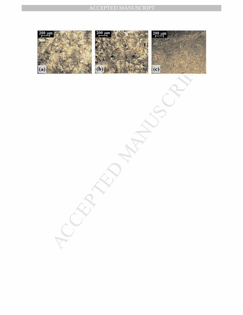
Figure 9: Light microscope images from Zone b of Anchor A, showing an equiaxed grain
structure. (a) from Section F and (b) from Section G show coarse pearlite and Widmanstätten
ferrite, (c) from Section H shows mostly pearlite phase.
Figure 10: Light microscope images from Zone b of Anchor B show no equiaxed grain
structure. (a) Section F shows Widmanstätten ferrite growth and pearlite phase. (b) from
Section G and (c) from Section H show ferrite grains with small amount of pearlite at grain
boundaries.
Figure 11: (a) Vickers microhardness (m = 100 gf) along the x-axis on the diameter of the
shank, Anchor A, Zone a, Section F, and (b) carbon weight percent vs. distance along the
diameter of the shank, Anchor A, Zone a, Section F.
Figure 12: (a) Vickers microhardness (m = 100 gf), along the x-axis, on the diameter of the
shank, Anchor B, Zone a, Section F, and (b) carbon weight percent vs. distance along the
diameter of the shank, Anchor B, Zone a, Section F.
Figure 13: SEM images of typical slag inclusions: (a) Anchor A, Zone a, Section F, and (b)
Anchor B, Zone a, Section F.
Figure 14: Exposed forge-weld lines, after removing the corrosion layer with soda blasting
and etching one side (front for Anchor B and back for Anchor A) of each anchor. a – back of
Anchor B, b – front of Anchor B, c – back of Anchor A, d – front of Anchor A.
MANUSCRIP
T
ACCEPTED
ACCEPTED MANUSCRIPT
1
Place Site Quantity Date (AD) Reference
Black Sea port of Tomis, Romania
Store room 8
6th century Canarache, 1967 :85
Sicilian coast Shipwreck-
Cefalù 1
6th –7th centuries
Purpura 1983: 93 94–
Turkey Shipwreck-Yassıada 11 625/6
Van Doorninck 1982: 121
Seville, Spain 1 Second half of
6th century Cabrera, 2007: 16–
21
Dor (Tantura) lagoon, Israel
Shipwreck- Dor J 5 Between late 6th
and early 7th century
Kingsley and Raveh, 1996: 60–61;
Wachsmann and Raveh, 1980: 260
Turkey Shipwreck- Bozburun I
2 874
Harpster, 2005: 5, 7; Hocker et al, 1998a:
13; Hocker et al, 1998b: 7–8
Southern coast of France
Shipwreck- Agay A
3 Middle of the 10th century
Visquis, 1973: 158; Joncheray, 2007:
226 Sea of Marmara,
Turkey Shipwreck-
Çamaltiburnu 13 13th century Günsenin, 2005: 121
a Kapitän (1978: 271) defined them as Y-shaped, while Van Doorninck (1982: 234) proposed that they could have been T-shaped. b Four broken Y-shaped and T-shaped anchors found together with an amphora assemblage dating to the 13th
century AD, as well as 13 T-shaped anchors and 18 Y-shaped anchors found 17 m from the shipwreck. Despite this distance, the researcher believes that they comprised part of the cargo and belong to the same context (Günsenin, 2005: 121).
MANUSCRIP
T
ACCEPTED
ACCEPTED MANUSCRIPT
1
Reference Shank/(arms sum) ratio
Length of shank
(m)
Distance between tips (m)
Anchor
(Joncheray, 1975: 118–9; 1977: 7 fig 8)
2.06 1.40 0.68 Dramont F
Van Doorninck, 1982: 125,126 fig. 6-12
1.52 2.14 1.41 Yassiada An.1
Van Doorninck, 1982: 125, 127 fig. 6-14
1.70 2.19 1.29 Yassiada An.3
Van Doorninck, 1982: 125, 128 fig. 6-15
1.29 2.04 1.58 Yassiada An.4
Van Doorninck, 1982: 125, 128 fig. 6-16
1.56 2.38 1.53 Yassiada An.5
Van Doorninck, 1982: 126, 129 fig. 6-17
1.81 2.57 1.42 Yassiada An.6
Van Doorninck, 1982: 126 129 fig. 6: 18
1.67 2.25 1.35 Yassiada An.7
Van Doorninck, 1982: 126, 129 fig. 6-19
1.57 2.47 1.57 Yassiada An.8
Van Doorninck, 1982: 126, 130 fig. 6-20
1.30 2.00 1.54 Yassiada An.9
Van Doorninck, 1982: 126, 131 fig. 6-21
1.60 2.41 1.50 Yassiada An.10
Van Doorninck, 1982: 127, 131 fig. 6-22
1.56 2.42 1.55 Yassiada An.11
Kingsley and Raveh, 1996, 23, pl. 18 MA12; Raveh and Kingsley,
1996: fig 20–22: MA12
1.88 0.75 0.4 Dor
1.77 1.50 0.85 Yavne Yam Observed in the National Maritime museum in
Haifa 1.91 1.85 0.97 Yavne Yam
Bonino, 1971: 320, fig. 4 1.65 1.14 0.69 Cervia 1.39 – d – Tomis 1.44 – – Tomis
Canarache, 1967: 85
1.55 – – Tomis Hocker et al., 1998a: 13,
fig. 2
1.71 – – Bozburun I
Green, 1973: 168 1.65 – – Cape Andreas
MANUSCRIP
T
ACCEPTED
ACCEPTED MANUSCRIPT
1
Testing methods
Object Location Description Radiography
Soda Blasting
& Etching
OM HV SEM &
EDS
OES
Anchor A In the starboard between frames
F21 and F24,
touching the
timbers of the hull.
Covered with
concretion and with broken shank.
+
After removing the concretion (7 measurements).
+ +
9 metallog
raphic samples.
+ + +
Anchor B In the port side
between frames
F21 and F24,
touching the
timbers of the hull.
Covered with
concretion and with broken shank.
+
Before removing the concretion (5 measurements)
and (7 measurements) after removing the concretion.
+ +
9 metallog
raphic samples.
+ + +
MANUSCRIP
T
ACCEPTED
ACCEPTED MANUSCRIPT
1
C Fe Cu Mo Ni Cr S P Mn Si Fe Anchor B Zone a
0.23 99.4 0.004 0.002 0.012 0.004 0.005 0.005 0.021 0.064 99.4
Anchor A Zone b
0.13 99.7 0.017 0.001 0.016 --- 0.008 0.025 0.004 0.004 99.7
Anchor B Zone b
0.61 99.2 0.002 0.001 <0.001 --- 0.003 0.007 0.037 0.029 99.2
Anchor A Zone a
0.41 99.2 0.005 0.001 0.054 --- 0.005 0.074 0.004 0.088 99.2
MANUSCRIP
T
ACCEPTED
ACCEPTED MANUSCRIPT
1
Element
[wt.%]
Typical inclusion
[Anchor A]
Typical inclusion
[Anchor B]
O 13.86 24.46
Al 2.43 1.15
Si 9.76 5.2
P 1.20 -
K 1.28 0.93
Ca 17.06 2.89
Mn 2.00 1.98
Fe 52.37 61.4
MANUSCRIP
T
ACCEPTED
ACCEPTED MANUSCRIPT
MANUSCRIP
T
ACCEPTED
ACCEPTED MANUSCRIPT
MANUSCRIP
T
ACCEPTED
ACCEPTED MANUSCRIPT
MANUSCRIP
T
ACCEPTED
ACCEPTED MANUSCRIPT
MANUSCRIP
T
ACCEPTED
ACCEPTED MANUSCRIPT
MANUSCRIP
T
ACCEPTED
ACCEPTED MANUSCRIPT
MANUSCRIP
T
ACCEPTED
ACCEPTED MANUSCRIPT
MANUSCRIP
T
ACCEPTED
ACCEPTED MANUSCRIPT
MANUSCRIP
T
ACCEPTED
ACCEPTED MANUSCRIPT
MANUSCRIP
T
ACCEPTED
ACCEPTED MANUSCRIPT
MANUSCRIP
T
ACCEPTED
ACCEPTED MANUSCRIPT
MANUSCRIP
T
ACCEPTED
ACCEPTED MANUSCRIPT
MANUSCRIP
T
ACCEPTED
ACCEPTED MANUSCRIPT
MANUSCRIP
T
ACCEPTED
ACCEPTED MANUSCRIPT
MANUSCRIP
T
ACCEPTED
ACCEPTED MANUSCRIPT
MANUSCRIP
T
ACCEPTED
ACCEPTED MANUSCRIPT