absorption of co2 in a suspension of lime
TRANSCRIPT
Chemical Engineering Science, 1973, Vol. 28, pp. 825-837. Pergamon Press. Printed in Great Britain
Absorption of CO, in a suspension of lime
V. A. JUVERAR and M. M. SHARMA
Department of Chemical Technology, University of Bombay, Matunga Road, Bombay-19, India
(Received 11 July 1972)
Abstract-The kinetics of absorption of lean CO, in a suspension of lime was studied in 5 and 20 cm i.d. bubble columns and a 12.5 cm i.d. mechanically agitated contactor. The absorption of CO* is accompanied by a fast pseudo first order reaction. The rate of absorption in a batch of a suspension of lime remains essentially constant up to a level of carbonation of about 90 per cent and thereafter it decreases, due to the resistance associated with the dissolution of solids. The published data in the literature and the reported mechanism have been reanalyzed.
INTRODUCTION
THE CARBONATION of suspensions of lime is industrially practised for the manufacture of precipitated calcium carbonate, which is used in a variety of industries such as rubber, paints and pigments, cosmetics, etc. It is also important in the manufacture of pentaerythritol by the lime process. The carbonation reaction involves gas, liquid and solid phases; Ca(OH), has a finite solubility in water and the reaction occurs between dissolved CO, and OH- ions.
The overall process of the carbonation of lime consists of the following steps:
(i) Ca(OH),(s) G Caz+(aq) + 20H-(aq)
(ii) CO,(g) * CO, (as)
(iii) CO,(aq) + OH-(aq) + HCO,-(aq)
(iv) HCO,(aq) + OH-(aq) + Hz0 + C0,2-(aq)
(v) Ca2+(aq) + C032-(aq) --* CaCO,(S).
Steps (iv) and (v) are instantaneous and the rate controlling steps could be the dissolution of Ca(OH), and/or simultaneous absorption with reaction of CO,. When CO, is present along with an inert gas then some gas-side resistance for the transport of CO, from the bulk gas to the gas-liquid interface may also be important.
Very few attempts have been made to study the mechanism of the carbonation reaction.
Early studies in this field were carried out by Weber and Nilson [l]. These authors studied the carbonation of lime in a mechanically agitated contactor with pure carbon dioxide at atmo- spheric pressure. Tadaki and Maeda[2] studied the carbonation in a wetted wall column with l-4% carbon dioxide in air. These studies, however, do not give an explicit idea about the mechanism of the carbonation reaction. Recently Morris and Woodbum[3-51 have studied the carbonation of lime. These authors used mechanically agitated contactors for their studies. These authors have suggested that the controlling resistance in the initial stages of the carbonation of lime in a semi-batch reactor is on the gas side. This interpretation is most unlikely to be correct as shown later in our paper.
The aim of the present study was to establish the mechanism of the carbonation of lime and reconsider the data reported by Morris and Woodbum.
THEORY
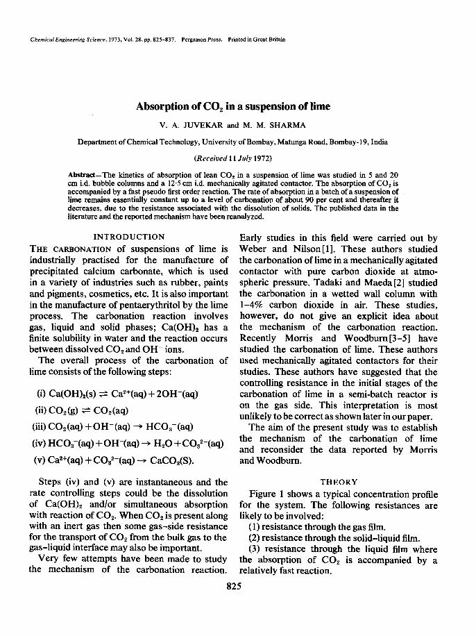
Figure 1 shows a typical concentration profile for the system. The following resistances are likely to be involved:
(1) resistance through the gas film. (2) resistance through the solid-liquid film. (3) resistance through the liquid film where
the absorption of CO2 is accompanied by a relatively fast reaction.
825
V. A. JUVEKAR and M. M. SHARMA
Bo r I
Distance- i
4 1 .!
0 a m
- Bs
Fig. 1. Concentration profile for the carbonation of lime suspension.
The rate of the various steps can be written as follows:
1. Rate of transport of CO, through the gasfilm
where
Ra = kGa(pQLpi) (1)
R = specific rate of absorption of CO, g mole/set cm2 dispersion
a = gas-liquid interfacial area, cm2/cm3 dispersion
kGa = gas-side mass transfer coefficient, g molelsec cm3 dispersion atm
ps = partial pressure of COz in the bulk gas, atm
pi = partial pressure of CO, at the gas- liquid interface, atm.
2. Rate of dissolution of lime
(2)
where,
ksa, = mass transfer coefficient for the dissolution of solids, se@
aP = solid-liquid interfacial area, cm2/ cm3 liquid
o = volume of liquid, cm3 &j = volume of dispersion, cm3 z = 2 = stoichiometric coefficient for
the overall reaction:
CO, + 20H- + C032- + H,O
[B,] = concentration of OH- ions at the solid- liquid interface (= solubility), g mole/cm3 liquid
CR,,] = concentration of OH- ions in the bulk of aqueous phase, g mole/cm3 liquid.
It is assumed that the bulk liquid is well agitated and there are no concentration gradients in the bulk liquid.
For the case when [B,] is approximately equal to [B,] there would be no resistance associated with the dissolution of solids.
3. Rate of transport of COz into the liquid and the reaction of CO, with hydroxyl ions
The transport of CO, into the liquid phase is accompanied by a fast reaction. Danckwerts and Sharma[6] have given a comprehensive account of the kinetics of the reaction between CO, and OH- ions. It is clear from their work that the rate of absorption of CO, will be considerably enhanced due to the fast reaction between CO2 and OH- ions. The enhancement factor will be dependent on the liquid side mass transfer coeffi- cient in the absence of chemical reaction kL, concentration of OH- ions, the diffusivities of CO, and OH- in the liquid, and the rate constant for the reaction between CO2 and OH-. Under certain circumstances the concentration of OH- ions at the gas-liquid interface may be the same as that in the bulk and the reaction may occur entirely in the film. The following equation will hold:
Ra = [A*]am. (3)
The necessary conditions to be satisfied are:
(44
826
and
(4b)
where,
k,, = liquid-side mass transfer coefficient in the absence of chemical reaction, cm/set
DB = diffusivity of OH- ions in the liquid, cm2/sec
k2 = rate constant for the reaction between CO, and OH- ions, cm3/g mole sec.
[A*] = solubility of CO, in aqueous phase, g mole/cm3 liquid, and is given by Eq. (5):
[A*] = Hpi (5)
where, H = Henry’s law solubility coefficient, g mole/cm3 atm.
Eliminating [A*] and pi from Eqs. (l), (3) and (5) we get:
Under certain circumstances the condition given by expression (4b) may be satisfied but that given by expression (4a) may not be satisfied. For instance the condition given by expression (4a) may not be satisfied for low values of [B,] and relatively high values of k[,. Here,
emJ_1 kL -
(7)
When the condition given by expression (4a) is not satisfied it implies that a part of the reaction between COZ and OH- occurs in the film and the rest in the bulk liquid.
Danckwert’s surface-renewal theory gives the following equation for Ra:
Absorption of CO, in a suspension of lime
Ra = tips, ~&ik,[Bol+ kL” 1 + aH d/DAk2 [B,] + kL*'
b
(8)
When the condition given by expression (4b) is not satisfied there will be depletion of OH- ions in the liquid film: Here,
-pCl_M_/Z& (9) L A
Under the above condition the rate of absorp- tion of COZ will be given by the following equation:
Ra2E&&_ 1+*
G
(10)
Where 4 is the enhancement factor, that is, the ratio of the liquid-side mass transfer co- efficient with reaction to that in the absence of chemical reaction.
The penetration theory does not give an analytic expression for 4 under the conditions of the depletion of B in the film. However, the film theory, with the assumption made by van Krevelen and Hoftizer[7], and Hikita and Asai [8], gives the following analytic expression:
(11)
For greater accuracy the term D /DA in Eq. (11) was replaced by &. The differences in the predictions based on the penetration and film theories under the above conditions are for practical purposes insignificant.
MATERIALS
Lime used in this work was obtained from Sturdia Chemicals (Rishikesh, U.P., India) Sodium hydroxide, sodium carbonate and sodium bicarbonate used were of technical grade. All
827
aqueous solutions were prepared with tap water. A small amount of tricresyl phosphate was used as an antifoami~ agent.
ANALYSIS
The extent of the car~nation of a lime sample was determined by the acidimetric titration of the sample with standard hydrochloric acid using phenolphthalein as an indicator.
EXPERIMENTAL
(a) Bubble column: Perspex bubble columns of 5 and 20 cm id. were used. The gas was introduced at the bottom of the column through tubes of 1 cm and 2.5 cm diameter, respectively. The super&&l gas velocity, based on the column cross-sectional area,, was varied from 10 to 70 cm/set. In this range of superficial gas velocity the mode of the introduction of the gas is unimportant provided the height of dispersion is at least four times the column diameter 191. The ratio of the height of dispersion to the column diameter was maintained between 7 and 8. The partial pressure of COz in the gas stream was varied by mixing it with air. The flow rates of air and carbon dioxide were measured with cali- brated rotameters. A suitable mixing length was provided to ensure a thorough mixing of COz and air.
(b) Mechanically agitated contactor: A 12.5 cm i.d. and 30cm high glass vessel (Corning resin kettle) was used. It was provided with standard vertical bathes, each one tenth of the diameter of the vessel. The impeller used was a stainless steel, 7.5 cm dia. six-bladed straight turbine. The agitator was driven by an induction motor and the speed of agitation was varied from 1000 to 2000 revlmin. by means of a set of pulleys.
PROCEDURE
All the experiments were carried out in a semi-batch manner. A freshly prepared lime suspension was introduced into a clean reactor to the required height. The slurry was first agitated and the initial sample was withdrawn through the sample outlet at the bottom of the
V. A. JUVEKAR and M. M. SHARMA
contactor. (In the case of bubble columns agitation was provided by sparging air through the slurry.) Then air-CO, mixture of the desired composition was introduced through the slurry and at the same time the stop watch was started. During a run, the height of dispersion of the liquid and the pressure of the gas at the inlet were noted. After a known interval of time, the flow of COz through the contactor was stopped. A sample of the slurry was withdrawn while the slurry was kept agitated. The temperatures at the beginning and the end of the run were also noted.
For the sake of comparison, some work was also carried out on the carbonation of sodium hydroxide and buffer solutions of sodium carbonate and bicarbonate.
RESULTS AND DISCUSSION
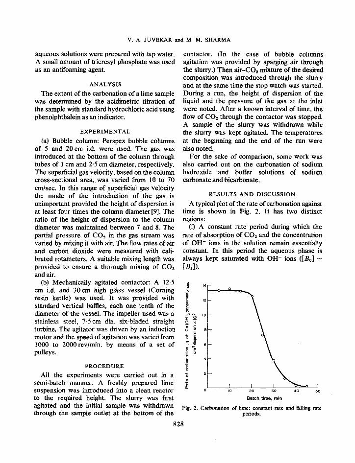
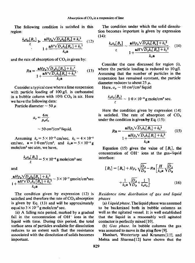
A typical plot of the rate of carbonation against time is shown in Fig. 2. It has two distinct regions:
(i) A constant rate period during which the rate of absorption of CO, and the concentration of OH- ions in the solution remain essentially constant. In this period the aqueous phase is always kept saturated with OH- ions (C&J - E&3).
14
12
IO
e
6
4
2
0 IO 20 30 40 SO
Batch time, min
Fig. 2. Carbonation of lime: constant rate and failing rate periods.
828
Absorption of CO2 in a suspension of lime
The following condition is satisfied in this region:
and the rate of absorption of COz is given by:
Ra = aHpJ’Q&z [&I + kL2 1 + aHvD.dz [&I + b2 * (13)
&a
Consider a typical case where a lime suspension with particle loading of 100 g/l. is carbonated in a bubble column with 10% CO2 in air. Here we have the following data:
Particle diameter - 50 p
6m ap= ppdp
- 50 cm2/cm3 liquid.
Assuming k, = 5 X low3 cmlsec, kL = 4 X 1O-2 cmlsec, a = I.0 cm2/cm3, and kca = 5 X low5 g mole/cm3 set atm, we have,
k,a,[ = 5 X lo+ g mole/cm3 set 2
and
aHp,dD,k, [B,] + kL2
1 + dvD,kz LB,1 + kL2 - 3 X lo-’ gmole/cm3sec.
kca
The condition given by expression (12) is satisfied and therefore the rate of CO2 absorption is given by Eq. (13) and will be approximately equal to 3 X lo-’ g mole/cm3 sec.
(ii) A falling rate period, marked by a gradual fall in the concentration of OH- ions in the liquid with time. During this period, the total surface area of particles available for dissolution reduces to an extent such that the resistance associated with the dissolution of solids becomes important.
The condition under which the solid dissolu- tion becomes important is given by expression (14):
Consider the case discussed for region (i), where the particle loading is reduced to 10 g/l. Assuming that the number of particles in the suspension has remained constant, the particle diameter reduces to about 25 CL.
Here, up - 10 cm2/cm3 liquid
ka,(&) - 1 *O X 1 0m6 g mole/cm3 sec. z
Here the condition given by expression (14) is satisfied. The rate of absorption of CO2 under the condition is given by Eq. (15):
Ra= ~Pg~D,kdBil+ k2
_ aPoV’D,hCBil+ kL2. (15)
1+ - _ - ka
Equation (15) gives the value of [BJ , the concentration of OH- ions at the gas-liquid interface:
[BiI = LB,1 +HPsJ VE-Ra[&@
(16)
Residence time distribution of gas and liquid phases
(a) Liquid phase. The liquid phase was assumed to be backmixed both in bubble columns as well as the agitated vessel. It is well established that the liquid in a reasonably well agitated contactor is perfectly mixed [ 101. _ -
(b) Gas phase. In bubble columns the was assumed to move in the plug flow [9].
Hanhart, Westerterp and Kramers [ 111, Mehta and Sharma [ 121 have shown that
gas
and the
829
V. A. JUVEKAR and M. M. SHARMA
gas phase in agitated gas-liquid dispersions is almost completely mixed, when the speed of agitation exceeds a certain critical speed. How- ever, in the presence of fine solid particles the coalescence in the gas bubbles may be sub- stantially different. This may change the back- mixing characteristics in the gas phase. Morris and Woodbum[3] have shown that in the presence of solid particles the gas phase moves essentially in the plug flow even under the conditions of fairly intense agitation. It was also found in the present investigation that the results were more consistent when the plug flow model for gas was assumed than when the backmix model was assumed (see Table 1).
Physical properties of systems Various system properties such as the
solubility of COz in aqueous solution of OH- ions, the rate constant for the reaction between COz and OH- ions, diffisivity of CO, in aqueous solutions of OH- ions were estimated by the procedures outlined by Danckwerts and Sharma [6]
The solubility of lime in water at 30°C was takenas2aOX 10-5gmo1e/cm3[13].
MASS TRANSFER COEFFICIENTS IN GAS-LIQUID-SOLID SYSTEMS
Bubble column (a) Determination of kLa. The values of kLa
in bubble columns were obtained by carrying out the absorption of CO, in an aqueous buffer solution of Na,C03-NaHCO,, (ionic strength
= 2 g ion/l.) in which calcium carbonate particles were suspended. The ratio of C032- ions to HC032- ions was kept equal to about 1. Under these conditions the pseudo first order rate constant (k,) for the reaction between CO2 and OH- ions is about O-6 set-‘[6]. Assuming kL = 3 X 10e2 cm/set and DA = 2 X 10m5 cm2/sec, we have,
-- 0.12 G 1. kL
The rate of absorption under these conditions is given by Eq. ( 17):
Ra = kLaHpE, (17)
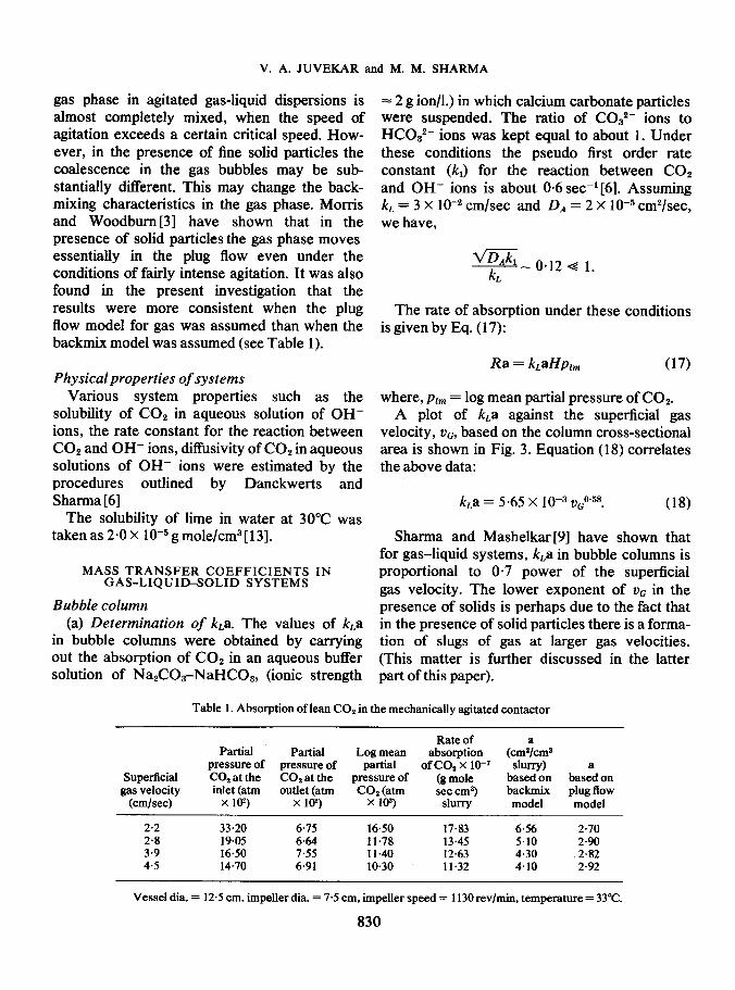
where, plm = log mean partial pressure of C02. A plot of kLa against the superficial gas
velocity, uG, based on the column cross-sectional area is shown in Fig. 3. Equation (18) correlates the above data:
k,a = 5.65 x 1O-3 vGo.5s. (18)
Sharma and Mashelkar[9] have shown that for gas-liquid systems, k,a in bubble columns is proportional to O-7 power of the superficial gas velocity. The lower exponent of vG in the presence of solids is perhaps due to the fact that in the presence of solid particles there is a forma- tion of slugs of gas at larger gas velocities. (This matter is further discussed in the latter part of this paper).
Table 1. Absorption of lean CO2 in the mechanically agitated contactor
Superficial gas velocity
(cmlsec)
2.2 2.8 3.9 4.5
Rate of a Partial Partial Log mean absorption (cmp/cm3
pressure of pressure of partial of co, x lo-’ slurry) a CO2 at the CO, at the pressure of (g mole based on based on inlet (atm outlet (atm CO* (atm set cm3 backmix plug flow
x 102) x loz) x lop) slurry model model
33.20 6.75 16.50 17.83 6.56 2.70 19.05 6.64 11.78 13.45 5.10 2.90 16.50 7.55 Il.40 12.63 4.30 2.82 14.70 6.91 10.30 11.32 4.10 2.92
Vessel dia. = 12.5 cm, impeller dia. = 7.5 cm, impeller speed = 1130 rev/min, temperature = 33°C.
830
10 20 30 40 50 60 70
v,. cm/set
Fig. 3. Effect of superficial gas velocity on liquid-side mass transfer coefficient in the 5 cm i.d. bubble column.
(b) Gas-side resistance in bubble columns Equation (6) shows that the gas side resistance would be negligible when Hps~D,k,[ B,]/ kGa is very much less than unity. The contribution of the gas film resistance to the total resistance to mass transfer should be negligible in the case of the carbonation of lime as can be seen from the following data:
For VG = lOcm/sec, kGa - 5 X 10m5 g mole/cm3 set atm [9] a - I.5 cm2/cm3, pn = 0.1 atm (10% CO, in air), we have:
HPS~ _ o.oo9 Q 1 kca
However, in the case of the carbonation of sodium hydroxide the contribution of the gas film resistance to the total resistance is about lo-20 per cent [9].
Mechanically agitated contactor (a) Determination of k,a and kL. The liquid-
side mass transfer coefficient in the agitated vessel was determined by the procedure analogous to that used for the bubble column contactors. The values of gas-liquid interfacial area were obtained from the experiments on the carbonation of caustic soda containing suspended lime. From kLa and a, values of true liquid side mass transfer coefficient, kL, were obtained.
Absorption of CO2 in a suspension of lime
The values of kL were found to be about 6.5 X lo+ cm/set and were practically independent of the impeller speed in the range of the impeller speeds employed (1000-2000 revlmin).
(b) Gas-side resistance in the mechanically agitated contactor. The values of the gas-side mass transfer coefficient (kGa) in the mechanically agitated contactor at the impeller speeds used in this work are of the order of 1 Om4 g mole/cm3 set atm [ 141. The gas film resistance is therefore expected to be insignificant even in the case of the carbonation of sodium hydroxide. Thus for the carbonation of 2M sodium hydroxide with 10% CO, in air, we have:
DETERMINATION OF GAS-LIQUID AREA IN GAS-LIQUID-SOLID SYSTEMS
For the carbonation of the suspension of lime in bubble columns we have:
G+ZZi _ 2.5. L
For lO%CO,inair(A*)=2~8~ 10-6gmole/cm3. Therefore,
g+ J- 4 - 10.
A
The conditions given by expressions (7) and (4b) are satisfied. The rate of COz absorption is therefore given by Eq. (8). Since the gas film resistance to the transfer of COz is negligible, Eq. (8) reduces to the form:
Ra = aHpl,qDAk2[ B,] + kL2. (19)
Since the conditions given by expressions (7) and (4b) are satisfied in mechanically agitated contactors, the rate of absorption of CO2 in the mechanically agitated contactor is also given by Eq. (19).
Equation (19) was used to determine the gas- liquid inter-facial area from the observed rate of
831
V. A. JUVEKAR and M. M. SHARMA
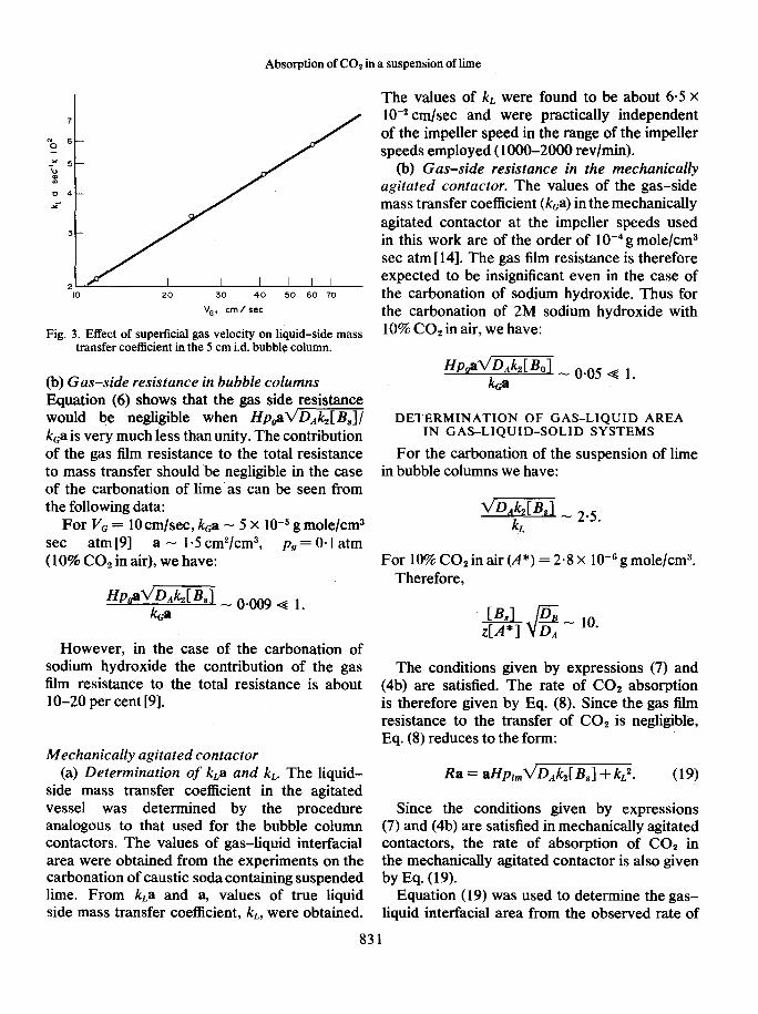
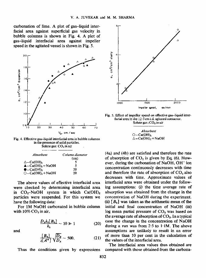
5r carbonation of lime. A plot of gas-liquid inter- facial area against superficial gas velocity in bubble columns is shown in Fig. 4. A plot of gas-squid inte~aci~ area against impeller speed in the agitated vessel is shown in Fig. 5.
08 I I I I I I
IO 20 30 40 xl 60 70
V,. cm /set
Fig. 4. Effective gas-liquid interfacial area in bubble columns in the presence of solid particles.
Solute gas: CO* in air
Absorbent Column diameter (cm)
A- Ca(OH), 5 A-CalOHL+NaOH 5 l -tia<OHj; 0-C~OH)~+NaOH
20 20
The above values of effective interfacial area were checked by dete~ining interfacial area in COrNaOH system in which Ca(OH)2 particles were suspended. For this system we have the following data:
For 1M NaOH carbonated in bubble column with 10% COz in air,
!l?d!pLlO,l L
and
mv
(21)
Thus the conditions given by expressions
Impeller speed, rev/n-tin
Fig. 5. Effect of impeller speed on effective gas-liquid inter- facial area in the 12.5 cm i.d. agitated contactor.
Solute gas :.COe in air
Absorbent 0 - Ca(OH)2 A-Ca~OH)~+NaOH
(4a) and (4b) are satisfied and therefore the rate of absorption of CO, is given by Eq. (6). How- ever, during the carbonation of NaOH, OH- ion concentration continuously decreases with time and therefore the rate of absorption of COz also decreases with time. Approximate values of interfacial area were obtained under the follow- ing assumptions: (i) the time average rate of absorption was obtained from the change in the concentration of NaOH during the experiment. (ii) [B,] was taken as the arithmetic mean of the initial and final concentration of NaOH (iii) log mean partial pressure of COz was based on the average rate of absorption of COz. In a typical case the change in the concent~tion of NaOH during a run was from 2.5 to 1 * 1M. The above assumptions are unlikely to result in an error of more than 10 per cent in the calculation of the values of the interfacial area.
The interfacial area values thus obtained are compared with those obtained from the carbona-
832
Absorption of CO, in a suspension of lime
tion of lime (see Figs. 3 and 5). The two sets of values are in fair agreement.
Efect of CO2 partial pressure on the rate of carbonation
An increase in the partial pressure of COZ beyond a certain value leads to the depletion of OH- ions at the gas-liquid interface. This leads to a reduction in the rate of COZ absorption per unit CO, partial pressure. The rate of absorption under these conditions can be obtained from Eq. (10).
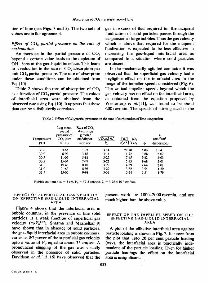
Table 2 shows the rate of absorption of COZ as a function of COZ partial pressure. The values of interfacial area were obtained from the observed rate using Eq. (10). It appears that these data can be satisfactorily correlated.
gas in excess of that required for the incipient fluidization of solid particles passes through the suspension as large bubbles. Thus the gas velocity which is above that required for the incipient fluidization is expected to be less effective in increasing the gas-liquid interfacial area as compared to a situation where solid particles are absent.
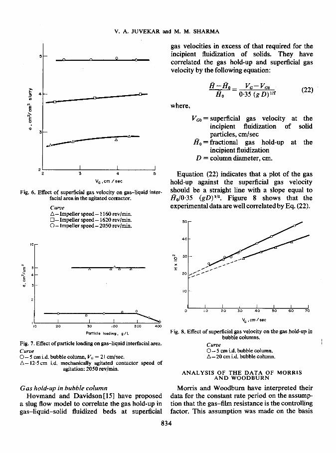
In the mechanically agitated contactor it was observed that the superficial gas velocity had a negligible effect on the interfacial area in the range of the impeller speeds considered (Fig. 6). The critical impeller speed, beyond which the gas velocity has no effect on the interfacial area, as obtained from the equation proposed by Westerterp et al. [l 11, was found to be about 600 revlmin. The speeds of stirring used in the
Table 2. Effect of CO* partial pressure on the rate of carbonation of lime suspension
Log mean Rate of CO, partial absorption
pressure of Temperature CO* (atm (cm&m3
(“c) x 102) dispersion)
30.0 3.65 1.93 3.14 22.20 3.00 1.94 30.0 6.92 3.87 3.14 11.72 2.88 2.07 30.5 11.02 5.81 3.22 7.45 2.82 2.03 30.5 15.04 7.47 3.22 5.45 2.68 2.01 31.0 1840 8.85 3.29 4.59 2.64 2.01 31.0 21.62 8*% 3.29 3.82 2.54 1.80 31.5 25.00 9.98 3.36 3.34 2.51 1.79
Bubble column dia. = 5 cm, Vc = 57.5 cm/set. k, = 3.25 X lo-* cm/set.
EFFECT OF SUPERFICIAL GAS VELOCITY ON EFFECTIVE GAS-LIQUID INTERFACIAL
AREA
Figure 4 shows that the interfacial area in bubble columns, in the presence of fine solid particles, is a weak function of superficial gas velocity (aaVG0”3). Sharma and Mashelkar [9] have shown that in absence of solid particles, the gas-liquid interfacial area in bubble columns, varies as O-7 power of the superficial gas velocity upto a value of V, equal to about 35 cm/set. A pronounced slugging of the gas was visually observed in the presence of solid particles. Davidson et al. [15,16] have observed that the
present work are lOOO-2000revlmin. and are much higher than the above value.
EFFECT OF THE IMPELLER SPEED ON THE EFFECTIVE GAS-LIQUID INTERFACIAL
AREA
A plot of the effective interfacial area against particle loading is shown in Fig. 7. It is seen from the plot that upto 20 per cent particle loading (w/v), the interfacial area is practically inde- pendent of the particle loading. Even for higher particle loadings the effect on the interfacial area is insignificant.
833
CES Vol. 2SNo. 3-K
a 6 . 0
3
!
A-
_YA-
A
*1 2 3 4 5
V, ,cm /set
Fig. 6. Effect of superficial gas velocity on gas-liquid inter- facial area in the agitated contactor.
Curve A- Impeller speed- 1160 rev/min. q - Impeller speed - 1620 rev/min. O-Impeller speed - 2050 rev/min.
V. A. JUVEKAR and M. M. SHARMA
gas velocities in excess of that required for the incipient fluidization of solids. They have correlated the gas hold-up and superficial gas velocity by the following equation:
- - H---Ho_ vc-v,o --
Ho 0.35 (g D) U2 (22)
where,
VGo = superficial gas velocity at the incipient fluidization of solid particles, cm/set
I?, = fractional gas hold-up at the incipient fluidization
D = column diameter, cm.
Equation (22) indicates that a plot of the gas hold-up against the superficial gas velocity should be a straight line with a slope equal to Ho/o*35 (gD) 1’2. Figure 8 shows that the experimental data are well correlated by Eq. (22).
I I I I I I I 0 10 20 30 40 50 60 70
Particle loading, g/l
Fig. 7. Effect of particle loading on gas-liquid interfacial area.
Fig. 8. Effect of superlicial gas velocity on the gas hold-up in bubble columns.
Curve Curve 0 - 5 cm i.d. bubble column, VG = 21 cmlsec. A- 125cm i.d. mechanicahy agitated contactor speed of
agitation: 2050 revlmin.
0 - 5 cm id. bubble column. A- 20 cm i.d. bubble column.
Gas hold-up in bubble column Hovmand and Davidson [ 151 have proposed
a slug flow model to correlate the gas hold-up in gas-liquid-solid fluidized beds at superficial
ANALYSIS OF THE DATA OF MORRIS AND WOODBURN
Morris and Woodbum have interpreted their data for the constant rate period on the assump- tion that the gas-film resistance is the controlling factor. This assumption was made on the basis
of the following points, which are most unlikely to be correct:
(i) The reaction CO,+ OH- + HCO,- is very fast and hence these authors assumed that this reaction is not the rate controlling step.
The liquid-side mass transfer coefficient (k,), under the experimental conditions used by these authors (vessel dia. 20 cm, impeller dia. 10 cm, impeller speed 2000 revlmin), can be estimated from the data of Mehta and Sharma [ 121 to be about 6 X 1 0e2 cmlsec.
Consider a case when 10% COz in air is used for the carbonation of lime suspension. Here we have:
and
@$@J_ 1.7 L
fi J- 4 - 10.
A
Thus the conditions given by expressions (7) and (4b) are satisfied which means that the rate of overall process is controlled by both the ditTu- sion of COz as well as the reaction between COz and OH- in the liquid film.
The condition for the gas-side resistance to be the controlling factor is given by fipgd/(DAh (B,) + kLz) /kGa a 1. For the present
caSe we have: kGa - 5 X low4 g mole/cm3 set atm[l4].
Here:
a&‘t,‘&kdBs) + kLz _ o.oo3 e 1
&a
Thus the gas film resistance is insignificant as compared to the total resistance.
(ii) Morris and Woodburn observed that for the carbonation of aqueous solution of NaOH in the concentration range of 2M-O*lM, the fractional conversion of COz was independent of inlet CO, concentration in the gas. These authors, therefore, concluded that the liquid-side resistance is unimportant and the process is gas film controlled. However these experimental data are in contradiction with the results of most
Absorption of CO, in a suspension of lime
of the published work on carbon dioxide absorp- tion. Danckwerts and Sharma[61 have analysed practically all the available information on the absorption of CO, in aqueous alkaline solutions. It is clear from their work that the absorption of CO* in aqueous solutions containing hydroxyl ions is essentially liquid film controlled.
For 2M caustic soda solution carbonated by 10% CO, in air, we have the following data:
y_,, L
and
-# +cMl. $ A
Thus the conditions given by expressions (4a) and (4b) are satisfied and the rate of absorption is given by Eq. (6).
Further we have:
HavD&[&l_ o.09
ka .
This shows that the contribution to the total resistance by the gas film is only about 9 per cent and hence the process is essentially liquid film controlled.
The experimental data of Morris and Woodbum can be reanalysed as follows:
Consider a run (Table 3, run 4 [4]) taken under the following conditions:
Vessel diameter = 38.8 cm Vessel capacity = 50 1 Impeller diameter = 9.7 cm Impeller type = 8 flat-bladed turbine Impeller speed = 50 rev/mitt. COz flow rate = 14.84 l/min at NTP Air flow rate = 84.09 I/min at NTP Fractional conversion of CO, = 0645 Temperature of dispersion = 30°C. Rate of COz absorption Ra = 1.43 X lo-‘g
mole/cm3 set Inlet COz partial pressure = O-15 atm Outlet COz partial pressure = 5.9 X lo-’ atm
835
V. A. JUVEKAR and M. M. SHARMA
Log mean COz partial pressure = 9.75 X IO-’ atm Henry’s law solubility constant (H) of COz in
water at 3O’C = 2.88 X 10e5 g mole/cm3 atm DifTusivity of Cot in water at 30°C DA = 2-l x
1 0e5 cm’/sec Second order rate constant for the reaction
between COz and OH- ions, k2 = 1.24 X 10⁴ l/g mole set
Saturation concentration of OH- ions, (I?,) = 4 x 10V5 g ion/cm3. kL is assumed to be about 6 x lo+ cm/set on the basis of the data obtained in this work.
Here,
m = 0.102 cm/set
and
Solubility of COz at log mean partial pressure,
(A*) = H~lrn = 2.81 X 10e6 g mole/cm3
(&) z. = 7.12.
Thus the conditions given by the expressions (7) and (4b) are satisfied and the rate of absorption of COz is given by Eq. (8).
kc is assumed to be about 1 X 10m4 g mole/cm’ sec.
Substituting all the values in Eq. (8) the inter- facial area value is calculated to be 0.48cm2/cm3 of slurry. This value of a appears to be reason- able in view of the fact that a low speed of agitation was employed.
CONCLUSION
The absorption of COa in a suspension of lime is accompanied by fast reaction in the gas- liquid film. The gas side resistance for the transport of COz to the gas-liquid interface is negligible. The data obtained from bubble columns and the mechanically agitated contactor can be correlated on the basis of the above model.
AcknowIedgeme&- We thank Dr. P. A. Ramachandran who had initially carried out some experimental work on the carbonation of lime.
[A*1
a
LB;
[&I
[&I
m
PQ Pi
Ph R
T
NOTATION
solubility of carbon dioxide in an aqueous solution, g mole/cm3
effective gas-liquid interfacial area, cm2/cm3 of dispersion (bubble column) cm2/cm3 slurry, mechanically agitated vessel
solid-liquid interfacial area, cm2/cm3 concentration of OH- ions at the gas-
liquid interface, g ion/cm3 concentration of OH- ions in the bulk
liquid phase, g ion/cm3 saturation concentration of OH- ions in
aqueous solution in equilibrium with Ca(OH)2 (solid), g ion/cm3
internal diameter of bubble column, cm diffisivity of CO, in aqueous solution,
cm2/sec diffisivity of OH- ions in aqueous
solution, cm2/sec particle diameter, cm gravitational acceleration, cm/sec2 Henry’s coefficient of solubility, g mole/
cm3 atm. fractional gas hold up fractional gas hold up at the incipient
fluidization gas side mass transfer coefficient, g
mole/cm2 set atm liquid side mass transfer coefficient,
cmlsec solid-liquid mass transfer coefficient,
cm/set pseudo first order rate constant, set-’ second order rate constant, cm3/g
mole set particle loading, g/cm3 liquid partial pressure of CO2 in gas stream, atm partial pressure of CO2 at the gas-liquid
interface, atm log mean partial pressure of C02, atm specific rate of absorption of C02, g
mole/cm3 set absolute temperature, “K
836

Ul PI r31 141 PI
;; PI [91
[Ill [121 [131 [I41 WI 1161
Absorption of CO, in a suspension of lime
I/ volume of the slurry charged, cm3 Greek symbols Vd volume of the dispersion, cm3 pP particle density, g/cm3 V, superficial gas velocity, cm/set $ enhancement factor, that is, the ratio of
z stoichiometric coefficient for the reaction mass transfer coefficient with reaction between CO, and OH- (= 2) to that without reaction.
REFERENCES
WEBER H. C. andNILSON K., Ind. Engng Ckem. 1926 18 1970. TADAKI T. and MAEDA S., Kagaku Kogaku Japan 1963 27 839; Ckem. Abstr. 1965 63 12391C. MORRIS R. M. and WOODBURN E. T., S.A. Ckem. Proc. 1967 Cp. 88. MORRIS R. M. and WOODBURN E. T., S.A. Ckem. Proc. 1967 Cp. 115. MORRIS R. M. and WOODBURN E. T., S. A. Ckem. Proc. 1967 Cp. 158. DANCKWERTS P. V. and SHARMA M. M., Ckem. Engnr Land. 1966 No. 202 CR244. VAN KREVELEN D. W. and HOFTYZER P. J., Rec. Trao. Ckim. 1948 67 563. HIKITA H. andASA1 S., Ckem. Engng Tokyo (English translation) 1964 28 1017. SHARMA M. M. and MASHELKAR R. A., Proceedings of the Symposium on Mass Transfer with Chemical Reaction, (Ed. Pirie J. M&p. 10. Institution of Chemical Engineers, London 1968. GEERLINGS M. W., Ph.D. thesis, Dannstadt, Germany 1957; WESTERTERP et al., Ckem. Engng Sci. 1963 18 157. HANHART J., WESTERTERP K R. and KRAMERS H., Ckem. Engng Sci. 1963 18 503. MEHTA V. D. and SHARMA M. M.. Ckem. Enenn Sci. 197126461. Int. Crit. Ta.bles, Vol. 4, p. 229 1928. ’
I I
MEHTA V. D., Ph.D. Thesis, University of Bombay, India 1970. HOVMAND S. and DAVIDSON J. F., Trans. Instn Ckem. Engrs 1968 46T-190. ORMISTON R. M., MITCHELL F. R. G. and DAVIDSON J. F., Trans. Instn Ckem. Engrs 1965 43T-209.
837