a treatise on analytical statics, with numerous examples
TRANSCRIPT

THE LIBRARYOF
THE UNIVERSITYOF CALIFORNIALOS ANGELES
SOUTHERNUNIVERSITY OF CALIFORNIA,
LIBRARY,*-OS ANGELES. CALIF.

A TREATISE ON
ANALYTICAL STATICS
CAMBRIDGE UNIVERSITY PRESS WAREHOUSE,C. F. CLAY, MANAGER.
UnnUon: FETTER LANE, B.C.
6inbrflf) : 100, PRINCES STREET.
Berlin : A. A8HER AND CO.
leipjig: F. A. BROCKHAU8.
eta goth: G. P. PUTNAM'S SONS.
Bombag anti Calcutta : MACMILLAN AND CO.. LTD.
[All Rights reserved]
A TREATISE ON
ANALYTICAL STATICS
WITH NUMEROUS EXAMPLES
BY
EDWARD JOHN ROUTH,Sc.D., LL.D., M.A., F.R.S., &c.
VOLUME I
SECOND EDITION
Cambridge:
at the University Press
1909
82219
First Edition 1891
Second Edition 1896
Reprinted 1909
CAMBRIDGE: PRINTED BY JOHN CLAY, si. A.
AT THE UNIVERSITY PRESS.
Engineering ft
a A Mafhematiea!
Sciences
PKEFACE
|~\URING many years it has been my duty and pleasure to
give courses of lectures on various Mathematical subjects^ to successive generations of students. The course on Statics
has been made the groundwork of the present treatise. It has
^ however been necessary to make many additions; for in a treatise
"> all parts of the subject must be discussed in a connected form r
while in a series of lectures a suitable choice has to be made.
A portion only of the science of Statics has been included in
this volume. It is felt that such subjects as Attractions, Astatics,
and the Bending of rods could not be adequately treated at the
end of a treatise without either making the volume too bulky
t> or requiring the other parts to be unduly curtailed. These re-
^ maining portions appear in the second volume.
In order to learn Statics it is essential to the student to work
numerous examples. Besides some of my own construction, I
have collected a large number from the University and College
Examination papers. Some of these are so good as to deserve to
rank among the theorems of the science rather than among the
examples. Solutions have been given to many of the examples,
sometimes at length and in other cases in the form of hints when
these appeared sufficient.
I have endeavoured to refer each result to its original author.
I have however found that it is a very difficult task to effect this
a 3
-VI PREFACE
with any completeness. The references will show that I have
searched many of the older books and memoirs as well as some
of those of recent date to discover the first mention of a theorem.
In this edition I have made many additions and have also
omitted several things which on after consideration appeared
to be of minor importance. The explanations also have been
simplified wherever there appeared to be any obscurity. For
the convenience of reference I have retained the order of the
articles as far as that was possible.
The latter part of the chapter on forces in three dimensions
has been enlarged by the addition of several theorems and the
portions on five and six forces re-arranged. The chapter on
graphical statics also has been almost entirely rewritten.
An index has been added which it is hoped will be found
useful.
EDWARD J. ROUTH.
PETERHOUSE,
May, 1896.
CONTENTS
CHAPTER I.
THE PARALLELOGRAM OF FORCES.
ARTS. PAGES
1 12. Elementary considerations on forces, &c. . . . I 7
13 18. Dynamical and statical laws . . . ... 7 11
1921. Rigid bodies 12
2223. Resultant forces 13
2430. Parallelogram of forces . ... . . . . . 14 17
31. Historical summary 17 18
CHAPTER II.
FORCES ACTING AT A POINT.
32 40. Geometrical Method. Triangle, Polygon and Parallelepiped
of forces. Three methods of resolution .... 19 23
41 46. Method of analysis. Resultant of any number of forces . 23 26
47. Forces which act normally to the faces of a polyhedron . 26
4849. Theorems on Determinants 262750. Oblique axes 27
51 53. The mean centre. Its use in resolving and compoundingforces 2731
54 61. Equilibrium of a particle. Smooth curves and surfaces . 31 34
6269. The principle of Work 343870 74. Astatic equilibrium. The astatic triangle of forces . . 38 40
75 77. Stable and unstable equilibrium. A free body under two
nd three forces . 40 42
Vlll CONTENTS
CHAPTER III.
PARALLEL FORCES.
ABTS.
78 81. Resultant of two and any number of parallel forces .
82 84. The centre of parallel forces
85 86. Conditions of equilibrium ......87. A body suspended from a fixed point....88. A body resting on a plane
89103. Theory of couples
CONTENTS IX
ARTS.
176178.
179.
180187.188190.
Problems on friction when the direction is known. Dif-
ferent methods of solution. Various examples
Wheel and axle with friction
Friction in unknown directions. Two methods
Examples. Botation of bodies on a finite and an infinite
number of supports. String of particles, &c.
PAGES
112120120122122127
127134
CHAPTER VI.
THE PRINCIPLE OF WORK.
191195. Proof of the principle 135138196. The forces which do not appear in the equation of work . 138 140
197. Work of a bent string. See also Art. 493 . . . . 140142198. Infinite forces 142
199. Converse of the principle of work 142 143
200201. Initial motion 143
202 204. Equations of equilibrium derived from work . . . 143 146
205. Examples on the principle . . . . . . . 146 148
206213. The work function 148152214 225. Stable and unstable equilibrium. Analytical method . 153 159
226228. Attracting or repelling atoms 159161229 234. Determination of stress in a simply stiff frame. Examples 161 168
235236. Abnormal deformations 168169237 238. Indeterminate tensions. Theorems of Crofton and Levy.
See also Art. 368 169170239 243. Geometrical method of determining the stability of a body.
The circle of stability 170174244 246. Rocking stones. Examples 175 177
247 254. Rocking stones, spherical and not spherical to a second
approximation in two and three dimensions . . . 177 182
255 256. Lagrange's proof of the principle of virtual work . . 182 183
CHAPTER VII.
FORCES IN THREE DIMENSIONS.
257 259. Resultants of a system at forces. Conditions of equi-
librium. See also Art. 331 184186260262. Components of a force 186187263267. Moment of a force 188190268 269. Problems on equilibrium. Pressures on an axis, rods,
spheres, rod on wall, curtain ring, &c 190 194
270. Poinsot's central axis 194195271278. The equivalent wrench. Analytical method . . . 195199279283. The Invariants . 199201
CONTENTS
ARTS.
CONTENTS XI
AKTS. PAGES
389 395. Tetrahedron. Volume, faces, and edges. Pyramid, cone
and double tetrahedra. Isosceles tetrahedron . . 259263396 399. Centres of gravity of arcs. Circle, catenary, cycloid, &c. . 263 264
400 402. Centres of gravity of circular areas 264 265
403 408. Geometrical and analytical projection of areas . . . 265 268
409 412. Centre of gravity of any area 268 271
413417. Theorems of Pappus 271 274
418 419. Areas on the surface of a right cone 274 276
420 424. Areas on a sphere. Theory of maps 276 279
425 427. Surfaces and solids of revolution. Moments and productsof inertia . 279 281
428 430. Ellipsoidal volumes and shells 281283431 432. Any surfaces and volumes 283 285
433 434. Heterogeneous bodies. Octant of ellipsoid. Triangular
area, &c 285287435 438. Lagrange's two theorems 287 289
439 441. Applications to pure geometry 289291
CHAPTER X.
ON STRINGS.
442 445. Catenary. Equations and properties . . . . 292 295
446 448. Problems on free and constrained catenaries . . . 295 301
449. Stability of catenaries 302
450 453. Heterogeneous chains. Cycloid, parabola, and the catenary
of equal strength . 302306454. String under any forces. General intrinsic equations . 306 307
455 456. General Cartesian equations 308 309
457 458. Constrained strings. Light string on a smooth curve.
Problem of Bernoulli 309310459 462. Heavy string on a smooth curve. The anti-centre and
statical directrix. Examples 310 314
463 466. Light string on a rough curve. Bough pegs . . . 315 317
467 471. Heavy string on a rough curve 317 320
472 473. Endless strings. Strings which just fit a curve . . . 321323474 477. Central forces. Various laws of force. Kinetic analogy.
Two centres 323 328
478 480. String on a smooth surface. Cartesian and Intrinsic
equations. Various theorems. Case of no forces . . 328 331
481. String on a surface of revolution 331 332
482. Spherical catenary . . 332333483. String on a cylinder 333335484. String on a right cone ....... 335
485 486. String on a rough surface 335 337
487. Minimum force to move a heavy circular string on a rough
plane, and other problems 337 338
Xll CONTENTS
ABTS. PAGES
488. Calculus of variations 338339489491. Elastic string. Hooke's law 339340
492. Heavy elastic string suspended by one end.... 341342
493. Work of an elastic string 342 343
494. Heavy elastic string on a smooth curve. The statical
directrix 343344495. Light elastic string on a rough curve. Rough pegs . . 344 345
496_499. Elastic string under any forces 345 346
500501. Elastic catenary 346347
CHAPTER XI.
THE MACHINES.
502505. Mechanical advantage. Efficiency 348349506 516. The Lever. Conditions of equilibrium. Pressure on axis.
Various kinds of Levers. For lever under any forces see
Art. 268 ; rough axis Art. 179 349353517. Roberval's balance 353354
518 520. The common balance 354355521 524. The common and Danish Steelyard 356 358
525 528. The single pulley 358359529 530. The system of pulleys with one rope 359361
531. Rigidity of cords 361
532 536. Systems of pulleys with several ropes 361 365
537539. The inclined plane 366368540 543. The wheel and axle. The differential axle . . . 368369544_546. Toothed wheels 369371547549. The wedge 371373550553. The screw 373375
NOTE ON TWO THEOKEMS IN CONICS ASSUMED IN ARTS. 126, 127 . . 376 378
INDEX 379391
CONTENTS OF VOLUME II.
ATTRACTIONS.
THE BENDING OF RODS.
ASIATICS.
CHAPTER I
1. THE science of Mechanics treats of the action of forces on
bodies. Under the influence of these forces the bodies may either
be in motion or remain at rest. That part of mechanics which
treats of the motion of bodies is called Dynamics. That part of
mechanics in which the bodies are at rest is called Statics.
If the determination of the motion of bodies under givenforces could be completely and easily solved, there would be no
obvious advantage in this division of the subject into two parts.
It is clear that statics is only that particular case of dynamics in
which the motions of the bodies are equated to zero. But the
particular case in which the motion is zero presents itself as a
much easier problem than the general one. At the same time
this particular case is one of great importance. It is importantnot merely for the intrinsic value of its own results but because
these are found to assist in the solution of the general case by the
help of a theorem due to DAlembert. It has therefore been
generally found convenient to lead up to the general problem of
dynamics by considering first the particular case of statics.
2. Since statics is a particular case of dynamics we may begin
by discussing the first principles of the more general science. Weshould consider how the mass of a body is measured, how the
velocity and acceleration of any particle are affected by the action
of forces. The general principles having been obtained we maythen descend to the particular case by putting these velocities
equal to zero. In this way the relationship of the two great
branches of mechanics is clearly seen and their results are founded
on a common basis.
R. s. i. 1
2 THE PARALLELOGRAM OF FORCES [CHAP. I
3. There is another way of studying statics which has its own
advantages. We might begin by assuming some simple axioms
relating to the action of forces on bodies without introducing
any properties of motion. In this method we introduce no
terms or principles but those which are continually used in
statics, leaving to dynamics the study of those terms which are
peculiar to it.
Whether this is an advantageous method of studying statics or
not depends on the choice of the fundamental axioms. In the
first place they must be simple in character. In the second place
they must be easily verified by experiment. For example we
might take as an axiom the proposition usually called the parallelo-
gram of forces or we might, after Lagrange, start from the
principle of work. But neither of these principles satisfies the
conditions just mentioned, for they do not seem sufficiently
obvious on first acquaintance to command assent.
If we found the two parts of mechanics on a common basis,
that basis must be broader than that which is necessary to support
merely the principles of statics. We have to assume at once all
the experimental results required in mechanics instead of onlythose required in statics. Now there is an advantage in intro-
ducing the fundamental experiments in the order in which theyare wanted. We thus more easily distinguish the special necessity
for each, we see more clearly what results are deduced from each
experiment. The order of proceeding would be to begin with
such elementary axioms about forces as will enable us to studytheir composition and resolution. Presently other experimentalresults are introduced as they are required and finally when the
general problem of dynamics is reached, the whole of the funda-
mental axioms are summed up and consolidated.
In a treatise on statics it is necessary to consider both these
methods. We shall examine first how the elementary principles
of statics are connected with the axioms required for the more
general problem of dynamics, and secondly how they may be made
to stand on a base of their own.
4. In mechanics we have to treat of the action of forces on
bodies. The term force is defined by Newton in the following
terms.
An impressed force is an action exerted on a body in order to
ART. 7] CHARACTERISTICS OF A FORCE 3
change its state either of rest or of uniform motion in a straightline.
5. Characteristics of a Force. When a force acts on a
body the action exerted has (1) a point of application, (2) a
direction in space, (3) magnitude.
Two forces are said to be equal in magnitude when, if appliedto the same particle in opposite directions, they balance each
other. The magnitudes of forces are measured by taking some
one force as a unit, then a force which will balance two unit
forces is represented by two units and so on.
6. The simplest appeal to our experience will convince us
that many at least of the ordinary forces of nature possess these
three characteristics. If force be exerted on a body by pulling a
string attached to it, the point of attachment of the string is the
point of application, and the direction of the string is the direction
of the force. The existence of the third element of a force is shown
by the fact that we may exert different pulls on the string.
All the causes which produce or tend to produce motion in a
body are not known. But as they are studied, it is found that
they can be analysed into simpler causes, and these simpler causes
are seen to have the three characteristics of a force. If there be
any causes of motion which cannot be thus analysed, such causes
are not considered as forces whose effects are to be discussed in
the science of statics.
7. There are other things besides forces which possess these
three characteristics. These other things may be used to help us
in our arguments about forces so far as their other properties are
common also to forces.
The most important of these analogies is that of a finite
straight line. Let this finite straight line be AB. One extremity
A will represent the point of application. The direction in space
of the straight line will represent the direction of the force and
the length of the line will represent the magnitude of the force.
Other things besides forces may also be represented graphically
by a finite straight line. Thus in dynamics it will be seen that
both the velocity and the momentum of a particle have direction
and magnitude and may in the same way be represented by a
finite straight line. One extremity A is placed at the particle,
12
4 THE PARALLELOGRAM OF FORCES [CHAP. I
the direction of the straight line represents the direction of the
velocity and the length represents the magnitude. Generally
this analogy is useful whenever the things considered obey what
we shall presently call the parallelogram law.
8. In order to represent completely the direction of a force bythe direction of the straight line AB, it is necessary to have some
convention to determine whether the force pulls A in the direction
AB or pushes A in the direction BA. This convention is supplied
by the use of the terms positive and negative. The positive and
negative directions of straight lines being defined by some conven-
tion or rule, the forces which act in the positive directions of their
lines of action are called positive and those in the opposite direc-
tions are called negative. These conventions are often indicated
by the conditions of the problem under consideration, but they
usually agree with the rules adopted in the differential calculus.
Thus the direction of the radius vector drawn from the origin
is usually taken as the positive direction, and so on for all lines.
Sometimes instead of using the term positive, the direction or
sense of a force is indicated by the order of the letters, thus a force
AB is a force acting in the direction A to B, a force BA is a force
acting from B towards A.
9. The third element of a force is its magnitude. This is
represented by the length of the representative straight line. Aunit of force is represented by a unit of length on any scale we
please ;a force of n such units of force is then represented by
a straight line of n units of length.
10. Measure of a force. A force must be measured by its
effects. Since a force may produce many effects there are several
methods open to us. If we wish the measure of two equal forces
acting together to be twice that of a single force equal to either,
the effect which is to measure the force must be properly chosen.
We may measure a force by the weight of the mass which it
will support. Placing two equal masses side by side, they will be
supported by equal forces. Joining these together we see that a
double force will support a double mass. Thus the effect is
proportional to the magnitude of the cause.
We may also measure a force by the motion it will produce in
a given body in a given time. If by motion is here meant velocity
ART. 11] MEASURE OF A FORCE 5
then it may be shown by the experiments usually quoted to provethe second law of motion that a double force will produce a double
velocity. So here also the effect chosen as the measure is pro-
portional to the magnitude of the cause. This measure requiressome experimental results, necessary for dynamics, but not used
afterwards in statics.
If we agree to measure a force by the weight it will supportthe unit will depend on the force of gravity at the place where
the experiment is made. Such a unit will therefore presentseveral inconveniences. If also we measure a force by the velocity
generated in a unit of mass in a unit of time, it is necessaryto discuss how these' other units are to be chosen.
It- is not necessary for us, at this stage of our argument, to decide on the
best method of measuring a force. It will be presently seen that our equationsare concerned for the most part with the ratios of forces rather than with the
forces themselves. The choice of the actual unit is therefore unimportant at
present, and we can leave this choice until the proper occasion arrives. The
comparative effects of forces will then have been discussed, and the reader will
the better understand the reasons why any particular choice is made.
When therefore we speak of several forces equal to the weight of one, two or
three pounds &c., acting on a body and determine the conditions of equilibrium,
we shall find that the same conditions are true for forces equal to the weight of
one, two or three oz. &c., and generally of all forces in the same ratio.
11. One system of units is that based on the foot, pound, and
second as the three fundamental units of length, mass, and time.
The unit force is that force which acting on a pound of matter for
one second generates a velocity of one foot per second. This unit
of force is called the poundal.
The foot and the pound are defined by certain standards keptin a place of security for reference. Thus the imperial yard is the
distance between two marks on a certain bar, preserved in the
Tower of London, when the whole bar has a temperature of
62 Fah. The unit of time is a certain known fraction of a mean
solar day.
The units committee of the British Association recommended
the general adoption of the centimetre the gramme and the
second as the three fundamental units of space, mass and time.
These they proposed should be distinguished from absolute units,
otherwise derived, by the letters c. G. s. prefixed, these being the
initial letters of the names of the three fundamental units. The
C.G. s. unit of force is called a dyne. This is the force which
6 THE PARALLELOGRAM OF FORCES. [CHAP. I
acting on a gramme for a second generates the velocity of a
centimetre per second.
It is found by experiment that a body, say a unit of mass,
falling in vacuo for one second acquires very nearly a velocity of
32'19 feet per second. This velocity is the same as 98117
centimetres per second. It follows therefore that a poundal is
about ^nd part of the weight of one pound, and a dyne is the
weight of-g|-j-st part of a gramme. These numerical relations
strictly apply only to the place of observation, for the force of
gravity is not the same at all places on the earth. The difference
between the greatest and least values of gravity is about y^th of
its mean value.
The relations which exist between these and other units in
common use are given at length in Everett's treatise on units and
Physical Constants and in Lupton's numerical tables. We have
nearly
one inch = 2'54 centimetres, one pound = 453'59 grammes.
It follows from what precedes that one poundal = 13825 dynes.
12. The parallelogram of velocities. This proposition is
preliminary to Newton's laws of motion.
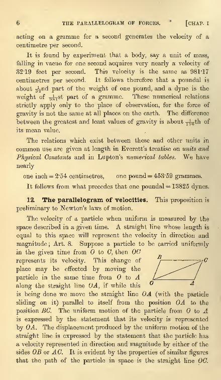
The velocity of a particle when uniform is measured by the
space described in a given time. A straight line whose length is
equal to this space will represent the velocity in direction and
magnitude; Art. 8. Suppose a particle to be carried uniformlyin the given time from to C, then 00
represents its velocity. This change of
place may be effected by moving the
particle in the same time from to Aalong the straight line OA, if while this
u 'd
is being done we move the straight line OA (with the particle
sliding on it) parallel to itself from the position OA to the
position BC. The uniform motion of the particle from to Ais expressed by the statement that its velocity is represented
by OA. The displacement produced by the uniform motion of the
straight line is expressed by the statement that the particle has
a velocity represented in direction and magnitude by either of the
sides OS or A C. It is evident by the properties of similar figures
that the path of the particle in space is the straight line 00.
ART. 13] THE PARALLELOGRAM OF VELOCITIES 7
It follows that when a particle moves with two simultaneous
velocities represented in direction and magnitude by the straight
lines OA, OB its motion is the same as if it were moved with
a single velocity represented in direction and magnitude by the
diagonal OC of the parallelogram described on OA, OB as sides.
This proposition is usually called the parallelogram of velocities.
Let a particle move with three simultaneous velocities repre-
sented in direction and magnitude by the three straight lines
OA i, OA 2 ,OA 3 . We may replace the two velocities OA 1} OA 2
by the single velocity represented in direction and magnitude
by the diagonal OBt of the parallelogram described on OA l} OA 2
as sides. The particle now moves with the two simultaneous
velocities represented by OB1 and OA 3 . We may again use the
same rule. We replace these two velocities by the single velocity
represented in direction and magnitude by the diagonal OB2
described on OB^ and on OA 3 as sides. We have thus replaced
the three given simultaneous velocities by a single velocity.
In the same way any number of simultaneous velocities maybe replaced by a single velocity.
If the simultaneous velocities represented by OA l} OA 2 &c.
were all altered in the same ratio, it is evident from the properties
of similar figures that the resulting single velocity will also be
altered in the same ratio.
Let the simultaneous velocities OA 1; OA% &c. be such that
their resulting velocity is zero. It follows that if all the velocities
OA 1} OA 2 &c. are altered in any, the same, ratio the resulting
velocity is still zero.
13. Newton's laws of Motion. These are given in the
introduction to the Principia.
1. Every body continues in its state of rest or of uniform
motion in a straight line, except in so far as it may be compelled
by force to change that state.
2. Change of motion is proportional to the force applied
and takes place in the direction of the straight line in which
the force acts.
3. To every action there is always an equal and contrary
reaction; or the mutual actions of any two bodies are always
equal and oppositely directed.
8 THE PARALLELOGRAM OF FORCES [CHAP. I
The full significance of these laws cannot be understood until
the student takes up the subject of dynamics. The experimentswhich suggest these laws, and their further verification, are best
studied in connection with that branch of the science, and are to
be found in books on elementary dynamics. The student who has
not already read some such treatise is advised to assume the truth
of these laws for the present. We shall accordingly not enter into
a full discussion of them in this treatise, but we shall confine our
remarks to those portions which are required in statical problems.
14. The first law asserts the inertness of matter. A body at
rest will continue at rest unless acted on by some external force.
At first sight this may appear to be a repetition of the definition
of force, since any cause which tends to move a body at rest is
called a force. But it is not so. Here we assert as the result
of observation or experiment the inertness of each particle of
matter. It has no tendency to move itself, it is moved only bythe action of causes external to itself.
15. In the second law of motion the independence of forces
which act on a particle is asserted. If the effect of a force is
always proportional to the force impressed it is clearly meant
that each force must produce its own effect in direction and mag-nitude as if it acted singly on the particle placed at rest.
Let us consider the meaning of this statement a little more
fully. Let a given force act on a given particle placed at rest at a
point and generate in a given time a velocity which we mayrepresent graphically by the straight line OA. Let a second force
act on the same particle again placed at rest at and generate in
the same time a velocity which we may represent by OB. If both
forces act simultaneously on the particle both these velocities are
generated. The actual velocity of the particle is then represented
by the diagonal OG of the parallelogram described on OA, OB as
sides, Art. 12. In the same way, if any number of forces act
simultaneously on a particle at rest, the law directs that we
are to determine the velocity generated by each as if it acted
alone for a given time. These separate velocities are then to
be combined into a single velocity in the manner described in
Art. 12. This single velocity is asserted to be the effect of the
simultaneous action of the forces.
Let a system of forces be such that when they act simul-
ART. 16] NEWTON'S LAWS OF MOTION _9
taneously on a particle placed at rest the resulting velocity of
the particle is zero. These forces are then in equilibrium. Let
a second system of forces be also such that when they act on
the particle placed at rest, the resulting velocity of the particle is
again zero. Then this second system of forces is also in equi-
librium. Let these two systems act simultaneously, then since
the forces do not interfere with each other, the resulting velocity
of the particle is still zero. We thus arrive at the following
important proposition.
Let us suppose that there are two systems offorces each of which
when acting alone on a particle would be in equilibrium. Then when
both systems act simultaneously there will still be equilibrium.
This is sometimes called the principle of the superposition of
forces in equilibrium. When we are trying to find the conditions
of equilibrium of some system of forces, the principle enables us to
simplify the problem by adding on or removing any particular
forces which by themselves are in equilibrium.
Let the forces Pj, P2 &c. acting on a given particle for a giventime generate velocities v1 ,
v2 &c. respectively. If the same or
equal forces were made to act on a different particle the velocities
generated in the same time may be different. But since the effect
of each force is proportional to its magnitude the velocities gene-rated by the several forces are to each other in the ratios of v^ to
vz to vs &c. If then a system of forces is in equilibrium when
acting on any one particle, that system will also be in equilibrium
when applied to any other particle (Art. 12).
16. We notice also that it is the change of motion which is the effect of force.
A given force produces the same change of motion in a particle whether that
particle is in motion or at rest.
In this way we can determine whether a moving particle is acted on by anyexternal force or not. If the velocity is uniform and the path rectilinear there is
no force acting on the particle. If either the velocity is not uniform, or the path
not rectilinear, there must be some force acting to produce that change.
Let two equal forces act one on each of two particles and generate in the same
time equal changes of velocity; these particles are said to have equal mass. If the
force acting on one particle must be n times that on the other in order to generate
equal changes of velocity in equal times, the mass of the first particle is n times that
of the second. It follows that the mass of a particle is proportional to the force
required to generate in it a given change of velocity in a given time. Now all bodies
falling from rest in a vacuum under the attraction of the earth are found to have
the same velocity at the end of the first second of time, Art. 11. We therefore infer
that the masses of bodies are proportional to their weights. The units of mass and
10 THE PARALLELOGRAM OF FORCES [CHAP. I
force are so chosen that the unit of force acting on the unit of mass will generate aunit of velocity in a unit of time.
The product of the mass of a particle into its velocity is called its momentum.It follows from what has just been said that the expression
"change of motion "
means change of momentum produced in a given time.
These results are peculiarly important in dynamics, but in statics, where the
particles acted on are all initially at rest and remain so, they have not the same
significance.
17. In the third law the principle of the transmissibility of
force is implied. The principle is more clearly stated in the re-
marks which Newton added to his laws of motion. The law asserts
the equality of action and reaction. If a force acting at a pointA pull a body which has some point B held at rest, the reaction
at B is asserted to be equal and opposite to the force acting at A.
In general, when two forces act at different points of a body there
will be equilibrium if the lines of action coincide, the directions
of the forces are opposite, and their magnitudes equal.
From this we deduce that when a force acts on a body, its
effect is the same whatever point of its line of action is taken as the
point of application, provided that point is connected with the rest ofthe body in some invariable manner.
For let a force P act at A and let B be another point in its line
of action. We have just seen that the force P acting at A maybe balanced by an equal force Q acting at B in the oppositedirection. But the force Q acting at B may also be balanced byan equal force P' acting at B in the same direction as P (Art. 15).
Thus the two equal forces P and P' acting respectively at A and
B in the same directions can be balanced by the same force Q.
Thus the force P acting at A is equivalent to an equal force P'
acting at B.
18. Statical Axioms. If we wish to found the science of
statics on a basis independent of the ideas of motion we require
some elementary axioms concerning matter and force.
In the first place we assume as before the principle of the
inertness of matter.
We also require the two principles of the independence and
transmissibility of force.
The first of these principles is regarded as a matter of common
experience. When our attention is called to the fact, we notice
ART. 18] STATICAL AXIOMS 11
that bodies at rest do not begin to move unless urged to do so bysome external causes.
The other two require some elementary experiments.
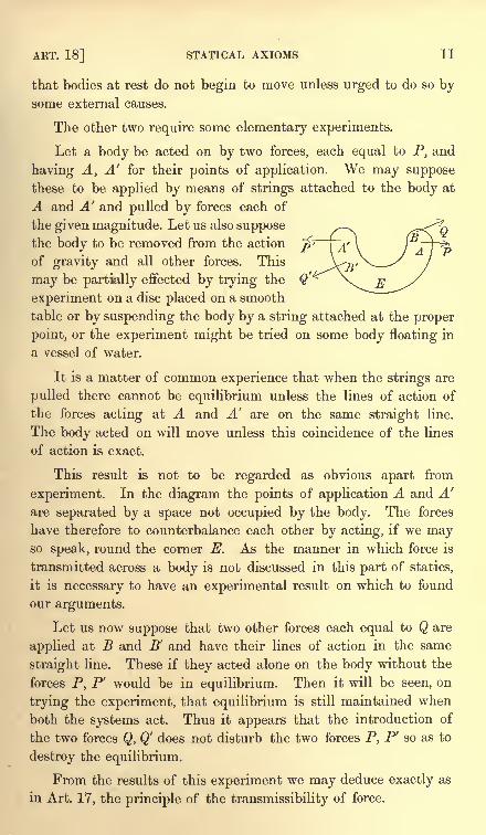
Let a body be acted on by two forces, each equal to P, and
having A, A' for their points of application. We may supposethese to be applied by means of strings attached to the body at
A and A' and pulled by forces each of
the given magnitude. Let us also supposethe body to be removed from the action
of gravity and all other forces. This
may be partially effected by trying the
experiment on a disc placed on a smooth
table or by suspending the body by a string attached at the proper
point, or the experiment might be tried on some body floating in
a vessel of water.
It is a matter of common experience that when the strings are
pulled there cannot be equilibrium unless the lines of action of
the forces acting at A and A' are on the same straight line.
The body acted on will move unless this coincidence of the lines
of action is exact.
This result is not to be regarded as obvious apart from
experiment. In the diagram the points of application A and A'
are separated by a space not occupied by the body. The forces
have therefore to counterbalance each other by acting, if we mayso speak, round the corner E. As the manner in which force is
transmitted across a body is not discussed in this part of statics,
it is necessary to have an experimental result on which to found
our arguments.
Let us now suppose that two other forces each equal to Q are
applied at B and B' and have their lines of action in the same
straight line. These if they acted alone on the body without the
forces P, P' would be in equilibrium. Then it will be seen, on
trying the experiment, that equilibrium is still maintained when
both the systems act. Thus it appears that the introduction of
the two forces Q, Q' does not disturb the two forces P, P' so as to
destroy the equilibrium.
From the results of this experiment we may deduce exactly as
in Art. 17, the principle of the transmissibility of force.
12 THE PARALLELOGRAM OF FORCES [CHAP. I
19. Rigid bodies. Let two or more bodies act and react on
each other and be in equilibrium under the action of any forces.
The principle of the transmissibility of force asserts that any one
of these forces may be applied at any point of its line of action.
If the line of action of any force acting on one of the bodies be
produced to cut another, it does not follow that equilibrium will
be maintained if the force is transferred from a point on the first
body to a point on the second.
It is therefore to be understood that when a force is transferred
from any point in its line of action to another the two points are
supposed to be rigidly connected together. When the points of
application of the forces are connected in some invariable manner,the body acted on is said to be rigid. Such are the bodies weshall in general speak of, though for the sake of brevity we shall
often refer to them simply as bodies.
20. It is sometimes convenient to form the conditions of
equilibrium of the whole system (or any part of it) as if it were
one body. That this may be done is evident, since the mutual
actions and reactions of the several bodies are equal and opposite.
But we may also reason thus;the system being in a position of
equilibrium, we may suppose the points of application of the
forces to be joined in some invariable manner. This will not
disturb the equilibrium. The system being now made rigid we
may form the conditions of equilibrium. These are generally
necessary and sufficient for the equilibrium of the system regardedas a rigid body, but though necessary they are not generally
sufficient for its equilibrium when regarded as a collection of
bodies.
21. When a force acts on a rigid body, the principle of the transmissibility of
force asserts that the body transmits its action from one point of application to
another, but does not itself alter the magnitude of the force. It appears, therefore,
that so far as this principle and that of the independence of forces are concerned
the conditions of equilibrium depend on the forces and not on the body.
If a system of forces be in equilibrium when acting on any body, that system
will also be in equilibrium when transferred to act on any other body, provided
always the points of application are connected by some kind of invariable relations.
It follows that no definition of the body acted on is necessary when the forces
in equilibrium are given. The forces must have something to act on, but all we
assume here about this something, is that it transmits the force so that the axioms
enunciated may be taken as true. For this reason, it is sometimes said that
statics is the science which treats of the equilibrium and action of forces apart fromthe subject matter acted on.
ART. 23] RESULTANT FORCE 13
22. Resultant force. When two forces act simultaneously
on a particle and are not in equilibrium, they will tend to move
the particle. We infer that there is always some one force which
will keep the particle at rest.
A force equal and opposite to this force is called the resultant
of the two forces and is equivalent to the forces. It is obvious
that the resultant of two forces acting on a particle must also act
on that particle. It is also clear that its line of action is inter-
mediate between those of the two forces.
Let PI, P2 ,...Pn be any number of forces acting on the same
particle. The two forces P,, P2 have a resultant, say Qx . We mayremove Pl and P2 and replace them by Qlf Again Q^ and P3 maybe replaced by their resultant Q2 and so on. We finally have all
the forces replaced by a single force. This single force is called
their resultant.
If the forces of a system do not all act at the same point,
it may happen that there is no single force which could balance
the system. If so, the system is not equivalent to any single
resultant force.
23. To find the resultant of any number of forces acting at a
point and having their lines of action in the same straight line.
Let be the point of application, and first let all the forces
act in the same direction Ox. Since each acts independently of
the others, the resultant is clearly the sum of the separate forces
and it acts in the direction Ox.
If some of the forces act in one direction Ox and others in the
opposite direction say Ox', we sum the forces in these two direc-
tions separately. Let X and X' be these separate sums, and let
X be the greater. Then by Art. 15 we can remove the force Xr
from both sets of forces. The whole system is therefore equivalent
to the single force X X' acting in the direction of X.
By the rule of signs this is also equivalent to a single force
represented by the negative quantity X' X acting in the opposite
direction, viz. that of X'.
The necessary and sufficient condition that a system of forces
acting at a point and having their lines of action in the same
straight line should be in equilibrium is that the algebraic sum of
the forces should be zero.
14 THE PARALLELOGRAM OF FORCES [CHAP. I
24. Parallelogram of forces. To find the resultant of two
forces acting at a given point and inclined to each other at any
angle. Let the two forces act at the point and let them be repre-
sented in direction and magnitude by two straight lines OA, OBdrawn from the point (Art. 7). Let us now construct a paral-
lelogram having OA, OB for two adjacent sides and let OC be that
diagonal which passes through the point 0. Then the resultant ofthe two forces will be represented in direction and magnitude by the
diagonal OC.
Several proofs of this important theorem have been given.
As the "parallelogram law
"is the foundation of the whole theory
of the composition and resolution of forces, it will be useful to
consider more than one proof, though the student at first readingshould confine his attention to one of them.
25. Newton's proof of the parallelogram of forces.
This proof is founded on the dynamical measure of force. Its
principle has already been explained in Art. 15. It is repeatedhere on account of its importance. The figure is the same as that
used in Art. 12 for the parallelogram of velocities.
26. Suppose two forces to act on the particle placed at in
the directions OA, OB. Let the lengths OA, OB be such that
they represent the velocities these forces could separately generate
in the particle by acting for a given time. Since each force
acts independently of the other, it will generate the same
velocity whether the other acts or does not act. When both act
the particle has at the end of the given time both the velocities
represented by OA and OB. These are together equivalent to
the single velocity 00. But this is also the measure of the
force which would generate that velocity. Thus the two forces
measured by OA, OB are together equivalent to the single force
measured by OC.
27. Duchayla's proof of the parallelogram of forces.
This proof is founded on the principle of the transmissibility of
force, Art. 17. It has been shown in Art. 18 that this principle
can be made to depend only on statical axioms.
To prove the proposition we shall use the inductive proof. Weshall assume that the theorem is true for forces of p and m units
inclined at any angle, and also for forces of p and n units inclined
ART. 27] PARALLELOGRAM OF FORCES 15
at the same angle ;we shall then prove that the theorem must be
true for forces of p and m + n units inclined at the same angle.
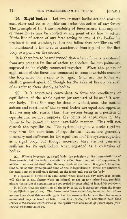
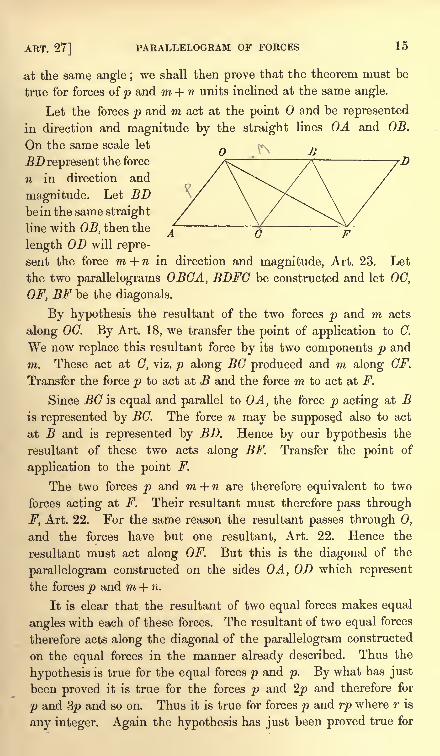
Let the forces p and m act at the point and be represented
in direction and magnitude by the straight lines OA and OB.
On the same scale let
BD represent the force
n in direction and
magnitude. Let BDbe in the same straight
line with OB, then the
length OD will repre-
sent the force m + n in direction and magnitude, Art. 23. Let
the two parallelograms OBCA, BDFC be constructed and let OC,
OF, BF be the diagonals.
By hypothesis the resultant of the two forces p and m acts
along OC. By Art. 18, we transfer the point of application to C.
We now replace this resultant force by its two components p and
m. These act at C, viz. p along BC produced and m along CF.
Transfer the force p to act at B and the force m to act at F.
Since BC is equal and parallel to OA, the force p acting at Bis represented by BC. The force n may be supposed also to act
at B and is represented by BD. Hence by our hypothesis the
resultant of these two acts along BF. Transfer the point of
application to the point F.
The two forces p and m + n are therefore equivalent to two
forces acting at F. Their resultant must therefore pass through
F, Art. 22. For the same reason the resultant passes through 0,
and the forces have but one resultant, Art. 22. Hence the
resultant must act along OF. But this is the diagonal of the
parallelogram constructed on the sides OA, OD which represent
the forces p and m + n.
It is clear that the resultant of two equal forces makes equal
angles with each of these forces. The resultant of two equal forces
therefore acts along the diagonal of the parallelogram constructed
on the equal forces in the manner already described. Thus the
hypothesis is true for the equal forces p and p. By what has just
been proved it is true for the forces p and 2p and therefore for
p and 3p and so on. Thus it is true for forces p and rp where r is
any integer. Again the hypothesis has just been proved true for
16 THE PARALLELOGRAM OF FORCES [CHAP. I
forces rp and p ;hence it is true for rp and 2p and so on. Thus
the hypothesis is true for forces rp and sp, where r and s are
any integers. Thus the proposition so far as the direction of the
resultant is concerned is established for any commensurable forces.
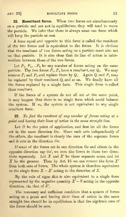
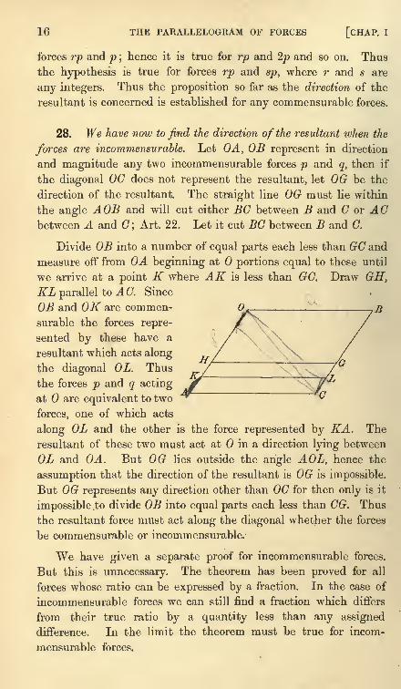
28. We have now to find the direction of the resultant when the
forces are incommensurable. Let OA, OB represent in direction
and magnitude any two incommensurable forces p and q, then if
the diagonal OC does not represent the resultant, let OG be the
direction of the resultant. The straight line OG must lie within
the angle AOB and will cut either BC between B and C or ACbetween A and C
;Art. 22. Let it cut BC between B and C.
Divide OB into a number of equal parts each less than GC and
measure off from OA beginning at portions equal to these until
we arrive at a point K where AK is less than GC. Draw GH,KL parallel to A C. Since
OB and OK are commen- 0^ 7 ./?
surable the forces repre-
sented by these have a
resultant which acts along
the diagonal OL. Thus
the forces p and q acting
at are equivalent to two
forces, one of which acts
along OL and the other is the force represented by KA. The
resultant of these two must act at in a direction lying between
OL and OA. But OG lies outside the angle AOL, hence the
assumption that the direction of the resultant is OG is impossible.
But OG represents any direction other than OC for then only is it
impossible to divide OB into equal parts each less than CG. Thus
the resultant force must act along the diagonal whether the forces
be commensurable or incommensurable.
We have given a separate proof for incommensurable forces.
But this is unnecessary. The theorem has been proved for all
forces whose ratio can be expressed by a fraction. In the case of
incommensurable forces we can still find a fraction which differs
from their true ratio by a quantity less than any assigned
difference. In the limit the theorem must be true for incom-
mensurable forces.
ART. 31] HISTORICAL SUMMARY 17
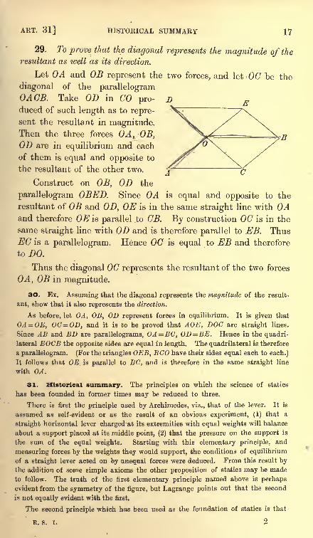
29. To prove that the diagonal represents the magnitude of the
resultant as well as its direction.
Let OA and OB represent the two forces, and let OC be the
diagonal of the parallelogramOACB. Take OD in CO pro-
duced of such length as to repre-
sent the resultant in magnitude.Then the three forces OA, OB,OD are in equilibrium and each
of them is equal and opposite to
the resultant of the other two.
Construct on OB, OD the
parallelogram OBED. Since OA is equal and opposite to the
resultant of OB and OD, OE is in the same straight line with OAand therefore OE is parallel to OB. By construction OC is in the
same straight line with OD and is therefore parallel to EB. ThusEC is a parallelogram. Hence OC is equal to EB and therefore
to DO.
Thus the diagonal 00 represents the resultant of the two forces
OA, OB in magnitude.
30. Ex. Assuming that the diagonal represents the magnitude of the result-
ant, show that it also represents the direction.
As before, let OA, OB, OD represent forces in equilibrium. It is given that
OA = OE, OC=OD, and it is to be proved that AOE, DOC are straight lines.
Since AB and BD are parallelograms, OA=BG, OD= BE. Hence in the quadri-
lateral EOCB the opposite sides are equal in length. The quadrilateral is therefore
a parallelogram. (For the triangles OEB, ECO have their sides equal each to each.)
It follows that OE is parallel to BC, and is therefore in the same straight line
with OA.
31. Historical summary. The principles on which the science of statics
has been founded in former times may be reduced to three.
There is first the principle used by Archimedes, viz., that of the lever. It is
assumed as self-evident or as the result of an obvious experiment, (1) that a
straight horizontal lever charged'at its extremities with equal weights will balance
about a support placed at its middle point, (2) that the pressure on the support is
the sum of the equal weights. Starting with this elementary principle, and
measuring forces by the weights they would support, the conditions of equilibrium
of a straight lever acted on by unequal forces were deduced. From this result bythe addition of some simple axioms the other proposition of statics may be made
to follow. The truth of the first elementary principle named above is perhaps
evident from the symmetry of the figure, but Lagrange points out that the second
is not equally evident with the first.
The second principle which has been used as the foundation of statics is that
R. s. I. 2
18 THE PARALLELOGRAM OF FORCES [CHAP. I
of the parallelogram of forces. In 1586, Stevinus enunciated the theorem of the
triangle of forces. Till this time the science of statics had rested on the theory of
the lever, but then a new departure became possible. The simplicity of the
principle and the ease with which it may be applied to the problems of mechanics
caused it to be generally adopted. The principle finally became the basis of modern
statics. For an account of its gradual development we refer the reader to A Short
History of Mathematics, by W. W. R. Ball.
Many writers have given or attempted to give proofs of this principle which are
independent of the idea of motion. One of these, that of Duchayla, has been
reproduced above, as that is the one which seems to have been best received.
There is another, that of Laplace, which has attracted considerable attention.
This is founded on principles similar to the proofs of Bernoulli and D'Alembert.
It is assumed as evident that if two forces be increased in any, the same, ratio the
magnitude of their resultant will be increased in the same ratio, but its direction
will be unaltered.
In comparing these proofs with that founded on the idea of motion, we must
admit the force of a remark of Lagrange. He says that, in separating the principle
of the composition of forces from the composition of motions, we deprive that
principle of its chief advantages. It loses its simplicity and its self-evidence, and
it becomes merely a result of some constructions of geometry or analysis.
The third fundamental principle which has been used is that of virtual
v elocities. This principle had been used by the older writers, but Lagrange gave,
or attempted to give, an elementary proof and then made it the basis of the whole
science of mechanics. This proof has not been generally received as presentingthe simplicity and evidence which he had admired in the principle of the compo-sition of forces.
FORCES ACTING AT A POINT
The triangle of forces
32. IN the last chapter we arrived at a fundamental pro-
position, usually called the parallelogram of forces, which weshall be continually using. Experience shows it is not alwaysconvenient to draw the parallelogram, for this complicates the
figure and makes the solution cumbersome. Several artifices
have been invented to enable us to use the principle with facility
and quickness. In this chapter we shall consider these in turn.
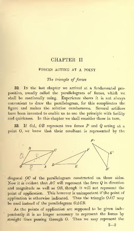
33. If OA, OB represent two forces P and Q acting at a
point 0, we know that their resultant is represented by the
D
diagonal OG of the parallelogram constructed on those sides.
Now it is evident that AC will represent the force Q in direction
and magnitude as well as OB, though it will not represent the
point of application. This however is unimportant if the point of
application is otherwise indicated. Thus the triangle OAC maybe used instead of the parallelogram OACB.
As the points of application are supposed to be given inde-
pendently it is no longer necessary to represent the forces by
straight lines passing through 0. Thus we may represent the
22
20 FORCES ACTING AT A POINT [CHAP. II
forces P, Q, R acting at both in direction and magnitude by the
sides of a triangle DEF provided these sides are parallel to the
forces and proportional to them in magnitude.
It is clear that all theorems about the parallelogram of forces
may be immediately transferred to the triangle. We therefore
infer the following proposition called the triangle of forces.
If two forces acting at some point are represented in direction
and magnitude by the sides DE, EF of any triangle, the third side
DF will represent their resultant.
If three forces acting at some point are represented in direction
and magnitude by the three sides of any triangle taken in order
viz., DE, EF, FD, the three forces are in equilibrium.
34. When three forces in one plane are given and we wish to
determine whether they are in equilibrium or not, we see that
there are two conditions to be satisfied.
1. If they are not all parallel two of them must meet in some
point 0. The resultant of these two will also pass through the
same point. The third force must be equal and opposite to this
resultant and must therefore also pass through the same point.
Hence the lines of action of the three forces must meet in one
point or be parallel.
2. If the forces are not all parallel, straight lines can be
drawn parallel to the forces so as to form a triangle. The
magnitudes of the forces must be proportional to the sides of
that triangle taken in order.
The case in which the forces are all parallel will be considered
in the next chapter.
35. We may evidently extend this proposition further. Sup-
pose we turn the triangle DEF through a right angle into the
position D'E'F', the sides will then be perpendicular Jinstead of
parallel to the forces. Also if the forces act in the directions DE,EF, FD they now act all three outwards with regard to the
triangle D'E'F'. If the forces were reversed they would all act
inwards. We have thus a new proposition.
If three forces acting at some point be represented in magnitude
by the sides of a triangle, and if the directions of the forces be
perpendicular to those sides and if they act all inwards or all
outwards, the three forces are in equilibrium.
ART. 37] POLYGON OF FORCES 21
Instead of turning the triangle through a right angle, we
might turn it through any acute angle. We thus obtain another
theorem. If three forces acting at a point be represented in
magnitude by the sides of a triangle and if their directions make
equal angles with the sides taken in order, the three forces are in
equilibrium.
In using this theorem, it is sometimes found to be inconvenient
to sketch the triangle. We then put the theorem into another
form. The sides of the triangle are proportional to the sines of
the opposite angles. This relation must therefore also hold for
the forces. Hence we infer the following theorem.
Three forces acting on a body in one plane are in equilibrium
if (1) their lines of action all meet in one point, (2) their directions
are all towards or all from that point, (3) the magnitude of each is
proportional to the sine of the angle between the other two.
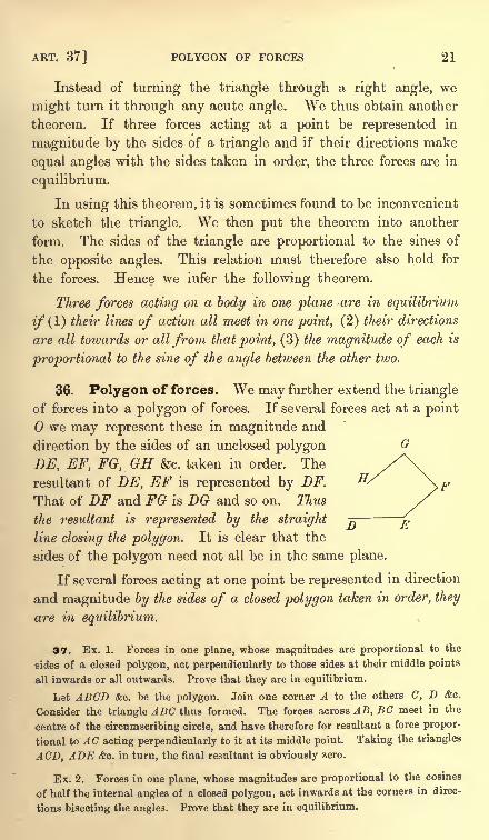
36. Polygon of forces. We may further extend the triangle
of forces into a polygon of forces. If several forces act at a point
we may represent these in magnitude and
direction by the sides of an unclosed polygon
DE, EF, FG, GH &c. taken in order. The
resultant of DE, EF is represented by DF.
That of DF and FG is DG and so on. Thus
the resultant is represented by the straight
line closing the polygon. It is clear that the
sides of the polygon need not all be in the same plane.
If several forces acting at one point be represented in direction
and magnitude by the sides of a closed polygon taken in order, they
are in equilibrium.
37. Ex. 1. Forces in one plane, whose magnitudes are proportional to the
sides of a closed polygon, act perpendicularly to those sides at their middle points
all inwards or all outwards. Prove that they are in equilibrium.
Let ABCD &c. be the polygon. Join one corner A to the others C, D &c.
Consider the triangle ABC thus formed. The forces across AB, BC meet in the
centre of the circumscribing circle, and have therefore for resultant a force propor-
tional to AC acting perpendicularly to it at its middle point. Taking the triangles
ACD, ADE &c. in turn, the final resultant is obviously zero.
Ex. 2. Forces in one plane, whose magnitudes are proportional to the cosines
of half the internal angles of a closed polygon, act inwards at the corners in direc-
tions bisecting the angles. Prove that they are in equilibrium.
22 FORCES ACTING AT A POINT [CHAP. II
Apply along each side of a polygon two equal and opposite forces, say each equal
to F, and let these act at the corners. The two which act at the corner A have a
resultant 2Fcos^A whose direction bisects that angle. These resultants must
therefore be in equilibrium.
38. Ex. 1. Forces represented by the numbers 4, 5, 6 are in equilibrium ; find
the tangents of the halves of the angles between the forces.
By drawing parallels to these forces we construct a triangle of the forces. The
angles of this triangle can be found by the ordinary rules of trigonometry.
Ex. 2. Forces represented by 6, 8, 10 Ibs. are in equilibrium; find the angle
between the two smaller forces. How must the least force be altered that the
angle between the other two may be halved?
Ex. 3. If OA, OB represent two forces, show that their resultant is represented
by twice OAT, where M is the middle point of AB.
Ex. 4. Two constant equal forces act at the centre of an ellipse parallel to the
directions SP and PH, where S and H are the foci and P is any point on the curve.
Show that the extremity of the line which represents their resultant lies on a circle.
[Math. Tripos, 1883.]
Ex. 5. Forces P, Q act at a point O, and their resultant is R;if any transversal
cut the directions of the forces in the points L, M, N respectively, show that
ijL+m=$N- [Math. Tripos, 1881.]
Clear of fractions and the equation reduces to the statement that the area LOMis the sum of the areas LON, MON.
Ex. 6. A particle O is in equilibrium under three forces, viz., a force F given
in magnitude, a force F' given in direction, and a force P given in magnitude and
direction. Find the lines of action of F by a geometrical construction.
If OA represent P, draw AB parallel to F', and describe a circle whose centre is
and whose radius represents F in magnitude.
Ex. 7. ABCD is a tetrahedron, P is any point in BG, and Q any point in AD.Prove that a force represented in magnitude, direction, and position by PQ, can be
replaced by four components in AB, BD, DC, CA in one and in only one way, and
find the ratios of these components. [St John's Coll., 1887.]
Ex. 8. Lengths BD, CE, AF are drawn from the corners along the sides BG,
CA, AB of a triangle ABC ; each length being proportional to the side along which
it is drawn. If forces represented in magnitude and direction by AD, BE, CFacted on a point, show that they would be in equilibrium. Conversely if the forces
AD, BE, CF act at a point and are in equilibrium, then BD, CE, AF are pro-
portional to the sides.
39. Parallelepiped of forces. Three forces acting at a
point are represented in direction and magnitude by three straight
lines OA, OB, OC not in one plane. To show that the resultant is
represented in direction and magnitude by the diagonal of the
parallelepiped constructed on the three straight lines as sides.
ART. 41] OBLIQUE RESOLUTION 23
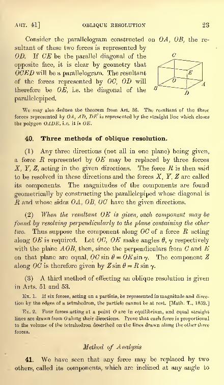
Consider the parallelogram constructed on OA, OB, the re-
sultant of these two forces is represented byOD. If CE be the parallel diagonal of the
opposite face, it is clear by geometry that
OCED will be a parallelogram. The resultant
of the forces represented by 00, OD will
therefore be OE, i.e. the diagonal of the
parallelepiped.
We may also deduce the theorem from Art. 36. The resultant of the three
forces represented by OA, AD, DE is represented by the straight line which closes
the polygon OADE, i.e. it is OE.
40. Three methods of oblique resolution.
(1) Any three directions (not all in one plane) being given,
a force R represented by OE may be replaced by three forces
X, Y, Z, acting in the given directions. The force R is then said
to be resolved in these directions and the forces X, Y, Z are called
its components. The magnitudes of the components are found
geometrically by constructing the parallelepiped whose diagonal is
R and whose sides OA, OB, 00 have the given directions.
(2) When the resultant OE is given, each component may be
found by resolving perpendicularly to the plane containing the other
two. Thus suppose the component along 00 of a force R acting
along OE is required. Let OC, OE make angles 0, y respectively
with the plane A OB, then, since the perpendiculars from and Eon that plane are equal, OCsin = OEsmy. The component Z
along OC is therefore given by Zsin 6 = R sin 7.
(3) A third method of effecting an oblique resolution is given
in Arts. 51 and 53.
Ex. 1. If six forces, acting on a particle, be represented in magnitude and direc-
tion by the edges of a tetrahedron, the particle cannot be at rest. [Math. T., 1859.]
Ex. 2. Four forces acting at a point O are in equilibrium, and equal straight
lines are drawn from along their directions. Prove that each force is proportional
to the volume of the tetrahedron described on the lines drawn along the other three
forces.
Method of Analysis
41. We have seen that any force may be replaced by two
others, called its components, which are inclined at any angle to
24 FORCES ACTING AT A POINT [CHAP. II
each other which may appear suitable. But it is found by
experience that when a force has to be resolved it is generally
more useful to resolve it into two components which are at right
angles. When therefore the component of a force is spoken of it
is meant, unless it is otherwise stated, that the other componentis at right angles to it. By referring to the figure of Art. 33, wesee that the parallelogram OACB becomes a rectangle. The two
components of the force 00 are 00 . cos COA and OC . sin COA.
We may put this result into the form of a working rule. If a
force R act at in the direction OC, its component in any direction
Ox is R cos COx. Its component in the opposite direction Ox is
R cos COx'. In the same way the component of R perpendicularto Ox is R sin COx.
It is convenient to have some short name to distinguish the
rectangular components of a force from its oblique components.The name resolute for the components in the first case has been
suggested in Lock's Elementary Statics.
42. Two forces P1} P2 act at a point 0. To find the position
and magnitude of their resultant.
Let Ox, Oy be any two rectangular axes, and let aly a2 be the
angles the forces P1} P2 make with the axis of #. The sums of the
components parallel to the axes are
X = P! COS di +P2 COS Oa,
Y = P! sin j + P2 sin o.j.
If these are the components of a force R whose line of action
makes an angle a with the axis of x, we have
X = Rcosa, Y=Rsina.
We easily find by adding together the squares of X and Y that
R? = Pf + P22 + 2P,P2 cos 0,
where =oii a2 ,
so that is the angle between the directions
of the forces P1? P2 . This result also follows from the parallelogramof forces. For the right-hand side is evidently the square of the
diagonal of the parallelogram whose sides are Px and P2 .
The direction of the resultant is also easily found, for we have
Y P, sin a, + P2 sin ar2tan a = ^ = ^ ~ -
.
2L P! COS j + P2 COS O.2
ART. 46] METHOD OF ANALYSIS 25
43. Ex. 1. Two forces P, Q act at an angle a and have a resultant R. If each
force be increased by R, prove that the new resultant makes with R an angle whose
tSt John's Coll., 1880.]
Take the line of action of the resultant R for the axis of x.
Ex. 2. Forces each equal to F act at a point parallel to the sides of a triangle
ABC. If R be their resultant, prove that R*=F*(3 - 2 cos A - 2 cos B - 2 cos C).
Ex. 3. The resultant of P and Q is R, if Q be doubled R is doubled, if Q be
reversed, R is also doubled ; show that P : Q : R :: ^/2 : J3 : N/2. [St John's Coll.]
44. Any number of forces act at a point in any directions.
It is required to find their resultant.
Take any rectangular axes Ox, Oy, Oz. Let Plt P2 ,P3 &c. be
the forces, (a^^), ( 2/3272) &c. their direction angles. The sums
of the components of these parallel to the axes are
X = P! cos Oj + P2 cos <x2 -f . . .= 2P cos a,
F= Pl cos& -I- P2 cos & + . . .= 2P cos ,
Z= Pl cos 7! + P2 cos 72 + . . .= 2P cos 7.
If these are the components of a force R whose direction
angles are (afty) we have
R cos a = X, R cos @ = Y, R cos <y= Z.
By a known theorem in solid geometry
cos2 a -1- cos2/3 + cos2
7 = 1.
Hence R2 = X2 + F2 + Z2,
cos a _ cos ft _ cos 7 _ 1
Z F ~(Z2+F2 + ^2)r
Thus both R and its direction cosines have been found.
If the conditions of equilibrium are required it is sufficient and
necessary that R = 0. This gives the three conditions
45. If the resolved parts of the forces Pj, P2 <&c. along any three directions
OA, OB, OC not all in one plane are zero, they are in equilibrium.
Let the axis Oz coincide with OC and let the plane xOz contain OA. Since
the resolved part along Oz is zero, we have Z= Q. Since the resolved part alongOA is zero, we have Xcos.rOA = Q. Since xOA cannot be a rigbt angle without
making OA, OC coincide, we have A'=0. Lastly since the resolved part along OBis zero we find YcosyOB= 0. This gives t/
= 0.
46. The magnitude and direction of. R may also be expressedin a form independent of coordinates in the following manner.
26 FORCES ACTING AT A POINT [CHAP. II
By a known theorem in solid geometry if #]2 be the anglebetween the straight lines whose direction angles are
) with the usual convention as to direction, then
cos #]2= cos ! cos 2 + cos & cos yS2 + cos ^ cos 72 .
Adding together the squares of the expressions for X, Y, Z we
have R2 = Pf (cos2a, + cos2& + cos2
7,) + &c.
+ 2PiP2 (cos a, cos 2 + cos & cos /32 + cos 7j cos 72) + &c.
= Pj2 + P2
2 + &c. + 2P1Pa cos 6>12 + &c.
This gives the magnitude of J?.
To determine the line of action of R, we shall find the angles
<f>i> $2 &c. which its direction makes with the- directions of the
forces P1} P2 &c. The axes of coordinates being perfectly arbitrary ;
let us take the axis of as to be coincident with the line of action of
the force P^ Then a = fa , j=
0, a2= #12 &c., the equations
R cos a = X = 2P cos a
become J? cos(f)1= Pl + P2 cos #]2 + P3 cos 13 4- &c.
In the same way by taking the axis of x along the force Pz
we find R cos < 2= P
lcos ]2 + P2 + P3 cos B^ + ...
and so on. Thus the direction of R has been found.
47. Polyhedron of forces. The equations of Art. 44 have a geometrical
meaning which is often useful. Let any closed polyhedron be constructed, let
Al , A 2 &c. be the areas of its faces. Let normals be drawn to these faces, each
from a point in the face all outwards or all inwards, and let1 , 6.2 &c. be the angles
these normals make with any straight line which we may call the axis of z. Let us
now project orthogonally all these areas on the plane of xy. The several projections.
are A^ cos 6lt A 2 cos 2 &c - Since the polyhedron is closed the total projected
area which is positive is equal to the total negative projected area. We therefore
have Alcos
3+ J 2 cos 2 + ... = 0.
Similar results hold for the projection on the other coordinate planes. Thus weobtain three equations which are the same as the equations of equilibrium already
found, except that we have A it A 2 &c. written for Plf P2 &c. We therefore have
the following theorem. If forces acting at a point be represented in magnitude bythe areas of the faces of a closed polyhedron and if the directions of the forces be
perpendicular to those faces respectively, acting all inwards or all outwards, then
these forces are in equilibrium.
48. By using the theory of determinants we may put the results of Art. 46 into-
a more convenient form. Let it be required to find the resultant of any three f orces
acting at a point. To obtain a symmetrical result we shall reverse the resul tant
and speak of four forces in equilibrium.
Let Pn P2 ,P3 , P4 be four forces in equilibrium. Putting .R = 0, we have found
ART. 51] POLYHEDRON OF FORCES 27
in Art. 46 four linear equations connecting these. Eliminating the forces, we have
the determinantal equation
= 0.1
28 FORCES ACTING AT A POINT [CHAP. II
a point which will be found very useful both in geometrical and
analytical reasoning.
Let us represent the forces P1; P2 &c. in direction by the
straight lines OA lt OA.2 &c. To represent their magnitudes we
shall take lengths measured along these straight lines, thus the
force along OA^ is represented by pl.OA l ,
that along OA 2 by
p2 . OA 2 ,and so on. The advantage of introducing the numerical
multipliers p1} p2 &c. is that the extremities A l} A 2 &c. of the
straight lines may be chosen so as to suit the figure of the problemunder consideration. It is evident that this is equivalent to
representing the forces by straight lines on different scales, viz.
the scales p1} p2 &c. of force to each unit of length.
Taking for origin, let (%$&), (x2y^ &c. be the coordinates
of the points A lt A* &c. We have already proved that the com-
ponents of the resultant are
X = 2P cos a = 2 . OAi cos a =
Z = 2P cos 7
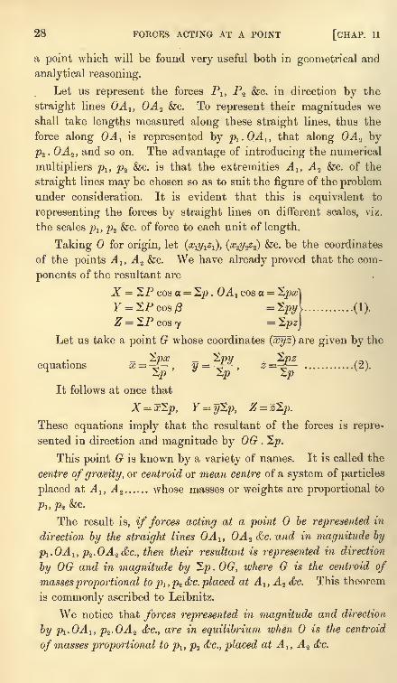
Let us take a point G whose coordinates (xyz) are given by the
,.
equations x = -^~ . &**-*-, z-^ ............ (2).Zp zp 2.p
It follows at once that
X = x^p, Y = y2p, Z = zZp.
These equations imply that the resultant of the forces is repre-
sented in direction and magnitude by OG . 2j5.
This point G is known by a variety of names. It is called the
centre of gravity, or centroid or mean centre of a system of particles
placed at A l} A 2 ...... whose masses or weights are proportional to
Pl,P-2&C.
The result is, if forces acting at a point be represented in
direction by the straight lines OA lt OA 2 &c. and in magnitude by
pl .OA l , p2.OA 2 &c., then their resultant is represented in direction
by OG and in magnitude by "Zp.OG, where G is the centroid of
masses proportional to p l ,p^&c. placed at A ly A z &c. This theorem
is commonly ascribed to Leibnitz.
We notice that forces represented in magnitude and direction
by p1.OA lt p2.OA 2 &c., are in equilibrium when is the centroid
of masses proportional to plt p2 <&c., placed at A lt A 2 &c.
ART. 53] THE MEAN CENTRE 29
Conversely, a force R, acting along OG, may be resolved into
three forces Pl ,P2 , P3 ,
which act along three given straight lines
passing through 0, by making G to be the mean centre of masses
placed at convenient points A 1} A 2 ,A 3 ,
on those straight lines. If
PI> Pz, PS are those masses, the components Pj, P2 ,P3 are given by
Pi P2 P3 =R
pl . OA l
~p2 . OA 2
~p3 . OA 3
~(p 1 + p2 + p,) OG
'
In using this theorem we may draw some or all of the straightlines OA ly OA 2 &c. in the opposite directions to the forces. If
this be done we simply regard the p's of those straight lines as
negative.
When some of the p's are negative, it may happen that 2p = 0.
In this case the centroid is at infinity and this representation of
the resultant though correct is not convenient. The components
along the axes are still given by the expressions X = ^px, Y= Spy,Z = "Zpz which do not contain any infinite quantities.
52. The utility of this proposition depends on the ease with which the pointG can be found when A lt A 2 , <c., are given. The working rule is that the distance
of G from any plane of reference, taken as the plane of xy, is given by the formula2pz
z =-^f
. The properties of this point and its positions in various cases are dis-
cussed in the chapter on the centre of gravity.
53. Ex. 1. The centroid G of two particles plt p2 , placed at two given pointsA lt
A2 , lies in the straight line A^A^ and divides it so that^. A1G=p2 . A2G.
Take AtA2 as the axis of x, A^ as origin and let A
lA2 =a. Then x
1= 0, x2
= a f
2/j= 0, 2/2
= 0. Using the working rule we have
Pi +Pz Pi +Ps Pi +Pz
Hence G lies in A^ 2 and since #= .4jG we find p1 .AiG=p2 (A 1A 2
- AlG)p2 .A 2G^
This theorem enables us to resolve a force P which acts along a given straight
line OG into two directions OA lt OA 2 , which are not necessarily at right angles.
The components Pl ,P2 are given byP-p -p
1 _ -*8 _ r
where plt p2 are the distances of G from A 2 ,A
1taken positively when measured
inwards.
Ex. 2. Prove that the centroid of three masses plt p2 , p3 , placed at the corners
of a triangle is the point whose areal coordinates are proportional to Pi, p%, pa ~
When the masses are equal this point is briefly called the centroid of the triangle.
If a, )3, 7 are the distances of a point G from the sides BC, CA, AB of a
triangle taken positively when measured inwards, and p, q, r are the perpendiculars
from the corners on the same sides, the ratios x=ajp, y=P/q, z = yjr are called the
30 FORCES ACTING AT A POINT [CHAP. II
areal coordinates of G. It is evident that x, y, z are also proportional to the areas
of the triangles BGC, CGA, AGB respectively. Also .r + y + z = l.
Taking any side AB as the axis of reference we deduce from the working rule
{Art. 52) that the distance of the centroid from it is y=p^rjs where &=Pi+Pz +p3 .
Similarly a-p^js, ^=p^qjs. It follows that x, y, z aie proportional to plt p%, ps .
Ex. 3. A force P acting at the corner 7) of a tetrahedron intersects the
opposite face ABC in a point G whose areal coordinates referred to the triangle
ABC are (xyz). If the components of P along the edges DA, DB, DC are P1( P2 , P3
P! P2 P3 _ P^x . DA
~y .DB
~z . DC
~DG '
Ex. 4. Any number of forces are represented in magnitude and direction by
straight lines A^Aj1
, A^A2',...AnA n' and G, G' are the centroids of the points
A lt A%,...An and A^, A 2',...A n '. Show that these forces transferred parallel to
themselves to act at a point have a resultant which is represented in magnitudeand direction by n . GG'. [Coll. Ex., 1889.]
The group of forces A A' is equivalent to the three groups AG, GG', G'A', Art. 36.
The first and last are separately in equilibrium, Art. 51.
Ex. 5. Three forces in one plane, acting at A, B, C, are represented by AD,
BE, CF where Z), E, F are their intersections with the sides of the triangle ABC.
Show that these are equivalent to three forces acting along the sides AB, BC, CA
. , , (CD CE\ fAE AF\ , fBF BD\of the triangle represented by )c, { )
a and 16.\ a b J \ b c I \ c a J
Thence show that if BDIa = CEIb = AFjc = K, these three forces are statically
equivalent to the three forces (1-
2/c) c, (1-2*) a, (1
-2/c) b acting along the sides
of the triangle.
Prove that the centroid of equal particles placed at D, E, F, coincides with that
of the triangle. Thence show that the forces represented by OD, OE, OF, (where
O is any point) have a resultant whose magnitude and line of action are indepen-
dent of the value of K.
Ex. 6. A particle in the plane of a triangle is acted on by forces directed
to the mid-points of the sides whose magnitudes are proportional directly to
the distances from those points and inversely to the radii of the circles escribed
to those sides. Find the position of equilibrium. [Math. Tripos, 1890.]
The point is the centre of the inscribed circle.
Ex. 7. A, B, C, D are four small holes in a vertical lamina, and four elastic
strings of natural lengths OA, OB, OC, OD are attached to a point in the lamina,
their other ends being passed through A, B, C, D respectively and attached to
a small heavy ring P. Assuming that the tension of an elastic string is a given
multiple of its extension, prove that when the lamina is turned in its own plane
about the locus of P in the lamina will be a circle. [Coll. Ex., 1888.]
Ex. 8. A quadrilateral ABCD is inscribed in a circle whose centre is 0,
forces proportional to ABCD 2 A OBD, AACD2&OAC, AABD + 2&.OBD,AABC2&.OAC, act along OA, OB, OC, OD respectively, the signs beingdetermined according to a certain convention, show that the forces are in equi-
librium. [Math. Tripos, 1889.]
Ex. 9. Three forces P, Q, R act along three straight lines DA , DB, DC not in
one plane ;if their resultant is parallel to the plane ABC, prove that
. [St John's Coll., 1882.]
ART. 55] EQUILIBRIUM OF A PARTICLE UNDER CONSTRAINT 31
Ex. 10. Assuming that the force of the wind on a sail is proportional to some
power of the difference of the velocities of the wind and boat resolved normally to
the sail, determine if the boat, by properly adjusting the sail, could be made to
travel quicker than the wind in a direction making a given angle with the wind,
and find the limits of the angle.
Ex. 11. ABCDEF is a regular hexagon, and at A forces act represented in
magnitude and direction by AB, 2AC, SAD, AE, 5AF. Show that the length of
the line representing their resultant is ^/351^-B. [Math. Tripos, 1880.]
Equilibrium of a particle under constraint
54. Distinction between smooth and rough bodies. Let a
particle under the influence of any forces be constrained to slide
along an infinitely thin- fixed wire. There is an action between
the particle and the curve. Let this force be resolved into two
components, one acting along a normal to the curve and the
other along the tangent. The latter of these is called friction.
By common experience it is found to depend on the nature of the
materials of which the wire and particle are made. When this
component is zero or so small that it can be neglected the bodies
are said to be smooth. When it cannot be neglected the conditions
of equilibrium are more complicated and will be found in another
chapter. For the present we shall confine our attention to smooth
bodies. Similar remarks apply when a particle is constrained to
remain on a surface. In all such cases the constraining curve or
surface is called smooth when the action between it and the particle
is along the normal to that curve or (surface.
55. If the particle be a bead slung on the curve, the bead can
only move in the direction of a tangent drawn to the curve at the
point occupied by the bead. The necessary and sufficient condition
of equilibrium is that the component of the forces along the tangentto the curve at the point occupied by the particle is zero.
If the particle rest on one side of the curve the action of the
curve on the particle will only prevent motion in one direction
along the normal. It is therefore also necessary for equilibriumthat the external forces should press the particle against the curve.
If a particle rest on a smooth surface at any point, the
component of the forces along every tangent to the surface at
that point must be zero. In other words, the resultant force at
a position of equilibrium must act normally to the surface in sudh
a direction as to press the particle against the surface.
32 FORCES ACTING AT A POINT [CHAP. II
56. The form of a curve being given by its equations ; to findthe positions on it at which a particle would rest in equilibriumunder the action of any given forces.
Suppose the curve to be given by its Cartesian equations, and
let the axes of reference be rectangular. Let x, y, z be the
coordinates of the particle when in a position of equilibrium.
Let X, Y, Z be the components of the forces parallel to these axes.
Let s be the arc measured from some fixed point on the curve
up to the point occupied by the particle. Then resolving the
forces X, Y, Z along the tangent, we have by Art. 41,
y dx dy dzA j h-r -s- -r 2S j- =* U.as as ds
If the equations of the curve are given in the form
<f> (x, y, z)=0, -f (x, y, z}= 0,
we have with the usual notation for partial differential coefficients
fysdx + <f)ydy + $,(Lz= 0, ^rxdx + ^rydy + ^r^z = 0.
Eliminating the ratios dx:dy: dz, we have the determinant
J~ X, Y,
<f>x> <f>y>
= 0.
This determinantal equation, joined to the two equations of the
curve, suffice in general to find the values of x, y, z. There maybe several sets of values of these coordinates, and these give all
the positions of equilibrium.
57. Theform of a surface being given by its equation ; to findthe point or points on it at which a particle would rest in equi-
librium under the action of given forces.
Let the surface be given by its Cartesian equation f(x, y,z}= (^
when referred to rectangular axes. By Art. 55 the direction
cosines of the resultant force must be proportional to those of
the normal to the surface. We therefore have
Joining these two equations to the given equation of the surface,.
we have three equations to find (x, y, z).
58. Pressure on the curve or surface. It follows from Art. 54
that in the position of equilibrium the resultant force acts normally-
ART. 61] PRESSURE ON THE CURVE OR SURFACE 33
and is equal to the pressure. If then R be the pressure on the
curve or surface, its magnitude is given by Rz =X2 + Y2 + Z* and its
direction is determined by the direction cosines X/R, Y/R, ZfR.
59. In these propositions the components X, Y, Z are supposed to be given
functions of the coordinates x, y, z. In many cases these components are respec-
tively partial differential coefficients with regard to x, y, z of some function VAV AV AV
called the potential of the forces. Thus X=~, Y=^-, Z=^- (1).dx dy dzThe condition of equilibrium of a particle resting on a smooth curve denned by its
Cartesian equations < = 0, ^=0 has been found above and is equivalent to the
assertion that the Jacobian of (V, <f>, \f/)vanishes at the points of equilibrium.
If we equate the potential V to an arbitrary constant c we obtain a system of
surfaces. Each of these is called a level surface. By equations (1) X, Y, Z are
proportional to the direction-cosines of the normal to a level surface. The resultant
force at any point, therefore, acts along the normal to the level surface which
passes through that point. If then a particle is constrained to rest on any smooth
curve or surface, the positions of equilibrium are those points at ichich the curve or
surface touches a level surface.
A curve or surface may be such that every point of it is a position of equilibrium.
In this case the resultant force is everywhere normal to the curve or surface. If
then the particle be constrained by a curve, the curve must lie on one of the level
surfaces, if by a surface, that surface must be a level surface.
60. Another interpretation may be found for the condition of equilibrium
Xdx + Ydy+ Zdz=0.
Substituting for X, Y, Z from (1), this is equivalent to dV=Q, i.e. at a position of
equilibrium the potential of the forces is a maximum or minimum.
61. Ex. 1. A heavy particle is constrained to slide on a smooth circle whose
plane is vertical. A string, attached to the particle, passes through a small ring
placed at the highest point of the circle and supports an equal weight at its other
end. Prove that the system is in equilibrium when the string between the ring and
the particle makes an angle 60 with the vertical.
Ex. 2. The ends of a string are attached to two heavy rings of masses m, m',
and the string carries a third ring of massM which can slide on it ; the rings m, m'
are free to slide on two smooth fixed rigid bars inclined at angles a and /3 to the
horizontal. Prove that if<f>be the angle which either part of the string makes with
the vertical, then cot : cot/3 : cot a= If : M + 2m' : M+2m. [St John's, 1890.]
Ex. 3. A weight P, attached by a cord to a fixed point 0, rests against a
smooth curve in the same vertical plane with 0; show that, (1) if the pressure on
the curve is to be independent of the position of the weight on it, the curve must be
a circle ; (2) if the tension in the cord is to be independent of the position of the
weight, the curve must be a conic section with as focus. [Math. Tripos, 1886.]
The vertical OA drawn through 0, the normal PA to the curve and the string
PO form a triangle whose sides are proportional to the forces which act along
them. In case (1) the ratio of OA to AP is constant ; it follows that P lies on
a circle or on a straight line passing through O. In case (2) the ratio of OAto OP is constant
;it follows that P lies on a conic or on a horizontal straight line
through 0.
R. 8. I. 3
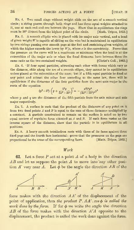
34 FORCES ACTING AT A POINT [CHAP. II
Ex. 4. Two small rings without weight slide on the arc of a smooth vertical
circle ; a string passes through both rings and has three equal weights attached to
it, one at each end and one between the pegs. Show that in equilibrium the rings
must be 30 distant from the highest point of the circle. [Math. Tripos, 1853.]
Ex. 5. A smooth elliptic wire is placed with its major axis vertical, and a bead
of given weight W is capable of sliding on the wire but is maintained in equilibrium
by two strings passing over smooth pegs at the foci and sustaining given weights, of
which the higher exceeds the lower by W\e, where e is the eccentricity. Prove that
the pressure on the curve will be a maximum or minimum when the bead is at the
extremities of the major axis or when the focal distances have between them the
same ratio as the two sustained weights. [Christ's Coll. , 1865.]
Ex. 6. If four equal particles, attracting each other with forces which vary as
the distance, slide along the arc of a smooth ellipse, they cannot be in equilibrium
unless placed at the extremities of the axes ; but if a fifth equal particle be fixed at
any point and attract the other four according to the same law, there will be
equilibrium if the distances of the four particles from the semi-axis major be the
roots of the equation
where p and q are the distances of the fifth particle from the axis minor and axis
major respectively.
Ex. 7. A surface is such that the product of the distances of any point on it
from two fixed points A and B is equal to the sum of those distances multiplied bya constant. A particle constrained to remain on the surface is acted on by two
equal centres of repulsive force situated at A and E. If each force varies as the
inverse square of the distance, show that the particle is in equilibrium in all
positions.
Ex. 8. A heavy smooth tetrahedron rests with three of its faces against three
fixed pegs and the fourth face horizontal : prove that the pressures on the pegs are
proportional to the areas of the corresponding faces. [Math. Tripos, 1869.]
Work
62. Let a force P act at a point A of a body in the direction
AB and let us suppose the point A to move into 'any other posi-
tion A' very near A. Let < be the angle the direction AB of the
4' 4 z>
MB A N M A M
force makes with the direction AA' of the displacement of the
point of application, then the product P. AA' . cos<f> is called the
work done by the force. If for < we write the angle the direction
AB of the force makes with the direction A'A opposite to the
displacement, the product is called the work done against the force.
ART. 65] WORK 35
Let us drop a perpendicular A'M on AB;the work done by the
force is also equal to the product P. AM, where AM is to be esti-
mated positive when in the direction of the force. Let P' be the
resolved part of P in the direction of the displacement ;the work
is also equal to P'.AA'. These expressions for the work of a
force are clearly equivalent, and all three are in continual use.
63. The forces which act on a particle generally depend on
the position of that particle. Thus if the particle be moved from
A to any point A at a finite distance from A, the force P will not
generally remain the same either in direction or magnitude. For
this reason it is necessary to suppose the displacement AA to be
so small a quantity that we may regard the force as fixed in
direction and magnitude. Taking the phraseology of the dif-
ferential calculus this is expressed by saying that the displacementAA is of the first order of small quantities.
We may suppose any finite displacement of the point A to be
made along a curve beginning at A and ending at some point C.
Let ds be any element of this curve, and when the particle has
reached this element let P' be the resolved part of the force along
ds in the direction in which s is measured. Then by the above
definition jP'ds is the sum of the separate works done by the force
P as the particle travels along each element in turn. This sum is
defined to be the whole work in any finite displacement. If s be
measured from any point on the curve, the limits of this
integral will evidently be s = A and s = OC.
64. The resolved displacement AA' cos<f>
is sometimes called
the virtual velocity of the point of application. The product
P. A A', cos<f>
is called the virtual moment or virtual work of the
force. But these terms are restricted to infinitely small displace-
ments. When the displacement is finite, the integral of the
virtual works is called the work.
65. It is often convenient to construct a proposed displace-
ment by several steps. Thus a displacement AA' may be con-
structed by moving A first to D and then from D to A' (see figure
in Art. 62). Supposing AD and DA' to be infinitely small so that
the direction and magnitude of the force P continue constant
throughout, it is easy to see that the work due to the whole displace-
ment AA' is the sum of the works due to the displacements AD and
32
36 FORCES ACTING AT A POINT [CHAP. II
DA'. For if we drop the perpendiculars DN and A'M on the
direction of the force, the separate works with their proper signs
will be P. AN and P.NM. The sum of these is P. AM, which
is the work due to the whole displacement AA'.
If the displacement AA' is finite, and the force P remains
unaltered in direction and magnitude, the work due to the
resultant displacement is equal to the sum of the works due to
the partial displacements AD, DA'.
66. Suppose next that several forces act at the point A ;then
as A moves to A' each of these will do work. The sum of the
works done by each separately is defined to be the work done
by all the forces collectively.
If any number of forces act at a point A, the sum of the works
due to any small displacement AA' is equal to the work done bytheir resultant.
The work done by any one force P is equal, by definition,
to the product of AA' into the resolved part of P in the direction
of AA. The work done by all the forces is therefore the productAA' into the sum of their resolved parts. By Art. 44 this is
equal to AA' into the resolved part of the resultant, i.e. is equal
to the work done by the resultant.
67. This theorem leads to another method of stating the
conditions of equilibrium of any number of forces P1; P2 &c. acting
at the same point A.
Case 1. If the particle at A is free to move in all directions it
is necessary for equilibrium that the resultant force should vanish.
The virtual work of the forces PJ} P2 &c. must therefore be zero in
whatever direction the particle is displaced.
Conversely, if the virtual work for any displacement AA' is
zero it immediately follows that the resolved part of the resultant
in that direction is also zero. If then the virtual work of
P1} P2 &c. is zero for any three different displacements not all in
one plane, the three resolved parts of the resultant in those
directions are zero. The particle is therefore in equilibrium.
68. Case 2. If the particle is constrained to move on some
curve or surface, then besides the forces P1} P2 &c. the particle is
acted on by a pressure R which is normal to the curve or surface.
The forces which maintain equilibrium are therefore Plf P2 &c.
ART. 69] WORK 37
and R, Then by Case 1 their virtual work is zero for all small
displacements.
If the displacement given to A is along a tangent to the curve
or is situated in the tangent plane to the surface, the angle </>
between the reaction R and the displacement is a right angle.
The virtual work of that force is therefore zero. It immediatelyfollows that for all such displacements the virtual work of P1} P2
&c. is zero.
Conversely, suppose the particle constrained to move on a
curve', then if the virtual work for a displacement along the
tangent is zero the resolved part of the resultant force in that
direction is also zero. The particle is therefore in equilibrium.
Next, suppose the particle constrained to move on a surface ',
then if the virtual works for any two displacements, not in the
same straight line, are each zero, the resolved parts of the
resultant force in those directions are each zero. The particle
is therefore in equilibrium.
69. Ex. 1. Deduce from the principle of virtual velocities the conditions of
equilibrium obtained in Art. 56, for a particle constrained to rest on a curve.
The forces on the particle are X, Y, Z ; the displacement is ds, the projections of
ds on the forces are dx, dy, dz. Multiplying each force by the corresponding pro-
jection, we see at once that the condition of equilibrium is Xdx + Ydy + Zdz = 0.
Ex. 2. Two small smooth rings of equal weight slide on a fixed elliptical wire,
of which the axis major is vertical, and are connected by a string passing over a
smooth peg at the upper focus; prove that the rings will rest in whatever position
they may be placed. [Math. Tripos, 1858.]
Let P, Q be the two rings, W the weight of either. Let T be the tension of the
string, I its length. Let S be the peg, let x, x' be the abscissae of P, Q measured
vertically downwards from S; let r=SP, r'=SQ, then r+ r'=l. Since the ring P
is in equilibrium, we have by the principle of virtual work Wdx-Tdr=Q. The
positive sign is given to the first term because x is measured in the direction in
which W acts ; the negative sign is given to the second term because T acts in
the opposite direction to that in which r is measured. In the same way we find
for the other ring Wdx'-Tdr'= 0. Since dr= -dr' this gives as the condition
of equilibrium Wdx + Wdx'= 0. As yet we have not introduced the condition that
the wire has the form of an ellipse. If 2c be its latus rectum and e its eccentricity,
we have r=c + ex,r'=c + ex'. It easily follows that dx + dx'= 0, so that the condition
of equilibrium is satisfied in whatever position the rings are placed.
Ex. 3. A small ring movable along an elliptic wire is attracted towards a given
centre of force which varies as the distance : prove that the positions of equilibriumof the ring lie in a hyperbola, the asymptotes of which are parallel to the axes of
the ellipse. [Math. Tripos, 1865.]
Ex. 4. Two small rings of the same weight attracting one another with a force
varying as the distance, slide on a smooth parabolic shaped wire, whose axis is
8221Q
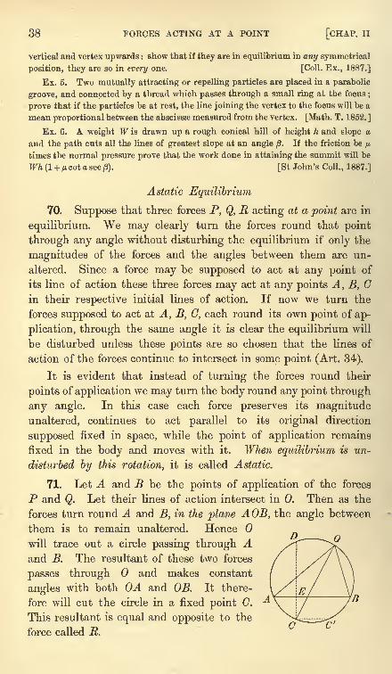
38 FORCES ACTING AT A POINT [CHAP. II
vertical and vertex upwards : show that if they are in equilibrium in any symmetrical
position, they are so in every one. [Coll. Ex., 1887.]
Ex. 5. Two mutually attracting or repelling particles are placed in a parabolic
groove, and connected by a thread which passes through a small ring at the focus;
prove that if the particles be at rest, the line joining the vertex to the focus will be a
mean proportional between the abscissae measured from the vertex. [Math. T. 1852. ]
Ex. 6. A weight W is drawn up a rough conical hill of height h and slope a
and the path cuts all the lines of greatest slope at an angle . If the friction be jj.
times the normal pressure prove that the work done in attaining the summit will be
JF7i(l + MCOtasec/3). [St John's Coll., 1887.]
Astatic Equilibrium
70. Suppose that three forces P, Q, R acting at a point are in
equilibrium. We may clearly turn the forces round that point
through any angle without disturbing the equilibrium if only the
magnitudes of the forces and the angles between them are un-
altered. Since a force may be supposed to act at any point of
its line of action these three forces may act at any points A, B, Cin their respective initial lines of action. If now we turn the
forces supposed to act at A, B, C, each round its own point of ap-
plication, through the same angle it is clear the equilibrium will
be disturbed unless these points are so chosen that the lines of
action of the forces continue to intersect in some point (Art. 34).
It is evident that instead of turning the forces round their
points of application we may turn the body round any point through
any angle. In this case each force preserves its magnitude
unaltered, continues to act parallel to its original direction
supposed fixed in space, while the point of application remains
fixed in the body and moves with it. When equilibrium is un-
disturbed by this rotation, it is called Astatic.
71. Let A and B be the points of application of the forces
P and Q. Let their lines of action intersect in 0. Then as the
forces turn round A and B, in the plane AOB, the angle between
them is to remain unaltered. Hence
will trace out a circle passing through Aand B. The resultant of these two forces
passes through and makes constant
angles with both OA and OB. It there-
fore will cut the circle in a fixed point C.
This resultant is equal and opposite to the
force called R.
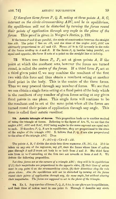
ART. 74] ASTATIC EQUILIBRIUM 39
If therefore three forces P, Q, R, acting at three points A, B, G,
intersect on the circle circumscribing ABC, and be in equilibrium,
the equilibrium will not be disturbed by turning the forces round
their points of application through any angle in the plane of the
forces. This proof is given in Moigno's Statics, p. 228.
If the forces P and Q are parallel, the circle of construction becomes the straight
line AB. The point C lies on AB, and the sines of the angles AOC, BOG are
ultimately proportional to AC and CB. Hence AC is to CB inversely in the ratio
of the forces tending to A and B. If the forces P, Q, besides being parallel, are
equal and opposite, the force JR acts at a point on the straight line at infinity.
72. When two forces P1} P2 act at given points A, B the
point at which the resultant acts, however the forces are turned
round, is called the centre of the forces. If a third force PB act at
a third given point C, we may combine the resultant of the first
two with this force and thus obtain a resultant acting at another
fixed point in the body. This is the centre of the three forces.
Thus we may proceed through any number of forces. We see that
we can obtain a single force acting at a fixed point of the body which
is the resultant of any number of given forces acting at any givenfixed points in one plane. This single force will continue to be
the resultant and to act at the same point when all the forces are
turned round their points of application through any angle. This
force is called their astatic resultant.
73. Astatic triangle of forces. This proposition leads us to another methodof using the triangle of forces. Referring to the figure of Art. 71, we see that the
angles ABC, AOC and BAC, BOG being angles in the same segment are equal each
to each. If therefore P, Q, R are in equilibrium, they are proportional to the sines
of the angles of the triangle ABC. It follows that P, Q, R are also proportional
to the sides of the triangle ABC. Thus
P: BC=Q : CA = R : AB.
The points A, B, C divide the circle into three segments AB, BC, CA. If be
taken on any one of the segments, say AB, then the forces whose lines of action
pass through A and B must act both to or both from A and B. The third force
acts from or to C according as the first two act towards or from A and B. Wededuce the following proposition.
Let three forces act at the corners of a triangle ABC ; they will be in equilibrium
if (1) their magnitudes are proportional to the opposite sides, (2) their lines of action
meet in any point on the circumscribing circle, (3) their directions obey the rule
given above. Also the equilibrium will not be disturbed by turning all the forces
round their points of application through any, the same angle, but without altering
their magnitudes. The forces are supposed to act in the plane of the triangle.
74. Ex. 1. Any number of forces P, Q, R, S &c. in one plane are in equilibrium,
and their lines of action meet in one point 0. Through O describe any circle
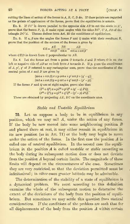
40 FORCES ACTING AT A POINT [CHAP. II
cutting the lines of action of the forces in A, B, C, D &c. If these points are regarded
as the points of application of the forces, prove that the equilibrium is astatic.
Ex. 2. If CO' is drawn parallel to the opposite side AB to cut the circle in C',
prove that the forces P, Q, R make equal angles with the sides BC', C'A, AB of the
triangle BC'A. Thence deduce from Art. 35 the conditions of equilibrium.
Ex. 3. If a, /3 are the angles the forces P and Q make with their resultant R,
prove that the position of the centres of the forces is given by
ABcot/3 cot a
where CED is drawn from C perpendicular to AB.
Ex. 4. Let the forces act from a point O towards A and B where is on the
left or negative side of AB as we look from A towards B. If p, q are the coordinates
of A , p', q' of B referred to any rectangular axes, prove that the coordinates of the
central point of A and B are given by
(cot a + cot/3)
x=p cot a +p' cot + (q'-
q)}
(cot a + cot p)y = q cot a + g'cot/3-
(p' -p)}'
If the forces P and Q are at right angles, prove also that
(P2+ Q2) x =pP* +p'Q* + (q'-
q) PQ]
These are obtained by projecting AE, EC on the coordinate axes.
Stable and Unstable Equilibrium
75. Let us suppose a body to be in equilibrium in any
position, which we may call A, under the action of any forces.
If the body be now moved into some neighbouring position Band placed there at rest, it may either remain in equilibrium in
its new position (as in Art. 71) or the body may begin to move
under the action of the forces. In the first case the position A is
called one of neutral equilibrium. In the second case the equili-
brium in the position A is called unstable or stable according as
the body during its subsequent motion does or does not deviate
from the position A beyond certain limits. The magnitude of these
limits will depend on the circumstances of the case. Sometimes
they are very restricted, so that the deviation permitted must be
infinitesimal;in other cases greater latitude may be admissible.
The determination of the stability of a state of equilibrium is
a dynamical problem. We must according to this definition
examine the whole of the subsequent motion to determine the
extent of the deviations of the body from the position of equili-
brium. But sometimes we may settle this question from statical
considerations. If the conditions of the problem are such that for
all displacements of the body from the position A within certain
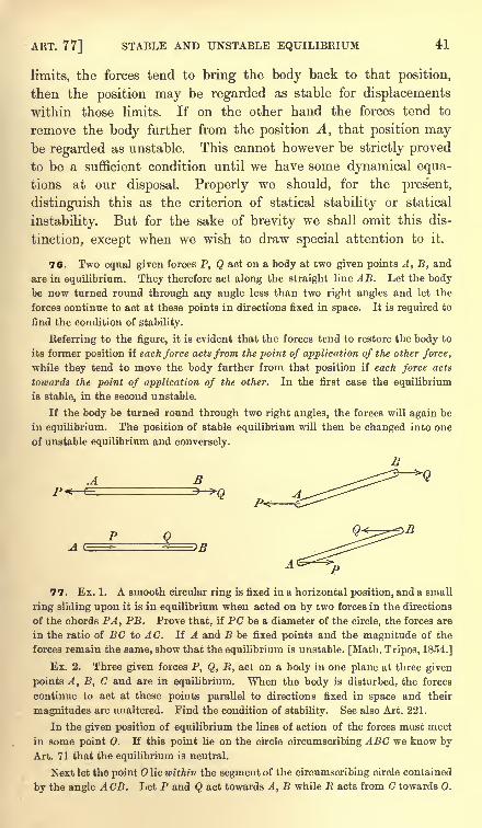
ART. 77] STABLE AND UNSTABLE EQUILIBRIUM 41
limits, the forces tend to bring the body back to that position,
then the position may be regarded as stable for displacements
within those limits. If on the other hand the forces tend to
remove the body further from the position A, that position maybe regarded as unstable. This cannot however be strictly proved
to be a sufficient condition until we have some dynamical equa-
tions at our disposal. Properly we should, for the pres'ent,
distinguish this as the criterion of statical stability or statical
instability. But for the sake of brevity we shall omit this dis-
tinction, except when we wish to draw special attention to it.
76. Two equal given forces P, Q act on a body at two given points A, B, and
are in equilibrium. They therefore act along the straight line AB. Let the bodybe now turned round through any angle less than two right angles and let the
forces continue to act at these points in directions fixed in space. It is required to
find the condition of stability.
Referring to the figure, it is evident that the forces tend to restore the body to
its former position if each force acts from the point of application of the other force,
while they tend to move the body further from that position if each force acts
towards the point of application of the other. In the first case the equilibrium
is stable, in the second unstable.
If the body be turned round through two right angles, the forces will again be
in equilibrium. The position of stable equilibrium will then be changed into one
of unstable equilibrium and conversely.
^ BP< r
-
-a
77. Ex. 1. A smooth circular ring is fixed in a horizontal position, and a small
ring sliding upon it is in equilibrium when acted on by two forces in the directions
of the chords PA, PB. Prove that, if PC be a diameter of the circle, the forces are
in the ratio of BC to AC. If A and B be fixed points and the magnitude of the
forces remain the same, show that the equilibrium is unstable. [Math. Tripos, 1854.]
Ex. 2. Three given forces P, Q, E, act on a body in one plane at three given
points A, B, C and are in equilibrium. When the body is disturbed, the forces
continue to act at these points parallel to directions fixed in space and their
magnitudes are unaltered. Find the condition of stability. See also Art. 221.
In the given position of equilibrium the lines of action of the forces must meet
in some point 0. If this point lie on the circle circumscribing ABC we know byArt. 71 that the equilibrium is neutral.
Next let the point lie within the segment of the circumscribing circle contained
by the angle ACB. Let P and Q act towards A, B while R acts from C towards 0.
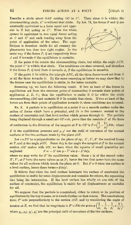
42 FORCES ACTING AT A POINT [CHAP. II
Describe a circle about OAB cutting OC in '. Then since is within the
circumscribing circle, C' is without that circle. By Art. 71, the forces P and Q are
astatically equivalent to a force equal and oppo-
site to R but acting at C". Thus the whole
system is equivalent to two equal forces acting
at C and C" and each tending away from the
point of application of the other. The equi-
librium is therefore stable for all rotatory dis-
placements less than two right angles. In the
same way if the forces P, Q act respectively from
A and B towards the equilibrium is unstable.
If the point lie outside the circumscribing circle, but within the angle ACB,the point C' is within that circle. The conditions are then reversed, and therefore
if the forces P, Q tend from towards A, B the equilibrium is unstable.
If the point lie within the triangle ABC, all the three forces must act from
or all the three towards 0. By the same reasoning as before we may show that in
the former case the equilibrium is stable, in the latter unstable.
Summing up, we have the following result. If two at least of the forces in
equilibrium act from the common point of intersection towards their points of
application A, B, C ;then the equilibrium is stable if lie within the circle
circumscribingABC and unstable if lie outside that circle. If two at least of the
forces act from their points of application towards O, these conditions are reversed.
Ex. 3. A particle is in equilibrium at a point on a smooth surface under the
action of forces which have a potential, and Oz is the common normal to the
surface of constraint and that level surface which passes through 0. The particle
being displaced through a small arc OP = ds, prove that the resolute F of the force
of restitution in the direction of the tangent at P to OP is F ={ ) Zds, where\P P/
Z is the equilibrium pressure and/>, />'
are the radii of curvature of the normal
sections of the two surfaces made by the plane zOP.
Let z=PN be a perpendicular on the plane of xy ; X', Y', Z' the resolved forces
at P, and <j>the angle xON. Since ds/p is the angle the tangent at P to the normal
section zOP makes with ON, we have when the squares of small quantities are
neglected F = - X' cos <- Y' sin
<j>-Z'dsjp,
where we may write for Z '
its equilibrium value. Since z is of the second order
X', Y', atP have the same values as at N; hence the two first terms have the same
values for all surfaces which touch the plane at 0. But F = when the surface is
a level surface, hence these terms= Zds/p'.
It follows that when the level surface intersects the surface of constraint the
equilibrium is stable for some displacements and unstable for others, the separating
line being the intersection. If the level surface lies wholly on one side of the
surface of constraint, the equilibrium is stable for all displacements or unstable
for all.
We suppose that the particle is constrained, either to return to its position of
equilibrium by the way it came, or to recede further on that course. The constraining
force F' acts perpendicularly to the section zOP, and by considering the angle of
torsion at P, we find that its magnitude is F'= Zds sin <f>cos
<f>( ; H , ) ,
\Pl />2 Pi P2 J
where plt p2 ; p/, p2'
are the principal radii of curvature of the two surfaces.
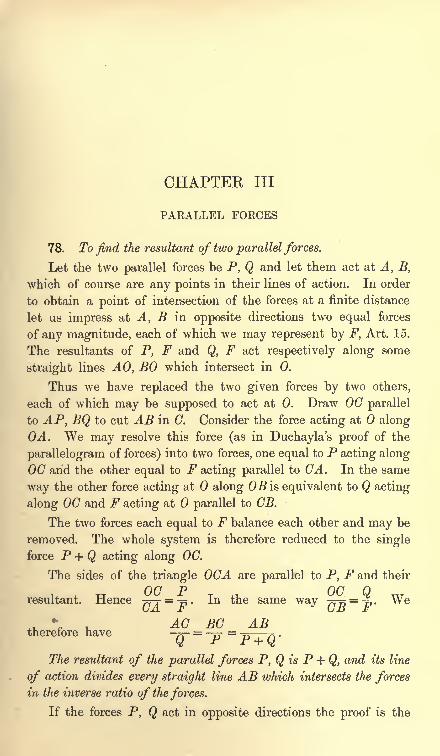
CHAPTER III
PARALLEL FORCES
78. To find the resultant of two parallel forces.
Let the two parallel forces be P, Q and let them act at A, B,
which of course are any points in their lines of action. In order
to obtain a point of intersection of the forces at a finite distance
let us impress at A, B in opposite directions two equal forces
of any magnitude, each of which we may represent by F, Art. 15.
The resultants of P, F and Q, F act respectively along some
straight lines AO, BO which intersect in 0.
Thus we have replaced the two given forces by two others,
each of which may be supposed to act at 0. Draw OC parallel
to AP, BQ to cut AB in C. Consider the force acting at along
OA. We may resolve this force (as in Duchayla's proof of the
parallelogram of forces) into two forces, one equal to P acting alongOC arid the other equal to F acting parallel to GA. In the same
way the other force acting at along OB is equivalent to Q acting
along OC and F acting at parallel to CB.
The two forces each equal to F balance each other and may be
removed. The whole system is therefore reduced to the single
force P + Q acting along OC.
The sides of the triangle OCA are parallel to P, F and their
u P T +v, Q wresultant. Hence -~-r =-. In the same way -^ = ^X. We(jA. Jb L>JJ f
AC EG ABtherefore have
Q"P P + Q'
The resultant of the parallel forces P, Q is P + Q, and its line
of action divides every straight line AB which intersects the forcesin the inverse ratio of the forces.
If the forces P, Q act in opposite directions the proof is the
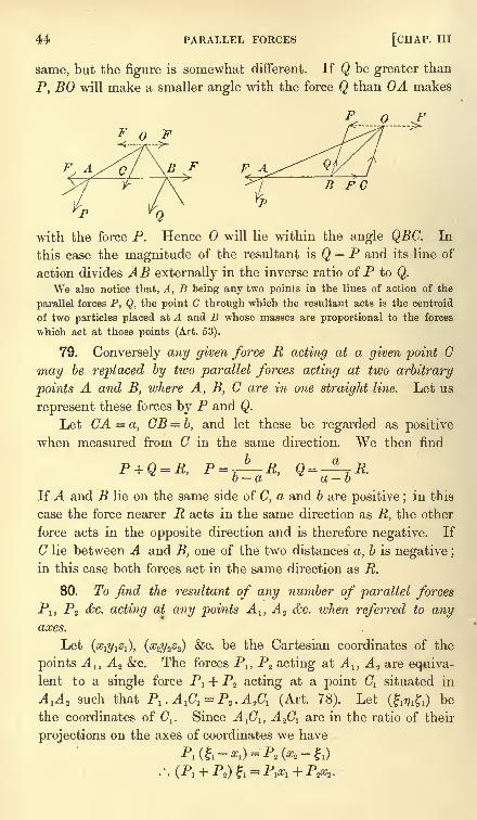
44 PARALLEL FORCES [CHAP. Ill
same, but the figure is somewhat different. If Q be greater than
P, BO will make a smaller angle with the force Q than OA makes
F. A B F F AB PC
with the force P. Hence will lie within the angle QBC. In
this case the magnitude of the resultant is Q P and its line of
action divides AB externally in the inverse ratio of P to Q.
We also notice that, A, B being any two points in the lines of action of the
parallel forces P, Q, the point C through which the resultant acts is the centroid
of two particles placed at A and B whose masses are proportional to the forces
which act at those points (Art. 53).
79. Conversely any given force R acting at a given point G
may be replaced by two parallel forces acting at two arbitrary
points A and B, where A, B, C are in one straight line. Let us
represent these forces by P and Q.
Let CA = a, CB = b, and let these be regarded as positive
when measured from C in the same direction. We then find
If A and B lie on the same side of C, a and b are positive ;in this
case the force nearer R acts in the same direction as R, the other
force acts in the opposite direction and is therefore negative. If
C lie between A and B, one of the two distances' a, b is negative ;
in this case both forces act in the same direction as R.
80. To find the resultant of any number of parallel forces
P!, P2 &c. acting at any points A lt A 2 &c. luhen referred to anyaxes.
Let (#i2/i^i), (#23/2^2) &c. be the Cartesian coordinates of the
points A 1} A 2 &c. The forces Pl} P2 acting at A l} A* are equiva-lent to a single force P1 + P2 acting at a point Cl situated in
A^AI such that Pl .AiCl =P*.A& (Art. 78). Let (f^O be
the coordinates of C^. Since A^G^ A^ are in the ratio of their
projections on the axes of coordinates we have
Pi(&-:- Pt 0*- ft)
ART. 82] CENTRE OF PARALLEL FORCES 45
Similar results apply for the other coordinates of C^.
The force Pl + P2 acting at Cl and a third force P3 acting at A 3
are in the same way equivalent to Pl + P2 + P3 acting at a point(72 whose coordinates (2^2 2) ai%e given by
(Px + P2 + P3) & = C^ + P2) + P^s=
f-flj\ T -L 2#/2 T -LyE-i
with similar expressions for ij2 and 2 .
Proceeding in this way we see that the resultant of all the
forces is P! + P2 + . . . and if (17 ) be the coordinates of its point of
application, we have
(Pl + P2 + &c.) f = P& + P^2 + &c.
(Pa + P2 + &C.) 77=P& +P27/2 + &c.
(P, + P2 + &C.)= P& + P& + &C.
These equations are usually written
81. It might be supposed that this proof would either fail or require somemodification if any one of the partial resultants P
1 + P2 ,P
1 +P2 +P3 &c. were zero,
for then some of the quantities : , 2 <fec. would be infinite. The final result also
might be thought to fail if 2P=0. But any proposition proved true for general
values of the forces must be true for these limiting cases, though its interpretation
may not be understood until we come to the theory of couples.
We may avoid this apparent difficulty by a slight modification of the proof.
Let us separate the forces which act in one direction from those which act in the
opposite direction, thus forming two groups. Let us suppose the sums of the
forces in the two groups are unequal. If we compound together first all the forces
in that group in which the sum is greatest and then join to these one by one the
forces of the other group, it is clear that we shall never have any of the partial
resultants equal to zero and no point of application of any such partial resultant
will be at infinity. If the sums of the forces in the two groups are equal, the
centre of parallel forces is infinitely distant.
82. The expressions for the coordinates (ffyf) are the same as
those given in Art. 51 for the coordinates of the centroid;we
therefore deduce the following rule.
To find the resultant of the parallel forces Pl} P2 &c. we select
convenient points A 1} A 2 &c. on their respective lines of action and
place at these points particles whose masses are proportional to the
forces PI ,P2 &c. The line of action of the resultant passes through
the centroid of these particles, its direction is parallel to that of the
forces, and its magnitude is SP.
46 PARALLEL FORCES [CHAP. Ill
Conversely, any given force can be replaced by parallel forces acting at arbitrary
points A l , A2 &c. provided the forces are such that the centroid lies on the given
force.
This proposition is really the limiting case of Leibnitz's theorem. If concurrent
forces act along OA l ,OA2 &c. their resultant may be found by any of the methods
considered in the last chapter. By regarding as a point very distant from
A lt A 2 &c., the forces acting along OAlt OA 2 &c. become parallel and the cor-
responding theorem follows at once. Thus in Art. 51 it is shown that the resultant
of forces proportional to Pl
. OA1 , P2 . OA 2 &c. is a force proportional to 2P. OC
acting along OC where C is the centroid of particles Pl ,P2 &c. placed at A
1 , A.2 &c.
In the limit OA, OB, OC are all equal; hence the resultant of parallel forces
proportional to Pl , P2 &c. is proportional to 2P and acts at C.
83. The point (j?) determined by the equations of Art. 80
has one important property. Its position is the same whatever be
the magnitudes of the angles made by the forces with the coor-
dinate axes. If then the points of application of the given parallel
forces viz. A 1} A 2 &c. are regarded as fixed in the body, the point of
application of their resultant is also fixed in the body however the
forces are turned round their points of application provided they
remain parallel and unaltered in magnitude.
This point of application of the resultant is called the "centre
ofparallel forces."
84. Ex. 1. Parallel forces, each equal to P, act at the corners A, B, C, D of
a re-entrant plane quadrilateral and a fifth force equal to - P acts at the intersection
H of the diagonals HCA, BHD. If the centre of the five parallel forces coincide
with a corner C of the quadrilateral, prove that HC= CA.
Ex. 2. ABC is a triangle; APD, BPE, CPF, the perpendiculars from A, B, Con the opposite sides. Prove that the resultant of six equal parallel forces, acting
at the middle points of the sides of the triangle and of the lines PA, PB, PC, passes
through the centre of the circle which goes through all of these middle points.
[Math. Tripos, 1877.]
Ex. 3. ABCD is a quadrilateral whose diagonals intersect in O. Parallel
forces act at the middle points of AB, B C, CD, DA respectively proportional to
the areas AOB, BOC, COD, DOA. Prove that the centre of parallel forces is at
the fourth angular point, viz. G, of the parallelogram described on OE, OF as
adjacent sides where E, F are the middle points of the diagonals AC, BD of the
quadrilateral. [Coll. Ex., 1885.]
Taking BD as the axis of x we find ij= \ (p-p') where p, p' are the per-
pendiculars from A and C on BD. It follows that the centre of parallel forces
lies on EG. Similarly it lies on FG.
85. To find the conditions of equilibrium of a system ofparallel
forces.
Let the forces be P1} ... Pn ;then by Art. 80 they will have a
resultant unless 2P = 0. This, though a necessary condition of
equilibrium, is not sufficient.
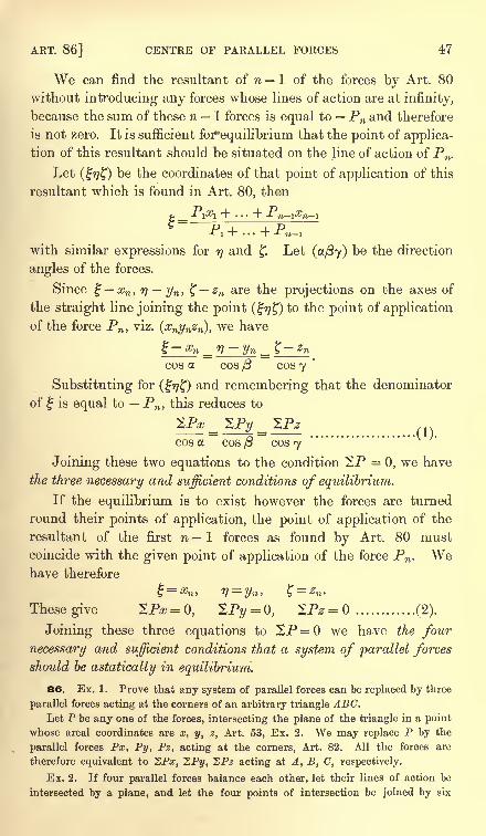
ART. 86] CENTRE OF PARALLEL FORCES 47
We can find the resultant of n 1 of the forces by Art. 80
without introducing any forces whose lines of action are at infinity,
because the sum of these n 1 forces is equal to Pn and therefore
is not zero. It is sufficient for*equilibrium that the point of applica-
tion of this resultant should be situated on the line of action of Pn .
Let (77 ) be the coordinates of that point of application of this
resultant which is found in Art. 80, then
Px-\-... + P_sc_
with similar expressions for77 and Let (a/3<y) be the direction
angles of the forces.
Since #n , 77 yw , t zn are the projections on the axes of^ 'ft/ *"'" J. /
the straight line joining the point (17 ) to the point of application
of the force Pn ,viz. {xnynz^, we have
cos a. cos /3 cos 7
Substituting for (&) and remembering that the denominator
of is equal to Pn ,this reduces to
.
cos a cos /3 cos 7
Joining these two equations to the condition 2P = 0, we have
the three necessary and sufficient conditions of equilibrium.
If the equilibrium is to exist however the forces are turned
round their points of application, the point of application of the
resultant of the first nI forces as found by Art. 80 must
coincide with the given point of application of the force Pn . Wehave therefore
Thesegive 2P=0, XPy = 0, 2P* = ............ (2).
Joining these three equations to SP = we have the four
necessary and sufficient conditions that a system of parallel forces
should be astatically in equilibrium.
86. Ex. 1. Prove that any system of parallel forces can be replaced by three
parallel forces acting at the corners of an arbitrary triangle ABC.Let P be any one of the forces, intersecting the plane of the triangle in a point
whose areal coordinates are x, y, z, Art. 53, Ex. 2. We may replace P by the
parallel forces Px, Py, Pz, acting at the corners, Art. 82. All the forces are
therefore equivalent to SP#, SPi/, SPz acting at A, B, C, respectively.
Ex. 2. If four parallel forces balance each other, let their lines of action be
intersected by a plane, and let the four points of intersection be joined by six
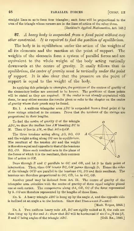
48 PARALLEL FORCES [CHAP. Ill
straight lines so as to form four triangles ; each force will be proportional to the
area of the triangle whose corners are in the lines of action of the other three.
[Rankine's Applied Mathematics, Art. 143.]
87. A heavy body is suspended from a fixed point without anyother constraint. It is required to find the position of equilibrium.
The body is in equilibrium under the action of the weights of
all its elements and the reaction at the point of support. The
weights of the elements form a system of parallel forces and are
equivalent to the whole weight of the body acting vertically
downwards at the centre of gravity. It easily follows that in-
equilibrium, the centre of gravity must be vertically under the point
of support. It is also clear that the pressure on the point of
support is equal to the weight of the body.
In applying this principle to examples, the positions of the centres of gravity of
the elementary bodies are assumed to be known. The positions of these points
will be stated as they are required. If the reader is not already acquainted with
them, he may either assume the results given or refer to the chapter on the centre
of gravity where their proofs may be found.
Ex. 1. A uniform triangular area ABC is suspended from a fixed point bythree strings attached to its corners. Prove that the tensions of the strings are
proportional to their lengths.
To find the centre of gravity G of the triangle
ABC, we draw the median line AM bisecting BC in
M. Then G lies in AM, so that AG = %AM.The three tensions acting along AO, BO, CO
and the weight acting along OG are in equilibrium.
The resultant of the tension AO and the weight
is therefore equal and opposite to that of the tensions
BO, CO. Since each resultant acts in the plane of
the forces of which it is the resultant, their commonline of action is OM.
Draw through B and C parallels to OC and OB, and let D be their point of
intersection. Then, since OM bisects BC, OM passes through D. Hence the sides
of the triangle OCD are parallel to the tensions CO, BO and their resultant. The
tensions are therefore proportional to OC, CD, i.e. to OC, OB.
Another proof may be deduced from Art. 51. The centre of gravity of the
triangular area coincides with the centre of gravity of three equal weights placed
one at each corner. The components along OA, OB, OC of the force represented
by 3 . 00 are therefore represented by the lengths of those lines.
Ex. 2. A heavy triangle ABC is hung up by the angle A, and the opposite side
is inclined at an angle o to the horizon. Show that 2 tan a= cot B ~ cot C.
[Math. Tripos, 1865.]
Ex. 3. Two uniform heavy rods AB, BC are rigidly united at B, the rods are
then hung up by the end A : show that BC will be horizontal if sin C=^/2 sin %B,
B and C being angles of the triangle ABC. [Coll. Ex. , 1883.]
ART. 87] EXAMPLES ON SUSPENDED BODIES 49
Ex. 4. A heavy equilateral triangle, hung up on a smooth peg by a string, the
ends of which are attached to two of its angular points, rests with one of its sides
vertical ; show that the length of the string is double the altitude of the triangle.
[Math. Tripos, 1857.]
Ex. 5. A piece of uniform wire is bent into three sides of a square ABCD, of
which the side AD is wanting ; prove that if it be hung up by the two points A and
B successively, the angle between the two positions of BC is tan"1 18.
The distance of the centre of gravity G from BC can be shown to be equal to
one third of AB. When hung up from A and B, AG and BG respectively are
vertical. The angle required is therefore equal to AGB. [Math. Tripos, 1854.]
Ex. 6. A triangle ABC is successively suspended from A and B, and the two
positions of any side are at right angles to each other; prove that 5c2=a2 + 62.
[Coll. Ex.]
Ex. 7. A uniform circular disc of weight nW has a heavy particle of weight Wattached to a point on its rim. If the disc be suspended from a point A on its rim,
B is the lowest point ; and if suspended from B, A is the lowest point. Show that
the angle subtended by AB at the centre is 2 sec"1 2 (n + 1). [Math. Tripos, 1883.]
Ex. 8. The altitude of a right cone is h and the radius of its base is r; a string
is fastened to the vertex and to a point on the circumference of the circular base
and is then put over a smooth peg : prove that if the cone rests with its axis
horizontal the length of the string is x/(ft2 + 4r2
). [Math. Tripos, 1865.]
If V be the vertex and C the centre of gravity of the base of a cone (either right
or oblique), the centre of gravity of the solid cone lies in VC, so that VG ^VC.
Ex. 9. A string nine feet long has one end attached to the extremity of a
smooth uniform heavy rod two feet in length, and at the other end carries a
light ring which slides upon the rod. The rod is suspended by means of the string
from a smooth peg; prove that if 6 be the angle which the rod makes with the
horizon, then tan = 3~* - 3
~$. [Math. Tripos, 1852. ]
Ex. 10. A heavy uniform rod of length 2a turns freely on a pivot at a point in
it, and suspended by a string of length I fastened to the ends of the rod hangs a
bead of equal weight which slides on the string. Prove that the rod cannot rest in
an inclined position unless the distance of the pivot from the middle point of the
rod be less than a2/*. [Math. Tripos, 1882.]
Ex. 11. Two equal rods AB, BC of length 2a are connected by a free hinge at B;
the ends A and C are connected by an inextensible string of length I : the system is
suspended from A : prove that, in order that the angle AB makes with the vertical
may be the greatest possible, I must be equal to iaj^/B. [St John's Coll., 1883.]
As I is varied the centre of gravity G of the system moves along the circle
described on BE as diameter, where E is the middle point of AB. Hence the angle
GAB is greatest when AG is a tangent to this circle.
Ex. 12. At the angular points A, B, C of a light rigid frame-work, three
heavy particles of weights WA , WB , Wc are fixed and the whole is suspended
from a point by three strings OA, OB, OC; if the tensions in equilibrium be
Tx> Tm ,Tc respectively, prove that ^-^^^^^^ and hence
determine T^, TB ,Tc . [St John's Coll., 1886.]
Ex. 13. A heavy triangular lamina is suspended from a fixed point by means
of three elastic strings attached to its angular points : the strings when unstretched
R. S. I. *
50 PARALLEL FORCES [CHAP. Ill
are equal in length, but the moduli of their elasticities are different. Assumingthat the tension of each is equal to the modulus multiplied by the ratio of the
extension to the unstretched length, prove that the strings will be equal, if a weightbe placed at a certain point on the lamina, provided the weight be not less than a
certain weight : prove also that the locus of its position for different magnitudes of
the weight, is a straight line. . [Coll. Ex., 1887.]
Ex. 14. A uniform circular disc, whose weight is w and radius a, is suspended
by three vertical strings attached to three points on the circumference of the disc
separated by equal intervals. A weight W may be put down anywhere within a
concentric circle of radius ma; prove that the strings will not break if they can
support a tension equal to (2mW+W+w). [Trin. Coll., 1886.]
Ex. 15. A right circular cone rests with its elliptic base on a smooth horizontal
table. A string fastened to the vertex and the other end of the longest generator
passes round a smooth pulley above the cone, so that all parts of the string except
those in contact with the pulley are vertical. If the string become gradually
contracted by dampness or other causes and tend to lift the cone, show that
the end of the shortest generator will remain in contact with the table provided
that the diameter of the pulley be less than three times the semi-major axis of the
elliptic base. [Math. Tripos, 1878.]
88. A heavy body is placed on either a smooth horizontal
plane or a rough inclined plane, and its base is any polygonal
area. Determine whether it will tumble over one side or remain
in equilibrium.
The weights of the particles of the body constitute a system of
parallel forces. These have a resultant whose position and magni-tude may be found by the theorem of Art. 80 when the weightsof the particles are known. This resultant acts vertically down-
wards through a point of the body called its centre of gravity. If
equilibrium exists, this must be balanced by the pressures of the
plane on the body. These pressures however distributed over the
polygonal area must have a resultant which acts at some point
within the polygonal area. It follows that equilibrium cannot
exist unless the vertical through the centre of gravity of the bodyintersects the plane within the area of the base.
Ex. 1. The distance between the heels of a man's feet is 2&, and the length of
each foot is a. As the body sways, the vertical through the centre of gravity
should always pass through the area contained by the feet. The toes should
therefore be turned out at such an angle that the area contained by the feet is a
maximum. Show (1) that a circle can be described about the feet with its centre
on the straight line joining the toes, (2) that its diameter is b + (62 + 2a2
).
Ex. 2. A heavy right cone whose height is h and semi-angle a is placed with
its base on a perfectly rough plane ; prove that the cone will tumble over the rim
of its base if the angle 6 at which the plane is inclined to the horizon is greater
than that given by tan = 4 tan o.
ART. 89] THEORY OF COUPLES 51
Ex. 3. A hemispherical cup of weight W is loaded by two weights w, w'
attached to its rim and is then placed on a smooth horizontal plane; show that
the angle 8 which the principal radius of the cup makes with the vertical when the
cup is in equilibrium is given by the equation
W tan e= 2{ (w
-w;')
2+ 4ww' cos2^}^,
where 2fi is the angle between the radii through the weights w, IK', and it is assumed
that the centre of gravity of the cup is at the middle point of its principal radius.
[King's Coll., 1889.]
Ex. 4. Two equal heavy particles are at the extremities of the latus rectum of
a parabolic arc without weight, which is placed with its vertex in contact with that
of an equal parabola, whose axis is vertical and concavity downwards. Prove that
the parabolic arc may be turned through any angle without disturbing the equi-
librium, provided no sliding be possible between the curves.
[Watson's Problem, Math. Tripos, I860.]
Theory of Couples
89. There is one case in which the theorem of Art. 80 leads
to a remarkable result. Let us suppose that the parallel forces
P, Q are equal and -act in opposite directions. According to the
theorem the magnitude of the resultant is zero, and the point of
application is infinitely distant.
Two equal and opposite forces acting at two points A and Bcannot balance each other unless these points are in the same
straight line with the forces. Yet we have just seen that these
two forces are not equivalent to any one single force at a finite
distance. They therefore supply a new method of analysing forces.
WThen a number of forces act on a body we simplify the system by
reducing the forces to as few as we can. Sometimes we can reduce
them to a single force acting at some point of the body. In other
cases (as in the case considered in this article) the point of appli-
cation is at infinity and the reduction to a single force is no longer
convenient. By using a couple of equal forces, as a new elementary
term, we obtain a simple method of expressing this infinitely distant
force. We now have two elementary quantities, viz. a force and a
couple. It may be possible to reduce a given system of forces
to either or both of these constituents. With the help of both
these, we may analyse a system of forces with greater completenessthan with one alone.
If we regard a couple as a new element in analysis, it becomes
necessary to consider the properties of such an element apart
from all other combinations of forces. Since a couple can itself be
42
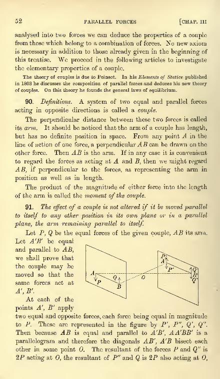
52 PARALLEL FORCES [CHAP, in
analysed into two forces we can deduce the properties of a couplefrom those which belong to a combination of forces. No new axiom
is necessary in addition to those already given in the beginning of
this treatise. We proceed in the following articles to investigate
the elementary properties of a couple.
The theory of couples is due to Poinsot. In his Elements of Statics published
in 1803 he discusses the composition of parallel forces and deduces his new theory
of couples. On this theory he founds the general laws of equilibrium.
90. Definitions. A system of two equal and parallel forces
acting in opposite directions is called a couple.
The perpendicular distance between these two forces is called
its arm. It should be noticed that the arm of a couple has length,
but has no definite position in space. From any point A in the
line of action of one force, a perpendicular AB can be drawn on the
other force. Then AB is the arm. If in any case it is convenient
to regard the forces as acting at A and B, then we might regard
AB, if perpendicular to the forces, as representing the arm in
position as well as in length.
The product of the magnitude of either force into the length
of the arm is called the moment of the couple.
91. The effect of a couple is not altered if it be moved parallel
to itself to any other position in its own plane or in a parallel
plane, the arm remaining parallel to itself.
Let P, Q be the equal forces of the given couple, AB its arm.
Let A'B' be equal
and parallel to AB,we shall prove that
the couple may be
moved so that the
same forces act at
A, B'.
At each of the
points A, B' applytwo equal and opposite forces, each force being equal in magnitudeto P. These are represented in the figure by P', P", Q', Q".
Then because AB is equal and parallel to A'B', AABB' is a
parallelogram and therefore the diagonals AB', A'B bisect each
other in some point 0. The resultant of the forces P and Q" is
2P acting at 0, the resultant of P" and Q is 2P also acting at 0,
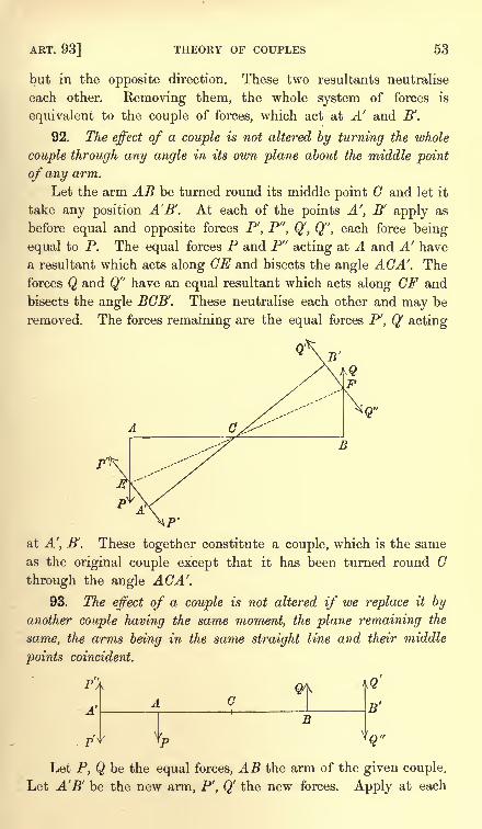
ART. 93] THEORY OF COUPLES 53
but in the opposite direction. These two resultants neutralise
each other. Removing them, the whole system of forces is
equivalent to the couple of forces, which act at A' and B'.
92. The effect of a couple is not altered by turning the whole
couple through any angle in its own plane about the middle point
of any arm.
Let the arm AB be turned round its middle point G and let it
take any position AB'. At each of the points A', B' apply as
before equal and opposite forces P', P", Q', Q", each force being
equal to P. The equal forces P and P" acting at A and A' have
a resultant which acts along CE and bisects the angle AGA. The
forces Q and Q" have an equal resultant which acts along CF and
bisects the angle BGB'. These neutralise each other and may be
removed. The forces remaining are the equal forces P', Q' acting
B
at A, B'. These together constitute a couple, which is the same
as the original couple except that it has been turned round G
through the angle AGA.93. The effect of a couple is not altered if we replace it by
another couple having the same moment, the plane remaining the
same, the arms being in the same straight line and their middle
points coincident.
p';
A'
rf S
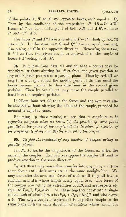
54 PARALLEL FORCES [CHAP. Ill
of the points A', B' equal and opposite forces, each equal to P'.
Then by the conditions of the proposition, P . AB = P' .A'B'.
Hence if C be the middle point of both AB and A'B', we have
P.AC = P' .A'C.
The forces P and P" have a resultant P - P" which by Art. 78
acts at G. In the same way Q and Q" have an equal resultant,
also acting at C in the opposite direction. Removing these two,
it follows that the given couple is equivalent to the couple of
forces + P acting at A', B.
94. It follows from Arts. 91 and 92 that a couple may be
transferred without altering its effect from one given position to
any other given position in a parallel plane. Thus by Art. 92 we
may turn a couple round the middle point of its arm until the
forces become parallel to their directions in the second given
position. Then by Art. 91 we may move the couple parallel to
itself into the required position.
It follows from Art. 93 that the forces and the arm may also
be changed without altering the effect of the couple, provided its
moment is kept the same.
Summing up these results, we see that a couple is to be
regarded as given when we know, (1) the position of some plane
parallel to the plane of the couple, (2) the direction of rotation ofthe couple in its plane, and (3) the moment of the couple.
95. To find the resultant of any number of couples acting in
parallel planes.
Let P1} P2 &c. be the magnitudes of the forces, alf a2 &c. the
arms of the couples. Let us first suppose the couples all tend to
produce rotation in the same direction.
By Art. 94 we may move these couples into one plane and turn
them about until their arms are in the same straight line. Wemay then alter the arms and forces of each until they all have a
common arm AB whose length is, say, equal to b. The forces of
the couples now act at the extremities of AB, and are respectively
equal to Pfa/b, P-fl^jb &c. All these together constitute a single
couple each of whose forces is (P^ + P-fl^ + &c.)/6 and whose arm
is 6. This single couple is equivalent to any other couple in the
same plane with the same direction of rotation whose moment is
ART. 97] THEORY OF COUPLES 55
P\OI + P2aa + &c., i.e. whose moment is the sum of the moments of
the separate couples.
If some of the couples tend to produce rotation in the oppositedirection to the others, we may represent this by regarding the
forces of these couples as negative. The same result follows as
before.
We thus obtain the following theorem;the resultant of any
number of couples whose planes are parallel is a couple whose
moment is the algebraic sum of the moments of the separate couples
and whose plane is parallel to those of the given couples.
96. Measure of a couple. We may use the proposition
just established to show that the magnitude of a couple regardedas a single element is properly measured by its moment. To provethis we assume as a unit the couple whose force is the unit of force
and whose arm is the unit of length. The moment of this coupleis unity. By this proposition a couple whose moment is n times
as great is equivalent to n such couples and its magnitude is
therefore properly represented by the symbol n.
97. Axis of a couple. A couple may tend to producerotation in one direction or the opposite according to the circum-
stances of the couple. One of these is usually called the positive
direction and the other the negative. Just as in choosing axes of
coordinates sometimes one direction is taken as the positive one
and sometimes the other, so in couples the choice of the positive
direction is not always the same. In trigonometry the direction
of rotation opposite to the hands of a watch is taken as the positive
direction. In most treatises on conies the same choice is made.
In solid geometry the opposite direction is generally chosen.
Having however chosen one of these two directions as the positive
one it is usual to indicate the direction of rotation of a given
couple in the following manner.
From any point C in the plane of the couple draw a straight
line CD at right angles to the plane and on one side of it. The
straight line is to be so drawn that if an observer stand with his
feet at C on the plane and his back along CD, the couple will
appear to him to produce rotation in what has been chosen as
the positive direction. The straight line CD is called the positive
direction of the axis of the couple.
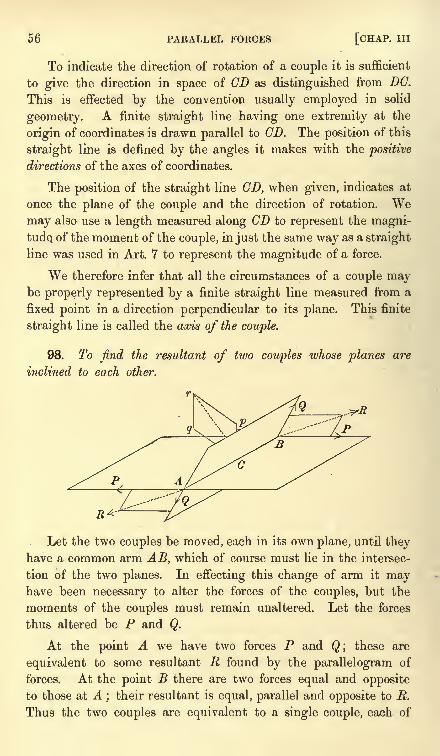
56 PARALLEL FORCES [CHAP. Ill
To indicate the direction of rotation of a couple it is sufficient
to give the direction in space of CD as distinguished from DC.
This is effected by the convention usually employed in solid
geometry. A finite straight line having one extremity at the
origin of coordinates is drawn parallel to CD. The position of this
straight line is defined by the angles it makes with the positive
directions of the axes of coordinates.
The position of the straight line CD, when given, indicates at
once the plane of the couple and the direction of rotation. Wemay also use a length measured along CD to represent the magni-
tude, of the moment of the couple, in just the same way as a straight
line was used in Art. 7 to represent the magnitude of a force.
We therefore infer that all the circumstances of a couple maybe properly represented by a finite straight line measured from a
fixed point in a direction perpendicular to its plane. This finite
straight line is called the axis of the couple.
98. To find the resultant of two couples whose planes are
inclined to each other.
Let the two couples be moved, each in its own plane, until theyhave a common arm AB, which of course must lie in the intersec-
tion of the two planes. In effecting this change of arm it mayhave been necessary to alter the forces of the couples, but the
moments of the couples must remain unaltered. Let the forces
thus altered be P and Q.
At the point A we have two forces P and Q; these are
equivalent to some resultant R found by the parallelogram of
forces. At the point B there are two forces equal and opposite
to those at A;their resultant is equal, parallel and opposite to R.
Thus the two couples are equivalent to a single couple, each of
ART. 100] THEORY OF COUPLES 57
whose forces is equal to R, and whose arm is AB. Let the length
of AB be b.
From any point C (which we may conveniently take in AB)draw Cp, Cq in the directions of the axes of the given couples, and
measure lengths along them proportional to their moments, viz. to
Pb and Qb. These axes are perpendicular to the planes of the
couples, and their lengths are also proportional to P and Q. If
we compound these two by the parallelogram law we evidently
obtain an axis perpendicular to the plane of the forces + R,
whose length is proportional to R. It is evident that the paral-
lelogram Cpqr is similar to that contained by the forces PQR,but the sides of one parallelogram are perpendicular to the sides
of the other.
We therefore infer the following construction for the resultant
of any two couples. Draw two finite straight lines from any point
C to represent the axes of the couples in direction and magnitude.
The resultant of these two obtained by the parallelogram law repre-
sents in direction and magnitude the axis of the resultant couple.
The rule to compound couples is therefore the same as that
already given for compounding forces. It follows that all the
theorems for compounding forces deduced from the parallelogram
law also apply to couples. The working rule is that if we represent
the couples by their axes, we may compound and resolve these as if
they were forces acting at a point.
99. Ex. 1. A system of couples is represented in position and magnitude bythe areas of the faces of a polyhedron, and their axes are turned all inwards or all
outwards. Show that they are in equilibrium. Art. 47. Mobius.
Ex. 2. Four straight lines are given in space, prove that four couples can be
found, having these for the directions of their axes, which are in equilibrium.
Find also their moments and discuss the case in which three of the given straight
lines are parallel to a plane, Arts. 40, 48.
Ex. 3. Three couples are represented in position and magnitude by the areas
of three faces OBC, OCA, OAB of the tetrahedron OABC, the axes of the first two
being turned inwards and that of the third outwards. Prove that the resultant
couple acts in the plane ODE bisecting the sides BC, CA and is represented by
four times the area of the triangle ODE.
Replace each couple by another one of whose forces passes through and the
other acts along a side of ABC. The forces represented by BC, CA and BA have
evidently a resultant IDE.
100. A force P acting at any point A may be transferred
parallel to itself, to act at any other point B, by introducing a couple
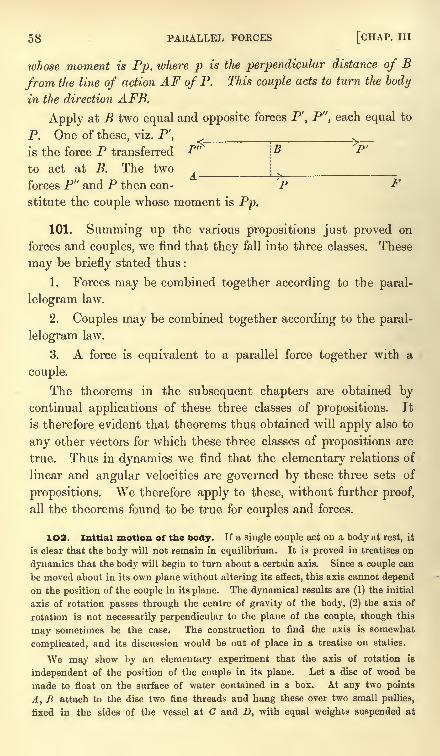
B P'
58 PARALLEL FORCES [CHAP. Ill
ivhose moment is Pp, where p is the perpendicular distance of B
from the line of action AF of P. This couple acts to turn the body
in the direction AFB.
Apply at B two equal and opposite forces P', P", each equal to
P. One of these, viz. P', ^is the force P transferred F"
to act at B. The two
forces P" and P then con- P Fstitute the couple whose moment is Pp.
101. Summing up the various propositions just proved on
forces and couples, we find that they fall into three classes. These
may be briefly stated thus :
1. Forces may be combined together according to the paral-
lelogram law.
2. Couples may be combined together according to the paral-
lelogram law.
3. A force is equivalent to a parallel force together with a
couple.
The theorems in the subsequent chapters are obtained bycontinual applications of these three classes of propositions. It
is therefore evident that theorems thus obtained will apply also to
any other vectors for which these three classes of propositions are
true. Thus in dynamics we find that the elementary relations of
linear and angular velocities are governed by these three sets of
propositions. We therefore apply to these, without further proof,
all the theorems found to be true for couples and forces.
102. Initial motion of the body. If a single couple act on a body at rest, it
is clear that the body will not remain in equilibrium. It is proved in treatises on
dynamics that the body will begin to turn about a certain axis. Since a couple can
be moved about in its own plane without altering its effect, this axis cannot depend
on the position of the couple in its plane. The dynamical results are (1) the initial
axis of rotation passes through the centre of gravity of the body, (2) the axis of
rotation is not necessarily perpendicular to the plane of the couple, though this
may sometimes be the case. The construction to find the axis is somewhat
complicated, and its discussion would be out of place in a treatise on statics.
We may show by an elementary experiment that the axis of rotation is
independent of the position of the couple in its plane. Let a disc of wood be
made to float on the surface of water contained in a box. At any two points
A, B attach to the disc two fine threads and hang these over two small pullies,
fixed in the sides of the vessel at C and D, with equal weights suspended at
ART. 103] THEORY OF COUPLES 59
the other extremities. Let the strings AC, BD be parallel so that their tensions
form a couple. Under the influence of this couple the body will begin to turn
round. However eccentrically the points A, B are situated the body begins to
turn round its centre of gravity. The body may not continue to turn round
this axis for, as the body moves, the strings cease to be parallel. For this and
other reasons the motion of rotation is altered.
1O3. Ex. 1. Forces P, 2P, 4P, 2P act along the sides of a square taken in
order; find the magnitude and position of their resultant. [St John's, 1880.]
Ex. 2. A triangular lamina ABC is moveable in its own plane about a point in
itself : forces act on it along and proportional to BC, CA, BA. Prove that if these
do not move the lamina, the point must lie in the straight line which bisects BCand CA. [Math. Tripos, 1874.]
Ex. 3. Forces are represented in magnitude, direction, and position by the sides
of a triangle taken in order; prove that they are equivalent to a couple whose
moment is twice the area of the triangle.
If the sides taken in order represent the axes of three couples, prove that these
couples are in equilibrium.
Ex. 4. If six forces acting on a body be completely represented three by the
sides of a triangle taken in order and three by the sides of the triangle formed by
joining the middle points of the sides of the original triangle, prove that they will
be in equilibrium if the parallel forces act in the same direction and the scale on
which the first three forces are represented be four times as large as that on which
the last three are represented. [Math. Tripos.]
Ex. 5. Four forces a . AB, ft . BC, y . CD, 5 . DA act along the sides AB, BC,
CD, DA of a skew quadrilateral ABCD; show that (1) they cannot be in equilibrium,
(2) if a=fi=y=d they form a single couple whose plane is parallel to the diagonals
AC, BD, (3) if ay= fid they reduce to a single resultant whose line of action
intersects the diagonals. Find also the magnitudes of the couple and resultant.
[Coll. Ex., 1892.]
The forces at the corners B and D have respectively resultants acting along
some lines BE, DF cutting AC in E and F. Since the planes ABC, ADC do not
coincide, these two partial resultants cannot act in the same straight line, and
therefore cannot be in equilibrium.
If the forces are equivalent to a couple, the sum of their resolved parts along
the perpendicular from B on the plane ADC is zero. This requires BE to be
parallel to AC and gives et= /3; similarly /3 -y and y= d. The partial resultants at
B and D are a . AC, and act parallel to AC and CA. The plane of the couple is
therefore parallel to AC, similarly it is parallel to BD. The moment of the couple
is 4a times the area of the parallelogram whose vertices are the middle points of
the sides.
If the forces are equivalent to a single resultant the points E and F on AC must
coincide;but E is the mean centre of - a and ft at A and C, while F is the mean
centre of 5 and -7 at the same points, Art. 51, hence ay= fid.The partial re-
sultants now intersect in the point E on the diagonal AC and are represented by
(a-/3) EB and (7-8) ED. The single resultant therefore passes through E and
a point H on the other diagonal BD and its magnitude is (a- fl + y-5) . EH.
If the quadrilateral is plane the four forces are equivalent to a single resultant
60 PARALLEL FORCES [CHAP. Ill
except when a, /8, 7, 5 are equal. The forces are in equilibrium when the partial
resultants are equal and opposite, i.e. when
where is the intersection of the diagonals.
Ex. 6. Forces are represented in magnitude, direction, and position by the
sides of a skew polygon taken in order;show that they are equivalent to a couple.
If the corners of the skew polygon are projected on any plane, prove that the
resolved part of the resultant couple in that plane is represented by twice the area
of the projected polygon.
Ex. 7. AC, BD are two non-intersecting straight lines of constant length ;
prove that the effect of forces represented in every respect by AB, BC, CD, DAis the same, so long as AC, BD remain parallel to the same plane, and the anglebetween their projections on that plane is constant. [Coll. Ex., 1881.]
Ex. 8. If two equal lengths Aa, Bb, are marked off in the same direction alonga given straight line, and two equal lengths Cc, Dd along another given line, provethat forces represented in every respect by AC, ca, CB, be, BD, db, DA, ad are in
equilibrium. [Trin. Coll.]
Ex. 9. Forces proportional to the sides alt az ... of a closed polygon act at
points dividing the sides taken in order in the ratios m1
: nlf 7 2 : n2 , ... and each
makes the same angle 6 in the same sense with the corresponding side; prove that
/ >m _ 7? \there will be equilibrium if 2 I
- a2)= 4Acot0, where A is the area of the
V/t+ n /polygon. [Math. Tripos, 1869.]
Resolve each force along and perpendicular to the corresponding side and
transfer the latter component to act at the middle point by introducing a couple,
Art. 100. The couples balance the components along the sides, Ex. 3. The other
components are in equilibrium, Art. 37.
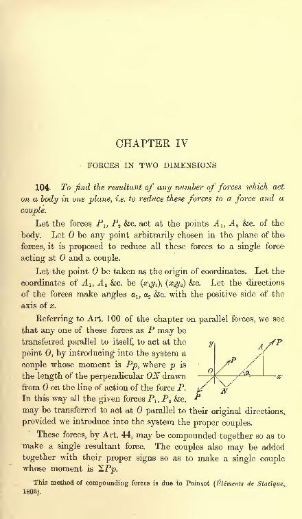
CHAPTER IV
FORCES IN TWO DIMENSIONS
104. To find the resultant of any number of forces which act
on a body in one plane, i.e. to reduce these forces to a force and a
couple.
Let the forces Pl5 P2 &c. act at the points A 1} A 2 &c. of the
body. Let be any point arbitrarily chosen in the plane of the
forces, it is proposed to reduce all these forces to a single force
acting at and a couple.
Let the point be taken as the origin of coordinates. Let the
coordinates of A 1} A z &c. be(dL\y-^, (^2) &c. Let the directions
of the forces make angles i, 2 &c. with the positive side of the
axis of x.
Referring to Art. 100 of the chapter on parallel forces, we see
that any one of these forces as P may be
transferred parallel to itself, to act at the
point 0, by introducing into the system a
couple whose moment is Pp, where p is
the length of the perpendicular ON drawn AOL
from on the line of action of the force P. ^' VIn this way all the given forces Plt P2 &c. **
may be transferred to act at parallel to their original directions,
provided we introduce into the system the proper couples.
These forces, by Art. 44, may be compounded together so as to
make a single resultant force. The couples also may be added
together with their proper signs so as to make a single couplewhose moment is 2 Pp.
This method of compounding forces is due to Poinsot (Elements de Statique,,
1803).
62 FORCES IN TWO DIMENSIONS [CHAP. IV
1O5. It should be noticed that the argument in Art. 104 is in no way restricted
to forces in two dimensions. If we refer the system to three rectangular axes
Ox, Oy, Oz, having an arbitrary origin 0, we may transfer the forces P1 ,P2 &c. to
the point by introducing the proper couples. The forces acting at may be
compounded into a single force, which we may call R. The couples also may be
compounded, by help of the parallelogram of couples, into a single couple which we
may call G. Thus the forces Pj , P2 &c. can always be reduced to a single force R
acting at an arbitrary point, together with the appropriate couple G.
106. To find the magnitude and the line of action of the
resultant force we follow the rules given in Art. 44. The resolved
parts of the resultant force parallel to the axes are
Z = 2Pcosa, F=2Psina.
Let R be the resultant force, and let 9 be the angle which its
line of action makes with the axis of x, then
E2 = (2P cos a)2 + (2P sin a)
2,
tan 6 = vp .
2 (P cos a)
107. To find the moment of the resultant couple, we must
find the value of Pp. By projecting the coordinates (xy} of A on
ON we have p = x cos NOx y sin NOx= x sin a y cos or.
Let G be the resultant couple, estimated positive when it tends
to turn the body from the positive end of Ox to the positive end
of Oy. Then G = 2Pp = 2 (xP sin a-yP cos a)
where Px and Py are the axial components of P.
108. The arbitrary point to which the forces have been
transferred may be called the base of reference, or more briefly
the base. It need not necessarily be the origin, though usually it
is convenient to take that point as origin.
Let some point 0', whose coordinates are (77), be the base. The
resultant force and the resultant couple for this new base may be
deduced from those for the origin by writing x and y 77for
x and y.
The expressions in Art. 106, for the resultant force do not con-
tain x or y. Hence the resultant force is the same in magnitude
direction whatever base is chosen.
The expression for the resultant couple is
G' = 2P {(x ) sin a(r/ 77) cos a]
ART. Ill] GENERAL PRINCIPLES 63
Thus the magnitude of the couple is, in general, different at
different bases.
109. To find the conditions of equilibrium of a rigid body.
Let the system of forces be reduced to a force R and a couple
G at any arbitrary base 0. Since by Art. 78 the resultant force
of the couple G is a force zero acting along the line at infinity, a
finite force R cannot balance a finite couple G. If it could, we
should have two forces in equilibrium, though they are not equal
and opposite. It is therefore necessary for equilibrium that the
resultant force R and the couple G should separately vanish.
110. Since R = in equilibrium, we have as in Art. 44,
2P cos a = 0, 2P sin a = 0.
These equations are necessary and sufficient to make R vanish.
But we may put this result into a more convenient form.
In order to make the resultant force R zero, it is necessary and
sufficient that the sum of the resolved parts or resolutes of the forces
along each of any two non-parallel straight lines should be zero.
It is obvious that these conditions are necessary, for each
straight line in turn may be taken as the axis of x. To provethat the conditions are sufficient, let one of these straight lines
be the axis of x, and let the other be Ox . Let the angle xOx =fS.
Equating to zero the resolved parts of the forces along these
straight lines we have
2Pcosa = 0, 2Pcos(a-/3) = 0.
These give X = 0, X' = X cos + Y sin 8 = 0.
Unless /3 is zero or a multiple of TT, these equations give X =and F= 0, and therefore R = 0.
The two equations of equilibrium obtained by resolving in anytwo different directions are commonly called the equations ofresolution.
111. Again, it is necessary for equilibrium that (7=0; this
gives SPp = 0. The product Pp is called the moment of the force
P about 0. In order then to make G = 0, it is necessary and suf-
Jicient that the sum of the moments of all the forces (taken with
their proper signs) about some arbitrary point should be zero. The
-equation of equilibrium thus obtained is usually called briefly the
equation of moments.
64 FORCES IN TWO DIMENSIONS [CHAP. IV
112. Thus for forces in one plane the conditions of equilibrium
supply three equations, viz. two equations of resolution and one of
moments. This will be better understood when we consider the
different ways in which a body can move. It may be proved that
every displacement of a body may be constructed by a combination
of the following motions. Firstly, the body may be moved, with-
out rotation, a distance h parallel to the axis of x. Secondly, the
body may be moved, also without rotation, a distance k parallel
to the axis of y. In this way some arbitrary point of the body
may be brought to another point 0' whose coordinates referred
to are any given quantities ft and k. Thirdly, the body maybe turned round this point through any given angle. The two
equations of resolution express the fact that the forces urging the
body in the two directions of the axes are zero, and the equationof moments expresses the fact that the forces do not tend to turn
the body round the origin.
113. As great use is made of moments of forces, it is import-ant that the meaning of this term should be distinctly understood.
Suppose a force P to act at any point A along any straight line
AB, and let be the point about which we wish to take the
moment of P. To find this moment we multiply the force P bythe length p of the perpendicular from on its line of action, viz.
AB. The product has already been defined to be the moment.
As we are now discussing the theory of forces in one plane, the
line AB and the point are all in the plane of reference. But
when we speak of forces in three dimensions it will be seen that
what has just been defined is the moment of the force about a
straight line through perpendicular to the plane GAB.
When several forces act on the body, and the sum of their
moments is required, attention must be paid to their proper signs.
Exactly as in elementary trigonometry we select either direction
of rotation round as the standard direction. This we call the
positive direction. Thus in Art. 104 the direction opposite to that
of the hands of a watch has been chosen as the positive direction.
The moment of each force is to be taken positive or negative
according as it tends to turn the body round in the positive or
negative direction.
114. The three equations of equilibrium may be expressed in
other forms besides the three given above, viz. X = 0, Y= 0, G = 0.
ART. 117] GENERAL PRINCIPLES 65
Thus there will be equilibrium if the sum, of the moments about
each of any two different points (say and C) is zero, and the sum
of the resolved parts of the forces in some one direction, not perpen-dicular to OC, is zero. To prove this, take for origin, let Ox be
parallel to the direction of resolution and let (, 77) be the coordi-
nates of C. The given conditions are therefore
= 0, G'=G-ZY+yX = 0, X=0.These lead to G = 0, X= 0, and F= 0, provided is not zero.
In the same way it may be proved that there will be equili-
brium if the sum of the moments about three different points 0, C, C'f
not all in the same straight line, are each zero.
115. We may also notice that we cannot obtain more than
three independent equations of equilibrium by resolving in several
other directions or taking moments about several other points. All
the equations thus obtained may be deduced from some three
equations of equilibrium. Thus if X, Y and G are zero it follows
from Arts. 108 and 110 that G' and X' are also zero.
116. Varignon's Theorem. If a system of forces be transformed by the rules
of statics into any other equivalent system, then (1) the sum of the resolved parts
of the forces in any given direction, and (2) the sum of the moments of the forces
about any given point are equal, each to each, in the two systems.
This theorem follows easily from the results of Art. 110. Let the two systems
be Pj, P2 Ac. and Pj', P2'&c. Let O be the point about which moments have to be
taken, and Ox the direction in which the resolution is to be made. Then we have
to prove (1) SPcosa= SP'cosa' and (2) G = G'. Since the two systems are
equivalent, there will be equilibrium if all the forces of either system are reversed,
and both systems, after this change, act simultaneously on the same body. Hence,
resolving in the given direction and taking moments about the given point, we
have, by Arts. 110 and 111
S(Pcosa-P'cosa')=0, G-G'= 0.
The result follows at once.
117. We may also give an elementary proof of this theorem, derived from first
principles.
According to the rules of statics one system of forces is transformed into
another by the use of three processes. (1) We may transfer a force from one
point of its line of action to another ; (2) we may remove or add equal and opposite
forces, as in Art. 78 ; (3) we may combine or resolve forces by the parallelogram of
forces.
It is evident that neither the sum of the resolved parts in any direction nor the
sum of the moments of the forces about any point is altered by the first two
processes. We shall now prove in an elementary manner that they are not
altered by the third.
R. 8. I. 5
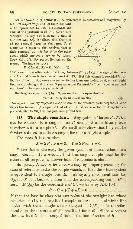
66 FORCES IN TWO DIMENSIONS [CHAP. IV
Let the forces P, Q, acting at C, be represented in direction and magnitude by
CA, CB respectively, and let their resultant
R be represented by CD. (I) Because the
sum of the projections of CA, AD on any ~
straight line (say Cx) is equal to that of
CD (see Art. 65), it follows that the sum
of the resolved parts of the forces P, Qalong Cx is equal to the resolved part of
their resultant E. (2) Let O be the point
about which moments are to be taken.
Draw OL, OM, ON perpendiculars on the
forces. We have to proveP.OL + Q. OM=R . ON ...... (1).
If O were on the other side of CA, say between CD and CA, the sign of the term
P .OL would have to be changed, see Art. 113. But this change is provided for bythe law of continuity, since the perpendicular from any point, as 0, on a straight
line, as OA, changes sign when passes across the straight line. Such cases need
not therefore be separately considered.
Dividing the equation (1) by CO, we see that it is equivalent to
Psin^CrO+Q8inBCO= JRsinDC'O ........................ (2).
This equation merely expresses that the sum of the resolved parts perpendicular to
CO of the forces P, Q is equal to that of R. But if we take the arbitrary line Cx
perpendicular to CO, this has just been proved true.
118. The single resultant. Any system of forces Pl ,P2 &c.
can be reduced to a single force R acting at an arbitrary base
together with a couple G. We shall now show that they can be
further reduced to either a single force or a single couple.
The force R is zero when
When this is the case, the given system of forces reduces to a
single couple. It is evident that this single couple must be the
same in all respects, whatever base of reference is chosen.
Supposing R not to be zero, we may by properly choosing the
base of reference make the couple vanish, so that the whole systemis equivalent to a single force R. Taking any convenient axes Ox,
Oy, let 0' be a base so chosen that the corresponding couple G' is
zero. If (77) be the coordinates of 0', we have by Art. 108,
G'=G-%Y + 77^ = ..................... (1).
If then the base be chosen at any point of the straight line whose
equation is (1), the resultant couple is zero. This straight line
makes with Ox an angle whose tangent is YfX ;it is therefore
parallel to the direction of the resultant force R. Since R acts at
the new base 0', this straight line is the line of action of R.
ART. 120] GENERAL PRINCIPLES 67
119. Summing up ; if any set of forces be given by their
resultant force and couple, viz. R and G, at any assumed base, wehave the following results :
(1) The condition that the forces can be reduced to a single
couple is R = 0. The condition that they can be reduced to a
single force is that R should not be zero.
(2) If R be not zero, the given forces can be reduced to a
single force whose magnitude is equal to R, and whose line of
action is the straight line
The direction in which the force acts along this straight line is
indicated by the known signs of its components X and F.
(3) Whatever system of coordinate axes is chosen this single
resultant must be the same in magnitude and position. We there-
fore infer that this straight line is independent of all coordinates,
i.e. is invariable in space.
12O. Ex. 1. Prove that a given system of forces can be reduced to two forces
acting one at each of two given points A and B, the force at A making a given angle
(not zero) with AB.
Ex. 2. Show that a system of forces in one plane can be reduced to three forces
which act along the sides of any triangle taken arbitrarily in that plane. Showalso how to find these three forces.
(1) This resolution is possible. Let P be any one force of the system, and let
it cut some one side, as AB, of the triangle ABC in M. Then P acting at M maybe resolved into two forces, one acting along AB and the other along CM. The
latter may be transferred to C and again resolved into two other forces acting
along CA, CB respectively. Since every force may be treated in the same way, the
whole system may be replaced by three forces, Flt Fz , F3 acting along BC, CA, AB.
(2) To find the forces Flt Fz ,F3 . Let Glt G2 ,
G3be the sums of the moments
of the forces of the given system about the corners A, B, C respectively. Then if
plt p2 , p :ibe the three perpendiculars from the corners on the opposite sides we
have FiPi = Glt F2p2=G^, F3p3= G3 .
Ex. 3. Show that the trilinear equation to the single resultant of the forces
Flt F2 ,F
3 acting along the sides of a triangle taken in order is F1a +F2p +F3y= Q.
What is the meaning of this result when Flt F2 ,F3 are proportional to the lengths
of the sides along which they act ?
Ex. 4. Two systems of three forces (P, Q, R), (P', Q', R') act along the sides
taken in order of a triangle ABC : prove that the two resultants will be parallel if
(QR'-Q'R) sinA + (RP'-R'P)smB + (PQ'-P'Q) smC=0. [Math. Tripos, 1869.]
Ex. 5. Four forces in equilibrium act along tangents to an ellipse, the direc-
tions at adjacent points tending in opposite directions round the ellipse. Prove
that the moment of each about the centre is proportional to the area of the triangle
formed by joining the points of contact of the three other forces.
52
68 FORCES IN TWO DIMENSIONS [CHAP. IV
Ex. 6. A rigid polygon A^A^... is moved into a new position AJA^... and the
mean centres of masses alf a2 ,... placed at the corners in the two positions are
G, G'. Prove that forces represented in direction and magnitude by Oj . A^-^y
0%. A SA Z', ... are equivalent to a force represented by Sa.GG' together with a
couple sin (a. G/l 2), where 6 is the angle any side of the polygon A-^A^ ... makes
with the corresponding side of A^'A^....
Solution of Problems
121. We shall now explain how the preceding theorems maybe used to determine the positions of equilibrium of one or more
rigid bodies in one plane. This can only be shown by examples.After some general remarks on the solution of statical problems a
series of examples will be found arranged under different heads.
The object is to separate the difficulties which occur in these
applications and enable the reader to attack them one by one. Acommentary is sometimes added to assist the reader in applyingthe same principles to other problems.
122. When the number of forces which act on a body is either
three, or can be conveniently reduced to three, we can find the
position of equilibrium by using the principle that these forces
must meet in one point or be parallel. This is proved in Art. 34.
There are two advantages in this method, (1) the criterion that
the three straight lines are concurrent may often be conveniently
expressed by some geometrical statement, (2) the actual magnitudesof the forces are not brought into the process, so that if these are
unknown, no further elimination is necessary. If the magnitudesof the forces are also required, they can be found afterwards from
the principle that each is proportional to the sine of the anglebetween the other two. This is often called the geometrical method.
123. If there are more than three forces, or if we prefer to use
an analytical method of solution even when there are only three
forces, we use the results of Art. 109. We express the conditions of
equilibrium (1) by resolving all the forces in some two convenient
directions and equating the result of each resolution to zero, (2) by
taking moments about some convenient point and equating the
result to zero. Having thus obtained three equations, we must
eliminate the unknown forces. Finally we shall obtain an equation
expressing in an algebraic manner the position of equilibrium.
ART. 125] SOLUTION OF PROBLEMS 69
As we have to eliminate the unknown forces it will be con-
venient to make one of the resolutions in the direction perpendicular
to a force which we intend to eliminate, and to take moments about
some point in its line of action. This force will then appear onlyin the other resolution, which may therefore be omitted altogether.
Thus by a proper choice of the directions of resolution and of the
point about which moments are taken we may sometimes save
much elimination.
124. When there are several bodies forming a system, we
represent the mutual actions of these bodies by introducing forces
called reactions at the points of contact. We may then regardeach body as if it
1
existed singly (all the others being removed) and
were acted on by these reactions in addition to the given forces.
We then form the equations for each body separately. Finally wemust eliminate the reactions, if unknown, and the remaining equa-tions will express the positions of equilibrium of the several bodies.
These eliminations are sometimes avoided by expressing the con-
ditions of equilibrium for two bodies taken together. Afterwards we
may form the equations for either separately in such a manner as
to avoid introducing the mutual reaction.
WT
hen we come to the theory of virtual work we shall have
a method of forming the equations of equilibrium free from these
reactions.
125. Ex. 1. A thin heavy uniform rod AB rests partly within and partly with-
out a hemispherical smooth bowl, which is fixed in space. Find the position of equi-
librium.
Let G be the middle point of the rod, then the weight W of the rod may be
collected at G. This should be evident from the theory of parallel forces, but it is
strictly proved in the chapter on centre of gravity.
It follows from the remarks made in Art. 54, that, when two smooth surfaces
touch each other, the pressure (if any exist) between the surfaces acts along the
normal to the common tangent plane at the point of contact. If the rod be re-
garded as a very thin cylinder with its extremities rounded off, it is easy to see that
the common tangent plane at A to the rod and the sphere coincides with the
tangent plane to the sphere. The pressure at this point therefore acts along the
normal AO to the sphere. We obtain the same result if we regard the rod as
resting with a single terminal particle in contact with the sphere ;it then follows
immediately from Art. 54 that the pressure between the terminal particle and the
sphere acts along the normal to the sphere.
Consider next the point C, at which the rod meets the rim of the bowl. The
common tangent plane to the rod and the rim passes through both the rod and the
tangent at C to the rim. The reaction is to be at right angles to both these, it
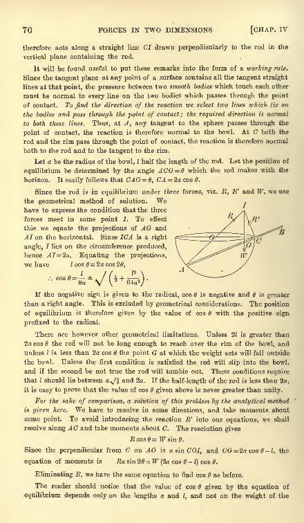
70 FORCES IN TWO DIMENSIONS [CHAP. IV
therefore acts along a straight line CI drawn perpendicularly to the rod in the
vertical plane containing the rod.
It will be found useful to put these remarks into the form of a working rule.
Since the tangent plane at any point of a surface contains all the tangent straight
lines at that point, the pressure between two smooth bodies which touch each other
must be normal to every line on the two bodies which passes through the point
of contact. To find the direction of the reaction we select two lines which lie on
the bodies and pass through the point of contact; the required direction is normal
to both these lines. Thus, at A, any tangent to the sphere passes through the
point of contact, the reaction is therefore normal to the bowl. At C both the
rod and the rim pass through the point of contact, the reaction is therefore normal
both to the rod and to the tangent to the rim.
Let a be the radius of the bowl, I half the length of the rod. Let the position of
equilibrium be determined by the angle ACO = B which the rod makes with the
horizon. It easily follows that CAO= 0, CA = 2a cos 0.
Since the rod is in equilibrium under three forces, viz. R, E' and W, we use
the geometrical method of solution. Wehave to express the condition that the three
forces meet in some point I. To effect
this we equate the projections of AG and
AI on the horizontal. Since 1CA is a right
angle, 7 lies on the circumference produced,
hence AI=2a. Equating the projections,
we have I cos 6= 2a cos 20,
If the negative sign is given to the radical, cos is negative and is greater
than a right angle. This is excluded by geometrical considerations. The position
of equilibrium is therefore given by the value of cos with the positive sign
prefixed to the radical.
There are however other geometrical limitations. Unless 21 is greater than
2a cos the rod will not be long enough to reach over the rim of the bowl, and
unless I is less than 2a cos the point G at which the weight acts will fall outside
the bowl. Unless the first condition is satisfied the rod will slip into the bowl,
and if the second be not true the rod will tumble out. These conditions require
that I should lie between a^/f and 2a. If the half-length of the rod is less than 2a,
it is easy to prove that the value of cos given above is never greater than unity.
For the sake of comparison, a solution of this problem by the analytical method
is given here. We have to resolve in some directions, and take moments about
some point. To avoid introducing the reaction R' into our equations, we shall
resolve along AC and take moments about C. The resolution gives
Rcos0-Wsin0.
Since the perpendicular from C on AO is a sin COI, and CG = 2acos0-l, the
equation of moments is Ra sin 20= W (2a cos -t)
cos 0.
Eliminating R, we have the same equation to find cos as before.
The reader should notice that the value of cos given by the equation of
equilibrium depends only on the lengths a and I, and not on the weight of the
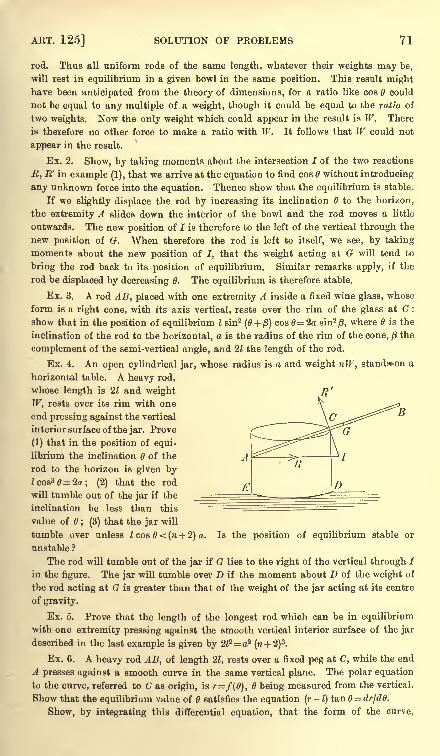
ART. 125] SOLUTION OF PROBLEMS 71
rod. Thus all uniform rods of the same length, whatever their weights may be,
will rest in equilibrium in a given bowl in the same position. This result mighthave been anticipated from the theory of dimensions, for a ratio like cos 6 could
not be equal to any multiple of a weight, though it could be equal to the ratio of
two weights. Now the only weight which could appear in the result is W. There
is therefore no other force to make a ratio with W. It follows that W could not
appear in the result.
Ex. 2. Show, by taking moments about the intersection I of the two reactions
R, R' in example (1), that we arrive at the equation to find cos 6 without introducing
any unknown force into the equation. Thence show that the equilibrium is stable.
If we slightly displace the rod by increasing its inclination 6 to the horizon,
the extremity A slides down the interior of the bowl and the rod moves a little
outwards. The new position of I is therefore to the left of the vertical through the
new position of G. When therefore the rod is left to itself, we see, by taking
moments about the new position of I, that the weight acting at G will tend to
bring the rod back to its position of equilibrium. Similar remarks apply, if the
rod be displaced by decreasing 6. The equilibrium is therefore stable.
Ex. 3. A rod AB, placed with one extremity A inside a fixed wine glass, whose
form is a right cone, with its axis vertical, rests over the rim of the glass at C :
show that in the position of equilibrium I sin2 (0 + /3) cos 2a sin2 /3,where 6 is the
inclination of the rod to the horizontal, a is the radius of the rim of the cone, /3the
complement of the semi-vertical angle, and 21 the length of the rod.
Ex. 4. An open cylindrical jar, whose radius is a and weight nW, standon a
horizontal table. A heavy rod,
whose length is 21 and weight
W, rests over its rim with one
end pressing against the vertical
interior surface of the jar. Prove
(1) that in the position of equi-
librium the inclination 6 of the
rod to the horizon is given byZcos3 = 2a; (2) that the rod
will tumble out of the jar if the
inclination be less than this
value of 6 ; (3) that the jar will
tumble over unless I cos 6 < (n + 2) a. Is the position of equilibrium stable or
unstable ?
The rod will tumble out of the jar if G lies to the right of the vertical through I
in the figure. The jar will tumble over D if the moment about D of the weight of
the rod acting at G is greater than that of the weight of the jar acting at its centre
of gravity.
Ex. 5. Prove that the length of the longest rod which can be in equilibrium
with one extremity pressing against the smooth vertical interior surface of the jar
described in the last example is given by 2l2=a?(ra + 2)
3.
Ex. 6. A heavy rod AB, of length 21, rests over a fixed peg at C, while the end
A presses against a smooth curve in the same vertical plane. The polar equation
to the curve, referred to C as origin, is r=f(6), being measured from the vertical.
Show that the equilibrium value of 6 satisfies the equation (r-
1)tan = dr/d0.
Show, by integrating this differential equation, that the form of the curve,
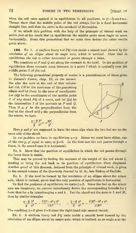
72 FORCES IN TWO DIMENSIONS [CHAP, iv
when the rod rests against it in equilibrium in all positions, is (r-l) cos 8 = a.
Thence show that the middle point of the rod always lies in a fixed horizontal
straight line, and that the curve is the conchoid of Nicomedes.
If we attack this problem with the help of the principle of virtual work wearrive first at the result that in equilibrium the middle point must begin to move
horizontally. From this geometrical fact we must then deduce the other results
given above.
126. Ex. 1. A uniform heavy rod PQ rests inside a smooth bowl formed by the
revolution of an ellipse about its major axis, which is vertical. Show that in
equilibrium the rod is either horizontal or passes through a focus.
The reactions at P and Q act along the normals to the bowl. In the position of
equilibrium these normals must intersect in a point I which is vertically over the
middle point G of the rod.
The following geometrical property of conies is a generalization of those givenin Salmon's Conies, chap. XI, on the normal.
See also the note at the end of this volume.
Let CA, CB be the semi-axes of the generating
ellipse and let these be the axes of coordinates.
Let (xy) be the coordinates of the middle pointG of any chord PQ of a conic, and let (17) be
the intersection I of the normals at P and Q.
Then if p, p' be the perpendiculars from the
foci on the chord and q the perpendicular from
the centre, we have
r)-yb*^ pp'
y a* q'2
'
Here p and p' are supposed to have the same sign when the two foci are on the
same side of the chord.
In our problem we have in equilibrium 17=
y. Hence we must have either, one
of the two p, p' equal to zero, or y = 0. In the first case the rod passes through a
focus, in the second case it is horizontal.
Ex. 2. Show that the position of equilibrium in which the rod passes throughthe lower focus is stable.
This may be proved by finding the moment of the weight of the rod about I,
tending to bring the rod back to its position of equilibrium when displaced.
Another proof of this theorem, deduced from the principle of virtual work, is given
in the second volume of the Quarterly Journal by H. G., late Bishop of Carlisle.
Ex. 3. If the bowl be formed by the revolution of an ellipse about the minor
axis, which is vertical, prove that the only position of equilibrium is horizontal.
To find the positions of equilibrium we make =x. Since the foci on the minor
axis are imaginary, we cannot immediately derive the corresponding formula for
from that for i\ by interchanging a and b. Let the chord cut the axes in L and M,then by similar triangles
rt-y ft2_ _ CZ,a -a*+fea -5 o _ _ CM*- &2 + a2
~^j~ a2"
CL3 ~* " ~i~P~ CM 2
The condition =x gives x=0 since the right-hand side cannot vanish.
Ex. 4. A uniform heavy rod PQ rests inside a smooth bowl formed by the
revolution of an ellipse about its major axis, which is inclined at an angle a to the
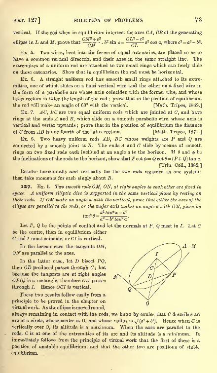
ART. 127] SOLUTION OF PROBLEMS 73
vertical. If the rod when in equilibrium intersect the axes CA, CB of the generating
CM2+ c2 CLP c2
ellipse in L and M, prove that -= . &2 sin a = -^= a2 cos a, where c2= a2 - 62.
\jaiL G-L*
Ex. 5. Two wires, bent into the forms of equal catenaries, are placed so as to
have a common vertical directrix, and their axes in the same straight line. The
extremities of a uniform rod are attached to two small rings which can freely slide
on these catenaries. Show that in equilibrium the rod must be horizontal.
Ex. 6. A straight uniform rod has smooth small rings attached to its extre-
mities, one of which slides on a fixed vertical wire and the other on a fixed wire in
the form of a parabolic arc whose axis coincides with the former wire, and whose
latus rectum is twice the length of the rod : prove that in the position of equilibrium
the rod will make an angle of 60 with the vertical. [Math. Tripos, 1869.]
Ex. 7. AC, EG are two equal uniform rods which are jointed at C, and have
rings at the ends A and B, which slide on a smooth parabolic wire, whose axis is
vertical and vertex upwards ; prove that in the position of equilibrium the distance
of C from AB is one fourth of the latus rectum. [Math. Tripos, 1871.]
Ex. 8. Two heavy uniform rods AB, BC whose weights are P and Q are
connected by a smooth joint at B. The ends A and G slide by means of smooth
rings on two fixed rods each inclined at an angle a to the horizon. If B andtf>be
the inclinations of the rods to the horizon,show that P cot <p
= Qcot0= (P+Q) tan a.
[Trin. Coll., 1882.]
Resolve horizontally and vertically for the two rods regarded as one system ;
then take moments for each singly about B.
127. Ex. 1. Two smooth rods OM, ON, at right angles to each other are fixed in
space. A uniform elliptic disc is supported in the same vertical plane by resting on
these rods. If OM make an angle a with the vertical, prove that either the axes of the
ellipse are parallel to the rods, or the major axis makes an angle with OM, given by
,a2 fan2 a -62
tan2 0= .
a* b* tan* a
Let P, Q be the points of contact and let the normals at P, Q meet in I. Let Cbe the centre, then in equilibrium either
C and I must coincide, or Cl is vertical.
In the former case the tangents OM,ON are parallel to the axes.
In the latter case, let D bisect PQ,then OD produced passes through C but
because the tangents are at right angles
OPIQ is a rectangle, therefore OD passes
through I. Hence OCI is vertical.
These two results follow easily from a
principle to be proved in the chapter on
virtual work . As the ellipse ismovedround,
always remaining in contact with the rods, we know by conies that C describes an
arc of a circle, whose centre is 0, and whose radius is ^(at + b'2
). Hence when C is
vertically over 0, its altitude is a maximum. When the axes are parallel to the
rods, C is at one of the extremities of its arc and its altitude is a minimum. It
immediately follows from the principle of virtual work that the first of these is a
position of unstable equilibrium, and that the other two are positions of stable
equilibrium.
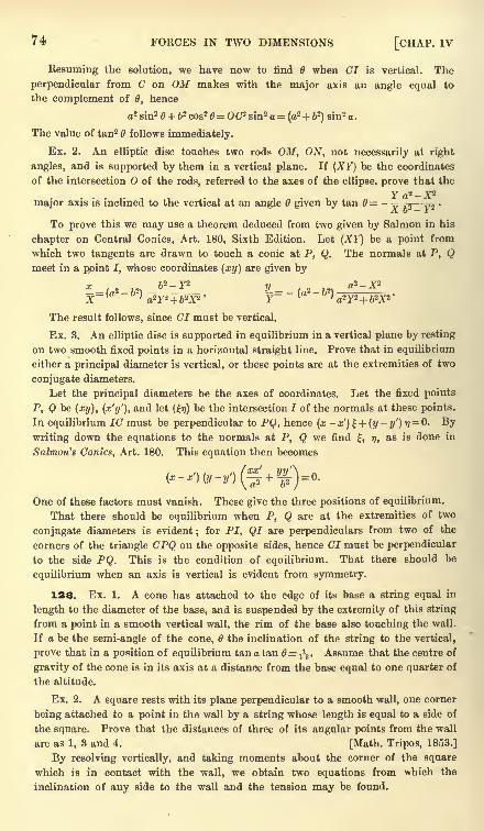
74 FORCES IN TWO DIMENSIONS [CHAP. IV
Resuming the solution, we have now to find 6 when CI is vertical. The
perpendicular from C on OM makes with the major axis an angle equal to
the complement of 0, hence
a1 sin2 + 62 cos2 = OC* sin2 o = (a2+ b2
)sin'- a.
The value of tan2 6 follows immediately.
Ex. 2. An elliptic disc touches two rods OM, ON, not necessarily at right
angles, and is supported by them in a vertical plane. If (XY) be the coordinates
of the intersection O of the rods, referred to the axes of the ellipse, prove that the
Fa2 - X'2
major axis is inclined to the vertical at an angle given by tan 0= - -= ^ .
,\ -i J:
To prove this we may use a theorem deduced from two given by Salmon in his
chapter on Central Conies, Art. 180, Sixth Edition. Let (XY) be a point from
which two tangents are drawn to touch a conic at P, Q. The normals at P, Qmeet in a point I, whose coordinates (xy) are given by
x fc2 - F2 a2 - X2
-= (a*- 2 -- '= ~ 2 - 2
The result follows, since CI must be vertical.
Ex. 3. An elliptic disc is supported in equilibrium in a vertical plane by resting
on two smooth fixed points in a horizontal straight line. Prove that in equilibrium
either a principal diameter is vertical, or these points are at the extremities of two
conjugate diameters.
Let the principal diameters be the axes of coordinates. Let the fixed points
P, Q be (xy), (x'y1
),and let (17) be the intersection I of the normals at these points.
In equilibrium 1C must be perpendicular to PQ, hence (x- x) + (y
-y') 17
= 0. Bywriting down the equations to the normals at P, Q we find , 17, as is done in
Salmon's Conies, Art. 180. This equation then becomes
One of these factors must vanish. These give the three positions of equilibrium.
That there should be equilibrium when P, Q are at the extremities of two
conjugate diameters is evident ;for PI, QI are perpendiculars from two of the
corners of the triangle CPQ on the opposite sides, hence CI must be perpendicular
to the side PQ. This is the condition of equilibrium. That there should be
equilibrium when an axis is vertical is evident from symmetry.
128. Ex. 1. A cone has attached to the edge of its base a string equal in
length to the diameter of the base, and is suspended by the extremity of this string
from a point in a smooth vertical wall, the rim of the base also touching the wall.
If a be the semi-angle of the cone, the inclination of the string to the vertical,
prove that in a position of equilibrium tana tan 0=iV Assume that the centre of
gravity of the cone is in its axis at a distance from the base equal to one quarter of
the altitude.
Ex. 2. A square rests with its plane perpendicular to a smooth wall, one corner
being attached to a point in the wall by a string whose length is equal to a side of
the square. Prove that the distances of three of its angular points from the wall
are as 1, 3 and 4. [Math. Tripos, 1853.]
By resolving vertically, and taking moments about the corner of the square
which is in contact with the wall, we obtain two equations from which the
inclination of any side to the wall and the tension may be found.
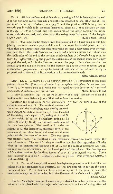
ART. 129] SOLUTION OF PROBLEMS 75
Ex. 3. AB is a uniform rod of length a; a string APBC is fastened to the end
A of the rod and passes through a smooth ring attached to the other end B ; the
end C of the string is fastened to a peg C, and the portion APB is hung over a
smooth peg P which is in the same horizontal plane as C at a distance 26 from
it (b<a). If AP is vertical, find the angles which the other parts of the string
make with the vertical, and show that the string must have one of the lengths
IV3 >/(2 - fc2)- [King's Coll., 1889.]
Ex. 4. Two light elastic strings have their ends tied to a fixed point on the line
joining two small smooth pegs which are in the same horizontal plane, so that
when they are unstretched their ends just reach the pegs ; they hang over the pegs
and have their other ends fastened to the ends of a heavy uniform rod; show that
the inclination of the rod to the horizon is independent of its length, being equal to
tan"1(y1
-j/,)/2a,'where y1
and ?/2 are the extensions of the strings when they singly
support the rod, and a is the distance between the pegs. Show also that the two
strings and the rod are inclined to the horizon at angles whose tangents are in
arithmetical progression. It may be assumed that the tension of each string is
proportional to the ratio of its extension to its unstretched length.
[Math. Tripos, 1887.]
129. Ex. 1. A sphere rests on a string fastened at its extremities to two fixed
points. Shoic that if the arc of contact of the sphere and plane be not less than
2 tan-1 ^f, the sphere may be divided into two equal portions by means of a vertical
plane without disturbing the equilibrium. [Math. Tripos, 1840.]
It may be assumed that the centre of gravity of a solid hemisphere is on the
middle radius at a distance fths of that radius from the centre.
Consider the equilibrium of the hemisphere ABD and the portion AD of the
string in contact with it. The mutual reactions of
the string and the hemisphere may now be omitted.
This compound body is acted on by (1) the tensions
of the string, each equal to T, acting at A and D,
(2) the weight W of the hemisphere acting at its
centre of gravity G, (3) the mutual reaction R of
the two hemispheres. The reaction E is the re-
sultant of all the horizontal pressures between the
elements of the plane bases and must act at some
point within the area of contact. The two bases
will separate unless the resultant of the remaining forces also passes inside the
area of contact. The arc AD being as small as possible, this separation will take
place by the hemispheres opening out at B, for the mutual pressures are then
confined to the single point A at the lowest point of the sphere. The hemisphereABD is then acted on by the three forces, T at D, T - E at A, and W at G. These
must intersect in a point 7. Hence CG = CA tan %ACD. This gives tan \ACD=and t&nACD= *%.
Ex. 2. Two equal heavy solid smooth hemispheres, placed so as to look like one
sphere with the diametral plane vertical, rest on two pegs which are on the same
horizontal line. Prove that the least distance apart of the pegs, so that the
hemispheres may not fall asunder, is to the diameter of the circle as 3 to \f(7B).
[Christ's Coll.]
Ex. 3. An elliptic lamina of eccentricity e, divided into two pieces along the
minor axis, is placed with its major axis horizontal in a loop of string attached
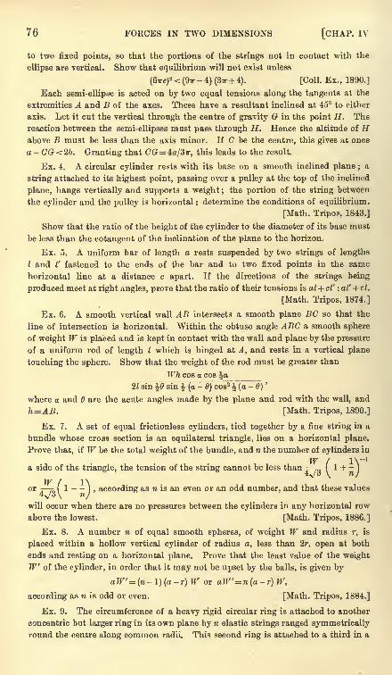
76 FORCES IN TWO DIMENSIONS [CHAP. IV
to two fixed points, so that the portions of the strings not in contact with the
ellipse are vertical. Show that equilibrium will not exist unless
(<oiref < (97r-
4) (Sir + 4). [Coll. Ex., 1890.]
Each semi-ellipse is acted on by two equal tensions along the tangents at the
extremities A and B of the axes. These have a resultant inclined at 45 to either
axis. Let it cut the vertical through the centre of gravity G in the point H . The
reaction between the semi-ellipses must pass through H. Hence the altitude of Habove B must be less than the axis minor. If C be the centre, this gives at once
a-CG<2b. Granting that CG = 4a/3?r, this leads to the result.
Ex. 4. A circular cylinder rests with its base on a smooth inclined plane ; a
string attached to its highest point, passing over a pulley at the top of the inclined
plane, hangs vertically and supports a weight ; the portion of the string between
the cylinder and the pulley is horizontal : determine the conditions of equilibrium.
[Math. Tripos, 1843.]
Show that the ratio of the height of the cylinder to the diameter of its base must
be less than the cotangent of the inclination of the plane to the horizon.
Ex. 5. A uniform bar of length a rests suspended by two strings of lengths
I and I' fastened to the ends of the bar and to two fixed points in the same
horizontal line at a distance c apart. If the directions of the strings being
produced meet at right angles, prove that the ratio of their tensions is al+ cl' : al' + cl.
[Math. Tripos, 1874.]
Ex. 6. A smooth vertical wall AB intersects a smooth plane BC so that the
line of intersection is horizontal. Within the obtuse angle ABC a smooth sphere
of weight W is placed and is kept in contact with the wall and plane by the pressure
of a uniform rod of length I which is hinged at A, and rests in a vertical plane
touching the sphere. Show that the weight of the rod must be greater than
Wh cos a cos \a21 sin \9 sin \ (a
-6) cos2 (a
-6)
'
where a and are the acute angles made by the plane and rod with the wall, and
h=AB. [Math. Tripos, 1890.]
Ex. 7. A set of equal frictionless cylinders, tied together by a fine string in a
bundle whose cross section is an equilateral triangle, lies on a horizontal plane.
Prove that, if W be the total weight of the bundle, and n the number of cylinders in
W / IV1
a side of the triangle, the tension of the string cannot be less than I 1 + -)
4^/3 \ nj
or T T^( 1) , according as 71 is an even or an odd number, and that these values
4\/o \ /will occur when there are no pressures between the cylinders in any horizontal row
above the lowest. [Math. Tripos, 1886.]
Ex. 8. A number n of equal smooth spheres, of weight W and radius r, is
placed within a hollow vertical cylinder of radius a, less than 2r, open at both
ends and resting on a horizontal plane. Prove that the least value of the weight
W of the cylinder, in order that it may not be upset by the balls, is given by
aW'=(n-l)(a-r)W or aW'=n(a-r) W,
according as n is odd or even. [Math. Tripos, 1884.]
Ex. 9. The circumference of a heavy rigid circular ring is attached to another
concentric but larger ring in its own plane by n elastic strings ranged symmetrically
round the centre along common radii. This second ring is attached to a third in a
ART. 131] REACTIONS AT JOINTS 77
similar manner by 2?i strings, and this to a fourth by 3n strings and so on.
Supposing all the rings to have the same weight, and the strings at first to be
without tension, show that, if the last ring be lifted tip and held horizontal, all
the other rings will be on the surface of a right cone. [Pet. Coll., 1862.)
Ex. 10. Two spheres of densities p and <r, and whose radii are a and b, rest in
a paraboloid of revolution whose axis is vertical and touch each other at the focus :
prove that pPa10 -^10
. [Curtis' problem. Educational Times, 5460.]
13O. Equilibrium of four repelling particles. Ex. 1. Four free particles
situated at the corners of a quadrilateral are in equilibrium under their mutual
attractions or repulsions ; the forces along the sides AB, BC, CD, DA being
attractive, those along the diagonals AC, BD being repulsive. If the forces are
proportional to the sides along which they act, prove that the quadrilateral is a
parallelogram.
In this case the forces on the particle A are represented by the sides AB, AD-
and the diagonal AC. The result follows at once from the parallelogram of forces.
Ex. 2. If the quadrilateral formed by joining the four particles can be inscribed
in a circle, show that the attracting force along any side is proportional to the
opposite side, and the repelling force along a diagonal to the other diagonal.
Ex. 3. If the quadrilateral be any whatever, prove that when the particles at.
the corners are in equilibrium
f(AB) f(BC) f(BD) f(AC)AB.OC.OD BC.OD.OA AC . OB . OD BD.OA.OC'
where O is the intersection of the diagonals BD, AC, and the mutual force along
any line, as AB, is represented \>y f(AB).
To prove this, consider the equilibrium of the particle A.
f (AC) _ sin DAB area DAB AD.AO_DB AOf(AB)
~sinDAO~ area DAO
'
AD. AB~DO '
AB'
all the results follow by symmetry.
Ex. 4. Whatever be the form of the quadrilateral, prove that (1) the moments,
about O of the forces which act along the sides are equal, and (2),
ABf (AB) + BCf (BC) + CDf (CD) + DAf (DA )= ACf (AC) + BDf (BD).
Reactions at Joints
131. When two beams are connected together by a smooth
hinge-joint or are fastened together by a very short string, the
mutual action between them will be equivalent to a single force
acting at the point of junction. In some cases the direction of
this force is at once apparent, in other cases its direction as well
as its magnitude must be deduced from the equations of equi-
librium.
There are two cases in which the direction is apparent. Firstly
let the body and the external forces be both symmetrical about
some straight line through the hinge. In this case the action and
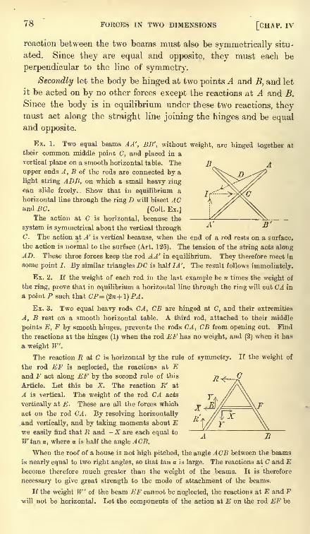
78 FORCES IN TWO DIMENSIONS [CHAP, iv
D'
reaction between the two beams must also be symmetrically situ-
ated. Since they are equal and opposite, they must each be
perpendicular to the line of symmetry.
Secondly let the body be hinged at two points A and B, and let
it be acted on by no other forces except the reactions at A and B.
Since the body is in equilibrium under these two reactions, theymust act along the straight line joining the hinges and be equaland opposite.
Ex. 1. Two equal beams AA', BB', without weight, are hinged together at
their common middle point (7, and placed in a
vertical plane on a smooth horizontal table. The
upper ends A, B of the rods are connected by a
light string ADB, on which a small heavy ring
can slide freely. Show that in equilibrium a
horizontal line through the ring D will bisect ACand BC. [Coll. Ex.]
The action at C is horizontal, because the
system is symmetrical about the vertical throughC. The action at A' is vertical because, when the end of a rod rests on a surface,
the action is normal to the surface (Art. 125). The tension of the string acts alongAD. These three forces keep the rod A A' in equilibrium. They therefore meet in
some point I. By similar triangles DC is half IA'. The result follows immediately.
Ex. 2. If the weight of each rod in the last example be n times the weight of
the ring, prove that in equilibrium a horizontal line through the ring will cut CA in
a point P such that CP- (2w + 1) PA.
Ex. 3. Two equal heavy rods CA, CB are hinged at C, and their extremities
A, B rest on a smooth horizontal table. A third rod, attached to their middle
points E, F by smooth hinges, prevents the rods CA, CB from opening out. Find
the reactions at the hinges (1) when the rod EF has no weight, and (2) when it has
& weight W.
The reaction R at C is horizontal by the rule of symmetry. If the weight of
the rod EF is neglected, the reactions at Eand F act along EF by the second rule of this
Article. Let this be X. The reaction R' at
A is vertical. The weight of the rod CA acts
vertically at E. These are all the forces which
act on the rod CA. By resolving horizontally
and vertically, and by taking moments about Ewe easily find that R and - A' are each equal to
Trtan o, where a is half the angle ACB.
When the roof of a house is not high pitched, the angle ACB between the beams
is nearly equal to two right angles, so that tan a is large. The reactions at C and Ebecome therefore much greater than the weight of the beams. It is therefore
necessary to give great strength to the mode of attachment of the beams.
If the weight W of the beam EF cannot be neglected, the reactions at E and Fwill not be horizontal. Let the components of the action at E on the rod EF be
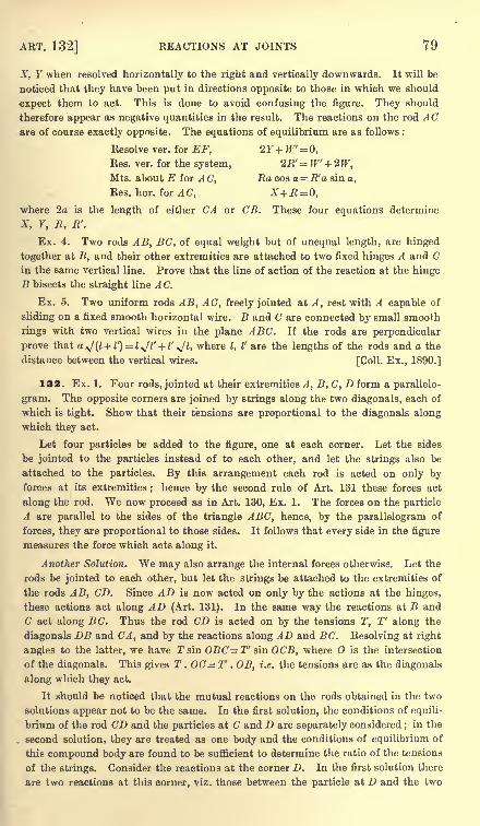
ART. 132] REACTIONS AT JOINTS 79
X, Y when resolved horizontally to the right and vertically downwards. It will be
noticed that they have been put in directions opposite to those in which we should
expect them to act. This is done to avoid confusing the figure. They should
therefore appear as negative quantities in the result. The reactions on the rod ACare of course exactly opposite. The equations of equilibrium are as follows :
Resolve ver. for EF, 2Y+W= 0,
Res. ver. for the system, 2R' = W' + 2W,Mts. about E for AC, Ra cos a = R'a sin a,
Res. hor. for A C, X+R=0,where 2a is the length of either CA or CB. These four equations determine
X, Y, R, R'.
Ex. 4. Two rods AB, BC, of equal weight but of unequal length, are hinged
together at B, and their other extremities are attached to two fixed hinges A and Cin the same vertical line. Prove that the line of action of the reaction at the hingeB bisects the straight line AC.
Ex. 5. Two uniform rods AB, AC, freely jointed at A, rest with A capable of
sliding on a fixed smooth horizontal wire. B and C are connected by small smooth
rings with two vertical wires in the plane ABC. If the rods are perpendicular
prove that a */(l + l')=
l*Jl' + 1' *Jl, where I, I' are the lengths of the rods and a the
distance between the vertical wires. [Coll. Ex., 1890.]
132. Ex. 1. Four rods, jointed at their extremities A, B, C, D form a parallelo-
gram. The opposite corners are joined by strings along the two diagonals, each of
which is tight. Show that their tensions are proportional to the diagonals along
which they act.
Let four particles be added to the figure, one at each corner. Let the sides
be jointed to the particles instead of to each other, and let the strings also be
attached to the particles. By this arrangement each rod is acted on only byforces at its extremities
; hence by the second rule of Art. 131 these forces act
along the rod. We now proceed as in Art. 130, Ex. 1. The forces on the particle
A are parallel to the sides of the triangle ABC, hence, by the parallelogram of
forces, they are proportional to those sides. It follows that every side in the figure
measures the force which acts along it.
Another Solution. We may also arrange the internal forces otherwise. Let the
rods be jointed to each other, but let the strings be attached to the extremities of
the rods AB, CD. Since AD is now acted on only by the actions at the hinges,
these actions act along AD (Art. 131). In the same way the reactions at B and
C act along BC. Thus the rod CD is acted on by the tensions T, T' along the
diagonals DB and CA, and by the reactions along AD and BC. Resolving at right
angles to the latter, we have Tsin OBC=T' sin OCB, where is the intersection
of the diagonals. This gives T . OC= T' . OB, i.e. the tensions are as the diagonals
along which they act.
It should be noticed that the mutual reactions on the rods obtained in the two
solutions appear not to be the same. In the first solution, the conditions of equili-
brium of the rod CD and the particles at C and D are separately considered ;in the
second solution, they are treated as one body and the conditions of equilibrium of
this compound body are found to be sufficient to determine the ratio of the tensions
of the strings. Consider the reactions at the corner D. In the first solution there
are two reactions at this corner, viz. those between the particle at D and the two
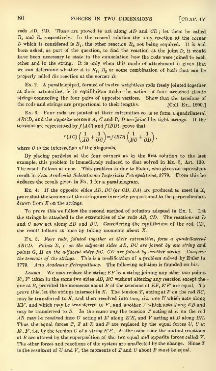
80 FORCES IN TWO DIMENSIONS [CHAP. IV
rods AD, CD. These are proved to act along AD and CD; let them be called
Rland JZ2 respectively. In the second solution the only reaction at the corner
D which is considered is E1 , the other reaction R2 not being required. If it had
been asked, as part of the question, to find the reaction at the joint D, it would
have been necessary to state in the enunciation how the rods were joined to each
other and to the string. It is only when this mode of attachment is given that
we can determine whether it is R1 , R% or some combination of both that can be
properly called the reaction at the corner D.
Ex. 2. A parallelepiped, formed of twelve weightless rods freely jointed together
at their extremities, is in equilibrium under the action of four stretched elastic
strings connecting the four pairs of opposite vertices. Show that the tensions of
the rods and strings are proportional to their lengths. [Coll. Ex., 1890.]
Ex. 3. Four rods are jointed at their extremities so as to form a quadrilateral
ABCD, and the opposite corners A, C and B, D are joined by tight strings. If the
tensions are represented by/ (A C) and/(BD), prove that
where is the intersection of the diagonals.
By placing particles at the four corners as in the first solution to the last
example, this problem is immediately reduced to that solved in Ex. 3, Art. 130.
The result follows at once. This problem is due to Euler, who gives an equivalent
result in Acta Academic Scientiarum Imperialis Petropolitame, 1779. From this he
deduces the result given in Ex. 1 for a parallelogram.
Ex. 4. If the opposite sides AD, BC (or CD, BA) are produced to meet in X,
prove that the tensions of the strings are inversely proportional to the perpendiculars
drawn from X on the strings.
To prove this we follow the second method of solution adopted in Ex. 1. Let
the strings be attached to the extremities of the rods AB, CD. The reactions at Dand C now act along AD and BC. Considering the equilibrium of the rod CD
t
the result follows at once by taking moments about X.
Ex. 5. Four rods, jointed together at their extremities, form a quadrilateral
ABCD. Points E, F on the adjacent sides AB, BC are joined by one string and
points G, H on the adjacent sides BC, CD are joined by another string. Comparethe tensions of the strings. This is a modification of a problem solved by Euler in
1779. Acta Academite Petropolitan<s. The following solution is founded on his.
Lemma. We may replace the string F.F by a string joining any other two points
E', F' taken in the same two sides AB, BC without altering any reaction except the
one at B, provided the moments about B of the tensions of EF, E'F' are equal. To
prove this, let the strings intersect in K. The tension T, acting at F on the rod BC,
may be transferred to K, and then resolved into two, viz. one U which acts along
KF', and which may be transferred to F', and another V which acts along KB and
may be transferred to B. In the same way the tension T acting at E on the rod
AB may be resolved into U acting at E' along E'K, and V acting at B along BK.
Thus the equal forces T, T at E and F are replaced by the equal forces U, U at
E', F', i.e. by the tension U of a string E'F1
. At the same time the mutual reactions
at B are altered by the superposition of the two equal and opposite forces called V.
The other forces and reactions of the system are unaffected by the change. Since Tis the resultant of U and V, the moments of T and U about B must be equal.
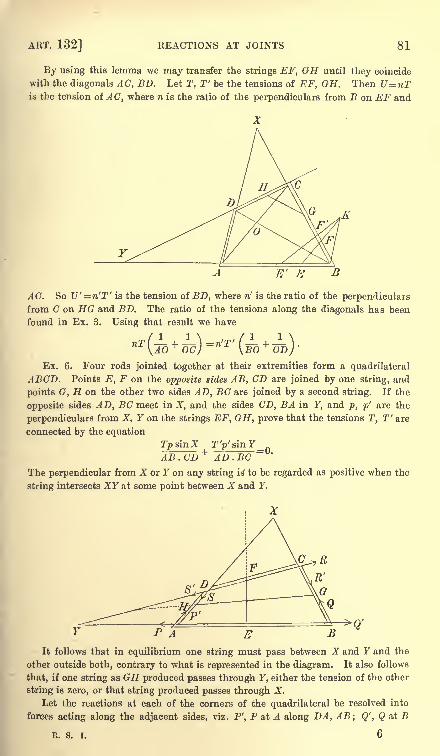
ART. 132] REACTIONS AT JOINTS 81
By using this lemma we may transfer the strings EF, GH until they coincide
with the diagonals AC, BD. Let T, T' be the tensions of EF, GH. Then U~nTis the tension of AC, where n is the ratio of the perpendiculars from B on EF and
AC. So U' = n'T' is the tension of BD, where n' is the ratio of the perpendiculars
from C on HG and BD. The ratio of the tensions along the diagonals has been
found in Ex. 3. Using that result we have
Ex. 6. Four rods jointed together at their extremities form a quadrilateral
ABCD. Points E, F on the opposite sides AB, CD are joined by one string, and
points G, H on the other two sides AD, BC are joined by a second string. If the
opposite sides AD, BC meet in X, and the sides CD, BA in Y, and p, p' are the
perpendiculars from X, Y on the strings EF, GH, prove that the tensions T, T' are
connected by the equation
Tp sin X rysinFAB . CD + AD.BC
The perpendicular from X or Y on any string is to be regarded as positive when the
string intersects XY at some point between X and Y.
PA EIt follows that in equilibrium one string must pass between X and Y and the
other outside both, contrary to what is represented in the diagram. It also follows
that, if one string as GH produced passes through Y, either the tension of the other
string is zero, or that string produced passes through X.
Let the reactions at each of the corners of the quadrilateral be resolved into
forces acting along the adjacent sides, viz. P', P at A along DA, AB; Q', Q at B
R. S. I. 6
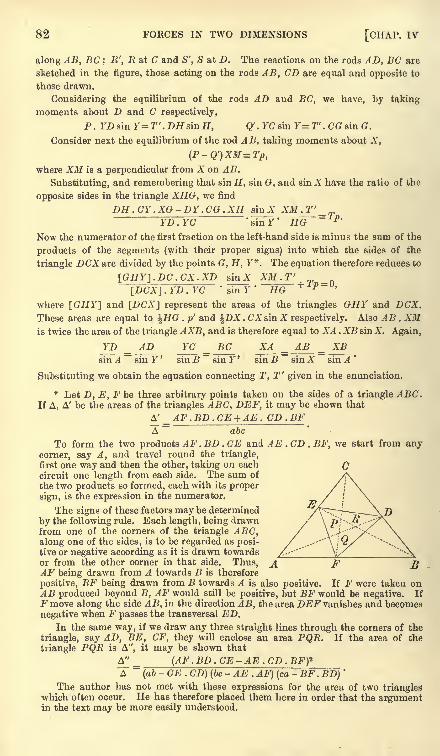
82 FORCES IN TWO DIMENSIONS [CHAP. IV
along AB, BC ; E', R at C and S', S at D. The reactions on the rods AD, BC are
sketched in the figure, those acting on the rods AB, CD are equal and opposite to
those drawn.
Considering the equilibrium of the rods AD and BC, we have, by taking
moments about D and C respectively,
P. YDs'mY=T'.DHsinH, Q' . YC sm Y=T'. CG sin G.
Consider next the equilibrium of the rod A B, taking moments about X,
(P-Q')XM=Tp,where XM is a perpendicular from A' on AB.
Substituting, and remembering that sin H, sin G, and sin X have the ratio of the
opposite sides in the triangle XHG, we find
DH.CY.XG-DY.CG.XH siu X XM^_' P 'YD . YC
Now the numerator of the first fraction on the left-hand side is minus the sum of the
products of the segments (with their proper signs) into which the sides of the
triangle DCX are divided by the points G, H, Y*. The equation therefore reduces to
[GHY]. DC. CX. XD sin A XM.T'~~[DCX]7YD . YC
*
suTT* HG
where [GHY] and [DCA] represent the areas of the triangles GHY and DCX.These areas are equal to \HG . p' and DA . CAsin X respectively. Also AB . AMis twice the area of the triangle AXB, and is therefore equal to XA . XB sin A. Again,
I'D _ AD YC _ BC XA _ AB _ XBsin .4
~sin F' sin~sinr' sin B~ sin A sin .4'
Substituting we obtain the equation connecting T, T' given in the enunciation.
* Let D, E, F be three arbitrary points taken on the sides of a triangle ABC.If A, A' be the areas of the triangles ABC, DEF, it may be shown that
A' AF.BD.CE + AE. CD.BFA - abc
To form the two products AF.BD . CE and AE . CD . BF, we start from anycorner, say A, and travel round the triangle,first one way and then the other, taking on each
circuit one length from each side. The sum of
the two products so formed, each with its proper
sign, is the expression in the numerator.
The signs of these factors may be determined
by the following rule. Each length, being drawnfrom one of the corners of the triangle ABC,along one of the sides, is to be regarded as posi-tive or negative according as it is drawn towardsor from the other corner in that side. Thus, A F BAF being drawn from A towards B is therefore
positive, BF being drawn from B towards A is also positive. If F were taken onAB produced beyond B, AF would still be positive, but BF would be negative. If
Fmove along the side AB, in the direction AB, the area DEF vanishes and becomes
negative when F passes the transversal ED.In the same way, if we draw any three straight lines through the corners of the
triangle, say AD, BE, CF, they will enclose an area PQR. If the area of the
triangle PQR is A", it may be shown that
A^'_ (AF.BD.CE-AE.CD. BF)*A~
(ab- CE . CD) (be
- AE . AF) (ca- BF . BD)
'
The author has not met with these expressions for the area of two triangleswhich often occur. He has therefore placed them here in order that the argumentin the text may be more easily understood.
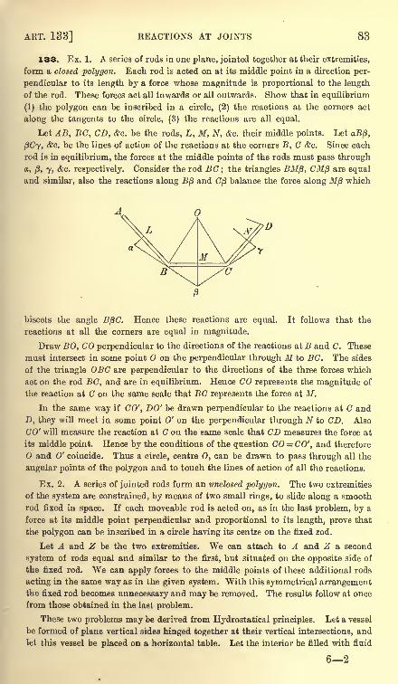
ART. 133] REACTIONS AT JOINTS 83
133. Ex. 1. A series of rods in one plane, jointed together at their extremities,
form a closed polygon. Each rod is acted on at its middle point in a direction per-
pendicular to its length by a force whose magnitude is proportional to the length
of the rod. These forces act all inwards or all outwards. Show that in equilibrium
(1) the polygon can be inscribed in a circle, (2) the reactions at the corners act
along the tangents to the circle, (3) the reactions are all equal.
Let AB, BC, CD, &c. be the rods, L, M, N, &c. their middle points. Let oB/3,
fiCy, &c. be the lines of action of the reactions at the corners B, C &c. Since each
rod is in equilibrium, the forces at the middle points of the rods must pass through
a, j8, 7, &c. respectively. Consider the rod BC; the triangles BMp, CM/3 are equal
and similar, also the reactions along B/3 and (7/3 balance the force along 7H/3 which
bisects the angle BfiC. Hence these reactions are equal. It follows that the
reactions at all the corners are equal in magnitude.
Draw BO, CO perpendicular to the directions of the reactions at B and C. These
must intersect in some point on the perpendicular through M to BC. The sides
of the triangle OBC are perpendicular to the directions of the three forces which
act on the rod BC, and are in equilibrium. Hence CO represents the magnitude of
the reaction at C on the same scale that BC represents the force at M.
In the same way if CO', DO' be drawn perpendicular to the reactions at C and
D, they will meet in some point 0' on the perpendicular through N to CD. Also
CO' will measure the reaction at C on the same scale that CD measures the force at
its middle point. Hence by the conditions of the question CO = CO', and therefore
and 0' coincide. Thus a circle, centre 0, can be drawn to pass through all the
angular points of the polygon and to touch the lines of action of all the reactions.
Ex. 2. A series of jointed rods form an unclosed polygon. The two extremities
of the system are constrained, by means of two small rings, to slide along a smooth
rod fixed in space. If each moveable rod is acted on, as in the last problem, by a
force at its middle point perpendicular and proportional to its length, prove that
the polygon can be inscribed in a circle having its centre on the fixed rod.
Let A and Z be the two extremities. We can attach to A and Z a second
system of rods equal and similar to the first, but situated on the opposite side of
the fixed rod. We can apply forces to the middle points of these additional rods
acting in the same way as in the given system. With this symmetrical arrangementthe fixed rod becomes unnecessary and may be removed. The results follow at once
from those obtained in the last problem.
These two problems may be derived from Hydrostatical principles. Let a vessel
be formed of plane vertical sides hinged together at their vertical intersections, and
let this vessel be placed on a horizontal table. Let the interior be filled with fluid
62
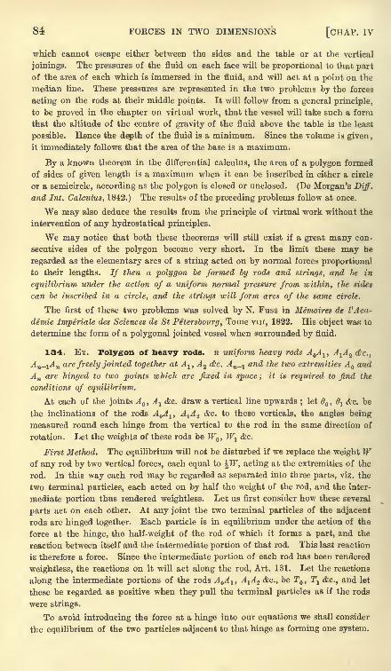
84 FORCES IN TWO DIMENSIONS [CHAP. IV
which cannot escape either between the sides and the table or at the vertical
joinings. The pressures of the fluid on each face will be proportional to that part
of the area of each which is immersed in the fluid, and will act at a point on the
median line. These pressures are represented in the two problems by the forces
acting on the rods at their middle points. It will follow from a general principle,
to be proved in the chapter on virtual work, that the vessel will take such a form
that the altitude of the centre of gravity of the fluid above the table is the least
possible. Hence the depth of the fluid is a minimum. Since the volume is given,
it immediately follows that the area of the base is a maximum.
By a known theorem in the differential calculus, the area of a polygon formed
of sides of given length is a maximum when it can be inscribed in either a circle
or a semicircle, according as the polygon is closed or unclosed. (De Morgan's Diff.
and Int. Calculus, 1842.) The results of the preceding problems follow at once.
We may also deduce the results from the principle of virtual work without the
intervention of any hydrostatical principles.
We may notice that both these theorems will still exist if a great many con-
secutive sides of the polygon become very short. In the limit these may be
regarded as the elementary arcs of a string acted on by normal forces proportional
to their lengths. If then a polygon be formed by rods and strings, and be in
equilibrium under the action of a uniform normal pressure from within, the sides
can be inscribed in a circle, and the strings will form arcs of the same circle.
The first of these two problems was solved by N. Fuss in Memoires de VAca-
demie Imperiale des Sciences de St Petersbourg, Tome vin, 1822. His object was to
determine the form of a polygonal jointed vessel when surrounded by fluid.
134. Ex. Polygon of heavy rods, n uniform heavy rods A Al , A-^A^ <c.,
An-i^n are freely jointed together at A^, A 2 dkc. An_ and the two extremities A and
An are hinged to two points which are fixed in space ; it is required to find the
conditions of equilibrium.
At each of the joints A ,A
1 &c. draw a vertical line upwards ; let 6, 6
1 &c. be
the inclinations of the rods A^, A^ 2 &c. to these verticals, the angles being
measured round each hinge from the vertical to the rod in the same direction of
rotation. Let the weights of these rods be W,W
l&o.
First Method. The equilibrium will not be disturbed if we replace the weight Wof any rod by two vertical forces, each equal to \W, acting at the extremities of the
rod. In this way each rod may be regarded as separated into three parts, viz. the
two terminal particles, each acted on by half the weight of the rod, and the inter-
mediate portion thus rendered weightless. Let us first consider how these several
parts act on each other. At any joint the two terminal particles of the adjacent
rods are hinged together. Each particle is in equilibrium under the action of the
force at the hinge, the half-weight of the rod of which it forms a part, and the
reaction between itself and the intermediate portion of that rod. This last reaction
is therefore a force. Since the intermediate portion of each rod has been rendered
weightless, the reactions on it will act along the rod, Art. 131. Let the reactions
along the intermediate portions of the rods A Al , A^A^ &c., be T , T^ &c., and let
these be regarded as positive when they pull the terminal particles as if the rods
were strings.
To avoid introducing the force at a hinge into our equations we shall consider
the equilibrium of the two particles adjacent to that hinge as forming one system.
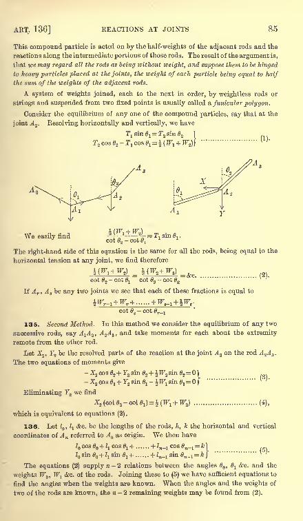
ART. 136] REACTIONS AT JOINTS 85
This compound particle is acted on by the half-weights of the adjacent rods and the
reactions along the intermediate portions of those rods. The result of the argument is,
that ice may regard all the rods as being without weight, and suppose them to be hinged
to heavy particles placed at the joints, the weight of each particle being equal to half
the sum of the weights of the adjacent rods.
A system of weights joined, each to the next in order, by weightless rods or
strings and suspended from two fixed points is usually called a funicular polygon.
Consider the equilibrium of any one of the compound particles, say that at the
joint A 2 . Resolving horizontally and vertically, we have
T! sin 61=
We easily find
The right-hand side of this equation is the same for all the rods, being equal to the
horizontal tension at any joint, we find therefore
COt 2- cot &l cot #3
~ cot #2
If A r ,A
sbe any two joints we see that each of these fractions is equal to
COtg- COt r_!
135. Second Method. In this method we consider the equilibrium of any two
successive rods, say A^A 2 ,A 2A 3 , and take moments for each about the extremity
remote from the other rod.
Let X2 ,F2 be the resolved parts of the reaction at the joint A2 on the rod A 2A X .
The two equations of moments give
-X2 cos0,+ F2 sin#2+ TF2 sin#2=0)V (*5)- X2 cos 1 + F2 sm 0j
- ^H7!sin 6
l=
|
Eliminating F2 we find
which is equivalent to equations (2).
136. Let 1 ,ia&c. be the lengths of the rods, h, k the horizontal and vertical
coordinates of An referred to A as origin. We then have
+'-i<^-i=n. .. (5) .
+ Zn_i sm n_1= h
I
The equations (2) supply n- 2 relations between the angles , l&c. and the
weights W , W-L &c. of the rods. Joining these to (5)we have sufficient equations to
find the angles when the weights are known. When the angles and the weights of
two of the rods are known, the n- 2 remaining weights may be found from (2).
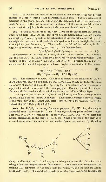
86 FORCES IN TWO DIMENSIONS [CHAP, iv
137. It is evident that either of these methods may be used if the rods are not
uniform or if other forces besides the weights act on them. The two equations of
moments in the second method will be slightly more complicated, but they can be
easily formed. In the first method the transference of the forces parallel to them-
selves to act at the joints is also only a little more complicated, see Art. 79.
138. To find the reactions at the joints. If we use the second method, these are
easily found from equations (3). But if we use the first method we must transfer
the weights ^W1and \WZ back to the extremities of the rods which meet at J 2 . In
the original arrangement of the rods when hinged to each other, let E.2be the action
at the joint A 2 on the rod A 2A 3 . The terminal particle of the rod A2A 3
is then
acted on by the three forces E2 , \W^ and T2 . We therefore have
E22=r
22+^F2
2 -TF2r2 cos02 ............. ."". ............... (6).
The direction of the reaction is easily deduced from equations (2). Supposethat the rods A^, A 2
A3 are joined by a short rod or string without weight. The
position of this rod is clearly the line of action of R2 . Treating this rod as if it
were one of the rods of the polygon, we have, if 2 be its inclination to the vertical,
.(7),cot
tf>- cot
1cot 2
- cot <j>'"
:.(W
1 + W^ cot <f>=W2 cot e1+W1
cot02 .
139. The subsidiary polygon. The lines of action of the reactions Rlt R2 &c.
at the joints will form a new polygon whose corners Bl ,
B.2 &c. are vertically under
the centres of gravity of the rods A^A2> A%A 3 &c. The weights of the rods may be
supposed to act at the corners of this new polygon. Each weight will be in equi-
librium with the reactions which act along the adjacent sides of the polygon.
If we suppose the corners B1 ,B2 &c. to be joined by weightless strings or rods
we shall have a second funicular polygon. This funicular polygon may be treated
in the same way as the former one, except that we have the weights TF1 ,W2 &c.
instead of \ (W^ +W2), \ (W2+ W3) &c.
140. Let B B1B2 &c. be any funicular polygon ;
Wlt W2 , &c., the weights
suspended from the corners Bl ,B2 &c. From any arbitrary point draw straight
lines O&i, Ob2 ,Ob
s &c. parallel to the sides B B1 ,B
1B2 ,
B2B3 &c. to meet anyvertical straight line in the points b
1 ,b2 ,
b3 &c. Since a particle at the point Blis
in equilibrium under the action of the weight Wland the tensions E
1 , R2 acting
N
along the sides B^B^, B^, it follows, by the triangle of forces, that the sides of the
triangle Ob^ are proportional to these forces. In the same way, the sides of the
triangle Ob2b3 represent on the same scale the weight Wz and the tensions acting
along J^jBj, B2B3 . In general the straight lines Oblt Ob2 &c. represent the tensions

ART. 141] REACTIONS AT JOINTS 87
acting along the sides of the funicular polygon to which they are respectively
parallel ;while any part of the vertical straight line as 6.
265 represents the sum of
the weights at B2 ,B3 and B.
By using this figure we may find geometrically the relations between the tensions
and the weights. If fa, fa&c. be the inclinations of the sides B Bl , B^B^&c. to
the vertical, we have ON (cot fa- cot fa)
=b^ ,
where ON is a perpendicular drawn from on the vertical straight line. Since ONrepresents the horizontal tension X at any point of the funicular polygon, this
W Wequation gives = X= = &c.
cot fa- cot 0, cot
<f>z- cot fa
In the same way other relations may be established.
The use of this diagram is described in Rankine's Applied Mechanics. Such
figures are usually called force diagrams. We have here only considered the
simple case in which the forces are parallel to each other. In the chapter on
Graphics this method of solving statical problems will be again considered and
extended to forces which act in any directions.
141. Ex. 1. A chain consisting of a number of equal and in every respect
similar uniform heavy rods, freely jointed at their ends, is hung up from two fixed
points ; prove that the tangents of the angles the rods make with the horizontal are
in arithmetical progression, as are also the tangents of the angles the directions of
the stresses at the joints make with the same, the common difference being the
same for each series. [Coll. Ex., 1881.]
Ex. 2. OA, OB are vertical and horizontal radii of a vertical circle, A being
the lowest point. A string A CDB is fixed to A and B and divided into three equal
parts in C and D. Weights W, W being hung on at C and D, it is found that in
the position of equilibrium C andD both lie on the circle. Prove that W=W tan 15.
[Trin. Coll., 1881.]
Ex. 3. Four equal heavy uniform rods AB, BC, CD, DA are jointed at their
extremities so as to form a rhombus, and the corners A and C are joined by a
string. If the rhombus is suspended by the corner A, show that the tension of the
string is 2JF and that the reaction at either B or D is %Wta,n$BAD, where W is the
weight of any rod.
Ex. 4. AB, BC, CD are three equal rods freely jointed at B and C. The rods
AB, CD rest on two pegs in the same horizontal line so that BC is horizontal. If
a be the inclination of AB, and the inclination of the reaction at B to the horizon,
prove that 3 tan atan/3=l. [St John's Coll., 1881.]
Ex. 5. Three equal uniform rods are freely jointed at their extremities and rest
in equilibrium over two smooth pegs, in a horizontal line at a distance apart equal
to half the length of one rod. If the lowest side be horizontal, then the resultant
action at the upper joint is ^J3W and at each of the lower T̂ JfrlW, where W is
the aggregate weight of the rods. [Coll. Ex., 1882.]
Ex. 6. Three rods, jointed together at their extremities, are laid on a smooth
horizontal table; and forces are applied at the middle points of the sides of the
triangle formed by the rods, and respectively perpendicular to them. Show that, if
these forces produce equilibrium, the strains at the joints will be equal to one
another, and their directions will touch the circle circumscribing the triangle.
[Math. Tripos, 1858.]
88 FORCES IN TWO DIMENSIONS [CHAP. IV
Ex. 7. Three pieces of wire, of the same kind, and of proper lengths, are bent
into the form of the three squares in the diagram of Euclid I., 47, and the angles of
the squares which are in contact are hinged together, so that the smaller ones are
supported by the larger square in a vertical plane. Show that in every position,
into which the figure can be turned, the action, if any, between the angles of the
smaller squares will be perpendicular to the hypothenuse of the right-angled triangle.
[Math. Tripos, 1867.]
Ex. 8. Three uniform rods, whose weights are proportional to their lengths
a, b, c, are jointed together so as to form a triangle, which is placed on a smooth
horizontal plane on its three sides successively, its plane being vertical : prove that
the stresses along the sides a, b, c when horizontal are proportional to
(b + c) cosec 2A, (c + a) cosec 2B, (a + b) cosec 2C. [Math. Tripos, 1870.]
Ex. 9. Three uniform rods AB, BC, CD of lengths 2c, 2b, 2c respectively rest
symmetrically on a smooth parabolic arc, the axis being vertical and vertex
upwards. There are hinges at B and C, and all the rods touch the parabola.
If W be the weight of either of the slant rods, show that its pressure against the
parabola is equal to Wj-^ ^ ,
where 4a is the latus rectum of the parabola.
[Coll. Ex., 1883.]
Ex. 10. ABCD is a quadrilateral formed by four uniform rods of equal weight
loosely jointed together. If the system be in equilibrium in a vertical plane with
the rod AB supported in a horizontal position, prove that 2 tan 6 tana ~ tan /3,
where a, /3 are the angles at A and B, and 6 is the inclination of CD to the horizon ;
also find the stresses at C and D, and prove that their directions are inclined to the
horizon at the angles tan- 1i (tan /3
- tan 6) and tan" 1J (tan a + tan 6) respectively.
[Math. Tripos, 1879.]
Ex. 11. Four equal rods AB, BC, CD, DA, jointed at A, B, C, D, are placed on
a horizontal smooth table to which BC is fixed, the middle points of AD, DC being
connected by a string which is tight when the rods form a square. Show that, if a
couple act on AB and produce a tension T in the string, its moment must be
T.ABJ2. [Coll. Ex., 1888.
Ex. 12. A weightless quadrilateral framework A1A^A SA4 rests with its plane
vertical and the side A^A Z on a horizontal plane. Two weights W, W are placed at
the corners A4 ,A 3 respectively, while a string connecting the two corners A-^A Z
prevents the frame from closing up. Show that the tension T of the string is given
by nT sin 8% sin 4= Wcoa O
lsin 3
-W cos 2 sin 4 ,
where lt 62 ,63 , 4 are the internal angles of the quadrilateral, and n is the ratio of
the side on the horizontal plane to the length of the string.
Ex. 13. A pentagon formed of five heavy equal uniform jointed bars is
suspended from one corner, and the opposite side is supported by a string
attached to its middle point of such length as to make the pentagon regular.
Prove that the tension of the string is equal to 4TF'cos2T1Tr 7r, where W is the
weight of any rod. Find also the reactions at the corners.
Ex. 14. A regular pentagon ABCDE, formed of five equal heavy rods jointed
together, is suspended from the joint A, and the regular pentagonal form is
maintained by a rod without weight joining the middle points K, L of BCand DE. Prove that the stress at K or L is to the weight of a rod in the
ratio of 2 cot 18 to unity. [Math. Tripos, 1885.]
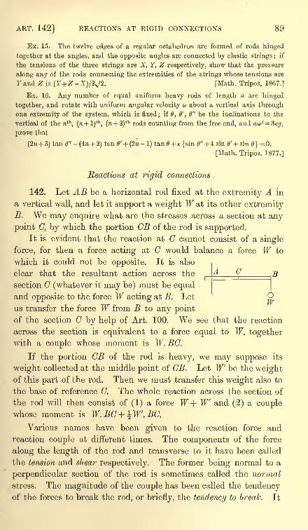
ART. 142] REACTIONS AT RIGID CONNECTIONS 89
Ex. 15. The twelve edges of a regular octahedron are formed of rods hinged
together at the angles, and the opposite angles are connected by elastic strings ;if
the tensions of the three strings are X, Y, Z respectively, show that the pressure
along any of the rods connecting the extremities of the strings whose tensions are
r and Z is (Y+Z -X)/2N/2. [Math. Tripos, 1867.]
Ex. 16. Any number of equal uniform heavy rods of length a are hinged
together, and rotate with uniform angular velocity u about a vertical axis throughone extremity of the system, which is fixed; if 0, 0', 6" be the inclinations to the
vertical of the nth, (w + l)
lh, (n + 2)
th rods counting from the free end, and aw2 =3/c<7,
prove that
(2n + 3) tan 0" - (4?i + 2) tan B' + (2n - 1) tan + K {sin 0" + 4 sin 0' + sin
}= 0.
[Math. Tripos, 1877.]
Reactions at rigid connections
142. Let AB be a horizontal rod fixed at the extremity A in
a vertical wall, and let it support a weight W at its other extremityB. We may enquire what are the stresses across a section at any
point 0, by which the portion OB of the rod is supported.It is evident that the reaction at C cannot consist of a single
force, for then a force acting at C would balance a force W to
which it could not be opposite. It is also
clear that the resultant action across the
section C (whatever it may be) must be equaland opposite to the force W acting at B. Let
us transfer the force W from B to any pointof the section C by help of Art. 100. We see that the reaction
across the section is equivalent to a force equal to W, togetherwith a couple whose moment is W. EG.
If the portion CB of the rod is heavy, we may suppose its
weight collected at the middle point of CB. Let W be the weightof this part of the rod. Then we must transfer this weight also to
the base of reference C. The whole reaction across the section of
the rod will then consist of (1) a force W+ W and (2) a couplewhose moment is W.BG + ^W'.BC.
Various names have been given to the reaction force arid
reaction couple at different times. The components of the force
along the length of the rod and transverse to it have been called
the tension and shear respectively. The former being normal to a
perpendicular section of the rod is sometimes called the normal
stress. The magnitude of the couple has been called the tendencyof the forces to break the rod, or briefly, the tendency to break. It
C
1
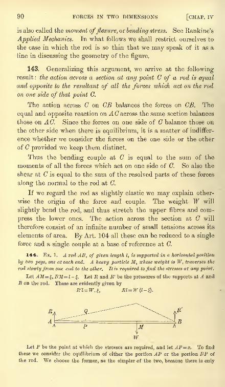
90 FORCES IN TWO DIMENSIONS [CHAP. IV
is also called the moment offlexure, or bending stress. See Rankine's
Applied Mechanics. In what follows we shall restrict ourselves to
the case in which the rod is so thin that we may speak of it as a
line in discussing the geometry of the figure.
143. Generalizing this argument, we arrive at the followingresult : the action across a section at any point C of a rod is equaland opposite to the resultant of all the forces which act on the rod
on one side of that point C.
The action across C on CB balances the forces on CB. The
equal and opposite reaction on AC across the same section balances
those on AC. Since the forces on one side of C balance those on
the other side when there is equilibrium, it is a matter of indiffer-
ence whether we consider the forces on the one side or the other
of C provided we keep them distinct.
Thus the bending couple at C is equal to the sum of the
moments of all the forces which act on one side of C. So also the
shear at C is equal to the sum of the resolved parts of these forces
along the normal to the rod at C.
If we regard the rod as slightly elastic we may explain other-
wise the origin of the force and couple. The weight W will
slightly bend the rod, and thus stretch the upper fibres and com-
press the lower ones. The action across the section at C will
therefore consist of an infinite number of small tensions across its
elements of area. By Art. 104 all these can be reduced to a single
force and a single couple at a base of reference at C.
144. Ex. 1. A rod AB, of given length I, is supported in a horizontal position
by two pegs, one at each end. A heavy particle M, whose weight is W, traverses the
rod slowly from one end to the other. It is required to find the stresses at any point.
Let AM=:, BM=l-%. Let R and R' be the pressures of the supports at A and
B on the rod. These are evidently given by
.9--
Ik-
Let P be the point at which the stresses are required, and let AP= x. To find
these we consider the equilibrium of either the portion AP or the portion BP of
the rod. We choose the former, as the simpler of the two, because there is only
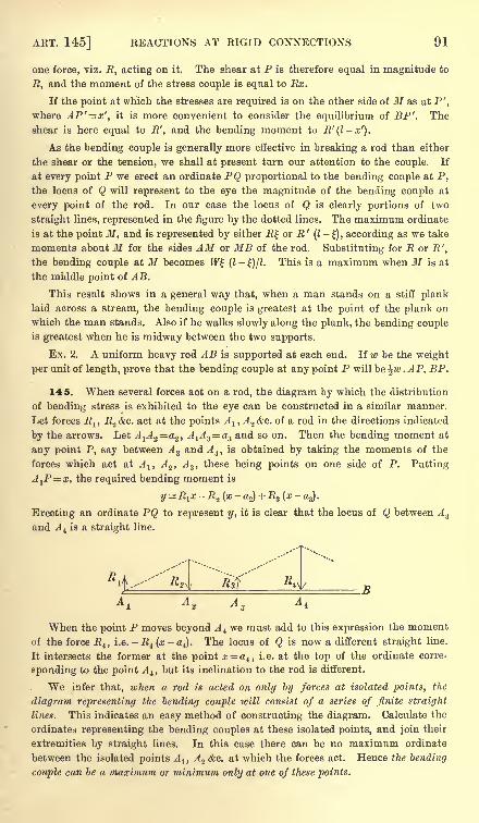
ART. 145] REACTIONS AT RIGID CONNECTIONS 91
one force, viz. R, acting on it. The shear at P is therefore equal in magnitude to
E, and the moment of the stress couple is equal to Rx.
If the point at which the stresses are required is on the other side of M as at P',
where AP'=x', it is more convenient to consider the equilibrium of BP'. The
shear is here equal to R', and the bending moment to R'(l-x').
As the bending couple is generally more effective in breaking a rod than either
the shear or the tension, we shall at present turn our attention to the couple. If
at every point P we erect an ordinate PQ proportional to the bending couple at P,
the locus of Q will represent to the eye the magnitude of the bending couple at
every point of the rod. In our case the locus of Q is clearly portions of two
straight lines, represented in the figure by the dotted lines. The maximum ordinate
is at the point M, and is represented by either R or R' (1-1-), according as we take
moments about M for the sides AM or MB of the rod. Substituting for R or R',
the bending couple at M becomes W (I-
)/Z. This is a maximum when M is at
the middle point of AB.
This result shows in a general way that, when a man stands on a stiff planklaid across a stream, the bending couple is greatest at the point of the plank on
which the man stands. Also if he walks slowly along the plank, the bending coupleis greatest when he is midway between the two supports.
Ex. 2. A uniform heavy rod AB is supported at each end. If w be the weight
per unit of length, prove that the bending couple at any point P will be \w .AP. BP.
145. When several forces act on a rod, the diagram by which the distribution
of bending stress is exhibited to the eye can be constructed in a similar manner.
Let forces RltR
2 &e. act at the points Al , A 2 &c. of a rod in the directions indicated
by the arrows. Let A1A2= a2 ,
A1A 3 a3 and so on. Then the bending moment at
any point P, say between A 3 and A 4 ,is obtained by taking the moments of the
forces which act at A lt A%, A 3 , these being points on one side of P. Putting
AlP= x, the required bending moment is
y-R^ -R^(x- a2)+R3 (x-
a.,).
Erecting an ordinate PQ to represent y, it is clear that the locus of Q between A3
and A 4 is a straight line.
R.}..-"" &*l Rfi L*yA
1A
2 A3
A t
When the point P moves beyond A we must add to this expression the moment
of the force .R4 ,i.e. - R4 (x-a4). The locus of Q is now a different straight line.
It intersects the former at the point x~a4 , i.e. at the top of the ordinate corre-
sponding to the point A, but its inclination to the rod is different.
We infer that, when a rod is acted on only by forces at isolated points, the
diagram representing the bending couple will consist of a series of finite straight
lines. This indicates an easy method of constructing the diagram. Calculate the
ordinates representing the bending couples at these isolated points, and join their
extremities by straight lines. In this case there can be no maximum ordinate
between the isolated points A ly A 2 &c. at which the forces act. Hence the bending
couple can be a maximum or minimum only at one of these points.
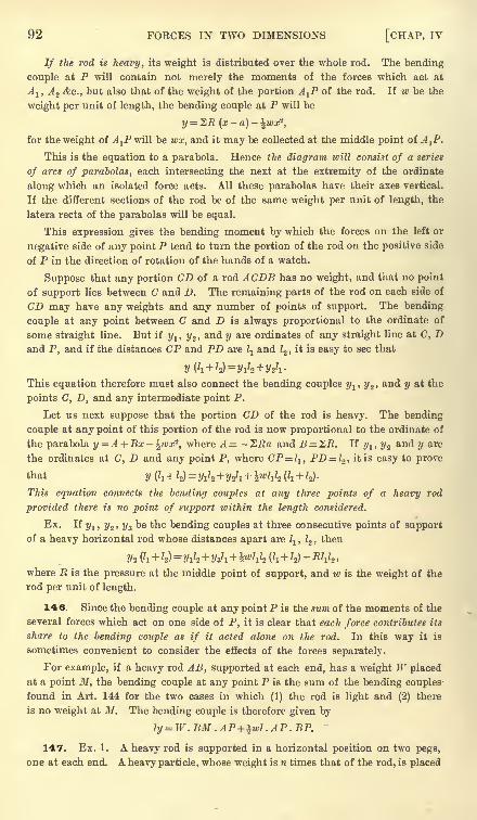
92 FORCES IN TWO DIMENSIONS [CHAP. IV
If the rod is heavy, its weight is distributed over the whole rod. The bending
couple at P will contain not merely the moments of the forces which act at
Alt A 2 &c., but also that of the weight of the portion A-J? of the rod. If w be the
weight per unit of length, the bending couple at P will be
y = ^R(x-a)-^wx2,
for the weight of Af will be wx, and it may be collected at the middle point of A^P.
This is the equation to a parabola. Hence the diagram icill consist of a series
of arcs of parabolas, each intersecting the next at the extremity of the ordinate
along which an isolated force acts. All these parabolas have their axes vertical.
If the different sections of the rod be of the same weight per unit of length, the
latera recta of the parabolas will be equal.
This expression gives the bending moment by which the forces on the left or
negative side of any point P tend to turn the portion of the rod on the positive side
of P in the direction of rotation of the hands of a watch.
Suppose that any portion CD of a rod ACDB has no weight, and that no point
of support lies between C and D. The remaining parts of the rod on each side of
CD may have any weights and any number of points of support. The bending
couple at any point between C and D is always proportional to the ordinate of
some straight line. But if y1 , y2 , and y are ordinates of any straight line at C, Dand P, and if the distances CP and PD are ^ and 12 ,
it is easy to see that
This equation therefore must also connect the bending couples y^,y2 > and y at the
points C, D, and any intermediate point P.
Let us next suppose that the portion CD of the rod is heavy. The bending
couple at any point of this portion of the rod is now proportional to the ordinate of
the parabola y = A + Bx -%wx*, where A = - "ZRa and B= SB. If yl , y% and y are
the ordinates at C, D and any point P, where CP=1I ,PD= 12 , it is easy to prove
that y (^ +y = yJz+y^ + ^wl^ (^ + Z2) .
This equation connects the bending couples at any three points of a heavy rod
provided there is no point of support within the length considered.
Ex. If ylt r/2 , ?/3be the bending couples at three consecutive points of support
of a heavy horizontal rod whose distances apart arel^ ,
Z2 , then
where JR is the pressure at the middle point of support, and w is the weight of the
rod per unit of length.
146. Since the bending couple at any point P is the sum of the moments of the
several forces which act on one side of P, it is clear that each force contributes its
share to the bending couple as if it acted alone on the rod. In this way it is
sometimes convenient to consider the effects of the forces separately.
For example, if a heavy rod AB, supported at each end, has a weight W placed
at a point M, the bending couple at any point P is the sum of the bending couples
found in Art. 144 for the two cases in which (1) the rod is light and (2) there
is no weight at M. The bending couple is therefore given by
ly= W.BM.AP+ ^wl.AP. BP.
147. Ex. 1. A heavy rod is supported in a horizontal position on two pegs,
one at each end. A heavy partide, whose weight is n times that of the rod, is placed
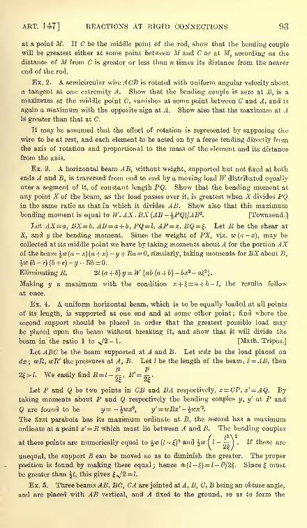
ART. 147] REACTIONS AT RIGID CONNECTIONS 93
at a point M. If C be the middle point of the rod, show that the bending couplewill be greatest either at some point between M and C or at I/, according as the
distance of M from C is greater or less than n times its distance from the nearer
end of the rod.
Ex. 2. A semicircular wire A CB is rotated with uniform angular velocity about
a tangent at one extremity A. Show that the bending couple is zero at B, is a
maximum at the middle point C, vanishes at some point between C and A, and is
again a maximum with the opposite sign at A. Show also that the maximum at Ais greater than that at C.
It may be assumed that the effect of rotation is represented by supposing the
wire to be at rest, and each element to be acted on by a force tending directly from
the axis of rotation and proportional to the mass of the element and its distance
from the axis.
Ex. 3. A horizontal beam AB, without weight, supported but not fixed at both
ends A and B, is traversed from end to end by a moving load W distributed equally
over a segment of it, of constant length PQ. Show that the bending moment at
any point X of the beam, as the load passes over it, is greatest when X divides PQin the same ratio as that in which it divides AB. Show also that this maximum
bending moment is equal to W. AX . BX (AB - %PQ)IAB2
. [Townsend.]
Let AX=a, BX=b, AB= a + b, PQ=l, AP=x, BQ = . Let R be the shear at
X, and y the bending moment. Since the weight of PX, viz. w(a x), may be
collected at its middle point we have by taking moments about A for the portion AXof the beam \w (a
-x) (a + x)
- y +Ea = 0, similarly, taking moments for BX about B,
%w (b-
e) (b + e)- y-Rb= 0.
Eliminating R, 2l(a + b)y=W {ab (a + b)- bx* - a}?}.
Making y a maximum with the condition x +^a + b-l, the results follow
at once.
Ex. 4. A uniform horizontal beam, which is to be equally loaded at all points
of its length, is supported at one end and at some other point ;find where the
second support should be placed in order that the greatest possible load maybe placed upon the beam without breaking it, and show that it will divide the
beam in the ratio 1 to >/2- 1. [Math. Tripos.]
Let ABC be the beam supported at A and B. Let wdx be the load placed on
dx; wR, wR' the pressures at A, B. Let I be the length of the beam, % = AB, then
2|>J. We easily find R= l-j-, R'= ^.It, 6t-
Let P and Q be two points in CB and BA respectively, x=CP, x'= AQ. Bytaking moments about P and Q respectively the bending couples y, y' at P and
Q are found to be y=-^wx2, y'
= wRx' -%wx'2.
The first parabola has its maximum ordinate at B, the second has a maximumordinate at a point x' R which must lie between A and B. The bending couples
/ Z2 \ 2
at these points are numerically equal to \w (I-
f)2 and %w ( I -
). If these are
unequal, the support B can be moved so as to diminish the greater. The proper
position is found by making these equal; hence (l-) = l-P/2. Since must
be greater than \l, this gives *J2 = l.
Ex. 5. Three beams AB, BC, CA are jointed at A, B, C, B being an obtuse angle,
and are placed with AB vertical, and A fixed to the ground, so as to form the
94 FORCES IN TWO DIMENSIONS [CHAP. IV
framework of a crane. There is a pulley at C, and the rope is fastened to ABnear B and passes along BC and over the pulley. If it support a weight IF, large in
comparison with the weights of the framework and rope, find the couples which
tend to break the crane at A and B. [Math. Tripos.]
Ex. 6. A gipsy's tripod consists of three uniform straight sticks freely hinged
together at one end. From this common end hangs the kettle. The other ends of
the sticks rest on a smooth horizontal plane, and are prevented from slipping by a
smooth circular hoop which encloses them and is fixed to the plane. Show that
there cannot be equilibrium unless the sticks be of equal length ; and if the weights
of the sticks be given (equal or unequal) the bending moment of each will be greatest
at its middle point, will be independent of its length, and will not be increased on
increasing the weight of the kettle. [Math. Tripos, 1878.]
Ex. 7. A brittle rod AB, attached to smooth hinges at A and B, is attracted
towards a centre of force C according to the law of nature. Supposing the absolute
force to be indefinitely augmented, prove that the rod will eventually snap at a
point E determined by the equation sin \ (a + /3)cos = sin \ (a- fi), where a, /3
denote the angles BAG, ABC, and 6 the angle AEG. Math. Tripos, 1854. See also
the solutions for that year by the Moderators and Examiners.
Indeterminate Problems
148. When a body is placed on a horizontal plane, the pressure
exerted by its weight is distributed over the points of support.
When there are more than three supports, or more than two in
one vertical plane, this distribution appears to be indeterminate.
Thus suppose the body to be a table with vertical legs, and let
these legs intersect the plane horizontal surface of the table in the
points A i, j4. 2 &c. Let the projection on this plane of the centre of
gravity of the body be G. The weight W of the table will then be
supported by certain pressures R lt R2 &c. acting at A 1} A 2 &c. Let
Ox, Oy be any rectangular axes of reference in this plane and let Oz
be vertical. Let (x^i), (#2y2) &c. be the coordinates of A ly A 2 &c.
and let (xy) be those of G. Since W is supported by a system of
parallel forces we have by Arts. 110 and 111
Wx = R^
These three equations suffice to determine Rlt R2 &c. if there are
but three of them and these not all in one vertical plane, but if
there are more than three, the problem appears to be indeterminate.
In this solution we have replaced the supporting power of the
floor by forces Rlt R% &c. acting upwards along the legs. What we
ART. 148] INDETERMINATE PROBLEMS 95
have really proved is that the table could be supported by such
forces in a variety of different ways. Suppose there were four legs ;
we could choose one of these forces to be what we please, the
others could then be found from these three equations. It is
therefore evident that the problem of finding what forces could
support the table must be indeterminate.
The actual pressures exerted by the table on the floor are not
indeterminate, for in nature things are necessarily determinate.
When anything appears to be indeterminate, it must be because
we have omitted some of the data of the question, i.e. some property
of matter on which the solution depends.
We notice that the elementary axioms relating to forces, which
have been enunciated in Art. 18, make no reference to the nature
of the materials of the body. We have found in the precedingArticles that the equations supplied by these axioms have in
general been sufficient to determine all the unknown quantities
in our statical problems. In all these problems therefore the
magnitudes of the reactions and the positions of equilibrium of
the bodies depended, not on the materials of the bodies, but on
their geometrical forms and on the magnitudes of the impressedforces. It is evident, however, that these axioms must be insuf-
ficient to determine any unknown quantities which depend on the
materials of the bodies. In such cases we must have recourse to
some new experiments to discover another statical axiom. Thus,
when we study the positions of equilibrium of rough bodies, another
experimental result, depending on the degree of roughness of the
special body considered, is found to be necessary. In the same
way the mode of distribution of the pressure over the legs of the
table is found to depend on the flexibility of the materials.
However slight the flexibility of the substance of the table maybe, yet the weight W will produce some deformation however
small. The magnitude of this will influence and be influenced bythe reactions R^, R^ &c. The amount of yielding produced by the
acting forces in any body is usually considered in that part of
mechanics called the theory of elastic solids. No complete solution
of the special problem of the table has yet been found. But when
any assumed law of elasticity is given, it is easy to show bysome examples, how the problem becomes determinate. Poinsot's
Elements de Statique and Poissons Traite de Mecanique.
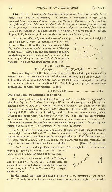
96 FORCES IN TWO DIMENSIONS [CHAP. IV
140. Ex. 1. A rectangular table has the legs at the four corners alike in all
respects and slightly compressible. The amount of compression in each leg is
supposed to be proportional to the pressure on that leg. Supposing the floor and the
top of the table to be rigid, and the table loaded in any given manner, find the pressure
on the four legs. Show that when the resultant weight lies in one of four straight
lines on the surface of the table, the table is supported by three legs only. [Math.
Tripos, 1860, Watson's problem, see also the Solutions for that year.]
Let the two sides AB, AD be the axes of x and y. Let the resultant weight Wact at a point G whose coordinates are (xy). Let
AB=a, AD b. Since the top of the table is rigid,
the surface as altered by the compression of the legs
is still plane. Also, since the compression is slight,
we shall neglect small quantities of the second order,
and suppose the pressures at A, B, C, D to remain
vertical. We have the usual statical equations
Because a diagonal of the table remains straight, the middle point descends a
space which is the arithmetic mean of the spaces descended by its two ends. It
follows that the mean of the compressions of the legs A and C is equal to the meanof the compressions of the legs B and D. But it is given that the pressures are
proportional to these compressions. Hence
.R1 + -R3 =.R2 + .R4 .................................... (2).
These four equations determine the pressures.
If we put .R3= 0, we easily find that 2x/a + 2y/b = 1 , i.e. the table is supported on
the three legs A, B, D when the weight W lies on the straight line joining the
middle points of AB, AD. Joining the middle points of the other sides in the
same way, we obtain four straight lines represented by the dotted lines. Whenthe weight W lies within this dotted figure all the four legs are compressed ;
when
without this figure three legs only are compressed. The equations above written
are then correct, only if we suppose that some of the reactions are negative. As
this cannot in general be possible, we must amend the equations (1) by putting one
reaction equal to zero. The equation (2) must then be omitted.
Ex. 2. A and C are fixed points or pegs in the same vertical line, about which
the straight beams ADB and CD are freely moveable. AB is supported in a hori-
zontal position by CD and has a weight W suspended at B. Find the pressure at C
(I) when there is a hinge joint at D, and (2) when CD forms one piece with AB, the
weights of the beams being in each case neglected. [Math. Tripos, 1841.]
In the first part of the problem the action at D is a single force, in the second
part it is a force and a couple, Art. 142. In both
parts of the problem the action at C is a force. A T) Ti
In the first part, the actions at C and D are equal
and act along CD by Art. 131. Taking momentsabout A for the rod AD, we easily find that this
action is equal to W. AB/AN where AN is a perpen-
dicular on CD.
In the second part there is nothing to determine the direction of the action
at C. We only know it balances an unknown force and a couple. If we write
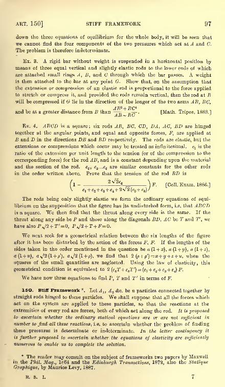
ART. 150] STIFF FRAMEWORK 97
down the three equations of equilibrium for the whole body, it will be seen that
we cannot find the four components of the two pressures which act at A and C.
The problem is therefore indeterminate.
Ex. 3. A rigid bar without weight is suspended in a horizontal position bymeans of three equal vertical and slightly elastic rods to the lower ends of which
are attached small rings A, B, and C through which the bar passes. A weightis then attached to the bar at any point G. Show that, on the assumption that
the extension or compression of an elastic rod is proportional to the force appliedto stretch or compress it, aud provided the rods remain vertical, then the rod at Bwill be compressed if G lie in the direction of the longer of the two arms AB, BC,
A T)2_{_ ft /~2
and be at a greater distance from B than ^- . [Math. Tripos, 1883.]A I > ~* B(s
Ex. 4. ABCD is a square; six rods AB, BC, CD, DA, AC, BD are hinged
together at the angular points, and equal and opposite forces, F, are applied at
B and D in the directions DB and BD respectively. The rods are elastic, but the
extensions or compressions which occur may be treated as infinitesimal. elis the
ratio of the extension per unit length to the tension (or of the compression to the
corresponding force) for the rod AB, and is a constant depending upon the material
and the section of the rod. e2 , e3 ...ee are similar constants for the other rods
in the order written above. Prove that the tension of the rod BD is
( I- - 2 6 -
} F. [Coll. Exam. 1886.]
The rods being only slightly elastic we form the ordinary equations of equi-
librium on the supposition that the figure has its undisturbed form, i.e. that ABCDis a square. We then find that the thrust along every side is the same. If the
thrust along any side be P and those along the diagonals BD, AC be T and T', we
have also PJ2 + T'=0, PJ2 + T+F=0.
We next seek for a geometrical relation between the six lengths of the figure
after it has been disturbed by the action of the forces F, F. If the lengths of the
sides taken in the order mentioned in the question be a(l + x), a(l+y), a (1 + z),
a(l + u), a^J2(l + p'), a>J2(l + p), we find that 2(p + p')=x + y+z + u, when the
squares of the small quantities are neglected. Using the law of elasticity, this
geometrical condition is equivalent to 2(e6T+e5T') = (e1 + e<
i + e3+ e4) P.
We have now three equations to find P, T and T' in terms of F.
ISO. Stiff Framework *. Let A lt A.2 <fec. be n particles connected together by
straight rods hinged to these particles. We shall suppose that all the forces whichact on the system are applied to these particles, so that the reactions at the
extremities of every rod are forces, both of which act along the rod. It is proposedto ascertain whether the ordinary statical equations are or are not sufficient in
number to find all these reactions, i.e. to ascertain whether the problem of finding
these pressures is determinate or indeterminate. In the latter contingency it
is further proposed to ascertain whether the equations of elasticity are sufficiently
numerous to enable us to complete the solution.
* The reader may consult on the subject of frameworks two papers by Maxwellin the Phil. Mag., 1864 and the Edinburgh Transactions, 1872, also the Statique
Graphique, by Maurice Levy, 1887.
R. S. I. 7
98 FORCES IN TWO DIMENSIONS [CHAP. IV
151. Let w first enquire what number of connecting rods could make the
framework stiff. Assuming n not to be less than 2, we start by stiffening two
particles A^ and A 2 by means of one connecting rod. The remaining n - 2 have
to be jointed to these. In order that a third particle A 3 should be rigidly connectei
to these two, it must be joined to both Aland A 2 ,
thus requiring two more connect-
ing rods. If a fourth A 4 is to be rigidly connected with these, it must be joined to
any two out of the three particles already joined. Proceeding in this manner we
see that for each particle joined to the system two additional rods are necessary.
Thus to make a system of n particles rigid, a framework of 2 (n-
2) + 1, i.e. 2 -3,
connecting rods is sufficient.
When any particle, as A 3 , is joined by two rods to two other particles as Al ,A 2 ,
there must be some convention to settle on which side of the base ArA
2 the vertex
of the triangle A ZA^A^ is to be taken. If not, there may be more than one polygon
having sides equal to the given lengths.
We must also notice that when the particle A 3 is joined to the fixed particles
Alt A 2 by two rods, if A3should happen to be in the same straight line with A
1A.2t
the connection is not made perfectly rigid. The particle A 3could make an infinitely
small displacement perpendicular to the straight line A1A
ZA 3 on either side of it.
This is an imaginary displacement, to be taken account of when the circumstances
of the problem require that we should neglect small quantities of the second order.
If the particles are not all in the same plane, and n is not less than 3, we start
with three particles requiring three rods to stiffen them. Each additional particle
of the remaining n - 3 must be attached to three of the particles already connected.
Thus to make a system of n particles rigid, a framework of 3 (n-
3) + 3, i.e. 3n 6,
connecting rods is sufficient.
It is not necessary that the connections between the particles should be made in
the precise way just described. All we have proved is that the system could be
stiffened by 2n - 3 or 3n - 6 rods properly placed. These may be arranged in
several different ways* so as to stiffen the system. On the other hand if the rods
are not properly placed the system may not be stiff;thus one part of the system
may be stiffened by more than the necessary number of rods, and another part maynot have a sufficient number.
A system of particles made rigid by just the necessary number of bars is said to
be simply stiff or just stiff. When there are more bars than the necessary number,the system may be called over stiff. When the number of bars is less than the
number necessary to stiffen the system, the framework is said to be deformable.
The shape it will assume in equilibrium is then unknown and has to be deduced,
along with the reactions, from the equations of equilibrium.
152. We may infer as a corollary from this that a polygon having n corners is
in general given when we know the lengths of 2 - 3 sides. If m be the number of
sides and diagonals in the polygon, there must be ?/i-(2n-3) relations between
their lengths. It appears that 2n-3 of the m lengtlis are arbitrary except that
* The argument may be summed up as follows. Taking any fixel axes, a figureis given in position and form when we know the 2 or Bn coordinates of its n corners.
These are the arbitrary quantities of the framework. If only its form is to be deter-
minate we refer the figure to coordinate axes fixed relatively to itself, and the
coordinates required to determine the position of a free rigid body are now no longerat our disposal. We therefore have 2n - 3 or 3n - 6 arbitrary quantities accordingas the body is in one plane or in space, Art. 206.
ART. 154] STIFF FRAMEWORK 99
they must satisfy such conditions as will permit a figure to be formed ; for instance
if three of the arbitrary lengths form a triangle, any two of the lengths must
together be greater than the third. The exceptional case referred to above occurs
when some of these necessary conditions are only just satisfied.
If a II the corners are joined, each to each, the number of lengths will be ^n (n-
1).
There will therefore be \ (n-
2) (n-
3) relations between the sides and diagonals of
a polygon of n corners. In the same way there will be (n-
3) (n-4) relations
between the edges of a polyhedron.
153. Let us next enquire how many statical equations we have. Let us
suppose the system to be acted on by any given forces whose points of application
are at some or all of the particles. These we may call the external forces.
Since each particle separately is in equilibrium, we may, by resolving the forces
on each parallel to the axes, obtain 2?i or 3w equations of equilibrium according as
the system is in one plane or in space.
However numerous the reactions along the rods may be, we can always eliminate
them from these equations and obtain either three or six equations, according as
the system is in one plane or in space. To prove this, we notice that, taking
all the particles together as one system, the internal reactions balance each other.
Resolving then the external forces in some two directions in the plane of the
system and taking moments about some point, we obtain* three equations of equi-
librium free from all internal reactions (Art. 112). And it is clear that no
resolutions in other directions and no moments about other points will give more
independent equations than three (Art. 115). In the same way, if the system is in
space, it will be shown that we can obtain six equations free from internal reactions
by resolving in some three directions and taking moments about some three axes.
On the whole then we have either 2-3 or 3n-6 equations to find the reactions.
In a simply stiff framework we have just this number of independent reactions.
Thus in a framework, simply stiff, icithout any unknown external reactions, we have
a sufficient number of equations to find all the 2n~3 or 3n-6 reactions.
If the framework is subject to external constraints, for example if some points
are fixed in space, the number of bars necessary to stiffen the system is altered.
Whether stiff or not let there be 2n - 3 - k or 3ra - 6 - k bars. It follows easily
that the equations of statics will supply k + 3 or k + 6 equations (after elimination
of the internal reactions) to find the external reactions and the position of
equilibrium. If these are sufficient the problem is determinate.
154. Although the equations in statics may be sufficient in number to de-
termine the internal reactions, yet exceptional cases may arise. The equations thus
obtained may not be independent, or they may be contradictory.*
If it is not clear that these three equations must follow from the '2n or Bn
equations of equilibrium of the separate particles, we may amplify the proof as
follows. If any particle A 1is acted on by a reaction R12 tending to A 2 ,
then the
particle A.2 is acted on by an equal and opposite reaction R2l tending to Al . The
resolved parts of RK and R21 parallel to x will therefore also be equal and opposite.
If then we add together all the equations obtained from all the particles separately
by the resolution parallel to x, the 'sum will yield an equation free from all the R's.
In the same way the resolution parallel to y or z will each yield another equationfree from all the internal reactions.
Next since the forces on each particle balance, the sum of their moments about
any straight line is zero. But by the same reasoning as before the moment of
the reaction R12 which acts on A1must be equal and opposite to that of the reaction
.R21 which acts on A%. Hence if we add all the equations obtained from all the
particles by taking moments, the sum will yield an equation free from all the R's.
72
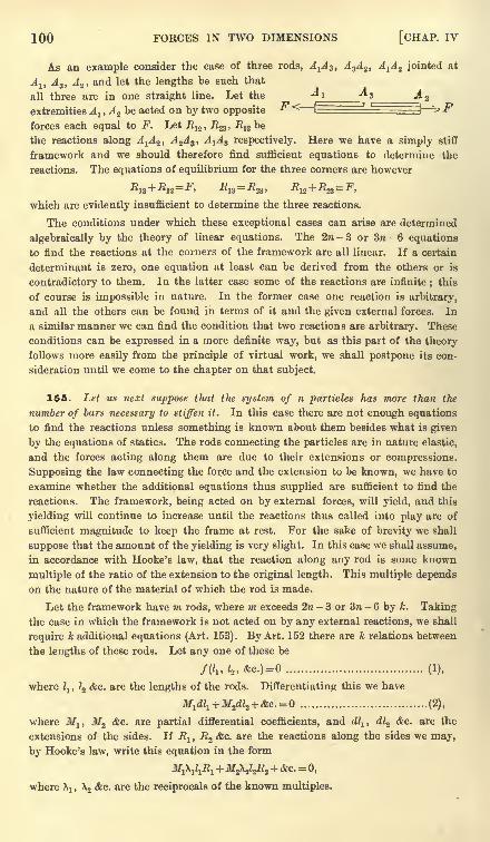
100 FORCES IN TWO DIMENSIONS [CHAP. IV
As an example consider the case of three rods, A^, A 3A2 , A^A Z jointed at
A-.. A,, A n , and let the lengths be such thatA A
all three are in one straight line. Let the ^1 ^3^extremities A l , A 2 be acted on by two opposite
F<r-
forces each equal to F. Let R12 , R&, R13 be
the reactions along A1A2 ,
A 2A 3 , A^3 respectively. Here we have a simply stiff
framework and we should therefore find sufficient equations to determine the
reactions. The equations of equilibrium for the three corners are however
which are evidently insufficient to determine the three reactions.
The conditions under which these exceptional cases can arise are determined
algebraically by the theory of linear equations. The 2ra - 3 or 3n - 6 equations
to find the reactions at the corners of the framework are all linear. If a certain
determinant is zero, one equation at least can be derived from the others or is
contradictory to them. In the latter case some of the reactions are infinite ; this
of course is impossible in nature. In the former case one reaction is arbitrary,
and all the others can be found in terms of it and the given external forces. In
a similar manner we can find the condition that two reactions are arbitrary. These
conditions can be expressed hi a more definite way, but as this part of the theory
follows more easily from the principle of virtual work, we shall postpone its con-
sideration until we come to the chapter on that subject.
155. Let us next suppose that the system of n particles has more than the
number of bars necessary to stiffen it. In this case there are not enough equations
to find the reactions unless something is known about them besides what is given
by the equations of statics. The rods connecting the particles are in nature elastic,
and the forces acting along them are due to their extensions or compressions.
Supposing the law connecting the force and the extension to be known, we have to
examine whether the additional equations thus supplied are sufficient to find the
reactions. The framework, being acted on by external forces, will yield, and this
yielding will continue to increase until the reactions thus called into play are of
sufficient magnitude to keep the frame at rest. For the sake of brevity we shall
suppose that the amount of the yielding is very slight. In this case we shall assume,
in accordance with Hooke's law, that the reaction along any rod is some known
multiple of the ratio of the extension to the original length. This multiple depends
on the nature of the material of which the rod is made.
Let the framework have m rods, where m exceeds 2 - 3 or 3n - 6 by ft. Taking
the case in which the framework is not acted on by any external reactions, we shall
require k additional equations (Art. 153). By Art. 152 there are k relations between
the lengths of these rods. Let any one of these be
whereZj ,
/2 &c. are the lengths of the rods. Differentiating this we have
where Mlt M2 &c. are partial differential coefficients, and dllt dly &c. are the
extensions of the sides. If R^ ,R2 &c. are the reactions along the sides we may,
by Hooke's law, write this equation in the form
where Xj ,X2 &c. are the reciprocals of the known multiples.
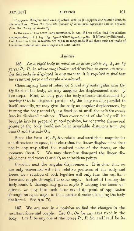
ART. 157] ASTATICS 101
It appears therefore that each equation such as (1) supplies one relation between
the reactions. Thus the requisite number of additional equations can be deduced
from the theory of elasticity.
In the case of the three rods mentioned in Art. 154 we notice that the relation
corresponding to (1) is Z13 + l<%
-Z]2 =0, where 1^= A^A^, &G. It follows by differentia-
tion that the three reactions are equal in magnitude if all three rods are made of
the same material and are of equal sectional areas.
Astatics
156. Let a rigid body be acted on at given points A 1} A z &c. by
forces P1 ,P2 &c. whose magnitudes and directions in space are given.
Let this body be displaced in any manner: it is required to find how
the resultant force and couple are altered.
Choosing any base of reference and any rectangular axes Ox,
Oy fixed in the body, we may imagine the displacement made bytwo steps. First, we may give the body a linear displacement by
moving to its displaced position Oi, the body moving parallel to
itself; secondly, we may give the body an angular displacement, by
turning the body round Ol as a fixed point until the axis Ox comes
into its displaced position. Then every point of the body will be
brought into its proper displaced position, for otherwise the several
points of the body would not be at invariable distances from the
base and the axis Ox.
Since the forces P1} P2 &c. retain unaltered their magnitudesand directions in space, it is clear that the linear displacement does
not in any way affect the resolved parts of the forces, or the
moment about 0. We may therefore disregard the linear dis-
placement and treat and 1 as coincident points.
Consider next the angular displacement. It is clear that we
are only concerned with the relative positions of the body and
forces, for a rotation of both together will only turn the resultant
force and couple through the same angle. Instead of turning the
body round through any given angle 6 keeping the forces un-
altered, we may turn each force round its point of application
through an equal angle in the opposite direction, keeping the bodyunaltered. See Art. 70.
157. We are now in a position to find the changes in the
resultant force and couple. Let Ox, Oy be any axes fixed in the
body. Let P be any one of the forces P1} P2 &c. and let A be its
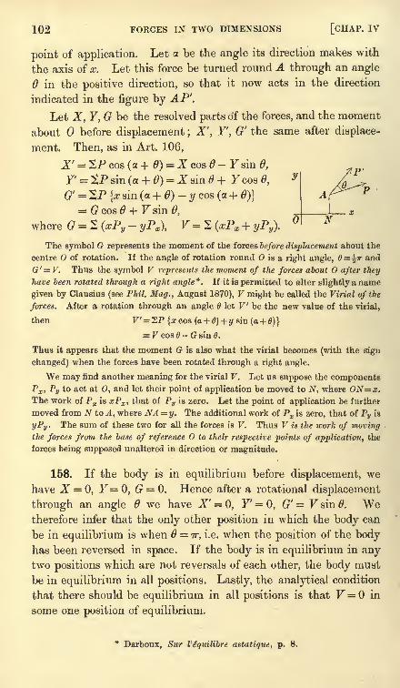
102 FORCES IN TWO DIMENSIONS [CHAP. IV
point of application. Let a. be the angle its direction makes with
the axis of x. Let this force be turned round A through an angle
6 in the positive direction, so that it now acts in the direction
indicated in the figure by AP'.
Let X, Y, G be the resolved parts of the forces, and the moment
about before displacement ; X', Y', G' the same after displace-
ment. Then, as in Art. 106,
X' = 2P cos (a + 0)= X cos - Fsin 0,
G' = 2P {x siri (a + 0)-y cos (a + <9)}
= G cos 0+ Fsin 0,
where G = 2 (#Py - yPx ), F = 2 (xPx + yPy\
The symbol G represents the moment of the forces before displacement about the
centre O of rotation. If the angle of rotation round is a right angle, 6 = ^ir and
G'= F. Thus the symbol V represents the moment of the forces about after they
have been rotated through a right angle*. If it is permitted to alter slightly a name
given by Clausius (see Phil. Mag., August 1870), V might be called the Virial of the
forces. After a rotation through an angle let V be the new value of the virial,
then F'= 2P {xcos (a + 6) + y sin(a + 0)}
= V cos 6 - G sin 6.
Thus it appears that the moment G is also what the virial becomes (with the sign
changed) when the forces have been rotated through a right angle.
We may find another meaning for the virial V. Let us suppose the componentsPx , Py to act at 0, and let their point of application be moved to N, where ON=x.The work of Px is xPx , that of Pv is zero. Let the point of application be further
moved from N to A, where NA =y. The additional work of Px is zero, that of Pv is
yPv . The sum of these two for all the forces is F. Thus F is the work of movingthe forces from the base of reference O to their respective points of application, the
forces being supposed unaltered in direction or magnitude.
158. If the body is in equilibrium before displacement, we
have X = 0, Y= 0, G = 0. Hence after a rotational displacement
through an angle we have X' = 0, F=0, G' = Fsin6>. Wetherefore infer that the only other position in which the body can
be in equilibrium is when =TT, i.e. when the position of the body
has been reversed in space. If the body is in equilibrium in anytwo positions which are not reversals of each other, the body must
be in equilibrium in all positions. Lastly, the analytical condition
that there should be equilibrium in all positions is that F = in
some one position of equilibrium.
*Darboux, Sur Veqnilibre astatique, p. 8.
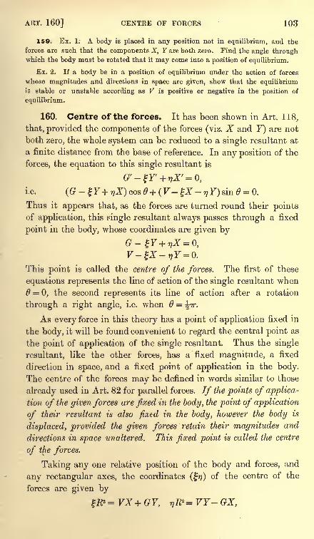
ART. 160] CENTRE OF FORCES 103
159. Ex. 1; A body is placed in any position not in equilibrium, and the
forces are such that the components X, Y are both zero. Find the angle throughwhich the body must be rotated that it may come into a position of equilibrium.
Ex. 2. If a body be in a position of equilibrium under the action of forces
whose magnitudes and directions in space are given, show that the equilibrium
is stable or unstable according as V is positive or negative in the position of
equilibrium.
160. Centre of the forces. It has been shown in Art. 118,
that, provided the components of the forces (viz. X and F) are not
both zero, the whole system can be reduced to a single resultant at
a finite distance from the base of reference. In any position of the
forces, the equation to this single resultant is
n0 = 0.
Thus it appears that, as the forces are turned round their pointsof application, this single resultant always passes through a fixed
point in the body, whose coordinates are given by
This point is called the centre of the forces. The first of these
equations represents the line of action of the single resultant when6 = 0, the second represents its line of action after a rotation
through a right angle, i.e. when =\ir.
As every force in this theory has a point of application fixed in
the body, it will be found convenient to regard the central point as
the point of application of the single resultant. Thus the single
resultant, like the other forces, has a fixed magnitude, a fixed
direction in space, and a fixed point of application in the body.
The centre of the forces may be defined in words similar to those
already used in Art. 82 for parallel forces. If the points of applica-
tion of the given forces are fixed in the body, the point of application
of their resultant is also fixed in the body, however the body is
displaced, provided the given forces retain their magnitudes and
directions in space unaltered. This fixed point is called the centre
of the forces.
Taking any one relative position of the body and forces, and
any rectangular axes, the coordinates (17) of the centre of the
forces are given by
= VX + GY, <nR2 = VY- GX,
104 FORCES IN TWO DIMENSIONS [CHAP. IV
where X, Y, V, G are referred to the origin as base, and R is the
resultant of X and Y.
161. Ex. 1. If the forces of a system are reducible to a single resultant couple,
show that the centre of the forces is at infinity.
Ex. 2. Show that, as the forces are rotated, the value of G/Fat any assumed
base is always equal to the tangent of the angle which the straight line joining Oto the centre C of the forces makes with the direction of the resultant force R, while
the value of G2+ F2 is invariable and equal to R2. CO-.
Since the system is equivalent to a single force R acting at G, it is evident that
G = R. ON, where ON is a perpendicular on the line of action of R. Turning Rthrough a right angle, we have V= R . CN. The results follow at once.
162. There is another method* of finding the astatic resultant of a given
system which is sometimes useful. The body having been placed in any position
relative to the forces which may be convenient, let two axes Ox, Oij be chosen so
that the resolved parts of the forces in these directions, viz. X and Y, are neither of
them zero. Consider first the resolved parts of all the forces parallel to x. By the
theory of parallel forces these are equivalent to a single force, viz. X=2PX ,which
acts at a point fixed in the body whose coordinates are (x^j), where
xlX=ZxPx , yiX= 2yPx .
Consider next the resolved parts parallel to y. These also form a system of parallel
forces and are equivalent to a single force F=SPy , which acts at a point fixed in
the body whose coordinates are (x<g/2), where
Since the axes of coordinates are arbitrary and need not be at right angles, the
forces have thus been reduced to two forces acting at two points fixed in the bodyin directions arbitrarily chosen but not parallel. The positions of these points
depend on the directions chosen.
163. Let the fixed points thus found be called A and B. In any one relative
position of the body and forces, let the two forces X and F intersect in I, and
let their resultant act along IF. Let IF intersect the circle described about the
triangle ABI in C. Then, by the astatic triangle of forces, G is a point fixed in
the body, and the resultant of X and Y may be supposed to act at G. The
point C is therefore the centre of the forces.
Conversely, when the resultant force and the centre of the forces are known,that force may be resolved into two astatic forces by usin r the triangle of forces
in the manner already explained in Art. 73.
* The method explained in this Article has been used by Darboux, Sur I'equilibreastatique, and by Larmor, Messenger of Mathematics.
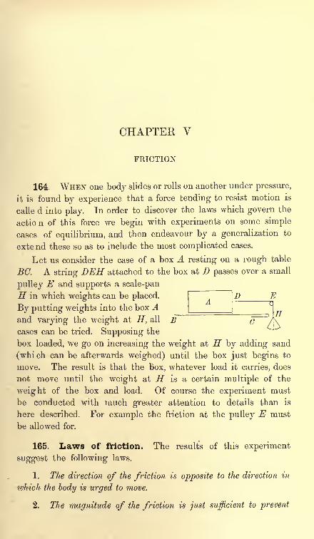
CHAPTER V
FRICTION
164. WHEN one body slides or rolls on another under pressure,
it is found by experience that a force tending to resist motion is
calle d into play. In order to discover the laws which govern the
action of this force we begin with experiments on some simple
cases of equilibrium, and then endeavour by a generalization to
exte nd these so as to include the most complicated cases.
Let us consider the case of a box A resting on a rough table
EG. A string DEH attached to the box at D passes over a small
pulley E and supports a scale-pan
H in which weights can be placed.
By putting weights into the box AD E
Hand varying the weight at H, all B /\cases can be tried. Supposing the
box loaded, we go on increasing the weight at H by adding sand
(which can be afterwards weighed) until the box just begins to
move. The result is that the box, whatever load it carries, does
not move until the weight at H is a certain multiple of the
weight of the box and load. Of course the experiment must
be conducted with much greater attention to details than is
here described. For example the friction at the pulley E must
be allowed for.
165. Laws of friction. The results of this experiment
suggest the following laws.
1. The direction of the friction is opposite to the direction in
which the body is urged to move.
2. The magnitude of the friction is just sufficient to prevent
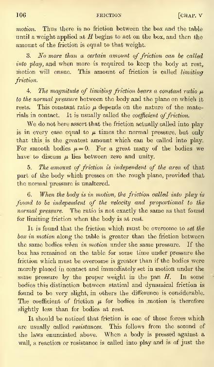
106 FRICTION [CHAP, v
motion. Thus there is no friction between the box and the table
until a weight applied at H begins to act on the box, and then the
amount of the friction is equal to that weight.
3. No more than a certain amount of friction can be called
into play, and when more is required to keep the body at rest,
motion will ensue. This amount of friction is called limiting
friction.
4. The magnitude of limiting friction bears a constant ratio p,
to the normal pressure between the body and the plane on which it
rests. This constant ratio p. depends on the nature of the mate-
rials in contact. It is usually called the coefficient offriction.
We do not here assert that the friction actually called into playis in every case equal to
/u,times the normal pressure, but only
that this is the greatest amount which can be called into play.
For smooth bodies fi= 0. For a great many of the bodies we
have to discuss p lies between zero and unity.
5. The amount of friction is independent of the area of that
part of the body which presses on the rough plane, provided that
the normal pressure is unaltered.
6. When the body is in motion, the friction called into play is
found to be independent of the velocity and proportional to the
normal pressure. The ratio is not exactly the same as that found
for limiting friction when the body is at rest.
It is found that the friction which must be overcome to set the
box in motion along the table is greater than the friction between
the same bodies when in motion under the same pressure. If the
box has remained on the table for some time under pressure the
friction which must be overcome is greater than if the bodies were
merely placed in contact and immediately set in motion under the
same pressure by the proper weight in the pan H. In some
bodies this distinction between statical and dynamical friction is
found to be very slight, in others the difference is considerable.
The coefficient of friction//.
for bodies in .motion is therefore
slightly less than for bodies at rest.
It should be noticed that friction is one of those forces which
are usually called resistances. This follows from the second of
the laws enunciated above. When a body is pressed against a
wall, a reaction or resistance is called into play and is of just the
ART. 167] LAWS OF FRICTION 107
magnitude necessary to balance the pressing force. If there is no
pressure there is no reaction. In the same way friction acts only
to prevent sliding, not to produce it.
166. There is another method of determining the laws of
friction by which the use of the pulley and string is avoided and
which therefore presents some ad-
vantages. Imagine the box Aplaced symmetrically on an inclined
plane BC. Let the inclination of
BC to the horizon be 6. If W be
the weight of the box we easily
find that the normal reaction is R = W cos 6, and the friction
ET
F= TFsin#. Hence -^= tan#. Let us now suppose the inclina-
tion 6 of the plane to the horizon to be gradually increased until
the box A begins to slide. The friction F is then the limiting
friction. It is found by experiment that this inclination is the
same, whatever the weight of the box may be. It follows that
the ratio of the limiting friction to the normal pressure is inde-
pendent of that pressure.
This experiment supplies us with an easy method of approxi-
mating to the value of p for any two materials. Place a body Aconstructed of one of these materials on an inclined plane BCconstructed of the other material. Supposing A to be at rest,
increase the inclination 6 until A just begins to slide, then p, is
slightly less than the value of tan 6 thus found. Next supposingthe inclination of the plane to be such that the body A slides,
we might decrease it until the box is just stationary, then//,
is
slightly greater than the value of tan 6 thus found. In this waywe have found two nearly equal numerical quantities between
which the coefficient of friction, viz. ft, must lie. The value ofwhich makes tan =
/*,is often called the angle offriction.
Ex. Assuming that limiting friction consists of two parts, one proportional to
the pressure and the other to the surface in contact, show that if the least forces
which can support a rectangular parallelepiped whose edges are a. b, and c on
a given inclined plane be P, Q, and R when the faces be, ca, and ab respectively
rest on the plane, then (Q-R) bc + (R- P)ca + (P - Q) ab=Q. [Trin. Coll., 1881.]
167. The friction couple. When a wheel rolls on a rough
plane the experiment must be conducted in a different manner.
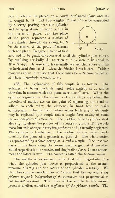
108 FRICTION [CHAP, v
Let a cylinder be placed on a rough horizontal plane and let
its weight be W. Let two weights P and P + p be suspended
by a string passing over the cylinder
and hanging down through a slit in
the horizontal plane. Let the plane
of the paper represent a section of
the cylinder through the string, let Cbe the centre, A the point of contact
with the plane. Imagine p to be at first
zero and to be gradually increased until the cylinder just moves.
By resolving vertically the reaction at A is seen to be equal to
W+ZP + p. By resolving horizontally we see that there can be
no horizontal force at A. Thus the friction force is zero. Takingmoments about A we see that there must be a friction couple at
A whose magnitude is equal to pr.
168. The explanation of this couple is as follows. The
cylinder not being perfectly rigid yields slightly at A and is
therefore in contact with the plane over a small area. When the
cylinder begins to roll, the elements of area which are behind the
direction of motion are on the point of separating and tend to
adhere to each other, the elements in front tend to resist
compression. The resultant action across both sets of elements
may be replaced by a couple and a single force acting at some
convenient point of reference. The yielding of the cylinder at Aalso slightly alters the position of the centre of gravity of the whole
mass, but this change is very insignificant and is usually neglected.
The cylinder is treated as if the section were a perfect circle
touching the plane at a geometrical point A. The whole action
is represented by a force acting at A and a couple. The resolved
parts of the force along the normal and tangent at A are often
called respectively the reaction and thefrictionforce. In our experi-
ment the latter is zero. The couple is called the friction couple.
The results of experiment show that the magnitude of pwhen the cylinder just moves is proportional to the normal
pressure directly and the radius of the cylinder inversely. Wetherefore state as another law of friction that the moment of the
friction couple is independent of the curvature and proportional to
the normal pressure. The ratio of the couple to the normal
pressure is often called the coefficient of the friction couple. The
ART. 171] LAWS OF FRICTION 109
magnitude of the friction couple is usually very small and its
effects are only perceptible when the circumstances of the case
make the friction force evanescent.
The weight p is commonly spoken of as the friction of cohesion,
which is then said to vary inversely as the radius of the cylinder.
But we have preferred the mode of statement given above.
169. It should be noticed that the laws of friction are only
approximations. It is not true that the ratio of the limitingfriction to the pressure is absolutely constant for all pressures and
under all circumstances. The law is to be regarded as representingin a compendious way the results of a great many experimentsand is to be trusted only for weights within the limits of the
experiments. These limits are so extended that the truth of
the law is generally assumed in mathematical calculations. If
we followed the proper order of the argument, we should now
enquire how nearly the laws of friction approximate to the truth,
so that we may be prepared to make the proper allowance whenthe necessity arises. We ought also to tabulate the approximatevalues of
//,for various substances. But these discussions would
occupy too much space and lead us too far away from the theoryof the subject.
17O. The experimenters on friction are so numerous that only a few namescan be mentioned. The earliest is perhaps Amontons in 1699. He was followed byMuschanbroek and Nollet. But the most famous are Coulomb (Savants etrangers
Acad. des Sc. de Paris x. 1785) ;Xim6nes (Teoria e pratica delle resistenze de
1
solidi
ne' loro attriti. Pisa 1782) ; Vince (Phil. Trans, vol. 75, 1785) and Morin (Savants
etrangers Acad. des Sc. de Paris iv. 1833). Besides these there are the experiments
of Southern, Rennie, Jenkin and Ewing, Osborne Reynolds &c.
171. One of the laws of friction requires that the direction
of the friction should be opposite to the direction in which the
body under consideration is urged to move. When, therefore,
the body can begin to move in only one way, the direction of
the friction is known and only its magnitude is required. But
when the body can move in any one of several ways, if properly
urged, both the direction and the magnitude of the friction are
unknown. It follows that problems on friction may be roughly
divided into two classes. (1) We have those in which the bodies
rest on one or more points of support, at all of which the lines
of action of the frictions are known, but not the magnitudes.
(2) There are those in which both the direction and magnitudeof the friction have to be discovered.
110 FRICTION [CHAP, v
We shall begin by using the laws of friction enunciated above
to solve some problems of the first class. Afterwards we shall
consider how the directions of the friction forces are to be dis-
covered when the system is bordering on motion.
172. A particle is placed on a rough curve in two dimensions
under the action of any forces. To find the positions of equilibrium.
Let X, Y be the resolved forces in any position P of the
particle. Let R be the reaction measured inwards of the curve
on the particle, F the friction called into play measured in the
direction of the arc s. Let-fy
be the angle the tangent makes
with the axis of x. The particle is supposed to be on the proper.side of the curve, so that it is pressed against the curve by the
action of the impressed forces. Taking the figure of the next
article, we have, by resolving and taking moments,
X cos-^r + FsinA/r + F=0,-X sin >|r + Fcos -^ + R = 0.
Now if p be the coefficient of friction F must be numerically less
than fiR. The required positions of equilibrium are therefore
those positions at which the expression
X cos-\IT+ Y sin ty
X sin-fy- + Fcos ty
is numerically less than /z. This expression is a function of the
position of the particle on the curve. Let us represent it by/(#).
The positions of equilibrium in which the particle borders on
motion are found by solving the equations/ (x) = + /*. Since this
equation may have several roots, we thus obtain several extreme
positions of equilibrium. We must then examine whether equi-
librium holds or fails for the intermediate positions, i.e. whether
f(x) is < or >/A numerically.
We may sometimes determine this last point in the following manner. Supposean extreme position, say x=x^, to be determined by solving the equation f(x)=/4.If equilibrium exist in the positions determined by values of x slightly less than x
,
f(x) must be increasing as x increases through the value x = xlf On the contrary
if equilibrium fail for these values of x, f(x) must be decreasing. Thus equilibrium
fails or holds for values of x slightly greater than.r-j according as /' (x) is positive or
negative when x= x^. Let us next suppose that an extreme position, say x = x2 , is
determined by solving the equation / (x)= -
p. If equilibrium exist in the positions
determined by values of x slightly less thanx2 , f(x) must be algebraically decreasing
as x increases through the value x= x.2 , and therefore /' (x2)is negative.
If therefore any extreme position of equilibrium is determined by the value
ART. 174] PARTICLE Off ROUGH CURVE 111
x = xlof the independent variable, equilibrium fails or holds for values of x slightly
greater than xl according as /'(xj) has the same sign as
/j.or the opposite. It is
clear that this rule may also be used in the case of a rigid body whose position in
gpace is determined by only one independent variable.
173. Cone of friction. There is another method of finding
the position of equilibrium which is more convenient when we
wish to use geometry. Let e be the angle of friction, so that
/i= tan e. At any point P draw two
straight lines each making an angle e
with the normal at P, viz. one on each
side. Let these be PA, PB. Then the
resultant reaction at P (i.e. the resultant
of R and F} must act between the two
straight lines PA,PB. These lines maybe called the extreme or bounding lines
of friction. If the forces on P were not restricted to two dimen-
sions, we should describe a right cone whose vertex is at P, whose
axis is the line of action of the reaction R, and whose semi-angleis tan""1
/*. This cone is called the cone of limiting friction or
more briefly the cone of friction.
Since the resultant reaction at P is equal and opposite to the
resultant of the impressed forces on the particle we have the
following rule. The particle is in equilibrium at all points at
which the impressed force acts within the cone of friction. In the
extreme positions of equilibrium the resultant of the impressedforces acts along the surface of the cone.
174. A particle is placed on a rough curve in three dimensions
under the action of any forces. To find the positions of equilibrium.
Let X, Y, Z be the resolved parts of the impressed forces.
Let R be their resultant, T their resolved part along the tangent
to the curve at the point where the particle is placed. Since Tmust be less than
//,times the normal pressure in any position of
equilibrium we have T2 < /*2(R
2 - T2). If ds be an element of
the arc of the curve, this may be put into the form
ds as dsj
Here X, Y, Z and s are functions of the coordinates x, y, z. The
particle will be in equilibrium at all the points of the curve at
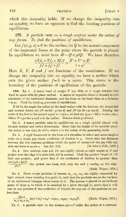
112 FRICTION [CHAP, v
which this inequality holds. If we change the inequality into
an equality, we have an equation to find the limiting positions of
equilibrium.
175. A particle rests on a rough surface under the action of
any forces. To find the positions of equilibrium.
Let f(x, y, z) = be the surface, let Q be the normal componentof the impressed forces at the point where the particle is placed.
In equilibrium we must have R?Qi < ^Q2. We have therefore
Here X, Y, Z and / are functions of the coordinates. If we
change the inequality into an equality, we have a surface which
cuts the given surface /=0 in a curve. This curve is the
boundary of the positions of equilibrium of the particle.
176. Ex. 1. A heavy bead of weight W can slide on a rough circular wire
fixed in space with its plane vertical. A centre of repulsive force is situated at one
extremity of the horizontal diameter, and the force on the bead when at a distance
r is pr. Find the limiting positions of equilibrium.
If 26 be the angle the radius at the bead makes with the horizon, the tangential
and normal forces are (W cos 26 - pr sin 0) and (TFsin 20+pr cos 0). Putting the
ratio of the first to the second equal to tan e, we find sin (y ^ e - 20) cos y sin t,
where W=pa tan y and a is the radius. Discuss these positions.
Ex. 2. A heavy particle rests in equilibrium on a rough cycloid placed with
its axis vertical and vertex downwards. Show that the height of the particle above
the vertex is less than 2a sin2 e, where a is the radius of the generating circle.
Ex. 3. A rigid framework in the form of a rhombus of side a and acute angle a
rests on a rough peg whose coefficient of friction is /x. Prove that the distance
between the two extreme positions which the point of contact of the peg with anyside can have is ap sin a. See Art. 173. [St John's Coll., 1890.]
Ex. 4. Two uniform rods AB, BC are rigidly joined at right angles at B and
project over the edge of a table with AB in contact. Find the greatest length of ABthat can project ;
and prove that if the coefficient of friction be greater than
the system can hang with only the end A resting on the edge.
[Math. Tripos, 1874.]
Ex. 5. Three rough particles of masses m1 ,m2 ,
m3 , are rigidly connected by
light smooth wires meeting in a point O, such that the particles are at the vertices
of an equilateral triangle whose centre is 0. The system is placed on an inclined
plane of slope o, to which it is attached by a pivot through 0; prove that it will
rest in any position if the coefficient of friction for any one of the particles be not
less than
^^(mf+m2
2 + m32 - m2m 3
-m^ -m^b. [Math. Tripos, 1877.]
Ex. 6. A particle rests on the surface xyz = c3 under the action of a constant
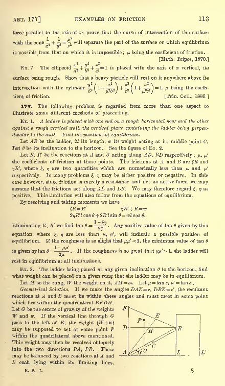
ART. 177] EXAMPLES ON FRICTION 113
force parallel to the axis of z : prove that the curve of intersection of the surface
1 1 u2
with the cone -^ H ,= ^ will separate the part of the surface on which equilibrium
a;2
y'2 z2
is possible from that on which it is impossible ; fj. being the coefficient of friction.
[Math. Tripos, 1870.]
Ex. 7. The ellipsoid -^ + rs + = 1 is placed with the axis of x vertical, itsa2 b- c*
surface being rough. Show that a heavy particle will rest on it anywhere above its
y2 i 2\ z 2 ( a2 \
intersection with the cylinder ~I 1 + -373 ) + n I
1 + -3-5 I =1* /* being the coeffi-
V\ fji-b^J c2 \ M c /cient of friction. [Trin. Coll., 1885.]
177. The following problem is regarded from more than one aspect to
illustrate some different methods of proceeding.
Ex. 1. A ladder is placed with one end on a rough horizontal floor and the other
against a rough vertical wall, the vertical plane containing the ladder being perpen-
dicular to the wall. Find the positions of equilibrium.
Let AB be the ladder, 21 its length, w its weight acting at its middle point C.
Let 6 be its inclination to the horizon. See the figure of Ex. 2.
Let E, R' be the reactions at A and B acting along AD, BD respectively ; /x, ^'
the coefficients of friction at these points. The frictions at A and B are R and
ijR', where , 17are two quantities which are numerically less than /u and
/x.'
respectively. In many problems , 77 may be either positive or negative. In this
case however, since friction is merely a resistance and not an active force, we mayassume that the frictions act along AL and LB. We may therefore regard , ?/ as
positive. This limitation will also follow from the equations of equilibrium.
By resolving and taking moments we have
R=R' f)R' +R =w2r}R'l cos B + 2R'l sin 6= wl cos 0.
Eliminating R, R we find tan = Any positive value of tan 6 given by this
equation, where , rj are less than ft,, /*', will indicate a possible position of
equilibrium. If the roughness is so slight that /*/*' <1, the minimum value of tan
is given by tan 6 '- -. If the roughness is so great that fj.fj.'>l, the ladder will
rest in equilibrium at all inclinations.
Ex. 2. The ladder being placed at any given inclination to the horizon, find
what weight can be placed on a given rung that the ladder may be in equilibrium.
Let M be the rung, W the weight on it, AM=m. Let /*=tan e, /j.'= t&ne'.
Geometrical Solution. If we make the angles DAE e, DBE = e', the resultant
reactions at A and B must lie within these angles and must meet in some pointwhich lies within the quadrilateral EFDH.Let G be the centre of gravity of the weights
W and w. If the vertical line through G
pass to the left of E, the weight (W+w)may be supposed to act at some point Pwithin the quadrilateral above mentioned.
This weight may then be resolved obliquely
into the two directions PA, PB. These
may be balanced by two reactions at A and
B each lying within its limiting lines.
R. S. I. 8
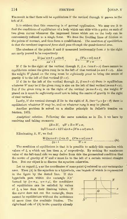
114 FRICTION [CHAP, v
The result is that there will be equilibrium if the vertical through G passes to the
left of E.
It is evident that this reasoning is of general application. We may use it to
find the conditions of equilibrium of a body which can slide with a point on each of
two given curves whenever the impressed forces which act on the body can be
conveniently reduced to a single force. We draw the limiting lines of friction at
the points of contact, and thus form a quadrilateral. The condition of equilibrium
is that the resultant impressed force shall pass through the quadrilateral area.
The abscissas of the points E and G measured horizontally from A to the right
are easily proved to be respectively
_2l (fifj.'cos + /z sin 6) __(Wm + wl) cos
fj.fi' + 1 W+ w
If C lie to the right of the vertical through E, (i.e. lcosB>x) there cannot be
equilibrium unless the given rung lie to the left of that vertical (m cos d<x). Also
the weight W placed on the rung must be sufficiently great to bring the centre of
gravity G to the left of that vertical (x<x).
If C lie to the left of the vertical through E, (lco&0<x) there is equilibrium
whatever W may be if the given rung is also on the left of that vertical (m cos 0<x).But if the given rung is on the right of the vertical (mcos0>o;), the weight Wplaced on it must be sufficiently small not to bring the centre of gravity to the right
of that vertical.
Lastly, if the vertical through E lie to the right of B, (tan-1 /i>ir-0) there is
equilibrium whatever W may be, and on whatever rung it may be placed.
Another problem is solved on a similar principle in Jellett's treatise on
friction, 1872.
Analytical solution. Following the same notation as in Ex. 1 we have by
resolving and taking moments
2i)R'l cos 6 + 2R'l sin 6 =(Wm + wl) cos 6.
Eliminating K, R', we find
2Z (7 cos 6 + g sin 6) _ (Wm + wl) cos
77 + 1 W+wThe condition of equilibrium is that it is possible to satisfy this equation with
values of |, 77 which are less than p, ft.' respectively. By seeking the maximumvalue of the left-hand side we may derive from this the geometrical condition that
the centre of gravity of W and w must lie to the left of a certain vertical straight
line. But our object is to discuss the equation otherwise.
Let us regard |, rj as the coordinates of some point Q referred to any rectangular
axes. Then (A) is the equation to a hyperbola, one branch of which is represented
in the figure by the dotted line. If this
hyperbola pass within the rectangle NN' yformed by =,11, r)=/j.', the conditions
of equilibrium can be satisfied by values
of , T) less than their limiting values. If
the curve does not cut the rectangle, there _cannot be equilibrium without the assistance
of more than the available friction. The "
right-hand side of (A) is the quantity already
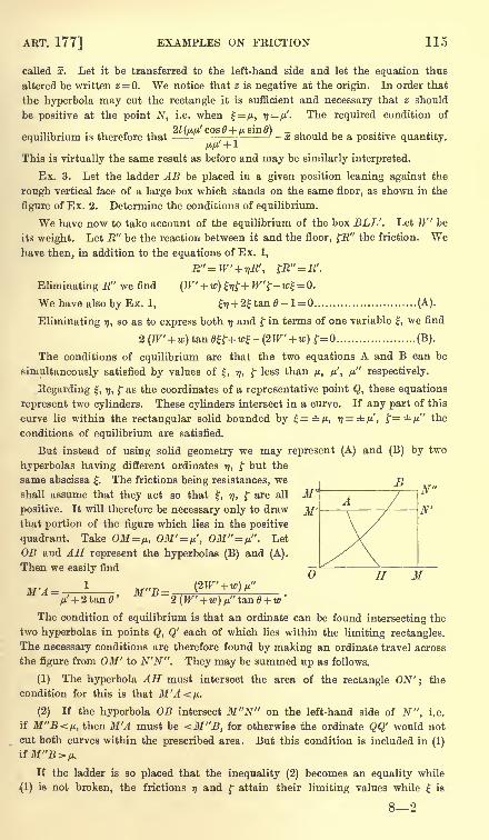
ART. 177] EXAMPLES ON FRICTION 115
called x. Let it be transferred to the left-hand side and let the equation thus
altered be written 2 = 0. We notice that z is negative at the origin. In order that
the hyperbola may cut the rectangle it is sufficient and necessary that z should
be positive at the point N, i.e. when |= /u, ij fj.'.The required condition of
equilibrium is therefore that,
~ -x should be a positive quantity.ftp +1
This is virtually the same result as before and may be similarly interpreted.
Ex. 3. Let the ladder AB be placed in a given position leaning against the
rough vertical face of a large box which stands on the same floor, as shown in the
figure of Ex. 2. Determine the conditions of equilibrium.
We have now to take account of the equilibrium of the box BLL'. Let W be
its weight. Let R" be the reaction between it and the floor, R" the friction. Wehave then, in addition to the equations of Ex. 1,
R"=W' + r,R', R"= R'.
Eliminating R" we find(W + w)&+ W'$ - w% = 0.
We have also by Ex. 1, ij + 2tan 0- 1 = (A).
Eliminating 77, so as to express both 77and f in terms of one variable ,
we find
2(W' + w)tan8K+w-(2W' + w)t=0 (B).
The conditions of equilibrium are that the two equations A and B can be
simultaneously satisfied by values of , 77, f less than p, /*', /j." respectively.
Eegarding , 77, f as the coordinates of a representative point Q, these equations
represent two cylinders. These cylinders intersect in a curve. If any part of this
curve lie within the rectangular solid bounded by =/i, i?=rfc/u', f= yti" the
conditions of equilibrium are satisfied.
But instead of using solid geometry we may represent (A) and (B) by two
hyperbolas having different ordinates 77, f but the
same abscissa . The frictions being resistances, we
shall assume that they act so that , 77, f are all M"positive. It will therefore be necessary only to draw
that portion of the figure which lies in the positive
quadrant. Take OM=n, OM'=n', OM"= fj.". Let
OB and AH represent the hyperbolas (B) and (A).
Then we easily find
N"
N'
(/ H M_ _/u' + 2tan6' 2 (W + w) p"
The condition of equilibrium is that an ordinate can be found intersecting the
two hyperbolas in points Q, Q' each of which lies within the limiting rectangles.
The necessary conditions are therefore found by making an ordinate travel across
the figure from OM' to N'N". They may be summed up as follows.
(1) The hyperbola AH must intersect the area of the rectangle ON'; the
condition for this is that M'A</j..
(2) If the hyperbola OB intersect M"N" on the left-hand side of N", i.e.
if M"B<fj,, then M'A must be <M"B, for otherwise the ordinate QQ' would not
cut both curves within the prescribed area. But this condition is included in (1)
if M"B>fj..
If the ladder is so placed that the inequality (2) becomes an equality while
(1) is not broken, the frictions 77 and f attain their limiting values while is
116 FRICTION [CHAP, v
not limiting, the ladder will therefore be on the point of slipping at its upper
extremity, and the box will be just slipping along the plane.
If the ladder is so placed that the inequality (1) becomes an equality while
(2) is not broken, and ij have their limiting values while f is less than its limit.
The box is therefore fixed and the ladder slips at both ends.
178. Ex. 1. A ladder AB rests against a smooth wall at B and on a rough
horizontal plane at A. A man whose weight is n times that of the ladder climbs
up it. Prove that the frictions at A in the two extreme cases in which the manis at the two ends of the ladder are in the ratio of 2n + 1 to 1.
Ex. 2. A boy of weight tc stands on a sheet of ice and pushes with his hands
against the smooth vertical side of a heavy chair of weight mo. Show that he can
incline his body to the horizon at any angle greater than cot"12/j. or cot"1
2fj.n,
according as the chair or the boy is the heavier, the coefficient of friction between
the ice and boy or the ice and chair being /*. [Queens' Coll.]
Ex. 3. Two hemispheres, of radii a and b, have their bases fixed to a horizontal
plane, and a plank rests symmetrically upon them. If/j.be the coefficient of friction
between the plank and either hemisphere, the other being smooth, prove that, when
the plank is on the point of slipping, the distance of its centre from its point of con-
tact with the smooth hemisphere is equal to (a ~ b)//j,. [St John's Coll., 1885.]
Ex. 4. A heavy rod rests with one end on a horizontal plane and the other
against a vertical wall. To a point in the rod one end of a string is tied, the
other end being fastened to a point in the line of intersection of the plane and
wall. The string and rod are in a vertical plane perpendicular to the wall. Show
that, if the rod make with the horizon an angle a which is less than the complementof 2e, then equilibrium is impossible unless the string make with the horizon an
acute angle less than a + e, where e is the angle of friction both with the wall and
the plane. [Math. Tripos, 1890.]
Ex. 5. A parabolic lamina whose centre of gravity is at its focus rests in a
vertical plane upon two rough rods of the same material at right angles and in the
same vertical plane ; if be the inclination of the directrix to the horizon in one
extreme position of equilibrium, prove that tan2(a-
<p) tan (a + e -<f>)= tan (a
-e) ;
where e is the angle of friction, a the inclination of one rod to the horizon.
[Trin. Coll., 1882.]
Ex. 6. Two rods AC, BC with a smooth hinge at C are placed in a given
position with their extremities A and B resting on a rough horizontal plane. The
plane of the rods being vertical, find the conditions of equilibrium.
Let 0, B' be the inclinations of the rods to the horizon, W and W their weights.
Let (R, R), {R', ijE') be the reactions and frictions at A and B. Resolving and
taking moments in the usual way, we find
W+W W'+W*~ Wt&n 0' + (2W+ W) tan 6
'
'
n~W' tan 6 + (2W+ W) tan e''
If the value of thus found is >n the system will slip at A;
if 17>M it will slip
at B. If the system slip at A only, then >-q ; this gives JFtan 0<W tan 6'.
Ex. 7. A groove is cut in the surface of a flat piece of board. Show that the
form of the groove may be so chosen as to satisfy this condition, that if the board
will just hang in equilibrium upon a rough peg placed at any one point of the
groove, it will also just hang in equilibrium when the peg is placed at any other
point. [Math. Tripos, 1859.]
ART. 178] EXAMPLES ON FRICTION 117
Ex. 8. A lamina is suspended by three strings from a point O ; if the lamina
be rough, and the coefficient of friction between it and a particle P placed upon it
be constant, show that the boundary of possible positions of equilibrium of the
particle on the lamina is a circle. [Math. Tripos, 1880.]
Let ON be a perpendicular on the lamina. Let D be the centre of gravity
of the lamina, G that of the lamina and particle. Then in equilibrium OG is
vertical and NG is the line of greatest slope. The angle NOG is equal to the
inclination of the plane to the horizon and is constant because the equilibrium
is limiting. The locus of G is a circle, centre N. Since DP : DG is constant the
locus of P is also a circle.
Ex. 9. Spheres whose weights are W, W rest on different and differently
inclined planes. The highest points of the spheres are connected by a horizontal
striug perpendicular to the common horizontal edge of the two planes and above it.
If fjL, fjf be the coefficients of friction and be such that each sphere is on the point of
slipping down, then /j.W=(j.'W. [Math. Tripos.]
Consider one sphere : the resultant of T and /J.E balances that of W and R. Bytaking moments about the centre T=jj.R. Hence, by drawing a figure, R = W.
Thus T= /j.W and the result follows.
Ex. 10. A uniform rod passes over one peg and under another, the coefficient
of friction between each peg and the rod being p. The distance between the pegs
is 6, and the straight line joining them makes an angle /3 with the horizon. Show
that equilibrium is not possible unless the length of the rod is >6 {1+ (tan/S)//^}.
[Coll. Ex.]
Ex. 11. A uniform rod ACB, length 2a, is supported against a rough wall by a
string attached to its middle point C : show that the rod can rest with C at any
point of a circular arc, whose extremities are distant a and a cos e from the wall,
where e is the angle of friction. [Take moments about C.]
Ex. 12. Two uniform and equal rods of length 2a have their extremities
rigidly connected, and are inclined to each other at an angle 2a. These rods rest on
a fixed rough cylinder with its axis horizontal, and whose radius is a tan a. Show
that in the limiting position of equilibrium the inclination 6 to the vertical of the
line through the point of intersection of the rods perpendicular to the axis of the
cylinder is given by sin2 a sin 6 = cos (0-e) sin e, where tan e is the coefficient of
friction. [Coll. Ex.]
Ex. 13. Three equal uniform heavy rods AB, BC, CD, hinged at B and C, are
suspended by a light string attached to D from a point E, and hang so that the
end A is on the point of motion, towards the vertical through E, along a roughhorizontal plane (coefficient of friction yit
= tan e) : show that
cos (a-
e) _ cos(/3
-e) _ cos (7
-e) _ n cos (6
-e)
cos a 3 cos /3
""
5 cos 7~
6 cos
where a, /3, y are the inclinations of the rods to the horizon beginning with the
lowest, and 8 that of the string. [Coll. Ex., 1881.]
Take moments about B, C, D, E in succession for the rods AB, AB and BC,and so on. Subtracting each equation from the next in order, the results follow at
once.
Ex. 14. A sphere rests on a rough horizontal plane, and its highest point is
118 FRICTION [CHAP, v
joined to a peg fixed in the plane by a tight cord parallel to the plane. Show that,
if the plane be gradually tilted about a line in it perpendicular to the direction
of the cord, the sphere will not slip until the inclination becomes equal to tan" 1 2p,
where /* is the coefficient of friction. [Math. Tripos, 1886.]
Ex. 15. A uniform hemisphere, placed with its base resting on a rough inclined
plane, is just on the point of sliding down. A light string, attached to the point of
the hemisphere farthest from the plane, is then pulled in a direction parallel to and
directly up the plane. If the tension of the string be gradually increased until
the sphere begins to move, it will slide or tilt according as 13 tan is less or
greater than 8, where <f> is the inclination of the plane to the horizon. The centre
of gravity of the hemisphere is at a distance from the centre equal to three-eighths
of the radius. [Coll. Ex., 1888.]
Ex. 16. A circular disc, of radius a, whose centre of gravity is distant c from
its centre, is placed on two rough pegs in a horizontal line distant 2a sin a apart.
Show that all positions will be possible positions of equilibrium, provided
asinasin(\1 + X2)>csin (2a=FXi ^2)>
where \, \ are the angles of friction at the two pegs. [St John's Coll., 1880.]
Ex. 17. A number of equally rough particles are knotted at intervals on a
string, one end of which is fixed to a point on an inclined plane. Show that, all
the portions of the string being tight, the lowest particle is in its highest possible
position, when they are all in a straight line making an angle sin" 1(tan X/tan a)
with the line of greatest slope, X being the angle of friction and a the inclination
of the plane to the horizon. Show also that, if any portion of the string makethis angle with the line of greatest slope, all the portions below it must do so too.
[Math. Tripos, 1886.]
Ex. 18. A rough paraboloid of revolution, of latus rectum 4a, and of coefficient
of friction cot /3, revolves with uniform angular velocity about its axis which is
vertical : prove that for any given angular velocity greater than (#/2a)4 cot \$ or less
than (<7/2a)4 tan ^/3 a particle can rest anywhere on the surface except within a
certain belt, but that for any intermediate angular velocity equilibrium is possible
at every point of the surface. [Math. Tripos, 1871.]
Let nig be the weight of the particle. It is known by dynamics that we maytreat the paraboloid as if it were fixed in space, provided we regard the particle as
acted on by a force mwV tending directly from the axis, where r is the distance of
the particle from the axis, and u the angular velocity of the paraboloid.
We may prove that the ordinates in the limiting positions of equilibrium are
given by jtw2?/2 -
(2auP-g) y + 2afig=Q. That a belt may exist, the roots of this
quadratic must be real.
Ex. 19. A rod rests partly within and partly without a box in the shape of a
rectangular parallelepiped, presses with one end against the rough vertical side of
the box, and rests in contact with the opposite smooth edge. The weight of the
box being four times that of the rod, show that, if the rod be about to slip and the
box about to tumble at the same instant, the angle the rod makes with the vertical
is X+ cos" 1
(cos X), where X is the angle of friction. [Math. Tripos, 1880.]
Ex. 20. A glass rod is balanced partly in and partly out of a cylindrical tumbler
with the lower end resting against the vertical side of the tumbler. If a and are
ART. 178] EXAMPLES ON FRICTION 119
the greatest and least angles which the rod can make with the vertical, prove that
the angle of friction is \ tan-1
sin 3 a -sin*ft
^ [Math. Tripos, 1875.1sm2 a cos a + sin3 cos
Ex. 21. A heavy rod, of length 21, rests horizontally on the inside roughsurface of a hollow circular cone, the axis of which is vertical and the vertex
downwards. If 2a is the vertical angle of the cone, and if the coefficient of friction fi
is less than cot a, prove that the greatest height of the rod, when in equilibrium,
(1 + cos2 a + sin a Jfsin2 a + 4u2)) iabove the vertex of the cone is I cot a { vr-i >
(2 (1 -ytr'tan-'a) )
[Math. Tripos, 1885.]
Ex. 22. A heavy uniform rod AB is placed inside a rough curve in the form
of a parabola whose focus is S and axis vertical. Prove that, when it is on the pointof slipping downwards, the angle of friction is J (SAB - SBA). [Coll. Ex., 1889.]
Ex. 23. A rod MN rests with its ends in two fixed straight rough grooves OA ,
OB, in the same vertical plane, which makes angles a and /3 with the horizon : prove
that, when the end M is on the point of slipping down AO, the tangent of the
inclination of MN to the horizon is 7. 7^ -. T-* ; . [Math. Tripos, 1876.]2 sin (/3 + e) sm (a
-e)
Ex. 24. A uniform rectangular board ABCD rests with the corner A against
a rough vertical wall and its side EC on a smooth peg, the plane of the board being
vertical and perpendicular to that of the wall. Show that, without disturbing the
equilibrium, the peg may be moved through a space /J.CQS a (a cos a + b sin a) along
the side with which it is in contact, provided the coefficient of friction(/j.)
lie
between certain limits;a being the angle BC makes with the wall, and a, b the
lengths of AB, BC respectively. Also find the limits of M- [Math. T., 1880.]
Ex. 25. An elliptical cylinder, placed in contact with a vertical wall and a
horizontal plane, is just on the point of motion when its major axis is inclined at an
angle a to the horizon. Determine the relation between the coefficients of friction
of the wall and plane ; and show from your result that, if the wall be smooth, and
a be equal to 45, the coefficient of friction between the plane and cylinder will be
equal to ^e2
, where e is the eccentricity of the transverse section of the cylinder.
[Math. Tripos, 1883.]
Ex. 26. A rough elliptic cylinder rests, wiih its axis horizontal, upon the ground
and against a vertical wall, the ground and the wall being equally rough ;show that
the cylinder will be on the point of slipping when its major axis plane is inclined at
an angle of jr/4 to the vertical if the square of the eccentricity of its principal
section be 2 sin e (sin e + cose), where e is the angle of friction. [Coll. Ex., 1885.]
Ex. 27. Three uniform rods of lengths a, b, c are rigidly connected to form
a triangle ABC, which is hung over a rough peg so that the side BC may rest
in contact with it;
find the length of the portion of the rod over which the peg
may range, showing that, if M>^TT r^ cosec C+ tan \ (C-B), where C>B, theO (0 -f- C)
triangle will rest in any position. [Math. Tripos, 1887.]
Ex. 28. A waggon, with four equal wheels on smooth axles whose plane
contains the centre of gravity, rests on the rough surface of a fixed horizontal
circular cylinder, the axles being parallel to the axis of the cylinder ; investigate
the pressures on the wheels, and prove that the inclination to the horizontal of the
plane containing the axles is tan" 1{tan a (w
-w')/W}, where w, w' are the weights
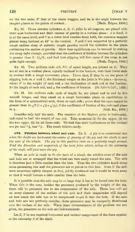
120 FRICTION [CHAP, v
on the two axles, W that of the whole waggon, and 2a is the angle between the
tangent planes at the points of contact. [Math. Tripos, 1888.]
Ex. 29. Three circular cylinders A, B, C, alike in all respects, are placed with
their axes horizontal and their centres of gravity in a vertical plane ; A is fixed, Bis at the same level, and C at a lower level touches them both, the common tangent
planes being inclined at 45 to the vertical. B and C are supported by a perfectly
rough endless strap of suitable length passing round the cylinders in the plane
containing the centres of gravity. Show that equilibrium can be secured by makingthe strap tight enough, provided that the coefficient of friction between the cylinders
is greater than 1 - l/v'2 ; and find how slipping will first occur if the strap is not
quite tight enough. [Math. Tripos, 1888.]
Ex. 30. Two uniform rods AB, BC, of equal length, are jointed at B. Theyare at rest in a vertical plane, equally inclined to the horizon, with their lower ends
in contact with a rough horizontal plane. Prove that, if they be on the point of
slipping both at A and C, the frictional couple at the joint is Wa (sin a-
2/n cos a),
where W is the weight of each rod, a the inclination of each rod to the horizon,
2a the length of each rod, and p the coefficient of friction. [St John's Coll., 1890.]
Ex. 31. Six uniform rods, each of length 2a, are joined end to end by five
smooth hinges, and they stand on a rough horizontal plane in equilibrium in
the form of a symmetrical arch, three on each side ; prove that the span cannot be
greater than 2a J2 (l + v'i + \/iV)' ^ ^e coefficient of friction of the rods and plane
be. [Coll. Ex., 1886.]
Consider only half the arch. The reaction at the highest point is horizontal,
and equal to half the weight of one rod. Take moments (1) for the upper, (2) for
the two upper, (3) for all three rods. We find that their inclinations to the vertical
are Jir, tan-1, tan" 1
1. The result follows easily.
179. Friction between wheel and axle. Ex. 1. A gig is so constructed that
when the shafts are horizontal the centre of gravity of the gig and tlie shafts is over
the axle of the wheels. The. gig in this position rests on a perfectly rough around.
Find the direction and magnitude of the least force which, acting at the extremity
of the shaft, will just move the gig.
When an axle is made to fit the nave of a wheel, the relative sizes of the axle
and hole are so arranged that the wheel can turn easily round the axle. The axle
is therefore just a little smaller than the hole. Thus the two cylinders touch along
some generating line and the pressures act at points in this line. Even if the axle
were somewhat tightly clasped at first, yet by continued use it would be worn awayso that it would become a little smaller than the hole.
It is possible that the axle may be so large that it has to be forced into the hole.
When this is the case, besides the pressures produced by the weight of the gig,
there will be pressures due to the compression of the axle. These last will act
on every element of the surface of the axle and their magnitudes will dependon how much the axle has to be compressed to get it into the hole. If the axle
and hole are not perfectly circular, these pressures may be unequally distributed
over the surface of the axle. When these circumstances of the problem are not
given, the pressures on the axle are indeterminate.
Let X, Y be the required horizontal and vertical components of the force applied
at the extremity S of the shaft.
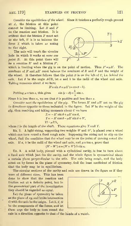
ART. 179] EXAMPLES ON FRICTION 121
Consider the equilibrium of the wheel. Since it touches a perfectly rough ground
at A, the friction at this point
cannot be limiting. Let E and Fbe the reaction and friction. It is
evident that the friction F must act
to the left, if it is to balance the
force X which is taken as acting
to the right.
The axle will touch the circular
hole in which it works at some one
point B. At this point there will
be a reaction R' and a friction F',
which is limiting when the gig is on the point of motion. Thus F'=fj.R'. The
resultant of R and pR' must balance the resultant of R and F and the weight of
the wheel. It therefore follows that the point B is on the left of C, i.e. behind the
axle. Let 6 be the angle ACB, let a and b be the radii of the wheel and axle.
Taking moments about A we have
R'a sin = uR r
(a cos 0-b).
Putting /j.= t&n e, this gives sin (e
-6)= - sin e.
Since b is less than a, we see that 6 is positive and less than e.
Consider next the equilibrium of the gig. The forces R' and p.R' act on the gig
in directions opposite to those indicated in the figure. Let W be the weight of the
gig, then resolving and taking moments about C we have
X= -R' sin0 + /jH'coa0,
Y- - R' cos - uR' sin + W,
Yl=uR'b,where I is the length of the shaft. These equations give X and Y.
Ex. 2. A light string, supporting two weights W and W, is placed over a wheel
which can turn round a fixed rough axle. Supposing the string not to slip on the
wheel, find the condition that the wheel may be on the point of turning round the
axle. If a, b be the radii of the wheel and axle, and /*=tan e, prove that
(W- W) a=(W+ W) b sin e.
Ex. 3. A solid body, pierced with a cylindrical cavity, is free to turn about
a fixed axle which just fits the cavity, and the whole figure is symmetrical about
a certain plane perpendicular to the axle. The axle being rough, and the bodyacted on by forces in the plane of symmetry, find the least coefficient of friction
that the body may be in equilibrium.
The circular sections of the cavity and axle are drawn in the figure as if they
were of different sizes. This has been
done to show that the reaction and
friction act at a definite point, but in
the geometrical part of the investigation
they should be regarded as equal.
Let the plane of symmetry be taken
as the plane of xy, and let its intersection
O with the axis be the origin. LetZ, Y, Gbe the components of the forces, and let
these urge the body to turn round the
axis in a direction opposite to that of the hands of a watch.
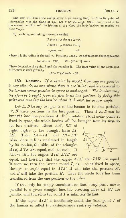
122 FRICTION [CHAP, v
The axle will touch the cavity along a generating line, let B be its point of
intersection with the plane of xy. Let 6 be the angle BOx. Let R and F bethe normal reaction and the friction at B
; when the body borders on motion we
By resolving and taking moments we find
E (sin0-yu,cos0) + F=0,
-fjJta +G =0,
where a is the radius of the cavity. Putting /*- tan e, we deduce from these equations
tan (<?-e)= YjX, R2= (X
3+ F2)cos2 e.
These determine the point B and the reaction R. The least value of the coefficient
of friction is then given by
180. Lemma. If a lamina be moved from any one positionto any other in its own plane, there is one point rigidly connected to
the lamina whose position in space is unchanged. The lamina maytherefore be brought from its first to its last position by fixing this
point and rotating the lamina about it through the proper angle.
Let A, B be any two points in the lamina in its first position,
A', B' their positions in the last position. Then if A, B can be
brought into the positions A', B' by rotation about some point /,
fixed in space, the whole lamina will be brought from its first to
its last position. Bisect AA, BB' at
right angles by the straight lines LI,
MI. Then IA =IA f
,and IB = IB'.
Also, since AB is unaltered in length
by its motion, the sides of the triangles
AIB, A'IB' are equal, each to each. It
follows that the angles AIB, A'lB' are
equal, and therefore that the angles AIA and BIB' are equal.
If then we turn the lamina round J, as a point fixed in space,
through an angle equal to AIA', A will take the position A',
and B will take the position B'. Thus the whole body has been
transferred from the one position to the other.
If the body be simply translated, so that every point moves
parallel to a given straight line, the bisecting lines LI, MI are
parallel, and therefore the point / is infinitely distant.
If the angle AIA' is indefinitely small, the fixed point / of
the lamina is called the instantaneous centre of rotation.
ART. 181] LAWS OF FRICTION 123
181. Frictions in unknown directions. We are now
prepared to make a step towards the generalization of the laws
of friction. Let us suppose a heavy body to rest on a rough hori-
zontal table on n supports. Let these points be A-i, A z ,...An ,and
let the pressures at these points be P,, P2 ,...PW . We shall also
suppose the body to be acted on by a couple and a force applied at
some convenient base of reference, the forces being all parallel to
the table. To resist these forces a frictional force is called into
play at each point of support. The directions and magnitudes of
these frictional forces are unknown, except that the magnitude of
each is less than the limiting friction, and the direction is opposedto the resultant of all the external and molecular forces which act
on that point of support. If the pressures Pl ,...Pn are known,there are thus 2n unknown quantities, and there are only three
equations of equilibrium. The frictions at the points of support
are therefore generally indeterminate.
By calling the frictions indeterminate we mean that there are
different ways of arranging forces at the points of support which
could balance the given forces and which might be frictional
forces. Which of these is the true arrangement of the frictional
forces depends on the manner in which the body, regarded as
partially elastic, begins to yield to the forces. Suppose, for
example, a force Q to act at a point B of the body, and to be
gradually increased in magnitude. The frictions on the points
of support nearest to B will at first be sufficient to balance
the force, but, as Q gradually increases, the frictions at these
points may attain their limiting values. As soon as they beginto yield, the frictions at the neighbouring points will be called
into play, and so on throughout the body.When the external forces are insufficient to move the body as
a whole, the directions and magnitudes of the frictions at the
points of support depend on the manner in which the body yields,
however slight that yielding may be. Even if the external forces
were absent, the body could be placed in a state of constraint
and might be maintained in that state by the frictions. Thus the
frictions depend on the initial state of constraint as well as on
the.external forces. It is also possible that the body, though
apparently at rest, may be performing small oscillations about
some position of stable equilibrium. This might cause other
changes in the frictions.
124 FRICTION [CHAP, v
182. Limiting Equilibrium. Let us now suppose that
the external forces have been gradually increased according to
some given 'law until the whole body is on the point of motion.
By this we mean that the least diminution of roughness or the
least increase of the forces will cause the body to move. We mayenquire what is the condition that these forces may be just great
enough to move the body, or just small enough not to move it.
When the body is just beginning to move, the arrangement of
the frictional forces is somewhat simplified. We suppose the
body to be so nearly rigid that the distances between the
several particles do not sensibly change. Thus their motions
are not independent, but are sensibly governed by the law provedin the lemma of Art. 180. The directions of the frictions, also,
being opposite to the directions of the motions, are governed bythe same law.
It will be seen from what follows that, when a rigid body turns round an
instantaneous axis, the friction at every point of support acts in the direction which
is most effective to prevent motion. If, therefore, the frictional forces thus arranged
are insufficient to prevent motion, there is no other arrangement by which they
can effect that result.
If the body move on a horizontal plane, no matter how
slightly, it must be turning about some vertical axis; let this
vertical axis intersect the plane in the point /. There are then
two cases to be considered, (1) the point / may not coincide with
any one of the points of support, and (2) it may coincide with
some one of them.
Let us take these cases in order. The position of / is un-
known;
let its coordinates be, rj referred to any axes in the plane
of the table. The points Ai,...A n are all beginning to move each
perpendicular to the straight line which joins it to the point /.
The frictions at these points will therefore be known when / is
known. Their directions are perpendicular to IA lt IA 2 , &c., and
they all act the same way round /. Their magnitudes are ^Pi,
yu.2P2 > &c-, if /*i, /*2, &c. are the coefficients of friction. Since the
impressed forces only just overbalance the frictions, we may regardthe whole as in equilibrium. Forming then the three equations of
equilibrium, we have sufficient equations to find both , 77 and
the condition that the body should be on the point of motion.
It may be that these equations do not give any available values
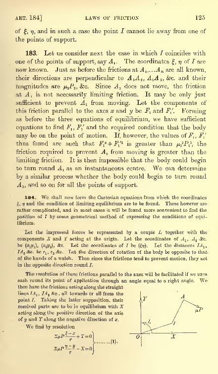
ART. 184] LAWS OF FRICTION 125
of, r), and in such a case the point / cannot lie away from one of
the points of support.
183. Let us consider next the case in which / coincides with
one of the points of support, say A 1 . The coordinates, rj of / are
now known. Just as before the frictions at A^,...An are all known,
their directions are perpendicular to A^^, A^A^, &c. and their
magnitudes are p^Pz ,&c. Since A^ does not move, the friction
at A! is not necessarily limiting friction. It may be only just
sufficient to prevent A l from moving. Let the components of
this friction parallel to the axes x and y be F^ and FJ. Formingas before the three equations of equilibrium, we have sufficient
equations to find F1} Fj and the required condition that the body
may be on the point of motion. If, however, the values of F1} F-[
thus found are such that F^ + F^'2
is greater than fi^Pi, the
friction required to prevent A 1 from moving is greater than the
limiting friction. It is then impossible that the body could beginto turn round A 1 as an instantaneous centre. We can determine
by a similar process whether the body could begin to turn round
A 2 ,and so on for all the points of support.
184. We shall now form the Cartesian equations from which the coordinates
|, 77 and the condition of limiting equilibrium are to be found. These however are
rather complicated, and in most cases it will be found more convenient to find the
position of I by some geometrical method of expressing the conditions of equi-
librium.
Let the impressed forces be represented by a couple L together with the
components X and Y acting at the origin. Let the coordinates of Alt Az &c.
be (#!?/!), (#22/2)' *c - Let the coordinates of / be (17). Let the distances IA lt .
lA^ &c. beT-J,
r2 &c. Let the direction of rotation of the body be opposite to that
of the hands of a watch. Then since the frictions tend to prevent motion, they act
in the opposite direction round J.
The resolution of these frictions parallel to the axes will be facilitated if we turn
each round its point of application through an angle equal to a right angle. Wethen have the frictions acting along the straight
lines IA lt IA 2 &c., all towards or all from the
point I. Taking the latter supposition, their
resolved parts are to be in equilibrium with Xacting along the positive direction of the axis
of y and Y along the negative direction of x.
We find by resolution
.(1).
126 FRICTION [CHAP, v
The equation of moments must be formed without changing the directions of the
frictions. Taking moments about I, we have
ZvPr+Y-Xr,-L = Q ................................. (2).
If the instantaneous centre I coincide with A lt the equations are only slightly
altered. We write (x^j^ for (rj), F1and -
Fj1
for ^P^ - andfj.1P
l- 1
,and
ri
ri
finally omit the term ^P^ in the moment.
185. The Minimum Method. There is another way of discussing these
equations which will more clearly explain the connection between the two cases. If
the body is just beginning to turn about some instantaneous axis, it would begin to
turn about that axis if it were fixed in space. Let then 7 be any point on the plane
of xy and let us enquire whether the body can begin to turn about the vertical
through I as an axis fixed in space. Supposing all the friction to be called into
play, the moment of the forces round I, measured in the direction in which the
frictions act, is u= 2/j.Pr+ Y| - Xrj- L.
If, in any position of I, u is negative, the moment of the forces is more powerful
than that of the frictions;the body will therefore begin to move. If on the other
hand u is positive, the moment of the frictions is more powerful than that of the forces,
and the body could be kept at rest by less than the limiting frictions. Let us find
the position of I which makes u a minimum. If in this position M is positive or
zero, there is no point I about which the body can begin to turn.
To make u a minimum we equate to zero the differential coefficients of u with
regard to, rj. Since r2= (x
-)
2 + (y-
ij)
2,the equations thus formed are exactly
the equations (1) already written down in Art. 184.
The statical meaning of these equations is that the pressures on the axis which
has been fixed in space are zero when that axis has been so chosen that u is a
minimum. If this is not evident, let Bx and Ry be the resolved pressures on the
axis. The resolved parts parallel to the axes of the impressed forces and the
frictions together with Rx &ndEy must then be zero. But the equations (1) express
the fact that these resolved parts without Ex and Ry are zero. It evidently follows
that both Ex and Ey are zero.
That this position of I makes u a minimum and not a maximum may be shown
analytically by finding the second differential coefficients of u with regard to and
i\. The terms of the second order are then found to be
where the 2 implies summation for all the points A lt A 2 , &c. Since each of these
squares is positive, it must be a minimum.
It appears therefore that the axis about which the body will begin to turn may be
found by making the moment (viz. u) of the forces about that axis a minimum ; and
the condition that the forces are only just sufficient to move the body is found by
equating to zero the least value thus found.
186. The quantities rlf r2 ,
&c. are necessarily positive, and therefore not
capable of unlimited decrease. Besides the minima found by the rules of the
differential calculus, other maxima or minima may be found by making some one
of the quantities r1 , r2 , &c. equal to zero.
Suppose M to be a minimum when ^ = 0, i.e. when the point I coincides with Al .
Take A1 as the origin of coordinates. Let I receive a small displacement from
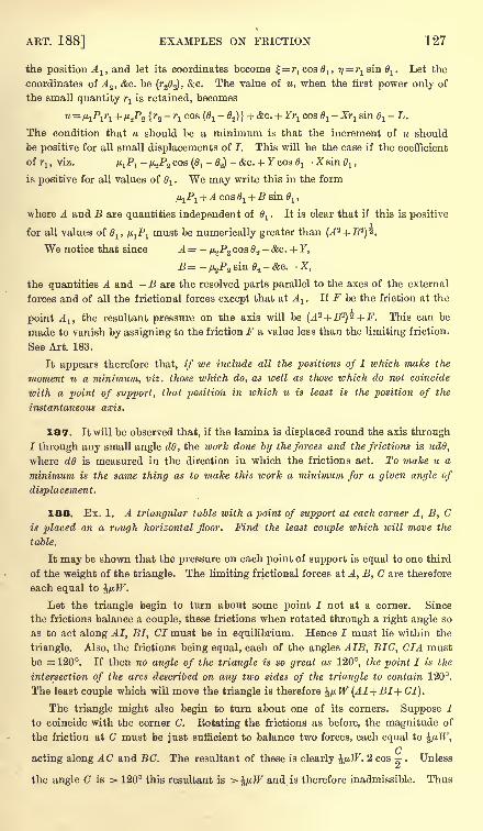
ART. 188] EXAMPLES ON FRICTION 127
the position A lt and let its coordinates become ^=^008^, 7?= r
1 sin^1. Let the
coordinates of A s ,&c. be (r2 2), &c. The value of u, when the first power only of
the small quantity r is retained, becomes
u=fj,lP
1r1 + u2P2 \r2 -r1
cos (01- 62)} +&c. + Yr-jcos 6
1-Xi^sin 61
- L.
The condition that u should be a minimum is that the increment of u should
be positive for all small displacements of I. This will be the case if the coefficient
of7-j ,
viz. JJ^P!-fj^P2 cos (0j
-62)
- &c. + Ycosffl-X sin d
l ,
is positive for all values of d1. We may write this in the form
^Pj +A cos 1 + B sin 0^ ,
where A and B are quantities independent of 61
. It is clear that if this is positive
for all values of 6lt /j.1P
lmust be numerically greater than (A* +B2
)*.
We notice that since A = -/ 2P2 cos 2
- &c. + F,
B = -/J^PZ sin 8.2
- &c. - X,
the quantities A and - B are the resolved parts parallel to the axes of the external
forces and of all the frictional forces except that at A1
. If F be the friction at the
point A lt the resultant pressure on the axis will be (A2 + B2
)z + F. This can be
made to vanish by assigning to the friction F a value less than the limiting friction.
See Art. 183.
It appears therefore that, if we include all the positions of I which make the
moment u a minimum, viz. those ivhich do, as well as those which do not coincide
with a point of support, that position in which u is least is the position of the
instantaneous axis.
187. It will be observed that, if the lamina is displaced round the axis through
/through any small angle dO, the work done by the forces and the frictions is udO,
where d6 is measured in the direction in which the frictions act. To make u a
minimum is the same thing as to make this work a minimum for a given angle of
displacement.
188. Ex. 1. A triangular table with a point of support at each corner A, B, Cis placed on a rough horizontal floor. Find the least couple which will move the
table.
It may be shown that the pressure on each point of support is equal to one third
of the weight of the triangle. The limiting fractional forces at A, B, C are therefore
each equal to ^iiW.
Let the triangle begin to turn about some point I not at a corner. Since
the frictions balance a couple, these frictions when rotated through a right angle so
as to act along AI, BI, CI must be in equilibrium. Hence I must lie within the
triangle. Also, the frictions being equal, each of the angles AIB, BIG, CIA must
be = 120. If then no angle of the triangle is so great as 120, the point I is the
intersection of the arcs described on any two sides of the triangle to contain 120.
The least couple which will move the triangle is therefore J^tW (AI+BI+ GI).
The triangle might also begin to turn about one of its corners. Suppose I
to coincide with the corner C. Rotating the frictions as before, the magnitude of
the friction at C must be just sufficient to balance two forces, each equal to ^/J.W,
Qacting along AC and B C. The resultant of these is clearly /tJF. 2 cos . Unless
SB
the angle C is > 120 this resultant is > J/xJF and is therefore inadmissible. Thus
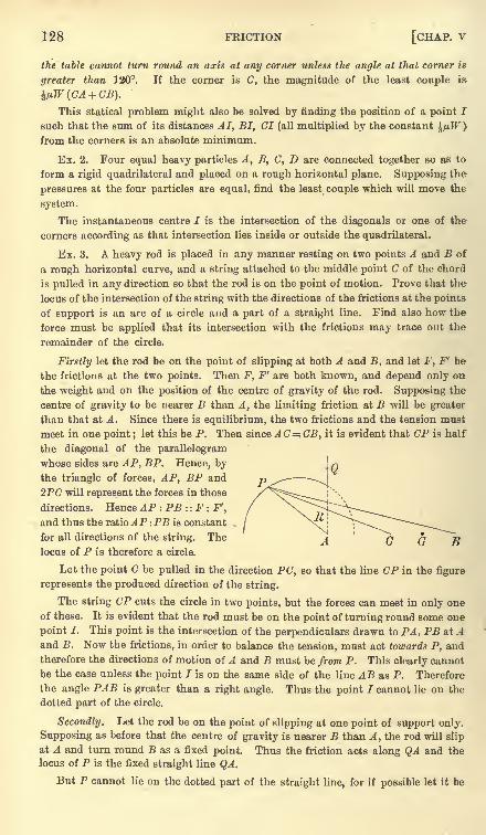
128 FRICTION [CHAP, v
the table cannot turn round an axis at any corner unless the angle at that corner is
greater than 120. If the corner is C, the magnitude of the least couple is
This statical problem might also be solved by finding the position of a point I
such that the sum of its distances AI, BI, CI (all multiplied by the constant ^fj.W)
from the corners is an absolute minimum.
Ex. 2. Four equal heavy particles A, B, C, D are connected together so as to
form a rigid quadrilateral and placed on a rough horizontal plane. Supposing the
pressures at the four particles are equal, find the least couple which will move the
system.
The instantaneous centre / is the intersection of the diagonals or one of the
corners according as that intersection lies inside or outside the quadrilateral.
Ex. 3. A heavy rod is placed in any manner resting on two points A and B of
a rough horizontal curve, and a string attached to the middle point C of the chord
is pulled in any direction so that the rod is on the point of motion. Prove that the
locus of the intersection of the string with the directions of the frictions at the points
of support is an arc of a circle and a part of a straight line. Find also how tbe
force must be applied that its intersection with the frictions may trace out the
remainder of the circle.
Firstly let the rod be on the point of slipping at both A and B, and let F, F' be
the frictions at the two points. Then F, F' are both known, and depend only on
the weight and on the position of the centre of gravity of the rod. Supposing the
centre of gravity to be nearer B than A, the limiting friction at B will be greater
than that at A. Since there is equilibrium, the two frictions and the tension must
meet in one point ; let this be P. Then since AC=.CB, it is evident that CP is half
the diagonal of the parallelogram
whose sides are AP, BP. Hence, bythe triangle of forces, AP, BP and
2PC will represent the forces in those
directions. Hence AP : PB : : F : F',
and thus the ratioAP :PB is constant
for all directions of the string. The
locus of P is therefore a circle.
Let the point C be pulled in the direction PC, so that the line CP in the figure
represents the produced direction of the string.
The string CP cuts the circle in two points, but the forces can meet in only one
of these. It is evident that the rod must be on the point of turning round some one
point I. This point is the intersection of the perpendiculars drawn to PA, PB at Aand B. Now the frictions, in order to balance the tension, must act towards P, andtherefore the directions of motion of A and B must be from P. This clearly cannot
be the case unless the point I is on the same side of the line AB as P. Therefore
the angle PAB is greater than a right angle. Thus the point 7 cannot lie on the
dotted part of the circle.
Secondly. Let the rod be on the point of slipping at one point of support only.
Supposing as before that the centre of gravity is nearer B than A, the rod will slip
at A and turn round B as a fixed point. Thus the friction acts along QA and the
locus of P is the fixed straight line QA.
But P cannot lie on the dotted part of the straight line, for if possible let it be
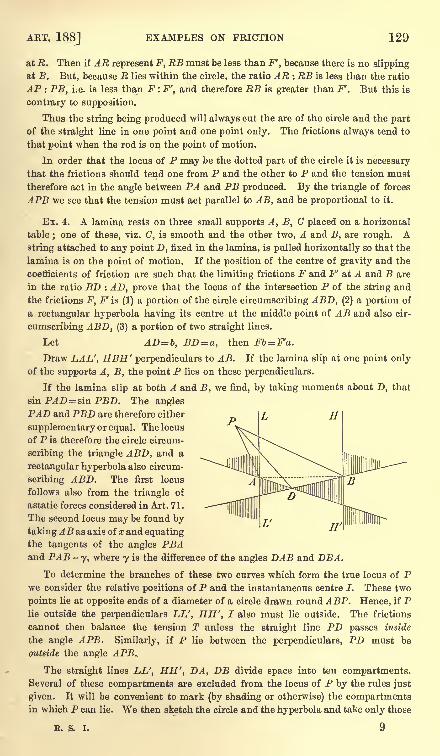
ART. 188] EXAMPLES ON FRICTION 129
at R. Then if AE represent F, RB must be less than F', because there is no slipping
at B. But, because R lies within the circle, the ratio AR : RB is less than the ratio
AP : PB, i.e. is less than F : F', and therefore RB is greater than F'. But this is
contrary to supposition.
Thus the string being produced will always cut the arc of the circle and the part
of the straight line in one point and one point only. The frictions always tend to
that point when the rod is on the point of motion.
In order that the locus of P may be the dotted part of the circle it is necessary
that the frictions should tend one from P and the other to P and the tension must
therefore act in the angle between PA and PB produced. By the triangle of forces
APB we see that the tension must act parallel to AB, and be proportional to it.
Ex. 4. A lamina rests on three small supports A, B, C placed on a horizontal
table; one of these, viz. C, is smooth and the other two, A and B, are rough. A
string attached to any point D, fixed in the lamina, is pulled horizontally so that the
lamina is on the point of motion. If the position of the centre of gravity and the
coefficients of friction are such that the limiting frictions F and F' at A and B are
in the ratio BD : AD, prove that the locus of the intersection P of the string and
the frictions F, F is (1) a portion of the circle circumscribing ABD, (2) a portion of
a rectangular hyperbola having its centre at the middle point of AB and also cir-
cumscribing ABD, (3) a portion of two straight lines.
Let AD= b, BD = a, then Fb=F'a.
Draw LAL', HBH' perpendiculars to AB. If the lamina slip at one point onlyof the supports A, B, the point P lies on these perpendiculars.
If the lamina slip at both A and B, we find, by taking moments about D, that
sinP^D^sinPP-D. The angles
PAD and PBD are therefore either
supplementary or equal. The locus
of P is therefore the circle circum-
scribing the triangle ABD, and a
rectangular hyperbola also circum-
scribing ABD. The first locus
follows also from the triangle of
astatic forces considered in Art. 71.
The second locus may be found by
taking AB as axis of a; and equatingthe tangents of the angles PBAand PAB -
y, where 7 is the difference of the angles DAB and DBA.
To determine the branches of these two curves which form the true locus of Pwe consider the relative positions of P and the instantaneous centre I. These two
points lie at opposite ends of a diameter of a circle drawn round ABP. Hence, if Plie outside the perpendiculars LL', HH', I also must lie outside. The frictions
cannot then balance the tension T unless the straight line PD passes inside
the angle APB. Similarly, if P lie between the perpendiculars, PD must be
outside the angle APB..
The straight lines LL', HH', DA, DB divide space into ten compartments.Several of these compartments are excluded from the locus of P by the rules just
given. It will be convenient to mark (by shading or otherwise) the compartmentsin which P can lie. We then sketch the circle and the hyperbola and take only those
R. S. I. 9
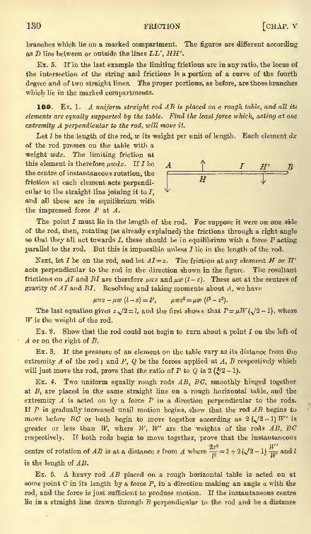
130 FRICTION [CHAP, v
branches which lie on a marked compartment. The figures are different according
as D lies between or outside the lines LL', HH'.
Ex. 5. If in the last example the limiting frictions are in any ratio, the locus of
the intersection of the string and frictions is a portion of a curve of the fourth
degree and of two straight lines. The proper portions, as before, are those branches
which lie in the marked compartments.
189. Ex. 1. A uniform straight rod AB is placed on a rough table, and all its
elements are equally supported by the table. Find the least force which, acting at one
extremity A perpendicular to the rod, will move it.
Let I be the length of the rod, w its weight per unit of length. Each element dx
of the rod presses on the table with a
weight wax. The limiting friction at
this element is therefore picdx. If I be A ^ j ri, nthe centre of instantaneous rotation, the r ,- ~3
TTfriction at each element acts perpendi-cular to the straight line joining it to I,
**
and all these are in equilibrium with
the impressed force P at A.
The point I must lie in the length of the rod. For suppose it were on one side
of the rod, then, rotating (as already explained) the frictions through a right angleso that they all act towards I, these should be in equilibrium with a force P acting
parallel to the rod. But this is impossible unless I lie in the length of the rod.
Next, let I be on the rod, and let AI=z. The friction at any element H or H'acts perpendicular to the rod in the direction shown in the figure. The resultant
frictions on AI and BI are therefore nwz and pw (I-
z). These act at the centres of
gravity of AI and BI. Resolving and taking moments about A, we have
/J.WZ /J.W (l z)=P, fJ.WZZ= fiW (I? 22
).
The last equation gives z *J2 = l, and the first shows that P=/xTf(v/2- 1), where
W is the weight of the rod.
Ex. 2. Show that the rod could not begin to turn about a point I on the left of
A or on the right of B.
Ex. 3. If the pressure of an element on the table vary as its distance from the
extremity A of the rod ; and P, Q be the forces applied at A, B respectively which
will just move the rod, prove that the ratio of P to Q is 2 (^/2-
1).
Ex. 4. Two uniform equally rough rods AB, BC, smoothly hinged together
at B, are placed in the same straight line on a rough horizontal table, and the
extremity A is acted on by a force P in a direction perpendicular to the rods.
If P is gradually increased until motion begins, show that the rod AB begins to
move before BC or both begin to move together according as 2 (^2 -1)W is
greater or less than W, where W, W are the weights of the rods AB, BCrespectively. If both rods begin to move together, prove that the instantaneous
2z2 W'centre of rotation of AB is at a distance z from A where ^ = 1 + 2 (^2 - 1) -== and I
is the length of AB.
Ex. 5. A heavy rod AB placed on a rough horizontal table is acted on at
some point C in its length by a force P, in a direction making an angle a with the
rod, and the force is just sufficient to produce motion. If the instantaneous centre
lie in a straight line drawn through B perpendicular to the rod and be a distance
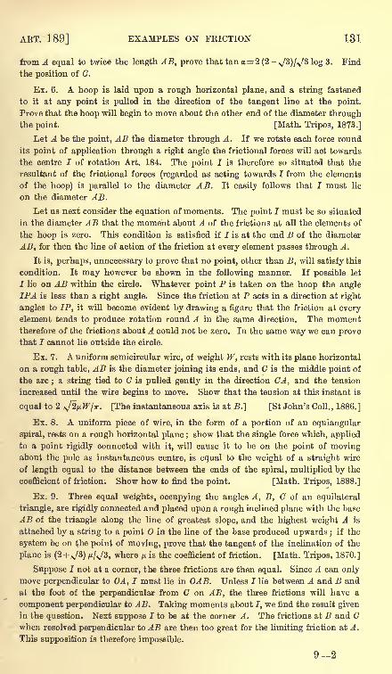
ART. 189] EXAMPLES ON FRICTION 131
from A equal to twice the length AB, prove that tan a= 2 (2-*jS)[*jS log 3. Find
the position of C.
Ex. 6. A hoop is laid upon a rough horizontal plane, and a string fastened
to it at any point is pulled in the direction of the tangent line at the point.
Prove that the hoop will begin to move about the other end of the diameter throughthe point. [Math. Tripos, 1873.]
Let A be the point, AB the diameter through A. If we rotate each force round
its point of application through a right angle the frictional forces will act towards
the centre I of rotation Art. 184. The point 7 is therefore so situated that the
resultant of the frictional forces (regarded as acting towards I from the elements
of the hoop) is parallel to the diameter AB. It easily follows that I must lie
on the diameter AB.
Let us next consider the equation of moments. The point I must be so situated
in the diameter AB that the moment about A of the frictions at all the elements of
the hoop is zero. This condition is satisfied if I is at the end B of the diameter
AB, for then the line of action of the friction at every element passes through A.
It is, perhaps, unnecessary to prove that no point, other than B, will satisfy this
condition. It may however be shown in the following manner. If possible let
I lie on AB within the circle. Whatever point P is taken on the hoop the angle
IPA is less than a right angle. Since the friction at P acts in a direction at right
angles to IP, it will become evident by drawing a figure that the friction at everyelement tends to produce rotation round A in the same direction. The momenttherefore of the frictions about A could not be zero. In the same way we can provethat I cannot lie outside the circle.
Ex. 7. A uniform semicircular wire, of weight W, rests with its plane horizontal
on a rough table, AB is the diameter joining its ends, and G is the middle point of
the arc ; a string tied to C is pulled gently in the direction CA, and the tension
increased until the wire begins to move. Show that the tension at this instant is
equal to 2 A/2/uIF/Tr. [The instantaneous axis is at B.] [St John's Coll., 1886.]
Ex. 8. A uniform piece of wire, in the form of a portion of an equiangular
spiral, rests on a rough horizontal plane ; show that the single force which, applied
to a point rigidly connected with it, will cause it to be on the point of movingabout the pole as instantaneous centre, is equal to the weight of a straight wire
of length equal to the distance between the ends of the spiral, multiplied by the
coefficient of friction. Show how to find the point. [Math. Tripos, 1888.]
Ex. 9. Three equal weights, occupying the angles A, B, C of an equilateral
triangle, are rigidly connected and placed upon a rough inclined plane with the base
AB of the triangle along the line of greatest slope, and the highest weight A is
attached by a string to a point in the line of the base produced upwards ;if the
system be on the point of moving, prove that the tangent of the inclination of the
plane is (2 + ^/3) /u/,/3, where p. is the coefficient of friction. [Math. Tripos, 1870.]
Suppose I not at a corner, the three frictions are then equal. Since A can only
move perpendicular to OA, I must lie in OAB. Unless I lie between A and B and
at the foot of the perpendicular from C on AB, the three frictions will have a
component perpendicular to AB. Taking moments about I, we find the result given
in the question. Next suppose I to be at the corner A. The frictions at B and Cwhen resolved perpendicular to AB are then too great for the limiting friction at A.
This supposition is therefore impossible.
92
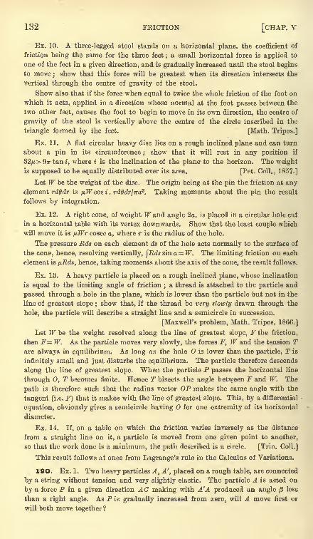
132 FRICTION [CHAP, v
Ex. 10. A three-legged stool stands on a horizontal plane, the coefficient of
friction being the same for the three feet ; a small horizontal force is applied to
one of the feet in a given direction, and is gradually increased until the stool begins
to move;show that this force will be greatest when its direction intersects the
vertical through the centre of gravity of the stool.
Show also that if the force when equal to twice the whole friction of the foot on
which it acts, applied in a direction whose normal at the foot passes between the
two other feet, causes the foot to begin to move in its own direction, the centre of
gravity of the stool is vertically above the centre of the circle inscribed in the
triangle formed by the feet. [Math. Tripos.]
Ex. 11. A flat circular heavy disc lies on a rough inclined plane and can turn
about a pin in its circumference;show that it will rest in any position if
32/i> 9ir tan i, where i is the inclination of the plane to the horizon. The weight
is supposed to be equally distributed over its area. [Pet. Coll., 1857.]
Let W be the weight of the disc. The origin being at the pin the friction at anyelement rdffdr is pWcosi. rdOdr/ira
2. Taking moments about the pin the result
follows by integration.
Ex. 12. A right cone, of weight JFand angle 2a, is placed in a circular hole cut
in a horizontal table with its vertex downwards. Show that the least couple which
will move it is /j.Wr cosec a, where r is the radius of the hole.
The pressure Rds on each element ds of the hole acts normally to the surface of
the cone, hence, resolving vertically, $Rds sin a = W. The limiting friction on each
element is fjJtds, hence, taking moments about the axis of the cone, the result follows.
Ex. 13. A heavy particle is placed on a rough inclined plane, whose inclination
is equal to the limiting angle of friction;a thread is attached to the particle and
passed through a hole in the plane, which is lower than the particle but not in the
line of greatest slope ;show that, if the thread be very slowly drawn through the
hole, the particle will describe a straight line and a semicircle in succession.
[Maxwell's problem, Math. Tripos, 1866.]
Let W be the weight resolved along the line of greatest slope, F the friction,
then F= W. As the particle moves very slowly, the forces F, W and the tension Tare always in equilibrium. As long as the hole is lower than the particle, T is
infinitely small and just disturbs the equilibrium. The particle therefore descends
along the line of greatest slope. When the particle P passes the horizontal line
through 0, T becomes finite. Hence T bisects the angle between F and IF. The
path is therefore such that the radius vector OP makes the same angle with the
tangent (i.e. F) that it makes with the line of greatest slope. This, by a differential
equation, obviously gives a semicircle having O for one extremity of its horizontal
diameter.
Ex. 14. If, on a table on which the friction varies inversely as the distance
from a straight line on it, a particle is moved from one given point to another,
so that the work done is a minimum, the path described is a circle. [Trin. Coll.]
This result follows at once from Lagrange's rule in the Calculus of Variations.
19O. Ex. 1. Two heavy particles A, A', placed on a rough table, are connected
by a string without tension and very slightly elastic. The particle A is acted on
by a force P in a given direction AC making with A'A produced an angle /3 less
than a right angle. As P is gradually increased from zero, will A move first or
will both move together ?
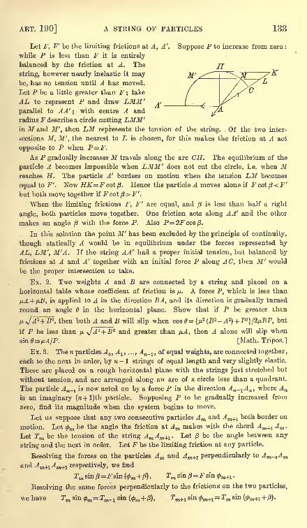
ART. 190] A STRING OF PARTICLES 133
Let F, F' be the limiting frictions at A, A'. Suppose P to increase from zero :
while P is less than F it is entirely
balanced by the friction at A. The
string, however nearly inelastic it maybe, has no tension until A has moved.
Let P be a little greater than F take
AL to represent P and draw LMM'parallel to AA'
;with centre A and
radius F describe a circle cutting LMM'in M and M', then LM represents the tension of the string. Of the two inter-
sections M, M', the nearest to L is chosen, for this makes the friction at A act
opposite to P when P=F.As P gradually increases H travels along the arc CH. The equilibrium of the
particle A becomes impossible when LMM' does not cut the circle, i.e. when Mreaches H. The particle A' borders on motion when the tension LM becomes
equal to F'. Now HK=Fcotft. Hence the particle A moves alone if Fcoij3<.F'but both move together if Fcotp>F'.
When the limiting frictions F, F' are equal, and /3 is less than half a right
angle, both particles move together. One friction acts along AA' and the other
makes an angle /J with the force P. Also P=2Fcosj3.
In this solution the point M ' has been excluded by the principle of continuity,
though statically A would be in equilibrium under the forces represented by
AL, LM', M'A. If the string AA' had a proper initial tension, but balanced by
frictions at A and A' together with an initial force P along AC, then M' would
be the proper intersection to take.
Ex. 2. Two weights A and B are connected by a string and placed on a
horizontal table whose coefficient of friction is /t. A force P, which is less than
pA + fiB, is applied to A in the direction BA, and its direction is gradually turned
round an angle in the horizontal plane. Show that if P be greater than
*, then both A and B will slip when cose={/j?(B2 -A2
) +P2}l2/j.BP, but
if P be less than /j,,A* + B'z and greater than pA, then A alone will slip when
sin0=/t,l/P. [Math. Tripos.]
Ex. 3. The n particles A ,A
l , . . . ,An^ ,
of equal weights, are connected together ,
each to the next in order, by n - 1 strings of equal length and very slightly elastic.
These are placed on a rough horizontal plane with the strings just stretched but
without tension, and are arranged along an arc of a circle less than a quadrant.
The particle An^ is now acted on by a force P in the direction An-lAn ,
where An
is an imaginary (n + l)th particle. Supposing P to be gradually increased from
zero, find its magnitude when the system begins to move.
Let us suppose that any two consecutive particles Am and Am+l both border on
motion. Let<f>m be the angle the friction at Am makes with the chord Am+1 Am .
Let Tm be the tension of the string AmAm+l . Let ft be the angle between any
string and the next in order. Let F be the limiting friction at any particle.
Resolving the forces on the particles Am and Am+1 perpendicularly to Am.1Am
and Am+1Am+% respectively, we find
Resolving the same forces perpendicularly to the frictions on the two particles,
wehave Tm sin^=rOT_sin (<f>m +p), r
134 FRICTION [CHAP, v
Comparing the first two equations, we see that<f>m+ ft and <f>m+l are either equal
or supplementary. The other two equations show that the second alternative
makes Tm+} = Tm_l. Both these alternatives are statically possible, and thus forces
which might be friction forces could be arranged at the several particles in many
ways so that equilibrium would be preserved.
We shall take the alternative which agrees with the supposition that the strings
are initially without tension. When P is less than F the friction at An_1acts in
the direction opposite to P, and all the tensions are zero. When P has become
greater than F, the string An_ 2An_lis slightly stretched and the tension An^ti
An_1
is called into play. The friction at An_z acts opposite to this tension, and all the
other tensions are zero. Thus, as P continually increases, the tensions and frictions
are one by one called into play. Supposing the tensions to be initially zero, we
shall assume that the tensions produced by P are such that their magnitudes
continually increase from the string with zero tension up to the string An_1AH .
Any other supposition would lead to the result that by pulling a string at one end
we could produce, after overcoming the resistances, a greater tension at the other
end. Since then Tm+1 must be greater than Tm_lt we have m+1= $m + ft.
Suppose that all the particles from Ap to An_^ border on motion and that
2T
P_1=0; we have then </>p= 0, <f>p+i=ft, and in general
Since Tn_1=P, we see that the force P required to make all the particles from
Ap to An,l border on motion is
P=F sin (n-p) ft . cosec ft.
When P becomes greater than the value given by this equation, a tension in the
string Ap^Ap will be called into play. The tension of A pAp+l required to move Apwithout ^p_j is F cosec ft, while that required to move both is F sin 2ft . cosec
ft.
Since the latter is less than the former tension, the friction at Ap^ will become
limiting before A p begins to move. Thus we see that, as P continues to increase,
the successive particles border on motion, but no one begins to move without the
others.
If nft be less than a right angle, we conclude that all the particles begin to move
together, and that the force required to move them is P=Fsin nft cosec ft.
If nft be greater than a right angle, we have shown that, without destroying the
equilibrium, P can increase up to Fsinpft. cosec ft, where pft is less and (p + l)ft
greater than a right angle. We have then Tn_p_1= 0. When P becomes greater
than this value, the particle A n_lwill begin to move alone. For the tension
required to move An-l is F cosec ft, and the tension Tn_2 is then F cot ft. Since
this is less than F sin pft cosec ft, the system An^, An_3) &c. is not bordering onmotion.
CHAPTER VI
THE PRINCIPLE OF VIRTUAL WORK
191. IN a former chapter the principle of virtual work has
been established for forces which act on a particle. It is now
proposed to consider this principle more fully, and to apply it to a
system of bodies in two and three dimensions.
The principle itself may be enunciated as follows. Let anynumber offorces P1} P.2 &c. act at the points A l} A 2 &c. of a system
of bodies. These bodies are connected together in any manner so as
either to allow or exclude relative motion, and they therefore exert
mutual actions and reactions on each other. Let the system be
slightly displaced so that the points A lt A 2 &c. assume the neighbour-
ing positions A-!, A 2 <$cc. Let dplt dp2 &c. be the projections of the
displacements A^AJ, A 2A 2 &c. on the directions of the forces P1} P2
&c. respectively, and let dW = Pldpl + P2dp2 + (fee. Then the system
is in equilibrium if dW = for all displacements consistent with the
geometrical connexions between the bodies of the system.
Also the system is not in equilibrium if one or more displacements
can be found for which dW is not equal to zero.
Strictly speaking we should say, not that dW is zero, but that
dW, in the language of the differential calculus, is a small quantityof the second order. This will be understood in what follows.
192. These displacements are to be regarded as imaginarymotions which the system might, but does not necessarily, take.
The principle of virtual work supplies a test, whether a given
position of the system is one of equilibrium or not. We first
consider what are the possible ways in which the system could
begin to move out of the given position. If for any one of these
136 THE PRINCIPLE OF VIRTUAL WORK [CHAP. VI
the sum *Pdp is zero, then the system will not begin to move in
that mode of displacement. In this way all the possible displace-
ments are examined, and if ^Pdp is zero for each and every one,
the given position is one of equilibrium.
These small tentative displacements of the system are called
virtual displacements. The product Pdp is called, sometimes the
virtual moment, and sometimes the virtual work of the force P.
The sum 'ZPdp is called the virtual moment or virtual work of all
the forces.
193. A proof of the principle of virtual work for forces actingon a single particle has been already given in Chap. II. No satis-
factory method has yet been found by which the principle for
a system of bodies can be deduced directly from the elementaryaxioms of statics. Lagrange has made a brilliant attempt which
will be discussed a little further on.
There is another line of argument which may be adopted.The system is regarded as composed of simpler bodies, each acted
on by some of the forces, and connected together by mutual
actions and reactions. Thus Poisson regards the system as a
collection of points in equilibrium connected together as if byflexible strings or inflexible rods without weight. To avoid
making any assumptions concerning the molecular structure of
bodies, we shall regard the system as made up of rigid bodies of
such size that the elementary laws of statics may be applied to
them.
The principle will first be proved for the simpler body, assumingthe composition and resolution of forces. The principle will there-
fore be true for the general system, provided we include amongstthe forces P1} P2 &c. all the mutual actions and reactions of the
bodies of the system.
Lastly, these actions and reactions are examined, and it will be
proved that they do not put in an appearance in the general
equation of virtual work. It follows that the principle may be
used as if P1} P2 &c. were the only forces acting on the system.
The chief objection to this mode of proof is that the mutual
actions and reactions must be sufficiently known to enable us
to prove that their separate virtual works are either zero or cancel
each other.
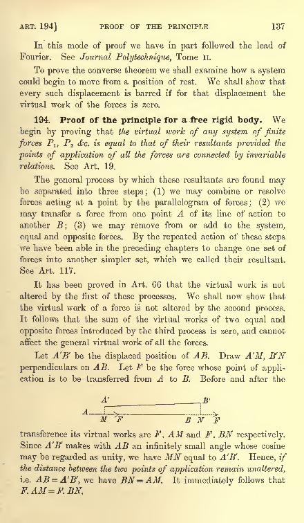
ART. 194] PROOF OF THE PRINCIPLE 137
In this mode of proof we have in part followed the lead of
Fourier. See Journal Polytechnique, Tome II.
To prove the converse theorem we shall examine how a systemcould begin to move from a position of rest. We shall show that
every such displacement is barred if for that displacement the
virtual work of the forces is zero.
194. Proof of the principle for a free rigid body. Webegin by proving that the virtual work of any system of finite
forces Pj, P2 &c. is equal to that of their resultants provided the
points of application of all the forces are connected by invariable
relations. See Art. 19.
The general process by which these resultants are found maybe separated into three steps; (1) we may combine or resolve
forces acting at a point by the parallelogram of forces; (2) we
may transfer a force from one point A of its line of action to
another B; (3) we may remove from or add to the system,
equal and opposite forces. By the repeated action of these steps
we have been able in the preceding chapters to change one set of
forces into another simpler set, which we called their resultant.
See Art. 117.
It has been proved in Art. 66 that the virtual work is not
altered by the first of these processes. We shall now show that
the virtual work of a force is not altered by the second process.
It follows that the sum of the virtual works of two equal and
opposite forces introduced by the third process is zero, and cannot
affect the general virtual work of all the forces.
Let A'B' be the displaced position of AB. Draw A'M, B'N
perpendiculars on AB. Let F be the force whose point of appli-
cation is to be transferred from A to B. Before and after the
M 'F B N Ftransference its virtual works are F . AM and F. BN respectively.
Since A'B' makes with AB an infinitely small angle whose cosine
may be regarded as unity, we have MN equal to A'B'. Hence, if
the distance between the two points of application remain unaltered,
i.e. AB = A'B', we have BN=AM. It immediately follows that
F.AM = F.BN.
138 THE PRINCIPLE OF VIRTUAL WORK [CHAP. VI
Thus in all changes of forces into other forces consistent with
the principles of statics, the work of the forces due to any givensmall displacement is unaltered.
195. We may now apply this result to a system of forces
P1} P2 &c. acting on a free rigid body.
All these forces can be reduced to a force R acting at an
arbitrary point 0, and a couple G, Art. 105. By what precedes
the virtual work of the forces P1} P2 &c. due to any displacementis equal to the virtual work of R and G.
If the forces P1} P2 &c. are in equilibrium, both R and Gare zero, Art. 109. Hence the virtual work of Pl} P2 &c. for any
displacement is zero.
Conversely, if the virtual work of Plf P2 &c. is zero for all
displacements, then the virtual work of R and G is zero. Weshall now show that this requires that R and G should each
be zero. First let the body be moved parallel to itself through
any small space 8r in the direction in which R acts. The virtual
work of the force R is RBr. Let AB be the arm of the coupleand let the forces act at A and B. Since equal and parallel
displacements A A', BB' are given to A and B, while the forces
acting at A and B are equal and opposite, it is evident that
the works due to the two forces cancel each other. The work
of the couple G is therefore zero. Hence the sum of the works
of R and G cannot vanish unless R = Q.
Next let the body be turned through a small angle 8o> round a
perpendicular drawn through to the plane of the couple, and
let this rotation be in the direction in which the couple urges
the body. Let bisect the arm AB and let the forces of the
couple be + Q. Each of the points A and B receives a displace-
ment equal to ^AB8oa in the direction of the force acting at that
point. The sum of the works due to these two forces is therefore
AB . Q8a), i.e. GSw. Since the point of application of R is not
displaced, the virtual work of R (even if R were not zero) is
zero. Hence the sum of the virtual works of R and G cannot
vanish unless G = 0. It immediately follows that the body is in
equilibrium.
196. On the forces which do not put in an appearancein the equation of virtual work. When the body is not free
but can move either under the guidance of fixed constraints or
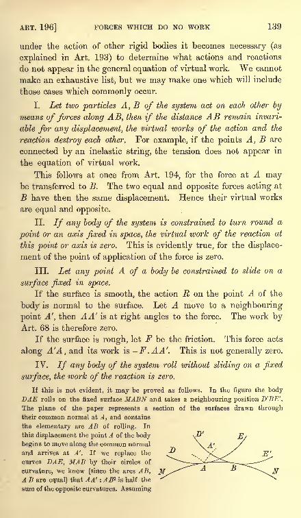
ART. 196] FORCES WHICH DO NO WORK 139
under the action of other rigid bodies it becomes necessary (as
explained in Art. 193) to determine what actions and reactions
do not appear in the general equation of virtual work. We cannot
make an exhaustive list, but we may make one which will include
those cases which commonly occur.
I. Let two particles A, B of the system act on each other by
means of forces along AB, then if the distance AB remain invari-
able for any displacement, the virtual works of the action and the
reaction destroy each other. For example, if the points A, B are
connected by an inelastic string, the tension does not appear in
the equation of virtual work.
This follows at once from Art. 194, for the force at A maybe transferred to B. The two equal and opposite forces acting at
B have then the same displacement. Hence their virtual works
are equal and opposite.
II. If any body of the system is constrained to turn round a
point or an axis fixed in space, the virtual work of the reaction at
this point or axis is zero. This is evidently true, for the displace-
ment of the point of application of the force is zero.
III. Let any point A of a body be constrained to slide on a
surface fixed in space.
If the surface is smooth, the action R on the point A of the
body is normal to the surface. Let A move to a neighbouring
point A', then AA' is at right angles to the force. The work byArt. 68 is therefore zero.
If the surface is rough, let F be the friction. This force acts
along A'A, and its work is -F .AA'. This is not generally zero.
IV. If any body of the system roll without sliding on a fixed
surface, the work of the reaction is zero.
If this is not evident, it may be proved as follows. In the figure the bodyDAE rolls on the fixed surface MABN and takes a neighbouring position D'BE'.
The plane of the paper represents a section of the surfaces drawn through
their common normal at A , and contains
the elementary arc AB of rolling. In
this displacement the point A of the body
begins to move along the common normal
and arrives at A'. If we replace the
curves DAE, MAB by their circles of
curvature, we know (since the arcs AB,A B are equal) that AA' : AB2 is half the
sum of the opposite curvatures. Assuming
D
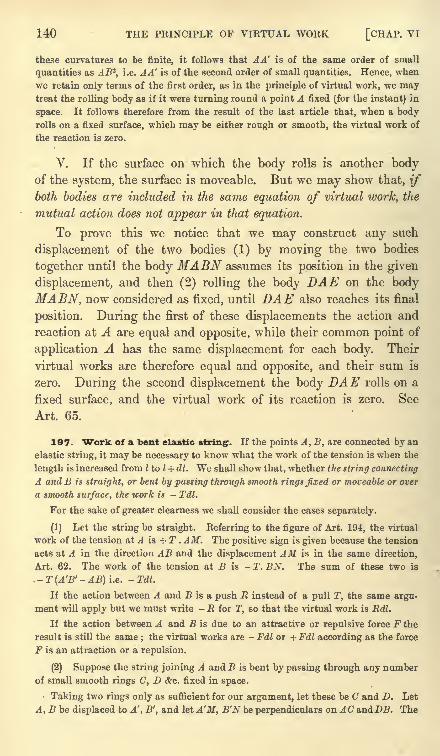
140 THE PRINCIPLE OF VIRTUAL WORK [CHAP. VI
these curvatures to be finite, it follows that A A' is of the same order of small
quantities as ARZ,
i.e. AA' is of the second order of small quantities. Hence, when
we retain only terms of the first order, as in the principle of virtual work, we maytreat the rolling body as if it were turning round a point A fixed (for the instant) in
space. It follows therefore from the result of the last article that, when a bodyrolls on a fixed surface, which may be either rough or smooth, the virtual work of
the reaction is zero.
V. If the surface on which the body rolls is another bodyof the system, the surface is moveable. But we may show that, if
both bodies are included in the same equation of virtual work, the
mutual action does not appear in that equation.
To prove this we notice that we may construct any such
displacement of the two bodies (1) by moving the two bodies
together until the body MABN assumes its position in the given
displacement, and then (2) rolling the body DAE on the body
MABN, now considered as fixed, until DAE also reaches its final
position. During the first of these displacements the action and
reaction at A are equal and opposite, while their common point of
application A has the same displacement for each body. Their
virtual works are therefore equal and opposite, and their sum is
zero. During the second displacement the body DAE rolls on a
fixed surface, and the virtual work of its reaction is zero. See
Art. 65.
197. Work of a bent elastic string. If the points A, B, are connected by an
elastic string, it may be necessary to know what the work of the tension is when the
length is increased from I to I + dl. We shall show that, whether the string connecting
A andB is straight, or bent by passing through smooth rings fixed or moveable or over
a smooth surface, the work is - Tdl.
For the sake of greater clearness we shall consider the cases separately.
(1) Let the string be straight. Referring to the figure of Art. 194, the virtual
work of the tension at A is + T . AM. The positive sign is given because the tension
acts at A in the direction AB and the displacement AM is in the same direction,
Art. 62. The work of the tension at B is - T. BN. The sum of these two is
.- T (A'B'- AB) i.e. -Tdl.
If the action between A and B is a push E instead of a pull T, the same argu-
ment will apply but we must write - R for T, so that the virtual work is Edl.
If the action between A and B is due to an attractive or repulsive force F the
result is still the same ; the virtual works are - Fdl or + Fdl according as the force
F is an attraction or a repulsion.
(2) Suppose the string joining A and B is bent by passing through any numberof small smooth rings C, D &c. fixed in space.
Taking two rings only as sufficient for our argument, let these be C and D. Let
A, B be displaced to A', B', and let A'M, B'N be perpendiculars on AC andZXB. The
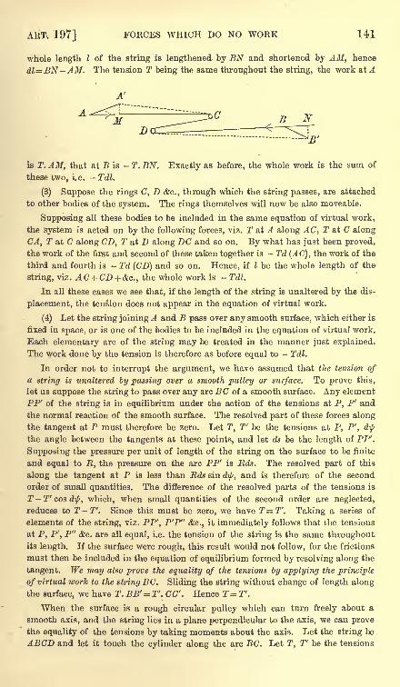
ART, 197] FORCES WHICH DO NO WORK 141
whole length I of the string is lengthened by BN and shortened by AH, hence
dl=BN-AM. The tension T being the same throughout the string, the work at A
is T. AM, that at B is - T. BN. Exactly as before, the whole work is the sum of
these two, i.e. - Tdl.
(3) Suppose the rings C, D &c., through which the string passes, are attached
to other bodies of the system. The rings themselves will now be also moveable.
Supposing all these bodies to be included in the same equation of virtual work,
the system is acted on by the following forces, viz. T at A along AC, T at C along
CA, T at C along CD, T at D along DC and so on. By what has just been proved,
the work of the first and second of these taken together is - Td (AC), the work of the
third and fourth is - Td (CD) and so on. Hence, if I be the whole length of the
string, viz. AC+CD + &C., the whole work is -Tdl.
In all these cases we see that, if the length of the string is unaltered by the dis-
placement, the tension does not appear in the equation of virtual work.
(4) Let the string joining A and B pass over any smooth surface, which either is
fixed in space, or is one of the bodies to be included in the equation of virtual work.
Each elementary arc of the string may be treated in the manner just explained.
The work done by the tension is therefore as before equal to - Tdl.
In order not to interrupt the argument, we have assumed that the tension ofa string is unaltered by passing over a smooth pulley or surface. To prove this,
let us suppose the string to pass over any arc BC of a smooth surface. Any element
PP' of the string is in equilibrium under the action of the tensions at P, P' and
the normal reaction of the smooth surface. The resolved part of these forces along
the tangent at P must therefore be zero. Let T, T' be the tensions at P, P', d\j/
the angle between the tangents at these points, and let ds be the length of PP\
Supposing the pressure per unit of length of the string on the surface to be finite
and equal to R, the pressure on the arc PP' is Rds. The resolved part of this
along the tangent at P is less than Rds sin dip, and is therefore of the second
order of small quantities. The difference of the resolved parts of the tensions is
T -T' cos d\f/, which, when small quantities of the second order are neglected,
reduces to T-T. Since this must be zero, we have T=T. Taking a series of
elements of the string, viz. PP', P'P" <fec., it immediately follows that the tensions
at P, P', P" &c. are all equal, i.e. the tension of the string is the same throughoutits length. If the surface were rough, this result would not follow, for the frictions
must then be included in the equation of equilibrium formed by resolving along the
tangent. We may also prove the equality of the tensions by applying the principle
of virtual work to the string BC. Sliding the string without change of length along
the surface, we have T. BB'= T'. CC'. Hence T-T'.
When the surface is a rough circular pulley which can turn freely about a
smooth axis, and the string lies in a plane perpendicular to the axis, we can prove
the equality of the tensions by taking moments about the axis. Let the string be
ABCD and let it touch the cylinder along the arc BC. Let T, T' be the tensions
142 THE PRINCIPLE OF VIRTUAL WORK [CHAP. VI
of AB, CD, r the radius of the cylinder. Taking moments about the axis, we have
Tr= T'r. This gives T= 2".
198. In the preceding arguments we have tacitly assumed
that the pressures which replace the constraints are finite in
magnitude. If this were not true it is not clear that the virtual
work would be zero. It is not enough to make a product P . dpvanish that one factor viz. dp should be zero, if the other factor Pis infinite. Such cases sometimes occur in our examples when we
treat the body under consideration as an unyielding rigid mass.
But in nature the changes of structure of the body cannot be
neglected when the forces acting on it become very great. The
displacements are therefore different from those of a rigid body.
199. Converse of the principle of virtual work. Weshall now prove the converse principle of virtual work for a systemof bodies. The system being placed at rest in some position, it
is given that the work of the external forces is zero for all small
displacements which do not infringe on the constraints. It is
required to prove that the system is in equilibrium.
If the system is not in equilibrium it will begin to move. Let
us then examine all the ways in which the system could begin to
move from its position of rest. Some one way having been selected,
it is clear that by introducing a sufficient number of smooth con-
straining curves we can so restrain the system that it cannot
move in any other way. Thus if any point of one of the bodies
would freely describe a curve in space, we can imagine that pointattached to a small ring which can slide along a rigid smooth wire,
whose form is the curve which the point would freely describe.
The point is thus prevented from moving in any other way. Thereaction of this smooth curve has been proved to have no virtual
work. It is also clear that these constraining curves in no wayalter the work of the external forces during the displacementof the body.
In order to prevent the system from moving from its initial
position it will now only be necessary to apply some force F to
some one point A in a direction opposite to that in which A would
move if F did not act. The forces of the system are now in equili-
brium with F. Let the system receive an arbitrary virtual dis-
placement along the only path open to it. In this displacementlet the point A come to A'. Then the work of the forces plus the
ART. 202] CONVERSE OF THE PRINCIPLE 143
work of F is zero. But it is given that the work of the forces is
zero for every such displacement, hence the work of F is zero.
But this work is F. AA', and since AA' is arbitrary it im-
mediately follows that F must be zero. Thus no force is required
to prevent the system from moving from its place of rest along anyselected path. The system is therefore in equilibrium. Treatise
on Natural Philosophy, Thomson and Tait, 1879, Art. 290.
200. Initial motion. Let us imagine a system to be placed at rest, and yet
not to be in equilibrium under the action of the given external forces. We shall
show that the system will so begin to move * that the work of the forces in the initial
displacement is positive.
The proof of this is really a repetition of the argument already given in Art. 199.
If the system begin to move from the position of rest in any given way, we constrain
it to move only in that way. If F be the force acting at A which will prevent
motion, we find as before that the work of the forces plus that of F is zero. But Fmust act opposite to the direction in which A would move if F were not applied,
hence its work is negative ; and the work of the impressed forces in this displacement
is therefore positive.
201. It follows from this result, that it is sufficient to ensure equilibrium that
the work of the forces should be negative instead of zero for all displacements, for then
there is no displacement which the system could take from its state of rest. If
however the work of the forces is negative for any one displacement, it must be
positive for an equal and opposite displacement, i.e. one in which the direction of
motion of every particle is reversed. To exclude therefore all displacements which
make the work positive, it is in general necessary that the work should be zero for
all displacements.
In some special cases of constraint it may happen that one displacement is
possible while the opposite is impossible. It is then not necessary that the work
should be zero for this displacement. For example, a heavy particle placed inside a
cone with the axis vertical is clearly in equilibrium, yet the work done in any
displacement is negative and not zero.
202. Method of using the principle. Let us supposethat points A 1} A 2 ,
&c. of a system are constrained to move on
fixed surfaces. We have then two objects, (1) to form those
equations of equilibrium which do not contain the reactions, (2)
to find the reactions. To effect the former purpose we give the
system all necessary displacements which do not separate A 1} A 2 ,
&c. from the constraining surfaces, and equate the sum of the
*Dynamical proof. When a system starts from a position of rest, it is proved
in dynamics that the semi vis viva after a displacement is equal to the work done
by the external forces. Now the vis viva cannot be negative, because it is the sumof the masses of the several particles multiplied by the squares of their velocities.
It is therefore clear that the system cannot begin to move in any way which makesthe virtual work of the forces negative.
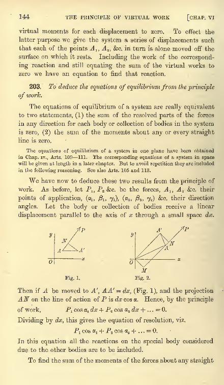
144 THE PRINCIPLE OF VIRTUAL WORK [CHAP. VI
virtual moments for each displacement to zero. To effect the
latter purpose we give the system a series of displacements such
that each of the points A lt A 2 , &c. in turn is alone moved off the
surface on which it rests. Including the work of the correspond-
ing reaction and still equating the sum of the virtual works to
zero we have an equation to find that reaction.
203. To deduce the equations of equilibrium from the principle
of work.
The equations of equilibrium of a system are really equivalent
to two statements, (1) the sum of the resolved parts of the forces
in any direction for each body or collection of bodies in the systemis zero, (2) the sum of the moments about any or every straight
line is zero.
The equations of equilibrium of a system in one plane have been obtained
in Chap, iv., Arts. 109 111. The corresponding equations of a system in spacewill be given at length in a later chapter. But to avoid repetition they are included
in the following reasoning. See also Arts. 105 and 113.
We have now to deduce these two results from the principle of
work. As before, let P1; P2 &c. be the forces, A 1} A z &c. their
points of application, (a,, /3lt 71), (a2 , /82 , 72) &c. their direction
angles. Let the body or collection of bodies receive a linear
displacement parallel to the axis of nc through a small space dx*
A'
Fig. 1.
Then if A be moved to A', AA' = dx, (Fig. 1), and the projection
AN on the line of action of P is dx cos a. Hence, by the principle
of work, P! cos x dx -f P2 cos a2 dx + . . . = 0.
Dividing by dx, this gives the equation of resolution, viz.
P! COS flj + P2 COS Cr2 + . . .= 0.
In this equation all the reactions on the special body considered
due to the other bodies are to be included.
To find the sum of the moments of the forces about any straight
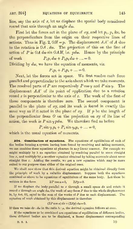
ART. 204] EQUATIONS OF EQUILIBRIUM 145
line, say the axis of z, let us displace the special body considered
round that axis through an angle dw.
First let the forces act in the plane of xy, and let p1} p2 &c. be
the perpendiculars from the origin on their respective lines of
actions. Thus in Fig. 2, OM=p. The displacement AA' of A due
to the rotation is OA . dco. The projection of this on the line of
action of P is OA dm sin 0AM, i.e. pda>. Hence by the principle
of work P^PI dco + P^pz &<*> + . . .= 0.
Dividing by dw, we have the equation of moments, viz.
Next, let the forces act in space. We first resolve each force
parallel and perpendicular to the axis about which we take moments.
The resolved parts of P are respectively P cos 7 and P sin 7. The
displacement AA' of its point of application due to a rotation
round z is perpendicular to the axis of z. The work of the first of
these components is therefore zero. The second component is
parallel to the plane of xy, and its work is found in exactly the
same way as if it acted in the plane of xy. If p be the length of
the perpendicular from on the projection on xy of its line of
action, the work is P sin 7 pdw. We therefore find as before
Pj sin 7^! + P2 sin <y2p2 + . . . = 0,
which is the usual equation of moments.
2O4. Combination of equations. The equations of equilibrium of each of
the bodies forming a system having been found by resolving and taking moments,we can combine these equations at pleasure in any linear manner. For example we
might multiply by X an equation obtained by resolving parallel to some straight
line x, and multiply by fj.another equation obtained by taking moments about some
straight line z. Adding the results, we get a new equation which may be more
suited to our purpose than either of the original ones.
We shall now show that this derived equation might be obtained directly from
the principle of work by a suitable displacement. Suppose both the equations
combined as above to be equations of equilibrium of the same body. Let these be
written in the form 2P cos a= 0, SPp= 0.
If we displace the body parallel to x through a small space dx and rotate it
round z through an angle dw, the work of any force P due to the whole displacement
is, by Art. 65, equal to the sum of the works of P due to each displacement. The
equation of work obtained by this displacement is therefore
(ZP cos a) dx + (ZPp) du= 0.
If then we take dx : du in the ratio X : /*, the derived equation follows at once.
If the equations to be combined are equations of equilibrium of different bodies,
these different bodies are to be displaced, a linear displacement corresponding
R. S. I. 10
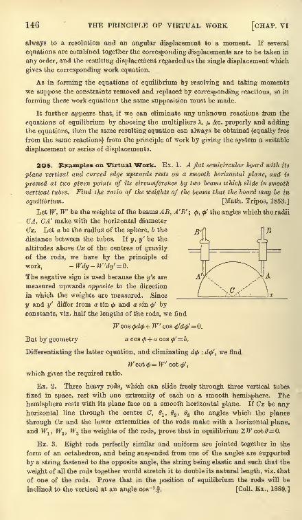
146 THE PRINCIPLE OF VIRTUAL WORK [CHAP. VI
always to a resolution and an angular displacement to a moment. If several
equations are combined together the corresponding displacements are to be taken in
any order, and the resulting displacement regarded as the single displacement which
gives the corresponding work equation.
As in forming the equations of equilibrium by resolving and taking moments
we suppose the constraints removed and replaced by corresponding reactions, so in
forming these work equations the same supposition must be made.
It further appears that, if we can eliminate any unknown reactions from the
equations of equilibrium by choosing the multipliers X, fj.&c. properly and adding
the equations, then the same resulting equation can always be obtained (equally free
from the same reactions) from the principle of work by giving the system a suitable
displacement or series of displacements.
2OS. Examples on Virtual Work. Ex. 1. A flat semicircular board with its
plane vertical and curved edge upwards rests on a smooth horizontal plane, and is
pressed at two given points of its circumference by two beams which slide in smooth
vertical tubes. Find the ratio of the weights of the beams tliat the board may be in
equilibrium. [Math. Tripos, 1853.]
Let W, W be the weights of the beams AB, A'B'; 0, <p' the angles which the radii
CA, CA' make with the horizontal diameter
Cx. Let a be the radius of the sphere, b thej$>^\ []]}
distance between the tubes. If y, y' be the
altitudes above Cx of the centres of gravity
of the rods, we have by the principle of
work, -Wdy-W'dy'= 0.
The negative sign is used because the y's are
measured upwards opposite to the direction
in which the weights are measured. Since
y and y' differ from a sin<f>
and a sin</>' by
constants, viz. half the lengths of the rods, we find
W cos</>d<f> +W cos Q'dtf= 0.
But by geometry a cos + a cos<f>'= b.
Differentiating the latter equation, and eliminating d<f> : d<f>', we find
Wcot<f>=W coif',
which gives the required ratio.
Ex. 2. Three heavy rods, which can slide freely through three vertical tubes
fixed in space, rest with one extremity of each on a smooth hemisphere. The
hemisphere rests with its plane face on a smooth horizontal plane. If Cx be anyhorizontal line through the centre C, O
l , 2 , 63 the angles which the planes
through Cx and the lower extremities of the rods make with a horizontal plane,
and Wlt W2) W3 the weights of the rods, prove that in equilibrium 2JFcot0=0.
Ex. 3. Eight rods perfectly similar and uniform are jointed together in the
form of an octahedron, and being suspended from one of the angles are supported
by a string fastened to the opposite angle, the string being elastic and such that the
weight of all the rods together would stretch it to double its natural length, viz. that
of one of the rods. Prove that in the position of equilibrium the rods will be
inclined to the vertical at an angle cos" 1!. [Coll. Ex., 1889.]
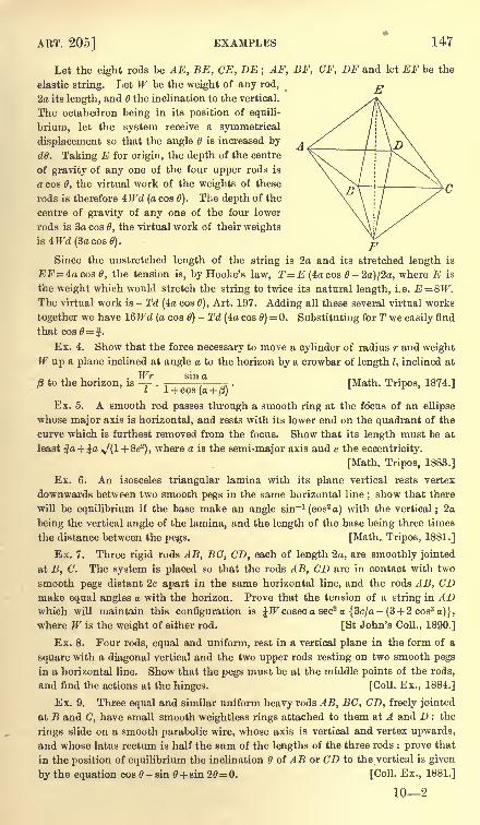
ART. 205] EXAMPLES 147
Let the eight rods be AE, BE, CE, DE ; AF, BF, CF, DF and let EF be the
elastic string. Let W be the weight of any rod,
2a its length, and the inclination to the vertical.
The octahedron being in its position of equili-
brium, let the system receive a symmetrical
displacement so that the angle is increased by
dO. Taking E for origin, the depth of the centre
of gravity of any one of the four upper rods is
a cos 0, the virtual work of the weights of these
rods is therefore 4TFd (a cos 6). The depth of the
centre of gravity of any one of the four lower
rods is 3a cos 6, the virtual work of their weights
is4JFd(3acos0).
Since the unstretched length of the string is 2a and its stretched length is
EF=4a cos 0, the tension is, by Hooke's law, T=E (4acos 0-2)/2a, where E is
the weight which would stretch the string to twice its natural length, i.e. E = 8W.The virtual work is - Td (4a cos 0), Art. 197. Adding all these several virtual works
together we have IQWd (a cos 6)- Td (4a cos 0)
= 0. Substituting for T we easily find
that cos0= J.
Ex. 4. Show that the force necessary to move a cylinder of radius r and weightW up a plane inclined at angle a to the horizon by a crowbar of length I, inclined at
8 to the horizon, is . ^- '
---r . [Math. Tripos, 1874.]
Ex. 5. A smooth rod passes through a smooth ring at the fo'cus of an ellipse
whose major axis is horizontal, and rests with its lower end on the quadrant of the
curve which is furthest removed from the focus. Show that its length must be at
least |a + ^a N/(l + 8e2), where a is the semi-major axis and e the eccentricity.
[Math. Tripos, 1883.]
Ex. 6. An isosceles triangular lamina with its plane vertical rests vertex
downwards between two smooth pegs in the same horizontal line ; show that there
will be equilibrium if the base make an angle sin"1(cos
2a) with the vertical ; 2a
being the vertical angle of the lamina, and the length of the base being three times
the distance between the pegs. [Math. Tripos, 1881.]
Ex. 7. Three rigid rods AB, BC, CD, each of length 2a, are smoothly jointed
at B, C. The system is placed so that the rods AB, CD are in contact with two
smooth pegs distant 2c apart in the same horizontal line, and the rods AB, CDmake equal angles a with the horizon. Prove that the tension of a string in ADwhich will maintain this configuration is JJFcoseca sec2 a {3c/a- (3 + 2 cos3 a)},
where W is the weight of either rod. [St John's Coll., 1890.]
Ex. 8. Four rods, equal and uniform, rest in a vertical plane in the form of a
square with a diagonal vertical and the two upper rods resting on two smooth pegs
in a horizontal line. Show that the pegs must be at the middle points of the rods,
and find the actions at the hinges. [Coll. Ex., 1884.]
Ex. 9. Three equal and similar uniform heavy rods AB, BC, CD, freely jointed
at B and C, have small smooth weightless rings attached to them at A and D : the
rings slide on a smooth parabolic wire, whose axis is vertical and vertex upwards,
and whose latus rectum is half the sum of the lengths of the three rods : prove that
in the position of equilibrium the inclination of AB or CD to the vertical is given
by the equation cos - sin + sin 20= 0. [Coll. Ex., 1881.]
102
148 THE PRINCIPLE OF VIRTUAL WORK [CHAP. VI
Ex. 10. A smooth hemispherical bowl of radius r is fixed with its rim horizontal.
A uniform heavy rectangle ABCD rests with two points A, B on the internal surface
of the bowl, and its sides AD, BC resting on, and reaching beyond, the edge of the
bowl. If 6 be its inclination to the horizontal, show that
4 (f2 -
fc2)cos2 28 - a2 cos2 = 0,
where AB=2b, BC=2a. [Coll. Ex., 1891.]
Ex. 11. re equal uniform rods, each of weight W and length I, are jointed
so as to form symmetrical generators of a cone whose semi-vertical angle is a,
the joint being at the vertex of the cone. The rods are placed with their other ends
in contact with the interior of a sphere whose radius is r, so that the axis of the
cone is vertical, and a weight W is hung on at the joint. Show that
and find the action at the joint on each rod. [Coll. Ex., 1884.]
Ex. 12. A conical tent resting on a smooth floor is made of an indefinitely great
number of equal isosceles triangular elements hinged at the vertex, and kept in
shape by a heavy circular ring placed on it as a necklace. Show that in equilibrium
the semi-vertical angle of the cone is sin" 1
-j-I
arTr/)}-
ff
>where W, W are
respectively the weights of the cone and the ring and r, h are in like manner the
radius of the ring and the slant side of the cone. [St John's Coll., 1885.]
Ex. 13. A smooth fixed sphere supports a zone of very small equal smooth
spherical particles, and the whole is prevented from slipping off the sphere by an
elastic ring occupying a horizontal circle of angular radius a. Show that in the
position of equilibrium the tension of the band is T, where 2irT= W tan a, and Wisthe whole weight of the ring and particles together. [St John's Coll., 1885.]
It may be assumed that the centre of gravity of such a zone is half way between
the bounding planes.
The work function.
206. Coordinates of a system. Our general object in statics
is to find the positions of equilibrium of a system. To solve this
problem we require some quantities which when given will deter-
mine the position of the system in space. Thus the position of a
particle in geometry of two dimensions is defined when we know
its coordinates x, y. In the same way if a body is free to move in
the plane of xy, its position is fixed when we know the coordinates
x, y of some point in it and also the angle 6 some straight line fixed
in the body makes with the axis of x. These three quantities, viz.
x, y and 6, are called the coordinates of the body.
If the body is in space we define its position by giving (1) the
coordinates x, y, z of some point A fixed in the body, (2) the two
angles some straight line AB fixed in the body makes with the
axes of x and y. If no more than this is given, the position of the
body is not fixed, for it could be turned round AB as an axis. We
ART. 208] THE WORK FUNCTION 149
therefore require (3) the angle some plane drawn through AB and
fixed in the body makes with some plane fixed in space. These
six quantities, or any other six which fix the place of the body, are
called its coordinates.
If the body be under constraint the case is a little altered.
Thus suppose the extremities of a rod of given length are constrained
to rest on two given curves in a vertical plane; its position is defined
simply by its inclination to the horizon or by the abscissa of one -
extremity. Either of these, or any other quantity which defines
the position of the rod, is called its coordinate.
207. In the general case of a system of bodies, any quantities
which, when given, determine the positions of all the members of the
system, are called the coordinates of that system. Just as the
Cartesian coordinates of a point are connected by one or more
equations when the point is constrained to lie on a given surface
or curve, so the coordinates of a system are connected by equations
when the system is subject to constraints. By help of these equa-tions we can eliminate as many coordinates as there are equations,
and thus make the position of the system depend on a smaller
number of coordinates. There being now no equations of constraint,
these remaining coordinates are independent of each other.
Let us suppose that the system is referred to independentcoordinates. Since each may be varied without altering the others,
there are as many ways of moving the system as there are co-
ordinates. Any small displacement, indicated by varying simul-
taneously several coordinates, may be constructed by varying first
one of the coordinates and then another, and so on. The number
of independent coordinates is therefore called the number of degrees
offreedom of the system.
208. The work function. Let a system of bodies be placedin any position, and let it receive any indefinitely small displace-
ment which the constraints imposed on the system permit it to
take. Let X, Y, Z be the components of any force P, and let (xyz)
be the rectangular Cartesian coordinates of its point of application.
The work of P is the same as that of its components, so that the
general expression for the work is
ZPdp = 2(Xdx+ Ydy + Zdz) (1),
where the X implies summation for all the forces of the system.
150 THE PRINCIPLE OF VIRTUAL WORK [CHAP. VI
Let the independent coordinates of the system be 6, (j>, ty &c.
Then since these determine its position, the coordinates x, y, z
of every point of each body can be expressed in terms of 0, (f><fec.
Thus x, y, z and X, Y, Z are all known functions of 6, $ &c.
Substituting, the equation (1) takes the form
SPrfp = ed0 + 4>cty + &c (2),
where,3> &c. are all known functions of the coordinates 0, < &c.
2O9. The coefficients 6, 4>, <&c. have sometimes an elementary statical meaning.
Suppose for example that the change in the coordinate 6 (the others remaining
constant) had the effect of turning the body about some straight line through the
angle d&. Then QdO is the work of the forces when this displacement is given to
the body. But, by Art. 203, this work is MdO, where M is the moment. It follows
that 9 is the moment of the forces about the straight line.
Again, suppose that the change of some abscissa <f>had the effect of moving the
body parallel to the axis of x, then by the same article, <j>is the resolved part of the
forces parallel to that axis.
210. In most cases the expression for the work is found to be
a perfect differential of some quantity which we may call W. For
example, suppose the force P which acts on the point (xyz) to be
due to the repulsion of some centre of force (7, i.e. let P be a force
whose line of action always passes through a point G fixed in space.
If r be the distance from C to the point of application, the work of
such a force for any small displacement is Pdr. If then the
magnitude of P is some function of the distance r, the part
contributed by such a central force to the expression "ZPdp is a
perfect differential.
To take another case, let a force T acting between two points
A, A' which move with the system be caused by such an elastic
string as that described in Art. 197 or in any other way, so only
that the force is some function of the distance between A and A'.
The work of such a force is + Tdr, and as I7
is a function of r, this
again is a perfect differential.
The system may be under the action of a variety of central
forces, attracting many points of the system ;or again there may
be any number of actions between different sets of points, yet in
all these cases the share contributed by each force to the virtual
work is a perfect differential.
These two typical cases represent the forces which in most
cases act on the system. The external forces are generally central
forces, and the internal forces either do not appear in the equation
ART. 211] THE WORK FUNCTION 151
of virtual work or appear as forces between one point and another
such as those just described.
211. Since the expression (2) in Art. 208 represents the work
of the forces due to any general small displacement, the integral of
that expression when taken between any limits is the work of the
forces as the system makes a finite displacement, i.e. as the systemmoves from any position I. to another II. The lower limit of the
integral is found by giving the coordinates 6, <j>&c. their values in
the position I., and the upper limit by giving the same coordinates
their values in the position II.
When the expression (2) is a perfect differential, this integration
can be effected without knowing the route by which the systemtravels from the one position to the other. The integral W is a
function of the upper and lower limits, and will thus depend on the
initial and final position of the system and not on any intermediate
position. It follows that the work due to a displacement from one
given position to another is the same, whatever route is taken by
the si/stem, provided always none of the geometrical constraints
are violated.
When the forces are such that the expression ^Pdp is a perfect
differential, they are said to form a conservative system.
Suppose we select any one position of the system of bodies as a
standard, and let this position be defined by the values of the
coordinates = 0^,^ = ^, &c. Then taking this standard position
as the lower limit of the integral and any general position as the
upper limit, we have
W =fZPdp = F (6, <f>, &c.) -F(6l ,<i>l , &c.) ;
when it is not necessary to make an immediate choice of a standard
position we write the integral in its indefinite form, viz.
W = F(8, <, &c.) + C.
The function W, particularly when used in the indefinite form, is
often called the force function, or work function.
Sometimes the upper limit is made the standard position and
the general position the lower limit. If this standard is deter-
mined by the values 0=02 , (f>=
<f>2 ,&c.
;the integral becomes
V= F(e,, c/>2) &c.)-F(0, </>, &c.).
This is usually called the potential energy of the forces with
reference to the position defined by (j = 62 , </>=
</>2 ,&c.
152 THE PRINCIPLE OF VIRTUAL WORK [CHAP. VI
If the two standards of reference were identical, we should have
W = V. But both these standards are seldom used in the same
problem. In every case that standard of reference is generally
chosen which is most suitable to the particular problem under
discussion. We notice that W+ V is the work of the forces as the
system moves along any route from the position (0lt <j>1} &c.) to the
position (#2 , <f>2 , &c.), and these being fixed, the sum is constant
for all positions of the system of bodies.
212. Maximum and Minimum. Suppose the system to be
in a position of equilibrium. We then have dW=0 for everyvirtual displacement, so that W is a maximum, a minimum, or
stationary. The last alternative represents the case in which the
evanescence of the first differential coefficients does not indicate a
true maximum or minimum.
We have therefore another method of finding the positions of
equilibrium of a system. We regard the work function as a known
function of the coordinates, 0, <, &c. of the system, say
w=F(0, <}>,...)+ aTo find the positions of equilibrium we use any of the rules givenin the differential calculus to find the values of 0, <f>,
&c. which
make W a maximum or minimum.
213. If the coordinates 8, <j>,&c. are all independent, we make the differential
coefficient of W with regard to each of the variables equal to zero. This is equiva-
lent to giving the system the geometrical displacements indicated by varying 6, <f>,
&c. in turn, and equating the virtual work in each case to zero. But tlie process is
analytical instead of geometrical, and this has sometimes great advantages.
When we cannot express the position of the system by independent coordinates,
we may yet reduce the problem to the solution of equation* by using Lagrange's method
of indeterminate multipliers. Let the n coordinates Ol , 2 , &c. be connected by the TO
geometrical relations
/, (Ol , 2 , <fec.)= 0, /2 (0j ,
62 , &c.) = 0, &c. = 0,
so that n - m of the coordinates are independent. Differentiating and using the TO
multipliers \lt X,,, &c. we have
d/i , 4/2,
where S implies summation for 0j, 2 , &c. Since there are m multipliers at our
disposal we choose these so that the coefficients of the differentials of the dependent
coordinates are zero. The remaining 0's being independent we can make each vary
separately and it then follows from the equation that the corresponding coefficient
is zero. The coefficient of every d9 being zero, we obtain n equations of the form
Joining these to the m given geometrical relations we have i + n equations to find
the 71 coordinates and the m multipliers.
ART. 216] STABILITY OF EQUILIBRIUM 153
214. Stable and Unstable equilibrium. It should be
noticed that it is necessary and sufficient for equilibrium that the
work function TFis a maximum, a minimum, or stationary. There
is however an important distinction between these cases.
Suppose the system is in equilibrium in such a position that
W is a true maximum, i.e. W is decreased if the system is moved
into any neighbouring position which is consistent with the con-
straints. Let the system be actually placed at rest in any one of
these neighbouring positions. Not being in equilibrium in this
new position it will begin to move. By Art. 200 it must so move
that the initial work of the forces is positive, i.e. it must so move
that W increases. The system therefore tends to approach closer
to its original position of equilibrium. The original position is
therefore said to be stable.
Suppose next the system is in equilibrium in such a position
that W is a true minimum, i.e. W is increased if the system is
moved into any neighbouring position. Let the system be placed
at rest in one of these neighbouring positions, then, by the same
reasoning as before, it will begin to move on some path which will
take it further off from its original position of equilibrium. The
equilibrium is then said to be unstable.
Lastly, suppose the system is in equilibrium in suck a position
that W is neither a true maximum nor a true minimum, i.e. Wis decreased when the system is moved into some neighbouring
positions and increased when the system is moved into some others.
By the same reasoning as in the two preceding cases the equili-
brium is stable for some displacements and unstable for others.
According to the definition given in Art. 75 this state of equilibrium
is to be regarded as on the whole unstable.
215. We have only considered how the system begins to move,
and not whether it may afterwards approach or recede from the
position of equilibrium. As explained in Art. 75, this is a dynam-ical problem. The general result however agrees with what has
been proved above.
216. Instead of using the work function we may use the
potential energy. Since their sum W + V is constant, the general
results are just reversed. When the system is placed at rest in
any position other than one of equilibrium, it begins to move so
154 THE PRINCIPLE OF VIRTUAL WORK [CHAP. VI
that the potential energy decreases. In a position of equilibriumthe potential energy is a maximum, a minimum, or stationary.
The equilibrium is stable or unstable according as the potential
energy is a true minimum or maximum.
217. We have supposed in what precedes that none of the
neighbouring positions are also positions of equilibrium. It is
of course possible that W should be constant for two consecutive
positions of the system of bodies, and yet (say) greater than whenthe system is moved into any other neighbouring position. In
such a case the equilibrium is neutral for the displacement from
one of the consecutive positions to the other and stable for all other
displacements. Various cases may occur. For example, the equi-
librium may be neutral for more than one or for all displacementsfrom a given position of equilibrium ;
or again W may be constant
for all positions denned by some relations between the coordinates,
and yet (say) a maximum for all displacements from this locus.
We then have a locus of positions of equilibrium, each of which is
stable for all displacements which do not move the system alongthe locus.
In a system with two coordinates 0, <f>,we could regard W as
the ordinate of a surface whose x and y coordinates are 6 and</>.
Every geometrical peculiarity connected with the maximum and
minimum ordinates of such a surface has a corresponding statical
peculiarity in the positions of equilibrium of the system.
218. Altitude of the centre of gravity a maximum or
minimum. There is one important application of the theorem on
virtual work of which much use is made. Let gravity be the onlyexternal force acting on the system. Let zlt z^ &c. be the altitudes
above any fixed horizontal plane of the several heavy particles, and
the altitude of their centre of gravity. If mn m2 &c. be the masses
of these particles, we have z%m = "mz. If g be a constant, so that
mg represents the weight of the mass m, the virtual work of the
weights is dW = ^mgdz = - g^mdz.
The work function is therefore W = zg'Zm + C.
This is a true maximum or a true minimum, according as z is at
the least or greatest height.
We deduce the following theorem. Let a system of bodies be
under the influence of no forces but their weights, together with such
ART. 220] STABILITY OF EQUILIBRIUM 155
mutual reactions as do not appear in the equation of virtual work,
and let it be supported by frictionless reactions with other fixed
surfaces, or in some other way by forces which do not appear in the
equation of virtual work ; the possible positions of equilibrium maybe found by making the altitude of the centre of gravity of the
system above any fixed horizontal plane a maximum, a minimum, or
stationary. The equilibrium will be stable or unstable according as
the altitude of the centre of gravity is or is not a true minimum.
219. Alternation of stable and unstable positions. Supposethe constraints are such that the system moves with one degree of
freedom. Then as the system moves through space the centre of
gravity will describe some definite curve. The positions in which
the ordinate is a true maximum and a true minimum must evidently
occur alternately. It follows that the truly stable and truly un-
stable positions of equilibrium occur alternately.
220. Analytical method of determining the stability of
a system. To show how this theorem may be used to find positions
of equilibrium in an analytical manner, let us suppose, as an example,that the system has one degree of freedom. We first choose some
convenient quantity by which the position of the system is fixed,
and which is therefore called its coordinate. Let this be called 6.
Then the value of when the system is in equilibrium is the
quantity to be found. Let z be the altitude of the centre of
gravity of the system above some fixed horizontal plane. Fromthe geometry of the question we now express z in terms of 6. The
required value of 6 is then found by making dzfdd 0. To deter-
mine whether the equilibrium is stable or unstable, we differentiate
again and find d*z/d62
. If this second differential coefficient is
positive, when 6 has the value just found, the equilibrium is stable.
If negative, the equilibrium is unstable. If zero we must examine
the third and higher differential coefficients of z, following the
rules given in the differential calculus to discriminate whether a
function of one independent variable is a maximum or minimum.
If the coordinate 6 cannot vary from = oo to = + oo,
it
may itself have maxima and minima. It must be remembered
that these values of 6 may lead to maxima and minima values of z
other than those given by the ordinary theory in the differential
calculus.
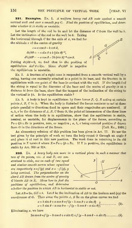
156 THE PRINCIPLE OF VIRTUAL WORK [CHAP. VI
221. Examples. Ex. 1. A uniform heavy rod AB rests against a smooth
vertical wall and over a smooth peg C. Find the position of equilibrium, and deter-
mine whether it is stable or unstable,
Let the length of the rod be 2a and let the distance of C from the wall be b.
Let the inclination of the rod to the wall be 6. Takingthe horizontal through C for the axis of x, we find for
the altitude z of the centre of gravity
z = a cos - b cot 8,
dz/de= - a sin 6 + b (sin 0)~2
,
d^zjdff2 = - a cos 8 - 26 (sin 0)~
3 cos 0.
Putting dzld&= Q, we find that in the position of
equilibrium sin3 = b/a. Since d2zjdd- is negative
the equilibrium is unstable.
Ex. 2. A frustum of a right cone is suspended from a smooth vertical wall by a
string, having one extremity attached to a point in its base, and the frustum is in
equilibrium with one point of the base in contact with the wall. If the length I of
the string is equal to the diameter of the base and the centre of gravity is at a
distance kl from the base, show that the tangent of the inclination of the string to
the vertical is fk. Is the equilibrium stable ?
Ex. 3. A body is kept in equilibrium by three forces P, Q, E acting at certain
points A, B, C in it. When the body is disturbed the forces continue to act at these
points parallel to directions fixed in space and their magnitudes are unaltered. If
a, b, c be the distances of A, B, C from 0, the point of intersection of the three lines
of action when the body is in equilibrium, show that the equilibrium is stable,
neutral, or unstable, for displacements in the plane of the forces, according as
Pa+Qb + Ec is positive, zero, or negative; a, b, c being counted positive if drawn
from in the directions of the forces. [Coll. Ex., 1892.]
An elementary solution of this problem has been given in Art. 77. To use the
test given by the principle of work we turn the body round through an angle
and place it at rest in this new position. The work done in returning to its old
position is X versin 6 where X=Pa+ Qb + Ec. If X is positive, the equilibrium is
stable by Art. 200 or 214.
222. Ex. A heavy body can move in a vertical plane in such a manner that
two of its points, viz. A and B, are con-
strained to slide, one on each of two equal
and similar smooth curves ivhose equations
are respectively x=f{y) and x= -f(y), y
being vertical. The perpendicular on the
chord AB drawn from the centre of gravity
G bisects AB in E. Show how to find the
positions of equilibrium, and determine
whether the position in which AB is horizontal is stable or not.
Let AB = 2a, GE = h. Let be the inclination of AB to the horizon and (xy) the
coordinates of G. Then since the points A, B lie on the given curves we find
x+ h sin 6 + a cos =f (y- h cos 6 + a sin 6)
x + h sin B - a cos 6= -f(y h cos - a sin 6) \
Eliminating x, we have
2acos0=/(z/-/icos0 + asin0)+/(i/-fccos0-a sin 0) (2).
(1).
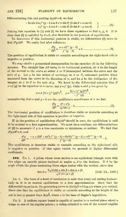
ART. 223] STABILITY OF EQUILIBRIUM 157
Differentiating this and putting dyjdff O, we find
-2asin 0=f (y -hcos0 + asin0) (ftsin0 + acos 0) 1
+/' (y- h cos e - a sin 0) (h sin - a cos 0) (
......... '
''
Joining this equation to (1) and (2) we have three equations to find x, y, 6. It is
clear that (3) is satisfied by 0=0, this therefore is one position of equilibrium.
To determine if this horizontal position is stable, we differentiate (2) twice to
find dzy[d0'2. We easily find after reduction
. hdp' f'(y-h)
The position of equilibrium is stable or unstable according as the right-hand side is
negative or positive.
We may obtain a geometrical interpretation for the equation (4) in the following
manner. The straight line AB being in its horizontal position, let n be the length
of the normal to the curve at either A or B intercepted between the curve and the
axis of y. Let p be the radius of curvature at A or B, estimated positive whenmeasured from the curve in the direction of n, and let
\f>be the inclination of the
tangent at A or B to the axis of y. We know by the differential calculus that if
x=f (y) be the equation to a curve, tan \j/=f (j/),while n and p are given by
remembering that a and y - h are the equilibrium coordinates of A we find
d?y _ M3 -a2p
~dfp- apt&nt~'The horizontal position of equilibrium is therefore stable or unstable according as
the right-hand side of this equation is positive or negative.
If in the position of equilibrium d2j//d0
2 should be zero, the equilibrium is said
to be neutral to a first approximation. We must then continue our differentiations
of (2) to ascertain if y is a true maximum or minimum, or neither. We find that
d:i
y/d03 =0, and
_ d*y _ - a+ (3/t2 - 4a'2) /" (y
-h) + 6a*tif'" (y -h) + a4
/"" (y-
h)
dO*~ f'(y-h)
The equilibrium is therefore stable or unstable according as the right-hand side
is negative or positive. If this again vanish we proceed to higher differential
coefficients.
223. Ex. 1. A prism whose cross section is an equilateral triangle rests with
two edges on smooth planes inclined at angles a, /3 to the horizon. If be the
angle which the plane containing these edges makes with the vertical, show that
tan 0= . [CoU . Ex., 1889>]N/3sm(a~)
Ex. 2. The form of a bowl of revolution is such that every rod resting horizon-
tally in it is in neutral equilibrium to a first approximation. Show that the
differential equation to the generating curve is (dx/dy)2= 2 log a/x where y is vertical.
Show also that the equilibrium is stable or unstable according as the length of the
rod is less or greater than 2a/2 )where e is the base of Napier's logarithms.
Ex. 3. A uniform square board is capable of motion in a vertical plane about a
hinge at one of its angular points ;a string attached to one of the nearest angular
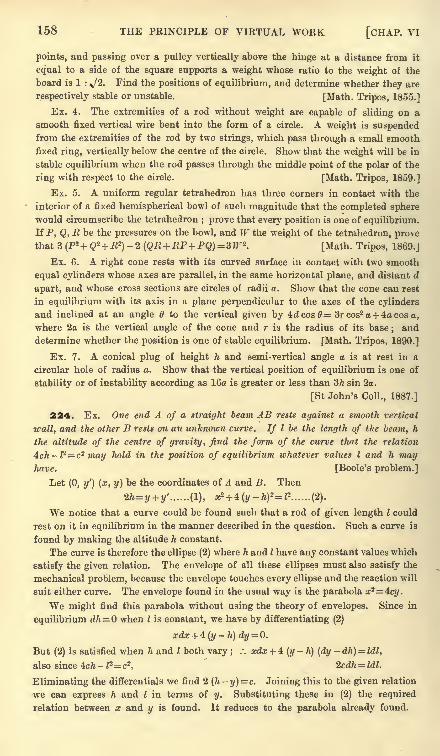
158 THE PRINCIPLE OF VIRTUAL WORK [CHAP. VI
points, and passing over a pulley vertically above the hinge at a distance from it
equal to a side of the square supports a weight whose ratio to the weight of the
board is 1 : ^/2. Find the positions of equilibrium, and determine whether they are
respectively stable or unstable. [Math. Tripos, 1855.]
Ex. 4. The extremities of a rod without weight are capable of sliding on a
smooth fixed vertical wire bent into the form of a circle. A weight is suspendedfrom the extremities of the rod by two strings, which pass through a small smooth
fixed ring, vertically below the centre of the circle. Show that the weight will be in
stable equilibrium when the rod passes through the middle point of the polar of the
ring with respect to the circle. [Math. Tripos, 1859.]
Ex. 5. A uniform regular tetrahedron has three corners in contact with the
interior of a fixed hemispherical bowl of such magnitude that the completed sphere
would circumscribe the tetrahedron; prove that every position is one of equilibrium.
If P, Q, R be the pressures on the bowl, and W the weight of the tetrahedron, prove
that 3(Ps + Q* + B*)-2 (QR +RP+PQ)=W*. [Math. Tripos, 1869.]
Ex. 6. A right cone rests with its curved surface in contact with two smooth
equal cylinders whose axes are parallel, in the same horizontal plane, and distant d
apart, and whose cross sections are circles of radii a. Show that the cone can rest
in equilibrium with its axis in a plane perpendicular to the axes of the cylinders
and inclined at an angle 6 to the vertical given by 4dcos0= 3rcos2 a + 4acos a,
where 2a is the vertical angle of the cone and r is the radius of its base ; and
determine whether the position is one of stable equilibrium. [Math. Tripos, 1890.]
Ex. 7. A conical plug of height h and semi-vertical angle o is at rest in a
circular hole of radius a. Show that the vertical position of equilibrium is one of
stability or of instability according as 16a is greater or less than 3h sin 2a.
[St John's Coll., 1887.]
224. Ex. One end A of a straight beam AB rests against a smooth vertical
wall, and the other B rests on an unknown curve. If I be the length of the beam, h
the altitude of the centre of gravity, find the form of the curve that the relation
4ch-P=cz may hold in the position of equilibrium whatever values I and h mayhave. [Boole's problem.]
Let (0, y') (x, y) be the coordinates of A and B. Then
2h= y + y' ...... (1), x*+ *(y-h)*=P ...... (2).
We notice that a curve could be found such that a rod of given length I could
rest on it in equilibrium in the manner described in the question. Such a curve is
found by making the altitude h constant.
The curve is therefore the ellipse (2) where h and I have any constant values which
satisfy the given relation. The envelope of all these ellipses must also satisfy the
mechanical problem, because the envelope touches every ellipse and the reaction will
suit either curve. The envelope found in the usual way is the parabola x'2= 4cy.
We might find this parabola without using the theory of envelopes. Since in
equilibrium dh=Q when I is constant, we have by differentiating (2)
But (2) is satisfied when h and I both vary ; .-. xdx + 4 (y-
h) (dy-dh) = Idl,
also since 4cft - 12= c2 . 2cdh Idl.
Eliminating the differentials we find 2 (h-y) = c. Joining this to the given relation
we can express h and I in terms of y. Substituting these in (2) the required
relation between x and y is found. It reduces to the parabola already found.
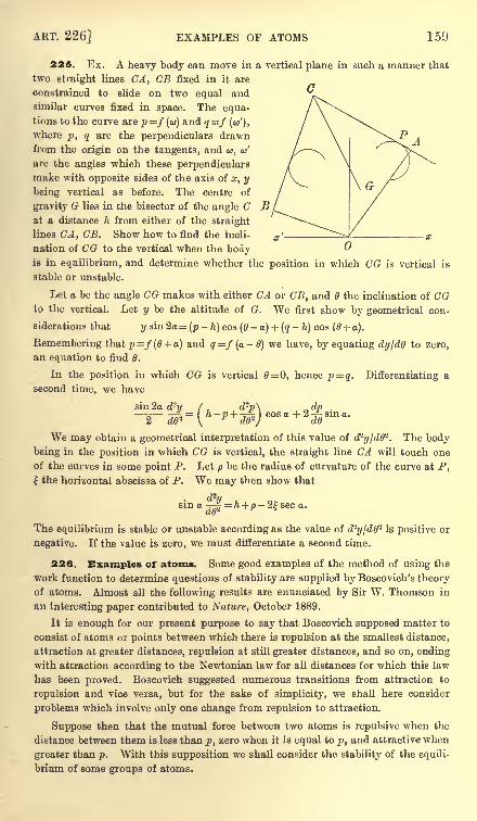
ART. 226] EXAMPLES OF ATOMS 159
225. Ex. A heavy body can move in a vertical plane in such a manner that
two straight lines CA, CB fixed in it are
constrained to slide on two equal andsimilar curves fixed in space. The equa-tions to the curve are p=f (u) and q=f (a/),
where p, q are the perpendiculars drawnfrom the origin on the tangents, and <a, w'
are the angles which these perpendicularsmake with opposite sides of the axis of x, y
being vertical as before. The centre of
gravity G lies in the bisector of the angle Cat a distance h from either of the straight
lines CA, CB. Show how to find the incli-
nation of CG to the vertical when the bodyis in equilibrium, and determine whether the position in which CG is vertical is
stable or unstable.
Let a be the angle CG makes with either CA or CB, and 6 the inclination of CGto the vertical. Let y be the altitude of G. We first show by geometrical con-
siderations that y sin 2a = (p-
h) cos (6-
a) + (q-
h) cos (6 + a).
Remembering that p =/ (0 + a) and q=f (a -6) we have, by equating dyjdO to zero,
an equation to find 0.
In the position in which CG is vertical 6= 0, hence p = q. Differentiating a
second time, we have
sin 2a n dp .
cos a + 2~ sin a.do
We may obtain a geometrical interpretation of this value of d?y/d62
. The body
being in the position in which CG is vertical, the straight line CA will touch one
of the curves in some point P. Let p be the radius of curvature of the curve at P,the horizontal abscissa of P. We may then show that
dzusin a |
= /t + /)-2|sec a.
The equilibrium is stable or unstable according as the value of d^yjdO2 is positive or
negative. If the value is zero, we must differentiate a second time.
226. Examples of atoms. Some good examples of the method of using the
work function to determine questions of stability are supplied by Boscovich's theoryof atoms. Almost all the following results are enunciated by Sir W. Thomson in
an interesting paper contributed to Nature, October 1889.
It is enough for our present purpose to say that Boscovich supposed matter to
consist of atoms or points between which there is repulsion at the smallest distance,
attraction at greater distances, repulsion at still greater distances, and so on, endingwith attraction according to the Newtonian law for all distances for which this law
has been proved. Boscovich suggested numerous transitions from attraction to
repulsion and vice versa, but for the sake of simplicity, we shah1
here consider
problems which involve only one change from repulsion to attraction.
Suppose then that the mutual force between two atoms is repulsive when the
distance between them is less than p, zero when it is equal to p, and attractive when
greater than p. With this supposition we shall consider the stability of the equili-
brium of some groups of atoms.
160 THE PRINCIPLE OF VIRTUAL WORK [CHAP. VI
227. Ex. 1. Three particles, whose masses are m, m', m" repel each other so
that the force between m and m' is F= -mm' (r-p)n-1 where n is an even integer.
The particles are in equilibrium when placed at the corners of an equilateral triangle
each of whose sides is equal to p. Show that the equilibrium is stable.
The term of the work function W corresponding to F is $Fdr=-
(r-p)n
.
When the atoms are displaced, let the three sides of the triangle be p + x, p + y, p + z.
We have by Art. 211, n (C - W) m'm"xn + m"myn + mm'zn.
The equilibrium is stable or unstable according as W is a maximum or a minimum,i.e. according as the right-hand side is a minimum or a maximum. But, since n is
even, the right-hand side is a minimum when x, y, z are each zero;for these values
make the right-hand side zero and all others make it greater than zero. The
equilibrium is therefore stable.
We have taken the law of force to be a single power of r-p, but it is clear that
the same reasoning will apply if the law of force is expressed by several terms with
different odd powers. Even greater generality may be given to the law, for it is
sufficient that the lowest power should be odd.
In just the same way we may prove that a group of four particles placed at the
corners of a regular tetrahedron, each of whose edges is equal to p, is a stable
arrangement.
Ex. 2. Three equal atoms A, B, C are placed in equilibrium in a straight line.
Supposing the force of repulsion to be F= -/* (r-p)11*1
, where n is even, determine
if the configuration is stable or unstable.
It is clear that in the position of equilibrium the distances AB, BC are each less
than the critical distance p, while AC is greater than p. Let AB and BC be each
equal to a. As we are only concerned with ~,
relative displacements, let A be fixed. Let
B', C" be the displaced positions of B, C;let
(xy) be the coordinates of B' referred to B,
and (x'y') those of C' referred to C. If r=AB', we have
i w222 -
.-. (r -p)*= (a-p)*+ n (a-p)
n~l ( x + ^\ + n^^ (a-p)*-*a? + &c.
If we replace (xy) by (x'- x, y'
-y), this expression gives the value of (r" -p)
n where
r"=B'C'. If instead we replace (xy) by (x'y') and write 2a for a, the expression
gives the value of (/ -p)n
,where r' = AC'.
Taking all these expressions, we have as before
-(C
- W) = (r-p)
n + (r' -p)n + (r"
-p)
n
+ n(2a-p)n~l -' +
where all the constant terms have been absorbed into one constant, viz. C.
To' find the position of equilibrium, we make W a maximum or a minimum, i.e.
AW AW AW AWwe put ^=0, jg=0,
= 0, ,= 0. These give (a-p)^ + (2a-p)^ = 0.
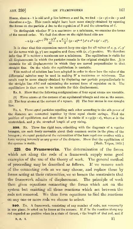
ART. 230] ON FRAMEWORKS 161
Hence, since n - 1 is odd and p lies between a and 2a, we find -(a -p) = 2a -p and
therefore a= %p. This result might have been more simply obtained by equating
the forces on the particle A due to the repulsion of B and the attraction of C.
To distinguish whether W is a maximum or a minimum, we examine the terms
of the second order. We find that those on the right-hand side are
It is clear that this expression cannot keep one sign for all values of a;, y, x', y'
for the terms with (y, y') are negative and those with (x, x') positive. We therefore
infer that W is neither a maximum nor a minimum. The equilibrium is stable for
all displacements in which the particles remain in the original straight line. ^&isunstable for all displacements in which they are moved perpendicular to that
straight line. On the whole the equilibrium is unstable.
This method of solution has been adopted in order to show how the rules of the
differential calculus may be used in making W a maximum or minimum. The
result may be more simply obtained by displacing one particle perpendicularly to
the straight line ABC and calculating the normal force of repulsion on it. The
equilibrium is then seen to be unstable for this displacement.
Ex. 3. Show that the following configurations of four equal atoms are unstable.
(1) Three atoms at the corners of an equilateral triangle and one at the centre.
(2) The four atoms at the corners of a square. (3) The four atoms in one straight
line.
Ex. 4. Three equal particles repelling each other according to the nth power of
the distance are connected together by three equal elastic strings. Find the
position of equilibrium and show that it is stable if n<pj(p-a), where a is the
unstretched, and p the stretched length of any string.
228. Ex. Three fine rigid bars, coinciding with the diagonals of a regular
hexagon, are each freely moveable about their common centre in the plane of the
hexagon ; six equal particles at the extremities of the bars repel one another with a
force varying inversely as any power of the distance. Show that the equilibrium of
the system is stable. [Math. Tripos, 1859.]
229. On Frameworks. The determination of the forces
which act along the rods of a framework supply some good
examples of the use of the theory of work. The general method
of proceeding may be described as follows. If we remove such
of the connecting rods as we may choose, and replace these byforces acting at their extremities, we so loosen the constraints that
the framework admits of displacement. The principle of work
then gives equations connecting the forces which act on the
system but omitting all those reactions which act between the
rods not removed. We thus form equations to find the reactions
on any one or more rods we choose to select.
23O. Ex. A framework, consisting of any number of rods, not necessarily
in one plane, is acted on by forces at the corners. If E be the reaction along anyrod regarded as positive when in a state of thrust, r the length of that rod, and if
R. 8. I. 11
162 THE PRINCIPLE OF VIRTUAL WORK [CHAP. VI
X, 1', Z be the components of the forces at that corner whose coordinates are
x, y, z, prove that 2-Rr + 2 (Xx + Yy + Zz) = 0,
where the S implies summation over the whole framework. Maxwell, Edinburgh
Transactions, 1872, Vol. 26, p. 14.
Let us remove all the rods and apply the corresponding reactions at particles
placed at the corners. We now displace the system by giving it a slight enlarge-
ment, so that the displaced figure is similar to the original one. The principle of
work gives 2Rdr+ S (Xdx+ Ydy + Zdz) = 0. But, since the figures are similar,
dr/r=dxlx = &c. Substituting, the result follows at once. As an example of this
theorem see Art. 130, Ex. 5.
231. When we apply the principle of work to a frame, we
have to displace the corners. It will be found convenient to
distinguish these displacements by different names.
If the frame is not stiffened by the proper number of rods
(Art. 151) the angles may receive finite changes of magnitudewithout altering the length of any side. When this is the case
any change is called a normal or ordinary deformation. The
actual displacement given may be infinitely small, but in a
normal deformation the change of angle may be increased until
it becomes finite.
If the framework is stiffened by the proper number of rods,
the connecting rods may possibly be so arranged that the anglescan receive infinitely small changes in magnitude, but not finite
changes, without altering the length of any side (Art. 151). Such
a displacement is called an abnormal or singular deformation.
This is an imaginary displacement, which could be a real one only
when small quantities of the second order are neglected.
If the frame is stiffened by only just the proper number of
rods so that there are no relations between the lengths of the
rods, any side of the frame can be increased in length without
breaking its connection with the others. Such a frame is said to
be simply stiff or freely dilatable.
If there are more rods than are necessary to stiffen the frame,
so that there are relations between the lengths of the sides, one
rod cannot be altered in length without altering some of the others.
Such a frame is said to be indilatable or dilatable under one or
more conditions.
These names are due partly to Maxwell, Phil. Mag. 1864, and partly to
M. Levy, Statique Graphique.
232. A simply stiffframe of rods connected by smooth hinges at
the corners A lt A 2 &c. is in equilibrium under the action ofany forces.
ART. 233] ON FRAMEWORKS 163
It is required to find the stress along any side A^A^ which is not acted
on by the external forces.
Let ^12 be the reaction along this rod, and let it be regarded as
positive when the rod is in a state of thrust. Let 112 be the lengthof the side.
Since the external forces are in equilibrium the work due to
any virtual displacement of the frame which does not alter the
length of any side is zero. Let us remove the rod A^ 2 from the
frame and replace its effects by applying to the particles at its
extremities forces each equal to R12 . If we now fix in space anyother side, say the adjoining side A^n, the polygon will have one
degree of freedom. It may be deformed, and each corner will
describe a curve fixed in space. Supposing a small deformation
given, let the length 112 be increased by c^12 ,and let dW be the
work of the external forces. Then, since the other reactions do
not put in any appearance in the equation of work, we have
R^l12 + dW=0 ........................ (1).
If in addition to this deformation we give the side AiAn anyvirtual displacement, the frame moving with it as a whole, the
work dW is not altered. We see therefore that the mode of
displacement is immaterial. It is not even necessary to remove
the side 1K ,we simply let its length increase by dllz . If dW be
the resulting work of the forces, the reaction _R12 is given by
R - - (2)dll2
"
It appears that, ifthe length ofany rod, not acted on by the external
forces, can be increased without undoing theframe the reaction along
that rod is determinate. For example, if there are no external forces
acting on the frame, the reaction along any such side is zero.
233. If the rod A^A^ is acted on by some of the 'external forces
the reactions at the corners A lt A 2 do not necessarily act along the
length of the rod. We may reduce this case to the one already
considered in the last article by replacing each of these forces bytwo parallel forces, one acting at each extremity of the rod. This
method has been explained in Art. 134. We may also find the
reactions by a more direct process.
Let R12 ,$12 be the components of the action at the corner A t
of the rod A^A^, resolved along and perpendicular to the length of
the rod. In the same way R^, $21 are the components at the
112
164 THE PRINCIPLE OF VIRTUAL WORK [CHAP. VI
corner A 2 of the same rod. Let us remove the rod A^ 2 and
replace its effects on the rest of the frame by applying at its
extremities the forces R^ ,S12 and R2l , S2l . Let Rn ,
R2l be regarded
as positive when the rod is in a state of thrust.
Let the system be so deformed that the length of the side A^A 2
is increased by dl^, while the corner A 2 and the direction in space
of that side are unaltered. The virtual work of the reactions R2l ,S21
and S12 in this displacement is evidently zero. Let dW be the
virtual work of the external forces which act on the system,
excluding the rod A^A^, then
To find the reaction S12 a different displacement must be
given to the system. The external forces which act on the rod
A-^Ay, having been removed, the remaining external forces are not
in equilibrium. The virtual work for a displacement of the
frame as a whole is not necessarily zero. Keeping A 2 as before
fixed in space and not altering the length 112 ,let us turn the frame
round an axis perpendicular to the plane containing A 2 and the
force $!2. If dd be the angle of displacement and dW the work
of the forces, we haveS12d0 + dW = 0.
By giving the frame these two deformations the reactions R12
and S12 at the corner A l can be found. If the frame be perfectly
free, the deformation necessary to find S12 can always be given. Thedeformation necessary to find R^ requires that the length of the
rod can be altered. It follows that both these reactions are deter-
minate if the length of the rod A :A 2 can be altered without
destroying the connections of the frame.
If the frame is subject to any external constraints, these maybe replaced by pressures at the points of constraint. When the
magnitudes of these pressures have been deduced from the general
equations of equilibrium, we may regard the frame as perfectlyfree and acted on by known forces. The reactions at any corner
may then be found as if the frame were free.
It is not meant that in every case exactly these displacementsmust be given to the system, for these may not suit the geometricalconditions of the problem. Other displacements may recommendthemselves by their symmetry or by the ease with which the
virtual work due to those displacements can be found. Any two
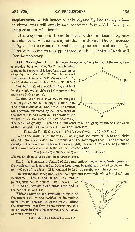
ART. 234] ON FRAMEWORKS 165
displacements which introduce only R12 and $12 into the equationsof virtual work will supply two equations from which these two
components may be found.
If the system be in three dimensions, the direction of S12 maybe unknown as well as its magnitude. In this case the componentsof $12 in two convenient directions may be used instead of $12 .
Three displacements to supply three equations of virtual work will
then be necessary.
234. Examples. Ex. 1. Six equal heavy rods, freely hinged at the ends, form
a regular hexagon ABCDEF, which when
hung up by the point A is kept from altering its
shape by two light rods BF, CE. Prove that
the thrusts of the rods BF, CE are as 5 to 1,
and find their magnitudes. [Math. T., 1874.]
Let the length of any side be 2a, and let
be the angle which either of the upper sides
makes with the vertical.
To find the thrust T of BF, we suppose
the length of BF to be slightly increased.
The inclinations of AB and AF to the vertical
are therefore increased by dd. The work of
the thrust T is Td (4asin 6). The work of the
weights of the two upper rods is 2Wd(a cos 6).
The centre of gravity of each of the four other rods is slightly raised, and the work
of their weights is 4Wd (2a cos 0). We have therefore
Td (4a sin 0) + 2Wd (a cos 0) + 4Wd (2a cos 6) =0, .". 2T=5W tan 0.
To find the thrust T' of the rod CE, we suppose the length of CE to be slightly
altered. No work is done by the weights of the four upper rods. The centres of
gravity of the two lower rods are however slightly raised. If 6 be the angle either
of the lower rods makes with the vertical, we easily find
2"d(4asin0) + 2TFd(acos0) = 0, .-. 2T'=fTtan0.
The result given in the question follows at once.
Ex. 2. A tetrahedron, formed of six equal uniform heavy rods, freely jointed at
their extremities, is suspended from a fixed point by a string attached to the middle
point of one of its edges. It is required to find the reactions at the corners.
The tetrahedron is regular, hence the upper and lower rods, viz. AB and CD, are
horizontal. Let L and M be their middle ^points, then LM is vertical; let LM=z. Let
P, P be the thrusts along these rods and wthe weight of any rod.
Without altering the direction in space of
the upper rod, or the position of its middle
point, let us increase its length by dr. Since
the transverse reactions at its extremities will
do no work in this displacement, the equation
of virtual work is
(1).
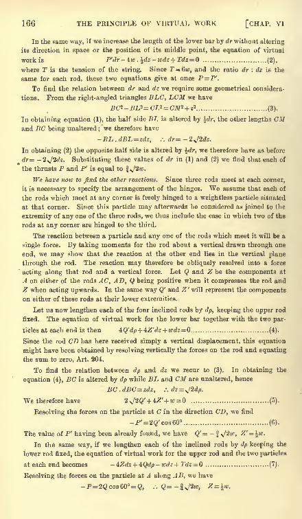
166 THE PRINCIPLE OF VIRTUAL WORK [CHAP. VI
In the same way, if we increase the length of the lower bar by dr without altering
its direction in space or the position of its middle point, the equation of virtual
work is P'dr-4w ,)[dz-wdz + Tdz=Q (2),
where T is the tension of the string. Since T = 6w, and the ratio dr : dz is the
same for each rod, these two equations give at once P=P'.
To find the relation betsveen dr and dz we require some geometrical considera-
tions. From the right-angled triangles BLC, LCM we have
BC*-BL2=CL*= CM*+ z* (3).
In obtaining equation (1), the half side BL is altered by idr, the other lengths CMand BC being unaltered ; we therefore have
- BL . dBL = zdz, .: dr= - 2 J2dz.
In obtaining (2) the opposite half side is altered by %dr, we therefore have as before
dr= -2,J2dz. Substituting these values of dr in (1) and (2) we find that each of
the thrusts P and P' is equal to *J2w.
We have now to find the other reactions. Since three rods meet at each corner,
it is necessary to specify the arrangement of the hinges. We assume that each of
the rods which meet at any corner is freely hinged to a weightless particle situated
at that corner. Since this particle may afterwards be considered as joined to the
extremity of any one of the three rods, we thus include the case in which two of the
rods at any corner are hinged to the third.
The reaction between a particle and any one of the rods which meet it will be a
single force. By taking moments for the rod about a vertical drawn through one
end, we may show that the reaction at the other end lies in the vertical plane
through the rod. The reaction may therefore be obliquely resolved into a force
acting along that rod and a vertical force. Let Q and Z be the components at
A on either of the rods AC, AD, Q being positive when it compresses the rod and
Z when acting upwards. In the same way Q' and Z' will represent the componentson either of these rods at their lower extremities.
Let us now lengthen each of the four inclined rods by dp, keeping the upper rod
fixed. The equation of virtual work for the lower bar together with the two par-
ticles at each end is then 4tQ'dp + 4:Z'dz +wdz=Q (4).
Since the rod CD has here received simply a vertical displacement, this equation
might have been obtained by resolving vertically the forces on the rod and equating
the sum to zero, Art. 204.
To find the relation between dp and dz we recur to (3). In obtaining the
equation (4), BC is altered by dp while BL and CM are unaltered, hence
BC.dBC=zdz, .:dz=^2dp.
We therefore have 2J2Q'+ 4Z'+ w = (5).
Resolving the forces on the particle at C in the direction CD, we find
-P'= 2Q'cos60 (6).
The value of P' having been already found, we have Q'= -f J'2w, Z'= \w.
In the same way, if we lengthen each of the inclined rods by dp keeping the
lower rod fixed, the equation of virtual work for the upper rod and the two particles
at each end becomes -4Zdz + 4Qdp-wdz + Tdz= Q (7).
Resolving the forces on the particle at A along AB, we have
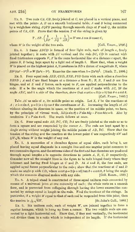
ART. 234] ON FRAMEWORKS 167
Ex. 3. Two rods CA, CB, freely jointed at C, are placed in a vertical plane, and
rest with the points A, B on a smooth horizontal table, A and B being connected
by a weightless string AQPB passing through smooth rings at P and Q, the middle
points of CA, CB. Prove that the tension T of the string is given by
T. AB. ( + -+ ^] = WcosAcosBcosecC,\BP AQ AB/
where W is the weight of the two rods. [Coll. Exam., 1890.]
Ex. 4. A frame ABCD is formed of four light rods, each of Jength a, freely
jointed together; it rests with AC vertical and the rods BC, CD in contact with
fixed frictionless supports E, F in the same horizontal line at a distance c apart, the
joints B, D being kept apart by a light rod of length b. Show that, when a weightW is placed on the highest joint A ,
it produces in BD a thrust of magnitude R, where
Rb* (4a2 - b2)i = W (2a
2c - b3). Examine the case when b = (2a
2c)i [Math. T. , 1886.]
Ex. 5. Four equal rods AEB, CRD, ESB, FSD form with each other a rhombus
RBSD ;A and C are fixed hinges at a distance a from R ; R, B, S and D are free
hinges, and at E and F forces, each equal to P, are applied perpendicular to the
rods. If a be the angle which the reactions at A and C make with AC, 20 the
angle ARC, and b a side of the rhombus, show that a cot a = 2 (a + b) tan 6 + a cot 0.
[Coll. Exam., 1889.]
Take AC as axis of x, its middle point as origin. Let X, Y be the reactions at
A ; x = a sin 0, y = 2 (a + b) cos the coordinates of E. Increasing the length of ACwithout altering its direction in space, or the position of its middle point, we have,
by the principle of virtual work, Xd (a sin 6) + Psin6dy -Pcos0dx 0. Also byresolution r+Psin0=0. The result follows at once.
Ex. 6. Four equal rods AB, BC, CD, DA are freely jointed at the ends so as to
form a square and are suspended by the corner A. The rods are kept apart by a
single string without weight joining the middle points of AB, BC. Show that the
tension of the string and the reaction at the lowest point C are respectively 4JF and
^W,J5, where W is the weight of any rod.
Ex. 7. A succession of n rhombus figures of equal sides, each being b, are
placed having equal diagonals in a straight line and one angular point common to
two successive figures, and the extreme sides of the first and last rhombus are produced
through equal lengths a in opposite directions to points A, B, C, D respectively.
Consider now all the straight lines in the figure to be rods hinged freely where they
intersect and having fixed hinges at C and D. At A and B, the free ends, are
applied equal forces perpendicular to the rods ;show that the reactions at C and D
make an angle <j>with CD, where a cot <p
= 2 (a + nb) tan 6 + a cot 6, B being the angle
which the common diagonal makes with any side. [Coll. Exam., 1889.]
Ex. 8. A tripod stand is constructed of three equal uniform rods connected bymeans of a universal joint at one extremity of each ; the whole rests on a smooth
floor, and is prevented from collapsing through having the lower extremities con-
nected by strings equal in length to the rods. Find the tensions of the strings. In
particular, if a weight W equal to that of each rod be suspended from this joint, then
the tension is & *J&W. [St John's Coll., 1882.]
Ex. 9. Six uniform rods, each of weight W, are jointed together to form a
regular hexagon, which is hung up from a corner. The two middle rods are con-
nected by a light horizontal rod. Show that, if they rest vertically, the horizontal
rod divides them in a ratio which is independent of its length. If the horizontal
168 THE PRINCIPLE OF VIRTUAL WORK [CHAP. VI
rod be heavy, and uniform in length and material with the others, show that the
ratio is 6 : 1, and that the stress in the horizontal rod is |JFx/3. Find also the
stresses at the joints. [Coll. Exam., 1888.]
235. Abnormal deformations. Referring to the general
theorem considered in Art. 232 we notice that there is a peculiar
case of exception. Let us suppose that the forces which act on
the frame are applied at the corners so that the reactions act along
the sides of the polygon.
The side A^^ being removed, the polygon may be deformed;
the principle of virtual work then gives
R^lu + dW =(1).
Supposing the side AnA l to be fixed in space, it is possible,
when the frame is deformed, that the corner A 2 may begin to move
perpendicularly to the side A 1A 2 . In this case dl12
= 0. If the side
A nAi is also displaced in any manner, by the frame moving as a
whole, the quantity dll2 is unaltered and is therefore still zero.
When the rod A^A 2 is replaced, it is now possible to give the
frame a small deformation without altering the length of any side,
provided we neglect small quantities of the second order. Since
the frame is now stiff, this deformation is of the kind called
abnormal. Art. 231.
The external forces acting on the frame are in equilibrium,
hence their virtual work for every displacement of the frame as a
whole is zero. If it be not zero for this abnormal deformation also,
the reaction jR12 must be infinite. But if it be zero the equation
(1) becomes nugatory, since both dll2 and dW are zero. The
reaction Rn may now be finite.
In order, then, to deform the frame so that the reaction ^12 maydo work, we must remove, or lengthen, two or more sides. Let
these be the given side 112 and any other say 4$. We now have
Rafttn + R,4las + dW=0 (2).
To use this equation we must know the ratio between the
corresponding increments of any two sides. The equation (2) will
then give the relation between the corresponding reactions. Thus
the reactions are indeterminate; one is arbitrary but the others
may be found in terms of this one.
336. In most cases the relation between the increments of any two sides maybe found by inspection or by differentiating some known relations between the sides
of the polygon. In more difficult cases we may proceed in the following manner.
See LeVy, Statique Graphique.
ART. 238] INDETERMINATE TENSIONS 169
Regarding the stiff framework as a general polygon with undetermined sides, we
can find as many angles as may be convenient in terms of the sides. Let us
suppose, as an example, that two equations have been found connecting, say, the
two angles l , 2 with the sides. Let these be
.Moos*!, cos 2 , /, !, &c.) = 0l
/2 (COS 0j, COS 2 ,J]2 , ?23> &C.)=0|
Since this particular polygon can have a slight deformation without altering the
sides we must have
These give d&l= and d02 =0, unless the special polygon under consideration is
such that the determinant J= dfjde, dfjde., (5).
d/2/d02
If we vary the lengths of the rods, the corresponding changes of the angles ^ , 2
are given by d/\ d/i _ d/i)-r aCTi + -j U0.,= 2. - (If I
Multiplying these equations by the minors of the first row of the determinant J,
and adding the results, the left-hand side will vanish. We thus obtain a relation
between the increments of length of the rods of the form
This relation must be satisfied by any assumed changes of length of the rods.
237. Indeterminate tensions. It is generally more con-
venient to consider these indeterminate reactions apart from anyexternal forces. To make this point clear, let us suppose that two
sets of external forces in all respects the same can produce two
different sets of internal stress when they act separately on the
frame. Then, reversing one set of the external forces and makingthem act simultaneously, we have the frame in a self-strained state
with no external forces. If then we can find all the internal stresses
when no forces act, we can superimpose them on any one set of
stress produced by a given set of forces, to find all the states
of stress consistent with those forces.
In the tenth volume of the Proceedings of the Mathematical Society, 1878, MrCrofton discusses some cases of hexagons and octagons in a state of self-strain.
His theory was afterwards enlarged by M. Le"vy in 1888 in his Statique Graphique.
338. Ex. 1. A plane framework, having an even number n of corners, has for its
bars the n sides joining these corners and the Jra diagonals joining the opposite corners.
Show that it may be in a state of stress without any external forces if the. fyi points
of intersection of opposite sides lie in one straight line. [Levy's theorem.]
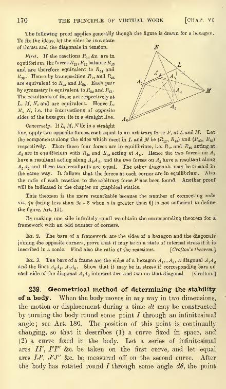
170 THE PRINCIPLE OF VIRTUAL WORK [CHAP. VI
The following proof applies generally though the figure is drawn for a hexagon.
To fix the ideas, let the sides be in a state
of thrust and the diagonals in tension.
First. If the reactions J?]2 &c. are in
equilibrium, the forces J?12 , R3.
2balance R .,s
and are therefore equivalent to EM and
Egg . Hence by transposition Ru and U45
are equivalent to R.^ and R56 . Each pair -*i
by symmetry is equivalent to R^ and JR61
.
The resultants of these act respectively at
L, M, N, and are equivalent. Hence L,
M, N, i.e. the intersections of opposite
sides of the hexagon, lie in a straight line.
Conversely. If L, M, N lie in a straight
line, apply two opposite forces, each equal to an arbitrary force F, at L and M. Let
the components along the sides which meet in L and J/ be (R 12 ,-R45 ) and (R&, R^)
respectively. Then these four forces are in equilibrium, i.e. JR12and J?32 acting at
A 2 are in equilibrium with R4S and R^ acting at A 5 . Hence the two forces on A 2
have a resultant acting along A^A 5 ,and the two forces on A s have a resultant along
A 5 A 2 and these two resultants are equal. The other diagonals may be treated in
the same way. It follows that the forces at each corner are in equilibrium. Also
the ratio of each reaction to the arbitrary force F has been found. Another proof
will be indicated in the chapter on graphical statics.
This theorem is the more remarkable because the number of connecting rods
viz. f re (being less than 2ra - 3 when n is greater than 6) is not sufficient to define
the figure, Art. 151.
By making one side infinitely small we obtain the corresponding theorem for a
framework with an odd number of corners.
Ex. 2. The bars of a framework are the sides of a hexagon and the diagonals
joining the opposite corners, prove that it may be in a state of internal stress if it is
inscribed in a conic. Find also the ratio of the reactions. [Crofton's theorem.}
Ex. 3. The bars of a frame are the sides of a hexagon A1 ...A 6 , a diagonal A^ t
and the lines A%A 6 , A 3A S . Show that it may be in stress if corresponding bars on
each side of the diagonal Ali
A i intersect two and two on that diagonal. [Crofton.]
239. Geometrical method of determining the stability
of a body. When the body moves in any way in two dimensions,
the motion or displacement during a time dt may be constructed
by turning the body round some point / through an infinitesimal
angle; see Art. 180. The position of this point is continually
changing, so that it describes (1) a curve fixed in space, and
(2) a curve fixed in the body. Let a series of infinitesimal
arcs //', I'l" &c. be taken on the first curve, and let equalarcs IJ', J'J" &c. be measured off on the second curve. After
the body has rotated round / through some angle dd, the point
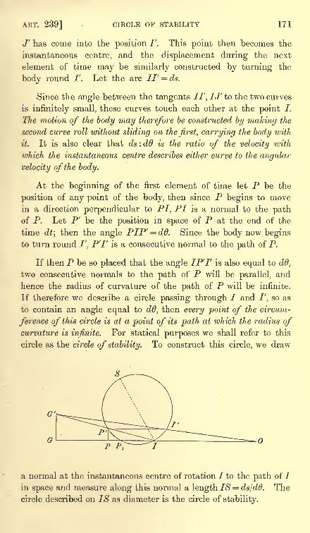
ART. 239] CIRCLE OF STABILITY 171
J' has come into the position /'. This point then becomes the
instantaneous centre, and the displacement during the next
element of time may be similarly constructed by turning the
body round /'. Let the arc IF = ds.
Since the angle between the tangents //', IJ' to the two curves
is infinitely small, these curves touch each other at the point /.
The motion of the body may therefore be constructed by making the
second curve roll without sliding on the first, carrying the body with
it. It is also clear that ds : d6 is the ratio of the velocity with
which the instantaneous centre describes either curve to the angular
velocity of the body.
At the beginning of the first element of time let P be the
position of any point of the body, then since P begins to movein a direction perpendicular to PI, PI is a normal to the pathof P. Let P' be the position in space of P at the end of the
time dt; then the angle PIP' = d6. Since the body now beginsto turn round /', P'F is a consecutive normal to the path of P.
If then P be so placed that the angle IP'F is also equal to dd,
two consecutive normals to the path of P will be parallel, and
hence the radius of curvature of the path of P will be infinite.
If therefore we describe a circle passing through / and F, so as
to contain an angle equal to dd, then every point of the circum-
ference of this circle is at a point of its path at which the radius ofcurvature is infinite. For statical purposes we shall refer to this
circle as the circle of stability. To construct this circle, we draw
P PI
a normal at the instantaneous centre of rotation / to the path of /in space and measure along this normal a length IS= ds/dd. The
circle described on IS as diameter is the circle of stability.
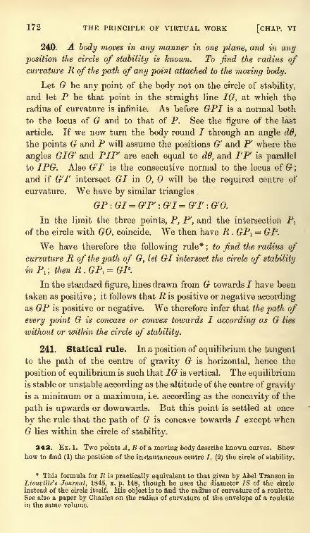
172 THE PRINCIPLE OF VIRTUAL WORK [CHAP. VI
240. A body moves in any manner in one plane, and in any
position the circle of stability is known. To find the radius ofcurvature R of the path of any point attached to the moving body.
Let G be any point of the body not on the circle of stability,
and let P be that point in the straight line IG, at which the
radius of curvature is infinite. As before GPI is a normal both
to the locus of G and to that of P. See the figure of the last
article. If we now turn the body round / through an angle dO,
the points G and P will assume the positions G' and P1
where the
angles GIG' and PIP' are each equal to dd, and I'P' is parallel
to IPG. Also GT is the consecutive normal to the locus of G ;
and if GT intersect GI in 0, will be the required centre of
curvature. We have by similar triangles
GP:GI= G'P' : G'l = GT : GO.
In the limit the three points, P, P', and the intersection Pl
of the circle with GO, coincide. We then have R . GP1= GI-.
We have therefore the following rule*;
to find the radius ofcurvature R of the path of G, let GI intersect the circle of stability
in Pl ; then R.GP,= GI2.
In the standard figure, lines drawn from G towards / have been
taken as positive ;it follows that R is positive or negative according
as GP is positive or negative. We therefore infer that the path of
every point G is concave or convex towards I according as G lies
without or within the circle of stability.
241. Statical rule. In a position of equilibrium the tangentto the path of the centre of gravity G is horizontal, hence the
position of equilibrium is such that IG is vertical. The equilibriumis stable or unstable according as the altitude of the centre of gravity
is a minimum or a maximum, i.e. according as the concavity of the
path is upwards or downwards. But this point is settled at once
by the rule that the path of G is concave towards / except when
G lies within the circle of stability.
342. Ex. 1. Two points A, B of a moving body describe known curves. Showhow to find (1) the position of the instantaneous centre /, (2) the circle of stability.
* This formula for R is practically equivalent to that given by Abel Transon in
Liouville's Journal, 1845, x. p. 148, though he uses the diameter 7.9 of the circle
instead of the circle itself. His object is to find the radius of curvature of a roulette.
See also a paper by Chasles on the radius of curvature of the envelope of a roulette
in the same volume.
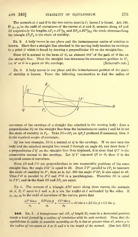
ART. 243] STABILITY OF EQUILIBRIUM 173
The normals at A and B to the two curves meet in I;hence 7 is found. Art. 180.
If ft , p2 be the radii of curvatures of the curves at A and B, measure along AI and
BI respectively the lengths APlAI 2
/pland 7?P2 =7?7
2/p2 ; the circle circumscribing
the triangle 7PjP2 is the circle of stability.
Ex. 2. A body moves in one plane and the instantaneous centre of rotation is
known. Show that a straight line attached to the moving body touches its envelopein a point G which is found by drawing a perpendicular IG on the straight line.
Since GI is normal to the locus of G, an element GG' of the path of G lies on
the straight line. Thus the straight line intersects its consecutive position in G',
i.e. G' or G is a point on the envelope. [Roberval's rule.]
Ex. 3. A body moves in one plane and the instantaneous position of the circle
of stability is known. Prove the following construction to find the radius of
curvature of the envelope of a straight line attached to the moving body : draw a
perpendicular IQ on the straight line from the instantaneous centre I and let it cut
the circle of stability in Pl
. Take IO=IP1 on QPJ produced if necessary, then Ois the required centre of curvature.
By the last example, 10 is a normal at Q to the envelope. If we now turn the
body and the attached straight line round I through an angle dO, and draw from I r
a perpendicular I'Q' on the straight line thus displaced, it is clear that QT is the
consecutive normal to the envelope. Let Q'l' intersect QI in O, then is the
required centre of curvature.
Since IO and I'O are perpendiculars to two consecutive positions of the same
straight line, the angle 701' is equal to dO. Draw I'P' parallel to IPlto intersect
the circle of stability in P', then as in Art. 239 the angle P'IPlis also equal to d6*
Thus I'O is parallel to P'7 and P'O is a parallelogram. Therefore IO is equal
to 7'P', and IB the limit IO and 7Pj are equal.
Ex. 4. The corners of a triangle ABC move along three curves, the normals
at A, B, C meet in 7 and a, /9, 7 are the angles at 7 subtended by the sides. If
Pi' /2' Pa be the radii of curvature of the curves, prove that
A I* sin a. BI*s'm8 C7 2sin-y"sin a. BI*s'm8--
1--"
Pi Pz
=^7 sin a + 7 sin /3 + C7 sin 7.
243. Ex. 1. A homogeneous rod AB, of length 21, rests in a horizontal position
inside a bowl formed by a surface of revolution with its axis vertical. Show that the
equilibrium is stable or unstable according as I2p is less or greater than n3
, where p is
the radius of curvature at A or B and n is the length of the normal. [See Art. 222.]
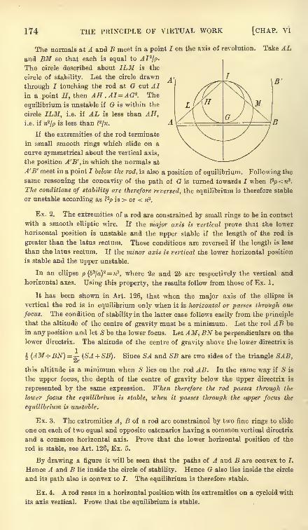
174 THE PRINCIPLE OF VIRTUAL WORK [CHAP, vi
The normals at A and B meet in a point I on the axis of revolution. Take ALand BM so that each is equal to AI*fp.
The circle described about ILM is the
circle of stability. Let the circle drawn
through I touching the rod at G cut AIin a point H, then AH . AI=AG*. The
equilibrium is unstable if G is within the
circle ILM, i.e. if AL is less than AH,i.e. if n2
//>is less than Z
2/n.
If the extremities of the rod terminate
in small smooth rings which slide on a
curve symmetrical about the vertical axis,
the position A'B', in which the normals at
A'B' meet in a point I below the rod, is also a position of equilibrium. Following the
same reasoning the concavity of the path of G is turned towards I when l-p < n*.
The conditions of stability are therefore, reversed, the equilibrium is therefore stable
or unstable according as I2p is > or < n3
.
Ex. 2. The extremities of a rod are constrained by small rings to be in contact
with a smooth elliptic wire. If the major axis is vertical prove that the lower
horizontal position is unstable and the upper stable if the length of the rod is
greater than the latus rectum. These conditions are reversed if the length is less
than the latus rectum. If the minor axis is vertical the lower horizontal position
is stable and the upper unstable.
In an ellipse p (62/a)
2=n3, where 2a and 26 are respectively the vertical and
horizontal axes. Using this property, the results follow from those of Ex. 1.
It has been shown in Art. 126, that when the major axis of the ellipse is
vertical the rod is in equilibrium only when it is horizontal or passes through one
focus. The condition of stability in the latter case follows easily from the principle
that the altitude of the centre of gravity must be a minimum. Let the rod AB be
in any position and let S be the lower focus. Let A M, BN be perpendiculars on the
lower directrix. The altitude of the centre of gravity above the lower directrix is
% (AM+BN)= (SA + SB). Since SA and SB are two sides of the triangle SAB,
this altitude is a minimum when S lies on the rod AB. In the same way if S is
the upper focus, the depth of the centre of gravity below the upper directrix is
represented by the same expression. When therefore the rod passes through the
lower focus the equilibrium is stable, when it passes through the upper focus the
equilibrium is unstable.
Ex. 3. The extremities A, B of a rod are constrained by two fine rings to slide
one on each of two equal and opposite catenaries having a common vertical directrix
and a common horizontal axis. Prove that the lower horizontal position of the
rod is stable, see Art. 126, Ex. 5.
By drawing a figure it will be seen that the paths of A and B are convex to I.
Hence A and B lie inside the circle of stability. Hence G also lies inside the circle
and its path also is convex to I. The equilibrium is therefore stable.
Ex. 4. A rod rests in a horizontal position with its extremities on a cycloid with
its axis vertical. Prove that the equilibrium is stable.
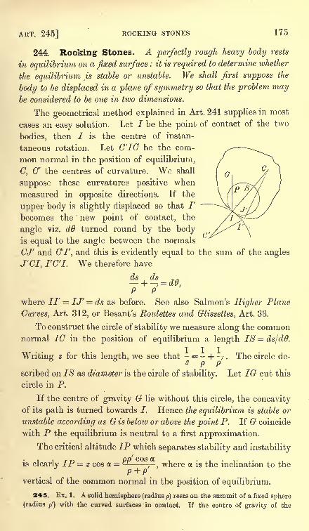
ART. 245] ROCKING STONES 175
244. Rocking Stones. A perfectly rough heavy body rests
in equilibrium on a fixed surface : it is required to determine whether
the equilibrium is stable or unstable. We shall first suppose the
body to be displaced in a plane of symmetry so that the problem maybe considered to be one in two dimensions.
The geometrical method explained in Art. 241 supplies in most
cases an easy solution. Let / be the point of contact of the two
bodies, then / is the centre of instan-
taneous rotation. Let C'lG be the com-
mon normal in the position of equilibrium,
C, C' the centres of curvature. We shall
suppose these curvatures positive when
measured in opposite directions. If the
upper body is slightly displaced so that /'
becomes the new point of contact, the
angle viz. d6 turned round by the bodyis equal to the angle between the normals
CJ' and C'l', and this is evidently equal to the sum of the angles
J'CI, I'C'I. We therefore have
*+^-*.P P
where //' = IJ' = ds as before. See also Salmon's Higher Plane
Curves, Art. 312, or Besant's Roulettes and Glissettes, Art. 33.
To construct the circle of stability we measure along the commonnormal 1C in the position of equilibrium a length IS = ds/dd.
Writing z for this length, we see that - = - + . The circle de-
scribed on IS as diameter is the circle of stability. Let IG cut this
circle in P.
If the centre of gravity G lie without this circle, the concavityof its path is turned towards I. Hence the equilibrium is stable or
unstable according as G is below or above the point P. If G coincide
with P the equilibrium is neutral to a first approximation.
The critical altitude IP which separates stability and instability
is clearly IP = z cos a = j- , where a is the inclination to thep + p
vertical of the common normal in the position of equilibrium.
245. Ex. 1. A solid hemisphere (radius p) rests on the summit of a fixed sphere
(radius p') with the curved surfaces in contact. If the centre of gravity of the
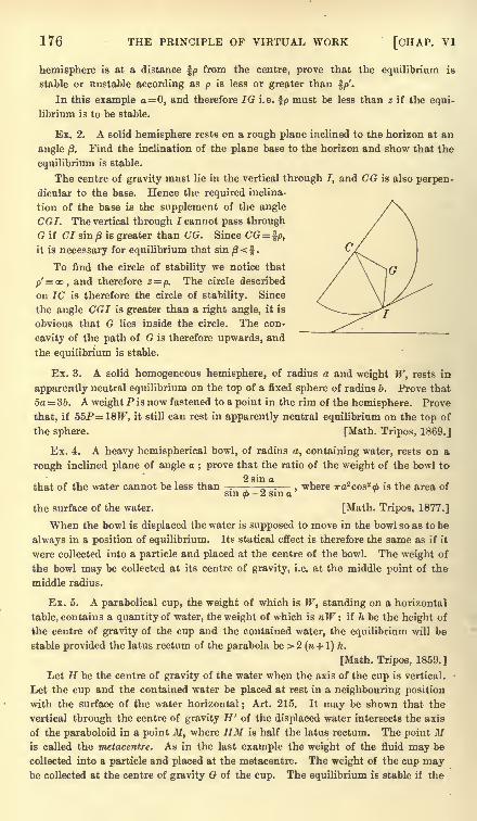
176 THE PRINCIPLE OF VIRTUAL WORK [CHAP. VI
hemisphere is at a distance f/> from the centre, prove that the equilibrium is
stable or unstable according as p is less or greater than 5p'.
In this example a= 0, and therefore IG i.e. fp must be less than z if the equi-
librium is to be stable.
Ex. 2. A solid hemisphere rests on a rough plane inclined to the horizon at an
angle /S.Find the inclination of the plane base to the horizon and show that the
equilibrium is stable.
The centre of gravity must lie in the vertical through I, and CG is also perpen-
dicular to the base. Hence the required inclina-
tion of the base is the supplement of the angle
CGI. The vertical through I cannot pass through
G if CI sin /3 is greater than CG. Since CG= %p,
it is necessary for equilibrium that sin /3<f .
To find the circle of stability we notice that
p'= oo, and therefore z = p. The circle described
on 1C is therefore the circle of stability. Since
the angle CGI is greater than a right angle, it is
obvious that G lies inside the circle. The con-
cavity of the path of G is therefore upwards, and
the equilibrium is stable.
Ex. 3. A solid homogeneous hemisphere, of radius a and weight W, rests in
apparently neutral equilibrium on the top of a fixed sphere of radius b. Prove that
5a 36. A weight P is now fastened to a point in the rim of the hemisphere. Prove
that, if 55P=18W, it still can rest in apparently neutral equilibrium on the top of
the sphere. [Math. Tripos, 1869.]
Ex. 4. A heavy hemispherical bowl, of radius a, containing water, rests on a
rough inclined plane of angle a ; prove that the ratio of the weight of the bowl to
that of the water cannot be less than -.'- ^. ,
where ira2cos2 d> is the area ofsin <p- 2 sin a
the surface of the water. [Math. Tripos, 1877.]
When the bowl is displaced the water is supposed to move in the bowl so as to be
always in a position of equilibrium. Its statical effect is therefore the same as if it
were collected into a particle and placed at the centre of the bowl. The weight of
the bowl may be collected at its centre of gravity, i.e. at the middle point of the
middle radius.
Ex. 5. A parabolical cup, the weight of which is W, standing on a horizontal
table, contains a quantity of water, the weight of which is nW : if h be the height of
the centre of gravity of the cup and the contained water, the equilibrium will be
stable provided the latus rectum of the parabola be > 2( + 1) h.
[Math. Tripos, 1859.]
Let H be the centre of gravity of the water when the axis of the cup is vertical.
Let the cup and the contained water be placed at rest in a neighbouring position
with the surface of the water horizontal;
Art. 215. It may be shown that the
vertical through the centre of gravity H' of the displaced water intersects the axis
of the paraboloid in a point 3/, where HM is half the latus rectum. The point Mis called the metacentre. As in the last example the weight of the fluid may be
collected into a particle and placed at the metacentre. The weight of the cup maybe collected at the centre of gravity G of the cup. The equilibrium is stable if the
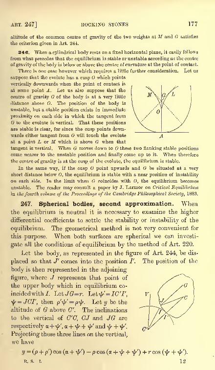
ART. 247] ROCKING STONES 177
altitude of the common centre of gravity of the two weights at M and G satisfies
the criterion given in Art. 244.
246. When a cylindrical body rests on a fixed horizontal plane, it easily follows
from what precedes that the equilibrium is stable or unstable according as the centre
of gravity of the body is below or above the centre of curvature at the point of contact.
There is one case however which requires a little further consideration. Let us
suppose that the evolute has a cusp which points
vertically downwards when the point of contact is
at some point A. Let us also suppose that the
centre of gravity G of the body is at a very little
distance above 0. The position of the body is
unstable, but a stable position exists in immediate
proximity on each side in which the tangent from
G to the evolute is vertical. That these positions
are stable is clear, for since the cusp points down-
wards either tangent from G will touch the evolute A.
at a point L or M which is above G when that
tangent is vertical. When G moves down to these two flanking stable positions
come nearer to the unstable position and finally come up to it. When therefore
the centre of gravity is at the cusp of the evolute, the equilibrium is stable.
In the same way, if the cusp point upwards and G be situated at a very
short distance below O, the equilibrium is stable with a near position of instability
on each side. In the limit when G coincides with 0, the equilibrium becomes
unstable. The reader may consult a paper by J. Larmor on Critical Equilibriumin the fourth volume of the Proceedings of the Cambridge Philosophical Society, 1883.
247. Spherical bodies, second approximation. WThen
the equilibrium is neutral it is necessary to examine the higherdifferential coefficients to settle the stability or instability of the
equilibrium. The geometrical method is not very convenient for
this purpose. When both surfaces are spherical we can investi-
gate all the conditions of equilibrium by the method of Art. 220.
Let the body, as represented in the figure of Art. 244, be dis-
placed so that J' comes into the position /'. The position of the
body is then represented in the adjoining
figure, where J represents that point of
the upper body which in equilibrium co-
incided with/. LeiJG=r. Leti//=/(7T,
^r= JGI', then
p'-^r' pty. Let y be the
altitude of G above G'. The inclinations
to the vertical of G'G, CJ and JG are
respectively a + ty', a + ty + \J/ and -v/r+ ty'.
Projecting these three lines on the vertical,
we have
=(p + p) cos (a + 1/r') p cos (a + ty + ^r') + r cos
R. S. I.
+ -//).
12
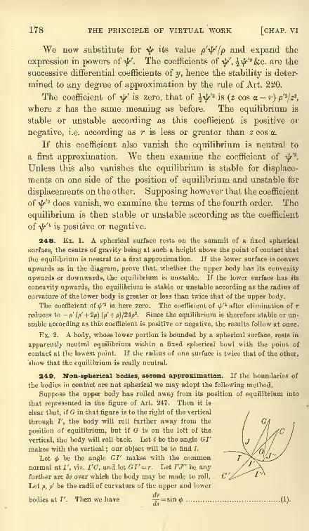
178 THE PRINCIPLE OF VIRTUAL WORK [CHAP. VI
We now substitute for ty its value p'ty'/p and expand the
expression in powers of ty'. The coefficients of-\J/, \-fy-
'- &c. are the
successive differential coefficients of y, hence the stability is deter-
mined to any degree of approximation by the rule of Art. 220.
The coefficient of ty' is zero, that of ^\|r/2
is (z cos a r) p'2
/22,
where z has the same meaning as before. The equilibrium is
stable or unstable according as this coefficient is positive or
negative, i.e. according as r is less or greater than z cos a.
If this coefficient also vanish the equilibrium is neutral to
a first approximation. We then examine the coefficient of ^r'3
.
Unless this also vanishes the equilibrium is stable for displace-
ments on one side of the position of equilibrium and unstable for
displacements on the other. Supposing however that the coefficient
oft/r'
3 does vanish, we examine the terms of the fourth order. The
equilibrium is then stable or unstable according as the coefficient
of i//4is positive or negative.
248. Ex. 1. A spherical surface rests on the summit of a fixed spherical
surface, the centre of gravity being at such a height above the point of contact that
the equilibrium is neutral to a first approximation. If the lower surface is convex
upwards as in the diagram, prove that, whether the upper body has its convexity
upwards or downwards, the equilibrium is unstable. If the lower surface has its
concavity upwards, the equilibrium is stable or unstable according as the radius of
curvature of the lower body is greater or less than twice that of the upper body.
The coefficient of ^'2 is here zero. The coefficient of
\f/'*after elimination of r
reduces to -p' (p' + 2p) (p' -f p)/24/>
2. Since the equilibrium is therefore stable or un-
stable according as this coefficient is positive or negative, the results follow at once.
Ex. 2. A body, whose lower portion is bounded by a spherical surface, rests in
apparently neutral equilibrium within a fixed spherical bowl with the point of
contact at the lowest point. If the radius of one surface is twice that of the other,
show that the equilibrium is really neutral.
249. Non-spherical bodies, second approximation. If the boundaries of
the bodies in contact are not spherical we may adopt the following method.
Suppose the upper body has rolled away from its position of equilibrium into
that represented in the figure of Art. 247. Then it is
clear that, if G in that figure is to the right of the vertical
through I', the body will roll further away from the
position of equilibrium, but if G is on the left of the
vertical, the body will roll back. Let i be the angle GI'
makes with the vertical;our object will be to find i .
Let<f>
be the angle GI' makes with the commonnormal at I', viz. I'C, and let GI' = r. Let I'J" be anyfurther arc 8s over which the body may be made to roll.
Let p, p be the radii of curvature of the upper and lower
bodies at I'. Then we hare = sin<f> (1).
(tS
ART. 249] ROCKING STONES 179
_ds r p
Lastly, let\f/'
be the inclination of the normal CC' to the vertical, then i =\j/'
-<j>and
=!//,'. Hence by (2) = + _-... ...(3).
ds p p r
These three equations supply all the conditions of stability. In the position of
equilibrium the centre of gravity is vertically over the point of support. Hence
i= 0. In any other position the value of i is given by Taylor's series, viz.
di , dH 5s2
i =~ SS + -T-;- +&C.
ds ds* 1 . 2
If in this series the first differential coefficient which does not vanish is positive
and of an odd order, it is clear that the straight line IG will move to the same side
of the vertical as that to which the body is moved. The equilibrium will therefore
be unstable for displacements on either side of the position of equilibrium. If the
coefficient is negative the equilibrium will be stable. If the term is of an even
order, it will not change sign with 5s, the equilibrium will therefore be stable for a
displacement on one side and unstable for a displacement on the other side.
The first differential coefficient is given by (3). The second may be found by
differentiating (3) and substituting for d^/ds and drfds from (2) and (1). The
third differential coefficient may be found by repeating this process. In this waywe may find any differential coefficient which may be required.
Firstly. Suppose the body such that di/ds is not zero in the position of
equilibrium. The condition of stability is therefore that - + - --- is negative.P P r
This leads to the rule already considered in Art. 244.
Secondly. Suppose the body such that in the position of equilibrium the centre
of gravity lies on the circle of stability. We then have di/ds = 0. Differentiating
(3) and substituting for (cos <)/r its value ljp+ 1/p' we find
d fl 1
T (- + -, ,
ds \p p'Jr\f pj\p p'
Unless this vanishes the equilibrium will be stable for displacements on one side
and unstable for displacements on the other side of the position of equilibrium.
Thirdly. Suppose the second differential coefficient given by (4) is also zero in
the position of equilibrium. We find by differentiating (3) twice and substituting
for r as before
dH d? fl 1\ (I 1 \ f/1 2\1 dl fl 1\ fl 2_ = --(_ + _) + (-+_) J(- + -
}- - tan
<j>
- - - 3 tan2 0-+-U- + -*> ds-\p p'J \p p J [\p p'Jp ^dsp r
\p p'J\p p'
* The equation (2) is useful for other purposes besides that of finding the con-ditions of stability. For example it may be very conveniently used in the differential
calculus to find the conic of closest contact at any point I of a curve. If <f> be the
angle between the central radius and the radius of curvature p at any point P of
a conic, it may be shown that tan$= ^-T--J where</>
is positive when measuredcts
behind the normal as P travels along the conic in the direction in which the arc s
is measured. Suppose G to be the centre of the conic, then assuming this value of
0, the distance r of the centre of the conic from I is given by the equation (2) in
the text.
Generally the equation (2) is useful to find the point of contact with its envelopeof a straight line IG drawn through each point of a curve making with the normalan angle <p which is a given function of s.
122
I 1\ fl 2\T-O
= T - + -, +tan - + -,)- + -) .................. (4).2 ' r pj\p p'J
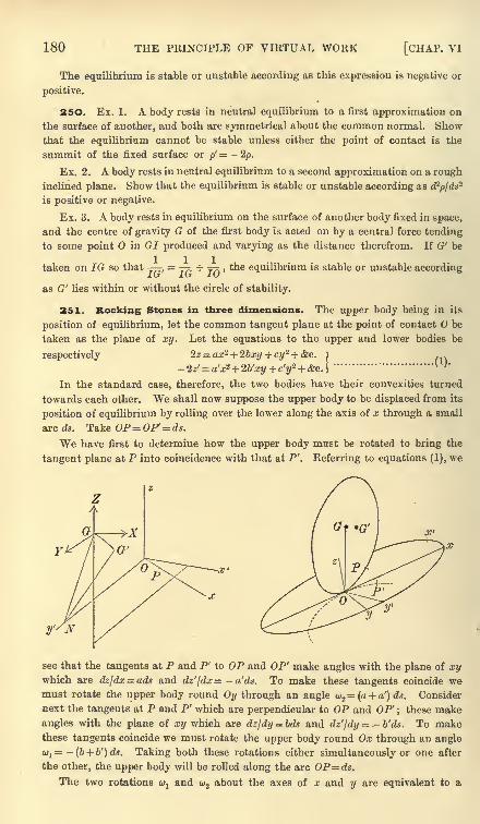
180 THE PRINCIPLE OF VIRTUAL WORK [CHAP, vi
The equilibrium is stable or unstable according as this expression is negative or
positive.
2 SO. Ex. 1. A body rests in neutral equilibrium to a first approximation on
the surface of another, and both are symmetrical about the common normal. Showthat the equilibrium cannot be stable unless either the point of contact is the
summit of the fixed surface or p'= -2p.
Ex. 2. A body rests in neutral equilibrium to a second approximation on a rough
inclined plane. Show that the equilibrium is stable or unstable according as d2pjds
2
is positive or negative.
Ex. 3. A bodj' rests in equilibrium on the surface of another body fixed in space,
and the centre of gravity G of the first body is acted on by a central force tending
to some point in GI produced and varying as the distance therefrom. If G' be
taken on IG so that, 77.
+TTJ
>foe equilibrium is stable or unstable according
as G' lies within or without the circle of stability.
251. Rocking Stones in three dimensions. The upper body being in its
position of equilibrium, let the common tangent plane at the point of contact be
taken as the plane of xy. Let the equations to the upper and lower bodies be
respectively 2z= axz+ 2bxy + cy- + &c.
- 2z'= a'x2+ 2b'xy + c'y2+ &c.\
In the standard case, therefore, the two bodies have their convexities turned
towards each other. We shall now suppose the upper body to be displaced from its
position of equilibrium by rolling over the lower along the axis of x through a small
arc ds. Take OP-OP'= ds.
We have first to determine how the upper body must be rotated to bring the
tangent plane at P into coincidence with that at P'. Eeferring to equations (1), we
y'/N
see that the tangents at P and P' to OP and OP' make angles with the plane of xywhich are dz/dx= ads and dz'jdx= - a'ds. To make these tangents coincide wemust rotate the upper body round Oy through an angle w.2
=(a + a') ds. Consider
next the tangents at P and P' which are perpendicular to OP and OP' ; these make
angles with the plane of xy which are Az\dy = bds and dz'fdy = - b'ds. To makethese tangents coincide we must rotate the upper body round Ox through an anglew
1= -
(b + b')ds. Taking both these rotations either simultaneously or one after
the other, the upper body will be rolled along the arc OP=ds.
The two rotations wxand w about the axes of x and y are equivalent to a
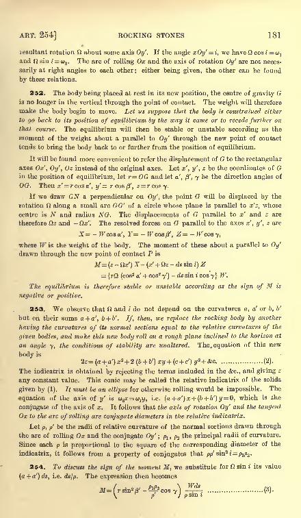
ART. 254] ROCKING STONES 181
resultant rotation O about some axis Oy'. If the angle xOy'= i, we have Si cosi = u1
and O sin i = u2 . The arc of rolling Ox and the axis of rotation Oy' are not neces-
sarily at right angles to each other ; either being given, the other can be found
by these relations.
252. The body being placed at rest in its new position, the centre of gravity Gis no longer in the vertical through the point of contact. The weight will therefore
make the body begin to move. Let us suppose that the body is constrained either
to go back to its position of equilibrium by the way it came or to recede further on
that course. The equilibrium will then be stable or unstable according as the
moment of the weight about a parallel to Oy' through the new point of contact
tends to bring the body back to or further from the position of equilibrium.
It will be found more convenient to refer the displacement of G to the rectangular
axes Ox', Oy', Oz instead of the original axes. Let x', y', z be the coordinates of Gin the position of equilibrium, let r=OG and let a', /3', y be the direction angles of
OG. Then x' = rcosa', y'= rcoa^, z = rcosy.
If we draw GN a perpendicular on Oy', the point G will be displaced by the
rotation along a small arc GG' of a circle whose plane is parallel to x'z, whose
centre is N and radius NG. The displacements of G parallel to x' and z are
therefore Oz and - Ox'. The resolved forces on G parallel to the axes x', y', z are
X= - Wcosa', Y= -TFcos/3', Z= - Wcosy,
where W is the weight of the body. The moment of these about a parallel to Oy'
drawn through the new point of contact P is
M= (z-Ox') X-(x' + toz - ds sin i)
Z
= {rO (cos2 a' + cos2
y') -ds sin icosy} W.
The equilibrium is therefore stable or unstable according as the sign of M is
negative or positive.
253. We observe that O and i do not depend on the curvatures a, a' or b, b'
but on their sums a + a', b + b'. If, then, we replace the rocking body by another
having the curvatures of its normal sections equal to the relative curvatures of the
given bodies, and make this new body roll on a rough plane inclined to the horizon at
an angle y, the conditions of stability are unaltered. The. equation of this new
body is
2z=(a+ a')x* + 2(b + b')xy + (c + c')y* + &c................... (2).
The indicatrix is obtained by rejecting the terms included in the &c., and giving z
any constant value. This conic may be called the relative indicatrix of the solids
given by (1). It must be an ellipse for otherwise rolling would be impossible. The
equation of the axis of y' is w2x= w1j/,
i.e. (a + a')x+ (b + b')y = 0, which is the
conjugate of the axis of x. It follows that the axis of rotation Oy' and the tangent
Ox to the arc of rolling are conjugate diameters in the relative indicatrix.
Let p, p' be the radii of relative curvature of the normal sections drawn through
the arc of rolling Ox and the conjugate Oy' ; pl , p2 the principal radii of curvature.
Since each p is proportional to the square of the corresponding diameter of the
indicatrix, it follows from a property of conjugates that />/>' ain?i=p1pa .
254. To discuss the sign of the moment M, we substitute for O sin i its value
(a + a') ds, i.e. ds/p. The expression then becomes
p sin i(3).
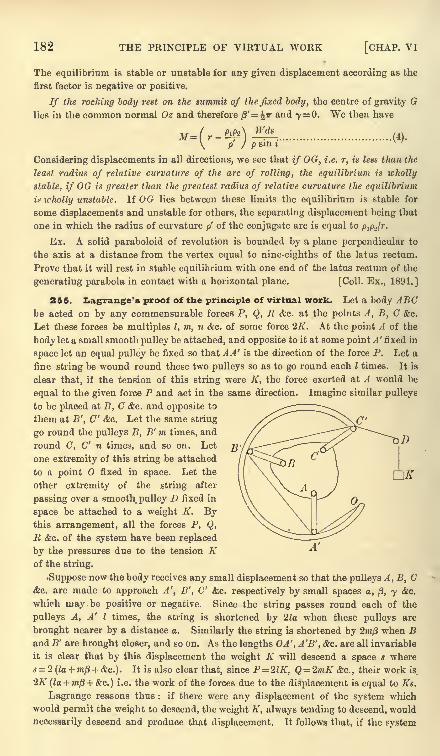
182 THE PRINCIPLE OF VIRTUAL WORK [CHAP. VI
The equilibrium is stable or unstable for any given displacement according as the
first factor is negative or positive.
If tlie rocking body rest on the summit of the fixed body, the centre of gravity Glies in the common normal Oz and therefore )3'
= \ir and 7= 0. We then have
(4).p' } p sin i'
Considering displacements in all directions, we see that if OG, i.e. r, is less than the
least radius of relative curvature of the arc of rolling, the equilibrium is icholly
stable, if OG is greater than the greatest radius of relative curvature the equilibrium
is icholly unstable. If OG lies between these limits the equilibrium is stable for
some displacements and unstable for others, the separating displacement being that
one in which the radius of curvature/>'
of the conjugate arc is equal to Pip-Jr.
Ex. A solid paraboloid of revolution is bounded by a plane perpendicular to
the axis at a distance from the vertex equal to nine-eighths of the latus rectum.
Prove that it will rest in stable equilibrium with one end of the latus rectum of the
generating parabola in contact with a horizontal plane. [Coll. Ex., 1891.]
255. Ziagrange's proof of the principle of virtual work. Let a body ABCbe acted on by any commensurable forces P, Q, R &c. at the points A, B, C &c.
Let these forces be multiples I, m, n &c. of some force 2K. At the point A of the
body let a small smooth pulley be attached, and opposite to it at some point A' fixed in
space let an equal pulley be fixed so that A A' is the direction of the force P. Let a
fine string be wound round these two pulleys so as to go round each I times. It is
clear that, if the tension of this string were K, the force exerted at A would be
equal to the given force P and act in the same direction. Imagine similar pulleys
to be placed at B, C &c. and opposite to
them at B', C' &c. Let the same string
go round the pulleys B, B' m times, and
round C, C' n times, and so on. Let
one extremity of this string be attached
to a point fixed in space. Let the
other extremity of the string after
passing over a smooth, pulley D fixed in
space be attached to a weight K. Bythis arrangement, all the forces P, Q,
E &c. of the system have been replaced
by the pressures due to the tension Kof the string.
Suppose now the body receives any small displacement so that the pulleys A, B, C&c. are made to approach A', B', C' &c. respectively by small spaces a, /3, y &c.
which may be positive or negative. Since the string passes round each of the
pulleys A, A' I times, the string is shortened by 2la when these pulleys are
brought nearer by a distance a. Similarly the string is shortened by 2m/3 when Band B' are brought closer, and so on. As the lengths OA', A'B', &c. are all invariable
it is clear that by this displacement the weight K will descend a space s where= 2 (la + mf) + &c.). It is also clear that, since P21K, Q = 2mK &c., their work is
2K (la + TO/3 + &c.)
i.e. the work of the forces due to the displacement is equal to Ks.
Lagrange reasons thus : if there were any displacement of the system which
would permit the weight to descend, the weight K, always tending to descend, would
necessarily descend and produce that displacement. It follows that, if the system
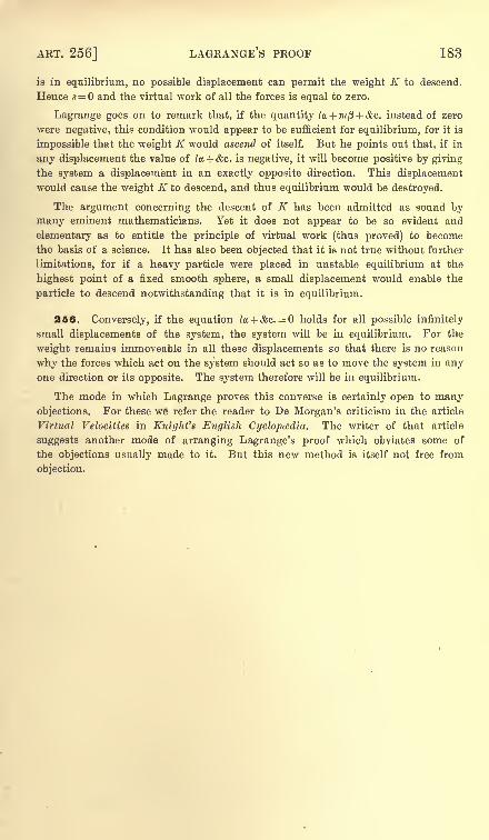
ART. 256] LAGRANGE'S PROOF 183
is in equilibrium, no possible displacement can permit the weight K to descend.
Hence s = and the virtual work of all the forces is equal to zero.
Lagrange goes on to remark that, if the quantity la + mfl + &c. instead of zero
were negative, this condition would appear to be sufficient for equilibrium, for it is
impossible that the weight K would ascend of itself. But he points out that, if in
any displacement the value of la + &c. is negative, it will become positive by giving
the system a displacement in an exactly opposite direction. This displacement
would cause the weight K to descend, and thus equilibrium would be destroyed.
The argument concerning the descent of K has been admitted as sound by
many eminent mathematicians. Yet it does not appear to be so evident and
elementary as to entitle the principle of virtual work (thus proved) to become
the basis of a science. It has also been objected that it is not true without further
limitations, for if a heavy particle were placed in unstable equilibrium at the
highest point of a fixed smooth sphere, a small displacement would enable the
particle to descend notwithstanding that it is in equilibrium.
256. Conversely, if the equation ta + &c. = holds for all possible infinitely
small displacements of the system, the system will be in equilibrium. For the
weight remains immoveable in all these displacements so that there is no reason
why the forces which act on the system should act so as to move the system in anyone direction or its opposite. The system therefore will be in equilibrium.
The mode in which Lagrange proves this converse is certainly open to manyobjections. For these we refer the reader to De Morgan's criticism in the article
Virtual Velocities in Knight's English Cyclopedia. The writer of that article
suggests another mode of arranging Lagrange's proof which obviates some of
the objections usually made to it. But this new method is itself not free from
objection.
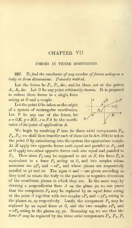
CHAPTER VII
FOECES IN THREE DIMENSIONS
257. To find the resultants of any number offorces acting on a
lody in three dimensions. Poinsot's method.
Let the forces be P1} P2 , &c., and let them act at the pointsA 1} A 2 ,&c. Let be any point arbitrarily chosen. It is proposedto reduce these forces to a single force
acting at and a couple.
Let the point be taken as the origin
of a system of rectangular coordinates.
Let P be any one of the forces, let
x = OM, y = MN, z = NA be the coordi-
nates of its point of application A.
We begin by resolving P into its three axial components Px ,
Py ,Pz ;
we shall then transfer each of these (as in Art. 104) to act at
the point by introducing into the system the appropriate couple.
At M apply two opposite forces each equal and parallel to Pz ,and
at apply two other opposite forces each also equal and parallel to
Pz . Then since P2 may be supposed to act at N, the force Pz is
equivalent to a force Pz acting at 0, and two couples whose
moments are yPz and xPz,and whose planes are respectively
parallel to yz and xz. The signs + and are given according as
they tend to rotate the body in the positive or negative directions
of the coordinate planes in which they act. In the same way, by
drawing a perpendicular from A on the plane yz, we can provethat the component Px may be replaced by an equal force actingat the point together with two couples zPx and yPx acting in
the planes xz, xy respectively. Lastly, the component Py may be
replaced by an equal force at 0, and the two couples xPy and
zPy acting in the planes xy, yz. Summing up, we see that the
force P may be replaced by the three axial components Px ,Py ,
Pz
ART. 258] GENERAL PRINCIPLES 185
acting at 0, and three couples whose moments are yPz zPy ,
zPx xPz ,xPy yPx ,
and whose planes are yz, zx, xy respectively.
Repeating this for all the given forces, we see that they maybe replaced by three forces X, Y, Z acting along the axes of
coordinates, and three couples whose moments are L, M, N, and
whose axes are the axes of coordinates, where
These are called the six components of the forces.
The three components X, Y, Z may be compounded into a
single force. Let R be its magnitude, and (I, m, n) the direction
cosines of its positive direction, then
Rl = X, Rm=Y, Rn = Z,
R2 = X*+ Y2 + Z\
This force is called by Moigno the principal force at the point 0.
The three components L, M, N in the same way may be
compounded into a single couple whose moment G and the
direction cosines (X, /t, v) of whose axis are given by
G\ = L, G(t = M, Gv = N,
G2 = L2 + M2 + N2.
The couple G is called the principal couple at the point 0. The
components L, M, N of the principal couple are also called the
moments of the forces about the axes.
258. The base of reference to which the forces have been
transferred, has been taken as the origin of coordinates. But when
it is necessary to distinguish between these points we must modifythe expressions for the components. Let some point 0' whose
coordinates are f, 77, be the base of reference. The expressions
for the six components for this new base may be deduced from
those for the origin by writing x %,y y,z % for x, y, z.
The expressions for the components of the force R do not contain
x, y, z, hence the principal force R is the same in magnitude and
direction whatever base is chosen.
The expressions for the components of the couple G become
186 FORCES IN THREE DIMENSIONS [CHAP. VII
Thus the magnitude and the axis of the principal couple G are in
general different at different bases.
259. Conditions of equilibrium. It has been proved in
Art. 105 that the forces on a body can be reduced to a single force
R and a single couple G. By the same reasoning as in Art. 109 it
is necessary and sufficient for equilibrium that these should
separately vanish. We therefore have R and G = 0.
If the axes of reference are at right angles, these lead at once
to the six conditions
X = 0, Y=0, Z=0, L = 0, M= 0, N = 0;
we may, however, put these results into a more convenient form.
In order to make the resultant force R zero, it is necessary and
sufficient that the sum of the resolutes of all the forces along each of
any three straight lines (not all parallel to the same plane} should
be zero. To prove this, let OA, OB, OC be parallel to the three
straight lines. If the resolute of R along OA is zero, it is evident
that either R is zero, or the direction of R is perpendicular to OA.If R is not zero, its direction is perpendicular to each of three
straight lines meeting in 0, not all in one plane, which is impossible.
In the same way, since couples are resolved according to the
same laws as forces, we infer that to make the principal couple Gzero, it is necessary and sufficient that the component couple of
all the forces about each of any three straight lines intersecting in
the base but not all in one plane, should be zero. It will be
presently seen that the moment of the component couple for
any axis through is also the moment of the forces about that
axis, Art. 263.
Since a couple may be moved into a parallel plane without
altering its effect, it is clear that, when the force R is zero, the
moments about all parallel straight lines are equal. It is therefore
sufficient for equilibrium that the moment of theforces about each of
any three straight lines (whether intersecting or not} should be zero,
but all three must not be parallel to the same plane, and no two must
be parallel to each other. The method of finding these moments
will be more fully explained a little further on.
260. Components of a force. Usually we suppose a force
to be given when we know its magnitude and the equations of its
line of action. We see from the results of the proposition in Art.
ART. 262J COMPONENTS OF A FORCE 187
257 that it will sometimes be more convenient to determine a force
P by the values of its six components, viz. Px ,Py ,
Pz ,and
yPz zPy ,zPx xPz ,
xPy yPx . The advantage of this repre-
sentation is that the resulting effect of any number of forces is
found by adding their several corresponding components.
If we wish to represent the line of action of the force apartfrom the force itself, we may regard the straight line as the seat
of some force of given magnitude, and suppose the line itself
determined by the six components of this chosen force. Let
(/, m, n) be the direction cosines of the straight line, (x, y, z) the
coordinates of any point on it. Then, if the force chosen is a unit,
the six components or coordinates* of the line are
I, m, n, \ = yn zm, /j,= zl - xn, v= xm yl,
with the obvious relation
l\ + mp + nv = ........................ (1).
If a force P act along this straight line, its six components or
coordinates are PI, Pin, Pn ; PA,, P/u,, Pi/.
If we compound several forces together, the six components become
X = ^Pl, Y= 2Pm, Z = 2Pn ;L = 2PX, M = 2P^, N = ^Pv,
but the relation
XL+ YM + ZN = Q ........................ (2)
is not necessarily true.
261. We have seen in Art. 257 that all these forces may be
joined together so as to make a single force _R and a couple G.
This combination of a force and a couple has been called byPliicker a dyname. The six quantities X, Y, Z, L, M, N are the
components of the dyname. The three former components are
multiples of some unit force, the three latter of some unit couple.
It will be shown further on that when the coordinates of the
dyname satisfy the condition (2), either the force R or the coupleG of the dyname is zero.
262. Ex. 1. The six components of a force are 1, 2, 7 ; 4, 5,- 2. Show that
the magnitude of the force is ^54, and that the equations to its line of action are
Ex. 2. The six components of a dyname are 1, 2, 3; 4, 5, 6. Show that the
magnitude of the force is /14, and that its direction cosines are proportional to
1, 2, 3. If this force act at the origin the magnitude of the couple is ^77, and the
direction cosines of its axis are proportional to 4, 5, 6.
* The six coordinates of a line are described in Salmon's Solid Geometry (fourthedition, Art. 51) from an analytical point of view. See also Cayley, Quart. Journal,1860 ; Camb. Trans. 1867 ; Pliicker, Phil. Trans. 1865 and 1866.
188 FORCES IX THREE DIMENSIONS [CHAP. VII
263. Moment of a force. It has already been stated that
the expressions for L, M, N in Art. 257 are usually called the
moments of the forces about the axes of x, y, z respectively. These
expressions are
L = 2 (yPz- zPy\ M = 2 (zPx - xPz\ N = 2 (xPy - yPx}.
To show how far this definition agrees with that already given
in Art. 113, let us examine how the expression for N has been
obtained. The force P has been resolved into its componentsPx ,
Py ,Pz ;
the two former act in a plane perpendicular to the
axis of whence by the definition given in Art. 113, the expressions
yPx and xPy are respectively equal to their moments about that
axis. The latter Pz acts parallel to the axis of z, and if the
moment of this component is defined to be zero, the expression Nwill become the moment of the forces about the axis of z. Let Qbe the resultant of the two components Px ,
Pz ,then the moment
of Q about the axis of z is equal to the sum of the moments of Px
and PZ, Art. 116.
Since any straight line may be taken as the axis of z, this
explanation applies to all straight lines. It appears therefore
that the moment of the component couple for any axis is the
same as the moment of all the forces about that axis.
We thus arrive at the following definition of the moment of a
force about any straight line. Let the straight line be called CD.
Resolve the force P into two components, one parallel and the other
perpendicular to the straight line CD. The moment of the formeris defined to be zero. The moment of the latter is obtained by
multiplying its magnitude by the shortest distance between it and the
given straight line CD.
It is evident that this shortest distance is equal to the shortest
distance between the original force P and the straight line CD,each being equal to the distance between CD and the plane of
the components. Let r be the length of this shortest distance.
Let 6 be the angle between the positive directions of the force
P and the line CD, then the resolved part of the force Pperpendicular to CD is P sin 6. We therefore find that the
moment of the force P about CD is equal to Pr sin 6.
When the moments of several forces round the same straight
line CD are to be added together, we must take care that these
have their proper signs. Any direction of rotation round CD
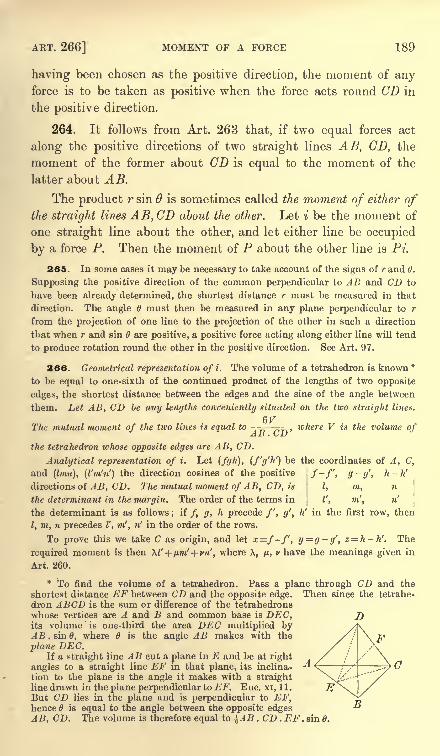
ART. 266] MOMENT OF A FORCE 189
having been chosen as the positive direction, the moment of anyforce is to be taken as positive when the force acts round CD in
the positive direction.
264. It follows from Art. 263 that, if two equal forces act
along the positive directions of two straight lines AB, CD, the
moment of the former about CD is equal to the moment of the
latter about AB.
The product r sin 6 is sometimes called the moment of either ofthe straight lilies AB, CD about the other. Let i be the moment of
one straight line about the other, and let either line be occupied
by a force P. Then the moment of P about the other line is Pi.
265. In some cases it may be necessary to take account of the signs of r and 6.
Supposing the positive direction of the common perpendicular to AB and CD to
have been already determined, the shortest distance r must be measured in that
direction. The angle d must then be measured in any plane perpendicular to r
from the projection of one line to the projection of the other in such a direction
that when r and sin are positive, a positive force acting along either line will tend
to produce rotation round the other in the positive direction. See Art. 97.
266. Geometrical representation of i. The volume of a tetrahedron is known*to be equal to one-sixth of the continued product of the lengths of two opposite
edges, the shortest distance between the edges and the sine of the angle between
them. Let AB, CD be any lengths conveniently situated on the two straight lines.
6VThe mutual moment of the two lines is equal to -
n ^, n ,where V is the volume ofAlj . G i)
the tetrahedron whose opposite edges are AB, CD.
Analytical representation of i. Let (fgh), (f'g'h') be the coordinates of A, C,
and (Imn), (I'm'n1
)the direction cosines of the positive . /-/', g-g', h-h'
directions of A B, CD. The mutual moment of AB, CD, is \ I, m, n
the determinant in the margin. The order of the terms in I', m', n'
the determinant is as follows ; if /, g, h precede /', g', h' in the first row, then
I, m, n precedes I', m', n' in the order of the rows.
To prove this we take C as origin, and let x=f-f, y=g-g', z= h-h'. The
required moment is then \V + pm' + vn', where X, /JL,v have the meanings given in
Art. 260.
* To find the volume of a tetrahedron. Pass a plane through CD and the
shortest distance EF between CD and the opposite edge. Then since the tetrahe-
dron ABCD is the sum or difference of the tetrahedrons
whose vertices are A and B and common base is DEC,its volume is one-third the area DEC multiplied byAB . sin B, where is the angle AB makes with the
plane DEC.If a straight line AB cut a plane in E and be at right
angles to a straight line EF in that plane, its inclina-
tion to the plane is the angle it makes with a straightline drawn in the plane perpendicular to EF. Euc. xi, 11.
But CD lies in the plane and is perpendicular to EF,hence 6 is equal to the angle between the opposite edgesAB, CD. The volume is therefore equal to ^AB . CD . EF . sin 6.
190 FORCES IN THREE DIMENSIONS [CHAP. VII
267. Ex. 1. Two straight lines are given by their six coordinates (bnn\/j.v),
(Z'm'n'X'/uV) : show that their mutual moment is i = l\' + m/*' + nv' + i\ + m'p + n'v.
This quantity is therefore invariable for the same two lines, to whatever rect-
angular axes their coordinates are referred. If 2 = 0, the lines intersect.
Other theorems on the moments of lines are given in Scott's Determinants.
Ex. 2. If (xyzu), (x'y'z'u') are the tetrahedral coordinates of any two points H,K on the line of action of a force P, show that the moment of the force about the
6Fedge AB of the tetrahedron, is P . -^==
- _ !
tiK. . AH u,r
i
If the force, when positive, acts from H towards K and the terms in the
determinant are taken in the order shown, this expression gives the moment of
the force round AB in the direction from the corner C to the corner D.
Ex. 3. If in a tetrahedron the mutual moments of the opposite edges are equal,
prove that the products of their lengths are also equal. If(r, s, t) are the lengths of
the lines joining the middle points of opposite edges and (a, /5, 7) are the angles at
which they intersect, prove also that
r4 - 2;-V2 cos2y + s4 = s4 - 2s2<2 cos2 n + 1 = t* - 2V2 cos2 /3 + r4. [St John's, 1891. ]
Ex. 4. Two triangles ABC and A'B'C' are seen in perspective by an eye placed
at O ;forces P, Q, R act in BC, CA and AB, another set P', Q', R' in C'B', A'C"
and B'A' respectively, and the whole system is in equilibrium. Show that
A..P.OA' &' .P'.OA _ A.Q.OB' _ A'.Q' . OB _ A.R.OC' A'.R' . PCBC.AA'
~B'C' . A A'
~CA . BB'
~C'A' . BB'
~AB . CC'
~~A'B' . CC' '
where A and A' are the volumes of the tetrahedra OABC and OA'B'C' respectively.
[Math. Tripos, 1883.]
The six lines OA, OB, OC, AB, BC, CA form a tetrahedron. If we equate to
zero the sum of the moments of the six forces about the edge OA, we find that the
first and second of the above given expressions are equal. In the same way taking
moments about the edge AB, we find that the second and fourth are equal. It
follows by symmetry that all the six expressions are equal. The moments may be
found by using the rule given in Ait. 266.
268. Problems on Equilibrium. Ex. 1. A body, free to turn about a straight
line as a fixed axis, is acted on by any forces. It is required to find the condition of
equilibrium and the pressure on the axis.
Let the straight line be the axis of z, and let x, y be two perpendicular axes.
The pressures on the elements of length of the axis constitute a system of forces.
If the body is free to slide smoothly along the axis, each of
these pressures will act perpendicularly to the axis. But
as this limitation does not simplify the result, we shall
suppose the direction of the pressure to be perfectly
general. Taking any arbitrary point B on the axis as a
base of reference, each pressure may be transferred to act
at B, by introducing a couple whose plane passes throughthe axis. All the pressures are therefore equivalent to a
resultant pressure which acts at B together with a resultant
couple whose plane passes through the axis. Let one of the
forces of this couple act at B and let the arm be so altered
(if necessary) that the other force acts at some other arbitrary point C of the axis.
Then compounding the forces which act at B, we see that the pressures on all the
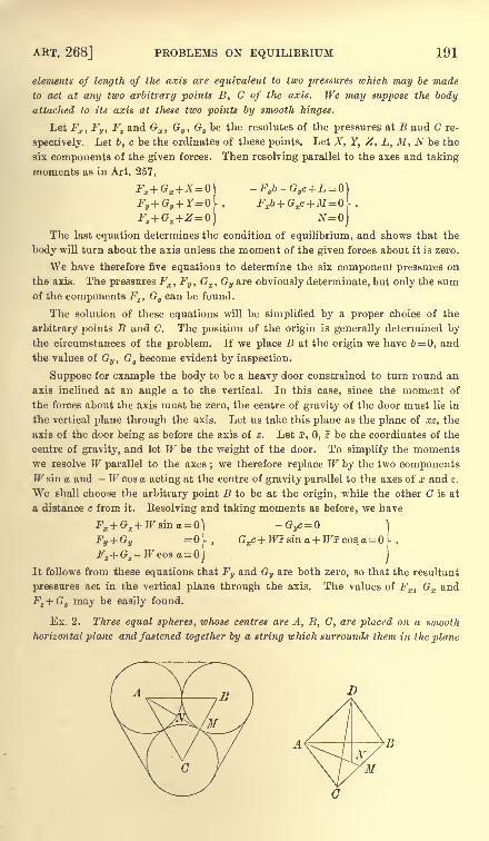
ART. 268] PROBLEMS ON EQUILIBRIUM 191
elements of length of the axis are equivalent to two pressures which may be made
to act at any two arbitrary points B, G of the axis. We may suppose the bodyattached to its axis at these two points by smooth hinges.
Let Fx , Fy ,Fz and Gx ,
Gy , G2 be the resolutes of the pressures at B and C re-
spectively. Let 6, c be the ordinates of these points. Let X, Y, Z, L, M, N be the
six components of the given forces. Then resolving parallel to the axes and taking
moments as in Art. 257,
The last equation determines the condition of equilibrium, and shows that the
body will turn about the axis unless the moment of the given forces about it is zero.
We have therefore five equations to determine the six component pressures on
the axis. The pressures Fx ,Fv , Gx , Gy are obviously determinate, but only the sum
of the components Fz ,Gz can be found.
The solution of these equations will be simplified by a proper choice of the
arbitrary points B and C. The position of the origin is generally determined by
the circumstances of the problem. If we place B at the origin we have 6= 0, and
the values of Gv ,G
zbecome evident by inspection.
Suppose for example the body to be a heavy door constrained to turn round an
axis inclined at an angle a to the vertical. In this case, since the moment of
the forces about the axis must be zero, the centre of gravity of the door must lie in
the vertical plane through the axis. Let us take this plane as the plane of xz, the
axis of the door being as before the axis of z. Let x, 0, z be the coordinates of the
centre of gravity, and let W be the weight of the door. To simplify the momentswe resolve W parallel to the axes
;we therefore replace W by the two components
TFsin a and - W cos a acting at the centre of gravity parallel to the axes of x and z.
We shall choose the arbitrary point B to be at the origin, while the other C is at
a distance c from it. Resolving and taking moments as before, we have
Fx + Gx + W sin a =]
- Gyc=
]
FV+GV =0r> Gxc+Wz sin a+Wxcosa [
It follows from these equations that Fy and Gy are both zero, so that the resultant
pressures act in the vertical plane through the axis. The values of Fx ,Gx and
Ft + Gz may be easily found.
Ex. 2. Three equal spheres, ivhose centres are A, B, C, are placed on a smooth
horizontal plane and fastened together by a string which surrounds them in the plane

192 FORCES IN THREE DIMENSIONS [CHAP. VII
of their centres, and is just not tight. A fourth equal sphere, whose centre is D, is
placed on the top of these touching all three. Prove that the tension of the string is
Let R be the reaction of any one of the lower spheres on the upper, I)X a
perpendicular from D on the plane ABC, then 3R cos ADN= W. Consider next the
sphere whose centre is A ; the other two of the lower spheres exert no pressure on it.
The resolved part of R in the direction NA balances the two tensions of the parts
of the string parallel to AB and AC. Hence R cos DAN= 2T cos BAN. The angle
&Q, and
We now easily find T in terms of W.
Ex. 3. Four equal spheres rest in contact at the bottom of a smooth spherical
bowl, their centres being in a horizontal plane. Show that, if another equal sphere
be placed upon them, the lower spheres will separate if the radius of the bowl be
greater than (2^/13 + 1) times the radius of a sphere. [Math. Tripos, 1883.]
Ex. 4. Six thin uniform rods, of equal length and equal weight W, are
connected by smooth hinge joints at their extremities so as to constitute the six
edges of a regular tetrahedron ; one face of the tetrahedron rests on a smooth
horizontal plane. Show that the longitudinal strain of each of the rods of the
lowest face is IF/2 ^/G. [Coll. Ex.]
Ex. 5. A heavy uniform ellipsoid is placed on three smooth pegs in the same
horizontal plane, so that the pegs are at the extremities of a system of conjugate
diameters. Prove that there will be equilibrium, and that the pressures on the pegsare one to another as the areas of the conjugate central sections. [Coll. Ex.]
Ex. 6. Four equal heavy rods are jointed to form a square. One side is held
horizontal and the opposite one is acted on by a given couple whose axis is vertical.
Show that in a position of equilibrium the lower rod makes an angle 2 sin-1 G/Wlwith the upper, G being the couple, and W and I the weight and length of a rod.
Find the action at either of the lower hinges. [Coll. Ex., 1880.]
Ex. 7. An equilateral triangular lamina, weight W, hangs in a horizontal
position with its angles suspended from three points by vertical strings each equal in
length to the diameter 2a of the circle circumscribing the triangle. Prove that the
couple required to keep the lamina at a height 2 (1-
n) a above its initial position is
Wa </(!- n2
). [Coll. Ex., 1886.]
Ex. 8. A weightless rod, of length 21, rests in a given horizontal position with
its ends on the curved surfaces of two horizontal smooth circular cylinders, each of
radius a, which have their axes parallel and at a distance 2c. The rod is acted on
at its centre by a given force P and a couple. Find the couple when there is
equilibrium, and prove that the magnitude of the couple will be least when P acts
vertically, provided that c< I sin + ^^/2 sec $<j>,where is the angle between the
rod and the axes of the cylinders. [Math. Tripos, 1889.]
Ex. 9. A solid circular cylinder, of height h and radius a, is enclosed in a rigid
hollow cylinder which it just fits, and is formed of an infinite number of parallel
equally elastic threads, which will together support a weight W when stretched to
a length 2h. The ends of these strings are fastened firmly to two discs, one of which
is then turned through an angle a in its own plane : assuming each thread to form
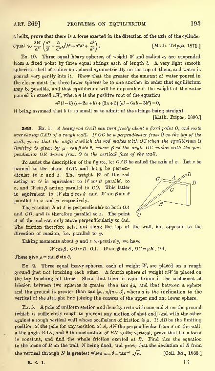
ART. 269] PROBLEMS ON EQUILIBRIUM 193
a helix, prove that there is a force exerted in the direction of the axis of the cylinder1W /a 2 h 7)
2\equal to
-^ (^-
-J,N/7i
2+ a2a2+ ^ )[Math. Tripos, 1871.]
Ex. 10. Three equal heavy spheres, of weight W and radius a, are suspended
from a fixed point by three equal strings each of length I. A very light smooth
spherical shell of radius b is placed symmetrically on the top of them, and water is
poured very gently into it. Show that the greater the amount of water poured in
the closer must the three lower spheres be to one another in order that equilibrium
may be possible, and that equilibrium will be impossible if the weight of the water
poured in exceed nW, where n is the positive root of the equation
n2(I-
b) (l+ 2a + b) + (2n + 3) (a2 - 6a& - 3ft
2) =0,
it being assumed that b is so small as to admit of the strings being straight.
[Math. Tripos, 1890.]
269. Ex. 1. A heavy rod OAB can turn freely about a fixed point 0, and rests
over the top CAD of a rough wall. If OC be a perpendicular from on the top of the
wall, prove that the angle 6 which the rod makes with OC when the equilibrium is
limiting is given by /JL= tan B sin 0, where $ is the angle OC makes with the per-
pendicular OE drawn from to the vertical face of the wall.
To assist the description of the figure, let OAB be called the axis of x. Let z be
normal to the plane AOC, and let y be perpen-
dicular to x and z. The weight W of the rod
acting at G is equivalent to W cos ^ parallel to
z, and TFsin/3 acting parallel to CO. This latter
is equivalent to W sin 8 cos and W sin sin 6
parallel to x and y respectively.
The reaction R at A is perpendicular to both OAand CD, and is therefore parallel to z. The point
A of the rod can only move perpendicularly to OA.
The friction therefore acts, not along the top of the wall, but opposite to the
direction of motion, i.e. parallel to y.
Taking moments about y and z respectively, we have
W cos/3. OG=R.OA, fFsin/Ssinfl. 0(?=/tB. OA.
These give p= tan /3sin 0.
Ex. 2. Three equal heavy spheres, each of weight W, are placed on a rough
ground just not touching each other. A fourth sphere of weight nW is placed on
the top touching all three. Show that there is equilibrium if the coefficient of
friction between two spheres is greater than tan a, and that between a sphere
and the ground is greater than tan^a. ra/(n + 3), where a is the inclination to the
vertical of the straight line joining the centres of the upper and one lower sphere.
Ex. 3. A pole of uniform section and density rests with one end A on the ground
(which is sufficiently rough to prevent any motion of that end) and with the other
against a rough vertical wall whose coefficient of friction is p.. If AB be the limiting
position of the pole for any position of A, AN the perpendicular from A on the wall,
a the angle BAN, and 6 the inclination of BN to the vertical, prove that tan a tan 6
is constant, and find the whole friction exerted at B. Find also the equation
to the locus of B on the wall, N being fixed, and prove that the deviation of B from
the vertical through N is greatest when a=0=taDT1fjfj,. [Coll. Ex., 1886.]
R. S. I. 13
194 FORCES IN THREE DIMENSIONS [CHAP. VII
Ex 4. A narrow uniform rod of length 2a rests in an oblique position with one
end on a rough horizontal table and the other against a rough vertical wall, the
coefficients of friction at the table and wall being ^ and ^ , and the distance of the
foot of the rod from the wall being k;show that the rod is on the point of slipping
at the lower end if the vertical plane in which it lies makes an angle 6 with the wall
given by A;^ (/*22 sin2 - cos2 0)
a = ft - 2^ (4a2 sin2 6- k-)* , and that the inclination
of the tangential action at the upper end to the horizon is then see" 1
(/^ tan 6).
[Math. Tripos, 1887.]
Ex. 5. A curtain is supported by an anchor ring capable of sliding on a
horizontal cylinder by means of a hook fixed at that point of the ring which is lowest
when the curtain is hanging. Show (1) that the ring may touch the cylinder at one
or two points but not more, (2) that if -there be double contact and the weight of
the ring can be neglected the ring will not slip along the cylinder however it be
pulled unless the coefficient of friction be less than "T .-
,in which b is the
radius of the generating circle, a that of the circle described by its centre and 6 the
inclination of the plane of this latter circle to the axis of the cylinder. [Math. T.]
For the sake of the perspective take the axis of the anchor ring as axis of z, and
let the plane of the circle whose radius is a be the plane of xy. Let the axis of x
pass through the hook. Let B, B' be the two points of contact of the cylinder and
ring, B' being nearest the hook. Let (E, /J.R) (R', fj.R') be the reactions at these
points, then these four forces lie in the plane xz. Taking moments about an axis
through the hook and solving, we find
(2a+ b) cos -pb cos 6
M~(2a + b) sin 6 - b + pb (1 + sin 0)
'
where p is the ratio of R' to R. As long as there is double contact R and R' are
both positive. But if fj.is greater than the value given in the question, this equation
shows that p must be negative.
Ex. 6. A solid heavy cone, placed with a generating line in contact with a
rough vertical wall, can turn freely about its vertex which is fixed, and is acted on
by a couple whose moment is L and whose plane is parallel to the base. Prove
that in equilibrium the inclination 6 to the vertical of the generating line in contact
with the wall is given by L=%Wh sin tana, where a is the semi-vertical angle of
the cone and h its altitude. If the rim only of the cone is rough, prove that the
least value of the coefficient of friction is 2 tan 6 . cosec 2a.
The central aocis and the invariants.
270. Poinsot's Central Axis. Any base having been
chosen, the forces of a system have been reduced to a force Racting at and a couple G. We shall now examine whether
this representation of the forces can be further simplified by a
proper choice of the base.
Let 6 be the angle between the direction of the force Rand the axis of the couple G. We may resolve G into two
couples, one G cos 6 whose plane is perpendicular to R, and
ART. 271] THE CENTRAL AXIS 195
the other G sin 6 whose plane contains that force. This latter
couple together with the force R may be replaced by a single
force in its plane equal and parallel to R, but situated at a
distance Gsin6/R from 0.
We have therefore reduced the system to a force R (a,cting in a
direction parallel to the principal force at any base) together with
a couple whose plane is perpendicular to the force. Th\e line of
action of this force R is called Poinsot's central axis.
To construct geometrically the central axis when the couple Gand the force R at any base of reference are given, we .notice
that (1) the central axis is parallel to R, (2) it is at a distance
G sin 0/R from R, (3) the perpendicular from on the central', axis
is at right angles both to R and the axis of G, (4) the perpendicularfrom must be so drawn that its foot is moved by the couple6rsin# in the same direction as that in which R acts.
271. Screws and wrenches. A body is said to be screwed
along a straight line when it is rotated round this straight line .as
an axis through any small angle d9, and at the same time trans -
lated parallel to the axis through a small distance ds. The ratio-
dsjdd is called the pitch of the screw. If the pitch is uniform, it
may also be defined as the space described along the axis when
the angle of rotation is a radian, i.e. a unit of circular measure.
The pitch of a screw is therefore a length. For the sake of brevity
the axis of the screw is often called the screw.
The term wrench has been applied by Sir R. Ball to denote a
force and a couple whose axis coincides with or is parallel to the
force. The phrase wrench on a screw denotes a force directed
along the axis of the screw and a couple in a plane perpendicularto the screw, the moment of the couple being equal to the productof the force and the pitch of the screw. The force is called the
intensity of the wrench. When the pitch of the screw is zero the
wrench is simply a force. When the pitch is infinite the wrench
reduces to a couple. The phrase wrench on a screw is sometimes
abbreviated into the single word, wrench.
A wrench is a dyname in which the direction of the force
is perpendicular to the plane of the couple.
To determine a screw five quantities are necessary. Four are
required to determine the position of the axis, for example the
coordinates of the points in which it cuts two of the coordinate
132
196 FORCES IN THREE DIMENSIONS [CHAP. VII
planes. One; more is necessary to determine the pitch. To
determine a wrench on a screw a sixth quantity is required, viz.
the magnitude of the force.
272. Screws are distinguished as right or left-handed accordingto the dire-ction in which the body is rotated for the same translation.
Let an observer stand with his back along the axis, so that the
translation is called positive when it is in the direction from the
feet to ;the head. The screw is then called right or left-handed
accordi'.ig as the rotation appears to be opposite to or the same
as tha't of the hands of a watch;see Art. 97.
A;s an example, the common corkscrew is a right-handed
screv/. As another example, let the reader push his two hands
forward horizontally, turning at the same time his right thumb to
the right and his left thumb to the left. The motion of the right
hamd will illustrate a right-handed screw, that of the left a left-
fa? i,nded screw.
In this chapter the figures are drawn in agreement with the system of coordinates
visually adopted in solid geometry. The left-handed screw will therefore represent
the conventions adopted to distinguish the positive and negative directions of
rotation and translation. By interchanging the positions of the axes of x and y the
figures may be adapted to the other system.
273. The equivalent wrench. A system of forces is given
by its six components X, Y,Z, L, M, N referred to any rectangular
axes with tlie origin as the base of reference. It is required to
find analytical expressions for the equivalent wrench.
It is obvious that the axis of the equivalent wrench is Poinsot's
central axis, and that it is parallel to the principal force R at anybase of reference. Hence
(1) the direction cosines of the central axis are
l=X/R, m=Y/R, n=Z}R,
(2) the force or intensity of the wrench is R.
(3) Let F be the required couple of the wrench. Then
by Poinsot's theorem all the forces are statically equivalent to
R and F, so that the moment of all the forces of the system about
any straight line is equal to that of R and F about the same line.
If this straight line be parallel to the central axis, the moment of
R is zero and that of the couple is F. It follows that the moment
of the forces of a system about all straight lines parallel to the
central axis are equal to the moment about the central axis.
ART. 276] THE EQUIVALENT WRENCH 197
The principal force R at the origin is parallel to the central
axis, hence, if 6 be the angle the axis of G makes with R,
= Ll + Mm + Nn.
The pitch of the screw on which the wrench acts is therefore
T LX +MY+NZ
(4) Let (Ifyf) be the coordinates of any point on tha central
axis. When this point is chosen as the base, the components
L', M', N' of the couples are given in Art. 258 and these com-
ponents are proportional to the direction cosines of the axis of
the principal couple. We have therefore by (1)
X Y ZThese are therefore the equations to the central axis.
If we multiply the numerator and denominator of each fraction
by X, Y, Z respectively and add them together, we see that each
fraction is equal to the expression found abovefor the pitch p.
274. If X, Y, Z are each equal to zero the principle on which
these equations have been obtained becomes nugatory. But in
this case the given system is equivalent to a resultant couple.
Any straight line parallel to its axis is the central axis.
If the couple T = 0, the given system is equivalent to a single
force R. Since the components L', M', N', at any point (f^O on
this force are zero, we have
Any two of these are the equations of the single resultant.
275. We may obtain the equations to the central axis in another way. The
moments of the force E and the couple F about the axes are L, M, N. Hence the
moments of the force R alone are L -Tl, M- F/n, N - Fn, i.e. they are L - Xp,
M -Yp, N - Zp. The six components of the force R are therefore X, Y, Z, L- Xp,
M -Yp, N - Zp. These are the six coordinates of the central axis.
276. Conversely, the equivalent wrench being given, we mayfind the six components of the forces at any base of reference.
Let Oz be the given axis of the wrench, and let 0' be any
point at which the components are required. Let O'O be a
perpendicular on Oz and let 00' = r. Let O'G be parallel to Oz
and O'B perpendicular to the plane O'Oz.
200 FORCES IN THREE DIMENSIONS [CHAP. VII
where r is the shortest distance between the forces P, Q, and
(P, Q) is the angle between these forces, the products being
taken with their proper signs. Then each of these expressions
is invariable when we change either system into any equivalent
system of forces. This theorem is given by Chasles, Liouville's Journal, 1847.
To prove this consider both systems as one, then however
the forces may be changed, the invariant / of the united systemsremains the same. Hence
SAP^ sin (Plf P2) 4- SQ1Q2r'12 sin (&, Q8) + SPQr sin (P, Q)
is invariable. But each of the two first terms is invariable. Hence
the last term is also invariable.
In just the same way by considering the invariant JR2 we mayshow that 2PQ cos (P, Q) is also invariable.
281. To find the invariants of a system of forces. To find the invariants of
two foi-ces P1? P2 we refer to the figure of Art. 276. Let the line of action of the
force Px be the axis of z, let the line of action of P2 be O'A, and let the shortest
distance 00' between these forces be the axis of x. The components of the forces
are Z=0, F=P2 sin0, Z=P1 +P2 cos0,
L= 0, M= - P2r cos 0, N=P2r sin 0.
Since the invariants are independent of all axes, we have
I=LX+MY+NZ=PlPzr sin 0,
Rz=Pi2+P2
2+ 2P1P2 cos 6.
Since 1= PjN, it follows that the invariant of two forces is equal to either force
multiplied by the moment of the other force about the first.
Let the positive direction of a straight line be determined by the signs of the
direction cosines of the line. The positive direction of rotation round that line
is then determined by the rule in Art. 272 or Art. 97. The sign of the invariant
of two forces is positive or negative according as the sign of either force and that of
the moment of the other are like or unlike.
The forces Plt P2 being represented by two lengths measured along their
respective lines of action, the invariant I is equal to six times the volume of the
tetrahedron having these lengths for opposite edges. This tetrahedron is sometimes
called the tetrahedron constructed on two forces. See Art. 266.
To find the invariant I of any number of forces Pl ,P2 <fec. Taking any rect-
angular axes, the six components are given in Art. 257. It follows that I is a
quadratic function of Plf P.2 &c. of the form
1= AuPi>+A&P*+ 2412P1P2 + <fcc.
where Au &c. are all independent of the magnitudes of the forces. When all the
forces except Plt P2 are put zero this expression should reduce to P^P^r-^ sin (Plt P2),
where (Plt Pn) expresses the angle between the directions of the forces. Hence
-4U =0, -4.22=0 ; applying the same reasoning to the other forces, we infer that
I=2P1P2r12 sin(P1 ,P2).
ART. 283] THE INVARIANTS 201
It follows that I is half the sum of each force multiplied by the sum of the momenta of
all the other forces about it, each moment being taken with its proper sign.
It also follows that the invariant of any number of forces is the sum of their
invariants taken two and two with their proper signs.
Any number of systems of forces being given the invariant I of the whole is the
sum of the invariants of each separate system plus the invariants of each two systems.
For in this summation any one force is taken in combination with every other
force in the partial invariant in which they both occur.
282. The invariant I of a force R and a couple whose moment is G is EG cos 6,
where is the angle the direction of the force makes with the axis of the couple.
For by definition I=Rr=RGcosO.The invariant I of two couples G, G', is zero. To prove this we move the couples
in their own planes until each has a force acting parallel to the intersection of the
planes. The four forces being now parallel, the invariant of every two is zero, and
therefore their sum is zero.
The invariant of two wrenches whose forces are P, P', and pitches p, p', is
P*p+ P'2/ + PP' { (p +p') cos 6 + r sin 6} .
This is seen to be true by adding together the six invariants of the forces P, P',
and the couples Pp, Pp', taken two and two, Art. 281.
Ex. If the system is equivalent to the forces X, Y, Z, acting along oblique
axes and the couples L, M, N, whose axes coincide with the oblique axes, show
that the invariant I is
283. Examples. Ex. 1. Forces la, mb, nc act in three non-intersecting edges
of a parallelepiped, where a, b, c are the lengths of those edges. Prove that, if the
system be reduced to a wrench, the product of the force and couple of that wrench
is (Im+ mn + nl) V, where V is the volume of the parallelepiped. [St John's, 1890.]
Ex. 2. A system of n given forces is combined with another force P, which is
given in magnitude and passes through a fixed point ; prove that, if the n + 1 forces
have a single resultant, P must lie on a right circular cone, and that, if their least
principal moment be constant, it must lie on a cone of the fourth degree. In the
second case, prove that if the n forces reduce to a couple, the central axis of the
M + l forces lies on a hyperboloid of revolution. [Math. Tripos, 1871.]
Ex. 3. If a system, consisting of two forces whose lines of action are givenand a couple whose plane is given, admit of a single resultant, prove that the
direction of this resultant lies upon a certain hyperbolic paraboloid. [Math. Tripos.]
Ex. 4. A rigid body is acted upon by three forces 2P tan A, -P tan B, 2P tan C
along three edges of a cube which do not meet, symmetrically chosen with respect
to the axes of coordinates drawn parallel to them through the centre of the cube.
Prove that the forces are equivalent to a single force acting along the line whose
equations are 2a cot B - x cot A = 2y cot B + a cot A = - z cot C, where 2A, 2B, 2C are
the angles of a triangle whose sides are in arithmetical progression, and 2a is the
edge of the cube. [Math. Tripos, 1867.]
Ex. 5. If the rectangle under the three pairs of opposite edges of a tetrahedron
are equal to each other, show that four equal forces acting along the sides taken in
order of the skew quadrilateral formed by leaving out one pair of opposite edges are
equivalent to a single resultant force ; and that the lines of action of the three
single resultants obtained by leaving out different pairs of opposite edges in
succession are the three diagonals of the complete quadrilateral in which the
faces of the tetrahedron are cut by a certain plane. [Coll. Ex., 1889.]
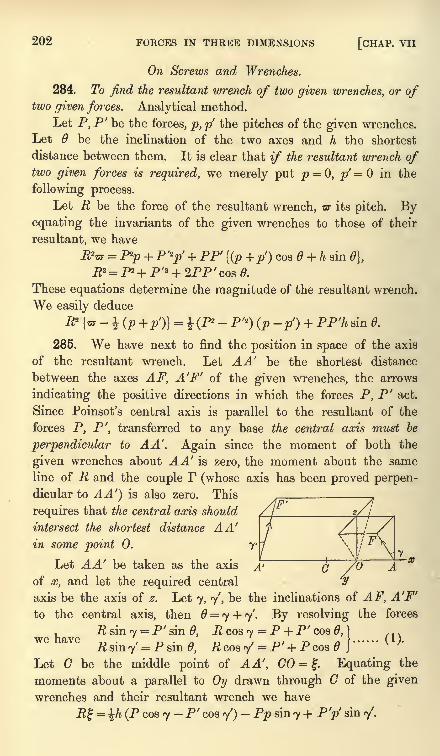
202 FORCES IN THREE DIMENSIONS [CHAP. VII
On Screws and Wrenches.
284. To find the resultant wrench of two given wrenches, or oftwo given forces. Analytical method.
Let P, P' be the forces, p, p' the pitches of the given wrenches.
Let 6 be the inclination of the two axes and h the shortest
distance between them. It is clear that if the resultant wrench oftwo given forces is required, we merely put p = 0, p' in the
following process.
Let R be the force of the resultant wrench, OT its pitch. Byequating the invariants of the given wrenches to those of their
resultant, we have
R*v = P2p + P'2
p' + PP {(p + p') cos0+h sin 0],
JRZ = P2 + P'* + 2PP' cos 0.
These equations determine the magnitude of the resultant wrench.
We easily deduce
R21
- \ (P + P')}= i (P
2 - P'2
) (p -p') + PP'h sin 0.
285. We have next to find the position in space of the axis
of the resultant wrench. Let AA' be the shortest distance
between the axes AF, A'F' of the given wrenches, the arrows
indicating the positive directions in which the forces P, P' act.
Since Poinsot's central axis is parallel to the resultant of the
forces P, P', transferred to any base the central axis must be
perpendicular to A A'. Again since the moment of both the
given wrenches about AA' is zero, the moment about the same
line of R and the couple F (whose axis has been proved perpen-dicular to AA') is also zero. This
requires that the central axis should
intersect the shortest distance A A'
in some point 0. y
Let AA' be taken as the axis
of x, and let the required central
axis be the axis of . Let 7, 7', be the inclinations of AF, A'F'
to the central axis, then = 7 + 7'. By resolving the forces
R sin 7 = P' sin 0, R cos 7 = P + P'cos 0, } ,,.we have .-/.'* , -^, /i r (!)R sin 7 = P sin 0, R cos 7'= P' + P cos }
Let C be the middle point of AA', CO =I;. Equating the
moments about a parallel to Oy drawn through C of the given
wrenches and their resultant wrench we have
Ef = %h (P cos 7 - P' cos 7')- Pp sin 7 + P'p' sin 7'.
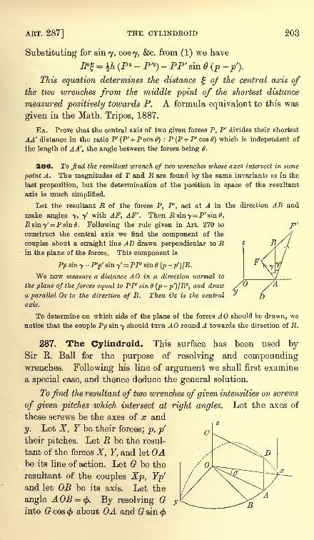
ART. 287] THE CYLINDROID 203
Substituting for sin 7, cosy, &c. from (1) we have
&%=\h (P2 - P'2
)- PP'sin 6 (p -p
f
).
This equation determines the distance % of the central axis ofthe two wrenches from the middle point of the shortest distance
measured positively towards P. A formula equivalent to this was
given in the Math. Tripos, 1887.
Ex. Prove that the central axis of two given forces P, P' divides their shortest
AA' distance in the ratio P^P' + Pcostf) : P(P + P'cos0) which is independent of
the length of AA', the angle between the forces being 6.
286. To find the resultant wrench of two wrenches whose axes intersect in some
point A. The magnitudes of T and R are found by the same invariants as in the
last proposition, but the determination of the position in space of the resultant
axis is much simplified.
Let the resultant R of the forces P, P', act at A in the direction AB and
make angles 7, y' with AF, AF''. Then R&iny^P'emO,R sin y'=P sin 0. Following the rule given in Art. 270 to
construct the central axis we find the component of the
couples about a straight line AD drawn perpendicular to Rin the plane of the forces. This component is
Pp sin 7 -P'p' sin 7' = PP' sin 6 (p
-p')/R.
We now measure a distance AO in a direction normal to
the plane of the forces equal to PP' sin 6 (p -p^/R2,and draw
a parallel Oz to the direction of R. Then Oz is the central
axis.
To determine on which side of the plane of the forces AO should be drawn, we
notice that the couple Pp sin 7 should turn AO round A towards the direction of R.
287. The Cylindroid. This surface has been used bySir R. Ball for the purpose of resolving and compoundingwrenches. Following his line of argument we shall first examine
a special case, and thence deduce the general solution.
To find the resultant of two wrenches of given intensities on screws
of given pitches which intersect at right angles. Let the axes of
these screws be the axes of x and
y. Let X, Y be their forces; p, p'
their pitches. Let R be the resul-
tant of the forces X, Y, and let Abe its line of action. Let G be the
resultant of the couples Xp, Yp'and let OB be its axis. Let the
angle AOB = (j>. By resolving Ginto G cos < about OA and G sin
</>
y7)
c
B
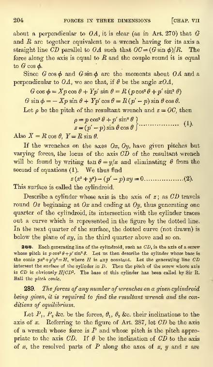
204 FORCES IN THREE DIMENSIONS [CHAP. VII
about a perpendicular to OA, it is clear (as in Art. 270) that Gand R are together equivalent to a wrench having for its axis a
straight line CD parallel to OA such that 00= (Gsin <f>)[R. The
force along the axis is equal to R and the couple round it is equal
to G cos <.
Since G cos < and G sin<f>
are the moments about OA and a
perpendicular to OA, we see that, if 6 be the angle xOA,
Gcos<f>= Xp cos 6 + Yp sin 6 = R (p cos2 + p sin2 6)
G sin $ = Xp sin 6 + Yp cos = R (p p) sin 6 cos 6.
Let p be the pitch of the resultant wrench and z = OC, then
p=jpcos2
0+;>'sin2
) ,
z = (p p) sin cos }
"
Also X = R cos d, Y= R sin 0.
If the wrenches on the axes Ox, Oy, have given pitches but
varying forces, the locus of the axis GD of the resultant wrench
will be found by writing tan 6 = yfx and eliminating 6 from the
second of equations (1). We thus find
z(a? + y*)-(p'-p)xy = (2).
This surface is called the cylindroid.
Describe a cylinder whose axis is the axis of z;as CD travels
round Oz beginning at Ox and ending at Oy, thus generating one
quarter of the cylindroid, its intersection with the cylinder traces
out a curve which is represented in the figure by the dotted line.
In the next quarter of the surface, the dotted curve (not drawn) is
below the plane of xy, in the third quarter above and so on.
288. Each generating line of the cylindroid, such as CD, is the axis of a screw
whose pitch is p cos2+p' sin2 6. Let us then describe the cylinder whose base is
the conic px2+p'y
z=H, where H is any constant. Let the generating line CDintersect the surface of the cylinder in D. Then the pitch of the screw whose axis
is CD is obviously If/CD2
. The base of this cylinder has been called by Sir R.
Ball the pitch conic.
289. The forces of any number ofwrenches on a given cylindroid
being given, it is required to find the resultant wrench and the con-
ditions of equilibrium.
Let PJ, P2 &c. be the forces, lt 2 &c. their inclinations to the
axis of x. Referring to the figure of Art. 287, let CD be the axis
of a wrench whose force is P and whose pitch is the pitch appro-
priate to the axis CD. If be the inclination of CD to the axis
of x, the resolved parts of P along the axes of x, y and z are
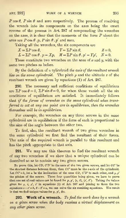
ART. 292] WORK OF A WRENCH 205
P cos 0, P sin 6 and zero respectively. The process of resolving
the wrench into its components on the axes being the exact
reverse of the process in Art. 287 of compounding the wrenches
on the axes, it is clear that the moments of the force P about the
axes are P cos 6 . p, P sin 6 .p and zero.
Taking all the wrenches, the six components are
JT = 2Pcos6>, F=2Psin0, Z = 0,
These constitute two wrenches on the axes of a and y, with the
same two pitches as before.
By the definition of a cylindroid the axis of the resultant wrench
lies on the same cylindroid. The pitch p and the altitude z of the
resultant wrench are given by equations (1) of Art. 287.
290. The necessary and sufficient conditions of equilibrium
are 2P cos 6 0, SP sin 6 = 0, for when these vanish all the six
conditions of equilibrium are satisfied. It immediately follows
that if the forces of wrenches on the same cylindroid when trans-
ferred to act at any one point are in equilibrium, then the wrenches
themselves will be in equilibrium.
For example, the wrenches on any three screws in the same
cylindroid are in equilibrium if the force of each is proportional to
the sine of the angle between the other two.
To find, also, the resultant wrench of two given wrenches in
the same cylindroid we first find the resultant of their forces.
The axis of the required wrench is parallel to this resultant and
has the pitch appropriate to that axis.
291. We may use this theorem to find the resultant wrench
of any two wrenches if we show that a unique cylindroid can be
described so as to contain any two given screws.
To prove this, let CD, C'D' be the axes of the two given screws, and let CO' be
the shortest distance between them, then CC' must be the z-axis of the cylindroid.
Let CC'= h, let a be the inclination of the axes CD, C'D' to each other, and p, p'
the pitches of the screws. These four quantities being given, we have to prove
that one set of real values can be found for p, p', (z, 0), (z', 6'). Taking the values
given for p, z, p', z' in equations (1) of Art. 287 and joining to them the two
equations z-z'= h, 0-0' a, we can solve the six resulting equations. The result
is that we find unique values for p, p', &c.
292. Work of a wrench. To find the work done by a wrench
on a given screw when the body receives a virtual displacement on
any other given screw.
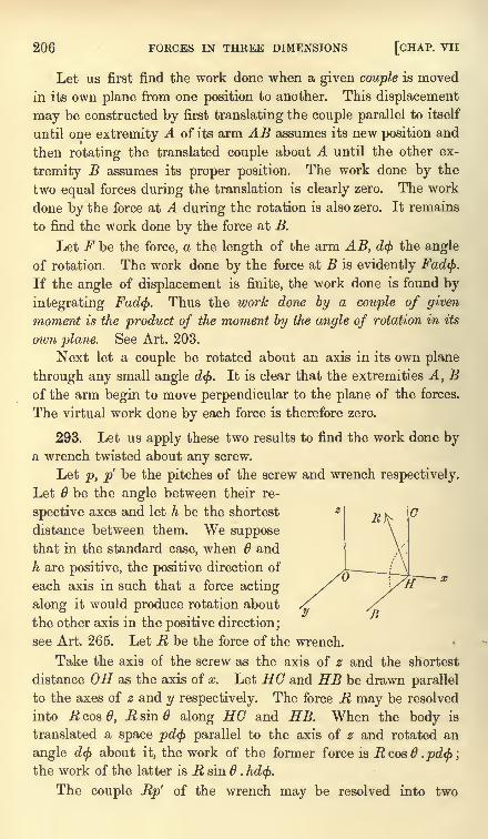
206 FORCES IN THREE DIMENSIONS [CHAP, vii
Let us first find the work done when a given couple is moved
in its own plane from one position to another. This displacement
may be constructed by first translating the couple parallel to itself
until one extremity A of its arm AB assumes its new position and
then rotating the translated couple about A until the other ex-
tremity B assumes its proper position. The work done by the
two equal forces during the translation is clearly zero. The work
done by the force at A during the rotation is also zero. It remains
to find the work done by the force at B.
Let F be the force, a the length of the arm AB, d<j> the angle
of rotation. The work done by the force at B is evidently Fad<f).
If the angle of displacement is finite, the work done is found by
integrating Fad(f>. Thus the work done by a couple of given
moment is the product of the moment by the angle of rotation in its
own plane. See Art. 203.
Next let a couple be rotated about an axis in its own plane
through any small angle d$. It is clear that the extremities A, Bof the arm begin to move perpendicular to the plane of the forces.
The virtual work done by each force is therefore zero.
293. Let us apply these two results to find the work done bya wrench twisted about any screw.
Let p, p be the pitches of the screw and wrench respectively.
Let 6 be the angle between their re-
spective axes and let h be the shortest
distance between them. We supposethat in the standard case, when 6 and
h are positive, the positive direction of
each axis in such that a force acting
along it would produce rotation about
the other axis in the positive direction;
see Art. 265. Let R be the force of the wrench.
Take the axis of the screw as the axis of z and the shortest
distance OH as the axis of x. Let UG and HB be drawn parallel
to the axes of z and y respectively. The force R may be resolved
into R cos 6, R sin 6 along HG and HB. When the body is
translated a space pd<j) parallel to the axis of z and rotated an
angle d<j> about it, the work of the former force is Rcosd .pd(j>;
the work of the latter is R sin 6 . hd<f>.
The couple Rp' of the wrench may be resolved into two
ART. 297] RECIPROCAL SCREWS 207
couples Rp' cos 6 and Rp' sin 6 whose axes are HG and HB.The work of the former is Rp cos 6d^>, the work of the latter is
zero. The whole work done is therefore
dW =Rd(j> {(p +p') cosd + h sin 6}.
We notice that this is a symmetrical function of p and p', so
that if the two screws are interchanged the work is unaltered.
294. Reciprocal screws.* Two screws are said to be reci-
procal when a wrench acting on either does no work as the bodyis twisted about the other. The analytical condition that two
screws are reciprocal is therefore
(p + p') cos6 + h sin 6 = 0.
Thus, two intersecting screws are reciprocal when either theyare at right angles or their pitches are equal and opposite.
It follows from the principle of virtual work that a body free
to move only on a screw a is in equilibrium if acted on by a
wrench on any screw reciprocal to a.
295. If a screw a is reciprocal to each of two given screws, say a and /3, it is
also reciprocal to every screw on the cylindroid containing a and /3. For a wrench
on any third screw 7 on this cylindroid may be replaced by two wrenches on the
screws a and /3, if the forces on a and p are the components of the force on y
(Art. 289). Since the virtual work of each of these when twisted along <r is zero,
the screws 7 and <r are reciprocal. We may say for brevity that the screw <r is
reciprocal to the cylindroid.
296. A screw <r if reciprocal to a cylindroid must intersect one of the generators
at right angles. The cylindroid, being a surface of the third order, will be cut bythe screw a in three points, and one screw of the cylindroid passes through each of
these points. Each of these three screws intersects the screw a- and is reciprocal to
it. It follows by Art. 294 that each of these is either perpendicular to <r or has a
pitch equal and opposite to that of <r. But since the pitch p of a screw on the
cylindroid is p cos2 d +p' sin2 there are only two different screws on the same
cylindroid of the same pitch, viz. those given by supplementary values of 6. Hence
the screw a must intersect one of the three screws at right angles. Also, as it
cannot be perpendicular to more than one screw on the cylindroid (unless it is the
nodal line or z axis), the pitches of the two remaining screws must be each equal
and opposite to that of <r.
297. Ex. 1. Show that the locus of a screw reciprocal to four screws (nothree of which are on the same cylindroid) is a cylindroid.
Since a screw is determined by five quantities it is clear that, when the four
conditions of reciprocity are fulfilled, the screw must in general be confined to a
certain ruled surface. If this surface be not a cylindroid, pass a cylindroid
* The theory of reciprocal screws is due to Sir R. Ball and the substance ofArts. 294 to 297 is taken from his book on Screws. To this work the reader is
referred for further development.
208 FORCES IN THREE DIMENSIONS [CHAP. VII
through any two of its generators, then any screw on this cylindroid will also be
reciprocal to the four given screws. The locus therefore would be, not a single
ruled surface, but a system of cylindroids.
Ex. 2. Prove that there is in general but one screw reciprocal to five given
screws. [As there are five conditions to be satisfied the number of screws is finite.
But if there were as many as two there would be a cylindroidal locus of screws.]
Ex. 3. Prove that any two reciprocal screws on the same cylindroid are parallel
to conjugate diameters of the pitch conic.
Let p, p' be the pitches, z, z' the altitudes. Let z>z' and 6>6'; Art. 293. It
will be seen that a force acting along the positive direction of the axis of either
screw would tend to produce rotation round the axis of the other in the negative
direction. We therefore put h=z -z', <j>=-
(0-
0'). The condition that the screws
are reciprocal is (p+ p') cos $ + h sin = 0, Art. 294. Substituting for p, p', z, z' their
values given in Art. 287, this reduces to p cos cos 0' +p' sin sin 0' 0. This is
the condition that the axes of the screws are parallel to conjugate diameters of the
pitch conic, Art. 288.
On Conjugate Forces.
298. The nul plane. The locus of all the straight lines,
drawn through a given point 0, and such that the moment of the
system about each vanishes is a plane.
This plane is called the nul plane of and the point is
called the nul point of the plane. Any line about which the
moment of the forces is zero is called a nul line.
To prove this proposition let us represent the system by a
couple G and a force R at as base. It is at once evident
that the moment about a straight line through cannot be
zero unless it lies in the plane of the couple. The nul plane
may therefore also be defined as the plane of the principal couple
at 0.
The names nul-point and nul-plane are due to Moebius, Lehrbuch der Statik,
1837. Instead of these the terms pole and polar plane have been used by Cremona,
Reciprocal Figures, 1872, translated into French, 1885, into English, 1890. The
term focus has also been used by Chasles, Comptes Rendus, 1843.
299. If any straight line in the nul plane of and not
passing through were a nul line, the moment of R about it
would be zero. This requires that R should either be zero or lie
in the nul plane. In the former case the system of forces is
equivalent to a single couple, and the nul plane is parallel to
the plane of the couple. In the latter, the system is equivalentto a single force, and the nul plane passes through its line of
action. In both cases the invariant / of the system is zero.
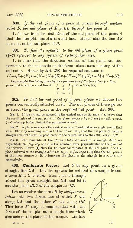
ART. 303] CONJUGATE FORCES 209
300. If. the nul plane of a point A passes through another
point B, the nul plane of B passes through the point A.
It follows from the definition of the nul plane of the point Athat the straight line AB is a nul line. Hence also the line ABmust lie in the nul plane of B.
301. To find the equation to the nul plane of a given point
(%?)) referred to any system of rectangular axes.
It is clear that the direction cosines of the. plane are pro-
portional to the moments of the forces about axes meeting at the
nul point. Hence by Art. 258 the required equation is
Any straight line being given by its equations (x-f)/l=(y -g)/m=(z -h)jn,
prove that it will be a nul line if Ll +Mm + Nn.
302. To find the nul point of a given plane we choose two
points conveniently situated on it. The nul planes of these pointsintersect the given plane in the required nul point. Art. 300.
Ex. 1. If the system be referred to the central axis as the axis of z, prove that
the coordinates of the nul point of the plane z=Ax + By + C are |= -pB, i)=pA,
f= C, where p is the pitch of the equivalent wrench.
Ex. 2. A plane intersects the central axis in C and makes an angle <f>with that
axis. Show by reasoning similar to that of Art. 270, that the nul point lies in a
straight line CO drawn perpendicular to the central axis so that CO = cot <f> . T/R.
Ex. 3. The moments of the forces about the sides of a triangle ABC are
respectively MltM2 ,
M3 , and Z is the resolved force perpendicular to the plane of
the triangle. Prove (1) that the trilinear coordinates of the nul point of the
plane referred to the triangle ABC are MJZ, M2/Z, M3/Z ; (2) that the nul planesof the three corners A, B, C intersect the plane of the triangle in AO, BO, COrespectively.
303. Conjugate forces. Let be any point on a given
straight line OA. Let the system be reduced to a couple G and
a force R at as base. Pass a plane throughR and the given straight line OA, and let it
cut the plane BOG of the couple in OB.
Let us resolve the force R by oblique reso-
lution into two forces, one of which F acts
along OA and the other F' acts along OB.
This force F' may be compounded with the
forces of the couple into a single force which
also acts in the plane of the couple. Its line
R. s. i. 14
210 FORCES IN THREE DIMENSIONS [CHAP. VII
of action is parallel to OB and distant GjF' from it. It follows
that all the forces of the system are equivalent to some force Facting along any assumed straight line OA together with a second
force F' which acts in the nul plane of the point 0. The forces are
given by FsmAOB = RsiuROB, F'smAOB = RsinROA.
The forces F, F' are called conjugate forces, and their lines of
action conjugate lines.
304. Since .0 is any point on the straight line OA, it follows
that when travels along a straight line, the nul plane of always
passes through the conjugate and turns round it as an axis.
3O5. Vanishing of the Invariant I. When the force R is zero or lies in the
nul plane BOG, the system reduces to either a single couple or a single force. In
both these cases every point in the plane BOC is a nul point.
If the system is equivalent to a single couple R=0, and if the assumed line OAis inclined to the plane of the couple the force F along it is zero
;the conjugate is
at infinity and its force also is zero. If OA is in the plane of the couple, the force
along it forms one force of the couple while the conjugate is the other force, the
distance between the conjugates, i.e. the arm of the couple, being arbitrary.
If the system is equivalent to a single resultant, OR lies in the plane BOC. If
the assumed line OA does not intersect the single force, the force F along OA is
zero, the conjugate being the single resultant. If OA intersects the single resultant,
the conjugate is any line in their plane passing through that intersection, the
conjugate forces being found by resolving the single resultant in their directions.
Conversely, since I=FF'r sin 0, (Art. 281) we see that when the invariant is zero
fither one conjugate force is zero, or the two conjugates lie in one plane.
306. To find the conjugate of a nul line. In this case OA lies
In the nul plane of 0, and if R is not zero and does not also lie in
that plane the straight lines OA, OB, are opposite to each other,
Art. 303. The components of R, viz. F and F', are therefore both
infinite so that the two forces F, F' act in opposite directions
along the same straight line OA. Such lines may therefore be
called self-conjugate. They have also been called double lines byCremona.
In the limiting case when the invariant I is zero, any line lying in the plane of
the single couple or intersecting the single resultant is a line of nul moment. Wehave seen above that their conjugates are indeterminate.
307. It has been proved that the conjugate of every line
passing through a given point lies in the nul plane of 0, we
shall now show that the conjugate of every straight line in that
plane passes through the nul point.
It is evident that if one conjugate intersect a line of nul
ART; 308] CONJUGATE FORCES 211
moment, the other conjugate must either intersect that line or its
force must be zero. Now the nul lines of the plane BOO radiate
from and are intersected by any chosen line DE in that plane.
It follows that the conjugate of DE must also intersect them or
its force must be zero. If I is finite the conjugate force cannot
also lie in that plane or be zero, it must therefore pass throughthe nul point 0. If / = every point in the plane is a nul pointand the theorem is again true.
308. To find the equation of the conjugate of the given line
(x-f)ll = (y-g)lm=(z-h)ln ............... (1).
It follows from Art. 304, that if any two points 0, 0' are
chosen on the given line OA, their nul planes intersect on the
conjugate. The nul planes of the point (fgh) and of another
point at infinity whose coordinates are proportional to I, m, n are
(Art. 301) respectively
(L-gZ+hY)x+(M-hX+fZ)y+(N-fY+gX)z=Lf+Mg+Nh(-mZ+nY)x+(-nX+lZ)y+(-lY+mX)z=Ll+Mm+Nn.These are the equations to the conjugate. They also take the
form
x,
f,
Y,
9,
z X,
I,
y,
Y,
m,
The line of action of the force F being given as above by the
equations (1), an analytical expression for the magnitude of Fcan be found which may be used when the position and magni-tude of the conjugate force F' are not required. If we reverse
the force F and join it to the given system, the compound systemwill be equivalent to a single force. The invariant of the com-
pound system is therefore equal to zero. If I, m, n are the actual
direction cosines of the given line of action of the force F, the
components of the compound system are
X' = X-Fl, L' = L + Fmh-Fng,Y'=Y-Fm, M' = M+Fnf -Flh,
Z'=Z-Fn, N' = N+Flg -Fmf.
Equating the invariant L'X' + M'Y' + N'Z' to zero, we find
/, 9,LX + MY + NZF
= LI + Mm + Nn -
I,
Y, Z
m, n
142
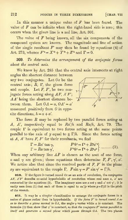
212 FORCES IN THREE DIMENSIONS [CHAP. VII
In this manner a unique value of F has been found. Thevalue of F can be infinite when the right-hand side is zero
;this
occurs when the given line is a nul line, Art. 301.
The value of F being known, all the six components of the
compound system are known. The magnitude and line of action
of the single resultant F' may then be found by equations (4) of
Art. 273, whence F'2 = X'2 + Y'2 + Z'2 and F = 0.
309. To determine the arrangement of the conjugate forces
about the central axis.
We know by Art. 285 that the central axis intersects at right
angles the shortest distance between
any two conjugates. Let Oz be the
central axis; R, F, the given force
and couple. Let F, F', be two con-
jugate forces acting along AF, A'F';
AA' being the shortest distance be- A'
tween them. Let OA = a, OA' = a'
measured positively from in oppo-site directions, h = a + a'.
The force R may be replaced by two parallel forces acting at
A, A', respectively equal to Ra'/h and Ra/h, Art. 79. The
couple F is equivalent to two forces acting at the same points
parallel to the axis of y equal to + F/A. Since the forces acting
at A, A' have F, F' for their resultants, we find
F = Ea'tan7, F2h2 = r2 + R2a' 2
}
F = .Ratan7/
,F'2h2 = P + P?a2
}( ''
When any arbitrary line AF is chosen as the seat of one force,
a and 7 are given ;these equations then determine F, F', 7', a'.
We notice also that since the resolved parts of F, F' in the plane
xy are equivalent to the couple F, Fsin 7 = F' sin y =F/A.
310. If the figure is turned round Oz as an axis of revolution, the conjugates
AF, A'F' describe co-axial hyperboloids of revolution whose real axes a, a' are
connected by the equations (1). The imaginary axes are a cot 7 and a' cot 7'; it is
easily seen from (1) that each of these is equal to aa'/p where p= r/R is the pitch
of the wrench.
311. It maybe a simpler classification to arrange the conjugate forces in a
series of planes rather than in hyperboloids. If the force F' is turned round A so
as to describe a plane normal to OA, the angle 7 varies while a is constant. Theformulae (1) then show that 7' is constant, so that the conjugate F' moves parallel to
itself and generates a second plane which passes through OA. The two planes
ART. 314] CONJUGATE FORCES 213
intersect in a nul line, whose locus when a varies is the paraboloid pz = -xy where
p is the pitch of the wrench.
Ex. Any two systems of forces being given show that they will have one
common system of conjugate lines real or imaginary. If O0'=2cis the shortest
distance between the axes of the equivalent wrenches, C the middle point of 00',
prove that the distances of the common conjugates from C are given by the
quadratic x2+ (p-p')cot Ox+pp' -c2 -
(p+p') ccot0=0 where p, p' are the pitches
and 6 the angle between the axes.
312. Ex. 1. If two straight lines intersect in a point 0, their conjugates also
intersect, and lie in the nul plane of 0. Art. 303.
Ex. 2. A transversal intersects a force and its conjugate. Prove that each
intersection is the nul point of the plane which contains the transversal and the
other force.
For every straight line drawn through one intersection to cut the other force is
a nul line, see also Art. 303.
Ex. 3. The locus of a straight line drawn through a given point so that
the moments about it of two conjugate forces F, F' have a given ratio /A is a plane,
which becomes the nul plane of when /*=-!. Whatever the forces andfj. may
be, this plane passes through the intersection of the two planes drawn from to
contain the forces, and makes angles <p, tj>'with these two planes such that the
given ratiofj.
is equal to Fp sin<j>
: F'p' sintf>'. Here p and p' are the perpendicular
distances of from the given straight lines.
313. Ex. 1. Two arbitrary points A, B are taken on a nul line. Prove that
the system can be reduced to two conjugate forces acting at A and B, the force at
A making a given angle c/>with AB. Prove also that if
<j>is varied, the locus of the
force at each point is the nul plane of the other point.
If<f>, <f>'
are the angles the conjugate forces make with AB, prove that
G cot<j>
G' cot<f>= aX, where G, G', are the principal couples at A, B, X the force
along AB and a AB.
To prove this take A as base (Art. 257) and change the couple G into another
whose forces pass through A and B.
Ex. 2. Two planes being given which intersect in a nul line, show that the
system can be reduced to two conjugates, one in each plane. [Take A, B of Ex. 1
at the nul points of the planes.]
Ex. 3. If AM, BN are two nul lines, show that the system can be reduced
to two finite conjugate forces intersecting both AM, BN.
Let A be any point on AM, the nul plane of A will pass through AM and cut
BN in some point B. The rest follows from Ex. 1.
314. The characteristic of a plane is the conjugate of the normal at the nul
point, Chasles, Comptes Rendus, 1843.
Ex. 1. Any two conjugates intersect a plane in M and M': show that MM'passes through the nul point of that plane. Show also that the projections of
these conjugates on the plane intersect in the characteristic. [Chasles' theorem.]
Ex. 2. The locus of the axes of the principal couples at all bases situated on a
given straight line is a hyperbolic paraboloid. This paraboloid is a plane when the
straight line can be a characteristic, and in this case the envelope of the axes of the
principal couples is a parabola whose focus is the pole of the plane. [Chasles.]
214 FORCES IN THREE DIMENSIONS [CHAP. VII
Let AB be the straight line, CD its conjugate. The axis of the principal coupleat any point on AB is perpendicular to the plane OCD, Art. 303. If the straight
line AB were turned round CD as an axis of rotation through any small angle dO,
each point on AB would move a small space perpendicular to the plane OCD,i.e. it would move a small space along the axis of the principal couple. Hencethese axes all intersect two straight lines, viz. AB and its consecutive position, and
are all parallel to a plane which is perpendicular to CD. The locus is therefore a
hyperbolic paraboloid.
Theorems on forces.
315. Three forces. If three forces are in equilibrium, they
must lie in one plane.
Let A and B be any two points on two of the forces. Since
the moment about the straight line AB is zero, this straight line
must intersect the third force in some point C. Let A be fixed
and let B move along the second line;the straight line AB will
describe a plane, and the second and third forces must lie in this
plane. If we fix C and let B move as before, we see that the first
force must also lie in the same plane.
Ex. 1. The forces of a system can be reduced to three forces Flt F2 ,F3 which
act along the sides of an arbitrary triangle ABC together with three other forces
Zlt Z2 ,Z3 which act at the corners A, B, C at right angles to the plane of the
triangle.
Resolve each force P of the system into two, one in the plane ABC and the
other perpendicular to that plane. The former can be replaced by three forces
acting along the sides (Art. 120, Ex. 2), and the latter by three parallel forces at
the corners (Art. 86, Ex. 1). If P is parallel to the plane ABC we can transfer it
to act in the plane by introducing a couple. Turning the couple round in its own
plane we can include its forces among those normal to ABC.
Ex. 2. The forces of a system can be reduced to three forces which act at the
corners of an arbitrary triangle and satisfy three other conditions.
Replace Fj by Fx + u at B and - u at C ; F2 by F2+ v at C and - v at A ; -F3 byF3+w at A and -w at B. Compounding the forces at the corners, the arbitrary
quantities u, v, w may be used to satisfy three conditions.
Ex. 3. A system of forces is reduced to three acting at fixed points A, B, C.
If the force at A is fixed in direction, prove that each of the other two lies in a
fixed plane. Show also that these planes intersect along the side BC.
[Coll. Ex., 1891.]
316. Four forces. If four non-intersecting forces are in
equilibrium, they must be generators of the same system of a
hyperboloid. Mrebius, Lehrbuch der Statik.
If a straight line move so as always to intersect three given
straight lines, called directors, the locus is known to be a hyper-boloid and the different positions of the moving straight line form
ART. 316] THEOREMS ON FOUR FORCES 215
one system of generators. An infinite number of transversals can
be drawn to cut three of the forces, but each must intersect the
fourth force also, for otherwise the moment of the four forces
about that transversal is not zero. Taking any three of these
transversals as directors, the four forces lie on the corresponding
hyperboloid.
The following theorems will serve as examples, as the proofs
are only briefly given.
Ex. 1. If n forces act along generators of the same system and have a single
resultant, prove by drawing transversals that the resultant acts along another
generator of the same system.
Ex. 2. When two of the forces P, P', act along generators of one system and
two Q, Q', along generators of another system, they form a skew quadrilateral.
The properties of such a combination of forces have been already considered in
Art. 103. Their invariants are given in Arts. 317 and 323.
Prove, by drawing transversals through the intersection of P and Q', that the
forces cannot be in equilibrium except when they lie in one plane.
Ex. 3. When three of the forces P1 ,P2 ,
P3 , act along generators of one system
and the fourth Q along a generator of the other system, prove that they cannot be
in equilibrium except when all the forces lie in a plane. For if every transversal
of P15 P2 ,P3 could intersect Q, this last would intersect all the generators of its
own system.
Ex. 4. F<>ur forces act along generators of the same system of a hyperboloid.
Their magnitudes are such that if transferred parallel to themselves to act at a
point they would be in equilibrium. Prove that they are in equilibrium when
acting along the generators.
Let Q be any generator of the other system, which therefore intersects the four
forces. Transfer the forces to act at any point of Q, then the transferred forces are
in equilibrium and the axes of the four couples thus introduced are perpendicular
to Q. The four forces are therefore equivalent to a resultant couple such that
either its moment is zero or its axis is perpendicular to every position of Q. The
latter supposition is impossible. Pliicker and Darboux.
Ex. 5. If four forces Plt P2 , P3 , P4 are in equilibrium, prove that the invariant
of any two is equal to that of the remaining two (this theorem is due to Chasles).
Also the invariant of any three of the forces is zero.
Reversing the directions of P3 , P4 ,the forces Plt P2 become equivalent to
P3 ,P4 . Their invariants are therefore equal.
Ex. 6. Four forces acting along the straight lines a, b, c, d are in equilibrium.
If the symbol ab represent the product of the shortest distance between a, b into
the sine of the angle between them, show that the forces acting along these lines
are proportional to (be . cd . db)%, (cd . da . oc)*, (da . ab . bd)*, (ab . be . ca)*.
[Cayley, Comptes Rendus, 1865.]
We have by Chasles' theorem PaP2 . ab PaP4 . cd and PjP3 . ac = P2P4 bd.
Multiplying these together we have the ratio of P-? : P42
.
216 FORCES IN THREE DIMENSIONS [CHAP. VII
317. Analytical discussion of the hyperboloid. Refer the
system to the axes of the hyperboloid as coordinate axes, and let
a, b, c V 1, be these axes. Let any generator be
x - a cos 6 _y 6 sin _ z
a sin 6 b cos 6 c'
where is the eccentric angle of the intersection with the planeof xy, and the generator belongs to one system or the other
according to the sign of c. Let P be the force along this
generator, X, Y, Z, L, M, N its six components. We see that
X= + -Zsin0, Y=+-Zcos0, L= bZsind, M=-aZcos0, tf=+ Z~c c c
where all the upper signs are to be taken together.
Ex. 1. If four forces act along generators of the same system prove that the
six equations of equilibrium reduce to the three 1,Z sin 0=0, 2/? cos = 0, SZ = 0.
This gives an analytical proof of the theorem in Art. 316, Ex. 4.
Ex. 2. Prove that the invariant I of two forces which act along generators of
the same system is 1= =p- Z\%i versin (01
- 62). If the forces act along generators
of different systems, their invariant is zero because the generators intersect. If
forces act along several generators, the invariant is the sum of the invariants
taken two and two, Art. 281.
Ex. 3. When four generators of the same system are given, the ratios of the
equilibrium forces are given by____vers (02
-3 )vers (03
-4) vers (04
-2) vers (03
-4)
vers (04-
: )vers (0X
-3)
These may be obtained by equating the invariants two and two, as in the proof of
Cayley's theorem, Art. 316.
Ex. 4. Four forces in equilibrium act along four generators of a hyperboloid
and intersect the plane of the real axes in Alt A2 , A 3 , A 4 . Show that the resolved
parts of the forces parallel to the imaginary axis are proportional to the areas of
the triangles A2A3A t ,A3AA l &c., the forces at adjacent corners of the quadrilateral
A 1A zA 3
Ai having opposite signs.
Ex. 5. Forces act along generators of the same kind, say c positive. Prove
that the pitch p of the equivalent screw lies between -abjc and the greater of the.. -quantities fic/oand ca/6. Forj>=-2
=(SZ)2 + (fec.
=^c,where |, ,,
have been written for "2Z cos 0/SZ and !LZ sin 0/2Z. We see at once that p + abjc
is positive and p be/a negative if 6> a.
Ex. 6. Forces act along generators of the same system and the pitch p of the
equivalent wrench is given. Prove that the central axis is that generator of the
concyclic hyperboloid
ab \ . fbc \ fca \ fab
which intersects the plane of xy in the point
__ac-bp ~LZ cos _bc-ap "LZ sinX~
c 2Z~ ' y ~~~c 2Z~'
ART. 318] THEOREMS ON FOUR FORCES 217
Ex. 7. Forces act along generators of the same system and admit of a single
resultant, which intersects the plane of xy in D. Prove that OD and the projection
of the resultant force are parallel to conjugate diameters.
Ex. 8. Forces act upon a rigid body along generators of the same system of a
hyperboloid. Prove that the necessary and sufficient condition of their being
reducible to a single resultant is that their central axis should be parallel to one of
the generating lines of the asymptotic cone. [Math. Tripos, 1877.]
Ex. 9. A system of forces have their directions along any non-intersecting
generators of a hyperboloid of one sheet ;show that the resultant couple at the
centre of the hyperboloid lies in the diametral plane of the resultant force, and the
least principal moment is -^ -^ 2 =-% =--% ', DI and D2 being the semi-axes ofa T" o c \ %
the section of the hyperboloid by the plane of the couple, and a, b, c the semi-axes
of the surface, and R the resultant force. Explain the difficulty in the geometrical
interpretation of these results for a single force. [Math. Tripos, 1880.]
318. Relation of four forces to a tetrahedron. Ex. 1. Forces act at the
centres of the circles circumscribing the faces of a tetrahedron perpendicular to
those faces and proportional to their areas. Prove that they are in equilibrium if
they act either all inwards or all outwards.
Ex. 2. Forces act at the corners of a tetrahedron perpendicularly to the
opposite faces and proportional to their areas. Prove that they are in equilibrium
if they act either all inwards or all outwards. [Math. Tripos, 1881.]
Let ABCD be the tetrahedron, AK, BL &c. the perpendiculars. Since the
product of each perpendicular into the area of the corresponding face is equal to
three times the volume of the tetrahedron, the forces are inversely proportional to
the perpendiculars along which they act. Let the forces be {J./AK, /J./BL &c.
Let us resolve the force \j.\AK into three components which act along the edges
AB, AC, AD. The component F which acts along AB is found by equating the
resolutes perpendicular to the plane ACD. This gives .F = = -^cos 0, where 9 isAB AK.
the angle between the perpendiculars AK and BL. In the same way we resolve
the force fjLJBL into components along the edges. The component F' which acts
along BA is found from F' . = = cos 0. Hence F and F' are equal and oppo-Ats JoLi
site forces. In the same way it may be shown that the forces along all the other
edges are equal and opposite. The system is therefore in equilibrium.
Ex. 3. Forces act at the centres of gravity of the four faces of a tetrahedron
perpendicularly to those faces and proportional to them in magnitude, all inwards
or all outwards. Prove that they are in equilibrium.
Joining the centres of gravity we construct an inscribed tetrahedron, the faces
of which are parallel to those of the former and proportional to them in area. The
given forces act at the corners of this new tetrahedron and are therefore in equili-
brium by Ex. 2.
Ex. 4. Forces act at the centres of gravity of the faces of a closed polyhedronin directions perpendicular to the faces and proportional to their areas in magni-tude. Prove that they are in equilibrium.
Divide each face into triangles by drawing a sufficient number of diagonals.
By joining any internal point P to the several corners we divide the polyhedron
218 FORCES IN THREE DIMENSIONS [CHAP. VII
into tetrahedra. Forces acting at the centres of gravity of the faces of each tetra-
hedron are in equilibrium by Ex. 3. Removing the equal and opposite forces
which act at the centre of gravity of each internal face, the forces which act at the
external faces must be in equilibrium.
Ex. 5. Forces act at the middle points of the edges of a closed polyhedron, in
directions bisecting the angles between the adjacent faces, and having magnitudes
proportional to the product of the length of the edge by the cosine of half the anglebetween the faces. Prove that they are in equilibrium.
Let forces act at the middle points of the sides of each face in the plane of the
face perpendicularly to and proportional to the sides. These are in equilibrium byArt. 37. Compounding the forces at each edge the theorem follows.
319. Normal forces on surfaces. Ex. 1. Forces act normally at every element
of a closed surface. Prove that they are in equilibrium if each force is either
(1) proportional to the area of the element, or (2) proportional to the product of the
area by --f where p, />'
are the principal radii of curvature.
Since the surface may be regarded as the limiting case of a polyhedron, the
first theorem follows from Ex. 4.
By drawing the lines of curvature the surface may be divided into rectangular
elements which may be regarded as the faces of a polyhedron. The second
theorem then follows from Ex. 5. Let ABCD be any element, the external angle
between the faces which meet in BO is AB/p. The force across this edge is
therefore \BC . AB/p and ultimately acts perpendicularly to the element.
M. Joubert deduces the second of these theorems from the first. He also
deduces from the second that normal forces proportional to the quotient of each
elementary area by pp' are in equilibrium. Liouville's J. vol. xm., 1848.
Ex. 2. One-eighth of an ellipsoid is cut off by the principal planes, and along
the normal at any point a force acts proportional to the element of surface at that
point. Show that all these forces are equivalent to a single force acting along
the line a (x-
4a/3?r) = b (y-
Ib/Sir)= c(z- 4c/37r), where 2a, 26, 2c are the principal
axes of the ellipsoid. [June Exam.]
320. Five forces. Iffive finite non-intersecting forces are in
equilibrium, they must intersect two straight lines which may be
real or imaginary. Moebius.
First, we shall prove that any four straight lines a, b, c, d can
be cut by two transversals. For, describing the hyperboloid
which has a, b, c for directors we notice that the line d cuts this
hyperboloid in two points real or imaginary. One generator of
the system opposite to a, b, c passes through each of these points
and therefore intersects the straight lines a, b, c as well as d.
Assuming this lemma we draw the two transversals of any four of
the forces. Each of these must intersect the fifth force, for other-
wise the moments about them would not be zero. These two
transversals may be called the directors of the five forces.
ART. 323] THEOREMS ON FIVE FORCES 219
321. Let the shortest distance between two straight lines be
taken as aoois of z. Let any five forces intersect these straight
lines at distances (rjr/) (r2r2') &c. from that axis, and let Zly Zz &c.
be the z resolutes of these forces respectively. Prove that the condi-
tions of equilibrium are *Z= 0, ^Zr = 0, ^Zr = 0, ^Zrr = 0.
Let the origin bisect the shortest distance between the two
directors of the forces, and let this shortest distance be 2c. Let 20
be the angle between the directors, and let the axes of x and y be
its bisectors. The equation to any force may then be written
(x r cos Q)l(r r) cos 6 = (y r sin 0)/(r + /) sin 6 = (z-
c)/2c.
Writing 1//i
2 =(r-
r')2 cos2 6 + (r + r'J sin2 + 4c2
,
and representing the forces by PJ...PS, the equations of equilibriumformed by resolving along the axes are
2P/i (r-
r') cos = 0, 2P/* (r + r') sin 6 = 0, 22P/zc = 0.
The equations of moments are
2 (zX -xZ} = - 2P/Lt (r + r')ccos = 0,
S(a?F-yZ)= 22P/zrr/
sin cos 6 = 0.
When c and sin 20 are not zero, these six equations reduce to the
four given above. These four equations determine the ratios of
the five forces P^.-Pg when the intersections of their lines of
action with the directors are known.
322. Let the two directors be moved so that either their.mutual inclination 29
or their distance apart 2c is altered, but let them continue to intersect the axis of z
at right angles. It follows from these results that equilibrium will continue to
exist provided (1) the forces always intersect the directors at the same distances
from the axis of z, and (2) the z component of each is unchanged.
When five forces jn equilibrium are given in one plane, which besides the three
conditions of equilibrium also satisfy the condition 2^rr'=0, we may by this
theorem construct five forces in space which are also in equilibrium.
323. Ex. 1. Any number of forces intersect two directors in the points
ABC..., A'B'C'..., prove that the invariant I=sin 202Z1Z2 . AB .A'B'fic.
Ex. 2. Four forces act along the sides of a skew quadrilateral taken in order
and their magnitudes are respectively a, /3, 7, 5 times the sides along which they
act, as in Art. 103, Ex. 5, Prove that the invariant 1= 2c sin 26 (ay-
/35) DD'where J>, D' are the lengths of the diagonals, 2c their shortest distance and 26 the
angle between them.
Ex. 3. Any number of forces intersect two directors and a plane is drawn
through each parallel to the other. Find the coordinates of the points in which
the central axis intersects these planes. The result is given in Art. 278, Ex. 7.
220 FORCES IN THREE DIMENSIONS [CHAP. VII
Ex. 4. Five forces in equilibrium intersect their two directors in the points
ABODE and A'B'C'D'E', and their magnitudes are a.AA', fi.BB', &c. Prove
(1) that the sum of the coefficients a, /3, &c. is zero and (2) that
CD . BE, DB . CEC'D' . B'E', D'B' . C'E'
DE.CA,EC.DAD'E' . C'A', E'C' . D'A'
= &c. [Coll. Ex., 1892.]
Ex. 5. Show that the force along AA' is zero when the other four lines cut the
two directors in the same anharmonic ratio. This is also a known property of anyfour generators of a hyperboloid intersected by two fixed lines.
Ex. 6. Show that, if the algebraic sums of the moments of a system of forces
about (1) three, (2) four, (3) five straight lines are zero, the central axis of the
system (1) lies along one of the generators of a system of concyclic hyperboloids,
(2) intersects a fixed straight line at right angles, (3) is fixed. [Math. Tripos, 1888.]
Replace the system by two conjugate forces, one of which cuts the three given
straight lines. Then the other force also cuts the same three lines. They are
therefore rectilinear generators of a fixed hyperboloid. The first result follows at
once by Art. 317, Ex. 6.
Choose one of the conjugates to cut the four given straight lines as in Art. 320.
The other also cuts the same four lines. Both these forces are therefore fixed in
position. By Art. 285 the central axis cuts the shortest distance between these
at right angles.
If the moments about five straight lines are zero, we can by taking two sets of
four forces obtain two straight lines each of which is cut at right angles by the
central axis. The central axis is therefore fixed.
324. Six forces*. Analytical view. Forces acting along
six straight lines are in equilibrium. Show that, five of these lines
and a point on the sixth being given, the sixth line must lie on a
certain plane.
Let a force P be given by its six components PI, Pm, Pn;
PX, P/A, Pv, Art. 260. If (fgh) be any point on its line of action,
then \=gn hm, p hl fn, v = fm gl.
Let us suppose that each of the six forces Pl...P6 is given in this
* The theorem that the locus of the sixth force is a plane is due to Mcebius,Lehrbuch der Statik, 1837. But he omitted to give a construction for the plane.This defect was supplied by Sylvester
" sur Vinvolution des lignes droites dans
Vespace considerees comme des axes de rotation." Comptes Rendus, 1861. He givesseveral theorems on the relative positions of the fifth and sixth lines. The terms" involution " and "
polar plane" are due to him. In a second paper in the same
volume he states as the criterion for the involution of six lines the determinant
given in Art. 327, the moments (12) &c. being replaced by secondary determinantswhen the equations of the straight lines are given in their most general form. Hementions that Cayley had found a determinant which is the square root of that
given by himself and which would do as well to define involution. A proof of this
is given by Spottiswoode, Comptes Bendus, 1868. See also Scott's Theory ofDeterminants. Analytical and statical investigations connected with involution
are given by Cayley," On the six coordinates of a line" Cambridge Transactions,
1867. The extension of the determinant of Art. 327 to six wrenches is given bySir R. Ball, Theory of Screws, 1876.
ART. 326] THEOREMS ON SIX FORCES 221
way, so that (^, m^, nlt \, fj,1} i>a) (4, &c.) &c. may be regarded as
the coordinates of their several lines of action.
Since the six forces are in equilibrium, they must satisfy
the six necessary and sufficient equations given in Art. 259.
We have therefore
2Pra = 0, SPn = ;SP\ = 0,
These six equations will in general require that each of
the forces P^...P6 should be zero. But if we eliminate the
ratios of these forces we obtain a determinantal equation which
is the condition that the forces should be finite. This determi-
nant has for its six rows the six coordinates of the six given
straight lines, viz.
,ml , Wi,#iWi
, &c.
Let us suppose that five of the lines are given and that
the sixth is to pass through a given point (/6 , gs ,h6).
Let
(x, y, z) be the current coordinates of the sixth line, then
writing for (16 me ne) in the last row their ratios xfs , y g9 ,
z h6 this determinantal equation becomes the equation to the
locus of the sixth line. It is clearly of the first degree and this
proves that the locus of the sixth line is a plane.
325. When six lines are so placed that forces can be found to
act along them and be in equilibrium, the six lines are said to be
in involution. The plane which is the locus of the sixth line when
a point in the line is given is called the polar plane of with
regard to the five given lines.
When five lines are so placed that forces can be found to- act
along them and be in equilibrium, they are in involution with
every line taken as a sixth and the force along that sixth is zero.
This is briefly expressed by saying that the five lines are in
involution.
When lines are in involution any force acting along one of
them can be replaced by finite components acting along the
remaining lines, provided these remaining lines alone are not in
involution.
326. If the six straight lines are the seats of six wrenches
of given pitches, instead of six forces, we may by an extension
222 FORCES IN THREE DIMENSIONS [CHAP. VII
of this determinant form the condition that these wrenches maybe in equilibrium.
Let P be the force of any wrench, p the pitch of its screw.
Let (I, m, n, X, p, v) be the six coordinates of its axis. Then,
resolving parallel to the axes of coordinates and taking moments
as before, we have
= 0, 2Pm = 0, 2Pw = 0.
Eliminating the forces, we have the following six-rowed deter-
minantal equation in which the first line only is written down.
The other lines are repetitions of the first with different suffixes.
This determinant has been called the sexiant by Ball.
By giving to the pitches p1 . . .p6 of these screws values either zero
or infinity we can express the condition that m forces and n couples
(m + n = 6) connected with six given straight lines should be in
equilibrium.
327. If we take moments in turn for the six forces P^..P6
about their lines of action, we obtain six equations of the form
where (12) represents the mutual moment of the lines of action of
Pa ,P2 (Art. 264). Eliminating the six forces, we obtain a deter-
minant of six rows equated to zero. This is the necessary condition
that the six lines should be in involution.
Taking any five of these equations, we can find the ratios of
the six forces. Thus, if J12 represent the minor of the constituent
in the first row and second column, we have
Since by Salmon's higher algebra Iul&= I\z, we may deduce
the more symmetrical ratios
P2IT _P2/r ._Z>2/r _&;P* I /-Ml * 1 /-/ 22 -* 3 l-
L 33 WdThis symmetrical form for the ratios of the forces is given by
Spottiswoode in the Comptes Rendus for 1868.
328. We have thus two determinants to define involution. One
expresses the condition in terms of the coordinates of the six lines,
the other in terms of their mutual moments. These are not
ART. 330] THEOREMS ON SIX FORCES 223
independent, for one determinant is the square of the other.
This may be shown by squaring the first and remembering the
expression for the mutual moment of two lines given in Ex. 1 of
Art. 267.
329. Let A, B, C, D, E, F be six lines not in involution, then
any given force R may be replaced by six components acting alongthese six lines.
Let I'm'n'X'fjLv' be the six coordinates of the line of action of
R. If Pj...P6 are the six equivalent forces on the given lines, wehave by Art. 324 ^Pl = Rl', &c., 2P\ = EV, &c. These six
equations will determine real values for P1 ...P6 . They will be
finite if the determinant of Art. 324 is not zero, i.e. if the givenlines are not in involution.
We notice that the value of Pj is zero if the determinant
formed by replacing llt m1} &c. in the first row by I'm &c. is zero,
i.e. if the line of action of R is in involution with BCDEF.Ex. Show that in general there is only one way of reducing a system of forces
to six forces which act along six given straight lines. If the lines of action of five
of the forces be given and the magnitude and point of application of the sixth,
prove that the line of action of the sixth will lie on a certain right circular cone.
[Coll. Exam., 1887.]
330. If the moments of a system of forces about six straight
lines not in involution are zero, the forces are in equilibrium.
If they are not in equilibrium let (T, R) be their equivalent
wrench. Let the axis of this wrench be taken as the axis of z, and
let the six lines make angles (01} </>l5 fa), (#2 , </>2 , ^2), &c. with the
axes of z, x, y. Let (rlt r/, r"), (r2 ,r2', r2") &c. be the shortest
distances between the six lines and the axes of z, x, y.
Since each of the six lines must be a nul line with regard to
the wrench, we have for each F cos 6 + Rr sin = 0. We shall
now prove that, if these six equations can be satisfied by values
of F and R other than zero, the six lines are in involution.
If forces PJ...PS can be found acting along these six lines in
equilibrium, they must satisfy the six necessary and sufficient
equations of equilibrium. These are
2Pr sin = 0, 2P/ sin = 0, 2Pr" sin = 0.
These six equations in general require that each of the forces
Pi.-.Pg should be zero. But when the six conditions given above
224 FORCES IN THREE DIMENSIONS [CHAP. VII
are satisfied the two equations 2P cos 6 = and SPr sin 6=follow one from the other. There are therefore only five necessaryand sufficient equations connecting the six forces. The ratios of
the forces can be found. Hence the lines must be in involution.
If the lines are not in involution, they cannot all six be nul
lines of a wrench, i.e. F and R must both be zero. It follows that
six equations of moments about six straight lines are insufficient to
express the conditions of equilibrium of a system if those six lines
are in involution.
331. If a system of forces is such that its moment about each
of m lines is zero, and its resolute along each of n lines is also
zero, where m + n 6, the system is in equilibrium, provided the
six lines are such that forces acting along the m lines and couples
having their axes placed along the n lines cannot be in equilibrium.
The forces and couples are not to be all zero.
For the sake of brevity, let us suppose that the moments of
the system about each of the four lines 1, 2, 3, 4 is zero, and that
the resolute along each of the lines 5 and 6 is zero. If the systemis not in equilibrium, let (F, R) be the equivalent wrench. Let
the axes of coordinates and the notation be the same as in
Art. 330. We thus have given the four equations
F cos 61 + Rr, sin 6l= 0, F cos 2 + Rr2 sin 2
= 0, &c. = 0,
and the two resolutions R cos 5= 0. R cos #6
= 0.
These six equations may be called the equations (A).
Let four forces Pi...Pt act along the four lines 1...4 and let
two couples M6 ,M6 have their axes placed along the lines 5, 6.
If these can be in equilibrium, they must satisfy the equations
PI cos 0j + . . . + P4 cos 4= 0,
PjT-j sin 0! + . . . + P4r4 sin 4 4-Ms cos 5 +M6 cos 6= 0,
with four other similar equations obtained by writing < and ^for 6. These six equations may be called the equations (B).
The equations (B) in general require that the four forces
Pi...P4 and the two couples M&> M6 should be zero. But if the
equations (A) can be satisfied by values of F and R which are not
both zero, the six equations (B) are not independent. If we
multiply the first by F and the second by R and add the products
together the sum is evidently an identity by virtue of equations
(A). The equations (B) are therefore equivalent to not more than
ART. 334] GENERAL THEOREMS 225
five equations, and thus forces P^.-P^ and couples M5 ,M6 ,
not all
zero, may be found to satisfy them.
It follows that, if the six lines are such that the forces Plt ..P4
and the couples Ms> M6 cannot be in equilibrium, the values of Fand R given by equations (A) must be zero, i.e. the given systemis in equilibrium.
332. If four of the six given lines are occupied by the axes of
couples, the remaining two having only zero couples or zero forces,
it is possible to so choose the four couples that equilibrium shall
exist, Art. 99. It follows that m equations of moments and n
equations of resolution are insufficient to express the conditions of
equilibrium ifm is less than three.
333. We may also deduce the theorem of Art. 331 from that of Art. 330 by
placing some of the lines at infinity.
The expression for the moment of a system of forces about a straight line,
drawn in the plane of xz parallel to x and at a distance I from it, is by Art. 258,
L'=L + IY. If I be very great the condition Z/ = leads to 7=0. It follows that
to equate to zero the resolved part of the forces along y is the same thing as to
equate to zero their moment about a straight line perpendicular to y but verydistant from it. Now a zero force along such a line at infinity is equivalent to a
couple round the axis of y. Since the axis of y is any straight line, it follows that,
if a system be such that its moments about m lines are each zero and its resolutes
along n lines are also each zero, where m + n= 6, then the system will be in equi-
librium provided the six lines are such that m forces along the m lines and n couples
round the n lines cannot be found which are in equilibrium.
334. Geometrical view. Six forces are in equilibrium. Whenthe lines of action ofJive are given, the possible positions of the sixth
are the nul lines of two determinate forces acting along the two
transversals of any four of the five. From this we can deduce
another proof of Mcebius' theorem.
Let us represent the lines of action of the forces Pj.-.Pg bythe numbers 1...6 and the mutual moments of the lines by the
symbols (12), (34), &c. Art. 264.
Let a, b be the two transversals which intersect the four
straight lines 1, 2, 3, 4 (Art. 320). Since the six forces P1 ...PS
are in equilibrium, the moment of PB and P6 about each of these
transversals is zero. Hence
P6 (5a) + P6 (6a) = 0, PB (56) + P6 (66)=
(1).
Eliminating the ratio P8/P6 ,we have
(56) (6a)-
(5a) (66) = (2).
Thus the sixth line is so situated that the sum of the moments
R. s. i. 15
226 FORCES IN THREE DIMENSIONS [CHAP. VII
about it of two forces proportional to (56) and ( 5a) acting alonga and b is zero. Let us call these forces Pa and Pb ;
hence
P (6a) + P6 (66) = (3).
We notice that the positions of the transversals a and b dependon the positions of the lines 1, 2, 3, 4, and are independent of the
magnitudes of the corresponding forces. The ratio of the forces
applied to these transversals depends on the position of the line 5
relatively to a and b. The transversals a, b and the lines 5, 6 are
so related that a, b are nul lines of the forces P8 ,P6 and 5, 6 are
nul lines of Pa , P&.
It follows from this reasoning that when the forces P^...P6
are varied, so that equilibrium always exists, the sixth line is
always a nul line of Pa ,Pb . Hence if any point in the line of
action of P6 is given, that force must lie in the nul plane of
taken with regard to these two forces.
335. Any conjugate forces equivalent to Pa , Pb may also be used. Assuming,for example, any two points A and B, their nul planes with regard to these two
forces will intersect in some straight line CD which is the conjugate of AB,Art. 308. Any straight line intersecting AB and CD will be a nul line and is a
possible position of the sixth force.
336. The sixth line will fremain in involution with the five given straight
lines 1...5 as it revolves round in the polar plane of O. The ratios of the forces
-Pj.-.Pg will however change.
Let the straight line joining to the intersection of its polar plane with the
transversal a be taken as the sixth line. Then since the sixth line is a nul line of
the forces which act along the transversals, it will also intersect the transversal b.
Thus the polar plane of intersects the transversals a and b in two points which lie
in the same straight line with 0.
The position in space of this straight line may be constructed when the four
straight lines 1, 2, 3, 4 and the point are known. Let it be called the line c of
the point with regard to the four lines 1, 2, 3, 4. To construct this line, we
first find the two transversals a and 6, we then pass a plane through O and each of
these transversals. The intersection of these planes is the line c.
If we had begun by finding the two transversals a', b' of some other four of the
five given lines say 1, 2, 3, 5, we must have arrived at the same plane as the polar
plane of 0. Thus by combining the forces in sets of four, we may arrive at five
such lines as c. All these lie in the polar plane of 0, and any two will determine
that plane.
When the four lines 1, 2, 3, 4 and the point are given, the fifth line being
arbitrary, the polar plane of O passes through the fixed straight line c.
337. Since the forces Pj.-.Pg are in equilibrium the moment of P5 and P6
about each of the transversals a, b is zero. Hence as in Art. 334
Ps (5a)+P6 (6a) = 0, P5 (56)+P6 (66)=0 (1).
When the sixth line is in the position c, the moment of the sixth force about each
of the transversals a and /) is zero. When the sixth line has revolved in the polar
ART. 339] TETRAHEDRAL COORDINATES 227
plane of from this position through an angle 6, the moment of the sixth force
may be found by resolving P6 into two forces, one along the line c and the other
along a line d drawn perpendicular to c in the polar plane of 0. The moment of
the first is zero, that of the second is (6a) =P6 sin 6 . (da) or (66)=P6 sin . (db). It
follows from either of the equations (1) that the ratio P5 : P6 is proportional to sin
and is therefore greatest when the sixth line is perpendicular to c.
We have assumed that the moments (5a) and (5b) are not both zero, i.e. that the
five given straight lines are not so placed that they all intersect the same two
straight lines; see Art. 320. When this happens the lines 1, 2, 3, 4, 5 alone are in
involution. The equations (1) then show that the force P6 is zero when its line of
action does not intersect the same directors.
338. Ex. 1. If A, B, C, D, E, F be six lines in involution, the polar plane of
with regard to A, B, C, D, E is the same as the polar plane of with regard to
A, B, C, D, F, the forces along E, F not being zero.
For let M be any straight line through in the first polar plane, then a force
acting along M can be replaced by five forces along A, B, C, D, E. But the force
along E can be replaced by forces along A, B, C, D, F, hence the force along M is
equivalent to forces along A, B, C, D, F, i.e. M lies in the second polar plane. The
two polar planes therefore coincide.
Ex. 2. Supposing two transversals, say a and b, to be known, we may take with
regard to these the convenient system of coordinates used in Art. 321. Let 2c be the
shortest distance between the transversals, 26 the angle between their directions.
Let (1 + /*)/(! -/J.) be equal to the known ratio (5a) : (5b), i.e. to the ratio of the
moments of the fifth force about the transversals a and b (Art. 334). Show that
the polar plane of is
X8m6(h+ /j.c) + ycos6 (/j.h+ c)-z(fsin B + ^gcos, 0) = c (/u/sin 6 + g cos 6).
This is obtained by substituting in (2) of Art. 334 the Cartesian expression for a
moment given in Art. 266.
Tetrahedral Coordinates.
339. Show that the forces of any system can be reduced to six
forces which act along the edges of any tetrahedron offinite volume.
Let ABCD be the tetrahedron, let any one force of the system
intersect the face opposite D in the point D'. Resolve the force
into oblique components, one along DD' and the other in the plane
ABC. The former can be transferred to D and then resolved along
the edges which meet at D. The second can by Art. 120 be
resolved into components which act along the sides of ABC.
We shall suppose that the positive directions of the edges are AB, BC, CA, AD,
BD, CD ;the order of the letters being such that a positive force acting along any
edge tends to produce rotation about the opposite edge in the same standard
direction. See Art. 97. We shall represent the forces which act along these sides
by the symbols F12 , F&, F3l ,Fu , F^, F^. The directions of the forces, when
positive, are indicated by the order of the suffixes. When we wish to measure the
forces in the opposite directions, the suffixes are to be reversed, so that .F12= -FZ1 .
152
228 FORCES IN THREE DIMENSIONS [CHAP, vii
The ratios of the forces F12 &c. to the edges along which they act will be represented
by/12 &c. The volume of the tetrahedron is V.
Ex. 1. Show that the six straight lines forming the edges of a tetrahedron are
not in involution. For, if forces acting along these could be in equilibrium we see,
by taking moments about the edges, that each would be zero.
Ex. 2. A force P acts along the straight line joining the points H, K, whose
tetrahedral coordinates are (x, y, z, u) (x', y', z', u') in the direction H to K. If this
force is obliquely resolved into six components along the edges of the tetrahedron
ABCD, show that the component F12 acting in the direction AB is P =-=. .
H.K.
where the terms in the leading diagonal follow the order indicated by the directions
HK, AB, of the forces.
To prove this we equate the moments of FJ2
and P about the edge CD. The
result follows from the expression for the moment given in Art. 267, Ex. 2.
Ex. 3. Two unit forces act along the straight lines HK, LM in the directions
H to K and L to M. If the tetrahedral coordinates of H, K, L, M are respectively
(x, y, z, u), (x' &c.), (a, ;3, 7, 5), (a', &c.), prove that the moment of
6FAeither about the other in the standard direction is - where AHK.MN a, p, y,
is the determinant in the margin. The order of the rows is deter- a', /3', y'
mined by the directions HK, LM in which the forces act; the order of the columns
by the positive directions of the edges. This follows from Art. 266. Notice also
that this expression is the invariant I of the two unit forces.
Ex. 4. The nul plane of the point whose tetrahedral coordinates are (a, fi, y, 5)
with regard to the six forces F12 &c. is
z, u
7, 5
+/21 X, U
a, 5
+/* y, u
ft, *
y, z
ft, 7
+/* +/* y =o.
The nul plane of the corner D is f^x+f^y+f^zO. The areal coordinates of
the nul point of the face ABC are proportional to/14 , /24,/34-
Ex. 5. Prove that the invariant I of the six forces is
I= 6 V (/12/34 +/23/U +/31/24) .
Ex. 6. If the six forces have a single resultant prove that it intersects each
face in its nul point. Thence find its equation by using Ex. 4.
Ex. 7. Prove that the central axis of the six forces intersects the face ABC in a
point whose areal coordinates are proportional to /14 -paX^/Q V, f^-p^X^/QV,
/34-.pc.yi2/6F, where p is the pitch, and X^, X13 ,X12 are the resolutes along the
sides a, b, c of the face.

CHAPTER VIII
GEAPHICAL STATICS
Analytical view of reciprocal figures.
340. Two plane rectilineal figures are said to be reciprocal*,
when (1) they consist of an equal number of straight lines or
edges such that corresponding edges are parallel, (2) the edgeswhich terminate in a point or corner of either figure correspondto lines which form a closed polygon or face in the other figure.
If either figure is turned round through a right angle the
corresponding lines become perpendicular to each other but the
figures are still called reciprocal.
Any figure being given, it cannot have a reciprocal unless
(1) every corner has at least three edges meeting at it, (2) the
figure can be resolved into faces such that each edge forms a base
for two faces and two only.
The edges meeting at a corner in one figure correspond to the
edges which form a closed polygon in the other. Since a closed
polygon must have three sides at least, it follows at once that
three edges at least must meet at each corner.
The edges of a figure can sometimes be combined together in
different ways so as to make a variety of polygons. Only those
* The following references will be found useful. Maxwell, On reciprocal figuresand diagrams of forces, Phil. Mag. 1864 ; Edin. Trans, vol. xxvi. 1870. The three
examples mentioned in Arts. 347 and 349 are given by him. Maxwell was the first
to give the theory with any completeness. Cremona, Le figure reciproche nella
statica grafica, 1872 ;a French translation has teen published and an English
version has been given by Prof. Beare, 1890. Fleeming Jenkin, On the practical
application of reciprocal figures to the calculation of strains on frameworks and some
forms of roofs. He also notices that this method of calculating the stresses hadbeen independently discovered by Mr Taylor, a practical draughtsman. He dis-
cusses the Warren girder, Edin. Trans, vol. xxv. 1869. Bankine's AppliedMechanics, eleventh edition, 1885. Maurice Le"vy, Statique Graphique, second
edition, 1886. He treats the subject at great length in several volumes. Culmann,Die graphische statik, Zurich, second edition, 1875. Major Clarke's Principles of
graphic statics, second edition, 1888. Graham's Graphic, and analytic statics,
second edition, 1887. Eddy, American Journal of Mathematics, vol. i. 1878.
230 GRAPHICAL STATICS [CHAP. VIII
polygons which correspond to corners in the reciprocal figure are
to be regarded as faces. The figure is then said to be resolved
into its faces. The side of any face corresponds to an edge
terminated at the corresponding corner of the reciprocal figure.
Since an edge can have only two ends, it is clear that two faces
and only two must intersect in each edge.
341. Maxwell's Theorem. If the sides of a plane figure are the orthogonal
projections of the edges of a closed polyhedron, that plane figure has a reciprocal
which can be deduced by the following method.
Let one polyhedron be given and let its polar reciprocal be formed with regard
to the paraboloid x* + y^=2hz. Then we know that each face of either polyhedron
is the polar plane of the corresponding corner of the other. Smith's Solid
Geometry, Art. 152.
We shall now prove that the orthogonal projections of these two polyhedra on
the plane of xy are reciprocal figures with their corresponding sides at right angles.
The intersection of two faces is an edge of one polyhedron, and the straight line
joining the poles of these faces is an edge of the other. These edges correspond to
each other. Consider the edges which meet at a corner A of one polyhedron ; the
corresponding edges of the second polyhedron lie in the polar plane of A and are
the sides of the face which corresponds to that corner. Thus for every comer in
one polyhedron there corresponds a face with as many sides as the corner has edges.
We shall next prove that the projection of each edge of one polyhedron is at right
angles to the projection of the corresponding edge of the other. To prove this wewrite down the equations to the faces of one polyhedron which are the polar planes
of the two corners (17^) , (|Vf )f *ne other. These are
Eliminating z, we have the equation to the projection of an edge of the first
polyhedron, viz. h (f-f')= x (-') +y (17- V)- The equation to the projection of
the edge joining the two corners is (y-
17) (-
')-
(x-
) (77-V) = 0- These two
projections are evidently at right angles.
It is useful to notice that the pole of the plane z = Ax + By + C is the point
whose coordinates are =hA, 7j= hB, f= - C.
Ex. Show that Maxwell's reciprocal is not altered (except in position) by
moving the paraboloid parallel to itself, and remains similar when the latus rectum
of the paraboloid is changed. What is the effect on the reciprocal figure of movingthe corners of the primitive polyhedron so that its projection is unchanged?
342. Cremona's Theorem. Another construction has been given by Cremona.
Let one polyhedron be given and let a second be derived from it by joining the
poles of the faces of the first. The Cremona-pole of a given plane is a certain
point which lies on the plane itself. If the edges of these two polyhedra are
orthogonally projected, these projections are reciprocal figures with their corre-
sponding edges parallel.
Supposing the projection to be made on the plane of xy, the Cremona-pole maybe defined in any of the following ways. Statically, the Cremona-pole of a planeis the nul point of that plane for a system of forces whose equivalent wrench is
situated in the axis of z and whose pitch is h. Analytically, the Cremona-pole of
the plane z=Ax+By + C is the point =-hB, i)= hA, =C; see Art. 302.
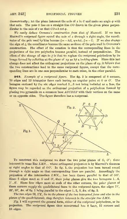
ART. 343] RECIPROCAL FIGURES 231
Geometrically ;let the plane intersect the axis of z in C and make an angle with
that axis. The pole lies on a straight line CO drawn in the given plane perpen-
dicular to the axis of z so that CO = h cot<f>.
We easily deduce Cremona's construction from that, of Maxwell. If we turn
Maxwell's reciprocal figure round the axis of z through a right angle, the coordi-
nates of the pole used by him become = - hB, r)= hA, f= - C, If we also change
the sign of f, the coordinates become the same as those of the pole used in Cremona's
construction. The effect of the rotation is that the corresponding lines in the
projections of the two polyhedra become parallel, instead of perpendicular. The
effect of the change of sign in f is that we replace the reciprocal polyhedron by its
image formed by reflexion at the plane of xy as by a looking-glass. Since this last
change does not affect the orthogonal projections on the plane of xy, it follows that
the two constructions lead to the same reciprocal figures, except that the corre-
sponding lines are in one case perpendicular to each other, in the other parallel.
343. Example of a reciprocal figure. The fig. 2 is composed of 8 corners,
18 edges and 12 triangular faces each having an angular point at or 0'. The
hexagon enclosed by the six edges marked 1...6 not being included as a face, the
figure may be regarded as the orthogonal projection of a polyhedron formed by
placing two pyramids on a common base ABCDEF with their vertices on the same
or on opposite sides. The figure therefore has a reciprocal.
Fig. 2.
F 6 E
Fig.1-
To construct this reciprocal we draw the two polar planes of 0, 0' ; these
intersect in some line LMN. . . whose orthogonal projection is by Maxwell's theorem
at right angles to that of 00'. In fig. 1, the projection has been turned round
through a right angle so that corresponding lines are parallel. Accordingly the
projection of the intersection LMN... has been drawn parallel to that of 00'.
Since 6 edges meet at O and 0', their polar planes give the two hexagons 1...6,
1/...6'. Since four edges meet at each of the other corners, the polar planes of
these corners supply six quadrilateral faces to the reciprocal figure, the edges 11',
22', 33', &c. of fig. 1 being parallel to the edges 1, 2, 3, &c. of fig. 2.
The two edges 12, 1'2', lie in the planes of the two hexagonal faces and also in the
planes of the quadrilaterals, they therefore intersect in the straight line LMN.Fig. 1 will represent the general form, either of the reciprocal polyhedron, or its
projection. The reciprocal figure thus constructed has 8 faces, 12 corners and18 edges.
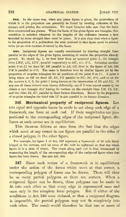
232 GRAPHICAL STATICS [CHAP. VIII
344. In the same way, when any plane figure is given, the polyhedron of
which it is the projection can generally be found by erecting ordinates at the
corners and joining the extremities. We must however take care that the faces
thus constructed are planes. When the faces of the given figure are triangles, this
condition is satisfied whatever be the lengths of the ordinates because a face
bounded by three straight lines must be plane. It is also clear that when a figure
is the projection of a polyhedron the area enclosed in that figure must be covered
twice (or an even number of times) by the faces.
345. Eeciprocal figures are usually constructed by drawing straight lines
parallel to the edges of the given figure, assuming of course the properties already
proved. To sketch fig. 1, we first draw from an assumed point L, the straight
lines LMN, L21, L2T, parallel respectively to 00', OA, O'A. Assuming another
point 2 on LI we draw 22', 2M parallel to AB, OB, then in the figure of Art. 343
2'M is parallel to O'B. The same is therefore true by similar figures (or by the
properties of co-polar triangles) for all positions of the point 2 on LI. A point 3
being taken on 2M we draw 33', 3.N, 3'N parallel to BC, OC, O'C, and so on for
the corners 4, 5, 6, the point 1 being known as the intersection of E6 and L2. If
any one of these corners were chosen differently, say if 6 were moved nearer Q, we
obtain a new triangle Ell' having its vertices on the straight lines LM, L2, L2',
and two sides El, El', parallel to their former directions. Hence by the properties
of co-polar triangles the third side 11' is also parallel to its former direction.
346. Mechanical property of reciprocal figures. Let
two equal and opposite forces be made to act along each edge of a
framework, one force at each end. If their magnitudes are pro-
portional to the corresponding edges of the reciprocal figure, the
forces at each corner are in equilibrium.
This theorem follows at once from the fact that the edgeswhich meet at any corner in one figure are parallel to the sides of
a closed polygon in the other figure.
For example, let figure 1 of Art. 343 represent a framework of 18 rods freely
hinged at the corners, and let some of the rods be tightened so that the whole
figure is in a state of strain. The stress along each rod is then determined by
measuring the length of the corresponding edge of the reciprocal figure when that
figure has been drawn. See also Art. 354.
347. Since each corner of a framework is in equilibriumunder the action of the forces which meet at that corner, a
corresponding polygon of forces can be drawn. There will thus
be as many partial polygons as there are corners. When a
reciprocal figure can be drawn, these polygons can be made to
fit into each other so that every edge is represented once and
once only in the complete force polygon. But if either of the
conditions in Art. 340 were violated, so that a reciprocal diagramis impossible, the partial polygons may not fit completely into
each other. The result would therefore be that one or more of
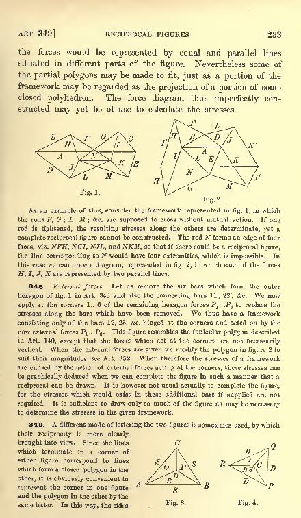
ART. 349] RECIPROCAL FIGURES 233
the forces would be represented by equal and parallel lines
situated in different parts of the figure. Nevertheless some of
the partial polygons may be made to fit, just as a portion of the
framework may be regarded as the projection of a portion of someclosed polyhedron. The force diagram thus imperfectly con-
structed may yet be of use to calculate the stresses.
.F i
Fig. 1.
FiR.2.
As an example of this, consider the framework represented in fig. 1, in which
the rods F, G; L, M ;
&c. are supposed to cross without mutual action. If one
rod is tightened, the resulting stresses along the others are determinate, yet a
complete reciprocal figure cannot be constructed. The rod N forms an edge of four
faces, viz. NFH, NGI, NJL, and NKM, so that if there could be a reciprocal figure,
the line corresponding to N would have four extremities, which is impossible. In
this case we can draw a diagram, represented in fig. 2, in which each of the forces
H, I, J, K are represented by two parallel lines.
348. External forces. Let us remove the six bars which form the outer
hexagon of fig. 1 in Art. 343 and also the connecting bars 11', 22', &c. We now
apply at the corners 1...6 of the remaining hexagon forces P^.Pg to replace the
stresses along the bars which have been removed. We thus have a framework
consisting only of the bars 12, 23, &c. hinged at the corners and acted on by the
now external forces Pl ...P6 . This figure resembles the funicular polygon described
in Art. 140, except that the forces which act at the corners are not necessarily
vertical. When the external forces are given we modify the polygon in figure 2 to
suit their magnitudes, see Art. 352. When therefore the stresses of a framework
are caused by the action of external forces acting at the corners, these stresses can
be graphically deduced when we can complete the figure in such a manner that a
reciprocal can be drawn. It is however not usual actually to complete the figure,
for the stresses which would exist in these additional bars if supplied are not
required. It is sufficient to draw only so much of the figure as may be necessaryto determine the stresses in the given framework.
340. A different mode of lettering the two figures is sometimes used, by which
their reciprocity is more clearly
brought into view. Since the lines (7
which terminate in a corner of
either figure correspond to lines
which form a closed polygon in the
other, it is obviously convenient to
represent the corner in one figure'
and the polygon in the other by the
same letter. In this way, the sides Fig. 4.
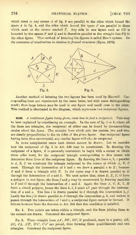
234 GRAPHICAL STATICS [CHAP, vm
which meet in any corner A of fig. 3 are parallel to the sides which bound the
space A in fig. 4, and the sides which bound the space P are parallel to those
which meet at the corner marked P. Any side in one figure such as CD is
bounded by the spaces P and Q and is therefore parallel to the straight line PQ in
the other figure. This method of lettering the figures is called Bow's system. On
the economics of construction in relation to framed structures (Spon, 1873).
A
Another method of lettering the two figures has been used by Maxwell. Cor-
responding lines are represented by the same letter, but with some distinguishing
mark; thus large letters may be used in one figure and small ones in the other.
This method is illustrated in the diagram, which represents two reciprocal figures.
35O. A rectilinear figure being given, show how to find a reciprocal. This maybe best explained by considering an example. In the case of fig. 3 or 4, where all
the faces are triangles, the reciprocal of either can be found by circumscribing
circles about the faces. The straight lines which join the centres, two and two,
are clearly perpendicular to the six sides of the given figure. One reciprocal figure
having been thus constructed, any similar figure will also be reciprocal.
In more complicated cases such circles cannot be drawn. Let us consider
how the reciprocal of fig. 5 in Art. 349 may be constructed. In drawing the
reciprocal of a figure, it is generally convenient to begin with a corner at which
three sides meet, for the reciprocal triangle corresponding to this corner will
determine three lines of the reciprocal figure. By drawing the lines a, b, c parallel
to A, B, C we construct the triangle reciprocal to the corner at which A, B, Cmeet. Through the intersection of b and c we draw a parallel e to E ; because
B and C form a triangle with E. In the same way d is drawn parallel to Dthrough the intersection of a and b. We next notice that, since D, E, F, G form
a polygon in one figure, the lines/ and g may be constructed by drawing parallels
to F and G through the intersection of e and d. Again the lines A, C, K, L, Hform a closed polygon, hence the lines k, I, h must all pass through the intersec-
tion of a and c. The line i is drawn parallel to I through the intersection h, f.
Lastly the linej is drawn parallel to J through the intersection g, k, and unless it
passes through the intersection of I and i, a reciprocal figure cannot be formed. It
follows however from the theorem in Art. 341 that this condition is satisfied.
Ex. 1. Two points are taken within a triangle, and the lines joining them to
the corners are drawn. Construct the reciprocal figure.
Ex. 2. Three straight lines A A', BB', CC', if produced, meet in a point; AB,
BC, CA, A'B', B'C', C'A' are joined, thus forming three quadrilaterals and two
triangles. Construct the reciprocal figure.
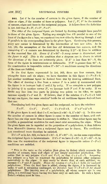
ART. Sol] RECIPROCAL FIGURES 235
351. Let C be the number of corners in the given figure, E the number of
sides or edges, F the number of faces or polygons. Let C', E', F' be the number
of corners, edges and faces in the reciprocal polygon. It follows from the definition
in Art. 340 that E= E', C=F', F=C'.The sides of the reciprocal figure are formed by drawing straight lines parallel
to those of the given figure. Taking any straight line AB parallel to one of the
lines of the figure for a base, we construct two new sides by drawing through A and
B parallels to the corresponding lines in the given figure. Continuing this process,
every new corner is determined by the intersection of two new sides. As in
Art. 151, the assumption of the first line AB determines two corners, and the
remaining C"-2 corners are determined by drawing 2 (C'-2) lines in addition
to the assumed line AB. Hence if E'= 2C'-3 every corner is determined, and
the figure is stiff. This is the condition that a diagram can be drawn in which
the. directions of the lines are arbitrarily given. If E' is less than 20" -3, the
form of the figure is indeterminate or deformable. If E' is greater than 2C"-3,the construction is impossible unless '-2(7' + 3 conditions among the directions
of the lines are fulfilled.
In the first figure represented in Art. 349, there are four corners, four
triangular faces and six edges; we have therefore in this figure C+F=E + 2.'
Let another rectilinear figure be derived from this by drawing additional lines.
The effect of drawing a line from a corner P to a point Q unconnected with
the figure is to increase both C and E by unity. If we complete a new polygon
by joining Q to another corner P', we increase both F and E by unity. If wedivide any face into two parts by joining two points on its sides, we again
increase equally C + F and E. If follows, that if the relation C +F=E + 2 hold
for any one figure, the same relation* holds for all rectilinear figures derived from
that one.
Considering both the given figure and the reciprocal, we have the relations
E=E', C=F', F=C', C +F=E + 2, C' + F' = E' + 2.
If the given figure is such that C= F, we have .E = 2C -2, .E'= 2C"-2. In this case
the number of corners in either figure is equal to the number of faces, and each
figure has one edge more than is necessary to stiffen it. That either figure may be
possible, a geometrical condition for each must exist connecting the edges. Whenthe given figure can be regarded as the projection of a polyhedron, it then follows
from Maxwell's theorem that a reciprocal figure can be drawn. The conditions
just mentioned must therefore be satisfied.
If C<F as in Art. 343, we have E>2C -2, E'<2C' -2;on the same supposition
the reciprocal figure is indeterminate. If C> F we have E < 2C -2, E' > 2C' - 2
; in
this case the construction of the reciprocal figure is impossible unless C-F+lconditions are satisfied.
* This is the same as the relation (first given by Euler) which connects thenumber of corners, faces and edges of any simply connected polyhedron. Wenotice that in any polygon C=E and F=l, so that C +F=E + l. Assumingany polygon as a base we construct the polyhedron by joining other polygonssuccessively to the edges. It may easily be shown that, at each addition, weincrease C +F and E equally. Hence the relation C+F=E + l holds for unclosed
polyhedrons. When the final face is added, closing the figure, F is increased byunity, C and E remaining unchanged, we therefore have C+F=E + 2 for closed
polyhedrons. The limiting case of a polyhedron, all whose corners are in one
plane, is a rectilineal figure having two faces only on each side. In such a figureEuler's relation must be true.
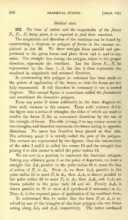
236 GRAPHICAL STATICS [CHAP. VIII
Statical view.
352. The lines of action and the magnitudes of the forcesPl ,
P2 . . .P5 being given, it is required to find their resultant.
The magnitude and direction of the resultant can be found byconstructing a diagram or polygon of forces in the manner ex-
plained in Art. 36. We draw straight lines parallel and pro-
portional to the given forces and place them end to end in anyorder. The straight line closing the polygon, taken in the proper
direction, represents the resultant. Let the forces Pl ...P5 be
represented by the lines 1...5, the line 6 then represents the
resultant in magnitude and reversed direction.
In constructing this polygon no reference has been made to
the points of application of the forces, so that the forces are not
fully represented. It will therefore be necessary to use a second
diagram. This second figure is sometimes called the frameworkand sometimes the funicular polygon.
From any point taken arbitrarily in the force diagram wedraw radii vectores to the corners. These radii vectores divide
the figure into a series of triangles, the sides of which are used to
resolve the forces P1 &c. in convenient directions by the use of
the triangle of forces. The side joining to any corner occurs in
two triangles, and therefore represents two forces acting in opposite
directions. No arrow has therefore been placed on that side.
The arbitrary point is usually called the pole of the polygon.
The corners are represented by two figures; thus the intersection
of the sides 1 and 2 is called the corner 12 and the straight line
joining to this corner is called the polar radius 12.
We are now in a position to construct the funicular polygon.
Taking any arbitrary point L as the point of departure, we draw a
straight line LA r parallel to the polar radius 61 to meet the line
of action of P1 in A-^. From Alwe draw A-^A^ parallel to the
polar radius 12 to meet P2 in A 2 ;then A ZA 3 is drawn parallel to
the polar radius 23 to meet P3 in A 3 ;then A 3A t and A 4A B are
drawn parallel to the polar radii 34 and 45. Finally A 5A 6 is
drawn parallel to 56 to meet A^L (produced if necessary) in A 6 .
Then A 6 is the required point of application of the resultant force.
To understand this, we notice that the force Px at A l is re-
solved by one of the triangles of the force polygon into two forces
acting along LA r and A^A-^ respectively. The latter combined
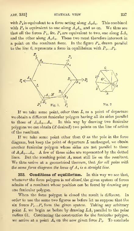
ART. 353] STATICAL VIEW 237
with P2 is equivalent to a force acting along A 3A 2 . This combined
with Pz is equivalent to one along A 4A 3 ,and so on. We thus see
that all the forces P1} &c. P5 are equivalent to two, one along LA^and the other along A eA 6 . These two must therefore intersect in
a point on the resultant force. In the figure P6 ,drawn parallel
to the line 6, represents a force in equilibrium with P^..P6 .
Fig. 2
If we take some point, other than L, as a point of departure
we obtain a different funicular polygon having all its sides parallel
to those of A^.^As. In this way by drawing two funicular
polygons we can obtain (if desired) two points on the line of action
of the resultant.
If we take some point other than as the pole in the force
diagram, but keep the point of departure L unchanged, we obtain
another funicular polygon whose sides are not parallel to those
of J. 1J. 2 ...-A 6 - A few of these sides are represented by the dotted
lines. But the resulting point A 6 must still lie on the resultant.
We thus arrive at a geometrical theorem, that for all poles with
the same force diagram the locus of A 6 is a straight line.
353. Conditions of equilibrium. In this way we see that,
whenever the force polygon is not closed, the given system of forces
admits of a resultant whose position can be found by drawing anyone funicular polygon.
When the force polygon is closed the result is different. In
order to use the same two figures as before let us suppose that the
six forces Pl ...P6 form the given system. Taking any arbitrary
point L, we begin as before by drawing LA 1 parallel to the polar
radius 61. Continuing the construction for the funicular polygon,
we arrive at a point A 6 on the now given force P6 . To conclude
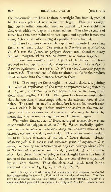
238 GRAPHICAL STATICS [CHAP. VIII
the construction we have to draw a straight line from A 6 parallel
to the same polar 61 with which we began. This last straight
line may be either coincident with, or parallel to, the straight line
LA l with which we began the construction. The whole system of
forces has thus been reduced to two equal and opposite forces, one
along A^L and the other along its parallel drawn from A 6 .
If these two lines coincide, the equal and opposite forces along
them cancel each other. The system is therefore in equilibrium.
In this case the funicular polygon drawn (and therefore everyfunicular polygon which can be drawn) is a closed polygon.
If these two straight lines are parallel, the forces have been
reduced to two equal, parallel, and opposite forces. The system is
therefore equivalent to a couple. In this case the funicular polygonis unclosed. The moment of this resultant couple is the productof either force into the distance between them.
354. Ifwe suppose the straight lines A-^A^ A 2A 3 , &c., joining
the points of application of the forces to represent rods jointed at
A l} A 2 , &c., the forces by which these press on the hinges act
along their lengths, Art. 131. The figure has been so constructed
that the reactions at each hinge balance the external force at that
point. The combination of rods therefore forms a framework each
part of which is in equilibrium under the action of the external
forces, and the stresses in the several rods may be found by
measuring the corresponding lines in the force diagram.
We notice that any set of forces acting at consecutive corners
of the funicular polygon (such as P4 ,P5 , P6) are statically equiva-
lent to the tensions or reactions along the straight lines at the
extreme corners (viz. A sA t and A-^A^). These sides must therefore
intersect in the resultant of the set of forces chosen. Hence,
whatever pole is chosen and whatever point of departure L is
taken, the locus of the intersection of any two corresponding sides
of the funicular polygon (such as A 3A t and A-^A^ is a straight
line. In a closed funicular polygon this straight line is the line of
action of the resultant of either of the two sets of forces separated
by the sides chosen. Thus the sides A 3A t , A^ 6 meet in the
resultant either of P4 ,P5 ,
P6 or of P3 ,P2 ,
Px .
355. It may be noticed that fig. 1 does not admit of a reciprocal because the
lines representing the forces P^...P& do not form the edges of any face. Neverthe-
less a force diagram has been constructed. The reason is that fig. 1 is a part of a
more complete figure which does admit of a reciprocal, Art. 343. It follows from
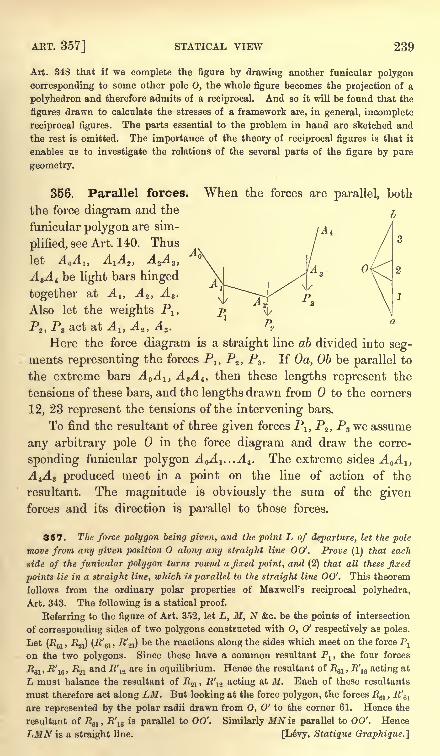
ART. 357] STATICAL VIEW 239
Art. 348 that if we complete the figure by drawing another funicular polygon
corresponding to some other pole 0, the whole figure becomes the projection of a
polyhedron and therefore admits of a reciprocal. And so it will be found that the
figures drawn to calculate the stresses of a framework are, in general, incomplete
reciprocal figures. The parts essential to the problem in hand are sketched and
the rest is omitted. The importance of the theory of reciprocal figures is that it
enables us to investigate the relations of the several parts of the figure by pure
geometry.
356. Parallel forces. When the forces are parallel, both
the force diagram and the ^
funicular polygon are sim-
plified, see Art. 140. Thus
let A A l} AiA 2 ,A 2A 3 ,
A 3A 4 be light bars hinged
together at A 1} A 2 , A 3 .
Also let the weights P1}
P2 ,P3 act at A lt A 2 ,
A s .
Here the force diagram is a straight line ab divided into seg-
ments representing the forces Pn P2 ,P3 . If Oa, Ob be parallel to
the extreme bars A A 1} A 3A 4 , then these lengths represent the
tensions of these bars, and the lengths drawn from to the corners
12, 23 represent the tensions of the intervening bars.
To find the resultant of three given forces Px ,P2 ,
P3 we assume
any arbitrary pole in the force diagram and draw the corre-
sponding funicular polygon A^A^^A^. The extreme sides A A 1}
A^ 3 produced meet in a point on the line of action of the
resultant. The magnitude is obviously the sum of the givenforces and its direction is parallel to those forces.
357. The force polygon being given, and the point L of departure, let the pole
move from any given position along any straight line 00'. Prove (1) that each
side of the funicular polygon turns round a fixed point, and (2) that all these fixed
points lie in a straight line, which is parallel to the straight line 00'. This theorem
follows from the ordinary polar properties of Maxwell's reciprocal polyhedra,
Art. 343. The following is a statical proof.
Referring to the figure of Art. 352, let L, M, N &c. be the points of intersection
of corresponding sides of two polygons constructed with 0, 0' respectively as poles.
Let (R61 ,.R21) (R'6i , R'^i) t*e *ne reactions along the sides which meet on the force P
1
on the two polygons. Since these have a common resultant Pl , the four forces
R6l , R'16 ,
R2l and R\2 are in equilibrium. Hence the resultant of R61 ,
R'1S acting at
L must balance the resultant of R2l ,R'12 acting at M. Each of these resultants
must therefore act along LM. But looking at the force polygon, the forces J?61 ,
R'61
are represented by the polar radii drawn from 0, 0' to the corner 61. Hence the
resultant of Rsl , R\6
is parallel to 00'. Similarly MN is parallel to 00'. Hence
LMN is a straight line. [Ldvy, Statique Graphique.]
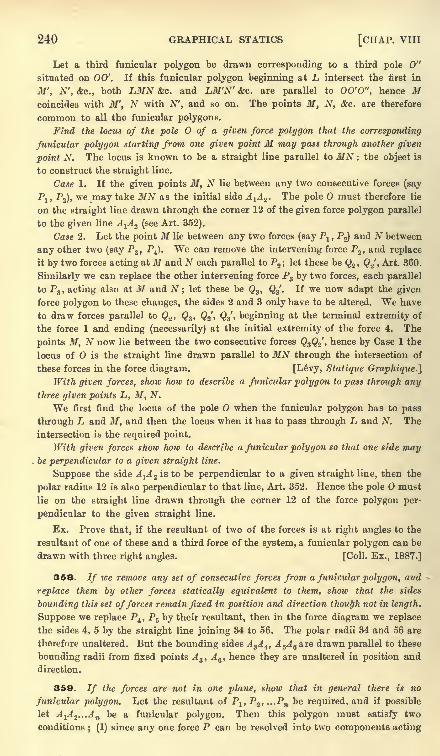
240 GRAPHICAL STATICS [CHAP. VIII
Let a third funicular polygon be drawn corresponding to a third pole 0"
situated on 00'. If this funicular polygon beginning at L intersect the first in
M' , N', &c., both LMN &c. and LM'N' &c. are parallel to OO'O", hence Mcoincides with M', N with N', and so on. The points M, N, &c. are therefore
common to all the funicular polygons.
Find the locus of the pole of a given force polygon that the corresponding
funicular polygon starting from one given point M may pass through another given
point N. The locus is known to be a straight line parallel to MN : the object is
to construct the straight line.
Case 1. If the given points M, N lie between any two consecutive forces (say
Pj, P2), we may take MN as the initial side A-^A^. The pole must therefore lie
on the straight line drawn through the corner 12 of the given force polygon parallel
to the given line A^A^ (see Art. 352).
Case 2. Let the point M lie between any two forces (say P1 , Pg) and N between
any other two (say P3 ,P4 ). We can remove the intervening force P2 , and replace
it by two forces acting at M and N each parallel to P2 ; let these be Q2 , Q2', Art. 360.
Similarly we can replace the other intervening force P3 by two forces, each parallel
to P3 , acting also at M. and N ; let these be Q3 , Q3'. If we now adapt the given
force polygon to these changes, the sides 2 and 3 only have to be altered. We have
to draw forces parallel to Qz , Q3 , Q%, Q./, beginning at the terminal extremity of
the force 1 and ending (necessarily) at the initial extremity of the force 4. The
points M, N now lie between the two consecutive forces Q3Q2', hence by Case 1 the
locus of is the straight line drawn parallel to MN through the intersection of
these forces in the force diagram. [Levy, Statique Graphique.]
With given forces, show how to describe a funicular polygon to pass through anythree given points L, M, N.
We first find the locus of the pole O when the funicular polygon has to pass
through L and M, and then the locus when it has to pass through L and N. The
intersection is the required point.
With given forces show how to describe a funicular polygon so that one side may. be perpendicular to a given straight line.
Suppose the side A^A Z is to be perpendicular to a given straight line, then the
polar radius 12 is also perpendicular to that line, Art. 352. Hence the pole must
lie on the straight line drawn through the corner 12 of the force polygon per-
pendicular to the given straight line.
Ex. Prove that, if the resultant of two of the forces is at right angles to the
resultant of one of these and a third force of the system, a funicular polygon can be
drawn with three right angles. [Coll. Ex., 1887.]
358. If we remove any set of consecutive forces from a funicular polygon, and
replace them by other forces statically equivalent to them, show that the sides
bounding this set offerees remain fixed in position and direction though not in length.
Suppose we replace P4 , P5 by their resultant, then in the force diagram we replace
the sides 4, 5 by the straight line joining 34 to 56. The polar radii 34 and 56 are
therefore unaltered. But the bounding sides A 3A 4 ,A 5A 6 &re drawn parallel to these
bounding radii from fixed points A 3 , A 6 , hence they are unaltered in position and
direction.
359. // the forces are not in one plane, show that in general there is no
funicular polygon. Let the resultant of Plt P2 , ...Pn be required, and if possible
let AlA z ...An be a funicular polygon. Then this polygon must satisfy two
conditions; (1) since any one force P can be resolved into two components acting
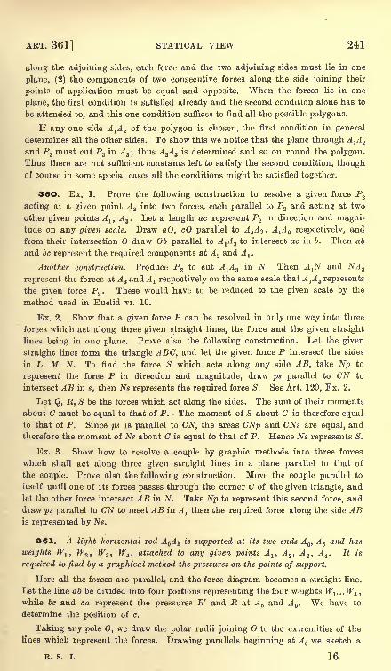
AET. 361] STATICAL VIEW 241
along the adjoining sides, each force and the two adjoining sides must lie in one
plane, (2) the components of two consecutive forces along the side joining their
points of application must be equal and opposite. When the forces lie in one
plane, the first condition is satisfied already and the second condition alone has to
be attended to, and this one condition suffices to find all the possible polygons.
If any one side AA Z of the polygon is chosen, the first condition in general
determines all the other sides. To show this we notice that the plane through A^A Z
and P2 must cut P3in A 3 ;
thus A%A 3 is determined and so on round the polygon.
Thus there are not sufficient constants left to satisfy the second condition, thoughof course in some special cases all the conditions might be satisfied together.
36O. Ex. 1. Prove the following construction to resolve a given force P2
acting at a given point A 2 into two forces, each parallel to P2 and acting at two
other given points A lt A 3. Let a length ac represent P2 in direction and magni-
tude on any given scale. Draw aO, cO parallel to A 2A 3 , A^ 2 respectively, and
from their intersection draw Ob parallel to A^A 3 to intersect ac in 6. Then ab
and be represent the required components at A 3 and A.
Another construction. Produce P2 to cut A^A 3 in N. Then A^ and NA 3
represent the forces at A 3 and A 1 respectively on the same scale that A^A3 represents
the given force P2 . These would have to be reduced to the given scale by the
method used in Euclid vi. 10.
Ex. 2. Show that a given force P can be resolved in only one way into three
forces which act along three given straight lines, the force and the given straight
lines being in one plane. Prove also the following construction. Let the given
straight lines form the triangle ABC, and let the given force P intersect the sides
in L, M, N. To find the force S which acts along any side AB, take Np to
represent the force P in direction and magnitude, draw ps parallel to CN to
intersect AB in s, then Ns represents the required force S. See Art. 120, Ex. 2.
Let Q, R, S be the forces which act along the sides. The sum of their moments
about C must be equal to that of P. The moment of S about C is therefore equal
to that of P. Since ps is parallel to CN, the areas CNp and CNs are equal, and
therefore the moment of Ns about C is equal to that of P. Hence Ns represents S.
Ex. 3. Show how to resolve a couple by graphic methods into three forces
which shall act along three given straight lines in a plane parallel to that of
the couple. Prove also the following construction. Move the couple parallel to
itself until one of its forces passes through the corner C of the given triangle, andlet the other force intersect AB in N. Take Np to represent this second force, and
drawls parallel to CN to meet AB in A, then the required force along the side ABis represented by Ns.
361. A light horizontal rod A A 5 is supported at its two ends A , A 5 and has
weights Wlt W2 , W3 , W4 ,attached to any given points Alt A 2 ,
A3 ,
A4 . It is
required to find by a graphical method the pressures on the points of support.
Here all the forces are parallel, and the force diagram becomes a straight line.
Let the line ab be divided into four portions representing the four weights Wl...Wttwhile be and ca represent the pressures R' and R at A 5 and A . We have to
determine the position of c.
Taking any pole 0, we draw the polar radii joining to the extremities of the
lines which represent the forces. Drawing parallels beginning at A we sketch a
R. S. I. 16
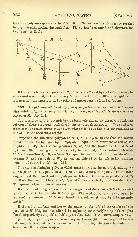
242 GRAPHICAL STATICS [CHAP, viii
funicular polygon represented by A Bl ...B5 . The polar radius Oc must be parallel
to the line B^A^ closing the funicular. Thus c has been found and therefore the
two pressures E, R'.
Al
If the rod is heavy, the pressures R, R' are not affected by collecting the weightat the centre of gravity. Drawing any funicular, with this additional weight taken
into account, the pressures on the points of support can be found as before.
362. A light horizontal rod A A 5 being supported at its two ends and loaded
with weights W1 ...Wi at the points A^...A^ it is required to find the stress couple at
any point M. Art. 145.
The pressures at the two ends having been determined, we describe a funicular
polygon of these six forces, such that it passes through A and A 5 . We shall now
prove that the stress couple at M is Hy, where y is the ordinate of the funicular at
M and H is the horizontal tension.
Supposing the funicular polygon to be A C1...C4A 5 , we notice that the system
of rods represented by A Clt C1C2 ...C4A 5 are in equilibrium under the action of the
weights W1 ...W4) the vertical pressures R, R', and the horizontal thrust H of
A1A5 ,
Art. 354. Taking moments about P, the extremity of the ordinate through
M, for the portion A ...P, we have Hy equal to the sum of the moments of the
pressure R, and the weights W1 , &c. on one side of P, i.e. Hy is the bending
moment of the rod at M. Art. 143.
To draw the funicular polygon which passes through the points A land A 5 , we
take a pole 0' at any point on a horizontal line through the point c in the force
diagram and then construct the polygon as before. Since cO is parallel to A B5
it follows that, when lies in cO', B5 must coincide with A 5 . It is evident that
O'c represents the horizontal tension.
If 0' is moved along cO', the funicular polygon and therefore both the horizontal
tension cO' and the ordinate MP change. The product however, being equal to
the bending moment at M, is not altered ; a result which may be independentlyverified.
If the rod is uniform and heavy, the moments about M of the weights of the
portions A M, MA 5 are not altered by replacing those weights by half weights
placed respectively at A , M and M, A 5 ,see Art. 134. If the stress couples at all
the points A 1 ...A t are required, we can replace the weight of each segment by two
half weights attached to its extremities. In this way the same funicular will
determine all the stress couples.
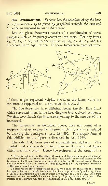
ART. 363] FRAMEWORKS 243
363. Frameworks. To show how the reactions along the bars
of a framework may be found by graphical methods, the eocternal
forces being supposed to act at the corners.
Let the given framework consist of a combination of three
triangles, such as frequently occurs in iron roofs. Let any forces
Pj, P2 ,Pa ,
Pt ,Ps act at the corners A l> A 2 ,
A 3 ,A t> A 5 ,
and let
the whole be in equilibrium. If these forces were parallel three
of them might represent weights placed at the joints, while the
structure is supported on its two extremities A 1} A 3 .
The five forces are in equilibrium, hence the five lines 1...5
which represent them in the force diagram form a closed pentagon.We shall now sketch the lines corresponding to the stresses of the
framework.
The framework, as described above, does not admit of a
reciprocal ;let us assume for the present that it can be completed
by drawing the pentagon ^...c^; Art. 355. The proper form of
this addition to the figure is discussed in Art. 365*.
The side AA 5 forms part of a quadrilateral A^A^a^. This
quadrilateral corresponds to four lines in the reciprocal figure
which meet in a point. Hence the reciprocal of the straight line
*If we do not refer to the theory of reciprocal figures the argument must be
somewhat altered. As there are more than three forces at several corners of the
framework, it will then require some attention to discover the force diagram, thoughwhen once known it can be drawn without difficulty to suit the numerical relations
of the bars in any like structure.
To discover the line corresponding to A^A 5 we notice that the forces at Almust
be represented by a triangle two sides of which are parallel to Pland A^A 5 , those
at A 5 by a quadrilateral two sides of which are parallel to P5 and A1A 5 . As a trial
construction we can satisfy these conditions by adopting the rule in the text. Thesuccess of the drawing will test the correctness of the hypothesis, Art. 347.
162
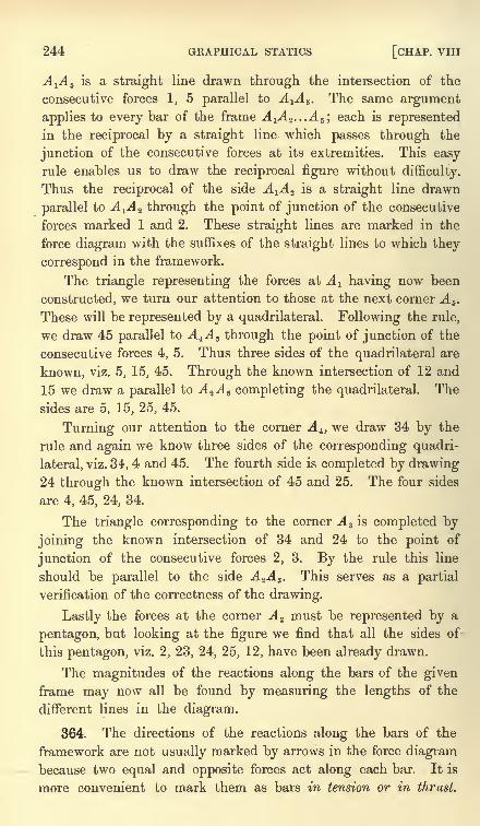
244 GRAPHICAL STATICS [CHAP. VIII
A^ 5 is a straight line drawn through the intersection of the
consecutive forces 1, 5 parallel to AA 5 . The same argument
applies to every bar of the frame A^A Z ,..A 5 \each is represented
in the reciprocal by a straight line which passes through the
junction of the consecutive forces at its extremities. This easyrule enables us to draw the reciprocal figure without difficulty.
Thus the reciprocal of the side A^A Z is a straight line drawn
parallel to A^A 2 through the point of junction of the consecutive
forces marked 1 and 2. These straight lines are marked in the
force diagram with the suffixes of the straight lines to which they
correspond in the framework.
The triangle representing the forces at A^ having now been
constructed, we turn our attention to those at the next corner A 5 .
These will be represented by a quadrilateral. Following the rule,
we draw 45 parallel to A^A 5 through the point of junction of the
consecutive forces 4, 5. Thus three sides of the quadrilateral are
known, viz. 5, 15, 45. Through the known intersection of 12 and
15 we draw a parallel to A ZA 5 completing the quadrilateral. The
sides are 5, 15, 25, 45.
Turning our attention to the corner A i} we draw 34 by the
rule and again we know three sides of the corresponding quadri-
lateral, viz. 34, 4 and 45. The fourth side is completed by drawing24 through the known intersection of 45 and 25. The four sides
are 4, 45, 24, 34.
The triangle corresponding to the corner A 3 is completed by
joining the known intersection of 34 and 24 to the point of
junction of the consecutive forces 2, 3. By the rule this line
should be parallel to the side A 2A 3 . This serves as a partial
verification of the correctness of the drawing.
Lastly the forces at the corner A 2 must be represented by a
pentagon, but looking at the figure we find that all the sides of
this pentagon, viz. 2, 23, 24, 25, 12, have been already drawn.
The magnitudes of the reactions along the bars of the givenframe may now all be found by measuring the lengths of the
different lines in the diagram.
364. The directions of the reactions along the bars of the
framework are not usually marked by arrows in the force diagrambecause two equal and opposite forces act along each bar. It is
more convenient to mark them as bars in tension or in thrust.
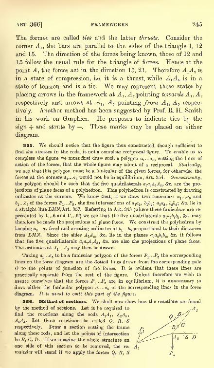
ART. 366] FRAMEWORKS 245
The former are called ties and the latter thrusts. Consider the
corner A lt the bars are parallel to the sides of the triangle 1, 12
and 15. The direction of the forces being known, those of 12 and
15 follow the usual rule for the triangle of forces. Hence at the
point A 1 the forces act in the direction 15, 21. Therefore A^A^ is
in a state of compression, i.e. it is a thrust, while AA 5 is in a
state of tension and is a tie. We may represent these states by
placing arrows in the framework at A 1} A 2 pointing towards A 1,A 2
respectively and arrows at A l} A s pointing from A l} A 5 respec-
tively. Another method has been suggested by Prof. R. H. Smith
in his work on Graphics. He proposes to indicate ties by the
sign + and struts by . These marks may be placed on either
diagram.
365. We should notice that the figure thus constructed, though sufficient to
find the stresses in the rods, is not a complete reciprocal figure. To enable us to
complete the figure we must first draw such a polygon aj...a5 , cutting the lines of
action of the forces, that the whole figure may admit of a reciprocal. Statically,
we see that this polygon must be a funicular of the given forces, for otherwise the
forces at the corners ^...aj would not be in equilibrium, Art. 354. Geometrically,
the polygon should be such that the five quadrilaterals a1a24 1
^ 2 ,&c. are the pro-
jections of plane faces of a polyhedron. This polyhedron is constructed by drawingordinates at the corners. We know that, if we draw two funiculars a
1 ...as and
&J...&5 of the forces Pa ...P5 ,the five intersections of a^, b^; a
2a3 ,
b2b3 ; &c. lie in
a straight line LMN,A.rt. 357. Referring to Art. 343 (where these funiculars are re-
presented by 1...6 and 1'...6') we see that the five quadrilaterals a^bjb^, &c. maytherefore be made the projections of plane faces. We construct the polyhedron by
keeping a-i...a5 fixed and erecting ordinates at ^...b^ proportional to their distances
from LMN. Since the sides A^A Z ,&c. lie in the planes a^bjb^, &c. it follows
that the five quadrilaterals a1a2^ 1
^ 2 , &c. are also the projections of plane faces.
The ordinates at A1 ...A 5 may then be drawn.
Taking a1 ...as to be a funicular polygon of the forces P1 ...P6 the corresponding
lines on the force diagram are the dotted lines drawn from the corresponding pole
to the points of junction of the forces. It is evident that these lines are
practically separate from the rest of the figure. Unless therefore we wish to
assure ourselves that the forces P^.Pj are in equilibrium, it is unnecessary to
draw either the funicular polygon a1 ...as or the corresponding lines in the force
diagram. It is usual to omit this part of the figure.
366. Method of sections. We shall now show how the reactions are found
by the method of sections. Let it be required to
find the reactions along the rods A 2A lt A%A 5 ,
ASA 4 . Let these reactions be called Q, R, S
respectively. Draw a section cutting the frame
along these rods, and let the points of intersection
be B, C, D. If we imagine the whole structure on
one side of this section to be removed, the re-
mainder will stand if we apply the forces Q, E, S
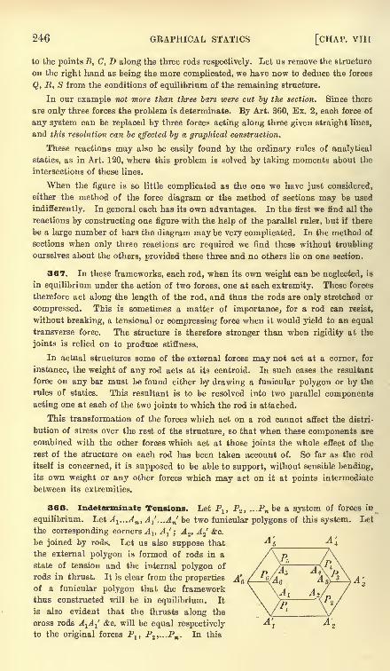
246 GRAPHICAL STATICS [CHAP. VIII
to the points B, C, D along the three rods respectively. Let us remove the structure
on the right hand as heing the more complicated, we have now to deduce the forces
Q, R, S from the conditions of equilibrium of the remaining structure.
In our example not more than three bars were cut by the section. Since there
are only three forces the problem is determinate. By Art. 360, Ex. 2, each force of
any system can be replaced by three forces acting along three given straight lines,
and this resolution can be effected by a graphical construction.
These reactions may also be easily found by the ordinary rules of analytical
statics, as in Art. 120, where this problem is solved by taking moments about the
intersections of these lines.
When the figure is so little complicated as the one we have just considered,
either the method of the force diagram or the method of sections may be used
indifferently. In general each has its own advantages. In the first we find all the
reactions by constructing one figure with the help of the parallel ruler, but if there
be a large number of bars the diagram may be very complicated. In the method of
sections when only three reactions are required we find these without troubling
ourselves about the others, provided these three and no others lie on one section.
367. In these frameworks, each rod, when its own weight can be neglected, is
in equilibrium under the action of two forces, one at each extremity. These forces
therefore act along the length of the rod, and thus the rods are only stretched or
compressed. This is sometimes a matter of importance, for a rod can resist,
without breaking, a tensional or compressing force when it would yield to an equal
transverse force. The structure is therefore stronger than when rigidity at the
joints is relied on to produce stiffness.
In actual structures some of the external forces may not act at a corner, for
instance, the weight of any rod acts at its centroid. In such cases the resultant
force on any bar must be found either by drawing a funicular polygon or by the
rules of statics. This resultant is to be resolved into two parallel components
acting one at each of the two joints to which the rod is attached.
This transformation of the forces which act on a rod cannot affect the distri-
bution of stress over the rest of the structure, so that when these components are
combined with the other forces which act at those joints the whole effect of the
rest of the structure on each rod has been taken account of. So far as the rod
itself is concerned, it is supposed to be able to support, without sensible bending,its own weight or any other forces which may act on it at points intermediate
between its extremities.
368. Indeterminate Tensions. Let Pl ,P2 , ...Pn be a system of forces in
equilibrium. Let ^1 ...^B , A^,..A^ be two funicular polygons of this system. Let
the corresponding corners Alt AJ ;
A 2, A 2'
&c.
be joined by rods. Let us also suppose that
the external polygon is formed of rods in a
state of tension and the internal polygon of
rods in thrust. It is clear from the properties
of a funicular polygon that the framework
thus constructed will be in equilibrium. It
is also evident that the thrusts along the
cross rods A^A^ &c. will be equal respectivelyto the original forces Plf P2 ,...Pn . In this
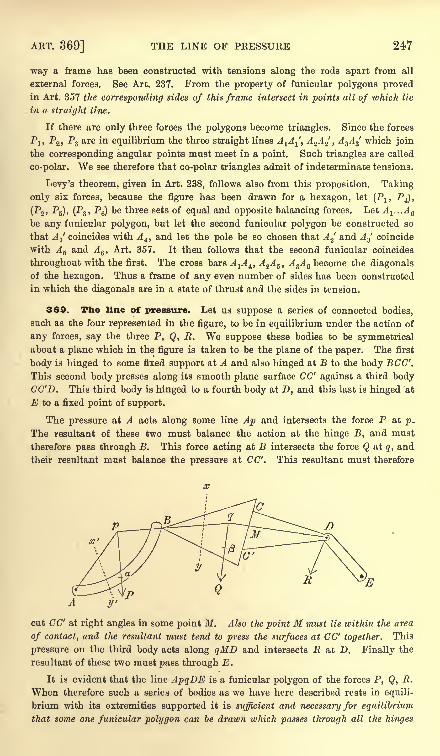
ART. 369] THE LINE OF PRESSURE 247
way a frame has been constructed with tensions along the rods apart from all
external forces, See Art. 237. From the property of funicular polygons provedin Art. 357 the corresponding sides of this frame intersect in points all of which lie
in a straight line.
If there are only three forces the polygons become triangles. Since the forces
Plt P2 ,
P3 are in equilibrium the three straight lines A^^', A 2A 2
'
,A
3A
3
' which join
the corresponding angular points must meet in a point. Such triangles are called
co-polar. We see therefore that co-polar triangles admit of indeterminate tensions.
Levy's theorem, given in Art. 238, follows also from this proposition. Taking
only six forces, because the figure has been drawn for a hexagon, let (Plt P4),
(P2 ,P6), (P3 ,
P6) be three sets of equal and opposite balancing forces. Let A 1 ...A e
be any funicular polygon, but let the second funicular polygon be constructed so
that AI coincides with A4 ,and let the pole be so chosen that A 2
' and A3 coincide
with A 5 and A6 ,
Art. 357. It then follows that the second funicular coincides
throughout with the first. The cross bars A^A^ A^A 5 ,A
3A 6 become the diagonalsof the hexagon. Thus a frame of any even number of sides has been constructed
in which the diagonals are in a state of thrust and the sides in tension.
369. Tbe line of pressure. Let us suppose a series of connected bodies,
such as the four represented in the figure, to be in equilibrium under the action of
any forces, say the three P, Q, R. We suppose these bodies to be symmetricalabout a plane which in the figure is taken to be the plane of the paper. The first
body is hinged to some fixed support at A and also hinged at B to the body BCC'.
This second body presses along its smooth plane surface CC" against a third bodyCC'D. This third body is hinged to a fourth body at D, and this last is hinged at
to a fixed point of support.
The pressure at A acts along some line Ap and intersects the force P at p.
The resultant of these two must balance the action at the hinge B, and must
therefore pass through B. This force acting at B intersects the force Q at q, and
their resultant must balance the pressure at CC'. This resultant must therefore
X'
cut CC' at right angles in some point M. Also the point M must lie within the area
of contact, and the resultant must tend to press the surfaces at CC' together. This
pressure on the third body acts along qMD and intersects R at D. Finally the
resultant of these two must pass through E.
It is evident that the line ApqDE is a funicular polygon of the forces P, Q, R.
When therefore such a series of bodies as we have here described rests in equili-
brium with its extremities supported it is sufficient and necessary for equilibrium
that some one funicular polygon can be drawn which passes through all the hinges
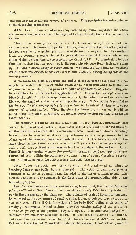
248 GRAPHICAL STATICS [CHAP. VIII
and cuts at right angles the surface of pressure. This particular funicular polygon
is called the line of pressure.
370. Let us take an ideal section, such as xy, which separates the whole
system into two parts, and let it be required to find the resultant action across this
section.
This action is really the resultant of the forces across each element of the
sectional area. But since each portion of the system must act on the other portion
in such a way as to keep that portion in equilibrium, we may also find the resultant
from the general principle that it balances all the external forces which act on
either of the two portions of the system : see also Art. 143. It immediately follows
that the resultant action across xy is the force already described which acts along
pq. Similar remarks apply to every section ; we therefore infer that the resultant
action across any section is the force which acts along the corresponding side of the
line of pressure.
If we move the section xy from one end A of the system to the other B, there
may be some difficulty in determining which is the "corresponding side of the line
of pressure" when the section passes the point of application of a force. Suppose
for example a to be the point of application of P. If a section as x'y' is ever so
little to the left of a, the corresponding side is Ap, but when the section is ever so
little on the right of a, the corresponding side is pq. If the section is parallel to
the force P, the side corresponding to any section is the side of the line of pressure
intersected by]that section. When therefore the forces are all vertical it will be
found more convenient to consider the actions across vertical sections than across
those inclined.
The resultant action across any section such as x'y' does not necessarily pass
within the area of that section. The reason is that this action is the resultant of
all the small forces across all the elements of area. As some of these elementary
forces across the same sectional area may be tensions and some pressures, the line
of action of the resultant may lie outside the area. If the forces all act in the
same direction like those across the section CO' (where two bodies press against
each other), the resultant must pass within the boundary of the section. Some-
times it is more useful to move the resultant parallel to itself and apply it at anyconvenient point within the boundary ;
we must then of course introduce a couple.
This is often done when the body AB is a thin rod. See Art. 142.
371. When the bodies are heavy we may find the action at any hinge or
boundary between two bodies by the same rule. The weight of each body is to be
collected at its centre of gravity and included in the list of external forces. The
resultant action at any boundary is the force along the corresponding side of the
funicular polygon.
But if the action across some section as xy is required, this partial funicular
polygon will not suffice. We must now consider the body BCC' to be equivalent to
two bodies separated by the plane xy. The weights of each of these portions maybe collected at its own centre of gravity, and a funicular polygon may be drawn to
suit this case. Thus, if Q is the weight of the body BCC' acting at its centre of
gravity /3,we remove Q and replace it by two weights acting at the respective
centres of gravity of the portions Bxy and xyCC'. The funicular polygon will
therefore have one more side than before. It also loses the corner on the force Qand gains two new corners which lie on the lines of action of these new weights.
But since the action at B must still balance the external forces whose points of
ART. 372] EXAMPLES 249
application are on the left of B, and the action at M must still balance the forces
on the right of CC', it is clear that the sides pB and HD of the funicular polygon
are not altered. Therefore the two corners of the new funicular polygon must lie
respectively on Bq and qD. Thus the new polygon is inscribed in the former partial
unicular polygon.
If we continue this process of separating the bodies into parts, we go on increasing
the number of sides in the funicular polygon, but the side which passes through anyreal section is unchanged in position. Finally, when the bodies are subdivided into
elements, the line of pressure becomes a curve. This curve will touch all the partial
polygons of pressure at each hinge and at each real surface of separation.
EXAMPLES372. Ex. I. A framework is constructed of eleven equal heavy bars. Nine
of them form three equilateral triangles ABC, BDE, DFG with their bases AB,
BD, DF hinged together in a horizontal straight line. The vertices C, E, G are
joined by the remaining two bars. The Warren girder thus formed is supported at
its two lower extremities A, F and loaded at the upper points C, E, G with weights
wlt w2 , w3 . Construct a force diagram showing the stresses in the bars.
Ex. 2. A horizontal girder has four bays AB, BG, CD, DE each 5 feet ; it is
stiffened by three vertical members BB', CC', DD' each 3 feet, by horizontal
members B'C', C'D' and by oblique members AB', B'C, CD', D'E. Find by a
graphical construction the tensions and thrusts produced in the members when a
uniformly distributed load W is supported by the girder. [St John's Coll. , 1893.]
Ex. 3. ABCDEFG is a jointed frame in a vertical plane, constructed as
follows. ABGD and GFE are horizontal, A being vertically above G; ABFG,
BCEF are squares ; CD is equal to CE ; also BG, CF, DE are three diagonal
stiffening bars. The frame is supported at the points A and G, while a weight is
hung at D. Supposing the weights of each bar to act half at each of its ends,
exhibit in a diagram the stresses in the various bars of the frame. Show that
those in GF and BC are equal, likewise those in FE and CD, and determine which
bars are struts and which are ties. The supporting force at A may be taken to be
horizontal. [Coll. Ex., 1894.]
Ex. 4. A roof ABCD is of the form of half a regular hexagon ; it is stiffened
by two cross-beams A C, BD ; and it rests on the walls at A and D. Find, by a
stress diagram, the tensions and thrusts in its members produced by a uniform
load of tiles. [St John's Coll., 1892.]
Ex. 5. A framework is composed of six light rods smoothly jointed so as to
form a regular hexagon ABCDEF whose centre is at 0. The points BF, OA, OC,
OE are also connected, without disturbing the regularity of the hexagon, by light
rods of which the first two are to be regarded as having no contact with one
another. If the framework be suspended from A and a weight W be attached to D,show by graphical methods that the thrust in BF will be W,JB, and find the force
along each of the other bars". [Trin. Coll., 1895.]
Ex. 6. A regular twelve-sided framework is formed by heavy loosely jointed
rods and each angular point is connected by a light rod to a peg at the centre.
The whole rests on the peg in a vertical plane with a diagonal vertical. Show that
the stresses in the rods are indeterminate; and assuming that the horizontal rods
are not under stress, draw a diagram in which lines are parallel to and proportional
to the stress in each rod and calculate the stresses. [Coll. Ex., 1893.]
250 GRAPHICAL STATICS [CHAP. VIII
Ex. 7. The lines of action of six forces in equilibrium are known. One force
is known, one other pair of the forces are in one known ratio, a second pair are in
another known ratio. Find a graphic construction determining the magnitudes of
the five undetermined forces. [Math. Tripos, 1895.]
Ex. 8. ABCD is a rhombus of jointed rods, and OB, OD are two equal rods
jointed to the rhombus at B and D and jointed at 0. Supposing all the joints
smooth and parallel forces, not in the same line, applied to the framework at 0, A,
C ; construct a force diagram. Show that for equilibrium the directions of the
forces must be parallel to BD. [Math. Tripos, 1891.]
Ex. 9. Four forces act in the sides AB, BC, CD, DA of a quadrilateral ABCD,and are proportional to those sides. Construct the funicular, one of whose sides
joins the middle points of AB and BC, when the thrust in that side is represented
by CA on the same scale as the given forces are represented by the sides of the
quadrilateral. [St John's Coll., 1893.]
Ex. 10. Prove that if the lines of action of (n-
1) forces be given, it is always
possible to adjust their magnitudes so that the system of (71-
1) forces and their
resultant reversed can hold in equilibrium a framework of jointed bars in the form
of an equiangular polygon of n sides, a force acting at each corner.
[St John's Coll., 1890.]
Ex. 11. Four points A, B, C, D are in equilibrium under forces acting between
every two : prove the following construction for a force diagram of the system.
With focus D a conic is described touching the sides of the triangle ABC, and D'
is its second focus ; D'A', D'B', D'C' are drawn perpendicular to the sides of the
triangle ABC ;then D'A'B'C' is a force diagram in which each side is perpendicular
to the force it represents. [Math. Tripos.]
Let AD cut B'C' in P;we notice (1) that AD, AD' make equal angles with the
tangents drawn from A, hence the angles PAC', B'AD' are equal ; (2) that a circle
can be described about D'B'C'A, hence the angles AC'P, AD'B' are equal. It follows
that the triangles PAC', B'AD' are equiangular. Hence AD is perpendicular to B'C'.
Ex. 12. Nine weightless rods are jointed together at their ends; six of them
form the perimeter of a regular hexagon, and the other three each join one angular
point to the opposite one;to each joint a weight W is attached, and the frame
is hung in a vertical plane by strings attached to adjacent angles A, B, so that ABis horizontal, and the strings bisect the hexagon angles externally. Find or show
by a diagram the forces in all the rods. [Coll. Ex., 1887.]
Ex. 13. Two points P, Q are taken within a hexagon ABCDEF, the point P is
joined to the corners A, B, C, D, and Q to the corners D, E, F, A. Construct the
reciprocal figure.
CHAPTER IX
CENTRE OF GRAVITY
373. The centre of parallel forces. It has been provedin Art. 82 that the resultant of any number of parallel forces
Pl5 P2 , &c., acting at definite points A 1} A 2 , &c., rigidly connected
together, is a force 2P.
Let the rigid system of points be moved about in any manner
in space; let the forces P1} P2 , &c. continue to act at these points,
and let them retain unchanged their magnitudes and directions in
space. It has also been proved that the line of action of the
resultant always passes through a point fixed relatively to the
points A-i^z, &c. This point is therefore regarded as the point of
application of the resultant. It is called the centre of the parallel
forces. The chief property of this point is its fixity relative to
the system of points A lt A 2 , &c.
When the forces P1} P2 , &c. are the weights of the particles of
a body, the centre of parallel forces is called the centre of gravity.
Thus the centre of gravity is a particular case of the centre of
parallel forces.
374. Definition of the centre of gravity. We. take as a systemof parallel forces the weights of the several particles of a body.
Each particle is supposed to be acted on by a force which is
parallel to the vertical. This force is called gravity. The
resultant of all these forces is the weight of the body. Weinfer from the theory of parallel forces that there is a certain
point fixed in each body (or rigid system of bodies) such that
in every position the line of action of the weight passes throughthat point. This point is called the centre of gravity *.
* The first idea of the centre of gravity is due to Archimedes, who flourished
about 250 B.C. In his work on Centres of gravity or aequiponderants he determinedthe position of the centre of gravity of the parallelogram, the triangle, the ordinaryrectilinear trapezium, the area of the parabola, the parabolic trapezium, &c. Seethe edition of his works in folio printed at the Clarendon Press, Oxford, 1792.
252 CENTRE OF GRAVITY [CHAP. IX
It is evident from this definition that if the centre of gravity
of a body is supported the body will balance about it in all
positions.
375. A body has but one centre of gravity. This is evident from the demon-
stration in the article already quoted. The following is an independent proof.
- If possible let there be two such points, say A and B. As we turn the system
into all positions, the resultant keeps its direction in space unaltered. Place the
body so that the straight line AB is perpendicular to the direction of the resultant
force. Then the line of action of that force cannot pass through both A and B.
376. Let (#1} ylt z^), (xz> y2> z2) &c. be the coordinates of the
points of application of the parallel forces P1} P2 , &c. respectively.
Let these coordinates be referred to any axes, rectangular or
oblique, but fixed in the system. By what has been already provedin Art. 80, the coordinates of the centre of parallel forces are
^Px 2Py ^Pz/yi /)/ ty"
2P ' y ~ SP '~2P '
It is important to notice that, if all the forces were altered in
the same ratio, the magnitude of the resultant would also be
altered in the same ratio, but the coordinates of its point of
application would not be changed.
377. When the weight of any two equal volumes of a
substance are the same, the substance is said to be homogeneousor of uniform density. In such bodies the weights of different
volumes are proportional to the volumes. The weight of any
elementary volume dv may therefore be measured by the volume.
Hence by Art. 376 we have
_ fdv .x _ _ fdv .y _ _ fdv . z
''^fdv~'y=
^fdT':
~Jdv~'
We have here replaced the S by an integral, because the parallel
forces we are considering are the weights of the elements of the
body.
From these equations all trace of weight has disappeared.
We might therefore call the point thus determined the centre
of volume.
When the body is not homogeneous the weights of the
elements are not proportional to their volumes. Let us represent
the weight of a volume dv of the substance by pdv. Here p will
be different for each element of the body, and will be known as a
function of the coordinates of the element when the structure of
ART. 379] THE FUNDAMENTAL EQUATIONS 253
the body is given. For our present purpose the body is givenwhen we know p as a function of x, y, z. We therefore have
-fpdv-x fpdv . y= _ =fpdv fpdv
''
fpdv'
In these equations we may replace p by tcp, where K is any quantitywhich is the same for all the elements of the body. All that is
necessary is that pdv should be proportional to the weight of dv.
We may therefore define p to be the limiting ratio of the
weight of a small volume (enclosing the point (xyz}) to the weightof an equal volume of some standard homogeneous substance.
For the sake of brevity we shall speak of p as the density of the
body. If the body is homogeneous the product of the density into
the volume is called the mass. If heterogeneous, then pdv is the
mass of the elementary volume dv, and fpdv is the mass of the
whole body. If we write dm = pdv, the equations become
_ fdm .x _ _ fdm . y _ fdm . zz =
fdm''
fdm'
fdmWhen we wish to regard the mass of an element as a quality
of the body apart from its weight, we may speak of the point
determined by these equations as the centre of mass.
378. Equations similar to these occur in other investigations besides those
which relate to parallel forces. In such cases the quantity here denoted by P or mhas some other meaning. Accordingly the point defined by these coordinates has
had other names given to it, depending on the train of reasoning by which the
equation has been reached. This may appear to complicate matters, but it has the
advantage that the special name adopted in any case helps the reader to understand
the particular property of the point to which attention is called.
We here arrive at the point as that particular case of the centre of parallel
forces in which the forces are due to gravity. There may therefore be some
propriety in using the term centre of gravity. There are also obvious advantages
in using the short and colourless term of centroid. Another name, much used,
is the centre of inertia. This expresses a dynamical property of the point which
cannot be properly discussed in a treatise on statics.
379. The positions of the centres of gravity of many bodies
are evident by inspection. Thus the centre of gravity of two equal
particles is the middle point of the straight line which joins them.
The centre of gravity of a uniform thin straight rod is at its middle
point. The centre of gravity of a thin uniform circular disc is at
its centre. Generally, if a body is symmetrical about a point, that
point is the centre of gravity. If the body is symmetrical about
an axis, the centre of gravity lies in that axis, and so on.
254 CENTRE OF GRAVITY [CHAP. IX
380. Working rule. To find the centre of gravity of any
body or system of bodies, we proceed in the following manner.
We divide the body or system into portions which may be either
finite in size or elementary. But they must be such that we know
both the mass and position of the centre of gravity of each. Let
m^Wa, &c. be the masses of these portions, and let the coordinates
of their respective centres of gravity be (x1} y^, z^, (#2 , y2 ,z2),
&c.
The weight of each portion is the resultant of the weightsof the elementary "particles, and may be supposed to act at the
centre of gravity of that portion (Art. 82). We may therefore
regard the whole body as acted on by a system of parallel forces
whose magnitudes are proportional to m1} w2 , &c., and whose
points of application are the centres of gravity of m 1} m2 ,&c.
The position of the centre of gravity of the whole system is
therefore found by substituting in the formulae
<mz
381. In using this rule it is important to notice that some ofthe masses may be negative. Thus suppose one of the bodies is
such that its mass and centre of gravity would be known if only a
certain vacant space were filled up. We regard such a body as the
difference of two bodies, one filling the whole volume of the body
(including the vacant space) whose particles are acted on by gravity
in the usual manner, the other filling the vacant space but such
that its particles are acted on by forces equal and opposite to that
of gravity. To represent this reversal of the direction of gravity
it is sufficient to regard the mass of the latter body as negative.
Since in the theory of parallel forces the forces may have any signs,
it is clear that we may use the same formulae to find the centre of
gravity of this new system.
382. Ex. 1. A painter's palette is formed by cutting a small circle of radius b
from a circular disc of radius a. It is required to find the distance of the centre of
gravity of the remainder from the centre of the larger circle.
Let O and C be the centres of the larger and smaller circles respectively. Let
OC=c. We take O as the origin and OC as the axis of x. The masses of the two
circles are proportional to their areas ;we therefore put m1
=ira?, m2
= - irbz. The
latter is regarded as negative because its material has been removed from the larger
circle. The centres of gravity of the two circles are at their centres, hence z,= 0,
Zma; ?ra2 .- irb2 . c - tfc
We have therefore =S/n *-a2 - jr&2 a2 - b2
'
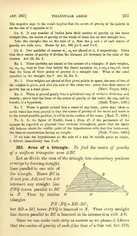
ART. 383] TRIANGULAR AREAS 255
The negative sign in the result implies that the centre of gravity of the palette is
on the side of opposite to C.
Ex. 2. If any number of bodies have their centres of gravity on the same
straight line, the centre of gravity of the whole of them lies on that straight line.
Take the straight line as the axis of x, then the y and z of each centre of
gravity are both zero. Hence by Art. 380 y= 0, and 2 = 0.
Ex. 3. Two particles of masses m1 ,m2 are placed at A, B respectively. Prove
that their centre of gravity G divides the distance AB inversely in the ratio of the
masses. Art. 53, Ex. 1.
Ex. 4. Three particles are placed at the corners of a triangle ; if their weights,
wlt w2 , w3 , vary so that they satisfy the linear equation Iw1 + mwz+ nw3
= 0, show
that the locus of their centre of gravity is a straight line. What is the areal
equation to the straight line? Art. 53, Ex. 2.
Ex. 5. Four weights are placed at four given points in space, the sum of two of
the weights is given, and also the sum of the other two : prove that their centre of
gravity lies on a fixed plane. [Math. Tripos, 1869.]
Ex. 6. Water is poured gently into a cylindrical cup of uniform thickness and
density ; prove that the locus of the centre of gravity of the water, the cup, and its
handle, is a hyperbola. [Math. Tripos, 1859.]
Ex. 7. Water is gently poured into a vessel of any form ; prove that, when so
much water has been poured in that the centre of gravity of the vessel and water is
in the lowest possible position, it will be in the surface of the water. [Math. T., 1859.]
Ex. 8. In the figure of Euclid, Book i. Prop. 47, if the perimeters of the
squares be regarded as physical lines uniform throughout, prove that the figure
will balance about the middle point of the hypothenuse with that line horizontal,
the lines of construction having no weight. [Math. Tripos, I860.]
If we take the hypothenuse as the axis of x and its middle point as origin,
it follows immediately that 5 = 0.
383. Area of a triangle. To find the centre of gravity
of a uniform triangular area ABC.
Let us divide the area of the triangle into elementary portionsor strips by drawing straight
lines parallel to one side of
the triangle. Bisect BC in
D and join AD, and let ADintersect any straight line
PNQ drawn parallel to BOin N. Then by similar B D
triangles
but BD = DG, hence PNQ is bisected in N. Thus every straight
line drawn parallel to BC is bisected at its intersection with AD.
Since we can make each strip as narrow as we please, it follows
that the centre of gravity of each (like that of a thin rod, Art. 379)
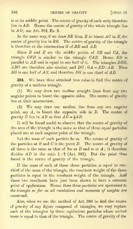
256 CENTRE OF GRAVITY [CHAP. IX
is at its middle point. The centre of gravity of each strip therefore
lies in AD. Hence the centre of gravity of the whole triangle lies
in AD; see Art. 382, Ex. 2.
In the same way, if we draw BE from B to bisect AC in E, the
centre of gravity lies in BE. The centre of gravity of the triangleis therefore at the intersection G of BE and AD.
Since D and E are the middle points of CB and CA, the
triangle GED is similar to the triangle CAB. Hence ED is
parallel to AB and is equal to one half of it. The triangles DEG,ABG are therefore also similar, and DG : GA = ED : AB. Thus
DG is one half of AG, and therefore DG is one third of AD.
384. We have thus obtained two rules to find the centre of
gravity of a uniform triangle.
(1) We may draw two median straight lines from any two
angular points to bisect the opposite sides. The centre of gravity
lies at their intersection.
(2) We may draw one median line from any one angular
point, say A, to bisect the opposite side in D. The centre of
gravity G lies in AD so that AG = %AD.
It will be found useful to observe that the centre of gravity of
the area of the triangle is the same as that of three equal particles
placed one at each angular point of the triangle.
Let the mass of each particle be m. The centre of gravity of
the particles at B and C is the point D. The centre of gravity of
all three is the same as that of 2m at D and 'm at A;
it therefore
divides AD in the ratio 1 : 2 (Art. 382). But the point thus
found is the centre of gravity of the triangle.
If the mass of each of these three particles is equal to one-
third of the mass of the triangle, the resultant weight of the three
particles is equal to the resultant weight of the triangle. Andthese two resultants have just been shown to have a common
point of application. Hence these three particles are equivalent to
the triangle so far as all resolutions and moments of weights are
concerned.
Also, when we use the method of Art. 380 to find the centre
of gravity of any figure composed of triangles, we may replace
each of the triangles by three equivalent particles whose united
mass is equal to that of the triangle. The centre of gravity of the
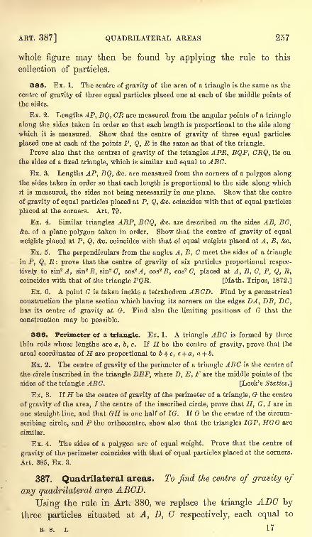
ART. 387] QUADRILATERAL AREAS 257
whole figure may then be found by applying the rule to this
collection of particles.
385. Ex. 1. The centre of gravity of the area of a triangle is the same as the
centre of gravity of three equal particles placed one at each of the middle points of
the sides.
Ex. 2. Lengths AP, BQ, CR are measured from the angular points of a triangle
along the sides taken in order so that each length is proportional to the side alongwhich it is measured. Show that the centre of gravity of three equal particles
placed one at each of the points P, Q, E is the same as that of the triangle.
Prove also that the centres of gravity of the triangles APE, BQP, CEQ, lie on
the sides of a fixed triangle, which is similar and equal to ABC.
Ex. 3. Lengths AP, BQ, &c. are measured from the corners of a polygon along
the sides taken in order so that each length is proportional to the side along which
it is measured, the sides not being necessarily in one plane. Show that the centre
of gravity of equal particles placed at P, Q, &c. coincides with that of equal particles
placed at the corners. Art. 79.
Ex. 4. Similar triangles ABP, BCQ, &c. are described on the sides AB, BC,&c. of a plane polygon taken in order. Show that the centre of gravity of equal
weights placed at P, Q, &c. coincides with that of equal weights placed at A, B, &c.
Ex. 6. The perpendiculars from the angles A, B, C meet the sides of a triangle
in P, Q, E: prove that the centre of gravity of six particles proportional respec-
tively to sin2 4, sin2 B, sin2 C, cos2 ^, cos2 B, cos2C, placed at A, B, C, P, Q, E,
coincides with that of the triangle PQE. [Math. Tripos, 1872.]
Ex. 6. A point G is taken inside a tetrahedron ABCD. Find by a geometrical
construction the plane section which having its corners on the edges DA, DB, DC,has its centre of gravity at G. Find also the limiting positions of G that the
construction may be possible.
386. Perimeter of a triangle. Ex. 1. A triangle ABC is formed by three
thin rods whose lengths are a, b, c. If H be the centre of gravity, prove that the
areal coordinates of H are proportional to b + c, c + a, a + b.
Ex. 2. The centre of gravity of the perimeter of a triangle ABC is the centre of
the circle inscribed in the triangle DEF, where D, E, F are the middle points of the
sides of the triangle ABC. [Lock's Statics.'}
Ex. 3. If H be the centre of gravity of the perimeter of a triangle, G the centre
of gravity of the area, / the centre of the inscribed circle, prove that H, G, I are in
one straight line, and that GH is one half of IG. If O be the centre of the circum-
scribing circle, and P the orthocentre, show also that the triangles IGP, HGO are
similar.
Ex. 4. The sides of a polygon are of equal weight. Prove that the centre of
gravity of the perimeter coincides with that of equal particles placed at the corners.
Art. 385, Ex. 3.
387. Quadrilateral areas. To find the centre of gravity of
any quadrilateral area ABCD.
Using the rule in Art. 380, we replace the triangle ADC by
three particles situated at A, D, C respectively, each equal to
R. s. i. 17
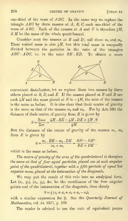
258 CENTRE OF GRAVITY [CHAP. IX
one-third of the mass of ADC. In the same way we replace the
triangle ABC by three masses at A, B, C, each one-third of the
mass of ABC. Each of the masses at A and C is therefore %M,ifM be the mass of the whole quadrilateral.
Consider next the masses at B and D; call these raj and m2 .
Their united mass is also ^M, but this total mass is unequallydivided between the particles in the ratio of the trianglesABC : ADC, i.e. in the ratio BE : ED. To obtain a more
D
B A B
convenient distribution, let us replace these two masses by three
others placed at B, D, and E. If the masses placed at B and D are
each ^M and the mass placed at E is ^M, the sum of the masses
is the same as before. It is also clear that their centre of gravity
is the same as that of the masses m^ and m^. For by Art. 380 the
distance of their centre of gravity from E is given by
_ Zmx pf . BE- pf . DE + p/ .
~^m~~- pfBut the distance of the centre of gravity of the masses m l ,
w2
from E is given by
_m1 .BE-m2 .DEm1 + mz
which is the same as before.
The centre of gravity of the area of the quadrilateral is therefore
the same as that of four equal particles, placed one at each angular
point of the quadrilateral, together with a fifth particle of equal but
negative mass, placed at the intersection of the diagonals.
We may put the result of this rule into an analytical form.
Let (a?!, 2/i), (x2 , y2), &c. be the coordinates of the four angular
points and of the intersection of the diagonals, then clearly
x |(X + #2 + #3 + #4 %s),
with a similar expression for y. See the Quarterly Journal of
Mathematics, vol. XI. 1871, p. 109.
The reader is advised to use the rule of equivalent points
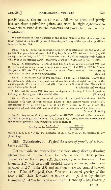
AKT. 389] TETRAHEDRAL VOLUMES 259
partly because the analytical result follows at once, and partlybecause these equivalent points are used in rigid dynamics to
enable us to write down the moments and products of inertia of a
quadrilateral.
We may replace the four particles at the angular points by four others, equal to
these, placed at the middle points of the sides, or in any of the equivalent positionsdescribed in Art. 385.
388. Ex. 1. Prove the following geometrical construction for the centre of
gravity of a quadrilateral area. Let P, Q be points in BD, AC such that QA, PBare equal respectively to EC, ED; the centre of gravity of the quadrilateral coincides
with that of the triangle EPQ. Quarterly Journal of Mathematics, vol. vi. 1864.
Ex. 2. A quadrilateral is divided into two triangles by one diagonal BD, andthe centres of gravity of these triangles are M and N. Let MN cut BD in I, fromthe greater NI take NG equal to MI the lesser. Prove that G is the centre of
gravity of the area of the quadrilateral. [Guldin.]
Ex. 3. A trapezium has the two sides AB= a and CD = b parallel. Prove that
the centre of gravity G of the quadrilateral area lies in the straight line joining the
middle points M and N of AB and CD. Prove also that G divides MN so that
MG : GN= a + 2b :2a + b. [Archimedes and Guldin.]
Notice that the ratio MG : GN does not depend on the height of the trapeziumbut only on the lengths of the parallel sides. [Poinsot.]
Ex. 4. Show that the centre of gravity of the quadrilateral area ABCDcoincides with that of four particles placed at the corners whose weights are
respectively p+ y + 8, 7 + 3 + a, 5+ a + /3,a + fi + y where a, j3, y, S are the
reciprocals of EA, EB, EC, ED and E is the intersection of the diagonals.
[Caius Coll. 1877.]
Ex. 5. Any corner C of a pentagonal area ABODE is joined to the corners A,
E, and the joining lines intersect EB, AD in F, G. Prove that the ordinate z of
the centre of gravity of the pentagonal area is given by
,tl-7i (b
-e) (d
-a)
where a, b, c, d, e, f, g are the ordinates of A, B, C, D, E, F, G, referred to any
plane of xy.
389. Tetrahedron. To find the centre of gravity of a tetra-
hedron ABCD.
Let us divide the tetrahedron into elementary slices by drawing
planes parallel to one face. Let abc be one of these planes.
Bisect BC in E and join DE, then, exactly as in the case of the
triangle, DE will bisect all straight lines such as be which are
parallel to BC. Join AE and ae, then these are parallel to each
other. Take AF = ^AE, then F is the centre of gravity of the
base ABC. Join DF and let it cut ae in /, then by similar
triangles af : AF Da : DA = ae : AE. Hence af= \ae, that is /172
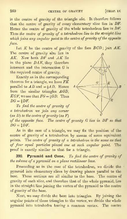
260 CENTRE OF GRAVITY [CHAP. IX
is the centre of gravity of the triangle abc. It therefore follows
that the centre of gravity of every elementary slice lies in DF.
Hence the centre of gravity of the whole tetrahedron lies in DF.
Thus the centre of gravity of a tetrahedron lies in the straight line
which joins any angular point to the centre of gravity of the opposite
face.
Let K be the centre of gravity of the face BCD; join AK.The centre of gravity also lies in
AK. Now both DF and AK lie
in the plane DAE, they therefore
intersect and the intersection G is
the required centre of gravity.
Exactly as in the correspondingtheorem for a triangle, we have FKparallel to AD and =^AD. Hence
from the similar triangles AGD,KGF, we see that FG = %GD. Thus
DG = IDF.To find the centre of gravity of
a tetrahedron we join any corner
(as D} to the centre ofgravity (as F)
of the opposite face. The centre of gravity G lies in DF so that
DG = IDF.As in the case of a triangle, we may fix the position of the
centre of gravity of a tetrahedron by means of some equivalent
points. The centre of gravity of a tetrahedron is the same as that
of four equal particles placed one at each angular point. The
proof is exactly similar to that for a triangle.
390. Pyramid and Cone. To find the centre of gravity ofthe volume of a pyramid on a plane rectilinear base.
Proceeding as in the case of the tetrahedron, we divide the
pyramid into elementary slices by drawing planes parallel to the
base. These sections are all similar to the base. The centre of
gravity of each slice, and therefore that of the whole pyramid, lies
in the straight line joining the vertex of the pyramid to the centre
of gravity of the base.
Next, we may divide the base into triangles. By joining the
angular points of these triangles to the vertex, we divide the whole
pyramid into tetrahedra having a common vertex. The centre
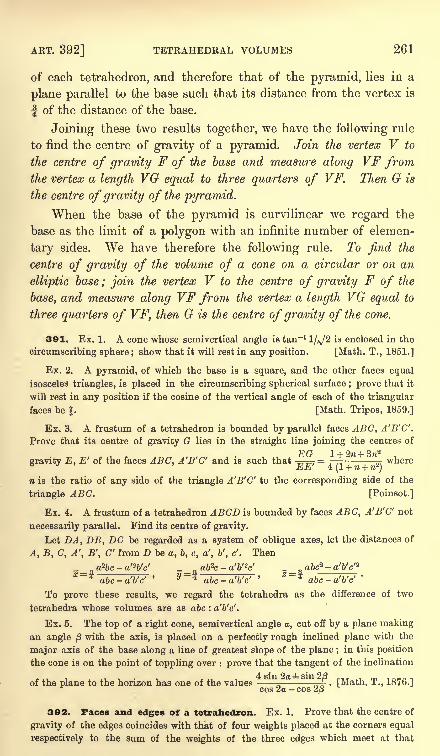
ART. 392] TETRAHEDRAL VOLUMES 261
of each tetrahedron, and therefore that of the pyramid, lies in a
plane parallel to the base such that its distance from the vertex is
f of the distance of the base.
Joining these two results together, we have the following rule
to find the centre of gravity of a pyramid. Join the vertex V to
the centre of gravity F of the base and measure along VF fromthe vertex a length VG equal to three quarters of VF. Then G is
the centre of gravity of the pyramid.
When the base of the pyramid is curvilinear we regard the
base as the limit of a polygon with an infinite number of elemen-
tary sides. We have therefore the following rule. To find the
centre of gravity of the volume of a cone on a circular or on an
elliptic base ; join the vertex V to the centre of gravity F of the
base, and measure along VF from the vertex a length VG equal to
three quarters of VF, then G is the centre of gravity of the cone.
391. Ex. 1. A cone whose semivertical angle is tan"11/^/2 is enclosed in the
circumscribing sphere; show that it will rest in any position. [Math. T., 1851.]
Ex. 2. A pyramid, of which the base is a square, and the other faces equal
isosceles triangles, is placed in the circumscribing spherical surface ; prove that it
will rest in any position if the cosine of the vertical angle of each of the triangular
faces be |. [Math. Tripos, 1859.]
Ex. 3. A frustum of a tetrahedron is bounded by parallel faces ABC, A'B'C'.
Prove that its centre of gravity G lies in the straight line joining the centres of
gravity E, E' of the faces ABC. A'B'C' and is such that -=p=7 = .-
^-,where
EE' 4 (1 + n + n2)
n is the ratio of any side of the triangle A'B'C' to the corresponding side of the
triangle ABC. [Poinsot.]
Ex. 4. A frustum of a tetrahedron ABCD is bounded by faces ABC, A'B'C' not
necessarily parallel. Find its centre of gravity.
Let DA, DB, DC be regarded as a system of oblique axes, let the distances of
A, B, C, A', B', C' from D be a, b, c, a', V, c'. Then
'~*abc-a'b'c'
'~
abc-a'b'c''
abc-a'b'c'
To prove these results, we regard the tetrahedra as the difference of two
tetrahedra whose volumes are as abc : a'b'c'.
Ex. 5. The top of a right cone, semivertical angle a, cut off by a plane making
an angle ft with the axis, is placed on a perfectly rough inclined plane with the
major axis of the base along a line of greatest slope of the plane ;in this position
the cone is on the point of toppling over : prove that the tangent of the inclination
of the plane to the horizon has one of the values-_-=^. [Math. T., 1876.]cos 2a - cos 2/3
392. Faces and edges of a tetrahedron. Ex. 1. Prove that the centre of
gravity of the edges coincides with that of four weights placed at the corners equal
respectively to the sum of the weights of the three edges which meet at that
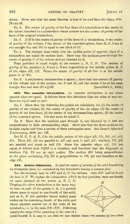
262 CENTRE OF GRAVITY [CHAP. IX
corner. Prove also that the same theorem is true if we read faces for edges, Arts.
79 and 86.
Ex. 2. The centre of gravity of the four faces of a tetrahedron is the centre of
the sphere inscribed in a tetrahedron whose corners are the centres of gravity of the
faces of the original tetrahedron.
Ex. 3. If H be the centre of gravity of the faces of a tetrahedron, G the centre
of gravity of the volume, I the centre of the inscribed sphere, then H, G, I are in
one straight line and HG is equal to one third of GI.
Ex. 4. The straight lines which join the middle points of opposite edges of a
tetrahedron are called the median lines. Show that the medians pass through the
centre of gravity G of the volume and are bisected by it.
Place particles of equal weight at the corners A, B, C, D. The centres of
gravity of the particles A, B and C, D are respectively at the middle points J/, Nof the edges AB, CD. Hence the centre of gravity of all four is at the middle
point G of MN.Ex. 5. A polyhedron circumscribes a sphere ;
show that the centres of gravity
of the volume and of the surface, viz. G and H, and the centre O lie in the same
straight line and that OG= %OH. [Liouville's J., 1843.]
393. The isosceles tetrahedron. An isosceles tetrahedron is one whose
opposite edges are equal. It follows from this definition that the sides of any two
faces are equal each to each.
Ex. 1. Show that the following five points are coincident, viz. (1) the centre of
gravity of the volume, (2) the centre of gravity of the six edges, (3) the centre of
gravity of the four faces, (4) the centre of the circumscribing sphere, (5) the centre
of the inscribed sphere. Let this point he called G.
Ex. 2. Show that the medians pass through G, are bisected by it and are
perpendicular to their corresponding edges. Show also that the three medians are
at right angles and form a system of three rectangular axes. See Casey's Spherical
Trigonometry, 1889, Art. 127.
Let M, N, P, Q, R, S be the middle points of the edges AB, CD, BD, AC, AD,BC. Then PE, QS are parallel to AB and each is half AB ; similarly PS, QRare parallel and equal to half CD. Since the opposite edges AB, CD are
equal, it follows that PQRS is a rhombus, and therefore that the diagonals or
medians PQ, RS are at right angles. The median MN being perpendicular
to the plane containing PQ, RS is perpendicular to PR, QS and therefore to the
edge AB.:
394. Double tetrahedra. To find the centre of gravity of the solid bounded by
six triangular faces, i.e. contained by two tetrahedra having a common face.
Let the common base be ABC and D, D' the vertices. Join DD', and let it cut
the base in E. We replace the tetrahedron ABCD by four particles, each one-fourth
its mass situated at the points A, B, C, D.
Treating the other tetrahedron in the same way,we have at each of the points A, B, C & particle
whose mass is equal to one-fourth of the solid,
and at D, D' two particles whose united mass
makes up the remaining fourth of the solid, and
whose separate masses are in the ratio of the
tetrahedra, i. e. in the ratio DE : ED'. Following
exactly the steps of the reasoning in the case of a
quadrilateral, it is easy to see that we can replace these two masses by two other
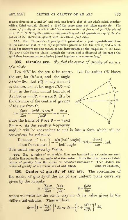
ART. 398] CENTRE OF GRAVITY OF AN ARC 263
masses situated at D and D', and each one-fourth that of the whole solid, together
with a third particle situated at E of the same mass but taken negatively. The
centre of gravity of the whole solid is the same as that of five equal particles placed
at A, B, C, D, D' together with a sixth particle equal and opposite to any of the five
placed at the intersection of DD' with the common face ABC.
395. Ex. The centre of gravity of a pyramid on a plane quadrilateral base
is the same as that of five equal particles placed at the five apices, and a sixth
equal but negative particle placed at the intersection of the diagonals of the base.
[To prove this draw a plane through the vertex and a diagonal of the base;the
solid then becomes two tetrahedra joined together at a common face.]
396. Circular arc. To find the centre of gravity of an arc
of a circle.
Let AGB be the arc, its centre. Let the radius OC bisect
the. arc, let 00= a, and the angle
AOB= 2a. Let PQ be any element
of the arc, and let the angle POG= 6.
Then in the fundamental formula of
Art. 380 ra = add, x = a cos 6. If * be
the distance of the centre of gravity
of the arc from 0,
^mx _ jadd . a cos 6 _ sin aX = -^ = ;;
-J25= a
,
2,ra Jada a.
since the limits of 6 are 6 = a and
6 = + a. As this result is frequently
used, it will be convenient to put it into a form which will be
convenient for reference.
Distance of C. G. ) _ sin (half angle) , _ chord ,
of arc from centre jhalf angle arc
This result was given by Wallis.
397. Ex. A series of 2 straight lines are inscribed in a circular arc, each
straight line subtending an angle 26 at the centre. Prove that the distance of their
centre of gravity from the centre is r cos 9 sin 2n0/2re sin 6. Then deduce the
centre of gravity of a circular arc of any angle. [Guldin's Problem.]
398. Centre of gravity of any arc. The coordinates of
the centre of gravity of the arc of any uniform plane curve are
given by the formulae
_ ^mx _ facds _ _ /yds=Z^
=Jd7'
y~Wwhere we write for the elementary arc ds its value given in the
differential calculus. Thus we have
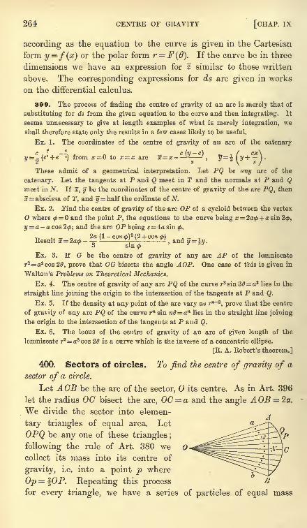
264 CENTRE OF GRAVITY [CHAP. IX
according as the equation to the curve is given in the Cartesian
form y=f(x) or the polar form r = F(d). If the curve be in three
dimensions we have an expression for z similar to those written
above. The corresponding expressions for ds are given in works
on the differential calculus.
399. The process of finding the centre of gravity of an arc is merely that of
substituting for ds from the given equation to the curve and then integrating. It
seems unnecessary to give at length examples of what is merely integration, we
shall therefore state only the results in a few cases likely to be useful.
Ex. 1. The coordinates of the centre of gravity of an arc of the catenary
c i *, -A , c (y-
c) . f cx\y= (e + e e
) from x = to x = x are x=x , y = A ( y -\ I .
2 s \ s J
These admit of a geometrical interpretation. Let PQ be any arc of the
catenary. Let the tangents at P and Q meet in T and the normals at P and Qmeet in N. If x, y be the coordinates of the centre of gravity of the arc PQ, then
x= abscissa of T, and y = half the ordinate of N.
Ex. 2. Find the centre of gravity of the arc OP of a cycloid between the vertex
where 0=0 and the point P, the equations to the curve being a;= 2a0 + a sin 20,
y = a-a cos 20, and the arc OP being s = 4a sin 0.
2a (1- cos 0)
2(2 + cos 0)
Result x= 2ad>- - ^.andu = iy.3 sin0
Ex. 3. If G be the centre of gravity of any arc AP of the lemniscate
r2= a2 cos 20, prove that OG bisects the angle AOP. One case of this is given in
Walton's Problems on Theoretical Mechanics.
Ex. 4. The centre of gravity of any arc PQ of the curve T^sin 30= a3 lies in the
straight line joining the origin to the intersection of the tangents at P and Q.
Ex. 5. If the density at any point of the arc vary as rn~3
, prove that the centre
of gravity of any arc PQ of the curve r sin nd= an lies in the straight line joining
the origin to the intersection of the tangents at P and Q.
Ex. 6. The locus of the centre of gravity of an arc of given length of the
lemniscate r2=a2 cos 26 is a curve which is the inverse of a concentric ellipse.
[R. A. Robert's theorem.]
400. Sectors of circles. To find the centre of gravity of a
sector of a circle.
Let ACB be the arc of the sector, its centre. As in Art. 396
let the radius OC bisect the arc, 0(7 = a and the angleWe divide the sector into elemen-
tary triangles of equal area. Let
OPQ be any one of these triangles ;
following the rule of Art. 380 wecollect its mass into its centre of
gravity, i.e. into a point p where
Op = fOP. Repeating this processfor every triangle, we have a series of particles of equal mass
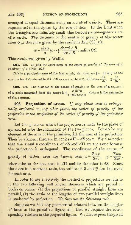
ART. 403] METHOD OF PROJECTIONS 265
arranged at equal distances along an arc ab of a circle. These are
represented in the figure by the row of dots. In the limit when
the triangles are infinitely small this becomes a homogeneous arc
of a circle. The distance of the centre of gravity of the sector
from is therefore given by the result in Art. 396, viz.
since, chord AB ,. nrix =-- la = f -m- radius OG.a.
( arc ABThis result was given by Wallis.
401. Ex. To find the coordinates of the centre of gravity of the area of a
quadrant of a circle AOB.
This is a particular case of the last article, viz. when a= ir. If x, y be the
4a 4acoordinates of G referred to OA, OB as axes, we have x= OG cos <x =
, y=^--OTT 37T
402. Ex. The distance of the centre of gravity of the area of a segment
of a circle measured from the centre is f-;-
, where a is the semianglea - sin a cos a
of the segment.
403. Projection of areas. If any plane area is orthogo-
nally projected on any other plane, the centre of gravity of the
projection is the projection of the centre of gravity of the primitive
area.
Let the plane on which the projection is made be the plane of
xy, and let a be the inclination of the two planes. Let dS be anyelement of the area of the primitive, dll the area of its projection.
Then by a known theorem in conies dTL = dScos a. We also notice
that the x and y coordinates of dS and dH are the same because
the projection is orthogonal. The coordinates of the centre of
J/it7/ 77177
gravity of either area are known from x = -= y =*
where the m for one area is cZTI and for the other is dS. Since
these are in a constant ratio, the values of x and y are the same
for each area.
In order to use effectively the method of projections we join to
it the two following well known theorems which are proved in
books on conies; (1) the projections of parallel straight lines are
parallel, (2) the ratio of the lengths of two parallel straight lines
is unaltered by projection. We then use the following rule.
Suppose we had any geometrical relation between the lengths
of lines in the primitive figure, and that we require the corre-
sponding relation in the projected figure. We first express the given
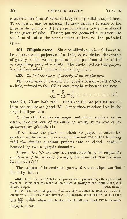
266 CENTRE OF GRAVITY [CHAP. IX
relation in the form of ratios of lengths of parallel straight lines.
To do this it may be necessary to draw parallels to some of the
lines in the primitive if there are no parallels to them mentioned
in the given relation. Having put the geometrical relation into
the form of ratios, the same relation is true for the projected
figure.
404. Elliptic areas. Since an elliptic area is well known to
be the orthogonal projection of a circle, we can deduce the centres
of gravity of the various parts of an ellipse from those of the
corresponding parts of a circle. The circle used for this purposeis sometimes called in conies the auxiliary circle.
405. To find the centre of gravity of an elliptic area.
The coordinates of the centre of gravity of a quadrant AOB of
a circle, referred to OA, OB as axes, may be written in the form
JL.-JL-A mOA OB STT
'
since OA, OB are both radii. But x and OA are parallel straight
lines, and so also are y and OB. Hence these relations hold in the
projected figure also.
If then OA, OB are the major and minor semiaxes of an
ellipse, the coordinates of the centre of gravity of the area of the
quadrant are given by (1).
If we make the plane on which we project intersect the
quadrant of the circle in any straight line not one of the boundingradii the circular quadrant projects into an elliptic quadrantbounded by two conjugate diameters.
If then OA, OB are any two semiconjugates of an ellipse, the
coordinates of the centre of gravity of the contained area are given
by equations (1).!
The position of the centre of gravity of a semi-ellipse was first
found by Guldin.
406. Ex. 1. A chord PQ of an ellipse, centre C, passes always through a fixed
point O. Prove that the locus of the centre of gravity of the triangle CPQ is a
similar ellipse. [Coll. Exam.]
Ex. 2. The centre of gravity G of any elliptic sector bounded by the semi-
diameters OP, OP' lies in the diameter OA' bisecting the chord PP', and is such
that,= f ,
where sin 6 is the ratio of half the chord PP' to the semi-C/.4 v
conjugate of OA'.
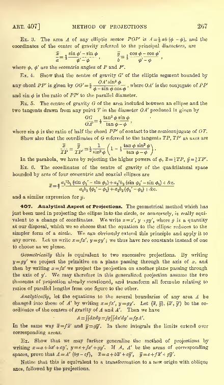
ART. 407] METHOD OF PROJECTIONS 267
Ex. 3. The area A of any elliptic sector POP' is A = ^ab(<f> -<), and the
coordinates of the centre of gravity referred to the principal diameters, are
x_ 2sin ^'- sin
<f> y_ cos
where 0, <f>'are the eccentric angles of P and P'.
Ex. 4. Show that the centre of gravity G' of the elliptic segment bounded by
any chord PP' is given by OG'^-:-
, where OA' is the conjugate of PP'3<f>- sin
<f>cos
<(>
and sin is the ratio of PP' to the parallel diameter.
Ex. 5. The centre of gravity G of the area included between an ellipse and the
two tangents drawn from any point T in the diameter OA' produced is given by
OG _ 1tan2 sin
<j>
UJ'~ 7tan
<f>-
<j>
'
where sin<f>
is the ratio of half the chord PP' of contact to the semiconjugate of OT.
Show also that the coordinates of G referred to the tangents TP, TP' as axes are
JL ___ -\ l d _ itan ^ sin2
TP TP' 4sin2 0V
Jt&n<j>-<
In the parabola, we have by rejecting the higher powers of 0, x= TP, y = \TP'.
Ex. 6. The coordinates of the centre of gravity of the quadrilateral space
bounded by arcs of four concentric and coaxial ellipses are
_ aj2^ (sin fa'
- sin fa ) + a2262 (sin fa'
- sin fa^ + &c.
A (<h'-
i) + 2&2 (&'-#s) + *c.
and a similar expression for y.
4O7. Analytical Aspect of Projections. The geometrical method which has
just been used in projecting the ellipse into the circle, or conversely, is really equi-
valent to a change of coordinates. We write x x', y=gy', where g is a quantity
at our disposal, which we so choose that the equation to the ellipse reduces to the
simpler form of a circle. We can obviously extend this principle and apply it to
any curve. Let us write x=fx', y=gy'; we thus have two constants instead of one
to choose as we please.
Geometrically this is equivalent to two successive projections. By writing
y=gy' we project the primitive on a plane passing through the axis of x, and
then by writing x =fx' we project the projection on another plane passing through
the axis of y'. We may therefore in this generalized projection assume the two
theorems of projection already mentioned, and transform all formulae relating to
ratios of parallel lengths from one figure to the other.
Analytically, let the equations to the several boundaries of any area A be
changed into those of A' by writing x=fxr
, y=gy'. Let (x, y), (x', y') be the co-
ordinates of the centres of gravity of A and A'. Then we have
A = \\dxdy =fg\\dx'dy' =fgA'.
In the same way x=fx' and y=gy'- In these integrals the limits extend over
corresponding areas.
Ex. Show that we may further generalize the method of projections by
writing x=a + bx' + cy', y= e+fx'+gy'. If A, A' be the areas of corresponding
spaces, prove that A = A' (bg-
cf), x=a+ bx' + cy', y = e+f~x'+ gy''.
Notice that this is equivalent to a transformation to a new origin with oblique
axes, followed by the projections.
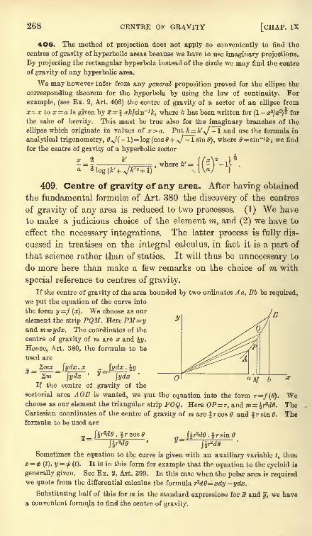
268 CENTRE OF GRAVITY [CHAP. IX
4O8. The method of projection does not apply so conveniently to find the
centres of gravity of hyperbolic areas because we have to use imaginary projections.
By projecting the rectangular hyperbola instead of the circle we may find the centre
of gravity of any hyperbolic area.
We may however infer from any general proposition proved for the ellipse the
corresponding theorem for the hyperbola by using the law of continuity. For
example, (see Ex. 2, Art. 406) the centre of gravity of a sector of an ellipse from
x= x to x= a is given by x= l afc/sin-'fc, where k has been written for (1- a;
2/a
2)4 for
the sake of brevity. This must be true also for the imaginary branches of the
ellipse which originate in values of x>a. Put k = k',J -1 and use the formula in
analytical trigonometry, 6,J(-
l) = log (cos 0+ J - 1 sin 6), where = sin~1fc
;we find
for the centre of gravity of a hyperbolic sector
x 2 k1
tf x\s |
4,- _
,where k' = 1 - - IV .+V+l IW I
409. Centre of gravity of any area. After having obtained
the fundamental formulas of Art. 380 the discovery of the centres
of gravity of any area is reduced to two processes. (1) We have
to make a judicious choice of the element m, and (2) we have to
effect the necessary integrations. The latter process is fully dis-
cussed in treatises on the integral calculus, in fact it is a part of
that science rather than of statics. It will thus be unnecessary to
do more here than make a few remarks on the choice of m with
special reference to centres of gravity.
If the centre of gravity of the area bounded by two ordinates Aa, Bb be required,
we put the equation of the curve into
the form y =f (x). We choose as our
element the strip PQM. Here PM=yand m=ydx. The coordinates of the
centre of gravity of m are x and %y.
Hence, Art. 380, the formulae to be
used are
Zmx {ydx . x (ydx . iwX = J
y =. i2-,Sm jydx
'
fydxIf the centre of gravity of the
sectorial area AOB is wanted, we put the equation into the form r=/(0). Wechoose as our element the triangular strip POQ. Here OP=r, and m= %r
2d0. TheCartesian coordinates of the centre of gravity of TO are r cos and f r sin 6.
formulae to be used are
. fr cos
The
Sometimes the equation to the curve is given with an auxiliary variable t, thus
x= <p (t), y= $(t). It is in this form for example that the equation to the cycloid is
generally given. See Ex. 2, Art. 399. In this case when the polar area is requiredwe quote from the differential calculus the formula rt
dff=xdy -ydx.
Substituting half of this for m in the standard expressions for x and y, we have
a convenient formula to find the centre of gravity.
ART. 411] AREAS BY INTEGRATION 269
41O. If the figure whose centre of gravity is required is a triangle or quadri-
lateral whose sides are curvilinear, the proper choice for the element m will depend
on the form of the curves.
If we join the angular points to the origin we have three or four sectors whose
areas and centres of gravity may be separately found and thence, by Art. 380, the
centre of gravity of the figure. Sometimes the bounding curves are of the same
species so that when the process has been gone through for one sector the results
for the other sectors may be inferred. In such cases the method is very advanta-
geous. For example, we have already seen how the area and centre of gravity of a
quadrilateral bounded by four elliptic arcs could be immediately deduced from the
area and centre of gravity of an elliptic sector. See Ex. 6, Art. 406.
Putting this in an analytical form, we have for a curvilinear triangle whose sides
arer=/i(0), r'=/2 (0'), r"=f3 (6"),
2mx = \ P r3 cos dde + \ I
Yr' :j cos O'dtf + 1 IV3 cos 6" d6" ,
J a J P J v
Sm= i ffW+i /Vw+ i| r"W,
J " J ft J y
where a, /3, 7 are the inclinations of the radii vectores of the angular points to the
axis of x. In forming these integrals we travel round the triangular figure taking
the sides in order.
It might appear at first sight that we are adding together all the three sectors
instead of adding some together and subtracting the others. But it will be clear
after a little consideration that in those sectors which should be subtracted from the
others the dO is made negative by taking the limits in the same order as we travel
round the triangle.
Instead of joining the angular points to the origin we might draw perpendiculars
on the axis of x. We then have
[b fc fa= I xydx+ I x'y'dx' + \ x"y"dx"J a J b J c
where a, b, e are the abscissae of the angular points. As before, in taking the
limits we travel round the sides in order.
411. Sometimes we may use double integration. Suppose we can express the
equations to both the opposite sides of a curvilinear quadrilateral in one form by
using an auxiliary quantity u. That is, let the one equation represent one
boundary when u= a, and let the same equation represent the opposite boundarywhen w= ft. Let this one equation be <t>(x,y, u)~0. It is always possible to do
this, for let/j (x, y) = Q, /2 (#, J/)= be the boundaries, then
0= (u-
a) /j (x, y) + (u- &)/ (x, y)=0represents one or the other according as u= a or u = b *. But this particular form
is not always a convenient mode of expressing 0. In the same way let ^ (x, y, v)=0represent the other two boundaries when v= e and v =/.
When this has been accomplished we have only to follow the rules of the
integral calculus. By giving u and v all values between u= a and u=b, v = e and
v=f, we obtain a double series of curves dividing the space into elements. Let mbe the area of one of these elements and J the Jacobian determinant of x, y with
regard to u, v, then m= Jdudv. Hence
__ ^Jdudv . yy~
$$Jdudv
This is adapted from De Morgan's Diff. Gale. p. 392.
270 CENTRE OF GRAVITY [CHAP. IX
To find the Jacobian it may be necessary to solve the equations <j>= 0, ^= 0, so as
to express a;, y in terms of u, v. We then have J= -^-~-
^- -f- . Unless we havedu dv dv du
been able in the first instance to express $ and\f/
so conveniently that this Jacobian
takes a simple form when expressed in terms of u, v, this method may lead to com-
plicated analysis. The advantage of the method is that the limits of integration
u=a to b, v= e to/are constants, so that the integrations may be performed in anyorder or simultaneously.
412. Ex. 1. An area is cut off from a parabola by a diameter ON and its
ordinate PN : prove that x=%x, y^y.Ex. 2. Two tangents TP, TP' are drawn to a parabola : show that the co-
ordinates of the centre of gravity of the area between the curve and the tangents
are x=\TP, y=\TP' referred to TP, TP' as axes. Art. 406, Ex. 5. [Walton.]
Eegard the area as the difference between a triangle and a parabolic segment.
Ex. 3. The equations of a cycloid are x= a (1- cos 6), ya (0 + sin 0). Show
that the centre of gravity of half the area is given by x= a, y-(ir-- ).2 \ y-a-/
[Wallis.]
Ex. 4. Find the centre of gravity of the half of either loop of the lemniscate
r2=a2 cos 26 bounded by the axis. The result is
_ ira __31og(v/2 + l)- N/2:
~4V2' 6^2
Ex. 5. Four parabolas whose equations are y*=a?x, y2=bs
x, y?=ezy,
x^f sy intersect and form a quadrilateral space. Find the centre of gravity.
We take as the equations to the opposite sides y'2= u3x and x2=v3
y. Solving,
we find x uv^, y = uzv and J=3wV. This gives by substitution
Ex. 6. The centre of gravity of the space bounded by two ellipses and two
hyperbolas all confocal lies in the straight line
y ^ K ~<h)
~OW+ aiaz+ i
2 ~< 2 ~ ~< 2)
x (-^(V-where the unaccented letters denote the semiaxes of the ellipse and the accented
letters those of the hyperbola.
We take as the equation to the opposite sides h . =1, (-- = 1.u u-h v v-h
where u>h and v<h. These give hx"= uv, - hy2
(u-
h) (v-
h), as shown in
Salmon's Conies. The result then follows easily enough.
Ex. 7. If the density at any point of a circular disc whose radius is a vary
directly as the distance from the centre, and a circle described on a radius as
diameter be cut out, prove that the centre of inertia of the remainder will be at a
6adistance -=-r from the centre. [Math. Tripos, 1875.]
J.O7T J-U
Ex. 8. A circular disc of radius r, whose density is proportional to the distance
from the centre, has a hole cut in it bounded by a circle of diameter a which passes
through the centre. Show that the distance from the centre of the disc of the
6a*centre of gravity of the remaining portion is
3. [Coll. Ex., 1888.]
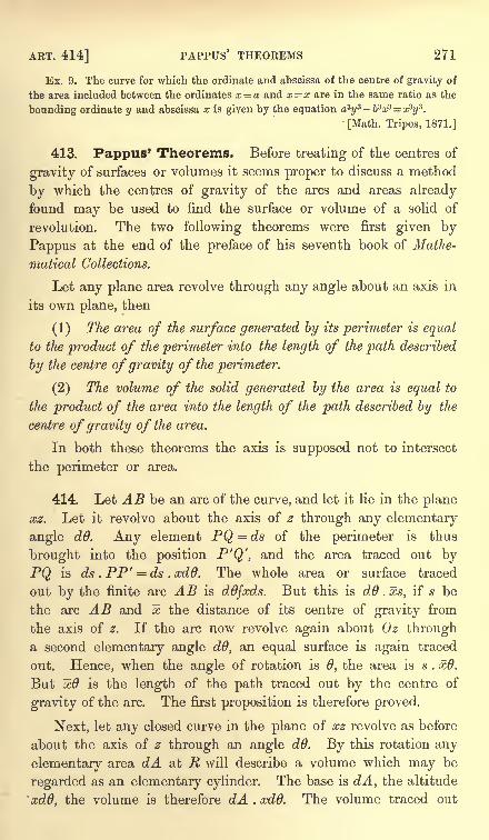
ART. 414] PAPPUS' THEOREMS 271
Ex. 9. The curve for which the ordinate and abscissa of the centre of gravity of
the area included between the ordinates x = a and x= x are in the same ratio as the
bounding ordinate y and abscissa x is given by the equation asys -b3x3 x3y
3.
[Math. Tripos, 1871.]
413. Pappus' Theorems. Before treating of the centres of
gravity of surfaces or volumes it seems proper to discuss a method
by which the centres of gravity of the arcs and areas already
found may be used to find the surface or volume of a solid of
revolution. The two following theorems were first given by
Pappus at the end of the preface of his seventh book of Mathe-
matical Collections.
Let any plane area revolve through any angle about an axis in
its own plane, then
(1) The area of the surface generated by its perimeter is equal
to the product of the perimeter into the length of the path described
by the centre of gravity of the perimeter.
(2) The volume of the solid generated by the area is equal to
the product of the area into the length of the path described by the
centre ofgravity of the area.
In both these theorems the axis is supposed not to intersect
the perimeter or area.
414. Let AB be an arc of the curve, and let it lie in the plane
xz. Let it revolve about the axis of z through any elementary
angle dd. Any element PQ = ds of the perimeter is thus
brought into the position P'Q', and the area traced out by
PQ is ds . PP' = ds . ccdQ. The whole area or surface traced
out by the finite arc AB is ddfxds. But this is dd . xs, if s be
the arc AB and x the distance of its centre of gravity from
the axis of z. If the arc now revolve again about Oz througha second elementary angle dd, an equal surface is again traced
out. Hence, when the angle of rotation is 0, the area is s . x6.
But x9 is the length of the path traced out by the centre of
gravity of the arc. The first proposition is therefore proved.
Next, let any closed curve in the plane of xz revolve as before
about the axis of z through an angle dd. By this rotation any
elementary area dA at R will describe a volume which may be
regarded as an elementary cylinder. The base is dA, the altitude
xdO, the volume is therefore dA . xdd. The volume traced out
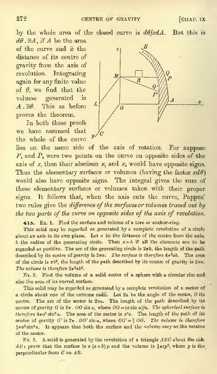
272 CENTRE OF GRAVITY [CHAP, ix
by the whole area of the closed curve is ddfxdA.dO . xA, if A be the area
of the curve and x the
distance of its centre of
gravity from the axis of
revolution. Integrating
again for any finite value
of 6, we find that the
volume generated is
A . xd. This as before
proves the theorem.
In both these proofs
we have assumed that
the whole of the curve
lies on the same side
But this is
y/0
on tne same side of the axis of rotation. For suppose
PI and P2 were two points on the curve on opposite sides of the
axis of z, then their abscissae xl and a?2 would have opposite signs.
Thus the elementary surfaces or volumes (having the factor xd6)would also have opposite signs. The integral gives the sum of
these elementary surfaces or volumes taken with their proper
signs. It follows that, when the axis cuts the curve, Pappus'two rules give the difference of the surfaces or volumes traced out by
the two parts of the curve on opposite sides of the axis of revolution.
415. Ex. 1. Find the surface and volume of a tore or anchor-ring.
This solid may be regarded as generated by a complete revolution of a circle
about an axis in its own plane. Let a be the distance of the centre from the axis,
b the radius of the generating circle. Then a>6 if all the elements are to be
regarded as positive. The arc of the generating circle is 2irb, the length of the path
described by its centre of gravity is 2wa. The surface is therefore, iir^ab. The area
of the circle is irb2,the length of the path described by its centre of gravity is 2n-a.
The volume is therefore 2w2a&2.
Ex. 2. Find the volume of a solid sector of a sphere with a circular rim and
also the area of its curved surface.
This solid may be regarded as generated by a complete revolution of a sector of
a circle about one of the extreme radii. Let 2a be the angle of the sector, its
centre. The arc of the sector is 2aa. The length of the path described by its
centre of gravity G is 2ir . OG sin a, where OG = (a sin a)/a. The spherical surface is
therefore 4ira2 sin2 a. The area of the sector is 2a. The length of the path of its
centre of gravity G'is27r. 00?' sin a, where OG'= \ OG. The volume is therefore
%ira3 sin2 a. It appears that both the surface and the volume vary as the versine
of the sector.
Ex. 3. A solid is generated by the revolution of a triangle ABC about the side
AB -. prove that the surface is IT (a + b)p and the volume is ^ircpz
,where p is the
perpendicular from C on AB.
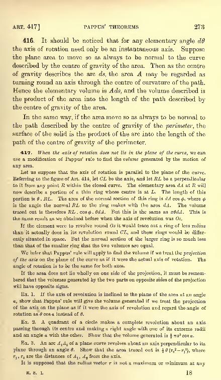
ART. 417] PAPPUS' THEOREMS 273
416. It should be noticed that for any elementary angle d0
the axis of rotation need only be an instantaneous axis. Supposethe plane area to move so as always to be normal to the curve
described by the centre of gravity of the area. Then as the centre
of gravity describes the arc ds, the area A may be regarded as
turning round an axis through the centre of curvature of the path.
Hence the elementary volume is Ads, and the volume described is
the product of the area into the length of the path described bythe centre of gravity of the area.
In the same way, if the area move so as always to be normal to
the path described by the centre of gravity of the perimeter, the
surface of the solid is the product of the arc into the length of the
path of the centre of gravity of the perimeter.
417. When the axis of rotation does not lie in the plane of the curve, we can
use a modification of Pappus' rule to find the volume generated by the motion of
any area.
Let us suppose that the axis of rotation is parallel to the plane of the curve.
Referring to the figure of Art. 414, let CL be the axis, and let EL be a perpendicular
to it from any point R within the closed curve. The elementary area dA at R will
now describe a portion of a thin ring whose centre is at L. The length of this
portion is 6 . RL. The area of the normal section of this ring is dA cos 0, where<f>
is the angle the normal RL to the ring makes with the area dA. The volume
traced out is therefore RL . cos<. QdA. But this is the same as xOdA. This is
the same result as we obtained before when the axis of revolution was Oz.
If the element were to revolve round Oz it would trace out a ring of less radius
than it actually does in its revolution round CL, and these rings would be differ-
ently situated in space. But the normal section of the larger ring is so much less
than that of the smaller ring that the two volumes are equal.
We infer that Pappus' rule will apply to find the volume if we treat the projection
of the axis on the plane of the curve as if it were the actual axis of rotation. The
angle of rotation is to be the same for both axes.
If the area does not lie wholly on one side of the projection, it must be remem-
bered that the volumes generated by the two parts on opposite sides of the projection
will have opposite signs.
Ex. 1. If the axis of revolution is inclined to the plane of the area at an angle
a, show that Pappus' rule will give the volume generated if we treat the projectionof the axis on the plane as if it were the axis of revolution aud regard the angle of
rotation as 6 cos a instead of 0.
Ex. 2. A quadrant of a circle makes a complete revolution about an axis
passing through its centre and making a right angle with one of its extreme radii
and an angle a with the other. Show that the volume generated is TTO? cos a.
Ex. 3. An arc A-^A^ of a plane curve revolves about an axis perpendicular to its
plane through an angle 6. Show that the area traced out is % 6 (r22 -?-
12), where
rlt r2 are the distances of A lt A a from the axis.
It is supposed that the radius vector r is not a maximum or minimum at any
R. S. I. 18
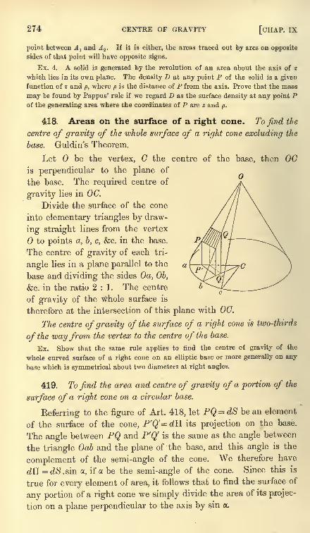
274 CENTRE OF GRAVITY [CHAP, ix
point between Aland Az . If it is either, the areas traced out by arcs on opposite
sides of that point will have opposite signs.
Ex. 4. A solid is generated hy the revolution of an area about the axis of z
which lies in its own plane. The density I) at any point P of the solid is a given
function of z and p, where p is the distance of P from the axis. Prove that the mass
may be found by Pappus' rule if we regard D as the surface density at any point Pof the generating area where the coordinates of P are z and p.
418. Areas on the surface of a right cone. To find the
centre of gravity of the whole surface of a right cone excluding the
base. Guldin's Theorem.
Let be the vertex, the centre of the base, then OCis perpendicular to the plane of
the base. The required centre of
gravity lies in OC.
Divide the surface of the cone
into elementary triangles by draw-
ing straight lines from the vertex
to points a, b, c, &c. in the base.
The centre of gravity of each tri-
angle lies in a plane parallel to the
base and dividing the sides Oa, Ob,
&c. in the ratio 2:1. The centre
of gravity of the whole surface is
therefore at the intersection of this plane with OC.
The centre of gravity of the surface of a right cone is two-thirds
of the wayfrom the vertex to the centre of the base.
Ex. Show that the same rule applies to find the centre of gravity of the
whole curved surface of a right cone on an elliptic base or more generally on any
base which is symmetrical about two diameters at right angles.
419. To find the area and centre of gravity of a portion of the
surface of a right cone on a circular base.
Referring to the figure of Art. 418, let PQ = dS be an element
of the surface of the cone, P'Q'= dU its projection on the base.
The angle between PQ and P'Q' is the same as the angle between
the triangle Oab and the plane of the base, and this angle is the
complement of the semi-angle of the cone. We therefore have
dTI = dS.sin a, if a be the semi-angle of the cone. Since this is
true for every element of area, it follows that to find the surface of
any portion of a right cone we simply divide the area of its projec-
tion on a plane perpendicular to the axis by sin a.
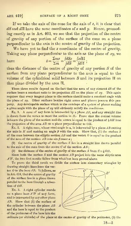
ART. 419] SURFACE OF A RIGHT CONE 275
If we take the axis of the cone for the axis of z, it is clear that
dS and dH have the same coordinates of # and y. Hence, proceed-
ing exactly as in Art. 403, we see that the projection of the centre
of gravity of any portion of the surface of the cone on a plane
perpendicular to the axis is the centre of gravity of the projection.
We have yet to find the z coordinate of the centre of gravity.
Taking any plane perpendicular to the axis as the plane of xy, we'Zmz fdSz fzdH
rl Q T7O ^ ^ - '
Helve Z -^ r~7T* r in )2,m /a$ fdU.
thus the distance of the centre of gravity of any portion $ of the
surface from any plane perpendicular to the axis is equal to the
volume of the cylindrical solid between $ and its projection II on
that plane divided by the area II.
These three results depend on the fact that the area of any element dS of the
surface bears a constant ratio to its projection dll on the plane of xy. This again
requires that every tangent plane to the surface should make a constant angle with
the plane of xy. Other surfaces besides right cones and planes possess this pro-
perty. Any developable surface which is the envelope of a system of planes makinga given angle with the plane of xy will obviously satisfy the conditions.
Ex. 1. A cone of any form is intersected by a plane AB, and any straight line
is drawn from the vertex to meet the section in H. Prove that the conical volume
between the plane of the section and the vertex is equal to the product of OR into
the projection of the area AB on a plane perpendicular to OH.Ex. 2. A right cone, whose semi-angle is a, is intersected by a plane AB cutting
the axis in H and making an angle /3 with the axis. Show that, (1) the surface Sof the cone between the elliptic section AB and the vertex is equal to the productof the area of the section AB into sin /3 cosec a
;
(2) the centre of gravity of the surface S lies in a straight line drawn parallel
to the axis of the cone from the centre C of the section AB;
(3) the distance of the centre of gravity of the surface S from C=^OH.Since both the surface S and the section AB project into the same elliptic area
A'B', the two first results follow from what has been proved above.
To prove the third result we divide the surface into elementary triangles by
drawing straight lines from the ver-
tex O to the base AB. It follows, as
in Art. 418, that the centre of gravity
of the surface lies in a plane drawn
parallel to the base through a trisec-
tion of OH.
Ex. 3. A right cylinder stands
on a plane base A'B' of any form,
and is intersected by any other plane
AB. Show that (1) the surface of
the cylinder between the plane ABand the base is equal to the productof the perimeter of the base into the
ordinate (or altitude) of the plane at the centre of gravity of the perimeter, (2) the
182
tt'
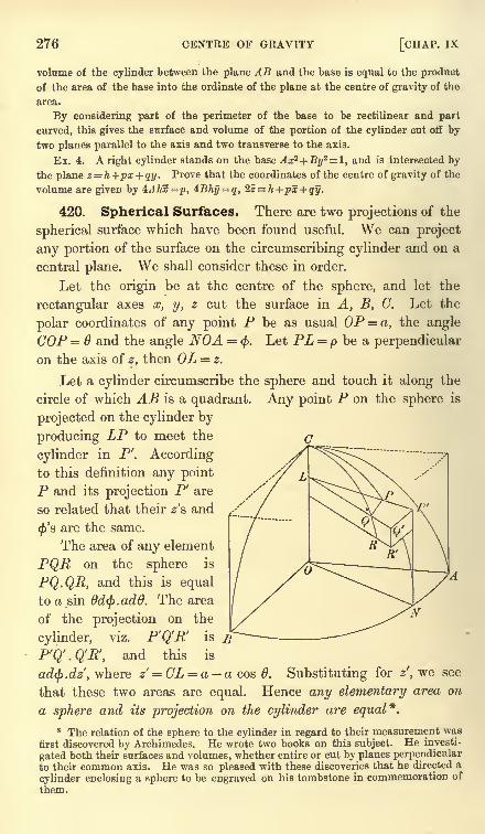
276 CENTRE OF GRAVITY [CHAP. IX
volume of the cylinder between the plane AB and the base is equal to the product
of the area of the base into the ordinate of the plane at the centre of gravity of the
area.
By considering part of the perimeter of the base to be rectilinear and part
curved, this gives the surface and volume of the portion of the cylinder cut off by
two planes parallel to the axis and two transverse to the axis.
Ex. 4. Aright cylinder stands on the base Ax2 + By2=l, and is intersected by
the plane z = h +px + qy. Prove that the coordinates of the centre of gravity of the
volume are given by 4Ahx=p, 4Bhy = q, 2z h+px+ qy.
420. Spherical Surfaces. There are two projections of the
spherical surface which have been found useful. We can project
any portion of the surface on the circumscribing cylinder and on a
central plane. We shall consider these in order.
Let the origin be at the centre of the sphere, and let the
rectangular axes a;, y, z cut the surface in A, B, C. Let the
polar coordinates of any point P be as usual OP = a, the angle
COP = Q and the angle NOA = <. Let PL = p be a perpendicular
on the axis of z, then OL = z.
Let a cylinder circumscribe the sphere and touch it along the
circle of which AB is a quadrant. Any point P on the sphere is
projected on the cylinder by
producing LP to meet the
cylinder in P'. Accordingto this definition any point
P and its projection P' are
so related that their z's and
<'s are the same.
The area of any element
PQR on the sphere is
PQ.QR, and this is equal
to a sin ddfy.add. The area
of the projection on the
cylinder, viz. P'Q'R is
P'Q'.Q'R, and this is
ad<f>.dz',where z' = CL = a acos 6. Substituting for z', we see
that these two areas are equal. Hence any elementary area on
a sphere and its projection on the cylinder are equal*.
* The relation of the sphere to the cylinder in regard to their measurement wasfirst discovered by Archimedes. He wrote two books on this subject. He investi-
gated both their surfaces and volumes, whether entire or cut by planes perpendicularto their common axis. He was so pleased with these discoveries that he directed a
cylinder enclosing a sphere to be engraved on his tombstone in commemoration of
them.
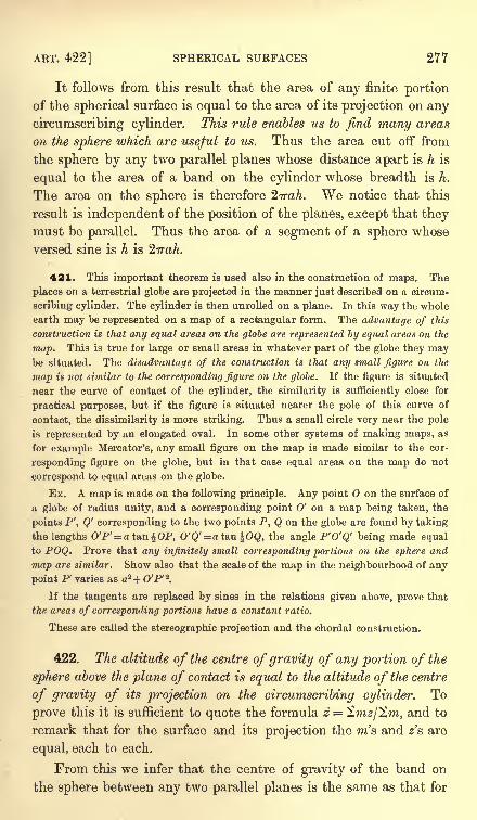
ART. 422] SPHERICAL SURFACES 277
It follows from this result that the area of any finite portionof the spherical surface is equal to the area of its projection on any
circumscribing cylinder. This rule enables us to find many areas
on the sphere which are useful to us. Thus the area cut off from
the sphere by any two parallel planes whose distance apart is h is
equal to the area of a band on the cylinder whose breadth is h.
The area on the sphere is therefore 2,7rah. We notice that this
result is independent of the position of the planes, except that theymust be parallel. Thus the area of a segment of a sphere whose
versed sine is h is
421. This important theorem is used also in the construction of maps. The
places on a terrestrial globe are projected in the manner just described on a circum-
scribing cylinder. The cylinder is then unrolled on a plane. In this way the whole
earth may be represented on a map of a rectangular form. The advantage of this
construction is that any equal areas on the globe are represented by equal areas on the
map. This is true for large or small areas in whatever part of the globe they maybe situated. The disadvantage of the construction is that any small figure on the
map is not similar to the corresponding figure on the globe. If the figure is situated
near the curve of contact of the cylinder, the similarity is sufficiently close for
practical purposes, but if the figure is situated nearer the pole of this curve of
contact, the dissimilarity is more striking. Thus a small circle very near the pole
is represented by an elongated oval. In some other systems of making maps, as
for example Mercator's, any small figure on the map is made similar to the cor-
responding figure on the globe, but in that case equal areas on the map do not
correspond to equal areas on the globe.
Ex. A. map is made on the following principle. Any point on the surface of
a globe of radius unity, and a corresponding point O' on a map being taken, the
points P', Q' corresponding to the two points P, Q on the globe are found by taking
the lengths 0'P'= a tan^OP, 0'Q' = ata,n %OQ, the angle P'O'Q' being made equal
to POQ. Prove that any infinitely small corresponding portions on the sphere and
map are similar. Show also that the scale of the map in the neighbourhood of any
point P varies as a2 + O'P' 2.
If the tangents are replaced by sines in the relations given above, prove that
the areas of corresponding portions have a constant ratio.
These are called the stereographic projection and the chordal construction.
422. The altitude of the centre of gravity of any portion of the
sphere above the plane of contact is equal to the altitude of the centre
of gravity of its projection on the circumscribing cylinder. To
prove this it is sufficient to quote the formula z = Snw/Sw, and to
remark that for the surface and its projection the ra's and z's are
equal, each to each.
From this we infer that the centre of gravity of the band on
the sphere between any two parallel planes is the same as that for
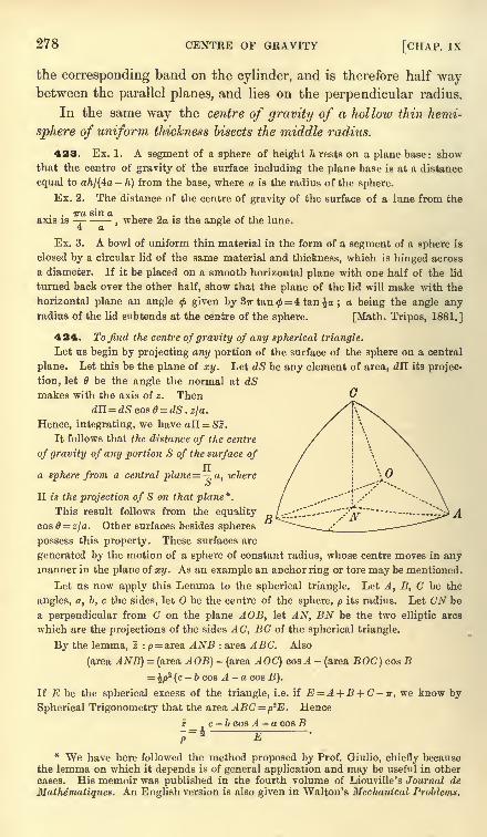
278 CENTRE OF GRAVITY [CHAP. IX
the corresponding band on the cylinder, and is therefore half waybetween the parallel planes, and lies on the perpendicular radius.
In the same way the centre of gravity of a hollow thin hemi-
sphere of uniform thickness bisects the middle radius.
423. Ex. 1. A segment of a sphere of height h rests on a plane base : showthat the centre of gravity of the surface including the plane base is at a distance
equal to aft/(4a-
h) from the base, where a is the radius of the sphere.
Ex. 2. The distance of the centre of gravity of the surface of a lime from the
axis is-j-
-,where 2a is the angle of the lune.
Ex. 3. A bowl of uniform thin material in the form of a segment of a sphere is
closed by a circular lid of the same material and thickness, which is hinged across
a diameter. If it be placed on a smooth horizontal plane with one half of the lid
turned back over the other half, show that the plane of the lid will make with the
horizontal plane an angle <f> given by Sir tan = 4 tan a ; a being the angle anyradius of the lid subtends at the centre of the sphere. [Math. Tripos, 1881.]
424. To find the centre of gravity of any spherical triangle.
Let us begin by projecting any portion of the surface of the sphere on a central
plane. Let this be the plane of xy. Let dS be any element of area, dll its projec-
tion, let 6 be the angle the normal at dSmakes with the axis of z. Then
dll = dS cos = dS . z\a.
Hence, integrating, we have a!i = Sz.
It follows that the distance of the centre
of gravity of any portion S of the surface of
a sphere from a central plane = -^,a, whereo
II is the projection of S on that plane*.
This result follows from the equality
cos0 = 2/a. Other surfaces besides spheres
possess this property. These surfaces are
generated by the motion of a sphere of constant radius, whose centre moves in anymanner in the plane of xy. As an example an anchor ring or tore may be mentioned.
Let us now apply this Lemma to the spherical triangle. Let A, B, G be the
angles, a, b, c the sides, let be the centre of the sphere, p its radius. Let CN be
a perpendicular from C on the plane AOB, let AN, BN be the two elliptic arcs
which are the projections of the sides AC, BC of the spherical triangle.
By the lemma, z :/>= area ANB : area ABC. Also
(area ANB) = (area AOB) -(area AOC) cos A -
(area BOG) cos B
\p* (c-b cos A - a cos B).
If E be the spherical excess of the triangle, i.e. if E A + B + C-tr, we know by
Spherical Trigonometry that the area ABC=p2E. Hence
z c - b cos A - a cos B
* We have here followed the method proposed by Prof. Giulio, chiefly becausethe lemma on which it depends is of general application and may be useful in othercases. His memoir was published in the fourth volume of Liouville's Journal de
Mathematiques. An English version is also given in Walton's Mechanical Problems.
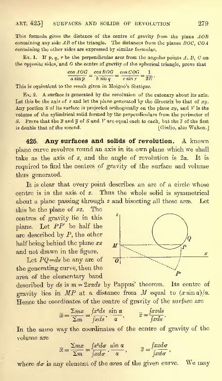
ART. 425] SURFACES AND SOLIDS OF REVOLUTION 279
This formula gives the distance of the centre of gravity from the plane AOBcontaining any side AB of the triangle. The distances from the planes BOG, COAcontaining the other sides are expressed by similar formulae.
Ex. 1. If p, q, r be the perpendicular arcs from the angular points A, B, C on
the opposite sides, and G the centre of gravity of the spherical triangle, prove that
cos AOG _ cos BOG _ cos COG _ I
a sinp b sin q c sin r 2E'
This is equivalent to the result given in Moigno's Statique.
Ex. 2. A surface is generated by the revolution of the catenary about its axis.
Let this be the axis of z and let the plane generated by the directrix be that of xy.
Any portion S of its surface is projected orthogonally on the plane xy, and V is the
volume of the cylindrical solid formed by the perpendiculars from the perimeter of
8. Prove that the x and y of S and V are equal each to each, but the z of the first
is double that of the second. [Giulio, also Walton.]
425. Any surfaces and solids of revolution. A known
plane curve revolves round an axis in its own plane which we shall
take as the axis of z, and the angle of revolution is 2a. It is
required to find the centres of gravity of the surface and volume
thus generated.
It is clear that every point describes an arc of a circle whose
centre is in the axis of z. Thus the whole solid is symmetricalabout a plane passing through z and bisecting all these arcs. Let
this be the plane of xz. The
centres of gravity lie in this
plane. Let PF be half the
arc described by P, the other
half being behind the plane xz
and not drawn in the figure.
Let PQ=ds be any arc of
the generating curve, then the
area of the elementary band
described by ds is m = %xads by Pappus' theorem. Its centre of
gravity lies in MP at a distance from M equal to (x sin a) /a.
Hence the coordinates of the centre of gravity of the surface are
_ _ _ fafds since _ _jxzds2ra
~~
faeds
'
a fxds'
In the same way the coordinates of the centre of gravity of the
volume are
_ _ ^mx _ fx*da- sin a _ _ jxzdv2m fader
'
OL f&dcr
where da- is any element of the area of the given curve. We may
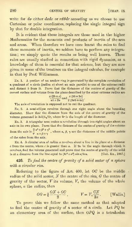
280 CENTRE OF GRAVITY [CHAP. IX
write for dcr either dxdz or rdOdr according as we choose to use
Cartesian or polar coordinates, replacing the single integral sign
by that for double integration.
It is evident that these integrals are those used in the higherMathematics for the moments and products of inertia of the arcs
and areas. When therefore we have once learnt the rules to find
these moments of inertia, we seldom have to perform any integra-
tion;we simply quote the results as being well known. These
rules are usually studied in connection with rigid dynamics, as a
knowledge of them is essential for that science, but they are now
given in some of the treatises on the integral calculus, for examplein that by Prof. Williamson.
Ex. 1. A portion of an anchor ring is generated by the complete revolution of
a quadrant of a circle (radius a) about an axis parallel to one of the extreme radii
and distant b from it. Prove that the distances of the centres of gravity of the
curved surface and volume from the plane described by the other extreme radius are
q(2fe=fco) a (8b3a)irb2a
&Q2 (3irb 4a)
'
The axis of revolution is supposed not to cut the quadrant.
Ex. 2. A semi-ellipse revolves through one right angle about the bounding
diameter. Show that the distance from the axis of the centre of gravity of the
volume generated is Sab/i^Sr, where 2r is the length of the diameter.
Ex. 3. A triangular area makes a revolution through two right angles about an
axis in its own plane. Prove that the distance of the centre of gravity of the volume
from the axis is---, where a, 8. y are the distances of the middle pointsw a + /3+ 7
of the sides from the axis.
Ex. 4. A circular area of radius a revolves about a line in its plane at a distance
c from the centre, where c is greater than a. If 2a be the angle through which it
revolves, find the volume generated and prove that the centre of gravity of the solid
is at a distance from the line equal to (4c2+ a2
) sina/4ca. [Coll. Ex., 1887.]
426. To find the centre of gravity of a solid sector of a sphere
with a circular rim.
Referring to the figure of Art. 400, let OG be the middle
radius of the solid sector, N the centre of the rim, G the centre of
gravity of the sector, V its volume, V the volume of the whole
sphere, a the radius, then
ON+OC ,CN
To prove this we follow the same method as that adopted
to find the centre of gravity of a sector of a circle. Let PQ be
an elementary area of the surface, then OPQ is a tetrahedon
ART. 428] ELLIPSOIDAL VOLUMES 281
whose centre of gravity is at p where Op = f OP. Hence, if G'
be the centre of gravity of the surface, OG = $OG'. But
OG' = | (ON + 00) by Art. 422. Hence the result follows. The
volume V has been already found in Art. 415.
The centre of gravity of a solid hemisphere follows immediatelyfrom this result. Putting ON = Q, we see that the centre of gravity
of a solid hemisphere lies on the middle radius and is at a distance
| of that radius from, the centre.
The centre of gravity of a solid octant also follows at once.
There are four octants on one side of any central plane and the
centre of gravity of each of these is at the same distance from that
plane. Hence the centre of gravity of all four must be also at the
same distance, and this has just been proved to be fa. Hence, for
any octant, the distance of the centre of gravityfrom any one of the
three plane faces is f of the radius.
427. Ex. 1. The centre of gravity and volume of a solid segment of a sphere
bounded by a plane distant z from the centre are given by
Ex. 2. Prove that in a sphere, whose density varies inversely as the distance
from a point in the surface, the distance of the centre of gravity from that point
bears to the diameter the ratio 2 : 5. [Math. Tripos, 1867.]
Ex. 3. Prove that the centre of gravity of a solid sphere, whose density
varies inversely as the fifth power of the distance from an external point, is
at the centre of the section of the sphere by the polar plane of the external
point. [Math. Tripos, 1872.]
428. Centres of gravity of volumes connected with the
ellipsoid. In order to deduce the centre of gravity of any portion
of an ellipsoid from that of the corresponding portion of a sphere,
we shall use an extension of that method of projections by which
we passed from the areas of circles to those of ellipses.
One point (xyz) is said to be projected into another (x'y'z'}
when we write x ax', y = by', z = cz'. The points are then said
to correspond. Volumes F, V correspond when their boundaries
are traced out by corresponding points. If (xyz), (x'y'z') be the
centres of gravity of V, V we have
V=fffdxdydz = abc tfdx'dtfdz' = abcV.
In the same way x = ax', y = by', z = cz'.
It appears from these equations that any corresponding volumes
have a constant ratio, and the centre of gravity of one corresponds
to the centre of gravity of the other.
282 CENTRE OF GRAVITY [CHAP. IX
We may also show* that (1) parallel straight lines correspond
to parallels, and (2) the ratio of the lengths of parallel straight
lines is unaltered by projection. Thus the rule already explainedin Art. 403 for areas is true also for solids.
We may apply these principles to an ellipsoidal solid. The
equation to an ellipsoid of semi-axes a, b, c is changed into that of
a concentric sphere by writing x = ax, y = by', z = cz' . It follows
that all projective theorems may be transferred from the sphere to
the ellipsoid.
429. Ex. 1. Find the centre of gravity of a solid sector of an ellipsoid with an
elliptic rim.
Let O and N be the centres of the ellipsoid and of the rim. Then ON is the
conjugate diameter of the plane of the rim. Let it cut the ellipsoid in C. The
corresponding theorem for a spherical sector is given in Art. 426. Since the
values of OG and V there given depend on the ratios of parallel lengths, we
may transfer them to the ellipsoid. The centre of gravity G of the ellipsoidal
sector therefore lies in ON, and we have
OG-^+QC y_ CNf ~l ' ~2Toc '
Ex. 2. The coordinates of a solid octant of an ellipsoid hounded by three
conjugate planes are 5= fa, y = %b, z = %c.
Ex. 3. The centre of gravity and volume of any solid segment of an ellipsoid
are given by <>G =*, V=,
V ,
where 2c is the conjugate diameter of the plane of the segment, z its ordinate
measured along c, and V the volume of the whole ellipsoid.
43O. Let us construct two concentric and coaxial ellipsoids forming between
them a thin solid shell. Let (a, b, c), (a + da, &e.) be the semi-axes of these
ellipsoids, p and p + dp the perpendiculars on two parallel tangent planes. Thent = dp is the thickness of the shell at any point. Let d<r be an element of the
surface of one ellipsoid, dn its projection on the plane of xy, then dH = d<r2
.
C
Ex. 1. Show that the ordinate z of the centre of gravity of any portion of the
shell is given by zV=c- 1 dH, where V is the volume of that portion of the shell.
Ex. 2. If the shell is bounded by similar ellipsoids, so that = = =,
a b c pprove that z : c= Hdc : V.
* Let the straight line AB project into A'B' by writing x= ax' leaving y, z
unaltered. Geometrically we construct A'B' by producing the abscissae (viz. LA,MB) of A and B in the given ratio a : 1. This gives LA' = a . LA and MB' = a . MB.Repeating this process for a straight line CD parallel to AB, it is easy to see, bysimilar triangles, that C'D' is also parallel to A'B', and that the ratio C'D' : A'B'= the ratio CD : AB. Having written x = ax' we repeat the process by writing
y = by' and finally zcz'. The theorems are obviously true after the third projectionas well as after the first.
ART. 431] ANY SURFACE AND SOLID 283
If two parallel planes cut off a portion from this thin shell, prove that its
centre of gravity lies in the common conjugate diameter and is equidistant from
the planes. Art. 428.
Ex. 3. If the shell is bounded by confocal ellipsoids, so that ada=bdb = cdc=pdp,z IMcL /, c2 \fc2
2/, c'W)
prove that - = -^- < 1 - 1 - --
t } -%-
(1 -
ra ) TJ? '
c V ( \ a?) a2\ b2 / b2
)
where IIA^2 and nfc2
2 are the moments of inertia of II about the axes of x and y
respectively, Art. 425.
Ex. 4. If the density of a shell bounded by concentric, similar, and similarly
situated ellipsoids vary inversely as the cube of the distance from a point within
the cavity, that point is the centre of gravity.
If the shell be thin, and the density vary inversely as the cube of the distance
from an external point, the centre of gravity is in the polar plane of the point. At
what point of the polar plane is the centre of gravity situated? [Math. T., 1880.]
Let the shell be thin, and let be the point within the cavity. With for
vertex describe an elementary cone cutting off from the shell two elementary
volumes. Let v and v' be these volumes, and r, r' their distances from 0. By the
properties of similar ellipsoids, we may show that v/r2=v'lr'*. Let D, D' be the
densities of these elements. Since D =/*/r
3, D'=/j./r'
3,we find vDr=v'D'r', i.e.
the centre of gravity of two elements is at 0. It easily follows that the centre of
gravity of the whole thin shell is at 0. Joining many thin shells together, it also
follows that the centre of gravity of a thick shell is at 0.
Next, let be an external point, and let the elementary cone whose vertex is at
intersect the polar plane of in an element whose distance from is p. Since p
is the harmonic mean of r and ?', we easily find vDr + v'D'r'=(vD+v'D') p, i.e. the
centre of gravity of the two elementary volumes v and v' lies in the polar plane of
O. It follows that the centre of gravity of the shell lies in the polar plane of 0.
Lastly, let any number of particles m^, m2 , &c., attract the origin according to
the Newtonian law, and let the resultant attraction be a force X acting along the
axis of x. If the coordinates of the particles be (x1 ylz1 )
<fec. , we find by resolution
The two latter equations show that, if the masses m1 , m2 ,&c. are divided by
numbers proportional to the cubes of their distances from the origin, the centre of
gravity of the masses so altered lies in the line of action of the force X. The first
equation shows the distance of the centre of gravity from the origin.
In this way many propositions on attractions may be translated into propositions
on centre of gravity, and vice versa.
It will be shown in the chapter on attractions that the resultant attraction of a
thin homogeneous shell bounded by similar ellipsoids at an exterual point is
normal to the confocal ellipsoid passing through 0. The centre of gravity of the
heterogeneous shell is the intersection of this normal with the polar plane of 0.
431. Centres of gravity of the volume and surface of
any solid. The fundamental formulae are in all cases those
already found in Art. 380, viz.
2m#/Vi _ A.~
284 CENTRE OF GRAVITY [CHAP. IX
the differences we have to indicate arise only from the varyingchoice which we may make for the element m.
Let us first find the centre of gravity of a volume. For
Cartesian coordinates we take m = dxdydz, and replace the 2 bythe sign of triple integration. We have then
- _ N$dxdy dz . x _ _fffdxdydz .y __ ^dxdydz . z
$ffdxdydz' *
\\\dxdydz'
fffdxdydzThese formulae evidently hold for oblique axes also.
For polar coordinates we take m = rd6 . dr . r sin 6d(f>, and
x = r sin cos<f>, y = r sin 6 sin <, z = r cos 0, and replace 2 by the
sign of triple integration. These relations are proved in treatises
on the integral calculus. We find
- _ I//7"3 sin2 e cosWrdOdQ __ JJJr
3 sin2 6 sin <t>drded<j> _ _ f/JV3 sin
~~JJJr2sin0drd0<ty
' y ~JJjr
2sin0drd0d0
' '
JJJr*sin drdedtp
'
For cylindrical coordinates we have m =pd(f> . dp . dz, and
x = p cos<f>, y = p sin
</>.Hence
- _ JJ/P2 sin <j>d<j>dpdz _
Or again, if x, y, z be given functions of three auxiliary
variables u, v, w, we can use the Jacobian form correspondingto that of Art. 411. We have then m = Jdudvdw.
432. To find the centre of gravity of the surface of a solid we
find the value of m suitable to the coordinates we wish to use.
If the equation to the surface is given in the Cartesian form
z=f(x,y), we project the element of surface on the plane of xy.
The area of the projection is dxdy. If (a/S^) be the direction
angles of the normal to the element, the area of the element must
be secy dxdy. This therefore is our value of m. We find
JJ sec jdxdy .x - _ JJ sec 7dxdy . y _
JJ sec ydxdy JJ sec 7dxdy
Taking the equation to the normal, we find
A_,sec 7= 1+ -y- + T-
( \dx) \dyJ
In a similar way, if the equation to the surface is given in
cylindrical coordinates z=f(p, </>),we find
. f_ fdz\* /cm = pd<bdp\l+ [-=-- )+ -r
( \dpj \p
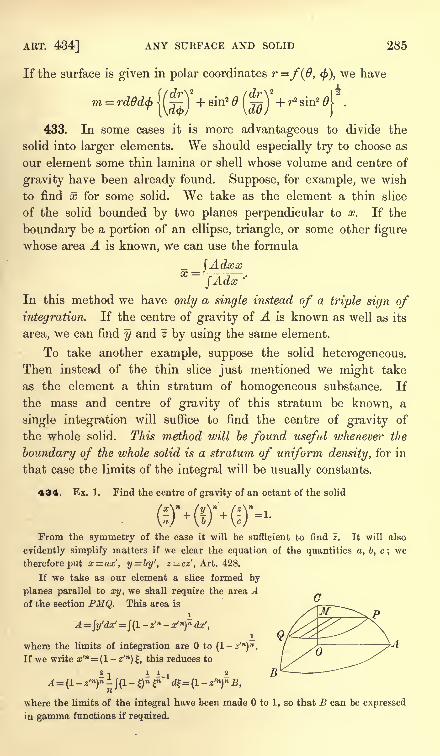
ART. 434] ANY SURFACE AND SOLID 285
If the surface is given in polar coordinates r =/(#, $), we have
{fdr\* fdr\* )2m = rdddd) < {-j-} + sin2 6 -y^ + r2 sin26\ .
(\a<p/ \at// j
433. In some cases it is more advantageous to divide the
solid into larger elements. We should especially try to choose as
our element some thin lamina or shell whose volume and centre of
gravity have been already found. Suppose, for example, we wish
to find x for some solid. We take as the element a thin slice
of the solid bounded by two planes perpendicular to x. If the
boundary be a portion of an ellipse, triangle, or some other figure
whose area A is known, we can use the formula
_ _ JAdxx
fAdx''
In this method we have only a single instead of a triple sign of
integration. If the centre of gravity of A is known as well as its
area, we can find y and z by using the same element.
To take another example, suppose the solid heterogeneous.Then instead of the thin slice just mentioned we might take
as the element a thin stratum of homogeneous substance. If
the mass and centre of gravity of this stratum be known, a
single integration will suffice to find the centre of gravity of
the whole solid. This method will be found useful whenever the
boundary of the whole solid is a stratum of uniform density, for in
that case the limits of the integral will be usually constants.
434. Ex. 1. Find the centre of gravity of an octant of the solid
From the symmetry of the case it will be sufficient to find z. It will also
evidently simplify matters if we clear the equation of the quantities a, b, c; we
therefore put x= ax', y = by', z = cz', Art. 428.
If we take as our element a slice formed by
planes parallel to xy, we shall require the area Aof the section PMQ. This area is
A= ly'dx'=
J(l- z'
n - x'n)
ndx',
i Qwhere the limits of integration are to (l-z'")
n.
If we write x'n= (1- z'n
) ,this reduces to
-1 - l-i Bn
where the limits of the integral have been made to 1, so that B can be expressed
in gamma functions if required.
286 CENTRE OF GRAVITY [CHAP. IX
, ,We have now, - =r . , .
c \Adz'
/(I- z'n
)n dz'
If we put z'n= and write m for 1/n, this reduces to
f J(l-
1)27" P"-1
d| T (2m+ 1) T (2m) T(3m+ l)
c-
J(l_|)2m^m-i^~
r(4m + l) r(2m+l)r(m)'
using the equation r (x + 1)= xT (x), this becomes
5 T (2m) T (3m) , 1- = S T-. / .'
'
r > where m= -.
c4 r m) T (4m) n
. / . r(m) T (4m)
Ex. 2. Find the centre of gravity of a hemisphere, the density at any point
varying as the nth power of the distance from the centre.
Here we notice that any stratum of uniform density is a thin hemispherical
shell, whose volume and centre of gravity are both known. We therefore take this
stratum as the element. We have the further advantage that the limits are
constants, because the external boundary of the solid is homogeneous.
Let the axis of z be along the middle radius, let (r,r + dr) be the radii of any
shell, and let the density D = /j.rn
. Then m= 2wr'2 dr . firn
,also the ordinate of its
centre of gravity is %r, see Art. 422. Hence
n + 3 an+4 - bn+*~
J2jrr2drnrn~
n+4 an+* - b +s '
The limits of the integral have been taken from r = b to r= a, so that we have found
the centre of gravity of a shell whose internal and external radii are 6 and a. For
a hemisphere we put b = 0. If n + 3 is positive, we then have z = -. In other
i ft T" 4
cases we find z = 0. If either n + 3 or n + 4 is zero the integrals lead to logarithmic
forms, but we still find 1 = 0.
Ex. 3. Find the centre of gravity of the octant of an ellipsoid when the density
at any point is D=/jixl
ymzn .
To effect this we shall have to find the values of 2mz and 2m, which are both
integrals of the form ^xl
ymzndxdydz
for all elements within the solid. To simplify matters, we write (x/a)2=
f, &c. The
limits of the integral are now fixed by the plane + ?7 + f=l. But these are the
integrals known as Dirichlet's integrals, and are to be found in treatises on the
Integral Calculus. The result is usually quoted in the form
though Liouville's extensions to ellipsoids and other surfaces are also given. Here
T (p + !)= !. 2. B...p when p is integral, and in all cases in which p is positive
T (p+ l)=pT (p). Also T (i) =v/T.
The result now follows from substitution;we find
When I, m, n are positive integers there -is no difficulty in deducing the values of
these gamma functions from the theorems just quoted.
In this way we can find 2mz and 27 and thence z whenever the density D is a
function which can be expanded in a finite series of powers of x, y, z.
ART. 436] LAGRANGE'S THEOREMS 287
If the density at any point of an octant of an ellipsoid is D=fixyz, show that
* = 16c/35.
Ex. 4. If the density at any point of an octant of an ellipsoid vary as the
5c a2+ 62 + 2c2
square of the distance from the centre, show that z = --^-
^-.
Ex. 5. To find the centre of gravity of a triangular area whose density at any
point is Dnx l
ym
.
To determine x and y we have to find 2;, 2mx and Zmy. All these are integrals
of the form \\xl
ym dx dy. If yl ,y, y3 are the ordinates of the corners of the triangle
and A the area, it may be shown that
2A -y3 +...} ........... (l),
where the right-hand side, after division by A, is the arithmetic mean of the homo-
geneous products of yl , y2 , ys . Thus when the density is D =/j.y
n the ordinate y
may be found by a simple substitution.
If we take y + kx= as a new axis of x, (1) may be written in the form
n dx dy= { (Vi + *xi)n+ (2/1 +fc^1
(2/2+ **2) + }
Equating the coefficient of k on each side, we find
"-1 dx dy = { ^i2/in~1 + (n
-
In general, if Hn be the arithmetic mean of the homogeneous products of
J/i.2/2.y3' we have
,, dP t/ d d d \P
\\xp - y
ndxdy = A I x, + x2
- ha;,-) Hn .JJ
dyPy
\J dVl
2dy2
3dyJ
One corner of a triangle is at the origin ;if the density vary as the cube of the
2^/5 _ y 5
distance from the axis of x, show that y = ^ '-^ ^ . Also write down the value of x.y\
~2/2
The same method may be used to find the centre of gravity of a quadrilateral, a
tetrahedron or a double tetrahedron, when the density is D = pucl
ymzn. See a paper
by the author in the Quarterly Journal of Mathematics, 1886.
435. Lagrange's two Theorems. Def. If the mass of a
particle be multiplied by the square of its distance from a given
point 0, the product is called the moment of inertia of the particle
about, or with regard to, the point 0. The moment of inertia of
a system of particles is the sum of the moments of inertia of the
several particles.
436. Lagranges first Theorem. The moment of inertia of a
system of particles about any point is equal to their moment of
inertia about their centre of gravity together with what would be
the moment of inertia about of the whole mass if it were collected
at its centre of gravity.
Let the particles m l ,ra2 , &c. be situated at the points A 1} A 2 , &c.
Let (x^y-iZ^, (x^y^z^, &c. be the coordinates of A l} A 2 , &c.
288 CENTRE OF GRAVITY [CHAP. IX
referred to as origin. Let x, y, z be the coordinates of the centre
of gravity G. Also let x = x + x', y = y + y' )&c. Now
2 (m . J. 2)= 2m {( + #')
2 + (y + yj + (z + zj]= 2m . OG2 + 2z2mo/ + 2^2my' + 2z2m/ + 2 (w&A 8
).
Since the origin of the accented coordinates is the centre of
gravity, we have 2raa/ = 0, 2my' = 0, 2m/ = 0. Hence putting
M= 2m, we have 2 (m . OA'i
)= M. OCP + ^ (m. GA Z
) ......(A).
This equation expresses Lagrange's theorem in an analytical form.
We notice that the moment of inertia of the body about any
point is least when that point is at the centre of gravity.
An important extension of this theorem is required in rigid
dynamics. It is shown that, if/ (x, y, z) be any quadratic function
of the coordinates of a particle, then
2m/(#, y, z)= Mf(x, y, z} + 2m/(#', y', z').
437. Lagrange's second Theorem. If m, m' be the masses
of any two particles, AA' the distance between them, then the
theorem may be analytically stated thus
2 (mm' . AA' 2)= MS (m . GA 2
) ...............(B).
The sum of the continued products of the masses taken two
together and the square of the distance between them is equal to
the product of the whole mass by the moment of inertia about the
centre of gravity.
This may be easily deduced from Lagrange's first theorem.
We have by (A)
2maOX2 = M . OG2 + 2maGA 2,
where 2 implies summation for all values of a. Putting the
arbitrary point successively at A lt A 2 , &c. we have
2mtt^^ 2 = M. A.
&c. = &c.
Multiplying these respectively by mlt m?, &c. and adding the
products together, we have
The 2 on the left-hand side implies summation for all values of
both a and /3. Each term will therefore appear twice over, once
in the form m^ma . ApA a*, and a second time with a. and /3 inter-
changed. If we wish to take each term once only, we must take
ART. 439] APPLICATION TO PURE GEOMETRY 289
half the right-hand side. But the terms on the right-hand side
are the same. Hence
438. Ex. Let the symbol [ABC] represent the area of the triangle formed
by joining the three points A, B, C. Let [ABCD] represent the volume of the
tetrahedron formed by joining the four points in space A, B, C, D. We may extend
the analytical expression for the area and volume to any number of points by the
same notation. We then have the following extensions of Lagrange's two theorems
ZmaOAa*=H . OG2+ 2maGJa2
[OGAJ*+ 2m
&c. = &c.
&c. = <fec.
The first of each of these sets of equations is of course a repetition of Lagrange's
equations. The remaining equations are due to Franklin.
[American Journal of Mathematics, Vol. x., 1888.]
439. Application to pure geometry- The property that
every body has but one centre of gravity* may be used to assist
us in discovering new geometrical theorems. The general method
may be described in a few words. We place weights of the proper
magnitudes at certain points in the figure. By combining these
in several different orders we find different constructions for the
centre of gravity. All these must give the same point. The
following are a few examples.
Ex. 1. The two straight lines which join the middle points of the opposite
sides of a quadrilateral and the straight line which joins the middle points of the
two diagonals, intersect in one point and are bisected at that point. [Coll. Exam.]
Ex. 2. The centre of gravity of four particles of equal weight in the same planeis the centre of the conic which bisects the lines joining each pair of points.
[Only one chord of a conic is bisected at a given point, unless that point is the
centre. Since, by the last example, three chords are bisected at the same point, that
point is the centre.] [Caius Coll.]
Ex. 3. Through each edge of a tetrahedron a plane is drawn bisecting the anglebetween the planes that meet in that edge and intersecting the opposite edge : provethat the three lines joining the points so determined on opposite edges meet in a
point. [St John's Coll., 1879.]
* In Milne's Companion to the weekly problem papers 1888, a number of ex-
amples will be found of the application of the "centroid" and of "force" to
geometry.
R. S. I. 19
290 CENTRE OF GRAVITY [CHAP. IX
Place weights at the corners proportional to the areas of the opposite faces.
The centre of gravity of these four weights lies in each of the three straight lines.
44O. The theorems on the centre of gravity are also useful in helping us to
remember the relations of certain points, much used in our geometrical figures, to
the other points and lines in the construction. For instance, when the results of
Ex. 1 have been noticed, the distance of the centre of the inscribed conic from any
straight line can be written down at once by taking moments about that line.
Ex. 1. The areal equation to the conic inscribed in the triangle of reference
is *Jlx + >Jmy + *Jnz= Q ; show that the centre of the conic is the centre of gravity
of three particles placed at the middle points of the sides, whose weights are
proportional to I, m, n. It is also the centre of gravity of three particles whose
weights are proportional to m+ n, n+ l, l + m, placed either at the points of contact
or at the corners of the triangle.
Let the conic touch the sides in D, E, F, then D and E divide BC and AC in the
ratios m : n and I : n. Let, 77, f be the weights placed at A, B, C whose centre of
gravity is the centre. Then, 17 are respectively equivalent to (l + n)/n and
i\ (m + n)jn placed at E and D together with some weight at C, Art. 79. But since
the straight line joining C to the centre bisects DE, we see by taking moments
about CO that the weights D aud E are equal. Hence and ?/ are proportional to
m+ n and n + l.
If the conic is a parabola l + m + n= Q, because the weights must reduce to a
couple. Hence the far extremity of the principal diameter, and therefore the far
focus, is the centre of gravity of weights I, m, n placed at the corners A, B, C.
Since the product of the perpendiculars from the foci on all tangents are equal, the
near focus is the centre of gravity of three weights a-jl, b'2jm, c2/n placed at the
corners.
Ex. 2. The areal equation to the conic circumscribed about a triangle is
lyz + mzx+ nxy = Q. Show that its centre is the centre of gravity of six particles,
three placed at the corners whose weights are proportional to P, wi2 , n 2, and three
at the middle points of the sides whose weights are - 2mn, -2nl,
- 2lm.
Ex. 3. Three particles of equal weight are placed at the corners of a triangle,
and a fourth particle of negative weight is placed at the centre of the circumscribing
circle. Show that the centre of gravity of all four is the centre of the nine-points
circle or the orthocentre, according as the weight of the fourth particle is numeri-
cally equal to or double that of any one of the particles at the corners.
Ex. 4. The equation to a conic being Apz + Bq2+ Cr2 + 2Dqr + 2Erp + 2Fpq =in tangential coordinates, show that the centre of the conic is the centre of gravity
of three weights proportional to A+E + F, B +F+D,C+D + E placed at the corner? .
For other theorems see a paper by the author in the Quarterly Journal, Vol. vin.
1866.
441. Theorems concerning the resolution and composition of forces maybe used,
as well as those relating to the centre of gravity, to prove geometrical properties.
Ex. 1. A straight line is drawn from the corner D of a tetrahedron making equal
angles with the edges DA, DB, DC. Show that this straight line intersects the
plane ABC in a point E such that AE/AD, BE/BD, CE/CD are proportional to the
sines of the angles BEG, CEA, AED. Show also that J^ + BD + CD=
^D '
where 6 is the angle DE makes with any edge at D.
ART. 441] APPLICATION TO PURE GEOMETRY 291
Ex. 2. ABCD is a quadrilateral, whose opposite sides meet in X and Y. Showthat the bisectors of the angles X, Y, the bisectors of the angles B, D and the
bisectors of the angles A, C intersect on a straight line, certain restrictions being
made as to which pairs of bisectors are taken. See figure in Art. 132.
[Apply four equal forces to act along the sides of the quadrilateral, and find their
resultant by combining them in different orders.] [Math. Tripos, 1882.]
Ex. 3. Prove, by mechanical considerations, that the locus of the centres of all
ellipses inscribed in the same quadrilateral is the straight line joining the middle
points of any two diagonals. [Coll. Exam.]
Let A, B, C, D be the corners taken in order. Apply forces along AB, AD, CB,
CD proportional to these lengths. The tangents measured from each corner to the
adjacent points of contact represent forces whose resultant passes through the centre.
Since these eight forces make up the four forces AB, AD, CB, CD, the resultant
passes through the centre. Again the resultant of AB, AD and also that of CB, CDbisect the diagonal BD. Similarly the resultant force bisects the other diagonal.
Ex. 4. If X, Y are the intersections of the opposite sides of a quadrilateral ABCD,prove that the ratio of the perpendiculars drawn from X and Y on the diagonal ACis equal to the ratio of the perpendiculars on the diagonal BD. Show also that
each of these ratios is equal to the ratio of AB . CD sin Y to AD . BC sin X. See
figure of Art. 132.
192
CHAPTER X
ON STRINGS
442. The Catenary. The strings considered in this chapter
are supposed to be perfectly flexible. By this we mean that the
resultant action across any section of the string consists of a single
force whose line of action is along a tangent to the length of the
string. Any normal section is considered to be so small that the
string may be regarded as a curved line, so that we may speak of
its tangent, or its osculating plane.
The resultant action across any section of the string is called
its tension, and in what follows will be represented by the letter T.
This force may theoretically be positive or negative, but it is
obvious that an actual string can only pull. The positive sign is
given to the tension when it exerts a pull on any object instead
of a push.
The weight of an element of length ds is represented by wds.
In a uniform string w is the weight of a unit of length. If the
string is not uniform, w is the weight of a unit of length of an
imaginary string, such that any element of it (whose length is ds)
is similar and equal to the particular element ds of the actual
string.
443. A heavy uniform string is suspended from two given
points A, B, and is in equilibrium in a vertical plane. It is
required to find the equation to the curve in which it hangs. This
curve is called the common Catenary*.
* The following short account of the history of the problem known under the
name of the " Chainette "is abridged from Montucla, Vol. ii., p. 468. The problem
of finding the form of a heavy chain suspended from two fixed points was proposedby James Bernoulli as a question to the other geometers of that day. Four
mathematicians, viz. James Bernoulli and his brother, Leibnitz and Huyghens, hadthe honour of solving it. They published their solutions in the Actes de Leipsick
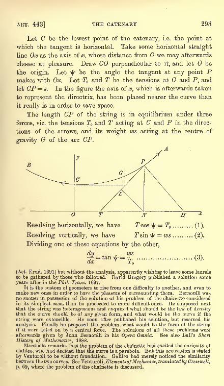
ART. 443] THE CATENARY 293
Let C be the lowest point of the catenary, i.e. the point at
which the tangent is horizontal. Take some horizontal straight
line Ox as the axis of x, whose distance from C we may afterwards
choose at pleasure. Draw GO perpendicular to it, and let be
the origin. Leti/r
be the angle the tangent at any point Pmakes with Ox. Let T and T be the tensions at C and P, and
let CP s. In the figure the axis of x, which is afterwards taken
to represent the directrix, has been placed nearer the curve than
it really is in order to save space.
The length CP of the string is in equilibrium under three
forces, viz. the tensions T and T acting at C and P in the direc-
tions of the arrows, and its weight ws acting at the centre of
gravity G of the arc CP.
A.-4
yB
O T N HResolving horizontally, we have T cos ty
= T ......... (1).
Resolving vertically, we have T sin ty= ws ......... (2).
Dividing one of these equations by the other,
(Act. Erud. 1691) but without the analysis, apparently wishing to leave some laurels
to be gathered by those who followed. David Gregory published a solution someyears after in the Phil. Trans. 1697.
It is the custom of geometers to rise from one difficulty to another, and even to
make new ones in order to have the pleasure of surmounting them. Bernoulli wasno sooner in possession of the solution of his problem of the chainette consideredin its simplest case, than he proceeded to more difficult ones. He supposed nextthat the string was heterogeneous and enquired what should be the law of densitythat the curve should be of any given form, and what would be the curve if the
string were extensible. He soon after published his solution, but reserved his
analysis. Finally he proposed the problem, what would be the form of the stringif it were acted on by a central force. The solutions of all these problems wereafterwards given by John Bernoulli in his Opera Omnia. See also Ball's Short
History of Mathematics, 1888.
Montucla remarks that the problem of the chainette had excited the curiosity of
Galileo, who had decided that the curve is a parabola. But this accusation is stated
by Venturoli to be without foundation. Galileo had merely noticed the similaritybetween the two curves. See Venturoli, Elements ofMechanics, translated by Cresswell,
p. 69, where the problem of the chainette is discussed.
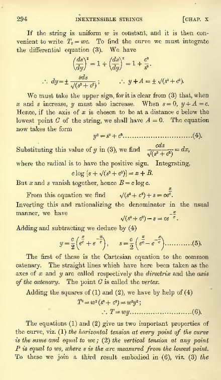
294 INEXTENSIBLE STRINGS [CHAP. X
If the string is uniform w is constant, and it is then con-
venient to write T = we. To find the curve we must integrate
the differential equation (3). We have
>
rdy) \dy
We must take the upper sign, for it is clear from (3) that, when
x and s increase, y must also increase. When s = 0, y + A = c.
Hence, if the axis of x is chosen to be at a distance c below the
lowest point C of the string, we shall have A = 0. The equation
now takes the form2 2 i r1 ( A.\
cdsSubstituting this value of y in (3), we find .,
2.= dx,
where the radical is to have the positive sign. Integrating,
c log Is + VO2 + c2
)}= x + B.
But x and s vanish together, hence B = c log c.
From this equation we find VC*2 + c
2) + s = cec .
Inverting this and rationalizing the denominator in the usual
manner, we have --
VO2 + c2)- s = ce
c.
Adding and subtracting we deduce by (4)
y =
The first of these is the Cartesian equation to the common
catenary. The straight lines which have here been taken as the
axes of x and y are called respectively the directrix and the axis
of the catenary. The point C is called the vertex.
Adding the squares of (1) and (2), we have by help of (4)
T* = w2(s
2-f c2)
= wzy
2;
.'.T=wy (6).
The equations (1) and (2) give us two important properties of
the curve, viz. (1) the horizontal tension at every point of the curve
is the same and equal to we ; (2) the vertical tension at any pointP is equal to ws, where s is the arc measured from the lowest point.
To these we join a third result embodied in (6), viz. (3) the
ART. 446] THE CATENARY 295
resultant tension at any point is equal to wy, where y is the ordinate
measuredfrom the directrix.
444. Referring to the figure, let PN be the ordinate of P,
then T=w.PN. Draw NL perpendicular to the tangent at P,
then the angle PNL = i/r.Hence
os^ = cby (1).
These two geometrical properties of the curve may also be
deduced from its Cartesian equation (5). By differentiating (3)
& A * dty 1 c .^.wefind rrj =- .'.p= rr ............ (?)cos^ ds c cos2
i/r
We easily deduce from the right-angled triangle PNH, that
the length of the normal, viz. PH, between the curve and the
directrix is equal to the radius of curvature, viz. p, at P.
It will be noticed that these equations contain only one
undetermined constant, viz. c;and when this is given the form of
the curve is absolutely determined. Its position in space dependson the positions of the straight lines called its directrix and axis.
This constant c is called the parameter of the catenary. Two arcs
of catenaries which have their parameters equal are said to be
arcs of equal catenaries.
Since p cos2
ty= c, it is clear that c is large or small according
as the curve is flat or much curved near its vertex. Thus if the
string is suspended from two points A, B in the same horizontal
line, then c is very large or very small compared with the distance
between A and B according as the string is tight or loose.
The relations between the quantities y, s, c, p, $ and T in the common catenary
may be easily remembered by referring to the rectilineal figure PLNH. We have
PN= y, PL=s, NL=c, PH=p, T=w.PN and the angles LNP, NPH are each
equal to\f/.
Thus the important relations (1), (2), (3), (4), and (7) follow from the
ordinary properties of a right-angled triangle.
445. Since the three forces, viz., the tensions at A and B and the weight are in
equilibrium, it follows that their lines of action must meet in a point. Hence the
centre of gravity G of the arc must lie vertically over the intersection of the tangents
at the extremities of the arc. This is a statical proof of one part of the more general
theorem given in Art. 399, Ex. 1, where it is also proved that the vertical ordinate
of the centre of gravity is half that of the intersection of the normals at the extremi-
ties of the arc.
446. Ex. 1. Show that it is impossible to pull a heavy string by forces at its
extremities so as to make it quite straight unless the string is vertical.
296 INEXTENSIBLE STRINGS [CHAP. X
If it be straight let\f/
be the inclination to the horizon, W its weight. Then,
resolving perpendicularly to its length, Wcos\f/ = 0, which gives -fy equal to a right
angle. This proof does not require the string to be uniform.
Ex. 2. If a string be suspended from any two points A and B not in the same
vertical, and be nearly straight, show that c is very large.
Let\f/, \j/'
be the inclinations at A and B, and I the length of the string. Then
l=s s'=c (tan \f/tan
\}/').Since
\f/and
\}/'are nearly equal, c is large compared
with L
Ex. 3. A heavy uniform string AB of length I is suspended from a fixed point
A, while the other extremity B is pulled horizontally by a given force F= wa. Show
that the horizontal and vertical distances between A and B are a log-^
a
and >J(P + a2)- a respectively.
Ex. 4. The extremities A and B of a heavy string of length 21 are attached
to two small rings which can slide on a fixed horizontal wire. Each of these rings
is acted on by a horizontal force F wl. Show that the distance apart of the rings
Ex. 5. If the inclination\f/
of the tangent at any point P of the catenary is
taken as the independent variable, prove that
fir ib\ c cx=c log tan I T + I
, y=--, s= ct&n\J/, p= .
\4 2 J cos ^ cos 2
^If x, y be the coordinates of the centre of gravity of the arc measured from the
vertex up to the point P, prove also that x= x - c tan -, w=x 1
-- + x cot \b] .
2 2 \cos^r
J
447. If the position in space of the points A and B of suspension and the
length of the string or chain are given, we may obtain sufficient equations to find
the parameter c of the catenary, and the positions in space of its directrix and axis.
Let the given point A be taken as an origin of coordinates, and let the axes be
horizontal and vertical. Let (h, k) be the coordinates of B referred to A,and let I
be the length of the string AB. These three quantities are therefore given. Let
(x, y), (x + h, y + k) be the coordinates of A, B referred to the directrix and axis of
the catenary. Then x, y, c are the three quantities to be found. By Art. 443
x_ x^x+ti x+h
y =c
-(et+e~'), y + k = C
-(e + e~ <)
............... (A).
Also by Art. 443, since I is the algebraic difference of the arcs CA, CB,
x+h x+h x _x_
!! -~)-i<
7-~') ........................ (B).
If C lie between A and B, x will be negative.
These three equations are sufficient to determine x, y and c. They cannot
however be solved in finite terms. We may eliminate
x, y in the following manner.
x h
Writing u=ee,v = ee , we find from (A) and (B)
(C).
ART. 448] THE CATENARY 297
We notice that v contains only c and the known quantity h. Hence, subtracting
the squares of these equations in order to eliminate u, we find
h _hJ(P-tf)= c(e
2c -e 2c) (D).
This agrees with the equation given by Poisson in his Traite de Mecanique.
The value of c has to be found from this equation. It gives two real finite
values of c, one positive and the other negative but numerically equal. A negative
value for c would make y negative and would therefore correspond to a catenary
with its concavity downwards. It is therefore clear that the positive value of c is to
be taken.
To analyse the equation (D), we let c = 1/7, and arrange the terms of the equation
in the form z = emv -e~mv -ay= (E),
so that a and m are both positive. We have a2=P-fc2, and 2m= h. Since the
length I of the string must be longer than the straight line joining the points of
suspension, it is clear that a must be greater than 2m. By differentiation,
^=m (emy + e-mi)-a.
dy
Thus dz/dy is negative when 7= 0, so that, as 7 increases from zero, z is at first
zero, then becomes negative and finally becomes positive for large values of 7.
There is therefore some one value of 7, say y=i, at which 2=0. If there could
be another, say y= i', then dz[dy must vanish twice, once between 7=0 and
y=i, and again between y=i and y= i'. We shall now show that this is impossible.
By differentiating twice we have
fJ2f**,* (-*-,->).
thus d^zjdy2 is positive when 7 is greater than zero. Hence dzjdy continually in-
creases with 7 from its initial value 2m -a when 7=0. It therefore cannot vanish
twice when 7 is positive. It appears from this reasoning that the equation gives
only one positive value of c.
The solitary positive value of c having been found from (D), we can form a
simple equation to find u by adding one of the equations (C) to the other. In this
way we find one real value of x. The value of y is then found from the first of the
equations (A). Thus it appears that, when a uniform string is suspended from two
fixed points of support, there is only one position of equilibrium.
The equation (D) can be solved by approximation when h/c is so small that wecan expand the exponentials and retain only the first powers of hjc which do not
disappear of themselves. This occurs when c is large, i.e. when the string is nearly
tight. In such cases, however, it will be found more convenient to resume the
problem from the beginning rather than to quote the equations (D) or (E).
448. Ex. 1. A uniform string of length I is suspended from two points A and
B in the same horizontal line, whose distance apart is h. If h and I are nearly
equal, find the parameter of the catenary.
Referring to the figure of Art. 443, we see that s = \l, x= \h. Hence using one
h_ _h_of the equations (5) of that article, we have l=c (e
2c - e 2c).
Whatever the given values of h and I may be, the value of c must be found from
this equation. When h and I are nearly equal, we know by Art. 446, Ex. 2, that hjc
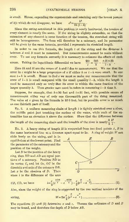
298 INEXTENSIBLE STRINGS [CHAP. X
is small. Hence, expanding the exponentials and retaining only the lowest powersh3
of hjc which do not disappear, we have c3= .
^4 I i ft}
Since the string considered in this problem is nearly horizontal, the tension of
every element is nearly the same. If the string be slightly extensible, so that the
extension of any element is some function of the tension, the stretched string will
still be homogeneous. The form will therefore be a catenary, and its parameterwill be given by the same formula, provided I represents its stretched length.
In order to use this formula, the length I of the string and the distance h
between A and B must be measured. But measurements cannot be made without
error. To use any formula correctly it is necessary to estimate the effects of such
. . 23c 3Sh dl5herrors. Taking the logarithmic differential we have = -r--- .
c h I h
Here 5ft and dl are the errors of h and I due to measurement. We see that the
error in c might be a large proportion of c if either h or I - h were small. In our
case I - h is small. Hence to find c we must so make our measurements that the
error of I - h is small compared with the small quantity I - h, while the length h
need be measured only so truly that its error is within the same fraction of the
larger quantity h. Thus greater care must be taken in measuring I- h than h.
Suppose, for example, that h= 30 feet and 1= 31 feet, with possible errors of
measurement either way of only one thousandth part of the thing measured.
The value of c given by the formula is 33*5 feet, but its possible error is as muchas one thirtieth part of itself.
Ex. 2. A uniform measuring chain of length I is tightly stretched over a river,
the middle point just touching the surface of the water, while each of the ex-
tremities has an elevation k above the surface. Show that the difference between
8 fc2
the length of the measuring chain and the breadth of the river is nearly ^ -y.
> f
Ex. 3. A heavy string of length 21 is suspended from two fixed points A, B in
the same horizontal line at a distance apart equal to 2a. A ring of weight W can
slide freely on the string, and is in
equilibrium at the lowest point. Find _the parameter of the catenary and the
position of the weight.
Let D be the position of the heavy
ring, then BD and AD are equal por-
tions of a catenary. Produce BD to
its vertex C, and let Ox, OC be the
directrix and axis of the catenary DB.
Let x be the abscissa of D. Then
since I is the difference of the arcs
x+a x+a x_ _x_
CB, CD, we have *=H(C -
~c )-( c - c
) ........................ (*)2 4
Also, since the weight of the ring is supported by the two vertical tensions of the
fi _a;
string, W=2w C-(e
c -e c) ................................. (2).
The equations (1) and (2) determine x and c. Thence the ordinates of D and B
may be found, and therefore the depth of D below AB.
ART. 448] EXAMPLES ON THE CATENARY 299
If the weight of the ring is much greater than the weight of the string, each
string is nearly tight. Thus ajc is small, but x\c is not necessarily small, for the
vertex C may be at a considerable distance from D. If we expand the terms con-
taining the exponent ajc and eliminate those containing x/c, we find
c=Waj2w^(l?-a?) nearly.
The contrary holds if the weight of the ring is much smaller than the weight of
the string. If W were zero the two catenaries BD and DA would be continuous,
and the vertex would be at D. Hence when W is very small, the vertex will be
near D and therefore xja will be small. But a/c is not necessarily small. Ex-
panding the terms with small exponentials, we find from (2) that x W/2w. Then
(1) gives l=^(e
c -e )+ {4(ee +e ')-!}.
If the weight W were absent this equation would reduce to the one already dis-
cussed above. If y be the change produced in the value of c there found by adding
the weight W, we find, by writing c + y for c in the first term on the right-hand side,
that (1- ) 7 + s (ft-
c)= 0, where k is the ordinate of B before the addition of W.
\ c J'
2tt>v
If the weight W had been attached to any point D of the string not its middle
point, AD, BD would still form catenaries, whose positions could be found in a
similar manner. We may notice that, however different the two strings may appearto be, the catenaries have equal parameters. For consider the equilibrium of the
weight W ; we see .by resolving horizontally that the we of each catenary must be
the same.
If the string be passed through a fine smooth ring fixed in space through which
it could slide freely, the two strings on each side must have their tensions equal.
Hence the two catenaries have the same directrix. The parameters are not neces-
sarily equal, for the difference between the horizontal tensions of the two catenaries
is equal to the horizontal pressure on the ring, which need not be zero.
Ex. 4. A heavy string of length I is suspended from two points A, A' in the
same horizontal line, and passes through a smooth ring D fixed in space. If DNbe a perpendicular from D on AA' and NA = h, NA'= h', DN= k, prove that the
parameters c, c' may be obtained from
4c2= P \cosh cosech( ^- + ^~.}[ - fc
2(cosech 5- ) ,
|2c \2c 2c J\ \ 2cJ
and a similar equation with the accented and unaccented letters interchanged.
Ex. 5. A portion AC of a uniform heavy chain rests extended in the form of a
straight line on a rough horizontal plane, while the other portion GB hangs in the
form of a catenary from a given point B above the plane. The whole chain is on
the point of motion towards the vertical through B. If I be the length of the whole
chain and h be the altitude of B above the plane, show that the parameter c of the
catenary is equal to p. (l + nh)-fj.J{(u? + l)h2 + 2fj.hl}.
Ex. 6. A heavy string hangs over two small smooth fixed pegs. The two ends
of the string are free, and the central portion hangs in a catenary. Show that the
free ends are on the directrix of the catenary. If the two pegs are on the same level
and distant 2 apart, show that equilibrium is impossible unless the length of
the string is equal to or greater than 2ae. [Coll. Exam.]
Ex. 7. A heavy uniform chain is suspended from two fixed points A and B in
the same horizontal line, and the tangent at A makes an angle 45 with the horizon.
300 INEXTENSIBLE STRINGS [CHAP. X
Prove that the depth of the lowest point of the chain below AB is to the length of
the chain as ^(2) - 1 : 2.
Ex. 8. A uniform heavy chain is fastened at its extremities to two rings of
equal weight, which slide on smooth rods intersecting in a vertical plane, and
inclined at the same angle a to the vertical : find the condition that the tension at
the lowest point may be equal to half the weight of the chain; and, in that case,
show that the vertical distance of the rings from the point of intersection of the rods
is I cot a log (^2 + 1), where 21 is the length of the chain. [Math. Tripos, 1856.]
Ex. 9. A heavy string of uniform density and thickness is suspended from two
given points in the same horizontal plane. A weight, an nth that of the string, is
attached to its lowest point ; show that, if 6, <p be the inclinations to the vertical of
the tangents at the highest and lowest points of the string, tan<j>=
(1 + n) tan 9.
[Math. Tripos, 1858.]
Ex. 10. If o, /3 be the angles which a string of length I makes with the vertical
at the points of support, show that the height of one point above the other is
I cos \ (a. + ft) /cos \ (a-
/3). [Pet. Coll. , 1855.]
Ex. 11. A heavy endless string passes over two small smooth fixed pegs in the
same horizontal line, and a small smooth ring without weight binds together the
upper and lower portions of the string : prove that the ratio of the cosines of the
angles which the portions of the string at either peg make with the horizon, is equal
to that of the tangents of the angles which the portions of the string at the ring
make with the vertical. [Math. Tripos, 1872.]
Ex. 12. A and B are two smooth pegs in the same horizontal line, and C is a
third smooth peg vertically below the middle point of AB ;an endless string hangs
upon them forming three catenaries AB, BC, and CA : it the lowest point of the
catenary AB coincides with C, prove that the pegs AB divide the whole string into
two parts in the ratio of 2w + w' to 2w-w', where w and w' are the vertical com-
ponents of the pressures on A and C respectively. [Math. Tripos, 1870.]
Ex. 13. An endless uniform chain is hung over two small smooth pegs in the
same horizontal line. Show that, when it is in a position of equilibrium, the ratio of
the distance between the vertices of the two catenaries to half the length of the
chain is the tangent of half the angle of inclination of the portions near the pegs.
[Math. Tripos, 1855.]
Ex. 14. A heavy uniform string of length 4i passes through two small smooth
rings resting on a fixed horizontal bar. Prove that, if one of the rings be kept
stationary, the other being held at any other point of the bar, the locus of the
position of equilibrium of that end of the string which is the further from the
stationary ring may be represented by the equation z= 2v/(fy) log-
. [Coll. Ex.]
Ex. 15. A heavy uniform string is suspended from two points A and B in the
same horizontal line, and to any point P of the string a heavy particle is attached.
Prove that the two portions of the string are parts of equal Catenaries.
Prove also that the portion of the tangent at^ intercepted between the verticals
through P and the centre of gravity of the string is divided by the tangent at B in
a ratio independent of the position of P.
If 0, <f>be the angles the tangents at P make with the horizon, a and /3 those
made by the tangents at A and B, show that f is constant for all posi-tan a+ tan/3
tions of P. [St John's Coll.]
ART. 448] EXAMPLES ON THE CATENARY 301
Ex. 16. A heavy uniform string hangs over two smooth pegs in the same
horizontal line. If the length of each portion which hangs freely be equal to
the length between the pegs, prove that the whole length of the string is to the
distance between the pegs as J(3) to log V(3). Compare also the pressures on
each peg with the weight of the string.
Ex. 17. A uniform endless string of length I is placed symmetrically over a
smooth cube which is fixed with one diagonal vertical. Prove that the string will
slip over the cube unless the side of the cube is greater than |Z^/21og(l + v/2).
[Emm. Coll., 1891.]
Ex. 18. An endless inextensible string hangs in two festoons over two small
pegs in the same horizontal line. Prove that, if be the inclination to the vertical
of one branch of the string at its highest point, the inclination of the other branch
at the same point must be either 6 or<j>,
where < has only one value and is a function
of only. If cot \9 = sec e, then tj>
= 6. [Coll. Ex. ]
Ex. 19. Four smooth pegs are placed in a vertical plane so as to form a square,
the diagonals being one vertical and one horizontal. Round the pegs an endless
chain is passed so as to pass over the three upper and under the lower one. If the
directions of the strings make with the vertical angles equal to a at the upper
peg, /S and 7 at each of the middle and 5 at the lower peg, prove the following
relations : sin ft log cot ^a tan J/3= sin 7 log cot 7 tan 5,
sin /3 sin S + sin a sin 7= 2 sin a sin 5. [Caius Coll.]
Ex. 20. A bar of length 2a has its ends fastened to those of a heavy string of
length 21, by which it is hung symmetrically over a peg. The weight of the bar is n
times, and the horizontal tension \m times the weight of the string. Show that
m2+ n2=j(n
+ l) cosech ,-n coth 1 . [Coll. Ex., 1889.]
Ex. 21. One end of a heavy chain is attached to the extremity of a fixed rod,
the other end is fastened to a small smooth ring which slides on the rod : prove that
in the position of equilibrium log {cot \Q cot (\ir-\$)\ =cot (sec ^-cosec 6),
& being the inclination of the rod to the horizon, andif/
that of the chain at its
highest point. [Coll. Ex.]
Ex. 22. A string of length ira is fastened to two points at a distance apart equal
to 2a, and is repelled by a force perpendicular to the line joining the points and
varying inversely as the square of the distance from it. Show that the form of the
string is a semi-circle. [Coll. Ex. , 1882.]
Ex. 23. A chain, of length 21 and weight 2W, hangs with one end A attached to
a fixed point in a smooth horizontal wire, and the other end B attached to a smooth
ring which slides along the wire. Initially A and B are together. Show that the
work done in drawing the ring along the wire till the chain at A is inclined at an
angle of 45 to the vertical is Wl (1- ^2 + log l+>/2). [Coll. Ex., 1883.]
Ex. 24. Determine if the catenary is the only curve such that, if AB be any arc
whose centre of gravity is G, and AT, BT tangents at A and B, then GT is always
parallel to a fixed line in space.
Ex. 25. A uniform heavy chain of length 2a is suspended from two points
in the same horizontal line ; if one of these points be moveable, find the equation
of the locus of the vertex of the catenary formed by the string; and show that
the area cut off from this locus by a horizontal line through the fixed point is
ja2 ^* _
4). [Math. Tripos, 1867.]
302 INEXTENSIBLE STRINGS [CHAP. X
449. Stability of equilibrium. Some problems on the equilibrium of heavy
strings may be conveniently solved by using the principle that the depth of the
centre of gravity below some fixed straight line is a maximum or minimum, Art.
218. If the curve of the string be varied from its form as a catenary, the use of this
principle will require the calculus of variations. But if we restrict the arbitrary
displacements to be such that the string retains its form as a catenary, though the
parameter c may be varied, the problem may be solved by the ordinary processes of
the differential calculus.
This method presents some advantages when we desire to know whether the
equilibrium is stable or not. We know, by Art. 218, that the equilibrium will be
stable or unstable according as the depth of the centre of gravity below some fixedhorizontal plane is a true maximum or minimum.
Ex. 1. A string of length 21 hangs over two smooth pegs which are in the same
horizontal plane and at a distance 2a apart. The two ends of the string are free, and
its central portion hangs in a catenary. Show that equilibrium is impossible unless
I be at least equal to ae;and that, if I > ae, the catenary in the position of stable
a
equilibrium for symmetrical displacements will be defined by that root of ve c = l
which is greater than a. [Math. Tripos, 1878.]
Let 2s be the length of the string between the pegs. Taking the horizontal
line joining the pegs for the axis of x, we easily find (Art. 399) that the depth y of
the centre of gravity of the catenary and the two parts hanging over the pegs is
given by 2ly= sy- ca + (I
-s)
2.
Substituting for y and s their values in terms of c, we find
dy=( c _ l\
dc \ p)
where p stands for efi. It is easy to see that the second factor on the right-hand side
is negative for all positive values of c. Equating dy/dc to zero, we find that the
possible positions of equilibrium are given by l= cp. To find the least value of I
given by this equation we put dljdc= ; this gives c = a, so that I must be equal to
or greater than ae.
For any value of I greater than ae there are two possible values of c, one greater
and the other less than a. To determine which of these two catenaries is stable, we
examine the sign of the second differential coefficient, Art. 220. We easily find,
n ,d?y . p2(c-a)- (c + a)when I= cp, 2l~ = (c- a)---^-=
.
ac2 c2
In order that the equilibrium may be stable, this expression must be negative.
This requires that c should be greater than a.
Ex. 2. A heavy string of given length has one extremity attached to a fixed
point A, and hangs over a small smooth peg B on the same level with A, the other
extremity of the string being free. Show that, if the length of the string exceed
a certain value, there are two positions of equilibrium, and that the one in which
the catenary has the greater parameter is stable.
450. Heterogeneous chain. A heavy heterogeneous chain
is suspended from two given points A and B. Find the equation to
the catenary.
ART. 451] HETEROGENEOUS CATENARY 303
This problem may be solved in a manner similar to that used
in Art. 443 for a homogeneous chain. Since the equations (1)
and (2) of that article are obtained by simple resolutions, they
will be true with some slight modifications when the string is not
uniform. In our case the weight of the string measured from the
lowest point is fwds between the limits s = 0, s = s, Art. 442. Wehave therefore by the same resolutions
Tcos^=T ...... (1), Tsm^=fwds ...... (2).
Dividing one of these by the other as before, we find
... ..(3),p COS ir
substituting for p and tan ^r, their Cartesian values
Conversely, when the law of density is known, say w=f(s),the equation (3) gives a relation between s and dy\dx which we
may write in the form dyjdx =fl (s). We easily deduce from this
s, y - + ! *-
i s>
whence x and y can be expressed in terms of an auxiliary variable
which has a geometrical meaning.
Ex. 1. Prove that the tension at any point P of the heterogeneous catenary is
equal to the weight of a uniform chain whose length is the projection of the radius
of curvature on the vertical and whose density is the same as that of the catenary
at P.
Ex. 2. A straight line BE is drawn through any fixed point B in the axis of y
parallel to the normal at P to the curve, cutting the axis of x in R. Prove that
(1) the tension at P is (T /c) times the length BR and (2) the weight of the arc OP,measured from the lowest point 0, is (TJc) times the length OR, where OB=c and
T is the horizontal tension ; Art. 35.
451. Cycloidal chain. A heterogeneous chain hangs in the form of a cycloid
under the action of gravity : find the law of density. ,
In a cycloid we have p= 4 cos\f/and s= 4a sin
\j/,where a is the radius of the
rolling circle. Substituting, we find w = -^ sec3 \b=-9.
-
It appears from this result that all the lower part of the chain is of nearly
uniform density ;thus the density at a point whose distance from the vertex
measured along the arc is equal to the radius of the rolling circle is about ten
ninths of the density at the vertex. The density increases rapidly higher up the
chain and is infinite at the cusp. If then the chain when suspended from two
points in the same horizontal line is not very curved, the chain may be regarded as
nearly uniform.
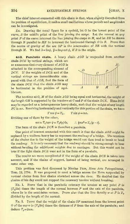
304 INEXTENSIBLE STRINGS [CHAP, x
The chief interest connected with this chain is that, when slightly disturbed from
its position of equilibrium, it makes small oscillations whose periods and amplitudes
can be investigated.
Ex. Drawing the usual figure for a cycloid, let be the lowest point of the
curve, B the middle point of the line joining the cusps. Let the normal at any
point P of the curve intersect the line joining the cusps in M, and let BR be drawn
through B parallel to HP to intersect the horizontal through in R. Prove that
the centre of gravity of the arc OP is the intersection of BR with the vertical
through M. We find x=2a\f/, y = 2a\j/cot \f/,if B is the origin.
462. Parabolic chain. A heavy chain AOB is suspended from another
chain DCE by vertical strings, which are
so numerous that every element of AOB is
attached to the corresponding element of
DCE. If the weights of DCE and of the
vertical strings are inconsiderable com-
pared with that of AOB, find the form of
the chain DCE that the chain AOB maybe horizontal in the position of equi-
librium.
The tensions at 0, M of the chain AOB being equal and horizontal, the weight of
the length OM is supported by the tensions at C and P of the chain DCE. Thus DCEmay be regarded as a heterogeneous heavy chain, such that the weight of any lengthPC is mx. Kesolving horizontally and vertically for this portion of the chain, we have
M
Dividing one of these by the other,
mx= T tan ^= T dyjdx, .: %mx2=T (y-c).
The form of the chain DCE is therefore a parabola.
One point of interest connected with this result is that the chain AOB might be
replaced by a uniform heavy bar to represent the roadway of a bridge. The tensions
of the chains due to the weight of the bridge would not then tend to break or bend
the roadway. It is only necessary that the roadway should be strong enough to bear
without bending the additional weights due to carriages. But this would not be
true if the light chain DCE were not in the form of a parabola.
The results are more complicated if the weight of the chain DCE is taken into
account, and if the chains of support, instead of being vertical, are arranged in
some other way.
This problem was first discussed by Nicolas Fuss, Nova Acta Petropolitance,
Tom. 12, 1794. It was proposed to erect a bridge across the Neva suspended byvertical chains from four chains stretched across the river. He decided that the
chains of his day could not support the necessary tension without breaking.
Ex. 1. Prove that in the parabolic catenary the tension at any point P is
(T /2o) times the length of the normal between P and the axis of the parabola,
where 2a is the semi-latus rectum. Prove also that the line density w at P is Tdivided by the length of the normal.
Ex. 2. Prove that the weight of the chain OP measured from the lowest pointO of the curve is (T /2a) times the distance of P from the axis of the parabola; and
deduce Tn=2am.
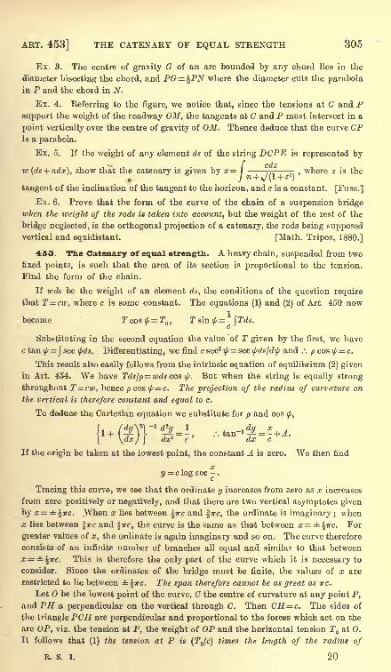
ART. 453] THE CATENARY OF EQUAL STRENGTH 305
Ex. 3. The centre of gravity G of an arc bounded by any chord lies in the
diameter bisecting the chord, and PG=^PN where the diameter cuts the parabola
in P and the chord in N.
Ex. 4. Referring to the figure, we notice that, since the tensions at C and Psupport the weight of the roadway OM, the tangents at C and P must intersect in a
point vertically over the centre of gravity of OM. Thence deduce that the curve CPis a parabola.
Ex. 5. If the weight of any element ds of the string DOPE is represented by
w (ds + ndx), show that the catenary is given by x= \ 77- ,where z is the
. J n+ *J(L+Z'')
tangent of the inclination of the tangent to the horizon, and c is a constant. [Fuss.]
Ex. 6. Prove that the form of the curve of the chain of a suspension bridgewhen the weight of the rods is taken into account, but the weight of the rest of the
bridge neglected, is the orthogonal projection of a catenary, the rods being supposedvertical and equidistant. [Math. Tripos, 1880.]
453. The Catenary of equal strength. A heavy chain, suspended from two
fixed points, is such that the area of its section is proportional to the tension.
Find the form of the chain.
If wds be the weight of an element ds, the conditions of the question require
that T=cw, where c is some constant. The equations (1) and (2) of Art. 450 now1
become Tcos^=T ,T sin ^= -
\ Tds.c
Substituting in the second equation the value of T given by the first, we have
c tan -fy= Jsec \f/ds. Differentiating, we find c sec2 ^=sec \j/dsjd\f/ and .'. p cos \[/=c.
This result also easily follows from the intrinsic equation of equilibrium (2) given
in Art. 454. We have Tdsjp= wds cos\f/.
But when the string is equally strong
throughout T=cw, hence pcos^= c. The projection of the radius of curvature on
the vertical is therefore constant and equal to c.
To deduce the Cartesian equation we substitute for p and cos\j/,
j /dy\2l-1
d*y _ 1
\ \dxj jdx*
~c
'
If the origin be taken at the lowest point, the constant A is zero. We then find
xy = c log sec - .
Tracing this curve, we see that the ordinate y increases from zero as x increases
from zero positively or negatively, and that there are two vertical asymptotes given
by x= J?rc. When x lies between \wc and |TTC, the ordinate is imaginary ; whenx lies between %irc and |TTC, the curve is the same as that between x irc. For
greater values of x, the ordinate is again imaginary and so on. The curve therefore
consists of an infinite number of branches all equal and similar to that between
x = ^TTC. This is therefore the only part of the curve which it is necessary to
consider. Since the ordinates of the bridge must be finite, the values of x are
restricted to lie between ^TTC. The span therefore cannot be as great as ire.
Let be the lowest point of the curve, C the centre of curvature at any point P,
and PH a perpendicular on the vertical through C. Then CH=c. The sides of
the triangle PCH are perpendicular and proportional to the forces which act on the
arc OP, viz. the tension at P, the weight of OP and the horizontal tension T at 0.
It follows that (1) the tension at P is (T /c) times the length of the radius of
R. 8. I. 20
-i_ Adx c
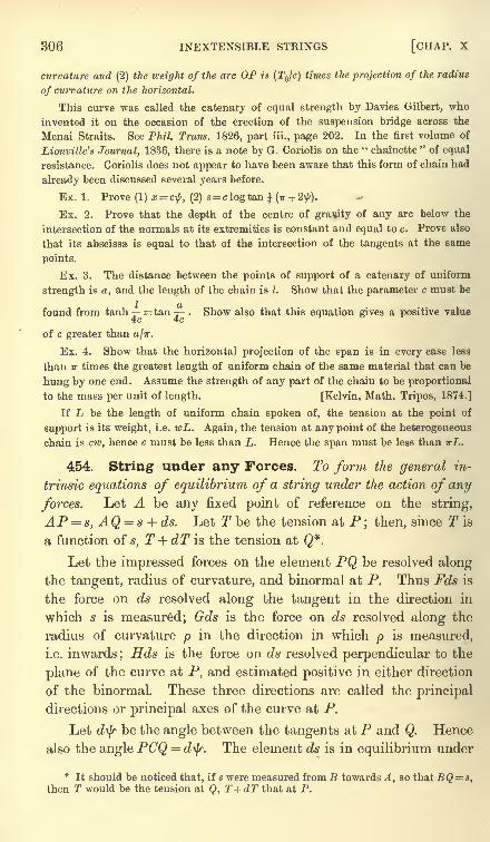
306 INEXTENSIBLE STRINGS [CHAP. X
curvature and (2) the weight of the arc OP is (TJc) times the projection of the radius
of curvature on the horizontal,
This curve was called the catenary of equal strength by Davies Gilbert, who
invented it on the occasion of the erection of the suspension bridge across the
Menai Straits. See Phil. Trans. 1826, part iii., page 202. In the first volume of
Liouville's Journal, 1836, there is a note by G. Coriolis on the " chainette"of equal
resistance. Coriolis does not appear to have been aware that this form of chain had
already been discussed several years before.
Ex. 1. Prove (1) x = c$, (2) *= clogtan \ (ir + 2\{<).
Ex. 2. Prove that the depth of the centre of gravity of any arc below the
intersection of the normals at its extremities is constant and equal to c. Prove also
that its abscissa is equal to that of the intersection of the tangents at the same
points.
Ex. 3. The distance between the points of support of a catenary of uniform
strength is a, and the length of the chain is I. Show that the parameter c must be
found from tanh = tan . Show also that this equation gives a positive value
of c greater than a/ir.
Ex. 4. Show that the horizontal projection of the span is in every case less
than TT times the greatest length of uniform chain of the same material that can be
hung by one end. Assume the strength of any part of the chain to be proportional
to the mass per unit of length. [Kelvin, Math. Tripos, 1874.]
If Z> be the length of uniform chain spoken of, the tension at the point of
support is its weight, i.e. wL. Again, the tension at any point of the heterogeneous
chain is cw, hence c must be less than L. Hence the span must be less than wL.
454. String under any Forces. To form the general in-
trinsic equations of equilibrium of a string under the action of any
forces. Let A be any fixed point of reference on the string,
AP =s, AQ = s + ds. Let T be the tension at P
; then, since T is
a function of s, T + dT is the tension at Q*.
Let the impressed forces on the element PQ be resolved alongthe tangent, radius of curvature, and binormal at P. Thus Fds is
the force on ds resolved along the tangent in the direction in
which s is measured; Gds is the force on ds resolved along the
radius of curvature p in the direction in which p is measured,
i.e. inwards; Hds is the force on ds resolved perpendicular to the
plane of the curve at P, and estimated positive in either direction
of the binormal. These three directions are called the principal
directions or principal axes of the curve at P.
Let d\}r be the angle between the tangents at P and Q. Hence
also the angle PCQ =d^r. The element ds is in equilibrium under
*It should be noticed that, if s were measured from B towards A, so that BQ = s,
then T would be the tension at Q, T + dT that at P.
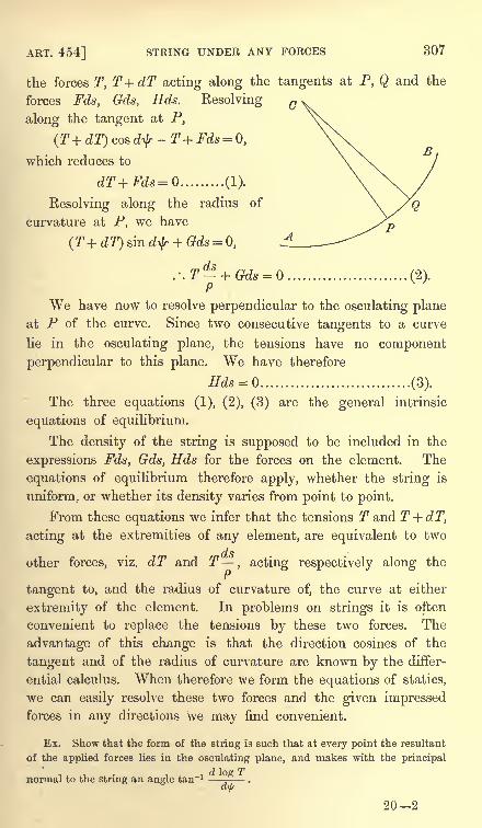
ART. 454] STRING UNDER ANY FORCES 307
the forces T, T+dT acting along the tangents at P, Q and the
forces Fds, Gds, Eds. Resolving
along the tangent at P,
(T+ dT) cos d^-T+Fds = 0,
which reduces to
dT+Fds=0 (1).
Resolving along the radius of
curvature at P, we have
dsT 4- ftdv (9\1
pH
We have now to resolve perpendicular to the osculating planeat P of the curve. Since two consecutive tangents to a curve
lie in the osculating plane, the tensions have no component
perpendicular to this plane. We have therefore
Hds = Q (3).
The three equations (1), (2), (3) are the general intrinsic
equations of equilibrium.
The density of the string is supposed to be included in the
expressions Fds, Gds, Hds for the forces on the element. The
equations of equilibrium therefore apply, whether the string is
uniform, or whether its density varies from point to point.
From these equations we infer that the tensions T and T+dT,acting at the extremities of any element, are equivalent to two
dsother forces, viz. dT and T
, acting respectively along the
tangent to, and the radius of curvature of, the curve at either
extremity of the element. In problems on strings it is often
convenient to replace the tensions by these two forces. The
advantage of this change is that the direction cosines of the
tangent and of the radius of curvature are known by the differ-
ential calculus. When therefore we form the equations of statics,
we can easily resolve these two forces and the given impressedforces in any directions we may find convenient.
Ex. Show that the form of the string is such that at every point the resultant
of the applied forces lies in the osculating plane, and makes with the principal
normal to the string an angle tan"1.
202
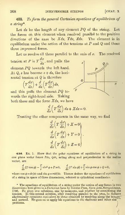
308 INEXTENSIBLE STRINGS [CHAP, x
455. To form the general Cartesian equations of' equilibrium of
a string*.
Let ds be the length of any element PQ of the string. Let
the forces on this element when resolved parallel to the positive
directions of the axes be Xds, Yds, Zds. The element is in
equilibrium under the action of the tensions at P and Q and these
three impressed forces.
Let us resolve all these parallel to the axis of x. The resolved
doctension at P is T -r ,
and pulls the
element PQ towards the left hand.
At Q, s has become s + ds, the hori-
zontal tension at Q is therefore
T{
ds) ds
and this pulls the element PQ to-
wards the right-hand side. Takingboth these and the force Xds, we have
d ( m dx\ 7 , _
-y- [T -y- ds + Xds = 0.ds\ ds)
Treating the other components in the same way, we find
ds
ds \ ds)
456. Ex. 1. Show that the polar equations of equilibrium of a string in
one plane under forces Pds, Qds, acting along and perpendicular to the radius
vector, are
T[(*)+!
r
where cos <p= drjds and sin <p
= rddjds. Thence deduce the equations of equilibrium
of a string in space of three dimensions, referred to cylindrical coordinates.
d T dT (Tcos<t>)
- -sin2</> + P= 0,
-(tS T CtS
* The equations of equilibrium of a string under the action of any forces in twodimensions were given in a Cartesian form by Nicolas Fuss, NovaActa Petropolitance,1796. He gives two solutions, one by moments, and another by considering the
tension. In this second solution, after resolving parallel to the axes, he deduces
algebraically equations equivalent to those obtained by resolving along the tangg^and normal. He goes on to apply his equations to the chainette and other sim
problems.
ART. 457] CONSTRAINED STRINGS 309
Ex. 2. A string is in equilibrium in the form of a helix, and the tension is
constant throughout the string. Show that the force on any element tends directly
from the axis of the helix.
Ex. 3. The extremities of a string of given length are attached to two given
points, and each element ds of the string is acted on by a repulsive force tending
directly from the axis of z and equal to 2/mZs. If (r0z) be the cylindrical coordinates
of any point, prove that T=A -/*r2
,
dOBdx -ja'
.,...--.- .. , 1.
Show how the five arbitrary constants are determined. Explain how a helix
is, in certain cases, the solution.
Ex. 4. A heavy chain is suspended from two points, and hangs partly immersed
in a fluid. Show that the curvatures of the portions just inside and just outside
the surface of the fluid are as D-D' to D, where D and D' are the densities of the
chain and fluid. [St John's Coll.]
The weights of the elements just above and just below the surface of the fluid are
proportional to Dds and (D - D') ds. If T be the tension, the resolved parts of these
weights along the normal must be Tds/p and Tdsfp'. Hence D/(D -D') =p'/p.
Ex. 5. A heavy string is suspended from two fixed points A and B, and the
density is such that the form of the string is an equiangular spiral. Show that the
density at any point P is inversely proportional to r cosa\f/,
where r is the distance of
P from the pole, and\f/
is the angle which the tangent atP makes with the horizon.
[Trin. Coll., 1881.]
Ex. 6. A heavy string, which is not uniform, is suspended from two fixed points.
Prove that the catenary formed of a given uniform string which touches at any
point the curve in which the string hangs and has the same tension at that point
will be of invariable dimensions.
457. Constrained Strings. A string rests on a curve of
any form in one plane, and is acted on by forces at its extremities.
It is required to find the conditions of equilibrium and the tension
at any point.
There are four cases of this proposition which are of con-
siderable importance; we shall consider these in order.
Let us first suppose that the weight of the string is so slight
that it may be neglected compared with the forces applied at the
two extremities of the string. Let us also suppose that the curve
is perfectly smooth. The forces on an element ds are merely the
tensions at its ends and the reaction or pressure of the curve.
Let Rds be this pressure, then R is the pressure per unit of length
of the string. For the sake of brevity this is usually expressed by
saying that R is the pressure at the element. It is usual to
estimate the pressure of the curve on the string as positive when'
acts in the direction opposite to that in which the radius ofnon
urvature is measured.
310 INEXTENSIBLE STRINGS [CHAP. X
Resolving along the tangent and normal to the string, we have
rZ<?
by Art. 454, dT= 0, T - - Rds = 0.
We infer from these equations that, when a light string rests
on a smooth curve, the tension is constant, and the pressure at any
point varies as the curvature.
458. This theorem has a wider range than would perhaps appear at first sight.
Since the curve may be of any form, the result includes the case of a string in
equilibrium under any forces which are at every point normal to the curve.
Supposing the normal forces given, the form of the curve can be found from the
result just proved, viz. that at every point the curvature is proportional to the
normal force.
As an example we may consider Bernoulli's problem ; to find the form of a
rectangular sail, two opposite sides of which are fixed so as to be parallel to each
other and perpendicular to the direction of the wind. The weight of the sail is
neglected compared with the pressure produced by the wind. Let us enquire what
is the curve formed by a plane section of the sail drawn perpendicular to the fixed
sides.
Two answers may be given to this question according as the wind after acting on
the sail immediately finds an issue, or remains to press on the sail like a gas in
equilibrium. On the former hypothesis we assume as the law of resistance, that
the pressure of the wind on any element of the sail acts along the normal to the
element and is proportional to the square of the resolved velocity of the wind. Wehave therefore E=w cos2
\j/,where ^ is the angle the normal to the section of the sail
makes with the direction of the wind, and w is a constant. This gives c//>= cos2
\j/.
By Art. 444 we infer that the curve is a catenary, whose axis is in the direction of
the wind, and whose directrix is vertical.
If the air presses on the sail like a gas in equilibrium, the pressure on each side
of the sail is equal in all directions by the laws of hydrostatics, but the pressure is
greater on one side than on the other. We have therefore R equal to this constant
difference, hence also p is constant, and the required curve is a circle.
Ex. 1. A "square sail
" of a ship is fastened to the mast by two yard-arms, and
in such that when filled with wind every section by a horizontal plane is a straight
line parallel to the yards. Show that, assuming the ordinary law of resistance, it
will have the greatest effect in propelling the ship when 3 sin (a-
2<j>)- sin a = 0,
where a is the angle between the direction from which the wind comes and the ship's
keel, and<jt
is the angle between the yard and the ship's keel. [Caius Coll.]
Ex. 2. A light string has one end fixed at the vertex of a smooth cycloid ; prove
that as the string, while taut, is wound on the curve, the line of action of the
resultant pressure on the cycloid envelopes another cycloid of double parameter.
[Coll. Ex., 1890.]
[The resultant pressure of the curve on an arc of the string balances the tensions
at the extremities of the arc. It therefore passes through the intersection of the
tangents at those extremities and bisects the angle between them.]
459. Heavy smooth string. Let us next suppose that the
weight of the string cannot be neglected. Let wds be the weight
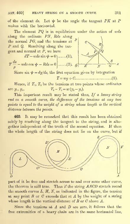
ART. 460] HEAVY STRING ON A SMOOTH CURVE 311
of the element ds. Let ty be the angle the tangent PK at Pmakes with the horizontal.
The element PQ is in equilibrium under the action of wds
along the ordinate PN, Rds along
the normal PG, and the tensions at
P and Q. Resolving along the tan-
gent and normal at P, we have
dT wds sin ar =
dsT wds cos -b Rds =
P
Since sin
(1),
...(2).
=dylds, the first equation gives by integration
T=wy + G (3).
Hence, if Tl} T2 be the tensions at two points whose ordinates
are ylt ya ,T2
- T, = w (ya-
y^.
This important result may be stated thus, If a heavy string
rest on a smooth curve, the difference of the tensions at any two
points is equal to the weight of a string whose length is the vertical
distance between the points.
460. It may be remarked that this result has been obtained
solely by resolving along the tangent to the string, and is alto-
gether independent of the truth of the second equation. If then
the whole length of the string does not lie on the curve, but if
part of it be free and stretch across to and over some other curve,
the theorem is still true. Thus if the string ABCD stretch round
the smooth curves L, M, N, as indicated in the figure, the tension
at any point B or G exceeds that at A by the weight of a string
whose length is the vertical distance of B or C above A.
Since the tensions at A and D are zero, it follows that the
free extremities of a heavy chain are in the same horizontal line.
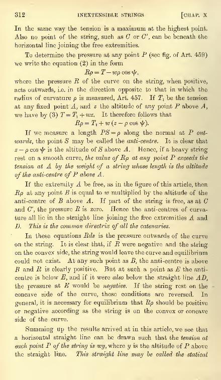
312 INEXTENSIBLE STRINGS [CHAP. X
In the same way the tension is a maximum at the highest point.
Also no point of the string, such as C or G', can be beneath the
horizontal line joining the free extremities.
To determine the pressure at any point P (see fig. of Art. 459)
we write the equation (2) in the form
Rp = T wp cos ty,
where the pressure R of the curve on the string, when positive,
acts outwards, i.e. in the direction opposite to that in which the
radius of curvature p is measured, Art. 457. If Tl be the tension
at any fixed point A, and z the altitude of any point P above A,
we have by (3) T=Tl + wz. It therefore follows that
Rp = T! + W (z p COS-\|r).
If we measure a length PS = p along the normal at P out-
wards, the point S may be called the anti-centre. It is clear that
z p cosT/T
is the altitude of S above A. Hence, if a heavy string
rest on a smooth curve, the value of Rp at any point P exceeds the
tension at A by the weight of a string whose length is the altitude
of the anti-centre ofP above A.
If the extremity A be free, as in the figure of this article, then
Rp at any point B is equal to w multiplied by the altitude of the
anti-centre of B above A. If part of the string is free, as at Gand C', the pressure R is zero. Hence the anti-centres of curva-
ture all lie in the straight line joining the free extremities A and
D. This is the common directrix of all the catenaries.
In these equations Rds is the pressure outwards of the curve
on the string. It is clear that, if R were negative and the string
on the convex side, the string would leave the curve and equilibrium
could not exist. At any such point as B, the anti-centre is above
B and R is clearly positive. But at such a point as E the anti-
centre is below E, and if it were also below the straight line AD,the pressure at E would be negative. If the string rest on the
concave side of the curve, these conditions are reversed. In
general, it is necessary for equilibrium that Rp should be positive
or negative according as the string is on the convex or concave
side of the curve.
Summing up the results arrived at in this article, we see that
a horizontal straight line can be drawn such that the tension at
each point P of the string is wy, where y is the altitude of P above
the straight line. This straight line may be called the statical
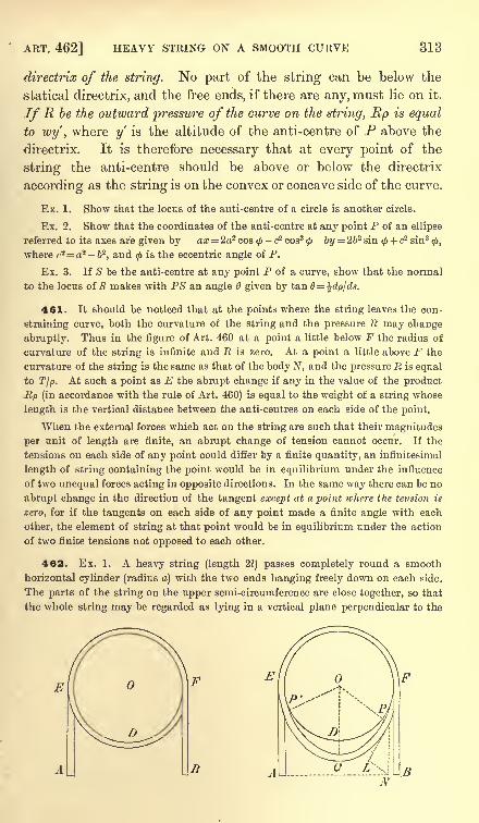
ART. 462] HEAVY STRING ON A SMOOTH CURVE 313
directrix of the string. No part of the string can be below the
statical directrix, and the free ends, if there are any, must lie on it.
IfR be the outward pressure of the curve on the string, Rp is equal
to wy' ,where y is the altitude of the anti-centre of P above the
directrix. It is therefore necessary that at every point of the
string the anti-centre should be above or below the directrix
according as the string is on the convex or concave side of the curve.
Ex. 1. Show that the locus of the anti-centre of a circle is another circle.
Ex. 2. Show that the coordinates of the anti-centre at any point P of an ellipse
referred to its axes are given by ax = 2a2 cos - c2 cos3 <p by = 2b2 sin<f> + c2 sin3
<f>,
where c2= a2 - 62,and
<f>is the eccentric angle of P.
Ex. 3. If S be the anti-centre at any point P of a curve, show that the normal
to the locus of S makes with PS an angle 6 given by tan 6=
461. It should be noticed that at the points where the string leaves the con-
straining curve, both the curvature of the string and the pressure R may change
abruptly. Thus in the figure of Art. 460 at a point a little below F the radius of
curvature of the string is infinite and R is zero. At a point a little above F the
curvature of the string is the same as that of the body N, and the pressure R is equal
to T/p. At such a point as E the abrupt change if any in the value of the product
Up (in accordance with the rule of Art. 460) is equal to the weight of a string whose
length is the vertical distance between the anti-centres on each side of the point.
When the external forces which act on the string are such that their magnitudes
per unit of length are finite, an abrupt change of tension cannot occur. If the
tensions on each side of any point could differ by a finite quantity, an infinitesimal
length of string containing the point would be in equilibrium under the influence
of two unequal forces acting in opposite directions. In the same way there can be no
abrupt change in the direction of the tangent except at a point ivhere the tension is
zero, for if the tangents on each side of any point made a finite angle with each
other, the element of string at that point would be in equilibrium under the action
of two finite tensions not opposed to each other.
462. Ex. 1. A heavy string (length 21) passes completely round a smooth
horizontal cylinder (radius a) with the two ends hanging freely down on each side.
The parts of the string on the upper semi-circumference are close together, so that
the whole string may be regarded as lying in a vertical plane perpendicular to the
V J
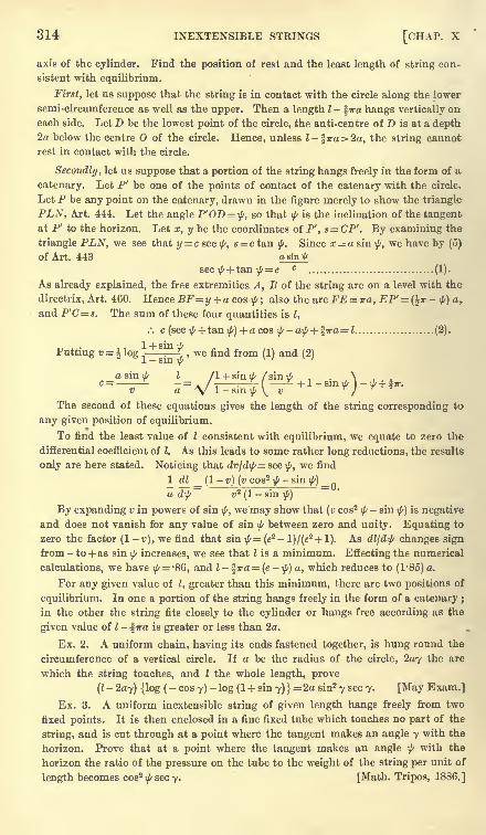
314 INEXTENSIBLE STRINGS [CHAP. X
axis of the cylinder. Find the position of rest and the least length of string con-
sistent with equilibrium.
First, let us suppose that the string is in contact with the circle along the lower
semi-circumference as well as the upper. Then a length I - %ira hangs vertically on
each side. Let D be the lowest point of the circle, the anti-centre of D is at a depth2a below the centre O of the circle. Hence, unless l-%ira>2a, the string cannot
rest in contact with the circle.
Secondly, let us suppose that a portion of the string hangs freely in the form of a
catenary. Let P' be one of the points of contact of the catenary with the circle.
Let P be any point on the catenary, drawn in the figure merely to show the triangle
PLN, Art. 444. Let the angle P'OD = \f/,so that ^ is the inclination of the tangent
at P7to the horizon. Let x, y be the coordinates of P', s= CP'. By examining the
triangle PLN, we see that y=c sec\f/,
s = c tan\f/.
Since x=a sin\f/,
we have by (5)
of Art. 443 asin^
sec\//+ tan
\f/= e c
(1).
As already explained, the free extremities A, B of the string are on a level with the
directrix, Art. 460. Hence BF=y + a cos ^ ; also the arc FE = ira, EP'= (TT - f) a,
and P'C=s. The sum of these four quantities is I,
.: c(sec \j/+ tan
\f/) + a cos $-a\(/ + %ira = l (2).
Putting v = log-
|5x , we find from (1) and (2)
a sin\f/
I /I + sin \i/ /sin \I/ \c= -= / -T +l-sm^ )v a \ 1-smij/ \ v J
The second of these equations gives the length of the string corresponding to
any given position of equilibrium.
To find the least value of I consistent with equilibrium, we equate to zero the
differential coefficient of I. As this leads to some rather long reductions, the results
only are here stated. Noticing that dv/difs= sec ^, we find
1 dl _ (1-
v) (v cos2\f/- sin
\f/) _a d\fs
~~v2 (1- sin $)
By expanding v in powers of sin\f/,
we may show that (v cos2
\//
- sin\f/)
is negative
and does not vanish for any value of sin ^ between zero and unity. Equating to
zero the factor (1-r), we find that sin ^= (2 -
l)/(e2+ l). As dlld\f/ changes sign
from - to + as sin ^ increases, we see that Hs a minimum. Effecting the numerical
calculations, we have\f/ -86, and I - fira= (e
-\f/) a, which reduces to (1'85) a.
For any given value of I, greater than this minimum, there are two positions of
equilibrium. In one a portion of the string hangs freely in the form of a catenary ;
in the other the string fits closely to the cylinder or hangs free according as the
given value of I - %ira is greater or less than 2o.
Ex. 2. A uniform chain, having its ends fastened together, is hung round the
circumference of a vertical circle. If a be the radius of the circle, 2ay the arc
which the string touches, and I the whole length, prove
(I-2ay) {log (
- cos y)-log (1 + sin y) }
= 2a sin2 y sec y. [May Exam.]
Ex. 3. A uniform inextensible string of given length hangs freely from two
fixed points. It is then enclosed in a fine fixed tube which touches no part of the
string, and is cut through at a point where the tangent makes an angle y with the
horizon. Prove that at a point where the tangent makes an angle \f/with the
horizon the ratio of the pressure on the tube to the weight of the string per unit of
length becomes cos2\f/ secy. [Math. Tripos, 1886.]
ART. 464] LIGHT STRING ON A ROUGH CURVE 315
463. Rough curve, light string. To consider the case in
which the weight of the string is inconsiderable, but the curve is
rough. Referring to the figure of Art. 459, we shall suppose the
extremities A and B to be acted on by unequal forces F, F'. Our
object is to find the conditions of limiting equilibrium; let us then
suppose the string is on the point of motion in the direction AB.
The friction on every element PQ is equal to ftRds, where /n is
the coefficient of friction. This force acts in the direction opposite
to motion, viz. from B to A.
Introducing this force into the equations obtained in Art. 459
by resolving the forces along the tangent and normal, and omittingthe terms containing the weight of the element, we have
dT-u,Rds = ...... (1), T -Rds = ...... (2).P
Eliminating R, we find,--
=//-=
where A and B are undetermined constants. If Tlt T2 be the
tensions at two points at which the tangents make angles ^, ty%
with the axis of x, this equation gives
Ta = 2>(*-*> ........................ (3).
It will be found useful to put the result in the form of a rule.
If a light string rest on a rough curve in a state bordering on
motion, the ratio of the tensions at any two points is equal to e to
the power of fi times the angle between the tangents or between the
normals at those points.
The sign to be given tofj.
in this equation depends on the direction in which
the friction acts. In using the rule, however, no difficulty arises from this
ambiguity ;for (1) it is evident that that tension is the greater of the two which
is opposed to the friction, and (2) it must be the ratio of the greater tension to the
lesser (not the lesser to the greater) which is equal to the exponential with the
positive index.
To determine the angle between the tangents ; let a straight line, starting from
a position coincident with one tangent, roll on the string until it coincides with the
other tangent ;the angle turned round by this moving tangent is the angle
required.
The pressure at any point is given by (2), and we see that Rpat any point is equal to the tension at that point.
464. If the forces F, F' which act at the extremities A, Bare given, and if the length I of the string is also given, we may
316 INEXTENSIBLE STRINGS [CHAP. X
find the limiting positions of equilibrium in the following manner.
Put the equation to the curve in the form ^=/(s). Let s
be the required arc-coordinate of A, then s + I is that of B. The
i/r's of A and B are therefore /(s) and f(s + I). Hence, by takingthe logarithms of equation (3),
log F, - log ^ = ,*{/(*+0 -/()}From this equation s must be found. The other limiting position
may be found by writing p, for p.
465. It should be noticed that the equation (3) of Art. 463 is
independent of the size of the curve. Suppose a heavy string to
pass through a small rough ring or over a small peg, and to be
in a state bordering on motion;the weight of the portion of string
on the pulley may sometimes be neglected compared with the
tensions of the string on either side. If the strings on either side
make a finite angle with each other, the pressures and therefore
the frictions will not be small, and cannot be neglected. Weinfer that, when a heavy tight string passes through a small rough
ring, the ratio of the tensions on each side is given by the same rule
as that for a light string.
466. Ex. 1. A rope is wound twice round a rough post, and the extremities
are acted on by forces F, F'. Find the ratio of F : F" when the rope is on the
point of slipping. [Here the angle between the tangents is 47r, hence the ratio of
the greater force to the other is e4""'1 -]
Ex. 2. A circle has its plane vertical, and is pressed against a vertical wall by a
string fixed to a point in the wall above the circle. The string sustains a weight P,
the coefficient of friction between the string and circle is /*, and the wall is perfectly
rough. When the circle is on the point of sliding, prove that, if IT' be the weight of
the circle and the angle between the string and the wall, P (1 + cos 0) e? = W+2P.[Coll. Exam.]
Ex. 3. A light string is placed over a rough vertical circle, and a uniform heavy
rod, whose length is equal to the diameter of the circle, has one end attached to each
end of the string, and rests in a horizontal position. Find within what points on
the rod a given mass may be placed, without disturbing the equilibrium of the
system : and show that the given mass may be placed anywhere on the rod, pro-
vided the ratio of its weight to that of the rod does not exceed \ (efv -
1), where /j. is
the coefficient of friction between the string and the circle. [Coll. Exam., 1880.]
Ex. 4. A string, whose weight is neglected, passes over a rough fixed horizontal
cylinder and is attached to a weight W; P is the weight which will just raise W, and
P' the weight which will just sustain W; show that, if R, R' are the corresponding
resultant pressures of the string on the cylinder, P:P'::RZ :R'*. [Math. T., 1880.]
Ex. 5. A band without weight passes tightly round the circumference of two
unequal rough wheels. One wheel is fixed while the other is made to turn slowly
round its centre. Show that the band will slip first on the smaller wheel.
ART. 467] HEAVY STRING ON A ROUGH CURVE 317
Ex. 6. On the top of a rough fixed sphere (radius c) is placed a heavy particle,
to which are tied two equally heavy particles by light strings each of length cO ; show
that, when the latter particles are as near together as possible, the planes of the
strings make with one another an angle <p, where 2 sin (6-X) cos = sin X . e
n A,
IB
and X is the angle of friction between the particles and the sphere, and between the
strings and the sphere. [Coll. Exam., 1887.]
Ex. 7. A uniform heavy string of length 21 passes through two given small fixed
rings A, B in the same horizontal line. Supposing the string to be on the point of
slipping inwards at both A and B, find the position of equilibrium.
If 2s be the portion of the string between the pegs, y the ordinate of the catenary
at either peg, the tensions at the two sides of either ring are proportional to y and
l-s. Referring to the triangle PLN in the figure of Art. 443, we see that the
angle through which the string has been turned is the supplement of the least angle
whose sine is c\y. Hence we have by (3) log =^- = (IT - sin"1 -
) /tt.Also if 2a be
L~ s \ yj
the known distance between the rings.we have x a. Substituting for y and s their
values in terms of x or a given in Art. 443, we have an equation to find c. Hence
y and s may be found.
Ex. 8. A,B,C are three rough points in a vertical plane ; P, Q, R are the greatest
weights which can be severally supported by a weight W when connected with it by
strings passing over A, B, C, over A, B, and over B, C respectively. Show that the1 OTl
coefficient of friction at B is -log T^JJ, [Math. Tripos, 1851.]
7T i rr
Let a, /3, 7 be the angles through which the string is bent at ABC, their sum is IT.
By Art. 463 log Pj W, logQ/W, logR/W are respectively equal to /j.a + fj.'p + /j."y,
fM + fj.' (/3 + 7), fj.' (ct + /3) +/J."y. The result follows by substitution. It is supposedthat B lies between the verticals through A and C.
Ex. 9. A string, whose length is I, is hung over two rough pegs at a distance a apart
in a horizontal line. If one free end of the string is as much as possible lower than the
other, the inclination to the vertical of the tangent to the string at either peg is given7 a
by the equation -sin & . log cot -= cos 9 + cosh/j. (IT -6). [St John's Coll., 1881.]a a
Ex. 10. An endless uniform heavy chain is passed round two rough pegs in the
same horizontal line, being partly supported by a smooth peg situated midway in
the line between the other pegs, so that the chain hangs in three festoons. If a, /3
are the angles which the tangents at one of the rough pegs make with the vertical,
and fj.is the coefficient of friction, prove that the limiting values of a and /3 are given
by the equation^ '
=2 ~ *. [Math. Tripos, 1879.]
467. Rough curve, heavy string. We shall now consider
the general case in which both the weight of the string and the
roughness of the curve are taken, account of.
Referring to the figure of Art. 459, and introducing both the
weight and the roughness into the equations (1) and (2), we have
dT-wdssm^-fiRds = Q .................. (1),
Tds-- tvds cosT/T
Rds = .................. (2).
318 INEXTENSIBLE STRINGS [CHAP. X
In applying these equations to other forms of the string wemust remember that the friction is fi times the pressure taken
positively. Thus as the string is heavy it might lie on the
concave side of the curve. We must then change the sign of Rin the second equation, but not in the first.
We shall presently have occasion to write p ds/dty. If the
figure is not so drawn that s andi/r
increase together, we shall
have p = ds/d-fr. To solve these equations, we eliminate It,
rIT.'.
-j/j,T
= wp (sini/r p cosi/r) ............... (3).
This is one of the standard forms in the theory of differential
equations. According to rule we multiply by e~^ and integrate ;
. Te -n<l>-fWp (sin ^ _ ^ Cos ^) e~^ dty + C......... (4).
We cannot effect this integration until the form of the curve
is given. By using the rules of the differential calculus we first
express p as a function of ^r. Then substituting and integrating,
we find Te-**=f(ty)+C........................ (5).
The value of T having been found by this equation, R follows
from either (1) or (2). It should be noticed that we have not
assumed that the string is necessarily uniform.
The pressure at any point is given by the equation
Rp = T wp cosi/r.
It may be noticed that this is the same as the corresponding
equation for a heavy string on a smooth curve, Art. 460.
If the string is not on the point of motion, we replace the term
in (1) by Fds, where F is the friction per unit of length.
Ex. If the string is uniform and of finite length, and if the extremities are
acted on by forces Plt P2 , prove that the whole friction called into play is
jFds=P9-P
l-
wz, where z=yz -yl , so that z is the vertical distance between the
extremities of the string.
468. It appears from the last article that the determination of the circumstances
of the equilibrium of a heavy string on a rough curve depends on the integral
I= fape~^
(sin ^ -fi cos \(/) d\j/.
This^integral can be found in several cases.
If the curve is a circle and the string homogeneous, we have pa. We easily find
1=_^L {(M2 _
i) cos ^ _ 2M sin ^} e '**.
If the curve is an equiangular spiral and the string homogeneous, we have
r = aeecota
. Since p sin a= r and\//= 6 + a, the integral may be obtained from the
last by writing p - cot a for p, and ae~ cot a
cosec a for a.
ART. 469] HEAVY STRING ON A SMOOTH OR ROUGH CURVE 319
If the curve is a cycloid with its base inclined to the horizon at any angle,
we have p=4acos (\f/-a), where a is the radius of the generating circle. More
generally, if the curve is such that wp can be expanded in a series of positive integral
powers of sin\(/and cos \p,
we can express wp (sin ^ -//.cos
\p)in a series of sines and
cosines of multiple angles. In this case the integral can be found by a method
similar to that used for the circle.
If the curve is a catenary we have p cos2\}/= c and 1= we sec
\f/e~^. More
generally, if the curve is such that p = acosn ^, where n is a -positive or negative
integer, we may find I by a formula of reduction. We easily see that
[f + (n + !)} Jn - (-
1) (n + 2) In_2
= wa (cos \f/)
n~^e~^ {n + 2 - p. (n + 2) sin\f/cos ^ -
(n + 1 -/j?)
cos2 ^}.
469. Ex. 1. A heavy string occupies a quadrant of the upper half of a rough
yertical circle in a state bordering on motion. Prove that the radius through the
lower extremity makes an angle a with the vertical given by tan (a-2e) = e~^ir
,
where /t= tane.
Ex. 2. A heavy string, resting on a rough vertical circle with one extremity at
the highest point, is on the point of motion. If the length of the string is equal to
a quadrant, prove that ^irtan e= log tan 2e. [Coll. Ex., 1881.]
Ex. 3. A single moveable pulley, of weight W, is just supported by a power P,
which is applied at one end of a cord which goes under the pulley and is then fastened
to a fixed point ; show that, if<f>be the angle subtended at the centre by the part of
the string in contact with the pulley, <j>is given by the equation
P (1-2^ cos + <#**)* = JT. [Coll. Ex., 1882.]
Ex. 4. If a heavy string be laid on a rough catenary, with its vertex upwardsand its axis vertical, so that one extremity is at the vertex, the string will just rest
if its length be equal to the parameter of the catenary, provided the coefficient of
friction be (2 log 2)/7r. [Coll. Ex., 1885.]
Ex. 5. A heavy string AB is placed on the concave side of a rough cycloidal
curve whose base is inclined at an angle a to the horizon, with one extremity A at
the lowest point and the other B at the vertex. Prove that the string will be in a
tane-2tana ",state bordering on motion if- = e
, where tan e is thetan e + (1
- 3 cos2e) tan a
coefficient of friction.
Ex. 6. A heavy string rests on a rough cycloid with its base horizontal and
plane vertical. The normals at the extremities of the string make with the vertical
angles each equal to a, which is also the angle of friction between string and
cycloid. If, when the cycloid is tilted about one end till the base makes an angle a
with the horizontal, the string is on the point of motion, show that
[It is assumed that no part of the string hangs freely.] [Coll. Ex., 1883.]
Ex. 7. A heavy uniform flexible string rests on a smooth complete cycloid, the
axis of which is vertical and vertex upwards, the whole length of the string exactly
coinciding with the whole arc of the cycloid ; prove that the pressure at any point
of the cycloid varies inversely as the curvature. [Math. Tripos, 1865.]
Ex. 8. A heavy string AB is laid on a rough convex curve in a vertical plane,
and the friction at every point acts in the same direction along the curve. Show
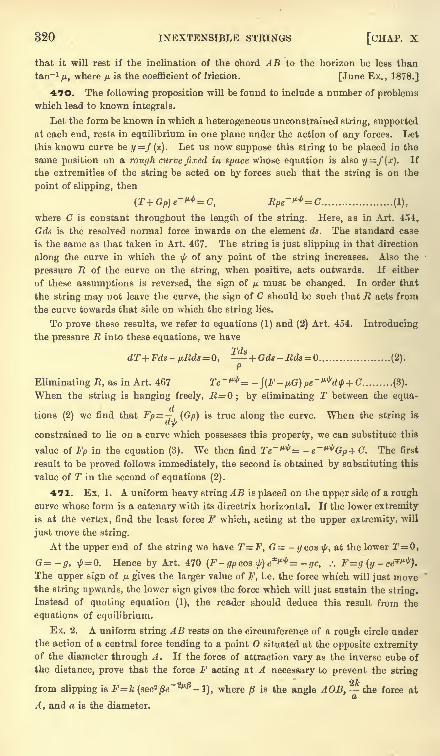
320 INEXTENSIBLE STRINGS [CHAP. X
that it will rest if the inclination of the chord AB to the horizon be less than
tan~V> where n is the coefficient of friction. [June Ex., 1878.]
470. The following proposition will be found to include a number of problemswhich lead to known integrals.
Let the form be known in which a heterogeneous unconstrained string, supported
at each end, rests in equilibrium in one plane under the action of any forces. Let
this known curve be y=f(x). Let us now suppose this string to be placed in the
same position on a rough curve fixed in space whose equation is also y=f(x). If
the extremities of the string be acted on by forces such that the string is on the
point of slipping, then
(T+Gp)e~^=C, Rpe-^^C (1),
where C is constant throughout the length of the string. Here, as in Art. 454,
Gds is the resolved normal force inwards on the element ds. The standard case
is the same as that taken in Art. 467. The string is just slipping in that direction
along the curve in which the ^ of any point of the string increases. Also the
pressure R of the curve on the string, when positive, acts outwards. If either
of these assumptions is reversed, the sign of p must be changed. In order that
the string may not leave the curve, the sign of C should be such that R acts from
the curve towards that side on which the string lies.
To prove these results, we refer to equations (1) and (2) Art. 454. Introducing
the pressure R into these equations, we have
TdtdT+Fds- /jLRds = Q,
~ + Gds-Rds = (2).P
Eliminating , as in Art. 467 Te~^= -\(F
- ^G) pe~^d$ + C (3).
When the string is hanging freely, R = ; by eliminating T between the equa-
tions (2) we find that Fp= (Gp) is true along the curve. When the string is
constrained to lie on a curve which possesses this property, we can substitute this
value of Fp in the equation (3). We then find Te~^= -e~^Gp+C. The first
result to be proved follows immediately, the second is obtained by substituting this
value of T in the second of equations (2).
471. Ex. 1. A uniform heavy string AB is placed on the upper side of a roughcurve whose form is a catenary with its directrix horizontal. If the lower extremity
is at the vertex, find the least force F which, acting at the upper extremity, will
just move the string.
At the upper end of the string we have T=F, G - gcos ty, at the lower T=0,
G=-g, ,fr=0. Hence by Art. 470 (F-gpcos t)e*^= -gc, :. F=g (y -ce***).
The upper sign of /* gives the larger value of F, i.e. the force which will just movethe string upwards, the lower sign gives the force which will just sustain the string.
Instead of quoting equation (1), the reader should deduce this result from the
equations of equilibrium.
Ex. 2. A uniform string AB rests on the circumference of a rough circle underthe action of a central force tending to a point O situated at the opposite extremityof the diameter through A. If the force of attraction vary as the inverse cube of
the distance, prove that the force F acting at A necessary to prevent the string
from slipping is Fk (sec2^" 2^-
1), where is the angle A OB, the force at
A , and a is the diameter.
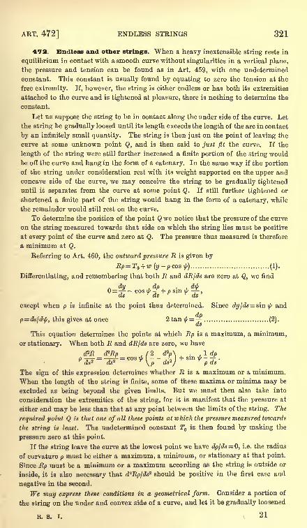
ART. 472] ENDLESS STRINGS 321
472. Endless and other strings. When a heavy inextensible string rests in
equilibrium in contact with a smooth curve without singularities in a vertical plane,
the pressure and tension can be found as in Art. 459, with one undetermined
constant. This constant is usually found by equating to zero the tension at the
free extremity. If, however, the string is either endless or has both its extremities
attached to the curve and is tightened at pleasure, there is nothing to determine the
constant.
Let us suppose the string to be in contact along the under side of the curve. Let
the string be gradually loosed until its length exceeds the length of the arc in contact
by an infinitely small quantity. The string is then just on the point of leaving the
curve at some unknown point Q, and is then said to just fit the curve. If the
length of the string were still further increased a finite portion of the string would
be off the curve and hang in the form of a catenary. In the same way if the portion
of the string under consideration rest with its weight supported on the upper andconcave side of the curve, we may conceive the string to be gradually tightened
until it separates from the curve at some point Q. If still further tightened or
shortened a finite part of the string would hang in the form of a catenary, while
the remainder would still rest on the curve.
To determine the position of the point Q we notice that the pressure of the curve
on the string measured towards that side on which the string lies must be positive
at every point of the curve and zero at Q. The pressure thus measured is therefore
a minimum at Q.
Referring to Art. 460, the outward pressure R is given by
Rp=T + w(y-pcost) (1).
Differentiating, and remembering that both R and dR/ds are zero at Q, we find
. dy .dp . d\L>= -^.- cosi/' -f+psm \b -^-,ds ds ds
except when p is infinite at the point thus determined. Since dyjds= sin\j/and
p=ds/d\f/, this gives at once 2 tan ^=-r (2).(ts
This equation determines the points at which Rp is a maximum, a minimum,or stationary. When both R and dRIds are zero, we have
cPR cPRp , ( 2 d?p\ . 1 dpP To = T? = cos 'M Tl + sm ^ -
-TKds2 ds2
r\p ds 2
/T
p ds
The sign of this expression determines whether R is a maximum or a minimum.
When the length of the string is finite, some of these maxima or minima may be
excluded as being beyond the given limits. But we must then also take into
consideration the extremities of the string, for it is manifest that the pressure at
either end may be less than that at any point between the limits of the string. The
required point Q is that one of all these points at which the pressure measured towards
the string is least. The undetermined constant T is then found by making the
pressure zero at this point.
If the string leave the curve at the lowest point we have dp/ds=0, i.e. the radius
of curvature p must be either a maximum, a minimum, or stationary at that point.
Since Rp must be a minimum or a maximum according as the string is outside or
inside, it is also necessary that d^Rpjds"2 should be positive in the first case and
negative in the second.
We may express these conditions in a geometrical form. Consider a portion of
the string on the under and convex side of a curve, and let it be gradually loosened
R. S. I. 21
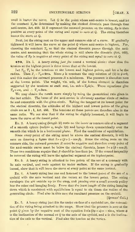
322 INEXTENSIBLE STRINGS [CHAP. X
until it leaves the curve. Let Q be the point whose anti-centre is lowest, and let
the constant T be determined by making the statical directrix pass through that
anti-centre, Art. 460. If R represent the outward pressure on the string, Ep is then
positive at every point of the string and equal to zero at Q. The string therefore
leaves the curve at Q.
Next, let the string rest on the upper and concave side of a curve. If gradually
tightened it will leave the curve at the point Q whose anti-centre is highest. For,
choosing the constant T so that the statical directrix passes through the anti-
centre, and assuming that the whole string is still above the directrix (Art. 460),
the value of Rp is negative at every point of the string and equal to zero at Q.
473. Ex. 1. A heavy string just fits round a vertical circle: show that the
tension at the highest point is three times that at the lowest.
Let T , Tj be the tensions at the lowest and highest points, and let a be the
radius. Then Tj- T = 2iva. Since p is constant the only solution of (2) is ^= 0,
and this makes the outward pressure R a minimum. The pressure is therefore zero
at the lowest point. The weight, viz. wds, of the lowest element is therefore
supported by the tensions at each end, i.e. wd*- = T ds/a. These equations give
T =wa, and .'. Tl= Bwa.
We may obtain the result more simply by using the geometrical rule given in
the last article. The locus of the anti-centre is obviously another circle of radius
2a and concentric with the given circle. Taking the tangent at its lowest point for
the statical directrix, the altitudes of the highest and lowest points of the given
circle are as 3 : 1, Art. 460. The tensions at these points are therefore also in the
same ratio. We see also that if the string be slightly loosened, it will begin to
leave the curve at the lowest point.
Ex. 2. A heavy string (length 21) rests on the inner or concave side of a segmentof a smooth sphere (radius a, angle 2/J) and hangs down symmetrically over the
smooth rim which is in a horizontal plane. Find the conditions of equilibrium.
Since every point of the string must be above the statical directrix, it will be
seen on drawing a figure that l>a(/3 + 1 -cos/3). Since the string rests on the
concave side, the outward pressure R must be negative and therefore every point of
the anti-centric curve must be below the statical directrix, hence l<.a(/3 + cos/3).
These two conditions require that /3 should be less than ^TT. If the second inequality
be reversed the string will leave the spherical segment at the highestpoint.
Ex. 3. A heavy string is attached to two points of the arc of a catenary with
its axis vertical, and rests against its under surface. If the string is gradually
loosed, show that it will leave the curve at every point at the same instant.
Ex. 4. A heavy string has one end fastened to the lowest point of the arc of a
cycloid with the axis vertical and the vertex at the lowest point. The string
envelopes the arc outside up to the cusp, and passing over a small smooth pulley
has the other end hanging freely. Prove that the least length of the string hangingdown which is consistent with equilibrium is equal to six times the radius of the
generating circle. Find also in this case the resultant pressure on the cycloid.
[Queens' Coll.]
Ex. 5. A heavy string just fits the under surface of a cycloidal arc, the extremi-
ties of the string being attached to the cusps. Show that the pressure is zero at the
point Q given by the negative root of the equation 3 sin(2<f> + a) -sin a, where
is the inclination of the normal at Q to the axis of the cycloid, and a is the inclina-
tion of the axis to the vertical. Find also the tension at the vertex.
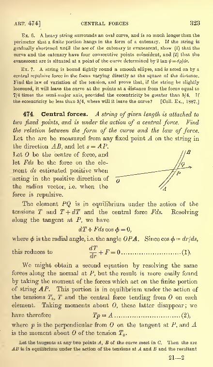
ART. 474] CENTRAL FORCES 323
Ex. 6. A heavy string surrounds an oval curve, and is so much longer than the
perimeter that a finite portion hangs in the form of a catenary. If the string is
gradually shortened until the arc of the catenary is evanescent, show (1) that the
curve and the catenary have four consecutive points coincident, and (2) that the
evanescent arc is situated at a point of the curve determined by 2 tan \l/=dpjds.
Ex. 7. A string is bound tightly round a smooth ellipse, and is acted on by a
central repulsive force in the focus varying directly as the square of the distance.
Find the law of variation of the tension, and prove that, if the string be slightly
loosened, it will leave the curve at the points at a distance from the focus equal to
7/4 times the semi-major axis, provided the eccentricity be greater than 3/4. If
the eccentricity be less than 3/4, where will it leave the curve? [Coll. Ex., 1887.]
474. Central forces. A string of given length is attached to
two fixed points, and is under the action of a central force. Find
the relation between the form of the curve and the law of force.
Let the arc be measured from any fixed point A on the string in
the direction AB, and let s = AP.Let be the centre of force, and
let Fds be the force on the ele-
ment ds estimated positive when
acting in the positive direction of
the radius vector, i.e. when the
force is repulsive.
The element PQ is in equilibrium under the action of the
tensions T and T + dT and the central force Fds. Resolving
along the tangent at P, we have
dT+Fdscos<(> = 0,
where<j)
is the radial angle, i.e. the angle OPA. Since cos</>=
dr/ds,
dTthis reduces to ^-+^=0.. ..(1).
dr
We might obtain a second equation by resolving the same
forces along the normal at P, but the result is more easily found
by taking the moment of the forces which act on the finite portionof string AP. This portion is in equilibrium under the action of
the tensions T,T and the central force tending from on each
element. Taking moments about 0, these latter disappear; we
have therefore Tp = A (2),
where p is the perpendicular from on the tangent at P, and Ais the moment about of the tension T .
Let the tangents at any two points A, B of the curve meet in C. Then the arc
AB is in equilibrium under the action of the tensions at A and B and the resultant
212
324 INEXTENSIBLE STRINGS [CHAP. X
R of the central forces on all the elements. This resultant force must therefore act
along the straight line joining the centre of force to the intersection C of the
tangents at A and B. Also if 07, OZ are the perpendiculars from on the
YZtangents at A and B, we see by compounding the tensions that R = A . -^= .
OY . OAAs the point P moves from A to B, the foot of the perpendicular on the tangent
at P traces out the pedal curve. This curve, when sketched, exhibits to the eye
the magnitude of the tension at all points of the catenary.
475. Two cases have now to be considered.
First. Suppose the form of the string to be given, and let the
force be required. By known theorems in the differential calculus
we can express the equation to the curve in the form p = ty (r).
The equations (1) and (2) then give
A(
^(r)*'
The constant A remains indeterminate, for it is evident that
the equilibrium would not be affected if the magnitude of the
central force were increased in any given ratio. The tension at
any point of the string and the pressures on the fixed points of
suspension would be increased in the same ratio.
Secondly. Suppose that the force is given, and that the form
of the curve is required. Eliminating T between (1) and (2), we
find -=B-JFdr ........................... (4).
This differential equation has now to be solved. Put u = l/r
and fFdr =f(u) ',we find by a theorem in the differential calculus
Separating the variables, we have
Adu(6).
When this integration has been effected the polar equation to
the curve has been found.
There are three undetermined constants, viz. A, B, C, in this
equation. To discover their values we have given the polar
coordinates (w ), (u^d^ of the points of suspension. After inte-
grating (6) we substitute in turn for (u0) these two terminal
values, and thus obtain two equations connecting the three con-
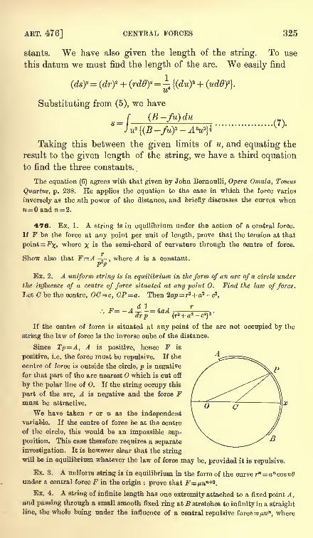
ART. 476] CENTRAL FORCES 325
stants. We have also given the length of the string. To use
this datum we must find the length of the arc. We easily find
(ds)*= (dry + (rd0)*
={(du)
z +u
Substituting from (5), we have
s= [(B-fu)du
J u* B - -AW*"
{(B
Taking this between the given limits of u, and equating the
result to the given length of the string, we have a third equationto find the three constants.
The equation (6) agrees with that given by John Bernoulli, Opera Omnia, Tomus
Quartus, p. 238. He applies the equation to the case in which the force varies
inversely as the nth power of the distance, and briefly discusses the curves whenn= and n= 2.
476. Ex. 1. A string is in equilibrium under the action of a central force.
If F be the force at any point per unit of length, prove that the tension at that
point= Fx, where x is the semi-chord of curvature through the centre of force.
7*
Show also that F=A -=-, where A is a constant.
P2P
Ex. 2. A uniform string is in equilibrium in the form of an arc of a circle under
the influence of a centre of force situated at any point 0. Find the law of force.
Let C be the centre, 00 = c, CP=a. Then 2op=r2 + a2 -c2,
. . j.' ^i -=- a:u
drp
If the centre of force is situated at any point of the arc not occupied by the
string the law of force is the inverse cube of the distance.
Since Tp=A, A is positive, hence F is
positive, i.e. the force must be repulsive. If the
centre of force is outside the circle, p is negative
for that part of the arc nearest O which is cut off
by the polar line of 0. If the string occupy this
part of the arc, A is negative and the force Fmust be attractive.
We have taken r or u as the independentvariable. If the centre of force be at the centre
of the circle, this would be an impossible sup-
position. This case therefore requires a separate
investigation. It is however clear that the string
will be in equilibrium whatever the law of force may be, provided it is repulsive.
Ex. 3. A uniform string is in equilibrium in the form of the curve rn= ancosnOunder a central force F in the origin : prove that F=/mn+2
.
Ex. 4. A string of infinite length has one extremity attached to a fixed point A,and passing through a small smooth fixed ring at B stretches to infinity in a straight
line, the whole being under the influence of a central repulsive force =yttMm
,where
326 INEXTENSIBLE STRINGS [CHAP. X
n>l. Show that the form of the string between A and B is rn~2=&n~2
cos(n-2) 6.
If n= 2 the curve is an equiangular spiral.
Ex. 5. A closed string surrounds a centre of force= /j.un
,where n>l and <2.
Show that, as the length of the string is indefinitely increased so that one apse
becomes infinitely distant from the centre of force, the equilibrium form of the string
tends to become rn~2= bn
~2 cos (n-
2) 6. If n= f the form of the curve is a parabola.
Ex. 6. A uniform string of length 21 is attached to two fixed points A, B at equal
distances from a centre of repulsive force = /t*w2
. If OA = OB= b and the angle
AOB = 28. prove that the equation to the string is = 1 H - ,
r cos a
where the real and imaginary values of M and a are determined from the equations
H cos (B sin a) . b . . .
1 H-- sin a = 7 sin (B sin a).b cos a I
The equations (1) and (2) of Art. 474 become here dT=/j.du, Tp = A.
Proceeding as explained in Art. 475, we find I- =6+ C.
J
This integral is one of the standards in the integral calculus, and assumes
different forms according as A2p? is positive, negative or zero. Taking the first
assumption, we have after a slight reduction
J2_ ..2A n ! / u? \
U=(JLACOS I 1-ji\ (6+C).B
The formula really includes all cases, for when A2 -/j? is negative we may write
for the sine of the imaginary angle on the right-hand side its exponential value.
Proceeding to find the arc in the manner already explained, we easily arrive at
Bs={(Br + fji.)2 -A'2
}% + D,
where the radical must have opposite signs on opposite sides of an apse.
The conditions of the question require that the string should be symmetrical
about the straight line determined by = 0. We have therefore (7= andD = 0.
, , /xtan'2 al cos (6 sin a)
Putting A = u. sec a, the equation to the curve reduces to - -= 1 =t --:---'- .B r cos a
We also have B*P= (Bb + tf- /jf sec2 a.
Eliminating B between these equations, we find I sin a= b sin (/3 sin a). We now
put M for the coefficient of 1/r and include the double sign in the value of a.
Since r=b when 6= the three results given above have been obtained.
Ex. 7. A string is in equilibrium in the form of a closed curve about a centre
of repulsive force =ju.w2
. Show that the form of the curve is a circle.
Beferring to the last example, we notice that, since r is unaltered when 6 is
increased by 2ir, r must be a trigonometrical function of 6. Hence sina=l or 0.
Putting M cos a=M',the first makes M'jr cos 6, which is not a closed curve, the
second gives M r, which is a circle.
Ex. 8. If the curve be a parabola, and the centre of force at the focus, and if
the equilibrium be maintained by fixing two points of the string, find the law of
force, and prove that the tension at any point P is 2/r, where r=SP and / is the
force at P per unit of length. [St John's Coll., 1883.]
Ex. 9. An infinite string passes through two small smooth rings, and is acted
on by a force tending from a given fixed point and varying inversely as the cube of
the distance from that point. Show that| the part of the string between the rings
assumes the form of an arc of a circle. [Coll. Ex., 1884.]
ART. 477] CENTRAL FORCES 327
Ex. 10. If a string, the particles of which repel each other with a force varyingas the. distance, be in equilibrium when fastened to two fixed points, prove that the
tension at any point varies as the square root of the radius of curvature.
[Math. Tripos, I860.]
Ex. 11. Show that the catenary of equal strength for a central force which varies
as the inverse distance is rn cos n& = an, where 1 - n is the ratio of the line density
to the tension. Show also that this system of curves includes the circle, the rect-
angular hyperbola, the lemniscate, and when n is zero the equiangular spiral.
[0. Bonnet, Liouville's J., 1844.]
Ex. 12. A string is placed on a smooth plane curve under the action of a central
force F, tending to a point in the same plane ; prove that, if the curve be such
that a particle could freely describe it under the action of that force, the pressure
of the string on the curve referred to a unit of length will be equal to - + -,
2 p
where is the angle which the radius vector from the centre of force makes with
the tangent, p is the radius of curvature, and c is an arbitrary constant.
If the curve be an equiangular spiral with the centre of force in the pole, and if
one end of the string rest freely on the spiral at a distance a from the pole, then
the pressure is equal to^
(-* + -=
). [Math. Tripos, I860.]&T \ T d J
Ex. 13. A free uniform string, in equilibrium under the action of a repulsive
central force F, has a form such that a particle could freely describe it under a
central force F' tending to the same centre. Show that F=kpF', where k is a
constant. If v be the velocity of the particle and T the tension of the string, show
also that T=kpv*. See Art. 476, Ex. 1.
Ex. 14. It is known that a particle can describe a rectangular hyperbola about
a repulsive central force which varies as the distance and tends from the centre of
the curve. Thence show that a string can be in equilibrium in the form of a
rectangular hyperbola under an attractive central force which is constant in
magnitude and tends to the centre of the curve. Show also that the tension varies
as the distance from the centre.
For a comparison of the free equilibrium of a uniform string with the free
motion of a particle under the action of a central force, see a paper by Prof.
Townsend in the Quarterly Journal of Mathematics, vol. xni., 1873.
477. When there are two centres of force the equations of equilibrium are best
found by resolving along the tangent and normal. Let r, r' be the distances of any
point P of the string from the centres of force; F, F' the central forces, which are
to be regarded as functions of r, r' respectively. Let p, p' be the perpendicularsfrom the centres of force on the tangent at P. We then have
dT+ Fdr+ F'dr' = 0. ..(1),- - F?-- F'^=0...(2).p r r'
The first equation gives T=B-\Fdr-\F'dr' .............................. (3).
We may suppose the lower limits of these integrals to correspond to any given pointP on the string. If this be done B will be the tension at P . Substituting the
value of T thus obtained from (1) and (2) and remembering that p=rdr/dp,
>)=B .............................. (4);
328 INEXTENSIBLE STRINGS [CHAP. X
on the other hand, if we find T from (2) and substitute in(1), we find after reduction
p \ r J p
Thus of the four elements, viz. (1) the force F, (2) the force F', (3) the tension T,
(4) the equation to the curve, if any two are given, sufficient equations have now
been found to discover the other two.
Ex. 1. A string can be in equilibrium in the form of a given curve under the
action of each of two different centres of force. Show that it is in equilibrium
under the joint action of both centres of force, and that the tension at any point is
equal to the sum of the tensions due to the forces acting separately.
Ex. 2. Prove that a uniform string will be in equilibrium in the form of the
curve r2= 2a2 cos 20 under the action of equal centres of repulsive force situated at
the points, (a, 0), ( -a, 0), the force of each per unit of length at a distance R being
pIR. Prove also that the tension at all points will be the same and equal to %/j..
[Coll. Ex., 1891.]
478. String on a surface. A string rests on a smooth
surface under the action of any forces. To find the position of
equilibrium.
Let the equation to the surface be f(x, y, z)= 0. Let Rds be
the outward pressure of the surface on the string. Let (I, m, n)
be the direction cosines of the inward direction of the normal.
By known theorems in solid geometry, I, m, n are proportional to
the partial differential coefficients of f(x, y, z) with regard to
x, y, z respectively.
If the equations are required to be in Cartesian coordinates, we
deduce them at once from those given in Art. 455 by including Ramong the impressed forces. We thus have
_ (T -
ds\ ds
ds
ds
We have here one more unknown quantity, viz. R, than wehad in Art. 455, but we have also one more equation, viz. the
given equation to the surface.
479. Let us next find the intrinsic equations to the string. Let
PQ be any element of the string, PA a tangent at P. Let APBbe a tangent plane to the surface, PB being at right angles to PA.Let PN be the normal to the surface. Let PC be the radius of
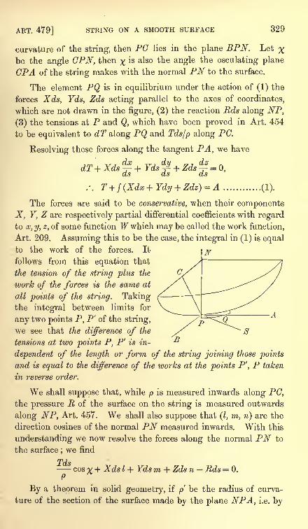
ART. 479] STRING ON A SMOOTH SURFACE 329
curvature of the string, then PC lies in the plane BPN. Let %be the angle CPN, then ^ is also the angle the osculating plane
CPA of the string makes with the normal PN to the surface.
The element PQ is in equilibrium under the action of (1) the
forces Xds, Yds, Zds acting parallel to the axes of coordinates,
which are not drawn in the figure, (2) the reaction Rds along NP,
(3) the tensions at P and Q, which have been proved in Art. 454
to be equivalent to dT along PQ and Tds/p along PG.
Resolving these forces along the tangent PA, we have
A ............ (1).
The forces are said to be conservative, when their components
X, Y, Z are respectively partial differential coefficients with regardto x, y, z, of some function W which may be called the work function,
Art. 209. Assuming this to be the case, the integral in (1) is equalto the work of the forces. It
follows from this equation that
the tension of the string plus the
work of the forces is the same at
all points of the string. Takingthe integral between limits for
any two points P, P' of the string,
we see that the difference of the
tensions at two points P, P' is in-
dependent of the length or form of the string joining those points
and is equal to the difference of the works at the points P', P taken
in reverse order.
We shall suppose that, while p is measured inwards along PC,the pressure R of the surface on the string is measured outwards
along NP, Art. 457. We shall also suppose that (I, m, n) are the
direction cosines of the normal PN measured inwards. With this
understanding we now resolve the forces along the normal PN to
the surface;we find
Tdscos % + Xds I + Ydsm + Zds n Rds = 0.
S
By a theorem in solid geometry, if p be the radius of curva-
ture of the section of the surface made by the plane NPA, i.e. by

330 INEXTENSIBLE STRINGS [CHAP. X
a plane containing the normal to the surface and the tangent to
the string, then p cos x = p. We therefore have
- + XI + Ym+Zn=R.. ...(2).P
It follows from this equation that the resultant pressure on
the surface is equal to the normal pressure due to the tension plusthe pressure due to the resolved part of the forces. The tension at
any point P having been found by (1), the pressure on the surface
follows by (2), provided we know the direction of the tangent PAto the string. This last is necessary in order to find the value of p'.
Lastly, let us resolve the forces along the tangent PB to the
surface. Let X, //,,v be the direction cosines of PB. Since PB is
at right angles to both PN and PA, these direction cosines may be
found from the two equations.. ,. ^ dx dy dz
y.+tf,+i/.-o, *s+^+ 5 -o.
We then have by the resolution
TYp + Zv = Q ............... (3).
Ex. An endless string lies along a central circular section of a smooth ellipsoid,
prove that b4jP2=T2(i
2 -p2), where F is the force per unit of length which acting
transversely to the string in the tangent plane is required to keep the string in its
place, p is the perpendicular from the centre on the tangent plane and b is the
mean semi-axis. [Trin. Coll., 1890.]
480. Geodesies. If any portion of the string is not acted on
by external forces, we have for that portion X = 0, F = 0, Z = 0.
The equation (1) then shows that the tension of the string is
constant. The equation (2) shows that the pressure at any point
is proportional to the curvature of the surface along the string. The
equation (3) (assuming the string not to be a straight line) shows
that % = 0, i.e. at every point the osculating plane of the curve
contains the normal to the surface. Such a curve is called a
geodesic in solid geometry.
Conversely, if the string rest on the surface in the form of a
geodesic under the action of forces, we see by (3) that they must
be such that at every point of the string their resolved part perpen-dicular to the osculating plane of the string is zero.
Returning to the general case in which the string is under the action of forces,
we notice that sin xlp is the resolved curvature of the string in the tangent plane at
P to the surface. When the resolved curvature vanishes and changes sign as P
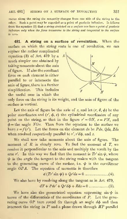
ART. 481] STRING ON A SURFACE OF REVOLUTION 331
moves along the string the concavity changes from one side of the string to the
other. Such a point may be regarded as a point of geodesic inflexion. It follows
from the equation (3) that a string stretched on a surface can have a point of geodesic
inflexion only when the force transverse to the string and tangential to the surface
is zero.
481. A string on a surface of revolution. When the
surface on which the string rests is one of revolution, we can
replace the rather complicated
equation (3) of Art. 479 by a B
much simpler one obtained by
taking moments about the axis
of figure. If also the resultant
force on each element is either
parallel to or intersects the
axis of figure, there is a further
simplification. This includes
the useful case in which the
only force on the string is its weight, and the axis of figure of the
surface is vertical.
Let the axis of figure be the axis of z, and let (r, 0, <f>)be the
polar coordinates and (r', <f>, 2) the cylindrical coordinates of any
point on the string, so that in the figure r' = ON, z = PN, and
$ = the angle NOx. Then from the equation to the surface wehave z =f(r'). Let the forces on the element ds be Pds, Qds, Zds
when resolved respectively parallel to r', r'd<f>, and z.
We shall now take moments about the axis of figure. The
moment of R is clearly zero. To find the moment of T, we
resolve it perpendicular to the axis and multiply the result by the
arm r'. In this way we find that the moment is Tr sini/r,
where
\/ris the angle the tangent to the string makes with the tangent
to the generating curve of the surface, i.e. ty is the curvilinear
angle OPA. The equation of moments is therefore
d (Tr' sin ^r) + Qr'ds = (4).
We also have by resolving along the tangent as in Art. 479,
dT+Pdr' + Qr'd<f> + Zdz = Q (5).
We have also the geometrical equation expressing sin-^ in
terms of the differentials of the coordinates of P. Let the gene-
rating curve OP turn round Oz through an angle d(j> and then
intersect the string in P' and a plane drawn through MP parallel
332 INEXTENSIBLE STRINGS [CHAP. X
to xy in Q. Then PQ = PP' sini/r,
i.e. r'd<f>= ds . sin
i/r.We
therefore have
(r'd$y = {(dr)* + (r'd$f + (dzf\ sin2 ^ ......... (6).
Eliminating T and sin i/r between (4), (5) and (6) we have an
equation from which the form of the string can be deduced.
If the only force acting on the string is gravity, and if the axis is vertical, the
equations take the simple forms
Trf
sin\f<= wB, T=w(z + A) ........................... (7).
Eliminating T and sin f , by help of (6), we have
Substituting for z from the equation of the surface, viz. z=f(r'), this becomes the
polar differential equation of the projection of the string on a horizontal plane.
The outward normal pressure of the surface on the string may be deduced from
equation (2) of Art. 479.
482. Heavy string on a sphere. Using polar coordinates referred to the
centre as origin, the fundamental equations take the simple forms
T sin sin \f/=wB', T=w (a cos + A),
(sin 8d<t>)*= {(sin 0d<f>)*+ (d0)2}sin2
^ , Ea =w (2acos 6 + A),
where\f/
is the angle the string makes with the meridian arc drawn through the
summit and B = aB'. These give as the differential equation* of the string
The tension at any point P= wz where z is the altitude of P above a fixed hori-
zontal plane called the directrix plane, and every point of the string must be above
this plane. The plane is situated at a depth A below the centre of the sphere. At
each point P let the normal OP be produced to cut in some point S a concentric
sphere whose radius is twice that of the given sphere. The point S is the anti-centre
of P, and the outward pressure on the string is wz'ja where z' is the altitude of 5above the directrix plane. As already explained every anti-centre must lie above or
below the directrix plane according as the string lies on the convex or concave side
of the sphere, Art. 460.
The values of the constants A ,B depend on the conditions at the ends of the
string. We see that B'=0, (1) if either end is free, for then T vanishes at that
end, (2) if the string pass through the summit of the sphere, for then sin 6 vanishes,
(3) if a meridian can be drawn from the summit to touch the sphere, for sin ^ =
at the point of contact. In all these cases, sin f vanishes throughout the string,
i.e. the string lies in a vertical plane.
If the string form a closed curve, the three quantities T, sin 0, sin\f/
cannot
* The reduction of the integral giving <j>in terms of 6 to elliptic functions is
given by Clebsch in Crelle's J., vol. 57. A model was exhibited at the RoyalSociety, June 1895, by Greenhill and Dewar of an algebraical spherical catenary.
By a proper choice of the constants the projection of the chain on a horizontal
plane became a closed algebraical curve of the tenth degree ;see also Nature,
Jan. 10, 1895.
ART. 483] HEAVY STRING ON A SPHERE 333
vanish or change sign at any point of the string. The highest and lowest points of
the string are therefore given by \f/=^ir, hence at these points
Tsin0 = M'.B', T=w (acos0 + ^), .-. sin (a cos 6 + A) = B'.
These equations yield only two available values of cos; for tracing the two curves
whose common abscissa is = cos0 and whose ordinates are the reciprocals of the
two values of T, we have an ellipse and a rectangular hyperbola, which, since T mustbe positive, give only two intersections. Let 6= a, = 8 be the meridian distances
of the highest and lowest points of the string, both being positive. Then
2A sin 2a - sin 28 B' cos a - cos 8= : =-^
,= sin a sin 8 .
a sin a - sin 8 a sin a - sin 8
It follows that the directrix plane passes through the centre of the sphere when a
and 8 are complementary. In general the tensions, and therefore the depths of the
directrix plane below the highest and lowest points, are invers'ely as the distances
of those points of the string from the vertical diameter.
It has been proved in Art. 480, that the string can have a point of geodesic
inflexion when the transverse tangential force is zero. This requires that the
meridian drawn from the summit should touch the string, and this, we have
already seen, cannot occur. It follows that the string must be concave throughoutits length on the same side.
If the form of the string is a circle its plane must be either horizontal or vertical,
and in the latter case it must pass through the centre of the sphere. To prove this
we give the string a virtual displacement without changing its form, it is easy to
see that the altitude of the centre of gravity can be a max-min only in the cases
mentioned. In both cases the altitude is a maximum and the equilibrium is
therefore unstable. Art. 218. In the same way it may be shown that any position
of equilibrium of a heavy free string on a smooth sphere is unstable.
Ex. 1. A heavy uniform chain, attached to two fixed points on a smooth
sphere, is drawn up just so tight that the lowest point just touches the sphere.
Prove that the pressure at any point is proportional to the vertical height of the
point above the lowest point of the string. [Coll. Ex., 1892.]
Ex. 2. A string rests on a smooth sphere, cutting all the sections through a
fixed diameter at a constant angle. Show that it would so rest if acted on by a
force varying inversely as the square of the distance from the given diameter, and
that the tension varies inversely as that distance. [Coll. Exam., 1884.]
Ex. 3. A string can rest under gravity on a sphere in a smooth undulating
groove lying between two small circles whose angular distances from the highest
point of the sphere are complementary, without pressing on the sides of the groove.
If\j/
is the acute angle at which the string cuts the vertical meridian prove that the
points at which ^ is a minimum occur at angular distances \ir from the highest
point and find the value of\f/
at these points. [Math. T., 1889.]
48-3. String on a Cylindrical Surface. Ex. 1. A heavy string is in equili-
brium on a cylindrical surface whose generators are vertical, the extremities of the
string being attached to two fixed points on the surface. Find the circumstances of
the equilibrium.
Let PQ= ds be any element, wds its weight. Let the axis of z be parallel to the
generators, and let z be measured in the direction opposite to gravity. Resolving
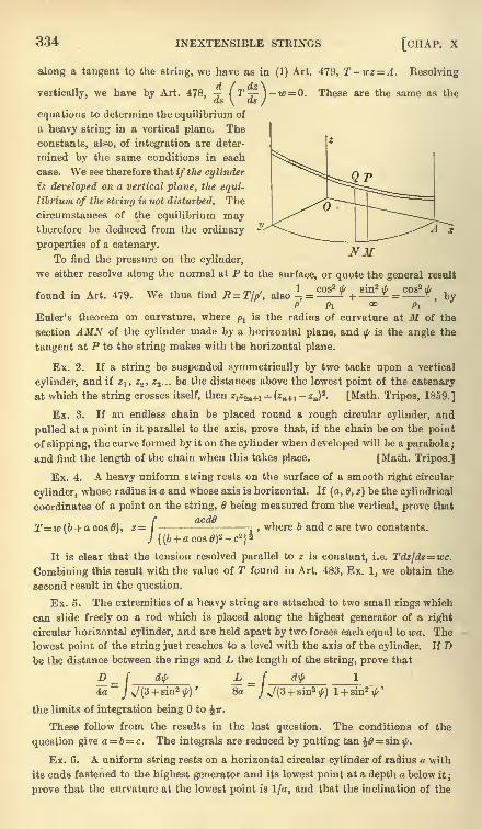
334 INEXTENSIBLE STRINGS [CHAP, x
along a tangent to the string, we have as in (1) Art. 479, T-wz= A. Kesolving
vertically, we have by Art. 478, ( T^-]-w = 0. These are the same as theds \ ds /
equations to determine the equilibrium of
a heavy string in a vertical plane. The
constants, also, of integration are deter-
mined by the same conditions in each
case. We see therefore that if the cylinder
is developed on a vertical plane, the equi-
librium of the string is not disturbed. The
circumstances of the equilibrium maytherefore be deduced from the ordinary
properties of a catenary.
To find the pressure on the cylinder,
we either resolve along the normal at P to the surface, or quote the general result
found in Art. 479.T,T ., ,, , _,, . .We thus find E=Tjp, also =
P Pi
Euler's theorem on curvature, where/>j
is the radius of curvature at M of the
section AMN of the cylinder made by a horizontal plane, and\f/
is the angle the
tangent at P to the string makes with the horizontal plane.
Ex. 2. If a string be suspended symmetrically by two tacks upon a vertical
cylinder, and if z1( z2 , z3 ... be the distances above the lowest point of the catenary
at which the string crosses itself, then zlz<in+l (zn+l -zn)
s. [Math. Tripos, 1859.]
Ex. 3. If an endless chain be placed round a rough circular cylinder, and
pulled at a point in it parallel to the axis, prove that, if the chain be on the point
of slipping, the curve formed by it on the cylinder when developed will be a parabola ;
and find the length of the chain when this takes place. [Math. Tripos.]
Ex. 4. A heavy uniform string rests on the surface of a smooth right circular
cylinder, whose radius is a and whose axis is horizontal. If (a, 6, z) be the cylindrical
coordinates of a point on the string, 6 being measured from the vertical, prove that
T=w(b + aco80), 2=|-
, where b and c are two constants.
It is clear that the tension resolved parallel to z is constant, i.e. Tdz/ds = wc.
Combining this result with the value of T found in Art. 483, Ex. 1, we obtain the
second result in the question.
Ex. 5. The extremities of a heavy string are attached to two small rings which
can slide freely on a rod which is placed along the highest generator of a right
circular horizontal cylinder, and are held apart by two forces each equal to wa. The
lowest point of the string just reaches to a level with the axis of the cylinder. If Dbe the distance between the rings and L the length of the string, prove that
D I d\j/L
4a=J V (3 + sin2 $)
'8a
the limits of integration being to ^v.
These follow from the results in the last question. The conditions of the
question give a= b= c. The integrals are reduced by putting tan = sin ^.
Ex. 6. A uniform string rests on a horizontal circular cylinder of radius a with
its ends fastened to the highest generator and its lowest point at a depth a below it;
prove that the curvature at the lowest point is I/a, and that the inclination of the
ART. 485] STRING ON A ROUGH SURFACE 335
string at any point to the axis is sec~ l(l+z/a), where z is the height of the point
above the axis, supposing the string cuts the highest generator at an angle of 60.
[June Exam.]
Ex. 7. A heavy uniform string has its two ends fastened to points in the
highest generator of a smooth horizontal cylinder of radius a, and is of such
a length that its lowest point just touches the cylinder. Prove that, if the
cylinder be developed, the origin being at one of the fixed points, the curve on
which the string lay is given by c2( ^ )
= a2 cos2 ^ + 2ac cosy~
. [Math. T., 1883.]\ dJc J a CL
484. String on a right cone. Ex. 1. A string has its extremities attached
to two fixed points on the surface of a right cone, and is in equilibrium under the
action of a centre of repulsive force F at the vertex. Show that the equilibrium is
not disturbed by developing the cone and string on a plane passing through the
centre of force.
Let the vertex O be the origin, (?', 6', z) the cylindrical coordinates of any pointP on the string. Let OP= r. Taking moments about the axis and resolving alongthe tangent, we have as in Art. 481,
Tr'smt=B, T +$Fdr=C (1).
We may imagine the coue divided along a generator and together with the
string on its surface unwrapped on a plane. Let (r, 6) be the polar coordinates of
the position of P in this plane. Let p be the perpendicular from on the tangentto the unwrapped string, then p= r sin ty. The equations (1) become
Tp= B', T+[Fdr=C (2).
These are the equations of equilibrium of a string in one plane under the
action of a central force, and the constants of integration are determined by the
same conditions in each case. We may therefore transfer the results obtained
in Art. 474 to the string on the cone. In transferring these results we notice that
the point (r, 0) on the plane corresponds to (r'&'z) on the cone, where r'= rsina,
ff'siua= &, 2 = rcosa.T sin d> B cos a 1 cos2 <f>
sin2 d>
The pressure R is given by R = = ^- . r-^ ,since - = +
p r2 sin2 a p <x> r sec a
by Euler's theorem on curvature. Art. 479.
Ex. 2. The two extremities of a string, whose length is 21, are attached to the
same point A on the surface of a right cone. The equation to the projection of
the string on a plane perpendicular to the axis is irr'= lcos (6' sin a), the point
A being given by 6'= ir. Show that the string will rest in equilibrium under the
influence of a centre of force in the vertex varying inversely as the cube of the
distance.
Ex. 3. A heavy uniform string has its ends fastened to two points on the
surface of a right circular cone whose axis is vertical and vertex upwards, the
string lying on the surface of the cone. Prove that, if the cone be developed
into a plane, the curve on which the string lay is given by p(a + br)= l, the
origin beiag the vertex, p the perpendicular on the tangent, and a, b constants.
[Coll. Ex., 1890.]
485. String on a rough surface. A string rests on a
rough surface under the action of any forces, and every element
borders on motion ; to find the conditions of equilibrium.
336 INEXTENSIBLE STRINGS [CHAP. X
The required conditions may be deduced from the equationsfor a smooth surface by introducing the limiting friction. The
pressure of the surface on the element ds being Rds, the limitingfriction will be pRds. This friction acts in some direction PSlying in the tangent plane to the surface. See figure of Art. 479.
Leti|r
be the angle SPA. Resolving along the principal axes at
any point of the string exactly as in Art. 479, we have
dT+ Xdx + Ydy + Zdz + fiRds cos ty= 0^
-, + Xl+Ym + Zn-R =P
T- tan x + X*- + Yp, + Zv + ^R sin ty=
These three equations express the conditions of equilibrium.
486. The simplest case is that in which the applied forces
can be neglected compared with the tension. We then have,
putting zero for X, Y, Z,
T
Ttan x + pR sin
i/r=
/
It easily follows from these equations that tan % + ^ sin ty= 0.
This requires that tan ^ should be less than /* ;thus equilibrium
is impossible if the string be placed on the surface so that its
osculating plane at any point makes an angle with the normal
greater than tan"1
/u,. Eliminating -\|rand R from these equations,
(IT T_ + -/(^-tan* %)^0,
Thus, when the string is laid on the surface in a given form and
is bordering on motion, the tension at any point can be found.
It also follows from the equations of Art. 486 that, if % = 0,
theni/r= 0. If therefore the string is placed along a geodesic
line on the surface, the friction must act along a tangent to the
string. Putting ifr= 0, we have from the two first equations
kg r- <?-
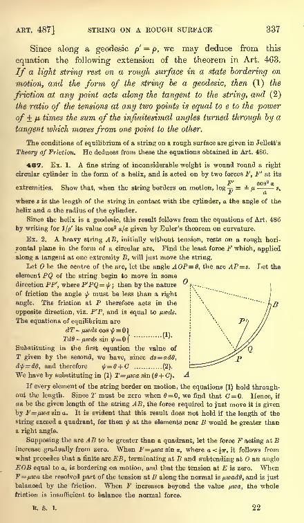
ART. 487] STRING ON A ROUGH SURFACE 337
Since along a geodesic p=
p, we may deduce from this
equation the following extension of the theorem in Art. 463.
If a light string rest on a rough surface in a state bordering on
motion, and the form of the string be a geodesic, then (1) the
friction at any point acts along the tangent to the string, and (2)
the ratio of the tensions at any two points is equal to e to the power
of fi times the sum of the infinitesimal angles turned through by a
tangent which movesfrom one point to the other.
The conditions of equilibrium of a string on a rough surface are given in Jellett's
Theory of Friction. He deduces from these the equations obtained in Art. 486.
487. Ex. 1. A fine string of inconsiderable weight is wound round a right
circular cylinder in the form of a helix, and is acted on by two forces F, F' at its
extremities. Show that, when the string borders on motion, log = p --s,
i) a
where s is the length of the string in contact with the cylinder, a the angle of the
helix and a the radius of the cylinder.
Since the helix is a geodesic, this result follows from the equations of Art. 486
by writing for !//>' its value cos2 a/a given by Euler's theorem on curvature.
Ex. 2. A heavy string AB, initially without tension, rests on a rough hori-
zontal plane in the form of a circular arc. Find the least force F which, applied
along a tangent at one extremity B, will just move the string.
Let be the centre of the arc, let the angle AOP=0, the arc AP=s. Let the
element PQ of the string begin to move in some
direction PP', where P'PQ= \(/ ; then by the nature jv-
of friction the angle \f/must be less than a right
angle. The friction at P therefore acts in the
opposite direction, viz. P'P, and is equal to fj,wds.
The equations of equilibrium are
dT - nwds cos\f/= 1= 1
=0|............
* ''
Substituting in the first equation the value of
T given by the second, we have, since ds= ad6,
d$=d0, and therefore \f/=0 + G ............ (2).
We have by substituting in (1) T=/j.wa sin (6 + C).
If every element of the string border on motion, the equations (1) hold through-out the length. Since T must be zero when = 0, we find that =0. Hence, if
aa be the given length of the string AB, the force required to just move it is given
by F=nwasina. It is evident that this result does not hold if the length of the
string exceed a quadrant, for then ^ at the elements near B would be greater than
a right angle.
Supposing the arc AB to be greater than a quadrant, let the force F acting at Bincrease gradually from zero. When F=pwa sin a, where a<^ir, it follows from
what precedes that a finite arc EB, terminating at B and subtending at an angle
EOB equal to a, is bordering on motion, and that the tension at E is zero. WhenF=fj.wa the resolved part of the tension at B along the normal is pwadO, and is just
balanced by the friction. When F increases beyond the value pwa, the whole
friction is insufficient to balance the normal force.
R. S. I. 22
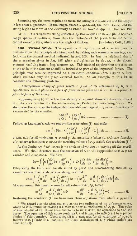
338 INEXTENSIBLE STRINGS [CHAP. X
Summing up, the force required to move the string is F=/j.aw sin a if the lengthis less than a quadrant. If the length exceed a quadrant, the force is paw, and the
string begins to move at the extremity at which the force is applied. See Art. 190.
Ex. 3. If a weightless string stretched by two weights lie in one plane across a
rough sphere of radius a, show that the distance of the plane from the centre
cannot exceed a sine, where e is the angle of friction. [St John's Coll., 1889.]
488. Virtual Work. The equations of equilibrium of a string may be
deduced from the principle of virtual work by taking each element separately, and
following the general method indicated in Art. 203. In fact the left-hand side of
the x equation given in Art. 455, after multiplication by ds . dx, is the virtual
moment resulting from a displacement dx. This method requires that the tensions
at the ends of the element should be included as part of the impressed forces. The
principle may also be expressed as a max-min condition (Art. 212) in a form
which includes only the given external forces. As an example of this let us
consider the following problem.
A heterogeneous string of given length I, fixed at its extremities A, B, is in
equilibrium in one plane in a field of force whose potential is V. It is required to
find the form of the string.
Supposing m=f (s) to be the line density at a point whose arc distance from Ais s, the work function for the whole string is $Vmds, the limits being to I. Weshall take the arc s as the independent variable and regard x, y as two functions of
* connected by the equation
Following Lagrange's rule we remove the restriction (1) and make
& max-min for all variations of x and y, the quantity X being an arbitrary function
of s, afterwards chosen to make the resulting values of x, y satisfy the condition (1) *.
As the limits are fixed, there is no obvious advantage in varying all the coordi-
nates. We shall therefore take the variation of u on the supposition that x, y are
variable and s constant. We have
f I (dV* dV , \ .^/dxdSx dy d8y\) ,
du= I J.m dx + dy ) + 2\ -j- + -/- -/ V ds.
J \ \dx dyy) \ds ds ds ds /J
Integrating the third and fourth terms by parts and remembering that dx, dy
vanish at the fixed ends of the string, we find
f if dV n d f dx\\ , / dV n d /^ dy\\ .
) ,du= I <M ro -2- (X ) )Sx + (?;i
-2 - (\-/- \\8y\ds.J (\ dx ds \ ds J J \ dy ds \ ds J J
J\
At a max-min, this must be zero for all values of dx, dy, hence
dV d /. dx\ dV d / dy\m-j 2 (X =0, m-j 2 X^)=0 (3).dx ds \ ds J dy ds \ ds J
Restoring the condition (1) we have now three equations from which x, y, and X
* We regard s as the abscissa, x, y as the two ordinates of an unknown curve,which is to be found by making u a max-min for all variations of x, y. The rules
of the calculus of variations then enable us to write down the equations to find the
curve. The equation of this curve contains X and is made to satisfy (1) by a properchoice of this quantity. Then since (2) is a max-min for all variations of x, y, it
follows that \Vmdx is a max-min for those variations of x, y which satisfy the
condition (1).
ART. 489] ELASTIC STRINGS 339
may be determined as functions of s. It is evident that these agree with the
equations already found in Art. 455, with 2\ written for T.
We may also deduce the value of \ by multiplying the equations (3) respectively
by dxjds and dy/ds and adding. We then find
d\dV_l d \fdx\*(dy\'\'*-\d \\di) ^(d^) I
~
which agrees with the equation to determine the tension in Art. 479.
If the string is in three dimensions and constrained to rest on a smooth surface,
we make jFmds a max-min subject to the two conditions
x'* + y'2+ z'*-l=0, F(x, y, z)=0 ........................ (I),
where accents denote differentiations with regard to s. Following the same
method as before we make
u=${Vm + \(x'*+ y'*+ z'2 -l) + (jiF(x, y, z)} ds
a max-min. Varying only x, y, z and integrating by parts exactly as before, we
find on equating the coefficients of 5x, 8y, Sz to zero
m-2-\-+=0, <fcc. = 0, &c. = ....... (II),dx ds\ ds / dx
the two latter equations being obtained from the first by writing y and z respec-
tively for x. These three equations joined to the conditions (I) determine x, y, z, X,
/j.in terms of s. These agree with the equations obtained in Art. 478, when - 2X
and -p{F,*+F9*+F/fi are written for T and E.
489. Elastic Strings. The theory of elastic strings dependson a theorem which is usually called Hooke's law. This may be
briefly enunciated in the following manner. Let an extensible
string uniform in the direction of its length have a natural length
l-i. Let this string be stretched by the application of two forces
at its extremities, and let these forces be each equal to T. Let
the stretched length of the string be I. Then it is found by
experiment that the extension I ^ bears to the force T a ratio
which is constant for the same string.
If the natural or unstretched length of the string were
doubled so as to be 2^, the force T being the same as before, it
is clear that each of the lengths ^ would be stretched exactly as
before to a length I. The extension of this string of double lengthwill therefore be twice that of the single string. More generally,
we infer that the extension must be proportional to the natural
length when the stretching force is the same.
Joining these two results together, we see that
TL ~
I'l=
^1~p<
y
where E is some constant, which is independent to the natural
length of the string and of the force by which it is stretched.
222
340 ELASTIC STRINGS [CHAP. X
It is clear that, if two similar and equal strings are placedside by side, they will together require twice the force to producethe same extension that each string alone would require. It
follows that the force required to produce a given extension is
proportional to the area of the section of the unstretched string.
The coefficient E is therefore proportional to the area of the
section of the string when unstretched. The value of E whenreferred to a sectional area equal to the unit of area is called
Young's modulus.
To find the meaning of the constant E, let us suppose that the
string can be stretched to twice its natural length without violat-
ing Hooke's law. We then have l = 2llt and therefore E=T.Thus E is a force, it is the force which would theoretically stretch
the string to twice its natural length.
490. This law governs the extension of other substances
besides elastic strings. It applies also to the compression and
elongation of elastic rods. It is the basis of the mathematical
theory of elastic solids. But at present we are not concerned
with its application except to strings, wires, and such like bodies.
The law is time only when the extension does not exceed
certain limits, called the limits of elasticity. When the stretchingis too great the body either breaks or receives such a permanent
change of structure that it does not return to its original lengthwhen the stretching force is removed. In all that follows, weshall suppose this limit not to be passed.
The reader will find tables of the values of Young's modulus
and the limits of elasticity for various substances given in the
article Elasticity, written by Sir W. Thomson (Lord Kelvin),
for the Encyclopaedia Britannica.
491. Ex. 1. A uniform rod AB, suspended by two equal vertical elastic strings,
rests in a horizontal line ; a fly alights on the rod at C, its middle point, and the
rod is thereupon depressed a distance h;
if the fly walk along the rod, then whenhe arrives at P, the depression of P below its original level is 2h (AP
2 + BP^)/AB2,
and the depression of Q, any other point of the rod, is 2fe (AP .AQ +BP. BQ)/AB2.
[St John's Coll., 1887. J
Ex. 2. A heavy lamina is supported by three slightly extensible threads, whose
unstretched lengths are equal, tied to three points forming a triangle ABC. Showthat when it assumes its position of equilibrium the plane of the lamina will meet
what would be its position in case the threads were inelastic in the line whose areal
equation is xx IE + yyQIF+zzQIG = 0, -where E, F, G are the moduli, and x, y , z^.
the areal coordinates of the centre of gravity of the lamina referred to the triangle
ABC. [St John's Coll., 1885.)
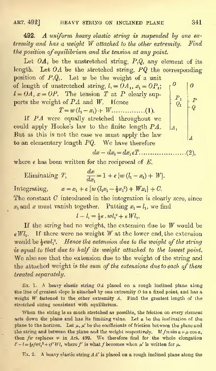
I P
ART. 492] HEAVY STRING ON INCLINED PLANE 341
492. A uniform heavy elastic string is suspended by one ex-
tremity and has a weight W attached to the other extremity. Find
the position of equilibrium and the tension at any point.
Let OA 1 be the unstretched string, P^ any element of its
length. Let OA be the stretched string, PQ the corresponding
position of PjQi. Let w be the weight of a unit
of length of unstretched string, ^ = OA lt xl= OP^,
I = OA, x = OP. The tension T at P clearly sup-
ports the weight of PA and W. Hence -
Q*
T=w(l1 -xl ) + W (1).^
If PA were equally stretched throughout wecould apply Hooke's law to the finite length PA.But as this is not the case we must apply the law
to an elementary length PQ. We have therefore
dx dx1= dx1eT (2),
where e has been written for the reciprocal of E.
Eliminating T, = 1 + e {w (^- x^ + W}.ax1
Integrating, x = xl + e {w (1& ^x^) + WxJ + G.
The constant C introduced in the integration is clearly zero, since
x must vanish together. Putting xl= ll ,
we find
A
If the string had no weight, the extension due to W would be
eTT/j. If there were no weight W at the lower end, the extension
would be ^ewl-f. Hence the extension due to the weight of the string
is equal to that due to half its weight attached to the lowest point.
We also see that the extension due to the weight of the string and
the attached weight is the sum of the extensions due to each of these
treated separately.
Ex. 1. A heavy elastic string OA placed on a rough inclined plane alongthe line of greatest slope is attached by one extremity to a fixed point, and has a
weight W fastened to the other extremity A. Find the greatest length of the
stretched string consistent with equilibrium.
When the string is as much stretched as possible, the friction on every element
acts down the plane and has its limiting value. Let a be the inclination of the
plane to the horizon. Let /JL, /j,' be the coefficients of friction between the plane and
the string and between the plane and the weight respectively. If/=sin a +p cos a,
then fw replaces w in Art. 492. We therefore find for the whole elongation
I'- i= le/wZj2 + e/' Wl, where/' is what /becomes when n' is written for ytt.
Ex. 2. A heavy elastic string A A' is placed on a rough inclined plane along the
342 ELASTIC STRINGS [CHAP. X
line of greatest slope. Supposing the inclination of the plane to be less than tan~Vfind the greatest length to which the string could be stretched consistent with
equilibrium. Compare also the stretching of the different elements of the string.
The frictions near the lower end A of the string will act down the plane, while
those near the upper end A' will act up the plane. There is some point separating
the string into two portions OA, OA' in which the frictions act in opposite directions.
Each of these portions may be treated separately by the method used in the last
example. An additional equation, necessary to find the unstretched length z of OA ,
is obtained by equating the tensions at due to the two portions. The results are
tano\ / tan2 a\.
\ / t
J, Z-^Je/urcosaV \\
--,
- -~^-
.
Ex. 3. A series of elastic strings of unstretched lengths 11 , 12 ,
13 ... are fastened
together in order, and suspended from a point, Zx being the lowest. Show that the
total extension is
where wlt w2 , &c. are the weights per unit of length of unstretched string, el ,
e2 ,&c.
the reciprocals of the moduli of elasticity. [Coll. Exam., 1888.]
493. Work of an elastic string. If the length of a light
elastic string be altered by the action of an external force, the
work done by the tension is the product of the compression of the
string and the arithmetic mean of the initial and final tensions.
In the standard case let the length be increased from a to a',
then a a' is the shortening or compression of the string. As
before, let ^ be the unstretched or natural length.
By referring to Art. 197, we see that the work required is
-Java jj-a jg^-"-^.the limits of the integral being from I = a to I = a'. This result
may be put into the form %(Tl + T2)(a a7
), where Tl and T2
represent the values of T when a and a are written for I. The
rule follows immediately. See the authors Rigid Dynamics 1877.
This rule is of considerable use in dynamics where the length of the string mayundergo many changes in the course of the motion. It is important to notice that
the rule holds even if the string becomes slack in the interval, provided it is
tight in the initial and final states. If the string is slack in either terminal state,
we may still use the same rule provided we suppose the string to have its natural or
unstretched length in that terminal state.
Ex. 1. Show that the depth below the point of suspension of the centre of
gravity of the elastic string considered in Art. 492 is i^ + e^ (%S+ ^W), where S is
the weight of the string. Show also that the work done by gravity as the string
and weight are moved from the unstretched position OA1to the stretched position
OA, is eZj (*S2 +SW+ W 2
)where e=l/.
Ex. 2. Let one end of an elastic string be fixed to the rim of a wheel sufficiently
rough to prevent sliding, and let the other be attached to a mass resting on the
ART. 494] HEAVY STRING ON SMOOTH CURVE 343
ground, so that when the string (of length a) is just taut it shall be vertical. Showthat the work which must be spent in turning the wheel so as just to lift the mass
off the ground is Mga + Ea\og E/(E + Mg), where E is the tension which would
double the length of the string, neglecting the weight of the string. [Math. Tripos.]
Ex. 3. A disc of radius r is connected by n parallel equal elastic strings, of
natural length Za ,
to an equal fixed disc ;the wrench necessary to maintain the
discs at a distance x apart with the moveable one turned through an angle 6 about
the common axis, consists of a force X and a couple L given by
X=nEx(r
-r)
L = 2nEr* sin *(f
~I) '
where 2 =a;2 + 4r2 sm2\6. [Coll. Exam., 1885.]
One disc being moved to a distance x from the other and turned round throughan angle 6, we first show that the length of each string is changed from ^ to .
Using the rule above, the work function is W=n. |T( -l1)=nE (^-Z1 )
2/2i1 .
dW dWBy Art. 208 we have Xdx + Ld6= dx + -j^ d6.
dx dO
Effecting the differentiations X=dW/dx, L dWjdd, we obtain the results given.
494. Heavy elastic string on a smooth curve. Ex. 1. A heavy elastic
string is stretched over a smooth curve in a vertical plane : show that the difference
between the values of T+ T2/2 at any two points of the string is equal to the
weight of a portion of the string whose unstretched length is the vertical distance
between the points. It follows from this theorem that any two points at which,
the tensions are equal are on the same level.
If ds1
is the unstretched length of any element ds of the string, we have byHooke's law ds
l= dsE/(T+E). If then w is the weight per unit of unstretched
length, the weight of any element ds of the stretched string is equal to w'ds, where
w'=wE/(T + E). Let us now form the equations of equilibrium, using the same
figure and reasoning as in Art. 459, where a similar problem is discussed for an
inextensible string. We evidently arrive at the same equations (1) and (2) with
w' written for w. Substituting for w' and integrating, we find that (1) leads to the
result given above.
Ex. 2. A heavy elastic string is stretched on a smooth curve in a vertical plane:
y2 jvshow that T + = wy, Rp- = wy',
where T is the tension at any point P, R the outward pressure of the curve on the
string per unit of length of unstretched string, w the weight of a unit of length of
unstretched string, and y, y' the altitudes of P and its anti-centre above a fixed
horizontal line called the statical directrix of the string, Art. 460. Show also that
no part of the string can be below the directrix, and that the free ends, if there are
any, must lie on it.
Ex. 3. A heavy elastic string rests in equilibrium on a smooth cycloid with its
cusps upwards. If one extremity is attached to a point on the curve while the free
extremity is at the vertex, prove that the stretched length of any unstretched arc s1
measured from the vertex is given by ys= sinhys1 , where 4a_E-y2=i0, and a is the
radius of the generating circle.
Ex. 4. An elastic string rests on a smooth curve whose plane is vertical with
its ends hanging freely. Show that the natural length y may be found from the
344 ELASTIC STKINGS [CHAP. X
equation ( )=
^--
= ,where y is the vertical height above the free extremities,
\ds J 2y + o
and b the natural length of a portion of the string whose weight is the coefficient of
elasticity. If the natural length of each vertical portion be I, and if(l + b)
22ab,
and if the curve be a circle of radius a, prove that the natural length of the portion
in contact with the curve is 2*f(ab) log (^2 + 1). [June Exam., 1877.]
Ex. 5. An elastic string, uniform when unstretched, lies at rest in a smooth
circular tube under the action of an attracting force(JJLT) tending to a centre on the
circumference of the tube diametrically opposite to the middle point of the string.
If the string when in equilibrium just occupies a semicircle, prove that the greatest
tension is {X (\ + 2fj.pa?)}2 -\ twhere X is the modulus of elasticity, a the radius of
the tube, p the mass of a unit of length of the unstretched string.
[Trinity Coll., 1878.]
Ex. 6. An infinite elastic string, whose weight per unit of length when un-
stretched is m, and which requires a tension ma to stretch any part of it to double
its length (when on a smooth table), is placed on a rough table (coefficient /*) in a
straight line perpendicular to its edge. The string just reaches the edge, which is
smooth. A weight ma/x is attached to the end and let hang over the edge. If the
weight takes up its position of rest quietly, so that no part of the string re-contracts
after having been once stretched, show that the distance of the weight below the
edge of the table is \ap. (3/t+ 4), and that beyond a distance \a (/J. + 2) from the edgeof the table the string is unstretched. [Trinity Coll.]
495. Light elastic string on a rough curve. Ex. 1. An elastic string is
stretched over a rough curve so that all the elements border on motion. If no
external forces act on the string except the tensions F, F' at its extremities, then1JT/
-=- e*^, where\f/
is the angle between the normals to the curve at its extremities.f
This follows by the same reasoning as in Art. 463.
Ex. 2. An elastic string (modulus X) is stretched round a rough circular arc
so that every element of it is just on the point of slipping ;if T, T' are the tensions
at its extremities, the ratio of the stretched to the unstretched length is
log~
: log [St John's Coll., 1884.]~
Ex. 3. An endless cord, such as a cord of a window blind, is just long enoughto pass over two very small fixed pulleys, the parts of the cord between the pulleys
being parallel. The cord is twisted, the amount of twisting or torsion being
different in the two parts, and the portions in contact with the pulleys being unable
to untwist. If the pulleys be made to turn slowly through a complete revolution
of the string, show that the quotient of the difference by the sum of the torsions is
decreased hi the ratio e4 : 1. [Math. Tripos, 1853.]
Ex. 4. An elastic band, whose unstretched length= 2a, is placed round four
rough pegs A, B, C, D, which constitute the angular points of a square of side= a.
If it be taken hold of at a point P between A and B, and pulled in the direc-
tion AB, show that it will begin to slip round both A and B at the same time if
AP = al(e*w + 1). [May Exam.]
Ex. 5. An endless slightly extensible strap is stretched over two equal pulleys :
prove that the maximum couple which the strap can exert on either pulley is-- -zr-c coth \\Lir + 2aj/jL
T, where a is the radius of either pulley, c the distance of their
ART. 497] STRING UNDER ANY FORCES 345
centres, /j.the coefficient of friction, and T the tension with which the strap is
put on. [Math. Tripos, 1879.]
Ex. 6. A rough circular cylinder (radius a) is placed with its axis horizontal,
and a string, whose natural length is I, is fastened to a point Q on the highest
generator of the cylinder and to an external point P at a distance I from Q, PQ being
horizontal and perpendicular to the axis of the cylinder ;the cylinder is then slowly
turned upon its fixed axis in the direction away from P; show that the string will
slip continually along the whole of the length in contact with the cylinder until
S (the natural length of the part wound up) = a//t, when all slipping will cease, and
that up to this stage the relation between S and (the angle turned through by the
cylinder) is U^'=(I-
a</>)e*
e+ a<t>, where S=a<t>. [Coll. Exam., 1880.]
496. Elastic string, any forces. To form the equations of
equilibrium of an elastic string under the action of any forces.
Let dsl be the unstretched length of any element ds of the
string. Then by Hooke's law ds = dsl (T+ E)/E. The forces on
the element, due to the attraction of other bodies, will be pro-
portional to the unstretched length. Let then the resolved parts
of these forces along the principal axes of the string be Fds1} Gdsl}
Hdsl ,as in Art. 454. The equations of equilibrium (1), (2), and
(3) of that article are obtained by equating to zero the resolved
parts of the forces along the principal axes of the curve; these
equations will therefore apply to the elastic string if we replace
Fds, Gds, Hds, by Fdsl} Gdsl,Hdsl . The equations of equilibriumfor the elastic string may therefore be derived from those for an
inelastic string by treating the forces as
E ~E ,-,., EHds
rrT+E' T+E' T + E'
i.e. reducing all the impressed forces in the ratio E : T+ E.
497. Suppose, for example, that the string rests on any smooth surface. The
resolution along the tangent to the string (as in Art. 479) gives
,
jii J
It follows that T+T2/2E + the work function of the forces is constant along the
whole length of the string, Art. 479.
Ex. When gravity is the only force acting, show that the equations of equili-
brium of an elastic string corresponding to (1), (2), (3) of Art. 479 may be written
in the simple forms
/ T^\
(WZ+
2EJ
where T is the tension at any point P, R the outward pressure of the surface on the
string per unit of unstretched length, x the angle the radius of curvature of the
string makes with the normal to the surface, z and z' the altitudes of P and the
346 ELASTIC STRINGS [CHAP. X
anti-centre S above a certain horizontal plane, the angle the vertical makes with
the plane containing the normal to the surface and the tangent to the string, and
w the weight of a unit of unstretched length. If PS be a length measured out-
wards along the normal to the surface equal to the radius of curvature of a normal
section of the surface drawn through the tangent at P to the string, S is the anti-
centre of P.
If the surface is one of revolution with its axis vertical, we replace the third
equation by Tr'sin \j/=B, where r' is the distance of P from the axis of the surface,
\j/the angle the tangent to the string makes with the meridian and I? is a constant.
See Art. 481.
498. To take another example, suppose that the elastic string is under the
action of a central force. Taking moments about the centre of force, and resolving
along the tangent to the string, we find, after integration,
These equations may be treated in a manner somewhat similar to that adoptedfor inelastic strings.
499. Ex. 1. An elastic string rests in equilibrium in the form of an arc of a
circle under the influence of a centre of force at any unoccupied point of the circle.
Show that the law of force is F=^ ( 1 + = ir3 \ 2E r2
Ex. 2. An elastic string, whose elements repel each other with a force propor-
tional to the product of their masses into the square of their distance, rests in
equilibrium on a smooth horizontal plane. If T be the tension at a point whose
d4c'2
distance from one extremity is y, show that -j (T+ E)2 + - =
<), where c is ady* L + Jii
constant depending on the nature of the string. Explain also how the constants of
integration are to be determined.
Ex. 3. An elastic string, whose elements repel each other with a force which
varies as the distance, rests on a smooth horizontal plane. If 2/j and 21 be the
unstretched and stretched lengths of the string, show that cZ= tanc^, where Ec-dx
is the force due to the whole string on an element whose unstretched length is dx
when placed at a unit of distance from the middle point of the string.
Ex. 4. A uniform elastic string lying on a rough horizontal plane is fixed to
two points, and forms a curve every part of which is on the point of motion.
/ t\ 2I / dt\ 2
]
Show that the tension is given by the equation I 1 + r) "Uj"; )+ *
f =f?wzp*,
where w is the weight per unit of length of the unstretched string, /j,the coefficient
of friction and p the radius of curvature. [Math. Tripos, 1881.]
Ex. 5. An elastic string has its two ends fastened to points on the surface of a
smooth circular cylinder of which the axis is vertical;show that in the position of
equilibrium of the string on the surface the density of the string at any point varies
as the tangent of the angle which the osculating plane at that point makes with a
normal section of the cylinder through the direction of the string. [Math. T., 1886.]
500. A heavy elastic string is suspended from two fixed points
and is in equilibrium in a vertical plane. To find its equation.
AET. 501] ELASTIC CATENARY 347
We may here use the same method as that employed in Art.
443 to determine the form of equilibrium of an inelastic string.
Referring to the figure of that article, let the unstretched lengthof GP (i.e. the arc measured from the lowest point up to any point
P) be sl} and let the rest of the notation be the same as before.
Consider the equilibrium of the finite portion GP ;
= T (1), Tsin^ = w81 (2),
'
dx 'J-'o c
From these equations we may deduce expressions for # and yin terms of some subsidiary variable. Since sl
= c tan ty by (3), it
will be convenient to choose either sror
-fyas this new variable.
Adding the squares of (1) and (2), we have
y2 _ wz /C2 _|_ s a\
^ itt /4\
Since dx/ds = cos -^ and dyjds = sin-v^,
we have by (1) and (2)
T. , f^c^ , T\^ wc_ , .,_* + V(^ + *-)
T-
[=j
where the constants of integration have been chosen to make
x = and y = c+ c^wj^E at the lowest point of the elastic catenary.
The axis of x is then the statical directrix, Art. 494, Ex. 2.
SOI. Ex. 1. Prove the following geometrical properties of the elastic catenary
(1) wy = T+ j^, (2) p=
(3) . = .1 +^
all of which reduce to known properties of the common catenary when E is made
infinite.
Ex. 2. Let M, M' be two points taken on the ordinate PN so that MM' is
bisected in N by the statical directrix and let each half be equal to T2l2Ew. IfM
be above the directrix draw ML perpendicular to the tangent at P. Show that
T=w .PM, !=PL, c= ML, ic.MN-T^/2E and that M' is the projection of the
anti-centre on the ordinate.
Ex. 3. An elastic string, uniform when unstretched, is hung up by two points.
Prove that the intrinsic equation of the catenary in which it will hang under
gravity is s=ctan^+ xtan^sec i/' + logtan f
j
where c is the natural length of the string whose weight is equal to the tension at
the lowest point, from which s is measured, and X is the natural length of the
string whose weight is equal to the modulus of elasticity. [Coll. Exam., 1880.]
CHAPTER XI
THE MACHINES
502. IT is usual to regard the complex machines as constructed
of certain simple combinations of cords, rods and planes. These
combinations are called the mechanical powers. Though given
variously by different authors, they are generally said to be six in
number, viz. the lever, the pulley, the wheel and axle, the inclined
plane, the wedge and the screw*.
Mechanical advantage. In the simplest cases they are
usually considered as acted on by two forces. One of these, viz.
the force applied to work the machine, is usually called the power.The other, viz. the force to be overcome, or the weight to be raised,
is called the weight. The ratio of the weight to the power is called
the mechanical advantage of the machine.
5O3. As a first approximation, we suppose that the several parts of the machine
are smooth, the cords used perfectly flexible, the solid parts of the machine rigid,
and so on. In some of the machines these suppositions are nearly true, but in
others they are far from correct. It is therefore necessary, as a second approxima-
tion, to modify these suppositions. We take such account as we can of the
roughness of the surfaces in contact, the rigidity of the cords and the flexibility of
the materials. After these corrections have been made, our result is still only an
approximation to the truth, for the corrections cannot be accurately made. For
example, in making allowance for friction we assume that the bodies in contact are
equally rough throughout, and that the coefficient of friction is properly known.
The results however thus obtained are much nearer the real state of things than
our first approximation.
504. Efficiency. Suppose a machine to be constructed of a
combination of levers, pulleys, &c., each acting on the next in order.
* In the descriptions of the machines given in this chapter, the author has
derivpd much assistance from Capt. Eater's Treatise on Mechanics in Lardner's
Cyclopaedia, 1830, Pratt's Mechanical Philosophy, 1842, Willis' Principles ofMechanism, 1870, and other books.
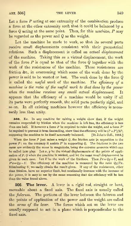
ART. 506] THE LEVER 349
Let a force P acting at one extremity of the combination producea force at the other extremity such that it could be balanced by a
force Q acting at the same point. Then, for this machine, P maybe regarded as the power and Q as the weight.
Let the machine be made to work, so that its several parts
receive small displacements consistent with their geometricalrelations. Such a displacement is called an actual displacement
of the machine. Taking this as a virtual displacement, the work
of the force P is equal to that of the force Q together with the
work of the resistances of the machine. These resistances are
friction &c., in overcoming which some of the work done by the
power is said to be wasted or lost. The work done by the force Qis called the useful work of the machine. The efficiency of a
machine is the ratio of the useful work to that done by the powerwhen the machine receives any small actual displacement. It
appears that the efficiency of a machine would be unity if all
its parts were perfectly smooth, the solid parts perfectly rigid, and
so on. In all existing machines however the efficiency is neces-
sarily less than unity.
5O5. Ex. In any machine for raising a weight show that, if the weightremains suspended by friction when the machine is left free, the efficiency is less
than one half. If however a force P be required to raise the weight, and a force P'
be required to prevent it from descending, show that the efficiency will be (P+P')/2P,
supposing the machine to be itself accurately balanced. [St John's Coll., 1884.]
When the force P just raises a weight Q, the friction acts in opposition to the
power P ; on the contrary it assists P' in supporting Q. The frictions in the two
cases are evidently the same in magnitude, being the extreme amounts which can
be called into play. Let x, y be the virtual displacements of the points of appli-
cation of P, Q when the machine is worked, and let the same small displacement be
given in each case. Let U be the work of the frictions. Then Px Qy+U, and
P'x=Qy-U. The efficiency of the machine is measured by the ratio Qy/Px.
Eliminating U, we easily obtain the result given. If any of the resistances, other
than friction, have no superior limit, but continually increase with the increase of
the power, it is easy to see by the same reasoning that the efficiency will be less
than the value found above.
506. The lever. A lever is a rigid rod, straight or bent,
moveable about a fixed axis. The fixed axis is usually called
the fulcrum. The portions of the lever between the fulcrum and
the points of application of the power and the weight are called
the arms of the lever. The forces which act on the lever are
usually supposed to act in a plane which is perpendicular to the
fixed axis.
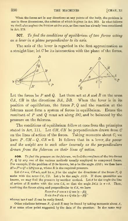
350 THE MACHINES [CHAP, xi
When the forces act in any directions at any points of the body, the problem is
one in three dimensions, the solution of which is given in Art. 268. In what follows
we shall also neglect the friction at the axis, as that case has already been considered
in Art. 179.
507. To find the conditions of equilibrium of two forces acting
on a lever in a plane perpendicular to its axis.
The axis of the lever is regarded in the first approximation as
a straight line; let G be its intersection with the plane of the forces.
U
Let the forces be P and Q. Let them act at A and B on the arms
CA, GB in the directions DA, DB. When the lever is in its
position of equilibrium, the forces P, Q and the reaction at the
fulcrum must form a system of forces in equilibrium. Hence the
resultant of P and Q must act along DC, and be balanced by the
pressure on the fulcrum.
The conditions of equilibrium follow at once from the principles
stated in Art. 111. Let CM, CN be perpendiculars drawn from Con the lines of action of the forces. Taking moments about C, wehave P. CM Q . CN = 0. It follows that in a lever, the powerand the weight are to each other inversely as the perpendiculars
drawn from the fulcrum on their lines of action.
5O8. To find the pressure on the fulcrum, we find the resultant of the two forces
P, Q by any one of the various methods usually employed to compound forces.
For example, if the position of D be known, let<f>be the angle ADB ;
we then have
R2= P*+Q2+ 2PQcos<j>, where R is the required pressure.
Let CA = a, CB= b, and let a, /3 be the angles the directions of the forces P, Qmake with the arms CA, CB. Let y be the angle ACB. If these quantities are
known, we may find the pressure by another method. Let be the angle the line
of action of R makes with the arm CA, so that the angle DCA is IT - 0. Then,
resolving the forces along and perpendicular to CA, we have
.Rcos0 = Pcosa + Q cos (y-p)\R sin 0=P sin a+ Q sin (7
-/3)J
'
whence tan B and R can be easily found.
Other relations between P, Q and R may be found by taking moments about A,
B or some other point suggested by the data of the question. In the same way
ART. 513] THE LEVER 351
other resolutions will sometimes be more convenient than those given above as
specimens.
509. When several forces act on the lever, we find the condition of equilibrium
by equating to zero the sum of their moments about the fulcrum, each moment being
taken with its proper sign. The moments are taken about the fulcrum to avoid
introducing into the equation the reaction at the axis.
To find the pressure on the fulcrum we transfer each force parallel to itself, in the
plane perpendicular to the axis, to act at the fulcrum. We thus obtain a system of
forces acting at a single point, viz. the intersection of the axis with the plane of the
forces. The resultant of these is the pressure on the axis.
510. In the investigation the weight of the lever itself has been supposed to be
inconsiderable compared with the forces P and Q. If this cannot be neglected, let
W be the weight of the lever. There are now three forces acting on the body
instead of two. These are P, Q acting at A and B, and W acting at the centre of
gravity G of the lever. Let the fulcrum be horizontal, and let CL be the per-
pendicular distance between the fulcrum and the vertical through G. Let us also
suppose that in the standard figure the weight W and the force P tend to turn the
lever round the fulcrum in the same direction. . The equation of moments now
becomes P . CM- Q . CN + W. CL = 0. The pressure on the fulcrum is found by
compounding the forces P, Q, W.
511. Levers are usually divided into three kinds according to the relative
positions of the power, the weight, and the fulcrum. In the first kind, the fulcrum
is between the power and the weight. In the second kind the weight acts between
the fulcrum and the power, and in the third kind the power acts between the fulcrum
and the weight. The investigation in Art 507 applies to all three kinds, the only
distinction being in the signs given to the forces and the arms, in resolving and
taking moments.
512. The mechanical advantage of the lever is measured by the ratio Q:P.This ratio has been proved to be equal to CN : CM. By applying the power so
that its perpendicular distance from the fulcrum is greater than that of the weight,
a small power may be made to balance a large weight. Thus a crowbar when used
to move a body is a lever of the second kind. The ground is the fulcrum, the weight
acts near the fulcrum, and the power is applied at the extreme end of the bar.
513. If the lever be slightly displaced by turning it round its
fulcrum through a small angle, the points of application A, B of
the forces P, Q are moved through small arcs A A', BB', whose
centres are on the fulcrum. Thus the actual displacements of the
points of application of the power and the weight are proportional
to their distances from the fulcrum. It is however the resolved
part of the displacement AA' in the direction of the force P which
measures the speed of working. For example, if the force P were
applied by pulling a rope attached to the point A, the amount of
rope to be pulled in would be measured by the resolved partof A A' in the direction of the length of the rope. The resolved
parts of A A', BB' in the direction of the forces P, Q are evidentlyAA' .sina, BB'.sin/B. These are proportional to CA sin a,
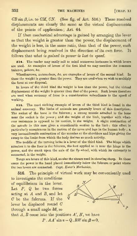
352 THE MACHINES [CHAP. XI
GB sin & i.e. to CM, CN. (See fig. of Art. 516.) These resolved
displacements are clearly the same as the virtual displacementsof the points of application; Art. 64.
If then mechanical advantage is gained by arranging the lever
so that the weight is greater than the power, the displacement of
the weight is less, in the same ratio, than that of the power, each
displacement being resolved in the direction of its own force. It
follows that what is gained in power is lost in speed.
514. The reader may easily call to mind numerous instances in which levers
are used. As examples of levers of the first kind we may mention the common
balance, pokers, &c.
Wheelbarrows, nutcrackers, &c. are examples of levers of the second kind. In
these the weight is greater than the power. They are used when we wish to multiply
the force at our disposal.
In levers of the third kind the weight is less than the power, but the virtual
displacement of the weight is greater than that of the power. Such levers therefore
are used when economy of force is a consideration subordinate to the speed of
working.
515. The most striking example of levers of the third kind is found in the
animal economy. The limbs of animals are generally levers of this description.
The socket of the bone is the fulcrum ; a strong muscle attached to the bone
near the socket is the power ;and the weight of the limb, together with what-
ever resistance is opposed to its motion, is the weight. A slight contraction of
the muscle in this case gives a considerable motion to the limb : this effect is
particularly conspicuous in the motion of the arms and legs in the human body ; a
very inconsiderable contraction of the muscles at the shoulders and hips giving the
sweep to the limbs from which the body derives so much activity.
The treddle of the turning lathe is a lever of the third kind. The hinge which
attaches it to the floor is the fulcrum, the foot applied to it near the hinge is the
power, and the crank upon the axis of the fly-wheel, with which its extremity is
connected, is the weight.
Tongs are levers of this kind, as also the shears used in shearing sheep. In these
cases the power is the hand placed immediately below the fulcrum or point where
the two levers are connected. Capt. Kater's Mechanics.
516. The principle of virtual work may be conveniently used
to investigate the conditions
of equilibrium in the lever.
Let P, Q be two forces
acting at A and B, and let
C be the fulcrum. If the
lever be displaced round G
through a small angle 86, so
that A, B come into the positions A', B', we have
P . AA' sin a - Q . BB' sin = 0,
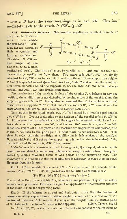
ART. 517] THE LEVER 353
where a, /3 have the same meanings as in Art. 507.
mediately leads to the result P.CM= Q . CN.
This im-
K
This machine supplies an excellent example of
B f
=^^r^iA'
B
E
C
II
517. Roberval's Balance.
the principle of virtual
work. In this balance
the four rods AA', A'B',
B'B, BA are hinged at 1
their extremities and
form a parallelogram.
The sides AB, A'B' are
also hinged at the
points C, C' to a fixed
vertical rod OCC'. The line CC' must be parallel to AA' and BB', but need not
necessarily be equidistant from them. Two more rods MM', NN' are rigidly
attached to A A', BB' so as to be at right angles to them. These support the weightsP and Q suspended in scale-pans from any two points H and K, As the combina-
tion turns smoothly round the supports C, C', the rods A A', BB' remain always
vertical, and MM', NN' are always horizontal.
The peculiarity of the machine is that, if the weights P, Q balance in any one
position, the equilibrium is not disturbed by moving either of the weights along the
supporting rods MM', NN'. It may also be remarked that, if the machine be turned
round its two supports C, C" so that one of the rods MM', NN' descends and the
other ascends, the two weights continue to balance each other.
To show this, let the equal lengths CM, CM' be denoted by a, and the equal lengths
CB, C'B' by ft. Let the inclination to the horizon of the parallel rods AB, A'B' be
0. If the machine is displaced so that the angle is increased by dO, the rod A A'
descends a vertical space a cos OdO, and the rod BB' ascends a space 6 cos OdO.
When the weights of all the parts of the machine are neglected in comparison with
P and Q, we have by the principle of virtual work PacosGd6=Qbcoa6dS. This
gives Pa = Qb; thus the condition of equilibrium is independent of the positions
H, K at which P and Q act on the supporting rods, and is also independent of the
inclination of the rods AB, A'B' to the horizon.
If the balance is so constructed that the weights P, Q are equal, when in equili-
brium, we can detect whether any difference in weight exists between two given
bodies by simply attaching them to any points of the supporting rods. The
advantage of the balance is that no special care is necessary to place them at equal
distances from the fulcrum.
Ex. 1. If 'the weights of the rods AB, A'B' are w, w' and the weights of the
bodies AA'M', BB'N' are W, W, prove that the condition of equilibrium is
(P+ W) a - (Q + W) b + 1 (w +w') (a-
b) =0.
Thence show that, if the weights P, Q balance in one position, they will as before
balance in all positions. Find also the point of application of the resultant pressure
of the stand EF on the supporting table.
Ex. 2. If the balance be at rest and horizontal, prove that the horizontal
pressure on either support bears to either weight the ratio of the difference of the
horizontal distances of the centres of gravity of the weights from the central plane
of the balance to the distance between the supports. [Math. Tripos, 1874.]
Let X, Y; X', Y', be the horizontal and vertical components of the reactions at
R. s. i. 23
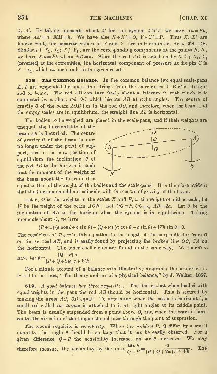
354 THE MACHINES [CHAP, xi
A, A'. By taking moments about A' for the system AM 'A' we have Xa= Ph,
where AA'=a, MH=h. We have also X+ X'= 0, Y+Y' = P. Thus X, X' are
known while the separate values of Y and Y' are indeterminate, Arts. 268, 148.
Similarly if Xlt Yl ; X^, Yj', are the corresponding components at the points B, B',
we have X1a=Pk where NK=k. Since the rod AB is acted on by X, Y; Xlt Y1
(reversed) at the extremities, the horizontal component of pressure at the pin C is
X-Xlt which at once leads to the given result.
518. The Common Balance. In the common balance two equal scale-pans
E, .Fare suspended by equal fine strings from the extremities A, B of a straight
rod or beam. The rod AB can turn freely about a fulcrum 0, with which it is
connected by a short rod OC which bisects AB at right angles. The centre of
gravity G of the beam AOB lies in the rod OC, and therefore, when the beam and
the empty scales are in equilibrium, the straight line AB is horizontal.
The bodies to be weighed are placed in the scale-pans, and if their weights are
unequal, the horizontality of the
,,-- Ibeam AB is disturbed. The centre
of gravity G of the beam is now
no longer under the point of sup-
port, and in the new position of
equilibrium the inclination 6 of
the rod AB to the horizon is such
that the moment of the weight of
the beam about the fulcrum O is
equal to that of the weight of the bodies and the scale-pans. It is therefore evident
that the fulcrum should not coincide with the centre of gravity of the beam.
Let P, Q be the weights in the scales E and F, w the weight of either scale, let
Wbe the weight of the beam AOB. Let OG = h, OC= c, AB= 2a. Let 6 be the
inclination of AB to the horizon when the system is in equilibrium. Takingmoments about 0, we have
(P+ w)(acos0 + csin0)-(Q + w) (a cos 0-c sin 6) + Wh sin B= 0.
The coefficient of P+ w in this equation is the length of the perpendicular from
on the vertical AE, and is easily found by projecting the broken line OC, CA on
the horizontal. The other coefficients are found in the same way. We therefore
have tan 9=
For a minute account of a balance with illustrative diagrams the reader is re-
ferred to the tract, "The theory and use of a physical balance," by J. Walker, 1887.
519. A good balance has three requisites. The first is that when loaded with
equal weights in the pans the rod AB should be horizontal. This is secured by
making the arms AC, CB equal. To determine when the beam is horizontal, a
small rod called the tongue is attached to it at right angles at its middle point.
The beam is usually suspended from a point above O, and when the beam is hori-
zontal the direction of the tongue should pass through the point of suspension.
The second requisite is sensibility. When the weights P, Q differ by a small
quantity, the angle should be so large that it can be easily observed. For a
given difference Q - P the sensibility increases as tan increases. We maytan a
therefore measure the sensibility by the ratioQ-P w)c+Wh'
The
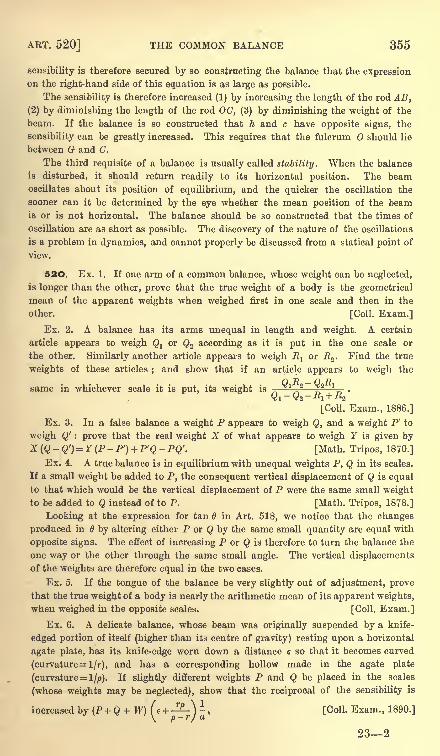
ART. 520] THE COMMON BALANCE 355
sensibility is therefore secured by so constructing the balance that the expressionon the right-hand side of this equation is as large as possible.
The sensibility is therefore increased (1) by increasing the length of the rod AB,
(2) by diminishing the length of the rod OC, (3) by diminishing the weight of the
beam. If the balance is so constructed that h and c have opposite signs, the
sensibility can be greatly increased. This requires that the fulcrum should lie
between G and C.
The third requisite of a balance is usually called stability. When the balance
is disturbed, it should return readily to its horizontal position. The beamoscillates about its position of equilibrium, and the quicker the oscillation the
sooner can it be determined by the eye whether the mean position of the beamis or is not horizontal. The balance should be so constructed that the times of
oscillation are as short as possible. The discovery of the nature of the oscillations
is a problem in dynamics, and cannot properly be discussed from a statical point of
view.
52O. Ex. 1. If one arm of a common balance, whose weight can be neglected,
is longer than the other, prove that the true weight of a body is the geometrical
mean of the apparent weights when weighed first in one scale and then in the
other. [Coll. Exam.]
Ex. 2. A balance has its arms unequal in length and weight. A certain
article appears to weigh Qlor Q2 according as it is put in the one scale or
the other. Similarly another article appears to weigh E1or R2 . Find the true
weights of these articles;and show that if an article appears to weigh the
(~)T> _ f) T>
same in whichever scale it is put, its weight is - * 2 *
[CoU. Exam., 1886.]
Ex. 3. In a false balance a weight P appears to weigh Q, and a weight P' to
weigh Q' : prove that the real weight X of what appears to weigh Y is given byX (Q
-Q')= Y (P - P') + P'Q - PQ'. [Math. Tripos, 1870.]
Ex. 4. A true balance is in equilibrium with unequal weights P, Q in its scales.
If a small weight be added to P, the consequent vertical displacement of Q is equal
to that which would be the vertical displacement of P were the same small weight
to be added to Q instead of to P. [Math. Tripos, 1878.]
Looking at the expression for tan 6 in Art. 518, we notice that the changes
produced in by altering either P or Q by the same small quantity are equal with
opposite signs. The effect of increasing P or Q is therefore to turn the balance the
one way or the other through the same small angle. The vertical displacements
of the weights are therefore equal in the two cases.
Ex. 5. If the tongue of the balance be very slightly out of adjustment, prove
that the true weight of a body is nearly the arithmetic mean of its apparent weights,
when weighed in the opposite scales. [Coll. Exam.]
Ex. 6. A delicate balance, whose beam was originally suspended by a knife-
edged portion of itself (higher than its centre of gravity) resting upon a horizontal
agate plate, has its knife-edge worn down a distance e so that it becomes curved
(curvature= !/?), and has a corresponding hollow made in the agate plate
(curvature= l/p). If slightly different weights P and Q be placed in the scales
(whose weights may be neglected), show that the reciprocal of the sensibility is
increased by (P + Q + W) ( e +-^\ ^* [Coll. Exam., 1890.]
232
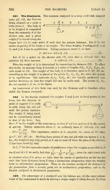
356 THE MACHINES [CHAP. XI
521. The Steelyards. The common steelyard is a lever ACB with unequal
arms AC, CB, the fulcrum
being situated at a point a
little above C. The body Q ^ E=G C D
to be weighed is suspendedfrom the extremity B of the
shorter arm, and a given
weight P is moved along the
longer arm CA to some point H such that the system balances. Let G be the
centre of gravity of the beam, w its weight. The three weights, P acting at H, w at
G, and Q at B are in equilibrium. Taking moments about C, we have
P .HC +w.GC=Q.CB (1).
Let D be a point on the shorter arm CB, such that w . GC=P.CD; the
equation (1) then becomes P.HD=Q.CB (2).
Thus the weight of Q is determined by measuring the distance HD. To effect
this easily, we measure from D towards A a series of lengths DElt E^EZ ,E2E3 , &e.
each equal to CB. The weight of the body Q is therefore equal to P, 2P, 3P, &c.
according as the weight P is placed at the points Elf E2 , E3 , <fec. when the system
is in equilibrium. The intervals E1E2 , E.2E3 , &c. are usually graduated into-
smaller divisions, so that the length HD can be easily read. The points El , E.2y.
&c. are marked 1, 2, &c. in the figure.
An instrument of this form was used by the Romans and is therefore often
called the Roman steelyard.
522. In the Danish steelyard the weights P and Q act at fixed points of the
lever, but the fulcrum or/y
point of support C is made
to slide along the rod AB G Auntil the system balances.
The weight P, being fixed,
can be conveniently joined
to that of the lever. Let,
then, P' be the weight of the instrument, so that P' =P+ 7, and let G be the centre
of gravity. Taking moments about C, we evidently have P'. GC=Q . CB, and
/. BC=p, ,Q
This expression enables us to calculate the values of BC when
Q= P', 2P', 3P', <fcc. Marking these points of the rod AB with the figures 1, 2, 3r
&c. ,the weight of any body placed at B can be read off when the place of the fulcrum
C has been found by trial.
If C, C' be two successive marks of graduation when the weights suspended at B1 1 S
are Q and Q + S, we easily find that =, -^-^ = _.
,, ; since the right-hand side.DC z>G r . ntr
is constant when <S is given, we infer that the marks of graduation on the bar are
such that their distances from B form a harmonical progression when the weightsform an arithmetical progression. Thus in the common steelyard tlw distances ofthe graduations from a certain point are in arithmetical progression, and in the
Danish steelyard in harmonical progression.
523. The advantages of a steelyard over the balance are, (1) the exact adjust-
ment of the instrument is made by moving a single weight P along the rod, (2) when
ART. 524] THE STEELYARDS 357
the body to be weighed is heavier than the fixed weight the pressure on the point of
support is less than in the balance. The steelyard is therefore better adapted to
measure large weights. There is on the other hand this advantage in the balance,
that by using numerous small weights the reading can be effected with greater
precision than by subdividing the arm of the steelyard.
524. Ex. 1. The weight of a common steelyard is w, and the distance of its
fulcrum from the point from which the weight hangs is a when the instrument is in
perfect adjustment ;the fulcrum is displaced to a distance a + a from this end
;show
that the correction to be applied to give the true weight of a body which in the
imperfect instrument appears to weigh W is (fF+P+ tc)a/(a + a), P being the
moveable weight. [Math. Tripos, 1881 ]
Ex. 2. In a weighing machine constructed on the principle of the common
steelyard the pounds are read off by graduations reaching from to 14, and the
stones by weights hung at the end of the arm ;if the weight corresponding to one
stone be 7 oz., the moveable weight \ lb., and the length of the arm one foot, prove
that the distances between the graduations are f in. [Math. Tripos.]
Ex. 3. In graduating a steelyard to weigh pounds, marks are made with a file,
a weight x being removed for each notch. With the moveable weight P at the end
of the beam, n Ibs. can be weighed after the graduation is completed, (ra+ 1)
before it is begun. Show that n (n + 1) x ^P, and find the error made in weighingm pounds. The centre of gravity of the steelyard is originally under the point of
suspension. [Coll. Exam., 1885.]
Ex. 4. Show that, if a steelyard be constructed with a given rod whose weight
is inconsiderable compared with that of the sliding weight, the sensibility varies
inversely as the sum of the sliding weight and the greatest weight which can be
weighed. [Math. Tripos, 1854.]
Ex. 5. A common steelyard is graduated on the assumptions that its weight is
Q, and that the moveable weight is IF, both which assumptions are incorrect. If
two masses whose real weights are P and R appear to weigh P+X and E + Y, then
the weight of the steelyard and the moveable weight are less than their assumed
W O avalues by (X-Y) and
j-(X-Y) + (PY-RX), where b, a are the distances
from the fulcrum to the centre of gravity of the bar and to the point of attachment
of the substance to be weighed, and D=P-R +X-Y. [Math. Tripos, 1887.]
Ex. 6. The sum of the weight of a certain Roman steelyard and of its moveable
weight is S, the fulcrum is at the point C and the body to be weighed is hung at
the end B. The steelyard is graduated and after graduation the fulcrum is shifted
towards B to another point G'. A body is then weighed, the old graduation being
used, and the apparent weight is W. Prove that the true weight is greater than the
apparent weight by (S+ W) CO '/BC '. [Trin. Coll. , 1889.]
Ex. 7. If, on a common steelyard, the moveable weight P, which forms the
power, be increased in the ratio 1 + k : 1, prove that the consequent error in Q, the
weight to be found, is kY, where Y is the weight which must be removed from Q in
order to preserve equilibrium when P is moved close to the fulcrum.
[Coll. Exam., 1885.]
Ex. 8. In the Danish steelyard, if an be the distance of the fulcrum from that
end of the steelyard at which the weight is suspended, the weight being n Ibs., prove
that + i=0. [Math. Tripos, 1859.]
358 THE MACHINES [CHAP. XI
Ex. 9. An old Danish steelyard, originally of weight W Ibs., and accurately
graduated, is found coated with rust. In consequence of the rust, the apparent
weights of two known weights of X Ibs. and Y Ibs. are found when weighed by the
steelyard to be (X- x) Ibs., (Y- y) Ibs. respectively. Prove that the centre of gravity
of the rust divides the graduated arm in the ratio W (x y) : Yx-Xy ; and that its
W+ Y W+Xweight is, to a first approximation, -^ x + y. [Math. Tripos, 1885.]
.A. Y JL A
Ex. 10. A brass figure ABDC, of uniform thickness, bounded by a circular arc
BDC (greater than a semicircle) and two tangents AB, AC inclined at an angle 2o,
is used as a letter-weigher as follows. The centre of the circle, O, is a fixed point
about which the machine can turn freely, and a weight P is attached to the point A ,
the weight of the machine itself being w. The letter to be weighed is suspendedfrom a clasp (whose weight may be neglected) at D on the rim of the circle, ODbeing perpendicular to OA. The circle is graduated, and is read by a pointer which
hangs vertically from : when there is no letter attached, the point A is vertically
below and the pointer indicates zero. Obtain a formula for the graduation of the
circle, and show that, if P=&w sin2o, the reading of the machine will be ^w when
. ((ir + 2a) sin2 o + 2 sin a cos a)OA makes with the vertical an angle equal to tan" 1 <-; > .
( (IT + 2a) sin3 o + 2 cos aj
[Math. Tripos, 1878.]
525. The Pulley. The common pulley consists of a wheel
which can turn freely on its axis. A rope or cord runs in a grooveformed on the edge of the wheel, and is acted on by two forces Pand P' one at each end. If the pulley is smooth and the weightof the string infinitesimal, the tension is necessarily the same
throughout the arc of contact. It follows that the forces P, P'
acting at the extremities of the string are equal to each other and
to the tension. See fig.1 of Art. 527. The same thing is true
if the pulley is rough and circular, but can turn freely about a
smooth axis; Art. 197.
526. When the axis of the pulley is fixed one of the forces
P, Q is the power and the other is the weight. Thus a fixed
pulley has no mechanical advantage in the technical sense. Amachine, however, which enables us to give the most advantageousdirection to the moving power is as useful as one which enables a
small power to support a large weight.
527. A moveable pulley can however be used to obtain
mechanical advantage. Suppose a perfectly flexible string to
be fixed at A, pass under a pulley C of weight Q, and to be acted
on at B by a force P; see fig. 2. In the position of equilibrium
the strings on each side of the pulley meet in the line of action of
the force Q (Art. 34), and must therefore make equal angles with
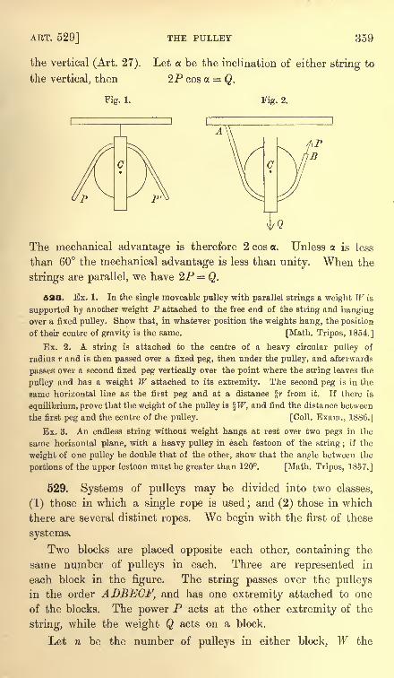
AKT. 529] THE PULLEY 359
the vertical (Art. 27). Let a be the inclination of either string to
the vertical, then 2P cos a = Q.
Fig. 1. Fig. 2.
C
IQ
The mechanical advantage is therefore 2 cos a. Unless a is less
than 60 the mechanical advantage is less than unity. When the
strings are parallel, we have 2P = Q.
528. Ex. 1. In the single moveable pulley with parallel strings a weight W is
supported by another weight P attached to the free end of the string and hangingover a fixed pulley. Show that, in whatever position the weights hang, the position
of their centre of gravity is the same. [Math. Tripos, 1854.]
Ex. 2. A string is attached to the centre of a heavy circular pulley of
radius r and is then passed over a fixed peg, then under the pulley, and afterwards
passes over a second fixed peg vertically over the point where the string leaves the
pulley and has a weight W attached to its extremity. The second peg is in the
same horizontal line as the first peg and at a distance fr from it. If there is
equilibrium, prove that the weight of the pulley is fW, and find the distance between
the first peg and the centre of the pulley. [Coll. Exam., 1886.]
Ex. 3. An endless string without weight hangs at rest over two pegs in the
same horizontal plane, with a heavy pulley in each festoon of the string ;if the
weight of one pulley be double that of the other, show that the angle between the
portions of the upper festoon must be greater than 120. [Math. Tripos, 1857.]
529. Systems of pulleys may be divided into two classes,
(1) those in which a single rope is used; and (2) those in which
there are several distinct ropes. We begin with the first of these
systems.
Two blocks are placed opposite each other, containing the
same number of pulleys in each. Three are represented in
each block in the figure. The string passes over the pulleys
in the order ADBEGF, and has one extremity attached to one
of the blocks. The power P acts at the other extremity of the
string, while the weight Q acts on a block.
Let n be the number of pulleys in either block, W the
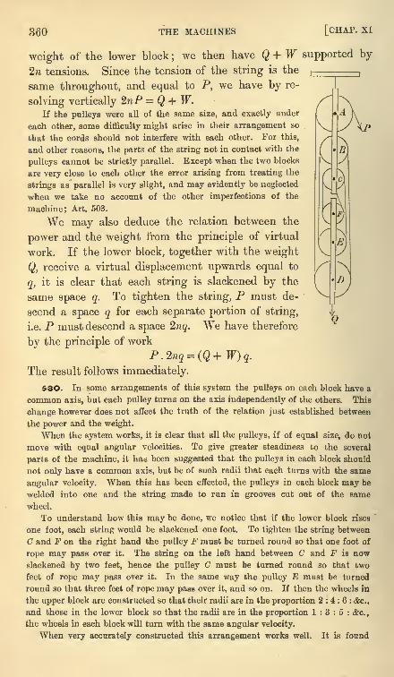
360 THE MACHINES [CHAP, xi
V
V
weight of the lower block;we then have Q + W supported by
2n tensions. Since the tension of the string is the
same throughout, and equal to P, we have by re-
solving vertically 2nP = Q + W.If the pulleys were all of the same size, and exactly under
each other, some difficulty might arise in their arrangement so
that the cords should not interfere with each other. For this,
and other reasons, the parts of the string not in contact with the
pulleys cannot be strictly parallel. Except when the two blocks
are very close to each other the error arising from treating the
strings as parallel is very slight, and may evidently be neglected
when we take no account of the other imperfections of the
machine; Art. 503.
We may also deduce the relation between the
power and the weight from the principle of virtual
work. If the lower block, together with the weight
Q, receive a virtual displacement upwards equal to
q, it is clear that each string is slackened by the
same space q. To tighten the string, P must de-
scend a space q for each separate portion of string,
i.e. P must descend a space 2nq. We have therefore
by the principle of work
P.2nq=(Q+W)q.The result follows immediately.
53O. In some arrangements of this system the pulleys on each block have a
common axis, but each pulley turns on the axis independently of the others. This
change however does not affect the truth of the relation just established between
the power and the weight.
When the system works, it is clear that all the pulleys, if of equal size, do not
move with equal angular velocities. To give greater steadiness to the several
parts of the machine, it has been suggested that the pulleys in each block should
not only have a common axis, but be of such radii that each turns with the same
angular velocity. When this has been effected, the pulleys in each block may be
welded into one and the string made to run in grooves cut out of the same
wheel.
To understand how this may be done, we notice that if the lower block rises
one foot, each string would be slackened one foot. To tighten the string between
C and F on the right hand the pulley F must be turned round so that one foot of
rope may pass over it. The string on the left hand between C and F is nowslackened by two feet, hence the pulley C must be turned round so that two
feet of rope may pass over it. In the same way the pulley E must be turned
round so that three feet of rope may pass over it, and so on. If then the wheels in
the upper block are constructed so that their radii are in the proportion 2:4:6: &c.,
and those in the lower block so that the radii are in the proportion 1:3:5: &c.,
the wheels in each block will turn with the same angular velocity.
When very accurately constructed this arrangement works well. It is found
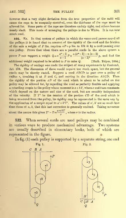
ART. 532] THE PULLEY 361
however that a very slight deviation from the true proportion of the radii will
cause the rope to be unequally stretched, even the thickness of the rope must be
allowed for. Some parts of the rope are therefore unduly tight, and others become
nearly slack. This mode of arranging the pulleys is due to White. It is not now
much used.
531. Ex. In that system of pulleys in which the same cord passes round all
the pulleys it is found that on account of the rigidity of the cord and the friction
of the axle a weight of P Ibs. requires aP+p Ibs. to lift it by a cord passing over
one pulley. Prove that when there are n parallel cords in the above system a
power P can support a weight Q= a P-\ pi ^ p, and find the
additional weight required to be added to P to raise Q. [Math. Tripos, 1884.]
The rigidity of cordage was made the subject of many experiments by Coulomb,
Art. 170. The discussion of these would require too much space, but the general
result may be shortly stated. Suppose a cord ABCD- to pass over a pulley of
radius r, touching it at B and C, and moving in the direction ABCD. Then
the rigidity of the portion AB of the cord which is about to be rolled on the
pulley may be allowed for, by regarding the cord as perfectly flexible and applyinga retarding couple to the pulley whose moment is a + bT, where a and b are constants
which depend on the nature and size of the cord, but are sensibly independentof the velocity. If T' be the tension of the portion CD of the cord which is
being unwound from the pulley, its rigidity may be represented in the same way bythe application of a couple equal to a' + b'T'. The values of a', b' are so much less
than those of a, b, that this last correction is generally omitted. Taking momentsi TiT7
about the centre this gives T' - T=,where r is the radius.
532. When several cords are used pulleys may be combined
in various ways to produce mechanical advantage. Two systemsare usually described in elementary books, both of which are
represented in the figure.
In fig. (1) each pulley is supported by a separate string, one end
Fig. 1. Fig. 2.
C B A
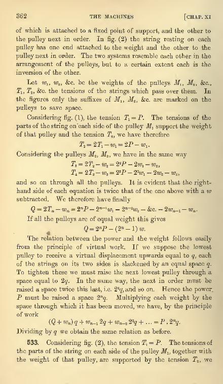
362 THE MACHINES [CHAP. XI
of which is attached to a fixed point of support, and the other to
the pulley next in order. In fig. (2) the string resting on each
pulley has one end attached to the weight and the other to the
pulley next in order. The two systems resemble each other in the
arrangement of the pulleys, but to a certain extent each is the
inversion of the other.
Let wlt w2 ,&c. be the weights of the pulleys Mlt Mz , &c.,
T-i, T2 , &c. the tensions of the strings which pass over them. In
the figures only the suffixes of M1} M2 ,&c. are marked on the
pulleys to save space.
Considering fig. (1), the tension Tl= P. The tensions of the
parts of the string on each side of the pulley Ml support the weightof that pulley and the tension Tz ,
we have therefore
T3 =2T1 -w1= 2P-w1 .
Considering the pulleys Mz ,Ms ,
we have in the same wayT3= 2T2-wa
= 22P - 2wx- w^
T, = 2T3 -w3= 23P - 22
w, - 2w2- w3 ,
and so on through all the pulleys. It is evident that the right-
hand side of each equation is twice that of the one above with a wsubtracted. We therefore have finally
Q = 2Tn -wn = 2nP - 2n-H01- 2n~X - &c. - 2wn_a
- wn .
If all the pulleys are of equal weight this gives
Q=2P-(2-l)w.The relation between the power and the weight follows easily
from the principle of virtual work. If we suppose the lowest
pulley to receive a virtual displacement upwards equal to q, each
of the strings on its two sides is slackened by an equal space q.
To tighten these we must raise the next lowest pulley through a
space equal to 2q. In the same way, the next in order must be
raised a space twice this last, i.e. 22
q, and so on. Hence the powerP must be raised a space 2nq. Multiplying each weight by the
space through which it has been moved, we have, by the principle
of work
(Q + >) q + wn_j 2q + wn..2 22
q + . . .= P . 2nq.
Dividing by q we obtain the same relation as before.
533. Considering fig. (2), the tension 2\ = P. The tensions of
the parts of the string on each side of the pulley Ml , together with
the weight of that pulley, are supported by the tension T2 ,we
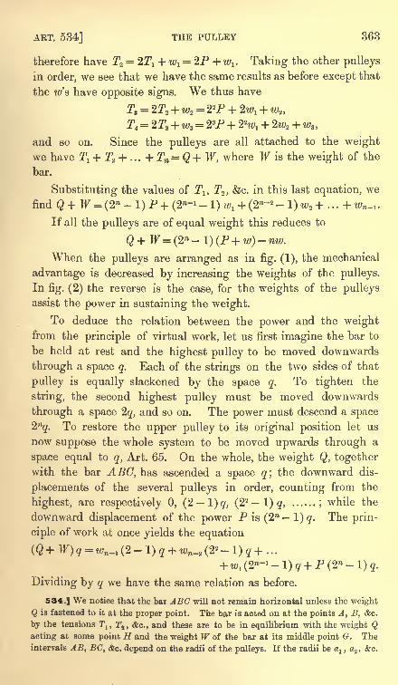
ART. 534] THE PULLEY 363
therefore have T2= 22\ + w1
= 2P + /a . Taking the other pulleys
in order, we see that we have the same results as before except that
the /s have opposite signs. We thus have
T3= 2r2 + w2
= 22P + Z
T. = 2T3 + ws= 23P + 2X
and so on. Since the pulleys are all attached to the weight
we have T1 + T* + ... +Tn=Q+W, where W is the weight of the
bar.
Substituting the values of Tlt T2 , &c. in this last equation, we
find Q+ F = (2n -l)P+(2w-1
-l)M;1 -t-(2w-2 -l)w2 + ...+;_,.
If all the pulleys are of equal weight this reduces to
When the pulleys are arranged as in fig. (1), the mechanical
advantage is decreased by increasing the weights of the pulleys.
Infig. (2) the reverse is the case, for the weights of the pulleys
assist the power in sustaining the weight.
To deduce the relation between the power and the weightfrom the principle of virtual work, let us first imagine the bar to
be held at rest and the highest pulley to be moved downwards
through a space q. Each of the strings on the two sides of that
pulley is equally slackened by the space q. To tighten the
string, the second highest pulley must be moved downwards
through a space 2q, and so on. The power must descend a space2n
q. To restore the upper pulley to its original position let us
now suppose the whole system to be moved upwards through a
space equal to q, Art. 65. On the whole, the weight Q, togetherwith the bar ABC, has ascended a space q',
the downward dis-
placements of the several pulleys in order, counting from the
highest, are respectively 0, (2 l)q, (22
1) q, ......;while the
downward displacement of the power P is (2n
l)q. The prin-
ciple of work at once yields the equation
+ w1 (2"-1 -
1) q + P (2W -
1) q.
Dividing by q we have the same relation as before.
534.] We notice that the bar ABC will not remain horizontal unless the weight
Q is fastened to it at the proper point. The bar is acted on at the points A, B, &c.
by the tensions Tlt T2 , <fec., and these are to be in equilibrium with the weight Qacting at some point H and the weight W of the bar at its middle point G. Theintervals AB, BC, &c. depend on the radii of the pulleys. If the radii be a
a ,a2 , &c.
364 THE MACHINES [CHAP. XI
we have AB = 2a2- CT
I ,BC=2a3
- a2 ,and so on. Taking moments about A we have
This equation determines the position of H.
If the weights of the strings or ropes cannot be neglected, we may suppose the
weight of the portion of string between the pulleys 1/j , 3/2 included in the weight
7j , that of the portion between the pulleys l/2 , If3included in w2 ,
and so on. The
portions of string which join the points A, B, C, &c. to the pulleys are supported bythe fixed beam ABC, &c. in fig. (1), and may be included in the weight of the bar
in fig. (2). The weight of the string wound on any pulley may be included in the
weight of that pulley.
The system of pulleys represented in fig. (1) of Art. 532 is sometimes called the
first system. That represented in Art. 529 is the second system; while the one drawn
in fig. (2) of Art. 532 is the third system.
535. When the weights of the pulleys are neglected and each hangs by a
separate string, we can easily find the relation
between the power and the weight when the
strings are not parallel.
Let 2^, 2a2 , 2a3 , cfec. be the angles be-
tween free parts of the strings which pass
over the pulleys .3/j ,3/2 ,
M3 ,&c. respectively.
Let also Tlt T2 ,T3 , &c. be the tensions.
(.3)
Then by the same reasoning as before
P T 271 on* n T IT on<j n fcf>j f ,
-i. 2 Af-i-tvyottj, J-2 2 ^^^*
^~2 '
If there are n pulleys we easily obtain Q=2P . cos ax . cos 0% . &c. cos ou .
536. Ex. 1. In that system of pulleys in which all the strings are attached to
the weight, if the weight of the lowest pulley be equal to the power P, of the second
3P, and so on... that of the highest moveable pulley being 3n~2 P, the ratio of
P : W will be 2 : 3n - 1. [Math. Tripos, 1856.]
Ex. 2. In that system of pulleys in which each hangs by a separate string
from a horizontal beam the weights of the pulleys, beginning with the highest, are
in arithmetical progression, and a power P supports a weight Q ; the pulleys are
then reversed, the highest being placed lowest, and the second highest placed
lowest but one, and so on, and now Q and P when interchanged are in equilibrium ;
show that n(Q + P) = 2W, where IF is the total weight of the pulleys, and n the
number of pulleys. [Coll. Exam., 1882.]
Ex. 3. In a system of n pulleys where a separate string goes round each pulley
and is attached to the weight, if the string which goes over the lowest have the end,
at which the power is usually hung, passed under another moveable pulley and
then over a fixed pulley, and attached to the weight Q ;and if the weight of each
pulley be w and no other power be used, prove that Q = (3 . 2B-1 - n - 1) w, and find
the point of the beam at which Q must be hung. [Math. Tripos, 1876.]
Ex. 4. In that system of pulleys in which each of the strings, supposed parallel,
is attached to the weight, if the power be equal to the weight of the lowest pulley,
and if each pulley weigh three times as much as the one immediately below it,
prove that the weight of each pulley is equal to the tension of the string passing
over it. [Coll. Exam.]
Ex. 5. In the system of pulleys in which each hangs by a separate string, all
ART. 536] THE PULLEY 365
the strings being vertical, if W be the weight supported, and wlt wz ......wn the
weights of the moveable pulleys, there will be no mechanical advantage unless
be positive. [Math. Tripos, 1869.]
Ex. 6. In the system of n heavy pulleys in which each hangs by a separate
string, P is the power (acting upwards), Q the weight, and R the stress on the
beam from which the pulleys hang : show that R is greater than Q (1- %2~n
)and
less than (2n -
1) P. [Math. Tripos, 1880.]
Ex. 7. If there be two pulleys, without weight, which hang by separate strings,
the fixed ends only of the string being parallel, and the power horizontal, prove
that the mechanical advantage is ^/3. [St John's Coll., 1883.]
Ex. 8. In that system of pulleys, in which all the strings are attached to the
weight, if the power be made to descend through one inch, through what distance
will the weight rise ? Illustrate by reference to this system of pulleys the principle
which is expressed by the words," In machines, what is gained in power is lost in
time." [Math. Tripos, 1859.]
Ex. 9. In the system of pulleys in which all the strings are attached to the
weight Q, prove that, if the pulleys be small compared with the lengths of the
strings, the necessary correction for the weight of the strings is the addition to
Q, iCj, w2 ...wn_l respectively, of the weights of lengths
h1 + h2 +... + hn^1 + h, 2 (! -A), 2 (hz
-h^.,.2 (h^ - hn_J
of string ;where h^, h2 ,
h3 ...hn are the heights of the n pulleys (whose weights are
tCj, w2 ...wn respectively) above the line of attachment, supposed horizontal, of the
strings to the weight Q, and h the height of the point of attachment of the powerabove the same line. [Math. Tripos, 1877.]
Ex. 10. In that system of pulleys in which the strings are all parallel, and the
weights of the pulleys assist the power, show that, if there are n pulleys, each of
diameter 2a and weight w, the distance of the point of suspension of the weight
from the line of action of the power is equal to
where Q is the weight. [Math. Tripos, 1883.]
Ex. 11. In a system of four pulleys, arranged so that each string is attached to
a bar carrying the weight, the string which usually carries the power is attached to
one end of the same bar, and the fourth string to the other end. The weight and
diameter of each pulley are respectively double of those of the pulley below it, and
the strings are 'all parallel. The weight being 33 times that of the lowest pulley,
find at what point of the bar it is hung. [Trin. Coll., 1885.]
Ex. 12. In the system of pulleys, in which each pulley hangs by a separate
string with one end attached to a fixed beam, there are n moveable pulleys of
equal weight w. The rth string, counting from the string round the highest
pulley, cannot bear a greater tension than T. Prove that the greatest weight which
can be sustained by the system is 2n~r+l T - (2-
r+i -1) w. [Trin. Coll., 1890. ]
Ex. 13. It is found that any force P being applied to the extremity of a string
passing over a pulley can just raise a weight P (1-
0). In the system of pulleys in
which each hangs by a separate string a weight Q is just supported, the weight of
each pulley being aQ. If a and 6 are small quantities, whose squares and products
may be neglected, show that an additional power equal to n6QI2n can be applied
without affecting the equilibrium. [Coll. Exam., 1888.]
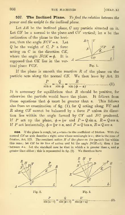
366 THE MACHINES [CHAP. XI
537. The Inclined Plane. To find the relation between the
power and the weight in the inclined plane.
Let AB be the inclined plane, C any particle situated on it.
Let CN be a normal to the plane and GV vertical; let a be the
inclination of the plane to the hori-
zon, then the angle NCV = a. Let
Q be the weight of C, P a force
acting on C in the direction CK,where the angle NCK = <. It is
supposed that CK lies in the ver-
tical plane VCN, Fig. l.
If the plane is smooth the reaction R of the plane on the
particle acts along the normal CN. We then have by Art. 35
sm a sin<f>
sm(<f> a)
It is necessary for equilibrium that R should be positive, for
otherwise the particle would leave the plane. It follows from
these equations that(j>
must be greater than a. This follows
also from an examination offig. (1), for Q acting along VC and
R along CN cannot be balanced by a force P unless its direc-
tion lies within the angle formed by GV and NC produced.If P act up the plane, < = TT and P = Q sin a, R= Q cos a.
If P act horizontally, < =^TT + a, and P = Q tan a, R = Q sec o.
538. If the plane is rough, let ^i=tan e be the coefficient of friction. With the
normal CN as axis describe a right cone whose semi-angle is e;this is the cone of
friction, Art. 173. The resultant action E' of the plane on the particle lies within
this cone; let CH be its line of action and let the angle NCH=i\ then i lies
between e. Let the standard case be that hi which a is greater than e, and<f>
greater than either ; this is represented in fig. (2). We therefore have
Fig. 2. Fig. 3.
sin(a-i) si.(2).
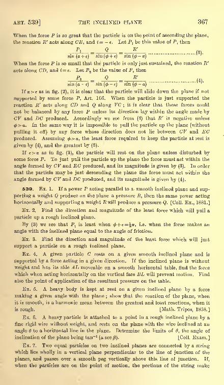
ART. 539] THE INCLINED PLANE 367
When the force P is so great that the particle is on the point of ascending the plane,
the reaction E' acts along CE, and i= -e. Let P1be this value of P, then
-Pi-- Q B'
(3).
sin(a+ e) sin(0+e) sin(<-a)
When the force P is so small that the particle is only just sustained, the reaction R'
acts along CD, and i= e. Let P2 be the value of P, then
P R'
__ _.
sin (a-
e)sin (p
-e)
sin(<f>
-a)
If a>e as in fig. (2), it is clear that the particle will slide down the plane if not
supported by some force P, Art. 166. When the particle is just supported the
reaction E' acts along CD and Q along VC;
it is clear that these forces could
not be balanced by any force P unless its direction lay within the angle made byCV and DC produced. Accordingly we see from (4) that E' is negative unless
<( a. In the same way it is impossible to pull the particle up the plane (without
pulling it off) by any force whose direction does not lie between CV and ECproduced. Assuming <fa, the least force required to keep the particle at rest is
given by (4), and the greatest by (3).
If e>a as in fig. (3), the particle will rest on the plane unless disturbed bysome force P. To just pull the particle up the plane the force must act within the
angle formed by CV and EC produced, and its magnitude is given by (3). In order
that the particle may be just descending the plane the force must act within the
angle formed by CV and DC produced, and its magnitude is given by (4).
539. Ex. 1. If a power P acting parallel to a smooth inclined plane and sup-
porting a weight Q produce on the plane a pressure R, then the same power acting
horizontally and supporting a weight Pi will produce a pressure Q. [Coll. Ex., 1881.]
Ex. 2. Find the direction and magnitude of the least force which will pull a
particle up a rough inclined plane.
By (3) we see that Px
is least when<j> + e=%ir, i.e. when the force makes an
angle with the inclined plane equal to the angle of friction.
Ex. 3. Find the direction and magnitude of the least force which will just
support a particle on a rough inclined plane.
Ex. 4. A given particle C rests on a given smooth inclined plane and is
supported by a force acting in a given direction. If the inclined plane is without
weight and has its side AL moveable on a smooth horizontal table, find the force
which when acting horizontally on the vertical face BL will prevent motion. Find
also the point of application of the resultant pressure on the table.
Ex. 5. A heavy body is kept at rest on a given inclined plane by a force
making a given angle with the plane ; show that the reaction of the plane, whenit is smooth, is a harmonic mean between the greatest and least reactions, when it
is rough. [Math. Tripos, 1858.]
Ex. 6. A heavy particle is attached to a point in a rough inclined plane by a
fine rigid wire without weight, and rests on the plane with the wire inclined at an
angle 6 to a horizontal line in the plane. Determine the limits of 6, the angle of
inclination of the plane being tan" 1
(p. sec /3). [Coll. Exam.]
Ex. 7. Two equal particles on two inclined planes are connected by a string
which lies wholly in a vertical plane perpendicular to the line of junction of the
planes, and passes over a smooth peg vertically above this line of junction. If,
when the particles are on the point of motion, the portions of the string make
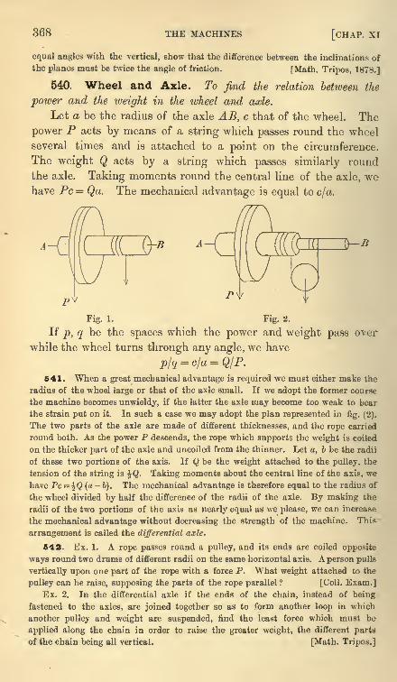
368 THE MACHINES [CHAP, xi
equal angles with the vertical, show that the difference between the inclinations of
the planes must be twice the angle of friction. [Math. Tripos, 1878.]
540. Wheel and Axle. To find the relation between the
power and the weight in the wheel and axle.
Let a be the radius of the axle AB, c that of the wheel. The
power P acts by means of a string which passes round the wheel
several times and is attached to a point on the circumference.
The weight Q acts by a string which passes similarly round
the axle. Taking moments round the central line of the axle, wehave PC Qa. The mechanical advantage is equal to c/a.
Fig. 1. Fig. 2.
If p, q be the spaces which the power and weight pass over
while the wheel turns through any angle, we have
p/q = c/a=QIP.541. When a great mechanical advantage is required we must either make the
radius of the wheel large or that of the axle small. If we adopt the former course
the machine becomes unwieldy, if the latter the axle may become too weak to bear
the strain put on it. In such a case we may adopt the plan represented in rig. (2).
The two parts of the axle are made of different thicknesses, and the rope carried
round both. As the power P descends, the rope which supports the weight is coiled
on the thicker part of the axle and uncoiled from the thinner. Let a, b be the radii
of these two portions of the axis. If Q be the weight attached to the pulley, the
tension of the string is %Q. Taking moments about the central line of the axis, we
have Pc = \Q(a-b). The mechanical advantage is therefore equal to the radius of
the wheel divided by half the difference of the radii of the axle. By making the
radii of the two portions of the axis as nearly equal as we please, we can increase
the mechanical advantage without decreasing the strength of the machine. This
arrangement is called the differential axle,
542. Ex. 1. A rope passes round a pulley, and its ends are coiled opposite
ways round two drums of different radii on the same horizontal axis. A person pulls
vertically upon one part of the rope with a force P. What weight attached to the
pulley can he raise, supposing the parts of the rope parallel ? [Coll. Exam.]Ex. 2. In the differential axle if the ends of the chain, instead of being
fastened to the axles, are joined together so as to form another loop in which
another pulley and weight are suspended, find the least force which must be
applied along the chain in order to raise the greater weight, the different parts
of the chain being all vertical. [Math. Tripos.]
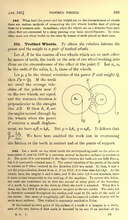
ART. 545] TOOTHED WHEELS 369
543. When both the power and the weight act on the circumference of wheels
there are various methods of connecting the two wheels besides that of putting
them on a common axis. Sometimes, when the wheels are at a distance from each
other, they are connected by a strap passing over their circumferences. In some
other cases one wheel works on the other by means of teeth placed on their rims.
544. Toothed Wheels. To obtain the relation between the
power and the weight in a pair of toothed wheels.
Let A, B be the centres of two wheels which act on each other
by means of teeth, the teeth on the axis of one wheel working into
those on the circumference of the other at the point C. Let c^, aa
be the radii of the axles, 61} b2 those of the wheels.
Let p, q be the virtual velocities of the power P and weight Q,
then Pp = Qq. If the teeth Eare small the average velo-
cities of the points near Con the two wheels are equal,
and the common direction is
perpendicular to the straight
line AB. If then Ol , 2 are
the angles turned through bythe wheels when the powerP receives a small displace-
ment, we have a^ = b2 2 . But p = It follows that
5 = . We have here omitted the work lost in overcomingJL Ct^(t2
the friction at the teeth in contact and at the points of support.
545. Let a tooth on one wheel touch the corresponding tooth on the other in
some point D, and let EDF be a common normal to the two surfaces in contact at
D. The point D is not marked in the figure because the teeth are not fully drawn,but it is necessarily situated near (7. The actual velocities of the points of the teeth
in contact at D when resolved in the direction EDF are equal. If, then, h and k
are the perpendiculars drawn from A, B on EDF, it is clear that Oih=0jt. As the
wheels turn, the lengths h and k alter, and if the ratio hjk is not constant, there
is more or less irregularity in the working of the machine. To correct this defect,
the teeth are sometimes cut so that the normal at every point of the boundaryof a tooth is a tangent to the circle to which the tooth is attached. When this is
done, the line EDF is always a common tangent to the two circles. The ratio h/kis therefore constant throughout the motion and equal to the ratio of the radii of
the circles. One cause of irregularity will thus be removed and the motion will be
made more uniform. This method is commonly ascribed to Euler.
If the normal at every point of the surface of a tooth is a tangent to a circle,
each of the two halves of that tooth is bounded by an arc of an involute of the
L 24
370 THE MACHINES [CHAP. XI
circle. The two involutes are unwrapped from the circle in opposite directions and
portions of each form the sides of the tooth.
When the centres of the toothed wheels are given, and the ratio of the angularvelocities at which they are to work, we may determine their radii in the followingmanner. Let A, B be the given centres ; divide AB in C so that AC . 6
l=BC . 62 .
Through C draw a straight line EOF, which should not deviate very much from a
perpendicular to AB. With A and B as centres describe two circles touching the
straight line EOF. The sides of the teeth are to be involutes of these circles. Bythis construction the common normal to two teeth pressing against each other at Dis the straight line ECF. As the wheels turn round, and the teeth move with them,the point of contact D travels along the fixed straight line ECF. The perpen-diculars h and k are equal to the radii of these circles and are constant during the
motion. Their ratio also is evidently equal to the ratio of AC to BC, i.e. of
2 to 61
.
It has already been shown that Pp= Qq, and p= bl61 , q = a2 2 . Since
1h=
2k,
we find as before = -^-2.P ttjOj
We may notice that, if the distance between the centres A and B is slightly
altered, the pair of wheels will continue to work without irregularity and the ratio
of the angular velocities will be the same as before. To prove this, we observe that
the common normal to two teeth pressing against each other is still a common
tangent to the two circles, though in their displaced positions. Thus, though the
inclination to AB of the straight line ECF is altered, the lengths of the perpen-
diculars h and k are the same as before.
That the teeth should be made of the proper form is a matter of importance
to the even working of the machine. Many other considerations enter into the
theory besides that mentioned above. Thus defects may arise from the wearing of
the teeth if the pressure be very great at the point of contact. There may also be
jolts and jars when the teeth meet or separate. But the subject is too large to be
treated of in a division of a chapter. The reader who is interested in this matter
is referred to books on the principles of mechanism. In Willis' Principles of
Meclianism (2nd edition, 1870) five different methods of constructing the teeth are
described, in three of which epicycloids are used ; the advantages and disadvantages
of these constructions are also compared.
546. Ex. 1. In a train of n wheels, the teeth on the axle of each wheel work
on those on the circumference of the next in order. Show that the power and
weight are connected by the relation ^ = 1 2 '" ",where Oj ,
a2 &c. are the radii" ala2---an
of the axles andfej ,
62 &c. those of the wheels.
Ex. 2. In a pair of toothed wheels show that, if the ratio of the power and
weight is to be approximately constant, the height and breadth of the teeth must
both be small relatively to the radius of each wheel.
Two equal and similar wheels, with straight narrow radial teeth, are started
with a tooth of each in contact and in the same straight line;show that they will
work together without locking, provided that the distance of their centres be
greater than 2acos2jr/n and less than 2acos7r//t, where a is the radius of either wheel
measured to the summit of a tooth, and n the number of teeth. [Math. T., 1872.]
Ex. 3. Investigate the relation QIP=b 1b<2lai
a2 f r a Paif f toothed wheels
without using the principle of virtual work.
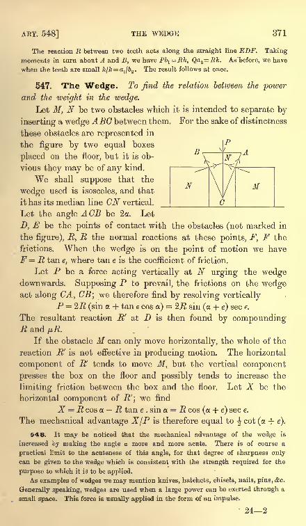
AET. 548] THE WEDGE 371
The reaction R between two teeth acts along the straight line EDF. Taking
moments in turn about A and B, we have Pb^ Rh, Qa2= Rk. As before, we have
when the teeth are small 7t//c= a
1/62 . The result follows at once.
547. The Wedge. To find the relation between the powerand the iveight in the wedge.
Let M, N be two obstacles which it is intended to separate by
inserting a wedge ABC between them. For the sake of distinctness
these obstacles are represented in
the figure by two equal boxes
placed on the floor, but it is ob-
vious they may be of any kind.
We shall suppose that the
wedge used is isosceles, and that
it has its median line CN vertical.
Let the angle A CB be 2oc. Let
D, E be the points of contact with the obstacles (not marked in
the figure), R, R the normal reactions at these points, F, F the
frictions. When the wedge is on the point of motion we have
F = R tan e, where tan e is the coefficient of friction.
Let P be a force acting vertically at N urging the wedgedownwards. Supposing P to prevail, the frictions on the wedgeact along CA, CB; we therefore find by resolving vertically
P = 2R (sin a + tan e cos a)= 2R sin (a + e) sec e.
The resultant reaction R' at D is then found by compoundingR and pR.
If the obstacle M can only move horizontally, the whole of the
reaction R' is not effective in producing motion. The horizontal
component of R' tends to move M, but the vertical component
presses the box on the floor and possibly tends to increase the
limiting friction between the box and the floor. Let X be the
horizontal component of R'; we find
X R cos a. R tan e . sin a = R cos (a + e) sec e.
The mechanical advantage X/P is therefore equal to \ cot (a + e).
548. It may be noticed that the mechanical advantage of the wedge is
increased by making the angle a more and more acute. There is of course a
practical limit to the acuteness of this angle, for that degree of sharpness onlycan be given to the wedge which is consistent with the strength required for the
purpose to which it is to be applied.
As examples of wedges we may mention knives, hatchets, chisels, nails, pins, &c.
Generally speaking, wedges are used when a large power can be exerted through a
small space. This force is usually applied in the form of an impulse.
242
372 THE MACHINES [CHAP. XI
It has not been considered necessary to consider separately the case in which
the wedge is smooth, as the results obtained on so erroneous a supposition have no
practical bearing.
549. If the force is applied in the form of a blow so that the
wedge is driven forwards between the obstacles, the problem to
determine its motion is properly one in dynamics. Our object
here is merely to find the conditions of equilibrium of a triangular
body inserted between two rough obstacles and acted on by a
force P.
When a series of blows is applied to the wedge, we mayhowever enquire what happens in the interval between two
impulses. The wedge may either stick fast, held by the friction,
or begin to return to its original position, being pressed back bythe elasticity of the materials. Assuming that these forces of
restitution may be represented by two equal pressures R, R,
acting on the sides of the wedge, let Pl be the force necessary
to hold the wedge in position. The friction now acts to assist
the power. To determine Pl we write e for e in the equationsof equilibrium. We therefore have
Pl= ZR sin (a e) sec e.
If a is greater than e, P 1is positive and therefore some force is
necessary to hold the wedge in position. If a. is less than e, Pt
is negative, thus the friction is more than sufficient to hold the
wedge fast. A force equal to this value of Pl with the sign
changed is necessary to pull the wedge out. The result is that
the wedge will stick fast or come out according as the angle ACSis less or greater than twice the angle of friction.
Ex. 1. Referring to the figure of Art. 547, show that if either of the equal
angles A or B of the wedge is less than the angle of friction, no force P however
great could separate the obstacles M, N.
If the angle A is less than e, we find that a + e is greater than a right angle, and
therefore that X is negative. It is easy also to see that, if the angle A is equal to e,
the resultant reaction between one side of the wedge and an obstacle is vertical.
The wedge therefore merely presses the obstacle against the floor.
Ex. 2. If the obstacles M, N are not of the same altitude and are unequally
rough, the position of the wedge when in equilibrium is such that the force P:and
the resultant actions .R/, B2
'across the faces meet in a point. Supposing the force
Pj to act perpendicularly to the face AB of the wedge and to be just sufficient toT) r> ' T> f
hold the wedge at rest, show that -, = = ~. = 7^ . , assuming
sin (2a- e
t-ej cos^-ej) cos(a-e2)
the obstacles to be of such form that the wedge must slip at both simultaneously.
Show also that, if the wedge be such that the angle C is less than the sum of the
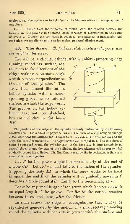
ART. 550] THE SCREW 373
angles el + e2 ,
the wedge can be held fast by the frictions without the application of
any force.
Ex. 3. Deduce from the principle of virtual work the relation between the
force X and the power P in a smooth isosceles wedge as represented in the figure
of Art. 547. Discuss the two cases in which (1) one obstacle is immoveable and
(2) both move equally when the wedge makes an actual displacement.
550. The Screw. To find the relation between the power and
the weight in the screw.
Let AB be a circular cylinder with a uniform projecting ridge
running round its surface, the
tangents to the directions of the
ridges making a constant angle
a with a plane perpendicular to
the axis of the cylinder. The
screw thus formed fits into a
hollow cylinder with a corre-
sponding groove on its internal
surface, in which the ridge works.
The grooves on the hollow cy-
linder have not been sketched,
but are included in the beam
EF.
O D
E
The position of the ridge on the cylinder is easily understood by the following
construction. Let a sheet of paper be cut into the form of a right-angled triangle
LMN, such that the altitude MN is equal to the altitude of the cylinder AB and the
angle the base LM makes with the hypothenuse LN is equal to a. Let this sheet of
paper be wrapped round the cylinder AB; if the base LM is long enough to go
several times round the base of the cylinder, the hypothenuse will appear to wind
gradually round the cylinder. The line thus traced by the hypothenuse is the curve
along which the ridge lies.
Let P be the power applied perpendicularly at the end of
a lever CD. Let AC = a, and let b be the radius of the cylinder.
Supposing the body EF in which the screw works to be fixed
in space, the end B of the cylinder will be gradually moved as Cdescribes a circle round AB. Let Q be the force acting at B.
Let a- be any small length of the screw which is in contact with
an equal length of the groove. Let Her be the normal reaction
between these small arcs, /j,R(r the friction.
In some screws the ridge is rectangular, so that it may be
regarded as generated by the motion of a small rectangle movinground the cylinder with one side in contact with the surface and
374 THE MACHINES [CHAP. XI
its plane passing through the axis. When the ridge has this form,
the line of action of R lies in the tangent plane to the cylinder and
its direction makes with the axis of the cylinder an angle equal to
a. In other screws the section of the ridge has some other form,
such, for example, as a triangle. In such cases the line of action
of R makes some angle 6 with the tangent plane to the cylinder.
We therefore resolve R into two components, one intersecting at
right angles the axis of the cylinder and the other lying in the
tangent plane. The magnitude of the latter is R cos 6, and its
direction makes with the axis of the cylinder an angle equal to a.
Since the ridge is uniform the angle will be the same throughout
the length of tKe screw.
Let us suppose that the power P is about to prevail, then the
friction acts so as to oppose the power. Resolving parallel to the
axis of the cylinder and taking moments about it, we have
Q = 5LRcr . cos 6 cos a 2Rcr . ^ sin a,
Pa = ZRa- . b cos sin a + 2-Rer . fib cos a.
Dividing one of these equations by the other we have
Q cos 6 cos a/j,
sin a a
P cos 6 cos a -f /z cos a'
6'
551. If it be possible to neglect the friction and treat the screw as smooth we
put /j.= 0. We then find for the mechanical advantage the expression (a cot a)/b.
If a point travelling along the ridge or thread of the screw make one completerevolution of the cylinder, it advances parallel to the axis a space equal to the
distance h between the ridges. This distance is therefore h= '2irb tana. Substi-
tuting for tan a, we find that the mechanical advantage of a smooth screw is c/h,
where c is the circumference described by the power and h is the distance between
two successive threads of the screw measured parallel to the axis.
552. We may easily deduce the relation between the powerand the weight in a smooth screw from the principle of virtual
work. When the power has turned the handle AC through a
complete circle, the screw and the attached weight have advanced
a space h equal to the distance between two threads of the screw
measured parallel to the axis. When therefore friction is neglectedand no work is otherwise lost in the machine, we have PC Qh,
where c is the circumference of the circle described by P.
When the friction between the ridge and the groove is taken
account of we see by Art. 550 that the efficiency of the machine is
, Qh cos 6 11 tan agiven by ~ =
.J PC cos 6 + fjbcot a
ART. 553] THE SCREW 375
When the thread of the screw is rectangular the angle 6 is
zero. In that case the expression for the efficiency takes the
simple form - =-. -r
,where e is the angle of friction.
PC tan (a + e)
If the weight Q is about to prevail over the power, we changethe signs of p, and e in these formulae.
553. Ex. 1. What force applied at the end of an arm(18 inches long will
produce a pressure of 1000 Ibs. upon the head of a smooth screw when 11 turns
cause the head to advance two-thirds of an inch? [Trin. Coll., 1884.]
Ex. 2. A screw with a rectangular thread passes into a fixed nut : show that
no force applied to the end of the screw in the direction of its length will cause it
to turn in the nut, if the pitch of the screw is not greater than e, where e is the
angle of friction. [Coll. Exam., 1878.]
Ex. 3. A rough screw has a rectangular thread : prove that the least amount of
work will he lost through friction when the pitch of the screw is(IT
-2e), where e
is the angle of friction. [St John's Coll., 1889.]
Ex. 4. The vertical distance between two successive threads of a screw is h, its
radius is b, and the power acts perpendicularly to an arm a. If the thread be square
and of small section, and the friction of the thread only be taken into account
show that if a and h are given, the efficiency of the machine is a maximum when2irb = h tan(^7r + |e), e being the limiting angle of friction. [Math. Tripos, 1867.]
Ex. 5. The axis AB of a screw is fixed in space and the beam EF throughwhich the cylinder passes is moveable. The power P, acting at the end of a lever
CD, tends to turn the cylinder, while a force Q, acting on EF parallel to the axis
AB, tends to prevent motion. Show that the relation between P and Q is the same
as that given in Art. 550.
Ex. 6. A weight is supported on a rough vertical screw with a rectangular
thread without the application of any power. If I be the length and b the radius
of the cylinder on which the thread lies, show that the screw has at least2wb
turns.
NOTE ON SOME THEOREMS IN CONICS REQUIREDIN ARTS. 126, 127.
THE following analytical proof of the two theorems in conies which are assumed
in these articles requires a knowledge only of such elementary equations as those of
the normal or of the chord joining two points.
Let<f>, <(>'
be the eccentric angles of two points P, Q on the conic. Taking the
principal axes of the curve as the axes of coordinates, the equations of the normals
at these points are
^L . i2_=*_ J*. - *=-*cos sm
<f>cos sin
<f>
The ordinate rj of their intersection is therefore given by
by sin \ (0 + 0') .
r sin < sin(1).o2 - 62 cos \ (0
-0')
The ordinate of the middle point of the chord PQ is
&sin (0 + 0') cos \ (0-0'),
i) _ - sin sin<f>' _ cos2 ^ (0 + <j>')~
2 '~ 2 '
Again, the equation to the chord PQ is
cos (0-0') = ............... (3).
If p, p' and q are the perpendiculars on the chord from the foci and the centre,
we have the usual formula for the length of a perpendicular
pp' _ {cos (0-0') -e cosi (0 + 0')} (cos^ (0- <f>') + e cos i (0 + 0')}
It follows by an easy reduction that
^ 7<2'
i--5 <4)-
<y
It is explained in the text that the corresponding form for is an inconvenient
one because the foci on the minor axis are imaginary. If the chord cut the axes in
L and M, we find, from the equation to the chord PQ given above, that
CL _ cos \ (0-
0') CM _ cos i (0- 00
a~
cos \ (0 + 0')'
6~
sin (0+ 0')"
We have immediately from (2)
P\* /~ CJf 2 ^ -
The second follows from the first by changing the letters. These are the formulae
used in Art. 126, Ex. 3. By introducing CM into the right-hand side of (1) we find
CM .T,
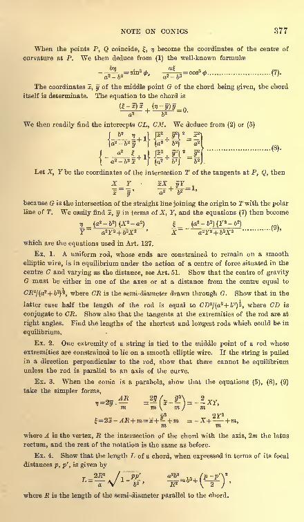
NOTE ON CONICS 377
When the points P, Q coincide, , 77 become the coordinates of the centre of
curvature at P. We then deduce from (1) the well-known formulae
The coordinates x, y of the middle point G of the chord being given, the chord
itself is determinate. The equation to the chord is
We then readily find the intercepts CL, CM. We deduce from (2) or (5)
p2 yv_s2
)~r
Ja2 t.j pyyv-rr
1 a2 -62 5j (a
2b'J
~62J
Let X, Y be the coordinates of the intersection T of the tangents at P, Q, then
X_Y xX yY~^ *>'r9 '
x y a* oi
because G is the intersection of the straight line joining the origin to T with the polar
line of T. We easily find x, y in terms of X, Y, and the equations (7) then become
r, _(a*--b*)(X*- a?) _ (q-6)(r-6)Y a2Y2+ 62X2 X~ a*3r*+ 6Z
which are the equations used in Art. 127.
Ex. 1. A uniform rod, whose ends are constrained to remain on a smooth
elliptic wire, is in equilibrium under the action of a centre of force situated in the
centre C and varying as the distance, see Art. 51. Show that the centre of gravity
G must be either in one of the axes or at a distance from the centre equal to
<7-R2/(a
2 + &2)2 (where CR is the semi-diameter drawn through G. Show that in the
latter case half the length of the rod is equal to CD2/(a
2+ 62)^, where CD is
conjugate to CR. Show also that the tangents at the extremities of the rod are at
right angles. Find the lengths of the shortest and longest rods which could be in
equilibrium.
Ex. 2. One extremity of a string is tied to the middle point of a rod whose
extremities are constrained to lie on a smooth elliptic wire. If the string is pulled
in a direction perpendicular to the rod, show that there cannot be equilibrium
unless the rod is parallel to an axis of the curve.
Ex. 3. When the conic is a parabola, show that the equations (5), (8), (9)
take the simpler forms,
y" 2Y2
x + +m =-X-\----fm,m mwhere A is the vertex, R the intersection of the chord with the axis, 2m the latus
rectum, and the rest of the notation is the same as before.
Ex. 4. Show that the length L of & chord, when expressed in terms of its focal
distances p, p', is given by
2E2 /& a6TV l ~W> -R?-
where R is the length of the semi-diameter parallel to the chord.
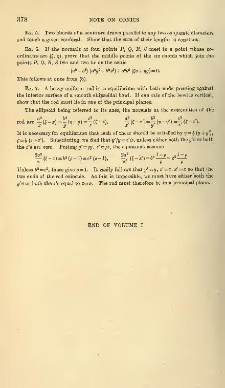
378 NOTE ON CONICS
Ex. 5. Two chords of a conic are drawn parallel to any two conjugate diameters
and touch a given confocal. Show that the sum of their lengths is constant.
Ex. 6. If the normals at four points P, Q, R, S meet in a point whose co-
ordinates are (f, if), prove that the middle points of the six chords which join the
points P, Q, E, S two and two lie on the conic
(a2 -
ft2) (a
2?/2 - bW) + a262 (r + r,y)
= 0.
This follows at once from (8).
Ex. 7. A heavy uniform rod is in equilibrium with both ends pressing against
the interior surface of a smooth ellipsoidal bowl. If one axis of the bowl is vertical,
show that the rod must lie in one of the principal planes.
The ellipsoid being referred to its axes, the normals at the extremities of the
rod are l*(f-*)=fo-y)=5!{r-*), pV*^ Of- ?') =p (f-O-x y z x y 6
It is necessary for equilibrium that each of these should be satisfied by <i= ^(y + y
r
),
f= \ (z + zr
). Substituting, we find that y'ly= z'jz, unless either both the y's or both
the z's are zero. Putting y'py, z'= pz, the equations become
Unless b2 cz , these give p= l. It easily follows that y'= y, z' = z,x' = x so that the
two ends of the rod coincide. As this is impossible, we must have either both the
y's or both the z's equal to zero. The rod must therefore be in a principal plane.
END OF VOLUME I
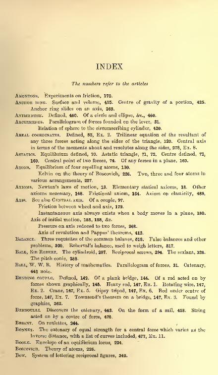
INDEX
The numbers refer to the articles
AMONTONS. Experiments on friction, 170.
ANCHOR RING. Surface and volume, 415. Centre of gravity of a portion, 425.
Anchor ring slides on an axis, 269.
ANTICENTRE. Defined, 460. Of a circle and ellipse, &c., 460.
ARCHIMEDES. Parallelogram of forces founded on the lever, 31.
Eelation of sphere to the circumscribing cylinder, 420.
AREAL COORDINATES. Defined, 53, Ex. 2. Trilinear equation of the resultant of
any three forces acting along the sides of the triangle, 120. Central axis
in terms of the moments about and resolutes along the sides, 278, Ex. 8.
ASIATICS. Equilibrium defined, 70. Astatic triangle, 71, 73. Centre defined, 72,
160. Central point of two forces, 74. Of any forces in a plane, 160.
ATOMS. Equilibrium of four repelling atoms, 130.
Kelvin on the theory of Boscovich, 226. Two, three and four atoms in
various arrangements, 227.
AXIOMS. Newton's laws of motion, 13. Elementary statical axioms, 18. Other
axioms necessary, 148. Frictional axiom, 164. Axiom on elasticity, 489.
Axis. See also CENTRAL AXIS. Of a couple, 97.
Friction between wheel and axis, 179.
Instantaneous axis always exists when a body moves in a plane, 180.
Axis of initial motion, 185, 188, <fec.
Pressure on axis reduced to two forces, 268.
Axis of revolution and Pappus' theorems, 413.
BALANCE. Three requisites of the common balance, 519. False balances and other
problems, 520. Eoberval's balance, used to weigh letters, 517.
BALL, SIR ROBERT. The cylindroid, 287. Reciprocal screws, 294. The sexiant, 326.
The pitch conic, 288.
BALL, W. W. R. History of mathematics. Parallelogram of forces, 31. Catenary,443 note.
BENDING COUPLE. Defined, 142. Of a plank bridge, 144. Of a rod acted on byforces shown graphically, 145. Heavy rod, 147, Ex. 1. Rotating wire, 147,
Ex. 2. Crane, 147, Ex. 5. Gipsy tripod, 147, Ex. 6. Rod under centre of
force, 147, Ex. 7. Townsend's theorem on a bridge, 147, Ex. 3. Found by
graphics, 362.
BERNOULLI. Discovers the catenary, 443. On the form of a sail, 458. Stringacted on by a centre of force, 475.
BESANT. On roulettes, 244.
BONNET. The catenary of equal strength for a central force which varies as the
inverse distance, with a list of curves included, 477, Ex. 11.
BOOLE. Envelope of an equilibrium locus, 224.
BOSCOVICH. Theory of atoms, 226.
Bow. System of lettering reciprocal figures, 349.
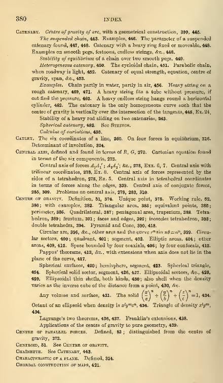
380 INDEX
CATENARY. Centre of gravity of are, with a geometrical construction, 399, 445.
The suspended chain, 443. Examples, 446. The parameter of a suspended
catenary found, 447, 448. Catenary with a heavy ring fixed or moveable, 448.
Examples on smooth pegs, festoons, endless strings, &c. , 448.
Stability of equilibrium of a chain over two smooth pegs, 449.
Heterogeneous catenary, 450. The cycloidal chain, 451. Parabolic chain,
when roadway is light, 452. Catenary of equal strength, equation, centre of
gravity, span, &c., 453.
Examples. Chain partly in water, partly in air, 456. Heavy string on a
rough catenary, 469, 471. A heavy string fits a tube without pressure, if
cut find the pressure, 462. A heavy endless string hangs round a horizontal
cylinder, 462. The catenary is the only homogeneous curve such that the
centre of gravity is vertically over the intersection of the tangents, 448, Ex. 24.
Stability of a heavy rod sliding on two catenaries, 243.
Spherical catenary, 482. See STRINGS.
Calculus of variations, 488.
CAYLEY. The six coordinates of a line, 260. On four forces in equilibrium, 316.
Determinant of involution, 324.
CENTBAL AXIS, defined and found in terms of R, G, 270. Cartesian equation found
in terms of the six components, 273.
Central axis of forces A^A^ ; A 2A 2'; &c. , 278, Exx. 6, 7. Central axis with
trilinear coordinates, 278, Ex. 8. Central axis of forces represented by the
sides of a tetrahedron, 278, Ex. 5. Central axis in tetrahedral coordinates
in terms of forces along the edges, 339. Central axis of conjugate forces,
285, 309. Problems on central axis, 278, 283, 310.
CENTRE OF GBAVITY. Definition, 51, 374. Unique point, 375. Working rule, 52,
380; with examples, 382. Triangular area, 383; equivalent points, 385;
perimeter, 386. Quadrilateral, 387; pentagonal area, trapezium, 388. Tetra-
hedron, 389; frustum, 391; faces and edges, 392; isosceles tetrahedron, 393;
double tetrahedra, 394. Pyramid and Cone, 390, 418.
Circular arc, 396, etc., other arcs and the curve rn sin nd un,399. Circu-
lar sectors, 400; quadrant, 401; segment, 402. Elliptic areas, 404; other
areas, 409, 412. Space bounded by four coaxials, 406; by four confocals, 412.
Pappus' theorems, 413, &c., with extensions when axis does not lie in the
plane of the curve, 417.
Spherical surfaces, 420; hemisphere, segment, 423. Spherical triangle,
424. Spherical solid sector, segment, 426, 427. Ellipsoidal sectors, &c., 428,
429. Ellipsoidal thin shells, both kinds, 430 ;also shell when the density
varies as the inverse cube of the distance from a point, 430, &c.
(,j\n
/y\n f Z\ n
-I + I r I +1-1 = 1. 434.a) \b) \c)
Octant of an ellipsoid when density is xl
ymzn , 434. Triangle of density x l
ym
,
434.
Lagrange's two theorems, 436, 437. Franklin's extensions, 438.
Applications of the centre of gravity to pure geometry, 439.
CENTBE OF PARALLEL FOBCES. Defined, 83; distinguished from the centre of
gravity, 373.
CENTBOID, 51. See CENTRE OF GRAVITY.
CHAINETTE. See CATENARY, 443.
CHABACTEBISTIC OF A PLANE. Defined, 314.
CHOBDAL CONSTRUCTION OF MAPS, 421.
INDEX 381
CHASLES. Badius of curvature of a roulette, 242.
Invariants of two systems of forces, 280.
Characteristic of a plane, 314.
Four forces in equilibrium, 316.
CIRCLE. Least force to move a hoop, disc, &c. placed on a rough plane, 189.
CLARKE. Principles of Graphic statics, 340 note.
CLAUSIUS. Virial, 157.
CLEBSCH. Expresses the form of a heavy string on a sphere in elliptic integrals,
482 note.
COMPONENT. Defined, 40. In three dimensions, 257, 260.
The six components of a system of forces, 273, 276.
CONE. Centre of gravity of volume, 390 ;of surface, 418 ; of cone on elliptic base, 419.
Cone of friction, 173.
Couple to turn a cone in a hole, 189, Ex. 12.
CONIC. The relations of a chord to the normals at its extremities, 126 and note.
Conic of closest contact, position found, 249.
Centre of inscribed and circumscribing conic, 440.
The pitch conic, 288.
CONJUGATE FORCES AND LINES. A system can be reduced to two forces, one line of
action arbitrary, 303; other elements arbitrary, 313. Self-conjugate lines,
306. Conjugate of a given line found, 308.
Arrangement of conjugate forces round the central axis, 309 ; arranged in
hyperboloids, 310 ;in planes, 311.
Theorems on conjugates, 312, 313. Two systems of forces with common
conjugate lines, 311.
CONSERVATIVE SYSTEM. Definition and fundamental theorem, 211. See also 479.
COORDINATES. Of a system defined, 206, 207.
The six coordinates of a line, 260.
Areal coordinates, 53. Tetrahedral coordinates, 339.
COUPLE. Poinsot's theory of couples, 89 ;&c. Measure of couple, 96 ; axis, 97.
Laws of combination of forces and couples, 101. Tetrahedron of couples,
99. Any four axes being given, couples in equilibrium can be found, 99.
Forces represented by skew polygon are equivalent to a couple, 99.
Friction couple, 167. Least couple which can turn a table on a roughfloor ; a cone in a rough circular hole ; and other problems, 188, 189.
Minimum couple of a system of forces, 277.
CORIOLIS. Invents the catenary of equal strength, after Gilbert, 453.
COULOMB. Experiments on friction, 170.
CREMONA. The polar plane of a system of forces, 298. Double lines, 306.
Reciprocal figures, 342.
CROFTON. On self-strained frames of six joints, 238.
CULMANN. Graphical statics, 340. Method of sections, 366.
CURTIS. Problem on two spheres in a paraboloid, 129.
CURVE. Equilibrium of a particle on a smooth curve, 56, 59. Rough curve, 172,
174. Pressure, 58.
Centre of gravity, 398; the curve rn sinn6 = an,399.
String on a curve, 457, &c.
CYCLOID. Centre of gravity of the arc, 399 ; of the area, 412.
Cycloidal catenary, the law of density, centre of gravity, &c., 451.
Heavy string on a rough cycloid, 469.
CYLINDROID. Defined, 287 ; the fundamental theorems, 289-291.
382 INDEX
DABBOUX. Astatic equilibrium in two dimensions, 157, 162.
On the relation of four forces in equilibrium to a hyperboloid, 316.
DEFOBMATION. Normal and abnormal deformations defined, 231. Abnormal defor-
mations lead to indeterminate reactions, 235
DE MOBGAN. The polygon of maximum area, 133.
On Lagrange's proof of virtual velocities, 256.
On the use of Jacobians in integration, 411.
DILATABLE. Framework defined, 231.
DIBECTBIX. Of a catenary, 443. Statical directrix of a heavy string on a smooth
curve, 460. Other cases, 482, 494, 500.
DOUBLE LINES. Defined by Cremona, 306. See NUL LINES.
DUCHAYLA. Proof of the parallelogram of forces, 27.
DYNAME. Defined by Pliicker, 261. Relation to a wrench, 271.
EDDY. Graphical statics, 340.
EFFICIENCY. Of a machine defined, 504. If a force P raise and P' support a
weight, the efficiency is (P + .F)/2P, 505.
ELASTIC STBINGS. Hooke's law, 489. Heavy string (a) free, (b) on an inclined
plane, 492.
Work of stretching, 493. Various problems, 492, 493.
Heavy string on a smooth curve, tension, pressure, &c., 494. Light
string on a rough curve, 495. See ENDLESS STRINGS. Various problems, 495.
General equations, 496.
Heavy string on various surfaces, 497.
String under central force, 498, 499.
Elastic catenary, equations, 500, geometrical properties, 501, Ex. 2.
ELLIPSE. See CONIC. Centre of gravity of sector, segment, &c., 405; of the space
bounded by co-axials, 406 ; confocals, 412 ; of the space between ellipse and
two tangents, 406.
Equilibrium of a rod in an ellipse, 126, 243.
ELLIPSOIDS. Centres of gravity of the two kinds of thin shells, 430. Centre of
gravity when the density varies as the cube of the distance from a point,
430. Centre of gravity of an octant, density xl
ymzn
,434.
Resultant of normal forces to an octant, 319.
ENDLESS STRINGS. Slipping of a band which works two wheels, 466, Ex. 5. Maxi-
mum tension when string is slightly extensible, 495, Ex. 5. Festoons, 466,
Ex. 10.
Strings which just fit a curve, 472. Examples of a circle, catenary,
cycloid, ellipse, &c., 473.
Twisted cords, 495, Ex. 3.
Slipping of cords round pegs, &c., 495, Ex. 4, &G.
EQUILIBRIUM. Of a particle, 45. Of a rigid body in two dimensions, 109. In three
dimensions, 259 ; problems on, 268.
Conditions deduced from the principle of work, 203. Altitude of the
centre of gravity a max-min, 218. Stability defined, 70, 75 ; of three forces,
77, 221;conditions of stability, 214, 220 ;
of rocking stones, 244, &c.
Critical equilibrium, 246.
On the sufficiency of the six conditions, i.e. m moments and n resolutions
being zero, 331.
Condition of equilibrium found by Graphics, 353.
Condition that six wrenches of given pitches on six given axes can be
in equilibrium, i.e. sexiant, 326.
INDEX 383
EULEK. Quadrilateral of jointed rods, not acted on by external forces, tightened
by strings, 132.
Eelation between corners, faces and edges in a polyhedron, 351.
Form of the teeth of wheels, 545.
EWING. Experiments on friction, 170.
FIVE FORCES. Two straight lines can be drawn to cut five forces in equilibrium,
320. Invariant, Central axis, &c., 323. Given the five lines of action, to find
the forces, 323, &c.
FLEEMING JENKIN. Practical use of reciprocal figures, 340.
FORCE. Its characteristics, 5. Eepresented by a straight line, 7. How measured,
10, 16. Superposition, 15.
n forces act along the generators of a hyperboloid, 316, 317. n forces
intersect two straight lines, 320, 323. Forces represented by the sides of a
skew polygon are equivalent to a couple, 103.
FORCES AT A POINT. Resultant, 42, 44, 46. Conditions of equilibrium, 45, 49. Aforce moved parallel to itself, 100.
FOUR FORCES. Their relations to (a) a skew quadrilateral, 103, 323 ; (b) a hyper-
boloid, 316 ; (c) a tetrahedron, 40, 318. Geometrical proofs, 316 ; analytical,
317.
Conditions of equilibrium of four forces acting at a point, 40. Bankine's
theorem on four parallel forces in equilibrium, 86.
Four forces acting along tangents to a conic, 120, Ex. 5, 317, Ex. 4.
The invariants, 316, 317, 323.
Given the lines of action, to find the forces, 316, 317.
FEET. Problem on the most stable position of the feet, 88.
FOURIER. Proof of the principle of virtual work, 193.
FRAMEWORK. Defined, 150. The number of rods necessary to stiffen a framework,
151. The reactions are determinate in a simply stiff framework, 153. The
same deduced from the principle of work, 232;in an overstiff framework,
indeterminate, 155, 235. Problems on hexagons, tetrahedra, polygons, &c.,
234. Self-strained frameworks, 132, 238.
Reactions found by graphical methods, 363. Problems on graphical
statics, 372.
FRANKLIN. Extension of Lagrange's two theorems on centres of gravity, 438.
FRICTION. Defined, 54; experiments, 164, 166; laws, 165; limiting friction, 165.
Coefficient and angle of friction, 166. Friction couple, 167. Cone, 173.
The two kinds of problems, 171, 181. Problems of the first kind, 176,
178, &c. The ladder, 177, 178. Tripos and College problems, 178. Wheel
and axle, 179, &c. The indeterminateness of friction, 181. Limiting equi-
librium, 182.
Problems of the second kind, 182, &c. The least couple or force which
can move a triangular table, a rod, a lamina, a hoop, a disc, a cone in a hole
and other bodies, 188, 189.
Two connected particles, 190 ; a string of n particles arranged in a circular
arc, 190, 487, Ex. 2.
Friction in three dimensions, 269. Examples, a rod over a wall, against
a wall; spheres, curtain ring on a pole, cone rolling on a wall, 269.
FUNICULAR POLYGON. For parallel forces, 140, 356. For forces not parallel, 353, &c.
Theorems, 357-360.
Fuss. Polygon of jointed rods, 133. The parabolic catenary, 452. General
equations of equilibrium of a string, 455.
384 INDEX
GILBERT. Invents the catenary of equal strength, 443, 453.
GIULIO. Centre of gravity of a spherical triangle, 424 ; also of a solid generated bya catenary, 424.
GOODWIN, HARVEY. Stability of a rod inside a spheroid, 126, 243.
GRAHAM. Graphic and Analytic statics, 340.
GREENHILL AND DEWAR. Construct a model of an algebraic spherical catenary, 482.
GREGORY. Solves the problem of the catenary, 443.
GULDIN. Centre of gravity of 2n sides of a regular polygon, 397. Centre of gravityof the area of a right cone, 418.
Guldin's or Pappus' theorems on surfaces of revolution, 413.
HOOKE. Law on elastic strings, 489.
HYPERBOLA. Relation of the theory of projection to the hyperbola, 408.
HYPERBOLOID. Forces act along the generators, pitch, single resultant, central axis,
&c. , 317.
Locus of principal force of a given system, 277.
Locus of conjugate forces, 310.
INCLINED PLANE. Smooth, 537 ; rough, 538; problems, 539.
INDETERMINATE. Problems so called, if the elementary laws of statics are in-
sufficient for their solution, 148. Additional laws derived from the elasticity
of bodies, 148. Examples of such problems, weight on a table, the gallows
problem, bars suspended by several strings, framework, &c., 149.
The reactions of a framework are not or are indeterminate according as
it is simply or over stiff, 153, 155, 235.
Indeterminate tensions, 237, 368. Indeterminate friction, 181.
Indeterminate multipliers, 213.
Indeterminate reciprocal figures, 351.
INDEPENDENCE OF FORCES. Principle explained, 15.
INERTNESS OF MATTER. Explained, 14.
INFINITE FORCES. 154, 198, 306.
INITIAL MOTION. Of a body when acted on by a couple, 102.
Of a system is such that the initial work is positive, 200 ; and that the
potential energy decreases, 216.
INVARIANTS. The two invariants defined, 279.
Meaning of the vanishing, 279.
Chasles' invariants of two systems of forces, 280.
Eules to find the invariants of two forces, any number of forces, of
couples, of wrenches, 281, 282.
Invariant of forces acting along n generators of a hyperboloid, 317. Of
forces intersecting two directors, 323. Invariant of any forces along the
edges of a tetrahedron, 339.
INVOLUTION. Forces in involution defined, 325.
Forces along the edges of a tetrahedron are not in involution, 339.
JACOBIAN. The Jacobian condition of equilibrium of a particle on a curve, 59.
Applied to centre of gravity of an area, 411.
JELLETT. Conditions of equilibrium of a string on a rough surface, 486.
JOUBEHT. Theorems on forces normal to every element of a surface, 319.
KATER. Treatise on mechanics, 502.
KELVIN. Proof of the principle of virtual work, 199.
On atoms in equilibrium in Boscovich's theory, 226.
Span of the catenary of equal strength, 453.
On Young's modulus, 490.
INDEX 385
LAGRANGE. Eemarks on the parallelogram of forces, 31.
Method of indeterminate multipliers, 213.
Proof of the principle of virtual work, 255.
Two theorems on centre of gravity, 436, 437.
LAPLACE. Proof of the parallelogram of forces, 31.
LARMOK. Astatic equilibrium in two dimensions, 162. Critical equilibrium, 246.
LAWS OF MOTION. Newton's, 13.
LEIBNITZ. Theorem on the mean centre, 51. Solves the problem of the catenary, 443.
LEMNISCATE. Centre of gravity of the arc AP lies in the bisector of the angle AOP,399. The locus of the centre of gravity of an arc of given length, 399. Thecentre of gravity of half the area of either loop, 412, string, 477.
LEVEE. Three kinds, 511. Conditions of equilibrium, 507, pressure, 508.
What is gained in power is lost in speed, 513.
Examples from animal economy, 515.
LEVY. Statique Graphique, on the reactions of frameworks, 150. His definitions,
231. Theorem on indeterminate tensions of a framework, 236, 368. Graphical
statics, 340. Theorems on the force polygon, 357.
LIMITING. Friction, 165, equilibrium, 182.
LOCK. Elementary statics, 41.
MACHINE. Mechanical advantage denned, 502 ; lever, 512 ; pulley, 527, 532, <fec. ;
inclined plane, 537 ;wheel and axle, 540 ; wedge, 547 ; screw, 550.
MAPS. The two systems of equal areas and of similarity, 421.
MAXWELL. On stiff jointed frameworks, 150, 151.
Friction locus of a particle, 189.
If R be the thrust of a rod in a framework, r its length, "ZRr found in
terms of the forces, 230.
Theorem on reciprocal figures, 341, &c.
MEAN CENTRE. See also CENTRE OF GRAVITY. Use of, in resolving and compoundingforces which meet at a point, 51. Also other forces, 120.
MILNE. Application of centre of gravity to pure geometry, 439.
MINIMUM. Minimum method of solving friction problems, 185.
The work is a max-min in equilibrium, 212.
Altitude of centre of gravity a max-min, 218.
Minimum couple of forces in three dimensions, 277.
Minimum couples and forces to move a body, 188, 189. Minimum force
at one end to move (a) a string of particles, 190, and (b) a heavy string in a
circular arc on a rough floor, 487.
MOEBIUS. The polyhedron of couples, 99.
The nul plane, 298.
Four forces in equilibrium lie on a hyperboloid, 316.
Five forces intersect two directors, 320.
Six forces in equilibrium, 324.
MOMENT. Moment of a force defined in two dimensions, 113, in three dimensions,
263.
Proved equal to dWjdO where W is the work, 209.
Moment of a line in geometry, 265. Represented by the volume of a
tetrahedron, 266. By a determinant, 266, 267. In tetrahedral coordinates,
267, 339.
MOIGNO. The astatic triangle of forces, 71.
Definition of principal force, 257.
MONTUCLA. History of the Catenary, 443.
R. s. i. 25
386 INDEX
MOBIN. Experiments on friction, 170.
NEWTON. Laws of motion, 13. Proof of the parallelogram of forces, 25.
NORMAL FORCES. To a polygon, 133 ;to a tetrahedron, 318 ; to a polyhedron, 318 ;
to a closed surface, 319 ;to an octant of an ellipsoid, 319.
NUL. Nul plane defined, 298. Its Cartesian equation, 301. Its tetrahedral equa-
tion, 339. Theorems on the nul plane, 304.
The Cartesian condition that a given line is a nul line, 301. Nul point
of a given plane found geometrically and analytically, 302.
OBLIQUE. Eesolution of forces, 40. Axes, 50.
PAPPUS. The surface and volume of a solid of revolution deduced from a centre of
gravity sometimes called Guldin's theorems, 413.
PARABOLA. Centre of gravity of areas, bounded by an ordinate, 412;bounded by
four parabolas, 412, &c.
Parabolic chain, tension, centre of gravity, &c., 452.
PARALLEL FORCES. Centre of parallel forces, 83, 373. Conditions of equilibrium, 85.
A given force replaced by two parallel forces, 79; by three forces, 86.
Eankine on the equilibrium of four parallel forces, 86.
Theory of couples, 89.
PARALLELEPIPED OF FORCES. Theorem, 39.
PARALLELOGRAM. The parallelogram law, 7. Of velocities, 12. Of forces, 24.
PENTAGON. Centre of gravity of a homogeneous pentagon, 388, Ex. 5.
PITCH. Defined, 271. Pitch of an equivalent wrench found, 273.
PLUCKEH. The six coordinates of a line, 260. A dyname, 261.
A proof of Moebius' theorem, 316.
POINSOT. Theory of couples, 89.
Why some problems are indeterminate, 148.
Method of finding resultants, 104, 257.
Central axis, 270.
POLAR PLANE. Cremona's polar plane defined, 298.
Sylvester's defined, 325. Various theorems, 336, &c.
POTENTIAL. Defined, 59. Potential energy, 211. Decreases in initial motion, 216.
POLYGON. The polygon of forces, 36. Forces at the corners, 37. Forces perpen-
dicular to the sides, 37. Forces wholly represented by the sides make a
couple, 103, Ex. 6. Forces proportional to the sides at an angle and
dividing the sides in a given ratio, 103, Ex. 9. Forces which join the corners
of two positions of the same polygon, 120, Ex. 6.
Polygon of heavy rods, 134. Subsidiary polygon, 139.
On the number of conditions necessary to determine a polygon, 152.
POLYHEDRON. Polyhedron of forces, 47, 318.
Euler's relation between the number of corners, faces and edges, 351.
Reciprocal polyhedra, 341, 351.
Centre of gravity of polyhedron circumscribing a sphere, 392, Ex. 5.
PRATT. Treatise on Mechanical Philosophy, 502.
PULLEY. Single pulley, 527. Systems with one rope, 529; several ropes, two
cases, 532. Problems, 535.
PRESSURE. See REACTIONS. Pressure of a particle on curves and surfaces, 58, 175.
Of a body on the supports, 87, 88.
Pressure found by graphical method, 361.
Line of pressure, 369. Various theorems, 370, &c.
PRINCIPAL FORCE. Moigno's definition, 257.
PRINCIPAL COUPLE. Of a system at any point defined, 257. See NUL PLANE.
INDEX 387
PROBLEMS. Rules for resolving and taking moments in the solution of problems,
121, Ac.
PROJECTION. Centre of gravity of the projection of an area, 403.
Working rule to project figures, 403.
Analytical aspect of projections, 407.
PYRAMID. Centre of gravity of the volume, 390.
The five equivalent points of a pyramid on a quadrilateral base, 395.
QUADRILATERAL. Jointed with attracting particles at the corners, 130. With various
strings, 132.
Centre of gravity when uniform, 387, 388. When heterogeneous, 434.
Some geometrical theorems deduced from statics, 439, 441.
Forces along the sides of a skew quadrilateral are not in equilibrium, form
a couple or single resultant, 103. Their invariant, 323.
RANKINE. Equilibrium of four parallel forces, 86.
Force diagram, 140.
Moment of flexure or bending stress, 142.
Graphical statics, 340.
REACTIONS. Three rules (1) when two smooth rods press, 125; (2) when two rods
are jointed, (a) line of symmetry, (b) one rod not acted on by a force, 131,
(c) when more than two rods meet at the same point, 132 ; (3) when two rods
are rigidly connected the reaction is a force and a couple, 142, 143.
Jointed quadrilaterals tightened up by various strings, 132.
Jointed polygons acted on by normal forces, 133. Reactions at the
joints of a polygon of heavy rods, 134. Various problems on reactions at
joints, 141.
Bending moment, 142. Weight on a light plank bridge, 144. Diagramof stress for a rod acted on by forces at isolated points, 145. Weight on a
heavy bridge, 147, Ex. 1. Bending moment for a rotating semicircular wire,
147, Ex. 2. Townsend's problem on a bridge, 147, &c.
Principle of work used to find reactions at the joints of a hexagon, tetra-
hedron, rhombus, tripods, <fec., 234.
Reactions in three dimensions, at an axis, pressures, joints, &c., 268.
Reactions found by graphics, 361, 363, &c.
?i spheres in a cylinder, 129.
RECIPROCAL FIGURES. Defined, 340. Maxwell's theorem, 341 ; Cremona's, 342. To
draw reciprocal figures, 343, 350. Mechanical property, 346.
RESOLUTE. Defined, 41. Equal to dWjds where IF is the work, 209.
RESOLUTION. Defined, 40. Resolved part or resolute, 41.
Three methods of oblique resolution, 40.
Use of the mean centre, 51.
Resolution in three dimensions, 260.
Along three lines by a tetrahedron, 53, Ex. 3.
Along six lines in space, 329.
Graphical method, 360.
RESULTANT. Resultant force defined, 22. Forces in a straight line, 23;
at a
point, 42.
Method of the mean centre, 51. With an extension, 53, Ex. 4.
Parallel forces, 78, 80.
Single resultant in two dimensions, 118. A trilinear equation, 120.
Resultant force and couple in three dimensions, 257. Single resultant, 274.
Resultant found by a graphical method, 352.
388 INDEX
REYNOLDS, OSBOBNE. Experiments on friction, 170.
RIGID BODY. Defined, 19. Rigidity of cords, 531.
ROBERTS, R. A. Theorem on the centre of gravity of the arc of a lemniscate, 399.
ROBEBVAL. Method of finding envelopes, 242.
Balance, 517.
ROCKING BODIES. Condition of stability, 244.
Hollow bodies with fluid, 245.
Second approximations, 247, 249.
In three dimensions, 251.
ROD. Heavy rod in a bowl and cylinder, 125. In a spheroid, 126, 243. Two rods
support an ellipse, 127. Jointed light rods forming quadrilaterals and
polygons, 131 133. Jointed heavy rods, 134. Friction problems, 178.
Bending couple due to a weight, 142, 144, &c.
Various problems, 141, 149. Stability, 221, &c.
Rod on rough wall in three dimensions, 269.
Pressure on supports of a rod found by graphics, 361. Stress at any
point, 362.
SAIL. Can a boat sail quicker than the wind ? 53, Ex. 10. Form of a sail acted on
by the wind and its best position, 458.
SALMON. The relation between the inclinations of any four lines in space, 48.
A leading theorem on determinants quoted, 49.
On roulettes, 244.
On the six coordinates of a line, 260.
Generalization of a theorem on the relations of a chord of a conic to the
two normals, 126 and note.
SCOTT, R. F. Treatise on determinants, 267.
SCBEWS. See also WRENCH. Pitch defined, 271. Right and left handed, 272.
Work of a wrench on a screw, 292.
Reciprocal screws, 294.
As a machine defined, 550. Mechanical advantage, 550. Various theorems,
551.
SHEAR. Defined, 142.
Six FORCES. Analytical view, 324. Geometrical view, 334.
Two methods of describing the sixth line (a) as a plane locus, (b) as the
nul line of two fixed forces, 334.
Only one way in general of reducing a system to six forces along given
straight lines, 329.
The case of involution, 328.
On the ratio of P5 to P6 and other theorems, 336. See also EQUILIBRIUM.
On six forces along the edges of a tetrahedron, 339. See also TETRAHEDRON.
SMITH, R. H. On graphics quoted, 364.
SMOOTH BODY. Defined, 54. Reactions, 55.
SPOTTISWOODE. The determinant of involution, 327.
STABILITY. Defined, 70, 75. Of two forces, 76. Of three forces, 77, 221. Resolute
of restitution for a particle on a surface, 77.
Deduced from the principle of work, 214.
Analytical rule when gravity is the only force, 220. Geometrical rule, 239.
Alternation of stable and unstable positions, 219.
Stability of a body when two points are constrained to slide on curves,
222. When two rods slide, 225.
Various problems on stability, 223.
INDEX 389
STABILITY. Circle of stability in rocking bodies, 244, 251. Stability of neutral
equilibrium determined by second approximations, 247.
Stability of a heavy string suspended from two points, 447 ; over two
pegs, 449. Of a free string on a sphere, 482.
STATICS. Defined as one case of mechanics, 1. As the science of force, 21.
STEELYARD, (a) Eoman, 521, (b) Danish, 522. Comparison of a steelyard and a
balance, 523. Problems on steelyards, 524.
STEREOGBAPHIC PROJECTION. On the principle of similitude in Maps, 421.
STEVINUS. Enunciates the triangle of forces, 31.
STRESS. Denned, 142. See BENDING COUPLE.
STRING. See CATENARY, ELASTIC STRINGS, ENDLESS STRINGS.
Tension of a light string unaltered by passing over a smooth surface, 197.
Intrinsic equations of equilibrium, 454. Cartesian form, 455. Polar, 456.
Constrained by a curve, four cases, (a) string light, curve smooth, 457,
(b) string heavy, curve smooth, 459, (c) string light, curve rough, 463,
(d) string heavy, curve rough, 467, &c.
String with normal forces, 458.
The statical directrix, 460. Heavy string on a circle with hanging ends
and a catenary, 462.
Methods of integration in case (d), 468, 469.
Hope wound round thin rough posts and pegs, 466.
One centre of force, 474, 476. Force when the curve is a circle, Ex. 2, the
curve rn=ancosn6, Ex. 3; infinite strings, Ex. 4, &c.; force the inverse
square, Ex. 6; catenary of equal strength when the force varies as the
inverse distance, Ex. 11; dynamic curves, Ex. 12.
Two centres offorce, 477. The lemniscate, Ex. 2.
Constrained by a surface. General equation, 478. Geodesic strings, 480.
Inflexional points, 480.
Solid of revolution, 481.
Spherical catenary form, tension, pressure, 482. Case of one end free,
case when directrix plane passes through the centre of the sphere, &c., 482.
Instability, 482.
Cylindrical surface, if smooth and vertical the string when developed is a
catenary, 483 ; if rough, Ex. 3. Examples on a horizontal cylinder, 483.
Conical surface with centre of force at the vertex, 484.
Rough surfaces, general equation, 485. Geodesies, 485. Helix, 487.
Minimum force to move a circular heavy string on a rough horizontal
plane, 487.
Calculus of variations. A string (a) suspended from two points, (b) on a
surface under any forces, 488.
SUPERPOSITION OF FORCES. A principle of statics, IB.
SURFACE. Particle on a smooth surface in equilibrium, 57. On a rough surface, 175.
Kesultant of normal forces, 319.
SUSPENSION. Of a heavy body, with examples on triangles, rods, cones, &c., 87.
Of a polygon of heavy rods, 134.
Of a heavy string, 447.
SUSPENSION BRIDGE. See CATENARY. When the main chain alone is heavy, 443.
When the roadway alone is heavy, 452.
When the vertical rods are heavy, 452. Other problems, 452.
SYLVESTER. On the equilibrium of six forces, 324. The determinant of involution,
325.
390 INDEX
TENDENCY TO BREAK. Defined, 142, see BENDING COUPLE.
TENSION. Of a rod defined, 142 ; of a string, 442. See FRAMEWORKS AND STRINGS.
A bundle of heavy horizontal cylinders tied by a string, 129, Ex. 7.
TETRAHEDRON. Used in two ways to resolve forces (a) by sines of angles, 40, (b) bythe mean centre of the base, 53, Ex. 3.
Volume found, 266 ; used to measure moments, 266, 267.
Any six forces along edges are not in involution, 339.
Central axis of the forces represented by the six sides, 278.
Forces referred to tetrahedral coordinates, 267, 339.
Eelation of four forces (a) acting at the corners perpendicularly to the
opposite faces, (b) at the centres of gravity of the faces, (c) at middle pointsof the edges, 318.
Centre of gravity of the volume, 389; frustum, 391; double tetrahedra,
394; faces and edges, 392; heterogeneous, 434.
The isosceles tetrahedron, 393.
Geometrical theorems deduced from the centre of gravity, 439.
THOMSON AND TAIT, see KELVIN. Proof of the principle of virtual work, 199.
THREE FORCES, see TRIANGLE. A system reduced to three forces acting at the
corners of an arbitrary triangle, (a) in two dimension-', 120, (b) in three
dimensions, 315.
Parallel forces reduced to three, 86.
THRDSTS. Defined, 364, see FRAMEWORKS.
TIES. Defined, 364, see FRAMEWORKS.
TOOTHED WHEELS. Small teeth, 544. Involute of a circle, 545; effect of sepa-
rating the wheels, 545. Epicycloidal teeth, 545. Problems, locking of
teeth, &c., 546.
TOWNSEND. Bending moment of a bridge with a carriage of finite size, 147.
Eelation between the equilibrium of a string and the free motion of a
particle, 476.
TRANSMISSIBILITY OF FORCE. A principle of statics, 17.
TRANSON. Eadius of curvature of a roulette, 242.
TRAPEZIUM. Centre of gravity of the area, 388.
TRIANGLE. Triangle of forces, 32, &c. ; theorems, 103 ; astatic triangle, 73.
A heavy triangle suspended by strings and in other ways, 87.
A system of forces reduced to three along the sides of an arbitrary
triangle, 120. A system in three dimensions reduced to forces at the
corners, 315.
The least couple to move a triangular table on a rough floor, 188.
Centre of gravity of area, 383 ; various equivalent points, 385 ; perimeter,
386 ; heterogeneous density xl
ymz n
, 434.
Geometrical property of the product of the alternate segments of points
on the sides, 132. Centre of the nine points circle and the orthocentre found
by centre of gravity, 440.
Two FORCES, see CONJUGATE FORCES. A system reduced to two forces (a) in two
dimensions acting at arbitrary points, 120, (b) in three dimensions with one
line of action arbitrary, 303, &c., 313.
UNITS. Various kinds, 11.
VARIGNON. On the transformation of forces, 116.
VENTUROLI. Contradicts Montucla's assertion about Galileo, 443.
VINCE. Experiments on friction, 170.
VIRTUAL VELOCITIES, see WORK.
INDEX 391
WALLIS. Centre of gravity of a circular arc, 396. Circular sector, 400. Cycloidal
area, 412.
WALTON. Centre of gravity of a spherical triangle, 424. Of the space between a
parabola and two tangents, 412. Of the lemniscate, 399.
WARBEN GIRDEB. Problem on, 372.
WATSON. Problems of the reactions of the legs of a table supporting a weight, 149.
On a case of neutral equilibrium, 88.
WEDGE. Denned, 547 ; mechanical advantage, 548. Condition that a wedge stays
in when struck, 549.
WHEEL AND AXLE. Mechanical advantage, 540 ;differential axle, 541. Problems
on the wheel and axle, 542.
Friction between wheel and axle, 179.
Work required to turn the wheel when the string is elastic, 493, Ex. 2.
WHITE. A system of pulleys invented to diminish friction, &c., 530.
WILLIS. His principles of mechanism, 502. On the form of toothed wheels, 545.
WOKK. Defined, 62 ; equilibrium of a particle, 66; rings on elliptic wires, &c., 69.
Proof of the general principle, after Fourier, 194, 195. The converse
after Thomson and Tait, 199. Work of forces equal to that of resultants,
194. List of forces which do not appear, 196.
Work of a bent elastic string, 197, 493.
Method of using the principle, 202, examples, semicircle, rods, &c., 205.
Work function denned, 208 ; stability deduced, 214; application to
frameworks, 229.
Lagrange's proof of virtual velocities, 255.
WRENCH. Denned, 271. See CENTRAL AXIS.
Equivalent wrench (a) when R and G are given, 270, (b) when system is
given by its six components, 273, (c) when the system is two wrenches, 285,
(d) when the system is two forces, 284.
Method of compounding wrenches by the cylindroid, 287.
Problems on wrenches, 278.
The work of a wrench, 292.
Condition of equilibrium of six wrenches, the sexiant, 326.
Used by Cremona for reciprocation, 342.
YOUNG. Modulus of elastic strings, 490.
tfTambnlrge:
PRINTED BY JOHN CLAY, M.A.
AT THE UNIVERSITY PRESS.
GELES
University of California
SOUTHERN REGIONAL LIBRARY FACILITY
405 Hilgard Avenue, Los Angeles, CA 90024-1388
Return this material to the library
from which it was borrowed.
</
APR 15 1993
1IAR10W4
Ml II I I HI
A 000 242 480 2
Engineering &
Mathetrvatical
Sciences
library
nt
STACK
J&72
WVEHS.TYLIBRARY
. CALIF.