a tactile sensor for the fingertips of the humanoid robot icub
TRANSCRIPT
A Tactile Sensor for the Fingertips of the Humanoid Robot iCub
Alexander Schmitz, Marco Maggiali, Lorenzo Natale, Bruno Bonino and Giorgio Metta
Abstract— In order to successfully perform object manipu-lation, humanoid robots must be equipped with tactile sensors.However, the limited space that is available in robotic fingersimposes severe design constraints. In [1] we presented a smallprototype fingertip which incorporates a capacitive pressuresystem. This paper shows an improved version, which hasbeen integrated on the hand of the humanoid robot iCub. Thefingertip is 14.5 mm long and 13 mm wide. The capacitivepressure sensor system has 12 sensitive zones and includesthe electronics to send the 12 measurements over a serialbus with only 4 wires. Each synthetic fingertip is shapedapproximately like a human fingertip. Furthermore, an integralpart of the capacitive sensor is soft silicone foam, and thereforethe fingertip is compliant. We describe the structure of thefingertip, their integration on the humanoid robot iCub andpresent test results to show the characteristics of the sensor.
I. INTRODUCTION
Tactile sensing is a key requirement for grasping and
object manipulation. If humans lose their sense of touch
it is hard for them to maintain a stable grasp [2]. Like
humans, humanoid robots are expected to adapt to novel
objects and changes in the environment. Tactile information
is essential for adapting the grasp, and in addition can be used
to actively explore the object in-hand. Thus, it is possible
to obtain information about objects that is hard or even
impossible to acquire through other sensing modalities such
as vision or sound (for example, weight, slipperiness, texture
and hardness). Therefore, sensing not only aids action, but
actions can be also performed to obtain “good” sensory
data, enabling categorization, adaptation and learning (see
for example [3][4][5]).
Many touch sensors have been described in literature, us-
ing various different methods of transduction [6]. For a recent
overview of existing technologies and their implementation
on humanoid robots, see [7]. Particular interest exists in
developing sensors for robotic hands for object grasping and
manipulation. For example, the 6-axis force sensor used in
DLR-HIT hand [8], the GIFU III hand [9] and the 3-axis
force sensor in the Paloma hand [10] can all measure pressure
This work is funded by the European Commission as part of the projectICT-FP7-231500 RoboSKIN and project ICT-FP7-215843 Poeticon.
Alexander Schmitz is with the Italian Institute of Technology, 16163Genoa, Italy and the Department of Automatic Control and Sys-tems Engineering, University of Sheffield, Sheffield, UK S1 [email protected]
Marco Maggiali, Lorenzo Natale and Bruno Bonino arewith the Italian Institute of Technology, 16163 Genoa, [email protected], [email protected],[email protected]
Giorgio Metta is with the Italian Institute of Technology, 16163Genoa, Italy and the Dipartimento di Informatica Sistemistica eTelematica, Universita degli Studi di Genova, 16145 Genoa, [email protected]
and shear forces. The GIFU III hand has 859 sensing points,
however due to the nature of its sensors, the skin is not
compliant and the signal conditioning happens at a distance
from the sensitive area. The Obrero hand [11] has 40 contact
points which embeds 4 sensors each. The Shadow hand [12]
has a high number of sensors in its fingertips, based on QTC
technology.
A number of groups have used capacitive technology
for sensors. Miyazaki and Ishida [13] used a capacitive
sensor to measure vertical foot force. In [14] a 3-axis sensor
based on capacitive principle is proposed. Gray and Fearing
[15] implemented an 8 x 8 capacitive tactile sensing array
within 1 mm2. In [16] 300dpi and 500dpi capacitive tactile
imaging arrays are reported. A system using small brushes
was integrated into a robot griper and was described to
have high sensitivity [17]. As reported in [18] and [19], a
distributed sensorized skin is under development using the
same capacitive sensor technology as described later in this
paper.
Commercial products incorporating sensors based on ca-
pacitive technology exist, for example the “iPod-touch” [20].
Capacitive sensors that fit on hands are available from
Pressure Profile Systems [21]. Their wearable glove-like
“FingerTPS” system supports up to 6 capacitive pressure
sensors per hand. They are made of soft, conductive Lycra
which conform to the finger and allow dexterous operations.
The measurements are sent wireless from a module strapped
on the forearm to the PC. The “RoboTouch” system, also
from Pressure Profile Systems, has been included in a
number of robotic hands.
Therefore, while research on tactile sensing is an active
research field, there is still a lack of satisfactory tactile
sensors for humanoid robots. This is because “they are too
big to be used without sacrificing dexterity or because they
are slow, fragile, lack elasticity, lack mechanical flexibility,
and lack robustness” [7]. As such, few tactile sensors have
been integrated into robots and few of them have gone
beyond the prototype stage.
II. COMPARISON TO PREVIOUS VERSIONS
In [1] we presented the first version of fingertips for the
iCub humanoid robot. The most important difference was
that the printed circuit board (PCB) was not flexible, but
instead the sensitive zones were painted with conductive ink
on the inner support and were connected to the rigid PCB
via small wires. As a result, the production process was work
intensive and error-prone. Moreover, the sensitive zones were
rectangular instead of circular.
The 2010 IEEE/RSJ International Conference on Intelligent Robots and Systems October 18-22, 2010, Taipei, Taiwan
978-1-4244-6676-4/10/$25.00 ©2010 IEEE 2212
(a)
(b)
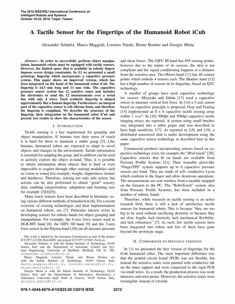
Fig. 1. A hand of the humanoid robot iCub. It has 9 controllable degreesof freedom, plus 3 for the wrist, and most of the actuators are located inthe forearm. In the lower picture the back of the hand can be seen.
In comparison, the version presented here is easier and
faster to produce, and the fingertips are more durable. In
addition, the 12 sensitive zones have a circular shape. A
drawback to this approach is that the silicone foam layer
does not have a uniform 2 mm thickness as before, even
though the differences in thickness are small.
III. DESCRIPTION OF THE FINGERTIP
The fingertips were designed to fit on the hands of the
humanoid robot iCub (see Figure 1). As a result each
fingertip is 14.5 mm long and 13 mm wide. The fingertip
has a round shape that resembles a human fingertip.
In brief, the fingertip is built up as follows (see Figure
2): A flexible PCB is wrapped around the inner support (see
Figure 3). Above the flexible PCB is a layer of soft silicone
foam (see also Figure 4). On top of the silicone foam is a
thin layer of conductive silicone rubber, which is connected
to ground.
The fingertip incorporates a capacitive pressure sensor
system. Generally speaking, a capacitor consists of two
conductors separated by a dielectric. The physical principle
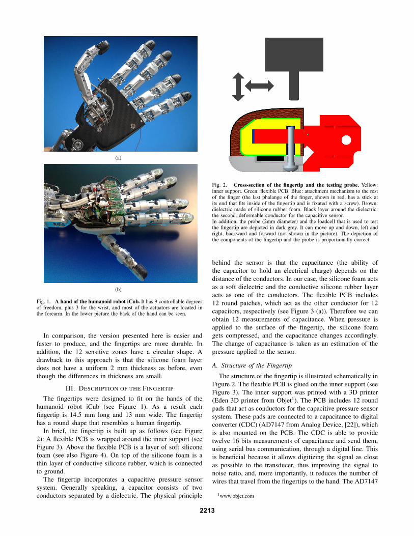
Fig. 2. Cross-section of the fingertip and the testing probe. Yellow:inner support. Green: flexible PCB. Blue: attachment mechanism to the restof the finger (the last phalange of the finger, shown in red, has a stick atits end that fits inside of the fingertip and is fixated with a screw). Brown:dielectric made of silicone rubber foam. Black layer around the dielectric:the second, deformable conductor for the capacitive sensor.In addition, the probe (2mm diameter) and the loadcell that is used to testthe fingertip are depicted in dark grey. It can move up and down, left andright, backward and forward (not shown in the picture). The depiction ofthe components of the fingertip and the probe is proportionally correct.
behind the sensor is that the capacitance (the ability of
the capacitor to hold an electrical charge) depends on the
distance of the conductors. In our case, the silicone foam acts
as a soft dielectric and the conductive silicone rubber layer
acts as one of the conductors. The flexible PCB includes
12 round patches, which act as the other conductor for 12
capacitors, respectively (see Figure 3 (a)). Therefore we can
obtain 12 measurements of capacitance. When pressure is
applied to the surface of the fingertip, the silicone foam
gets compressed, and the capacitance changes accordingly.
The change of capacitance is taken as an estimation of the
pressure applied to the sensor.
A. Structure of the Fingertip
The structure of the fingertip is illustrated schematically in
Figure 2. The flexible PCB is glued on the inner support (see
Figure 3). The inner support was printed with a 3D printer
(Eden 3D printer from Objet1). The PCB includes 12 round
pads that act as conductors for the capacitive pressure sensor
system. These pads are connected to a capacitance to digital
converter (CDC) (AD7147 from Analog Device, [22]), which
is also mounted on the PCB. The CDC is able to provide
twelve 16 bits measurements of capacitance and send them,
using serial bus communication, through a digital line. This
is beneficial because it allows digitizing the signal as close
as possible to the transducer, thus improving the signal to
noise ratio, and, more importantly, it reduces the number of
wires that travel from the fingertips to the hand. The AD7147
1www.objet.com
2213
(a) (b)
(c)
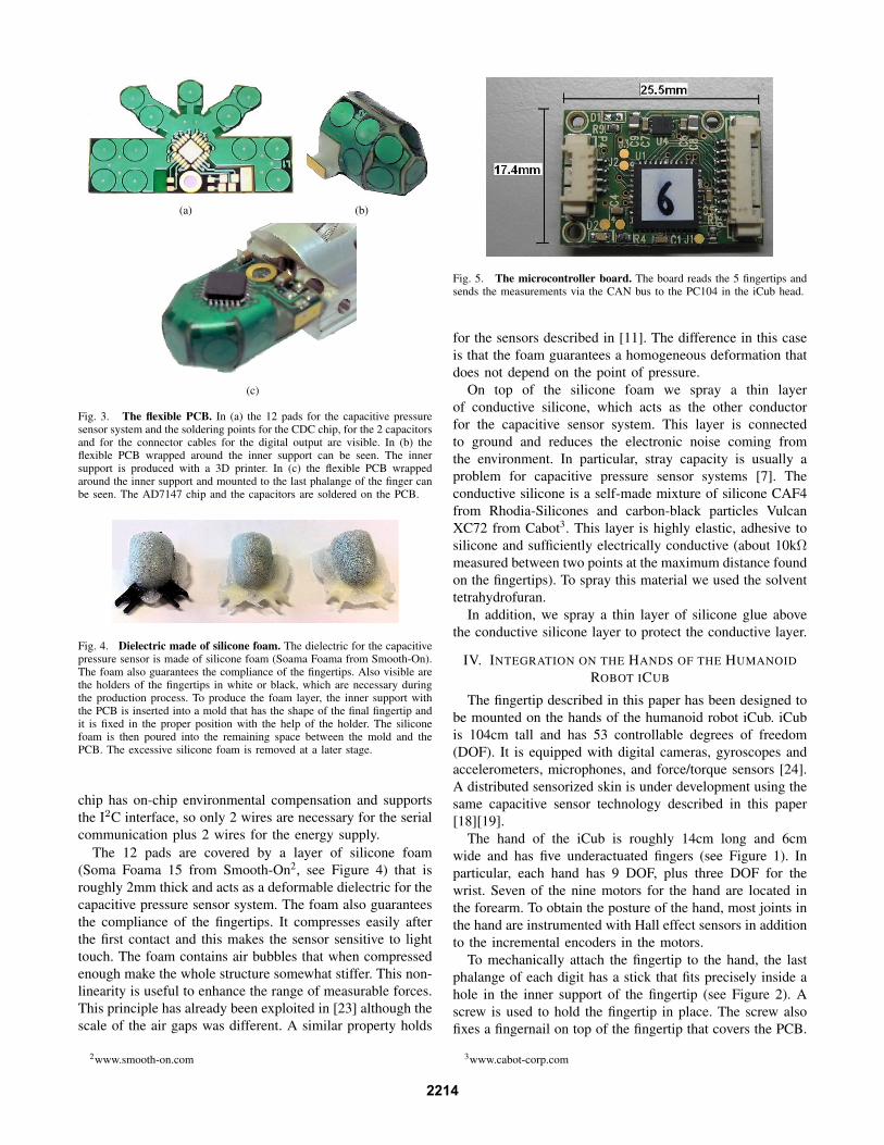
Fig. 3. The flexible PCB. In (a) the 12 pads for the capacitive pressuresensor system and the soldering points for the CDC chip, for the 2 capacitorsand for the connector cables for the digital output are visible. In (b) theflexible PCB wrapped around the inner support can be seen. The innersupport is produced with a 3D printer. In (c) the flexible PCB wrappedaround the inner support and mounted to the last phalange of the finger canbe seen. The AD7147 chip and the capacitors are soldered on the PCB.
Fig. 4. Dielectric made of silicone foam. The dielectric for the capacitivepressure sensor is made of silicone foam (Soama Foama from Smooth-On).The foam also guarantees the compliance of the fingertips. Also visible arethe holders of the fingertips in white or black, which are necessary duringthe production process. To produce the foam layer, the inner support withthe PCB is inserted into a mold that has the shape of the final fingertip andit is fixed in the proper position with the help of the holder. The siliconefoam is then poured into the remaining space between the mold and thePCB. The excessive silicone foam is removed at a later stage.
chip has on-chip environmental compensation and supports
the I2C interface, so only 2 wires are necessary for the serial
communication plus 2 wires for the energy supply.
The 12 pads are covered by a layer of silicone foam
(Soma Foama 15 from Smooth-On2, see Figure 4) that is
roughly 2mm thick and acts as a deformable dielectric for the
capacitive pressure sensor system. The foam also guarantees
the compliance of the fingertips. It compresses easily after
the first contact and this makes the sensor sensitive to light
touch. The foam contains air bubbles that when compressed
enough make the whole structure somewhat stiffer. This non-
linearity is useful to enhance the range of measurable forces.
This principle has already been exploited in [23] although the
scale of the air gaps was different. A similar property holds
2www.smooth-on.com
Fig. 5. The microcontroller board. The board reads the 5 fingertips andsends the measurements via the CAN bus to the PC104 in the iCub head.
for the sensors described in [11]. The difference in this case
is that the foam guarantees a homogeneous deformation that
does not depend on the point of pressure.
On top of the silicone foam we spray a thin layer
of conductive silicone, which acts as the other conductor
for the capacitive sensor system. This layer is connected
to ground and reduces the electronic noise coming from
the environment. In particular, stray capacity is usually a
problem for capacitive pressure sensor systems [7]. The
conductive silicone is a self-made mixture of silicone CAF4
from Rhodia-Silicones and carbon-black particles Vulcan
XC72 from Cabot3. This layer is highly elastic, adhesive to
silicone and sufficiently electrically conductive (about 10kΩ
measured between two points at the maximum distance found
on the fingertips). To spray this material we used the solvent
tetrahydrofuran.
In addition, we spray a thin layer of silicone glue above
the conductive silicone layer to protect the conductive layer.
IV. INTEGRATION ON THE HANDS OF THE HUMANOID
ROBOT ICUB
The fingertip described in this paper has been designed to
be mounted on the hands of the humanoid robot iCub. iCub
is 104cm tall and has 53 controllable degrees of freedom
(DOF). It is equipped with digital cameras, gyroscopes and
accelerometers, microphones, and force/torque sensors [24].
A distributed sensorized skin is under development using the
same capacitive sensor technology described in this paper
[18][19].
The hand of the iCub is roughly 14cm long and 6cm
wide and has five underactuated fingers (see Figure 1). In
particular, each hand has 9 DOF, plus three DOF for the
wrist. Seven of the nine motors for the hand are located in
the forearm. To obtain the posture of the hand, most joints in
the hand are instrumented with Hall effect sensors in addition
to the incremental encoders in the motors.
To mechanically attach the fingertip to the hand, the last
phalange of each digit has a stick that fits precisely inside a
hole in the inner support of the fingertip (see Figure 2). A
screw is used to hold the fingertip in place. The screw also
fixes a fingernail on top of the fingertip that covers the PCB.
3www.cabot-corp.com
2214
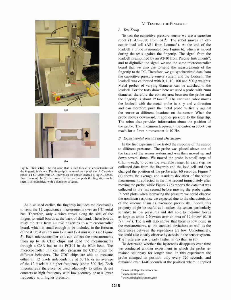
(a)
(b)
Fig. 6. Test setup. The test setup that is used to test the characteristics ofthe fingertip is shown. The fingertip is mounted on a platform. A Cartesianrobot (TT-C3-2020 from IAI) moves an off-center loadcell (1 kg AL series,from Laumas). In (b) the probe that is used to push the fingertip can beseen. It is cylindrical with a diameter of 2mm.
As discussed earlier, the fingertip includes the electronics
to send the 12 capacitance measurements over an I2C serial
bus. Therefore, only 4 wires travel along the side of the
fingers to small boards at the back of the hand. These boards
relay the data from all five fingertips to a microcontroller
board, which is small enough to be included in the forearm
of the iCub; it is 25.5 mm long and 17.4 mm wide (see Figure
5). Each microcontroller unit can collect the measurements
from up to 16 CDC chips and send the measurements
through a CAN bus to the PC104 in the iCub head. The
microcontroller unit can also program the CDC chips for
different behaviors. The CDC chips are able to measure
either all 12 taxels independently at 50 Hz or an average
of the 12 taxels at a higher frequency (about 500 Hz). Each
fingertip can therefore be used adaptively to either detect
contacts at high frequency with low accuracy or at a lower
frequency with higher precision.
V. TESTING THE FINGERTIP
A. Test Setup
To test the capacitive pressure sensor we use a cartesian
robot (TT-C3-2020 from IAI4). The robot moves an off-
center load cell (AS1 from Laumas5). At the end of the
loadcell a probe is mounted (see Figure 6), which is moved
during the tests against the fingertip. The signal from the
loadcell is amplified by an AT-10 from Precise Instruments6,
and to digitalize the signal we use the same microcontroller
board that we also use to send the measurements of the
fingertip to the PC. Therefore, we get synchronized data from
the capacitive pressure sensor system and the loadcell. The
loadcell was calibrated with 0, 1, 10, 100 and 500 g weights.
Metal probes of varying diameter can be attached to the
loadcell. For the tests shown here we used a probe with 2mm
diameter, therefore the contact area between the probe and
the fingertip is about 12.6mm2. The cartesian robot moves
the loadcell with the metal probe in x, y and z direction
and can therefore push the metal probe vertically against
the sensor at different locations on the sensor. When the
probe moves downward, it applies pressure to the fingertip.
The robot also provides information about the position of
the probe. The maximum frequency the cartesian robot can
reach for a 2mm z-movement is 10 Hz.
B. Experimental Results and Discussion
In the first experiment we tested the response of the sensor
to different pressures. The probe was placed above one of
the taxels of the sensor system and was then moved up and
down several times. We moved the probe in small steps of
0.1mm each, to cover the available range. In each step we
collected data from the fingertip and the load cell and then
changed the position of the probe after 60 seconds. Figure 7
(a) shows the average and standard deviation of the sensor
measurements collected in the first second immediately after
moving the probe, while Figure 7 (b) reports the data that was
collected in the last second before moving the probe again.
In both plots, when increasing the pressure we could observe
the nonlinear response we expected due to the characteristics
of the silicone foam as discussed previously. Indeed, this
property might be useful as it makes the sensor particularly
sensitive to low pressures and still able to measure forces
as large as about 2 Newton over an area of 12.6mm2 (0.16
N/mm2). The result also shows that there is low noise in
the measurements, as the standard deviations as well as the
differences between the repetitions are low. Unfortunately,
we could also clearly observe hysteresis in the sensor system.
The hysteresis was clearly higher in (a) than in (b).
To determine whether the hysteresis disappears over time
we conducted another experiment in which the probe re-
mained stationary for longer time. In this experiment the
probe changed its position only every 720 seconds, and
remained even 1440 seconds at the position where it applied
4www.intelligentactuator.com5www.laumas.com6www.preciseinstrument.com
2215
0 50 100 150 2000
50
100
150
200
250
Load(g)
Taxel
1(a
rbit
rary
un
its)
B
A
C
(a)
0 50 100 150 2000
50
100
150
200
250
Load(g)
Taxel
1(a
rbit
rary
un
its)
(b)
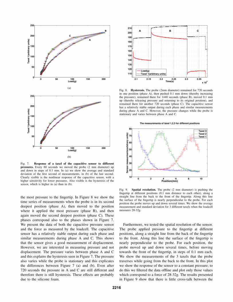
Fig. 7. Response of a taxel of the capacitive sensor to different
pressures. Every 60 seconds we moved the probe (2 mm diameter) upand down in steps of 0.1 mm. In (a) we show the average and standarddeviation of the first second of measurements, in (b) of the last second.Clearly visible is the nonlinear response of the capacitive sensor, with ahigher sensitivity for lower pressures. Also visible is the hysteresis of thesensor, which is higher in (a) than in (b).
the most pressure to the fingertip. In Figure 8 we show the
time series of measurements when the probe is in its second
deepest position (phase A), then moved to the position
where it applied the most pressure (phase B), and then
again moved the second deepest position (phase C). These
phases correspond also to the phases shown in Figure 7.
We present the data of both the capacitive pressure sensor
and the force as measured by the loadcell. The capacitive
sensor has a relatively stable output during each phase and
similar measurements during phase A and C. This shows
that the sensor gives a good measurement of displacement.
However, we are interested in measuring pressure and not
displacement. The pressure varies between phase A and C
and this explains the hysteresis seen in Figure 7. The pressure
also varies while the probe is stationary and this explicates
the differences between Figure 7 (a) and (b). Even after
720 seconds the pressure in A and C are still different and
therefore there is still hysteresis. These effects are probably
due to the silicone foam.
2.1 2.15 2.2 2.25 2.3 2.35
x 104
110
120
130
140
150
160
170
180
190
200
210
Time(s)
Load(g)
Taxel 1(arbitrary units)
A B C
Fig. 8. Hysteresis. The probe (2mm diameter) remained for 720 secondsin one position (phase A), then pushed 0.1 mm down (thereby increasingthe pressure), remained there for 1440 seconds (phase B), moved 0.1 mmup (thereby releasing pressure and returning to its original position), andremained there for another 720 seconds (phase C). The capacitive sensorhas a relatively stable output during each phase and similar measurementsduring phase A and C. However, the pressure changes while the probe isstationary and varies between phase A and C.
0 2 4 6 8 1010
20
30
40
50
60
70
80
Position(mm)
Sen
so
r m
easu
rmen
ts(a
rbit
rary
un
its)
The measurements of taxel 1,2,3 for different positions
Taxel 3
Taxel 2
Taxel 1
Fig. 9. Spatial resolution. The probe (2 mm diameter) is pushing thefingertip at different positions (0.1 mm distance to each other), along astraight line from the back to the front of the fingertip. Along this linethe surface of the fingertip is nearly perpendicular to the probe. For eachposition the probe moves up and down several times. We show the averagemeasurement and standard deviation for 3 different taxels when the loadcellmeasures 28-32g.
Furthermore, we tested the spatial resolution of the sensor.
The probe applied pressure to the fingertip at different
positions, along a straight line from the back of the fingertip
to the front. Along this line the surface of the fingertip is
nearly perpendicular to the probe. For each position, the
probe moved up and down several times, before moving
towards the front of the fingertip, in steps of 0.1 mm each.
We show the measurements of the 3 taxels that the probe
traverses while going from the back to the front. In this plot
we show the response of the sensor to a constant pressure; to
do this we filtered the data offline and plot only those values
which correspond to a force of 28-32g. The results presented
in Figure 9 show that there is little cross-talk between the
2216
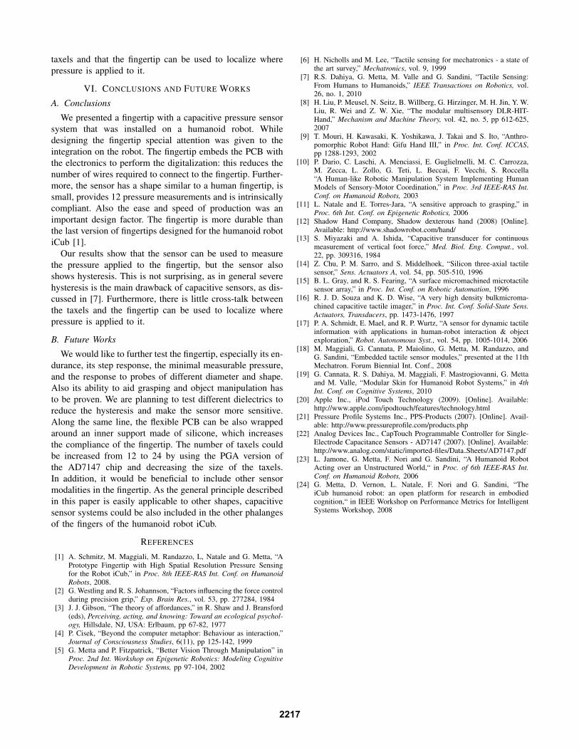
taxels and that the fingertip can be used to localize where
pressure is applied to it.
VI. CONCLUSIONS AND FUTURE WORKS
A. Conclusions
We presented a fingertip with a capacitive pressure sensor
system that was installed on a humanoid robot. While
designing the fingertip special attention was given to the
integration on the robot. The fingertip embeds the PCB with
the electronics to perform the digitalization: this reduces the
number of wires required to connect to the fingertip. Further-
more, the sensor has a shape similar to a human fingertip, is
small, provides 12 pressure measurements and is intrinsically
compliant. Also the ease and speed of production was an
important design factor. The fingertip is more durable than
the last version of fingertips designed for the humanoid robot
iCub [1].
Our results show that the sensor can be used to measure
the pressure applied to the fingertip, but the sensor also
shows hysteresis. This is not surprising, as in general severe
hysteresis is the main drawback of capacitive sensors, as dis-
cussed in [7]. Furthermore, there is little cross-talk between
the taxels and the fingertip can be used to localize where
pressure is applied to it.
B. Future Works
We would like to further test the fingertip, especially its en-
durance, its step response, the minimal measurable pressure,
and the response to probes of different diameter and shape.
Also its ability to aid grasping and object manipulation has
to be proven. We are planning to test different dielectrics to
reduce the hysteresis and make the sensor more sensitive.
Along the same line, the flexible PCB can be also wrapped
around an inner support made of silicone, which increases
the compliance of the fingertip. The number of taxels could
be increased from 12 to 24 by using the PGA version of
the AD7147 chip and decreasing the size of the taxels.
In addition, it would be beneficial to include other sensor
modalities in the fingertip. As the general principle described
in this paper is easily applicable to other shapes, capacitive
sensor systems could be also included in the other phalanges
of the fingers of the humanoid robot iCub.
REFERENCES
[1] A. Schmitz, M. Maggiali, M. Randazzo, L, Natale and G. Metta, “APrototype Fingertip with High Spatial Resolution Pressure Sensingfor the Robot iCub,” in Proc. 8th IEEE-RAS Int. Conf. on Humanoid
Robots, 2008.[2] G. Westling and R. S. Johannson, “Factors influencing the force control
during precision grip,” Exp. Brain Res., vol. 53, pp. 277284, 1984[3] J. J. Gibson, “The theory of affordances,” in R. Shaw and J. Bransford
(eds), Perceiving, acting, and knowing: Toward an ecological psychol-
ogy, Hillsdale, NJ, USA: Erlbaum, pp 67-82, 1977[4] P. Cisek, “Beyond the computer metaphor: Behaviour as interaction,”
Journal of Consciousness Studies, 6(11), pp 125-142, 1999[5] G. Metta and P. Fitzpatrick, “Better Vision Through Manipulation” in
Proc. 2nd Int. Workshop on Epigenetic Robotics: Modeling Cognitive
Development in Robotic Systems, pp 97-104, 2002
[6] H. Nicholls and M. Lee, “Tactile sensing for mechatronics - a state ofthe art survey,” Mechatronics, vol. 9, 1999
[7] R.S. Dahiya, G. Metta, M. Valle and G. Sandini, “Tactile Sensing:From Humans to Humanoids,” IEEE Transactions on Robotics, vol.26, no. 1, 2010
[8] H. Liu, P. Meusel, N. Seitz, B. Willberg, G. Hirzinger, M. H. Jin, Y. W.Liu, R. Wei and Z. W. Xie, “The modular multisensory DLR-HIT-Hand,” Mechanism and Machine Theory, vol. 42, no. 5, pp 612-625,2007
[9] T. Mouri, H. Kawasaki, K. Yoshikawa, J. Takai and S. Ito, “Anthro-pomorphic Robot Hand: Gifu Hand III,” in Proc. Int. Conf. ICCAS,pp 1288-1293, 2002
[10] P. Dario, C. Laschi, A. Menciassi, E. Guglielmelli, M. C. Carrozza,M. Zecca, L. Zollo, G. Teti, L. Beccai, F. Vecchi, S. Roccella“A Human-like Robotic Manipulation System Implementing HumanModels of Sensory-Motor Coordination,” in Proc. 3rd IEEE-RAS Int.
Conf. on Humanoid Robots, 2003[11] L. Natale and E. Torres-Jara, “A sensitive approach to grasping,” in
Proc. 6th Int. Conf. on Epigenetic Robotics, 2006[12] Shadow Hand Company, Shadow dexterous hand (2008) [Online].
Available: http://www.shadowrobot.com/hand/[13] S. Miyazaki and A. Ishida, “Capacitive transducer for continuous
measurement of vertical foot force,” Med. Biol. Eng. Comput., vol.22, pp. 309316, 1984
[14] Z. Chu, P. M. Sarro, and S. Middelhoek, “Silicon three-axial tactilesensor,” Sens. Actuators A, vol. 54, pp. 505-510, 1996
[15] B. L. Gray, and R. S. Fearing, “A surface micromachined microtactilesensor array,” in Proc. Int. Conf. on Robotic Automation, 1996
[16] R. J. D. Souza and K. D. Wise, “A very high density bulkmicroma-chined capacitive tactile imager,” in Proc. Int. Conf. Solid-State Sens.
Actuators, Transducers, pp. 1473-1476, 1997[17] P. A. Schmidt, E. Mael, and R. P. Wurtz, “A sensor for dynamic tactile
information with applications in human-robot interaction & objectexploration,” Robot. Autonomous Syst., vol. 54, pp. 1005-1014, 2006
[18] M. Maggiali, G. Cannata, P. Maiolino, G. Metta, M. Randazzo, andG. Sandini, “Embedded tactile sensor modules,” presented at the 11thMechatron. Forum Biennial Int. Conf., 2008
[19] G. Cannata, R. S. Dahiya, M. Maggiali, F. Mastrogiovanni, G. Mettaand M. Valle, “Modular Skin for Humanoid Robot Systems,” in 4th
Int. Conf. on Cognitive Systems, 2010[20] Apple Inc., iPod Touch Technology (2009). [Online]. Available:
http://www.apple.com/ipodtouch/features/technology.html[21] Pressure Profile Systems Inc., PPS-Products (2007). [Online]. Avail-
able: http://www.pressureprofile.com/products.php[22] Analog Devices Inc., CapTouch Programmable Controller for Single-
Electrode Capacitance Sensors - AD7147 (2007). [Online]. Available:http://www.analog.com/static/imported-files/Data Sheets/AD7147.pdf
[23] L. Jamone, G. Metta, F. Nori and G. Sandini, “A Humanoid RobotActing over an Unstructured World,“ in Proc. of 6th IEEE-RAS Int.
Conf. on Humanoid Robots, 2006[24] G. Metta, D. Vernon, L. Natale, F. Nori and G. Sandini, “The
iCub humanoid robot: an open platform for research in embodiedcognition,“ in IEEE Workshop on Performance Metrics for IntelligentSystems Workshop, 2008
2217