a study on critical order of joints with clearances and its effect
TRANSCRIPT
A study on critical order of joints with clearances and its effecton kinematic performance of multiloop planar mechanisms
SHASHI ALOK1, KAILASH CHAUDHARY2,* and ANIRBAN GUHA1
1Department of Mechanical Engineering, Indian Institute of Technology Bombay, Mumbai, India2Department of Mechanical Engineering, MBM Engineering College, JNVU Jodhpur, Jodhpur, India
e-mail: [email protected]
MS received 30 January 2019; revised 10 February 2020; accepted 19 February 2020
Abstract. Simulation and study of joint clearances has usually focused on appropriate simulation strategies
and their validation against experiments. The effect of joint clearances on the output of a mechanism has been
usually evaluated qualitatively. The relative importance of different joints in a mechanism in producing devi-
ation from the output of an ideal mechanism has not been studied. This work identifies the appropriate statistical
measure for quantifying this deviation and uses it to rank the joints of one degree of freedom multi-loop planar
mechanisms. The inversions of six-bar mechanism have been studied through ADAMS simulations involving
different clearance sizes and speed of crank. A trend in clearance location ranking has been identified which can
probably be extended to planar mechanisms of higher complexity.
Keywords. Planar mechanism; joint clearance; simulation; kinematic performance.
1. Introduction
A mechanism is designed to perform a specific task and it
may produce errors when used in real working conditions.
These errors occur due to unavoidable factors such as
flexibility of links, joint clearances, friction, lubrication and
wear. Links and joints are the main constituents of any
mechanism and a designer needs to carefully consider their
function and limitations. The links form the basic structure
of the system while the joints are used to define the relative
interactions between them. In general analysis of the
mechanism, it is assumed that the joints are ideal and there
is no clearance in them. However, clearances are
unavoidable due to machining tolerances, wear, and local
deformations. Joint clearances are necessary to allow
motion between the links and hence they are essential for
correct functioning of the mechanism. The performance of
a mechanism is adversely affected by the wear and tear of
the joints as a result of impact forces generated due to joint
clearances [1].
Due to clearances, there is a deviation from the expected
ideal behavior which is considered as error. These errors
are small for small clearance size but they cannot be
neglected for high precision operations. However, reduc-
tion in these joint clearances increases the overall cost of
the manufacturing. In order to reach a compromise between
the manufacturing cost and the output error, it is necessary
to analyze the errors and their patterns to estimate the
effects caused by the clearances for the given set of
conditions.
Researchers around the world have reported various
methods for studying the effects of joint clearances and
predicting their effect on a mechanism’s performance as
accurately as possible. Research in this area is mainly
focused on developing mathematical models for joint
clearances to predict the mechanism’s dynamic and kine-
matic behavior in a variety of situations [2–5]. Neural
networks have also been used for this purpose [6–10].
Models for taking into account both joint clearance and
link flexibility/compliance have also been reported [11–35].
Models to capture system dynamics and mechanism opti-
mization for reducing their effect was the natural progres-
sion in this field and have been reported by many [36–43].
Low joint clearance is certainly preferable but it
increases the cost of manufacturing. Mechanism designers
and manufacturers need to take a decision on how much
clearance can be allowed at which location in the mecha-
nism. In order to take this decision, one needs to know
whether the location of joint clearance makes a difference
to the output of a mechanism. Such a study, which does not
appear to be reported, has been undertaken in this work.
One degree of freedom planar mechanisms with only rev-
olute and prismatic pairs have been simulated in ADAMS
and the effect of clearance location, clearance size and
crank speed have been studied. The first step necessary for
such a study was quantification of the deviation of the
kinematic output of a mechanism with clearance from that
of an ideal mechanism. The appropriate statistical tool for*For correspondence
Sådhanå (2020) 45:126 � Indian Academy of Sciences
https://doi.org/10.1007/s12046-020-01366-6Sadhana(0123456789().,-volV)FT3](0123456789().,-volV)
this has been identified and used for analyzing all the
simulations.
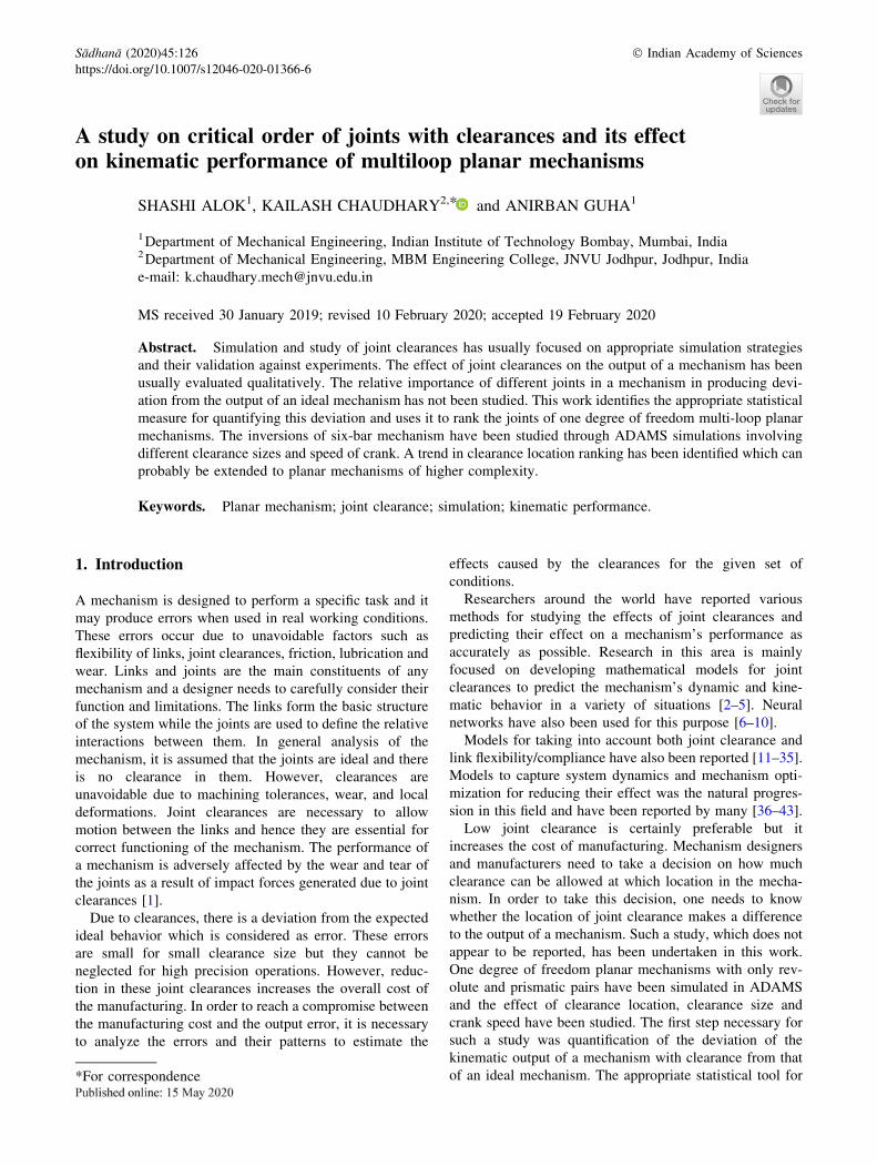
2. Joint clearance modeling
Modeling of joints with clearance is very crucial to analyze
the performance of mechanisms. With the help of these
models, the designer can estimate the output and corrective
actions can be taken to reduce the output error. The com-
monly used modeling strategies for mechanisms are shown
in figure 1.
a) The clearance is modeled by adding a virtual massless
link that has a constant length equal to the radial
clearance.
b) Spring-damper can also be used to model the joint
clearance.
c) The journal and bearing are considered as two colliding
bodies known as momentum exchange approach.
The third approach is more realistic for a dry clearance
joint. It allows the contact force models to be applied and it
takes into account the dissipation of energy during the
impact process. Radial clearances introduce two extra
degrees of freedom in the mechanism. Three different types
of motion are observed between journal and bearing. They
are:
• Free flight: The motion is said to be in free flight mode
when the journal moves freely within the bearing’s
boundary.
• Impact: Impact occurs at the instant when the journal’s
surface collides with that of the bearing’s inner
surface. It occurs at the end of free flight.
• Contact: In the contact mode, contact is constantly
maintained. The relative penetration between the
journal and the bearing may vary during this mode.
Modeling of a mechanism with clearances requires a
force model which can accommodate the real conditions as
far as possible. The important models of contact force are:
2.1 Hertz’s model [44]
This non-linear model is the best known contact force law.
It is limited to frictionless surfaces and perfectly elastic
solids and does not include damping in its original form.
The contact process can be defined as two rigid bodies
interacting through a nonlinear spring along the line of
impact. The deformation is assumed to be concentrated in
the vicinity of the contact area, elastic wave motion is
neglected, and the total mass of each body moves with the
velocity of its center of mass. Hertz model does not account
for energy dissipation and the impact force is defined as:
FN ¼ Kdn ð1Þwhere K and n depend on material and geometric properties
and are obtained by using elastostatic theory. The exponent
n is equal to 1.5 for metallic contacts. K is the stiffness
coefficient of the impact body, which is obtained from the
impact experiment of two spheres as follows:
K ¼ 4
3p ri þ rj� � RiRj
Ri � Rj
� �1=2ð2Þ
ri ¼ 1� m2ipEi
ð3Þ
rj ¼1� m2jpEj
ð4Þ
Where, m is the Poisson’s ratio and E is the Young modulus,
Riand Rj are the radii of the two spheres.
2.2 Lankarani-Nikravesh model [14]
Lankarani and Nikravesh [14] developed a contact force
model with hysteresis damping for impact in multibody
systems. The model uses the general trend of the Hertz
contact law, in which a hysteresis damping function is
included to represent the energy dissipated during the
impact. They suggested separating the normal contact force
Figure 1. Modeling strategies [2].
126 Page 2 of 11 Sådhanå (2020) 45:126
into elastic and dissipative components. The impact force is
defined as:
FN ¼ Kdn þ D _d ð5ÞElastic deformation force is represented by the first term
and the energy loss is represented by the second term. d is
the deformation, _d is the relative deformation velocity, K is
the contact stiffness coefficient of the impact body.
D ¼ 3K 1� c2e� �
dn
4 _d �ð Þ ð6Þ
_d �ð Þ is the initial relative velocity of the impact point, ce is
the coefficient of restitution.
ADAMS uses a very similar contact force model, where
the dissipative term is given by a step function as discussed
in the next section.
3. Modeling in ADAMS
The most common computational tool used for design and
analysis of multi-body mechanical systems is ADAMS
[45, 46]. Various types of links and joints along with their
properties like mass, location of center of mass, moment of
inertia and degrees of freedom can be assigned for a
mechanism in this tool [18]. The joints defined by this tool
are ideal as they do not have any clearance or deformation.
Therefore, to compare performance of the mechanisms with
joint clearances, clearances at joints were made in
ADAMS. The clearance at revolute joint between coupler
and slider has been made by making a cylindrical hole in
the slider cube and attaching a cylinder to the end of the
coupler. So, we can change the size of the hole to set a
clearance size. Similarly, the clearance at revolute joint
between crank and coupler has been made by attaching a
cylinder to the end of the crank and making a hole in the
attached cylinder.
3.1 Input factors
Various input parameters for modeling of mechanism in
ADAMS are as follows:
3.1a Clearance size: For a standard journal-bearing of
journal diameter 20 mm, the clearance size ranges from
0.02 mm to 0.08 mm. However, due to wear during oper-
ation and other environmental factors, the clearance can
increase. So, in this research work, the clearance size has
been taken in the range of 0.02 mm to 1 mm.
3.1b Crank speed: To cover a wide range of cases, the
speeds range from 100 rpm to 3000 rpm.
3.1c Contact conditions: For the modeling of contacts,
ADAMS uses the contact method based on the impact
function: IMPACT-Function-Based Contact. In this
method, the solver computes the contact force from the
IMPACT function available in the ADAMS function
library. The normal force of the contact has two compo-
nents: rigidity and viscous damping. The component of
rigidity is a function of the penetration d. The component of
the viscous damping is a function of the speed of penetra-
tion. In this model the normal force of contact is given as:
FN ¼ Kdn þ STEP d; 0; 0; dmax;Cmaxð Þ _d; d[ 0
0; d� 0
�ð7Þ
3.1d Value of K: The revolute joint is a case of contact
between two cylinders (one inside the other). So, the con-
tact should start with a line contact and then become a 2D
rectangular contact. But the value of K in this case will not
only depend on the material and geometrical property but
also the stress distribution between the cylinders, which
cannot be determined accurately unless it is a static case
and the force is applied externally.
2
3
41
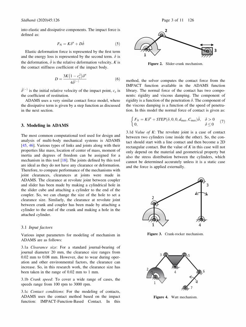
Figure 3. Crank-rocker mechanism.
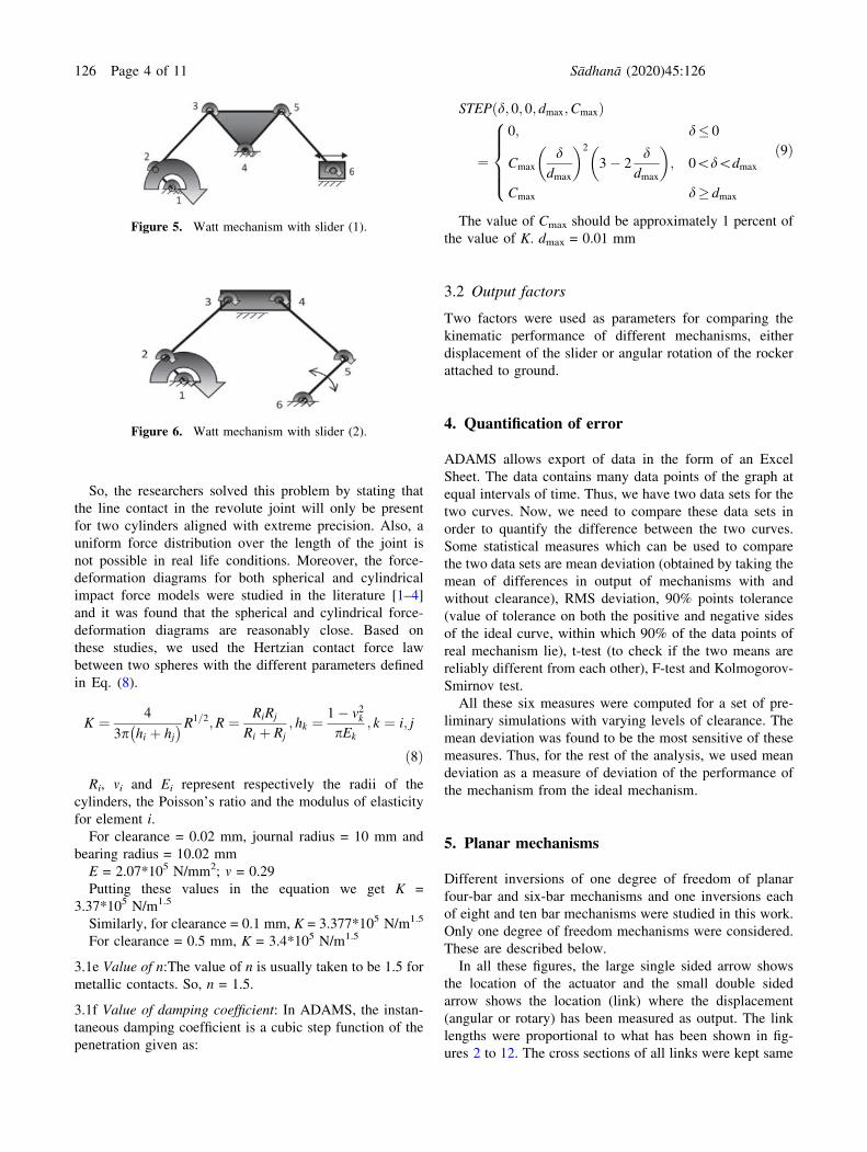
Figure 4. Watt mechanism.
1
2
3
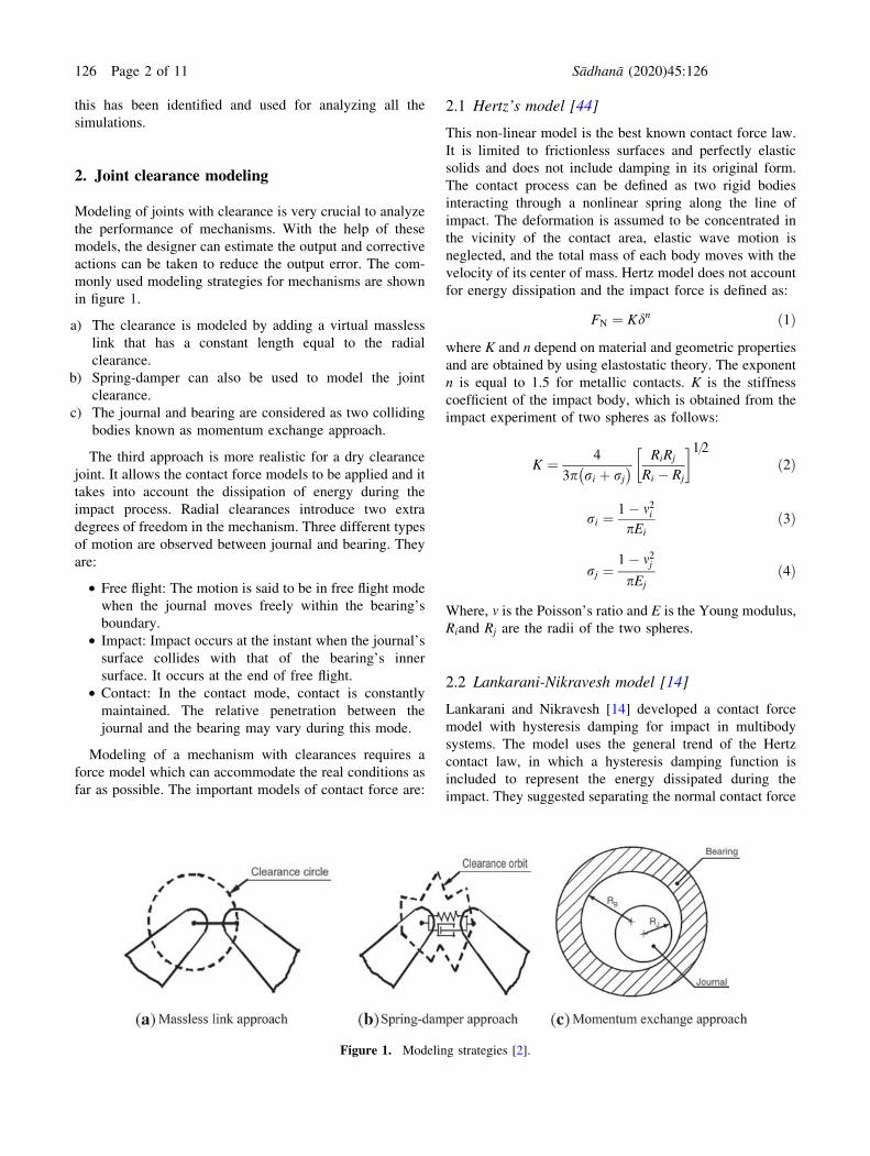
Figure 2. Slider-crank mechanism.
Sådhanå (2020) 45:126 Page 3 of 11 126
So, the researchers solved this problem by stating that
the line contact in the revolute joint will only be present
for two cylinders aligned with extreme precision. Also, a
uniform force distribution over the length of the joint is
not possible in real life conditions. Moreover, the force-
deformation diagrams for both spherical and cylindrical
impact force models were studied in the literature [1–4]
and it was found that the spherical and cylindrical force-
deformation diagrams are reasonably close. Based on
these studies, we used the Hertzian contact force law
between two spheres with the different parameters defined
in Eq. (8).
K ¼ 4
3p hi þ hj� �R1=2;R ¼ RiRj
Ri þ Rj
; hk ¼ 1� v2kpEk
; k ¼ i; j
ð8ÞRi, mi and Ei represent respectively the radii of the
cylinders, the Poisson’s ratio and the modulus of elasticity
for element i.
For clearance = 0.02 mm, journal radius = 10 mm and
bearing radius = 10.02 mm
E = 2.07*105 N/mm2; m = 0.29
Putting these values in the equation we get K =
3.37*105 N/m1.5
Similarly, for clearance = 0.1 mm, K = 3.377*105 N/m1.5
For clearance = 0.5 mm, K = 3.4*105 N/m1.5
3.1e Value of n:The value of n is usually taken to be 1.5 for
metallic contacts. So, n = 1.5.
3.1f Value of damping coefficient: In ADAMS, the instan-
taneous damping coefficient is a cubic step function of the
penetration given as:
STEP d; 0; 0; dmax;Cmaxð Þ
¼0; d� 0
Cmax
ddmax
� �2
3� 2d
dmax
� �; 0\d\dmax
Cmax d� dmax
8>>><>>>:
ð9Þ
The value of Cmax should be approximately 1 percent of
the value of K. dmax = 0.01 mm
3.2 Output factors
Two factors were used as parameters for comparing the
kinematic performance of different mechanisms, either
displacement of the slider or angular rotation of the rocker
attached to ground.
4. Quantification of error
ADAMS allows export of data in the form of an Excel
Sheet. The data contains many data points of the graph at
equal intervals of time. Thus, we have two data sets for the
two curves. Now, we need to compare these data sets in
order to quantify the difference between the two curves.
Some statistical measures which can be used to compare
the two data sets are mean deviation (obtained by taking the
mean of differences in output of mechanisms with and
without clearance), RMS deviation, 90% points tolerance
(value of tolerance on both the positive and negative sides
of the ideal curve, within which 90% of the data points of
real mechanism lie), t-test (to check if the two means are
reliably different from each other), F-test and Kolmogorov-
Smirnov test.
All these six measures were computed for a set of pre-
liminary simulations with varying levels of clearance. The
mean deviation was found to be the most sensitive of these
measures. Thus, for the rest of the analysis, we used mean
deviation as a measure of deviation of the performance of
the mechanism from the ideal mechanism.
5. Planar mechanisms
Different inversions of one degree of freedom of planar
four-bar and six-bar mechanisms and one inversions each
of eight and ten bar mechanisms were studied in this work.
Only one degree of freedom mechanisms were considered.
These are described below.
In all these figures, the large single sided arrow shows
the location of the actuator and the small double sided
arrow shows the location (link) where the displacement
(angular or rotary) has been measured as output. The link
lengths were proportional to what has been shown in fig-
ures 2 to 12. The cross sections of all links were kept same
Figure 5. Watt mechanism with slider (1).
Figure 6. Watt mechanism with slider (2).
126 Page 4 of 11 Sådhanå (2020) 45:126
as was the material. Studies with small changes in dimen-
sions of the links showed that the relative ranking of the
importance of the joints did not change. For all these
simulations, we have not introduced clearance at the joint
where the crank is connected to the ground. This is because
that joint is the power source which drives the crank. It may
be a motor, a set of gears or any other arrangement which
are not the part of mechanism we are studying. A motor can
be attached to only on an ideal revolute jointin ADAMS.
Clearance has also not been considered at the joint where
the output link is attached to the ground because of the
problem of output measurement. In order to have a fair
comparison between two outputs of the same mechanism in
different conditions, the measurement technique of the
output factor should be the same. If we introduce a clear-
ance, at the joint where output rocker is attached to the
ground, the angle measurement of the rocker will get dis-
turbed. Therefore, in order to keep the input and output
conditions same for all the mechanisms and to compare the
effects, we have not introduced clearances at the revolute
joints between crank and ground and between the output
(rocker) and ground.
6. Results and discussions
The primary objective of this study was to identify the joint
that producesthe highest error in a mechanism due to
clearance. Simulations were carried out for all mechanisms
described in the previous section by introducing clearances
in different joints, one at a time. The effect of different
speeds (of crank) and clearance sizes was also studied.
Some important results are discussed here. The results for
the four bar mechanisms have been summarized in fig-
ures 13, 14 and 15.
These show that Joint 3 is the most critical joint and the
values vary significantly for 0.02 mm but they are very
similar for 0.5 mm. So, sensitivity to speed is high for low
clearance.
Figures 16, 17 and 18 show mean deviation at different
joints of different inversions of the Watt chain at 0.1 mm
radial clearance. The trend of all the curves is the same.
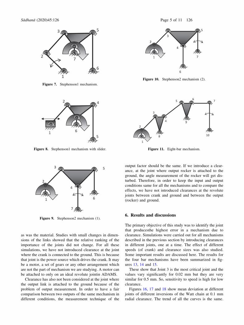
Figure 7. Stephenson1 mechanism.
Figure 9. Stephenson2 mechanism (1).
Figure 11. Eight-bar mechanism.
Figure 10. Stephenson2 mechanism (2).
Figure 8. Stephenson1 mechanism with slider.
Sådhanå (2020) 45:126 Page 5 of 11 126
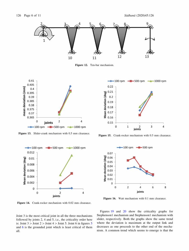
Joint 3 is the most critical joint in all the three mechanisms
followed by joints 2, 4 and 5, i.e., the criticality order here
is: Joint 3[ Joint 2[Joint 4[ Joint 5. Joint 6 in figures 5
and 6 is the grounded joint which is least critical of them
all.
Figures 19 and 20 show the criticality graphs for
Stephenson1 mechanism and Stephenson1 mechanism with
slider, respectively. Both the graphs show the same trend
where the deviation is maximum at the output link and
decreases as one proceeds to the other end of the mecha-
nism. A common trend which seems to emerge is that the
1
2 3 4 5 6 7 8 9
10 11 12 13
Figure 12. Ten-bar mechanism.
Figure 14. Crank-rocker mechanism with 0.02 mm clearance.
Figure 13. Slider-crank mechanism with 0.5 mm clearance.Figure 15. Crank-rocker mechanism with 0.5 mm clearance.
Figure 16. Watt mechanism with 0.1 mm clearance.
126 Page 6 of 11 Sådhanå (2020) 45:126
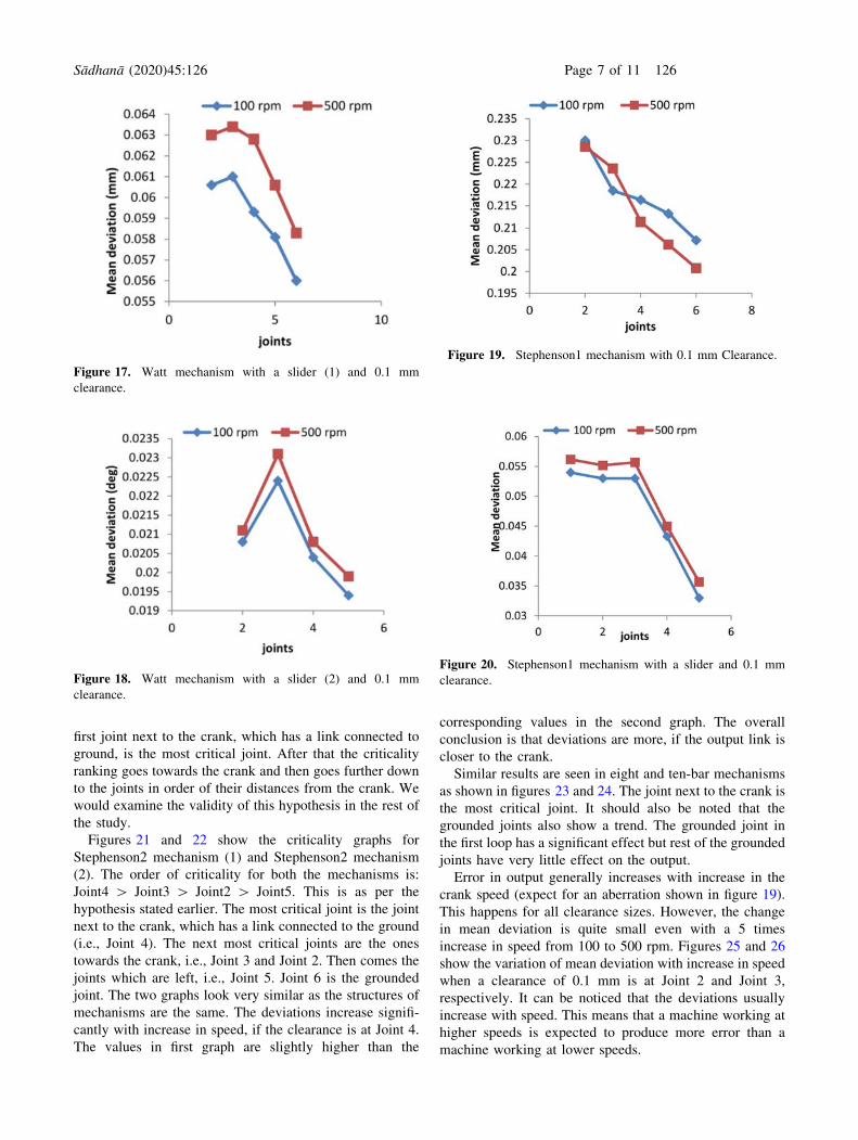
first joint next to the crank, which has a link connected to
ground, is the most critical joint. After that the criticality
ranking goes towards the crank and then goes further down
to the joints in order of their distances from the crank. We
would examine the validity of this hypothesis in the rest of
the study.
Figures 21 and 22 show the criticality graphs for
Stephenson2 mechanism (1) and Stephenson2 mechanism
(2). The order of criticality for both the mechanisms is:
Joint4 [ Joint3 [ Joint2 [ Joint5. This is as per the
hypothesis stated earlier. The most critical joint is the joint
next to the crank, which has a link connected to the ground
(i.e., Joint 4). The next most critical joints are the ones
towards the crank, i.e., Joint 3 and Joint 2. Then comes the
joints which are left, i.e., Joint 5. Joint 6 is the grounded
joint. The two graphs look very similar as the structures of
mechanisms are the same. The deviations increase signifi-
cantly with increase in speed, if the clearance is at Joint 4.
The values in first graph are slightly higher than the
corresponding values in the second graph. The overall
conclusion is that deviations are more, if the output link is
closer to the crank.
Similar results are seen in eight and ten-bar mechanisms
as shown in figures 23 and 24. The joint next to the crank is
the most critical joint. It should also be noted that the
grounded joints also show a trend. The grounded joint in
the first loop has a significant effect but rest of the grounded
joints have very little effect on the output.
Error in output generally increases with increase in the
crank speed (expect for an aberration shown in figure 19).
This happens for all clearance sizes. However, the change
in mean deviation is quite small even with a 5 times
increase in speed from 100 to 500 rpm. Figures 25 and 26
show the variation of mean deviation with increase in speed
when a clearance of 0.1 mm is at Joint 2 and Joint 3,
respectively. It can be noticed that the deviations usually
increase with speed. This means that a machine working at
higher speeds is expected to produce more error than a
machine working at lower speeds.
Figure 17. Watt mechanism with a slider (1) and 0.1 mm
clearance.
Figure 18. Watt mechanism with a slider (2) and 0.1 mm
clearance.
Figure 19. Stephenson1 mechanism with 0.1 mm Clearance.
Figure 20. Stephenson1 mechanism with a slider and 0.1 mm
clearance.
Sådhanå (2020) 45:126 Page 7 of 11 126
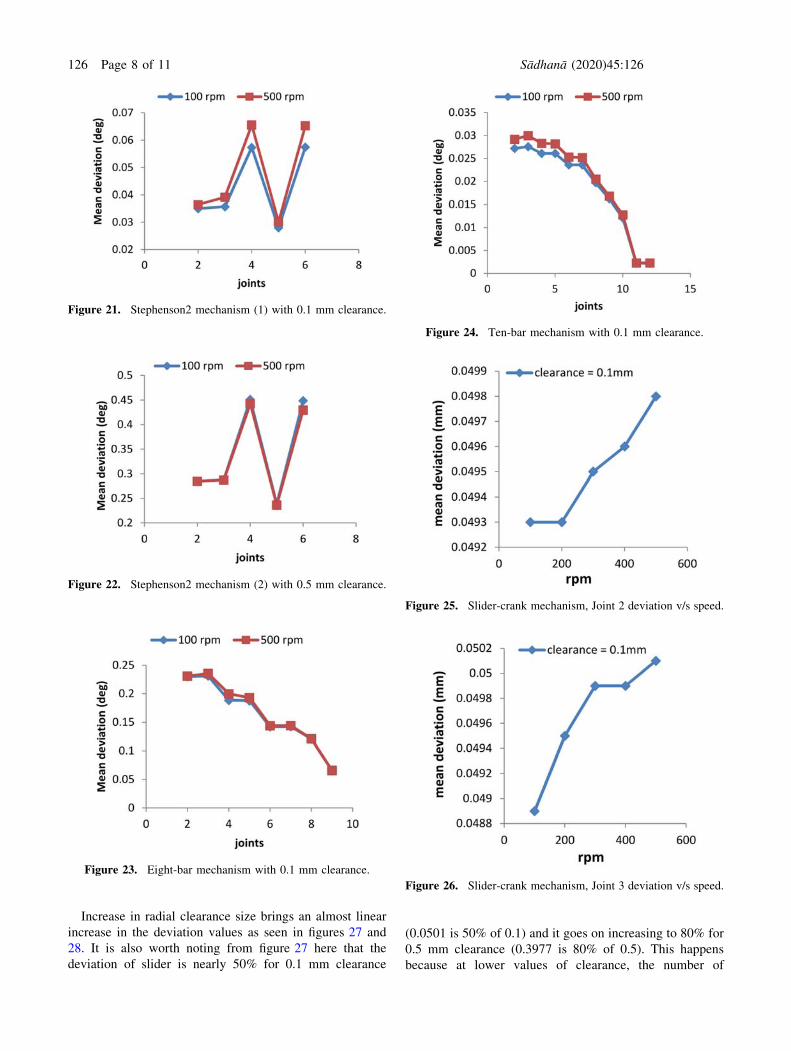
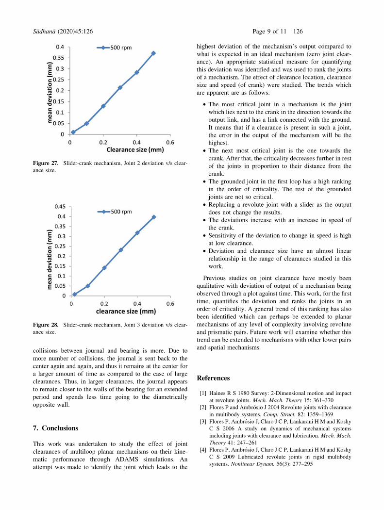
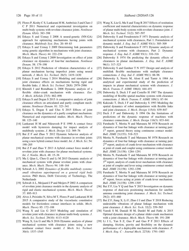
Increase in radial clearance size brings an almost linear
increase in the deviation values as seen in figures 27 and
28. It is also worth noting from figure 27 here that the
deviation of slider is nearly 50% for 0.1 mm clearance
(0.0501 is 50% of 0.1) and it goes on increasing to 80% for
0.5 mm clearance (0.3977 is 80% of 0.5). This happens
because at lower values of clearance, the number of
Figure 21. Stephenson2 mechanism (1) with 0.1 mm clearance.
Figure 22. Stephenson2 mechanism (2) with 0.5 mm clearance.
Figure 23. Eight-bar mechanism with 0.1 mm clearance.
Figure 24. Ten-bar mechanism with 0.1 mm clearance.
Figure 25. Slider-crank mechanism, Joint 2 deviation v/s speed.
Figure 26. Slider-crank mechanism, Joint 3 deviation v/s speed.
126 Page 8 of 11 Sådhanå (2020) 45:126
collisions between journal and bearing is more. Due to
more number of collisions, the journal is sent back to the
center again and again, and thus it remains at the center for
a larger amount of time as compared to the case of large
clearances. Thus, in larger clearances, the journal appears
to remain closer to the walls of the bearing for an extended
period and spends less time going to the diametrically
opposite wall.
7. Conclusions
This work was undertaken to study the effect of joint
clearances of multiloop planar mechanisms on their kine-
matic performance through ADAMS simulations. An
attempt was made to identify the joint which leads to the
highest deviation of the mechanism’s output compared to
what is expected in an ideal mechanism (zero joint clear-
ance). An appropriate statistical measure for quantifying
this deviation was identified and was used to rank the joints
of a mechanism. The effect of clearance location, clearance
size and speed (of crank) were studied. The trends which
are apparent are as follows:
• The most critical joint in a mechanism is the joint
which lies next to the crank in the direction towards the
output link, and has a link connected with the ground.
It means that if a clearance is present in such a joint,
the error in the output of the mechanism will be the
highest.
• The next most critical joint is the one towards the
crank. After that, the criticality decreases further in rest
of the joints in proportion to their distance from the
crank.
• The grounded joint in the first loop has a high ranking
in the order of criticality. The rest of the grounded
joints are not so critical.
• Replacing a revolute joint with a slider as the output
does not change the results.
• The deviations increase with an increase in speed of
the crank.
• Sensitivity of the deviation to change in speed is high
at low clearance.
• Deviation and clearance size have an almost linear
relationship in the range of clearances studied in this
work.
Previous studies on joint clearance have mostly been
qualitative with deviation of output of a mechanism being
observed through a plot against time. This work, for the first
time, quantifies the deviation and ranks the joints in an
order of criticality. A general trend of this ranking has also
been identified which can perhaps be extended to planar
mechanisms of any level of complexity involving revolute
and prismatic pairs. Future work will examine whether this
trend can be extended to mechanisms with other lower pairs
and spatial mechanisms.
References
[1] Haines R S 1980 Survey: 2-Dimensional motion and impact
at revolute joints. Mech. Mach. Theory 15: 361–370
[2] Flores P and Ambrosio J 2004 Revolute joints with clearance
in multibody systems. Comp. Struct. 82: 1359–1369
[3] Flores P, Ambrosio J, Claro J C P, Lankarani H M and Koshy
C S 2006 A study on dynamics of mechanical systems
including joints with clearance and lubrication. Mech. Mach.
Theory 41: 247–261
[4] Flores P, Ambrosio J, Claro J C P, Lankarani H M and Koshy
C S 2009 Lubricated revolute joints in rigid multibody
systems. Nonlinear Dynam. 56(3): 277–295
Figure 27. Slider-crank mechanism, Joint 2 deviation v/s clear-
ance size.
Figure 28. Slider-crank mechanism, Joint 3 deviation v/s clear-
ance size.
Sådhanå (2020) 45:126 Page 9 of 11 126
[5] Flores P, Koshy C S, Lankarani H M, Ambrosio J and Claro J
C P 2011 Numerical and experimental investigation on
multi-body systems with revolute clearance joints. Nonlinear
Dynam. 65(4): 383–398
[6] Erkaya S and Uzmay I 2008 A neural-genetic (NN-GA)
approach for optimizing mechanisms having joints with
clearance. Multibody Syst. Dyn. 20: 69–83
[7] Erkaya S and Uzmay I 2009 Determining link parameters
using genetic algorithm in mechanisms with joint clearance.
Mech. Mach. Theory 44: 222–234
[8] Erkaya S and Uzmay I 2009 Investigation on effect of joint
clearance on dynamics of four-bar mechanism. Nonlinear
Dynam. 58: 179–198
[9] Erkaya S 2012 Prediction of vibration characteristics of a
planar mechanism having imperfect joints using neural
network. J. Mech. Sci. Technol. 26(5): 1419–1430
[10] Erkaya S and Uzmay I 2014 Modeling and simulation of
joint clearance effects on mechanisms having rigid and
flexible links. J. Mech. Sci. Technol. 28(8): 2979–2986
[11] Khemili I and Romdhane L 2008 Dynamic analysis of a
flexible slider–crank mechanism with clearance. Eur.
J. Mech. A/Solids 27(5): 882–898
[12] Erkaya S and Dogan S 2015 A comparative analysis of joint
clearance effects on articulated and partly compliant mech-
anisms. Nonlinear Dynam. 81: 323–341
[13] Erkaya S, Dogan S and Ulus S 2015 Effects of joint
clearance on the dynamics of a partly compliant mechanism:
Numerical and experimental studies. Mech. Mach. Theory
88: 125–140
[14] Lankarani H M and Nikravesh P E 1990 A contact force
model with hysteresis damping for impact analysis of
multibody systems. J. Mech. Design 112: 369–76
[15] Bai Z F and Zhao Y 2012 Dynamic behavior analysis of
planar mechanical systems with clearance in revolute joints
using a new hybrid contact force model. Int. J. Mech. Sci. 54:
190–205
[16] Bai Z F and Zhao Y 2013 A hybrid contact force model of
revolute joint with clearance for planar mechanical systems.
Int. J. Nonlin. Mech. 48: 15–36
[17] Ma J, Qian L, Chen G and Li M 2015 Dynamic analysis of
mechanical systems with planar revolute joints with clear-
ance. Mech. Mach. Theory 94: 148–164
[18] Schwab A L 2002 Dynamics of flexible multibody systems:
small vibrations superimposed on a general rigid body
motion. PhD thesis, Delft University of Technology, The
Netherlands
[19] Schwab A L, Meijaard J P and Meijers P 2002 A comparison
of revolute joint clearance models in the dynamic analysis of
rigid and elastic mechanical systems. Mech. Mach. Theory
37: 895–913
[20] Alves J, Peixinho N, Silva M T, Flores P and Lankarani H M
2015 A comparative study of the viscoelastic constitutive
models for frictionless contact interfaces in solids. Mech.
Mach. Theory 85: 172–188
[21] Wang X and Liu G 2015 Modeling and simulation of
revolute joint with clearance in planar multi-body systems. J.
Mech. Sci. Technol. 29(10): 4113–4120
[22] Wang X, Liu G and Ma S 2016 Dynamic analysis of planar
mechanical systems with clearance joints using a new
nonlinear contact force model. J. Mech. Sci. Technol.
30(4): 1537–1545
[23] Wang X, Liu G, Ma S and Tong R 2017 Effects of restitution
coefficient and material characteristics on dynamic response
of planar multi-body systems with revolute clearance joint. J.
Mech. Sci. Technol. 31(2): 587–597
[24] Dubowsky S and Freudenstein F 1971 Dynamic analysis of
mechanical systems with clearances, Part 1: Formulation of
dynamic model. J. Eng. Ind.-T. ASME 93(1): 305–309
[25] Dubowsky S and Freudenstein F 1971 Dynamic analysis of
mechanical systems with clearances, Part 2: Dynamic
response. J. Eng. Ind.-T. ASME 93(1): 310–316
[26] Dubowsky S 1974 On predicting the dynamic effects of
clearances in planar mechanisms. J. Eng. Ind.-T. ASME
96(1): 317–323
[27] Dubowsky S and Gardner T N 1977 Design and analysis of
multilink flexible mechanisms with multiple clearance
connections. J. Eng. Ind.-T. ASME 99(1): 88–96
[28] Dubowsky S, Norris M, Aloni E and Tamir A 1984 An
analytical and experimental study of the prediction of
impacts in planar mechanical systems with clearances. J.
Mech. Transm.-T. ASME 106(4): 444–451
[29] Dubowsky S, Deck J F and Costello H 1987 The dynamic
modeling of flexible spatial machine systems with clearance
connections. J. Mech. Transm.-T. ASME 109(1): 87–94
[30] Kakizaki T, Deck J F and Dubowsky S 1993 Modeling the
spatial dynamics of robot manipulators with flexible links
and joint clearances. J. Mech. Design 115(4): 839–847
[31] Deck J F and Dubowsky S 1994 On the limitations of
predictions of the dynamic response of machines with
clearance connections. J. Mech. Design 116(3): 833–841
[32] Furuhashi T, Morita N and Matsuura M 1978 Research on
dynamics of four-bar linkage with clearance at turning pair:
1st report, general theory using continuous contact model.
Bull. JSME 21(153): 518–523
[33] Morita N, Furuhashi T and Matsuura M 1978 Research on
dynamics of four-bar linkage with clearance at turning pair:
2nd report, analysis of crank-lever mechanism with clearance
at joint of crank and coupler using continuous contact model.
Bull. JSME 21(158): 1284–1291
[34] Morita N, Furuhashi T and Matsuura M 1978 Research on
dynamics of four-bar linkage with clearance at turning pair:
3rd report, analysis of crank-lever mechanism with clearance
at joint of coupler and lever using continuous contact model.
Bull. JSME 21(158): 1292–1298
[35] Furuhashi T, Morita N and Matsuura M 1978 Research on
dynamics of four-bar linkage with clearance at turning pair:
4th report, forces acting at joints of crank-lever mechanism.
Bull. JSME 21(158): 1299–1305
[36] Bai Z F, Liu Y Q and Sun Y 2015 Investigation on dynamic
response of dual-axis positioning mechanism for satellite
antenna considering joint clearance. J. Mech. Sci. Technol.
29(2): 453–460
[37] Bai Z F, Jiang X, Li F, Zhao J J and Zhao Y 2018 Reducing
undesirable vibrations of planar linkage mechanism with
joint clearance. J. Mech. Sci. Tech. 32(2): 559–565
[38] Varedi S M, Daniali H M, Dardel M and Fathi A 2015
Optimal dynamic design of a planar slider-crank mechanism
with a joint clearance. Mech. Mach. Theory 86: 191–200
[39] Li J L, Yan S Z, Guo F and Guo P F 2013 Effects of
damping, friction, gravity and flexibility on the dynamic
performance of a deployable mechanisms with clearance. P.
I. Mech. Eng. C - Journal Mech. 227(8): 1791–1803
126 Page 10 of 11 Sådhanå (2020) 45:126
[40] Choi J H, Lee S J and Choi D H 1998 Tolerance optimization
for mechanisms with lubricated joints. Multibody Syst. Dyn.
2(2): 145–168
[41] Zhe L and Shixian B 1992 Optimum balancing of linkages
with clearances. Mech. Mach. Theory 27(5): 535–541
[42] Park C B and Kwak B M 1987 Counterweight optimization
for reducing dynamic effects of clearance at a revolute joint.
Mech. Mach. Theory 22(6): 549–556
[43] Feng B, Morita N and Torii T 2002 A new optimization
method for dynamic design of planar linkage with clearance
at joints—optimizing the mass distribution of links to reduce
the change of joint force. J. Mech. Design 124: 68–73
[44] Timoshenko S P and Goodier J N 1970 Theory of elasticity.
New York: McGraw-Hill
[45] Ryan R R 1990 ADAMS—multibody system analysis soft-
ware, multibody systems handbook. Berlin: Springer-Verlag
[46] MSC ADAMS, Automatic Dynamic Analysis of Mechanical
Systems, MSC Software Corporation
[47] Yan S, Xiang W and Zhang L 2015 A comprehensive model
for 3D revolute joints with clearances in mechanical systems.
Nonlinear Dynam. 80: 309–328
[48] Bengisu M T, Hidayetoglu E and Akay A 1986 A theoretical
and experimental investigation of contact loss in the
clearances of a four-bar mechanism. J. Mech. Transm-T.
ASME 108: 237–244
[49] Wu C L S and Earles S W E 1977 A determination of
contact-loss at a bearing of a linkage mechanism. J. Eng.
Ind-T. ASME 99(2): 375–80
Sådhanå (2020) 45:126 Page 11 of 11 126