a review of gas engine driven heat pumps (gehps) for residential and industrial applications
TRANSCRIPT
This article appeared in a journal published by Elsevier. The attachedcopy is furnished to the author for internal non-commercial researchand education use, including for instruction at the authors institution
and sharing with colleagues.
Other uses, including reproduction and distribution, or selling orlicensing copies, or posting to personal, institutional or third party
websites are prohibited.
In most cases authors are permitted to post their version of thearticle (e.g. in Word or Tex form) to their personal website orinstitutional repository. Authors requiring further information
regarding Elsevier’s archiving and manuscript policies areencouraged to visit:
http://www.elsevier.com/copyright
Author's personal copy
Renewable and Sustainable Energy Reviews 13 (2009) 85–99
A review of gas engine driven heat pumps (GEHPs) for residential andindustrial applications
Arif Hepbaslia,�, Zafer Erbayb, Filiz Icierc, Neslihan Colakd, Ebru Hancioglue
aDepartment of Mechanical Engineering, Faculty of Engineering, Ege University, 35100 Izmir, TurkeybGraduate School of Natural and Applied Sciences, Food Engineering Branch, Ege University, 35100 Izmir, Turkey
cDepartment of Food Engineering, Faculty of Engineering, Ege University, 35100 Izmir, TurkeydSolar Energy Institute, Ege University, 35100, Izmir, Turkey
eMavi Ege Environmental Technologies, 35100 Bornova, Izmir, Turkey
Received 21 May 2007; accepted 20 June 2007
Abstract
This study reviews gas engine-driven heat pump (GEHP) systems for residential and industrial applications in terms of energetic and
exergetic aspects for the first time to the best of the authors’ knowledge. These systems are novel heat pump systems (one of today’s
promising new technologies). Although the first investigations had been performed at late 1970s, the first merchandized GEHP was
produced and introduced in the market in 1985. Gradually, it has become widespread all over the world for various purposes. Main
application of GEHPs are for space and water heating/cooling purposes. However, they can be integrated to industrial applications,
especially to drying processes.
In this study, historical development of GEHP systems was briefly given first. Next, the operation of these systems was described, while
studies conducted on them were reviewed and presented in tabulated forms. GEHPs were then modeled for performance evaluation
purposes by using energy and exergy analysis methods. Finally, an illustrative example was given, while the results obtained were
discussed. In addition, a new project on integration of GEHP systems to food drying processes in Turkey initiated by the authors was
introduced. It is expected that this comprehensive study will be very beneficial to everyone involved or interested in the energetic and
exergetic design, simulation, analysis and performance of assessment of GEHP systems.
r 2007 Elsevier Ltd. All rights reserved.
Keywords: Gas engine heat pump; Gas engine driven heat pumps; Heat pumps; Exergy; Sustainable development
Contents
1. Introduction . . . . . . . . . . . . . . . . . . . . . . . . . . . . . . . . . . . . . . . . . . . . . . . . . . . . . . . . . . . . . . . . . . . . . . . . . . . . . . . . 86
2. Description of GEHPs . . . . . . . . . . . . . . . . . . . . . . . . . . . . . . . . . . . . . . . . . . . . . . . . . . . . . . . . . . . . . . . . . . . . . . . . . 86
3. A brief historical development of GEHP systems . . . . . . . . . . . . . . . . . . . . . . . . . . . . . . . . . . . . . . . . . . . . . . . . . . . . . . 87
4. Reviewing the studies conducted on GEHP systems . . . . . . . . . . . . . . . . . . . . . . . . . . . . . . . . . . . . . . . . . . . . . . . . . . . . 89
5. Modeling and an illustrative example . . . . . . . . . . . . . . . . . . . . . . . . . . . . . . . . . . . . . . . . . . . . . . . . . . . . . . . . . . . . . . 93
5.1. Modeling . . . . . . . . . . . . . . . . . . . . . . . . . . . . . . . . . . . . . . . . . . . . . . . . . . . . . . . . . . . . . . . . . . . . . . . . . . . . . . 94
5.1.1. General energy and exergy balance equations . . . . . . . . . . . . . . . . . . . . . . . . . . . . . . . . . . . . . . . . . . . . . . 94
5.1.2. General energy and exergy efficiency relations . . . . . . . . . . . . . . . . . . . . . . . . . . . . . . . . . . . . . . . . . . . . . . 95
5.2. An illustrative example . . . . . . . . . . . . . . . . . . . . . . . . . . . . . . . . . . . . . . . . . . . . . . . . . . . . . . . . . . . . . . . . . . . . 96
5.2.1. Description of the system . . . . . . . . . . . . . . . . . . . . . . . . . . . . . . . . . . . . . . . . . . . . . . . . . . . . . . . . . . . . 96
5.2.2. Energetic and exergetic assessment of gas engine . . . . . . . . . . . . . . . . . . . . . . . . . . . . . . . . . . . . . . . . . . . . 96
ARTICLE IN PRESS
www.elsevier.com/locate/rser
1364-0321/$ - see front matter r 2007 Elsevier Ltd. All rights reserved.
doi:10.1016/j.rser.2007.06.014
�Corresponding author. Tel.: +90232 343 4000x5124; fax: +90 232 388 8562.
E-mail addresses: [email protected], [email protected] (A. Hepbasli).
Author's personal copy
5.2.3. Energetic and exergetic assessment of GEHP components . . . . . . . . . . . . . . . . . . . . . . . . . . . . . . . . . . . . . 96
5.2.4. Results and discussion. . . . . . . . . . . . . . . . . . . . . . . . . . . . . . . . . . . . . . . . . . . . . . . . . . . . . . . . . . . . . . . 97
6. Conclusions . . . . . . . . . . . . . . . . . . . . . . . . . . . . . . . . . . . . . . . . . . . . . . . . . . . . . . . . . . . . . . . . . . . . . . . . . . . . . . . . 97
Acknowledgment . . . . . . . . . . . . . . . . . . . . . . . . . . . . . . . . . . . . . . . . . . . . . . . . . . . . . . . . . . . . . . . . . . . . . . . . . . . . . 97
References . . . . . . . . . . . . . . . . . . . . . . . . . . . . . . . . . . . . . . . . . . . . . . . . . . . . . . . . . . . . . . . . . . . . . . . . . . . . . . . . . 97
1. Introduction
Nowadays, two of main problems in the whole world aredepletion of fossil fuels and environmental pollution. Themain energy source in the world is fossil fuels and depletionof fossil fuels is a risk for energy poverty in the future. Onthe other hand, consumption of fossil fuels causes anotherproblem of environmental pollution. Investigations arefocused on solving these two problems by two ways:(i) developing alternative energy sources (especially renew-able energy sources) and its applications and (ii) improvingenergy efficiency of equipments that use fossil fuels.
Consumption of energy, especially domestic consump-tion, mainly occurs in hot water production and spaceheating, and the source of energy used in these applicationsare generally supplied from fossil fuels and/or electricityproduced from them.
Heat pump (HP) systems are heat-generating devicesthat transfer heat from low temperature medium to hightemperature one and are used in either hot water or spaceheating applications. HPs generally use vapor-compressioncycle or absorption-compression cycle. Although vapor-compression cycles dates back to 1834 and its firstcommercialized machine was produced at 1850, HPs werenot so popular because of their high installation costs [1].For example, HPs were first commercially produced in theUS in 1930s, but after 1970 s they have become popularbecause of their low operating costs. Approximately, one-third of all single-family homes built in the US were heatedby HPs in 1984 [2]. Recently, many studies have beenprogressing in alternative industrial applications of HPs,especially in dehumidification and in drying agriculturalproducts [3–5].
HPs are divided into many categories according toenergy sources, namely electric driven HPs (EHPs),chemical HPs, ground source HP, geothermal energy HP,solar assisted HPs and/or hybrid power systems etc. [6–9]and gas engine driven HPs (GEHPs).
Generally, fuel is mainly converted to electrical energy atpower plants and the waste heat is discharged to theenvironment, then electrical energy is transmitted to theHPs and is converted to mechanical energy by motor of theHPs. In this process, energy is converted twice and heatloss is high. However, energy efficiency can become higherif fuel conversion can be located closer to where heatrequired, heat released in fuel conversion can be efficientlyused. Since GEHPs are harmonious with this concept, theyare attracted the investigators with the high energyefficiency, especially in heating [10].
A GEHP usually consists of a reversible vapor compres-sion HP with an open compressor driven by a gas fuelledinternal combustion engine. Although the efficiency of agas engine is not very high (about 30–45%), the waste heatof fuel combustion can be recovered by approximately80%. This is the main advantage of GEHPs [11]. The heatrecovery is done by utilizing the energy of exhaust gas andby utilizing the waste heat released by the engine cylinderjacket [11–13].Since high energy efficiency of GEHPs causes low fossil
fuel consumption, the environmental pollution could bereduced. In addition, GEHPs use cheap energy sources,such as natural gas, propane or LPG instead of electricity[11], so GEHPs become an economic choice [10,14,15]. Thefeature of them is the easy modulation of the compressorspeed by adjusting the gas supply. Therefore the optimumworking conditions could be effectively obtained [13].Furthermore, GEHPs can play important social andeconomic roles by effectively balancing electricity demand,mitigating the electricity peaks and adjusting the energyconfiguration [14].In this regard, GEHP systems improve energy efficiency
and cause less fossil fuel consumption, so that thesesystems appropriate to a sustainable development concept.One of the most widely accepted definitions of sustainabledevelopment is: ‘‘development that meets the needs of thepresent without compromising the ability of futuregenerations to meet their own needs’’. There are manyfactors that can help to achieve sustainable development.Today, one of the main factors that must be considered indiscussions of sustainable development is energy, and oneof the most important issues is the requirement for a supplyof energy that is fully sustainable [16,17].The main objectives of the present study are: (i) to review
the studies conducted on GEHP systems by taking intoconsideration the analysis and utilization areas, (ii) toexpose the advantages and disadvantages of GEHPsystems, (iii) to anticipate the development of the GEHPsystems and (iv) to model GEHPs for performanceevaluation purposes by using energy and exergy analysismethods.
2. Description of GEHPs
A GEHP usually consists of a reversible vapor compres-sion HP with an open compressor. It is driven by a gasfuelled internal combustion engine instead of an electricmotor. A GEHP system mainly consists of two parts:(i) the HP itself, which includes an open compressor, a
ARTICLE IN PRESSA. Hepbasli et al. / Renewable and Sustainable Energy Reviews 13 (2009) 85–9986
Author's personal copy
condenser, an expansion valve and an evaporator, and(ii) the gas engine system [13].
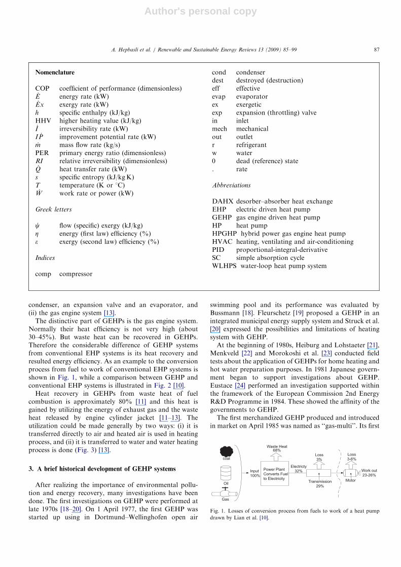
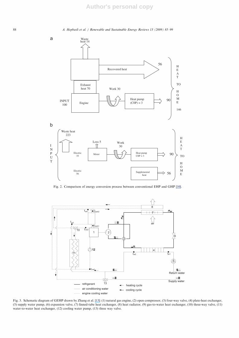
The distinctive part of GEHPs is the gas engine system.Normally their heat efficiency is not very high (about30–45%). But waste heat can be recovered in GEHPs.Therefore the considerable difference of GEHP systemsfrom conventional EHP systems is its heat recovery andresulted energy efficiency. As an example to the conversionprocess from fuel to work of conventional EHP systems isshown in Fig. 1, while a comparison between GEHP andconventional EHP systems is illustrated in Fig. 2 [10].
Heat recovery in GEHPs from waste heat of fuelcombustion is approximately 80% [11] and this heat isgained by utilizing the energy of exhaust gas and the wasteheat released by engine cylinder jacket [11–13]. Theutilization could be made generally by two ways: (i) it istransferred directly to air and heated air is used in heatingprocess, and (ii) it is transferred to water and water heatingprocess is done (Fig. 3) [13].
3. A brief historical development of GEHP systems
After realizing the importance of environmental pollu-tion and energy recovery, many investigations have beendone. The first investigations on GEHP were performed atlate 1970s [18–20]. On 1 April 1977, the first GEHP wasstarted up using in Dortmund–Wellinghofen open air
swimming pool and its performance was evaluated byBussmann [18]. Fleurschetz [19] proposed a GEHP in anintegrated municipal energy supply system and Struck et al.[20] expressed the possibilities and limitations of heatingsystem with GEHP.At the beginning of 1980s, Heiburg and Lohstaeter [21],
Menkveld [22] and Morokoshi et al. [23] conducted fieldtests about the application of GEHPs for home heating andhot water preparation purposes. In 1981 Japanese govern-ment began to support investigations about GEHP.Eustace [24] performed an investigation supported withinthe framework of the European Commission 2nd EnergyR&D Programme in 1984. These showed the affinity of thegovernments to GEHP.The first merchandized GEHP produced and introduced
in market on April 1985 was named as ‘‘gas-multi’’. Its first
ARTICLE IN PRESS
Nomenclature
COP coefficient of performance (dimensionless)_E energy rate (kW)_Ex exergy rate (kW)
h specific enthalpy (kJ/kg)HHV higher heating value (kJ/kg)_I irreversibility rate (kW)I _P improvement potential rate (kW)_m mass flow rate (kg/s)PER primary energy ratio (dimensionless)RI relative irreversibility (dimensionless)_Q heat transfer rate (kW)
s specific entropy (kJ/kgK)T temperature (K or 1C)_W work rate or power (kW)
Greek letters
c flow (specific) exergy (kJ/kg)Z energy (first law) efficiency (%)� exergy (second law) efficiency (%)
Indices
comp compressor
cond condenserdest destroyed (destruction)eff effectiveevap evaporatorex exergeticexp expansion (throttling) valvein inletmech mechanicalout outletr refrigerantw water0 dead (reference) state. rate
Abbreviations
DAHX desorber–absorber heat exchangeEHP electric driven heat pumpGEHP gas engine driven heat pumpHP heat pumpHPGHP hybrid power gas engine heat pumpHVAC heating, ventilating and air-conditioningPID proportional-integral-derivativeSC simple absorption cycleWLHPS water-loop heat pump system
coal
Oil
Gas
Waste Heat68%
Input100%
Power PlantConverts Fuelto Electricity
Electricty32%
Loss3%
Transmission29%
Loss3-6%
Motor
Work out23-26%
Fig. 1. Losses of conversion process from fuels to work of a heat pump
drawn by Lian et al. [10].
A. Hepbasli et al. / Renewable and Sustainable Energy Reviews 13 (2009) 85–99 87
Author's personal copy
ARTICLE IN PRESS
Heat pump (C0P) = 3 Engine
90
56
Work 30
INPUT 100
Wasteheat 14
HEAT
TO
HOME
146
Exhaust heat 70
Recovered heat
Heat pump C0P = 3
Supplemental heat
Motor 90
56
Loss 5 Work 30
Electric 35
Electric 56
Waste heat 223
INPUT
HEAT
TO
HOME
Fig. 2. Comparison of energy conversion process between conventional EHP and GHP [10].
tw3
tw4
texh1
texh2
tw2
tcw2
tw1
tcw1
1 2
3
12
11
13refrigerant
air conditioning water
engine cooling water
heating cycle
cooling cycle
10
12 4
5
Return water
Supply water
8
7
air
6
Fig. 3. Schematic diagram of GEHP drawn by Zhang et al. [13]: (1) natural gas engine, (2) open compressor, (3) four-way valve, (4) plate-heat exchanger,
(5) supply water pump, (6) expansion valve, (7) finned-tube heat exchanger, (8) heat radiator, (9) gas-to-water heat exchanger, (10) three-way valve, (11)
water-to-water heat exchanger, (12) cooling water pump, (13) three way valve.
A. Hepbasli et al. / Renewable and Sustainable Energy Reviews 13 (2009) 85–9988
Author's personal copy
performance tests were done by Ogura et al. [25]. Sincethen, many products were introduced in the market byJapanese companies.
Many investigators focused on the system integralenergy efficiency and economic aspects of the units byfield tests [26–32], improving GEHP by designing anddeveloping its parts [10,33–38], modeling of GEHP systems[13,39–42], its industrial applications [43,44], improvingcontrolling strategies and systems [11,45], and testing itsenvironmental effects [46,47]. Nowadays, investigations onthe use of GEHPs have been increased up for residentialand industrial application purposes by gaining importance(Table 1).
4. Reviewing the studies conducted on GEHP systems
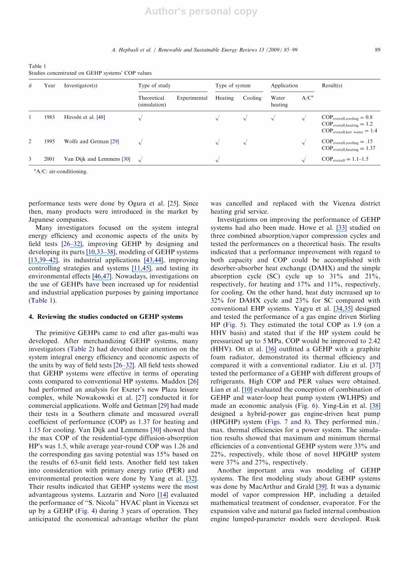
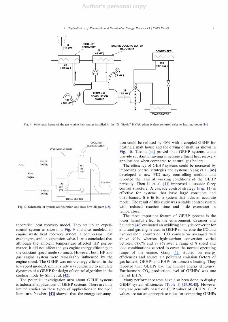
The primitive GEHPs came to end after gas-multi wasdeveloped. After merchandizing GEHP systems, manyinvestigators (Table 2) had devoted their attention on thesystem integral energy efficiency and economic aspects ofthe units by way of field tests [26–32]. All field tests showedthat GEHP systems were effective in terms of operatingcosts compared to conventional HP systems. Maddox [26]had performed an analysis for Exeter’s new Plaza leisurecomplex, while Nowakowski et al. [27] conducted it forcommercial applications. Wolfe and Getman [29] had madetheir tests in a Southern climate and measured overallcoefficient of performance (COP) as 1.37 for heating and1.15 for cooling. Van Dijk and Lemmens [30] showed thatthe max COP of the residential-type diffusion-absorptionHP’s was 1.5, while average year-round COP was 1.26 andthe corresponding gas saving potential was 15% based onthe results of 63-unit field tests. Another field test takeninto consideration with primary energy ratio (PER) andenvironmental protection were done by Yang et al. [32].Their results indicated that GEHP systems were the mostadvantageous systems. Lazzarin and Noro [14] evaluatedthe performance of ‘‘S. Nicola’’ HVAC plant in Vicenza setup by a GEHP (Fig. 4) during 3 years of operation. Theyanticipated the economical advantage whether the plant
was cancelled and replaced with the Vicenza districtheating grid service.Investigations on improving the performance of GEHP
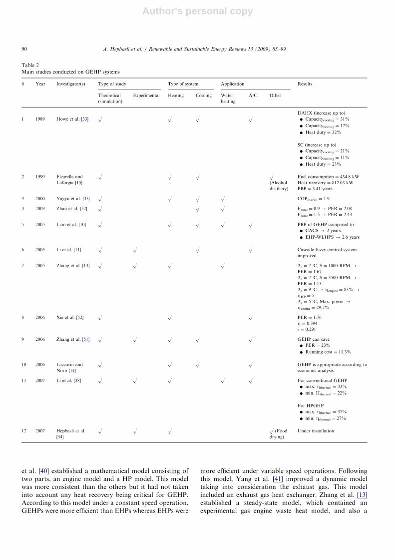
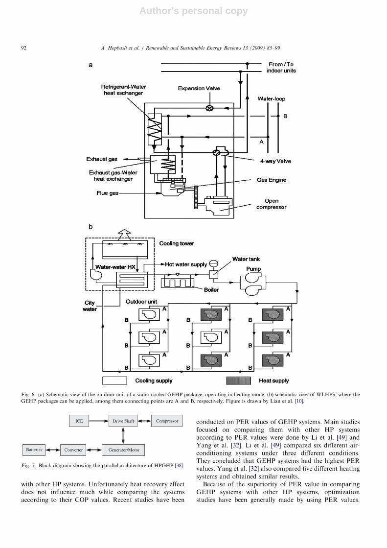
systems had also been made. Howe et al. [33] studied onthree combined absorption/vapor compression cycles andtested the performances on a theoretical basis. The resultsindicated that a performance improvement with regard toboth capacity and COP could be accomplished withdesorber-absorber heat exchange (DAHX) and the simpleabsorption cycle (SC) cycle up to 31% and 21%,respectively, for heating and 17% and 11%, respectively,for cooling. On the other hand, heat duty increased up to32% for DAHX cycle and 23% for SC compared withconventional EHP systems. Yagyu et al. [34,35] designedand tested the performance of a gas engine driven StirlingHP (Fig. 5). They estimated the total COP as 1.9 (on aHHV basis) and stated that if the HP system could bepressurized up to 5MPa, COP would be improved to 2.42(HHV). Ott et al. [36] outfitted a GEHP with a graphitefoam radiator, demonstrated its thermal efficiency andcompared it with a conventional radiator. Liu et al. [37]tested the performance of a GEHP with different groups ofrefrigerants. High COP and PER values were obtained.Lian et al. [10] evaluated the conception of combination ofGEHP and water-loop heat pump system (WLHPS) andmade an economic analysis (Fig. 6). Ying-Lin et al. [38]designed a hybrid-power gas engine-driven heat pump(HPGHP) system (Figs. 7 and 8). They performed min./max. thermal efficiencies for a power system. The simula-tion results showed that maximum and minimum thermalefficiencies of a conventional GEHP system were 33% and22%, respectively, while those of novel HPGHP systemwere 37% and 27%, respectively.Another important area was modeling of GEHP
systems. The first modeling study about GEHP systemswas done by MacArthur and Grald [39]. It was a dynamicmodel of vapor compression HP, including a detailedmathematical treatment of condenser, evaporator. For theexpansion valve and natural gas fueled internal combustionengine lumped-parameter models were developed. Rusk
ARTICLE IN PRESS
Table 1
Studies concentrated on GEHP systems’ COP values
# Year Investigator(s) Type of study Type of system Application Result(s)
Theoretical
(simulation)
Experimental Heating Cooling Water
heating
A/Ca
1 1985 Hiroshi et al. [48] O O O O O COPoverall,cooling ¼ 0.8
COPoverall,heating ¼ 1.2
COPoverall,hot water ¼ 1.4
2 1995 Wolfe and Getman [29] O O O O COPoverall,cooling ¼ .15
COPoverall,heating ¼ 1.37
3 2001 Van Dijk and Lemmens [30] O O O COPoverall ¼ 1.1–1.5
aA/C: air-conditioning.
A. Hepbasli et al. / Renewable and Sustainable Energy Reviews 13 (2009) 85–99 89
Author's personal copy
et al. [40] established a mathematical model consisting oftwo parts, an engine model and a HP model. This modelwas more consistent than the others but it had not takeninto account any heat recovery being critical for GEHP.According to this model under a constant speed operation,GEHPs were more efficient than EHPs whereas EHPs were
more efficient under variable speed operations. Followingthis model, Yang et al. [41] improved a dynamic modeltaking into consideration the exhaust gas. This modelincluded an exhaust gas heat exchanger. Zhang et al. [13]established a steady-state model, which contained anexperimental gas engine waste heat model, and also a
ARTICLE IN PRESS
Table 2
Main studies conducted on GEHP systems
# Year Investigator(s) Type of study Type of system Application Results
Theoretical
(simulation)
Experimental Heating Cooling Water
heating
A/C Other
DAHX (increase up to)
1 1989 Howe et al. [33] O O O O � Capacitycooling ¼ 31%
� Capacityheating ¼ 17%
� Heat duty ¼ 32%
SC (increase up to)
� Capacitycooling ¼ 21%
� Capacityheating ¼ 11%
� Heat duty ¼ 23%
2 1999 Ficarella and
Laforgia [15]
O O O O(Alcohol
distillery)
Fuel consumption ¼ 434.8 kW
Heat recovery ¼ 812.03 kW
PBP ¼ 3.41 years
3 2000 Yagyu et al. [35] O O O O COPoverall ¼ 1.9
4 2003 Zhao et al. [52] O O O Ftotal ¼ 0.9 - PER ¼ 2.08
Ftotal ¼ 1.5 - PER ¼ 2.43
5 2005 Lian et al. [10] O O O O O PBP of GEHP compared to
� CACS - 2 years
� EHP-WLHPS - 2.6 years
6 2005 Li et al. [11] O O O O Cascade fuzzy control system
improved
7 2005 Zhang et al. [13] O O O O Ta ¼ 7 1C, S ¼ 1000 RPM -
PER ¼ 1.67
Ta ¼ 7 1C, S ¼ 3500 RPM -
PER ¼ 1.13
Ta ¼ 9 1C - Zengine ¼ 83% -
ZHP ¼ 5
Ta ¼ 5 1C, Max. power -
Zengine ¼ 29.7%
8 2006 Xie et al. [52] O O O PER ¼ 1.76
Z ¼ 0.394
e ¼ 0.291
9 2006 Zhang et al. [51] O O O O O GEHP can save
� PER ¼ 23%
� Running cost ¼ 11.3%
10 2006 Lazzarin and
Noro [14]
O O O O GEHP is appropriate according to
economic analysis
11 2007 Li et al. [38] O O O O O For conventional GEHP
� max. Zthermal ¼ 33%
� min. Hthermal ¼ 22%
For HPGHP
� max. Zthermal ¼ 37%
� min. Zthermal ¼ 27%
12 2007 Hepbasli et al.
[54]
O O O O (Food
drying)
Under installation
A. Hepbasli et al. / Renewable and Sustainable Energy Reviews 13 (2009) 85–9990
Author's personal copy
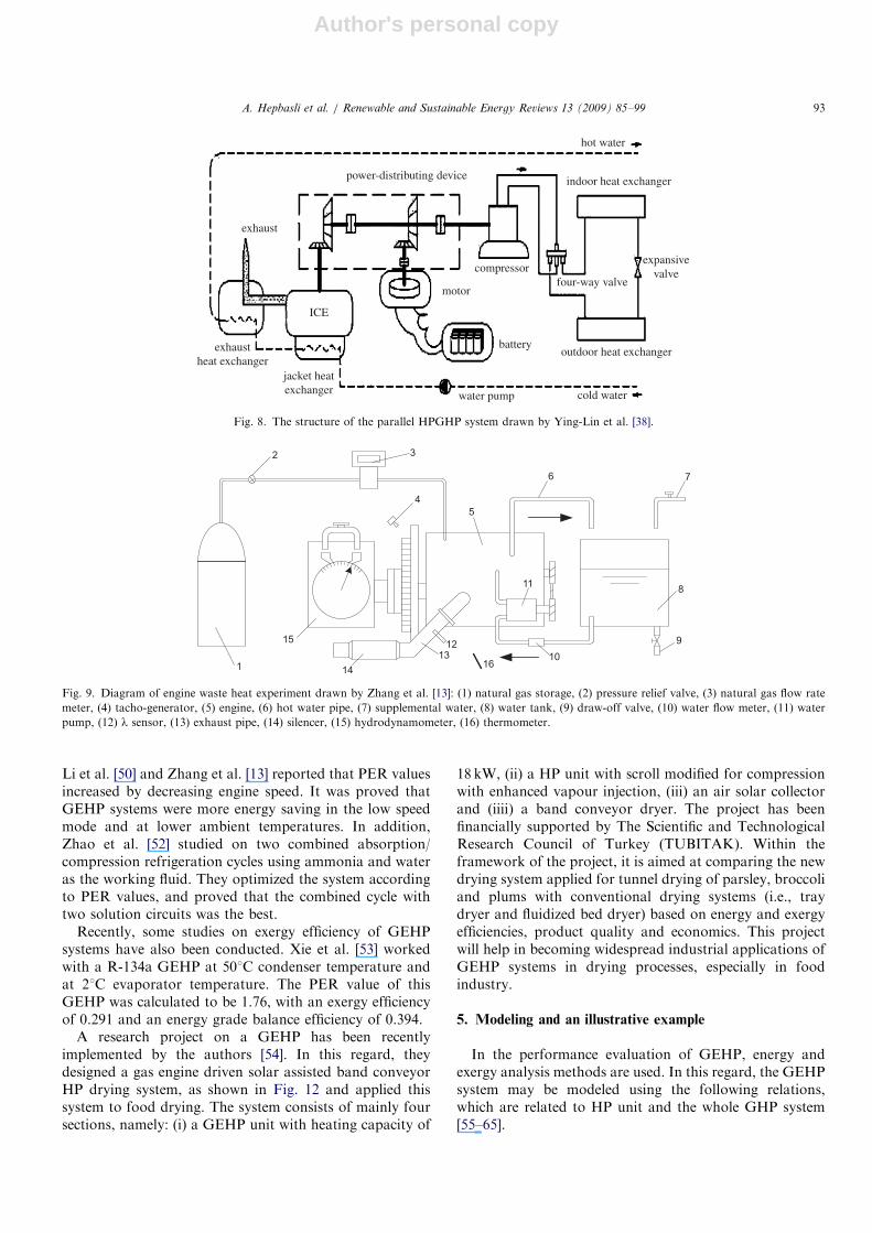
theoretical heat recovery model. They set up an experi-mental system as shown in Fig. 9 and also modeled anengine waste heat recovery system, a compressor, heatexchangers, and an expansion valve. It was concluded thatalthough the ambient temperature affected HP perfor-mance, it did not affect the gas engine energy efficiency inthe constant speed mode so much. However, both HP andgas engine system were remarkably influenced by theengine speed. The GEHP was more energy efficient in thelow speed mode. A similar study was conducted to simulatedynamics of a GEHP for design of control algorithm in thecooling mode by Shin et al. [42].
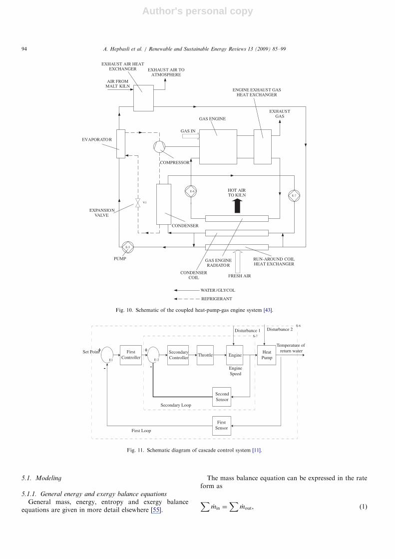
The potential investigation area about GEHP systemsis industrial applications of GEHP systems. There are onlylimited studies on these types of applications in the openliterature. Newbert [43] showed that the energy consump-
tion could be reduced by 40% with a coupled GEHP forheating a malt house and for drying of malt, as shown inFig. 10. Tassou [44] proved that GEHP systems couldprovide substantial savings in sewage effluent heat recoveryapplications when compared to natural gas boilers.The efficiency of GEHP systems could be increased by
improving control strategies and systems. Yang et al. [45]developed a new PID-fuzzy controlling method andreported the laws of working conditions of the GEHPperfectly. Then Li et al. [11] improved a cascade fuzzycontrol structure. A cascade control strategy (Fig. 11) iseffective for systems that have large constants anddisturbances. It is fit for a system that lacks an accuratemodel. The result of this study was a stable control systemwith reduced reaction time and little overshoot intemperature.The most important feature of GEHP systems is the
lower harmful effect to the environment. Creamer andSaunders [46] evaluated an oxidizing catalytic converter fora natural gas engine used in GEHP to increase the CO andhydrocarbon conversion. CO conversion averaged wellabove 90% whereas hydrocarbon conversion variedbetween 68.6% and 89.8% over a range of 8 speed andload combinations selected to cover the normal operatingrange of the engine. Ganji [47] studied on energyefficiencies and source air pollutant emission factors ofgas heaters, GEHPs and EHPs for domestic heating. Theyreported that GEHPs had the highest energy efficiency.Furthermore CO2 production level of GEHPs’ was onehalf of EHPs.Many performance tests have also been done to display
GEHP system efficiencies (Table 1) [29,30,48]. Howeverthey are generally based on COP values of GEHPs. COPvalues are not an appropriate value for comparing GEHPs
ARTICLE IN PRESS
Fig. 4. Schematic figure of the gas engine heat pump installed in the ‘‘S. Nicola’’ HVAC plant (values reported refer to heating mode) [14].
Fig. 5. Schematic of system configuration and heat flow diagram [35].
A. Hepbasli et al. / Renewable and Sustainable Energy Reviews 13 (2009) 85–99 91
Author's personal copy
with other HP systems. Unfortunately heat recovery effectdoes not influence much while comparing the systemsaccording to their COP values. Recent studies have been
conducted on PER values of GEHP systems. Main studiesfocused on comparing them with other HP systemsaccording to PER values were done by Li et al. [49] andYang et al. [32]. Li et al. [49] compared six different air-conditioning systems under three different conditions.They concluded that GEHP systems had the highest PERvalues. Yang et al. [32] also compared five different heatingsystems and obtained similar results.Because of the superiority of PER value in comparing
GEHP systems with other HP systems, optimizationstudies have been generally made by using PER values.
ARTICLE IN PRESS
Fig. 6. (a) Schematic view of the outdoor unit of a water-cooled GEHP package, operating in heating mode; (b) schematic view of WLHPS, where the
GEHP packages can be applied, among them connecting points are A and B, respectively. Figure is drawn by Lian et al. [10].
ICE Drive Shaft Compressor
Generator/MotorConverterBatteries
Fig. 7. Block diagram showing the parallel architecture of HPGHP [38].
A. Hepbasli et al. / Renewable and Sustainable Energy Reviews 13 (2009) 85–9992
Author's personal copy
Li et al. [50] and Zhang et al. [13] reported that PER valuesincreased by decreasing engine speed. It was proved thatGEHP systems were more energy saving in the low speedmode and at lower ambient temperatures. In addition,Zhao et al. [52] studied on two combined absorption/compression refrigeration cycles using ammonia and wateras the working fluid. They optimized the system accordingto PER values, and proved that the combined cycle withtwo solution circuits was the best.
Recently, some studies on exergy efficiency of GEHPsystems have also been conducted. Xie et al. [53] workedwith a R-134a GEHP at 501C condenser temperature andat 21C evaporator temperature. The PER value of thisGEHP was calculated to be 1.76, with an exergy efficiencyof 0.291 and an energy grade balance efficiency of 0.394.
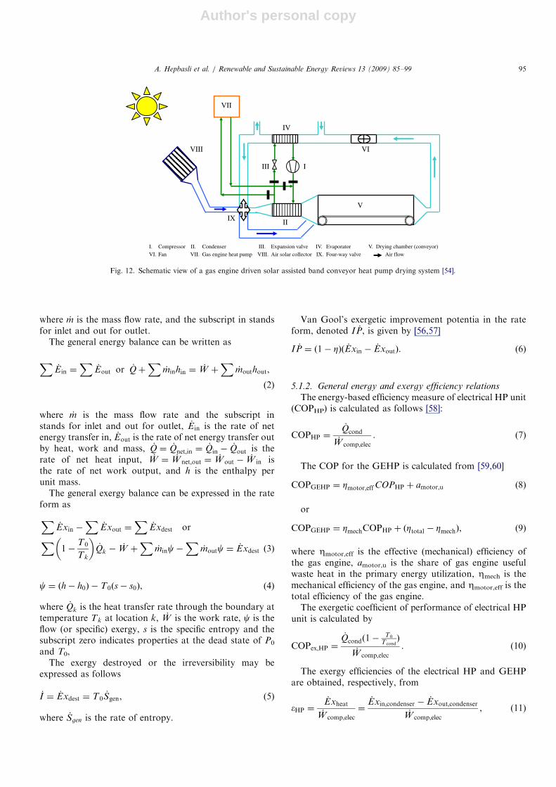
A research project on a GEHP has been recentlyimplemented by the authors [54]. In this regard, theydesigned a gas engine driven solar assisted band conveyorHP drying system, as shown in Fig. 12 and applied thissystem to food drying. The system consists of mainly foursections, namely: (i) a GEHP unit with heating capacity of
18 kW, (ii) a HP unit with scroll modified for compressionwith enhanced vapour injection, (iii) an air solar collectorand (iiii) a band conveyor dryer. The project has beenfinancially supported by The Scientific and TechnologicalResearch Council of Turkey (TUBITAK). Within theframework of the project, it is aimed at comparing the newdrying system applied for tunnel drying of parsley, broccoliand plums with conventional drying systems (i.e., traydryer and fluidized bed dryer) based on energy and exergyefficiencies, product quality and economics. This projectwill help in becoming widespread industrial applications ofGEHP systems in drying processes, especially in foodindustry.
5. Modeling and an illustrative example
In the performance evaluation of GEHP, energy andexergy analysis methods are used. In this regard, the GEHPsystem may be modeled using the following relations,which are related to HP unit and the whole GHP system[55–65].
ARTICLE IN PRESS
Fig. 9. Diagram of engine waste heat experiment drawn by Zhang et al. [13]: (1) natural gas storage, (2) pressure relief valve, (3) natural gas flow rate
meter, (4) tacho-generator, (5) engine, (6) hot water pipe, (7) supplemental water, (8) water tank, (9) draw-off valve, (10) water flow meter, (11) water
pump, (12) l sensor, (13) exhaust pipe, (14) silencer, (15) hydrodynamometer, (16) thermometer.
power-distributing device
hot water
cold waterwater pump
indoor heat exchanger
outdoor heat exchanger
expansivevalve
four-way valve
battery
motor
ICE
jacket heatexchanger
exhaustheat exchanger
exhaust
compressor
Fig. 8. The structure of the parallel HPGHP system drawn by Ying-Lin et al. [38].
A. Hepbasli et al. / Renewable and Sustainable Energy Reviews 13 (2009) 85–99 93
Author's personal copy
5.1. Modeling
5.1.1. General energy and exergy balance equations
General mass, energy, entropy and exergy balanceequations are given in more detail elsewhere [55].
The mass balance equation can be expressed in the rateform as
X_min ¼
X_mout, (1)
ARTICLE IN PRESS
E-5
V-1
PUMP
EXPANSIONVALVE
EVAPORATO R
AIR FROMMALT KILN
EXHAUST AIR HEATEXCHANGER EXHAUST AIR TO
ATMOSPHERE
COMPRESSOR
CONDENSER
FRESH AIR
GAS IN
GAS ENGINE
EXHAUSTGAS
ENGINE EXHAUST GASHEAT EXCHANGER
HOT AIRTO KILN
RUN-AROUND COILHEAT EXCHANGER
GAS ENGINERADIATO R
CONDENSERCOIL
REFRIGERANT
WATER /GLYCOL
E-6
E-7
Fig. 10. Schematic of the coupled heat-pump-gas engine system [43].
Set Point FirstController
SecondaryController
Secondary Loop
First Loop
Throttle
Disturbance 1 Disturbance 2
Temperature of return waterHeat
PumpEngine
EngineSpeed
SecondSensor
FirstSensor
E1 E-2
S-7
S-6
Fig. 11. Schematic diagram of cascade control system [11].
A. Hepbasli et al. / Renewable and Sustainable Energy Reviews 13 (2009) 85–9994
Author's personal copy
where _m is the mass flow rate, and the subscript in standsfor inlet and out for outlet.
The general energy balance can be written as
X_Ein ¼
X_Eout or _Qþ
X_minhin ¼ _W þ
X_mouthout,
(2)
where _m is the mass flow rate and the subscript instands for inlet and out for outlet, _Ein is the rate of netenergy transfer in, _Eout is the rate of net energy transfer outby heat, work and mass, _Q ¼ _Qnet;in ¼
_Qin �_Qout is the
rate of net heat input, _W ¼ _Wnet;out ¼ _Wout � _W in isthe rate of net work output, and h is the enthalpy perunit mass.
The general exergy balance can be expressed in the rateform as
X_Exin �
X_Exout ¼
X_Exdest or
X1�
T0
Tk
� �_Qk �
_W þX
_minc�X
_moutc ¼ _Exdest ð3Þ
c ¼ ðh� h0Þ � T0ðs� s0Þ, (4)
where _Qk is the heat transfer rate through the boundary attemperature Tk at location k, _W is the work rate, c is theflow (or specific) exergy, s is the specific entropy and thesubscript zero indicates properties at the dead state of P0
and T0,The exergy destroyed or the irreversibility may be
expressed as follows
_I ¼ _Exdest ¼ T0_Sgen, (5)
where _Sgen is the rate of entropy.
Van Gool’s exergetic improvement potentia in the rateform, denoted I _P, is given by [56,57]
I _P ¼ ð1� ZÞð _Exin � _ExoutÞ. (6)
5.1.2. General energy and exergy efficiency relations
The energy-based efficiency measure of electrical HP unit(COPHP) is calculated as follows [58]:
COPHP ¼_Qcond
_W comp;elec
. (7)
The COP for the GEHP is calculated from [59,60]
COPGEHP ¼ Zmotor;effCOPHP þ amotor;u (8)
or
COPGEHP ¼ ZmechCOPHP þ ðZtotal � ZmechÞ, (9)
where Zmotor,eff is the effective (mechanical) efficiency ofthe gas engine, amotor,u is the share of gas engine usefulwaste heat in the primary energy utilization, Zmech is themechanical efficiency of the gas engine, and Zmotor,eff is thetotal efficiency of the gas engine.The exergetic coefficient of performance of electrical HP
unit is calculated by
COPex;HP ¼
_Qcondð1�T0
T condÞ
_W comp;elec
. (10)
The exergy efficiencies of the electrical HP and GEHPare obtained, respectively, from
�HP ¼_Exheat
_W comp;elec
¼_Exin;condenser � _Exout;condenser
_W comp;elec
, (11)
ARTICLE IN PRESS
I. Compressor II. Condenser III. IV. VI. VII. Gas engine heat pump VIII. Air solar collector IX. Air flow
IIII
IV
II
V
VIVIII
IX
VII
Fan Expansion valve Evaporator V. Drying chamber (conveyor)
Four-way valve
Fig. 12. Schematic view of a gas engine driven solar assisted band conveyor heat pump drying system [54].
A. Hepbasli et al. / Renewable and Sustainable Energy Reviews 13 (2009) 85–99 95
Author's personal copy
�GEHP ¼_Exin;condenser � _Exout;condenser
_Exfuel
. (12)
5.2. An illustrative example
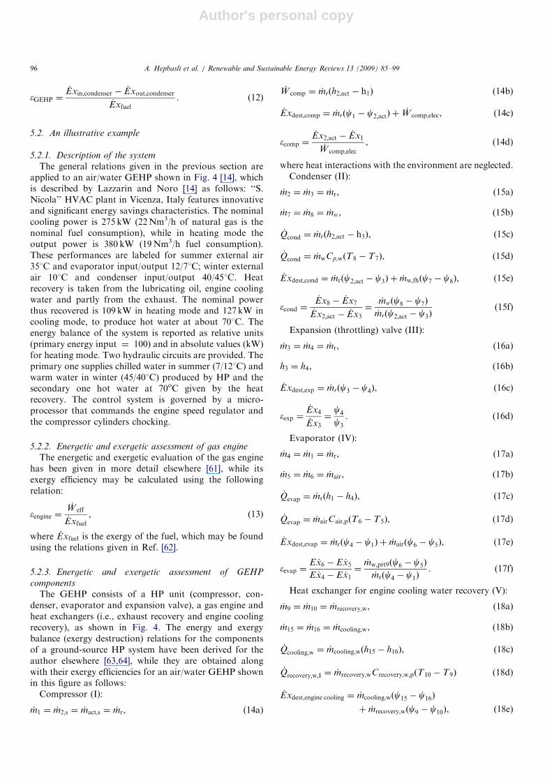
5.2.1. Description of the system
The general relations given in the previous section areapplied to an air/water GEHP shown in Fig. 4 [14], whichis described by Lazzarin and Noro [14] as follows: ‘‘S.Nicola’’ HVAC plant in Vicenza, Italy features innovativeand significant energy savings characteristics. The nominalcooling power is 275 kW (22Nm3/h of natural gas is thenominal fuel consumption), while in heating mode theoutput power is 380 kW (19Nm3/h fuel consumption).These performances are labeled for summer external air351C and evaporator input/output 12/71C; winter externalair 101C and condenser input/output 40/451C. Heatrecovery is taken from the lubricating oil, engine coolingwater and partly from the exhaust. The nominal powerthus recovered is 109 kW in heating mode and 127 kW incooling mode, to produce hot water at about 701C. Theenergy balance of the system is reported as relative units(primary energy input ¼ 100) and in absolute values (kW)for heating mode. Two hydraulic circuits are provided. Theprimary one supplies chilled water in summer (7/121C) andwarm water in winter (45/401C) produced by HP and thesecondary one hot water at 70oC given by the heatrecovery. The control system is governed by a micro-processor that commands the engine speed regulator andthe compressor cylinders chocking.
5.2.2. Energetic and exergetic assessment of gas engine
The energetic and exergetic evaluation of the gas enginehas been given in more detail elsewhere [61], while itsexergy efficiency may be calculated using the followingrelation:
�engine ¼_W eff
_Exfuel
, (13)
where _Exfuel is the exergy of the fuel, which may be foundusing the relations given in Ref. [62].
5.2.3. Energetic and exergetic assessment of GEHP
components
The GEHP consists of a HP unit (compressor, con-denser, evaporator and expansion valve), a gas engine andheat exchangers (i.e., exhaust recovery and engine coolingrecovery), as shown in Fig. 4. The energy and exergybalance (exergy destruction) relations for the componentsof a ground-source HP system have been derived for theauthor elsewhere [63,64], while they are obtained alongwith their exergy efficiencies for an air/water GEHP shownin this figure as follows:
Compressor (I):
_m1 ¼ _m2;s ¼ _mact;s ¼ _mr, (14a)
_W comp ¼ _mrðh2;act � h1Þ (14b)
_Exdest;comp ¼ _mrðc1 � c2;actÞ þ_W comp;elec, (14c)
�comp ¼_Ex2;act � _Ex1
_W comp;elec
, (14d)
where heat interactions with the environment are neglected.Condenser (II):
_m2 ¼ _m3 ¼ _mr, (15a)
_m7 ¼ _m8 ¼ _mw, (15b)
_Qcond ¼ _mrðh2;act � h3Þ, (15c)
_Qcond ¼ _mwCp;wðT8 � T7Þ, (15d)
_Exdest;cond ¼ _mrðc2;act � c3Þ þ _mw;fhðc7 � c8Þ, (15e)
�cond ¼_Ex8 � _Ex7
_Ex2;act � _Ex3
¼_mwðc8 � c7Þ
_mrðc2;act � c3Þ(15f)
Expansion (throttling) valve (III):
_m3 ¼ _m4 ¼ _mr, (16a)
h3 ¼ h4, (16b)
_Exdest;exp ¼ _mrðc3 � c4Þ, (16c)
�exp ¼_Ex4
_Ex3
¼c4
c3
. (16d)
Evaporator (IV):
_m4 ¼ _m1 ¼ _mr, (17a)
_m5 ¼ _m6 ¼ _mair, (17b)
_Qevap ¼ _mrðh1 � h4Þ, (17c)
_Qevap ¼ _mairCair;pðT6 � T5Þ, (17d)
_Exdest;evap ¼ _mrðc4 � c1Þ þ _mairðc6 � c5Þ, (17e)
�evap ¼E _x6 � E _x5
E _x4 � E _x1¼_mw;prt9ðc6 � c5Þ
_mrðc4 � c1Þ. (17f)
Heat exchanger for engine cooling water recovery (V):
_m9 ¼ _m10 ¼ _mrecovery;w, (18a)
_m15 ¼ _m16 ¼ _mcooling;w, (18b)
_Qcooling;w ¼ _mcooling;wðh15 � h16Þ, (18c)
_Qrecovery;w;I ¼ _mrecovery;wCrecovery;w;pðT10 � T9Þ (18d)
_Exdest;engine cooling ¼ _mcooling;wðc15 � c16Þ
þ _mrecovery;wðc9 � c10Þ, ð18eÞ
ARTICLE IN PRESSA. Hepbasli et al. / Renewable and Sustainable Energy Reviews 13 (2009) 85–9996
Author's personal copy
�HE;cooling;w ¼E _x10 � E _x9
E _x15 � E _x16¼_mrecovery;wðc10 � c9Þ
_mcooling;wðc15 � c16Þ. (18f)
Heat exchanger for exhaust recovery (VI):
_m10 ¼ _m11 ¼ _mrecovery;w, (19a)
_m12 ¼ _m13 ¼ _mexhaust;gas, (19b)
_Qexhaust;gas ¼ _mexhaust;gasðh12 � h13Þ, (19c)
_Qrecovery;w;II ¼ _mrecovery;wCrecovery;w;pðT11 � T10Þ, (19d)
_Exdest;engine exhaust ¼ _mexhaust gasðc12 � c13Þ
þ _mrecovery;wðc10 � c11Þ, ð19eÞ
�HE;exhaust gas ¼E _x11 � E _x10
E _x12 � E _x13¼
_mrecovery;wðc11 � c10Þ
_mexhaust gasðc12 � c13Þ.
(19f)
Circulating pump (VII):
_m14 ¼ _m15s ¼ _m15;act ¼ _mcooling;w (20a)
_Wpump ¼ _mcooling;wðh15;act � h14Þ, (20b)
_Exdest;pump ¼ _mcooling;wðc14 � c15Þ þ_Wpump;elec, (20c)
_Wpump;elec ¼ _Wpump=ðZpump;elecZpump;mechÞ, (20d)
�pump ¼_Ex15 � _Ex14
_Wpump;elec
¼_mcooling;wðc15 � c14Þ
_Wpump;elec
. (20e)
Relative irreversibility is given by:
RI ¼_Exi
_Extotal
. (21)
5.2.4. Results and discussion
The system considered could not be evaluated usingnumeric values in terms of energetic and exergetic aspectssince they were not available in Ref. [14]. However, thefollowing assessments may be done: Since compressorpower depends strongly on the inlet and outlet pressures,any heat exchanger improvements that reduce the tem-perature difference will reduce compressor power bybringing the condensing and evaporating temperaturescloser together. From a design standpoint, compressorirreversibility can be reduced independently. Recentadvances in the market have led to the use of scrollcompressors. Irreversibilities in heat exchangers (i.e.,evaporator, condenser and heat recovery components)occur due to the temperature differences between the twoheat exchanger fluids, pressure losses, flow imbalances andheat transfer with the environment. The irreversibilityassociated with the expansion valve (capillary tube) due tothe pressure drop of the refrigerant passing through it. Theonly way to eliminate the throttling loss is to replace thecapillary tube with an isentropic turbine (an isentropic
expander) and to recover some shaft work from thepressure drop.
6. Conclusions
For development of sustainable energy, three importanttechnological changes are required: energy economies onthe demand side, efficiency improvements in the energyproduction, and renewing of fossil fuels by various sourcesof renewable energy. This study reviewed GEHP systemsfor residential and industrial applications. Energy andexergy balance equations were also derived for anillustrative example.The main conclusions, which may be drawn from the
results of the present study, are listed below:
a. Heat gained by heat recovery can be provided approxi-mately by 30% of the total heating capacity for GEHPsystems.
b. System energy efficiency can be maximized with lowengine speed mode.
c. When ambient temperature is low, energy saving madeby GEHP systems increases.
d. Although there are many studies performed on energyanalysis of GEHPs, exergy analyses are very few innumbers.
e. GEHP systems become more efficient when used both inwater and space heating.
f. Generally, studies concentrated on air-conditioning andwater heating processes. There are very few studiesfocused on industrial applications of GEHP systems,although GEHP systems can be suitable for especiallydrying processes.
g. GEHP systems can become more efficient with im-provement of appropriate control systems and equip-ments.
Acknowledgment
The authors are grateful for the financial supportprovided for the project entitled ‘‘Design, test andperformance evaluation of a gas engine driven solarassisted band conveyor heat pump drying system’’ underProject No. of 106M482 by The Scientific and Technolo-gical Research Council of Turkey (TUBITAK).
References
[1] Cengel YA, Boles MA. Thermodynamics an engineering approach,
5th ed. New York: McGraw-Hill; 2006.
[2] Calm JM. Heat pumps in USA. Int J Refrigeration 1997;10:190–6.
[3] Daniel G, Andreson MJ, Schmid W, Tokumitsu M. Performance of
selected synthetic lubricants in industrial heat pumps. J. Heat
Recovery Systems 1982;2:359–68.
[4] Perera CO, Rahman MS. Heat pump dehumidifier drying of food.
Trends in Food Sci Technol 1997;8:75–9.
ARTICLE IN PRESSA. Hepbasli et al. / Renewable and Sustainable Energy Reviews 13 (2009) 85–99 97
Author's personal copy
[5] Kudra T, Mujumdar AS. Advanced drying technologies. New York:
Marcel Dekker, Inc.; 2002.
[6] Wongsuwan W, Kumar S, Neveu P, Meunier F. A review of chemical
heat pump technology and applications. Appl Thermal Eng
2001;21:1489–519.
[7] Hepbasli A, Ozgener L. Development of geothermal energy utiliza-
tion in Turkey: a review. Renewable Sustainable Energy Rev 2004;
8:433–60.
[8] Ozgener O, Hepbasli A. A review on the energy and exergy analysis
of solar assisted heat pump systems. Renewable Sustainable Energy
Rev 2007;11:482–96.
[9] Omer AM. Ground-source heat pumps systems and applications.
Renewable and Sustainable Energy Rev, 2007: in press.
[10] Lian Z, Park S, Huang W, Baik Y, Yao Y. Conception of
combination of gas-engine-driven heat pump and water-loop heat
pump system. Int J Refrigeration 2005;28:810–9.
[11] Li S, Zhang W, Zhang R, Lv D, Huang Z. Cascade fuzzy control for
gas engine driven heat pump. Energy Convers Manage 2005;
46:1757–66.
[12] d’Accadia MD. Survey on GHP technology. Proc ASMEAdv Energy
Syst Div 1998;1:313–23.
[13] Zhang RR, Lu XS, Li SZ, Lin WS, Gu AZ. Analysis on the heating
performance of a gas engine driven air to water heat pump based on a
steady-state model. Energy Convers Manage 2005;46:1714–30.
[14] Lazzarin R, Noro M. District heating and gas engine heat pump:
economic analysis based on a case study. Appl Thermal Eng
2006;26:193–9.
[15] Ficarella A, Laforgia D. Energy conservation in alcohol distillery
with the application of pinch technology. Energy Convers Manage
1999;40:1495–514.
[16] Rosen MA. The role of energy efficiency in sustainable development.
Technol Soc 1996;15(4):21–6.
[17] Dincer I, Rosen MA. A worldwide perspective on energy, environ-
ment and sustainable development. Int J Energy Res 1998;22(15):
1305–21.
[18] Bussmann W. Heating of the Dortmund–Wellinghofen open air
swimming pool with a gas heat pump (two years of operational
experience). Collection of technical papers—AIAA/ASME/ASCE/
AHS structures, structural dynamics & materials conference. 1978:
p. 26–31, 34.
[19] Flurschetz E. Use of heat pump in a municipal energy supply system.
Elektrowaerme Int Ed A 1978;36(3):a164–7.
[20] Struck W, Willeitner E, Kok G. Generation of heat with diesel and
gas-motor-heat-pumps. Klim Kaelte Ing 1978;6(7–8):279–84.
[21] Heiburg O, Lohstaeter W. Energy conservation in the heating and
hot water supply of multi-family houses with the help of a gas-engine-
driven heat pump which can operate in a monovalent way up to -12
degree C outside temperature. Heizen mit Sonne 1980:266–74.
[22] Menkveld HJ. Laboratory test results and practical implications of
the use of a gas engine driven compression heat pump. Congres,
Pompes a chaleur et circulation d’air dans les locaux clematises.
Institut international du froid. Commissions B1, B2, E1, E2.
Reunions, INCONNU 1981. p. 355–65.
[23] Morokoshi H, Inoue S, Fujio K, Okuda I, Suzuki S, Yamada H, et al.
Gas-engine-driven cooling/heating hot-water supply system. National
Technical Report 1984;30(5):35–42.
[24] Eustace VA. Testing and applications of a high temperature gas
engine driven heat pump. J Heat Recovery Systems 1984;4:257–63.
[25] Ogura M, Kawasaki T, Motokawa M, Terada F. The first
commercialized direct-expansion type gas engine heat pump.
Government Inst Inc Publishing: 1987.
[26] Maddox M. Savings at leisure. HAC 1986;56(651):40–2.
[27] Nowakowski GA, Inada M, Dearing MP. Development and field
testing of a high-efficiency engine-driven gas heat pump for light
commercial applications. ASHRAE Trans 1992(Pt. 1):994–1000.
[28] Nowakowski G, Metren G, Brogan J. Field performance of a 3-ton
natural gas engine-driven heating and cooling system. ASHRAE
Trans 1995(Pt. 2):1382–8.
[29] Wolfe Jr VI, Getman RP. Gas engine heat pump performance in a
southern climate. ASHRAE Trans 1995;101(Pt. 2):1389–95.
[30] Van Dijk GHJ, Lemmens TMP. Natural-gas-driven heat pumps in
the Netherlands-on field experiences and future perspective. Interna-
tional Gaz research conference proceedings, 2001.
[31] Inoue M. Gas engine driven heat pump (GHP). J Japan Inst Energy
2001;80:912–5.
[32] Yang Z, Haibo Z, Wu Z. Technical and economic analysis of gas-
engine driven heat pump in China. Int J Global Energy Issues
2003;20(3):223–32.
[33] Howe LA, Radermacher R, Herold KE. Combined cycles for engine-
driven heat pumps. Int J Refrigeration 1989;12(1):21–8.
[34] Yagyu S, Fujishima I, Corey J, Isshiki N, Satoh I. Design, simulation
and test results of a heat-assisted three-cylinder Stirling heat pump
(C-3). Proceeding of 32nd IECEC 1997;2:1033–8.
[35] Yagyu S, Fujishima I, Fukuyama Y, Morikawa T, Obata N, Corey J,
et al. Performance characteristics of a gas engine driven Stirling heat
pump. Am Inst Aeronau Astronaut 2000:85–91.
[36] Ott RD, Zaltash A, Klett JW. Utilization of a graphite foam radiator
on a natural gas engine-driven heat pump. 2002 ASME international
mechanical engineering congress & exposition.
[37] Liu SC, Ma YT, Xie YB, Su WC. Optimizing option of refrigerant in
gas engine heat pump. J Tianjin University 2005;38:258–61.
[38] Ying-Lin L, Xiao-Song Z, Liang C. A novel parallel-type hybrid-
power gas engine-driven heat pump system. Int J Refrigeration 2007;
30(7):1134–42.
[39] MacArthur JW, Grald EW. Unsteady compressible two-phase flow
model for predicting cyclic heat pump performance and a comparison
with experimental data. Int J Refrigeration 1989;12:29–41.
[40] Rusk RP, Van Gerpen JN, Nelson RM, Pate MB. Development and
use of a mathematical model of an engine-driven heat pump.
ASHRAE Trans 1990(Pt. 2):282–90.
[41] Yang Z, Zhang S, Zhao H. Dynamic study of the exhaust heat
recovery system for a gas engine-driven heat pump. ACTA Energiae
Solaris Sinica 2004;25:712–6.
[42] Shin Y, Yang H, Tae C-S, Jang C-Y, Cho S. Dynamics modeling of a
gas engine-driven heat pump in cooling mode. J Mech Sci Technol
2006;20:278–85.
[43] Newbert GJ. Energy efficient drying, evaporation and similar
processes. J of Heat Recovery Systems 1985;5:551–9.
[44] Tassou SA. Heat recovery from sewage effluent using heat pumps.
Heat Recovery Systems & CHP 1988;8:141–8.
[45] Yang Z, Liu B, Zhang S, Xie D. Controlling study of the unitary air-
to-air gas-engine driven heating and cooling system. ACTA Energiae
Solaris Sinica 2003;24:493–6.
[46] Creamer SK, Saunders HJ. Evaluation of a catalytic converter for a
3.73 kW natural gas engine. SAE Special Publications
1993(968):9–20.
[47] Ganji AR. Environmental and energy efficiency evaluation of
residential gas and heat pump heating. J Energy Resources Technol
1993;115:264–71.
[48] Hiroshi K, Yukio S, Kenichi S. Development of a gas engine heat
pump for domestic and commercial use. Government Inst Inc
Publishing, Conference Proceedings, 1985.
[49] Li MX, Ma YT, Wang JG, Kang FB. Study of the multiple objective
comprehensive evaluation for heating and air-conditioning systems. J
Tianjin University 2003;36(3):311–5.
[50] Li YL, Zhang XS, Yin YG, Guan Z, Jiang Y. Experimental research
on variable speed operation of cold-hot water unit driven by gas
engine. J Southeast University (natural science Ed) 2005;35(2):
298–301 (In China).
[51] Zhang RR, Lu XS, Li SZ, Gu AZ. Analysis of energy consumption
and running cost of gas engine-driven heat pump. J Harbin Inst
Technol 2006;38:1243–6.
[52] Zhao Y, Shigang Z, Haibe Z. Optimization study of combined
refrigeration cycles driven by an engine. Appl Energy 2003;76:379–89.
[53] Xie Y, Liu C, Yu Z. Energy grade balance of gas engine-driven heat
pump. In Proceedings of solar 2006, Denver, July 2006.
ARTICLE IN PRESSA. Hepbasli et al. / Renewable and Sustainable Energy Reviews 13 (2009) 85–9998

Author's personal copy
[54] Hepbasli A, Icier F, Kuzgunkaya EH, Colak N. Design, test and
performance evaluation of a gas engine driven solar assisted band
conveyor heat pump drying system. Project no: 106M482, supported
by The Scientific and Technological Research Council of Turkey
(TUBITAK), 2007, unpublished project.
[55] Hepbasli A. A key review on exergetic analysis and assessment of
renewable energy resources for a sustainable future. Renewable
Sustainable Energy Rev 2007; in Press.
[56] Van Gool W. Energy policy: fairly tales and factualities. In: Soares
ODD et al., editors. Innovation and technology. Strategies and
policies, Dordrecht: Kluwer; 1997, p. 93–105.
[57] Hammond GP, Stapleton AJ. Exergy analysis of the United
Kingdom energy system. Proc Inst Mech Eng 2001;215(2):141–62.
[58] Kuzgunkaya EH, Hepbasli A. Exergetic performance assessment of a
ground source heat pump drying system. Int J Energy Res 2007;31:760–7.
[59] Juttemann H. Waermepumpen: Band 3-Andwendung der Gas-und
Dieselwaermepumpe in der Haustechnik. Karlsruhe, Germany:
Verlag CF Muler; 1981.
[60] Berntsson T, Franck P. Learning from experiences and industrial
heat pumps. CADDET Analysis Series 1997, No.23, England.
[61] Rakopoulos CD, Giakoumis EG. Second-law analyses applied to
internal combustion engines operation. Progr Energy Combust Sci
2006;32:2–47.
[62] Hepbasli A. A study on estimating the energetic and exergetic
prices of various residential energy sources. Energy Buildings 2007;
in Press.
[63] Hepbasli A. Thermodynamic analysis of a ground-source heat
pump system for district heating. Int J Energy Res 2005;7:
671–87.
[64] Hepbasli A. Exergetic modeling and assessment of solar assisted
domestic hot water tank integrated ground-source heat pump systems
for residences. Energy Buildings 2007; in Press.
[65] Hepbasli, A. Exergetic performance assessment of gas engine
heat pumps. CLIMA 2007 Congress, Helsinki, Finland, 10–14
June 2007, /http://www.clima2007.org/portal/S (Access date: 18
May 2007).
ARTICLE IN PRESSA. Hepbasli et al. / Renewable and Sustainable Energy Reviews 13 (2009) 85–99 99