a quantum memory with near-millisecond coherence in circuit qed
TRANSCRIPT
A quantum memory with near-millisecond coherence in circuit QED
Matthew Reagor,1, ∗ Wolfgang Pfaff,1 Christopher Axline,1 Reinier W. Heeres,1 Nissim Ofek,1
Katrina Sliwa,1 Eric Holland,1 Chen Wang,1 Jacob Blumoff,1 Kevin Chou,1 Michael J.
Hatridge,1 Luigi Frunzio,1 Michel H. Devoret,1 Liang Jiang,1 and Robert J. Schoelkopf1
1Departments of Applied Physics and Physics, Yale University, New Haven, CT 06520, USA(Dated: August 29, 2015)
Significant advances in coherence have made superconducting quantum circuits a viable platformfor fault-tolerant quantum computing. To further extend capabilities, highly coherent quantum sys-tems could act as quantum memories for these circuits. A useful quantum memory must be rapidlyaddressable by qubits, while maintaining superior coherence. We demonstrate a novel supercon-ducting microwave cavity architecture that is highly robust against major sources of loss that areencountered in the engineering of circuit QED systems. The architecture allows for near-millisecondstorage of quantum states in a resonator while strong coupling between the resonator and a trans-mon qubit enables control, encoding, and readout at MHz rates. The observed coherence timesconstitute an improvement of almost an order of magnitude over those of the best available super-conducting qubits. Our design is an ideal platform for studying coherent quantum optics and marksan important step towards hardware-efficient quantum computing with Josephson junction-basedquantum circuits.
INTRODUCTION
The ongoing quest to build a quantum computer de-mands sustaining the coherence of quantum states whilescaling up the system size. Superconducting quantumcircuits have experienced enormous improvements in co-herence over the last decade, making them a leading con-tender for the implementation of practical quantum in-formation processing devices. State-of-the-art Josephsonjunction qubits reach coherence times, T2, of up to onehundred microseconds [1, 2] and can be manipulated innanoseconds [3]. The large ratio of these timescales al-lows for high-fidelity gate operations [4] and places super-conducting circuits close to the error threshold requiredfor fault-tolerant quantum computation [5–7]. However,because the overhead of fault-tolerance scales with theerror rates [8], improving coherence still remains imper-ative. Furthermore, quantum memories with extendedstorage times could be useful for operations with finitelatency, such as encountered in protocols using measure-ment and digital feedback [9–11]. It is a continuing chal-lenge to engineer superconducting circuits that enablelonger coherence times and, crucially, to understand thelimitations on the timescales achievable.
A promising route forward is to supplement supercon-ducting qubits with additional, highly coherent systemsfor quantum state storage [12, and references therein].Although quantum states have been swapped betweensuperconducting qubits and other systems, no quantummemory times that exceed those of the best qubits them-selves have been reported as of yet [12]. Superconduct-ing microwave cavities, which can reach near-second life-
times [13], could be effective quantum memories. Be-cause of their high degree of engineerability, cavities canbe coupled to qubits with a large amount of control andprecision in what is known as 3D circuit quantum elec-trodynamics (3D cQED) [1]. Such qubit-cavity systemshave been employed for fast (up to several MHz) genera-tion and manipulation of non-classical photonic resonatorstates [14], and cQED compatible cavities have beenshown to yield energy decay times surpassing one mil-lisecond [15]. In addition, schemes for hardware-efficientquantum error correction have been proposed for such ar-chitectures [16]. However, realizing long resonator coher-ence times while also introducing the required couplingto qubits has remained an open challenge.
Here we demonstrate a novel microwave cavity quan-tum memory that stores quantum states with millisecondrelaxation and pure dephasing times. A superconductingtransmon qubit is strongly coupled to the cavity mode,allowing for quantum control of the resonator state onthe MHz-scale. We characterize the coherence of the res-onator with superpositions of its lowest two Fock states,finding T2 = 0.72 ± 0.03 ms. We find that the coher-ence time of the resonator is somewhat reduced from thevalue anticipated from measurements on uncoupled res-onators of this type. By modifying the decay rate andexcited state population of the transmon in situ, we fullytrace that enhancement of decoherence rates back to thequbit-resonator coupling.
HIGH-Q COAXIAL λ/4 RESONATOR
Superconducting microwave cavities can achieve lowenergy decay rates, κ/2π = (1-100) Hz, for single mi-crowave photons [15, 17]. However, leveraging such cav-ities as quantum memories for circuits has remained an
arX
iv:1
508.
0588
2v2
[qu
ant-
ph]
25
Aug
201
5

2
Phas
e an
gle
− π
π
λ/4
e-βz
1 mm
L
Al Al
AlOx100 nm
E
p
(a) (b) (d)
(c)
Δf = 60 Hz
VNA
Sup. Fig. 1. System architecture. (a) A quarter-wave coaxial resonator is defined by shorting a coaxial transmission line’sinner and outer conductors at one location on the transmission line (bottom) and open-circuiting the line a distance λ/4 away(upward). A superconducting transmon qubit (green) can be coupled to the λ/4 mode by aligning the electric dipole moment
of the transmon −→p to the electric field of the resonator−→E . In the section above the coaxial resonator, the outer conductor’s
cylindrical waveguide TE/TM modes are well below cutoff. Placing a light-tight seam a distance L away from the resonatorthus allows the perturbation to be exponentially eliminated. (b) A superconducting transmon qubit on sapphire (green) isinserted through a 1.5 mm hole. The qubit is also coupled to a second cavity used for readout that is not shown here. (c)Electron beam microscopy image of a Josephson junction that provides the nonlinearity to the system. (d) Measured linearresponse of a coaxial λ/4 resonator at single-photon excitation levels, showing a quality factor of 7× 10⁷.
outstanding challenge. Combining resonators with qubitshas resulted in resonator performances that are similarto qubits, κ/2π & 1 kHz [18]. Several dissipation mecha-nisms are introduced alongside a superconducting qubit,including substrate loss [19], and mechanical instability[20]. Moreover, 3D cQED systems require assembly fromparts in order to allow for integration of qubits on chips.Due to finite contact resistance this practice introducesdissipative seams [21] that have been identified as a con-tributor to enhanced decay rates [13, 15, 22].
In order to avoid this seam dissipation we design oursystem as sketched in Figure 1. The memory is formedby a coaxial transmission line that is short-circuited onone end and open-circuited on the other by virtue of anarrow circular waveguide [23]. The fundamental reso-nance frequency, f0, is determined by the length of thetransmission line, ` ≈ λ/4 (here, `= 20 mm results inf0 = 4.25 GHz). We rely on a length L of circular waveg-uide, located between the λ/4 section and our light-tightseal, to protect the λ/4 mode from contact resistance atthat joint. Because we design the resonator to be wellbelow the waveguide’s cutoff frequency (f0 < fc), thefundamental mode’s energy density decreases exponen-tially into the waveguide section, at a rate determinedby the radius of the outer conductor [24], r = 5 mm.We close the device at L = 23 mm where the normal-ized energy density of the mode has been reduced topart per billion [25]. The cavity is fabricated from highpurity (4N) aluminum [15] and driven by a pin cou-pler through a hole in the side wall of the cavity [1].The mode is strongly under-coupled to avoid externaldamping (κext/2π ≈ 1 Hz). The experiments are per-
formed in a dilution refrigerator at a base temperatureof about 15 mK. Without qubit integration, we determinea single-photon quality factor for one such resonator tobe Q = 7× 10⁷ (Fig. 1d) [25], corresponding to a single-photon lifetime of approximately 3 ms.
QUBIT INTEGRATION
In addition to the high quality factors achievable,the small mode volume makes this quarter-wave res-onator particularly attractive for integration with trans-mon qubits. By inserting a sapphire chip holding thequbit as shown in Fig. 1a and Fig. 1b, we are able toachieve strong coupling between the qubit and the mem-ory resonator. The qubit is also coupled to a second,over-coupled cavity used for qubit control and readout[18]. We set the coupling strength between the trans-mon and each resonator by the location, orientation,and size of the antenna pads of the transmon. Wechoose to work in the strong dispersive regime of cQED[26], where the transmon and storage resonator acquirea state-dependent frequency shift that exceeds the linewidths of both qubit and resonator, described by the in-teraction Hamiltonian Hint/~ = −χa†ab†b. Here, χ is
the dispersive shift, and a and b are the photon annihi-lation operators of the cavity and transmon modes, re-spectively. For the device discussed in this work, we setthe coupling strength to χ/2π = 0.5 MHz (Fig. 2a) [25].The resonator can then be controlled on timescales ofπ/χ = 1µs [14, 27]. This is faster than the coherencetime of the transmon, for which we find T2,q = 10 µs.

3
0 2 4 6 8 10Delay (ms)
0.0
0.2
0.4
0.6
0.8
Sign
al (P
e)
0.0 0.2 0.4 0.6 0.8 1.00.0
0.2
0.4
0.6
0.8
1.0
Spec
trosc
opy
sign
al0.0
0.2
0.4
−1.0 −0.5 0.0 0.5Drive detuning (MHz)
0.0
0.2
0.4
|g〉|e〉
|0〉|1〉
|2〉qubit
cavity(a)
κ/2π =120 Hz
IQ
decay
displace
flip qubitiff n=0
(b)
Sup. Fig. 2. Initial characterization of the cavity-qubit sys-tem. (a) With strong dispersive coupling, the spectrum of theresonator depends on the state of the transmon (top) and viceversa (bottom). (b) (top) The decay rate of the resonatorcan be measured by monitoring the population of the vacuumstate after displacing the resonator; the state is schematicallyrepresented as a blue circle in the IQ plane of the resonator.(bottom) From the population decay we extract a decay rateof κ/2π = 120± 5 Hz, see main text for details.
Utilizing the dispersive coupling to the qubit, we canefficiently determine the energy decay rate of the cavity κat the single-photon level (Fig. 2b). We first displace theresonator to create a coherent state with β0 =
√n = 3,
where β0 is the independently calibrated displacementamplitude [18] and n is the mean number of photons.This state decays as β(t) = β0 exp(−κt/2), and the prob-ability to find the cavity in its vacuum state is Pvac(t) =exp(−|β(t)|2) [28]. We probe the vacuum populationdirectly by applying a photon number-selective π-pulseon the transmon that is narrow-bandwidth (FWHM χ/2π) and centered on the |g, 0〉 → |e, 0〉 transi-tion of transmon. This pulse is immediately followedby a measurement of the qubit state [26]. The proba-bility for the qubit to be measured in the excited stateis Pe(t) ∝ exp
(−|β0|2 exp(−κt)
). By fitting the decay
curve (Fig. 2b) we extract κ/2π = 120 ± 5 Hz, corre-sponding to a quality factor of Q = 3.5± 0.1× 10⁷. Weexpect from this classical decay rate that a single exci-tation in the mode would have a lifetime T1 = 1/κ =1.33± 0.06 ms.
QUANTUM MEMORY CHARACTERIZATION
For evaluating the resonator as a quantum memory it isessential to quantify its coherence time, T2, by the decayof quantum states. The coherence time is bounded bythe relaxation time, T1 = 1/κ, as 1/T2 = 1/(2T1)+1/Tφ.Analogously to the case of a two-level system, the puredephasing time (transversal relaxation time), Tφ, is thetime constant with which the coherence between a pairof Fock states, n and n + 1, decays in the absence ofenergy relaxation (longitudinal relaxation). T1, T2 canbe measured directly by monitoring the time evolutionof the resonator after generating the Fock state |1〉 orthe superposition state (|0〉+ |1〉) /
√2, respectively.
We first determine the decay time T1 of the Fock state|1〉. In our cQED system, arbitrary Fock states (andtheir superpositions) can be generated in the resonatorby a combination of appropriately chosen cavity modedisplacements and number-state selective phase gates onthe qubit (Fig. 3a) [14, 27]. After preparing the state|ψ〉0 = |1〉 [25] we measure the time-dependent proba-bility for finding the resonator in the vacuum (Fig. 3b),yielding T1 = 1.22± 0.06 ms, in agreement with the clas-sical energy decay rate extracted from coherent states.The fluxonium superconducting qubit has reached simi-lar T1 at a flux bias of Φ = Φ0/2 but has T2,q T1,q atthat bias point due to flux noise [29].
In order to find the coherence time of the resonator, weprepare the mode in the state (|0〉+ |1〉) /
√2 and mea-
sure the decay of coherence between |0〉 and |1〉 (Fig. 3c)[25]. This is done in close analogy to Ramsey-type mea-surements done for qubits [30] or resonators [31]. Afterstate preparation and a delay, we map the phase coher-ence between |0〉 and |1〉 onto the population of |0〉 with adisplacement (taking the role of a π/2 pulse in a two-levelsystem experiment). This technique gives a detected sig-nal proportional to the state’s phase coherence [25]. Thedecay of the measured signal yields T2 = 0.72 ± 0.03 msor a pure dephasing time Tφ = 0.98 ± 0.05 ms. This co-herence time exceeds that of the best superconductingqubit by almost an order of magnitude [2].
It is critical for our understanding of the cavity mem-ory’s performance to identify decoherence mechanismsthat are introduced together with the coupling to thequbit. We expect that photon-loss in the resonatorshould be affected by the dissipation of the transmonas consequence of the hybridization between the modes.This is analogous to the ‘bad-cavity’ limit of cavity QED,where an atom’s emission is enhanced by Purcell couplingto a low-Q cavity [32, 33]. In our case the cavity is longerlived than the artificial atom, leading to an ‘inverse Pur-cell effect’. A simple cavity QED treatment [34] wouldsuggest that the resonator mode inherits an additionaldecay rate from the qubit, κq ≈ (g2/∆2)× γ, due to themode hybridization, where g is the vacuum Rabi rate, ∆
4
0 1 2 3 4Delay (ms)
0.10.20.30.40.5
Sign
al (P
e)
0.0 0.5 1.0 1.5Delay (ms)
0.2
0.3
0.4
0.5
0.6
Sign
al (P
e)cavity
qubit
delay read-out
0
write(a)
02
1 2 3
T1 = 1.2 ms
T2 = 0.7 ms
(b)
(c)
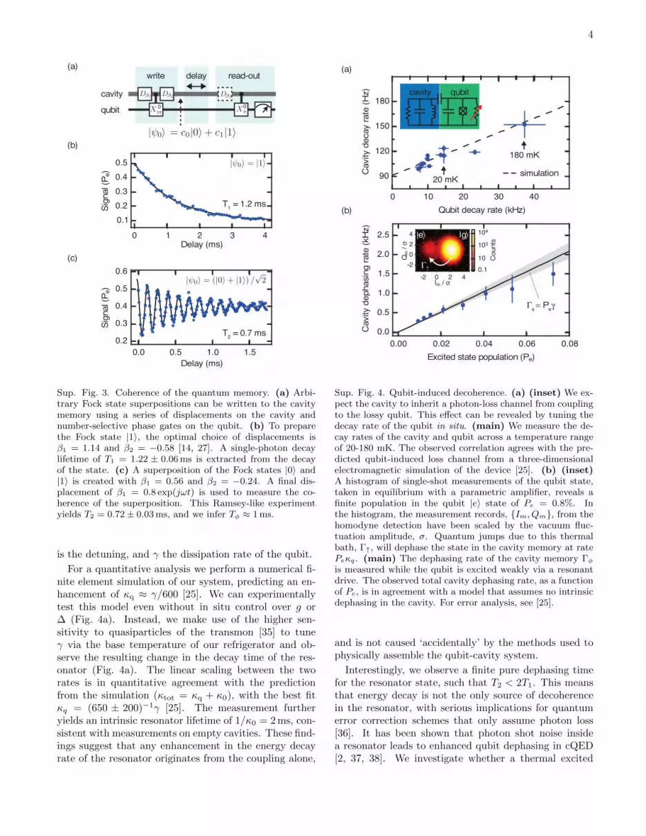
Sup. Fig. 3. Coherence of the quantum memory. (a) Arbi-trary Fock state superpositions can be written to the cavitymemory using a series of displacements on the cavity andnumber-selective phase gates on the qubit. (b) To preparethe Fock state |1〉, the optimal choice of displacements isβ1 = 1.14 and β2 = −0.58 [14, 27]. A single-photon decaylifetime of T1 = 1.22 ± 0.06 ms is extracted from the decayof the state. (c) A superposition of the Fock states |0〉 and|1〉 is created with β1 = 0.56 and β2 = −0.24. A final dis-placement of β1 = 0.8 exp(jωt) is used to measure the co-herence of the superposition. This Ramsey-like experimentyields T2 = 0.72± 0.03 ms, and we infer Tφ ≈ 1 ms.
is the detuning, and γ the dissipation rate of the qubit.
For a quantitative analysis we perform a numerical fi-nite element simulation of our system, predicting an en-hancement of κq ≈ γ/600 [25]. We can experimentallytest this model even without in situ control over g or∆ (Fig. 4a). Instead, we make use of the higher sen-sitivity to quasiparticles of the transmon [35] to tuneγ via the base temperature of our refrigerator and ob-serve the resulting change in the decay time of the res-onator (Fig. 4a). The linear scaling between the tworates is in quantitative agreement with the predictionfrom the simulation (κtot = κq + κ0), with the best fitκq = (650 ± 200)−1γ [25]. The measurement furtheryields an intrinsic resonator lifetime of 1/κ0 = 2 ms, con-sistent with measurements on empty cavities. These find-ings suggest that any enhancement in the energy decayrate of the resonator originates from the coupling alone,
0.00 0.02 0.04 0.06 0.08Excited state population (Pe)
0.0
0.5
1.0
1.5
2.0
2.5
Cav
ity d
epha
sing
rate
(kH
z)
qubitcavity
Γφ = Peγ
-2 0 2 4Im / σ
-2024
Qm
/ σ
0.110
103
104
Cou
nts
(a)
(b)
|g|e
Γ↑
0 10 20 30 40Qubit decay rate (kHz)
90
120
150
180
Cav
ity d
ecay
rate
(Hz)
180 mK
20 mKsimulation
⟨ ⟨
Sup. Fig. 4. Qubit-induced decoherence. (a) (inset) We ex-pect the cavity to inherit a photon-loss channel from couplingto the lossy qubit. This effect can be revealed by tuning thedecay rate of the qubit in situ. (main) We measure the de-cay rates of the cavity and qubit across a temperature rangeof 20-180 mK. The observed correlation agrees with the pre-dicted qubit-induced loss channel from a three-dimensionalelectromagnetic simulation of the device [25]. (b) (inset)A histogram of single-shot measurements of the qubit state,taken in equilibrium with a parametric amplifier, reveals afinite population in the qubit |e〉 state of Pe = 0.8%. Inthe histogram, the measurement records, Im, Qm, from thehomodyne detection have been scaled by the vacuum fluc-tuation amplitude, σ. Quantum jumps due to this thermalbath, Γ↑, will dephase the state in the cavity memory at ratePeκq. (main) The dephasing rate of the cavity memory Γφis measured while the qubit is excited weakly via a resonantdrive. The observed total cavity dephasing rate, as a functionof Pe, is in agreement with a model that assumes no intrinsicdephasing in the cavity. For error analysis, see [25].
and is not caused ‘accidentally’ by the methods used tophysically assemble the qubit-cavity system.
Interestingly, we observe a finite pure dephasing timefor the resonator state, such that T2 < 2T1. This meansthat energy decay is not the only source of decoherencein the resonator, with serious implications for quantumerror correction schemes that only assume photon loss[36]. It has been shown that photon shot noise insidea resonator leads to enhanced qubit dephasing in cQED[2, 37, 38]. We investigate whether a thermal excited

5
state population of the transmon [9, 39, 40] is responsi-ble for dephasing resonator states. This dephasing mech-anism can be understood intuitively: if one mode under-goes a stochastic photon number jump, it changes theother mode’s frequency by χ, leading to rapid loss ofphase information whenever the uncertainty in the timeof a stochastic jump is greater than 1/χ. The cavity de-phasing rate is given by the qubit jump rate as Γφ ≈ Peγ,where Pe is the excited state population of the qubit [25].
In our sample we estimate an excited state popula-tion in equilibrium of ∼ 0.8%, corresponding to an ef-fective temperature of 80 mK (Fig. 4b, inset). In orderto test the dependence of Γφ on Pe, we monitor the T2of the resonator while applying weak drives on the qubitto populate |e〉, creating a known increase in qubit jumprate. The total dephasing of the cavity should be givenby Γφ = Peγ+ Γ0
φ, where Γ0φ is the intrinsic dephasing of
the resonator. We find that, to the precision of our mea-surement, the observed T2 decays are entirely explainedby the calibrated Pe and observed γ (the theory line inFig. 4b), consistent with the resonator having no intrin-sic dephasing mechanisms (Γ0
φ/2π . 40 Hz) [25]. An en-couraging conclusion from these results is therefore thatappropriate remedies against thermal qubit population,such as improved thermalization [40–42], active coolingschemes [9, 39], or tunable couplers [43, 44], could ex-tend the coherence of this quantum memory back to 2T1,leaving photon loss as the only source of decoherence.
CONCLUSION AND OUTLOOK
We have demonstrated a long-lived superconductingcavity resonator that can serve as a quantum memoryfor superconducting quantum circuits, outperforming thebest Josephson junction-based qubits available to date.An important conclusion from our data is that any deco-herence beyond that of a bare resonator not coupled toa qubit can be explained by the Hamiltonian and qubitproperties alone, and is not caused by other technicaldifficulties that arise from integration. We emphasizethat therefore, with given properties of the cavity andthe qubit as well as the coupling Hamiltonian, the co-herence properties of the memory are optimal, and canonly be improved by employing better qubits or cavities.It can be expected that this observation of the coupling-induced decoherence will be useful for ongoing efforts toharness hybrid quantum systems for enhancing the co-herence times in superconducting circuits [12].
Because our device reaches the strong dispersiveregime of cavity QED, control and measurement canbe conducted on fast timescales set by t = π/χ. Theresonator presented shows little degradation on thistimescale, with χT1 ≈ 3000, suggesting that quantum op-erations with very high fidelities can be performed [14],and that error syndromes on quantum states encoded in
microwave photons can be detected much more rapidlythan jumps occur [45]. We therefore expect that thearchitecture shown will enable further advancement to-wards fault-tolerance in superconducting quantum com-puting [16], and could enable quantum optics experi-ments that require very high degrees of control and sta-bility [46].
We thank B. Vlastakis, G. Kirchmair, U. Vool, Z.Leghtas, D. Schuster, and H. Paik for helpful discussions.Facilities use was supported by YINQE and NSF MRSECDMR 119826. This research was supported by ARO un-der Grant No. W911NF-14-1-0011. W.P. was supportedby NSF grant PHY1309996 and by a fellowship institutedwith a Max Planck Research Award from the Alexandervon Humboldt Foundation.
[1] H. Paik, D. I. Schuster, L. S. Bishop, G. Kirchmair,G. Catelani, A. P. Sears, B. R. Johnson, M. J. Reagor,L. Frunzio, L. I. Glazman, S. M. Girvin, M. H. De-voret, and R. J. Schoelkopf, Physical Review Letters107, 240501 (2011).
[2] C. Rigetti, J. M. Gambetta, S. Poletto, B. L. T. Plourde,J. M. Chow, A. D. Corcoles, J. A. Smolin, S. T. Merkel,J. R. Rozen, G. A. Keefe, M. B. Rothwell, M. B. Ketchen,and M. Steffen, Physical Review B 86, 100506 (2012).
[3] F. Motzoi, J. M. Gambetta, P. Rebentrost, and F. K.Wilhelm, Physical Review Letters 103, 110501 (2009).
[4] J. M. Chow, J. M. Gambetta, L. Tornberg, J. Koch, L. S.Bishop, A. A. Houck, B. R. Johnson, L. Frunzio, S. M.Girvin, and R. J. Schoelkopf, Physical Review Letters102, 119901 (2009).
[5] R. Barends, J. Kelly, A. Megrant, A. Veitia,D. Sank, E. Jeffrey, T. C. White, J. Mutus, A. G.Fowler, B. Campbell, Y. Chen, Z. Chen, B. Chiaro,A. Dunsworth, C. Neill, P. O’Malley, P. Roushan,A. Vainsencher, J. Wenner, A. N. Korotkov, A. N. Cle-land, and J. M. Martinis, Nature 508, 500 (2014).
[6] D. Riste, S. Poletto, M. Z. Huang, A. Bruno, V. Vester-inen, O. P. Saira, and L. DiCarlo, Nature Communica-tions 6, 6983 (2015).
[7] A. D. Corcoles, E. Magesan, S. J. Srinivasan, A. W.Cross, M. Steffen, J. M. Gambetta, and J. M. Chow,Nature Communications 6, 6979 (2015).
[8] B. M. Terhal, Reviews of Modern Physics 87, 307 (2015).[9] D. Riste, C. C. Bultink, K. W. Lehnert, and L. DiCarlo,
Physical Review Letters 109, 240502 (2012).[10] P. Campagne-Ibarcq, E. Flurin, N. Roch, D. Darson,
P. Morfin, M. Mirrahimi, M. H. Devoret, F. Mallet, andB. Huard, Phys. Rev. X 3, 021008 (2013).
[11] L. Steffen, A. Fedorov, M. Oppliger, Y. Salathe,P. Kurpiers, M. Baur, G. Puebla-Hellmann, C. Eichler,and A. Wallraff, Nature 500, 319 (2013).
[12] G. Kurizki, P. Bertet, Y. Kubo, K. Mølmer, D. Pet-rosyan, P. Rabl, and J. Schmiedmayer, Proceedings ofthe National Academy of Sciences 112, 3866 (2015).
[13] J. P. Turneaure and N. T. Viet, Applied Physics Letters16, 333 (1970).
[14] R. W. Heeres, B. Vlastakis, E. Holland, S. Krastanov,

6
V. V. Albert, L. Frunzio, L. Jiang, and R. J. Schoelkopf,ArXiv e-prints (2015), arXiv:1503.01496 [quant-ph].
[15] M. Reagor, H. Paik, G. Catelani, L. Sun, C. Axline,E. Holland, I. M. Pop, N. A. Masluk, T. Brecht, L. Frun-zio, M. H. Devoret, L. Glazman, and R. J. Schoelkopf,Applied Physics Letters 102, 192604 (2013).
[16] M. Mirrahimi, Z. Leghtas, V. V. Albert, S. Touzard, R. J.Schoelkopf, L. Jiang, and M. H. Devoret, New Journalof Physics 16, 045014 (2014).
[17] S. Kuhr, S. Gleyzes, C. Guerlin, J. Bernu, U. B. Hoff,S. Deleglise, S. Osnaghi, M. Brune, J. M. Raimond,S. Haroche, E. Jacques, P. Bosland, and B. Visentin,Applied Physics Letters 90, 164101 (2007).
[18] G. Kirchmair, B. Vlastakis, Z. Leghtas, S. E. Nigg,H. Paik, E. Ginossar, M. Mirrahimi, L. Frupzio, S. M.Girvin, and R. J. Schoelkopf, Nature 495, 205 (2013).
[19] A. D. O’Connell, M. Ansmann, R. C. Bialczak,M. Hofheinz, N. Katz, E. Lucero, C. McKenney, M. Nee-ley, H. Wang, E. M. Weig, A. N. Cleland, and J. M.Martinis, Applied Physics Letters 92, 112903 (2008).
[20] V. B. Braginsky, V. P. Mitrofanov, V. I. Panov, andC. Eller, “Systems with small dissipation,” (1985).
[21] A. F. Harvey, Proceedings of the IEE - Part B: Radioand Electronic Engineering 102, 493 (1955).
[22] T. Brecht, M. Reagor, Y. Chu, W. Pfaff, C. Wang,L. Frunzio, M. H. Devoret, and R. J. Schoelkopf, inpreparation.
[23] B. Bianco, A. Corana, L. Gogioso, S. Ridella, andM. Parodi, Electronics Letters 16, 373 (1980).
[24] D. M. Pozar, Microwave Engineering, 3rd Ed. (John Wi-ley & Sons Inc, 1998).
[25] See supplemental materials for details.[26] D. I. Schuster, A. A. Houck, J. A. Schreier, A. Wallraff,
J. M. Gambetta, A. Blais, L. Frunzio, J. Majer, B. John-son, M. H. Devoret, S. M. Girvin, and R. J. Schoelkopf,Nature 445, 515 (2007).
[27] S. Krastanov, V. V. Albert, C. Shen, C.-L. Zou, R. W.Heeres, B. Vlastakis, R. J. Schoelkopf, and L. Jiang,ArXiv e-prints (2015), arXiv:1502.08015 [quant-ph].
[28] S. Haroche and J. M. Raimond, Exploring the Quantum:Atoms, Cavities, and Photons (Oxford University Press,New York, 2006).
[29] I. M. Pop, K. Geerlings, G. Catelani, R. J. Schoelkopf,L. I. Glazman, and M. H. Devoret, Nature 508, 369(2014).
[30] M. A. Nielsen and I. L. Chuang, Quantum Computationand Quantum Information, 10th Anniversary Ed. (Cam-bridge University Press, New York, 2011).
[31] Z. L. Wang, Y. P. Zhong, L. J. He, H. Wang, J. M. Mar-tinis, A. N. Cleland, and Q. W. Xie, Applied PhysicsLetters 102, 163503 (2013).
[32] E. M. Purcell, Physical Review 69, 681 (1946).[33] P. Goy, J. M. Raimond, M. Gross, and S. Haroche, Phys.
Rev. Lett. 50, 1903 (1983).[34] H. J. Kimble, Physica Scripta 1998, 127 (1998).[35] M. Lenander, H. Wang, R. C. Bialczak, E. Lucero,
M. Mariantoni, M. Neeley, A. D. O’Connell, D. Sank,M. Weides, J. Wenner, T. Yamamoto, Y. Yin, J. Zhao,A. N. Cleland, and J. M. Martinis, Physical Review B84, 024501 (2011).
[36] Z. Leghtas, G. Kirchmair, B. Vlastakis, R. J. Schoelkopf,M. H. Devoret, and M. Mirrahimi, Physical Review Let-ters 111, 120501 (2013).
[37] J. Gambetta, A. Blais, D. I. Schuster, A. Wallraff,
L. Frunzio, J. Majer, M. H. Devoret, S. M. Girvin, andR. J. Schoelkopf, Phys. Rev. A 74, 042318 (2006).
[38] A. P. Sears, A. Petrenko, G. Catelani, L. Sun, H. Paik,G. Kirchmair, L. Frunzio, L. I. Glazman, S. M. Girvin,and R. J. Schoelkopf, Physical Review B 86, 180504(2012).
[39] K. Geerlings, Z. Leghtas, I. M. Pop, S. Shankar, L. Frun-zio, R. J. Schoelkopf, M. Mirrahimi, and M. H. Devoret,Physical Review Letters 110, 120501 (2013).
[40] X. Y. Jin, A. Kamal, A. P. Sears, T. Gudmundsen,D. Hover, J. Miloshi, R. Slattery, F. Yan, J. Yoder, T. P.Orlando, S. Gustavsson, and W. D. Oliver, Physical Re-view Letters 114, 240501 (2015).
[41] R. Barends, J. Wenner, M. Lenander, Y. Chen,R. C. Bialczak, J. Kelly, E. Lucero, P. O’Malley,M. Mariantoni, D. Sank, H. Wang, T. C. White, Y. Yin,J. Zhao, A. N. Cleland, J. M. Martinis, and J. J. A.Baselmans, Applied Physics Letters 99, 113507 (2011).
[42] A. D. Corcoles, J. M. Chow, J. M. Gambetta, C. Rigetti,J. R. Rozen, G. A. Keefe, M. B. Rothwell, M. B. Ketchen,and M. Steffen, Applied Physics Letters 99, 181906(2011).
[43] M. Mariantoni, H. Wang, T. Yamamoto, M. Neeley,R. C. Bialczak, Y. Chen, M. Lenander, E. Lucero, A. D.O’Connell, D. Sank, M. Weides, J. Wenner, Y. Yin,J. Zhao, A. N. Korotkov, A. N. Cleland, and J. M. Mar-tinis, Science 334, 61 (2011).
[44] S. J. Srinivasan, A. J. Hoffman, J. M. Gambetta, andA. A. Houck, Physical Review Letters 106, 083601(2011).
[45] L. Sun, A. Petrenko, Z. Leghtas, B. Vlastakis, G. Kirch-mair, K. M. Sliwa, A. Narla, M. Hatridge, S. Shankar,J. Blumoff, L. Frunzio, M. Mirrahimi, M. H. Devoret,and R. J. Schoelkopf, Nature 511, 444 (2014).
[46] J. M. Raimond, C. Sayrin, S. Gleyzes, I. Dotsenko,M. Brune, S. Haroche, P. Facchi, and S. Pascazio, Phys-ical Review Letters 105, 213601 (2010).

1
Supplemental materials
MATERIALS AND METHODS
Design considerations for waveguide below cutoff
The resonator geometry described in the main text includes a section of waveguide below cutoff to separate theresonant mode from contact dissipation. The resonator couples to several circular waveguide modes in the sectiondirectly above the transmission line (Fig. 1-a in main text). Of these waveguide modes, the TM01 mode has the lowestcutoff frequency. Therefore, the TM01 mode sets the λ/4 mode’s propagation into the waveguide. The evanescentTM01 mode has a propagation constant β =
√k2 − (2.41/a)2, where k = 2π/λ is the wavenumber, and a = 5 mm
is the radius of the circular waveguide section [S1]. At our transmission line’s fundamental resonance frequency of4.25 GHz, the propagation constant is β = ı/2.03 mm, below cutoff. Therefore, the λ/4 mode’s energy density fallsas |E × H| ∝ e−2|β|z into the waveguide section. Finite element simulations, which take into account all possiblewaveguide modes, confirm these simple predictions to within 5%. We seal the cavity for light-tightness after a lengthof waveguide section that is L ≈ 10/|β|. The resonator’s energy has been suppressed at this location by a factor ofabout e−20. We therefore rule out assembly defects such as contact resistance as a potentially limiting dissipationmechanism at internal quality factors of Qint ∼ 109.
Linear resonator measurements
In order to estimate the maximum quality of our coaxial transmission line memory, we measure the frequencyresponse of a second, empty resonator with a VNA. We use the shunt-resonator technique to separate the internalquality factor (Qint) from the external coupling quality factor (Qext) [S2–S4]. In particular, the data shown in Fig. 1dis evaluated along the frequency-parametrized, complex circle that is traced out in the transmitted linear voltage (S21)in this measurement configuration as done in [S2]. We have achieved Qext > 109 for this geometry, indicating thatthe under-coupled control scheme used in the main text is feasible for our control purposes. Indeed, the bandwidth ofthe curve in Figure 1d in the main text is given by total quality factor of the resonator under test, which is dominatedby internal losses Qtot ≈ Qint.
In the absence of a transmon or sapphire chip, these coaxial λ/4 resonators are observed to have single-photonquality factors of Qint = 5 − 7 × 10⁷. At large circulating field strengths, corresponding to millions of photonsin the resonator, we find that these resonators can have higher performance Qint = 2 × 10⁸, corresponding to alifetime of 7 ms. The saturable nature of this dominate loss mechanism indicates that material defects [S5–S8] are alimiting factor for this particular cavity as a memory at the T1 = Qint/ω ≈ 3 ms level. This is consistent with theT1 = 1/κ0 = 2 ms extracted in the main text for the internal loss-limit of the device used in the quantum memoryexperiment.
The VNA measurements allow us to place a bound on the quality of the dielectric (Qdiel) and conductor (Qmag)surfaces for our high purity aluminum by assuming that all loss comes from either a dielectric loss (Qint ∝ Qdiel)or conductor loss (Qint ∝ Qmag). By finite element simulations, we calculate the normalized field-energy stored inthe surface layer of our cavity. These calculations allow us to estimate the participation ratios [S6, S9] for the AlOx
dielectric of pdiel = 2 × 10⁻⁷ (assuming an oxide thickness of 3 nm and a relative dielectric constant of 10), and akinetic inductance fraction [S10], or magnetic participation ratio, of pmag= 4×10⁻⁵ (using a penetration depth of 50 nm[S11]). These measurements thus achieve a bound for bulk, high purity aluminum of Qdiel ≥ 14 and Qmag ≥ 3000 atsingle-photon energies. Further, the difference between high and low power quality factors indicates that at least oneof these loss mechanisms may be saturable, at the Qdiel ∼ 40 or Qmag ∼ 8000 level.
Qubit fabrication
The transmon qubit is fabricated on a 430µm thick sapphire wafer with a standard Dolan bridge process. Abilayer of resists (MMA/PMMA) support a suspended structure at the Josephson tunnel junction location and arecompletely stripped where the antenna is to be deposited. Both exposures are completed in a single step of electron-beam lithography. Before deposition, the sapphire surface is cleaned with ion etching, an Ar/O2 descum at 250 V for30 s. We deposit aluminum with double-angle evaporation (±28) with thicknesses of 20 nm and 60 nm, exposing

2
the chamber to oxygen in between these depositions (720 seconds in 2000 Pa static pressure of a gaseous mixtureof 85% argon and 15% oxygen) and again before removing the sample (600 seconds, 400 Pa). We liftoff aluminumdeposited on undeveloped resist. Our transmon’s junction has a normal-state resistance of 3.5 kΩ at room temperature,corresponding to a Josephson inductance of LJ = 4.5 nH, or a Josephson energy of EJ = Φ2
0/((2π)2~LJ) = 150µeV ,at 15 mK. The geometry of the transmon’s dipole antenna pads are relatively long, approximately 2 mm each, toachieve strong coupling to both resonators and narrow, 50µm, to maintain a large anharmonicity.
Measurement setup
Our measurement set up is shown in Supplementary Figure S1. We shape qubit and resonator-control signals withsingle-sideband modulation (SSB), driven by an FPGA DAC with 500 MHz bandwidth. Stainless steel coaxial cablescarry input signals to our package, which is shielded from magnetic field by a light-tight Amuneal magnetic shield(A4K) at the 15 mK stage of the dilution refrigerator. For input lines, we have physical attenuation at the 4 K(20 dB) and 15 mK (30 dB) cooling stages, followed by 10 GHz lowpass filters and eccosorb IR filters. The JPC ispumped by an input line that has physical attenuation at the 4 K stage (20 dB) and the 15 mK stage (23 dB). Thepump terminates at the Σ-port of a hybrid coupler connected to the JPC.
The qubit state is encoded in the phase of a signal transmitted through the readout cavity. This signal passesthrough an eccosorb filter, two circulators, and into the ∆ port of of a hybrid connected to the JPC. The JPC acts asa nearly quantum limited phase preserving amplifier [S12]. It provides the reflected signal with 18 dB gain at 4 MHzbandwidth, which yields sufficient SNR for the single-shot histogram shown in Figure 4b. The readout signal traversesfrom the JPC back through one circulator, through two additional isolators, and is carried by superconducting coaxto a low-nose HEMT amplifier at 4 K. The read-out signal is further amplified at room temperature. Finally, thereadout signal is demodulated with a heterodyne interferometer (fIF=50 MHz), which is integrated by the FPGA’s 1gigasample-per-second ADC to obtain the histograms shown in the main text. We assign the probability of detectingthe qubit in the ground state (Pe) by thresholding at the center of these two distributions.
FULL SYSTEM HAMILTONIAN
Our system shares the nonlinearity of a single Josepnson junction across the three coupled modes: two nearly-harmonic modes (resonators) and an anharmonic (qubit) mode. Each is well within the weak nonlinearity limit(transmon limit) of the coupled Hamiltonian [S13], which allows us to approximate the system’s total Hamiltonian,as in [S14], to fourth-order in ladder operators as
H
~= ωsa
†a+ ωqb†b+ ωrc
†c (S1)
− χsqa†a b†b− χrqb†b c†c− χsra†a c†c
− Ks
2a†a†aa− Kq
2b†b†bb− Kr
2c†c†cc
where we label the operators of storage cavity as a, transmon as b, and the readout mode as c. We provide values forthe self-Kerr nonlinearities (Ki’s) and cross-Kerr nonlinearities (χij ’s) in Table I. We allow for a 0.5 mm machiningtolerance in the resonators and a junction capacitance of CJ = 2 fF in order to correct the linear frequencies in thesimulation, increasing the accuracy of the calculated coupling terms.
In the main text, we limit our consideration of the storage cavity to its lowest two levels, and therefore, Ka does notenter into our analysis. However, we measure the mode’s nonlinearity to be small (Ka = 450 Hz), which is encouragingfor error correction schemes, or quantum optics experiments, that access the full Hilbert space of the resonator.
FOCK STATE PREPARATION
To make a |1〉 Fock state, we implement the pulse sequence experimentally demonstrated in [S15]. We first displacethe resonator to β= 1.14, via a Gaussian pulse with width σt = 40 ns. Then, we apply a 2π rotation on the transmonthat is selective on the qubit’s zero-photon dispersive peak, driving the transition |g, 0〉 → |e, 0〉. For this pulse, we use

3
eccoscorb
eccoscorbinput
inputoutput
eccoscorb
circulators
JPC
eccoscorb
isolators
hybrid
cryopermmagneticshield
cryopermmagneticshield
ΣΔ
10GHzLP Filter
30 dB
30 dB
20 dB3 dB
20 dB
20 dB
20 dB10G
Hz
LP Filter
10GH
zLP Filter
10GH
zLP Filter
HEM
T
storage-in
JPC pump
4 K
15 mK
300 K
LO
qubit-in
readout-in
I Q I Q
signal-out
FPGA 4-Channel DAC FPGA 2-Channel ADC
reference
signal
Sup. Fig. S1.Experimental schematic.At room temperature,we shape control signalsfor the qubit and cavitymemory by mixing CWlocal oscillators with adigitized FPGA output,giving full IQ control.The qubit drive is carriedon the same input cableas the readout resonatormeasurement tone. In-put signals are filteredat successive dilutionrefrigerator stages. Thetransmitted signal isboosted by a parametricamplifier and a followingHEMT amplifier, beforebeing demodulated andcompared to a referenceheterodyne signal insoftware.

4
Table I. Predicted and extracted parameters for the full device device Hamiltonian (Eq. S1).
H/~ Experiment (Hz) Simulation (Hz) Deviation (%)
ωs/2π 4.250 ×10⁹ 4.246 ×10⁹ < 1
ωq/2π 7.906 ×10⁹ 7.878 ×10⁹ < 1
ωr/2π 9.777 ×10⁹ 9.653 ×10⁹ 1
χsq/2π 4.99 ×10⁵ 5.56 ×10⁵ 11
χrq/2π 8.25 ×10⁵ 7.77 ×10⁵ 6
χsr/2π - 1.60 ×10³ -
Ks/2π 4.50 ×10² 5.20 ×10² 16
Kq/2π 1.46 ×10⁸ 1.41 ×10⁸ 3
Kr/2π - 1.20 ×10³ -
a Gaussian tone with σt = 1.5µs so that the frequency bandwidth remains smaller that the dispersive shift of resonatorphotons (σf ≈ 100 kHz χ/2π = 500 kHz). A final displacement, β= -0.58 finishes the Fock-state creation.
In a dissipationless system, this type of sequence can prepare an |1〉 Fock state with 99% fidelity [S16]. However,finite qubit coherence (χsqT2,q ≈ 10), limits our quality of state preparation. We quantify the photon-statistics ofresulting resonator state by qubit spectroscopy (Sup. Fig. S2).
To make a superposition of |0〉-|1〉 Fock states, we modify the pulse sequence above, as outlined in [S16]. We usedisplacements on the resonator, β= 0.56,-0.24, interlaced with the same selective 2π rotation on the transmon. Thestatistics of the resulting state is shown in (Sup. Fig. S2). We reveal the coherent phase between these two states witha third displacement pulse on the cavity, β = 0.8ejωt, where ω is a frequency set by a digital phase. The amplitude|β| is chosen to saturate the resonator with half of the population in the vacuum when the state has lost all phasecoherence.
DISSIPATION MECHANISMS
Qubit-induced energy loss
We estimate the effect of the qubit’s dissipation on the resonator by finite element simulations. We use an eigenmode-type solver (HFSS), which is capable of capturing the hybridization between the system’s modes and can handledissipative circuit elements. We add a parallel shunt resistor to the linear inductor that represents the Josephsonjunction in simulation. The only loss in the calculation arises from currents passing through the inductor. Thus, theratio of the resulting quality factors is expected to be the scaling between an otherwise perfect cavity’s lifetime andthe lifetime of the imperfect qubit.
In the main text, we present temperature dependent data which agrees with these simulations, assuming that theonly dissipation in the cavity mode that is temperature dependent is caused by the qubit. However, because the cavityis superconducting, its own BCS temperature dependence might be expected to be observed in this experiment. Wehave also performed temperature dependence on an empty resonator for comparison (Sup. Fig. S3). The linear cavityshows a slight trend toward increased lifetime at elevated temperatures below 180 mK. The bare resonator’s lifetimeimproves up to 15% at these elevated temperatures. To estimate how this behavior affects the extracted qubit-induceddecay rate of the qubit-coupled resonator, we re-express the total decay rate for this coupled resonator as κtot(T ) =κq(T ) + κ0(T ), where the internal resonator dissipation (κ0(T )) is taken to be the temperature-dependent behaviorof an empty resonator. We subtract the best fit linear trend that is obtained from empty resonator measurements,κ0(T ) (dashed line in Sup. Fig. S3), from the observed decay rate of the qubit-coupled resonator, κtot(T ). Finally, wecorrelate the qubit’s decay rate to this scaled resonator decay rate for all recorded temperatures. The more thoroughanalysis changes the best fit result from the main text for κq = (650 ± 200)−1γ by only 2%, well within the 30%uncertainty in the value from our measurements. This effect is therefore ignored in the main text.

5
0.0 0.2 0.4 0.6 0.8 1.00.0
0.2
0.4
0.6
0.8
1.0
Spec
trosc
py s
igna
l
0.00.40.8
−1.0 −0.5 0.0 0.5Drive detuning (MHz)
0.00.40.8
|0〉|1〉
|2〉
|0〉|1〉|2〉
Sup. Fig. S2. Preparation of quantum resonator states. To verify the input states for the resonator’s T1, T2 experiments, weperform spectroscopy on the qubit after preparing the resonator in an input state. (top) When the cavity is mostly in thefirst Fock state, |1〉, the qubit’s frequency distribution reflects these statistics. By the normalized area under each peak, wedetermine that the population of each Fock state (Pn) is P0 = 0.21± 0.02, P1 = 0.75± 0.02, P2 = 0.04± 0.02 (bottom) Afterpreparing a superposition of |0〉 and |1〉, we find the distribution to be P0 = 0.49 ± 0.02, P1 = 0.41 ± 0.02, P2 = 0.10 ± 0.02.This experiment alone is not sufficient to distinguish between a statistical mixture of these states and a coherent superposition.However, the phase coherence is revealed in the sinusoidal oscillations of the subsequent T2 experiment.
Qubit-induced dephasing
An exact model for the pure-dephasing of a qubit due to thermal photons in strongly coupled, lossy resonators hasbeen developed for the dispersive regime of cQED in which we operate[S18? ]. However, because our Hamiltonian issymmetric, this model is directly applicable to resonators being subjected to the reverse process of thermal shot-noisein the qubit mode. The dephasing rate Γφ derived in [S18? ], can thus be used for our case of a resonator coupled toa single, thermally populated qubit as
Γφ =γ
2Re
√(1 +2ıχ
γ
)2
+8ıχPeγ− 1
, (S2)
where Pe is the excited state population of the qubit and γ is the qubit’s decay rate. Expanding this expression inthe strong dispersive limit (χ γ) gives
Γφ ≈ Peγ
[1−O
(γ
χ
)2]. (S3)
The quadratic term is of order 1×10⁻⁴ and thus neglected in our analysis.
Error analysis
The error bounds on all quoted lifetimes in the main text are taken from bootstrapping [S19] five or more experimentsof averaged repeated measurements (≥200 averages) under the assumption that the experimental noise is Gaussian.For the qubit’s lifetime (T1,q) we observe a Gaussian variation (T1,q = 6.1± 0.5µs) across the 24 hours of integrationrequired for the transmon dephasing experiment (Fig. 4b in main text). To obtain those statistics, ninety-four T1,qexperiments were conducted concurrently with the same number of resonator T2 experiments. The fluctuation in T1,qis represented in the gray shading of Figure 4b in the main text, since this effect generates variation in the slope ofΓφ vs Pe.
[S1] D. M. Pozar, Microwave Engineering, 3rd Ed. (John Wiley & Sons Inc, 1998).[S2] P. J. Petersan and S. M. Anlage, Journal of Applied Physics 84, 3392 (1998), cond-mat/9805365.
6
0 50 100 150 200Temperature (mK)
−1
0
1
2
Ener
gy d
ecay
rate
(Δκ/κ 0
+ o
ffset
) qubitqubit-coupled resonatorbare resonator
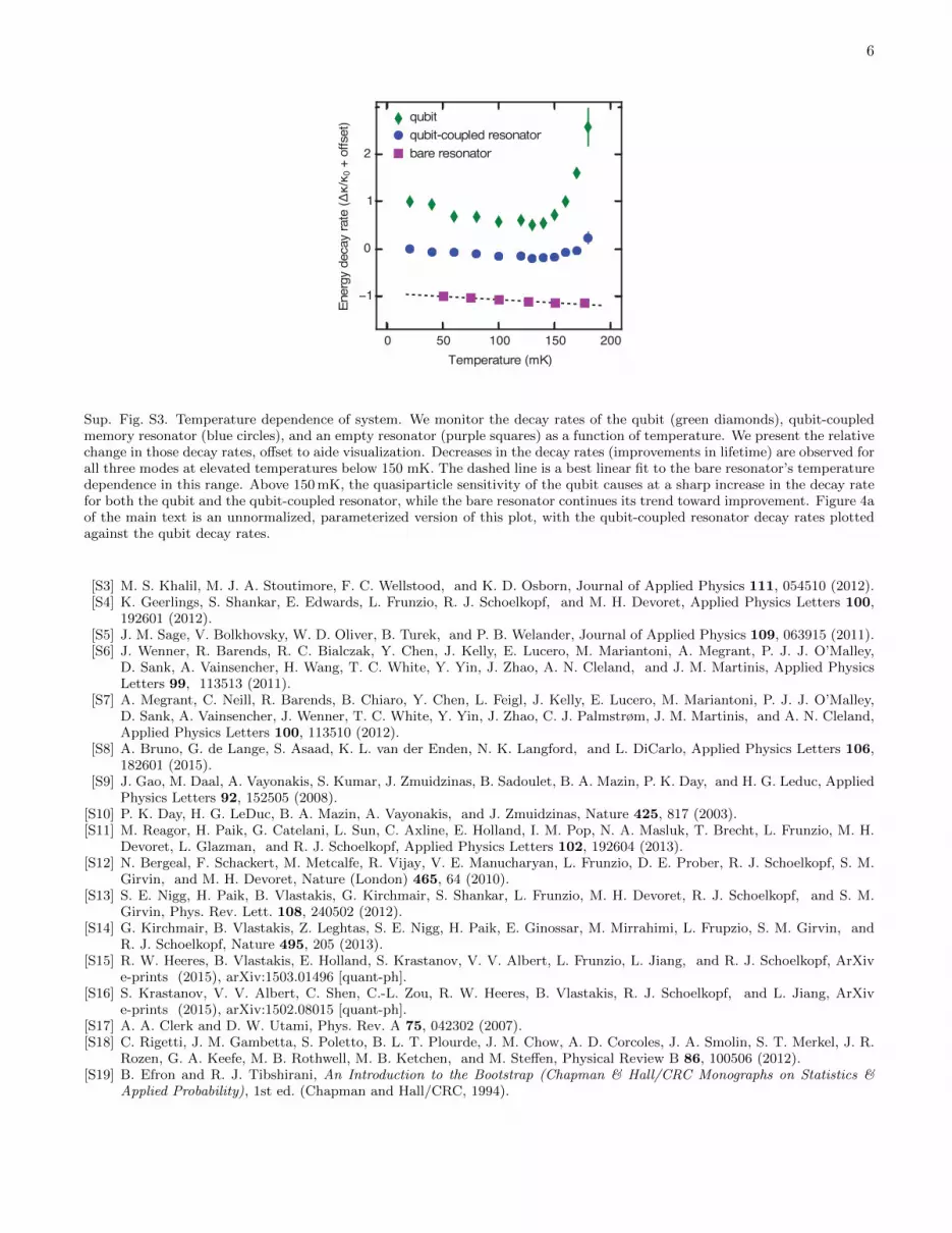
Sup. Fig. S3. Temperature dependence of system. We monitor the decay rates of the qubit (green diamonds), qubit-coupledmemory resonator (blue circles), and an empty resonator (purple squares) as a function of temperature. We present the relativechange in those decay rates, offset to aide visualization. Decreases in the decay rates (improvements in lifetime) are observed forall three modes at elevated temperatures below 150 mK. The dashed line is a best linear fit to the bare resonator’s temperaturedependence in this range. Above 150 mK, the quasiparticle sensitivity of the qubit causes at a sharp increase in the decay ratefor both the qubit and the qubit-coupled resonator, while the bare resonator continues its trend toward improvement. Figure 4aof the main text is an unnormalized, parameterized version of this plot, with the qubit-coupled resonator decay rates plottedagainst the qubit decay rates.
[S3] M. S. Khalil, M. J. A. Stoutimore, F. C. Wellstood, and K. D. Osborn, Journal of Applied Physics 111, 054510 (2012).[S4] K. Geerlings, S. Shankar, E. Edwards, L. Frunzio, R. J. Schoelkopf, and M. H. Devoret, Applied Physics Letters 100,
192601 (2012).[S5] J. M. Sage, V. Bolkhovsky, W. D. Oliver, B. Turek, and P. B. Welander, Journal of Applied Physics 109, 063915 (2011).[S6] J. Wenner, R. Barends, R. C. Bialczak, Y. Chen, J. Kelly, E. Lucero, M. Mariantoni, A. Megrant, P. J. J. O’Malley,
D. Sank, A. Vainsencher, H. Wang, T. C. White, Y. Yin, J. Zhao, A. N. Cleland, and J. M. Martinis, Applied PhysicsLetters 99, 113513 (2011).
[S7] A. Megrant, C. Neill, R. Barends, B. Chiaro, Y. Chen, L. Feigl, J. Kelly, E. Lucero, M. Mariantoni, P. J. J. O’Malley,D. Sank, A. Vainsencher, J. Wenner, T. C. White, Y. Yin, J. Zhao, C. J. Palmstrøm, J. M. Martinis, and A. N. Cleland,Applied Physics Letters 100, 113510 (2012).
[S8] A. Bruno, G. de Lange, S. Asaad, K. L. van der Enden, N. K. Langford, and L. DiCarlo, Applied Physics Letters 106,182601 (2015).
[S9] J. Gao, M. Daal, A. Vayonakis, S. Kumar, J. Zmuidzinas, B. Sadoulet, B. A. Mazin, P. K. Day, and H. G. Leduc, AppliedPhysics Letters 92, 152505 (2008).
[S10] P. K. Day, H. G. LeDuc, B. A. Mazin, A. Vayonakis, and J. Zmuidzinas, Nature 425, 817 (2003).[S11] M. Reagor, H. Paik, G. Catelani, L. Sun, C. Axline, E. Holland, I. M. Pop, N. A. Masluk, T. Brecht, L. Frunzio, M. H.
Devoret, L. Glazman, and R. J. Schoelkopf, Applied Physics Letters 102, 192604 (2013).[S12] N. Bergeal, F. Schackert, M. Metcalfe, R. Vijay, V. E. Manucharyan, L. Frunzio, D. E. Prober, R. J. Schoelkopf, S. M.
Girvin, and M. H. Devoret, Nature (London) 465, 64 (2010).[S13] S. E. Nigg, H. Paik, B. Vlastakis, G. Kirchmair, S. Shankar, L. Frunzio, M. H. Devoret, R. J. Schoelkopf, and S. M.
Girvin, Phys. Rev. Lett. 108, 240502 (2012).[S14] G. Kirchmair, B. Vlastakis, Z. Leghtas, S. E. Nigg, H. Paik, E. Ginossar, M. Mirrahimi, L. Frupzio, S. M. Girvin, and
R. J. Schoelkopf, Nature 495, 205 (2013).[S15] R. W. Heeres, B. Vlastakis, E. Holland, S. Krastanov, V. V. Albert, L. Frunzio, L. Jiang, and R. J. Schoelkopf, ArXiv
e-prints (2015), arXiv:1503.01496 [quant-ph].[S16] S. Krastanov, V. V. Albert, C. Shen, C.-L. Zou, R. W. Heeres, B. Vlastakis, R. J. Schoelkopf, and L. Jiang, ArXiv
e-prints (2015), arXiv:1502.08015 [quant-ph].[S17] A. A. Clerk and D. W. Utami, Phys. Rev. A 75, 042302 (2007).[S18] C. Rigetti, J. M. Gambetta, S. Poletto, B. L. T. Plourde, J. M. Chow, A. D. Corcoles, J. A. Smolin, S. T. Merkel, J. R.
Rozen, G. A. Keefe, M. B. Rothwell, M. B. Ketchen, and M. Steffen, Physical Review B 86, 100506 (2012).[S19] B. Efron and R. J. Tibshirani, An Introduction to the Bootstrap (Chapman & Hall/CRC Monographs on Statistics &
Applied Probability), 1st ed. (Chapman and Hall/CRC, 1994).