a process for verifying and validating requirements for fault tolerant systems using model
TRANSCRIPT

A Process for Verifying and Validating Requirements for Fault Tolerant Systems
using Model Checking1
Francis Schneider2, Steve M. Easterbrook, John R. Callahan and Gerard J. Holzmann3 William K. Reinholtz2, Adins, Ko2, Mohammad Shahabuddin2
NASA/WVU Software Research Lab 100 University Drive, Fairmont, West Virginia 26505
Abstract Model checking is shown to be an effective
tool in validating the behavior of a fault tolerant embedded spacecrafi controllel: The case study presented here shows that by judiciously abstract- ing away extraneous complexity, the state space of the model could be exhaustively searched allowing critical functional requirements to be validated down to the design level. Abstracting away detail not germane to the problem of interest leaves by definition a partial specification behind. The suc- cess of this procedure shows that it is feasible to effectively validate a partial Specification with this technique. Three anomalies were found in the sys- tem. One was an error in the detailed require- ments, and the other two were missing/ambiguous requirements. Because the method allows valida- tion of partial specifications, it is also an effective approach for maintaining fidelity between a co- evolving specification and an implementation. We also show that two of the three anomalies were found in the implementation, demonstrating the overall effectiveness of the process and the im- portance of a good software design.
The research described in this paper was carried out in part by the Jet Propulsion Laboratory, California Institute of Technology, under a contract with the National Aeronautics and Space Administration, and in part by West Virginia Uni- versity under NASA cooperative agreement #NCC 2-979. Ref- erence herein to any specific commercial product, process, or service by trade, name, trademark, manufacturer, or other- wise, does not constitute or imply its endorsement by the United States Government, the Jet Propulsion Laboratory, California Institute of Technology or West Virginia University
Jet Propulsion Laboratory I California Institute of Technol- om, MS 125-233 Pasadena, CA 91109.
Computing Sciences Research, Bell Laboratories, Lucent Technologies, Murray Hill, NJ 07974
1 Introduction This paper describes a practical application of
model checking for validating the requirements for a complex embedded system. The case study de- scribed here is of a dually redundant spacecraft controller, in which a checkpoint and rollback scheme is used to provide fault tolerance during the execution of critical control sequences. The challenge given to us and the purpose of this study was to determine if model checking could be used to uncover errors in an existing design specifica- tion for a space craft system. To this end the proj- ect manager supplied us with such a specification.
The software requirements specification for the spacecraft specifies the required behavior for the checkpoint and rollback scheme. However, the validity of these requirements could not be deter- mined through inspection. In other words, it was not possible to determine whether the behavior described in these requirements would provide the desired level of fault tolerance. More importantly, testing of the eventual implementation would not necessarily provide this validation either, due to the difficulty of ensuring test case coverage for all possible fault occurrence scenarios.
The approach described here uses a formal automata-based model derived from the specifica- tion. We used various high-level safety properties to validate the generalized system model. Key system functional requirements were then vali- dated by defining corresponding liveness proper- ties in linear temporal logic, which were required to be satisfied when the system responds to errors. We used the model checker Spin [2] to identify traces in the model for which these properties were violated.
The work described in this paper forms part of an on-going investigation into lightweight formal
- 1 -
methods for V&V of requirements specifications. We use the term ‘lightweight’ to indicate that the methods can be used to perform partial analysis on partial specifications, without a commitment to developing and baselining complete, consistent formal specifications. The formal methods are used to model critical chunks of an informal speci- fication, to check that key properties hold. The aim is to find errors, rather than to prove correctness. Application of the methods is driven by the .needs of the project, and is used as a modeling tool to answer questions that arise during verification and validation.
The paper is organized as follows. Section 2 provides a motivation for the case study by briefly surveying existing approaches to requirements validation and demonstrating why these ap- proaches do not provide the desired level of assur- ance. We introduce the distinction between verifying requirements through completeness and consistency checking, and validating requirements against real world properties (‘claims’) that should follow if the statement of the requirements is cor- rect.
Section 3 introduces the dually redundant sys- tem, and shows how it was expressed as a FSM. We show how the system behaves as a communi- cations system, making it particularly amenable to analysis using the model checker Spin.
Section 4 describes the steps that were taken to optimize the model, in order to reduce the size of the state space. We show how the model was par- titioned into five separate fault scenarios, and ex- plain in detail how one of these scenarios was checked. We discuss the process of checking the model against claims expressed as linear temporal logic formulae. Section 5 presents the results of the analysis.
Section 6 provides a discussion of the results, including a reflection on the benefits seen in the case study. The importance of partitioning the model in order to make the analysis feasible is dis- cussed, along with some reflection on the resulting limitation of the analysis (‘partial analysis of par- tial specifications’).
Section 7 presents conclusions and describes our future work. A short overview of the theoreti- cal basis for the use of the LTL and Buchi auto- mata is provided in appendix A.
2 Background Requirements validation is the process of de-
termining that the specified requirements capture the real world needs of the stakeholders. For real- time control systems, this involves checking that the specified behavior will in fact provide safe and effective control, without introducing any undesir- able effects. For reasonably complex systems, va- lidity of the requirements is hard to establish. Informal methods only provide a very basic level of assurance, by imposing a structure on the speci- fication that facilitates inspection by domain ex- perts. Formal methods have the potential to provide a much greater level of assurance, through the construction of a precise model of the require- ments, which can be tested against domain proper- ties.
A number of formal modeling tools are avail- able that are applicable to software systems. Heit- meyer and Mandrioli [3] provide an excellent overview of the current state of the art. Here we concentrate on state machine models, which can be used to test safety and liveness properties.
RSML [ 1, 31 and SCR [5] have both been very successful at providing static analysis techniques for checking completeness and consistency of specifications expressed as deterministic state ma- chines. However, fault tolerant systems are inher- ently non-deterministic, that is, the transition schemes are relational not functional. Systems with inherent non-determinism are not easily ame- nable to analytic static evaluation methods. Sys- tems that can be partitioned into a deterministic and a non-deterministic part can apply tools such as RSML or SCR to validate deterministic compo- nents. For example, Easterbrook [6] has reported using the SCR tool in this way to validate the Fault Detection, Isolation and Recovery (FDIR) re- quirements for a spacecraft bus controller. The deterministic part was modeled in SCR, and then extended to include non-deterministic elements (i.e. fault occurrences) using the Spin model checker [2]. Such a procedure would be suggested for example when an otherwise deterministic sys- tem had to be shown to be resilient under (non- deterministic) fault injection.
An analysis based methodology such as RSML or SCR requires determinism in the underlying model to prove requirements completeness and
- 2 -

consistency. In contrast, state space exploration methods (‘model checking’) are operational in na- ture rather than analytic. They allow functional requirements to be validated over non- deterministic finite state machines using optimized reachability schemes. By incorporating functional requirements in a non-deterministic model, re- quirements properties can be validated. Manna and Pneuli [6] have shown that virtually any expressi- ble requirements property can be represented as a safety, precedence, or liveness property using the Linear Temporal Logic (see appendix A).
Three such model checkers have been widely used for verification of low-level designs of both hardware and software, and communication proto- cols. The Murphi model checker has a rich support for temporal logic and allows invariants to be ex- pressed in the model to be checked as the state space exploration evolves. It supports a single site model only, which is a disadvantage in the valida- tion of concurrent systems. The Symbolic Model Verifier (SMV) has been applied successfully to communication protocols [8]. SMV can validate synchronous and asynchronous systems against a system specification specified in the temporal logic CTL [lo] [2]. It allows for non-determinism in the specifications and for concurrency in the model within procedures. It supports rich temporal logic specifications but does not support complex data structures, making it difficult to build a complete
Tool
RSML
SCR
Murphi
SMV
Spin
Table 1:
Deter- Counter minis- Exam-
tic? Ple Genera-
tion?
Y I N
N Y
I
N l y N I Y
Reqts. expressi-
ble as LTL
Formu- lae?
N
N
Y
Y
Y
Devel- oped for V&V of:
TCAS S I W A7e Air- craft S I W Single Process S I W comms ww comms S I W
low level model. Both SMV and Murphi were de- signed for validating hardware systems. The Spin model checker was designed for verification of communication protocols, and provides support for a basic set of software data structures.
Each of the three model checkers permits a rich set of temporal logic formulae to be incorpo- rated into the modeling system. We chose to use the Spin model checking system for this study be- cause it (a) was designed to validate software communications protocols (a) is algorithmic in nature (c) supports data structures allowing detail where appropriate (d) incorporates linear temporal logic primitives allowing functional requirements to be validated over the model (e) and, signifi- cantly, because the modeling system can be used to validate functional requirements over traces from the implementation. 3 DRS High Level Model Description
The case study described here is a Dually Re- dundant System (DRS) for a spacecraft controller, consisting of two hardware platforms running identical software to maximize system reliability and availability. The systems exchange information to synchronize software operation. One of the sys- tems has control of the system bus and is called the prime string. The other, known as the online string, provides a backup, executing in synchroni- zation or at most within one second of the prime string. Information is exchanged between the two systems by the synchronous (rendezvous) commu- nication of a 32-word table, the State Table Broad- cast (STB), broadcast by the prime string once per second. The online string uses this to keep itself in synchronization with the prime string.
The system executes high priority programs called critical sequences that must be tolerant of arbitrary faults. To this end, the strings use a vari- ant of the checkpoint and rollback process found to work well in industrial applications [ll]. Check- points correspond to completed transactions in the executable code. Such a completion is referred to as a commit operation, meaning that if a system crash occurs, system operations could be rolled back to the point where the commit occurred and proceed from here. The spacecraft controller works analogously except that the checkpoints are re- ferred to as markpoints, and are hard coded into the executing program.
- 3 -

For example, consider the retrieval and return Meaning Value Flag of a soil sample by a remote robot, Successful re-
which would be another markpoint. If any opera- CS inactive and not sus- 0 of the sample that was just retrieved, at the end of CS active or suspended 1 CM The next group of instructions might be the storage CS not executing 0 this process would be delineated with a markpoint. CS executing 1 cs be repeated. The code ending in the completion of Cleared 0 trieval of the sample is an operation that need not Fault 1 SFFJ
pended tion were interrupted by the occurrence of a fault, Table 2: Communication Flags the system would repair the fault; roll back control to the beginning of the last markpoint; and con- fined a communications protocol as a five compo- tinue execution from there. It would not be neces- nent specification for how communication is to be sary to waste battery power or time to retrieve carried out in an error free way among two or more another sample if that was already achieved. This separate elements. For the mark and rollback proc- paper focuses on the validation of the fault toler- ess, these properties are: ance provided by this mark and rollback process. 1. The service provided by the protocol is to keep
The fault containment requirements specify the prime and the online systems in synchroni- that fault protection shall operate only in the prime zation. This is done so that the online string string. While the prime string is repairing a fault, can take over quickly should the prime system the online string must stop executing its copy of become inoperable. the critical sequence and wait for the STB to tell it 2. The environmental assumptions are that the that the fault has been repaired, thereby signaling it prime string interacts with an entity that pro- to proceed with the critical sequence. vides information about faults.
The rollback requirements specify that three 3. The major vocabulary consists of the variables full seconds of execution time shall be allowed to SFP, CS, and CM. SFP is the Spacecraft Fault pass after a new markpoint is encountered by the Protection flag. When this flag is set, the sys- software before the new markpoint is recognized tem has experienced a fault that has not yet as a legitimate rollback point. This is because the been repaired. The CS flag is set in the prime system controls external elements that are mostly string and in the backup string when the criti- mechanical in nature. Accordingly, the software is, cal sequence is active i.e. running in each re- in general, always ahead of the hardware. The spective string. The CM flag is set to indicate three-second delay gives any mechanical tasks a that the critical sequence is active or in chance to be completed, and for any faults that standby pending the repair of a fault and ac- occurred to be properly logged, before the previous cordingly to remind the strings that when an section of the critical sequence can be considered interfering fault is fixed, the suspended critical successfully complete. To implement this require- sequence needs to be restarted at the last valid ment, each new markpoint is aged each second by aged markpoint. one second by moving it one level deeper in a 4. The three protocol flags each use single bit three-level buffer. Only markpoints that have encoding, as shown in Table 2. reached the bottom will be eligible for use in the 5 . The procedure rules are most complex to deal rollback process. Figure 1 shows a high level snap- with, the hardest to specify, the most difficult shot of normal critical sequence operation in both to validate. Most of the validation work occurs strings. here. Examples from the mark and rollback 4 Validation Procedure support application are that the protocol vari- 4.1 Modeling ables SFP, CM, and CS are to be broadcast
The first step was to produce a state model of once each second to the online string and actu- the DRS system. To model the specified behavior, ally also back to the prime string by the prime we treated the mark and rollback process as a string to allow the prime string to check its communications system. Holzmann [12] has de- own synchronization.
- 4 -

The initial model was represented using state- charts [13]. Figures 1 and 2 show portions of the statecharts for the prime and online strings respec- tively.
In the case study presented here, certain types of faults are of such a nature that they can be re- paired by the prime string. When a fault occurs, the three protocol flags (CS, CM, SFP) change state from (1, 1, 0) to (0, 1, 1). This information is broadcast to the online string once per second. When the online string sees the SFP flag is set, it suspends operation of the executing critical se- quence and waits for the prime string to repair the fault. Once the fault is repaired, the prime string can roll back to the last valid markpoint and re- sume processing. The online string will see the new SFP flag is reset in the STB message, rollback to the aged broadcast markpoint and restart its copy of the critical sequence.
This example shows a small subset of the ac- tual elements and their procedure rules,that belong in each category. The complete protocol specifica- tion is in excess of 80 pages. 4.2 Estimation of State Space Size
Once an initial model is obtained, the state space size must be estimated, in order to assess the potential for automated validation. This was done by estimating the number of substates needed in the Spin model to implement each state shown on
+c online
PRIME’
suspend tl - PRIME NOMINAL
v
Figure 1: A partial statechart for the DRS prime string
the statecharts. For example, the full statechart for the prime string has 16 states and each could be implemented with, say, 4 substates giving a state space of 4 x 4 x ... x 4 = 232.
The full statechart for the online string has 14 states. Assuming 4 substates for each gives 4 X 4 X
... x 4 = 228 states. The rendezvous communica- tion contains 32 data elements, 5 of which are un- used leaving a total of 27 elements. Each of these remaining 27 is at least a binary flag. This gives 2 x 2 x 2 . .. x 2 = 227 states as a minimum. This contributes to the state space of the online string, giving 228 x 227 = 255 states total.
Both strings operating as one system will have a state space of
(232 states prime string) x (255 states online string) = 287 states.
With a CPU that executes 1 state per micro- second, the system will traverse its reachability graph in about 10l2 years.
The problem of interest here is to discover the failure modes of this system. To be able to do this we must reduce the state space down to an man- ageable size by abstracting away states that are not germane to the operation we are interested in, namely (a) the repair of faults (b) the rollback pro- cess and (c) the synchronization between the prime and the online (backup) systems. The result is a
Q Online init
I Y
ONLINE NOMINAL
. ( SEQUBCE IDLE 7 Power-up Fault
I I k e s m e \ SFP
I Y SEQUENCE CRITICAL
ONLINE
Figure 2: A partial statechart for the DRS on- line string
- 5 -

partial specification, but which has enough detail left to partially validate the properties of interest. 4.3 Reducing the state space
There are a number of ways in which the state space can be reduced to a size amenable to model checking. Firstly, the functional requirements of the system may be partitioned into equivalence classes, by exploiting natural symmetries or sub- classes that may be present in the domain. Sec- ondly, the validation task can be partitioned by separately validating requirements that are known to be independent from one another. Validation of each requirement in isolation should traverse less of the overall state space than all of the require- ments taken together. In either case, detail that is not germane to each validation task can be tempo- rarily removed from the model. We will illustrate each of these approaches below.
For the DRS system, we partitioned the func- tional behavior by separating out the classes of fault that can occur. The requirements include a simplifying assumption that facilitated this parti- tioning:
Fault protection shall be designed assum- ing only one fault occurs at a time, and that a subsequent fault will occur no ear- lier than the response completion time for the first fault, and that multiple detections occurring within the response time are symptoms of the original fault. The requirements identify 5 classes of faults
that can occur on the spacecraft. Accordingly, the Mark and Rollback process can be partitioned into five equivalence classes. Each can be treated inde- pendently of the others, significantly reducing the size of the overall state space to be checked by the validation process. We also exploited the symme- try between the redundant processors running the online and the prime strings, by recognizing that either string could run on either processor.
1. SFF Execution Non-UV Trip 2. Online Fault 3. Peripheral Interfering Fault 4. Prime Fault 5. SFP Under-Voltage Trip
In the first three cases, the Prime String will handle the fault, while both strings suspend execu- tion of the critical sequence. In case 4, the fault is
The five fault classes are as follows:
in the prime string, and the online string will take over. The online string then becomes prime. In the final case, the fault could be anywhere, so either processor may end up as prime. In all cases, once the fault protection response is complete, the criti- cal sequence should be resumed from the last aged markpoint, by whichever processor is now prime.
Equivalence class 1 contains the fundamental mark and rollback scenario common to the other classes during normal operation and it has less structure, in that it executes the smallest subset of states in the 5 partitions considered above. We therefore used this as the first validation exercise. We will concentrate only on this class for the re- mainder of the paper. It will be seen that validation of this class has implications for the other re- quirements classes as well. We proceed first by removing all states in the statecharts that do not contribute to the mark and rollback process. The resulting states are, in fact, those shown in figures 1 and 2.
The prime string now contains 7 states and the online string 5 states. If we assume once again that as a minimum again each state can be implemented with 4 substates, then these two elements contrib- ute
47 x 45 = 16,777,216 states. The overall state space can be further reduced
by ignoring the CM and CS flags. By abstracting these two flags away we will be checking only the fundamental mark and rollback process that de- pends upon the SFP flag and the relative position of the markpoint with respect to critical sequence execution time. If we want to learn about any pos- sible effects of the CS and the CM flags they will have to be inserted back into the model at some point. If the state space becomes too large, a non- exhaustive search option would then have to be used.
A further strategy for reducing the state space is to reduce the complexity of the input data. The model can be validated on the simplest possible test runs, and then if no errors are uncovered, the size of the dataset can be increased gradually. In this case, the length of the critical sequence can be considered input data. A minimal critical sequence would contain the smallest number of markpoints possible. A critical sequence containing 3 mark- points was chosen for the initial exercise, as it
- 6 -

contained sufficient complexity to determine all possible combinations of fault occurrence and rollback.
Finally, by removing the states that are not executed in fault class 1, the state space was re- duced to an estimated:
(4 prime)4 x (3 x 2 rendezvous packet) x (4 online)3 = 98,304 states
Now adding an extra flag for the presence of a fault doubles this to 196,608 states. This is still a manageable state space for the Spin tool. 4.4 Validation of Case 1
A SFP Execution Non-UV Trip is a spacecraft fault that is outside of the DRS system per se. These correspond to the type covered by partition 1 in this case study. In this case the prime string is given the task of repairing the fault. The prime string would set the SFP flag to 1 to indicate a fault operation is in progress; stop the running critical sequence; and enter the SFP Active state to repair the fault (see Figure 1). The STB would still be transmitted to the online string once per second. That is, since the fault is outside of the prime string, its ability to function has not been impaired. Having received the STB, the online string will cease running its copy of the critical sequence and transition to the Fault Idle state, waiting there until it receives an STB message indicating that the fault has been cleared. Once the prime string has re- paired the fault it sets its SFP flag to zero and en- ters the Fault Idle state in preparation for resuming the critical sequence. At this point it rolls back to the last valid (aged) markpoint; and resumes exe- cuting its copy of the critical sequence at this loca- tion. When the online string sees an STB message indicating that the SFP flag is 0, it enters the SEQUENCE CRITICAL state resuming execution of its copy of the critical sequence at the aged broadcast markpoint.
The first step in the validation is to develop Linear Temporal Formulae representing the re- quirements to be validated. Each LTL formula is then incorporated into the resulting Spin model as a "never" clause. Details of the validation method are described in Appendix A.
To check that the desired fault tolerance is achieved, three separate functional requirements need to be validated in each string:
R1. If a fault occurs when the last markpoint was at the start of the program, the prime string shall roll back to the start regardless of how much time has expired since the program started running.
R2. If a fault occurs when the time t following the last markpoint was less than 3 seconds and the last markpoint was not at the start of the pro- gram, the prime string shall roll back to the next previous markpoint. That is, do not use the markpoint that has not yet been properly aged, even though it has been encountered in the execution of the current critical sequence.
R3. If a fault occurs when the time t following the last markpoint was greater than or equal to 3 seconds the prime string shall roll back to the last valid aged markpoint. Requirements R4, R5, and R6 express the
same three requirements for the online string. These can all be expressed as liveness conditions; they specify an action that must take place now or in the future. Symbolically, the LTL formulae rep- resenting these conditions have the form:
OPA Wp-,Oq) Where p is the occurrence of a fault, and q is
the correct response. 0 and 0 are the temporal logic operators 'eventually' and 'always'. Ox means at some future state x will be true. Ux means the x is true in the current state and in all future states. The formula expresses the condition that eventually a fault (p) does occur, and that it is always true that when it occurs, at some point in the future the correct rollback operation (4) will occur.
Note that strictly speaking, our validation of the requirements only involves the latter part of this formula, i.e. O(p + 0 q), as we are checking that the correct rollback eventually occurs in re- sponse to a fault. However, this is trivially true if no faults ever occur (i.e. if p is never true). Hence we add the condition Op to check that our fault in- jection model does indeed inject this type of fault. This removes the possibility of false positives during the validation exercise.
The LTL equivalent of requirement R l is as follows:
OPA O(p+Oq) (R1) where p = (SFP = l)A(markpoint = start)
- 7 -
and q = (PC = markpoint)r\(SFP = 0) Where markpoint is the default markpoint ad-
dress of the beginning of the sequence; PC is the critical sequence machine program counter; and start is the address of the beginning of the critical sequence program. Note that requirement R1 said nothing about how quickly the rollback should oc- cur, and neither does our formalization, as we have not said anything about the intervening states be- tween the fault, p, and the rollback, q. We could define further temporal formulae to investigate such concerns at a later stage in the analysis.
Requirement R2 becomes: OrA O(r+Os) (R2)
where r = (t < ~)A(SFP = l)A(mp-current # start) and s = (PC = mp-next-previous)A(SFP = 0)
and R3 becomes: O U A U(U+oV) (R3)
where U=
(t>3)~(SFP=1)~(mp_current=mp_ge_three_sec) and v = (PC = mp-current)A(SFP = 0)
Where t is time in seconds since the last en- countered markpoint; here mp-current represents the current markpoint and mp-previous represents the markpoint preceding mp-current; each of these represents the case where less than three seconds have expired. mp_ge-three-sec represents the markpoint for the case where three or more sec- onds have expired since the last encounter of a markpoint in the sequence.
Three analogous requirements are needed for the online string, using its copies of SFP and Mark:
Oh/\ O(h+Oi) (R4) o j A U ( i + o k ) (R5) 0 1 ~ o(l+Om) (R6)
Each additional LTL formula that is added to the model adds more complexity, making runtimes and memory consumption very large. The best way to circumvent this problem is to validate each functional requirement separately. For example, we can check that requirement Rl is satisfied without looking at R2 and R3 because they are independent requirements. However, requirement R1 is not in- dependent of R4. This non-orthogonality requires that both be validated in the same run. Semanti- cally, this means that when rollback takes place in the prime string under the condition that we are at the start of the program, then the same rollback
must be also shown to take place in the online string. The derivation in Appendix A shows that a jointly operational Buchi Automaton can be pro- duced from separate LTL formula by writing down the logical conjunction of the formulae and then converting the result to an equivalent automaton. The conversion itself is done with the Spin option - f and is automatic, although the user may want to apply a certain amount of optimization on the re- sult to make the resulting automaton more effi- cient. To keep the resulting system at a minimum, the automaton for rollback to the beginning of the program is derived from R1 and R4:
o p ~ O(p+Oq)AOhA O(h+Oi) (R7) where p, q, h and i are as defined above. Analogous minimal LTL formulae were de-
rived for the other 3 cases and they were imple- mented in the model.
Additional validation can be performed by de- fining further properties that should hold in the model. For example, we could check that aged markpoints are always in agreement with each other. This condition can be stated by using the safety condition that the aged markpoint x in the prime string never disagree with the aged broad- cast markpoint y in the online string. The corre- sponding safety condition would be
U(x = y) (R8) Additionally, assertions were used throughout
the model to confirm that the model had the de- sired behavior. 5 Results
Five different fault categories were identified to test the model. The results reported here cover the first of these categories only (partition l), but we do discuss implications for the other five fault categories. Fault category 1 refers to the behavior of the DRS prime string in the face of a SFP Exe- cution Non-UV Trip.
Six separate requirements on the rollback scheme were validated, as described in section 4.4. Each of the six requirements involved exhaustive examination of approximately 100,000 states in the model, and took about 30 seconds each. The re- sponse and recovery in each case was to the injec- tion of a non-UV trip fault in all possible ways, based on the model. Three of the 6 runs for the 6 requirements failed in the verification.
- 8 -
We define a fault as an element in a system that that doesn’t perform to specifications. An anomaly is incorrect information appearing in the system that is the manifestation of the fault. Three anomalies were identified and are described below. The first two are errors in the requirements that we thought might not occur in the DRS implementa- tion. The third was a discrepancy in the detailed requirements that could allow for erroneous be- havior of the implemented system.
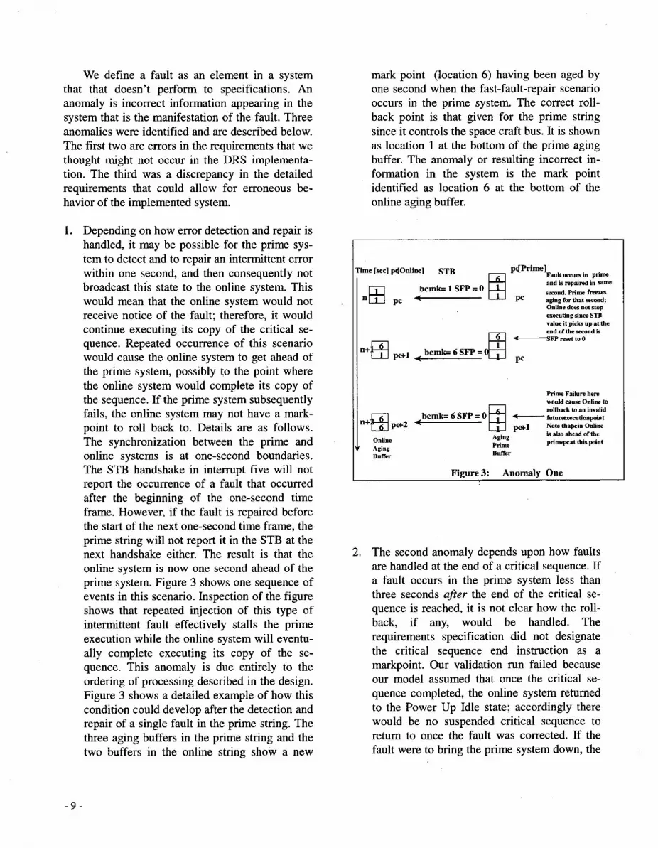
1. Depending on how error detection and repair is handled, it may be possible for the prime sys- tem to detect and to repair an intermittent error within one second, and then consequently not broadcast this state to the online system. This would mean that the online system would not receive notice of the fault; therefore, it would continue executing its copy of the critical se- quence. Repeated occurrence of this scenario would cause the online system to get ahead of the prime system, possibly to the point where the online system would complete its copy of the sequence. If the prime system subsequently fails, the online system may not have a mark- point to roll back to. Details are as follows. The synchronization between the prime and online systems is at one-second boundaries. The STB handshake in interrupt five will not report the occurrence of a fault that occurred after the beginning of the one-second time frame. However, if the fault is repaired before the start of the next one-second time frame, the prime string will not report it in the STB at the next handshake either. The result is that the online system is now one second ahead of the prime system. Figure 3 shows one sequence of events in this scenario. Inspection of the figure shows that repeated injection of this type of intermittent fault effectively stalls the prime execution while the online system will eventu- ally complete executing its copy of the se- quence. This anomaly is due entirely to the ordering of processing described in the design. Figure 3 shows a detailed example of how this condition could develop after the detection and repair of a single fault in the prime string. The three aging buffers in the prime string and the two buffers in the online string show a new
mark point (location 6) having been aged by one second when the fast-fault-repair scenario occurs in the prime system. The correct roll- back point is that given for the prime string since it controls the space craft bus. It is shown as location 1 at the bottom of the prime aging buffer. The anomaly or resulting incorrect in- formation in the system is the mark point identified as location 6 at the bottom of the online aging buffer.
pQPrime] Fault occurs in pr im and is repaired in same second. Prime freezes
PC aging for that second; Online does not stop executing since STB value it picks up at the end of the second is
-FPresettoo
PC
I I Prime Failure here would cause Online to -
I bcmk= 6 SFP = 0 - tutuwxecntionpnint rnllback to an invalid
pwl Note thapcin Online is also ahead of the primepcat this point Online Aging
Prime Buffer Buffer Aging
Figure 3: Anomaly One
2. The second anomaly depends upon how faults are handled at the end of a critical sequence. If a fault occurs in the prime system less than three seconds after the end of the critical se- quence is reached, it is not clear how the roll- back, if any, would be handled. The requirements specification did not designate the critical sequence end instruction as a markpoint. Our validation run failed because our model assumed that once the critical se- quence completed, the online system returned to the Power Up Idle state; accordingly there would be no suspended critical sequence to return to once the fault was corrected. If the fault were to bring the prime system down, the
- 9 -

online system may need to roll back to the last aged markpoint. This anomaly is due to a missing requirement. Figure 4 shows a detailed example of how this condition could evolve. Both the aging buffers would have had time to develop correct rollback points shown as loca- tion 9 in both cases. However, the time se- quence following the dashed line indicates that each critical sequence would have finished execution, therefore neither critical sequence would be available for follow-on rollback after fault repair. In each case both critical se- quences terminated and transitioned out of their execution state. In this instance the anomaly or incorrect information in the system is 1oss.of the critical sequence itself and its as- sociated program counters and aging buffers.
3. The third anomaly concerns the occurrence of a fault 2 seconds after a markpoint is encoun- tered in the prime string. The prime system freezes the aging function at n+2 seconds. Since faults that occurred in the previous sec- ond are not broadcast to the online system un- til the current second, the online system will continue to execute, aging its markpoint by one further second. At this point the online system receives the SFP = 1 value and now both agers are frozen. Once the fault is re- paired, the both strings will roll back, but the online system will roll back to the newer markpoint. This would not cause a problem if the prime system then completes the critical
sequence. However, if the online system should subsequently have to take over due to a prime failure - possibly associated with the (symptomatic) fault that was just processed, it could roll to an inappropriate block of code. This problem would not go away if the aging buffers were made deeper or shallower. It would just occur at a different place since it is a consequence of the relative time difference between the two aging schemes. Figure 4 shows a detailed example of how this condi- tion could develop. ' It shows a fault occur- rence that freezes the prime ager with mark point 6 at the 2-second point. Subsequently the corresponding online string ager ages its 6 by one extra second before receiving the STB message informing it of the occurrence of the prime fault. Accordingly, the anomaly or in- correct information in the system resulting from this fault is that the 6 has made it to the bottom of the online string aging buffer yield- ing an invalid rollback point. The correct roll- back point is to location 1, the start of the critical sequence.
6 Validation of the Implementation
We have subsequently validated the implementa- tion for the presence of the three design anomalies.
- 10-

For this purpose we used a special purpose space- craft simulator called the High Speed Simulator (HSS) [16,17]. The simulator uses code identical’ to the real spacecraft. However, it is decoupled from hardware and telemetry. Accordingly, its use as a test vehicle (1) is an accurate measure of sys- tem functionality and (2) it allows rapid turn- around on test suite creation, execution, and reporting of results.
The simulator allows test engineers to write test sequences for execution on the simulator. Given the data structures present in the spacecraft con- troller, a Tool command language (Tcl) program is written that orchestrates (1) the execution of the test sequence, (2) the extraction and printing of values of selected data attributes (3) the extraction and printing of any relevant time stamps and (4) fault injection scenarios and their responces.
6.1 Validation of the Implementation
The context here uses the term “prime system fault” to mean the prime system is responding to and repairing a fault that occurred in another part of the spacecraft. Additionally, the prime system must repair the fault before the sequence can be continued.
6.2 Procedural Steps
We wanted to know if the software implementation contained the same anomalies as were found in the design. To determine this, we supplied the High Speed Simulator with a simple sequence program for execution. By injecting faults into the running sequence, the same problematic conditions would be set up in the implementation that were discov- ered by design validation. Our earlier validation work derived the design anomalies from a three- step process. First, the prime system would stop running freezing its mark point ager in response to a fault occurrence somewhere in the spacecraft. Second, the prime system would load and begin
execution of a fault recovery program. Finally, during its execution of the fault recovery program, the prime system itself would fail. To affect this same scenarjo in the software implementation, the prime system was commanded to do a cold boot at execution points in the implementation identical to those that caused the anomalies in the design vali- dation. An operational online system considers the prime system cold boot to be a prime system fail- ure. It reacts by becoming prime itself; taking con- trol of the spacecraft bus; rolling back to the relevant earlier mark point address if necessary; and resuming execution of the sequence program. For example, the third anomaly found in the design validation process occurs when the prime system fails after encountering a fault scenario that freezes its mark point at second two in the aging process. This results in the new prime system rolling back to an inappropriate address due to a timing prob- lem in the design. Accordingly, cold booting the prime system when it has aged its mark point by two seconds has the same effect as the two step process considered in the design case.
Detection of the presence of design anomalies in the implementation was done by selecting data structures for output identical to those used in the design case. These output data values taken to- gether at any execution cycle represent the state of the implementation at a particular point in time. As the implementation executes, this ‘state vector’ de- scribes a finite state machine that represents the implementation. This finite state machine is an abstracted finite state machine since it doesn’t in- clude all variables, only the ones considered rele- vant to the current validation. If a corresponding design anomaly is itself present in the implemen- tation, the implementations’ abstracted state vector will go through an equivalent sequence to that found in the design validation done earlier. In this case the work proceeded by outputting each state vector for the executing implementation. The out- put list was then manually examined line by line to look for the presence of anomaly states.
The input sequence program that was incorporated into the HSS Tcl interface program to check for the presence of anomalies in the implementation is shown in Figure 6.
- 11 -

IP 800 803 805 807 809 8Ob 80d 80f 81 1 813 815 817 819 81b 81d 81f 821 823 825
Mnemonic BEGIN NOP NOP NOP NOP NOP MARK NOP NOP NOP NOP NOP MARK NOP NOP NOP NOP NOP END
Figure 6 Sequence Validation Sequence
To keep the analysis as straight forward as possi- ble, each instruction was executed on one-second boundaries. A HSS Tcl interface program was written to generate the output state vector sequence of the abstracted implementation state machine. Schematically, the overall process is shown in Fig- ure 7.
Commands for
(Sequence For i nspection)
I Figure 7: Implementation Abstracted State Machine
The implementation was validated at this point by simply looking at the results of the simulation by
hand and recognizing that a design anomaly was or was not reproduced in the output. This means visually examining the output sequence labeled “Abstracted State Vectors” to check the rollback process functionality. Two of the three anomalies found in the design validation were present in the implementation. A brief summary of the results follows.
6.3 Implementation Anomaly Validation Re- sults
The first anomaly resulted from repetitive errors that caused the prime and the online system to get out of synchronization. Our design anomaly fault scenario required a series of prime-fault-repair se- quences each of one-second duration or less. We did not see the first anomaly in the system. Further investigation with system engineers revealed that all faults take at least several minutes to repair. Therefore, repair time was extended so that anom- aly one would not be seen.
The second anomaly occurs when a fault occurs less than three seconds after the sequence ends. In this case, there is no rollback. That is, once the sequence has been completed there is no rollback in response to an error injected inside the three- second-rollback window. Therefore, there is no guarantee that all instructions at the end of the se- quence would have been carried out by the space- craft. Accordingly, on this basis, the last instruction in the program should have been identi- fied as a rollback point. Our technique demon- strated that the second anomaly was present in the implementation.
The third anomaly results from a fault that brings the prime system down when its aging buffer con- tains a mark point rollback address that has been aged by two seconds. According to our model checking validation, this information would not get to the online system until the following second, thereby causing its two deep online buffer to age its rollback address by an additional second. Con- sequently, its rollback address would be consistent with a three-second delay following a mark point when only two seconds had elapsed since the prime string had executed its last instruction.
- 12-
Prime system failure was again caused by cold booting the prime string at the point it had aged its mark point by two seconds. The subsequent roll- back in the new prime system did not match the old prime’s rollback address. Accordingly, our technique demonstrated that the third anomaly was present in the implementation.
The cold boot process is equivalent to the injection of a single fault that brings the prime system down. This process causes the overall spacecraft control- ler to fail to conform to requirements since control in the new prime system rolls back to an inappro- priate location. Therefore, our technique also dem- onstrated that the overall system made up of prime and backup systems was not single fault tolerant.
All of these results were taken with respect to the spacecraft software as it existed on the High Speed Simulator.
7 Discussion The analysis technique used in this study is
relatively new, and was not sufficiently mature just a few years ago to enable its use. The DRS oper- ates as a communication system that must be ro- bust under the incidence of arbitrary faults. The validation of requirements for such fault tolerant systems is particularly hard, because of the non- determinacy introduced by the fault behavior. Holzmann [lo] points out that even for relatively simple communication protocols:
“It is almost impossible to manually verify correctness requirements such as the ones discussed, no matter how diligent or disci- plined the designer. The behavior of even simple protocol systems can be of a com- plexity that no designer can be expected to assess accurately.” Worse still, the desired validation cannot be
established through rigorous testing of the imple- mentation either. The complexity of the communi- cation system, together with the non-deterministic occurrence of faults makes exhaustive testing in- feasible.
The use of model checkers opens up new pos- sibilities for validating such systems. In principle, exhaustive checking of the requirements model is also infeasible. However, by exploiting the struc-
ture of the state space, a partial model can be ex- tracted that is sufficient for the validation exercise. The reduction in the size of the state space was critical in this case study, and was achieved by di- viding the requirements into 5 partitions and ab- stracting away extraneous detail. The original (reduced) estimate of the size of the model state space was over 100 million states. Although the estimate after simplification was between about 62,000 and 800,000 states, the actual number of states in the model was just over 100,000 states, allowing the validation of each of the six require- ments in partition 1 to be completed in 30 seconds.
The complexity of the validation exercise was also reduced by validating requirements individu- ally. It is possible to combine requirements (and domain properties), as described in Appendix A, so that they can be checked in a single validation run. However, doing so often increases the com- plexity of the model beyond the limit of current model checking technology. Hence, we only com- bine requirements in this way when they are known or suspected not to be independent.
It is important to note that with this approach, any claims of completeness are sacrificed; we are only performing partial validation of partial speci- fications. Hence, the focus is not on proving cor- rectness, but on revealing errors [13]. We have shown in the case study that the approach is capa- ble of finding subtle errors that are otherwise al- most impossible to detect. If we did not find any errors, that would not establish correctness, but it does provide a higher level of assurance than is otherwise possible.
8 Summary and Conclusions We have demonstrated through a case study
how fault tolerance requirements can be validated through non-deterministic model checking. The system described in the case study used a mark and rollback scheme to implement fault tolerance. The system has to complete high priority tasks called critical sequences efficiently and at the same time respond to and repair faults. To meet this require- ment, hard rollback points (markpoints) are em- bedded in the critical sequence code so that completed subtasks would not have to be repeated when fault conditions force the executing critical sequence to suspend operation to service the fault.
- 1 3 -

Faults occurring within subtasks are repaired and rollback is then done to the start of the last uncom- pleted subtask. A hot backup (the ‘online string’) is operational synchronously to increase reliability and availability.
The validation scheme described in this paper was implemented as a Spin model with three key components. First, the model contains an underly- ing operating system (executive) that contains a checkpointing scheme referred to as the mark and rollback process, which was modeled deterministi- cally. Second, a generalized critical sequence was chosen to be executed by the model operating sys- tem to make it possible for requirements and de- sign errors to surface. Finally, a fault injection process was used to non-deterministically inject a single fault into the system model. The validation system then attempted to execute the critical se- quence and to recover from all possible injections of a single fault into the executing critical se- quence. In this way three anomalies were discov- ered.
The model was reduced to a feasible size for validation by abstracting away unnecessary detail leaving behind a partial specification. The func- tional rollback requirement was elaborated into 6 separate but dependent requirements. A Linear Temporal Logic scheme was developed to validate three pairs of coupled requirements over the dually redundant system. This procedure allowed the rollback requirement in the prime or control sys- tem to be validated together with its coupled an- cillary mirror rollback requirement in the online (hot backup) system. In this way, the study showed that a partial specification for a complex spacecraft controller can be effectively validated within the framework of the remaining requirements.
Validating all six rollback requirements in one validation run would have added a large amount of execution time to the validation. This is because the resulting LTL automaton that gets coupled to the model contributes exponentially to the size of the model. Accordingly, by partitioning the over- all rollback requirements into three equivalence classes with two rollback requirements each sig- nificantly reduced the model in size (state space) and consequently in execution time as well. As a byproduct, the analysis of the results was much
more straightforward since one type of rollback could be analyzed at a time. Having completed the work of finding the three design errors using model checking, we then vali- dated the software implementation for the presence of ‘the three anomalies found in the design. Using a spacecraft simulator running code identical to the real spacecraft, two of the three design anomalies were found to be present in the implementation. The method is efficient since the design state space search problem is generally a relatively fast proc- ess. Whereas, the state space of a software imple- mentation is potentially too large to search exhaustively or even reliably partially. Having found design errors by rapid search, efficient im- plementation validation can be done by checking for the presence of a small number of individual design anomalies
We plan to extend the application of the methodol- ogy demonstrated here to developmental efforts over the software lifecycle using partial specifica- tions and their associated co-evolving prototype implementations. We are exploring two different approaches. The first approach works by instru- menting a partial or complete implementation in order to detect the presence of paths through the state space that correspond to the satisfaction of functional requirements. The resulting log files are then transformed into a set of traces to be executed by a model checker to validate that the implemen- tation preserves the key properties. The functional requirements in the system are validated by ex- pressing them as Linear Temporal Logic proposi- tions that are translated into an appropriate automata type supported by the particular model checker in use. Then, by traversing the annotated log files encapsulated as processes over the model, the functional requirements are validated in the usual way by the model checker as discussed by Holzmann [2].
The second approach is to use the model checker to generate runtime monitors that may be embedded in the implementation. In this approach, we express correctness properties as LTL, formu- lae, and use Spin to generate a C-encoded proce- dure from the formula, which is then included as a run-time monitor inside the growing implementa-
- 14-
tion. The implementation is then instrumented, by hand, to inform the monitor at the occurrence of the events that the monitor is interested in, namely those events that can cause a change in the truth- value of the correctness property. The monitor would complain if it ever saw an execution that violated a stated correctness property.
This first of these approaches has been suc- cessfully used on a pilot project to validate a com- plex communications protocol called RMP [ 141. Two teams consisting of an Independent Verifica- tion and Validation (IV&V) team and a software development team were used. Both the develop- ment team and the IV&V teams worked from an evolving partial specification. While the develop- ment team was responsible for the implementation, it was the responsibility of the IV&V team to apply a modeling scheme to check that the evolving specification and the implementation were consis- tent with each other. The IV&V team then used the model checker to validate the requirements. In this way when errors in the implementation surfaced they could be brought up to date with the specifi- cation; and if the specification were in error the implementation could be used to update the speci- fication. Each derived or added requirement would, of course, then be incrementally validated and used to assist in driving the specification for- ward and so on. By working in tandem in this way, costly backtracking errors are prevented. The re- sult was a saving in operational efficiency and lower maintenance costs due to good underlying design. 9 References [l] W. Chan, R. J. Anderson, P. Beame, and
David Notkin, “Improving Efficiency of Symbolic Model Checking for State-Based System Requirements”, Proceedings of the ACM SIGSOFT International Symposium on Software Testing and Analysis, (ISSTA’98), Clearwater Beach, Florida, March 1998.
[2] G. J. Holzmann, “The Model Checker Spin,” IEEE Transactions on Software En- gineering, vol. 23, pp. 279-295, 1997.
[3] C. Heitmeyer and D. Mandrioli, “Formal Methods for Real-time Computing: An overview,’’ in Formal Methods for Real- time Computing, C. Heitmeyer and D.
71
81
[91
Mandrioli, Eds. Chichester, UK: J. Wiley,
N. G Leveson, M. P. E. Heimdahl, H. Hil- dreth, and J. D. Reese, “Requirements Specification for Process Control Sys- tems,’’ IEEE Transactions on Software En- gineering, vol. 20, 1984. K. L. Heninger, “Specifying Software Re- quirements for Complex Systems: New Techniques and Their Application,” IEEE Transactions on Software Engineering,
S. Easterbrook and J. Callahan, “Formal Methods for V&V of partial specifications: An experience report,” Proceedings, Third IEEE Symposium on Requirements Engi- neering (RE’97), Annapolis, Maryland, 5-8 January 1997. Z. Manna and A. Pnueli, “Tools and rules for the practicing verifier,” Department of Computer Science, Stanford University, Technical Report CS-TR-90-1321, 1990. K. L. McMillan, “Symbolic model check- ing - an approach to the state explosion problem,” in School of Computer Science. Pittsburgh, PA: Carnegie Mellon Univer- sity, 1992. J. R. Burch, E. M. Clarke, and D. E. Long, “Symbolic Model Checking for Sequential Circuit Verification,” IEEE Transactions on Computer Aided Design of Integrated Circuits and Systems, vol. 13, pp. 401-424, 1994. P. Ramanathan and K. G. Shin, “Use of Common Time Base for Checkpointing and Rollback Recovery in a Distributed System,” IEEE Transactions on Software Engineering, vol. 19, pp. 571-583, 1993. G J. Holzmann, Design and Validation of Computer Protocols: Prentice Hall, 1991. D. Harel, “Statecharts: A Visual Formalism for Complex Systems,” Science of Com- puter Programming, vol. 8, pp. 23 1-74, 1987. D. Jackson and C. A. Damon, “Elements of Style: Analysing a software design with a counter-example detector,” International Symposium on Software Testing and
1996, pp. 1-32.
V O ~ . 6, pp. 2-13, 1980.
- 15 -

Analysis (ISSTA’96), San Diego, CA, 8-10 January 1996. J. R. Callahan and T. L. Montgomery, “An Approach to Verification and Validation of a Reliable Multicasting Protocol,” Znter- national Symposium on SofhYare Testing and Analysis (ISSTA’96), San Diego, CA, 8-10 January 1996, pp. 187-194. J. R. Buchi, “On a Decision method in re- stricted second-order arithmetic,” Pro- ceedings of the International Conference on Logic Methodology and Philosophy of Sciences, 1960, Stanford University Press, pp. 1-11.
Reinholtz, WK and Robison, WJ., 111, “The ZIPSIM series of high-performance, high fidelity spacecraft simulators,” Proceed- ings AIMUtah State University Annual Conference on Small Satellites, Aug 29- sept 1, 1994.
Patel, K and Reinholtz, W and Robison, W, “High-speed simulator: A simulator for all seasons”, Proceedings International Sym- posium on Space Mission Operations and Ground Data Systems (SPACEOPS96, Munich, Germany Sept 16-20 1996; pg. 749-756
10 Appendix A: Linear Temporal Logic Back- ground
The SpinPROMELA modeling scheme de- rives much of its power from its ability to incorpo- rate formal theorem proving elements into its search schemes. Buchi [14] discovered the funda- mental relationship between finite automata and the second-order monadic calculi. This innovation made it possible to incorporate Linear Temporal Logic (LTL) assertions as components of computer modeling schemes.
A Buchi automaton is a non-deterministic Fi- nite State Machine (FSM) A = (X, 3, So, 3). C is the input alphabet, S i s the set of states, So the
set of initial states, and 3 is the set of accepting states. 3 E S x X x S i s the transition relation. If (s, O, SI) E 3 then A can move from s to s’ upon reading O. An input word is an infinite sequence O= 01, 02, 03, . .: ,Oi E X, while a run, r, over o is an infinite sequence so SI LL . . ., where SO E SO, ( S i , Oi+l, si+l) E 3, i = 0, 1, .... Arun, r, is said to be accepting iff there exists a state g E 3 such that g appears infinitely often in r. The lan- guage 4 A ) is the set of all input words, O, such that A has an accepting run over O.
Let f i be an LTL assertion corresponding to a system requirement to be validated that generates automaton Ai. Given n Buchi automata of the form Ai = (Xi, 3, 3 i , Soi, 2), they are closed under the operation of intersection. Their intersection n :=, A i
accordingly is a Buchi automaton, and it accepts the language n :=, (A ’ ) . The LTL formula that gen- erates this automaton has the form
f = X f , (1) I =1
Equation (1) allows multiple LTL formulae to be concatenated such that the resulting automaton will preserve the characteristics of the language accepted by each automaton were it to be imple- mented in isolation. This means that the set of all input words, O, that were recognized by each automaton Ai in isolation will also be recognized by the composite automaton n (A c ) .
By incorporating the Finite State Machine (FSM) representation of the formal properties to be validated by the model, the model can be routinely checked for the presence or the absence of the de- sired characteristics.
The SpinPROMELA system has an LTL translator that can produce the corresponding Biichi automaton from an input requirement ex- pressed as an LTL formula. The Spin modeling system checks to see that finite state program .p satisfies the temporal logic formula f . First, the global state graph of P i s computed. Second, the Buchi automaton is constructed for 11 A+ . Third, the synchronous product P x A- , , is com- puted. Finally, the validation run is performed on p
- 16-

x A,, For each state transition in Spin checks to see if a corresponding transition in A,, is pos- sible. Once one of the accepting states of A- , , has been entered, it must be shown that that state is reachable from itself. When this happens, A,, will have been shown to have recognized a string (3
from the language generated from the original LTL formula 7 , For efficiency, Spin executes the 3 steps in 1 pass. At this point a trail file can be written showing the sequence of state transitions in Pthat gave rise to the accepting state in A,, This file can then be annotated and run as a test case against the implementation.
- 17 -