validating conceptual models by transformational prototyping
TRANSCRIPT

Validating Conceptual Models by Transformational Prototyping
Odd Ivar Lindland and John Krogstie
Faculty of Electrical Engineering and Computer Science The Norwegian Institute of Technology
N-7034 TRONDHEIM, NORWAY
Abs t r ac t . Validation of user requirements shouldstart as early as possi- ble in the development process. A conceptual model is a suitable medium for an early representation of functional requirements. Despite the user- oriented nature of many conceptual models, requirements error are dif- ficult to detect as the size and complexity of the model increases. Thus, the consequences of the specified requirements are difficult to judge only from inspecting the models. To improve the model comprehensibility, a conceptual model with executable properties can be transformed to an executable prototype that can be evaluated to detect potential miscon- ceptions expressed in the model. One major validation approach to improve the comprehensibility of com- plex models is based on and exploits the executability of conceptual mod- eling languages. A conceptual model can be interpreted as or transformed to an executable prototype. An executable prototype is particularly use- ful for validating the dynamic properties of the conceptual model. In this paper the executable properties of the PPP language are ex- ploited and a PPP model is transformed into an executable prototype in TEQUEL and C. The transformation strategy and execution mech- anisms of the approach are presented, and its potential for validating model behavior is discussed.
1 Introduction
Validation of user requirements has tradit ionally been concentrated on testing program code prior to system installation. However, experiences have shown tha t requirement errors detected at this stage are enormously expensive compared to earlier detection and correction [1]. Validation of user requirements should therefore s tar t as early as possible.
A conceptual model is a suitable medium for representing domain knowledge and functional requirements early in the development process. However, the first versions of a conceptual model seldom reflect the actual requirements. Since the model is a result of communicat ion processes among several parties involved in the project, misunderstandings and misconceptions may cause ambiguous, invalid, redundant, inconsistent, and/or incomplete models [5]. Despite the user- oriented nature of many conceptual model, these obstacles are difficult to detect as the size and complexity of the model increases. Thus, the consequences of the specified requirements are difficult to judge only from inspecting the models.
This manuscript is published by Springer as part of Lecture Notes in Computer Science Volume 685, 1993, pp 165-183 Published version can be found at http://link.springer.com/chapter/10.1007/3-540-56777-1_9

166
One major validation approach to improve the comprehensibility of complex models is based on and exploits the executability of some conceptual modeling languages. A conceptual model can be interpreted as or transformed to an exe- cutable prototype. An executable prototype is particularly useful for validating the dynamic properties of the conceptual model. The prototype is a tangible product which can be exercised and searched for deficiencies and incompliance with user requirements.
This paper will show how an integrated conceptual model is transformed into an executable prototype that can be used to validate the dynamic properties of the model. The paper very much builds on the work presented in [16], but the emphasis is on the validation potential of the work. The paper is organized as fol- lows: Section 2 presents the PPP modeling language along with a description of a problem domain. In Section 3 we describe the strategy for transforming a PPP model into an executable prototype which is made of statements in TEQUEL, C, and Prolog. Also, the execution strategy is presented. In Section 4 we show how the prototype is used to validate the model behavior, whereas its validation potential is discussed in Section 5. Related work and some tentative conclusions are offered in Sections 6 and 7, respectively.
2 The Modeling Languages in PPP
ppp1 (Phenomena, Processes, and Programs) is an experimental ICASE envi- ronment presented in [8]. The PPP environment is running on Sun work-station under Unix and Sunview and has been developed using BIM-Prolog as the major implementation language.
The language used in the PPP environment is a visual language that is thoroughly defined in [13, 23]. The PPP language consists of four sub-languages which are grounded on well established languages and address different aspects of the functional requirements to an information system:
- The PrM (Process Model) language is used to describe dynamic aspects. It is based on the traditional DFD language, with added constructs for better precision and increased expressiveness. As will be shown, it has some char- acteristics in common with Ward's Transformation Schema [31], and other languages like [17].
- The PhM (Phenomenon Model) language is an extension of the entity- relationship model, and includes many features of newer semantic data mod- els [25].
- The PLD (Process Life Description) language is used to specify process logic of bottom-level processes. It has many similarities with block-structured, program design languages [30].
1 ppp is developed within the RHAPSODY-project (1989-1993) at the University of Trondheim and very much builds on and relates to the results of the DAISEE-project (1982-88). Furthermore, cooperation has taken place towards the ESPRIT-projects TEMPORA and IMSE.
This manuscript is published by Springer as part of Lecture Notes in Computer Science Volume 685, 1993, pp 165-183 Published version can be found at http://link.springer.com/chapter/10.1007/3-540-56777-1_9

167
- The UID (User Interface Description) language is used to describe static and dynamic aspects of user interfaces, based on the possibilities offered by graphical user interface technology.
Although the languages cover different aspects, they are tightly integrated. Thus, transformations between different sub-models are enabled.
In this paper, we will concentrate on the PrM language and the PLD lan- guage, since these are mainly used to express dynamic properties of a problem domain. For descriptions of PhM and UID, see [8, 26] and [13], respectively.
The modeling constructs of PrM and PLD will be explained using a domain description from the "Swedish Post Case Study" [28]. Within the scope of this text, we have concentrated on the business area "Management of payment and invoicing" and an overall description of this area is given as follows:
A registration clerk receives a delivery-note from a customer. The delivery-note contains information about the customer, which articles have been delivered, and the number of articles. The customer can either pay cash or he can use a credit agreement if available. If he pay cash, a cash-receipt is given to the customer. Otherwise, an invoice is produced. The invoice contains the total amount of money attached to the delivery- note, and status values indicating whether the invoice have been sent, paid, or not. Each fifth day, invoices are sent to the customer with an administration fee of 10 NOK added and the sent status is updated. Furthermore, each week a reminder is sent to the customer based on sent, but unpaid, invoices. Also here, a reminder fee of 20 NOK is added to the total amount. Payment from customers are related to specific invoices which are deleted (marked paid) from the system.
2.1 T h e P r M L a n g u a g e
The PrM language is used to describe the overall dynamic aspects of the problem domain. A top level PrM model for our example is shown in Fig. 1 and modeling constructs that differ from the traditional DFD language are labeled.
P r o c e s s e s have the same meaning here as in a DFD model, i.e. describing the business activities as transformation of input flows to output flows. From our domain description, four activities can be identified and modeled as processes. Processes can be decomposed in the same manner as done in the DFD language. Since our example already shows a restricted part of the problem domain, a further decomposition is not necessary.
Also, f lows and s t o r e s have the same meaning as in a DFD. However, the PrM language allows flow contents to be specified as variables or attributes from the PhM model, with accompanying type information. A set of variables with type information is called i t ems . Also, e x t e r n a l a g e n t s have the same seman- tics as external entities in DFD. The name difference has been made to emphasize the dynamic aspects of entities. In the top level model, the R e g i s t r a t i o n c l e r k and the Customer are modeled as external agents.
This manuscript is published by Springer as part of Lecture Notes in Computer Science Volume 685, 1993, pp 165-183 Published version can be found at http://link.springer.com/chapter/10.1007/3-540-56777-1_9

168
DII Custo~r8
[D21 AIliclcs
C.sto=r info ~ ~--'--"--~ ~ ~
Anidr info
A tinro . . . . ' pcnvr %~ m~~162162 J : ~ T [ .......... / |
�9 ~ . . . III l~ e A J [ ' ~ invoicin----~ IInvoicing ~ invoir /
Invoi~ /
7 ",( p . . . . t ~h~g i~r . .q-mlote invoice. -Upaym~t
C.,~on~r I U 9 ~ ~ Money,
Fig. 1. The PrM model of the Sweden Post
T i m e r s increase the temporal expressiveness of PrM and can either be used as clocks or delays. Clocks send output signals on a regular basis in order to monitor processes, whereas delays are used where output signals are sent some specified interval after an input signal has been received. Generally, input signals may start and stop timers. In Fig. 1, two timers (of clock type) are included to regularly send Invo ic ing_schedu le and Reminder_schedule each 4th day and each week, respectively.
Control flow is modeled by the use of t r i g g e r i n g and t e r m i n a t i n g proper- ties of data flows. These properties determine when a process will start and stop its execution, respectively. If a process is passive and receives the right combina- tion of triggering flows, it will start executing. On the other hand, an active pro- cess terminates when a combination of terminating flows is sent. Non-triggering and non-terminating flows can be sent/received any time while the process is active. In the example, process P4 is activated if it receives the triggering input flow Reminder_schedule 2, and will terminate by sending the terminating flow Reminder to Customer.
To define logical relationships between input flows and output flows, PrM offers i n p u t p o r t s and o u t p u t po r t s , respectively. There are three basic kinds of ports corresponding to the three logical connectives: conjunction (AND), dis- junction (OR), and exclusive disjunction (XOR). From the example model in Fig. 1, we see that the input port of P1 is an AND port with four input flows which are all received during execution. The output port of P1 is of XOR type and means that P1 either sends a Cash_receipt to the Customer or (exclusively)
2 Marked with a 'T'.
This manuscript is published by Springer as part of Lecture Notes in Computer Science Volume 685, 1993, pp 165-183 Published version can be found at http://link.springer.com/chapter/10.1007/3-540-56777-1_9

169
store an invoice in D4: Invoices by sending Store_invoice. An OR port is not used in the example, but is symbolized with an "arc".
Moreover, a port may be conditional, repeating, or both in any combination. A conditional port reflects a situation where flows are sent or received depending on some condition. A repeating port means that flows may be received or sent a number of times during a single execution of a process. In Fig. 1 the output port of P2 is repeating which is indicated by a unbroken line. A conditional port is not shown in the model, but is depicted by a dashed line. Also, composite ports can be formed by placing ports inside each other. For instance, the input port of P2 cor- responds to the logical expression AND(Invoicing_schedule,R-hND3(Invoice_ in~o) ).
Now, we can describe a single execution of process P2 as follows: The process is activated by receiving the flow Invoicing_~chedule from timer 4 day. Then it repeatedly receives Invo ice . in fo from D4 : Invoices. All invoices which have not been sent or paid earlier are sent to the Customer and stored in D4: Invoices with updated status information (defined by Update_invoice).
For more detailed descriptions of PrM, see [8, 23].
2.2 The PLD language
The PLD language is used to specify process logic of bottom-level processes. The processes that have associated PLD models will be denoted automatic processes, whereas processes that emulate human tasks will be called manual processes. Constructs for assignments, iteration, and choices are defined. In addition, two constructs for receiving and sending data provide interprocess communication and communication with users and databases.
Fig. 2 shows the process interface of process P2:Invoic ing reflected in a PLD model. The different modeling constructs of the PLD language is labeled. The initial PLD model is automatically generated from the PrM model in Fig. 1. Roughly speaking, the items are inherited in the PLD models. Also, the ports and triggering/terminating flow properties define the overall structure and the ordering of the PLD model, respectively. It should be noted that the item infor- mation is not shown in the PLD model in Fig. 2, whereas the "dashed" boxes containing statements written in "courier" are manually filled in by the developer in order to complete the model.
The flow of control of a PLD model is downwards and from left to right. The s t a r t cons t ruc t simply marks the start of the PLD model. First, the process receives Invoicing_schedule. The receive cons t ruc t identifies the data flow and the sender. In addition, though not shown in the figure, it contains the item information.
A loop cons t ruc t follows, to indicate that data from D4:Invoices is re- peatly received during the execution. A loop construct may either correspond to a WHILE-loop (as in the example model) or a FOR-loop of traditional pro- gramming languages.
3 A short-hand notation of repeating-AND. This manuscript is published by Springer as part of Lecture Notes in Computer Science Volume 685, 1993, pp 165-183
Published version can be found at http://link.springer.com/chapter/10.1007/3-540-56777-1_9

170
. . . . . ~176
I ........... ~ \ ~or162 t,1,,oi,r I ! " w ' : ' < = I i / inf~176
'.. i . selection . . . . . . . 11 . . .
I /
Invoice_info
invoiee
@ I~voir �9 Invoice ( ~
. . . . . ~ 1 7 6 1 7 6 t
:'.~ ,eat = 0 .,""t:i ~ ....
amount : =amount ~ 10...l'-..o ...u...~176176 .~176176 ~176 i -
,ent t= I 1 ~
To IN
Send Invoice To A1
Fig. 2. A PLD model corresponding to the process interface of P2
To check whether an invoice already has been sent or not, a choice con- s t r u c t is used. The choice construct is composed of one se lec t ion c o n s t r u c t which marks the choice situation, and one or more a l t e r n a t i v e c o n s t r u c t s , one for each alternative to be evaluated. Each alternative contains an expression. If this expression evaluates to true, the block below the alternative construct will be executed. In the example, only one alternative is evaluated. For the case that an invoice has not been sent before (sent = 0), the amount is updated using the a s s i g n m e n t c o n s t r u c t . Moreover, Update_invoice and Invo ice are sent to D4: Invo ices and Customer, respectively. The s e n d c o n s t r u c t identifies the data flow and the receiver. In addition, though not shown in the figure, it con- tains the item information.
3 T r a n s f o r m i n g P P P m o d e l s i n t o T E Q U E L / C
In PPP, transformations form an integral part of the development process. They are actively used as the system is being modeled, to speed up the modeling pro- cess while preserving the consistency between different sub-models. The transfor- mation from a PrM model to an initial PLD framework has already been shown in Fig. 2. Similarly, transformations generate programs on the basis of different parts of a PPP model. So far, these transformations are mainly restricted to the construction of prototypes. The most important transformations implemented in the PPP tool are: (1) from UID models to C/Moti f ([13]), (2) from PLD models to Ada ([8, 19]), (3) from PPP models to Simula/Demos ([9]), and (4) from PPP models to TEQUEL/C ([16]).
In this section we will take a closer look at the generation of TEQUEL/C
This manuscript is published by Springer as part of Lecture Notes in Computer Science Volume 685, 1993, pp 165-183 Published version can be found at http://link.springer.com/chapter/10.1007/3-540-56777-1_9
171
code. The main structure of the transformation strategy will be outlined and selected transformation rules will be included to the extent they shed light on the process. The interested reader is referred to [15, 18] for a more complete documentation and evaluation of the code generation process. First, however, a brief introduction to TEQUEL.
3.1 T E Q U E L
TEQUEL is a programming language with temporal semantics and has been developed at Imperial College, London [24]. The underlying execution platform for TEQUEL is called the Rule Manager [27]. Roughly speaking, a TEQUEL specification is a set of rules on the form [16]:
formula about the future <= formula about the past
These rules are evaluated with respect to a particular state in a temporal database, yielding a number of formulae about the future which must be made true, if not already true. The formula about the past is expressed in TQL, Temporal Query Language, whereas the formula about the future is expressed in TAL, Temporal Action Language [24].
In this work TEQUEL has served two main purposes. First, it has been used as a target platform for the transformed PPP models. Secondly, it has been used to exploit the temporal semantics of the PPP language.
3.2 The Trans fo rma t ion S t r a t e g y
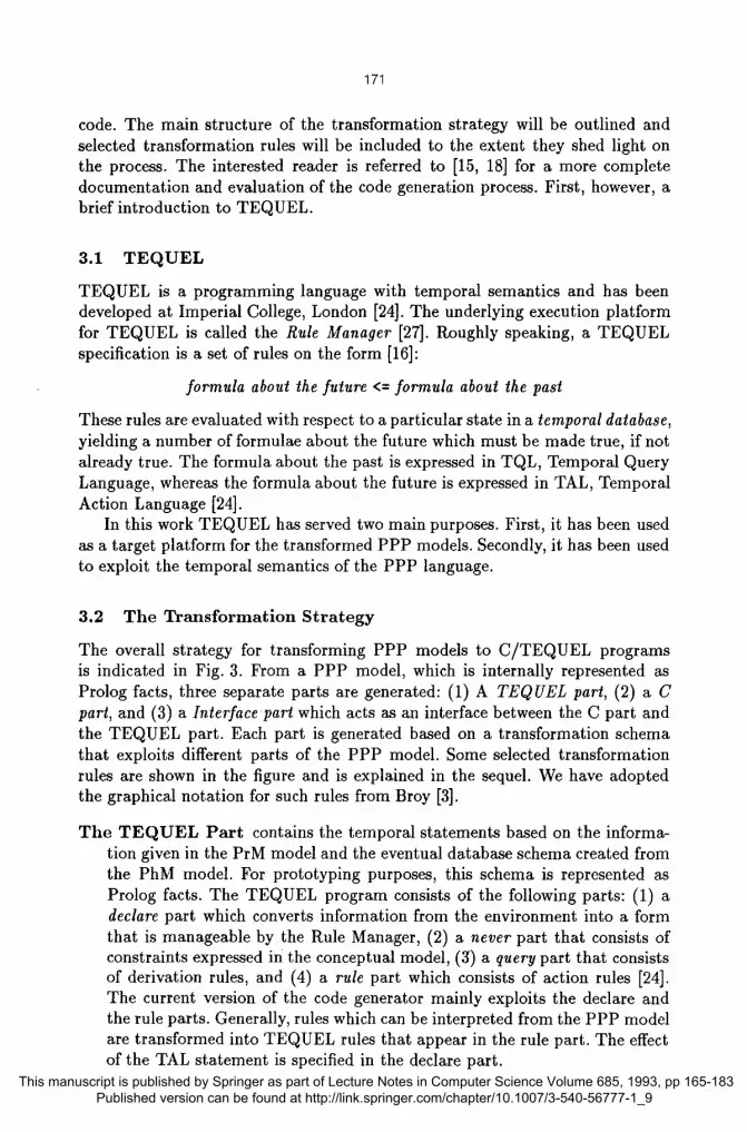
The overall strategy for transforming PPP models to C/TEQUEL programs is indicated in Fig. 3. From a PPP model, which is internally represented as Prolog facts, three separate parts are generated: (1) A TEQUEL part, (2) a C part, and (3) a Interface part which acts as an interface between the C part and the TEQUEL part. Each part is generated based on a transformation schema that exploits different parts of the PPP model. Some selected transformation rules are shown in the figure and is explained in the sequel. We have adopted the graphical notation for such rules from Broy [3].
The T E Q U E L P a r t contains the temporal statements based on the informa- tion given in the PrM model and the eventual database schema created from the PhM model. For prototyping purposes, this schema is represented as Prolog facts. The TEQUEL program consists of the following parts: (1) a declare part which converts information from the environment into a form that is manageable by the Rule Manager, (2) a never part that consists of constraints expressed in the conceptual model, (3) a query part that consists of derivation rules, and (4) a rule part which consists of action rules [24]. The current version of the code generator mainly exploits the declare and the rule parts. Generally, rules which can be interpreted from the PPP model are transformed into TEQUEL rules that appear in the rule part. The effect of the TAL statement is specified in the declare part.
This manuscript is published by Springer as part of Lecture Notes in Computer Science Volume 685, 1993, pp 165-183 Published version can be found at http://link.springer.com/chapter/10.1007/3-540-56777-1_9

172
T r a n s f o r m a t i o n r u l e s - - ( . )
i~oceee(Item = actondotrue:ceJ cP~oce~ lem ;
ruie
~oces~ltem) <= <+ Mow(item);
- - ( b )
oIf I I o ~ t e r n )
t~ow Item <= ago Ticks.on I~ow Item (not off flow(~em) s[noe on_fiow(llam))
- - (e)
Qu~AtI1.AII2.Att3 :- ~em po raOu er y( e r~tity(Atll ,AItZ,Atl3 ),
r PPP model
I l l l l l l l ~
Transformation
/ i n ,
- (c)
- (d)
I SENO RGw{Itam) TO I~oc~ss~
ponllerRow= pointsrtoRowjmst~oc~stzeof structFIow ; pointer Row -> lisfn = expr;
~imerFlaw -> next = NULL # (la~iFIow == NULL
{ headF~ow = pointerFIow; I~st Fbw = I:ointer Row;
poinler Flow = hesdRow, vhde (poimer Flow ~= NOLL II ftrstFIow)
il(lirstFIow
trstRow = FALSE;
( ge l ilsm_frc~n list F~e~'~Flow = ~'nterFbw -> next; kee(pohlerP"~ow~);
I I ~n t~R~ =headRow;
1 ....
- T e q uel inducing(X1 ) . aclior~ d~ruo :-{c.all dnvoici~g} ); : invoio~KXl,..X$)=
database(persistent=yes ; invoicingsohedule(X 1 )=
dal abase(persistent :no); e
luk ls V, vo~<:~(XM) <.
<+ invoid, ng~hedu le (X 1)
i nvo~qgsc~ lu le (X1 ) < . a0o<4,k.woiok, g ~ h K l u l ~ X l ))
i r~, icingsch edule( 1 ) <= time(4) e
r
- - in ter face :-exter n J o a d ( [ o i n ~ g , .] ,[ 'swedenpost .ol). :-e~d ern~edica~ e(olnvoicing(integ er:i)).
invx)io~nfc~X1 ...X 6):. t imels(Now), Previous is Now - 1, invoioe{Xl ,..,X6,Slart,End), Slzct . < Previous, End > - ~ev lco s.
upda ldnvo i~ (X l X2.X4):. i ec~occa Query(invc~o~(x1 ,X8,...X12}),
lec~por aAsserl(not(ilwok:~(X 1 ,X$,..,X t 2)),now), t~.~oora.C~ss~r t (mvoiee(X 1 ,Y.2,Xg,X4,X11 ~(12),now).
C / T e q u e l c o d e
- C clnvoidng(dummy) ~t dum~;
iN no,sent.paid,am~nt.du e_d ale; a lom nam~ BIM_Prolog_S~lip Cal~'invoiceinfo',
: &no &amocml, &due_dale, &seN, t.paid,
il senl ~ O) { a m o u n t , acnount + 0;
sent = 1; 8 ~_prolog_ca~j>redioale
(%-pdatoinvok~', no, acnotn, sent);
~ind(" no: %d ~n", no); ~ n d �9 arnourd: ~ ~ ' ,amount ; ~n t t l " due..date: %d ~'~-,du~n_t~ale); ~nff(" Setll %d ~ ' , Se~); ~n t l "paid: %d ~=,pald); xintt(" name: %s ~n',name ;
BIM _PrdogJ$rnl inale_r
F|g. 3. The overall transformation strategy.
This manuscript is published by Springer as part of Lecture Notes in Computer Science Volume 685, 1993, pp 165-183 Published version can be found at http://link.springer.com/chapter/10.1007/3-540-56777-1_9

173
Trans fo rma t ion rule a shows how a triggering flow and the triggered pro- cess is transformed into a TEQUEL rule. The TQL statement says that when flow, containing item, appeared in the previous state, the TAL statement, process( i tem) , follows. The effect of the TAL statement is declared as an action that calls the C function cProcess (see below). Item can be sent from an agent, a timer or from another process, simulating both external events, temporal events and internal events, respectively.
T rans fo rma t ion rule b shows the implementation of a delay. The rule that is produced says that if item is received a certain time ago (specified in the temporal expression Ticks), item is forwarded in flow unless the timer has been turned off in the meantime (receiving the off_:flow). If flow is triggering a process, a rule like the one shown in t r a n s f o r m a t i o n rule a will also be produced.
The C P a r t corresponds to the internal behavior of the processes which are described by the PLD language. The procedural semantics of the PLD lan- guage makes a transformation to C straightforward, giving one C function for each PLD model. Selection constructs, iterative constructs, and assign- ment constructs have the traditional semantics and are transformed into the corresponding C statements. As mentioned above, an action initiates a C function. A major part of the C part is devoted to transfer of data and control to and from the Rule Manager. All items that are contained in triggering input flows to processes are transferred to the function as parameters.
Furthermore, non-triggering flows between automatic processes correspond to data transfer between C functions. The actual transfer is implemented as a queue buffer. T rans fo rma t ion rule c shows how a send construct produces an item that is put into the end of the buffer. The reception of item is shown in t r a n s f o r m a t i o n rule d. Moreover, the rule illustrates the handling of a triggering, repetitive flow. The first item is passed to the TEQUEL part in order to trigger the process proces-~. The item is received through the parameters of the C function. The remaining items is retrieved from the buffer structure.
Non-triggering flows from agents/manual processes to automatic processes and vice versa are interpreted as communicatiofi between the end-user and the system. Consequently, input and output routines are generated.
Flows from stores to processes are interpreted as queries, whereas flows from processes to stores work either as insert-, update-, or delete-statements de- pending on detailed specifications in the PLD model.
The In te r face Pa r t takes care of the communication between the C part and the TEQUEL part by (1) statements which link created C functions to their counterparts in the TEQUEL part, (2) predicates which enable the sending of triggering flows to an event list used by the Rule Manager, and (3) predicates which enable the C program to access the temporal database. There are four kinds of accesses: queries, deletes, updates, and inserts. T rans fo rma t ion rule e shows how a flow from a store to a process is interpreted as a single
This manuscript is published by Springer as part of Lecture Notes in Computer Science Volume 685, 1993, pp 165-183 Published version can be found at http://link.springer.com/chapter/10.1007/3-540-56777-1_9

174
query and transformed into a Prolog predicate. The item is defined by parts of the PhM model and is reflected in the predicate structure.
During the transformation process, lexical and syntactical analysis of the PPP model are performed [18]. Also, the model is checked for internal consis- tency. Fig. 3 illustrates how process P2's PLD model and the P2's interface to other parts of the PrM model have passed these checks and are transformed into the prototype code.
Before code is generated, the user must decide the length of a tick, the dura- tion of the smallest time interval. To simulate our example, "day" is a suitable tick unit.
3.3 Internal View of the Execut ion
The Rule Manager controls the execution. The execution sequence of the pro- gram is conceptually related to triggering flows of the PrM model. In Fig. 4 we show the execution sequence with respect to the periodic property of clock 4 Day. We have divided the execution period into the following steps that are labeled in the figure:
1. The clock 4 day will be activated on every fourth tick (day). When this oc- curs, the temporal event invoie ingschedule(1) is asserted in the TEQUEL part.
2. This event will trigger the rule with action part invoic ing(Xl) . This part is recognized as an action in the declare part of the TEQUEL part. On the conceptual level this step corresponds to the triggering of P2 : Invoicing.
3. The action is a call to the C function c invoic ing which corresponds to the PLD model shown in Fig. 2. Now, the execution follows the logic of the C part. All items on the input flows are received. Since the flow invo ice in fo is a query, the items are retrieved through the Interface part.
4. The C function produces output data to agent Customer. Here, the infor- mation about the invoice is shown by writing out plain text according to the definition in the send construct.
5. In order to update the database D4 : Invoices, a predicate upda te invo ice /3 is called. Since there is no logical "update-concept" in the temporal model, the old tuple has to be deleted and the new tuple including the changes has to be inserted.
6. After 4 new ticks step 1 to 5 are repeated.
This internal execution sequence is hidden from the user of the system. The user view of the execution is explained in the next section.
4 U s e r V i e w o f t h e E x e c u t i o n a n d V a l i d a t i o n
User involvement during the execution is central for model validation. In connec- tion with the work presented here, we have identified three major tasks where
This manuscript is published by Springer as part of Lecture Notes in Computer Science Volume 685, 1993, pp 165-183 Published version can be found at http://link.springer.com/chapter/10.1007/3-540-56777-1_9

1 7 5
ConoepCual level:
~ l Invoicin~_~ schedule
Program level I
�9 - Tequel
I r do.uo : ic~Idn~dng] I( )~ :
_ | invoice(Xl,...X6)- 2 1 databsee(p:or mst~ t=yse);
| involdng schedule(X1 ) . I datab, ase(~,r sistun t:no);
rules l~n Invoidng(Xl) <= I �9 <+ involcingsch~ul~(X t )
I / ~ a ~ , , < X l ) <,, 1 I ~ ago(4,~nvoicing scheduk~X 111
I ~ ~dn~.ch,,~(~)<. I lime(4) I
",,,i
Invoice info
P2 Invoicing
:% / '.,.
/ \ / \
. C dnvoicmg(dummy) | lint dummy; I int no,sent.p,~ d,emount.due_date; _1 atom name; BIM Prolog Scrip CalK'invoiceinfo', ~ |
I
- - & n o . &amount, / &due da~, L - ~,n{-,
~,~d, ~5 l i f ~ t . = O ) { amount, amount+ 10, ~nt - 1; BIM Prolog call l~edicale
- ('Jpdat~invoice', no, amount, sent);
printf.C no: o/~ ~., no); prin W amount: %r ,,n',amount); prin .t~ duo_da~: %d ~n',due_date); print W sent %d ~n', sent); printfl" paid: ~Y~ ~" ~,id) F "~'"am.: ~ " ~5;am.); 4 $
BI M_Pr d og_termirkate_callO;
Invoice
I
- - Interface :-extem Ioad([cinvoidng..] ,r 6w~e~oo6to']). :-extem predicate(cinvoicin g(intog or:l)). j~voicoinfo(X1 ,...X6):-
~rhals(Now), Previous is Now - 1
3 invoic~X1 ,..X6,$t~'t,Eno'), Start. ,< Pre~ous, End >. Pr~ous.
I~l~Xtemat einvoice( X t ,X2,X4):. p<xaQu~y(inv~X1 ~XS,...X12)),
I, temper aAseerl(not{invoiceCX 1 ,X8, .. ,Xt 2)),now), temper aAsserl(invoieo( X 1 ,X2,X9,X4,Xt 1 ,Xt2),r~w).
Fig.4. Execution sequence of parts of the generated programs
the user can participate: (1) setting up the execution session, (2) viewing the execution trace, and (3) inspecting the temporal database. The tasks are briefly explained in the sequel.
4.1 Se t t ing up the Execu t ion Session
An execution session is set up by defining the test data. That is, the initial database content and the external events which are invoked during execution. Both aspects should reflect the situation in the problem domain.
Assuming that the initial database content is as indicated in Fig. 5a. For simplicity reasons, we have only loaded the database with one customer, John, who lives in Trondheim. John has a c r e d i t agreement stating that payment should be issued within 5 days. Also, the post services are limited to sending l e t t e r s . Such a service costs 5 NOK.
Here, we define the execution to last for 10 ticks (days). During that period the user invokes the external events that are shown in Fig. 5b. At day 3, John
This manuscript is published by Springer as part of Lecture Notes in Computer Science Volume 685, 1993, pp 165-183 Published version can be found at http://link.springer.com/chapter/10.1007/3-540-56777-1_9

[ customer(John,Trondheim) agreements(John,credit,5) !
M articles(letter,5) . . ~
(a)
176
(b)
Fig, 5. The test data for the execution session.
delivers a de l ive ryno te stating that he has sent 10 l e t t e r s . The deliverynote (and later the invoice) is identified by a number 1. If John receives both an invoice and a reminder, it can be deduced that the total fee has accumulated to 80 NOK at day 8. A natural consequence is that John pays invoice 1 at day 9, which corresponds to the second external event given in Fig. 5b.
4.2 Viewing the Execu t ion Trace The Rule Manager executes the generated prototype on the basis of the initial database content and the external events. Here, the Rule Manager uses a textual interface for user communication. The execution trace shows the situation at each tick and allows for invoking external events.
In Fig. 6, parts of the execution trace (.day 3 to day 5) of our example are shown. At day 3, the external event de l i ve ryno t e is invoked. No more in- formation is available at this day. At day 4, the timer 4 day sends the signal invoicingschedule. Also, an invoice corresponding to the deliverynote issued in the previous is produced.
From the domain description in Section 2, the following statement is ex- tracted:
...Each fifth day, invoices are sent ....
The model developed so far has assumed that invoices are been sent each fourth day. If such an error hadn't been detected by only inspecting the model, the execution trace has clearly revealed the error.
The next day (5), process P2 : Invoic ing is activated and new invoices, among them the one associated with John's deliverynote, are sent to the customer. The content of the invoice is shown in order to give realistic response to the user.
4.3 Inspecting the Temporal Database In addition to the execution trace, the Rule Manager provides a temporal database throughout the execution. Roughly speaking, the content of this database rep- resents the historic view of the execution. By inspecting the temporal database,
This manuscript is published by Springer as part of Lecture Notes in Computer Science Volume 685, 1993, pp 165-183 Published version can be found at http://link.springer.com/chapter/10.1007/3-540-56777-1_9

177
Rule Manager- Tick 3
External events: deliverynote(1,John,letter,10) Temporal events: _ Actions: ---
Tick 4
External events: - - Temporal events: invo ic ingschedule (1 ) Actions: produceinvoice(1,John,letter,10)
Tick 5
External events: - -
Temporal events: - - Actions: invoicing(l)
Message to agents:
invoice no: 1 due date: 8 name: - John sen~ 1 amount: 60 paid: 0
Fig. 6. Parts of an execution trace of our example.
it can be learnt within what time period the collected execution information has been valid.
In Fig. 7, we have shown some of the tuples of the temporal database after executing the Swedish Post example. Each tuple is time-stamped with a start- time and an end-time indicated in which time period of the execution the tuple was valid. The initial database from Fig. 5a is recorded in the tuples 1 to 3. These tuples are persistent which is indicated by start-time and end-time being 0 and 999994, respectively.
Furthermore, the temporal database records external, temporal, and internal events where the start-time and end-time collapses into a time-period of one tick. An external event is recorded with the happened tuple 4, whereas a temporal event is indicated in tuple 8.
Tuple 7, 10, 13, and 18 illustrate how the invoice tuple is recorded and modified in the database. The day after the deliverynote was entered the system, a corresponding invoice was produced. Tuple 7 states that John has to pay 50 NOK for the invoice at day 4. The due_date is 8 and the invoice has neither
4 This is the convention for persistent data.
This manuscript is published by Springer as part of Lecture Notes in Computer Science Volume 685, 1993, pp 165-183 Published version can be found at http://link.springer.com/chapter/10.1007/3-540-56777-1_9

178
1. customer(John,Trondheim,0,99999) [ 10. invoice(1,60,8,1,0,John,5,7) I 2. agreements(John,credit,5,0,99999) [ U. reminderschedule(1,7,7) 3. articles(letter,5,0,99999) [ 12. producereminder(1,8,8) J 4. happened(deliverynote(1,John,letter,10),3,3) [ 13. invoice(1,80,8,1,0,John,8,9) 5. deliverynote(1,John,letter,10,3,3) i 14. happened(payment(I,80),9,9) t 6. produceinvoice(l,John,letter,lO,4,4) ] 15. payment(I,80,9,9) J 7. invoice(1,50,8,0,O,John,4,4) i 16. registerpayment(1,80,10,10) 8. invoicingschedule(1,4,4) [ 17. payments(I,80,10,99999) ]~ 9. invoicing(I,d,S) " 18 invoice 1 80 8 1 1 ohn 10 99999
Fig. 7. Parts of the temporal database after execution of the model
been sent (0) nor paid (0). Tuple 10 records the information after the invoice has been sent. Here, the amount has been accumulated to 60 NOK, whereas the sent-status is 1. This information is valid from day 5 to day 7. In Tuple 13, when a reminder has been sent, the amount has been accumulated to 80. Finally, after John has paid the invoice at day 9, tuple 18 records the payment; paid-status is set to 1.
The inspection of the temporal database also show how the error in the model can be revealed.
5 D i s c u s s i o n
The chosen approach enables the user to validate model behavior based on exe- cuting the generated prototype. How well validation can be supported depends on several factors. Here, we will discuss the validation potential with respect to (1) the modeling language, (2) the underlying method, (3) the tool support, and (4) the execution flexibility. The former two factors depends mainly on the PPP environment, whereas the last is dependent on the Rule Manager. The third fac- tor is affected by both environments. In the sequel we will briefly discuss these factors with respect to the current status and devise possible improvements.
The mode l ing languages In PPP, the internal logic of automated processes is specified by PLD models. Detailed specifications may hamper the validation process if rapidness is a central requirement. In TEMPORA, process logic may be specified as business rules using the External Rule Language (ERL) [27]. Moreover, this language is used for specifying constraints on the data model. A translator from ERL to TEQUEL is currently being developed at Imperial College. ERL will therefore be an interesting alternative to the PLD
This manuscript is published by Springer as part of Lecture Notes in Computer Science Volume 685, 1993, pp 165-183 Published version can be found at http://link.springer.com/chapter/10.1007/3-540-56777-1_9

179
language, since the business rules are expected to be captured regardless of design considerations. If the process logic is completely specified by ERL, the generated code will consists of only the TEQUEL part. Such an approach is expected to be more in accordance with rapid prototyping than the current approach.
The UID language can be used to specify the user interface for window applications. By exploiting UID within the frame of this work, the external events and execution results can be related to a generated window. As such, the execution can be presented in a way that is more like the one the user will meet in the final application. By combining this facility with the execution approach discussed in this paper, multi-modal validation is enabled, showing the same situation through several viewpoints.
The M e t h o d The PPP method devises a depth-first strategy for investigating specific parts of the domain [8]. Thus, the model do not need to be completely specified prior to creating a prototype. Processes and flows between stores and processes are given different interpretation according to the detail of the model. For instance, if a process is empty, it is interpreted as a manual process. In this way we can validate separate parts of the model at different times according to the level of detail.
Tool s u p p o r t In the current version of the tools, the PPP tool and the Rule Manager are loosely coupled. The validation is therefore carried by remotely comparing the model behavior with the execution trace. By data integration [29], the tools will interpret the underlying data structure equally. Such an integration could have interesting effects on the validation support. First, one could envisage that the Rule Manager would be an integral part of the PPP tool and is directly invoked from PPP, whenever an execution is appropriate. Secondly, faster generation of the executable code can be achieved by retransforming only those parts of the model that are modified. Finally, animation [11] of the model can be provided by directly feeding the execution trace and the temporal database into the model. For instance, events and actions could be shown by highlighting the actual PrM construct. Moreover, external events can be enterered in a pop-up window and temporal results of the execution could be accessed by clicking one the relevant PrM constructs.
Independently of data integration, the presentation of execution traces and the temporal database can directly be improved by new versions of the Rule Manager. From providing a textual user interface as described in this pa- per, the new versions have adopted a graphical interface under X windows. Thus, a more flexible and user-friendly execution mechanisms could be sup- ported by upgrading the PPP tool correspondingly, obtaining presentation integration [29] of the tools.
Execu t ion f lexibil i ty The current version of the Rule Manager exploits step- by-step execution and batch execution [11]. When using step-by-step execu- tion, as shown in Fig. 6, break points are included at each tick in order to suspend the execution. Then, the user can interactively participate in the ex-
This manuscript is published by Springer as part of Lecture Notes in Computer Science Volume 685, 1993, pp 165-183 Published version can be found at http://link.springer.com/chapter/10.1007/3-540-56777-1_9

180
ecution by invoking external events. Moreover, he can investigate the state of the temporal database. Batch execution is realised by loading the temporal database with initial persistent data plus the events that shall happen dur- ing the execution. It is also possible to combine these two execution types. Some parts of the execution can be run in a step-by-step fashion and other parts in batch. Also, the code generator provides a flexible way of specifying the "execution speed" or the tick-length. For instance, to simulate various real-time situa- tions, a time granularity of a tenth of a second may be appropriate, whereas a granularity of one day was suitable in the Sweden Post example. Finally, the execution can be triggered to run for as many ticks as wanted. Improvements of execution flexibility is dependent on future versions of the Rule Manager. This discussion, however, is outside the scope of this paper.
6 R e l a t e d W o r k
The work presented in this paper emphasizes on validating the dynamic proper- ties of the conceptual model by execution. The need for this is also acknowledged by other researchers, arguing that users find it easier to comprehend the model dynamics by execution, than by studying a document incorporating a sometimes unfamiliar and complex notation. If the users work in close cooperation with the developers, useful feedback can be given, improving the quality of the models [6, 7, 21]. Furthermore, executability provides developers a mean for model de- bugging [12]. This is not discussed in this paper, but can also be supported by our system.
Many prototyping tools have been developed for reducing the risks attached to information systems development. Usually, the prototyping language is spe- cific and thus distinct from the development language [20]. This means that the designer must manipulate several languages for specification. We share the point raised in [20] about the inefficiency of such an approach, and proposes a scheme where the same set of languages are used both for prototyping and development.
The majority of executable modeling languages like TEMPORA ([21]) and Statecharts ([10]) are mainly declarative. However, some languages provides pro- cedural constructs, e.g. Proto ([14]), PROQUEL ([20]), and JSD ([4]). When including ERL rules in our description, both declarative rules and procedural constructs can be used within the same framework.
Executability requires formality, and a variety of formal foundations have been used to define execution semantics. Many languages are extensions of earlier formalisms like Petri-nets ([22]) or finite state machines ([10]). Other languages have a logical basis and are implemented in PROLOG, for instance CPL ([7]). Since we ground our approach on languages well known from current CASE technology, we are fairly confident that it serves as a sound basis, not only for generating executable prototypes, but also for being transferred to IS engineering practice.
This manuscript is published by Springer as part of Lecture Notes in Computer Science Volume 685, 1993, pp 165-183 Published version can be found at http://link.springer.com/chapter/10.1007/3-540-56777-1_9

181
7 Conclusions
Validating conceptual models of a problem domain by executing its behavior may improve the model comprehensibility. The work presented in this paper has concentrated on transforming conceptual PPP models to executable prototypes. The target platform (C, TEQUEL, and the Rule Manager) provides a "temporal semantics" and a temporM database which gives a historic view of the execution. The interactive step-wise execution mechanisms of Rule Manager is used to support user participation so that potential misconceptions can be detected.
The need for validation support is expected to increase as the model com- plexity grows. When the complexity of the underlying domain increases though, the complexity of the models will also increase if they are to contain sufficient information for the generation of a running system. This is due to the essential problem of complexity in information systems [2]. The example used in this paper is artificially simple since it is also used to present PPP's modeling constructs. So, the error could easily have been discovered by a simple inspection of the model. In cases of more complex models, misconceptions about the requirement are expected to be much harder to track down by mere inspection.
Anyway, further experiments are needed to assess the gain of validating mod- els using transformational prototyping compared to model inspection. The vari- ous issues outlined in Section 5 should be addressed. Particularly, the integration strategy of the PPP tool and the Rule Manager should be decided, as well as the execution presentation should be improved by using graphical facilities.
Acknowledgements
The work reported in this paper has been carried out as an extension to our par- ticipation in the TEMPORA project (number E2469). We would like to thank our colleagues at the project for a fruitful cooperation during the work; in par- ticular the founders of the TEQUEL environment, Richard Owens and Peter McBrien from Imperial College.
References
1. B.W. Boehm. Software Engineering Economics. Prentice-Hall, Inc., 1981. 2. F. P. Brooks. No Silver Bullet: Essence and Accidents of Software Engineering.
IEEE Computer, pages 10-18, April 1987. 3. M. Broy and P. Pepper. Program Development as a Formal Activity. IEEE Trans-
actions on Software Engineering, 7(1):14-22, January 1981. 4. J. R. Cameron. An Overview of JSD. IEEE Transactions on Software Engineering,
SE-12(2):222-240, February 1986. 5. A. M. Davis. Software Requirements: analysis and specification. Prentice-Hall,
Inc., 1990. 6. A.M. Davis. Rapid Prototyping Using Executable Requirements Specifications.
ACM SIGSOFT Software Engineering Notes, 7(5):39-44, December 1982. This manuscript is published by Springer as part of Lecture Notes in Computer Science Volume 685, 1993, pp 165-183
Published version can be found at http://link.springer.com/chapter/10.1007/3-540-56777-1_9

182
7. F. Dignum, T. Kemme, W. Kreuzen, H. Weigand, and R. P. van de Riet. Con- straJnt modelling using a conceptual prototyping language. Data ~ Knowledge Engineering, 2(3):213-254, September 1987.
8. J.A. Gulla, O.I. Lindland, and G. Willumsen. PPP - An Integrated CASE environ- ment. In R. Andersen, J.A Bubenko jr, and A. Sr editors, Advanced Infor- mation Systems Engineering, Third International Conference - CAiSE'91, pages 194-221. Springer-Verlag, 1991.
9. G.F. H~la~ad. SIMSPEC - Simulating a PPP Specification. Master's thesis, Faculty of Electrical Engineering and Computer Science, Norwegian Institute of Technol- ogy, Trondheim, 1991.
10. D. Hard. Statecharts: a Visual Formalism for Complex Systems. Science of Com- puter Programming, (8):231-274, 1987.
11. D. Harel. Biting the Silver Bullet - Towards a Brighter Future for System Devel- opment. IEEE Computer, 25(1):8-20, January 1992.
12. D. Harel et. al. STATEMATE: A Working Environment for the Development of Complex Reactive Systems. IEEE Transactions on Software Engineering, 16(4):403-414, April 1990.
13. J.R. JCrgensen, O.T. Kogstad, and H. Nilsen. Rapid Prototyping of User Interfaces in the I-CASE Environment PPP. Master's thesis, Faculty of Electrical Engineer- ing and Computer Science, Norwegian Institute of Technology, Trondheim, 1991.
14. M.D. Konrad. FunctionM Prototyping with PROTO. In P.A. Fig and R.T. Yeh, editors, Modern software engineering: foundations and current perspectives, pages 378-398. Van Nostrand Reinhold, 1990.
15. J. Krogstie. Conceptual Modelling in Tempora. Master's thesis, Faculty of Electri- cal Engineering and Computer Science, Norwegian Institute of Technology, Trond- helm, 1991.
16. J. Krogstie, P. McBrien, R. Owens, and A.H. Seltveit. Information Systems De- velopment Using a Combination of Process and Rule Based Approaches. In R. Andersen, J.A Bubenko jr, and A. Sr editors, Advanced Information Systems Engineering, Third International Conference - CA iS E '91, pages 319-335. Springer-Verlag, 1991.
17. C. Kung. Process Interface Modeling and Consistency Checking. The Journal of Systems and Software, 15(2):185-191, May 1991.
18. O.I. Lindland and J. Krogstie. Transformations in CASE tools - A Compiler View. Submitted to CASE'93.
19. O.I. Lindland, G. Willumsen, and J.A. Gulla. Prototyping in Transformation- Based CASE Environments. Submitted to SEKE'93.
20. J. Lingat, P. Colignon, and C. Rolland. Rapid Application Prototyping - The PROQUEL Language. In F. Bancilhon and D.J. DeWitt, editors, Proceedings of the fourteenth international conference on very large data bases, pages 206-217, 1988.
21. P. Loucopoulos et. al. Integrating database technology, rule-based systems and temporal reasoning for effective information systems: the TEMPORA paradigm. Journal of Information Systems, 1:129-152, 1991.
22. M. D. Lubars. A General Design Representation. Technical Report STP-066-89, Microelectronics and computer technology corporation (MCC), 1989.
23. A.L. Opdahl. RAPIER - A Formal Definition of Diagrammatic Systems Specifi- cation. Technical Report DAISEE Working Paper No. 88, Faculty of Electrical Engineering and Computer Science, Norwegian Institute of Technology, 1988.
This manuscript is published by Springer as part of Lecture Notes in Computer Science Volume 685, 1993, pp 165-183 Published version can be found at http://link.springer.com/chapter/10.1007/3-540-56777-1_9

183
24. R.P. Owens and P. McBrien. TEQUEL: The TEMPORA Execution Language. Technical Report E2469/IC/3.1/2/3, Imperial College, 1990.
25. J. Peckham and F. Maryanski. Semantic Data Models. ACM Computing Surveys, 20(3):153-190, September 1988.
26. A. Sr A contribution to the definition of concepts for expressing user's infor- mation systems requirements. "Entity-Relationship Approach to Systems Analysis and Design", N. 1t. PubL Comp., 1980.
27. TEMPORA. Project Manual - Esprit Project 2469." Technical report, BIM, Bel- gium, 1992.
28. TEMPORA - Esprit Project 2469. The Sweden Post Case Study. Technical report, BIM, Belgium, November 1991.
29. I. Thomas and B.A. Nejmeh. Definitions of Tool Integration for Environments. IEEE Software, 9(2):29-35, March 1992.
30. L. L. Tripp. A Survey of Graphical Notations for Program Design - - An Update. A CM SIGSOFT Software Engineering Notes, 13(4):39-44, October 1988.
31. Paul T. Ward. The Transformation Schema: An Extension of the Data Flow Di- agram to Represent Control and Timing. IEEE Transactions on Software Engi- neering, SE-12(2):198-210, February 1986.
This manuscript is published by Springer as part of Lecture Notes in Computer Science Volume 685, 1993, pp 165-183 Published version can be found at http://link.springer.com/chapter/10.1007/3-540-56777-1_9