a multifrequency driving system for ultrasound hyperthermia
TRANSCRIPT
Combining Power Patterns of Different frequencies for lmproved Tumor Therapy
yperthermia (the heating of tumor cells) is a type of adjuvant cancer therapy. In previous studies, heating tissues to temperatures above 42°C
has been shown to destmy cells a well as augment the effects of cancer therapy such as radiotherapy and chemotherapy [ 1-41, Ogilvie, et al. [5], indicated that current techniques and equipment using rmcmwave and radio-frequency energies appear to pro- duce largely inadequate heating patterns in superficial or accessible tumors and in nor- mal tissues. In place of electromagnetic en- ergy, ultrasound techniques have shown promise for delivering controlled heating of both superficial and deep lesions.
106
Ultrasound phased mays using elec- trically programmable synthesis of focal size, shape, and position can offer a flexi- ble heating method. Several types of ultra- sound phased arrays with a single operating frequency have been proposed for hyperthermic purposes [6-121. Moros, et al. 1131, pointed out that the lateral conformability of power deposition is im- proved by a dual-frequency system. Their results showed that by varying the power outputs from the low- and high-frequency arrays, the depth of the 50% isopower contourcan be controlledoverarangeof3 cm. The depth of therapeutic isotherms overa 2.5 cmrangeis controlled by differ-
ent low-to-high power ratios. Lin, et al. 1141, demonstrated that the cornhination of low and high frequencies can be used to obtain a therapeutic range covering the breast with a more uniform specific ab- sorption ratio (SAR) ratio. Ldlonde and Hunt [15-16] used field-conjugate lenses with a variable-frequency driving signal (0.75 to 2.6 MHz) to achieve focus scan- ning. They indicated that field-conjugate lenses have the advantage that their focus patterns are frequency dependent.
Compared with a single-frequency system, the multiple-frequency system has an additional function to combine power patterns of different frequencies.
IB€ tNGINEERING IN MEDI[IWt A N D BlDlDGY 0739~5175/99/$10.0001999ItEt SepternbedOdober 1999
Authorized licensed use limited to: National Taiwan University. Downloaded on January 11, 2009 at 22:09 from IEEE Xplore. Restrictions apply.
This function increases the availability of power patterns to treat various shapes and depths of tumors. Therefore, we proposed a system with the ability to drive ultra- sonic phased arrays of multiple resonant frequencies for ultrasound hyperthermia, which will be discussed in this article.
Materials and Methods System Architecture
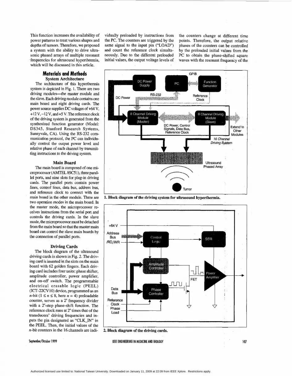
The architecture of this hyperthermia system is depicted in Fig. 1. There are two driving modules-the master module and the slave. Each driving module contains one main board and eight driving cards. The power source supplies DC voltages of t64 V, +12 V, -12 V, and +5 V. The reference clock of the driving system is generated from the synthesized function generator (Model: DS345, Stanford Research Systems, Sunnyvale, CA). Using the RS-232 com- munication protocol, the PC can individu- ally control the output power level and relative phase of each channel by transmit- ting instructions to the driving system.
Main Board The main board is composed of one mi-
croprocessor (AMTEL 89C5 l), three paral- lel ports, and nine slots for plug-in driving cards. The parallel ports contain power lines, control lines, data bus, address bus, and reference clock to connect with the main board in the other module. There are two operation modes in the main board. In the master mode, the microprocessor re- ceives instructions from the serial port and controls the driving cards. In the slave mode, the microprocessor must be detached from the main board so that the master main board can control the slave main boards by the connection of parallel ports.
Driving Cards The block diagram of the ultrasound
driving cards is shown in Fig. 2. The driv- ing card is inserted in the slots on the main board with 62 golden fingers. Each driv- ing card includes four units: phase shifter, amplitude controller, power amplifier, and on-off switch. The programmable electrical erasable logic (PEEL) (ICT-22CV10) device, programmed as an n-bit (1 2 n 5 8, here n = 4) preloadable counter, serves as a 2" frequency divider with a 2'-step phase-shift function. The reference clock runs at 2" times that of the transducers' driving frequencies and in- puts the pin designated as "CLK-IN in the PEEL. Then, the initial values of the n-bit counters in the 16 channels are indi-
vidually preloaded by instructions from the PC. The counters are triggered by the same signal to the input pin (''LOAD) and count the reference clock simulta- neously. Due to the different preloaded initial values, the output voltage levels of
the counters change at different time points. Therefore, the output relative phases of the counters can be controlled by the preloaded initial values from the PC to obtain the phase-shifted square waves with the resonant frequency of the
DC Power, Control Signals, Data Bus, Reference Clock
16 Channel I Driving System * * Ultrasouno
Phased Array
a Tumor
1. Block diagram of the driving system for ultrasound hyperthermia.
+64V - I _ I . Phase Load - Id 2. Block diagram of the driving cards.
Septomber/Ottobor 1999 IEEE ENGINEERING IN MEDICINE AND BIOLOGY 101
Authorized licensed use limited to: National Taiwan University. Downloaded on January 11, 2009 at 22:09 from IEEE Xplore. Restrictions apply.
ultrasound transducer. Here, we empha- sized that the PEEL device can be easily programmed for different bit counters to individually divide the frequency of the same reference clock for concurrently driving different operating frequencies of the ultrasound transducers.
The aforementioned phase-shifted square wave inputs to the gate. of the FET. The voltage of the FET drain depends on the digital input of ,the digital-to-analog con- verter (AD7524). The output signal of the FET, serving as the input to the power am- plifier, is adjusted for the relative phase and amplitude by the counter and amplitude controller. In this manner, the PC can con- trol the output parameters of each channel.
The power amplifier comprises three stages: preamplifier, push-pull amplifier, and class A power amplifier. In the preamplifier, the square wave from the E T output is filtered to become a sine wave by an RC low-pass filter. The filtered sine wave inputs to the base of a 2N3904 transistor that operates in a common emit-
ter configuration. 2N2219 and 2N2905 transistors serve as a push-pull amplifier to support sufficient input current for the next stage. The output stage is constructed with a pair of RF power MOSFETs (IRF 450) with a transformer of 3:2 coupling. This transformer isolates the connected applica- tors and ensures electrical safety. A solid-state relay (SSR), used as a power switch for the +64 V power source, is con- trolled by instructions from the PC to select which channels to turn on or off. If over- heating occurs during the hyperthermia treatment, the power switch can be turned off automatically by the PC program.
Tests for System Performance The driving system has been tested for
output power with respect to the input am- plitude level, power stability, relative phase shifts, and frequency response. The equipment for these tests are a digital power meter (Model: 4421, BIRD, Cleve- land, OH) and a digital storage oscillo- scope (DSO; Model: 9310A, LeCroy, Geneva, Switzerland). The DSO can pres- ent statistics of the real-time stability of measured signals. In these tests, auto- matic measurement has been realized by a general-purpose interface bus (GPIB) in- terface. The system is warmed up for at least 10 minutes to achieve thermal steady state before the tests are carried out.
Results Output Power vs.
Input Amplitude Level For this test, the output of each channel
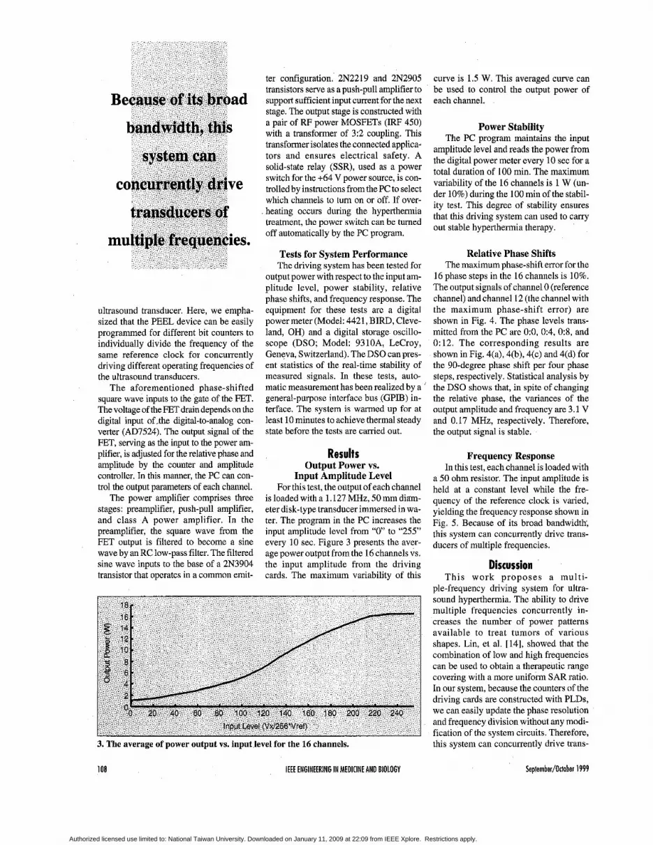
is loaded with a 1.127 MHz, 50 mm ditim- eter disk-type transducer immersed in wa- ter. The program in the PC increases the input amplitude level from “0” to “255” every 10 sec. Figure 3 presents the aver- age power output from the 16 channels vs. the input amplitude from the driving cards. The maximum variability of this
18. 16 *
Input Level (Vxl256‘Vret)
3. The average of power output YS. input level for the 16 channels.
108 IEEE ENGINEERING IN MEDICINE AND BIOLOGY
curve is 1.5 W. This averaged curve can be used to control the output power of each channel.
Power Stability The PC program maintains the input
amplitude level and reads the power from the digital power meter every 10 sec for a total duration of 100 min. The maximum variability of the 16 channels is 1 W (un- der 10%) during the 100 min of the stabil- ity test. This degree of stability ensures that this driving system can used to carry out stable hyperthermia therapy.
Relative Phase Shifts The maximum phase-shift error for the
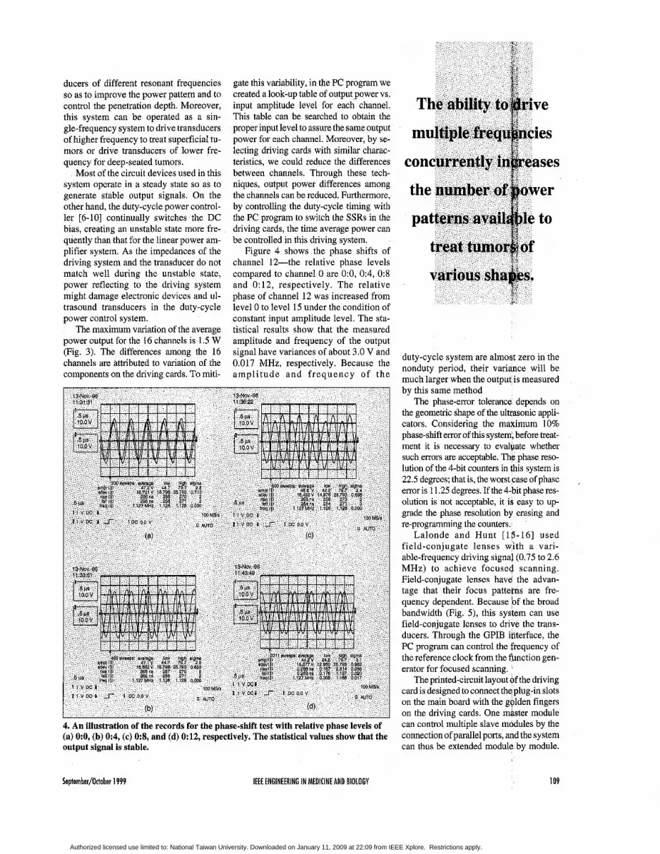
16 phase steps in the 16 channels is 10%. The output signals of channel 0 (reference channel) and channel 12 (the channel with the maximum phase-shift error) are shown in Fig. 4. The phase levels trans- mitted from the PC are O:O, 0:4, 09 , and 0: 12. The corresponding results are shown in Fig. 4(a), 4(b), 4(c) and 4(d) for the 90-degree phase shift per four phase steps, respectively. Statistical analysis by the DSO shows that, in spite of changing the relative phase, the variances of the output amplitude and frequency are 3.1 V and 0.17 MHz, respectively. Therefore, the output signal is stable.
Frequency Response In this test, each channel is loaded with
a 50 ohm resistor. The input amplitude is held at a constant level while the fre- quency of the reference clock is varied, yielding the frequency response shown in Fig. 5. Because of its broad bandwidth, this system can Concurrently drive trans- ducers of multiple frequencies.
Discussion This work proposes a multi-
ple-frequency driving system for ultra- sound hyperthermia. The ability to drive multiple frequencies concurrently in- creases the number of power patterns available to treat tumors of various shapes. Liu, et al. [14], showed that the combination of low and high frequencies can be used to obtain a therapeutic range covering with a more uniform SAR ratio. In our system, because the counters of the driving cards are constructed with PLDs, we can easily update the phase resolution and frequency division without any modi- fication of the system circuits. Therefore, this system can Concurrently drive trans-
Seplernber/Otlober 1999
Authorized licensed use limited to: National Taiwan University. Downloaded on January 11, 2009 at 22:09 from IEEE Xplore. Restrictions apply.
ducers of different resonant frequencies so as to improve the power pattern and to control the penetration depth. Moreover, this system can be operated as a sin- gle-frequency system to drive transducers of higher frequency to treat superficial tu- mors or drive transducers of lower fre- quency for deep-seated tumors.
Most of the circuit devices used in this system operate in a steady state so as to generate stable output signals. On the other hand, the duty-cycle power control- ler [6-10] continually switches the DC bias, creating an unstable state more fre- quently than that for the linear power am- plifier system. As the impedances of the driving system and the transducer do not match well during the unstable state, power reflecting to the driving system might damage electronic devices and ul- trasound transducers in the duty-cycle power control system.
The maximum variation of the average power output for the 16 channels is 1.5 W (Fig. 3). The differences among the 16 channels are attributed to variation of the components on the driving cards. To miti-
gate this variability, in the PC program we created a look-up table of output power vs. input amplitude level for each channel. This table can be searched to obtain the proper input level to assure the same output power for each channel. Moreover, by se- lecting driving cards with similar charac- teristics, we could reduce the differences between channels. Through these tech- niques, output power differences among the channels can be reduced. Furthermore, by controlling the duty-cycle timing with the PC program to switch the SSRs in the driving cards, the time average power can be controlled in this driving system.
Figure 4 shows the phase shifts of channel 12-the relative phase levels compared to channel 0 are 0:0, 0:4, 0:8 and 0:12, respectively. The relative phase of channel 12 was increased from level 0 to level 15 under the condition of constant input amplitude level. The sta- tistical results show that the measured amplitude and frequency of the output signal have variances of about 3.0 V and 0.017 MHz, respectively. Because the ampl i tude and frequency of the
4. An illustration of the records for the phase-shift test with relative phase levels of (a) O:O, (b) 0:4, (c) 0:8, and (d) 0:12, respectively. The statistical values show that the output signal is stable.
duty-cycle system are almost zero in the nonduty period, their variance will be much larger when the output is measured by this same method
The phase-eror tolerance depends on the geometric shape of the ultcasonic appli- cators. Considering the maximum 10% phase-shift emor of this system, before treat- ment it is necessary to evalpate whether such errors are acceptable. The phase reso- lution of the 4-bit counters in this system is 22.5 degrees; that is, the worst case of phase error is 11.25 degrees. If the 4-bit phase res- olution is not acceptable, it is easy to up- grade the phase resolution by erasing and re-programming the counters.
Lalonde and Hunt [15-16] used field-conjugate lenses with a vari- able-frequency driving signal (0.75 to 2.6 MHz) to achieve focused scanning. Field-conjugate lenses have the advan- tage that their focus patterns are fre- quency dependent. Because of the broad bandwidth (Fig. 5), this system can use field-conjugate lenses to drive the trans- ducers. Through the GPIB interface, the PC program can control the frequency of the reference clock from the function gen- erator for focused scanning.
The printed-circuit layo card is designed to connect on the main board with the golden fingers on the driving cards. One master module can control multiple slave modules by the connection of parallel ports, and the system can thus be extended module by module.
September/October 1999 IEEE ENGINEERING I N MEDICINE AND BIOLOGY 109
Authorized licensed use limited to: National Taiwan University. Downloaded on January 11, 2009 at 22:09 from IEEE Xplore. Restrictions apply.

With this design, it is convenient to extend and maintain the driving system.
Conclusion Above all, the driving system is able
to: (1) drive multi-element applicators or phased arrays of a single resonant fre- quency through the multichannel linear power amplifiers, (2) concurrently drive transducers with different resonant fre- quencies, (3) adjust the relative phase and output power of each channel for the scanning ultrasonic focus, and (4) oper- ate each channel with good output stabil- ity. This driving system has the flexibility to drive transducers of higher frequency for superficial tumors or lower frequency for the deep-seated tumors. Through the proper design of ultrasound applicators, this driving system can be applied as an adjuvant treatment with other medical therapies.
0.5 1 .o 1.5 2.0 2.5 3.0 Frequency (MHz)
Acknowledgments The authors thank the National sei-
ence council and the Department of Health of the Republic of China for par-
particularly in the areas of developing high-power ultrasound devices for hyperthermia and other medical therapies.
Technology, Atlanta, in 1967 and 1970, respectively. From 1963 to 1964, he had a one-year study on digital computers in the
tially supporting this research (NSC 87-2213-E-002-075 and DOH 87-HR-635).
Bing-Yuh Lu received a B.S. in electrical engi- neering from National Central University, Chungli, Taiwan, in 1988 and an M.S. in electrical engineering from National Taiwan University, Taipei, Tai-
wan, in 1993. From 1988 to 1990, he served in the military in the R.O.C. Army. He is a Ph.D. candidate in electrical engi- neering at National Taiwan University. Since 1993, he has been an instructor in the Department of Electronic Engineering at Tung-Nan Junior College of Technology, Taipei, Taiwan. His fields of interest are therapeutic ultrasound and microprocessor applications in medical engineering.
Win-Li Lin received an M.S. from the Univer- $ity of Iowa, Iowa City, in 1983 andaPh.D. from the University of Ari- zona, Tucson, in 1990. From 1990 to 1992, he was a researcher at the Industrial Technology
Research Institute, developing ultrasound diagnostic equipment. In 1992, he joined the faculty of National Taiwan University, Taipei, Taiwan, R.O.C., where he reached the rank of a Research Associate Professor of Biomedical Engineering. He has been interested in biomedical related research,
Yung-Yaw Chen re- ceived a B.S. in electri- cal engineering from National Taiwan Uni- versityin 1981,andthe Ph.D. degree in electri- cal engineering and computer science from Universitv of Califor-
nia, Berkeley, in 1989. He was with the Art i f ic ia l Intel l igence branch of NASA-Ames in 1989. From 1993 to 1994, he was a visiting scholar at the University of California, Berkeley. He has been with the Department of Electri- cal Engineering at National Taiwan University as an associate professor since 1989. His research interests in- clude fuzzy logic control, precision mo- tion control, intelligent systems, and ultrasound hyperthermia.
Rong-Sen Yung gradu- ated from the College of Medicine at Na- tional Taiwan Univer- s i ty i n 1982. His resident training has was completed at the Department of Ortho- pedics at National Tai-
wan University Hospital in 1989. Thereafter, he studied at the Graduate Institute of Clinical Medicine of Na- tional Taiwan University and received a Ph.D. degree in 1992. At present, he is a professor and orthopedic surgeon at Na- tional Taiwan University. His clinical subspecialty fields include orthopedic oncology, bone metabolism, osteoporo- sis, and bone cell physiology. He has
, been the national deleeate of the
Authorized licensed use limited to: National Taiwan University. Downloaded on January 11, 2009 at 22:09 from IEEE Xplore. Restrictions apply.
lands. He was a visiting assistant professor in the Electrical Engineering Department at Texas A&M University, College Station, in 1970. From 1970 to 1973, he was an associate professor and became a full professor in 1973, then served as department head f rom 1975-1981, all in the Department of Elec- trical Engineering, National Taiwan Uni- versity, where he is now a full professor. He has also held ajoint appointment with the Institute of Biomedical Engineering at National Taiwan University since Febru- ary 1993. His fields of interest are com- puter-aided design, control systems, and biomedical engineering.
Cheng-Yi Wang, MD, Dr. Med. Sci., is amedi- cal doctor specialized in internal medicine and gastroenterology. He graduated from Na- tional Taiwan Univer- sity Col lege of Medicine in 1965 and
received his doctor degree in Tokyo, Ja- pan, in 1976, and his medical residency was completed with the National Taiwan University Hospital (1966-1970). He is an expert in gastrointestinal endoscopy and has published more than 100 papers in the studies of peptic ulcer, gastric cancer, in- flammatory bowel diseases, colorectal cancer, malabsorption, hepatitis, cirrho- sis, and hepatocellular cancer. He is the founding chairman of the Department of Biomedical Engineering in the hospital and also the founding chairman of the Center for Biomedical Engineering at the College of Medicine, NTU. He has en- gaged greatly in biomedical engineering educational programs and research in the past 10 years (1987-1998) and has already
published more than 50 papers on bio- medical engineering. He has organized four international symposiums on “bio- medical engineering in the 21st century” (1990,1992,1994, and 1996).Heis adep- uty director of the NTUH and also profes- sor of internal medicine at theInstitute of Biomedical Engineering, NTU. He is also president of the Digestive Endoscopy So- ciety of Taiwan (1995-present) and past president of the Biomedical Engineering Society ofR.0.C. (Taiwan) (1993-1996).
Address for Correspondence: Win-Li Lin, Institute for Biomedical Engi- neering, National Taiwan University, No. 1, sec. 1, Jen-Ai Road, Taipei, Tai- wan, Tel: 886-2-23970800, ext. 1445. fax : 886-2-23940049. E-mail : d83048 @me.ee.ntu.edu.tw.
References 1. Seegenschmiedt MH, Fessenden P, Vernon CC: Thermoradiotherapy and Thermo-chemo- therapy, Springer-Verlag. 1995. 2. Overgaard J: The current and potential role of hyperthermia in radiotherapy. Int JRadiat Oncol Biol Phy 16:535-549, 1989. 3. Vernon CC, Hand JW, Neld SB, Machin D, Whaley JB, e t al.: Radiotherapy with or without hyperthermia in the treatment of superficial local- ized breast cancer: Results from five randomized controlled trials, Int J Radiat Oncol Biol Phys 35(4):731-744, 1996. 4. Sneed PK, Stauffer PR, McDermott MW, Diederich CJ, Lamborn KR, et al.: Survival benefit of hyperthermia in a prospective random- ized trial of hrachytherapy hoot - Hyperthermia for glioblastoma multiforme. Int J Radiat Oncol Bio Phys 40287-295, 1998. 5 . Ogilvie GK, Reynolds HA, Richardson BC, Badger CW, Goss SA, etc.: .Performance of a multi-sector ultrasound hyperthermia applicator and control system: In vivo studies. Int J Hyperthermia 6(3):697-705, 1990.
6. Cain CA, Umemnra SI: Concentric-ring and sector-vortex phased-array applicators for nltra- sound hyperthermia. IEEE Trans Microwave Theo Tech 34542-551, 1986. 7. Cain CA, Umemura SI: the sector-vortex phased array: acoustic field synthesis for hyperthermia. IEEE Trans Ultrason Ferroelec Freq Contr 36(2):249-257, 1989. 8. Ehhini ES, Umemura SI, Ibhinl N, and Cain CA: A cylindrical-section ultrasound phased ar- ray applicator for hyperthermia cancer therapy. IEEE Trans Biomed Eng 35(5):561-572,1988. 9. Ehhini ES, Cain CA: Experimental evaluation of a prototype cylindrical section ultrasound hyperthermia phased array applicator. IEEE T r a n s U l t r a s o n F e r r o e l e c F r e q C o n t r 38(5):5 10-520, 199 1. 10. Buchanan MT, Hynynen K Design and ex- perimental evaluation of an intracavitary ultra- sound phased array system for hyperthermia. IEEE Trans Biomed Eng 41(12):1178-1187, 1994. 11. Daum DR, Hynynen K Thermal dose opti- mization via temporal switching in ultrasound surgery. IEEE Trans Ultrason Ferroelec Freq Contr 45(1):208-215, 1998. 12. Goss SA, Frizzell LA, Konzmanoff JT, Barich JM,YangMJ: Sparse randomultrasonnd phased array for local surgery. IEEE Trans Ultrason Ferroelec Freq Conrr43(6)1111-1121, 1996. 13. Moros EG, Fan X, Stranhe WL: Penetration depth control with dual frequency ultrasound, Proc. ASME Int Mech Engng Cong and Expos, Atlanta, pp. 59-65, 1996. 14. Lin WL, Yen JY, Chen YY, Cheng KS, Shieh M J Specific absorption rate ratio patterns of cylinder ultrasound transducers for breast tu- mor. Med Phy 25(6):1041-1048, 1998. 15. Lalunde RJ, Worthington A, Hunt JW: Field conjugate acoustic lenses for ultrasound hyperthermia, IEEE Trans Ultrason Ferroelec Freq Contr 40(5):529-602, 1993. 16. Lalonde RJ, Hunt JW: Variable frequency field conjugate lenses for ul t rasound hyperthermia, IEEE Trans Ultrason Ferroelec Freq Contr 42(5):825-831, 1995.
Brain Teaser ANSWERS lfrompage36)
1. Seven-year-olds do not have wives in Chicago, and fathers rarely confuse their children’s names. This type of logic yields Mr White as president, Mr. Green as professor, Mr. Black as instructor, and Mr. Green as handyman.
2. Frank (winner), Joe, Jane, Tom, Joan.
3. There are five permutations of any five numbers. The probability is thus: 1/5 x 4 x 3 x 2 x 1 = 1/120.
September/Odober 1999 IEEE ENGINEERING I N MEDICINE AND BIOLOGY 111
Authorized licensed use limited to: National Taiwan University. Downloaded on January 11, 2009 at 22:09 from IEEE Xplore. Restrictions apply.