a lighting mechanism for flat electron emission lamp
TRANSCRIPT
13
A Lighting Mechanism for Flat Electron Emission Lamp
Jung-Yu Li et al.* Green Energy and Environment Research Laboratories,
Industrial Technology Research Institute, Hsinchu, Taiwan
1. Introduction
A novel lighting device, flat electron emission lamp (FEEL), has been developed for generating planar light. The mechanism of FEEL is different from the mainstream techniques for lighting and display. The basic idea for FEEL is, for the first time, to integrate the discharge mechanisms of fluorescent lamp at cathode with the cathodoluminescent effect at anode. In that the electrons are induced by gas discharge, accelerated toward anode under electrical field, and finally impacting the phosphor-coated anode to emit visible light. The light spectrum radiated from FEEL is thus, dominated by the detailed composition of the phosphor coated on the anode. Unlike most of the fluorescent lamps, ultraviolet light is unnecessary in this case, and therefore there is no need to have mercury inside the device. By taking into account the human factors, such as safety and health, the uniform lighting obtained in FEEL further offers a prominent characteristic which prevents the eyes from the uncomfortable glare and drastically improves the persistence of vision. In this article we also demonstrate various prototype potential applications featured by FEEL, namely the double-side lighting, transparency, colored gray-scale image and heat insulation, etc. It is indicative that FEEL not only could have broad potential markets for normal lighting, but also might play a prominent role in power-saving building material and gray-scale ambiance lighting. More importantly, the unique mechanism prevailing in FEEL shows the high flexibility of expanding its applicability albeit it is still in the early stage of laboratory studies. We believed that it may become one of the competing candidates for the next generation green lighting in the near future.
2. Motivation of the technique development
In the nineteenth century, the new electrical lighting, incandescent lamp, was invented and had totally changed the human behavior and social environment in the early stage of electrical power generation. Hereafter many different kinds of lighting and display technologies were
*Ming-Chung Liu1, Yi-Ping Lin1, Shih-Pu Chen1, Tai-Chiung Hsieh1,2, Po-Hung Wang1, Chang-Lin Chiang1,2, Ming-Shan Jeng1, Li-Ling Lee1, Hui-Kai Zeng3 and Jenh-Yih Juang1,2
1Green Energy and Environment Research Laboratories, Industrial Technology Research Institute, Chutung, Taiwan 2Department of Electrophysics, National Chiao Tung University, Hsinchu, Taiwan 3Department of Electronic Engineering, Chung Yuan Christian University, Chung Li, Taiwan
Cathodoluminescence
306
developed vigorously for illuminating every corner in the world. At present, the major branches of lighting techniques can be catalogued into four kinds of mechanisms: (1) Fluorescent Lamps (FL) (2) Cathodoluminescence (CL) (3) Solid-state lightings (SSL) (4) Gas-discharge lamps (GDL). All of these technologies have been developing for several decades and spread into broad range of daily applications. The maturity and wide-spread industrialization of these techniques have, consequently, led the manufacturing of most lighting and/or display equipments to be confined within the concepts derived from these mechanisms.
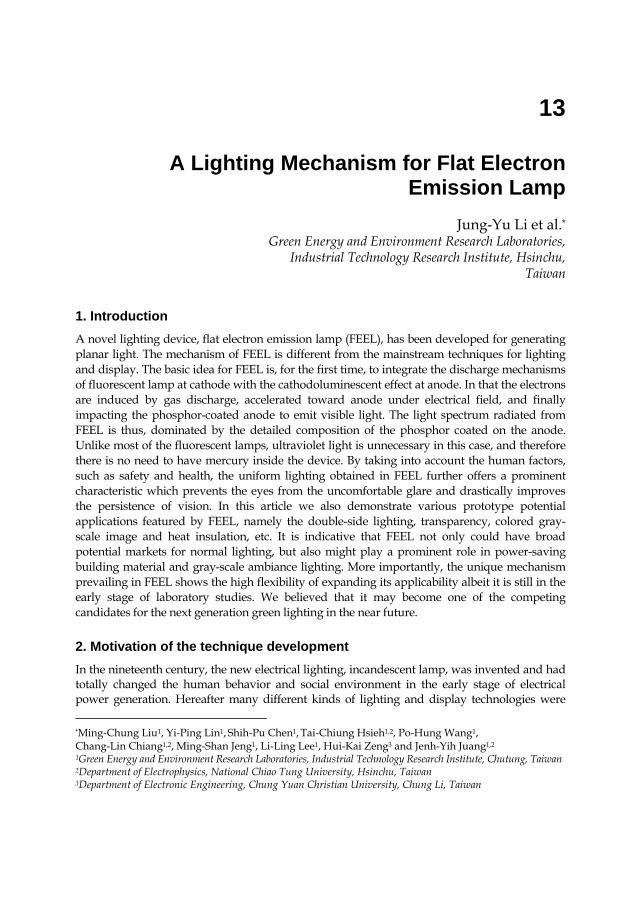
In this chapter, a novel lighting device, flat electron emission lamp (FEEL), for generating uniform planar light with competitive power efficiency in an environmentally recuperative manner is described. The lighting mechanism prevailing in FEEL is different from that operating in the mainstream techniques, such as FL, CL, SSL, and GDL. The originality is primarily based on the innovative integration of the working mechanisms of FL and CL. As depicted schematically in Fig. 1, the lighting model of FEEL can be clearly interpreted by dividing it into three steps: (1) Analogous to FL mechanism, the secondary electron emissions are generated by ion bombardment at the cathode surface. It is noted that, in FEEL, the gas pressure used to initiate the production of electrons is significantly lower than that used in FL, being in the range of 10-1 to 10-2 torr. (2) The electrons are subsequently accelerated by the electric field established between the cathode and the anode. During the course of flight, the gas excitation and ionization are induced by electron collision with gas. The probability of electron collision depends on the pressure, electron kinetic energy and gas type. (3) As an analogy to the anode structure of CL, electrons impact with CL phosphor-coated anode and transfer the kinetic energy to the emission of visible light. Evidently, over the whole process of lighting in FEEL, ultraviolet light is unnecessary and therefore there is no need to have mercury inside the device. Thus, the mechanism meets requirements for developing green lamps by completely avoiding the pollution issues from the involvement of mercury.
Fig. 1. The lighting mechanism of FEEL is proposed by integrating the mechanisms operating at the cathode of FL and the anode of CL. Briefly, the electrons are induced by discharge in the vicinity of cathode, accelerated by electrical field, and finally impacts on the phosphor-coated anode, which gives rise to the eventual light emission by transferring the electron kinetic energy into phosphorous radiations. The combination is advantageous in generating large area planar electron beams for obtaining uniform photon distributions over the entire CL phosphor screen.
A Lighting Mechanism for Flat Electron Emission Lamp
307
So far FL is the most mature technology for general daily lighting, while CL has been ubiquitously used in the long history of the display technology. For instance, the fluorescent tubes and plasma display panels (PDP) belong to the field of FL mechanism, while the cathode ray tube (CRT), field emission display (FED), and field emission lamp (FEL) are all based on CL mechanism. It is interesting to note that over the long history of development in the two respective fields there was essentially no overlap between FL and CL technologies. In fact, they are working at very different gas pressure conditions. From the required conditions of FL, it is necessary to infuse a sufficient amount of gas (in the range of 100 torr) in order to sustain the stable glow discharge; it is also necessary to further produce high enough ultraviolet intensity during the discharge process to maintain photoluminescence effect for obtaining the visible light radiated from photoluminescence phosphor. On the contrary, in the case of CL, high vacuum environment (< 10-6 torr) is essential for reducing energy dissipation from electron scattering. The suitable vacuum pressure conditions for FL and CL can be different by eight orders magnitude or even larger. As will be discussed in more details later, the working pressure in the current FEEL device is in a more compromised condition, which is in the middle range between the pressure of FL and CL, and, hence exhibiting some unique features that were not fully explored previously.
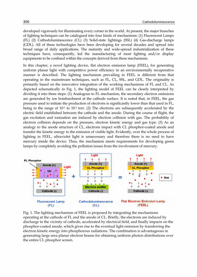
In contrast to the traditional line or point shaped lighting sources, the planar lighting sources with the uniform light have the important advantage of no glare, thus can create a comfortable lighting environment. The mercury-free field emission-like (FEL) lighting technology has been one of the potential candidates for the planar lighting or backlighting applications. Unfortunately, the random dark points constantly appearing in the lighting screen of FEL have severely hindered its market development. Usually, an additional diffuser covering the entire the device surface to obtain uniform light emission is required. However, the extra diffuser also reduces the effective lighting intensity of the lamp. Thus, either from the consideration of cost down or from the view point of energy-saving, the issue of dark points has become one of the technology bottlenecks for FEL. The primary source of such non-uniform light emission is attributed to the grown-in disorders during the growth of nanoscale electron emitters. For instance, one of the most favored materials for electron emitter, the carbon nanotubes (CNTs), turned out to be very difficult to control the uniformity of nanotube length and alignment over large area by the processes of screen printing or direct growth. To this respect, the gas discharge and emitter-free characteristic of FEEL provides an alternative solution for easily generating planar beam-like electrons from cathode. As an example, the lighting screen shown in Fig. 2 for a typical FEEL device evidently demonstrates the complete elimination of the dark points. In addition, it also avoids the unfavorable cost and process time spent in growing the electron emitter material. Nevertheless, it should be emphasized that making use of gas discharge in unconventionally low pressure regime is the first attempt for the development of cathodoluminescence technology and further understandings of the detailed mechanisms are certainly needed.
3. The lighting mechanism
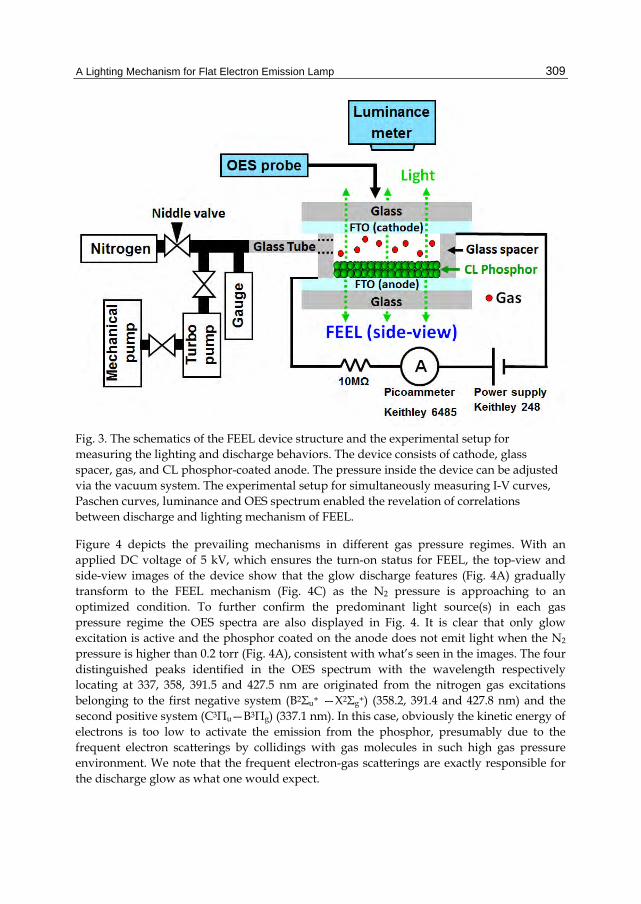
In order to investigate the intrinsic discharge property of FEEL, an experimental setup was established for simultaneously measuring current-voltage (I-V) curves, Paschen curves, luminance and optical emission spectroscopy (OES) of FEEL device. As illustrated in Fig. 3, the experimental FEEL device consists of a cathode glass, a glass spacer, and a
Cathodoluminescence
308
CL phosphor-coated anode glass. The electrode glasses were deposited with a transparent conducting oxide film (fluorine-doped tin-oxide/FTO). The electrode and spacer were sealed by glass glue with infused gas as the working gas. The height of glass spacer was 10 mm and size of lighting screen (phosphor surface) was 30 mm x 30 mm. A glass tube connected the glass spacer and the vacuum system for evacuating and adjusting pressure inside the device. A DC voltage power (Keithley 248) and a picoammeter (Keithley 6485) were used for analyzing the discharge and electrical behavior; a Multi-function Color Analyzer (Ruyico Tech.) and an OES (optical emission spectroscopy) probe (StekkarNet EPP200V) were positioned on top of device for measuring the optical properties. The OES spectrum was measured to further reveal the correlated behaviors between glow excitations and the lighting mechanism of FEEL devices. To obtain the optimal conditions for FEEL lighting, the gas pressure inside the device was gradually decreased and the transitions of the lighting mode were simultaneously analyzed by observing the images of the lighting screen.
Fig. 2. The photo shows the lighting screen of a typical FEEL device demonstrating the uniform light radiation and absence of dark points ubiquitously encountered in traditional FED devices.
A Lighting Mechanism for Flat Electron Emission Lamp
309
Fig. 3. The schematics of the FEEL device structure and the experimental setup for measuring the lighting and discharge behaviors. The device consists of cathode, glass spacer, gas, and CL phosphor-coated anode. The pressure inside the device can be adjusted via the vacuum system. The experimental setup for simultaneously measuring I-V curves, Paschen curves, luminance and OES spectrum enabled the revelation of correlations between discharge and lighting mechanism of FEEL.
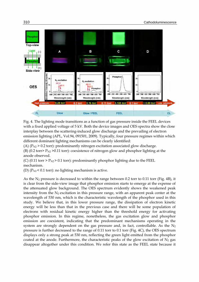
Figure 4 depicts the prevailing mechanisms in different gas pressure regimes. With an applied DC voltage of 5 kV, which ensures the turn-on status for FEEL, the top-view and side-view images of the device show that the glow discharge features (Fig. 4A) gradually transform to the FEEL mechanism (Fig. 4C) as the N2 pressure is approaching to an optimized condition. To further confirm the predominant light source(s) in each gas pressure regime the OES spectra are also displayed in Fig. 4. It is clear that only glow excitation is active and the phosphor coated on the anode does not emit light when the N2 pressure is higher than 0.2 torr (Fig. 4A), consistent with what’s seen in the images. The four distinguished peaks identified in the OES spectrum with the wavelength respectively locating at 337, 358, 391.5 and 427.5 nm are originated from the nitrogen gas excitations belonging to the first negative system (B2Σu+ —X2Σg+) (358.2, 391.4 and 427.8 nm) and the second positive system (C3Πu—B3Πg) (337.1 nm). In this case, obviously the kinetic energy of electrons is too low to activate the emission from the phosphor, presumably due to the frequent electron scatterings by collidings with gas molecules in such high gas pressure environment. We note that the frequent electron-gas scatterings are exactly responsible for the discharge glow as what one would expect.
Cathodoluminescence
310
Fig. 4. The lighting mode transitions as a function of gas pressure inside the FEEL devices with a fixed applied voltage of 5 kV. Both the device images and OES spectra show the close interplay between the scattering-induced glow discharge and the prevailing of electron emission lighting (APL, Vol.94, 091501, 2009). Typically, four pressure regimes within which different dominant lighting mechanisms can be clearly identified: (A) (PN2 > 0.2 torr): predominantly nitrogen excitation associated glow discharge. (B) (0.2 torr> PN2 >0.11 torr): coexistence of nitrogen glow and phosphor lighting at the anode observed. (C) (0.11 torr > PN2 > 0.1 torr): predominantly phosphor lighting due to the FEEL mechanism. (D) (PN2 < 0.1 torr): no lighting mechanism is active.
As the N2 pressure is decreased to within the range between 0.2 torr to 0.11 torr (Fig. 4B), it is clear from the side-view image that phosphor emission starts to emerge at the expense of the attenuated glow background. The OES spectrum evidently shows the weakened peak intensity from the N2 excitation in this pressure range, with an apparent peak center at the wavelength of 530 nm, which is the characteristic wavelength of the phosphor used in this study. We believe that, in this lower pressure range, the dissipation of electron kinetic energy will be less than that in the previous case and there will be some population of electrons with residual kinetic energy higher than the threshold energy for activating phosphor emission. In this regime, nonetheless, the gas excitation glow and phosphor emission are coexistent, indicating that the predominant mechanisms operating in the system are strongly dependent on the gas pressure and, in fact, controllable. As the N2 pressure is further decreased to the range of 0.11 torr to 0.1 torr (Fig. 4C), the OES spectrum displays only a strong peak at 530 nm, reflecting the green light emitted from the phosphor coated at the anode. Furthermore, the characteristic peaks of the glow excitation of N2 gas disappear altogether under this condition. We refer this state as the FEEL state because it
A Lighting Mechanism for Flat Electron Emission Lamp
311
appears to be the dominant lighting mechanism. It is noticed that, although the pressure (0.11 torr) at which the system switches from the glow/FEEL coexistent state to the pure FEEL state (Fig. 4B and Fig. 4C) appears to be somewhat arbitrary, the existence of even a slight portion of glow can affect the luminance of the device dramatically. It suggests that the electron-gas scatterings during the flight journey from cathode to anode can have significant effect on the luminance efficiency.
Lastly, as the pressure of N2 is below P = 0.1 torr, neither any lighting is seen in the images nor any peak is revealed in the OES spectrum. It indicates that the glow excitation of N2 gas and lighting from phosphor emission are all not active under this condition (Fig. 4D). Intuitively, one would expect that at this low pressure condition, the device should be operating similarly to the CL mode prevailing in FED. However, we note that, for FED applications, usually the turn-on electrical field of cathode emitter is well-above order of V/m as indicated by the Fowler-Nordheim (F-N) theory. Consequently, recent development of the cathode emitter for FED was mainly focused to lowering the turn-on electrical field. Indeed, the CNT with its advantageous high aspect ratio has successfully reduced the turn-on field to E = 0.5 ~ 1V/μm. In our case, the estimated electrical field is about 0.5 V/µm, near the turn-on field of CNT. It implies that by combining the glow discharge effect, the present FEEL device has the equivalent effect of CNT field emission. Nevertheless, without glow discharge, there will be no electron because the applied external field is not enough to trigger the FED mechanism, leading to virtually no response in the FEEL device when operated at low gas pressure regime (Fig. 4D).
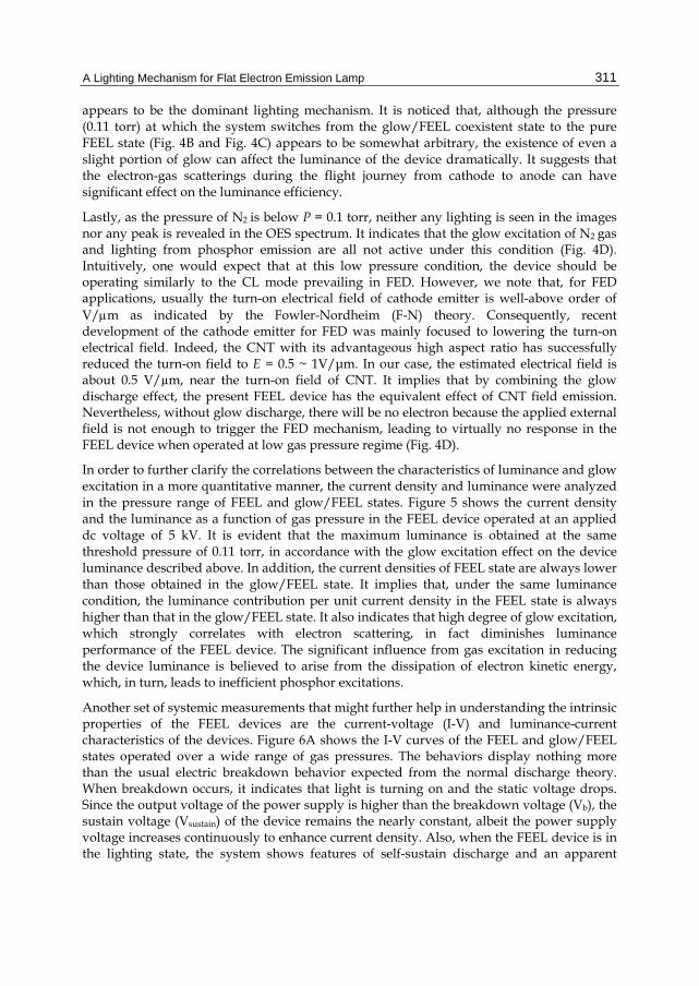
In order to further clarify the correlations between the characteristics of luminance and glow excitation in a more quantitative manner, the current density and luminance were analyzed in the pressure range of FEEL and glow/FEEL states. Figure 5 shows the current density and the luminance as a function of gas pressure in the FEEL device operated at an applied dc voltage of 5 kV. It is evident that the maximum luminance is obtained at the same threshold pressure of 0.11 torr, in accordance with the glow excitation effect on the device luminance described above. In addition, the current densities of FEEL state are always lower than those obtained in the glow/FEEL state. It implies that, under the same luminance condition, the luminance contribution per unit current density in the FEEL state is always higher than that in the glow/FEEL state. It also indicates that high degree of glow excitation, which strongly correlates with electron scattering, in fact diminishes luminance performance of the FEEL device. The significant influence from gas excitation in reducing the device luminance is believed to arise from the dissipation of electron kinetic energy, which, in turn, leads to inefficient phosphor excitations.
Another set of systemic measurements that might further help in understanding the intrinsic properties of the FEEL devices are the current-voltage (I-V) and luminance-current characteristics of the devices. Figure 6A shows the I-V curves of the FEEL and glow/FEEL states operated over a wide range of gas pressures. The behaviors display nothing more than the usual electric breakdown behavior expected from the normal discharge theory. When breakdown occurs, it indicates that light is turning on and the static voltage drops. Since the output voltage of the power supply is higher than the breakdown voltage (Vb), the sustain voltage (Vsustain) of the device remains the nearly constant, albeit the power supply voltage increases continuously to enhance current density. Also, when the FEEL device is in the lighting state, the system shows features of self-sustain discharge and an apparent
Cathodoluminescence
312
negative resistance. It is evident that FEEL works after breakdown occurs, a behavior akin to normal glow discharge. The results also indicate a tendency of lower Vb and Vsustain for higher pressure devices. It suggests that the operation window for FEEL and glow/FEEL states are both located in the left hand side of the Paschen curve, which are sensitively dependent on parameters such as the gas type, cathode material, pressure condition and discharge gap width.
Fig. 5. The current density and luminance as a function of gas pressure inside the FEEL device. A close correlation between luminance efficiency and glow excitation is observed. The characteristic threshold pressure of 0.11 torr distinguishing the regimes of FEEL and glow/FEEL states is consistent with the observations shown in Figure 4.
A Lighting Mechanism for Flat Electron Emission Lamp
313
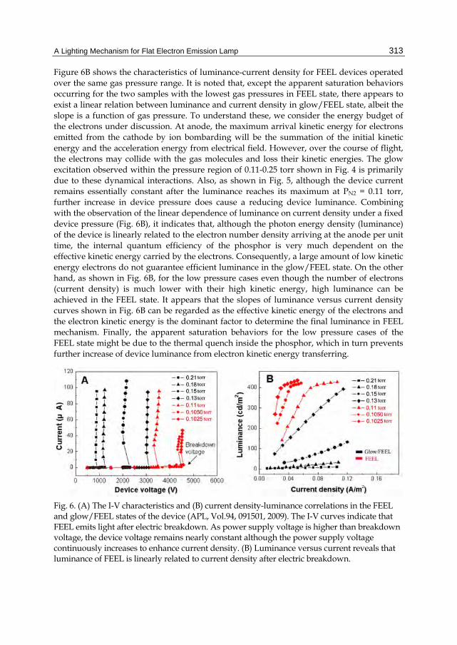
Figure 6B shows the characteristics of luminance-current density for FEEL devices operated over the same gas pressure range. It is noted that, except the apparent saturation behaviors occurring for the two samples with the lowest gas pressures in FEEL state, there appears to exist a linear relation between luminance and current density in glow/FEEL state, albeit the slope is a function of gas pressure. To understand these, we consider the energy budget of the electrons under discussion. At anode, the maximum arrival kinetic energy for electrons emitted from the cathode by ion bombarding will be the summation of the initial kinetic energy and the acceleration energy from electrical field. However, over the course of flight, the electrons may collide with the gas molecules and loss their kinetic energies. The glow excitation observed within the pressure region of 0.11-0.25 torr shown in Fig. 4 is primarily due to these dynamical interactions. Also, as shown in Fig. 5, although the device current remains essentially constant after the luminance reaches its maximum at PN2 = 0.11 torr, further increase in device pressure does cause a reducing device luminance. Combining with the observation of the linear dependence of luminance on current density under a fixed device pressure (Fig. 6B), it indicates that, although the photon energy density (luminance) of the device is linearly related to the electron number density arriving at the anode per unit time, the internal quantum efficiency of the phosphor is very much dependent on the effective kinetic energy carried by the electrons. Consequently, a large amount of low kinetic energy electrons do not guarantee efficient luminance in the glow/FEEL state. On the other hand, as shown in Fig. 6B, for the low pressure cases even though the number of electrons (current density) is much lower with their high kinetic energy, high luminance can be achieved in the FEEL state. It appears that the slopes of luminance versus current density curves shown in Fig. 6B can be regarded as the effective kinetic energy of the electrons and the electron kinetic energy is the dominant factor to determine the final luminance in FEEL mechanism. Finally, the apparent saturation behaviors for the low pressure cases of the FEEL state might be due to the thermal quench inside the phosphor, which in turn prevents further increase of device luminance from electron kinetic energy transferring.
Fig. 6. (A) The I-V characteristics and (B) current density-luminance correlations in the FEEL and glow/FEEL states of the device (APL, Vol.94, 091501, 2009). The I-V curves indicate that FEEL emits light after electric breakdown. As power supply voltage is higher than breakdown voltage, the device voltage remains nearly constant although the power supply voltage continuously increases to enhance current density. (B) Luminance versus current reveals that luminance of FEEL is linearly related to current density after electric breakdown.
Cathodoluminescence
314
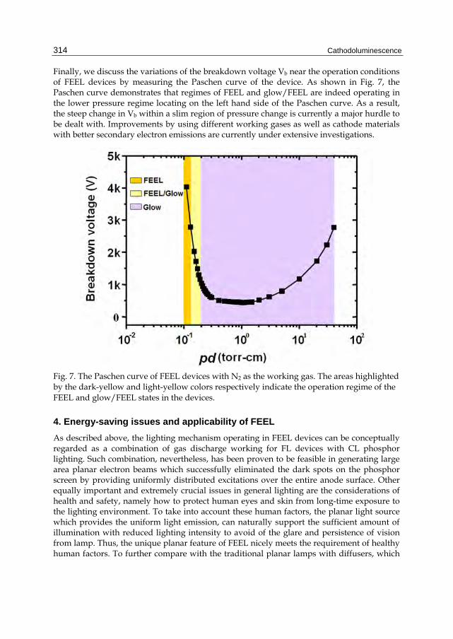
Finally, we discuss the variations of the breakdown voltage Vb near the operation conditions of FEEL devices by measuring the Paschen curve of the device. As shown in Fig. 7, the Paschen curve demonstrates that regimes of FEEL and glow/FEEL are indeed operating in the lower pressure regime locating on the left hand side of the Paschen curve. As a result, the steep change in Vb within a slim region of pressure change is currently a major hurdle to be dealt with. Improvements by using different working gases as well as cathode materials with better secondary electron emissions are currently under extensive investigations.
Fig. 7. The Paschen curve of FEEL devices with N2 as the working gas. The areas highlighted by the dark-yellow and light-yellow colors respectively indicate the operation regime of the FEEL and glow/FEEL states in the devices.
4. Energy-saving issues and applicability of FEEL
As described above, the lighting mechanism operating in FEEL devices can be conceptually regarded as a combination of gas discharge working for FL devices with CL phosphor lighting. Such combination, nevertheless, has been proven to be feasible in generating large area planar electron beams which successfully eliminated the dark spots on the phosphor screen by providing uniformly distributed excitations over the entire anode surface. Other equally important and extremely crucial issues in general lighting are the considerations of health and safety, namely how to protect human eyes and skin from long-time exposure to the lighting environment. To take into account these human factors, the planar light source which provides the uniform light emission, can naturally support the sufficient amount of illumination with reduced lighting intensity to avoid of the glare and persistence of vision from lamp. Thus, the unique planar feature of FEEL nicely meets the requirement of healthy human factors. To further compare with the traditional planar lamps with diffusers, which
A Lighting Mechanism for Flat Electron Emission Lamp
315
are composed of spot or line shaped light sources inside the lamp structure, FEEL doesn’t need extra diffuser to obtain uniform planar lighting from originally concentrated radiation sources. Hence, without energy dissipation from diffuser, FEEL doesn’t need to increase the power to obtain higher radiated intensity for compensating the energy loss from diffuser. It means that even total illumination and input power of the FEEL are reduced for energy saving, it still simultaneously matches the requirements of specification and lighting environment. Obviously, lower material cost and power consumption become the production advantages for FEEL. Besides, to consider the heat extraction issue, FEEL is similar to the planar heat source with low heat density. Without heat concentration, it also doesn’t need special device design for heat extraction.
In addition to planar lighting market, FEEL has high potential to expand its applicability by modifying the device design. We find that, especially in the FEEL anode, there are several methods to adjust the styles of light emission through modifying the phosphor pattern. In the following demonstrations, we illustrate that FEEL not only can be applied to planar lamp, but also can be designed as many kinds of unique lighting productions. For instance, the prototypes of transparent lighting glass, gray-scale image lighting, and colorful image lighting have all been developed.
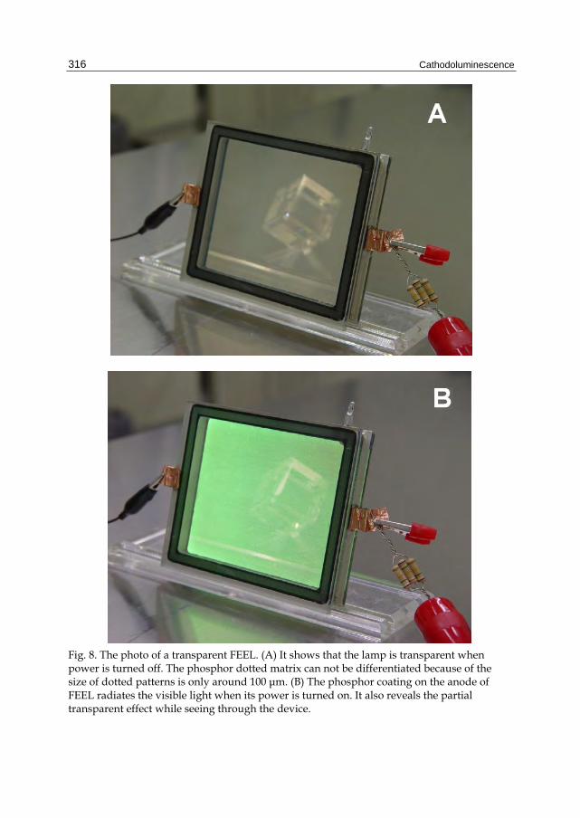
Figure 8 individually reveals the power turned-off and turned-on status of transparent FEEL device. It shows that the FEEL is transparent when its power is turned off (Fig. 8A). In Fig. 8B, the phosphor coating on the FEEL anode radiates the visible light when it is turned on the power. Due to the influence of the light emitted from phosphor, at the turn-on status the transparency of the device is reduced to a lower level. For transparency purpose, in this case transparent FTO films were used as the electrodes of the device. The only opaque material, the phosphor coating on the anode surface, was designed as regular dot-matrix pattern for light transparency. The area of the dot pattern is around 100 m, so the detailed structure of the pattern cannot be differentiated by human eyes. The device transparency could be evaluated by the coverage of phosphor on the whole anode surface. The maximum device transparency is about 60%, which is limited by the transparency of transparent electrodes and total coverage of phosphor. It means that FEEL can be a lighting window to receive the extra natural light in the daytime-indoor, and provides the indoor lighting at night. Additionally, we found that the isolated glass structure and a very small amount of gas inside the 4 inch FEEL device naturally give rise to the property of low heat conductivity (0.07 W/mK), which is about 20% of the heat conductivity of a 4 inch normal glass (1.4 W/mK). The thermal conductivity of the device was measured by thermal conductivity meter (EKO HC-072). It is interesting to note that FEEL is the only lighting technology to have the property of heat isolation. It is very useful for the windows of passive house to prevent the heat from transferring through the FEEL window. In other words, it can preserve the thermal energy inside the house in winter and avoid the outside heat from transferring into the indoor in summer.
It is clear from the above description that FEEL does have the potential of being simultaneously used as the energy-saving thermal insulation window, daylighting system, and indoor lighting in sustainable passive house for saving the power consumption of air-condition in summer, indoor heating in winter or daytime-indoor lighting (Fig. 9). In particular, with the unique features of transparency and heat insulation, it can also meet the demand of the sustainable building material. It may be anticipated that the building’s
Cathodoluminescence
316
Fig. 8. The photo of a transparent FEEL. (A) It shows that the lamp is transparent when power is turned off. The phosphor dotted matrix can not be differentiated because of the size of dotted patterns is only around 100 μm. (B) The phosphor coating on the anode of FEEL radiates the visible light when its power is turned on. It also reveals the partial transparent effect while seeing through the device.
A Lighting Mechanism for Flat Electron Emission Lamp
317
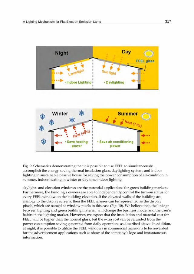
Fig. 9. Schematics demonstrating that it is possible to use FEEL to simultaneously accomplish the energy-saving thermal insulation glass, daylighting system, and indoor lighting in sustainable passive house for saving the power consumption of air-condition in summer, indoor heating in winter or day time indoor lighting.
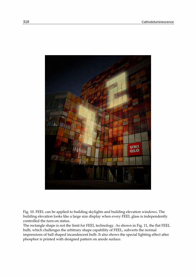
skylights and elevation windows are the potential applications for green building markets. Furthermore, the building’s owners are able to independently control the turn-on status for every FEEL window on the building elevation. If the elevated walls of the building are analogy to the display screens, then the FEEL glasses can be represented as the display pixels, which are named as window pixels in this case (Fig. 10). We believe that, the linkage between lighting and green building material, will change the business model and the user’s habits in the lighting market. However, we expect that the installation and material cost for FEEL will be higher than the normal glass, but the extra cost can be refunded from the power consumption saving generated from daily operations as described above. In addition, at night, it is possible to utilize the FEEL windows in commercial mansions to be rewarded for the advertisement applications such as show of the company’s logo and instantaneous information.
Cathodoluminescence
318
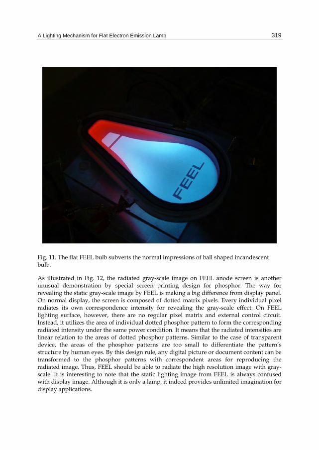
Fig. 10. FEEL can be applied to building skylights and building elevation windows. The building elevation looks like a large size display when every FEEL glass is independently controlled the turn-on status. The rectangle shape is not the limit for FEEL technology. As shown in Fig. 11, the flat FEEL bulb, which challenges the arbitrary shape capability of FEEL, subverts the normal impressions of ball shaped incandescent bulb. It also shows the special lighting effect after phosphor is printed with designed pattern on anode surface.
A Lighting Mechanism for Flat Electron Emission Lamp
319
Fig. 11. The flat FEEL bulb subverts the normal impressions of ball shaped incandescent bulb.
As illustrated in Fig. 12, the radiated gray-scale image on FEEL anode screen is another unusual demonstration by special screen printing design for phosphor. The way for revealing the static gray-scale image by FEEL is making a big difference from display panel. On normal display, the screen is composed of dotted matrix pixels. Every individual pixel radiates its own correspondence intensity for revealing the gray-scale effect. On FEEL lighting surface, however, there are no regular pixel matrix and external control circuit. Instead, it utilizes the area of individual dotted phosphor pattern to form the corresponding radiated intensity under the same power condition. It means that the radiated intensities are linear relation to the areas of dotted phosphor patterns. Similar to the case of transparent device, the areas of the phosphor patterns are too small to differentiate the pattern’s structure by human eyes. By this design rule, any digital picture or document content can be transformed to the phosphor patterns with correspondent areas for reproducing the radiated image. Thus, FEEL should be able to radiate the high resolution image with gray-scale. It is interesting to note that the static lighting image from FEEL is always confused with display image. Although it is only a lamp, it indeed provides unlimited imagination for display applications.
Cathodoluminescence
320
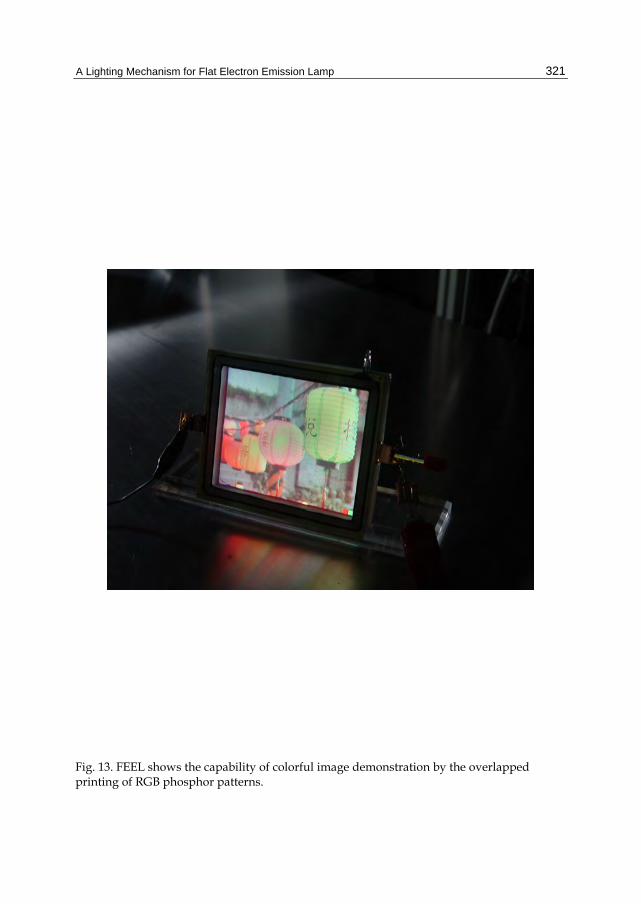
In Fig. 13, we further extend the gray-scale function to show the possibility of using FEEL for colorful image demonstrations. Basically, colorful radiation is linear superposition of three original colors (Red, Green and Blue). It means that any color image can be decomposed into three individual images with original color. As described before, these individual RGB images are further transformed into dotted phosphor patterns in correspondent areas to produce the gray-scale image with single color. At last, RGB phosphor patterns are overlapped (multi-layers) printing on the same anode of FEEL to reveal the color image. Once again, its image resolution looks like the static color picture in display, although there is no display driver and pixel structure inside the device.
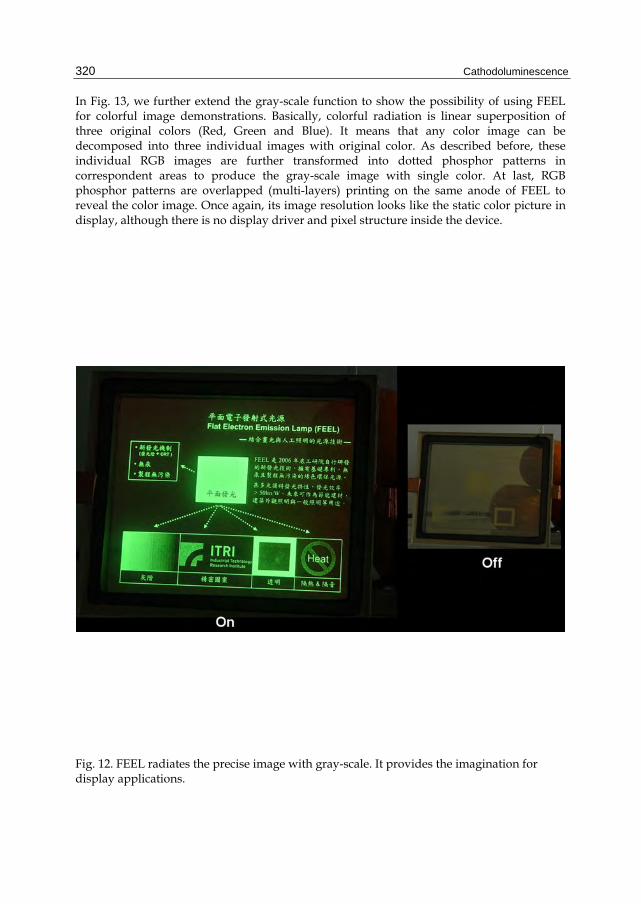
Fig. 12. FEEL radiates the precise image with gray-scale. It provides the imagination for display applications.
A Lighting Mechanism for Flat Electron Emission Lamp
321
Fig. 13. FEEL shows the capability of colorful image demonstration by the overlapped printing of RGB phosphor patterns.
Cathodoluminescence
322
5. Conclusion and remarks
The lighting mechanism for FEEL is based on the innovative integration from mature theories, such as gas discharge and cathodoluminescence. It has been indicated that the working range for FEEL may obey the rule of normal glow discharge, with the features of voltage drop and negative resistance. The measurements of I-V curves, Paschen curve, luminance and OES show that the electron kinetic energy is the dominant factor to determine the final luminance efficiency. The first priority to enhance the luminance efficiency of FEEL is to reduce the electron scattering dissipation by decreasing gas pressure. However, it conflicts with the requirement for stable discharge. In general, it needs sufficient amount of gas for maintaining self-sustain discharge, or higher gas pressure means lower breakdown voltage. The solution to solve such dilemma between low gas pressure and efficient discharge is to improve the secondary electron emission efficiency of cathode material under the low gas pressure environment. It is noticed that the suitable gas type should be carefully selected to match with cathode material for getting higher discharge efficiency. Besides, the optimized phosphor composition and printing process need to be further investigated for obtaining higher quantum efficiency of phosphor. So far, FEEL mechanism shows the high flexibility and potential for applicability in the early stage. It already presents the potential to expand applicability for normal lighting, power-saving building material and gray-scale ambiance lighting. We believe that FEEL could be the candidates of next generation green lighting for providing the comfortable lighting, power-saving, and ambiance applications.
6. Acknowledgments
The authors would like to acknowledge the support from the Energy Fund of Ministry of Economics Affairs, Taiwan. The authors would also like to acknowledge the support from the Energy Foundation. JYJ is supported partially by National Science Council of Taiwan and by MOE-ATU program operated at National Chiao Tung University (NCTU).
7. References
Jung-Yu Li, Shih-Pu Chen, Chia-Hung Li, Yi-Ping Lin, Yen-I Chou, Ming-Chung Liu, Po-Hung Wang, Hui-Kai Zeng, Tai-Chiung Hsieh, and Jenh-Yih Juang (2009). A lighting mechanism for flat electron emission lamp, APPLIED PHYSICS LETTERS, Vol.94, pp.091501-1-091501-3, Taiwan
Chia-Hung Li, Ming-Chung Liu, Chang-Lin Chiang, Jung-Yu Li, Shih-Pu Chen, Tai-Chiung Hsieh, Yen-I Chou, Yi-Ping Lin, Po-Hung Wang, Ming-Shin Chun, Hui-Kai Zeng, and Jenh-Yih Juang (2011). Discharge and photo-luminance properties of a parallel plates electron emission lighting device, Optics Express, Vol.19, pp.A51-A56, Taiwan
T. Jüstel, H. Nikol, C. Ronda (1998). New Developments in the Field of Luminescent Materials for Lighting and Displays, Angew. Chem. Int. Ed, Vol.37, pp. 3084-3103, Germany
A Lighting Mechanism for Flat Electron Emission Lamp
323
M. IImer, R. Lecheler, H. Schweizer, M. Seibold (2000). Hg-free Flat Panel Light Source PLANON - a Promising Candidate for Future LCD Backlights, SID International Symposium, Digest of Technical Papers, XXXI, pp. 931-933, Germany
A. A. Talin, K. A. Dean, J. E. Jaskie (2001). Field emission from carbon nanotubes: the first five years, Solid-State Electronics, Vol.45, pp. 893-914, Switzerland
U. Kogelschatz (2004), Excimer Lamps: History, Discharge Physics, and industrial Applications Proceedings of SPIE, Vol.5483, pp. 272-286, Switzerland
G. G. Lister, J. E. Lawler, W. P. Lapatovich, V. A. Godyak (2004). The physics of discharge lamps, Rev. Mod. Phys., Vol. 76, pp. 541-598, USA
J. P. Boeuf (2003). Plasma display panels: physics, recent developments and key issues, J. Phys. D: Appl. Phys., Vol.36, R53-79, France
M. Itoh, L. Ozawa (2006). Cathodoluminescent phosphors, Annu. Rep. Prog. Chem., Sect. C, Vol.102, pp. 12-42, Japan
Y. X. Liu, J. H. Liu, C. C. Zhu (2009). Flame synthesis of carbon nanotubes for panel field emission lamp, Applied surface science, Vol.255, pp.7985-7989, China
R. W. B. Pearse and A. G. Gaydon (1965). The Identification of Molecular Spectra,3rd ed., Chapman and Hall, pp. 209–220, London
Y. Saito and S. Uemura (2000). Field emission from carbon nanotubes and its application to electron sources, Carbon, Vol.38, pp.169-182, Japan
J.-M. Bonard, H. Kind, T. Stöckli, and L.-O. Nilsson (2001). Field emission from carbon nanotubes: the first five years, Solid-State Electron, Vol.45, pp.893-914, Switzerland
M. J. Druyvesteyn, F. M. Penning (1940). The mechanism of electrical discharges in gases of low pressure , Reviews of Modern Physics, Vol.12, pp.87-174, Holland
M. M Pejović, Goran S Ristić, J. P Karamarković (2002). Electrical breakdown in low pressure gases, J. Phys. D: Appl. Phys., Vol.35, R91-103, Yugoslavia
G. Cho, J. Y. Lee, Dae H. Lee, S. B. Kim, H. S. Song, J. Koo, B. S. Kim, J. G. Kang, E. H. Choi, U. W. Lee, S. C. Yang, J. P. Verboncoeur (2005). Glow Discharge in the External Electrode Fluorescent Lamp, IEEE Transactions On Plasma Science, Vol.33, pp.1410-1415, Korea
J. Reece Roth (1995). Industrial Plasma Engineering-V.1 : Principle, Institute of Physics, p.353, London
Yuri P. Raizer (1991). Gas discharge physics, Springer-Verlag Berlin Heidelberg, pp.134-135, New York
A. Miller (1988). Conflguration-independent minimum voltage for the Townsend model of breakdown in gases, J. Appl. Phys., Vol.63, pp.665-667, New Jersey
Nikolai N. Chubun, Andrei G. Chakhovskoi, Charles E. Hunt (2003). Efficiency of cathodoluminescent phosphors for a field-emission light source application, J. Vac. Sci. Technol. B, Vol.21, pp.1618-1621, California
J. J. Rocca, J. D. Meyer, M. R. Farrell, G. J. Collins (1984). Glow-discharge-created electron beams: Cathode materials, electron gun disigns, and technological applications, J. Appl. Phys., Vol.56, pp.790-797, Colorado
Cathodoluminescence
324
A.P. Bokhan, P.A. Bokhan and D.E. Zakrevsky (2005). Peculiarities of electron emission from the cathode in an abnormal glow discharge, Appl. Phys. Lett., Vol.86, pp.1-3, Russia
P. Hartmann, H. Matsuo, Y. Ohtsuka, M. Fukao, M. Kando, and Z. Donko (2003). Heavy-particle hybrid simulation of a high-voltage glow discharge in helium, Jpn. J. Appl. Phys., Vol.42, pp.3633-3640, Hungary