a guide to marine air compressors on ships
TRANSCRIPT

Marine Air Compressor
by
A GUIDE TO

About
Marine Insight©
“A Guide to Marine Air Compressors on Ships”
Publication date: Nov - 2019 Author: Marine InsightEditor : Raunek Kantharia
Published by: Marine Insightwww.marineinsight.com
Graphic Design: Anish Wankhede Copyright 2019 Marine Insight
NOTICE OF RIGHTS
All rights reserved. No part of this book may be rewritten, reproduced, stored in a retrieval system, transmitted or distributed in any form or means, without prior written permission of the publisher.
NOTICE OF LIABILITY
The authors and editors have made every effort possible to ensure the accuracy of the information provided in the book. Neither the authors and Marine Insight, nor editors or distributors, will be held liable for any damages caused either directly or indirectly by the instructions contained in this book, or the equipment, tools, or methods described herein.

Table Of Content TOC
1. Introduction
2. Construction
3. Operation
4. Safety
5. Maintenance and Troubleshooting

Chapter 1Introduction

Introduction CH-1
A compressor is one such multipurpose device which finds many applications on a ship.
The main aim of the compressor, as the name suggests, is to compress air or a fluid to reduce its volume.
Introduction CH-1
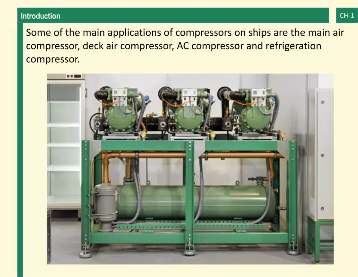
Some of the main applications of compressors on ships are the main air compressor, deck air compressor, AC compressor and refrigeration compressor.

Introduction CH-1
APPLICATIONS OF AIR COMPRESSOR
An air compressor is used in almost all sorts of industries and has several household requirements. In the maritime sector as well, air compressors are used in all essential machinery systems on ships.
Compressors can be used in processes ranging from cleaning of the filters to more significant and crucial tasks such as starting main or secondary engines of the ship.
Air compressor produces pressurized air by decreasing the volume of air and in turn increasing its pressure. Different types of air compressors are used on ships according to the usage.
In a more technical language, an air compressor can be defined as a mechanical device in which electrical or mechanical energy is transformed into pressure energy in the form of pressurized air.

Introduction CH-1
Air compressor works on the principles of thermodynamics. According to the ideal gas equation without any temperature difference, with an increase in gaseous pressure, its volume reduces.

Introduction CH-1
The air compressor works on the same principle on which it produces compressed air, by reducing the volume of air this reduction in volume results in an increase in air pressure without any temperature difference.
TYPES OF AIR COMPRESSOR
Introduction CH-1
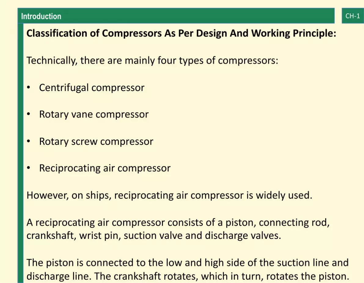
Classification of Compressors As Per Design And Working Principle:
Technically, there are mainly four types of compressors:
• Centrifugal compressor
• Rotary vane compressor
• Rotary screw compressor
• Reciprocating air compressor
However, on ships, reciprocating air compressor is widely used.
A reciprocating air compressor consists of a piston, connecting rod, crankshaft, wrist pin, suction valve and discharge valves.
The piston is connected to the low and high side of the suction line and discharge line. The crankshaft rotates, which in turn, rotates the piston.
Introduction CH-1
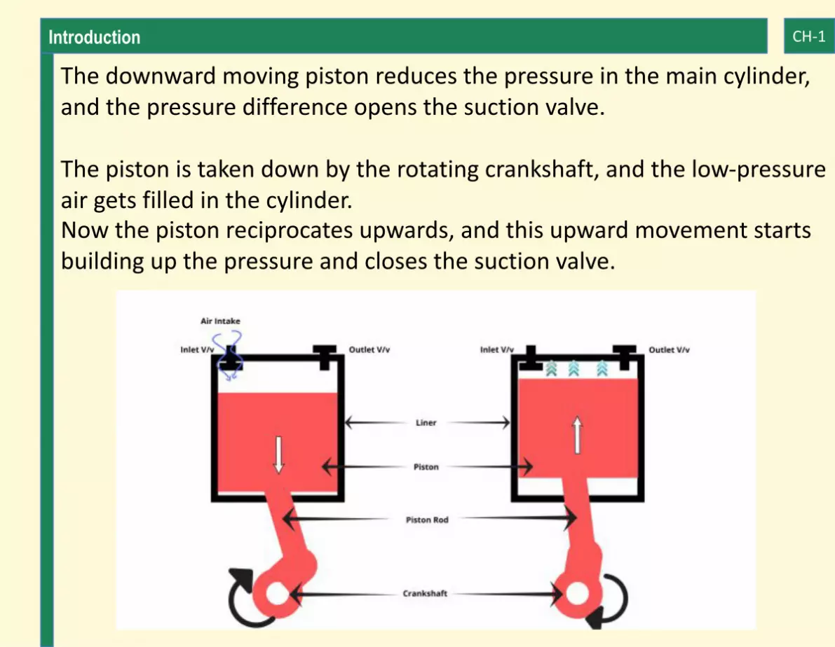
The downward moving piston reduces the pressure in the main cylinder, and the pressure difference opens the suction valve.
The piston is taken down by the rotating crankshaft, and the low-pressure air gets filled in the cylinder. Now the piston reciprocates upwards, and this upward movement starts building up the pressure and closes the suction valve.

Introduction CH-1
When the air gets pressurized to its specific value, the discharge valve opens, and the pressurized air starts moving through the discharge line and gets stored in the air bottle.
This pressurized air in the air bottle can be used to run the main as well as auxiliary engines when required.
There can be a single acting and a double-acting reciprocating air compressor on the ship.
Classification Based on Usage:
Usually, air compressors used on board ships are:
• Main air compressor
• Topping up compressor
• Deck air compressor

Introduction CH-1
• Emergency air compressor
Main air compressor: It is used to supply highly pressurized air to start the main and secondary engines. The air compressor has an air storage bottle which stores the pressurized air.

Introduction CH-1
Different makers provide different capacities of air compressor, however, the capacity of the main air compressor should be such that it can generate minimum air pressure of 30 bars which is adequate to start the main engine ( Minimum air pressure required is 30 bars to start the main engine).
A pressure valve is also provided, which reduces pressure and supplies controlled air from the storage air bottle. The control air filter controls the input as well as output air in the air bottle.
Topping up compressor: This type of compressor is used to cater to any leakage in a system. If any leakage is observed in the system, the topping up air compressor covers up the leakage by taking the lead.
The topping up compressor helps in supporting the main air compressor if there are any leakages in the air line, thus reducing the load on the main air compressor and maintaining the supply pressure.

Introduction CH-1
Deck air compressor: Deck air compressor is used for deck usages and as service air compressor. It might have a separate service air bottle for the same. These are lower capacity pressure compressors as the pressure required for service air is in the range of 6 to 8 bar.
Introduction CH-1
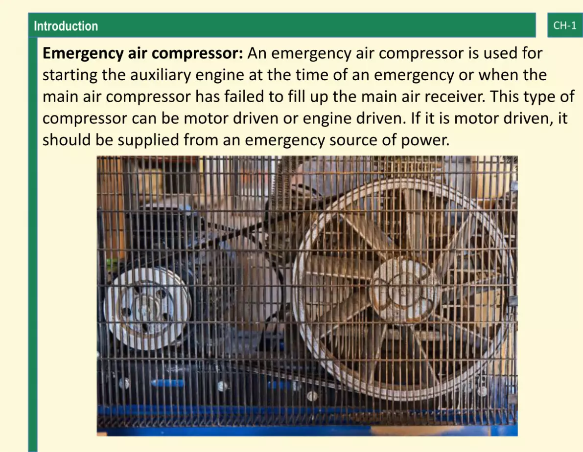
Emergency air compressor: An emergency air compressor is used for starting the auxiliary engine at the time of an emergency or when the main air compressor has failed to fill up the main air receiver. This type of compressor can be motor driven or engine driven. If it is motor driven, it should be supplied from an emergency source of power.

Introduction CH-1
Efficiency of Air Compressors: The air compressors can work efficiently if appropriately installed as per the installation guide. The efficiency of the air compressor highly depends on how it is operated and maintained. The engine crew must be aware of the correct operating procedure during the normal engine room operation and also during an emergency period.
Pressure-Bar:Pressure bars also known as pressure gauges are critical measuring tools installed on the air compressor to measure the air pressure of both suction and discharge side. The pressure gauge helps the engine crew to troubleshoot if the suction filters are choked or if the compressor is generating the required air pressure, which is essential to start the main engine.
Safety Devices:These are the devices that are used to reduce the loss of energy from the air compressor and increase the efficiency. Safety devices automatically shuts down the input and output air when
Introduction CH-1
adequate compression is reached, and thus saves the device from overpressure.
MAIN COMPONENT OF AIR COMPRESSOR
Some of the essential components which are common to all types of compressors are mentioned below:
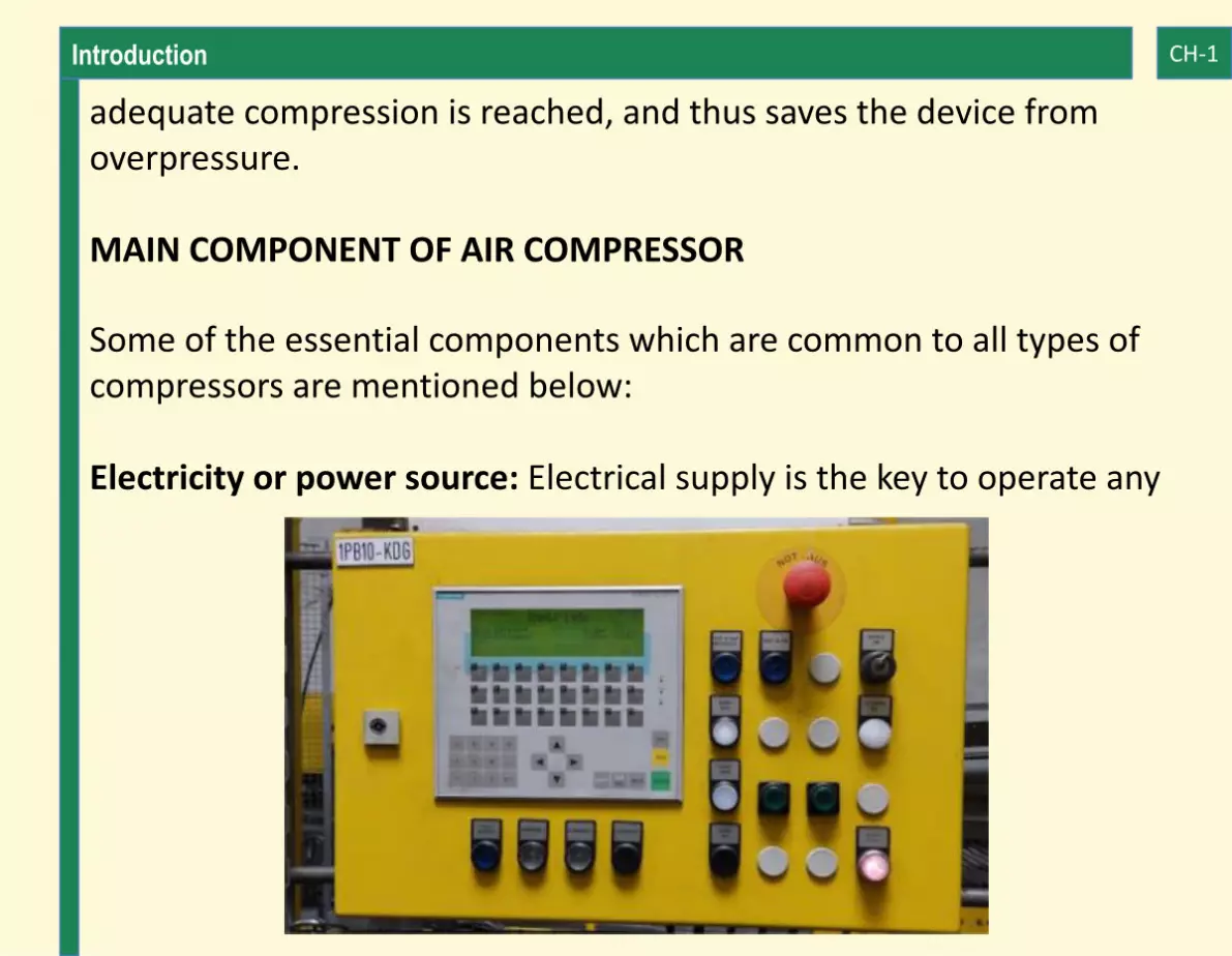
Electricity or power source: Electrical supply is the key to operate any

Introduction CH-1
machinery onboard ship. The Main Air compressor is fed from Main switch board with a starter for soft start. The emergency air compressor is supplied electricity from emergency switch board.
Cooling Water: Cooling water is used to cool the compressor in between different stages.
Lubricating Oil: Lubricating oil is necessary to keep all the moving parts of the compressor well-lubricated. Lubrication reduces the friction in parts of the compressor and thus imparts more life to the compressor by lowering wear and tear of the components.

Introduction CH-1
Air: The most important component for the compressor is supply of fresh air in the suction area of the compressor. The compressor is usually placed below the ventilation ducts to receive low pressure air which serves as input to the compressor.
Suction Valve: As the name suggests, the suction valve of the compressor is responsible to supply input air from the atmosphere into the compressor cylinder, which is then converted into high pressure air. Each stage is provided with one suction valve.
Discharge Valve: The discharge valve is fitted to take out the high pressurised air into the next stage and then to the air bottle, where it is stored in that pressure. Each stage is provided with one suction valve.
Unloader: During the starting of the compressor, it is essential that there is no pressure inside the cylinder unit. If the compressor is started with already pressed cylinder, the motor will get overload and draw high current. It may also lead to burning of the motor.

Introduction CH-1
Hence, an unloader valve is used which opens the cylinders to the atmosphere at the time of starting and stopping of the compressor.

Chapter 2Construction

Construction CH-2
DIFFERENT PARTS OF MARINE AIR COMPRESSOR
Just like any other machinery, the compressor is an assembly of different parts operating together. The construction is somewhat similar to a 4 stroke engine, however, there is no ignition and only air is compressed and delivered.

Construction CH-2
The main parts of the marine air compressor are:
1) Cylinder liner:
It is made of graded cast iron and is accompanied by a water jacket around it to absorb heat produced during the compression process. It is designed to give a smooth passage to the pressurized air, resulting in minimal pressure drop.
2) Piston:
For a non-lubricating type compressor, a lightweight aluminium alloy piston is used. For lubricating type graded, the cast iron piston is used with piston rings for sealing and scrapping off excess oil.
3) Piston Rod:
In high capacity compressor, which is usually big in size, the piston is

Construction CH-2
attached to a piston rod made up of alloy steel. It is fitted with anti-friction packing ring to avoid chances of compressed air leakage.
4) Connecting rod:
Connecting rod plays its role to minimize thrust to the bearing surface. It is made up of forged alloy steel.
5) Big end bearing and main bearing:
They give rigidity to the running rotational mechanism. They are made up of copper-lead alloy and have a long operational life if proper lubrication is provided.
6) Crank shaft:
The crankshaft is responsible for transmitting motor power into rotary motion to activate piston for compressing the air.

Construction CH-2
The crankshaft is usually forged in one piece, using counterweights for dynamic balancing during the high speed of rotation to avoid twisting due to torsion forces. Piston rod, big end bearing, and the main bearing are connected to crankshaft at crankpin and journal pin, which helps convert the rotary motion to reciprocating motion of the piston.
7) Frame and crankcase:
They are made from rigid cast iron and usually have a rectangular shape to accommodate all the moving parts. The main bearing housing is fitted on a bore in the crankcase and is made with the highest precision to avoid eccentricity or misalignment.
8 ) Oil pump:
A lubricating oil pump is fitted to supply lube oil to all the bearings, which can be chain or gear driven, through the crankshaft. The oil pressure can be regulated using regulating screw provided in

Construction CH-2
the pump. A filter in the inlet of the pump is also attached to supply clean and particle free oil to the bearings.
9) Water pump:
Some compressor may have attached water cooling pump driven by the crankshaft through chain or gear. Some system does not use the attached pump as they use water supply from the main or auxiliary system for cooling.
10) Suction and Discharge valve:
These are multi-plate valves made up of stainless steel. They are used for taking in and discharge air from one stage to another and the air bottle. Proper assembling of valves is very important for the efficient operation of the compressor.

Construction CH-2
11) Suction Filter:
It is an air filter made up of copper or soft steel with a paper material to absorb oil. It also has a wire mesh to avoid any metal or dust particle to go inside the compression chamber.
12) Inter-coolers:
Inter-coolers are typically fitted in between two stages to cool down the air temperature and to increase the volumetric efficiency of the compressor. Some compressors have inbuilt attached copper tubes for cooling, whereas some have an outside assembly of copper tube inter-coolers.
13) Driving Motor:
An electrical motor is attached to the compressor for making it operational and is connected to the compressor through the flywheel.

Construction CH-2
These are the main parts of a marine air compressor. The parts may vary according to the requirement of the system or the ship.

Construction CH-2
DIFFERENT AUXILIARIES USED FOR MARINE AIR COMPRESSOR
Almost all machinery systems in the engine room are dependent on another systems in some form or another. For e.g., the main air compressor is also provided with other auxiliaries, which helps to operate it safely and efficiently. The compressor also acts as a part of another system to ensure the ship’s propulsion plant is up and running.
1. Oil Separator: The air produced by the compressor might contain small amount of oil which needs to be separated. Hence an oil separator is placed on the outlet of the compressor which allows the separation of oil, moisture, and air.
2. Main Air bottle: The compressed air from the main air compressor is supplied to the main air bottles of the ship, which are usually 2 in nos., to store the compressed air at high pressure for starting the main engine of the ship.

Construction CH-2
1. Auxiliary Air Bottle: The emergency compressor supplies air to a smaller capacity bottle, known as auxiliary air bottle, which can be used if the main air bottle pressure is low or when main air compressors fails to operate.
2. Sea water Jacket Coolers: In older compressor, sea water was used for cooling. Hence, the freshwater is circulated through the jacket of the compressor and this freshwater with high temperature goes to a seawater cooler for cooling down.

Construction CH-2
AIR LINE ON SHIP:
The compressed air from the main air compressor outlet is supplied and stored in the air bottle. From the air bottle, there are many lines which goes out for different uses. These lines are controlled with valves.
The most important use of the compressed air from the bottle is to supply starting air and control air to the main engine. Another branch supplies starting air to the auxiliary engines present onboard.
A line from the main air bottle, which goes to other auxiliary connections such as service air, safety air etc., is also provided with an isolating valve.
The line diagram for the main air compressor is shown in the figure.

Construction CH-2

Chapter 3Operation

Operation CH-3
Certain steps and a systematic procedure need to be followed in order to start or stop an air compressor on a ship.
Checks are also to be made before starting the air compressor and also during its operation.

Operation CH-3
Checks Before Starting the Air Compressor
The following steps are to be followed before starting an air compressor on a ship:
• Check the lube oil in the crankcase sump by means of a dipstick or sight glass
• Check the drain valve is fully open
• All the valves of compressor discharge must be open
• Check if the cooling water supply is sufficient in the flow sight glass
• If any manual valve is present in the un-loader line, it must always be kept open

Operation CH-3
• All alarms and trips - Lube oil low pressure, high water temperature, overload trip etc. must be checked for operation
• All valves in the cooling water line must be in a normally open position
• Cocks for all the pressure gauges must be in open position

Operation CH-3
• Air intake filter should be clean
• If the compressor has not been started for a long time, then it should be turned on manually with a tommy-bar to check for the free movement of its parts
• Ensure that the discharge valve leading to air bottle is fully open
• Switch on the compressor and put it in auto

Operation CH-3
• Check whether the compressor pressure switch is working properly, i.e. at a set pressure, it must Auto start/stop
• Check for any abnormal sound
• Check “hissing” sound near all the valves for air leakage, including solenoid and drains

Operation CH-3
What is Unloading the Compressor?
Unloading is a standard procedure during the starting and stopping of the compressor.
When starting a compressor motor, since the load on the motor is very high, the starting current is also high.
To avoid further loading of the compressor, an un-loader arrangement is provided which is normally pneumatic or solenoid control. The un-loader releases the pressure during the starting of the compressor.
Once the current comes down to the running value, the un-loader closes automatically. Usually, a timer function is used for opening and closing of un-loader.
Air contains moisture, and during the compression process, some amount of moisture gets released.

Operation CH-3
The liquid in any form is incompressible. If some amount of oily water mixture is present inside the cylinder, then it will damage the compressor. To overcome this problem, an un-loader is used.
During starting un-loader comes in action and releases all the moisture accumulated inside the cylinder..

Operation CH-3
Intermediate operation of un-loader is also selected so that during the process of compression, any moisture or oil accumulation cannot take place inside it.
During stopping, the un-loader is operated so that for the next start the cylinder will remain moisture-free
Checks During the Operation of Compressor
• Check if all the pressure gauges are showing correct readings of lube oil pressure, water pressure etc.
• Check for any abnormal sound like knocking
• Check for any lube oil or water leakages
• Check if the discharge pressure for all units is normal

Operation CH-3
• If cylinder lubrication is provided, check the supply from sight glass

Operation CH-3
• Check air temperature after the final stage is under limit
• Check the flow of cooling water from the sight glass
• If the attached cooling water pump is provided, check for its free rotation
• Check the relief valve of all units for leakage. In some compressor, provision is given to check the relief valve with hand lever. If provided, check all units.
Stopping
• Put drain in open position and switch off the compressor
• Switch off the main power supply
• After the compressor is completely stopped, close the drain/ un-loader

Operation CH-3
• Never shut the discharge valve of the compressor
Use of Air from Air Compressor
On board ships, compressed air is used for several purposes. On the basis of application, different air compressors are kept for a particular usage.
• Air compressor is used to provide starting air to various machines and main engine
• Other than the main engine, systems such as control valves, throttle controls and other monitoring systems, which work on pressurized air, also require compressed air
• In pneumatic tools such as cleaning devices, compressed air is required to keep the machines running and serve the purpose efficiently
Operation CH-3
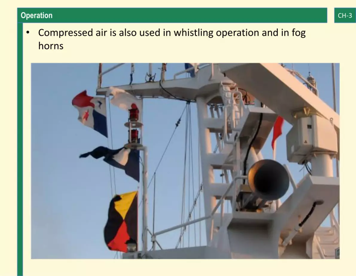
• Compressed air is also used in whistling operation and in fog horns

Operation CH-3
• Hydraulic jack in the ship also uses compressed air to perform lifting operations
• Many times boilers, refrigerants and heat exchangers in the ship are started using compressed air
• Sometimes compressed air is used as braking air for stopping the propeller of the ship
• Some main engine special tools require compressed air for operation
• The compressed air is used to operate hydroblaster, which is a high pressure machinery to clean ship surface
• The recently introduced concept of hull lubrication air also requires air supply to be fed from the compressed air line of the ship

Chapter 4Safety

Safety CH-4
Every Air compressor on a ship is fitted with several safety features to avoid abnormal and dangerous operational errors of the equipment. If safety, alarms and trips are not present on the air compressor, the abnormal operation may lead to the breakdown of the compressor and may also injure a person working on or around it.
Different safety features on an air compressor are -
Relief valve:
Fitted after every stage to release excess pressure developed inside it. The setting of the lifting pressure increases after every ascending stage. It is usually installed between 1st stage and intercooler, and also 2nd stage and aftercooler.
Bursting disc:
A bursting disc is a copper disc provided at the air cooler of the

Safety CH-4
compressor. It is a safety disc which breaks when the pressure exceeds over the pre-determined value due to leaky air tubes of the cooler (intercooler or aftercooler).

Safety CH-4
Fusible plug:
Generally located on the discharge side of the compressor, it fuses if the air temperature is higher than the operational temperature. The fusible plug is made up of material which melts at high temperature.
Lube Oil low-pressure alarm and trip:
If the lube oil pressure goes lower than the normal, the alarm is sounded followed by a cut out trip signal to avoid damage to bearings and crankshaft.
Water high-temperature trip:
If the intercoolers are choked or the flow of water is less, then the air compressor will get overheated. To avoid this situation, high water temperature trip is activated, which cut-offs the compressor.

Safety CH-4
Water no-flow trip:
If the attached pump is not working or the flow of water inside the intercooler is not enough to cool the compressor, then the moving part inside the compressor will get seized due to overheating. A no-flow trip is provided, which continuously monitors the flow of water and trips the compressor when there is none.
Motor Overload trip:
If the current taken by the motor during running or starting is very high, then there is a possibility of damage to the motor. An overload trip is thus fitted to avoid such situation.

Safety CH-4
Clearance Volume or Bumping Clearance:
Clearance volume or bumping clearance is the space between the top of the piston and the cylinder head of an air compressor.

Safety CH-4
This clearance is an essential aspect of the compressors and should be as less as practically possible to improve the volumetric efficiency of the compressor.
The clearance volume should not be too less or too more as it affects the efficiency of the machinery and thus should be checked at regular intervals of time.
Significance and Effects of Bumping Clearance:
In an air compressor, when the discharge valve closes at the end of the compression cycle, a small amount of high-pressure air is trapped in the clearance volume.
Before again taking suction, the air trapped in the clearance volume must expand below the suction pressure, i.e. below the atmospheric pressure.
The expansion of this trapped air in the clearance volume causes

Safety CH-4
effective loss of stroke due to which the volumetric efficiency of compressor drops. Therefore, the clearance volume has a significant effect on the efficiency of the compressor.
Effects Due to Less Clearance:
Small clearance volume may result in piston banging or colliding to the cylinder head. This is dangerous when the compressor is running in an unloaded condition without any resistance to the movement of the piston.
Effects Due to Large Clearance:
Large bumping clearance retards the formation of vacuum on the suction stroke and thus less air is drawn inside for compression and accordingly, the weight of the air delivered is reduced proportionally to the clearance volume. The compressor has to run for a more extended period to provide the necessary compression pressure.

Safety CH-4
Reasons for Change in Clearance Volume:
During overhauls of the air compressor, if the gasket fitted betweenthe cylinder head joints is of the wrong type, then the bumping clearance will increase, resulting in wear down of bottom bearings.
How Is Bumping Clearance checked?
Bumping clearance is checked by putting a lead ball or plastic gauges over the piston and then turning the compressor one revolution by hand.
By doing this, the lead ball will compress, and the thickness obtained is the clearance volume. This thickness is measured with a Vernier calliper or micrometre and is then compared with the manufacturer’s value.
Adjustments are made in case there is an offset in the value.

Safety CH-4
Adjustment of bumping clearance:
What Should be the Bumping Clearance?
Generally bumping clearance depends on the manufacturer but as a thumb rule, it should be between 0.5% to 1% of the bore of the cylinder.
Bumping clearance can be adjusted with the help of inserting shims(thin metallic plates) in the bottom bearings.
Inserting shims will move the connecting rod and the piston, which will change the clearance.

Chapter 5Maintenance and Troubleshooting

Maintenance and Troubleshooting CH-5
MAINTENANCE OF AIR COMPRESSOR
A compressor requires proper planned routine maintenance for safe and efficient operation and for avoiding breakdown maintenance.
Routine of maintenace depends on the manufacturer’s advice given in the manual.

Maintenance and Troubleshooting CH-5
The following are the maintenance checks that should be carried out after the mentioned running hours.
@ 250hrs:
1) Clean air filter
2) Check the un-loader operation
3) If a belt is provided for driving cooling water pump, check its tightness
@ 500hrs:
1) Change lube oil and clean sump
2) Clean lube oil filter
3) Check and renew suction and discharge valves with new one

Maintenance and Troubleshooting CH-5
@ 4000 hrs:
1) Piston and big end bearing overhauling, piston ring renewal
2) Intercooler cleaning
3) Motor overhauling
Running hour may differ from maker to maker. The above description is a rough idea for the general maintenance of the marine air compressor.
Without the supply of air, a ship will soon be termed as a dead ship.
It is the responsibility of the engineers onboard to maintain the compressor, the air receiver, the air pipeline and to ensure the overall system is in proper working condition.

Maintenance and Troubleshooting CH-5
Cooling System Maintenance
The cooling system of the main air compressor should include the following maintenance procedures:
• Regular inspection of the intercoolers and aftercoolers
• Leakage testing of the intercoolers and if any tube is found leaking, same to be plugged
• Removal of oil or deposits from the intercooler tube nests using suitable chemicals
• Regular inspection of cylinder water jacket to check for any cracks or deposits
• Overhauling of water line valves
Maintenance and Troubleshooting CH-5
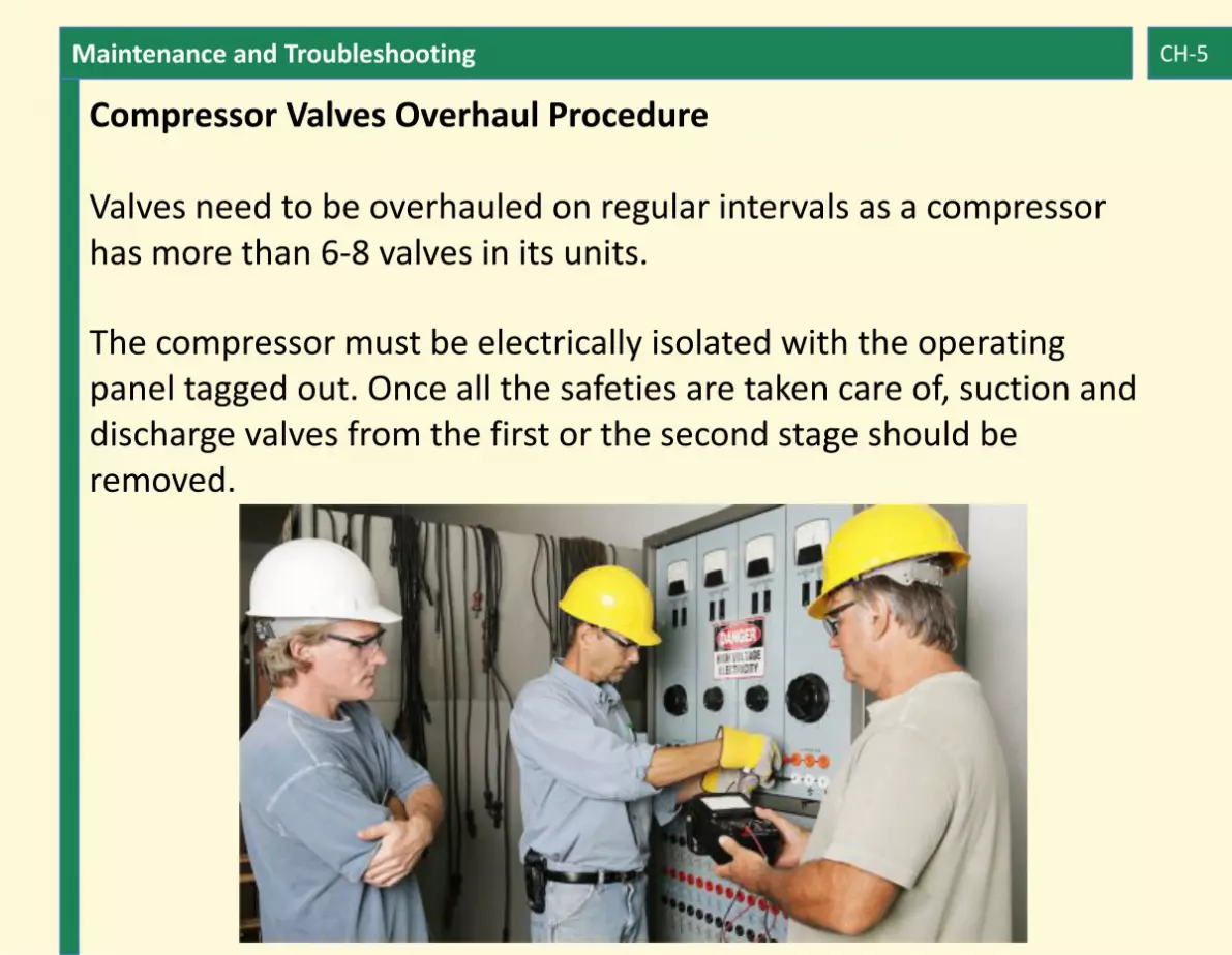
Compressor Valves Overhaul Procedure
Valves need to be overhauled on regular intervals as a compressor has more than 6-8 valves in its units.
The compressor must be electrically isolated with the operating panel tagged out. Once all the safeties are taken care of, suction and discharge valves from the first or the second stage should be removed.

Maintenance and Troubleshooting CH-5
Most of the marine air compressors are installed with HOERBIGER automatic valves, which comprise of different plates stacked together. The suction and the discharge valves look similar; however, the direction of the operation and the spring stiffness will differ in both.
To overhaul the valves;
• Remove the split pin and open the castle nut
• Dismantle all the parts and soak them in clean diesel oil or approved cleaning chemical
• Remove any hard deposit by using a copper plate or copper washer for scraping
• Lap the valve seat with appropriate fine lapping paste
• Lap the valve plate separately using fine lapping paste

Maintenance and Troubleshooting CH-5
• Check the condition of the springs and valve plate. If the spring is bent or broken, it should be replaced
• If the valve plate is showing sign of fatigue or damage, it should be replaced
• Ensure not to turn over the valve plate for reusing as it can lead to fatigue failure
• Once the lapping is done, the plate and seat can be washed in diesel oil and cleaned using compressed air
• Assemble the valve seat in the reverse sequence as it was opened
• Once the assembly is complete, the valve is checked for leakage by putting light grade oil or water inside it. If the water or oil is seeping out, the valve needs more lapping.

Maintenance and Troubleshooting CH-5
Extreme caution must be taken to fix the correct valve in suction and discharge lines, as a wrongly fitted valve may lead to breakdown and even an explosion of the high-pressure chamber.

Maintenance and Troubleshooting CH-5
TROUBLESHOOTING OF AIR COMPRESSOR PROBLEMS
Air compressors on a ship require special attention and care for their smooth running. It is only through routine maintenance and check-ups that you can expect a smooth and efficient running of the compressors.

Maintenance and Troubleshooting CH-5
Following are some common problems that can arise in an air compressor:
Lube Oil Pressure LowThe following can be the reasons for low lube oil pressure in the air compressor:
• Faulty pressure gauge
• Cock to pressure gauge in closed position
• Low oil level in the sump
• Leakage in the supply pipe
• The suction filter is choked
• Oil grade in the crankcase is not compatible

Maintenance and Troubleshooting CH-5
• Attached Lube oil gear pump is faulty
• Worn out Bearing, clearance is more
Abnormal noise during operation:If you get any unusual noise during operation, the following can be the reasons:
• Loose foundation bolts

Maintenance and Troubleshooting CH-5
• Worn out bearings, clearance is high
• Imbalance crankshaft resulting in high-end play
• Valve plate broken or faulty
• Relief valve lifting below setting pressure
• Bumping clearance is less
• Piston worn-out, broken piston ring
Vibration in the machinery:In the case of vibrations, the following reasons are to be considered and checked:
• Foundation bolts are loose
• Discharge pressure high, faulty discharge valve plates

Maintenance and Troubleshooting CH-5
• Liner and piston are worn out
• Small bumping clearance
Cooling water temperature is highCooling water temperature can go high because of the following reasons:
• Inlet or outlet valve for cooling water is closed
• Inter-cooler is chocked
• Cooling water in the expansion tank is low
• Pipe passage becomes narrow due to scale formation
• Water-pump belt or gear drive broken
• Pump not working

Maintenance and Troubleshooting CH-5
First stage discharge pressure highIn case the first stage discharge pressure is high, it must be because of :
• The pressure gauge is faulty
• Inter-cooler air passage is chocked
• Second stage suction valve is not closing correctly, allowing air to escape from the 2nd to 1st stage
• Discharge valve of the first stage is malfunctioning and remains in the closed position
• Spring of discharge valve is malfunctioning
• Discharge valve wrongly assembled and fitted after overhaul

Maintenance and Troubleshooting CH-5
First stage discharge pressure lowIn case the first stage discharge pressure is low, it must be because of:
• The pressure gauge is faulty
• The suction filter is choked
• Unloader of the first stage is leaking
• First stage suction valve is not closing properly, resulting in compressed air leakage
• First stage suction valve is not opening fully, leading to less intake of air
• Relief valve after the first stage is leaking
• The discharge valve is faulty and remains open permanently
Maintenance and Troubleshooting CH-5
• Piston ring of the first stage is badly worn out, allowing air to pass
Second stage discharge pressure highIn case of high discharge pressure in the second stage, the reasons can be:
• Faulty pressure gauge
• Discharge valve to air bottle is shut
• Second stage-discharge valve plate worn out, and even the spring worn out
• The valve is stuck in the closed position
• Aftercooler air passage choked
• Air bottle is over pressurized

Maintenance and Troubleshooting CH-5
Second stage discharge pressure lowWhen the second stage discharge pressure is low, it could be because of:
• Suction valve for the second stage is malfunctioning, in open position
• The pressure gauge is faulty
• Suction valve for the second stage is not opening fully, and thus less intake of air
• The discharge valve is faulty and remains open during operation
• Piston rings of the second stage are worn out, leaking out compressed air
• The relief valve of the second stage is leaking

Maintenance and Troubleshooting CH-5
• Un-loader of the second stage is leaking
The relief valve of the first stage liftingIf the relief valve of the first stage is lifting, it can be because of:
• Spring of relief valve is malfunctioning, thus raising at less pressure
• Discharge valve of the first stage is not opening
• Intercooler air passage is blocked
• Water is leaking inside the compression chamber due to crack in the jacket
• The suction valve of the second stage is in a stuck position

Maintenance and Troubleshooting CH-5
Relief valve of the second stage is liftingIf the relief valve of the second stage is lifting, look for the following reasons:
• The relief valve is malfunctioning, lifting at lower than setting pressure
• Main discharge valve to the air bottle is closed
• Discharge valve plates and spring are worn out, the valve in a closed position
• Blockage in the after cooler air passage
• Water inside the compression chamber due to crack jacket
The points mentioned above are just a brief explanation of the problems of the air compressor tackled on board. However, they serve reference for finding the right fault in the compressors.

www.marineinsight.com
EXPLORE MORE MARITIME EBOOKS. VISIT OUR STORE
https://learn.marineinsight.comCLICK HERE TO KNOW MORE