a framework architecture for d2d based cellular vehicular
TRANSCRIPT
© Copyright by Thouraya Toukabri - 2016

© Copyright by Thouraya Toukabri - 2016
Abstract
The traffic explosion in today’s mobile networks is one of the major concerns of mobile operators. This explosion is mostly widening the gap between networks’ capacities and users’ growing needs in terms of bandwidth and QoS (Quality of Service), which directly impacts operators’ business profitability. In this context, Device-to-Device (D2D) communications offer mobile operators business and technical opportunities by allowing the network traffic offload with D2D direct communications between mobile devices. The recent standardization of D2D-based services as Proximity Services (ProSe) by the 3GPP provides already a set of enhancements to the current LTE/4G architecture to support these services. However, still in its infancy, the proposed solutions are envisioned for short-term market deployments and for a limited set of service categories (e.g. public safety services). As a first contribution of this thesis, the proposed Distributed ProSe Architecture enhances the current ProSe architecture for a longer term deployment perspective of D2D-based services. On the basis of this enhanced architecture, vehicular communications and related services are further investigated as a specific implementation of ProSe as well as a new market opportunity for mobile operators. The CVS (Cellular Vehicular Services) solution is then introduced as an architecture framework that enables the integration of vehicular networks into mobile operators’ network infrastructure. A mobile network clustering algorithm and D2D relay-based communication mechanisms are used in the solution design in order to optimize the use of both core and radio network resources. Performance evaluation through analytical modeling and simulations are also carried out to validate the proposed contributions.
Key words: Device-to-Device, Proximity Services, LTE architecture, vehicular communications
Résumé
L'explosion du trafic dans les réseaux mobiles d'aujourd'hui est l'une des préoccupations majeures des opérateurs mobiles. En effet, entre investir dans le développement de l’infrastructure pour supporter l’évolution des besoins des utilisateurs et faire face à la concurrence accrue des nouveaux acteurs du marché, l’enjeu est considérable. Dans ce contexte, les communications Device-to-Device (D2D) offrent aux opérateurs mobiles de nouvelles opportunités aussi bien financières que techniques, à travers les communications directes entre les appareils mobiles permettant de délester le réseau d'une partie du trafic. L'organisme de standardisation 3GPP a défini des évolutions de son architecture LTE/4G fonctionnelle pour supporter les communications D2D dans le cadre de Services de Proximité (ProSe). Cependant, les modèles économiques autour de ces nouveaux services sont encore flous et les solutions actuellement proposées par le 3GPP visent un déploiement à court terme d’un ensemble limité de services (ex : les services de sécurité publique). La première contribution proposée dans le cadre de cette thèse est une évolution de l'architecture ProSe vers une architecture cible distribuée dans laquelle les fonctions liées à ProSe sont mutualisées avec d'autres fonctions réseaux. La deuxième contribution porte sur l’intégration des services véhiculaires dans les réseaux mobiles en tant que services ProSe particuliers reposant sur les communications D2D. L'architecture CVS (Cellular Vehicular Services) est alors proposée comme solution pour un déploiement à grande échelle des services véhiculaires en s'appuyant sur une nouvelle évolution de l’architecture ProSe distribuée. Un algorithme de « clustering » ainsi que des procédures de communication en mode relais D2D sont utilisés dans la conception de la solution afin d’optimiser l'usage des ressources du réseau. Enfin, les performances de ces contributions sont évaluées à l'aide de modèles analytiques et de simulations afin de valider les approches et solutions proposées.
Mots clés: Device-to-Device, services de proximité, l'architecture LTE, communications véhiculaires

To Hayet and Béchir.

Acknowledgements
This thesis not only marks a professional achievement in my carrier but also a personal
accomplishment that accompanied a very important mind ascension step in my life. It took me a lot of courage, self-confidence and perseverance to achieve it but it would not have been possible without the support of many persons. My deepest gratitude goes to the following:
My thesis director, Professor Hossam Afifi, for his continuous encouragements, support and valuable advices in directing the research work,
My friend and advisor from Orange Labs, Mr. Lionel Morand, for his patience, infinite support and guidance throughout the thesis,
My advisor from Orange Labs, Mr. Steve Tsang Kwong U, for his support and advices especially during the first year of the thesis,
Mr. Nabil Charkani El Hassani for his trust and comprehension during the rough periods of the thesis,
The collaborators from Telecom Sud Paris and collegues from Orange Labs for their professional help and friendship,
And finally, to my mother and father, for their incoditionnal love and trust.
To all these persons and to those that I may not mentioned, Thank You!
Thouraya Toukabri

1
Contents
Introduction ............................................................................................................................7
A. General context and research problems ........................................................................7
B. Goals ......................................................................................................................... 10
C. Contributions ............................................................................................................. 10
Chapter 1: State of the art ..................................................................................................... 14
1.1 Methodology .......................................................................................................... 14
1.2 State of the art of LTE-based D2D communications ............................................... 15
1.2.1 What is D2D? .................................................................................................. 15
1.2.2 D2D technologies and use cases ...................................................................... 15
1.2.3 D2D modes ..................................................................................................... 17
1.2.4 D2D communication mechanisms ................................................................... 18
1.2.5 D2D Business challenges for mobile operators ................................................ 20
1.2.6 Conclusion ...................................................................................................... 20
1.3 State of the art of 3GPP Proximity-based Services (ProSe) ..................................... 21
1.3.1 The ProSe architecture .................................................................................... 21
1.3.1.1 ProSe basic features ..................................................................................... 21
1.3.1.2 The ProSe function ...................................................................................... 21
1.3.2 ProSe service authorization ............................................................................. 23
1.3.3 ProSe direct discovery ..................................................................................... 24
1.3.3.1 Main parameters .......................................................................................... 24
1.3.3.2 ProSe Direct Discovery setup procedure ...................................................... 25
1.3.3.3 The PC5 protocol ......................................................................................... 28
1.3.4 ProSe direct communication ............................................................................ 29
1.3.4.1 ProSe one-to-one direct communication ....................................................... 32
1.3.4.2 ProSe one-to-many direct communication .................................................... 33
1.3.4.3 ProSe UE-to-Network relay direct communication ....................................... 34
1.3.5 Analysis of the ProSe architecture limitations .................................................. 35
1.3.6 Conclusion ...................................................................................................... 36
1.4 State of the art of ITS and V2X communications .................................................... 37
2
1.4.1 Overview......................................................................................................... 37
1.4.1.1 ITS requirements ......................................................................................... 38
1.4.1.2 ITS applications ........................................................................................... 38
1.4.2 ITS reference architecture ................................................................................ 39
1.4.3 ITS network domains ...................................................................................... 39
1.4.4 Vehicular Networks Vs. Cellular Networks ..................................................... 40
1.4.5 ITS deployment models and business challenges for mobile operators ............. 42
1.4.6 Conclusion ...................................................................................................... 44
1.5 State of the art of Clustering in mobile networks .................................................... 45
1.5.1 Clustering basic concepts in Mobile clouds ..................................................... 45
1.5.2 Clustering approaches in mobile networks ....................................................... 47
1.5.3 Overview on clustering algorithms .................................................................. 49
1.5.4 Conclusion ...................................................................................................... 52
Chapter 2: The Distributed ProSe Architecture ..................................................................... 53
2.1 Introduction ............................................................................................................ 53
2.2 The Distributed ProSe architecture ......................................................................... 55
2.2.1 Description and key features ............................................................................ 55
2.2.2 ProSe support in the LTE initial attach ............................................................ 57
2.2.3 ProSe support in the NAS protocol .................................................................. 59
2.2.3.1 « NAS PROSE SERVICE REQUEST » message format .......................... 61
2.2.3.2 « NAS PROSE SERVICE RESPONSE » message format ........................ 61
2.3 Enhanced ProSe Direct Discovery Service .............................................................. 62
2.3.1 Proposed solution ............................................................................................ 62
2.3.2 Analytical performance evaluation .................................................................. 63
2.4 Network-assisted communication via eNode B ....................................................... 66
2.4.1 Motivations ..................................................................................................... 66
2.4.2 Proposed solution ............................................................................................ 67
2.4.3 Simulation and performance evaluation ........................................................... 69
2.4.3.1 Extension of the NS3-LENA simulator ........................................................ 69
2.4.3.2 Simulation methodology .............................................................................. 70
2.4.3.3 Results analysis ........................................................................................... 71
2.5 Conclusion ............................................................................................................. 73
Chapter 3: Cellular Vehicular Services (CVS) ...................................................................... 74
3
3.1 Introduction ............................................................................................................ 74
3.2 The CVS architecture framework ........................................................................... 76
3.2.1 Enhancements to the Distributed ProSe architecture to support ITS services .... 77
3.2.1.1 Extended ProSe Direct Discovery setup procedure to support ITS services .. 77
3.2.1.2 PC5 protocol extension to support ITS ProSe Direct Discovery ................... 79
3.2.2 A Hybrid Clustering approach ......................................................................... 80
3.2.3 ProSe Gateway selection ................................................................................. 81
3.3 Network performance evaluation ............................................................................ 82
3.3.1 Methodology ................................................................................................... 82
3.3.2 Results analysis ............................................................................................... 83
3.4 Conclusion ............................................................................................................. 84
Chapter 4: The Adaptive Context-aware Weighted Clustering algorithm (ACWC) ............... 85
4.1 Introduction ............................................................................................................ 85
4.2 The Adaptive Context-aware Weighted Clustering Algorithm (ACWCA) .............. 86
4.2.1 Description ...................................................................................................... 86
4.2.2 Context parameters calculation ........................................................................ 87
4.2.3 ACWCA Setup procedure ............................................................................... 90
4.2.4 ACWCA maintenance procedure ..................................................................... 92
4.3 Performance evaluation of ACWCA ....................................................................... 94
4.3.1 Performance metrics ........................................................................................ 95
4.3.2 Simulation and results analysis ........................................................................ 96
4.4 Conclusion ............................................................................................................. 99
Conclusion and Future work ............................................................................................... 100
Annex 1: LTE architecture basics ....................................................................................... 105
Annex 2: NAS PROSE messages format ............................................................................ 111
Annex 3: ProSe direct discovery parameters ....................................................................... 117
Annex 4: Analytical optimization for a dynamic context-aware network clustering strategy119
Glossary ............................................................................................................................. 122
References .......................................................................................................................... 124
4
List of Figures
Figure 1: The CVS architecture framework .......................................................................... 13
Figure 2: D2D communication modes................................................................................... 18
Figure 3: ProSe non-roaming reference architecture [9] ........................................................ 22
Figure 4: The ProSe function components [9] ....................................................................... 23
Figure 5: ProSe configuration and service authorization procedure ....................................... 24
Figure 6: Overall procedure for ProSe direct discovery setup ................................................ 26
Figure 7: ProSe direct discovery request procedure for an announcing UE ............................ 27
Figure 8: ProSe direct discovery request procedure for a monitoring UE .............................. 28
Figure 9: Match report procedure for a monitoring UE ......................................................... 28
Figure 10: PC5 ProSe Direct Discovery protocol .................................................................. 29
Figure 11: EPC-based data path vs. ProSe communication data paths ................................... 30
Figure 12: Control path schemes for ProSe communication .................................................. 32
Figure 13: Establishment of secure layer-2 link over PC5 for ProSe one-to-one Direct
Communication .................................................................................................................... 33
Figure 14: Layer-2 link release over PC5 for ProSe one-to-one Direct Communication ........ 33
Figure 15: Remote UE with ProSe UE-to-Network relay direct communication establishment
procedure ............................................................................................................................. 34
Figure 16: IPv6 prefix allocation using ProSe UE-to-Network Relay .................................... 35
Figure 17: ITS network domains ........................................................................................... 40
Figure 18: Architecture of a Mobile cloud ............................................................................ 45
Figure 19: A clustered network structure .............................................................................. 46
Figure 20: Mobile clouds architecture approaches ................................................................ 48
Figure 21: The Distributed ProSe architecture ...................................................................... 55
Figure 22: Initial network attach procedure enhancements .................................................... 57
Figure 23: Control plane protocol stack and interface between the ProSe-MME and the UE . 61
Figure 24: Enhanced ProSe Direct Discovery setup procedure .............................................. 62
Figure 25: The BCMP queuing model for the CVS solution.................................................. 64
Figure 26: Impact of messages arrival rate (λ) on the ProSe Direct Discovery setup time (D)66
Figure 27: ProSe network-assisted communication establishment procedure ......................... 68
Figure 28: Mapping of dedicated D2D radio bearers in the eNode B ..................................... 69
Figure 29: Impact of D2D communications on EPC-based communications with a fixed UEs’
number ................................................................................................................................. 71
Figure 30: Impact of D2D communications on the average E2E delay with different D2D
percentages ........................................................................................................................... 72
Figure 31: Impact of D2D communications on the E2E delay for EPC communications with
different D2D percentages .................................................................................................... 73
Figure 32: The Cellular Vehicular Services framework architecture (CVS)........................... 77
Figure 33: Extended ProSe authorization and authentication procedure for ITS services ....... 78
5
Figure 34: Extended PC5 protocol tu support ITS services.................................................... 79
Figure 35: E2E communication delay according to the cluster size ....................................... 83
Figure 36: ProSe-CH election by the ProSe-MME ................................................................ 92
Figure 37: Cluster formation latency for different cluster sizes ............................................. 96
Figure 38: Cluster formation signaling overhead for different cluster sizes ........................... 97
Figure 39: Created Clusters number for different CH transmission ranges ............................ 98
Figure 40: The 4G/LTE network architecture [5] ................................................................ 105
Figure 41: The EPC control plane protocol stack [5] [6] ..................................................... 106
Figure 42: The EPC User plane protocol stack [5] [6] ......................................................... 107
Figure 43: EPS bearers system in LTE [6] .......................................................................... 108
Figure 44: The LTE initial attach procedure [37] ................................................................ 109
Figure 45: Structure of IMSI ............................................................................................... 114
Figure 46: ProSe Application ID structure .......................................................................... 115
6
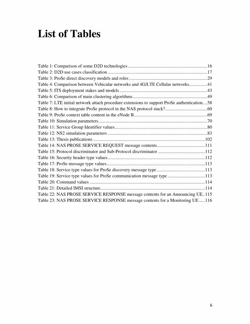
List of Tables
Table 1: Comparison of some D2D technologies .................................................................. 16
Table 2: D2D use cases classification ................................................................................... 17
Table 3: ProSe direct discovery models and roles ................................................................. 29
Table 4: Comparison between Vehicular networks and 4G/LTE Cellular networks ............... 41
Table 5: ITS deployment stakes and models ......................................................................... 43
Table 6: Comparison of main clustering algorithms .............................................................. 49
Table 7: LTE initial network attach procedure extensions to support ProSe authentication .... 58
Table 8: How to integrate ProSe protocol in the NAS protocol stack? ................................... 60
Table 9: ProSe context table content in the eNode B ............................................................. 69
Table 10: Simulation parameters........................................................................................... 70
Table 11: Service Group Identifier values ............................................................................. 80
Table 12: NS2 simulation parameters ................................................................................... 83
Table 13: Thesis publications ............................................................................................. 102
Table 14: NAS PROSE SERVICE REQUEST message contents ........................................ 111
Table 15: Protocol discriminator and Sub-Protocol discriminator ....................................... 112
Table 16: Security header type values ................................................................................. 112
Table 17: ProSe message type values .................................................................................. 113
Table 18: Service type values for ProSe discovery message type ........................................ 113
Table 19: Service type values for ProSe communication message type ............................... 113
Table 20: Command values ................................................................................................ 114
Table 21: Detailed IMSI structure ....................................................................................... 114
Table 22: NAS PROSE SERVICE RESPONSE message contents for an Announcing UE.. 115
Table 23: NAS PROSE SERVICE RESPONSE message contents for a Monitoring UE ..... 116
7
Introduction
A. General context and research problems
A new ecosystem for Mobile Network Operators
Today’s mobile networking world facts are:
- The mobile industry is shipping more smart phones and tablets than laptops.
- The new social networks fashion and success stories like Facebook and Twitter
influenced users’ behavior considerably as they have further enforced their need to
be connected everywhere at any time.
These facts added to the evolution of mobile applications’ complexity and the
heterogeneity of device types are also highlighted by the statistics in [4], which envision an
exploding number of more than a thousand billion wireless connections around the world in
2020. Meanwhile, mobile operators’ revenues from mobile services have been growing at a
much slower rate than the growth of mobile connections since 2011 [4].
Otherwise, looking back at the development of the 3G and the 4G, it is clear that these
generations of mobile networks focused on creating new physical radio transmission schemes
in order to meet new capacity requirements. Today, in order to address the new user-oriented
challenges and prepare the transition toward the 5G, an evolution of existing network
functions need to be foreseen by mobile operators; for example, the network extension to edge
networks through device-to-device communications, as well as the development of new
functions such as moving networks and massive machine communications.
Along with the predominance of IT networks, mobile operators as Telco’s main actors
need also to adapt their strategies and positioning in the market in order to adapt to this new
ecosystem. Hence, they are faced with a considerable challenge akin to a puzzle; they must
firstly invest to support the evolving user’s needs in terms of QoS (Quality of Service),
budget, security and privacy, while facing an increased competition with new OTT (Over-
The-Top) players who massively commercialize highly value-added and low cost mobile
services.
Besides, the joint exponential increase in the number of subscribers, the number of
connections per subscriber and the total volume of data exchanged is a problem that
particularly affects mobile operators. Although they are robust enough to withstand the
occasional traffic overload, the currently deployed mobile network infrastructures can hardly
absorb the considerably growing needs related to new mobile networking uses. As such, an
increase of network failures (malfunction, unavailability etc.) over the next few years is
strongly expected if nothing is done to fix these issues.
In terms of wireless solutions, the Wi-Fi technology seem to obtrude the mobile market
more and more, thanks to its attracting panoply of use cases (public hotspot, home network,
Wi-Fi community, etc.), its low cost and its QoS that even exceeds that of the most recent
cellular access technologies like 3G and 4G. The emergence of such new alternative access
networks directly impacts mobile operators’ business and strategies, thus pushing them to
reconsider their positioning in the mobile market and to strengthen their role as service
providers in addition to being mobile access providers. However, with this growing panoply
of mobile networking uses that have put more awareness and consideration on mobile
8
networks security and the importance of user’s privacy protection, this fashion of free/low-
cost mobile access technologies remains an alternative that, while interesting, is less reliable
and less secure than conventional cellular access.
Considering all these facts, a first issue related to the role of mobile operators in this
new ecosystem emerges through the following questions:
- How to strengthen the operator's position in the mobile market while taking
advantage of its assets in security as a trust third-party, QoS and infrastructure
provider?
- How to build on the trend toward IT networks to develop new strategies and service
offers that would help managing the issue of the overall increase in the number of
subscribers, the number of connections and the total volume of data?
D2D as an enabler for the 4G/LTE architecture evolution
According to a recent study [26], the evolution toward the 5G would provide some
answers to these first questions, in particular through the expansion of mobile edge networks
mainly based on direct communications between devices called Device-to-Device
communications (D2D). D2D as an infrastructure-less communication mode exists already
using other wireless technologies like Wi-Fi Direct and Bluetooth. Recently envisioned to rely
on a cellular access technology called LTE-Direct [25], this new LTE-based ad-hoc
communication mode would create new business opportunities for mobile operators through a
new generation of mobile services that are based on devices’ geographical proximity and the
capability of devices to discover their surroundings based on an enriched knowledge of their
context. Besides the business opportunity it offers, D2D is also an interesting technical
opportunity for operators as it would alleviate the current core network traffic load and
optimize the use of core network resources through the offload of local communications
related to proximity-based services to the D2D mode.
Recently gaining further attention from the Telco industry and researchers ,D2D
communications have been the focus of standardization activities within the 3GPP (3rd
Generation Partnership Project) since 2014 to define a set of improvements to the 4G/LTE
architecture to support Proximity-based Services (ProSe). Actually, the ProSe standard [9]
goes beyond the before-mentioned definition of D2D as an infrastructure-less direct
communication, to include an operator-assisted D2D mode. From an architectural point of
view, the ProSe standard clearly advocates an operator-assisted model through a centralized
and unique entity that allows the operator to monitor the implementation and the setup of a
ProSe service. The solution proposes mainly authentication and service authorization
procedures to enable a reliable and secure use of ProSe services. In addition, the deployment
of ProSe services in roaming and inter-operator communication situations (e.g. a user
accesses a ProSe service offered by an operator by connecting to the access network of
another operator) are also particularly studied to enable fast, wide and interoperable
deployment of these services.
Nevertheless, the ProSe standard [9] seems to have not yet defined all the mechanisms
that would exploit the D2D full potential. Indeed, the proposed solution by the 3GPP lacks
from a long term vision and an extensible approach of D2D since it targets a short-term
deployment of ProSe services for a near market business. This definitely puts less
consideration to the possible evolutions of the 4G/LTE architecture in the upcoming years
especially with the arrival of the 5G. Besides, the specification work on the LTE-Direct radio
is still underway and the debate is still open on regulatory aspects related to the frequency to
9
be used for D2D communications. This hinders somehow mobile operators from defining
D2D and ProSe commercial offers, which significantly limits their competitiveness in this
new market. From this analysis emerge the following questions related to the second research
problem of this thesis work:
- How to anticipate, as a mobile operator, the changes and evolutions in the 4G/LTE
core network architecture to facilitate the integration at the long-term of new
services based on new communication modes like D2D?
- What are the possible improvements to the current ProSe architecture in order to
allow a more competitive positioning for mobile operators on the ProSe market?
- How to take advantage from D2D mechanisms to improve the network performance
in terms of radio efficiency and QoS and to optimize operational costs of core
network resources?
A new Business opportunity: Vehicular Networks & Services
To answer these questions, vehicular services and communications known as V2X
(Vehicle-to-everything) in Intelligent Transportation Systems (ITS) [15] are an interesting use
case to study from the ProSe perspective, especially considering that these V2X
communications such as "Vehicle to Vehicle" (V2V) or "Infrastructure to vehicle" (V2I) are
based on D2D communications. Studies have been conducted for more than fifteen years on
the large scale deployment of ITS infrastructures and services. Such a deployment would
allow road users, drivers or pedestrians, to communicate between them and with the
infrastructure in order to reduce road’s accidents, allow a better road traffic control through
congestion management and contribute accordingly to reduce the pollution and preserve the
environment. The deployment of such a smart system needs to fulfill first a set of basic
requirements:
- The system should ensure the reliability of the road safety information that is
exchanged between the system entities;
- The system should provide secure vehicular communications and protect the
system’s users privacy against cyber-attacks;
- The system should reduce the network latency and provide very short
communication delays in order to ensure the efficiency and timely transmit the road
safety alerts timely.
To meet these requirements, a common reference ITS communication architecture [15]
have been standardized by ETSI (European Telecommunications Standard Institute) and ISO
(International Standards Organization) in order to deploy an ITS dedicated communication
infrastructure at the large scale. It includes the deployment of roadside units and
communication systems on vehicles based on the IEEE802.11p access technology. This
technology operates on an unliscenced band dedicated to V2X communications in ITS.
However, the deployment of such a system for an exploding number of vehicles (1.2 billion
vehicles in 2014 that can reach 2 billion in 2035) [34] seems to be a tedious task for the
automotive industry and road OEMs (Original Equipment Manufacturers). Moreover,
according to several studies, the IEEE802.11p technology proposed as the main access media
for ITS has shown its limitations in providing low latency and short communication setup
delays in ITS, especially for delay-sensitive services like road safety and traffic efficiency.
In this perspective, it is interesting to study the advisability of using the ProSe
architecture to integrate vehicular networks as an underlay network that is managed and
controlled by the mobile operator. The idea is to consider ITS services as ProSe services that
10
rely on D2D communication mechanisms like direct communications or group
communications, and use the LTE-Direct technology in order to efficiently relay and transmit
road safety and traffic information. This integration is not only a business opportunity for
mobile operators but also a driving force that would guarantee the deployment of large scale
ITS based on a reliable and efficient network infrastructure. However, this integration will
only be possible after solving certain technical challenges, particularly regarding the ability of
mobile operators’ infrastructures to support additional load of ITS subscribers and to manage
a network with a large number of ITS nodes (vehicles, pedestrians’ devices,
etc.).Accordingly, the third issue of this thesis work is related to the opportunity for operators
to deploy ITS services based on the 4G/LTE infrastructure and the ProSe architecture. It can
be defined through the following questions:
- What are the possible evolutions of the 4G/LTE architecture and enhancements that
could be brought to the ProSe architecture in order to integrate and deploy ITS
services by mobile operators?
- What mechanisms can be setup to deploy these ITS networks and manage the high
number of additional ITS subscribers without impacting the cellular network
performance in terms of energy, throughput, bandwidth and QoS?
- How to take advantage from these enhancements to anticipate future evolutions of
4G/LTE networks to the 5G?
B. Goals
The work presented in the following chapters aims at proposing efficient and flexible
solutions to achieve the following objectives:
• Help strengthen the mobile operator’s role in the market through the exploitation of its
valuable assets to provide reliable communications and innovating value-added
services;
• Alleviate operator’s core network traffic load through the implementation of flexible
and evolving offloading mechanisms;
• Study and analyze the business opportunity for mobile operators for ITS, and lift the
technical obstacles to its deployment at the large-scale.
• Guarantee an efficient, reliable and secure ITS services to the user by designing a
global and flexible architecture and implementing the appropriate mechanisms and
procedures.
C. Contributions
The work presented in this thesis revolves around three major contributions:
State of the art analysis
The first contribution is a state of the art of the different fields related to each previously
identified research problem, namely; a state of the art of LTE-based D2D communications, a
state of the art of the 3GPP ProSe architecture and a state of the art of ITS and V2X
communications and their integration within 4G/LTE networks. A deep analysis of the
existing literature of each of these fields is exposed in order to identify the possible
enhancements that align with the previously mentioned goals. It is to note that, while there is
11
a lot of studies and works related to V2X communications and ITS, there are few rigorous
studies on LTE-based D2D from an architecture point of view and there is a lack of a critical
vision on the recently issued 3GPP ProSe standard. In addition, the integration of V2X
communications and services within 4G/LTE networks have rarely been studied from an
operational perspective while taking into account the possible impacts of such integration on
the cellular network in terms of traffic load and QoS. Moreover, a state of the art of clustering
in mobile networks is also proposed to complement the state of the art of V2X integration
within 4G/LTE networks. The goal is mainly to design a mechanism that helps managing the
additional number of ITS subscribers while optimizing the use of radio resources and
efficiently managing the energy in the mobile devices.
The Distributed ProSe architecture
The second contribution of this thesis work is the Distributed ProSe architecture, which
results mainly from the study of LTE-based D2D communications literature and the current
3GPP standard for Proximity-based Services (ProSe). Described in Chapter 2, it consists of a
set of enhancements to the 3GPP ProSe architecture that aim at providing a more flexible and
evolving architecture for a scalable ProSe deployment in 4G/LTE networks and beyond. The
support of ProSe functions in the 4G/LTE core network is rethought through a distributed
model in which ProSe functions are implemented in the Mobility Management Entity (MME)
in order to align more with flexibility and scalability requirements. This also provides a more
efficient control signaling and more coherence with some existing core network functions,
such as users’ authentication and service authorization functions. The setup of a ProSe service
is ensured by a control protocol “The NAS PROSE protocol” that is proposed to be
implemented in the Mobility Management Entity (MME) at the Non Access Stratum protocol
layer (NAS) in order to:
- Minimize the implementation redundancy of existing procedures in the 4G/LTE
core network, such as users’ authentication and service authorization procedures
which are supported natively by the MME.
- Ensure a scalable and wide deployment of ProSe especially through the native
support by the MME of inter-operator communications scenario and roaming
scenario. This allows minimizing additional control signaling overhead.
- Benefit from the rich mobility and context information available at the MME in
order to design innovating context-aware ProSe services.
The Distributed ProSe architecture includes the following enhancements:
- Extensions to the LTE initial network attachment procedure in order to support
ProSe users’ authentication.
- The NAS PROSE protocol used between the user and the MME in order to setup a
ProSe Direct Discovery service.
- A procedure to setup a ProSe network-assisted communication between two users
who have already used a ProSe direct discovery service, while optimizing the data
routing path through the eNode B instead of the Packet Data Network (PDN)
gateway.
12
A performance evaluation of the solution is then proposed in order to demonstrate its
scalability and efficiency; First, through an analytical model that is developed based on the
network queuing theory in order to estimate the network latency of the ProSe Direct
Discovery service setup procedure based on the Distributed ProSe architecture compared to
the same procedure based on the 3GPP ProSe architecture. A second performance evaluation
is then proposed through the implementation and network simulation of the ProSe network-
assisted communication procedure(via the eNode B) in order to measure the impact of
network-assisted D2D offloading on End-to-End communication delays.
The Cellular Vehicular Services (CVS) architecture framework
ITS and V2X communications state of the art presented in Chapter 1 allowed the analysis
of the weaknesses and strengths of existing solutions on vehicular networks integration within
cellular networks and ITS deployment. With regards to the Distributed ProSe architecture
presented in Chapter 2, the third major contribution of this thesis work is use case study of
ProSe through the study of V2X communications and services deployment as ProSe services
in 4G/LTE networks. This study led to the design of the Cellular Vehicular Services (CVS)
architecture framework described mainly through Chapters 3 and 4. CVS is proposed as a
global framework solution for the deployment of vehicular networks and services within
4G/LTE networks. This contribution explores the opportunity for mobile operators to invest in
ITS vehicular services market as a trusted third-party and a service provider who can
guarantee reliable V2X communications and efficient transmissions of road safety and traffic
efficiency information in ITS. Providing a secure ITS service with short setup times between
the user terminal and the 4G/LTE core network through native authentication and service
registration procedures are one of the major mobile operator’s assets that are highlighted in
CVS. The framework revolves around four main features, as depicted in Figure 1, namely:
a. Enhanced Distributed ProSe architecture to support ITS services: it includes
extensions to the ProSe authentication and authorization procedure and to the ProSe
Direct Discovery setup procedure.
b. Enhanced ProSe Direct Discovery procedure to support ITS neighbor
discovery: it descrcibes an extension to the ProSe Direct Discovery protocol used
between the devices for neighbor discovery. The extension has been proposed as a
patent;
c. A hybrid clustering approach: in order to optimize the use of bandwidth
resources, it is proposed to use a clustering mechanism that allows managing
efficiently the additional number of ITS subscribers in the network (vehicles and
pedestrians devices) by organizing them into groups (clusters) that are led by leader
nodes. The definition of the proposed clustering approach is introduced first through
Chapter 1 by a state of the art of clustering approaches and an analysis on existing
clustering algorithms. The proposed hybrid approach is described in Chapter 3 and
consists mainly of:
o The election procedure of groups’ leaders
o How the clustered network topology is setup initially?
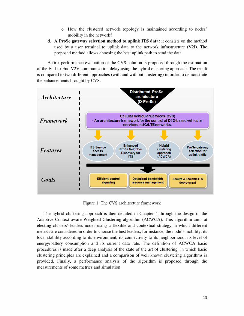
13
o How the clustered network topology is maintained according to nodes’
mobility in the network?
d. A ProSe gateway selection method to uplink ITS data: it consists on the method
used by a user terminal to uplink data to the network infrastructure (V2I). The
proposed method allows choosing the best uplink path to send the data.
A first performance evaluation of the CVS solution is proposed through the estimation
of the End-to-End V2V communication delay using the hybrid clustering approach. The result
is compared to two different approaches (with and without clustering) in order to demonstrate
the enhancements brought by CVS.
Figure 1: The CVS architecture framework
The hybrid clustering approach is then detailed in Chapter 4 through the design of the
Adaptive Context-aware Weighted Clustering algorithm (ACWCA). This algorithm aims at
electing clusters’ leaders nodes using a flexible and contextual strategy in which different
metrics are considered in order to choose the best leaders; for instance, the node’s mobility, its
local stability according to its environment, its connectivity to its neighborhood, its level of
energy/battery consumption and its current data rate. The definition of ACWCA basic
procedures is made after a deep analysis of the state of the art of clustering, in which basic
clustering principles are explained and a comparison of well known clustering algorithms is
provided. Finally, a performance analysis of the algorithm is proposed through the
measurements of some metrics and simulation.
14
Chapter 1: State of the art
1.1 Methodology
In order to answer the questions posed in the previous chapter, it is necessary to take a
deep look on the state of the art related to the raised issues. The goal of the following chapter
is mainly to provide an overview on the background of our work, understand and analyze the
existing solutions and proposals, and identify the weaknesses and strengths of each one of
them. This mainly helps understanding the motivations behind the different choices we made
during the design of our CVS architecture framework.
The starting point of our investigation is D2D communications; after providing a
description of the basic concepts and mechanisms of D2D discovery and communication, we
have identified the use cases and scenarios of D2D communications in order to provide an
analysis on the business challenges of the deployment of D2D-based services in 4G and future
5G networks for mobile operators. This helped us find the opportunities that allowed us to
position our CVS solution within a mobile operator business.
We introduce in a second place the state of the art of the standardization of D2D
communications for Proximity-based Services (ProSe) by the 3GPP; we provide in this part a
brief overview on the main enhancements of the 4G/LTE core network architecture to support
ProSe using LTE-based D2D communications. We are particularly interested here in the
mechanisms, procedures and protocols that are relevant to the design of our CVS framework
basic components, which include ProSe authentication and authorization procedures as well
as ProSe direct discovery and ProSe direct communication protocols and procedures. The goal
is mainly to point out the limitation of the ProSe standard and anticipate its enhancements and
future extensions.
The third section of this chapter is dedicated to the state of the art of V2X
communications in Intelligent Transportation Systems (ITS). Considering that these networks
can benefit from D2D communications, we have been interested in investigating the
background of their integration within 4G/LTE networks. Our investigation is mainly focused
on providing an overview on the ITS reference architecture standard and establishing a state
of the art of existing ITS architectures, as well as giving an overview on the existing solutions
and deployment models, in order to highlight the strategic opportunities for mobile operators
to be the precursors of the ITS large scale deployment in 5G networks.
These different state of the art on D2D communications, ProSe, ITS and V2X
communications allow us first to justify the design and technical choices of our CVS
architecture framework that we describe later on in the following chapters, and provide us
second with the necessary background related to existing solutions and which would help us
enrich our solution proposal.
15
1.2 State of the art of LTE-based D2D communications
1.2.1 What is D2D?
D2D communications are defined as direct communications between devices in short
range proximity without the support of any network infrastructure. Similarly to location-based
communications, D2D communications benefit from the geographical and radio proximity of
devices in order to establish a direct link between them for a local data exchange. Basically,
devices could be any device equipped with a D2D technology suitable for short range
communication (e.g. Bluetooth, Wi-Fi Direct…), such as smart phones, tablets, laptops,
network printers, cameras, or even connected vehicles.
In LTE networks, D2D is a new communication mode that paces the evolution of the user
device role toward a new generation of devices that acquire new functions and more network
capabilities than what it used to have in the past; the device is no longer a passive node in the
communication process and is rather an active network node that can perform some network
functions like relaying, routing and cooperation with its D2D neighbors.
Besides, considering the fast growth of the mobile data load as highlighted in [4], D2D is
considered as an efficient offloading solution to alleviate current mobile cellular networks
load while benefiting from better user data rates and native security and QoS mechanisms.
Thanks to D2D, it is envisioned that the current cellular network architecture would evolve
toward a layered topology in which heterogeneous networks would coexist and cooperate
under the control of a one macro-cell layer.
1.2.2 D2D technologies and use cases
• Technologies
D2D communications exist already since a decade within mobile services that are based
on some well-known short range technologies such as Bluetooth and Wi-Fi Direct.
Nevertheless, these technologies present some limitations and seem to be no longer suitable
for the future generation of proximity-aware, real time and context-aware services envisioned
in the context of the evolution toward 5G networks. Instead, LTE-based D2D services using a
new LTE short range radio called “LTE Direct” [25] in the devices are becoming the new
trend. Hence, LTE Direct is a D2D technology that utilizes licensed LTE spectrum for
proximal discovery of friends, services, offers, and other relevant value. It leverages the
global LTE standard as part of 3GPP release 12. LTE Direct works seamlessly with LTE,
setting aside a small percentage of radio sub-frames for efficient discovery. It leverages the
LTE network for timing, resource allocation, as well as user authentication. LTE Direct can
be efficiently integrated with existing LTE services and networks
A comparison of the main characteristics of this new radio technology with Bluetooth and
Wi-Fi direct is provided in Table 1.
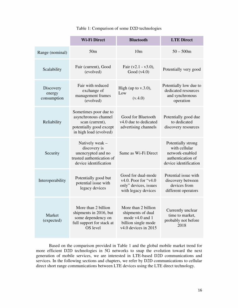
16
Table 1: Comparison of some D2D technologies
Wi-Fi Direct Bluetooth LTE Direct
Range (nominal) 50m 10m 50 – 500m
Scalability Fair (current), Good
(evolved)
Fair (v2.1 - v3.0),
Good (v4.0) Potentially very good
Discovery
energy
consumption
Fair with reduced
exchange of
management frames
(evolved)
High (up to v.3.0),
Low
(v.4.0)
Potentially low due to
dedicated resources
and synchronous
operation
Reliability
Sometimes poor due to
asynchronous channel
scan (current),
potentially good except
in high load (evolved)
Good for Bluetooth
v4.0 due to dedicated
advertising channels
Potentially good due
to dedicated
discovery resources
Security
Natively weak –
discovery is
unencrypted and no
trusted authentication of
device identification
Same as Wi-Fi Direct
Potentially strong
with cellular
network-enabled
authentication of
device identification
Interoperability
Potentially good but
potential issue with
legacy devices
Good for dual-mode
v4.0. Poor for “v4.0
only” devices, issues
with legacy devices
Potential issue with
discovery between
devices from
different operators
Market
(expected)
More than 2 billion
shipments in 2016, but
some dependency on
full support for stack at
OS level
More than 2 billion
shipments of dual
mode v4.0 and 1
billion single mode
v4.0 devices in 2015
Currently unclear
time to market,
probably not before
2018
Based on the comparison provided in Table 1 and the global mobile market trend for
more efficient D2D technologies in 5G networks to snap the evolution toward the next
generation of mobile services, we are interested in LTE-based D2D communications and
services. In the following sections and chapters, we refer by D2D communications to cellular
direct short range communications between LTE devices using the LTE direct technology.
17
• Use cases
D2D services have gained significant attention recently from mobile operators and
Telecommunication industrials as they present multiple attractive use cases of new services,
going from public/commercial services to more specific fields like public safety and military.
Multiple use case classifications were made in the literature for D2D [1] [2]. The commonly
identified three main categories are described in Table 2.
Table 2: D2D use cases classification
Use case category Applications
Commercial and Social Proximity Services: An
evolution of LBS services
through hyper-local and
dynamic proximity data.
• Discovery-centric services: Context-aware applications,
Social networking applications, location enhancement
applications, Social gaming, and smart cities services…
• Communication-centric services: content and video
sharing services
Public safety services based
on group and relay communications: Secure
services used on specific
D2D enabled devices and
deployed on a dedicated non-
public network
• Direct communication between public safety agents in
or outside network coverage: push-to-talk, group
communication, priority handling…
• Dedicated network access sharing for out of coverage
devices through peer-to-peer connections to nearby in-
coverage devices.
Services for network
capabilities enhancement
• Offloading services: offload of local data traffic or
video/voice call traffic.
• Multi-hop access services: Internet connection sharing
through devices acting as relays, Connectivity
extension to heterogeneous networks (UE acting as a
gateway to a Sensor network, UE in a vehicle acting as
a cooperative relay to a vehicular network
infrastructure, etc.)
1.2.3 D2D modes
D2D communication modes has been the focus of many research works in the recent years
[1] [2] [3]. Considering the interest of mobile operators for D2D-based services, the concept
of D2D has been extended to cover also a network-assisted scheme in which a mobile
operator can intervene as a trust third party that guaranty the security, the privacy and the
QoS. Consequently, mainly two communication modes are distinguished in D2D: the D2D
distributed mode and the D2D network-assisted mode.
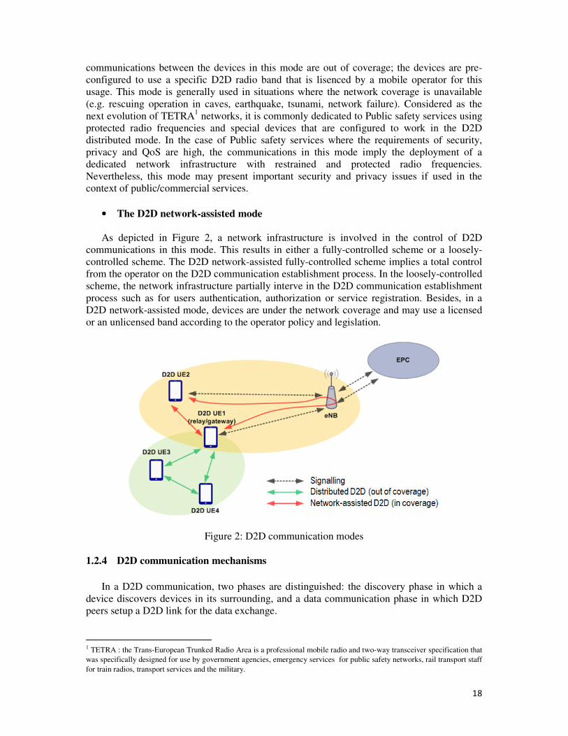
• The D2D distributed mode
As depicted in Figure 2, devices in this mode are organized in a completely distributed
and self-organizing network without the control of any network infrastructure. Usually, the
18
communications between the devices in this mode are out of coverage; the devices are pre-
configured to use a specific D2D radio band that is lisenced by a mobile operator for this
usage. This mode is generally used in situations where the network coverage is unavailable
(e.g. rescuing operation in caves, earthquake, tsunami, network failure). Considered as the
next evolution of TETRA1 networks, it is commonly dedicated to Public safety services using
protected radio frequencies and special devices that are configured to work in the D2D
distributed mode. In the case of Public safety services where the requirements of security,
privacy and QoS are high, the communications in this mode imply the deployment of a
dedicated network infrastructure with restrained and protected radio frequencies.
Nevertheless, this mode may present important security and privacy issues if used in the
context of public/commercial services.
• The D2D network-assisted mode
As depicted in Figure 2, a network infrastructure is involved in the control of D2D
communications in this mode. This results in either a fully-controlled scheme or a loosely-
controlled scheme. The D2D network-assisted fully-controlled scheme implies a total control
from the operator on the D2D communication establishment process. In the loosely-controlled
scheme, the network infrastructure partially interve in the D2D communication establishment
process such as for users authentication, authorization or service registration. Besides, in a
D2D network-assisted mode, devices are under the network coverage and may use a licensed
or an unlicensed band according to the operator policy and legislation.
Figure 2: D2D communication modes
1.2.4 D2D communication mechanisms
In a D2D communication, two phases are distinguished: the discovery phase in which a
device discovers devices in its surrounding, and a data communication phase in which D2D
peers setup a D2D link for the data exchange.
1 TETRA : the Trans-European Trunked Radio Area is a professional mobile radio and two-way transceiver specification that
was specifically designed for use by government agencies, emergency services for public safety networks, rail transport staff
for train radios, transport services and the military.
19
• D2D Discovery
The D2D discovery phase can be done in a direct way or assisted by the network, which
leads to two different discovery approaches:
- Direct discovery approach:
According to the 3GPP standard on Proximity-based Services (ProSe) [9], two direct
discovery models were identified: the “I’m Here” model (A) and the “who is there? /are you
there?” model (B). In addition, a device performs the direct discovery of its surrounding
according to a discovery role: the announcing role in which the device is in an active
discovery mode and announces its presence and the service it is offering, and the monitoring
role in which the device is more in a passive mode and only monitors from its surrounding
specific information and services related to its fields of interest. The Direct discovery
approach has the advantage of flexibility and scalability as it profits from the local radio and
positioning information of the devices to discover their neighborhood in a more efficient way.
The radio resources for this discovery mode can be either allocated by the network (e.g. the
base station) if the devices are under the network coverage, or preconfigured on specific
devices (e.g. public safety devices) if the devices are out of the network coverage.
- Centralized discovery approach:
This approach has been considered in some research studies and mostly by the ProSe standard
[9]: it involves at least one or more network entities in the discovery procedure. It is an
operator business oriented approach for the D2D discovery that highlights particularly the role
of the mobile operator as a provider of context and proximity information in the discovery
phase. Thanks to the wider vision of the mobile operator on the overall traffic and on the user
device mobility context, centralized discovery approaches aim at exploiting mobile operator
core network assets about devices micro/macro mobility in order to provide a more accurate
and efficient discovery information. It is to note that this discovery approach exceeds the
basic definition of D2D as an infrastructure-less communication between two devices.
Nevertheless, it is considered as one alternative discovery model for Proximity Services by
the 3GPP.
• D2D data communication
After a D2D discovery phase, D2D peers may need to establish a communication link for
data exchange. When the establishment of such a link is triggered by the network in order to
reduce the network overload, the process is known as offloading and is defined as the fact of
using alternative access technologies than the cellular one to exchange data between mobile
devices. As shown in Figure 2 and similarly to the D2D discovery phase, the offloading can
be done using two approaches:
- Direct D2D offloading: the data are routed between the devices directly using the
D2D radio interface and does not traverse the network infrastructure.
- Controlled D2D offloading: the data are routed between D2D devices using an
optimized data path (e.g. through the eNode B).
Based on these two offloading schemes, the data communication between devices could
be Best-Effort (no QoS support, connectionless links) or QoS-enabled (establishment of
dedicated LTE data bearers).
As described in Annex 1, in a classic LTE communication [10] [12], data flows between
two devices are setup through the establishment of data bearers. A data bearer is composed of
20
a radio bearer between the device and the eNode B, an EPC (Evolved Packet Core) bearer
between the eNode B and the Core network and packet filters in the devices. The
establishment of a data bearer consists on the setup of a PDN (Packet Data Network)
connection with the PDN Gateway and the allocation of an IP address for the communicating
devices.
In a D2D Direct communication scheme, the establishment of LTE data bearers between
devices may not be needed; the data are exchanged directly on the radio link between the
devices and only MAC layer addressing is used to identify the source and the destination of
the data packets.
1.2.5 D2D Business challenges for mobile operators
The relevance of D2D to the core business of a mobile operator may not be clear at first
glance, as it implies numerous challenges on how to control, manage and charge for the local
traffic, and may even have an impact on existing cellular revenues. Nevertheless, D2D
technology is of interest due to its potential to deliver a new class of mobile services.
Yet, the challenge for mobile operators is still to face the threat of Over-The-Top (OTT)
providers who have put their foot down at the mobile market with apps that supply instant
messaging, multimedia services like photo sharing and video conferencing and other popular
services for free. In such highly competitive ecosystem, operators’ strengths consist in having
a powerful network infrastructure that will allow the deployment of new D2D-based services
while assuming their guarantor role on users’ data security and privacy.
Despite the set of technical issues and challenges that operators may face with the
integration of D2D in LTE networks, they still have rich valuable assets that meet user
expectations toward new D2D services. Operators’ important assets may include:
• Service security and QoS through secure and uninterrupted connections.
• Identity management, authentication and Privacy when using a D2D service.
• Context information exposure for more attractive services and better QoE.
• Devices management: user’s cellular and non-cellular devices are associated to his
user profile and included into the operator’s subscriber database and automatically
associated with the owner’s cellular devices.
• Ensure the consistency of the user experience including reach ability and mobility
aspects (seamless offload, seamless handover, etc.).
1.2.6 Conclusion
With regards to the objectives described in chapter 1, more specifically the one that aims
at re-enforcing the mobile operator position in the mobile market and emphasizing its role in
the future D2D market, we chose to focus our work on network-assisted D2D
communications and services in LTE networks, considering the interesting opportunities they
present for mobile operators and also the benefits they provide for users in terms of security
and QoS. In order to understand the protocols enhancements and mechanisms that we
designed in our CVS architecture framework, it is important to understand the basic technical
procedures and protocols defined by the 3GPP for ProSe. As such, we provide in the
following section a state of the art of the 3GPP ProSe architecture [9] and an overview on its
basic protocols, entities and features.
21
1.3 State of the art of 3GPP Proximity-based Services (ProSe)
1.3.1 The ProSe architecture
The recent interest of mobile operators and the mobile industry for LTE-based D2D
communications and services has motivated, in 2013, the 3GPP to initiate a standardization
work on two major aspects: the specification of a new cellular short range radio [14] to be
deployed on users devices (e.g LTE Direct) and the specification of the LTE architecture
enhancements to support Proximity Services (ProSe) [9].The issued specification studies the
case of ProSe in non-roaming and roaming situations, as well as the interworking of ProSe
when used between different operators. In the following, we provide a description of the
ProSe architecture basic features, components and procedures, mainly those related to ProSe
Direct Discovery and Direct Communication in non-roaming scenario with a single PLMN.
1.3.1.1 ProSe basic features
ProSe [9] is a set of new features and mechanisms introduced as enhancements to the
Evolved Packet System (EPS) architecture (described in Annex 1) to support Proximity-based
Services in 4G and future 5G networks. The ProSe enablers for the support of LTE-based
D2D services consist mainly of the following features:
- ProSe Direct discovery: this function defines the procedures and mechanisms used to
identify ProSe-enabled UEs that are in proximity using E-UTRAN. It corresponds to
the D2D direct discovery which could be performed according to two discovery
models: the model A” I’m Here” and the model B “who is there? /are you there?”
- EPC-level ProSe Discovery: this function defines the procedures and mechanisms
used to identify ProSe-enabled UEs that are in proximity using EPC. It corresponds to
network-assisted D2D discovery in the fully-controlled scheme.
- ProSe Direct communication: this function consists on the procedures and
mechanisms that enable the establishment of communication paths between two or
more ProSe-enabled UEs who are in direct communication range. The ProSe Direct
Communication path could use E-UTRAN or WLAN. The direct communication
through E-UTRAN is currently dedicated by the standard to Public Safety cases.
- ProSe UE-to-Network relay: this function consists on the procedures and
mechanisms to implement for a ProSe-enabled UE that is in E-UTRAN coverage to
serve as a network relay for one or more ProSe-enabled UEs that are out of E-UTRAN
coverage. This function is currently dedicated by the standard to Public safety usages.
1.3.1.2 The ProSe function
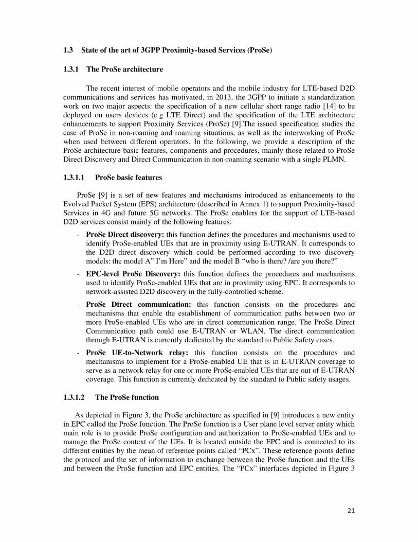
As depicted in Figure 3, the ProSe architecture as specified in [9] introduces a new entity
in EPC called the ProSe function. The ProSe function is a User plane level server entity which
main role is to provide ProSe configuration and authorization to ProSe-enabled UEs and to
manage the ProSe context of the UEs. It is located outside the EPC and is connected to its
different entities by the mean of reference points called “PCx”. These reference points define
the protocol and the set of information to exchange between the ProSe function and the UEs
and between the ProSe function and EPC entities. The “PCx” interfaces depicted in Figure 3
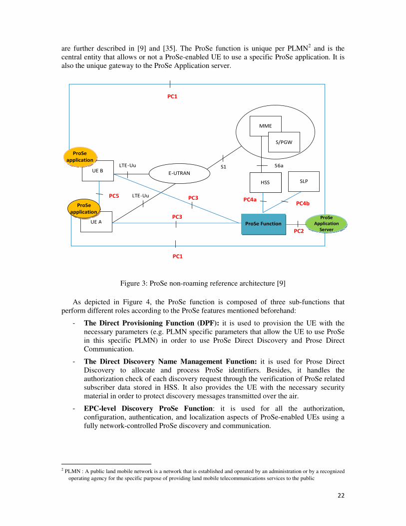
22
are further described in [9] and [35]. The ProSe function is unique per PLMN2 and is the
central entity that allows or not a ProSe-enabled UE to use a specific ProSe application. It is
also the unique gateway to the ProSe Application server.
UE B
ProSe
applicationLTE -Uu
E-UTRAN
UE A
S1
ProSe Function
PC4aPC5 LTE-Uu
PC3
PC1
MME
S/PGW
HSS
ProSe
application
S6a
HSS SLP
PC4b
PC1
ProSe
Application
Server PC2
PC3
Figure 3: ProSe non-roaming reference architecture [9]
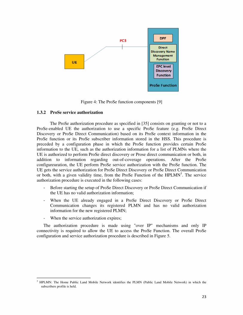
As depicted in Figure 4, the ProSe function is composed of three sub-functions that
perform different roles according to the ProSe features mentioned beforehand:
- The Direct Provisioning Function (DPF): it is used to provision the UE with the
necessary parameters (e.g. PLMN specific parameters that allow the UE to use ProSe
in this specific PLMN) in order to use ProSe Direct Discovery and Prose Direct
Communication.
- The Direct Discovery Name Management Function: it is used for Prose Direct
Discovery to allocate and process ProSe identifiers. Besides, it handles the
authorization check of each discovery request through the verification of ProSe related
subscriber data stored in HSS. It also provides the UE with the necessary security
material in order to protect discovery messages transmitted over the air.
- EPC-level Discovery ProSe Function: it is used for all the authorization,
configuration, authentication, and localization aspects of ProSe-enabled UEs using a
fully network-controlled ProSe discovery and communication.
2 PLMN : A public land mobile network is a network that is established and operated by an administration or by a recognized
operating agency for the specific purpose of providing land mobile telecommunications services to the public
23
Figure 4: The ProSe function components [9]
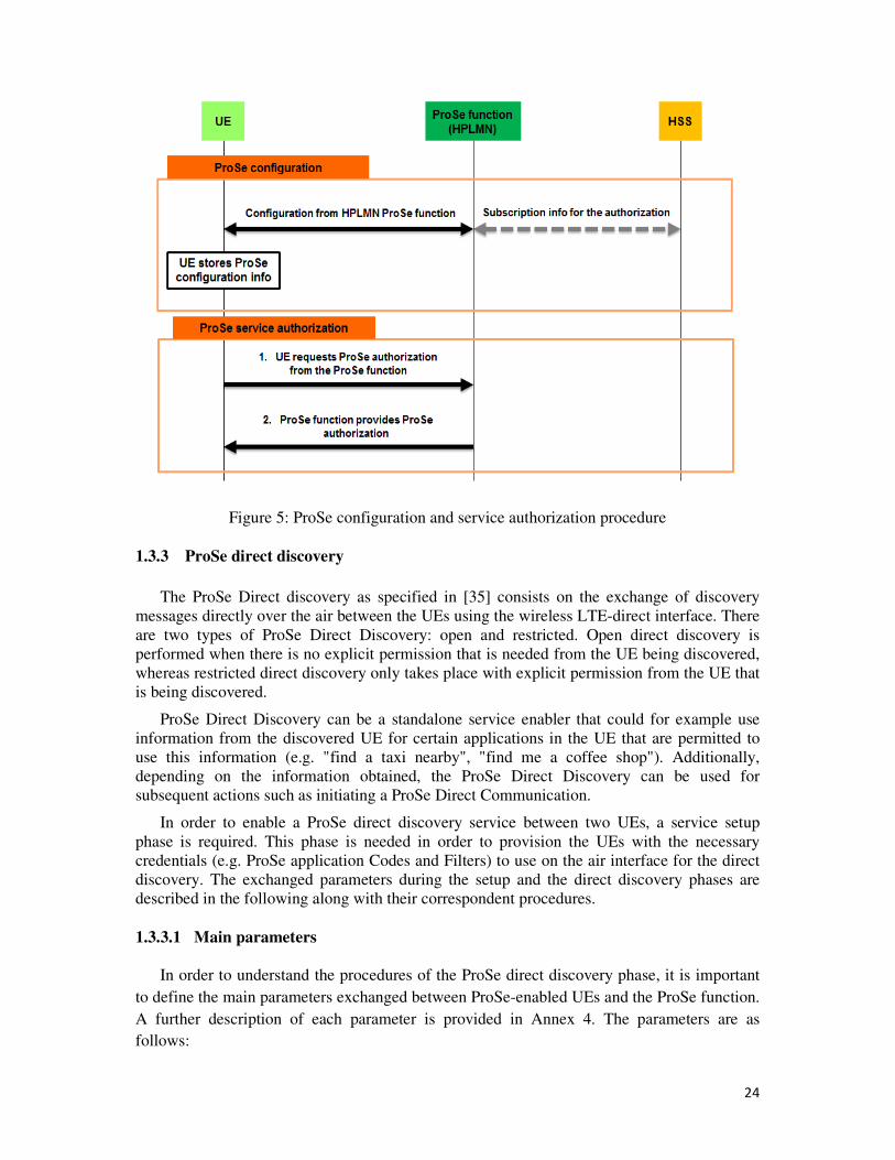
1.3.2 ProSe service authorization
The ProSe authorization procedure as specified in [35] consists on granting or not to a
ProSe-enabled UE the authorization to use a specific ProSe feature (e.g. ProSe Direct
Discovery or ProSe Direct Communication) based on its ProSe context information in the
ProSe function or its ProSe subscriber information stored in the HSS. This procedure is
preceded by a configuration phase in which the ProSe function provides certain ProSe
information to the UE, such as the authorization information for a list of PLMNs where the
UE is authorized to perform ProSe direct discovery or Prose direct communication or both, in
addition to information regarding out-of-coverage operations. After the ProSe
configureuration, the UE perform ProSe service authorization with the ProSe function. The
UE gets the service authorization for ProSe Direct Discovery or ProSe Direct Communication
or both, with a given validity time, from the ProSe Function of the HPLMN3. The service
authorization procedure is executed in the following cases:
- Before starting the setup of ProSe Direct Discovery or ProSe Direct Communication if
the UE has no valid authorization information;
- When the UE already engaged in a ProSe Direct Discovery or ProSe Direct
Communication changes its registered PLMN and has no valid authorization
information for the new registered PLMN;
- When the service authorization expires;
The authorization procedure is made using "over IP" mechanisms and only IP
connectivity is required to allow the UE to access the ProSe Function. The overall ProSe
configuration and service authorization procedure is described in Figure 5.
3 HPLMN: The Home Public Land Mobile Network identifies the PLMN (Public Land Mobile Network) in which the
subscribers profile is held.
24
Figure 5: ProSe configuration and service authorization procedure
1.3.3 ProSe direct discovery
The ProSe Direct discovery as specified in [35] consists on the exchange of discovery
messages directly over the air between the UEs using the wireless LTE-direct interface. There
are two types of ProSe Direct Discovery: open and restricted. Open direct discovery is
performed when there is no explicit permission that is needed from the UE being discovered,
whereas restricted direct discovery only takes place with explicit permission from the UE that
is being discovered.
ProSe Direct Discovery can be a standalone service enabler that could for example use
information from the discovered UE for certain applications in the UE that are permitted to
use this information (e.g. "find a taxi nearby", "find me a coffee shop"). Additionally,
depending on the information obtained, the ProSe Direct Discovery can be used for
subsequent actions such as initiating a ProSe Direct Communication.
In order to enable a ProSe direct discovery service between two UEs, a service setup
phase is required. This phase is needed in order to provision the UEs with the necessary
credentials (e.g. ProSe application Codes and Filters) to use on the air interface for the direct
discovery. The exchanged parameters during the setup and the direct discovery phases are
described in the following along with their correspondent procedures.
1.3.3.1 Main parameters
In order to understand the procedures of the ProSe direct discovery phase, it is important
to define the main parameters exchanged between ProSe-enabled UEs and the ProSe function.
A further description of each parameter is provided in Annex 4. The parameters are as
follows:
25
• ProSe Application Identifier (ProSe_App_ID): This parameter is used to carry an
identity used for open ProSe direct discovery, identifying application related information
for the ProSe-enabled UE.
• ProSe Application Code (ProSe_App_Code): For announcing UEs, the ProSe
Application Code is obtained from the HPLMN ProSe Function using the Announce
Request procedure. The ProSe Application Code is contained in the message that is
transmitted over the radio interface (on PC5) by a UE engaged in the ProSe Direct
Discovery procedure to monitoring UEs.
• ProSe Application Mask (ProSe_App_mask): A ProSe Application Mask is a bitmask
that is used for partial matching of ProSe Application Codes broadcasted by announcing
UEs on the PC5 interface and received by monitoring UEs. A ProSe Application Mask is
contained in a Discovery Filter and consists of one or more applicable parts of temporary
identities of ProSe Application Codes to allow partial matching. The length of the ProSe
Application Mask is the same as the length of a ProSe Application Code.
• Discovery Filter: A Discovery Filter is provided to a monitoring UE by its HPLMN
ProSe Function to selectively match ProSe Application Codes received from announcing
UEs on the PC5 interface.
• UE identity (UE Id): This parameter is used to indicate the requesting UE's identity and
is set to the IMSI4.
• Message type: This parameter is used to indicate the type of ProSe direct discovery in the
PC5 messages.
1.3.3.2 ProSe Direct Discovery setup procedure
As specified in [35], when an authorized ProSe-enabled UE wants to perform a ProSe
direct Discovery, it sends a ProSe direct discovery request message to the ProSe function with
parameters like the discovery role parameter set to “announce” or “monitor”, the ProSe
application identifier “ProSe_App_Id”, the ProSe UE identity, etc. Upon this discovery
request, the ProSe function performs the necessary authorization checks on the ProSe UE
identity and the requested ProSe_App_ID and generates a temporary ProSe identity. The
ProSe temporary identity could be a ProSe_App_Code or a ProSe_Filter according to the type
of the discovery role that the UE is requesting (e.g. announcing UE or monitoring UE). These
credentials are then sent to the UE with their correspondent validity timers and are used to
perform ProSe direct discovery. The overall ProSe direct discovery request procedure is
explained in Figure 6. Hence, two different procedures can be triggered according to the
requested discovery role: discovery request for announcing UEs or discovery request for
monitoring UEs.
4 IMSI: International Mobile Subscriber Identity is used to identify the user of a cellular network and is a unique
identification associated with all cellular networks. It is stored as a 64 bit field and is sent by the phone to the network
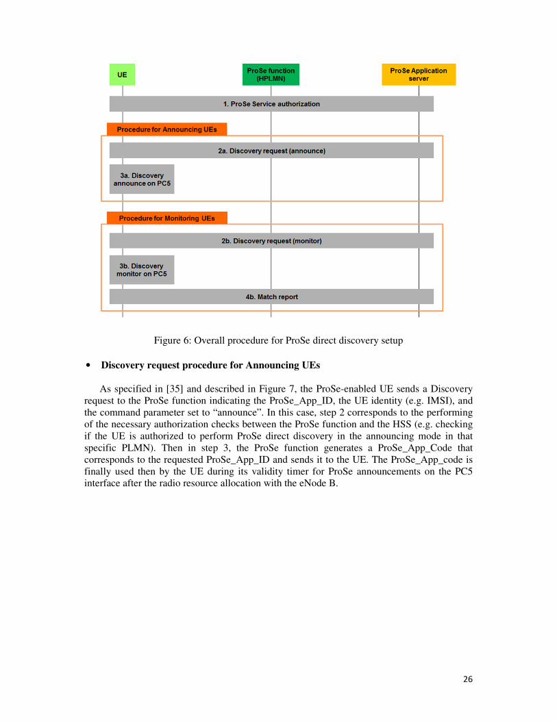
26
Figure 6: Overall procedure for ProSe direct discovery setup
• Discovery request procedure for Announcing UEs
As specified in [35] and described in Figure 7, the ProSe-enabled UE sends a Discovery
request to the ProSe function indicating the ProSe_App_ID, the UE identity (e.g. IMSI), and
the command parameter set to “announce”. In this case, step 2 corresponds to the performing
of the necessary authorization checks between the ProSe function and the HSS (e.g. checking
if the UE is authorized to perform ProSe direct discovery in the announcing mode in that
specific PLMN). Then in step 3, the ProSe function generates a ProSe_App_Code that
corresponds to the requested ProSe_App_ID and sends it to the UE. The ProSe_App_code is
finally used then by the UE during its validity timer for ProSe announcements on the PC5
interface after the radio resource allocation with the eNode B.
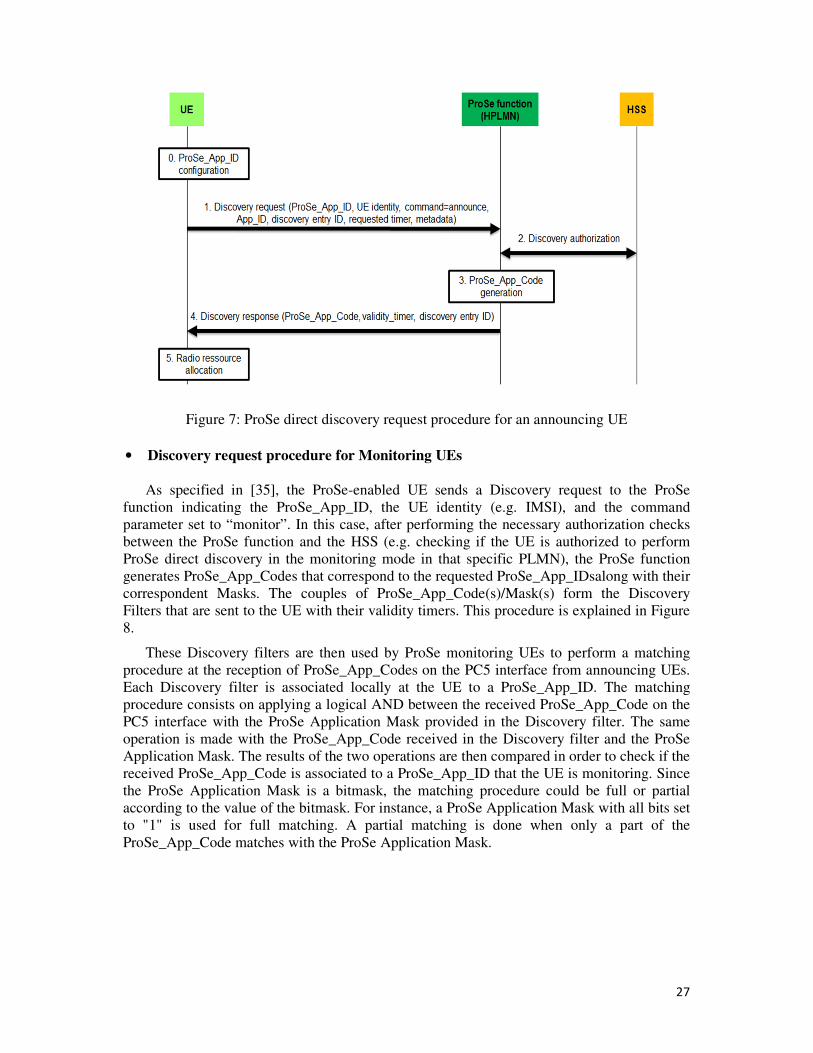
27
Figure 7: ProSe direct discovery request procedure for an announcing UE
• Discovery request procedure for Monitoring UEs
As specified in [35], the ProSe-enabled UE sends a Discovery request to the ProSe
function indicating the ProSe_App_ID, the UE identity (e.g. IMSI), and the command
parameter set to “monitor”. In this case, after performing the necessary authorization checks
between the ProSe function and the HSS (e.g. checking if the UE is authorized to perform
ProSe direct discovery in the monitoring mode in that specific PLMN), the ProSe function
generates ProSe_App_Codes that correspond to the requested ProSe_App_IDsalong with their
correspondent Masks. The couples of ProSe_App_Code(s)/Mask(s) form the Discovery
Filters that are sent to the UE with their validity timers. This procedure is explained in Figure
8.
These Discovery filters are then used by ProSe monitoring UEs to perform a matching
procedure at the reception of ProSe_App_Codes on the PC5 interface from announcing UEs.
Each Discovery filter is associated locally at the UE to a ProSe_App_ID. The matching
procedure consists on applying a logical AND between the received ProSe_App_Code on the
PC5 interface with the ProSe Application Mask provided in the Discovery filter. The same
operation is made with the ProSe_App_Code received in the Discovery filter and the ProSe
Application Mask. The results of the two operations are then compared in order to check if the
received ProSe_App_Code is associated to a ProSe_App_ID that the UE is monitoring. Since
the ProSe Application Mask is a bitmask, the matching procedure could be full or partial
according to the value of the bitmask. For instance, a ProSe Application Mask with all bits set
to "1" is used for full matching. A partial matching is done when only a part of the
ProSe_App_Code matches with the ProSe Application Mask.
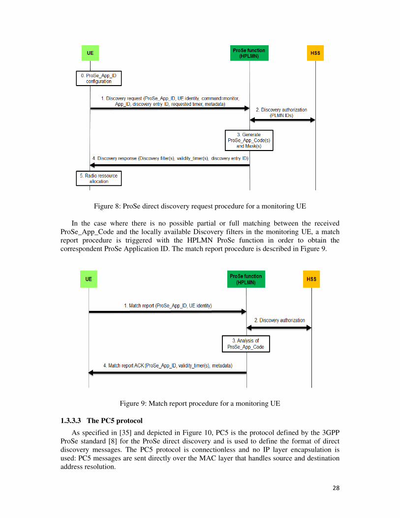
28
Figure 8: ProSe direct discovery request procedure for a monitoring UE
In the case where there is no possible partial or full matching between the received
ProSe_App_Code and the locally available Discovery filters in the monitoring UE, a match
report procedure is triggered with the HPLMN ProSe function in order to obtain the
correspondent ProSe Application ID. The match report procedure is described in Figure 9.
Figure 9: Match report procedure for a monitoring UE
1.3.3.3 The PC5 protocol
As specified in [35] and depicted in Figure 10, PC5 is the protocol defined by the 3GPP
ProSe standard [8] for the ProSe direct discovery and is used to define the format of direct
discovery messages. The PC5 protocol is connectionless and no IP layer encapsulation is
used: PC5 messages are sent directly over the MAC layer that handles source and destination
address resolution.
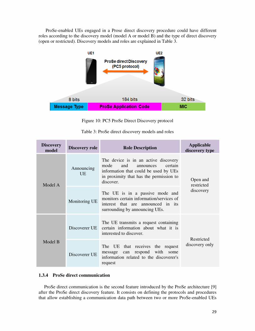
29
ProSe-enabled UEs engaged in a Prose direct discovery procedure could have different
roles according to the discovery model (model A or model B) and the type of direct discovery
(open or restricted). Discovery models and roles are explained in Table 3.
Figure 10: PC5 ProSe Direct Discovery protocol
Table 3: ProSe direct discovery models and roles
Discovery
model Discovery role Role Description
Applicable
discovery type
Model A
Announcing
UE
The device is in an active discovery
mode and announces certain
information that could be used by UEs
in proximity that has the permission to
discover. Open and
restricted
discovery
Monitoring UE
The UE is in a passive mode and
monitors certain information/services of
interest that are announced in its
surrounding by announcing UEs.
Model B
Discoverer UE
The UE transmits a request containing
certain information about what it is
interested to discover.
Restricted
discovery only
Discoverer UE
The UE that receives the request
message can respond with some
information related to the discoverer's
request
1.3.4 ProSe direct communication
ProSe direct communication is the second feature introduced by the ProSe architecture [9]
after the ProSe direct discovery feature. It consists on defining the protocols and procedures
that allow establishing a communication data path between two or more ProSe-enabled UEs
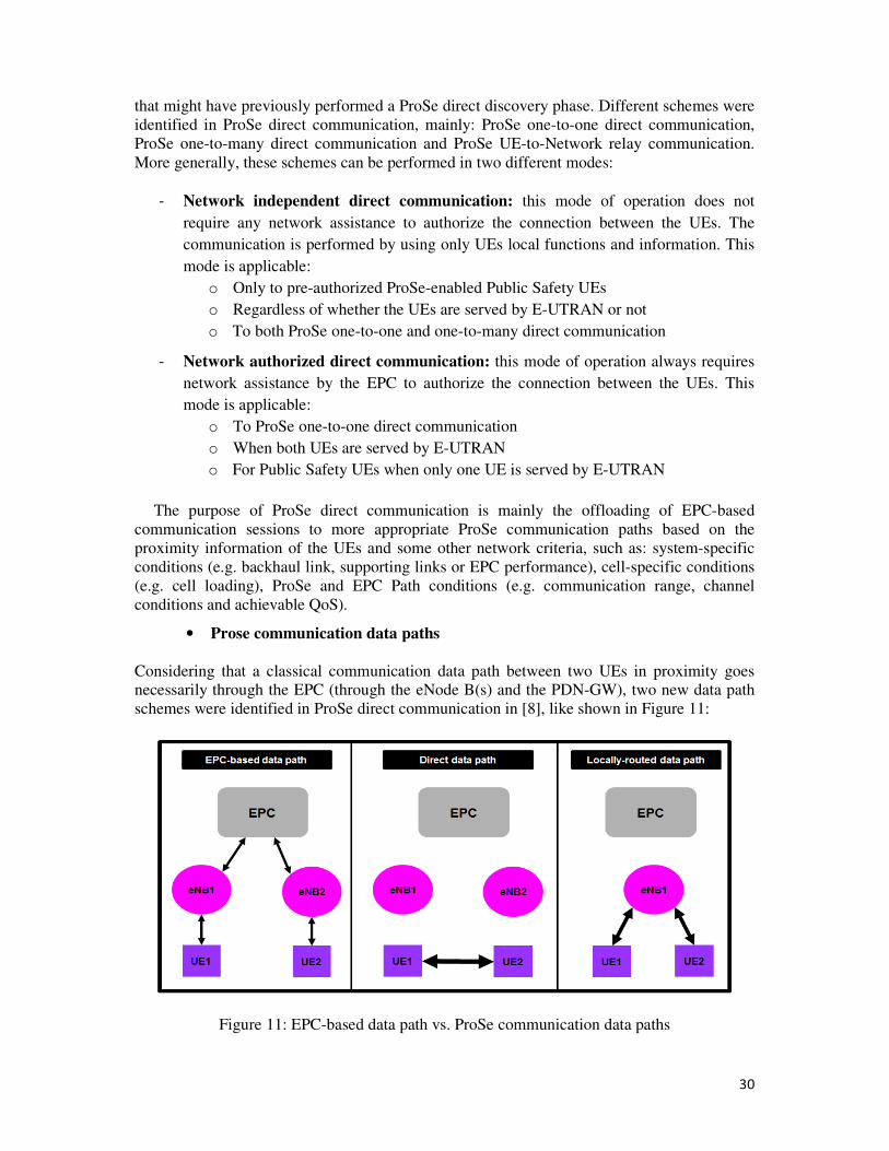
30
that might have previously performed a ProSe direct discovery phase. Different schemes were
identified in ProSe direct communication, mainly: ProSe one-to-one direct communication,
ProSe one-to-many direct communication and ProSe UE-to-Network relay communication.
More generally, these schemes can be performed in two different modes:
- Network independent direct communication: this mode of operation does not
require any network assistance to authorize the connection between the UEs. The
communication is performed by using only UEs local functions and information. This
mode is applicable:
o Only to pre-authorized ProSe-enabled Public Safety UEs
o Regardless of whether the UEs are served by E-UTRAN or not
o To both ProSe one-to-one and one-to-many direct communication
- Network authorized direct communication: this mode of operation always requires
network assistance by the EPC to authorize the connection between the UEs. This
mode is applicable:
o To ProSe one-to-one direct communication
o When both UEs are served by E-UTRAN
o For Public Safety UEs when only one UE is served by E-UTRAN
The purpose of ProSe direct communication is mainly the offloading of EPC-based
communication sessions to more appropriate ProSe communication paths based on the
proximity information of the UEs and some other network criteria, such as: system-specific
conditions (e.g. backhaul link, supporting links or EPC performance), cell-specific conditions
(e.g. cell loading), ProSe and EPC Path conditions (e.g. communication range, channel
conditions and achievable QoS).
• Prose communication data paths
Considering that a classical communication data path between two UEs in proximity goes
necessarily through the EPC (through the eNode B(s) and the PDN-GW), two new data path
schemes were identified in ProSe direct communication in [8], like shown in Figure 11:
Figure 11: EPC-based data path vs. ProSe communication data paths
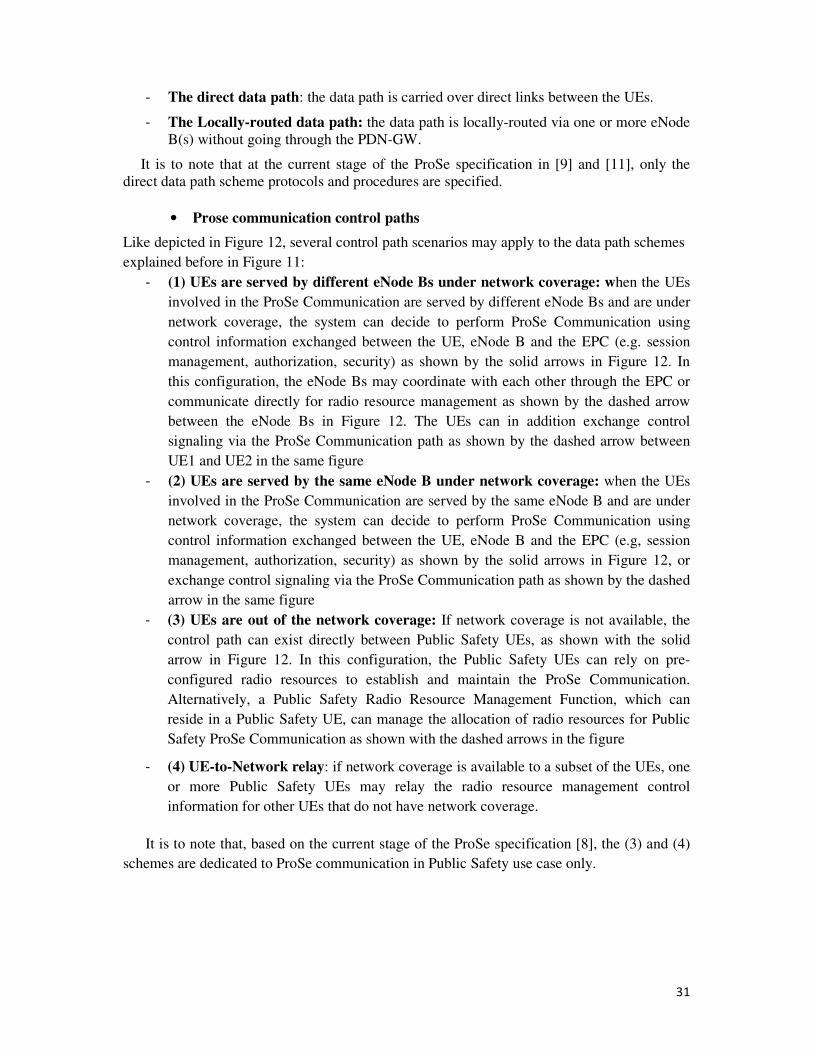
31
- The direct data path: the data path is carried over direct links between the UEs.
- The Locally-routed data path: the data path is locally-routed via one or more eNode
B(s) without going through the PDN-GW.
It is to note that at the current stage of the ProSe specification in [9] and [11], only the
direct data path scheme protocols and procedures are specified.
• Prose communication control paths
Like depicted in Figure 12, several control path scenarios may apply to the data path schemes
explained before in Figure 11:
- (1) UEs are served by different eNode Bs under network coverage: when the UEs
involved in the ProSe Communication are served by different eNode Bs and are under
network coverage, the system can decide to perform ProSe Communication using
control information exchanged between the UE, eNode B and the EPC (e.g. session
management, authorization, security) as shown by the solid arrows in Figure 12. In
this configuration, the eNode Bs may coordinate with each other through the EPC or
communicate directly for radio resource management as shown by the dashed arrow
between the eNode Bs in Figure 12. The UEs can in addition exchange control
signaling via the ProSe Communication path as shown by the dashed arrow between
UE1 and UE2 in the same figure
- (2) UEs are served by the same eNode B under network coverage: when the UEs
involved in the ProSe Communication are served by the same eNode B and are under
network coverage, the system can decide to perform ProSe Communication using
control information exchanged between the UE, eNode B and the EPC (e.g, session
management, authorization, security) as shown by the solid arrows in Figure 12, or
exchange control signaling via the ProSe Communication path as shown by the dashed
arrow in the same figure
- (3) UEs are out of the network coverage: If network coverage is not available, the
control path can exist directly between Public Safety UEs, as shown with the solid
arrow in Figure 12. In this configuration, the Public Safety UEs can rely on pre-
configured radio resources to establish and maintain the ProSe Communication.
Alternatively, a Public Safety Radio Resource Management Function, which can
reside in a Public Safety UE, can manage the allocation of radio resources for Public
Safety ProSe Communication as shown with the dashed arrows in the figure
- (4) UE-to-Network relay: if network coverage is available to a subset of the UEs, one
or more Public Safety UEs may relay the radio resource management control
information for other UEs that do not have network coverage.
It is to note that, based on the current stage of the ProSe specification [8], the (3) and (4)
schemes are dedicated to ProSe communication in Public Safety use case only.
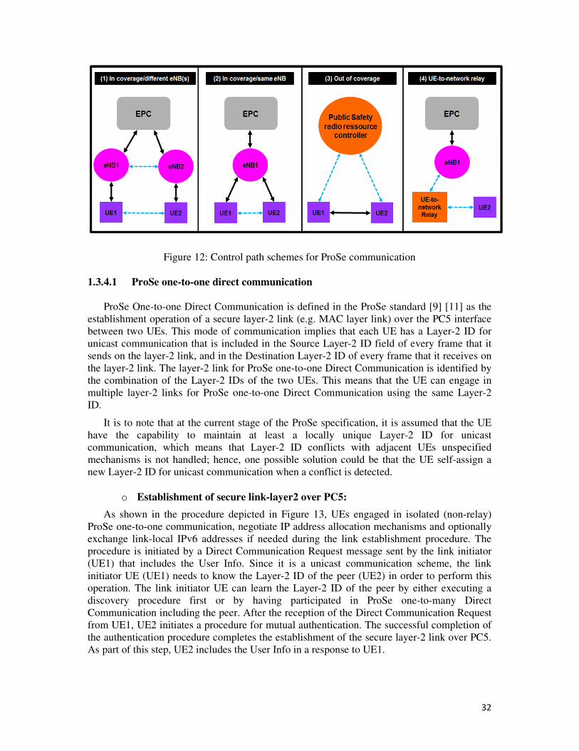
32
Figure 12: Control path schemes for ProSe communication
1.3.4.1 ProSe one-to-one direct communication
ProSe One-to-one Direct Communication is defined in the ProSe standard [9] [11] as the
establishment operation of a secure layer-2 link (e.g. MAC layer link) over the PC5 interface
between two UEs. This mode of communication implies that each UE has a Layer-2 ID for
unicast communication that is included in the Source Layer-2 ID field of every frame that it
sends on the layer-2 link, and in the Destination Layer-2 ID of every frame that it receives on
the layer-2 link. The layer-2 link for ProSe one-to-one Direct Communication is identified by
the combination of the Layer-2 IDs of the two UEs. This means that the UE can engage in
multiple layer-2 links for ProSe one-to-one Direct Communication using the same Layer-2
ID.
It is to note that at the current stage of the ProSe specification, it is assumed that the UE
have the capability to maintain at least a locally unique Layer-2 ID for unicast
communication, which means that Layer-2 ID conflicts with adjacent UEs unspecified
mechanisms is not handled; hence, one possible solution could be that the UE self-assign a
new Layer-2 ID for unicast communication when a conflict is detected.
o Establishment of secure link-layer2 over PC5:
As shown in the procedure depicted in Figure 13, UEs engaged in isolated (non-relay)
ProSe one-to-one communication, negotiate IP address allocation mechanisms and optionally
exchange link-local IPv6 addresses if needed during the link establishment procedure. The
procedure is initiated by a Direct Communication Request message sent by the link initiator
(UE1) that includes the User Info. Since it is a unicast communication scheme, the link
initiator UE (UE1) needs to know the Layer-2 ID of the peer (UE2) in order to perform this
operation. The link initiator UE can learn the Layer-2 ID of the peer by either executing a
discovery procedure first or by having participated in ProSe one-to-many Direct
Communication including the peer. After the reception of the Direct Communication Request
from UE1, UE2 initiates a procedure for mutual authentication. The successful completion of
the authentication procedure completes the establishment of the secure layer-2 link over PC5.
As part of this step, UE2 includes the User Info in a response to UE1.
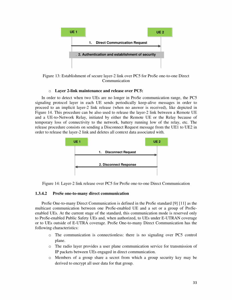
33
UE 1 UE 2
1. Direct Communication Request
. 2. Authentication and establishment of security association
Figure 13: Establishment of secure layer-2 link over PC5 for ProSe one-to-one Direct
Communication
o Layer 2-link maintenance and release over PC5:
In order to detect when two UEs are no longer in ProSe communication range, the PC5
signaling protocol layer in each UE sends periodically keep-alive messages in order to
proceed to an implicit layer-2 link release (when no answer is received), like depicted in
Figure 14. This procedure can be also used to release the layer-2 link between a Remote UE
and a UE-to-Network Relay, initiated by either the Remote UE or the Relay because of
temporary loss of connectivity to the network, battery running low of the relay, etc. The
release procedure consists on sending a Disconnect Request message from the UE1 to UE2 in
order to release the layer-2 link and deletes all context data associated with.
UE 1 UE 2
1. Disconnect Request
2. Disconnect Response
Figure 14: Layer-2 link release over PC5 for ProSe one-to-one Direct Communication
1.3.4.2 ProSe one-to-many direct communication
ProSe One-to-many Direct Communication is defined in the ProSe standard [9] [11] as the
multicast communication between one ProSe-enabled UE and a set or a group of ProSe-
enabled UEs. At the current stage of the standard, this communication mode is reserved only
to ProSe-enabled Public Safety UEs and, when authorized, to UEs under E-UTRAN coverage
or to UEs outside of E-UTRA coverage. ProSe One-to-many Direct Communication has the
following characteristics:
o The communication is connectionless: there is no signaling over PC5 control
plane.
o The radio layer provides a user plane communication service for transmission of
IP packets between UEs engaged in direct communication.
o Members of a group share a secret from which a group security key may be
derived to encrypt all user data for that group.
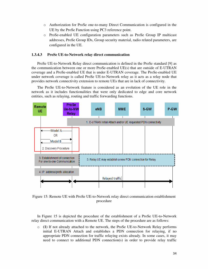
34
o Authorization for ProSe one-to-many Direct Communication is configured in the
UE by the ProSe Function using PC3 reference point.
o ProSe-enabled UE configuration parameters such as ProSe Group IP multicast
addresses, ProSe Group IDs, Group security material, radio related parameters, are
configured in the UE.
1.3.4.3 ProSe UE-to-Network relay direct communication
ProSe UE-to-Network Relay direct communication is defined in the ProSe standard [9] as
the communication between one or more ProSe-enabled UE(s) that are outside of E-UTRAN
coverage and a ProSe-enabled UE that is under E-UTRAN coverage. The ProSe-enabled UE
under network coverage is called ProSe UE-to-Network relay as it acts as a relay node that
provides network connectivity extension to remote UEs that are in lack of connectivity.
The ProSe UE-to-Network feature is considered as an evolution of the UE role in the
network as it includes functionalities that were only dedicated to edge and core network
entities, such as relaying, routing and traffic forwarding functions.
Figure 15: Remote UE with ProSe UE-to-Network relay direct communication establishment
procedure
In Figure 15 is depicted the procedure of the establishment of a ProSe UE-to-Network
relay direct communication with a Remote UE. The steps of the procedure are as follows:
o (1) If not already attached to the network, the ProSe UE-to-Network Relay performs
initial E-UTRAN Attach and establishes a PDN connection for relaying, if no
appropriate PDN connection for traffic relaying exists already. In some cases, it may
need to connect to additional PDN connection(s) in order to provide relay traffic
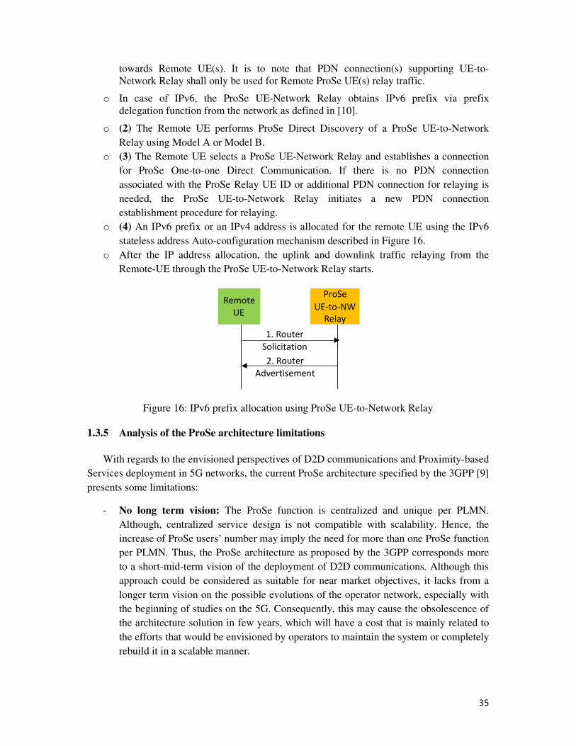
35
towards Remote UE(s). It is to note that PDN connection(s) supporting UE-to-
Network Relay shall only be used for Remote ProSe UE(s) relay traffic.
o In case of IPv6, the ProSe UE-Network Relay obtains IPv6 prefix via prefix
delegation function from the network as defined in [10].
o (2) The Remote UE performs ProSe Direct Discovery of a ProSe UE-to-Network
Relay using Model A or Model B.
o (3) The Remote UE selects a ProSe UE-Network Relay and establishes a connection
for ProSe One-to-one Direct Communication. If there is no PDN connection
associated with the ProSe Relay UE ID or additional PDN connection for relaying is
needed, the ProSe UE-to-Network Relay initiates a new PDN connection
establishment procedure for relaying.
o (4) An IPv6 prefix or an IPv4 address is allocated for the remote UE using the IPv6
stateless address Auto-configuration mechanism described in Figure 16.
o After the IP address allocation, the uplink and downlink traffic relaying from the
Remote-UE through the ProSe UE-to-Network Relay starts.
Remote
UE
ProSe
UE-to-NW
Relay
2. Router
Advertisement
1. Router
Solicitation
Figure 16: IPv6 prefix allocation using ProSe UE-to-Network Relay
1.3.5 Analysis of the ProSe architecture limitations
With regards to the envisioned perspectives of D2D communications and Proximity-based
Services deployment in 5G networks, the current ProSe architecture specified by the 3GPP [9]
presents some limitations:
- No long term vision: The ProSe function is centralized and unique per PLMN.
Although, centralized service design is not compatible with scalability. Hence, the
increase of ProSe users’ number may imply the need for more than one ProSe function
per PLMN. Thus, the ProSe architecture as proposed by the 3GPP corresponds more
to a short-mid-term vision of the deployment of D2D communications. Although this
approach could be considered as suitable for near market objectives, it lacks from a
longer term vision on the possible evolutions of the operator network, especially with
the beginning of studies on the 5G. Consequently, this may cause the obsolescence of
the architecture solution in few years, which will have a cost that is mainly related to
the efforts that would be envisioned by operators to maintain the system or completely
rebuild it in a scalable manner.
36
- Useless additional control signaling: ProSe signaling is handled on the LTE User
plane (IP level).The authentication and authorization aspects introduced by the ProSe
function are functions that exist already and are provided by the MME and HSS.
Considering the evolution towards 5G networks, the ProSe function could then
become a small feature that is integrated in the MME entity in the long term.
- The underuse of D2D direct communications’ potential as an underlay solution to
cellular networks: The current ProSe standard restrains the use of ProSe direct
communications to Public safety services. Nevertheless, the data overload of today’s
cellular networks is mainly caused by non-Public Safety services. Yet, using ProSe
direct communications for commercial services maybe risky for the operator business
mainly because of its security and privacy challenges. One possible solution to offload
the data for non-Public safety communications could be the use of locally-routed data
paths for ProSe direct communications in non-Public Safety cases.
1.3.6 Conclusion
The 3GPP ProSe architecture is an enabler for the deployment of a new generation of
services that exploits the potential of LTE-based D2D direct communications as a means to
relieve the data overload in mobile operators’ core networks. Yet, the current 3GPP ProSe
standard seems to fit more likely into a short/mid-term vision of ProSe deployment than into a
long term one that corresponds to the future 5G perspectives. For this reason, we have been
interested in investigating the possible enhancements to the ProSe architecture in order to
make it more scalable and more flexible to adapt to the transition to 5G networks. The
investigation results on these enhancements lead us to the contribution presented in chapter 3,
which we consider as the basis of our CVS architecture framework. Secondly, we have been
interested in studying a new opportunity for the mobile operator to benefit from the ProSe
architecture assets as an enabler for the deployment of vehicular networks and services at the
large scale. The following section is related to the study of this opportunity.
37
1.4 State of the art of ITS and V2X communications
1.4.1 Overview
Vehicular Networks known as VANETs (Vehicular Ad-hoc NETworks) are defined as the
next generation of urban networks in smart cities that are based on V2X (Vehicle to
Everything) communications and smart vehicles. Hence, VANETs and V2X communications
have been very popular research fields in the past decade and have attracted a huge number of
research studies and real field experimental projects both from the academia and from the
industry. In this context, ITS (Intelligent Transportation Systems) has been defined as an
evolution of the classical transportation system that aims at deploying V2X communications
and VANETs at the large scale. Hence, ITS are considered as a new domain of
Telecommunications and their deployment aims to achieve three objectives:
• Public road safety objective: ITS would help the reduction of road accidents through
vehicles’ onboard communication systems for collision avoidance and providing road
operators the possibility to warn drivers about route hazards.
• Ecological objective: ITS would help optimizing the transportation and traffic
regulation allowing at the same time the reduction of petrol consumption and the
emissions of greenhouse effect gazes.
• New market opportunity objective: Through the expansion of Internet connectivity
everywhere on the road and on vehicles, ITS would open new market perspectives to
promote new infotainment services for increased road users comfort and a better road
travel experience.
More generally, ITS would provide an evolved transportation system that is based on the
principle of cooperation between all road entities (infrastructure, vehicles and road users) in
order to provide safer roads, greener cities and an enhanced driver experience. Yet, such a
communication system requires reliable control technologies for vehicles and for the
infrastructure, efficient data transmission between ITS entities and a reliable and undisrupted
end-to-end ITS service. These requirements are achieved through the deployment of on-board
communication systems embedded on ITS subsystems such as vehicles, users’ personal
devices, roadside infrastructures and ITS remote servers, based on a reliable wireless short
range technology dedicated to these usages.
In this context, the IEEE802.11p technology has been adopted as the Wireless Access for
Vehicular Environments (WAVE) standard [18] for V2X communications in ITS. In addition,
an ITS reference architecture has been standardized by ETSI5 [15] to provide a harmonized
basis for the deployment of a global ITS communication system. This architecture was
designed to support a variety of access media types (802.11p, 802.11a/b/g, 3G/4G, etc.) and a
variety of networking protocols (Geo-networking, IPv6, etc.) for a variety of Cooperative ITS
5 ETSI : European telecommunciations Standards Institue
38
applications in different types of ITS stations (vehicle, personal device, infrastructure, central
servers, etc.).
1.4.1.1 ITS requirements
To achieve the above-mentioned objectives and reach a reliable system, careful
considerations need to be taken with regards to the challenges of ITS in managing an
increasing number of mobile nodes (including vehicles and personal devices) and maintaining
highly dynamic network topologies while ensuring the security, the efficiency and the
reliability of the whole system. Thus, the deployment and design of ITS should answer the
following basic set of requirements:
- Enabling Direct discovery and communication between ITS entities through an
adequate wireless technology
- The support of high speed nodes
- The need for direction and accurate location information
- Ensuring the efficiency and the low latency for road safety and traffic efficiency
applications
- Enabling the broadcast function in ITS stations
- Capability of traffic information broadcast from the base station (e.g. eNode B or ITS
Roadside Unit)
1.4.1.2 ITS applications
ITS applications or services have been classified in three main classes of cooperative
ITS services based on the type of V2X communication used (e.g. Vehicle to Vehicle “V2V”,
Vehicle to Infrastructure “V2I”, Vehicle to Pedestrian “V2P”, ect):
- Road safety services: these services are generally based on V2V and V2P
communications. They are delay sensitive (require latency < 100ms) and require
reliability and scalability of the short range technology used to transmit the road safety
information between vehicles. They aim mainly at using the communication system to
implement a cooperative awareness that assists the driver and helps preventing road
hazards like vehicles collision. Thus, these services are based on the periodic
transmission of information from vehicles and pedestrians.
- Traffic efficiency services: these services are generally based on V2V and V2I
communications and combine the use of different connectivity technologies, such as
IEEE802.11p and cellular (3G/4G and beyond), in order to deliver a reliable
information to the users. In some cases, these services can be delay tolerant as they are
considered rather as informational services more than road safety critical services.
- Infotainment services: these services are among location based services and global
internet services. Similar to Proximity-based Services (ProSe), they are based on the
use of the proximity and the geographical location of the vehicles and pedestrians in
order to deliver value-added services that enhance the driver and passengers driving
experience. They are generally based on V2I communications but can also use V2V
and V2P communications in some cases.
39
1.4.2 ITS reference architecture
In order to enable vehicles made by different manufacturers to communicate with each
other and with road infrastructure systems, standardization actions have been engaged for
Cooperative ITS to deliver a coherent set of standards, specifications and guidelines to
support european wide implementation and deployment of Cooperative ITS systems. This
standardization work brought together experts from the automotive industry including car
manufacturers and their suppliers, as well as infrastructure system suppliers and mobile
operators, in order to define a harmonized ITS reference communication architecture. This
architecture [15] will be deployed on various types of ITS stations involved in Cooperative
ITS communications (e.g. vehicle ITS station, personal ITS station, central ITS station and
roadside ITS station), but different features would be supported according to the type of ITS
station, deployment environment and user needs. This reference architecture offers the
flexibility to deploy on the same platform a variety of ITS applications with different
requirements
Meanwhile, considering the recent advances on D2D communications and considering
the role of mobile operators as one the main key players in the ITS ecosystem, and with
regards to the recent standardization work made for the deployment of ProSe in 4G/LTE and
future 5G networks, a special focus has been given very recently by the 3GPP on V2X
communications in order to study at a first step the feasibility of the deployment of ITS
services by mobile operators using D2D communications. This work has issued a technical
report [36] that studies the 4G/LTE architecture enhancements for V2X, the set of ITS
applications that would be supported, the possible enhancements to envision for the UEs in
case of V2V, V2P or V2I communications and the requirements in terms of QoS with
consideration to some criteria such as the traffic density.
1.4.3 ITS network domains
The Cooperative ITS deployment requires first the definition of the ITS network
infrastructure and organization. As shown in Figure 17, the ITS network is divided into two
domains:
- The ITS Domain comprises two networks:
o The ITS ad hoc network enables ad hoc communication among vehicle,
roadside and personal ITS stations. Currently, the main technology envisioned
for this is the IEEE802.11p technology.
o The ITS access network is a dedicated network that provides access to
specific ITS services and applications and can be operated by a road operator
or other operators.
- The Generic Domain comprises three networks:
o The public access network provides access to general purpose networks
publicly accessible (e.g. 3G/4G networks)
o The private access network provides data services to a closed user group for
a secured access to another network (e.g. a private access network can connect
vehicular ITS stations to a company’s intranet).
o The core network provides mainly the access to Internet and its services.
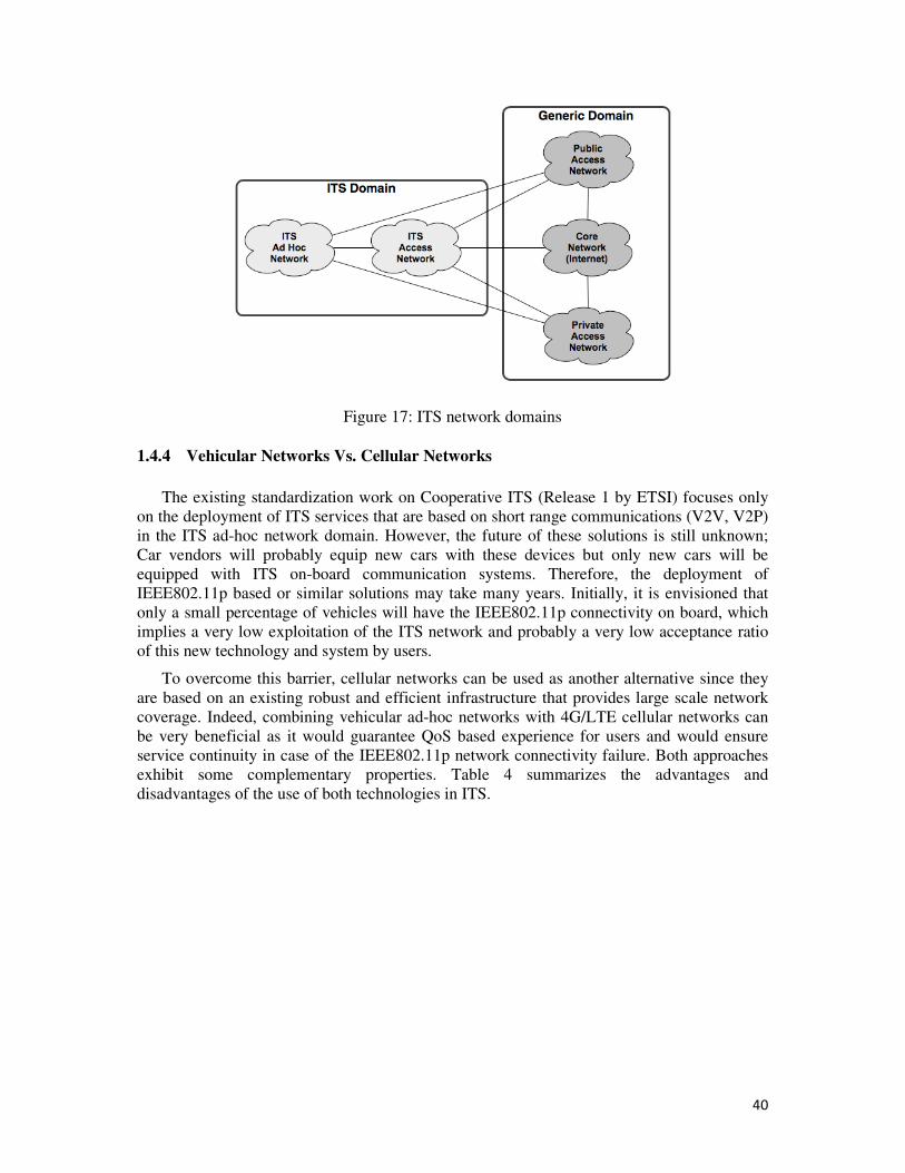
40
Figure 17: ITS network domains
1.4.4 Vehicular Networks Vs. Cellular Networks
The existing standardization work on Cooperative ITS (Release 1 by ETSI) focuses only
on the deployment of ITS services that are based on short range communications (V2V, V2P)
in the ITS ad-hoc network domain. However, the future of these solutions is still unknown;
Car vendors will probably equip new cars with these devices but only new cars will be
equipped with ITS on-board communication systems. Therefore, the deployment of
IEEE802.11p based or similar solutions may take many years. Initially, it is envisioned that
only a small percentage of vehicles will have the IEEE802.11p connectivity on board, which
implies a very low exploitation of the ITS network and probably a very low acceptance ratio
of this new technology and system by users.
To overcome this barrier, cellular networks can be used as another alternative since they
are based on an existing robust and efficient infrastructure that provides large scale network
coverage. Indeed, combining vehicular ad-hoc networks with 4G/LTE cellular networks can
be very beneficial as it would guarantee QoS based experience for users and would ensure
service continuity in case of the IEEE802.11p network connectivity failure. Both approaches
exhibit some complementary properties. Table 4 summarizes the advantages and
disadvantages of the use of both technologies in ITS.
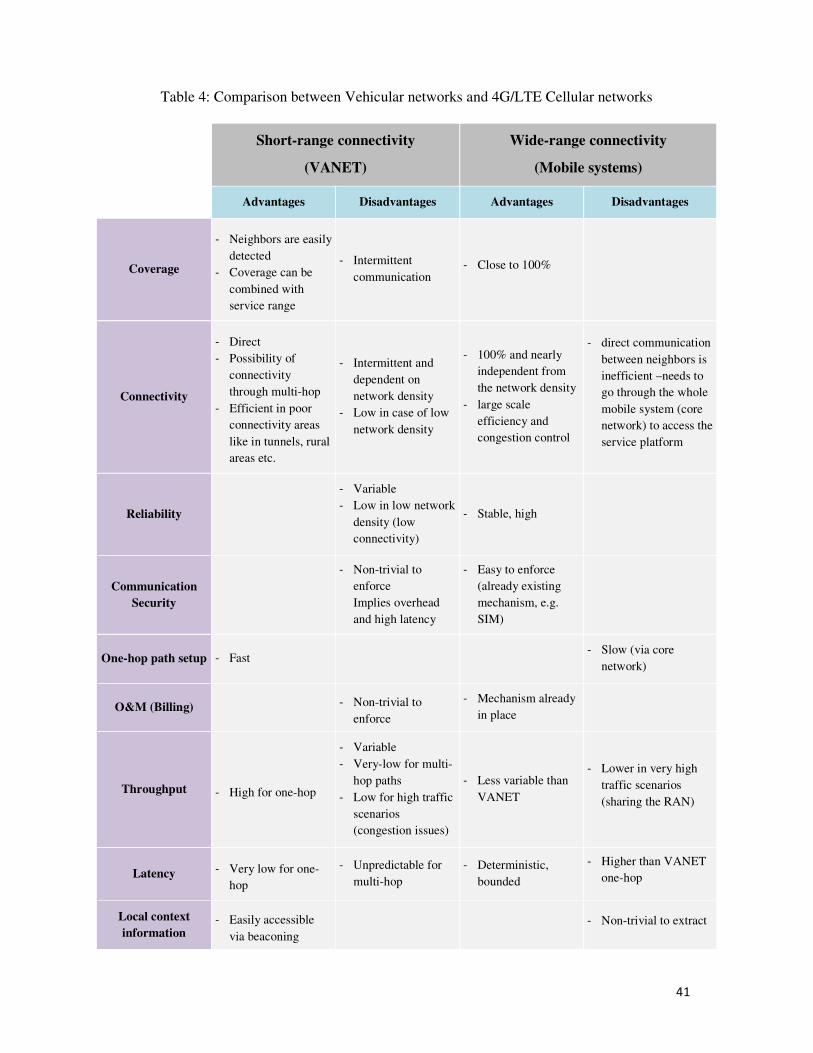
41
Table 4: Comparison between Vehicular networks and 4G/LTE Cellular networks
Short-range connectivity
(VANET)
Wide-range connectivity
(Mobile systems)
Advantages Disadvantages Advantages Disadvantages
Coverage
- Neighbors are easily
detected
- Coverage can be
combined with
service range
- Intermittent
communication - Close to 100%
Connectivity
- Direct
- Possibility of
connectivity
through multi-hop
- Efficient in poor
connectivity areas
like in tunnels, rural
areas etc.
- Intermittent and
dependent on
network density
- Low in case of low
network density
- 100% and nearly
independent from
the network density
- large scale
efficiency and
congestion control
- direct communication
between neighbors is
inefficient –needs to
go through the whole
mobile system (core
network) to access the
service platform
Reliability
- Variable
- Low in low network
density (low
connectivity)
- Stable, high
Communication
Security
- Non-trivial to
enforce
Implies overhead
and high latency
- Easy to enforce
(already existing
mechanism, e.g.
SIM)
One-hop path setup - Fast - Slow (via core
network)
O&M (Billing) - Non-trivial to
enforce
- Mechanism already
in place
Throughput - High for one-hop
- Variable
- Very-low for multi-
hop paths
- Low for high traffic
scenarios
(congestion issues)
- Less variable than
VANET
- Lower in very high
traffic scenarios
(sharing the RAN)
Latency - Very low for one-
hop
- Unpredictable for
multi-hop
- Deterministic,
bounded
- Higher than VANET
one-hop
Local context
information - Easily accessible
via beaconing - Non-trivial to extract
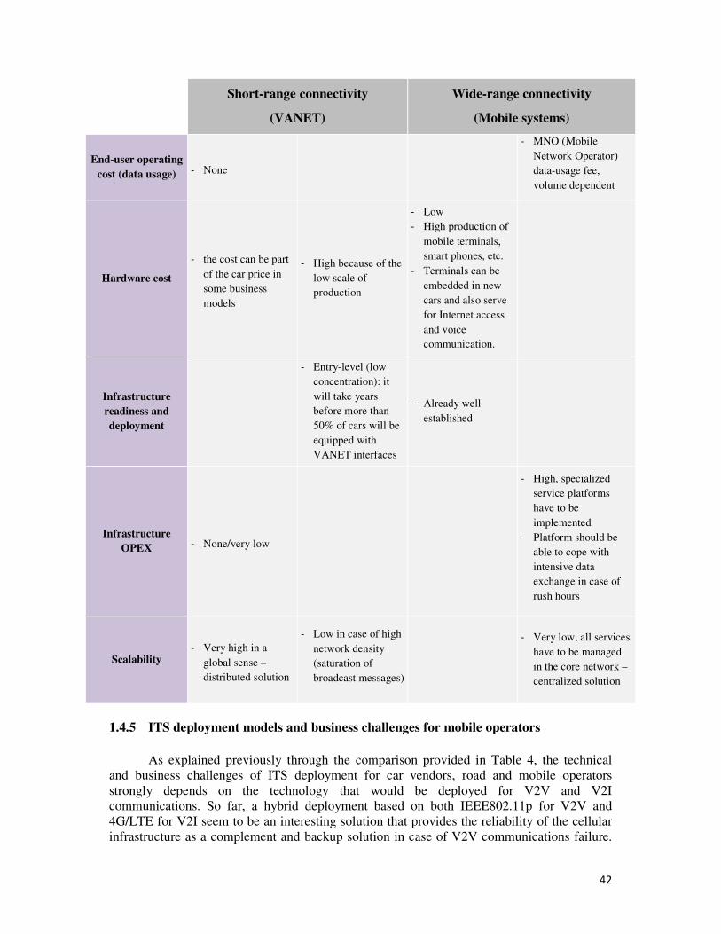
42
Short-range connectivity
(VANET)
Wide-range connectivity
(Mobile systems)
End-user operating
cost (data usage) - None
- MNO (Mobile
Network Operator)
data-usage fee,
volume dependent
Hardware cost
- the cost can be part
of the car price in
some business
models
- High because of the
low scale of
production
- Low
- High production of
mobile terminals,
smart phones, etc.
- Terminals can be
embedded in new
cars and also serve
for Internet access
and voice
communication.
Infrastructure
readiness and
deployment
- Entry-level (low
concentration): it
will take years
before more than
50% of cars will be
equipped with
VANET interfaces
- Already well
established
Infrastructure
OPEX - None/very low
- High, specialized
service platforms
have to be
implemented
- Platform should be
able to cope with
intensive data
exchange in case of
rush hours
Scalability - Very high in a
global sense –
distributed solution
- Low in case of high
network density
(saturation of
broadcast messages)
- Very low, all services
have to be managed
in the core network –
centralized solution
1.4.5 ITS deployment models and business challenges for mobile operators
As explained previously through the comparison provided in Table 4, the technical
and business challenges of ITS deployment for car vendors, road and mobile operators
strongly depends on the technology that would be deployed for V2V and V2I
communications. So far, a hybrid deployment based on both IEEE802.11p for V2V and
4G/LTE for V2I seem to be an interesting solution that provides the reliability of the cellular
infrastructure as a complement and backup solution in case of V2V communications failure.
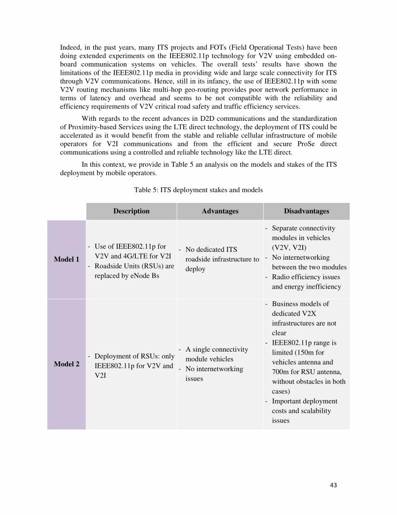
43
Indeed, in the past years, many ITS projects and FOTs (Field Operational Tests) have been
doing extended experiments on the IEEE802.11p technology for V2V using embedded on-
board communication systems on vehicles. The overall tests’ results have shown the
limitations of the IEEE802.11p media in providing wide and large scale connectivity for ITS
through V2V communications. Hence, still in its infancy, the use of IEEE802.11p with some
V2V routing mechanisms like multi-hop geo-routing provides poor network performance in
terms of latency and overhead and seems to be not compatible with the reliability and
efficiency requirements of V2V critical road safety and traffic efficiency services.
With regards to the recent advances in D2D communications and the standardization
of Proximity-based Services using the LTE direct technology, the deployment of ITS could be
accelerated as it would benefit from the stable and reliable cellular infrastructure of mobile
operators for V2I communications and from the efficient and secure ProSe direct
communications using a controlled and reliable technology like the LTE direct.
In this context, we provide in Table 5 an analysis on the models and stakes of the ITS
deployment by mobile operators.
Table 5: ITS deployment stakes and models
Description Advantages Disadvantages
Model 1
- Use of IEEE802.11p for
V2V and 4G/LTE for V2I
- Roadside Units (RSUs) are
replaced by eNode Bs
- No dedicated ITS
roadside infrastructure to
deploy
- Separate connectivity
modules in vehicles
(V2V, V2I)
- No internetworking
between the two modules
- Radio efficiency issues
and energy inefficiency
Model 2 - Deployment of RSUs: only
IEEE802.11p for V2V and
V2I
- A single connectivity
module vehicles
- No internetworking
issues
- Business models of
dedicated V2X
infrastructures are not
clear
- IEEE802.11p range is
limited (150m for
vehicles antenna and
700m for RSU antenna,
without obstacles in both
cases)
- Important deployment
costs and scalability
issues
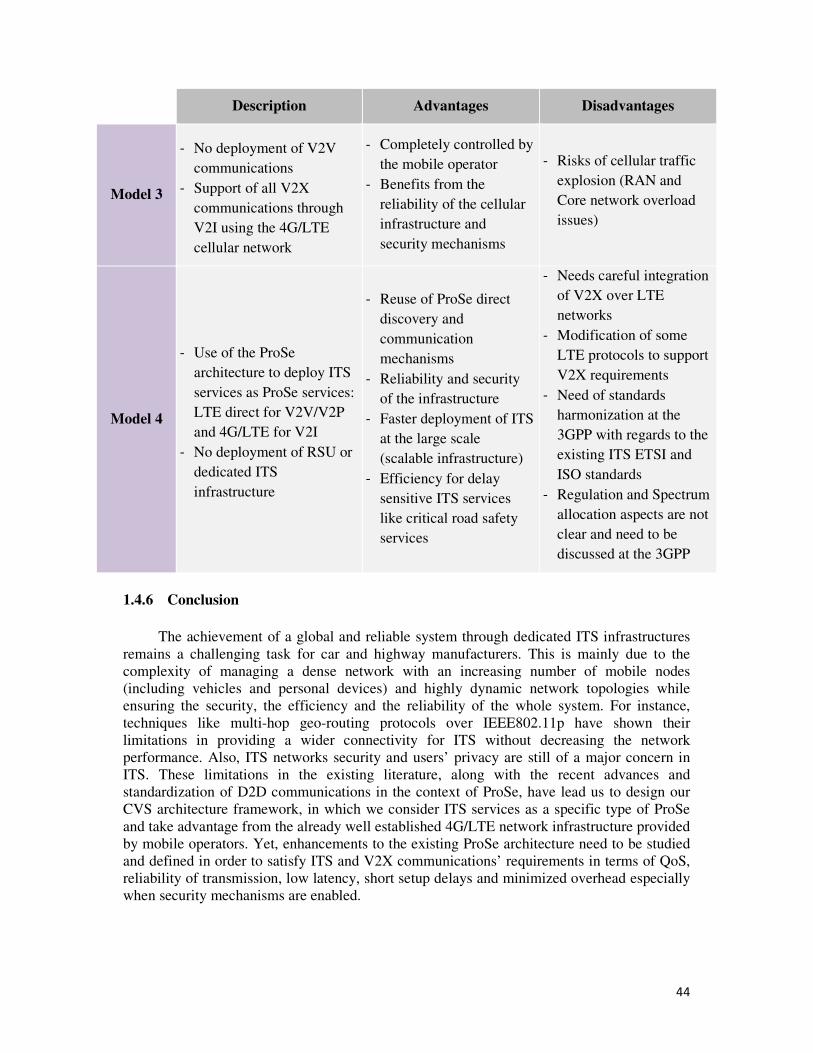
44
Description Advantages Disadvantages
Model 3
- No deployment of V2V
communications
- Support of all V2X
communications through
V2I using the 4G/LTE
cellular network
- Completely controlled by
the mobile operator
- Benefits from the
reliability of the cellular
infrastructure and
security mechanisms
- Risks of cellular traffic
explosion (RAN and
Core network overload
issues)
Model 4
- Use of the ProSe
architecture to deploy ITS
services as ProSe services:
LTE direct for V2V/V2P
and 4G/LTE for V2I
- No deployment of RSU or
dedicated ITS
infrastructure
- Reuse of ProSe direct
discovery and
communication
mechanisms
- Reliability and security
of the infrastructure
- Faster deployment of ITS
at the large scale
(scalable infrastructure)
- Efficiency for delay
sensitive ITS services
like critical road safety
services
- Needs careful integration
of V2X over LTE
networks
- Modification of some
LTE protocols to support
V2X requirements
- Need of standards
harmonization at the
3GPP with regards to the
existing ITS ETSI and
ISO standards
- Regulation and Spectrum
allocation aspects are not
clear and need to be
discussed at the 3GPP
1.4.6 Conclusion
The achievement of a global and reliable system through dedicated ITS infrastructures
remains a challenging task for car and highway manufacturers. This is mainly due to the
complexity of managing a dense network with an increasing number of mobile nodes
(including vehicles and personal devices) and highly dynamic network topologies while
ensuring the security, the efficiency and the reliability of the whole system. For instance,
techniques like multi-hop geo-routing protocols over IEEE802.11p have shown their
limitations in providing a wider connectivity for ITS without decreasing the network
performance. Also, ITS networks security and users’ privacy are still of a major concern in
ITS. These limitations in the existing literature, along with the recent advances and
standardization of D2D communications in the context of ProSe, have lead us to design our
CVS architecture framework, in which we consider ITS services as a specific type of ProSe
and take advantage from the already well established 4G/LTE network infrastructure provided
by mobile operators. Yet, enhancements to the existing ProSe architecture need to be studied
and defined in order to satisfy ITS and V2X communications’ requirements in terms of QoS,
reliability of transmission, low latency, short setup delays and minimized overhead especially
when security mechanisms are enabled.
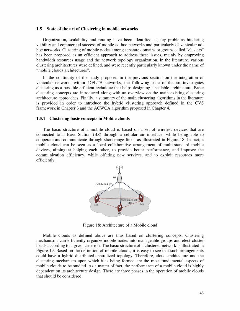
45
1.5 State of the art of Clustering in mobile networks
Organization, scalability and routing have been identified as key problems hindering
viability and commercial success of mobile ad hoc networks and particularly of vehicular ad-
hoc networks. Clustering of mobile nodes among separate domains or groups called “clusters”
has been proposed as an efficient approach to address these issues, mainly by emproving
bandwidth resources usage and the network topology organization. In the literature, various
clustering architectures were defined, and were recently particularly known under the name of
“mobile clouds architectures”.
In the continuity of the study proposed in the previous section on the integration of
vehicular networks within 4G/LTE networks, the following state of the art investigates
clustering as a possible efficient technique that helps designing a scalable architecture. Basic
clustering concepts are introduced along with an overview on the main existing clustering
architecture approaches. Finally, a summary of the main clustering algorithms in the literature
is provided in order to introduce the hybrid clustering approach defined in the CVS
framework in Chapter 3 and the ACWCA algorithm proposed in Chapter 4.
1.5.1 Clustering basic concepts in Mobile clouds
The basic structure of a mobile cloud is based on a set of wireless devices that are
connected to a Base Station (BS) through a cellular air interface, while being able to
cooperate and communicate through short-range links, as illustrated in Figure 18. In fact, a
mobile cloud can be seen as a local collaborative arrangement of multi-standard mobile
devices, aiming at helping each other, to provide better performance, and improve the
communication efficiency, while offering new services, and to exploit resources more
efficiently.
Figure 18: Architecture of a Mobile cloud
Mobile clouds as defined above are thus based on clustering concepts. Clustering
mechanisms can efficiently organize mobile nodes into manageable groups and elect cluster
heads according to a given criterion. The basic structure of a clustered network is illustrated in
Figure 19. Based on the definition of mobile clouds, it is easy to see that such arrangements
could have a hybrid distributed-centralized topology. Therefore, cloud architecture and the
clustering mechanism upon which it is being formed are the most fundamental aspects of
mobile clouds to be studied. As a matter of fact, the performance of a mobile cloud is highly
dependent on its architecture design. There are three phases in the operation of mobile clouds
that should be considered:
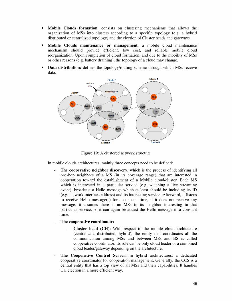
46
• Mobile Clouds formation: consists on clustering mechanisms that allows the
organization of MSs into clusters according to a specific topology (e.g. a hybrid
distributed or centralized topology) and the election of Cluster heads and gateways.
• Mobile Clouds maintenance or management: a mobile cloud maintenance
mechanism should provide efficient, low cost, and reliable mobile cloud
reorganization. Upon completion of cloud formation, and due to the mobility of MSs
or other reasons (e.g. battery draining), the topology of a cloud may change.
• Data distribution: defines the topology/routing scheme through which MSs receive
data.
Figure 19: A clustered network structure
In mobile clouds architectures, mainly three concepts need to be defined:
- The cooperative neighbor discovery, which is the process of identifying all
one-hop neighbors of a MS (in its coverage range) that are interested in
cooperation toward the establishment of a Mobile cloud/cluster. Each MS
which is interested in a particular service (e.g. watching a live streaming
event), broadcast a Hello message which at least should be including its ID
(e.g. network interface address) and its interesting service. Afterward, it listens
to receive Hello message(s) for a constant time, if it does not receive any
message; it assumes there is no MSs in its neighbor interesting in that
particular service, so it can again broadcast the Hello message in a constant
time.
- The cooperative coordinator:
- Cluster head (CH): With respect to the mobile cloud architecture
(centralized, distributed, hybrid), the entity that coordinates all the
communication among MSs and between MSs and BS is called
cooperative coordinator. Its role can be only cloud leader or a combined
cloud leader/gateway depending on the architecture.
- The Cooperative Control Server: in hybrid architectures, a dedicated
cooperative coordinator for cooperation management. Generally, the CCS is a
central entity that has a top view of all MSs and their capabilities. It handles
CH election in a more efficient way.
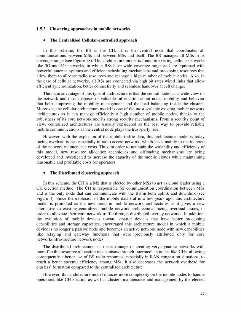
47
1.5.2 Clustering approaches in mobile networks
• The Centralized Cellular-controlled approach
In this scheme, the BS is the CH. It is the central node that coordinates all
communications between MSs and between MSs and itself. The BS manages all MSs in its
coverage range (see Figure 18). This architecture model is found in existing cellular networks
like 3G and 4G networks, in which BSs have wide coverage range and are equipped with
powerful antenna systems and efficient scheduling mechanisms and processing resources that
allow them to allocate radio resources and manage a high number of mobile nodes. Also, in
the case of cellular networks, all BSs are connected via high bit rates wired links that allow
efficient synchronization, better connectivity and seamless handover at cell change.
The main advantage of this type of architecture is that the central node has a wide view on
the network and thus, disposes of valuable information about nodes mobility and behavior
that helps improving the mobility management and the load balancing inside the clusters.
Moreover, the cellular architecture model is one of the most scalable existing mobile network
architectures as it can manage efficiently a high number of mobile nodes, thanks to the
robustness of its core network and its strong security mechanisms. From a security point of
view, centralized architectures are usually considered as the best way to provide reliable
mobile communications as the central node plays the trust-party role.
However, with the explosion of the mobile traffic data, this architecture model is today
facing overload issues especially in radio access network, which leads mainly to the increase
of the network maintenance costs. Thus, in order to maintain the scalability and efficiency of
this model, new resource allocation techniques and offloading mechanisms are being
developed and investigated to increase the capacity of the mobile clouds while maintaining
reasonable and profitable costs for operators.
• The Distributed clustering approach
In this scheme, the CH is a MS that is elected by other MSs to act as cloud leader using a
CH election method. The CH is responsible for communication coordination between MSs
and is the only node that can communicate with the BS in both uplink and downlink (see
Figure 4). Since the explosion of the mobile data traffic a few years ago, this architecture
model is promoted as the new trend in mobile network architectures as it gives a new
alternative to existing centralized mobile network architectures facing overload issues, in
order to alleviate their core network traffic through distributed overlay networks. In addition,
the evolution of mobile devices toward smarter devices that have better processing
capabilities and storage capacities, encouraged this architecture model in which a mobile
device is no longer a passive node and becomes an active network node with new capabilities
like relaying and gateway functions that were previously attributed only for core
network/infrastructure network nodes.
The distributed architecture has the advantage of creating very dynamic networks with
more flexible resource allocation mechanisms through intermediate nodes like CHs, allowing
consequently a better use of BS radio resources, especially in RAN congestion situations, to
reach a better spectral efficiency among MSs. It also decreases the network overhead for
clusters’ formation compared to the centralized architecture.
However, this architecture model induces more complexity on the mobile nodes to handle
operations like CH election as well as clusters maintenance and management by the elected
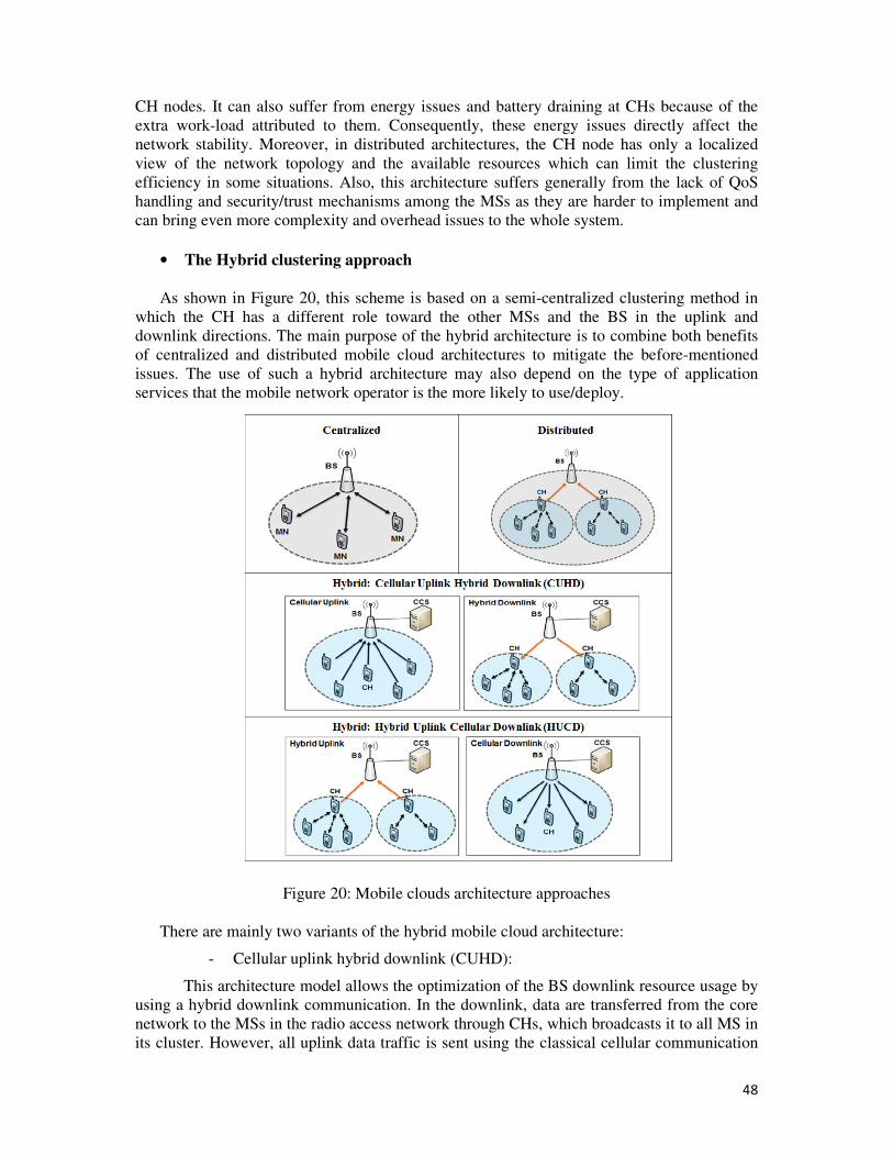
48
CH nodes. It can also suffer from energy issues and battery draining at CHs because of the
extra work-load attributed to them. Consequently, these energy issues directly affect the
network stability. Moreover, in distributed architectures, the CH node has only a localized
view of the network topology and the available resources which can limit the clustering
efficiency in some situations. Also, this architecture suffers generally from the lack of QoS
handling and security/trust mechanisms among the MSs as they are harder to implement and
can bring even more complexity and overhead issues to the whole system.
• The Hybrid clustering approach
As shown in Figure 20, this scheme is based on a semi-centralized clustering method in
which the CH has a different role toward the other MSs and the BS in the uplink and
downlink directions. The main purpose of the hybrid architecture is to combine both benefits
of centralized and distributed mobile cloud architectures to mitigate the before-mentioned
issues. The use of such a hybrid architecture may also depend on the type of application
services that the mobile network operator is the more likely to use/deploy.
Figure 20: Mobile clouds architecture approaches
There are mainly two variants of the hybrid mobile cloud architecture:
- Cellular uplink hybrid downlink (CUHD):
This architecture model allows the optimization of the BS downlink resource usage by
using a hybrid downlink communication. In the downlink, data are transferred from the core
network to the MSs in the radio access network through CHs, which broadcasts it to all MS in
its cluster. However, all uplink data traffic is sent using the classical cellular communication
49
model (MS to BS). This architecture could be beneficial in the case of the deployment of
multicast/broadcast services in which there is no acknowledgment that has to be received
from the MSs. In this case, hybrid communications in the uplink is not needed.
- Hybrid uplink cellular downlink (HUCD):
In this architecture model, data are sent using broadcast over the cellular classic media
in the downlink, while a hybrid communication link is used in the uplink through CHs. The
main objective of such architecture is to optimize the use of the uplink resources. This
architecture model could be recommended for the deployment of data collection based
services in which, a considerable amount of data should be collected from the MSs to the core
network. In such a case, a hybrid uplink through a CH node could help reduce the congestion
issues implied by sending the data flow by flow by each device.
1.5.3 Overview on clustering algorithms
Cloud formation mechanisms commonly called clustering algorithms refer to Cluster
head (CH) or Cloud leader election mechanisms. In the literature, many CH election
mechanisms have been defined [29] [31]. Table 6 presents a classification of the most
important CH election mechanisms for MANETs with their advantages and disadvantages.
Table 6: Comparison of main clustering algorithms
CH election
mechanisms Description Advantages Disadvantages
Identifier-
based
clustering
o A unique ID is assigned to
each node and each node
knows the IDs of its
neighbors.
o The CH is the node with the
lowest ID and can hear only
nodes with higher ID than
itself.
o The gateway is the node that
can hear two or more CH.
o A simple method to
organize the network
into clusters with a static
topology.
o Very low rate of CH
change
o Can apply for schemes
with a limited nodes’
mobility.
o IDs are assigned
randomly to nodes
without considering
other parameters like
nodes’ mobility or their
power status.
o Since the assigned IDs
are static, nodes with
smaller IDs are more
likely to become CH and
thus, can suffer from
power issues due to the
fact of being CH for long
periods of time.
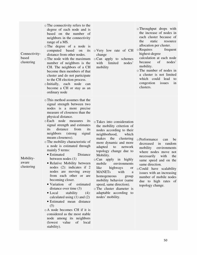
50
Connectivity-
based
clustering
o The connectivity refers to the
degree of each node and is
based on the number of
neighbors in the connectivity
range of a MS.
o The degree of a node is
computed based on its
distance from other nodes.
o The node with the maximum
number of neighbors is the
CH. The neighbors of a CH
become then members of that
cluster and do not participate
to the CH election process.
o Initially, each node can
become a CH or stay as an
ordinary node
o Very low rate of CH
change
o Can apply to schemes
with limited nodes’
mobility
o Throughput drops with
the increase of nodes in
each cluster because of
the static resource
allocation per cluster.
o Requires frequent
highest-degree
calculation at each node
because of nodes’
mobility.
o The number of nodes in
a cluster is not limited
which could lead to
congestion issues in
clusters.
Mobility-
aware
clustering
o This method assumes that the
signal strength between two
nodes is a more precise
measure of closeness than the
physical distance.
o Each node measures its
signal strength and estimates
its distance from its
neighbors (strong signal
means closeness).
o The mobility characteristic of
a node is estimated through
mainly 5 terms:
• Estimated Distance
between nodes (1)
• Relative Mobility between
nodes (2): indicates if 2
nodes are moving away
from each other or are
becoming closer.
• Variation of estimated
distance over time (3)
• Local stability (4):
calculated using (1) and (2)
• Estimated mean distance
(5)
o A node becomes CH if it is
considered as the most stable
node among its neighbors
(lowest value of local
stability).
o Takes into consideration
the mobility criterion of
nodes according to their
neighborhood, which
makes the clustering
more dynamic and more
adapted to network
topology change due to
Mobility.
o Can apply in highly
mobile environments
like highways or
MANETs with a
homogeneous group
mobility behavior (same
speed, same direction).
o The cluster diameter is
adaptable according to
nodes’ mobility.
o Performance can be
decreased in random
mobility environments
where nodes move not
necessarily with the
same speed and on the
same direction.
o Could have scalability
issues with an increasing
number of mobile nodes
due to high rates of
topology change.
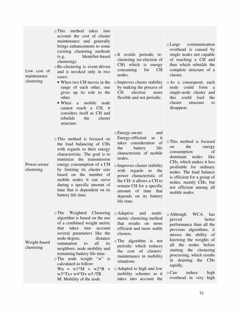
51
Low cost of
maintenance
clustering
o This method takes into
account the cost of cluster
maintenance and generally
brings enhancements to some
existing clustering methods
(e.g. Identifier-based
clustering).
o Re-clustering is event-driven
and is invoked only in two
cases:
• When two CH moves in the
range of each other, one
gives up its role to the
other.
• When a mobile node
cannot reach a CH, it
considers itself as CH and
rebuilds the cluster
structure.
o It avoids periodic re-
clustering (re-election of
CH) which is energy
consuming for CH
nodes.
o Improves cluster stability
by making the process of
CH election more
flexible and not periodic.
o Large communication
overhead is caused by
single nodes not capable
of reaching a CH and
thus which rebuilds the
complete structure of a
cluster.
o As a consequent, each
node could form a
single-node cluster and
this could lead the
cluster structure to
disappear.
Power-aware
clustering
o This method is focused on
the load balancing of CHs
with regards to their energy
characteristic. The goal is to
minimize the transmission
energy consumption of a CH
by limiting its cluster size
based on the number of
mobile nodes it can serve
during a specific amount of
time that is dependent on its
battery life time.
o Energy-aware and
Energy-efficient as it
takes consideration of
the battery life
characteristic of mobile
nodes.
o Improves cluster stability
with regards to the
power characteristic of
the CH: it allows a CH to
remain CH for a specific
amount of time that
depends on its battery
life time.
o This method is focused
on the energy
consumption of
dominant nodes like
CHs, which makes it less
profitable for ordinary
nodes. The load balance
is efficient for a group of
nodes, mainly CHs, but
not efficient among all
mobile nodes.
Weight-based
clustering
o The Weighted Clustering
algorithm is based on the use
of a combined weight metric
that takes into account
several parameters like the
node-degree, distance
summation to all its
neighbors, node mobility and
remaining battery life time.
o The node weight “w” is
calculated as follow:
Wn = w1*M + w2*B +
w3*Tx+ w4*D+ w5 /TR
M: Mobility of the node
o Adaptive and multi-
metric clustering method
that results on more
efficient and more stable
clusters.
o The algorithm is not
periodic which reduces
the cost of clusters’
maintenance in mobility
situations.
o Adapted to high and low
mobility schemes as it
takes into account the
o Although WCA has
proved better
performance than all the
previous algorithms, it
misses the ability of
knowing the weights of
all the nodes before
starting the clustering
processing, which results
in draining the CHs
rapidly.
o Can induce high
overhead in very high
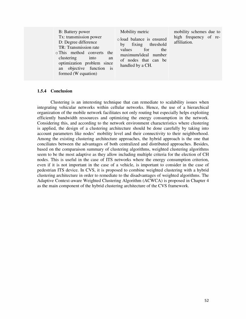
52
B: Battery power
Tx: transmission power
D: Degree difference
TR: Transmission rate
o This method converts the
clustering into an
optimization problem since
an objective function is
formed (W equation)
Mobility metric
o load balance is ensured
by fixing threshold
values for the
maximum/ideal number
of nodes that can be
handled by a CH.
mobility schemes due to
high frequency of re-
affiliation.
1.5.4 Conclusion
Clustering is an interesting technique that can remediate to scalability issues when
integrating vehicular networks within cellular networks. Hence, the use of a hierarchical
organization of the mobile network facilitates not only routing but especially helps exploiting
efficiently bandwidth ressources and optimizing the energy consumption in the network.
Considering this, and according to the network environment characteristics where clustering
is applied, the design of a clustering architecture should be done carefully by taking into
account parameters like nodes’ mobility level and their connectivity to their neighborhood.
Among the existing clustering architecture approaches, the hybrid approach is the one that
conciliates between the advantages of both centralized and distributed approaches. Besides,
based on the comparaison summary of clustering algorithms, weighted clustering algorithms
seem to be the most adaptive as they allow including multiple criteria for the election of CH
nodes. This is useful in the case of ITS networks where the energy consumption criterion,
even if it is not important in the case of a vehicle, is important to consider in the case of
pedestrian ITS device. In CVS, it is proposed to combine weighted clustering with a hybrid
clustering architecture in order to remediate to the disadvantages of weighted algorithms. The
Adaptive Context-aware Weighted Clustering Algorithm (ACWCA) is proposed in Chapter 4
as the main component of the hybrid clustering architecture of the CVS framework.
53
Chapter 2: The Distributed ProSe
Architecture
2.1 Introduction
According to [26], the evolution toward 5G networks will be accompagnied with an
evolution of existing network functions, like network densification into ultra-dense networks
and the development of new functions such as moving networks and Massive Machine
Communications (MMC). This requires network capabilities well beyond today’s network
features, which have to be reflected in the architectural layer to achieve their full potential.
D2D communications are considered as one of these evolutions of today’s networks’
functions; they would offer an underlay solution to cellular networks through a layered
topology in which multiple network layers (e.g femto-network, D2D-network, Wifi-
network…) would coexist with a main macro-cell layer. Envisioned in [26] as a key feature of
the future Internet of Things (IoT) and Massive Machine Communications (MMC), the
deployment of D2D in mobile networks would have to answer the following main
requirements and challenges:
- Support in a scalable way the increase of connected devices number (10 to 100 times
more devices than today)
- Increase or maintain sustainably wireless devices battery lifetimes
- Contribute to green networking through the reduction of network signaling overhead
(reduce energy consumption at the infrastructure)
- Support efficient transmission of small payloads with fast setup and low latency
- Contribute to extend mobile networks coverage to reach 100% coverage, while
managing sustainably the energy consumption and cost for the infrastructure
With regards to these requirements, D2D mechanisms and services have attracted in the
recent years much interest from both academics and industrials. In particular, mobile
operators have seen D2D as an interesting market opportunity that would help them enforce
their position against the OTT players in the mobile market and lead the transition toward the
5G. Yet, the standardization work done at the 3GPP to define the 4G/LTE architecture
enhancements and support the deployment of ProSe is still under progress and does not fulfill
yet all the before-mentioned requirements for the deployment of D2D at the large scale. The
current specification is globally lacking from a more extensible and evolutionary vision of the
D2D integration as a native feature in next generation networks. For instance, features like
direct D2D communication, group communication and Relay functions are restricted to a
specific category of services (e.g. Public safety services) that are explicitly subject to mobile
operator authorizations. This is mainly due to the unclear business models of ProSe
deployment at the large scale especially with OTT players that are well settled in the mobile
market and promoting similar services at much cheaper costs using technologies like WiFi
Direct.
Therewith, the current ProSe specification has been defined to answer near market
needs that aim at a quick deployment of ProSe, while limiting the technical and cost impacts
of the proposed solution on the 4G/LTE core network architecture. Besides, the legislation of
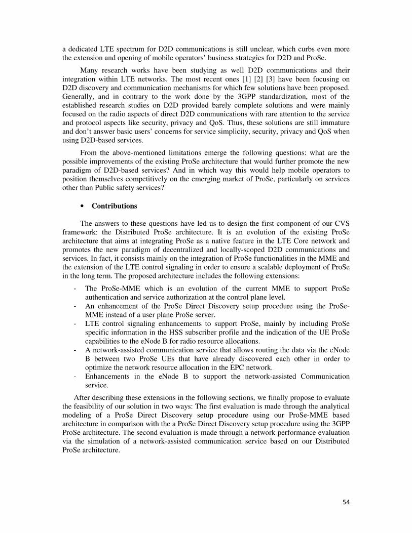
54
a dedicated LTE spectrum for D2D communications is still unclear, which curbs even more
the extension and opening of mobile operators’ business strategies for D2D and ProSe.
Many research works have been studying as well D2D communications and their
integration within LTE networks. The most recent ones [1] [2] [3] have been focusing on
D2D discovery and communication mechanisms for which few solutions have been proposed.
Generally, and in contrary to the work done by the 3GPP standardization, most of the
established research studies on D2D provided barely complete solutions and were mainly
focused on the radio aspects of direct D2D communications with rare attention to the service
and protocol aspects like security, privacy and QoS. Thus, these solutions are still immature
and don’t answer basic users’ concerns for service simplicity, security, privacy and QoS when
using D2D-based services.
From the above-mentioned limitations emerge the following questions: what are the
possible improvements of the existing ProSe architecture that would further promote the new
paradigm of D2D-based services? And in which way this would help mobile operators to
position themselves competitively on the emerging market of ProSe, particularly on services
other than Public safety services?
• Contributions
The answers to these questions have led us to design the first component of our CVS
framework: the Distributed ProSe architecture. It is an evolution of the existing ProSe
architecture that aims at integrating ProSe as a native feature in the LTE Core network and
promotes the new paradigm of decentralized and locally-scoped D2D communications and
services. In fact, it consists mainly on the integration of ProSe functionalities in the MME and
the extension of the LTE control signaling in order to ensure a scalable deployment of ProSe
in the long term. The proposed architecture includes the following extensions:
- The ProSe-MME which is an evolution of the current MME to support ProSe
authentication and service authorization at the control plane level.
- An enhancement of the ProSe Direct Discovery setup procedure using the ProSe-
MME instead of a user plane ProSe server.
- LTE control signaling enhancements to support ProSe, mainly by including ProSe
specific information in the HSS subscriber profile and the indication of the UE ProSe
capabilities to the eNode B for radio resource allocations.
- A network-assisted communication service that allows routing the data via the eNode
B between two ProSe UEs that have already discovered each other in order to
optimize the network resource allocation in the EPC network.
- Enhancements in the eNode B to support the network-assisted Communication
service.
After describing these extensions in the following sections, we finally propose to evaluate
the feasibility of our solution in two ways: The first evaluation is made through the analytical
modeling of a ProSe Direct Discovery setup procedure using our ProSe-MME based
architecture in comparison with the a ProSe Direct Discovery setup procedure using the 3GPP
ProSe architecture. The second evaluation is made through a network performance evaluation
via the simulation of a network-assisted communication service based on our Distributed
ProSe architecture.
55
2.2 The Distributed ProSe architecture
2.2.1 Description and key features
Unlike the 3GPP ProSe architecture proposed in [9], our Distributed ProSe architecture
aims at proposing a scalable, extensible and sustainable deployment of ProSein the long term.
It is depicted in Figure 21 and is based on the following main enhancements:
Figure 21: The Distributed ProSe architecture
• The ProSe-MME
Although it is inspired from the 3GPP ProSe standard, its major enhancement is the
evolution of the MME to support ProSe functionalities at the control plane level. Hence, by
integrating ProSe functions in the MME, ProSe roaming and ProSe Inter-PLMN (inter-
operator communication) cases are natively supported by the architecture without additional
user plane signaling; this is due to the fact that MMEs are key entities in the EPS architecture
and handle natively all basic procedures required in ProSe for authentication and service
authorization. In the 3GPP ProSe architecture [9], these procedures require frequent exchange
of information between the ProSe server and the HSS. Yet, in case of ProSe roaming or ProSe
Inter-PLMN, each authentication or service authorization require the communication between
the HPLMN ProSe function, the Local ProSe function in the visited network and the HSS.
These exchanges are made over a new interface that was defined between the HSS and the
ProSe functions that is based on the Diameter6 protocol, which is basically used between the
HSS and the MME for classical authentication and authorization procedures in LTE. As a
result, the integration of ProSe in the MME allows saving a lot of unnecessary signaling in
EPC without the definition of new protocol interfaces, thanks to MME’s native capability to
support roaming and inter-PLMN use cases. Moreover, the MMEs network in EPS enhances
the scalability of ProSe deployment compared to the deployment of a standalone and
centralized ProSe entity, especially with the increase of the number of UEs supporting and
using the ProSe mode.
6 Diameter: it is an authentication, authorization, and accounting protocol for computer networks. It evolved from and
replaces the much less capable RADIUS protocol that preceded it
56
• S1-MME and S6a enhancements
The second extension that we propose is a set of enhancements in the S1-MME and S6a
protocol interfaces in order to support ProSe operations that we included in the ProSe-MME.
These enhancements occur especially after the reception at the ProSe-MME of ProSe service
requests for discovery or communication from a UE. They consist mainly on the indication of
UEs ProSe capabilities and ProSe radio resource allocation authorization from the ProSe-
MME to the eNode B. Moreover, additional subscriber information related to ProSe is added
in the user profile in the HSS and consists mainly of: The following ProSe capability
information should be added in the HSS: UE ProSe_ID, UE ProSe capability, ProSe
subscription data like the list of authorized ProSe services by ProSe_application_ID and per
authorized PLMN for the UE. There is also additional information related to the UE ProSe
capability that we propose to include in the LTE initial network attach procedure in order to
perform ProSe authentication. This information is detailed in subsection 2.2.3.
• ProSe authentication in the LTE initial network attach
Based on the procedure described in details in Annex 1, we propose to extend the LTE
initial attach procedure in order to include ProSe authentication of ProSe-enabled UEs as a
native and seamless operation. The idea is to allow the ProSe-MME to first, identify uniquely
a ProSe-capable UE during the network attach, and second, to acquire all its ProSe related
information from its subscriber profile in the HSS during the UE initial authentication phase.
After a successful authentication, the ProSe-MME disposes of all ProSe authorization
information related to UEs and doesn’t need to perform any other specific ProSe authorization
request procedure. This procedure and the details of the extended messages in the LTE initial
attach procedure are described in subsection 2.2.2.
• Enhanced ProSe Direct Discovery setup procedure
With regards to the enhancements brought to the MME to support a hybrid protocol
stack and the ProSe functionalities, the setup procedure of ProSe Direct Discovery as
specified in [9] and [35] should be modified to fit in our Distributed ProSe architecture. As
such, we propose an Enhanced ProSe Direct Discovery setup procedure that allows the
communication between ProSe-enabled UEs and the network to setup a ProSe Direct
Discovery service in the Monitoring or Announcing mode. This procedure includes the use of
enhanced NAS signaling messages with the ProSe-MME to get ProSe authorization and radio
resource allocation from the eNode B. The procedure call-flow is detailed in subsection 2.3.
• Network-assisted ProSe communication service procedure
The last extension proposed in our Distributed ProSe architecture is related to the
support of a network-assisted Communication service between ProSe-enabled devices that
have previously performed a ProSe Direct Discovery procedure. Hence, considering the
challenges for operators to provide QoS based services in the case of ProSe and the remaining
unclear business models of services using D2D direct communication mechanisms, we
propose a communication model that is based on offloading. As such, after achieving a ProSe
Direct Discovery procedure, ProSe-enabled devices in proximity can use a data service that is
controlled by the mobile operator in a reliable and efficient way. The service mechanism is
based on the concept of establishing a dedicated LTE bearer that allows routing the
exchanged data between the devices through the eNode B without going up to the PDN-GW
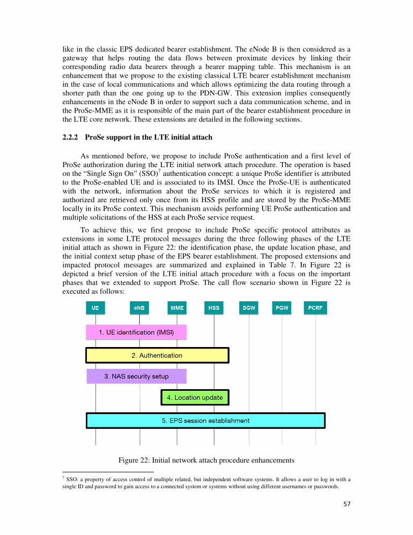
57
like in the classic EPS dedicated bearer establishment. The eNode B is then considered as a
gateway that helps routing the data flows between proximate devices by linking their
corresponding radio data bearers through a bearer mapping table. This mechanism is an
enhancement that we propose to the existing classical LTE bearer establishment mechanism
in the case of local communications and which allows optimizing the data routing through a
shorter path than the one going up to the PDN-GW. This extension implies consequently
enhancements in the eNode B in order to support such a data communication scheme, and in
the ProSe-MME as it is responsible of the main part of the bearer establishment procedure in
the LTE core network. These extensions are detailed in the following sections.
2.2.2 ProSe support in the LTE initial attach
As mentioned before, we propose to include ProSe authentication and a first level of
ProSe authorization during the LTE initial network attach procedure. The operation is based
on the “Single Sign On” (SSO)7 authentication concept: a unique ProSe identifier is attributed
to the ProSe-enabled UE and is associated to its IMSI. Once the ProSe-UE is authenticated
with the network, information about the ProSe services to which it is registered and
authorized are retrieved only once from its HSS profile and are stored by the ProSe-MME
locally in its ProSe context. This mechanism avoids performing UE ProSe authentication and
multiple solicitations of the HSS at each ProSe service request.
To achieve this, we first propose to include ProSe specific protocol attributes as
extensions in some LTE protocol messages during the three following phases of the LTE
initial attach as shown in Figure 22: the identification phase, the update location phase, and
the initial context setup phase of the EPS bearer establishment. The proposed extensions and
impacted protocol messages are summarized and explained in Table 7. In Figure 22 is
depicted a brief version of the LTE initial attach procedure with a focus on the important
phases that we extended to support ProSe. The call flow scenario shown in Figure 22 is
executed as follows:
Figure 22: Initial network attach procedure enhancements
7 SSO: a property of access control of multiple related, but independent software systems. It allows a user to log in with a
single ID and password to gain access to a connected system or systems without using different usernames or passwords.
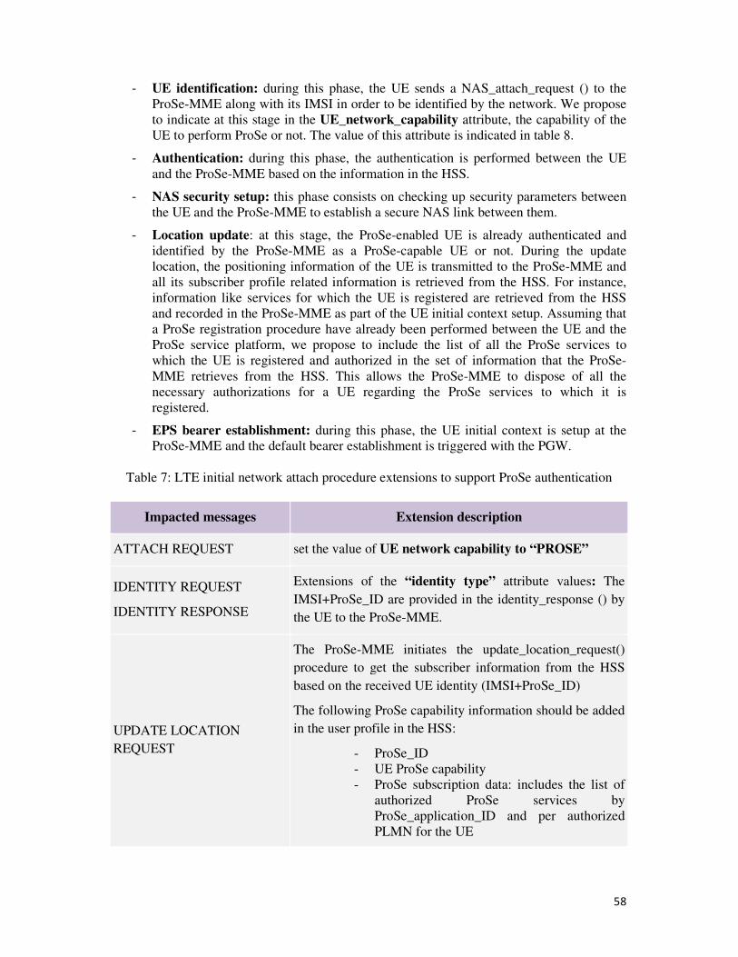
58
- UE identification: during this phase, the UE sends a NAS_attach_request () to the
ProSe-MME along with its IMSI in order to be identified by the network. We propose
to indicate at this stage in the UE_network_capability attribute, the capability of the
UE to perform ProSe or not. The value of this attribute is indicated in table 8.
- Authentication: during this phase, the authentication is performed between the UE
and the ProSe-MME based on the information in the HSS.
- NAS security setup: this phase consists on checking up security parameters between
the UE and the ProSe-MME to establish a secure NAS link between them.
- Location update: at this stage, the ProSe-enabled UE is already authenticated and
identified by the ProSe-MME as a ProSe-capable UE or not. During the update
location, the positioning information of the UE is transmitted to the ProSe-MME and
all its subscriber profile related information is retrieved from the HSS. For instance,
information like services for which the UE is registered are retrieved from the HSS
and recorded in the ProSe-MME as part of the UE initial context setup. Assuming that
a ProSe registration procedure have already been performed between the UE and the
ProSe service platform, we propose to include the list of all the ProSe services to
which the UE is registered and authorized in the set of information that the ProSe-
MME retrieves from the HSS. This allows the ProSe-MME to dispose of all the
necessary authorizations for a UE regarding the ProSe services to which it is
registered.
- EPS bearer establishment: during this phase, the UE initial context is setup at the
ProSe-MME and the default bearer establishment is triggered with the PGW.
Table 7: LTE initial network attach procedure extensions to support ProSe authentication
Impacted messages Extension description
ATTACH REQUEST set the value of UE network capability to “PROSE”
IDENTITY REQUEST
IDENTITY RESPONSE
Extensions of the “identity type” attribute values: The
IMSI+ProSe_ID are provided in the identity_response () by
the UE to the ProSe-MME.
UPDATE LOCATION
REQUEST
The ProSe-MME initiates the update_location_request()
procedure to get the subscriber information from the HSS
based on the received UE identity (IMSI+ProSe_ID)
The following ProSe capability information should be added
in the user profile in the HSS:
- ProSe_ID
- UE ProSe capability
- ProSe subscription data: includes the list of
authorized ProSe services by
ProSe_application_ID and per authorized
PLMN for the UE
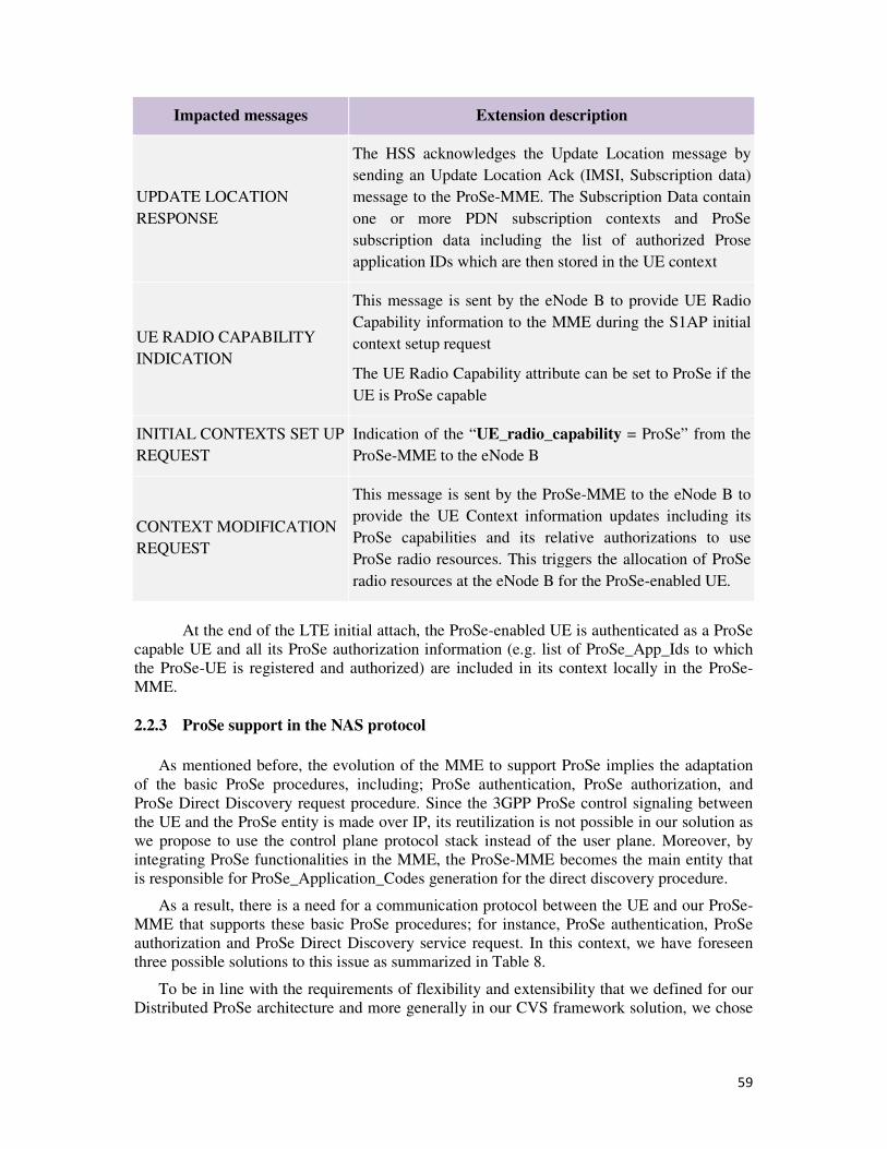
59
Impacted messages Extension description
UPDATE LOCATION
RESPONSE
The HSS acknowledges the Update Location message by
sending an Update Location Ack (IMSI, Subscription data)
message to the ProSe-MME. The Subscription Data contain
one or more PDN subscription contexts and ProSe
subscription data including the list of authorized Prose
application IDs which are then stored in the UE context
UE RADIO CAPABILITY
INDICATION
This message is sent by the eNode B to provide UE Radio
Capability information to the MME during the S1AP initial
context setup request
The UE Radio Capability attribute can be set to ProSe if the
UE is ProSe capable
INITIAL CONTEXTS SET UP
REQUEST
Indication of the “UE_radio_capability = ProSe” from the
ProSe-MME to the eNode B
CONTEXT MODIFICATION
REQUEST
This message is sent by the ProSe-MME to the eNode B to
provide the UE Context information updates including its
ProSe capabilities and its relative authorizations to use
ProSe radio resources. This triggers the allocation of ProSe
radio resources at the eNode B for the ProSe-enabled UE.
At the end of the LTE initial attach, the ProSe-enabled UE is authenticated as a ProSe
capable UE and all its ProSe authorization information (e.g. list of ProSe_App_Ids to which
the ProSe-UE is registered and authorized) are included in its context locally in the ProSe-
MME.
2.2.3 ProSe support in the NAS protocol
As mentioned before, the evolution of the MME to support ProSe implies the adaptation
of the basic ProSe procedures, including; ProSe authentication, ProSe authorization, and
ProSe Direct Discovery request procedure. Since the 3GPP ProSe control signaling between
the UE and the ProSe entity is made over IP, its reutilization is not possible in our solution as
we propose to use the control plane protocol stack instead of the user plane. Moreover, by
integrating ProSe functionalities in the MME, the ProSe-MME becomes the main entity that
is responsible for ProSe_Application_Codes generation for the direct discovery procedure.
As a result, there is a need for a communication protocol between the UE and our ProSe-
MME that supports these basic ProSe procedures; for instance, ProSe authentication, ProSe
authorization and ProSe Direct Discovery service request. In this context, we have foreseen
three possible solutions to this issue as summarized in Table 8.
To be in line with the requirements of flexibility and extensibility that we defined for our
Distributed ProSe architecture and more generally in our CVS framework solution, we chose
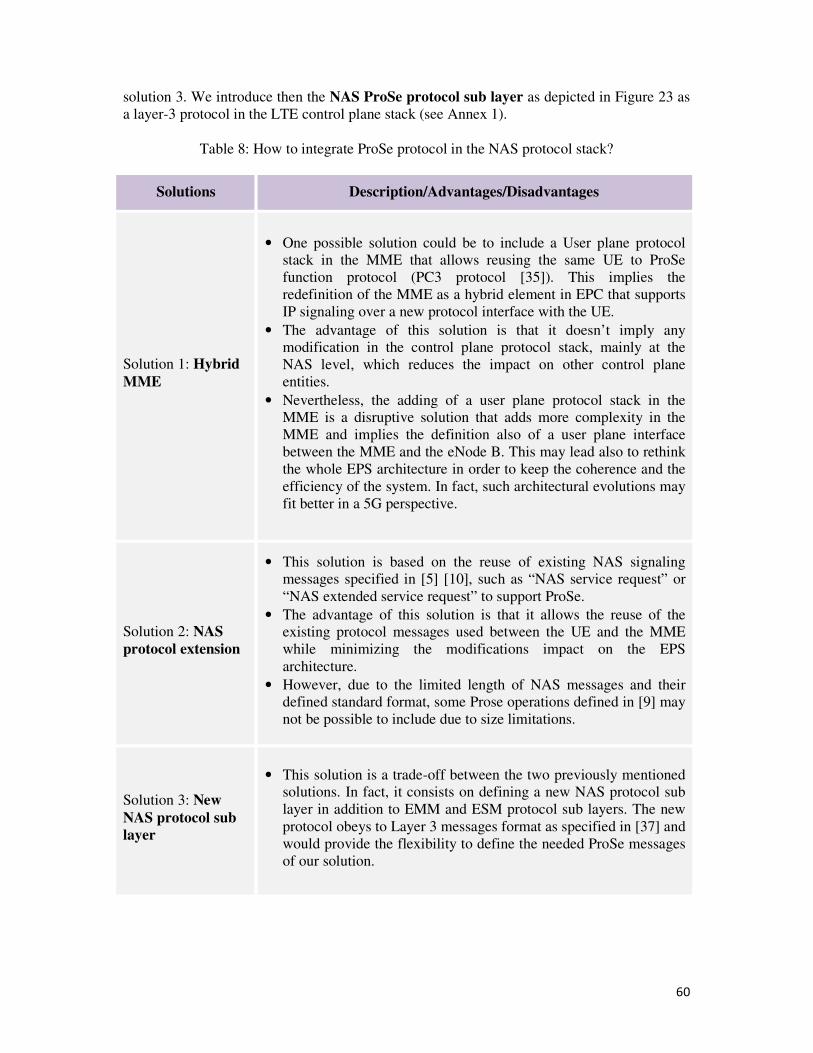
60
solution 3. We introduce then the NAS ProSe protocol sub layer as depicted in Figure 23 as
a layer-3 protocol in the LTE control plane stack (see Annex 1).
Table 8: How to integrate ProSe protocol in the NAS protocol stack?
Solutions Description/Advantages/Disadvantages
Solution 1: Hybrid
MME
• One possible solution could be to include a User plane protocol
stack in the MME that allows reusing the same UE to ProSe
function protocol (PC3 protocol [35]). This implies the
redefinition of the MME as a hybrid element in EPC that supports
IP signaling over a new protocol interface with the UE.
• The advantage of this solution is that it doesn’t imply any
modification in the control plane protocol stack, mainly at the
NAS level, which reduces the impact on other control plane
entities.
• Nevertheless, the adding of a user plane protocol stack in the
MME is a disruptive solution that adds more complexity in the
MME and implies the definition also of a user plane interface
between the MME and the eNode B. This may lead also to rethink
the whole EPS architecture in order to keep the coherence and the
efficiency of the system. In fact, such architectural evolutions may
fit better in a 5G perspective.
Solution 2: NAS
protocol extension
• This solution is based on the reuse of existing NAS signaling
messages specified in [5] [10], such as “NAS service request” or
“NAS extended service request” to support ProSe.
• The advantage of this solution is that it allows the reuse of the
existing protocol messages used between the UE and the MME
while minimizing the modifications impact on the EPS
architecture.
• However, due to the limited length of NAS messages and their
defined standard format, some Prose operations defined in [9] may
not be possible to include due to size limitations.
Solution 3: New
NAS protocol sub
layer
• This solution is a trade-off between the two previously mentioned
solutions. In fact, it consists on defining a new NAS protocol sub
layer in addition to EMM and ESM protocol sub layers. The new
protocol obeys to Layer 3 messages format as specified in [37] and
would provide the flexibility to define the needed ProSe messages
of our solution.
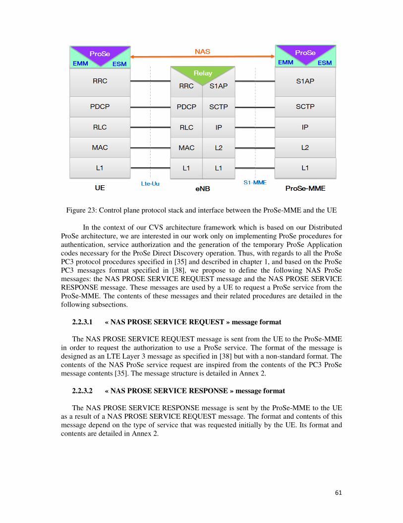
61
Figure 23: Control plane protocol stack and interface between the ProSe-MME and the UE
In the context of our CVS architecture framework which is based on our Distributed
ProSe architecture, we are interested in our work only on implementing ProSe procedures for
authentication, service authorization and the generation of the temporary ProSe Application
codes necessary for the ProSe Direct Discovery operation. Thus, with regards to all the ProSe
PC3 protocol procedures specified in [35] and described in chapter 1, and based on the ProSe
PC3 messages format specified in [38], we propose to define the following NAS ProSe
messages: the NAS PROSE SERVICE REQUEST message and the NAS PROSE SERVICE
RESPONSE message. These messages are used by a UE to request a ProSe service from the
ProSe-MME. The contents of these messages and their related procedures are detailed in the
following subsections.
2.2.3.1 « NAS PROSE SERVICE REQUEST » message format
The NAS PROSE SERVICE REQUEST message is sent from the UE to the ProSe-MME
in order to request the authorization to use a ProSe service. The format of the message is
designed as an LTE Layer 3 message as specified in [38] but with a non-standard format. The
contents of the NAS ProSe service request are inspired from the contents of the PC3 ProSe
message contents [35]. The message structure is detailed in Annex 2.
2.2.3.2 « NAS PROSE SERVICE RESPONSE » message format
The NAS PROSE SERVICE RESPONSE message is sent by the ProSe-MME to the UE
as a result of a NAS PROSE SERVICE REQUEST message. The format and contents of this
message depend on the type of service that was requested initially by the UE. Its format and
contents are detailed in Annex 2.
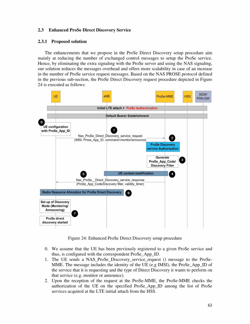
62
2.3 Enhanced ProSe Direct Discovery Service
2.3.1 Proposed solution
The enhancements that we propose in the ProSe Direct Discovery setup procedure aim
mainly at reducing the number of exchanged control messages to setup the ProSe service.
Hence, by eliminating the extra signaling with the ProSe server and using the NAS signaling,
our solution reduces the messages overhead and offers more scalability in case of an increase
in the number of ProSe service request messages. Based on the NAS PROSE protocol defined
in the previous sub-section, the ProSe Direct Discovery request procedure depicted in Figure
24 is executed as follows:
Figure 24: Enhanced ProSe Direct Discovery setup procedure
0. We assume that the UE has been previously registered to a given ProSe service and
thus, is configured with the correspondent ProSe_App_ID.
1. The UE sends a NAS_ProSe_Discovery_service_request () message to the ProSe-
MME. The message includes the identity of the UE (e.g IMSI), the ProSe_App_ID of
the service that it is requesting and the type of Direct Discovery it wants to perform on
that service (e.g. monitor or announce).
2. Upon the reception of the request at the ProSe-MME, the ProSe-MME checks the
authorization of the UE on the specified ProSe_App_ID among the list of ProSe
services acquired at the LTE initial attach from the HSS.
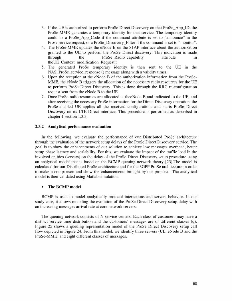
63
3. If the UE is authorized to perform ProSe Direct Discovery on that ProSe_App_ID, the
ProSe-MME generates a temporary identity for that service. The temporary identity
could be a ProSe_App_Code if the command attribute is set to “announce” in the
Prose service request, or a ProSe_Discovery_Filter if the command is set to “monitor”.
4. The ProSe-MME updates the eNode B on the S1AP interface about the authorization
granted to the UE to perform the ProSe Direct discovery. This indication is made
through the ProSe_Radio_capability attribute in
theUE_Context_modification_Request()
5. The generated ProSe temporary identity is then sent to the UE in the
NAS_ProSe_service_response () message along with a validity timer.
6. Upon the reception at the eNode B of the authorization information from the ProSe-
MME, the eNode B triggers the allocation of the necessary radio resources for the UE
to perform ProSe Direct Discovery. This is done through the RRC re-configuration
request sent from the eNode B to the UE.
7. Once ProSe radio resources are allocated at theeNode B and indicated to the UE, and
after receiving the necessary ProSe information for the Direct Discovery operation, the
ProSe-enabled UE applies all the received configurations and starts ProSe Direct
Discovery on its LTE Direct interface. This procedure is performed as described in
chapter 1 section 1.3.3.
2.3.2 Analytical performance evaluation
In the following, we evaluate the performance of our Distributed ProSe architecture
through the evaluation of the network setup delays of the ProSe Direct Discovery service. The
goal is to show the enhancements of our solution to achieve low messages overhead, better
setup phase latency and scalability. For this, we evaluate the impact of the traffic load in the
involved entities (servers) on the delay of the ProSe Direct Discovery setup procedure using
an analytical model that is based on the BCMP queuing network theory [23].The model is
calculated for our Distributed ProSe architecture and for the 3GPP ProSe architecture in order
to make a comparison and show the enhancements brought by our proposal. The analytical
model is then validated using Matlab simulation.
• The BCMP model
BCMP is used to model analytically protocol interactions and servers behavior. In our
study case, it allows modeling the evolution of the ProSe Direct Discovery setup delay with
an increasing messages arrival rate at core network servers.
The queuing network consists of N service centers. Each class of customers may have a
distinct service time distribution and the customers’ messages are of different classes (q).
Figure 25 shows a queuing representation model of the ProSe Direct Discovery setup call
flow depicted in Figure 24. From this model, we identify three servers (UE, eNode B and the
ProSe-MME) and eight different classes of messages.
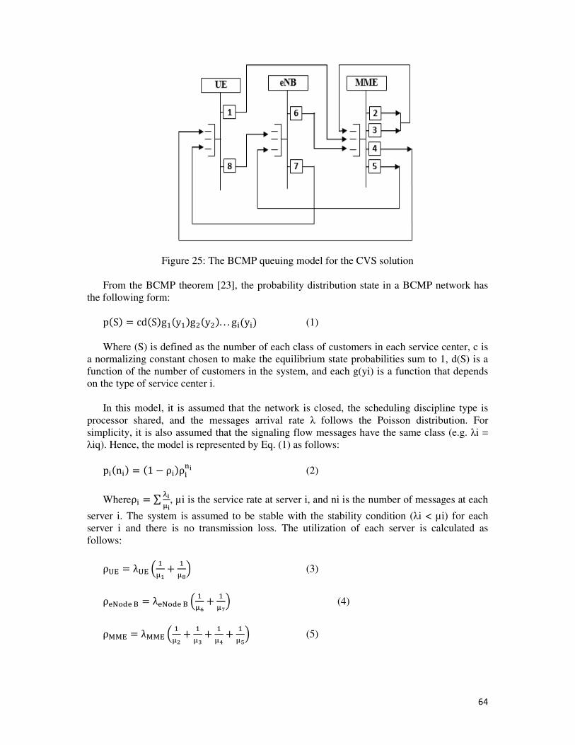
64
Figure 25: The BCMP queuing model for the CVS solution
From the BCMP theorem [23], the probability distribution state in a BCMP network has
the following form:
p�S� = cd�S�g�y�g��y��. . . g �y � (1)
Where (S) is defined as the number of each class of customers in each service center, c is
a normalizing constant chosen to make the equilibrium state probabilities sum to 1, d(S) is a
function of the number of customers in the system, and each g(yi) is a function that depends
on the type of service center i.
In this model, it is assumed that the network is closed, the scheduling discipline type is
processor shared, and the messages arrival rate λ follows the Poisson distribution. For
simplicity, it is also assumed that the signaling flow messages have the same class (e.g. λi =
λiq). Hence, the model is represented by Eq. (1) as follows:
p �n � = �1 − ρ �ρ �� (2)
Whereρ = ∑ ����, µi is the service rate at server i, and ni is the number of messages at each
server i. The system is assumed to be stable with the stability condition (λi < µi) for each
server i and there is no transmission loss. The utilization of each server is calculated as
follows:
ρ�� = λ�� � �� + ��� (3)
ρ� !"�$ = λ� !"�$ � �% + �&� (4)
ρ''� = λ''� � �( + �) + �* + �+� (5)

65
The average arrival rate of messages λi for each server i is different and is calculated according to the message flows in each server queue. So, the average arrival rate for each server i can be calculated as:
λ=∑ λp (6)
Where λj = ej λ, and ej is the rate of visiting server i to the average number of passages of that server. So, Eq. (6) can be written as follows:
e=∑ ep (7)
Then, we can conclude a system of equations that satisfies the visit rate for each server i. Based on Eq. (7), the distribution of messages for each server (UE, eNode B, and ProSe-MME) can be represented by the following equations:
e=
e+
e (8)
e=
e+
e (9)
e=
e+
e+
e (10)
The above equations are solved together hereafter, to state the arrival rate for each server in terms of ProSe-MME server arrival rate (as it has the highest arrival rate):
λ=
λ (11)
λ=
λ (12)
From Eq. (2), the mean queue size related to the average number of clients waiting on each server i is calculated as:
En=∑ npn∞
=
(13)
Following the Little’s Law and assuming that there is no waiting time at each server, the ProSe Direct Discovery setup time D can be calculated as follows:
D=
=
=
(14)
The previous model and its resulting equations are calculated in a second phase for the ProSe Direct Discovery setup procedure that is based on the 3GPP ProSe architecture model [ref]. Both performance results are then simulated on Matlab and compared.
• Results analysis
Hereafter, we present a validation of the previously calculated BCMP model for both solutions using Matlab. Figure 26 shows the variation of the ProSe Direct Discovery setup
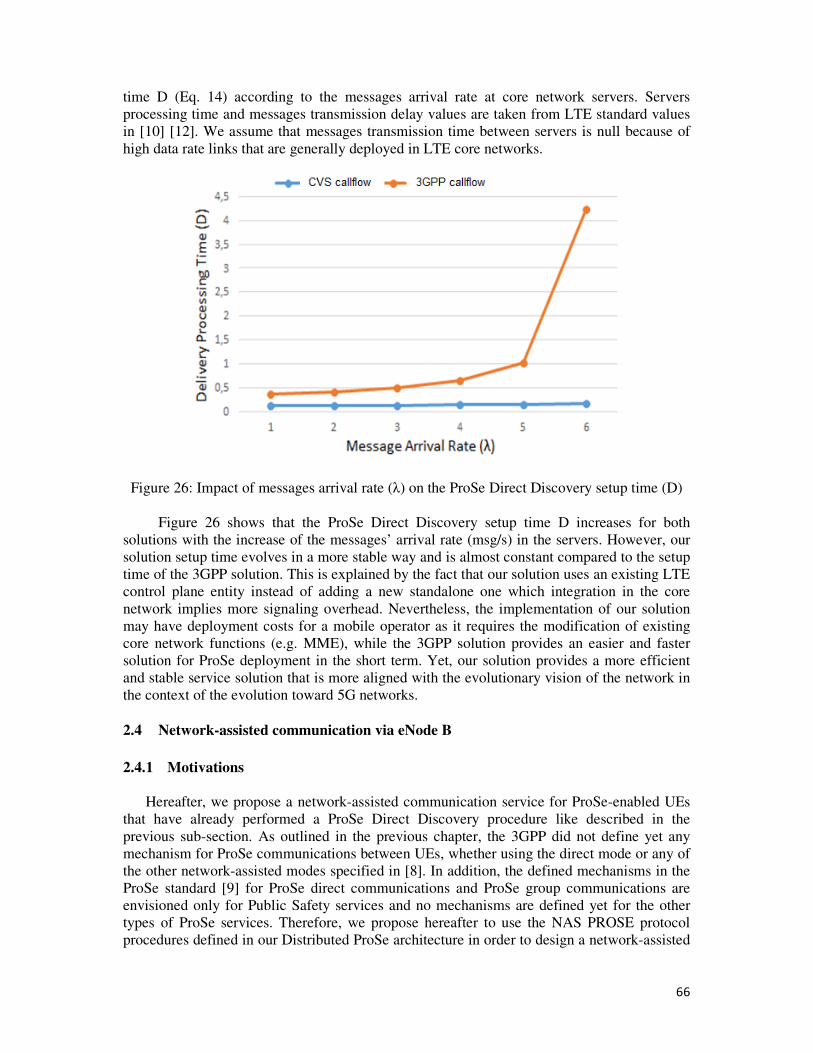
66
time D (Eq. 14) according to the messages arrival rate at core network servers. Servers
processing time and messages transmission delay values are taken from LTE standard values
in [10] [12]. We assume that messages transmission time between servers is null because of
high data rate links that are generally deployed in LTE core networks.
Figure 26: Impact of messages arrival rate (λ) on the ProSe Direct Discovery setup time (D)
Figure 26 shows that the ProSe Direct Discovery setup time D increases for both
solutions with the increase of the messages’ arrival rate (msg/s) in the servers. However, our
solution setup time evolves in a more stable way and is almost constant compared to the setup
time of the 3GPP solution. This is explained by the fact that our solution uses an existing LTE
control plane entity instead of adding a new standalone one which integration in the core
network implies more signaling overhead. Nevertheless, the implementation of our solution
may have deployment costs for a mobile operator as it requires the modification of existing
core network functions (e.g. MME), while the 3GPP solution provides an easier and faster
solution for ProSe deployment in the short term. Yet, our solution provides a more efficient
and stable service solution that is more aligned with the evolutionary vision of the network in
the context of the evolution toward 5G networks.
2.4 Network-assisted communication via eNode B
2.4.1 Motivations
Hereafter, we propose a network-assisted communication service for ProSe-enabled UEs
that have already performed a ProSe Direct Discovery procedure like described in the
previous sub-section. As outlined in the previous chapter, the 3GPP did not define yet any
mechanism for ProSe communications between UEs, whether using the direct mode or any of
the other network-assisted modes specified in [8]. In addition, the defined mechanisms in the
ProSe standard [9] for ProSe direct communications and ProSe group communications are
envisioned only for Public Safety services and no mechanisms are defined yet for the other
types of ProSe services. Therefore, we propose hereafter to use the NAS PROSE protocol
procedures defined in our Distributed ProSe architecture in order to design a network-assisted
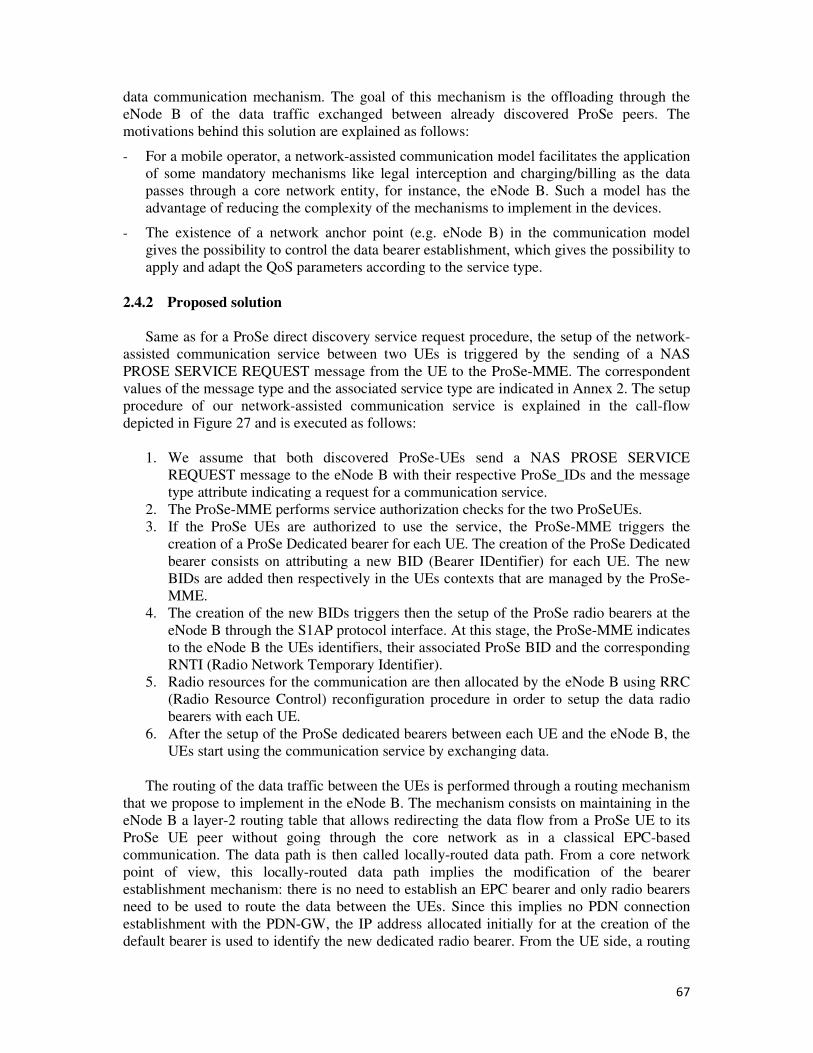
67
data communication mechanism. The goal of this mechanism is the offloading through the
eNode B of the data traffic exchanged between already discovered ProSe peers. The
motivations behind this solution are explained as follows:
- For a mobile operator, a network-assisted communication model facilitates the application
of some mandatory mechanisms like legal interception and charging/billing as the data
passes through a core network entity, for instance, the eNode B. Such a model has the
advantage of reducing the complexity of the mechanisms to implement in the devices.
- The existence of a network anchor point (e.g. eNode B) in the communication model
gives the possibility to control the data bearer establishment, which gives the possibility to
apply and adapt the QoS parameters according to the service type.
2.4.2 Proposed solution
Same as for a ProSe direct discovery service request procedure, the setup of the network-
assisted communication service between two UEs is triggered by the sending of a NAS
PROSE SERVICE REQUEST message from the UE to the ProSe-MME. The correspondent
values of the message type and the associated service type are indicated in Annex 2. The setup
procedure of our network-assisted communication service is explained in the call-flow
depicted in Figure 27 and is executed as follows:
1. We assume that both discovered ProSe-UEs send a NAS PROSE SERVICE
REQUEST message to the eNode B with their respective ProSe_IDs and the message
type attribute indicating a request for a communication service.
2. The ProSe-MME performs service authorization checks for the two ProSeUEs.
3. If the ProSe UEs are authorized to use the service, the ProSe-MME triggers the
creation of a ProSe Dedicated bearer for each UE. The creation of the ProSe Dedicated
bearer consists on attributing a new BID (Bearer IDentifier) for each UE. The new
BIDs are added then respectively in the UEs contexts that are managed by the ProSe-
MME.
4. The creation of the new BIDs triggers then the setup of the ProSe radio bearers at the
eNode B through the S1AP protocol interface. At this stage, the ProSe-MME indicates
to the eNode B the UEs identifiers, their associated ProSe BID and the corresponding
RNTI (Radio Network Temporary Identifier).
5. Radio resources for the communication are then allocated by the eNode B using RRC
(Radio Resource Control) reconfiguration procedure in order to setup the data radio
bearers with each UE.
6. After the setup of the ProSe dedicated bearers between each UE and the eNode B, the
UEs start using the communication service by exchanging data.
The routing of the data traffic between the UEs is performed through a routing mechanism
that we propose to implement in the eNode B. The mechanism consists on maintaining in the
eNode B a layer-2 routing table that allows redirecting the data flow from a ProSe UE to its
ProSe UE peer without going through the core network as in a classical EPC-based
communication. The data path is then called locally-routed data path. From a core network
point of view, this locally-routed data path implies the modification of the bearer
establishment mechanism: there is no need to establish an EPC bearer and only radio bearers
need to be used to route the data between the UEs. Since this implies no PDN connection
establishment with the PDN-GW, the IP address allocated initially for at the creation of the
default bearer is used to identify the new dedicated radio bearer. From the UE side, a routing
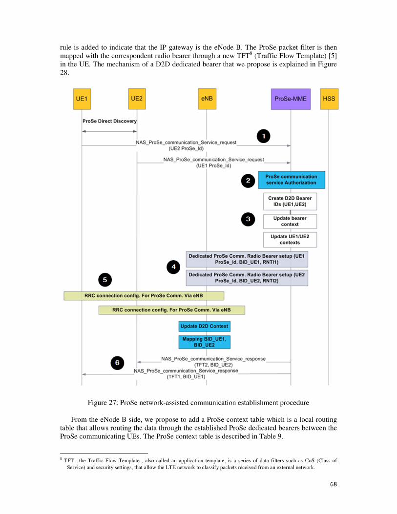
68
rule is added to indicate that the IP gateway is the eNode B. The ProSe packet filter is then
mapped with the correspondent radio bearer through a new TFT8 (Traffic Flow Template) [5]
in the UE. The mechanism of a D2D dedicated bearer that we propose is explained in Figure
28.
Figure 27: ProSe network-assisted communication establishment procedure
From the eNode B side, we propose to add a ProSe context table which is a local routing
table that allows routing the data through the established ProSe dedicated bearers between the
ProSe communicating UEs. The ProSe context table is described in Table 9.
8 TFT : the Traffic Flow Template , also called an application template, is a series of data filters such as CoS (Class of
Service) and security settings, that allow the LTE network to classify packets received from an external network.
69
Figure 28: Mapping of dedicated D2D radio bearers in the eNode B
Table 9: ProSe context table content in the eNode B
Attribute Description
SIMSI IMSI of the sender
SD2D_BID Bearer ID of the sender
SRNTI Radio Network Temporary
Identityof the sender
RIMSI IMSI of the receiver
RPROSE_BID ProSe Radio Bearer of the receiver
RRNTI Radio Network Temporary Identity
of the receiver
2.4.3 Simulation and performance evaluation
2.4.3.1 Extension of the NS3-LENA simulator
In order to evaluate the network performance of the proposed ProSe network-assisted
communication service, we chose to use the NS3 LENA simulator [39] [40]. The NS3 LENA
is an open source LTE/EPC simulator that provides one of the most complete
implementations of the EPC architecture and the LTE radio access network functions. It is
composed of two main components; the LTE model which includes the LTE radio protocol
stack, a quite complete implementation of UE and eNode B entities, and the EPC model
which includes core network interfaces, protocol stacks and entities such as the MME, the
PDN-GW, the S-GW and the eNode B. Nevertheless, the LENA package implementation in
NS3 is in its infancy and lacks from some procedures and functions that are used in our
network-assisted communication service solution (e.g. the LTE initial network attach
procedure [5] [10], some mobility context management functions in the MME). For this
purpose, a set of extensions has been added at a first step to the NS3 LENA package in order
to have a solid basis for our simulation work. In a second step, a basic set of functions and
70
procedures of our Distributed ProSe architecture were integrated in the simulator, in particular
the Network-assisted communication service. These extensions are summarized as follows:
- Extensions in the MME to support devices’ mobility context management.
- Extensions in the UE RRC states to support the network-assisted communication
mode via the eNode B (e.g. creation of a new RRC state “D2D_connected” )
- Extensions in the eNode B to handle the mapping of data flows between two
communicating ProSe devices using ProSe dedicated bearers
- Extensions in the bearer establishment procedure to create a ProSe dedicated bearer.
- Extensions in the LTE initial attach procedure to handle ProSe authentication and
service authorization.
2.4.3.2 Simulation methodology
In this section, we present the simulation results of our solution using the extended NS3
LENA simulator. The goal of these simulations is to evaluate the network performance of the
network-assisted communication service in terms of End-to-End delay and more specifically
the impact of the used offloading mechanism through the eNode B on radio and core networks
overload. In the simulation scenario, we assume that there is a number of UEs that are
attached to the same eNode B and located within the same cell. The UEs are mobile in the
simulation but we don’t consider yet at this stage of our work the micro mobility (UEs
moving from one eNode B to another) or the macro mobility (UEs being handled by different
MMEs) cases. Moreover, we consider two types of UEs involved in the simulation: UEs that
are ProSe-capable and UEs that can operate only in the classic LTE cellular mode. The
communications between ProSe UEs using the network-assisted communication service are
called D2D. In order to evaluate the impact of this D2D load in the cell, we measured the E2E
communication delay for both categories of UEs (ProSe UEs and normal UEs). We mainly
varied the number of ProSe peers according to the total number of UEs present in the cell. We
assume that all the UEs communicate simultaneously during the simulation time, that they are
all initially in the RRC “Connected Normally” mode and that interferences are managed.
Simulations’ parameters are summarized in Table 10.
Table 10: Simulation parameters
Parameters Values
UEs number 8,12,20,24,32,40,48,64,88,92,100
eNode B number 1
UEs speed (m/s) 20
Packet number 10
Inter-packet interval (ms) 100
Packet size (octets) 1095
Packet type UDP
LTE Bandwidh 5 Mhz
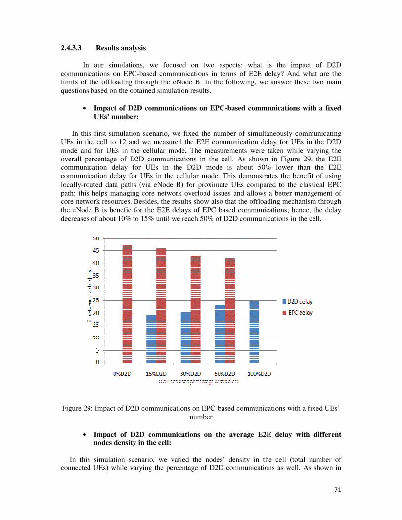
71
2.4.3.3 Results analysis
In our simulations, we focused on two aspects: what is the impact of D2D
communications on EPC-based communications in terms of E2E delay? And what are the
limits of the offloading through the eNode B. In the following, we answer these two main
questions based on the obtained simulation results.
• Impact of D2D communications on EPC-based communications with a fixed
UEs’ number:
In this first simulation scenario, we fixed the number of simultaneously communicating
UEs in the cell to 12 and we measured the E2E communication delay for UEs in the D2D
mode and for UEs in the cellular mode. The measurements were taken while varying the
overall percentage of D2D communications in the cell. As shown in Figure 29, the E2E
communication delay for UEs in the D2D mode is about 50% lower than the E2E
communication delay for UEs in the cellular mode. This demonstrates the benefit of using
locally-routed data paths (via eNode B) for proximate UEs compared to the classical EPC
path; this helps managing core network overload issues and allows a better management of
core network resources. Besides, the results show also that the offloading mechanism through
the eNode B is benefic for the E2E delays of EPC based communications; hence, the delay
decreases of about 10% to 15% until we reach 50% of D2D communications in the cell.
Figure 29: Impact of D2D communications on EPC-based communications with a fixed UEs’
number
• Impact of D2D communications on the average E2E delay with different
nodes density in the cell:
In this simulation scenario, we varied the nodes’ density in the cell (total number of connected UEs) while varying the percentage of D2D communications as well. As shown in
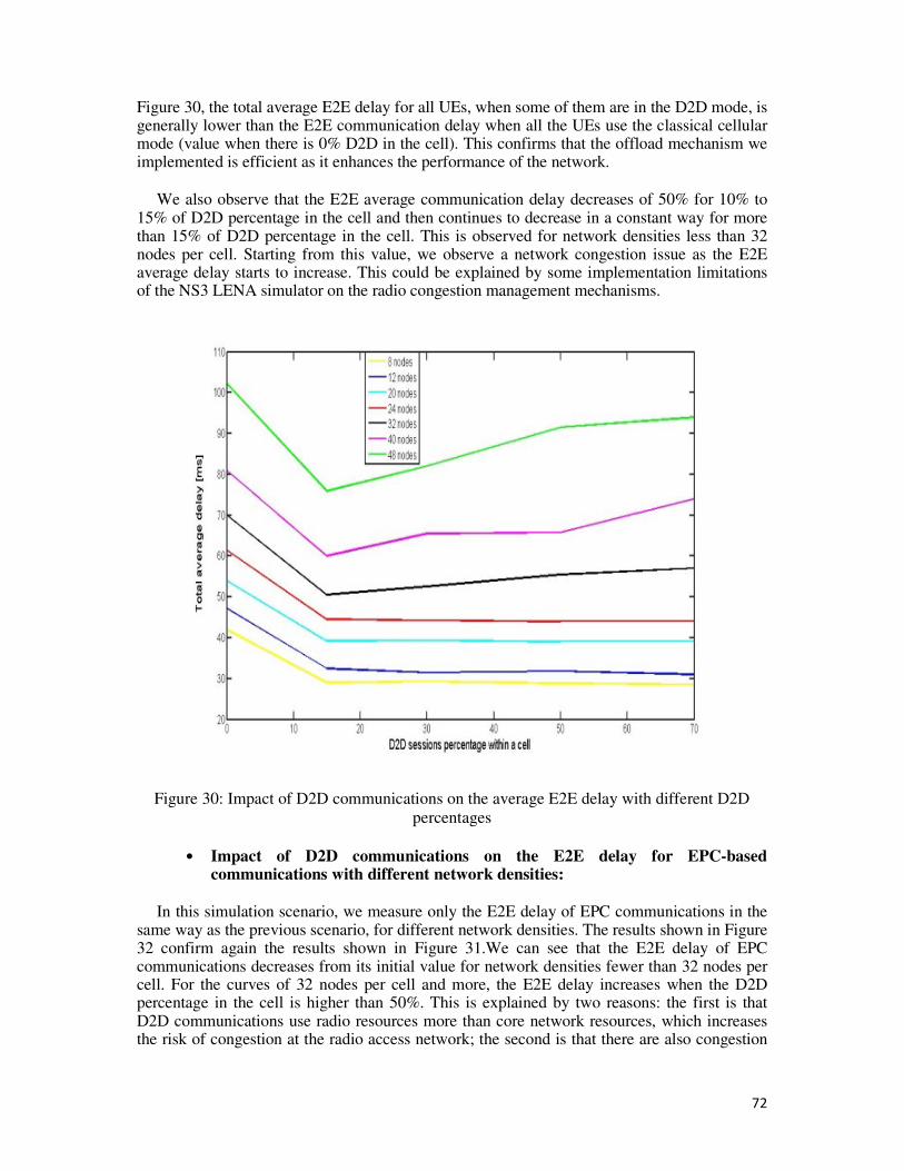
72
Figure 30, the total average E2E delay for all UEs, when some of them are in the D2D mode, is generally lower than the E2E communication delay when all the UEs use the classical cellular mode (value when there is 0% D2D in the cell). This confirms that the offload mechanism we implemented is efficient as it enhances the performance of the network.
We also observe that the E2E average communication delay decreases of 50% for 10% to 15% of D2D percentage in the cell and then continues to decrease in a constant way for more than 15% of D2D percentage in the cell. This is observed for network densities less than 32 nodes per cell. Starting from this value, we observe a network congestion issue as the E2E average delay starts to increase. This could be explained by some implementation limitations of the NS3 LENA simulator on the radio congestion management mechanisms.
Figure 30: Impact of D2D communications on the average E2E delay with different D2D
percentages
• Impact of D2D communications on the E2E delay for EPC-based communications with different network densities:
In this simulation scenario, we measure only the E2E delay of EPC communications in the same way as the previous scenario, for different network densities. The results shown in Figure 32 confirm again the results shown in Figure 31.We can see that the E2E delay of EPC communications decreases from its initial value for network densities fewer than 32 nodes per cell. For the curves of 32 nodes per cell and more, the E2E delay increases when the D2D percentage in the cell is higher than 50%. This is explained by two reasons: the first is that D2D communications use radio resources more than core network resources, which increases the risk of congestion at the radio access network; the second is that there are also congestion
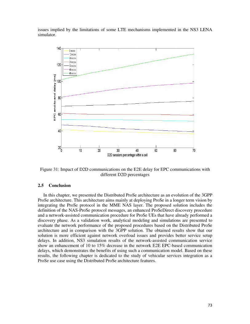
73
issues implied by the limitations of some LTE mechanisms implemented in the NS3 LENA simulator.
Figure 31: Impact of D2D communications on the E2E delay for EPC communications with
different D2D percentages
2.5 Conclusion
In this chapter, we presented the Distributed ProSe architecture as an evolution of the 3GPP ProSe architecture. This architecture aims mainly at deploying ProSe in a longer term vision by integrating the ProSe protocol in the MME NAS layer. The proposed solution includes the definition of the NAS-ProSe protocol messages, an enhanced ProSeDirect discovery procedure and a network-assisted communication procedure for ProSe UEs that have already performed a discovery phase. As a validation work, analytical modeling and simulations are presented to evaluate the network performance of the proposed procedures based on the Distributed ProSe architecture and in comparison with the 3GPP solution. The obtained results show that our solution is more efficient against network overload issues and provides better service setup delays. In addition, NS3 simulation results of the network-assisted communication service show an enhancement of 10 to 15% decrease in the network E2E EPC-based communication delays, which demonstrates the benefits of using such a communication model. Based on these results, the following chapter is dedicated to the study of vehicular services integration as a ProSe use case using the Distributed ProSe architecture features.
74
Chapter 3: Cellular Vehicular
Services (CVS)
3.1 Introduction
In Cooperative Intelligent Transportation Systems (Cooperative ITS), services like road
safety, fleet control, traffic efficiency, infotainment and other applications would be deployed
within an integrated on-board communication system embedded on vehicles, users’ personal
devices, roadside infrastructures and dedicated ITS remote servers, to provide safer roads,
greener cities and an enhanced driver experience. Research studies and real field experiments
have been conducted for over 15 years to achieve such a large scale and smart system. Hence,
ITS infrastructures should meet the following requirements:
- Ensure the reliable transmission of the ITS road safety information between the
different ITS entities (e.g. vehicles, infrastructure, servers, pedestrians…)
- Ensure the security and privacy of road users’ information against hackers and
malicious road users.
- Deploy low-latency communication protocols in order to spread efficiently road
safety alerts and warnings
Referring to the ITS standard [15], it is envisioned that ITS networks would be based on
short range ad-hoc inter-vehicular communications using the IEEE802.11p wireless
technology on an unlicensed spectrum. Mechanisms like multi-hop geographical routing
between vehicles would be used to relay the information at a wider distance in the ITS
network domains.
Yet, the deployment of ITS at the large scale is still a challenging task for automotive
and highway manufacturers, who are not equipped with the adequate infrastructures to operate
and control such a complex network characterized by its dynamic topology, high velocity and
a continuously increasing number of vehicles (an increase from 1.2 billionvehicles in 2014 to
2 billion is envisioned in 2035) [34]. In addition, several studies have shown the limitations of
the IEEE802.11p technology over multi-hop geo-routing protocols in terms of security
efficiency, network latency and overhead; hence, it was proved that these protocols increase
network transmission delays and the control signaling overhead, in addition to the complexity
of ITS security mechanisms integration and their overhead.
In this context, many attempts have proposed to couple ITS with cellular networks [16]
[17] [18], particularly with 4G/LTE networks, within an integrated architecture that is driven
and controlled by mobile operators. This solution has mainly two advantages: the first is the
opportunity to reuse the existing reliable and efficient cellular network infrastructure instead
of deploying a dedicated one for ITS, which mainly guarantee the scalability. The second is
the possibility to benefit from the native security mechanisms provided by the 4G/LTE
protocols in order to reduce the impacts of ITS security overhead on the network latency.Yet,
deploying such an integrated architecture did not take much attention from mobile operators
in the past years as they have been facing at their turn challenges in handling core network
overload issues and the infrastructure maintenance costs implied by the prominent increase of
the mobile traffic, users’ data and the number of connected mobile devices.
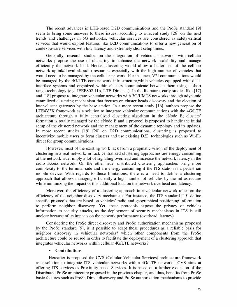
75
The recent advances in LTE-based D2D communications and the ProSe standard [9]
seem to bring some answers to these issues; according to a recent study [26] on the next
trends and challenges in 5G networks, vehicular services are considered as safety-critical
services that would exploit features like D2D communications to offer a new generation of
context-aware services with low latency and extremely short setup times.
Generally, research studies on the integration of vehicular networks with cellular
networks propose the use of clustering to enhance the network scalability and manage
efficiently the network load. Hence, clustering would allow a better use of the cellular
network uplink/downlink radio resources especially with the high number of vehicles that
would need to be managed by the cellular network. For instance, V2I communications would
be managed by the 4G/LTE core network infrastructure,while vehicles equipped with dual-
interface systems and organized within clusters communicate between them using a short
range technology (e.g. IEEE802.11p, LTE-Direct…). In the literature, early studies like [17]
and [18] propose to integrate vehicular networks with 3G/UMTS networks through adynamic
centralized clustering mechanism that focuses on cluster heads discovery and the election of
inter-cluster gateways by the base station. In a more recent study [16], authors propose the
LTE4V2X framework as a solution to integrate vehicular communications with the 4G/LTE
architecture through a fully centralized clustering algorithm in the eNode B; clusters’
formation is totally managed by the eNode B and a protocol is proposed to handle the initial
setup of the clustered network and the management of the dynamic topology and its updates.
In more recent studies [19] [20] on D2D communications, clustering is proposed to
incentivize mobile users to form clusters and use existing D2D technologies such as Wi-Fi-
direct for group communications.
However, most of the existing work lack from a pragmatic vision of the deployment of
clustering in a real network; in fact, centralized clustering approaches are energy consuming
at the network side, imply a lot of signaling overhead and increase the network latency in the
radio access network. On the other side, distributed clustering approaches bring more
complexity to the terminal side and are energy consuming if the ITS station is a pedestrian
mobile device. With regards to these limitations, there is a need to define a clustering
approach that allows managing efficiently a high number of vehicles by the infrastructure
while minimizing the impact of this additional load on the network overhead and latency.
Moreover, the efficiency of a clustering approach in a vehicular network relies on the
efficiency of the neighbor discovery mechanism. For instance, the ITS standard [15] define
specific protocols that are based on vehicles’ radio and geographical positioning information
to perform neighbor discovery. Yet, these protocols expose the privacy of vehicles
information to security attacks, as the deployment of security mechanisms in ITS is still
unclear because of its impacts on the network performance (overhead, latency).
Considering the ProSe direct discovery and ProSe authorization mechanisms proposed
by the ProSe standard [9], is it possible to adapt these procedures as a reliable basis for
neighbor discovery in vehicular networks? which other components from the ProSe
architecture could be reused in order to facilitate the deployment of a clustering approach that
integrates vehicular networks within cellular 4G/LTE networks?
• Contributions
Hereafter is proposed the CVS (Cellular Vehicular Services) architecture framework
as a solution to integrate ITS vehicular networks within 4G/LTE networks. CVS aims at
offering ITS services as Proximity-based Services. It is based on a further extension of the
Distributed ProSe architecture proposed in the previous chapter, and thus, benefits from ProSe
basic features such as ProSe Direct discovery and ProSe authorization mechanisms to provide
76
reliable and efficient V2X communications. The CVS solution would help fastening the
deployment of ITS at the large scale and opening new business opportunities for mobile
operators in the ProSe market. In addition, it provides better connectivity for V2X
communications through the use of the LTE-direct technology for V2V communications in
combination with D2D relay based communications and the infrastructure based mode. This
would limit high latency and signaling overhead issues caused by the use of the IEEE802.11p
technology and multi-hop geo-routing protocols usually proposed in vehicular networks.
The following sections are dedicated to the description of the CVS architecture
framework components as follows:
- The enhanced ProSe setup procedure for ITS services: a set of extensions to the
procedure proposed in the previous chapter in order to support ITS services.
- ProSe Direct Discovery for V2X: the extension of the PC5 protocol in the ProSe
Direct Discovery to support the discovery of ITS entities in the ITS domain.
- The CVS hybrid clustering approach: a hybrid clustering approach that combines
the advantages of both centralized and distributed approaches for network
scalability and more efficiency.
- The ProSe Gateway selection mechanism: a mechanism that allows collecting data
from ITS mobile nodes to the core network through the clustering approach.
Finally, a simulation work is carried out in order to compare the End-to-End
communication delays of the hybrid clustering approach in CVS with two other approaches of
V2X deployments (approaches with and without clustering).
3.2 The CVS architecture framework
The Cellular Vehicular Network (CVS) architecture framework is proposed to
completely integrate ITS services in 4G/LTE networks and beyond. Inspired by the 3GPP
ProSe standard [9], it is based on the Distributed ProSe architecture and features to support
ITS services as Proximity Services.
In CVS, ITS vehicles are considered as ProSe-enabled devices with ITS capabilities.
No dedicated ITS infrastructure needs to be deployed in CVS. Thanks to the wider range
offered by the LTE-direct technology (experiments in [27] envision a coverage range of up to
1km) and the LTE high data rates, V2V link establishment delays are enhanced and V2I/I2V
communications are facilitated, reducing thereby overhead issues implied by the use of multi-
hop relaying mechanisms.
The use of enhanced ProSe authorization and authentication procedures provided by
the Distributed ProSe architecture allow a native support of basic security and trust features
needed in ITS networks for neighbor discovery and inter-vehicular communications. The use
of such native efficient and reliable LTE security mechanisms offered by the mobile operator
infrastructure allows limiting security overhead issues mentioned previously.
Besides, in order to prevent vehicular networks integration scalability issues, CVS is
designed based on a clustering approach. Considering the benefits of clustering in resolving
overload’ issues through the decoupling of some network functions and roles on end users
devices, a network-controlled context-aware clustering strategy is proposed. Thus, as shown
in Figure 32, vehicles are organized into clusters in which members can communicate directly
between them (V2V) using D2D direct communications and with the infrastructure (V2I)
through the 4G/LTE connectivity. ProSe Direct discovery procedures are used to serve the
clustering approach based on a Clustering algorithm that we propose to implement firstly in
the ProSe-MME. The algorithm’s main function is to elect among the ITS mobile nodes
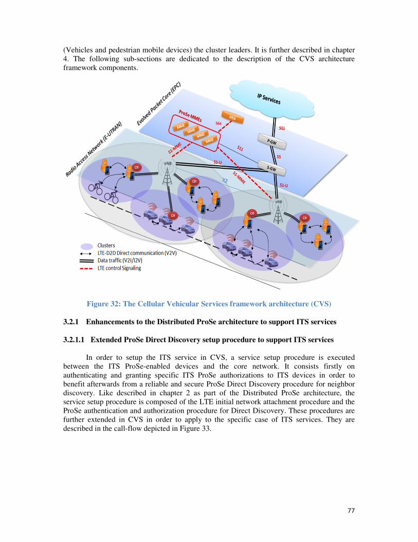
77
(Vehicles and pedestrian mobile devices) the cluster leaders. It is further described in chapter
4. The following sub-sections are dedicated to the description of the CVS architecture
framework components.
Figure 32: The Cellular Vehicular Services framework architecture (CVS)
3.2.1 Enhancements to the Distributed ProSe architecture to support ITS services
3.2.1.1 Extended ProSe Direct Discovery setup procedure to support ITS services
In order to setup the ITS service in CVS, a service setup procedure is executed
between the ITS ProSe-enabled devices and the core network. It consists firstly on
authenticating and granting specific ITS ProSe authorizations to ITS devices in order to
benefit afterwards from a reliable and secure ProSe Direct Discovery procedure for neighbor
discovery. Like described in chapter 2 as part of the Distributed ProSe architecture, the
service setup procedure is composed of the LTE initial network attachment procedure and the
ProSe authentication and authorization procedure for Direct Discovery. These procedures are
further extended in CVS in order to apply to the specific case of ITS services. They are
described in the call-flow depicted in Figure 33.
78
Figure 33: Extended ProSe authorization and authentication procedure for ITS services
As a reminder of what is explained in the state of the art of ProSe in chapter 1, a
ProSe-enabled UE can be in the Announcing mode or in the Monitoring mode. In the
Announcing mode, a ProSe_App_Code and a validity timer are allocated by the ProSe entity
for the UE. The ProSe_App_Code is then broadcasted by the UE to all the nodes in its
coverage range to announce a specific ProSe service until the expiration of thevalidity timer.
In the Monitoring mode, the device monitors information for a specific ProSe service using a
Discovery filter allocated by the ProSe enity and by applying a matching procedure between
the received ProSe_App_Code and the ProSe_App_Mask contained in the Discovery filter.
This operation helps determining if the received code corresponds to the sought ProSe
service.
In the CVS architecture, we assume that initially all ITS ProSeUEs are configured in
the Monitoring mode with aglobal ITS ProSe_App_Mask. This ITS ProSe_App_Mask is
common to all ITS applications and allows all CVS Monitoring nodes to communicate with
all CVS Announcing nodes independently from the used ITS application. Besides,
LTEcontrol signaling is exchanged between ITS ProSe-enabled devices and the core network
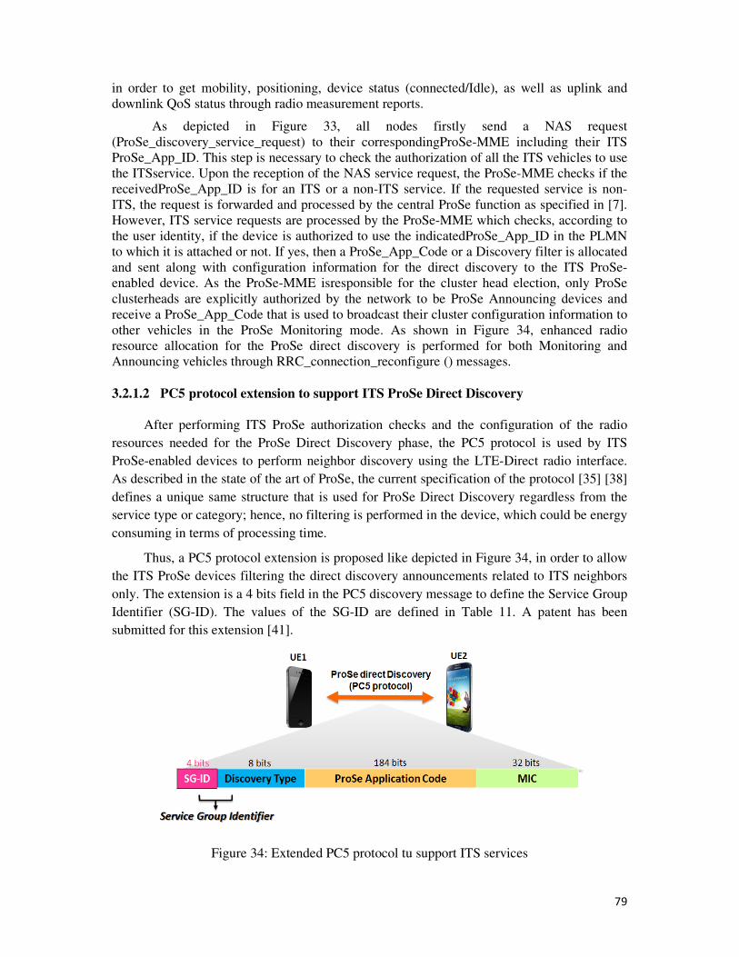
79
in order to get mobility, positioning, device status (connected/Idle), as well as uplink and
downlink QoS status through radio measurement reports.
As depicted in Figure 33, all nodes firstly send a NAS request
(ProSe_discovery_service_request) to their correspondingProSe-MME including their ITS
ProSe_App_ID. This step is necessary to check the authorization of all the ITS vehicles to use
the ITSservice. Upon the reception of the NAS service request, the ProSe-MME checks if the
receivedProSe_App_ID is for an ITS or a non-ITS service. If the requested service is non-
ITS, the request is forwarded and processed by the central ProSe function as specified in [7].
However, ITS service requests are processed by the ProSe-MME which checks, according to
the user identity, if the device is authorized to use the indicatedProSe_App_ID in the PLMN
to which it is attached or not. If yes, then a ProSe_App_Code or a Discovery filter is allocated
and sent along with configuration information for the direct discovery to the ITS ProSe-
enabled device. As the ProSe-MME isresponsible for the cluster head election, only ProSe
clusterheads are explicitly authorized by the network to be ProSe Announcing devices and
receive a ProSe_App_Code that is used to broadcast their cluster configuration information to
other vehicles in the ProSe Monitoring mode. As shown in Figure 34, enhanced radio
resource allocation for the ProSe direct discovery is performed for both Monitoring and
Announcing vehicles through RRC_connection_reconfigure () messages.
3.2.1.2 PC5 protocol extension to support ITS ProSe Direct Discovery
After performing ITS ProSe authorization checks and the configuration of the radio
resources needed for the ProSe Direct Discovery phase, the PC5 protocol is used by ITS
ProSe-enabled devices to perform neighbor discovery using the LTE-Direct radio interface.
As described in the state of the art of ProSe, the current specification of the protocol [35] [38]
defines a unique same structure that is used for ProSe Direct Discovery regardless from the
service type or category; hence, no filtering is performed in the device, which could be energy
consuming in terms of processing time.
Thus, a PC5 protocol extension is proposed like depicted in Figure 34, in order to allow
the ITS ProSe devices filtering the direct discovery announcements related to ITS neighbors
only. The extension is a 4 bits field in the PC5 discovery message to define the Service Group
Identifier (SG-ID). The values of the SG-ID are defined in Table 11. A patent has been
submitted for this extension [41].
Figure 34: Extended PC5 protocol tu support ITS services
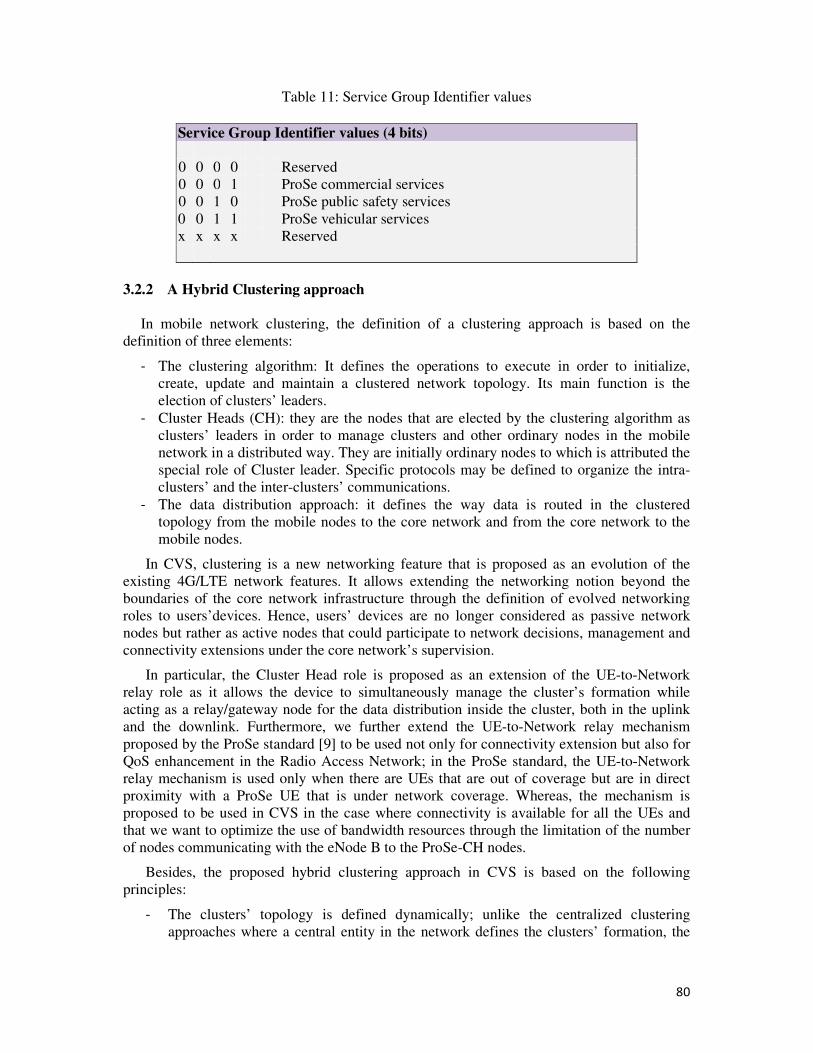
80
Table 11: Service Group Identifier values
Service Group Identifier values (4 bits)
0 0 0 0 Reserved
0 0 0 1 ProSe commercial services
0 0 1 0 ProSe public safety services
0 0 1 1 ProSe vehicular services
x x x x Reserved
3.2.2 A Hybrid Clustering approach
In mobile network clustering, the definition of a clustering approach is based on the
definition of three elements:
- The clustering algorithm: It defines the operations to execute in order to initialize,
create, update and maintain a clustered network topology. Its main function is the
election of clusters’ leaders.
- Cluster Heads (CH): they are the nodes that are elected by the clustering algorithm as
clusters’ leaders in order to manage clusters and other ordinary nodes in the mobile
network in a distributed way. They are initially ordinary nodes to which is attributed the
special role of Cluster leader. Specific protocols may be defined to organize the intra-
clusters’ and the inter-clusters’ communications.
- The data distribution approach: it defines the way data is routed in the clustered
topology from the mobile nodes to the core network and from the core network to the
mobile nodes.
In CVS, clustering is a new networking feature that is proposed as an evolution of the
existing 4G/LTE network features. It allows extending the networking notion beyond the
boundaries of the core network infrastructure through the definition of evolved networking
roles to users’devices. Hence, users’ devices are no longer considered as passive network
nodes but rather as active nodes that could participate to network decisions, management and
connectivity extensions under the core network’s supervision.
In particular, the Cluster Head role is proposed as an extension of the UE-to-Network
relay role as it allows the device to simultaneously manage the cluster’s formation while
acting as a relay/gateway node for the data distribution inside the cluster, both in the uplink
and the downlink. Furthermore, we further extend the UE-to-Network relay mechanism
proposed by the ProSe standard [9] to be used not only for connectivity extension but also for
QoS enhancement in the Radio Access Network; in the ProSe standard, the UE-to-Network
relay mechanism is used only when there are UEs that are out of coverage but are in direct
proximity with a ProSe UE that is under network coverage. Whereas, the mechanism is
proposed to be used in CVS in the case where connectivity is available for all the UEs and
that we want to optimize the use of bandwidth resources through the limitation of the number
of nodes communicating with the eNode B to the ProSe-CH nodes.
Besides, the proposed hybrid clustering approach in CVS is based on the following
principles:
- The clusters’ topology is defined dynamically; unlike the centralized clustering
approaches where a central entity in the network defines the clusters’ formation, the
81
hybrid approach allows the dynamic management of clusters’ formation by the Cluster
Head nodes.
- The election of Cluster Head nodes is centralized and executed by the clustering
algorithm in the ProSe-MME after collecting the necessary information about the
nodes in the network.
- Cluster Head nodes are used as relay/gateway nodes for data collection from ordinary
nodes to the network or data distribution from the network to ordinary nodes.
Besides, the CVS clustering approach benefits from the ProSe features for the Direct
Discovery as follows:
- The presence announcement of ProSe-CH: it is made through the extended PC5
protocol to support ITS services and the configuration of ProSe-CH nodes as
“Announcing” ProSe nodes that advertise a specific ProSe Application Code for ITS
services.
- The discovery of ProSe-CH by the other nodes: it is made using the extended PC5
protocol and the configuration of ordinary nodes as “Monitoring” ProSe nodes
The Adaptive Context-Aware Weighted Clustering Algorithm (ACWCA) is the clustering
algorithm in CVS. Its main characteristic is that it selects the minimum number of ProSe-CH
nodes in order to optimize the throughput usage in the Radio Access Network (RAN). The
ACWCA is executed by the ProSe-MME after the ProSe authentication and authorization of
the UEs as ProSe-ITS enabled UEs. The ACWCA mechanism is further detailed in chapter 4.
3.2.3 ProSe Gateway selection
The transmission of data between ordinary nodes and the network in CVS could be
done according to two schemes: the V2I (Vehicle to Infrastructure) scheme and the I2V
(Infrastructure to Vehicle) scheme. Generally, I2V services aim at broadcasting the ITS
information to the maximum number of vehicles. Such a scheme could be deployed using
classical broadcast mechanisms of the eNode B which guarantee a wider broadcast zone.
However, V2I services requiring the allocation of uplink resources are generally more costly
to a mobile operator. For instance, a congestion situation at the eNode B in the uplink can
cause temporary disconnection of users from the network. As a solution to this issue,
intermediate nodes in the mobile network like ProSe-CH may reduce the total number of
uplink links to establish with the eNode B. Data collection and aggregation through a ProSe-
CH allows a more efficient usage of uplink resources in the eNode Bs and provides better
rates and delays for users, thanks to D2D direct communications between ProSe-CHs and the
ordinary nodes.
For these reasons, we are interested in CVS in defining a procedure for V2I services
that takes advantage from clustering. The ProSe Gateway selection is related to the procedure
of data transmission from ordinary nodes to the network through ProSe-CHs (V2I
communications). Assuming that in the coverage area of an eNode B, there is more than one
ProSe-CH node available, each ordinary node entering the area may see multiple ProSe-CH
announcements. The ProSe Gateway Selection procedure consists in selecting the best ProSe-
CH node as a gateway to uplink the data to the network. Different mechanisms exist already
for such situations. In CVS, it is proposed to use an extension of the LIFBE (Low Bandwidth
and Fast Intrusive Estimation) mechanism proposed and described in [42] to measure the
82
radio link quality between an ordinary node and a ProSe-CH. Based on these measurements,
the ordinary node runs an algorithm that selects the best gateway.
3.3 Network performance evaluation
3.3.1 Methodology
Hereafter, it is proposed to evaluate the performance of End-To-End V2V
communications in CVS in terms of delay. The idea is to show the enhancements brought by
the CVS solution compared to older solutions for ITS services and V2X communications
deployments at two different levels: the used clustering approach and the efficiency of V2V
radio communications. For this purpose, NS2 simulations are carried out to measure the E2E
communication delay for three different solutions for ITS services deployments:
- CVS: solution that is based on the 4G/LTE infrastructure for V2I/I2V
communications, LTE-Direct D2D communications for V2V communications, and a
hybrid clustering approach that optimizes the use of radio and bandwidth resources.
The hybrid clustering does not imply a centralized clusters formation. The
communication range of V2V communications based on LTE-Direct is assumed to be
wider than IEEE802.11p communication range. No multi-hop communication
protocols are used to relay the vehicular information between nodes that are not in
radio communication range. Instead, the classical 4G/LTE communications are used in
this case.
- LTE4V2X: solution described in [16]. It is based on the 4G/LTE infrastructure for
V2I/I2V communications, IEEE802.11p for V2V communications and a centralized
clustering approach that manages clusters formation and maintains clusters’ structure.
Multi-hop communication protocols are used for communication between nodes not in
radio communication range.
- Classical VANET: solution that is based on the classical deployment models of
VANETs using a dedicated ITS infrastructure for V2I/I2V communications, mainly
IEEE802.11p for V2V communications and without clustering. Multi-hop
communication protocols are used for communication between nodes not in radio
communication range.
The simulation scenario consists of varying the total number of vehicles in the network
assuming that, in the case of the clustering based solutions, only one cluster is considered.
The NS2 simulation parameters are shown in Table 12.
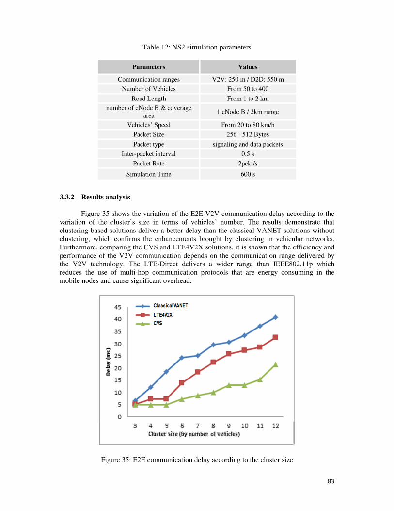
83
Table 12: NS2 simulation parameters
Parameters Values
Communication ranges V2V: 250 m / D2D: 550 m
Number of Vehicles From 50 to 400
Road Length From 1 to 2 km
number of eNode B & coverage
area 1 eNode B / 2km range
Vehicles’ Speed From 20 to 80 km/h
Packet Size 256 - 512 Bytes
Packet type signaling and data packets
Inter-packet interval 0.5 s
Packet Rate 2pckt/s
Simulation Time 600 s
3.3.2 Results analysis
Figure 35 shows the variation of the E2E V2V communication delay according to the
variation of the cluster’s size in terms of vehicles’ number. The results demonstrate that
clustering based solutions deliver a better delay than the classical VANET solutions without
clustering, which confirms the enhancements brought by clustering in vehicular networks.
Furthermore, comparing the CVS and LTE4V2X solutions, it is shown that the efficiency and
performance of the V2V communication depends on the communication range delivered by
the V2V technology. The LTE-Direct delivers a wider range than IEEE802.11p which
reduces the use of multi-hop communication protocols that are energy consuming in the
mobile nodes and cause significant overhead.
Figure 35: E2E communication delay according to the cluster size
84
3.4 Conclusion
The CVS architecture framework was presented in this chapter as an integrated solution
in the 4G/LTE infrastructure for the deployment of LTE-based V2X communications in ITS.
Extensions of the Distributed ProSe architecture were proposed in order to support ITS
services as ProSe services. The use of ProSe features for this integration provides basic and
native authentication and authorization procedures for ITS services as well as efficient Direct
Discovery mechanism for neighbor discovery in ITS. A hybrid clustering approach is then
introduced through the definition of the ACWC algorithm in the ProSe-MME. The goal is
mainly to optimize the use of radio and bandwidth resources and to manage the additional
high number of vehicles by the 4G/LTE network. The following chapter is dedicated to its
description.
85
Chapter 4: The Adaptive Context-
aware Weighted Clustering algorithm
(ACWC)
4.1 Introduction
The integration of vehicular networks within 4G/LTE networks will definitely increase
the traffic load in cellular networks because of the additional number of subscribers that they
comprise. On the other hand, the variable traffic density and mobility in these networks are
challenging characteristics to handle: for instance, in urban environments, the network could
be very dense with low to medium mobility rate, while it goes to a very sparse and highly
mobile in rural environments. When the vehicular network is operated by a cellular network
like 4G/LTE, this dynamic nature has impacts on the radio resource allocation in the RAN
and the delivered throughput from the base station to the mobile nodes especially in network
congestion situations.
Besides, ITS vehicular networks are generally based on the spread of the information
through V2V communications using single and multi-hop geographical-based routing
protocols. Though, it has been proved that these mechanisms imply a lot of control signaling
overhead and high network latency du to the exchange of a lot of routing packets between
vehicles in order to reach the destination over multi-hops.
In such dynamic and multi-hop environments, clustering has been considered as a
promising approach to address routing, throughput and resource allocation problems. It
proposes mainly to build hierarchies among the nodes, such that the network topology can be
abstracted. The substructures that are collapsed in higher levels are called clusters.
The concept of clustering in vehicular networks has been studied well in MANETs and
VANETs literature [30] [32] [33]; referring to the state of the art of clustering architectures
and algorithms presented in Chapter 1, many algorithms that consider different metrics and
focus on diverse objectives have been proposed. Particularly, weighted clustering algorithms
are considered as the most adaptive as they include multiple metrics in the CH nodes election
process. Yet, their efficiency strongly depends on the clustering architecture in which they are
deployed.
• Contributions
With regards to the importance of the mobility context change in these networks, it is
proposed in the following chapter to design an adaptive weighted clustering algorithm that is
based on the context information of the nodes. The Adaptive Context-aware Weighted
Clustering Algorithm (ACWCA) is the main component of the CVS architecture framework.
It aims at providing a hierarchical topology in which vehicles are organized into clusters
which members can communicate directly between them (V2V) using D2D direct
communications (based on the LTE-Direct radio) and with the infrastructure (V2I) through
4G/LTE communications. Through this contribution, the implementation of a clustering
mechanism in the 4G/LTE core network is studied from a protocol point of view and new
86
procedures are proposed. The implementation is proposed in the ProSe-MME entity, which
provides locally some interesting network information like the UEs mobility context
information that are necessary for the CH nodes election procedure. The integration of the
ACWCA procedures within the 4G/LTE core network procedures is proposed based on the
Distributed ProSe architecture procedures described in Chapter 2. Besides, the design of
ACWCA relies on the definition of three following steps:
- Context parameters calculation: consists on defining the expression of each parameter
considered in the weight calculation equation.
- The ACWCA setup procedure: consists on the set of operations to perform in order to
initialize a clustered network topology.
- The ACWCA maintenance procedure: consists on the set of operations to perform or
to trigger to update the clustered network topology based on nodes context changes.
The chapter is concluded by a performance evaluation of the algorithm and the CVS
hybrid clustering approach based on the definition of some metrics. The results are compared
to two other similar clustering algorithms but using different clustering architecture
approaches.
4.2 The Adaptive Context-aware Weighted Clustering Algorithm (ACWCA)
4.2.1 Description
The ACWCA is composed mainly of two procedures: the Cluster formation procedure
which aims at electing Cluster heads in order to organize the network into virtual zones called
clusters, and the clusters maintenance and management procedure which allows maintaining
the clusters’ structure and updates the network topology according to nodes’ mobility
changes. The main characteristics of the proposed ACWCA are as follows:
o Hybrid architecture:
Referring to the clustering algorithms comparaison in table 6 in chapter 1, weight-
based clustering in distributed mobile cloud architectures can cause overhead issues since it
lacks from knowing the weights of all nodes before the startup of the clustering process; this
results in a high frequency of CHs reelection, longer delays before reaching a stable clustered
topology which increases the control signaling traffic load. This issue affects directly the
clusters stability and is somehow a consequence of the distributed nature of the mobile
architecture in which the clustering algorithm is applied. In our solution, we solve this issue
by applying the weight-based clustering algorithm on a hybrid mobile architecture. Through
centralized core network entities, mainly the ProSe-MME responsible of CHs election in
CVS, a more global view on the mobile network and mobile nodes behavior before the startup
of the clustering process is provided to the ProSe-MME through mobility and context
information. This reduces the complexity of the clustering process at mobile nodes while
benefiting from central nodes high processing capabilities to execute more complex
operations.
o Event-driven clustering:
The ACWCA clustering is not periodic because applying periodicity in highly
dynamic mobile networks with frequent topology changes causes clusters instability and
overhead issues, which reduces consequently the efficiency of the algorithm. Instead, we
87
propose an event-driven clustering in which the CH reelection procedure is delayed as much
as possible to increase clusters’ lifetime and reduce the rate of CHs reelection and processing
delays due to clusters maintenance. This procedure is triggered when a CH node is no more
stable and becomes not suitable to act as a CH; for instance, if the device’s remaining battery
power is low or if it tends to move away from its neighbors.
o Adaptive:
The ACWCA is adaptive as it is based on the combination of several significant metrics
that are used to calculate the weight of a node in order to decide if it can be a CH or not.
These metrics are described as follows:
- Mobility: the mobility metric of the node is usually expressed in terms of the variation
of its speed over time. In ACWCA, it is expressed as the Local stability of the node,
which indicates, independently from its speed, the standard deviation of its relative
mobility values toward all its neighbors.
- Battery energy: it is important for a clustering algorithm that is executed in mobile
devices with limited energy resources, to take into account the consumed battery
power. Hence, a CH node that goes out of battery may cause a break point in the
topology and the battery draining of the other nodes.
- Transmission Rate: since our hybrid cloud architecture implies that the CH serves as
a gateway node for uplink traffic, it is important to consider the transmission rate
criteria of a node in the CH election procedure.
- Connectivity: a CH node candidate should be selected as CH according to its
coverage range, which can be expressed by the number of neighbors that it is
connected to. This allows especially avoiding situations of mono-node clusters. Node
connectivity could also be calculated as the remaining number of nodes that it can
handle if it is a CH node. This is based on the calculation of the node degree and its
comparison to a threshold value of the maximum number of nodes that a CH should
handle. It is called the degree difference.
o Context-aware:
Since we are in a mobile environment in which the topology and the mobility of the
nodes are variable, we propose to combine our algorithm to a context learning method. The
context learning method is executed by a software module that we propose to implement in
the ProSe-MME. This module allows the detection of the context situation of the network
based on context information collected from the mobile nodes. For example, in the coverage
area of an eNode B, it tells if there is a “high mobility” context, a “low connectivity” context
or a “high density” context. According to these different situations, the weighting factors of
our algorithm are adapted in order to select efficiently the adequate CHs mobile nodes.
4.2.2 Context parameters calculation
In ACWCA, the weight calculation method is inspired by the solution of a Weight-
Based Adaptive Clustering Algorithm (WBACA) proposed in [31] and [33]. However, we
propose to improve it by using the mobile node local stability expression proposed in [32]
instead of calculating only its distance from the base station. Hence, we calculate the weight
of a node based on the following context parameters that correspond to the before mentioned
metrics:
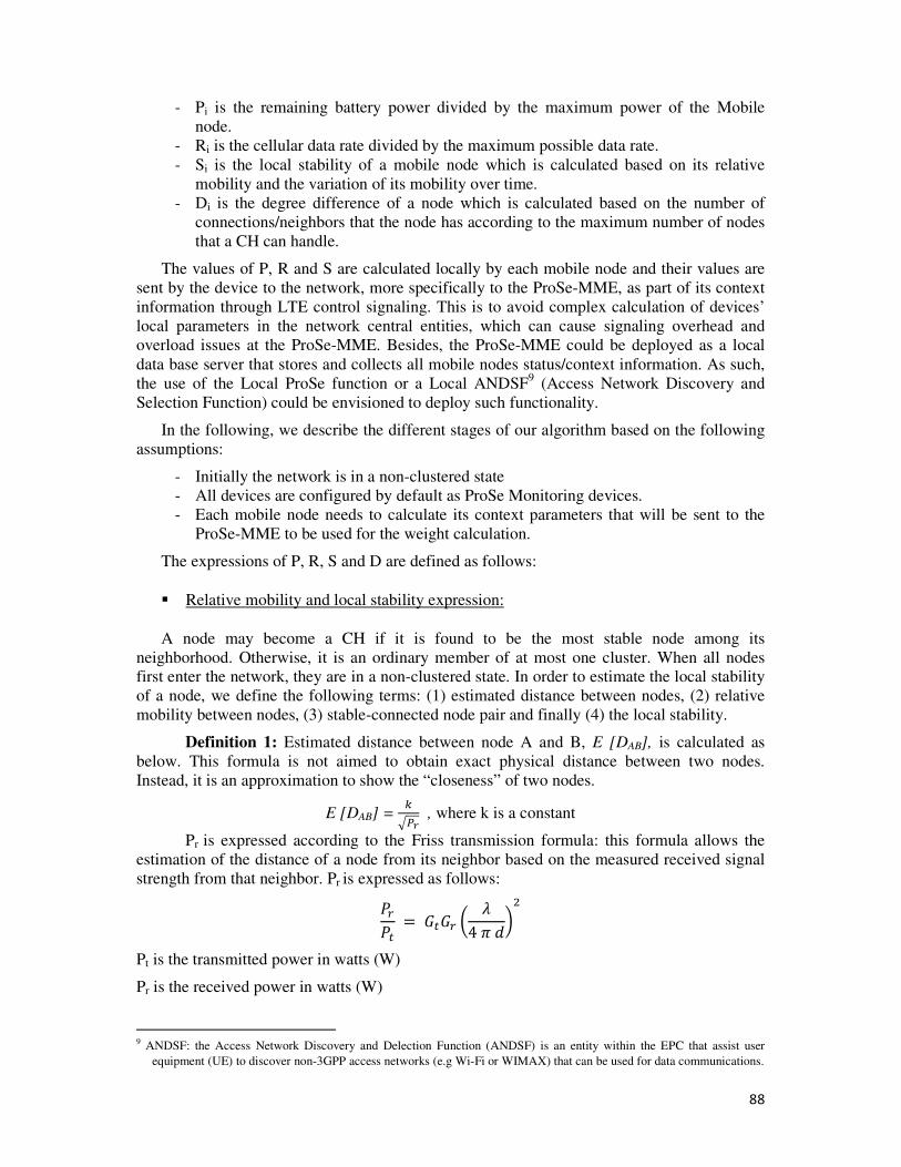
88
- Pi is the remaining battery power divided by the maximum power of the Mobile
node.
- Ri is the cellular data rate divided by the maximum possible data rate.
- Si is the local stability of a mobile node which is calculated based on its relative
mobility and the variation of its mobility over time.
- Di is the degree difference of a node which is calculated based on the number of
connections/neighbors that the node has according to the maximum number of nodes
that a CH can handle.
The values of P, R and S are calculated locally by each mobile node and their values are
sent by the device to the network, more specifically to the ProSe-MME, as part of its context
information through LTE control signaling. This is to avoid complex calculation of devices’
local parameters in the network central entities, which can cause signaling overhead and
overload issues at the ProSe-MME. Besides, the ProSe-MME could be deployed as a local
data base server that stores and collects all mobile nodes status/context information. As such,
the use of the Local ProSe function or a Local ANDSF9 (Access Network Discovery and
Selection Function) could be envisioned to deploy such functionality.
In the following, we describe the different stages of our algorithm based on the following
assumptions:
- Initially the network is in a non-clustered state
- All devices are configured by default as ProSe Monitoring devices.
- Each mobile node needs to calculate its context parameters that will be sent to the
ProSe-MME to be used for the weight calculation.
The expressions of P, R, S and D are defined as follows:
� Relative mobility and local stability expression:
A node may become a CH if it is found to be the most stable node among its
neighborhood. Otherwise, it is an ordinary member of at most one cluster. When all nodes
first enter the network, they are in a non-clustered state. In order to estimate the local stability
of a node, we define the following terms: (1) estimated distance between nodes, (2) relative
mobility between nodes, (3) stable-connected node pair and finally (4) the local stability.
Definition 1: Estimated distance between node A and B, E [DAB], is calculated as
below. This formula is not aimed to obtain exact physical distance between two nodes.
Instead, it is an approximation to show the “closeness” of two nodes.
E [DAB] = 5678 , where k is a constant
Pr is expressed according to the Friss transmission formula: this formula allows the
estimation of the distance of a node from its neighbor based on the measured received signal
strength from that neighbor. Pr is expressed as follows: 9:9; = <;<: = >4@AB�
Pt is the transmitted power in watts (W)
Pr is the received power in watts (W)
9 ANDSF: the Access Network Discovery and Delection Function (ANDSF) is an entity within the EPC that assist user
equipment (UE) to discover non-3GPP access networks (e.g Wi-Fi or WIMAX) that can be used for data communications.
89
Gt is the antenna gain of the transmitter
Gr is the antenna gain of the receiver
d is the distance in meter (m) between the transmitter and the receiver. > is the wave length
Definition 2: the Relative mobility CDE:FG between nodes A and B, indicates whether
they are moving away from each other, moving closer to each other or maintain the same
distance from each other. To calculate relative mobility, we compute the difference of the
distance at time, t and the distance at time t -1. Relative mobility at node A with respect to
node B at t is calculated as follows: CDE:FG = HIJDE; K − HIJDE;3K For more simplicity, the relative mobility could be calculated using physical position
coordinates of the nodes using a Global Positioning System (GPS). The problem of such
technique is that it assumes that all nodes are equipped with a GPS system and that position
information is always provided accurately by the GPS. Nevertheless, the GPS-based
calculation in many situations may not be feasible, for instance in indoor scenario where GPS
signal may be unavailable. Also, the before-mentioned formula for relative mobility is not
based on the availability of any velocity information at the mobile node, which makes the
system more adaptive to the scenario (high mobility environment or low mobility
environment).
Definition 3: The variation of E [DAB] over a time period, T, VDAB, is defined as the
changes of estimated distances between node A and B over a predefined time period. Let us
consider node A as measuring node. Node A has a series of estimated distance values from
node B measured at certain time interval for n times, E [DAB] = {E [DAB]t, t = 0, 1, 2, … , n}.
Therefore we calculate VDAB as the standard deviation of distance variation as follows:
LJDE = M�NHOJDEP − HOJDEPQN , NHOJDEP� − HOJDEPQN , … NHOJDEPT − HOJDEPQN�
Definition 4: Local stability at node A, StA , represents the degree of stability at node
A with respect to all its neighbors. Local stability is the standard deviation of relative mobility
values of all neighbors. Therefore it is calculated as follows: UVD = M�LJDE, LJDE�, … LJDET� � Power expression:
We define Pi as the ratio of available battery power in the mobile node. It is calculated as
follows:
9W = 9_YZZY[VW9_\]^W
9_YZZY[VW is the remaining battery power of the device. 9_\]^W is the maximum battery power of the device.

90
� Rate expression:
We define Ri as the ratio of the available cellular data rate for a mobile node. It is
calculated as follows:
_W = __YZZY[VW__\]^W
__YZZY[VW is the available cellular data rate of the device. __\]^W is the maximum data rate of the device.
� Connectivity expression:
We define di (t) as the degree of the node (number of neighbors) at time t and which is
calculated as follows:
AW�V� = `abcdW,e �V� Where linki,j is the link between node i and node j.
Then, we express Di as the degree difference of the node, which is calculated as follows: JW = |AW − gahiVYj_ibkY| Where Cluster_size is the maximum number of mobile nodes that can be handled by a CH
node.
4.2.3 ACWCA Setup procedure
The ProSe-MME is responsible of executing the CH election algorithm which collects
nodes’ status information to calculate in a second step the weight of each node W based on
the following equation and parameters: lW = g × 9W +g� × _W +g0 × UW +g/ × JW C1, C2 and C3 are weighting factors which values are calculated based on system
requirements. These values can be fixed statically for each parameter according to its
relevance in the decision process of CHs election for all the possible scenarios. In this section,
we assume fixed values for the weighting factors. Later on, a dynamic weights calculation is
proposed through a Context-Learning method that adapts the values of these weighting factors
according to the context of mobile nodes.
The mobile node that has the highest weight W is elected as CH. In order to avoid
scalability and overload issues in clusters, the ProSe-MME elects a limited number of CH
nodes in each LTE cell in order to avoid situations where all nodes are CHs. In addition, a
limited number of mobile nodes that can access simultaneously a CH as a gateway are defined
in order to avoid CH overload issues. The average number of CH in a cell Avg_NCH/cell and
the average number of mobile nodes accessing simultaneously a CH as a gateway for uplink
traffic Cluster_size are configured according to threshold values that can be adapted by
configuration based on the operator policy. Based on the before-mentioned expressions of P,
R, S and D parameters and the Weight formula, the CH election procedure of our algorithm is
defined as follows:

91
Algorithm 1: Adaptive context-aware weight-based clustering algorithm
Variables
NCH/cell is an integer variable for the number of selected CH per cell and is initialized to 0.
Cluster_size is a constant and is calculated as follows:
Cluster_size = Rwx R' y
Avg_NCH/cell is an integer constant and is calculated as follows:
Avg_Nwx/w�~~ = Uh� =Y��_j]c�Yg�_j]c�Y B�
Wi is an integer variable and represents the weight value of a node.
Pi, Ri, Si and Di are Real variables representing respectively the node parameters Power, Rate,
local Stability and Degree difference.
C1, C2, C3 and C4 are constants.
Procedure 1: Cluster head election in the ProSe-MME
1. Set the values of the weighting factors C1, C2, C3 and C4.
2. For each Node, store the received Context Parameters values (Pi, Ri , Si, Di)
3. For each Node and based on each node Context parameters, calculate: lW = g × 9W +g� × _W +g0 × UW +g/ × JW 4. For each Node, store the value of its calculated Wi in its Context profile.
5. Sort Nodes’ weights by Maximum and put the result in MaxSort_NodeWeights table.
6. Select a number NCH/cell of CH nodes with weight Wi from the sorted weight table
such as: Nwx/w�~~ ≤ Avg_Nwx/w�~~ 7. For each selected CH node, send ProSe configuration Info and Cluster_size.
End Procedure.
Based on this algorithm, Figure 36 describes the protocol procedure of ProSe-CH
election by the ProSe-MME and how it is combined with ProSe authentication and
authorization procedures for Direct Discovery over the PC5 protocol. Initially, it is assumed
that all the ProSe-ITS UEs are setup in the “Monitoring” mode according to the procedure
described in the previous chapter in Figure 33. It is assumed that an application for ITS data
collection is embedded in all ProS-ITS enabled nodes. This application allows the processing
and sending of some ITS context parameters that are needed by the ACWCA in the ProSe-
MME in order to initiate the clustering procedure. Upon the reception of this information
from all the nodes, the ACWCA elects ProSe-CH nodes and a notification message is sent by
the ProSe-MME. To switch to the ProSe-CH role, nodes that have received ProSe-CH
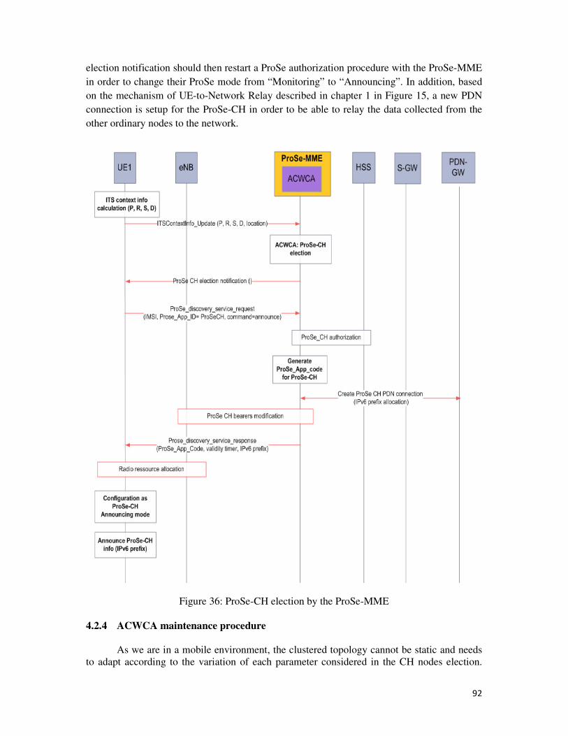
92
election notification should then restart a ProSe authorization procedure with the ProSe-MME
in order to change their ProSe mode from “Monitoring” to “Announcing”. In addition, based
on the mechanism of UE-to-Network Relay described in chapter 1 in Figure 15, a new PDN
connection is setup for the ProSe-CH in order to be able to relay the data collected from the
other ordinary nodes to the network.
Figure 36: ProSe-CH election by the ProSe-MME
4.2.4 ACWCA maintenance procedure
As we are in a mobile environment, the clustered topology cannot be static and needs
to adapt according to the variation of each parameter considered in the CH nodes election.
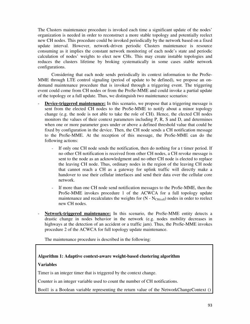
93
The Clusters maintenance procedure is invoked each time a significant update of the nodes’
organization is needed in order to reconstruct a more stable topology and potentially reelect
new CH nodes. This procedure could be invoked periodically by the network based on a fixed
update interval. However, network-driven periodic Clusters maintenance is resource
consuming as it implies the constant network monitoring of each node’s state and periodic
calculation of nodes’ weights to elect new CHs. This may create instable topologies and
reduces the clusters lifetime by broking systematically in some cases stable network
configurations.
Considering that each node sends periodically its context information to the ProSe-
MME through LTE control signaling (period of update to be defined), we propose an on-
demand maintenance procedure that is invoked through a triggering event. The triggering
event could come from CH nodes or from the ProSe-MME and could invoke a partial update
of the topology or a full update. Thus, we distinguish two maintenance scenarios:
- Device-triggered maintenance: In this scenario, we propose that a triggering message is
sent from the elected CH nodes to the ProSe-MME to notify about a minor topology
change (e.g. the node is not able to take the role of CH). Hence, the elected CH nodes
monitors the values of their context parameters including P, R, S and D, and determines
when one or more parameter goes under or above a defined threshold value that could be
fixed by configuration in the device. Then, the CH node sends a CH notification message
to the ProSe-MME. At the reception of this message, the ProSe-MME can do the
following actions:
- If only one CH node sends the notification, then do nothing for a t timer period. If
no other CH notification is received from other CH nodes, a CH revoke message is
sent to the node as an acknowledgment and no other CH node is elected to replace
the leaving CH node. Thus, ordinary nodes in the region of the leaving CH node
that cannot reach a CH as a gateway for uplink traffic will directly make a
handover to use their cellular interfaces and send their data over the cellular core
network.
- If more than one CH node send notification messages to the ProSe-MME, then the
ProSe-MME invokes procedure 1 of the ACWCA for a full topology update
maintenance and recalculates the weights for (N - NCH/cell) nodes in order to reelect
new CH nodes.
- Network-triggered maintenance: In this scenario, the ProSe-MME entity detects a
drastic change in nodes behavior in the network (e.g. nodes mobility decreases in
highways at the detection of an accident or a traffic jam). Thus, the ProSe-MME invokes
procedure 2 of the ACWCA for full topology update maintenance.
The maintenance procedure is described in the following:
Algorithm 1: Adaptive context-aware weight-based clustering algorithm
Variables
Timer is an integer timer that is triggered by the context change.
Counter is an integer variable used to count the number of CH notifications.
Bool1 is a Boolean variable representing the return value of the NetworkChangeContext ()
94
function. It is initialized to false.
Bool2 is a Boolean variable representing the return value of the
CHContextChangeNotification () function. It is initialized to false.
NCH/cell is an integer variable indicating the number of elected CH per cell
Functions
NetworkChangeContext () is a function that indicates if the network context has changed
based on the output of a Context learning software module in the ProSe-MME.
CHdetachNotification () is a function that notifies the ProSe-MME that a CH node message
is no more suitable to act as a CH node and that it wants to detach.
GetCounter () is a function that gets the current value of the Counter variable from the main
program.
Procedure 2: Clusters maintenance in the ProSe-MME
1. Initialize timer = StartTimer (10);
2. Counter = GetCounter ();
3. If (Bool1 == True), then call Procedure1 ().
4. Else if (Bool2 == True and Counter = 1), then
Do
timer = timer - 1;
Counter = GetCounter ();
if (Counter =1), then send CHdetachNotification ();
until (timer = 0 || Counter >= NCH/cell/2)
call Procedure 1 ();
End Procedure
4.3 Performance evaluation of ACWCA
In this section, we present a performance evaluation of ACWCA using Matlab [40] and
NS3 [43]. Different metrics are considered in the simulation scenarios, namely, the Cluster
stability, the Average Cluster lifetime, Clusters number, Messages overhead for cluster
formation and the Cluster formation Latency. The results analysis is based on the comparison
of our algorithm performance with similar existing algorithms but with different clustering
approaches (centralized and distributed). Through this performance evaluation, we want to
demonstrate that our algorithm:
- Minimizes the number of clusters created in the network
- Increases the clusters lifetime and provides a stable topology
- Minimizes the signaling overhead especially in the maintenance phase
95
4.3.1 Performance metrics
o Created Clusters number
The dynamic nature of vehicular ITS networks imply the volatility of clusters: clusters
are created and vanish over time according to network conditions change. The Cluster
formation rate is defined as the total number of clusters created over a period of time. To
evaluate this metric, we calculate the total number of clusters created and added to the
network for different transmission ranges of CHs. The cluster formation rate is calculated for
our algorithm and then compared to the rate of a similar approach; the TB algorithm described
in [30] that uses a weight based clustering method to organize a vehicular network.
o Messages Overhead
This metric represents the number of control/signaling messages that have to be
exchanged in order to form a cluster. It is calculated as the sum of the total number of
exchanged messages over short range links (D2D) and over cellular links (e.g. UE to eNode
B). The total message overhead is then given by:
C� =`C���W- +`C��
W-
Where:
MSR is the total number of exchanged messages over short range links (D2D)
MC is the total number of exchanged messages over the cellular link
This metric is measured for the ACWCA and for two other approaches (distributed and
centralized) described in [29] for comparison.
o Cluster Formation Latency
The Cluster formation latency is defined as the time needed to exchange all the required
messages between the involved nodes to form a cluster. It is the sum of the times taken to
exchange cluster formation messages over short range links (D2D) and over the cellular link.
It is given by:
� = �`C���W- × V� + �`C��
W- × ��
Where:
MSR is the total number of exchanged messages over short range links (D2D)
MC is the total number of exchanged messages over the cellular link
96
t is the duration of a time slot needed for exchanging a packet between two vehicles
using their short-range radio link.
T is the duration of a time slot for exchanging a packet between a vehicle and the
eNode B over the cellular radio link.
In our methodology, this metric is measured for ACWCA and for the approaches described in
[29] for comparison.
4.3.2 Simulation and results analysis
• Clusters formation latency estimation
In this scenario, the clusters formation latency is calculated for three clustering approaches
using similar weighted clustering algorithms, namely: the ACWCA with the hybrid clustering
approach, a weighted clustering algorithm with a distributed clustering approach (cloud
leader) described in [29] and a without clustering approach (cellular).
Figure 37: Cluster formation latency for different cluster sizes
As shown in Figure 37, ACWCA provides much better cluster formation delays than the
two other approaches. In the cellular case, there is no clustering and cluster size corresponds
to the total number of devices connected to the eNode B. In such a case, the latency increases
in a faster way when the number of devices increases compared to ACWCA and Cloud leader
approach. This is explained by the fact that network and radio resources are allocated on a one
by one basis for each device for communication, which leads at a certain level to congestion
issues. It has been proved that clustering is one solution to this kind of issues, but the
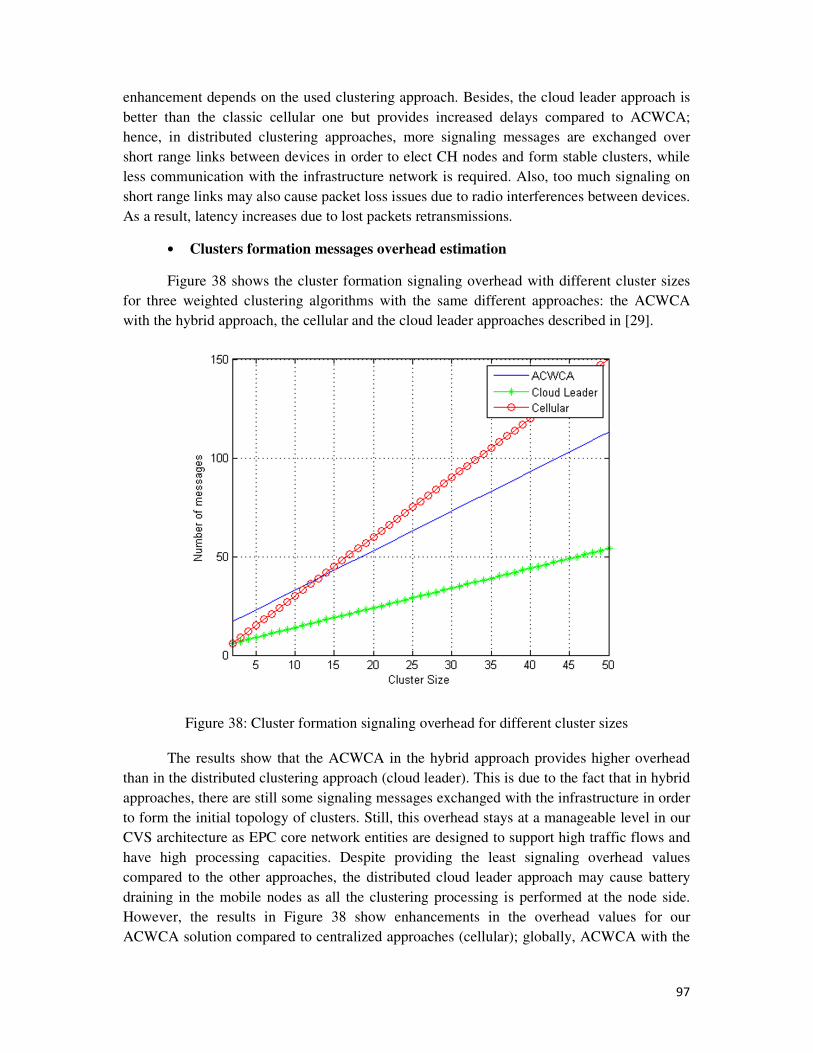
97
enhancement depends on the used clustering approach. Besides, the cloud leader approach is
better than the classic cellular one but provides increased delays compared to ACWCA;
hence, in distributed clustering approaches, more signaling messages are exchanged over
short range links between devices in order to elect CH nodes and form stable clusters, while
less communication with the infrastructure network is required. Also, too much signaling on
short range links may also cause packet loss issues due to radio interferences between devices.
As a result, latency increases due to lost packets retransmissions.
• Clusters formation messages overhead estimation
Figure 38 shows the cluster formation signaling overhead with different cluster sizes
for three weighted clustering algorithms with the same different approaches: the ACWCA
with the hybrid approach, the cellular and the cloud leader approaches described in [29].
Figure 38: Cluster formation signaling overhead for different cluster sizes
The results show that the ACWCA in the hybrid approach provides higher overhead
than in the distributed clustering approach (cloud leader). This is due to the fact that in hybrid
approaches, there are still some signaling messages exchanged with the infrastructure in order
to form the initial topology of clusters. Still, this overhead stays at a manageable level in our
CVS architecture as EPC core network entities are designed to support high traffic flows and
have high processing capacities. Despite providing the least signaling overhead values
compared to the other approaches, the distributed cloud leader approach may cause battery
draining in the mobile nodes as all the clustering processing is performed at the node side.
However, the results in Figure 38 show enhancements in the overhead values for our
ACWCA solution compared to centralized approaches (cellular); globally, ACWCA with the
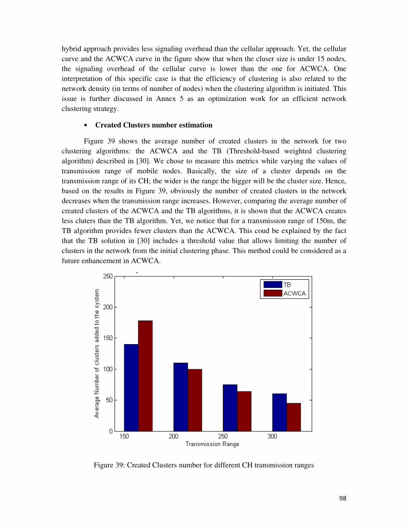
98
hybrid approach provides less signaling overhead than the cellular approach. Yet, the cellular
curve and the ACWCA curve in the figure show that when the cluser size is under 15 nodes,
the signaling overhead of the cellular curve is lower than the one for ACWCA. One
interpretation of this specific case is that the efficiency of clustering is also related to the
network density (in terms of number of nodes) when the clustering algorithm is initiated. This
issue is further discussed in Annex 5 as an optimization work for an efficient network
clustering strategy.
• Created Clusters number estimation
Figure 39 shows the average number of created clusters in the network for two
clustering algorithms: the ACWCA and the TB (Threshold-based weighted clustering
algorithm) described in [30]. We chose to measure this metrics while varying the values of
transmission range of mobile nodes. Basically, the size of a cluster depends on the
transmission range of its CH; the wider is the range the bigger will be the cluster size. Hence,
based on the results in Figure 39, obviously the number of created clusters in the network
decreases when the transmission range increases. However, comparing the average number of
created clusters of the ACWCA and the TB algorithms, it is shown that the ACWCA creates
less cluters than the TB algorithm. Yet, we notice that for a transmission range of 150m, the
TB algorithm provides fewer clusters than the ACWCA. This coud be explained by the fact
that the TB solution in [30] includes a threshold value that allows limiting the number of
clusters in the network from the initial clustering phase. This method could be considered as a
future enhancement in ACWCA.
Figure 39: Created Clusters number for different CH transmission ranges
99
4.4 Conclusion
The Adaptive Contex-aware Weighted Clustering Algorithm (ACWCA) was proposed in
this chapter as the main component of the CVS architecture framework. Deployed in the
ProSe-MME based on a hybrid clustering architecture, it performs the election of CH nodes
based on the calculation of the weight of each device that is already registered as a ProSe-ITS
device. The proposed algorithm is adaptive and context-aware as the weight calculation
formula includes several context parameters. Mathematical experessions of these context
parameters were proposed, namely; the energy of the device, its data rate, its local stability
(mobility) and its connectivity degree. The contribution presented through this chapter resides
mainly in the definition of the protocol procedures to implement in the 4G/LTE core network
in order to integrate clustering operations. Finally, a performance evaluation of the solution
was proposed through the simulation of some metrics like the control messages overhead and
the clusters formation latency. The results were compared with those of similar algorithms but
with different clustering approaches and showed that the use of weighted clustering in a
hybrid clustering architecture helps enhancing the limitations of weighted clustering
algorithms.
100
Conclusion and Future work
• Thesis summary
The exponential traffic increase in mobile networks is still considered today as one of
the major problems of the digital era. In telecommunications, it’s one of the engines that
power the evolution of current mobile networks’ functions and infrastructures toward more
scalable and efficient systems.
This thesis addressed several research issues related to the evolution of mobile
network operators role in the new telecommunication ecosystem and toward the transition to
the 5G. It has mainly highlighted new opportunities for mobile operators through the
deployment of alternative communication networks like D2D-based ones. These opportunities
lie both at the business and technical levels; at the business level, the deployment of D2D-
based networks and services allows mobile operators to position themselves on the new
market of Proximity-based Services as service providers and trusted third parties. Though
D2D was basically defined as an infrastructureless communication mode, the operator-
assisted mode that has been push by mobile operators promotes a more reliable and scalable
deployment model of ProSe. At the technical level, including D2D Direct communications
and their mechanisms into cellular networks triggers an evolution of the user’s device role as
a no longer passive but active entity in the network; hence, through the integration of relaying
functions into user’s devices, core network functions are extended to mobile edge networks.
This allows alleviating the core network traffic load through underlay networks like D2D, and
opening some core network functions to the interconnection with heterogeneous mobile edge
networks in order to build a smarter infrastructure.
Several contributions were proposed in this thesis and could be summarized in the
following three main parts:
- State of the art analysis and solution requirements specification: the very
recent advances on LTE-based D2D communications made it difficult at the beginning of
this thesis to establish a detailed and deep state of the art on the subject. Besides, the
unclear positioning of mobile operators on alternative communication networks, like D2D-
based networks, has put more constraints on the study of D2D services business models.
Thus, the stake from the study of the different state of the arts was to point out the possible
opportunities that are worth investigating in order to define a coherent set of requirements
and solutions for each research issue. Hence, the state of the art of D2D communications
and the 3GPP ProSe standard helped us pointing out the limitations of the ProSe
architecture and led to the definition of a set of enhancements. Afterwards, through the
state of the art of ITS and V2X integration within 4G/LTE networks, an overview of the
existing ITS deployment models and their limitations was proposed and helped defining
the requirements for a more efficient and reliable solution. Finally, a state of the art of
101
mobile clouds architectures and clustering mechanisms provided the necessary
mechanisms used to build the CVS architecture framework.
- The Distributed ProSe architecture: through the analysis of the 3GPP ProSe
architecture limitations, a Distributed architecture approach was proposed for a more
flexible and scalable deployment of ProSe at the long term. ProSe authentication and
service authorization functions are proposed to be implemented in the MME as it is
natively in LTE the entity responsible of these procedures in cooperation with the HSS.
This ProSe-MME solution allows then reducing the number of exchanged control
messages exchanged between the UEs, the ProSe entity and core network entities as no
additional interfaces had to be defined. In addition, the support of ProSe in the MME as the
main entity of the control plane in the LTE architecture allows a native support of ProSe
roaming and inter-operator scenario, yet, without the definition of any additional interface.
The solution revolves around the design of the ProSe protocol at the NAS layer as a control
protocol for the setup of ProSe services and a set of extensions and enhanced ProSe
procedures to enable two basic ProSe services: the ProSe direct discovery service and a
network-assisted communication service. A performance evaluation of the solution is then
proposed through the analytical modeling of the enhanced ProSe direct discovery setup
procedure and the simulation of the network-assisted communication service. The results
analysis showed the enhancements of network setup delays brought by the distributed
solution compared to the 3GPP solution and the intake of network-assisted D2D
communications via the eNode B in enhancing core network performances.
- The CVS architecture framework: as an attempt to answer one of the objective
of this thesis in proposing new services that would exploit mobile operators trust and
security assets to potentially enhance their competitiveness on the ProSe market, the CVS
architecture framework was proposed based on the Distributed ProSe architecture to
deploy vehicular services meaning existing LTE mechanisms and ProSe features. After the
study of the state of the art of vehicular networks and ITS deployments models, a set of
enhancements and extensions are proposed to the Distributed ProSe architecture to support
ITS services. The concept of clustering in mobile networks is then introduced as a mean to
optimize the use of the LTE radio network ressources in CVS. Through the study of the
state of the art of clustering architectures and algorithms, a hybrid clustering approach was
defined along with the ACWC algorithm. New LTE procedures were defined to support
the setup of a clustered network based on enhanced LTE and ProSe procedures. Simulation
is carried out to provide a performance evaluation of the ACWC algorithm compared to
some existing algorithms, and to demonstrate the benefits of using a hybrid clustering
approach compared to existing clustering apporoaches.
• Perspectives and future works
Based on the achieved contributions of this thesis, several perspectives and future works
emerge, mainly:
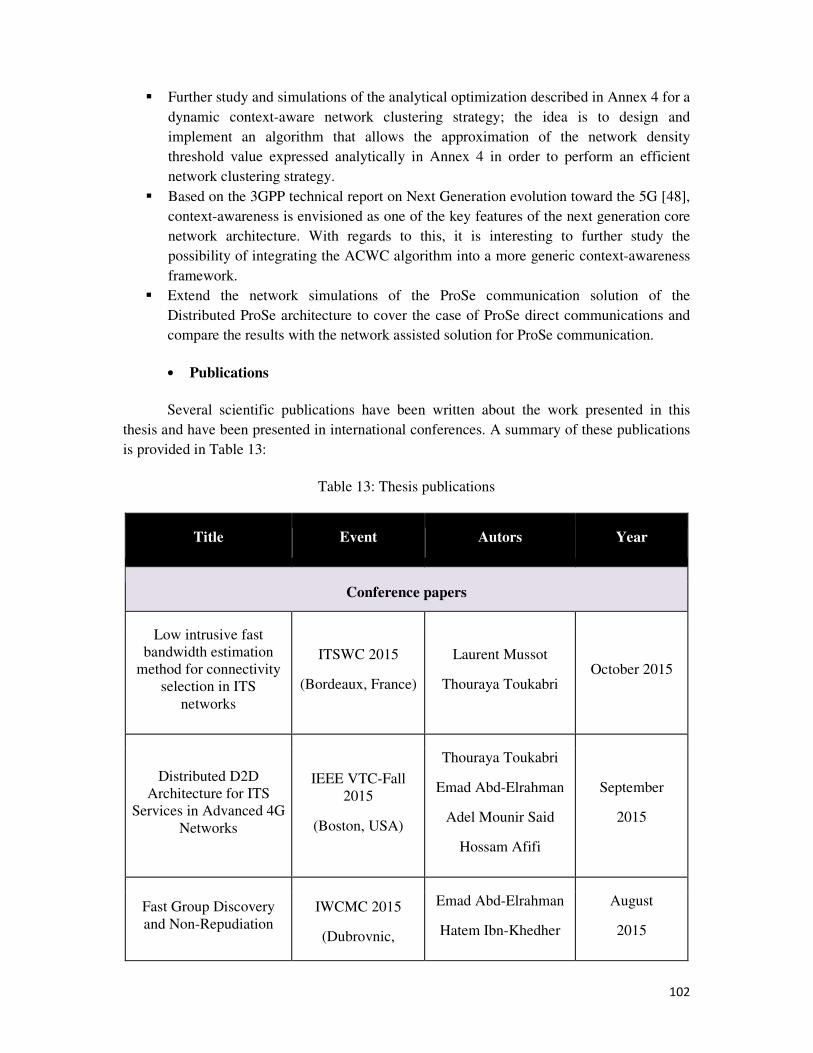
102
� Further study and simulations of the analytical optimization described in Annex 4 for a
dynamic context-aware network clustering strategy; the idea is to design and
implement an algorithm that allows the approximation of the network density
threshold value expressed analytically in Annex 4 in order to perform an efficient
network clustering strategy.
� Based on the 3GPP technical report on Next Generation evolution toward the 5G [48],
context-awareness is envisioned as one of the key features of the next generation core
network architecture. With regards to this, it is interesting to further study the
possibility of integrating the ACWC algorithm into a more generic context-awareness
framework.
� Extend the network simulations of the ProSe communication solution of the
Distributed ProSe architecture to cover the case of ProSe direct communications and
compare the results with the network assisted solution for ProSe communication.
• Publications
Several scientific publications have been written about the work presented in this
thesis and have been presented in international conferences. A summary of these publications
is provided in Table 13:
Table 13: Thesis publications
Title Event Autors Year
Conference papers
Low intrusive fast
bandwidth estimation
method for connectivity
selection in ITS
networks
ITSWC 2015
(Bordeaux, France)
Laurent Mussot
Thouraya Toukabri October 2015
Distributed D2D
Architecture for ITS
Services in Advanced 4G
Networks
IEEE VTC-Fall
2015
(Boston, USA)
Thouraya Toukabri
Emad Abd-Elrahman
Adel Mounir Said
Hossam Afifi
September
2015
Fast Group Discovery
and Non-Repudiation
IWCMC 2015
(Dubrovnic,
Emad Abd-Elrahman
Hatem Ibn-Khedher
August
2015
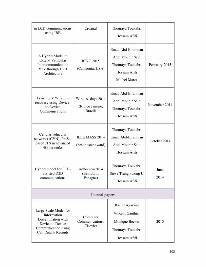
103
in D2D communications
using IBE
Croatia) Thouraya Toukabri
Hossam Afifi
A Hybrid Model to
Extend Vehicular
Intercommunication
V2V through D2D
Architecture
ICNC 2015
(California, USA)
Emad Abd-Elrahman
Adel Mounir Said
Thouraya Toukabri
Hossam Afifi
Michel Marot
February 2015
Assisting V2V failure
recovery using Device-
to-Device
Communications
Wireless days 2014
(Rio de Janeiro,
Brazil)
Emad Abd-Elrahman
Adel Mounir Said
Thouraya Toukabri
Hossam Afifi
November 2014
Cellular vehicular
networks (CVN): ProSe-
based ITS in advanced
4G networks
IEEE MASS 2014
(best poster award)
Thouraya Toukabri
Emad Abd-Elrahman
Adel Mounir Said
Hossam Afifi
October 2014
Hybrid model for LTE-
assisted D2D
communications
Adhocnow2014
(Benidorm,
Espagne)
Thouraya Toukabri
Steve Tsang kwong U
Hossam Afifi
June
2014
Journal papers
Large Scale Model for
Information
Dissemination with
Device to Device
Communication using
Call Details Records
Computer
Communications,
Elsevier
Rachit Agarwal
Vincent Gauthier
Monique Becker
Thouraya Toukabri
Hossam Afifi
2015
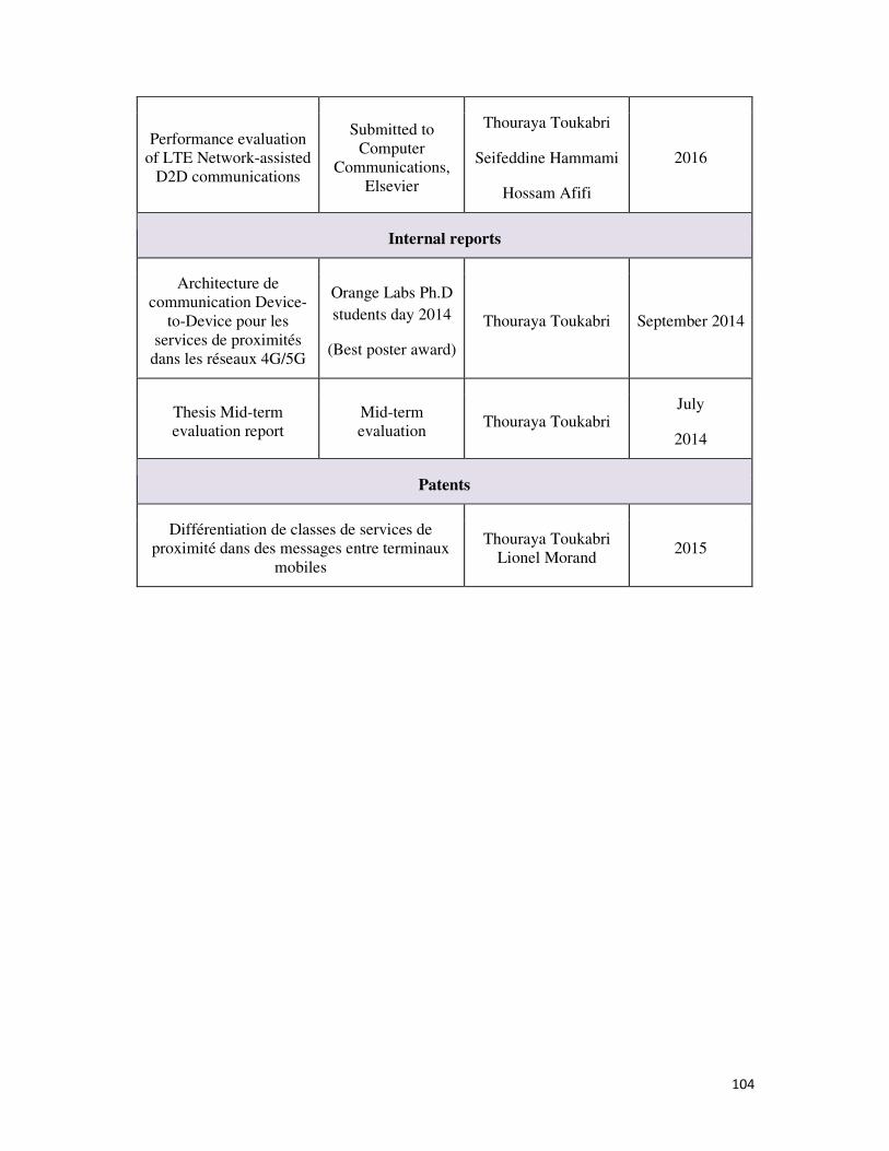
104
Performance evaluation
of LTE Network-assisted
D2D communications
Submitted to
Computer
Communications,
Elsevier
Thouraya Toukabri
Seifeddine Hammami
Hossam Afifi
2016
Internal reports
Architecture de
communication Device-
to-Device pour les
services de proximités
dans les réseaux 4G/5G
Orange Labs Ph.D
students day 2014
(Best poster award)
Thouraya Toukabri September 2014
Thesis Mid-term
evaluation report
Mid-term
evaluation Thouraya Toukabri
July
2014
Patents
Différentiation de classes de services de
proximité dans des messages entre terminaux
mobiles
Thouraya Toukabri
Lionel Morand 2015
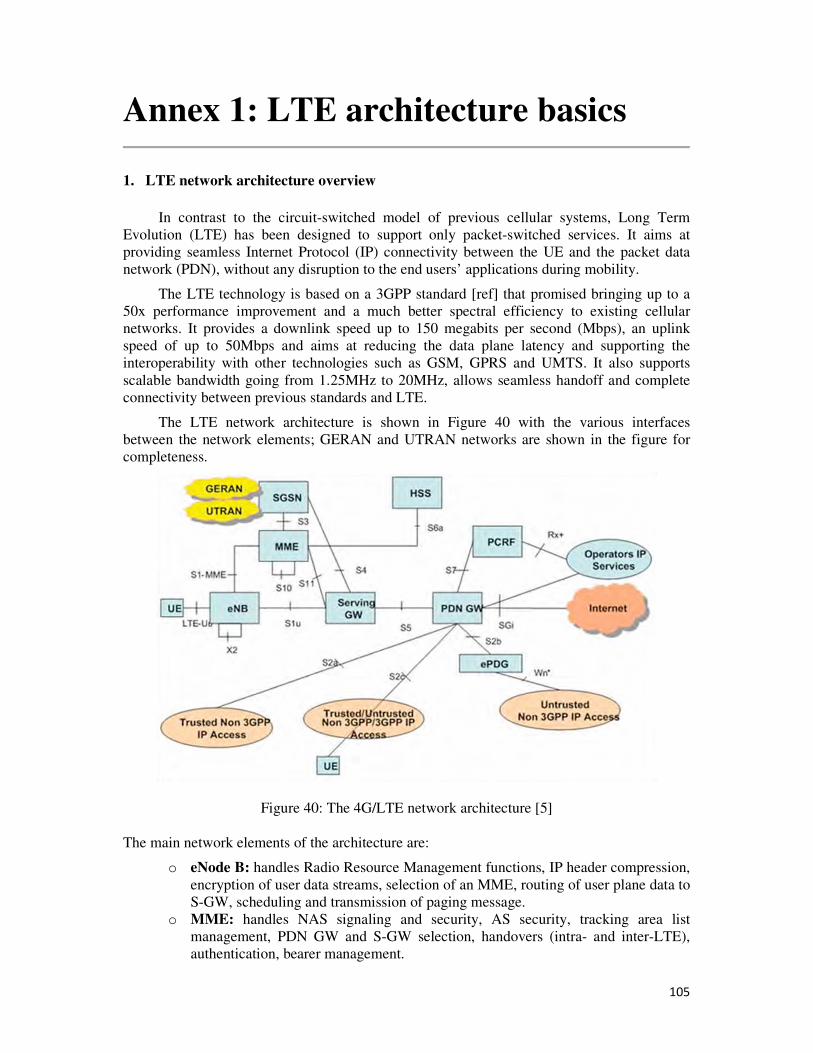
105
Annex 1: LTE architecture basics
1. LTE network architecture overview
In contrast to the circuit-switched model of previous cellular systems, Long Term
Evolution (LTE) has been designed to support only packet-switched services. It aims at
providing seamless Internet Protocol (IP) connectivity between the UE and the packet data
network (PDN), without any disruption to the end users’ applications during mobility.
The LTE technology is based on a 3GPP standard [ref] that promised bringing up to a
50x performance improvement and a much better spectral efficiency to existing cellular
networks. It provides a downlink speed up to 150 megabits per second (Mbps), an uplink
speed of up to 50Mbps and aims at reducing the data plane latency and supporting the
interoperability with other technologies such as GSM, GPRS and UMTS. It also supports
scalable bandwidth going from 1.25MHz to 20MHz, allows seamless handoff and complete
connectivity between previous standards and LTE.
The LTE network architecture is shown in Figure 40 with the various interfaces
between the network elements; GERAN and UTRAN networks are shown in the figure for
completeness.
Figure 40: The 4G/LTE network architecture [5]
The main network elements of the architecture are:
o eNode B: handles Radio Resource Management functions, IP header compression,
encryption of user data streams, selection of an MME, routing of user plane data to
S-GW, scheduling and transmission of paging message.
o MME: handles NAS signaling and security, AS security, tracking area list
management, PDN GW and S-GW selection, handovers (intra- and inter-LTE),
authentication, bearer management.
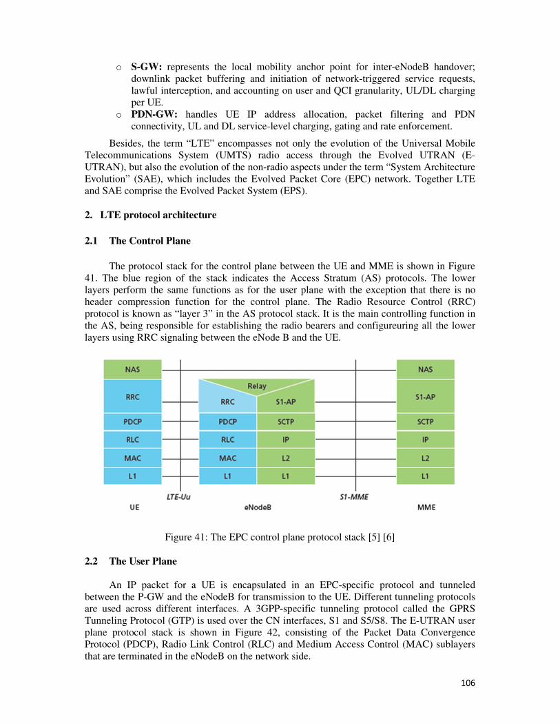
106
o S-GW: represents the local mobility anchor point for inter-eNodeB handover;
downlink packet buffering and initiation of network-triggered service requests,
lawful interception, and accounting on user and QCI granularity, UL/DL charging
per UE.
o PDN-GW: handles UE IP address allocation, packet filtering and PDN
connectivity, UL and DL service-level charging, gating and rate enforcement.
Besides, the term “LTE” encompasses not only the evolution of the Universal Mobile
Telecommunications System (UMTS) radio access through the Evolved UTRAN (E-
UTRAN), but also the evolution of the non-radio aspects under the term “System Architecture
Evolution” (SAE), which includes the Evolved Packet Core (EPC) network. Together LTE
and SAE comprise the Evolved Packet System (EPS).
2. LTE protocol architecture
2.1 The Control Plane
The protocol stack for the control plane between the UE and MME is shown in Figure
41. The blue region of the stack indicates the Access Stratum (AS) protocols. The lower
layers perform the same functions as for the user plane with the exception that there is no
header compression function for the control plane. The Radio Resource Control (RRC)
protocol is known as “layer 3” in the AS protocol stack. It is the main controlling function in
the AS, being responsible for establishing the radio bearers and configureuring all the lower
layers using RRC signaling between the eNode B and the UE.
Figure 41: The EPC control plane protocol stack [5] [6]
2.2 The User Plane
An IP packet for a UE is encapsulated in an EPC-specific protocol and tunneled
between the P-GW and the eNodeB for transmission to the UE. Different tunneling protocols
are used across different interfaces. A 3GPP-specific tunneling protocol called the GPRS
Tunneling Protocol (GTP) is used over the CN interfaces, S1 and S5/S8. The E-UTRAN user
plane protocol stack is shown in Figure 42, consisting of the Packet Data Convergence
Protocol (PDCP), Radio Link Control (RLC) and Medium Access Control (MAC) sublayers
that are terminated in the eNodeB on the network side.
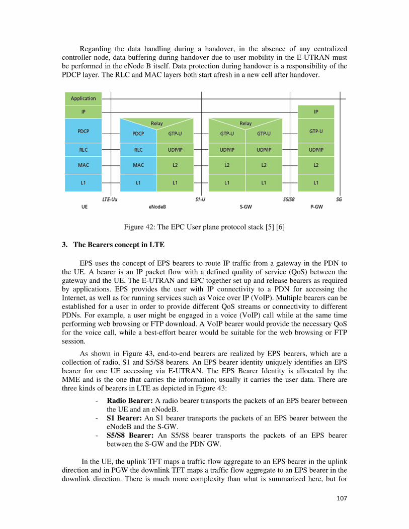
107
Regarding the data handling during a handover, in the absence of any centralized
controller node, data buffering during handover due to user mobility in the E-UTRAN must
be performed in the eNode B itself. Data protection during handover is a responsibility of the
PDCP layer. The RLC and MAC layers both start afresh in a new cell after handover.
Figure 42: The EPC User plane protocol stack [5] [6]
3. The Bearers concept in LTE
EPS uses the concept of EPS bearers to route IP traffic from a gateway in the PDN to
the UE. A bearer is an IP packet flow with a defined quality of service (QoS) between the
gateway and the UE. The E-UTRAN and EPC together set up and release bearers as required
by applications. EPS provides the user with IP connectivity to a PDN for accessing the
Internet, as well as for running services such as Voice over IP (VoIP). Multiple bearers can be
established for a user in order to provide different QoS streams or connectivity to different
PDNs. For example, a user might be engaged in a voice (VoIP) call while at the same time
performing web browsing or FTP download. A VoIP bearer would provide the necessary QoS
for the voice call, while a best-effort bearer would be suitable for the web browsing or FTP
session.
As shown in Figure 43, end-to-end bearers are realized by EPS bearers, which are a
collection of radio, S1 and S5/S8 bearers. An EPS bearer identity uniquely identifies an EPS
bearer for one UE accessing via E-UTRAN. The EPS Bearer Identity is allocated by the
MME and is the one that carries the information; usually it carries the user data. There are
three kinds of bearers in LTE as depicted in Figure 43:
- Radio Bearer: A radio bearer transports the packets of an EPS bearer between
the UE and an eNodeB.
- S1 Bearer: An S1 bearer transports the packets of an EPS bearer between the
eNodeB and the S-GW.
- S5/S8 Bearer: An S5/S8 bearer transports the packets of an EPS bearer
between the S-GW and the PDN GW.
In the UE, the uplink TFT maps a traffic flow aggregate to an EPS bearer in the uplink
direction and in PGW the downlink TFT maps a traffic flow aggregate to an EPS bearer in the
downlink direction. There is much more complexity than what is summarized here, but for
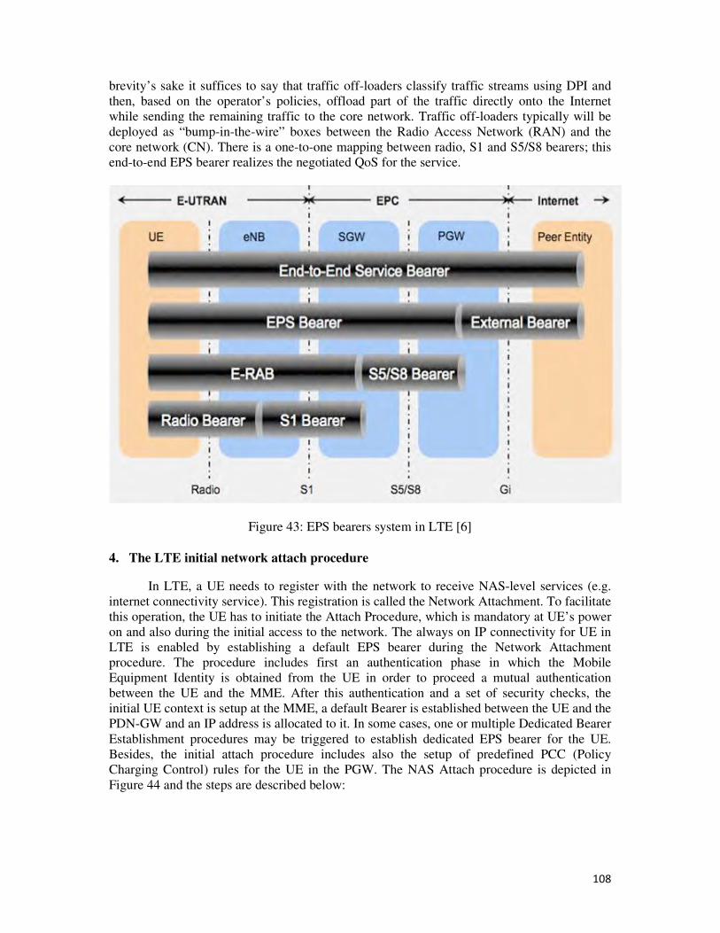
108
brevity’s sake it suffices to say that traffic off-loaders classify traffic streams using DPI and
then, based on the operator’s policies, offload part of the traffic directly onto the Internet
while sending the remaining traffic to the core network. Traffic off-loaders typically will be
deployed as “bump-in-the-wire” boxes between the Radio Access Network (RAN) and the
core network (CN). There is a one-to-one mapping between radio, S1 and S5/S8 bearers; this
end-to-end EPS bearer realizes the negotiated QoS for the service.
Figure 43: EPS bearers system in LTE [6]
4. The LTE initial network attach procedure
In LTE, a UE needs to register with the network to receive NAS-level services (e.g.
internet connectivity service). This registration is called the Network Attachment. To facilitate
this operation, the UE has to initiate the Attach Procedure, which is mandatory at UE’s power
on and also during the initial access to the network. The always on IP connectivity for UE in
LTE is enabled by establishing a default EPS bearer during the Network Attachment
procedure. The procedure includes first an authentication phase in which the Mobile
Equipment Identity is obtained from the UE in order to proceed a mutual authentication
between the UE and the MME. After this authentication and a set of security checks, the
initial UE context is setup at the MME, a default Bearer is established between the UE and the
PDN-GW and an IP address is allocated to it. In some cases, one or multiple Dedicated Bearer
Establishment procedures may be triggered to establish dedicated EPS bearer for the UE.
Besides, the initial attach procedure includes also the setup of predefined PCC (Policy
Charging Control) rules for the UE in the PGW. The NAS Attach procedure is depicted in
Figure 44 and the steps are described below:
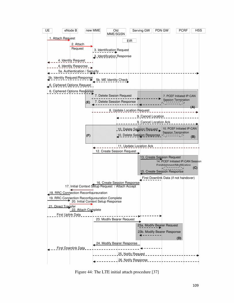
109
Figure 44: The LTE initial attach procedure [37]
3. Identification Request
1. Attach Request
new MME Old MME/SGSN
Serving GW PCRF HSS
3. Identification Response
PDN GW
2. Attach Request
eNode B UE
4. Identity Request
4. Identity Response 5a. Authentication / Security
17. Initial Context Setup Request / Attach Accept
First Uplink Data
19. RRC Connection Reconfigureuration Complete
18. RRC Connection Reconfigureuration
20. Initial Context Setup Response
24. Modify Bearer Response
23. Modify Bearer Request
First Downlink Data
25. Notify Request
26. Notify Response
(B)
(A)
16. Create Session Response
12. Create Session Request
8. Update Location Request
9. Cancel Location
11. Update Location Ack
9. Cancel Location Ack
10. Delete Session Request
10. Delete Session Response
13. Create Session Request
15. Create Session Response
7. Delete Session Response
7. Delete Sesion Request
First Downlink Data (if not handover)
(C)
EIR
5b. ME Identity Check
5b. Identity Request/Response
10. PCEF Initiated IP-CAN
Session Termination
7. PCEF Initiated IP-CAN
Session Termination
14. PCEF Initiated IP-CAN Session
Establishment/Modification
6. Ciphered Options Request
6. Ciphered Options Response
23a. Modify Bearer Request
23b. Modify Bearer Response
(D)
21. Direct Transfer 22. Attach Complete
(E)
(F)
110
0. The UE establishes the RRC Connection with the eNodeB.
1. The UE sends the ATTACH REQUEST message together with a PDN
CONNECTIVITY REQUEST for the PDN (IP) connectivity on the established RRC
Connection. As part of this, the eNodeB establishes the S1 logical connection with the
MME for this UE.
2. If the Network is not able to identify the UE with the Identity given in the Attach
Request message, it initiates the identification followed by Authentication and
Security Mode procedures.
3. The MME update the HSS with the location of the UE using the Update Location
request message using the Diameter protocol; it also requests the subscriber profile
from the HSS using this message.
4. The HSS updates its database with the current location of the UE and sends the
subscriber profile information to the MME in the Diameter Update Location
Acknowledge message.
5. The MME now establishes an eGTP User Tunnel to establish the default bearer at the
SGW; it sends a Create Session Request (eGTP-C protocol) toward the SGW.
6. The SGW creates the default bearer for this UE and requests the PGW to create a
bearer for this UE between the SGW and the PGW to provide end-to-end bearer
connectivity. The PDN-GW then creates the bearer and allocates an IP Address for the
UE.
7. Once the SGW receives the response from the PGW, it responds with a Create Session
Response to MME.
8. The MME now has to establish the bearer between the eNodeB and SGW. It sends the
S1AP Initial Context Setup Request to the eNodeB to create a context for this UE,
which includes the bearer Context and the security Context.
9. After receiving the Initial Context Setup Request, the eNodeB now establishes the
security parameters with the UE by initiating the AS Security Mode Command
Procedure.
10. The UE establishes the security parameters (parameters required for ciphering the
Integrity protection) and sends the Security Mode Complete Message to the eNodeB.
From now on, all the messages exchanged between the UE and eNodeB on the radio
interface are ciphered as well as integrity-protected.
11. The eNodeB reconfigures the resources to the UE by sending an RRC Connection
Reconfigure Request to the UE. In this message, the eNodeB piggy-backs the Activate
Default EPS Bearer Context Request NAS message to the UE.
12. The UE updates its RRC Connection configuration and responds back with an RRC
Connection Reconfigure Complete.
13. The eNodeB now sends the Initial Context Setup Response to the MME.
14. The MME sends the eGTP-C Modify Bearer Request to the SGW to update the eNode
B Tunnel Id for the default bearer.
15. After updating the information, the SGW responds with a Modify Bearer Response to
the MME.
16. The MME now sends the Attach Accept and Activate Default Bearer Context Request
NAS message to the UE.
17. If the MME has allocated a GUTI while sending the Attach Accept, the UE needs to
process it and give back the Attach Complete as a response to it. The UE piggy-packs
the Activate Default EPS bearer context Accept NAS message to the MME.
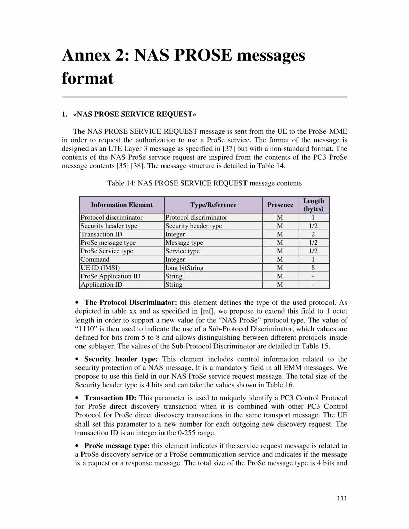
111
Annex 2: NAS PROSE messages
format
1. «NAS PROSE SERVICE REQUEST»
The NAS PROSE SERVICE REQUEST message is sent from the UE to the ProSe-MME
in order to request the authorization to use a ProSe service. The format of the message is
designed as an LTE Layer 3 message as specified in [37] but with a non-standard format. The
contents of the NAS ProSe service request are inspired from the contents of the PC3 ProSe
message contents [35] [38]. The message structure is detailed in Table 14.
Table 14: NAS PROSE SERVICE REQUEST message contents
Information Element Type/Reference Presence Length (bytes)
Protocol discriminator Protocol discriminator M 1
Security header type Security header type M 1/2
Transaction ID Integer M 2
ProSe message type Message type M 1/2
ProSe Service type Service type M 1/2
Command Integer M 1
UE ID (IMSI) long bitString M 8
ProSe Application ID String M -
Application ID String M -
• The Protocol Discriminator: this element defines the type of the used protocol. As
depicted in table xx and as specified in [ref], we propose to extend this field to 1 octet
length in order to support a new value for the “NAS ProSe” protocol type. The value of
“1110” is then used to indicate the use of a Sub-Protocol Discriminator, which values are
defined for bits from 5 to 8 and allows distinguishing between different protocols inside
one sublayer. The values of the Sub-Protocol Discriminator are detailed in Table 15.
• Security header type: This element includes control information related to the
security protection of a NAS message. It is a mandatory field in all EMM messages. We
propose to use this field in our NAS ProSe service request message. The total size of the
Security header type is 4 bits and can take the values shown in Table 16.
• Transaction ID: This parameter is used to uniquely identify a PC3 Control Protocol
for ProSe direct discovery transaction when it is combined with other PC3 Control
Protocol for ProSe direct discovery transactions in the same transport message. The UE
shall set this parameter to a new number for each outgoing new discovery request. The
transaction ID is an integer in the 0-255 range.
• ProSe message type: this element indicates if the service request message is related to
a ProSe discovery service or a ProSe communication service and indicates if the message
is a request or a response message. The total size of the ProSe message type is 4 bits and
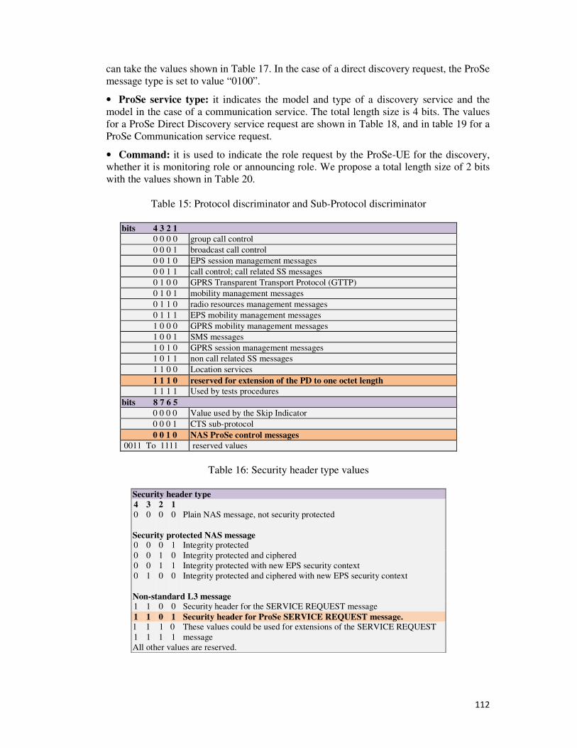
112
can take the values shown in Table 17. In the case of a direct discovery request, the ProSe
message type is set to value “0100”.
• ProSe service type: it indicates the model and type of a discovery service and the
model in the case of a communication service. The total length size is 4 bits. The values
for a ProSe Direct Discovery service request are shown in Table 18, and in table 19 for a
ProSe Communication service request.
• Command: it is used to indicate the role request by the ProSe-UE for the discovery,
whether it is monitoring role or announcing role. We propose a total length size of 2 bits
with the values shown in Table 20.
Table 15: Protocol discriminator and Sub-Protocol discriminator
bits 4 3 2 1
0 0 0 0 group call control
0 0 0 1 broadcast call control
0 0 1 0 EPS session management messages
0 0 1 1 call control; call related SS messages
0 1 0 0 GPRS Transparent Transport Protocol (GTTP)
0 1 0 1 mobility management messages
0 1 1 0 radio resources management messages
0 1 1 1 EPS mobility management messages
1 0 0 0 GPRS mobility management messages
1 0 0 1 SMS messages
1 0 1 0 GPRS session management messages
1 0 1 1 non call related SS messages
1 1 0 0 Location services
1 1 1 0 reserved for extension of the PD to one octet length
1 1 1 1 Used by tests procedures
bits 8 7 6 5
0 0 0 0 Value used by the Skip Indicator
0 0 0 1 CTS sub-protocol
0 0 1 0 NAS ProSe control messages
0011 To 1111 reserved values
Table 16: Security header type values
Security header type
4 3 2 1
0 0 0 0 Plain NAS message, not security protected
Security protected NAS message 0 0 0 1 Integrity protected
0 0 1 0 Integrity protected and ciphered
0 0 1 1 Integrity protected with new EPS security context
0 1 0 0 Integrity protected and ciphered with new EPS security context
Non-standard L3 message 1 1 0 0 Security header for the SERVICE REQUEST message
1 1 0 1 Security header for ProSe SERVICE REQUEST message. 1 1 1 0 These values could be used for extensions of the SERVICE REQUEST
message 1 1 1 1
All other values are reserved.
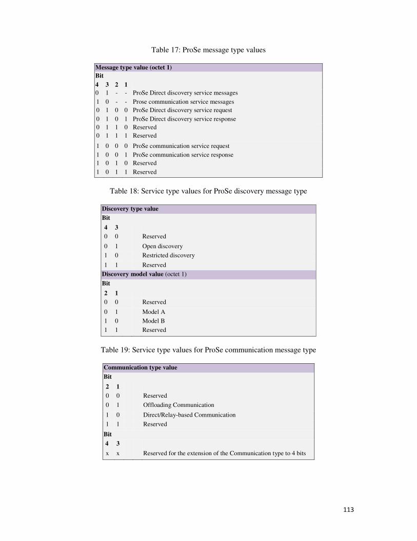
113
Table 17: ProSe message type values
Message type value (octet 1)
Bit
4 3 2 1
0 1 - - ProSe Direct discovery service messages
1 0 - - Prose communication service messages
0 1 0 0 ProSe Direct discovery service request
0 1 0 1 ProSe Direct discovery service response
0 1 1 0 Reserved
0 1 1 1 Reserved
1 0 0 0 ProSe communication service request
1 0 0 1 ProSe communication service response
1 0 1 0 Reserved
1 0 1 1 Reserved
Table 18: Service type values for ProSe discovery message type
Discovery type value
Bit
4 3
0 0 Reserved
0 1 Open discovery
1 0 Restricted discovery
1 1 Reserved
Discovery model value (octet 1)
Bit
2 1
0 0 Reserved
0 1 Model A
1 0 Model B
1 1 Reserved
Table 19: Service type values for ProSe communication message type
Communication type value
Bit
2 1
0 0 Reserved
0 1 Offloading Communication
1 0 Direct/Relay-based Communication
1 1 Reserved
Bit
4 3
x x Reserved for the extension of the Communication type to 4 bits
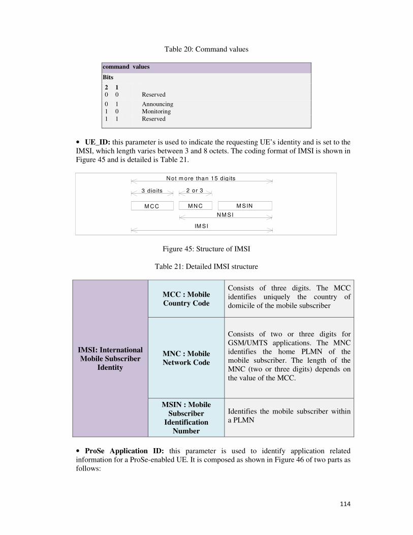
114
Table 20: Command values
command values
Bits
2 1
0 0 Reserved
0 1 Announcing
1 0 Monitoring
1 1 Reserved
• UE_ID: this parameter is used to indicate the requesting UE’s identity and is set to the
IMSI, which length varies between 3 and 8 octets. The coding format of IMSI is shown in
Figure 45 and is detailed is Table 21.
M CC
N ot m ore than 15 d ig its
3 d ig its 2 or 3
M N C M SIN
N M SI
IM SI
Figure 45: Structure of IMSI
Table 21: Detailed IMSI structure
IMSI: International
Mobile Subscriber
Identity
MCC : Mobile
Country Code
Consists of three digits. The MCC
identifies uniquely the country of
domicile of the mobile subscriber
MNC : Mobile
Network Code
Consists of two or three digits for
GSM/UMTS applications. The MNC
identifies the home PLMN of the
mobile subscriber. The length of the
MNC (two or three digits) depends on
the value of the MCC.
MSIN : Mobile
Subscriber
Identification
Number
Identifies the mobile subscriber within
a PLMN
• ProSe Application ID: this parameter is used to identify application related
information for a ProSe-enabled UE. It is composed as shown in Figure 46 of two parts as
follows:
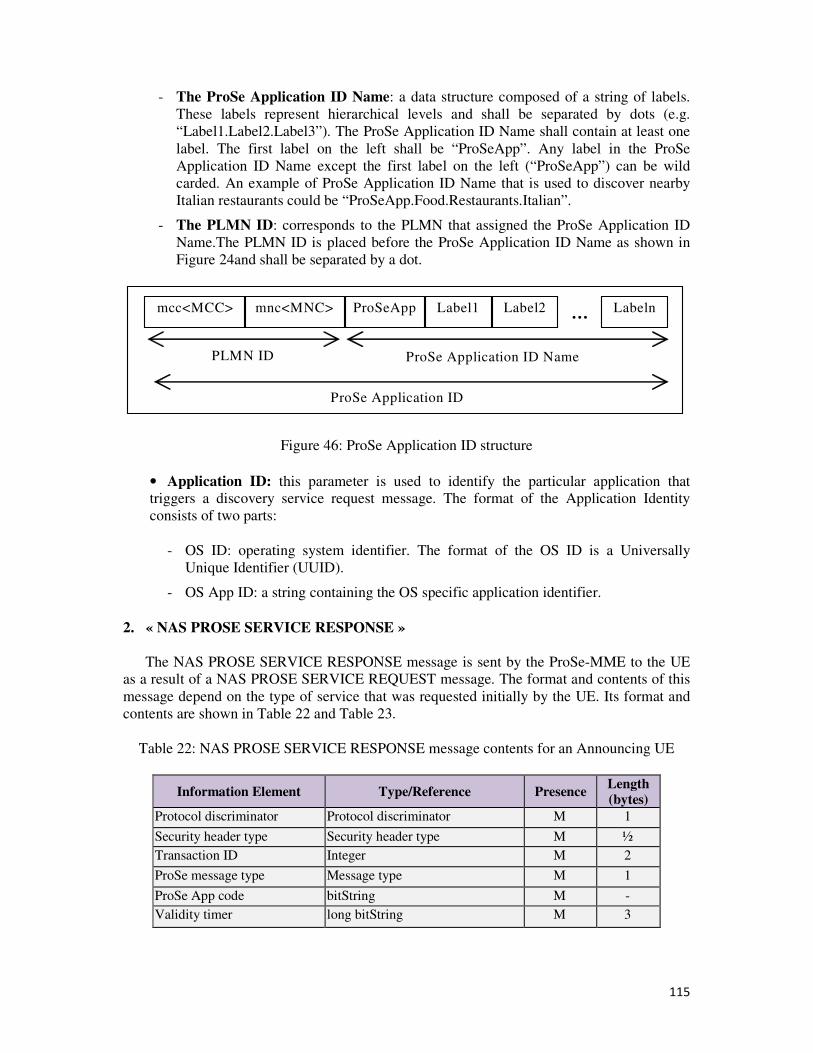
115
- The ProSe Application ID Name: a data structure composed of a string of labels.
These labels represent hierarchical levels and shall be separated by dots (e.g.
“Label1.Label2.Label3”). The ProSe Application ID Name shall contain at least one
label. The first label on the left shall be “ProSeApp”. Any label in the ProSe
Application ID Name except the first label on the left (“ProSeApp”) can be wild
carded. An example of ProSe Application ID Name that is used to discover nearby
Italian restaurants could be “ProSeApp.Food.Restaurants.Italian”.
- The PLMN ID: corresponds to the PLMN that assigned the ProSe Application ID
Name.The PLMN ID is placed before the ProSe Application ID Name as shown in
Figure 24and shall be separated by a dot.
ProSeApp Label1
ProSe Application ID
ProSe Application ID Name PLMN ID
Label2 Labeln … mnc<MNC> mcc<MCC>
Figure 46: ProSe Application ID structure
• Application ID: this parameter is used to identify the particular application that
triggers a discovery service request message. The format of the Application Identity
consists of two parts:
- OS ID: operating system identifier. The format of the OS ID is a Universally
Unique Identifier (UUID).
- OS App ID: a string containing the OS specific application identifier.
2. « NAS PROSE SERVICE RESPONSE »
The NAS PROSE SERVICE RESPONSE message is sent by the ProSe-MME to the UE
as a result of a NAS PROSE SERVICE REQUEST message. The format and contents of this
message depend on the type of service that was requested initially by the UE. Its format and
contents are shown in Table 22 and Table 23.
Table 22: NAS PROSE SERVICE RESPONSE message contents for an Announcing UE
Information Element Type/Reference Presence Length (bytes)
Protocol discriminator Protocol discriminator M 1
Security header type Security header type M ½
Transaction ID Integer M 2
ProSe message type Message type M 1
ProSe App code bitString M -
Validity timer long bitString M 3
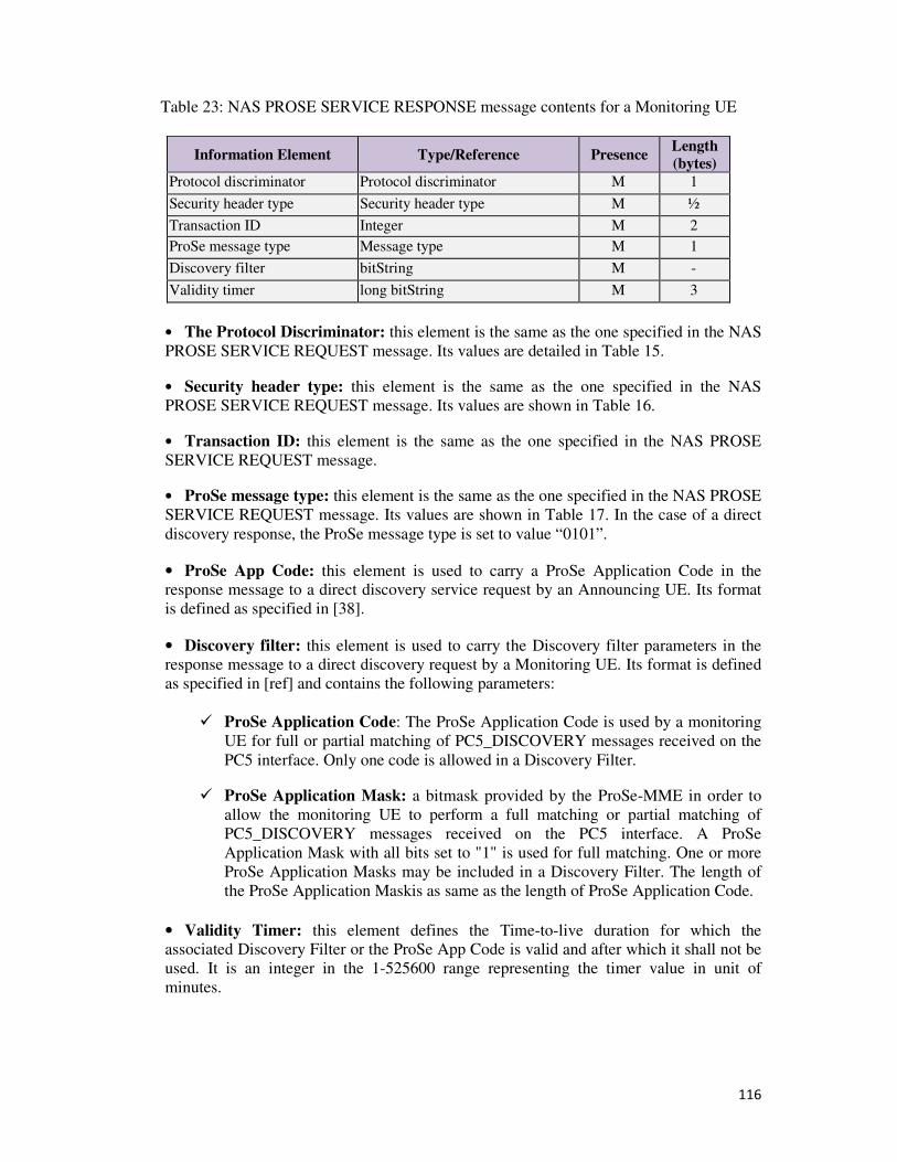
116
Table 23: NAS PROSE SERVICE RESPONSE message contents for a Monitoring UE
Information Element Type/Reference Presence Length
(bytes)
Protocol discriminator Protocol discriminator M 1
Security header type Security header type M ½
Transaction ID Integer M 2
ProSe message type Message type M 1
Discovery filter bitString M -
Validity timer long bitString M 3
• The Protocol Discriminator: this element is the same as the one specified in the NAS
PROSE SERVICE REQUEST message. Its values are detailed in Table 15.
• Security header type: this element is the same as the one specified in the NAS
PROSE SERVICE REQUEST message. Its values are shown in Table 16.
• Transaction ID: this element is the same as the one specified in the NAS PROSE
SERVICE REQUEST message.
• ProSe message type: this element is the same as the one specified in the NAS PROSE
SERVICE REQUEST message. Its values are shown in Table 17. In the case of a direct
discovery response, the ProSe message type is set to value “0101”.
• ProSe App Code: this element is used to carry a ProSe Application Code in the
response message to a direct discovery service request by an Announcing UE. Its format
is defined as specified in [38].
• Discovery filter: this element is used to carry the Discovery filter parameters in the
response message to a direct discovery request by a Monitoring UE. Its format is defined
as specified in [ref] and contains the following parameters:
� ProSe Application Code: The ProSe Application Code is used by a monitoring
UE for full or partial matching of PC5_DISCOVERY messages received on the
PC5 interface. Only one code is allowed in a Discovery Filter.
� ProSe Application Mask: a bitmask provided by the ProSe-MME in order to
allow the monitoring UE to perform a full matching or partial matching of
PC5_DISCOVERY messages received on the PC5 interface. A ProSe
Application Mask with all bits set to "1" is used for full matching. One or more
ProSe Application Masks may be included in a Discovery Filter. The length of
the ProSe Application Maskis as same as the length of ProSe Application Code.
• Validity Timer: this element defines the Time-to-live duration for which the
associated Discovery Filter or the ProSe App Code is valid and after which it shall not be
used. It is an integer in the 1-525600 range representing the timer value in unit of
minutes.
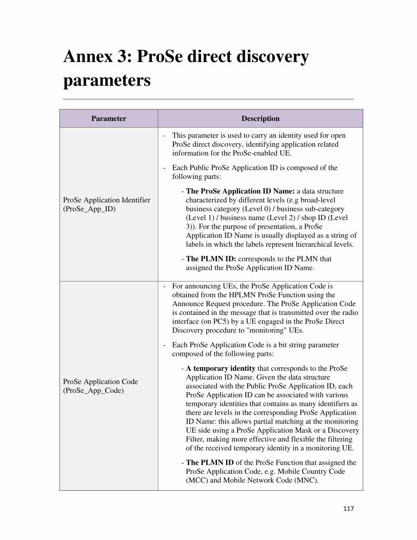
117
Annex 3: ProSe direct discovery
parameters
Parameter Description
ProSe Application Identifier
(ProSe_App_ID)
- This parameter is used to carry an identity used for open
ProSe direct discovery, identifying application related
information for the ProSe-enabled UE.
- Each Public ProSe Application ID is composed of the
following parts:
- The ProSe Application ID Name: a data structure
characterized by different levels (e.g broad-level
business category (Level 0) / business sub-category
(Level 1) / business name (Level 2) / shop ID (Level
3)). For the purpose of presentation, a ProSe
Application ID Name is usually displayed as a string of
labels in which the labels represent hierarchical levels.
- The PLMN ID: corresponds to the PLMN that
assigned the ProSe Application ID Name.
ProSe Application Code
(ProSe_App_Code)
- For announcing UEs, the ProSe Application Code is
obtained from the HPLMN ProSe Function using the
Announce Request procedure. The ProSe Application Code
is contained in the message that is transmitted over the radio
interface (on PC5) by a UE engaged in the ProSe Direct
Discovery procedure to "monitoring" UEs.
- Each ProSe Application Code is a bit string parameter
composed of the following parts:
- A temporary identity that corresponds to the ProSe
Application ID Name. Given the data structure
associated with the Public ProSe Application ID, each
ProSe Application ID can be associated with various
temporary identities that contains as many identifiers as
there are levels in the corresponding ProSe Application
ID Name: this allows partial matching at the monitoring
UE side using a ProSe Application Mask or a Discovery
Filter, making more effective and flexible the filtering
of the received temporary identity in a monitoring UE.
- The PLMN ID of the ProSe Function that assigned the
ProSe Application Code, e.g. Mobile Country Code
(MCC) and Mobile Network Code (MNC).
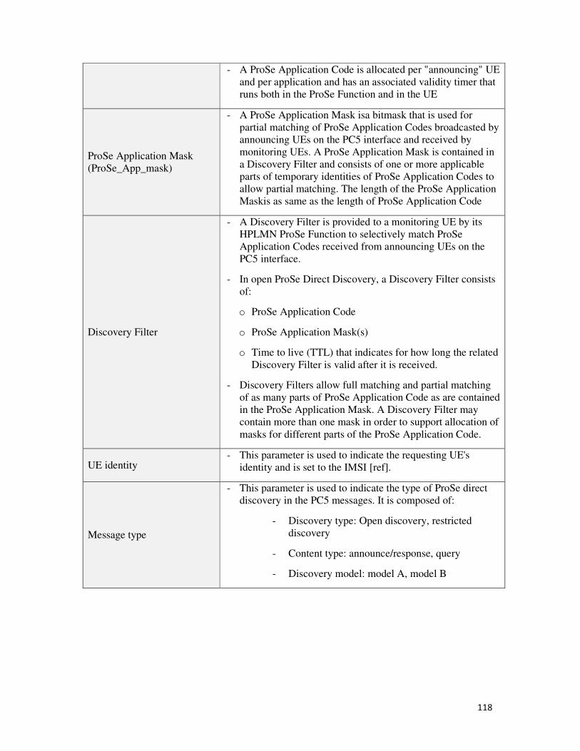
118
- A ProSe Application Code is allocated per "announcing" UE
and per application and has an associated validity timer that
runs both in the ProSe Function and in the UE
ProSe Application Mask
(ProSe_App_mask)
- A ProSe Application Mask isa bitmask that is used for
partial matching of ProSe Application Codes broadcasted by
announcing UEs on the PC5 interface and received by
monitoring UEs. A ProSe Application Mask is contained in
a Discovery Filter and consists of one or more applicable
parts of temporary identities of ProSe Application Codes to
allow partial matching. The length of the ProSe Application
Maskis as same as the length of ProSe Application Code
Discovery Filter
- A Discovery Filter is provided to a monitoring UE by its
HPLMN ProSe Function to selectively match ProSe
Application Codes received from announcing UEs on the
PC5 interface.
- In open ProSe Direct Discovery, a Discovery Filter consists
of:
o ProSe Application Code
o ProSe Application Mask(s)
o Time to live (TTL) that indicates for how long the related
Discovery Filter is valid after it is received.
- Discovery Filters allow full matching and partial matching
of as many parts of ProSe Application Code as are contained
in the ProSe Application Mask. A Discovery Filter may
contain more than one mask in order to support allocation of
masks for different parts of the ProSe Application Code.
UE identity - This parameter is used to indicate the requesting UE's
identity and is set to the IMSI [ref].
Message type
- This parameter is used to indicate the type of ProSe direct
discovery in the PC5 messages. It is composed of:
- Discovery type: Open discovery, restricted
discovery
- Content type: announce/response, query
- Discovery model: model A, model B
119
Annex 4: Analytical optimization for
a dynamic context-aware network
clustering strategy
1. Analytical optimization for a dynamic context-aware network clustering strategy
In this section, we want to estimate the energy cost ratio from the UE side and from the
network side (eNode B) for an uplink traffic transmission from the UE to the eNode B. Thus,
we consider two cases:
- The case of a clustered network in which the communication with the eNode B is
made through a CH. This case represents
- The case of a non-clustered network in which the communication is direct between
the UE and the eNode B.
The objective of this estimation is to find the optimal value of the network density (in
terms of number of nodes) according to which we can adjust our clustering strategy in order
to enhance the global network energy cost, both from UE side and network side.
1.1 Assumptions
In the first case, we consider a group of UEs organized in a cluster and managed by a
CH. In our study, we are firstly interested in an uplink communication service in which UEs
in the cluster send periodically data packets to the network infrastructure (eNode B) through
the CH. As depicted in Figure (Ref), UEs inside the cluster use Direct D2D communications
to communicate between them and with the CH. We also assume that there is a data
aggregation mechanism enabled in the CH that allows the transmission of all the collected
data packets inside the cluster in one packet from the CH to the eNode B. Thus, the
communication from the UEs to the eNode B is a One-hop communication (through CH) in a
clustered-network and direct when the network is non-clustered. We also consider that the
Direct D2D communications between the UEs inside the cluster create interferences on the
communications between the CH and the eNode B (the infrastructure-based communications).
Assuming that all the UEs inside the cluster are located in the same geographic area
and that the attenuation is the same for all the UEs, we consider the following:
- We define two different costs for the transmission of a data packet from the UE to
the eNode B:
o The long path cost Clong for the transmission of a data packet from the UE to
the eNode B
o The short path cost Cshort for the transmission of a data packet UE-CH

120
- There is no error correction on the received data packets, which means that one bit
error is enough to discard a data packet.
1.2 The model
We define the following:
- n : the number of UEs in a cluster
- Cf : the fixed cost for the transmission of a data packet
- Cd : the additionnal cost for the transmission of a data packet over a long path (e.g
the additional cost is the cost of CH-eNode B transmission in the case of a long
path UE-CH-eNode B)
- τp : packet size in bits
- r : compression/agreggation ration in the CH
- Cclus = C+a.n : the cost of a cluster setup
- Pr : the signal power received by the eNode B for the transmission of a data packet
from the CH.
- PI : the signal power received by the eNode B for the transmission of a data packet
from a UE.
- PN : the power of ambiant noise signal
- fp : the frequency of packet sending from the UEs to the CH
- Pb: the bit error rate for the received traffic at eNode B
- Pp: packet loss rate
Assuming that we use QPSK, the bit error rate for the received traffic at the eNode B is:
9� = 2� ������ − �� ������ Ou : ��^� = � YjZ[ � �√�� = √��� Y��((��� AV Assuming that all the throughputs are the same for all the devices:
���� = � 787��T7� , as there are n D2Dcommunications.
As a result, we have:
9� = 2� � 9:9� + c9¡¢− �� � 9:9� + c9¡¢
We calculate the packet loss rate as follows:
9£ = 1 − �1 − 9��¤¥
Consequently, the average number of retransmissions is:

121
`�d + 1�9£5¦1 − 9£§ =��5-Q
1�1 − 9��¤¥
In the case there is a cluster, the sending cost is:
Z£¦cg̈ + j × �g̈ + g©§ × ª£�1 − 9��¤¥
And the total cost is:
g + ]c + Z£¦cg̈ + j × �g̈ + g©§ × ª£�1 − 9��¤¥
In the case there are no clusters, the sending cost is calculated as follows:
c × Z£¦cg̈ + j × �g̈ + g©§ × ª£�1 − 9��¤¥
The ratio is then equal to:
g + ]c + Z£¦cg̈ + j × �g̈ + g©§ × ¤¥�37«�¬¥c × Z£¦cg̈ + j × �g̈ + g©§ × ¤¥�37«�¬¥= ¦�g + ]c� × �1 − 9��¤¥§ +�ª£ × Z£¦cg̈ + j × �g̈ + g©§�c × Z£ × ª£ × ¦g̈ + g©§
122
Glossary
3GPP 3rd
Generation Partnership Project
5GPPP 5G Infrastructure Public Private Partnership
BID Bearer Identifier
CCS Cooperative Control Server
CH Cluster Head
CLA Context Learning Adapter
D2D Device-to-Device
E-UTRAN Evolved Universal Terrestrial Radio Access Network
EMM EPS Mobility Management
EPC Evolved Packet Core
EPS Evolved Packet System
ESM EPS Session Management
ETSI European Telecommunication Standards Institute
FOT Field Operational Tests
HPLMN Home Public Mobile Network
HSS Home Subscriber Server
I2V Infrastructure to Vehicle
IMSI International Mobile Subscriber Identity
ISO International Standards Organization
ITS Intelligent Transportation System
LTE Long Term Evolution
MME Mobility Management Entity
MS Mobile Station
123
NAS Non-Access Stratum
PDCP Packet Data Convergence Protocol
PDN Packet Data Network
PDN-GW Packet Data Network Gateway
PLMN Public Land Mobile Network
ProSe Proximity-based Services
ProSe-CH ProSe Cluster Head
ProSe_App_ID ProSe Application identifier
ProSe_App_Mask ProSe Application Mask
ProSe_App_Code ProSe Application Code
RAN Radio Access Network
RLC Radio Link Control
RNTI Radio Network Temporary Identifier
RRC Radio Ressource Control
RSU Roadside Unit
S-GW Serving Gateway
SG-ID Service Group Identifier
UE User Equipment
V2X Vehicule to anything
V2V Vehicle to Vehicle
V2I Vehicle to Infactructure
V2P Vehicle to Pedestrian
VANET Vehicular Ad-hoc Network
124
References
[1] G. Fodor, E. Dahlman, G. Mildh, S. Parkvall, N. Reider, G. Miklos, and Z. Turanyi,
“Design Aspects of Network Assisted Device-to-Device Communications,”
Communications Magazine, IEEE, vol. 50, pp. 170-177, March 2012.
[2] L. Lei, Z. Zhong, C. Lin, and X. Shen, “Operator Controlled Device-to-Device
Communications in LTE-Advanced Networks,” IEEE Wireless Communications, vol. 19,
pp. 96–104, June 2012
[3] K. Doppler, M. Rinne, C. Wijting, C. Ribeiro, and K. Hugl, “Device-to-Device
Communication as an Underlay to LTE-Advanced Networks,” Communications
Magazine, IEEE, vol. 47, pp. 42–49, December 2009
[4] K. David, S. Dixit, and N. Jefferies, “2020 Vision The Wireless World Research Forum
Looks to the Future,” IEEE Vehicular Technology Magazine, vol. 5, no. 3, pp. 22–29,
September 2010
[5] V. Srinivasa Rao, Rambabu Gajula, “Protocol signaling procedures in LTE”, Radysis
white paper, September 2011
[6] Mi Jeong yang, Soon yong lim, hyeong Jun Park, and nam hoon Park, “Solving the data
overload: device-to-device bearer control architecture for cellular data offloading”, IEEE
vehicular technology magazine, March 2013
[7] K. Sundaresan, M.Y. Arslan, S. Singh, S. Rangarajan and S. V. Krishnamurthy,
“FluidNet: A Flexible Cloud-based Radio Access Network for Small Cells”,
MobiCom’13, September 2013
[8] 3GPP TR 22.803 “Feasibility study for Proximity Services (ProSe)”, 2013
[9] 3GPP TS 23.303 “Architecture enhancements to Support Proximity Services (ProSe)”,
2014
[10] 3GPP TS 23.401 “General Packet Radio Service (GPRS) enhancements for Evolved
Universal Terrestrial Radio Access Network (E-UTRAN) access”, 2014
[11] 3GPP TR 36.843 “Feasibility Study on LTE Device to Device Proximity Services -
Radio Aspects”, 2014
[12] 3GPP TS 36.300 “Evolved Universal Terrestrial Radio Access (E-UTRA) and
Evolved Universal Terrestrial Radio Access Network (E-UTRAN); Overall description;
Stage 2”, 2014
[13] 3GPP TR 22.468 “Group communication system enablers for LTE (GCSE-LTE)”,
2014
[14] 3GPP TR 25.912 “Feasibility study for evolved Universal Terrestrial Radio Access
(UTRA) and Universal Terrestrial Radio Access Network (UTRAN)”, 2012
[15] ETSI EN V1.1.1; “Intelligent Transport Systems (ITS);Communications
Architecture”, Sept. 2010
125
[16] G. Rémy, S.-M. Senouci, F. Jan, and Y. Gourhant, “Lte4v2x: Lte for a centralized
vanet organization” , IEEE Globecom 2011, Houston ,USA, 2011
[17] T. Taleb and A. Benslimane, “Design guidelines for a network architecture integrating
vanet with 3g & beyond networks”, IEEE Globecom 2010, Miami, Florida.
[18] A. Benslimane, T. Taleb, and R. Sivaraj, “Dynamic clustering-based adaptive mobile
gateway management in integrated vanet-3g heterogeneous wireless networks”, IEEE
JSAC, Vol. 29, No. 3, Mar. 2011.
[19] A. Asadi, V. Mancuso, “On the compound impact of opportunistic scheduling and
D2D communications in cellular networks”, MSWiM2013, Barcelona, Spain, November
2013
[20] A. Asadi, V. Mancuso, “Wifi direct and LTE D2D in action”, Wireless days
conference 2013, Valencia, Spain, November 2013
[21] L. Xiao, T. E. Fuja, D. J. Costello, “Mobile relaying: coverage extension and
throughput enhancement” IEEE transactions on communications, vol. 58, pp. 2709-2717,
September 2010.
[22] R. Pragada, B. Raghothaman, K. Vanganuru, G. Sternberg, T. Deng, E. Deng, Q.
Zhang, “System architecture for LTE-based coverage solution using UE relays”, Future
network and mobile summit 2012, Berlin, Germany, July 2012
[23] F. Baskett, K. Chandy, R. Muntz, F. Palacios, “Open, closed, and Mixed Networks of
Queues with Different Classes of Customers,” Journal of the ACM, vol. 22, issue 2, pp.
248-260, 1975
[24] Adel Mounir Said, Michel Marot, Ashraf William Ibrahim, Hossam Afifi, “Modeling
Interactive Real-Time Applications in VANETs with Performance Evaluation,” in press.
[25] LTE direct: http://www.qualcomm.com/solutions/wireless-
networks/technologies/lte/lte-direct/.
[26] White paper on 5G radio network architecture: http://www.ict-ras.eu/.
[27] LTE direct experiments: http://english.etnews.com/internet/2909211_1299.htm
[28] VanetMobiSim: http://vanet.eurecom.fr/.
[29] H. Bagheri, P. Karunakaran, K. Ghaboosi, T. Braysy, M. Katz, " Mobile Clouds :
Comparative Study of Architectures and Formation Mechanisms ", Wireless and Mobile
Computing, Networking and Communications (WiMob), 2012
[30] Z. Rawashdeh, S. Mahmud, "A novel algorithm to form stable clusters in vehicular
adhoc networks on highway", EURASIP J. Wirel. Commun. Netw, 2012
[31] Ratish Agarwal and al, "Survey of clustering algorithms for MANET" , International
Journal on Computer Science and Engineering Vol.1(2), 2009
[32] I. Er and W. Seah. “Mobility-based d-hop clustering algorithm for mobile ad hoc
networks”. IEEE Wireless Communications and Networking Conference, 2004
[33] S.K. Dhurandher and G.V. Singh, “Weight-based adaptive clustering in wireless ad
hoc networks” IEEE, 2005
[34] “Green car report” : http://www.greencarreports.com/news/1093560_1-2-billion-
vehicles-on-worlds-roads-now-2-billion-by-2035-report
[35] 3GPP TS 24.334 “ProSe UE to ProSe function protocol aspects (PC3)”, 2014
[36] 3GPP TR 23.285 “Architecture enhancements for V2X services”, 2015
126
[37] 3GPP TS 24.301 “Non-Access-Stratum (NAS) protocol for Evolved Packet System
(EPS) stage3”, 2014
[38] 3GPP TS 23.003 “Numbering, addressing and identification”, 2014
[39] The LENA ns-3 LTE Module Documentation Release v8, Centre Tecnològic de
Telecomunicacions de Catalunya (CTTC), January 2014.
[40] NS3: http://www.nsnam.org/
[41] Patent : Thouraya Toukabri, Lionel Morand, « Différentiation de classes de services de
proximité dans des messages entre terminaux mobiles », 2015
[42] T. Toukabri, L. Mussot, “Low Intrusive Fast Bandwidth Estimation method for
connectivity selection in ITS networks”, 22nd ITS World Congress, Bordeaux, October 2015
[43] Matlab: http://fr.mathworks.com/
[44] C. R. Li, M. Gerla, “Adaptive Clustering for Mobile Wireless Networks”, IEEE
Journal of Selected Areas in Communications, 15(7), pp. 1265-1275, 1997.
[45] X. Hong, K. Xu, M. Gerla, “Scalable Routing Protocols for Mobile Ad Hoc
Networks”, IEEE Network, 16(4), pp. 11-21, July-Aug 2002
[46] J. Yu, P. Chong, “A Survey οf Clustering Schemes for Mobile Ad Hoc Networks”,
IEEE Communications Surveys, 7(1), pp. 32-48, March 2005.
[47] 5G-PPP: https://5g-ppp.eu
[48] 3GPP TR 23.799
127
Résumé de thèse détaillé
« CVS : un Framework d’architecture pour le
déploiement de Services Véhiculaires basés sur les
communications LTE-D2D dans les réseaux 4G/5G »
128
Introduction
• Contexte géneral
Le monde actuel des réseaux mobiles peut se caractériser par les faits suivants:
- L'industrie du mobile fabrique plus de smartphones et de tablettes que de PC;
- Les réseaux sociaux tels que Facebook et Tweeter ont contribué à créer de
nouveaux besoins chez les utilisateurs des appareils mobiles, renforçant le besoin
d'être connecté à son environnement partout et à n’importe quel moment;
Cette évolution dans le comportement des utilisateurs du mobile est soulignée dans le
rapport d'étude [4] qui prévoit une explosion de plus de mille milliards de connexions sans fil
à Internet à travers le monde en 2020. Cependant, cette explosion ne réjouit pas pour autant
les opérateurs mobiles qui voient leurs revenus augmenter à un rythme beaucoup plus lent que
la croissance du nombre de connexions mobiles depuis 2011.
Avec la prédominance de l’IT-isation des réseaux, les opérateurs mobiles sont confrontés
à un enjeu considérable qui s'apparente à un casse-tête: il leur faut d'une part investir pour
supporter l’évolution des besoins des utilisateurs en terme de qualité de service, prix, sécurité
et protection de la vie privée, tout en faisant face à une concurrence accrue avec de nouveaux
acteurs du marché qui commercialisent aujourd’hui des services mobiles à forte valeur ajoutée
à bas prix.
Par ailleurs, l'augmentation exponentielle conjointe du nombre d'abonnés, du nombre de
connexions par abonné et du volume total de données échangées est un problème qui affecte
particulièrement les opérateurs mobiles. Bien qu'elles soient suffisamment robustes pour
supporter les surcharges ponctuelles de trafic actuel, les infrastructures des réseaux mobiles
déployées aujourd'hui pourront difficilement absorber les besoins considérables liés aux
nouveaux usages mobiles et il est à prévoir une multiplication des pannes réseau
(dysfonctionnement, indisponibilité, etc.) au cours des prochaines années si rien n’est fait.
En matière de solution sans fil, la technologie Wi-Fi et ses différents cas d'usage (hot-spot
public, réseau domestique, Wi-Fi communautaire, etc.) attirent de plus en plus les utilisateurs
grâce à sa gratuité et sa qualité de service qui avoisine ou dépasse celle d’un accès cellulaire
3G/4G. Ces réseaux d'accès alternatifs impactent directement le modèle d'affaire défini par les
opérateurs mobiles, les poussant ainsi revoir leur modèle de rôle et renforcer leur rôle de
fournisseur de services en plus de celui de fournisseur d'accès mobile. Néanmoins, avec la
sensibilisation de plus en plus présente des utilisateurs à la sécurité et l’importance de la
protection de la vie privée, cette tendance des technologies d’accès gratuit ou à bas prix reste
une alternative qui, bien qu’intéressante, est moins fiable et moins sécurisée que les accès
cellulaires classiques.
129
• Les problématiques
En tenant compte de tous ces éléments, deux premières problématiques liées au rôle de
l’opérateur dans ce nouvel écosystème se dégagent:
- Comment renforcer la position de l'opérateur sur le marché du mobile tout en profitant
de ses atouts en matière de sécurité, de confiance, de qualité de service et de fiabilité
d’infrastructure réseau ?
- Comment s'appuyer sur l’IT-isation des réseaux pour développer une nouvelle
stratégie d'offre de services et faire face à l’augmentation globale du nombre
d'abonnés, du nombre de connexions et du volume total des données ?
Selon une étude récente [26], l’arrivée de la 5G semble apporter des éléments de réponse à
ces premières questions avec les communications directes entre équipements (Device-to-
Device en anglais, ou encore D2D). Défini comme un nouveau mode de communication
directe entre les équipements sans le contrôle de l’infrastructure, les communications D2D
peuvent depuis peu s'appuyer sur une technologie d’accès cellulaire courte-moyenne portée
appelée LTE-Direct [27] lancée en 2014 par le grand acteur américain de l’industrie du
mobile Qualcomm. Ce nouveau mode de communication ad-hoc permettrait de créer une
nouvelle génération de services mobiles basés sur la proximité géographique des terminaux et
la découverte du voisinage.
Considéré comme l’un des éléments clés de l’évolution des réseaux LTE/4G actuels vers
la 5G, le déploiement du D2D ferait évoluer les réseaux cellulaires vers une topologie en
couches dans laquelle plusieurs couches de réseaux (femto, D2D, WiFi, etc.) coexisteraient
avec une couche macro-cellulaire principale. Le D2D est aussi une opportunité de revenus
supplémentaires pour les opérateurs mobiles qui leur permettra, grâce à la nouvelle
technologie LTE-Direct [25], d’offrir une nouvelle génération de services basés sur la collecte
d’informations de proximité et de contexte, ainsi que sur la découverte du voisinage en temps-
réel, pour accéder à des services ciblés ou localisés (voir figure 1).
Le D2D est une opportunité intéressante pour les opérateurs aussi bien sur le plan
économique que sur le plan technique: en effet, il permettra d’alléger la charge du réseau
cœur de l’opérateur en déchargeant une partie de la charge de trafic vers le mode D2D, en
particulier le trafic relatif à des communications ou services de proximité. Ce déport de trafic
(ou Offload en anglais) serait contrôlé par l'opérateur pour optimiser ou réduire l’utilisation
des ressources du cœur du réseau, en s’appuyant sur les communications D2D directes et
d’autres mécanismes du D2D tel que le D2D-Relai et les communications de groupe.
A la vue de l’intérêt croissant porté par les industriels et les chercheurs pour le D2D,
des activités de standardisation au sein du 3GPP (3rd Generation Partnership Project) sont
menées depuis 2014 pour définir l’ensemble des améliorations à apporter à l’architecture
LTE/4G afin de supporter les services de proximité (Proximity Services en anglais ou encore
ProSe) basés sur le nouveau mode de communication D2D. Trois grandes catégories de
services ProSe ont été identifiées: les services de sécurité publique, les services commerciaux
et les services d’extension de connectivité. Par ailleurs, le standard ProSe [9] étend la notion
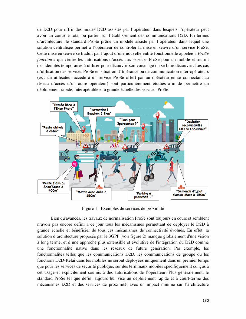
130
de D2D pour offrir des modes D2D assistés par l’opérateur dans lesquels l’opérateur peut
avoir un contrôle total ou partiel sur l’établissement des communications D2D. En termes
d’architecture, le standard ProSe prône un modèle assisté par l’opérateur dans lequel une
solution centralisée permet à l’opérateur de contrôler la mise en œuvre d’un service ProSe.
Cette mise en œuvre se traduit par l’ajout d’une nouvelle entité fonctionnelle appelée « ProSe
function » qui vérifie les autorisations d’accès aux services ProSe pour un mobile et fournit
des identités temporaires à utiliser pour découvrir son voisinage ou se faire découvrir. Les cas
d’utilisation des services ProSe en situation d'itinérance ou de communication inter-opérateurs
(ex : un utilisateur accède à un service ProSe offert par un opérateur en se connectant au
réseau d’accès d’un autre opérateur) sont particulièrement étudiés afin de permettre un
déploiement rapide, interopérable et à grande échelle des services ProSe.
Figure 1 : Exemples de services de proximité
Bien qu'avancés, les travaux de normalisation ProSe sont toujours en cours et semblent
n’avoir pas encore défini à ce jour tous les mécanismes permettant de déployer le D2D à
grande échelle et bénéficier de tous ces mécanismes de connectivité évolués. En effet, la
solution d’architecture proposée par le 3GPP (voir figure 2) manque globalement d'une vision
à long terme, et d’une approche plus extensible et évolutive de l'intégration du D2D comme
une fonctionnalité native dans les réseaux de future génération. Par exemple, les
fonctionnalités telles que les communications D2D, les communications de groupe ou les
fonctions D2D-Relai dans les mobiles ne seront déployées uniquement dans un premier temps
que pour les services de sécurité publique, sur des terminaux mobiles spécifiquement conçus à
cet usage et explicitement soumis à des autorisations de l’opérateur. Plus généralement, le
standard ProSe tel que défini aujourd’hui vise un déploiement rapide et à court-terme des
mécanismes D2D et des services de proximité, avec un impact minime sur l’architecture
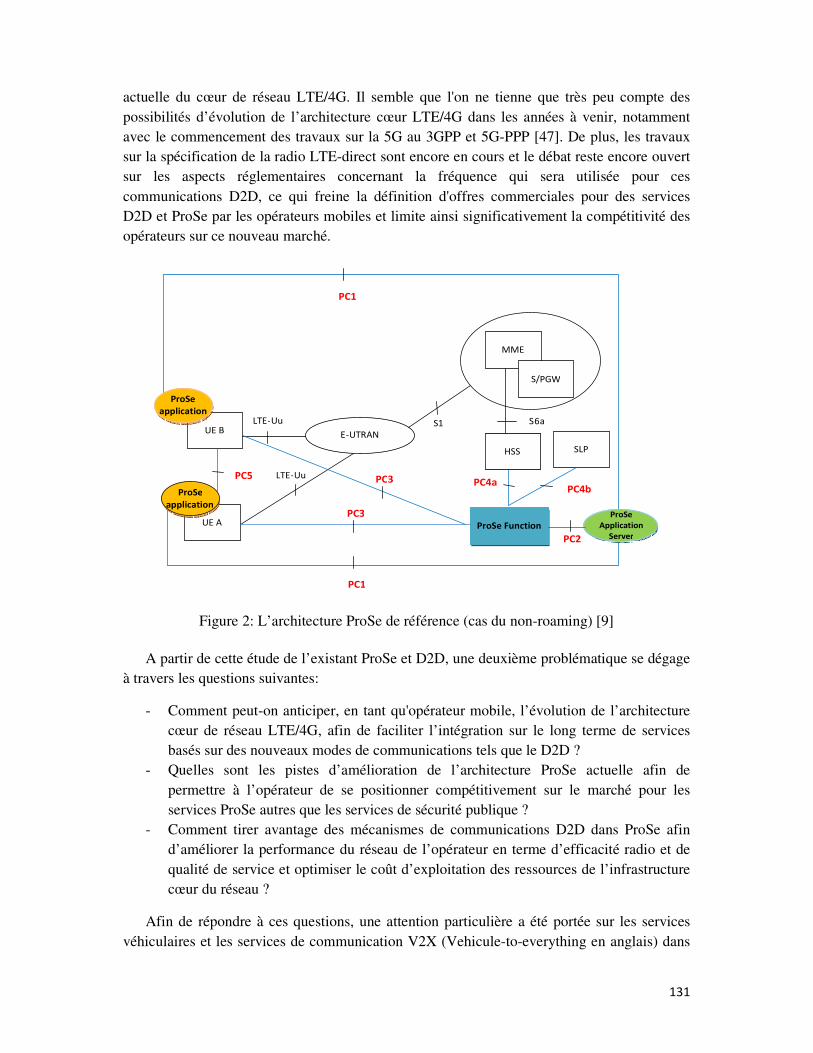
131
actuelle du cœur de réseau LTE/4G. Il semble que l'on ne tienne que très peu compte des
possibilités d’évolution de l’architecture cœur LTE/4G dans les années à venir, notamment
avec le commencement des travaux sur la 5G au 3GPP et 5G-PPP [47]. De plus, les travaux
sur la spécification de la radio LTE-direct sont encore en cours et le débat reste encore ouvert
sur les aspects réglementaires concernant la fréquence qui sera utilisée pour ces
communications D2D, ce qui freine la définition d'offres commerciales pour des services
D2D et ProSe par les opérateurs mobiles et limite ainsi significativement la compétitivité des
opérateurs sur ce nouveau marché.
UE B
ProSe
applicationLTE -Uu
E-UTRAN
UE A
S1
ProSe Function
PC4aPC5 LTE-Uu
PC3
PC1
MME
S/PGW
HSS
ProSe
application
S6a
HSS SLP
PC4b
PC1
ProSe
Application
Server PC2
PC3
Figure 2: L’architecture ProSe de référence (cas du non-roaming) [9]
A partir de cette étude de l’existant ProSe et D2D, une deuxième problématique se dégage
à travers les questions suivantes:
- Comment peut-on anticiper, en tant qu'opérateur mobile, l’évolution de l’architecture
cœur de réseau LTE/4G, afin de faciliter l’intégration sur le long terme de services
basés sur des nouveaux modes de communications tels que le D2D ?
- Quelles sont les pistes d’amélioration de l’architecture ProSe actuelle afin de
permettre à l’opérateur de se positionner compétitivement sur le marché pour les
services ProSe autres que les services de sécurité publique ?
- Comment tirer avantage des mécanismes de communications D2D dans ProSe afin
d’améliorer la performance du réseau de l’opérateur en terme d’efficacité radio et de
qualité de service et optimiser le coût d’exploitation des ressources de l’infrastructure
cœur du réseau ?
Afin de répondre à ces questions, une attention particulière a été portée sur les services
véhiculaires et les services de communication V2X (Vehicule-to-everything en anglais) dans
132
les systèmes de transports intelligents (Intelligent Transport Systems en anglais ou ITS) [15].
En considérant que ces communications V2X telles que « Véhicule à Véhicule » (V2V) ou
« Véhicule à Infrastructure » (V2I), sont basées sur le même principe de fonctionnement que
celui du D2D, il existe une opportunité intéressante pour les opérateurs mobiles à considérer
ces services comme de futurs services ProSe.
Des études ont été menées depuis plus de quinze ans sur le déploiement à grande échelle
des ITS. Un tel déploiement permettrait aux usagers de la route, conducteurs ou piétons, de
communiquer entre eux et avec une infrastructure routière intelligente afin de réduire les
accidents de la route, mieux gérer la congestion du trafic routier, et contribuer en conséquence
à la réduction de la pollution et à la préservation de l’environnement. De ce fait, les solutions
de déploiement se doivent de répondre aux exigences suivantes :
- la fiabilité de l’information de sécurité routière échangée entre les entités ITS ;
- la sécurisation des communications contre les attaques informatiques et la protection
de la vie privée des usagers du système ITS ;
- des délais d’établissement de communication très courts avec une faible latence pour
une assurer l’efficacité des alertes de sécurité routière.
Pour répondre à ces exigences, des travaux de standardisation ont été menés par l’ETSI10
et l’ISO11 afin d’harmoniser les solutions existantes sous une unique architecture de
communication ITS de référence. Cette architecture de référence vise particulièrement le
déploiement d’une infrastructure de communication ITS dédiée, équipée d’unités de bordure
de route et de stations de communication embaqués sur les véhicules. Cette infrastructure est
basée sur l’utilisation de la technologie d’accès IEEE802.11p sur une bande de fréquence
dédiée aux communications V2X ITS. Néanmoins, le déploiement d’un tel système pour un
nombre de véhicules qui explose (1,2 billions de véhicules en 2014 qui peuvent atteindre les 2
billions en 2035) [34] est une tâche fastidieuse pour les industriels de l’automobile et les
équipementiers routiers. Par ailleurs, selon plusieurs études, la technologie IEEE802.11p
prévue comme le media d’accès principal dans les ITS semble ne pas répondre aux exigences
des communications ITS en termes de délais et de fiabilité de transmission de l’information
entre les entités ITS.
C’est dans cette perspective qu'il est intéressant d'étudier l’opportunité d’utiliser
l’architecture ProSe afin d’intégrer les réseaux véhiculaires comme une sous-couche de réseau
gérée et contrôlée par l’opérateur. L’idée est de considérer les services ITS comme des
services ProSe qui s’appuient sur les mécanismes du D2D tels que les communications
directes ou encore les communications de groupe, et l’utilisation de la technologie LTE-Direct
à la place de la technologie IEEE802.11p pour relayer d’une manière fiable et sécurisé
l’information routière. Cette intégration serait non seulement une opportunité pour l’opérateur
pour se positionner sur le marché des ITS mais aussi une solution qui garantirait le
déploiement des systèmes ITS à grande échelle en se basant sur une infrastructure réseau
fiable et performante. Cependant, cette intégration ne sera possible qu'en résolvant certains
10 ETSI : European Telecommunications Standards Institute (http://www.etsi.org/)
11 ISO : International Organization for Standardization (http://www.iso.org/iso/fr/)
133
défis techniques, notamment concernant la capacité du réseau de l’opérateur à supporter une
charge supplémentaire d’abonnées/utilisateurs ITS et à gérer un réseau avec un grand nombre
de nœuds ITS (véhicules, terminaux mobiles de piétons, etc.).
En conséquence, une troisième problématique peut être définie comme suit :
- Quelles sont les évolutions nécessaires à mettre en place dans le réseau LTE/4G, et
plus particulièrement dans l’architecture ProSe, afin d'intégrer les services ITS dans le
réseau de l’opérateur?
- Quels mécanismes mettre en place pour déployer ces services ITS et gérer la charge
réseau supplémentaire des réseaux ITS sans impacter la performance et la qualité de
service du réseau LTE/4G ?
- Comment profiter de ces évolutions pour anticiper les prochaines évolutions du réseau
LTE/4G vers la 5G ?
• Contributions
A travers les problématiques relevées précédemment et l’étude de l’état de l’art des trois
domaines relatifs à chaque problématique, à savoir les communications D2D, l’architecture
ProSe et les services véhiculaires dans les ITS, l'architecture CVS (Cellular Vehicular
Services ou Services Véhiculaires Cellulaires en français) est proposée comme solution
permettant de déployer les services véhiculaires ITS à grande échelle en se basant sur une
architecture ProSe distribuée.
L'architecture CVS est la solution globale proposée dans cette thèse. Elle s’articule autour
de trois grandes contributions, à savoir :
- L’architecture ProSe distribuée qui permet de gérer d’une manière plus efficace sur le
long terme l’intégration de nouveaux services ProSe.
- L’architecture CVS et ses composants, à savoir:
o Un mécanisme de contrôle de la mise en œuvre d’un service de type ProSe-
ITS ;
o Un mécanisme de découverte directe ProSe qui permet de différencier les
annonces ProSe spécifiques aux services ITS ;
o Une méthode de clustering qui permet de regrouper les nœuds mobiles du
réseau ITS sous forme de groupes guidés par un leader afin d’optimiser la
gestion des ressources dans le réseau sur le sens montant (uplink) et descendant
(downlink).
- L’algorithme de clustering ACWCA (Adaptive Context-aware Weighted Clustering
Algorithm ou Algorithme Pondéré de Regroupement Adaptatif en Fonction du
Contexte en français)
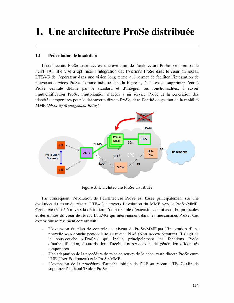
134
1. Une architecture ProSe distribuée
1.1 Présentation de la solution
L’architecture ProSe distribuée est une évolution de l’architecture ProSe proposée par le
3GPP [9]. Elle vise à optimiser l’intégration des fonctions ProSe dans le cœur du réseau
LTE/4G de l’opérateur dans une vision long terme qui permet de faciliter l’intégration de
nouveaux services ProSe. Comme indiqué dans la figure 3, l’idée est de supprimer l’entité
ProSe centrale définie par le standard et d’intégrer ses fonctionnalités, à savoir
l’authentification ProSe, l’autorisation d’accès à un service ProSe et la génération des
identités temporaires pour la découverte directe ProSe, dans l’entité de gestion de la mobilité
MME (Mobility Management Entity).
Figure 3: L’architecture ProSe distribuée
Par conséquent, l’évolution de l’architecture ProSe est basée principalement sur une
évolution du cœur du réseau LTE/4G à travers l’évolution du MME vers le ProSe-MME.
Ceci a été réalisé à travers la définition d’un ensemble d’extensions au niveau des protocoles
et des entités du cœur de réseau LTE/4G qui interviennent dans les mécanismes ProSe. Ces
extensions se résument comme suit :
- L’extension du plan de contrôle au niveau du ProSe-MME par l’intégration d’une
nouvelle sous-couche protocolaire au niveau NAS (Non Access Stratum). Il s’agit de
la sous-couche « ProSe » qui inclue principalement les fonctions ProSe
d’authentification, d’autorisation d’accès aux services et de génération d’identités
temporaires.
- Une adaptation de la procédure de mise en œuvre de la découverte directe ProSe entre
l’UE (User Equipment) et le ProSe-MME.
- L’extension de la procédure d’attache initiale de l’UE au réseau LTE/4G afin de
supporter l’authentification ProSe.
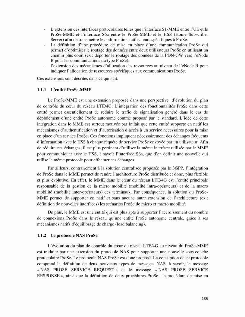
135
- L’extension des interfaces protocolaires telles que l’interface S1-MME entre l’UE et le
ProSe-MME et l’interface S6a entre le ProSe-MME et le HSS (Home Subscriber
Server) afin de transmettre les informations utilisateurs spécifiques à ProSe.
- La définition d’une procédure de mise en place d’une communication ProSe qui
permet d’optimiser le routage des données entre deux utilisateurs ProSe en utilisant un
chemin plus court (ex : déporter le routage des données de la PDN-GW vers l’eNode
B pour les communications du type ProSe).
- l’extension des mécanismes d’allocation des ressources au niveau de l’eNode B pour
indiquer l’allocation de ressources spécifiques aux communications ProSe.
Ces extensions sont décrites dans ce qui suit.
1.1.1 L’entité ProSe-MME
Le ProSe-MME est une extension proposée dans une perspective d’évolution du plan
de contrôle du cœur du réseau LTE/4G. L’intégration des fonctionnalités ProSe dans cette
entité permet essentiellement de réduire le trafic de signalisation généré dans le cas de
déploiement d’une entité ProSe autonome comme proposé par le standard. L’idée de cette
intégration dans le MME est surtout motivée par le fait que cette entité supporte en natif les
mécanismes d’authentification et d’autorisation d’accès à un service nécessaires pour la mise
en place d’un service ProSe. Ces fonctions impliquent nécessairement des échanges fréquents
d’information avec le HSS à chaque requête de service ProSe envoyée par un utilisateur. Afin
de réduire ces échanges, il est plus pertinent d’utiliser la même interface utilisée par le MME
pour communiquer avec le HSS, à savoir l’interface S6a, que d’en définir une nouvelle qui
utilise le même protocole pour effectuer ces échanges.
Par ailleurs, contrairement à la solution centralisée proposée par le 3GPP, l’intégration
de ProSe dans le MME permet de rendre l’architecture ProSe distribuée et donc, plus flexible
et plus évolutive. En effet, le MME dans le cœur du réseau LTE/4G est l’entité principale
responsable de la gestion de la micro mobilité (mobilité intra-opérateurs) et de la macro
mobilité (mobilité inter-opérateurs) des terminaux. Par conséquence, la solution du ProSe-
MME permet de supporter en natif et sans aucune autre extension de l’architecture (ex :
définition de nouvelles interfaces) les scénarios ProSe de micro et macro mobilité.
De plus, le MME est une entité qui est plus apte à supporter l’accroissement du nombre
de connexions ProSe dans le réseau qu’une entité ProSe autonome centrale, grâce à ses
mécanismes natifs d’équilibrage de charge (load balancing).
1.1.2 Le protocole NAS ProSe
L’évolution du plan de contrôle du cœur du réseau LTE/4G au niveau du ProSe-MME
est traduite par une extension du protocole NAS pour supporter une nouvelle sous-couche
protocolaire ProSe. Le protocole NAS ProSe est donc proposé. La conception de ce protocole
comprend la définition de deux nouveaux types de messages NAS, à savoir, le message
« NAS PROSE SERVICE REQUEST » et le message « NAS PROSE SERVICE
RESPONSE », ainsi que la définition de deux procédures ProSe : la procédure de mise en
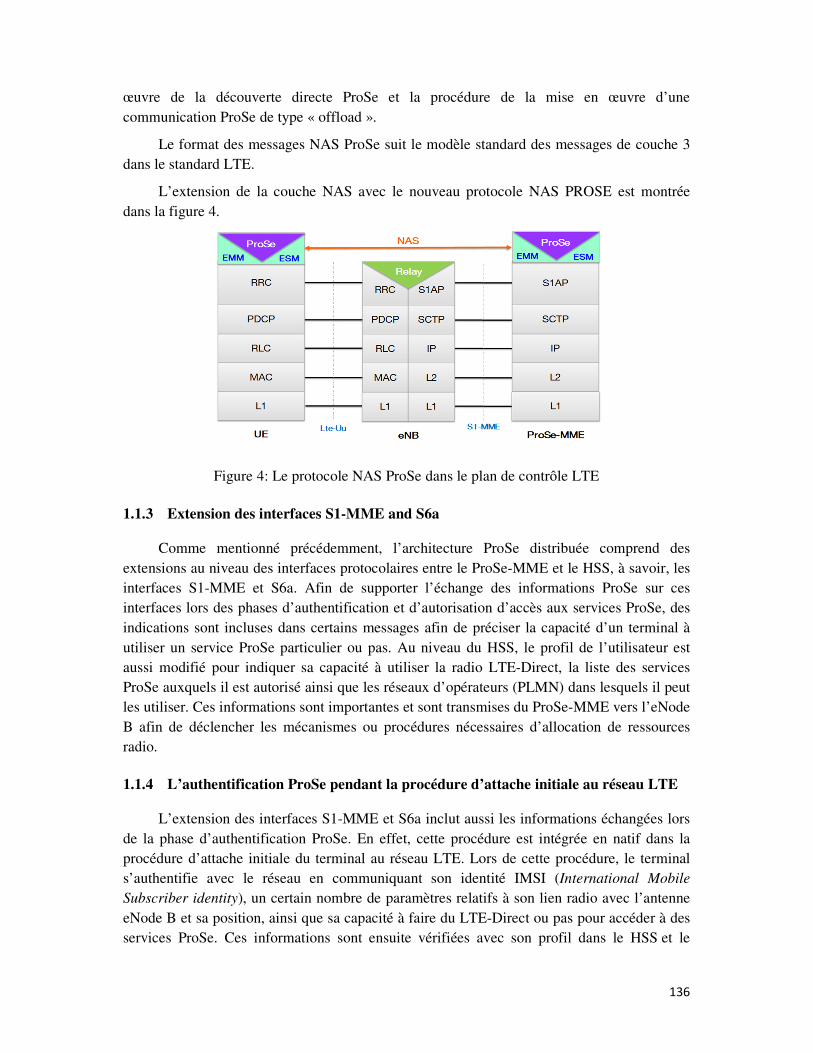
136
œuvre de la découverte directe ProSe et la procédure de la mise en œuvre d’une
communication ProSe de type « offload ».
Le format des messages NAS ProSe suit le modèle standard des messages de couche 3
dans le standard LTE.
L’extension de la couche NAS avec le nouveau protocole NAS PROSE est montrée
dans la figure 4.
Figure 4: Le protocole NAS ProSe dans le plan de contrôle LTE
1.1.3 Extension des interfaces S1-MME and S6a
Comme mentionné précédemment, l’architecture ProSe distribuée comprend des
extensions au niveau des interfaces protocolaires entre le ProSe-MME et le HSS, à savoir, les
interfaces S1-MME et S6a. Afin de supporter l’échange des informations ProSe sur ces
interfaces lors des phases d’authentification et d’autorisation d’accès aux services ProSe, des
indications sont incluses dans certains messages afin de préciser la capacité d’un terminal à
utiliser un service ProSe particulier ou pas. Au niveau du HSS, le profil de l’utilisateur est
aussi modifié pour indiquer sa capacité à utiliser la radio LTE-Direct, la liste des services
ProSe auxquels il est autorisé ainsi que les réseaux d’opérateurs (PLMN) dans lesquels il peut
les utiliser. Ces informations sont importantes et sont transmises du ProSe-MME vers l’eNode
B afin de déclencher les mécanismes ou procédures nécessaires d’allocation de ressources
radio.
1.1.4 L’authentification ProSe pendant la procédure d’attache initiale au réseau LTE
L’extension des interfaces S1-MME et S6a inclut aussi les informations échangées lors
de la phase d’authentification ProSe. En effet, cette procédure est intégrée en natif dans la
procédure d’attache initiale du terminal au réseau LTE. Lors de cette procédure, le terminal
s’authentifie avec le réseau en communiquant son identité IMSI (International Mobile
Subscriber identity), un certain nombre de paramètres relatifs à son lien radio avec l’antenne
eNode B et sa position, ainsi que sa capacité à faire du LTE-Direct ou pas pour accéder à des
services ProSe. Ces informations sont ensuite vérifiées avec son profil dans le HSS et le
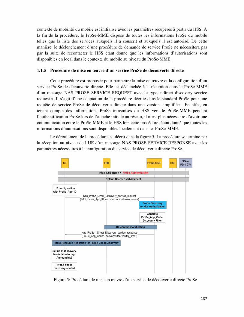
137
contexte de mobilité du mobile est initialisé avec les paramètres récupérés à partir du HSS. A
la fin de la procédure, le ProSe-MME dispose de toutes les informations ProSe du mobile
telles que la liste des services auxquels il a souscrit et auxquels il est autorisé. De cette
manière, le déclenchement d’une procédure de demande de service ProSe ne nécessitera pas
par la suite de recontacter le HSS étant donné que les informations d’autorisations sont
disponibles en local dans le contexte du mobile au niveau du ProSe-MME.
1.1.5 Procédure de mise en œuvre d’un service ProSe de découverte directe
Cette procédure est proposée pour permettre la mise en œuvre et la configuration d’un
service ProSe de découverte directe. Elle est déclenchée à la réception dans le ProSe-MME
d’un message NAS PROSE SERVICE REQUEST avec le type « direct discovery service
request ». Il s’agit d’une adaptation de la procédure décrite dans le standard ProSe pour une
requête de service ProSe de découverte directe dans une version simplifiée. En effet, en
tenant compte des informations ProSe transmises du HSS vers le ProSe-MME pendant
l’authentification ProSe lors de l’attache initiale au réseau, il n’est plus nécessaire d’avoir une
communication entre le ProSe-MME et le HSS lors cette procédure, étant donné que toutes les
informations d’autorisations sont disponibles localement dans le ProSe-MME.
Le déroulement de la procédure est décrit dans la figure 5. La procédure se termine par
la réception au niveau de l’UE d’un message NAS PROSE SERVICE RESPONSE avec les
paramètres nécessaires à la configuration du service de découverte directe ProSe.
Figure 5: Procédure de mise en œuvre d’un service de découverte directe ProSe
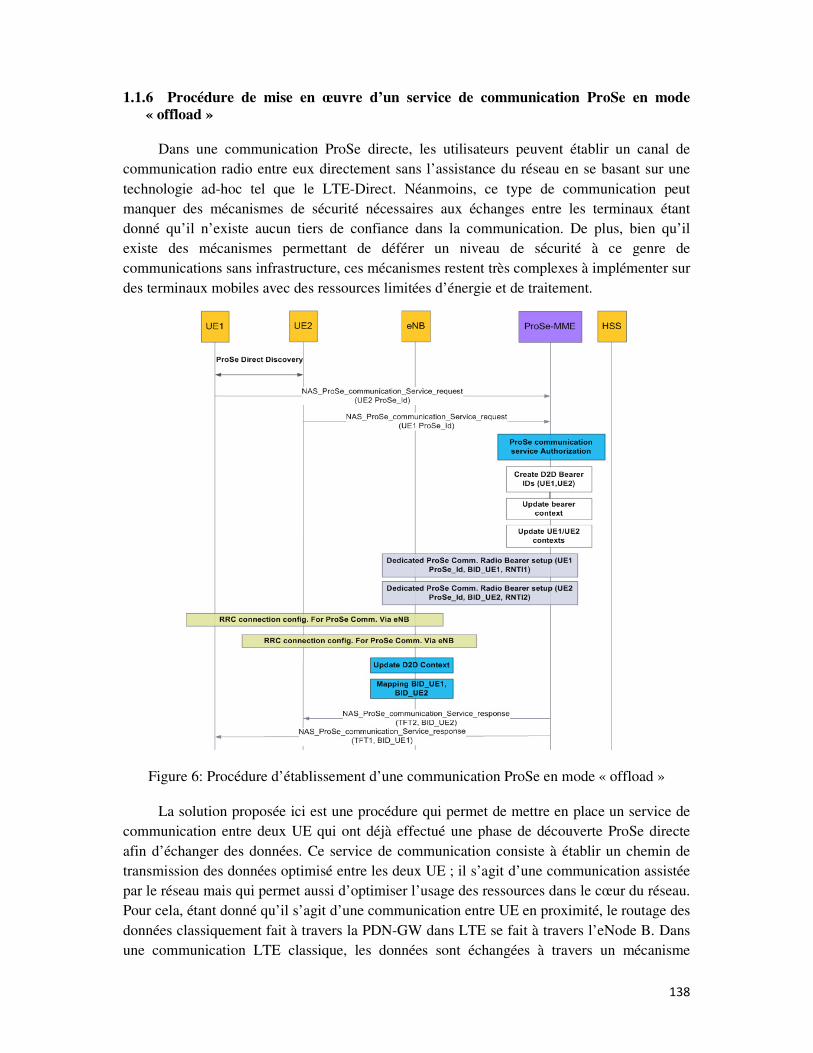
138
1.1.6 Procédure de mise en œuvre d’un service de communication ProSe en mode « offload »
Dans une communication ProSe directe, les utilisateurs peuvent établir un canal de
communication radio entre eux directement sans l’assistance du réseau en se basant sur une
technologie ad-hoc tel que le LTE-Direct. Néanmoins, ce type de communication peut
manquer des mécanismes de sécurité nécessaires aux échanges entre les terminaux étant
donné qu’il n’existe aucun tiers de confiance dans la communication. De plus, bien qu’il
existe des mécanismes permettant de déférer un niveau de sécurité à ce genre de
communications sans infrastructure, ces mécanismes restent très complexes à implémenter sur
des terminaux mobiles avec des ressources limitées d’énergie et de traitement.
Figure 6: Procédure d’établissement d’une communication ProSe en mode « offload »
La solution proposée ici est une procédure qui permet de mettre en place un service de
communication entre deux UE qui ont déjà effectué une phase de découverte ProSe directe
afin d’échanger des données. Ce service de communication consiste à établir un chemin de
transmission des données optimisé entre les deux UE ; il s’agit d’une communication assistée
par le réseau mais qui permet aussi d’optimiser l’usage des ressources dans le cœur du réseau.
Pour cela, étant donné qu’il s’agit d’une communication entre UE en proximité, le routage des
données classiquement fait à travers la PDN-GW dans LTE se fait à travers l’eNode B. Dans
une communication LTE classique, les données sont échangées à travers un mécanisme
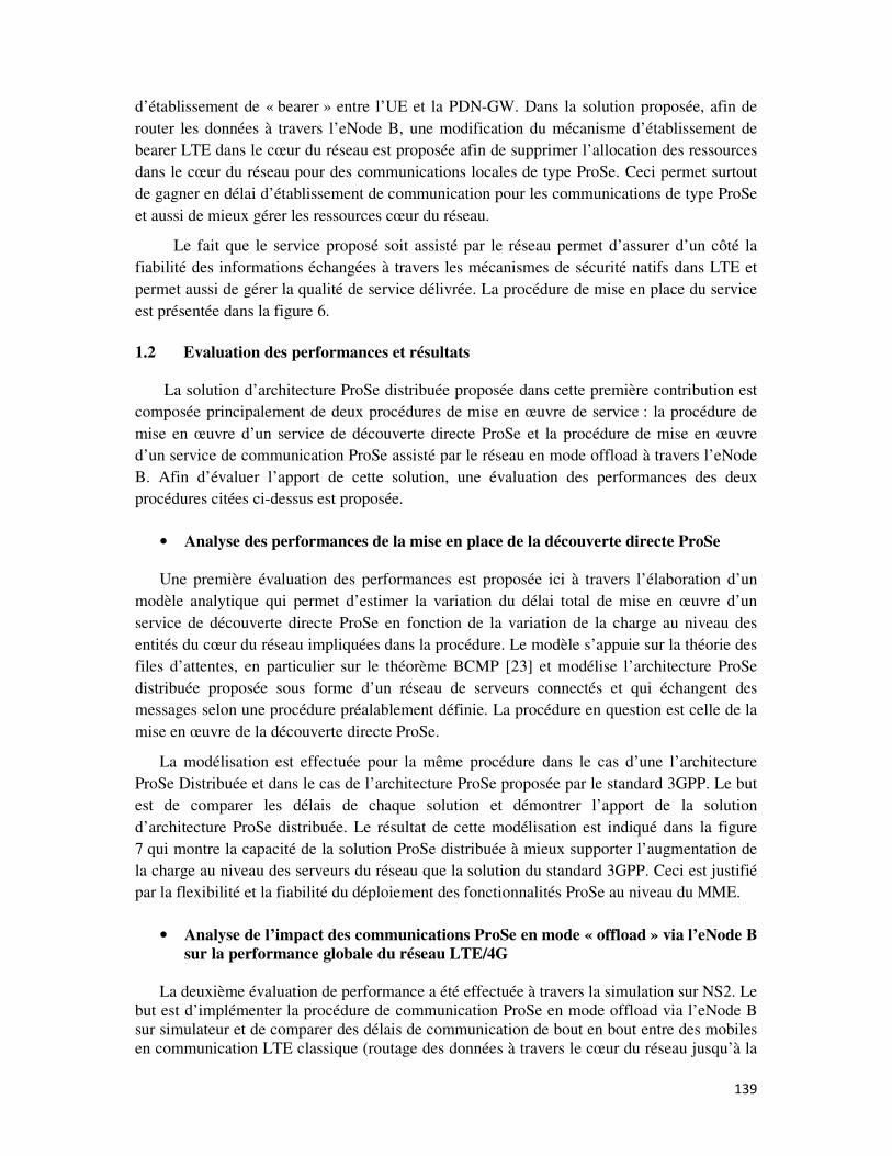
139
d’établissement de « bearer » entre l’UE et la PDN-GW. Dans la solution proposée, afin de
router les données à travers l’eNode B, une modification du mécanisme d’établissement de
bearer LTE dans le cœur du réseau est proposée afin de supprimer l’allocation des ressources
dans le cœur du réseau pour des communications locales de type ProSe. Ceci permet surtout
de gagner en délai d’établissement de communication pour les communications de type ProSe
et aussi de mieux gérer les ressources cœur du réseau.
Le fait que le service proposé soit assisté par le réseau permet d’assurer d’un côté la
fiabilité des informations échangées à travers les mécanismes de sécurité natifs dans LTE et
permet aussi de gérer la qualité de service délivrée. La procédure de mise en place du service
est présentée dans la figure 6.
1.2 Evaluation des performances et résultats
La solution d’architecture ProSe distribuée proposée dans cette première contribution est
composée principalement de deux procédures de mise en œuvre de service : la procédure de
mise en œuvre d’un service de découverte directe ProSe et la procédure de mise en œuvre
d’un service de communication ProSe assisté par le réseau en mode offload à travers l’eNode
B. Afin d’évaluer l’apport de cette solution, une évaluation des performances des deux
procédures citées ci-dessus est proposée.
• Analyse des performances de la mise en place de la découverte directe ProSe
Une première évaluation des performances est proposée ici à travers l’élaboration d’un
modèle analytique qui permet d’estimer la variation du délai total de mise en œuvre d’un
service de découverte directe ProSe en fonction de la variation de la charge au niveau des
entités du cœur du réseau impliquées dans la procédure. Le modèle s’appuie sur la théorie des
files d’attentes, en particulier sur le théorème BCMP [23] et modélise l’architecture ProSe
distribuée proposée sous forme d’un réseau de serveurs connectés et qui échangent des
messages selon une procédure préalablement définie. La procédure en question est celle de la
mise en œuvre de la découverte directe ProSe.
La modélisation est effectuée pour la même procédure dans le cas d’une l’architecture
ProSe Distribuée et dans le cas de l’architecture ProSe proposée par le standard 3GPP. Le but
est de comparer les délais de chaque solution et démontrer l’apport de la solution
d’architecture ProSe distribuée. Le résultat de cette modélisation est indiqué dans la figure
7 qui montre la capacité de la solution ProSe distribuée à mieux supporter l’augmentation de
la charge au niveau des serveurs du réseau que la solution du standard 3GPP. Ceci est justifié
par la flexibilité et la fiabilité du déploiement des fonctionnalités ProSe au niveau du MME.
• Analyse de l’impact des communications ProSe en mode « offload » via l’eNode B
sur la performance globale du réseau LTE/4G
La deuxième évaluation de performance a été effectuée à travers la simulation sur NS2. Le
but est d’implémenter la procédure de communication ProSe en mode offload via l’eNode B
sur simulateur et de comparer des délais de communication de bout en bout entre des mobiles
en communication LTE classique (routage des données à travers le cœur du réseau jusqu’à la
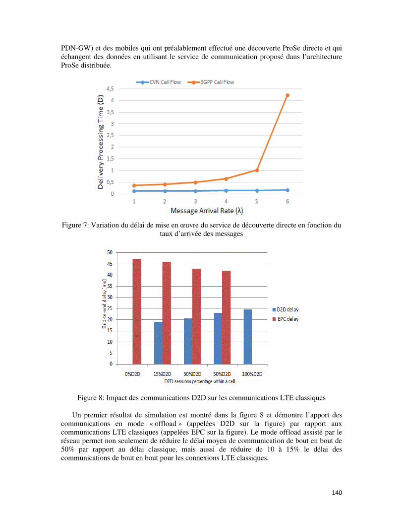
140
PDN-GW) et des mobiles qui ont préalablement effectué une découverte ProSe directe et qui
échangent des données en utilisant le service de communication proposé dans l’architecture
ProSe distribuée.
Figure 7: Variation du délai de mise en œuvre du service de découverte directe en fonction du
taux d’arrivée des messages
Figure 8: Impact des communications D2D sur les communications LTE classiques
Un premier résultat de simulation est montré dans la figure 8 et démontre l’apport des
communications en mode « offload » (appelées D2D sur la figure) par rapport aux
communications LTE classiques (appelées EPC sur la figure). Le mode offload assisté par le
réseau permet non seulement de réduire le délai moyen de communication de bout en bout de
50% par rapport au délai classique, mais aussi de réduire de 10 à 15% le délai des
communications de bout en bout pour les connexions LTE classiques.
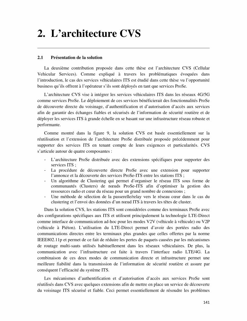
141
2. L’architecture CVS
2.1 Présentation de la solution
La deuxième contribution proposée dans cette thèse est l’architecture CVS (Cellular
Vehicular Services). Comme expliqué à travers les problématiques évoquées dans
l’introduction, le cas des services véhiculaires ITS est étudié dans cette thèse vu l’opportunité
business qu’ils offrent à l’opérateur s’ils sont déployés en tant que services ProSe.
L’architecture CVS vise à intégrer les services véhiculaires ITS dans les réseaux 4G/5G
comme services ProSe. Le déploiement de ces services bénéficierait des fonctionnalités ProSe
de découverte directe du voisinage, d’authentification et d’autorisation d’accès aux services
afin de garantir des échanges fiables et sécurisés de l’information de sécurité routière et de
déployer les services ITS à grande échelle en se basant sur une infrastructure réseau robuste et
performante.
Comme montré dans la figure 9, la solution CVS est basée essentiellement sur la
réutilisation et l’extension de l’architecture ProSe distribuée proposée précédemment pour
supporter des services ITS en tenant compte de leurs exigences et particularités. CVS
s’articule autour de quatre composantes :
- L’architecture ProSe distribuée avec des extensions spécifiques pour supporter des
services ITS ;
- La procédure de découverte directe ProSe avec une extension pour supporter
l’annonce et la découverte des services ProSe-ITS entre les stations ITS ;
- Un algorithme de Clustering qui permet d’organiser le réseau ITS sous forme de
communautés (Clusters) de nœuds ProSe-ITS afin d’optimiser la gestion des
ressources radio et cœur du réseau pour un grand nombre de connexions ;
- Une méthode de sélection de la passerelle/relay vers le réseau cœur dans le cas du
clustering et l’envoi des données d’un nœud ITS à travers les têtes de cluster.
Dans la solution CVS, les stations ITS sont considérées comme des terminaux ProSe avec
des configurations spécifiques aux ITS et utilisent principalement la technologie LTE-Direct
comme interface de communication ad-hoc pour les modes V2V (véhicule à véhicule) ou V2P
(véhicule à Piéton). L’utilisation du LTE-Direct permet d’avoir des portées radio des
communications directes entre les terminaux plus grandes que celles offertes par la norme
IEEE802.11p et permet de ce fait de réduire les pertes de paquets causées par les mécanismes
de routage multi-sauts utilisés habituellement dans les réseaux véhiculaires. De plus, la
communication avec l’infrastructure est faite à travers l’interface radio LTE/4G. La
combinaison de ces deux modes de communication directe et infrastructure permet une
meilleure fiabilité dans la transmission de l’information de sécurité routière et assure par
conséquent l’efficacité du système ITS.
Les mécanismes d’authentification et d’autorisation d’accès aux services ProSe sont
réutilisés dans CVS avec quelques extensions afin de mettre en place un service de découverte
du voisinage ITS sécurisé et fiable. Ceci permet essentiellement de résoudre les problèmes
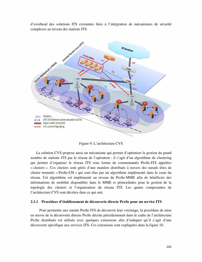
142
d’overhead des solutions ITS existantes liées à l’intégration de mécanismes de sécurité
complexes au niveau des stations ITS.
Figure 9: L’architecture CVS
La solution CVS propose aussi un mécanisme qui permet d’optimiser la gestion du grand
nombre de stations ITS par le réseau de l’opérateur : il s’agit d’un algorithme de clustering
qui permet d’organiser le réseau ITS sous forme de communautés ProSe-ITS appelées
« clusters ». Ces clusters sont gérés d’une manière distribuée à travers des nœuds têtes de
cluster nommés « ProSe-CH » qui sont élus par un algorithme implémenté dans le cœur du
réseau. Cet algorithme est implémenté au niveau du ProSe-MME afin de bénéficier des
informations de mobilité disponibles dans le MME et primordiales pour la gestion de la
topologie des clusters et l’organisation du réseau ITS. Les quatre composantes de
l’architecture CVS sont décrites dans ce qui suit.
2.1.1 Procédure d’établissement de découverte directe ProSe pour un service ITS
Pour permettre aux nœuds ProSe-ITS de découvrir leur voisinage, la procédure de mise
en œuvre de la découverte directe ProSe décrite précédemment dans le cadre de l’architecture
ProSe distribuée est utilisée avec quelques extensions afin d’indiquer qu’il s’agit d’une
découverte spécifique aux services ITS. Ces extensions sont expliquées dans la figure 10.
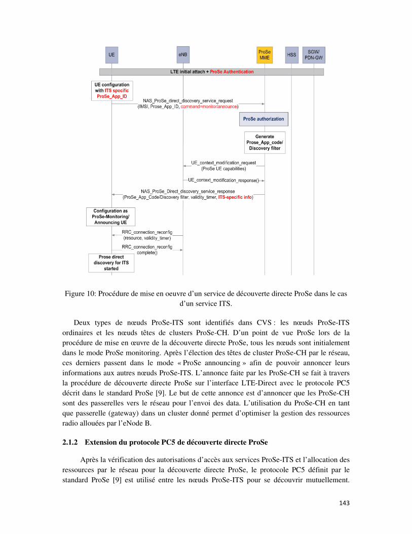
143
Figure 10: Procédure de mise en oeuvre d’un service de découverte directe ProSe dans le cas
d’un service ITS.
Deux types de nœuds ProSe-ITS sont identifiés dans CVS : les nœuds ProSe-ITS
ordinaires et les nœuds têtes de clusters ProSe-CH. D’un point de vue ProSe lors de la
procédure de mise en œuvre de la découverte directe ProSe, tous les nœuds sont initialement
dans le mode ProSe monitoring. Après l’élection des têtes de cluster ProSe-CH par le réseau,
ces derniers passent dans le mode « ProSe announcing » afin de pouvoir annoncer leurs
informations aux autres nœuds ProSe-ITS. L’annonce faite par les ProSe-CH se fait à travers
la procédure de découverte directe ProSe sur l’interface LTE-Direct avec le protocole PC5
décrit dans le standard ProSe [9]. Le but de cette annonce est d’annoncer que les ProSe-CH
sont des passerelles vers le réseau pour l’envoi des data. L’utilisation du ProSe-CH en tant
que passerelle (gateway) dans un cluster donné permet d’optimiser la gestion des ressources
radio allouées par l’eNode B.
2.1.2 Extension du protocole PC5 de découverte directe ProSe
Après la vérification des autorisations d’accès aux services ProSe-ITS et l’allocation des
ressources par le réseau pour la découverte directe ProSe, le protocole PC5 définit par le
standard ProSe [9] est utilisé entre les nœuds ProSe-ITS pour se découvrir mutuellement.
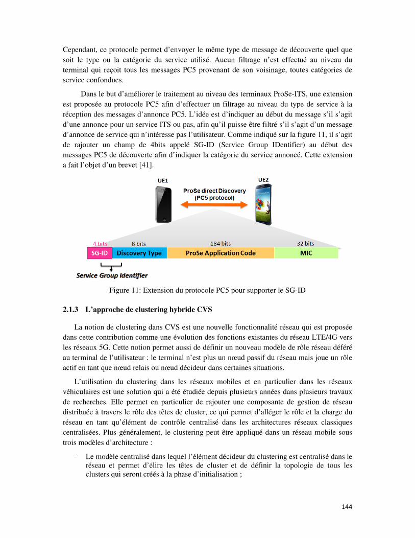
144
Cependant, ce protocole permet d’envoyer le même type de message de découverte quel que
soit le type ou la catégorie du service utilisé. Aucun filtrage n’est effectué au niveau du
terminal qui reçoit tous les messages PC5 provenant de son voisinage, toutes catégories de
service confondues.
Dans le but d’améliorer le traitement au niveau des terminaux ProSe-ITS, une extension
est proposée au protocole PC5 afin d’effectuer un filtrage au niveau du type de service à la
réception des messages d’annonce PC5. L’idée est d’indiquer au début du message s’il s’agit
d’une annonce pour un service ITS ou pas, afin qu’il puisse être filtré s’il s’agit d’un message
d’annonce de service qui n’intéresse pas l’utilisateur. Comme indiqué sur la figure 11, il s’agit
de rajouter un champ de 4bits appelé SG-ID (Service Group IDentifier) au début des
messages PC5 de découverte afin d’indiquer la catégorie du service annoncé. Cette extension
a fait l’objet d’un brevet [41].
Figure 11: Extension du protocole PC5 pour supporter le SG-ID
2.1.3 L’approche de clustering hybride CVS
La notion de clustering dans CVS est une nouvelle fonctionnalité réseau qui est proposée
dans cette contribution comme une évolution des fonctions existantes du réseau LTE/4G vers
les réseaux 5G. Cette notion permet aussi de définir un nouveau modèle de rôle réseau déféré
au terminal de l’utilisateur : le terminal n’est plus un nœud passif du réseau mais joue un rôle
actif en tant que nœud relais ou nœud décideur dans certaines situations.
L’utilisation du clustering dans les réseaux mobiles et en particulier dans les réseaux
véhiculaires est une solution qui a été étudiée depuis plusieurs années dans plusieurs travaux
de recherches. Elle permet en particulier de rajouter une composante de gestion de réseau
distribuée à travers le rôle des têtes de cluster, ce qui permet d’alléger le rôle et la charge du
réseau en tant qu’élément de contrôle centralisé dans les architectures réseaux classiques
centralisées. Plus généralement, le clustering peut être appliqué dans un réseau mobile sous
trois modèles d’architecture :
- Le modèle centralisé dans lequel l’élément décideur du clustering est centralisé dans le
réseau et permet d’élire les têtes de cluster et de définir la topologie de tous les
clusters qui seront créés à la phase d’initialisation ;
145
- Le modèle distribué dans lequel l’élection des têtes de cluster se fait par les nœuds
mobiles ou même avec des algorithmes de clustering distribués ;
- Le modèle hybride dans lequel l’élection des têtes de cluster se fait d’une manière
centralisée tandis que l’organisation des clusters et des nœuds dans les clusters se fait
d’une manière distribuée gérée par les têtes de cluster et les autres nœuds mobile de
réseau.
Dans CVS, une méthode de clustering hybride est proposée avec les caractéristiques
suivantes :
- La topologie des clusters n’est pas figée et n’est pas définie d’une manière centralisée
par le réseau;
- La gestion des nœuds ordinaires du réseau se fait d’une manière dynamique à travers
les têtes de cluster ProSe-CH;
- L’élection des têtes de cluster se fait d’une manière centralisée à travers un algorithme
de clustering implémenté dans le ProSe-MME;
- Les têtes de cluster sont considérés comme des nœuds relais/passerelles pour les
nœuds ordinaires du réseau : afin d’optimiser l’allocation des ressources dans le sens
montant ou descendant, les ProSe-CHs peuvent être utilisés comme des points de
collecte ou de diffusion des données vers et depuis le réseau.
Cette méthode de clustering est réalisée principalement à travers l’algorithme de clustering
ACWCA (Adaptive Context-aware Weighted Clustering Algorithm) qui est proposé dans la
troisième contribution de cette thèse. La méthode de clustering s’articule autour de trois
fonctionnalités :
- La fonction d’élection des têtes de cluster ProSe-CH: elle est réalisée à travers
l’algorithme de clustering implémenté dans le ProSe-MME;
- La fonction de d’annonce de la présence des ProSe-CH dans le réseau ITS : elle est
réalisée à travers la configuration des ProSe-CH dans le mode « ProSe Announcing » ;
- La fonction de découverte des ProSe-CH par les nœuds ProSe-CH ordinaires : elle est
réalisée à travers la configuration des nœuds ProSe-ITS dans le mode « ProSe
monitoring ».
2.1.4 Séléction de la passerelle ProSe vers le réseau
Cette fonctionnalité de l’architecture CVS est implémentée au niveau des nœuds ProSe-
ITS ordinaires et est spécifique au cas de transmission des données dans le mode V2I, c’est-à-
dire en partant des stations ProSe-ITS vers le réseau : en effet, le but de cette fonction est
d’optimiser l’utilisation des ressources en bande passante dans le sens montant (uplink) dans
le cas d’envoi massif de données à partir du réseau ITS vers l’infrastructure (ex : collecte
périodique des données routières). Le mécanisme associé permet aux nœuds ProSe-ITS
ordinaires, en présence de plusieurs nœuds ProSe-CH comme passerelles dans leur voisinage,
de sélectionner la meilleure passerelle pour remonter les données vers le réseau.
Cette sélection de passerelle ProSe est faite en se basant sur un certain nombre de
paramètres tels que la qualité du lien radio LTE-direct entre un nœud ProSe-ITS et un nœud
ProSe-CH ainsi que le débit de transmission possible. Par conséquent, afin d’effectuer les
mesures nécessaires, l’utilisation de la méthode LIFBE (Low Intrusive and Fast Bandwidth
Estimation) [42] est proposée avec une extension de son mécanisme pour supporter la mesure
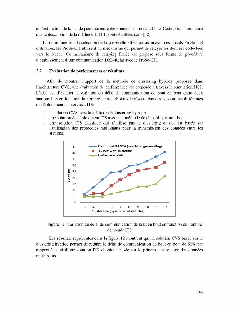
146
et l’estimation de la bande passante entre deux nœuds en mode ad-hoc. Cette proposition ainsi
que la description de la méthode LIFBE sont détaillées dans [42].
En outre, une fois la sélection de la passerelle effectuée au niveau des nœuds ProSe-ITS
ordinaires, les ProSe-CH utilisent un mécanisme qui permet de relayer les données collectées
vers le réseau. Ce mécanisme de relaying ProSe est proposé sous forme de procédure
d’établissement d’une communication D2D-Relai avec le ProSe-CH.
2.2 Evaluation de performances et résultats
Afin de montrer l’apport de la méthode de clustering hybride proposée dans
l’architecture CVS, une évaluation de performance est proposée à travers la simulation NS2.
L’idée est d’évaluer la variation du délai de communication de bout en bout entre deux
stations ITS en fonction du nombre de nœuds dans le réseau, dans trois solutions différentes
de déploiement des services ITS:
- la solution CVS avec la méthode de clustering hybride
- une solution de déploiement ITS avec une méthode de cluserting centralisée
- une solution ITS classique qui n’utilise pas le clustering et qui est basée sur
l’utilisation des protocoles multi-sauts pour la transmission des données entre les
stations.
Figure 12: Variation du délai de communication de bout en bout en fonction du nombre
de nœuds ITS
Les résultats représentés dans la figure 12 montrent que la solution CVS basée sur le
clustering hybride permet de réduire le délai de communication de bout en bout de 50% par
rapport à celui d’une solution ITS classique basée sur le principe du routage des données
mutli-sauts.
147
3. Le clustering hybride ACWCA
3.1 Présentation de la solution
La troisième contribution de cette thèse est l’algorithme ACWCA (Adaptive Context-
aware Weighted Clustering Algorithm). Il s’agit d’une des composantes principales de
l’architecture CVS qui permet de mettre en œuvre la méthode de clustering hybride décrite
précédemment. Implémentée dans le ProSe-MME, la fonction principale de l'algorithme est
de collecter des informations de contexte à partir des nœuds ProSe-ITS afin d’élire les têtes de
cluster ProSe-CH. Le fait d’implémenter cet algorithme dans le ProSe-MME permet surtout
de profiter des informations de mobilité et de contexte disponibles localement dans le MME
afin d’optimiser le choix des ProSe-CH. En effet, les réseaux véhiculaires sont caractérisés
par une forte mobilité des nœuds, ce qui résulte, dans le cas du clustering, en une topologie en
cluster instable. L’objectif est donc d’élire les ProSe-CH les mieux adaptés au contexte et de
maximiser leur durée de vie afin de maintenir la stabilité de la topologie du réseau. Les têtes
de cluster ProSe-CH ont pour mission de gérer de manière distribuée l’envoi des données vers
ou depuis les nœuds ProSe-ITS afin d’optimiser la gestion des ressources radio dans les
environnements avec un grand nombre de nœuds ProSe-ITS. La communication entre les
ProSe-CH et le réseau se fait à travers la radio LTE/4G, tandis que celle entre les ProSe-CH et
les nœuds ProSe-ITS ordinaires dans les clusters se font à travers la radio LTE-Direct.
3.1.1 Caractéristiques de l’algorithme
Afin de définir l’algorithme ACWCA utilisé dans l’architecture CVS, une étude de l’état
de l’art des algorithmes de clustering a été faite afin de choisir la technique de clustering la
mieux adaptée aux besoins de la solution CVS. Le résultat de cette étude a mené à la
définition des caractéristiques suivantes de l’algorithme:
- Clustering pondéré: la méthode de sélection des ProSe-CH par l’algorithme
ACWCA est basée sur la technique de calcul des poids pondérés d’un certain nombre
de paramètres qui sont collectés initialement à partir de tous les nœuds présents dans le
réseau. L’idée est de calculer pour chaque nœud ProSe-ITS un poids W qui est la
somme pondérée de quatre paramètres de contexte Pi caractérisant un nœud ProSe-ITS
initialement et pondérés par des coefficients Cj. La formule du poids s’écrit comme
suit : l = g × 9 +g� × 9� +g0 × 90 +g/ × 9/
- Clustering « à la demande »: la méthode de clustering proposée est exécutée sur
deux phases : une phase d’initialisation du réseau en clusters et une phase de mise à
jour de la topologie. Le clustering à la demande concerne la phase de mise à jour de la
topologie du réseau lors de changements significatifs. En effet, elle consiste à ré-
exécuter l’algorithme de clustering afin de reformer une topologie en cluster stable.
Dans l’algorithme ACWCA, cette mise à jour est faite à la demande lorsqu’un
évènement survient et impacte la stabilité de la topologie (ex : un ProSe-CH qui ne
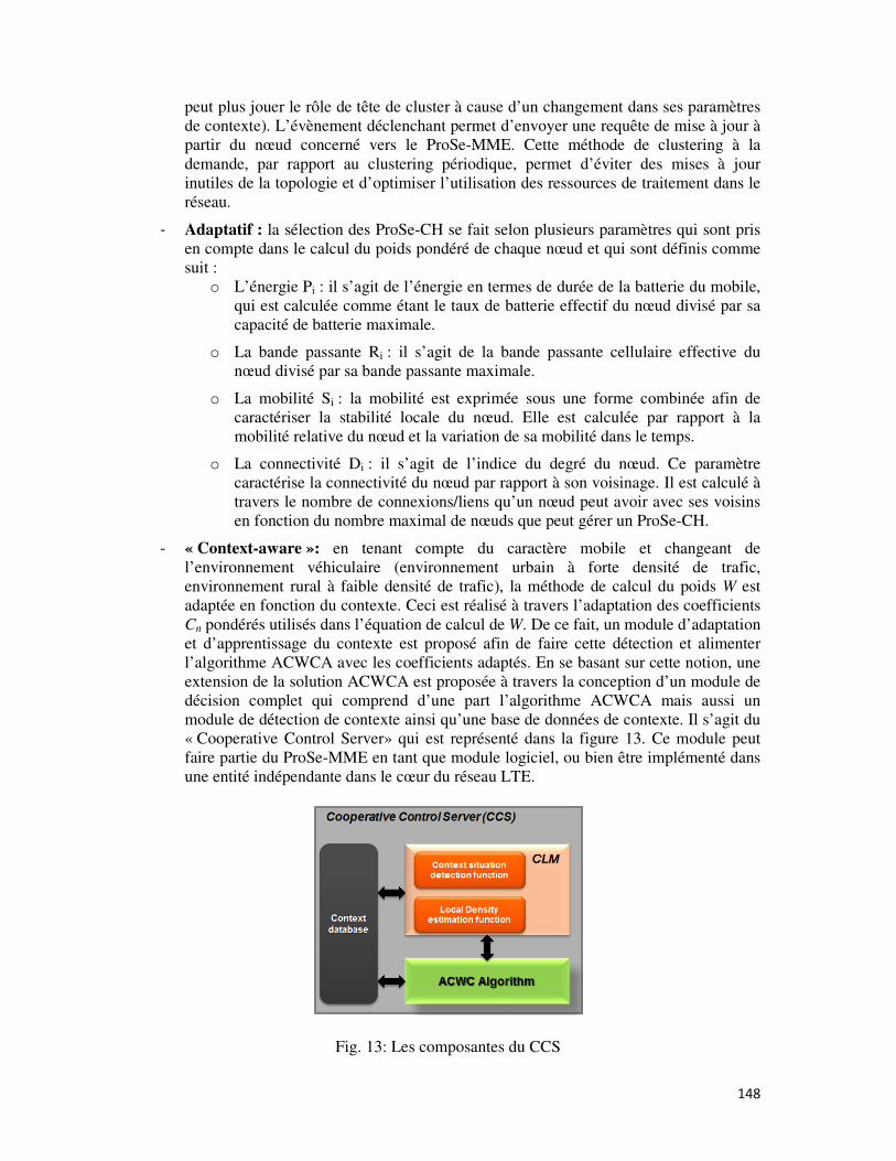
148
peut plus jouer le rôle de tête de cluster à cause d’un changement dans ses paramètres
de contexte). L’évènement déclenchant permet d’envoyer une requête de mise à jour à
partir du nœud concerné vers le ProSe-MME. Cette méthode de clustering à la
demande, par rapport au clustering périodique, permet d’éviter des mises à jour
inutiles de la topologie et d’optimiser l’utilisation des ressources de traitement dans le
réseau.
- Adaptatif : la sélection des ProSe-CH se fait selon plusieurs paramètres qui sont pris
en compte dans le calcul du poids pondéré de chaque nœud et qui sont définis comme
suit :
o L’énergie Pi : il s’agit de l’énergie en termes de durée de la batterie du mobile,
qui est calculée comme étant le taux de batterie effectif du nœud divisé par sa
capacité de batterie maximale.
o La bande passante Ri : il s’agit de la bande passante cellulaire effective du
nœud divisé par sa bande passante maximale.
o La mobilité Si : la mobilité est exprimée sous une forme combinée afin de
caractériser la stabilité locale du nœud. Elle est calculée par rapport à la
mobilité relative du nœud et la variation de sa mobilité dans le temps.
o La connectivité Di : il s’agit de l’indice du degré du nœud. Ce paramètre
caractérise la connectivité du nœud par rapport à son voisinage. Il est calculé à
travers le nombre de connexions/liens qu’un nœud peut avoir avec ses voisins
en fonction du nombre maximal de nœuds que peut gérer un ProSe-CH.
- « Context-aware »: en tenant compte du caractère mobile et changeant de
l’environnement véhiculaire (environnement urbain à forte densité de trafic,
environnement rural à faible densité de trafic), la méthode de calcul du poids W est
adaptée en fonction du contexte. Ceci est réalisé à travers l’adaptation des coefficients
Cn pondérés utilisés dans l’équation de calcul de W. De ce fait, un module d’adaptation
et d’apprentissage du contexte est proposé afin de faire cette détection et alimenter
l’algorithme ACWCA avec les coefficients adaptés. En se basant sur cette notion, une
extension de la solution ACWCA est proposée à travers la conception d’un module de
décision complet qui comprend d’une part l’algorithme ACWCA mais aussi un
module de détection de contexte ainsi qu’une base de données de contexte. Il s’agit du
« Cooperative Control Server» qui est représenté dans la figure 13. Ce module peut
faire partie du ProSe-MME en tant que module logiciel, ou bien être implémenté dans
une entité indépendante dans le cœur du réseau LTE.
Fig. 13: Les composantes du CCS
149
3.1.2 La méthode d’élection des ProSe-CH
Les données d’entrée de l’algorithme ACWCA sont les paramètres de contexte P, R, S et
D. Ces paramètres sont collectés dans une première phase à partir des nœuds mobiles dans
lesquels ils sont calculés en local. La délocalisation du calcul de ses paramètres au niveau des
terminaux permet d’éviter de rajouter de la complexité de calcul et de traitement au niveau du
cœur du réseau surtout pour un nombre important de nœuds. De plus, la remontée de ces
paramètres de contexte se fait de manière périodique afin d’alimenter l’algorithme
continuellement avec les données les plus récentes et d’éviter des situations bloquantes et de
mettre à jour la topologie en cluster en fonction de l’état réel du réseau.
Aprés la collecte de ces paramètres, le CCS dans le ProSe-MME procède au calcul du
poids pondéré W de chaque nœud en se basant sur les coefficients Cn sélectionnés par le
module de détection de contexte. L’algorithme ACWCA procède ensuite à la sélection d’un
nombre de nœuds à élire en tant que ProSe-CH selon une méthode de tri croissant : Les poids
W sont triés du plus grand au plus petit et les nœuds ayant le plus grand W sont désignés
comme ProSe-CH. Le nombre des ProSe-CH à élire par cellule LTE peut être fixé par
configuration selon la stratégie du réseau ou bien calculé de manière dynamique en fonction
de la densité de trafic du réseau qui est remonté à partir du CCS à travers la fonction
d’estimation de densité locale. De même, afin d’éviter de surcharger les nœuds ProSe-CH lors
de la remontée des données à partir des nœuds ProSe-ITS, un nombre maximal de connexions
supportées est configuré pour chaque nœud ProSe-CH élu. Ce nombre correspond à la taille
du cluster qui pourra être géré par un ProSe-CH et permet de ne pas surutiliser les ressources
des nœuds ProSe-CH.
3.2 Evaluation des performances et résultats
Afin de montrer l’apport de la méthode de clustering hybride proposée par l’algorithme
ACWCA, une évaluation des performances a été réalisée en utilisant des simulations sur
MATLAB et sur NS3 [40]. Les indicateurs de performance mesurés sont essentiellement:
- la stabilité des clusters
- la latence de formation d’un cluster
- la durée moyenne de vie d’un cluster
- le nombre des clusters créés
- l’overhead des messages
L’analyse de performance effectuée consiste à mesurer ces indicateurs dans le cas de
l’algorithme ACWCA en comparaison avec une approche de clustering distribué et une
approche sans clustering. Le but est de montrer que l’approche ACWCA permet de :
- Réduire le nombre de clusters créés
- Permet de maintenir la stabilité de la topologie en cluster en augmentant la durée de
vie des têtes de cluster ProSe-CH.
- Réduit le nombre de messages de signalisation pour la mise en place de la topologie en
cluster
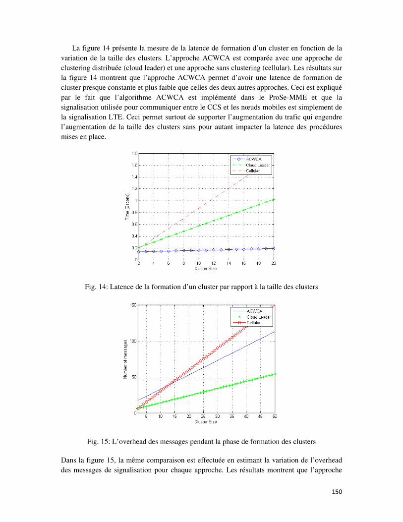
150
La figure 14 présente la mesure de la latence de formation d’un cluster en fonction de la
variation de la taille des clusters. L’approche ACWCA est comparée avec une approche de
clustering distribuée (cloud leader) et une approche sans clustering (cellular). Les résultats sur
la figure 14 montrent que l’approche ACWCA permet d’avoir une latence de formation de
cluster presque constante et plus faible que celles des deux autres approches. Ceci est expliqué
par le fait que l’algorithme ACWCA est implémenté dans le ProSe-MME et que la
signalisation utilisée pour communiquer entre le CCS et les nœuds mobiles est simplement de
la signalisation LTE. Ceci permet surtout de supporter l’augmentation du trafic qui engendre
l’augmentation de la taille des clusters sans pour autant impacter la latence des procédures
mises en place.
Fig. 14: Latence de la formation d’un cluster par rapport à la taille des clusters
Fig. 15: L’overhead des messages pendant la phase de formation des clusters
Dans la figure 15, la même comparaison est effectuée en estimant la variation de l’overhead
des messages de signalisation pour chaque approche. Les résultats montrent que l’approche

151
ACWCA réduit l’overhead des messages, comparée à l’approche classique sans clustering;
ceci est expliqué par le fait que le nombre des nœuds communicants avec l’eNode B en cas de
clustering ACWCA est inférieur à celui de l’approche cellulaire. En effet, dans l’approche
ACWCA, les ProSe-CH sont les nœuds qui communiquent directement avec le réseau. Par
ailleurs, les résultats montrent que l’approche ACWCA rajoute plus d’overhead que
l’approche distribuée ; ceci est expliqué par le fait que l’approche hybride est basée en partie
sur un échange de messages supplémentaires entre les nœuds ProSe-CH et le réseau.

152