8, editerlal c, i - bhabha atomic research centre
TRANSCRIPT
~c
ct
1c
,"c IOC
fjfIc
The IPIG worksonthehigh magnetic flux
pipelinewiththeh
a Magnetic ModuResidual Sensors'
arealsoattachedtor,
11
Ii
Can ten t s
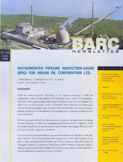
U, In;trem'"te'U[I,. Ceepe"tlooLtdc'.8, Editerlalc,cl
.3 ~~'
12
.5 Wee" Emlmnmeet Day
"'eb"led 13
6 Geldee Peacock
Emltoomeet Management
te 14
]7
15
I18 Weddne"",;lete,
I In 19981
1Cct
15
EDITORIAL
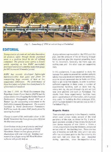
Fig. ] .. Launching of lPlG 01 wet test loop at Faridabad
BARC has
transporting
temperatore
World
RAPS ho, made the enlim DAEfamily proud hy,ecuringtheaward.
and it add.v colour
IheMoyi.,.vueanwards.
Contribations
in BARC
illustrations
~ -.-'===-
A polyurethane cup mounted on theIPIGsealstheand the pressure of the oil flowing throughpipelines give the required force
lor its movement Generally the cups aresealing cups and the other cups are supporting
cups.
In this assignment, it was essential to theleakage flux patterns around the notches pitstaking into consideration material characteristics,acquire signals generated due to faults and filter
to get noise-free signals. In order to achievein these areas, a number ofies, such as static test rig,
rotary test rig, dry pull-through rig and wettestloop were planned and built at Faridabad. Theresults from these facilities havegivenagood information, which proved
uselul for building the first prototype IPIG,1 has been tested inthewettestloopatlOC in
Faridabad (Fig. 11.
Magnetic Module
There are eight segments in the Magnetic
which cover almost ninety percent of thelery of the pipe, as shown in Fig. 2 and 3.segment consists 01 two strong Neodymium
Iron Boron magnets 01 size 70mm x 70mm x
on two sides of the Backing Iron. There are twosets 01 brushes on both the sides which not onlyofler low reluctance to the flux entering the
pipe wall, but also the wax depositedduring operation, since the deposition 01any
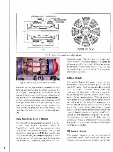
Fig 2 : Magnetic module assembly (sketch)
Fig 3 : Actual magnetic module assembly
material on the pipe surface increases the gap
between pipe surface and the sensor, affecting thefault signal. Spring loaded polyurethane sensorarms with hall sensorsare inthe central portionofthe backing iron. The directions of magnetisationof the permanent magnets are such that the mmf ofeach gets added and this helps in driving the pipewall into saturation. Each assembly is mounted onleaf springs so that the magnetic module cannegotiate the weld protrusions, bends and tees,etc.
Data Acquisition System Module
The heart of the data acquisition system is a 486-based single board computer ISBC). A"multiplexer card" and an analogue dataacquisition card acquire magnetic flux leakagesignal from 64 sensors. The SBC then transfers thedata to a hard disk, qualified for high level of shockand vibration. The electronics and the hard disk
are housed i~ a pressure tight vessel on anti-
vibration mounts. The electrical connections are
taken through connectors specially designed towithstand very high pressure. All the 64 sensorsare sampled for every 2mm travel of PIG. The cue
for acquisition is taken from the fastest movingodometer at anytime.
Battery Module
This module houses the power supply for theinstrument. It has two battery packs for thetwo DAS units. Each battery pack is connectedto a DC-to-DC converter which feeds the
electronics of DAS unit. It also gives supply toactive and residual sensors. Ampere hour of eachpack is 60 at rated drainage. With our present
requi rement of DAS and taking into considerationthe efficiency of the DC-to-DC converter, thelifetime of each battery pack is expected to be 40hours. The battery module also houses a controlcircuitry which gets input from the odometers andconverts them into signal acceptable for DAS unit.In case the PIG stops fora long theDC-to-DC converters are switchedoff. saves the
unnecessary drainage of the battery when the data)0 is not required during the period whenis not moving.
PIG LocatorModule
This module consists of an electromagnetictransmitter which after emits low
frequency electro-magnetic which can
be picked up by a pistol type antenna at a distance
upto 10 metres. One can locate the IPIG during itstravel along the length of pipe with the help of thisantenna.
Data Analysis
The data is analysed off-line by a defect inspectionsoftware. The raw data is filtered in scale-spaceplane to eliminate noise due to sensor bounce,unequal lift-off, non-uniform pipe thickness, etc.The "denoised" signal is used for automaticdetection of peaks due to metal loss defects and an
image is formed by using a set of rules. The gray-scaledlcoloured image is used for visual inspectionof surface and depth extent of a defect. Fig. 12shows a typical image developed from the dataobtained from a run in wet evaluation facilitY. Thelong vertical line spanning the full periphery of thepipe is the air gap at the flange joint. Other graypatches are due to welding at the cut edges andcreated defects.
Finite Element Method (FEM)
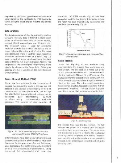
Since close form solutions for the computation ofleakage flux around the faults in the pipe are notpossible in this case due to nonlinearitY of the B-Hcharacteristics of the pipe material, the leakageflux distribution around pits and notches can becalculated quite satisfactorily by FEMtechnique using commercially available
packages. The samples of pipe materials of
Fig. 4.. 3-D FEM model of magnetic modulesub-asmnbly using MAGNET software
different grades have been procured from IOC andthe torroid shaped core of this material have beenfabricated for the generation of actual B-H curve,since the leakage flux pattern is heavily dependenton the S-H characteristics of pipe material. Usingthe actual B-H characteristics of these pipe
materials, 3D FEM models (Fig. 4) have been
generated and the flux density distribution aroundthe notch has been theoretically established andverified experimentally IFig. 5).
i::"\J\- !i~ \~- I~-:: \Vr"\,..
'-, ... - - ,- ",'- - ... ,-
Fig. 5 .. Comparison of actual and computed fluxdensity level
Static Test Rig
Static Test Rig (Fig. 6) was made to studyexperimentally the leakage flux levels around atest section. The test section is made out of theactual pipe obtained from IOC. The dimension ofthe test section is 320mm (IJ x 125mm (w). The
plates used for the test section are 6 mm and 9 mmthick. One sub-assembly of the magnetic module isfixed on the table. The sub-assembly consists ofbacking iron, brushes, test section and two NdFeBpermanent magnets. The test section is placedover the brushes. Hall sensors are used to detect
Fig. 6.. Static test rig
the leakage flux near the test section. The hallsensors are potted in a module and the pottedmodule is fixed on a sensor arm. The sensor arms
are mounted on a moving x-y table. The lead screwof the x-ytable is coupled to a D.C motor. The entirearea over the test section can be scanned using thismethod. Limit switches are installed on both sides
of the x-y table.
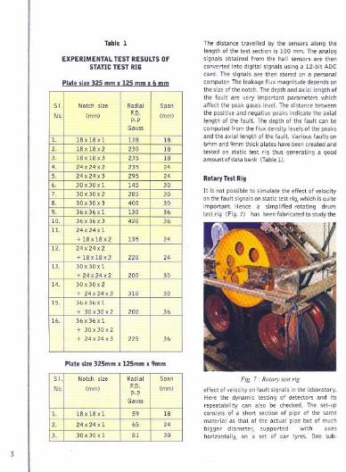
Table 1
EXPERIMENTAL TEST RESULTS OFSTATIC TEST RIG
Platesize325 mmx 125 mmx 6 mm
Plate size 325mm x 125mm x 9mm
The distance travelled by the sensors along thelength of the test section is 100 mm. The analogsignals obtained from the hall sensors are thenconverted into digital signals using a 12-bit ADCcard. The signals are then stored on a personalcomputer. The leakage flux magnitude dependsonthe size olthe notch. The depth and axial length ofthe fault are very important parameters whichaffect the peak gauss level. The distance betweenthe positive and negative peaks indicate the axiallength of the fault. The depth of the fault can becomputed from the flux density levels of the peaksand the axial length of the fault. Various faults on6mm and 9mm thick plates havebeencreated andtested on static test rig thus generating a goodamount of data bank (Table11.
RotaryTest Rig
It is not possible to simulate the effect of velocityon the fault signals on static test rig, which is quiteimportant. Hence a simplified rotating drumtest rig (Fig.7I has beenfabricated to study the
Fig. 7.. Rotary test rig
effect of velocity on fault signals in the laboratory.Here the dynamic testing of detectors and itsrepeatability can also be checked. The set-upconsists of a short section of pipe of the samematerial as that of the actual pipe but of muchbigger diameter, supported with axeshorizontally, on a set of car tyres. One sub-
S I. Notch size Radial Span
No. (mm) F.D. (mm)pop
Gauss
1. 18 x 18 x 1 128 182. 18x18x2 230 183. 18x18x3 235 184. 24x24x2 235 24
5. 24x24x3 295 246. 30x30xl 145 307. 30x30x2 285 308. 30x30x3 400 30
9. 36x36xl 130 36
10. 36x36x3 420 36
11. 24x24xl
+18x18x2 135 2412. 24x24x2
+18x18x3 220 2413. 30x30xl
+24x24x2 200 30
14. 30x30x2
+ 24x24x3 310 30
15. 36x36xl
+ 30x30x2 200 36
16. 36x36xl
+ 30x30x2
+ 24x24x3 225 36
S I. Notch size Radial Span
No. (mm) ED. (mm)pop
Gauss
1. 18x18xl 59 18
2- 24x24xl 65 24
3. 30x30xl 81 30
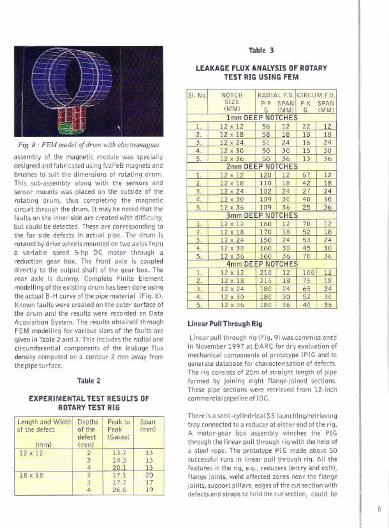
Fig. 8 . FEM model of drum with electmmognet
assembly 01 the magnetic module was speciallydesignedandlabricatedusingNdFeBmagnetsandbrushes to suit the dimensions 01 rotating drum.
This sub-assembly along with the sensors andsensor mounts was placed on the outside 01 therotating thus completing the magnetic
the drum. It may be noted that the
laultsonthe in.nersideare created with difficulty,but could be detected. These are tothe far side defects in actual pipe. drum is
on two axles from
a speed DC motor through areduction gearbox. front axle is coupleddi rectly to the output shaft of the gear box. Therear axle is dummy. Complete Finite Elementmodelling oltheexisting drum has been done usingthe actual B-H curve ollhe pipe material IFig.8)'I<nown faults were created on the outer surface ofthe drum and the results were recorded on Data
Acquisition System. The results obtained throughFEM modelling for various sizes of the faults aregiven in Table 2 and 3. This includes the radial and
components 01 the leakage fluxon a contour 2 mm away from
Table 2
EXPERIMENTAL TEST RESULTS OFROTARYTEST RIG
Table 3
LEAKAGE FLUX ANALYSIS OF ROTARY
TEST RIG USING FEM
Linear Pull Through Rig
Linear pull through rig (Fig. 9) was commissionedin November 1997 at BARC for dry evaluation of
mechanical components of prototype IPIG and togenerate database for characterisation of defects.The rig consists of 25m of straight length 01 pipeformed by joining eight flange-joined sections.These pipe sections were retrieved from 12-inch
pipeline oflOC.
Thereisasemi-cylindricalSS
tray connected to a reducer at either end olthe rig.A motor-gear box assembly winches the PIGthrough the linear pull through rig with the help 01a steel The PIG made about 50
runs in pull through rig. All the
leatures in the e.g., reducers lentry and exitl,flange joints, affected zones near the flangejoints,
could be
Peak to I SpanPeak (mm)
I It(Gauss)
(mm)12 x 12 I 2 13.7 13
3 14.3 134 20.1 13
18 x 18 I 2 17.1 203 17.7 174 26.6 19
51. No. NOTCH RADIAL FD. CIRCUM.F.D.SIZE P-P SPAN P-K SPAN(MM) G (MM) G (MM)Imm DEEP NOTCHES
L 12 x 12 56 12 22 122. 12 x 18 58 18 18 183. 12 x 24 51 24 16 244. 12 x 30 50 30 15 305. 12 x 36 50 36 13 36
2mm DEEP NOTCHESL 12 x 12 120 12 67 122. 12 x 18 110 18 42 183. 12 x 24 102 24 27 244. 12 x 30 109 30 40 305. 12 x 36 109 36 25 36
3mm DEEP NOTCHESL 12 x 12 160 12 70 122. 12 x 18 170 18 52 183. 12 x 24 150 24 53 244. 12 x 30 160 30 45 305. 12 x 36 160 36 70 36
4mm DEEP NOTCHESL 12 x 12 210 12 100 122. 12 x 18 215 18 75 183. 12 x 24 180 24 65 244. 12 x 30 180 30 52 305. 12 x 36 180 36 40 36
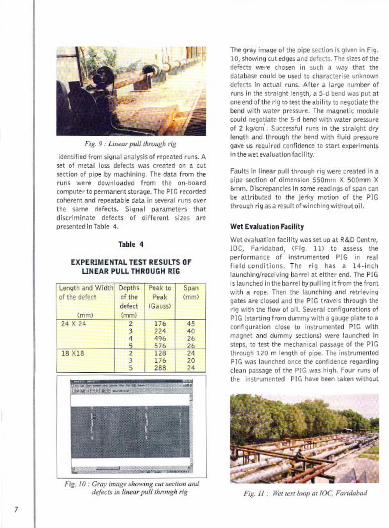
Fig. 9.. Linear pull through rig
identified from signal analysis of repeated runs.Aset of metal loss defects was created on a cutsection of by machining. The data from theruns were from the on-boardcomputerto permanentstorage. The PIG recordedcoherent and repeatable data in several runs averthe same defects. Signal parameters thatdiscriminate defects of different sizes arepresented in Table 4.
Table 4
EXPERIMENTAL TEST RESULTS OFLINEAR PULL THROUGH RIG
The gray image of the pipe section is given in Fig.10,shawing cut edgesand defects. Thesizesof thedefects were chosen in such a way that thedatabase could be used to characterise unknown
defects in actual runs. After a large number ofruns in the straight length, a 5-d bend was put atone endofthe rig to test the abilityto negotiate thebend with water The magnetic modulecould 5-d bend with water pressureof2 .Successful runs in the straight drylength and through the bend with fluid pressuregave us required confidence to start experimentsin the wet evaluation facility.
Faults in linear through rig were created in apipe section 550mm X 500mm X6mm. Discrepancies in some readings of span canbe attributed to the jerky motion of the PIGthrough rig asa result of winching without oil.
Wet Evaluation Facility
Wetevaluationfacility was set up at R&D Centre,lOC, IFig. III to assess theperformance instrumented PIG in realfield conditions. The rig has a 14-inchlaunching/receiving barrel at either end. The PIGis launched in the barrel bypulling itfromthefrontwith a rope. Then the launching and retrievinggates are closed and the PIG travels through therig with the flow of oil. Several configurations ofPIG (starting from dummy with a gauge plate to aconfiguration close to instrumented PIG withmagnet and dummy sections) were launched insteps, to test the passage of the PIGthrough 120 m length The instrumentedPIGwas launched once confidence regardingclean passage of the PIG was high. Four runs ofthe instrumented PIG have been taken without
Fig. 11.. Wettest/Gap atIDC, Faridabad
Length and Width Depths
Peak ta I Spanaf the defect of the Peak (mm
defect (Gauss)
(mm) (mm)24 X 24 2 176 45
3 224 404 496 265 576 26
18 XIS I 2 128 243 176 205 288 24
created defects on any pipe section, including the
first run on December 2, 1998. The runs haveensured that all the sections of the PIG negotiate
6-d mitred bends and pass through girth weld
joints, flange joints, barred tees and a motor-
operated valve IMOV) without any damage to
components. The pressure sealing of vessels andelectrical connectors were also tested in these runs
and were found to be all right.
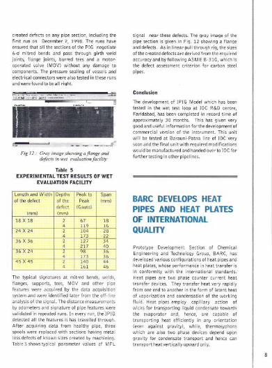
Fig 12.. Gray image showing ajlange and
dejectsin wet evalaanon/aeility
Table 5EXPERIMENTAL TE5T RE5ULTS OF WET
EVALUATION FACIUTY
The typical signatures at mitred welds,flanges, supports, MOV and pipefeatures were the data acquisitionsystem and were from the off-lineanalysis of the signal. The distance measurementsby odometers and signature of pipe features werevalidated in repeated runs. In every run, the IPIGdetected all the features it has travelled through.After acquiring data from pipe, threespools were replaced with sections metalloss defects of known sizes created by machining.Table 5 showstypical parameter values of MFL
signal near these defects. The gray image of the
pipe section is given in Fig. 12 showing a flange
and defects. Asin linear pull through rig, the sizes
ofthe created defects are derived from the required
accuracy and by following ASM E B-31G, which isthe defect assessment criterion for carbon steel
pipes.
Conclusion
The development of IPIG Model which has been
tested in the wet test loop at JOC R&D centre,
Faridabad, has been completed in record time of
approximately 30 months. This has given very
good and useful information forthe development ofcommercial version of the instrument. This unit
will be tested at Barauni-Patna line of JOC very
soon and the final unit with required modificationswould be manufactured and handed overto JOC for
furthertesting in otherpipelines.
BARC DEVELOPSHEATPIPES AND HEAT PLATESOF INTERNATIONAlQUALITY
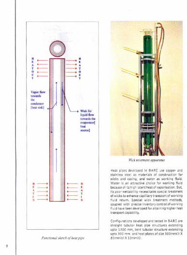
Prototype Development Section of ChemicalEngineering and Technology Group, BARC, hasdevelopedvarious configurations of heat pipes andheat plates, whose in heat transfer isin conformity the international standards.Heat pipes are two phase counter current heattransfer devices. They transfer heat very rapidlyfrom one end to another in the form of latent heatof vaporization and condensation of the workingfluid. Heat pipes employ capillary action ofwicks for transporting liquid condensatetowardsthe evaporator and, hence, are capable oftransporting heat efficiently in any orientation(even against gravity), while, thermosyphonswhich are also two phase devices depend upongravity for condensate transport and hence cantransport heat vertically upward only.
Length and Width Depths Peak to Spanof the defect of the Peak (mm)
defect (Gauss)Imm) Imm)
18 X 18 2 67 184 119 16
24 X 24 2 104 284 173 22
36 X 36 2 127 344 217 40
36 X 24 2 98 364 173 36
45 X 45 2 140 444 161 46
: ...-.-A ...-.-T ...-.-0 ...-.-U ...-.-T
V.portlowtowardsthe00-[heatsink)
H >. >~ >I >N >~.,
>:> A> T> 0> UT
Wlckfol"liquidftowtoward,theevaporator[heatsource]
~1
''"
H.~IN
Functional sketch of heat pipe
"""~!!!i
w,ck treatment apparatus
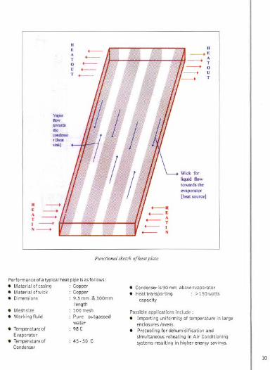
Heat pipes developed in BARC use copper andstainless steel as materials of construction forwicks and casing, and water as working fluid.Water is an attractive choice for working fluidbecauseof its high latent heat of vaporisation. But,its poor wettabllity necessitatesspecial treatmentof wicks to enhancecapillary transport ofworkingfluid return. Special wick treatment methods,coupled with precise inventory control ofworkingfluid havebeendevelopedfor attaining higher heattransport capability.
Configurations developed and tested In BARC arestraight tubular heat pipe structures extendingupto 1300 mm, bent tubular structure extendingupto 300 mm and heat plates of size 300mm(l) X80mmlb) X 10mml!l.
y"""now-the""""",,,rlh...s""']
R -->E -->~ -->1-->N-->
Wick forliquidnowtowardstheev'porator[heat source]
Functional sketch o(heat plate
Performance of atypical heat pipe Isasfollows:. Materlalolcaslng: Copper. Materialofwick : Copper.Dimensions : 9.5 mm.& 300mm
length: 100 mesh: Pure outgassed
water: 98 C
. Meshslze
. Workingfluid
. TemperatureofEvaporator
. Temperature01Condenser
: 45- 50 C
. CondenserIsgOmmaboveevaporator. Heattransportlng : >150watts
capacity
. Precoolingfor dehumidificationandsimultaneousreheatingInAir ConditioningsystemsresultingInhigherenergysavings.
10

Heat pipelplate canstruc/ion camponen/.'. High efficiency heat sinks in electrical
industry.
. Waste heat recovery systems.
. Passivecooling system for decay heat
removal from radioactive waste solution
and vitrified waste cannisters.
. Concentration of nuclear waste solution.
. Solar heat collection and transport systems.
. Diffusion of hot spots in chemical and
electricalindustries.
. Eliminationof thermalstressesin pipe
joints.
. Thermalcontrolofsatellites.
Special properties of heat pipes which make
them an attractive choice for aforesaid
applications are:
. Thereisnomotivepowerrequiredinformof
pumps ete. to increase turbulence as in
case of conventional Heat Exchangers.
11
. Abilitytotransportlargeamountofheatat
low temperature differences.
. Temperature gradient along heat pipe
surface is negligible.
. Heatpipes/platesaremaintenancefreefor
manydecades.. Workingfluid of heatpipedoesnotcomein
directphysicalcontactwiththesourceor
sink fluids.
. Heatpipesaresignificantlylightweight.
. Highheattransfercapacitypreventsanyhot
spots/zones.
. It canbemadeusingdifferentcombination
of working fluid, wick and pipe materials as
well as in different shapesaccording to the
application requirements.
. Responseisveryfast.
. Highaxialheatflux impartscapabilityto
removelargeamountofheatfromsmall
aperture/openings.
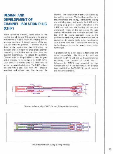
DESIGNANDDEVElOPMENTOFCHANNELISOLATIONPLUG(CHIP)
While operating PHWRs, leaks occur in thesealing face of the end fitting where the sealingplug normally helpsto retain the integrity of PHTpressure boundary. Although lapping of the sealface can solve the problem, it involves shuttingdown of the reactor and then de-fuelling, iceplugging and draining of the problematic channel,consuming considerable reactor down time andmanrem expenditure. To reduce this problem,Channel Isolation Plug (CHIP) has beendesignedand developed. Inthedesignofthe.CHI~safetylatch similar to normal plug has been used toprevent accidental unlatching. The CHIP isolatesthe end fitting seal face from PHT pressureboundary and allows free flow through the
channel. The installation of the CHIP is done bythe fuelling machine. The fuelling machine visitsthe problematic end fitting, removes the sealingand shielding plugs, and installs the CHIP in theshielding plug groove. After installation of theCHIP and leak test, the fuelling machine getsunclamped. Some of the components like rarecasing and fasteners are manually removed fromthe CHIP to create approach route to theproblematic seal face, where maintenance can becarried out by special tools. After maintenancework is over, the CHIP is normalised, removed bythe fuelling machine and the coolant channel is alsonormalised.
A prototype of the CHIP has been fabricated andtested successfully. The first of its kind wasdelivered to NAPS and was used successfully for
j-O4 channel of NAPS Unit-I.
MAPS has requested for twoPtosuittheirreactor.Theplughas
been modified for RAPS/MAPS type of reactorsanddeliveredtothesite.
Channel isolation plug (CHIP)fo, endfitting seolfoce lopping
The component reor casing is being removed
12

Endfitting sealface is opened and ready far lapping
DevelopmentofChannel Isolation Plugwill greatlyhelp in maintaining the problematic leaky seal faceof end fitting without draining, drying andisolation of the channel. Italsomakespossibleto
quickly lap the seal face. This kind of plug isrequired by all the operating PHWRs. (Ref. BARCReport No. BARC/1998/II16).
WORLD ENVIRONMENTDAY CELEBRATED
Dr Ani! Kakodkar Director BARC. planting atree sapling
Onthe eveof the World Environment DayonJune4, 1999, Landscape and Cosmetic MaintenanceSection, BARC, a programme ofplanting trees as as the inauguration ofPolyhousesand Shadenet houseswhich were builtinhouse at the Nursery of BARC. The polyhousesand shade net houses, where roses, gerberas andindoor plants are grown,were inaugurated by DrAnil Kakodkar, Director, BARC. Tree saplings ofPolyalthia longifolia (Asupala) were also planted
13
by Dr Anil Kakodkar, Mr S. Narendra, PrincipalAdvisor, Planning Commission, New Delhi, DrU. C. Mishra, Director, Health, Safety &Environment Group, BARC, Mr R. Ganesan,Controller, BARC, and other senior officers ofBARC.
[nterior view of the Polyhouse. showingcultivation of ro.<es and gerberas
Thepolyhouse/shadenethouseis the latest conceptin rearing plants and growing flowers,which notonly provides conducive environment for plants butalso gives a good working atmosphere during allthe seasonsof the year for the staff. Thequalityof

flowers/plants grown in a polyhouse is better andthe yield is also 5 or6 times that in field condition.Four small polyhouse/shadenet houses wereerected in the Nursery recently by using re-cycledand re-usedmaterials available in Trombay.
The greenery preserved and created in Trombay isserving as green lung to the suburbs of Mumbai.BARC is highly conscious about the environmentand its protection right from Its inception by itsfounder, Dr Homi J. Bhabha.
GOLDENPEACOCKENVIRONMENTMANAGEMENTAWARDPRESENTEDTO RAPS
Consequentto the efforts put in by EnvironmentSurvey and Micrometeorological Laboratories(ESMLI of Health Physics Division, BARC, inmonitoring the radiation doses received by themembers of public from Rajasthan Atomic PowerStation (RAPS) and continuously datato RAPS about the radiation in the
environment, the latter was adjudged as theRunner Up for exemplary achievement in the fieldof Environment Management and received theGolden Peacock Environment Award 1999 onJune 5, the World Environment Day. The awardwas presented by Mr Suresh P. Prabhu,Honourable Minister of Environment and Forest,Govt. of India, during the World Conference onEnvironment Management 1999 at New Delhi.The award, instituted by World Environment
is distributed to large, medium andsmall industries for excellence Inenvironment management. This award has beenconferred on Nuclear Industry for the first timeand RAPS, the oldest Indian Pressurised HeavyWater Reactor (PHWR) is the proud recipient ofthe award. .The environment surveillance around RAPS is
conducted by ESML. The primary objective ofenvironmental monitoring is to assess the
radiation dosesreceived by the members of publicdue to RAPS operations and to demonstratecompliance with the dose limits set by AtomicEnergy Regulatory Board (AERB). Themonitoring programme is being continued byESML since 1973 to assess the radiologicalimpact of RAPS operations on the localenvironment.
The radiation doseto the members of public due tothe releasesfrom the station is evaluated onannualbasis. Annually about 4000 samples ofatmospheric, terrestrial and acquatlc origin wereprocessed to evaluate the radiation doses to themembers of public at different distances.
The contribution of radiation dose due to RAPS
releases during the past three decades is observedto bevery small. The computation of the dosesdueto intake of radionuclidesbythe population aroundtheplantupto 30 km is doneby measurementofconcentrations of radionuclide in air, ~vegetables,cereals,milk,meat,fish,egg,etc.data collected on environmental surveillance
reveals that in any of the years since 1973, thetotal dose to the members of the public at RAPSfence post 11.6 kmlwas lessthan 10% of the limitof 1mSv setbyICRP/AERBforthepublic.
Furthermore, RAPS 2 had undergone thechallenging task of en-mass coolant channel
1996-98.may be said as heart transplantation thepower reactor which is unprecedented in the Indian
first time in our counry. The task was completedsuccessfully in a safe and economic manner andwell before the time schedule. Theen-masscoolant
channel composed ofremoval safe disposal the exposed coolanttubes and their replacement with fresh ones.Although tremendous amount of radioactivity washandled during the process,the radiation
were observed to be well below the prescribedlimits. This was achieved by good housekeeping andat each step. education/ awareness andtraining about radiation protection also helped inreducing the environmental discharges.The award to RAPS this year isa tribute to theeco-friendliness"four nuclear installations.
14

WORKSHOPON SAFETYOF RADIATIONSOURCESAND SECURITYOFRADIOACTIVEMATERIALS
A workshop on Safety of RadiationSources andSecurity of Radioactive Materials was jointlyorganised by the Radiological Physics andAdvisory Division, BARC and Atomic EnergyRegulatory Board at Mumbai during April 14-15,1999. from scientists of BARC, DAE andAERB, participants were from variousorganizations allover India representing theCentral and State Governments such as Airport
Port Trusts of Intelligenceand Customs, Secority
In his welcome address, Dr U.C. Mishra,Safety and EnvironmentJut the importance among
various Government units handling the
problems arising out of threat to security ofsources. The workshop was inaugurated by Prof.P Rama Rao, who describedspecific loss ofsources. Mr PN.Central Board of
a!the in
nature the problem. The inauguration was
followed by Technicalsessions spread over twodays which included a total of fifteen lecturesapart from a demonstration.The workshop included discussions whichhighlighted the specific areas of each ofthe handling agencies. Several questions ahoutradiological hazards were answered during theworkshop. Participants expressed that unfoundedfear for radiation was removed in the discussions
during the workshop. Further, the responsibilitiesof the various agencies were clearlydelineated. All expressedsatisfaction over the and utility of the
workshop as it identified the role of each
the safety of sources and security of radioactivematerial. Some desired that such workshopsshould be conducted periodically to refresh andupdate the participants on the developments. It
15
was unanimously agreed that the outcome of the
would be a training programme whichfor the various personnel
WORLD NUCLEARSTATUSIN 1998
A total of434 nuclear power plants were operatingaround the world in based on data reportedto the International Energy Agency(]AEA) Power Reactor Information I
(PRISt. During 1998, four nuclear powerrepresenting 2958 MW(e) net electric
in the R.
I<orea and one in Slovak Republic.Additionally, construction of four new nuclearreactors started in 1998 twoinChinalplusoneinTaiwan, China) and one in Japan, bringing the totalnumber of nuclear reactors reported as beingundereonstruction to 36.
The countries with more than 40% reliance onnuclear power in 1998 were: Lithuania, 77.2%;France, 75.8%; Sweden, 45.8%;Ukraine, 45.4%; 5 lovak 43.8%;
41.5%; Republic of I<orea, 41.4% and
1d,41.1%. Intotal,18countriesreliedupon nuclear power plants to supply at least aquarter oftheirtotal electricity needs.
A table showing by nuclear
power reactors in 1998 respectivepercentage of electricity produced by nuclearenergy is given overleaf.

ti
1;,-II"'~
it'~i'(,
~I
j
11Ii
tfIi
IJ".,I-.IiI"1',
IIt
f'fi\..;
o,'Ii
ft,I}.'I1-'(,
1:i'.
;Ii
I
16
Reactors
under construction
No. of I TotalUnits MWCe)
935
I I
692 6.93376 1.42
5712 43.89626 1 1229 3.27
6 353814 9998
3 2167 I 6 I 42204 1648 2 1824
4 265658 61653 I 1 I 145020 222 82
4 1729
10 1695 4 808 10.152 2111
53 43691 2 1863 306.941 70 0.09
15 12340 3 2550 85.192 2370 12.29
2 1308 8.831 449 3.59
1 125 1 3001 650 1 650
29 19843 4 3375
2 1842
5 2020 3 1164 11.391 632 4.79
9 7377 56.68
12 10040 70.00
5 3079 24.37
35 12968 91.1416 13765 4 3800 70.64 45.42
104 96423 673.70 18.69
434 348891 36 27536 2291.41
'operation and 1 unit under con,truction in Taiwan, China.
PubU$h.d by DrViiai Kumar, Head, Library & Information Services Division, Bhabba
re, T\'ombay, Mumbai 400085.
, T,C. Balan; Computer graphics & layout, RA,S. Warriyar.