50i18 ijaet0118706 v6 iss6 2745 2757
TRANSCRIPT
International Journal of Advances in Engineering & Technology, Jan. 2014.
©IJAET ISSN: 22311963
2745 Vol. 6, Issue 6, pp. 2745-2757
CHARACTERIZATION AND ANALYSIS OF WEAR STUDY ON
SISAL FIBRE REINFORCEMENT EPOXY COMPOSITE
MATERIALS USED AS ORTHOPAEDIC IMPLANT
K R Dinesh1, Jagadish S P2, A Thimmanagouda3 1Principal and Professor
Department of Mechanical Engineering, Government Engineering College, Raichur, India 2Assistant Professor, Research Scholar-VTU
Department of Mechanical Engineering,
Rao Bahadur Y Mahabaleswarappa Engg. College, Bellary, India 3Professor and Head
Department of Industrial Production Engineering,
Rao Bahadur Y Mahabaleswarappa Engg. College, Bellary, India
ABSTRACT This paper constitutes the wear study of 10%,20% and 30% Natural (Sisal) fibre reinforcement epoxy composite
materials used as bio-material. An attempt has been made to develop 10%, 20% and 30% sisal fibre
reinforcement epoxy composite materials with low density and economical, according to ASTM G-99 using
resin -LY556 as a matrix material and hardener -HY 951 with 10%, 20% and 30% Sisal fibres as the
reinforcement material (with fiber weight fraction) using hand layup fabrication technique. The wear tests were
conducted on the varying percentage standard samples prepared. It is found that appreciable improvements in
tribological properties of the 30% natural (sisal) fibres reinforced epoxy composites (SFRECM) when
compared with 10 % and 20% SFRECM. This study suggests 30% SFRECM can be used for different
applications in the human body bone replacement or orthopaedic implant.
KEYWORDS— Hand layup Fabrication Technique, Wear Resistance, Bio-Material, 10%, 20% and 30%
Sisal fibre Reinforcement epoxy Composite Materials (SFRECM), Orthopaedic applications.
I. INTRODUCTION
The Bone, which is a natural composite material, consists mainly of collagen fibers and an inorganic
bone mineral matrix in the form of small crystal called apatite. Collagen is the main fibrous protein,
the composite of mineral component in the body. Cartilage is a collagen based tissue which contains
large protein saccharit molecules that form a gel in which collagen fibrous are bonded [1].No health
risk of Sisal fibre [2], Utilization of Sisal in orthopaedics [14], natural fibres represent an
environmentally friendly alternative by virtue of several attractive attributes that include lower
density, lower cost, non-toxicity, ease of processing, renewability and recyclability [15-17],
Biocomposite materials based on biopolymers and natural fibers used as bone implants[8].Much of
natural product obtained from plants having own medicinal values such as biologically active
phytochemicals are normally present in leaves, roots, barks and flowers [18] and there are number of
medicinal plants which possess anti fertility property [19]. Nanocomposites have its own importance
such as ZnO is an ecofriendly material and non toxic for human bodies and also used in biomedical
applications [20]. Hybrid Polymer Matrix Composites are used for Biomedical Applications [24]. It is
International Journal of Advances in Engineering & Technology, Jan. 2014.
©IJAET ISSN: 22311963
2746 Vol. 6, Issue 6, pp. 2745-2757
found that red mud particulates results in improvement of erosion wear resistance of both the bamboo
and glass fiber composites [25].
A Bio-material is defined as any systemically, pharmacologically inert substance or combination of
substances utilized for implantation within or incorporation with a living system to supplement or
replace functions of living tissues or organs. Biomaterial devices used in orthopedics are commonly
called implants; these are manufactured for a great number of orthopaedic applications [12]. Wear
behaviour due to the presence of both particulate fillers and the reinforcing fibers[22]. The field of
corrosion in biological systems is young and fertile as man knows only little about his physiology and
its interactions with the foreign body is much more complicated and hence the mission will continue
[26].Finally current used orthopaedic implants have the tendencies to fail after long period of usage,
due to the corrosion issue of implant in the human body[23],
The main fundamental requirements that orthopedic devices must fulfill in order to function
adequately are summarized as follows.
Biocompatibility.
Appropriate Design and Manufacturability of Implants, Mechanical and Biological Stabilities.
Corrosion Resistance.
Resistance to Implant Wear and Aseptic Loosening.
Properties of Biomaterials. [3]
Requirements of Biomaterials [4]
The following are the requirements of a Biomaterial:
It must be inert or specifically interactive.
It must be Biocompatible.
Mechanically and chemically stable.
Biodegradable.
Processable (for manufacturability): It must be machinable, moldable, and extrudable.
Nonthrombogenic (if blood contracting).
Sterilizable.
Non-carcinogenic, non-pyrogenic, non-toxic, non-allergenic, blood compatible, non-
inflammatory.
Physical Characteristics Requirements: Strength, Toughness, Elasticity, Corrosion-resistance,
Wear resistance, Long term stability.
Ways in Which Materials Can Fail [5]
1. Corrosion
2. Fatigue
3. Wear [21]
Corrosion: Gradual degradation of material by electro-chemical attack, when placed in the
electrolytic environment of the body.
Corrosion can be minimized by,
Choosing a corrosion resistant material
Treating the surface with a passivating layer prior to use
Not using combinations of metals in close proximity.
Careful operating technique to reduce surface scratching.
Using non modular implants.
Fatigue: Progressive failure of a material due to the application of cyclical stresses below the
ultimate stress of the material is causing crack propagation. Stress concentrator or stress riser e.g.
a scratch, a hole, a corner or a change in cross section or where fretting is occurring. At these
places stress is greater than the average stress in the material.
Wear : The removal of material from solid surfaces by mechanical action[6].
Effects of wear: Most predominant in joint prostheses. Joint wears out but prior to this, the
particles produced by wear (metal or polyethylene or cement particles) are phagocytosed by
osteoclasts causing osteolysis and therefore loosening of components.
The goals of the present study are:
1. To produce the composite materials of different compositions
International Journal of Advances in Engineering & Technology, Jan. 2014.
©IJAET ISSN: 22311963
2747 Vol. 6, Issue 6, pp. 2745-2757
2. To report wear analysis.
3. To study wear properties of biomaterials.
4. To compare results of wear with different compositions of composite material.
The paper is organized as follows. In section 1, Introduction of biomaterials and requirements are
listed. In section 2, the method of preparation of composite materials is explained. In section 3,
gives the detail of wear study of experimental process. In section 4 Results of experimental
process for different specimen are tabulated. In section 5, conclusions and future scope of paper
are listed.
II. FABRICATION METHOD AND PREPARATION OF SISAL FIBRE
REINFORCED EPOXY COMPOSITE
2.1 methodology
Each layer of fabric was pre-impregnated with matrix material which is prepared by mixing general
purpose (polyester) Epoxy resin (LY556), accelerator and catalyst in the weight ratio of 1:0.02:0.026
respectively and these layers were placed one over the other in the mould with care to maintain
practically achieved tolerance on fabric alignment. Casting was cured under light pressure for 2 hours
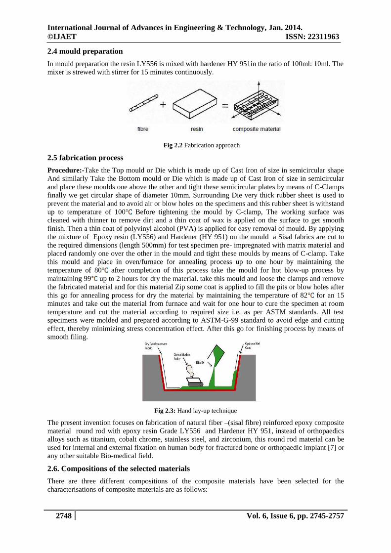
before removal from the mould.Hand lay-up technique is used [09, 10,11,13] to prepare specimen as
shown in Fig.1.
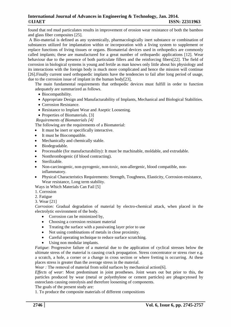
2.2 natural fibre preparation
Here continuous fibre is used for fabricate the natural fibre composites. First the natural fibres are
cleaned in the distilled water. The cleaned natural fibres are dried in the sun light. The dried natural
fibres are again cleaned by chemical cleaning process. In chemical cleaning process the 80% sodium
hydroxide is mixed with 20% distilled water. The dried natural fibres dipped in the diluted sodium
hydroxide solution. Its again dried in sun light .The dried natural fibres are cut in the length of 500mm
by manually. The cut natural fibres are used in fabricate the natural(Sisal)fibre reinforced epoxy
composite material (SFRECM).
Fig 2.1 Sisal Fibre
Materials Used for Fabrication Work:- Natural fiber-(sisal fibre), Epoxy resin LY556 and Hardener
HY 951.
2.3 requirements for fabricate natural fibre composites
Epoxy resin
Hardener
Natural Fibre
Sodium Hydroxide (NaOH)
Weighing Machine
Roller
Bowl
Stirrer
Oven or Furnace to dry the specimen
International Journal of Advances in Engineering & Technology, Jan. 2014.
©IJAET ISSN: 22311963
2748 Vol. 6, Issue 6, pp. 2745-2757
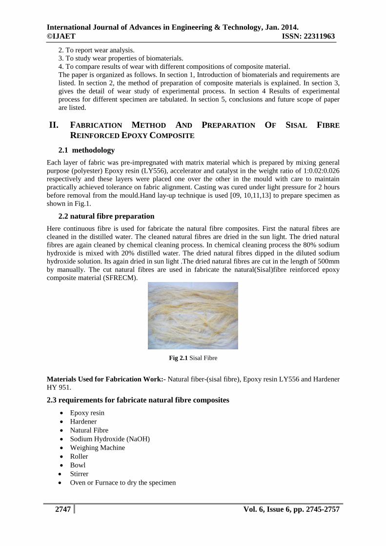
2.4 mould preparation
In mould preparation the resin LY556 is mixed with hardener HY 951in the ratio of 100ml: 10ml. The
mixer is strewed with stirrer for 15 minutes continuously.
Fig 2.2 Fabrication approach
2.5 fabrication process
Procedure:-Take the Top mould or Die which is made up of Cast Iron of size in semicircular shape
And similarly Take the Bottom mould or Die which is made up of Cast Iron of size in semicircular
and place these moulds one above the other and tight these semicircular plates by means of C-Clamps
finally we get circular shape of diameter 10mm. Surrounding Die very thick rubber sheet is used to
prevent the material and to avoid air or blow holes on the specimens and this rubber sheet is withstand
up to temperature of 100 Before tightening the mould by C-clamp, The working surface was
cleaned with thinner to remove dirt and a thin coat of wax is applied on the surface to get smooth
finish. Then a thin coat of polyvinyl alcohol (PVA) is applied for easy removal of mould. By applying
the mixture of Epoxy resin (LY556) and Hardener (HY 951) on the mould a Sisal fabrics are cut to
the required dimensions (length 500mm) for test specimen pre- impregnated with matrix material and
placed randomly one over the other in the mould and tight these moulds by means of C-clamp. Take
this mould and place in oven/furnace for annealing process up to one hour by maintaining the
temperature of 80 after completion of this process take the mould for hot blow-up process by
maintaining 99 up to 2 hours for dry the material. take this mould and loose the clamps and remove
the fabricated material and for this material Zip some coat is applied to fill the pits or blow holes after
this go for annealing process for dry the material by maintaining the temperature of 82 for an 15
minutes and take out the material from furnace and wait for one hour to cure the specimen at room
temperature and cut the material according to required size i.e. as per ASTM standards. All test
specimens were molded and prepared according to ASTM-G-99 standard to avoid edge and cutting
effect, thereby minimizing stress concentration effect. After this go for finishing process by means of
smooth filing.
Fig 2.3: Hand lay-up technique
The present invention focuses on fabrication of natural fiber –(sisal fibre) reinforced epoxy composite
material round rod with epoxy resin Grade LY556 and Hardener HY 951, instead of orthopaedics
alloys such as titanium, cobalt chrome, stainless steel, and zirconium, this round rod material can be
used for internal and external fixation on human body for fractured bone or orthopaedic implant [7] or
any other suitable Bio-medical field.
2.6. Compositions of the selected materials
There are three different compositions of the composite materials have been selected for the
characterisations of composite materials are as follows:
International Journal of Advances in Engineering & Technology, Jan. 2014.
©IJAET ISSN: 22311963
2749 Vol. 6, Issue 6, pp. 2745-2757
Composition:- Proportion (Fibre weight Fraction) of Sisal Fibre 1) 10% Sisal Fibre + 80% Resin
+10% Hardener. Similarly take & Weight the 10%,20%,30% sisal fibre by means of Electronic
Weighing machine for Fabrication work. (Proportion of resin, accelerator and catalyst in the weight
ratio of 1:0.02:0.026) The resin and hardener were taken in the ratio of 10: 1 parts by weight,
respectively. Then, a pre-calculated amount of hardener was mixed with the epoxy resin and stirred
for 20 minutes before pouring into the mold.
Table 2.1 Shows the Different Composition used to prepare of the specimen
Sl
no
% of Sisal
fibre used
to prepare
the
specimens
Mass of Sisal Fibre used for
fabrication work
(in Grams)
(length of specimen=500mm)
Mass of
Epoxy(Resin -
LY556) used
for fabrication
work
Mass of
Hardner- HY
951used for
fabrication
work
Mass of the
specimen(gm)
after
curing(Under
dry condition)
01 10% 15gms 100 gm 10gms 58gms
02 20% 15x1+(15x10/100)=16.5gms 80gm 8 gm 56gms
03 30% 16.5x1+(16.5x10/100)=18.15gms 70 gm 7 gm 54gms
Cut the Wear test specimens of length=30mm,of Dia=10mm as per ASTM standard G-99 of
10%,20%,30% Sisal fibre[9] Reinforcement epoxy Composite Materials.
In this present work we have taken Four specimens of 10%,20%,30% Sisal fibre Reinforcement
epoxy Composite Materials. Wear (Micrometers),Co-eff. Of friction, Frictional force (N), Weight loss
of the specimen.
a) 10% Sisal fibre Reinforcement epoxy Composite Materials (SFRECM)-04 specimens.
b) 20% Sisal fibre Reinforcement epoxy Composite Materials (SFRECM)-04 specimens.
c) 30% Sisal fibre Reinforcement epoxy Composite Materials (SFRECM)-04 specimens.
III. EXPERIMENTAL PROCESS
Wear test: Wear Test: Pin-On-Disc Wear Testing- This test method covers a laboratory procedure for
determining the wear of materials during sliding using a pin-on-disk apparatus and is issued under the
standard ASTM G 99. For the pin-on-disk wear test conducted in this research, the specimens were a
pin with a rounded tip, which is positioned perpendicular to a flat circular disk (the test sample). A
ball, rigidly held, is often used as the pin. The test machine causes either the disk specimen or the pin
to revolve about the disk centre. The sliding path is a circle on the sample surface. The pin is pressed
against the disk at a specified load usually by means of an arm or lever and attached weights.
Data Acquisition: The friction coefficient signal is displayed in real time on a PC Screen. Data can
be viewed as it is logged for the entire specified test duration, which can be recalled later for detailed
analysis. The software allows 4 different logged test files for on-line analysis / mapping. The software
displays the test time, turn count, linear velocity, and user-defined test parameters. This data can be
stored and printed along with the friction traces.
Purpose: Records friction and wear in sliding contact in dry, lubricated, controlled environment and
partial vacuum.
Application: Fundamental wear studies. Wear mapping and PV diagrams. Friction and wear testing
of metals, ceramics, soft and hard coatings, plastics, polymers and composites, lubricants, cutting
fluids, heat processed samples.
Wear test specimens as per ASTM standard G-99 ( Dia=10mm,Length=30mm) of 10%,20%,30%
Sisal fibre Reinforcement epoxy Composite Materials.
The objective is to study the friction and wear behaviour of 10% SFRECM (Sisal fibre Re-
inforcement epoxy Composite Material) 4 (four) Specimens, Similarly for 20%,30% SFRECM in
Wear and Friction Monitor TR-20LC
Table3.1. Test rig parameters
Sl.No Description Details
1 Speed Min 200 rpm, max 2000 rpm
International Journal of Advances in Engineering & Technology, Jan. 2014.
©IJAET ISSN: 22311963
2750 Vol. 6, Issue 6, pp. 2745-2757
2 Normal load 200N max
3 Frictional force 200N max
4 Wear ± 2mm
5 Wear track diameter Min 50mm, max 100mm
6 Sliding speed Min 0.3m/sec, max 10m/sec
7 Preset timer 99/59/59 hr/min/sec
8 Specification size (pin) Ø3,4,5,6,8,10 & 12mm
9 Wear disc size Dia 165mm x 8mm thick, EN-31 hardened to
60HRc, ground to surface roughness 1.6Ra.
10 Environmental chamber This chamber prevents oil spillage and collects
debris after test
11 Software Winducom 2010
12 Software Interface Comport
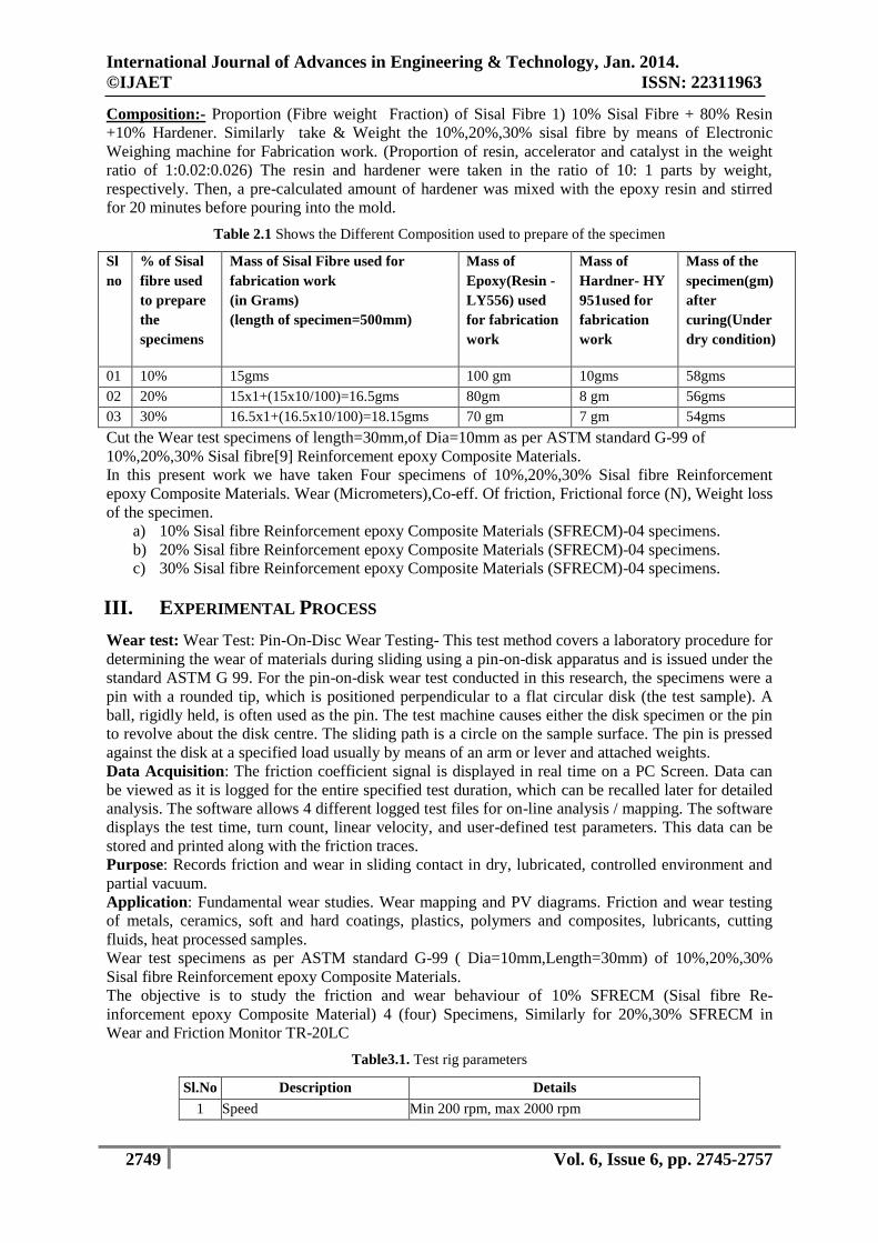
Table 3.2 Tabulated results with Pin on Disc apparatus
Specimen Diameter 10mm
Materials Image Load(N) Wear(Micrometers) Co-eff. Of
friction
Frictional
force (N)
Time
(sec)
10%
SFREC
20 6 0.343 7 1800
40 32 0.375 15.5 1800
60 68 0.59 35 1800
80 120 0.48 37 1800
20%
SFREC
20 50 0.8 16 1800
40 280 0.75 29 1800
60 90 0.76 45 1800
80 650 0.725 58 1800
30%
SFREC
20 95 0.72 14.2 1800
40 450 0.8 32 1800
60 138 0.97 55 1800
80 230 0.73 58
1800
IV. RESULTS AND DISCUSSIONS
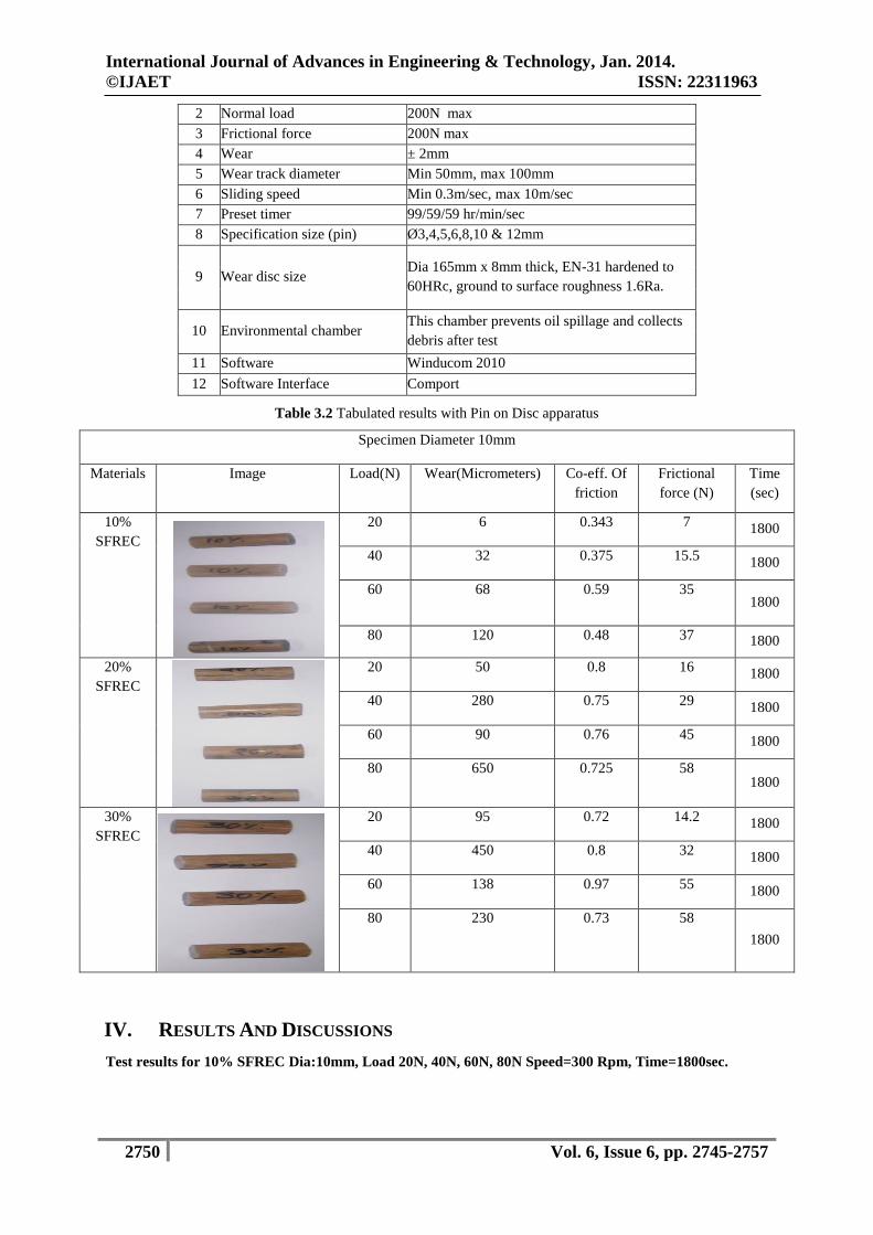
Test results for 10% SFREC Dia:10mm, Load 20N, 40N, 60N, 80N Speed=300 Rpm, Time=1800sec.
International Journal of Advances in Engineering & Technology, Jan. 2014.
©IJAET ISSN: 22311963
2751 Vol. 6, Issue 6, pp. 2745-2757
Test results for 20% SFREC Dia:10mm, Load 20N, 40N, 60N, 80N, Speed=300 Rpm, samples/min=60
,Time=1800sec
Graph 1.5 wear, coefficient of friction, frictional force of 20% SFREC Dia10mm.For load=20N
Graph 1.6 wear, coefficient of friction
, frictional force of 20% SFREC Dia10mm.For load=40N
Graph 1.3 wear, coefficient of friction, frictional force of 10%
SFREC Dia10mm.For load=60N
Graph 1.4 wear, coefficient of friction, frictional force of 10%
SFREC Dia10mm.For load=80N
Graph 1.1 wear, coefficient of friction, frictional force of 10%
SFREC Dia10mm.For load=20N
Graph 1.2 wear, coefficient of friction,
frictional force of 10% SFREC Dia10mm.For load=40N
International Journal of Advances in Engineering & Technology, Jan. 2014.
©IJAET ISSN: 22311963
2752 Vol. 6, Issue 6, pp. 2745-2757
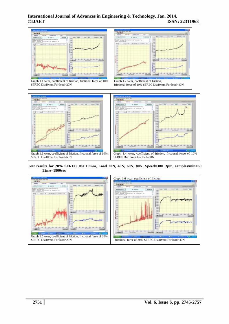
Graph 1.9 wear, coefficient of friction, frictional force of 30%
SFREC Dia10mm.For load=20N
Graph 2.0 wear, coefficient of friction, frictional force of 30%
SFREC Dia10mm.For load=40N
Graph 2.1 wear, coefficient of friction, frictional force of 30%
SFREC Dia10mm.For load=60N
Graph 2.2 wear, coefficient of friction, frictional force of 30% SFREC Dia10mm.For load=80N
Graph 1.7 wear, coefficient of friction, frictional force of 20% SFREC Dia10mm.For load=60N
Graph 1.8 wear, coefficient of friction, frictional force of 20% SFREC Dia10mm.For load=80N
International Journal of Advances in Engineering & Technology, Jan. 2014.
©IJAET ISSN: 22311963
2753 Vol. 6, Issue 6, pp. 2745-2757
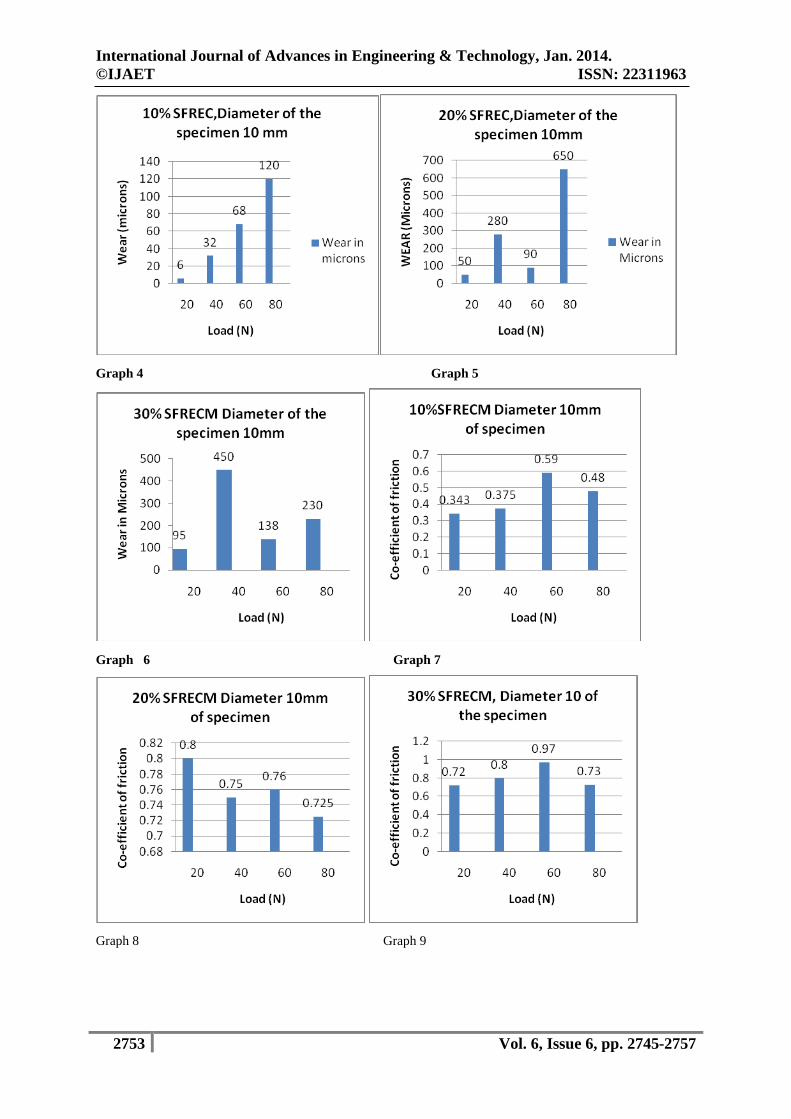
Graph 4 Graph 5
Graph 6 Graph 7
Graph 8 Graph 9
International Journal of Advances in Engineering & Technology, Jan. 2014.
©IJAET ISSN: 22311963
2754 Vol. 6, Issue 6, pp. 2745-2757
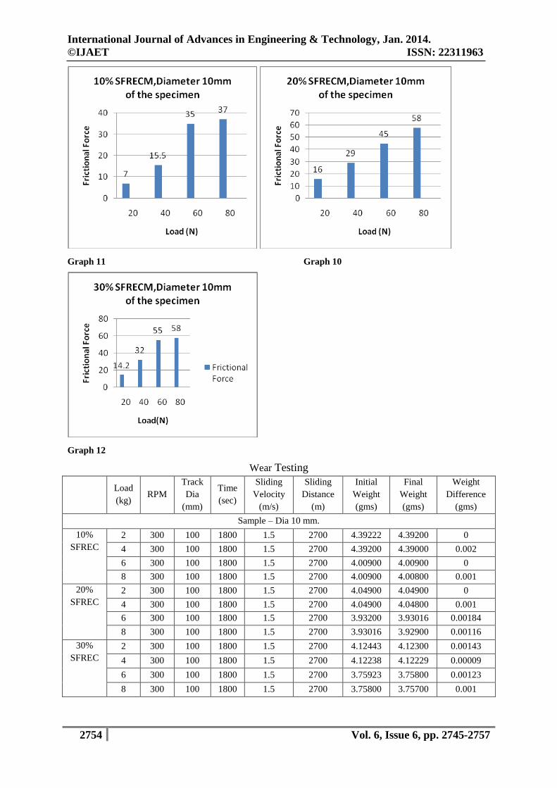
Graph 11 Graph 10
Graph 12
Wear Testing
Load
(kg) RPM
Track
Dia
(mm)
Time
(sec)
Sliding
Velocity
(m/s)
Sliding
Distance
(m)
Initial
Weight
(gms)
Final
Weight
(gms)
Weight
Difference
(gms)
Sample – Dia 10 mm.
10%
SFREC
2 300 100 1800 1.5 2700 4.39222 4.39200 0
4 300 100 1800 1.5 2700 4.39200 4.39000 0.002
6 300 100 1800 1.5 2700 4.00900 4.00900 0
8 300 100 1800 1.5 2700 4.00900 4.00800 0.001
20%
SFREC
2 300 100 1800 1.5 2700 4.04900 4.04900 0
4 300 100 1800 1.5 2700 4.04900 4.04800 0.001
6 300 100 1800 1.5 2700 3.93200 3.93016 0.00184
8 300 100 1800 1.5 2700 3.93016 3.92900 0.00116
30%
SFREC
2 300 100 1800 1.5 2700 4.12443 4.12300 0.00143
4 300 100 1800 1.5 2700 4.12238 4.12229 0.00009
6 300 100 1800 1.5 2700 3.75923 3.75800 0.00123
8 300 100 1800 1.5 2700 3.75800 3.75700 0.001
International Journal of Advances in Engineering & Technology, Jan. 2014.
©IJAET ISSN: 22311963
2755 Vol. 6, Issue 6, pp. 2745-2757
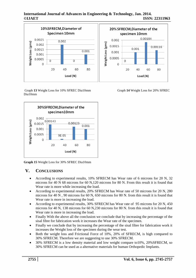
Graph 13 Weight Loss for 10% SFREC Dia10mm Graph 14 Weight Loss for 20% SFREC
Dia10mm
Graph 15 Weight Loss for 30% SFREC Dia10mm
V. CONCLUSIONS
According to experimental results, 10% SFRECM has Wear rate of 6 microns for 20 N, 32
microns for 40 N 68 microns for 60 N,120 microns for 80 N. From this result it is found that
Wear rate is more while increasing the load.
According to experimental results, 20% SFRECM has Wear rate of 50 microns for 20 N, 280
microns for 40 N , 90 microns for 60 N, 650 microns for 80 N. from this result it is found that
Wear rate is more in increasing the load.
According to experimental results, 30% SFRECM has Wear rate of 95 microns for 20 N, 450
microns for 40 N, 138 microns for 60 N,230 microns for 80 N. from this result it is found that
Wear rate is more in increasing the load.
Finally With the above all the conclusion we conclude that by increasing the percentage of the
sisal fibre for fabrication work it increases the Wear rate of the specimen.
Finally we conclude that by increasing the percentage of the sisal fibre for fabrication work it
increases the Weight loss of the specimen during the wear test.
Both the weight loss and Frictional Force of 10%, 20% of SFRECM, is high compared to
30% SFRECM. Therefore we are suggesting to use 30% SFRECM.
30% SFRECM is a low density material and low weight compare to10%, 20%SFRECM, so
30% SFRECM can be used as a alternative materials for human Orthopedic Implants.
International Journal of Advances in Engineering & Technology, Jan. 2014.
©IJAET ISSN: 22311963
2756 Vol. 6, Issue 6, pp. 2745-2757
VI. FURTHER WORK
Corrosion Test to be Conducted
For these (SFRECM) composite materials coating will be done by different bio-compatible
coating material.
Finite Element Analysis will be carried out.
ACKNOWLEDGEMENTS
I express my sincere thanks to my beloved mother S.P. Eramma, wife N. Manjula and daughter S.P. Srujana for
their invaluable love; moral support and constant encouragement in my life. I express my sincere thanks to
Brother in-Law Dr. N. Prashanth and his wife Dr. Neeta. P. N. And thanks to my Brother Dr. S.P. Jamabana
Goud. I profoundly express my sincere thanks and heartfelt respect to V.V. Sangha’s Management, Honorable
Chairman Sri B. V. Basavaraj, Principal Dr. T. Hanumantha Reddy-RYMEC-Bellary, my guide Prof. Dr. K.R.
Dinesh, Ph.D., Principal, Professor, Department of Mechanical Engineering, Govt Engg college-Raichur-VTU-
Belgaum, Co-Guide Prof. Dr. A Thimmanagouda IPE-Dept-RYMEC, and Dr. K. Veeresh-HOD-Mech-Dept-
RYMEC-Bellary, for giving precious suggestions and inspiring guidance during this research work and course
study. I thank my friends who were directly and indirectly helped me during this Research work. I express my
sincere thanks to Reinforced Plastic Industries-Bangalore for carrying out fabrication work and Ducom
Instruments Pvt. Ltd-Bangalore for carrying out WEAR test.
REFERENCES
[1]. M S.Ramakrishna, J. Mayer, E. Wintermantel, Kam W. Leong, paper entitled “Biomedical application
of polymer-composite materials: a review”, Composites science and technology journal, 61 (2001), pp
(1189-1224), ELSEVIER.
[2]. Yan Li, Yiu-Wing Mai *, Lin Ye paper entitled Sisal Fibre and its composites: a review of recent
developments Composites Science and Technology 60 (2000) 2037±2055
www.elsevier.com/locate/compscitech.
[3]. Hanumantharaju, H. G., Dr. H. K Shivanand,., "Static analysis of bi-polar femur Bone implant using
fea", International Journal of Recent Trends in Engineering, Vol. 1, No.5, May 2009, pp. 118- 121
[4]. Williams), Wiley, New York, 1980, Ch. 36. G. F. Howden, Mechanical Properties of Biomaterials (eds
G. W. Hastings & D. F. )
[5]. MATERIALS DEGRADATION AND ITS CONTROL BY SURFACE ENGINEERING (2nd
EDITION) Copyright © 2002 by Imperial College Press Wear Mechanisms, Materials Science &
Engineering.
[6]. ASTM Standard Specification for Titanium and Titanium Alloy Strip, Sheet, and Plate, ANSI– ASTM
B265-95, American Society for Testing and Materials
[7]. Medical Devices and Services, Vol 13.01, Annual Book of ASTM Standards, ASTM International,
2004
[8]. D. CHANDRAMOHAN et al. paper entitled “Bio composite materials based on bio polymers and
natural fibers -contribution as bone implants” (ijamsar) international journal of advanced medical
sciences and applied research vol no. 1, issue no. 1, 009 – 012.
[9]. M.SAKTHIVEl1, S.RAMESH2,1Asst.Professor, Adhiyamaan College of Engineering, Hosur
.2Professor, Sona College of Engineering, Salem paper entitled “Mechanical Properties of Natural
Fibre (Banana, Coir, Sisal) Polymer Composites” SCIENCE PARK ISSN: 2321 – 8045 Vol-1, Issue-1,
July 2013.
[10]. Girisha.C, Sanjeevamurthy, Gunti Ranga Srinivas paper entitled “Sisal/Coconut Coir Natural Fibers –
Epoxy Composites: Water Absorption and Mechanical Properties” International Journal of Engineering
and Innovative Technology (IJEIT) Volume 2, Issue 3, September 2012.
[11]. K. Murali Mohan Rao, K. Mohana Rao, A.V. Ratna Prasad, paper entitled ‘Fabrication and testing of
natural fibre composites: Vakka, sisal, bamboo and banana’. Journal of Materials and Design, volume
31, (2010), 508–513.
[12]. www.biomaterials.com
[13]. Girisha.C*1, Sanjeevamurthy2, Gunti Rangasrinivas3 , Manu.S4 paper entitled “ Mechanical
Performance Of Natural Fiber-Reinforced Epoxy-Hybrid Composites” International Journal of
Engineering Research and Applications (IJERA) ISSN: 2248-9622 www.ijera.com Vol. 2, Issue 5,
September- October 2012, pp.615-619
International Journal of Advances in Engineering & Technology, Jan. 2014.
©IJAET ISSN: 22311963
2757 Vol. 6, Issue 6, pp. 2745-2757
[14]. D.Chandramohan, * K. Marimuthu, S.Rajesh & M.M.Ravikumar paper entitled “Applications of
CT/CAD/RPT in the Futuristic Development of Orthopaedics and Fabrication of Plate and Screw
Material from Natural Fiber Particle Reinforced Composites for Humerus Bone Fixation – A Future
Drift” Malaysian Journal of Educational Technology Volume 10, Number 2, December 2010.
[15]. A.K. Bledzk and J. Gassan, Composites reinforced with cellulose-based fibres, Prog.Polym. Sci.24,
211-274 (1999).
[16]. A.N. Netravali and S. Chabba, paper entitled Composites get greener, Materials Today 6, 22-29 (2003)
[17]. G. Marsh, paper entitled A guide for green composites, Reinforced Plastics 48, 18-26 (2004).
[18]. Thillai Sivakumar N and Venkataraman R, paper entitled Der Pharmacia Sinica, 1 (1): 1-6 (2010)
[19]. Dubey R, Dubey K, Sridhar C and Jayaveera KN , Der Pharmacia Sinica, 2 (2): 11-16(2011).
[20]. Gangopadhyay A and Sarkar A, Advances in Applied Science Research, 2 (1): 149-152
[21]. Chand N. and Dwivedi U.K. 2007c. paper entitled Influence of fiber orientation on high stress wear
behavior of sisal fiber-reinforced epoxy composites. Polymer composites, Vol. 28, p. 437-441.
[22]. Sandhyarani Biswas paper entitled “Erosion Wear Behaviour of Copper Slag Filled Short Bamboo
Fiber Reinforced Epoxy Composites” IACSIT International Journal of Engineering and Technology,
Vol. 6, No. 2, April, 2013.
[23]. Kean-Khoon Chew, Sharif Hussein Sharif Zein*, Abdul Latif Ahmad paper entitled “The corrosion
scenario in human body: Stainless steel 316L orthopaedic implants” Vol.4, No.3, 184-188 (2012)
Natural Science http://dx.doi.org/10.4236/ns.2012.43027.
[24]. Dr. Mohammed Haneef, 1 Dr. J. Fazlur Rahman, 2 Dr. Mohammed Yunus, 3 Mr. Syed Zameer, 4 Mr.
Shanawaz patil, 5 Prof.Tajuddin Yezdani6 paper entitled “Hybrid Polymer Matrix Composites for
Biomedical Applications” International Journal of Modern Engineering Research (IJMER)
www.ijmer.com Vol.3, Issue.2, March-April. 2013 pp-970-979 ISSN: 2249-6645.
[25]. Sandhyarani Biswas and Alok Satapathy paper entitled “A Comparative Study on Erosion
Characteristics of Red Mud Filled Bamboo-Epoxy and Glass-Epoxy Composites” paper entitled
journals of materials and Design, Vol 31, issue04,April 2010.pages 1752-1767.
[26]. Geetha Manivasagam*, Durgalakshmi Dhinasekaran and Asokamani Rajamanickam Biomedical
Implants: Corrosion and its Prevention - A Review Recent Patents on Corrosion Science, 2010, 2, 40-
54.
[27]. www.azom.com
[28]. www.efunda.com
[29]. www.matweb.com
AUTHORS
K R Dinesh obtained his M.E Degree from Mysore University (SJCE-Mysore) in 1991 and
his Ph.D from University Vishweshwarayya College of Engineering Bangalore. Presently
working at the capacity of Principal and Professor Mechanical Engineering at Government
Engineering College- Raichur, guiding three Ph.D. students under VTU -Belgaum on
composite materials, Bio implant materials and Tool design, Having 22 years of teaching,
research and 8 years of research experience BOE at VTU University level. Papers
Publication12 Papers at National level conferences and 6 papers at National/international
level journals.
Jagadish S P obtained his M.E Degree from Bangalore University -Bangalore in 2010 and
pursuing part-time Ph.D from Visvesvaraya technological University –Belgaum in Bio-
composite materials. Having 10 years of teaching experience, at present he is serving as
Assistant Professor in Department of Mechanical engineering at RYMEC-Bellary. He has
many national and international publications to his credit.
A Thimmanagouda obtained his M.Tech Degree from Mysore University (SJCE-Mysore)
in 1991 and his Ph.D from S.K. University Ananthpur in 2011.At present he is serving as
Professor, and HOD Department of Industrial Production Engineering at RYMEC-Bellary.
He served as Principal PD institute of Technology Hospet from 2001 to 2005.He has many
national and international publications to his credit. His area of interest is Quality
Management and Composite Materials. He is guiding Three Ph.D research Scholars under
VTU-Belgaum.