5 project description 5.1 introduction
TRANSCRIPT
Pengerang Energy Complex Sdn Bhd Pengerang Energy Complex
Environmental Impact Assessment
April 2019 J18-780-MY-PA PEC EIA Rev 00
5-1
5 PROJECT DESCRIPTION
5.1 Introduction
This chapter provides details of the following:
• Project Siting
• Site Layout & Elements
• Raw Materials Supply and Characteristics
• Process Description
• Utilities to be Constructed and Operated by PEC
• Emission, Effluents and Waste Inventory
• Plant Instrumentation, Monitoring and Control
• Safety Systems
• Fire Detection and Protection Systems
• Key HSE Design Goals, Objectives and Targets
• Project Planning Schedule
• Construction, Commissioning & Start-Up
5.2 Project Siting
The facilities associated with the proposed Pengerang Energy Complex will be developed within the proposed
Pengerang Industrial Park (PIP) in Pengerang Integrated Petroleum Complex, Mukim Pengerang, Daerah Kota
Tinggi, Johor Darul Ta'zim. PIP is part of the full PIPC development spearheaded by Johor Corporation (JCorp).
The PIP is proposed to 787.6 acres of land within Mukim Pengerang, Daerah Kota Tinggi, Johor, in to heavy
industrial estate. It would consist of industrial, commercial, green areas and as well as supporting facilities
(JCorp EIA, 2018).
The PEC site (shown in Chapter 6) is situated 7.5 km northeast of Pengerang and 6km northwest of Sungai
Rengit. Singapore’s Pulau Tekong and Changi Airport lie 9 km and 17 km east of the site. Highways connect
the PIPC to Johor Bahru, the state capital, and its airport, Senai. The direct distance between PEC and Johor
Bahru, and PEC and Senai Airport is approximately 50 and 67 km, respectively, and it is also accessible by
scheduled ferry from Singapore to Pengerang and to larger vessels via the PIPC’s Pengerang Deepwater
Terminal (PDT). To the south is Petronas’s RAPID development.
5.3 Site Layout & Elements
The proposed PEC will comprise the following key elements:
• Condensate Splitter;
• Aromatics Plant;
• An elevated flare;
• Bulk storage area;
• Wastewater treatment plant; and
• Office and administrative buildings.
The main process areas of the PEC facility are the Condensate Splitter in the northeast corner of the layout,
areas C1 and C2, and the Aromatics Plant in AREA R1 to AREA A3. The manufacturing process is supported
by tankage for raw materials, intermediate and final products in day tanks, as well as a flare stack for safety
Pengerang Energy Complex Sdn Bhd Pengerang Energy Complex
Environmental Impact Assessment
April 2019 J18-780-MY-PA PEC EIA Rev 00
5-2
purposes, a waste water treatment plant to treat liquid waste prior to discharge, as well as warehouse and
office facilities.
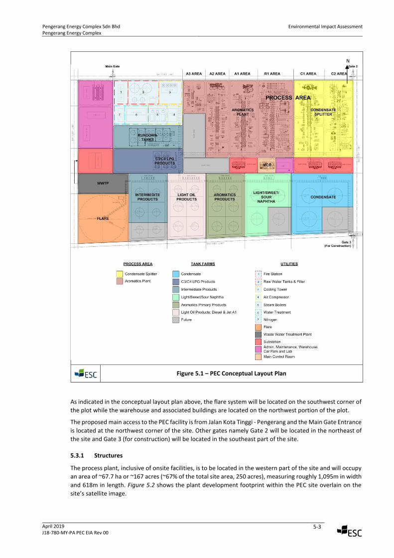
Figure 5.1 below shows the conceptual layout plan of the PEC. The scope of this report is indicated in Figure
5.1 and comprise the major process areas detailed within the plan, which include:
• Condensate Splitter Section
• Sour Water Stripping / Sulphur Recovery / Amine Regeneration / Spent Caustic Treatment
DHT (C2 AREA); and
• Prefractionation, KHT (C1 AREA).
• Aromatics Plant
• Naphtha Hydrotreating unit; / CCR Platforming and Regeneration unit / Olefin Reduction
Process unit (R1 AREA);
• Sulfolane unit / BT/ Tatoray unit (A1 AREA);
• Xylene / Parex (A2 AREA); and
• Isomar unit (A3 AREA).
• Support facilities
• 15 emissions stacks serving 9 furnace stacks, 1 SRU thermal oxidiser 2 vent stacks, 3 boiler
stacks
• 1 Elevated Flare stack for emergency use
• Onsite tankage for bulk storage for chemicals
• Waste water treatment plant
• Offices and other Site support facilities
Pengerang Energy Complex Sdn Bhd Pengerang Energy Complex
Environmental Impact Assessment
April 2019 J18-780-MY-PA PEC EIA Rev 00
5-3
Figure 5.1 – PEC Conceptual Layout Plan
As indicated in the conceptual layout plan above, the flare system will be located on the southwest corner of
the plot while the warehouse and associated buildings are located on the northwest portion of the plot.
The proposed main access to the PEC facility is from Jalan Kota Tinggi - Pengerang and the Main Gate Entrance
is located at the northwest corner of the site. Other gates namely Gate 2 will be located in the northeast of
the site and Gate 3 (for construction) will be located in the southeast part of the site.
5.3.1 Structures
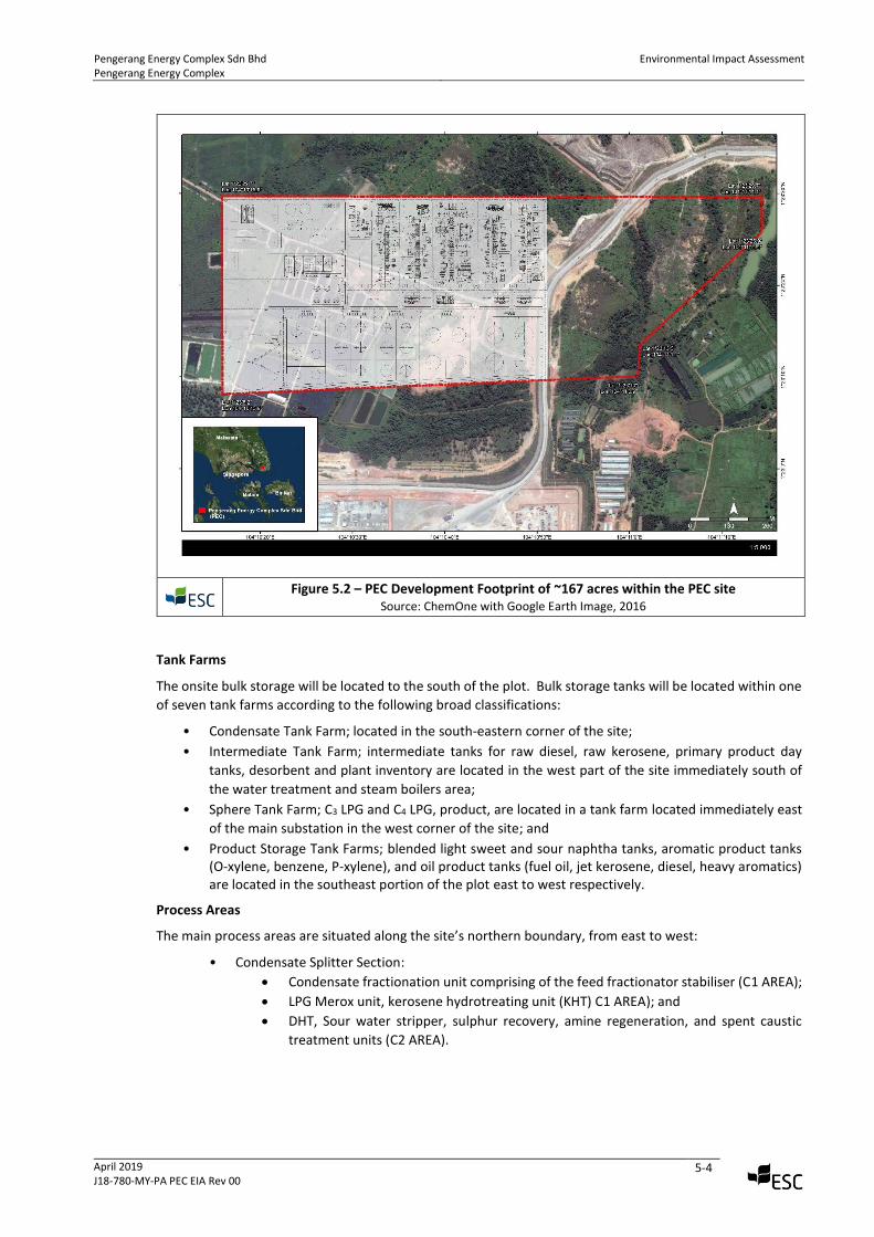
The process plant, inclusive of onsite facilities, is to be located in the western part of the site and will occupy
an area of ~67.7 ha or ~167 acres (~67% of the total site area, 250 acres), measuring roughly 1,095m in width
and 618m in length. Figure 5.2 shows the plant development footprint within the PEC site overlain on the
site’s satellite image.
N
Pengerang Energy Complex Sdn Bhd Pengerang Energy Complex
Environmental Impact Assessment
April 2019 J18-780-MY-PA PEC EIA Rev 00
5-4
Figure 5.2 – PEC Development Footprint of ~167 acres within the PEC site
Source: ChemOne with Google Earth Image, 2016
Tank Farms
The onsite bulk storage will be located to the south of the plot. Bulk storage tanks will be located within one
of seven tank farms according to the following broad classifications:
• Condensate Tank Farm; located in the south-eastern corner of the site;
• Intermediate Tank Farm; intermediate tanks for raw diesel, raw kerosene, primary product day
tanks, desorbent and plant inventory are located in the west part of the site immediately south of
the water treatment and steam boilers area;
• Sphere Tank Farm; C3 LPG and C4 LPG, product, are located in a tank farm located immediately east
of the main substation in the west corner of the site; and
• Product Storage Tank Farms; blended light sweet and sour naphtha tanks, aromatic product tanks (O-xylene, benzene, P-xylene), and oil product tanks (fuel oil, jet kerosene, diesel, heavy aromatics) are located in the southeast portion of the plot east to west respectively.
Process Areas
The main process areas are situated along the site’s northern boundary, from east to west:
• Condensate Splitter Section:
• Condensate fractionation unit comprising of the feed fractionator stabiliser (C1 AREA);
• LPG Merox unit, kerosene hydrotreating unit (KHT) C1 AREA); and
• DHT, Sour water stripper, sulphur recovery, amine regeneration, and spent caustic
treatment units (C2 AREA).
Pengerang Energy Complex Sdn Bhd Pengerang Energy Complex
Environmental Impact Assessment
April 2019 J18-780-MY-PA PEC EIA Rev 00
5-5
• Aromatics Plant:
• Naphtha hydrotreating unit (NHT), naphtha splitter, CCR platforming and regeneration
unit, reformate splitter (R1 AREA);
• Sulfolane unit, benzene/ toluene column, Tatoray unit (A1 AREA);
• Xylene / Parex unit (A2 AREA); and
• Isomar unit (A3 AREA).
Pipelines
Incoming pipelines to the site include condensate from the third-party bulk storage terminal, raw water and
natural gas (from external suppliers). Outgoing pipelines from PEC may supply other users in the PIPC with
light naphtha, C4 LPG and hydrogen. The remaining product export is via the same pipelines as condensate.
5.3.2 Other Facilities
The laboratory, main control building, an admin building with a canteen and car park, as well as the site’s fire
station will be centrally located in the northwest part of the site. South of the admin building and car park
are the maintenance shop and warehouse (which will be used for chemical and catalyst storage), with the
wastewater treatment plant (WWTP) in the southeast corner of the carpark.
The northwest corner will house on-site utilities including raw water and firewater tanks, raw water
treatment and demineralised water system, together with the sites boilers for steam supply, cooling water
system, the main site electrical switchboard.
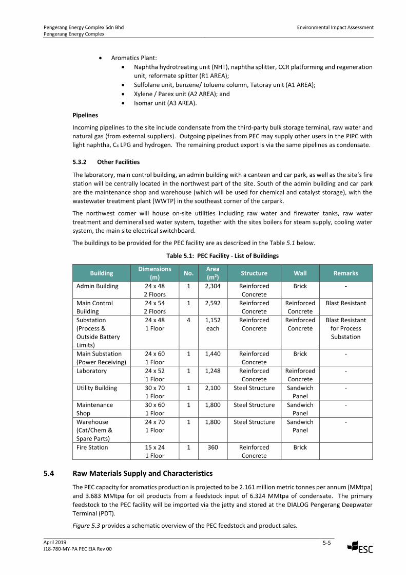
The buildings to be provided for the PEC facility are as described in the Table 5.1 below.
Table 5.1: PEC Facility - List of Buildings
Building Dimensions
(m) No.
Area (m2)
Structure Wall Remarks
Admin Building 24 x 48 2 Floors
1 2,304 Reinforced Concrete
Brick -
Main Control Building
24 x 54 2 Floors
1 2,592 Reinforced Concrete
Reinforced Concrete
Blast Resistant
Substation (Process & Outside Battery Limits)
24 x 48 1 Floor
4 1,152 each
Reinforced Concrete
Reinforced Concrete
Blast Resistant for Process Substation
Main Substation (Power Receiving)
24 x 60 1 Floor
1 1,440 Reinforced Concrete
Brick -
Laboratory 24 x 52 1 Floor
1 1,248 Reinforced Concrete
Reinforced Concrete
-
Utility Building 30 x 70 1 Floor
1 2,100 Steel Structure Sandwich Panel
-
Maintenance Shop
30 x 60 1 Floor
1 1,800 Steel Structure Sandwich Panel
-
Warehouse (Cat/Chem & Spare Parts)
24 x 70 1 Floor
1 1,800 Steel Structure Sandwich Panel
-
Fire Station 15 x 24 1 Floor
1 360 Reinforced Concrete
Brick
5.4 Raw Materials Supply and Characteristics
The PEC capacity for aromatics production is projected to be 2.161 million metric tonnes per annum (MMtpa)
and 3.683 MMtpa for oil products from a feedstock input of 6.324 MMtpa of condensate. The primary
feedstock to the PEC facility will be imported via the jetty and stored at the DIALOG Pengerang Deepwater
Terminal (PDT).
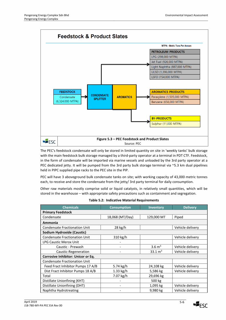
Figure 5.3 provides a schematic overview of the PEC feedstock and product sales.
Pengerang Energy Complex Sdn Bhd Pengerang Energy Complex
Environmental Impact Assessment
April 2019 J18-780-MY-PA PEC EIA Rev 00
5-6
Figure 5.3 – PEC Feedstock and Product Slates
Source: PEC
The PEC’s feedstock condensate will only be stored in limited quantity on site in ‘weekly tanks’ bulk storage
with the main feedstock bulk storage managed by a third-party operator at a terminal in PDT CTF. Feedstock,
in the form of condensate will be imported via marine vessels and unloaded by the 3rd party operator at a
PEC dedicated jetty. It will be pumped from the 3rd party bulk storage terminal via ~5.3 km dual pipelines
held in PIPC supplied pipe racks to the PEC site in the PIP.
PEC will have 3 aboveground bulk condensate tanks on site; with working capacity of 43,000 metric tonnes
each, to receive and store the condensate from the jetty/ 3rd party terminal for daily consumption.
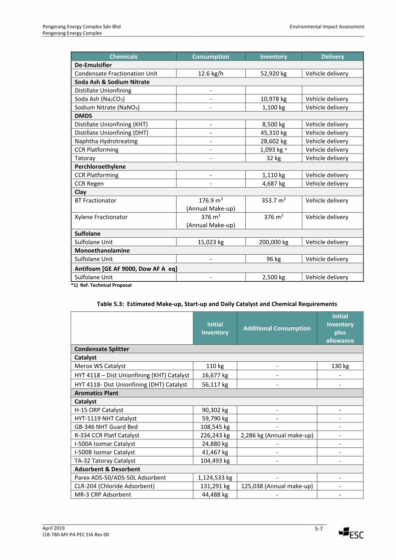
Other raw materials mostly comprise solid or liquid catalysts, in relatively small quantities, which will be
stored in the warehouse – with appropriate safety precautions such as containment and segregation.
Table 5.2: Indicative Material Requirements
Chemicals Consumption Inventory Delivery
Primary Feedstock
Condensate 18,068 (MT/Day) 129,000 MT Piped
Ammonia
Condensate Fractionation Unit 28 kg/h Vehicle delivery
Sodium Hydroxide (Caustic)
Condensate Fractionation Unit 310 kg/h Vehicle delivery
LPG Caustic Merox Unit -
Caustic - Prewash - 3.6 m3 Vehicle delivery
Caustic-Regeneration - 33.1 m3 Vehicle delivery
Corrosive Inhibitor: Unicor or Eq.
Condensate Fractionation Unit
Feed Fract Inhibitor Pumps 17 A/B 5.74 kg/h 24,108 kg Vehicle delivery
Dist Fract Inhibitor Pumps 18 A/B 1.33 kg/h 5,586 kg Vehicle delivery
Total 7.07 kg/h 29,696 kg
Distillate Unionfining (KHT) - 500 kg
Distillate Unionfining (DHT) - 1,095 kg Vehicle delivery
Naphtha Hydrotreating - 9,980 kg Vehicle delivery
Pengerang Energy Complex Sdn Bhd Pengerang Energy Complex
Environmental Impact Assessment
April 2019 J18-780-MY-PA PEC EIA Rev 00
5-7
Chemicals Consumption Inventory Delivery
De-Emulsifier
Condensate Fractionation Unit 12.6 kg/h 52,920 kg Vehicle delivery
Soda Ash & Sodium Nitrate
Distillate Unionfining -
Soda Ash (Na2CO3) - 10,978 kg Vehicle delivery
Sodium Nitrate (NaNO3) - 1,100 kg Vehicle delivery
DMDS
Distillate Unionfining (KHT) - 8,500 kg Vehicle delivery
Distillate Unionfining (DHT) - 45,310 kg Vehicle delivery
Naphtha Hydrotreating - 28,602 kg Vehicle delivery
CCR Platforming - 1,093 kg * Vehicle delivery
Tatoray - 32 kg Vehicle delivery
Perchloroethylene
CCR Platforming - 1,110 kg Vehicle delivery
CCR Regen - 4,687 kg Vehicle delivery
Clay
BT Fractionator 176.9 m3 (Annual Make-up)
353.7 m3 Vehicle delivery
Xylene Fractionator 376 m3 (Annual Make-up)
376 m3 Vehicle delivery
Sulfolane
Sulfolane Unit 15,023 kg 200,000 kg Vehicle delivery
Monoethanolamine
Sulfolane Unit - 96 kg Vehicle delivery
Antifoam [GE AF 9000, Dow AF A eq]
Sulfolane Unit - 2,500 kg Vehicle delivery *1) Ref. Technical Proposal
Table 5.3: Estimated Make-up, Start-up and Daily Catalyst and Chemical Requirements
Initial Inventory
Additional Consumption
Initial Inventory
plus allowance
Condensate Splitter
Catalyst
Merox WS Catalyst 110 kg - 130 kg
HYT 4118 – Dist Unionfining (KHT) Catalyst 16,677 kg - -
HYT 4118- Dist Unionfining (DHT) Catalyst 56,117 kg - -
Aromatics Plant
Catalyst
H-15 ORP Catalyst 90,302 kg - -
HYT-1119 NHT Catalyst 59,790 kg - -
GB-346 NHT Guard Bed 108,545 kg - -
R-334 CCR Platf Catalyst 226,243 kg 2,286 kg (Annual make-up) -
I-500A Isomar Catalyst 24,880 kg - -
I-500B Isomar Catalyst 41,467 kg - -
TA-32 Tatoray Catalyst 104,493 kg - -
Adsorbent & Desorbent
Parex ADS-50/ADS-50L Adsorbent 1,124,533 kg - -
CLR-204 (Chloride Adsorbent) 131,291 kg 125,038 (Annual make-up) -
MR-3 CRP Adsorbent 44,488 kg - -
Pengerang Energy Complex Sdn Bhd Pengerang Energy Complex
Environmental Impact Assessment
April 2019 J18-780-MY-PA PEC EIA Rev 00
5-8
5.5 Process Description
5.5.1 Process Overview
The PEC will be divided into two main sections, the ‘condensate splitting plant’ and the ‘aromatics plant’. The
condensate splitting plant produces Full Boiling Range (FBR) naphtha as feedstock to the aromatics plant.
Feedstocks are processed using standard oil refining ‘unit operations’ that utilise heating, cooling,
fractionation, reforming and distillation processes. The PEC will utilise the refining and aromatics technologies
of Honeywell UOP, the globally leading vendor.
The condensate splitting plant will produce intermediate naphtha as feedstock for the aromatics plant and
various petroleum products including LPG i.e. C3 (propane), C4 (butane and isobutane), Ultra Low Sulphur
Diesel (ULSD) and Low Sulphur Fuel Oil (LSFO). The feedstock for the aromatics plant, intermediate naphtha,
will be processed in the aromatics plant to produce paraxylene, and benzene and sulphur as its by product.
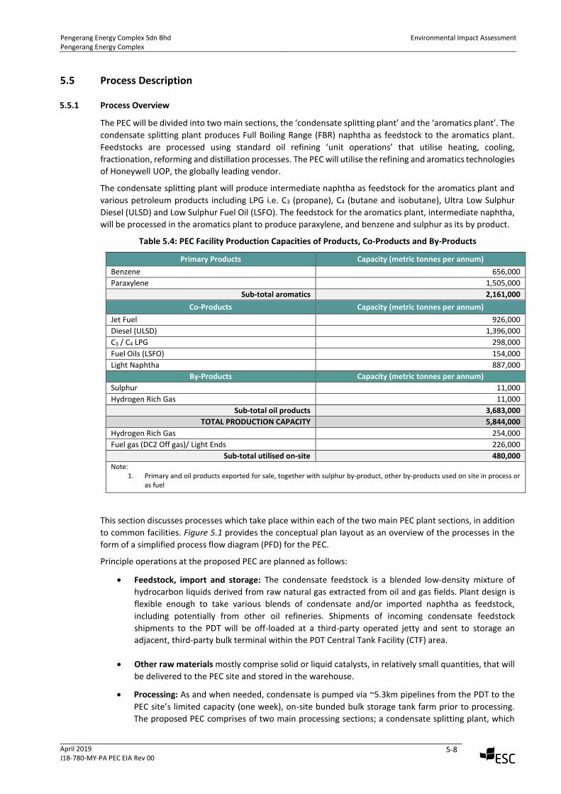
Table 5.4: PEC Facility Production Capacities of Products, Co-Products and By-Products
Primary Products Capacity (metric tonnes per annum)
Benzene 656,000
Paraxylene 1,505,000
Sub-total aromatics 2,161,000
Co-Products Capacity (metric tonnes per annum)
Jet Fuel 926,000
Diesel (ULSD) 1,396,000
C3 / C4 LPG 298,000
Fuel Oils (LSFO) 154,000
Light Naphtha 887,000
By-Products Capacity (metric tonnes per annum)
Sulphur 11,000
Hydrogen Rich Gas 11,000
Sub-total oil products 3,683,000
TOTAL PRODUCTION CAPACITY 5,844,000
Hydrogen Rich Gas 254,000
Fuel gas (DC2 Off gas)/ Light Ends 226,000
Sub-total utilised on-site 480,000 Note:
1. Primary and oil products exported for sale, together with sulphur by-product, other by-products used on site in process or as fuel
This section discusses processes which take place within each of the two main PEC plant sections, in addition
to common facilities. Figure 5.1 provides the conceptual plan layout as an overview of the processes in the
form of a simplified process flow diagram (PFD) for the PEC.
Principle operations at the proposed PEC are planned as follows:
• Feedstock, import and storage: The condensate feedstock is a blended low-density mixture of
hydrocarbon liquids derived from raw natural gas extracted from oil and gas fields. Plant design is
flexible enough to take various blends of condensate and/or imported naphtha as feedstock,
including potentially from other oil refineries. Shipments of incoming condensate feedstock
shipments to the PDT will be off-loaded at a third-party operated jetty and sent to storage an
adjacent, third-party bulk terminal within the PDT Central Tank Facility (CTF) area.
• Other raw materials mostly comprise solid or liquid catalysts, in relatively small quantities, that will
be delivered to the PEC site and stored in the warehouse.
• Processing: As and when needed, condensate is pumped via ~5.3km pipelines from the PDT to the
PEC site’s limited capacity (one week), on-site bunded bulk storage tank farm prior to processing.
The proposed PEC comprises of two main processing sections; a condensate splitting plant, which
Pengerang Energy Complex Sdn Bhd Pengerang Energy Complex
Environmental Impact Assessment
April 2019 J18-780-MY-PA PEC EIA Rev 00
5-9
produces the oil products and the full boiling range (FBR) naphtha that is the feedstock to the
aromatics plant, the second main section.
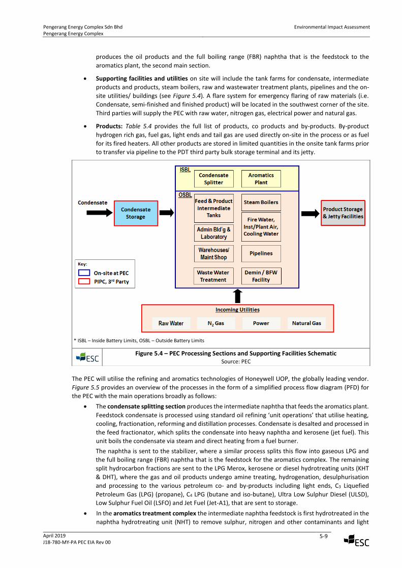
• Supporting facilities and utilities on site will include the tank farms for condensate, intermediate
products and products, steam boilers, raw and wastewater treatment plants, pipelines and the on-
site utilities/ buildings (see Figure 5.4). A flare system for emergency flaring of raw materials (i.e.
Condensate, semi-finished and finished product) will be located in the southwest corner of the site.
Third parties will supply the PEC with raw water, nitrogen gas, electrical power and natural gas.
• Products: Table 5.4 provides the full list of products, co products and by-products. By-product
hydrogen rich gas, fuel gas, light ends and tail gas are used directly on-site in the process or as fuel
for its fired heaters. All other products are stored in limited quantities in the onsite tank farms prior
to transfer via pipeline to the PDT third party bulk storage terminal and its jetty.
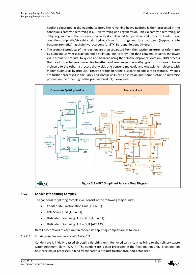
The PEC will utilise the refining and aromatics technologies of Honeywell UOP, the globally leading vendor.
Figure 5.5 provides an overview of the processes in the form of a simplified process flow diagram (PFD) for
the PEC with the main operations broadly as follows:
• The condensate splitting section produces the intermediate naphtha that feeds the aromatics plant.
Feedstock condensate is processed using standard oil refining ‘unit operations’ that utilise heating,
cooling, fractionation, reforming and distillation processes. Condensate is desalted and processed in
the feed fractionator, which splits the condensate into heavy naphtha and kerosene (jet fuel). This
unit boils the condensate via steam and direct heating from a fuel burner.
The naphtha is sent to the stabilizer, where a similar process splits this flow into gaseous LPG and
the full boiling range (FBR) naphtha that is the feedstock for the aromatics complex. The remaining
split hydrocarbon fractions are sent to the LPG Merox, kerosene or diesel hydrotreating units (KHT
& DHT), where the gas and oil products undergo amine treating, hydrogenation, desulphurisation
and processing to the various petroleum co- and by-products including light ends, C3 Liquefied
Petroleum Gas (LPG) (propane), C4 LPG (butane and iso-butane), Ultra Low Sulphur Diesel (ULSD),
Low Sulphur Fuel Oil (LSFO) and Jet Fuel (Jet-A1), that are sent to storage.
• In the aromatics treatment complex the intermediate naphtha feedstock is first hydrotreated in the
naphtha hydrotreating unit (NHT) to remove sulphur, nitrogen and other contaminants and light
* ISBL – Inside Battery Limits, OSBL – Outside Battery Limits
Figure 5.4 – PEC Processing Sections and Supporting Facilities Schematic
Source: PEC
Pengerang Energy Complex Sdn Bhd Pengerang Energy Complex
Environmental Impact Assessment
April 2019 J18-780-MY-PA PEC EIA Rev 00
5-10
naphtha separated in the naphtha splitter. The remaining heavy naphtha is then processed in the
continuous catalytic reforming (CCR) platforming and regeneration unit via catalytic reforming, or
dehydrogenation in the presence of a catalyst at elevated temperature and pressure. Under these
conditions, aliphatic/straight chain hydrocarbons form rings and lose hydrogen (by-product) to
become aromatic/ring chain hydrocarbons (or BTX; Benzene-Toluene-Xylenes).
• The aromatic products of the reaction are then separated from the reaction mixture (or reformate)
by Sulfolane solvent extraction and distillation. The Tatoray unit then converts toluene, the lower
value aromatic-product, to xylene and benzene using the toluene disproportionation (TDP) process
that reacts two toluene molecules together and rearranges the methyl groups from one toluene
molecule to the other, a process that yields one benzene molecule and one xylene molecule, with
molten sulphur as by product. Primary product benzene is separated and sent to storage. Xylenes
are further processed in the Parex and Isomar units, via absorption and isomerisation to maximise
production the other high value primary product, paraxylene.
Figure 5.5 – PEC Simplified Process Flow Diagram
5.5.2 Condensate Splitting Complex
The condensate splitting complex will consist of the following major units:
• Condensate Fractionation Unit (AREA C1)
• LPG Merox Unit (AREA C1)
• Distillate Unionfining Unit – KHT (AREA C1)
• Distillate Unionfining Unit – DHT (AREA C2)
Detail descriptions of each unit in condensate splitting complex are as follows:
5.5.2.1 Condensate Fractionation Unit (AREA C1)
Condensate is initially passed through a desalting unit. Removed salt is sent as brine to the refinery waste
water treatment plant (WWTP). The condensate is then processed in the fractionation unit. Fractionation
has three major processes, a feed fractionator, a product fractionator, and a stabiliser.
Pengerang Energy Complex Sdn Bhd Pengerang Energy Complex
Environmental Impact Assessment
April 2019 J18-780-MY-PA PEC EIA Rev 00
5-11
The condensate first enters the feed fractionator. This unit boils the condensate via steam and direct heating
from a fuel burner in the reboiler. Ammonia and Unicor (corrosion inhibitor) are added to assist the process
of splitting the condensate into two fractions, called overheads and bottoms. The process also produces sour
water, which is sent to the sour water stripper. Point source emissions are generated from the reboiler and
any other gases and air displaced from the equipment is channelled into the air treatment system, described
later. Gaseous emissions are collected in the same manner as above.
The overheads are sent to the stabilizer. A similar process splits this flow into two further fractions. The
stabilizer overheads are gaseous LPG, which is routed to the LPG Merox unit. The stabilizer bottom product
is full boiling range (FBR) naphtha, the feedstock for the aromatics complex and sent to the naphtha
hydrotreating unit. This unit may produce sour water, which is channelled to the sour water stripper.
The bottoms from the feed fractionator are sent to the product fractionator, where it is split into three
fractions, the condensate is heated via a fuel fired boiler and steam. The overheads are routed to the KHT
and DHT units and is stored onsite. The bottoms are sent directly to fuel oil storage. The product fractionator
also has a side-cut which is routed to the distillate unionfining unit.
Waste and emissions from this process include brine and sour water (sent to waste water treatment plant),
point source gaseous emissions (2) from feed fractionator reboiler & product fractionator heater will be
released through their stacks, and displaced air which will be sent to the flare stack. The unit has several over
pressure vents to the flare stack, which may be activated in the event of over pressure, air emissions are
reprocessed in various subsequent units. No solid waste is expected.
5.5.2.2 LPG Merox Unit (AREA C1)
An LPG Extraction Merox Unit is designed to remove H2S, COS and Mercaptans from the LPG required when
further processing of C3 and C4 olefins in alkylation, polymerization or petrochemical synthesis is required.
The capital-efficient Extractor Plus design is typically used in this service.
The Extractor Plus design incorporates caustic pre-treatment, mercaptan extraction and post-treatment into
a single vessel, thereby offering a low capital cost alternative to other extraction processes. Typical product
mercaptan levels can be controlled to less than 5 wppm1.
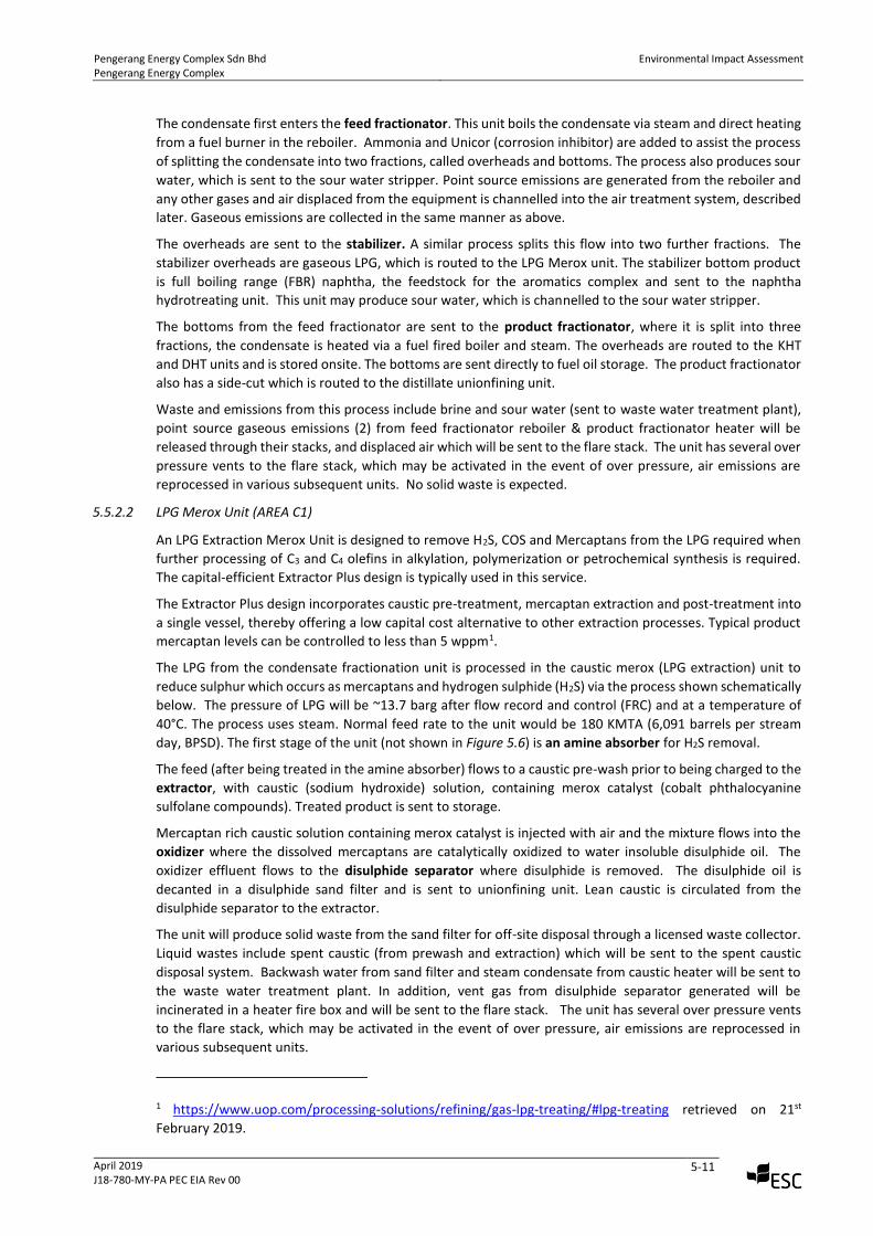
The LPG from the condensate fractionation unit is processed in the caustic merox (LPG extraction) unit to
reduce sulphur which occurs as mercaptans and hydrogen sulphide (H2S) via the process shown schematically
below. The pressure of LPG will be ~13.7 barg after flow record and control (FRC) and at a temperature of
40°C. The process uses steam. Normal feed rate to the unit would be 180 KMTA (6,091 barrels per stream
day, BPSD). The first stage of the unit (not shown in Figure 5.6) is an amine absorber for H2S removal.
The feed (after being treated in the amine absorber) flows to a caustic pre-wash prior to being charged to the
extractor, with caustic (sodium hydroxide) solution, containing merox catalyst (cobalt phthalocyanine
sulfolane compounds). Treated product is sent to storage.
Mercaptan rich caustic solution containing merox catalyst is injected with air and the mixture flows into the
oxidizer where the dissolved mercaptans are catalytically oxidized to water insoluble disulphide oil. The
oxidizer effluent flows to the disulphide separator where disulphide is removed. The disulphide oil is
decanted in a disulphide sand filter and is sent to unionfining unit. Lean caustic is circulated from the
disulphide separator to the extractor.
The unit will produce solid waste from the sand filter for off-site disposal through a licensed waste collector.
Liquid wastes include spent caustic (from prewash and extraction) which will be sent to the spent caustic
disposal system. Backwash water from sand filter and steam condensate from caustic heater will be sent to
the waste water treatment plant. In addition, vent gas from disulphide separator generated will be
incinerated in a heater fire box and will be sent to the flare stack. The unit has several over pressure vents
to the flare stack, which may be activated in the event of over pressure, air emissions are reprocessed in
various subsequent units.
1 https://www.uop.com/processing-solutions/refining/gas-lpg-treating/#lpg-treating retrieved on 21st
February 2019.
Pengerang Energy Complex Sdn Bhd Pengerang Energy Complex
Environmental Impact Assessment
April 2019 J18-780-MY-PA PEC EIA Rev 00
5-12
Figure 5.6 – LPG Merox Unit RFD*
Source: UOP *RFD - representative flow diagram
5.5.2.3 Distillate Unionfining (KHT) Process Unit
KHT Distillate Unionfining Process Unit is divided into reactor and stripper sections (Figure 5.7). The unit
consists of one reactor section with separate stripper section.
For KHT, two fired heaters with the following fuel requirement will be utilised:
• Charge Heater fuel fired: 3.27 MM kcal/hr
• Stripper Reboiler: 5.38 MM kcal/hr
The total fuel requirement is 8.65 MMkcal/hr. And for KHT fuel, internal fuel gas will be utilised.
Pengerang Energy Complex Sdn Bhd Pengerang Energy Complex
Environmental Impact Assessment
April 2019 J18-780-MY-PA PEC EIA Rev 00
5-13
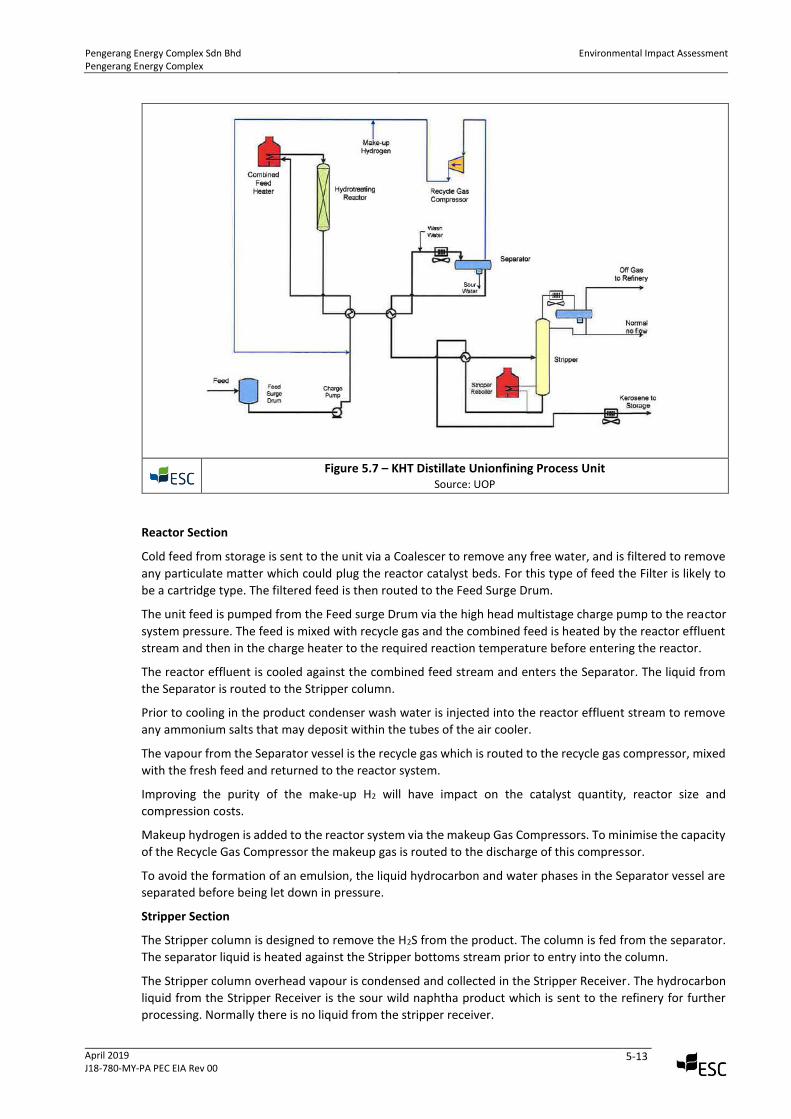
Figure 5.7 – KHT Distillate Unionfining Process Unit
Source: UOP
Reactor Section
Cold feed from storage is sent to the unit via a Coalescer to remove any free water, and is filtered to remove
any particulate matter which could plug the reactor catalyst beds. For this type of feed the Filter is likely to
be a cartridge type. The filtered feed is then routed to the Feed Surge Drum.
The unit feed is pumped from the Feed surge Drum via the high head multistage charge pump to the reactor
system pressure. The feed is mixed with recycle gas and the combined feed is heated by the reactor effluent
stream and then in the charge heater to the required reaction temperature before entering the reactor.
The reactor effluent is cooled against the combined feed stream and enters the Separator. The liquid from
the Separator is routed to the Stripper column.
Prior to cooling in the product condenser wash water is injected into the reactor effluent stream to remove
any ammonium salts that may deposit within the tubes of the air cooler.
The vapour from the Separator vessel is the recycle gas which is routed to the recycle gas compressor, mixed
with the fresh feed and returned to the reactor system.
Improving the purity of the make-up H2 will have impact on the catalyst quantity, reactor size and
compression costs.
Makeup hydrogen is added to the reactor system via the makeup Gas Compressors. To minimise the capacity
of the Recycle Gas Compressor the makeup gas is routed to the discharge of this compressor.
To avoid the formation of an emulsion, the liquid hydrocarbon and water phases in the Separator vessel are
separated before being let down in pressure.
Stripper Section
The Stripper column is designed to remove the H2S from the product. The column is fed from the separator.
The separator liquid is heated against the Stripper bottoms stream prior to entry into the column.
The Stripper column overhead vapour is condensed and collected in the Stripper Receiver. The hydrocarbon
liquid from the Stripper Receiver is the sour wild naphtha product which is sent to the refinery for further
processing. Normally there is no liquid from the stripper receiver.
Pengerang Energy Complex Sdn Bhd Pengerang Energy Complex
Environmental Impact Assessment
April 2019 J18-780-MY-PA PEC EIA Rev 00
5-14
The Stripper column bottoms stream is the desulfurized product and is cooled against the cold Stripper feed.
To produce a dry product the bottoms stream is further cooled before being sent to storage.
The unit will generate point source gas emissions from the fuel feed heater and it will be released through its
stack. Gaseous emissions from air displacement and the steam stripper and over pressure vents to the flare
stack may be activated in the event of over pressure. Sour water and amine waste water will be sent to the
waste water treatment plant. Solid wastes including sulphur, wastes from the catalyst and salt drying beds
will be sent for off-site disposal by a licensed waste collector.
5.5.2.4 Distillate Unionfining (DHT) Unit (AREA C2)
The unit processes the diesel fraction, from the condensate fractionation unit. The objective of the unit is to
reduce the sulphur in the diesel to less than 10 wppm to meet the Euro-V fuel specification. The nominal feed
rate is 1,342 KMTA (28,699 BPSD). This unit will produce a sweet fuel gas stream and an un-stabilised naphtha
stream which is recycled in the condensate fractionation unit.
The unit comprises the reactor, separator, compressor, stripper, and diesel product section. The Feed enters
the pressurised reactor and is combined with recycled gas and heated via a fuel boiler together with reactor
effluent. The proposed design has only a single reactor with two catalyst beds and hydrogen quench. The
two catalyst beds filter out fine particles such as corrosion products to avoid high-pressure drop across the
catalyst bed during operation, followed by the desulphurisation catalyst. Subsequently the gas and liquid
mixture is separated in the high-pressure separator unit. Water is injected into the reactor effluent ahead of
the effluent air cooler to prevent the deposition of ammonium disulphide. Sour water is coalesced and
removed from the boot of the separator, and sent to the flash drum.
High-purity (90%) make-up hydrogen, from the make-up gas compressor discharge, is mixed with the recycled
gas at the suction of the recycle compressor and the combined recycle and make up gas stream is sent to the
reactor system. The separator liquid is sent to the flash drum (low pressure separator) where the hydrocarbon
liquid, flash gas and sour water are separated. The flash gas is sent to the amine absorber for H2S removal.
The flash drum liquid requires stripping to remove residual hydrogen sulphide, ammonia and light
hydrocarbons. The steam stripper will generate off-gas, sour water and the diesel product. Diesel product
with a moisture content less than 200 wppm will be achieved, by routing the diesel product through a product
coalescer and salt dryer to remove the free water. The product is then sent to storage.
The unit will generate point source gas emissions from the fuel feed heater and it will be released through its
stack. Gaseous emissions from air displacement and the steam stripper and over pressure vents to the flare
stack may be activated in the event of over pressure. Sour water and amine waste water will be sent to the
waste water treatment plant. Solid wastes including sulphur, wastes from the catalyst and salt drying beds
will be sent for off-site disposal by a licensed waste collector.
5.5.2.5 Sulphur Recovery Unit (SRU)
The modified Claus (also known as conventional Claus) process is the workhorse in sulfur recovery, and is
used worldwide in more plants than any other process. In the typical modified Claus process, the acid gas
feed is partially oxidized to generate sulfur dioxide (SO2), which then reacts with the remaining hydrogen
sulfide (H2S) over a catalyst to produce sulfur. Most Claus sulfur plants contain two or three catalytic stages
and can achieve 94-97% sulfur recovery efficiency.
The Claus process utilizes the following chemical reactions to convert hydrogen sulfide to elemental sulfur:
(1) H2S + 3/2 O2 ⇌ SO2+H2O
(2) 2 H2S + SO2 ⇌ 3/nSn + H2O
The overall reaction for the process is:
(3) 3 H2S + 3/2 O2 ⇌ 3/nSn + 3H2O
Most sulphur plants contain one non-catalytic conversion stage (the reactor furnace) and two or more
catalytic conversion stages in series. The Claus reaction is highly exothermic, releasing a great deal of heat
energy that can be recovered by generating steam in heat exchangers following the conversion stages.
Pengerang Energy Complex Sdn Bhd Pengerang Energy Complex
Environmental Impact Assessment
April 2019 J18-780-MY-PA PEC EIA Rev 00
5-15
Modified Claus with Tailgas Cleanup
In applications where a high level (more than 99.5%) of overall sulfur recovery is required, the Modified Claus
Process coupled with an amine-based tailgas cleanup process is used. This process is the best widely-proven
technology available in the industry for achieving overall sulfur recovery performance up to 99.9%. Ortloff
has performed the detailed process engineering, specification, and design of more than fifteen amine-based
tailgas cleanup units.
The tailgas cleanup process reduces all of the sulfur compounds in the tailgas leaving the front-end Claus
sulfur plant back to hydrogen sulfide (H2S), then uses selective amine absorption to remove the H2S while
allowing most of the carbon dioxide (CO2) to “slip” by. The H2S and CO2 removed by the amine are stripped
from the amine and recycled back to the Claus plant, allowing an overall sulfur recovery in excess of 99.5%.
Depending on the performance required, the effluent from the tailgas cleanup unit (TGCU) can contain as
little as 10 PPM of H2S. This effluent is normally routed to a Tailgas Thermal Oxidizer to incinerate the H2S and
any other remaining sulfur compounds to sulfur dioxide (SO2) before dispersion to the atmosphere. Effluent
gas would meet regulatory requirement.
5.5.3 Aromatics Treatment Complex
The Aromatic treatment complex will consist of the following major units:
• Naphtha Hydro-treating Unit (NHT)
• Contaminant Removal Process Unit
• Continuous Catalytic Reforming (CCR) Platforming and Regeneration Unit
• Olefin Reduction Process Unit
• Sulfolane Unit
• Tatoray Unit
• Aromatic Fractionation Unit
• Parex Unit
• Isomar Unit
5.5.3.1 Naphtha Hydrotreating Unit (NHT)
FBR naphtha produced from the condensate splitting section is further treated in the NHT unit. NHT uses a
selective catalyst HYT 1119, Aluminum Oxide, and GB-346 to hydrotreat with hydrogen rich gas to decompose
organic sulphur, nitrogen and oxygen compounds in the naphtha prior to further processing in the CCR
platforming unit. In addition, hydrotreating removes organometallic compounds (including mercury – see
contaminant removal process below) and saturates olefinic compounds.
The unit comprises the following sections:
• Reaction Section – consists of a heat exchanger, fuel fired heater, reactor, separator, recycled
gas compressor and ancillary equipment
• Stripper Section – comprises a stripper column, fuel fired reboiler, amine treater and ancillary
equipment
The stripper net overhead gas is amine treated prior to being sent to fuel gas system.
5.5.3.2 Contaminant Removal Process (CRP) Unit (part of NHT)
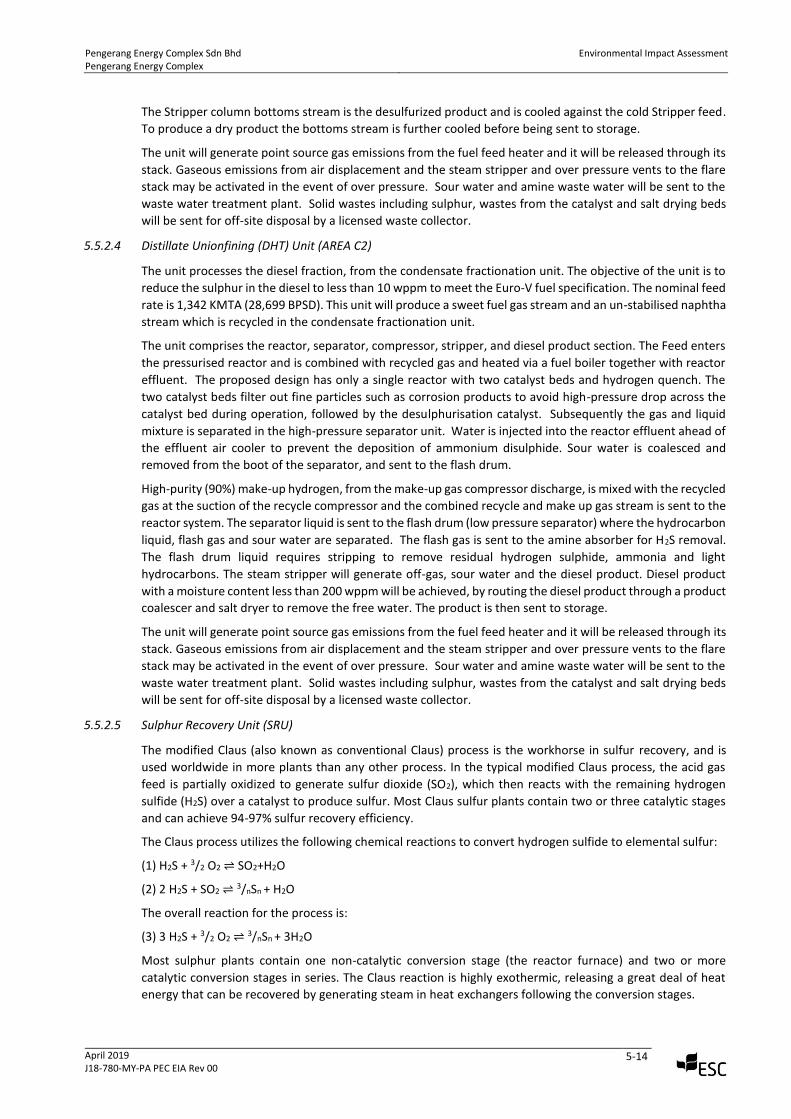
The Contaminant Removal Process removes mercury and arsenic from the feedstocks through an adsorber.
Mercury is a catalyst and adsorbent poison and is known to corrosively attack equipment made with
aluminum, such as heat exchangers in gas processing plants or olefin complexes. Arsenic compounds are also
catalyst poisons in many petrochemical processes.
The CRP is designed to reduce the mercury content of certain feeds to 5 ppb or less, and to remove the arsenic
compounds typically present in light and heavy naphtha streams to less than 5 ppb. In addition to protecting
equipment, catalyst and adsorbents, the CRP provides a means to control emissions of mercury and arsenic.
Pengerang Energy Complex Sdn Bhd Pengerang Energy Complex
Environmental Impact Assessment
April 2019 J18-780-MY-PA PEC EIA Rev 00
5-16
The regenerable adsorbent has a long useful life and when ultimately spent, has no detectable mercury level.
Arsenic generally occurs only in combined forms. The various species of arsenic will be adsorbed by the non-
regenerable material depending on the boiling points of the arsenic compounds present.
The NHT and CRP units will generate significant waste and gas streams, waste water may be contaminated
with metals such as mercury and arsenic, and will be sent to the waste water treatment plant.
Figure 5.8 – Contaminant Removal Process (CRP) Unit
Source: UOP
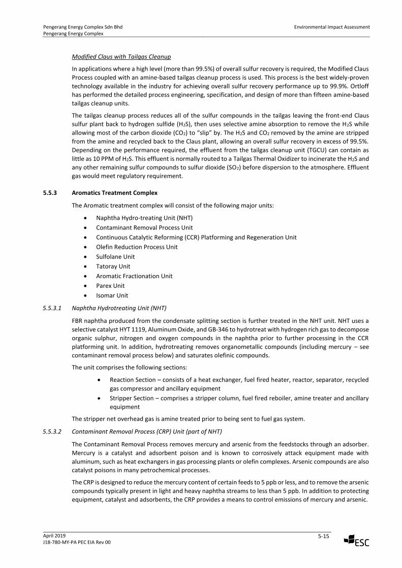
5.5.3.3 Continuous Catalytic Reforming (CCR) Platforming and Regeneration Unit
The CCR platforming process produces aromatics and hydrogen from napthenes and paraffin at high severity,
it is the only in the complex that creates aromatic rings. The rest of the complex is used to separate the
various aromatic components into individual products and to convert undesired aromatics into additional
high value products. Feed for the CCR platforming unit is the naphtha splitter bottoms from the NHT. This
unit upgrades mercury depleted low octane hydrotreated heavy naphtha to produce 105 RONC reformate.
Hydrogen, LPG and light ends are also produced in this process.
Figure 5.9 – Continuous Catalytic Reforming (CCR) Platforming and Regeneration Unit
Source: UOP
Pengerang Energy Complex Sdn Bhd Pengerang Energy Complex
Environmental Impact Assessment
April 2019 J18-780-MY-PA PEC EIA Rev 00
5-17
As shown in Figure 5.9 above, the unit comprises a reaction section, recontact section and debutaniser
section. The unit produces the following product streams:
• A hydrogen rich gas stream, which is routed to the NHT unit, isomar unit, tatoray unit and olefin
reduction unit.
• An unstabilised LPG stream, which is routed to condensate splitting for combined treatment
(de-ethaniser followed by C3/ C4 splitter)
• A reformate intermediate, which is sent to the reformate splitter.
The reaction section consists of four stacked radial flow reactors, fuel fired charge heater and inter-heaters,
combined feed exchanger, separators, recycle gas compressor and their ancillary equipment. Four major
reactions occur in the reactors including dehydrocyclisation, isomerisation, dehydrogenation, hydrocracking
of large hydrocarbons to smaller hydrocarbons.
Vapor from the product separator is split into two streams: recycle gas and hydrogen rich net gas. The recycle
compressor compresses the recycle gas while the net gas is sent to the product recovery section. The product
recovery section consists of recontacting and net gas compression. The net gas from product recovery section
flows to a Recovery Plus system to further improve the recovery of LPG.
Recontact section consists of a two-stage counter-current recontacting and net gas compression scheme plus
a third stage of net gas compression. The recontact pressure is 31 barg. The hydrogen gas from the second
stage compression and recontacting scheme is treated to remove chlorides and is sent to the NHT unit and
isomar unit. The gas from the third stage compression goes to the tatoray and olefin reduction unit. The light
ends from the second stage of the compression and recontacting scheme is sent to the de-ethaniser and C3/
C4 splitter, after chloride removal. As a result of chloride removal, chlorinated water from CCR platforming
process will be collected and treated in waste water treatment plant on site.
5.5.3.4 CCR Catalyst Regeneration
The CCR platformer uses a movable bed of R-334 catalyst. Over time, coke will build up on the catalyst surface,
reducing catalyst activity. Hence, the catalyst requires regeneration. During the regeneration process, the
refinery will suffer production loss, which is the reason why UOP developed a major process enhancement
by making the regeneration possible continuously, while the process is also taking place.
In UOP design, the catalyst is able to flow by gravity between reactors and is continuously regenerated.
Catalyst regeneration will generate particulate which will be filtered prior to venting. Catalyst regeneration
consists of four steps. The first three steps of coke burning, oxychlorination, and drying occur in the CCR
Cyclemax® regeneration unit. The fourth step, reduction, occurs in the reduction zone on top of the reactor
stack. The CCR Cyclemax® regeneration unit uses a pressurized regenerator design. The Chlorosorb® system,
which recovers upto 99% of chlorides from the vent gas stream and recycles the chlorides back to the process,
is also applied. Spent catalyst is used as chlorides adsorbent.
According to UOP, the unit has low emissions and high energy efficiency as the Chlorosorb® technology
recycles chloride and reduces atmospheric emissions. Even so, the unit has several over pressure vents to the
flare stack, which may be activated in the event of over pressure, other lights and gaseous fractions are
reprocessed in various subsequent units.
There will be 3 natural gas fired charge heaters, inter-heaters no.1 to 3 and stabilizer reboiler heaters, whose
emissions and will be released through combined stacks. In addition, vent gas, containing trace hydrogen
chloride (HCL), will be produced from CCR disengaging hopper and will be released directly via a stack. Waste
water containing ammonium chloride and trace hydrocarbons generated will be sent to the waste water
treatment plant. Solid waste will include spent adsorbent (activated alumina) generated once every 6 months
from the net gas clay treaters and will be sent for off-site disposal by a licensed waste collector.
5.5.3.5 Reformate Splitter
The reformate splitter reboils the intermediate product, bottoms from the debutanizer at the CCR. The
bottoms are passed through the Olefin Reduction Process (ORP) prior to being sent to the xylene splitter. The
top fraction is condensed and sent to the sulfolane unit. Vent gases are sent to the sulfolane vent tank and
Pengerang Energy Complex Sdn Bhd Pengerang Energy Complex
Environmental Impact Assessment
April 2019 J18-780-MY-PA PEC EIA Rev 00
5-18
subsequently to the flare stack. The unit will produce solid waste when clay beds are changed and will be sent
for off-site disposal by a licensed waste collector.
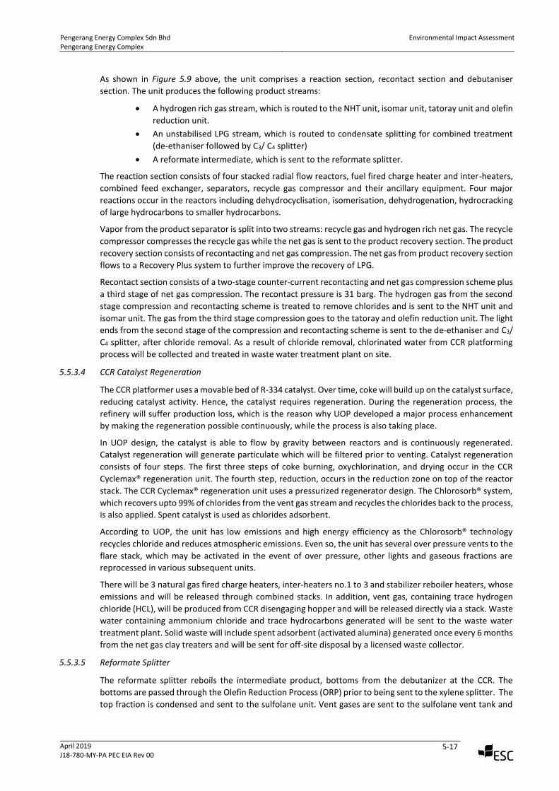
5.5.3.6 Olefin Reduction Process (ORP) Unit
ORP Unit uses a simple, fixed-bed reactor system where olefins in the reformate are selectively hydrogenated
to their corresponding alkane or cycloalkane using hydrogen rich gas from the third compression stage of the
CCR platforming unit. The unit includes a heat exchanger train and two swing-bed reactors.
Figure 5.10 – Olefin Reduction Process (ORP) Unit
Source: UOP
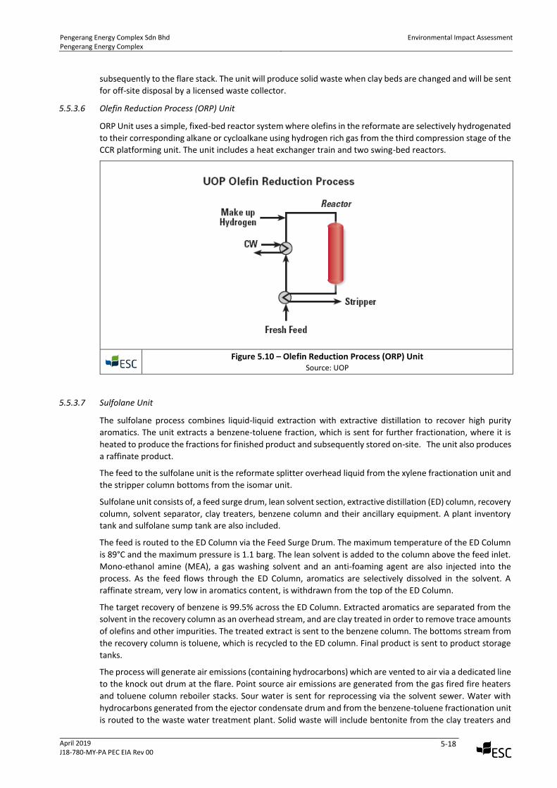
5.5.3.7 Sulfolane Unit
The sulfolane process combines liquid-liquid extraction with extractive distillation to recover high purity
aromatics. The unit extracts a benzene-toluene fraction, which is sent for further fractionation, where it is
heated to produce the fractions for finished product and subsequently stored on-site. The unit also produces
a raffinate product.
The feed to the sulfolane unit is the reformate splitter overhead liquid from the xylene fractionation unit and
the stripper column bottoms from the isomar unit.
Sulfolane unit consists of, a feed surge drum, lean solvent section, extractive distillation (ED) column, recovery
column, solvent separator, clay treaters, benzene column and their ancillary equipment. A plant inventory
tank and sulfolane sump tank are also included.
The feed is routed to the ED Column via the Feed Surge Drum. The maximum temperature of the ED Column
is 89°C and the maximum pressure is 1.1 barg. The lean solvent is added to the column above the feed inlet.
Mono-ethanol amine (MEA), a gas washing solvent and an anti-foaming agent are also injected into the
process. As the feed flows through the ED Column, aromatics are selectively dissolved in the solvent. A
raffinate stream, very low in aromatics content, is withdrawn from the top of the ED Column.
The target recovery of benzene is 99.5% across the ED Column. Extracted aromatics are separated from the
solvent in the recovery column as an overhead stream, and are clay treated in order to remove trace amounts
of olefins and other impurities. The treated extract is sent to the benzene column. The bottoms stream from
the recovery column is toluene, which is recycled to the ED column. Final product is sent to product storage
tanks.
The process will generate air emissions (containing hydrocarbons) which are vented to air via a dedicated line
to the knock out drum at the flare. Point source air emissions are generated from the gas fired fire heaters
and toluene column reboiler stacks. Sour water is sent for reprocessing via the solvent sewer. Water with
hydrocarbons generated from the ejector condensate drum and from the benzene-toluene fractionation unit
is routed to the waste water treatment plant. Solid waste will include bentonite from the clay treaters and
Pengerang Energy Complex Sdn Bhd Pengerang Energy Complex
Environmental Impact Assessment
April 2019 J18-780-MY-PA PEC EIA Rev 00
5-19
spent catalyst which is generated once every 3 years and will be sent for off-site disposal by a licensed waste
collector. Sulfolane solvent with aromatic hydrocarbons is generated once every six months from the solvent
regenerator and removed on a batch basis by a licensed waste collector.
Figure 5.11 – ED Sulfolane Process Unit
Source: UOP
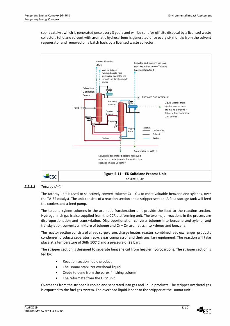
5.5.3.8 Tatoray Unit
The tatoray unit is used to selectively convert toluene C9 – C10 to more valuable benzene and xylenes, over
the TA-32 catalyst. The unit consists of a reaction section and a stripper section. A feed storage tank will feed
the coolers and a feed pump.
The toluene xylene columns in the aromatic fractionation unit provide the feed to the reaction section.
Hydrogen rich gas is also supplied from the CCR platforming unit. The two major reactions in the process are
disproportionation and transkylation. Disproportionation converts toluene into benzene and xylene; and
transkylation converts a mixture of toluene and C9 – C10 aromatics into xylenes and benzene.
The reactor section consists of a feed surge drum, charge heater, reactor, combined feed exchanger, products
condenser, products separator, recycle gas compressor and their ancillary equipment. The reaction will take
place at a temperature of 368/ 500°C and a pressure of 29 barg.
The stripper section is designed to separate benzene cut from heavier hydrocarbons. The stripper section is
fed by:
• Reaction section liquid product
• The isomar stabilizer overhead liquid
• Crude toluene from the parex finishing column
• The reformate from the ORP unit
Overheads from the stripper is cooled and separated into gas and liquid products. The stripper overhead gas
is exported to the fuel gas system. The overhead liquid is sent to the stripper at the isomar unit.
Heater Flue Gas
Stack
Vent containing
hydrocarbons to flare
stacks via a dedicated line
through the flare knockout
drums
Reboiler and heater Flue Gas
stack from Benzene – Toluene
Fractionation Unit
Extraction
Distillation
Column Raffinate Non-Aromatics
Liquid wastes from
ejector condensate
drum and Benzene –
Toluene Fractionation
Unit WWTP
Recovery
Column
Solvent and
Extract
Stripping
Steam
Steam
Steam
Solvent
Feed
Solvent regenerator bottoms removed
on a batch basis (once in 6 months) by a
licensed Waste Collector
Sour water to WWTP
Hydrocarbon
Solvent
Water
Legend
Pengerang Energy Complex Sdn Bhd Pengerang Energy Complex
Environmental Impact Assessment
April 2019 J18-780-MY-PA PEC EIA Rev 00
5-20
The unit will produce point source emissions from the charge heater stack and stripper reboiler heater stack.
Condensate from the separator and stripper will be sent to the waste water treatment plant. Solid waste
generated once every 6 years from the catalysts (Alumnina/ Mordentite) will be sent for off-site disposal by
a licensed waste collector. Regeneration waste gas (vent gas) from the tatoray unit will be produced during
catalyst regeneration which occurs once in two years and will be released to the atmosphere. Water
generated from the regenerator dryer package during catalyst regeneration will be sent to the waste water
treatment plant.
Figure 5.12 – Tatoray Process Unit
Source: UOP
5.5.3.9 Aromatic Fractionation Unit
The aromatic fractionation unit prepares feed for the parex and tatoray units. It also produces a toluene
stream, which is fed to the sulfolane unit and the heavy aromatics product stream.
The unit consists of several columns, one each for toluene, xylene and heavy aromatics. Feed to the unit is
the tatoray stripper bottoms and the isomar deheptaniser bottoms which is fed to the xylene column together
with toluene column bottoms.
Products / Intermediates from the aromatic fractionation unit are:
• Xylene stripper overheads to the parex unit,
• Xylene Rerun Column
• Heavy aromatics column overhead contains C9 and C10 aromatics & is sent to the tatoray unit
• Heavy aromatics column bottoms are the heavy aromatics to be blended with diesel.
The stabilized reformate from the Depentanizer Column is sent to the Reformate Splitter section where the
reformate is split into a light reformate stream, predominantly a C6/C7 cut, and C8+ heavy reformate.
The light reformate stream from the Reformate Splitter is taken overhead and sent to the ED Sulfolane Unit
where the aromatics in the ED Sulfolane feed are recovered as an extract stream. The non-aromatics are
rejected as raffinate stream; this stream is run down to by-product storage and is typically sold as
isomerization unit feed, stream cracker feed or bending component. The aromatics-rich extract stream is clay
treated and sent to the Benzene-Toluene Column, which also processes the Tatoray Stripper bottoms. The
Benzene-Toluene Column is a dividing-wall column that provides the finished benzene product as an upper
Heater Flue Gas Stack
Stripper reboiler heater stack
Vent gas to atmosphere during
catalyst regeneration
Fuel Gas
Overhead Liquid
Condensate from stripper and
receiver to WWTP
Separator Purge Gas
to Isomar
unit
Product
Liquid waste from drier regenerator package
during catalyst regeneration to WWTP
Recycle Gas
Reactor
Heater
Feed Surge
Drum
Toluene from
Toluene Column
C6 Aromatics from
A6 Column
Toluene from
Parex Unit
Pengerang Energy Complex Sdn Bhd Pengerang Energy Complex
Environmental Impact Assessment
April 2019 J18-780-MY-PA PEC EIA Rev 00
5-21
sidedraw, a toluene-rich stream as a lower sidedraw and a bottoms stream that is reach in A8+. The toluene
produced in the Benzene-Toluene Column is combined with A9/A10 recycle-comprised of the A8 Rerun Column
sidedraw stream and the Heavy Aromatics Rectifier overhead- and is charged to the Tatoray Unit. Toluene
desorbent make-up to the Parex unit is also provided by the Benzene-Toluene Column lower sidedraw when
needed. The Benzene-Toluene Column bottoms stream is sent to the A8 Stripper.
The tatoray unit processes toluene from the Benzene-Toluene (B-T) column and A9/A10 from the A8 Rerun
Column and Heavy Aromatics Rectifier to produce mixed xylenes and benzene. The tatoray unit reactor
effluent is sent to the Tatoray Stripper Column, which removes hydrogen and light ends in the overhead vapor
and some of the benzene in the overhead liquid. The A6+ Tatoray Stripper bottoms stream is sent to the
Benzene-Toluene Column for fractionation of aromatics. The Tatoray Stripper overhead liquid combines with
the A8 Stripper overhead, and the combined stream is sent to stabilizer. The Tatoray Stripper vapor stream is
sent to fuel gas.
The A8 Stripper processes the clay-treated heavy reformate from the Reformate Splitter bottoms, the B-T
Column Bottoms, and the Isomar Hot and Cold Separator liquid streams. The A8 Stripper produces a mixed
xylenes sidedraw that is sent to the Parex Unit and an A9+ bottoms stream that is sent to the A8 Rerun Column.
The C7- overhead from the A8 Stripper is sent to the Stabilizer for recovery of benzene, toluene and fuel gas.
The Stabilizer bottoms stream contains benzene and toluene and is sent to the ED Sulfolane Unit for aromatics
recovery.
The A8 Rerun Column is fed by the A8 Stripper bottoms and the A9+ bottoms from the Paraxylene Column. The
A8 Rerun Column recovers mixed xylenes from the A8 Stripper bottoms as overhead, and it produces an A9/A10
vapor sidedraw that is sent to the Tatoray Unit and an A11+ bottoms astream that is sent to the Heavy
Aromatics Rectifier.
The overhead from the Heavy Aromatics Rectifier, mainly A10, is combined with the A8 Rerun Column A9/A10
sidedraw as feed to the Tatoray. The A11+ bottoms stream from the Heavy Aromatics Rectifier is sent to diesel
pool, or alternative uses as required.
The mixed xylenes from the sidedraw of the A8 Stripper are combined with the A8 Rerun Column overhead
and set to the Parex Unit. In the Parex Unit, very high purity paraxylene (PX) product is recovered in the
extract and paraxylene columns. The extract column is fed by the Parex extract stream, which contains PX
and toluene desorbent. The bottoms stream rom the Extract Column is sent to the Paraxylene Column;
Paraxylene Column overhead is the finished PX product. The Paraxylene Column bottoms stream contains A9+
with some xylene and is, therefore, returned to the A8 Rerun Column for fractionation of xylenes and A9/A10
from A11+.
The Parex Rafffinate Column is fed by the Parex raffinate stream, which is depleted of PX and contains
ethylbenzene (EB), metaxylene (MX), orthoxylene (OX) and toluene desorbent. The Raffinate Column
bottoms stream, which contains the PX-depleted xylenes, is sent to the Isomar Unit where xylene equilibrium
is re-established and ethylbenzene is dealkylated to benzene. The Isomar Hot and Cold Seperator liquids are
fed to the A8 stripper for separation of dissolved light ends, benzene, toluene, mixed xylenes and A9+.
The overhead streams from the Parex Extract and Raffinate Columns recycle the toluene desorbent to the
Parex unit. A small desorbent drag stream is taken to the B-T Column, and make-up desorbent is recycled
from the B-T Column to the Parex Unit.
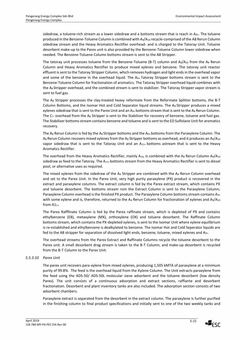
5.5.3.10 Parex Unit
The parex unit recovers para-xylene from mixed xylenes, producing 1,505 kMTA of paraxylene at a minimum
purity of 99.8%. The feed is the overhead liquid from the Xylene Column. The Unit extracts paraxylene from
the feed using the ADS-50/ ADS-50L molecular sieve adsorbent and the toluene desorbent (low density
Parex). The unit consists of a continuous adsorption and extract sections, raffiante and desorbent
fractionation. Desorbent and plant inventory tanks are also included. The adsorption section consists of two
adsorbent chambers.
Paraxylene extract is separated from the desorbent in the extract column. The paraxylene is further purified
in the finishing column to final product specifications and initially sent to one of the two weekly tanks and
Pengerang Energy Complex Sdn Bhd Pengerang Energy Complex
Environmental Impact Assessment
April 2019 J18-780-MY-PA PEC EIA Rev 00
5-22
then storage. The finishing column overhead liquid is sent to the stripper column in the tatoray unit.
Desorbent is recycled to the adsorption section.
The raffinate is separated from the desorbent in the raffinate column and is then routed to the isomar unit.
Desorbent is recycled to the adsorption section. The desorbent rerun column bottoms are routed to the
heavy aromatics tank via the heavy aromatics product cooler in the aromatic fractionation unit.
Waste water produced from the raffinate column receiver and the finishing column receiver will be routed
to the waste water treatment plant. Solid waste will include spent adsorbent (zeolite) from the adsorbent
chambers and will be generated once every 10 years and will be sent for off-site disposal by a licensed waste
collector.
Figure 5.13 – Parex Process Unit
Source: UOP
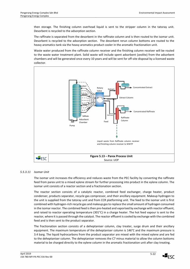
5.5.3.11 Isomar Unit
The isomar unit increases the efficiency and reduces waste from the PEC facility by converting the raffinate
feed from parex unit to a mixed xylene stream for further processing into product in the xylene column. The
isomar unit consists of a reactor section and a fractionation section.
The reactor section consists of a catalytic reactor, combined feed exchanger, charge heater, product
condenser, products separator, recycle gas compressor, and their ancillary equipment. Makeup hydrogen to
the unit is supplied from the tatoray unit and from CCR platforming unit. The feed to the isomar unit is first
combined with hydrogen-rich recycle gas and makeup gas to replace the small amount of hydrogen consumed
in the isomar reactor. The combined feed is then pre-heated and vaporised by exchange with reactor effluent,
and raised to reactor operating temperature (301°C) in a charge heater. The hot feed vapour is sent to the
reactor, where it is passed through the catalyst. The reactor effluent is cooled by exchange with the combined
feed and is then sent to the product separator.
The fractionation section consists of a deheptaniser column, clay treater, surge drum and their ancillary
equipment. The maximum temperature of the deheptaniser column is 146°C and the maximum pressure is
3.4 barg. The liquid hydrocarbons from the product separator are mixed with the mixed xylene and are fed
to the deheptaniser column. The deheptaniser removes the C7 minus material to allow the column bottoms
material to be charged directly to the xylene column in the aromatic fractionation unit after clay treating.
Rotary
Valve
Concentrated Extract
Extract Column
Extract
Desorbent
Concentrated Raffinate
Raffinate
Column
Desorbent
Feed
Liquid waste from Raffinate column receiver
and finishing column receiver to WWTP
Raffinate
Extract
Feed
Raffinate
Adsorbent
Chamber
Pump
Pengerang Energy Complex Sdn Bhd Pengerang Energy Complex
Environmental Impact Assessment
April 2019 J18-780-MY-PA PEC EIA Rev 00
5-23
The deheptaniser overhead liquid is routed to the stabiliser column in the tatoray unit. The deheptaniser
column net overhead gas and product separator net gas from the unit is routed to fuel gas. Stripper column
net bottoms will be routed to the sulfolane unit.
Waste water with aromatic hydrocarbons generated from the deheptaniser will be routed to the waste water
treatment plant. The unit will produce point source emissions from the deheptaniser reboiler and charge
heater stacks. Regeneration waste gas is vented to atmosphere during catalyst regeneration. Solid waste will
include spent catalyst (Pt on silica-alumina) generated once every 6 years and spent clay and will be sent for
off-site disposal by a licensed waste collector.
Figure 5.14 – Isomar Process Unit
Source: UOP
5.6 Utilities to be Constructed and Operated by PEC
In addition to the Process Areas described above, PEC will also set up the instrument air/plant air system,
liquid nitrogen tank with vaporizer, potable water system and flare system. Buildings as listed in Table 5.2
such as warehouse, etc. will also be constructed for use during the operations of the PEC facility.
5.6.1 Steam Boilers
To enable steam production to support the manufacturing process PEC will operate 3 Steam Boilers (2
operating continuously and 1 on standby). Each boiler will have a capacity of 220 t/hr producing 45 kg/cm2
high pressure steam with firing by natural gas. Each boiler will have an individual stack (Modular Boiler system
envisaged). Each stack height is estimated to be ~40 m with a stack diameter of ~2.6 m.
Vent gas to atmosphere during catalyst
regeneration
Heater Flue Gas Stack
Purge
Gas
Separator
Deheptaniser reboiler flue gas stack
Fuel Gas
To Benzene
Recovery Deheptaniser
Steam
To Xylene
Splitter
Liquid waste from
Deheptaniser to WWTP
Makeup
Hydrogen
Charge
Heater
Parex Raffinate
Pengerang Energy Complex Sdn Bhd Pengerang Energy Complex
Environmental Impact Assessment
April 2019 J18-780-MY-PA PEC EIA Rev 00
5-24
5.6.2 Instrument and Plant Air System
The instrument and plant air system consist of four non-lubricated (oil free) motor driven centrifugal
compressors, each having a capacity of 4,500 Nm3/hr. To ensure an uninterrupted supply of instrument air,
normally three compressors will work to cater for the instrument and plant air requirement. Another one
motor driven compressor will be on stand-by.
5.6.3 Nitrogen System
Nitrogen is required continuously for tank blanketing, for operation of CCR catalyst regeneration and to other
process units. Nitrogen will be supplied from an external supplier with a normal pressure of 9° barg and
99.7% purity. The normal supply temperature shall be 20°C min and 40°C maximum.
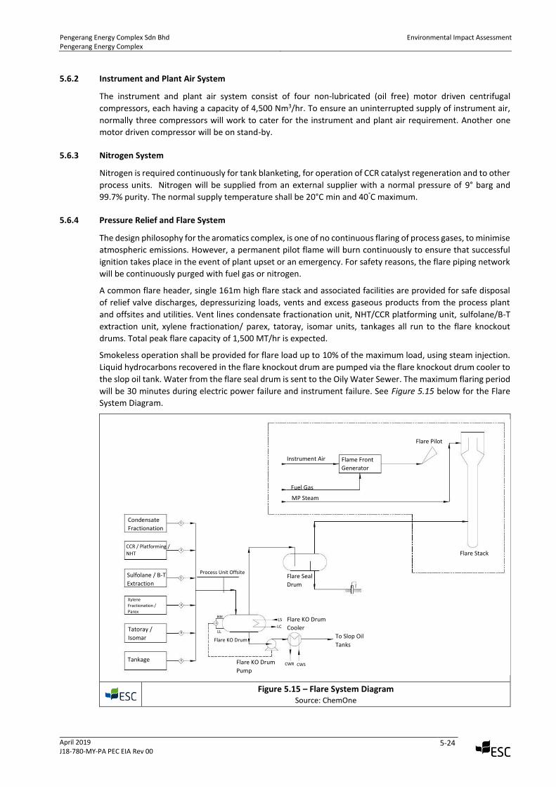
5.6.4 Pressure Relief and Flare System
The design philosophy for the aromatics complex, is one of no continuous flaring of process gases, to minimise
atmospheric emissions. However, a permanent pilot flame will burn continuously to ensure that successful
ignition takes place in the event of plant upset or an emergency. For safety reasons, the flare piping network
will be continuously purged with fuel gas or nitrogen.
A common flare header, single 161m high flare stack and associated facilities are provided for safe disposal
of relief valve discharges, depressurizing loads, vents and excess gaseous products from the process plant
and offsites and utilities. Vent lines condensate fractionation unit, NHT/CCR platforming unit, sulfolane/B-T
extraction unit, xylene fractionation/ parex, tatoray, isomar units, tankages all run to the flare knockout
drums. Total peak flare capacity of 1,500 MT/hr is expected.
Smokeless operation shall be provided for flare load up to 10% of the maximum load, using steam injection.
Liquid hydrocarbons recovered in the flare knockout drum are pumped via the flare knockout drum cooler to
the slop oil tank. Water from the flare seal drum is sent to the Oily Water Sewer. The maximum flaring period
will be 30 minutes during electric power failure and instrument failure. See Figure 5.15 below for the Flare
System Diagram.
Figure 5.15 – Flare System Diagram
Source: ChemOne
Instrument Air
Fuel Gas
MP Steam
Flame Front
Generator
Flare Pilot
Flare Stack
Flare Seal
Drum
Flare KO Drum
Cooler
To Slop Oil
Tanks
Flare KO Drum
Pump CWR CWS
LS
LC
Flare KO Drum
Process Unit Offsite
Condensate
Fractionation
CCR / Platforming /
NHT
Sulfolane / B-T
Extraction
Xylene
Fractionation /
Parex
Tatoray /
Isomar
Tankage
HH
LL
Pengerang Energy Complex Sdn Bhd Pengerang Energy Complex
Environmental Impact Assessment
April 2019 J18-780-MY-PA PEC EIA Rev 00
5-25
The facility will also have a continuous emission monitoring system (CEMS) to assess compliance
determinations or determination of exceedances of the standards.
CEMS (for steam boiler chimney and process heater stacks) will typically include:
• A NOx pollutant concentration monitor;
• A CO concentration monitor;
• Total Particulate Matter monitor;
• A volumetric flow monitor;
• A computer-based data acquisition and handling system for recording and performing
calculations with the data.
5.6.5 Potable Water Supply
Potable water supply will be distributed to from Syarikat Air Johor Sdn Bhd, the city water supplier in Johor.
5.6.6 Support Facilities
As discussed previously, the following support facilities will be constructed and operated by PEC:
• Steam boiler including steam supply and condensate recovery system;
• Cooling water system;
• Demineralized water system;
• Waste water system;
• Fire water system;
• Instrument Air/Plant Air;
• Nitrogen system;
• Potable water; and
• Pipelines from/to Pengerang Deepwater Terminal (PDT).
The following support facilities will be developed, operated and managed by third parties:
• Condensate (feed) bulk storage;
• Products bulk storage; and
• Jetty facilities.
The following sections present an overview of the major support facilities to be constructed and operated
for information purposes about the general operations of the entire Aromatics Complex.
5.6.7 Product Import and Export
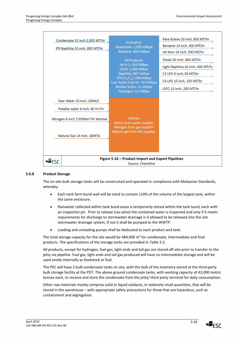
Figure 5.16 below provides the figurative layout for all product import and export pipelines for the PEC
facility. Incoming pipelines to the jetty include condensate (which is directed on to the third-party bulk
storage terminal and sour naphtha (which is directed onto the PEC). Other incoming pipelines to the PEC
include condensate from the 3rd party bulk storage terminal and nitrogen (from an external supplier).
The product export is via the same pipelines back to the dedicated PEC jetty of for storage at the third-party
bulk storage terminal pending export.
The jetty will be located approximately 5.3 km south of the site at the PDT and the third-party bulk storage
terminal located in the PDTs CTF area. The design will be required to meet Malaysian and PEC standards
with the jetty topside facilities including for marine receipt and dispatch for PEC facility aromatic products,
oil products and LPG.
The jetty including its pipeline from the PEC plant/tank farm and third-party bulk storage terminal will be
constructed and operated by the third party.
Pengerang Energy Complex Sdn Bhd Pengerang Energy Complex
Environmental Impact Assessment
April 2019 J18-780-MY-PA PEC EIA Rev 00
5-26
Figure 5.16 – Product Import and Export Pipelines
Source: ChemOne
5.6.8 Product Storage
The on-site bulk storage tanks will be constructed and operated in compliance with Malaysian Standards,
whereby:
• Each tank farm bund wall will be sized to contain 110% of the volume of the largest tank, within
the same enclosure.
• Rainwater collected within tank bund areas is temporarily stored within the tank bund, each with
an inspection pit. Prior to release (via valve) the contained water is inspected and only if it meets
requirements for discharge to stormwater drainage is it allowed to be released into the site
stormwater drainage system, if not it shall be pumped to the WWTP.
• Loading and unloading pumps shall be dedicated to each product and tank.
The total storage capacity for the site would be 484,000 m3 for condensate, intermediate and final
products. The specifications of the storage tanks are provided in Table 5.5.
All products, except for hydrogen, fuel gas, light ends and tail gas are stored off-site prior to transfer to the
jetty via pipeline. Fuel gas, light ends and tail gas produced will have no intermediate storage and will be
used onsite internally as feedstock or fuel.
The PEC will have 3 bulk condensate tanks on site, with the bulk of the inventory stored at the third-party
bulk storage facility at the PDT. The above ground condensate tanks, with working capacity of 43,000 metric
tonnes each, to receive and store the condensate from the jetty/ third party terminal for daily consumption.
Other raw materials mostly comprise solid or liquid catalysts, in relatively small quantities, that will be
stored in the warehouse – with appropriate safety precautions for those that are hazardous, such as
containment and segregation.
Pengerang Energy Complex Sdn Bhd Pengerang Energy Complex
Environmental Impact Assessment
April 2019 J18-780-MY-PA PEC EIA Rev 00
5-27
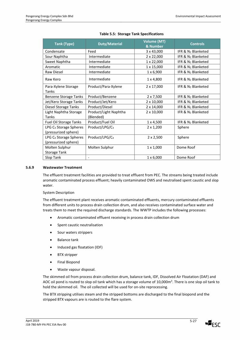
Table 5.5: Storage Tank Specifications
Tank (Type) Duty/Material Volume (MT)
& Number Controls
Condensate Feed 3 x 43,000 IFR & N2 Blanketed
Sour Naphtha Intermediate 2 x 22,000 IFR & N2 Blanketed
Sweet Naphtha Intermediate 1 x 22,000 IFR & N2 Blanketed
Aromatic Intermediate 1 x 15,000 IFR & N2 Blanketed
Raw Diesel Intermediate 1 x 6,900 IFR & N2 Blanketed
Raw Kero Intermediate 1 x 4,800 IFR & N2 Blanketed
Para-Xylene Storage Tanks
Product/Para-Xylene 2 x 17,000 IFR & N2 Blanketed
Benzene Storage Tanks Product/Benzene 2 x 7,500 IFR & N2 Blanketed
Jet/Kero Storage Tanks Product/Jet/Kero 2 x 10,000 IFR & N2 Blanketed
Diesel Storage Tanks Product/Diesel 2 x 14,000 IFR & N2 Blanketed
Light Naphtha Storage Tanks
Product/Light Naphtha (Blended)
2 x 10,000 IFR & N2 Blanketed
Fuel Oil Storage Tanks Product/Fuel Oil 1 x 4,500 IFR & N2 Blanketed
LPG C3 Storage Spheres (pressurized sphere)
Product/LPG/C3 2 x 1,200 Sphere
LPG C4 Storage Spheres (pressurized sphere)
Product/LPG/C4 2 x 2,500 Sphere
Molten Sulphur Storage Tank
Molten Sulphur 1 x 1,000 Dome Roof
Slop Tank - 1 x 6,000 Dome Roof
5.6.9 Wastewater Treatment
The effluent treatment facilities are provided to treat effluent from PEC. The streams being treated include
aromatic contaminated process effluent; heavily contaminated OWS and neutralised spent caustic and slop
water.
System Description
The effluent treatment plant receives aromatic contaminated effluents, mercury contaminated effluents
from different units to process drain collection drum, and also receives contaminated surface water and
treats them to meet the required discharge standards. The WWTP includes the following processes:
• Aromatic contaminated effluent receiving in process drain collection drum
• Spent caustic neutralisation
• Sour waters strippers
• Balance tank
• Induced gas floatation (IDF)
• BTX stripper
• Final Biopond
• Waste vapour disposal.
The skimmed oil from process drain collection drum, balance tank, IDF, Dissolved Air Floatation (DAF) and
AOC oil pond is routed to slop oil tank which has a storage volume of 10,000m3. There is one slop oil tank to
hold the skimmed oil. The oil collected will be used for on-site reprocessing.
The BTX stripping utilises steam and the stripped bottoms are discharged to the final biopond and the
stripped BTX vapours are is routed to the flare system.
Pengerang Energy Complex Sdn Bhd Pengerang Energy Complex
Environmental Impact Assessment
April 2019 J18-780-MY-PA PEC EIA Rev 00
5-28
Treated waste water is discharged to the on-site final pond, which will have a holding volume of 10,000 m3,
prior to discharge to the PIP detention pond. The sludge generated from waste water treatment is
periodically collected and disposed of as scheduled waste by a DoE-licensed waste collector, off-site.
All wastewater from the PEC facility will be treated in the on-site wastewater treatment plant (WWTP) and
discharged after treatment to the surrounding PIP storm drainage system. Hydrocarbon contaminants are
separated, concentrated and recycled or disposed of by external licensed parties. Aqueous components are
treated and neutralised prior to discharge to storm water drainage, depending on source and composition.
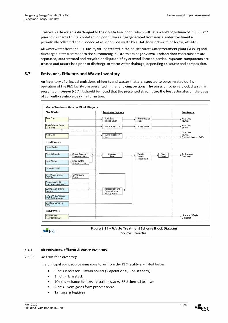
5.7 Emissions, Effluents and Waste Inventory
An inventory of principal emissions, effluents and wastes that are expected to be generated during
operation of the PEC facility are presented in the following sections. The emission scheme block diagram is
presented in Figure 5.17. It should be noted that the presented streams are the best estimates on the basis
of currently available design information.
Figure 5.17 – Waste Treatment Scheme Block Diagram
Source: ChemOne
5.7.1 Air Emissions, Effluent & Waste Inventory
5.7.1.1 Air Emissions Inventory
The principal point source emissions to air from the PEC facility are listed below:
• 3 no’s stacks for 3 steam boilers (2 operational, 1 on standby)
• 1 no’s - flare stack
• 10 no’s – charge heaters, re-boilers stacks, SRU thermal oxidiser
• 2 no’s – vent gases from process areas
• Tankage & fugitives
Pengerang Energy Complex Sdn Bhd Pengerang Energy Complex
Environmental Impact Assessment
April 2019 J18-780-MY-PA PEC EIA Rev 00
5-29
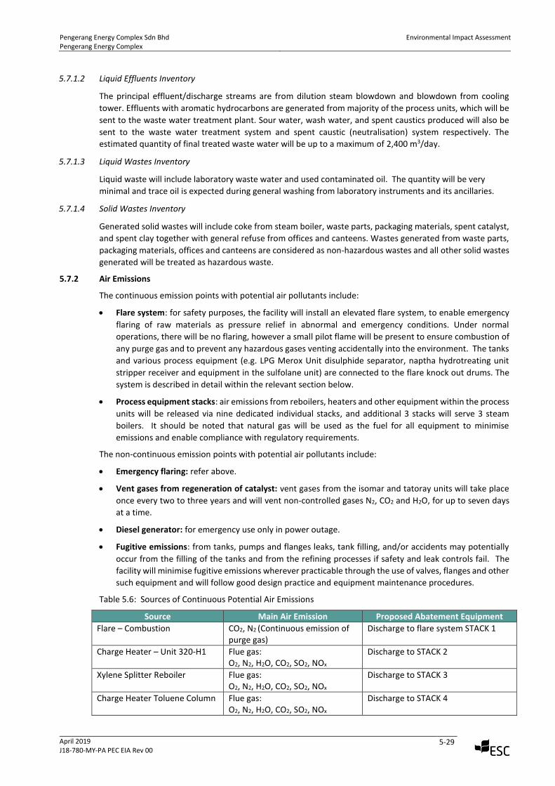
5.7.1.2 Liquid Effluents Inventory
The principal effluent/discharge streams are from dilution steam blowdown and blowdown from cooling
tower. Effluents with aromatic hydrocarbons are generated from majority of the process units, which will be
sent to the waste water treatment plant. Sour water, wash water, and spent caustics produced will also be
sent to the waste water treatment system and spent caustic (neutralisation) system respectively. The
estimated quantity of final treated waste water will be up to a maximum of 2,400 m3/day.
5.7.1.3 Liquid Wastes Inventory
Liquid waste will include laboratory waste water and used contaminated oil. The quantity will be very
minimal and trace oil is expected during general washing from laboratory instruments and its ancillaries.
5.7.1.4 Solid Wastes Inventory
Generated solid wastes will include coke from steam boiler, waste parts, packaging materials, spent catalyst,
and spent clay together with general refuse from offices and canteens. Wastes generated from waste parts,
packaging materials, offices and canteens are considered as non-hazardous wastes and all other solid wastes
generated will be treated as hazardous waste.
5.7.2 Air Emissions
The continuous emission points with potential air pollutants include:
• Flare system: for safety purposes, the facility will install an elevated flare system, to enable emergency
flaring of raw materials as pressure relief in abnormal and emergency conditions. Under normal
operations, there will be no flaring, however a small pilot flame will be present to ensure combustion of
any purge gas and to prevent any hazardous gases venting accidentally into the environment. The tanks
and various process equipment (e.g. LPG Merox Unit disulphide separator, naptha hydrotreating unit
stripper receiver and equipment in the sulfolane unit) are connected to the flare knock out drums. The
system is described in detail within the relevant section below.
• Process equipment stacks: air emissions from reboilers, heaters and other equipment within the process
units will be released via nine dedicated individual stacks, and additional 3 stacks will serve 3 steam
boilers. It should be noted that natural gas will be used as the fuel for all equipment to minimise
emissions and enable compliance with regulatory requirements.
The non-continuous emission points with potential air pollutants include:
• Emergency flaring: refer above.
• Vent gases from regeneration of catalyst: vent gases from the isomar and tatoray units will take place
once every two to three years and will vent non-controlled gases N2, CO2 and H2O, for up to seven days
at a time.
• Diesel generator: for emergency use only in power outage.
• Fugitive emissions: from tanks, pumps and flanges leaks, tank filling, and/or accidents may potentially
occur from the filling of the tanks and from the refining processes if safety and leak controls fail. The
facility will minimise fugitive emissions wherever practicable through the use of valves, flanges and other
such equipment and will follow good design practice and equipment maintenance procedures.
Table 5.6: Sources of Continuous Potential Air Emissions
Source Main Air Emission Proposed Abatement Equipment
Flare – Combustion
CO2, N2 (Continuous emission of purge gas)
Discharge to flare system STACK 1
Charge Heater – Unit 320-H1 Flue gas: O2, N2, H2O, CO2, SO2, NOx
Discharge to STACK 2
Xylene Splitter Reboiler Flue gas: O2, N2, H2O, CO2, SO2, NOx
Discharge to STACK 3
Charge Heater Toluene Column Flue gas: O2, N2, H2O, CO2, SO2, NOx
Discharge to STACK 4
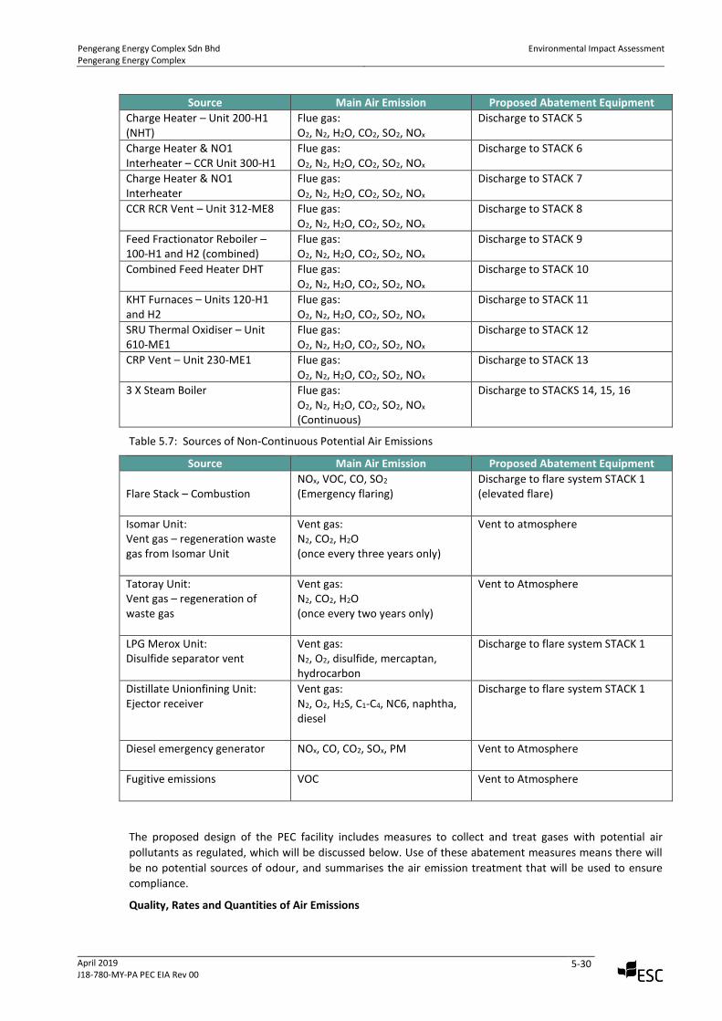
Pengerang Energy Complex Sdn Bhd Pengerang Energy Complex
Environmental Impact Assessment
April 2019 J18-780-MY-PA PEC EIA Rev 00
5-30
Source Main Air Emission Proposed Abatement Equipment
Charge Heater – Unit 200-H1 (NHT)
Flue gas: O2, N2, H2O, CO2, SO2, NOx
Discharge to STACK 5
Charge Heater & NO1 Interheater – CCR Unit 300-H1
Flue gas: O2, N2, H2O, CO2, SO2, NOx
Discharge to STACK 6
Charge Heater & NO1 Interheater
Flue gas: O2, N2, H2O, CO2, SO2, NOx
Discharge to STACK 7
CCR RCR Vent – Unit 312-ME8 Flue gas: O2, N2, H2O, CO2, SO2, NOx
Discharge to STACK 8
Feed Fractionator Reboiler – 100-H1 and H2 (combined)
Flue gas: O2, N2, H2O, CO2, SO2, NOx
Discharge to STACK 9
Combined Feed Heater DHT Flue gas: O2, N2, H2O, CO2, SO2, NOx
Discharge to STACK 10
KHT Furnaces – Units 120-H1 and H2
Flue gas: O2, N2, H2O, CO2, SO2, NOx
Discharge to STACK 11
SRU Thermal Oxidiser – Unit 610-ME1
Flue gas: O2, N2, H2O, CO2, SO2, NOx
Discharge to STACK 12
CRP Vent – Unit 230-ME1 Flue gas: O2, N2, H2O, CO2, SO2, NOx
Discharge to STACK 13
3 X Steam Boiler Flue gas: O2, N2, H2O, CO2, SO2, NOx (Continuous)
Discharge to STACKS 14, 15, 16
Table 5.7: Sources of Non-Continuous Potential Air Emissions
Source Main Air Emission Proposed Abatement Equipment
Flare Stack – Combustion
NOx, VOC, CO, SO2
(Emergency flaring) Discharge to flare system STACK 1 (elevated flare)
Isomar Unit: Vent gas – regeneration waste gas from Isomar Unit
Vent gas: N2, CO2, H2O (once every three years only)
Vent to atmosphere
Tatoray Unit: Vent gas – regeneration of waste gas
Vent gas: N2, CO2, H2O (once every two years only)
Vent to Atmosphere
LPG Merox Unit: Disulfide separator vent
Vent gas: N2, O2, disulfide, mercaptan, hydrocarbon
Discharge to flare system STACK 1
Distillate Unionfining Unit: Ejector receiver
Vent gas: N2, O2, H2S, C1-C4, NC6, naphtha, diesel
Discharge to flare system STACK 1
Diesel emergency generator
NOx, CO, CO2, SOx, PM Vent to Atmosphere
Fugitive emissions
VOC Vent to Atmosphere
The proposed design of the PEC facility includes measures to collect and treat gases with potential air
pollutants as regulated, which will be discussed below. Use of these abatement measures means there will
be no potential sources of odour, and summarises the air emission treatment that will be used to ensure
compliance.
Quality, Rates and Quantities of Air Emissions
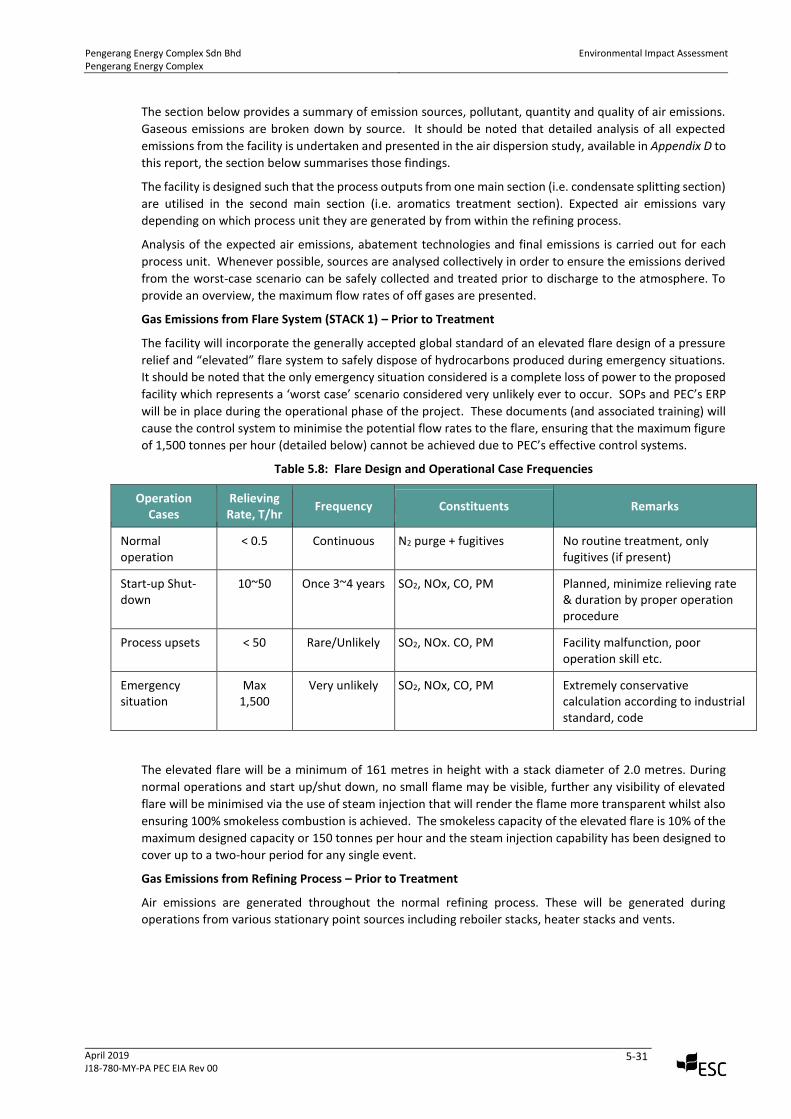
Pengerang Energy Complex Sdn Bhd Pengerang Energy Complex
Environmental Impact Assessment
April 2019 J18-780-MY-PA PEC EIA Rev 00
5-31
The section below provides a summary of emission sources, pollutant, quantity and quality of air emissions.
Gaseous emissions are broken down by source. It should be noted that detailed analysis of all expected
emissions from the facility is undertaken and presented in the air dispersion study, available in Appendix D to
this report, the section below summarises those findings.
The facility is designed such that the process outputs from one main section (i.e. condensate splitting section)
are utilised in the second main section (i.e. aromatics treatment section). Expected air emissions vary
depending on which process unit they are generated by from within the refining process.
Analysis of the expected air emissions, abatement technologies and final emissions is carried out for each
process unit. Whenever possible, sources are analysed collectively in order to ensure the emissions derived
from the worst-case scenario can be safely collected and treated prior to discharge to the atmosphere. To
provide an overview, the maximum flow rates of off gases are presented.
Gas Emissions from Flare System (STACK 1) – Prior to Treatment
The facility will incorporate the generally accepted global standard of an elevated flare design of a pressure
relief and “elevated” flare system to safely dispose of hydrocarbons produced during emergency situations.
It should be noted that the only emergency situation considered is a complete loss of power to the proposed
facility which represents a ‘worst case’ scenario considered very unlikely ever to occur. SOPs and PEC’s ERP
will be in place during the operational phase of the project. These documents (and associated training) will
cause the control system to minimise the potential flow rates to the flare, ensuring that the maximum figure
of 1,500 tonnes per hour (detailed below) cannot be achieved due to PEC’s effective control systems.
Table 5.8: Flare Design and Operational Case Frequencies
Operation Cases
Relieving Rate, T/hr
Frequency Constituents Remarks
Normal operation
< 0.5 Continuous N2 purge + fugitives No routine treatment, only fugitives (if present)
Start-up Shut-down
10~50 Once 3~4 years SO2, NOx, CO, PM Planned, minimize relieving rate & duration by proper operation procedure
Process upsets < 50 Rare/Unlikely SO2, NOx. CO, PM
Facility malfunction, poor operation skill etc.
Emergency situation
Max 1,500
Very unlikely SO2, NOx, CO, PM
Extremely conservative calculation according to industrial standard, code
The elevated flare will be a minimum of 161 metres in height with a stack diameter of 2.0 metres. During
normal operations and start up/shut down, no small flame may be visible, further any visibility of elevated
flare will be minimised via the use of steam injection that will render the flame more transparent whilst also
ensuring 100% smokeless combustion is achieved. The smokeless capacity of the elevated flare is 10% of the
maximum designed capacity or 150 tonnes per hour and the steam injection capability has been designed to
cover up to a two-hour period for any single event.
Gas Emissions from Refining Process – Prior to Treatment
Air emissions are generated throughout the normal refining process. These will be generated during
operations from various stationary point sources including reboiler stacks, heater stacks and vents.
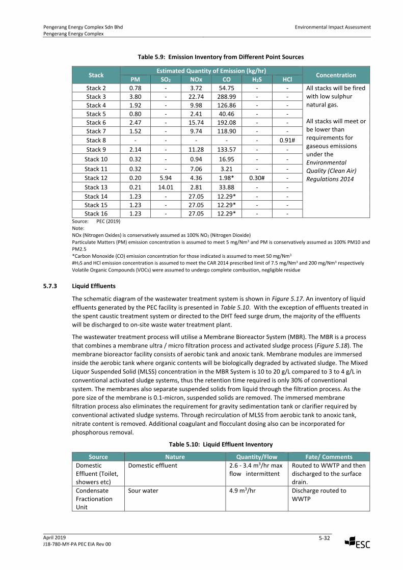
Pengerang Energy Complex Sdn Bhd Pengerang Energy Complex
Environmental Impact Assessment
April 2019 J18-780-MY-PA PEC EIA Rev 00
5-32
Table 5.9: Emission Inventory from Different Point Sources
Stack Estimated Quantity of Emission (kg/hr)
Concentration PM SO2 NOx CO H2S HCl
Stack 2 0.78 - 3.72 54.75 - - All stacks will be fired with low sulphur natural gas. All stacks will meet or be lower than requirements for gaseous emissions under the Environmental Quality (Clean Air) Regulations 2014
Stack 3 3.80 - 22.74 288.99 - -
Stack 4 1.92 - 9.98 126.86 - -
Stack 5 0.80 - 2.41 40.46 - -
Stack 6 2.47 - 15.74 192.08 - -
Stack 7 1.52 - 9.74 118.90 - -
Stack 8 - - - - - 0.91#
Stack 9 2.14 - 11.28 133.57 - -
Stack 10 0.32 - 0.94 16.95 - -
Stack 11 0.32 - 7.06 3.21 - -
Stack 12 0.20 5.94 4.36 1.98* 0.30# -
Stack 13 0.21 14.01 2.81 33.88 - -
Stack 14 1.23 - 27.05 12.29* - -
Stack 15 1.23 - 27.05 12.29* - -
Stack 16 1.23 - 27.05 12.29* - - Source: PEC (2019)
Note:
NOx (Nitrogen Oxides) is conservatively assumed as 100% NO2 (Nitrogen Dioxide)
Particulate Matters (PM) emission concentration is assumed to meet 5 mg/Nm3 and PM is conservatively assumed as 100% PM10 and
PM2.5
*Carbon Monoxide (CO) emission concentration for those indicated is assumed to meet 50 mg/Nm3
#H2S and HCl emission concentration is assumed to meet the CAR 2014 prescribed limit of 7.5 mg/Nm3 and 200 mg/Nm3 respectively
Volatile Organic Compounds (VOCs) were assumed to undergo complete combustion, negligible residue
5.7.3 Liquid Effluents
The schematic diagram of the wastewater treatment system is shown in Figure 5.17. An inventory of liquid
effluents generated by the PEC facility is presented in Table 5.10. With the exception of effluents treated in
the spent caustic treatment system or directed to the DHT feed surge drum, the majority of the effluents
will be discharged to on-site waste water treatment plant.
The wastewater treatment process will utilise a Membrane Bioreactor System (MBR). The MBR is a process
that combines a membrane ultra / micro filtration process and activated sludge process (Figure 5.18). The
membrane bioreactor facility consists of aerobic tank and anoxic tank. Membrane modules are immersed
inside the aerobic tank where organic contents will be biologically degraded by activated sludge. The Mixed
Liquor Suspended Solid (MLSS) concentration in the MBR System is 10 to 20 g/L compared to 3 to 4 g/L in
conventional activated sludge systems, thus the retention time required is only 30% of conventional
system. The membranes also separate suspended solids from liquid through the filtration process. As the
pore size of the membrane is 0.1-micron, suspended solids are removed. The immersed membrane
filtration process also eliminates the requirement for gravity sedimentation tank or clarifier required by
conventional activated sludge systems. Through recirculation of MLSS from aerobic tank to anoxic tank,
nitrate content is removed. Additional coagulant and flocculant dosing also can be incorporated for
phosphorous removal.
Table 5.10: Liquid Effluent Inventory
Source Nature Quantity/Flow Fate/ Comments
Domestic Effluent (Toilet, showers etc)
Domestic effluent 2.6 - 3.4 m3/hr max flow intermittent
Routed to WWTP and then discharged to the surface drain.
Condensate Fractionation Unit
Sour water 4.9 m3/hr Discharge routed to WWTP
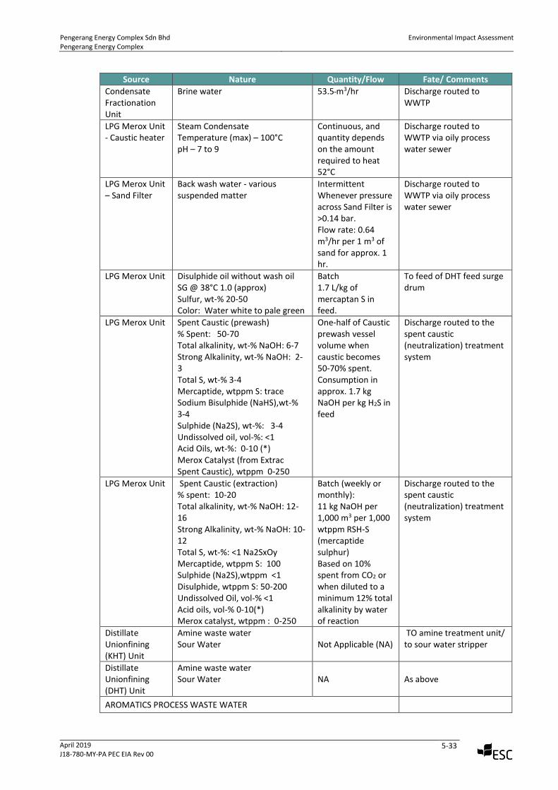
Pengerang Energy Complex Sdn Bhd Pengerang Energy Complex
Environmental Impact Assessment
April 2019 J18-780-MY-PA PEC EIA Rev 00
5-33
Source Nature Quantity/Flow Fate/ Comments
Condensate Fractionation Unit
Brine water 53.5 m3/hr Discharge routed to WWTP
LPG Merox Unit - Caustic heater
Steam Condensate Temperature (max) – 100°C pH – 7 to 9
Continuous, and quantity depends on the amount required to heat 52°C
Discharge routed to WWTP via oily process water sewer
LPG Merox Unit – Sand Filter
Back wash water - various suspended matter
Intermittent Whenever pressure across Sand Filter is >0.14 bar. Flow rate: 0.64 m3/hr per 1 m3 of sand for approx. 1 hr.
Discharge routed to WWTP via oily process water sewer
LPG Merox Unit Disulphide oil without wash oil SG @ 38°C 1.0 (approx) Sulfur, wt-% 20-50 Color: Water white to pale green
Batch 1.7 L/kg of mercaptan S in feed.
To feed of DHT feed surge drum
LPG Merox Unit Spent Caustic (prewash) % Spent: 50-70 Total alkalinity, wt-% NaOH: 6-7 Strong Alkalinity, wt-% NaOH: 2-3 Total S, wt-% 3-4 Mercaptide, wtppm S: trace Sodium Bisulphide (NaHS),wt-% 3-4 Sulphide (Na2S), wt-%: 3-4 Undissolved oil, vol-%: <1 Acid Oils, wt-%: 0-10 (*) Merox Catalyst (from Extrac Spent Caustic), wtppm 0-250
One-half of Caustic prewash vessel volume when caustic becomes 50-70% spent. Consumption in approx. 1.7 kg NaOH per kg H2S in feed
Discharge routed to the spent caustic (neutralization) treatment system
LPG Merox Unit Spent Caustic (extraction) % spent: 10-20 Total alkalinity, wt-% NaOH: 12-16 Strong Alkalinity, wt-% NaOH: 10-12 Total S, wt-%: <1 Na2SxOy Mercaptide, wtppm S: 100 Sulphide (Na2S),wtppm <1 Disulphide, wtppm S: 50-200 Undissolved Oil, vol-% <1 Acid oils, vol-% 0-10(*) Merox catalyst, wtppm : 0-250
Batch (weekly or monthly): 11 kg NaOH per 1,000 m3 per 1,000 wtppm RSH-S (mercaptide sulphur) Based on 10% spent from CO2 or when diluted to a minimum 12% total alkalinity by water of reaction
Discharge routed to the spent caustic (neutralization) treatment system
Distillate Unionfining (KHT) Unit
Amine waste water Sour Water
Not Applicable (NA) TO amine treatment unit/ to sour water stripper
Distillate Unionfining (DHT) Unit
Amine waste water Sour Water
NA As above
AROMATICS PROCESS WASTE WATER
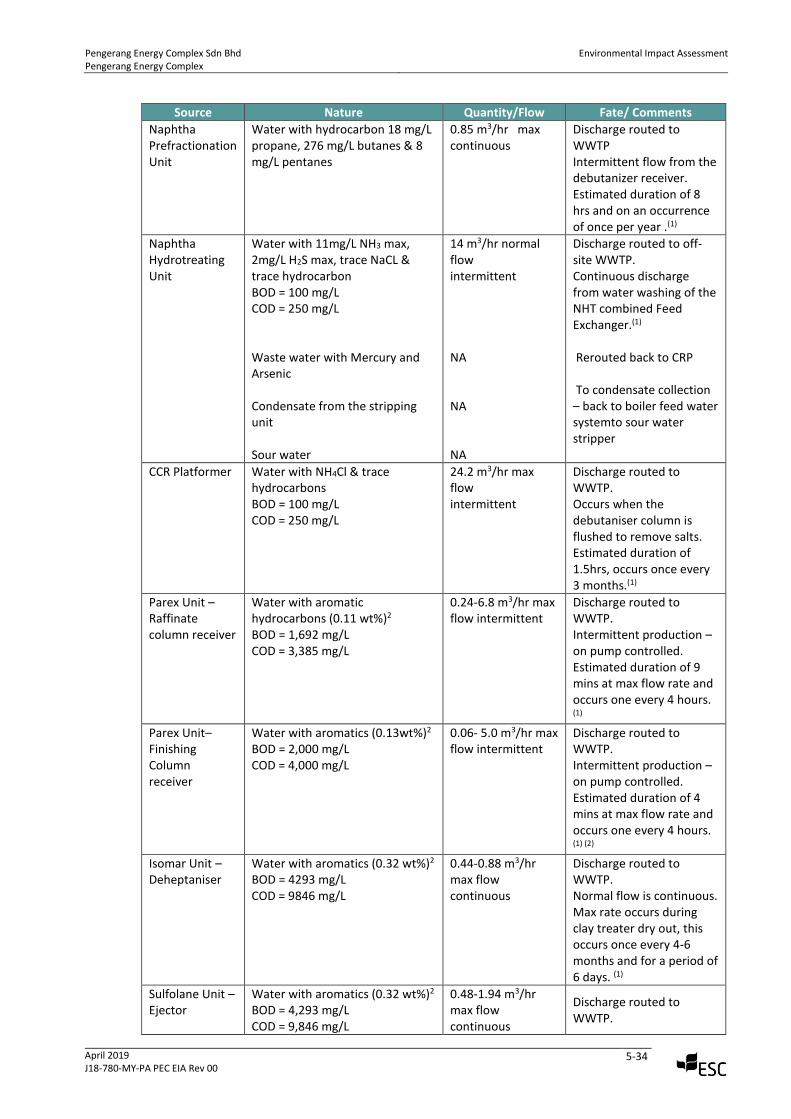
Pengerang Energy Complex Sdn Bhd Pengerang Energy Complex
Environmental Impact Assessment
April 2019 J18-780-MY-PA PEC EIA Rev 00
5-34
Source Nature Quantity/Flow Fate/ Comments
Naphtha Prefractionation Unit
Water with hydrocarbon 18 mg/L propane, 276 mg/L butanes & 8 mg/L pentanes
0.85 m3/hr max continuous
Discharge routed to WWTP Intermittent flow from the debutanizer receiver. Estimated duration of 8 hrs and on an occurrence of once per year .(1)
Naphtha Hydrotreating Unit
Water with 11mg/L NH3 max, 2mg/L H2S max, trace NaCL & trace hydrocarbon BOD = 100 mg/L COD = 250 mg/L Waste water with Mercury and Arsenic Condensate from the stripping unit Sour water
14 m3/hr normal flow intermittent NA NA NA
Discharge routed to off-site WWTP. Continuous discharge from water washing of the NHT combined Feed Exchanger.(1) Rerouted back to CRP To condensate collection – back to boiler feed water systemto sour water stripper
CCR Platformer Water with NH4Cl & trace hydrocarbons BOD = 100 mg/L COD = 250 mg/L
24.2 m3/hr max flow intermittent
Discharge routed to WWTP. Occurs when the debutaniser column is flushed to remove salts. Estimated duration of 1.5hrs, occurs once every 3 months.(1)
Parex Unit – Raffinate column receiver
Water with aromatic hydrocarbons (0.11 wt%)2
BOD = 1,692 mg/L COD = 3,385 mg/L
0.24-6.8 m3/hr max flow intermittent
Discharge routed to WWTP. Intermittent production – on pump controlled. Estimated duration of 9 mins at max flow rate and occurs one every 4 hours. (1)
Parex Unit– Finishing Column receiver
Water with aromatics (0.13wt%)2 BOD = 2,000 mg/L COD = 4,000 mg/L
0.06- 5.0 m3/hr max flow intermittent
Discharge routed to WWTP. Intermittent production – on pump controlled. Estimated duration of 4 mins at max flow rate and occurs one every 4 hours. (1) (2)
Isomar Unit – Deheptaniser
Water with aromatics (0.32 wt%)2
BOD = 4293 mg/L COD = 9846 mg/L
0.44-0.88 m3/hr max flow continuous
Discharge routed to WWTP. Normal flow is continuous. Max rate occurs during clay treater dry out, this occurs once every 4-6 months and for a period of 6 days. (1)
Sulfolane Unit – Ejector
Water with aromatics (0.32 wt%)2
BOD = 4,293 mg/L COD = 9,846 mg/L
0.48-1.94 m3/hr max flow continuous
Discharge routed to WWTP.
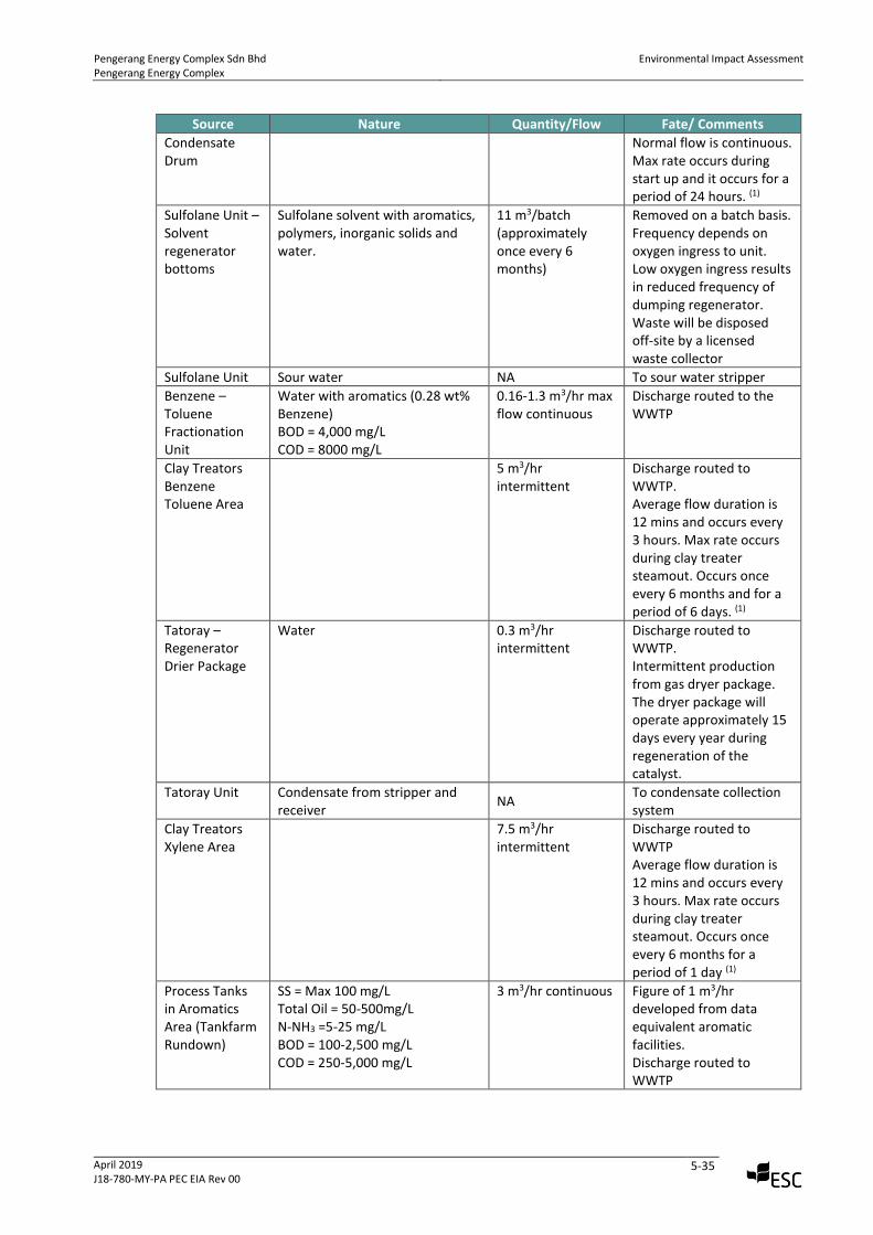
Pengerang Energy Complex Sdn Bhd Pengerang Energy Complex
Environmental Impact Assessment
April 2019 J18-780-MY-PA PEC EIA Rev 00
5-35
Source Nature Quantity/Flow Fate/ Comments
Condensate Drum
Normal flow is continuous. Max rate occurs during start up and it occurs for a period of 24 hours. (1)
Sulfolane Unit – Solvent regenerator bottoms
Sulfolane solvent with aromatics, polymers, inorganic solids and water.
11 m3/batch (approximately once every 6 months)
Removed on a batch basis. Frequency depends on oxygen ingress to unit. Low oxygen ingress results in reduced frequency of dumping regenerator. Waste will be disposed off-site by a licensed waste collector
Sulfolane Unit Sour water NA To sour water stripper
Benzene – Toluene Fractionation Unit
Water with aromatics (0.28 wt% Benzene) BOD = 4,000 mg/L COD = 8000 mg/L
0.16-1.3 m3/hr max flow continuous
Discharge routed to the WWTP
Clay Treators Benzene Toluene Area
5 m3/hr intermittent
Discharge routed to WWTP. Average flow duration is 12 mins and occurs every 3 hours. Max rate occurs during clay treater steamout. Occurs once every 6 months and for a period of 6 days. (1)
Tatoray – Regenerator Drier Package
Water 0.3 m3/hr intermittent
Discharge routed to WWTP. Intermittent production from gas dryer package. The dryer package will operate approximately 15 days every year during regeneration of the catalyst.
Tatoray Unit Condensate from stripper and receiver
NA To condensate collection system
Clay Treators Xylene Area
7.5 m3/hr intermittent
Discharge routed to WWTP Average flow duration is 12 mins and occurs every 3 hours. Max rate occurs during clay treater steamout. Occurs once every 6 months for a period of 1 day (1)
Process Tanks in Aromatics Area (Tankfarm Rundown)
SS = Max 100 mg/L Total Oil = 50-500mg/L N-NH3 =5-25 mg/L BOD = 100-2,500 mg/L COD = 250-5,000 mg/L
3 m3/hr continuous Figure of 1 m3/hr developed from data equivalent aromatic facilities. Discharge routed to WWTP
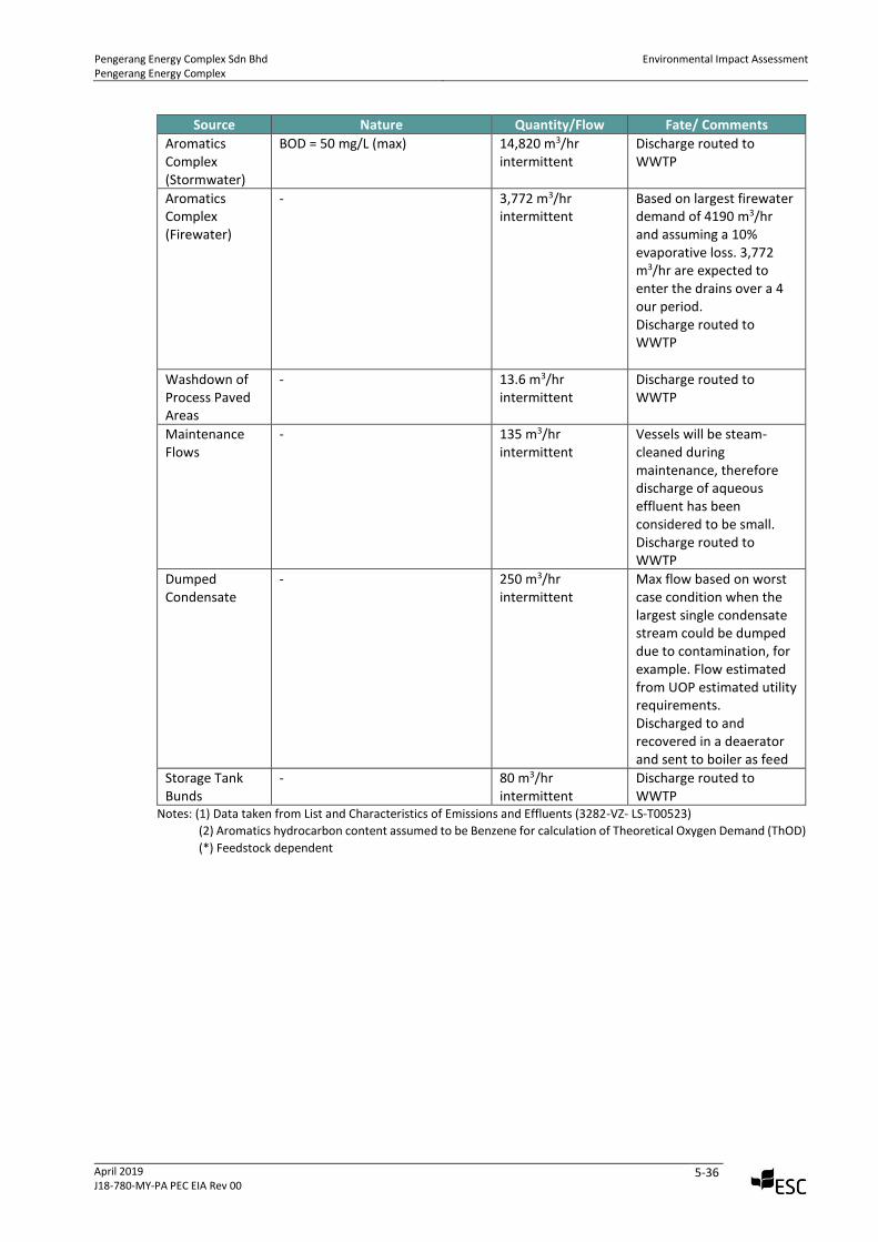
Pengerang Energy Complex Sdn Bhd Pengerang Energy Complex
Environmental Impact Assessment
April 2019 J18-780-MY-PA PEC EIA Rev 00
5-36
Source Nature Quantity/Flow Fate/ Comments
Aromatics Complex (Stormwater)
BOD = 50 mg/L (max) 14,820 m3/hr intermittent
Discharge routed to WWTP
Aromatics Complex (Firewater)
- 3,772 m3/hr intermittent
Based on largest firewater demand of 4190 m3/hr and assuming a 10% evaporative loss. 3,772 m3/hr are expected to enter the drains over a 4 our period. Discharge routed to WWTP
Washdown of Process Paved Areas
- 13.6 m3/hr intermittent
Discharge routed to WWTP
Maintenance Flows
- 135 m3/hr intermittent
Vessels will be steam-cleaned during maintenance, therefore discharge of aqueous effluent has been considered to be small. Discharge routed to WWTP
Dumped Condensate
- 250 m3/hr intermittent
Max flow based on worst case condition when the largest single condensate stream could be dumped due to contamination, for example. Flow estimated from UOP estimated utility requirements. Discharged to and recovered in a deaerator and sent to boiler as feed
Storage Tank Bunds
- 80 m3/hr intermittent
Discharge routed to WWTP
Notes: (1) Data taken from List and Characteristics of Emissions and Effluents (3282-VZ- LS-T00523)
(2) Aromatics hydrocarbon content assumed to be Benzene for calculation of Theoretical Oxygen Demand (ThOD)
(*) Feedstock dependent
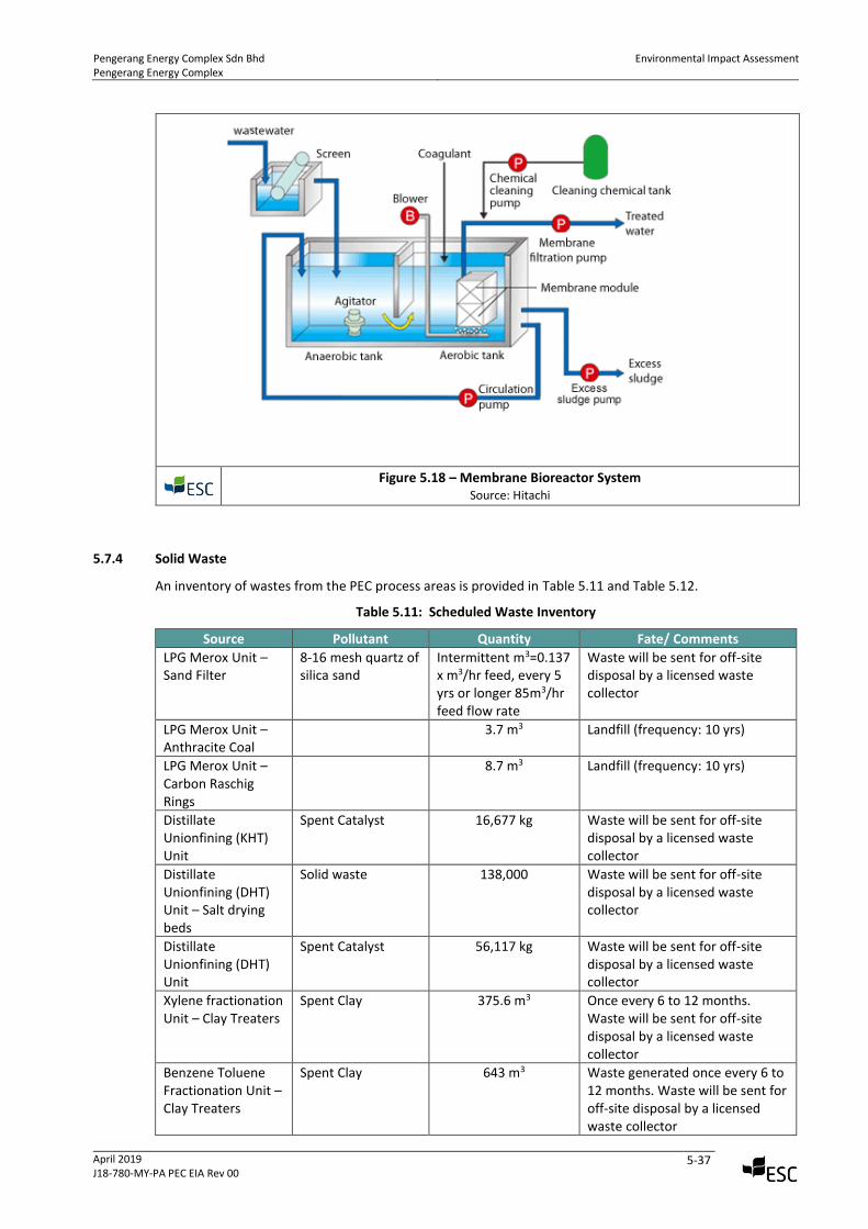
Pengerang Energy Complex Sdn Bhd Pengerang Energy Complex
Environmental Impact Assessment
April 2019 J18-780-MY-PA PEC EIA Rev 00
5-37
Figure 5.18 – Membrane Bioreactor System
Source: Hitachi
5.7.4 Solid Waste
An inventory of wastes from the PEC process areas is provided in Table 5.11 and Table 5.12.
Table 5.11: Scheduled Waste Inventory
Source Pollutant Quantity Fate/ Comments
LPG Merox Unit – Sand Filter
8-16 mesh quartz of silica sand
Intermittent m3=0.137 x m3/hr feed, every 5 yrs or longer 85m3/hr feed flow rate
Waste will be sent for off-site disposal by a licensed waste collector
LPG Merox Unit – Anthracite Coal
3.7 m3 Landfill (frequency: 10 yrs)
LPG Merox Unit – Carbon Raschig Rings
8.7 m3 Landfill (frequency: 10 yrs)
Distillate Unionfining (KHT) Unit
Spent Catalyst 16,677 kg Waste will be sent for off-site disposal by a licensed waste collector
Distillate Unionfining (DHT) Unit – Salt drying beds
Solid waste 138,000 Waste will be sent for off-site disposal by a licensed waste collector
Distillate Unionfining (DHT) Unit
Spent Catalyst 56,117 kg Waste will be sent for off-site disposal by a licensed waste collector
Xylene fractionation Unit – Clay Treaters
Spent Clay 375.6 m3 Once every 6 to 12 months. Waste will be sent for off-site disposal by a licensed waste collector
Benzene Toluene Fractionation Unit – Clay Treaters
Spent Clay 643 m3 Waste generated once every 6 to 12 months. Waste will be sent for off-site disposal by a licensed waste collector
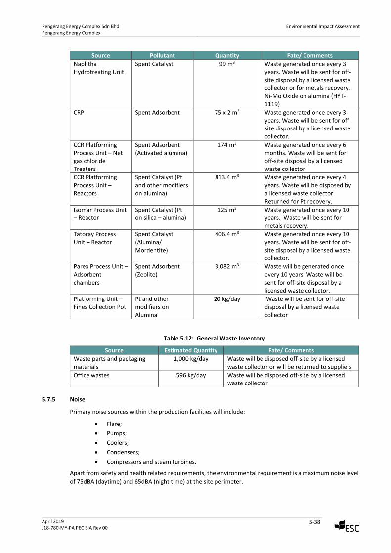
Pengerang Energy Complex Sdn Bhd Pengerang Energy Complex
Environmental Impact Assessment
April 2019 J18-780-MY-PA PEC EIA Rev 00
5-38
Source Pollutant Quantity Fate/ Comments
Naphtha Hydrotreating Unit
Spent Catalyst 99 m3 Waste generated once every 3 years. Waste will be sent for off-site disposal by a licensed waste collector or for metals recovery. Ni-Mo Oxide on alumina (HYT-1119)
CRP Spent Adsorbent 75 x 2 m3 Waste generated once every 3 years. Waste will be sent for off-site disposal by a licensed waste collector.
CCR Platforming Process Unit – Net gas chloride Treaters
Spent Adsorbent (Activated alumina)
174 m3
Waste generated once every 6 months. Waste will be sent for off-site disposal by a licensed waste collector
CCR Platforming Process Unit – Reactors
Spent Catalyst (Pt and other modifiers on alumina)
813.4 m3 Waste generated once every 4 years. Waste will be disposed by a licensed waste collector. Returned for Pt recovery.
Isomar Process Unit – Reactor
Spent Catalyst (Pt on silica – alumina)
125 m3 Waste generated once every 10 years. Waste will be sent for metals recovery.
Tatoray Process Unit – Reactor
Spent Catalyst (Alumina/ Mordentite)
406.4 m3 Waste generated once every 10 years. Waste will be sent for off-site disposal by a licensed waste collector.
Parex Process Unit – Adsorbent chambers
Spent Adsorbent (Zeolite)
3,082 m3 Waste will be generated once every 10 years. Waste will be sent for off-site disposal by a licensed waste collector.
Platforming Unit – Fines Collection Pot
Pt and other modifiers on Alumina
20 kg/day Waste will be sent for off-site disposal by a licensed waste collector
Table 5.12: General Waste Inventory
Source Estimated Quantity Fate/ Comments
Waste parts and packaging materials
1,000 kg/day Waste will be disposed off-site by a licensed waste collector or will be returned to suppliers
Office wastes 596 kg/day Waste will be disposed off-site by a licensed waste collector
5.7.5 Noise
Primary noise sources within the production facilities will include:
• Flare;
• Pumps;
• Coolers;
• Condensers;
• Compressors and steam turbines.
Apart from safety and health related requirements, the environmental requirement is a maximum noise level
of 75dBA (daytime) and 65dBA (night time) at the site perimeter.
Pengerang Energy Complex Sdn Bhd Pengerang Energy Complex
Environmental Impact Assessment
April 2019 J18-780-MY-PA PEC EIA Rev 00
5-39
5.8 Plant Instrumentation, Monitoring and Control Systems
5.8.1 Plant and Equipment Protection
The new plant will be designed with consideration for the highest levels of plant safety and equipment
protection systems; provided Instrumented Protective Function systems will include:
• Emergency Shut Down (ESD) and/or Emergency Depressurizing (EDP) systems to protect process
units and their related facilities;
• Fire and Gas Detection Systems for early detection and protection from developing hazardous
conditions; and
• Fire protection and Alarm Management Systems.
5.9 Safety Systems
Both passive and active safety systems will be provided in the plants, including the following:
• In-place safety management systems (standard operating procedure, permits to work etc.)
• Fire detection, alarms and firefighting systems;
• Automatic sprinkler;
• Fireproofing of critical structures and equipment;
• Fixed and portable gas detectors and smoke/flame detectors;
• Lighting protection;
• Electrical grounding;
• Safety shower and eye bath systems;
• Personal Protective Equipment (PPE);
• Inert gas blanketing; and
• Flare System.
5.10 Fire Detection and Protection Systems
The basic features of fire detection and protection systems are outlined below:
• The plant will be covered by a fire water ring main. Water from the fire water reservoir will be
charged and pressurised in the ring main using a combination of motor and diesel driven fire water
pumps. Hydrant stand post, water monitors and other appropriate firefighting accessories will be
placed in the fire water network as per NFPA design guidelines.
• Storage tanks will be provided with appropriate fire protection measure (e.g. foam, deluge etc.) as
per design codes and standards.
• Control room and sub stations will be protected with clean agent flooding systems such as FM 200
etc.
• Automatic sprinkler system and fire hose reel system will be provided for admin building. Fire
extinguishers will be placed in strategic location of the buildings as necessary.
• Design scheme for automatic fire alarm system and Manual call point system will be provided in
the storage tank areas and in the buildings as necessary.
The establishment shall be provided with an Automatic Fire Alarm System conforming to Malaysian
Standards for Fire safety and Protection, and Uniform Building By-Laws 1984 requirements.
For safe storage of flammable liquids, fire protection measures will be provided according to the SDS of the
storage liquid. Such systems include but are not limited to:
• Foam protection system
Pengerang Energy Complex Sdn Bhd Pengerang Energy Complex
Environmental Impact Assessment
April 2019 J18-780-MY-PA PEC EIA Rev 00
5-40
• Deluge System
• Fire hydrant with monitor
The storage tank will be equipped with heat detectors connected to automatic fire alarm system. The
storage area will include manual call points.
Fire extinguishers will be placed in strategic locations for adequate fire protection as per code requirement
of the Uniform Building By-Laws 1984.
5.11 Key HSE Design Goals, Objectives and Targets
PEC facility will design, construct and operate a world scale chemicals manufacturing facility that leads the
industry in safety, health and environment performance and exceeds the business objectives of the
venture.
HSE Goals
• To ensure no accidents, no environmental incidents and no harm to people.
HSE Objectives
• Maximise the utilisation of energy resources to produce clean and safe energy
• Achieve zero lost time injury through aggressive safety strategies;
• Attain a high level of preparedness to manage emergency incidents;
• Become a leader of sustainable growth; and
• Use high level of good HSE practices.
Targets
• To develop and maintain an HSE management system;
• Hold at all level of management, staff, and contractors accountable for HSE within their areas of
responsibility;
• To develop a positive HSE culture throughout the company through effective communication and
training;
• To conduct HSE reviews and audit in order to identify shortcomings within the organisation and
ensure compliance with local, international and corporate standards and regulations;
• To ensure that contractors demonstrate full compliance with the policy;
• To provide the necessary resources in order to meet company’s stated HSE objectives; and
• To ensure optimal security standards are maintained to protect personnel, company assets and
information.
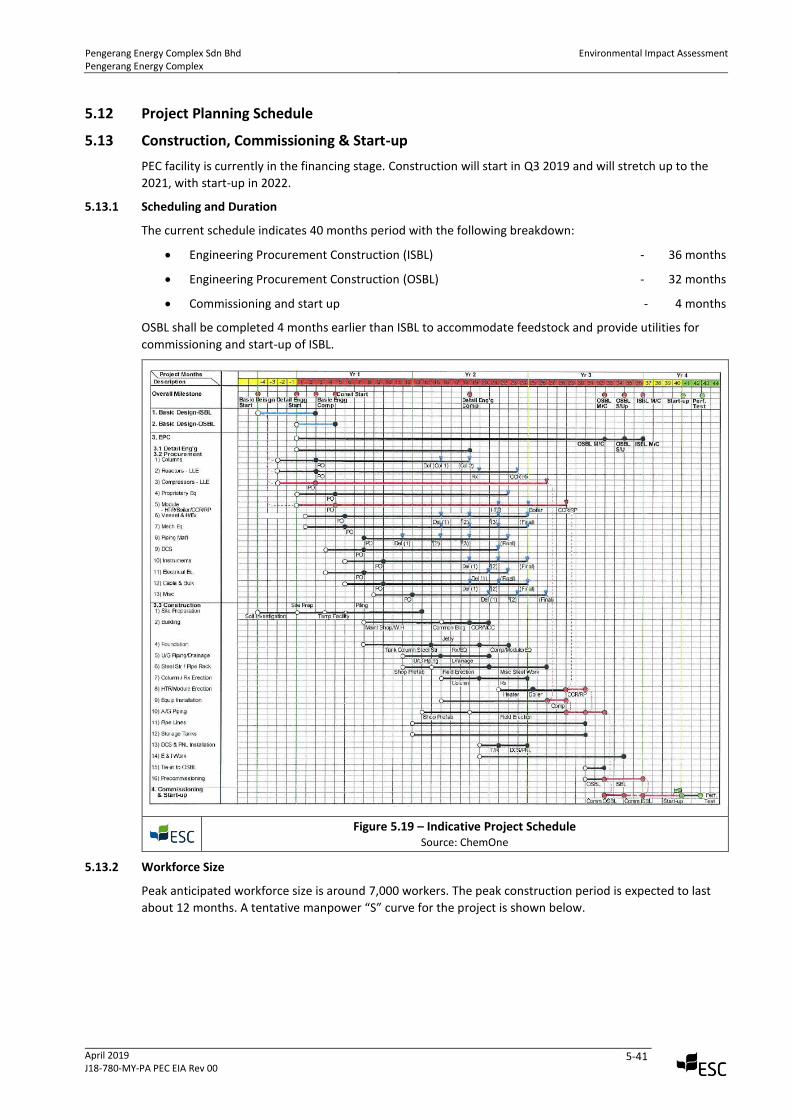
Pengerang Energy Complex Sdn Bhd Pengerang Energy Complex
Environmental Impact Assessment
April 2019 J18-780-MY-PA PEC EIA Rev 00
5-41
5.12 Project Planning Schedule
5.13 Construction, Commissioning & Start-up
PEC facility is currently in the financing stage. Construction will start in Q3 2019 and will stretch up to the
2021, with start-up in 2022.
5.13.1 Scheduling and Duration
The current schedule indicates 40 months period with the following breakdown:
• Engineering Procurement Construction (ISBL) - 36 months
• Engineering Procurement Construction (OSBL) - 32 months
• Commissioning and start up - 4 months
OSBL shall be completed 4 months earlier than ISBL to accommodate feedstock and provide utilities for
commissioning and start-up of ISBL.
Figure 5.19 – Indicative Project Schedule
Source: ChemOne
5.13.2 Workforce Size
Peak anticipated workforce size is around 7,000 workers. The peak construction period is expected to last
about 12 months. A tentative manpower “S” curve for the project is shown below.
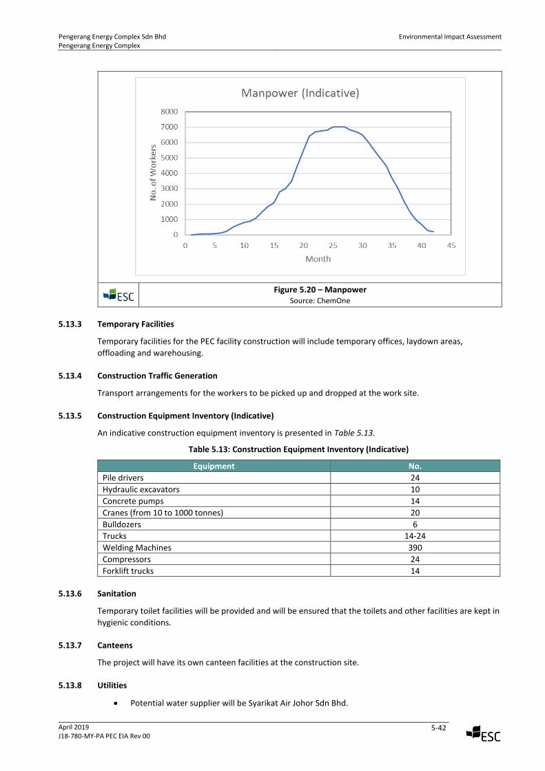
Pengerang Energy Complex Sdn Bhd Pengerang Energy Complex
Environmental Impact Assessment
April 2019 J18-780-MY-PA PEC EIA Rev 00
5-42
Figure 5.20 – Manpower
Source: ChemOne
5.13.3 Temporary Facilities
Temporary facilities for the PEC facility construction will include temporary offices, laydown areas,
offloading and warehousing.
5.13.4 Construction Traffic Generation
Transport arrangements for the workers to be picked up and dropped at the work site.
5.13.5 Construction Equipment Inventory (Indicative)
An indicative construction equipment inventory is presented in Table 5.13.
Table 5.13: Construction Equipment Inventory (Indicative)
Equipment No.
Pile drivers 24
Hydraulic excavators 10
Concrete pumps 14
Cranes (from 10 to 1000 tonnes) 20
Bulldozers 6
Trucks 14-24
Welding Machines 390
Compressors 24
Forklift trucks 14
5.13.6 Sanitation
Temporary toilet facilities will be provided and will be ensured that the toilets and other facilities are kept in
hygienic conditions.
5.13.7 Canteens
The project will have its own canteen facilities at the construction site.
5.13.8 Utilities
• Potential water supplier will be Syarikat Air Johor Sdn Bhd.
Pengerang Energy Complex Sdn Bhd Pengerang Energy Complex
Environmental Impact Assessment
April 2019 J18-780-MY-PA PEC EIA Rev 00
5-43
• Electrical power supply requirements will be supplied from the nearest TNB substation near Kg.
Lepau.