307670d ultra 433 airless paint sprayer - graco inc
TRANSCRIPT
INSTRUCTIONWFIELD REPAIR 307-670 ORAC0 SUPERSEDES C
Rev D
This manual contains IMPORTANT WARNINGS and INSTRUCTIONS
READ AND RETAIN FOR REFERENCE
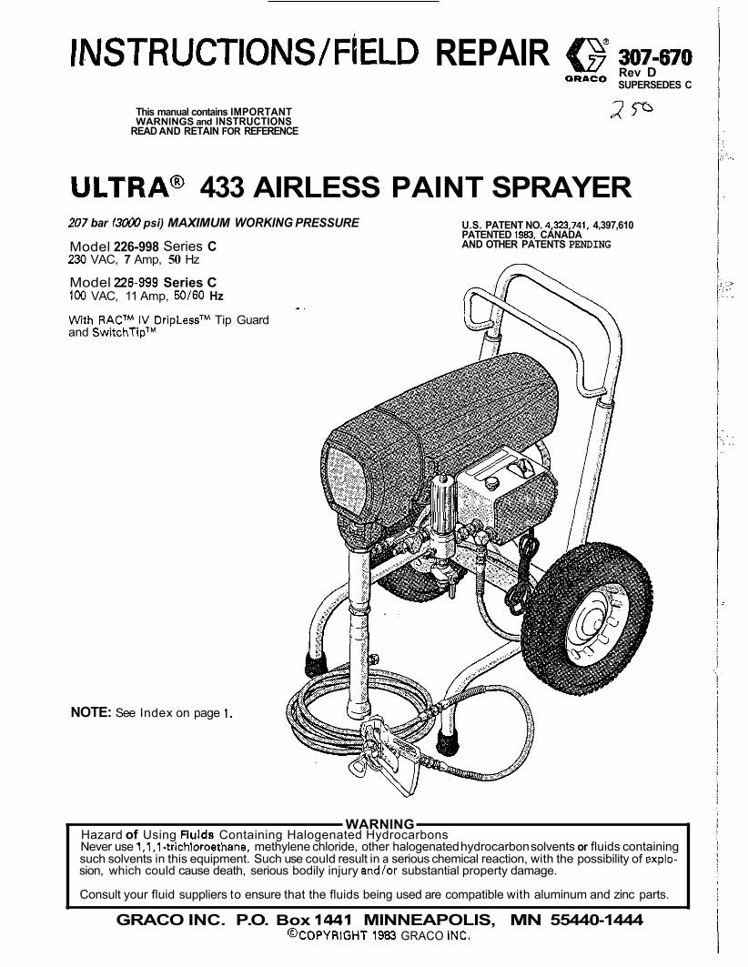
ULTRA@ 433 AIRLESS PAINT SPRAYER 207 bar 13000 psi) MAXIMUM WORKING PRESSURE
230 VAC, 7 Amp, 50 Hz Model 226-998 Series C
Model 226-999 Series C 100 VAC, 11 Amp, 50/60 Hz
With RACTM IV DripLessTM Tip Guard and SwitchTipTM
NOTE: See Index on page 1.
U.S. PATENT NO. 4,323,741, 4,397,610 PATENTED 1963, CANADA AND OTHER PATENTS PENDING
Hazard of Using Fiulds Containing Halogenated Hydrocarbons WARNING
Never use 1.1.1-trichloroethane, methylene chloride, other halogenated hydrocarbon solvents or fluids containing
sion, which could cause death, serious bodily injury and/or substantial property damage. such solvents in this equipment. Such use could result in a serious chemical reaction, with the possibility of explo-
Consult your fluid suppliers to ensure that the fluids being used are compatible with aluminum and zinc parts.
GRACO INC. P.O. Box 1441 MINNEAPOLIS, MN 55440-1444 @COPYRIGHT 1983 GRACO INC.
c .~.
:.> . : . ..
- . . .
INDEX
WARNINGS .................................................. 2, 3 INTRODUCTION ................................................. SETUP ............................................................. 5 OPERATION .................................................. 6, 7 SHUTDOWN Et CARE: ........................................ 7
TROUBLESHOOTING GUIDE FLUSHING GUIDELINES 8
Motor Won't Operate ................................... 9-11 Low output .................................................. 12 No Output ............................................... 12, 13
Motor Is Hot and Runs Intermittently 13 Excessive Pressure Fluctuations .13
Electrical Short .............................................. 14 Spin Test .................................................... .15 Bridge Ten .16
List of Tools.. ................................................ 17 General Repair Notes .......................... : ........... 17 Power Supply Cord Replacement ....................... 18
ONIOFF Switch Replacement 19 Filter Replacement .18
.....................................
........................ ..................
.................................................. REPAIR SECTION
........................................ ...........................
Microswitch Replacement ................................ 19 Bridge Replacement ....................................... 20
Varistor Replacement 21 Choke Replacement 21
Circuit Board Replacement ............................... 22 Pressure Control Replacement. ....................... ..23 Drive Housing Replacement 25 Pressure Control Calibration 24
Bearing Housing & Conn. Rod Replacement ..... 26-27 Motor Brush Replacement ................................ 28 Capacitor Replacement ................................... 29 Motor Replacement ................................... 30. 31
Sprayer .................................................. 32, 33 Pressure Control ....................................... 34, 35 How To Order Replacement Parts ...................... 35
TECHNICAL DATA ............................... Back Cover
NOTE: See manual 307-793, supplied for the displacement pump repair instructions and parts list.
........................................ ......................................
............................. ..............................
PARTS LISTS 8 DRAWINGS
307-670 1
. .
.;
, : . , . : . . . .
HIGH PRESSURE SPRAY CAN CAUSE SERIOUS INJURY. FOR PROFESSIONAL USE ONLY. OBSERVE ALL WARNINGS.
Read and understand all instruction manuals before operating equipment.
FLUID IPJJECTIOM HAZARD
This equipment generates very high fluid pressure. Spray from General Safety
the gun, leaks or ruptured components can inject fluid through your skin and into your body and cause extremely serious bodily injury, including the need for amputation. Also, fluid injected or splashed into the eyes or onto the skin can cause serious damage.
NEVER point the spray gun at anyone or at any pan of the
try to "blow back" paint; this is NOT an air spray system. body. NEVER put hand or fingers over the spray tip. NEVER
ALWAYS have the tip guard in place on the spray gunwhen spraying.
ALWAYS follow the Pressure Rellef Procedure, below, before cleaning or removing the spray tip or servicing any system equipment.
NEVER try to stop or deflect leaks with your hand or body.
Be sure equipment safety devices are operating properly before each use. - If any fluid appears to penetrate your skin, get EMERGENCY Med ica l A ler t- Air less Spray Wounds
MEDICAL CARE AT ONCE. DO NOT TREAT AS A SIMPLE CUT. Tell the doctor exactly what fluid was injected.
jury. It Is important t o treat the injury surgically as soon Note to Physician: Injection in the skin is e traumatic in-
as possible. Do not delay treatment fo research toxicity. Toxicity is a concern with some exotic coatings injected directly into the blood stream. Consultation with a plastic surgeon or reconstructive hand surgeon may be advisable.
Spray Gun Safety Devices Be sure all gun safety devices are operating properly before each use. 00 not remove or modify any part of the gun; this can cause a malfunction and result in serious bodily injury.
Safety Latch
the gun safety latch in the closed or "safe" position, making Whenever you stop spraying, even for a moment. always set
the gun inoperative. Failure to set the safety latch can result in accidental triggering of the gun.
The gun diffuser breaks up spray end reduces the risk of fluid Diffuser
injection when the tip is not installed. Check diffuser operation
then remove the spray tip. Aim the gun into a metal pail, regularly. Follow the Pressure Relief Procedure, below,
holding the gun firmly to the pail. Using the lowest possible
to an irregular stream, replace the diffuser immediately. pressure, trigger the gun. If the fluid emitted is not diffused in-
Tip Guard
spraying. The tip guard alerts you to the fluid injection hazard ALWAYS have the tip guard in place on the spray gun while
and helps reduce, but does not prevent. the risk of accidental- ly placing your fingers or any pan of your body close to the spray tip.
Spray Tlp Safety Use extreme caution when cleaning or changing spray tips. If the spray tip clogs while spraying, engage the gun safety latch immediately. ALWAYS follow the Pressure Rellef Pro- cedure and then remove the spray tip to clean it.
fully relieved end the gun safety latch is engaged. NEVER wipe off build-up around the spray tip until pressure is
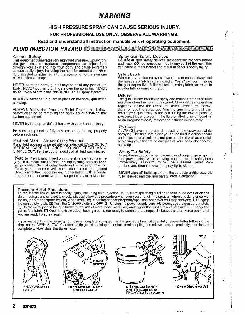
To reduce the risk of serious bodily injury, including fluid injection, injury from splashing fluid or solvent in the eyes or on.the Pressure Relief Procedure
skin, moving pans or electric shock, aiways follow this procedure whenever you shut off~the sprayer, when checking or servic- ing any pan of the spray system, when installing, cleaning or changing spray tips, and whenever you stop spraying. (1) Engage the gun safety latch. (21 Turn the ONlOFF switch to,OFF. (3) Unplug the power supply cord. (41 Disengage the gun safety latch. (5) Hold a metal pan of the gun firmly to the side of a grounded metal pail, and trigger the gun to relieve pressure. 16) Engage the gun safety latch. (7) Open the drain valve, having a container ready to catch the drainage. 18) Leave the drain valve open until you are ready t o spray again.
If you suspect that the spray tip or hose is completely clogged, or that pressure has not been fully relieved after following the steps above, VERY SLOWLY loosen the tip guard retaining nut or hose end coupling and relieve pressure gradually, then loosen completely. Now clear the tip or hose.
ENGAGE SAF-ETY LATCH ANDTRII
ENGAGE
DISENGAGESAFETY
!
. , . , . .. . .
, .. . .
. .
. ..
EQUIPMENT MISUSE HAZARD General Safety Any misuse,of the spray equipment or accessories, such as overpressurmng, modifying parts, using incompatible
cause them to rupture and result in fluid injection or other chemicals and fluids, or using worn or damaged parts, can
serious bodily injury, fire, explosion or property damage.
NEVER alter or modify any part of this equipment; doing so could cause it to malfunction.
worn or damaged parts immediately. CHECK a11 spray equipment regularly and repair or replace
Read and follow the fluid and solvent manufacturer's literature regarding the use of protective clothing and equipment.
System Pressure This sprayer can develop 207 bar /.?&XI psi1 MAXIMUM
accessories are rated to withstand the maximum working WORKING PR€SSUR€. Be sure that a11 spray equipment and
pressure of this sprayer. DO NOT exceed the maximum work- ing pressure of any component or accessory used in the system. - .
Fluid Compat ib i l i t y BE SURE that all fluids and solvents used are chemically com- patible with the wetted parts shown in the Technical Data on the back cover. Always read the fluid and solvent manufac- turer's literature before using them in this sprayer.
HOSE SAFETY High pressure fluid in the hoses can be very dangerous. If the hose develops a leak, split or rupture due to any kind of wear, damage or misuse, the high pressure spray emitted from it can
property damage. cause a fluid injection injury or other serious bodily injuty or
ALL FLUID HOSES MUST HAVE SPRING GUARDS ON BOTH ENDS1 The spring guards help protect the hose from
hose rupture. kinks or bends at or close to the coupling which can result in
TIGHTEN all fluid connections securely before each use. High pressure fluid can dislodge a loose coupling or allow high pressure spray to be emitted from the coupling.
NEVER use a damaged hose. Before each use, check the en- tire hose for cuts, leaks, abrasion, bulging cover, or damage or movement of the hose couplings. If any of these conditions exist, replace the hose immediately. 00 NOT try to recouple high pressure hose or mend it with tape or any other device. A repaired hose cannot contain the high pressure fluid.
HANDLE AND ROUTE HOSES CAREFULLY. Do not pull on
are not compatible with the inner tube and cover of the hose. hoses to move equipment. Do not use fluids or solvents which
DO NOT expose Graco hose to temperatures above &Z°C 1180°F) or below -40°C I-40°F).
Hose Ground ing Continuity Proper hose grounding continuity is essential to maintaining a grounded spray system. Check the electrical resistance of your air and fluid hoses at least once a week, If your hose does not have a tag on it which specifies the maximum electrical
maximum resistance limits. Use a resistance meter in the ap- resistance, contact the hose supplier or manufacturer for the
propriate range for your hose to check the resistance. If the resistance exceeds the recommended limits, replace it im- mediately. An ungrounded or poorly grounded hose can make your system hazardous. Also read FIRE OR EXPLOSION HAZARD.
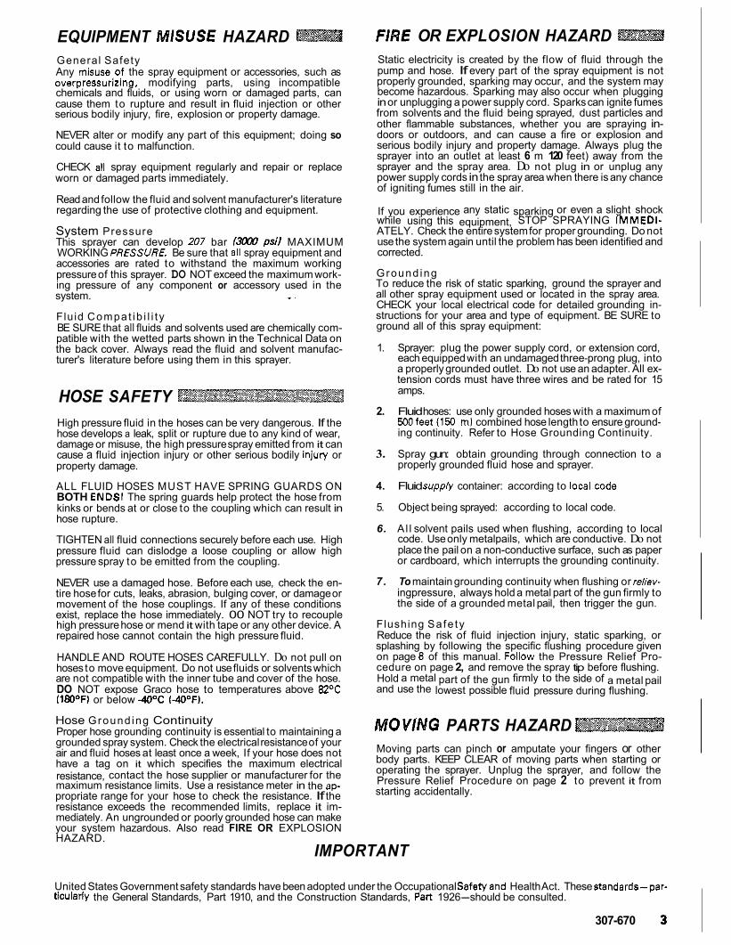
FIRE OR EXPLOSION HAZARD
pump and hose. If every part of the spray equipment is not Static electricity is created by the flow of fluid through the
properly grounded, sparking may occur, and the system may become hazardous. Sparking may also occur when plugging
from solvents and the fluid being sprayed, dust particles and in or unplugging a power supply cord. Sparks can ignite fumes
other flammable substances, whether you are spraying in- doors or outdoors, and can cause a fire or explosion and serious bodily injury and property damage. Always plug the sprayer into an outlet at least 6 m 120 feet) away from the sprayer and the spray area. Do not plug in or unplug any power supply cords in the spray area when there is any chance of igniting fumes still in the air.
while using this equipment, STOP SPRAYING IMMEDI- If you experience any static sparking or even a slight shock
ATELY. Check the entire system for proper grounding. Do not use the system again until the problem has been identified and corrected.
To reduce the risk of static sparking, ground the sprayer and Ground ing
all other spray equipment used or located in the spray area. CHECK your local electrical code for detailed grounding in- structions for your area and type of equipment. BE SURE to ground all of this spray equipment:
1. Sprayer: plug the power supply cord, or extension cord, each equipped with an undamaged three-prong plug, into a properly grounded outlet. Do not use an adapter. All ex- tension cords must have three wires and be rated for 15 amps.
2. Fluid hoses: use only grounded hoses with a maximum of 500feet (150 m) combined hose length to ensure ground- ing continuity. Refer to Hose Grounding Continuity.
3. Spray gun: obtain grounding through connection to a properly grounded fluid hose and sprayer.
4. Fluid supply container: according to localkode
5. Object being sprayed: according to local code.
6. Al l solvent pails used when flushing, according to local code. Use only metalpails, which are conductive. Do not
or cardboard, which interrupts the grounding continuity. place the pail on a non-conductive surface, such as paper
7. To maintain grounding continuity when flushing or reliev- ingpressure, always hold a metal part of the gun firmly to the side of a grounded metal pail, then trigger the gun.
Flushing Sa fe ty Reduce the risk of fluid injection injury, static sparking, or splashing by following the specific flushing procedure given on page 8 of this manual. Follow the Pressure Relief Pro- cedure on page 2, and remove the spray tip before flushing.
and use the lowest possible fluid pressure during flushing. Hold a metal part of the gun firmly to the side of a metal pail
MOVlMG PARTS HAZARD Moving parts can pinch or amputate your fingers or other body parts. KEEP CLEAR of moving parts when starting or operating the sprayer. Unplug the sprayer, and follow the Pressure Relief Procedure on page 2 to prevent it from starting accidentally.
IMPORTANT
United States Government safety standards have been adopted under the Occupational Safewand Health Act. These standards-par- ticularly the General Standards, Part 1910, and the Construction Standards, Part 1926-should be consulted.
307-670 3
INTRODUCTION ULTRA" 433 SPRAYER BASIC COMPONENTS
ELECTRIC MOTOR
DRIVEASSEMBLY ON/OFFSWITCH
PRESSURECONTROLKNOB
OISPIACEMEMPUMP
FLUID OUTLET DRAIN VALVE
MAIN FLUID HOSE
INTRODUCTION ULTRA" 433 SPRAYER BASIC COMPONENTS
ELECTRIC MOTOR 7
DRIVEASSEMBLY ON/OFFSWITCH
PRESSURECONTROLKNOB
OISPIACEMEMPUMP
FLUID OUTLET
MAIN FLUID HOSE
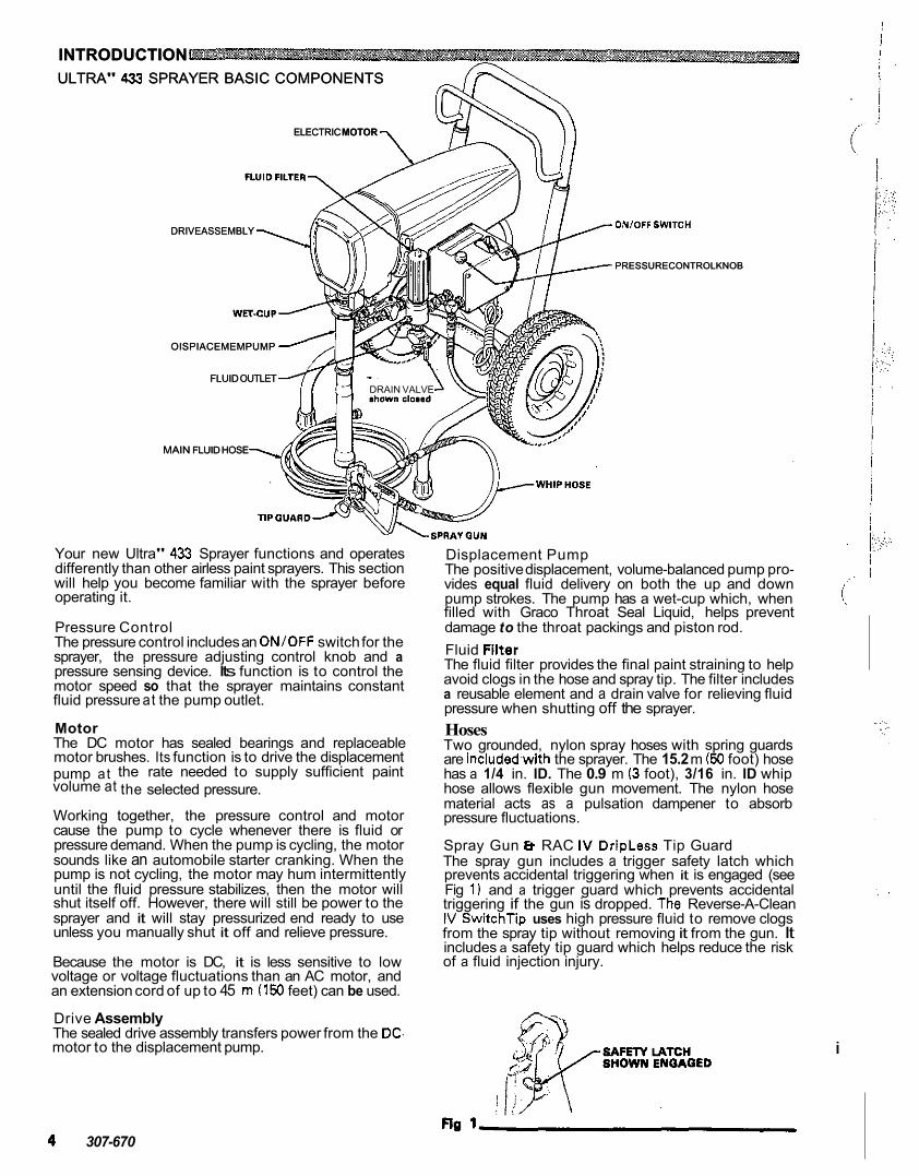
Your new Ultra" 433 Sprayer functions and operates differently than other airless paint sprayers. This section will help you become familiar with the sprayer before operating it.
Pressure Control The pressure control includes an ONlOFF switch for the sprayer, the pressure adjusting control knob and a pressure sensing device. Its function is to control the motor speed so that the sprayer maintains constant fluid pressure at the pump outlet.
Motor The DC motor has sealed bearings and replaceable motor brushes. Its function is to drive the displacement
volume at the selected pressure. pump at the rate needed to supply sufficient paint
Working together, the pressure control and motor cause the pump to cycle whenever there is fluid or pressure demand. When the pump is cycling, the motor sounds like an automobile starter cranking. When the pump is not cycling, the motor may hum intermittently
shut itself off. However, there will still be power to the until the fluid pressure stabilizes, then the motor will
sprayer and it will stay pressurized end ready to use unless you manually shut it off and relieve pressure.
Because the motor is DC, it is less sensitive to low voltage or voltage fluctuations than an AC motor, and an extension cord of up to 45 m (150 feet) can be used.
The sealed drive assembly transfers power from the DC. Drive Assembly
motor to the displacement pump.
Displacement Pump The positive displacement, volume-balanced pump pro- vides equal fluid delivery on both the up and down
filled with Graco Throat Seal Liquid, helps prevent pump strokes. The pump has a wet-cup which, when
damage to the throat packings and piston rod. Fluid Filter The fluid filter provides the final paint straining to help avoid clogs in the hose and spray tip. The filter includes a reusable element and a drain valve for relieving fluid pressure when shutting off the sprayer. Hoses Two grounded, nylon spray hoses with spring guards are included.with the sprayer. The 15.2 m ( 5 0 foot) hose has a 1/4 in. ID. The 0.9 m (3 foot), 3/16 in. ID whip hose allows flexible gun movement. The nylon hose material acts as a pulsation dampener to absorb pressure fluctuations.
Spray Gun a RAC IV DripLess Tip Guard The spray gun includes a trigger safety latch which prevents accidental triggering when it is engaged (see Fig 1) and a trigger guard which prevents accidental triggering if the gun is dropped. The Reverse-A-Clean IV SwitchTip uses high pressure fluid to remove clogs from the spray tip without removing it from the gun. It
of a fluid injection injury. includes a safety tip guard which helps reduce the risk
4 307-670
i
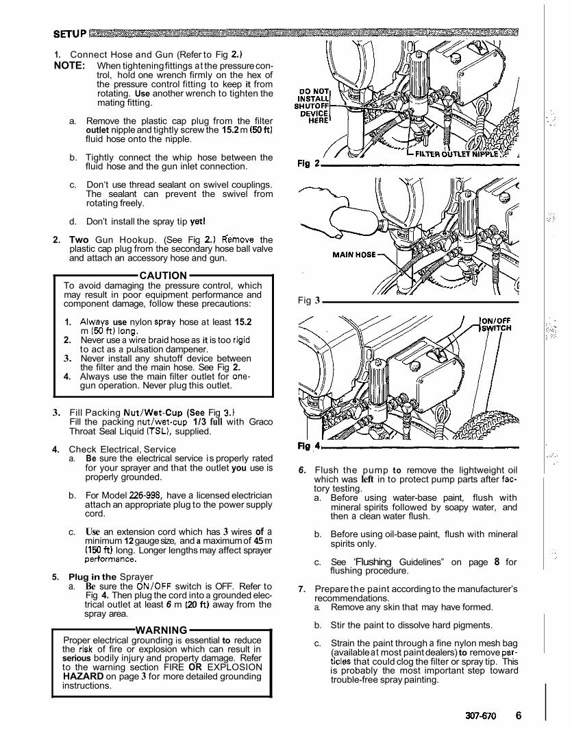
1. Connect Hose and Gun (Refer to Fig 2.) NOTE: When tightening fittings at the pressure con-
trol, hold one wrench firmly on the hex of the pressure control fitting to keep it from rotating. Use another wrench to tighten the mating fitting.
a. Remove the plastic cap plug from the filter
fluid hose onto the nipple. outlet nipple and tightly screw the 15.2 m ( 5 0 f t )
b. Tightly connect the whip hose between the fluid hose and the gun inlet connection.
c. Don‘t use thread sealant on swivel couplings. The sealant can prevent the swivel from rotating freely.
d. Don’t install the spray tip yet1
2. Two Gun Hookup. (See Fig 2.) Hemove the plastic cap plug from the secondary hose ball valve and attach an accessory hose and gun.
CAUTION To avoid damaging the pressure control, which may result in poor equipment performance and component damage, follow these precautions:
1. Always use nvlon swav hose at least 15.2 m ( 5 d f t ) long‘.
. .
2. Never use a wire braid hose as it is too rigid - 3. Never install any shutoff device between
to act as a pulsation dampener.
the filter and the main hose. See Fig 2. 4. Always use the main filter outlet for one-
gun operation. Never plug this outlet.
3. Fill Packing Nut/Wet-Cup (See Fig 3.) Fill the packing nut/wet-cup 1/3 full with Graco Throat Seal Liquid (TSL), supplied.
a. Be sure the electrical service is properly rated for your sprayer and that the outlet you use is properly grounded.
4. Check Electrical, Service
b. For Model 226-998, have a licensed electrician attach an appropriate plug to the power supply cord.
c. Use an extension cord which has 3 wires of a minimum 12 gauge size, and a maximum of 45 m (150 f t ) long. Longer lengths may affect sprayer periormance.
5. Plug in the Sprayer a. Be sure the ONlOFF switch is OFF. Refer to
Fig 4. Then plug the cord into a grounded elec- trical outlet at least 6 m (20 f t ) away from the spray area.
WARNING 1 Proper electrical grounding is essential to reduce
the rlsk of fire or explosion which can result in serious bodily injury and property damage. Refer to the warning section FIRE OR EXPLOSION
instructions. HAZARD on page 3 for more detailed grounding
Fig 3
6. Flush the pump to remove the lightweight oil
tory testing. which was left in to protect pump parts after fac-
a. Before using water-base paint, flush with mineral spirits followed by soapy water, and then a clean water flush.
b. Before using oil-base paint, flush with mineral spirits only.
c. See ‘Flushing Guidelines” on page 8 for
7. Prepare the paint according to the manufacturer’s
flushing procedure.
recommendations. a. Remove any skin that may have formed.
b. Stir the paint to dissolve hard pigments.
c. Strain the paint through a fine nylon mesh bag
ticles that could clog the filter or spray tip. This (available at most paint dealers) to remove par-
is probably the most important step toward trouble-free spray painting.
307-670 6
OPERATION WARNING
Pressure Relief Procedure To reduce the risk of serious bodily injury, in-
or solvent in the eyes or on the skin, moving parts cluding fluid injection, injury from splashing fluid
whenever you shut off the sprayer, when check- or electric shock, always follow this procedure
when installing, cleaning or changing spray tips, ing or servicing any part of the spray system,
and whenever you stop spraying.
2. Turn the ON/OFF switch to OFF. 1. Engage the gun safety latch.
3. Unplug the power supply cord. 4. Disengage the gun safety latch. 5. Hold a metal part of the gun firmly to the
side of a grounded metal pail, and trigger the gun to relieve pressure.
6. Engage the gun safety latch. 7. Open the drain valve, having a container
ready to catch the drainage. 8. Leave the drain valve open until you are
ready to spray again.
- .
if you suspect that the spray tip or hose is com- pletely clogged, or thatpressure has not been fully relieved after followlng the steps above, VERY SLOWLY loosen the tip guard retaining nut or
then loosen completely. Now clear the tip or hose hose end coupling and relieve pressure gradually,
obstruction.
a. Close the filter drain valve (and the secondary Prime the Sprayer with Paint.
hose ball valve). If you have not installed a secondary hose, be sure the ball valve is firmly closed.
b. Don't install the spray tip yet1
c. Put the suction tube into the paint container.
d. Turn the pressure adjusting knob all the way counterclockwise to lower the pressure setting.
e. Disengage the gun safety latch.
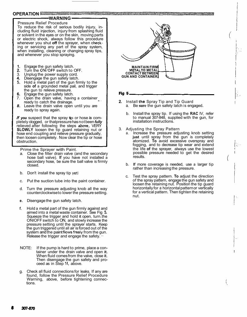
f. Hold a metal part of the gun firmly against and aimed into a metal waste container. See Fig 5. Squeeze the trigger and hold it open, turn. the ONlOFF switch to ON, and slowly increase the pressure setting until the sprayer starts. Keep the gun triggered until all air is forced out of the system and the paint flowsfreely from the gun. Release the trigger and engage the safety. -
NOTE: If the pump is hard to prime, place a con- tainer under the drain valve and open it. When fluid comes from the valve, close it. Then disengage the gun safety and pro- ceed as in Step If , above.
g. Check all fluid connections for leaks. If any are found, follow the Pressure Relief Procedure
tions. Warning, above, before tightening connec-
METALTO METAL MAINTAIN FIRM
GUN AND CONTAINER CONTACT BETWEEN
2. Install the Spray Tip and Tip Guard a. Be sure the gun safety latch is engaged.
b. Install the spray tip. If using the RAC IV, refer to manual 307-848, supplied with the gun, for installation instructions.
3. Adjusting the Spray Pattern a. Increase the pressure adjusting knob setting
just until spray from the gun is completely atomized. To avoid excessive overspray and fogging, and to decrease tip wear and extend the life of the sprayer, always use the lowest possible pressure needed to get the desired results.
i'
b. If more coverage is needed, use a larger tip rather than increasing the pressure.
c. Test the spray pattern. To adjust the direction of the spray pattern, engage the gun safety and loosen the retaining nut. Position the tip guard horizontally for a horizontal pattern or vertically for a vertical pattern. Then tighten the retaining nut.
!
!
I I
1 '.::
. . . .
i
. .
~-
4. Cleaning a Clogged Tip WARNING
your hand, body, or a rag in front of the spray tip To avoid a fluid injection injury, DO NOT hold
when cleaning or checking a clogged tip. Always point the gun toward the ground or into a waste container when checking to see if the tip is clear.
.air spray sprayer. DO NOT try to "blow back" paint; 1 this is NOT an
6. Coil the hose and hang it on the hose rack when storing it, even for overnight, to help protect the hose from kinking, abrasion, coupling damage, etc.
WARNING Refer to the warning section HOSE SAFETY on page 3 for information on the hazard of using damaged hoses.
a. Clean the front of the tip frequently during the day's operation. First, follow the Pressure
use a solvent-soaked brush to keep fluid from Relief Procedure Warning on page 6. Then
building up and clogging the tip.
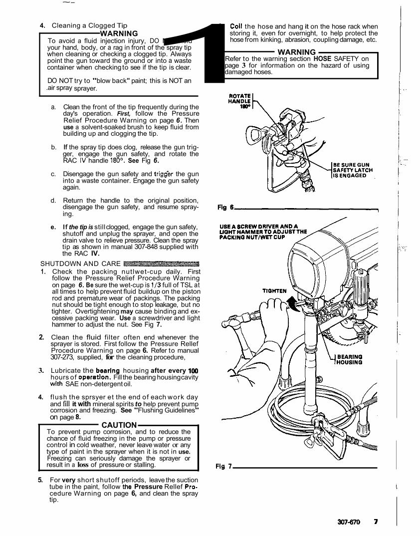
b. If the spray tip does clog, release the gun trig- ger, engage the gun safety, and rotate the RAC IV handle 180'. See Fig 6.
c. Disengage the gun safety and trigfer the gun into a waste container. Engage the gun safety again.
d. Return the handle to the original position, disengage the gun safety, and resume spray- ing.
e. If the tip is still clogged, engage the gun safety, shutoff and unplug the sprayer, and open the drain valve to relieve pressure. Clean the spray tip as shown in manual 307-848 supplied with the RAC IV.
SHUTDOWN AND CARE 1. Check the packing nutlwet-cup daily. First
follow the Pressure Relief Procedure Warning on page 6. Be sure the wet-cup is 1/3 full of TSL at all times to help prevent fluid buildup on the piston rod and premature wear of packings. The packing nut should be tight enough to stop leakage, but no tighter. Overtightening may cause binding and ex- cessive packing wear. Use a screwdriver and light hammer to adjust the nut. See Fig 7.
2. Clean the fluid filter often end whenever the sprayer is stored. First follow the Pressure Rellef
307-273, supplied, for the cleaning procedure, Procedure Warning on page 6. Refer to manual
3. Lubricate the bearing housing after every 1W hours of operatlon. Fill the bearing housing cavity with SAE non-detergent oil.
4. f lush the sprsyer et the end of each work day and fill it with mineral spirits to help prevent pump
on page 0. corrosion and freezing. See "Flushing Guidelines"
CAUTION To prevent pump corrosion, and to reduce the
control in cold weather, never leave water or any chance of fluid freezing in the pump or pressure
type of paint in the sprayer when it is not in use.
result in a loss of pressure or stalling. Freezing can seriously damage the sprayer or
5. For very short shutoff periods, leave the suction tube in the paint, follow the Pressure Rellef Pro-
tip. cedure Warning on page 6, and clean the spray
I
Fig 7
307870 7
. .
.... ..,:
.... .. :.
FLUSHING GUIDELINES
When to Flush 1 . New Sprayer. Your new Ultra" 433 Sprayer was
factory tested in motor oil which was left in to pro- tect pump parts. Before using water-base paint, flush with mineral
water flush. spirits, followed by soapy water, and then a clean
Before using oii-base paint, flush with mineral spirits only.
2. Changing Colors. Flush with a compatible solvent such as mineral spirits or water.
3. Changing from water-base t o oil-base paint. Flush with soapy water, then mineral spirits.
5. Storage.
spirits and leave the pump, hose and gun filled with Water-base paint: flush with water, then mineral
mineral spirits. Shutoff' and unplug the sprayer,
open. ,
open the drain valve to relieve pressure and leave
and unplug the sprayer, open the drain valve to Oil-base paint: flush with mineral spirits. Shutoff
relieve pressure and leave open.
Before using water-base paint, flush out mineral
flllah~ spirits with soapy water and then a clean water
6. Startup after storage.
4. Changing from oil-base'to water-base paint. When using oil-base paint, flush out the mineral Flush with mineral spirits, followed by soapy water, then a clean water flush.
spirits with the fluid to be sprayed and the sprayer is ready to use.
. . - -. . .
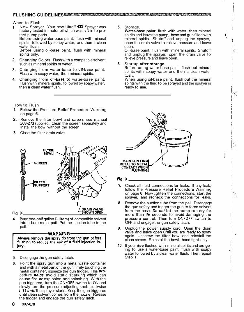
How t o Flush 1. Follow the Pressure Rellef Procedure Warning
on page 6. 2. Remove the filter bowl and screen; see manual
307-273 supplied. Clean the screen separately and install the bowl without the screen.
3. Close the filter drain valve.
Fig a. 4 DRAIN VALVE SHOWN OPEN
4. Pour one-half gallon 12 liters) of compatible solvent into a bare metal pail. Put the suction tube in the pail.
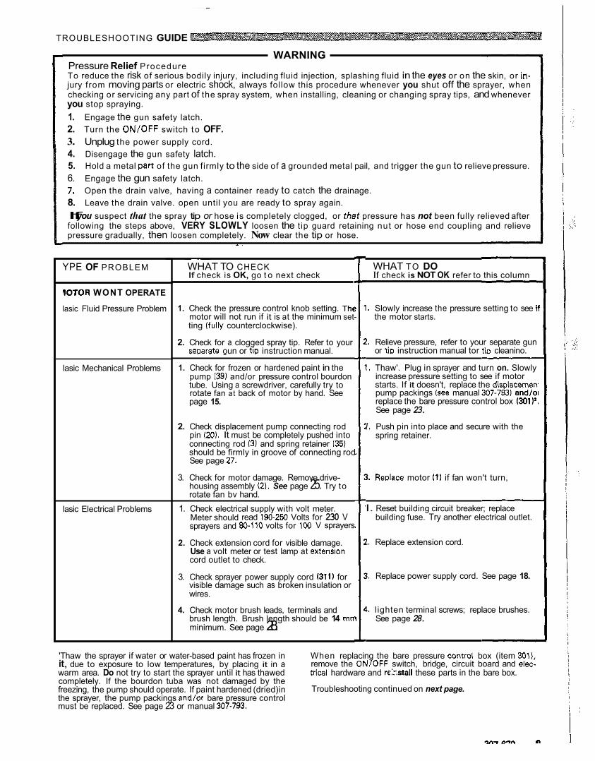
5. Disengage the gun safety latch. 6. Point the spray gun into a metal waste container
and with a metal part of the gun firmly touching the metal container, squeeze the gun trigger. This pro-
cause fire or explosion and splashing. With the cedure heips avoid static sparking which can
gun triggered, turn the ON/OFF switch to ON and
iust until the sprayer starts. Keep the gun triggered slowly turn the pressure adjusting knob clockwise
until clean solvent comes from the nozzle. Release the trigger and engage the gun safety latch.
8 307-670
METAL TO METAL MAINTAIN FIRM
CONTACT WHEN
Fig 9 7. Check all fluid connections for leaks. If any leak,
follow the Pressure Relief Procedure Warning on page 6. Now tighten the connections, start the sprayer, and recheck the connections for leaks.
8. Remove the suction tube from the pail. Disengage the gun safety and trigger the gun to force solvent from the hose. Do not let the pump run dry for more than 30 seconds to avoid damaging the pressure control. Then turn ONIOFF switch to OFF and engage the gun safety latch.
9. Unplug the power supply cord. Open the drain valve and leave open until you are ready to spray again. Unscrew the filter bowl and reinstall the clean screen. Reinstall the bowl, hand tight only.
10. If you have flushed with mineral spirits and are go- ing to use a water-base paint, flush with soapy water followed by a clean water flush. Then repeat Step 1.
~- ~
TROUBLESHOOTING GUIDE
WARNING
To reduce the risk of serious bodily injury, including fluid injection, splashing fluid in the eyes or on the skin, or in- Pressure Relief Procedure
jury from moving parts or electric shock, always follow this procedure whenever you shut off the sprayer, when
you stop spraying. checking or servicing any part of the spray system, when installing, cleaning or changing spray tips, and whenever
2. Turn the ON/OFF switch t o OFF. 1. Engage the gun safety latch.
3. Unplug the power supply cord. 4. Disengage the gun safety latch. 5. Hold a metal p a n of the gun firmly to the side of a grounded metal pail, and trigger the gun to relieve pressure. 6. Engage the gun safety latch. 7. Open the drain valve, having a container ready to catch the drainage. 8. Leave the drain valve. open until you are ready to spray again. If you suspect that the spray tip or hose is completely clogged, or that pressure has not been fully relieved after following the steps above, VERY SLOWLY loosen the tip guard retaining nut or hose end coupling and relieve pressure gradually, then loosen completely. Now clear the tip or hose.
- .
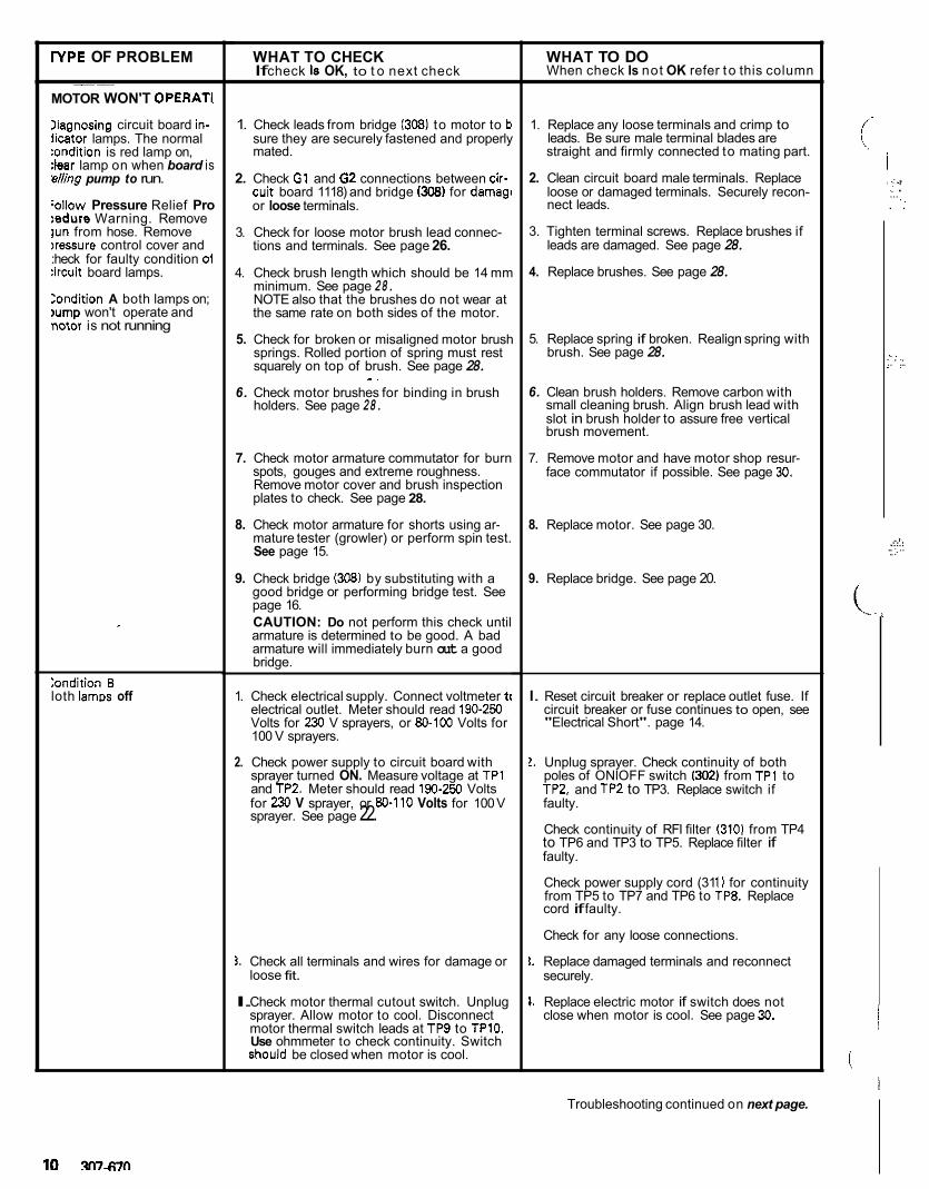
YPE OF PROBLEM
OOTOR WONT OPERATE
lasic Fluid Pressure Problem
lasic Mechanical Problems
lasic Electrical Problems
~~
WHAT TO CHECK If check is OK, go t o next check
1. Check the pressure control knob setting. The
ting lfully counterclockwise). motor will not run if it is at the minimum set
seoarate oun or tiD instruction manual. 2. Check for a clogged spray tip. Refer to your
1. Check for frozen or hardened paint in the
tube. Using a screwdriver, carefully try to pump 1 3 9 ) and/or pressure control bourdon
page 15. rotate fan at back of motor by hand. See
2. Check displacement pump connecting rod pin 120). It must be completely pushed into connecting rod 13) and spring retainer (35) should be firmly in groove of connecting rod See page 27.
housing assembly (2). See page 25. Try to rotate fan bv hand.
3. Check for motor damage. Remove drive-
1. Check electrical supply with volt meter.
sprayers and 80-110 volts for 100 V sprayers Meter should read 190-2513 Volts for 230 V
2. Check extension cord for visible damage. Use a volt meter or test lamp at extension cord outlet to check.
3. Check sprayer power supply cord 1311) for visible damage such as broken insulation or wires.
4. Check motor brush leads, terminals and brush length. Brush length should be 14 mn minimum. See page 28.
WHAT TO DO If check is NOT OK refer to this column
I. Slowly increase the pressure setting to see i' the motor starts.
?. Relieve pressure, refer to your separate gun or tiD instruction manual tor tin cleanino.
I . Thaw'. Plug in sprayer and turn on. Slowly
starts. If it doesn't, replace the displacemen increase pressure setting to see if motor
pump packings (see manual 307-7931 andlo1 replace the bare pressure control box (301J'. See page 23.
spring retainer.
~~
I . Push pin into place and secure with the
3. ReDlace motor (1) if fan won't turn,
I. Reset building circuit breaker; replace building fuse. Try another electrical outlet.
l . Replace extension cord.
1. Replace power supply cord. See page 18.
1. l ighten terminal screws; replace brushes. See page 28.
it, due to exposure to low temperatures, by placing it in a 'Thaw the sprayer if water or water-based paint has frozen in When replacing the bare pressure mntrol box (item 301).
remove the ONIOFF switch, bridge, circuit board and elec- warm area. Do not try to start the sprayer until it has thawed trical hardware and rE::staII these parts in the bare box.
freezing, the pump should operate. If paint hardened (dried) in completely. If the bourdon tuba was not damaged by the
the sprayer, the pump packings andlor bare pressure control Troubleshooting continued on next page.
must be replaced. See page 23 or manual 307-793.
rYPE OF PROBLEM
MOTOR WON'T OPERATI
Iiagnosing circuit board in- iicator lamps. The normal :ondition is red lamp on, :bar lamp on when board is 'dling pump to run.
:allow Pressure Relief Pro :edure Warning. Remove lun from hose. Remove ~ressure control cover and :heck for faulty condition 01 :ircuit board lamps.
Zondition A both lamps on; lump won't operate and notor is not running
~
:ondition B loth lamm off
WHAT TO CHECK If check Is OK, to t o next check
1. Check leads from bridge (308) to motor to b sure they are securely fastened and properly mated.
2. Check G1 and 62 connections between cir-
or loose terminals. cuit board 1118) and bridge (308) for damag,
3. Check for loose motor brush lead connec- tions and terminals. See page 26.
4. Check brush length which should be 14 mm minimum. See page 28. NOTE also that the brushes do not wear at the same rate on both sides of the motor.
5. Check for broken or misaligned motor brush springs. Rolled portion of spring must rest squarely on top of brush. See page 28.
- . 6. Check motor brushes for binding in brush
holders. See page 28.
7. Check motor armature commutator for burn spots, gouges and extreme roughness. Remove motor cover and brush inspection plates to check. See page 28.
8. Check motor armature for shorts using ar- mature tester (growler) or perform spin test. See page 15.
9. Check bridge (308) by substituting with a good bridge or performing bridge test. See page 16.
armature is determined to be good. A bad CAUTION: Do not perform this check until
armature will immediately burn out a good bridge.
1. Check electrical supply. Connect voltmeter t( electrical outlet. Meter should read 190-250 Volts for 230 V sprayers, or 80-100 Volts for 100 V sprayers.
2. Check power supply to circuit board with sprayer turned ON. Measure voltage at TPl
for 230 V sprayer, or 80-110 Volts for 100 V and TP2. Meter should read 190-250 Volts
sprayer. See page 22.
3. Check all terminals and wires for damage or loose fit.
I. Check motor thermal cutout switch. Unplug sprayer. Allow motor to cool. Disconnect motor thermal switch leads at TP9 to TPlO. Use ohmmeter to check continuity. Switch should be closed when motor is cool.
WHAT TO DO When check Is not OK refer t o this column
1. Replace any loose terminals and crimp to
straight and firmly connected to mating part. leads. Be sure male terminal blades are
2. Clean circuit board male terminals. Replace loose or damaged terminals. Securely recon- nect leads.
3. Tighten terminal screws. Replace brushes if leads are damaged. See page 28.
4. Replace brushes. See page 28.
5. Replace spring if broken. Realign spring with brush. See page 28.
6. Clean brush holders. Remove carbon with small cleaning brush. Align brush lead with slot in brush holder to assure free vertical brush movement.
7. Remove motor and have motor shop resur- face commutator if possible. See page 30.
8. Replace motor. See page 30.
9. Replace bridge. See page 20.
I. Reset circuit breaker or replace outlet fuse. If circuit breaker or fuse continues to open, see "Electrical Short". page 14.
2. Unplug sprayer. Check continuity of both poles of ONlOFF switch 1302) from TPl to TP2, and TP2 to TP3. Replace switch if faulty.
to TP6 and TP3 to TP5. Replace filter if Check continuity of RFI filter (3101 from TP4
faulty.
Check power supply cord (31 1) for continuity from TP5 to TP7 and TP6 to TP8. Replace cord if faulty.
Check for any loose connections.
1. Replace damaged terminals and reconnect securely.
1. Replace electric motor if switch does not close when motor is cool. See page 30.
i
i , :.. I .: .:' ... . . ,.
. . . , ., .. ... . .
.: .. . . . i. .. . .....
.. .~
Troubleshooting continued on next page.
FPE OF PROBLEM
Contihion B (continued1
Condition C
Unplug sprayer! Red lamp on, clear lamp off
~ ~ ~~~
WHAT TO CHECK f check is OK, to t o next check
5. Check microswitch (306). With no fluid
wires TPlB and TP19. Check continuity pressure in the pressure control disconnect
across switch terminals with an ohmmeter. Switch contact should be closed. Depress actuator button. An audible "click" indicates the contacts have opened. Ohmmeter should read infinity.
6. Check circuit board (118) by substituting with a good board. See page 22.
1. Check circuit board (118) by removing from
22 for removal procedure. box without disconnecting wires; see page
WARNING: Removing the circuit board
tor which could cause the sprayer to over- while still wired over-rides the optical detec-
pressurize. if the microswitch does not func- tion prop-erly. Turn the sprayer on ONLY
shut off immediately. long enough to check lamp condition,then
shock, handle board by edges onlyl Do not allow any metal objects to come in contact with the boardl Plug in and turn on sprayer. Clear lamp should be on now - removing the circuit
off and unplug sprayer.' board over-rides the optical detector. Turn
WARNING: To reduce the risk of electric
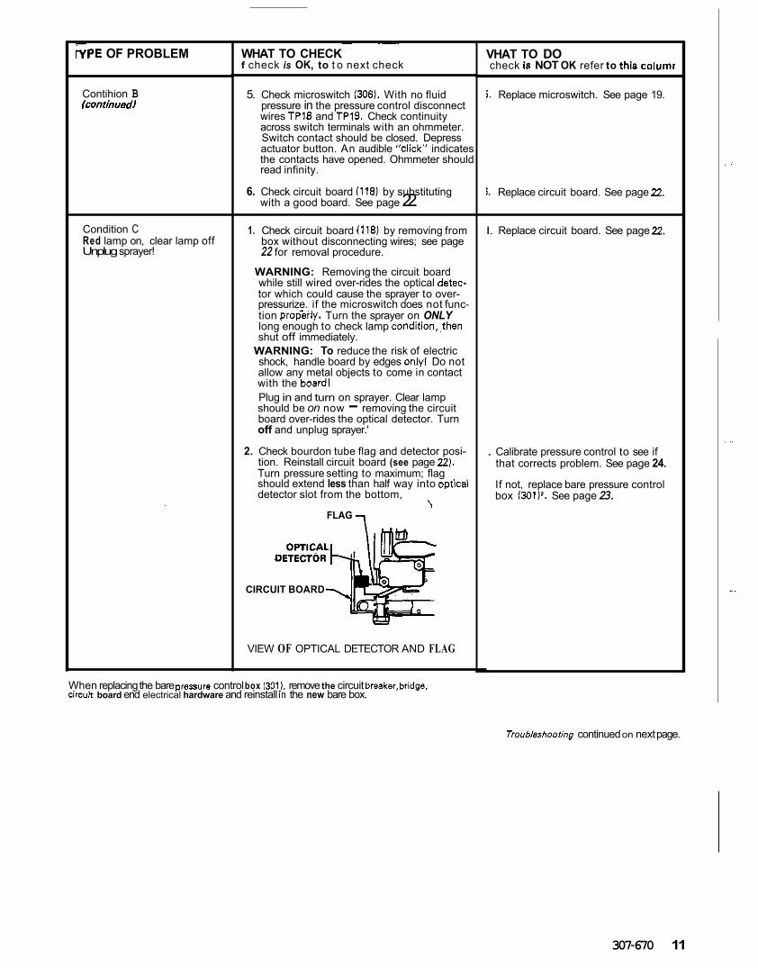
2. Check bourdon tube flag and detector posi- tion. Reinstall circuit board (see page 22). Turn pressure setting to maximum; flag should extend less than half way into oDtical detector slot from the bottom,
\ FLAG -,
CIRCUIT BOARD
VIEW OF OPTICAL DETECTOR AND FLAG
VHAT TO DO check Is NOT OK refer to this columr
i . Replace microswitch. See page 19.
i. Replace circuit board. See page 22.
I. Replace circuit board. See page 22.
. Calibrate pressure control to see if that corrects problem. See page 24.
If not, replace bare pressure control box (301)'. See page 23.
When replacing the bare pressure control box 1301 ), remove the circuit breaker,bridge. u'rcuh board end electrical hardware and reinstall in the new bare box.
Troubleshooring continued on next page.
307-670 11
, .'
. ..
.. .
YPE OF PROBLEM
OW OUTPUT
UO OUTPUT
Motor runs and pump stroke!
WHAT TO CHECK If check is OK, go to next check
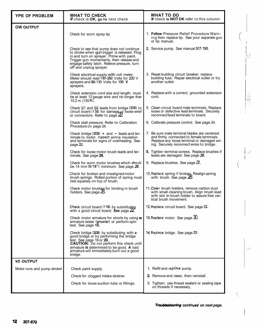
Check for worn spray tip.
Check to see that pump does not continue to stroke when gun trigger is released. Plug in and turn on sprayer. Prime with paint. Trigger gun momentarily, then release and engage safety latch. Relieve pressure, turn off and unplug sprayer.
Check electrical supply with volt meter.
sprayers and 80-110 Volts for 100 V Meter should read 190-250 Volts for 230 V
sprayers.
Check extension cord size and length; must be at least 12 gauge wire and no longer thar 15.2 m (150 ft).
Check G1 and G2 leads from bridge (308) to circuit board 11181 for damage or loose wire! or connectors. Refer to page 22. Check stall pressure. Refer to Calibration Procedure on page 24.
Check bridge (308) + and - leads and ter- minals to motor. InsDect wirina insulation and terminals for signs of overheating. See page 20.
Check for loose motor brush leads and ter- minals. See page 28.
Check for worn motor brushes which shoulc be 14 mm (9/16"l minimum. See page 28.
Check for broken and misaligned motor brush springs. Rolled portion of spring must rest squarely on top of brush.
Check motor brushes for binding in brush holders. See page 28.
,Check circuit board (118) by substituting with a good circuit board. See page 22. Check motor armature for shorts by using a1 armature tester (growler) or perform spin test. See page 15.
Check bridge (308) by substituting with a good bridge or by performing the bridge test. See page 16 or 20. CAUTION: Do not perform this check until armature is determined to be good. A bad armature will immediately burn out a good bridge.
Check paint supply.
Check for clogged intake strainer.
Check for loose suction tube or fittings.
WHAT TO DO If check is NOT OK refer t o this column
1. Follow Pressure Relief Procedure Warn- ing then replace tip. See your separate gun or tip manual.
2. Service pump. See manual 307-793.
3. Reset building circuit breaker; replace
another outlet. building fuse. Repair electrical outlet or try
4. Replace with a correct, grounded extension cord.
5. Clean circuit board male terminals. Replace loose or defective lead terminals. Securely reconnect'lead terminals to board.
6. Calibrate pressure control. See page 24.
7. Be sure male terminal blades are centered and firmly connected to female terminals.
ing. Securely reconnect wires to bridge. Replace any loose terminal or damaged wir-
8. Tighten terminai screws. Replace brushes if leads are damaged. See page 28.
9. Replace brushes. See page 28.
10.Replace spring if broken. Realign spring with brush. See page 28.
11.Clean brush holders, remove carbon dust with small cleaning brush. Align brush lead with slot in brush holder to assure free ver- tical brush movement.
l2.Replace circuit board. See page 22.
13.Replace motor. See page 30.
14.Replace bridge. See page 20.
1. Refill and reprime pump.
2. Remove and clean, then reinstall.
3. Tighten; use thread sealant or sealing tape on threads if necessary.
I !
~
I > ,'. ,..
j .. ..::
Tmubhhooting continued on next page.
TYPE OF PROBLEM
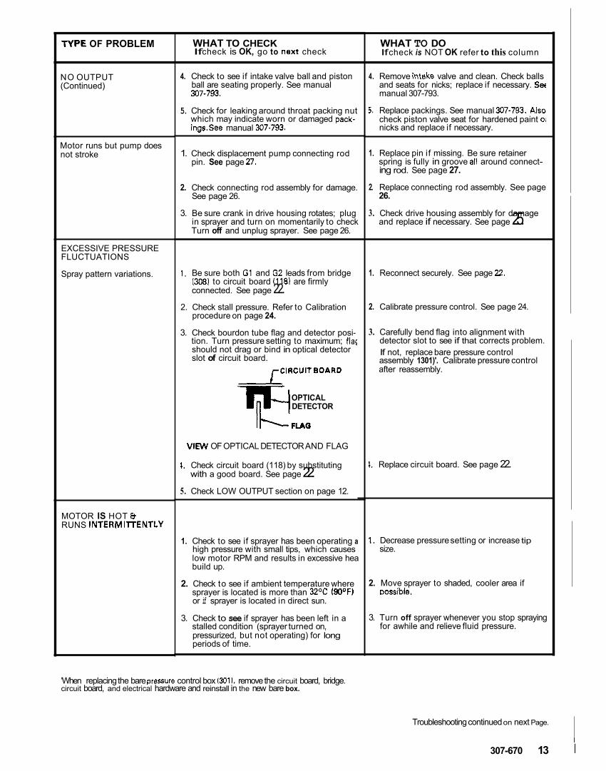
NO OUTPUT (Continued)
Motor runs but pump does not stroke
EXCESSIVE PRESSURE FLUCTUATIONS
Spray pattern variations.
MOTOR IS HOT 8 RUNS INTERMllTENTLY
WHAT TO CHECK If check is OK, go to next check
4. Check to see if intake valve ball and piston ball are seating properly. See manual 307-793.
5. Check for leaking around throat packing nut which may indicate worn or damaged pack- ings.See manual 307.793.
1. Check displacement pump connecting rod pin. See page 27.
2. Check connecting rod assembly for damage. See page 26.
3. Be sure crank in drive housing rotates; plug
Turn off and unplug sprayer. See page 26. in sprayer and turn on momentarily to check
1. Be sure both G1 and G2 leads from bridge
connected. See page 22. (3081 to circuit board (1181 are firmly
procedure on page 24. 2. Check stall pressure. Refer to Calibration
3. Check bourdon tube flag and detector posi- tion. Turn pressure setting to maximum; flag should not drag or bind in optical detector slot of circuit board.
rCIRCU17BOARD
OPTICAL DETECTOR
VIEW OF OPTICAL DETECTOR AND FLAG
1. Check circuit board (118) by substituting with a good board. See page 22.
5. Check LOW OUTPUT section on page 12.
1. Check to see if sprayer has been operating a
low motor RPM and results in excessive hea high pressure with small tips, which causes
build up.
2. Check to see if ambient temperature where sprayer is located is more than 32OC ( W F ) or if sprayer is located in direct sun.
3. Check to see if sprayer has been left in a stalled condition (sprayer turned on, pressurized, but not operating) for long periods of time.
WHAT TO DO If check is NOT OK refer to this column
4. Remove intake valve and clean. Check balls and seats for nicks; replace if necessary. Set manual 307-793.
5. Replace packings. See manual 307-793. Also check piston valve seat for hardened paint 01 nicks and replace if necessary.
1. Replace pin if missing. Be sure retainer spring is fully in groove a11 around connect- ing rod. See page 27.
2. Replace connecting rod assembly. See page
3. Check drive housing assembly for damage and replace if necessary. See page 25. 26.
1. Reconnect securely. See page 22.
2. Calibrate pressure control. See page 24.
3. Carefully bend flag into alignment with detector slot to see if that corrects problem. If not, replace bare pressure control
after reassembly. assembly 1301)'. Calibrate pressure control
1. Replace circuit board. See page 22.
1. Decrease pressure setting or increase tip size.
2. Move sprayer to shaded, cooler area if Dossible.
3. Turn off sprayer whenever you stop spraying for awhile and relieve fluid pressure.
'When replacing the bare pressure control box 131111, remove the circuit board, bridge. circuit board, and electrical hardware and reinstall in the new bare box.
Troubleshooting continued on next Page.
307-670 13
TYPE OF PROBLEM
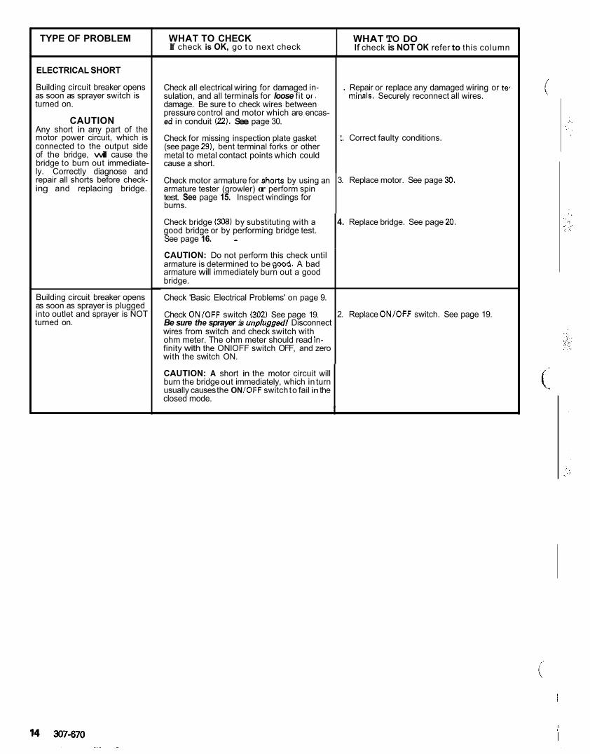
ELECTRICAL SHORT
Building circuit breaker opens as soon as sprayer switch is turned on.
CAUTION Any short in any part of the motor power circuit, which is connected to the output side of the bridge, will cause the bridge to burn out immediate- ly. Correctly diagnose and repair all shorts before check- ing and replacing bridge.
Building circuit breaker opens as soon as sprayer is plugged
turned on. into outlet and sprayer is NOT
WHAT TO CHECK If check is NOT OK refer to this column If check is OK, go t o next check WHAT TO DO
Check all electrical wiring for damaged in- sulation, and all terminals for loose fit or, damage. Be sure to check wires between pressure control and motor which are encas- ed in conduit (22). See page 30.
Check for missing inspection plate gasket (see page 2 9 1 , bent terminal forks or other
cause a short. metal to metal contact points which could
. Repair or replace any damaged wiring or ter. minals. Securely reconnect all wires.
I. Correct faulty conditions.
Check motor armature for shorts by using an armature tester (growler) or perform spin
3. Replace motor. See page 30.
test. See page 15. Inspect windings for burns.
Check bridge (308) by substituting with a good bridge or by performing bridge test.
4. Replace bridge. See page 20.
See page 16. - CAUTION: Do not perform this check until armature is determined to be good. A bad armature will immediately burn out a good bridge.
Check 'Basic Electrical Problems' on page 9.
Be sure the sprayer is unpluggedi Disconnect Check ONlOFF switch (302) See page 19. 2. Replace ON/OFF switch. See page 19.
wires from switch and check switch with
finity with the ONlOFF switch OFF, and zero ohm meter. The ohm meter should read in-
with the switch ON.
CAUTION: A short in the motor circuit will burn the bridge out immediately, which in turn usually causes the ON /OFF switch to fail in the closed mode.
I
~~ ~~
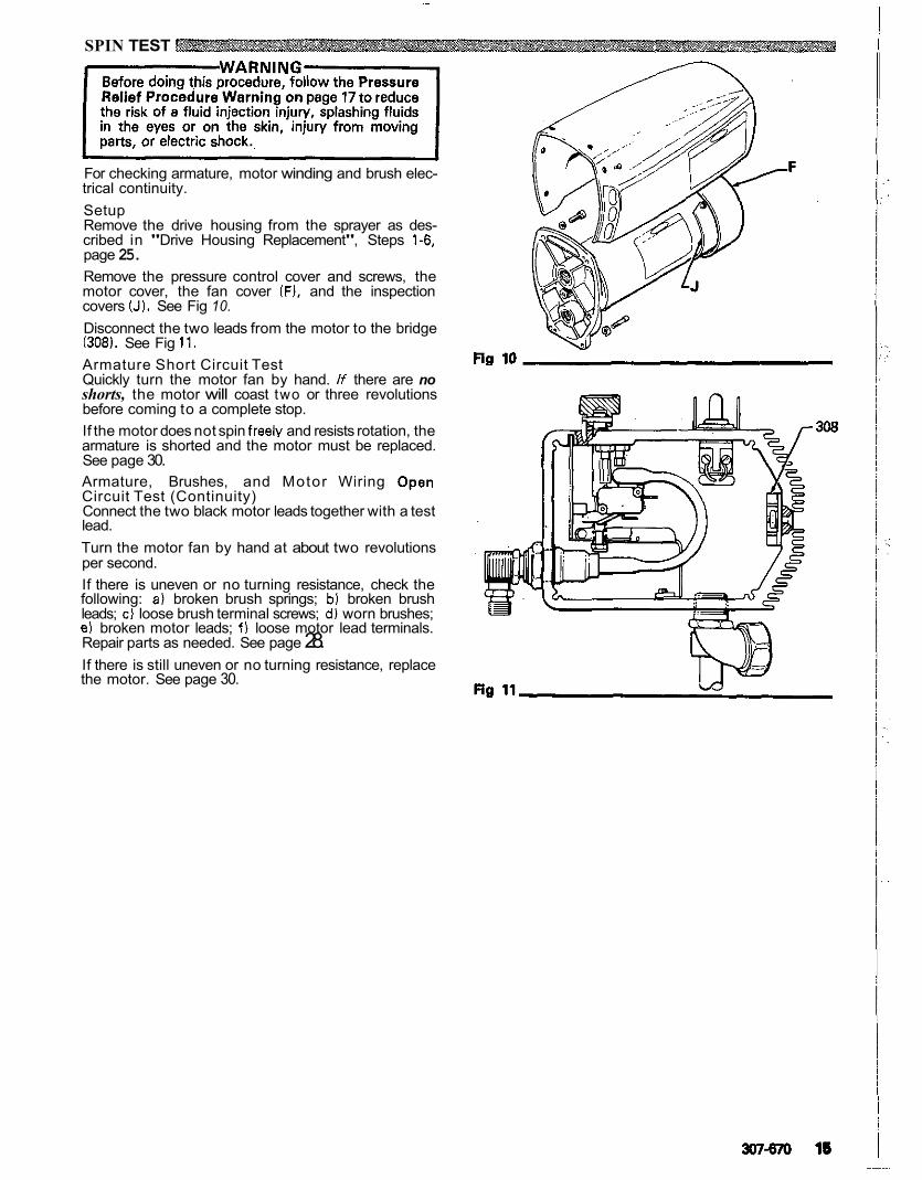
SPIN TEST
For checking armature, motor winding and brush elec- trical continuity. Setup Remove the drive housing from the sprayer as des- cribed in "Drive Housing Replacement", Steps 1-6, page 25.
motor cover, the fan cover (F), and the inspection Remove the pressure control cover and screws, the
covers (J). See Fig 10. Disconnect the two leads from the motor to the bridge 1308). See Fig 11. Armature Short Circuit Test
shorts, the motor will coast two or three revolutions Quickly turn the motor fan by hand. If there are no
before coming to a complete stop. If the motor does not spin freely and resists rotation, the armature is shorted and the motor must be replaced. See page 30. Armature, Brushes, and Motor Wiring Open Circuit Test (Continuity) Connect the two black motor leads together with a test lead. Turn the motor fan by hand at about two revolutions per second.
following: a) broken brush springs; b) broken brush If there is uneven or no turning resistance, check the
leads; c) loose brush terminal screws; d) worn brushes; e) broken motor leads; f) loose motor lead terminals. Repair parts as needed. See page 28. If there is still uneven or no turning resistance, replace the motor. See page 30.
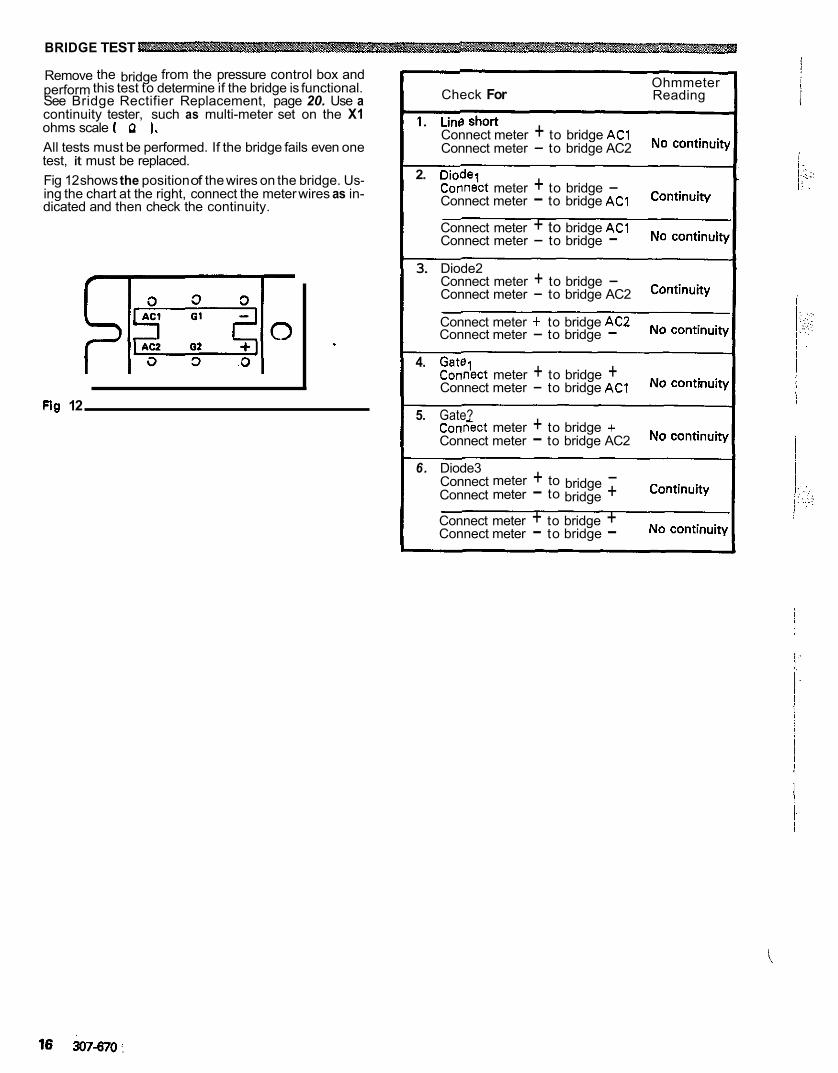
BRIDGE TEST
perform this test to determine if the bridge is functional. Remove the bridge from the pressure control box and
See Bridge Rectifier Replacement, page 20. Use a continuity tester, such as multi-meter set on the X1 ohms scale ( n 1.
test, it must be replaced. All tests must be performed. If the bridge fails even one
Fig 12 shows the position of the wires on the bridge. Us- ing the chart at the right, connect the meter wires as in- dicated and then check the continuity.
Fig 12
Check For Ohmmeter Reading
Connect meter + to bridge AC1 Connect meter - to bridge AC2 No continuifi
2. Diode? Connict meter + to bridge - Connect meter - to bridge AC1 Continuity
Connect meter + to bridge ACl Connect meter - to bridge - No continuib
3. Diode2 Connect meter + to bridge - Connect meter - to bridge AC2 Continuity
Connect meter + to bridge AC2 No continuity Connect meter - to bridge -
4. Gatel Connbct meter + to bridge + Connect meter - to bridge AC1 No
5. Gate? C o n k t meter + to bridge + Connect meter - to bridge AC2 No continuiv
6. Diode3
Connect meter - to bridge + Continuity Connect meter + to bridge -
Connect meter + to bridge + Connect meter - to bridge - No
I.:.. : :... :. : . .
GENERAL REPAIR NOTES WARNING
To reduce the risk of serious bodily injury, in- Pressure Relief Procedure
cluding fluid injection, splashing fluid in the eyes or on the skin, or injury from moving parts or elec- tric shock, always follow this procedure whenever you shut off the sprayer, when checking or servic- ing any part of the spray system, when installing, cleaning or changing spray tips, and whenever you stop spraying.
2. Turn the ONlOFF switch to OFF. 1. Engage the gun safety latch.
3. Unplug the power supply cord. 4. Disengage the gun safety latch. 5. Hold a metal part of the gun firmly to the side of
a grounded metal pail, and trigger the gun to relieve pressure.
6. Engage the gun safety latch. 7. Open the drain valve, having a container ready
8. Leave the drain valve open until you are ready
If you suspect that the spray tip or hose is com- pletely clogged, or that pressure has not been fully relieved after following the steps above, VERY SLOWLY loosen the tip guard retaining nut or
then loosen completely. Now clear the tip or hose. hose end coupling and relieve pressure gradually,
to catch the drainage.
to spray again.
Tool List The following tools are needed when repairing this sprayer. Phillips screwdriver Small flatblade screwdriver Needle nose pliers Plastic mallet Adjustable wrench 2" adjustable, open-end wrench Torque wrench
3/16" hex key wrench 114" hex key wrench
518" socket wrench 318" open end wrench
314" open end wrench 112' open end'wrench
718" open end wrench High quality motor oil Bearing grease
318' ignition wrench For calibration procedure only:
0.015" spray tip
5 gallon pail High pressure, oil-filled test gauge, Part No. 102-814
Clean water Mineral spirits NEW 207 bar (3000 psi1 high pressure spray hose,
Before repairing any part of the sprayer, read the follow-
sure you have the necessary tools and parts available. ing general repair notes and the repair procedure. Be
1. When disconnecting wires in the pressure control assembly, use needle nose pliers to separate mating connectors. When reconnecting the wires, be sure the flat blade of the insulated male connector is centered in the
the connection is made. - ~
wrap-around blade of the female connector when
Part No. 214-915.
CAUTION
tion, be sure to properly mate connectors, and never pull on a wire to dwonnect it. Pulling on a wire could loosen the connector from the wire.
2. Route wires in the pressure control assembly
tube, where appropriate, to avoid interfering with carefully through the legs of the U-shaped bourdon
the bourdon tube which moves as the pressure set- ting changes and to avoid pinching the wires be- tween the pressure control box and cover.
CAUTION
performance or damage to the pressure control. Improper wire routing can result in poor sprayer
3. Keep all screws, nuts, washers, gaskets, and elec- trical fittings removed during repair procedures. These parts are not normally provided with replace- ment assemblies.
4. Test your repair before regular operation of the sprayer to be sure the problem is corrected. If the sprayer does not operate properly, review the repair procedure again to verify thaf everything was done correctly. If necessary, refer to the Troubleshooting Guide, pages 9-16, to help identify other possible problems and solutions.
WARNING To reduce the risk of serious bodily injury, in- cluding electric shock, DO NOT touch any moving
while inspecting the repair. parts or electrical parts with your fingers or a tool
Shut off the sprayer'and unplug it as soon as you complete the inspection. Reinstall all covers, gaskets, screws and washers before operating the sprayer.
I c A u T l o N 1 seconds toavoid damaging the pump packings. Do not run the sprayer dry for more than 30
5. Reinstall the motor cover before regular operation of the sprayer and replace it if it is damaged. The cover directs cooling air around the motor to help prevent overheating. It can also help prevent burns, fire or explosion; see the WARNING, below.
WARNING During operation, the motor becomes very hot and could burn your skin if touched. Flammable materials spilled on the hot, bare motor could cause a fire or explosion. Always have the motor
the risk of burns, fire or explosion. cover in place during regular operation to reduce
307-670 17
. . . . .. . .~
~. ~.
. ,, . .. . .
. .
. .
I 1 !
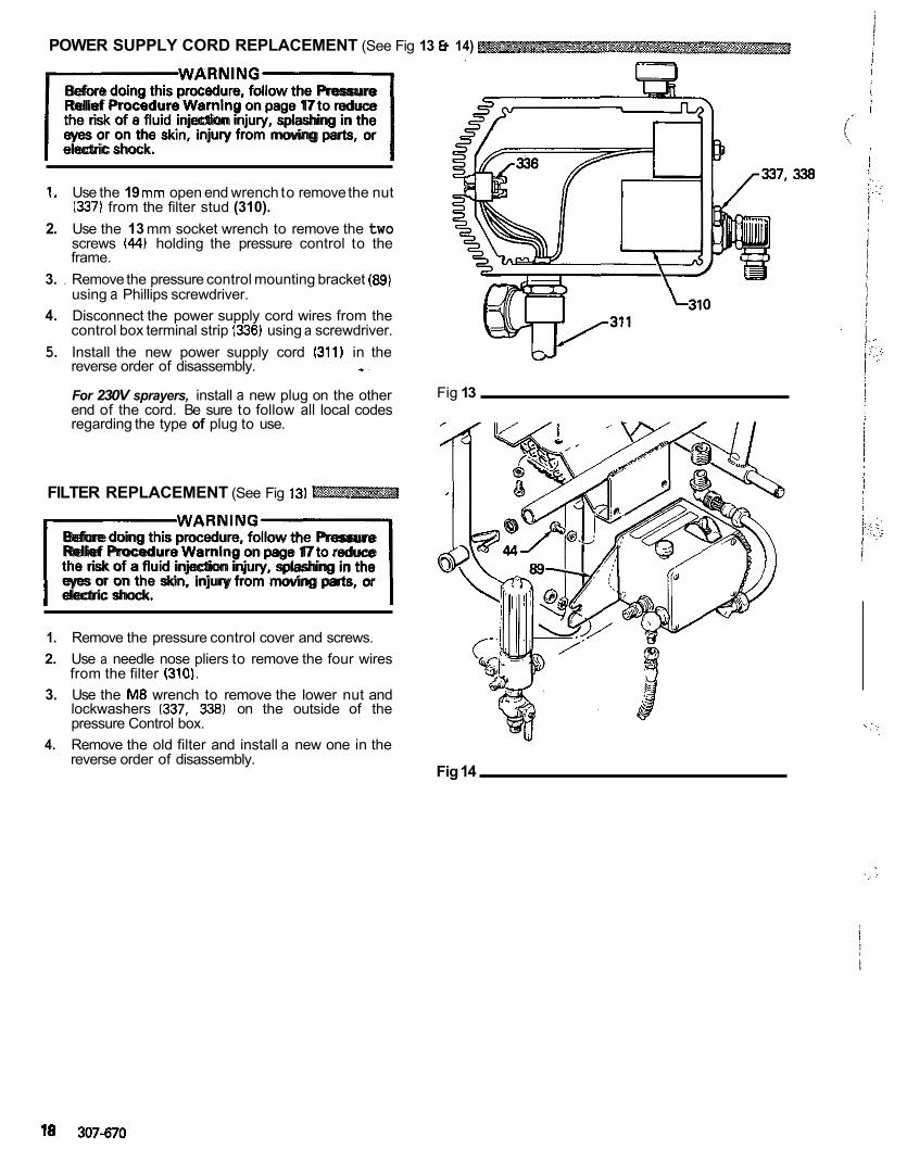
POWER SUPPLY CORD REPLACEMENT (See Fig 13 Et 14)
F W A R N l N G 1
Before doing this procedure, follow the Pressure Relief Procedure Warning on page 17 to reduce the risk of e fluid injection injury, splashing in the eyes or on the skin, injury from moving parts, or electric shock.
1. Use the 19 mm open end wrench to remove the nut (337) from the filter stud (310).
2. Use the 13 mm socket wrench to remove the two
frame. screws (44) holding the pressure control to the
3. . Remove the pressure control mounting bracket (89) using a Phillips screwdriver.
4. Disconnect the power supply cord wires from the control box terminal strip (336) using a screwdriver.
5. Install the new power supply cord (311) in the reverse order of disassembly. - .
end of the cord. Be sure to follow all local codes For 230V sprayers, install a new plug on the other
regarding the type of plug to use.
FILTER REPLACEMENT (See Fig 13)
I W A R N I N G 1
Before doing this procedure, follow the Pressure Relief Procedure Warning on page 17 to reduce the risk of a fluid injection injury, splashing in the eyes or on the skin, injury from moving parts, or electric shock.
1. Remove the pressure control cover and screws. 2. Use a needle nose pliers to remove the four wires
from the filter (3101. 3. Use the M8 wrench to remove the lower nut and
lockwashers (337, ,338) on the outside of the pressure Control box.
4. Remove the old filter and install a new one in the reverse order of disassembly.
Fig 13
Fig 14
18 307-670
338
~~~
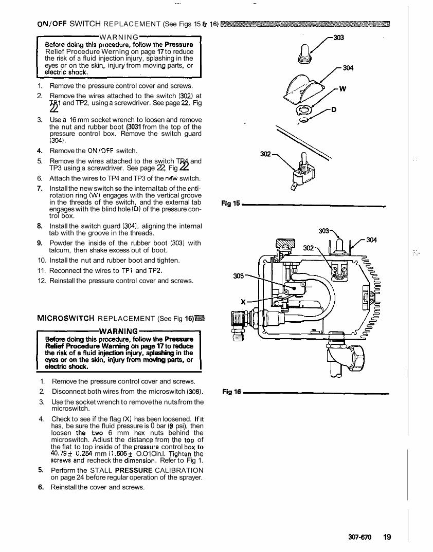
ON/OFF SWITCH REPLACEMENT (See Figs 15 16)
WARNING
the risk of a fluid injection injury, splashing in the Relief Procedure Werning on page 17 to reduce
eyes or on the skin, injury from moving parts, or
1. Remove the pressure control cover and screws. 2. Remove the wires attached to the switch (302) at
TP1 and TP2, using a screwdriver. See page 22, Fig 22. 3. Use a 16 mm socket wrench to loosen and remove
the nut and rubber boot (3031 from the top of the pressure control box. Remove the switch guard (304).
4. Remove the ONlOFF switch. 5. Remove the wires attached to the switch TP4 and
TP3 using a screwdriver. See page 22, Fig 22. 6. Attach the wires to TP4 and TP3 of the n& switch. 7. Install the new switch so the internal tab of the anti-
rotation ring (W) engages with the vertical groove in the threads of the switch, and the external tab engages with the blind hole (D) of the pressure con- trol box.
8. Install the switch guard ( 3 0 4 1 , aligning the internal tab with the groove in the threads.
9. Powder the inside of the rubber boot (303) with talcum, then shake excess out of boot.
10. Install the nut and rubber boot and tighten. 11. Reconnect the wires to TP1 and TP2. 12. Reinstall the pressure control cover and screws.
MICROSWITCH REPLACEMENT (See Fig 16)
IWARNINGl
Before doing this procedure, follow the Pressure Relief Procedure Warning on page 17 to reduce the risk of a fluid injection injury, splashing in the eyes or on the skin, injury from moving parts, or electric shock.
1. Remove the pressure control cover and screws. 2. Disconnect both wires from the microswitch (306). 3. Use the socket wrench to remove the nuts from the
microswitch. 4. Check to see if the flag (X) has been loosened. If it
has, be sure the fluid pressure is 0 bar (0 psi), then loosen -the two 6 mm hex nuts behind the microswitch. Adiust the distance from the toD of the flat to top inside of the pressure control b& to 40.79f 0.254 mm (1.606+ O.O1Oin.l. Tiahten the
~~ ~ ~~
screwFand recheck the dimension. Refer to Fig 1. 5. Perform the STALL PRESSURE CALIBRATION
on page 24 before regular operation of the sprayer. 6. Reinstall the cover and screws.
~I ~~~ ~
307-670 19
. .
. ,. ,: . .. . .
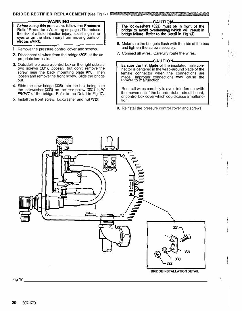
BRIDGE RECTIFIER REPLACEMENT (See Fig 17)
the risk of a fluid injection injury, splashing in the Relief Procedure Warning on page 17 to reduce
eyes or on the skin, injury from moving parts or
1; Remove the pressure control cover and screws. 2. Disconnect all wires from the bridoe (308) at the aD-
I C A U T ' O N 1
The lockwashers (333) must be in front of the bridge to avoid overheating which will result in bridge failure. Refer to the Detail in Fig 17.
6. Make sure the bridge is flush with the side of the box
7. Connect all wires. Carefully route the wires. and tighten the screws securely.
I
propriate terminals. 3. Outside the pressure control box on the right side are
CAUTION
two screws (331). Loosen, but don't remove the of the insulated male con-
screw near the back mounting plate (89). Then nector is centered in the wrap-around blade of the
loosen and remove the front screw. Slide the bridge female connector when the connections are made. Improper connections may cause the
out. sDrayer to malfunction. 4. Slide the new bridge (308) into the box being sure
the lockwasher (333) on the rear screw (331) is /N FRONTof the bridge. Refer to the Detail in Fig 17.
Route all wires carefully to avoid interference with the movement of the bourdon tube, circuit board, or control box cover which could cause a malfunc- tion.
. .
5. Install the front screw, lockwasher and nut 1332).
8. Reinstall the pressure control cover and screws.
BRIDGE INSTALLATION DETAIL
Fig 17 \..
307-670
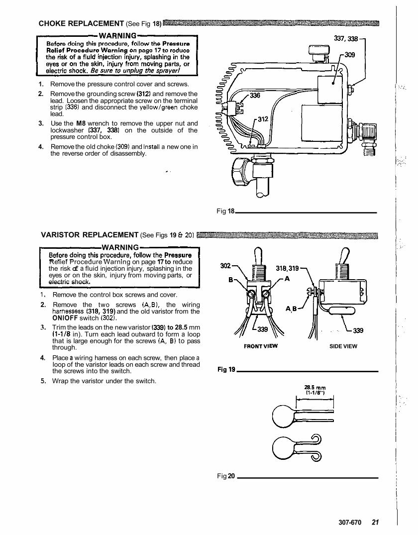
CHOKE REPLACEMENT (See Fig 18)
337,338
1. Remove the pressure control cover and screws. 2. Remove the grounding screw (312) and remove the
strip (336) and disconnect the yellowlgreen choke lead. Loosen the appropriate screw on the terminal
lead. 3. Use the M8 wrench to remove the upper nut and
lockwasher (337, 338) on the outside of the pressure control box.
4. Remove the old choke (309) and instell a new one in the reverse order of disassembly.
Fig 18
VARISTOR REPLACEMENT (See Figs 19 8 201
WARNING
the risk of a fluid injection injury, splashing in the Relief Procedure Warning on page 17 to reduce
eyes or on the skin, injury from moving parts, or electric shock.
1. Remove the control box screws and cover. 2. Remove the two screws IA,B), the wiring
harnesses (318, 319) and the old varistor from the ONlOFF switch (302).
3. Trim the leads on the new varistor 1339) to 28.5 mm (1-118 in). Turn each lead outward to form a loop that is large enough for the screws (A, B) to pass through.
4. Place a wiring harness on each screw, then place a
the screws into the switch. loop of the varistor leads on each screw and thread
5. Wrap the varistor under the switch.
FRONTVIEW SIDE VIEW
Fig 20
307-670 21
~ ~ ~~~ ~~
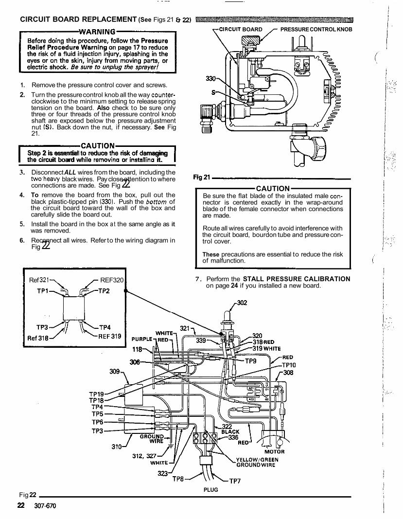
CIRCUIT BOARD REPLACEMENT (See Figs 21 8 22)
1. Remove the pressure control cover and screws. 2. Turn the pressure control knob all the way counter-
tension on the board. Also check to be sure only clockwise to the minimum setting to release spring
three or four threads of the pressure control knob shaft are exposed below the pressure adjustment nut (SI. Back down the nut, if necessary. See Fig 21.
IcAuT'oNl Step 2 is essential to reduce the risk of damaging the circuit board while removina or installino it.
~~~~~ ~~ ~
3. Disconnect ALL wires from the board, including the twoheavy black wires. Pay close attention to where connections are made. See Fig 22.
4. To remove the board from the box, pull out the
the circuit board toward the wall of the box and black plastic-tipped pin (330). Push the bortom of
carefully slide the board out. 5. Install the board in the box a t the same angle as it
was removed. 6. Reconnect all wires. Refer to the wiring diagram in
Fig 22.
~~~
Ref 3 2 1 7 REF320
y-CIRCUIT BOARD 7 PRESSURE CONTROL KNOB
CAUTION
nector is centered exactly in the wrap-around Be sure the flat blade of the insulated male con-
are made. blade of the female connector when connections
Route all wires carefully to avoid interference with the circuit board, bourdon tube and pressure con- trol cover.
These precautions are essential to reduce the risk of malfunction.
7. Perform the STALL PRESSURE CALIBRATION on page 24 if you installed a new board.
P 2
YELLOW/GREEN GROUND WIRE
Fig 22 22 307-670
PLUG
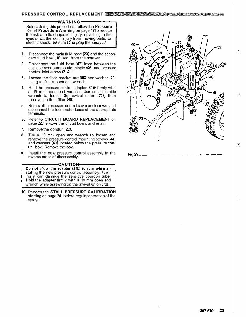
PRESSURE CONTROL REPLACEMENT
WARNING Before doing this procedure, follow the Pressure
the risk of a fluid injection injury, splashing in the Relief Procedure Warning on page 17 to reduce
eyes or on the skin, injury from moving parts, or electric shock. Be sure to unplug the sprayed
1. Disconnect the main fluid hose (23) and the secon- dary fluid hose, if used, from the sprayer.
2. Disconnect the fluid hose (47) from between the displacement pump outlet nipple (46) and pressure control inlet elbow (314).
3. Loosen the filter bracket nut (85) and washer (13) using a 19 mm open end wrench.
4. Hold the pressure control adapter 1315) firmly with a 19 mm open end wrench. Use an adjustable wrench to loosen ths swivel union 179). then remove the fluid filter (48).
5. Remove the pressure control cover and screws, and disconnect the four motor leads at the appropriate terminals.
6. Refer to CIRCUIT BOARD REPLACEMENT on page 22'remove the circuit board and retain.
7. Remove the conduit 122). 8. Use a 13 mm open end wrench to loosen and
remove the pressure control mounting screws (44)
trol box. Remove the box. and washers (40) located below. the pressure con-
9. Install the new pressure control assembly in the reverse order of disassembly.
CAUTION
stalling the new pressure control assembly. Turn- ing it can damage the sensitive bourdon tube. Hold the adapter firmly with a 19 mm open end wrench while screwing on the swivel union 179).
10. Perform the STALL PRESSURE CALIBRATION starting on page 24, before regular operation of the sprayer.
* .
. . , . .,, . .
. . . ...
. ., . ,.. .; . .. .
. . . .
STALL PRESSURE CALIBRATION
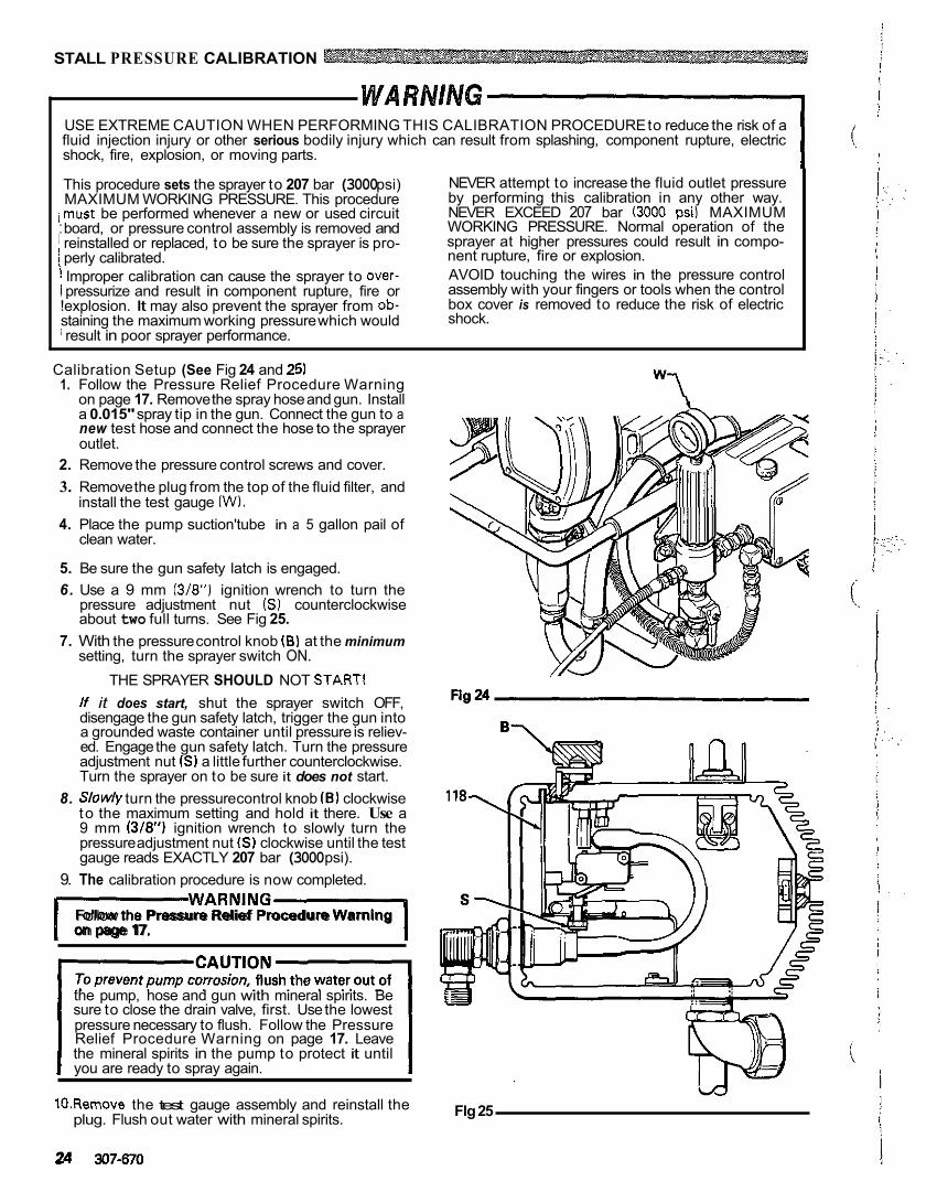
USE EXTREME CAUTION WHEN PERFORMING THIS CALIBRATION PROCEDURE to reduce the risk of a fluid injection injury or other serious bodily injury which can result from splashing, component rupture, electric shock, fire, explosion, or moving parts.
MAXIMUM WORKING PRESSURE. This procedure This procedure sets the sprayer to 207 bar (3000 psi)
,must be performed whenever a new or used circuit
1 reinstalled or replaced, to be sure the sprayer is pro- : board, or pressure control assembly is removed and
1 perly calibrated. ! Improper calibration can cause the sprayer to over- I pressurize and result in component rupture, fire or !explosion. It may also prevent the sprayer from ob- staining the maximum working pressure which would i result in poor sprayer performance.
NEVER attempt to increase the fluid outlet pressure by performing this calibration in any other way. NEVER EXCEED 207 bar (3000 psi) MAXIMUM WORKING PRESSURE. Normal operation of the sprayer at higher pressures could result in compo- nent rupture, fire or explosion. AVOID touching the wires in the pressure control assembly with your fingers or tools when the control box cover is removed to reduce the risk of electric shock.
Calibration Setup (See Fig 24 and 25) 1. Follow the Pressure Relief Procedure Warning
on page 17. Remove the spray hose and gun. Install a 0.015" spray tip in the gun. Connect the gun to a new test hose and connect the hose to the sprayer outlet.
2. Remove the pressure control screws and cover. 3. Remove the plug from the top of the fluid filter, and
4. Place the pump suction'tube in a 5 gallon pail of install the test gauge (W).
clean water.
5. Be sure the gun safety latch is engaged. 6. Use a 9 mm (3/8") ignition wrench to turn the
about two full turns. See Fig 25. pressure adjustment nut ( S ) counterclockwise
7. With the pressure control knob (E) at the minimum setting, turn the sprayer switch ON.
THE SPRAYER SHOULD NOT STARTI lf it does start, shut the sprayer switch OFF, disengage the gun safety latch, trigger the gun into a grounded waste container until pressure is reliev- ed. Engage the gun safety latch. Turn the pressure adjustment nut 1s) a little further counterclockwise. Turn the sprayer on to be sure it does not start.
8. S/ow/y turn the pressure control knob (E) clockwise to the maximum setting and hold it there. Use a 9 mm (3/8") ignition wrench to slowly turn the pressure adjustment nut 1s) clockwise until the test gauge reads EXACTLY 207 bar (3000 psi).
9. The calibration procedure is now completed.
IWARNINGl Follow the Pressure Relief Procedure Warning on page 17.
the pump, hose and gun with mineral spirits. Be sure to close the drain valve, first. Use the lowest pressure necessary to flush. Follow the Pressure Relief Procedure Warning on page 17. Leave the mineral spirits in the pump to protect it until you are ready to spray again.
10.Remove the test gauge assembly and reinstall the plug. Flush out water with mineral spirits.
24 307-670
"1
Flg 25
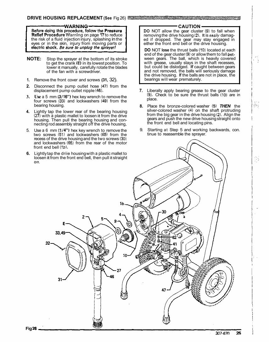
DRIVE HOUSING REPLACEMENT (See Fig 26)
WARNING
the risk of a fluid injection injury, splashing in the Relief Procedure Warning on page 17 to reduce
eyes or in the skin, injury from moving parts or
NOTE: Stop the sprayer at the bottom of its stroke to get the crank (E) in its lowest position. To lower it manually, carefully rotate the blades of the fan with a screwdriver.
1. Remove the front cover and screws (31, 32). 2. Disconnect the pump outlet hose (47) from the
displacement pump outlet nipple 1 4 6 ) . 3. Use a 5 mm (3/16') hex key wrench to remove the
four screws ( 3 3 1 and lockwashers (49) from the bearing housing.
4. Lightly tap the lower rear of the bearing housing 127) with a plastic mallet to loosen it from the drive housing. Then pull the bearing housing and con- necting rod assembly straight off the drive housing,
5. Use a 6 mm (1/4") hex key wrench to remove the two screws (51) and lockwashers (65) from the recess of the drive housing and the two screws (30)
front end bell (lb). and lockwashers (65) from the rear of the motor
6. Lightly tap the driie housing with a plastic mallet to loosen it from the front end bell, then pull it straight Off .
CAUTION DO NOT allow the gear cluster (91 to fall when removing the drive housing (2). It is eas17y damag- ed if dropped. The gear may stay engaged in either the front end bell or the drive housing.
end of the gear cluster (9) or allow them to fall bet- DO NOT lose the thrust balls (10) located at each
with grease, usually stays in the shaft recesses, ween gears. The ball, which is heavily covered
but could be dislodged. If caught between gears and not removed, the balls will seriously damage the drive housing. If the balls are not in place, the bearings will wear prematurely.
7. Liberally apply bearing grease to the gear cluster (9). Check to be sure the thrust balls (10) are in place.
8. Place the bronze-colored washer (5) THEN the silver-colored washer (4) on the shaft protruding from the big gear in the drive housing (2). Align the gears and push the new drive housing straight onto the front end bell and locating pins.
9. Starting at Step 5 and working backwards, con. tinue to reassemble the sprayer.
Fig 26
1 i : !
!
! 1
I
I
~- ~
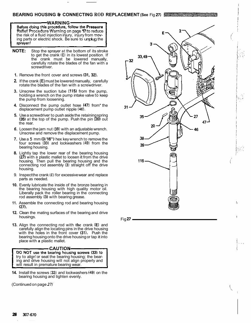
BEARING HOUSING 8 CONNECTING ROD REPLACEMENT (See Fig 27)
WARNING
the risk of a fluid injection injury, injury from mov- Relief Procedure Warning on page 17 to reduce
ing parts or electric shock. Be sure to unplug the
NOTE: Stop the sprayer at the bottom of its stroke to get the crank (E) in its lowest position. If the crank must be lowered manually, carefully rotate the blades of the fan with a screwdriver.
1. Remove the front cover and screws (31, 32). 2. If the crank (E) must be lowered manually, carefully
rotate the blades of the fan with a screwdriver. 3. Unscrew the suction tube (115) from the pump,
holding a wrench on the pump intake valve to keep the pump from loosening.
4. Disconnect the pump outlet hose (47) from* the displacement pump outlet nipple (46).
5. Use a screwdriver to push aside the retaining spring (35) at the top of the pump. Push the pin (20) out the rear.
6. Loosen the jam nut (38) with an adjustable wrench. Unscrew and remove the displacement pump.
7. Use a 5 mm ( 3 /16 ) hex key wrench to remove the four screws (33) and lockwashers (49) from the bearing housing.
8. Lightly tap the lower rear of the bearing housing
housing. Then pull the bearing housing and the (27) with a plastic mallet to loosen it from the drive
connecting rod assembly (3) straight off the drive housing.
9. Inspect the crank (E) for excessive wear and replace parts as needed.
10. Evenly lubricate the inside of the bronze bearing in the bearing housing with high quality motor oil.
rod assembly (3) with bearing grease. Liberally pack the roller bearing in the connecting
11. Assemble the connecting rod and bearing housing (27).
w 12. Clean the mating surfaces of the bearing and drive
housings. Fig 27 13. Align the connecting rod with the crank (E) and
carefully align the locating pins in the drive housing with the holes in the front cover (31). Push the bearing housing onto the drive housing or tap it into place with a plastic mallet.
CAUTION
try to align' or seat the bearing housing; the bear- ing and drive housing will not align properly and will result in premature bearing wear.
14. Install the screws (33) and lockwashers (49) on the bearing housing and tighten evenly.
(Continued on page 271
i J
I
. .. ,
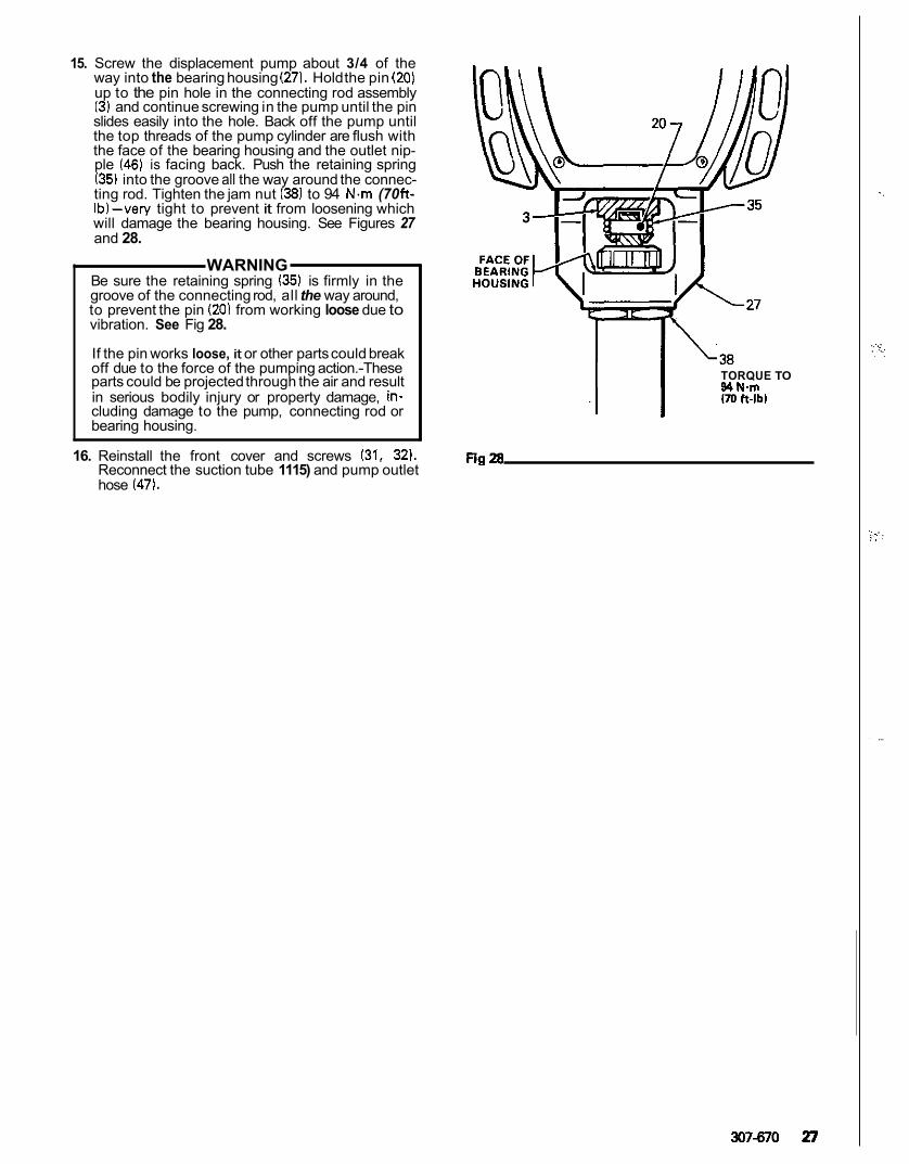
15. Screw the displacement pump about 3/4 of the way into the bearing housing (271. Hold the pin (20) up to the pin hole in the connecting rod assembly (3) and continue screwing in the pump until the pin slides easily into the hole. Back off the pump until the top threads of the pump cylinder are flush with the face of the bearing housing and the outlet nip- ple (46) is facing back. Push the retaining spring
ting rod. Tighten the jam nut (38) to 94 N m (70 ft- (35) into the groove all the way around the connec-
will damage the bearing housing. See Figures 27 Ib)-very tight to prevent it from loosening which
and 28.
WARNING Be sure the retaining spring (35) is firmly in the groove of the connecting rod, all the way around, to prevent the pin (20) from working loose due to vibration. See Fig 28.
If the pin works loose, it or other parts could break off due to the force of the pumping action.-These parts could be projected through the air and result
cluding damage to the pump, connecting rod or in serious bodily injury or property damage, in-
bearing housing.
TORQUE TO 90 N.m .I I UOft-lbl
16. Reinstall the front cover and screws (31, 32). Reconnect the suction tube 1115) and pump outlet hose 147).
307870 27
..
. :_. ..I: . ,
.. . .:, . . . . .
,. ...
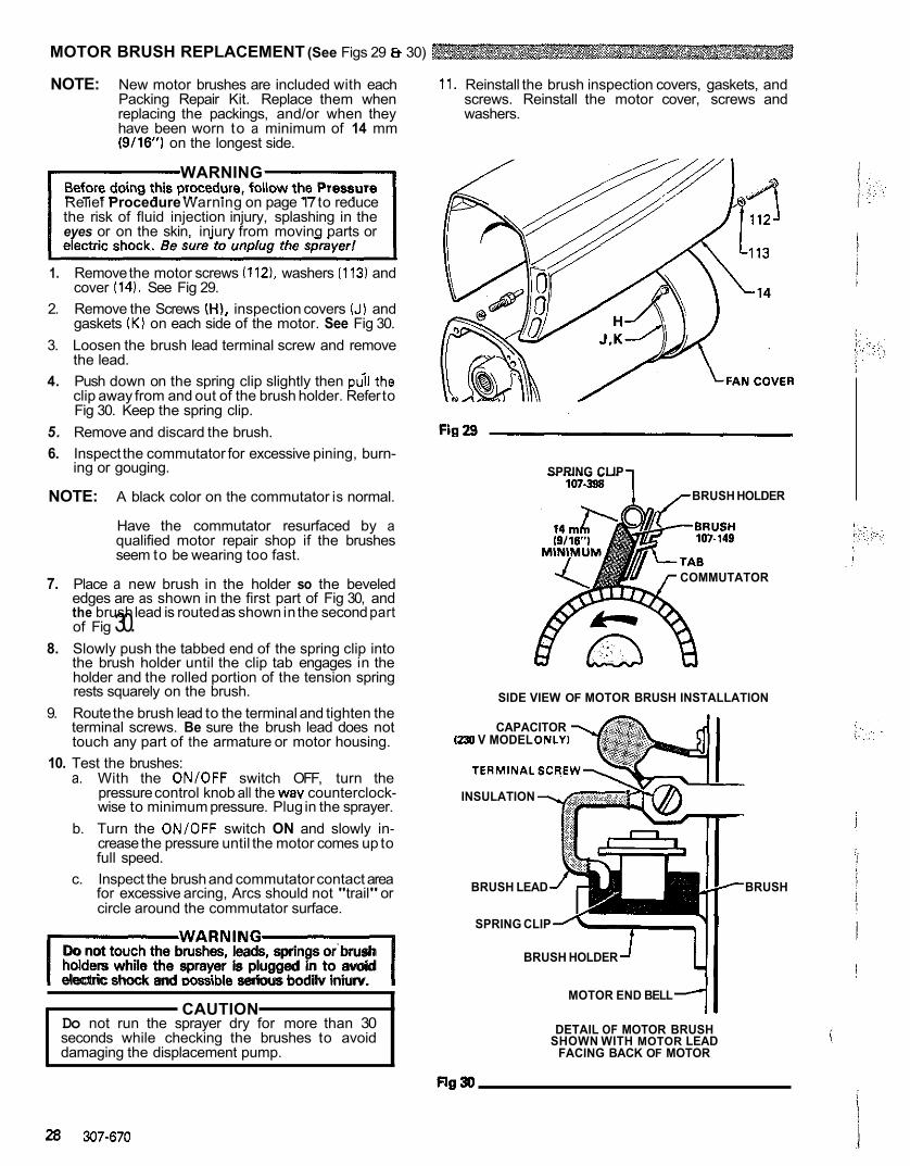
MOTOR BRUSH REPLACEMENT (See Figs 29 Et 30)
NOTE: New motor brushes are included with each
replacing the packings, and/or when they Packing Repair Kit. Replace them when
have been worn to a minimum of 14 mm (9/16) on the longest side.
WARNING
Relief Procedure Warning on page 17 to reduce the risk of fluid injection injury, splashing in the eyes or on the skin, injury from moving parts or
1. Remove the motor screws (112). washers (113) and cover (14). See Fig 29.
2. Remove the Screws (HI, inspection covers (J) and gaskets (K) on each side of the motor. See Fig 30.
3. Loosen the brush lead terminal screw and remove the lead.
4. Push down on the spring clip slightly then pdl'the clip away from and out of the brush holder. Refer to Fig 30. Keep the spring clip.
5. Remove and discard the brush. 6. Inspect the commutator for excessive pining, burn-
ing or gouging.
NOTE: A black color on the commutator is normal.
qualified motor repair shop if the brushes Have the commutator resurfaced by a
seem to be wearing too fast.
7. Place a new brush in the holder so the beveled edges are as shown in the first part of Fig 30, and the brush lead is routed as shown in the second part of Fig 30.
8. Slowly push the tabbed end of the spring clip into the brush holder until the clip tab engages in the holder and the rolled portion of the tension spring rests squarely on the brush.
9. Route the brush lead to the terminal and tighten the terminal screws. Be sure the brush lead does not touch any part of the armature or motor housing.
10. Test the brushes: a. With the ON/OFF switch OFF, turn the
pressure control knob all the way counterclock- wise to minimum pressure. Plug in the sprayer.
b. Turn the ON/OFF switch ON and slowly in- crease the pressure until the motor comes up to full speed.
c. Inspect the brush and commutator contact area for excessive arcing, Arcs should not "trail" or circle around the commutator surface.
IWARNIND1 Do not touch the brushes, leads, springs or brush
electric shock and wssible serious bodilv iniurv. holders while the sprayer is plugged in to avoid
~~ ~~ ~ ~~~~ ~~
CAUTION Do not run the sprayer dry for more than 30 seconds while checking the brushes to avoid damaging the displacement pump.
~~ ~
11. Reinstall the brush inspection covers, gaskets, and screws. Reinstall the motor cover, screws and washers.
SPRING CLIP
BRUSH HOLDER
COMMUTATOR
SIDE VIEW OF MOTOR BRUSH INSTALLATION
(230 V MODEL ONLY) CAPACITOR
TERMINALSCREW
INSULATION
BRUSH LEAD BRUSH
SPRING CLIP
BRUSH HOLDER
MOTOR END BELL
DETAIL OF MOTOR BRUSH SHOWN WITH MOTOR LEAD
FACING BACK OF MOTOR
28 307-670
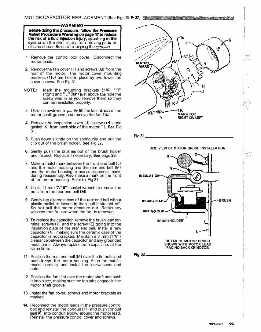
MOTOR CAPACITOR REPLACEMENT (See Figs 31 8 321
IWARNING1 Before doing this procedure, follow the Pressure Relief Procedure Warning on page 17 to reduce the risk of a fluid injection injury, splashina in the eyes or on the skin, injury from moving parts or electric shock. Be sure to unplug the sprayer1
1. Remove the control box cover. Disconnect the motor leads.
2. Remove the fan cover (F) and screws IG) from the rear of the motor. The motor cover mounting brackets 1110) are held in place by two lower fan cover screws. See Fig 31.
NOTE: Mark the mounting brackets (110) "R"
screw was in as you remove them so they (right) and "L" (left) just above the hole the
can be reinstalled properly.
3. Use a screwdriver to gently lift the fan tab out of the motor shaft groove and remove the fan l lc l .
4. Remove the inspection cover IJ), screws (HI, and gasket IK) from each side of the motor (1). See Fig 31.
5. Push down slightly on the spring clip and pull the clip out of the brush holder. See Fig 32.
6. Gently push the brushes out of the brush holder and inspect. Replace if necessary. See page 28.
7. Make a matchmark between the front end bell IL) and the motor housing and the rear end bell (M) and the motor housing to use as alignment marks during reassembly. Also make a mark on the front of the motor housing. Refer to Fig 31.
8. Use a 11 mm (7/16') socket wrench to remove the nuts from the rear end bell (MI.
9. Gently tap alternate ears of the rear end bell with a plastic mallet to loosen it; then pull it straight off. Do not pull the motor armature out. Retain any washers that fall out when the bell is removed.
10. To replace the capacitor, remove the brush lead ter- minal screws IY) and the screw 121 going into the insulation plate of the rear end bell. Install a new capacitor (X), making sure the ceramic case of the capacitor is not cracked. Maintain a 3 mm (118") clearance between the capacitor and any grounded metal parts. Always replace both capacitors at the same time.
11. Position the rear end bell IM) over the tie bolts and push it onto the motor housing. Align the match-
nuts. marks carefully and install the lockwashers and
12. Position the fan (IC) over the motor shaft and push it into place, making sure the fan tabs engage in the motor shaft groove.
marked. 13. Install the fan cover, screws and motor brackets as
14. Reconnect the motor leads in the pressure control
seal (81 into conduit elbow, around the motor lead. box and reinstall the conduit ( 7 7 ) and push conduit
Reinstall the pressure control cover and screws.
.. ,.
RIGHT OR LEFT MARK FOR
Fig 31
SIDE VIEW OF MOTOR BRUSH INSTALLATION
BRUSH
BRUSH HOLDER' 41 L l l
SHOWN WITH MOTOR LEAD DETAIL OF MOTOR BRUSH
FACINQ BACK OF MOTOR
Fig 32
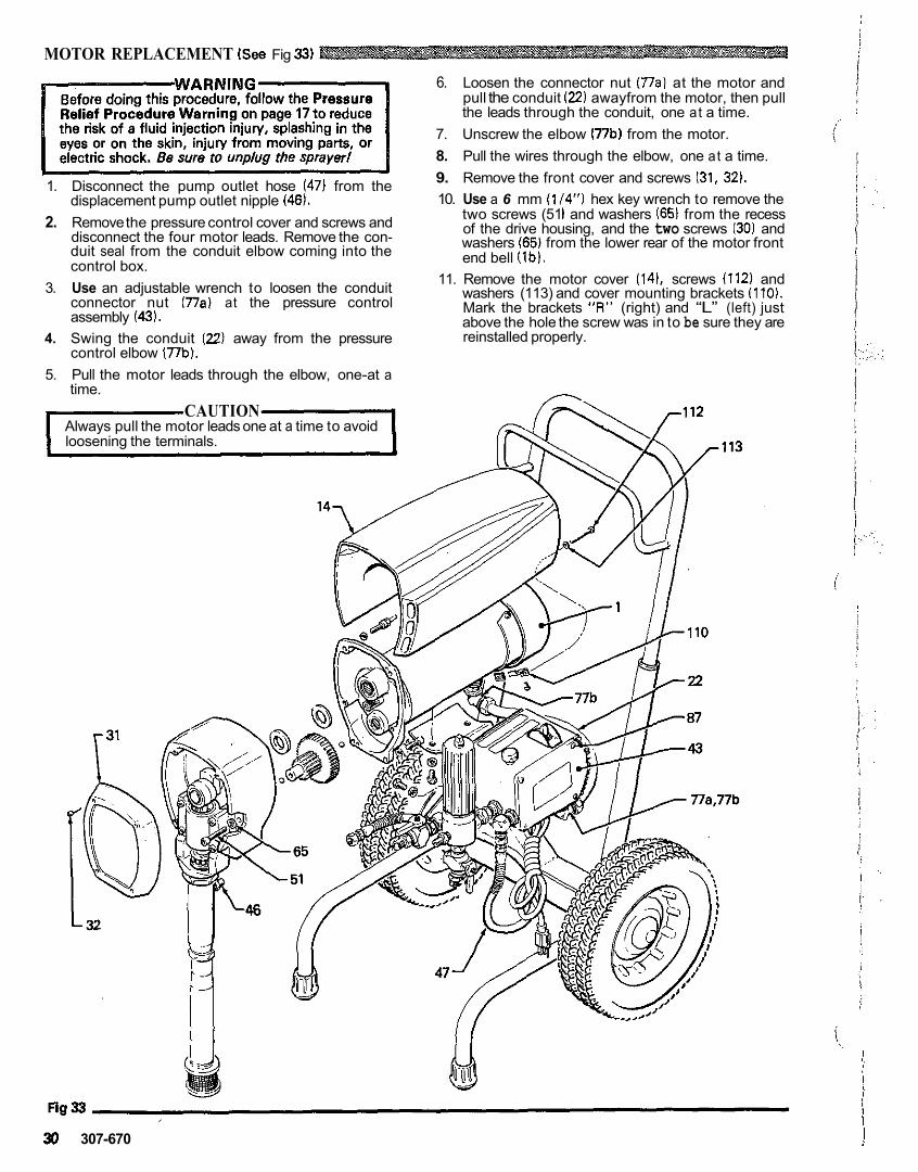
MOTOR REPLACEMENT (See Fig 33)
1. Disconnect the pump outlet hose (47) from the displacement pump outlet nipple (46).
2. Remove the pressure control cover and screws and disconnect the four motor leads. Remove the con- duit seal from the conduit elbow coming into the control box.
3. Use an adjustable wrench to loosen the conduit connector nut (77a) at the pressure control assembly (43).
4. Swing the conduit (22) away from the pressure control elbow (77b).
5. Pull the motor leads through the elbow, one-at a time.
CAUTION Always pull the motor leads one at a time to avoid loosening the terminals.
6. Loosen the connector nut (77al at the motor and pull the conduit ( 2 2 ) awayfrom the motor, then pull the leads through the conduit, one at a time.
7. Unscrew the elbow 177b) from the motor. 8. Pull the wires through the elbow, one at a time. 9. Remove the front cover and screws (31, 32). 10. Use a 6 mm (1/4“) hex key wrench to remove the
two screws (51 1 and washers (65) from the recess of the drive housing, and the two screws (30) and washers (65) from the lower rear of the motor front end bell (lb).
11. Remove the motor cover (14). screws 1112) and washers (113) and cover mounting brackets (110).
above the hole the screw was in to be sure they are Mark the brackets “A” (right) and “L” (left) just
reinstalled properly.
,”-.
30 307-670
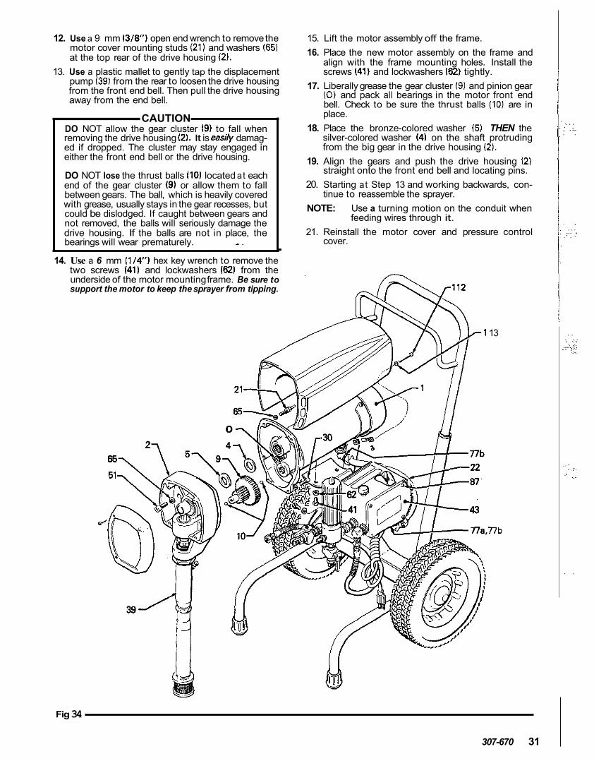
12. Use a 9 mm (3/87 open end wrench to remove the motor cover mounting studs (21) and washers (65) at the top rear of the drive housing (2).
13. Use a plastic mallet to gently tap the displacement pump (39) from the rear to loosen the drive housing from the front end bell. Then pull the drive housing away from the end bell.
CAUTION DO NOT allow the gear cluster (9) to fall when removing the drive housing (2). It is easily damag- ed if dropped. The cluster may stay engaged in either the front end bell or the drive housing.
DO NOT lose the thrust balls (10) located at each end of the gear cluster (9) or allow them to fall between gears. The ball, which is heavily covered with grease, usually stays in the gear recesses, but could be dislodged. If caught between gears and not removed, the balls will seriously damage the drive housing. If the balls are not in place, the bearings will wear prematurely. -~ .
14. Use a 6 mm (1/4") hex key wrench to remove the two screws (41) and lockwashers (62) from the
support the motor to keep the sprayer from tipping. underside of the motor mounting frame. Be sure to
15. Lift the motor assembly off the frame. 16. Place the new motor assembly on the frame and
align with the frame mounting holes. Install the screws (41) and lockwashers (62) tightly.
17. Liberally grease the gear cluster (9) and pinion gear (0) and pack all bearings in the motor front end bell. Check to be sure the thrust balls (10) are in place.
18. Place the bronze-colored washer (5) THEN the silver-colored washer (4) on the shaft protruding from the big gear in the drive housing (2).
19. Align the gears and push the drive housing 12) straight onto the front end bell and locating pins.
20. Starting at Step 13 and working backwards, con- tinue to reassemble the sprayer.
NOTE: Use a turning motion on the conduit when feeding wires through it.
21. Reinstall the motor cover and pressure control cover.
13
.i7b
Fig 34
307-670 31
., . . . . ,, . ... . .
. . ... . , . . . . .. .
. . . . .
.,., <., .
.... :.i: . . .:.
.,.. . ;. . .. . .
. .

ULTRA" 433 SPRAYERS
Model 226-998, Series C, 230 Volt Model 226-999. Series C. 100 Volt Includes items 1-118
32 307-670
1 j . ..:.:.
I i 'I
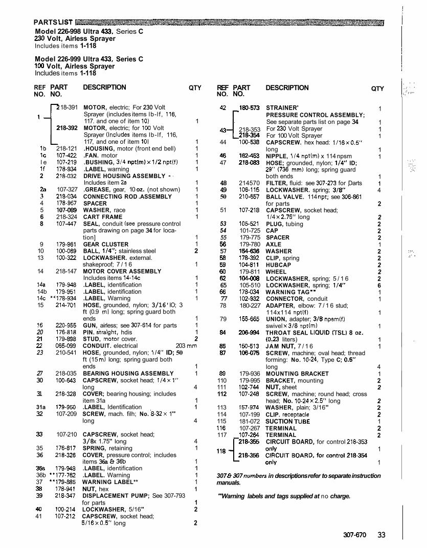
~~~~
PARTS LIST Model 226-998 Ultra 433, Series C 230 Volt, Airless Sprayer Includes items 1-118
Model 226-999 Ultra 433, Series C 100 Volt, Airless Sprayer Includes items 1-118
REF PART DESCRIPTION NO. NO.
.E 18-391 MOTOR, electric; For 230 Volt Sprayer (includes items lb-l f , 116, 117. and one of item 10)
Sprayer llncludes items lb-lf, 116, 117, and one of item 101
lb 218-121 .HOUSING, motor (front end bell) IC 107-422 .FAN. motor l e 107-219 .BUSHING, 314 np t (m)x l /2 nptlf)
2 218-032 DRIVE HOUSING ASSEMBLY - . If 178-934 .LABEL, warning
2a 107-327 .GREASE, gear, 10 02. (not shown) Includes item 2a
3 218-03 CONNECTING ROD .ASSEMBLY 4 178-967 SPACER 5 .107-089 WASHER, race 6 218-324 CART FRAME 8 107-447 SEAL, conduit (see pressure control
218-392 MOTOR, electric; for 100 Volt
parts drawing on page 34 for loca- tion]
10 100-069 BALL, 1/4"; stainless steel 13 100-322 LOCKWASHER. external.
9 179-961 GEAR CLUSTER
shakeproof; 7 / 1 6 14 218-147 MOTOR COVER ASSEMBLY
Includes items 14-14c 14a 179-948 .LABEL, identification 14b 179-951 .LABEL, identification 14c '*178-934 .LABEL, Warning 15 214-701 HOSE, grounded, nylon; 3/16' IO; 3
ft (0.9 m l long; spring guard both ends
20 176-818 PIN. straiaht. hdis 16 220-955 GUN, airless; see 307-614 for parts
21 179-898 STUD, motor cover. 22 065-099 CONDUIT. electrical
QTY
1
1 1 1 1 1
1 1 1 1 1 1
1
2 1
1
1 1 1 1
1 1
1
203 mm 2
23 210-541 HOSE, grounded, nylon; 114" ID; 50 ft (15 m) long; spring guard both ends 1
30 100-643 CAPSCREW, socket head; 1/4x1" 27 218-035 BEARING HOUSING ASSEMBLY 1
31 218-328 COVER; bearing housing; includes long 4
item 31a 1 31a 179-950 .LABEL, Identification 1 32 107-209 SCREW, mach. filh; No. 8-32x 1"
long 4
33 107-210 CAPSCREW, socket head;
35 176-817 SPRING, retaining 36 218-326 COVER, pressure control; includes
3/8 x 1.75" long 4 1
items 36a 8 36b 1 36a 179-949 .LABEL, identification 36b Y77-762 .LABEL. Warning
1
37 ""179-885 WARNING LABEL** 1 1
38 178-941 NUT, hex 1 39 218-347 DISPLACEMENT PUMP; See 307-793
for parts 40 100-214 LOCKWASHER, 5/16" 2
1
41 107-212 CAPSCREW, socket head; 5 / 16x0 .5 long 2
REF PART NO. NO.
DESCRIPTION
42 1 8 0 - m STRAINER'
l PRESSURE CONTROL ASSEMBLY; See separate parts list on page 34
43 218-353 For 230 Volt Sprayer 218354 For 100 Volt Sprayer
44 100-538 CAPSCREW. hex head: 1116~0.5"
46 47
48 49 50
51
53 54 55 56 57 58 59 60 62
66 65
77 78
79
84
85 87
89
111 110
112
113 114 115 116
162-453 NIPPLE, 114 npth) x 114 npsm 218-083 HOSE; grounded, nylon; 1/4" ID;
29" ( 7 3 6 mm) long; spring guard both ends
long
214570 FILTER, fluid: see 307-273 for Darts 106-115 LOCKWASHER. spring; 3/8" ' 210-657 BALL VALVE. 114 nDt: see 306-8131 . .
107-218 CAPSCREW, socket head; for parts
105521 PLUG, tubing 1/4 x2.75" long
101-725 CAP
179-780 AXLE 179-775 SPACER
154-636 WASHER 178-392 CLIP, spring 104411 HUBCAP 179-811 WHEEL 104-008 LOCKWASHER, spring; 5 / 1 6 105-510 LOCKWASHER, spring; 114" 178-034 WARNING TAG" 102-932 CONNECTOR, conduit 180-227 ADAPTER, elbow: 7 / 1 6 stud;
155-665 UNION, adapter; 3/8 npsmlfl 114x114 nptlf)
206.994 THROAT SEAL LICIUID (TSLI 8 02. swivel x3 /8 nptlml
150-513 JAM NUT, 7 / 1 6 (0:23 liters)
106-075 SCREW, machine; oval head; thread forming: No. 10-24, Type C; 0.5' long
179-936 MOUNTING BRACKET 179-995 BRACKET, mounting 102-744 NUT, sheet 107-248 SCREW, machine; round head; cross
157-974 WASHER, plain; 3/16" head; No. 1 0 - 2 4 ~ 2 . 5 long
107-199 CLIP. receDtacle 181-072 SUCTION TUBE 107-267 TERMINAL
117 107-264 TERMINAL rzws CIRCUIT BOARD, for control 218.353
QTY
1
1 1
1
1 1
1 1 4
2
2 2 2 2
2 1
2 2 2 2 6 1 1
1
1
1 1
4
2 1
2
2 2 2 1 2 2
1
1
307 & 307nurnbers in descriptions refer to separate instruction manuals.
"'Warning labels and tags supplied at no charge.
307-670 33
. .
. .... . . . .
. . . . ... . .. ,. . . j.
... :.. ,. .. .
, .
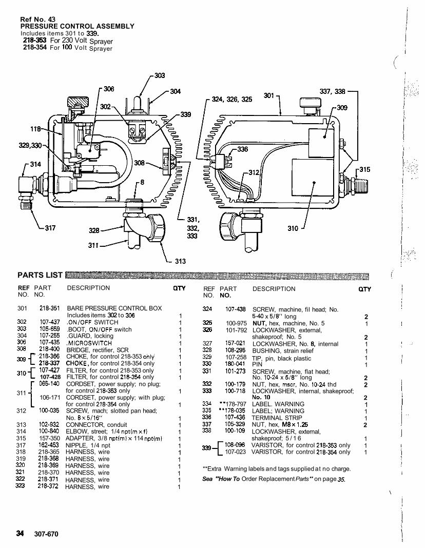
Ref No. 43 PRESSURE CONTROL ASSEMBLY Includes items 301 t o 339.
218-354 For 100 Volt Sprayer 218-353 For 230 Volt Sprayer
313
PARTS LIST REF PART DESCRIPTION NO. NO.
301 218-351 BARE PRESSURE CONTROL BOX
302 107-437 .ON/OFF SWITCH 3w 105-659 .BOOT, ONlOFF switch 304 107-255 .GUARD, locking 306 107-435 .MICROSWITCH 308 218-400 BRIDGE, rectifier, SCR
Includes items 302 to 306
918-366 CHOKE, for control 218-353 onlv
107-427 FILTER, for control 218-353 only , for control 218-354 only
310 f 107-428 FILTER, for control 218-354 only
311 { 065-140 CORDSET, power supply; no plug;
106-171 CORDSET, power supply; with plug; for control 218-353 only
for control 218-354 only 312 100-035 SCREW, mach; slotted pan head;
No. 8x5/16" 313 102-932 CONNECTOR, conduit
315 157-350 ADAPTER, 3/8 nptlmlx 114 nptlm) 314 100-840 ELBOW, street; 1/4 nptlm x f )
318 218-365 HARNESS, wire 317 162-453 NIPPLE, 1/4 npt
319 218-368 HARNESS, wire 320 218-369 HARNESS, wire 321 218-370 HARNESS, wire
323 218-372 HARNESS, wire 322 218-371 HARNESS, wire
a n
1 1
1 1
1 1
1 1
1 1
1
1
1 1 1 1
1 1
1 1 1 1 1
REF PART DESCRIPTION NO. NO.
324 107-438 SCREW, machine, fil head; No.
325 100-975 NUT, hex, machine, No. 5 326 101-792 LOCKWASHER, external,
327 157-021 LOCKWASHER, No. 8. internal 328 108-295 BUSHING, strain relief 329 107-258 TIP, pin, black plastic 330 180-041 PIN
5-40 x 5/8" long
shakeproof; No. 5
331 101-273 SCREW, machine, flat head;
332 100.179 NUT, hex, mscr. No. 10-24 thd 333 100.718 LOCKWASHER, internal, shakeproof;
No. 10-24 x 5/8" long
N" rn 334 "178-797 LABEL. WARNING
._ 335 "178-035 LABEL; WARNING 336 107-436 TERMINAL STRIP 337 105-329 NUT, hex, M8x1.25 338 100-109 LOCKWASHER, external,
=--c shakeproof; 5 / 1 6
107-023 VARISTOR, for control 218-354 only 108496 VARISTOR, for control 218-353 only
**Extra Warning labels and tags supplied at no charge. Sea "How To Order Replacement Parts" on page 35.
a n
2 1
2 1
1 1
1
2 2
2 1 1 1 2
1 1 1
\
I j
I
', 1 . :
! j
j I i
i I
I ' '
I I
I j i
34 307-670
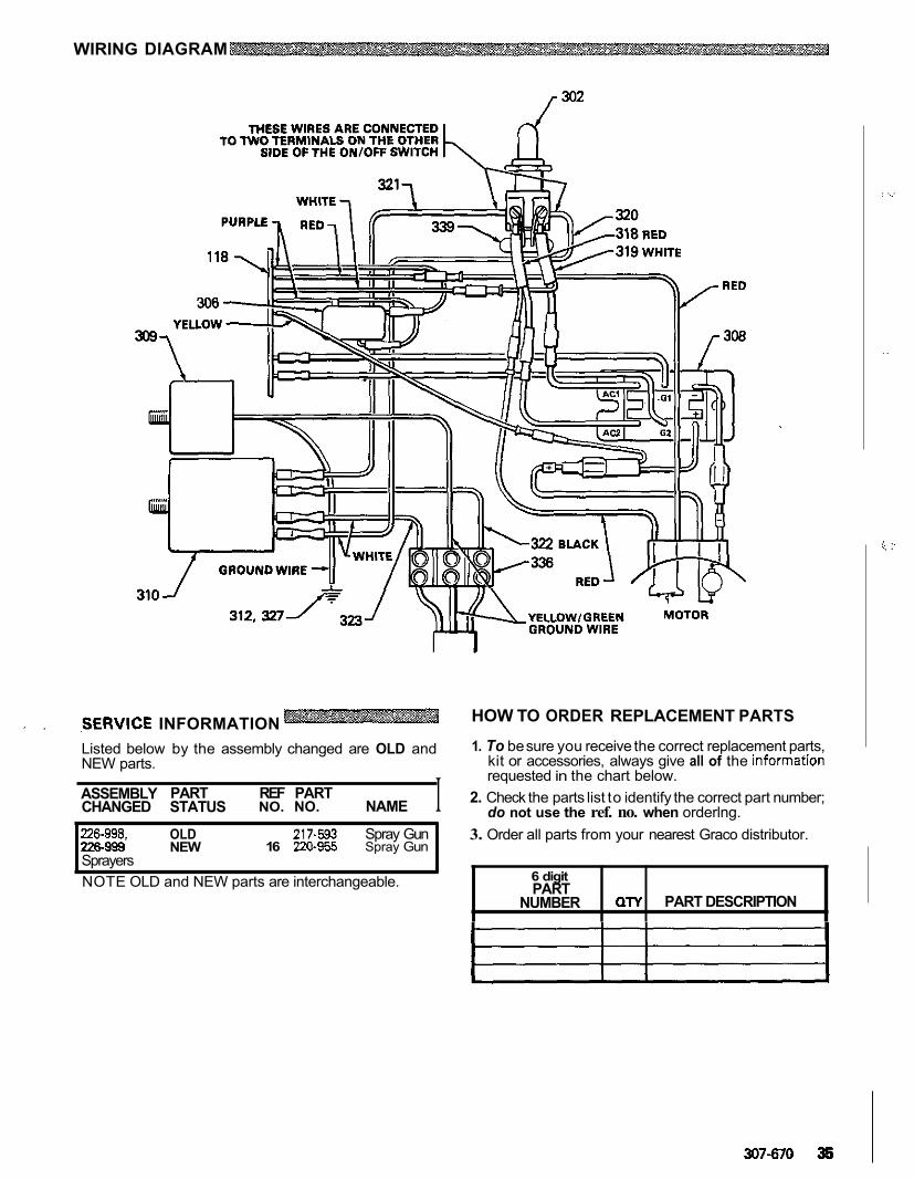
WIRING DIAGRAM
.. . ,SERVICE INFORMATION Listed below by the assembly changed are OLD and NEW parts.
ASSEMBLY PART REF PART CHANGED STATUS NO. NO. NAME I 226-998. OLD 217-593 Spray Gun 226999 NEW Sprayers
16 220-955 Spray Gun
NOTE OLD and NEW parts are interchangeable.
HOW TO ORDER REPLACEMENT PARTS
1. To be sure you receive the correct replacement parts,
requested in the chart below. kit or accessories, always give all of the Information
2. Check the parts list to identify the correct part number; do not use the ref. no. when orderlng.
3. Order all parts from your nearest Graco distributor.
6 digit PART
NUMBER PART DESCRIPTION QTY
. . . . .
..
0, .. .., .
307-670 36
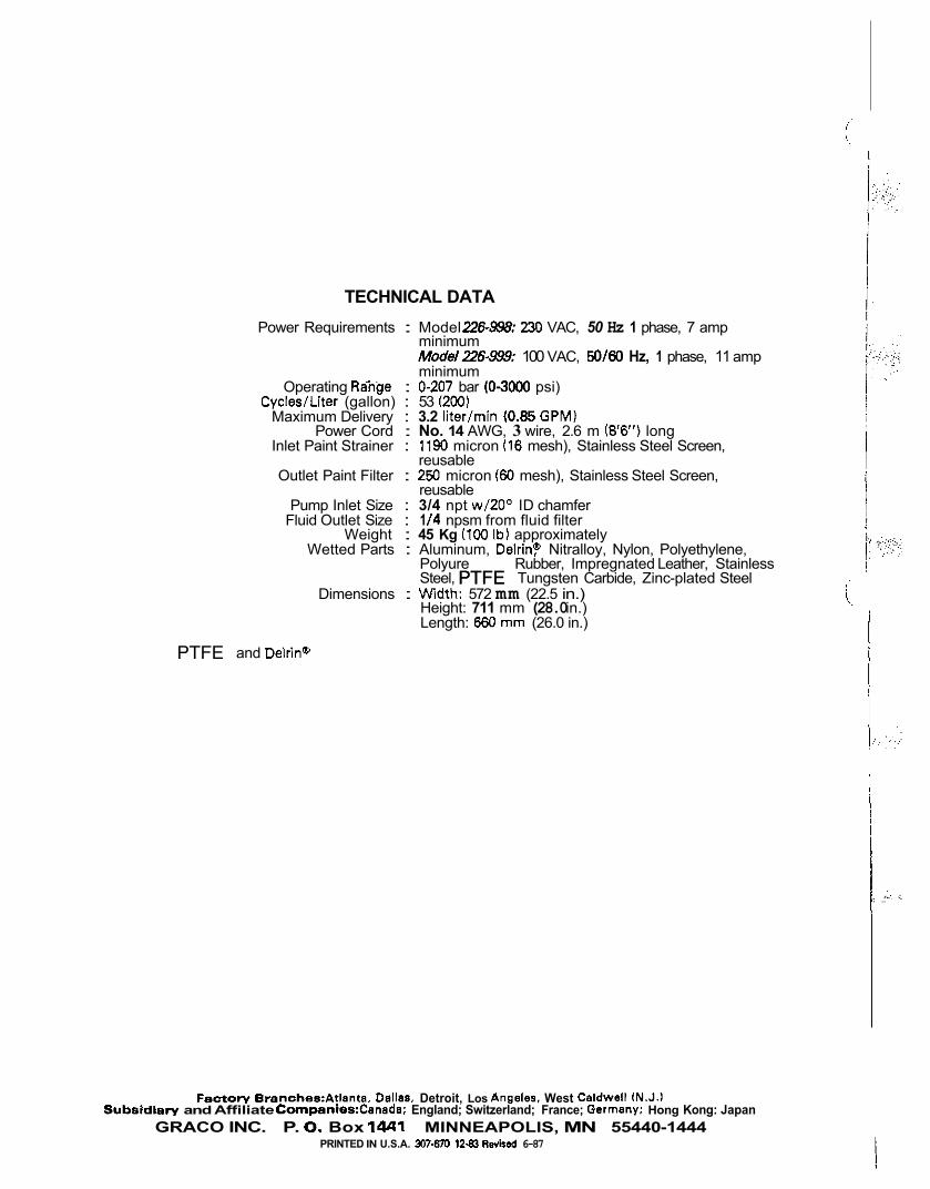
TECHNICAL DATA Power Requirements : Model 22&%: 230 VAC, 50 Hz 1 phase, 7 amp
ModelZ6-999: 100 VAC, 50/W Hz, 1 phase, 11 amp minimum
minimum Operating RaXge : 0-207 bar (0-3000 psi)
Maximum Delivery : 3.2 liter/min (0.85 GPM)
Inlet Paint Strainer : 1190 micron (16 mesh), Stainless Steel Screen, Power Cord : No. 14 AWG, 3 wire, 2.6 m (8'6") long
Outlet Paint Filter : 250 micron (€0 mesh), Stainless Steel Screen,
Cycles/Liter (gallon) : 53 (200)
reusable
reusable
Fluid Outlet Size : 1 /4 npsm from fluid filter Pump Inlet Size : 3/4 npt w/20° ID chamfer
Weight : 45 Kg (100 Ibl approximately Wetted Parts : Aluminum, Delrin? Nitralloy, Nylon, Polyethylene,
Polyure Rubber, Impregnated Leather, Stainless
Dimensions : Wldth: 572 mm (22.5 in.) Steel, Tungsten Carbide, Zinc-plated Steel
Height: 711 mm (28.0 in.) Length: 660 mm (26.0 in.)
and Delrin'
Subsidlery and Affiliate Companies:Canada; England; Switzerland; France; Germany; Hong Kong: Japan Fectory Eranches:Atlanta. Dsllas. Detroit, Los Angeles. West Celdwall lN.J.1
GRACO INC. P. 0. Box 1441 MINNEAPOLIS, MN 55440-1444 PRINTED IN U.S.A. 3J7slo 1281 Revised 6-87
! I..
1 ' , i ?
j::
1: i .:
PTFEPTFE
PTFE