switch™ 3d gun mounting kit - graco inc
TRANSCRIPT

3A8066DEN
Installation and Parts
Switch™ 3D Gun Mounting KitKit to mount a Switch 3D Gun to an ABB robot. For professional use only.
See Kits Numbers for applications of this manual.Important Safety InstructionsFor complete warnings, refer to the Switch 3D Gun manual 3A8004 and 3A8476.
Note: Switch 3D Gun and robot shown for reference only and are not included with kit.
Typical Switch 3D Gun Mounting Kit.
2 3A8066D
ContentsRelated Manuals . . . . . . . . . . . . . . . . . . . . . . . . . . . . 2Kits. . . . . . . . . . . . . . . . . . . . . . . . . . . . . . . . . . . . . . . 3SST Switch 3D Gun Installation for 25U342 Yaskawa
Motoman 20 Kg. Robot . . . . . . . . . . . . . . . . . . . 4Parts for Yaskawa Motoman 20 Kg. Robot
Mounting Installation Kit, 25U342. . . . . . . . . 5SST Switch 3D Gun Installation for 25U343 Fanuc
M710iC 20 Kg. Robot. . . . . . . . . . . . . . . . . . . . . 6Parts for Fanuc M710iC 20 Kg. Mounting
Installation Kit, 25U343. . . . . . . . . . . . . . . . . 7SST Switch 3D Gun Installation for 25U344 Yaskawa
Motoman 50 Kg. Robot. . . . . . . . . . . . . . . . . . . 8Parts for Yaskawa Motoman 50 Kg. Robot
Mounting Installation Kit, 25U344. . . . . . . . . 9SST Switch 3D Gun Installation for 25U345 Fanuc
M710iC 50 Kg. Robot. . . . . . . . . . . . . . . . . . . . 10Parts for Fanuc M710iC 50 Kg. Robot Mounting
Installation Kit, 25U345. . . . . . . . . . . . . . . . 11SST Switch 3D Gun Installation for 25U455 ABB
Robot. . . . . . . . . . . . . . . . . . . . . . . . . . . . . . . . . 12Parts for ABB Mounting Installation Kit, 25U455. . . . . . . . . . . . . . . . . . . . . . . . . . . . . . . . . . . . . . . . 13
Switch 3D Gun Installation for ABB Robot 25T598
. . . . . . . . . . . . . . . . . . . . . . . . . . . . . . . . . . . . . . . . . 14Parts for ABB Robot Mounting Installation Kit,
25T598. . . . . . . . . . . . . . . . . . . . . . . . . . . . . 15Calibration Kit for ABB Robot 26D485 . . . . . . . . . 16
Parts for Calibration Kit for ABB Robot 26D485 17SST Switch 3D Gun Installation for Kawasaki
RS010N 10 kg. Robot, 26D453. . . . . . . . . . . . . 18Parts for Kawasaki RS010N 10 Kg Robot Mounting
Installation Kit, 26D453 . . . . . . . . . . . . . . . . 19Calibration Kit for Kawasaki 10 kg Robot 26D48620
Parts for Calibration Kit for Kawasaki 10 kg 26D486 . . . . . . . . . . . . . . . . . . . . . . . . . . . . . . . . . . . . . . 21
SST Switch 3D Gun Installation for Kawasaki RS020N 20 kg. Robot, 26D454. . . . . . . . . . . . . 22Parts for Kawasaki RS020N 20 Kg Robot Mounting
Installation Kit, 26D454 . . . . . . . . . . . . . . . . 23Calibration Kit for 20 kg Kawasaki Robot 26D49124
Parts for Calibration Kit for 20 kg Kawasaki 26D491 . . . . . . . . . . . . . . . . . . . . . . . . . . . . . . . . . . . . . . 25
Recycling and Disposal . . . . . . . . . . . . . . . . . . . . . 27End of Product Life. . . . . . . . . . . . . . . . . . . . . . . 27
Technical Specifications . . . . . . . . . . . . . . . . . . . . 27California Proposition 65 . . . . . . . . . . . . . . . . . . . . 27Graco Standard Warranty. . . . . . . . . . . . . . . . . . . . 28
Related ManualsManual in English Description
3A8004 (Aluminum) Switch 3D Gun 3A8476 SST Switch 3D Gun

Kits
3A8066D 3
Kits
NOTE: The details shown in this Switch 3D Gun mounting kit manual are only for the mounting kit parts and installation. For information regarding the Switch 3D Gun including warnings, maintenance, repair, operation, trouble shooting or parts, please refer to the (Aluminum) Switch 3D Gun manual 3A8004 or SST Switch 3D Gun manual 3A8476.
Kit No. Robot Manufacture Robot Models For Use on Switch 3D Guns Calibration Kit25U342 Yaskawa Motoman 20 Kg All None25U343 Fanuc M710iC 20 Kg All None25U344 Yaskawa Motoman 50 K All None25U345 Fanuc M710iC 20 Kg All None
25U455 ABBIRB 2400 10/16, IRB 2600 12/20, IRB 4400 L10, IRB 4600 20
All 26D485
25T598 ABBIRB 2400 10/16, IRB 2600 12/20, IRB 4400 L10, IRB 4600 20
Aluminum guns only: 17V558, 17V559, 17V561, 17V562,
17V563. 17V564, 17V565 and 17V567
26D485
26D453 Kawasaki RS2006L, RA006L, RS2010N, RA010N All 26D486
26D454 Kawasaki RS020N, RA020N All 26D491
SST Switch 3D Gun Installation for 25U342 Yaskawa Motoman 20 Kg. Robot
4 3A8066D
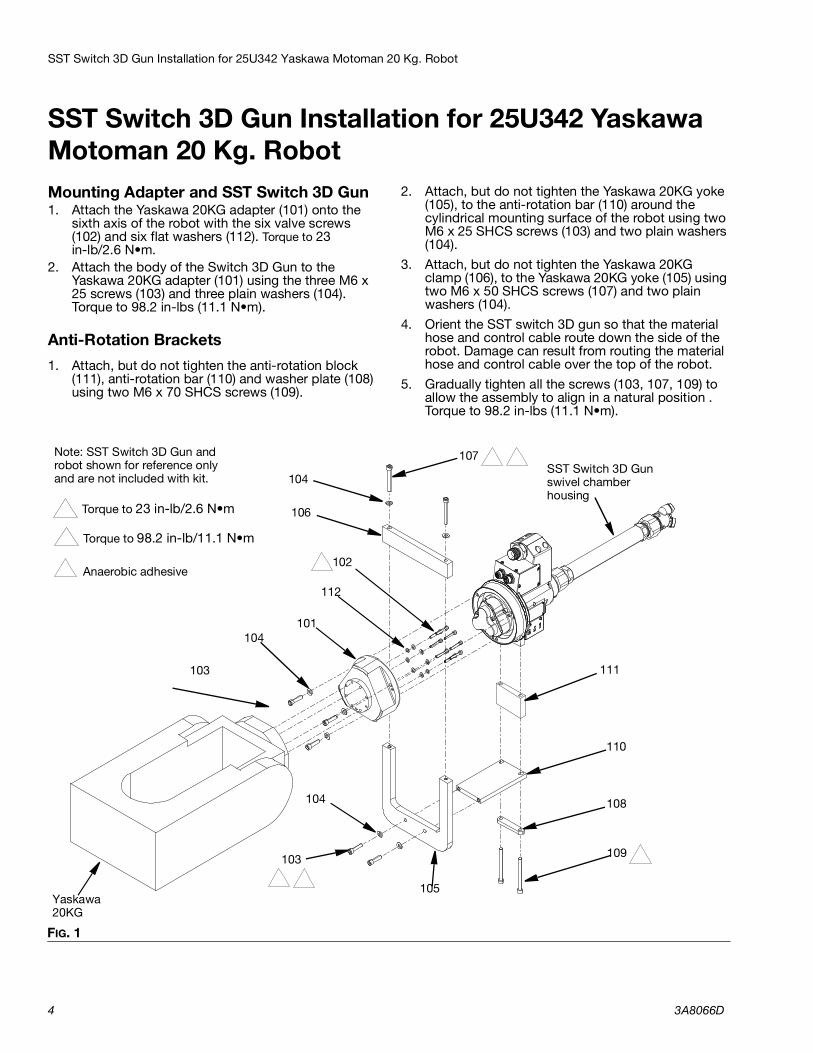
SST Switch 3D Gun Installation for 25U342 Yaskawa Motoman 20 Kg. RobotMounting Adapter and SST Switch 3D Gun1. Attach the Yaskawa 20KG adapter (101) onto the
sixth axis of the robot with the six valve screws (102) and six flat washers (112). Torque to 23 in-lb/2.6 N•m.
2. Attach the body of the Switch 3D Gun to the Yaskawa 20KG adapter (101) using the three M6 x 25 screws (103) and three plain washers (104). Torque to 98.2 in-lbs (11.1 N•m).
Anti-Rotation Brackets1. Attach, but do not tighten the anti-rotation block
(111), anti-rotation bar (110) and washer plate (108) using two M6 x 70 SHCS screws (109).
2. Attach, but do not tighten the Yaskawa 20KG yoke (105), to the anti-rotation bar (110) around the cylindrical mounting surface of the robot using two M6 x 25 SHCS screws (103) and two plain washers (104).
3. Attach, but do not tighten the Yaskawa 20KG clamp (106), to the Yaskawa 20KG yoke (105) using two M6 x 50 SHCS screws (107) and two plain washers (104).
4. Orient the SST switch 3D gun so that the material hose and control cable route down the side of the robot. Damage can result from routing the material hose and control cable over the top of the robot.
5. Gradually tighten all the screws (103, 107, 109) to allow the assembly to align in a natural position . Torque to 98.2 in-lbs (11.1 N•m).
FIG. 1
105
107
101
110
112
111
104
104
103
SST Switch 3D Gunswivel chamber housing
Note: SST Switch 3D Gun and robot shown for reference only and are not included with kit.
106
108
102
103
Yaskawa 20KG
109
104
Torque to 23 in-lb/2.6 N•m 1
2 Torque to 98.2 in-lb/11.1 N•m
1
3
3 Anaerobic adhesive
2
32
2
SST Switch 3D Gun Installation for 25U342 Yaskawa Motoman 20 Kg. Robot
3A8066D 5
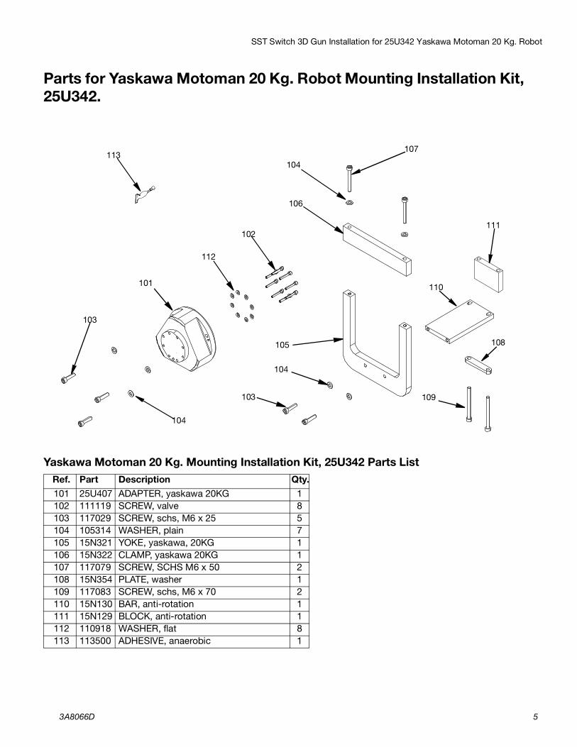
Parts for Yaskawa Motoman 20 Kg. Robot Mounting Installation Kit, 25U342.
Yaskawa Motoman 20 Kg. Mounting Installation Kit, 25U342 Parts ListRef. Part Description Qty.101 25U407 ADAPTER, yaskawa 20KG 1102 111119 SCREW, valve 8103 117029 SCREW, schs, M6 x 25 5104 105314 WASHER, plain 7105 15N321 YOKE, yaskawa, 20KG 1106 15N322 CLAMP, yaskawa 20KG 1107 117079 SCREW, SCHS M6 x 50 2108 15N354 PLATE, washer 1109 117083 SCREW, schs, M6 x 70 2110 15N130 BAR, anti-rotation 1111 15N129 BLOCK, anti-rotation 1112 110918 WASHER, flat 8113 113500 ADHESIVE, anaerobic 1
104
107
111
104
105 108
109
101
104
102
103
110
106
112
113
103
SST Switch 3D Gun Installation for 25U343 Fanuc M710iC 20 Kg. Robot.
6 3A8066D
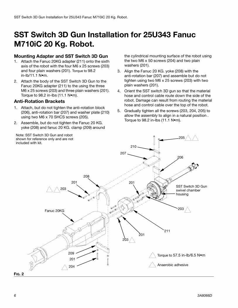
SST Switch 3D Gun Installation for 25U343 Fanuc M710iC 20 Kg. Robot. Mounting Adapter and SST Switch 3D Gun1. Attach the Fanuc 20KG adapter (211) onto the sixth
axis of the robot with the four M6 x 25 screws (203) and four plain washers (201). Torque to 98.2 in-lb/11.1 N•m.
2. Attach the body of the SST Switch 3D Gun to the Fanuc 20KG adapter (211) to the using the three M6 x 25 screws (203) and three plain washers (201). Torque to 98.2 in-lbs (11.1 N•m).
Anti-Rotation Brackets1. Attach, but do not tighten the anti-rotation block
(206), anti-rotation bar (207) and washer plate (210) using two M6 x 70 SHCS screws (205).
2. Assemble, but do not tighten the Fanuc 20 KG. yoke (208) and fanuc 20 KG. clamp (209) around
the cylindrical mounting surface of the robot using the two M6 x 50 screws (204) and two plain washers (201).
3. Align the Fanuc 20 KG. yoke (208) with the anti-rotation bar (207) and assemble but do not tighten using two M6 x 25 screws (203) with two plain washers (201).
4. Orient the SST switch 3D gun so that the material hose and control cable route down the side of the robot. Damage can result from routing the material hose and control cable over the top of the robot.
5. Gradually tighten all the screws (203, 204, 205) to allow the assembly to align in a natural position . Torque to 98.2 in-lbs (11.1 N•m).
FIG. 2
205
207
210
203
211
201
201203
Torque to 57.5 in-lb/6.5 N•m 1
2 Anaerobic adhesive
SST Switch 3D Gunswivel chamber housing
Note: SST Switch 3D Gun and robot shown for reference only and are not included with kit.
206
208201
203
Fanuc 20KG
204
201209
1 2
21
1
1
1
SST Switch 3D Gun Installation for 25U343 Fanuc M710iC 20 Kg. Robot.
3A8066D 7
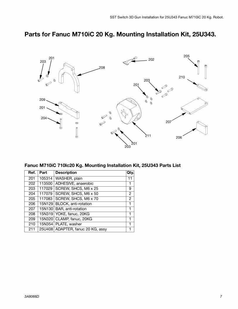
Parts for Fanuc M710iC 20 Kg. Mounting Installation Kit, 25U343.
Fanuc M710iC 710Ic20 Kg. Mounting Installation Kit, 25U343 Parts ListRef. Part Description Qty.201 105314 WASHER, plain 11202 113500 ADHESIVE, anaerobic 1203 117029 SCREW, SHCS, M6 x 25 9204 117079 SCREW, SHCS, M6 x 50 2205 117083 SCREW, SHCS, M6 x 70 2206 15N129 BLOCK, anti-rotation 1207 15N130 BAR, anti-rotation 1208 15N319 YOKE, fanuc, 20KG 1209 15N320 CLAMP, fanuc, 20KG 1210 15N354 PLATE, washer 1211 25U408 ADAPTER, fanuc 20 KG, assy 1
201
207
211
204
205
206
208
209
201
201
201203
203
210
203 202
SST Switch 3D Gun Installation for 25U344 Yaskawa Motoman 50 Kg. Robot.
8 3A8066D
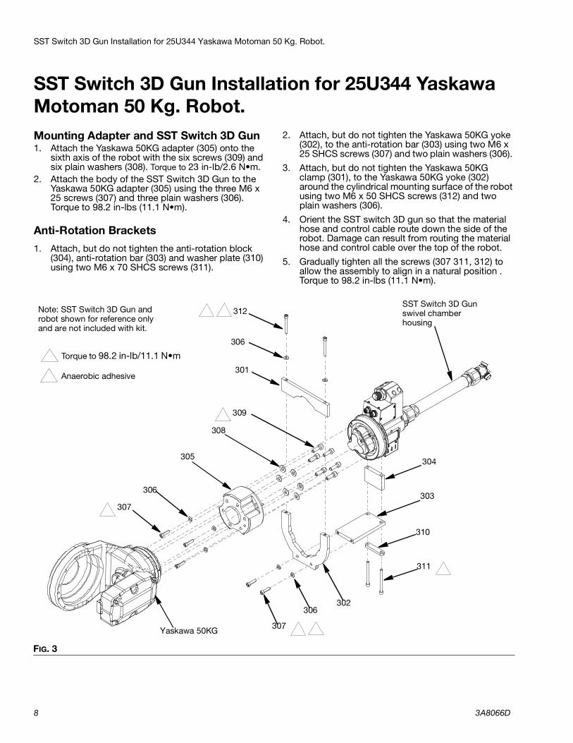
SST Switch 3D Gun Installation for 25U344 Yaskawa Motoman 50 Kg. Robot. Mounting Adapter and SST Switch 3D Gun1. Attach the Yaskawa 50KG adapter (305) onto the
sixth axis of the robot with the six screws (309) and six plain washers (308). Torque to 23 in-lb/2.6 N•m.
2. Attach the body of the SST Switch 3D Gun to the Yaskawa 50KG adapter (305) using the three M6 x 25 screws (307) and three plain washers (306). Torque to 98.2 in-lbs (11.1 N•m).
Anti-Rotation Brackets1. Attach, but do not tighten the anti-rotation block
(304), anti-rotation bar (303) and washer plate (310) using two M6 x 70 SHCS screws (311).
2. Attach, but do not tighten the Yaskawa 50KG yoke (302), to the anti-rotation bar (303) using two M6 x 25 SHCS screws (307) and two plain washers (306).
3. Attach, but do not tighten the Yaskawa 50KG clamp (301), to the Yaskawa 50KG yoke (302) around the cylindrical mounting surface of the robot using two M6 x 50 SHCS screws (312) and two plain washers (306).
4. Orient the SST switch 3D gun so that the material hose and control cable route down the side of the robot. Damage can result from routing the material hose and control cable over the top of the robot.
5. Gradually tighten all the screws (307 311, 312) to allow the assembly to align in a natural position . Torque to 98.2 in-lbs (11.1 N•m).
FIG. 3
SST Switch 3D Gunswivel chamber housing
Note: SST Switch 3D Gun and robot shown for reference only and are not included with kit.
Yaskawa 50KG
312
306
301
304
303
310
311
302306
309
307
305
308
307
306
Torque to 98.2 in-lb/11.1 N•m 1
2 Anaerobic adhesive
1
2
2
1
1
1
1
SST Switch 3D Gun Installation for 25U344 Yaskawa Motoman 50 Kg. Robot.
3A8066D 9
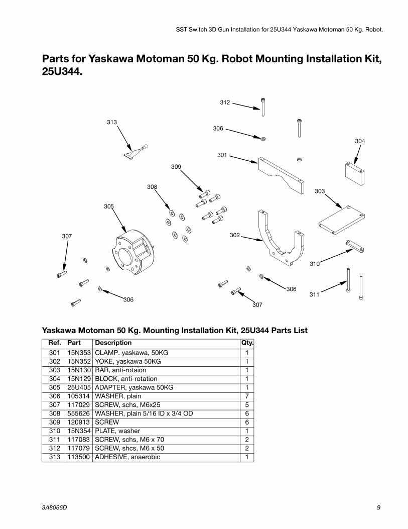
Parts for Yaskawa Motoman 50 Kg. Robot Mounting Installation Kit, 25U344.
Yaskawa Motoman 50 Kg. Mounting Installation Kit, 25U344 Parts ListRef. Part Description Qty.301 15N353 CLAMP. yaskawa, 50KG 1302 15N352 YOKE, yaskawa 50KG 1303 15N130 BAR, anti-rotaion 1304 15N129 BLOCK, anti-rotation 1305 25U405 ADAPTER, yaskawa 50KG 1306 105314 WASHER, plain 7307 117029 SCREW, schs, M6x25 5308 555626 WASHER, plain 5/16 ID x 3/4 OD 6309 120913 SCREW 6310 15N354 PLATE, washer 1311 117083 SCREW, schs, M6 x 70 2312 117079 SCREW, shcs, M6 x 50 2313 113500 ADHESIVE, anaerobic 1
306
307
306
304
305
308
309
302
301
312
306
310
303
307
311
313

SST Switch 3D Gun Installation for 25U345 Fanuc M710iC 50 Kg. Robot.
10 3A8066D
SST Switch 3D Gun Installation for 25U345 Fanuc M710iC 50 Kg. Robot.Mounting Adapter and SST Switch 3D Gun 1. Attach the Fanuc 50 KG. plate (402) onto the sixth
axis of the robot with the four M8 x 60 screws (410) with four lock washers (412) and the four spacers (403) between the adapter and robot mounting. The notch in the Fanuc 50 KG. plate is aligned with the top of the robot. Align the square corners of the Fanuc 50 KG. adapter with the square corners of the robot. Torque to 98.2 in-lb/11.1 N•m.
2. Attach the Fanuc 20KG adapter (401) onto the sixth axis of the robot with the fhree M8 x 25 screws (411). Torque to 350in-lb/39.5 N•m.
3. Attach the body of the SST Switch 3D Gun to the Fanuc 50KG adapter (401) using the three cap screws (408) and three plain washers (407). Torque to 98.2 in-lbs (11.1 N•m).I
Anti-Rotation Brackets1. Attach, but do not tighten the anti-rotation block
(405), anti-rotation bar (404) and washer plate (406)
using two M6 x 70 SHCS screws (409) with two plain washers (407).
2. Align theFanuc 50 KG. plate (402) with the anti-rotation bar (404) and assemble but do not tighten using two cap screws (408) with two plain washers (407).
3. Orient the SST switch 3D gun so that the material hose and control cable route down the side of the robot. Damage can result from routing the material hose and control cable over the top of the robot.
4. Gradually tighten the screws (408, 409) to allow the assembly to align in a natural position. Torque to 98.2 in-lbs (11.1 N•m).
FIG. 4
409
405406
404
407
410
411
412
403
Torque to 98.2 in-lb/11.1 N•m1
2 Torque to 350 in-lb/39.5 N•m
SST Switch 3D Gunswivel chamber housing
Note: SST Switch 3D Gun and robot shown for reference only and are not included with kit.
401
408
407
402
Fanuc 50KG
408
Notch
3 Anaerobic adhesive
1
1
2
2
3
3
SST Switch 3D Gun Installation for 25U345 Fanuc M710iC 50 Kg. Robot.
3A8066D 11
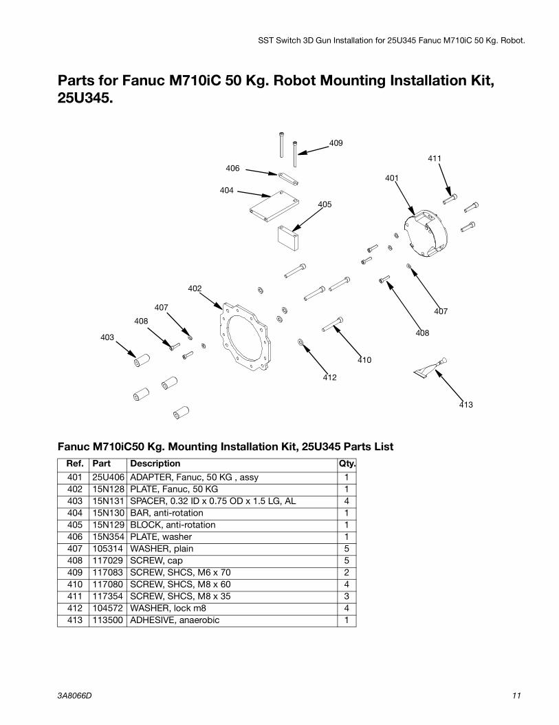
Parts for Fanuc M710iC 50 Kg. Robot Mounting Installation Kit, 25U345.
Fanuc M710iC50 Kg. Mounting Installation Kit, 25U345 Parts ListRef. Part Description Qty.401 25U406 ADAPTER, Fanuc, 50 KG , assy 1402 15N128 PLATE, Fanuc, 50 KG 1403 15N131 SPACER, 0.32 ID x 0.75 OD x 1.5 LG, AL 4404 15N130 BAR, anti-rotation 1405 15N129 BLOCK, anti-rotation 1406 15N354 PLATE, washer 1407 105314 WASHER, plain 5408 117029 SCREW, cap 5409 117083 SCREW, SHCS, M6 x 70 2410 117080 SCREW, SHCS, M8 x 60 4411 117354 SCREW, SHCS, M8 x 35 3412 104572 WASHER, lock m8 4413 113500 ADHESIVE, anaerobic 1
401
407
404405
408
409
402
406
403
410
411
407408
412
413

SST Switch 3D Gun Installation for 25U455 ABB Robot
12 3A8066D
SST Switch 3D Gun Installation for 25U455 ABB Robot NOTE: This kit can be used for both the SST Switch 3D Gun and the (Aluminum) Switch 3d Gun. See Kits table page 3.
Mounting Flange 1. Attach the ABB adapter assy (507) onto the sixth
axis of the robot with the six M6 x 12 screws (505). Torque to 98.2 in-lb/11.1 N•m.
2. Attach the body of the SST Switch 3D Gun to the ABB adapter assy (507) using the three M6 x 20 hex socket screws (502) and three plain washers (501). Torque to 98.2 in-lbs (11.1 N•m).
Anti-Rotation Brackets1. Follow the instructions from Calibration Kit for
ABB Robot 26D485 on page 16 to install ABB robot bracket (509) and SCH cap screws (504).
2. Assemble the anti-rotation block (506), ABB gun bracket (508), and washer bar (510) to the SST switch 3D gun, using two M6 x 60 screws(503). Do not tighten the screws.
3. Line up the trunnion of the ABB robot bracket (509), with the bearing of the ABB gun bracket (508) and fit together lining up the fixation points of the assembly.
4. Tighten the two M6 x 60 screws (503) gradually to allow the assembly to find a relaxed position. Then torque to 57.5 in-lb/6.5 N•m.
FIG. 5
505
507510
502
504
Torque to 57.5 in-lb/6.5 N•m 1
2 Torque to 98.2 in-lb/11.1 N•m
SST Switch 3D Gunswivel chamber housing
Note: SST Switch 3D Gun and robot shown for reference only and are not included with kit.
506
508
501
503
ABB Robot
5091
2
2
2
3 Anaerobic adhesive
3
3
SST Switch 3D Gun Installation for 25U455 ABB Robot
3A8066D 13
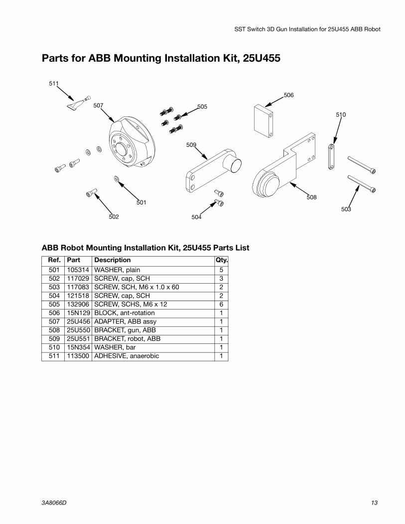
Parts for ABB Mounting Installation Kit, 25U455
ABB Robot Mounting Installation Kit, 25U455 Parts ListRef. Part Description Qty.501 105314 WASHER, plain 5502 117029 SCREW, cap, SCH 3503 117083 SCREW, SCH, M6 x 1.0 x 60 2504 121518 SCREW, cap, SCH 2505 132906 SCREW, SCHS, M6 x 12 6506 15N129 BLOCK, ant-rotation 1507 25U456 ADAPTER, ABB assy 1508 25U550 BRACKET, gun, ABB 1509 25U551 BRACKET, robot, ABB 1510 15N354 WASHER, bar 1511 113500 ADHESIVE, anaerobic 1
507
504
505
508
509
506
501
510
502503
511

Switch 3D Gun Installation for ABB Robot 25T598
14 3A8066D
Switch 3D Gun Installation for ABB Robot 25T598NOTE: This kit can be used only with the (Aluminum) Switch 3d Gun. See Kits table page 3.
Mounting Flange 1. Attach the robot mounting adapter (601) onto the
sixth axis of the robot with the six M6 x 12 screws (607). Torque to 98.2 in-lb/11.1 N•m.
2. Attach the body of the Switch 3D Gun to the robot mounting adapter (601) using the three M6 x 20 hex socket screws (606) and three plain washers (605). Torque to 98.2 in-lbs (11.1 N•m).
Anti-Rotation Brackets1. Follow instructions from Calibration Kit for ABB
Robot 26D485 on page 16 to install ABB robot bracket (604) and SHC cap screws ( 609).
2. Assemble the anti-rotation block (602), ABB gun bracket (603), and washer bar (610) to the SST switch 3D gun, using two M6 x 70 screws (608). Do not tighten the screws.
3. Line up the trunnion of the ABB robot bracket (604), with the bearing of the ABB gun bracket (603) and fit together lining up the fixation points of the assembly.
4. Tighten the two M6 x 70 screws (608) gradually to allow the assembly to find a relaxed position. Then torque to 57.5 in-lb/6.5 N•m.
FIG. 6
1
601
609
602
604
605
606
607
603
2
Torque to 98.2 in-lb/11.1 N•m 1
2 Anaerobic Adhesive
Note: Switch 3D Gun and robot shown for reference only and are not included with kit.
Switch 3D Gunswivel chamber housing
610
6081
1
Switch 3D Gun Installation for ABB Robot 25T598
3A8066D 15
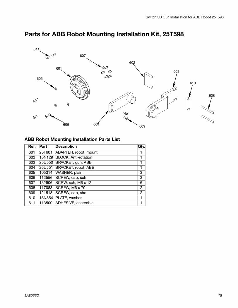
Parts for ABB Robot Mounting Installation Kit, 25T598
ABB Robot Mounting Installation Parts ListRef. Part Description Qty.601 25T601 ADAPTER, robot, mount 1602 15N129 BLOCK, Anti-rotation 1603 25U550 BRACKET, gun, ABB 1604 25U551 BRACKET, robot, ABB 1605 105314 WASHER, plain 3606 112556 SCREW, cap, sch 3607 132906 SCRW, sch, M6 x 12 6608 117083 SCREW, M6 x 70 2609 121518 SCREW, cap, shc 2610 15N354 PLATE, washer 1611 113500 ADHESIVE, anaerobic 1
602601
609604
603
605
608
606
607
610
611
Calibration Kit for ABB Robot 26D485
16 3A8066D
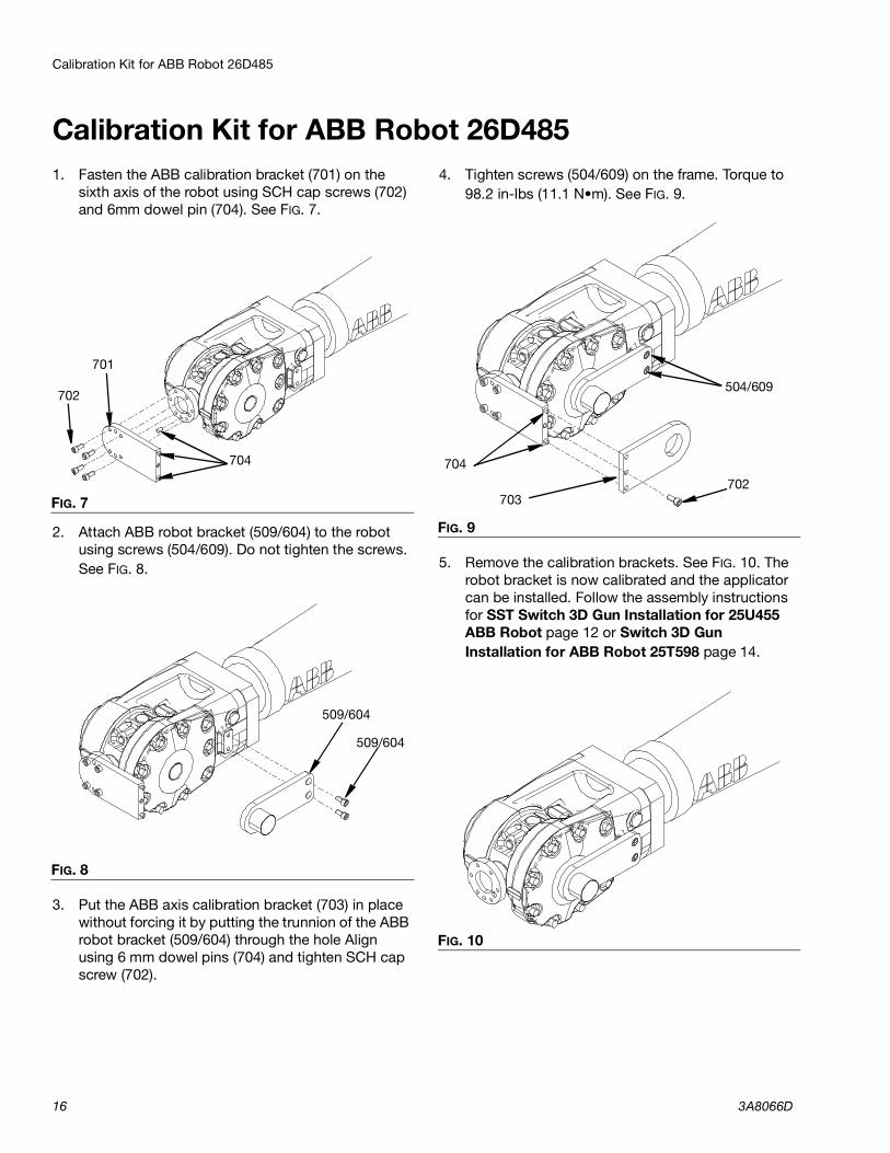
Calibration Kit for ABB Robot 26D4851. Fasten the ABB calibration bracket (701) on the
sixth axis of the robot using SCH cap screws (702) and 6mm dowel pin (704). See FIG. 7.
2. Attach ABB robot bracket (509/604) to the robot using screws (504/609). Do not tighten the screws. See FIG. 8.
3. Put the ABB axis calibration bracket (703) in place without forcing it by putting the trunnion of the ABB robot bracket (509/604) through the hole Align using 6 mm dowel pins (704) and tighten SCH cap screw (702).
4. Tighten screws (504/609) on the frame. Torque to 98.2 in-lbs (11.1 N•m). See FIG. 9.
5. Remove the calibration brackets. See FIG. 10. The robot bracket is now calibrated and the applicator can be installed. Follow the assembly instructions for SST Switch 3D Gun Installation for 25U455 ABB Robot page 12 or Switch 3D Gun Installation for ABB Robot 25T598 page 14.
FIG. 7
FIG. 8
701
702
704
509/604
509/604
FIG. 9
FIG. 10
504/609
704702
703
Calibration Kit for ABB Robot 26D485
3A8066D 17
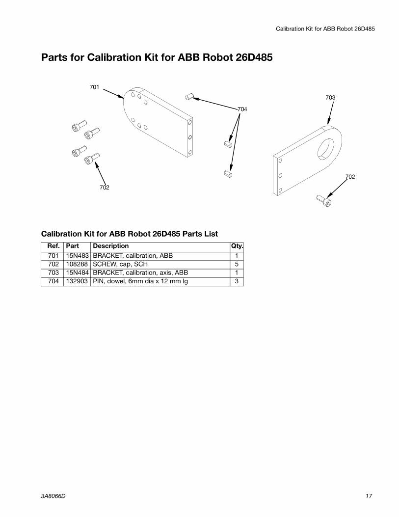
Parts for Calibration Kit for ABB Robot 26D485
Calibration Kit for ABB Robot 26D485 Parts ListRef. Part Description Qty.701 15N483 BRACKET, calibration, ABB 1702 108288 SCREW, cap, SCH 5703 15N484 BRACKET, calibration, axis, ABB 1704 132903 PIN, dowel, 6mm dia x 12 mm lg 3
704
703
702
702
701
SST Switch 3D Gun Installation for Kawasaki RS010N 10 kg. Robot, 26D453
18 3A8066D
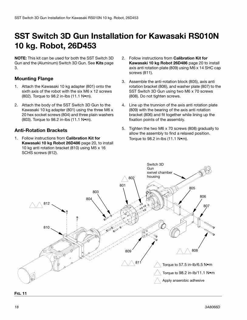
SST Switch 3D Gun Installation for Kawasaki RS010N 10 kg. Robot, 26D453NOTE: This kit can be used for both the SST Switch 3D Gun and the (Aluminum) Switch 3D Gun. See Kits page 3.
Mounting Flange1. Attach the Kawasaki 10 kg adapter (801) onto the
sixth axis of the robot with the six M6 x 12 screws (802). Torque to 98.2 in-lbs (11.1 N•m).
2. Attach the body of the SST Switch 3D Gun to the Kawasaki 10 kg adapter (801) using the three M6 x 20 hex socket screws (804) and three plain washers (803). Torque to 98.2 in-lbs (11.1 N•m).
Anti-Rotation Brackets1. Follow instructions from Calibration Kit for
Kawasaki 10 kg Robot 26D486 page 20, to install 10 kg anti rotation bracket (810) using M5 x 16 SCHS screws (812).
2. Follow instructions from Calibration Kit for Kawasaki 10 kg Robot 26D486 page 20 to install axis anti rotation plate (809) using M6 x 14 SHC cap screws (811).
3. Assemble the anti-rotation block (805), axis anti rotation bracket (806), and washer plate (807) to the SST Switch 3D Gun using two M6 x 70 screws (808). Do not tighten screws.
4. Line up the trunnion of the axis anti rotation plate (809) with the bearing of the axis anti rotation bracket (806) and fit together while lining up the fixation points of the assembly.
5. Tighten the two M6 x 70 screws (808) gradually to allow the assembly to find a relaxed position. Torque to 98.2 in-lbs (11.1 N•m).
FIG. 11
1
803
811
805
809
804812
801
806
2
Torque to 57.5 in-lb/6.5 N•m 1
2 Torque to 98.2 in-lb/11.1 N•m
Switch 3D Gunswivel chamber housing
807
808
810
802
3
3 Apply anaerobic adhesive
3
2
2 3
SST Switch 3D Gun Installation for Kawasaki RS010N 10 kg. Robot, 26D453
3A8066D 19
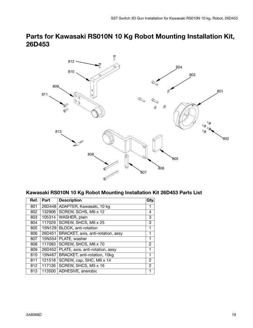
Parts for Kawasaki RS010N 10 Kg Robot Mounting Installation Kit, 26D453
Kawasaki RS010N 10 Kg Robot Mounting Installation Kit 26D453 Parts ListRef. Part Description Qty.801 26D448 ADAPTER, Kawasaki, 10 kg 1802 132906 SCREW, SCHS, M6 x 12 4803 105314 WASHER, plain 3804 117029 SCREW, SHCS, M6 x 25 3805 15N129 BLOCK, anti-rotation 1806 26D451 BRACKET, axis, anti-rotation, assy 1807 15N354 PLATE, washer 1808 117083 SCREW, SHCS, M6 x 70 2809 26D452 PLATE, axis, anti-rotation, assy 1810 15N467 BRACKET, anti-rotation, 10kg 1811 121518 SCREW, cap, SHC, M6 x 14 2812 117126 SCREW, SHCS, M5 x 16 2813 113500 ADHESIVE, anerobic 1
812
810804
803
801
802
805
806807
808
809
813
811
Calibration Kit for Kawasaki 10 kg Robot 26D486
20 3A8066D
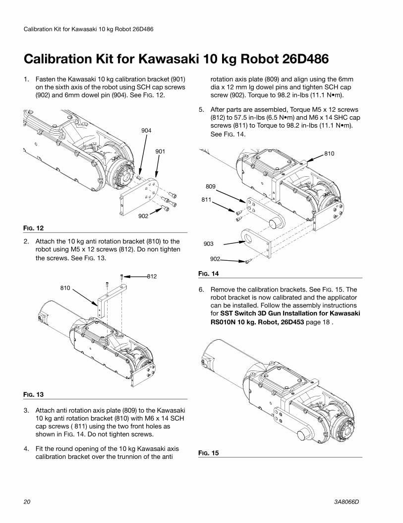
Calibration Kit for Kawasaki 10 kg Robot 26D4861. Fasten the Kawasaki 10 kg calibration bracket (901)
on the sixth axis of the robot using SCH cap screws (902) and 6mm dowel pin (904). See FIG. 12.
2. Attach the 10 kg anti rotation bracket (810) to the robot using M5 x 12 screws (812). Do non tighten the screws. See FIG. 13.
3. Attach anti rotation axis plate (809) to the Kawasaki 10 kg anti rotation bracket (810) with M6 x 14 SCH cap screws ( 811) using the two front holes as shown in FIG. 14. Do not tighten screws.
4. Fit the round opening of the 10 kg Kawasaki axis calibration bracket over the trunnion of the anti
rotation axis plate (809) and align using the 6mm dia x 12 mm lg dowel pins and tighten SCH cap screw (902). Torque to 98.2 in-lbs (11.1 N•m).
5. After parts are assembled, Torque M5 x 12 screws (812) to 57.5 in-lbs (6.5 N•m) and M6 x 14 SHC cap screws (811) to Torque to 98.2 in-lbs (11.1 N•m). See FIG. 14.
6. Remove the calibration brackets. See FIG. 15. The robot bracket is now calibrated and the applicator can be installed. Follow the assembly instructions for SST Switch 3D Gun Installation for Kawasaki RS010N 10 kg. Robot, 26D453 page 18 .
FIG. 12
FIG. 13
901
902
904
810
812 FIG. 14
FIG. 15
809
903
902
811
810
Calibration Kit for Kawasaki 10 kg Robot 26D486
3A8066D 21
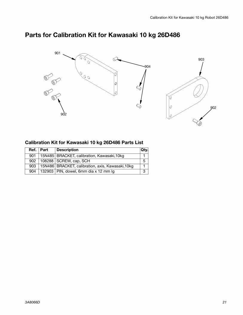
Parts for Calibration Kit for Kawasaki 10 kg 26D486
Calibration Kit for Kawasaki 10 kg 26D486 Parts ListRef. Part Description Qty.901 15N485 BRACKET, calibration, Kawasaki,10kg 1902 108288 SCREW, cap, SCH 5903 15N486 BRACKET, calibration, axis, Kawasaki,10kg 1904 132903 PIN, dowel, 6mm dia x 12 mm lg 3
904
903
902
902
901
SST Switch 3D Gun Installation for Kawasaki RS020N 20 kg. Robot, 26D454
22 3A8066D
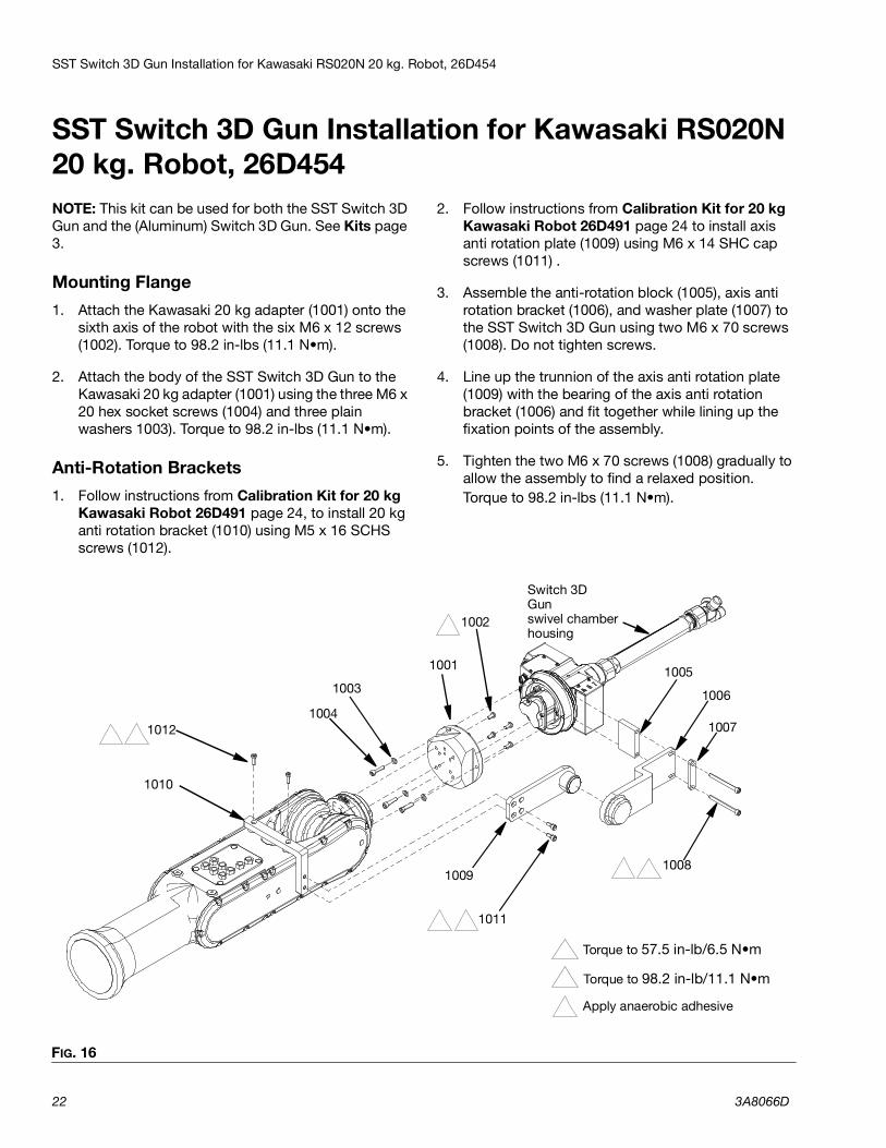
SST Switch 3D Gun Installation for Kawasaki RS020N 20 kg. Robot, 26D454NOTE: This kit can be used for both the SST Switch 3D Gun and the (Aluminum) Switch 3D Gun. See Kits page 3.
Mounting Flange1. Attach the Kawasaki 20 kg adapter (1001) onto the
sixth axis of the robot with the six M6 x 12 screws (1002). Torque to 98.2 in-lbs (11.1 N•m).
2. Attach the body of the SST Switch 3D Gun to the Kawasaki 20 kg adapter (1001) using the three M6 x 20 hex socket screws (1004) and three plain washers 1003). Torque to 98.2 in-lbs (11.1 N•m).
Anti-Rotation Brackets1. Follow instructions from Calibration Kit for 20 kg
Kawasaki Robot 26D491 page 24, to install 20 kg anti rotation bracket (1010) using M5 x 16 SCHS screws (1012).
2. Follow instructions from Calibration Kit for 20 kg Kawasaki Robot 26D491 page 24 to install axis anti rotation plate (1009) using M6 x 14 SHC cap screws (1011) .
3. Assemble the anti-rotation block (1005), axis anti rotation bracket (1006), and washer plate (1007) to the SST Switch 3D Gun using two M6 x 70 screws (1008). Do not tighten screws.
4. Line up the trunnion of the axis anti rotation plate (1009) with the bearing of the axis anti rotation bracket (1006) and fit together while lining up the fixation points of the assembly.
5. Tighten the two M6 x 70 screws (1008) gradually to allow the assembly to find a relaxed position. Torque to 98.2 in-lbs (11.1 N•m).
FIG. 16
1
1003
1011
1005
1009
10041012
1001
1006
2
Torque to 57.5 in-lb/6.5 N•m 1
2 Torque to 98.2 in-lb/11.1 N•m
Switch 3D Gunswivel chamber housing
1007
1008
1010
1002
3
3 Apply anaerobic adhesive
3
2
2 3
SST Switch 3D Gun Installation for Kawasaki RS020N 20 kg. Robot, 26D454
3A8066D 23
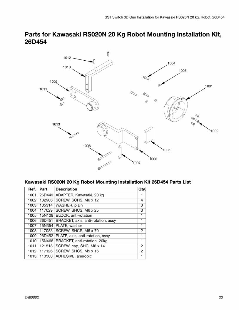
Parts for Kawasaki RS020N 20 Kg Robot Mounting Installation Kit, 26D454
Kawasaki RS020N 20 Kg Robot Mounting Installation Kit 26D454 Parts ListRef. Part Description Qty.1001 26D449 ADAPTER, Kawasaki, 20 kg 11002 132906 SCREW, SCHS, M6 x 12 41003 105314 WASHER, plain 31004 117029 SCREW, SHCS, M6 x 25 31005 15N129 BLOCK, anti-rotation 11006 26D451 BRACKET, axis, anti-rotation, assy 11007 15N354 PLATE, washer 11008 117083 SCREW, SHCS, M6 x 70 21009 26D452 PLATE, axis, anti-rotation, assy 11010 15N468 BRACKET, anti-rotation, 20kg 11011 121518 SCREW, cap, SHC, M6 x 14 21012 117126 SCREW, SHCS, M5 x 16 21013 113500 ADHESIVE, anerobic 1
1012
10101004
1003
1001
1002
1005
10061007
1008
1009
1013
1011
Calibration Kit for 20 kg Kawasaki Robot 26D491
24 3A8066D
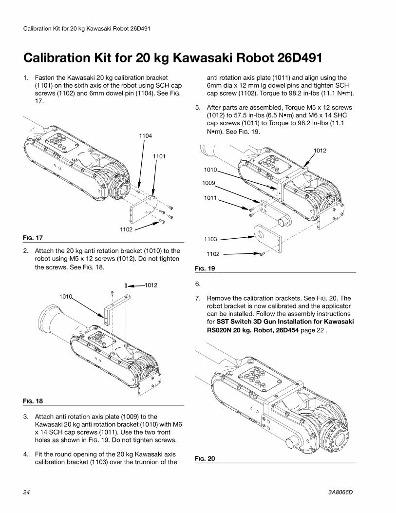
Calibration Kit for 20 kg Kawasaki Robot 26D4911. Fasten the Kawasaki 20 kg calibration bracket
(1101) on the sixth axis of the robot using SCH cap screws (1102) and 6mm dowel pin (1104). See FIG. 17.
2. Attach the 20 kg anti rotation bracket (1010) to the robot using M5 x 12 screws (1012). Do not tighten the screws. See FIG. 18.
3. Attach anti rotation axis plate (1009) to the Kawasaki 20 kg anti rotation bracket (1010) with M6 x 14 SCH cap screws (1011). Use the two front holes as shown in FIG. 19. Do not tighten screws.
4. Fit the round opening of the 20 kg Kawasaki axis calibration bracket (1103) over the trunnion of the
anti rotation axis plate (1011) and align using the 6mm dia x 12 mm lg dowel pins and tighten SCH cap screw (1102). Torque to 98.2 in-lbs (11.1 N•m).
5. After parts are assembled, Torque M5 x 12 screws (1012) to 57.5 in-lbs (6.5 N•m) and M6 x 14 SHC cap screws (1011) to Torque to 98.2 in-lbs (11.1 N•m). See FIG. 19.
6.
7. Remove the calibration brackets. See FIG. 20. The robot bracket is now calibrated and the applicator can be installed. Follow the assembly instructions for SST Switch 3D Gun Installation for Kawasaki RS020N 20 kg. Robot, 26D454 page 22 .
FIG. 17
FIG. 18
1101
1102
1104
1010
1012
FIG. 19
FIG. 20
1009
1103
1102
1011
1010
1012

Calibration Kit for 20 kg Kawasaki Robot 26D491
3A8066D 25
Parts for Calibration Kit for 20 kg Kawasaki 26D491
Calibration Kit for ABB Robot 26D491 Parts ListRef. Part Description Qty.1101 15N487 BRACKET, calibration, Kawasaki,20kg 11102 108288 SCREW, cap, SCH 51103 15N488 BRACKET, calibration, axis, Kawasaki,20kg 11104 132903 PIN, dowel, 6mm dia x 12 mm lg 3
11041103
1102
1102
1101

Calibration Kit for 20 kg Kawasaki Robot 26D491
26 3A8066D
Recycling and Disposal
3A8066D 27
Recycling and Disposal
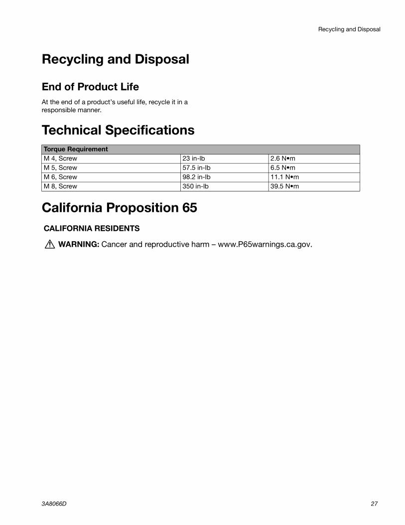
End of Product LifeAt the end of a product’s useful life, recycle it in a responsible manner.
Technical Specifications
California Proposition 65
Torque RequirementM 4, Screw 23 in-lb 2.6 N•mM 5, Screw 57.5 in-lb 6.5 N•mM 6, Screw 98.2 in-lb 11.1 N•mM 8, Screw 350 in-lb 39.5 N•m
CALIFORNIA RESIDENTS
WARNING: Cancer and reproductive harm – www.P65warnings.ca.gov.

All written and visual data contained in this document reflects the latest product information available at the time of publication. Graco reserves the right to make changes at any time without notice.
Original instructions. This manual contains English. MM 3A8066Graco Headquarters: Minneapolis
International Offices: Belgium, China, Japan, KoreaGRACO INC. AND SUBSIDIARIES • P.O. BOX 1441 • MINNEAPOLIS MN 55440-1441 • USACopyright 2020, Graco Inc. All Graco manufacturing locations are registered to ISO 9001.
www.graco.comRevision D, January 2022
Graco Standard WarrantyGraco warrants all equipment referenced in this document which is manufactured by Graco and bearing its name to be free from defects in material and workmanship on the date of sale to the original purchaser for use. With the exception of any special, extended, or limited warranty published by Graco, Graco will, for a period of twelve months from the date of sale, repair or replace any part of the equipment determined by Graco to be defective. This warranty applies only when the equipment is installed, operated and maintained in accordance with Graco’s written recommendations.
This warranty does not cover, and Graco shall not be liable for general wear and tear, or any malfunction, damage or wear caused by faulty installation, misapplication, abrasion, corrosion, inadequate or improper maintenance, negligence, accident, tampering, or substitution of non-Graco component parts. Nor shall Graco be liable for malfunction, damage or wear caused by the incompatibility of Graco equipment with structures, accessories, equipment or materials not supplied by Graco, or the improper design, manufacture, installation, operation or maintenance of structures, accessories, equipment or materials not supplied by Graco.
This warranty is conditioned upon the prepaid return of the equipment claimed to be defective to an authorized Graco distributor for verification of the claimed defect. If the claimed defect is verified, Graco will repair or replace free of charge any defective parts. The equipment will be returned to the original purchaser transportation prepaid. If inspection of the equipment does not disclose any defect in material or workmanship, repairs will be made at a reasonable charge, which charges may include the costs of parts, labor, and transportation.
THIS WARRANTY IS EXCLUSIVE, AND IS IN LIEU OF ANY OTHER WARRANTIES, EXPRESS OR IMPLIED, INCLUDING BUT NOT LIMITED TO WARRANTY OF MERCHANTABILITY OR WARRANTY OF FITNESS FOR A PARTICULAR PURPOSE.
Graco’s sole obligation and buyer’s sole remedy for any breach of warranty shall be as set forth above. The buyer agrees that no other remedy (including, but not limited to, incidental or consequential damages for lost profits, lost sales, injury to person or property, or any other incidental or consequential loss) shall be available. Any action for breach of warranty must be brought within two (2) years of the date of sale.
GRACO MAKES NO WARRANTY, AND DISCLAIMS ALL IMPLIED WARRANTIES OF MERCHANTABILITY AND FITNESS FOR A PARTICULAR PURPOSE, IN CONNECTION WITH ACCESSORIES, EQUIPMENT, MATERIALS OR COMPONENTS SOLD BUT NOT MANUFACTURED BY GRACO. These items sold, but not manufactured by Graco (such as electric motors, switches, hose, etc.), are subject to the warranty, if any, of their manufacturer. Graco will provide purchaser with reasonable assistance in making any claim for breach of these warranties.
In no event will Graco be liable for indirect, incidental, special or consequential damages resulting from Graco supplying equipment hereunder, or the furnishing, performance, or use of any products or other goods sold hereto, whether due to a breach of contract, breach of warranty, the negligence of Graco, or otherwise.
FOR GRACO CANADA CUSTOMERSThe Parties acknowledge that they have required that the present document, as well as all documents, notices and legal proceedings entered into, given or instituted pursuant hereto or relating directly or indirectly hereto, be drawn up in English. Les parties reconnaissent avoir convenu que la rédaction du présente document sera en Anglais, ainsi que tous documents, avis et procédures judiciaires exécutés, donnés ou intentés, à la suite de ou en rapport, directement ou indirectement, avec les procédures concernées.
Graco Information Sealant and Adhesive Dispensing EquipmentFor the latest information about Graco products, visit www.graco.com.For patent information, see www.graco.com/patents.TO PLACE AN ORDER, contact your Graco distributor, go to www.graco.com, or call to identify the nearest distributor.
If calling from the USA: 1-800-746-1334If calling from outside the USA: 0-1-330-966-3000