2021_catalog_with_links-195.pdf - heule tool
TRANSCRIPT

Catalog No. HTC021/
www.HeuleTool.com
Deburring
Drilling
Chamfering
Countersinking
For Front and Back Deburring, Chamfering, Drilling and Countersinking
www.heuletool.comHTC021/V1.0
Deburring
Drilling
Chamfering
Countersinking
For Front and Back Deburring, Chamfering, Drilling and Countersinking
www.heuletool.comHTC021/V1.0

Swiss Precision since 1961
www.heuletool.comHTC021/V1.0

Swiss Precision since 1961
Since 1961, HEULE has been a family company that believes in the power
of collaboration for creating unique solutions that make our customers
world leaders in their industries.
Heinrich Heule designed the first HEULE tool in 1961 for an application for
which there was no existing tool: to chamfer the insides of a fork com-
ponent at low cost, within a short time and in a large production run. Our
company mission was established: to design cost-effective solutions for
automating processes in high-volume manufacturing.
Still today, HEULE continues to run on a single-minded passion for design-
ing solutions for complex applications. Through constant development of
solutions for customer applications around the globe, we have created a
series of innovative precision tools for front and back deburring, chamfer-
ing, spotfacing, and countersinking.
Most of our products are sold as standard stocked items, but our technical
engineers can provide custom solutions for your specific applications. At
HEULE, the energy of progress through innovation fuels the work we do
every day.
Reduce process times. Cut production costs. Produce higher quality parts off the machine.
“The leader in their field…nothing out there compares to the quality and reliability HEULE
provides.”- Customer Testimonial
Our innovation equals your success
Founded in 1961 by Heinrich Heule in the Rhine Valley of
western Switzerland, HEULE continues to be a world leader in
manufacturing of chamfering and deburring tools. After serving
the European community for over 25 years, HEULE expanded
to the United States. Heule Tool Corporation has been providing
high quality chamfering and deburring tools to the North
American market since 1988.
HEULE is committed to the values of quality, precision,and
service. Competent service, fast delivery times, and customized
solutions are the highest priorities. From all ranks, HEULE’s
committed and motivated expert staff carry out their work with
reliability and professionalism. Customer’s worldwide attest
to the high quality standard HEULE provides and continually
improves through innovative ideas and sophisticated technology.
•StateoftheartandEcofriendlyfactory
•Familyownedandoperated
•Guaranteedcustomersatisfaction
•Customizeddesignandbuilttooling
Innovative Tools with Timesaving Results
HeuleTool.com (513) 860-9900
Table of Contents
Heule Tool Corporation 4722 A Interstate Drive | Cincinnati, Ohio 45246
3 Case Study
4 Introduction
5-6 MICROSNAp Series 2
7-8 MICROSNAp Series 3
9-10 MICROSNAp Series 4
11 Technical Instructions
12 Technical Information
13 Programming Information
14 Technical Information
MICROSNAP
HeuleTool.com (513) 860-9900ONEOPERATION

513.860.9900 www.heuletool.com4
Catalog No. HTC14HTC021/V1.0
Serie
s
Product Application Guide .....................................................Pgs 05-07Case Studies & Best Practices.................................................Pgs 08-22COFA – Elliptical Deburring Tool ........................................Pgs 23-54 Series 2 ................................................................................Pgs 26-27 Series 3 ................................................................................Pgs 28-29 Series 4 ................................................................................ Pgs 30-31 Series 5 ................................................................................Pgs 32-33 Series 6 ............................................................................... Pgs 34-35 Series 8 ............................................................................... Pgs 36-37 Series 12 ............................................................................. Pgs 38-39 Series 12OS ........................................................................ Pgs 40-43 Cassette .............................................................................. Pgs 44-45 Programming Information ............................................ Pgs 46-47 Changing Blades .............................................................. Pgs 48-51 Troubleshooting ....................................................................... Pg 52 Blade Options ........................................................................... Pg 53COFA-C – New Generation Deburring Tool .....................Pgs 55-72 Series C6 ............................................................................. Pgs 58-59 Series C8 ............................................................................. Pgs 60-61 Series C12 ........................................................................... Pgs 62-63 Cassette ............................................................................... Pgs 64-67 Programming Information ............................................ Pgs 68-69 Changing Blades ...................................................................... Pg 70 Blade Options ........................................................................... Pg 71 Troubleshooting ....................................................................... Pg 72SNAP – Universal Chamfering Tool ..................................Pgs 73-102 Series 2 .................................................................................Pgs 76-77 Series 3 .................................................................................Pgs 78-79 Series 4 ................................................................................ Pgs 80-81 Series 5 ................................................................................ Pgs 82-83 Series 8 ................................................................................Pgs 84-85 Series 12 .............................................................................. Pgs 86-87 Series 20 .............................................................................. Pgs 88-89 Snap5Cassette .................................................................. Pgs 90-91 Snap35Cassette .................................................................Pgs 92-93 Series 5 Tapped Holes ............................................................. Pg 94 Blade Options .................................................................... Pgs 95-96 Technical Information .............................................................Pg 97 Changing Blades .............................................................. Pgs 98-99 Programming Information ..........................................Pgs 100-101 Troubleshooting ..................................................................... Pg 102VEX-S – Combination Drill/Chamfer .............................Pgs 103-116 Series 1xd ........................................................................Pgs 106-107 Series 2xd........................................................................Pgs 108-109 Programming Information ..........................................Pgs 110-111 Spare Parts ...............................................................................Pg 112 Change Drill ............................................................................Pg 113 Troubleshooting .............................................................Pgs 114-115 VEX-P – Combination Drill/Chamfer .............................Pgs 117-124 Series C .................................................................................... Pg 120 Series D .................................................................................... Pg 121 Technical Information .......................................................... Pg 122 Programming Information ...................................................Pg 123 Change Drill ............................................................................Pg 124
COMBI – Combination Drill/Chamfer ...........................Pgs 125-140 Series Y, Z Drill/Chamfer .....................................................Pg 128 Series 0 Drill/Chamfer .......................................................... Pg 129 Series 1 Drill/Chamfer ..........................................................Pg 130 Series 2 Drill/Chamfer .......................................................... Pg 131 Series Y, Z Drill/Chamfer/Countersink............................. Pg 132 Series 0 Drill/Chamfer/Countersink .................................. Pg 133 Series 1 Drill/Chamfer/Countersink ..................................Pg 134 Series 2 Drill/Chamfer/Countersink .................................. Pg 135 Programming Information .........................................Pgs 136-138 Spare Parts .............................................................................. Pg 139DEFA – Precision Chamfering ...........................................Pgs 141-166 Series 02-06 .................................................................. Pgs 144- 145 Series 07-09 .................................................................. Pgs 146- 147 Series 10-11 .................................................................. Pgs 148- 149 Series 12-13 ..................................................................Pgs 150- 151 Series 14-15 .................................................................. Pgs 152- 153 Series 16-17 ..................................................................Pgs 154- 155 Series 18-19 ..................................................................Pgs 156- 157 Series 22-24 .............................................................................. Pg 158 Series 26-28 .............................................................................. Pg 159 Series 30-32.............................................................................. Pg 160 Blade Options ...........................................................................Pg 161 Programming Information ........................................... Pgs 162-163 SettingØD2Dimension ....................................................... Pg 164 Technical Information ...................................................Pgs 165-166GH-K – Chatter Free Countersinking ................................Pgs 167-172 Ø25 Tool ...................................................................................Pg 170 Ø45 Tool ...................................................................................Pg 171 Programming and Changing Blades .................................Pg 172BSF – Back Counterboring and Spotfacing ......................Pgs 173-214 Series A ................................................................................... Pg 175 Series B ..........................................................................Pgs 176-177 Series C ........................................................................ Pgs 178-179 Series D ........................................................................ Pgs 180-182 Series E ......................................................................... Pgs 183-187 Series F ......................................................................... Pgs 188-193 Series G ........................................................................ Pgs 194-203 Spare Parts ..................................................................... Pgs 204-206 Technical Information ...........................................................Pg 207 Blade Dimensions ...................................................................Pg 208 Programming Informaiton ..........................................Pgs 209-211 Blade Change ...........................................................................Pg 212 Frequently Asked Questions................................................Pg 213SOLO – Automatic Spotfacing .............................................Pgs 215-227 SOLO 1900 Programming.....................................................Pg 223 SOLO 2 Programming ...........................................................Pg 224 Technical Information ................................................. Pgs 225-227 APPENDIX – Reference Materials .................................... Pgs 229-241 Application Data Sheets ...............................................Pgs 231-234 Materials Reference Chart ....................................................Pg 235 Metric to Inch Conversion Chart.........................................Pg 236Tool Recommendations .................................................................Pg 237
Table of Contents

513-860-9900 www.heuletool.com 5
Catalog No. HTC014HTC021/V1.0
Serie
s
Pages 23-54
Pages 55-72
Pages 73-102
COFAUniversal Deburring Tool
The COFA tool removes burrs on the front and back of a drilled through-hole on even and uneven surfaces in a single cycle.
• Radial edge breaks on flat or uneven surfaces.• Deburrthroughholesonirregularsurfacesupto30°.• Typicaledgebreakrange.005-.015”.• Used on all materials; aluminum to nickel alloy.• Availableinsizes2mm(.080”)andup.
COFA-CThe New Generation Deburring Tool
The COFA-C tool is a new innovation of our proven COFA product. Like its predecessor, COFA-C will efficiently deburr bore edges in one single pass, but with added features to encompass a broader range of applications.
• Designed for added durability.• Suitable for threaded bores and larger edge breaks.• Shorter working length for a more stable tool.• Newly-designed blade holder for better guidance
and longer spring life.
SNAPSimple Front/Back Chamfering Tool
The SNAP tool is easy to use and offers quick blade change, which makes it practical for any manufacturing environment.
• Createsstandard90°controlledchamfers.• Most economical and fastest front and back
chamfer tool.• Absolutely safe for reamed and finished holes.• Cutting blade options offer controlled
chamfersizes:.010”,.020”,.030”or.040”x45°.• Used on all materials under 30Rc.• Availableinsizes2mm(.080”)andup.
Product Application Guide

513.860.9900 www.heuletool.com6
Catalog No. HTC14HTC021/V1.0
Serie
s
Pages 141-166
VEX-PCombination of Drilling and Front/Back Chamfering
The VEX-P tool combines a replaceable solid carbide high performancedrilltipwithHEULE’spatentedSNAPchamfering system to enable drilling and front and back chamfering in one operation.
• VEX drill geometry for better chip control• Quick and easy drill tip and chamfer blade replacement• No presetting between drill changes• Availableinsizes11.0-17.0mm(.433-.669”)• Bore depths up to 1.5 times diameter
COMBICombination Chamfering and Drilling
The COMBI tool combines front and back chamfering and drilling to save time, money, and space on your machining center.
• Stock 1x diameter tooling accepts standard spade drills.• Custom made tooling for boring, drilling, and countersinking
with chamfering.• Ideal for automotive applications: e.g. wheel and disc brake
manufacturers.• Availableinsizes9.5-35mm(.374-1.378”)
DEFAPrecision Front/Back Chamfering
Double bladed DEFA chamfering tools create pre-adjusted front and back chamfers in a single operation without stopping or reversing the spindle.
• Sliding-surface blade geometry prevents damage to finished hole surfaces.
• Precise,adjustablechamfersizesupto.050”x45°.• Used on all materials, cast steel to nickel base materials.• Availableinsizes4.0-38mm(.157-1.500”)
Pages 125-140
Pages 117-124
VEX-SCombination Front/Back Chamfering and Drilling
The VEX-S tool combines a replaceable solid carbide high performance twist drill with Heule s patented SNAP chamfering system to make drilling and front and back chamfering in a single operation possible.
• Standard stock tooling for 1x and 2x diameter depth.• Replaceable drill tip can be reground and recoated.• Used on common steel and non-ferrous applications.• Availableinsizes5.0-12.7mm(.197-.500”) Pages 103-116
Product Application Guide
513-860-9900 www.heuletool.com 7
Catalog No. HTC014HTC021/V1.0
Serie
s
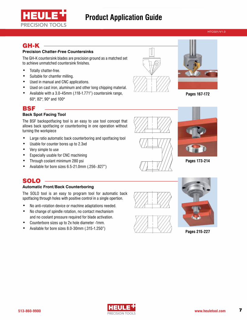
GH-KPrecision Chatter-Free Countersinks
The GH-K countersink blades are precision ground as a matched set to achieve unmatched countersink finishes.
• Totally chatter-free.• Suitable for chamfer milling.• Used in manual and CNC applications.• Used on cast iron, aluminum and other long chipping material.• Availablewitha3.0-45mm(.118-1.771”)countersinkrange,
60°, 82°, 90° and 100°
BSFBack Spot Facing Tool
The BSF backspotfacing tool is an easy to use tool concept that allows back spotfacing or counterboring in one operation without turning the workpiece
• Large ratio automatic back counterboring and spotfacing tool• Usable for counter bores up to 2.3xd• Very simple to use • Especially usable for CNC machining• Through coolant minimum 280 psi• Availableforboresizes6.5-21.0mm(.256-.827”)
SOLOAutomatic Front/Back Counterboring
The SOLO tool is an easy to program tool for automatic back spotfacing through holes with positive control in a single opertion.
• No anti-rotation device or machine adaptations needed.• No change of spindle rotation, no contact mechanism
and no coolant pressure required for blade activation.• Counterbore sizes up to 2x hole diameter -1mm.• Availableforboresizes8.0-30mm(.315-1.250”)
Pages 167-172
Pages 215-227
Pages 173-214
Product Application Guide

513.860.9900 www.heuletool.com8
Catalog No. HTC14HTC021/V1.0
Serie
s
TOOLCOFA3-3.6-S with blade C3-M-0011-A (back cutting only)TheoreticaldeburringØ4.2
PRODUCTION2400perdaywith24holesintube
MACHINECNC machining center
MATERIALSimilar to St52 steel with approximately 700N/mm2
HOLE SIZECrossholeØ3.6withmainHoleØ12.0whichare90°to each other. Need to be back deburred (unevenness onaØ4.2mmdeburringdiametertoØ12.0mainhole=0.37mmor10.24°)
BLADEBladelifeisover4500holes
PARAMETERs=2500RPM,f=0.05mm/rev.S-Spring, flood coolant
The COFA Family2mm - 41mm (.079” - 1.614”)
The MICRO SERIES, for COFA 2 and 3, is for all purpose deburringofthroughholes2mm-4.1mm(.079”-.161”),frontandback,inasinglepass.Heule’sMICROCOFAdeburringtoolistheanswerfortoday’smanufacturers requiring more simple and flexible solutions without sacrificing quality or tool life.
MICRO COFA is a very simple tool for deburring through holes on even or uneven parts from the top and bottom without reversing the spindle, dwelling, or indexing the part. The MICRO COFA tool offers a simple to use, high quality deburring tool with Carbide inserts coated with TiAINtomeettoday’smanufacturingneeds.
Stud
y De
tails
PRODUCT SECTION
PG. 23
Case Study - Small Hole Operation
COFAUniversal Front/Back Solutions for Hole Deburring Operations

513-860-9900 www.heuletool.com 9
Catalog No. HTC014HTC021/V1.0
Serie
s
Tired of inconsistent hole chamfers? Our COFA tools produce consistent edge breaks EVERY time, front and back, in one pass. No adjusting screws or setting requirements are necessary. Each tool is sized for your application and material. Operators might be skeptical... until they see it run.
The COFA tool removes the burrs from elliptical bores created when drilling into round parts, contoured surfaces, or angled faces. Cuts a tapered radius rather than an angled chamfer.
“After seeing parts made by the HEULE tool, our customer will no longer accept hand benching of
their parts.”
TOOLCOFA Tool
PRODUCTION1,400parts/day(2holesperpart)
MACHINECNC Machining Center
MATERIALLow Carbon Steel
HOLE SIZEØ.630mmholerequiringevenedgebreakof.005-.015”onall4surfaces
DETAILSTool COFA12-599-ZSpeed 1180 RPMFeed 0.3mm/revLife 4000-5000parts
CYCLE TIME12 seconds per part
REPLACINGHand benching
PRODUCT SECTION
PG. 23
Stud
y De
tails
Case Study - Automotive
COFA COFAConsistent Deburring Through Holes on Even & Uneven Surfaces in Any Material
BEFORE AFTER

513.860.9900 www.heuletool.com10
Catalog No. HTC14HTC021/V1.0
Serie
s
Stud
y De
tails
TOOLCOFA C6-6.09-SC6-M-0021-T
PRODUCTION3500 Per Day3 Cells1 hole per part
MACHINEVertical machining center with robot load
MATERIALCast steel
PROCESSINGTool: COFA C6-6.0-SSpeed: 1100 RPMFeed:140mm/m(5.5IPM)Life: 3500 holesCycle Time: 3.62 seconds per hole REMARKSCustomer had trouble leaving the drill cap in the 23mm bore. They used a bore scope to 100% inspect. Now this is not needed.
Typical ApplicationsCOFA has been specifically designed for front and back deburring on even and uneven bore edges, in one operation. It radially removes the burrs from the bore edges. Independent of the Z-position of the work piece, the deburring capacity of the tool does not vary.
The tool concept is suitable for both soft and difficult to machine materials. This is done without the need for preadjustments. The blades are made out of coated carbide and guarantee a long tool life. They are interchangeable according to the required deburring capacity. Typical applications are forks, yokes, common rails, castings, tubes with cross bores and other work pieces with cross bores in main bores.
Blade Working Principle
The COFA system guarantees a consistent, radially shaped deburring of even and uneven bore edges.
1 Tool Body2 Spring3 Blade Holder
4Blade5 Cutting edge forward6 Cutting edge backward
Case Study - Elliptical Deburring
COFA-CElliptical Deburring Tool with Exchangeable Blade Options
PRODUCT SECTION
PG. 55

513-860-9900 www.heuletool.com 11
Catalog No. HTC014HTC021/V1.0
Serie
s
Stud
y De
tails
TheSNAPtoolsexpandsHeuleTool’sabilitytoofferquality, automated deburring tools with multiple carbide blade choices for front and back chamfers in almost any material. Our standard inserts are ground to exact chamfer sizes which will not damage or mark the through hole.
This automotive supplier is deburring several small cross holes in a critical component. The holes required only a break edge, but due to the difficulty to machine material and cross hole situation, carbide“backcuttingonly”bladeswereused.
Using our Patented DF-Geometry allows our tools to cut consistent chamfers in INCONEL, TITANIUM and otherSuper Alloy steels.
“The SNAP Series tools are REALLY working great...”
TOOLSNAP front & back chamfer tool
PRODUCTION450pc/wk6xholes/part
MACHINECNC Vert. machining centers
MATERIALCase harden steel
HOLE SIZEØ2.4+/-.0526.5mmdeepbreakingintoØ10mmdiametercrosshole
DETAILSTool SpecØ2.25Speed 3300 RPMFeed .045mm/revBlade GH-Q-M-42671Ø2.8mmx60°CarbideTiAINbackonlycutting60°
OUTCOMEConsistent deburring improving part quality
PRODUCT SECTION
PG. 73
Case Study - Small Hole Operation
COFA-C SNAPSmall Precision Front/Back Chamfer Solutions for Small Hole Operations

513.860.9900 www.heuletool.com12
Catalog No. HTC14HTC021/V1.0
Serie
s
Our standard chamfering system takes the guess work out of producing front and back chamfers. The insert geometry is ground to the exact chamfer sizes and capable of running 2-3x faster than competitive tooling. This low carbon steel automotive component was drilled and reamed leaving behind heavy burrs causing problems with automated assembly machines and eventually transmission quality.
The heavy burr causing the problem was removed using a SNAP tool with front and back cutting blade. With clean and chamfered edge breaks, assembly problems were eliminated.
Each Standard SNAPtool comes with thechoiceof4chamfersizes:0.25, 0.5, 0.75 and 1.0mm.Can be used withthreaded / tapped holes.
“We got the consistency we need-ed to keep our production going, AND saw a $45,000/yr saving in
time and labor.”
Stud
y De
tails
TOOLSNAP front & back chamfer tool
PRODUCTION8,000 parts / week
MACHINECNC Vert. machining centers
MATERIALLow carbon steel
HOLE SIZEØ13.0mmholerequires0.5mm max chamfer 2x places with no secondary burr
DETAILSTool SNAP12-512Speed 280 SFMFeed 0.2mm/revLife 10,500+
REPLACINGSecondary operation
OUTCOMEConsistent chamfer to specification
PRODUCT SECTION
PG. 73
BEFORE AFTER
Case Study - Automotive
SNAPFast, Accurate, and Able to Produce Large Chamfers with No Secondary Burr Issues

513-860-9900 www.heuletool.com 13
Catalog No. HTC014HTC021/V1.0
Serie
s
Stud
y De
tails
Cycle time is always a premium and so is quality. Each time tooling can be combined into one operation, while at the same time producing a better product, everyone wins. The VEX tool combines drilling and front/back chamfering into a single tool. Save setup time, cycle time and tool space.
The VEX-S drill geometry limits chip wrapping issues or interference with any mechanical operations of the deburr operations. The single bladed front/back SNAP chamfer blade is easy to use and offers quick change features so the tools never leave the machine. Most common ap-plication is deburring bolt holes in flanges. From 5mm to 12.7mm.
“We saved over $60,000 just by eliminating a second machine
operation.”
TOOLVEX-S
PRODUCTION1,000,000 / yr
MACHINEEmag multi spindle machine
MATERIALSteel 52, 7mm thickness
HOLE SIZEØ8.0mm;holerequireschamfersize9.5mmx90°front&back
DETAILSTool MultipleSpeed 3700 RPMFeed 0.14mm/rev(0.006IPR)Life Drilllife4-5,000holes
REPLACINGTool Drill & 2 countersinking operations.
PRODUCT SECTION
PG. 103
Case Study - Flange Hole Drilling
SNAP VEX-SDrill & Front/Back Chamfer in ONE STEP. Rotors, Hubs, Axle Flanges...

513.860.9900 www.heuletool.com14
Catalog No. HTC14HTC021/V1.0
Serie
s
Stud
y De
tails
The VEX-P tool combines a replaceable solid carbide highperformancedrilltipwithHEULE’spatentedSNAP chamfering system to enable drilling and front and back chamfering in one operation.
For bores from diameters 11.00 mm to 17.0 mm (0.433-0.669”)andboredepthsupto1.5timesdiameter.
“The Vex-P combination tool re-
placed two tools and cut our cycle time in half for that operation....”
TOOLVEX-P
PRODUCTION30,000 parts per month
MACHINEVertical CNC
MATERIAL1050 Steel
HOLE SIZEØ13.0mm(.512”)drilledfront and back chamfered in one single operation
DETAILSTool: Speed: Feed:
Life:
REPLACINGSolid carbide and secondary operation
PRODUCT SECTION
PG. 117
Case Study - Automotive
VEX-PCombination of Drilling and Front/Back Chamfering in One Operation
VEX-P SNAP12 drill combi3720 RPM 500 SFMVEX:0.25mm/rev(.0101”IPR) SNAP:0.20mm/rev(.008”IPR)VEX:4,500holes/ SNAP: 13,500 holes

513-860-9900 www.heuletool.com 15
Catalog No. HTC014HTC021/V1.0
Serie
s
Stud
y De
tails
Our aluminum and steel wheel Multi-Tasking tools for the lug nut drill chamfer operations lead the industry in performance and efficiency. Capable of increasing part production with high performance, accurate drills, combinedwithHEULE’spatentedbackchamferSNAPsystem.
All robot wheel cells that require back chamfers now use HEULE tools. Some tool holders have run over ONE MILLION holes. Also using COFA tooling for deburring uneven stem holes.
“The cycle time savings are huge... in one day alone we get 157 more
wheels out of the cell.”
TOOLCOMBI multi-task drill back chamfer tool with coolant through.
PRODUCTION250,000 wheels / month
MACHINEHorizontal Machining Centers
MATERIALCast Aluminum 7%
HOLE SIZEØ15.7,19.0&21.6mm;holerequiresfront countersink and counter bore Ø32.0mm&backchamfer.
DETAILSTool MultipleSpeed 6500-10,500(2,336SFM)Feed 0.3-0.4mm/rev(0.015IPR)Life All drills, countersinks and deburr blades are changed every 8 days.
REPLACINGCircle Interpolation and wheel flip operations tool.
PRODUCT SECTION
PG. 125
Case Study - Wheel Rim Drill
VEX-P COMBIThe Fastest Multi-Task Wheel Rim Tool on The Market

513.860.9900 www.heuletool.com16
Catalog No. HTC14HTC021/V1.0
Serie
s
Stud
y De
tails
Tested and approved by the major jet engine and aircraft component suppliers, the DEFA tooling will not leave any witness mark inside your finish holes, and produces accurate front & back chamfer break edges in Titanium, Inconel and other Nickel alloys.
The form blade set can be adjusted radially to exact required chamfer size; in most cases within+/-0.003.ThecuttingbladesareheldinsidethetoolwithHEULE’spatentedpindrivesystem.Onebladecannot collapse without the other.
“...the Heule tooling took a 2 1/2 hour manual operation and re-duced it to only 10 minutes.”
TOOLTwin bladed DEFA tools with coated carbide blades
PRODUCTION2parts/wk(360holes/part)
MACHINENC Horizontal
MATERIALInconel 718
HOLE SIZEØ.345andØ.401requiringfront/backbreakedge0.005-0.015”.
DETAILSTool DEFA11-34-339& DEFA13-30-390Speed 60 SFMFeed 0.002 IPRLife Blade life: 800-2000 holesChamfer 0.010”x90°
REPLACINGManual bench operation, minimizing a potential ergonomic risk.
PRODUCT SECTION
PG. 141
DEFA BladeRadial Blade Force
Chamfer Diameter "D"Chamfer Angle
AdjustableBlades
DEFATool
ToolPath
SlidingEdge
45°DefinitionSurface
Flat Cutting Edge
Case Study - Aerospace
DEFAAccurate Tooling for Front/Back Chamfers in Difficult Materials
513-860-9900 www.heuletool.com 17
Catalog No. HTC014HTC021/V1.0
Serie
s
Stud
y De
tails
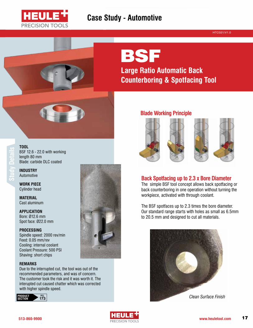
REMARKSDue to the interrupted cut, the tool was out of the recommended parameters, and was of concern. The customer took the risk and it was worth it. The interupted cut caused chatter which was corrected with higher spindle speed.
TOOLBSF 12.6 - 22.0 with working length 80 mm Blade: carbide DLC coated
INDUSTRY Automotive
WORK PIECECylinder head
MATERIALCast aluminum
APPLICATION Bore: Ø12.6 mm Spot face: Ø22.0 mm
PROCESSINGSpindle speed: 2000 rev/minFeed: 0.05 mm/revCooling: internal coolantCoolant Pressure: 500 PSI Shaving: short chips
Back Spotfacing up to 2.3 x Bore DiameterThe simple BSF tool concept allows back spotfacing or back counterboring in one operation without turning the workpiece, activated with through coolant. The BSF spotfaces up to 2.3 times the bore diameter. Our standard range starts with holes as small as 6.5mm to 20.5 mm and designed to cut all materials.
Blade Working Principle
Clean Surface FinishPRODUCT SECTION
PG. 173
Case Study - Automotive
DEFA BSFLarge Ratio Automatic Back Counterboring & Spotfacing Tool

513.860.9900 www.heuletool.com18
Catalog No. HTC14HTC021/V1.0
Serie
s
Stud
y De
tails
The switch in tooling significantly reduced cycle time. Machining time on valve bottoms, which included boring the hole to size, drilling and back spotfacing, dropped from 39 minutes to 15. While this is running at the low end of the recommended speed and feed range, it was a vast improvement in productivity.
Custom back spotfacing tools that can produce front and back spotfaces and counterbores allow for reduced cycle times and extended tool life. Capable of cutting nickel based alloys.
“So far we’ve run 420 counter bores, up from 32 on the old tool and we’ve only indexed the two-
sided inserts once.”
TOOLAutomated Back Spotfacing
PRODUCTION4or8boltholesontheflanges of 316 stainless valves
MACHINEMazak Ultra 650 horizontal machining center
MATERIALStainless Steel
HOLE SIZEØ34.8mmcounterbore; Ø19.05mmthroughhole
DETAILSTool SOLO 2Speed 613 RPMFeed .002 IPRLife 420holes (indexablecarbide)
REPLACINGCompetitors hinge-type tool
PRODUCT SECTION
PG. 215 Rene 88
Case Study - Fluid Power
SOLOHigh Production Automated Back Spotfacing Tool

513-860-9900 www.heuletool.com 19
Catalog No. HTC014HTC021/V1.0
Serie
s
Stud
y De
tails
COFA-X is the first and only tooling system that consistently and reliably removes burrs from interior uneven bore edges in applications with large intersections. The tools possess special geometries that are designed either for front or back cutting only.
The penetrating SNAP-X Tool is designed to deburr several cross bores through the main bore in a single pass. The blade is built with a clockwise and an anti-clockwise working cutting edge for high production deburring solutions.
“There is no comparison between our previous hand results and the quality results of the Heule tool. And the time savings are
exponential.”
TOOLCOFA C6X-8.0-S with C6X-M-0001-A
PARTT-Fittings
MACHINEHorz CNC
MATERIALAlloy Steel
HOLE SIZEDiameter:Ø8.0mmCrossBore:Ø8.5mm
DETAILSTool COFA-XSpeed 500 RPMFeed 0.1 mm/rev
REPLACINGInconstant brushes and hand operation
SOLO X-BORESFor Extreme, High Production, Deburring Applications With One to One Diameter Ratios
PRODUCT SECTION
PG. CALL

513.860.9900 www.heuletool.com20
Catalog No. HTC14HTC021/V1.0
Serie
s
Stud
y De
tails
Our SNAP & COFA cassettes and custom-made tooling make ordinary boring operations into money making processes by saving space and time. Any large bore operationabove1”canutilizeaHEULEfront&backchamfer cassette.
Challenge: The cast surface where the 76mm bore was produced could move in location as much as 6mm. The spring loaded HEULE chamfer cartridge with special 60 degree cutting blades produced the same size chamfers front and back regardless of surface location.
“We saved approximately $150,000 a year by cutting over 1 min./part out of production of 300,000 parts
a year.”
TOOLPrecision Mico Adjusting Boring Unit with SNAP chamfer cassette
PRODUCTION300,000 / yr
MACHINEHorizontal Machining Centers
MATERIALCast Aluminum
HOLE SIZEØ76.2mmandØ73.0mm;requiresfront/backchamferof74.1mmx60°
DETAILSTool COMBI multi-task bore and front/back chamfer with std. deburr cassette chamfer blade 60 degree carbide diamond film cutting blade.Speed 1070SFM(1,400RPM)Feed 6 IPMLife 10,000+
REPLACINGCycletimereduced20%(1.5min)
PRODUCT SECTION
PG. CALL
Case Study - Industrial
SPECIALSCustom Multi-TaskingEasy and Cost Effective

513-860-9900 www.heuletool.com 21
Catalog No. HTC014HTC021/V1.0
Serie
s
Stud
y De
tails
Meetingaerospacecustomers’furtherneedforaccuracyand non-rotational end effectors that cannot mark super critical finishes, the COMP tool was born. The HEULE COMP highlights the true meaning of swiss engineering and innovation by meeting the challenges of manufacturing state of the art tooling that can hold up in high demand production facilities.
There are three different versions:V1: Allowed simple insertable inserts to front countersink or radius drill holes where the surface of the part variedV2: Allowed the cage to contact the part first avoiding chip interference. The double compression action allowed for drilling and countersinking with a carbide drillV3: Offersfineadjustmenttothechamferdepthof.0008”(0.02MM),alongerdrilldepthofupto3xd,and non-rotating end effector.
“We’ve had the tool in production with no problems... our scrap rate went from
approx. 400 pcs a month to less than one due to chamfer issues...”
TOOLCOMP V2 Tool
PRODUCTION40,000amonth
PARTHousingwith4holeboltpattern
MATERIALCast Aluminum
HOLE SIZEØ7.6mm
COUNTERSINK0.30±0.12mmx72.5°±2°
Speed 500 RPMFeed .007 IPR
REPLACINGReplaced solid carbide countersink which could not hold countersink tolerance due to 0.3 casting variation
PRODUCT SECTION
PG. CALL
Case Study - Industrial
SPECIALS SPECIALSCustom Multi-TaskingEasy and Cost Effective

513.860.9900 www.heuletool.com22
Catalog No. HTC14HTC021/V1.0
Serie
s
For more case studies, testimonials,and videos
We are also available on:
We provide online tool selectors for the COFA, SNAP, DEFA and BSF product groups.
Simply enter your application information and the correct tool will be provided complete with order number and sample drawing.
www.HeuleTool.com

Replaceable solid carbide coated blades
Consistent deburring of even and uneven bore edges
Breakthrough technology provides consistent quality
Sizes 2-30mm (.079-1.180”) available from stock
COFADeburring Tool for Elliptical or ContouredSurfaces

513.860.9900 www.heuletool.com
Catalog No. HTC14
24
HTC021/V1.0
Serie
s
The HEULE COFA deburring tool removes burrs from the front and back of a drilled through hole without stopping or reversing the spindle. Whether you are deburring a flat surface or an irregular surface, the edge break is always even and consistent.
Deburr Elliptical HolesThe COFA tool will deburr the contours of an elliptical hole when
two holes intersect or a hole is not perpendicular to the surface.
The COFA with a standard blade can be used when the larger
intersecting hole is two or more times the smaller or for surfaces
upto15°.Deburrmoreextremecontoursbyusinga30°blade
with extra clearance relief.
Radiused Edge Breaks on Flat PartsDeburr the front and back of any through hole with a smooth
tapered edge break to relieve stress points and sharp corners.
Usethebladewith10°clearancereliefforbettertoollifewhen
deburring flat parts.
Wide Range of ToolsOur COFA tool is a proven winner for any deburring challenge,
and now with the addition of the COFA-C New Generation line,
your process capability and efficiency is even further expanded
to include threaded holes and larger edge breaks (see the COFA-C
sectionpage55formoreinformation).COFAtoolsareavalable
inarangeofstockoptionssizes2mm-30mm(.079”-1.180”).The
COFA Cassette is designed for deburring even larger bores quickly
and efficently.
COFA
CO
FA C
OFA
-C l S
NA
P l V
EX
-S l V
EX
-P l C
OM
BI l D
EFA
l GH
-K l B
SF l S
OLO
Introduction

513-860-9900 www.heuletool.com
Catalog No. HTC014
25
HTC021/V1.0
Serie
s
CO
FA C
OFA
-C l S
NA
P l V
EX
-S l V
EX
-P l C
OM
BI l D
EFA
l GH
-K l B
SF l S
OLO
How Does It Work?Controlled by a simple spring, the carbide cutting blade follows thecontourofthehole’ssurfaceremovingallburrswhilecreatingan even tapered corner break. The blade does not cut as it passes throughtheboreandwillnotdamagethehole’ssurface.
The edge break begins only at the point where the blade makes contactwiththematerialandthentapersthehole’sedge.Thisallows for faster feed rates since the tool slows itself down as it enters the through hole.
The simple concept of the COFA tool has no adjusting screws or presetting requirements. Only a choice of common tool sizes and spring strengths for various materials and hole sizes.
Spring Option
Tool Series
Blade Option
Min. Hole Dia. Ød
COFA4 b – 4.0 - W
How to Order:Ordering is simple. The COFA tool provides different blade and spring options to create the most effective tool for any application depending on the hole geometry and type of material being machined.
1. Choose the tool that best fits the hole diameter. 2. Choose the blade that best fits the hole geometry. 3. Choose the spring that best fits the material.
Example:
COFA
Typical Parts
Introduction

513.860.9900 www.heuletool.com
Catalog No. HTC14
26
HTC021/V1.0
Serie
sSe
ries2
Ød1 ØD¹
Tool Diameter +0/- .03
mm inches
2.0 .079 1.95 .077 2.2 .087
2.1 .083 2.05 .081 2.3 .090
2.2 .087 2.15 .085 2.4 .094
2.3 .091 2.25 .089 2.5 .098
2.4 .094 2.35 .092 2.6 .102
2.5 .099 2.45 .096 2.7 .106
2.6 .102 2.55 .100 2.8 .110
2.7 .106 2.65 .104 2.9 .114
2.8 .110 2.75 .108 3.0 .118
2.9 .114 2.85 .112 3.1 .122
3.0 .118 2.95 .116 3.2 .126
3.1 .122 3.05 .120 3.3 .130
COFA2-2.0-
COFA2-2.1-
COFA2-2.2-
COFA2-2.3-
COFA2-2.4-
COFA2-2.5-
COFA2-2.6-
COFA2-2.7-
COFA2-2.8-
COFA2-2.9-
COFA2-3.0- COFA2-3.1-
COFA2b-2.0-
COFA2b-2.1-
COFA2b-2.2-
COFA2b-2.3-
COFA2b-2.4-
COFA2b-2.5-
COFA2b-2.6-
COFA2b-2.7-
COFA2b-2.8-
COFA2b-2.9-
COFA2b-3.0- COFA2b-3.1-
Min. Hole mm inches
Approx. Cutting Diameter
mm inches
Front and Back Order Number
Back Only Order Number
Complete Tool with BladeØd
Deburring Tools – For holes 2.0 - 3.1mm .079-.122”Se
ries
2COFA
COFA Deburring Series 2
SPARE PARTS
PG. 27
PG. 53
BLADE OPTIONS
Spring Choice: W, H, S, Z
Easy to change Blade and pin
(tab that snaps off)
60 (2.362”)
37 (1.457”)
3 (.118”)
Ø8mmØd1
4.5 (.177”)
H = 15.3 (.602”)0.38 (.015”)
CO
FA C
OFA
-C l S
NA
P l V
EX
-S l V
EX
-P l C
OM
BI l D
EFA
l GH
-K l B
SF l S
OLO
¹ The deburring result varies depending on material, cutting data and application. The indicated dimension is the theoretically possible maximum. The spring has to be selected accordingly.

513-860-9900 www.heuletool.com
Catalog No. HTC014
27
HTC021/V1.0
Serie
s
* Not recommended with COFA2-2.0 tool.
2Serie
s
COFA
How to Order:The COFA tool provides different blade and spring options to create the most effective tool for any application depend-ing on the hole geometry and type of material being machined.
1. Choose the tool that best fits the hole diameter. 2. Choose the blade that best fits the hole geometry. 3. Choose the spring that best fits the material.
Spring Options: The cutting force of the COFA tool is controlled by a flat spring Choose the proper spring for the material being machined.
Har
der
Sof
ter
Blade Code
b
y
yb
Blade Type Geo. Series 2
fab
bco
fab
bco
TiALN 20°Standard
TiALN 10°
C2-M-0006-A
C2-M-0016-A
C2-M-0007-A
C2-M-0017-A
Blade Options:Blades are available from stock as front and back cutting (fab) or back cutting only (bco).
Spare Parts – COFA 2
COFA
Spring Option
Tool Series
Blade Option
Min. Hole Dia. Ød
COFA2 b – 2.0 - WExample:
7
Spare Parts
Spring Order Typical Materials Code Number Large or Heavy Burrs may require a stronger spring
W C2-E-0013 Aluminum, Brass, Magnesium
H C2-E-0014 Grey Cast Iron, Nodular Iron
S C2-E-0015 Carbon Steel, Free Machining Steel
Z* C2-E-0016 Nickel, Titanium, Stainless
1 2 3 4 5 6 7 Retainer Pin Assembly Pin Split Pin Blade Spring Set Screw Wrench 1.3mm Fixture GH-H-S-1017 C2-V-0001 C2-E-0002 See Below See Below GH-H-S-0135 GH-H-S-2106 C3-V-0002
6
CHANGE BLADES PG. 48-51
PG. 46-47PROGRAMMING
Optional
CO
FA C
OFA
-C l S
NA
P l V
EX
-S l V
EX
-P l C
OM
BI l D
EFA
l GH
-K l B
SF l S
OLO

513.860.9900 www.heuletool.com
Catalog No. HTC14
28
HTC021/V1.0
Serie
sSe
ries2
COFA Deburring Series 3
Serie
s3
Ød1 ØD¹
Tool Diameter +0/- .03
mm inches
3.0 .118 2.95 .116 3.3 .130
3.1 .122 3.05 .120 3.4 .134
3.2 .126 3.15 .124 3.5 .138
3.3 .130 3.25 .128 3.6 .142
3.4 .134 3.35 .132 3.7 .146
3.5 .138 3.45 .136 3.8 .150
3.6 .142 3.55 .140 3.9 .154
3.7 .146 3.65 .144 4.0 .157
3.8 .150 3.75 .148 4.1 .161
3.9 .154 3.85 .152 4.2 .165
4.0 .158 3.95 .156 4.3 .169
4.1 .161 4.05 .159 4.4 .173
COFA3-3.0-
COFA3-3.1-
COFA3-3.2-
COFA3-3.3-
COFA3-3.4-
COFA3-3.5-
COFA3-3.6-
COFA3-3.7-
COFA3-3.8-
COFA3-3.9-
COFA3-4.0- COFA3-4.1-
COFA3b-3.0-
COFA3b-3.1-
COFA3b-3.2-
COFA3b-3.3-
COFA3b-3.4-
COFA3b-3.5-
COFA3b-3.6-
COFA3b-3.7-
COFA3b-3.8-
COFA3b-3.9-
COFA3b-4.0- COFA3b-4.1-
Ød
Min. Hole mm inches
Approx. Cutting Diameter
mm inches
Front and Back Order Number
Back Only Order Number
Complete Tool with Blade
Serie
s Deburring Tools – For holes 3.0 - 4.1mm .118-.161”Se
ries
3COFA
Spring Choice: W, H, S, Z
Easy to change Blade and pin
(tab that snaps off)
66 (2.598”)
36.5 (1.437”)
4 (.157”)
Ø8mmØd1
6 (.236”)
H = 20.8 (.819”).53 (.021”)
SPARE PARTS
PG. 29
PG. 53
BLADE OPTIONS
CO
FA C
OFA
-C l S
NA
P l V
EX
-S l V
EX
-P l C
OM
BI l D
EFA
l GH
-K l B
SF l S
OLO
¹ The deburring result varies depending on material, cutting data and application. The indicated dimension is the theoretically possible maximum. The spring has to be selected accordingly.

513-860-9900 www.heuletool.com
Catalog No. HTC014
29
HTC021/V1.0
Serie
s
How to Order:The COFA tool provides different blade and spring options to create the most effective tool for any application depend-ing on the hole geometry and type of material being machined.
1. Choose the tool that best fits the hole diameter. 2. Choose the blade that best fits the hole geometry. 3. Choose the spring that best fits the material.
Spring Options: The cutting force of the COFA tool is controlled by a flat spring Choose the proper spring for the material being machined.
Har
der
Sof
ter
Blade Code
b
y
yb
Blade Type Geo. Series 3
fab
bco
fab
bco
TiALN 20°Standard
TiALN 10°
C3-M-0006-A
C3-M-0016-A
C3-M-0007-A
C3-M-0017-A
Blade Options:Blades are available from stock as front and back cutting (fab) or back cutting only (bco).
Spare Parts – COFA 3
Spring Option
Tool Series
Blade Option
Min. Hole Dia. Ød
COFA3 b – 3.0 - WExample:
7
Spring Order Typical Materials Code Number Large or Heavy Burrs may require a stronger spring
W C3-E-0013 Aluminum, Brass, Magnesium
H C3-E-0014 Grey Cast Iron, Nodular Iron
S C3-E-0015 Carbon Steel, Free Machining Steel
Z C3-E-0016 Nickel, Titanium, Stainless
1 2 3 4 5 6 7 Retainer Pin Assembly Pin Split Pin Blade Spring Set Screw Wrench 1.3mm Fixture GH-H-S-1017 C3-V-0001 C3-E-0002 See Below See Below GH-H-S-0135 GH-H-S-2106 C3-V-0002
6
3Serie
s
COFACOFA Spare Parts
Optional
PG. 48-51
PG. 46-47PROGRAMMING
CHANGE BLADES
CO
FA C
OFA
-C l S
NA
P l V
EX
-S l V
EX
-P l C
OM
BI l D
EFA
l GH
-K l B
SF l S
OLO

513.860.9900 www.heuletool.com
Catalog No. HTC14
30
HTC021/V1.0
Serie
s
Ød Ød1 ØD¹ Complete Tool with Blade Min. Hole Tool Dia. Approx. Cutting Dia. Front and Back Back Only mm inches mm inches mm inches Order Number Order Number
4.0 .157 3.9 .154 4.5 .177 COFA4-4.0- COFA4b-4.0- 4.1 .161 4.0 .157 4.6 .181 COFA4-4.1- COFA4b-4.1- 4.2 .165 4.1 .161 4.7 .185 COFA4-4.2- COFA4b-4.2- 4.3 .169 4.2 .165 4.8 .189 COFA4-4.3- COFA4b-4.3- 4.4 .173 4.3 .169 4.9 .193 COFA4-4.4- COFA4b-4.4- 4.5 .177 4.4 .173 5.0 .197 COFA4-4.5- COFA4b-4.5- 4.6 .181 4.5 .177 5.1 .201 COFA4-4.6- COFA4b-4.6- 4.7 .185 4.6 .181 5.2 .205 COFA4-4.7- COFA4b-4.7- 4.8 .189 4.7 .185 5.3 .209 COFA4-4.8- COFA4b-4.8- 4.9 .193 4.8 .189 5.4 .213 COFA4-4.9- COFA4b-4.9-
COFA Deburring Series 4
Deburring Tools – For holes 4.0 - 4.9mm .157-.193”Se
ries
4COFA
Spring Choice: W, H, S, Z, Z1
SPARE PARTS
PG. 31
PG. 53
BLADE OPTIONS
CO
FA C
OFA
-C l S
NA
P l V
EX
-S l V
EX
-P l C
OM
BI l D
EFA
l GH
-K l B
SF l S
OLO
¹ The deburring result varies depending on material, cutting data and application. The indicated dimension is the theoretically possible maximum. The spring has to be selected accordingly.

513-860-9900 www.heuletool.com
Catalog No. HTC014
31
HTC021/V1.0
Serie
s
How to Order:The COFA tool provides different blade and spring options to create the most effective tool for any application depend-ing on the hole geometry and type of material being machined.
1. Choose the tool that best fits the hole diameter. 2. Choose the blade that best fits the hole geometry. 3. Choose the spring that best fits the material.
Spring Options: The cutting force of the COFA tool is controlled by a flat spring Choose the proper spring for the material being machined.
Har
der
S
ofte
r
Blade Code
b
y
yb
x
xb
Blade Type Geo. Series 4
fab
bco
fab
bco
fab
bco
TiN 20°Standard
TiCN 10°Flat Surfaces
TiN 30°Uneven Spec
GH-C-M-0504
GH-C-M-0914
GH-C-M-0744
GH-C-M-0854
GH-C-M-0148
GH-C-M-0182
Blade Options:Blades are available from stock as front and back cutting (fab) or back cutting only (bco).
1 2 3 4 5 6 Retainer Pin Assembly Pin Split Pin Blade Spring Fixture GH-H-S-0902 GH-C-V-0206 GH-C-E-0819 See Below See Below GH-C-V-0541
Spare Parts – COFA 4
Spring Order Typical Materials Code Number Large or Heavy Burrs may require a stronger spring
W GH-C-E-0342 Aluminum, Brass, Magnesium
H GH-C-E-0343 Grey Cast Iron, Nodular Iron
S GH-C-E-0344 Carbon Steel, Free Machining Steel
Z GH-C-E-0345 Long Chipping Steel, Stainless
Z1 GH-C-E-0346 Titanium, Hardened Steel, Nickel Alloy
Spare Parts
Serie
s
4COFA
Spring Option
Tool Series
Blade Option
Min. Hole Dia. Ød
COFA4 b – 4.0 - Z1Example:
6
Optional
PG. 48-51
PG. 46-47PROGRAMMING
CHANGE BLADES
CO
FA C
OFA
-C l S
NA
P l V
EX
-S l V
EX
-P l C
OM
BI l D
EFA
l GH
-K l B
SF l S
OLO

513.860.9900 www.heuletool.com
Catalog No. HTC14
32
HTC021/V1.0
Serie
s
Spring Choice: W, H, S, Z, Z1
COFA Deburring Series 5 Ød Ød1 ØD¹ Complete Tool with Blade Min. Hole Tool Dia. Approx. Cutting Dia. Front and Back Back Only mm inches mm inches mm inches Order Number Order Number
5.0 .197 4.9 .193 5.7 .224 COFA5-5.0- COFA5b-5.0- 5.1 .201 5.0 .197 5.8 .228 COFA5-5.1- COFA5b-5.1- 5.2 .205 5.1 .201 5.9 .232 COFA5-5.2- COFA5b-5.2- 5.3 .209 5.2 .205 6.0 .236 COFA5-5.3- COFA5b-5.3- 5.4 .213 5.3 .209 6.1 .240 COFA5-5.4- COFA5b-5.4- 5.5 .217 5.4 .213 6.2 .244 COFA5-5.5- COFA5b-5.5- 5.6 .220 5.5 .217 6.3 .248 COFA5-5.6- COFA5b-5.6- 5.7 .224 5.6 .220 6.4 .252 COFA5-5.7- COFA5b-5.7- 5.8 .228 5.7 .224 6.5 .256 COFA5-5.8- COFA5b-5.8- 5.9 .232 5.8 .228 6.6 .260 COFA5-5.9- COFA5b-5.9-
Deburring Tools – For holes 5.0 - 5.9mm .197-.232”Se
ries
5COFA
SPARE PARTS
PG. 33
PG. 53
BLADE OPTIONS
CO
FA C
OFA
-C l S
NA
P l V
EX
-S l V
EX
-P l C
OM
BI l D
EFA
l GH
-K l B
SF l S
OLO
¹ The deburring result varies depending on material, cutting data and application. The indicated dimension is the theoretically possible maximum. The spring has to be selected accordingly.
75.5 (2.972”)
35.5 (1.398”)H = 32.6 (1.283”)0.85 (.033”)
5.4 (.213”)
3.8 (.150”)

513-860-9900 www.heuletool.com
Catalog No. HTC014
33
HTC021/V1.0
Serie
s
How to Order:The COFA tool provides different blade and spring options to create the most effective tool for any application depend-ing on the hole geometry and type of material being machined.
1. Choose the tool that best fits the hole diameter. 2. Choose the blade that best fits the hole geometry. 3. Choose the spring that best fits the material.
Spring Option
Tool Series
Blade Option
Min. Hole Dia. Ød
COFA5 b – 5.0 - Z1Example:
Spring Options: The cutting force of the COFA tool is controlled by a flat spring Choose the proper spring for the material being machined.
Blade Options:Blades are available from stock as front and backcutting(fab)orbackcuttingonly(bco).
Spare Parts – COFA 5
Blade Code
b
y
yb
x
xb
Blade Type Geo. Series 5
fab
bco
fab
bco
fab
bco
TiN 20°Standard
TiCN 10°Flat Surfaces
TiN 30°Uneven Spec
GH-C-M-0505
GH-C-M-0915
GH-C-M-0745
GH-C-M-0855
GH-C-M-0150
GH-C-M-0184 Har
der
S
ofte
r
Spring Order Typical Materials Code Number Large or Heavy Burrs may require a stronger spring
W GH-C-E-0352 Aluminum, Brass, Magnesium
H GH-C-E-0353 Grey Cast Iron, Nodular Iron
S GH-C-E-0354 Carbon Steel, Free Machining Steel
Z GH-C-E-0355 Long Chipping Steel, Stainless
Z1 GH-C-E-0356 Titanium, Hardened Steel, Nickel Alloy
Spare Parts
Serie
s
5COFA
6
1 2 3 4 5 6 Retainer Pin Assembly Pin Split Pin Blade Spring Fixture GH-H-S-0902 GH-C-V-0211 GH-C-E-0820 See Below See Below GH-C-V-0541
Optional
PG. 48-51
PG. 46-47PROGRAMMING
CHANGE BLADES
CO
FA C
OFA
-C l S
NA
P l V
EX
-S l V
EX
-P l C
OM
BI l D
EFA
l GH
-K l B
SF l S
OLO

513.860.9900 www.heuletool.com
Catalog No. HTC14
34
HTC021/V1.0
Serie
s
Spring Choice: W, H, S, Z, Z1, Z2, Z3
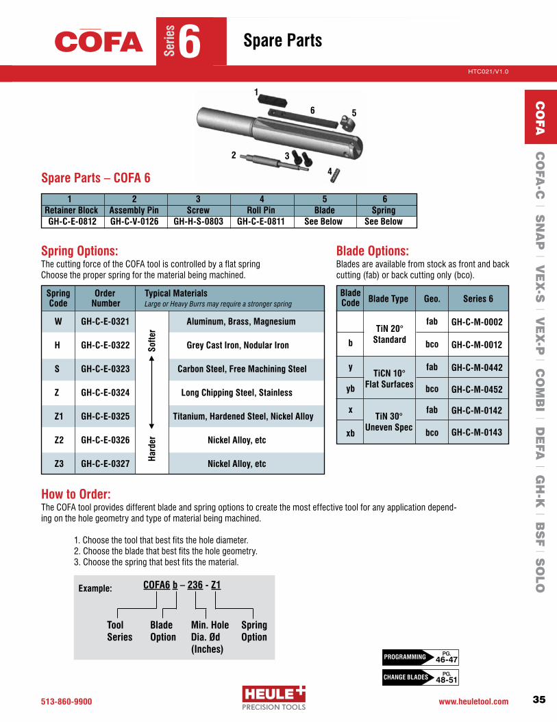
COFA Deburring Series 6 Ød Ød1 ØD¹ Complete Tool with Blade Min. Hole Tool Dia. Approx. Cutting Dia. Front and Back Back Only mm inches mm inches mm inches Order Number Order Number
6.0 .236 5.8 .228 6.7 .264 COFA6-236- COFA6b-236- 6.2 .244 6.0 .236 6.9 .272 COFA6-244- COFA6b-244- 6.4 .252 6.2 .244 7.1 .280 COFA6-252- COFA6b-252- 6.6 .260 6.4 .252 7.3 .287 COFA6-260- COFA6b-260- 6.8 .268 6.6 .260 7.5 .295 COFA6-268- COFA6b-268- 7.0 .276 6.8 .268 7.7 .303 COFA6-276- COFA6b-276- 7.2 .284 7.0 .276 7.9 .311 COFA6-284- COFA6b-284- 7.4 .291 7.2 .284 8.1 .319 COFA6-291- COFA6b-291- 7.6 .299 7.4 .291 8.3 .327 COFA6-299- COFA6b-299- 7.8 .307 7.6 .299 8.5 .335 COFA6-307- COFA6b-307- 8.0 .315 7.8 .307 8.7 .342 COFA6-315- COFA6b-315-
Deburring Tools – For holes 6.0 - 8.0mm .236-.315”Se
ries
6COFA
SPARE PARTS
PG. 35
PG. 53
BLADE OPTIONS
CO
FA C
OFA
-C l S
NA
P l V
EX
-S l V
EX
-P l C
OM
BI l D
EFA
l GH
-K l B
SF l S
OLO
¹ The deburring result varies depending on material, cutting data and application. The indicated dimension is the theoretically possible maximum. The spring has to be selected accordingly.
513-860-9900 www.heuletool.com
Catalog No. HTC014
35
HTC021/V1.0
Serie
s
1
2 3
4
56
How to Order:The COFA tool provides different blade and spring options to create the most effective tool for any application depend-ing on the hole geometry and type of material being machined.
1. Choose the tool that best fits the hole diameter. 2. Choose the blade that best fits the hole geometry. 3. Choose the spring that best fits the material.
Spring Option
Tool Series
Blade Option
Min. Hole Dia. Ød (Inches)
COFA6 b – 236 - Z1Example:
1 2 3 4 5 6 Retainer Block Assembly Pin Screw Roll Pin Blade Spring GH-C-E-0812 GH-C-V-0126 GH-H-S-0803 GH-C-E-0811 See Below See Below
Spring Options: The cutting force of the COFA tool is controlled by a flat spring Choose the proper spring for the material being machined.
Spring Order Typical Materials Code Number Large or Heavy Burrs may require a stronger spring
W GH-C-E-0321 Aluminum, Brass, Magnesium
H GH-C-E-0322 Grey Cast Iron, Nodular Iron
S GH-C-E-0323 Carbon Steel, Free Machining Steel
Z GH-C-E-0324 Long Chipping Steel, Stainless
Z1 GH-C-E-0325 Titanium, Hardened Steel, Nickel Alloy
Z2 GH-C-E-0326 Nickel Alloy, etc
Z3 GH-C-E-0327 Nickel Alloy, etc
Blade Options:Blades are available from stock as front and back cutting(fab)orbackcuttingonly(bco).
Spare Parts – COFA 6
Blade Code
b
y
yb
x
xb
Blade Type Geo. Series 6
fab
bco
fab
bco
fab
bco
TiN 20°Standard
TiCN 10°Flat Surfaces
TiN 30°Uneven Spec
GH-C-M-0002
GH-C-M-0012
GH-C-M-0442
GH-C-M-0452
GH-C-M-0142
GH-C-M-0143
Har
der
S
ofte
r
Spare Parts
Serie
s
6COFA
PG. 48-51
PG. 46-47PROGRAMMING
CHANGE BLADES
CO
FA C
OFA
-C l S
NA
P l V
EX
-S l V
EX
-P l C
OM
BI l D
EFA
l GH
-K l B
SF l S
OLO
513.860.9900 www.heuletool.com
Catalog No. HTC14
36
HTC021/V1.0
Serie
s
Spring Choice: W, H, S, Z, Z1, Z2, Z3
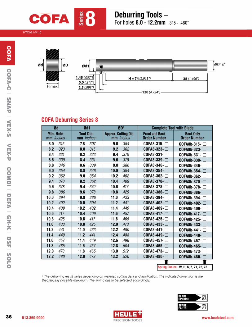
COFA Deburring Series 8
8.0 .315 7.8 .307 9.0 .354 COFA8-315- 8.2 .323 8.0 .315 9.2 .362 COFA8-323- 8.4 .331 8.2 .323 9.4 .370 COFA8-331- 8.6 .339 8.4 .331 9.6 .378 COFA8-339- 8.8 .346 8.6 .339 9.8 .386 COFA8-346- 9.0 .354 8.8 .346 10.0 .394 COFA8-354- 9.2 .362 9.0 .354 10.2 .402 COFA8-362- 9.4 .370 9.2 .362 10.4 .409 COFA8-370- 9.6 .378 9.4 .370 10.6 .417 COFA8-378- 9.8 .386 9.6 .378 10.8 .425 COFA8-386- 10.0 .394 9.8 .386 11.0 .433 COFA8-394- 10.2 .402 10.0 .394 11.2 .441 COFA8-402- 10.4 .409 10.2 .402 11.4 .449 COFA8-409- 10.6 .417 10.4 .409 11.6 .457 COFA8-417- 10.8 .425 10.6 .417 11.8 .465 COFA8-425- 11.0 .433 10.8 .425 12.0 .473 COFA8-433- 11.2 .441 11.0 .433 12.2 .480 COFA8-441- 11.4 .449 11.2 .441 12.4 .488 COFA8-449- 11.6 .457 11.4 .449 12.6 .496 COFA8-457- 11.8 .465 11.6 .457 12.8 .504 COFA8-465- 12.0 .473 11.8 .465 13.0 .512 COFA8-473- 12.2 .480 12.0 .473 13.2 .520 COFA8-480-
COFA8b-315- COFA8b-323- COFA8b-331- COFA8b-339- COFA8b-346- COFA8b-354- COFA8b-362- COFA8b-370- COFA8b-378- COFA8b-386- COFA8b-394- COFA8b-402- COFA8b-409- COFA8b-417- COFA8b-425- COFA8b-433- COFA8b-441- COFA8b-449- COFA8b-457- COFA8b-465- COFA8b-473- COFA8b-480-
Ød Ød1 ØD¹ Complete Tool with Blade Min. Hole Tool Dia. Approx. Cutting Dia. Front and Back Back Only mm inches mm inches mm inches Order Number Order Number
Deburring Tools – For holes 8.0 - 12.2mm .315-.480”Se
ries
8COFA
SPARE PARTS
PG. 37
PG. 53
BLADE OPTIONS
CO
FA C
OFA
-C l S
NA
P l V
EX
-S l V
EX
-P l C
OM
BI l D
EFA
l GH
-K l B
SF l S
OLO
¹ The deburring result varies depending on material, cutting data and application. The indicated dimension is the theoretically possible maximum. The spring has to be selected accordingly.

513-860-9900 www.heuletool.com
Catalog No. HTC014
37
HTC021/V1.0
Serie
s
1
2 3
4
56
How to Order:The COFA tool provides different blade and spring options to create the most effective tool for any application depend-ing on the hole geometry and type of material being machined.
1. Choose the tool that best fits the hole diameter. 2. Choose the blade that best fits the hole geometry. 3. Choose the spring that best fits the material.
Spring Option
Tool Series
Blade Option
Min. Hole Dia. Ød (Inches)
COFA8 b – 315 - Z1Example:
1 2 3 4 5 6 Retainer Block Assembly Pin Screw Roll Pin Blade Spring GH-C-E-0808 GH-C-V-0111 GH-H-S-0517 GH-C-E-0810 See Below See Below
Spring Options: The cutting force of the COFA tool is controlled by a flat spring Choose the proper spring for the material being machined.
Blade Options:Blades are available from stock as front and back cutting(fab)orbackcuttingonly(bco).
Spare Parts – COFA 8
Spring Order Typical Materials Code Number Large or Heavy Burrs may require a stronger spring
W GH-C-E-0331 Aluminum, Brass, Magnesium
H GH-C-E-0332 Grey Cast Iron, Nodular Iron
S GH-C-E-0333 Carbon Steel, Free Machining Steel
Z GH-C-E-0334 Long Chipping Steel, Stainless
Z1 GH-C-E-0335 Titanium, Hardened Steel, Nickel Alloy
Z2 GH-C-E-0336 Nickel Alloy, etc
Z3 GH-C-E-0337 Nickel Alloy, etc
Blade Type Geo. Series 8
fab
bco
fab
bco
fab
bco
TiN 20°Standard
TiCN 10°Flat Surfaces
TiN 30°Uneven Spec
GH-C-M-0003
GH-C-M-0013
GH-C-M-0443
GH-C-M-0453
GH-C-M-0133
GH-C-M-0131
Har
der
S
ofte
r
Spare Parts
Serie
s
8COFA
Blade Code
b
y
yb
x
xb
PG. 48-51
PG. 46-47PROGRAMMING
CHANGE BLADES
CO
FA C
OFA
-C l S
NA
P l V
EX
-S l V
EX
-P l C
OM
BI l D
EFA
l GH
-K l B
SF l S
OLO

513.860.9900 www.heuletool.com
Catalog No. HTC14
38
HTC021/V1.0
Serie
s
Ød Ød1 ØD¹ Complete Tool with Blade Min. Hole Tool Dia. Approx. Cutting Dia. Front and Back Back Only mm inches mm inches mm inches Order Number Order Number
12.4 .488 12.2 .480 13.8 .543 COFA12-488- 12.8 .504 12.6 .496 14.2 .559 COFA12-504- 13.2 .520 13.0 .512 14.6 .575 COFA12-520- 13.6 .536 13.4 .528 15.0 .591 COFA12-536- 14.0 .551 13.8 .543 15.4 .606 COFA12-551- 14.4 .567 14.2 .559 15.8 .622 COFA12-567- 14.8 .583 14.6 .575 16.2 .638 COFA12-583- 15.2 .599 15.0 .591 16.6 .654 COFA12-599- 15.6 .614 15.4 .606 17.0 .669 COFA12-614- 16.0 .630 15.8 .622 17.4 .685 COFA12-630- 16.4 .646 16.2 .638 17.8 .701 COFA12-646- 16.8 .662 16.6 .654 18.2 .717 COFA12-662- 17.2 .677 17.0 .669 18.6 .732 COFA12-677- 17.6 .693 17.4 .685 19.0 .748 COFA12-693- 18.0 .709 17.8 .701 19.4 .764 COFA12-709- 18.4 .725 18.2 .717 19.8 .780 COFA12-725- 18.8 .740 18.6 .732 20.2 .795 COFA12-740- 19.2 .756 19.0 .748 20.6 .811 COFA12-756- 19.6 .772 19.4 .764 21.0 .827 COFA12-772- 20.0 .788 19.8 .780 21.4 .843 COFA12-788-
Spring Choice: W, H, S, Z, Z1, Z2, Z3
COFA Deburring Series 12
COFA12b-488- COFA12b-504- COFA12b-520- COFA12b-536- COFA12b-551- COFA12b-567- COFA12b-583- COFA12b-599- COFA12b-614- COFA12b-630- COFA12b-646- COFA12b-662- COFA12b-677- COFA12b-693- COFA12b-709- COFA12b-725- COFA12b-740- COFA12b-756- COFA12b-772- COFA12b-788-
Deburring Tools – For holes 12.4 - 20.0mm .488-.788”Se
ries
12COFA
SPARE PARTS
PG. 39
PG. 53
BLADE OPTIONS
CO
FA C
OFA
-C l S
NA
P l V
EX
-S l V
EX
-P l C
OM
BI l D
EFA
l GH
-K l B
SF l S
OLO
¹ The deburring result varies depending on material, cutting data and application. The indicated dimension is the theoretically possible maximum. The spring has to be selected accordingly.

513-860-9900 www.heuletool.com
Catalog No. HTC014
39
HTC021/V1.0
Serie
s
1
2 3
4
56
How to Order:The COFA tool provides different blade and spring options to create the most effective tool for any application depend-ing on the hole geometry and type of material being machined.
1. Choose the tool that best fits the hole diameter. 2. Choose the blade that best fits the hole geometry. 3. Choose the spring that best fits the material.
Spring Option
Tool Series
Blade Option
Min. Hole Dia. Ød (Inches)
COFA12 b – 488 - Z1Example:
1 2 3 4 5 6 Retainer Block Assembly Pin Screw Roll Pin Blade Spring GH-C-E-0800 GH-C-V-0100 GH-H-S-0530 GH-C-E-0801 See Below See Below
Spring Options: The cutting force of the COFA tool is controlled by a flat spring Choose the proper spring for the material being machined.
Blade Options:Blades are available from stock as front and back cutting(fab)orbackcuttingonly(bco).
Spare Parts – COFA 12
Spring Order Typical Materials Code Number Large or Heavy Burrs may require a stronger spring
W GH-C-E-0361 Aluminum, Brass, Magnesium
H GH-C-E-0362 Grey Cast Iron, Nodular Iron
S GH-C-E-0363 Carbon Steel, Free Machining Steel
Z GH-C-E-0364 Long Chipping Steel, Stainless
Z1 GH-C-E-0365 Titanium, Hardened Steel, Nickel Alloy
Z2 GH-C-E-0366 Nickel Alloy, etc
Z3 GH-C-E-0367 Nickel Alloy, etc
Blade Type Geo. Series 12
fab
bco
fab
bco
fab
bco
TiN 20°Standard
TiCN 10°Flat Surfaces
TiN 30°Uneven Spec
GH-C-M-0007
GH-C-M-0017
GH-C-M-0447
GH-C-M-0457
GH-C-M-0105
GH-C-M-0104
Har
der
S
ofte
r
Spare Parts
Serie
s
12COFA
Blade Code
b
y
yb
x
xb
PG. 48-51
PG. 46-47PROGRAMMING
CHANGE BLADES
CO
FA C
OFA
-C l S
NA
P l V
EX
-S l V
EX
-P l C
OM
BI l D
EFA
l GH
-K l B
SF l S
OLO

513.860.9900 www.heuletool.com
Catalog No. HTC14
40
HTC021/V1.0
Serie
s
Ød Ød1 ØD¹ Complete Tool with Blade Min. Hole Tool Dia. Approx. Cutting Dia. Front and Back Back Only mm inches mm inches mm inches Order Number Order Number
20.5 .807 20.3 .799 21.8 .858 COFA12-20.5- 20.8 .819 20.6 .811 22.2 .874 COFA12-20.8- 21.0 .827 20.8 .819 22.4 .882 COFA12-21.0- 21.2 .835 21.0 .827 22.6 .890 COFA12-21.2- 21.5 .847 21.3 .838 23.0 .906 COFA12-21.5- 22.0 .866 21.8 .858 23.4 .921 COFA12-22.0- 22.5 .886 22.3 .878 23.9 .941 COFA12-22.5- 22.8 .898 22.6 .890 24.2 .953 COFA12-22.8- 23.0 .905 22.8 .898 24.4 .960 COFA12-23.0- 23.2 .914 23.0 .906 24.6 .969 COFA12-23.2- 23.5 .925 23.3 .917 24.9 .981 COFA12-23.5- 24.0 .945 23.8 .937 25.4 1.000 COFA12-24.0- 24.5 .965 24.3 .957 25.9 1.020 COFA12-24.5- 24.8 .977 24.6 .969 26.2 1.031 COFA12-24.8- 25.0 .984 24.8 .976 26.4 1.039 COFA12-25.0- 25.5 1.004 25.3 .996 26.9 1.059 COFA12-25.5- 26.0 1.024 25.8 1.016 27.4 1.079 COFA12-26.0-26.5 1.043 26.3 1.035 27.9 1.098 COFA12-26.5-26.8 1.055 26.6 1.047 28.2 1.110 COFA12-26.8- 27.0 1.063 26.8 1.055 28.4 1.118 COFA12-27.0-27.2 1.071 27.0 1.063 28.6 1.126 COFA12-27.2-27.5 1.083 27.3 1.075 28.9 1.138 COFA12-27.5-28.0 1.102 27.8 1.094 29.4 1.157 COFA12-28.0-28.5 1.122 28.3 1.114 29.9 1.177 COFA12-28.5-29.0 1.142 28.8 1.134 30.4 1.197 COFA12-29.0-29.5 1.162 29.3 1.154 30.9 1.217 COFA12-29.5-30.0 1.181 29.8 1.173 31.4 1.236 COFA12-30.0-
COFA Deburring Series 12 OVERSIZE - METRIC
COFA12b-20.5- COFA12b-20.8- COFA12b-21.0- COFA12b-21.2- COFA12b-21.5- COFA12b-22.0- COFA12b-22.5- COFA12b-22.8- COFA12b-23.0- COFA12b-23.2- COFA12b-23.5- COFA12b-24.0- COFA12b-24.5- COFA12b-24.8- COFA12b-25.0- COFA12b-25.5- COFA12b-26.0- COFA12b-26.5- COFA12b-26.8- COFA12b-27.0- COFA12b-27.2- COFA12b-27.5- COFA12b-28.0- COFA12b-28.5- COFA12b-29.0- COFA12b-29.5- COFA12b-30.0-
Spring Choice: W, H, S, Z, Z1, Z2, Z3
Deburring Tools – For holes 20.5 - 30.0mm .807-1.181”Se
ries
12OSCOFA
SPARE PARTS
PG. 41
PG. 53
BLADE OPTIONS
CO
FA C
OFA
-C l S
NA
P l V
EX
-S l V
EX
-P l C
OM
BI l D
EFA
l GH
-K l B
SF l S
OLO
*******
* Non-stock standard item with extended delivery time
¹ The deburring result varies depending on material, cutting data and application. The indicated dimension is the theoretically possible maximum. The spring has to be selected accordingly.

513-860-9900 www.heuletool.com
Catalog No. HTC014
41
HTC021/V1.0
Serie
s
1
2 3
4
56
How to Order:The COFA tool provides different blade and spring options to create the most effective tool for any application depend-ing on the hole geometry and type of material being machined.
1. Choose the tool that best fits the hole diameter. 2. Choose the blade that best fits the hole geometry. 3. Choose the spring that best fits the material.
Spring Option
Tool Series
Blade Option
Min. Hole Dia. Ød
COFA12 b – 20.5 - Z1Example:
1 2 3 4 5 6 Retainer Block Assembly Pin Screw Roll Pin Blade Spring GH-C-E-0800 GH-C-V-0130 GH-H-S-0513 GH-C-E-0807 See Below See Below
Spring Options: The cutting force of the COFA tool is controlled by a flat spring Choose the proper spring for the material being machined.
Blade Options:Blades are available from stock as front and backcutting(fab)orbackcuttingonly(bco).
Spare Parts – COFA 12 OVERSIZE
Spring Order Typical Materials Code Number Large or Heavy Burrs may require a stronger spring
W GH-C-E-0361 Aluminum, Brass, Magnesium
H GH-C-E-0362 Grey Cast Iron, Nodular Iron
S GH-C-E-0363 Carbon Steel, Free Machining Steel
Z GH-C-E-0364 Long Chipping Steel, Stainless
Z1 GH-C-E-0365 Titanium, Hardened Steel, Nickel Alloy
Z2 GH-C-E-0366 Nickel Alloy, etc
Z3 GH-C-E-0367 Nickel Alloy, etc
Blade Type Geo. Series 12
fab
bco
fab
bco
fab
bco
TiN 20°Standard
TiCN 10°Flat Surfaces
TiN 30°Uneven Spec
GH-C-M-0007
GH-C-M-0017
GH-C-M-0447
GH-C-M-0457
GH-C-M-0105
GH-C-M-0104
Har
der
S
ofte
r
Spare Parts
Serie
s
12OSCOFA
Blade Code
b
y
yb
x
xb
PG. 48-51
PG. 46-47PROGRAMMING
CHANGE BLADES
CO
FA C
OFA
-C l S
NA
P l V
EX
-S l V
EX
-P l C
OM
BI l D
EFA
l GH
-K l B
SF l S
OLO

513.860.9900 www.heuletool.com
Catalog No. HTC14
42
HTC021/V1.0
Serie
s
Spring Choice: W, H, S, Z, Z1, Z2, Z3
Ød Ød1 ØD¹ Complete Tool with Blade Min. Hole Tool Dia. Approx. Cutting Dia. Front and Back Back Only mm inches mm inches mm inches Order Number Order Number
*30.5 1.201 30.3 1.193 31.9 1.256 COFA12-30.5-*31.0 1.221 30.8 1.213 32.4 1.276 COFA12-31.0-*31.5 1.240 31.3 1.232 32.9 1.295 COFA12-31.5-*32.0 1.260 31.8 1.252 33.4 1.315 COFA12-32.0-*32.5 1.280 32.3 1.272 33.9 1.335 COFA12-32.5-*33.0 1.299 32.8 1.291 34.4 1.354 COFA12-33.0-*33.5 1.318 33.3 1.311 34.9 1.374 COFA12-33.5-*34.0 1.339 33.8 1.331 35.4 1.394 COFA12-34.0-*34.5 1.358 34.3 1.350 35.9 1.413 COFA12-34.5-*35.0 1.378 34.8 1.370 36.4 1.433 COFA12-35.0-*35.5 1.398 35.3 1.390 36.9 1.453 COFA12-35.5-*36.0 1.417 35.8 1.409 37.4 1.472 COFA12-36.0- *36.5 1.437 36.3 1.429 37.9 1.492 COFA12-36.5-*37.0 1.457 36.8 1.449 38.4 1.512 COFA12-37.0-*37.5 1.477 37.3 1.469 38.9 1.531 COFA12-37.5-*38.0 1.496 37.8 1.488 39.4 1.551 COFA12-38.0-*38.5 1.516 38.3 1.508 39.9 1.571 COFA12-38.5-*39.0 1.536 38.8 1.528 40.4 1.591 COFA12-39.0-*39.5 1.555 39.3 1.547 40.9 1.610 COFA12-39.5-*40.0 1.575 39.8 1.567 41.4 1.630 COFA12-40.0-
COFA Deburring Series 12 OVERSIZE - METRIC*
COFA12b-30.5- COFA12b-31.0- COFA12b-31.5- COFA12b-32.0- COFA12b-32.5- COFA12b-33.0- COFA12b-33.5- COFA12b-34.0- COFA12b-34.5- COFA12b-35.0- COFA12b-35.5- COFA12b-36.0- COFA12b-36.5-
COFA12b-37.0-COFA12b-37.5-COFA12b-38.0-COFA12b-38.5- COFA12b-39.0-COFA12b-39.5-COFA12b-40.0-
Deburring Tools – For holes 30.5 - 40.0mm 1.201-1.575”Se
ries
12OSCOFA
SPARE PARTS
PG. 43
PG. 53
BLADE OPTIONS
CO
FA C
OFA
-C l S
NA
P l V
EX
-S l V
EX
-P l C
OM
BI l D
EFA
l GH
-K l B
SF l S
OLO
* Non-stock standard item with extended delivery time
¹ The deburring result varies depending on material, cutting data and application. The indicated dimension is the theoretically possible maximum. The spring has to be selected accordingly.

513-860-9900 www.heuletool.com
Catalog No. HTC014
43
HTC021/V1.0
Serie
s
1
2 3
4
56
How to Order:The COFA tool provides different blade and spring options to create the most effective tool for any application depend-ing on the hole geometry and type of material being machined.
1. Choose the tool that best fits the hole diameter. 2. Choose the blade that best fits the hole geometry. 3. Choose the spring that best fits the material.
Spring Option
Tool Series
Blade Option
Min. Hole Dia. Ød
COFA12 b – 30.5 - Z1Example:
Spring Options: The cutting force of the COFA tool is controlled by a flat spring Choose the proper spring for the material being machined.
Blade Options:Blades are available from stock as front and backcutting(fab)orbackcuttingonly(bco).
Spring Order Typical Materials Code Number Large or Heavy Burrs may require a stronger spring
W GH-C-E-0361 Aluminum, Brass, Magnesium
H GH-C-E-0362 Grey Cast Iron, Nodular Iron
S GH-C-E-0363 Carbon Steel, Free Machining Steel
Z GH-C-E-0364 Long Chipping Steel, Stainless
Z1 GH-C-E-0365 Titanium, Hardened Steel, Nickel Alloy
Z2 GH-C-E-0366 Nickel Alloy, etc
Z3 GH-C-E-0367 Nickel Alloy, etc
Blade Type Geo. Series 12
fab
bco
fab
bco
fab
bco
TiN 20°Standard
TiCN 10°Flat Surfaces
TiN 30°Uneven Spec
GH-C-M-0007
GH-C-M-0017
GH-C-M-0447
GH-C-M-0457
GH-C-M-0105
GH-C-M-0104
1 2 3 4 5 6 Retainer Block Assembly Pin Screw Roll Pin Blade Spring GH-C-E-0800 GH-C-V-0130 GH-H-S-0513 GH-C-E-0807 See Below See Below
Spare Parts – COFA 12 OVERSIZE
Har
der
S
ofte
r
Spare Parts
Serie
s
12OSCOFA
Blade Code
b
y
yb
x
xb
PG. 48-51
PG. 46-47PROGRAMMING
CHANGE BLADES
CO
FA C
OFA
-C l S
NA
P l V
EX
-S l V
EX
-P l C
OM
BI l D
EFA
l GH
-K l B
SF l S
OLO

513.860.9900 www.heuletool.com
Catalog No. HTC14
44
HTC021/V1.0
Serie
s
Order Number(CassetteOnly)
L1 L2 L3 HK L5 BK Ød1
COFA6-CAS-COFA8-CAS-
COFA12-CAS-
13 .51216 .63025 .984
60 2.3680 3.15 93 3.66
2.0 .0792.5 .098 4.0 .157
4.0 .1575.5 .216 8.0 .315
7.55 .2979.65 .380 15.0 .590
12 .47220 .787 16 .630
7.6 .299 9.0 .354 14.0 .551
Ød - 1.1Ød - 1.4 Ød - 2.5
Cassette Calc. of the “X” - Offset
MAX Edge Break GW GT OAL (min) OAL ØdSeries 6
(ØDmax= Ød + 1.1)Series 8
(ØDmax= Ød + 1.4)
Series 12 (ØDmax= Ød + 1.8)
X = Ød/2 – 6.6
X = Ød/2 – 8.3
X = Ød/2 – 13.1
M2.5
M3
M4
6 .236
7.5 .295
8.0 .315
70 + Ls
90 + Ls
103 + Ls
Customer Specific:
Customer Specific:
Recommended DimensionsØd1
Ø13 - 16Ø16 - 30Ø30 - 50
Ø50+
Ø1/2 s.s.Ø5/8 s.s.Ø1” s.s.
Ø1.125 s.s.
Shank ØS Ls47 1.850 48 1.890 58 2.28358 2.283
Spring Choice: W, H, S, Z, Z1, Z2, Z3
Ød
ØD
Ød1
x
Hole Diameter
Chamfer Diameter
Tool Diameter
Offset from Center
Minimum Hole Ød
mm inches
Cassette Deburring Tools
Serie
s
CASCOFA
SPARE PARTS
PG. 45
PG. 53
BLADE OPTIONS
CO
FA C
OFA
-C l S
NA
P l V
EX
-S l V
EX
-P l C
OM
BI l D
EFA
l GH
-K l B
SF l S
OLO
**
* Non-stock standard item with extended delivery time

513-860-9900 www.heuletool.com
Catalog No. HTC014
45
HTC021/V1.0
Serie
s
Hard
er
S
ofte
r
Blade Type Geo. Series 6 Series 8 Series 12
fab
bco
fab
bco
fab
bco
TiN 20°Standard
TiCN 10°Flat Surfaces
TiN 30°Uneven Spec
GH-C-M-0002
GH-C-M-0012
GH-C-M-0442
GH-C-M-0452
GH-C-M-0142
GH-C-M-0143
Blade Options:Bladesareavailablefromstockasfrontandbackcutting(fab)orbackcuttingonly(bco).
GH-C-M-0003
GH-C-M-0013
GH-C-M-0443
GH-C-M-0453
GH-C-M-0133
GH-C-M-0131
GH-C-M-0007
GH-C-M-0017
GH-C-M-0447
GH-C-M-0457
GH-C-M-0105
GH-C-M-0104
Spring Options:The cutting force of the COFA tool is controlled by a flat spring. Choose the proper spring for the material being machined.
Cassette Retainer Block Assembly Pin Screw Roll Pin Blade Spring Cap Screw
SERIES 6 GH-C-E-0812 GH-C-V-0126 GH-H-S-0803 GH-C-E-0811 See Below See Below GH-H-S-0533
SERIES 8 GH-C-E-0808 GH-C-V-0111 GH-H-S-0517 GH-C-E-0810 See Below See Below GH-H-S-0538
SERIES 12 GH-C-E-0800 GH-C-V-0100 GH-H-S-0530 GH-C-E-0801 See Below See Below GH-H-S-0519
Spare Parts – Cassette 1 2 3 4 5 6 7
Cassette Deburring Tools
Serie
s
CASCOFA
Blade Code
b
y
yb
x
xb
PG. 48-51
PG. 46-47PROGRAMMING
CHANGE BLADES
Spring Typical Materials Series 6 Series 8 Series 12 Code Large or Heavy Burrs may require a stronger spring
W Alum., Brass, Magnesium GH-C-E-0321 GH-C-E-0331 GH-C-E-0361
H Cast Iron, Nodular Iron GH-C-E-0322 GH-C-E-0332 GH-C-E-0362
S Steel, Free Machining Steel GH-C-E-0323 GH-C-E-0333 GH-C-E-0363
Z Long Chip Steel, Stainless GH-C-E-0324 GH-C-E-0334 GH-C-E-0364
Z1 Ti, Hardened Steel, Ni Alloy GH-C-E-0325 GH-C-E-0335 GH-C-E-0365
Z2 Nickel Alloy, etc GH-C-E-0326 GH-C-E-0336 GH-C-E-0366
Z3 Nickel Alloy, etc GH-C-E-0327 GH-C-E-0337 GH-C-E-0367
CO
FA C
OFA
-C l S
NA
P l V
EX
-S l V
EX
-P l C
OM
BI l D
EFA
l GH
-K l B
SF l S
OLO
513.860.9900 www.heuletool.com
Catalog No. HTC14
46
HTC021/V1.0
Serie
s
Technical InformationFor the standard COFA tool, the maximum cross hole to main hole ratio is 2:1 and the maximumsurfaceangleis15°.Abovethesevalues,thecuttinginsertmaynothaveenoughclearance. All cutting data below are standard values. Deburr more extreme contours by usingthe30°bladewithextraclearancerelief.
Spring InformationThe spring gives cutting force to the carbide blade and the COFA tool easily accommodates several spring sizes. For easier cutting materialssuchasaluminum,asofter“W”springisrecommended.Forhardermaterialsoralloys,astifferspringisrecommended.
COFA
CO
FA C
OFA
-C l S
NA
P l V
EX
-S l V
EX
-P l C
OM
BI l D
EFA
l GH
-K l B
SF l S
OLO
Programming Information
NOTE: All listed cutting data are standard values only. The cutting values depend on the amount of slope of the unevenboreedge(i.e.highslope=lowcuttingvalue).Thefeedalsodependsontheslopingratio.Incaseofhard-to-machine materials or uneven bore edges, we recommend applying cutting speeds that are at the lower end of the range for uneven bore edges.
COFA 2/3/4/5 Carbide-TiN COFA 6/8/12 Carbide-TiNMaterial Hardness Spring IPR SFM IPR SFM
BHN Index mm/rev MPM mm/rev MPM
Carbon Steels 100-250 H-Z.002-.006 40-160 .006-.012 100-3400.05-0.15 12-49 0.15-0.30 30-104
Free Machining Alloy 125-340 H-Z.002-.006 22-100 .006-.014 60-2400.05-0.15 7-30 0.15-0.30 18-73
High Alloy Steel 250-350 S-Z1.002-.006 22-85 .006-.010 60-2000.05-0.15 7-26 0.15-0.25 18-60
Stainless Steel 140-250 S-Z2.002-.006 15-110 .006-.010 40-1750.05-0.15 4-34 0.15-0.25 12-53
Grey Cast Iron 150-330 H-S.002-.006 18-110 .008-.016 50-3300.05-0.15 5-34 0.20-0.40 15-100
Nodular Cast Iron 140-310 H-S.002-.006 18-130 .006-.012 50-3000.05-0.15 5-40 0.15-0.30 15-91
Aluminum Alloys 30-180 W-H.002-.006 30-200 .008-.016 80-6000.05-0.15 9-61 0.20-0.35 24-183
Nickel-based Alloys 220-310 Z1-Z3.002-.006 7-38 .005-.010 15-800.05-0.15 2-12 0.12-0.25 5-24
Titanium Alloys Z1-Z3.002-.006 7-38 .005-.010 15-800.05-0.15 2-12 0.12-0.25 5-24
Copper-Brass-Bronze 80-202 S.002-.006 30-200 .008-.016 80-6000.05-0.15 9-61 0.20-0.40 24-183
Cutting Data
H = d/D H max = 0.5

513-860-9900 www.heuletool.com
Catalog No. HTC014
47
HTC021/V1.0
Serie
s
Tool Type A B-Flat B-Irregular C* D* E-Flat* E-Irregular*
COFA 2COFA 3COFA 4COFA 5COFA 6COFA 8COFA 12
.067”(1.7)
.098”(2.5)
.079”(2.0)
.090”(2.3)
.039”(1.0)
.059”(1.5)
.118” (3.0)
.177”(4.5)
.236”(6.0)
.217”(5.5)
.276”(7.0)
.217”(5.5)
.276”(7.0)
.394”(10)
.177”(4.5)
.236”(6.0)
.217” (5.5)
.272”(6.9)
.236” (6.0)
.315” (8.0)
.472” (12)
.169”(4.3)
.217”(5.5)
.209”(5.3)
.252”(6.4)
.197” (5.0)
.256” (6.5)
.354” (9.0)
.059”(1.5)
.078”(2.0)
.071” (1.8)
.087” (2.2)
.020” (0.5)
.0 (0)
.079” (2.0)
Step 1:Referencing the front of the tool. Rapid traversethetoolthedistance“A”intothehole. This will give .040”(1) clearance from the cutter.
Step 2: In forward working feed machine the top surface of the hole by moving to distance “B”.(Ref. the front of the tool)
Step 3:Rapid traverse through the hole. The hole will not be damaged.
Step 4:In order to make the blade pop out again, the tool has to be positioned beyond the rear bore edge by the distance“C”. (Ref. the front of the tool)
Step 5: (optional)Travel the tool in back rapid feed below the rear material surface of the hole or burr to reduce cycle time. Move to distance“D”.(Ref. the front of the tool)
Step 6:In back working feed, move to distance “E” to machine the rear surface. (Ref. the front of the tool)
Rapid out.
For back deburring only, the COFA tool can rapid traverse through the top hole without damage to your hole surface.
Step 1:Rapid traverse through the hole. The hole cannot be damaged.
Step 2:In order to make the blade pop out again, the tool has to be positioned beyond the rear bore edge by the distance“C”.(Ref. the front of the tool)
Step 3: (optional)Travel the tool in back rapid feed below the rear material surface of the hole or burr to reduce cycle time. Move to distance“D”.(Ref. the front of the tool)
Step 4:In back working feed, move to distance “E” to machine the rear surface. (Ref. the front of the tool)
Rapid out.
For Front & Back Deburring For Back Only Deburring
.194”(4.9)
.260”(6.6)
.240”(6.1)
.286”(7.3)
.258”(6.5)
.324”(8.2)
.468”(11.9)
.040”(1.0)
.055”(1.4)
.048” (1.2)
.037” (0.9)
-.018”(-0.5)
-.049”(-1.2)
0
* Plus Material Thickness
COFA
CO
FA C
OFA
-C l S
NA
P l V
EX
-S l V
EX
-P l C
OM
BI l D
EFA
l GH
-K l B
SF l S
OLO
A
1 m
m
BC
D
1 m
m
E
Programming Information

513.860.9900 www.heuletool.com
Catalog No. HTC14
48
HTC021/V1.0
Serie
s
*COFA assembly fixture is recommended to remove blades
COFA
Assembly device for tool type COFA 2 and 3.
Fixture Order Number: C3-V-0002
Adjust the tool lengthwise so that the blade bore is above the recess for the roll pin. Then clamp the tool. Make sure that the larger spring recess in the shaft is on clamp screw side.
Push the roll pin out of the tool by using the smaller diameter of the assembly pin.
Insert the new blade nose first. The nose must be on the side of the shaft where the larger spring recess is (observe themarkon the tool).Thespring must engage with the groove of the blade.
Push out the blade by using the smaller diameter of the assembly pin.
Center the blade with the help of the assembly pin. Its smaller diameter serves for pre-centering.
Insert roll pin with its longer and thinner section first.
Use assembly pin to push roll pin level with blade. Then unclamp the tool.
How to Change the Blades COFA Series 2 and 3 with Fixture:
Brake off the assembly aid extensions of the blade and from the roll pin manually.
CO
FA C
OFA
-C l S
NA
P l V
EX
-S l V
EX
-P l C
OM
BI l D
EFA
l GH
-K l B
SF l S
OLO
Changing Blades
Blade Change Videos:HeuleTool.com

513-860-9900 www.heuletool.com
Catalog No. HTC014
49
HTC021/V1.0
Serie
s
Assembly device for tool types COFA 4and5.
FixtureOrderNumber:GH-C-V-0541
Insert the split pin manually with the split end upwards. Then push it with the assembly pin.
The assembly pin must be level with both sides of the tool body.
Push the split pin carefully out of the bore. Make sure you apply the assembly pin to the split end of the pin. If necessary, use a small hammer.
Adjust the tool lengthwise so that the blade bore is above the recess for the split pin. Clamp the tool as shown.
Push out the blade by means of the long end of the assembly pin.
Insert the new blade into the tool with the blade groove orientated towards the spring. Please observe the marks on the tool body.
Guide the assembly pin with its long end through the bore and center the blade.
How to Change the Blades COFA Series 4 and 5 with Fixture:
COFAC
OFA
CO
FA-C
l SN
AP
l VE
X-S
l VE
X-P
l CO
MB
I l DE
FA l G
H-K
l BS
F l S
OLO
*COFA assembly fixture is recommended to remove blades
Changing Blades
Blade Change Videos:HeuleTool.com

513.860.9900 www.heuletool.com
Catalog No. HTC14
50
HTC021/V1.0
Serie
s
How to Change the Blades (without fixture) COFA Series 2, 3, 4 and 5:
Step 1: Line up the assembly pin on the side with the solid endofthesplitpin(oppositesideofthesplitend).
Step 2: (2a) Remove the split pin out of the tool body by pressing the assembly pin from the solid end of the split pin. (2b) The bladewill fall out of the tool.Carefully use a hammer if necessary.
NOTE: HEULE recommends that you use a new split pin with each blade change and throw out the old pin.
Step 3: Insert the blade in the tool body with the notch down towards the spring. Use the mark on the tool body to reference the correct position.
Step 4: (4a) Line up the blade with the split pin hole using the assembly pin given with each tool. (4b) Insert the solid end of the split pin in the hole on the opposite side of the assembly pin and manually press into place. Using a small hammer or mallet, carefully press in the split pin on the split end into the hole.
IMPORTANT:The split pin must be below the tool body surface. If necessary, use the assembly pin and hammer to press the split pin completely in. Make sure it does not stick out on either side of the tool body.
Step 5: Series 2 and 3 Only: Using your fingers break off the blade tab and longer end of the split pin.
COFA
Easy to change Blade and pin
(tab that snaps off)
CO
FA C
OFA
-C l S
NA
P l V
EX
-S l V
EX
-P l C
OM
BI l D
EFA
l GH
-K l B
SF l S
OLO
Changing Blades
Blade Change Videos:HeuleTool.com

513-860-9900 www.heuletool.com
Catalog No. HTC014
51
HTC021/V1.0
Serie
s
How to Change the Blades COFA Series 6, 8, and 12:
STEP 1:Insert the long end of the assembly pin into the roll pin.
STEP 2:Drive the roll pin out of the tool body. Keep the roll pin to reuse it.
STEP 3:Remove the assembly pin and then remove the blade.
STEP 4:Place new blade into the tool with the notch on the end of the spring.
STEP 5:Place the long end of the assembly pin through the holes to align the blade in the tool.
STEP 6:Place the roll pin on the end of the assembly pin and hammer it into the tool. Use the assembly pin to maintain the proper alignment.
STEP 7:Place the short end of the assembly pin into the roll pin and drive the assembly pin so it seats against the counterbore.
Assembly Pin
12
Roll Pin
BladeBlade
notch down3b
3a
Spring
5
6a
6b pin is flush with body
7 set pin flush with counter-bore
COFAC
OFA
CO
FA-C
l SN
AP
l VE
X-S
l VE
X-P
l CO
MB
I l DE
FA l G
H-K
l BS
F l S
OLO
Changing Blades
Blade Change Videos:HeuleTool.com

513.860.9900 www.heuletool.com
Catalog No. HTC14
52
HTC021/V1.0
Serie
s
PROBLEM
Chamfer Ø too large
Chamfer Ø too small
Tool chatters
Tool is pushing the burr
Tool creates a secondary burr or poor surface finish
Cutting Blades are chipping
Uneven chamfer or missing some burrs
Blade is breaking or falling out of tool
•Toolisdesignedtocuttoasetchamfer diameter
•Chamferiscuttingtothedesignated maximum from the catalog but this is not large enough
•Chamferisnottodesignedmaximumsize
•Operatingconditionsarenotcorrect
•Notenoughcuttingforceforyourmaterial
•Bladeisusedordull
•Bladeisnewbutstillnotworking
•Springistooheavy •Chamfersizeislarge
•Operatingconditionsarenotcorrect
•Programmingerror
•Interrupted cut or possible wall interference
•Speedratefartoohigh
•Ratiobetweencrossholeandtube diameter(d:D)islargerthan0.5 •Notenoughcuttingforceforyourmaterial
•Interrupted cut or possible wall interference•Rollpinsarebeingdeformed
•Programisincorrect
EXPLANATION SOLUTION
•Selectasmallersizedtool
•Usethenextsizelargertoolifpossible •The COFA tool is only designed for edge breaks but specials can be requested •Use the next higher strength spring •Use a slower feed rate•Increasefeedrates •Decrease speed rates •Use coolant on tool •Use the next higher strength spring
•Changetheinsert •Use the next higher strength spring •Check programming position and feed rates •Burrs are too large
•Use next lighter strength spring •Use a smaller tool to achieve a smaller edge break •Check recommended feed and speed rates
•Makesurecuttingedgeisnot in fast feed when cutting •Try smaller tool •Reduce speed rate
•Specialinsertsarepossible •Change spring or use the next higher strength spring
•Trysmallertool •Check assembly procedures •Assembly pins must be used when changing blades •Change roll pin •Check programming positioning •Do not use bore cycle
COFA
Grinding may produce hazardous dust. To avoid adverse effects, use adequate ventilation and read MSDS. Cutting tools may break during use. To avoid injury, use proper safety precautions and protective equipment. Use the machine tool with sufficient rigidity and horsepower. Use a cover on a machine tool and protector, such as glasses, against shattering chips and broken tools due to misuse. Do not use insoluble oil because there is a danger of causing fire.
CO
FA C
OFA
-C l S
NA
P l V
EX
-S l V
EX
-P l C
OM
BI l D
EFA
l GH
-K l B
SF l S
OLO
Troubleshooting

513-860-9900 www.heuletool.com
Catalog No. HTC014
53
HTC021/V1.0
Serie
s
Blade Type Geo. Series 2 Series 3 Series 4 Series 5 Series 6 Series 8 Series 12
fab
bco
fab
bco
fab
bco
TiN 20°Standard
TiCN 10°Flat Surfaces
TiN 30°Uneven Spec
-0504
-0914
-0744
-0854
-0148
-0182
-0505
-0915
-0745
-0855
-0150
-0184
-0002
-0012
-0442
-0452
-0142
-0143
-0003
-0013
-0443
-0453
-0133
-0131
-0007
-0017
-0447
-0457
-0105
-0104
Blade Type Geo. Series 4 Series 5 Series 6 Series 8 Series 12
fab
bco
fab
bco
fab
bco
fab
bco
fab
bco
fab
bco
DLC 20°Diamond
DLC 10°Flat Surfaces
TiALN 20°Spec Coat
GH-C-M-0584
GH-C-M-0994
GH-C-M-0784
GH-C-M-0894
GH-C-M-0564
GH-C-M-0974
GH-C-M-0764
GH-C-M-0874
GH-C-M-0524
GH-C-M-0934
GH-C-M-0724
GH-C-M-0834
GH-C-M-0585
GH-C-M-0995
GH-C-M-0785
GH-C-M-0895
GH-C-M-0565
GH-C-M-0975
GH-C-M-0765
GH-C-M-0875
GH-C-M-0525
GH-C-M-0935
GH-C-M-0725
GH-C-M-0835
GH-C-M-0082
GH-C-M-0092
GH-C-M-0482
GH-C-M-0492
GH-C-M-0062
GH-C-M-0072
GH-C-M-0462
GH-C-M-0472
GH-C-M-0022
GH-C-M-0032
GH-C-M-0422
GH-C-M-0432
GH-C-M-0083
GH-C-M-0093
GH-C-M-0483
GH-C-M-0493
GH-C-M-0063
GH-C-M-0073
GH-C-M-0463
GH-C-M-0473
GH-C-M-0023
GH-C-M-0033
GH-C-M-0423
GH-C-M-0433
GH-C-M-0087
GH-C-M-0097
GH-C-M-0487
GH-C-M-0497
GH-C-M-0067
GH-C-M-0077
GH-C-M-0467
GH-C-M-0477
GH-C-M-0027
GH-C-M-0037
GH-C-M-0427
GH-C-M-0437
TiALN 10°Flat Surfaces
Uncoated 20°
Uncoated 10°
Special Blade Options:To order a standard COFA tool with a special insert (those not marked with an *), add a ‘k’ behind the series number to indicate the tool is without the standard insert and then order the special blades separately.
Standard Blade Options: StandardBladesareavailablefromstockasfrontandbackcutting(fab)orbackcuttingonly(bco).
For example: 1 pc COFA8k-315-H - COFA Tool Holder without insert 5 pc GH-C-M-0083 - COFA8 Blade, DLC 10° *special*
Note: These items are non-stock standard items with extended delivery time.
COFA
Blade Code
b
y
yb
x
xb
C2-M- C3-M- GH-C-M- GH-C-M- GH-C-M- GH-C-M- GH-C-M-
-0006-A*
-0016-A*
-0007-A*
-0017-A*
-0009-A*
-0019-A*
-0006-A*
-0016-A*
-0007-A*
-0017-A*
-0009-A*
-0019-A*
* TIALN is standard for COFA Series 2 and 3
CO
FA C
OFA
-C l S
NA
P l V
EX
-S l V
EX
-P l C
OM
BI l D
EFA
l GH
-K l B
SF l S
OLO
Blade Options

513.860.9900 www.heuletool.com
Catalog No. HTC14
54
HTC021/V1.0
Serie
s
For more case studies, testimonials,and videos
We are also available on:
We provide online tool selectors for the COFA, SNAP, DEFA and BSF product groups.
Simply enter your application information and the correct tool will be provided complete with order number and sample drawing.
www.HeuleTool.com
CO
FA C
OFA
-C l S
NA
P l V
EX
-S l V
EX
-P l C
OM
BI l D
EFA
l GH
-K l B
SF l S
OLO

Designed for added durability
Suitable for bores being threaded and larger edge breaks
Shorter working length for a more stable tool
Newly-designed blade holder for better guidance and longer spring life
COFA-CNew Generation Deburring Tool for Elliptical or Contoured Surfaces

513.860.9900 www.heuletool.com56
Catalog No. HTC14HTC021/V1.0
Serie
s
C-Series tooling functions the same as our standard proven COFA products. The COFA-C allows larger break edge sizes, with different choices & sizes of carbide coated blades. The cutting blade is held in a separate steel blade holder which allows less wear to the spring and quicker exchangeability of each insert. C-Series adds more capability by allowing pre-chamfering of threaded holes on uneven surfaces.
Availableforholesizes6mm(.236“)andup.TheC-Series product also offers a complete range of cassettes for each series.
The COFA-C Series
COFA-C
CO
FA C
OFA
-C S
NA
P l V
EX
-S l V
EX
-P l C
OM
BI l D
EFA
l GH
-K l B
SF l S
OLO
1
2
34
5
6
1 - Tool Body2 - Spring3 - Blade Holder4-BladeC6-C125 - Front Cutting Edge6 - Back Cutting Edge
For blade changevideos visit:
www.HeuleTool.com
C-Series Offers Extra-large Break Edge
COFA-C Series

513-860-9900 www.heuletool.com 57
Catalog No. HTC014HTC021/V1.0
Serie
s
1 Split pin2 Blade holder3 Blade4Spring
5 Screw6 Retainer block7 Tool body8 Assembly pin
Tool Description
1 2 3 54 6 78
How to Order:The COFA tool provides different blade and spring options to create the most effective tool for any application depending on the hole geometry and type of material being machined. Blades sold separately for COFA-C series.
1. Choose the tool that best fits the hole diameter. 2. Choose the spring that best fits the material. 3.Choosethebladethatbestfitstheholegeometryandedgebreaksize(forallseries).
Spring Option
Tool Series
Min. Hole Dia. Ød (mm)
C8 - 8.0 - Z1 and C8-M-0006-AExample:
Blade Option
How Does It Work?Controlled by a simple spring, the carbide cutting blade follows the contour of the hole’s surface removing all burrs whilecreating an even tapered corner break. The blade does not cut as it passes through thebore andwill not damage thehole’ssurface.
The edge break begins only at the point where the blade makes contactwiththematerialandthentapersthehole’sedge.Thisallows for faster feed rates since the tool slows itself down as it enters the through hole.
The simple concept of the COFA tool has no adjusting screws or presetting requirements. Only a choice of common tool sizes and spring strengths for various materials and hole sizes.
COFA-CC
OFA
CO
FA-C
SN
AP
l VE
X-S
l VE
X-P
l CO
MB
I l DE
FA l G
H-K
l BS
F l S
OLO
Introduction

513.860.9900 www.heuletool.com58
Catalog No. HTC14HTC021/V1.0
Serie
s
Ød Ød1 ØD Tool without Blade Min. Hole Tool Dia. Approx. Cutting Dia. Approx. Cutting Dia. mm inches mm inches mm inches mm inches Medium Blade Large Blade
6.0 .236 5.8 .228 7.0 .276 7.4 .2916.2 .244 6.0 .236 7.2 .283 7.6 .2996.4 .252 6.2 .244 7.4 .291 7.8 .3076.6 .260 6.4 .252 7.6 .299 8.0 .3156.8 .268 6.6 .260 7.8 .307 8.2 .3237.0 .276 6 .8 .268 8.0 .315 8.4 .3317.2 .283 7.0 .276 8.2 .323 8.6 .3397.4 .291 7.2 .283 8.4 .331 8.8 .3467.6 .299 7.4 .291 8.6 .339 9.0 .3547.8 .307 7.6 .299 8.8 .346 9.2 .3628.0 .315 7.8 .307 9.0 .354 9.4 .370
Spring Choice: W, H, S, Z, Z1, Z2, Z3
COFA Deburring Series C6
Deburring Tools – For holes 6.0 - 8.0mm .236-.315”
Tool Order Number
Blades sold separately for COFA-C Series, see Blade Options
ØD2 = ØD + 1.3 (.051”) ØD2 = Swing Diameter Ød1 = Tool Body Diameter
H = 48(1.890”) 38(1.496”)
93 (3.661”)
3.8(.150”)2.2(.087”)
Ød1
Serie
s
Ø6mm
C6
C6-6.0- C6-6.2- C6-6.4- C6-6.6- C6-6.8- C6-7.0- C6-7.2- C6-7.4- C6-7.6- C6-7.8- C6-8.0-
ØD2
COFA-C
CO
FA C
OFA
-C S
NA
P l V
EX
-S l V
EX
-P l C
OM
BI l D
EFA
l GH
-K l B
SF l S
OLO

513-860-9900 www.heuletool.com 59
Catalog No. HTC014HTC021/V1.0
Serie
sSe
ries
How to Order:The COFA tool provides different blade and spring options to create the most effective tool for any application depend-ing on the hole geometry and type of material being machined. Blades sold separately for COFA-C series.
1. Choose the tool that best fits the hole diameter. 2. Choose the spring that best fits the material. 3. Choose the blade that best fits the hole geometry and edge break size.
Spring Option
Tool Series
Min. Hole Dia. Ød (mm)
C6 - 6.0 - Z1 and C6-M-0006-AExample:
1 2 3 4 5 6 7 Split Pin Blade Holder Blade Spring Screw Retainer Block Assembly Pin Fixture* C6-E-0003 C6-E-0001 See Below See Below GH-H-S-0803 GH-C-E-0812 C6-V-0006 C6-V-0008
Spring Options: The cutting force of the COFA tool is controlled by a flat spring Choose the proper spring for the material being machined.
Blade Options:Blades are available from stock as front and back cutting(fab)orbackcuttingonly(bco).
Spare Parts – COFA C6
Spring Order Typical Materials Code Number Large or Heavy Burrs may require a stronger spring
W C6-E-0008 Aluminum, Brass, Magnesium
H C6-E-0009 Grey Cast Iron, Nodular Iron
S C6-E-0010 Carbon Steel, Free Machining Steel
Z C6-E-0011 Long Chipping Steel, Stainless
Z1 C6-E-0012 Titanium, Hardened Steel, Nickel Alloy
Z2 C6-E-0013 Nickel Alloy, etc
Z3 C6-E-0014 Nickel Alloy, etc
Geo.
fab
bco
fab
bco
fab
bco
C6-M-0006-A
C6-M-0026-A
C6-M-0007-A
C6-M-0027-A
C6-M-0009-A
C6-M-0029-A
Har
der
S
ofte
r
Spare Parts
BladeType
20° Standard
10° Flat
Surfaces
30° Uneven Surfaces
Medium Blade TiAlN Coated
Large Blade TiAIN Coated
C6-M-0001-A
C6-M-0021-A
C6-M-0002-A
C6-M-0022-A
C6-M-0004-A
C6-M-0024-A
Blade Option
C6
1 2 3 54 67
*See Page 70
COFA-CC
OFA
CO
FA-C
SN
AP
l VE
X-S
l VE
X-P
l CO
MB
I l DE
FA l G
H-K
l BS
F l S
OLO
PG. 70
PG. 68-69PROGRAMMING
CHANGE BLADES

513.860.9900 www.heuletool.com60
Catalog No. HTC14HTC021/V1.0
Serie
s
Ød Ød1 ØD Tool without Blade Min. Hole Tool Dia. Approx. Cutting Dia. Approx. Cutting Dia. mm inches mm inches mm inches mm inches Medium Blade Large Blade
8.0 .315 7.8 .307 9.2 .362 9.8 .3868.2 .323 8.0 .315 9.4 .370 10.0 .3948.4 .331 8.2 .323 9.6 .378 10.2 .4028.6 .339 8.4 .331 9.8 .386 10.4 .4098.8 .346 8.6 .339 10.0 .394 10.6 .4179.0 .354 8.8 .346 10.2 .402 10.8 .4259.2 .362 9.0 .354 10.4 .409 11.0 .4339.4 .370 9.2 .362 10.6 .417 11.2 .4419.6 .378 9.4 .370 10.8 .425 11.4 .4499.8 .386 9.6 .378 11.0 .433 11.6 .45710.0 .394 9.8 .386 11.2 .441 11.8 .46510.2 .402 10.0 .394 11.4 .449 12.0 .47210.4 .409 10.2 .402 11.6 .457 12.2 .48010.6 .417 10.4 .409 11.8 .465 12.4 .48810.8 .425 10.6 .417 12.0 .472 12.6 .49611.0 .433 10.8 .425 12.2 .480 12.8 .50411.2 .441 11.0 .433 12.4 .488 13.0 .51211.4 .449 11.2 .441 12.6 .496 13.2 .52011.6 .457 11.4 .449 12.8 .504 13.4 .52811.8 .465 11.6 .457 13.0 .512 13.6 .53512.0 .472 11.8 .465 13.2 .520 13.8 .543
Spring Choice: W, H, S, Z, Z1, Z2, Z3
COFA Deburring Series C8
C8-8.0- C8-8.2- C8-8.4- C8-8.6- C8-8.8- C8-9.0- C8-9.2- C8-9.4- C8-9.6- C8-9.8- C8-10.0- C8-10.2- C8-10.4- C8-10.6- C8-10.8- C8-11.0- C8-11.2- C8-11.4- C8-11.6- C8-11.8- C8-12.0-
Serie
s Deburring Tools – For holes 8.0 - 12.0mm .315-.472”C8
Tool Order Number
Blades sold separately for COFA-C Series, see Blade Options
H = 61(2.402”) 38(1.496”)
107(4.213”)
5.0(.197”)3.0(.118”)
Ød1
Ø8mm
ØD2
ØD2 = ØD + 1.6 (.063”) ØD2 = Swing Diameter Ød1 = Tool Body Diameter
COFA-C
CO
FA C
OFA
-C S
NA
P l V
EX
-S l V
EX
-P l C
OM
BI l D
EFA
l GH
-K l B
SF l S
OLO

513-860-9900 www.heuletool.com 61
Catalog No. HTC014HTC021/V1.0
Serie
sSe
ries
How to Order:The COFA tool provides different blade and spring options to create the most effective tool for any application depend-ing on the hole geometry and type of material being machined. Blades sold separately for COFA-C series.
1. Choose the tool that best fits the hole diameter. 2. Choose the spring that best fits the material. 3. Choose the blade that best fits the hole geometry.
Spring Option
Tool Series
Min. Hole Dia. Ød (mm)
C8 - 8.0 - Z1 and C8-M-0006-AExample:
1 2 3 4 5 6 7 Split Pin Blade Holder Blade Spring Screw Retainer Block Assembly Pin Fixture* C8-E-0003 C8-E-0001 See Below See Below GH-H-S-0517 GH-C-E-0808 C8-V-0005 C8-V-0007
Spring Options: The cutting force of the COFA tool is controlled by a flat spring. Choose the proper spring for the material being machined.
Blade Options:Blades are available from stock as front and back cutting(fab)orbackcuttingonly(bco).
Spare Parts – COFA C8
Spring Order Typical Materials Code Number Large or Heavy Burrs may require a stronger spring
W C8-E-0008 Aluminum, Brass, Magnesium
H C8-E-0009 Grey Cast Iron, Nodular Iron
S C8-E-0010 Carbon Steel, Free Machining Steel
Z C8-E-0011 Long Chipping Steel, Stainless
Z1 C8-E-0012 Titanium, Hardened Steel, Nickel Alloy
Z2 C8-E-0013 Nickel Alloy, etc
Z3 C8-E-0014 Nickel Alloy, etc
Geo.
fab
bco
fab
bco
fab
bco
C8-M-0006-A
C8-M-0026-A
C8-M-0007-A
C8-M-0027-A
C8-M-0009-A
C8-M-0029-A
Har
der
S
ofte
r
Spare Parts
BladeType
20° Standard
10° Flat
Surfaces
30° Uneven Surfaces
Medium Blade TiAlN Coated
Large Blade TiAlN Coated
C8-M-0001-A
C8-M-0021-A
C8-M-0002-A
C8-M-0022-A
C8-M-0004-A
C8-M-0024-A
Blade Option
C8
1 2 3 54 67
*See Page 70
COFA-CC
OFA
CO
FA-C
SN
AP
l VE
X-S
l VE
X-P
l CO
MB
I l DE
FA l G
H-K
l BS
F l S
OLO
PG. 70
PG. 68-69PROGRAMMING
CHANGE BLADES

513.860.9900 www.heuletool.com62
Catalog No. HTC14HTC021/V1.0
Serie
s
Ød Ød1 ØD Tool without Blade Min. Hole Tool Dia. Approx. Cutting Dia. Approx. Cutting Dia. mm inches mm inches mm inches mm inches Medium Blade Large Blade
12.0 .472 11.8 .465 13.6 .535 14.8 .583 12.5 .492 12.3 .484 14.1 .555 15.3 .602 13.0 .512 12.8 .504 14.6 .575 15.8 .622 13.5 .531 13.3 .524 15.1 .594 16.3 .642 14.0 .551 13.8 .543 15.6 .614 16.8 .661 14.5 .571 14.3 .563 16.1 .634 17.3 .681 15.0 .591 14.8 .583 16.6 .654 17.8 .701 15.5 .610 15.3 .602 17.1 .673 18.3 .720 16.0 .630 15.8 .622 17.6 .693 18.8 .740 16.5 .650 16.3 .642 18.1 .713 19.3 .760 17.0 .669 16.8 .661 18.6 .732 19.8 .780 17.5 .689 17.3 .681 19.1 .752 20.3 .799 18.0 .709 17.8 .701 19.6 .772 20.8 .819 18.5 .728 18.3 .720 20.1 .791 21.3 .839 19.0 .748 18.8 .740 20.6 .811 21.8 .858 19.5 .768 19.3 .760 21.1 .831 22.3 .878 20.0 .787 19.8 .780 21.6 .850 22.8 .898*20.5 .807 20.3 .795 22.1 .870 23.3 .917*21.0 .827 20.8 .819 22.6 .890 23.8 .937*21.5 .846 21.3 .839 23.1 .909 24.3 .957*22.0 .866 21.8 .858 23.6 .929 24.8 .976*22.5 .886 22.3 .878 24.1 .949 25.3 .996*23.0 .906 22.8 .898 24.6 .969 25.8 1.016*23.5 .925 23.3 .917 25.1 .988 26.3 1.035*24.0 .945 23.8 .937 25.6 1.008 26.8 1.055*24.5 .965 24.3 .957 26.1 1.028 27.3 1.075*25.0 .984 24.8 .976 26.6 1.047 27.8 1.094*25.5 1.004 25.3 .996 27.1 1.067 28.3 1.114*26.0 1.024 25.8 1.016 27.6 1.087 28.8 1.134
Spring Choice: W, H, S, Z, Z1, Z2, Z3
COFA Deburring Series C12
C12-12.0- C12-12.5- C12-13.0- C12-13.5- C12-14.0- C12-14.5- C12-15.0- C12-15.5- C12-16.0- C12-16.5- C12-17.0- C12-17.5- C12-18.0- C12-18.5- C12-19.0- C12-19.5- C12-20.0- C12-20.5- C12-21.0- C12-21.5- C12-22.0- C12-22.5- C12-23.0- C12-23.5- C12-24.0- C12-24.5- C12-25.0- C12-25.5- C12-26.0-
Serie
s Deburring Tools – For holes 12.0 - 26.0mm .472-1.024”C12
Tool Order Number
Blades sold separately for COFA-C Series, see Blade Options.*Non-stock standard item with extended delivery time.
H = 70(2.756”) Ls:Ø12.0:47(1.850”)Ls:Ø16.0:50(1.968”)
OAL:Ø12.0:129(5.079”)OAL:Ø16.0:132(5.197”)
7.4(.291”)4.6(.181”)
Ød1
Ø12.0-19.5=Ø12mm
Ø20.0-26.0=Ø16mm
ØD2
ØD2 = ØD + 2.2 (.087”) ØD2 = Swing Diameter Ød1 = Tool Body Diameter
COFA-C
CO
FA C
OFA
-C S
NA
P l V
EX
-S l V
EX
-P l C
OM
BI l D
EFA
l GH
-K l B
SF l S
OLO

513-860-9900 www.heuletool.com 63
Catalog No. HTC014HTC021/V1.0
Serie
sSe
ries
How to Order:The COFA tool provides different blade and spring options to create the most effective tool for any application depend-ing on the hole geometry and type of material being machined. Blades sold separately for COFA-C series.
1. Choose the tool that best fits the hole diameter. 2. Choose the spring that best fits the material. 3. Choose the blade that best fits the hole geometry.
Spring Option
Tool Series
Min. Hole Dia. Ød (mm)
C12 - 15.0 - Z1 and C12-M-0006-AExample:
1 2 3 4 5 6 7 Split Pin Blade Holder Blade Spring Screw Retainer Block Assembly Pin Fixture* C12-E-0003 C12-E-0001 See Below See Below GH-H-S-0530 GH-C-E-0800 C12-V-0005 C12-V-0018
Spring Options: The cutting force of the COFA tool is controlled by a flat spring Choose the proper spring for the material being machined.
Blade Options:Blades are available from stock as front and back cutting(fab)orbackcuttingonly(bco).
Spare Parts – COFA C12
Spring Order Typical Materials Code Number Large or Heavy Burrs may require a stronger spring
W C12-E-0008 Aluminum, Brass, Magnesium
H C12-E-0009 Grey Cast Iron, Nodular Iron
S C12-E-0010 Carbon Steel, Free Machining Steel
Z C12-E-0011 Long Chipping Steel, Stainless
Z1 C12-E-0012 Titanium, Hardened Steel, Nickel Alloy
Z2 C12-E-0013 Nickel Alloy, etc
Z3 C12-E-0014 Nickel Alloy, etc
Geo.
fab
bco
fab
bco
fab
bco
C12-M-0006-A
C12-M-0026-A
C12-M-0007-A
C12-M-0027-A
C12-M-0009-A
C12-M-0029-A
Har
der
S
ofte
r
Spare Parts
BladeType
20° Standard
10° Flat
Surfaces
30° Uneven Surfaces
C121 2 3 54 67
Medium Blade TiAlN Coated
Large Blade TiAlN Coated
C12-M-0001-A
C12-M-0021-A
C12-M-0002-A
C12-M-0022-A
C12-M-0004-A
C12-M-0024-A
Blade Option
*See Page 70
COFA-CC
OFA
CO
FA-C
SN
AP
l VE
X-S
l VE
X-P
l CO
MB
I l DE
FA l G
H-K
l BS
F l S
OLO
PG. 70
PG. 68-69PROGRAMMING
CHANGE BLADES

513.860.9900 www.heuletool.com64
Catalog No. HTC14HTC021/V1.0
Serie
s Deburring Tools – Cassette Deburring ToolsSe
ries
CASCOFA-C
CO
FA C
OFA
-C S
NA
P l V
EX
-S l V
EX
-P l C
OM
BI l D
EFA
l GH
-K l B
SF l S
OLO
BK
L4L3L1
L1 L2
LK
HG
L5
HKHK
BK
L4L3L1
LK
L5
HG
L1
COFA
C6
Kass
ette
COFA
C8/
C12
Cass
ette
COF
A C6
Cas
sette
The COFA Cassette is used for installation into combination tools and cassette holders. The holder can be ordered from Heule Tool, or the customers can use their own, utilizing the following specificiations:
Spring Choice: W, H, S, Z, Z1, Z2, Z3
Cass. without Blade Tool Series Min. Bore size Max Chamfer size Blade
C6-0-0900-C8-0-0900-
C12-0-0900-
Cassette Order
Number
C6C8C12
10.0 .39414.0 .55120.0 .787
See Page 67 See Page 67 See Page 67
See Page 59 See Page 61 See Page 63
mm inches

513-860-9900 www.heuletool.com 65
Catalog No. HTC014HTC021/V1.0
Serie
sSe
ries
Spare PartsCASCOFA-CC
OFA
CO
FA-C
SN
AP
l VE
X-S
l VE
X-P
l CO
MB
I l DE
FA l G
H-K
l BS
F l S
OLO
22 11 33 55 44 66 778
Cassette Split Pin Blade Holder Blade Tool Body Spring Retainer Block Screw Set Screw
Spare Parts – Cassette 1 2 3 4 5 6 7 8
Spring Options: The cutting force of the COFA tool is controlled by a flat spring Choose the proper spring for the material being machined.
Spring Order Typical Materials Code Number Large or Heavy Burrs may require a stronger spring
W Aluminum, Brass, Magnesium
H Grey Cast Iron, Nodular Iron
S Carbon Steel, Free Machining Steel
Z Long Chipping Steel, Stainless
Z1 Titanium, Hardened Steel, Nickel Alloy
Z2 Nickel Alloy, etcHar
der
S
ofte
r
MeasurementsType BK HG LK HK L1 L2 L3 L4 L5
C6
C8
C12
5.0
8.0
10.0
5.8
8.5
13.0
42.5
51.5
60.0
4.0
4.0
7.5
20.0
-
-
14.0
29.6
35.0
8.5
9.5
8.5
3.3
5.2
7.7see
pg 6
7
COFA C6 COFA C8/C12
SERIES 6
SERIES 8
SERIES 12
C6-E-0003
C8-E-0003
C12-E-0003
C6-E-0001
C8-E-0001
C12-E-0001
See Page 59
See Page 61
See Page 63
C6-G-0900
C8-G-0900
C12-G-0900
See Below
See Below
See Below
GH-C-E-0812
C8-E-0800
C12-E-0800
GH-H-S-0803
GH-H-S-0050
GH-H-S-0012
GH-H-S-0137
The
orde
r num
bers
for t
he s
prin
gs a
re
iden
tical
with
thos
e fo
r the
sta
ndar
d to
ols.
C6
- pa
ge 5
9C8
- pa
ge 6
1C1
2 - p
age
63

513.860.9900 www.heuletool.com66
Catalog No. HTC14HTC021/V1.0
Serie
s
CO
FA C
OFA
-C S
NA
P l V
EX
-S l V
EX
-P l C
OM
BI l D
EFA
l GH
-K l B
SF l S
OLO
Deburring Tools – Cassette Deburring ToolsSe
ries
CAS
min.Ø2
min.Ø2
ØD3
Ø1.8(2x)
Ø3.5(2x)
42+0.5/0
42+0.5/0
LK+0.5/0
21.12.9
14±0.1
L3±0.1
17.1
L6
34
L7
3.05
3.05
A
1.8
M2
5.06
±0.04
5.06
±0.04
BK±0.04
min.Ø8
min.Ø10
min.Ø
C8Ø10
C12Ø12
ØD10
/-0.
3
ØD10
/-0.
3ØD10
/-0.
3
2X ±0.
1X ±
0.1
X ±0.
1
CO
FA C
6 Ø
10.0
-14.
99C
OFA
C6
Ø15
.0 -
CO
FA C
8 /
C12
M1,6
REckmax0.3x45°
REckmax0.3x45°
(R2.53)
(R2.53)
C8: M2C12: M3
(C8:R4.03)(C12:R5.03)
REckmax0.5x45°
COFA-C

513-860-9900 www.heuletool.com 67
Catalog No. HTC014HTC021/V1.0
Serie
s
CO
FA C
OFA
-C S
NA
P l V
EX
-S l V
EX
-P l C
OM
BI l D
EFA
l GH
-K l B
SF l S
OLO
Serie
s
Spare PartsCAS
Limiting Values
Measure Table Cassette Holder
HK MeasurementsType S M L
C6
C8
C12
7.6
10.6
15.6
7.8
11.0
16.2
-
-
-
Type BK LK D3 L3 L6 L7 X A R
C6
C8
C12
s.p. 30
8.06
10.06
42.5
52.0
61.0
Must be calculated for every application (see below formula)
s.p.30
2.0
3.0
s.p. 30
29.55
35.0
s.p. 30
9.85
11.1
s.p. 30
42.05
51.5
s.p. 30
4.70
6.45
s.p. 30
4.03
5.03
C6 X = Ød/2 - 6.3 C8 X = Ød/2 - 9.2 C12 X = Ød/2 - 13.7
X Formula
From Bore Ø
max. ØD M
Ød + 0.8L
Ød + 1.4Ød - 0.5
C6Ø10.0
C8Ø14.0
C12Ø20.0
MØd + 1.1
LØd + 1.8
Ød - 0.5
MØd + 1.5
LØd + 2.8
Ød - 0.5max. ØD1
Type Formula
ØD
2=2(
X+H
K)
ØD
1
Ød
ØD
X
COFA-C
Note: all values in Metric

513.860.9900 www.heuletool.com68
Catalog No. HTC14HTC021/V1.0
Serie
s
CO
FA C
OFA
-C S
NA
P l V
EX
-S l V
EX
-P l C
OM
BI l D
EFA
l GH
-K l B
SF l S
OLO
COFA-C
Technical InformationFor the standard COFA tool, the maximum cross hole to main hole ratio is 2:1 and themaximumsurfaceangleis15°.Abovethesevalues,thecuttinginsertmaynothave enough clearance. With irregular surfaces, the RPM must be lowered but the feedrateisunaffected.Deburrmoreextremecontoursbyusingthe30°bladewithextra clearance relief.
Spring InformationThe spring gives cutting force to the carbide blade and the COFA tool easily accommodates several spring sizes. For easier cutting materialssuchasaluminum,asofter“W”springisrecommended.Forhardermaterialsoralloys,astifferspringisrecommended.
H = d/D H max = 0.5
Programming Information
NOTE: All listed cutting data are standard values only. The cutting values depend on the amount of slope of the unevenboreedge(i.e.highslope=lowcuttingvalue).Thefeedalsodependsontheslopingratio.Incaseofhard-to-machine materials or uneven bore edges, we recommend applying cutting speeds that are at the lower end of the range for uneven bore edges.
COFA-C 6/8/12 Carbide TiAINMaterial Hardness Spring IPR SFM
BHN Index mm/rev MPM
Carbon Steels 100-250 H-Z.006-.012 100-3400.15-0.30 30-104
Free Machining Alloy 125-340 H-Z.006-.012 60-2400.15-0.30 18-73
High Alloy Steel 250-350 S-Z1.006-.01 60-2000.15-0.25 18-60
Stainless Steel 140-250 S-Z2.006-.01 40-1750.15-0.25 12-53
Grey Cast Iron 150-330 H-S.008-.016 50-3300.20-0.40 15-100
Nodular Cast Iron 140-310 H-S.006-.012 50-3000.15-0.30 15-91
Aluminum Alloys 30-180 W-H.008-.014 80-6000.20-0.35 24-183
Nickel-based Alloys 220-310 Z1-Z3.005-.01 15-800.12-0.25 5-24
Titanium Alloys Z1-Z3.005-.01 15-80
0.12-0.25 5-24
Copper-Brass-Bronze 80-202 H-S.008-.016 80-6000.20-0.40 24-183
Cutting Data

513-860-9900 www.heuletool.com 69
Catalog No. HTC014HTC021/V1.0
Serie
s
CO
FA C
OFA
-C S
NA
P l V
EX
-S l V
EX
-P l C
OM
BI l D
EFA
l GH
-K l B
SF l S
OLO
COFA-C
* Values above based on either med or lrg blade. Plus Material Thickness
Programming Information
Tool Type A B-Flat B-Irregular C* D* E-Flat* E-Irregular*
C6C8C12
.043”(1.1)
.075”(1.9)
.134” (3.4)
.268”(6.8)
.347”(8.8)
.512”(13.0)
.268”(6.8)
.335”(8.5)
.492”(12.5)
.193”(4.9)
.240”(6.1)
.339”(8.6)
-.03”(-0.8)
-.016”(-0.4)
-.039”(-1.0)
.306”(7.8)
.392”(10.0)
.584”(14.9)
-.071”(-1.8)
-.063”(-1.6)
-.118”(-3.0)
Step 1:Referencing the front of the tool. Rapid traversethetoolthedistance“A”intothehole. This will give .040”(1) clearance from the cutter.
Step 2: In forward working feed machine the top surface of the hole by moving to distance “B”.(Ref. the front of the tool)
Step 3:Rapid traverse through the hole. The hole will not be damaged.
Step 4:In order to make the blade pop out again, the tool has to be positioned beyond the rear bore edge by the distance“C”. (Ref. the front of the tool)
Step 5: (optional)Travel the tool in back rapid feed below the rear material surface of the hole or burr to reduce cycle time. Move to distance“D”.(Ref. the front of the tool)
Step 6:In back working feed, move to distance “E” to machine the rear surface. (Ref. the front of the tool)
Rapid out.
For back deburring only, the COFA tool can rapid traverse through the top hole without damage to your hole surface.
Step 1:Rapid traverse through the hole. The hole cannot be damaged.
Step 2:In order to make the blade pop out again, the tool has to be positioned beyond the rear bore edge by the distance“C”.(Ref. the front of the tool)
Step 3: (optional)Travel the tool in back rapid feed below the rear material surface of the hole or burr to reduce cycle time. Move to distance“D”.(Ref. the front of the tool)
Step 4:In back working feed, move to distance “E” to machine the rear surface. (Ref. the front of the tool)
Rapid out.
For Front & Back Deburring For Back Only Deburring
A
1 m
m
BC
D
1 m
m
E

513.860.9900 www.heuletool.com70
Catalog No. HTC14HTC021/V1.0
Serie
s
COFA-C
*COFA assembly fixture is not mandatory to remove blades
The COFA series blades can be installed and removed by clamping the tool in the COFA assembly fixture. Fixture Order Number:C6-V-0008, C8-V-0007, C12-V-0018
Place tool into the assembly device so that support pin from the assembly device enters into the spring recess behind the fixing strip and that the tool holder lies with its contour flush on the front rest.
Make sure that the bore with the roll pin is entirely free.
Then, clamp the tool.
Use the assembly pin to make sure the blade hole and the pin hole are aligned. Press the assembly pin all the way through to the larger diameter.
There is a line mark on the black roll pin. Push the roll pin through the tool holder by using the smaller diameter assembly pin (same direction for disassemblyandassembly).
Insert new blade with cutting edge up into the blade holder. Make sure that the blade is pushed in from the line mark side.
In order to define the right position of the blade and to pre-center for the new roll pin, push the assembly pin in the roll pin hole.
Insert new roll pin short section first into the hole until the back end of the pin is flush with tool holder.
How to Change the Blades COFA Series C6/C8/C12 with Fixture:
Loosen clamping screw and take the tool into your hands. Manually brake off the projecting section of the roll pin at the predetermined breaking point.
www.HeuleTool.com
CO
FA C
OFA
-C S
NA
P l V
EX
-S l V
EX
-P l C
OM
BI l D
EFA
l GH
-K l B
SF l S
OLO
Changing Blades
For blade change videos and technical information visit:
Blade Change Videos:HeuleTool.com

513-860-9900 www.heuletool.com 71
Catalog No. HTC014HTC021/V1.0
Serie
s
COFA-CC
OFA
CO
FA-C
SN
AP
l VE
X-S
l VE
X-P
l CO
MB
I l DE
FA l G
H-K
l BS
F l S
OLO
Technical Information C-Series Cutting Blade and Holder
ØD Size M
.080”(2.0).238” (6.05)
L.080”(2.0).246”(6.25)
COFA C6 COFA C8 COFA C12
M.098“(2.5).297“(7.54)
L.098“(2.5).309“(7.85)
M.138“(3.5).448“(11.37)
L.138“(3.5).472“(12.00)A
Thepositioningpin(A)isafixedcomponentof the Blade holder and is used to properly position the cutting blade. This pin should not be removed.
The split Pin (B) may be removed fordismounting the blade. One split pin is given with each cutting blade ordered.
*Non-StockItems(T);Pleaseinquireaboutstockordeliverytimesforallnon-standardItems(Fab=Front&BackCutting/bco=BackCuttingOnly)Explanation&OtherCoatings(LastLetterinordernumberdesignatescoating)A:Coating(TiAlN)StandardT:Coating(TiN)GeneralPurposeD:Coating(DLC)DiamondforAluminum
A
ØD
Blade Geo. Series C6 Series C8 Series C12M - Med M - Med M - MedL - Lrg L - Lrg L - Lrg
TiAlN10°
TiAlN20°
TiAlN30°
*Tin10°
*TiN20°
*TiN30°
FabbcoFabbcoFabbcoFabbcoFabbcoFabbco
C6-M-0007-AC6-M-0027-AC6-M-0006-AC6-M-0026-AC6-M-0009-AC6-M-0029-AC6-M-0007-TC6-M-0027-TC6-M-0006-TC6-M-0026-TC6-M-0009-TC6-M-0029-T
C8-M-0007-AC8-M-0027-AC8-M-0006-AC8-M-0026-AC8-M-0009-AC8-M-0029-AC8-M-0007-TC8-M-0027-TC8-M-0006-TC8-M-0026-TC8-M-0009-TC8-M-0029-T
C12-M-0007-AC12-M-0027-AC12-M-0006-AC12-M-0026-AC12-M-0009-AC12-M-0029-AC12-M-0007-TC12-M-0027-TC12-M-0006-TC12-M-0026-TC12-M-0009-TC12-M-0029-T
C6-M-0002-AC6-M-0022-AC6-M-0001-AC6-M-0021-AC6-M-0004-AC6-M-0024-AC6-M-0002-TC6-M-0022-TC6-M-0001-TC6-M-0021-TC6-M-0004-TC6-M-0024-T
C8-M-0002-AC8-M-0022-AC8-M-0001-AC8-M-0021-AC8-M-0004-AC8-M-0024-AC8-M-0002-TC8-M-0022-TC8-M-0001-TC8-M-0021-TC8-M-0004-TC8-M-0024-T
C12-M-0002-AC12-M-0022-AC12-M-0001-AC12-M-0021-AC12-M-0004-AC12-M-0024-AC12-M-0002-TC12-M-0022-TC12-M-0001-TC12-M-0021-TC12-M-0004-TC12-M-0024-T
A B
COFA Series Family

513.860.9900 www.heuletool.com72
Catalog No. HTC14HTC021/V1.0
Serie
s
COFA-C
PROBLEM
Chamfer Ø too large
Chamfer Ø too small
Tool chatters
Tool is pushing the burr
Tool creates a secondary burr or poor surface finish
Cutting Blades are chipping
Uneven chamfer or missing some burrs
•Toolisdesignedtocuttoasetchamfer diameter
•Chamferiscuttingtothedesignated maximum from the catalog but this is not large enough
•Chamferisnottodesignedmaximumsize
•Operatingconditionsarenotcorrect
•Notenoughcuttingforceforyourmaterial
•Bladeisusedordull
•Bladeisnewbutstillnotworking
•Springistooheavy •Chamfersizeislarge
•Operatingconditionsarenotcorrect
•Programmingerror
•Interrupted cut or possible wall interference
•Speedratefartoohigh
•Ratiobetweencrossholeandtube diameter(d:D)islargerthan0.5 •Notenoughcuttingforceforyourmaterial
EXPLANATION SOLUTION
•Selectasmallersizedtool
•Usethenextsizelargertoolifpossible •Select larger blade if possible •Use the next higher strength spring •Use a slower feed rate
•Increasefeedrates •Decrease speed rates •Use coolant on tool •Use the next higher strength spring
•Changetheinsert •Use the next higher strength spring •Check programming position and feed rates •Burrs are too large
•Use next lighter strength spring •Use a smaller tool to achieve a smaller edge break •Check recommended feed and speed rates
•Makesurecuttingedgeisnot in fast feed when cutting •Try smaller tool •Reduce speed rate
•Specialinsertsarepossible •Change spring or use the next higher strength spring
Grinding may produce hazardous dust. To avoid adverse effects, use adequate ventilation and read MSDS. Cutting tools may break during use. To avoid injury, use proper safety precautions and protective equipment. Use the machine tool with sufficient rigidity and horsepower. Use a cover on a machine tool and protector, such as glasses, against shattering chips and broken tools due to misuse. Do not use insoluble oil because there is a danger of causing fire.
CO
FA C
OFA
-C S
NA
P l V
EX
-S l V
EX
-P l C
OM
BI l D
EFA
l GH
-K l B
SF l S
OLO
Troubleshooting

Chamfers front and back surfaces in a single pass
Provides high quality, consistent chamfers
Coated carbide blades provide long tool life
Sizes 2mm-35mm (.079”-1.378”) available from stock
SNAPAll Purpose Front & Back Chamfering of Through Holes

513.860.9900 www.heuletool.com
Catalog No. HTC14
74
HTC021/V1.0
Serie
s
The HEULE SNAP chamfering tool is the ideal solution for high-volume manufacturersrequiring simpler and more flexible solutions without sacrificing quality or tool life. SNAPis a very simple tool for deburring and/or chamfering through-holes on the top and bottomwithout reversing the spindle, dwelling, or indexing the part. The SNAP tool offers asimple-to-use high quality chamfering tool with carbide inserts coated with TiN or TiAlN.
High Quality Consistent ChamfersThe SNAP Blade starts to cut only when making contact with the
work piece. This ensures consistent chamfers regardless of the
part height or cast surface location. Cutting blade options allow for
variouschamfersizes.010-.040”(0.25-1.0mm).Hardermaterial,
request SNAP-Df or Dr geometry.
AdvantagesManufactured for high volume applications, the SNAP tool Is
surprisingly easy to use. Quick change Blades, high quality
chamfers with no secondary burrs. There is no need for
adjustments or operator intervention.
Wide Range of Standard ToolsSNAPtoolsareavailablefromstockfrom2mmto35mm(0.079”-
1.378”).TheSNAPCassettemakesitpossibletodeburrevenlarger
holes quickly and efficiently and is also available from stock.
SNAP
CO
FA l C
OFA
-C S
NA
P V
EX
-S l V
EX
-P l C
OM
BI l D
EFA
l GH
-K l B
SF l S
OLO
Pass through the hole without fear of surface damage, even reamed holes.
Quick ChangeBlade
Introduction
SNAP Cassette

513-860-9900 www.heuletool.com
Catalog No. HTC014
75
HTC021/V1.0
Serie
s
How Does It Work?Astherotatingtoolisfedintothehole,thefrontcuttingedgedeburrsthetopoftheholebycuttinga45°chamfer.Asthetool feeds into the part, the blade is forced into the body and slides in the blade window.
When the blade is in the hole, only the ground sliding surface touches the hole protecting it from damage while the tool is fed through the part. There is no need to stop or reverse the spindle.
When the blade reaches the back of the part the coiled spring acts with the control bolt to push it back out into cutting position. The back edge is deburred and chamfered as the tool is withdrawn. When the blade is again in the hole, the tool can be rapid fed out and on the next hole.
Typical Parts
Bore Ø.094” (2.4) / Chamfer Ø.110” (2.8) fab
Tool Holder Order Number: SNAP2-2.3-20Blade Order Number: GH-Q-M-40071
How to Select the Tool and Blade:Selecting the proper tool is very easy and you only need to know the bore diameter and desired chamfer size.Tools are sold without blades. In most cases, there are four choices of blade sizes based on size of desired edge break. (Example: .010”, .020”, .030” x 45°)
Sample Tool Selection 1.Usetheboresizetoselectatoolbody.Ød - Select the largest tool that fits the bore. 2.Usethedesiredchamfersizetoselectablade.ØD - Select the proper cutting blade.
Order Example:
SNAPC
OFA
l CO
FA-C
SN
AP
VE
X-S
l VE
X-P
l CO
MB
I l DE
FA l G
H-K
l BS
F l S
OLO
For harder materials, use DF geometry options.
Introduction

513.860.9900 www.heuletool.com
Catalog No. HTC14
76
HTC021/V1.0
Serie
s
SNAP Series 2 (ØD2= ØD+0.2mm)
Note: DEFA Geometry available for material above 28Rc* Limited stock standard item with extended delivery time. Blades sold separately.
Easy toChangeBlade TabThatSNAPS Off
Tool DiameterØd1 +0/- .03mm inches
2.0 .079 1.95 .077 SNAP2-2.0-20
2.1 .083 2.05 .081 SNAP2-2.1-20
2.2 .087 2.15 .085 SNAP2-2.2-20
2.3 .091 2.25 .089 SNAP2-2.3-20
2.4 .095 2.35 .092 SNAP2-2.4-20
2.5 .099 2.45 .097 SNAP2-2.5-20
2.6 .102 2.55 .100 SNAP2-2.6-20
2.7 .106 2.65 .104 SNAP2-2.7-20
2.8 .110 2.75 .108 SNAP2-2.8-20
2.9 .114 2.85 .112 SNAP2-2.9-20
Minimum Hole Ø
mm inchesOrder Number
2. Housings Ln-20mmGH-Q-N-
-0061
-0062
-0063
-0064
-0065
-0066
-0067
-0068
-0069
-0070
9. Blade Gs, 90°, Carbide, TiAINGH-Q-M-____ and Chamfer ØD (mm)
Front & Back (fab)--
-40031 (2.4)
-40031 (2.4)
-40051 (2.6)
-40051 (2.6)
-40071 (2.8)
-40071 (2.8)
-40091 (3.0)
-40091 (3.0)
-40111 (3.2)
-40031 (2.4)
-40051 (2.6)
-40051 (2.6)
-40071 (2.8)
-40071 (2.8)
-40091 (3.0)
-40091 (3.0)
-40111 (3.2)
-40111 (3.2)
-40131 (3.4)
--
--
-40071 (2.8)
--
-40091 (3.0)
--
-40111 (3.2)
--
-40131 (3.4)
--
h6
SPARE PARTS
PG. 77
PG. 77
BLADE OPTIONS
Ød1
CO
FA l C
OFA
-C S
NA
P V
EX
-S l V
EX
-P l C
OM
BI l D
EFA
l GH
-K l B
SF l S
OLO
Serie
s
2SNAP Chamfering Tools - For holes 2.0 - 2.9mm .079”-.118”

513-860-9900 www.heuletool.com
Catalog No. HTC014
77
HTC021/V1.0
Serie
s
Blades – SNAP 2 – GS geometry 90° angle
Blades – SNAP 2 – DF (DEFA) geometry 90° angle
Max. Chamfer ØDmm Inches
Max. Chamfer ØDmm Inches
fab TiAIN coated
fab TiAIN coated
Dimensions
Dimensions
A
A
C
C
2.4 .0952.6 .1022.8 .1103.0 .1183.2 .1263.4 .134
2.4 .0952.6 .1022.8 .1103.0 .1183.2 .1263.4 .134
GH-Q-M-40031GH-Q-M-40051GH-Q-M-40071GH-Q-M-40091GH-Q-M-40111GH-Q-M-40131
1.922.022.122.122.522.72
1.922.022.122.122.522.72
0.530.580.630.630.630.63
0.530.580.630.630.630.63
GH-Q-M-40631*GH-Q-M-40651*GH-Q-M-40671*GH-Q-M-40691*GH-Q-M-40711*GH-Q-M-40731*
GH-Q-M-44631*GH-Q-M-44651*GH-Q-M-44671*GH-Q-M-44691*GH-Q-M-44711*GH-Q-M-44731*
bco TiAIN coated*
bco TiAIN coated*
* Limited stock standard item with extended delivery time
* Limited stock standard item with extended delivery time
1Tool BodyGH-Q-G-
-5024
2Housing20mm
See pg 76
3Control 20mm
GH-Q-E--0237
4Spring
GH-H-F--0047
5Set ScrewGH-H-S-
-1075
6Screw
GH-H-S--0134
7EccentricGH-S-E--0031
8Roll PinGH-C-E--0811
9Blade
Below
Spare Parts – SNAP 2
GH-Q-M-44031GH-Q-M-44051GH-Q-M-44071GH-Q-M-44091GH-Q-M-44111GH-Q-M-44131
CHANGE BLADES
PG. 98
PG. 100-101PROGRAMMING
Chamfering Tools - For holes 2.0 - 2.9mm .079”-.118”
10. 1.5mm Hex Wrench for Set ScrewGH-H-S-2101
CO
FA l C
OFA
-C S
NA
P V
EX
-S l V
EX
-P l C
OM
BI l D
EFA
l GH
-K l B
SF l S
OLO
Serie
s
2SNAP

513.860.9900 www.heuletool.com
Catalog No. HTC14
78
HTC021/V1.0
Serie
s
SNAP Series 3 (ØD2= ØD+0.3mm)
Easy toChangeBlade TabThatSNAPS Off
Tool DiameterØd1 +0/- .03mm inches
3.0 .118 2.90 .114 SNAP3-3.0-30
3.1 .122 3.00 .118 SNAP3-3.1-30
3.2 .126 3.10 .122 SNAP3-3.2-30
3.3 .130 3.20 .126 SNAP3-3.3-30
3.4 .134 3.30 .130 SNAP3-3.4-30
3.5 .138 3.40 .134 SNAP3-3.5-30
3.6 .142 3.50 .138 SNAP3-3.6-30
3.7 .146 3.60 .142 SNAP3-3.7-30
3.8 .150 3.70 .146 SNAP3-3.8-30
3.9 .154 3.80 .150 SNAP3-3.9-30
Minimum Hole Ø
mm inchesOrder Number
2. Housings Ln-30mmGH-Q-N-
-0141
-0142
-0143
-0144
-0145
-0146
-0147
-0148
-0149
-0150
9. Blade Gs, 90°, Carbide, TiAINGH-Q-M-____ and Chamfer ØD (mm)
Front & Back (fab)-40171 (3.3)
-40201 (3.6)
-40201 (3.6)
-40231 (3.9)
-40231 (3.9)
-40231 (3.9)
-40261 (4.2)
-40261 (4.2)
-40261 (4.2)
-40291 (4.5)
-40201 (3.6)
-40231 (3.9)
-40231 (3.9)
-40261 (4.2)
-40261 (4.2)
-40261 (4.2)
-40291 (4.5)
-40291 (4.5)
-40291 (4.5)
-40321 (4.8)
--
--
-40261 (4.2)
--
--
-40291 (4.5)
--
--
-40321 (4.8)
--
* Limited stock standard item with extended delivery time. Blades sold separately.
Note: DEFA Geometry available for material above 28Rc
h6
Chamfering Tools - For holes 3.0 - 3.9mm .118”-.154”
SPARE PARTS
PG. 79
PG. 79
BLADE OPTIONS
Ød1
CO
FA l C
OFA
-C S
NA
P V
EX
-S l V
EX
-P l C
OM
BI l D
EFA
l GH
-K l B
SF l S
OLO
Serie
s
3SNAP
513-860-9900 www.heuletool.com
Catalog No. HTC014
79
HTC021/V1.0
Serie
sSpare Parts – SNAP 3
3Control 30mm
GH-Q-E--0238
2Housing30mm
See pg 78
1Tool BodyGH-Q-G-
-5024
4Spring
GH-H-F--0047
5Set ScrewGH-H-S-
-1075
6Screw
GH-H-S--0134
7EccentricGH-S-E--0031
8Roll PinGH-C-E--0811
9Blade
Below
Blades – SNAP 3 – GS geometry 90° angle
Blades – SNAP 3 – DF (DEFA) geometry 90° angle
Max. Chamfer ØDmm Inches
Max. Chamfer ØDmm Inches
fab TiAIN coated
fab TiAIN coated
Dimensions
Dimensions
A
A
C
C
bco TiAIN coated*
bco TiAIN coated*
* Limited stock standard item with extended delivery time
* Limited stock standard item with extended delivery time
3.3 .1303.6 .1423.9 .1544.2 .1654.5 .1774.8 .189
GH-Q-M-40171GH-Q-M-40201GH-Q-M-40231GH-Q-M-40261GH-Q-M-40291GH-Q-M-40321
GH-Q-M-40771*GH-Q-M-40801*GH-Q-M-40831*GH-Q-M-40861*GH-Q-M-40891*GH-Q-M-40921*
2.842.842.843.043.343.64
0.550.700.850.900.900.90
3.3 .1303.6 .1423.9 .1544.2 .1654.5 .1774.8 .189
GH-Q-M-44171GH-Q-M-44201GH-Q-M-44231GH-Q-M-44261GH-Q-M-44291GH-Q-M-44321
GH-Q-M-44771*GH-Q-M-44801*GH-Q-M-44831*GH-Q-M-44861*GH-Q-M-44891*GH-Q-M-44921*
2.842.842.843.043.343.64
0.550.700.850.900.900.90
Chamfering Tools - For holes 3.0 - 3.9mm .118”-.154”
10. 1.5mm Hex Wrench for Set ScrewGH-H-S-2101
CO
FA l C
OFA
-C S
NA
P V
EX
-S l V
EX
-P l C
OM
BI l D
EFA
l GH
-K l B
SF l S
OLO
Serie
s
3SNAP
CHANGE BLADES
PG. 98
PG. 100-101PROGRAMMING

513.860.9900 www.heuletool.com
Catalog No. HTC14
80
HTC021/V1.0
Serie
s
SNAP Series 4 (ØD2= ØD+0.4mm)
Easy toChangeBlade TabThatSNAPS Off
Tool DiameterØd1 +0/- .03mm inches
4.0 .157 3.90 .153 SNAP4-4.0-30
4.1 .161 4.00 .157 SNAP4-4.1-30
4.2 .165 4.10 .161 SNAP4-4.2-30
4.3 .169 4.20 .165 SNAP4-4.3-30
4.4 .173 4.30 .169 SNAP4-4.4-30
4.5 .177 4.40 .173 SNAP4-4.5-30
4.6 .181 4.50 .177 SNAP4-4.6-30
4.7 .185 4.60 .181 SNAP4-4.7-30
4.8 .189 4.70 .185 SNAP4-4.8-30
4.9 .193 4.80 .189 SNAP4-4.9-30
5.0 .197 4.90 .193 SNAP4-5.0-30
Minimum Hole Ø
mm inchesOrder Number
2. Housings Ln-30mmGH-Q-N-
-0161
-0162
-0163
-0164
-0165
-0166
-0167
-0168
-0169
-0170
-0171
9. Blade Gs, 90°, Carbide, TiAINGH-Q-M-____ and Chamfer ØD (mm)
Front & Back (fab)-40381
(4.4)
-40421 (4.8)
-40421 (4.8)
-40421 (4.8)
-40421 (4.8)
-40461 (5.2)
-40461 (5.2)
-40461 (5.2)
-40461 (5.2)
-40501 (5.6)
-40501 (5.6)
-40421 (4.8)
-40461 (5.2)
-40461 (5.2)
-40461 (5.2)
-40461 (5.2)
-40501 (5.6)
-40501 (5.6)
-40501 (5.6)
-40501 (5.6)
-40541 (6.0)
-40541 (6.0)
-40461 (5.2)
-40501 (5.6)
-40501 (5.6)
-40501 (5.6)
-40501 (5.6)
-40541 (6.0)
-40541 (6.0)
-40541 (6.0)
-40541 (6.0)
-40581 (6.4)
-40581 (6.4)
Note: DEFA Geometry available for material above 28Rc
h6
Chamfering Tools - For holes 4.0 - 5.0mm .157”-.197”
SPARE PARTS
PG. 81
PG. 81
BLADE OPTIONS
Ød1
CO
FA l C
OFA
-C S
NA
P V
EX
-S l V
EX
-P l C
OM
BI l D
EFA
l GH
-K l B
SF l S
OLO
* Blades sold separately.
Serie
s
4SNAP

513-860-9900 www.heuletool.com
Catalog No. HTC014
81
HTC021/V1.0
Serie
s
10. 1.5mm Hex Wrench for Set ScrewGH-H-S-2101
Spare Parts – SNAP 43
Control 30mm
GH-Q-E--0238
2Housing30mm
See pg 80
1Tool BodyGH-Q-G-
-5024
4Spring
GH-H-F--0047
5Set ScrewGH-H-S-
-1075
6Screw
GH-H-S--0134
7EccentricGH-S-E--0031
8Roll PinGH-C-E--0811
9Blade
Below
Blades – SNAP 4 – GS geometry 90° angle
Blades – SNAP 4 – DF (DEFA) geometry 90° angle
Max. Chamfer ØDmm Inches
Max. Chamfer ØDmm Inches
fab TiAIN coated
fab TiAIN coated
Dimensions
Dimensions
A
A
C
C
bco TiAIN coated*
bco TiAIN coated*
* Limited stock standard item with extended delivery time
* Limited stock standard item with extended delivery time
4.4 .1734.8 .1895.2 .2055.6 .2206.0 .2366.4 .252
GH-Q-M-40381GH-Q-M-40421GH-Q-M-40461GH-Q-M-40501GH-Q-M-40541GH-Q-M-40581
GH-Q-M-40981*GH-Q-M-41021*GH-Q-M-41061*GH-Q-M-41101*GH-Q-M-41141*GH-Q-M-41181*
3.843.843.843.944.354.75
0.650.851.051.201.201.20
4.4 .1734.8 .1895.2 .2055.6 .2206.0 .2366.4 .252
GH-Q-M-44381GH-Q-M-44421GH-Q-M-44461GH-Q-M-44501GH-Q-M-44541GH-Q-M-44581
GH-Q-M-44981*GH-Q-M-45021*GH-Q-M-45061*GH-Q-M-45101*GH-Q-M-45141*GH-Q-M-45181*
3.843.843.843.944.354.75
0.650.851.051.201.201.20
Chamfering Tool - For holes 4.0 - 5.0mm .157”-.197”
CO
FA l C
OFA
-C S
NA
P V
EX
-S l V
EX
-P l C
OM
BI l D
EFA
l GH
-K l B
SF l S
OLO
Serie
s
4SNAP
CHANGE BLADES
PG. 98
PG. 100-101PROGRAMMING

513.860.9900 www.heuletool.com
Catalog No. HTC14
82
HTC021/V1.0
Serie
s
Minimum Hole Ød
mm inches
5.0 .197 4.9 .193 SNAP5-5.0
5.5 .217 5.4 .214 SNAP5-5.5
6.0 .236 5.9 .232 SNAP5-6.0
6.5 .256 6.4 .252 SNAP5-6.5
7.0 .276 6.9 .272 SNAP5-7.0
7.5 .296 7.4 .291 SNAP5-7.5
8.0 .315 7.8 .307 SNAP5-8.0
8.5 .335 8.3 .331 SNAP5-8.5
9.0 .354 8.8 .346 SNAP5-9.0
9.5 .374 9.3 .366 SNAP5-9.5
10.0 .394 9.8 .386 SNAP5-10.0
10.5 .413 10.3 .406 SNAP5-10.5
SNAP Series 5 (ØD2= ØD+0.6mm)
Tool DiameterØd1
mm inches
Tool Holder
ShankDiameter ØS
mm
OAL mm inches
Blade Options* Front and Back Cutting Gs, 90° , Carbide, TiAIN
GH-Q-M- Chamfer ØD (mm)
Ø8mm
Ø8mm
Ø8mm
Ø8mm
Ø8mm
Ø8mm
Ø10mm
Ø10mm
Ø10mm
Ø10mm
Ø12mm
Ø12mm
88 3.465
88 3.465
88 3.465
88 3.465
88 3.465
88 3.465
98 3.858
98 3.858
98 3.858
98 3.858
107 4.213
107 4.213
-30204 (5.5)
-30205 (6.0)
-30206 (6.5)
-30207 (7.0)
-30208 (7.5)
-30209 (8.0)
-30210 (8.5)
-30211 (9.0)
-30212 (9.5)
-30213 (10.0)
-30214 (10.5)
-30215 (11.0)
-30205 (6.0)
-30206 (6.5)
-30207 (7.0)
-30208 (7.5)
-30209 (8.0)
-30210 (8.5)
-30211 (9.0)
-30212 (9.5)
-30213 (10.0)
-30214 (10.5)
-30215 (11.0)
-30216 (11.5)
-30206 (6.5)
-30207 (7.0)
-30208 (7.5)
-30209 (8.0)
-30210 (8.5)
-30211 (9.0)
-30212 (9.5)
-30213 (10.0)
-30214 (10.5)
-30215 (11.0)
-30216 (11.5)
-30217 (12.0)
-30207 (7.0)
-30208 (7.5)
-30209 (8.0)
-30210 (8.5)
-30211 (9.0)
-30212 (9.5)
-30213 (10.0)
-30214 (10.5)
-30215 (11.0)
-30216 (11.5)
-30217 (12.0)
-30218 (12.5)
* Blade sold separately
BLADE OPTIONS
PG. 83
SPARE PARTS
PG. 83
Chamfering Tools – For holes 5.0 - 9.5mm .197-.374”Se
ries
5SNAP
CO
FA l C
OFA
-C S
NA
P V
EX
-S l V
EX
-P l C
OM
BI l D
EFA
l GH
-K l B
SF l S
OLO
Ls:Ø5.0:38(1.496”)Ls:Ø10.0:47(1.850”)

513-860-9900 www.heuletool.com
Catalog No. HTC014
83
HTC021/V1.0
Serie
s
Blades – SNAP 5 – GH-S geometry 90° angle (a = 90°)
1 2 3 4 5 6 Set Screw Spring Distance Pin Control Bolt Blade Wrench GH-H-S-0127 GH-H-F-0019 GH-Q-E-0041* GH-Q-E-0008 See Below GH-H-S-2101
Spare Parts – SNAP 5
1 2
3
4
5
6
* For SNAP 5-8.0 through SNAP 5-9.5 use GH-Q-E-0068* For SNAP 5-10.0 through SNAP 5-10.5 use GH-Q-E-0067
CHANGE BLADES
PG. 99
PG. 100-101PROGRAMMING
* Limited stock standard item with extended delivery time
Max. Chamfer ØD fab TiAIN coated
Dimensions
A C
5.56.06.57.07.58.08.59.09.510.010.511.011.512.012.513.0
GH-Q-M-30204GH-Q-M-30205GH-Q-M-30206GH-Q-M-30207GH-Q-M-30208GH-Q-M-30209GH-Q-M-30210GH-Q-M-30211GH-Q-M-30212GH-Q-M-30213
GH-Q-M-30214 GH-Q-M-30215GH-Q-M-30216GH-Q-M-30217GH-Q-M-30218GH-Q-M-30219
4.404.654.704.855.205.705.806.306.807.307.807.808.058.308.558.80
0.81.31.61.61.61.71.71.71.71.71.71.81.81.81.81.8
GH-Q-M-31204GH-Q-M-31205GH-Q-M-31206GH-Q-M-31207GH-Q-M-31208GH-Q-M-31209GH-Q-M-31210GH-Q-M-31211GH-Q-M-31212GH-Q-M-31213GH-Q-M-31214GH-Q-M-31215GH-Q-M-31216GH-Q-M-31217GH-Q-M-31218GH-Q-M-31219
bco TiAIN coated*
Serie
s
5SNAP Spare PartsC
OFA
l CO
FA-C
SN
AP
VE
X-S
l VE
X-P
l CO
MB
I l DE
FA l G
H-K
l BS
F l S
OLO

513.860.9900 www.heuletool.com
Catalog No. HTC14
84
HTC021/V1.0
Serie
s
Minimum Hole Ø
mm inches
SNAP Series 8 (ØD2= ØD+0.8mm)
Tool DiameterØd1
mm inches
Tool Holder
Blade Options* Front and Back Cutting Gs,90° , Carbide, TiN
GH-Q-M- Chamfer ØD (mm)-03720
(8.5)
-03721 (9.0)
-03722 (9.5)
-03723 (10.0)
-03724 (10.5)
-03725 (11.0)
-03726 (11.5)
-03727 (12.0)
-03728 (12.5)
-03721 (9.0)
-03722 (9.5)
-03723 (10.0)
-03724 (10.5)
-03725 (11.0)
-03726 (11.5)
-03727 (12.0)
-03728 (12.5)
-03729 (13.0)
8.0 .315
8.5 .335
9.0 .354
9.5 .374
10.0 .394
10.5 .413
11.0 .433
11.5 .453
12.0 .472
SNAP8-315
SNAP8-335
SNAP8-354
SNAP8-374
SNAP8-394
SNAP8-413
SNAP8-433
SNAP8-453
SNAP8-472
7.8 .307
8.3 .327
8.8 .346
9.3 .366
9.8 .386
10.3 .406
10.8 .425
11.3 .445
11.8 .465
-- --
-03723 (10.0)
-03724 (10.5)
-03725 (11.0)
-03726 (11.5)
-03727 (12.0)
-03728 (12.5)
-03729 (13.0)
-03730 (13.5)
* Blade sold separately
Chamfering Tools – For holes 8.0 - 12.0mm .315-.472”Se
ries
8SNAP
CO
FA l C
OFA
-C S
NA
P V
EX
-S l V
EX
-P l C
OM
BI l D
EFA
l GH
-K l B
SF l S
OLO
SPARE PARTS
PG. 88
BLADE OPTIONS
PG. 95-96

513-860-9900 www.heuletool.com
Catalog No. HTC014
85
HTC021/V1.0
Serie
s
Blades – SNAP 8 – GH-S geometry 90° angle (a = 90°)
1 2 3 4 5 6 Set Screw Spring Distance Pin Control Bolt Blade Wrench GH-H-S-0119 GH-H-F-0007 GH-Q-E-0028 GH-Q-E-0002 See Below GH-H-S-2100
Spare Parts – SNAP 8
Max. Chamfer ØD fab TiN coated Dimensions
A B8.59.09.510.010.511.011.512.0 12.5 13.0 13.5
GH-Q-M-03720GH-Q-M-03721GH-Q-M-03722GH-Q-M-03723GH-Q-M-03724GH-Q-M-03725GH-Q-M-03726GH-Q-M-03727GH-Q-M-03728GH-Q-M-03729GH-Q-M-03730
7.57.68.08.18.58.69.09.49.810.210.5
8.08.08.08.08.08.08.08.08.08.08.0
1
2
3
45
6
bco TiN coated*
GH-Q-M-05720GH-Q-M-05721GH-Q-M-05722GH-Q-M-05723GH-Q-M-05724GH-Q-M-05725GH-Q-M-05726GH-Q-M-05727GH-Q-M-05728GH-Q-M-05729GH-Q-M-05730
1.21.41.61.61.61.81.81.81.81.81.8
2.02.02.02.02.02.02.02.02.02.02.0
C H
* Limited stock standard item with extended delivery time
Serie
s
8SNAP Spare PartsC
OFA
l CO
FA-C
SN
AP
VE
X-S
l VE
X-P
l CO
MB
I l DE
FA l G
H-K
l BS
F l S
OLO
CHANGE BLADES
PG. 99
PG. 100-101PROGRAMMING

513.860.9900 www.heuletool.com
Catalog No. HTC14
86
HTC021/V1.0
Serie
s
Minimum Hole Ø
mm inches
SNAP Series 12 (ØD2= ØD+0.8mm)
Tool DiameterØd1
mm inches
Tool Holder
Blade Options* Front and Back Cutting Gs, 90° , Carbide, TiN
GH-Q-M- Chamfer ØD (mm)-03740 (12.5)
-03741 (13.0)
-03742 (13.5)
-03743 (14.0)
-03744 (14.5)
-03745 (15.0)
-03746 (15.5)
-03747 (16.0)
-03748 (16.5)
-03749 (17.0)
-03750 (17.5)
-03751 (18.0)
-03752 (18.5)
-03753 (19.0)
-03754 (19.5)
-03755 (20.0)
-03756 (20.5)
SNAP12-473
SNAP12-492
SNAP12-512
SNAP12-531
SNAP12-551
SNAP12-571
SNAP12-591
SNAP12-610
SNAP12-630
SNAP12-650
SNAP12-669
SNAP12-689
SNAP12-709
SNAP12-729
SNAP12-748
SNAP12-768
SNAP12-787
11.8 .465
12.3 .484
12.8 .504
13.3 .524
13.8 .543
14.3 .563
14.8 .583
15.3 .602
15.8 .622
16.3 .642
16.8 .661
17.3 .681
17.8 .701
18.3 .720
18.8 .740
19.3 .760
19.8 .780
12.0 .473
12.5 .492
13.0 .512
13.5 .531
14.0 .551
14.5 .571
15.0 .591
15.5 .610
16.0 .630
16.5 .650
17.0 .669
17.5 .689
18.0 .709
18.5 .729
19.0 .748
19.5 .768
20.0 .787
-03741 (13.0)
-03742 (13.5)
-03743 (14.0)
-03744 (14.5)
-03745 (15.0)
-03746 (15.5)
-03747 (16.0)
-03748 (16.5)
-03749 (17.0)
-03750 (17.5)
-03751 (18.0)
-03752 (18.5)
-03753 (19.0)
-03754 (19.5)
-03755 (20.0)
-03756 (20.5)
-03757 (21.0)
-03742 (13.5)
-03743 (14.0)
-03744 (14.5)
-03745 (15.0)
-03746 (15.5)
-03747 (16.0)
-03748 (16.5)
-03749 (17.0)
-03750 (17.5)
-03751 (18.0)
-03752 (18.5)
-03753 (19.0)
-03754 (19.5)
-03755 (20.0)
-03756 (20.5)
-03757 (21.0)
-03758 (21.5)
-03743 (14.0)
-03744 (14.5)
-03745 (15.0)
-03746 (15.5)
-03747 (16.0)
-03748 (16.5)
-03749 (17.0)
-03750 (17.5)
-03751 (18.0)
-03752 (18.5)
-03753 (19.0)
-03754 (19.5)
-03755 (20.0)
-03756 (20.5)
-03757 (21.0)
-03758 (21.5)
-03759 (22.0)
* Blade sold separately
SPARE PARTS
PG. 87
BLADE OPTIONS
PG. 96
Chamfering Tools – For holes 12.0 - 20.0mm .473-.787”Se
ries
12SNAP
CO
FA l C
OFA
-C S
NA
P V
EX
-S l V
EX
-P l C
OM
BI l D
EFA
l GH
-K l B
SF l S
OLO

513-860-9900 www.heuletool.com
Catalog No. HTC014
87
HTC021/V1.0
Serie
s
1
2
3
45
6
Blades – SNAP 12 – GH-S geometry 90° angle (a = 90°)
1 2 3 4 5 6 Set Screw Spring Distance Pin Control Bolt Blade Wrench GH-H-S-0119 GH-H-F-0007 GH-Q-E-0032 GH-Q-E-0002 See Below GH-H-S-2100
Spare Parts – SNAP 12
Max. Chamfer ØD fab TiN coated Dimensions
A B12.5 13.0 13.5 14.014.5 15.015.516.0 16.5 17.0 17.5 18.0 18.5 19.0 19.5 20.0 20.5 21.0 21.5 22.0
GH-Q-M-03740GH-Q-M-03741GH-Q-M-03742GH-Q-M-03743GH-Q-M-03744GH-Q-M-03745GH-Q-M-03746GH-Q-M-03747GH-Q-M-03748GH-Q-M-03749GH-Q-M-03750 GH-Q-M-03751GH-Q-M-03752GH-Q-M-03753GH-Q-M-03754GH-Q-M-03755GH-Q-M-03756GH-Q-M-03757GH-Q-M-03758GH-Q-M-03759
10.5 10.7 11.0 11.5 12.0 12.5 12.8 13.0 13.2 13.6 14.0 14.2 14.5 14.8 15.0 15.4 15.6 16.0 16.4 16.6
8.08.08.08.08.08.08.08.08.08.08.0 8.08.08.08.08.08.08.08.08.0
bco TiN coated*
GH-Q-M-05740*GH-Q-M-05741*GH-Q-M-05742*GH-Q-M-05743*GH-Q-M-05744*GH-Q-M-05745*GH-Q-M-05746*GH-Q-M-05747*GH-Q-M-05748*GH-Q-M-05749*GH-Q-M-05750*GH-Q-M-05751*GH-Q-M-05752*GH-Q-M-05753*GH-Q-M-05754*GH-Q-M-05755*GH-Q-M-05756*GH-Q-M-05757*GH-Q-M-05758*GH-Q-M-05759*
1.51.81.81.81.81.81.81.81.81.81.8 1.81.81.8 1.81.81.81.81.81.8
3.03.03.03.03.0 3.03.03.03.03.0 3.03.0 3.03.03.03.03.0 3.03.03.0
C H
* Limited stock standard item with extended delivery time
Serie
s
12SNAP Spare PartsC
OFA
l CO
FA-C
SN
AP
VE
X-S
l VE
X-P
l CO
MB
I l DE
FA l G
H-K
l BS
F l S
OLO
CHANGE BLADES
PG. 99
PG. 100-101PROGRAMMING

513.860.9900 www.heuletool.com
Catalog No. HTC14
88
HTC021/V1.0
Serie
s
Minimum Hole Ø
mm inches
SNAP Series 20 (ØD2= ØD+1.0mm)
Tool DiameterØd1
mm inches
Tool Holder*
Blade Options* Front and Back Cutting Gs,90° , Carbide, TiN
GH-Q-M- and Chamfer ØD (mm)-03770 (21.0)
-03771 (22.0)
-03772 (23.0)
-03773 (24.0)
-03774 (25.0)
-03775 (26.0)
-03776 (27.0)
-03777 (28.0)
-03778 (29.0)
-03779 (30.0)
-03780 (31.0)
-03781 (32.0)
-03782 (33.0)
-03783 (34.0)
-03784 (35.0)
-03785 (36.0)
SNAP20-20.0
SNAP20-21.0
SNAP20-22.0
SNAP20-23.0
SNAP20-24.0
SNAP20-25.0
SNAP20-26.0
SNAP20-27.0
SNAP20-28.0
SNAP20-29.0
SNAP20-30.0*
SNAP20-31.0*
SNAP20-32.0*
SNAP20-33.0*
SNAP20-34.0*
SNAP20-35.0*
19.8 .780
20.8 .819
21.8 .858
22.8 .898
23.8 .937
24.8 .976
25.8 1.016
26.8 1.055
27.8 1.094
28.8 1.134
29.8 1.173
30.8 1.213
31.8 1.252
32.8 1.291
33.8 1.331
34.8 1.370
20.0 .787
21.0 .827
22.0 .866
23.0 .906
24.0 .945
25.0 .984
26.0 1.024
27.0 1.063
28.0 1.102
29.0 1.142
30.0 1.181
31.0 1.220
32.0 1.260
33.0 1.299
34.0 1.339
35.0 1.378
-03771 (22.0)
-03772 (23.0)
-03773 (24.0)
-03774 (25.0)
-03775 (26.0)
-03776 (27.0)
-03777 (28.0)
-03778 (29.0)
-03779 (30.0)
-03780 (31.0)
-03781 (32.0)
-03782 (33.0)
-03783 (34.0)
-03784 (35.0)
-03785 (36.0)
-03786 (37.0)
-03772 (23.0)
-03773 (24.0)
-03774 (25.0)
-03775 (26.0)
-03776 (27.0)
-03777 (28.0)
-03778 (29.0)
-03779 (30.0)
-03780 (31.0)
-03781 (32.0)
-03782 (33.0)
-03783 (34.0)
-03784 (35.0)
-03785 (36.0)
-03786 (37.0)
-03787 (38.0)
* Blade sold separately* Non-stock standard item with extended delivery time
SPARE PARTS
PG. 89
Chamfering Tools – For holes 20.0 - 35.0mm .787-1.378”Se
ries
20SNAP
CO
FA l C
OFA
-C S
NA
P V
EX
-S l V
EX
-P l C
OM
BI l D
EFA
l GH
-K l B
SF l S
OLO
*
*
*
*
*
*

513-860-9900 www.heuletool.com
Catalog No. HTC014
89
HTC021/V1.0
Serie
s
3
61
2
45
Blades – SNAP 20 – GH-S geometry 90° angle (a = 90°)
1 2 3 4 5 6 Set Screw Spring Distance Pin Control Bolt Blade Wrench GH-H-S-0119 GH-H-F-0011 GH-Q-E-0031 GH-Q-E-0003 See Table GH-H-S-2100
Spare Parts – SNAP 20
Max. Chamfer ØD fab TiN coated Dimensions
A B21.0 22.0 23.0 24.0 25.026.0 27.0 28.0 29.0 30.0 31.0 32.0 33.0 34.0 35.0 36.0 37.0 38.0
GH-Q-M-03770GH-Q-M-03771GH-Q-M-03772GH-Q-M-03773GH-Q-M-03774GH-Q-M-03775GH-Q-M-03776GH-Q-M-03777GH-Q-M-03778GH-Q-M-03779GH-Q-M-03780 GH-Q-M-03781GH-Q-M-03782GH-Q-M-03783GH-Q-M-03784GH-Q-M-03785GH-Q-M-03786GH-Q-M-03787
17.0 17.5 18.0 18.5 20.0 20.5 21.0 21.5 22.0 23.5 24.0 24.5 25.0 25.5 27.0 27.5 28.0 28.5
10.010.010.010.010.010.010.010.010.010.010.010.0 10.010.010.010.010.0 10.0
bco TiN coated*
GH-Q-M-05770*GH-Q-M-05771*GH-Q-M-05772*GH-Q-M-05773*GH-Q-M-05774*GH-Q-M-05775*GH-Q-M-05776*GH-Q-M-05777*GH-Q-M-05778*GH-Q-M-05779*GH-Q-M-05780*GH-Q-M-05781*GH-Q-M-05782*GH-Q-M-05783*GH-Q-M-05784*GH-Q-M-05785*GH-Q-M-05786*GH-Q-M-05787*
2.52.52.5 2.5 2.5 2.5 2.52.52.5 2.5 2.5 2.5 2.52.52.5 2.5 2.5 2.5
5.05.05.05.05.0 5.05.05.05.05.0 5.05.0 5.05.05.05.05.0 5.0
C H
* Non-stock standard item with extended delivery time
Spare Parts
Serie
s
20SNAPC
OFA
l CO
FA-C
SN
AP
VE
X-S
l VE
X-P
l CO
MB
I l DE
FA l G
H-K
l BS
F l S
OLO
CHANGE BLADES
PG. 99
PG. 100-101PROGRAMMING

513.860.9900 www.heuletool.com
Catalog No. HTC14
90
HTC021/V1.0
Serie
s
Minimum Bore Ød Maximum Chamfer ØDmax Maximum Tool Diameter Ød1 Calc. of the “X” offset
20mm - 80mm(SpecialsonrequestdowntoØ12.6mm)
ØDmax= Ød+2 Max Ød1 = Bore Ød - 0.5mm X=BORE Dia (Ød) 2 –7.3mm
bore - Ød
2.2
Ø 6.2
7.3X 0.050.10
0.05
0.1M3
-0.05-0.15
5+
0.1
+0
5+0.1+04.25 4x R1.50
15
30.1
+ –+ –
+ –
+ –
The SNAP 5 Cassette is the smallest standard cassette HEULE makes, measuring 5mm thick and 30mm long.
The advantage of the Slim Line SNAP 5 Cassette is that it can easily be incorporated into various multi-tasking tools, including drills, boring tools and other state-of-the-art technology.
The part number for the cassette is GH-Q-O-1430.
Easy Incorporation with Various Multi-Tasking Tools while Producing Quality Front & Back Chamfers
BLADE OPTIONS
PG. 91
SPARE PARTS
PG. 91
Cassette Chamfering Tools
Serie
s
5 CASSNAP
SNAP 5 Slim Line Cassette
Ød
ØD2
ØD
Ød1
x
ReferenceHole Diameter
Over Blade Dia.
Chamfer Diameter
Tool Diameter
Offset from Center
SNAP Cassette
Ød1
CO
FA l C
OFA
-C S
NA
P V
EX
-S l V
EX
-P l C
OM
BI l D
EFA
l GH
-K l B
SF l S
OLO
513-860-9900 www.heuletool.com
Catalog No. HTC014
91
HTC021/V1.0
Serie
s
Cassette Chamfering Tools
Spare Parts – SNAP 5 CAS; Order Number Complete GH-Q-O-1430*
1 2 3 4 5 6
Blade* Bolt Spring Distance Pin Screw Set Screw
See Above GH-Q-E-0008 GH-H-F-0027 GH-Q-E-0046 GH-H-S-0127 GH-H-S-0355
Blade Options: SNAP 5 CassetteBlades are available from stock as front and back cutting (fab) or back only cutting (bco).
GS Geometry 90º Carb-TiAlN DF Geometry 90º Carbide-TiAlN
Chamfer ChamferC CA AFront & Back GH-Q-M-
Front & Back GH-Q-M-
Back Only GH-Q-M-
Back Only GH-Q-M-
0.5 x 45º 1.0 x 45º
0.5 x 45º 1.0 x 45º
-30770-30771
-30780*-30781*
-31770-31771
-31780*-31781*
1.251.8
1.31.8
6.156.6
6.36.8
C
5
7
10º
1.5
7.0
1 2 3 4 5 6
* Blade sold separately.*Harderspring:GH-H-F-0055(Useordernumber:GH-Q-O-1430-HS)
Cassette Chamfering Tools
Serie
s
5 CASSNAP
AC
90º
AC
45º5.5
3
5.5
3
*Extended delivery
CO
FA l C
OFA
-C S
NA
P V
EX
-S l V
EX
-P l C
OM
BI l D
EFA
l GH
-K l B
SF l S
OLO
CHANGE BLADES
PG. 99
PG. 100-101PROGRAMMING

513.860.9900 www.heuletool.com
Catalog No. HTC14
92
HTC021/V1.0
Serie
s
BLADE OPTIONS
PG. 93
SPARE PARTS
PG. 93
Cassette Chamfering Tools
Serie
s
35 CASSNAP
Minimum Bore Ød Maximum Chamfer ØDmax Maximum Tool Diameter Ød1 Calc. of the “X” offset
35mm ØDmax= Ød+3.0 Max Ød1 = Bore Ød - 2.0mm X=BORE Dia (Ød) 2
The SNAP 35 Cassette deburrs larger holes quickly and efficiently and is also available from stock.
New blade options include both DF and GS geometries.Largechamferupto.060” (1.5mm)ispossible.UseDFgeometryfor materials above 28Rc.
The part number for the cassette is GH-Q-O-1030.
Large Bore Chamfering and Multi-Tasking Made Easy
SNAP 35 Cassette
–17.0mm
Ød
ØD2
ØD
Ød1
x
ReferenceHole Diameter
Over Blade Dia.
Chamfer Diameter
Tool Diameter
Offset from Center
SNAP Cassette
40
CO
FA l C
OFA
-C S
NA
P V
EX
-S l V
EX
-P l C
OM
BI l D
EFA
l GH
-K l B
SF l S
OLO
513-860-9900 www.heuletool.com
Catalog No. HTC014
93
HTC021/V1.0
Serie
s
Cassette Chamfering Tools
1 2 3 4 5 Cassette Set Screw Spring Control Bolt Blade Cap Screw Series 35 GH-H-S-0120 GH-H-F-0012 GH-Q-E-0003 See Above GH-H-S-0502
Spare Parts – Cassette
Maximum Chamfer
Dimensions
GH-Q-M-01901
GH-Q-M-01904
GH-Q-M-01907
A B
Blade Options: Cassette Series 35: Blades are available from stock as front and back cutting (fab) or back cutting only (bco).
SNAP DEFA Front & Back
SNAP DEFA Back Only
SNAP GS Front & Back
0.5 0.020
1.0 0.039
1.5 0.059
15.5 0.610 16.0
0.63016.5
0.650
10 0.394
10 0.394
10 0.394
9.5 0.374 9.5
0.3749.5
0.374
F G5.0
0.197 5.0
0.1975.0
0.197
H9.0
0.354 9.0
0.3549.0
0.354
GH-Q-M-01921
GH-Q-M-01924
GH-Q-M-01927
GH-Q-M-01802
GH-Q-M-01812
GH-Q-M-01822
DEFA front and back cutting 90°
Carb-TiN
DEFA back cutting only 90°
Carb-TiN
GS front and back cutting 90°
Carb-TiAlN
Cassette Chamfering Tools
Serie
s
35 CASSNAP
1
23
4 5
*Note: GS chamfer range can vary more than DF geometry.
CO
FA l C
OFA
-C S
NA
P V
EX
-S l V
EX
-P l C
OM
BI l D
EFA
l GH
-K l B
SF l S
OLO
CHANGE BLADES
PG. 99
PG. 100-101PROGRAMMING

513.860.9900 www.heuletool.com
Catalog No. HTC14
94
HTC021/V1.0
Serie
s
6
1
2
3
4
5
SNAP Tooling for Common Tap HolesSNAP Deburring Series 5-T (Thread) For holes 5mm-12.7mm(0.197”through.500”)
ØD2=ØD+0.6mm Ød1+0/-.002”
Tap/PitchM6-1.0 1/4”-20 M7-1.0 5/16”-18 M8-1.25 3/8”-16M10-1.5
M10-1.25 7/16”-14 7/16”-20 M12-1.75 1/2”-13
(.197) (.201) (.236) (.257) (.264) (.311)(.335) (.344) (.368) (.391) (.406) (.421)
Drill+0.1 -0
mm inchesOrder
NumberGH-Q-O-2763 GH-Q-O-2764 GH-Q-O-2765 GH-Q-O-2766 GH-Q-O-2767 GH-Q-O-2768GH-Q-O-2769 GH-Q-O-2770
GH-Q-O-2771 GH-Q-O-2772 GH-Q-O-2773 GH-Q-O-2774
Tool Dia. Ød1mm4.9 5.0 5.9 6.4 6.6 7.88.4 8.6 9.2 9.8 10.2 10.6
L1
mm88 88 88 88 88 9898 98 98 107 107 107
NLmm40 40 40 40 40 5050 50 50 50 50 50
SLmm38 38 38 38 38 3838 38 38 47 47 47
ShankØSmmØ8 Ø8 Ø8 Ø8 Ø8 Ø10Ø10 Ø10 Ø10 Ø12 Ø12 Ø12
Chamfer(ØD)1 mm inches
Blade**, Carbide-TiAIN, 90°, fab
Order Number6.5 7.0 7.5 8.5 8.5 10.010.5 10.5 11.5 12.0 12.5 13.0
(.256) (.276) (.295) (.335) (.335) (.394)(.413) (.413) (.453) (.472) (.492) (.512)
GH-Q-M-30206 GH-Q-M-30207 GH-Q-M-30208 GH-Q-M-30210 GH-Q-M-30210 GH-Q-M-30213
GH-Q-M-30214* GH-Q-M-30214* GH-Q-M-30216* GH-Q-M-30217* GH-Q-M-30218 GH-Q-M-30219
5.00 5.11 6.00 6.53 6.70 7.908.50 8.75 9.35 9.92 10.30 10.70
1 Attainable chamfer size depends on material, blade force and feed rate. Not recommended for materials above 28Rc
1 2 3 4 5 6 Set Screw Spring Distance Pin Control Bolt Blade Wrench GH-H-S-0127 GH-H-F-0019 GH-Q-E-0049 GH-Q-E-0121 See Above GH-H-S-2101 GH-H-S-0127 GH-H-F-0019 GH-Q-E-0041 GH-Q-E-0121 See Above GH-H-S-2101 GH-H-S-0127 GH-H-F-0019 GH-Q-E-0042 GH-Q-E-0121 See Above GH-H-S-2101
1 2 3 4 5 6 Set Screw Spring Distance Pin Control Bolt Blade Wrench GH-H-S-0538-1 GH-H-F-0055 GH-Q-E-0505 GH-Q-E-0121 See Above GH-H-S-2100 GH-H-S-0538-1 GH-H-F-0055 GH-Q-E-0507 GH-Q-E-0121 See Above GH-H-S-2100 GH-H-S-0538-1 GH-H-F-0055 GH-Q-E-0508 GH-Q-E-0121 See Above GH-H-S-2100
Spare Parts
Spare Parts (Optional -LM) Locking Mechinism
Tool No. ReferenceGH-Q-O-2763...-2767GH-Q-O-2768...-2771GH-Q-O-2772...-2774
Tool No. ReferenceGH-Q-O-2763...-2767-LM
GH-Q-O-2768...-2771-LM
GH-Q-O-2772...-2774-LM
*Non-stock standard item with extended delivery time **Blade sold separately
BLADE OPTIONS
PG. 94
Tooling for Common Tap Holes
Serie
s
5SNAP
CO
FA l C
OFA
-C S
NA
P V
EX
-S l V
EX
-P l C
OM
BI l D
EFA
l GH
-K l B
SF l S
OLO
CHANGE BLADES
PG. 99
PG. 100-101PROGRAMMING

513-860-9900 www.heuletool.com
Catalog No. HTC014
95
HTC021/V1.0
Serie
s
SNAP 8 – DEFA Geometry 90° angle* (a = 90°)
Max. Chamfer fab TiN coated Dimensions
A B8.5 9.0 9.5 10.0 10.511.0 11.5 12.0 12.5 13.0 13.5
GH-Q-M-03120GH-Q-M-03121GH-Q-M-03122GH-Q-M-03123GH-Q-M-03124GH-Q-M-03125GH-Q-M-03126GH-Q-M-03127GH-Q-M-03128GH-Q-M-03129GH-Q-M-03130
7.5 7.6 8.0 8.1 8.5 8.6 9.0 9.4 9.8 10.2 10.5
8.08.08.08.08.08.08.08.08.08.08.0
bco TiN coated
GH-Q-M-05120GH-Q-M-05121GH-Q-M-05122GH-Q-M-05123GH-Q-M-05124GH-Q-M-05125GH-Q-M-05126GH-Q-M-05127GH-Q-M-05128GH-Q-M-05129GH-Q-M-05130
1.21.41.6 1.6 1.6 1.8 1.81.81.8 1.8 1.8
7.27.27.27.27.2 7.27.27.27.27.2 7.2
C G2.02.02.02.02.0 2.02.02.02.02.0 2.0
H7.67.67.67.67.6 7.67.67.67.67.6 7.6
F
Front & Back Chamfering Back Only Chamfering
Special Blade Options – DEFA Geometry
Serie
s
8SNAP
SNAP Blade OptionsTherearedifferentbladeoptionsfortheSNAPtoolifanapplicationrequiresadifferentchamferthanthestandard90°blade.The60°bladesoffera60°angledchamferinsteadofthestandard90°angledchamferwhiletheDEFAgeometry blades provide precision chamfering and handles larger burr formation. All blades are sold separately.
CO
FA l C
OFA
-C S
NA
P V
EX
-S l V
EX
-P l C
OM
BI l D
EFA
l GH
-K l B
SF l S
OLO
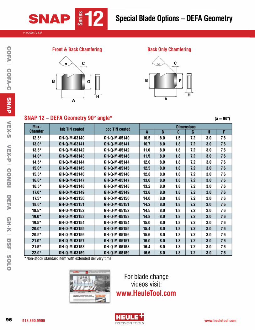
513.860.9900 www.heuletool.com
Catalog No. HTC14
96
HTC021/V1.0
Serie
s
SNAP 12 – DEFA Geometry 90° angle* (a = 90°)
Max. Chamfer fab TiN coated Dimensions
A B12.5* 13.0* 13.5* 14.0* 14.5* 15.0* 15.5* 16.0* 16.5* 17.0* 17.5* 18.0* 18.5* 19.0* 19.5* 20.0* 20.5* 21.0* 21.5* 22.0*
GH-Q-M-03140GH-Q-M-03141GH-Q-M-03142GH-Q-M-03143GH-Q-M-03144GH-Q-M-03145GH-Q-M-03146GH-Q-M-03147GH-Q-M-03148GH-Q-M-03149GH-Q-M-03150 GH-Q-M-03151GH-Q-M-03152GH-Q-M-03153GH-Q-M-03154GH-Q-M-03155GH-Q-M-03156GH-Q-M-03157GH-Q-M-03158GH-Q-M-03159
10.5 10.7 11.0 11.5 12.0 12.5 12.8 13.0 13.2 13.6 14.0 14.2 14.5 14.8 15.0 15.4 15.6 16.0 16.4 16.6
8.08.08.08.08.08.08.08.08.08.08.0 8.0 8.08.08.08.08.08.08.08.0
bco TiN coated
GH-Q-M-05140GH-Q-M-05141GH-Q-M-05142GH-Q-M-05143GH-Q-M-05144GH-Q-M-05145GH-Q-M-05146GH-Q-M-05147GH-Q-M-05148GH-Q-M-05149GH-Q-M-05150 GH-Q-M-05151 GH-Q-M-05152 GH-Q-M-05153 GH-Q-M-05154 GH-Q-M-05155 GH-Q-M-05156 GH-Q-M-05157 GH-Q-M-05158 GH-Q-M-05159
1.51.8 1.81.81.8 1.8 1.8 1.81.81.8 1.8 1.8 1.8 1.81.81.8 1.8 1.8 1.8 1.8
7.27.27.27.27.2 7.27.27.27.27.2 7.2 7.27.2 7.27.27.27.27.2 7.2 7.2
C G3.03.03.03.03.0 3.03.03.03.03.0 3.0 3.0 3.03.03.03.03.0 3.0 3.0 3.0
H7.67.67.67.67.6 7.67.67.67.67.6 7.6 7.67.67.6 7.67.67.67.67.6 7.6
F
*Non-stock standard item with extended delivery time
Front & Back Chamfering Back Only Chamfering
Special Blade Options – DEFA Geometry
Serie
s
12SNAP
CO
FA l C
OFA
-C S
NA
P V
EX
-S l V
EX
-P l C
OM
BI l D
EFA
l GH
-K l B
SF l S
OLO
For blade changevideos visit:
www.HeuleTool.com

513-860-9900 www.heuletool.com
Catalog No. HTC014
97
HTC021/V1.0
Serie
s
Adjusting the Chamfer SizeChamfer size is based on the size of the blade. There are several blade size choices for each tool.
Setting the Blade Force
The blade force can be adjusted by the set screw in the rear of the shank. The blade force should be enough to extend the blade fully after passing the back end of the bore. This ensures that the blade can work with the necessary cutting performance. The blade should always be able to move in by hand. Turning the set screw clockwise increases the blade force.MaximumDepth6.0mm(SNAP2-5)and11.0mm(SNAP8-20);or12-13revolutionsmax.
Optional SNAP Tool With Harder SpringAn extremely tough material requires a high spring force or -DF Geometry.Hardersprings:SNAP5:GH-H-F-0041,SNAP8&SNAP12: GH-H-F-0011. Working with the correct blade pressure increases the blade life and improves the chamfer quality. Add the suffix -HS (Hard Spring) for a complete tool with harder spring: (e.g. SNAP12-473-HS)
SNAPC
OFA
l CO
FA-C
SN
AP
VE
X-S
l VE
X-P
l CO
MB
I l DE
FA l G
H-K
l BS
F l S
OLO
Technical Information
Optional SNAP Locking Mechanism Configurations Locking mechanism LOCKS the blade The blade is free to move but cannot be removed completely until the cap screw is loosened. This allows for higher operational speeds and avoids possible drill burr chip interference issues. Add the suffix -LM (Locking Mechanism for the complete tool with locking mechanism (e.g. SNAP12-473-LM)
Tooling Size (mm) L1 L2 L3 L4 Cap Screw - LM Distance Pin - LM Spring- LM
SNAP 2-4 Contact Heule For Information
SNAP 5 5.0–7.5 52.85 61.35 9 3.5 GH-H-S-0538-1 GH-Q-E-0089 GH-H-F-0055
8–9.5 62.85 71.35 9 3.5 GH-H-S-0538-1 GH-Q-E-0090 GH-H-F-0055
10–10.5 71.85 80.35 9 3.5 GH-H-S-0538-1 GH-Q-E-0091 GH-H-F-0055
SNAP8 8–12 73.9 82.4 11 4 GH-H-S-0524-5 GH-Q-E-0093 GH-H-F-0012
SNAP12 12–20 90.5 102 11 4 GH-H-S-0524-1 GH-Q-E-0384 GH-H-F-0012
DIMENSIONS (mm) PART NUMBER
L1
L2 L3 L4
Cap Screw LMDistance Pin LMSpring LM
Important Note: Tool holder must be modified for locking mechanism components.
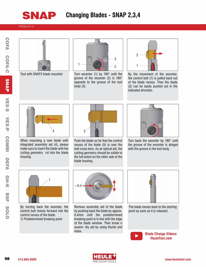
513.860.9900 www.heuletool.com
Catalog No. HTC14
98
HTC021/V1.0
Serie
s
SNAP Changing Blades - SNAP 2,3,4
Tool with SNAP2 blade mounted Turn excenter (1) by 180° until thegroove of the excenter (2) is 180°opposite to the groove of the tool body(3).
By the movement of the excenter, thecontrolbolt(1)ispulledbackoutof the blade recess. Then the blade (2) can be easily pushed out in theindicated direction.
Push the blade so far that the control recess of the blade (5) is over thebolt cross bore. As an optical aid, the cutting geometry should be visible to the full extent on the other side of the blade housing.
When mounting a new blade with integrated assembly aid (4), pleasemake sure to insert the blade with the cutting geometry rst into the blade housing.
Turn back the excenter by 180° untilthe groove of the excenter is alinged with the groove in the tool body.
By turning back the excenter, the control bolt moves forward into the control recess of the blade.1)Predeterminedbreakingpoint
Remove assembly aid of the blade by pushing back the blade by approx. 0.4mm until the predeterminedbreaking point is in line with the edge of the blade window. Then break o assem- bly aid by using thumb and index.
The blade moves back to the starting point as soon as it is released.
1
~0.4
4 5
11
3
2
2
CO
FA l C
OFA
-C S
NA
P V
EX
-S l V
EX
-P l C
OM
BI l D
EFA
l GH
-K l B
SF l S
OLO
Blade Change Videos:HeuleTool.com

513-860-9900 www.heuletool.com
Catalog No. HTC014
99
HTC021/V1.0
Serie
s
SNAP Changing Blades - SNAP 5,8,12,20
Tool SNAP12 with assembled blade The SNAP blade can be pushed through the tool with an edgeless object.Puttheaidonatthebladehead(1).
The deburring blade is pushed with its back rst into the blade window of the tool until it engages. Please make sure that it is aligned with the recess (2) inthedirectionof thetoolshank.The blade can be inserted into the tool from both sides.
Thecontrolbolthas“snapped” intothe blade recess. The tool is now ready for operation.
1
2
CO
FA l C
OFA
-C S
NA
P V
EX
-S l V
EX
-P l C
OM
BI l D
EFA
l GH
-K l B
SF l S
OLO
Blade Change Videos:HeuleTool.com

513.860.9900 www.heuletool.com
Catalog No. HTC14
100
HTC021/V1.0
Serie
s
SNAP
CO
FA l C
OFA
-C S
NA
P V
EX
-S l V
EX
-P l C
OM
BI l D
EFA
l GH
-K l B
SF l S
OLO
Programming Information
IMPORTANT:RECOMMENDEDMAXIMUMSPEEDIS6,000RPMFORSNAPSERIES2,3,4.PleasecontactHEULEforfurtherassistance with your application.
NOTE: All listed cutting data are standard values only. In case of hard-to-machine materials, we recommend applying cutting speeds that are at the lower end of the range. Use DF/DR geometry for materials above 28 Rc.
Material Hardness Cutting SNAP 2/3/4 SNAP 5/8/12/20BHN Speed GS DF/DR GS DF/DR
SFM IPR IPRMPM mm/rev mm/rev
Carbon Steels 100-250150-210 .003-.008 .001-.003 .004-.012 .001-.003
45-64 0.07-0.20 0.02-0.07 0.10-0.30 0.02-0.07
Free Machining Alloy 125-340100-260 .003-.006 .001-.002 .004-.012 .001-.00267-107 0.07-0.15 0.02-0.05 0.10-0.30 0.02-0.05
High Alloy Steel 250-35065-160 .003-.006 .001-.002 .004-.008 .001-.00220-49 0.07-0.15 0.02-0.05 0.10-0.20 0.02-0.05
Stainless Steel 140-25030-100 .002-.005 .001-.002 .002-.006 .001-.002 9-30 0.05-0.12 0.02-0.05 0.05-0.15 0.02-0.05
Steel Castings 90-250130-230 .002-.006 .001-.002 .004-.012 .001-.002
40-70 0.05-0.15 0.02-0.05 0.10-0.30 0.02-.005
Grey Cast Iron 150-330150-300 .003-.008 .001-.003 .004-.012 .001-.003
45-91 0.07-0.20 0.02-0.07 0.10-0.30 0.02-0.07
Nodular Cast Iron 140-310130-220 .003-.006 .001-.002 .004-.012 .001-.002
40-67 0.07-0.15 0.02-0.05 0.10-0.30 0.02-0.05
Aluminum Alloys 30-180210-400 .003-.008 .001-.003 .004-.012 .001-.00364-121 0.07-0.20 0.02-0.07 0.10-0.30 0.02-0.07
Nickel-based Alloys 140-31030-65 .001-.004 .001-.002 .001-.004 .001-.002 9-20 0.02-0.10 0.02-0.05 0.02-0.10 0.02-0.05
Titanium Alloys30-65 .001-.004 .001-.002 .001-.004 .001-.002 9-20 0.02-0.10 0.02-0.05 0.02-0.10 0.02-0.05
Copper-Brass-Bronze 80-20265-300 .002-.006 .001-.003 .002-.006 .001-.00320-91 0.05-0.15 0.02-0.07 0.05-0.15 0.02-0.07
Cutting Data

513-860-9900 www.heuletool.com
Catalog No. HTC014
101
HTC021/V1.0
Serie
sStep 1:
Set the RPM according to the suggested values.
Step 2: (Moveintoposition)
Move the tool with rapid feed into position with the front.
Step 3: (Cutfrontchamfer)
Machine the part with cutting feed (cf)andspeed(cs).Feedintothepart the chamfer depth + 0.040”to ensure the tool is finished cutting.
Step 4: (Rapidthroughpart)
Move the tool through the part with rapid feed until the blade is0.040”beyondburr.Thebladewill not damage the through hole.
Step 5:(Cutbackchamfer)
Machine the part with cutting feed (cf)andspeed(cs).Feedintothepartthechamferdepth+0.040”toensure the tool is finished cutting.
Step 6:(Removefromthepart)
Remove the tool from the part with a rapid feed and proceed to the next hole. The blade will not dam-age the through hole.
For Front & Back Chamfer Back Chamfer Only
Programming Information
SNAPC
OFA
l CO
FA-C
SN
AP
VE
X-S
l VE
X-P
l CO
MB
I l DE
FA l G
H-K
l BS
F l S
OLO
Programming Information

513.860.9900 www.heuletool.com
Catalog No. HTC14
102
HTC021/V1.0
Serie
s
PROBLEM
Chamfer too small
No chamfer at all
Chamfer is too large
Chamfer differs from front to back
Poor surface finish
Inconsistent chamfer
Poor blade life (chipping) (excessive wear)
•Selectedbladeistoosmall•Bladeforceistoosmall•Feedrateistoohigh
•Toolisincorrectlyprogrammed•Bladeforceistoosmall•Bladeisdull•Tooheavyofaburr
•Selectedbladeistoolarge•Feedratetoosmall•Bladeforcetoohigh
•Feedvariesbetweenforwardand reverse feed•Variationofburrbetweenfront and back
•Toolorpartnotheldproperly•Toolisunstable•Speedrateistoohigh
•Varyingfeedrate•Incorrectprogrammingposition•Toolisunstable
•Workpieceortoolnotsecured•Insufficientmachinestability•Poorcuttingconditions
EXPLANATION SOLUTION
•Chooselargerblade(ifpossible)•Increasebladeforce•Reducefeedrate
•Checkprogrammingdepths•Increasebladeforce•Replacetheblade•Replacethedrilltool
•Chooseasmallerblade•Increasethefeedrate•Reducethebladeforce•UseDFgeometry
•Selectaconstantfeedrate•Reducethefeedratewhentoosmallor increase feed rate when too large•Increasebladetension
•Ensuretoolandpartaresecured•ReduceSpeed•Checkworkpieceandholder
•Ensureconstantfeedrate•Checkworkpieceandholder•Checkprogramming•ReduceSpeed
•Ensuretoolorpartissecured•Reconditionorrectifymachinefaults•Checkspeedandfeedandcoolantsupply
SNAP
Grinding may produce hazardous dust. To avoid adverse effects, use adequate ventilation and read MSDS. Cutting tools may break during use. To avoid injury, use proper safety precautions and protective equipment. Use the machine tool with sufficient rigidity and horsepower. Use a cover on a machine tool and protector, such as glasses, against shattering chips and broken tools due to misuse. Do not use insoluble oil because there is a danger of causing fire.
CO
FA l C
OFA
-C S
NA
P V
EX
-S l V
EX
-P l C
OM
BI l D
EFA
l GH
-K l B
SF l S
OLO
Troubleshooting

High performance solid carbide drill tip combined with patented SNAP chamfering system
VEX drill geometry for better chip control
Quick and easy drill tip and chamfer blade replacement
No presetting between drill changes
VEX-SCombination Drill with Front & Back Chamfering of Through Holes
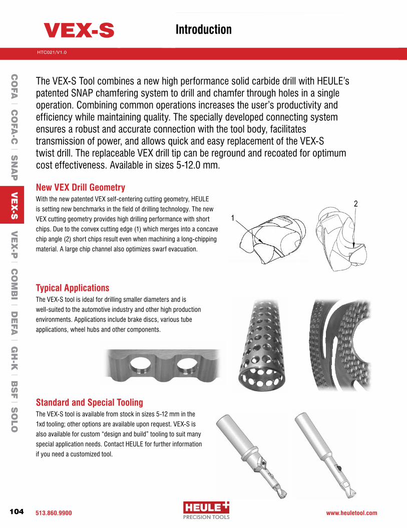
513.860.9900 www.heuletool.com
Catalog No. HTC14
104
HTC021/V1.0
Serie
s
TheVEX-SToolcombinesanewhighperformancesolidcarbidedrillwithHEULE’s patented SNAP chamfering system to drill and chamfer through holes in a single operation.Combiningcommonoperationsincreasestheuser’sproductivityand efficiency while maintaining quality. The specially developed connecting system ensures a robust and accurate connection with the tool body, facilitates transmission of power, and allows quick and easy replacement of the VEX-S twist drill. The replaceable VEX drill tip can be reground and recoated for optimum cost effectiveness. Available in sizes 5-12.0 mm.
New VEX Drill GeometryWith the new patented VEX self-centering cutting geometry, HEULE
is setting new benchmarks in the field of drilling technology. The new
VEX cutting geometry provides high drilling performance with short
chips.Duetotheconvexcuttingedge(1)whichmergesintoaconcave
chipangle(2)shortchipsresultevenwhenmachiningalong-chipping
material. A large chip channel also optimizes swarf evacuation.
Typical ApplicationsThe VEX-S tool is ideal for drilling smaller diameters and is
well-suited to the automotive industry and other high production
environments. Applications include brake discs, various tube
applications, wheel hubs and other components.
Standard and Special ToolingThe VEX-S tool is available from stock in sizes 5-12 mm in the
1xd tooling; other options are available upon request. VEX-S is
alsoavailableforcustom“designandbuild”toolingtosuitmany
special application needs. Contact HEULE for further information
if you need a customized tool.
VEX-S
CO
FA l C
OFA
-C l S
NA
P V
EX
-S V
EX
-P l C
OM
BI l D
EFA
l GH
-K l B
SF l S
OLO
Introduction

513-860-9900 www.heuletool.com
Catalog No. HTC014
105
HTC021/V1.0
Serie
s
How to Select a VEX-S Tool1. Determine the drill hole size.2. Select the appropriate Drill Tip and the coordinating Tool holder.3. Choose the SNAP chamfer blade according to the needed chamfer size.
Sample Order: Ø3/8”DrillHole: 1pcP-S-E2-0953-1A VEX-SDRILLØ3/8”,TiAln,SeriesE,1:1 1pcVEXS-9.5-1d VEX-SToolHolderØ9.5SeriesE,1:1,withoutinserts 1pcGH-Q-M-30214 SNAP5ChamferBladeØ10.5mm,Carb-TiAlN1 Series
2 Bore-depth T
Indicate the bore diameter here. For example: Ø9.50 = 0950Standard size as shown.
3 Bore Diameter Ød
Carbide K20-K30 1
4 Cutting Material
UncoatedTiAINDLC
UAD
5 Coating
Bore-ØdCarbide Quality
CoatingBore-depth T
= 9.50mm= K20-K30
= TIALN= 9.50mm 1xd
Order Example:
Order Number: P-S-E2-0950-1A
B
C
D
E
F
Ød35.0-5.495.5-5.996.0-6.496.5-6.997.0-7.497.5-7.998.0-8.498.5-8.999.0-9.499.5-9.99
10.0-10.4910.5-10.99 11.0-11.49
Bore Range
Series Bore Depth
Bore Depth
Wrench Size
Torque Setting
Flat Wrench
X11.001.101.20 1.30 1.35 1.451.551.651.751.851.902.10 2.22
1xd
2xd
T5.05.56.06.5 7.07.58.08.59.09.510.0 10.5 11.0
T 10 111213 14151617181920 21 22
L10.211.111.7 12.7 13.6 14.415.216.116.917.818.6 19.1 19.9
L16.017.4 18.4 20.0 21.422.724.025.426.728.1 29.4 30.2 31.5
L114.715.616.2 17.2 19.1 19.920.721.622.423.324.1 24.6 25.4
L120.521.9 22.9 24.5 26.928.229.530.932.233.6 34.9 35.7 37.0
SW44556677889 9 9
Ncm170170250250400400400600600600600 600 600
GH-H-S-23012301230123012302230223022302230323032303 2303 2303
Drill Blade Dimensions
Order Number Example:
1 = Series
2 = Bore-depth T
3 = Bore-Ød
4 = Cutting Material
5 = Coating
P-S-E 2-0950-1 A
.5xd1xd
1.5xd2xd
1234
VEX-S
Bore Range5.00-5.996.00-6.997.00-8.498.50-10.49 10.50-11.49
BCDE F
Series
*Other coatings available on request
CO
FA l C
OFA
-C l S
NA
P V
EX
-S V
EX
-P l C
OM
BI l D
EFA
l GH
-K l B
SF l S
OLO
Introduction

513.860.9900 www.heuletool.com
Catalog No. HTC14
106
HTC021/V1.0
Serie
s
SPARE PARTS
PG. 112
1xdVEX-S Drill/Chamfer Tools – For holes 5 - 8.4mm .197-.331”
VEX-S Series B, C and D - 1xd ToolsTool Holder
Order NumberØd Range
mm T Max Ød1 X L1 Ln Ls Øs
GH-Q-O-4000 5.0 - 5.4 5.0 (.197”) 4.9 (.193”) 18.9 (.744”) 70.5 (2.776”) 7.5 (.295”) 36.0 (1.417”) 8.0 (.315”)
GH-Q-O-4001 5.5 - 5.9 5.5 (.217”) 5.4 (.213”) 19.8 (.780”) 71.6 (2.776”) 8.0 (.315”) 36.0 (1.417”) 8.0 (.315”)
GH-Q-O-4052 6.0 - 6.4 6.0 (.236”) 5.9 (.232”) 20.6 (.811”) 84.1 (3.311”) 15.0 (.591”) 40.0 (1.575”) 10.0 (.394”)
GH-Q-O-4053 6.5 - 6.9 6.5 (.256”) 6.4 (.252”) 21.6 (.850”) 86.1 (3.390”) 16.0 (.630”) 40.0 (1.575”) 10.0 (.394”)
GH-Q-O-4054 7.0 - 7.4 7.0 (.276”) 6.9 (.272”) 23.8 (.937”) 89.3 (3.518”) 17.0 (.669”) 40.0 (1.575”) 10.0 (.394”)
GH-Q-O-4055 7.5 - 7.9 7.5 (.295”) 7.4 (.291”) 24.6 (.969”) 91.1 (3.587”) 18.0 (.709”) 40.0 (1.575”) 10.0 (.394”)
GH-Q-O-4056 8.0 - 8.4 8.0 (.315”) 7.9 (.311”) 25.4 (1.000”) 92.9 (3.658”) 19.0 (.748”) 45.0 (1.772) 12.0 (.472”)
B
C
D
Ød Drill* mm inches
Tool Holder Order Number
Drill Tip Order #
VEX-S Series B, C and D - 1xd Drills and BladesChamfer Blade Order Number (fab)**
Serie
s
5.0mm (.197)
5.1mm (.201)
5.5mm (.217)
6.0mm (.236)
6.35mm (1/4”)
6.5mm (.256)
6.8mm (.268)
7.0mm (.276)
7.14mm (9/32”)
7.5mm (.295)
7.94mm (5/16”)
8.0mm (.315)
8.4mm (.331)
GH-Q-O-4000
GH-Q-O-4000
GH-Q-O-4001
GH-Q-O-4052
GH-Q-O-4052
GH-Q-O-4053
GH-Q-O-4053
GH-Q-O-4054
GH-Q-O-4054
GH-Q-O-4055
GH-Q-O-4055
GH-Q-O-4056
GH-Q-O-4056
P-S-B2-0500-1A
P-S-B2-0510-1A
P-S-B2-0550-1A
P-S-C2-0600-1A
P-S-C2-0635-1A
P-S-C2-0650-1A
P-S-C2-0680-1A
P-S-D2-0700-1A
P-S-D2-0714-1A
P-S-D2-0750-1A
P-S-D2-0794-1A
P-S-D2-0800-1A
P-S-D2-0840-1A
-30204 (5.5)
-30204 (5.5)
-30205 (6.0)
-30206 (6.5)
-30206 (6.5)
-30207 (7.0)
-30207 (7.0)
-30208 (7.5)
-30208 (7.5)
-30209 (8.0)
-30210 (8.5)
-30210 (8.5)
-30211 (9.0)
-30205 (6.0)
-30205 (6.0)
-30206 (6.5)
-30207 (7.0)
-30207 (7.0)
-30208 (7.5)
-30208 (7.5)
-30209 (8.0)
-30209 (8.0)
-30210 (8.5)
-30211 (9.0)
-30211 (9.0)
-30212 (9.5)
-30206 (6.5)
-30206 (6.5)
-30207 (7.0)
-30208 (7.5)
-30208 (7.5)
-30209 (8.0)
-30209 (8.0)
-30210 (8.5)
-30210 (8.5)
-30211 (9.0)
-30212 (9.5)
-30212 (9.5)
-30213 (10.0)
-30207 (7.0)
-30207 (7.0)
-30208 (7.5)
-30209 (8.0)
-30209 (8.0)
-30210 (8.5)
-30210 (8.5)
-30211 (9.0)
-30211 (9.0)
-30212 (9.5)
-30213 (10.0)
-30213 (10.0)
-30214 (10.5)
(0.25mmx45°)GH-Q-M-
(0.5mmx45°)GH-Q-M-
(0.75mmx45°)GH-Q-M-
(1.0mmx45°)GH-Q-M-Cm
f. Se
ries
5
*Otherdrillsizesavailableonrequest.Example:Ød=8.33mm(.328”)-P-S-D4-0833-1A
**Chamferbladesareinterchangeable;maximumchamferdiameterØD=holeØd+2mmBLADE OPTIONS
PG. 83
CO
FA l C
OFA
-C l S
NA
P V
EX
-S V
EX
-P l C
OM
BI l D
EFA
l GH
-K l B
SF l S
OLO
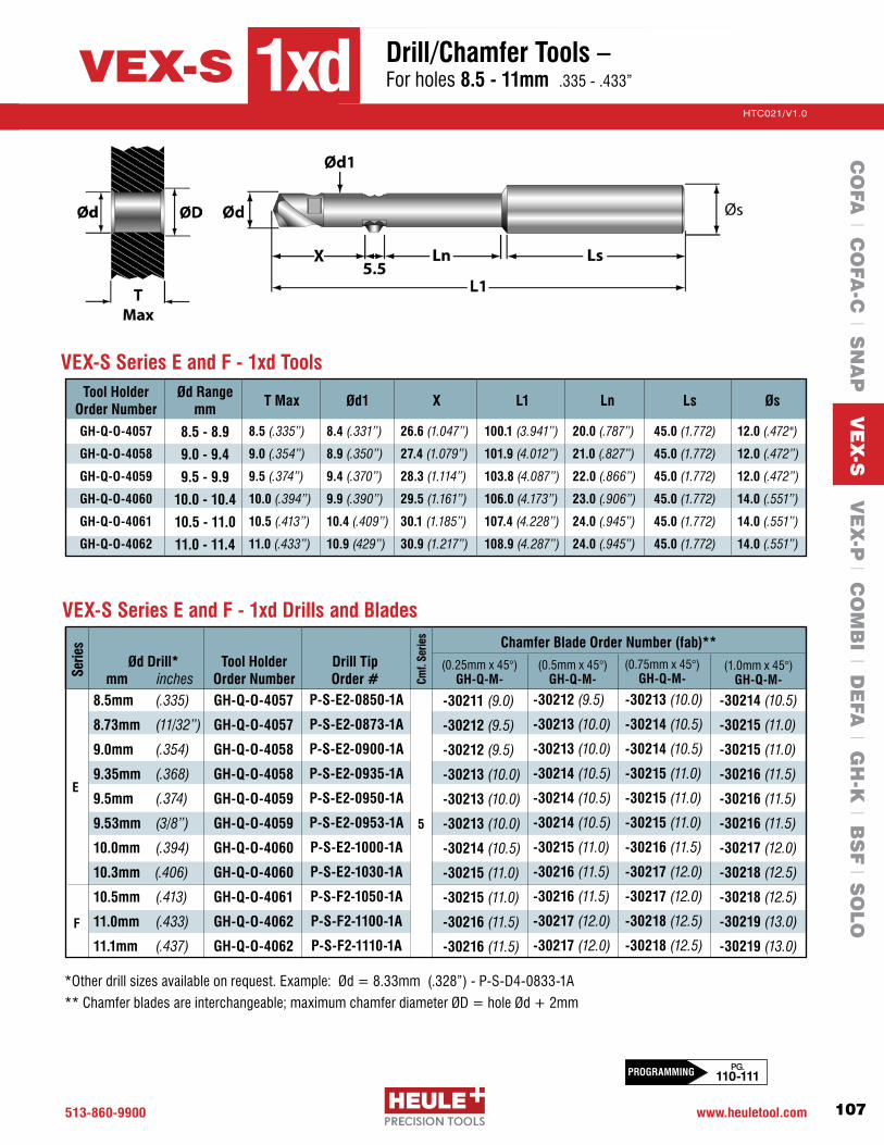
513-860-9900 www.heuletool.com
Catalog No. HTC014
107
HTC021/V1.0
Serie
s
*Otherdrillsizesavailableonrequest.Example:Ød=8.33mm(.328”)-P-S-D4-0833-1A
**Chamferbladesareinterchangeable;maximumchamferdiameterØD=holeØd+2mm
1xdVEX-S Drill/Chamfer Tools – For holes 8.5 - 11mm .335-.433”
PG. 110-111PROGRAMMING
Ød Drill* mm inches
Tool Holder Order Number
Drill Tip Order #
VEX-S Series E and F - 1xd Drills and BladesChamfer Blade Order Number (fab)**
Serie
s
8.5mm (.335)
8.73mm (11/32”)
9.0mm (.354)
9.35mm (.368)
9.5mm (.374)
9.53mm (3/8”)
10.0mm (.394)
10.3mm (.406)
10.5mm (.413)
11.0mm (.433)
11.1mm (.437)
GH-Q-O-4057
GH-Q-O-4057
GH-Q-O-4058
GH-Q-O-4058
GH-Q-O-4059
GH-Q-O-4059
GH-Q-O-4060
GH-Q-O-4060
GH-Q-O-4061
GH-Q-O-4062
GH-Q-O-4062
P-S-E2-0850-1A
P-S-E2-0873-1A
P-S-E2-0900-1A
P-S-E2-0935-1A
P-S-E2-0950-1A
P-S-E2-0953-1A
P-S-E2-1000-1A
P-S-E2-1030-1A
P-S-F2-1050-1A
P-S-F2-1100-1A
P-S-F2-1110-1A
E
-30211 (9.0)
-30212 (9.5)
-30212 (9.5)
-30213 (10.0)
-30213 (10.0)
-30213 (10.0)
-30214 (10.5)
-30215 (11.0)
-30215 (11.0)
-30216 (11.5)
-30216 (11.5)
-30212 (9.5)
-30213 (10.0)
-30213 (10.0)
-30214 (10.5)
-30214 (10.5)
-30214 (10.5)
-30215 (11.0)
-30216 (11.5)
-30216 (11.5)
-30217 (12.0)
-30217 (12.0)
-30213 (10.0)
-30214 (10.5)
-30214 (10.5)
-30215 (11.0)
-30215 (11.0)
-30215 (11.0)
-30216 (11.5)
-30217 (12.0)
-30217 (12.0)
-30218 (12.5)
-30218 (12.5)
-30214 (10.5)
-30215 (11.0)
-30215 (11.0)
-30216 (11.5)
-30216 (11.5)
-30216 (11.5)
-30217 (12.0)
-30218 (12.5)
-30218 (12.5)
-30219 (13.0)
-30219 (13.0)
(0.25mmx45°)GH-Q-M-
(0.5mmx45°)GH-Q-M-
(0.75mmx45°)GH-Q-M-
(1.0mmx45°)GH-Q-M-
F
Cmf.
Serie
s
5
VEX-S Series E and F - 1xd ToolsTool Holder
Order NumberØd Range
mm T Max Ød1 X L1 Ln Ls Øs
GH-Q-O-4057 8.5 - 8.9 8.5 (.335”) 8.4 (.331”) 26.6 (1.047”) 100.1 (3.941”) 20.0 (.787”) 45.0 (1.772) 12.0 (.472")
GH-Q-O-4058 9.0 - 9.4 9.0 (.354”) 8.9 (.350”) 27.4 (1.079”) 101.9 (4.012”) 21.0 (.827”) 45.0 (1.772) 12.0 (.472”)
GH-Q-O-4059 9.5 - 9.9 9.5 (.374”) 9.4 (.370”) 28.3 (1.114”) 103.8 (4.087”) 22.0 (.866”) 45.0 (1.772) 12.0 (.472”)
GH-Q-O-4060 10.0 - 10.4 10.0 (.394”) 9.9 (.390”) 29.5 (1.161”) 106.0 (4.173”) 23.0 (.906”) 45.0 (1.772) 14.0 (.551”)
GH-Q-O-4061 10.5 - 11.0 10.5 (.413”) 10.4 (.409”) 30.1 (1.185”) 107.4 (4.228”) 24.0 (.945”) 45.0 (1.772) 14.0 (.551”)
GH-Q-O-4062 11.0 - 11.4 11.0 (.433”) 10.9 (429”) 30.9 (1.217”) 108.9 (4.287”) 24.0 (.945”) 45.0 (1.772) 14.0 (.551”)
CO
FA l C
OFA
-C l S
NA
P V
EX
-S V
EX
-P l C
OM
BI l D
EFA
l GH
-K l B
SF l S
OLO

513.860.9900 www.heuletool.com
Catalog No. HTC14
108
HTC021/V1.0
Serie
s
2xdVEX-S Drill/Chamfer Tools – For holes 5 - 8.4mm .197-.331”
VEX-S Series B, C and D - 2xd ToolsTool Holder
Order NumberØd Range
mm T Max Ød1 X L1 Ln Ls Øs
GH-Q-O-4050 5.0 - 5.4 10.0 (.394”) 4.9 (.193”) 24.7 (0.972”) 81.8 (3.220”) 13.0 (.512”) 36.0 (1.417”) 8.0 (.315”)
GH-Q-O-4051 5.5 - 5.9 11.0 (.433”) 5.4 (.212”) 26.1 (1.028”) 83.9 (3.303”) 14.0 (.551”) 36.0 (1.417”) 8.0 (.315”)
GH-Q-O-4052 6.0 - 6.4 12.0 (.472”) 5.9 (.232”) 27.3 (1.075”) 90.8 (3.575”) 15.0 (.591”) 40.0 (1.575”) 10.0 (.394”)
GH-Q-O-4053 6.5 - 6.9 13.0 (.512”) 6.4 (.252”) 28.9 (1.138”) 93.3 (3.673”) 16.0 (.630”) 40.0 (1.575”) 10.0 (.394”)
GH-Q-O-4054 7.0 - 7.4 14.0 (.551”) 6.9 (.272”) 31.6 (1.244”) 96.7 (3.807”) 17.0 (.669”) 40.0 (1.575”) 10.0 (.394”)
GH-Q-O-4055 7.5 - 7.9 15.0 (.591”) 7.4 (.291”) 32.9 (1.295”) 98.7 (3.886”) 18.0 (.709”) 40.0 (1.575”) 10.0 (.394”)
GH-Q-O-4056 8.0 - 8.4 16.0 (.630”) 7.9 (.311”) 33.3 (1.311”) 106.8 (4.205”) 19.0 (.748”) 40.0 (1.575”) 12.0 (.472”)
VEX-S Series B, C and D - 2xd Drills and BladesChamfer Blade Order Number (fab)**
Serie
s
C
B
D
5.0mm (.197)
5.1mm (.201)
5.5mm (.217)
6.0mm (.236)
6.35mm (1/4”)
6.5mm (.256)
6.8mm (.268)
7.0mm (.276)
7.14mm (9/32”)
7.5mm (.295)
7.94mm (5/16”)
8.0mm (.315)
8.4mm (.331)
P-S-C4-0500-1A
P-S-C4-0510-1A
P-S-C4-0550-1A
P-S-C4-0600-1A
P-S-C4-0635-1A
P-S-C4-0650-1A
P-S-C4-0680-1A
P-S-D4-0700-1A
P-S-D4-0714-1A
P-S-D4-0750-1A
P-S-D4-0794-1A
P-S-D4-0800-1A
P-S-D4-0840-1A
-30204 (5.5)
-30204 (5.5)
-30205 (6.0)
-30206 (6.5)
-30206 (6.5)
-30207 (7.0)
-30207 (7.0)
-30208 (7.5)
-30208 (7.5)
-30209 (8.0)
-30210 (8.5)
-30210 (8.5)
-30211 (9.0)
-30205 (6.0)
-30205 (6.0)
-30206 (6.5)
-30207 (7.0)
-30207 (7.0)
-30208 (7.5)
-30208 (7.5)
-30209 (8.0)
-30209 (8.0)
-30210 (8.5)
-30211 (9.0)
-30211 (9.0)
-30212 (9.5)
-30206 (6.5)
-30206 (6.5)
-30207 (7.0)
-30208 (7.5)
-30208 (7.5)
-30209 (8.0)
-30209 (8.0)
-30210 (8.5)
-30210 (8.5)
-30211 (9.0)
-30212 (9.5)
-30212 (9.5)
-30213 (10.0)
-30207 (7.0)
-30207 (7.0)
-30208 (7.5)
-30209 (8.0)
-30209 (8.0)
-30210 (8.5)
-30210 (8.5)
-30211 (9.0)
-30211 (9.0)
-30212 (9.5)
-30213 (10.0)
-30213 (10.0)
-30214 (10.5)
(0.25mmx45°)GH-Q-M-
(0.5mmx45°)GH-Q-M-
(0.75mmx45°)GH-Q-M-
(1.0mmx45°)GH-Q-M-Cm
f. Se
ries
GH-Q-O-4050
GH-Q-O-4050
GH-Q-O-4051
GH-Q-O-4052
GH-Q-O-4052
GH-Q-O-4053
GH-Q-O-4053
GH-Q-O-4054
GH-Q-O-4054
GH-Q-O-4055
GH-Q-O-4055
GH-Q-O-4056
GH-Q-O-4056
5
*Otherdrillsizesavailableonrequest.Example:Ød=8.33mm(.328”)-P-S-D2-0833-1A
**Chamferbladesareinterchangeable;maximumchamferdiameterØD=holeØd+2mm
Ød Drill* mm inches
Tool Holder Order Number
Drill Tip Order #
CO
FA l C
OFA
-C l S
NA
P V
EX
-S V
EX
-P l C
OM
BI l D
EFA
l GH
-K l B
SF l S
OLO
SPARE PARTS
PG. 112
BLADE OPTIONS
PG. 83

513-860-9900 www.heuletool.com
Catalog No. HTC014
109
HTC021/V1.0
Serie
s
2xdVEX-S Drill/Chamfer Tools – For holes 8.5 - 11mm .335-.394”
Ød Drill* mm inches
Tool Holder Order Number
Drill Tip Order #
VEX-S Series E and F - 2xd Drills and BladesChamfer Blade Order Number (fab)**
Serie
s
8.5mm (.335)
8.73mm (11/32”)
9.0mm (.354)
9.35mm (.368)
9.5mm (.374)
9.53mm (3/8”)
10.0mm (.394)
10.3mm (.406)
10.5mm (.413)
11.0mm (.433)
11.1mm (.437)
P-S-E4-0850-1A
P-S-E4-0873-1A
P-S-E4-0900-1A
P-S-E4-0935-1A
P-S-E4-0950-1A
P-S-E4-0953-1A
P-S-E4-1000-1A
P-S-E4-1030-1A
P-S-F4-1050-1A
P-S-F4-1100-1A
P-S-F4-1110-1A
E
F
-30211 (9.0)
-30212 (9.5)
-30212 (9.5)
-30213 (10.0)
-30213 (10.0)
-30213 (10.0)
-30214 (10.5)
-30215 (11.0)
-30215 (11.0)
-30216 (11.5)
-30216 (11.5)
-30212 (9.5)
-30213 (10.0)
-30213 (10.0)
-30214 (10.5)
-30214 (10.5)
-30214 (10.5)
-30215 (11.0)
-30216 (11.5)
-30216 (11.5)
-30217 (12.0)
-30217 (12.0)
-30213 (10.0)
-30214 (10.5)
-30214 (10.5)
-30215 (11.0)
-30215 (11.0)
-30215 (11.0)
-30216 (11.5)
-30217 (12.0)
-30217 (12.0)
-30218 (12.5)
-30218 (12.5)
-30214 (10.5)
-30215 (11.0)
-30215 (11.0)
-30216 (11.5)
-30216 (11.5)
-30216 (11.5)
-30217 (12.0)
-30218 (12.5)
-30218 (12.5)
-30219 (13.0)
-30219 (13.0)
(0.25mmx45°)GH-Q-M-
(0.5mmx45°)GH-Q-M-
(0.75mmx45°)GH-Q-M-
(1.0mmx45°)GH-Q-M-Cm
f. Se
ries
GH-Q-O-4057
GH-Q-O-4057
GH-Q-O-4058
GH-Q-O-4058
GH-Q-O-4059
GH-Q-O-4059
GH-Q-O-4060
GH-Q-O-4060
GH-Q-O-4061
GH-Q-O-4062
GH-Q-O-4062
5
VEX-S Series E and F - 2xd ToolsTool Holder
Order NumberØd Range
mm T Max Ød1 X L1 Ln Ls Øs
GH-Q-O-4057 8.5 - 8.9 17.0 (.669”) 8.4 (.331”) 35.8 (1.409”) 109.1 (4.295”) 20.0 (.787”) 40.0 (1.575”) 12.0 (.472”)
GH-Q-O-4058 9.0 - 9.4 18.0 (.709”) 8.9 (.350”) 37.2 (1.465”) 111.2 (4.378”) 21.0 (.827”) 45.0 (1.772) 12.0 (.472”)
GH-Q-O-4059 9.5 - 9.9 19.0 (.748”) 9.4 (.370”) 38.6 (1.520”) 113.3 (4.461”) 22.0 (.866”) 45.0 (1.772) 12.0 (.472")
GH-Q-O-4060 10.0 - 10.4 20.0 (.787”) 9.9 (.390”) 39.9 (1.571”) 116.4 (4.583”) 23.0 (.906”) 45.0 (1.772) 14.0 (.551”)
GH-Q-O-4061 10.5 - 10.9 21.0 (.827”) 10.4 (.409”) 41.2 (1.622”) 118.5 (4.665”) 24.0 (.945”) 45.0 (1.772) 14.0 (.551”)
GH-Q-O-4062 11.0 - 11.4 22.0 (.866”) 10.9 (.429”) 42.5 (1.673”) 120.5 (4.744”) 25.0 (.984”) 45.0 (1.772) 14.0 (.551”)
*Otherdrillsizesavailableonrequest.Example:Ød=8.33mm(.328”)-P-S-D2-0833-1A
**Chamferbladesareinterchangeable;maximumchamferdiameterØD=holeØd+2mm
CO
FA l C
OFA
-C l S
NA
P V
EX
-S V
EX
-P l C
OM
BI l D
EFA
l GH
-K l B
SF l S
OLO
PG. 110-111PROGRAMMING

513.860.9900 www.heuletool.com
Catalog No. HTC14
110
HTC021/V1.0
Serie
s
VEX-S
CO
FA l C
OFA
-C l S
NA
P V
EX
-S V
EX
-P l C
OM
BI l D
EFA
l GH
-K l B
SF l S
OLO
Programming Sequence
Material Hardness Cutting Bore DiameterBHN Speed
Ø5-Ø6.5 Ø6.5-Ø8 Ø8-Ø11.5SFM IPR IPR IPRMPM mm/rev mm/rev mm/rev
Carbon Steels 100-250150-400 .003-.005 .004-.008 .006-.01045-122 0.08-0.13 0.10-0.02 0.15-0.25
Free Machining Alloy 100-250220-350 .003-.005 .004-.008 .006-.01067-107 0.08-0.13 0.10-0.20 0.15-0.25
High Alloy Steel 100-250130-220 .002-.004 .003-.005 .004-.008
40-67 0.05-0.10 0.08-0.15 0.10-0.20
Stainless Steel 140-250100-160 .001-.002 .002-.004 .003-.005
30-50 0.03-0.05 0.05-0.10 0.08-0.13
Steel Castings 90-250130-350 .002-.004 .003-.005 .004-.00840-107 0.05-0.10 0.08-0.15 0.10-0.20
Grey Cast Iron 150-330150-300 .004-.007 .006-.010 .008-.013
45-91 0.10-0.18 0.15-0.25 0.20-0.32
Nodular Cast Iron 140-310130-220 .003-.006 .004-.009 .006-.012
40-67 0.08-0.15 0.10-0.23 0.15-0.30
Aluminum Alloys 30-180210-600 .005-.007 .007-.010 .010-.01365-183 0.13-0.18 0.17-0.25 0.25-0.32
Titanium* 120-33490-130 .003-.006 .005-.008 .006-.01027-40 0.08-0.15 0.13-0.20 0.15-0.25
Copper-Brass-Bronze 80-200130-500 .003-.007 .004-.010 .006-.01340-152 0.08-0.18 0.10-0.25 0.15-0.32
Cutting Data
*Optional geometry available upon request
NOTE: All listed cutting data are stanadard values only. In case of hard-to machine materials or uneven surfaces, we recommend applying cutting speeds that are at the low end of the range.
IMPORTANT: Tool Holder must be modified with blade locking mechanism for spindle speeds above 6000RPM. Please contact Heule Tool Corporation engineering department.

513-860-9900 www.heuletool.com
Catalog No. HTC014
111
HTC021/V1.0
Serie
sStep 1: Rapid Feed the tool to within clearance of the workpiece.
Step 2: WithforwardWorkingFeed(WF),feedthetool through the workpiece until the hole is drilled and the drill tip is clear of the bore.
Step 3: Rapid feed the tool so the SNAP blade is within clearance of the workpiece top surface or burr.
Step 4: With working feed, cut the top chamfer.Continue feed-ing until the SNAP blade is completely retracted into the tool body.
Step 5: Use rapid feed to position the SNAP blade on the far side of the part. Position the tool so the SNAP blade is completely extended and clear of the part or burr.
Step 6: With back working feed, cut the back chamfer. When the SNAP blade is completely within the tool and clear of the back surface, the tool can be extracted with rapid feed.
VEX-S Programming Sequence
It is not necessary to change the direction of rotation or stop the spindle AV: Working feed, forward AR: Working feed, backward EV: Rapid feed, forward ER: Rapid feed, backward
VEX-SC
OFA
l CO
FA-C
l SN
AP
VE
X-S
VE
X-P
l CO
MB
I l DE
FA l G
H-K
l BS
F l S
OLO
Programming Sequence
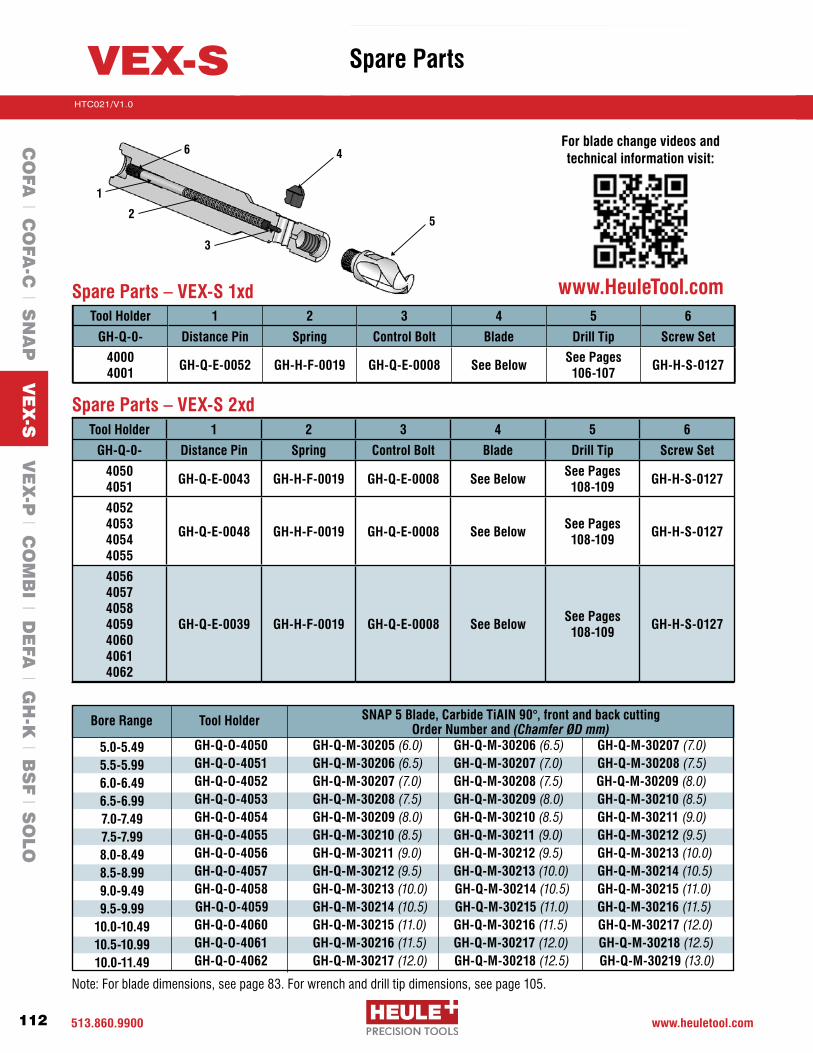
513.860.9900 www.heuletool.com
Catalog No. HTC14
112
HTC021/V1.0
Serie
s
Tool Holder 1 2 3 4 5 6
GH-Q-0- Distance Pin Spring Control Bolt Blade Drill Tip Screw Set
40504051 GH-Q-E-0043 GH-H-F-0019 GH-Q-E-0008 See Below See Pages
108-109 GH-H-S-0127
4052405340544055
GH-Q-E-0048 GH-H-F-0019 GH-Q-E-0008 See Below See Pages 108-109 GH-H-S-0127
4056405740584059406040614062
GH-Q-E-0039 GH-H-F-0019 GH-Q-E-0008 See Below See Pages 108-109 GH-H-S-0127
Spare Parts – VEX-S 1xd
Spare Parts – VEX-S 2xd
1
6
2
4
3
5
Tool HolderBore Range SNAP 5 Blade, Carbide TiAIN 90°, front and back cuttingOrder Number and (Chamfer ØD mm)
Note: For blade dimensions, see page 83. For wrench and drill tip dimensions, see page 105.
VEX-S
Tool Holder 1 2 3 4 5 6
GH-Q-0- Distance Pin Spring Control Bolt Blade Drill Tip Screw Set
40004001 GH-Q-E-0052 GH-H-F-0019 GH-Q-E-0008 See Below See Pages
106-107 GH-H-S-0127
5.0-5.495.5-5.996.0-6.496.5-6.997.0-7.497.5-7.998.0-8.498.5-8.999.0-9.499.5-9.99
10.0-10.4910.5-10.9910.0-11.49
GH-Q-O-4050 GH-Q-M-30205 (6.0) GH-Q-M-30206 (6.5) GH-Q-M-30207 (7.0) GH-Q-O-4051 GH-Q-M-30206 (6.5) GH-Q-M-30207 (7.0) GH-Q-M-30208 (7.5) GH-Q-O-4052 GH-Q-M-30207 (7.0) GH-Q-M-30208 (7.5) GH-Q-M-30209 (8.0) GH-Q-O-4053 GH-Q-M-30208 (7.5) GH-Q-M-30209 (8.0) GH-Q-M-30210 (8.5) GH-Q-O-4054 GH-Q-M-30209 (8.0) GH-Q-M-30210 (8.5) GH-Q-M-30211 (9.0) GH-Q-O-4055 GH-Q-M-30210 (8.5) GH-Q-M-30211 (9.0) GH-Q-M-30212 (9.5) GH-Q-O-4056 GH-Q-M-30211 (9.0) GH-Q-M-30212 (9.5) GH-Q-M-30213 (10.0) GH-Q-O-4057 GH-Q-M-30212 (9.5) GH-Q-M-30213 (10.0) GH-Q-M-30214 (10.5) GH-Q-O-4058 GH-Q-M-30213 (10.0) GH-Q-M-30214 (10.5) GH-Q-M-30215 (11.0) GH-Q-O-4059 GH-Q-M-30214 (10.5) GH-Q-M-30215 (11.0) GH-Q-M-30216 (11.5) GH-Q-O-4060 GH-Q-M-30215 (11.0) GH-Q-M-30216 (11.5) GH-Q-M-30217 (12.0) GH-Q-O-4061 GH-Q-M-30216 (11.5) GH-Q-M-30217 (12.0) GH-Q-M-30218 (12.5) GH-Q-O-4062 GH-Q-M-30217 (12.0) GH-Q-M-30218 (12.5) GH-Q-M-30219 (13.0)
CO
FA l C
OFA
-C l S
NA
P V
EX
-S V
EX
-P l C
OM
BI l D
EFA
l GH
-K l B
SF l S
OLO
Spare Parts
For blade change videos and technical information visit:
www.HeuleTool.com

513-860-9900 www.heuletool.com
Catalog No. HTC014
113
HTC021/V1.0
Serie
s
How to Change the VEX Drill Tip
Assembly:Step 1: Clean the surfaces between the VEX-S twist drill and the tool body.
Step 2: Screw the VEX-S drill insert tightly with a flat wrench to the tool body.
Step 3:Check to make sure there is a seamless connection between the drill insert and tool body after tightening the drill insert. There should not be any gaps.
NOTE: There are a few situations that could cause gaps; •Dirtbetweendrillandtoolbody. To fix: remove the VEX-S twist drill and clean. •VEX-Stwistdrillisnottightenough. To fix: tighten the VEX-S twist drill. •Adaptionareasaredamaged. To fix: exchange the VEX-S twist drill and/or VEX-S tool body.
Disassembly: Step 1: Unscrew the VEX-S twist drill with a flat wrench in counter-clockwise direction from the tool body and remove the twist drill.
Wrenches: Be sure to use the wrenches available from HEULE to assemble the VEX-S tools. This chart explains which wrench goes with which series.
1
2
3
Clean
1
GH-H-S-2301 Wrench; Series B&C, 5.0-6.99 4 or 5mmGH-H-S-2302 Wrench; Series D&E 7.0-8.99 6 or 7mmGH-H-S-2303 Wrench; Series E&F, 9.0-11.5 8 or 9mm
Wrenches Description Distance Across Flats
VEX-SC
OFA
l CO
FA-C
l SN
AP
VE
X-S
VE
X-P
l CO
MB
I l DE
FA l G
H-K
l BS
F l S
OLO
Change Drill
Drill Change Videos:HeuleTool.com

513.860.9900 www.heuletool.com
Catalog No. HTC14
114
HTC021/V1.0
Serie
s
Built-up material on cutting edge
Chips Jamming in the Chip Gullet
Burr Formation on the Exit of the Bore(see SNAP troubleshooting on page56forburrremovalissues)
Hole size is inconsistent or notsymmetrical
Poor Surface finish Quality
Chatter during drilling(this must be corrected to avoid toolbreakage)
Excessive Cutting Edge Wear
Chipping of Cutting Edge
Excessive Margin Wear (Corner wear or discoloration onMarginsO.D.)
Chipping of the Top of the Drill-bit
Problem Explanation
•CuttingSpeedistooslow•FeedRateistooslow•Coatingisincorrectforthismaterial•Insufficientcoolantflow
•Feedrateistoohighforchip evacuation•Drilltipistooshortformaterial thickness•Insufficientcoolantflow
•FeedandSpeedRateistoohigh•DrillTipworn•Insufficientcoolantflow
•Feedistooheavy•Spindle,fixtureorset-upis not stable•Insufficientcoolantflow
•DrillTipworn•Incorrectfeedsandspeeds•Spindle,fixtureorset-upis not stable•Insufficientcoolantflow•Incorrectfeedsandspeeds (normallyinsignificantfeedrate)•Spindle,fixtureorset-upis not stable•Insufficientcoolantflow
•Incorrectfeedsandspeeds (normallylackingcuttingspeed)•Spindle,fixtureorset-upis not stable•Insufficientcoolantflow
•MaterialbuildinguponCutting edge(chippingoff)•Incorrectfeedsandspeeds (normallylackingcuttingspeed)•Spindle,fixtureorset-upis not stable•Entering/Exitingonincline,or irregular surface•Insufficientcoolantflow
•Incorrectfeedsandspeeds (normallyexcessivecuttingspeed)•Toolisrunningoutofround•Insufficientcoolantflow
•Drillisdeflectingduringdrilling
•IncreasecuttingSpeed•IncreaseFeedRate•ChangeDrillTipCoating•Adjustcoolantfloworposition
•Reducefeedrate•UseaPeckDrillcycle•Adjustcoolantfloworposition•Uselongerdrill
•Reducecuttingspeed•Reduceexitfeed50%•Exchangeworndrilltip•Adjustcoolantfloworposition•Reducefeedrate•Checkstabilityofsetup•Checkrotation•Adjustcoolantfloworposition
•Exchangeworndrilltip•Changefeedandspeed•Checkstabilityofsetup•Adjustcoolantfloworposition
•Reducecuttingspeed•Increasefeedrate•Checkstabilityofsetup•Adjustcoolantfloworposition
•Increasecuttingspeed•Decreasefeedrate•Checkstabilityofsetup•Adjustcoolantfloworposition
•Increasecuttingspeed•Reducefeedrate.•Enter/Exitirregularitiesat50% of feed rate•Checkstabilityofsetup•Adjustcoolantfloworposition
•Reducecuttingspeed•Checkrunout•Checkstabilityofsetup•Adjustcoolantfloworposition
•Reducefeedrate•Checkstabilityofsetup
Solution
VEX-S
CO
FA l C
OFA
-C l S
NA
P V
EX
-S V
EX
-P l C
OM
BI l D
EFA
l GH
-K l B
SF l S
OLO
Troubleshooting
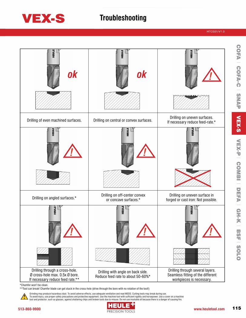
513-860-9900 www.heuletool.com
Catalog No. HTC014
115
HTC021/V1.0
Serie
s
Drilling of even machined surfaces. Drilling on central or convex surfaces.Drilling on uneven surfaces.
If necessary reduce feed-rate.*
Drilling on angled surfaces.*Drilling on uneven surface in
forged or cast iron: Not possible.Drilling on off-center convex
or concave surfaces.*
Drilling through a cross-hole. Øcross-holemax.0.5xØbore. If necessary reduce feed rate.**
Drilling with angle on back side. Reduce feed rate to about 50-60%*
Drilling through several layers. Seamless fitting of the different
workpieces is necessary.
ok ok !
! !
! ! !
*Chamferwon’tbeclean. **Toolcanbreak!Chamferbladecangetstuckinthecross-hole(drivethroughtheborewithnorotationofthetool!)
VEX-S
Grinding may produce hazardous dust. To avoid adverse effects, use adequate ventilation and read MSDS. Cutting tools may break during use. To avoid injury, use proper safety precautions and protective equipment. Use the machine tool with sufficient rigidity and horsepower. Use a cover on a machine tool and protector, such as glasses, against shattering chips and broken tools due to misuse. Do not use insoluble oil because there is a danger of causing fire.
CO
FA l C
OFA
-C l S
NA
P V
EX
-S V
EX
-P l C
OM
BI l D
EFA
l GH
-K l B
SF l S
OLO
Troubleshooting

513.860.9900 www.heuletool.com
Catalog No. HTC14
116
HTC021/V1.0
Serie
s
CO
FA l C
OFA
-C l S
NA
P V
EX
-S V
EX
-P l C
OM
BI l D
EFA
l GH
-K l B
SF l S
OLO
VEX-S Range Summary
Series Bore Range Bore Depth 1 x d Bore Depth 2 x d Chamfer MaxB Ø 5.00 – Ø 5.49 mm
Ø 5.50 – Ø 5.99 mm
5.5 mm
6.0 mm
11.0 mm
12.0 mm
Ø 7.0 mm
Ø 7.5 mmC Ø 6.00 – Ø 6.49 mm
Ø 6.50 – Ø 6.99 mm
6.5 mm
7.0 mm
13.0 mm
14.0 mm
Ø 8.0 mm
Ø 8.5 mmD Ø 7.00 – Ø 7.49 mm
Ø 7.50 – Ø 7.99 mm
Ø 8.00 – Ø 8.49 mm
7.5 mm
8.0 mm
8.5 mm
15.0 mm
16.0 mm
17.0 mm
Ø 9.0 mm
Ø 9.5 mm
Ø 10.0 mmE Ø 8.50 – Ø 8.99 mm
Ø 9.00 – Ø 9.49 mm
Ø 9.50 – Ø 9.99 mm
Ø 10.00 – Ø 10.49 mm
9.0 mm
9.5 mm
10.0 mm
10.5 mm
18.0 mm
19.0 mm
20.0 mm
21.0 mm
Ø 10.5 mm
Ø 11.0 mm
Ø 11.5 mm
Ø 12.0 mmF Ø 10.50 – Ø 10.99 mm
Ø 11.00 – Ø 11.49 mm
11.0 mm
11.5 mm
22.0 mm
23.0 mm
Ø 12.5 mm
Ø 13.0 mmØ 11.50 mm and larger upon request

High performance replaceable carbide drill tip combined with patented SNAP chamfering system
VEX drill geometry for better chip control
Quick and easy drill tip and chamfer blade replacement
Coolant Through
Sizes 11.0-17.0mm (.433”-.669”) available from stock
VEX-PCombination of Drilling and Front & Back Chamfering in One Operation

513.860.9900 www.heuletool.com
Catalog No. HTC14
118
HTC021/V1.0
Serie
s
VEX-P
CO
FA l C
OFA
-C l S
NA
P l V
EX
-S V
EX
-P C
OM
BI l D
EFA
l GH
-K l B
SF l S
OLO
Introduction
TheVEX-PToolcombinesanewhighperformancesolidcarbidedrillwithHEULE’s patented SNAP chamfering system to drill and chamfer through holes in a single operation.Combiningcommonoperationsincreasestheuser’sproductivityand efficiency while maintaining quality. The specially developed connecting system ensures a robust and accurate connection with the tool body, facilitates transmission of power, and allows quick and easy replacement of the VEX-P twist drill. The replaceable VEX drill tip can be reground and recoated for optimum cost effectiveness. Available in sizes 11-17.0 mm.
New VEX Drill GeometryWith the new patented VEX self-centering cutting geometry, HEULE
is setting new benchmarks in the field of drilling technology. The new
VEX cutting geometry provides high drilling performance with short
chips.Duetotheconvexcuttingedge(1)whichmergesintoaconcave
chipangle(2)shortchipsresultevenwhenmachiningalong-chipping
material. A large chip channel also optimizes swarf evacuation.
Typical ApplicationsThe VEX-P tool is ideal for drilling larger diameters and is
well-suited to the automotive industry and other high production
environments. Applications include brake discs, various tube
applications, wheel hubs and other components.
Standard and Special ToolingThe VEX-P tool is available from stock in sizes 11-17 mm in the
1xd tooling; other options are available upon request. VEX-P is
alsoavailableforcustom“designandbuild”toolingtosuitmany
special application needs. Contact HEULE for further information
if you need a customized tool.

513-860-9900 www.heuletool.com
Catalog No. HTC014
119
HTC021/V1.0
Serie
s
How to Select a VEX-P Tool1. Determine the drill hole size.2. Select the appropriate drill tip and the coordinating tool holder.3. Choose the SNAP chamfer blade according to the needed chamfer size.
Bore Range11.0-13.9914.0-17.0
CD
1 Series
Indicate the bore diameter here. For example: Ø15.10 = 1510Standard size as shown.
2 Bore Diameter Ød
Carbide K20-K30 1
3 Cutting Material
TiAINDLC
AD
4 Coating
Bore-ØdCarbide Quality
Coating
= 14.50mm= K20-K30= TiAlN
Order Example:
Order Number: P-P-D-1450-1A
Spare Parts
Order Number Example:
1 = Series
2 = Bore-Ød
3 = Cutting Material
4 = Coating
P- P- D 1450 -1 A
Series
Within the holder range, drill tips of different diameters can be exchanged within the same series number.
C C DD
11.0 - 11.99 12.0 - 13.9914.0 - 15.4915.5 - 17.0
Bore Range Series
Torx Wrench GH-H-S-
Hex Wrench GH-H-S-
Clamp Screw Description
6 Torx Screw
M2.2 x 10.2 T7M2.2 x 10.2 T7 M2.5 x 12 T8M2.5 x 12 T8
GH-H-S-0038 GH-H-S-0038 GH-H-S-0035 GH-H-S-0035
Torque Setting
Nm
1.1 1.1 1.21.2
2001 2001 20022002
2100 2103 21032103
5 Cap Screw
GH-H-S-
0538-1 0524-1 0524-10524-1
C C D D
11.0 - 11.9912.0 - 13.99 14.0 - 15.49 15.5 - 17.0
Bore Range Series
2
Control Bolt3
Spring4
Distance Pin
GH-Q-E-0078 GH-Q-E-0002 GH-Q-E-0002 GH-Q-E-0002
GH-H-F-0027 GH-H-F-0012 GH-H-F-0012 GH-H-F-0012
GH-Q-E-0503 GH-Q-E-0514 GH-Q-E-0514 GH-Q-E-0515
1 Tool Body2 Control Bolt 3 Spring4DistancePin 5 Cap Screw 6 Torx Screw7 Chamfer Blade8 Drill Tip
Tool Description 4
5
6
8
7
2
3
1
2.5 3.0 3.03.0
Hex Wrench Description mm
Recommended Precision Torque Wrench
Wrench Order # Description
Handle 1.1 NM with IP7 Torx Bit
Handle 1.2 NM with T8 Torx Bit
HT-TX-H-0002 HT-TX-H-0003
VEX-PC
OFA
l CO
FA-C
l SN
AP
l VE
X-S
VE
X-P
CO
MB
I l DE
FA l G
H-K
l BS
F l S
OLO
Introduction

513.860.9900 www.heuletool.com
Catalog No. HTC14
120
HTC021/V1.0
Serie
s
Ød Drill* Tool Holder Order Number
Carbide TiAlN Drill Order #
11.0mm (.433”)
GH-Q-O-4250E P-P-C-1100-1A-03726 (11.5)
-03727 (12.0)
-03728 (12.5)
-
11.1mm (.437”)
GH-Q-O-4250E P-P-C-1110-1A-03727(12.0)
-03728 (12.5)
-03729 (13.0)
-
11.5mm (.453”)
GH-Q-O-4251E P-P-C-1150-1A-03727 (12.0)
-03728 (12.5)
-03729 (13.0)
-
11.9mm (.469”)
GH-Q-O-4251E P-P-C-1190-1A-03728 (12.5)
-03729 (13.0)
-03730 (13.5)
-
12.0mm (.472”)
GH-Q-O-4252E P-P-C-1200-1A-03740 (12.5)
-03741 (13.0)
-03742 (13.5)
-03743 (14.0)
12.5mm (.492”)
GH-Q-O-4253E P-P-C-1250-1A-03741 (13.0)
-03742 (13.5)
-03743 (14.0)
-03744 (14.5)
12.7mm (.500”)
GH-Q-O-4253E P-P-C-1270-1A-03741 (13.0)
-03742 (13.5)
-03743 (14.0)
-03744 (14.5)
13.0mm (.511”)
GH-Q-O-4254E P-P-C-1300-1A-03742 (13.5)
-03743 (14.0)
-03744 (14.5)
-03745 (15.0)
13.5mm (.531”)
GH-Q-O-4255E P-P-C-1350-1A-03743 (14.0)
-03744 (14.5)
-03745 (15.0)
-03746 (15.5)
1.5xd Drill/Chamfer Tools – Series CFor holes 11.0 - 13.9mm .433-.547”
VEX-P Series C Tool Holders Ødx1.5 with Coolant Through
VEX-P Series C Drills & Chamfer Blades
528 LnXX1
Ød
Ød1
Ø20h6
L1
T Max = 1.5 x hole diameter
Chamfer Blade Order Number (fab)*
*Special sizes and geometries available on request
(0.25mmx45°)GH-Q-M-
(0.5mmx45°)GH-Q-M-
(0.75mmx45°)GH-Q-M-
(1.0mmx45°)GH-Q-M-Cm
f. Se
ries
8
12
Tool Holder Order Number Ød Range Ød1 L1 Ln X1
GH-Q-O-4250E 11.0 – 11.4 10.8 (.425”) 116.9 (4.602”) 17.2 (.677”) 2.5 (.099”) 33.5 (1.319”)
GH-Q-O-4251E 11.5 – 11.9 11.3 (.445”) 118.2 (4.654”) 18.0 (.709”) 2.6 (.102”) 34.3 (1.350”)
GH-Q-O-4252E 12.0 – 12.4 11.8 (.465”) 119.4 (4.701”) 18.7 (.736”) 2.7 (.106”) 35.1 (1.382”)
GH-Q-O-4253E 12.5 – 12.9 12.3 (.484”) 120.7 (4.752”) 19.5 (.768”) 2.8 (.110”) 35.8 (1.409”)
GH-Q-O-4254E 13.0 – 13.4 12.8 (.504”) 121.9 (4.799”) 20.2 (795”) 2.9 (.114”) 36.6 (1.441”)
GH-Q-O-4255E 13.5 – 13.9 13.3 (.524”) 123.2 (4.850”) 21.0 (.827”) 3.0 (.118”) 37.3 (1.469”)
X
VEX-P
SPARE PARTS
PG. 119
CO
FA l C
OFA
-C l S
NA
P l V
EX
-S V
EX
-P C
OM
BI l D
EFA
l GH
-K l B
SF l S
OLO

513-860-9900 www.heuletool.com
Catalog No. HTC014
121
HTC021/V1.0
Serie
s
Ød Drill* Tool Holder Order Number
Carbide TiAlN Drill Order #
14.0mm (.551”)
GH-Q-O-4256E P-P-D-1400-1A-03744
14.5-03745
15.0-03746
15.5-03747
16.0
14.3mm (.562”)
GH-Q-O-4256E P-P-D-1430-1A-03744
14.5-03745 15.0
-03746 15.5
-03747 16.0
14.5mm (.571”)
GH-Q-O-4257E P-P-D-1450-1A-03745
15.0-03746 15.5
-03747 16.0
-03748 16.5
15.0mm (.591”)
GH-Q-O-4258E P-P-D-1500-1A-03746
15.5-03747 16.0
-03748 16.5
-03749 17.0
15.5mm (.610”)
GH-Q-O-4259E P-P-D-1550-1A-03747 16.0
-03748 16.5
-03749 17.0
-03750 17.5
15.9mm (5/8”)
GH-Q-O-4259E P-P-D-1590-1A-03748
16.5-03749
17.0-03750 17.5
-03751 18.0
16.0mm (.630”)
GH-Q-O-4260E P-P-D-1600-1A-03748
16.5-03749 17.0
-03750 17.5
-03751 18.0
16.5mm (.650”)
GH-Q-O-4261E P-P-D-1650-1A-03749
17.0 -03750
17.5-03751 18.0
-03752 18.5
17.0mm (.669”)
GH-Q-O-4261E P-P-D-1700-1A-03750
17.5 -03751
18.0 -03752
18.5 -03753
19.0
1.5xd Drill/Chamfer Tools – Series DFor holes 14.0 - 17mm .551-.669”
VEX-P Series D Tool Holders Ødx1.5 with Coolant Through
VEX-P Series D Drills & Chamfer Blades
528 LnXX1
Ød
Ød1
Ø20h6
L1
Tool Holder Order Number Ød Range Ød1 L1 Ln X1 X
GH-Q-O-4256E 14.0 – 14.4 13.8 (.543”) 123.4 (4.858”) 21.7 (.854”) 3.1 (.122”) 37.1 (1.461)
GH-Q-O-4257E 14.5 – 14.9 14.3 (.563”) 124.7 (4.909”) 22.5 (.886”) 3.2 (.126”) 37.8 (1.488)
GH-Q-O-4258E 15.0 – 15.4 14.8 (.583”) 125.9 (4.957”) 23.2 (.913”) 3.3 (.130”) 38.6 (1.520)
GH-Q-O-4259E 15.5 – 15.9 15.3 (.602”) 127.2 (5.008”) 24.0 (.945”) 3.4 (.134”) 39.3 (1.547)
GH-Q-O-4260E 16.0 – 16.4 15.8 (.622”) 128.4 (5.055”) 24.7 (.972”) 3.5 (.138”) 40.1 (1.579)
GH-Q-O-4261E 16.5 – 17.0 16.3 (.642”) 129.7 (5.106”) 25.5 (1.004”) 3.6 (.142”) 40.8 (1.606)
Chamfer Blade Order Number (fab)*
T Max = 1.5 x hole diameter
(0.25mmx45°)GH-Q-M-
(0.5mmx45°)GH-Q-M-
(1.0mmx45°)GH-Q-M-
(0.75mmx45°)GH-Q-M-
*Special sizes available on request
Cmf.
Serie
s
12
VEX-P
PG. 123PROGRAMMING
CHANGE BLADES
PG. 124
CO
FA l C
OFA
-C l S
NA
P l V
EX
-S V
EX
-P C
OM
BI l D
EFA
l GH
-K l B
SF l S
OLO
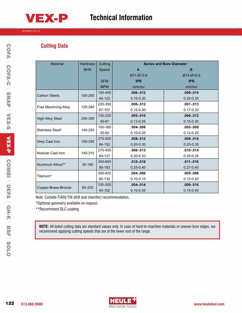
513.860.9900 www.heuletool.com
Catalog No. HTC14
122
HTC021/V1.0
Serie
s
VEX-P
CO
FA l C
OFA
-C l S
NA
P l V
EX
-S V
EX
-P C
OM
BI l D
EFA
l GH
-K l B
SF l S
OLO
Technical Information
NOTE: All listed cutting data are standard values only. In case of hard-to-machine materials or uneven bore edges, we recommend applying cutting speeds that are at the lower end of the range.
Material Hardness Cutting Series and Bore DiameterBHN Speed A B
Ø11-Ø13.9 Ø14-Ø16.9SFM IPR IPRMPM mm/rev mm/rev
Carbon Steels 100-250150-400 .006-.012 .008-.01445-122 0.15-0.30 0.20-0.35
Free Machining Alloy 125-340220-350 .006-.012 .007-.01367-107 0.15-0.30 0.17-0.32
High Alloy Steel 250-350130-220 .005-.010 .006-.01240-67 0.13-0.25 0.15-0.30
Stainless Steel* 140-250100-160 .004-.008 .005-.00830-50 0.10-0.20 0.12-0.20
Grey Cast Iron 150-330275-500 .008-.012 .008-.01484-152 0.20-0.30 0.20-0.35
Nodular Cast Iron 140-310275-450 .008-.013 .010-.01484-137 0.20-0.33 0.25-0.35
Aluminum Alloys** 30-180300-600 .010-.016 .011-.01690-183 0.25-0.40 0.27-0.40
Titanium*300-425 .004-.006 .005-.00890-130 0.10-0.15 0.12-0.20
Copper-Brass-Bronze 80-202130-500 .004-.014 .006-.01640-152 0.10-0.35 0.15-0.40
Cutting Data
Note:Carbide-TiAlN/TiN(drillandchamfer)recommendation.
*Optional geometry available on request.
**Recommend DLC coating.
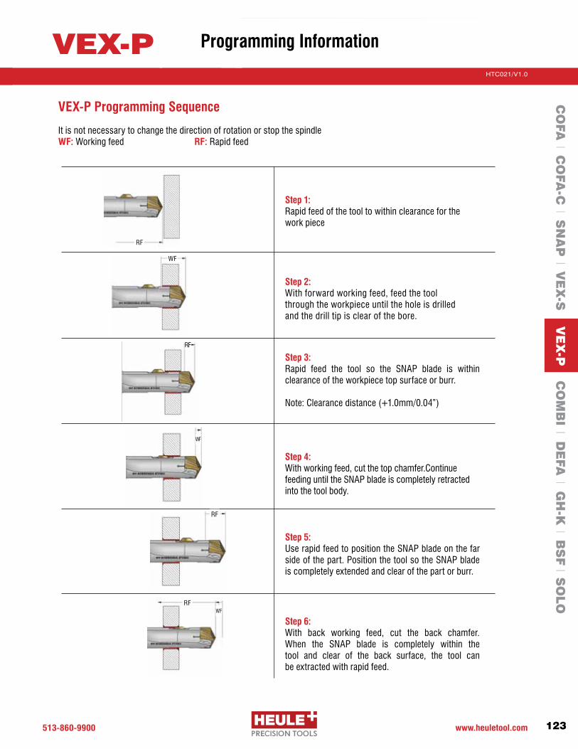
513-860-9900 www.heuletool.com
Catalog No. HTC014
123
HTC021/V1.0
Serie
s
Step 1: Rapid feed of the tool to within clearance for the work piece
Step 2: With forward working feed, feed the tool through the workpiece until the hole is drilled and the drill tip is clear of the bore.
Step 3: Rapid feed the tool so the SNAP blade is within clearance of the workpiece top surface or burr. Note:Clearancedistance(+1.0mm/0.04”)
Step 4: With working feed, cut the top chamfer.Continue feeding until the SNAP blade is completely retracted into the tool body.
Step 5: Use rapid feed to position the SNAP blade on the far side of the part. Position the tool so the SNAP blade is completely extended and clear of the part or burr.
Step 6: With back working feed, cut the back chamfer. When the SNAP blade is completely within the tool and clear of the back surface, the tool can be extracted with rapid feed.
VEX-P Programming Sequence
It is not necessary to change the direction of rotation or stop the spindle WF: Working feed RF: Rapid feed
RF
RF
WF
RF
RFWF
WF
VEX-PC
OFA
l CO
FA-C
l SN
AP
l VE
X-S
VE
X-P
CO
MB
I l DE
FA l G
H-K
l BS
F l S
OLO
Programming Information

513.860.9900 www.heuletool.com
Catalog No. HTC14
124
HTC021/V1.0
Serie
s
1
2
3
1
2
How to Replace the Snap Chamfer Blade Step 1: Turn cap screw counterclockwise approximately 3-5 turns.
Step 2: Remove the blade by simply pushing it past center and out the back of the tool.
Step 3: Install the new blade by pushing the back side ofthebladethroughthewindowuntilit“snaps“.Retighten screw clockwise. Check to make sure blade moves freely.
How to Replace the Drill Tip Step 1: Use Torx wrench to remove drill tip.
Clean the drill connection.
Step 2: Insert new drill tip and screw into holder. Tighten screw to recommended torque setting.
VEX-P
CO
FA l C
OFA
-C l S
NA
P l V
EX
-S V
EX
-P C
OM
BI l D
EFA
l GH
-K l B
SF l S
OLO
Blade and Drill Change
Blade Change Videos:HeuleTool.com

Save time and money by combining operations
Ideal for automotive applications - wheels, brake discs
Custom tooling options available for various multi-task operations
Available in sizes 9.5-35mm
COMBICombination Drill with Front & Back Chamfering of Through Holes

513.860.9900 www.heuletool.com
Catalog No. HTC14
126
HTC021/V1.0
Serie
s
The HEULE COMBI tool is a unique innovation combining the proven throw-away styledrillbladeswithHEULE’spatentedSNAPchamferingsystemtocreateasingletool. Simple tools combine drilling and chamfering, complex tools combine drilling, chamfering, countersinking, and spotfacing. This tool offers several machining operations in one machine cycle saving time, money, and space.
Combines OperationsThe HEULE COMBI tool combines operations into one tool to reduce tool
changes and cycle time, which saves time, money, and space. Boosting
productionandforacompetitiveadvantage.WithHEULE’sprovenSNAP
chamfering system, the COMBI tool provides high quality consistent
chamfers on every bore.
Ideal for Automotive IndustryThe HEULE COMBI tool has proven effective in the automotive industry,
particularly with wheel, axle and brake disc applications. The tool design and
function are well-suited for high volume environments, Providing consistent,
high quality results.
Custom Tooling OptionsThe HEULE COMBI design allows custom
tooling for almost any application. The
COMBI standard drilling range is 9.5-
35mm(.374-1.378”)anddesign
options can combine drilling, spotfacing,
and countersinking with chamfering or
back chamfering only. Through coolant
is available, as well as varied lengths to
improve rigidity or meet specific application
needs.
COMBI
CO
FA l C
OFA
-C l S
NA
P l V
EX
-S l V
EX
-P C
OM
BI D
EFA
l GH
-K l B
SF l S
OLO
Introduction

513-860-9900 www.heuletool.com
Catalog No. HTC014
127
HTC021/V1.0
Serie
s
How Does It Work?The Combi tool uses a standard spade drill and SNAP Chamfer Blade to create drilled holes that are chamfered and deburred on the front and back of the work piece in one operation.
The drill forward-feeds completely through the work piece until the spade drill insert clears the part. Then rapid feed so the SNAP blade is within clearance of the top of the part. Feed the tool forward to produce the front chamfer. When the SNAP blade is retracted in the hole, only the ground sliding surface touches the hole, protecting it from damage while the tool is fed through the part in rapid feed. There is no stopping or reversing the spindle.
When the blade reaches the back of the part past the burr, the chamfer blade extends to the cutting position and then the tool is retracted with the same working feed and speed. When the blade is again in the hole, the tool can be rapid fed out and on to the next hole. Standard Countersink Combi tools add pocket ISO inserts to the tool body to create large front countersinks.
Typical Parts
How to Order:1 Series
Indicate the bore diameter here.Forexample:Ø9.50=0950
Standard size as shown.
2 Bore Diameter Ød
3 Cutting Material12
HSSC2 Carbide
4 CoatingUTAD
UcoatedTiN
TiAINDLC
Sample:
=9.50mm=C2Carbide=TiAIN
Bore-ØdCarbide QualityCoating
Order Number: P-A-Y-0950-2A
SeriesYZ012
Bore Range Ød9.5 - 11.0 11.1 - 12.913.0 - 17.617.7-24.324.4-35.0
Order Number Example:
1 = Series
2 = Bore Ød
3 = Cutting Material
4 = Coating
P - A -Y- 0 9 5 0 - 2 A
COMBI
CO
FA l C
OFA
-C l S
NA
P l V
EX
-S l V
EX
-P C
OM
BI D
EFA
l GH
-K l B
SF l S
OLO
Introduction

513.860.9900 www.heuletool.com
Catalog No. HTC14
128
HTC021/V1.0
Serie
s
Ød RangemmSe
ries
Y
Z
GH-Q-O-3441
GH-Q-O-3445
GH-Q-O-3449
GH-Q-O-3453
Ød1
9.4 (.370”)
10.0 (.394”)
10.8 (.425”)
11.8 (.465”)
T
12 (.472”)
12 (.472”)
12 (.472”)
14 (.551”)
X
21.3 (.839”)
21.3 (.839”)
21.3 (.839”)
24.3 (.957”)
L1
102.3 (4.028”)
102.3 (4.028”)
102.3 (4.028”)
104.8 (4.126”)
20
(.787”)
Ln
17 (.669”)
17 (.669”)
17 (.669”)
18 (.709”)
Ls
50
(1.969”)
Øs
COMBI Drill Chamfer Tools Ø9.5-Ø17.99mm with coolant through
SPARE PARTS
PG. 139
Drill/Chamfer Tools – 1xd For holes 9.5 - 12.9mm .374-.508”Se
ries
Y ,ZCOMBI
9.5 - 10.1
10.2 - 11.0
11.1 - 11.9
12.0 - 12.9
Tool Holder Order Number
Chamfer Blade Options
Blade, Carbide-TiN, 90°, front and back**Order Number (Chamfer ØD mm)
-03723 (10.0)-03724 (10.5)-03725 (11.0)-03725 (11.0) -03726 (11.5)-03726 (11.5)-03727 (12.0)-03728 (12.5)-03740 (12.5)-03741 (13.0)-03742 (13.5)
-03724 (10.5)-03725 (11.0)-03726 (11.5)-03726 (11.5) -03727 (12.0)-03727 (12.0)-03728 (12.5)-03729 (13.0)-03741 (13.0)-03742 (13.5)-03743 (14.0)
-03725 (11.0)-03726 (11.5)-03727 (12.0)-03727 (12.0) -03728 (12.5)-03728 (12.5)-03729 (13.0)-03730 (13.5)-03742 (13.5)-03743 (14.0)-03744 (14.5)
- - - - - - --
-03743 (14.0)-03744 (14.5)-03745 (15.0)
Y
Z
(0.25mmx45°)GH-Q-M-
(0.5mmx45°)GH-Q-M-
(0.75mmx45°)GH-Q-M-
(1.0mmx45°)GH-Q-M-
Serie
s
Cmf.
Serie
s
8
Ød Drill mm inches
Tool Holder 1 Order Number
Drill Tip* Order Number
9.53 .37510.0 .39410.32 13/32”10.5 .41311.0 .43311.1 7/16”11.5 .45311.91 15/32”12.0 .47212.5 .49212.7 1/2”
GH-Q-O-3441GH-Q-O-3441GH-Q-O-3445GH-Q-O-3445GH-Q-O-3445GH-Q-O-3449GH-Q-O-3449GH-Q-O-3449GH-Q-O-3453GH-Q-O-3453GH-Q-O-3453
P-A-Y-0953-2AP-A-Y-1000-2AP-A-Y-1032-2AP-A-Y-1050-2AP-A-Y-1100-2AP-A-Z-1110-2AP-A-Z-1150-2AP-A-Z-1191-2AP-A-Z-1200-2AP-A-Z-1250-2AP-A-Z-1270-2A
12
* Non-stock standard item with extended delivery time. Spade drill 10 piece minimum. Other drill sizes available upon request. Example: Ød = 13.75mm (.541”) - P-A-O-1375-2A.** Chamfer blades are interchangeable; maximum chamfer diameter ØD = hole Ød + 1.5mm (series 8)/2.0mm (series 12). 1 Non-stock standard item with extended delivery time.
CO
FA l C
OFA
-C l S
NA
P l V
EX
-S l V
EX
-P C
OM
BI D
EFA
l GH
-K l B
SF l S
OLO
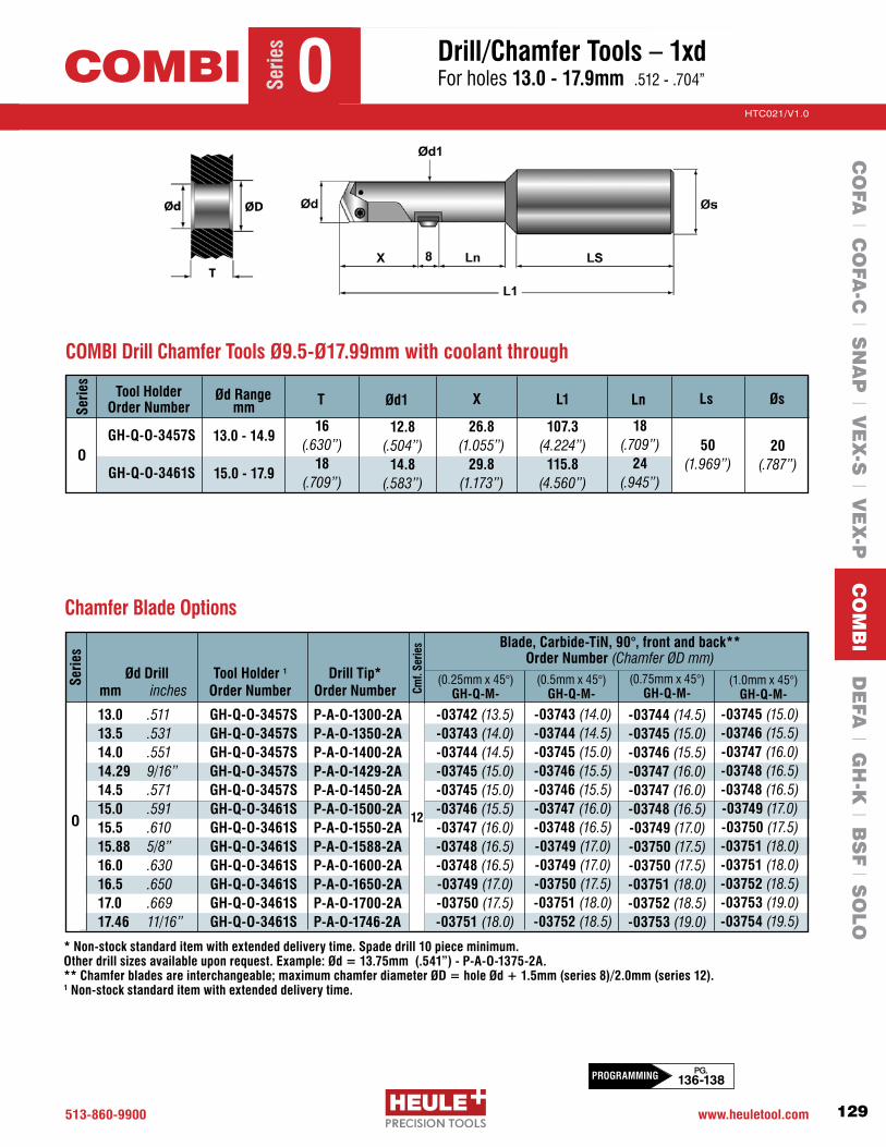
513-860-9900 www.heuletool.com
Catalog No. HTC014
129
HTC021/V1.0
Serie
s
* Non-stock standard item with extended delivery time. Spade drill 10 piece minimum. Other drill sizes available upon request. Example: Ød = 13.75mm (.541”) - P-A-O-1375-2A.** Chamfer blades are interchangeable; maximum chamfer diameter ØD = hole Ød + 1.5mm (series 8)/2.0mm (series 12). 1 Non-stock standard item with extended delivery time.
Chamfer Blade Options
Blade, Carbide-TiN, 90°, front and back**Order Number (Chamfer ØD mm)
-03742 (13.5)-03743 (14.0)-03744 (14.5)-03745 (15.0)-03745 (15.0)-03746 (15.5)-03747 (16.0)-03748 (16.5)-03748 (16.5)-03749 (17.0)-03750 (17.5)-03751 (18.0)
-03743 (14.0)-03744 (14.5)-03745 (15.0)-03746 (15.5)-03746 (15.5)-03747 (16.0)-03748 (16.5)-03749 (17.0)-03749 (17.0)-03750 (17.5)-03751 (18.0)-03752 (18.5)
-03744 (14.5)-03745 (15.0)-03746 (15.5)-03747 (16.0)-03747 (16.0)-03748 (16.5)-03749 (17.0)-03750 (17.5)-03750 (17.5)-03751 (18.0)-03752 (18.5)-03753 (19.0)
-03745 (15.0)-03746 (15.5)-03747 (16.0)-03748 (16.5)-03748 (16.5)-03749 (17.0)-03750 (17.5)-03751 (18.0)-03751 (18.0)-03752 (18.5)-03753 (19.0)-03754 (19.5)
PG. 136-138PROGRAMMING
Serie
s
OCOMBI
O
(0.25mmx45°)GH-Q-M-
(0.5mmx45°)GH-Q-M-
(0.75mmx45°)GH-Q-M-
(1.0mmx45°)GH-Q-M-
Serie
s
Cmf.
Serie
s
Ød Drill mm inches
Tool Holder 1 Order Number
Drill Tip* Order Number
Drill/Chamfer Tools – 1xd For holes 13.0 - 17.9mm .512-.704”
13.0 .51113.5 .53114.0 .55114.29 9/16”14.5 .57115.0 .59115.5 .61015.88 5/8”16.0 .63016.5 .65017.0 .66917.46 11/16”
GH-Q-O-3457SGH-Q-O-3457SGH-Q-O-3457SGH-Q-O-3457SGH-Q-O-3457SGH-Q-O-3461SGH-Q-O-3461SGH-Q-O-3461SGH-Q-O-3461SGH-Q-O-3461SGH-Q-O-3461SGH-Q-O-3461S
P-A-O-1300-2AP-A-O-1350-2AP-A-O-1400-2AP-A-O-1429-2AP-A-O-1450-2AP-A-O-1500-2AP-A-O-1550-2AP-A-O-1588-2AP-A-O-1600-2AP-A-O-1650-2AP-A-O-1700-2AP-A-O-1746-2A
Ød RangemmSe
ries
OGH-Q-O-3457S
GH-Q-O-3461S
Ød1
12.8 (.504”)
14.8 (.583”)
T
16 (.630”)
18 (.709”)
X
26.8 (1.055”)
29.8 (1.173”)
L1
107.3 (4.224”)
115.8 (4.560”)
20
(.787”)
Ln
18 (.709”)
24 (.945”)
Ls
50 (1.969”)
Øs
COMBI Drill Chamfer Tools Ø9.5-Ø17.99mm with coolant through
13.0 - 14.9
15.0 - 17.9
Tool Holder Order Number
12
CO
FA l C
OFA
-C l S
NA
P l V
EX
-S l V
EX
-P C
OM
BI D
EFA
l GH
-K l B
SF l S
OLO

513.860.9900 www.heuletool.com
Catalog No. HTC14
130
HTC021/V1.0
Serie
s
Tool HolderOrder NumberSe
ries
COMBI Drill Chamfer Tools Ø18.0-Ø35.0mm with Coolant Through
SPARE PARTS
PG. 139
Drill/Chamfer Tools – 1xd For holes 18.0 - 24.9mm .709-.980”Se
ries 1COMBI
1GH-Q-O-3465S
GH-Q-O-3469S
18.0 - 19.9
20.0 - 24.9
Ød Rangemm
Ød1T X L1 Ln Ls Øs
17.5 (.689”)
19.8 (.780”)
20 (.787”)
24 (.945”)
25 (.984”)
25 (.984”)
56 (2.205”)
56 (2.205”)
22 (.866”)
28 (1.102”)
125.6 (4.945”)
136.6 (5.3787”)
34.6 (1.362”)
39.6 (1.559”)
B
8 (.315”)
8 (.315”)
* Non-stock standard item with extended delivery time. Spade drill 10 piece minimum. Other drill sizes available upon request. Example: Ød = 26.5mm (1.043”) - P-A-2-2650-2A.** Chamfer blades are interchangeable; maximum chamfer diameter ØD = hole Ød + 2mm.1 Non-stock standard item with extended delivery time.
COMBI Series 1 Chamfer Drill and Chamfer Blades
Blade, Carbide-TiN, 90°, front and backOrder Number (Chamfer ØD mm)
-03753 (19.0)-03754 (19.5)-03755 (20.0)-03756 (20.5)-03770 (21.0)-03771 (22.0)-03772 (23.0)-03773 (24.0)-03774 (25.0)
-03754 (19.5)-03755 (20.0)-03756 (20.5)-03757 (21.0)-03771 (22.0)-03772 (23.0)-03773 (24.0)-03774 (25.0)-03775 (26.0)
-03755 (20.0)-03756 (20.5)-03757 (21.0)-03758 (21.5)-03772 (23.0)-03773 (24.0)-03774 (25.0)-03775 (26.0)-03776 (27.0)
Ød Drillmm inches
18.0 .70918.5 .72819.05 3/4”19.50 .76820.0 .78721.0 .82722.0 .86623.0 .90624.0 .945
Tool Holder1
(withcoolant)
GH-Q-O-3465SGH-Q-O-3465SGH-Q-O-3465SGH-Q-O-3465SGH-Q-O-3469SGH-Q-O-3469SGH-Q-O-3469SGH-Q-O-3469SGH-Q-O-3469S
(0.5mmx45°)GH-Q-M-
(0.75mmx45°)GH-Q-M-Cm
f. Se
ries
12
P-A-1-1800-2AP-A-1-1850-2AP-A-1-1905-2AP-A-1-1950-2AP-A-1-2000-2AP-A-1-2100-2AP-A-1-2200-2AP-A-1-2300-2AP-A-1-2400-2A
1
Serie
s
20
Drill Tip*Order Number (1.0mmx45°)
GH-Q-M-
CO
FA l C
OFA
-C l S
NA
P l V
EX
-S l V
EX
-P C
OM
BI D
EFA
l GH
-K l B
SF l S
OLO

513-860-9900 www.heuletool.com
Catalog No. HTC014
131
HTC021/V1.0
Serie
s
* Non-stock standard item with extended delivery time. Spade drill 10 piece minimum. Other drill sizes available upon request. Example: Ød = 26.5mm (1.043”) - P-A-2-2650-2A.** Chamfer blades are interchangeable; maximum chamfer diameter ØD = hole Ød + 2mm.1 Non-stock standard item with extended delivery time.
COMBI Series 2 Chamfer Drill and Chamfer Blades
Blade, Carbide-TiN, 90°, front and backOrder Number (Chamfer ØD mm)
-03775 (26.0)-03775 (26.0)-03776 (27.0)-03777 (28.0)-03778 (29.0)-03779 (30.0)-03780 (31.0)-03780 (31.0)-03781 (32.0)-03782 (33.0)-03783 (34.0)-03784 (35.0)-03785 (36.0)
-03776 (27.0)-03776 (27.0)-03777 (28.0)-03778 (29.0)-03779 (30.0)-03780 (31.0)-03781 (32.0)-03781 (32.0)-03782 (33.0)-03783 (34.0)-03784 (35.0)-03785 (36.0)-03786 (37.0)
-03777 (28.0)-03777 (28.0)-03778 (29.0)-03779 (30.0)-03780 (31.0)-03781 (32.0)-03782 (33.0)-03782 (33.0)-03783 (34.0)-03784 (35.0)-03785 (36.0)-03786 (37.0)-03787 (38.0)
PG. 136-138PROGRAMMING
Serie
s 2COMBI Drill/Chamfer Tools – 1xd For holes 25.0 - 35.0mm .984-1.378”
Ød Drillmm inches
25.0 .98425.4 1.0026.0 1.02327.0 1.06328.0 1.10229.0 1.14130.0 1.18131.0 1.22031.75 1 1/4”32.0 1.26033.0 1.30034.0 1.33935.0 1.378
Tool Holder1
(withcoolant)
GH-Q-O-3473SGH-Q-O-3473SGH-Q-O-3473SGH-Q-O-3473SGH-Q-O-3473SGH-Q-O-3473SGH-Q-O-3477SGH-Q-O-3477SGH-Q-O-3477SGH-Q-O-3477SGH-Q-O-3477SGH-Q-O-3477SGH-Q-O-3477S
(0.5mmx45°)GH-Q-M-
(1.0mmx45°)GH-Q-M-Cm
f. Se
ries
P-A-2-2500-2AP-A-2-2540-2AP-A-2-2600-2AP-A-2-2700-2AP-A-2-2800-2AP-A-2-2900-2AP-A-2-3000-2AP-A-2-3100-2AP-A-2-3175-2AP-A-2-3200-2AP-A-2-3300-2AP-A-2-3400-2AP-A-2-3500-2A
2
Serie
s
Drill Tip*Order Number (1.5mmx45°)
GH-Q-M-
Tool HolderOrder NumberSe
ries
COMBI Drill Chamfer Tools Ø18.0-Ø35.0mm with Coolant Through
2GH-Q-O-3473S
GH-Q-O-3477S
25.0 - 29.9
30.0 - 34.9
Ød Rangemm
Ød1T X L1 Ln Ls Øs
24.2 (.953”)
29.8 (1.173”)
30 (1.181”)
38 (1.496”)
32 (1.260”)
32 (1.260”)
60 (2.362”)
60 (2.362”)
32 (1.260”)
40 (1.575”)
155.6 (6.126”)
171.6 (6.756”)
48.6 (1.913”)
59.6 (2.346”)
B
10 (.394”)
10 (.394”)
20
CO
FA l C
OFA
-C l S
NA
P l V
EX
-S l V
EX
-P C
OM
BI D
EFA
l GH
-K l B
SF l S
OLO

513.860.9900 www.heuletool.com
Catalog No. HTC14
132
HTC021/V1.0
Serie
sCOMBI Drill Chamfer Tools Ø9.5-Ø17.99mm with Coolant Through
SPARE PARTS
PG. 139
Drill/Countersink/Chamfer Tools – 1xd For holes 9.5 - 11.4mm .374-.449”Se
ries
Y,ZCOMBI
Ød RangemmSe
ries
Y
Z
GH-Q-O-3641
GH-Q-O-3645
GH-Q-O-3649
GH-Q-O-3653
Ød1
9.4 (.370”)
10.0 (.394”)
10.8 (.425”)
11.8 (.465”)
T
12 (.472”)
12 (.472”)
12 (.472”)
14 (.551”)
X
21.3 (.839”)
21.3 (.839”)
21.3 (.839”)
24.3 (.957”)
L1
112.3 (4.421”) 112.3
(4.421”) 112.3
(4.421”) 119.8
(4.717”)
16 (.630”)
16 .630”)
16 (.630”)
20 (.787”)
Ln Ls
48 (1.890”)
48 (1.890”)
48 (1.890”)
50 (1.969”)
Øs
9.5 - 10.0
10.3 - 11.0
11.1 - 11.9
12.0 - 12.7
Tool Holder Order Number
12.2 (.480”) 12.4
(.488”) 13.5
(.531”) 14.2
(.559”)
Ød3
20.0 (.787”) 20.0
(.787”) 20.0
(.787”) 24.0
(.945”)
Drill Ød ØIC L S Ød2 Order Number 9.5-11.9 3.97 6.8 1.59 2.2 GH-H-P-0140 12.0-14.9 5.56 9.6 2.38 2.5 GH-H-P-0128 15.0-19.9 6.35 11.0 2.38 2.8 GH-H-P-0130
Indexable Inserts for Countersinking
* Non-stock standard item with extended delivery time.Spade drill 10 piece minimum. Other drill sizes available upon request. Example: Ød = 13.75mm (.541”) - P-A-O-1375-2A.** Chamfer blades are interchangeable; maximum chamfer diameter ØD = hole Ød + 1.5mm.1 Non-stock standard item with extended delivery time.
Blade, Carbide-TiN, 90°, front and back**Order Number (Chamfer ØD mm)
-03723 (10.0)-03724 (10.5)-03725 (11.0)-03725 (11.0) -03726 (11.5)-03726 (11.5)-03727 (12.0)-03728 (12.5)-03740 (12.5)-03741 (13.0)-03742 (13.5)
-03724 (10.5)-03725 (11.0)-03726 (11.5)-03726 (11.5) -03727 (12.0)-03727 (12.0)-03728 (12.5)-03729 (13.0)-03741 (13.0)-03742 (13.5)-03743 (14.0)
-03725 (11.0)-03726 (11.5)-03727 (12.0)-03727 (12.0) -03728 (12.5)-03728 (12.5)-03729 (13.0)-03730 (13.5)-03742 (13.5)-03743 (14.0)-03744 (14.5)
Y
Z
(0.25mmx45°)GH-Q-M-
(0.5mmx45°)GH-Q-M-
(0.75mmx45°)GH-Q-M-
Serie
s
Cmf.
Serie
s
Ød Drill mm inches
Tool Holder Order #
Drill Tip* Order #
9.53 .37510.0 .39410.32 13/32”10.5 .41311.0 .43311.1 7/16”11.5 .45311.91 15/32”12.0 .47212.5 .49212.7 1/2”
P-A-Y-0953-2AP-A-Y-1000-2AP-A-Y-1032-2AP-A-Y-1050-2AP-A-Y-1100-2AP-A-Z-1110-2AP-A-Z-1150-2AP-A-Z-1191-2AP-A-Z-1200-2AP-A-Z-1250-2AP-A-Z-1270-2A
GH-Q-O-3641GH-Q-O-3641GH-Q-O-3645GH-Q-O-3645GH-Q-O-3645GH-Q-O-3649GH-Q-O-3649GH-Q-O-3649GH-Q-O-3653GH-Q-O-3653GH-Q-O-3653
Insert GH-H-P-
-0140
COMBI Series Y, Z Chamfer Drill and Chamfer Blades
8
1
-012812C
OFA
l CO
FA-C
l SN
AP
l VE
X-S
l VE
X-P
CO
MB
I DE
FA l G
H-K
l BS
F l S
OLO

513-860-9900 www.heuletool.com
Catalog No. HTC014
133
HTC021/V1.0
Serie
s
* Non-stock standard item with extended delivery time.Spade drill 10 piece minimum. Other drill sizes available upon request. Example: Ød = 13.75mm (.541”) - P-A-O-1375-2A.** Chamfer blades are interchangeable; maximum chamfer diameter ØD = hole Ød + 2mm.1 Non-stock standard item with extended delivery time.
COMBI Series 0 Chamfer Drill and Chamfer Blades
PG. 136-138PROGRAMMING
Serie
s
OCOMBI Drill/Countersink/Chamfer Tools – 1xd For holes 11.5 - 17.9mm .453-.704”
Blade, Carbide-TiN, 90°, front and back**Order Number (Chamfer ØD mm)
-03742 (13.5)-03743 (14.0)-03744 (14.5)-03745 (15.0)-03745 (15.0)-03746 (15.5)-03747 (16.0)-03748 (16.5)-03748 (16.5)-03749 (17.0)-03750 (17.5)-03751 (18.0)
-03743 (14.0)-03744 (14.5)-03745 (15.0)-03746 (15.5)-03746 (15.5)-03747 (16.0)-03748 (16.5)-03749 (17.0)-03749 (17.0)-03750 (17.5)-03751 (18.0)-03752 (18.5)
-03744 (14.5)-03745 (15.0)-03746 (15.5)-03747 (16.0)-03747 (16.0)-03748 (16.5)-03749 (17.0)-03750 (17.5)-03750 (17.5)-03751 (18.0)-03752 (18.5)-03753 (19.0)
-03745 (15.0)-03746 (15.5)-03747 (16.0)-03748 (16.5)-03748 (16.5)-03749 (17.0)-03750 (17.5)-03751 (18.0)-03751 (18.0)-03752 (18.5)-03753 (19.0)-03754 (19.5)
O
(0.25mmx45°)GH-Q-M-
(0.5mmx45°)GH-Q-M-
(0.75mmx45°)GH-Q-M-
(1.0mmx45°)GH-Q-M-
Serie
s
Cmf.
Serie
s
Ød Drill mm inches
Tool Holder Order #
Drill Tip* Order #
13.0 .51113.5 .53114.0 .55114.29 9/16”14.5 .57115.0 .59115.5 .61015.88 5/8”16.0 .63016.5 .65017.0 .66917.46 11/16”
P-A-O-1300-2AP-A-O-1350-2AP-A-O-1400-2AP-A-O-1429-2AP-A-O-1450-2AP-A-O-1500-2AP-A-O-1550-2AP-A-O-1588-2AP-A-O-1600-2AP-A-O-1650-2AP-A-O-1700-2AP-A-O-1746-2A
GH-Q-O-3657SGH-Q-O-3657SGH-Q-O-3657SGH-Q-O-3657SGH-Q-O-3657SGH-Q-O-3661SGH-Q-O-3661SGH-Q-O-3661SGH-Q-O-3661SGH-Q-O-3661SGH-Q-O-3661SGH-Q-O-3661S
Insert GH-H-P-
-0128
-0130
12
COMBI Drill Chamfer Tools Ø9.5-Ø17.99mm with Coolant Through
Ød RangemmSe
ries
OGH-Q-O-3657S
GH-Q-O-3661S
Ød1
12.8 (.504”)
14.8 (.583”)
T
16 (.630”)
18 (.709”)
X
26.8 (1.055”)
29.8 (1.173”)
L1
122.3 (4.815”) 125.3
(4.933”)
20 (.787”)
20 (.787”)
Ln Ls
50 (1.969”)
50 (1.969”)
Øs
13.0 - 14.9
15.0 - 17.9
Tool Holder Order Number
15.9 (.626”)
18.4 (.724”)
Ød3
24.0 (.945”) 26.0
(1.024”)
1
CO
FA l C
OFA
-C l S
NA
P l V
EX
-S l V
EX
-P C
OM
BI D
EFA
l GH
-K l B
SF l S
OLO

513.860.9900 www.heuletool.com
Catalog No. HTC14
134
HTC021/V1.0
Serie
s
COMBI Drill Chamfer Tools Ø18.0-Ø35.0mm with Coolant Through
SPARE PARTS
PG. 139
Drill/Countersink/Chamfer Tools – 1xd For holes 18.0 - 24.9mm .709-.980”Se
ries
1COMBI
Ød RangemmSe
ries
1
Ød1T X L1 Ln Ls ØsTool Holder Order Number Ød3
28.0 (1.102”)
30.0 (1.181”)
GH-Q-O-3665S
GH-Q-O-3669S
18.0 - 19.9
20.0 - 24.9
20 (.787”)
24 (.945”)
17.5 (.689”)
19.8 (.780”)
34.6 (1.362”)
39.6 (1.559”)
125.6 (4.945”)
136.6 (5.378”)
22 (.866”)
28 (1.102”)
56 (2.205”)
56 (2.205”)
25 (.984”)
25 (.984”)
Drill Ød ØIC L S Ød2 Order Number 15.0-35.0 6.35 11.0 2.38 2.8 GH-H-P-0130
Indexable Inserts for Countersinking
COMBI Series 1 Chamfer Drill and Chamfer Blades
Blade, Carbide-TiN, 90°, front and back**Order Number (Chamfer ØD mm)
1
Serie
s
Cmf.
Serie
s
12
Ød Drill mm inches
Tool Holder Order #
Drill Tip* Order #
18.0 .70918.5 .72819.05 3/4”19.50 .76820.0 .78721.0 .82722.0 .86623.0 .90624.0 .945
GH-Q-O-3665SGH-Q-O-3665SGH-Q-O-3665SGH-Q-O-3665SGH-Q-O-3669SGH-Q-O-3669SGH-Q-O-3669SGH-Q-O-3669SGH-Q-O-3669S
P-A-1-1800-2AP-A-1-1850-2AP-A-1-1905-2AP-A-1-1950-2AP-A-1-2000-2AP-A-1-2100-2AP-A-1-2200-2AP-A-1-2300-2AP-A-1-2400-2A
(0.5mmx45°)GH-Q-M-
(0.75mmx45°)GH-Q-M-
(1.0mmx45°)GH-Q-M-
Insert GH-H-P-
-0130
-03753 (19.0)-03754 (19.5)-03755 (20.0)-03756 (20.5)-03770 (21.0)-03771 (22.0)-03772 (23.0)-03773 (24.0)-03774 (25.0)
-03754 (19.5)-03755 (20.0)-03756 (20.5)-03757 (21.0)-03771 (22.0)-03772 (23.0)-03773 (24.0)-03774 (25.0)-03775 (26.0)
-03755 (20.0)-03756 (20.5)-03757 (21.0)-03758 (21.5)-03772 (23.0)-03773 (24.0)-03774 (25.0)-03775 (26.0)-03776 (27.0)
20
(0.25mmx45°) GH-Q-M-
-03752 (18.5)-03753 (19.0)-03754 (19.5)-03755 (20.0)
-----
B
8(.315”)
10 (.394”)
* Non-stock standard item with extended delivery time. Spade drill 10 piece minimum. Other drill sizes available upon request. Example: Ød = 26.5mm (1.043”) - P-A-2-2650-2A.** Chamfer blades are interchangeable; maximum chamfer diameter ØD = hole Ød + 2mm.1 Non-stock standard item with extended delivery time.
1
CO
FA l C
OFA
-C l S
NA
P l V
EX
-S l V
EX
-P C
OM
BI D
EFA
l GH
-K l B
SF l S
OLO

513-860-9900 www.heuletool.com
Catalog No. HTC014
135
HTC021/V1.0
Serie
s
* Non-stock standard item with extended delivery time. Spade drill 10 piece minimum. Other drill sizes available upon request. Example: Ød = 26.5mm (1.043”) - P-A-2-2650-2A.** Chamfer blades are interchangeable; maximum chamfer diameter ØD = hole Ød + 2mm.1 Non-stock standard item with extended delivery time.
COMBI Series 2 Chamfer Drill and Chamfer Blades
PG. 136-138PROGRAMMING
Serie
s
2COMBI Drill/Countersink/Chamfer Tools – 1xd For holes 25.0 - 35.0mm .984-1.378”
Blade, Carbide-TiN, 90°, front and back**Order Number (Chamfer ØD mm)
2
(0.5mmx45°)GH-Q-M-
(0.75mmx45°)GH-Q-M-
(1.0mmx45°)GH-Q-M-
Serie
s
Cmf.
Serie
s
Ød Drill mm inches
Tool Holder Order #
Drill Tip* Order #
20
Insert GH-H-P-
-0130
25.0 .98425.4 1.0026.0 1.02327.0 1.06328.0 1.10229.0 1.14130.0 1.18131.0 1.22031.75 1 1/4”32.0 1.26033.0 1.30034.0 1.33935.0 1.378
GH-Q-O-3673SGH-Q-O-3673SGH-Q-O-3673SGH-Q-O-3673SGH-Q-O-3673SGH-Q-O-3673SGH-Q-O-3677SGH-Q-O-3677SGH-Q-O-3677SGH-Q-O-3677SGH-Q-O-3677SGH-Q-O-3677SGH-Q-O-3677S
P-A-2-2500-2AP-A-2-2540-2AP-A-2-2600-2AP-A-2-2700-2AP-A-2-2800-2AP-A-2-2900-2AP-A-2-3000-2AP-A-2-3100-2AP-A-2-3175-2AP-A-2-3200-2AP-A-2-3300-2AP-A-2-3400-2AP-A-2-3500-2A
-03775 (26.0)-03775 (26.0)-03776 (27.0)-03777 (28.0)-03778 (29.0)-03779 (30.0)-03780 (31.0)-03780 (31.0)-03781 (32.0)-03782 (33.0)-03783 (34.0)-03784 (35.0)-03785 (36.0)
-03776 (27.0)-03776 (27.0)-03777 (28.0)-03778 (29.0)-03779 (30.0)-03780 (31.0)-03781 (32.0)-03781 (32.0)-03782 (33.0)-03783 (34.0)-03784 (35.0)-03785 (36.0)-03786 (37.0)
-03777 (28.0)-03777 (28.0)-03778 (29.0)-03779 (30.0)-03780 (31.0)-03781 (32.0)-03782 (33.0)-03782 (33.0)-03783 (34.0)-03784 (35.0)-03785 (36.0)-03786 (37.0)-03787 (38.0)
COMBI Drill Chamfer Tools Ø18.0-Ø35.0mm with Coolant Through
Ød RangemmSe
ries
2
Ød1T X L1 Ln Ls ØsTool Holder Order Number Ød3
38.0 (1.496”)
42.0 (1.654”)
GH-Q-O-3673S
GH-Q-O-3677S
25.0 - 29.9
30.0 - 35.0
30 (1.181”)
38 (1.496”)
24.2 (.953”)
29.8 (1.173”)
48.6 (1.913”)
59.6 (2.346”)
155.6 (6.126”)
171.6 (6.757”)
32 (1.260”)
40 (1.575”)
60 (2.362”)
60 (2.362”)
32 (1.260”)
32 (1.260”)
B
8(.315”)
10 (.394”)
1
CO
FA l C
OFA
-C l S
NA
P l V
EX
-S l V
EX
-P C
OM
BI D
EFA
l GH
-K l B
SF l S
OLO

513.860.9900 www.heuletool.com
Catalog No. HTC14
136
HTC021/V1.0
Serie
s
SNAP Chamfer Inserts
IPR (SNAP - GS)Aluminum Brass Low Carbon Steels Med Carbon Steels Free Machining AlloysStainless Steel Gray Cast Iron Nodular Cast Iron Short Chipping IronTitanium
SFMMaterial0.006-0.012 0.006-0.014 0.004-0.008 0.004-0.009 0.004-0.0060.002-0.005 0.004-0.008 0.003-0.007 0.003-0.0070.001-0.003
320-800 210-400 150-210 130-180 100-16090-140
150-220 150-220 100-15020-50
Important: Tool holder must be modified with blade locking mechanism for spindle speeds above 6,000 rpm. Please contact HEULE.
COMBI
CO
FA l C
OFA
-C l S
NA
P l V
EX
-S l V
EX
-P C
OM
BI D
EFA
l GH
-K l B
SF l S
OLO
Programming Information
NOTE: All listed cutting data are standard values only In case of hard-to-machine materials or uneven surfaces, we recommend applying cutting speeds that are at the lower end of the range.
Material Hardness Carbide Bore DiameterBHN Grade Ø9.5-Ø11.5 Ø13-Ø17 Ø18-Ø24 Ø25-Ø35
SFM IPR IPR IPR IPRMPM mm/rev mm/rev mm/rev mm/rev
Carbon Steels 100-250 *HSS/C2220-320 .004-.006 .007-.008 .008-.010 .012-.014
67-98 0.10-0.15 0.18-0.20 0.20-0.25 0.30-0.35
Free Machining Alloy 125-340 *HSS/C2260-320 .005-.006 .008-.009 .010-.012 .012-.015
79-98 0.13-0.15 0.20-0.23 0.25-0.30 0.30-0.38
High Alloy Steel 250-350 *HSS/C2140-250 .004-.006 .006-.008 .007-.011 .009-.01343-76 0.10-0.15 0.15-0.20 0.18-0.28 0.23-0.33
Stainless Steel 140-250 *HSS/C2120-160 .005-.006 .007-.008 .008-.009 .010-.01137-49 0.13-0.15 0.18-0.20 0.20-0.23 0.25-0.28
Grey Cast Iron 150-330 C2240-320 .005-.006 .007-.009 .008-.011 .012-.01573-98 0.13-0.15 0.18-0.23 0.20-0.28 0.30-0.38
Aluminum Alloys 30-180 C2800-1200 .007-.008 .011-.013 .014-.016 .014-.020244-366 0.18-0.20 0.28-0.33 0.35-0.40 0.35-0.50
Cutting Data
*Use 50% surface speed for HSS
Blade Change Videos:HeuleTool.com
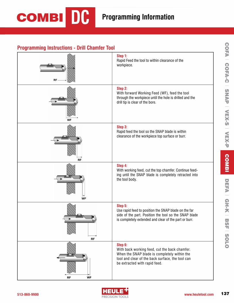
513-860-9900 www.heuletool.com 137
Catalog No. HTC014HTC021/V1.0
Serie
s
Programming Instructions - Drill Chamfer ToolStep 1: Rapid Feed the tool to within clearance of the workpiece.
Step 2: WithforwardWorkingFeed(WF),feedthetoolthrough the workpiece until the hole is drilled and the drill tip is clear of the bore.
Step 3: Rapid feed the tool so the SNAP blade is within clearance of the workpiece top surface or burr.
Step 4: With working feed, cut the top chamfer. Continue feed-ing until the SNAP blade is completely retracted into the tool body.
Step 5: Use rapid feed to position the SNAP blade on the farside of the part. Position the tool so the SNAP blade is completely extended and clear of the part or burr.
Step 6: With back working feed, cut the back chamfer. When the SNAP blade is completely within the tool and clear of the back surface, the tool can be extracted with rapid feed.
COMBI Programming InformationDCC
OFA
l CO
FA-C
l SN
AP
l VE
X-S
l VE
X-P
CO
MB
I DE
FA l G
H-K
l BS
F l S
OLO

513.860.9900 www.heuletool.com
Catalog No. HTC14
138
HTC021/V1.0
Serie
s
Programming Instructions - Drill Countersink Chamfer ToolStep 1:Rapid Feed the tool to within clearance of the workpiece.
Step 2: WithforwardWorkingFeed(WF),feedthetool through the workpiece until the hole is drilled and the drill tip is clear of the bore.
Step 3: Rapid feed the tool so the SNAP blade is within clearance of the workpiece top surface or burr.
Step 4: With working feed, cut the top countersink. Continuefeeding until the required countersink size is achieved.
Step 5: If necessary, use rapid backward feed to position theSNAP insert within clearance distance of the back surface of the workpiece or burr. The back chamfer can then be cut in working backward feed.
Step 6: When the SNAP insert is clear of the back surface and completely retracted in the tool body, the tool can be retracted from the workpiece using rapid backward feed.
COMBI Programming InformationDCC
CO
FA l C
OFA
-C l S
NA
P l V
EX
-S l V
EX
-P C
OM
BI D
EFA
l GH
-K l B
SF l S
OLO

513-860-9900 www.heuletool.com
Catalog No. HTC014
139
HTC021/V1.0
Serie
s
COMBI
1
7
2
34
5
6
Tool Holder
GH-Q-O-3441GH-Q-O-3445GH-Q-O-3449GH-Q-O-3453GH-Q-O-3457SGH-Q-O-3461S
COMBI Drill Chamfer Tools Ø9.5-Ø17.99mm-Spare Parts 1 2 3 4 5 and 6 7 Set Screw Distance Pin Spring Control Bolt Chamfer & Drill Blades Torx Screw Size GH-H-S-0119 GH-Q-E-0021 GH-H-F-0007 GH-Q-E-0002SeePage134GH-H-S-0070IP7 GH-H-S-0119 GH-Q-E-0021 GH-H-F-0007 GH-Q-E-0002 SeePage134GH-H-S-0070IP7 GH-H-S-0119 GH-Q-E-0021 GH-H-F-0007 GH-Q-E-0002 SeePage134GH-H-S-0071IP7 GH-H-S-0119 GH-Q-E-0021 GH-H-F-0007 GH-Q-E-0002 SeePage134GH-H-S-0071IP7 GH-H-S-0119 GH-Q-E-0021 GH-H-F-0007 GH-Q-E-0002 See Page 135 GH-H-S-0066 T8 GH-H-S-0119 GH-Q-E-0022 GH-H-F-0007 GH-Q-E-0002 See Page 135 GH-H-S-0067 IP8
1 2 3 4 5 and 6 7 Set Screw Distance Pin Spring Control Bolt Chamfer & Drill Blades Torx Screw Size GH-H-S-0119 GH-Q-E-0023 GH-H-F-0007 GH-Q-E-0002 See Page 136 GH-H-S-0068 IP9 GH-H-S-0119 GH-Q-E-0023 GH-H-F-0011 GH-Q-E-0003 See Page 136 GH-H-S-0069 IP9 GH-H-S-0119 GH-Q-E-0025 GH-H-F-0011 GH-Q-E-0003 See Page 137 GH-H-S-0072 IP15 GH-H-S-0119 GH-Q-E-0026 GH-H-F-0011 GH-Q-E-0003 See Page 137 GH-H-S-0072 IP15
Tool Holder
GH-Q-O-3465SGH-Q-O-3469SGH-Q-O-3473SGH-Q-O-3477S
COMBI Drill Chamfer Tools Ø18.0-Ø35.0mm-Spare Parts
1 2 3 4 5 and 6 7 8 9 Set Screw Distance Pin Spring Control Bolt Chamfer & Drill Blades Torx Screw* C’sink Insert Torx Screw Size GH-H-S-0119 GH-Q-E-0023 GH-H-F-0007 GH-Q-E-0002 See Page 138 GH-H-S-0070 GH-H-P-0131 GH-H-S-0055 T6 GH-H-S-0119 GH-Q-E-0023 GH-H-F-0007 GH-Q-E-0002 See Page 138 GH-H-S-0070 GH-H-P-0131 GH-H-S-0055 T6 GH-H-S-0119 GH-Q-E-0023 GH-H-F-0007 GH-Q-E-0002 See Page 138 GH-H-S-0071 GH-H-P-0131 GH-H-S-0055 T6GH-H-S-0119 GH-Q-E-0024 GH-H-F-0007 GH-Q-E-0002 See Page 138 GH-H-S-0071 GH-H-P-0128 GH-H-S-0050 T6GH-H-S-0119 GH-Q-E-0024 GH-H-F-0007 GH-Q-E-0002 See Page 139 GH-H-S-0066 GH-H-P-0128 GH-H-S-0050 T6 GH-H-S-0119 GH-Q-E-0024 GH-H-F-0007 GH-Q-E-0002 See Page 139 GH-H-S-0067 GH-H-P-0130 GH-H-S-0051 T7
Tool Holder
GH-Q-O-3641GH-Q-O-3645GH-Q-O-3649GH-Q-O-3653GH-Q-O-3657SGH-Q-O-3661S
COMBI Drill/Countersink/Chamfer Tools Ø9.5-Ø17.99mm-Spare Parts
1
72
3
4
5
6
98
1 2 3 4 5 and 6 7 8 9 Set Screw Distance Pin Spring Control Bolt Chamfer & Drill Blades Torx Screw* C’sink Insert Torx Screw Size GH-H-S-0119 GH-Q-E-0026 GH-H-F-0007 GH-Q-E-0002 SeePage140 GH-H-S-0068 GH-H-P-0130 GH-H-S-0051 T7 GH-H-S-0119 GH-Q-E-0026 GH-H-F-0011 GH-Q-E-0003 SeePage140 GH-H-S-0069 GH-H-P-0130 GH-H-S-0051 T7 GH-H-S-0119 GH-Q-E-0029 GH-H-F-0011 GH-Q-E-0003 SeePage141 GH-H-S-0072 GH-H-P-0130 GH-H-S-0051 T7 GH-H-S-0119 GH-Q-E-0030 GH-H-F-0011 GH-Q-E-0003 SeePage141 GH-H-S-0072 GH-H-P-0130 GH-H-S-0051 T7
Tool Holder
GH-Q-O-3665SGH-Q-O-3669SGH-Q-O-3673SGH-Q-O-3677S
COMBI Drill/Countersink/Chamfer Tools Ø18.0-Ø35.0mm-Spare Parts
COMBI Drill Chamfer Tools COMBI Drill/Countersink/Chamfer Tools
Serie
sSe
ries
Serie
s
Y
Z
O
Serie
s
1
2
Y
Z
O
1
2
*Torx Screw GH-H-S- 0070/0071 0066 0067 0068/0069 0072 Size IP7 T8 IP8 IP9 IP15
CO
FA l C
OFA
-C l S
NA
P l V
EX
-S l V
EX
-P C
OM
BI D
EFA
l GH
-K l B
SF l S
OLO
Spare Parts

513.860.9900 www.heuletool.com140
Catalog No. HTC14HTC021/V1.0
Serie
s
For more case studies, testimonials,and videos
We are also available on:
We provide online tool selectors for the COFA, SNAP, DEFA and BSF product groups.
Simply enter your application information and the correct tool will be provided complete with order number and sample drawing.
www.HeuleTool.com
CO
FA l C
OFA
-C l S
NA
P l V
EX
-S l V
EX
-P C
OM
BI D
EFA
l GH
-K l B
SF l S
OLO

Chamfers front and back in a single pass
Adjustable chamfer range to provide precise chamfer size
Solid carbide cutting blades with coatings to provide long tool life
Sliding surface in blade geometry prevents damage to finished holes
DEFAPrecision Chamfering for the Front and Back of Through Holes

513.860.9900 www.heuletool.com
Catalog No. HTC14
142
HTC021/V1.0
Serie
s
The HEULE DEFA chamfering tool was designed to offer controlled chamfers over a range of adjustments. DEFA chamfers the front and back of through holes without reversing the spindle or indexing the work piece. The DEFA tool offers the user a high quality chamfering tool with TiAlN coated solid carbide cutting blades.
Consistent ChamfersOne of the biggest advantages of the DEFA tool is the ability to set
the chamfer size. The DEFA tool is designed to allow the user to set
the blade force, which holds the blades to the desired size and allows
the blades to cut consistent chamfers despite material or burr size.
Thisprovidesprecisefrontandbackchamfersspecifictotheuser’s
needs.
Protects Threaded HolesThe DEFA blade geometry has a sliding surface that
allows the tool to cut chamfers without damaging the bore
or thread surface. This provides a finished hole once the
chamfers are cut.
Ideal for the Aerospace IndustryStartingat4mm,theDEFAtooloffersconsistentchamfersidealfor
cutting Inconel and other exotic materials. The spring loaded tool with
form cutting blades reacts only when both cutting blades touch the
part. Tooling is available with front and back cutting or back cutting
only geometry.
DEFA
CO
FA l C
OFA
-C l S
NA
P l V
EX
-S l V
EX
-P l C
OM
BI D
EFA
GH
-K l B
SF l S
OLO
Introduction
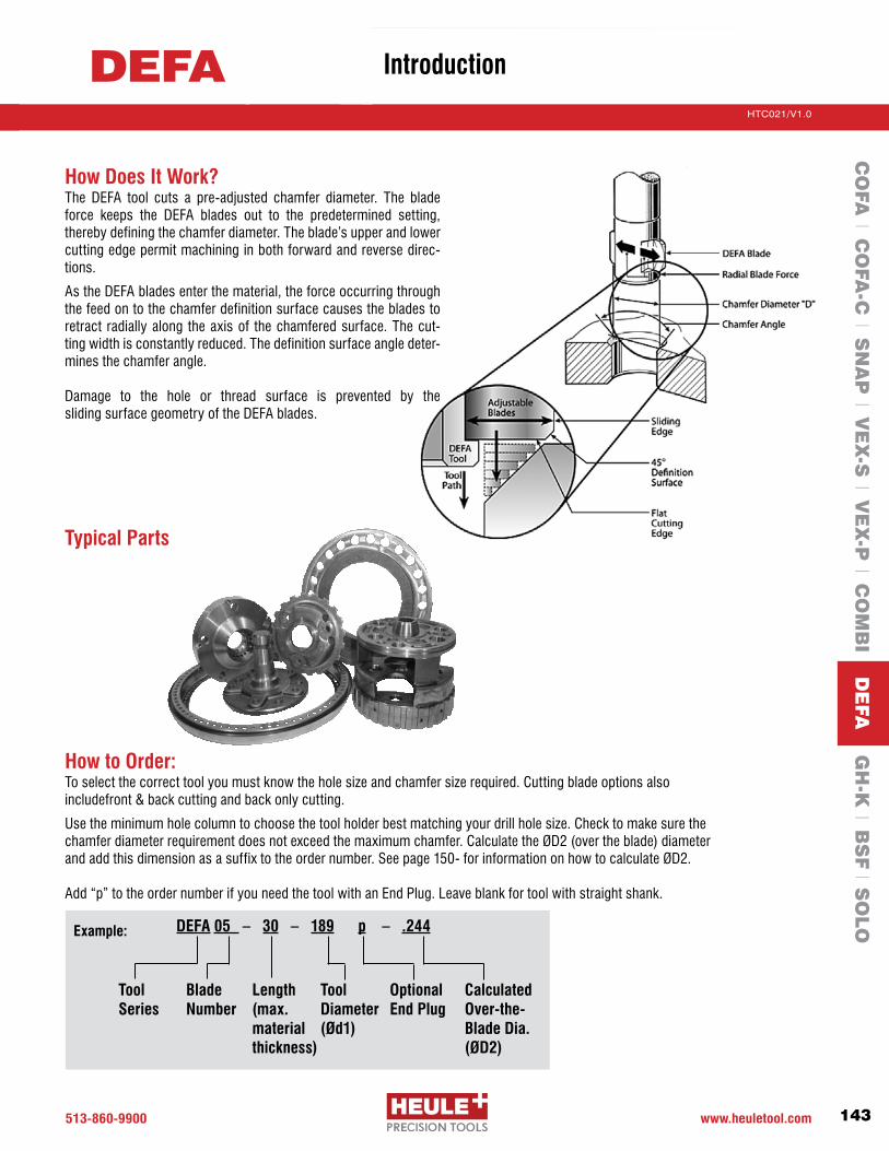
513-860-9900 www.heuletool.com
Catalog No. HTC014
143
HTC021/V1.0
Serie
s
How Does It Work?The DEFA tool cuts a pre-adjusted chamfer diameter. The blade force keeps the DEFA blades out to the predetermined setting, therebydefiningthechamferdiameter.Theblade’supperandlowercutting edge permit machining in both forward and reverse direc-tions.
As the DEFA blades enter the material, the force occurring through the feed on to the chamfer definition surface causes the blades to retract radially along the axis of the chamfered surface. The cut-ting width is constantly reduced. The definition surface angle deter-mines the chamfer angle.
Damage to the hole or thread surface is prevented by the sliding surface geometry of the DEFA blades.
Typical Parts
How to Order:To select the correct tool you must know the hole size and chamfer size required. Cutting blade options also includefront & back cutting and back only cutting.
Use the minimum hole column to choose the tool holder best matching your drill hole size. Check to make sure the chamferdiameterrequirementdoesnotexceedthemaximumchamfer.CalculatetheØD2(overtheblade)diameterandaddthisdimensionasasuffixtotheordernumber.Seepage150-forinformationonhowtocalculateØD2.
Add“p”totheordernumberifyouneedthetoolwithanEndPlug.Leaveblankfortoolwithstraightshank.
CalculatedOver-the-Blade Dia.(ØD2)
Tool Series
Blade Number
Tool Diameter (Ød1)
DEFA 05 – 30 – 189 p – .244Example:
Length(max.materialthickness)
Optional End Plug
DEFAC
OFA
l CO
FA-C
l SN
AP
l VE
X-S
l VE
X-P
l CO
MB
I DE
FA G
H-K
l BS
F l S
OLO
Introduction

513.860.9900 www.heuletool.com
Catalog No. HTC14
144
HTC021/V1.0
Serie
s
DEFA Series 02-06 Ød1 = Ødmin –.2mm (.008”)
Tool Holder without blades
Min. HoleØd
mm inches
Max Chamfer
ØDmm inches
Max ØD2
mm inches LN = 30mm LN = 60mm
Order Number Order Number
TiAlN Blade SetOrder
Number Front/Back Back only
GH-S-M-
To order the tool with a pre-set chamfer size, we recommend adding acalculatedover-the-bladediameter(ØD2=ØD+.024”)asasuffix totheordernumber,otherwiseacalculateddefaultdimensionisused(ØD2=.052”+Ød1).
The first tool in each series are STANDARD TOOLS which should be used when you have a stable set-up and are cutting any material under 28 Rc.
–Add“p”fortoolwithendplug. Leave blank for tool with straight shank.
–Fillinyourcalculatedover-the-bladediameterØD2 = ØD + .024”orØD2=ØD+(2x’s’)
BLADE OPTIONS
PG. 161
SPARE PARTS
PG. 145
CalculatedOver-the-Blade Dia.(ØD2)
Tool Series
Blade Number
Tool Diameter (Ød1)
DEFA 02 – 30 – 150 p – .201Example:
Length(max.materialthickness)
Optional End Plug
Serie
s
02-06DEFA Chamfering Tools – For holes 4.0 - 5.9mm .157-.232”
4.0 .157 DEFA02-30-150- / DEFA02-60-150- / 4.1 .161 4.8 .189 5.4 .213 DEFA02-30-153- / DEFA02-60-153- / -3X02 -4X024.2 .165 DEFA02-30-157- / DEFA02-60-157- / 4.3 .169 DEFA03-30-161- / DEFA03-60-161- /
4.4 .173 5.2 .205 5.8 .229 DEFA03-30-165- / DEFA03-60-165- / -3X03 -4X034.5 .177 DEFA03-30-169- / DEFA03-60-169- / 4.6 .181 DEFA04-30-173- / DEFA04-60-173- / 4.7 .185
5.8 .228 6.4 .252 DEFA04-30-177- / DEFA04-60-177- /
-3X04 -4X044.8 .189 DEFA04-30-181- / DEFA04-60-181- / 4.9 .193 DEFA04-30-185- / DEFA04-60-185- / 5.0 .197 DEFA05-30-189- / DEFA05-60-189- / 5.1 .201 DEFA05-30-193- / DEFA05-60-193- /
-3X05 -4X055.2 .205 6.4 .252 7.0 .276 DEFA05-30-197- / DEFA05-60-197- / 5.3 .209 DEFA05-30-201- / DEFA05-60-201- / 5.4 .213 DEFA05-30-205- / DEFA05-60-205- / 5.5 .216 DEFA06-30-209- / DEFA06-60-209- / 5.6 .220 DEFA06-30-213- / DEFA06-60-213- / 5.7 .224 6.8 .268 7.4 .292 DEFA06-30-216- / DEFA06-60-216- / -3X06 -4X065.8 .228 DEFA06-30-220- / DEFA06-60-220- / 5.9 .232 DEFA06-30-224- / DEFA06-60-224- /
CO
FA l C
OFA
-C l S
NA
P l V
EX
-S l V
EX
-P l C
OM
BI D
EFA
GH
-K l B
SF l S
OLO

513-860-9900 www.heuletool.com
Catalog No. HTC014
145
HTC021/V1.0
Serie
sChamfering Tools – For holes 4.0 - 5.9mm .157-.232”
DEFA Series 02-06 – Blade Housing Chart*
1 GH-H-S-0101 Tension Screw 2 GH-H-S-0322 Set Screw 3 GH-S-E-0001 Eccentric Cam 4 GH-H-S-0201 Clamping Screw 5 GH-S-X-0001 Positioning Screw 6 GH-S-S-0155** 3/8” Straight Shank GH-S-S-0090** End Plug 7 GH-S-G-0001 Tool Body 8 GH-S-C-0001 Gear Wheel 9 GH-S-T-0001 Torsion Spring10 GH-S-W-0002 Blade Control-Length=15mm GH-S-W-0003 Blade Control-Length=30mm GH-S-W-0027* Blade Control-Length=60mm11 Blade Housing See housing chart below 12 Blade Set See table on pg. 144
Spare Parts – DEFA Series 02-06
1
23
4
5
6
4
7
8
9
10
11
12
Order Number Description
*Non-stock standard item with extended delivery time.**Tool bodies are sold with either a straight shank or end plug, please read the ordering instructions to indicate your preference. Other options are available and sold separately. Please contact engineering for details.
DEFA02-30-150 DEFA02-30-153DEFA02-30-157DEFA03-30-161DEFA03-30-165DEFA03-30-169DEFA04-30-173DEFA04-30-177DEFA04-30-181DEFA04-30-185DEFA05-30-189 DEFA05-30-193DEFA05-30-197DEFA05-30-201DEFA05-30-205DEFA06-30-209DEFA06-30-213DEFA06-30-216DEFA06-30-220DEFA06-30-224
GH-S-N-1001GH-S-N-1004GH-S-N-1007GH-S-N-1010GH-S-N-1013GH-S-N-1016GH-S-N-1019GH-S-N-1022GH-S-N-1025GH-S-N-1028GH-S-N-1031GH-S-N-1034GH-S-N-1037GH-S-N-1040GH-S-N-1043GH-S-N-1046GH-S-N-1049GH-S-N-1052GH-S-N-1055GH-S-N-1058
DEFA02-60-150 DEFA02-60-153DEFA02-60-157DEFA03-60-161DEFA03-60-165DEFA03-60-169DEFA04-60-173DEFA04-60-177DEFA04-60-181DEFA04-60-185DEFA05-60-189 DEFA05-60-193DEFA05-60-197DEFA05-60-201DEFA05-60-205DEFA06-60-209DEFA06-60-213DEFA06-60-216DEFA06-60-220DEFA06-60-224
GH-S-N-1002GH-S-N-1005GH-S-N-1008GH-S-N-1011GH-S-N-1014GH-S-N-1017GH-S-N-1020GH-S-N-1023GH-S-N-1026GH-S-N-1029GH-S-N-1032GH-S-N-1035GH-S-N-1038GH-S-N-1041GH-S-N-1044GH-S-N-1047GH-S-N-1050GH-S-N-1053GH-S-N-1056GH-S-N-1059
Tool Holder Order Number
Blade Housing Order Number
Tool Holder Order Number
Blade Housing Order Number
CHANGE BLADES
PG. 165
PG. 163-164PROGRAMMING
Serie
s
02-06DEFA
*Extended delivery time
CO
FA l C
OFA
-C l S
NA
P l V
EX
-S l V
EX
-P l C
OM
BI D
EFA
GH
-K l B
SF l S
OLO
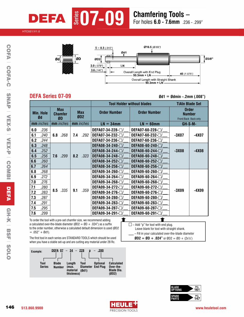
513.860.9900 www.heuletool.com
Catalog No. HTC14
146
HTC021/V1.0
Serie
s
DEFA Series 07-09 Ød1 = Ødmin –.2mm (.008”)
Tool Holder without blades
Min. HoleØd
mm inches
Max Chamfer
ØDmm inches
Max ØD2
mm inches LN = 34mm LN = 60mm
Order Number Order Number
TiAln Blade SetOrder
Number Front/Back Back only
GH-S-M-
6.0 .236 DEFA07-34-228- / DEFA07-60-228- / 6.1 .240 6.8 .268 7.4 .292 DEFA07-34-232- / DEFA07-60-232- / -3X07 -4X076.2 .244 DEFA07-34-236- / DEFA07-60-236- / 6.3 .248 DEFA08-34-240- / DEFA08-60-240- /
6.4 .252 DEFA08-34-244- / DEFA08-60-244- / -3X08 -4X086.5 .256 7.6 .299 8.2 .323 DEFA08-34-248- / DEFA08-60-248- / 6.6 .260 DEFA08-34-252- / DEFA08-60-252- / 6.7 .264
DEFA08-34-256- / DEFA08-60-256- /
6.8 .268 DEFA09-34-260- / DEFA09-60-260- / 6.9 .272 DEFA09-34-264- / DEFA09-60-264- / 7.0 .276 DEFA09-34-268- / DEFA09-60-268- / 7.1 .280 DEFA09-34-272- / DEFA09-60-272- /
-3X09 -4X097.2 .283 8.5 .335 9.1 .359 DEFA09-34-276- / DEFA09-60-276- / 7.3 .287 DEFA09-34-280- / DEFA09-60-280- / 7.4 .291 DEFA09-34-283- / DEFA09-60-283- / 7.5 .295 DEFA09-34-287- / DEFA09-60-287- / 7.6 .299 DEFA09-34-291- / DEFA09-60-291- /
–Add“p”fortoolwithendplug. Leave blank for tool with straight shank.
–Fillinyourcalculatedover-the-bladediameterØD2 = ØD + .024”orØD2=ØD+(2x’s’)
To order the tool with a pre-set chamfer size, we recommend adding acalculatedover-the-bladediameter(ØD2=ØD+.024”)asasuffix totheordernumber,otherwiseacalculateddefaultdimensionisused(ØD2=.052”+Ød1).
The first tool in each series are STANDARD TOOLS which should be used when you have a stable set-up and are cutting any material under 28 Rc.
CalculatedOver-the-Blade Dia.(ØD2)
Tool Series
Blade Number
Tool Diameter (Ød1)
DEFA 07 – 34 – 228 p – .280Example:
Length(max.materialthickness)
Optional End Plug
Serie
s
07-09DEFA Chamfering Tools – For holes 6.0 - 7.6mm .236-.299”
BLADE OPTIONS
PG. 161
SPARE PARTS
PG. 147
CO
FA l C
OFA
-C l S
NA
P l V
EX
-S l V
EX
-P l C
OM
BI D
EFA
GH
-K l B
SF l S
OLO

513-860-9900 www.heuletool.com
Catalog No. HTC014
147
HTC021/V1.0
Serie
sChamfering Tools – For holes 6.0 - 7.6mm .236-.299”
DEFA Series 07-09 – Blade Housing Chart*
1 GH-H-S-0101 Tension Screw 2 GH-H-S-0322 Set Screw 3 GH-S-E-0001 Eccentric Cam 4 GH-H-S-0201 Clamping Screw 5 GH-S-X-0001 Positioning Screw 6 GH-S-S-0155** 3/8” Straight Shank GH-S-S-0090** End Plug 7 GH-S-G-0001 Tool Body 8 GH-S-C-0001 Gear Wheel 9 GH-S-T-0001 Torsion Spring10 GH-S-W-0604 Blade Control-Length=20mm GH-S-W-0605 Blade Control-Length=34mm GH-S-W-0628* Blade Control-Length=60mm11 Blade Housing See housing chart below 12 Blade Set See table on pg. 146
Spare Parts – DEFA Series 07-09
1
23
4
5
6
4
7
8
9
10
11
12
Order Number Description
*Non-stock standard item with extended delivery time.**Tool bodies are sold with either a straight shank or end plug, please read the ordering instructions to indicate your preference. Other options are available and sold separately. Please contact engineering for details.
DEFA07-34-228 DEFA07-34-232DEFA07-34-236DEFA08-34-240DEFA08-34-244DEFA08-34-248DEFA08-34-252DEFA08-34-256DEFA09-34-260DEFA09-34-264DEFA09-34-268DEFA09-34-272DEFA09-34-276DEFA09-34-280DEFA09-34-283DEFA09-34-287DEFA09-34-291
GH-S-N-1082GH-S-N-1085GH-S-N-1088GH-S-N-1091GH-S-N-1094GH-S-N-1097GH-S-N-1100GH-S-N-1103GH-S-N-1106GH-S-N-1109GH-S-N-1112GH-S-N-1115GH-S-N-1118GH-S-N-1121GH-S-N-1124GH-S-N-1127GH-S-N-1130
DEFA07-60-228 DEFA07-60-232DEFA07-60-236DEFA08-60-240DEFA08-60-244DEFA08-60-248DEFA08-60-252DEFA08-60-256DEFA09-60-260DEFA09-60-264DEFA09-60-268 DEFA09-60-272DEFA09-60-276DEFA09-60-280DEFA09-60-283DEFA09-60-287DEFA09-60-291
GH-S-N-1083GH-S-N-1086GH-S-N-1089GH-S-N-1092GH-S-N-1095GH-S-N-1098GH-S-N-1101GH-S-N-1104GH-S-N-1107GH-S-N-1110GH-S-N-1113GH-S-N-1116GH-S-N-1119GH-S-N-1122GH-S-N-1125GH-S-N-1128GH-S-N-1131
Tool Holder Order Number
Blade Housing Order Number
Tool Holder Order Number
Blade Housing Order Number
Serie
s
07-09DEFA Spare Parts
*Extended delivery time
CHANGE BLADES
PG. 165
PG. 163-164PROGRAMMING
CO
FA l C
OFA
-C l S
NA
P l V
EX
-S l V
EX
-P l C
OM
BI D
EFA
GH
-K l B
SF l S
OLO

513.860.9900 www.heuletool.com
Catalog No. HTC14
148
HTC021/V1.0
Serie
s
Tool Holder without blades
Min. HoleØd
mm inches
Max Chamfer
ØDmm inches
Max ØD2
mm inches LN = 34mm LN = 60mm
Order Number Order Number
TiAlN Blade SetOrder
Number Front/Back Back only
GH-S-M-
7.7 .303 DEFA10-34-295- / DEFA10-60-295- / 7.8 .307 DEFA10-34-299- / DEFA10-60-299- / 7.9 .311 9.6 .378 10.4 .410 DEFA10-34-303- / DEFA10-60-303- / -3X10 -4X108.0 .315 DEFA10-34-307- / DEFA10-60-307- /
8.1 .319 DEFA10-34-311- / DEFA10-60-311- / 8.2 .323 DEFA11-34-315- / DEFA11-60-315- / 8.3 .327 DEFA11-34-319- / DEFA11-60-319- / 8.4 .331
DEFA11-34-323- / DEFA11-60-323- /
8.5 .335 DEFA11-34-327- / DEFA11-60-327- / 8.6 .339 10.4 .409 11.2 .441 DEFA11-34-331- / DEFA11-60-331- / -3X11 -4X11
8.7 .343 DEFA11-34-335- / DEFA11-60-335- / 8.8 .346 DEFA11-34-339- / DEFA11-60-339- / 8.9 .350 DEFA11-34-343- / DEFA11-60-343- /
DEFA Series 10-11 Ød1 = Ødmin –.2mm (.008”)
–Add“p”fortoolwithendplug. Leave blank for tool with straight shank.
–Fillinyourcalculatedover-the-bladediameterØD2 = ØD + .032”orØD2=ØD+(2x’s’)
To order the tool with a pre-set chamfer size, we recommend adding acalculatedover-the-bladediameter(ØD2=ØD+.032”)asasuffix totheordernumber,otherwiseacalculateddefaultdimensionisused(ØD2=.060”+Ød1).
The first tool in each series are STANDARD TOOLS which should be used when you have a stable set-up and are cutting any material under 28 Rc.
CalculatedOver-the-Blade Dia.(ØD2)
Tool Series
Blade Number
Tool Diameter (Ød1)
DEFA 10 – 34 – 295 p – .355Example:
Length(max.materialthickness)
Optional End Plug
Serie
s
10-11DEFA Chamfering Tools – For holes 7.7 - 8.9mm .303-.350”
CO
FA l C
OFA
-C l S
NA
P l V
EX
-S l V
EX
-P l C
OM
BI D
EFA
GH
-K l B
SF l S
OLO
BLADE OPTIONS
PG. 161
SPARE PARTS
PG. 149

513-860-9900 www.heuletool.com
Catalog No. HTC014
149
HTC021/V1.0
Serie
sChamfering Tools – For holes 7.7 - 8.9mm .303-.350”
DEFA Series 10-11 – Blade Housing Chart*
1 GH-H-S-0101 Tension Screw 2 GH-H-S-0322 Set Screw 3 GH-S-E-0001 Eccentric Cam 4 GH-H-S-0201 Clamping Screw 5 GH-S-X-0001 Positioning Screw 6 GH-S-S-0155** 3/8” Straight Shank GH-S-S-0090** End Plug 7 GH-S-G-0001 Tool Body 8 GH-S-C-0001 Gear Wheel 9 GH-S-T-0001 Torsion Spring10 GH-S-W-0604 Blade Control-Length=20mm GH-S-W-0605 Blade Control-Length=34mm GH-S-W-0628* Blade Control-Length=60mm11 Blade Housing See housing chart below 12 Blade Set See table on pg. 148
Spare Parts – DEFA Series 10-11
1
23
4
5
6
4
7
8
9
10
11
12
Order Number Description
*Non-stock standard item with extended delivery time.**Tool bodies are sold with either a straight shank or end plug, please read the ordering instructions to indicate your preference. Other options are available and sold separately. Please contact engineering for details.
DEFA10-34-295 DEFA10-34-299DEFA10-34-303DEFA10-34-307DEFA10-34-311DEFA11-34-315DEFA11-34-319DEFA11-34-323DEFA11-34-327DEFA11-34-331DEFA11-34-335DEFA11-34-339DEFA11-34-343
GH-S-N-1151GH-S-N-1154GH-S-N-1157GH-S-N-1160GH-S-N-1163GH-S-N-1166GH-S-N-1169GH-S-N-1172GH-S-N-1175GH-S-N-1178GH-S-N-1181GH-S-N-1184GH-S-N-1187
DEFA10-60-295 DEFA10-60-299DEFA10-60-303DEFA10-60-307DEFA10-60-311DEFA11-60-315DEFA11-60-319DEFA11-60-323DEFA11-60-327DEFA11-60-331DEFA11-60-335 DEFA11-60-339DEFA11-60-343
GH-S-N-1152GH-S-N-1155GH-S-N-1158GH-S-N-1161GH-S-N-1164GH-S-N-1167GH-S-N-1170GH-S-N-1173GH-S-N-1176GH-S-N-1179GH-S-N-1182GH-S-N-1185GH-S-N-1188
Tool Holder Order Number
Blade Housing Order Number
Tool Holder Order Number
Blade Housing Order Number
Serie
s
10-11DEFA Spare Parts
*Extended delivery time
CO
FA l C
OFA
-C l S
NA
P l V
EX
-S l V
EX
-P l C
OM
BI D
EFA
GH
-K l B
SF l S
OLO
CHANGE BLADES
PG. 165
PG. 163-164PROGRAMMING
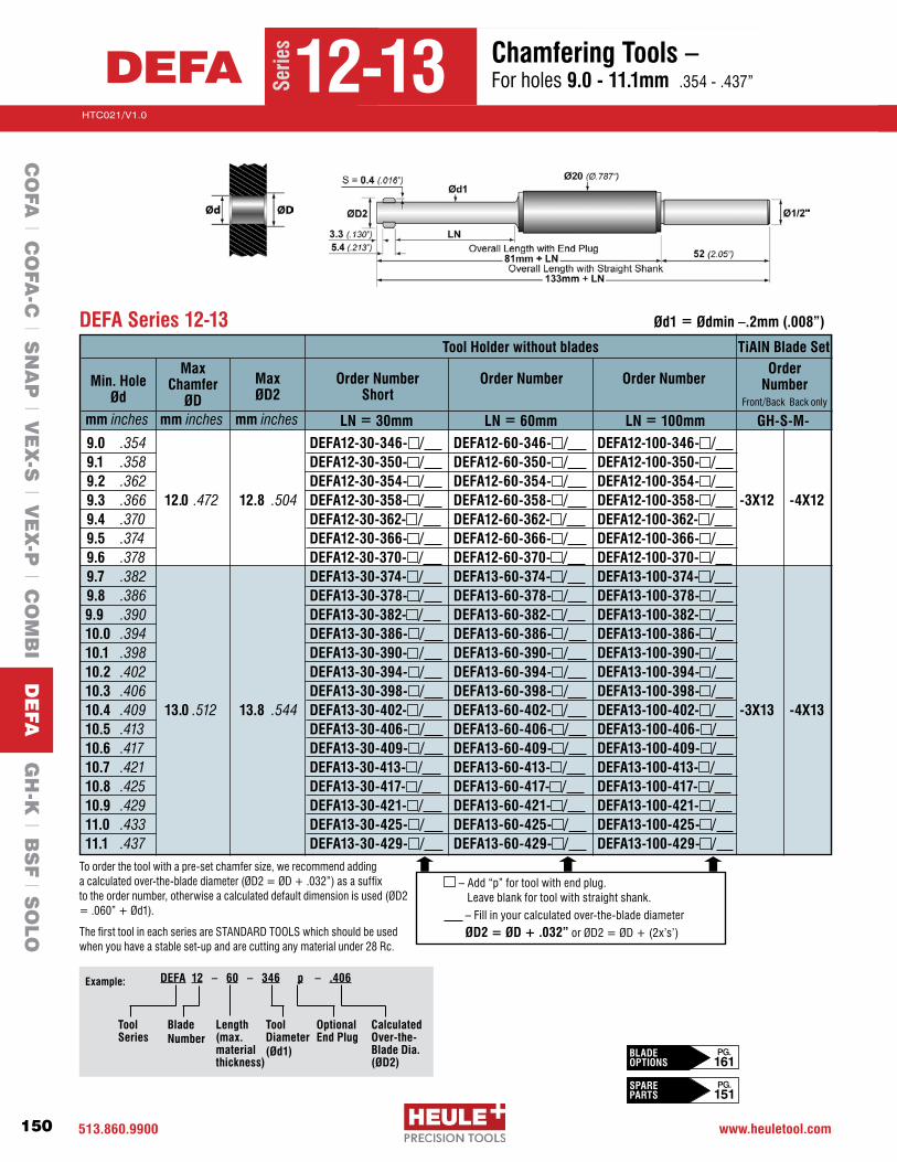
513.860.9900 www.heuletool.com
Catalog No. HTC14
150
HTC021/V1.0
Serie
s
Tool Holder without blades
Min. HoleØd
mm inches
Max Chamfer
ØDmm inches
Max ØD2
mm inches LN = 30mm LN = 60mm LN = 100mm
Order Number Short
Order Number Order Number
TiAlN Blade SetOrder
Number Front/Back Back only
GH-S-M-
9.0 .354 DEFA12-30-346- / DEFA12-60-346- / DEFA12-100-346- / 9.1 .358 DEFA12-30-350- / DEFA12-60-350- / DEFA12-100-350- / 9.2 .362 DEFA12-30-354- / DEFA12-60-354- / DEFA12-100-354- / 9.3 .366 12.0 .472 12.8 .504 DEFA12-30-358- / DEFA12-60-358- / DEFA12-100-358- / -3X12 -4X12
9.4 .370 DEFA12-30-362- / DEFA12-60-362- / DEFA12-100-362- / 9.5 .374 DEFA12-30-366- / DEFA12-60-366- / DEFA12-100-366- / 9.6 .378 DEFA12-30-370- / DEFA12-60-370- / DEFA12-100-370- / 9.7 .382
DEFA13-30-374- / DEFA13-60-374- / DEFA13-100-374- /
9.8 .386 DEFA13-30-378- / DEFA13-60-378- / DEFA13-100-378- / 9.9 .390 DEFA13-30-382- / DEFA13-60-382- / DEFA13-100-382- / 10.0 .394 DEFA13-30-386- / DEFA13-60-386- / DEFA13-100-386- / 10.1 .398 DEFA13-30-390- / DEFA13-60-390- / DEFA13-100-390- / 10.2 .402 DEFA13-30-394- / DEFA13-60-394- / DEFA13-100-394- / 10.3 .406 DEFA13-30-398- / DEFA13-60-398- / DEFA13-100-398- / 10.4 .409 13.0 .512 13.8 .544 DEFA13-30-402- / DEFA13-60-402- / DEFA13-100-402- / -3X13 -4X1310.5 .413
DEFA13-30-406- / DEFA13-60-406- / DEFA13-100-406- /
10.6 .417 DEFA13-30-409- / DEFA13-60-409- / DEFA13-100-409- / 10.7 .421 DEFA13-30-413- / DEFA13-60-413- / DEFA13-100-413- / 10.8 .425 DEFA13-30-417- / DEFA13-60-417- / DEFA13-100-417- / 10.9 .429 DEFA13-30-421- / DEFA13-60-421- / DEFA13-100-421- / 11.0 .433 DEFA13-30-425- / DEFA13-60-425- / DEFA13-100-425- / 11.1 .437 DEFA13-30-429- / DEFA13-60-429- / DEFA13-100-429- /
DEFA Series 12-13 Ød1 = Ødmin –.2mm (.008”)
–Add“p”fortoolwithendplug. Leave blank for tool with straight shank.
–Fillinyourcalculatedover-the-bladediameterØD2 = ØD + .032”orØD2=ØD+(2x’s’)
To order the tool with a pre-set chamfer size, we recommend adding acalculatedover-the-bladediameter(ØD2=ØD+.032”)asasuffix totheordernumber,otherwiseacalculateddefaultdimensionisused(ØD2=.060”+Ød1).
The first tool in each series are STANDARD TOOLS which should be used when you have a stable set-up and are cutting any material under 28 Rc.
CalculatedOver-the-Blade Dia.(ØD2)
Tool Series
Blade Number
Tool Diameter (Ød1)
DEFA 12 – 60 – 346 p – .406Example:
Length(max.materialthickness)
Optional End Plug
Serie
s
12-13DEFA Chamfering Tools – For holes 9.0 - 11.1mm .354-.437”
CO
FA l C
OFA
-C l S
NA
P l V
EX
-S l V
EX
-P l C
OM
BI D
EFA
GH
-K l B
SF l S
OLO
BLADE OPTIONS
PG. 161
SPARE PARTS
PG. 151
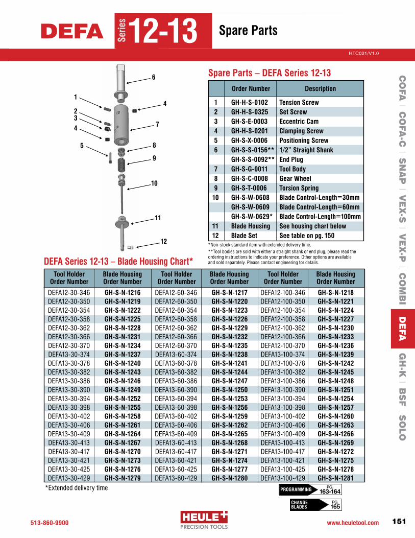
513-860-9900 www.heuletool.com
Catalog No. HTC014
151
HTC021/V1.0
Serie
sChamfering Tools – For holes 9.0 - 11.1mm .354-.437”
DEFA Series 12-13 – Blade Housing Chart*
1 GH-H-S-0102 Tension Screw 2 GH-H-S-0325 Set Screw 3 GH-S-E-0003 Eccentric Cam 4 GH-H-S-0201 Clamping Screw 5 GH-S-X-0006 Positioning Screw 6 GH-S-S-0156** 1/2” Straight Shank GH-S-S-0092** End Plug 7 GH-S-G-0011 Tool Body 8 GH-S-C-0008 Gear Wheel 9 GH-S-T-0006 Torsion Spring10 GH-S-W-0608 Blade Control-Length=30mm GH-S-W-0609 Blade Control-Length=60mm GH-S-W-0629* Blade Control-Length=100mm11 Blade Housing See housing chart below 12 Blade Set See table on pg. 150
Spare Parts – DEFA Series 12-13
Tool Holder Order Number
GH-S-N-1216GH-S-N-1219GH-S-N-1222GH-S-N-1225GH-S-N-1228GH-S-N-1231GH-S-N-1234GH-S-N-1237GH-S-N-1240GH-S-N-1243GH-S-N-1246GH-S-N-1249GH-S-N-1252GH-S-N-1255GH-S-N-1258GH-S-N-1261GH-S-N-1264GH-S-N-1267GH-S-N-1270GH-S-N-1273GH-S-N-1276GH-S-N-1279
1
234
5
6
4
7
8
9
10
11
12
Order Number Description
*Non-stock standard item with extended delivery time.**Tool bodies are sold with either a straight shank or end plug, please read the ordering instructions to indicate your preference. Other options are available and sold separately. Please contact engineering for details.
DEFA12-60-346 DEFA12-60-350DEFA12-60-354DEFA12-60-358DEFA12-60-362DEFA12-60-366DEFA12-60-370DEFA13-60-374DEFA13-60-378DEFA13-60-382DEFA13-60-386 DEFA13-60-390DEFA13-60-394DEFA13-60-398DEFA13-60-402DEFA13-60-406DEFA13-60-409DEFA13-60-413DEFA13-60-417DEFA13-60-421DEFA13-60-425DEFA13-60-429
GH-S-N-1217GH-S-N-1220GH-S-N-1223GH-S-N-1226GH-S-N-1229GH-S-N-1232GH-S-N-1235GH-S-N-1238GH-S-N-1241GH-S-N-1244GH-S-N-1247GH-S-N-1250GH-S-N-1253GH-S-N-1256GH-S-N-1259GH-S-N-1262GH-S-N-1265GH-S-N-1268GH-S-N-1271GH-S-N-1274GH-S-N-1277GH-S-N-1280
DEFA12-100-346 DEFA12-100-350DEFA12-100-354DEFA12-100-358DEFA12-100-362DEFA12-100-366DEFA12-100-370DEFA13-100-374DEFA13-100-378DEFA13-100-382DEFA13-100-386 DEFA13-100-390DEFA13-100-394DEFA13-100-398DEFA13-100-402DEFA13-100-406DEFA13-100-409DEFA13-100-413DEFA13-100-417DEFA13-100-421DEFA13-100-425DEFA13-100-429
GH-S-N-1218GH-S-N-1221GH-S-N-1224GH-S-N-1227GH-S-N-1230GH-S-N-1233GH-S-N-1236GH-S-N-1239GH-S-N-1242GH-S-N-1245GH-S-N-1248GH-S-N-1251GH-S-N-1254GH-S-N-1257GH-S-N-1260GH-S-N-1263GH-S-N-1266GH-S-N-1269GH-S-N-1272GH-S-N-1275GH-S-N-1278GH-S-N-1281
Blade Housing Order Number
Tool Holder Order Number
Blade Housing Order Number
Tool Holder Order Number
Blade Housing Order Number
DEFA12-30-346 DEFA12-30-350DEFA12-30-354DEFA12-30-358DEFA12-30-362DEFA12-30-366DEFA12-30-370DEFA13-30-374DEFA13-30-378DEFA13-30-382DEFA13-30-386 DEFA13-30-390DEFA13-30-394DEFA13-30-398DEFA13-30-402DEFA13-30-406DEFA13-30-409DEFA13-30-413DEFA13-30-417DEFA13-30-421DEFA13-30-425DEFA13-30-429
Serie
s
12-13DEFA Spare Parts
*Extended delivery time
CO
FA l C
OFA
-C l S
NA
P l V
EX
-S l V
EX
-P l C
OM
BI D
EFA
GH
-K l B
SF l S
OLO
CHANGE BLADES
PG. 165
PG. 163-164PROGRAMMING
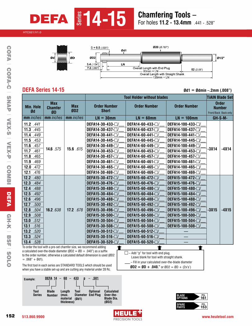
513.860.9900 www.heuletool.com
Catalog No. HTC14
152
HTC021/V1.0
Serie
s
Tool Holder without blades
Min. HoleØd
mm inches
Max Chamfer
ØDmm inches
Max ØD2
mm inches LN = 30mm LN = 60mm LN = 100mm
Order Number Short
Order Number Order Number
TiAlN Blade SetOrder
Number Front/Back Back only
GH-S-M-
11.2 .441 DEFA14-30-433- / DEFA14-60-433- / DEFA14-100-433- / 11.3 .445 DEFA14-30-437- / DEFA14-60-437- / DEFA14-100-437- / 11.4 .449 DEFA14-30-441- / DEFA14-60-441- / DEFA14-100-441- / 11.5 .453 DEFA14-30-445- / DEFA14-60-445- / DEFA14-100-445- / 11.6 .457 DEFA14-30-449- / DEFA14-60-449- / DEFA14-100-449- / 11.7 .461 14.6 .575 15.6 .615 DEFA14-30-453- / DEFA14-60-453- / DEFA14-100-453- / -3X14 -4X14
11.8 .465 DEFA14-30-457- / DEFA14-60-457- / DEFA14-100-457- / 11.9 .469
DEFA14-30-461- / DEFA14-60-461- / DEFA14-100-461- /
12.0 .472 DEFA14-30-465- / DEFA14-60-465- / DEFA14-100-465- / 12.1 .476 DEFA14-30-469- / DEFA14-60-469- / DEFA14-100-469- / 12.2 .480 DEFA15-30-472- / DEFA15-60-472- / DEFA15-100-472- / 12.3 .484 DEFA15-30-476- / DEFA15-60-476- / DEFA15-100-476- / 12.4 .488 DEFA15-30-480- / DEFA15-60-480- / DEFA15-100-480- / 12.5 .492 DEFA15-30-484- / DEFA15-60-484- / DEFA15-100-484- / 12.6 .496 DEFA15-30-488- / DEFA15-60-488- / DEFA15-100-488- / 12.7 .500
DEFA15-30-492- / DEFA15-60-492- / DEFA15-100-492- /
12.8 .504 16.2 .638 17.2 .678 DEFA15-30-496- / DEFA15-60-496- / DEFA15-100-496- / -3X15 -4X1512.9 .508 DEFA15-30-500- / DEFA15-60-500- / DEFA15-100-500- / 13.0 .512 DEFA15-30-504- / DEFA15-60-504- / DEFA15-100-504- / 13.1 .516 DEFA15-30-508- / DEFA15-60-508- / DEFA15-100-508- / 13.2 .520 DEFA15-30-512- / DEFA15-60-512- / —13.3 .524 DEFA15-30-516- / DEFA15-60-516- / —13.4 .528 DEFA15-30-520- / DEFA15-60-520- / —
DEFA Series 14-15 Ød1 = Ødmin –.2mm (.008”)
–Add“p”fortoolwithendplug. Leave blank for tool with straight shank.
–Fillinyourcalculatedover-the-bladediameterØD2 = ØD + .040.”orØD2=ØD+(2x’s’)
To order the tool with a pre-set chamfer size, we recommend adding acalculatedover-the-bladediameter(ØD2=ØD+.040”)asasuffix totheordernumber,otherwiseacalculateddefaultdimensionisused(ØD2=.068”+Ød1).
The first tool in each series are STANDARD TOOLS which should be used when you have a stable set-up and are cutting any material under 28 Rc.
CalculatedOver-the-Blade Dia.(ØD2)
Tool Series
Blade Number
Tool Diameter (Ød1)
DEFA 14 – 60 – 433 p – .501Example:
Length(max.materialthickness)
Optional End Plug
Serie
s
14-15DEFA Chamfering Tools – For holes 11.2 - 13.4mm .441-.528”
CO
FA l C
OFA
-C l S
NA
P l V
EX
-S l V
EX
-P l C
OM
BI D
EFA
GH
-K l B
SF l S
OLO
BLADE OPTIONS
PG. 161
SPARE PARTS
PG. 153

513-860-9900 www.heuletool.com
Catalog No. HTC014
153
HTC021/V1.0
Serie
sChamfering Tools – For holes 11.2 - 13.4mm .441-.528”
1
234
5
6
4
7
8
9
10
11
12
DEFA Series 14-15 – Blade Housing Chart*
1 GH-H-S-0102 Tension Screw 2 GH-H-S-0325 Set Screw 3 GH-S-E-0003 Eccentric Cam 4 GH-H-S-0201 Clamping Screw 5 GH-S-X-0006 Positioning Screw 6 GH-S-S-0156** 1/2” Straight Shank GH-S-S-0092** End Plug 7 GH-S-G-0011 Tool Body 8 GH-S-C-0008 Gear Wheel 9 GH-S-T-0006 Torsion Spring10 GH-S-W-0611 Blade Control-Length=30mm GH-S-W-0612 Blade Control-Length=60mm GH-S-W-0630* Blade Control-Length=100mm11 Blade Housing See housing chart below 12 Blade Set See table on pg. 152
Spare Parts – DEFA Series 14-15
Order Number Description
*Non-stock standard item with extended delivery time.**Tool bodies are sold with either a straight shank or end plug, please read the ordering instructions to indicate your preference. Other options are available and sold separately. Please contact engineering for details.
Tool Holder Order Number
GH-S-N-1327GH-S-N-1330GH-S-N-1333GH-S-N-1336GH-S-N-1339GH-S-N-1342GH-S-N-1345GH-S-N-1348GH-S-N-1351GH-S-N-1354GH-S-N-1357GH-S-N-1360GH-S-N-1363GH-S-N-1366GH-S-N-1369GH-S-N-1372GH-S-N-1375GH-S-N-1378GH-S-N-1381GH-S-N-1384GH-S-N-1387GH-S-N-1390GH-S-N-1393
DEFA14-60-433 DEFA14-60-437DEFA14-60-441DEFA14-60-445DEFA14-60-449DEFA14-60-453DEFA14-60-457DEFA14-60-461DEFA14-60-465DEFA14-60-469DEFA15-60-472DEFA15-60-476DEFA15-60-480DEFA15-60-484DEFA15-60-488DEFA15-60-492DEFA15-60-496DEFA15-60-500DEFA15-60-504DEFA15-60-508DEFA15-60-512DEFA15-60-516DEFA15-60-520
GH-S-N-1328GH-S-N-1331GH-S-N-1334GH-S-N-1337GH-S-N-1340GH-S-N-1343GH-S-N-1346GH-S-N-1349GH-S-N-1352GH-S-N-1355GH-S-N-1358GH-S-N-1361GH-S-N-1364GH-S-N-1367GH-S-N-1370GH-S-N-1373GH-S-N-1376GH-S-N-1379GH-S-N-1382GH-S-N-1385GH-S-N-1388GH-S-N-1391GH-S-N-1394
DEFA14-100-433 DEFA14-100-437DEFA14-100-441DEFA14-100-445DEFA14-100-449DEFA14-100-453DEFA14-100-457DEFA14-100-461DEFA14-100-465DEFA14-100-469DEFA15-100-472DEFA15-100-476DEFA15-100-480DEFA15-100-484DEFA15-100-488DEFA15-100-492DEFA15-100-496DEFA15-100-500DEFA15-100-504DEFA15-100-508
———
GH-S-N-1329GH-S-N-1332GH-S-N-1335GH-S-N-1338GH-S-N-1341GH-S-N-1344GH-S-N-1347GH-S-N-1350GH-S-N-1353GH-S-N-1356GH-S-N-1359GH-S-N-1362GH-S-N-1365GH-S-N-1368GH-S-N-1371GH-S-N-1374GH-S-N-1377GH-S-N-1380GH-S-N-1383GH-S-N-1386
— — —
Blade Housing Order Number
Tool Holder Order Number
Blade Housing Order Number
Tool Holder Order Number
Blade Housing Order Number
DEFA14-30-433 DEFA14-30-437DEFA14-30-441DEFA14-30-445DEFA14-30-449DEFA14-30-453DEFA14-30-457DEFA14-30-461DEFA14-30-465DEFA14-30-469DEFA15-30-472DEFA15-30-476DEFA15-30-480DEFA15-30-484DEFA15-30-488DEFA15-30-492DEFA15-30-496DEFA15-30-500DEFA15-30-504DEFA15-30-508DEFA15-30-512DEFA15-30-516DEFA15-30-520
Serie
s
14-15DEFA Spare Parts
*Extended delivery time
CO
FA l C
OFA
-C l S
NA
P l V
EX
-S l V
EX
-P l C
OM
BI D
EFA
GH
-K l B
SF l S
OLO
CHANGE BLADES
PG. 165
PG. 163-164PROGRAMMING

513.860.9900 www.heuletool.com
Catalog No. HTC14
154
HTC021/V1.0
Serie
s
Tool Holder without blades
Min. HoleØd
mm inches
Max Chamfer
ØDmm inches
Max ØD2
mm inches LN = 30mm LN = 60mm LN = 100mm
Order Number Short
Order Number Order Number
TiAlN Blade SetOrder
Number Front/Back Back only
GH-S-M-
13.2 .520 DEFA16-30-512- / DEFA16-60-512- / DEFA16-100-512- / 13.4 .528 DEFA16-30-520- / DEFA16-60-520- / DEFA16-100-520- / 13.6 .535 DEFA16-30-528- / DEFA16-60-528- / DEFA16-100-528- / 13.8 .543 DEFA16-30-535- / DEFA16-60-535- / DEFA16-100-535- / 14.0 .551 DEFA16-30-543- / DEFA16-60-543- / DEFA16-100-543- / 14.2 .559 17.6 .693 18.6 .733 DEFA16-30-551- / DEFA16-60-551- / DEFA16-100-551- / -3X16 -4X16
14.4 .567 DEFA16-30-559- / DEFA16-60-559- / DEFA16-100-559- / 14.6 .575 DEFA16-30-567- / DEFA16-60-567- / DEFA16-100-567- / 14.8 .583
DEFA16-30-575- / DEFA16-60-575- / DEFA16-100-575- /
15.0 .591 DEFA16-30-583- / DEFA16-60-583- / DEFA16-100-583- / 15.2 .598 DEFA17-30-591- / DEFA17-60-591- / DEFA17-100-591- / 15.4 .606 DEFA17-30-598- / DEFA17-60-598- / DEFA17-100-598- / 15.6 .614 DEFA17-30-606- / DEFA17-60-606- / DEFA17-100-606- / 15.8 .622 DEFA17-30-614- / DEFA17-60-614- / DEFA17-100-614- / 16.0 .630 19.0 .748 20.0 .788 DEFA17-30-622- / DEFA17-60-622- / DEFA17-100-622- / -3X17 -4X17
16.2 .638 DEFA17-30-630- / DEFA17-60-630- / DEFA17-100-630- / 16.4 .646 DEFA17-30-638- / DEFA17-60-638- / DEFA17-100-638- / 16.6 .654 DEFA17-30-646- / DEFA17-60-646- / DEFA17-100-646- /
DEFA Series 16-17 Ød1 = Ødmin –.2mm (.008”)
–Add“p”fortoolwithendplug. Leave blank for tool with straight shank.
–Fillinyourcalculatedover-the-bladediameterØD2 = ØD + .040.”orØD2=ØD+(2x’s’)
To order the tool with a pre-set chamfer size, we recommend adding acalculatedover-the-bladediameter(ØD2=ØD+.040”)asasuffix totheordernumber,otherwiseacalculateddefaultdimensionisused(ØD2=.068”+Ød1).
The first tool in each series are STANDARD TOOLS which should be used when you have a stable set-up and are cutting any material under 28 Rc.
CalculatedOver-the-Blade Dia.(ØD2)
Tool Series
Blade Number
Tool Diameter (Ød1)
DEFA 16 – 60 – 512 p – .580Example:
Length(max.materialthickness)
Optional End Plug
Serie
s
16-17DEFA Chamfering Tools – For holes 13.2 - 16.6mm .520-.654”
CO
FA l C
OFA
-C l S
NA
P l V
EX
-S l V
EX
-P l C
OM
BI D
EFA
GH
-K l B
SF l S
OLO
BLADE OPTIONS
PG. 161
SPARE PARTS
PG. 155

513-860-9900 www.heuletool.com
Catalog No. HTC014
155
HTC021/V1.0
Serie
sChamfering Tools – For holes 13.2 - 16.6mm .520-.654”
DEFA Series 16-17 – Blade Housing Chart*
1 GH-H-S-0102 Tension Screw 2 GH-H-S-0325 Set Screw 3 GH-S-E-0003 Eccentric Cam 4 GH-H-S-0201 Clamping Screw 5 GH-S-X-0006 Positioning Screw 6 GH-S-S-0156** 1/2” Straight Shank GH-S-S-0092** End Plug 7 GH-S-G-0011 Tool Body 8 GH-S-C-0008 Gear Wheel 9 GH-S-T-0006 Torsion Spring10 GH-S-W-0611 Blade Control-Length=30mm GH-S-W-0612 Blade Control-Length=60mm GH-S-W-0630* Blade Control-Length=100mm11 Blade Housing See housing chart below 12 Blade Set See table on pg. 154
Spare Parts – DEFA Series 16-17
Tool Holder Order Number
GH-S-N-1465GH-S-N-1471GH-S-N-1477GH-S-N-1483 GH-S-N-1489GH-S-N-1495GH-S-N-1501GH-S-N-1507GH-S-N-1513GH-S-N-1519GH-S-N-1525GH-S-N-1531GH-S-N-1537GH-S-N-1543GH-S-N-1549GH-S-N-1555GH-S-N-1561GH-S-N-1567
1
23
4
5
6
4
7
8
9
10
11
12
Order Number Description
*Non-stock standard item with extended delivery time.**Tool bodies are sold with either a straight shank or end plug, please read the ordering instructions to indicate your preference. Other options are available and sold separately. Please contact engineering for details.
DEFA16-60-512 DEFA16-60-520DEFA16-60-528DEFA16-60-535DEFA16-60-543DEFA16-60-551DEFA16-60-559DEFA16-60-567DEFA16-60-575DEFA16-60-583DEFA17-60-591 DEFA17-60-598DEFA17-60-606DEFA17-60-614DEFA17-60-622DEFA17-60-630 DEFA17-60-638DEFA17-60-646
GH-S-N-1466GH-S-N-1472GH-S-N-1478GH-S-N-1484GH-S-N-1490GH-S-N-1496GH-S-N-1502GH-S-N-1508GH-S-N-1514GH-S-N-1520GH-S-N-1526GH-S-N-1532GH-S-N-1538GH-S-N-1544GH-S-N-1550GH-S-N-1556GH-S-N-1562GH-S-N-1568
DEFA16-100-512 DEFA16-100-520DEFA16-100-528DEFA16-100-535DEFA16-100-543DEFA16-100-551DEFA16-100-559DEFA16-100-567DEFA16-100-575DEFA16-100-583DEFA17-100-591 DEFA17-100-598DEFA17-100-606DEFA17-100-614DEFA17-100-622DEFA17-100-630 DEFA17-100-638DEFA17-100-646
GH-S-N-1467GH-S-N-1473GH-S-N-1479GH-S-N-1485GH-S-N-1491GH-S-N-1497GH-S-N-1503GH-S-N-1509GH-S-N-1515GH-S-N-1521GH-S-N-1527GH-S-N-1533GH-S-N-1539GH-S-N-1545GH-S-N-1551GH-S-N-1557GH-S-N-1563GH-S-N-1569
Blade Housing Order Number
Tool Holder Order Number
Blade Housing Order Number
Tool HolderOrder Number
Blade Housing Order Number
DEFA16-30-512 DEFA16-30-520DEFA16-30-528DEFA16-30-535DEFA16-30-543DEFA16-30-551DEFA16-30-559DEFA16-30-567DEFA16-30-575DEFA16-30-583DEFA17-30-591 DEFA17-30-598DEFA17-30-606DEFA17-30-614DEFA17-30-622DEFA17-30-630DEFA17-30-638 DEFA17-30-646
Serie
s
16-17DEFA Spare Parts
*Extended delivery time
CO
FA l C
OFA
-C l S
NA
P l V
EX
-S l V
EX
-P l C
OM
BI D
EFA
GH
-K l B
SF l S
OLO
CHANGE BLADES
PG. 165
PG. 163-164PROGRAMMING
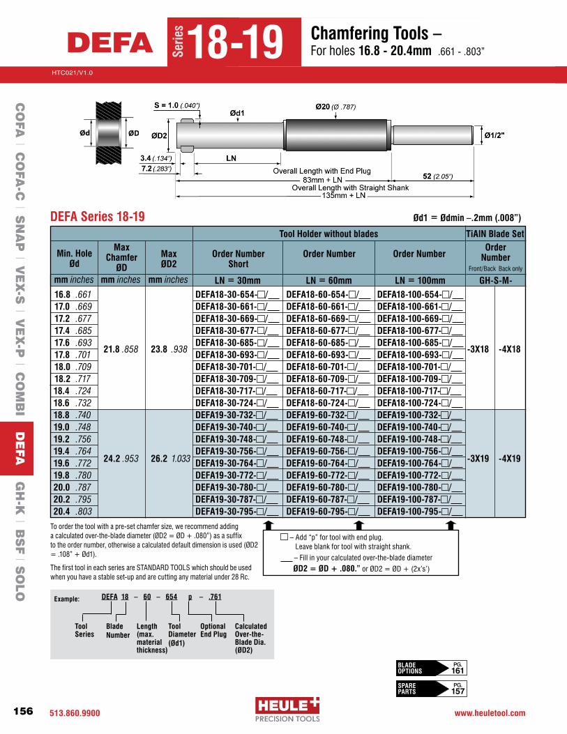
513.860.9900 www.heuletool.com
Catalog No. HTC14
156
HTC021/V1.0
Serie
s
Tool Holder without blades
Min. HoleØd
mm inches
Max Chamfer
ØDmm inches
Max ØD2
mm inches LN = 30mm LN = 60mm LN = 100mm
Order Number Short
Order Number Order Number
TiAlN Blade SetOrder
Number Front/Back Back only
GH-S-M-
16.8 .661 DEFA18-30-654- / DEFA18-60-654- / DEFA18-100-654- / 17.0 .669 DEFA18-30-661- / DEFA18-60-661- / DEFA18-100-661- / 17.2 .677 DEFA18-30-669- / DEFA18-60-669- / DEFA18-100-669- / 17.4 .685 DEFA18-30-677- / DEFA18-60-677- / DEFA18-100-677- /
17.6 .693 DEFA18-30-685- / DEFA18-60-685- / DEFA18-100-685- / 17.8 .701 21.8 .858 23.8 .938 DEFA18-30-693- / DEFA18-60-693- / DEFA18-100-693- / -3X18 -4X18
18.0 .709 DEFA18-30-701- / DEFA18-60-701- / DEFA18-100-701- / 18.2 .717 DEFA18-30-709- / DEFA18-60-709- / DEFA18-100-709- / 18.4 .724
DEFA18-30-717- / DEFA18-60-717- / DEFA18-100-717- /
18.6 .732 DEFA18-30-724- / DEFA18-60-724- / DEFA18-100-724- / 18.8 .740 DEFA19-30-732- / DEFA19-60-732- / DEFA19-100-732- / 19.0 .748 DEFA19-30-740- / DEFA19-60-740- / DEFA19-100-740- / 19.2 .756 DEFA19-30-748- / DEFA19-60-748- / DEFA19-100-748- / 19.4 .764 DEFA19-30-756- / DEFA19-60-756- / DEFA19-100-756- / 19.6 .772 24.2 .953 26.2 1.033 DEFA19-30-764- / DEFA19-60-764- / DEFA19-100-764- / -3X19 -4X19
19.8 .780 DEFA19-30-772- / DEFA19-60-772- / DEFA19-100-772- / 20.0 .787 DEFA19-30-780- / DEFA19-60-780- / DEFA19-100-780- / 20.2 .795 DEFA19-30-787- / DEFA19-60-787- / DEFA19-100-787- / 20.4 .803 DEFA19-30-795- / DEFA19-60-795- / DEFA19-100-795- /
DEFA Series 18-19 Ød1 = Ødmin –.2mm (.008”)
–Add“p”fortoolwithendplug. Leave blank for tool with straight shank.
–Fillinyourcalculatedover-the-bladediameterØD2 = ØD + .080.”orØD2=ØD+(2x’s’)
To order the tool with a pre-set chamfer size, we recommend adding acalculatedover-the-bladediameter(ØD2=ØD+.080”)asasuffix totheordernumber,otherwiseacalculateddefaultdimensionisused(ØD2=.108”+Ød1).
The first tool in each series are STANDARD TOOLS which should be used when you have a stable set-up and are cutting any material under 28 Rc.
CalculatedOver-the-Blade Dia.(ØD2)
Tool Series
Blade Number
Tool Diameter (Ød1)
DEFA 18 – 60 – 654 p – .761Example:
Length(max.materialthickness)
Optional End Plug
Serie
s
18-19DEFA Chamfering Tools – For holes 16.8 - 20.4mm .661-.803”
CO
FA l C
OFA
-C l S
NA
P l V
EX
-S l V
EX
-P l C
OM
BI D
EFA
GH
-K l B
SF l S
OLO
BLADE OPTIONS
PG. 161
SPARE PARTS
PG. 157

513-860-9900 www.heuletool.com
Catalog No. HTC014
157
HTC021/V1.0
Serie
sChamfering Tools – For holes 16.8 - 20.4mm .661-.803”
DEFA Series 18-19 – Blade Housing Chart*
1 GH-H-S-0102 Tension Screw 2 GH-H-S-03251 Set Screw 3 GH-S-E-0003 Eccentric Cam 4 GH-H-S-0201 Clamping Screw 5 GH-S-X-0006 Positioning Screw 6 GH-S-S-0156** 1/2” Straight Shank GH-S-S-0092** End Plug 7 GH-S-G-0013 Tool Body 8 GH-S-C-0008 Gear Wheel 9 GH-S-T-0006 Torsion Spring10 GH-S-W-0620 Blade Control-Length=30mm GH-S-W-0621 Blade Control-Length=60mm GH-S-W-0631* Blade Control-Length=100mm11 Blade Housing See housing chart below 12 Blade Set See table on pg. 156
Spare Parts – DEFA Series 18-19
Tool Holder Order Number
GH-S-N-1639GH-S-N-1645GH-S-N-1651GH-S-N-1657 GH-S-N-1663GH-S-N-1669GH-S-N-1675GH-S-N-1681GH-S-N-1687GH-S-N-1693GH-S-N-1699GH-S-N-1705GH-S-N-1711GH-S-N-1717GH-S-N-1723GH-S-N-1729GH-S-N-1735GH-S-N-1741GH-S-N-1747
1
23
4
5
6
4
7
8
9
10
11
12
Order Number Description
*Non-stock standard item with extended delivery time.**Tool bodies are sold with either a straight shank or end plug, please read the ordering instructions to indicate your preference. Other options are available and sold separately. Please contact engineering for details.1UsesetscrewGH-H-S-0302ifØD2isgreaterthan22.5mm(.880”)for Series18or25.4mm(1.00”)forSeries19.
DEFA18-60-654 DEFA18-60-661DEFA18-60-669DEFA18-60-677DEFA18-60-685DEFA18-60-693DEFA18-60-701DEFA18-60-709DEFA18-60-717DEFA18-60-724DEFA19-60-732 DEFA19-60-740DEFA19-60-748DEFA19-60-756DEFA19-60-764DEFA19-60-772 DEFA19-60-780DEFA19-60-787DEFA19-60-795
GH-S-N-1640GH-S-N-1646GH-S-N-1652GH-S-N-1658 GH-S-N-1664GH-S-N-1670GH-S-N-1676GH-S-N-1682GH-S-N-1688GH-S-N-1694GH-S-N-1700GH-S-N-1706GH-S-N-1712GH-S-N-1718GH-S-N-1724GH-S-N-1730GH-S-N-1736GH-S-N-1742GH-S-N-1748
DEFA18-100-654 DEFA18-100-661DEFA18-100-669DEFA18-100-677DEFA18-100-685DEFA18-100-693DEFA18-100-701DEFA18-100-709DEFA18-100-717DEFA18-100-724DEFA19-100-732 DEFA19-100-740DEFA19-100-748DEFA19-100-756DEFA19-100-764DEFA19-100-772 DEFA19-100-780DEFA19-100-787DEFA19-100-795
GH-S-N-1641GH-S-N-1647GH-S-N-1653GH-S-N-1659 GH-S-N-1665GH-S-N-1671GH-S-N-1677GH-S-N-1683GH-S-N-1689GH-S-N-1695GH-S-N-1701GH-S-N-1707GH-S-N-1713GH-S-N-1719GH-S-N-1725GH-S-N-1731GH-S-N-1737GH-S-N-1743GH-S-N-1749
Blade Housing Order Number
Tool Holder Order Number
Blade Housing Order Number
Tool Holder Order Number
Blade Housing Order Number
DEFA18-30-654 DEFA18-30-661DEFA18-30-669DEFA18-30-677DEFA18-30-685DEFA18-30-693DEFA18-30-701DEFA18-30-709DEFA18-30-717DEFA18-30-724DEFA19-30-732 DEFA19-30-740DEFA19-30-748DEFA19-30-756 DEFA19-30-764DEFA19-30-772DEFA19-30-780 DEFA19-30-787DEFA19-30-795
Serie
s
18-19DEFA Spare Parts
*Extended delivery time
CO
FA l C
OFA
-C l S
NA
P l V
EX
-S l V
EX
-P l C
OM
BI D
EFA
GH
-K l B
SF l S
OLO
CHANGE BLADES
PG. 165
PG. 163-164PROGRAMMING

513.860.9900 www.heuletool.com
Catalog No. HTC14
158
HTC021/V1.0
Serie
s
To order the tool with a pre-set chamfer size, we recommend adding a calculated over-the-blade diameter (ØD2=ØD+.080”)asasuffixtotheordernumber,otherwiseacalculateddefaultdimensionisusedasfollows:
Series22:ØD2=1.057”(26.7mm)Series24:ØD2=1.120”(28.4mm)
1
2
6
3
4
5
7
8
9
10
11
DEFA Series 22-24 Ød1 = Ødmin –.2mm (.008”)
Tool Holder w/o Blades
Min. HoleØd
mm inches
Max Chamfer
ØDmm inches
Max ØD2
mm inches
Order Number
Blade SetOrder
Number Front/Back Back only
GH-S-M-
20.7 .815 25.2 .992 27.2 1.072 DEFA22-807/ -3X22 -4X2223.2 .913 27.5 1.083 29.5 1.163 DEFA24-906/ -3X24 -4X24
1 GH-H-S-0201 Clamping Screw 2 GH-H-S-0102 Tension Screw GH-H-S-0103 Tension Screw 3 GH-H-S-0325 Set Screw 4 GH-S-E-0003 Ecclentric Cam GH-S-E-0004 Ecclentric Cam 5 GH-S-X-0006 Positioning Screw 6 GH-S-S-0157 3/4” Weldon Shank 7 GH-S-C-0008 Gear Wheel 8 GH-S-T-0006 Torsion Spring 9 GH-S-W-0014 Blade Control10 GH-S-G-0023 Tool Body GH-S-G-0024 Tool Body11 Blade Set See table above
Spare Parts – DEFA Series 22-24*
Order Number Description Series
22-242224
22-242224
22-2422-2422-2422-2422-24
2224
22-24
–Fillinyourcalculatedover-the-bladediameterØD2 = ØD + .080.”orØD2=ØD+(2x’s’)
BLADE OPTIONS
PG. 161
CHANGE BLADES
PG. 165
PG. 163-164PROGRAMMING*Non-stock standard item with extended delivery time
Serie
s
22-24DEFA Chamfering Tools – For holes 20.7 - 23.2mm .815-.913”
CO
FA l C
OFA
-C l S
NA
P l V
EX
-S l V
EX
-P l C
OM
BI D
EFA
GH
-K l B
SF l S
OLO

513-860-9900 www.heuletool.com
Catalog No. HTC014
159
HTC021/V1.0
Serie
s
BLADE OPTIONS
PG. 161
CHANGE BLADES
PG. 165
PG. 163-164PROGRAMMING
Chamfering Tools – For holes 20.7 - 23.2mm .815-.913”
DEFA Series 26-28 Ød1 = Ødmin –.2mm (.008”)
Tool Holder w/o Blades
Min. HoleØd
mm inches
Max Chamfer
ØDmm inches
Max ØD2
mm inches
Order Number
Blade SetOrder
Number Front/Back Back only
GH-S-M-
26.2 1.031 31.8 1.252 33.8 1.331 DEFA26-1024/ -3X26 -4X2629.2 1.150 34.8 1.370 36.8 1.449 DEFA28-1142/ -3X28 -4X28
1 GH-H-S-0202 Clamping Screw 2 GH-H-S-0105 Tension Screw GH-H-S-0106 Tension Screw 3 GH-H-S-0327 Set Screw 4 GH-S-E-0005 Ecclentric Cam GH-S-E-0006 Ecclentric Cam 5 GH-S-X-0007 Positioning Screw 6 GH-S-S-0163 1” Weldon Shank 7 GH-S-C-0009 Gear Wheel 8 GH-S-T-0007 Torsion Spring 9 GH-S-W-0015 Blade Control10 GH-S-G-0025 Tool Body GH-S-G-0026 Tool Body11 Blade Set See table above
Spare Parts – DEFA Series 26-28*
Order Number Description Series
26-282628
26-282628
26-2826-2826-2826-2826-28
2628
26-28
To order the tool with a pre-set chamfer size, we recommend adding a calculated over-the-blade diameter (ØD2=ØD+.080”)asasuffixtotheordernumber,otherwiseacalculateddefaultdimensionisusedasfollows:
Series26:ØD2=1.235”(31.3mm)Series28:ØD2=1.370”(34.8mm)
–Fillinyourcalculatedover-the-bladediameterØD2 = ØD + .080.”orØD2=ØD+(2x’s’)
1
2
6
3
4
5
7
8
9
10
11
*Extended delivery time
Serie
s
26-28DEFA Chamfering Tools – For holes 26.2 - 29.2mm 1.031-1.150”
CO
FA l C
OFA
-C l S
NA
P l V
EX
-S l V
EX
-P l C
OM
BI D
EFA
GH
-K l B
SF l S
OLO

513.860.9900 www.heuletool.com
Catalog No. HTC14
160
HTC021/V1.0
Serie
s
1 GH-H-S-0202 Clamping Screw 2 GH-H-S-0107 Tension Screw 3 GH-H-S-0327 Set Screw 4 GH-S-E-0007 Eccentric Cam GH-S-E-0008 Eccentric Cam 5 GH-S-X-0007 Positioning Screw 6 GH-S-S-0158 1” Weldon Shank 7 GH-S-C-0009 Gear Wheel 8 GH-S-T-0007 Torsion Spring 9 GH-S-W-0015 Blade Control10 GH-S-G-0027 Tool Body GH-S-G-0028 Tool Body11 Blade Set See table above
Spare Parts – DEFA Series 30-32*
Order Number Description Series
30-3230-3230-32
3032
30-3230-3230-3230-3230-32
3032
30-32
DEFA Series 30-32 Ød1 = Ødmin –.2mm (.008”)
Tool Holder w/o Blades
Min. HoleØd
mm inches
Max Chamfer
ØDmm inches
Max ØD2
mm inches
Order Number
Blade SetOrder
Number Front/Back Back only
GH-S-M-
32.2 1.268 37.8 1.488 39.8 1.568 DEFA30-1260/ -3X30 -4X3036.2 1.425 41.8 1.646 43.8 1.724 DEFA32-1417/ -3X32 -4X32
–Fillinyourcalculatedover-the-bladediameterØD2 = ØD + .080.”orØD2=ØD+(2x’s’)
To order the tool with a pre-set chamfer size, we recommend adding a calculated over-the-blade diameter (ØD2=ØD+.080”)asasuffixtotheordernumber,otherwiseacalculateddefaultdimensionisusedasfollows:
Series30:ØD2=1.495”(37.9mm))Series32:ØD2=1.620”(41.1mm)
1
2
6
3
4
5
7
8
9
10
11
*Non-stock standard item with extended delivery time
Serie
s
30-32DEFA Chamfering Tools – For holes 32.2 - 36.2mm 1.268-1.425”
CO
FA l C
OFA
-C l S
NA
P l V
EX
-S l V
EX
-P l C
OM
BI D
EFA
GH
-K l B
SF l S
OLO
BLADE OPTIONS
PG. 161
CHANGE BLADES
PG. 165
PG. 163-164PROGRAMMING

513-860-9900 www.heuletool.com
Catalog No. HTC014
161
HTC021/V1.0
Serie
sChamfering Tools – For holes 32.2 - 36.2mm 1.268-1.425”
Front and Back Chamfering Back Chamfering Only
DEFA Blade Sets – Carbide- 90° (1 set = 2 pieces)
NEW (old) Series
TiN* F&B Chamfer
GH-S-M-
TiN*BCO
GH-S-M-S
mmL
mmB
mmH
mmB1 mm
B2 mm
Chamfer Angle
* Extended delivery item Note: Heule’s‘X’bladesusethelatestTiAlNcoating,itprovidesastrongercuttingedgeandamoreeffectiveangletolerace correctionforhardertomachinematerials.‘X’bladescanbeusedforallmaterials.
02 (4-4.8) -4902 0.3 3.8 03 (4.2-5.2) -4903 0.3 3.95 04 (4.6-5.8) -4904 0.3 4.35 05 (5-6.4) -4905 0.3 4.8 06 (5.5-6.8) -4906 0.3 5.0 07 (6-7) -4907 0.3 5.6 08 (6.5-7.5) -4908 0.3 6.0 09 (7-8) -4909 0.3 6.4 10 (8-9.5) -4910 0.4 7.0 11 (8.5-10) -4911 0.4 7.4 12 (9-12) -4912 0.4 8.8 13 (10-13) -4913 0.4 9.2 14 (12-14) -4914 0.5 10.7 15 (13-16) -4915 0.5 11.5 16 (14-17) -4916 0.5 12.2 17 (16-19) -4917 0.5 12.9 18 (17-21) -4918 1.0 15.9 19 (19-24) -4919 1.0 17.1 22 (21-25) -4922 1.0 19.3 24 (23-28) -4924 1.0 20.4 26 (26-32) -4926 1.0 23.0 28 (29-35) -4928 1.0 24.6 30 (32-38) -4930 1.0 26.0 32 (36-42) -4932 1.0 28.1 **
B1 B2B
H L
S
B
H
S
L
Serie
s
02-32DEFA Blade Sets – Carbide-TiN 90°
Standard F&B Chamfer
GH-S-M-
Standard BCO
GH-S-M-
-3902 -3903-3904-3905-3906-3907 -3908-3909-3910-3911-3912-3913-3914-3915-3916-3917-3918-3919-3922-3924-3926-3928-3930-3932
-3X02 -3X03-3X04-3X05-3X06-3X07 -3X08-3X09-3X10-3X11-3X12-3X13-3X14-3X15-3X16-3X17-3X18-3X19-3X22*-3X24*-3X26*-3X28*-3X30*-3X32*
-4X02 -4X03-4X04-4X05-4X06-4X07 -4X08-4X09-4X10-4X11-4X12-4X13-4X14-4X15-4X16-4X17-4X18-4X19-4X22*-4X24*-4X26*-4X28*-4X30*-4X32*
90°
2.8 3.0
3.6 3.8
5.4 5.7
7.2 7.6
8.0 8.5
9.0 9.5
3.2 1.0
4.0 1.25
6.0 1.5
8.0
9.0 5.0
10.0 6.0
2.0
3.0
4.0
CO
FA l C
OFA
-C l S
NA
P l V
EX
-S l V
EX
-P l C
OM
BI D
EFA
GH
-K l B
SF l S
OLO

513.860.9900 www.heuletool.com
Catalog No. HTC14
162
HTC021/V1.0
Serie
s
DEFA
CO
FA l C
OFA
-C l S
NA
P l V
EX
-S l V
EX
-P l C
OM
BI D
EFA
GH
-K l B
SF l S
OLO
Programming Information
Key TermsØd1 Blade Housing diameterØD2 Over-the-blade diameter settingØD Chamfer diameter ØD(f)–Frontchamferdiameter ØD(b)–BackchamferdiameterØd Holediameter(inprocess)s Definitionsurfacewidth(non-cuttingportion)Ln Working LengthH Workpiece thicknesst Clearance from interferences
Formulas and GuidelinesØD2 = ØD + [2 x ‘s’]ØD < Maximum chamfer diameter is shown for each tool size. DO NOT EXCEED THIS VALUE!H < Ln (useshorteststandardLnvaluepossible)t > ØD2/2Recommended(formaterialsabove28Rc):min: Ød1 = Ød (mean) - .006”max: Ød1 = Ød - .012”
NOTE: All listed cutting data are standard values only. In case of hard-to-machine materials or uneven bore edges, we recommend applying cutting speeds that are at the lower end of the range.
Material Hardness IPR SFMBHN mm/rev MPM
Carbon Steels 100-250.001-.003 100-2600.03-0.08 30-79
Free Machining Alloy 125-340.001-.003 140-2000.03-0.08 43-61
High Alloy Steel 250-350.001-.003 100-1300.03-0.08 30-40
Stainless Steel 140-250.001-.003 100-1500.03-0.08 30-46
Grey Cast Iron 150-330.001-.003 140-2400.03-0.08 43-73
Nodular Cast Iron 140-310.001-.003 140-2100.03-0.08 43-64
Aluminum Alloys 30-180.001-.003 300-4000.03-0.08 91-122
Nickel-based Alloys 140-310.0008-.0015 20-800.02-0.04 6-24
Titanium 120-334.0008-.0015 60-100
0.02-0.04 18-30
Copper-Brass-Bronze 80-202.001-.003 240-3150.03-0.08 73-96
Cutting Data

513-860-9900 www.heuletool.com
Catalog No. HTC014
163
HTC021/V1.0
Serie
sStep 1: See Feed and Speed chart on next page for proper parameters.
Step 2: (Rapidintoposition)Move the tool with rapid feed into position with the front of the cutting blade0.040”abovethepart.
Step 3: (Cutfrontchamfer)Machine the part with cutting feed (cf) and speed (cs). Feed into the part the chamfer depth +0.040” to ensure the blade has finished cutting.
Step 4: (Rapidtoback)Move the tool through the part with rapid feed (rf) so the blade is 0.040” beyond the burr. The blade will not mark nor damage the through hole.
Step 5: (Cutbackchamfer)Machine the part with back cutting feed (cf) and speed (cs). Feed into part the chamfer depth +0.040” to ensure the blade has finished cutting the back cham-fer.
Step 6: (Removefromthepart)Remove the tool from the hole with rapid feed and proceed to the next hole. The blade will not mark nor damage the through hole.
For Front & Back Chamfer Back Chamfer Only
Programming Information
N/A
N/A
While the DEFA tool is designed to handle almost any size of breakout burr, poor machining procedures may result in an excessively large, extruded burr which are extremely hard and difficult to machine. Timely replacement of dull drills and reamers as well as sufficient coolant supply can help control the burr size extending the life of the chamfer tool and improve chamfer quality.
DEFAC
OFA
l CO
FA-C
l SN
AP
l VE
X-S
l VE
X-P
l CO
MB
I DE
FA G
H-K
l BS
F l S
OLO
Programming Information

513.860.9900 www.heuletool.com
Catalog No. HTC14
164
HTC021/V1.0
Serie
s
DEFA
CO
FA l C
OFA
-C l S
NA
P l V
EX
-S l V
EX
-P l C
OM
BI D
EFA
GH
-K l B
SF l S
OLO
Setting ØD2 Dimension
The D2 Dimension
Setting ØD2TheØD2 is themeasurementacross theouteredgeof theDEFAblades.TheØD2canbeadjustedbychanging the position of the chamfer adjusting “Set Screw.” Use a pre-setter or calipers tomeasure across the outer edges of thebladeswheninstalledinthetoolholderandadjustthe“SetScrew”togettheproperdimensionforØD2.
Calculating ØD2 ØD2is themeasurementacrosstheouterslidingedgeof thecuttingbladeswhentheyare installed in thetoolholder. ØD2isbasedonthedesiredchamferdiameter,ØD,andtheprojectedlengthofthenon-cuttingguidingedge,‘s’.
ØD2 = Chamfer Dia. (ØD) + [2 x ‘s’]
Values for ‘s’Series
02 thru 0910 thru 1314 thru 1718 thru 32
4 thru 88 thru 1312 thru 1917 thru 42
Old Series ‘s’0.3mm .012”0.4mm .016”0.5mm .020”1.0mm .040”
Adjusting ØD2 •Removetheredsealantfromthechamferadjustingsetscrew. •ToincreasetheØD2dimension,turnthesetscrewcounter-clockwise. •TodecreasetheØD2dimension,turnthesetscrewclockwise.
•Reapplyscrewsealanttothesetscrewtopreventunintentionalchanges.
Hint:WhensettingtheØD2,increasethebladetensiontoensuremaximumextensionofthebladesagainstthecalipers.

513-860-9900 www.heuletool.com
Catalog No. HTC014
165
HTC021/V1.0
Serie
s
Step 1:With a 1.5mm Allen wrench, turn the eccentric 180° until the eccentric notch is opposite the tool body notch. The blade control will be lift-ed so the control pins release the blades.
Step 2: Remove the blades from the housing.
Step 3: Insert the clean new blade set so they are nearly flush with the blade housing. Ensure the notches are in the proper orientation.
Step 4: Turn the eccentric back towards the tool body notch until a slight resistance is left. DO NOT USE FORCE!
Step 5: Slide one blade then the other until control pins engage the blades. Check that both blades move simultaneously.
Eccentric Blade Control Control Pins
Blade Set
Blade Set
Eccentric Control Pins
Is there another way?•Witha#8TorxDriver,remove the clamping screw and lift the blade housing.
•Removetheoldbladesbypushing them through the window.
•Turnthebladehousing¼turn to the right by observing the clamping screw hole in the blade housing and the clamping screw.
•Insertthenewbladesetinto the blade window so that they are flush with the diameter of the housing.
•Letthehousingdownandgently wiggle it back and forth until the control pins engage and the housing sits flush with the tool body. DO NOT USE FORCE!
•Ensuretheclampingscrewhole is aligned with the clamping screw andtightenthescrewwitha#8 Torx Driver.
NOTE: Slide one blade then the other until control pins engage the blades. Check that both blades move simultaneously.
DEFA
CO
FA l C
OFA
-C l S
NA
P l V
EX
-S l V
EX
-P l C
OM
BI D
EFA
GH
-K l B
SF l S
OLO
Changing Blades
Blade Change Videos:HeuleTool.com

513.860.9900 www.heuletool.com
Catalog No. HTC14
166
HTC021/V1.0
Serie
s
How much Blade Force is enough?
The blade force does not affect the chamfer size. The blade force merely ensures that the blades open to their full diameter after passing through the hole. It should be possible to press the blades into the tool easily with the fingers. When released, the blades shouldsnapouttothediametersetastheØD2.
Setting Blade Force
How to adjust the Blade Force
The tool body has a “tension screw” which can be used to adjust the force behind the blades. By turning this screw, the force will be increased or decreased.
•Toincreasethebladeforce,turnthe“tensionscrew” clockwise.
•Todecreasethebladeforce,turnthe“tensionscrew” counter-clockwise.
How to to check the Blade Force
If the DEFA tools are being setup by various operators and consistency in setting the blade force is desired, the HEULE DPM3 Force Caliper Gage is recommended.
The HEULE DPM3 Force Caliper Gage is battery operated and uses a digital readout to display the force required to push the blades into the tool.
Using the DPM3 assures consistency in tool setup when several operators are using the same tooling.
When measuring with the DPM3, the recommended force is 8-12 newtons for the DEFA tools.
What do the screws do?
1)ClampingScrew(BladeHousing)–Holdstheblade housing to the tool body. It must seat at the tapered pocket in the housing for maximum holding force.
2)EccentricCam–Disengagesandengagestheblade control pins from the blades making it possible to exchange the blades easily.
3)SetScrew(Chamferadjusting)–AdjustsØD2setting andchamferØD.Turnclockwisetodecreasechamfer, counter-clockwise to increase chamfer.
4)TensionScrew–Adjuststheforcebehindtheblades. Turn clockwise to increase tension, counter-clockwise to decrease tension.
5)ClampingScrew(Shank)–Holdstheshanktothetool body. It must seat in the tapered pocket in the shank for maximum holding force.
DEFA
ØD2
DPM3 Order Number: DPM3-US
CO
FA l C
OFA
-C l S
NA
P l V
EX
-S l V
EX
-P l C
OM
BI D
EFA
GH
-K l B
SF l S
OLO
Setting Blade Force

High-performance countersink tool with three blades for chatter-free countersinking and circular cutting.
Wide countersink range from diam. 4 mm to diam. 45 mm with one single tool.
Exchangeable blades that can be re-sharpened, available in carbide Carbide-Coated or HSS-E Coated.
Tools available for 60°, 82°, 90° and 100° countersinks.
GH-KInterchangeable Blade Countersink Tool For Large Chatter-free Countersinks

513.860.9900 www.heuletool.com
Catalog No. HTC14
168
HTC021/V1.0
Serie
s
Chatter Free Cutting Blades with wide countersink range with one single tool. Positive geometry allows for high shear cutting action. Carbide blades are best suited for cast iron, aluminum and other non-ferrous materials and the Coated HSS-Cobalt blades are used for stainless and steel applications.
Precision Ground BladesPrecision Ground cutting blades are ground in a set and numerically marked,
not to be separated. Each blade cuts at the same time reducing any chance of
chatter.
Wide Countersink RangeWideCountersinkRangeavailableforboresØ3mmtoØ25mmorØ4mmto
Ø45mmwithonesingletool.Bladesavailablein60°,82°90°and100°.
Large CountersinksChamfer Mill / Large Countersinks
Coolant through Tool bodies are made of alloyed heat treated steel together
with the carbide blade enable the chatter-free production of countersinks on
bores and chamfer milling work piece edges.
GH-K
CO
FA l C
OFA
-C l S
NA
P l V
EX
-S l V
EX
-P l C
OM
BI l D
EFA
GH
-K B
SF l S
OLO
Introduction
Types of Parts: Knuckles, all Rivet Heads, Tube ends, etc

513-860-9900 www.heuletool.com
Catalog No. HTC014
169
HTC021/V1.0
Serie
s
GH-K Tool Description
GH-K Regrindable Cutting BladesTo increase the economy of the precision countersinking tool, the single and triple blades can be reground to original accuracy using available regrind fixtures. When regrinding pay attention to the following details:
•Triplebladesetsarematchedandnumbered.Thesenumberedsetsshouldbe
kept as a set of three.
•Regrindthe30°radialrakeonlyenoughtorenewasharpedge.Themaximum
regrinddepthis1.0mmforGH-K25and1.4mmforGH-K45.
•AppropriatesafetymeasuresshouldbeusedwhengrindingCarbide.
GH-K
Grinding may produce hazardous dust. To avoid adverse effects, use adequate ventilation and read MSDS. Cutting tools may break during use. To avoid injury, use proper safety precautions and protective equipment. Use the machine tool with sufficient rigidity and horsepower. Use a cover on a machine tool and protector, such as glasses, against shattering chips and broken tools due to misuse. Do not use insoluble oil because there is a danger of causing fire.
CO
FA l C
OFA
-C l S
NA
P l V
EX
-S l V
EX
-P l C
OM
BI l D
EFA
GH
-K B
SF l S
OLO
Introduction
Series Countersink Angle Number of Blades Min Max
GH-K 25 100° 3 Ø3.0 Ø25.0
90° 3 Ø3.0 Ø25.0
90° 1 Ø3.0 Ø25.0
82° 3 Ø3.0 Ø23.5
60° 3 Ø3.0 Ø25.0
Series Countersink Angle Number of Blades Min Max
GH-K 45 100° 3 Ø5.0 Ø45.0
90° 3 Ø4.0 Ø45.0
90° 1 Ø4.0 Ø45.0
60° 3 Ø9.0 Ø45.0

513.860.9900 www.heuletool.com
Catalog No. HTC14
170
HTC021/V1.0
Serie
s
Tool Body GH-K25/90° w/10mm shank Blade Set*, HSS-TiN Blade Set*, Carbide Blade Set*, Carbide-TiN Shim, 0.05mm thick, trio
Tool Body GH-K25/100° w/10mm shank Blade Set*, HSS-TiN Blade Set*, Carbide Blade Set*, Carbide-TiN Shim, 0.05mm thick, trio
Size Angle (X) ØD Three Bladed Description Order NumberGHK 25
90°
60°
100°
3
3
3
Tool Body GH-K25/60° w/10mm shank Blade Set*, Carbide Blade Set*, Carbide-TiN Shim, 0.05mm thick, trio
GH-K-B-0001 GH-K-M-0001 GH-K-M-0007 GH-K-M-0017 GH-K-U-0001
GH-K-O-0109 GH-K-M-0001 GH-K-M-0007 GH-K-M-0017 GH-K-U-0001
GH-K-B-0601 GH-K-M-0607 GH-K-M-0617 GH-K-U-0004
* IMPORTANT NOTE: All tool bodies are sold without cutting blades.Single bladed countersink tools; cutting blades are sold per piece . Threebladedcountersinktools;cuttingbladesaresoldandpackagedinsetsofthree(trio)i.e.1set=3pcs.Max82°cuttingdiameterØ23.5
CHANGE BLADES
PG. 172
PG. 172PROGRAMMING
Countersinking – Ø25 Tool GH-K
Tool Body GH-K25/90° w/10mm shank Blade*, HSS-TiN Blade*, Carbide Blade*, Carbide-TiN Shim, 0.05mm thick, trio
GHK 25 90° 3 GH-K-B-0010 GH-K-M-0022 GH-K-M-0023 GH-K-M-0024 GH-K-U-0001
Order NumberSize Angle (X) ØD Single Bladed Description
82° 5 Tool Body GH-K25/82° w/12mm shank Blade Set*, Carbide Blade Set*, Carbide-TiALN Shim, 0.05mm thick, trio
GH-K-0-0016 GH-K-M-0070 GH-K-M-0074 GH-K-U-0001
L
26.37
35.65
25.82
26.32L
28.45
Spare Parts
GH-K 2590° regrind fixture 82° regrind fixture60° regrind fixture
GH-K-V-0020 GH-K-V-0133GH-K-V-0023
Torx screw GH-K25 GH-H-S-0008
Torx driver T9 GH-H-S-2014
Uncoated carbide can be requested with alternative coatings. Contact Heule Tool Engineering for more information.
Ø25
Shank Øs
10mm
10mm
10mm
10mm
12mm
Shank Øs
GHK 25
GHK 25
GHK 25
THREE BLADED TOOL BODY & CUTTING BLADESL2
24.87
33.05
24.56
24.82L2
25.57
SINGLE BLADED TOOL BODY & CUTTING BLADES
* NOTE:100°holdersusestandard90°blades.
Ø25 Three-Bladed or Single-Bladed Countersink Tool with Through CoolantCO
FA l C
OFA
-C l S
NA
P l V
EX
-S l V
EX
-P l C
OM
BI l D
EFA
GH
-K B
SF l S
OLO
ØD

513-860-9900 www.heuletool.com
Catalog No. HTC014
171
HTC021/V1.0
Serie
s
CHANGE BLADES
PG. 172
PG. 172PROGRAMMING
THREE BLADED TOOL BODY & CUTTING BLADES
Spare Parts
GH-K 45 90° regrind fixture 60° regrind fixture
GH-K-V-0021 GH-K-V-0024
Torx screw GH-K45 GH-H-S-0009
Torx driver T15 GH-H-S-2016
Ø45 Three-Bladed or Single-Bladed Countersink Tool wih Through Coolant
* NOTE:100°holdersusestandard90°blades. Uncoated carbide can be requested with alternative coatings. Contact Heule Tool Engineering for more information.
GH-K Countersinking – Ø45 Tool
* IMPORTANT NOTE: All tool bodies are sold without cutting blades.Single bladed countersink tools; cutting blades are sold per piece . Threebladedcountersinktools;cuttingbladesaresoldandpackagedinsetsofthree(trio)i.e.1set=3pcs.
Ø45
Size Angle (X) ØD LGHK 45
90°
60°
100°
4
9
5
46.56
63.03
46.1
Size Angle (X) ØD LGHK 45 90° 4 46.6
Three Bladed Description
Tool Body GH-K45/90° w/16mm shank Blade Set*, HSS-TiN Blade Set*, Carbide Blade Set*, Carbide-TiN Shim, 0.05mm thick, trio
Tool Body GH-K45/100° w/16mm shank Blade Set*, HSS-TiN Blade Set*, Carbide Blade Set*, Carbide-TiN Shim, 0.05mm thick, trio
Single Bladed DescriptionTool Body GH-K45/90° w/16mm shank Blade*, HSS-TiN Blade*, Carbide Blade*, Carbide-TiN Shim, 0.05mm thick, trio
Tool Body GH-K45/60° w/16mm shank Blade Set*, Carbide Blade Set*, Carbide-TiN Shim, 0.05mm thick, trio
Order Number
Order NumberGH-K-B-0011 GH-K-M-0028 GH-K-M-0029 GH-K-M-0030 GH-K-U-0002
GH-K-B-0012 GH-K-M-0002 GH-K-M-0008 GH-K-M-0018 GH-K-U-0002
GH-K-O-0108 GH-K-M-0002 GH-K-M-0008 GH-K-M-0018 GH-K-U-0002
GH-K-B-0612 GH-K-M-0608 GH-K-M-0618 GH-K-U-0005
Shank Øs
16mm
16mm
16mm
Shank Øs16mm
GHK 45
GHK 45
L2
44.56
55.23
44.0
L244.6
SINGLE BLADED TOOL BODY & CUTTING BLADES
ØD=Minimumrecommendedcountersink
*Use single blade design only with power feed and stable ridge set-up
CO
FA l C
OFA
-C l S
NA
P l V
EX
-S l V
EX
-P l C
OM
BI l D
EFA
GH
-K B
SF l S
OLO
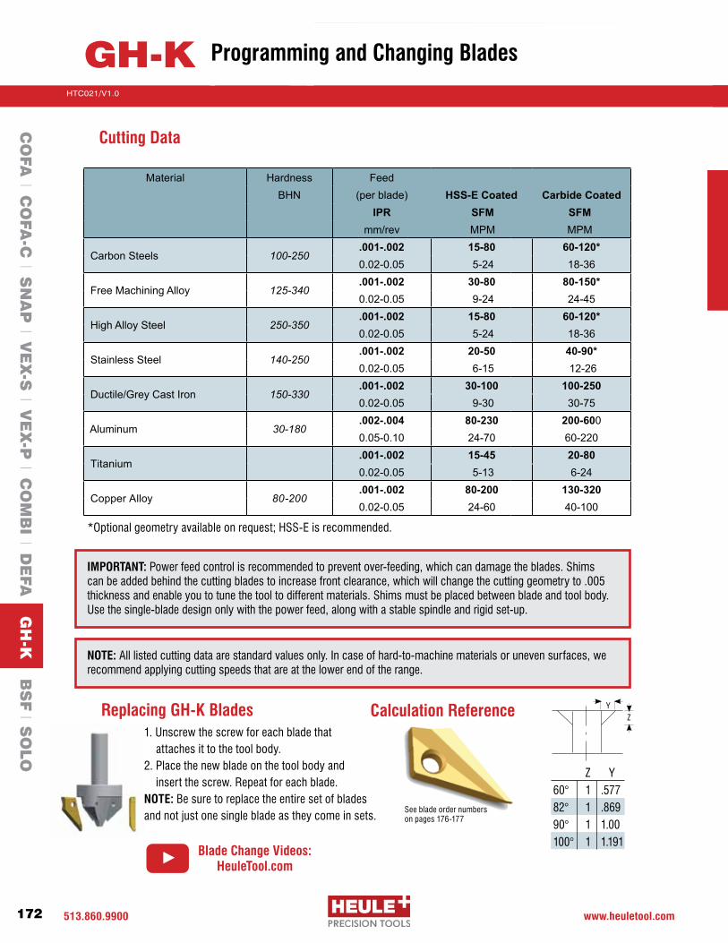
513.860.9900 www.heuletool.com
Catalog No. HTC14
172
HTC021/V1.0
Serie
s
Replacing GH-K Blades1. Unscrew the screw for each blade that attaches it to the tool body.2. Place the new blade on the tool body and insert the screw. Repeat for each blade.NOTE: Be sure to replace the entire set of blades and not just one single blade as they come in sets.
GH-K
Calculation Reference
60° 82°90°100°
Z1111
Y.577.869 1.001.191
ZY
See blade order numbers on pages 176-177
CO
FA l C
OFA
-C l S
NA
P l V
EX
-S l V
EX
-P l C
OM
BI l D
EFA
GH
-K B
SF l S
OLO
Programming and Changing Blades
NOTE: All listed cutting data are standard values only. In case of hard-to-machine materials or uneven surfaces, we recommend applying cutting speeds that are at the lower end of the range.
IMPORTANT: Power feed control is recommended to prevent over-feeding, which can damage the blades. Shims can be added behind the cutting blades to increase front clearance, which will change the cutting geometry to .005 thickness and enable you to tune the tool to different materials. Shims must be placed between blade and tool body. Use the single-blade design only with the power feed, along with a stable spindle and rigid set-up.
Material Hardness FeedBHN (per blade) HSS-E Coated Carbide Coated
IPR SFM SFMmm/rev MPM MPM
Carbon Steels 100-250.001-.002 15-80 60-120*0.02-0.05 5-24 18-36
Free Machining Alloy 125-340.001-.002 30-80 80-150*0.02-0.05 9-24 24-45
High Alloy Steel 250-350.001-.002 15-80 60-120*0.02-0.05 5-24 18-36
Stainless Steel 140-250.001-.002 20-50 40-90*0.02-0.05 6-15 12-26
Ductile/Grey Cast Iron 150-330.001-.002 30-100 100-2500.02-0.05 9-30 30-75
Aluminum 30-180.002-.004 80-230 200-6000.05-0.10 24-70 60-220
Titanium.001-.002 15-45 20-800.02-0.05 5-13 6-24
Copper Alloy 80-200.001-.002 80-200 130-3200.02-0.05 24-60 40-100
Cutting Data
*Optional geometry available on request; HSS-E is recommended.
Blade Change Videos:HeuleTool.com

Counterbores up to 2.3xd
Replaceable carbide-coated blades for extended life
Very simple to use
Suitable for CNC machines with through coolant
Sizes 6.5-21mm (.256-.827”) available from stock
BSFLarge Ratio Automatic Back Counterboring & Spotfacing Tool
HTC021/V1.0

513.860.9900 www.heuletool.com
Catalog No. HTC14
174
HTC021/V1.0
Serie
s
Offset CoatingMaterialSeries
BSF- M - A - 1A - 6.0
How Does the BSF Tool Work?
BSF(BackSpotFacer)isaneconomicalbackwardscounterboringtool. Itallowsthemachiningof largespotfacesand counterbores without turning the work piece over. This means that the machining is done on the same side as the drilled hole. The BSF is specifically designed for CNC machining and functions without an anti-rotation device, change of spindle direction or contact mechanism. The blade expands using centrifugal force when activating the spindle. The blade retracts by coolant pressure. The coolant pressure moves a piston which is pushing a pin that forces the blade (closed)intothebladehousing.ThedesignoftheBSFfocusesonoptimalcuttingperformance,chipremovalandreliability. The tool and the blade have special coolant pipes and chip guiding geometries that continuously flush the blade window and the blade itself with coolant. This keeps the whole section clean and allows for optimal chip removal performance. The tool is a has a very simplistic design but is also very robust due to the coolant pressure.
Easy to Change Carbide Cutting Blades
Changing the blade is easily executed with an assembly pin that is included with each tool. An extra split pin is included with each bladethatisordered.Seepage194formoreinformation.
1 2 3 4 5 6 7 8 9
1 Blade2 Split pin3 Control pin4Housing5 Clamping screw
6 Spring7 Piston8 Set Screw9 Cylindrical Shank
Tool Description
How to Order
The tools and blades are sold separately and they each have an OFFSET dimension. When combined they equal the effective counterbore diameter. Choose the tool closest to the bore diameter, then choose the proper blade for the required counterbore diameter. There are 36 different size carbide blades that can fit their corresponding tool holder series.
Offset Working LengthMin. HoleSeries
BSF-A-0650/40-7.0
Tool Part Number Blade Part Number
Material: 1 = Carbide blade
Coating: A = TiAIN D = DLC
BSF
CO
FA l C
OFA
-C l S
NA
P l V
EX
-S l V
EX
-P l C
OM
BI l D
EFA
l GH
-K B
SF S
OLO
Introduction

513-860-9900 www.heuletool.com
Catalog No. HTC014
175
HTC021/V1.0
Serie
s
Tool Series AMinimum Hole Ød
mm inches
40 56(128.5)
Ø25
h6
6.1515.0
Ød1
Tool Order #C’Bore ØDmm inches
Blade Order #Carbide, TiAlN*
Ød1 mm inches
6.5 0.256 6.4 0.252 9.50 0.374 BSF-A-0650/040-6.5 BSF-M-A-1A-3.0
10.00 0.394 BSF-A-0650/040-7.0
10.50 0.413 BSF-A-0650/040-7.5
11.00 0.433 BSF-A-0650/040-6.5 BSF-M-A-1A-4.5
11.50 0.453 BSF-A-0650/040-7.0
12.00 0.472 BSF-A-0650/040-7.5
12.50 0.492 BSF-A-0650/040-6.5 BSF-M-A-1A-6.0
13.00 0.512 BSF-A-0650/040-7.0
13.50 0.531 BSF-A-0650/040-7.5
14.00 0.551 BSF-A-0650/040-6.5 BSF-M-A-1A-7.5
14.50 0.571 BSF-A-0650/040-7.0
15.00 0.591 BSF-A-0650/040-7.5
7.0 0.276 6.9 0.272 10.50 0.413 BSF-A-0700/040-7.5 BSF-M-A-1A-3.0
11.00 0.433 BSF-A-0700/040-8.0
11.50 0.453 BSF-A-0700/040-7.0 BSF-M-A-1A-4.5
12.00 0.472 BSF-A-0700/040-7.5
12.50 0.492 BSF-A-0700/040-8.0
13.00 0.512 BSF-A-0700/040-7.0 BSF-M-A-1A-6.0
13.50 0.531 BSF-A-0700/040-7.5
14.00 0.551 BSF-A-0700/040-8.0
14.50 0.571 BSF-A-0700/040-7.0 BSF-M-A-1A-7.5
15.00 0.591 BSF-A-0700/040-7.5
15.50 0.610 BSF-A-0700/040-8.0
16.00 0.630 BSF-A-0700/040-7.0 BSF-M-A-1A-9.0
16.50 0.650 BSF-A-0700/040-7.5
17.00 0.669 BSF-A-0700/040-8.0
*Other blade options available
Serie
s
BSF A Back Spotfacing and Counterboring Tools For holes Ø6.5-7.5 .256”-.295”
HOUSINGOPTIONS
PG. 205
SPARE PARTS
PG. 204
CHANGE BLADES
PG. 212
PG. 209PROGRAMMING
Special Application? Submit the Application Data Sheet on Page 232 to Heule Tool with your application information for our engineering team to review. Submit to: [email protected]
Order Instructions: Refertopage174 “HowtoOrder”
for order instructions and
example
CO
FA l C
OFA
-C l S
NA
P l V
EX
-S l V
EX
-P l C
OM
BI l D
EFA
l GH
-K B
SF S
OLO

513.860.9900 www.heuletool.com
Catalog No. HTC14
176
HTC021/V1.0
Serie
s40 56
7.5517.0
(130.5)
Ø25
h6
Ød1
Tool Series BMinimum Hole Ød
mm inchesTool Order #C’Bore ØD
mm inchesØd1
mm inches
7.5 0.295 7.4 0.291 11.0 0.433 BSF-B-0750/040-7.5 BSF-M-B-1A-3.5
11.5 0.453 BSF-B-0750/040-8.0
12.0 0.472 BSF-B-0750/040-8.5
12.5 0.492 BSF-B-0750/040-7.5 BSF-M-B-1A-5.0
13.0 0.512 BSF-B-0750/040-8.0
13.5 0.531 BSF-B-0750/040-8.5
14.0 0.551 BSF-B-0750/040-7.5 BSF-M-B-1A-6.5
14.5 0.571 BSF-B-0750/040-8.0
15.0 0.591 BSF-B-0750/040-8.5
15.5 0.610 BSF-B-0750/040-7.5 BSF-M-B-1A-8.0
16.0 0.630 BSF-B-0750/040-8.0
16.5 0.650 BSF-B-0750/040-8.5
17.0 0.669 BSF-B-0750/040-7.5 BSF-M-B-1A-9.5
17.5 0.689 BSF-B-0750/040-8.0
18.0 0.709 BSF-B-0750/040-8.5
8.0 0.315 7.9 0.311 12.0 0.472 BSF-B-0800/040-8.5 BSF-M-B-1A-3.5
12.5 0.492 BSF-B-0800/040-9.0
13.0 0.512 BSF-B-0800/040-8.0 BSF-M-B-1A-5.0
13.5 0.531 BSF-B-0800/040-8.5
14.0 0.551 BSF-B-0800/040-9.0
14.5 0.571 BSF-B-0800/040-8.0 BSF-M-B-1A-6.5
15.0 0.591 BSF-B-0800/040-8.5
15.5 0.610 BSF-B-0800/040-9.0
16.0 0.630 BSF-B-0800/040-8.0 BSF-M-B-1A-8.0
16.5 0.650 BSF-B-0800/040-8.5
17.0 0.669 BSF-B-0800/040-9.0
17.5 0.689 BSF-B-0800/040-8.0 BSF-M-B-1A-9.5
18.0 0.709 BSF-B-0800/040-8.5
18.5 0.728 BSF-B-0800/040-9.0
Blade Order #Carbide, TiAlN*
*Other blade options available
Serie
s
BSF B Back Spotfacing and Counterboring Tools For holes Ø7.5-9.0 .295”-.354”
HOUSINGOPTIONS
PG. 205-206
SPARE PARTS
PG. 204
Special Application? Submit the Application Data Sheet on Page 232 to Heule Tool with your application information for our engineering team to review. Submit to: [email protected]
Order Instructions: Refertopage174“HowtoOrder”
for order instructions and
example
CO
FA l C
OFA
-C l S
NA
P l V
EX
-S l V
EX
-P l C
OM
BI l D
EFA
l GH
-K B
SF S
OLO

513-860-9900 www.heuletool.com
Catalog No. HTC014
177
HTC021/V1.0
Serie
s
Tool Series BMinimum Hole Ød
mm inches
40 567.55
17.75(131.25)
Ø25
h6
Ød1
Tool Order #C’Bore ØDmm inches
Blade Order #Ød1 mm inches
8.5 0.335 8.4 0.331 12.5 0.492 BSF-B-0850/040-9.0 BSF-M-B-1A-3.5
13.0 0.512 BSF-B-0850/040-9.5
13.5 0.531 BSF-B-0850/040-8.5 BSF-M-B-1A-5.0
14.0 0.551 BSF-B-0850/040-9.0
14.5 0.571 BSF-B-0850/040-9.5
15.0 0.591 BSF-B-0850/040-8.5 BSF-M-B-1A-6.5
15.5 0.610 BSF-B-0850/040-9.0
16.0 0.630 BSF-B-0850/040-9.5
16.5 0.650 BSF-B-0850/040-8.5 BSF-M-B-1A-8.0
17.0 0.669 BSF-B-0850/040-9.0
17.5 0.689 BSF-B-0850/040-9.5
18.0 0.709 BSF-B-0850/040-8.5 BSF-M-B-1A-9.5
18.5 0.728 BSF-B-0850/040-9.0
19.0 0.748 BSF-B-0850/040-9.5
19.5 0.768 BSF-B-0850/040-8.5 BSF-M-B-1A-11.0
20.0 0.787 BSF-B-0850/040-9.0
20.5 0.807 BSF-B-0850/040-9.5
Carbide, TiAlN*
*Other blade options available
Serie
s
BSF B Back Spotfacing and Counterboring Tools For holes Ø7.5-9.0 .295”-.354”
CHANGE BLADES
PG. 212
PG. 209PROGRAMMING
Order Instructions: Refertopage174 “HowtoOrder”
for order instructions and
example
Special Application? Submit the Application Data Sheet on Page 232 to Heule Tool with your application information for our engineering team to review. Submit to: [email protected]
CO
FA l C
OFA
-C l S
NA
P l V
EX
-S l V
EX
-P l C
OM
BI l D
EFA
l GH
-K B
SF S
OLO

513.860.9900 www.heuletool.com
Catalog No. HTC14
178
HTC021/V1.0
Serie
s50 56
8.6520.25
(143.75)
Ø25
h6
Ød1
Tool Series CMinimum Hole Ød
mm inchesTool Order #C’Bore ØD
mm inches
Blade Order #Ød1 mm inches
9.0 0.354 8.9 0.350 13.5 0.531 BSF-C-0900/050-9.5 BSF-M-C-1A-4.0
14.0 0.551 BSF-C-0900/050-10.0
14.5 0.571 BSF-C-0900/050-10.5
15.0 0.591 BSF-C-0900/050-9.5 BSF-M-C-1A-5.5
15.5 0.610 BSF-C-0900/050-10.0
16.0 0.630 BSF-C-0900/050-10.5
16.5 0.650 BSF-C-0900/050-9.5 BSF-M-C-1A-7.0
17.0 0.669 BSF-C-0900/050-10.0
17.5 0.689 BSF-C-0900/050-10.5
18.0 0.709 BSF-C-0900/050-9.5 BSF-M-C-1A-8.5
18.5 0.728 BSF-C-0900/050-10.0
19.0 0.748 BSF-C-0900/050-10.5
19.5 0.768 BSF-C-0900/050-9.5 BSF-M-C-1A-10.0
20.0 0.787 BSF-C-0900/050-10.0
20.5 0.807 BSF-C-0900/050-10.5
21.0 0.827 BSF-C-0900/050-9.5 BSF-M-C-1A-11.5
21.5 0.846 BSF-C-0900/050-10.0
22.0 0.866 BSF-C-0900/050-10.5
9.5 0.374 9.4 0.370 14.5 0.571 BSF-C-0950/050-10.5 BSF-M-C-1A-4.0
15.0 0.591 BSF-C-0950/050-11.0
15.5 0.610 BSF-C-0950/050-10.0 BSF-M-C-1A-5.5
16.0 0.630 BSF-C-0950/050-10.5
16.5 0.650 BSF-C-0950/050-11.0
17.0 0.669 BSF-C-0950/050-10.0 BSF-M-C-1A-7.0
17.5 0.689 BSF-C-0950/050-10.5
18.0 0.709 BSF-C-0950/050-11.0
18.5 0.728 BSF-C-0950/050-10.0 BSF-M-C-1A-8.5
19.0 0.748 BSF-C-0950/050-10.5
19.5 0.768 BSF-C-0950/050-11.0
20.0 0.787 BSF-C-0950/050-10.0 BSF-M-C-1A-10.0
20.5 0.807 BSF-C-0950/050-10.5
21.0 0.827 BSF-C-0950/050-11.0
21.5 0.846 BSF-C-0950/050-10.0 BSF-M-C-1A-11.5
22.0 0.866 BSF-C-0950/050-10.5
22.5 0.886 BSF-C-0950/050-11.0
Carbide, TiAlN*
*Other blade options available
Serie
s
BSF C Back Spotfacing and Counterboring Tools For holes Ø9.0-10.5 .354”-.413”
CO
FA l C
OFA
-C l S
NA
P l V
EX
-S l V
EX
-P l C
OM
BI l D
EFA
l GH
-K B
SF S
OLO
Special Application? Submit the Application Data Sheet on Page 232 to Heule Tool with your application information for our engineering team to review. Submit to: [email protected]
Order Instructions: Refertopage174“HowtoOrder”
for order instructions and
example
HOUSINGOPTIONS
PG. 205-206
SPARE PARTS
PG. 204

513-860-9900 www.heuletool.com
Catalog No. HTC014
179
HTC021/V1.0
Serie
s50 56
8.6520.25
(143.75)
Ø25
h6
Ød1
Tool Series CMinimum Hole Ød
mm inchesTool Order #C’Bore ØD
mm inches
Blade Order #Ød1 mm inches
10.0 0.394 9.9 0.390 15.0 0.591 BSF-C-1000/050-11.0 BSF-M-C-1A-4.0
15.5 0.610 BSF-C-1000/050-11.5
16.0 0.630 BSF-C-1000/050-10.5 BSF-M-C-1A-5.5
16.5 0.650 BSF-C-1000/050-11.0
17.0 0.669 BSF-C-1000/050-11.5
17.5 0.689 BSF-C-1000/050-10.5 BSF-M-C-1A-7.0
18.0 0.709 BSF-C-1000/050-11.0
18.5 0.728 BSF-C-1000/050-11.5
19.0 0.748 BSF-C-1000/050-10.5 BSF-M-C-1A-8.5
19.5 0.768 BSF-C-1000/050-11.0
20.0 0.787 BSF-C-1000/050-11.5
20.5 0.807 BSF-C-1000/050-10.5 BSF-M-C-1A-10.0
21.0 0.827 BSF-C-1000/050-11.0
21.5 0.846 BSF-C-1000/050-11.5
22.0 0.866 BSF-C-1000/050-10.5 BSF-M-C-1A-11.5
22.5 0.886 BSF-C-1000/050-11.0
23.0 0.906 BSF-C-1000/050-11.5
Carbide, TiAlN*
*Other blade options available
Serie
s
BSF C Back Spotfacing and Counterboring Tools For holes Ø9.0-10.5 .354”-.413”
CO
FA l C
OFA
-C l S
NA
P l V
EX
-S l V
EX
-P l C
OM
BI l D
EFA
l GH
-K B
SF S
OLO
Order Instructions: Refertopage174 “HowtoOrder”
for order instructions and
example
Special Application? Submit the Application Data Sheet on Page 232 to Heule Tool with your application information for our engineering team to review. Submit to: [email protected]
CHANGE BLADES
PG. 212
PG. 209PROGRAMMING

513.860.9900 www.heuletool.com
Catalog No. HTC14
180
HTC021/V1.0
Serie
s50 56
9.7322.5
(146.0)
Ø25
h6
Ød1
Tool Series DMinimum Hole Ød
mm inchesTool Order #C’Bore ØD
mm inches
Blade Order #Ød1 mm inches
10.5 0.413 10.4 0.409 16.0 0.630 BSF-D-1050/050-11.5 BSF-M-D-1A-4.5
16.5 0.650 BSF-D-1050/050-12.0
17.0 0.669 BSF-D-1050/050-12.5
17.5 0.689 BSF-D-1050/050-13.0
18.0 0.709 BSF-D-1050/050-11.0 BSF-M-D-1A-7.0
18.5 0.728 BSF-D-1050/050-11.5
19.0 0.748 BSF-D-1050/050-12.0
19.5 0.768 BSF-D-1050/050-12.5
20.0 0.787 BSF-D-1050/050-13.0
20.5 0.807 BSF-D-1050/050-11.0 BSF-M-D-1A-9.5
21.0 0.827 BSF-D-1050/050-11.5
21.5 0.846 BSF-D-1050/050-12.0
22.0 0.866 BSF-D-1050/050-12.5
22.5 0.886 BSF-D-1050/050-13.0
23.0 0.906 BSF-D-1050/050-11.0 BSF-M-D-1A-12.0
23.5 0.925 BSF-D-1050/050-11.5
24.0 0.945 BSF-D-1050/050-12.0
24.5 0.965 BSF-D-1050/050-12.5
25.0 0.984 BSF-D-1050/050-13.0
Carbide, TiAlN*
*Other blade options available
Serie
s
BSF D Back Spotfacing and Counterboring Tools For holes Ø10.5-12.0 .413”-.472”
CO
FA l C
OFA
-C l S
NA
P l V
EX
-S l V
EX
-P l C
OM
BI l D
EFA
l GH
-K B
SF S
OLO
Special Application? Submit the Application Data Sheet on Page 232 to Heule Tool with your application information for our engineering team to review. Submit to: [email protected]
Order Instructions: Refertopage174“HowtoOrder”
for order instructions and
example
HOUSINGOPTIONS
PG. 205-206
SPARE PARTS
PG. 204

513-860-9900 www.heuletool.com
Catalog No. HTC014
181
HTC021/V1.0
Serie
s50 56
9.7322.5
(146.0)
Ø25
h6
Ød1
Tool Series DMinimum Hole Ød
mm inchesTool Order #C’Bore ØD
mm inches
Blade Order #Ød1 mm inches
11.0 0.433 10.9 0.429 16.5 0.650 BSF-D-1100/050-12.0 BSF-M-D-1A-4.5
17.0 0.669 BSF-D-1100/050-12.5
17.5 0.689 BSF-D-1100/050-13.0
18.0 0.709 BSF-D-1100/050-13.5
18.5 0.728 BSF-D-1100/050-11.5 BSF-M-D-1A-7.0
19.0 0.748 BSF-D-1100/050-12.0
19.5 0.768 BSF-D-1100/050-12.5
20.0 0.787 BSF-D-1100/050-13.0
20.5 0.807 BSF-D-1100/050-13.5
21.0 0.827 BSF-D-1100/050-11.5 BSF-M-D-1A-9.5
21.5 0.846 BSF-D-1100/050-12.0
22.0 0.866 BSF-D-1100/050-12.5
22.5 0.886 BSF-D-1100/050-13.0
23.0 0.906 BSF-D-1100/050-13.5
23.5 0.925 BSF-D-1100/050-11.5 BSF-M-D-1A-12.0
24.0 0.945 BSF-D-1100/050-12.0
24.5 0.965 BSF-D-1100/050-12.5
25.0 0.984 BSF-D-1100/050-13.0
25.5 1.004 BSF-D-1100/050-13.5
Carbide, TiAlN*
*Other blade options available
Serie
s
BSF D Back Spotfacing and Counterboring Tools For holes Ø10.5-12.0 .413”-.472”
CO
FA l C
OFA
-C l S
NA
P l V
EX
-S l V
EX
-P l C
OM
BI l D
EFA
l GH
-K B
SF S
OLO
Order Instructions: Refertopage174 “HowtoOrder”
for order instructions and
example
Special Application? Submit the Application Data Sheet on Page 232 to Heule Tool with your application information for our engineering team to review. Submit to: [email protected]
CHANGE BLADES
PG. 212
PG. 209PROGRAMMING

513.860.9900 www.heuletool.com
Catalog No. HTC14
182
HTC021/V1.0
Serie
s50 56
9.7323.75
(147.25)
Ø25
h6
Ød1
Tool Series DMinimum Hole Ød
mm inchesTool Order #C’Bore ØD
mm inches
Blade Order #Ød1 mm inches
11.5 0.453 11.4 0.449 17.5 0.689 BSF-D-1150/050-13.0 BSF-M-D-1A-4.5
18.0 0.709 BSF-D-1150/050-13.5
18.5 0.728 BSF-D-1150/050-14.0
19.0 0.748 BSF-D-1150/050-12.0 BSF-M-D-1A-7.0
19.5 0.768 BSF-D-1150/050-12.5
20.0 0.787 BSF-D-1150/050-13.0
20.5 0.807 BSF-D-1150/050-13.5
21.0 0.827 BSF-D-1150/050-14.0
21.5 0.846 BSF-D-1150/050-12.0 BSF-M-D-1A-9.5
22.0 0.866 BSF-D-1150/050-12.5
22.5 0.886 BSF-D-1150/050-13.0
23.0 0.906 BSF-D-1150/050-13.5
23.5 0.925 BSF-D-1150/050-14.0
24.0 0.945 BSF-D-1150/050-12.0 BSF-M-D-1A-12.0
24.5 0.965 BSF-D-1150/050-12.5
25.0 0.984 BSF-D-1150/050-13.0
25.5 1.004 BSF-D-1150/050-13.5
26.0 1.024 BSF-D-1150/050-14.0
26.5 1.043 BSF-D-1150/050-12.0 BSF-M-D-1A-14.5
27.0 1.063 BSF-D-1150/050-12.5
27.5 1.083 BSF-D-1150/050-13.0
28.0 1.102 BSF-D-1150/050-13.5
28.5 1.122 BSF-D-1150/050-14.0
Carbide, TiAlN*
*Other blade options available
Serie
s
BSF D Back Spotfacing and Counterboring Tools For holes Ø10.5-12.0 .413”-.472”
CO
FA l C
OFA
-C l S
NA
P l V
EX
-S l V
EX
-P l C
OM
BI l D
EFA
l GH
-K B
SF S
OLO
Special Application? Submit the Application Data Sheet on Page 232 to Heule Tool with your application information for our engineering team to review. Submit to: [email protected]
Order Instructions: Refertopage174“HowtoOrder”
for order instructions and
example
HOUSINGOPTIONS
PG. 205-206
SPARE PARTS
PG. 204

513-860-9900 www.heuletool.com
Catalog No. HTC014
183
HTC021/V1.0
Serie
s50 56
11.426.75
(150.25)
Ø25
h6
Ød1
Tool Series EMinimum Hole Ø
mm inchesTool Order #C’Bore
mm inches
Blade Order #Ød1 mm inches
12.0 0.472 11.9 0.469 18.0 0.709 BSF-E-1200/050-13.0 BSF-M-E-1A-5.0
18.5 0.728 BSF-E-1200/050-13.5
19.0 0.748 BSF-E-1200/050-14.0
19.5 0.768 BSF-E-1200/050-14.5
20.0 0.787 BSF-E-1200/050-15.0
20.5 0.807 BSF-E-1200/050-13.0 BSF-M-E-1A-7.5
21.0 0.827 BSF-E-1200/050-13.5
21.5 0.846 BSF-E-1200/050-14.0
22.0 0.866 BSF-E-1200/050-14.5
22.5 0.886 BSF-E-1200/050-15.0
23.0 0.906 BSF-E-1200/050-13.0 BSF-M-E-1A-10.0
23.5 0.925 BSF-E-1200/050-13.5
24.0 0.945 BSF-E-1200/050-14.0
24.5 0.965 BSF-E-1200/050-14.5
25.0 0.984 BSF-E-1200/050-15.0
25.5 1.004 BSF-E-1200/050-13.0 BSF-M-E-1A-12.5
26.0 1.024 BSF-E-1200/050-13.5
26.5 1.043 BSF-E-1200/050-14.0
27.0 1.063 BSF-E-1200/050-14.5
27.5 1.083 BSF-E-1200/050-15.0
28.0 1.102 BSF-E-1200/050-13.0 BSF-M-E-1A-15.0
28.5 1.122 BSF-E-1250/050-13.5
29.0 1.142 BSF-E-1250/050-14.0
29.5 1.161 BSF-E-1250/050-14.5
30.0 1.181 BSF-E-1250/050-15.0
Carbide, TiAlN*
*Other blade options available
Serie
s
BSF E Back Spotfacing and Counterboring Tools For holes Ø12.0-14.5 .472”-.571”
CO
FA l C
OFA
-C l S
NA
P l V
EX
-S l V
EX
-P l C
OM
BI l D
EFA
l GH
-K B
SF S
OLO
Order Instructions: Refertopage174 “HowtoOrder”
for order instructions and
example
Special Application? Submit the Application Data Sheet on Page 232 to Heule Tool with your application information for our engineering team to review. Submit to: [email protected]
CHANGE BLADES
PG. 212
PG. 209PROGRAMMING

513.860.9900 www.heuletool.com
Catalog No. HTC14
184
HTC021/V1.0
Serie
s50 56
11.426.75
Ø25
h6
Ød1
Tool Series EMinimum Hole Ød
mm inchesTool Order #C’Bore ØD
mm inches
Blade Order #Ød1 mm inches
12.5 0.492 12.4 0.488 19.0 0.748 BSF-E-1250/050-14.0 BSF-M-E-1A-5.0
19.5 0.768 BSF-E-1250/050-14.5
20.0 0.787 BSF-E-1250/050-15.0
20.5 0.807 BSF-E-1250/050-15.5
21.0 0.827 BSF-E-1250/050-13.5 BSF-M-E-1A-7.5
21.5 0.846 BSF-E-1250/050-14.0
22.0 0.866 BSF-E-1250/050-14.5
22.5 0.886 BSF-E-1250/050-15.0
23.0 0.906 BSF-E-1250/050-15.5
23.5 0.925 BSF-E-1250/050-13.5 BSF-M-E-1A-10.0
24.0 0.945 BSF-E-1250/050-14.0
24.5 0.965 BSF-E-1250/050-14.5
25.0 0.984 BSF-E-1250/050-15.0
25.5 1.004 BSF-E-1250/050-15.5
26.0 1.024 BSF-E-1250/050-13.5 BSF-M-E-1A-12.5
26.5 1.043 BSF-E-1250/050-14.0
27.0 1.063 BSF-E-1250/050-14.5
27.5 1.083 BSF-E-1250/050-15.0
28.0 1.102 BSF-E-1250/050-15.5
28.5 1.122 BSF-E-1250/050-13.5 BSF-M-E-1A-15.0
29.0 1.142 BSF-E-1250/050-14.0
29.5 1.161 BSF-E-1250/050-14.5
30.0 1.181 BSF-E-1250/050-15.0
30.5 1.201 BSF-E-1250/050-15.5
(150.25)
Carbide, TiAlN*
*Other blade options available
Serie
s
BSF E Back Spotfacing and Counterboring Tools For holes Ø12.0-14.5 .472”-.571”
CO
FA l C
OFA
-C l S
NA
P l V
EX
-S l V
EX
-P l C
OM
BI l D
EFA
l GH
-K B
SF S
OLO
Special Application? Submit the Application Data Sheet on Page 232 to Heule Tool with your application information for our engineering team to review. Submit to: [email protected]
Order Instructions: Refertopage174“HowtoOrder”
for order instructions and
example
HOUSINGOPTIONS
PG. 205-206
SPARE PARTS
PG. 204

513-860-9900 www.heuletool.com
Catalog No. HTC014
185
HTC021/V1.0
Serie
s50 56
11.426.75
Ø25
h6
Ød1
Tool Series EMinimum Hole Ød
mm inchesTool Order #C’Bore ØD
mm inches
Blade Order #Ød1 mm inches
13.0 0.512 12.9 0.508 19.5 0.768 BSF-E-1300/050-14.5 BSF-M-E-1A-5.0
20.0 0.787 BSF-E-1300/050-15.0
20.5 0.807 BSF-E-1300/050-15.5
21.0 0.827 BSF-E-1300/050-16.0
21.5 0.846 BSF-E-1300/050-14.0 BSF-M-E-1A-7.5
22.0 0.866 BSF-E-1300/050-14.5
22.5 0.886 BSF-E-1300/050-15.0
23.0 0.906 BSF-E-1300/050-15.5
23.5 0.925 BSF-E-1300/050-16.0
24.0 0.945 BSF-E-1300/050-14.0 BSF-M-E-1A-10.0
24.5 0.965 BSF-E-1300/050-14.5
25.0 0.984 BSF-E-1300/050-15.0
25.5 1.004 BSF-E-1300/050-15.5
26.0 1.024 BSF-E-1300/050-16.0
26.5 1.043 BSF-E-1300/050-14.0 BSF-M-E-1A-12.5
27.0 1.063 BSF-E-1300/050-14.5
27.5 1.083 BSF-E-1300/050-15.0
28.0 1.102 BSF-E-1300/050-15.5
28.5 1.122 BSF-E-1300/050-16.0
29.0 1.142 BSF-E-1300/050-14.0 BSF-M-E-1A-15.0
29.5 1.161 BSF-E-1300/050-14.5
30.0 1.181 BSF-E-1300/050-15.0
30.5 1.201 BSF-E-1300/050-15.5
31.0 1.220 BSF-E-1300/050-16.0
(150.25)
Carbide, TiAlN*
*Other blade options available
Serie
s
BSF E Back Spotfacing and Counterboring Tools For holes Ø12.0-14.5 .472”-.571”
CO
FA l C
OFA
-C l S
NA
P l V
EX
-S l V
EX
-P l C
OM
BI l D
EFA
l GH
-K B
SF S
OLO
Order Instructions: Refertopage174 “HowtoOrder”
for order instructions and
example
Special Application? Submit the Application Data Sheet on Page 232 to Heule Tool with your application information for our engineering team to review. Submit to: [email protected]
CHANGE BLADES
PG. 212
PG. 209PROGRAMMING

513.860.9900 www.heuletool.com
Catalog No. HTC14
186
HTC021/V1.0
Serie
s50 56
11.426.75
Ø25
h6
Ød1
Tool Series EMinimum Hole Ød
mm inchesTool Order #C’Bore ØD
mm inches
Blade Order #Ød1 mm inches
13.5 0.531 13.4 0.528 20.5 0.807 BSF-E-1350/050-15.5 BSF-M-E-1A-5.0
21.0 0.827 BSF-E-1350/050-16.0
21.5 0.846 BSF-E-1350/050-16.5
22.0 0.866 BSF-E-1350/050-14.5 BSF-M-E-1A-7.5
22.5 0.886 BSF-E-1350/050-15.0
23.0 0.906 BSF-E-1350/050-15.5
23.5 0.925 BSF-E-1350/050-16.0
24.0 0.945 BSF-E-1350/050-16.5
24.5 0.965 BSF-E-1350/050-14.5 BSF-M-E-1A-10.0
25.0 0.984 BSF-E-1350/050-15.0
25.5 1.004 BSF-E-1350/050-15.5
26.0 1.024 BSF-E-1350/050-16.0
26.5 1.043 BSF-E-1350/050-16.5
27.0 1.063 BSF-E-1350/050-14.5 BSF-M-E-1A-12.5
27.5 1.083 BSF-E-1350/050-15.0
28.0 1.102 BSF-E-1350/050-15.5
28.5 1.122 BSF-E-1350/050-16.0
29.0 1.142 BSF-E-1350/050-16.5
29.5 1.161 BSF-E-1350/050-14.5 BSF-M-E-1A-15.0
30.0 1.181 BSF-E-1350/050-15.0
30.5 1.201 BSF-E-1350/050-15.5
31.0 1.220 BSF-E-1350/050-16.0
31.5 1.240 BSF-E-1350/050-16.5
(150.25)
Carbide, TiAlN*
*Other blade options available
Serie
s
BSF E Back Spotfacing and Counterboring Tools For holes Ø12.0-14.5 .472”-.571”
CO
FA l C
OFA
-C l S
NA
P l V
EX
-S l V
EX
-P l C
OM
BI l D
EFA
l GH
-K B
SF S
OLO
Special Application? Submit the Application Data Sheet on Page 232 to Heule Tool with your application information for our engineering team to review. Submit to: [email protected]
Order Instructions: Refertopage174“HowtoOrder”
for order instructions and
example
HOUSINGOPTIONS
PG. 205-206
SPARE PARTS
PG. 204
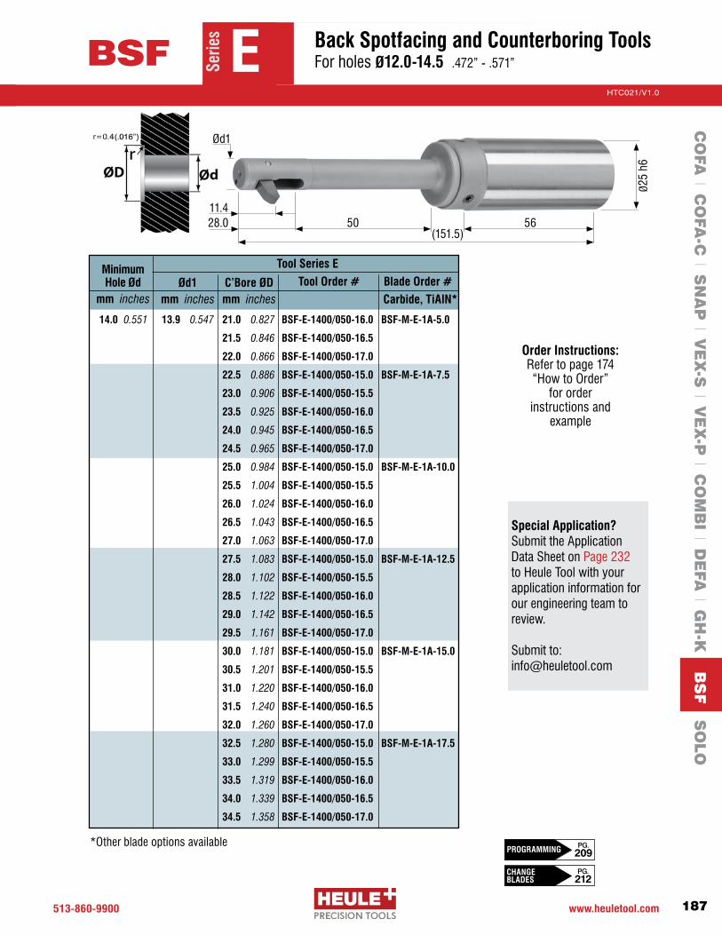
513-860-9900 www.heuletool.com
Catalog No. HTC014
187
HTC021/V1.0
Serie
s50 56
11.428.0
(151.5)
Ø25
h6
Ød1
Tool Series EMinimum Hole Ød
mm inchesTool Order #C’Bore ØD
mm inches
Blade Order #Ød1 mm inches
14.0 0.551 13.9 0.547 21.0 0.827 BSF-E-1400/050-16.0 BSF-M-E-1A-5.0
21.5 0.846 BSF-E-1400/050-16.5
22.0 0.866 BSF-E-1400/050-17.0
22.5 0.886 BSF-E-1400/050-15.0 BSF-M-E-1A-7.5
23.0 0.906 BSF-E-1400/050-15.5
23.5 0.925 BSF-E-1400/050-16.0
24.0 0.945 BSF-E-1400/050-16.5
24.5 0.965 BSF-E-1400/050-17.0
25.0 0.984 BSF-E-1400/050-15.0 BSF-M-E-1A-10.0
25.5 1.004 BSF-E-1400/050-15.5
26.0 1.024 BSF-E-1400/050-16.0
26.5 1.043 BSF-E-1400/050-16.5
27.0 1.063 BSF-E-1400/050-17.0
27.5 1.083 BSF-E-1400/050-15.0 BSF-M-E-1A-12.5
28.0 1.102 BSF-E-1400/050-15.5
28.5 1.122 BSF-E-1400/050-16.0
29.0 1.142 BSF-E-1400/050-16.5
29.5 1.161 BSF-E-1400/050-17.0
30.0 1.181 BSF-E-1400/050-15.0 BSF-M-E-1A-15.0
30.5 1.201 BSF-E-1400/050-15.5
31.0 1.220 BSF-E-1400/050-16.0
31.5 1.240 BSF-E-1400/050-16.5
32.0 1.260 BSF-E-1400/050-17.0
32.5 1.280 BSF-E-1400/050-15.0 BSF-M-E-1A-17.5
33.0 1.299 BSF-E-1400/050-15.5
33.5 1.319 BSF-E-1400/050-16.0
34.0 1.339 BSF-E-1400/050-16.5
34.5 1.358 BSF-E-1400/050-17.0
Carbide, TiAlN*
*Other blade options available
Serie
s
BSF E Back Spotfacing and Counterboring Tools For holes Ø12.0-14.5 .472”-.571”
CO
FA l C
OFA
-C l S
NA
P l V
EX
-S l V
EX
-P l C
OM
BI l D
EFA
l GH
-K B
SF S
OLO
Order Instructions: Refertopage174 “HowtoOrder”
for order instructions and
example
Special Application? Submit the Application Data Sheet on Page 232 to Heule Tool with your application information for our engineering team to review. Submit to: [email protected]
CHANGE BLADES
PG. 212
PG. 209PROGRAMMING

513.860.9900 www.heuletool.com
Catalog No. HTC14
188
HTC021/V1.0
Serie
s70 56
13.430.75
(193.75)
Ø25
h6
Ød1
Tool Series FMinimum Hole Ød
mm inchesTool Order #C’Bore ØD
mm inches
Blade Order #Ød1 mm inches
14.5 0.571 14.4 0.567 22.0 0.866 BSF-F-1450/070-16.5 BSF-M-F-1A-5.5
22.5 0.886 BSF-F-1450/070-17.0
23.0 0.906 BSF-F-1450/070-17.5
23.5 0.925 BSF-F-1450/070-18.0
24.0 0.945 BSF-F-1450/070-18.5
24.5 0.965 BSF-F-1450/070-19.0
25.0 0.984 BSF-F-1450/070-16.0 BSF-M-F-1A-9.0
25.5 1.004 BSF-F-1450/070-16.5
26.0 1.024 BSF-F-1450/070-17.0
26.5 1.043 BSF-F-1450/070-17.5
27.0 1.063 BSF-F-1450/070-18.0
27.5 1.083 BSF-F-1450/070-18.5
28.0 1.102 BSF-F-1450/070-19.0
28.5 1.122 BSF-F-1450/070-16.0 BSF-M-F-1A-12.5
29.0 1.142 BSF-F-1450/070-16.5
29.5 1.161 BSF-F-1450/070-17.0
30.0 1.181 BSF-F-1450/070-17.5
30.5 1.201 BSF-F-1450/070-18.0
31.0 1.220 BSF-F-1450/070-18.5
31.5 1.240 BSF-F-1450/070-19.0
32.0 1.260 BSF-F-1450/070-16.0 BSF-M-F-1A-16.0
32.5 1.280 BSF-F-1450/070-16.5
33.0 1.299 BSF-F-1450/070-17.0
33.5 1.319 BSF-F-1450/070-17.5
34.0 1.339 BSF-F-1450/070-18.0
34.5 1.358 BSF-F-1450/070-18.5
35.0 1.378 BSF-F-1450/070-19.0
Carbide, TiAlN*
*Other blade options available
Ø30.5
Serie
s
BSF F Back Spotfacing and Counterboring Tools For holes Ø14.5-17.5 .571”-.689”
CO
FA l C
OFA
-C l S
NA
P l V
EX
-S l V
EX
-P l C
OM
BI l D
EFA
l GH
-K B
SF S
OLO
Special Application? Submit the Application Data Sheet on Page 232 to Heule Tool with your application information for our engineering team to review. Submit to: [email protected]
Order Instructions: Refertopage174“HowtoOrder”
for order instructions and
example
HOUSINGOPTIONS
PG. 205-206
SPARE PARTS
PG. 204

513-860-9900 www.heuletool.com
Catalog No. HTC014
189
HTC021/V1.0
Serie
s70 56
13.430.75
Ø25
h6
Ød1
Tool Series FMinimum Hole Ød
mm inchesTool Order #C’Bore ØD
mm inches
Blade Order #Ød1 mm inches
15.0 0.591 14.9 0.587 22.5 0.886 BSF-F-1500/070-17.0 BSF-M-F-1A-5.5
23.0 0.906 BSF-F-1500/070-17.5
23.5 0.925 BSF-F-1500/070-18.0
24.0 0.945 BSF-F-1500/070-18.5
24.5 0.965 BSF-F-1500/070-19.0
25.0 0.984 BSF-F-1500/070-19.5
25.5 1.004 BSF-F-1500/070-16.5 BSF-M-F-1A-9.0
26.0 1.024 BSF-F-1500/070-17.0
26.5 1.043 BSF-F-1500/070-17.5
27.0 1.063 BSF-F-1500/070-18.0
27.5 1.083 BSF-F-1500/070-18.5
28.0 1.102 BSF-F-1500/070-19.0
28.5 1.122 BSF-F-1500/070-19.5
29.0 1.142 BSF-F-1500/070-16.5 BSF-M-F-1A-12.5
29.5 1.161 BSF-F-1500/070-17.0
30.0 1.181 BSF-F-1500/070-17.5
30.5 1.201 BSF-F-1500/070-18.0
31.0 1.220 BSF-F-1500/070-18.5
31.5 1.240 BSF-F-1500/070-19.0
32.0 1.260 BSF-F-1500/070-19.5
32.5 1.280 BSF-F-1500/070-16.5 BSF-M-F-1A-16.0
33.0 1.299 BSF-F-1500/070-17.0
33.5 1.319 BSF-F-1500/070-17.5
34.0 1.339 BSF-F-1500/070-18.0
34.5 1.358 BSF-F-1500/070-18.5
(193.75)
Carbide, TiAlN*
Ø30.5
Serie
s
BSF F Back Spotfacing and Counterboring Tools For holes Ø14.5-17.5 .571”-.689”
CO
FA l C
OFA
-C l S
NA
P l V
EX
-S l V
EX
-P l C
OM
BI l D
EFA
l GH
-K B
SF S
OLO
Order Instructions: Refertopage174 “HowtoOrder”
for order instructions and
example
Special Application? Submit the Application Data Sheet on Page 232 to Heule Tool with your application information for our engineering team to review. Submit to: [email protected]
CHANGE BLADES
PG. 212
PG. 209PROGRAMMING

513.860.9900 www.heuletool.com
Catalog No. HTC14
190
HTC021/V1.0
Serie
s70 56
13.430.75
Ø25
h6
Ød1
Tool Series FMinimum Hole Ød
mm inchesTool Order #C’Bore ØD
mm inches
Blade Order #Ød1 mm inches
15.5 0.610 15.4 0.606 23.5 0.925 BSF-F-1550/070-18.0 BSF-M-F-1A-5.5
24.0 0.945 BSF-F-1550/070-18.5
24.5 0.965 BSF-F-1550/070-19.0
25.0 0.984 BSF-F-1550/070-19.5
25.5 1.004 BSF-F-1550/070-20.0
26.0 1.024 BSF-F-1550/070-17.0 BSF-M-F-1A-9.0
26.5 1.043 BSF-F-1550/070-17.5
27.0 1.063 BSF-F-1550/070-18.0
27.5 1.083 BSF-F-1550/070-18.5
28.0 1.102 BSF-F-1550/070-19.0
28.5 1.122 BSF-F-1550/070-19.5
29.0 1.142 BSF-F-1550/070-20.0
29.5 1.161 BSF-F-1550/070-17.0 BSF-M-F-1A-12.5
30.0 1.181 BSF-F-1550/070-17.5
30.5 1.201 BSF-F-1550/070-18.0
31.0 1.220 BSF-F-1550/070-18.5
31.5 1.240 BSF-F-1550/070-19.0
32.0 1.260 BSF-F-1550/070-19.5
32.5 1.280 BSF-F-1550/070-20.0
33.0 1.299 BSF-F-1550/070-17.0 BSF-M-F-1A-16.0
33.5 1.319 BSF-F-1550/070-17.5
34.0 1.339 BSF-F-1550/070-18.0
34.5 1.358 BSF-F-1550/070-18.5
35.0 1.378 BSF-F-1550/070-19.0
35.5 1.398 BSF-F-1550/070-19.5
36.0 1.417 BSF-F-1550/070-20.0
(193.75)
Carbide, TiAlN*
*Other blade options available
Ø30.5
Serie
s
BSF F Back Spotfacing and Counterboring Tools For holes Ø14.5-17.5 .571”-.689”
CO
FA l C
OFA
-C l S
NA
P l V
EX
-S l V
EX
-P l C
OM
BI l D
EFA
l GH
-K B
SF S
OLO
Special Application? Submit the Application Data Sheet on Page 232 to Heule Tool with your application information for our engineering team to review. Submit to: [email protected]
Order Instructions: Refertopage174“HowtoOrder”
for order instructions and
example
HOUSINGOPTIONS
PG. 205-206
SPARE PARTS
PG. 204

513-860-9900 www.heuletool.com
Catalog No. HTC014
191
HTC021/V1.0
Serie
s70 56
13.432.5
Ø25
h6
Ød1
Tool Series FMinimum Hole Ød
mm inchesTool Order #C’Bore ØD
mm inches
Blade Order #Ød1 mm inches
16.0 0.630 15.9 0.626 24.0 0.945 BSF-F-1600/070-18.5 BSF-M-F-1A-5.5
24.5 0.965 BSF-F-1600/070-19.0
25.0 0.984 BSF-F-1600/070-19.5
25.5 1.004 BSF-F-1600/070-20.0
26.0 1.024 BSF-F-1600/070-20.5
26.5 1.043 BSF-F-1600/070-17.5 BSF-M-F-1A-9.0
27.0 1.063 BSF-F-1600/070-18.0
27.5 1.083 BSF-F-1600/070-18.5
28.0 1.102 BSF-F-1600/070-19.0
28.5 1.122 BSF-F-1600/070-19.5
29.0 1.142 BSF-F-1600/070-20.0
29.5 1.161 BSF-F-1600/070-20.5
30.0 1.181 BSF-F-1600/070-17.5 BSF-M-F-1A-12.5
30.5 1.201 BSF-F-1600/070-18.0
31.0 1.220 BSF-F-1600/070-18.5
31.5 1.240 BSF-F-1600/070-19.0
32.0 1.260 BSF-F-1600/070-19.5
32.5 1.280 BSF-F-1600/070-20.0
33.0 1.299 BSF-F-1600/070-20.5
33.5 1.319 BSF-F-1600/070-17.5 BSF-M-F-1A-16.0
34.0 1.339 BSF-F-1600/070-18.0
34.5 1.358 BSF-F-1600/070-18.5
35.0 1.378 BSF-F-1600/070-19.0
35.5 1.398 BSF-F-1600/070-19.5
36.0 1.417 BSF-F-1600/070-20.0
36.5 1.437 BSF-F-1600/070-20.5
37.0 1.457 BSF-F-1600/070-17.5 BSF-M-F-1A-19.5
(195.5)
Carbide, TiAlN*
*Other blade options available
Ø30.5
Serie
s
BSF F Back Spotfacing and Counterboring Tools For holes Ø14.5-17.5 .571”-.689”
CO
FA l C
OFA
-C l S
NA
P l V
EX
-S l V
EX
-P l C
OM
BI l D
EFA
l GH
-K B
SF S
OLO
Order Instructions: Refertopage174 “HowtoOrder”
for order instructions and
example
Special Application? Submit the Application Data Sheet on Page 232 to Heule Tool with your application information for our engineering team to review. Submit to: [email protected]
CHANGE BLADES
PG. 212
PG. 209PROGRAMMING

513.860.9900 www.heuletool.com
Catalog No. HTC14
192
HTC021/V1.0
Serie
s F
Tool Series FMinimum Hole Ød
mm inchesTool Order #C’Bore ØD
mm inches
Blade Order #Ød1 mm inches
16.5 0.650 16.4 0.646 25.0 0.984 BSF-F-1650/070-19.5 BSF-M-F-1A-5.5
25.5 1.004 BSF-F-1650/070-20.0
26.0 1.024 BSF-F-1650/070-20.5
26.5 1.043 BSF-F-1650/070-21.0
27.0 1.063 BSF-F-1650/070-18.0 BSF-M-F-1A-9.0
27.5 1.083 BSF-F-1650/070-18.5
28.0 1.102 BSF-F-1650/070-19.0
28.5 1.122 BSF-F-1650/070-19.5
29.0 1.142 BSF-F-1650/070-20.0
29.5 1.161 BSF-F-1650/070-20.5
30.0 1.181 BSF-F-1650/070-21.0
30.5 1.201 BSF-F-1650/070-18.0 BSF-M-F-1A-12.5
31.0 1.220 BSF-F-1650/070-18.5
31.5 1.240 BSF-F-1650/070-19.0
32.0 1.260 BSF-F-1650/070-19.5
32.5 1.280 BSF-F-1650/070-20.0
33.0 1.299 BSF-F-1650/070-20.5
33.5 1.319 BSF-F-1650/070-21.0
34.0 1.339 BSF-F-1650/070-18.0 BSF-M-F-1A-16.0
34.5 1.358 BSF-F-1650/070-18.5
35.0 1.378 BSF-F-1650/070-19.0
35.5 1.398 BSF-F-1650/070-19.5
36.0 1.417 BSF-F-1650/070-20.0
36.5 1.437 BSF-F-1650/070-20.5
37.0 1.457 BSF-F-1650/070-21.0
37.5 1.476 BSF-F-1650/070-18.0 BSF-M-F-1A-19.5
38.0 1.496 BSF-F-1650/070-18.5
70 5613.432.5
Ø25
h6
Ød1
(195.5)
Carbide, TiAlN*
*Other blade options available
Ø30.5
Serie
s
BSF F Back Spotfacing and Counterboring Tools For holes Ø14.5-17.5 .571”-.689”
CO
FA l C
OFA
-C l S
NA
P l V
EX
-S l V
EX
-P l C
OM
BI l D
EFA
l GH
-K B
SF S
OLO
Special Application? Submit the Application Data Sheet on Page 232 to Heule Tool with your application information for our engineering team to review. Submit to: [email protected]
Order Instructions: Refertopage174“HowtoOrder”
for order instructions and
example
HOUSINGOPTIONS
PG. 205-206
SPARE PARTS
PG. 204

513-860-9900 www.heuletool.com
Catalog No. HTC014
193
HTC021/V1.0
Serie
s
Tool Series FMinimum Hole Ød
mm inchesTool Order #C’Bore ØD
mm inches
Blade Order #Ød1 mm inches
17.0 0.669 16.9 0.665 25.5 1.004 BSF-F-1700/070-20.0 BSF-M-F-1A-5.5
26.0 1.024 BSF-F-1700/070-20.5
26.5 1.043 BSF-F-1700/070-21.0
27.0 1.063 BSF-F-1700/070-21.5
27.5 1.083 BSF-F-1700/070-18.5 BSF-M-F-1A-9.0
28.0 1.102 BSF-F-1700/070-19.0
28.5 1.122 BSF-F-1700/070-19.5
29.0 1.142 BSF-F-1700/070-20.0
29.5 1.161 BSF-F-1700/070-20.5
30.0 1.181 BSF-F-1700/070-21.0
30.5 1.201 BSF-F-1700/070-21.5
31.0 1.220 BSF-F-1700/070-18.5 BSF-M-F-1A-12.5
31.5 1.240 BSF-F-1700/070-19.0
32.0 1.260 BSF-F-1700/070-19.5
32.5 1.280 BSF-F-1700/070-20.0
33.0 1.299 BSF-F-1700/070-20.5
33.5 1.319 BSF-F-1700/070-21.0
34.0 1.339 BSF-F-1700/070-21.5
34.5 1.358 BSF-F-1700/070-18.5 BSF-M-F-1A-16.0
35.0 1.378 BSF-F-1700/070-19.0
35.5 1.398 BSF-F-1700/070-19.5
36.0 1.417 BSF-F-1700/070-20.0
36.5 1.437 BSF-F-1700/070-20.5
37.0 1.457 BSF-F-1700/070-21.0
37.5 1.476 BSF-F-1700/070-21.5
38.0 1.496 BSF-F-1700/070-18.5 BSF-M-F-1A-19.5
38.5 1.516 BSF-F-1700/070-19.0
39.0 1.535 BSF-F-1700/070-19.5
39.5 1.555 BSF-F-1700/070-20.0
70 5613.432.5
(195.5)
Ø25
h6
Ød1
Carbide, TiAlN*
*Other blade options available
Ø30.5
Serie
s
BSF F Back Spotfacing and Counterboring Tools For holes Ø14.5-17.5 .571”-.689”
CO
FA l C
OFA
-C l S
NA
P l V
EX
-S l V
EX
-P l C
OM
BI l D
EFA
l GH
-K B
SF S
OLO
Order Instructions: Refertopage174 “HowtoOrder”
for order instructions and
example
Special Application? Submit the Application Data Sheet on Page 232 to Heule Tool with your application information for our engineering team to review. Submit to: [email protected]
CHANGE BLADES
PG. 212
PG. 209PROGRAMMING
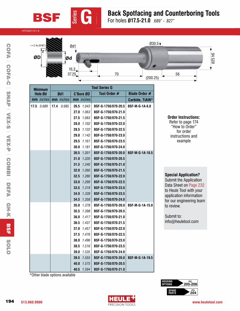
513.860.9900 www.heuletool.com
Catalog No. HTC14
194
HTC021/V1.0
Serie
s G
70 5616.3
37.25(200.25)
Ø25
h6
Ød1
Tool Series GMinimum Hole Ød
mm inchesTool Order #C’Bore ØD
mm inches
Blade Order #Ød1 mm inches
17.5 0.689 17.4 0.685 26.5 1.043 BSF-G-1750/070-20.5 BSF-M-G-1A-6.0
27.0 1.063 BSF-G-1750/070-21.0
27.5 1.083 BSF-G-1750/070-21.5
28.0 1.102 BSF-G-1750/070-22.0
28.5 1.122 BSF-G-1750/070-22.5
29.0 1.142 BSF-G-1750/070-23.0
29.5 1.161 BSF-G-1750/070-23.5
30.0 1.181 BSF-G-1750/070-24.0
30.5 1.201 BSF-G-1750/070-20.0 BSF-M-G-1A-10.5
31.0 1.220 BSF-G-1750/070-20.5
31.5 1.240 BSF-G-1750/070-21.0
32.0 1.260 BSF-G-1750/070-21.5
32.5 1.280 BSF-G-1750/070-22.0
33.0 1.299 BSF-G-1750/070-22.5
33.5 1.319 BSF-G-1750/070-23.0
34.0 1.339 BSF-G-1750/070-23.5
34.5 1.358 BSF-G-1750/070-24.0
35.0 1.378 BSF-G-1750/070-20.0 BSF-M-G-1A-15.0
35.5 1.398 BSF-G-1750/070-20.5
36.0 1.417 BSF-G-1750/070-21.0
36.5 1.437 BSF-G-1750/070-21.5
37.0 1.457 BSF-G-1750/070-22.0
37.5 1.476 BSF-G-1750/070-22.5
38.0 1.496 BSF-G-1750/070-23.0
38.5 1.516 BSF-G-1750/070-23.5
39.0 1.535 BSF-G-1750/070-24.0
39.5 1.555 BSF-G-1750/070-20.0 BSF-M-G-1A-19.5
40.0 1.575 BSF-G-1750/070-20.5
40.5 1.594 BSF-G-1750/070-21.0
Carbide, TiAlN*
*Other blade options available
Ø30.5
Serie
s
BSF G Back Spotfacing and Counterboring Tools For holes Ø17.5-21.0 .689”-.827”
CO
FA l C
OFA
-C l S
NA
P l V
EX
-S l V
EX
-P l C
OM
BI l D
EFA
l GH
-K B
SF S
OLO
Special Application? Submit the Application Data Sheet on Page 232 to Heule Tool with your application information for our engineering team to review. Submit to: [email protected]
Order Instructions: Refertopage174“HowtoOrder”
for order instructions and
example
HOUSINGOPTIONS
PG. 205-206
SPARE PARTS
PG. 204

513-860-9900 www.heuletool.com
Catalog No. HTC014
195
HTC021/V1.0
Serie
s70 56
16.337.25
(200.25)
Ø25
h6
Ød1
Tool Series GMinimum Hole Ød
mm inchesTool Order #C’Bore ØD
mm inches
Blade Order #Ød1 mm inches
18.0 0.709 17.9 0.705 27.0 1.063 BSF-G-1800/070-21.0 BSF-M-G-1A-6.0
27.5 1.083 BSF-G-1800/070-21.5
28.0 1.102 BSF-G-1800/070-22.0
28.5 1.122 BSF-G-1800/070-22.5
29.0 1.142 BSF-G-1800/070-23.0
29.5 1.161 BSF-G-1800/070-23.5
30.0 1.181 BSF-G-1800/070-24.0
30.5 1.201 BSF-G-1800/070-24.5
31.0 1.220 BSF-G-1800/070-20.5 BSF-M-G-1A-10.5
31.5 1.240 BSF-G-1800/070-21.0
32.0 1.260 BSF-G-1800/070-21.5
32.5 1.280 BSF-G-1800/070-22.0
33.0 1.299 BSF-G-1800/070-22.5
33.5 1.319 BSF-G-1800/070-23.0
34.0 1.339 BSF-G-1800/070-23.5
34.5 1.358 BSF-G-1800/070-24.0
35.0 1.378 BSF-G-1800/070-24.5
35.5 1.398 BSF-G-1800/070-20.5 BSF-M-G-1A-15.0
36.0 1.417 BSF-G-1800/070-21.0
36.5 1.437 BSF-G-1800/070-21.5
37.0 1.457 BSF-G-1800/070-22.0
37.5 1.476 BSF-G-1800/070-22.5
38.0 1.496 BSF-G-1800/070-23.0
38.5 1.516 BSF-G-1800/070-23.5
39.0 1.535 BSF-G-1800/070-24.0
39.5 1.555 BSF-G-1800/070-24.5
40.0 1.575 BSF-G-1800/070-20.5 BSF-M-G-1A-19.5
40.5 1.594 BSF-G-1800/070-21.0
41.0 1.614 BSF-G-1800/070-21.5
41.5 1.634 BSF-G-1800/070-22.0
Carbide, TiAlN*
*Other blade options available
Ø30.5
Serie
s
BSF G Back Spotfacing and Counterboring Tools For holes Ø17.5-21.0 .689”-.827”
CO
FA l C
OFA
-C l S
NA
P l V
EX
-S l V
EX
-P l C
OM
BI l D
EFA
l GH
-K B
SF S
OLO
Order Instructions: Refertopage174 “HowtoOrder”
for order instructions and
example
Special Application? Submit the Application Data Sheet on Page 232 to Heule Tool with your application information for our engineering team to review. Submit to: [email protected]
CHANGE BLADES
PG. 212
PG. 209PROGRAMMING

513.860.9900 www.heuletool.com
Catalog No. HTC14
196
HTC021/V1.0
Serie
s G
70 5616.3
37.25(200.25)
Ø25
h6
Ød1
Tool Series GMinimum Hole Ød
mm inchesTool Order #C’Bore ØD
mm inches
Blade Order #Ød1 mm inches
18.5 0.728 18.4 0.724 28.0 1.102 BSF-G-1850/070-22.0 BSF-M-G-1A-6.0
28.5 1.122 BSF-G-1850/070-22.5
29.0 1.142 BSF-G-1850/070-23.0
29.5 1.161 BSF-G-1850/070-23.5
30.0 1.181 BSF-G-1850/070-24.0
30.5 1.201 BSF-G-1850/070-24.5
31.0 1.220 BSF-G-1850/070-25.0
31.5 1.240 BSF-G-1850/070-21.0 BSF-M-G-1A-10.5
32.0 1.260 BSF-G-1850/070-21.5
32.5 1.280 BSF-G-1850/070-22.0
33.0 1.299 BSF-G-1850/070-22.5
33.5 1.319 BSF-G-1850/070-23.0
34.0 1.339 BSF-G-1850/070-23.5
34.5 1.358 BSF-G-1850/070-24.0
35.0 1.378 BSF-G-1850/070-24.5
35.5 1.398 BSF-G-1850/070-25.0
36.0 1.417 BSF-G-1850/070-21.0 BSF-M-G-1A-15.0
36.5 1.437 BSF-G-1850/070-21.5
37.0 1.457 BSF-G-1850/070-22.0
37.5 1.476 BSF-G-1850/070-22.5
38.0 1.496 BSF-G-1850/070-23.0
38.5 1.516 BSF-G-1850/070-23.5
39.0 1.535 BSF-G-1850/070-24.0
39.5 1.555 BSF-G-1850/070-24.5
40.0 1.575 BSF-G-1850/070-25.0
40.5 1.594 BSF-G-1850/070-21.0 BSF-M-G-1A-19.5
41.0 1.614 BSF-G-1850/070-21.5
41.5 1.634 BSF-G-1850/070-22.0
42.0 1.654 BSF-G-1850/070-22.5
42.5 1.673 BSF-G-1850/070-23.0
43.0 1.693 BSF-G-1850/070-23.5
Carbide, TiAlN*
*Other blade options available
Ø30.5
Serie
s
BSF G Back Spotfacing and Counterboring Tools For holes Ø17.5-21.0 .689”-.827”
CO
FA l C
OFA
-C l S
NA
P l V
EX
-S l V
EX
-P l C
OM
BI l D
EFA
l GH
-K B
SF S
OLO
Special Application? Submit the Application Data Sheet on Page 232 to Heule Tool with your application information for our engineering team to review. Submit to: [email protected]
Order Instructions: Refertopage174“HowtoOrder”
for order instructions and
example
HOUSINGOPTIONS
PG. 205-206
SPARE PARTS
PG. 204

513-860-9900 www.heuletool.com
Catalog No. HTC014
197
HTC021/V1.0
Serie
s G
70 5616.3
37.25(200.25)
Ø25
h6
Ød1
Tool Series GMinimum Hole Ød
mm inchesTool Order #C’Bore ØD
mm inches
Blade Order #Ød1 mm inches
19.0 0.748 18.9 0.744 28.5 1.122 BSF-G-1900/070-22.5 BSF-M-G-1A-6.0
29.0 1.142 BSF-G-1900/070-23.0
29.5 1.161 BSF-G-1900/070-23.5
30.0 1.181 BSF-G-1900/070-24.0
30.5 1.201 BSF-G-1900/070-24.5
31.0 1.220 BSF-G-1900/070-25.0
31.5 1.240 BSF-G-1900/070-25.5
32.0 1.260 BSF-G-1900/070-21.5 BSF-M-G-1A-10.5
32.5 1.280 BSF-G-1900/070-22.0
33.0 1.299 BSF-G-1900/070-22.5
33.5 1.319 BSF-G-1900/070-23.0
34.0 1.339 BSF-G-1900/070-23.5
34.5 1.358 BSF-G-1900/070-24.0
35.0 1.378 BSF-G-1900/070-24.5
35.5 1.398 BSF-G-1900/070-25.0
36.0 1.417 BSF-G-1900/070-25.5
36.5 1.437 BSF-G-1900/070-21.5 BSF-M-G-1A-15.0
37.0 1.457 BSF-G-1900/070-22.0
37.5 1.476 BSF-G-1900/070-22.5
38.0 1.496 BSF-G-1900/070-23.0
38.5 1.516 BSF-G-1900/070-23.5
39.0 1.535 BSF-G-1900/070-24.0
39.5 1.555 BSF-G-1900/070-24.5
40.0 1.575 BSF-G-1900/070-25.0
40.5 1.594 BSF-G-1900/070-25.5
41.0 1.614 BSF-G-1900/070-21.5 BSF-M-G-1A-19.5
41.5 1.634 BSF-G-1900/070-22.0
42.0 1.654 BSF-G-1900/070-22.5
42.5 1.673 BSF-G-1900/070-23.0
43.0 1.693 BSF-G-1900/070-23.5
43.5 1.713 BSF-G-1900/070-24.0
44.0 1.732 BSF-G-1900/070-24.5
Carbide, TiAlN*
Ø30.5
Serie
s
BSF G Back Spotfacing and Counterboring Tools For holes Ø17.5-21.0 .689”-.827”
CO
FA l C
OFA
-C l S
NA
P l V
EX
-S l V
EX
-P l C
OM
BI l D
EFA
l GH
-K B
SF S
OLO
Order Instructions: Refertopage174 “HowtoOrder”
for order instructions and
example
Special Application? Submit the Application Data Sheet on Page 232 to Heule Tool with your application information for our engineering team to review. Submit to: [email protected]
CHANGE BLADES
PG. 212
PG. 209PROGRAMMING

513.860.9900 www.heuletool.com
Catalog No. HTC14
198
HTC021/V1.0
Serie
s70 56
16.337.25
(200.25)
Ø25
h6
Ød1
Tool Series GMinimum Hole Ød
mm inchesTool Order #C’Bore ØD
mm inches
Blade Order #Ød1 mm inches
19.5 0.768 19.4 0.764 29.5 1.161 BSF-G-1950/070-23.5 BSF-M-G-1A-6.0
30.0 1.181 BSF-G-1950/070-24.0
30.5 1.201 BSF-G-1950/070-24.5
31.0 1.220 BSF-G-1950/070-25.0
31.5 1.240 BSF-G-1950/070-25.5
32.0 1.260 BSF-G-1950/070-26.0
32.5 1.280 BSF-G-1950/070-22.0 BSF-M-G-1A-10.5
33.0 1.299 BSF-G-1950/070-22.5
33.5 1.319 BSF-G-1950/070-23.0
34.0 1.339 BSF-G-1950/070-23.5
34.5 1.358 BSF-G-1950/070-24.0
35.0 1.378 BSF-G-1950/070-24.5
35.5 1.398 BSF-G-1950/070-25.0
36.0 1.417 BSF-G-1950/070-25.5
36.5 1.437 BSF-G-1950/070-26.0
37.0 1.457 BSF-G-1950/070-22.0 BSF-M-G-1A-15.0
37.5 1.476 BSF-G-1950/070-22.5
38.0 1.496 BSF-G-1950/070-23.0
38.5 1.516 BSF-G-1950/070-23.5
39.0 1.535 BSF-G-1950/070-24.0
39.5 1.555 BSF-G-1950/070-24.5
40.0 1.575 BSF-G-1950/070-25.0
40.5 1.594 BSF-G-1950/070-25.5
41.0 1.614 BSF-G-1950/070-26.0
41.5 1.634 BSF-G-1950/070-22.0 BSF-M-G-1A-19.5
42.0 1.654 BSF-G-1950/070-22.5
42.5 1.673 BSF-G-1950/070-23.0
43.0 1.693 BSF-G-1950/070-23.5
43.5 1.713 BSF-G-1950/070-24.0
44.0 1.732 BSF-G-1950/070-24.5
44.5 1.752 BSF-G-1950/070-25.0
45.0 1.772 BSF-G-1950/070-25.5
Carbide, TiAlN*
Ø30.5
Serie
s
BSF G Back Spotfacing and Counterboring Tools For holes Ø17.5-21.0 .689”-.827”
CO
FA l C
OFA
-C l S
NA
P l V
EX
-S l V
EX
-P l C
OM
BI l D
EFA
l GH
-K B
SF S
OLO
Special Application? Submit the Application Data Sheet on Page 232 to Heule Tool with your application information for our engineering team to review. Submit to: [email protected]
Order Instructions: Refertopage174“HowtoOrder”
for order instructions and
example
HOUSINGOPTIONS
PG. 205-206
SPARE PARTS
PG. 204

513-860-9900 www.heuletool.com
Catalog No. HTC014
199
HTC021/V1.0
Serie
s70 56
16.337.25
(200.25)
Ø25
h6
Ød1
Tool Series GMinimum Hole Ød
mm inchesTool Order #C’Bore ØD
mm inchesBlade Order #Ød1
mm inches20.0 0.787 19.9 0.783 30.0 1.181 BSF-G-2000/070-24.0 BSF-M-G-1A-6.0
30.5 1.201 BSF-G-2000/070-24.5
31.0 1.220 BSF-G-2000/070-25.0
31.5 1.240 BSF-G-2000/070-25.5
32.0 1.260 BSF-G-2000/070-26.0
32.5 1.280 BSF-G-2000/070-26.5
33.0 1.299 BSF-G-2000/070-22.5 BSF-M-G-1A-10.5
33.5 1.319 BSF-G-2000/070-23.0
34.0 1.339 BSF-G-2000/070-23.5
34.5 1.358 BSF-G-2000/070-24.0
35.0 1.378 BSF-G-2000/070-24.5
35.5 1.398 BSF-G-2000/070-25.0
36.0 1.417 BSF-G-2000/070-25.5
36.5 1.437 BSF-G-2000/070-26.0
37.0 1.457 BSF-G-2000/070-26.5
37.5 1.476 BSF-G-2000/070-22.5 BSF-M-G-1A-15.0
38.0 1.496 BSF-G-2000/070-23.0
38.5 1.516 BSF-G-2000/070-23.5
39.0 1.535 BSF-G-2000/070-24.0
39.5 1.555 BSF-G-2000/070-24.5
40.0 1.575 BSF-G-2000/070-25.0
40.5 1.594 BSF-G-2000/070-25.5
41.0 1.614 BSF-G-2000/070-26.0
41.5 1.634 BSF-G-2000/070-26.5
42.0 1.654 BSF-G-2000/070-22.5 BSF-M-G-1A-19.5
42.5 1.673 BSF-G-2000/070-23.0
43.0 1.693 BSF-G-2000/070-23.5
43.5 1.713 BSF-G-2000/070-24.0
44.0 1.732 BSF-G-2000/070-24.5
44.5 1.752 BSF-G-2000/070-25.0
45.0 1.772 BSF-G-2000/070-25.5
45.5 1.791 BSF-G-2000/070-26.0
46.0 1.811 BSF-G-2000/070-26.5
Carbide, TiAlN*
Ø30.5
Serie
s
BSF G Back Spotfacing and Counterboring Tools For holes Ø17.5-21.0 .689”-.827”
CO
FA l C
OFA
-C l S
NA
P l V
EX
-S l V
EX
-P l C
OM
BI l D
EFA
l GH
-K B
SF S
OLO
Order Instructions: Refertopage174 “HowtoOrder”
for order instructions and
example
Special Application? Submit the Application Data Sheet on Page 232 to Heule Tool with your application information for our engineering team to review. Submit to: [email protected]
CHANGE BLADES
PG. 212
PG. 209PROGRAMMING

513.860.9900 www.heuletool.com
Catalog No. HTC14
200
HTC021/V1.0
Serie
sSe
ries
BSF G Back Spotfacing and Counterboring Tools For holes Ø17.5-21.0 .689”-.827”
70 5616.3
39.50(202.50)
Ø25
h6
Ød1Ø30.5
Serie
s
BSF G
Tool Series GMinimum Hole Ød
mm inchesTool Order #C’Bore ØD
mm inches
Blade Order #Ød1 mm inches
20.5 0.807 20.4 0.803 29.0 1.142 BSF-G-2050/070-23.0 BSF-M-G-1A-6.0
29.5 1.161 BSF-G-2050/070-23.5
30.0 1.181 BSF-G-2050/070-24.0
30.5 1.201 BSF-G-2050/070-24.5
31.0 1.220 BSF-G-2050/070-25.0
31.5 1.240 BSF-G-2050/070-25.5
32.0 1.260 BSF-G-2050/070-26.0
32.5 1.280 BSF-G-2050/070-26.5
33.0 1.299 BSF-G-2050/070-27.0
33.5 1.319 BSF-G-2050/070-23.0 BSF-M-G-1A-10.5
34.0 1.339 BSF-G-2050/070-23.5
34.5 1.358 BSF-G-2050/070-24.0
35.0 1.378 BSF-G-2050/070-24.5
35.5 1.398 BSF-G-2050/070-25.0
36.0 1.417 BSF-G-2050/070-25.5
36.5 1.437 BSF-G-2050/070-26.0
37.0 1.457 BSF-G-2050/070-26.5
37.5 1.476 BSF-G-2050/070-27.0
38.0 1.496 BSF-G-2050/070-23.0 BSF-M-G-1A-15.0
38.5 1.516 BSF-G-2050/070-23.5
39.0 1.535 BSF-G-2050/070-24.0
39.5 1.555 BSF-G-2050/070-24.5
40.0 1.575 BSF-G-2050/070-25.0
40.5 1.594 BSF-G-2050/070-25.5
41.0 1.614 BSF-G-2050/070-26.0
41.5 1.634 BSF-G-2050/070-22.0
42.0 1.654 BSF-G-2050/070-22.5
42.5 1.673 BSF-G-2050/070-23.0 BSF-M-G-1A-19.5
43.0 1.693 BSF-G-2050/070-23.5
43.5 1.713 BSF-G-2050/070-24.0
44.0 1.732 BSF-G-2050/070-24.5
44.5 1.752 BSF-G-2050/070-25.0
Carbide, TiAlN*
CO
FA l C
OFA
-C l S
NA
P l V
EX
-S l V
EX
-P l C
OM
BI l D
EFA
l GH
-K B
SF S
OLO
Back Spotfacing and Counterboring Tools For holes Ø17.5-21.0 .689”-.827”
Special Application? Submit the Application Data Sheet on Page 232 to Heule Tool with your application information for our engineering team to review. Submit to: [email protected]
Order Instructions: Refertopage174“HowtoOrder”
for order instructions and
example
HOUSINGOPTIONS
PG. 205-206
SPARE PARTS
PG. 204

513-860-9900 www.heuletool.com
Catalog No. HTC014
201
HTC021/V1.0
Serie
sSe
ries
BSF G Back Spotfacing and Counterboring Tools For holes Ø17.5-21.0 .689”-.827”
70 5616.3
39.50(202.50)
Ø25
h6
Ød1Ø30.5
Serie
s
BSF G
Tool Series GMinimum Hole Ød
mm inchesTool Order #C’Bore ØD
mm inchesBlade Order #Ød1
mm inches20.5 0.807 20.4 0.803 45.0 1.772 BSF-G-2050/070-25.5 BSF-M-G-1A-19.5
45.5 1.791 BSF-G-2050/070-26.0
46.0 1.811 BSF-G-2050/070-26.5
46.5 1.831 BSF-G-2050/070-27.0
47.0 1.850 BSF-G-2050/070-23.0 BSF-M-G-1A-24.0
47.5 1.870 BSF-G-2050/070-23.5
48.0 1.890 BSF-G-2050/070-24.0
48.5 1.909 BSF-G-2050/070-24.5
Carbide, TiAlN*
CO
FA l C
OFA
-C l S
NA
P l V
EX
-S l V
EX
-P l C
OM
BI l D
EFA
l GH
-K B
SF S
OLO
Back Spotfacing and Counterboring Tools For holes Ø17.5-21.0 .689”-.827”
Order Instructions: Refertopage174 “HowtoOrder”
for order instructions and
example
Special Application? Submit the Application Data Sheet on Page 232 to Heule Tool with your application information for our engineering team to review. Submit to: [email protected]
CHANGE BLADES
PG. 212
PG. 209PROGRAMMING
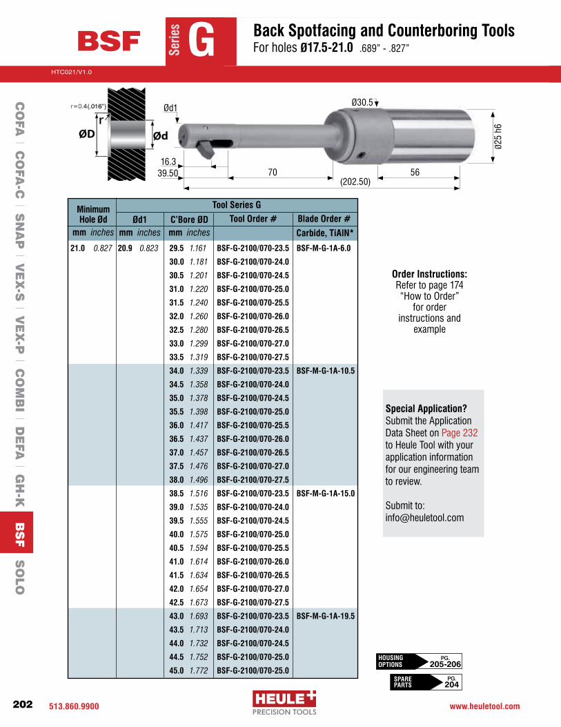
513.860.9900 www.heuletool.com
Catalog No. HTC14
202
HTC021/V1.0
Serie
sSe
ries
BSF G
CO
FA l C
OFA
-C l S
NA
P l V
EX
-S l V
EX
-P l C
OM
BI l D
EFA
l GH
-K B
SF S
OLO
Back Spotfacing and Counterboring Tools For holes Ø17.5-21.0 .689”-.827”
70 5616.3
39.50(202.50)
Ø25
h6
Ød1Ø30.5
Tool Series GMinimum Hole Ød
mm inchesTool Order #C’Bore ØD
mm inches
Blade Order #Ød1 mm inches
21.0 0.827 20.9 0.823 29.5 1.161 BSF-G-2100/070-23.5 BSF-M-G-1A-6.0
30.0 1.181 BSF-G-2100/070-24.0
30.5 1.201 BSF-G-2100/070-24.5
31.0 1.220 BSF-G-2100/070-25.0
31.5 1.240 BSF-G-2100/070-25.5
32.0 1.260 BSF-G-2100/070-26.0
32.5 1.280 BSF-G-2100/070-26.5
33.0 1.299 BSF-G-2100/070-27.0
33.5 1.319 BSF-G-2100/070-27.5
34.0 1.339 BSF-G-2100/070-23.5 BSF-M-G-1A-10.5
34.5 1.358 BSF-G-2100/070-24.0
35.0 1.378 BSF-G-2100/070-24.5
35.5 1.398 BSF-G-2100/070-25.0
36.0 1.417 BSF-G-2100/070-25.5
36.5 1.437 BSF-G-2100/070-26.0
37.0 1.457 BSF-G-2100/070-26.5
37.5 1.476 BSF-G-2100/070-27.0
38.0 1.496 BSF-G-2100/070-27.5
38.5 1.516 BSF-G-2100/070-23.5 BSF-M-G-1A-15.0
39.0 1.535 BSF-G-2100/070-24.0
39.5 1.555 BSF-G-2100/070-24.5
40.0 1.575 BSF-G-2100/070-25.0
40.5 1.594 BSF-G-2100/070-25.5
41.0 1.614 BSF-G-2100/070-26.0
41.5 1.634 BSF-G-2100/070-26.5
42.0 1.654 BSF-G-2100/070-27.0
42.5 1.673 BSF-G-2100/070-27.5
43.0 1.693 BSF-G-2100/070-23.5 BSF-M-G-1A-19.5
43.5 1.713 BSF-G-2100/070-24.0
44.0 1.732 BSF-G-2100/070-24.5
44.5 1.752 BSF-G-2100/070-25.0
45.0 1.772 BSF-G-2100/070-25.0
Carbide, TiAlN*
Special Application? Submit the Application Data Sheet on Page 232 to Heule Tool with your application information for our engineering team to review. Submit to: [email protected]
Order Instructions: Refertopage174“HowtoOrder”
for order instructions and
example
HOUSINGOPTIONS
PG. 205-206
SPARE PARTS
PG. 204
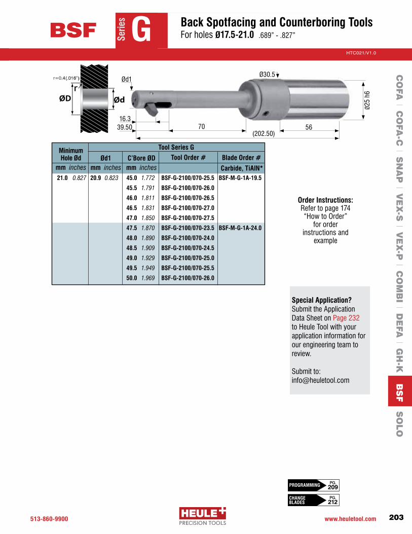
513-860-9900 www.heuletool.com
Catalog No. HTC014
203
HTC021/V1.0
Serie
sSe
ries
BSF GC
OFA
l CO
FA-C
l SN
AP
l VE
X-S
l VE
X-P
l CO
MB
I l DE
FA l G
H-K
BS
F S
OLO
Back Spotfacing and Counterboring Tools For holes Ø17.5-21.0 .689”-.827”
70 5616.3
39.50(202.50)
Ø25
h6
Ød1Ø30.5
Tool Series GMinimum Hole Ød
mm inchesTool Order #C’Bore ØD
mm inchesBlade Order #Ød1
mm inches21.0 0.827 20.9 0.823 45.0 1.772 BSF-G-2100/070-25.5 BSF-M-G-1A-19.5
45.5 1.791 BSF-G-2100/070-26.0
46.0 1.811 BSF-G-2100/070-26.5
46.5 1.831 BSF-G-2100/070-27.0
47.0 1.850 BSF-G-2100/070-27.5
47.5 1.870 BSF-G-2100/070-23.5 BSF-M-G-1A-24.0
48.0 1.890 BSF-G-2100/070-24.0
48.5 1.909 BSF-G-2100/070-24.5
49.0 1.929 BSF-G-2100/070-25.0
49.5 1.949 BSF-G-2100/070-25.5
50.0 1.969 BSF-G-2100/070-26.0
Carbide, TiAlN*
Order Instructions: Refertopage174 “HowtoOrder”
for order instructions and
example
Special Application? Submit the Application Data Sheet on Page 232 to Heule Tool with your application information for our engineering team to review. Submit to: [email protected]
CHANGE BLADES
PG. 212
PG. 209PROGRAMMING

513.860.9900 www.heuletool.com
Catalog No. HTC14
204
HTC021/V1.0
Serie
s
7 2 9 6 3 4 5 1
1 Cylindrical Shank2 Control Pin 3 Spring4Piston 5 Set Screw 6 Clamping Screw
7 Split Pin8 Blade 9 Housing 10 Assembly Pin Torx Wrench
Tool Description
SPARE PARTS SERIES D SERIES E SERIES F
SPARE PARTS SERIES A SERIES B SERIES C
SPARE PARTS SERIES G
8
10
1- Clamping screws sold individually (3x needed)
1 CYLINDRICAL SHANK BSF-S-0003 BSF-S-0003 BSF-S-00032 CONTROL PIN BSF-B-0001 (6.5) BSF-B-0003 (7.5) BSF-B-0005 (9.0) BSF-B-0002 (7.0) BSF-B-0004 (8.5)3 SPRING GH-H-F-0052 GH-H-F-0052 GH-H-F-00534 PISTON BSF-E-0014 BSF-E-0014 BSF-E-00145 SET SCREW GH-H-S-0302 GH-H-S-0302 GH-H-S-03026 CLAMPING SCREW GH-H-S-0201 GH-H-S-0201 GH-H-S-02017 SPLIT PIN BSF-E-0009 BSF-E-0018 BSF-E-001010 ASSEMBLY PIN BSF-V-0009 BSF-V-0009 BSF-V-0006 WRENCH GH-H-S-2023 GH-H-S-2023 GH-H-S-2023 1 CYLINDRICALSHANK BSF-S-0003 BSF-S-0003 BSF-S-00042 CONTROL PIN BSF-B-0006 (10.5) BSF-B-0008 (12.0) BSF-B-0010 (14.5) BSF-B-0007 (11.5) BSF-B-0009 (14.0) BSF-B-0011 (16.0)3 SPRING GH-H-F-0053 GH-H-F-0053 GH-H-F-00514 PISTON BSF-E-0014 BSF-E-0014 BSF-E-00145 SET SCREW GH-H-S-0302 GH-H-S-0302 GH-H-S-03026 CLAMPING SCREW GH-H-S-0201 GH-H-S-0201 GH-H-S-02027 SPLIT PIN BSF-E-0019 BSF-E-0011 BSF-E-001210 ASSEMBLY PIN BSF-V-0006 BSF-V-0007 BSF-V-0007 WRENCH GH-H-S-2023 GH-H-S-2023 GH-H-S-2100
1 CYLINDRICALSHANK BSF-S-0004 2 CONTROL PIN BSF-B-0012 (17.5) BSF-B-0013 (20.5 & 21.0)3 SPRING GH-H-F-0051 4 PISTON BSF-E-0014 5 SET SCREW GH-H-S-0302 6 CLAMPING SCREW GH-H-S-0202 7 SPLIT PIN BSF-E-0013 10 ASSEMBLY PIN BSF-V-0008 WRENCH GH-H-S-2100
BSF
CO
FA l C
OFA
-C l S
NA
P l V
EX
-S l V
EX
-P l C
OM
BI l D
EFA
l GH
-K B
SF S
OLO
Spare Parts

513-860-9900 www.heuletool.com
Catalog No. HTC014
205
HTC021/V1.0
Serie
s
(8) Carbide TiAlN
BLADES TOOL NUMBER(9)
HOUSING TOOL NUMBER(9)
HOUSINGSE
RIES
ASE
RIES
BSE
RIES
CSE
RIES
D
SERI
ES E
SERI
ES A
SERI
ES B
SERI
ES C
SERI
ES D
SERI
ES E
SERI
ES F
SERI
ES G
Series F and G on next page
BSF-M-A-1A-3.0 BSF-A-0650/040-6.5 BSF-N-A-0650/N025/040 BSF-E-1200/050-13.0 BSF-N-E-1200/N050/050BSF-M-A-1A-4.5 BSF-A-0650/040-7.0 BSF-N-A-0650/0000/040 BSF-E-1200/050-13.5 BSF-N-E-1200/N025/050BSF-M-A-1A-6.0 BSF-A-0650/040-7.5 BSF-N-A-0650/P025/040 BSF-E-1200/050-14.0 BSF-N-E-1200/0000/050BSF-M-A-1A-7.5BSF-A-0700/040-7.0 BSF-N-A-0700/0000/040 BSF-E-1200/050-14.5 BSF-N-E-1200/P025/050BSF-M-A-1A-9.0 BSF-A-0700/040-7.5 BSF-N-A-0700/P025/040 BSF-E-1200/050-15.0 BSF-N-E-1200/P050/050BSF-M-B-1A-3.5 BSF-A-0700/040-8.0 BSF-N-A-0700/P050/040 BSF-E-1250/050-13.5 BSF-N-E-1250/N025/050BSF-M-B-1A-5.0 BSF-B-0750/040-7.5 BSF-N-B-0750/N025/040 BSF-E-1250/050-14.0 BSF-N-E-1250/0000/050BSF-M-B-1A-6.5 BSF-B-0750/040-8.0 BSF-N-B-0750/0000/040 BSF-E-1250/050-14.5 BSF-N-E-1250/P025/050BSF-M-B-1A-8.0 BSF-B-0750/040-8.5 BSF-N-B-0750/P025/040 BSF-E-1250/050-15.0 BSF-N-E-1250/P050/050BSF-M-B-1A-9.5BSF-B-0800/040-8.0 BSF-N-B-0800/0000/040 BSF-E-1250/050-15.5 BSF-N-E-1250/P075/050BSF-M-B-1A-11.0 BSF-B-0800/040-8.5 BSF-N-B-0800/P025/040 BSF-E-1300/050-14.0 BSF-N-E-1300/0000/050BSF-M-C-1A-4.0 BSF-B-0800/040-9.0 BSF-N-B-0800/P050/040 BSF-E-1300/050-14.5 BSF-N-E-1300/P025/050BSF-M-C-1A-5.5 BSF-B-0850/040-8.5 BSF-N-B-0850/P025/040 BSF-E-1300/050-15.0 BSF-N-E-1300/P050/050BSF-M-C-1A-7.0 BSF-B-0850/040-9.0 BSF-N-B-0850/P050/040 BSF-E-1300/050-15.5 BSF-N-E-1300/P075/050BSF-M-C-1A-8.5 BSF-B-0850/040-9.5 BSF-N-B-0850/P075/040 BSF-E-1300/050-16.0 BSF-N-E-1300/P100/050BSF-M-C-1A-10.0 BSF-C-0900/050-9.5 BSF-N-C-0900/N025/050 BSF-E-1350/050-14.5 BSF-N-E-1350/P025/050BSF-M-C-1A-11.5 BSF-C-0900/050-10.0 BSF-N-C-0900/0000/050 BSF-E-1350/050-15.0 BSF-N-E-1350/P050/050BSF-M-D-1A-4.5 BSF-C-0900/050-10.5 BSF-N-C-0900/P025/050 BSF-E-1350/050-15.5 BSF-N-E-1350/P075/050BSF-M-D-1A-7.0 BSF-C-0950/050-10.0 BSF-N-C-0950/0000/050 BSF-E-1350/050-16.0 BSF-N-E-1350/P100/050BSF-M-D-1A-9.5 BSF-C-0950/050-10.5 BSF-N-C-0950/P025/050 BSF-E-1350/050-16.5 BSF-N-E-1350/P125/050BSF-M-D-1A-12.0 BSF-C-0950/050-11.0 BSF-N-C-0950/P050/050 BSF-E-1400/050-15.0 BSF-N-E-1400/P050/050BSF-M-D-1A-14.5 BSF-C-1000/050-10.5 BSF-N-C-1000/P025/050 BSF-E-1400/050-15.5 BSF-N-E-1400/P075/050BSF-M-E-1A-5.0 BSF-C-1000/050-11.0 BSF-N-C-1000/P050/050 BSF-E-1400/050-16.0 BSF-N-E-1400/P100/050BSF-M-E-1A-7.5 BSF-C-1000/050-11.5 BSF-N-C-1000/P075/050 BSF-E-1400/050-16.5 BSF-N-E-1400/P125/050BSF-M-E-1A-10.0 BSF-D-1050/050-11.0 BSF-N-D-1050/N050/050 BSF-E-1400/050-17.0 BSF-N-E-1400/P150/050BSF-M-E-1A-12.5 BSF-D-1050/050-11.5 BSF-N-D-1050/N025/050 BSF-M-E-1A-15.0 BSF-D-1050/050-12.0 BSF-N-D-1050/0000/050 BSF-M-F-1A-5.5 BSF-D-1050/050-12.5 BSF-N-D-1050/P025/050 BSF-M-F-1A-9.0 BSF-D-1050/050-13.0 BSF-N-D-1050/P050/050 BSF-M-F-1A-12.5 BSF-D-1100/050-11.5 BSF-N-D-1100/N025/050 BSF-M-F-1A-16.0 BSF-D-1100/050-12.0 BSF-N-D-1100/0000/050 BSF-M-F-1A-19.5 BSF-D-1100/050-12.5 BSF-N-D-1100/P025/050 BSF-M-G-1A-6.0 BSF-D-1100/050-13.0 BSF-N-D-1100/P050/050 BSF-M-G-1A-10.5 BSF-D-1100/050-13.5 BSF-N-D-1100/P075/050 BSF-M-G-1A-15.0 BSF-D-1150/050-12.0 BSF-N-D-1150/0000/050 BSF-M-G-1A-19.5 BSF-D-1150/050-12.5 BSF-N-D-1150/P025/050 BSF-D-1150/050-13.0 BSF-N-D-1150/P050/050 BSF-D-1150/050-13.5 BSF-N-D-1150/P075/050 BSF-D-1150/050-14.0 BSF-N-D-1150/P100/050
BSFC
OFA
l CO
FA-C
l SN
AP
l VE
X-S
l VE
X-P
l CO
MB
I l DE
FA l G
H-K
BS
F S
OLO
Spare Parts - Housings

513.860.9900 www.heuletool.com
Catalog No. HTC14
206
HTC021/V1.0
Serie
s
(9)HOUSING
SERIES G
TOOL NUMBER(9)
HOUSING TOOL NUMBER(9)
HOUSINGSERIES F SERIES G cont...
BSF
CO
FA l C
OFA
-C l S
NA
P l V
EX
-S l V
EX
-P l C
OM
BI l D
EFA
l GH
-K B
SF S
OLO
BSF-F-1450/070-16.0 BSF-N-F-1450/N075/070BSF-F-1450/070-16.5 BSF-N-F-1450/N050/070BSF-F-1450/070-17.0 BSF-N-F-1450/N025/070BSF-F-1450/070-17.5 BSF-N-F-1450/0000/070BSF-F-1450/070-18.0 BSF-N-F-1450/P025/070BSF-F-1450/070-18.5 BSF-N-F-1450/P050/070BSF-F-1450/070-19.0 BSF-N-F-1450/P075/070BSF-F-1500/070-16.5 BSF-N-F-1500/N050/070BSF-F-1500/070-17.0 BSF-N-F-1500/N025/070BSF-F-1500/070-17.5 BSF-N-F-1500/0000/070BSF-F-1500/070-18.0 BSF-N-F-1500/P025/070BSF-F-1500/070-18.5 BSF-N-F-1500/P050/070BSF-F-1500/070-19.0 BSF-N-F-1500/P075/070BSF-F-1500/070-19.5 BSF-N-F-1500/P100/070BSF-F-1550/070-17.0 BSF-N-F-1550/N025/070BSF-F-1550/070-17.5 BSF-N-F-1550/0000/070BSF-F-1550/070-18.0 BSF-N-F-1550/P025/070BSF-F-1550/070-18.5 BSF-N-F-1550/P050/070BSF-F-1550/070-19.0 BSF-N-F-1550/P075/070BSF-F-1550/070-19.5 BSF-N-F-1550/P100/070BSF-F-1550/070-20.0 BSF-N-F-1550/P125/070BSF-F-1600/070-17.5 BSF-N-F-1600/0000/070BSF-F-1600/070-18.0 BSF-N-F-1600/P025/070BSF-F-1600/070-18.5 BSF-N-F-1600/P050/070BSF-F-1600/070-19.0 BSF-N-F-1600/P075/070BSF-F-1600/070-19.5 BSF-N-F-1600/P100/070BSF-F-1600/070-20.0 BSF-N-F-1600/P125/070BSF-F-1600/070-20.5 BSF-N-F-1600/P150/070BSF-F-1650/070-18.0 BSF-N-F-1650/P025/070BSF-F-1650/070-18.5 BSF-N-F-1650/P050/070BSF-F-1650/070-19.0 BSF-N-F-1650/P075/070BSF-F-1650/070-19.5 BSF-N-F-1650/P100/070BSF-F-1650/070-20.0 BSF-N-F-1650/P125/070BSF-F-1650/070-20.5 BSF-N-F-1650/P150/070BSF-F-1650/070-21.0 BSF-N-F-1650/P175/070BSF-F-1700/070-18.5 BSF-N-F-1700/P050/070BSF-F-1700/070-19.0 BSF-N-F-1700/P075/070BSF-F-1700/070-19.5 BSF-N-F-1700/P100/070BSF-F-1700/070-20.0 BSF-N-F-1700/P125/070BSF-F-1700/070-20.5 BSF-N-F-1700/P150/070BSF-F-1700/070-21.0 BSF-N-F-1700/P175/070BSF-F-1700/070-21.5 BSF-N-F-1700/P200/070
BSF-G-1750/070-20.0 BSF-N-G-1750/N100/070BSF-G-1750/070-20.5 BSF-N-G-1750/N075/070BSF-G-1750/070-21.0 BSF-N-G-1750/N050/070BSF-G-1750/070-21.5 BSF-N-G-1750/N025/070BSF-G-1750/070-22.0 BSF-N-G-1750/0000/070BSF-G-1750/070-22.5 BSF-N-G-1750/P025/070BSF-G-1750/070-23.0 BSF-N-G-1750/P050/070BSF-G-1750/070-23.5 BSF-N-G-1750/P075/070BSF-G-1750/070-24.0 BSF-N-G-1750/P100/070BSF-G-1800/070-20.5 BSF-N-G-1800/N075/070BSF-G-1800/070-21.0 BSF-N-G-1800/N050/070BSF-G-1800/070-21.5 BSF-N-G-1800/N025/070BSF-G-1800/070-22.0 BSF-N-G-1800/0000/070
BSF-G-1800/070-22.5 BSF-N-G-1800/P025/070BSF-G-1800/070-23.0 BSF-N-G-1800/P050/070BSF-G-1800/070-23.5 BSF-N-G-1800/P075/070BSF-G-1800/070-24.0 BSF-N-G-1800/P100/070BSF-G-1800/070-24.5 BSF-N-G-1800/P125/070BSF-G-1850/070-21.0 BSF-N-G-1850/N050/070BSF-G-1850/070-21.5 BSF-N-G-1850/N025/070BSF-G-1850/070-22.0 BSF-N-G-1850/0000/070BSF-G-1850/070-22.5 BSF-N-G-1850/P025/070BSF-G-1850/070-23.0 BSF-N-G-1850/P050/070BSF-G-1850/070-23.5 BSF-N-G-1850/P075/070BSF-G-1850/070-24.0 BSF-N-G-1850/P100/070BSF-G-1850/070-24.5 BSF-N-G-1850/P125/070BSF-G-1850/070-25.0 BSF-N-G-1850/P150/070BSF-G-1900/070-21.5 BSF-N-G-1900/N025/070BSF-G-1900/070-22.0 BSF-N-G-1900/0000/070BSF-G-1900/070-22.5 BSF-N-G-1900/P025/070BSF-G-1900/070-23.0 BSF-N-G-1900/P050/070BSF-G-1900/070-23.5 BSF-N-G-1900/P075/070BSF-G-1900/070-24.0 BSF-N-G-1900/P100/070BSF-G-1900/070-24.5 BSF-N-G-1900/P125/070BSF-G-1900/070-25.0 BSF-N-G-1900/P150/070BSF-G-1900/070-25.5 BSF-N-G-1900/P175/070BSF-G-1950/070-22.0 BSF-N-G-1950/0000/070BSF-G-1950/070-22.5 BSF-N-G-1950/P025/070BSF-G-1950/070-23.0 BSF-N-G-1950/P050/070BSF-G-1950/070-23.5 BSF-N-G-1950/P075/070BSF-G-1950/070-24.0 BSF-N-G-1950/P100/070BSF-G-1950/070-24.5 BSF-N-G-1950/P125/070BSF-G-1950/070-25.0 BSF-N-G-1950/P150/070BSF-G-1950/070-25.5 BSF-N-G-1950/P175/070BSF-G-1950/070-26.0 BSF-N-G-1950/P200/070BSF-G-2000/070-22.5 BSF-N-G-2000/P025/070BSF-G-2000/070-23.0 BSF-N-G-2000/P050/070BSF-G-2000/070-23.5 BSF-N-G-2000/P075/070BSF-G-2000/070-24.0 BSF-N-G-2000/P100/070BSF-G-2000/070-24.5 BSF-N-G-2000/P125/070BSF-G-2000/070-25.0 BSF-N-G-2000/P150/070BSF-G-2000/070-25.5 BSF-N-G-2000/P175/070BSF-G-2000/070-26.0 BSF-N-G-2000/P200/070BSF-G-2000/070-26.5 BSF-N-G-2000/P225/070BSF-G-2050/070-23.0 BSF-N-G-2050/P050/070BSF-G-2050/070-23.5 BSF-N-G-2050/P075/070BSF-G-2050/070-24.0 BSF-N-G-2050/P100/070BSF-G-2050/070-24.5 BSF-N-G-2050/P125/070BSF-G-2050/070-25.0 BSF-N-G-2050/P150/070BSF-G-2050/070-25.5 BSF-N-G-2050/P175/070BSF-G-2050/070-26.0 BSF-N-G-2050/P200/070BSF-G-2050/070-26.5 BSF-N-G-2050/P225/070BSF-G-2050/070-27.0 BSF-N-G-2050/P250/070BSF-G-2100/070-23.5 BSF-N-G-2100/P075/070BSF-G-2100/070-24.0 BSF-N-G-2100/P100/070BSF-G-2100/070-24.5 BSF-N-G-2100/P125/070BSF-G-2100/070-25.0 BSF-N-G-2100/P150/070BSF-G-2100/070-25.5 BSF-N-G-2100/P175/070BSF-G-2100/070-26.0 BSF-N-G-2100/P200/070BSF-G-2100/070-26.5 BSF-N-G-2100/P225/070BSF-G-2100/070-27.0 BSF-N-G-2100/P250/070BSF-G-2100/070-27.5 BSF-N-G-2100/P275/070
Spare Parts - Housings
TOOL NUMBER

513-860-9900 www.heuletool.com
Catalog No. HTC014
207
HTC021/V1.0
Serie
s
2 31
ThroughCoolant
4
Blade Working Principle
1 Withthecoolanton,thecontrolpinisforcingtheblade(redcolor)toretractintothebladehousing.
2 The control pin, while still under coolant pressure, supplies pressure to the back of the blade which forces the blade to fully retract.
3 The control pin holds the blade in the retracted position and the tool may be moved in the axial direction(Z-axis)throughthehole.
4 Turnoffthethroughcoolantandstartthespindlerotationattherecommendedactivationspeed.Withcentrifugal force the blade will swing out into working position. The through coolant may be turned on when the cutting blade is in full contact with the work piece. When the counterbore operation is finished the through coolant is turned off, the insert exits the counterbore. Reactivate the through coolant, the blade will retract again.
CNC Machine RequirementsBSFTools requireaminimum280PSI (approximately19.3BAR)and2000-5000RPMtoproperlyactivate.Typicalspotfacediametertolerancesof+/-0.1mm(0.004“).Therecommendedtooldiametersshouldbe0.004“-0.016“belowtheminimumholediameter. All materials can be machined but special considerations should be given to interruptions and long chipping materials. All tools are ground with large cylindrical shanks with h6 tolerances. Proper tool holding may include hydraulic, mill chuck or precisioncolletholders.Coolantfiltrationrequired(<25μm).
BSFC
OFA
l CO
FA-C
l SN
AP
l VE
X-S
l VE
X-P
l CO
MB
I l DE
FA l G
H-K
BS
F S
OLO
Technical Information

513.860.9900 www.heuletool.com
Catalog No. HTC14
208
HTC021/V1.0
Serie
s
BSF
BLADE NUMBERR=0.4
CUSTOM BLADER=0.8
LENGTH Lmm inches
WIDTH Bmm inches
HEIGHT Hmm inches
BSF-M-A-1A-3.0 BSF-M-A-08-1A-3.0 7.70 0.303 2.00 0.079 4.50 0.177
BSF-M-A-1A-4.5 BSF-M-A-08-1A-4.5 8.40 0.331 2.00 0.079 4.50 0.177
BSF-M-A-1A-6.0 BSF-M-A-08-1A-6.0 9.20 0.362 2.00 0.079 4.50 0.177
BSF-M-A-1A-7.5 BSF-M-A-08-1A-7.5 9.90 0.390 2.00 0.079 4.50 0.177
BSF-M-A-1A-9.0 BSF-M-A-08-1A-9.0 10.70 0.421 2.00 0.079 4.50 0.177
BSF-M-B-1A-3.5 BSF-M-B-08-1A-3.5 8.90 0.350 2.50 0.098 5.50 0.217
BSF-M-B-1A-5.0 BSF-M-B-08-1A-5.0 9.60 0.378 2.50 0.098 5.50 0.217
BSF-M-B-1A-6.5 BSF-M-B-08-1A-6.5 10.40 0.409 2.50 0.098 5.50 0.217
BSF-M-B-1A-8.0 BSF-M-B-08-1A-8.0 11.10 0.437 2.50 0.098 5.50 0.217
BSF-M-B-1A-9.5 BSF-M-B-08-1A-9.5 11.90 0.468 2.50 0.098 5.50 0.217
BSF-M-B-1A-11.0 BSF-M-B-08-1A-11.0 12.70 0.500 2.50 0.098 5.50 0.217
BSF-M-C-1A-4.0 BSF-M-C-08-1A-4.0 10.80 0.425 3.00 0.118 6.50 0.256
BSF-M-C-1A-5.5 BSF-M-C-08-1A-5.5 11.60 0.457 3.00 0.118 6.50 0.256
BSF-M-C-1A-7.0 BSF-M-C-08-1A-7.0 12.30 0.484 3.00 0.118 6.50 0.256
BSF-M-C-1A-8.5 BSF-M-C-08-1A-8.5 13.10 0.516 3.00 0.118 6.50 0.256
BSF-M-C-1A-10.0 BSF-M-C-08-1A-10.0 13.80 0.543 3.00 0.118 6.50 0.256
BSF-M-C-1A-11.5 BSF-M-C-08-1A-11.5 14.60 0.575 3.00 0.118 6.50 0.256
BSF-M-C-1A-13.0 BSF-M-C-08-1A-13.0 15.30 0.602 3.00 0.118 6.50 0.256
BSF-M-D-1A-4.5 BSF-M-D-08-1A-4.5 12.50 0.492 3.50 0.138 7.25 0.285
BSF-M-D-1A-7.0 BSF-M-D-08-1A-7.0 13.80 0.543 3.50 0.138 7.25 0.285
BSF-M-D-1A-9.5 BSF-M-D-08-1A-9.5 15.00 0.590 3.50 0.138 7.25 0.285
BSF-M-D-1A-12.0 BSF-M-D-08-1A-12.0 16.30 0.642 3.50 0.138 7.25 0.285
BSF-M-D-1A-14.5 BSF-M-D-08-1A-14.5 17.50 0.689 3.50 0.138 7.25 0.285
BSF-M-E-1A-5.0 BSF-M-E-08-1A-5.0 14.30 0.563 4.50 0.177 8.50 0.335
BSF-M-E-1A-7.5 BSF-M-E-08-1A-7.5 15.50 0.610 4.50 0.177 8.50 0.335
BSF-M-E-1A-10.0 BSF-M-E-08-1A-10.0 16.80 0.661 4.50 0.177 8.50 0.335
BSF-M-E-1A-12.5 BSF-M-E-08-1A-12.5 18.10 0.713 4.50 0.177 8.50 0.335
BSF-M-E-1A-15.0 BSF-M-E-08-1A-15.0 19.30 0.760 4.50 0.177 8.50 0.335
BSF-M-E-1A-17.5 BSF-M-E-08-1A-17.5 20.60 0.811 4.50 0.177 8.50 0.335
BSF-M-F-1A-5.5 BSF-M-F-08-1A-5.5 17.20 0.677 5.00 0.197 10.00 0.394
BSF-M-F-1A-9.0 BSF-M-F-08-1A-9.0 19.00 0.748 5.00 0.197 10.00 0.394
BSF-M-F-1A-12.5 BSF-M-F-08-1A-12.5 20.80 0.819 5.00 0.197 10.00 0.394
BSF-M-F-1A-16.0 BSF-M-F-08-1A-16.0 22.60 0.890 5.00 0.197 10.00 0.394
BSF-M-F-1A-19.5 BSF-M-F-08-1A-19.5 24.30 0.957 5.00 0.197 10.00 0.394
BSF-M-G-1A-6.0 BSF-M-G-08-1A-6.0 20.80 0.819 6.00 0.236 12.00 0.472
BSF-M-G-1A-10.5 BSF-M-G-08-1A-10.5 23.10 0.909 6.00 0.236 12.00 0.472
BSF-M-G-1A-15.0 BSF-M-G-08-1A-15.0 25.40 1.000 6.00 0.236 12.00 0.472
BSF-M-G-1A-19.5 BSF-M-G-08-1A-19.5 27.70 1.090 6.00 0.236 12.00 0.472
BSF-M-G-1A-24.0 BSF-M-G-08-1A-24.0 29.90 1.177 6.00 0.236 12.00 0.472
CO
FA l C
OFA
-C l S
NA
P l V
EX
-S l V
EX
-P l C
OM
BI l D
EFA
l GH
-K B
SF S
OLO
Technical Information
Blade Dimensions R

513-860-9900 www.heuletool.com
Catalog No. HTC014
209
HTC021/V1.0
Serie
s
BSF Technical Information
45002500
450025002000
350025002000
500030002500
350025001500
350030002000
350020001500
45002500
450025002000
350025002000
500030002500
350025001500
350030002000
350020001500
45002500
450025002000
350025002000
500030002500
350025001500
350030002000
350020001500
35002500
350025002000
300025002000
350025002000
250020001500
250025001500
250015001000
35002500
350025002000
300020002000
350025002000
250020001500
250025001500
250015001000
35002000
300020002000
250020002000
350025002000
250020001500
250025001500
250015001000
30002000
300020002000
250020002000
300025002100
250020001500
250020001500
200015001000
30002000
250020002000
250020002000
300025002000
250015001500
250020001500
200015001000
25002000
250020001500
250020002000
250020002000
200015001500
250020001500
200015001000
25002000
250020001500
250020001500
250020002000
200015001500
200020001500
150015001000
CounterboreRatio
1.4 1.5 1.6 1.7 1.8 1.9 2.0 2.1 2.2 2.3
Theactivationspeed(rev./min.)tobesettoswingoutthebladedependsontheborediameterandthecounterboreratio(counterborediameter:borediameter).
Activation Speed Chart
Bore-Ø dSeries A6.57.0
Series B7.58.08.5
Series C9.09.510.0
Series D10.511.011.5
Series E12.012.5 - 13.013.5-14.0
Series F14.515.0 - 15.516.0 - 17.0
Series G17.5 - 18.018.5 - 19/520.0 - 21.0
*All above values are recommended minumum RPM
CO
FA l C
OFA
-C l S
NA
P l V
EX
-S l V
EX
-P l C
OM
BI l D
EFA
l GH
-K B
SF S
OLO

513.860.9900 www.heuletool.com
Catalog No. HTC14
210
HTC021/V1.0
Serie
s
BSF
RECOMMENDATIONS:• Activation speed: 2000-5000 RPM• Coolant filtration: <25μm• Clamping: Sealed coolant or hydraulic holder• Minimumcoolantpressure:280PSI(approximately19.3BAR)• If there is long-chipping and deep counterbores, program the feed cycle so short chips are received.
NOTE: All listed cutting data are standard values only. The cutting values depend on the amount of slope of the material. In case of hard-to-machine materials or interrupted cuts, use lower end of the range.
CAUTION: High-pressure flood coolant directed at cutter may prematurely close blade before engaging. Recommend turn flood on after cutter engages part.
CO
FA l C
OFA
-C l S
NA
P l V
EX
-S l V
EX
-P l C
OM
BI l D
EFA
l GH
-K B
SF S
OLO
Series and Bore DiameterMaterial Hardness Cutting A B C D E/F/G
BHN Speed Ø6.5-Ø7.0 Ø7.5-Ø8.5 Ø9.0-Ø10.0 Ø10.5-Ø11.5 Ø12.0-Ø21.0SFM IPRMPM mm/rev
Carbon Steels 100-250100-260 .0004-.0008 .0004-.0012 .0008-.0016 .0012-.0025 .0012-.0030
30-80 0.01-0.02 0.01-0.03 0.02-0.04 0.03-0.06 0.03-0.08
Free Machining Alloy 125-340100-230 .0004-.0008 .0004-.0008 .0004-.0012 .0008-.0016 .0008-.0020
30-70 0.01-0.02 0.01-0.02 0.01-0.03 0.02-0.04 0.02-0.05
High Alloy Steel 250-350100-200 .0004-.0008 .0004-.0012 .0008-.0016 .0012-.0025 .0012-.0030
30-60 0.01-0.02 0.01-0.03 0.02-0.04 0.03-0.06 0.03-0.08
Stainless Steel 140-25050-100 .0004-.0008 .0004-.0012 .0008-.0016 .0008-.0020 .0008-.002515-30 0.01-0.02 0.01-0.03 0.02-0.04 0.02-0.06 0.02-0.08
Grey Cast Iron 150-330130-230 .0004-.0008 .0004-.0012 .0008-.0016 .0012-.0025 .0012-.0025
40-70 0.01-0.02 0.01-0.03 0.02-0.04 0.03-0.06 0.03-0.08
Nodular Cast Iron 140-310100-260 .0004-.0008 .0004-.0012 .0008-.0016 .0012-.0025 .0012-.0030
30-80 0.01-0.02 0.01-0.03 0.02-0.04 0.03-0.06 0.03-0.08
Aluminum Alloys 30-18060-120 .0008-.0012 .0008-.0020 .0012-.0025 .0012-.0030 .0020-.004018-37 0.02-0.03 0.02-0.05 0.03-0.06 0.03-0.08 0.05-0.10
Nickel-based Alloys 140-31020-60 .0004-.0008 .0004-.0008 .0004-.0012 .0008-.0016 .0008-.0020 7-18 0.01-0.02 0.01-0.02 0.01-0.03 0.02-0.04 0.02-0.03
Titanium Alloys 120-33430-100 .0004-.0008 .0004-.0008 .0008-.0012 .0008-.0020 .0008-.0025 10-30 0.01-0.02 0.01-0.02 0.02-0.03 0.02-0.05 0.02-0.06
Copper-Brass-Bronze 80-202100-290 .0004-.0008 .0004-.0012 .0008-.0016 .0012-.0025 .0012-.0030
30-90 0.01-0.02 0.01-0.03 0.02-0.04 0.03-0.06 0.03-0.08
Technical Information
Cutting Data

513-860-9900 www.heuletool.com
Catalog No. HTC014
211
HTC021/V1.0
Serie
s
BSFC
OFA
l CO
FA-C
l SN
AP
l VE
X-S
l VE
X-P
l CO
MB
I l DE
FA l G
H-K
BS
F S
OLO
Technical Information
1 2 3
4 5 6
7 8 9
Z Pos.
Z Pos.
M05 (spindlestop) M88(internalcoolanton)G04 X2.0(dwell2seconds)
G00 Z- (Z Pos. = T max + AL) M89 (internalcoolantoff)S5000 M03 (blade moves intocuttingposition)G04 X5.0 (dwell2-5sec.)
S400 M03 (spindle rotation for cuttingspeed)G00 Z- (T max+Hs+1.0mm)M08(floodcoolanton)
G01 Z- (T max+Hs-.25mm or full cut dimension) F(feed .025mm (.001“) per rev.)*
Optional Step M88 (internalcoolanton)G01 Z- (desired depth of cut)
M09 (turnofffloodcoolant)M89 (turn off internal coolantifon)G00 Z- (Z Pos. = T max +AL) from figure #2
M05(spindleoff)M88 (internal coolant on)G04 X5.0 (dwell 5 seconds)
G00 Z1.0 (rapid out of workpiece)M88 (internalcoolantoff)
Position tool above part, spindle off, internal coolant on, dwell 2- 5 seconds (dwelltimedependsonpump),bladeretracts.
Position tool through the hole (ZPos.=Tmax+AL).
Internal coolant off and start spindle 2000-5000 RPM, dwell 2-5 seconds (dwell depends on time it takes to purgetheinternalcoolant),blademoves into cutting position.
Turn on spindle at cutting speed. Position cutting blade 1 mm below Tmax(notetoleranceandburrsize),turn on flood coolant.
Move Z axis for cutting (approximately .25mmdeeporuntilfullcut)withcutting feed rate. *continue to desired depth of cut unless optional next step is required
Optional: For deep bores, turn internal coolant on and feed to desired depth. Insert must be in full cut.
If the counterbore depth is reached, switch off internal coolant and external coolant, and rapid back toZposition(ZPos.=Tmax+AL).
Spindle stop, internal coolant on, dwell 2-5 seconds, blade retracts.
Position tool out of work piece. Internal coolant off or move to next hole location.
*Programming codes vary per machine make and model 1 - Check swing length 2 - Check activation speed on pg 209 3 - Reference cutting data on pg 210
Ød Borediameter(tol.0/+0.1)
ØD Counterbore diameter
X Cutting edge width
E Distance interfering edge
NL Working length
AL Swing length
HS Cutting position
RE Edgeradiusstandard0.4mm
T max Maximum material thicknessMinimum internal coolant pressure: 280 PSI (19.3 BAR)
1.0 mm
Legend Programming Example

513.860.9900 www.heuletool.com
Catalog No. HTC14
212
HTC021/V1.0
Serie
s
1 2
3 4
Note:The blade must move freely. If it is not, dismantle the blade and repeat the steps listed above. The blade and blade housing must be cleaned and inspected.
After an extended time, check that the blade moves about freely. Dried oil, coolant or dust may cause the blade to stick.
Every time the blade is changed the split pin must be replaced (pin is includedinbladeshipment).Usingasplitpinseveraltimesmaycauseblade fixing problems.
BSF
CO
FA l C
OFA
-C l S
NA
P l V
EX
-S l V
EX
-P l C
OM
BI l D
EFA
l GH
-K B
SF S
OLO
Dismantling - Use the supplied assembly pin for the BSF blade change.
Assembling - Insert the blade. Then insert the split pin and fix the blade.
Position the assembly pin on the solid end of the split pin (oppositesideoftheslot).Presstheassemblypininuntilthe split pin falls out and the blade is free.
With the flat side of the assembly pin, push in the split pin until it is flush with the blade housing diameter. Blade is fixed in place.
Technical Information
Blade Change
Blade Change Videos:HeuleTool.com

513-860-9900 www.heuletool.com
Catalog No. HTC014
213
HTC021/V1.0
Serie
s
The blade swings out automatically after the spindle stops (vertical position), is that normal?Yes. The BSF is designed so the blade swings out automatically. Nevertheless, for machining the recommended activation speed is compulsory.
After running the machine, a counterbore is missing. Check for correct activation speed and tool position. Check to see if the blade moves freely. Dismount the blade and clean the window of the blade housing and the blade itself. Increase activation speed and/or dwell if necessary. Check to make sure through coolant is off. Replace split pin if necessary.
Does the BSF tool rub the bore surface?The possibility of rubbing the hole exists due to the single blade design. For critical hole finishes we recommendusingasmallerborediameter(semi-finishedbore).
The housing is fixed with 3 clamping screws. Is there a fixing procedure recommended?No. The housing can be set in any position. Make sure all screws are secure.
Are the housings replaceable?Yes, each tool size has a different diameter and hole off-set size, housings are not interchangeable between series.
Note: Payspecialattentiontotherecommendedboreholetolerance(+0.1).Boreswithabiggertolerancecancauseundesirableresults(toolisrubbinginthebore,reducedcounterborediameteretc.)Watchthetoolcollisiondiameter(counterborediameter+2mm)whenyoustorethetoolinthetoolmagazine.
Fullyinterruptedcut(nut,groove,etc.) not possible.
Are sloping surface permitted? If you are working near a radius area do not use internal coolant until blade is in a full cut. Slow feeds and speeds accordingly.
Caution must be taken on interrupted cuts
()
BSF
Grinding may produce hazardous dust. To avoid adverse effects, use adequate ventilation and read MSDS. Cutting tools may break during use. To avoid injury, use proper safety precautions and protective equipment. Use the machine tool with sufficient rigidity and horsepower. Use a cover on a machine tool and protector, such as glasses, against shattering chips and broken tools due to misuse. Do not use insoluble oil because there is a danger of causing fire.
CO
FA l C
OFA
-C l S
NA
P l V
EX
-S l V
EX
-P l C
OM
BI l D
EFA
l GH
-K B
SF S
OLO
Technical Information
Frequently Asked Questions

513.860.9900 www.heuletool.com
Catalog No. HTC14
214
HTC021/V1.0
Serie
s
For more case studies, testimonials,and videos
We are also available on:
We provide online tool selectors for the COFA, SNAP, DEFA and BSF product groups.
Simply enter your application information and the correct tool will be provided complete with order number and sample drawing.
www.HeuleTool.com
CO
FA l C
OFA
-C l S
NA
P l V
EX
-S l V
EX
-P l C
OM
BI l D
EFA
l GH
-K B
SF S
OLO

Easy to handle, Quick and easy Blade Change
No Presetting Required
Modular Design for easy setup
No Anti-rotation device or stop block required
Sealed System for reliable automated machining
Strong design able to handle difficult materials and interruptions
SOLOAutomatic Front & Back Counterbore and Spotfacing Tool

513.860.9900 www.heuletool.com216
Catalog No. HTC14HTC021/V1.0
Serie
s
SOLO Introduction
CO
FA l C
OFA
-C l S
NA
P l V
EX
-S l V
EX
-P l C
OM
BI l D
EFA
l GH
-K l B
SF S
OLO
SOLO Back Counterboring Tool
Strong, Reliable Cutting Tool
Cuts Interruptions / Nickel, Titanium and Other Exotic Alloy Materials
The Strongest, Most Reliable Automatic Back Spotfacing/Counterboring ToolAs a worldwide leader in tool development, HEULE introduces
SOLO, an easy-to-use front and back spotfacing and form
sinking tool. The SOLO tool functions reliably without an anti-
rotation device, change of spindle rotation, coolant pressure
or Contact mechanism. The SOLO tool is immediately ready
for operation on any machine (CNC, transfer, multi-spindle or
conventionalmachine).
Thecompletelyclosedtooldesign(toolhead) preventsany
coolant contamination. In addition, the pin-driven cutting
blade, which moves in and out radially, prevents chips from
jamming the system.
(Ratio Limit = Ødx2 - 1mm).
Quick ChangeCutting Blade. Options
include: Forms, Radius and
Front & Back Cutting
Modular Design allows easy and quick spare parts change.
Standard tool heads and application specific housing,
control and cutting blades.

513-860-9900 www.heuletool.com 217
Catalog No. HTC014HTC021/V1.0
Serie
s
SOLO IntroductionC
OFA
l CO
FA-C
l SN
AP
l VE
X-S
l VE
X-P
l CO
MB
I l DE
FA l G
H-K
l BS
F S
OLO
SOLO Back Counterboring Tool
How Does It Work?
Sample Blade Configurations
Reliable Automatic Back Spotfacing/CounterboringEach Solo Tool is designed and built to
your specifications and manufactured
for superior strength and quality. SOLO
Tooling System is completely customizable
to create multiple features in one tool
including indexable countersinks, form
countersinks, and more.
The SOLO uses two centrifugal weights installed in a sealed tool head. With an activation speed rate of 2000
rpm or higher, the weights start moving outwards and turn the gearwheel. The gearwheel drives the blade out
by rotating the blade control. When the spindle is stopped, a pull back spring pushes the centrifugal weights
back to the center and retracts or extends the blade depending which system you have.
The SOLO 2 uses similar parts, but works in the opposite way. With an activation speed rate of 2000 rpm or
higher, the blades retract when the centrifugal weights move. When the spindle rotation is below 1500 RPM, the
weights are pushed back to the center and the blade is fixed in the cutting position.
SOLO2-S,alargerSOLOhead(bluering)maybeusedforboreslargerthanapproximately25mm.Cartridges
with indexable inserts may be an option.
Fig. 1: Spindle stopped: SOLO > Blade retracted; SOLO2 > Blade extended Fig. 2: Spindle rotating: SOLO > Blade extended; SOLO2 > Blade retracted
Fig. 3: Blade retractedFig. 4: Blade extended
1: Control Pin2: Blade Slot
Fig. 3
Fig. 4
Fig. 2
Form Blade
Countersink
Special Radius
12

513.860.9900 www.heuletool.com218
Catalog No. HTC14HTC021/V1.0
Serie
s
SOLO Introduction
CO
FA l C
OFA
-C l S
NA
P l V
EX
-S l V
EX
-P l C
OM
BI l D
EFA
l GH
-K l B
SF S
OLO
Front & Back in One Operation SOLO Back Counterboring
Each SOLO tool consists of two components:1. Standard tool head with integral shank - This tool head is of standard design and is the base element for all applications with bore diameters 8 to 30mm.2. Custom Components - Housing pilots, control mechanism and cutting blades are optimized per the desired back bore application and are customized to suit the needs of our customers. The SOLO Back Boring System is modular. Set-ups can use the same tool head reducing set-up cost and inventory requirements. To Order: Simply submit the SOLO Application Data Sheet with your application information for our engineering team to review. With each order, approval prints will be supplied to the end user within one week of order.
Tool Head (1) SOLO/SOLO2/SOLO2-SToolHeadsarestandardandofferedwithH6ToleranceStraightShanks(2);Optional V-Taper or other adoptions including HSK or ABS shanks are available on request. All heads are sealed and havea100KCycleguarantee.SOLO(BlackRing)headsareusedprimarilyforHighRPMCuttingabove2000RPMe.gAluminum.SOLO2(GreenRing)headsaremostcommonandusedforcuttingparametersupto0-1400RPM.SOLO2-SHeads(BlueRing)areastrongerversionwithlargerconnectionandusedforborediametersabove25mm. Housings (3)aredesignedandbuilttothecustomer’sspecificapplications.EachHousingisoptimizedforstrengthdepending on the application and ratio of cut. Coolant through the housing is standard when possible; dependent ofwallthicknessofthehousing.OptionalBushingscanbeusedforsmallratio(Hole:C’bore).Maxratio=Ødx2-1mm).
Controls (4)aredesignedandbuilttothecustomer’sspecificapplications.Thecontrolpindrivesthebladeinandout with varying RPM.
Blades (5) are solid Carbide and are specific to each application. Optional; Cartridges, for indexable inserts, are designedtothecustomer’sspecificapplicationsandaretypicallyavailableforholesizesabove25mm.
Thank you for your consideration. Please do not hesitate to call us to discuss your application and any other questions you may have. Contact our Technical Application Specialist Team.
1345 2

513-860-9900 www.heuletool.com 219
Catalog No. HTC014HTC021/V1.0
Serie
s
SOLO IntroductionC
OFA
l CO
FA-C
l SN
AP
l VE
X-S
l VE
X-P
l CO
MB
I l DE
FA l G
H-K
l BS
F S
OLO
SOLO Back Counterboring Tool
Technical Information - Tool Heads
There are three different models of the SOLO tool, the SOLO, SOLO 2 and SOLO 2-S . Each tool is capable of reaching counterbore sizes two times the bore diameter minus 1mm. Possible applications up to 40mmthroughholedependingon the Counterbore to Bore ratio, and parameters. Max ratio=Ødx2-1mm(0.040”)
SOLO SOLO2 SOLO2-STool Head GH-B-O-0084 GH-B-O-0085 GH-B-O-0086Center Ring Color Black Green BlueBlade Position at Standstill Retracted Extended ExtendedActivation Speed 1900 RPM/min Spindle Stop Spindle StopRetraction Speed Spindle Stop 2000+ RPM/min 2000+ RPM/minMachining Speed 1900-3000 RPM 0-1500 rev/min 0-1500 rev/minMinimum Hole 6.0mm 6.0mm 25mmMaximum C'Bore 2xhole - 1.0mm

513.860.9900 www.heuletool.com220
Catalog No. HTC14HTC021/V1.0
Serie
s
SOLO Introduction
CO
FA l C
OFA
-C l S
NA
P l V
EX
-S l V
EX
-P l C
OM
BI l D
EFA
l GH
-K l B
SF S
OLO
Tooling Options
To Order: Please fill out SOLO DATA SHEET in last section of catalog or online and submit to HEULE Engineering
NOTE Tool heads are quoted with shank using last four digits of shank numberFor example:SOLO2with1”strshankordernumber:TOOL HEAD+ADAPTIONGH-B-O-0085-0165
Shank Adaption Options SOLO Str. Shank 1” h6 GH-B-S-0165 Str. Shank 1 1/4” h6 GH-B-S-0166 Str. Shank 20mm h6 GH-B-S-0124 Str. Shank 25mm h6 GH-B-S-0125 HSK63 GH-B-S-0203 ABS50 GH-B-S-0302 Weldon 1” GH-B-S-0185 Weldon 1 ¼” GH-B-S-0186
SK40 DIN 69871 GH-B-S-0251
SK50 DIN 69871 GH-B-S-0253
Type 1 Type 2 Type 3 Type 4Common Geometry Back C/bore Only Back C’bore w/
ChamferForm Insert
Countersink ° orRadius Form
Front & Back C’bore; solid carbide or
cartridge
Type 1 Type 3
Type 2 Type 4
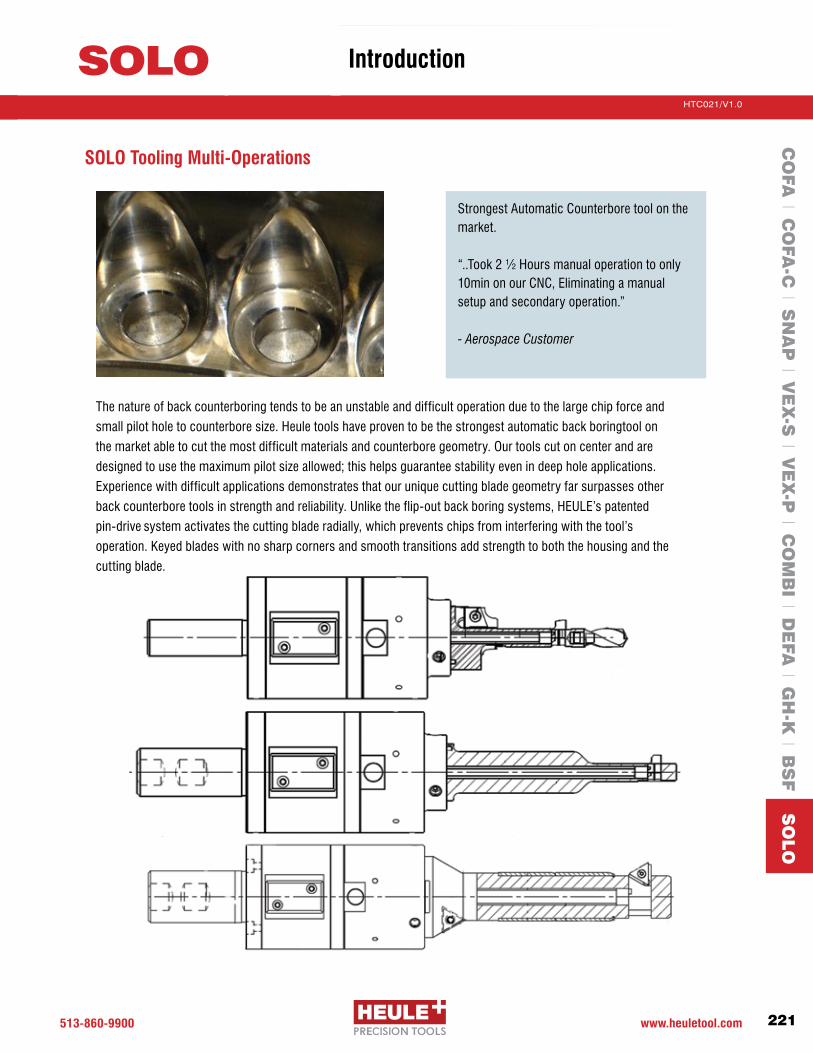
513-860-9900 www.heuletool.com 221
Catalog No. HTC014HTC021/V1.0
Serie
s
SOLO IntroductionC
OFA
l CO
FA-C
l SN
AP
l VE
X-S
l VE
X-P
l CO
MB
I l DE
FA l G
H-K
l BS
F S
OLO
SOLO Tooling Multi-Operations
The nature of back counterboring tends to be an unstable and difficult operation due to the large chip force and
small pilot hole to counterbore size. Heule tools have proven to be the strongest automatic back boring tool on
the market able to cut the most difficult materials and counterbore geometry. Our tools cut on center and are
designed to use the maximum pilot size allowed; this helps guarantee stability even in deep hole applications.
Experience with difficult applications demonstrates that our unique cutting blade geometry far surpasses other
backcounterboretoolsinstrengthandreliability.Unliketheflip-outbackboringsystems,HEULE’spatented
pin-drivesystemactivatesthecuttingbladeradially,whichpreventschipsfrominterferingwiththetool’s
operation. Keyed blades with no sharp corners and smooth transitions add strength to both the housing and the
cutting blade.
Strongest Automatic Counterbore tool on the market.
“..Took2½Hoursmanualoperationtoonly10min on our CNC, Eliminating a manual setupandsecondaryoperation.”
- Aerospace Customer

513.860.9900 www.heuletool.com222
Catalog No. HTC14HTC021/V1.0
Serie
s
SOLO Programming
CO
FA l C
OFA
-C l S
NA
P l V
EX
-S l V
EX
-P l C
OM
BI l D
EFA
l GH
-K l B
SF S
OLO
NOTE: All listed cutting data are standard values only. The cutting value depends on the slope of the surface. In case of hard-to-machine materials or interrupted cuts, we recommend applying cutting speeds that are at the lower end of the range.
Series and Bore DiameterØ6-Ø11 Ø11-Ø18 Ø18+
Material Hardness IPR SFM IPR SFM IPR SFMBHN mm/rev MPM mm/rev MPM mm/rev MPM
Low Alloy Steel.001-.003 100-300 .001-.004 130-300 .001-.004 130-3000.02-0.08 30-90 0.02-0.10 40-90 0.02-0.10 40-90
High Alloy Steel 250-350.0007-.002 80-190 .0008-.003 100-230 .001-.004 100-2300.02-0.05 25-60 0.02-0.08 30-70 0.02-0.10 30-70
Stainless Steel 140-250.001-.003 140-300 .002-.004 140-300 .002-.005 140-3000.02-0.08 40-90 0.03-0.10 40-90 0.03-0.12 40-90
Grey Cast Iron150-330 .001-.003 170-360 .002-.006 170-360 .002-.008 170-360200-330 0.02-0.08 50-110 0.03-0.15 50-110 0.03-0.20 50-110
Aluminum Alloys 30-180.001-.004 300-600 .0015-.006 320-640 .0015-.006 320-6400.02-0.10 90-180 0.03-0.15 100-200 0.03-0.15 100-200
Nickel-based Alloys140-220 .0007-.0012 25-60 .0007-.0012 25-60 .0008-.0015 25-60220-310 0.02-0.03 8-18 0.02-0.03 8-18 0.02-0.04 8-18
Titanium Alloys.0008-.0015 60-80 .001-.003 60-180 .001-.004 60-1800.02-0.04 18-55 0.02-0.08 18-55 0.02-0.10 18-55
Copper-Brass-Bronze80-85 .001-.003 100-300 .002-.004 130-320 .002-.006 130-320
135-202 0.02-0.08 30-90 0.05-0.10 40-100 0.05-0.15 40-100
NOTE:Pleaseobservetherecommendedvalueforthetoleranceoftheborediameter(d).Thelargerthetoleranceischosen,themoresideeffectscanoccur(damagedbore,enlarging,countersink-Øgetssmaller).Recommended hole diameter above tool diameter; .006”-.008” Surface footage are recommended only; Remember you must run the minimum or Maximum of your rated Tool Head (Reduce RPMforinterruptedcuts).For interrupted cuts; Slow both Feeds and speed Parameters 10-50% depending on the severity of interruption and size of cut. Counterborediametertoleranceisdependentonboretolerance&clearance.Typical2xtol.ofbore+clearances.
Ød Borediameter(tol.0/+0.1)
ØD Counterbore diameter
Ød1 ToolDiameter-0.1/0.2<Ød
NL Working Length
Hs Blade Height
From Drawing/Application
Coolant through optional Integrated HSK optional
Legend

513-860-9900 www.heuletool.com 223
Catalog No. HTC014HTC021/V1.0
Serie
s
SOLO ProgrammingC
OFA
l CO
FA-C
l SN
AP
l VE
X-S
l VE
X-P
l CO
MB
I l DE
FA l G
H-K
l BS
F S
OLO
O Zero Gage Line
G Burr Height
H Workpiece Thickness
T Countersink Depth
S Clearance Distance
From Drawing/Application
Ød Borediameter(tol.0/+0.1)
ØD Counterbore diameter
Ød1 ToolDiameter-0.1/0.2<Ød
Legend
Programming SOLO (Black Ring)
1 2 3
4 5 6
Stop spindle, pass through the workpiece.
Start spindle to working speed. Dwell time 1 sec. at least. Switch on coolant. Position:h+G+S
Machine the workpiece backwards in working speed and with working feed.
Position: h - t.
Travel out of countersink. Turn coolant off.
Position:h+G+S.
Stop the spindle. Dwell time 1 sec. at least.
Travel out of workpiece.

513.860.9900 www.heuletool.com224
Catalog No. HTC14HTC021/V1.0
Serie
s
SOLO Programming
CO
FA l C
OFA
-C l S
NA
P l V
EX
-S l V
EX
-P l C
OM
BI l D
EFA
l GH
-K l B
SF S
OLO
O Zero Gage Line
G Burr Height
H Workpiece Thickness
T Countersink Depth
S Clearance Distance
From Drawing/Application
Ød Borediameter(tol.0/+0.1)
ØD Counterbore diameter
Ød1 ToolDiameter-0.1/0.2<Ød
Legend
Programming SOLO2 (Green Ring) or SOLO2-S (Blue Ring)
1 2 3
4 5 6
With 2000-3000 RPM spindle rotation, pass through the workpiece (Blade is retracted).Dwell if necessary to allow blade retract.
Stop the spindle. Dwell time 1-2 sec. minimum. Switch on coolant. Set the speed to working speed.
Position:h+G+S
Machine the workpiece backwards in working speed and with working feed.
Position: h - t.
Travel out of countersink in rapid traverse. Switch off coolant.
Position:h+G+S
Retract blade by increasing spindle speed to 2000 rev./min. or above. Attention: Dwell time 1-2 sec. minimum.
Position:h+G+S
Travel through workpiece with retraction speed (Speed rate 2000 rev./min. minimum)andinrapidtraverseandwithretracted blade.

513-860-9900 www.heuletool.com 225
Catalog No. HTC014HTC021/V1.0
Serie
s
SOLO TechnicalC
OFA
l CO
FA-C
l SN
AP
l VE
X-S
l VE
X-P
l CO
MB
I l DE
FA l G
H-K
l BS
F S
OLO
Changing The Blade
Dismantling of blade: Push both buttons of the control unit at the same time. The blade control and the blade control pin will be retracted. Thus, the blade is released.
Push out the blade. Keep the buttons pressed until the blade is completely removed.
Insertion of blade: Push both buttons of the control unit at the same time.
Release the buttons. Make sure that the buttons are extended fully.IMPORTANT: Line up blade slot and pin; do not have pin under the cutting edge. Results in damage.
Insert blade in blade window to the extent that the cutting part of the blade remains fully visible. To do this keep on pushing the buttons of the control unit.
Position the blade in the blade window so that the blade control pin audibly engages into the blade slot.
IMPORTANT: ToolHeadsaresealed;RecommendedMaintenanceinterval:after18-24monthsor200,000strokes.Allserviceworkrequiringtheopeningofsealed screws has to be carried out by authorized personnel that has been certified by HEULE Werkzeug AG. HEULE Werkzeug AG rejects any warrantees & responsibility after opening the control unit tool heads by a non-authorized body. HEULE Werkzeug AG offers support and services for all products. Professional maintenance work and timely service intervals assure a safe process.
Blade Change Videos:HeuleTool.com

513.860.9900 www.heuletool.com226
Catalog No. HTC14HTC021/V1.0
Serie
s
SOLO Technical
CO
FA l C
OFA
-C l S
NA
P l V
EX
-S l V
EX
-P l C
OM
BI l D
EFA
l GH
-K l B
SF S
OLO
Dismantling: Loosen the 3 clamp screws of the Tool Head control unit and unscrew them only partly.
Pull the blade housing forward - away from the control unit. The blade house wrench simplifies the disassembly and should be used always.
Pull forward the blade control too by applying some force but without unscrewing anything always.
Assembly: Push blade control (snap mechanism+seal)wellpositionedwith some force into the control unit.Attention:Please make sure that the mark on the blade control and the mark on the control unit are aligned.
Please use the blade house wrench in case of small diameter and/or short working length.
Mount the blade housing onto the control unit. Please make sure that the blade control bolt is mounted with a twistofapprox.10°intotheclearancegroove of the blade housing always.
Then, align the mark of the blade housing with the mark of the control unit.
Screw the 3 clamp screws tightly. For this, please observe the torque value and screw order indicated on the control unit housing.
ATTENTION: Before setting to work after a change of blade housing and/or blade control, a function check is compulsory.
10°
Changing The Housing & Control
Component Change Videos:HeuleTool.com

513-860-9900 www.heuletool.com 227
Catalog No. HTC014HTC021/V1.0
Serie
s
SOLO TechnicalC
OFA
l CO
FA-C
l SN
AP
l VE
X-S
l VE
X-P
l CO
MB
I l DE
FA l G
H-K
l BS
F S
OLO
Function Check
SPARE PARTSHousingwrench(“KEY”)Comesstandardwith each SOLO Tool HeadSOLO/SOLO2 (Black/Green Ring GH-B-X-0103) SOLO2-S (BlueRing)GH-B-X-0105Kaiser Screws GH-H-S-0203Recommend;use1.4Nor1ft-ib/torque;
SOLOoffersanoptiontocheckthefunctionofthetool(extendingandretractingoftheblade)whileitisstandingstill.Procedure:
1 - Loosen the three clamp screws.2 - Insert HEULE Red wrench over the blade housing.3 - SOLO: Turn wrench clock-wise, SOLO2/2S: turn wrench anti-clock wise.4-PleasenotethatthebladeextendsifitisSOLO.IfitisSOLO2/2Sthebladewillretract.5 - After the Function Check, the SOLO wrench has to be turned back in the opposite direction until the positioning bolt hits the control unit at the start mark again. Then the blade housing is aligned with the groove in the control unit again. 7 - Re-tighten the clamp screws again. Observe the correct order of screw tightening and torque value (values aremarkedonthetool).8 - Ready; Activate the tool 2 - 3 x in the machine before operation.
Explanation The function check is recommended if:*Please carry out all SOLO wrench-swivel movements by hand gently in order to be able to recognize possible faults and malfunctions of the blade. •Thetoolhasnotbeenusedforalongerperiodoftime•Afterbladechange•Afterchangeofthehousing•Afterchangeofthecontrol•Amalfunctioneventhasoccurred
NOTE: Before use: Remove Key and Check that all screws are tightened; Not recommendtoruntoolabove3000RPM;30bar(500psi)maxthru-coolant(Filtration<0.01ppm).

513.860.9900 www.heuletool.com
Catalog No. HTC14
228
HTC021/V1.0
Serie
s
For more case studies, testimonials,and videos
We are also available on:
We provide online tool selectors for the COFA, SNAP, DEFA and BSF product groups.
Simply enter your application information and the correct tool will be provided complete with order number and sample drawing.
www.HeuleTool.com
CO
FA l C
OFA
-C l S
NA
P l V
EX
-S l V
EX
-P l C
OM
BI l D
EFA
l GH
-K l B
SF S
OLO

513-860-9900 www.heuletool.com
Catalog No. HTC014
229
HTC021/V1.0
Serie
s
W W W . H E U L E T O O L . C O M
AppendixR E F E R E N C E M A T E R I A L S

513.860.9900 www.heuletool.com
Catalog No. HTC14
230
HTC021/V1.0
Serie
s
Notes

513-860-9900 www.heuletool.com 231
Catalog No. HTC014HTC021/V1.0
Serie
s
HEULE Application Data SheetFor Deburring – Chamfering
Interest: Front and Back Deburring Back Only Deburring Front and Back Chamfering Back Only Chamfering Combination Tooling Front Countersinking Back Spotfacing Other
Information for:Purchase Order RequestforQuotation(RFQ)Request for Tool Test Approval Requesting Technical HelpDate Needed:By Urgent
Company Name: Date:
Contact Name: Phone:
Address: Fax:
Email:
City: State: Zip:
Problem Description: (Pleasespecifyanyissuesandincludedrawingorpartprint)
Part Configuration: (Fillinvaluesthatapply): REF: Part name/Drawing number:
Straight HoleDeburring/Chmf.
Tube or I.D.Deburring
Inline Holes Deburring/Chmf.
Irregular Surface
Back Counterboring
d = + f =
Df = + g =
Db = + h =
H = i =
E = Surface Finish Req. =
In Process Hole Size:
Material: Hardness: Production (Yr.): Cycle Time: Sequence (1, 2, 3, etc.): Drill Bore Tap Ream Deburr/Chmf.
Other Information/Sketch:
Machine Type:
Shank Size:
Feed Unit: Hydrl. Pneum. Elec.
Back Feed Control? Y or N Interrupted Cuts/Cross Holes? Y or N
Return to [email protected]
Application Data Sheet COFA, SNAP and DEFA

513.860.9900 www.heuletool.com232
Catalog No. HTC14HTC021/V1.0
Serie
s
513-860-9900 www.heuletool.com
HEULE Application Data SheetFor Back Counterboring – Spotfacing
Information for:Purchase Order Request for Quotation (RFQ)
Date Needed: Urgent ASAPBy
Date:
Phone:
Fax:
Email:
REF: Part name/Drawing number:
Part Configuration: (Fill in values that apply):
Ød = +/-
ØD = +/-
Production (Yr.): Cycle Time: Sequence (1, 2, 3, etc.): Drill Bore Tap Ream C’bore/sink
Other Information/Sketch:
Machine Type/Data:
Shank Size:
Tool Holder: Coolant Pressure : (300 PSI Required)
Interrupted Cuts/Cross Holes? Y or N
Application Data SheetBSF
H =
R =
E =
T (depth) =
Surface Finish required:
Material:
Hardness:
Company Name:
Contact Name:
Address:
City:
State: Zip:
r
r
Ød1 = _______ +/- _______
ØD = ________ +/- _______
T max = ___________
r = ________________
E = _______________
T (depth) = __________
Surface Finish required: _____________________
Material: _________________________________
Hardness: ________________________________
Heule Tool Application Data SheetFor Counterboring – Spotfacing
Return to [email protected]
Information for:Purchase Order RequestforQuotation(RFQ)Request for Tool Test Approval Requesting Technical HelpDate Needed:By Urgent
Application Data Sheet BSF

513-860-9900 www.heuletool.com 233
Catalog No. HTC014HTC021/V1.0
Serie
s
Heule Tool Application Data SheetFor Countersinking – Counterboring – Spotfacing
Interest:Back Counterboring Back CountersinkFront and Back Counterboring Front and Back CountersinkBack SpotfacingFront and Back Spotfacing Other
Company Name: Date:
Contact Name: Phone:
Address: Fax:
Email:
City: State: Zip:
Application Description: (Pleasespecifyanyissuesandincludedrawingorpartprint)
Part Configuration: (Fillinvaluesthatapply): REF: Part name/Drawing number:
Back Counterboring Back Spotfacing InterruptedBackC’bore Back/Front Countersink Front/Back Counterbore
Ød = +/- a° =
ØDb = +/- b° =
ØDf = +/- t1 (depth) =
H = t2 (depth) =
r =
Surface Finish required:
Material: Hardness: Production (Yr.): Cycle Time: Sequence (1, 2, 3, etc.): Drill Bore Tap Ream C’bore/sink
Other Information/Sketch:
Machine Type:
Shank Size:
Feed Unit: Hydrl. Pneum. Elec.
Back Feed Control? Y or N Interrupted Cuts/Cross Holes? Y or N
Information for:Purchase Order RequestforQuotation(RFQ)Request for Tool Test Approval Requesting Technical HelpDate Needed:By Urgent
Return to [email protected]
Application Data Sheet SOLO

513.860.9900 www.heuletool.com234
Catalog No. HTC14HTC021/V1.0
Serie
s
Company Name: Date:
Contact Name: Phone:
Address: Fax:
City: State: Zip: Email:
Application DataPart No.: Description: Workpiece Material:
Hardness: Print (YesorNo): Surface Quality of Workpiece:
Required Hole Surface Finish: Hole Diameter Tolerance: Position of Workpiece:
Hole Description: Blind Through Pre-Drilled Interrupted Cast Hole Actual Size: Hole Depth:
Single Pass Sketch: Chip Form: Multiple Pass Reamed Hole Threaded Hole
Machine DataDrilling Info.: Tool Holder: Spindle RPM Range:
Drilling Angle: Coolant Available (YesorNo): Through Spindle External
Coolant Pressure: Coolant Flow: Compressed Air:
Type of Coolant: Soluble Oil Cutting Oil Synthetic Type of Tool Holder: Bushing (YesorNo):
Distance to Workpiece: Current Type of Cutting Tool in Use: HSS Inserted Carbide Other:
Flute Style: Fast Standard Slow Other:
Present DataNo. of Parts to be Machined (Month/Year): No. of Holes Per Part: Surface Footage (SFM):
Spindle Speed (RPM/SFM): Feed (IPR/mm/u): Feed (IPR/MPM):
Index Time: Cut Time: Tool Change Time:
No. of Holes Per Grind: No. of Grinds Available Per Tool: No. of Tools to Produce Job:
ObjectiveIncrease Holes Per Tool Shorten Process Time Improve Hold Finish Eliminate 2nd Operation
Combine Drilling/Deburring Cut Multi-Diameter Holes in One Pass Other:
Explanation:
Heule Tool Application Data SheetFor Drilling
Return to [email protected]
Application Data Sheet VEX-S and VEX-P

513-860-9900 www.heuletool.com 235
Catalog No. HTC014HTC021/V1.0
Serie
s
Material Description W - Nr. German DIN - German AIS/SAE - USA
Low Carbon Steel
Alloy Steel
Tool Steel
Alloy Tool Steel
Alloy Cast Steel
Stainless Steel
Stainless Steel – Austenitic, Martensitic
Grey Cast Iron
Cast Iron Malleable
Copper Alloys
Aluminum Alloys
1.00351.00381.04011.00501.05011.11411.57321.72251.12211.35051.72251.51411.11911.72251.20801.72201.65821.81591.23671.73611.40061.40571.40341.40051.43001.43011.44351.45420.60100.60150.60200.60250.81350.81400.70502.03312.04012.10302.0920
3.2582.053.3541.01
3.23153.0205
St 33RSt 37-2
C 15St 50-2Ck 35 VCk 15
14 NiCr 1442 CrMo 4 G
Ck 60100 Cr 6
42 CrMo 453MnSi 4Ck 45 V
42 CrMo 4X 210 Cr 12
CS-34 CrMo 1234 CrNiMo 6
50 CrV4X 38 CrMoV 5 3
32 CrMo 12X 10 Cr 13
X 22 CrNi 12X 40 Cr 13
X 12 CrS 13X 12 CrNi 18 8X 5 CrNi 18 9
X 2 CrNiMo 18 12X 10 CrNiMoTi 18 12
GG-10GG-15GG-20GG-25GTS-35GTS-40GGG-50
CuZn 36 Pb 1.5CuZn 36 Pb 3
CuSn 8CuAI 8
GD-AISi 12G-AIMg 3AIMgSi 1
AI 99
101010451015105010351115341541401060
521004140
–41404142D3
413543406150A2
4145403431420416302
304 (304H)316
17-4 phA48-20BA48-25BA48-30BA48-35BA48-40BA48-45B80-55-06
B121B121B103
CuAI 8383.2 (ALSi0120)
514.0 (AIMg 3)413.0 (ALMgSi 1)
1200 AL 99
Materials Reference Chart

513.860.9900 www.heuletool.com236
Catalog No. HTC14HTC021/V1.0
Serie
s
Metric Inch
2.0 0.0792.1 0.0832.2 0.0872.3 0.0912.4 0.0952.5 0.0992.6 0.1022.7 0.1062.8 0.1102.9 0.1143.0 0.1183.1 0.1223.2 0.1263.3 0.1303.4 0.1343.5 0.1383.6 0.1423.7 0.1463.8 0.1503.9 0.1544.0 0.1574.1 0.1614.2 0.1654.3 0.1694.4 0.1734.5 0.1774.6 0.1814.7 0.1854.8 0.1894.9 0.1935.0 0.1975.1 0.2015.2 0.2055.3 0.2095.4 0.2135.5 0.2175.6 0.2205.7 0.2245.8 0.2285.9 0.2326.0 0.2366.1 0.2406.2 0.2446.3 0.2486.4 0.2526.5 0.2566.6 0.2606.7 0.264 6.8 0.268 6.9 0.2727.0 0.276 7.1 0.2807.2 0.2837.3 0.2877.4 0.2917.5 0.2957.6 0.2997.7 0.3037.8 0.3077.9 0.311
8.0 0.3158.1 0.3198.2 0.3238.3 0.3278.4 0.3318.5 0.3358.6 0.3398.7 0.3438.8 0.3468.9 0.3509.0 0.354 9.1 0.3589.2 0.362 9.3 0.366 9.4 0.3709.5 0.3749.6 0.3789.7 0.3829.8 0.3869.9 0.39010.0 0.39410.1 0.39810.2 0.40210.3 0.406 10.4 0.40910.5 0.41310.6 0.41710.7 0.42110.8 0.42510.9 0.42911.0 0.43311.1 0.43711.2 0.44111.3 0.44511.4 0.44911.5 0.45311.6 0.45711.7 0.46111.8 0.46511.9 0.469 12.0 0.47212.1 0.47612.2 0.48012.3 0.48412.4 0.48812.5 0.49212.6 0.49612.7 0.50012.8 0.50412.9 0.50813.0 0.51213.1 0.51613.2 0.52013.3 0.52413.4 0.52813.5 0.53113.6 0.53513.7 0.53913.8 0.54313.9 0.547
32.0 1.26032.1 1.26432.2 1.26832.3 1.27232.4 1.27632.5 1.28032.6 1.28332.7 1.28732.8 1.29132.9 1.29533.0 1.29933.1 1.30333.2 1.30733.3 1.31133.4 1.31533.5 1.31933.6 1.32333.7 1.32733.8 1.33133.9 1.33534.0 1.339 34.1 1.34334.2 1.34634.3 1.35034.4 1.35434.5 1.35834.6 1.36234.7 1.36634.8 1.37034.9 1.37435.0 1.37835.1 1.38235.2 1.38635.3 1.39035.4 1.39435.5 1.39835.6 1.40235.7 1.40635.8 1.40935.9 1.41336.0 1.41736.1 1.42136.2 1.42536.3 1.42936.4 1.43336.5 1.43736.6 1.44136.7 1.44536.8 1.44936.9 1.45337.0 1.45737.1 1.46137.2 1.46537.3 1.46937.4 1.47237.5 1.47637.6 1.48037.7 1.48437.8 1.48837.9 1.492
14.0 0.55114.1 0.55514.2 0.55914.3 0.56314.4 0.56714.5 0.57114.6 0.57514.7 0.57914.8 0.58314.9 0.58715.0 0.59115.1 0.59415.2 0.59815.3 0.60215.4 0.60615.5 0.61015.6 0.61415.7 0.61815.8 0.62215.9 0.62616.0 0.63016.1 0.63416.2 0.638 16.3 0.64216.4 0.64616.5 0.65016.6 0.65416.7 0.65716.8 0.66116.9 0.66517.0 0.66917.1 0.67317.2 0.67717.3 0.68117.4 0.68517.5 0.68917.6 0.69317.7 0.69717.8 0.70117.9 0.70518.0 0.70918.1 0.71318.2 0.71718.3 0.72018.4 0.72418.5 0.72818.6 0.73218.7 0.73618.8 0.74018.9 0.74419.0 0.74819.1 0.75219.2 0.75619.3 0.76019.4 0.76419.5 0.76819.6 0.77219.7 0.77619.8 0.78019.9 0.783
20.0 0.78720.1 0.79120.2 0.79520.3 0.79920.4 0.80320.5 0.80720.6 0.81120.7 0.81520.8 0.81920.9 0.82321.0 0.82721.1 0.83121.2 0.83521.3 0.83921.4 0.84321.5 0.84621.6 0.85021.7 0.85421.8 0.85821.9 0.86222.0 0.86622.1 0.87022.2 0.87422.3 0.87822.4 0.88222.5 0.88622.6 0.89022.7 0.89422.8 0.89822.9 0.90223.0 0.90623.1 0.90923.2 0.91323.3 0.91723.4 0.92123.5 0.92523.6 0.92923.7 0.93323.8 0.93723.9 0.94124.0 0.94524.1 0.94924.2 0.95324.3 0.95724.4 0.96124.5 0.96524.6 0.96924.7 0.97224.8 0.97624.9 0.98025.0 0.98425.1 0.98825.2 0.99225.3 0.99625.4 1.00025.5 1.00425.6 1.00825.7 1.01225.8 1.01625.9 1.020
26.0 1.02426.1 1.02826.2 1.03226.3 1.03626.4 1.04026.5 1.04426.6 1.04726.7 1.05126.8 1.05526.9 1.05927.0 1.06327.1 1.06727.2 1.07127.3 1.07527.4 1.07927.5 1.08327.6 1.08727.7 1.09127.8 1.09427.9 1.09828.0 1.10228.1 1.10628.2 1.11028.3 1.11428.4 1.11828.5 1.12228.6 1.12628.7 1.13028.8 1.13428.9 1.13829.0 1.14229.1 1.14629.2 1.15029.3 1.15429.4 1.15729.5 1.16129.6 1.16529.7 1.16929.8 1.17329.9 1.17730.0 1.18130.1 1.18530.2 1.18930.3 1.19330.4 1.19730.5 1.20130.6 1.20530.7 1.20930.8 1.21330.9 1.21731.0 1.22031.1 1.22431.2 1.22831.3 1.23231.4 1.23631.5 1.24031.6 1.24431.7 1.24831.8 1.25231.9 1.256
Metric Inch Metric Inch Metric Inch Metric Inch Metric Inch
Metric to Inch Conversion Chart

513-860-9900 www.heuletool.com 237
Catalog No. HTC014HTC021/V1.0
Serie
s
Key Words
Common Deburr
Angle Call-out
Tube/I.D. Deburr
Large Back Countersinks
Tap/Thread
Back Counterbore
Large Bore
Interference
Deep Hole Deburring
Deburring Snap
Grooves
Part Configuration
Typical Call-Out
Break edge.005 - .015”
Deburr.010x45°
Break edge.005 - .015”
Back Countersinks over 0.060”
Deburr Tap hole; Chamfer
over Major Diameter
Back Counterbore
Deburr Bores larger than 1”;
up to 6”
Deburr close to
interruption
Deburr deep holes
Break edge.005 - .015”
Material
Any; Rc<28
Any; Rc<28
COFA
SNAP
-GH
S
SNAP
-DEF
A
DEF
A
SOLO Important Limits/Comments
Any; Rc>28
Any; Rc>28
Any; Rc<28
Any; Rc>28
Any; Rc<28
Any; Rc>28
Any; Rc<28
Any; Rc>28
Any; Rc<28
Any; Rc>28
Any; Rc<28
Any; Rc>28
Any; Rc<28
Any; Rc>28
Any; Rc<28
Any; Rc>28
Any; Rc<28
Any; Rc>28
SNAP tooling is quick and simple
COFAwith10°cuttingbladesonflatsurfacesis ideal for break edge; DEFA for large burr formation
SNAP tooling is quick and simple
DEFA is the best solution for harder to cut material or large burr formations
Use standard COFA tooling up to 1:2 (hole:cross hole)SNAP toolingupto1:5oruseSNAP60°bladesupto1:4
COFA is ideal for common break edge
SOLO or use DEFA if possible
SOLO tooling
Best choice is standard SNAP tool with large enough SNAP blade
Over 28Rc DEFA may be the best choice
SOLO is your choice
SOLO is your choice
Use HEULE Cassettes
Use HEULE Cassettes
Check with HEULE - Need Special Blades with clearance
Check with HEULE - Need Special Blades with clearance
Extended tool may be required
Possible cassette application
PossibleapplicationforHeule’sspecial penetration deburr tooling
NOTE: The above information is for reference only; please contact Heule Tool Corp for application specific tooling.
l l 4 4 n
l s 4 l n
X l 4 4 s
X s 4 l s
l s X X s
l n X X s
X X s s l
X X s s l
n l 4 l s
n n l l s
X X X X l
X X X X l
l 4 l s X
l 4 l s X
n 4 n n 4
n 4 n n 4
l l s s n
l l s s n
l 4 X X X
l X X X X
VEX-
S
l
n
l
n
s
n
X
X
l
n
X
X
X
X
n
n
X
X
X
X
l = Best Choice4 = Recommendeds = Possible Solutionn = AvailableX = Will not work
Tool Recommendations

513.860.9900 www.heuletool.com238
Catalog No. HTC14HTC021/V1.0
Serie
s
Accurate analysis
Personal support
Customized development
High-precision manufacture

513-860-9900 www.heuletool.com 239
Catalog No. HTC014HTC021/V1.0
Serie
s
Since 1961, when HEULE Werkzeug AG was initially set up as a contract manufacturing business, our goal has been in reducing production times. At first, it was simply to meet our own needs that we developed tools that can front and back deburr, chamfer and countersink in one operation. Not long after, we were awarded a contract for our tool. That's when we began helping other manufacturers to become more efficient with their production processes and we continue that mission still today..
HEULE is committed to the values of quality, precision and service. Competent service, fast delivery times, and customized solutions are the highest priorities. From all ranks, HEULE’s committed and motivated expert staff carry out their work with reliability and professionalism. HEULE provides and continually improves through innovative ideas and sophisticated technology. This is achieved with our state-of-the-art manufacturing equipment which gives us the flexibility to take unconventional approaches to our customers manufacturing needs.
HEULE continues its global presence and excellent customer service with its subsidiary offices in the United States, China, South Korea and Germany, and experienced distribution partners that offer excellent advice and support to you locally.
Committed to Progress Faster production times. More efficient processes. Superior parts.
Not only are we committed to our loyal employees and partnership-based customer relationships, we are also committed to the environment. Our state-of-the-art factory is eco friendly and the air-condition emits zero carbon emissions. In the summer, we cool the interior and production equipment with groundwater. In the winter, we use heat pumps to utilize the ground water and the exhaust heat released by our production machinery for heating. We firmly believe that a philosophy dedicated to sustainability and the wise use of resources will secure our future.
Committed to SustainabilityBecause progress means a better world.

513.860.9900 www.heuletool.com240
Catalog No. HTC14HTC021/V1.0
Serie
s
Large production runs
Oversize work pieces
Inaccessible work areas
Complex materials

513-860-9900 www.heuletool.com 241
Catalog No. HTC014HTC021/V1.0
Serie
s
What ultimately counts is the reduction of your unit costs. Front and back machining of bore edges in One Operation without having to turn the work piece will enable you to reduce your production times and eliminate the entire deburring operation outside of the machine.
All our tools are made of hardened tool steel and fitted with exchangeable carbide blades. The coatings and the geometries of the blades are matched to the material that is to be machined. This ensures a long service life of the blades and a long life cycle of the tools. All our tools have been specifically designed for use on automatic machine tools.
Through constant development of solutions for various customer applications, HEULE created a series of innovative precision tools for front and back deburring, chamfering and countersinking. Most of HEULE’s products are sold as standard stocked items, but with state-of-the-art engineering, they also provide custom solutions for customer’s specific needs.
Designed for Efficiency
In the early seventies, HEULE struggled for recognition in the cutting tool industry until their acquisition of their first large account, Daimler in Stuttgart. Today, all major automobile manufactures in Europe, America and Asia take advantage of HEULE’s front and back deburring, chamfering and countersinking tools in One Operation.
HEULE’s tools have also been tested and approved in the aerospace industry by Airbus, Boeing, GE and other manufacturers alike. HEULE’s tools are used for machining all materials, ranging from aluminum and steel to titanium, Inconel, and other nickel-based alloys.
Find peak production by optimizing processes.
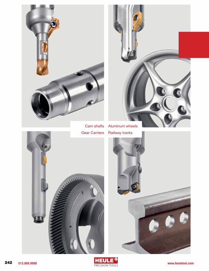
513.860.9900 www.heuletool.com242
Catalog No. HTC14HTC021/V1.0
Serie
s
Cam shafts
Railway tracks
Aluminum wheels
Gear Carriers

513-860-9900 www.heuletool.com 243
Catalog No. HTC014HTC021/V1.0
Serie
s
Work piece geometry, material, fixturing, machining process and the requirements that cutting tools are expected to fulfill vary from industry to industry. Since no application is like any other, HEULE’s unique cutting tool line offers standard and specialty tools for all your technical needs.
As solution finders, we take up this challenge. We offer you specific tools that are tailored to your individual application and will therefore offer you the best possible performance. On the basis of our standard technologies, we combine multiple operations in a single tool or adapt tool dimensions and blades to suit your machining concept. Thanks to our in-house development and manufacture of all components, we are flexible, dependable and fast.
Our customer used to machine the lug bolt holes in two operations – first drilling using a step drill, then back deburring using an interpolation tool. With the HEULE Drilling Countersinking Combi Tool, they can now produce the bores in One Operation. The customer's voice:
“The process time reduction is enor-mous. We have boosted output by 157 rims per day and per machine.”
Today, this customer applies our solution on all production units requiring back bore machining. The reduction of the cycle time, the long service life of the tools, and the easy blade changes that do not require any presetting have given a tremendous boost to their productivity.
Success Story
Tailored SolutionsBecause every application is unique.

ISO 9001:2008 CompanyHEULE TOOL CORPORATION 131 Commerce Drive Loveland, Ohio 45140 USA
Phone (513) 860-9900 Fax (513) 860-9992 [email protected] www.heuletool.com
HEULE WERKZEUG AG Wegenstrasse 11/Postfach 9436 Balgach Switzerland
Phone +41 71 726 38 38 Fax +41 71 726 38 39 www.heule.com
Since 1961, Swiss-based HEULE Werkzeug AG has set the standard in the development of front and back deburring, chamfering, drilling, countersinking and back spotfacing tools in One Operation. We are committed to finding innovative solutions for customers.
Our global distribution network, including our subsidiaries in the United States, China, South Korea, and Germany, ensure HEULE’s worldwide presence. Our specialists are experienced in machining processes and offer excellent on-site support.
Customers worldwide attest to the high quality standard HEULE provides through innovative ideas and sophisticated technology.
Swiss Precision Since 1961Over 50 years of progress in deburring solutions
2019 Heule Tool Corporation All Rights Reserved Catalog No. HTC021/V1.0