2019_tesa_en.pdf - mister worker
TRANSCRIPT
www.tesatechnology.com
General information
Calipers
internal measurement
Dial GauGes – eleCtroniC anD analoGue
Comparative measurement
straiGhtness, anGle anD inClination measurement
Calibration equipment
heiGht GauGes
aCCessories
ConneCtivity
external miCrometers
measurinG instruments for larGe Dimensions
lever-type Dial test inDiCators
measurinG supports anD auxiliary equipment
lenGth anD anGle stanDarDs
surfaCe rouGhness testinG
eleCtroniC lenGth measurinG equipment
a
b
C
D
e
f
G
h
i
J
K
l
m
n
o
p
INFO-1
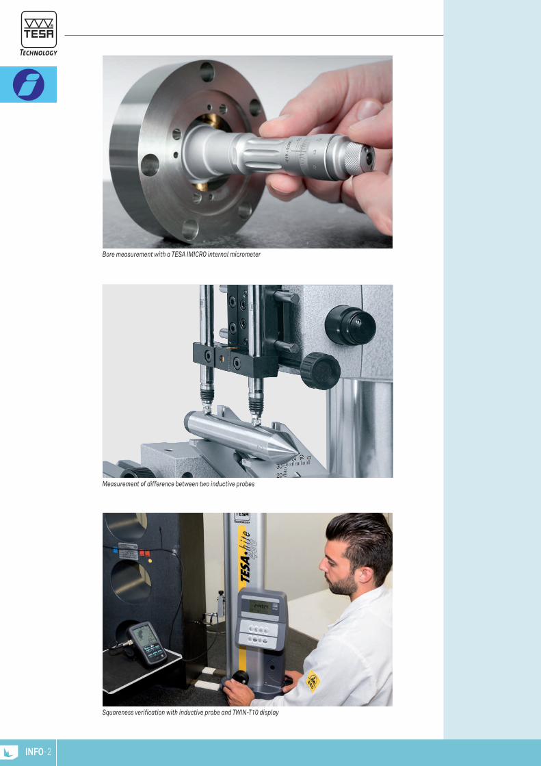
bore measurement with a tesa imiCro internal micrometer
measurement of difference between two inductive probes
squareness verification with inductive probe and tWin-t10 display
INFO-2

Dear Customers and partners,
this catalogue reflects the image of tesa today. it is a company with solid roots in precision metro-
logy that has been able to follow the trend of the times with cutting-edge technologies. today, just
as yesterday, tesa precision measuring instruments and solutions help customers to improve their
quality control and increase their productivity.
over the years, tesa has become the home for many renowned brands such as brown&sharpe, Com-
paC, merCer, roCh, etalon and interapiD. all these brands have added a great value and have
shaped what tesa products today stand for: a unique blend of high excellence metrology tools with
strong reputation for quality, reliability and durability.
tesa is today part of hexagon manufacturing intelligence. as a leading, metrology and manufac-
turing solution specialist, the company’s mission is to give customers the confidence to increase
production speed and accelerate productivity while enhancing product quality. all the products in
the hexagon manufacturing intelligence portfolio support this objective in three areas – sensing,
thinking and acting. sensing: generating large quantities of accurate measurement data. thinking:
transforming that data into actionable information. acting: applying corrections to the manufactu-
ring process based on this information.
Going beyond the boundaries of traditional gauging tasks, tesa products smoothly integrate into the
complete manufacturing solutions offered by hexagon through advanced connectivity systems and
software interfaces. they enable better use of data through integration with analytic systems like
statistical process control (spC) software and can help businesses to embrace industry 4.0 princip-
les.
We hope that this catalogue will inspire you to find new and better solutions to your measurement
challenges.
stefan ruh
tesa managing Directorhexagon manufacturing intelligence
INFO-3

TESA – 75 yEArS of TEchnology
since its foundation 75 years ago, tesa has distinguished itself in the market through its unique
expertise in micromechanics, precision machining and dimensional metrology.
With its roots and headquarters in renens, switzerland, a region well known for watchmaking,
precision engineering and research, tesa has always been dedicated to precision, quality and the
sustainability of its products.
today as part of hexagon manufacturing intelligence, tesa is a modern firm with an international
footprint operating globally. our measuring instruments help customers around the world find solu-
tions for their metrology challenges, improving their quality control and increasing their productivity.
www.tesatechnology.com
www.hexagonmi.com
1941 2016
INFO-4

PASSion for PrEciSionrenowned tesa flagship products, like CCma dial callipers, the unimaster large dimension gauge,
tesatast level indicators, the imiCro internal micrometer and our 1D probes – just to name a few –
have been a standard in workshops for many decades.
With the evolution of digital communication, tesa made the
next step and introduced tesa link Connector (tlC) and
wireless module. this allows today’s tWin-Cal calliper to
be equipped with a unique tlC, as easily as replacing the
battery cap of the device, enabling bidirectional communi-
cation between the instrument and the computer. Data can
be sent directly to software, turning single data-points into
actionable information.
tesa height Gauges are world market leaders in their
class. With their versatility and accuracy, they are in many
cases an easy to use and cost-efficient alternative to coor-
dinate measurement machines (Cmms).
tesa is also a manufacturer of tactile and non-contact
probing solutions for Cmms. available through the world-
wide sales network of hexagon manufacturing intelligence,
these products represent the high end of technical capabi-
lities in sensing.
to maintain the value of our customers’ investments, tesa pays exacting attention to customer sup-
port services. our offering includes the core services of calibration, maintenance and repair. an sCs
certified calibration lab, qualified for measurement uncertainties down to 0,02 µm, provides certifi-
cation for measurement tools where accuracy and reliability matters.
understanding that precision is not only a result of the right tool but also of environmental influen-
ces, we offer technical assistance for applications, product selection and installation as well as trai-
ning from basic metrology up to specialist measurement tasks.
our product customisation offering will help you to find solutions that go beyond the capabilities of
standard tools.
customer Service and Technical Support organisation TESA email us at [email protected]
Call us on +41 21 611 18 40 – from 7.30 to 17.30 (Cet)
INFO-5

W h a t i s K n o W n . . .
QuAnTiTiES And uniTS
MEASurEMEnT TASkS
international System of units (Si)F: Système international d’unités (SI)D: Internationales Einheitensystem (SI)
definition of the metreF: Définition du mètre – D: Meterdefinition "the metre is defined as the distance travelled by light in vacuum during a time of 1/299 792 458 of a second."17th General Conference on Weights and Measures, 1983.
reference temperatureF: Température de référenceD: Bezugstemperatur for measuring instruments and workpieces, iso r1 assesses this temperature is 20°C.the temperature of 20°C is assumed to be valid for any size, material measure, measur ement result etc., unless otherwise specified.
inspectingF: Contrôler – D: PrüfenDetermining whether a test object complies with specified requirements (e.g. as regards both dimensions and form).
MeasuringF: Mesurer – D: Messenobtaining a value (e.g. length value) measured by comparison against a master standard (e.g. material measure).
calibratingF: Etalonner – D: Kalibrierenestablishing the actual deviation of a measuring instrument from desired value. this is usually done through measurement oper-ations. the result of a calibration is documented in the form of a calibration certificate and can be used later on for adjustment purposes, for instance.
decimal multiples and submultiples of the base unit "metre"
derived units (of measurement)F: Unités dérivéesD: Abgeleitete Einheiten
SI base unitQuantity Name Symbollength metre mmass kilogram kgtime second selectric current ampere Athermodynamic temperature kelvin Kamount of substance mole mdluminous intensity candela cd
Unit Symbol m cm mm µm nmkilometre km 13 m 1000 m 1 000 000 mmMetre m 1 m 1 m 100 cm 1 000 mm 1 000 000 µmdecimetre dm 10-1 m 0,1 m 10 cm 100 mm 100 000 µmcentimetre cm 10-2 m 0,01 m 1 cm 10 mm 10 000 µmMillimetre mm 10-3 m 0,001 m 0,1 cm 1 mm 1 000 µm 1 000 000 nm tenth millimetre 10-4 m 0,000 1 m 0,1 mm 100 µm 100 000 nm hundredth millimetre 10-5 m 0,000 01 m 0,01 mm 10 µm 10 000 nmMicrometre µm 10-6 m 0,000 001 m 0,001 mm 1 µm 1 000 nm tenth micrometre 10-7 m 0,000 000 1 m 0,000 1 mm 0,1 µm 100 nm hundredth micrometre 10-8 m 0,000 000 01 m 0,000 01 mm 0,01 µm 10 nmNanometre nm 10-9 m 0,000 000 001 m 0,000 001 mm 0,001 µm 1 nm
Unit Relationship toQuantity Name Symbol SI base unitplane angle radian rad 1 rad = 1 mm
1 rad = 57,295 779 51°frequency hertz Hz 1 Hz = 1 s-1
force newton N 1 N = 1 m kg s-2
pressure pascal Pa 1 Pa = 1 m-1 kg s-2
power watt W 1 W = 1 m2 kg s-3
electrical potential volt V 1 V = 1 m2 kg s-3 A-1
INFO-6
W h a t i s K n o W n . . .
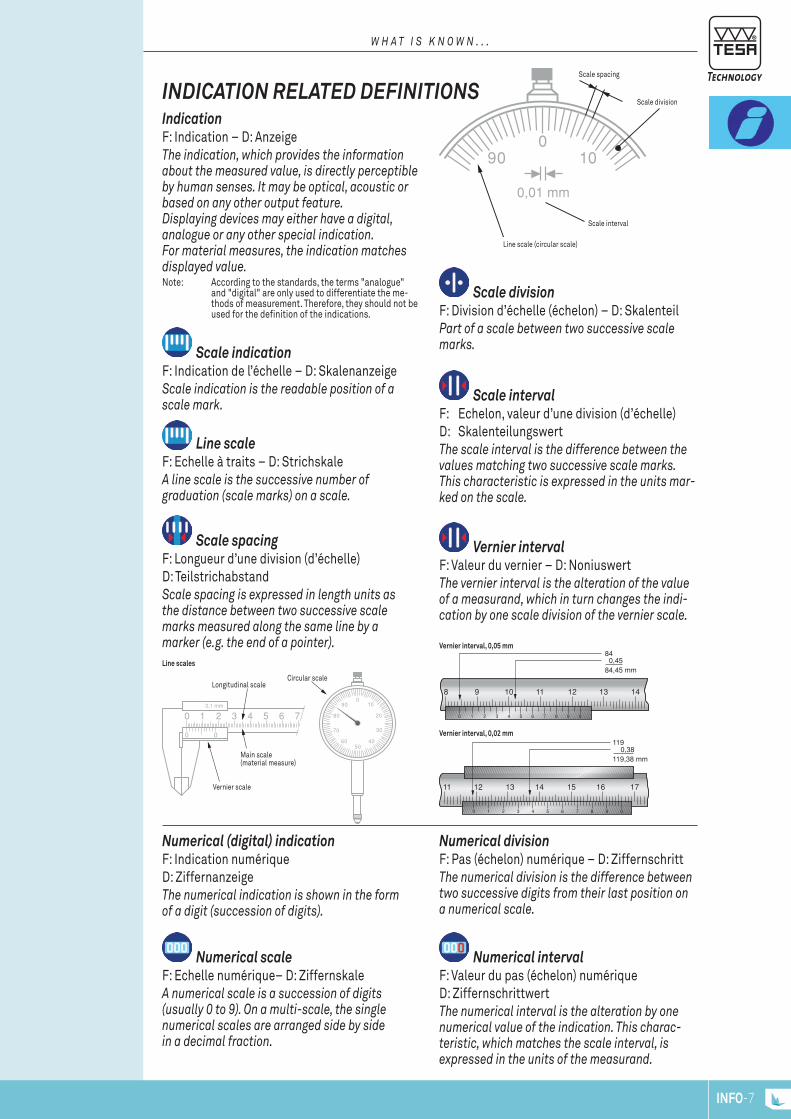
indicATion rElATEd dEfiniTionSindicationF: Indication – D: Anzeigethe indication, which provides the information about the measured value, is directly perceptible by human senses. it may be optical, acoustic or based on any other output feature.Displaying devices may either have a digital, analogue or any other special indication.for material measures, the indication matches displayed value.Note: According to the standards, the terms "analogue"
and "digital" are only used to differentiate the me-thods of measurement. Therefore, they should not be used for the definition of the indications.
Scale indication
F: Indication de l’échelle – D: Skalenanzeigescale indication is the readable position of a scale mark.
Scale divisionF: Division d’échelle (échelon) – D: Skalenteilpart of a scale between two successive scale marks.
Scale intervalF: Echelon, valeur d’une division (d’échelle) D: Skalenteilungswertthe scale interval is the difference between the values matching two successive scale marks. this characteristic is expressed in the units mar-ked on the scale.
01090
0,01 mm
0 1 2 3 4 5 6 7 8 9 0
8 9 10 11 12 13 14
84 0,4584,45 mm
0 1 2 3 4 5 6 7 8 9 0
11 12 13 14 15 16 17
119 0,38119,38 mm
0 1 2 3 4 5 6 70,1 mm
0 0
010
20
30
4050
90
80
70
60
0 1 2 3 4 5 6 7 8 9 0
8 9 10 11 12 13 14
84 0,4584,45 mm
0 1 2 3 4 5 6 7 8 9 0
11 12 13 14 15 16 17
119 0,38119,38 mm
Vernier intervalF: Valeur du vernier – D: Noniuswertthe vernier interval is the alteration of the value of a measurand, which in turn changes the indi-cation by one scale division of the vernier scale.
line scaleF: Echelle à traits – D: Strichskalea line scale is the successive number ofgraduation (scale marks) on a scale.
Scale spacing F: Longueur d’une division (d’échelle) D: Teilstrichabstand scale spacing is expressed in length units as the distance between two successive scale marks measured along the same line by a marker (e.g. the end of a pointer).
numerical (digital) indicationF: Indication numériqueD: Ziffernanzeige the numerical indication is shown in the form of a digit (succession of digits).
numerical divisionF: Pas (échelon) numérique – D: Ziffernschrittthe numerical division is the difference between two successive digits from their last position on a numerical scale.
numerical scaleF: Echelle numérique– D: Ziffernskalea numerical scale is a succession of digits (usually 0 to 9). on a multi-scale, the single numerical scales are arranged side by side in a decimal fraction.
numerical intervalF: Valeur du pas (échelon) numérique D: Ziffernschrittwertthe numerical interval is the alteration by one numerical value of the indication. this charac-teristic, which matches the scale interval, is expressed in the units of the measurand.
Line scale (circular scale)
Vernier interval, 0,05 mm
Line scales
Vernier interval, 0,02 mm
Scale interval
Scale spacing
Scale division
Main scale(material measure)
Longitudinal scaleCircular scale
Vernier scale
INFO-7

W h a t i s K n o W n . . .
METrologicAl dEfiniTionS
range of indicationF: Etendue d’indication – D: Anzeigebereichthe range of indication lies between the high-est and lowest display values of a measuring instrument.
Measuring rangeF: Etendue de mesure – D: Messbereichthe measuring range of an indicating device is the range within which the measured values cannot exceed the maximum permissible errors.for tools having several measuring ranges, these errors may vary from a range to another.the measuring range may well be contained wit-hin the related whole range of indication.
Measuring spanF: Champ de mesure – D: Messspannethis span equals the difference between both first and last values of the measuring range as specified.
displacement rangeF: Etendue de déplacement – D: Verstellbereichmeasurand related extent within which the meas uring range can be moved.
Application rangeF: Etendue d’application D: Anwendungsbereichthe application range is equal to the sum of both displacement and measuring ranges.Note: The first and last values make each range different from
one another.
0
25
25
25
75
010
20
30
40
10
20
30
40
0,01 mm
± 0,45 mm
0,8 mm
± 0,4 mm
0 150 mm
010
20
30
4050
90
80
70
60
Application range 300 mm to 400 mm
First value
First value 0 mmLast value 150 mmDifference 150 mm = Measuring span
Example: Measuring range 0 to 150 mm
Last value
Upper end stop
Rang
e of
indi
catio
n
Mea
surin
g ra
nge
Lower end stop Pre span
Example
Measuring span:
Post span
Measuring range 300 mm to 325 mm
Range of indication
Measuring range
25 mm Measuring span
Displacement range0 to 75 mm
MeasurandF: Mesurande – D: Messgrößephysical quantity of a measurement. in other words, the measurand is the length or the angle as measured or to be measured.
Measured valueF: Valeur mesurée – D: Messwertany measured value expresses the result of a measurement. therefore, this value is directly associated with the measurand and further allocated to the output feature (e.g. display) of a measuring instrument or device. a measured value is expressed as the product of both numerical value and unit.the measured value includes the true value plus the random and systematic errors of the relevant tool.
result of measurementF: Résultat de mesure – D: Messergebnis product of a measured value once corrected on the basis of the known systematic errors.this result is further increased by the uncer-tainty of measurement, which includes the ran-dom as well as any unknown systematic error.
INFO-8

W h a t i s K n o W n . . .
Permissible limits of a metrological characteristic MPl
f: limites tolérées d’une charactéristique métrologique mpl
D: Grenzwerte eines messtechnischen merkmals mpl
extreme permissible values of a metrological characteristic of a given measuring equipment, according to specifications or standards of the manufacturer or others.
Maximum permissible errors for a metrological characteristic MPE
f: erreurs maximales tolérées d’une charactéristique métrologique mpe
D: Grenzwerte für messabweichungen für ein messtechnisches merkmal mpe
extreme values of the permissible error for a metrological characteristic of a given measuring equipment, according to specifications or stan-dards of the manufacturer or others.
repeatabilityf: fidélité (répétabilité)D: Wiederholpräzisionability of a measuring instrument to repeat the results obtained from the same measurand successively measured in the same direction, also under the same conditions.repeatability, which delivers important in for-mation for the assessment of the uncertainty of measurement, is quantitatively expressed as standard deviation of dispersion values.
repeatability limitf: fidélité (répétabilité) limiteD: Wiederholgrenzeextreme value for repeatability.
deviation span of indicationf : Champ d’erreur d’indicationD: abweichungsspannethis deviation span matches the distance from the highest to the lowest point of a coordinate as shown on the relevant diagram. the value obtained is either applicable to whole or the local measuring span or measuring range. all required measurements are carried out in one direction (without reversal of the measuring force) – i.e. with upward plunger movement for a dial gauge. for those needed to establish the whole deviation span, they are performed in both directions (with reversal of the measuring force) – i.e. with upward and downward movement of the plunger for a dial gauge.
hysteresisf: hystérésis D: (messwert-) umkehrspanne hysteresis expresses the difference between various indications of a measuring instrument. this value is achieved through measurements of the increasing/decreasing value of the same measurand, taken under the same conditions. hysteresis, which is quantitatively stated as standard deviation of value dispersion, can be determined anywhere within the measuring span or range. its amount can also be obtained from the diagram of the deviation span as a whole.
Maximum permissible errors g
f: erreurs maximales tolérées GD: fehlergrenzen Gthese errors are assimilated to the "permissible limits of a metrological characteristic mpl".being related to both upper and lower highest deviations of a measuring instrument, they are usually symmetrical in practical metrology and, therefore, stated as single value, without any sign.
010
20
30
4050
90
80
70
60
010
20
30
4050
90
80
70
60
010
20
30
4050
90
80
70
60
010
20
30
4050
90
80
70
60
Repeatability Hysteresis
INFO-9

W h a t i s K n o W n . . .
dEciSion rulES for ProVing conforMiTy or nonconforMiTy wiTh SPEcificATionS
U U
0
UU
0
UU
U U
U U
U U
Neither conformance nor nonconformity with specification
can be proved
Nonconformity with specification
is proved
Conformity with specification is proved
Lower specification limit LSL (= lower tolerance limit)
or lower maximum permissible error MPE
Nonconformity zone
Two-sided specification
Nonconformity zoneConformity zone
Conformity zone Nonconformity zone
Uncertainty Range
One-sided specification
Uncertainty Range
Uncertainty Range
Upper specification limit USL (= upper tolerance limit)
or upper maximum permissible error MPE
Specification limit LSL or USL(= Tolerance limit) or
maximum permissible error MPE
Upper specification limit USL (= upper tolerance limit)
or upper maximum permissible error MPE
Lower specification limit LSL (= lower tolerance limit)
or lower maximum permissible error MPE
Deviations
Deviations
Deviations
Result of measurement y
Result of measurement y
Specification zone
(= Tolerance zone)
Specification zone
(= Tolerance zone)
Specification zone
(= Tolerance zone)
relationship with the uncertainty of measurement iso 14253-1, which is a part of "Geometrical product specification Gps", provides "rules for establi-shing the conformity or nonconformity with specifications". these rules are valid for "inspection by measurements of workpieces and measuring equipment".this iso standard makes allowances for the uncertainty of measurement – or more precisely for the true uncertainty of any measurement whenever the conformity or nonconformity with a given specifi-cation must be proved. so, for a workpiece, the specification matches a preset tolerance while being equal to the maximum permissible errors for a metrological characteristic (mpe) for a measuring instrument.any given specification is a constant, whereas the measurement uncertainty is a variable which is affected by many components. therefore, the zone of conformity or nonconformity depends on the size of the effective expanded uncertainty u.
rule for proving conformityConformity is proved when the measurement result y is lying within the specification zone, reduced on either side by the expanded uncertainty u. Consequently, workpieces or measuring instruments can be accepted as far as their conformity with the specification is proved by the manufacturer (supplier).
rule for proving nonconformitynonconformity is proved when the mea-surement result y is lying beyond the spe-cification zone, increased on either side by the expanded uncertainty u. in such a case, the relevant measuring instruments can be rejected if the purchaser (cus-tomer) gives evidence of its non-confor-mance.
neither conformity nor nonconfor-mity can be proventhis often happens when the mea-surement result y associated with the expanded uncertainty u includes either of the lSl or uSl specification limits. as a result, workpieces or measuring instruments can neither be automati cally accepted nor rejected.for such "dead end cases", it is advisable to follow the rule below.– repeat all measurements based on a reduced uncertainty, so that conformity or nonconformity can clearly be demons-trated. usually, proceeding in this way benefits to the party that’s able to provide the needed proof.– Come to a mutual agreement providing the procedure to be applied if such cases arise.
Result of measurement y
INFO-10
W h a t i s K n o W n . . .
TrAcEAbiliTy To nATionAl STAndArdS
Fertigingslinie
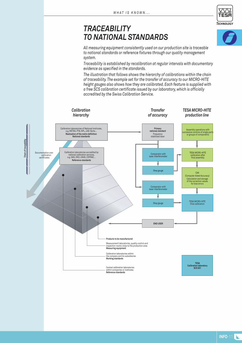
all measuring equipment consistently used on our production site is traceable to national standards or reference fixtures through our quality management system.traceability is established by recalibration at regular intervals with docu mentary evidence as specified in the standards.the illustration that follows shows the hierarchy of calibrations within the chain of traceability. the example set for the transfer of accuracy to our miCro-hite height gauges also shows how they are calibrated. each feature is supplied with a free sCs calibration certificate issued by our laboratory, which is officially accredited by the swiss Calibration service.
Calibration laboratories of National Institutes, e.g. METAS, PTB, NPL, LNE-Syrte...Realization of the metre definition
National standards
Calibration laboratories accredited by national calibration services,
e.g. SAS, DKD, UKAS, COFRAC...Reference standards
Products to be manufactured
Measurement laboratories, quality control and inspection rooms close to the production areaMeasuring equipment
Calibration laboratories within the company and its subsidiariesWorking standards
Central calibration laboratories within companies or institutesReference standards
Chai
n of
trac
eabi
lity
Documentation overcalibration
certificates
Primary national standard
Frequency stabilised laser
Assembly operations with successive controls of single parts
or groups of components
TESA MICRO-HITE calibration after final assembly
CAA(Computer Aided Accuracy)
Calculation and storage of the correction values
for bias errors
TESA MICRO-HITE final calibration
Comparator with laser interferometer
Comparator with laser interferometer
Step gauge
Step gauge
END usER
TEsACalibration laboratory
sCs 001
calibration hierarchy
Transfer of accuracy
TESA Micro-hiTE production line
INFO-11

INFO-12
www.tesatechnology.com A-1
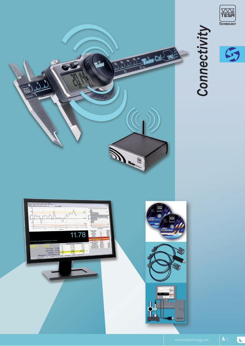
Conn
ectiv
ity

A-2
Software + Report (DATA-DIRECT / STAT-EXPRESS)
Wireless connection
Portable printer
Software + Report (DATA-DIRECT / STAT-EXPRESS)
Connection with USB, Opto-RS, Sub-D, TLC cables
TESA offers various types of connection between measuring instruments and a PC as well as software for the management of results so that the production process can be optimised, quality improved and documents for traceability can be created.
Inspection, traceability and cost reduction have a growing significance in all industrial sectors. This requires not only high quality metrology instruments, but also software suitable for evaluation and further analysis of the measurements carried out.
TESA SofTwArE, CAblES And linkS for ThE TrAnSfEr of mEASuring rESulTS.
C o n n E C T I v I T y
ProduCTIon InSPECTIon EvAluATIon ArChIvIngTESA DATA-DIRECTList of measurements, archiving, customised results calculations, traceability, statistics.
TESA STAT-EXPRESSStatistical analysis of measurements, control charts, traceability and sharing of results.
TESA PRINTER SPCSimple statistics, without the need for a PC, documented traceability.
Measuring instrument Software or portable printer
Database Electronic file (PDF) Printed report
A-3
Minimum system requirements to run DATA-DIRECT: – Pentium 4 or equivalent – 512 MB RAM (live memory) – 10 GB HD – Windows XP, Windows 7 (32 or 64 bits) or Windows 8 (32 or 64 bits)
Please contact your TESA representative or an authorised distributor for a 30-day demo version.
Included in delivery04981001 DATA-DIRECT Software
and dongleTESA DATA-DIRECT installation CD with licence key (dongle) USB and user instructions (PDF version)
TESA DATA-DIRECT Software
TESA Instruments compatible with DATA-DIRECT
Opto-RS Cables – Opto-USB Cables – Height gauges (TESA-HITE, MICRO-HITE) – USB probes – Surface roughness gauges RUGOSURF 10 / 20 / 10G / 90G – TPS presetting bench – BPX probe interface – TWIN-STATION wireless probe interface – TESA wireless systems – TLC-TWIN wireless transceiver
Other instruments compatible with DATA-DIRECT
Custom made instruments with RS232 output – Instruments from other makers: Mitutoyo: DMX3 - DMX8 – Steinwald single 6 – Etc.
Functions Export of results to .csv file – ASCII commands – Real time dispay of measured results on a PC (except for models using the Rf-USB receiver)
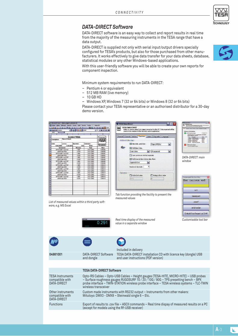
real time display of the measured value in a separate window
Customisable tool bar
dATA-dIrECT: main window
Tab function providing the facility to present the measured values
list of measured values within a third party soft-ware, e.g. MS Excel
dATA-dirECT Software DATA-DIRECT software is an easy way to collect and report results in real time from the majority of the measuring instruments in the TESA range that have a data output.DATA-DIRECT is supplied not only with serial input/output drivers specially configured for TESA’s products, but also for those purchased from other manu-facturers. It works effectively to give data transfer for your data sheets, database, statistical modules or any other Windows-based applications.With this user-friendly software you will be able to create your own reports for component inspection.
C o n n E C T I v I T y
A-4
Minimum system requirements to run STAT-EXPRESS:
– Pentium 4 or equivalent – 512 MB RAM (live memory) – 10 GB HD – Windows XP, Windows 7 (32 or
64 bits) or Windows 8 (32 or 64 bits)Please contact your TESA representa-tive or an authorised distributor for a 30-day demo version.
Included in delivery04981002 STAT-EXPRESS software
and dongleTESA DATA-DIRECT installation CD with USB licence key (dongle) and user instructions (PDF version)
STAT-EXPRESS Software
TESA instruments compatible with STAT-EXPRESS
Opto-RS cables – Opto-USB cables – Height gauges (TESA-HITE, MICRO-HITE) – USB probes – Surface roughness gauges: RUGOSURF 10 / 20 / 10G / 90G – TPS presetting bench – BPI Probe interface– BPX probe interface – TWIN-STATION wireless probe interface – TESA wireless systems – TLC-TWIN wireless emitter-receiver
Other instruments compatibles with STAT-EXPRESS
Custom made instruments with RS232 ouput – Instruments from other makers: Mitutoyo: DMX3 - DMX8 – Steinwald single 6 – etc.
Features DATA-DIRECT included – Export of results to .csv file – Import of .csv files – Table of all mea-sured results – XR control charts – Report by part measured – Report by feature measured – Simultaneous data acquisition – Overall report with statistics – Measuring report in .pdf or .html format etc.– Security protection set for each user
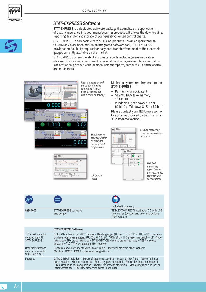
Xr Control chart
detailed measuring report for each part measured, together with serial number
detailed measuring report for each feature measuredSimultaneous
data acquisition from several measurement programmes
Measuring display with the option of adding operational instruc-tions, accompanied with a photo or drawing
STAT-EXPrESS Software STAT-EXPRESS is a dedicated software package that enables the application of quality assurance into your manufacturing processes. It allows the downloading, reporting, transfer and storage of your quality-oriented control charts.STAT-EXPRESS is compatible with all TESA’s products – from calipers through to CMM or Vision machines. As an integrated software tool, STAT-EXPRESS provides the flexibility required for easy data transfer from most of the electronic gauges currently available on the market. STAT-EXPRESS offers the ability to create reports including measured values obtained from a single instrument or several handtools, assign tolerances, calcu-late statistics, print out various measurement reports, compute XR control charts, and much more.
C o n n E C T I v I T y
A-5
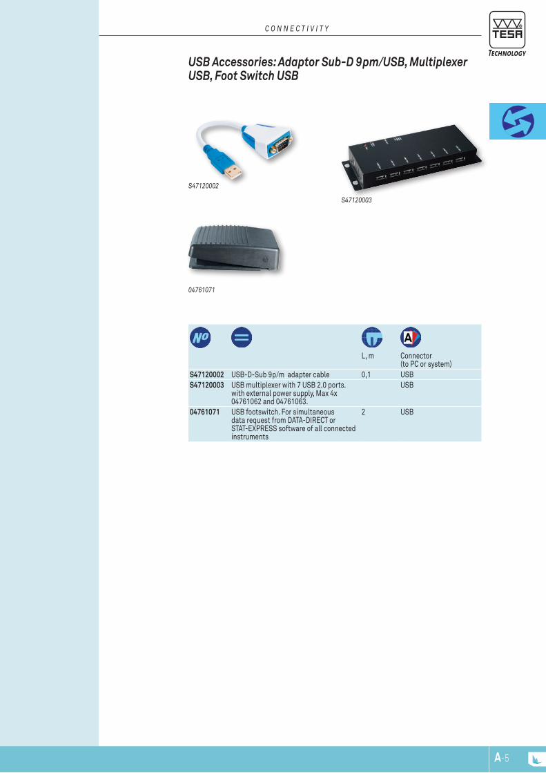
S47120002 USB-D-Sub 9p/m adapter cable 0,1 USBS47120003 USB multiplexer with 7 USB 2.0 ports.
with external power supply, Max 4x 04761062 and 04761063.
USB
04761071 USB footswitch. For simultaneous data request from DATA-DIRECT or STAT-EXPRESS software of all connected instruments
2 USB
L, m Connector
(to PC or system)
04761071
S47120003
S47120002
uSb Accessories: Adaptor Sub-d 9pm/uSb, multiplexer uSb, foot Switch uSb
C o n n E C T I v I T y

A-6
06430000 SPC PRINTER EUPortable. With memory, SPC, value classification and graphs. RS232 interface
180 x 180 x 84 mm (W x D x H)
Paper width: 110 mm. Print mode: 40 signs/lineRS232 for data inputs (9-pin male, trapezoid connector) DIGIMATIC (Ansley connector, 10-pin) Connector with mini-jack for remote triggering of data transferMains adapter 100 to 240 Vac, 6,6 Vdc.Optional accessory: 6 V rechargeable battery pack.
IP40 (IEC 60529)
EN 50081-1, EN 50081-2, EN 50082-1, EN 50082-2
"Normal" Mode
"Tolerance" Mode
Lower size limit (min.) Upper size limit (max.) Tolerance
– – –
Number of values taken: number of samples < smallest dimension > largest dimension % out of tolerance
– – –
Lowest value listed Highest value listed Dispersion R
Arithmetical mean Standard deviation sn, sn-1 Indication of capacity Cp, Cpk
–
Graphical representations: Position of each single value within the tolerance zone (10 classes)
–
Graphical representations: Histogrammes
–
Display (LED) - Classification of the value measured: Green for pass, yellow for rework,red for reject
–
– Memory capacity : 9999 single va-lues for one feature per sample.
– Two operating modes: “Normal” and “Tolerance”.
– Limits of size quickly set on the dis-play of the connected instrument with subsequent transfer to TESA PRINTER SPC.
– Output of statistical values printed out with graphical representations.
– Output of reports with headings to be filled in by the operator.
– Hardcopies printed in preferred language (English, German, French, Italian or Spanish).
– Battery-powered (6 V) printer unit for use on the move (optional).
TESA SPC Printer
TESA Portable SPC PrinTEr TESA portable intelligent printer designed for the inspection of finished parts or incoming goods – Provides SPC statistics and prints out measurement results with graphical representations.The TESA SPC PRINTER can be connected not only to TESA measuring instru-ments, but also to those provided with a DIGIMATIC output – Your TESA SPC PRINTER is capable of recognising the plug in tool and will execute the appro-priate configuration automatically.
C o n n E C T I v I T y
dElIvErEd wITh ThE followIng ACCESSorIES:04765013 Roll of printer paper, width =
110 mm for TESA SPC Printer04761054 Mains adapter /battery charger 100 ÷ 240 VAC
50 ÷ 60 Hz, 6,6 Vdc, 750 mAh supplied without cable04761055 EU Mains cable for 04761054 adapter
oPTIonAl ACCESSorIES:04761056 USA Mains cable04768035 Battery charger 6V, 0,5AH
A-7
Operating range, m
Compatible with connector
Diameter, mm
Weight, g
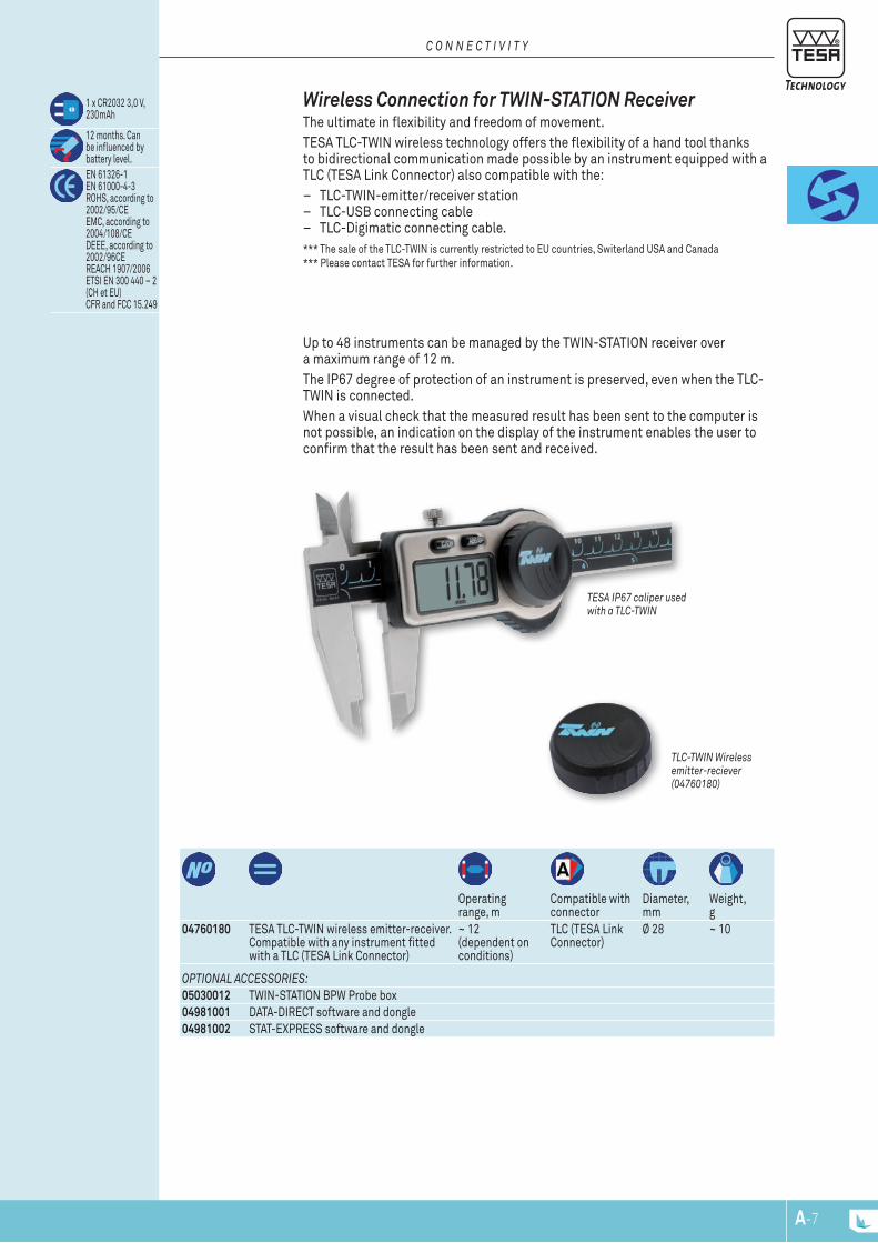
Up to 48 instruments can be managed by the TWIN-STATION receiver over a maximum range of 12 m.The IP67 degree of protection of an instrument is preserved, even when the TLC-TWIN is connected. When a visual check that the measured result has been sent to the computer is not possible, an indication on the display of the instrument enables the user to confirm that the result has been sent and received.
04760180 TESA TLC-TWIN wireless emitter-receiver. Compatible with any instrument fitted with a TLC (TESA Link Connector)
~ 12 (dependent on conditions)
TLC (TESA Link Connector)
Ø 28 ~ 10
1 x CR2032 3,0 V, 230mAh
12 months. Can be influenced by battery level.EN 61326-1 EN 61000-4-3 ROHS, according to 2002/95/CE EMC, according to 2004/108/CE DEEE, according to 2002/96CE REACH 1907/2006 ETSI EN 300 440 – 2 (CH et EU)CFR and FCC 15.249
TlC-TwIn wireless emitter-reciever (04760180)
TESA IP67 caliper used with a TlC-TwIn
wireless Connection for Twin-STATion receiver The ultimate in flexibility and freedom of movement.TESA TLC-TWIN wireless technology offers the flexibility of a hand tool thanks to bidirectional communication made possible by an instrument equipped with a TLC (TESA Link Connector) also compatible with the:
– TLC-TWIN-emitter/receiver station – TLC-USB connecting cable – TLC-Digimatic connecting cable.
*** The sale of the TLC-TWIN is currently restricted to EU countries, Switerland USA and Canada*** Please contact TESA for further information.
C o n n E C T I v I T y
oPTIonAl ACCESSorIES:05030012 TWIN-STATION BPW Probe box04981001 DATA-DIRECT software and dongle04981002 STAT-EXPRESS software and dongle

A-8
Transfer of results with TESA link ConnECTor TlC
Number of instru-ments with TLC-TWIN
Power supply Weight, kg
05030012 TWIN-STATION for TLC-TWIN wireless data transmisson
48 Power supply via: - USB port of the PC - connected USB hub - USB hub of the BPX interface
0,85
Housing case in aluminium
Power supply via the connection of the USB cable: - directly to the PC (USB Port) to a mains powered USB hub
IP 40 (IEC 60529) (DIN 40050)
IEC/EN 61326-1 U.S. 47 CFR part 15, subpart B, Class B digital deviceData transfer delay from digital serial output (USB): depends on the operating system of the computer.
RS232
55 x 172 x 155 mm (H x W x D)
USB Cable 1, 80 m
For a temperature of 20° C and a relative humidity of ≤ 50%: Digital output: ± (0,05 + 0,15% of the measuring range)
TwIn-STATIon (rear view)TwIn-STATIon (front view)
Twin-STATion receiver TWIN-STATION: Receiver for wireless TLC-TWIN emitter-receiver unitsReceives input signals from wireless TLC-TWIN emitter-receiver units Output signals – digital, RS232
– Direct connection to a PC via the USB port. – Optimal use for your measuring tasks as up to 48 instruments equipped with
TLC-TWIN can be connected to this unit. – Great reliability.
*** the sale of TWIN-STATION is currently limited to EU countries, Switzerland, USA and Canada*** Please contact TESA for further details.
C o n n E C T I v I T y
TESA presents its new connectivity concept: the TLC connector that allows freedom of movement, flexibility, and ease of use, all combined.Once an instrument is equipped with a TLC connector:1) There is no longer any need to choose between a model with or without data output.2) There is inbuilt compatibility for both cable and wireless connectivity.3) A TLC connector can also be used for connection to a USB interface, a DIGIMATIC interface or for wireless connection,
using a suitable cable or emitter-receiver unit, see table below:
Instrument equipped with a TLC connector. For example, TESA TWIN-CAL IP67 caliper
Wireless connection Cable connection
TLC-TWIN Two way wireless emitter-receiver unit
TLC-USB Two way communication cable
TLC-DIGIMATIC Two way communication cable
+ + +TWIN-STATION receiver base station for signals from the wireless TLC emitter- receiver unit
Interface with USB port DIGIMATIC* interface
Personal computer
* Please check with TESA for the list of equipment and instruments compatible with TESA-DIGIMATIC

A-9
04761062 Opto-USB cable, duplex, bidirectional communication
2 Opto- RS232
Type A USB
04761046 Opto-RS cable, simplex, 2 m, one way communication: from the instrument to the PC
2 Opto- RS232
Sub-D 9p/f Simplex
S47010022 Opto-RS cable, simplex, 5 m, one way communication: from the instrument to the PC
5 Opto- RS232
Sub-D 9p/f Simplex
04761049 Opto-RS cable, duplex, 2 m, bidirec-tional communication
2 Opto- RS232
Sub-D 9p/f Duplex
S47010024 Opto-RS cable, duplex, 5 m, bidirec-tional communication
5 Opto- RS232
Sub-D 9p/f Duplex
04761027 Connecting cable without connector
2 Opto- RS232
Without connector
L, m Connection (to instru-ment)
Connection (to PC or system)
0476102704761049
0476104604761062
Examples of instruments with type Opto connector:TESA-CAL IP67 / IP65 – TESA MICROMASTER – TESA IMICRO – TESA ALESOMETRE – TESA DIGICO 10 / 11 / 205 / 305 / 400 / 500 / 600 / 705 – TESATRONIC TT20 / TT60 / TT80 / TT90 – INTERAPID - Light
Standard opto Connection Any connecting cable is defined by each of the connectors fitted at either end of the cable principally to suit the computer, and the measuring instrument being used. To achieve highest compatibility levels, TESA uses only standardized and proven connectors.
oPTo And Sub-d ConnECTion
C o n n E C T I v I T y
L, m Connector (to instrument)
Connector (to PC or system)
04761063 Sub-D 9p/m to USB cable, 2M 2 Sub-D 9p/m USB04761052 Extension cable, Sub-D 9p/f to 9p/m, 2 m 2 Sub-D 9p/m Sub-D 9p/fS47010025 Extension cable, Sub-D 9p/f to 9p/m, 10 m 10 Sub-D 9p/m Sub-D 9p/fS47120002 Sub-D 9p/m to USB adapter cable 0,1 Sub-D 9p/m USB
S4712000204761063
Standard Sub-d Connection RS232, Sub-D 9p/m connector connecting cables for the following machines or precision handtools:TESA MICRO-HITE /TESA-HITE / TESA-μHITE / TESA TG / 3D Machines
Current systems Compatible connectors
TESA PRINTER SPC
Sub-D 9p/f Ansley 10p/f
Computer USB Sub-D 9p/f
04761052
A-10
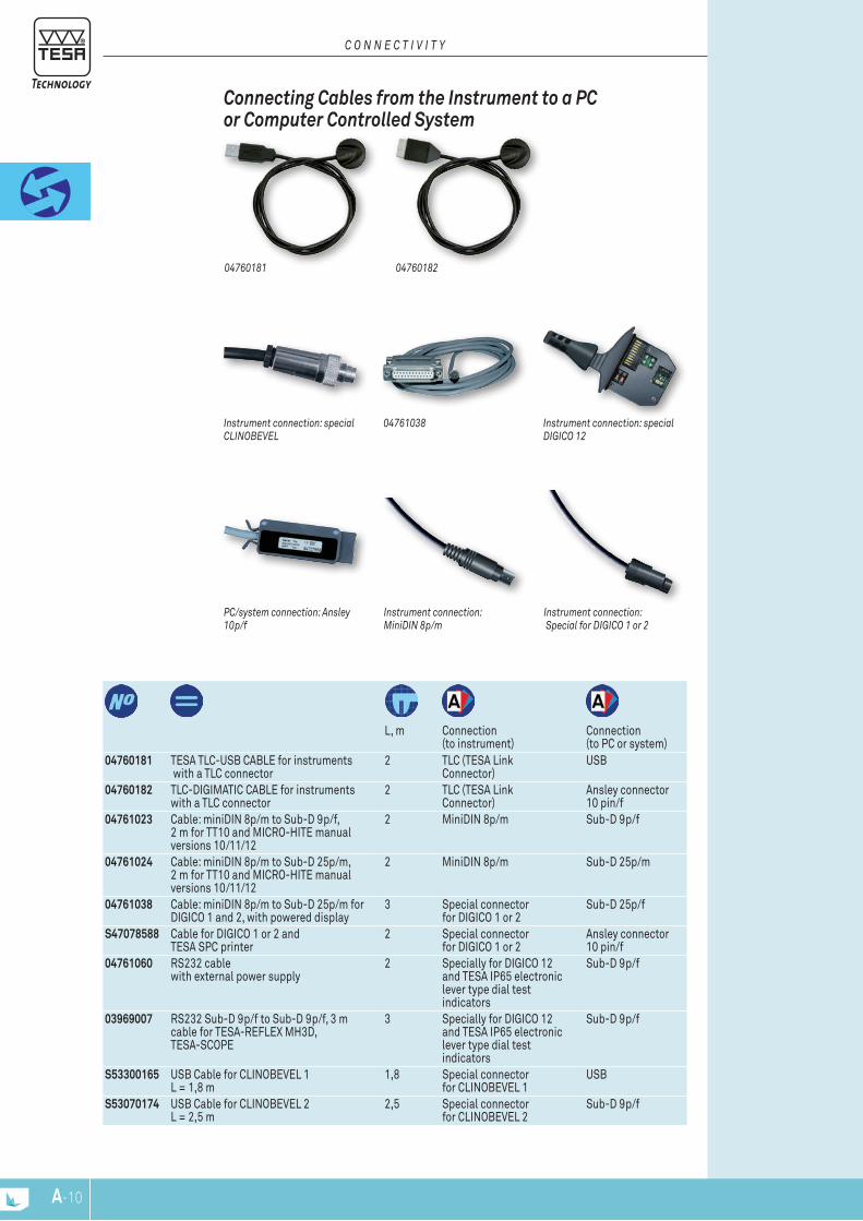
Instrument connection: MinidIn 8p/m
Instrument connection: Special for dIgICo 1 or 2
PC/system connection: Ansley 10p/f
Connecting Cables from the instrument to a PC or Computer Controlled System
C o n n E C T I v I T y
L, m Connection
(to instrument)Connection (to PC or system)
04760181 TESA TLC-USB CABLE for instruments with a TLC connector
2 TLC (TESA Link Connector)
USB
04760182 TLC-DIGIMATIC CABLE for instruments with a TLC connector
2 TLC (TESA Link Connector)
Ansley connector 10 pin/f
04761023 Cable: miniDIN 8p/m to Sub-D 9p/f, 2 m for TT10 and MICRO-HITE manual versions 10/11/12
2 MiniDIN 8p/m Sub-D 9p/f
04761024 Cable: miniDIN 8p/m to Sub-D 25p/m, 2 m for TT10 and MICRO-HITE manual versions 10/11/12
2 MiniDIN 8p/m Sub-D 25p/m
04761038 Cable: miniDIN 8p/m to Sub-D 25p/m for DIGICO 1 and 2, with powered display
3 Special connector for DIGICO 1 or 2
Sub-D 25p/f
S47078588 Cable for DIGICO 1 or 2 and TESA SPC printer
2 Special connector for DIGICO 1 or 2
Ansley connector 10 pin/f
04761060 RS232 cable with external power supply
2 Specially for DIGICO 12 and TESA IP65 electronic lever type dial test indicators
Sub-D 9p/f
03969007 RS232 Sub-D 9p/f to Sub-D 9p/f, 3 m cable for TESA-REFLEX MH3D, TESA-SCOPE
3 Specially for DIGICO 12 and TESA IP65 electronic lever type dial test indicators
Sub-D 9p/f
S53300165 USB Cable for CLINOBEVEL 1 L = 1,8 m
1,8 Special connector for CLINOBEVEL 1
USB
S53070174 USB Cable for CLINOBEVEL 2 L = 2,5 m
2,5 Special connector for CLINOBEVEL 2
Sub-D 9p/f
Instrument connection: special ClInobEvEl
Instrument connection: special dIgICo 12
04761038
0476018204760181

A-11
hand / foot Switches, Adapters, battery Chargers, Power Cables
C o n n E C T I v I T y
L, mm Connection
(to instrument)Connection (to PC or system)
04761054 S4700189104761017
04768001 04768000
04768000 Hand switch for triggering data transfer. Jack plug, 1,8 m – to TESA SPC PRINTER – to TESATRONIC (TT) display units
1,8 – Jack plug
04768001 Foot switch for triggering data transfer. Jack plug, 1,8 m – to TESA SPC PRINTER – to TESATRONIC (TT) display units
1,8 – Jack plug
04761017 Adapter ADP-01 Sub-D 9pf to Sub-D 25pm
– –
S47001891 DIGIMATIC adapter for 04761046 cable Sub-D 9p/m to Ansley 10p/f
0,2 – Sub-D 9p/f or Ansley 10p/f
04761054 Mains adapter /battery charger 100 ÷ 240 VAC, 50 ÷ 60 Hz, 6,6 Vdc, 750 mAh, supplied without cable
2 DC-Jack –
04761055 EU mains cable for 04761054
1,5 – –
04761056 USA mains cable for 04761054
1,5 – –
04761037 Mains cable 230V for DIGICO 1 or 2
2 Special connector for DIGICO 1 or 2
–
04761057 Mains cable 110V for DIGICO 1 or 2
2 Special connector for DIGICO 1 or 2
Sub-D 9p/f
12
058213
056109
A-12
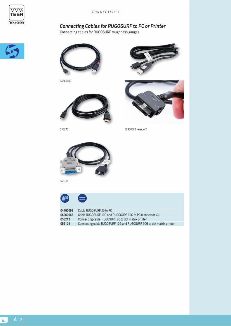
06960062 version 3
04760099 Cable RUGOSURF 20 to PC06960062 Cable RUGOSURF 10G and RUGOSURF 90G to PC (connector v3)058213 Connecting cable RUGOSURF 20 to dot matrix printer056109 Connecting cable RUGOSURF 10G and RUGOSURF 90G to dot matrix printer
04760099
Connecting Cables for rugoSurf to PC or Printer Connecting cables for RUGOSURF roughness gauges
C o n n E C T I v I T y
www.tesatechnology.com B-1
Calip
ers
0 1 2 3 4 5 6 7 8 9 0
11 12 13 14 15 16 17
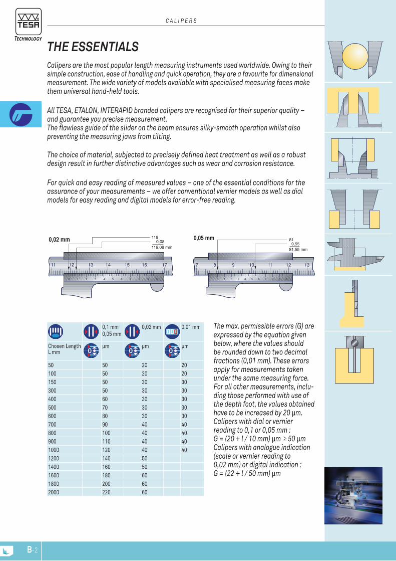
0,02 mm 119 0,08119,08 mm
0 1 2 3 4 5 6 7 8 9 0
7 8 9 10 11 12 13
0,05 mm 81 0,5581,55 mm
B-2
The max. permissible errors (G) are expressed by the equation given below, where the values should be rounded down to two decimal fractions (0,01 mm). These errors apply for measurements taken under the same measuring force. For all other measurements, inclu-ding those performed with use of the depth foot, the values obtained have to be increased by 20 μm. Calipers with dial or vernier reading to 0,1 or 0,05 mm : G = (20 + l / 10 mm) μm ≥ 50 μm Calipers with analogue indication (scale or vernier reading to 0,02 mm) or digital indication : G = (22 + l / 50 mm) μm
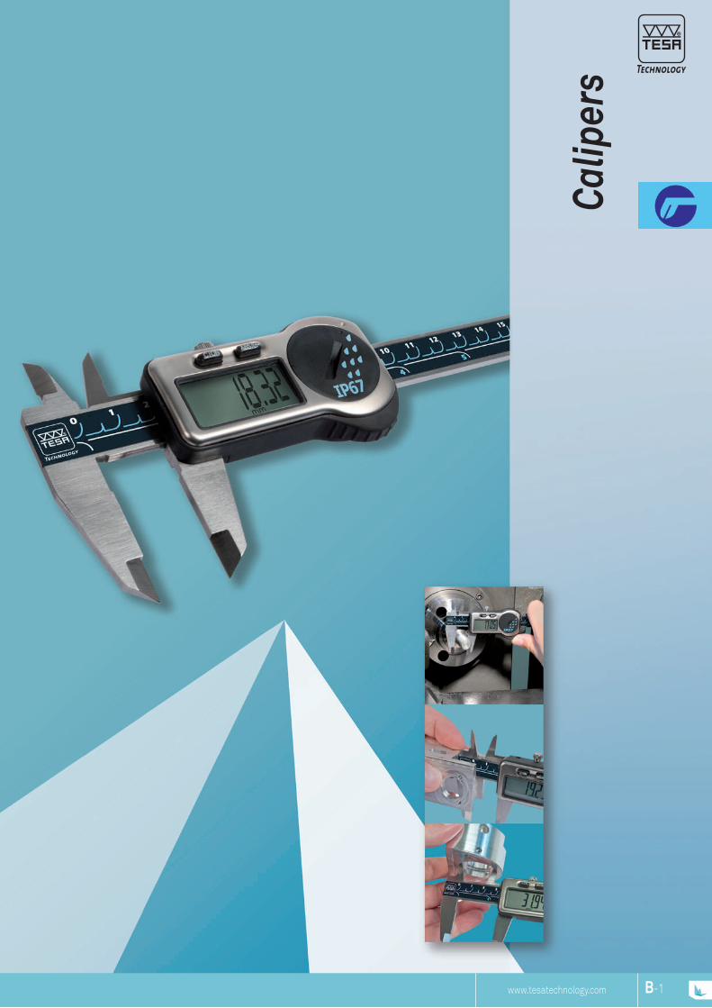
Calipers are the most popular length measuring instruments used worldwide. Owing to their simple construction, ease of handling and quick operation, they are a favourite for dimensional measurement. The wide variety of models available with specialised measuring faces make them universal hand-held tools.
All TESA, ETALON, INTERAPID branded calipers are recognised for their superior quality – and guarantee you precise measurement. The flawless guide of the slider on the beam ensures silky-smooth operation whilst also preventing the measuring jaws from tilting. The choice of material, subjected to precisely defined heat treatment as well as a robust design result in further distinctive advantages such as wear and corrosion resistance.
For quick and easy reading of measured values – one of the essential conditions for the assurance of your measurements – we offer conventional vernier models as well as dial models for easy reading and digital models for error-free reading.
THE ESSENTIALS
C A L I P E R S
0,1 mm0,05 mm
0,02 mm 0,01 mm
Chosen Length L mm
µm µm µm
50 50 20 20100 50 20 20150 50 30 30300 50 30 30400 60 30 30500 70 30 30600 80 30 30700 90 40 40800 100 40 40900 110 40 401000 120 40 401200 140 501400 160 501600 180 601800 200 602000 220 60

13
C
B
A
ø1.5
15.5
3.2/3.6/4
B-3
OPTIONAL ACCESSORIES:00560013 Depth foot for calipers up to 150 mm01961000 Lithium battery, 3V, CR203204760180 TESA TLC-TWIN wireless emitter-receiver
Compatible with any instrument fitted with a TLC – TESA Link Connector04760181 TESA TLC-USB cable for instruments with a TLC connector04760182 TLC-DIGIMATIC cable for instruments with a TLC connector
00530319 150 6 – 40 16 74 150 Square00530320 150 6 – 40 16 74 150 Round00530321 150 6 With 40 16 74 150 Round00530322 200 8 With 50 20 90 200 Square00530323 300 12 With 64 22 106 280 Square
mm in Drive system / Thumb Roller
A mm B mm C mm g Depth rod
ISO 13385-1
0,01 mm / 0.0005 in
LCD, 11 mm
Fixed zero
mm / inconversion
≤ 100 mm: 20 µm >100 mm: 30 µm
10 µm
Scale with incre-mental divisions, inductive
2,5 m/s
TLC Connectivity
Stainless steel
Lithium battery, 3V, CR2032
12.000 hours
Standby mode after 10 minutes, instru-ment retains the zero position. Auto-matic shut off after 2 hours, instrument retains the zero in ABS mode, but the zero must be reset if the instrument is in DIFF mode.1907/2006/CE 2004/108/CE 2002/96/CEInspection report and declaration of conformity
TWIN-CAL IP67 Welcome to the new generation of TESA electronic calipers, with the highest degree of protection ever offered.The TWIN-CAL IP67 are all equipped with TLC (TESA Link Connector), the unique integral data output facility, providing the opportunity to upgrade your caliper at any time.
D I G I T A L C A L I P E R S

13
C
B
A
ø1.5
15.5
3.2/3.6/4
B-4
OPTIONAL ACCESSORIES:00560013 Depth foot for calipers up to 150 mm01961000 Lithium battery, 3V, CR203204760180 TESA TLC-TWIN wireless emitter-receiver
Compatible with any instrument fitted with a TLC – TESA Link Connector04760181 TESA TLC-USB cable for instruments with a TLC connector04760182 TLC-DIGIMATIC cable for instruments with a TLC connector
00530094 150 6 With 40 16 74 150 Round00530097 150 6 – 40 16 74 150 Square00530095 200 8 With 50 20 90 200 Square00530096 300 12 With 64 22 106 280 Square
mm in Drive system / Thumb roller
A mm B mm C mm g Depth rod
ISO 13385-1
0,01 mm / 0.0005 in
LCD, 11 mm
Fixed zero
mm/inconversion
≤ 100 mm: 20 µm >100 mm: 30 µm
10 µm
Scale with incre-mental divisions, inductive
2,5 m/s
TLC connectivity
Stainless steel
3V Lithium battery, CR2032
12.000 hours
Standby mode after 10 minutes, instrument retains zero. Automatic shut off after 2 hours. The instrument retains zero in ABS mode, but if the instrument is in DIFF mode, the zero must be reset.1907/2006/CE 2004/108/CE 2002/96/CEInspection report with declaration of conformity
TWIN-CAL IP40 The new TWIN-CAL calipers are all supplied with a built in data output port. Simply plug the TESA TLC connector into the TWIN-CAL and the other end into a PC and all your measurement results will be captured and stored for optimal SPC monitoring.
D I G I T A L C A L I P E R S
13
C
B
A
ø1.5
15.5
3.2/3.6/4
D I G I T A L C A L I P E R S
B-5
mm in Drive system/ thumb roller
A mm B mm C mm g Depth rod
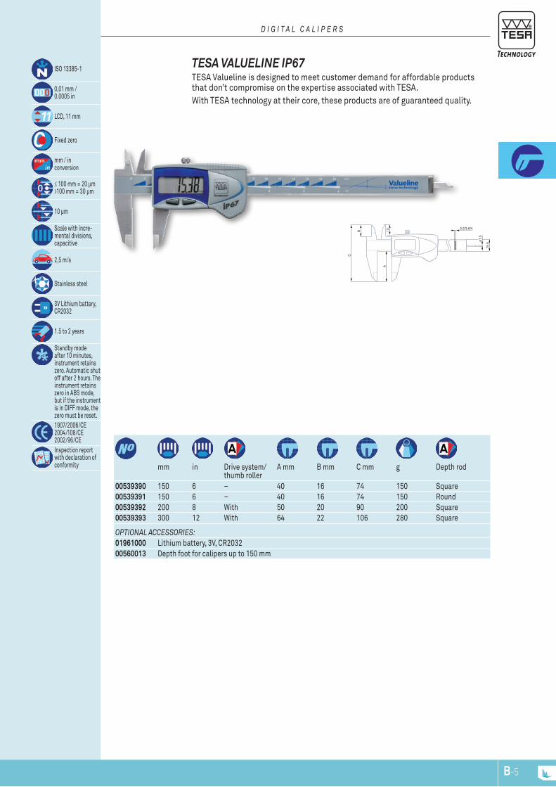
00539390 150 6 – 40 16 74 150 Square00539391 150 6 – 40 16 74 150 Round00539392 200 8 With 50 20 90 200 Square00539393 300 12 With 64 22 106 280 Square
OPTIONAL ACCESSORIES:01961000 Lithium battery, 3V, CR203200560013 Depth foot for calipers up to 150 mm
TESA VALUELINE IP67 TESA Valueline is designed to meet customer demand for affordable products that don’t compromise on the expertise associated with TESA. With TESA technology at their core, these products are of guaranteed quality.
ISO 13385-1
0,01 mm / 0.0005 in
LCD, 11 mm
Fixed zero
mm / in conversion
≤ 100 mm = 20 μm >100 mm = 30 μm
10 µm
Scale with incre-mental divisions, capacitive
2,5 m/s
Stainless steel
3V Lithium battery, CR2032
1.5 to 2 years
Standby mode after 10 minutes, instrument retains zero. Automatic shut off after 2 hours. The instrument retains zero in ABS mode, but if the instrument is in DIFF mode, the zero must be reset.1907/2006/CE 2004/108/CE 2002/96/CEInspection report with declaration of conformity

A
C
B
3.2
15.5
3.7
1.5x
1.9
3.6
15.5
3.7
1.5x
1.9
4
15.5
3.7
1.5x
1.9
40
74
13
3.2
15.5
3.7
1.5x
1.9
B-6
OPTIONAL ACCESSORy:00560013 Depth foot for calipers up to 150 mm
00510050 0 ÷ 150 mm 0,01 1 mmmm mm mm
DIN 862 (Style 1AR)
≤ 100 mm = 20 μm >100 mm = 30 μm
Gear mechanism made of hardened ground steel
Hardened stainless steel
Inspection report with a declaration of conformity32 mm diameter rotating dial with lock
Slider with locking screw
Patented shockproof design
Model TESA CCMA-M, 0,01 mm Slider with metal dial housing – 1 mm per dial revolution.
OPTIONAL ACCESSORy:00560013 Depth foot for calipers up to 150 mm
00510008 0 ÷ 150 mm 0,02 mm 2 mm – 40 13 7400520002 0 ÷ 6 in 0.001 in 0.1 in – 40 13 7400510045 0 ÷ 200 mm 0,02 mm 2 mm 50 18,6 89,500510046 0 ÷ 300 mm 0,02 mm 2 mm 64 20,6 105,5
Thumb roller A mm B mm C mm
DIN 862 (Style 1AR)
≤ 100 mm = 20 μm >100 mm = 30 μm
Gear mechanism made of hardened ground steel
Hardened stainless steel
Inspection report with a declaration of conformity32 mm diameter rotating dial with lock
Slider with locking screw
Patented shockproof design
300 mm / 12 in 200 mm / 8 in
150 mm / 6 in
Models TESA CCMA-M Easy-to-read dial calipers – Slider with metal dial housing – Models with a 200 or 300 measuring span are fitted with a thumb roller.
DIAL CALIPErS The dial caliper is the favourite instrument of many professionals working in mechanics, as it is an ideal tool for the workshop.
All dial calipers use the original shockproof technology developed and patented in 1970 by TESA, pioneer of this technology. Thanks to the shockproof system inserted between the mobile measuring element and the mechanism of the dial pointer, this patent guarantees reliable measurements even in case of a shock to the instrument.
D I A L C A L I P E R S
40
74
13
3.2
15.5
3.7
1.5x
1.9
40
74
13
3.2
15.5
3.7
1.5x
1.9
B-7
OPTIONAL ACCESSORy:00560013 Depth foot for calipers up to 150 mm
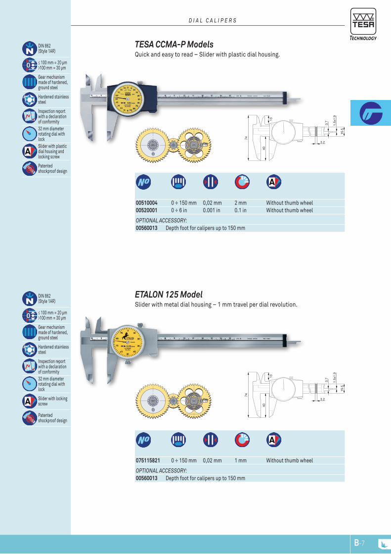
00510004 0 ÷ 150 mm 0,02 mm 2 mm Without thumb wheel00520001 0 ÷ 6 in 0.001 in 0.1 in Without thumb wheel
DIN 862 (Style 1AR)
≤ 100 mm = 20 μm >100 mm = 30 μm
Gear mechanism made of hardened, ground steel
Hardened stainless steel
Inspection report with a declaration of conformity32 mm diameter rotating dial with lockSlider with plastic dial housing and locking screw
Patented shockproof design
TESA CCMA-P Models Quick and easy to read – Slider with plastic dial housing.
D I A L C A L I P E R S
OPTIONAL ACCESSORy:00560013 Depth foot for calipers up to 150 mm
075115821 0 ÷ 150 mm 0,02 mm 1 mm Without thumb wheel
DIN 862 (Style 1AR)
≤ 100 mm = 20 μm >100 mm = 30 μm
Gear mechanism made of hardened, ground steel
Hardened stainless steel
Inspection report with a declaration of conformity32 mm diameter rotating dial with lock
Slider with locking screw
Patented shockproof design
ETALON 125 Model Slider with metal dial housing – 1 mm travel per dial revolution.

6
25,5
8
75
B-8
0051610365 Magnetic magnifying glass, 3x magnification
2 permanent magnets
Magnetic Magnifying Glass Can be mounted on calipers and other such instruments for easier reading of vernier scales.
00560013 Depth foot for calipers up to 150 mm 75 x 6mm
Hardened stainless steel
Ground measuring face
Depth Measuring Foot For use with TESA or ETALON universal calipers with a measuring span of 0 to 150 mm / 0 to 6 inch.
ACCESSOrIES FOr CALIPErS Accessories for standard calipers
C A L I P E R S

B
A
C
B
A
C
2
B-9
OPTIONAL ACCESSORIES:00560013 Depth foot for calipers up to 150 mm0051610365 Magnetic magnifying glass, 3x magnification
00510041 SWISSCAL 2 0 ÷ 150 – 0,02 – 40 15,5 Ø 1,500510047 Standard 0 ÷ 150 – 0,05 – 40 15,5 Ø 1,500530103 Standard 0 ÷ 150 0 ÷ 6 0,05 1/128 40 15,5 Ø 1,500530104 Standard 0 ÷ 200 0 ÷ 8 0,05 1/128 50 18 1,5 x 200530105 Standard 0 ÷ 300 0 ÷ 12 0,05 1/128 64 22 –00530110 Standard 0 ÷ 150 0 ÷ 6 0,02 0.001 40 15,5 Ø 1,500530111 Standard 0 ÷ 200 0 ÷ 8 0,02 0.001 50 18 1,5 x 200530112 Standard 0 ÷ 300 0 ÷ 12 0,02 0.001 64 22 –00530120 Self-locking model 0 ÷ 150 0 ÷ 6 0,05 1/128 40 15,5 1,5 x 200530121 Self-locking model 0 ÷ 150 0 ÷ 6 0,02 0.001 40 15,5 1,5 x 200530130 Self-locking model
with parallax-free readout0 ÷ 150 0 ÷ 6 0,05 1/128 40 15,5 1,5 x 2
00530131 Self-locking model with parallax-free readout
0 ÷ 150 0 ÷ 6 0,02 0.001 40 15,5 1,5 x 2
mm in mm in A mm B mm C mm
DIN 862 (Style 1AN-2) NF E 11-091Maximum permissable errors, in accordance with standard
Hardened stainless steel
Inspection report with a declaration of conformitySatin-chrome scale background; main scale slightly set back for protection against wear
Standard Models Calipers offering great value for money:– Fitted with a locking screw.– With rectangular or round depth rod.
VErNIEr CALIPErS The simplest calipers to use with engraved scales for reading very fine divisions on measurements.
V E R N I E R C A L I P E R S
B
A
B-10
OPTIONAL ACCESSORIES:01961000 Lithium battery, 3V, CR203204760180 TESA TLC-TWIN wireless emitter-receiver
Compatible with any instrument fitted with a TLC – TESA Link Connector04760181 TESA TLC-USB cable for instruments with a TLC connector04760182 TLC-DIGIMATIC cable for instruments with a TLC connector
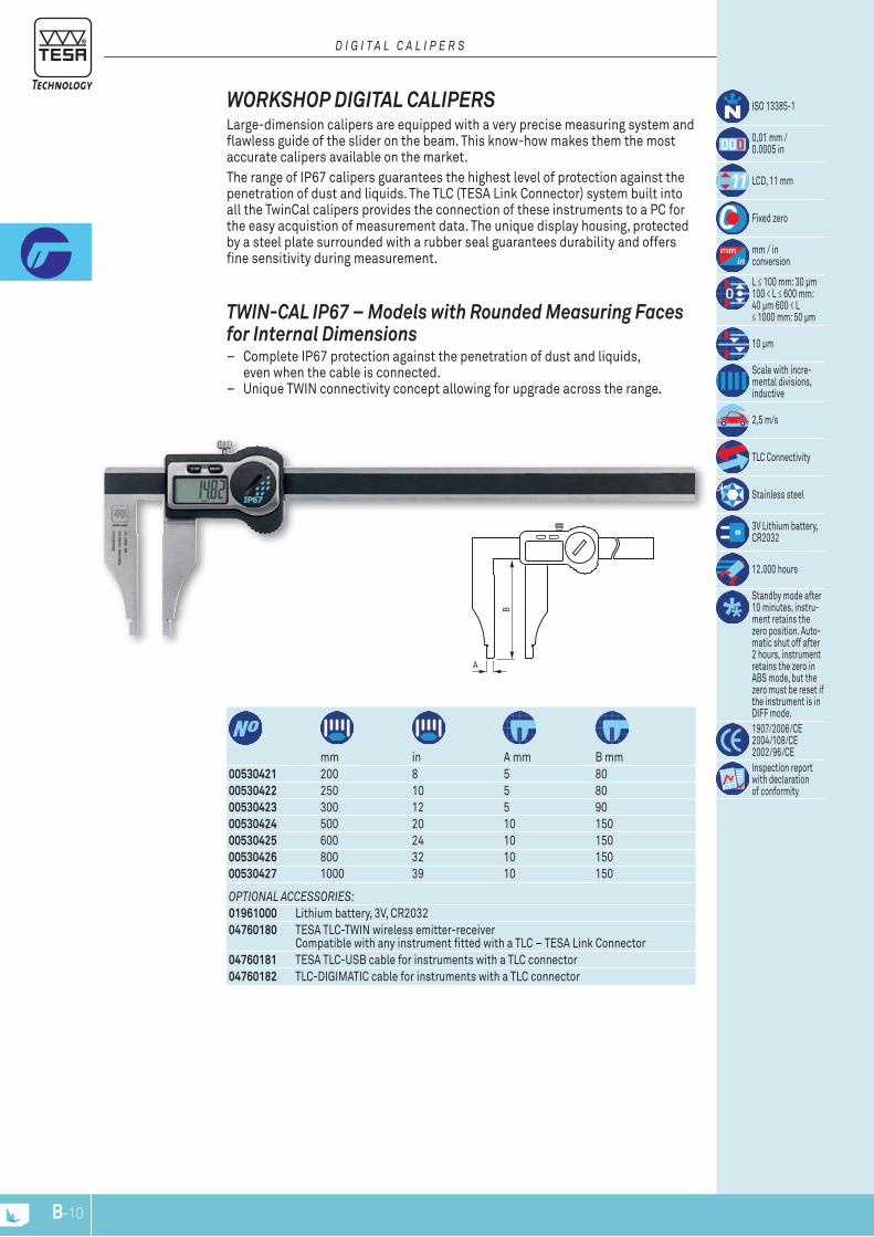
00530421 200 8 5 8000530422 250 10 5 8000530423 300 12 5 9000530424 500 20 10 15000530425 600 24 10 15000530426 800 32 10 15000530427 1000 39 10 150
mm in A mm B mm
ISO 13385-1
0,01 mm / 0.0005 in
LCD, 11 mm
Fixed zero
mm / inconversion
L ≤ 100 mm: 30 µm 100 < L ≤ 600 mm: 40 µm 600 < L ≤ 1000 mm: 50 µm
10 µm
Scale with incre-mental divisions, inductive
2,5 m/s
TLC Connectivity
Stainless steel
3V Lithium battery, CR2032
12.000 hours
Standby mode after 10 minutes, instru-ment retains the zero position. Auto-matic shut off after 2 hours, instrument retains the zero in ABS mode, but the zero must be reset if the instrument is in DIFF mode.1907/2006/CE 2004/108/CE 2002/96/CEInspection report with declaration of conformity
TWIN-CAL IP67 – Models with rounded Measuring Faces for Internal Dimensions
– Complete IP67 protection against the penetration of dust and liquids, even when the cable is connected.
– Unique TWIN connectivity concept allowing for upgrade across the range.
WOrkSHOP DIGITAL CALIPErS Large-dimension calipers are equipped with a very precise measuring system and flawless guide of the slider on the beam. This know-how makes them the most accurate calipers available on the market.The range of IP67 calipers guarantees the highest level of protection against the penetration of dust and liquids. The TLC (TESA Link Connector) system built into all the TwinCal calipers provides the connection of these instruments to a PC for the easy acquistion of measurement data. The unique display housing, protected by a steel plate surrounded with a rubber seal guarantees durability and offers fine sensitivity during measurement.
D I G I T A L C A L I P E R S
C
A
B
B-11
OPTIONAL ACCESSORIES:01961000 Lithium battery, 3V, CR203204760180 TESA TLC-TWIN wireless emitter-receiver
Compatible with any instrument fitted with a TLC – TESA Link Connector04760181 TESA TLC-USB cable for instruments with a TLC connector04760182 TLC-DIGIMATIC cable for instruments with a TLC connector
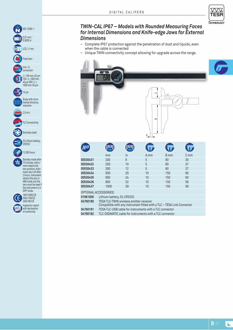
00530431 200 8 5 80 3000530432 250 10 5 80 3700530433 300 12 5 90 3700530434 500 20 10 150 6000530435 600 24 10 150 6000530436 800 32 10 150 5600530437 1000 39 10 150 56
mm in A mm B mm C mm
ISO 13385-1
0,01 mm / 0.0005 in
LCD, 11 mm
Fixed zero
mm / in conversion
L ≤ 100 mm: 30 µm 100 < L ≤ 600 mm: 40 µm 600 < L ≤ 1000 mm: 50 µm
10 µm
Scale with incre-mental divisions, inductive
2,5 m/s
TLC Connectivity
Stainless steel
3V Lithium battery, CR2032
12.000 hours
Standby mode after 10 minutes, instru-ment retains the zero position. Auto-matic shut off after 2 hours, instrument retains the zero in ABS mode, but the zero must be reset if the instrument is in DIFF mode.1907/2006/CE 2004/108/CE 2002/96/CEInspection report with declaration of conformity
TWIN-CAL IP67 – Models with rounded Measuring Faces for Internal Dimensions and knife-edge Jaws for External Dimensions
– Complete IP67 protection against the penetration of dust and liquids, even when the cable is connected
– Unique TWIN connectivity concept allowing for upgrade across the range.
D I G I T A L C A L I P E R S

CB
A
B-12
OPTIONAL ACCESSORIES:01961000 Lithium battery, 3V, CR203204760180 TESA TLC-TWIN wireless emitter-receiver
Compatible with any instrument fitted with a TLC – TESA Link Connector04760181 TESA TLC-USB cable for instruments with a TLC connector04760182 TLC-DIGIMATIC cable for instruments with a TLC connector
00530430 250 10 5 80 54mm in A mm B mm C mm
ISO 13385-1
0,01 mm / 0.0005 in
LCD, 11 mm
Fixed zero
mm / in conversion
L ≤ 100 mm: 30 µm 100 < L ≤ 250 mm: 40 µm
10 µm
Scale with incre-mental divisions, inductive
2,5 m/s
TLC Connectivity
Stainless steel
3V Lithium battery, CR2032
12.000 hours
Standby mode after 10 minutes, instru-ment retains the zero position. Auto-matic shut off after 2 hours, instrument retains the zero in ABS mode, but the zero must be reset if the instrument is in DIFF mode.1907/2006/CE 2004/108/CE 2002/96/CEInspection report with declaration of conformity
TWIN-CAL IP67 – Models with rounded Measuring Faces for Internal Dimensions and knife-edge Jaws for Internal Dimensions
– Complete IP67 protection against the penetration of dust and liquids, even when the cable is connected
– Unique TWIN connectivity concept allowing for upgrade across the range.
D I G I T A L C A L I P E R S
A
B
a
b
A
B
b
a
B-13
OPTIONAL ACCESSORy:0051610365 Magnetic magnifying glass, 3x magnification
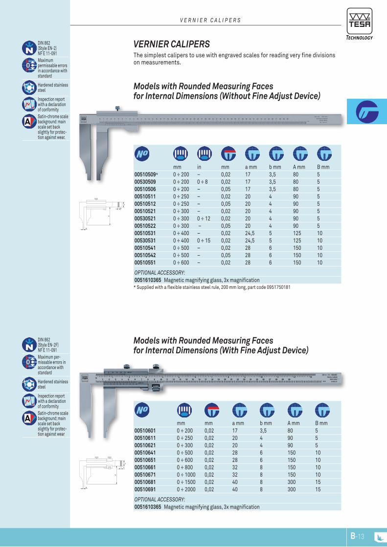
00510601 0 ÷ 200 0,02 17 3,5 80 500510611 0 ÷ 250 0,02 20 4 90 500510621 0 ÷ 300 0,02 20 4 90 500510641 0 ÷ 500 0,02 28 6 150 1000510651 0 ÷ 600 0,02 28 6 150 1000510661 0 ÷ 800 0,02 32 8 150 1000510671 0 ÷ 1000 0,02 32 8 150 1000510681 0 ÷ 1500 0,02 40 8 300 1500510691 0 ÷ 2000 0,02 40 8 300 15
mm mm a mm b mm A mm B mm
DIN 862 (Style EN-2F) NF E 11-091Maximum per-missable errors in accordance with standard
Hardened stainless steel
Inspection report with a declaration of conformitySatin-chrome scale background; main scale set back slightly for protec-tion against wear
Models with rounded Measuring Faces for Internal Dimensions (With Fine Adjust Device)
OPTIONAL ACCESSORy:0051610365 Magnetic magnifying glass, 3x magnification
00510509* 0 ÷ 200 – 0,02 17 3,5 80 500530509 0 ÷ 200 0 ÷ 8 0,02 17 3,5 80 500510506 0 ÷ 200 – 0,05 17 3,5 80 500510511 0 ÷ 250 – 0,02 20 4 90 500510512 0 ÷ 250 – 0,05 20 4 90 500510521 0 ÷ 300 – 0,02 20 4 90 500530521 0 ÷ 300 0 ÷ 12 0,02 20 4 90 500510522 0 ÷ 300 – 0,05 20 4 90 500510531 0 ÷ 400 – 0,02 24,5 5 125 1000530531 0 ÷ 400 0 ÷ 15 0,02 24,5 5 125 1000510541 0 ÷ 500 – 0,02 28 6 150 1000510542 0 ÷ 500 – 0,05 28 6 150 1000510551 0 ÷ 600 – 0,02 28 6 150 10
mm in mm a mm b mm A mm B mm
* Supplied with a flexible stainless steel rule, 200 mm long, part code 0951750181
DIN 862 (Style EN-2) NF E 11-091Maximum permissable errors in accordance with standard
Hardened stainless steel
Inspection report with a declaration of conformitySatin-chrome scale background: main scale set back slightly for protec-tion against wear.
Models with rounded Measuring Faces for Internal Dimensions (Without Fine Adjust Device)
VErNIEr CALIPErS The simplest calipers to use with engraved scales for reading very fine divisions on measurements.
V E R N I E R C A L I P E R S
A
B
C
b
a
A
B
C
b
a
B-14
OPTIONAL ACCESSORy:0051610365 Magnetic magnifying glass, 3x magnification
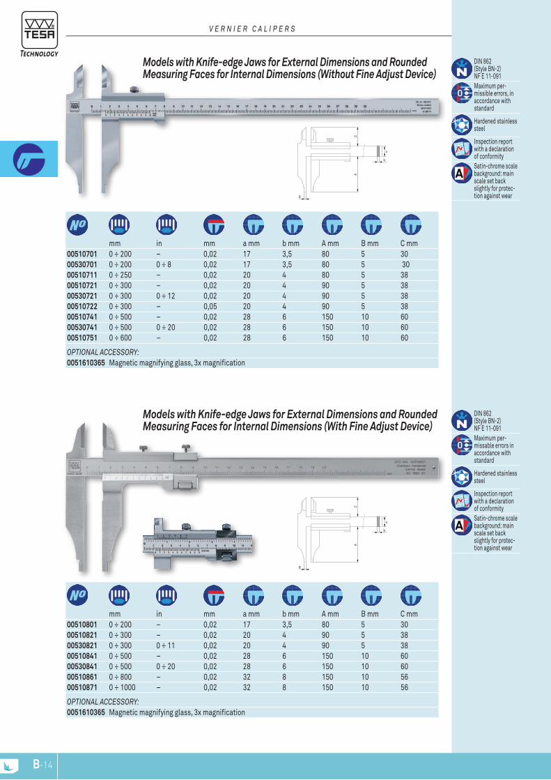
00510801 0 ÷ 200 – 0,02 17 3,5 80 5 3000510821 0 ÷ 300 – 0,02 20 4 90 5 3800530821 0 ÷ 300 0 ÷ 11 0,02 20 4 90 5 3800510841 0 ÷ 500 – 0,02 28 6 150 10 6000530841 0 ÷ 500 0 ÷ 20 0,02 28 6 150 10 6000510861 0 ÷ 800 – 0,02 32 8 150 10 5600510871 0 ÷ 1000 – 0,02 32 8 150 10 56
mm in mm a mm b mm A mm B mm C mm
DIN 862 (Style BN-2) NF E 11-091Maximum per-missable errors in accordance with standard
Hardened stainless steel
Inspection report with a declaration of conformitySatin-chrome scale background: main scale set back slightly for protec-tion against wear
Models with knife-edge Jaws for External Dimensions and rounded Measuring Faces for Internal Dimensions (With Fine Adjust Device)
OPTIONAL ACCESSORy:0051610365 Magnetic magnifying glass, 3x magnification
00510701 0 ÷ 200 – 0,02 17 3,5 80 5 3000530701 0 ÷ 200 0 ÷ 8 0,02 17 3,5 80 5 3000510711 0 ÷ 250 – 0,02 20 4 80 5 3800510721 0 ÷ 300 – 0,02 20 4 90 5 3800530721 0 ÷ 300 0 ÷ 12 0,02 20 4 90 5 3800510722 0 ÷ 300 – 0,05 20 4 90 5 3800510741 0 ÷ 500 – 0,02 28 6 150 10 6000530741 0 ÷ 500 0 ÷ 20 0,02 28 6 150 10 6000510751 0 ÷ 600 – 0,02 28 6 150 10 60
mm in mm a mm b mm A mm B mm C mm
DIN 862 (Style BN-2) NF E 11-091Maximum per-missible errors, in accordance with standard
Hardened stainless steel
Inspection report with a declaration of conformitySatin-chrome scale background: main scale set back slightly for protec-tion against wear
Models with knife-edge Jaws for External Dimensions and rounded Measuring Faces for Internal Dimensions (Without Fine Adjust Device)
V E R N I E R C A L I P E R S

10
15,5
15
8,5
4 15
27,5
5
15
A
4
B
27,5
5
15
B-15
00530441 200 8 100 800530442 250 10 100 800530443 300 12 150 800530444 500 20 150 8
mm in A mm B mm
ISO 13385-1
0,01 mm / 0.0005 in
LCD, 11 mm
Fixed zero
mm / in conversion
L ≤ 100 mm: 30 µm 100 < L ≤ 600 mm: 40 µm 600 < L ≤ 1000 mm: 50 µm
10 µm
Scale with incre-mental divisions, inductive
2,5 m/s
TLC Connectivity
Stainless steel
3V lithium battery, CR2032
12.000 hours
Standby mode after 10 minutes, instru-ment retains the zero position. Auto-matic shut off after 2 hours, instrument retains the zero in ABS mode, but the zero must be reset if the instrument is in DIFF mode.
1907/2006/CE 2004/108/CE 2002/96/CEInspection report with declaration of conformity
TWIN-CAL IP67 – Models with Short Cut Measuring Face
DIGITAL DEPTH CALIPErS The range of IP67 calipers gurantees the highest level of protection against the penetration of dust and liquids. The TLC (TESA Link Connector) system built into all the TWIN-CAL calipers provides the connection of these instruments to a PC for the easy acquistion of measurement data. The unique display housing, pro-tected by a steel plate surrounded with a rubber seal guarantees durability and offers fine sensitivity during measurement.
D E P T h C A L I P E R S
mm in A mm B mm
TWIN-CAL IP67 – Models with Two Fixed Measuring Jaws
00530447 300 12 150 8
00530445 300 12 150 800530446 500 20 150 8
TWIN-CAL IP67 – Models with One Fixed Measuring Jaw
mm in A mm B mm
2
15
1,1 4
2
15
15,7
48,2
A
BØ
2
50
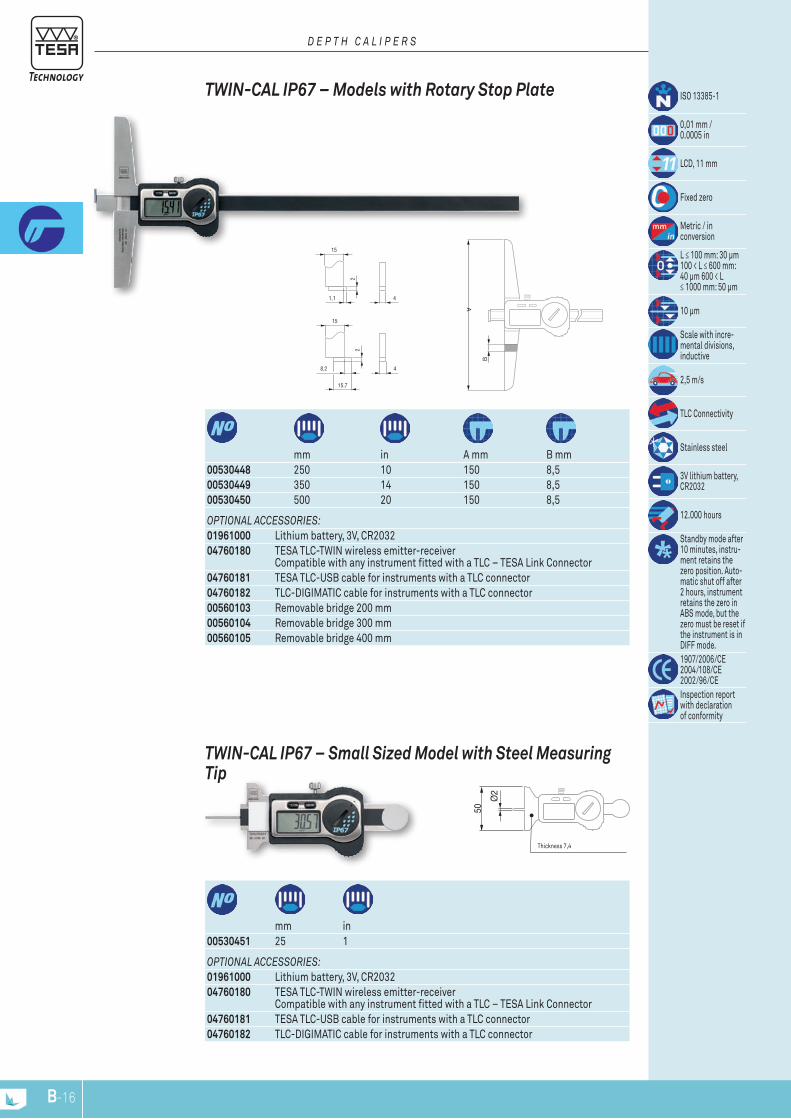
B-16
Thickness 7,4
OPTIONAL ACCESSORIES:01961000 Lithium battery, 3V, CR203204760180 TESA TLC-TWIN wireless emitter-receiver
Compatible with any instrument fitted with a TLC – TESA Link Connector04760181 TESA TLC-USB cable for instruments with a TLC connector04760182 TLC-DIGIMATIC cable for instruments with a TLC connector
00530451 25 1mm in
TWIN-CAL IP67 – Small Sized Model with Steel Measuring Tip
OPTIONAL ACCESSORIES:01961000 Lithium battery, 3V, CR203204760180 TESA TLC-TWIN wireless emitter-receiver
Compatible with any instrument fitted with a TLC – TESA Link Connector04760181 TESA TLC-USB cable for instruments with a TLC connector04760182 TLC-DIGIMATIC cable for instruments with a TLC connector00560103 Removable bridge 200 mm00560104 Removable bridge 300 mm00560105 Removable bridge 400 mm
00530448 250 10 150 8,500530449 350 14 150 8,500530450 500 20 150 8,5
mm in A mm B mm
ISO 13385-1
0,01 mm / 0.0005 in
LCD, 11 mm
Fixed zero
Metric / in conversion
L ≤ 100 mm: 30 µm 100 < L ≤ 600 mm: 40 µm 600 < L ≤ 1000 mm: 50 µm
10 µm
Scale with incre-mental divisions, inductive
2,5 m/s
TLC Connectivity
Stainless steel
3V lithium battery, CR2032
12.000 hours
Standby mode after 10 minutes, instru-ment retains the zero position. Auto-matic shut off after 2 hours, instrument retains the zero in ABS mode, but the zero must be reset if the instrument is in DIFF mode.1907/2006/CE 2004/108/CE 2002/96/CEInspection report with declaration of conformity
TWIN-CAL IP67 – Models with rotary Stop Plate
D E P T h C A L I P E R S
C
B
A
D
A
6
ø1,
5
E
D
B
C
B-17
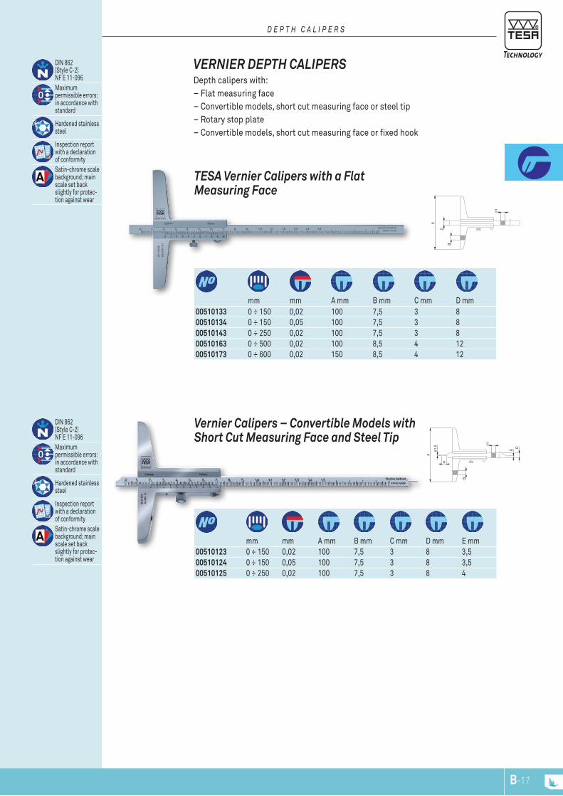
mm mm A mm B mm C mm D mm E mm
Vernier Calipers – Convertible Models with Short Cut Measuring Face and Steel Tip
00510123 0 ÷ 150 0,02 100 7,5 3 8 3,500510124 0 ÷ 150 0,05 100 7,5 3 8 3,500510125 0 ÷ 250 0,02 100 7,5 3 8 4
mm mm A mm B mm C mm D mm00510133 0 ÷ 150 0,02 100 7,5 3 8 00510134 0 ÷ 150 0,05 100 7,5 3 8 00510143 0 ÷ 250 0,02 100 7,5 3 8 00510163 0 ÷ 500 0,02 100 8,5 4 12 00510173 0 ÷ 600 0,02 150 8,5 4 12
DIN 862 (Style C-2) NF E 11-096Maximum permissible errors: in accordance with standard
Hardened stainless steel
Inspection report with a declaration of conformitySatin-chrome scale background; main scale set back slightly for protec-tion against wear
TESA Vernier Calipers with a Flat Measuring Face
VErNIEr DEPTH CALIPErS Depth calipers with:– Flat measuring face – Convertible models, short cut measuring face or steel tip– Rotary stop plate– Convertible models, short cut measuring face or fixed hook
D E P T h C A L I P E R S
DIN 862 (Style C-2) NF E 11-096Maximum permissible errors: in accordance with standard
Hardened stainless steel
Inspection report with a declaration of conformitySatin-chrome scale background; main scale set back slightly for protec-tion against wear
C
B
A
D
AB
C ± 0,005
A
E D
15.5
C
B
10
B-18
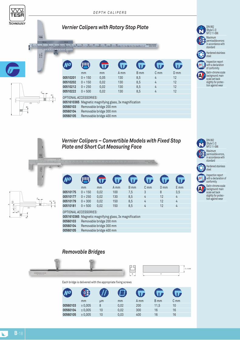
OPTIONAL ACCESSORIES:0051610365 Magnetic magnifying glass, 3x magnification00560103 Removable bridge 200 mm00560104 Removable bridge 300 mm00560105 Removable bridge 400 mm
00510175 0 ÷ 150 0,02 100 7,5 3 8 3,500510177 0 ÷ 250 0,02 130 8,5 4 12 400510179 0 ÷ 300 0,02 150 8,5 4 12 400510181 0 ÷ 500 0,02 150 8,5 4 12 4
mm mm A mm B mm C mm D mm E mm
DIN 862 (Style C-2) NF E 11-096Maximum permissible errors, in accordance with standard
Hardened stainless steel
Inspection report with a declaration of conformitySatin-chrome scale background: main scale set back slightly for protec-tion against wear
Vernier Calipers – Convertible Models with Fixed Stop Plate and Short Cut Measuring Face
00560103 ± 0,005 8 0,02 200 11,5 10 00560104 ± 0,005 10 0,02 300 16 16 00560105 ± 0,005 10 0,03 400 16 16
mm μm mm A mm B mm C mm
Each bridge is delivered with the appropriate fixing screws
removable Bridges
OPTIONAL ACCESSORIES:0051610365 Magnetic magnifying glass, 3x magnification00560103 Removable bridge 200 mm00560104 Removable bridge 300 mm00560105 Removable bridge 400 mm
mm mm A mm B mm C mm D mm00510201 0 ÷ 150 0,05 130 8,5 4 12 00510202 0 ÷ 150 0,02 130 8,5 4 12 00510212 0 ÷ 250 0,02 130 8,5 4 12 00510222 0 ÷ 500 0,02 130 8,5 4 12
DIN 862 (Style C-2) NF E 11-096Maximum permissible errors: in accordance with standard
Hardened stainless steel
Inspection report with a declaration of conformitySatin-chrome scale background; main scale set back slightly for protec-tion against wear
Vernier Calipers with rotary Stop Plate
D E P T h C A L I P E R S
6,8
4,318,1
14
30
B
A
3068,5
40 14
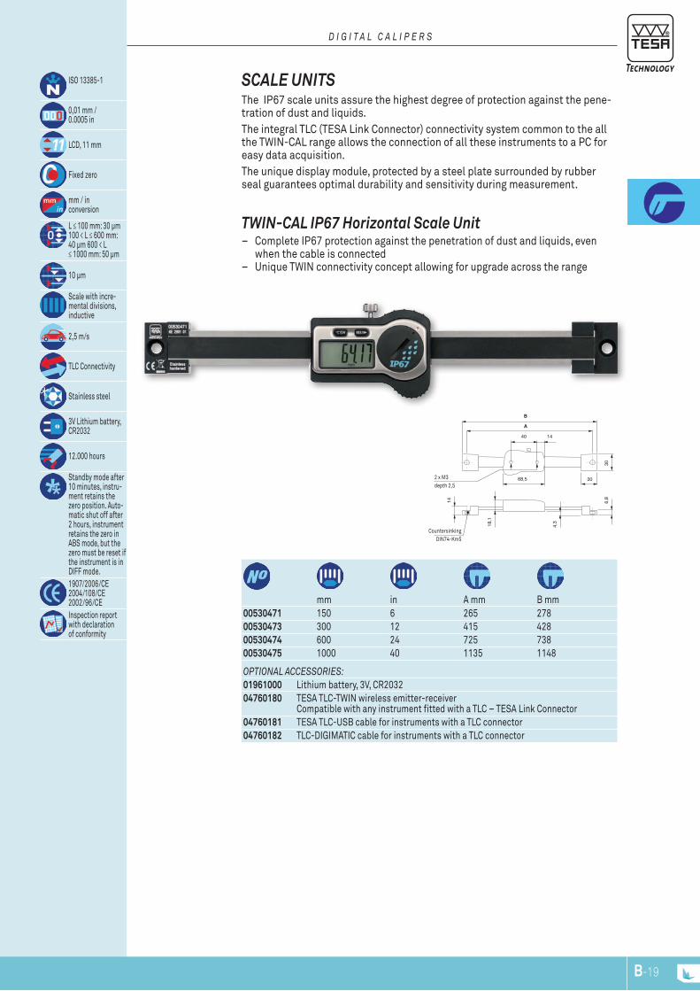
B-19
Countersinking DIN74-Km5
2 x M3 depth 2,5
00530471 150 6 265 27800530473 300 12 415 42800530474 600 24 725 73800530475 1000 40 1135 1148
mm in A mm B mm
ISO 13385-1
0,01 mm / 0.0005 in
LCD, 11 mm
Fixed zero
mm / inconversion
L ≤ 100 mm: 30 µm 100 < L ≤ 600 mm: 40 µm 600 < L ≤ 1000 mm: 50 µm
10 µm
Scale with incre-mental divisions, inductive
2,5 m/s
TLC Connectivity
Stainless steel
3V Lithium battery, CR2032
12.000 hours
Standby mode after 10 minutes, instru-ment retains the zero position. Auto-matic shut off after 2 hours, instrument retains the zero in ABS mode, but the zero must be reset if the instrument is in DIFF mode.1907/2006/CE 2004/108/CE 2002/96/CEInspection report with declaration of conformity
OPTIONAL ACCESSORIES:01961000 Lithium battery, 3V, CR203204760180 TESA TLC-TWIN wireless emitter-receiver
Compatible with any instrument fitted with a TLC – TESA Link Connector04760181 TESA TLC-USB cable for instruments with a TLC connector04760182 TLC-DIGIMATIC cable for instruments with a TLC connector
TWIN-CAL IP67 Horizontal Scale Unit – Complete IP67 protection against the penetration of dust and liquids, even
when the cable is connected – Unique TWIN connectivity concept allowing for upgrade across the range
SCALE UNITS The IP67 scale units assure the highest degree of protection against the pene-tration of dust and liquids. The integral TLC (TESA Link Connector) connectivity system common to the all the TWIN-CAL range allows the connection of all these instruments to a PC for easy data acquisition. The unique display module, protected by a steel plate surrounded by rubber seal guarantees optimal durability and sensitivity during measurement.
D I G I T A L C A L I P E R S
A
B
C
230
150
18
10
20,6
32
SWISS MADE
B-20
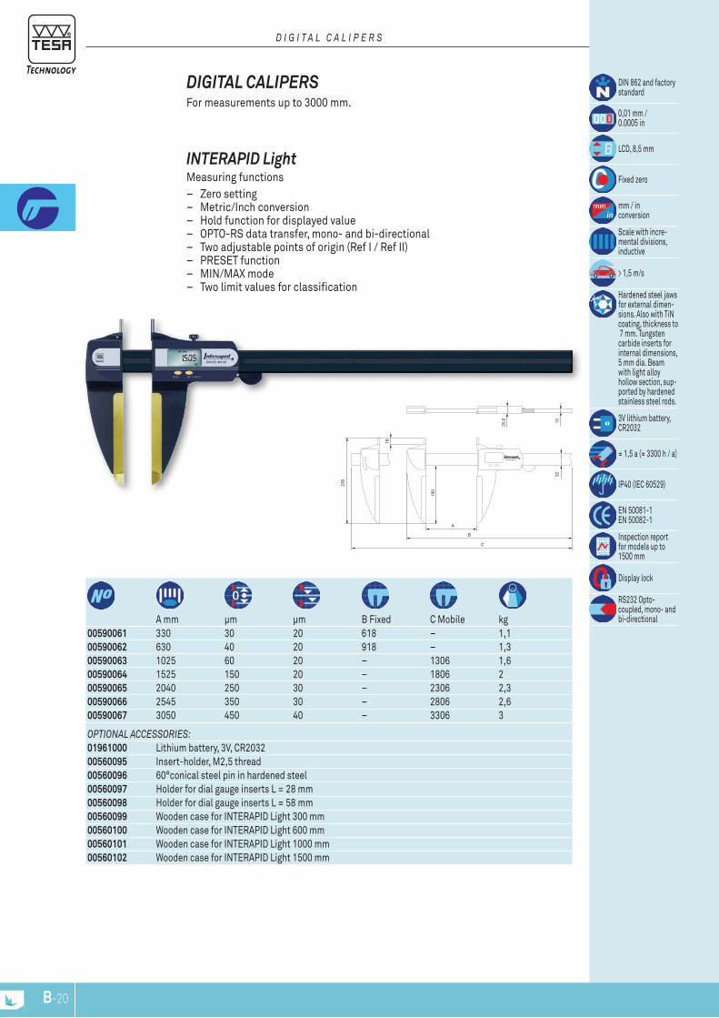
OPTIONAL ACCESSORIES:01961000 Lithium battery, 3V, CR203200560095 Insert-holder, M2,5 thread00560096 60°conical steel pin in hardened steel00560097 Holder for dial gauge inserts L = 28 mm00560098 Holder for dial gauge inserts L = 58 mm00560099 Wooden case for INTERAPID Light 300 mm00560100 Wooden case for INTERAPID Light 600 mm00560101 Wooden case for INTERAPID Light 1000 mm00560102 Wooden case for INTERAPID Light 1500 mm
00590061 330 30 20 618 – 1,100590062 630 40 20 918 – 1,300590063 1025 60 20 – 1306 1,600590064 1525 150 20 – 1806 200590065 2040 250 30 – 2306 2,300590066 2545 350 30 – 2806 2,600590067 3050 450 40 – 3306 3
A mm μm μm B Fixed C Mobile kg
DIN 862 and factory standard
0,01 mm / 0.0005 in
LCD, 8,5 mm
Fixed zero
mm / inconversion
Scale with incre-mental divisions, inductive
> 1,5 m/s
Hardened steel jaws for external dimen-sions. Also with TiN coating, thickness to 7 mm. Tungsten carbide inserts for internal dimensions, 5 mm dia. Beam with light alloy hollow section, sup-ported by hardened stainless steel rods.
3V lithium battery, CR2032
≈ 1,5 a (≈ 3300 h / a)
IP40 (IEC 60529)
EN 50081-1EN 50082-1
Inspection report for models up to 1500 mm
Display lock
RS232 Opto- coupled, mono- and bi-directional
INTErAPID Light Measuring functions
– Zero setting – Metric/Inch conversion – Hold function for displayed value – OPTO-RS data transfer, mono- and bi-directional – Two adjustable points of origin (Ref I / Ref II) – PRESET function – MIN/MAX mode – Two limit values for classification
DIGITAL CALIPErS For measurements up to 3000 mm.
D I G I T A L C A L I P E R S
H 2,5
14
58
28
SWISS MADE
A
DCB
B-21
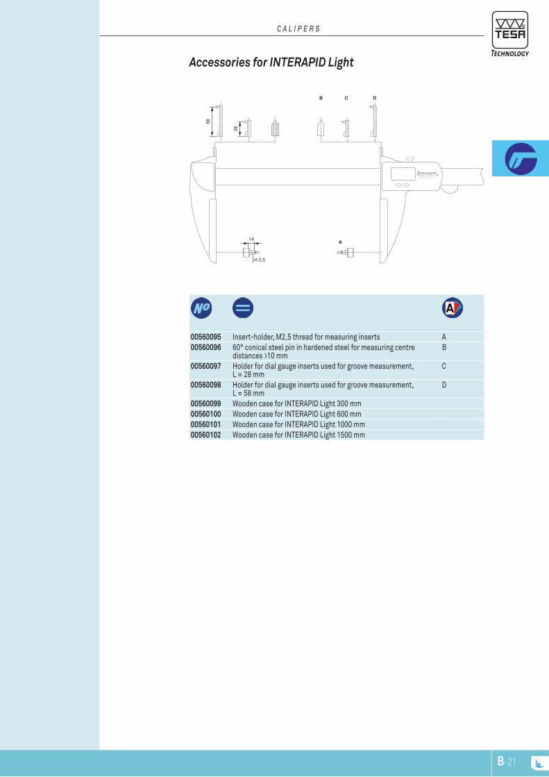
00560095 Insert-holder, M2,5 thread for measuring inserts A00560096 60° conical steel pin in hardened steel for measuring centre
distances >10 mmB
00560097 Holder for dial gauge inserts used for groove measurement, L = 28 mm
C
00560098 Holder for dial gauge inserts used for groove measurement, L = 58 mm
D
00560099 Wooden case for INTERAPID Light 300 mm00560100 Wooden case for INTERAPID Light 600 mm00560101 Wooden case for INTERAPID Light 1000 mm00560102 Wooden case for INTERAPID Light 1500 mm
Accessories for INTErAPID Light
C A L I P E R S
b
a
A
B
C
151
75
55
43
3
357
75
R12
3
B-22
OPTIONAL ACCESSORy:0051610365 Magnetic magnifying glass, 3x magnification
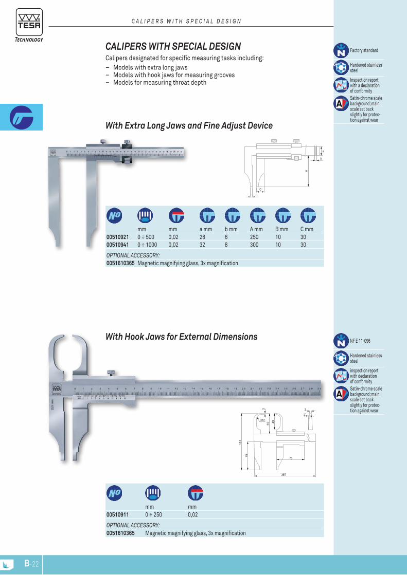
00510911 0 ÷ 250 0,02mm mm
NF E 11-096
Hardened stainless steel
inspection report with declaration of conformitySatin-chrome scale background; main scale set back slightly for protec-tion against wear
With Hook Jaws for External Dimensions
OPTIONAL ACCESSORy:0051610365 Magnetic magnifying glass, 3x magnification
00510921 0 ÷ 500 0,02 28 6 250 10 3000510941 0 ÷ 1000 0,02 32 8 300 10 30
mm mm a mm b mm A mm B mm C mm
Factory standard
Hardened stainless steel
Inspection report with a declaration of conformitySatin-chrome scale background; main scale set back slightly for protec-tion against wear
With Extra Long Jaws and Fine Adjust Device
CALIPErS WITH SPECIAL DESIGN Calipers designated for specific measuring tasks including:
– Models with extra long jaws – Models with hook jaws for measuring grooves – Models for measuring throat depth
C A L I P E R S W I T h S P E C I A L D E S I G N
151
75
355
75
20
49.5
5
22
204
e x f
A
c x d
a x b
CA
B
a
b
B-23
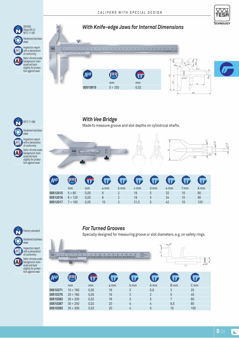
00510371 10 ÷ 160 0,05 16 3 0,9 3 2500510375 20 ÷ 160 0,05 16 3 2 5 4000510383 26 ÷ 200 0,02 16 3 3 7 6000510387 30 ÷ 250 0,02 20 4 4 8,5 8000510393 35 ÷ 300 0,02 20 4 5 10 100
mm mm a mm b mm A mm B mm C mm
Factory standard
Hardened stainless steel
Inspection report with a declaration of conformitySatin-chrome scale background: main scale set back slightly for protec-tion against wear
For Turned Grooves Specially designed for measuring groove or slot diameters, e.g. on safety rings.
00512015 5 ÷ 80 0,05 8 2 18 5 32 10 6000512016 6 ÷ 120 0,05 8 2 18 5 34 10 9000512017 7 ÷ 160 0,05 10 2 21,5 5 42 10 120
mm mm a mm b mm c mm d mm e mm f mm A mm
NF E 11-096
Hardened stainless steel
Inspection report with a declaration of conformitySatin-chrome scale background; main scale set back slightly for protec-tion against wear
With Vee Bridge Made to measure groove and slot depths on cylindrical shafts.
00510915 0 ÷ 250 0,02mm mm
DIN 862 (Style DN-2) NF E 11-091
Hardened stainless steel
Inspection report with a declaration of conformitySatin-chrome scale background: main scale set back slightly for protec-tion against wear
With knife-edge Jaws for Internal Dimensions
C A L I P E R S W I T h S P E C I A L D E S I G N

B-24

www.tesatechnology.com C-1
Exte
rnal
Mic
rom
eter
s
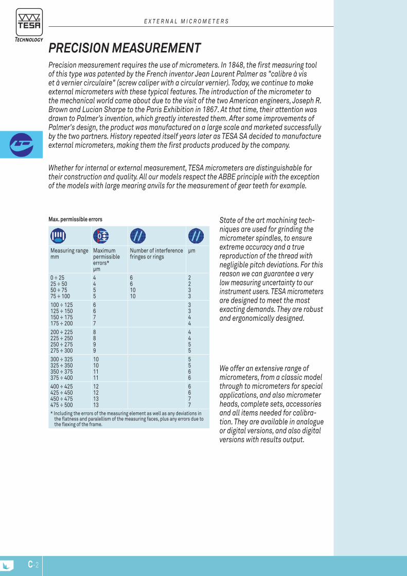
C-2
Max. permissible errors
Measuring range mm
Maximum permissible errors* µm
Number of interference fringes or rings
µm
0 ÷ 25 25 ÷ 50 50 ÷ 75 75 ÷ 100
4 4 5 5
6 6 10 10
2 2 3 3
100 ÷ 125 125 ÷ 150 150 ÷ 175 175 ÷ 200
6 6 7 7
3 3 4 4
200 ÷ 225 225 ÷ 250 250 ÷ 275 275 ÷ 300
8 8 9 9
4 4 5 5
300 ÷ 325 325 ÷ 350 350 ÷ 375 375 ÷ 400
10 10 11 11
5 5 6 6
400 ÷ 425 425 ÷ 450 450 ÷ 475 475 ÷ 500
12 12 13 13
6 6 7 7
* Including the errors of the measuring element as well as any deviations in the flatness and paralellism of the measuring faces, plus any errors due to the flexing of the frame.
We offer an extensive range of micrometers, from a classic model through to micrometers for special applications, and also micrometer heads, complete sets, accessories and all items needed for calibra-tion. They are available in analogue or digital versions, and also digital versions with results output.
State of the art machining tech-niques are used for grinding the micrometer spindles, to ensure extreme accuracy and a true reproduction of the thread with negligible pitch deviations. For this reason we can guarantee a very low measuring uncertainty to our instrument users. TESA micrometers are designed to meet the most exacting demands. They are robust and ergonomically designed.
Whether for internal or external measurement, TESA micrometers are distinguishable for their construction and quality. All our models respect the ABBE principle with the exception of the models with large mearing anvils for the measurement of gear teeth for example.
Precision measurement requires the use of micrometers. In 1848, the first measuring tool of this type was patented by the French inventor Jean Laurent Palmer as "calibre à vis et à vernier circulaire" (screw caliper with a circular vernier). Today, we continue to make external micrometers with these typical features. The introduction of the micrometer to the mechanical world came about due to the visit of the two American engineers, Joseph R. Brown and Lucian Sharpe to the Paris Exhibition in 1867. At that time, their attention was drawn to Palmer’s invention, which greatly interested them. After some improvements of Palmer's design, the product was manufactured on a large scale and marketed successfully by the two partners. History repeated itself years later as TESA SA decided to manufacture external micrometers, making them the first products produced by the company.
PrEcision MEasurEMEnt
E x T E R n A L M I c R o M E T E R S

C-3
conSISTIng oF:06030030 MICROMASTER RS IP54 digital micrometer, 0 ÷ 30 mm, 0,001 mm resolution, IP54 rating and RS232 output.06030031 MICROMASTER RS IP54 digital micrometer, 25 ÷ 50 mm, 0,001 mm resolution, IP54 rating and RS232 output.06030032 MICROMASTER RS IP54 digital micrometer, 50 ÷ 75 mm, 0,001 mm resolution, IP54 rating and RS232 output.02119021 Etalon setting standard, 50 mm
06030029 Set of 3 MICROMASTER IP54 with RS232 output
0 ÷ 75
MicroMastEr iP54 sEt Set consisting of 3 Micromaster external micrometers covering 0 ÷ 75 mm measuring range.
oPTIonAL AccESSoRIES:01961000 Lithium battery, 3V, CR203200160201 TESA micrometer stand with clamp aperture 16 mm072110123 ETALON micrometer stand with clamp aperture 20 mm04761062 Opto-USB cable, duplex, bidirectional communication
06030010 0 ÷ 30 0 ÷ 30 0 ÷ 1.2 0 ÷ 1.2 IP40 –06030020 0 ÷ 30 0 ÷ 30 0 ÷ 1.2 0 ÷ 1.2 IP54 –06030021 25 ÷ 50 23 ÷ 53 1 ÷ 2 0.9 ÷ 2.1 IP54 –06030022 50 ÷ 75 48 ÷ 78 2 ÷ 3 1.9 ÷ 3.1 IP54 –06030023 75 ÷ 100 74 ÷ 104 3 ÷ 4 2.9 ÷ 4.1 IP54 –06030030 0 ÷ 30 0 ÷ 30 0 ÷ 1.2 0 ÷ 1.2 IP54 RS23206030031 25 ÷ 50 23 ÷ 53 1 ÷ 2 0.9 ÷ 2.1 IP54 RS23206030032 50 ÷ 75 48 ÷ 78 2 ÷ 3 1.9 ÷ 3.1 IP54 RS23206030033 75 ÷ 100 74 ÷ 104 3 ÷ 4 2.9 ÷ 4.1 IP54 RS23206030071 100 ÷ 125 98 ÷ 127 4 ÷ 5 3.9 ÷ 5.01 IP54 RS23206030072 125 ÷ 150 123 ÷ 152 5 ÷ 6 4.9 ÷ 6.01 IP54 RS23206030073 150 ÷ 175 149 ÷ 178 6 ÷ 7 5.9 ÷ 7.01 IP54 RS23206030074 175 ÷ 200 174 ÷ 203 7 ÷ 8 6.9 ÷ 8.01 IP54 RS23206030075 200 ÷ 225 199 ÷ 229 8 ÷ 9 7.9 ÷ 9.01 IP54 RS23206030076 225 ÷ 250 224 ÷ 254 9 ÷ 10 8.9 ÷ 10.01 IP54 RS23206030077 250 ÷ 275 250 ÷ 279 10 ÷ 11 9.9 ÷ 11.01 IP54 RS23206030078 275 ÷ 300 275 ÷ 304 11 ÷ 12 10.9 ÷ 12.01 IP54 RS232
mm mm in in
DIN 863 T1
0,001 mm /0.00005 in
LCD, digit height: 7 mm
Floating zero
Conversionmm/in
Tungsten carbide tipped
3V lithium battery
1 to 2 a (≈ 2000 h/a)
Automatic shut-down after 10 min. Display setting is maintained as long as power supply remains stable.Protection as per IEC 60529): IP40 (also valid with usedRS data output) or IP54 Measuring range 0 to 100: with SCS calibration certificateMeasuring range > 100 mm : with inspection report and declaration of conformity
Display lock (except for model EASY)
RS232 interface, opto-coupled
0,5 mm
Max. 10 N
≤ 100 mm: Ø 6,5 mm> 100 mm: Ø 8 mm
tEsa MicroMastEr Electronic Micrometers with Digital Display With patented TESA CAPA μ SYSTEM.
– Measuring span of 30 mm. – Large easy-to-read digital display. – Models:
• EASY IP40 with a single function key. • IP54 with water spray protection as well as IP54 RS
with an RS232 interface.
D I g I T A L M I c R o M E T E R S
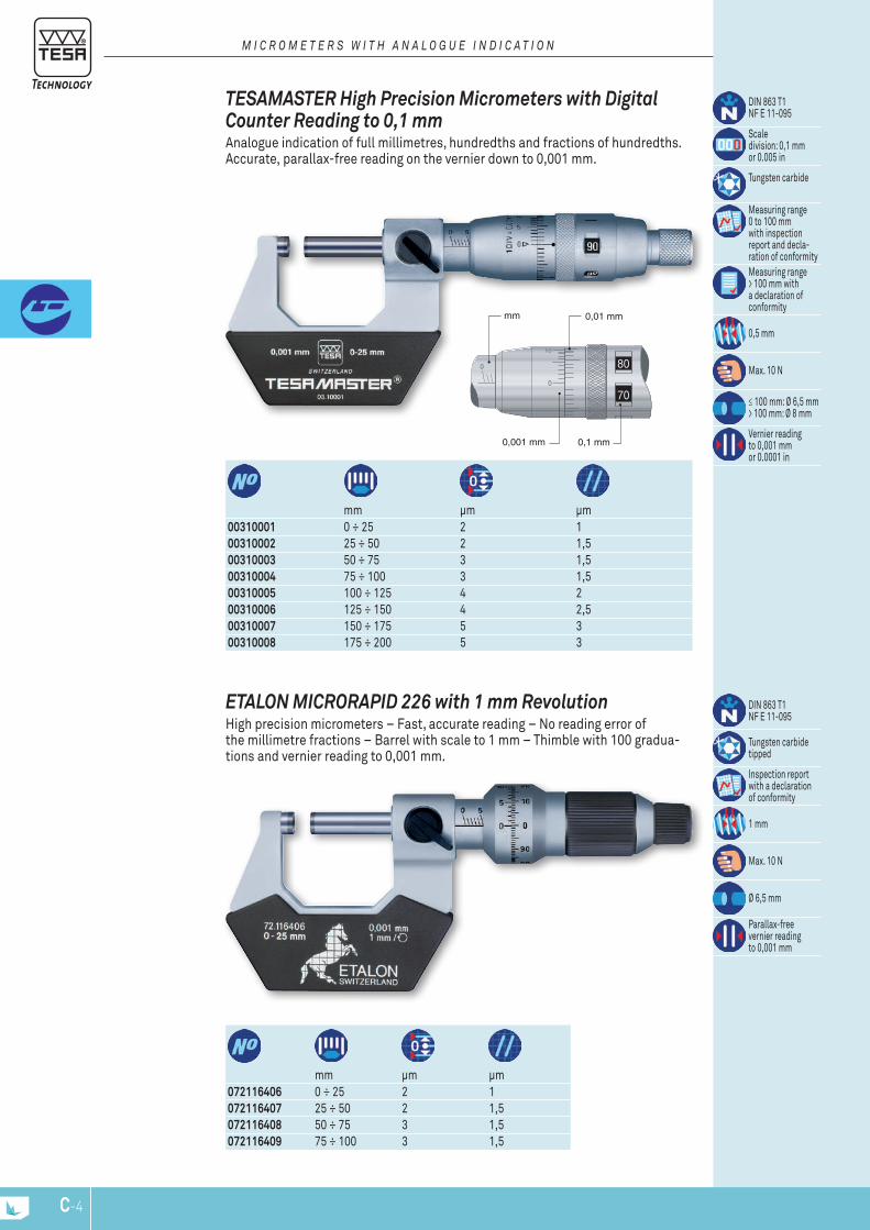
80
70
0
0
10
mm 0,01 mm
0,1 mm0,001 mm
C-4
072116406 0 ÷ 25 2 1072116407 25 ÷ 50 2 1,5 072116408 50 ÷ 75 3 1,5 072116409 75 ÷ 100 3 1,5
mm μm μm
DIN 863 T1NF E 11-095
Tungsten carbidetipped
Inspection reportwith a declarationof conformity
1 mm
Max. 10 N
Ø 6,5 mm
Parallax-freevernier readingto 0,001 mm
EtaLon MicroraPiD 226 with 1 mm revolution High precision micrometers – Fast, accurate reading – No reading error of the millimetre fractions – Barrel with scale to 1 mm – Thimble with 100 gradua-tions and vernier reading to 0,001 mm.
00310001 0 ÷ 25 2 100310002 25 ÷ 50 2 1,5 00310003 50 ÷ 75 3 1,5 00310004 75 ÷ 100 3 1,5 00310005 100 ÷ 125 4 200310006 125 ÷ 150 4 2,500310007 150 ÷ 175 5 300310008 175 ÷ 200 5 3
mm μm μm
DIN 863 T1NF E 11-095
Scaledivision: 0,1 mmor 0.005 in
Tungsten carbide
Measuring range 0 to 100 mmwith inspection report and decla- ration of conformityMeasuring range > 100 mm with a declaration of conformity
0,5 mm
Max. 10 N
≤ 100 mm: Ø 6,5 mm> 100 mm: Ø 8 mm
Vernier readingto 0,001 mm or 0.0001 in
tEsaMastEr High Precision Micrometers with Digital counter reading to 0,1 mm Analogue indication of full millimetres, hundredths and fractions of hundredths. Accurate, parallax-free reading on the vernier down to 0,001 mm.
M I c R o M E T E R S W I T H A n A L o g u E I n D I c A T I o n
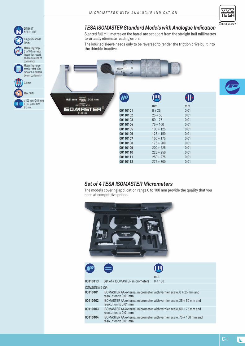
C-5
conSISTIng oF:00110101 ISOMASTER AA external micrometer with vernier scale, 0 ÷ 25 mm and
resolution to 0,01 mm00110102 ISOMASTER AA external micrometer with vernier scale, 25 ÷ 50 mm and
resolution to 0,01 mm00110103 ISOMASTER AA external micrometer with vernier scale, 50 ÷ 75 mm and
resolution to 0,01 mm00110104 ISOMASTER AA external micrometer with vernier scale, 75 ÷ 100 mm and
resolution to 0,01 mm
00110113 Set of 4 ISOMASTER micrometers 0 ÷ 100 mm
set of 4 tEsa isoMastEr Micrometers The models covering application range 0 to 100 mm provide the quality that you need at competitive prices.
00110101 0 ÷ 25 0,0100110102 25 ÷ 50 0,0100110103 50 ÷ 75 0,0100110104 75 ÷ 100 0,0100110105 100 ÷ 125 0,0100110106 125 ÷ 150 0,0100110107 150 ÷ 175 0,0100110108 175 ÷ 200 0,0100110109 200 ÷ 225 0,0100110110 225 ÷ 250 0,0100110111 250 ÷ 275 0,0100110112 275 ÷ 300 0,01
mm mm
DIN 863 T1NF E 11-095
Tungsten carbide tipped
Measuring range 0 to 100 mm with inspection report and declaration of conformityMeasuring range smaller than 100 mm with a declara-tion of conformity
0.5 mm
Max. 10 N
≤ 100 mm: Ø 6,5 mm> 100 ≤ 300 mm: Ø 8 mm
tEsa isoMastEr standard Models with analogue indication Slanted full millimetres on the barrel are set apart from the straight half millimetres to virtually eliminate reading errors.The knurled sleeve needs only to be reversed to render the friction drive built into the thimble inactive.
M I c R o M E T E R S W I T H A n A L o g u E I n D I c A T I o n
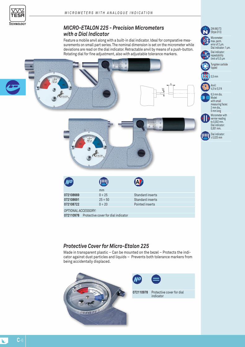
ø2
5
C-6
072110978 Protective cover for dial indicator
Protective cover for Micro-Etalon 225 Made in transparent plastic – Can be mounted on the bezel – Protects the indi-cator against dust particles and liquids – Prevents both tolerance markers from being accidentally displaced.
oPTIonAL AccESSoRy:072110978 Protective cover for dial indicator
072108669 0 ÷ 25 Standard inserts072108691 25 ÷ 50 Standard inserts072108722 0 ÷ 20 Pointed inserts
mm
DIN 863 T3(Style D13)
Micrometer:max. perm.error of 2 μm.Dial indicator: 1 μm.Dial indicator: repeatabilitylimit of 0.5 μm
Tungsten carbidetipped
0,5 mm
Anvil:4,5 to 5,5 N
6,5 mm dia.Modelwith smallmeasuring faces:2 mm dia., 5 mm longMicrometer withvernier readingto 0,002 mm.Dial indicator: 0,001 mm.
Dial indicator:± 0,025 mm
Micro-EtaLon 225 - Precision Micrometers with a Dial indicator Feature a mobile anvil along with a built-in dial indicator. Ideal for comparative mea-surements on small part series. The nominal dimension is set on the micrometer while deviations are read on the dial indicator. Retractable anvil by means of a push-button. Rotating dial for fine adjustment, also with adjustable tolerance markers.
M I c R o M E T E R S W I T H A n A L o g u E I n D I c A T I o n
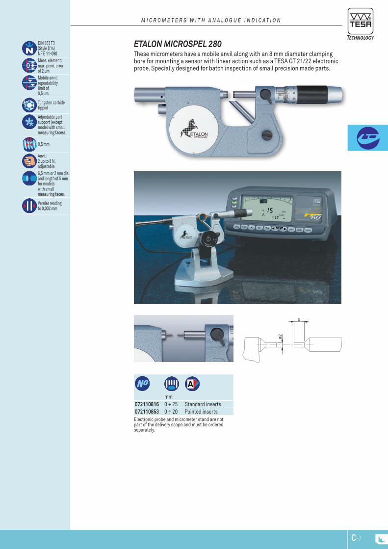
5
ø2
C-7
072110816 0 ÷ 25 Standard inserts072110853 0 ÷ 20 Pointed inserts
mm
DIN 863 T3(Style D14)NF E 11-090Meas. element:max. perm. errorof 2 μmMobile anvil:repeatabilitylimit of0,5 μm.
Tungsten carbidetipped
Adjustable partsupport (exceptmodel with smallmeasuring faces).
0,5 mm
Anvil:2 up to 8 N,adjustable6,5 mm or 2 mm dia.and length of 5 mmfor modelswith smallmeasuring faces.
Vernier readingto 0,002 mm
Electronic probe and micrometer stand are not part of the delivery scope and must be ordered separately.
EtaLon MicrosPEL 280 These micrometers have a mobile anvil along with an 8 mm diameter clamping bore for mounting a sensor with linear action such as a TESA GT 21/22 electronic probe. Specially designed for batch inspection of small precision made parts.
M I c R o M E T E R S W I T H A n A L o g u E I n D I c A T I o n

5
ø2
5
ø2
C-8
00311301 0 ÷ 25mm
DIN 863 T3(Style D3)NF E 11-090
Scale division0,1 mm
Fixed measuring faces: tungsten carbideInspection report with a declaration of conformity
Max. 10 N
Vernier readingto 0,001 mm
tEsaMastEr aD Micrometer with small Measuring Faces
oPTIonAL AccESSoRy:01961000 Lithium battery 3V, CR2032
06030034 0 ÷ 30 0 ÷ 1.2 mm in
DIN 863 T3(Style D3)
0,001 mm /0.00005 in
Conversionmm/in
Fixed measuring faces: tungsten carbide.Degree of protection (IEC 60529):IP54 or IP40 with use of the digital outputMeasuring range 0 to 100: with a SCS calibration certificate.
RS232 interface, opto-coupled.
For additional technical data: see standard.
Max. 10 N
MicroMastEr Micrometer with small Measuring Faces For measuring grooves, feather grooves, splines and other difficult to reach locations – Small measuring faces specially made to check small precision workpieces.
D I g I T A L M I c R o M E T E R S

5
ø2
C-9
00210101 0 ÷ 25mm
DIN 863 T3 (Style D3)NF E 11-090Fixed measuring faces:tungsten carbideInspection report with a declaration of conformity
Max. 10 N
0,01 mm
isoMastEr aD Micrometer with small Measuring Faces
M I c R o M E T E R S W I T H A n A L o g u E I n D I c A T I o n
072103522 5 mm
Steel ball tip,hardened and lapped.Dull-chrome brass retainer
spherical Element for External Micrometers Holder with a ball tip to fit measuring faces Ø 6,5 mm– Used to measure tubing wall thickness or components with concave surfaces etc.

C-10
06030079 0 ÷ 30 0 ÷ 1.2 mm in
DIN 863 T3(Style D1)
0,001 mm or0.00005 in
Anvil in tungsten carbide. Micrometric spindle in tungsten carbideInspection report with a declaration of conformity
RS232
Other technicaldata see standard.
Max. 10 N
Anvil with a 3,5 mm spherical face (MI-CROMASTER) or 3,25 mm (ETALON). Spindle with a flat measuring face.
MicroMastEr Micrometer with one spherical Measuring Face For the measurement of wall thickness of tubing and other similar tasks.
06030081 0 ÷ 25 0 ÷ 1 mm in
DIN 863 T3(Style D1)
0,001 mm /0.00005 in
Tungsten carbide
Inspection report with a declaration of conformity
RS232
Additional technical data: see standard.
Max. 10 N
Spherical: 3,5 mm radius.
MicroMastEr Micrometer with two spherical Measuring Faces Rounded measuring faces on both anvil and spindle for measuring concave surfaces on components, e.g. ball-bearing guides or wall thickness.
D I g I T A L M I c R o M E T E R S
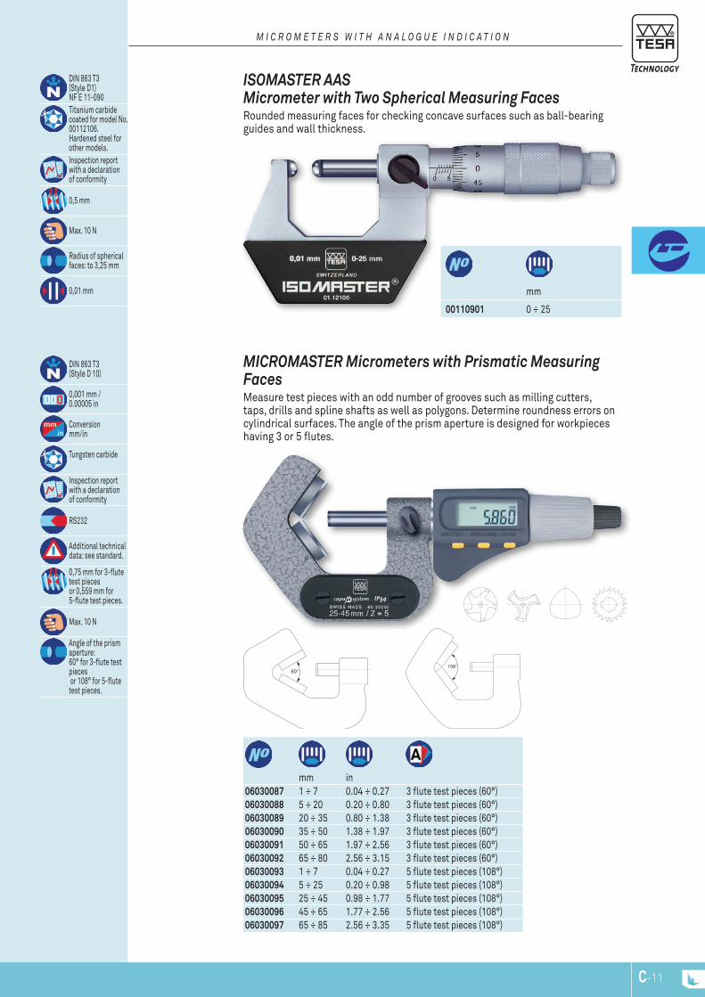
C-11
M I c R o M E T E R S W I T H A n A L o g u E I n D I c A T I o n
mm
00110901 0 ÷ 25
DIN 863 T3 (Style D1) NF E 11-090Titanium carbide coated for model No. 00112106. Hardened steel for other models.Inspection report with a declaration of conformity
0,5 mm
Max. 10 N
Radius of spherical faces: to 3,25 mm
0,01 mm
isoMastEr aas Micrometer with two spherical Measuring Faces Rounded measuring faces for checking concave surfaces such as ball-bearing guides and wall thickness.
06030087 1 ÷ 7 0.04 ÷ 0.27 3 flute test pieces (60°)06030088 5 ÷ 20 0.20 ÷ 0.80 3 flute test pieces (60°)06030089 20 ÷ 35 0.80 ÷ 1.38 3 flute test pieces (60°)06030090 35 ÷ 50 1.38 ÷ 1.97 3 flute test pieces (60°)06030091 50 ÷ 65 1.97 ÷ 2.56 3 flute test pieces (60°)06030092 65 ÷ 80 2.56 ÷ 3.15 3 flute test pieces (60°)06030093 1 ÷ 7 0.04 ÷ 0.27 5 flute test pieces (108°)06030094 5 ÷ 25 0.20 ÷ 0.98 5 flute test pieces (108°)06030095 25 ÷ 45 0.98 ÷ 1.77 5 flute test pieces (108°)06030096 45 ÷ 65 1.77 ÷ 2.56 5 flute test pieces (108°)06030097 65 ÷ 85 2.56 ÷ 3.35 5 flute test pieces (108°)
mm in
DIN 863 T3(Style D 10)
0,001 mm /0.00005 in
Conversionmm/in
Tungsten carbide
Inspection report with a declaration of conformity
RS232
Additional technical data: see standard.
0,75 mm for 3-flute test piecesor 0,559 mm for 5-flute test pieces.
Max. 10 N
Angle of the prism aperture:60° for 3-flute test pieces or 108° for 5-flute test pieces.
MicroMastEr Micrometers with Prismatic Measuring Faces Measure test pieces with an odd number of grooves such as milling cutters, taps, drills and spline shafts as well as polygons. Determine roundness errors on cylindrical surfaces. The angle of the prism aperture is designed for workpieces having 3 or 5 flutes.

C-12
mm
00410001 1 ÷ 7 3 flute test pieces (60°)
00410002 5 ÷ 20 3 flute test pieces (60°)
00410003 20 ÷ 35 3 flute test pieces (60°)
00410004 35 ÷ 50 3 flute test pieces (60°)
00410005 50 ÷ 65 3 flute test pieces (60°)
00410102 5 ÷ 25 5 flute test pieces (108°)
DIN 863 T3 (Style D 10) NF E 11-090
Tungsten carbide tipped
0,75 mm for 3-flute test pieces or 0,559 mm for 5-flute test pieces
Max. 10 N
Angle of the prism aperture: 60° for 3-flute test pieces or 108° for 5-flute test pieces.
0,01 mm
isoMastEr as Micrometers with Prismatic Measuring Faces The micrometer ISOMASTER AS is used for measuring test pieces with an odd number of grooves such as milling cutters, taps, drills and spline shafts as well as poliygons. It can also determine roundness errors on cylindrical workpieces.The aperture angle of the prism is designed for workpiees having 3 or 5 flutes or their multiples.
M I c R o M E T E R S W I T H A n A L o g u E I n D I c A T I o n
00440001 0,5 – 5 00440002 0,7 1 20 00440003 0,7 1 25 00440004 1 1 35 00440005 1,2 1,5 45 00440006 1,2 1,5 50 00440007 1,5 1,5 65
μm μm
Alloyed steel, hardend
With a protective cap from the nomi-nal size of 20 mm. Effective diameter engraved on the front face.
cylindrical setting standards for Micrometers

WK
WK
C-13
06030041 0 ÷ 30 0 ÷ 1.2 06030042 25 ÷ 55 1 ÷ 2.106030043 55 ÷ 85 2.1 ÷ 3.3506030044 85 ÷ 115 3.35 ÷ 4.5
mm in
DIN 863 T3(Style D7)
0,001 mm /0.00005 in
Conversionmm/in
Hardened steel
Suitable from module 0,5 onwards
Inspection report with a declaration of conformity
RS232
Additional technical data: see standard.
Max. 10 N
Non-rotating spindle ≤ 85 mm: 25 mm dia.> 85 ≤ 115 mm: 30 mm dia.
MicroMastEr Micrometers for Gear Pitch Measurement Flanges with ring-shaped measuring faces for root tangent lengths, Wk on gear pitches, distance between grooves and slots as well as other hard-to-reach locations. Non-rotating measuring spindle, without spindle lock.
D I g I T A L M I c R o M E T E R S
00210201 0 ÷ 2500210202 25 ÷ 50 00210203 50 ÷ 7500210204 75 ÷ 100
Maximum permissible error disregarding a rim of 1 mm during inspection of the measuring faces and having partial contact with the measuring face.
Maximum permissible error with full contact of the measuring face (DIN863-T1)
Flatness Parallelism Maximum flexure of the frame
mm µm µm µm µm µm0 ÷ 30 10 4 2 5 225 ÷ 55 10 4 2 5 255 ÷ 85 11 5 2 5 385 ÷ 115 12 5 2 6 4
mm
DIN 863 T3(Style D7)NF E 11-090
Hardenedsteel
Suitable frommodule 0,6
Inspection reportwith a declarationof conformity
Max. 10 N
≤ 100 mm:25 mm dia.> 100 ≤ 150 mm:32 mm dia
0,01 mm
isoMastEr aE Micrometers for Gear tooth / Pitch Measurement
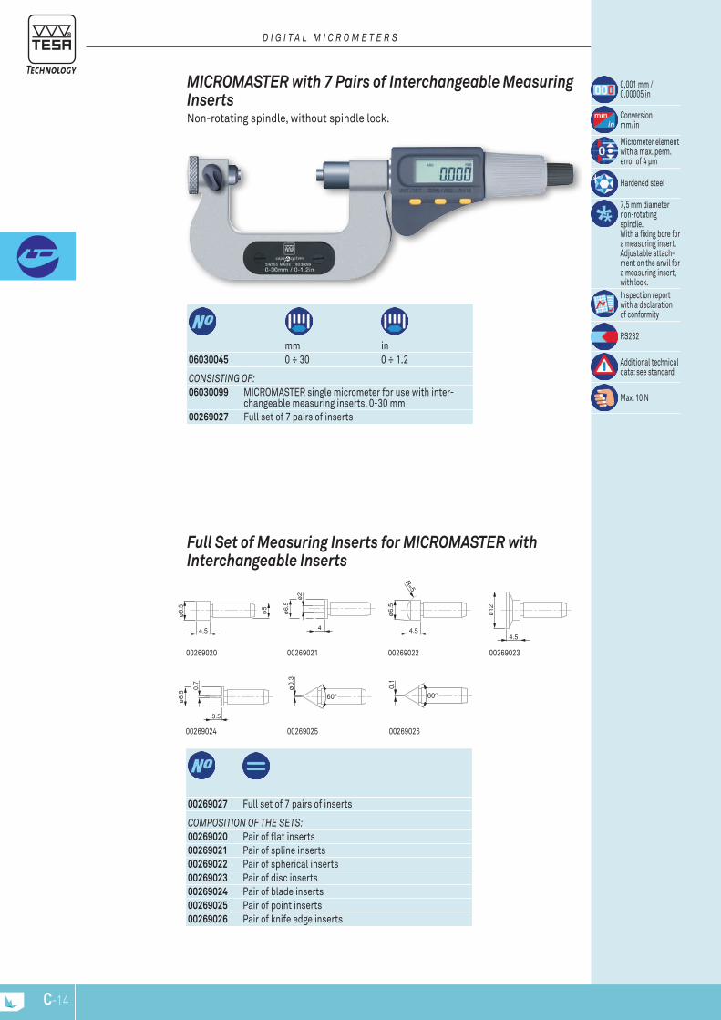
ø12
4.5
ø0.
3
ø6.
5
4.5
ø5
ø2
4
ø6.
5
ø6.
5
4.5
R=5
0.7
3.5
ø6.
5
C-14
00269026
00269023
00269025
00269022
00269024
0026902100269020
coMPoSITIon oF THE SETS:00269020 Pair of flat inserts00269021 Pair of spline inserts00269022 Pair of spherical inserts00269023 Pair of disc inserts00269024 Pair of blade inserts00269025 Pair of point inserts00269026 Pair of knife edge inserts
00269027 Full set of 7 pairs of inserts
Full set of Measuring inserts for MicroMastEr with interchangeable inserts
06030045 0 ÷ 30 0 ÷ 1.2
conSISTIng oF:06030099 MICROMASTER single micrometer for use with inter-
changeable measuring inserts, 0-30 mm00269027 Full set of 7 pairs of inserts
mm in
0,001 mm /0.00005 in
Conversionmm/in
Micrometer element with a max. perm. error of 4 μm
Hardened steel
7,5 mm diameter non-rotating spindle.With a fixing bore for a measuring insert.Adjustable attach-ment on the anvil for a measuring insert,with lock.Inspection report with a declaration of conformity
RS232
Additional technical data: see standard
Max. 10 N
MicroMastEr with 7 Pairs of interchangeable Measuring inserts Non-rotating spindle, without spindle lock.
D I g I T A L M I c R o M E T E R S

C-15
Measuring inserts and setting standards must be ordered separately.
00210001 0 ÷ 2500210002 25 ÷ 50 00210003 50 ÷ 7500210004 75 ÷ 100
mm
DIN 863 T3(Style D 18)NF E 11-090
0,5 mm
Max. 10 N
0,01 mm
isoMastEr ac Micrometers for thread Measurement Models
Note: Measuring inserts and setting standards must be ordered separately.
06030062 0 ÷ 25 0 ÷ 1 06030063 25 ÷ 50 1 ÷ 2 06030064 50 ÷ 75 2 ÷ 3 06030065 75 ÷ 100 3 ÷ 4
mm in
DIN 863 T3(Style D18)
0,001 mm /0.00005 in
Conversionmm/in
Inspection report with a declaration of conformity
RS232
Additionaltechnical data: see appropriate standard
Max. 10 N
30 mm measuring span
MicroMastEr ac Micrometers for thread Measurement Used for pitch diameter inspection. Anvil with adjustable holder for mounting a measuring insert with prismatic faces. Fine screw adjustment and locking device. The spindle has a fixing bore for a cone-shaped measuring insert.
D I g I T A L M I c R o M E T E R S
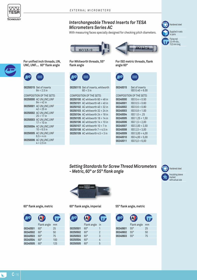
C-16
coMPoSITIon oF THE SETS:00250100 AC whitworth 60 ÷ 48 in00250101 AC whitworth 48 ÷ 40 in00250102 AC whitworth 40 ÷ 32 in00250103 AC whitworth 32 ÷ 24 in00250104 AC whitworth 24 ÷ 18 in00250105 AC whitworth 18 ÷ 14 in00250106 AC whitworth 14 ÷ 10 in00250107 AC whitworth 10 ÷ 7 in00250108 AC whitworth 7 ÷ 4.5 in00250109 AC whitworth 4.5 ÷ 3 in
For Whitworth threads, 55° flank angle
00250115 Set of inserts, whitworth 60 ÷ 3 in
coMPoSITIon oF THE SETS:00240000 ISO 0.4 ÷ 0.5000240001 ISO 0.5 ÷ 0.6000240002 ISO 0.6 ÷ 0.8000240003 ISO 0.8 ÷ 1.0000240004 ISO 1.0 ÷ .2500240005 ISO 1.25 ÷ 1,5000240006 ISO 1,5 ÷ 2,0000240007 ISO 2,00 ÷ 2,5000240008 ISO 2,5 ÷ 3,0000240009 ISO 3,00 ÷ 4,0000240010 ISO 4,00 ÷ 5,0000240011 ISO 5,0 ÷ 6,00
For ISO metric threads, flank angle 60°
00240015 Set of inserts ISO 0.40 ÷ 6.00
coMPoSITIon oF THE SETS:00250000 AC UN,UNC,UNF
64 ÷ 42 in00250001 AC UN,UNC,UNF
42 ÷ 25 in00250002 AC UN,UNC,UNF
25 ÷ 17 in00250003 AC UN,UNC,UNF
17 ÷ 10 in00250004 AC UN,UNC,UNF
10 ÷ 6.5 in00250005 AC UN,UNC,UNF
6.5 ÷ 4 in00250006 AC UN,UNC,UNF
4 ÷ 2.5 in
For unified inch threads, UN, UNC, UNF.... 60° flank angle
00250015 Set of inserts 64 ÷ 2.5 in
Hardened steel
Insulating sleeve marked with actual size
setting standards for screw thread Micrometers - Metric, 60° or 55° flank angle
60° flank angle, metric
00240501 60° 2500240502 60° 5000240503 60° 7500240504 60° 10000240505 60° 125
Flank angle mm
60° flank angle, imperial
00250501 60° 100250502 60° 200250503 60° 300250504 60° 400250505 60° 5
Flank angle in
55° flank angle, metric
00240601 55° 2500240602 55° 5000240603 55° 75
Flank angle mm
Hardened steel
Supplied in sets or pairs
Fixing rod: 3,5 mm dia., 15,5 mm long
interchangeable thread inserts for tEsa Micrometers series ac With measuring faces specially designed for checking pitch diameters.
E x T E R n A L M I c R o M E T E R S
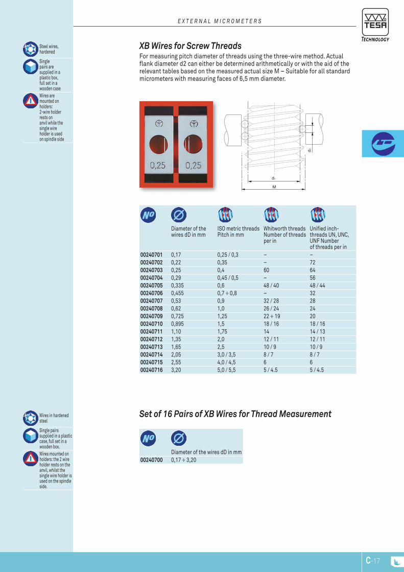
d2
dD
M
C-17
00240701 0,17 0,25 / 0,3 – –00240702 0,22 0,35 – 7200240703 0,25 0,4 60 6400240704 0,29 0,45 / 0,5 – 5600240705 0,335 0,6 48 / 40 48 / 4400240706 0,455 0,7 ÷ 0,8 – 3200240707 0,53 0,9 32 / 28 2800240708 0,62 1,0 26 / 24 2400240709 0,725 1,25 22 ÷ 19 2000240710 0,895 1,5 18 / 16 18 / 1600240711 1,10 1,75 14 14 / 1300240712 1,35 2,0 12 / 11 12 / 1100240713 1,65 2,5 10 / 9 10 / 900240714 2,05 3,0 / 3,5 8 / 7 8 / 700240715 2,55 4,0 / 4,5 6 600240716 3,20 5,0 / 5,5 5 / 4.5 5 / 4.5
Diameter of the wires dD in mm
ISO metric threads Pitch in mm
Whitworth threads Number of threads per in
Unified inch- threads UN, UNC, UNF Number of threads per in
Steel wires, hardened
Singlepairs aresupplied in aplastic box, full set in awooden caseWires aremounted onholders:2-wire holder rests onanvil while the single wireholder is used on spindle side
XB Wires for screw threads For measuring pitch diameter of threads using the three-wire method. Actual flank diameter d2 can either be determined arithmetically or with the aid of the relevant tables based on the measured actual size M – Suitable for all standard micrometers with measuring faces of 6,5 mm diameter.
E x T E R n A L M I c R o M E T E R S
00240700 0,17 ÷ 3,20Diameter of the wires dD in mm
Wires in hardened steel
Single pairs supplied in a plastic case, full set in a wooden box.Wires mounted on holders: the 2 wire holder rests on the anvil, whilst the single wire holder is used on the spindle side.
set of 16 Pairs of XB Wires for thread Measurement
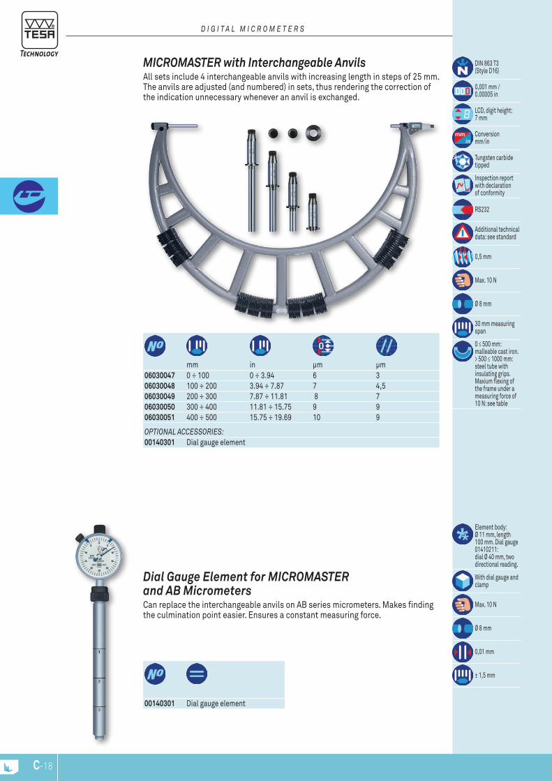
C-18
00140301 Dial gauge element
Element body: Ø 11 mm, length 100 mm. Dial gauge 01410211: dial Ø 40 mm, two directional reading.
With dial gauge and clamp
Max. 10 N
Ø 8 mm
0,01 mm
± 1,5 mm
Dial Gauge Element for MicroMastEr and aB Micrometers Can replace the interchangeable anvils on AB series micrometers. Makes finding the culmination point easier. Ensures a constant measuring force.
oPTIonAL AccESSoRIES:00140301 Dial gauge element
06030047 0 ÷ 100 0 ÷ 3.94 6 306030048 100 ÷ 200 3.94 ÷ 7.87 7 4,506030049 200 ÷ 300 7.87 ÷ 11.81 8 7 06030050 300 ÷ 400 11.81 ÷ 15.75 9 906030051 400 ÷ 500 15.75 ÷ 19.69 10 9
mm in μm μm
DIN 863 T3(Style D16)
0,001 mm /0.00005 in
LCD, digit height: 7 mm
Conversionmm/in
Tungsten carbide tipped
Inspection report with declaration of conformity
RS232
Additional technical data: see standard
0,5 mm
Max. 10 N
Ø 8 mm
30 mm measuring span
0 ≤ 500 mm: malleable cast iron. > 500 ≤ 1000 mm: steel tube with insulating grips. Maxium flexing of the frame under a measuring force of 10 N: see table
MicroMastEr with interchangeable anvils All sets include 4 interchangeable anvils with increasing length in steps of 25 mm. The anvils are adjusted (and numbered) in sets, thus rendering the correction of the indication unnecessary whenever an anvil is exchanged.
D I g I T A L M I c R o M E T E R S
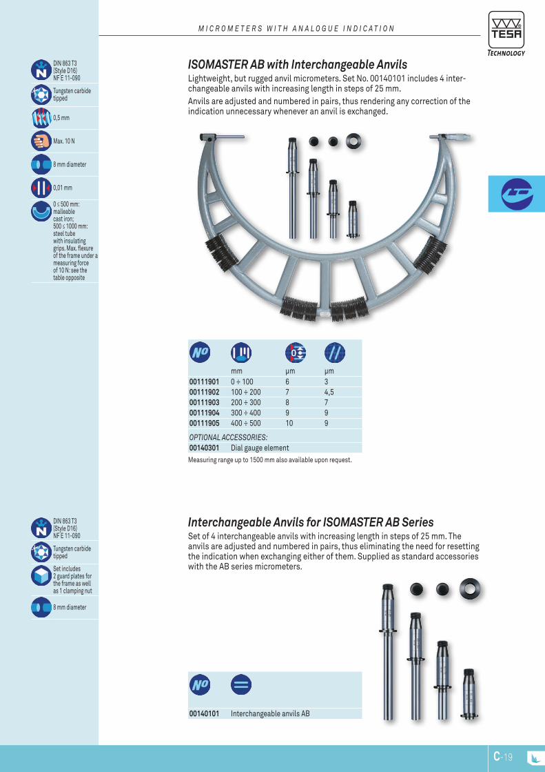
C-19
00140101 Interchangeable anvils AB
DIN 863 T3(Style D16)NF E 11-090
Tungsten carbidetipped
Set includes2 guard plates forthe frame as wellas 1 clamping nut
8 mm diameter
interchangeable anvils for isoMastEr aB series Set of 4 interchangeable anvils with increasing length in steps of 25 mm. The anvils are adjusted and numbered in pairs, thus eliminating the need for resetting the indication when exchanging either of them. Supplied as standard accessories with the AB series micrometers.
Measuring range up to 1500 mm also available upon request.
oPTIonAL AccESSoRIES:00140301 Dial gauge element
00111901 0 ÷ 100 6 300111902 100 ÷ 200 7 4,500111903 200 ÷ 300 8 7 00111904 300 ÷ 400 9 900111905 400 ÷ 500 10 9
mm μm μm
DIN 863 T3(Style D16)NF E 11-090
Tungsten carbidetipped
0,5 mm
Max. 10 N
8 mm diameter
0,01 mm
0 ≤ 500 mm:malleablecast iron;500 ≤ 1000 mm: steel tubewith insulating grips. Max. flexure of the frame under a measuring forceof 10 N: see the table opposite
isoMastEr aB with interchangeable anvils Lightweight, but rugged anvil micrometers. Set No. 00140101 includes 4 inter-changeable anvils with increasing length in steps of 25 mm.Anvils are adjusted and numbered in pairs, thus rendering any correction of the indication unnecessary whenever an anvil is exchanged.
M I c R o M E T E R S W I T H A n A L o g u E I n D I c A T I o n

C-20
072112020 5 ÷ 100072112021 5 ÷ 150
mm
Maximum permissible errors for nominal diameters:≤ 80 mm = 1,5 μm≥ 90 ≤ 120 mm = 2,0 μm ≥ 130 mm = 2,5 μm
Alloyed steel,hardened
Diameters in steps of 5 mm (≤ 50 mm)or 10 mm (> 50 mm).
EtaLon cylindrical step Gauges For adjustement of the display and calibration.
02140103 100 ÷ 175 802140108 200 ÷ 1475 8
mm mm
Guide collars for setting standards Making the positioning of INTERAPID setting standards quick and easy.
02140011 275 02140012 300 02140013 325 02140014 350 02140015 375 02140016 400 02140017 425 02140018 450 02140019 475 02140020 500
02140001 25 02140002 50 02140003 75 02140004 100 02140005 125 02140006 150 02140007 175 02140008 200 02140009 225 02140010 250
mmmm
Maximum permissible error over the length: ± (1 + L/100) μm, L in mm
Hardened steel
Inspection report with actualmeasured lengthCylindrical gauge block with plastic insulating grip and dull chrome shaftTwo measuring faces, flat and roundedWith lengths: ≤ 175 mm= 10 mm.≥ 200 mm = 13 mm.
intEraPiD setting standards
E x T E R n A L M I c R o M E T E R S
Measuring range up to 1500 mm also available upon request.

C-21
00160201 TESA micrometer stand with clamp aperture 16 mm072110123 ETALON micrometer stand with clamp aperture 20 mm
Micrometer stands For external micrometers up to 300 mm as well as many other hand-held tools.
E x T E R n A L M I c R o M E T E R S
mm02510000 Set interference glass 12 ÷ 12,375 mm 12,00 ÷ 12,37502510001 Interference glass 12 12,0002510002 Interference glass 12,125 12,12502510003 Interference glass 12,25 mm 12,2502510004 Interference glass 12,375 mm 12,37502510100 Set interference glass 27 ÷ 27,335 mm 27,00 ÷ 27,33502510101 Interference glass 27 mm 27,0002510102 Interference glass 27,165 mm 27,16502510103 Interference glass 27,335 mm 27,33502510200 Set interference glass 52 - 52,3 52,00 ÷ 52,33502510201 Interference glass 52 mm 52,0002510202 Interference glass 52,165 mm 52,16502510203 Interference glass 52,335 mm 52,33502510300 Set interference glass 77 ÷ 77,335 mm 77,00 ÷ 77,33502510301 Interference glass 77,00 mm 77,0002510302 Interference glass 77,165 mm 77,16502510303 Interference glass 77,335 mm 77,335
Length tolerance with reference to the nominaldimension: ± 100 μmEach setis supplied ina wooden caseFlatnesstolerances foroptical parallelswith lengths:≤ 27,335 mm = 0,15 μm ≥ 52,00 ÷ 77,335 mm = 0,2 μmTolerancesin parallelism foroptical parallelswith lengths:≤ 27,335 mm: 0,4 μm≥ 52,00 ÷ 77,335 mm:0,5 μm
31 mm
optical Flats with two Parallel Faces Used for examining the flatness and parallelism of the measuring faces on exter-nal micrometers as well as other similar measuring instruments. The difference in length of the optical flats within a set matches a quarter or a third of the spindle pitch of 0,5 mm.
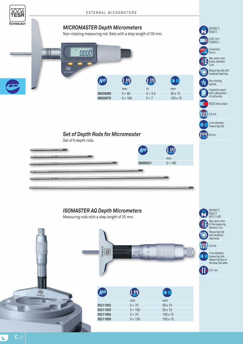
C-22
00211002 0 ÷ 75 50 x 1500211003 0 ÷ 150 50 x 1500211004 0 ÷ 75 100 x 1500211005 0 ÷ 150 100 x 15
mm mm
DIN 863 T2(Style T)NF E 11-097Max. perm. errorof the measuringelement: 3 μmMeasuring rodswith hardenedsteel ends
0,5 mm
3 mm diameter measuring rods.Measuring face on the base: see table
0,01 mm
isoMastEr aQ Depth Micrometers Measuring rods with a step length of 25 mm.
06060021 0 ÷ 180mm
set of Depth rods for Micromaster Set of 6 depth rods.
06030069 0 ÷ 90 0 ÷ 3.5 50 x 1506030070 0 ÷ 180 0 ÷ 7 100 x 15
mm in mm
DIN 863 T2(Style T)
0,001 mm / 0.00005 in
Conversionmm/in
Max. perm. error (meas. element):3 μm
Measuring rods with hardened steel tips
Non-rotating spindle
Inspection report with a declaration of conformity
RS232 data output
0,5 mm
3 mm diameter measuring rods
30 mm
MicroMastEr Depth Micrometers Non-rotating measuring rod. Sets with a step length of 30 mm.
E x T E R n A L M I c R o M E T E R S

18
44
107
ø6.
5
ø12
h6
ø21
ø11
.5
31
ø6.
5
ø12
h6
47
16
145
C-23
00312301 0 ÷ 25 12h6mm
DIN 863 T2 (Style E)
Value of the scale: 0,1 mm
Max. perm. error of 2 μm
Tungsten carbide tipped
0,5 mm
Max. 10 N
6,5 mm dia
Vernier reading to 0,001 mm
tEsaMastEr ar Micrometer Heads Without spindle lock.
06030038 0 ÷ 30 12h606030039 30 ÷ 0 12h606030040 30 ÷ 0 12h6
mm
DIN 863 T2(Style E)
0,001 mm /0.00005 in
Conversionmm/in
Max. perm.error of 4 μm
Tungsten carbidetipped
Inspection reportwith a declarationof conformity
RS232 interface, opto-coupled
Additionaltechnical data: see standard
0,5 mm
Max. 10 N
6,5 mm dia.
MicroMastEr Micrometer Heads Without spindle lock
MicroMEtEr HEaDs Micrometer heads used principally for the measurement of displacement on special fixtures such as roller tables, XY tables. Mounted using the cylindrical couping shaft.
E x T E R n A L M I c R o M E T E R S
06030038/39
06030040

16
44
107
ø6.
5
ø12
h6
ø18
.6
ø12
.2
119
16
43.5
ø8 ø12
h6
ø18.
6
C-24
072115943 0 ÷ 25 Ø 8 12h6 mm D mm Spindle lock
DIN 863 T2(Style E)NF E 11-090
Max. perm.error: 3 μm
Tungsten carbidetipped
0,5 mm
Vernier readingto 0,002 mm
EtaLon 266 Micrometer Heads With spindle lock.
E x T E R n A L M I c R o M E T E R S
00211201 0 ÷ 25 12h6mm
DIN 863 T2(Style E)NF E 11-090
Max. perm.error of 3 μm
Tungsten carbidetipped
0,5 mm
Max. 10 N
6,5 mm dia
0,01 mm
isoMastEr ar Micrometer Heads Without spindle lock.
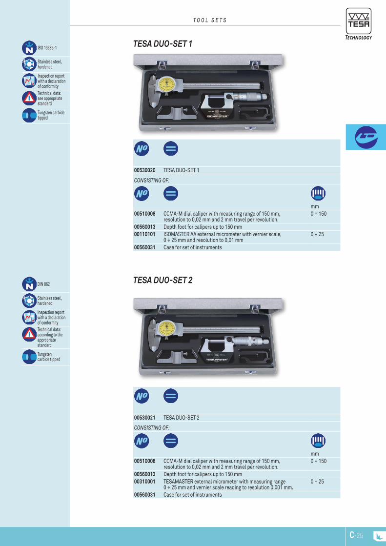
C-25
conSISTIng oF:
mm00510008 CCMA-M dial caliper with measuring range of 150 mm,
resolution to 0,02 mm and 2 mm travel per revolution.0 ÷ 150
00560013 Depth foot for calipers up to 150 mm00110101 ISOMASTER AA external micrometer with vernier scale,
0 ÷ 25 mm and resolution to 0,01 mm0 ÷ 25
00560031 Case for set of instruments
00530020 TESA DUO-SET 1
ISO 13385-1
Stainless steel, hardened
Inspection report with a declaration of conformityTechnical data: see appropriate standard
Tungsten carbide tipped
tEsa Duo-sEt 1
T o o L S E T S
conSISTIng oF:
mm00510008 CCMA-M dial caliper with measuring range of 150 mm,
resolution to 0,02 mm and 2 mm travel per revolution.0 ÷ 150
00560013 Depth foot for calipers up to 150 mm00310001 TESAMASTER external micrometer with measuring range
0 ÷ 25 mm and vernier scale reading to resolution 0,001 mm.0 ÷ 25
00560031 Case for set of instruments
00530021 TESA DUO-SET 2
DIN 862
Stainless steel, hardened
Inspection report with a declaration of conformityTechnical data: according to the appropriate standard
Tungsten carbide tipped
tEsa Duo-sEt 2
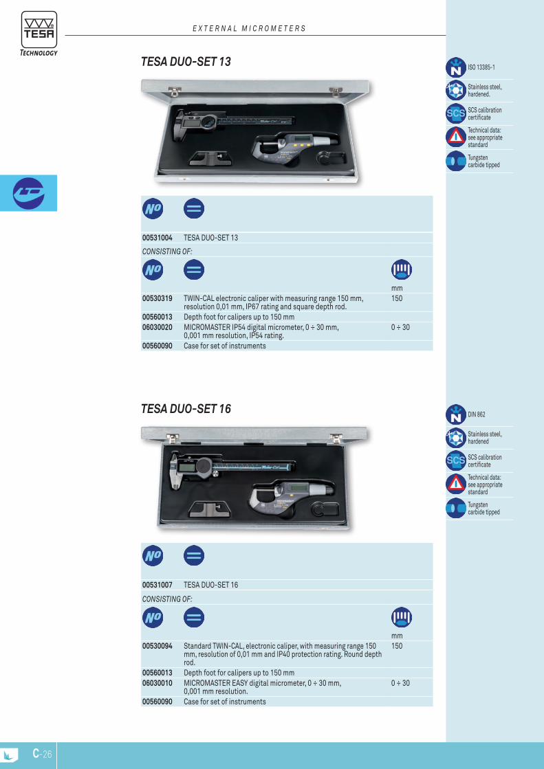
C-26
00531004 TESA DUO-SET 13
conSISTIng oF:
mm00530319 TWIN-CAL electronic caliper with measuring range 150 mm,
resolution 0,01 mm, IP67 rating and square depth rod.150
00560013 Depth foot for calipers up to 150 mm06030020 MICROMASTER IP54 digital micrometer, 0 ÷ 30 mm,
0,001 mm resolution, IP54 rating.0 ÷ 30
00560090 Case for set of instruments
ISO 13385-1
Stainless steel, hardened.
SCS calibration certificate
Technical data: see appropriate standard
Tungsten carbide tipped
tEsa Duo-sEt 13
E x T E R n A L M I c R o M E T E R S
00531007 TESA DUO-SET 16
conSISTIng oF:
mm00530094 Standard TWIN-CAL, electronic caliper, with measuring range 150
mm, resolution of 0,01 mm and IP40 protection rating. Round depth rod.
150
00560013 Depth foot for calipers up to 150 mm06030010 MICROMASTER EASY digital micrometer, 0 ÷ 30 mm,
0,001 mm resolution.0 ÷ 30
00560090 Case for set of instruments
DIN 862
Stainless steel, hardened
SCS calibration certificate
Technical data: see appropriate standard
Tungsten carbide tipped
tEsa Duo-sEt 16
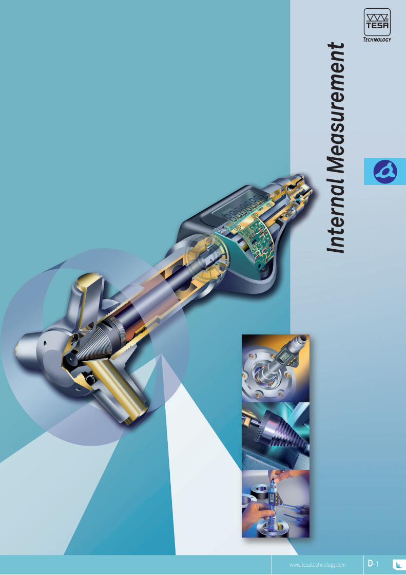
www.tesatechnology.com
Inte
rnal
Mea
sure
men
t
D-1
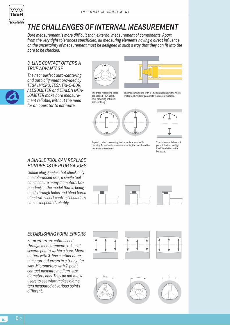
? ? ? ?
The three measuring bolts are spaced 120° apart, thus providing optimumself-centring.
The measuring bolts with 3-line contact allows the micro-meter to align itself parallel to the contact surfaces.
2-point contact measuring instruments are not self-centring. To enable bore measurements, the use of auxilia-ry means are required.
2-point contact does not permit the tool to align itself in relation to thebore axis.
Dmax. Dmin.
Establishing form Errors form errors are established through measurements taken at several points within a bore. micro-meters with 3-line contact deter-mine run-out errors in a triangular way. micrometers with 2-point contact measure medium-size diameters only. they do not allow users to see what makes diame-ters measured at various points different.
a singlE tool can rEplacE hundrEds of plug gaugEs unlike plug gauges that check only one toleranced size, a single tool can measure many diameters. de-pending on the model that is being used, through holes and blind bores along with short centring shoulders can be inspected reliably.
3-linE contact offErs a truE advantagEthe near perfect auto-centering and auto alignment provided by tEsa imicro, tEsa tri-o-bor, alEsomEtEr and Etalon inta-lomEtEr make bore measure-ment reliable, without the need for an operator to estimate.
bore measurement is more difficult than external measurement of components. apart from the very tight tolerances specificied, all measuring elements having a direct influence on the uncertainty of measurement must be designed in such a way that they can fit into the bore to be checked.
THE CHALLENGES OF INTERNAL MEASUREMENT
i n t E r n a l m E a s u r E m E n t
D-2
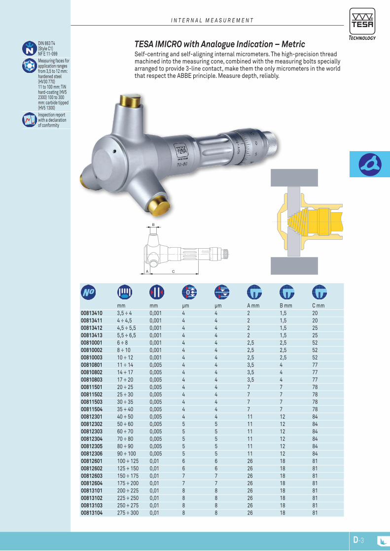
A C
B
00813410 3,5 ÷ 4 0,001 4 4 2 1,5 2000813411 4 ÷ 4,5 0,001 4 4 2 1,5 2000813412 4,5 ÷ 5,5 0,001 4 4 2 1,5 2500813413 5,5 ÷ 6,5 0,001 4 4 2 1,5 2500810001 6 ÷ 8 0,001 4 4 2,5 2,5 5200810002 8 ÷ 10 0,001 4 4 2,5 2,5 5200810003 10 ÷ 12 0,001 4 4 2,5 2,5 5200810801 11 ÷ 14 0,005 4 4 3,5 4 7700810802 14 ÷ 17 0,005 4 4 3,5 4 7700810803 17 ÷ 20 0,005 4 4 3,5 4 7700811501 20 ÷ 25 0,005 4 4 7 7 7800811502 25 ÷ 30 0,005 4 4 7 7 7800811503 30 ÷ 35 0,005 4 4 7 7 7800811504 35 ÷ 40 0,005 4 4 7 7 7800812301 40 ÷ 50 0,005 4 4 11 12 8400812302 50 ÷ 60 0,005 5 5 11 12 8400812303 60 ÷ 70 0,005 5 5 11 12 8400812304 70 ÷ 80 0,005 5 5 11 12 8400812305 80 ÷ 90 0,005 5 5 11 12 8400812306 90 ÷ 100 0,005 5 5 11 12 8400812601 100 ÷ 125 0,01 6 6 26 18 8100812602 125 ÷ 150 0,01 6 6 26 18 8100812603 150 ÷ 175 0,01 7 7 26 18 8100812604 175 ÷ 200 0,01 7 7 26 18 8100813101 200 ÷ 225 0,01 8 8 26 18 8100813102 225 ÷ 250 0,01 8 8 26 18 8100813103 250 ÷ 275 0,01 8 8 26 18 8100813104 275 ÷ 300 0,01 8 8 26 18 81
mm mm μm μm A mm B mm C mm
DIN 863 T4(Style C1)NF E 11-099Measuring faces for application ranges from 3,5 to 12 mm: hardened steel (HV30 770)11 to 100 mm: TiN hard-coating (HV5 2300) 100 to 300 mm: carbide tipped (HV5 1300)Inspection report with a declaration of conformity
TESA IMICRO with Analogue Indication – Metric Self-centring and self-aligning internal micrometers. The high-precision thread machined into the measuring cone, combined with the measuring bolts specially arranged to provide 3-line contact, make them the only micrometers in the world that respect the ABBE principle. Measure depth, reliably.
i n t E r n a l m E a s u r E m E n t
D-3
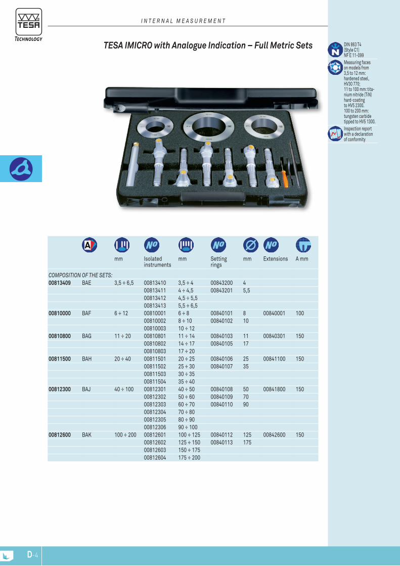
DIN 863 T4(Style C1)NF E 11-099Measuring faceson models from3,5 to 12 mm:hardened steel, HV30 770;11 to 100 mm: tita-nium nitride (TiN) hard-coatingto HV5 2300.100 to 200 mm: tungsten carbide tipped to HV5 1300.Inspection reportwith a declarationof conformity
mm Isolated instruments
mm Setting rings
mm Extensions A mm
composition of thE sEts:00813409 BAE 3,5 ÷ 6,5 00813410 3,5 ÷ 4 00843200 4
00813411 4 ÷ 4,5 00843201 5,5 00813412 4,5 ÷ 5,5 00813413 5,5 ÷ 6,5
00810000 BAF 6 ÷ 12 00810001 6 ÷ 8 00840101 8 00840001 100 00810002 8 ÷ 10 00840102 10 00810003 10 ÷ 12
00810800 BAG 11 ÷ 20 00810801 11 ÷ 14 00840103 11 00840301 150 00810802 14 ÷ 17 00840105 17 00810803 17 ÷ 20
00811500 BAH 20 ÷ 40 00811501 20 ÷ 25 00840106 25 00841100 150 00811502 25 ÷ 30 00840107 35 00811503 30 ÷ 35 00811504 35 ÷ 40
00812300 BAJ 40 ÷ 100 00812301 40 ÷ 50 00840108 50 00841800 15000812302 50 ÷ 60 00840109 70 00812303 60 ÷ 70 00840110 90 00812304 70 ÷ 8000812305 80 ÷ 90 00812306 90 ÷ 100
00812600 BAK 100 ÷ 200 00812601 100 ÷ 125 00840112 125 00842600 15000812602 125 ÷ 150 00840113 175 00812603 150 ÷ 175 00812604 175 ÷ 200
TESA IMICRO with Analogue Indication – Full Metric Sets
i n t E r n a l m E a s u r E m E n t
D-4
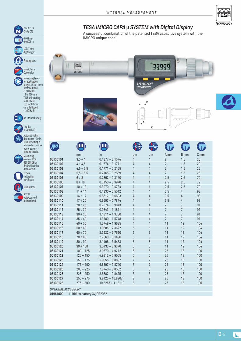
A
B
C
06130101 3,5 ÷ 4 0.1377 ÷ 0.1574 4 4 2 1,5 2006130102 4 ÷ 4,5 0.1574 ÷ 0.1771 4 4 2 1,5 2006130103 4,5 ÷ 5,5 0.1771 ÷ 0.2165 4 4 2 1,5 2506130104 5,5 ÷ 6,5 0.2165 ÷ 0.2559 4 4 2 1,5 2506130105 6 ÷ 8 0.2362 ÷ 0.3150 4 4 2,5 2,5 7906130106 8 ÷ 10 0.3150 ÷ 0.3970 4 4 2,5 2,5 7906130107 10 ÷ 12 0.3970 ÷ 0.4724 4 4 2,5 2,5 7906130108 11 ÷ 14 0.4330 ÷ 0.5512 4 4 3,5 4 9306130109 14 ÷ 17 0.5512 ÷ 0.6693 4 4 3,5 4 9306130110 17 ÷ 20 0.6693 ÷ 0.7874 4 4 3,5 4 9306130111 20 ÷ 25 0.7874 ÷ 0.9843 4 4 7 7 9106130112 25 ÷ 30 0.9843 ÷ 1.1811 4 4 7 7 9106130113 30 ÷ 35 1.1811 ÷ 1.3780 4 4 7 7 9106130114 35 ÷ 40 1.3780 ÷ 1.5748 4 4 7 7 9106130115 40 ÷ 50 1.5748 ÷ 1.9685 4 4 11 12 10406130116 50 ÷ 60 1.9685 ÷ 2.3622 5 5 11 12 10406130117 60 ÷ 70 2.3622 ÷ 2.7560 5 5 11 12 10406130118 70 ÷ 80 2.7560 ÷ 3.1496 5 5 11 12 10406130119 80 ÷ 90 3.1496 ÷ 3.5433 5 5 11 12 10406130120 90 ÷ 100 3.5433 ÷ 3.9370 5 5 11 12 10406130121 100 ÷ 125 3.9370 ÷ 4.9212 6 6 26 18 10006130122 125 ÷ 150 4.9212 ÷ 5.9055 6 6 26 18 10006130123 150 ÷ 175 5.9055 ÷ 6.8897 7 7 26 18 10006130124 175 ÷ 200 6.8897 ÷ 7.8740 7 7 26 18 10006130125 200 ÷ 225 7.8740 ÷ 8.8582 8 8 26 18 10006130126 225 ÷ 250 8.8582 ÷ 9.8425 8 8 26 18 10006130127 250 ÷ 275 9.8425 ÷ 10.8267 8 8 26 18 10006130128 275 ÷ 300 10.8267 ÷ 11.8110 8 8 26 18 100
mm in μm μm A mm B mm C mm
optional accEssory01961000 1 Lithium battery 3V, CR2032
DIN 863 T4(Style C1)
0,001 mm0,00005 in
LCD, 7 mmdigit height
Floating zero
Metric/inchConversion
Measuring facesfor applicationranges 3,5 to 12 mm:hardened steel (770 HV 30)11 to 100 mm:TiN hard-coating (2300 HV 5)100 to 300 mm:carbide tipped (1300 HV 5)
3 V lithium battery
1 to 2 a(≈ 2000 h/a)
Automatic shut down after 10 min.Display setting is retained as long as power supplyremains stable.Measuringelement IP54(IEC 60529) orIP40 with active data outputTESA’scalibrationcertificate
Display lock
RS232opto-coupled,bidirectional
TESA IMICRO CAPA μ SYSTEM with Digital Display A successful combination of the patented TESA capacitive system with the IMICRO unique cone.
i n t E r n a l m E a s u r E m E n t
D-5
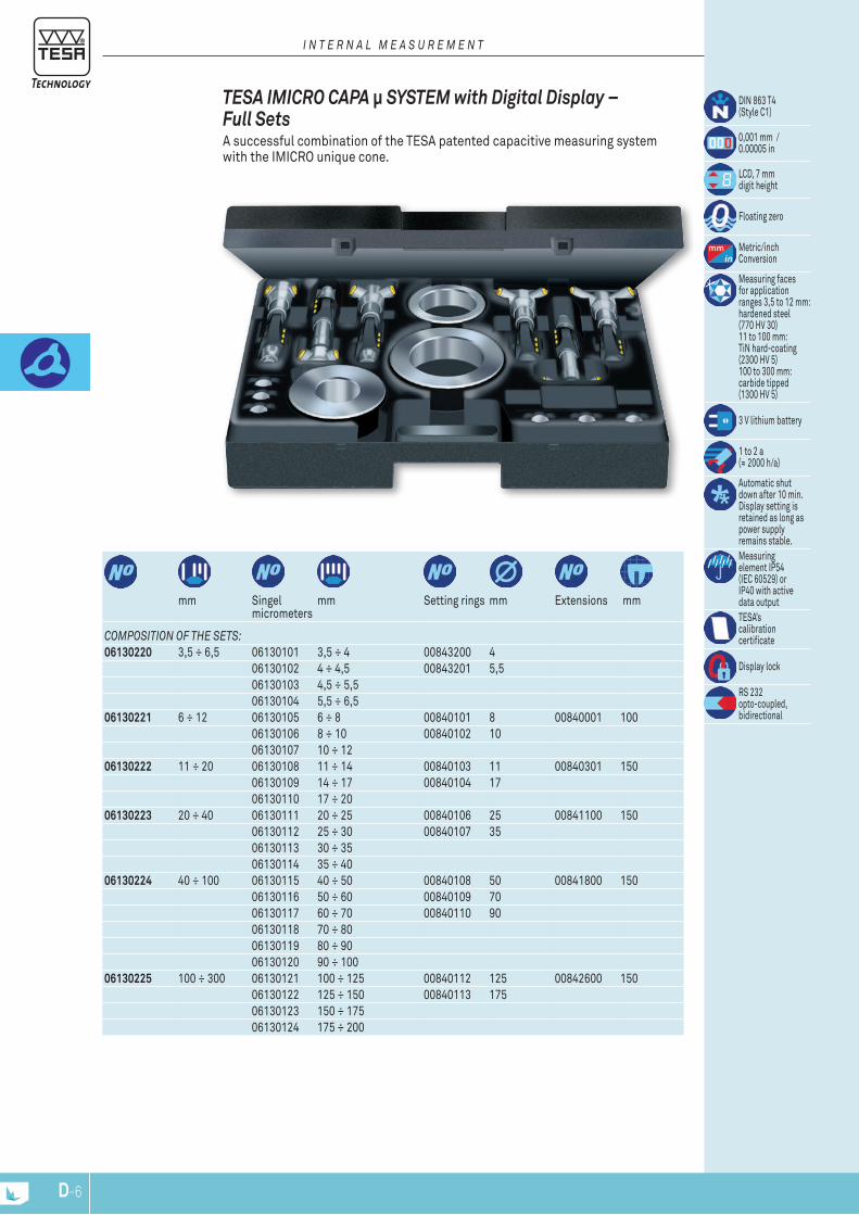
DIN 863 T4(Style C1)
0,001 mm /0.00005 in
LCD, 7 mmdigit height
Floating zero
Metric/inchConversion
Measuring facesfor applicationranges 3,5 to 12 mm:hardened steel (770 HV 30) 11 to 100 mm:TiN hard-coating (2300 HV 5)100 to 300 mm:carbide tipped (1300 HV 5)
3 V lithium battery
1 to 2 a(≈ 2000 h/a)
Automatic shut down after 10 min.Display setting is retained as long as power supplyremains stable.Measuringelement IP54(IEC 60529) orIP40 with active data outputTESA’scalibrationcertificate
Display lock
RS 232opto-coupled,bidirectional
mm Singel micrometers
mm Setting rings mm Extensions mm
composition of thE sEts:06130220 3,5 ÷ 6,5 06130101 3,5 ÷ 4 00843200 4
06130102 4 ÷ 4,5 00843201 5,5 06130103 4,5 ÷ 5,5 06130104 5,5 ÷ 6,5
06130221 6 ÷ 12 06130105 6 ÷ 8 00840101 8 00840001 100 06130106 8 ÷ 10 00840102 10 06130107 10 ÷ 12
06130222 11 ÷ 20 06130108 11 ÷ 14 00840103 11 00840301 150 06130109 14 ÷ 17 00840104 17 06130110 17 ÷ 20
06130223 20 ÷ 40 06130111 20 ÷ 25 00840106 25 00841100 150 06130112 25 ÷ 30 00840107 35 06130113 30 ÷ 35 06130114 35 ÷ 40
06130224 40 ÷ 100 06130115 40 ÷ 50 00840108 50 00841800 15006130116 50 ÷ 60 00840109 70 06130117 60 ÷ 70 00840110 90 06130118 70 ÷ 8006130119 80 ÷ 90 06130120 90 ÷ 100
06130225 100 ÷ 300 06130121 100 ÷ 125 00840112 125 00842600 15006130122 125 ÷ 150 00840113 175 06130123 150 ÷ 175 06130124 175 ÷ 200
TESA IMICRO CAPA μ SYSTEM with Digital Display – Full Sets A successful combination of the TESA patented capacitive measuring system with the IMICRO unique cone.
i n t E r n a l m E a s u r E m E n t
D-6
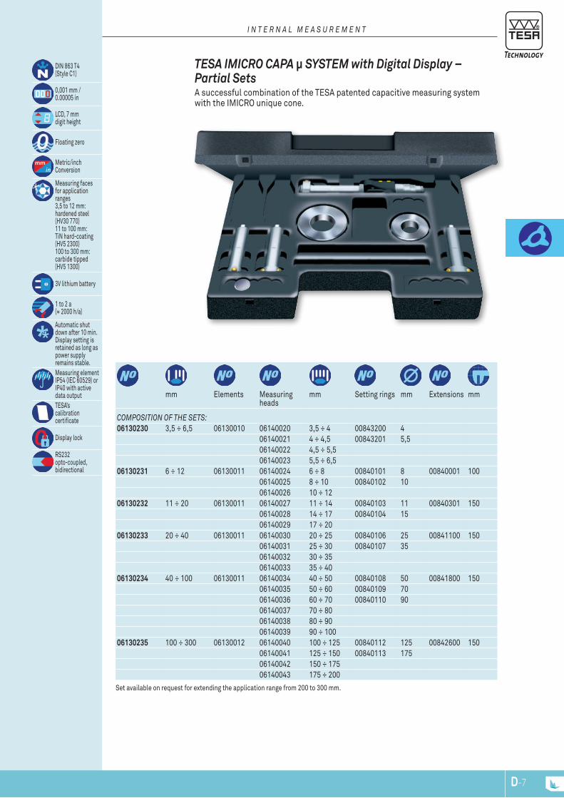
DIN 863 T4(Style C1)
0,001 mm /0.00005 in
LCD, 7 mmdigit height
Floating zero
Metric/inchConversion
Measuring facesfor applicationranges3,5 to 12 mm:hardened steel (HV30 770)11 to 100 mm:TiN hard-coating (HV5 2300)100 to 300 mm:carbide tipped (HV5 1300)
3V lithium battery
1 to 2 a(≈ 2000 h/a)
Automatic shut down after 10 min.Display setting is retained as long as power supplyremains stable.Measuring element IP54 (IEC 60529) orIP40 with active data outputTESA’scalibrationcertificate
Display lock
RS232opto-coupled,bidirectional
mm Elements Measuring heads
mm Setting rings mm Extensions mm
composition of thE sEts:06130230 3,5 ÷ 6,5 06130010 06140020 3,5 ÷ 4 00843200 4
06140021 4 ÷ 4,5 00843201 5,5 06140022 4,5 ÷ 5,5 06140023 5,5 ÷ 6,5
06130231 6 ÷ 12 06130011 06140024 6 ÷ 8 00840101 8 00840001 100 06140025 8 ÷ 10 00840102 10 06140026 10 ÷ 12
06130232 11 ÷ 20 06130011 06140027 11 ÷ 14 00840103 11 00840301 150 06140028 14 ÷ 17 00840104 15 06140029 17 ÷ 20
06130233 20 ÷ 40 06130011 06140030 20 ÷ 25 00840106 25 00841100 150 06140031 25 ÷ 30 00840107 35 06140032 30 ÷ 35 06140033 35 ÷ 40
06130234 40 ÷ 100 06130011 06140034 40 ÷ 50 00840108 50 00841800 15006140035 50 ÷ 60 00840109 70 06140036 60 ÷ 70 00840110 90 06140037 70 ÷ 8006140038 80 ÷ 90 06140039 90 ÷ 100
06130235 100 ÷ 300 06130012 06140040 100 ÷ 125 00840112 125 00842600 15006140041 125 ÷ 150 00840113 175 06140042 150 ÷ 175 06140043 175 ÷ 200
Set available on request for extending the application range from 200 to 300 mm.
TESA IMICRO CAPA μ SYSTEM with Digital Display – Partial Sets A successful combination of the TESA patented capacitive measuring system with the IMICRO unique cone.
i n t E r n a l m E a s u r E m E n t
D-7
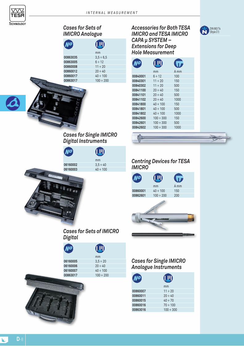
mm A mm
Centring Devices for TESA IMICRO
00860001 40 ÷ 100 15000862601 100 ÷ 200 200
mm
Cases for Sets of IMICRO Digital
06160005 3,5 ÷ 2006160006 20 ÷ 4006160007 40 ÷ 10000863017 100 ÷ 200
mm
Cases for Single IMICRO Digital Instruments
06160002 3,5 ÷ 4006160003 40 ÷ 100
mm
Cases for Sets of IMICRO Analogue
00863035 3,5 ÷ 6,500863005 6 ÷ 1200860008 11 ÷ 2000860012 20 ÷ 40 00860017 40 ÷ 10000863017 100 ÷ 200
mm
Cases for Single IMICRO Analogue Instruments
00860007 11 ÷ 2000860011 20 ÷ 40 00860015 40 ÷ 7000860016 70 ÷ 100 00863016 100 ÷ 300
mm A mm
DIN 863 T4(Style C1)
Accessories for Both TESA IMICRO and TESA IMICRO CAPA μ SYSTEM – Extensions for Deep Hole Measurement
00840001 6 ÷ 12 100 00840301 11 ÷ 20 150 00840302 11 ÷ 20 500 00841100 20 ÷ 40 150 00841101 20 ÷ 40 500 00841102 20 ÷ 40 1000 00841800 40 ÷ 100 15000841801 40 ÷ 100 50000841802 40 ÷ 100 100000842600 100 ÷ 300 15000842601 100 ÷ 300 50000842602 100 ÷ 300 1000
i n t E r n a l m E a s u r E m E n t
D-8
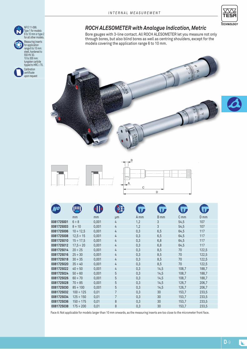
B
AC
D
B2
0081725001 6 ÷ 8 0,001 4 1,2 3 54,5 1070081725003 8 ÷ 10 0,001 4 1,2 3 54,5 1070081725006 10 ÷ 12,5 0,001 4 0,3 6,5 64,5 1170081725008 12,5 ÷ 15 0,001 4 0,3 6,5 64,5 1170081725010 15 ÷ 17,5 0,001 4 0,3 6,8 64,5 1170081725012 17,5 ÷ 20 0,001 4 0,3 6,8 64,5 1170081725014 20 ÷ 25 0,001 4 0,3 8,5 70 122,50081725016 25 ÷ 30 0,001 4 0,3 8,5 70 122,50081725018 30 ÷ 35 0,001 4 0,3 8,5 70 122,50081725020 35 ÷ 40 0,001 4 0,3 8,5 70 122,50081725022 40 ÷ 50 0,001 4 0,3 14,5 108,7 188,70081725024 50 ÷ 60 0,001 5 0,3 14,5 108,7 188,70081725026 60 ÷ 70 0,001 5 0,3 14,5 108,7 188,70081725028 70 ÷ 85 0,001 5 0,3 14,5 126,7 206,70081725030 85 ÷ 100 0,001 5 0,3 14,5 126,7 206,70081725032 100 ÷ 125 0,01 7 0,3 30 153,7 233,50081725034 125 ÷ 150 0,01 7 0,3 30 153,7 233,50081725036 150 ÷ 175 0,01 8 0,3 30 153,7 233,50081725038 175 ÷ 200 0,01 8 0,3 30 153,7 233,5
mm mm μm A mm B mm C mm D mm
NF E 11-099.Type 1 for models6 to 10 mm or type 2 for all other models.Measuring insertsfor application range 6 to 10 mm: steel, hardened to 550 HV 30.10 to 300 mm:tungsten carbide tipped to HRC ≥ 70.Calibrationcertificateupon request
Face A: Not applicable for models larger than 10 mm onwards, as the measuring inserts are too close to the micrometer front face.
ROCH ALESOMETER with Analogue Indication, Metric Bore gauges with 3-line contact. All ROCH ALESOMETER let you measure not only through bores, but also blind bores as well as centring shoulders, except for the models covering the application range 6 to 10 mm.
i n t E r n a l m E a s u r E m E n t
D-9
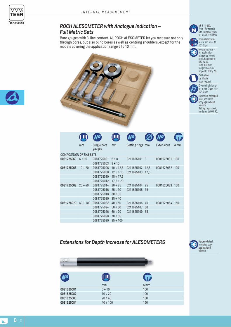
0081625081 6 ÷ 10 1000081625082 10 ÷ 20 1000081625083 20 ÷ 40 1500081625084 40 ÷ 100 150
mm A mm
Hardened steel. Insulated body against hand warmth.
Extensions for Depth Increase for ALESOMETERS
mm Single bore gauges
mm Setting rings mm Extensions A mm
composition of thE sEts:0081725063 6 ÷ 10 0081725001 6 ÷ 8 0211625101 8 0081625081 100
0081725003 8 ÷ 100081725066 10 ÷ 20 0081725006 10 ÷ 12,5 0211625102 12,5 0081625082 100
0081725008 12,5 ÷ 15 0211625103 17,5 0081725010 15 ÷ 17,5 0081725012 17,5 ÷ 20
0081725068 20 ÷ 40 0081725014 20 ÷ 25 0211625104 25 0081625083 1500081725016 25 ÷ 30 0211625105 35 0081725018 30 ÷ 35 0081725020 35 ÷ 40
0081725070 40 ÷ 100 0081725022 40 ÷ 50 0211625106 45 0081625084 1500081725024 50 ÷ 60 0211625107 60 0081725026 60 ÷ 70 0211625109 85 0081725028 70 ÷ 85 0081725030 85 ÷ 100
NF E 11-099. Type 1 for models 6 to 10 mm or type 2 for all other models.Bore related tole-rance: ± (3 μm + 10 · 10-6 D) μmMeasuring inserts for application range 6 to 10 mm: steel, hardened to 550 HV 30. 10 to 300 mm: tungsten carbide tipped to HRC ≥ 70.Calibration certificate upon requestD = nominal diame-ter in mm (1 μm + 5 · 10-6 D) μmExtension: hardened steel, insulated body agains hand warmthSetting rings: steel, hardened to 60 HRC.
ROCH ALESOMETER with Analogue Indication – Full Metric Sets Bore gauges with 3-line contact. All ROCH ALESOMETER let you measure not only through bores, but also blind bores as well as centring shoulders, except for the models covering the application range 6 to 10 mm.
i n t E r n a l m E a s u r E m E n t
D-10

A
B
C
optional accEssory01961000 1 Lithium battery 3V, CR2032
06230051 6 ÷ 8 0.2362 ÷ 0.3150 4 4 1,2 3 5506230052 8 ÷ 10 0.3150 ÷ 0.3970 4 4 1,2 3 5506230023 10 ÷ 12,5 0.3970 ÷ 0.4921 4 4 0,3 6,5 6506230024 12,5 ÷ 15 0.4921 ÷ 0.5905 4 4 0,3 6,5 6506230025 15 ÷ 17,5 0.5905 ÷ 0.6890 4 4 0,3 6,8 6506230026 17,5 ÷ 20 0.6890 ÷ 0.7874 4 4 0,3 6,8 9506230027 20 ÷ 25 0.7874 ÷ 0.9843 4 4 0,3 8,5 10006230028 25 ÷ 30 0.9843 ÷ 1.1811 4 4 0,3 8,5 10006230029 30 ÷ 35 1.1811 ÷ 1.3780 4 4 0,3 8,5 10006230030 35 ÷ 40 1.3780 ÷ 1.5748 4 4 0,3 8,5 10006230031 40 ÷ 50 1.5748 ÷ 1.9685 4 4 0,3 14,5 14006230032 50 ÷ 60 1.9685 ÷ 2.3622 5 5 0,3 14,5 14006230033 60 ÷ 70 2.3622 ÷ 2.7560 5 5 0,3 14,5 14006230034 70 ÷ 85 2.7560 ÷ 3.3465 5 5 0,3 14,5 14006230035 85 ÷ 100 3.3465 ÷ 3.9370 5 5 0,3 14,5 14006230036 100 ÷ 125 3.9370 ÷ 4.9212 6 6 0,3 30 17506230037 125 ÷ 150 4.9212 ÷ 5.9055 6 6 0,3 30 17506230038 150 ÷ 175 5.9055 ÷ 6.8897 7 7 0,3 30 17506230039 175 ÷ 200 6.8897 ÷ 7.8740 7 7 0,3 30 175
mm in μm μm A mm B mm C mm
DIN 863 T4.Style C1 for models6 to 10 mm or style C2 for all other models.
0,001 mm /0.00005 in
LCD, digit height7 mm
Floating zero
Metric/inchconversion
Measuring inserts for application range6 to 10 mm: steel,hardened to 550 HV 30. 10 to 300: tungsten carbidetipped, HRC ≥ 70.
3 V lithium battery
1 to 2 a(≈ 2000 h/a)
Automatic shut down after 10 min.Display setting is retained as long as power supplyremains stable.For the measuringelement IP54(IEC 60529) orIP40 with active data outputInspection reportwith a declarationof conformity
Display lock
RS232opto-coupled,bidirectional
Face A: Not applicable for models larger than 10 mm onwards, as the measuring inserts are too close to the micrometer front face.
TESA ALESOMETER CAPA μ SYSTEM with Digital Display Fitted with a TESA patented capacitive measuring system. Bore gauges with 3-line contact. All TESA ALESOMETER are made to measure through and blind bores as well as short centring shoulders, except for the models covering the application range from 6 to 10 mm.
i n t E r n a l m E a s u r E m E n t
D-11
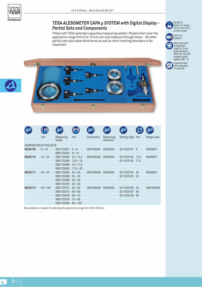
DIN 863 T4.Style C1 for models6 to 10 mm or C2 forall other models
0,001 mm /0.00005 in
Measuring insertsfor applicationrange 6 to 10 mm: steel, hardened to 550 HV 30. 10 to 300: tungsten carbidetipped to HRC ≥ 70.Inspection reportwith a declarationof conformity
mm Measuring heads
mm Connectors Measuring elements
Setting rings mm Storge case
composition of thE sEts:06230100 6 ÷ 10 0081720351 6 ÷ 8 0081620491 06230020 0211625101 8 06260001
0081720353 8 ÷ 1006230110 10 ÷ 20 0081720356 10 ÷ 12,5 0081620492 06230020 0211625102 12,5 06260001
0081720358 12,5 ÷ 15 0211625103 17,5 0081720360 15 ÷ 17,5 0081720362 17,5 ÷ 20
06230111 20 ÷ 40 0081720364 20 ÷ 25 0081620493 06230020 0211625104 25 062600010081720366 25 ÷ 30 0211625105 35 0081720368 30 ÷ 35 0081720370 35 ÷ 40
06230112 40 ÷ 100 0081720372 40 ÷ 50 0081620494 06230020 0211625106 45 00816295250081720374 50 ÷ 60 0211625107 60 0081720376 60 ÷ 70 0211625109 85 0081720378 70 ÷ 85 0081720380 85 ÷ 100
Set available on request for extending the application range from 100 to 300 mm.
TESA ALESOMETER CAPA μ SYSTEM with Digital Display - Partial Sets and Components Fitted with TESA patented capacitive measuring system. Models that cover the application range from 6 to 10 mm can only measure through bores – All other partial sets also allow blind bores as well as short centring shoulders to be inspected.
i n t E r n a l m E a s u r E m E n t
D-12

30
35
40
25
B
C
A
078112356 5 ÷ 6 2 x 180° 3 ≥ 32 ≤ 109078112357 6 ÷ 7 2 x 180° 3 ≥ 33 ≤ 111078112358 7 ÷ 8,5 2 x 180° 4 ≥ 60 ≤ 130078112359 8,5 ÷ 10 2 x 180° 4 ≥ 72 ≤ 133078112360 10 ÷ 12,5 3 x 120° 3 ≥ 60 ≤ 118078112361 12,5 ÷ 15 3 x 120° 3 ≥ 63 ≤ 120078112362 15 ÷ 17,5 3 x 120° 3 ≥ 65 ≤ 122078112363 17,5 ÷ 20 3 x 120° 3 ≥ 68 ≤ 125078112364 20 ÷ 25 90°–135°–135° 7 ≥ 75 ≤ 132078112365 25 ÷ 30 90°–135°–135° 7 ≥ 90 ≤ 138078112366 30 ÷ 35 90°–135°–135° 7 ≥ 90 ≤ 142078112367 35 ÷ 40 90°–135°–135° 7 ≥ 90 ≤ 148078112368 40 ÷ 45 90°–135°–135° 10,5 ≥ 110 ≤ 167078112369 45 ÷ 50 90°–135°–135° 10,5 ≥ 113 ≤ 170078112370 50 ÷ 60 90°–135°–135° 15 ≥ 123 ≤ 187078112371 60 ÷ 70 90°–135°–135° 15 ≥ 130 ≤ 193078112372 70 ÷ 85 90°–135°–135° 15 ≥ 145 ≤ 213078112373 85 ÷ 100 90°–135°–135° 15 ≥ 155 ≤ 224078110733 100 ÷ 125 3 x 120° 27 ≥ 105 ≤ 194078110735 125 ÷ 150 3 x 120° 27 ≥ 105 ≤ 194078110737 150 ÷ 175 3 x 120° 27 ≥ 105 ≤ 194078110739 175 ÷ 200 3 x 120° 27 ≥ 105 ≤ 194
mm A mm B mm C mm
Models from10 to 100 mm:DIN 863 T4(Style C2) NF E 11-099Max. perm. errorfor models covering the application ranges from 5 to 40 mm = 3 μm40 to 100 mm = 4 μm100 to 200 mm = 5 μmRepeatabilitylimit for modelscovering the appli-cation ranges from5 to 40 mm = 3 μm40 to 100 mm = 4 μm100 to 200 mm = 5 μmMeasuring boltson models from5 to 100 mm:hardened steel.100 to 200 mm:tungsten carbide tippedInspection reportwith a declarationof conformityModels from5 to 100 mm:0,002 mmModels 100 to 200 mm with vernier reading: 0,01 mm
Measuring range up to 300 mm available upon request.
ETALON INTALOMETER 531 Made to check through holes, blind bores and short centring shoulders. All models covering the application range up to 100 mm have sloped bolts extending beyond the front face of the measuring head.
i n t E r n a l m E a s u r E m E n t
D-13

Models from10 to 100mm:DIN 863 T4 (Style C2) NF E 11-099Max. perm. errorfor models covering the application ranges from5 to 40 mm = 3 µm40 to 100 mm = 4 µm100 to 200 mm = 5 µmRepeatabilitylimit for modelsconvering the appli-cation ranges from5 to 40 mm = 3 µm40 to 100 mm = 4 µm100 to 200 mm = 5 µmMeasuring boldson models from5 to 100 mm:hardened steel.100 to 200 mm:tungsten carbide tipped.Inspection reportwith a declaration of conformityModels from5 to 100 mm =0,002 mm onvernier, 100 to 200 mm = 0,01 mm
mm Isolated instruments
mm Setting rings mm Extensions mm
composition of thE sEts:078110592 5 ÷ 10 078112356 5 ÷ 6 00840114 6 078103613 100
078112357 6 ÷ 7 00840115 8,5 078112358 7 ÷ 8,5 078112359 8,5 ÷ 10
078110594 10 ÷ 20 078112360 10 ÷ 12,5 00840116 12,5 078103621 150078112361 12,5 ÷ 15 00840117 17,5 078112362 15 ÷ 17,5 078112363 17,5 ÷ 20
078110596 20 ÷ 40 078112364 20 ÷ 25 00840106 25 078103624 150078112365 25 ÷ 30 00840107 35 078112366 30 ÷ 35 078112367 35 ÷ 40
078110598 40 ÷ 100 078112368 40 ÷ 45 00843230 45 078104940 150078112369 45 ÷ 50 00843239 60 078112370 50 ÷ 60 00840118 85 078112371 60 ÷ 70078112372 70 ÷ 85 078112373 85 ÷ 100
ETALON INTALOMETER 531, Metric Sets Made to check through holes, blind bores and short centring shoulders. All models covering the application range up to 100 mm have sloped bolts extending beyond the front face of the measuring head.
i n t E r n a l m E a s u r E m E n t
D-14
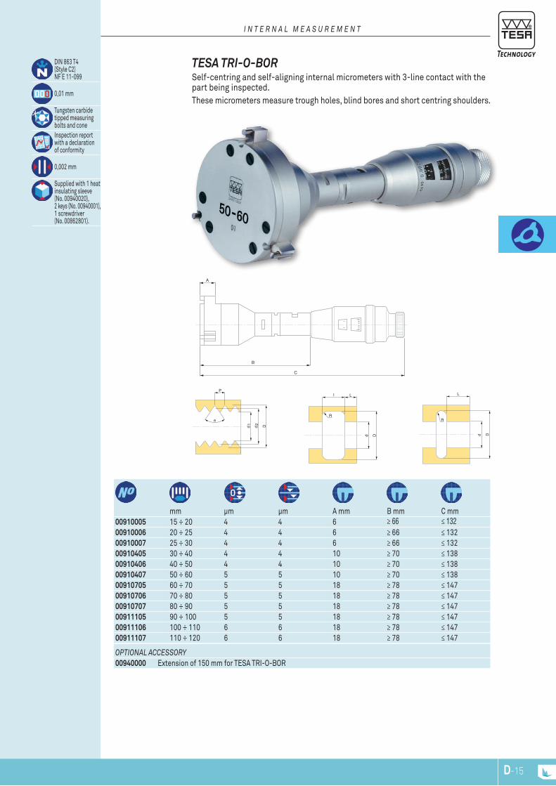
Dd
R
L
B
A
C
D
e
P
d1
d2
Dd
R
l L
00910005 15 ÷ 20 4 4 6 ≥ 66 ≤ 13200910006 20 ÷ 25 4 4 6 ≥ 66 ≤ 13200910007 25 ÷ 30 4 4 6 ≥ 66 ≤ 13200910405 30 ÷ 40 4 4 10 ≥ 70 ≤ 13800910406 40 ÷ 50 4 4 10 ≥ 70 ≤ 13800910407 50 ÷ 60 5 5 10 ≥ 70 ≤ 13800910705 60 ÷ 70 5 5 18 ≥ 78 ≤ 14700910706 70 ÷ 80 5 5 18 ≥ 78 ≤ 14700910707 80 ÷ 90 5 5 18 ≥ 78 ≤ 14700911105 90 ÷ 100 5 5 18 ≥ 78 ≤ 14700911106 100 ÷ 110 6 6 18 ≥ 78 ≤ 14700911107 110 ÷ 120 6 6 18 ≥ 78 ≤ 147
mm μm μm A mm B mm C mm
optional accEssory00940000 Extension of 150 mm for TESA TRI-O-BOR
DIN 863 T4(Style C2)NF E 11-099
0,01 mm
Tungsten carbidetipped measuringbolts and coneInspection reportwith a declarationof conformity
0,002 mm
Supplied with 1 heatinsulating sleeve (No. 00940020), 2 keys (No. 00940001),1 screwdriver(No. 00862801).
TESA TRI-O-BOR Self-centring and self-aligning internal micrometers with 3-line contact with the part being inspected.These micrometers measure trough holes, blind bores and short centring shoulders.
i n t E r n a l m E a s u r E m E n t
D-15

00940000 150mm
Extension for Depth Increase TESA TRI-O-BOR
DIN 863 T4 (Style 2)NF E 11-099
0,01 mm
Tungsten carbidetipped measuring bolts and coneInspection reportwith a declarationof conformity
0,002 mm
Supplied with1 heat insulatingsleeve No 00940020,2 key No 00940001,1 screwdriver No 00862801
TESA TRI-O-BOR, Full Sets Self-centring and self-aligning internal micrometers with 3-line contact with the part being inspected.These micrometers measure through holes, blind bores and short centring shoulders.
i n t E r n a l m E a s u r E m E n t
mm Single micrometers
mm Setting rings mm Extensions mm
composition of thE sEts:00910004 BSC 15 ÷ 30 00910005 15 ÷ 20 00840104 15 00940000 150
00910006 20 ÷ 25 00840106 25 00910007 25 ÷ 30
00910404 BSD 30 ÷ 60 00910405 30 ÷ 40 00840107 35 00940000 15000910406 40 ÷ 50 00840108 50 00910407 50 ÷ 60
00910704 BSF 60 ÷ 90 00910705 60 ÷ 70 00840109 70 00940000 15000910706 70 ÷ 80 00840110 90 00910707 80 ÷ 90
00911104 BSG 90 ÷ 120 00911105 90 ÷ 100 00840110 90 00940000 15000911106 100 ÷ 110 00840111 110 00911107 110 ÷ 120
D-16
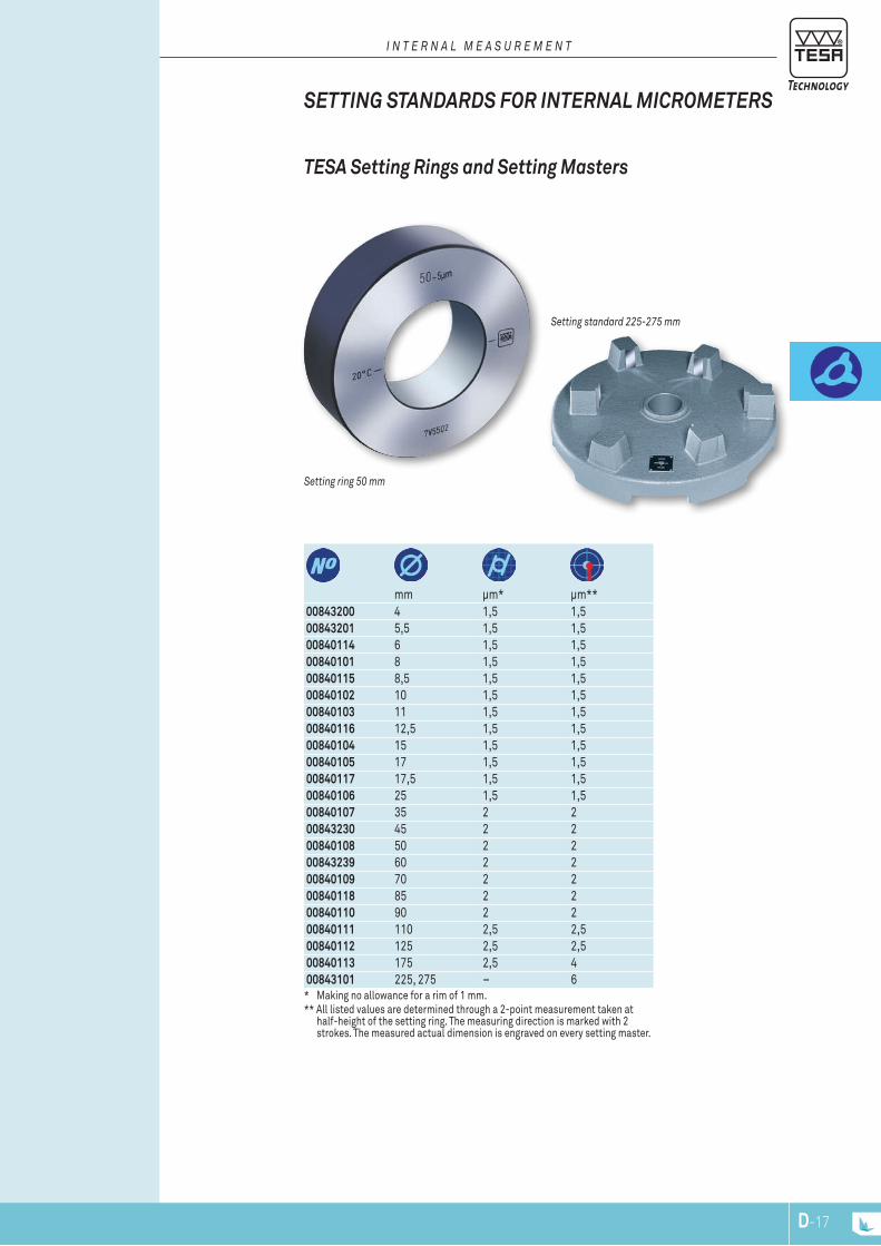
setting ring 50 mm
setting standard 225-275 mm
mm μm* μm**00843200 4 1,5 1,500843201 5,5 1,5 1,500840114 6 1,5 1,500840101 8 1,5 1,500840115 8,5 1,5 1,500840102 10 1,5 1,500840103 11 1,5 1,500840116 12,5 1,5 1,500840104 15 1,5 1,500840105 17 1,5 1,500840117 17,5 1,5 1,500840106 25 1,5 1,500840107 35 2 200843230 45 2 200840108 50 2 200843239 60 2 200840109 70 2 200840118 85 2 200840110 90 2 200840111 110 2,5 2,500840112 125 2,5 2,500840113 175 2,5 400843101 225, 275 – 6
* Making no allowance for a rim of 1 mm. ** All listed values are determined through a 2-point measurement taken at
half-height of the setting ring. The measuring direction is marked with 2 strokes. The measured actual dimension is engraved on every setting master.
TESA Setting Rings and Setting Masters
SETTING STANDARDS FOR INTERNAL MICROMETERS
i n t E r n a l m E a s u r E m E n t
D-17

D-18
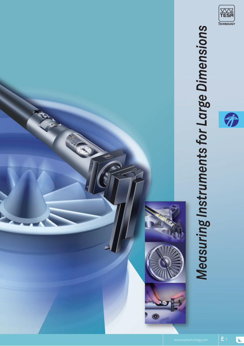
www.tesatechnology.com
Mea
surin
g In
stru
men
ts fo
r Lar
ge D
imen
sion
s
E-1

Here's an example of a proportional relationship. With a bore of ø 1200 H7, the tolerance area matches 0,1 mm. Reducing both values by a factor of 100 would give a manufacturing tolerance as low as 1 μm. Of course, things are not as simple, but this example gives some ideas about the proportions.
There are other methods that often call for very simple techniques, such as fixed gauges (caliper gauges), combinations of gauge blocks, or even adjustable telescopic gauges.
Large sizes in mechanical engineering generally mean dimensions in excess of 500 mm. Various measurement procedures are brought into play, using such items as large internal and external micrometers with two-point contact, periphery tapes (for outside diameters), V-bases, rotating measuring disks (rolling-contact) optical systems (triangulation with theodolite), fixed gauges (inside caliper gauges), gauge blocks combinations or adjustable telescopic gauges.
Whatever the sizes, from a simple distance between two surfaces parallel to one another measurement is always a challenge. Apart from the usual influences, which are proportional to the size whilst adding to your contributions in the uncertainty budget, those due to gravity play a key role in distortion.
For large dimensions from 250 mm up to several meters, TESA offers various types of mea-suring instruments that have long proven their value in practical use.
TESA – THE SPECIALISTS FOR LONG LENGTHS
M E A S u R i n g i n S T R u M E n T S F O R L A R g E D i M E n S i O n S
E-2
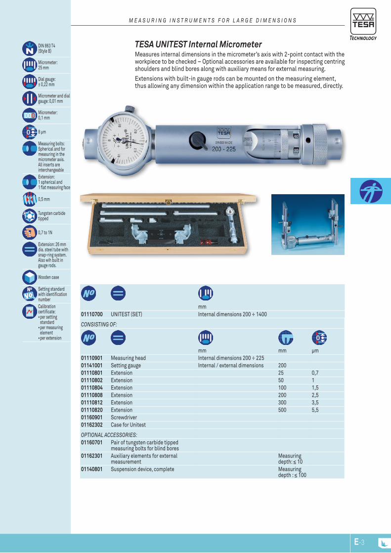
DIN 863 T4(Style B)
Micrometer: 25 mm
Dial gauge: ± 0,22 mm
Micrometer and dial gauge: 0,01 mm
Micrometer: 0,1 mm
8 μm
Measuring bolts: Spherical and for measuring in the micrometer axis. All inserts are interchangeableExtension: 1 spherical and 1 flat measuring face
0,5 mm
Tungsten carbide tipped
0,7 to 1N
Extension: 26 mm dia. steel tube with snap-ring system. Also wih built in gauge rods.
Wooden case
Setting standardwith identificationnumberCalibration certificate:•per setting
standard•per measuring
element•per extension
mm01110700 UNITEST (SET) Internal dimensions 200 ÷ 1400
Extensions with built-in gauge rods can be mounted on the measuring element, thus allowing any dimension within the application range to be measured, directly.
COnSiSTing OF:
mm mm μm01110901 Measuring head Internal dimensions 200 ÷ 22501141001 Setting gauge Internal / external dimensions 20001110801 Extension 25 0,701110802 Extension 50 101110804 Extension 100 1,501110808 Extension 200 2,501110812 Extension 300 3,501110820 Extension 500 5,501160901 Screwdriver01162302 Case for Unitest
OpTiOnAL ACCESSORiES:01160701 Pair of tungsten carbide tipped
measuring bolts for blind bores01162301 Auxiliary elements for external
measurement Measuring depth: ≤ 10
01140801 Suspension device, complete Measuring depth : ≤ 100
TESA UNITEST Internal Micrometer Measures internal dimensions in the micrometer’s axis with 2-point contact with the workpiece to be checked – Optional accessories are available for inspecting centring shoulders and blind bores along with auxiliary means for external measuring.
M E A S u R i n g i n S T R u M E n T S F O R L A R g E D i M E n S i O n S
E-3
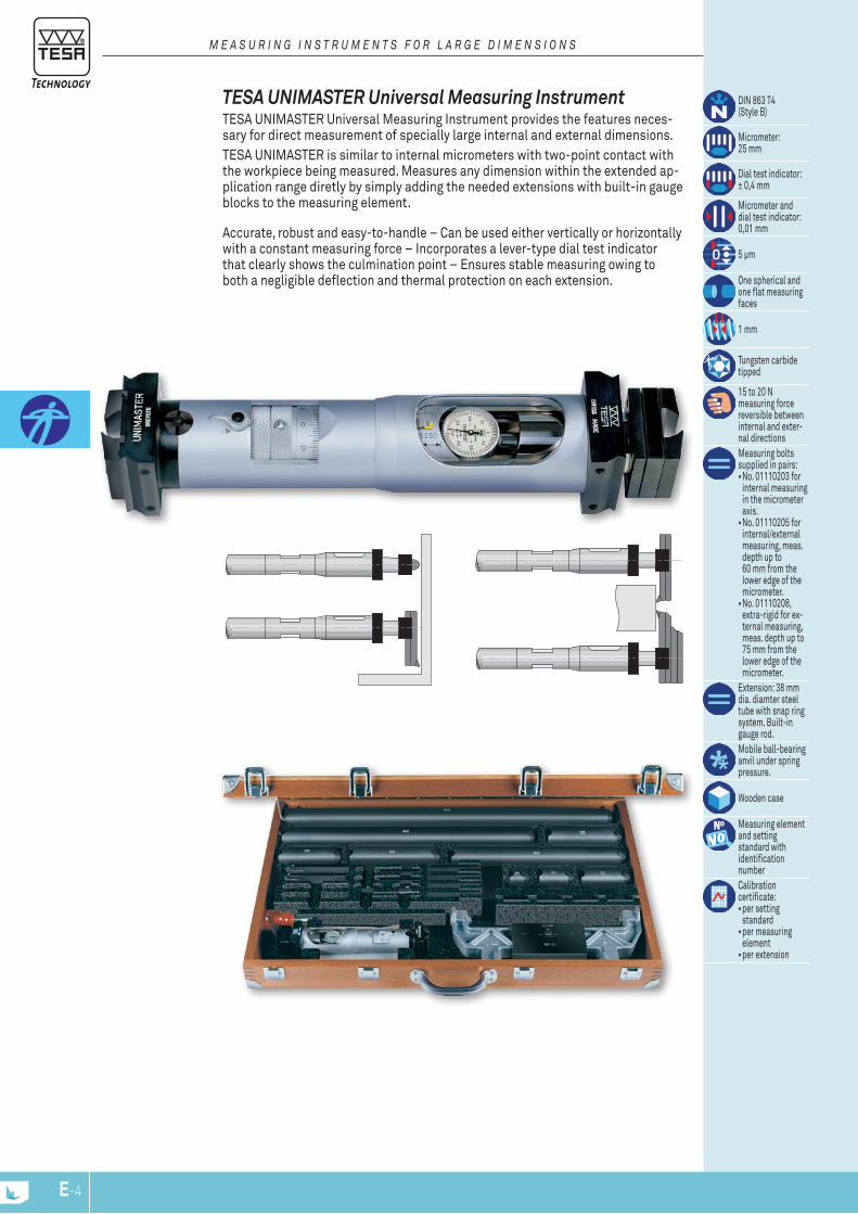
DIN 863 T4(Style B)
Micrometer: 25 mm
Dial test indicator: ± 0,4 mm
Micrometer and dial test indicator: 0,01 mm
5 μm
One spherical and one flat measuring faces
1 mm
Tungsten carbide tipped
15 to 20 N measuring force reversible between internal and exter-nal directionsMeasuring bolts supplied in pairs:•No. 01110203 for
internal measuring in the micrometer axis. •No. 01110205 for
internal/external measuring, meas. depth up to 60 mm from the lower edge of the micrometer.•No. 01110208,
extra-rigid for ex-ternal measuring, meas. depth up to 75 mm from the lower edge of the micrometer.
Extension: 38 mm dia. diamter steel tube with snap ring system. Built-in gauge rod.Mobile ball-bearing anvil under spring pressure.
Wooden case
Measuring element and setting standard with identification numberCalibration certificate:•per setting
standard•per measuring
element•per extension
Accurate, robust and easy-to-handle – Can be used either vertically or horizontally with a constant measuring force – Incorporates a lever-type dial test indicator that clearly shows the culmination point – Ensures stable measuring owing to both a negligible deflection and thermal protection on each extension.
TESA UNIMASTER Universal Measuring Instrument TESA UNIMASTER Universal Measuring Instrument provides the features neces-sary for direct measurement of specially large internal and external dimensions.TESA UNIMASTER is similar to internal micrometers with two-point contact with the workpiece being measured. Measures any dimension within the extended ap-plication range diretly by simply adding the needed extensions with built-in gauge blocks to the measuring element.
M E A S u R i n g i n S T R u M E n T S F O R L A R g E D i M E n S i O n S
E-4
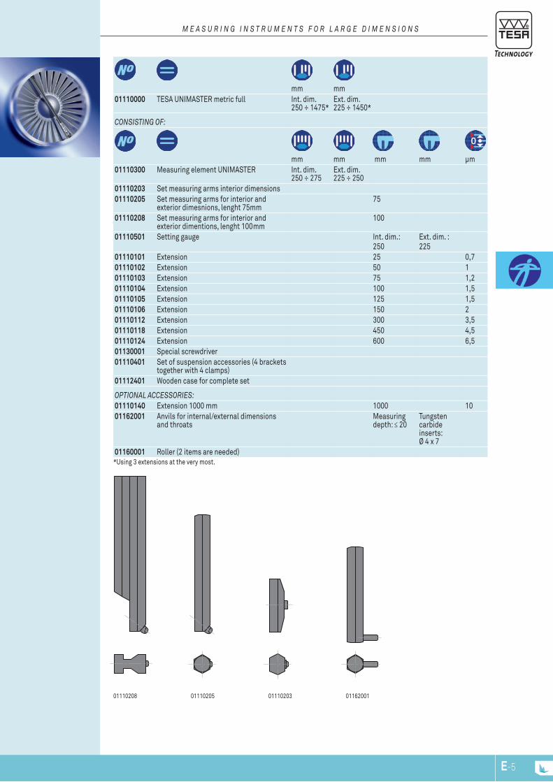
01110208 01110205 01110203 0116200111.10205
11.6200111.10208 11.10203
mm mm
01110000 TESA UNIMASTER metric full Int. dim. 250 ÷ 1475*
Ext. dim. 225 ÷ 1450*
COnSiSTing OF:
mm mm mm mm μm01110300 Measuring element UNIMASTER Int. dim.
250 ÷ 275Ext. dim. 225 ÷ 250
01110203 Set measuring arms interior dimensions01110205 Set measuring arms for interior and
exterior dimesnions, lenght 75mm75
01110208 Set measuring arms for interior and exterior dimentions, lenght 100mm
100
01110501 Setting gauge Int. dim.: 250
Ext. dim. : 225
01110101 Extension 25 0,701110102 Extension 50 101110103 Extension 75 1,201110104 Extension 100 1,501110105 Extension 125 1,501110106 Extension 150 201110112 Extension 300 3,501110118 Extension 450 4,501110124 Extension 600 6,501130001 Special screwdriver01110401 Set of suspension accessories (4 brackets
together with 4 clamps)01112401 Wooden case for complete set
OpTiOnAL ACCESSORiES:01110140 Extension 1000 mm 1000 1001162001 Anvils for internal/external dimensions
and throatsMeasuring depth: ≤ 20
Tungsten carbide inserts: Ø 4 x 7
01160001 Roller (2 items are needed)*Using 3 extensions at the very most.
M E A S u R i n g i n S T R u M E n T S F O R L A R g E D i M E n S i O n S
E-5
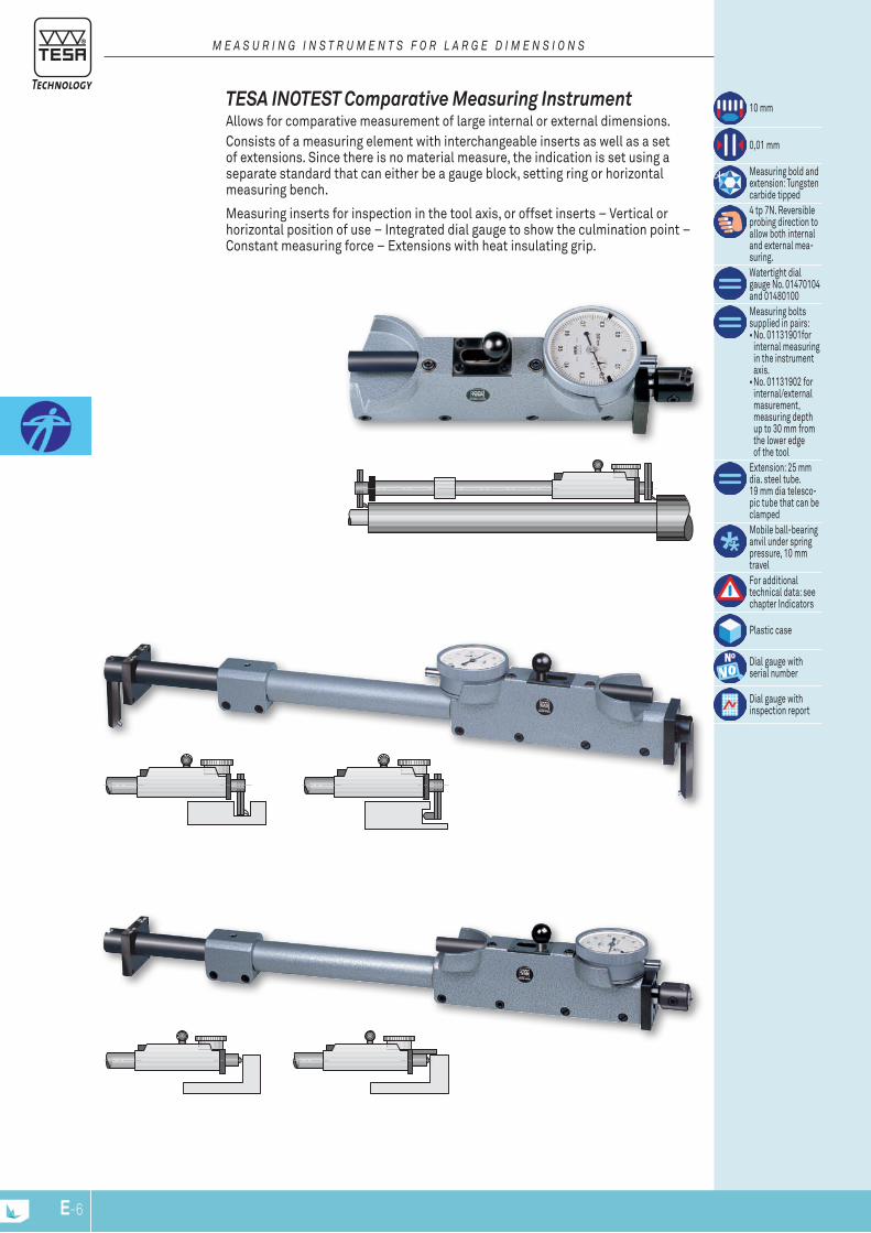
10 mm
0,01 mm
Measuring bold and extension: Tungsten carbide tipped4 tp 7N. Reversible probing direction to allow both internal and external mea-suring.Watertight dial gauge No. 01470104 and 01480100Measuring bolts supplied in pairs:•No. 01131901for
internal measuring in the instrument axis.•No. 01131902 for
internal/external masurement, measuring depth up to 30 mm from the lower edge of the tool
Extension: 25 mm dia. steel tube. 19 mm dia telesco-pic tube that can be clampedMobile ball-bearing anvil under spring pressure, 10 mm travelFor additional technical data: see chapter Indicators
Plastic case
Dial gauge with serial number
Dial gauge withinspection report
Measuring inserts for inspection in the tool axis, or offset inserts – Vertical or horizontal position of use – Integrated dial gauge to show the culmination point – Constant measuring force – Extensions with heat insulating grip.
TESA INOTEST Comparative Measuring Instrument Allows for comparative measurement of large internal or external dimensions.Consists of a measuring element with interchangeable inserts as well as a set of extensions. Since there is no material measure, the indication is set using a separate standard that can either be a gauge block, setting ring or horizontal measuring bench.
M E A S u R i n g i n S T R u M E n T S F O R L A R g E D i M E n S i O n S
E-6
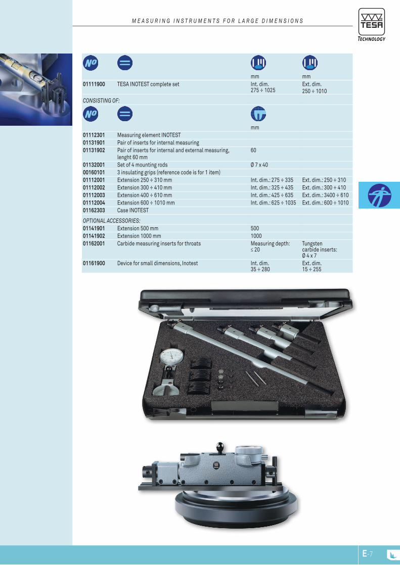
mm mm
01111900 TESA INOTEST complete set Int. dim. 275 ÷ 1025
Ext. dim.250 ÷ 1010
COnSiSTing OF:
mm01112301 Measuring element INOTEST01131901 Pair of inserts for internal measuring01131902 Pair of inserts for internal and external measuring,
lenght 60 mm60
01132001 Set of 4 mounting rods Ø 7 x 4000160101 3 insulating grips (reference code is for 1 item)01112001 Extension 250 ÷ 310 mm Int. dim.: 275 ÷ 335 Ext. dim.: 250 ÷ 31001112002 Extension 300 ÷ 410 mm Int. dim.: 325 ÷ 435 Ext. dim.: 300 ÷ 41001112003 Extension 400 ÷ 610 mm Int. dim.: 425 ÷ 635 Ext. dim.: 3400 ÷ 61001112004 Extension 600 ÷ 1010 mm Int. dim.: 625 ÷ 1035 Ext. dim.: 600 ÷ 101001162303 Case INOTEST
OpTiOnAL ACCESSORiES:01141901 Extension 500 mm 50001141902 Extension 1000 mm 100001162001 Carbide measuring inserts for throats Measuring depth:
≤ 20Tungsten carbide inserts: Ø 4 x 7
01161900 Device for small dimensions, Inotest Int. dim. 35 ÷ 280
Ext. dim. 15 ÷ 255
M E A S u R i n g i n S T R u M E n T S F O R L A R g E D i M E n S i O n S
E-7
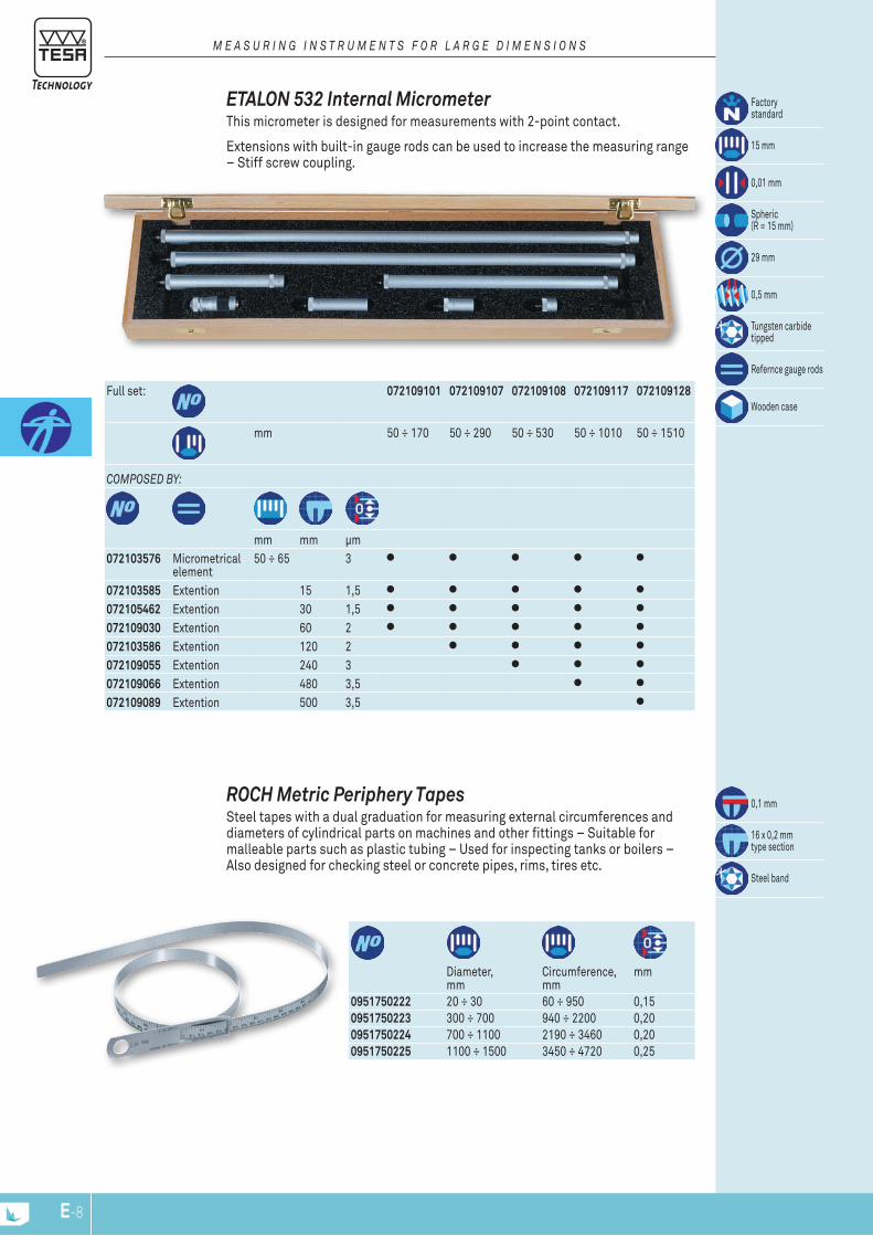
Diameter, mm
Circumference, mm
mm
0951750222 20 ÷ 30 60 ÷ 950 0,150951750223 300 ÷ 700 940 ÷ 2200 0,200951750224 700 ÷ 1100 2190 ÷ 3460 0,200951750225 1100 ÷ 1500 3450 ÷ 4720 0,25
0,1 mm
16 x 0,2 mmtype section
Steel band
ROCH Metric Periphery Tapes Steel tapes with a dual graduation for measuring external circumferences and diameters of cylindrical parts on machines and other fittings – Suitable for malleable parts such as plastic tubing – Used for inspecting tanks or boilers – Also designed for checking steel or concrete pipes, rims, tires etc.
Factorystandard
15 mm
0,01 mm
Spheric (R = 15 mm)
29 mm
0,5 mm
Tungsten carbide tipped
Refernce gauge rods
Wooden caseFull set: 072109101 072109107 072109108 072109117 072109128
mm 50 ÷ 170 50 ÷ 290 50 ÷ 530 50 ÷ 1010 50 ÷ 1510
COMpOSED by:
mm mm μm072103576 Micrometrical
element50 ÷ 65 3
072103585 Extention 15 1,5072105462 Extention 30 1,5072109030 Extention 60 2072103586 Extention 120 2072109055 Extention 240 3072109066 Extention 480 3,5072109089 Extention 500 3,5
Extensions with built-in gauge rods can be used to increase the measuring range – Stiff screw coupling.
ETALON 532 Internal Micrometer This micrometer is designed for measurements with 2-point contact.
M E A S u R i n g i n S T R u M E n T S F O R L A R g E D i M E n S i O n S
E-8
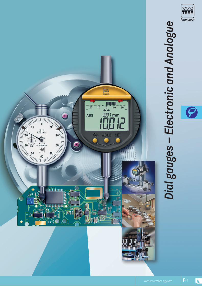
www.tesagroup.comNP www.tesagroup.com 1www.tesatechnology.com
Dial
gau
ges
– El
ectr
onic
and
Ana
logu
e
F-1F-NP
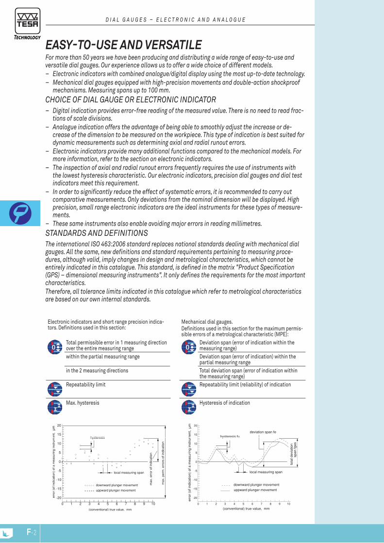
www.tesagroup.com2 www.tesagroup.com 3
0
10
5
-5
20
15
-10
-15
-20
0 1 2 3 4 5 76 8 9 10
(conventional) true value, mm
erro
r (o
f ind
icat
ion)
of a
mea
surin
g in
stru
men
t,
uppward plunger movement
downward plunger movement
hysteresis
max
. per
m. e
rror
s of
indi
catio
n
local measuring span
max
. err
or o
f ind
icat
ion
µm
0
10
5
-5
20
15
-10
-15
-20
0 1 2 3 4 5 76 8 9 10
(conventional) true value, mm
erro
r (o
f ind
icat
ion)
of a
mea
surin
g in
stru
men
t, µm
uppward plunger movement
downward plunger movement
hysteresis fu
tota
l dev
iatio
n
s
pan
fges
deviation span fe
local measuring span
Electronic indicators and short range precision indica-tors. Definitions used in this section:
Mechanical dial gauges.Definitions used in this section for the maximum permis-sible errors of a metrological characteristic (MPE):
Total permissible error in 1 measuring direction over the entire measuring range
Deviation span (error of indication within the measuring range)
within the partial measuring range Deviation span (error of indication) within the partial measuring range
in the 2 measuring directions Total deviation span (error of indication within the measuring range)
Repeatability limit Repeatability limit (reliability) of indication
Max. hysteresis Hysteresis of indication
EASY-TO-USE AND VERSATILEFor more than 50 years we have been producing and distributing a wide range of easy-to-use and versatile dial gauges. Our experience allows us to offer a wide choice of different models.
– Electronic indicators with combined analogue/digital display using the most up-to-date technology. – Mechanical dial gauges equipped with high-precision movements and double-action shockproof
mechanisms. Measuring spans up to 100 mm. ChOiCE OF Dial GauGE Or ElECtrOniC inDiCatOr
– Digital indication provides error-free reading of the measured value. there is no need to read frac-tions of scale divisions.
– analogue indication offers the advantage of being able to smoothly adjust the increase or de-crease of the dimension to be measured on the workpiece. this type of indication is best suited for dynamic measurements such as determining axial and radial runout errors.
– Electronic indicators provide many additional functions compared to the mechanical models. For more information, refer to the section on electronic indicators.
– the inspection of axial and radial runout errors frequently requires the use of instruments with the lowest hysteresis characteristic. Our electronic indicators, precision dial gauges and dial test indicators meet this requirement.
– in order to significantly reduce the effect of systematic errors, it is recommended to carry out comparative measurements. Only deviations from the nominal dimension will be displayed. high precision, small range electronic indicators are the ideal instruments for these types of measure-ments.
– these same instruments also enable avoiding major errors in reading millimetres. StanDarDS anD DEFinitiOnSthe international iSO 463:2006 standard replaces national standards dealing with mechanical dial gauges. all the same, new definitions and standard requirements pertaining to measuring proce-dures, although valid, imply changes in design and metrological characteristics, which cannot be entirely indicated in this catalogue. this standard, is defined in the matrix "Product Specification (GPS) – dimensional measuring instruments". it only defines the requirements for the most important characteristics. therefore, all tolerance limits indicated in this catalogue which refer to metrological characteristics are based on our own internal standards.
D i a l G a u G E S – E l E C t r O n i C a n D a n a l O G u E
F-3F-2
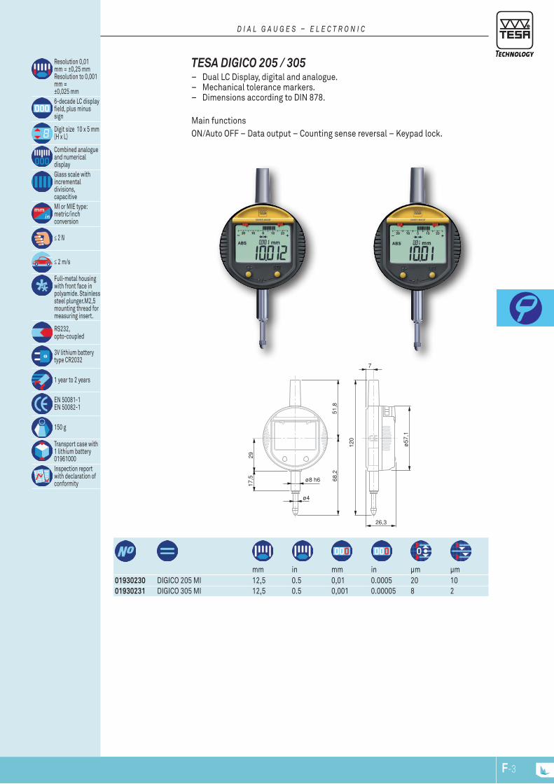
www.tesagroup.com2 www.tesagroup.com 3
17,5 68
,251
,8
29
ø8 h6
ø4
120
ø57
,1
7
26,3
mm in mm in μm μm
01930230 DIGICO 205 MI 12,5 0.5 0,01 0.0005 20 1001930231 DIGICO 305 MI 12,5 0.5 0,001 0.00005 8 2
TESA DIGICO 205 / 305 – Dual LC Display, digital and analogue. – Mechanical tolerance markers. – Dimensions according to DIN 878.
Main functionsON/Auto OFF – Data output – Counting sense reversal – Keypad lock.
Resolution 0,01 mm = ±0,25 mm Resolution to 0,001 mm = ±0,025 mm6-decade LC display field, plus minus sign
Digit size 10 x 5 mm (H x L)
Combined analogue and numerical displayGlass scale withincremental divisions,capacitiveMI or MIE type: metric/inch conversion
≤ 2 N
≤ 2 m/s
Full-metal housing with front face in polyamide. Stainless steel plunger.M2,5 mounting thread for measuring insert.
RS232, opto-coupled
3V lithium battery type CR2032
1 year to 2 years
EN 50081-1 EN 50082-1
150 g
Transport case with 1 lithium battery 01961000Inspection report with declaration of conformity
D i a l G a u G E S – E l E C t r O n i C
F-3F-2
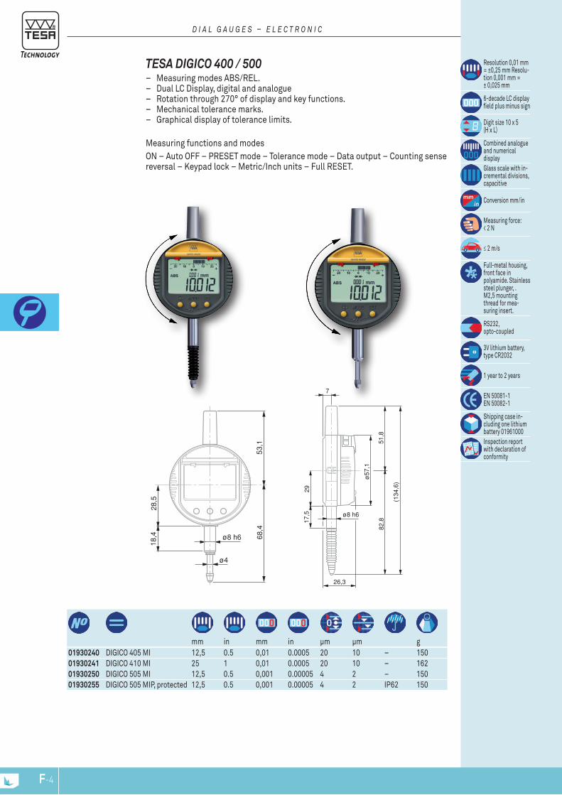
17,5
82,8
51,8
29
ø8 h6
(134
,6)
ø57
,1
7
26,3
53,1
18,4 68
,4
28,5
ø8 h6
ø4
121,
5
ø57
,1
7
27
134,
4
ø57
,1
7
27
mm in mm in μm μm g
01930240 DIGICO 405 MI 12,5 0.5 0,01 0.0005 20 10 – 15001930241 DIGICO 410 MI 25 1 0,01 0.0005 20 10 – 16201930250 DIGICO 505 MI 12,5 0.5 0,001 0.00005 4 2 – 15001930255 DIGICO 505 MIP, protected 12,5 0.5 0,001 0.00005 4 2 IP62 150
Resolution 0,01 mm = ±0,25 mm Resolu-tion 0,001 mm = ± 0,025 mm
6-decade LC display field plus minus sign
Digit size 10 x 5 (H x L)
Combined analogue and numerical displayGlass scale with in-cremental divisions, capacitive
Conversion mm/in
Measuring force: < 2 N
≤ 2 m/s
Full-metal housing, front face in polyamide. Stainless steel plunger, .M2,5 mounting thread for mea-suring insert.
RS232, opto-coupled
3V lithium battery, type CR2032
1 year to 2 years
EN 50081-1 EN 50082-1
Shipping case in-cluding one lithium battery 01961000Inspection report with declaration of conformity
TESA DIGICO 400 / 500 – Measuring modes ABS/REL. – Dual LC Display, digital and analogue – Rotation through 270° of display and key functions. – Mechanical tolerance marks. – Graphical display of tolerance limits.
Measuring functions and modesON – Auto OFF – PRESET mode – Tolerance mode – Data output – Counting sense reversal – Keypad lock – Metric/Inch units – Full RESET.
D i a l G a u G E S – E l E C t r O n i C
F-5F-4
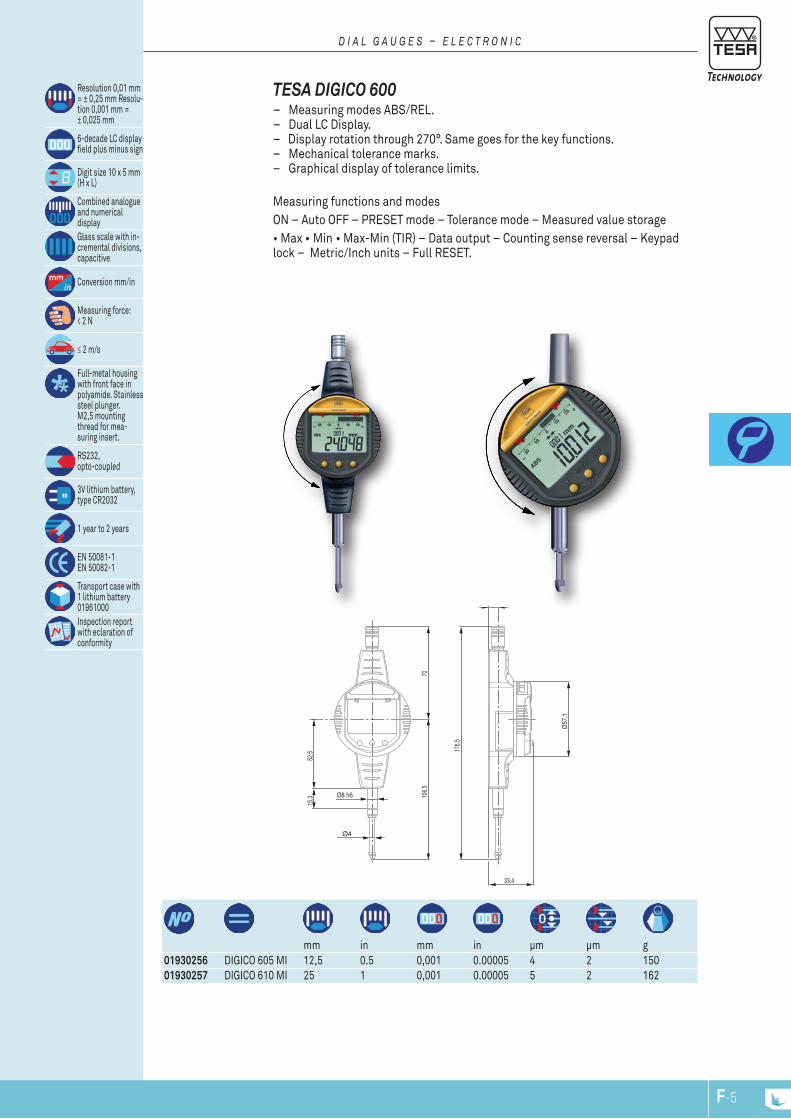
106,
570
176,
5
Ø57
,1
7
33,4
Ø8 h6
Ø4
52,5
15,3
mm in mm in μm μm g
01930256 DIGICO 605 MI 12,5 0.5 0,001 0.00005 4 2 15001930257 DIGICO 610 MI 25 1 0,001 0.00005 5 2 162
TESA DIGICO 600 – Measuring modes ABS/REL. – Dual LC Display. – Display rotation through 270°. Same goes for the key functions. – Mechanical tolerance marks. – Graphical display of tolerance limits.
Measuring functions and modes ON – Auto OFF – PRESET mode – Tolerance mode – Measured value storage • Max • Min • Max-Min (TIR) – Data output – Counting sense reversal – Keypad lock – Metric/Inch units – Full RESET.
Resolution 0,01 mm = ± 0,25 mm Resolu-tion 0,001 mm = ± 0,025 mm
6-decade LC display field plus minus sign
Digit size 10 x 5 mm (H x L)
Combined analogue and numerical displayGlass scale with in-cremental divisions, capacitive
Conversion mm/in
Measuring force: < 2 N
≤ 2 m/s
Full-metal housing with front face in polyamide. Stainless steel plunger.M2,5 mounting thread for mea-suring insert.
RS232, opto-coupled
3V lithium battery, type CR2032
1 year to 2 years
EN 50081-1 EN 50082-1
Transport case with 1 lithium battery 01961000Inspection report with eclaration of conformity
D i a l G a u G E S – E l E C t r O n i C
F-5F-4

01961000 Lithium battery, 3V, CR203204761054 Battery charger 100 ÷ 200 VAC / 50 ÷ 60 Hz, 6,6 Vdc, 750 mAh supplied without
power cable04761055 Cable EU for charger 047105404761056 Power cable US for charger 0471054
01962002 External power supply
- Measuring inserts, see chapter "Measuring inserts for dial gauges, axial probes and other hand tools".- Backs and retraction devices, see chapter "Devices for plunger retraction" and "Backs for Dial Gauges".- Connectivity, see corresponding chapter.
Accessories for TESA DIGICO 200 – 700
mm in mm in μm μm g
01930258 DIGICO 705 MI 12,5 0.5 0,001 0.00005 4 2 150
Resolution to 0,01 mm = ± 0,25 mm Resolution 0,001 mm =± 0,025 mm6-decade LC display field, plus minus sign
Digit size 10 x 5 mm (H x L)
Combined analogue and numerical displayGlass scale with in-cremental divisions, capacitive
Conversion mm/in
Measuring force < 2 N
≤ 2 m/s
Full-metal housing with front face in polyamide. Stainless steel plunger,M2,5 mounting thread for the mea-suring insert.
RS232, opto-coupled
3V lithium battery, type CR2032
1 to 2 years
EN 50081-1 EN 50082-1
Transport case with 1 lithium battery 01961000Inspection report with declaration of conformity
TESA DIGICO 705 For use with 2-point contact bore gauges. Allows setting of the dial gauge to the smallest setting ring value.
– Same functions as DIGICO 600.
D i a l G a u G E S – E l E C t r O n i C
F-7F-6
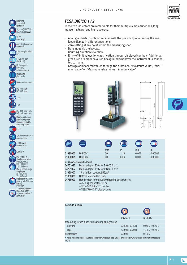
57 /
86,5
30 /
60
199
/ 233
6
ø8 h6
49
18/17
29
9
20
ø4,5
mm in mm in
01930000 DIGICO 1 30 1.18 0,001 0.0000501930001 DIGICO 2 60 3.36 0,001 0.00005
Force de mesure
DIGICO 1 DIGICO 2Measuring force* close to measuring plunger stop– Bottom 0.85 N ± 0.15 N 0.90 N ± 0.20 N– Top 1.10 N ± 0.20 N 1.45 N ± 0.25 NHysteresis* 0.10 N 0.15 N* Valid with indicator in vertical position, measuring plunger oriented downwards and in static measure-ment.
OPtiOnal aCCESSOriES:04761037 Mains adaptor 230V for DIGICO 1 or 204761057 Mains adaptor 110V for DIGICO 1 or 201960007 3.5 V lithium battery, LR6, AA01960005 Bottom mounted lift lever04768000 Hand switch for manually triggering data transfer.
Jack plug connector, 1,8 m – TESA SPC PRINTER printer – TESATRONIC TT display units
Accordingto selectedtolerances
30,4 mm (DIGICO 1) or60,4 mm (DIGICO 2)
40 mmscale length
According to selected tolerances
6 decades plus minus sign
9 x 4,5 mm digitsize (H x W)
LC display withbacklight, with 25 divisions
Incrementalglass scale
Metric/inch conversion
DIGICO 1: 2 μmDIGICO 2: 3 μm
1 μm
1 μm
DIGICO 1: max. 1 m/sDIGICO 2: max. 2 m/s
Plunger guided on a plain bearing M2,5 mounting thread fo measuring insert.
RS232
3,6 V lithium battery or mains adapter
≈ 1000 h withlithium battery
0,002%/°C
DIGICO case in standard execution:IP54 (IEC 60529)290 g (DIGICO 1)310 g (DIGICO 2)Moved mass through the plunger:28 g (DIGICO 1)27 g (DIGICO 2)Supplied in transport packing with 1 lithium battery01960007 1 lift lever 01960005Inspection report with a declaration of conformity
TESA DIGICO 1 / 2 These two indicators are remarkable for their multiple simple functions, long measuring travel and high accuracy.
– Analogue/digital display combined with the possibility of orienting the ana-logue display in different positions.
– Zero setting at any point within the measuring span. – Data input via the keypad. – Counting direction reversible. – Entry of limit values for classification through displayed symbols. Additional
green, red or amber coloured background whenever the instrument is connec-ted to mains.
– Storage of measured values through the functions: "Maximum value", "Mini-mum value" or "Maximum value minus minimum value".
D i a l G a u G E S – E l E C t r O n i C
F-7F-6
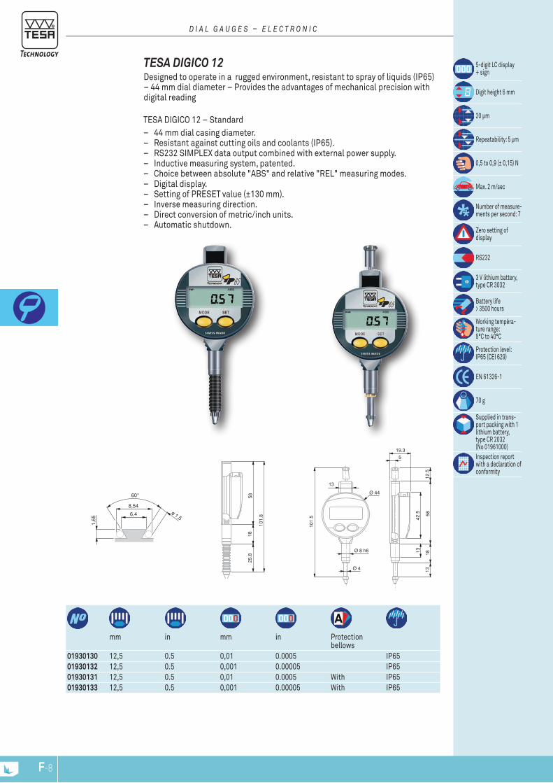
42.5
13
1318
5812
.5
19.3
5
Ø 4
Ø 8 h6
13
101.
5
Ø 44
5818
25.8
101.
8
8,54
6,4 ø 1,5
1,65
mm in mm in Protection
bellows01930130 12,5 0.5 0,01 0.0005 IP6501930132 12,5 0.5 0,001 0.00005 IP6501930131 12,5 0.5 0,01 0.0005 With IP6501930133 12,5 0.5 0,001 0.00005 With IP65
TESA DIGICO 12 – Standard – 44 mm dial casing diameter. – Resistant against cutting oils and coolants (IP65). – RS232 SIMPLEX data output combined with external power supply. – Inductive measuring system, patented. – Choice between absolute "ABS" and relative "REL" measuring modes. – Digital display. – Setting of PRESET value (±130 mm). – Inverse measuring direction. – Direct conversion of metric/inch units. – Automatic shutdown.
TESA DIGICO 12Designed to operate in a rugged environment, resistant to spray of liquids (IP65) – 44 mm dial diameter – Provides the advantages of mechanical precision with digital reading
5-digit LC display + sign
Digit height 6 mm
20 μm
Repeatability: 5 μm
0,5 to 0,9 (± 0,15) N
Max. 2 m/sec
Number of measure-ments per second: 7
Zero setting of display
RS232
3 V lithium battery, type CR 3032
Battery life > 3500 hours
Working tempéra-ture range: 5°C to 40°C
Protection level: IP65 (CEI 629)
EN 61326-1
70 g
Supplied in trans-port packing with 1 lithium battery, type CR 2032 (No 01961000)Inspection report with a declaration of conformity
D i a l G a u G E S – E l E C t r O n i C
F-9F-8

19,05
6,4
9,5
14,3
ø 6,4
26,2
1050
24.5
8,54
6,4 ø 1,5
1,65
50.5
1816
.3
84.842
.513
5.5
1850
.512
.5
19.3
5
Ø 4
Ø 8 h6
13
86.5
Ø 44
mm in mm in Protection bellows
01930134 5 0.210 0,001 0.00005 IP6501930135 5 0.210 0,001 0.00005 With IP65
LCD, 5 digits + sign
Digit height: 6 mm
Max. permissible error: 4 μm
Repeatability limit: 2 μm
0,4 to 0,75 (± 0,15) N
Max. 2 m/sec
Number of measure-ments per second: 9
Zero-setting of display
RS232
3 V lithium battery, type CR 2032
Battery life: > 4000 hours
Working tempéra-ture range: 5°C to 40°C
IP65 (CEI 529)
EN 61326-1
70 g
Supplied in trans-port packing with 1 lithium battery, type CR 2032 (No 01961000)Inspection report with a declaration of conformity
TESA DIGICO 12 – HP – High precision measuring system. – Resistant to cutting oils and coolants (IP65). – Combined analogue/digital display. – Analogue reading from ±0.025 to ±1.25 mm. – NOR/MIN/MAX/MAX-MIN measuring modes. – 44 mm dial casing diameter. – RS 232 data output combined with external power supply. – Inductive measuring system, patented. – Zero-setting of display. – Direct conversion of metric/inch units. – Shut down: either automatic or blocked.
D i a l G a u G E S – E l E C t r O n i C
01960005 Bottom mounted lift lever04761060 RS 232 cable with external power supply01961000 Lithium battery, 3V, CR2032
03238013 Mounting lug01961012 Upper lift lever
Accessories for TESA DIGICO 12
01961012
03238013
F-9F-8
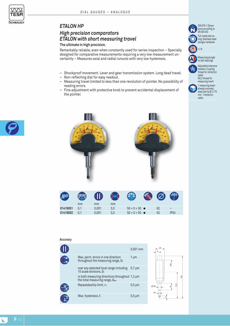
23
9
18
6
72,5
108
ø8 h6
ø4
R31
mm mm mm
01419051 0,1 0,001 3,0 50 ÷ 0 ÷ 50 62 –01419052 0,1 0,001 3,0 50 ÷ 0 ÷ 50 62 IP54
Accuracy
– Shockproof movement. Lever and gear transmission system. Long dead travel. – Non-reflecting dial for easy readout. – Measuring travel limited to less than one revolution of pointer. No possibility of
reading errors. – Fine adjustment with protective knob to prevent accidental displacement of
the pointer.
0,001 mm
Max. perm. errors in one direction throughout the measuring range, Ge
1 µm
over any selected local range including 10 scale divisions, Gt
0,7 µm
in both measuring directions throughout the total measuring range, Gges
1,2 µm
Repeatabaility limit, rw 0,5 µm
Max. hysteresis, fu 0,5 µm
ETALON HPHigh precision comparators ETALON with short measuring travel The ultimate in high precision. Remarkably reliable, even when constantly used for series inspection – Specially designed for comparative measurements requiring a very low measurement un-certainty – Measures axial and radial runouts with very low hysteresis.
DIN 879-1 Dimen-sions according to EN ISO 463Full-metal dial ca-sing. Stainless steel plunger, hardened.
≈1 N
Measuring plunger on ball-bearings
Adjustable tolerance markers. Coupling thread for retraction cable. M2,5 thread for measuring insert1 measuring insert already mounted, steel ball tip Ø 3.175 mm. 1 retraction cable.
D i a l G a u G E S – a n a l O G u E
F-11F-10
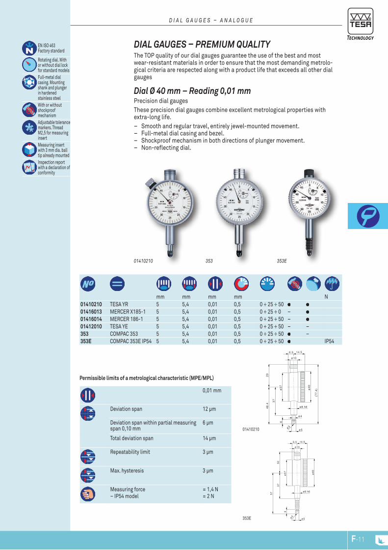
ø4
ø8 h6
ø5
ø10
37
29
6
48
.4
(77
.4)
6.5 14.5
ø4
0
ø3
7
ø3
ø8 h6
ø5
ø10
37
30
6
6.5 14.5
ø4
0
ø3
7
ø3
57
mm mm mm mm N
01410210 TESA YR 5 5,4 0,01 0,5 0 ÷ 25 ÷ 50 01416013 MERCER X185-1 5 5,4 0,01 0,5 0 ÷ 25 ÷ 0 – 01416014 MERCER 186-1 5 5,4 0,01 0,5 0 ÷ 25 ÷ 50 – 01412010 TESA YE 5 5,4 0,01 0,5 0 ÷ 25 ÷ 50 – –353 COMPAC 353 5 5,4 0,01 0,5 0 ÷ 25 ÷ 50 –353E COMPAC 353E IP54 5 5,4 0,01 0,5 0 ÷ 25 ÷ 50 IP54
Permissible limits of a metrological characteristic (MPE/MPL)
EN ISO 463 Factory standard
Rotating dial. With or without dial lock for standard modelsFull-metal dial casing. Mounting shank and plunger in hardened stainless steelWith or without shockproof mechanismAdjustable tolerance markers. Thread M2,5 for measuring insertMeasuring insert with 3 mm dia. ball tip already mountedInspection report with a declaration of conformity
0,01 mm
Deviation span 12 µm
Deviation span within partial measuring span 0,10 mm
6 µm
Total deviation span 14 µm
Repeatability limit 3 µm
Max. hysteresis 3 µm
Measuring force– IP54 model
= 1,4 N= 2 N
353E
01410210
35301410210
Dial Ø 40 mm – Reading 0,01 mm Precision dial gaugesThese precision dial gauges combine excellent metrological properties with extra-long life.
– Smooth and regular travel, entirely jewel-mounted movement. – Full-metal dial casing and bezel. – Shockproof mechanism in both directions of plunger movement. – Non-reflecting dial.
DIAL GAUGES – PREMIUM QUALITY The TOP quality of our dial gauges guarantee the use of the best and most wear-resistant materials in order to ensure that the most demanding metrolo-gical criteria are respected along with a product life that exceeds all other dial gauges
D i a l G a u G E S – a n a l O G u E
353E
F-11F-10
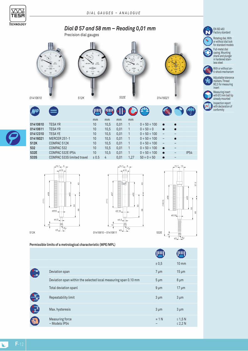
ø4.5
ø8h6
ø5
ø10
50
43
6
68
(111
)
915.7
ø5
8
ø5
3
ø3
ø4.5
ø8 h6
ø5
ø10
50
43
6
68
(111
)
915.7
ø5
7
ø5
3
ø3
ø8 h6
ø5
50
57
.5
6
85
(14
2.5
)
1015.7ø
58
ø5
3
ø3
mm mm mm mm
01410610 TESA YR 10 10,5 0,01 1 0 ÷ 50 ÷ 100 01410611 TESA YR 10 10,5 0,01 1 0 ÷ 50 ÷ 0 01412310 TESA YE 10 10,5 0,01 1 0 ÷ 50 ÷ 100 – – 01416021 MERCER 251-1 10 10,5 0,01 1 0 ÷ 50 ÷ 100 – 512K COMPAC 512K 10 10,5 0,01 1 0 ÷ 50 ÷ 100 – –532 COMPAC 532 10 10,5 0,01 1 0 ÷ 50 ÷ 100 –532E COMPAC 532E IP54 10 10,5 0,01 1 0 ÷ 50 ÷ 100 – IP54533S COMPAC 533S limited travel ± 0.5 4 0,01 1,27 50 ÷ 0 ÷ 50 –
Permissible limits of a metrological characteristic (MPE/MPL)
± 0,5 10 mm
Deviation span 7 µm 15 µm
Deviation span within the selected local measuring span 0.10 mm 5 µm 8 µm
Total deviation spanl 9 µm 17 µm
Repeatability limit 3 µm 3 µm
Max. hysteresis 3 µm 3 µm
Measuring force– Models IP54
= 1 N–
≤ 1,5 N≤ 2,2 N
532E01410610 – 01410611512K
01416021532E512K01410610
Dial Ø 57 and 58 mm – Reading 0,01 mm Precision dial gauges
EN ISO 463 Factory standard
Rotating dial. With or without dial lock for standard modelsFull-metal dial casing. Mounting shank and plunger in hardened stain-less steel
With or without an-ti-shock mechanism
Adjustable tolerance markers. Thread M2,5 for measuring insertMeasuring insert with Ø 3 mm ball tip already mountedInspection report with declaration of conformity
D i a l G a u G E S – a n a l O G u E
F-13F-12

D15.7
ø6
.4
E
F
ø4.5
6
ø5
A
B
ø3
ø5
8
C
M 2,5 - 6H
mm mm mm mm
712 COMPAC 712 30 30,5 0,01 1 0 ÷ 50 ÷ 100 – 58722 COMPAC 722 50 50,5 0,01 1 0 ÷ 50 ÷ 100 – 58732 COMPAC 732 100 100,5 0,01 1 0 ÷ 50 ÷ 100 – 58
Permissible limits of a metrological characteristic (MPE/MPL)Dimensions
EN ISO 463 Factory standard
Rotating dial. With or without dial lock.
Full-metal dial casing. Mounting shank and plunger in hardened stain-less steelAdjustable tolerance markers. Thread M2,5 for measuring insertMeasuring insert with 3 mm ball tip already mountedInspection report with declaration of conformity
30 mm 50 mm 100 mm
Deviation span 20 µm 25 µm 30 µm
Total deviation span 25 µm 30 µm 35 µm
Repeatability limit 3 µm 3 µm 3 µm
Max. hysteresis 5 µm 5 µm 8 µm
Measuring force ≤ 2,2 N ≤ 2,5 N ≤ 3,2 N
mm 30 mm 50 mm 100 mm
A 148 228 390
B 88 117,2 211,6
C 50 60 103,6
D 10 9 9
E 20 19 19
F Ø 8h6 Ø 8h6 Ø 8h6
712
Dial Ø 58 mm – Reading 0,01 mm – Long travel Long range precision dial gauges
D i a l G a u G E S – a n a l O G u E
F-13F-12
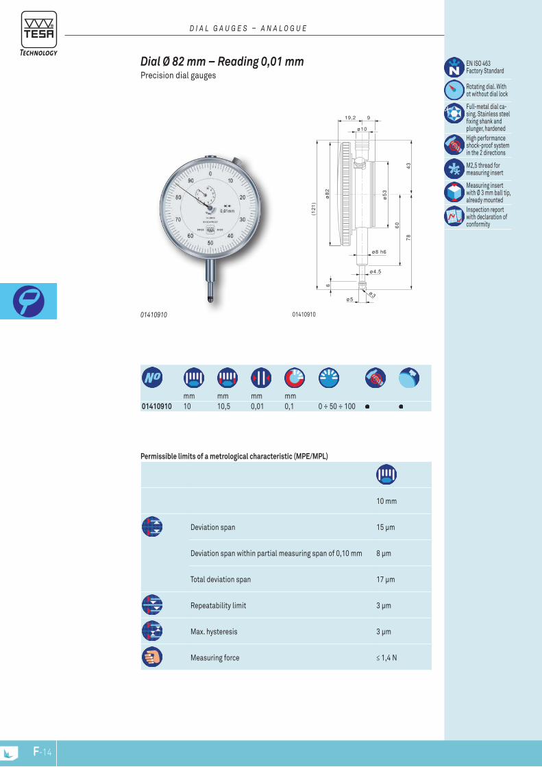
ø4.5
ø8 h6
ø5
ø10
60
43
6
78
(12
1)
919,2
ø8
2
ø5
3
ø3
mm mm mm mm
01410910 10 10,5 0,01 0,1 0 ÷ 50 ÷ 100
Permissible limits of a metrological characteristic (MPE/MPL)
10 mm
Deviation span 15 µm
Deviation span within partial measuring span of 0,10 mm 8 µm
Total deviation span 17 µm
Repeatability limit 3 µm
Max. hysteresis 3 µm
Measuring force ≤ 1,4 N
0141091001410910
Dial Ø 82 mm – Reading 0,01 mm Precision dial gauges
EN ISO 463 Factory Standard
Rotating dial. With ot without dial lock
Full-metal dial ca-sing. Stainless steel fixing shank and plunger, hardenedHigh performance shock-proof system in the 2 directions
M2,5 thread for measuring insert
Measuring insert with Ø 3 mm ball tip, already mountedInspection report with declaration of conformity
D i a l G a u G E S – a n a l O G u E
F-15F-14
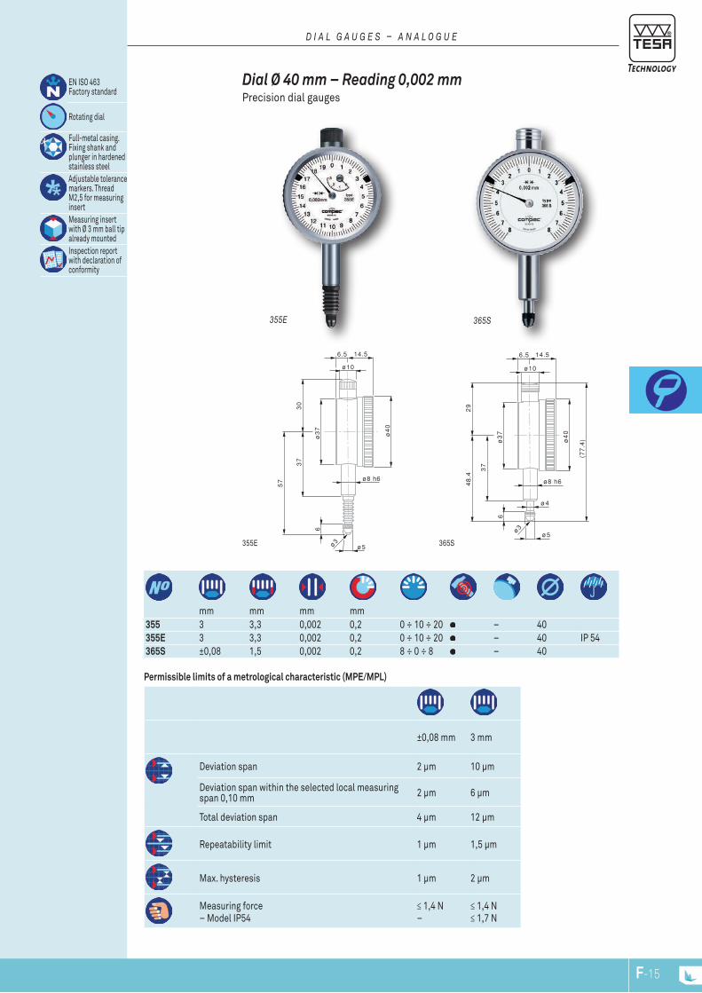
ø8 h6
ø5
ø10
37
30
6
6.5 14.5
ø4
0
ø3
7
ø3
57
ø4
ø8 h6
ø5
ø10
37
29
6
48
.4
(77
.4)
6.5 14.5
ø4
0
ø3
7
ø3
EN ISO 463 Factory standard
Rotating dial
Full-metal casing. Fixing shank and plunger in hardened stainless steelAdjustable tolerance markers. Thread M2,5 for measuring insertMeasuring insert with Ø 3 mm ball tip already mountedInspection report with declaration of conformity
mm mm mm mm
355 3 3,3 0,002 0,2 0 ÷ 10 ÷ 20 – 40355E 3 3,3 0,002 0,2 0 ÷ 10 ÷ 20 – 40 IP 54365S ±0,08 1,5 0,002 0,2 8 ÷ 0 ÷ 8 – 40
Permissible limits of a metrological characteristic (MPE/MPL)
±0,08 mm 3 mm
Deviation span 2 µm 10 µm
Deviation span within the selected local measuring span 0,10 mm 2 µm 6 µm
Total deviation span 4 µm 12 µm
Repeatability limit 1 µm 1,5 µm
Max. hysteresis 1 µm 2 µm
Measuring force– Model IP54
≤ 1,4 N–
≤ 1,4 N≤ 1,7 N
365S355E
365S355E
Dial Ø 40 mm – Reading 0,002 mm Precision dial gauges
D i a l G a u G E S – a n a l O G u E
F-15F-14

ø4.5
ø8 h6
ø5
ø10
50
43
6
62
(10
5)
915.7
ø5
7
ø5
3
ø3
ø4.5
ø8 h6
ø5
ø10
50
43
6
62
(10
5)
915.7
ø5
8
ø5
3
ø3
ø8 h6
ø5
50
57
.5
6
71
.5
(12
9)
1015.7
ø5
8
ø5
3ø3
mm mm mm mm
01416034 MERCER 253-1 5 5,3 0,002 0,2 0 ÷ 10 ÷ 0 – 58 –555 COMPAC 555 5 5,3 0,002 0,2 0 ÷ 10 ÷ 20 – 58555E COMPAC 555E IP54 5 5,3 0,002 0,2 0 ÷ 10 ÷ 20 – 58 IP 54565S COMPAC 565S limited
travel±0,08 3,3 0,002 0,2 8 ÷ 0 ÷ 8 – 58 –
Permissible limits of a metrological characteristic (MPE/MPL)
±0,08 mm 5 mm
Deviation span 4 µm 12 µm
Total deviation span 4 µm 14 µm
Repeatability limit 1 µm 2 µm
Max. hysteresis 1 µm 2 µm
Measuring force– Model IP54
≤ 1,5 N–
≤ 1,5 N≤ 1,7 N
555E55501416034
555E565S55501416034
Dial Ø 58 mm – Reading 0,002 mm Precision dial gauges
EN ISO 463 Factory standard
Rotating dial. With or without dial lock.
Full-metal dial casing. Mounting shank and plunger in hardened stain-less steelAdjustable tolerance markers. Thread M2,5 for measuring insertMeasuring insert with 3 mm ball tip already mountedInspection report with declaration of conformity
D i a l G a u G E S – a n a l O G u E
F-17F-16
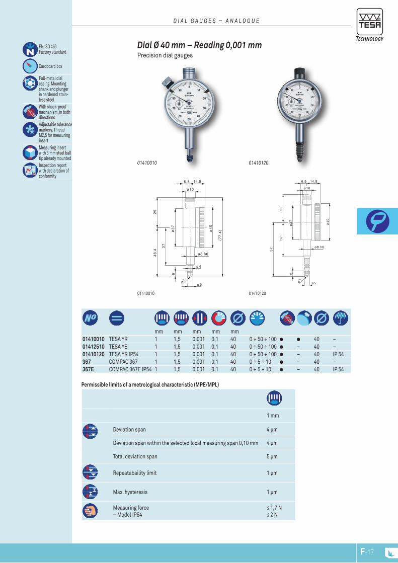
ø8 h6
ø5
ø10
37
30
6
6.5 14.5
ø4
0
ø3
7
ø3
57
ø4
ø8 h6
ø5
ø10
37
29
6
48
.4
(77
.4)
6.5 14.5
ø4
0
ø3
7
ø3
mm mm mm mm mm
01410010 TESA YR 1 1,5 0,001 0,1 40 0 ÷ 50 ÷ 100 40 – 01412510 TESA YE 1 1,5 0,001 0,1 40 0 ÷ 50 ÷ 100 – 40 – 01410120 TESA YR IP54 1 1,5 0,001 0,1 40 0 ÷ 50 ÷ 100 – 40 IP 54367 COMPAC 367 1 1,5 0,001 0,1 40 0 ÷ 5 ÷ 10 – 40 – 367E COMPAC 367E IP54 1 1,5 0,001 0,1 40 0 ÷ 5 ÷ 10 – 40 IP 54
Permissible limits of a metrological characteristic (MPE/MPL)
EN ISO 463 Factory standard
Cardboard box
Full-metal dial casing. Mounting shank and plunger in hardened stain-less steelWith shock-proof mechanism, in both directionsAdjustable tolerance markers. Thread M2,5 for measuring insertMeasuring insert with 3 mm steel ball tip already mountedInspection report with declaration of conformity
1 mm
Deviation span 4 µm
Deviation span within the selected local measuring span 0,10 mm 4 µm
Total deviation span 5 µm
Repeatabaility limit 1 µm
Max. hysteresis 1 µm
Measuring force– Model IP54
≤ 1,7 N≤ 2 N
0141012001410010
0141012001410010
Dial Ø 40 mm – Reading 0,001 mm Precision dial gauges
D i a l G a u G E S – a n a l O G u E
F-17F-16
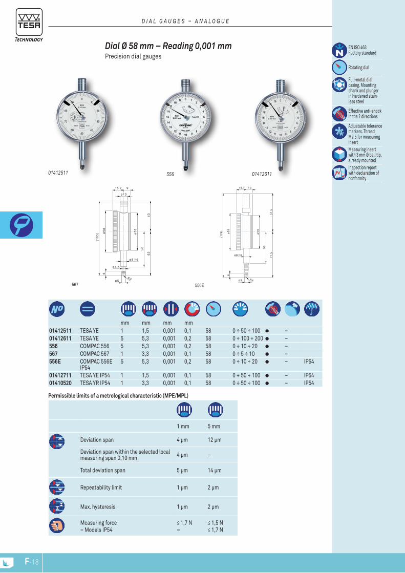
ø4.5
ø8 h6
ø5
ø10
50
43
6
62
(10
5)
915.7
ø5
8
ø5
3
ø3
ø8 h6
ø5
50
57
.5
6
71
.5
(12
9)
1015.7
ø5
8
ø5
3
ø3
EN ISO 463 Factory standard
Rotating dial
Full-metal dial casing. Mounting shank and plunger in hardened stain-less steel
Effective anti-shock in the 2 directions
Adjustable tolerance markers. Thread M2,5 for measuring insertMeasuring insert with 3 mm Ø ball tip, already mountedInspection report with declaration of conformity
mm mm mm mm
01412511 TESA YE 1 1,5 0,001 0,1 58 0 ÷ 50 ÷ 100 –01412611 TESA YE 5 5,3 0,001 0,2 58 0 ÷ 100 ÷ 200 –556 COMPAC 556 5 5,3 0,001 0,2 58 0 ÷ 10 ÷ 20 –567 COMPAC 567 1 3,3 0,001 0,1 58 0 ÷ 5 ÷ 10 –556E COMPAC 556E
IP545 5,3 0,001 0,2 58 0 ÷ 10 ÷ 20 – IP54
01412711 TESA YE IP54 1 1,5 0,001 0,1 58 0 ÷ 50 ÷ 100 – IP5401410520 TESA YR IP54 1 3,3 0,001 0,1 58 0 ÷ 50 ÷ 100 – IP54
Permissible limits of a metrological characteristic (MPE/MPL)
1 mm 5 mm
Deviation span 4 µm 12 µm
Deviation span within the selected local measuring span 0,10 mm 4 µm –
Total deviation span 5 µm 14 µm
Repeatability limit 1 µm 2 µm
Max. hysteresis 1 µm 2 µm
Measuring force– Models IP54
≤ 1,7 N–
≤ 1,5 N≤ 1,7 N
556E567
01412711
0141261155601412511
Dial Ø 58 mm – Reading 0,001 mm Precision dial gauges
D i a l G a u G E S – a n a l O G u E
F-19F-18
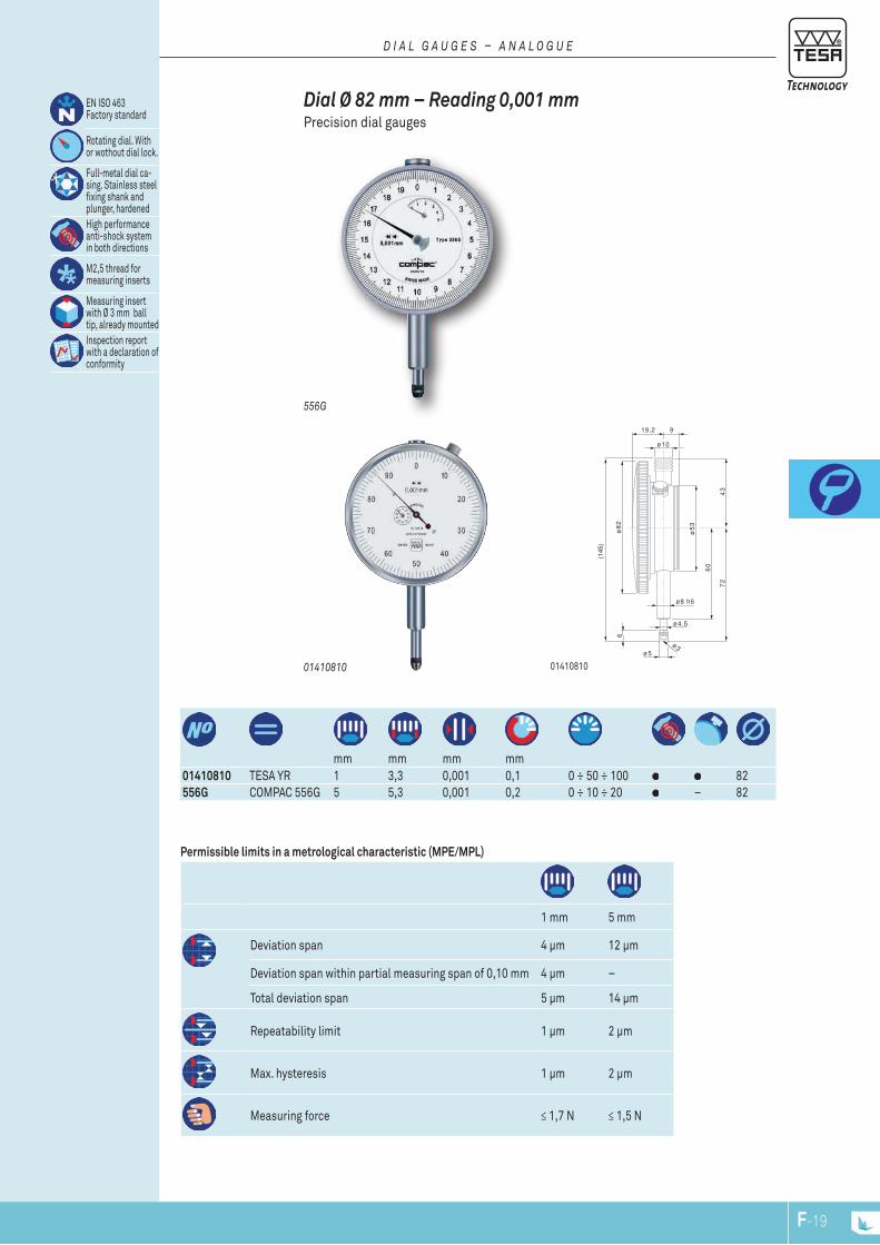
mm mm mm mm
01410810 TESA YR 1 3,3 0,001 0,1 0 ÷ 50 ÷ 100 82556G COMPAC 556G 5 5,3 0,001 0,2 0 ÷ 10 ÷ 20 – 82
Permissible limits in a metrological characteristic (MPE/MPL)
EN ISO 463 Factory standard
Rotating dial. With or wothout dial lock.
Full-metal dial ca-sing. Stainless steel fixing shank and plunger, hardenedHigh performance anti-shock system in both directions
M2,5 thread for measuring inserts
Measuring insert with Ø 3 mm ball tip, already mountedInspection report with a declaration of conformity
1 mm 5 mm
Deviation span 4 µm 12 µm
Deviation span within partial measuring span of 0,10 mm 4 µm –
Total deviation span 5 µm 14 µm
Repeatability limit 1 µm 2 µm
Max. hysteresis 1 µm 2 µm
Measuring force ≤ 1,7 N ≤ 1,5 N
556G
Dial Ø 82 mm – Reading 0,001 mmPrecision dial gauges
D i a l G a u G E S – a n a l O G u E
01410810 01410810
ø4.5
ø8 h6
ø5
ø10
60
43
6
72
(145
)
919,2
ø8
2
ø5
3
ø3
F-19F-18
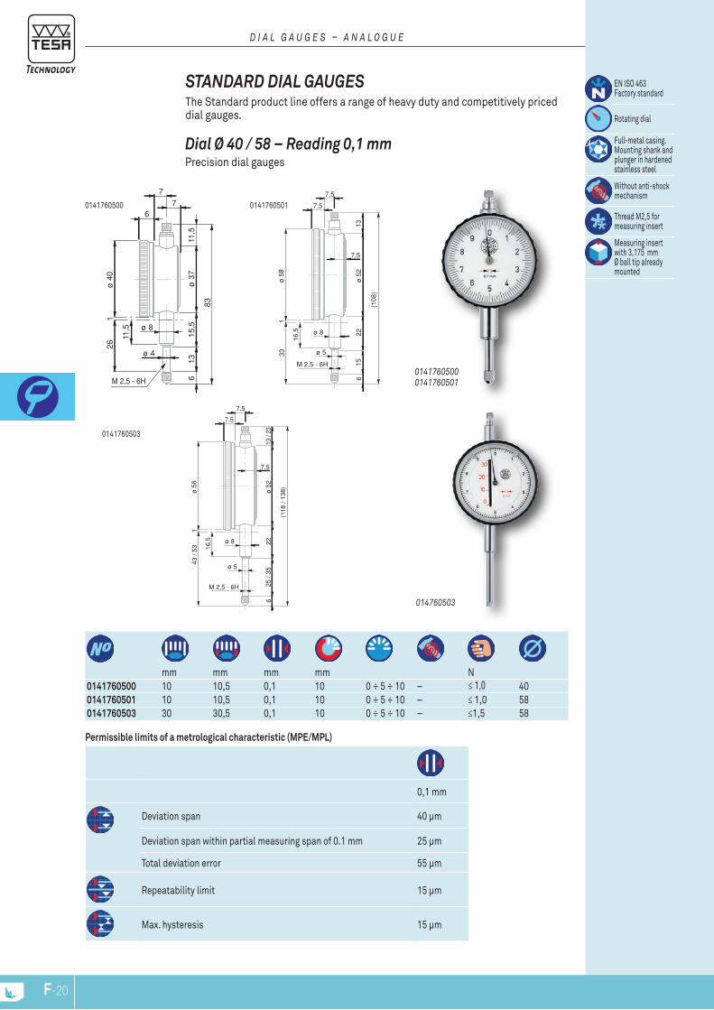
6
ø 4
77
11,5
ø 4
026
11,5 ø 8
ø 3
7
83
15,5
613
M 2,5 - 6H
1
ø 5
8
ø 5
2
(108
)
2215
6
16,5
13
ø 8
1
7,5
7,5
7,5
M 2,5 - 6H
33 ø 5
ø 5
8
ø 5
2
(118
/ 13
8)
2225
/ 35
6
16,5
13 /
23
ø 8
1
7,5
7,5
7,5
M 2,5 - 6H
43 /
53
ø 5
mm mm mm mm N
0141760500 10 10,5 0,1 10 0 ÷ 5 ÷ 10 – ≤ 1,0 40 0141760501 10 10,5 0,1 10 0 ÷ 5 ÷ 10 – ≤ 1,0 58 0141760503 30 30,5 0,1 10 0 ÷ 5 ÷ 10 – ≤1,5 58
Permissible limits of a metrological characteristic (MPE/MPL)
0,1 mm
Deviation span 40 µm
Deviation span within partial measuring span of 0.1 mm 25 µm
Total deviation error 55 µm
Repeatability limit 15 µm
Max. hysteresis 15 µm
0141760503
01417605010141760500
014760503
0141760500 0141760501
Dial Ø 40 / 58 – Reading 0,1 mm Precision dial gauges
STANDARD DIAL GAUGES The Standard product line offers a range of heavy duty and competitively priced dial gauges.
EN ISO 463 Factory standard
Rotating dial
Full-metal casing. Mounting shank and plunger in hardened stainless steel
Without anti-shock mechanism
Thread M2,5 for measuring insert
Measuring insert with 3,175 mm Ø ball tip already mounted
D i a l G a u G E S – a n a l O G u E
F-21F-20
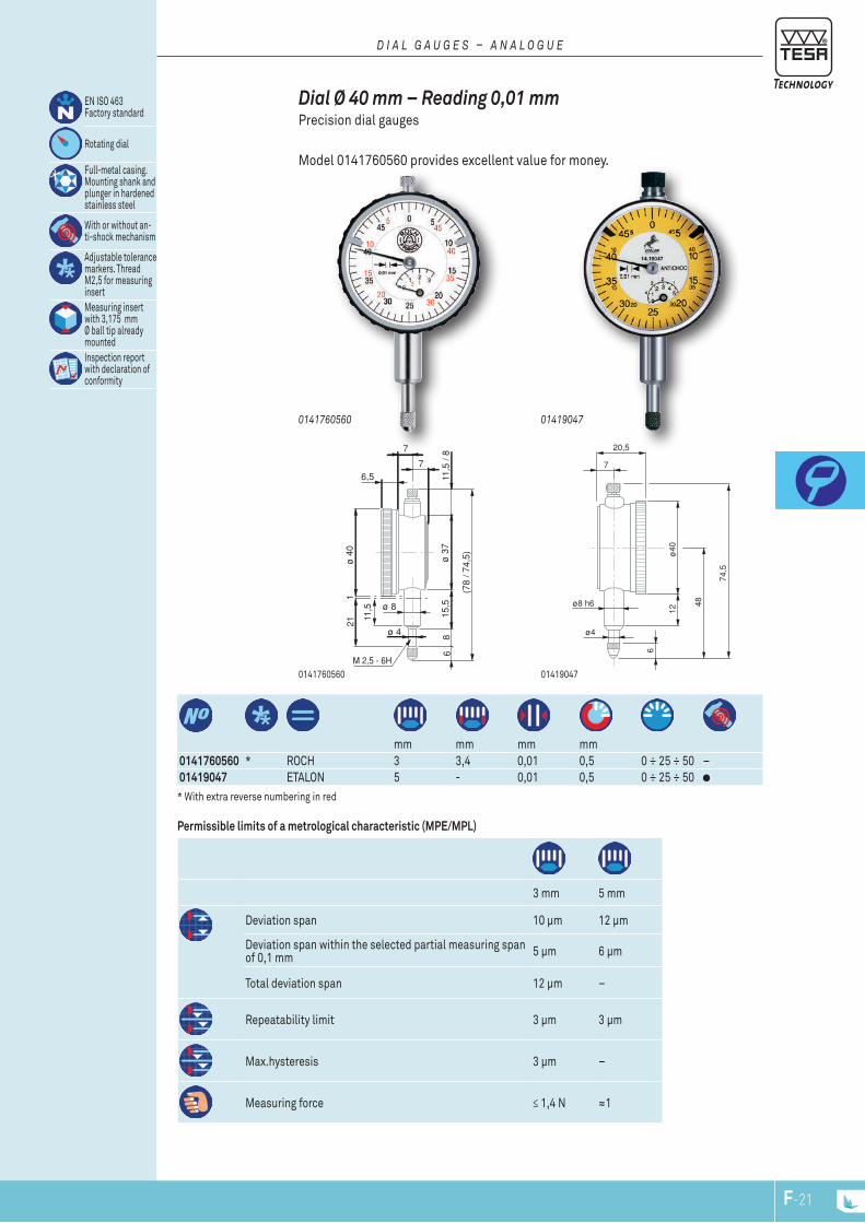
6,5
ø 4
7
7
11,5
/ 8
ø 4
01
21
11,5 ø 8
ø 3
7
(78
/ 74,
5)
15,5
68
M 2,5 - 6H
7
6
ø4
ø8 h6
20,5
48
12ø
40
74,5
mm mm mm mm
0141760560 * ROCH 3 3,4 0,01 0,5 0 ÷ 25 ÷ 50 –01419047 ETALON 5 - 0,01 0,5 0 ÷ 25 ÷ 50
Permissible limits of a metrological characteristic (MPE/MPL)
EN ISO 463 Factory standard
Rotating dial
Full-metal casing. Mounting shank and plunger in hardened stainless steel
With or without an-ti-shock mechanism
Adjustable tolerance markers. Thread M2,5 for measuring insertMeasuring insert with 3,175 mm Ø ball tip already mounted Inspection report with declaration of conformity
3 mm 5 mm
Deviation span 10 µm 12 µm
Deviation span within the selected partial measuring span of 0,1 mm 5 µm 6 µm
Total deviation span 12 µm –
Repeatability limit 3 µm 3 µm
Max.hysteresis 3 µm –
Measuring force ≤ 1,4 N ≈1
* With extra reverse numbering in red
014190470141760560
014190470141760560
Dial Ø 40 mm – Reading 0,01 mm Precision dial gauges
Model 0141760560 provides excellent value for money.
D i a l G a u G E S – a n a l O G u E
F-21F-20
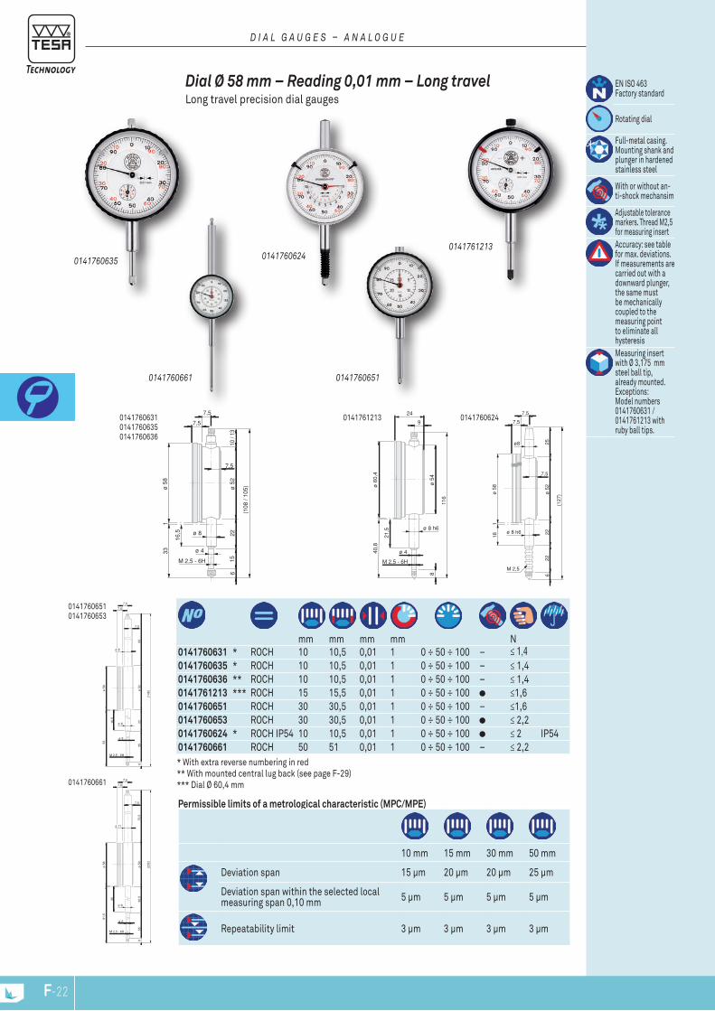
24
116
ø 5
4
ø 6
0,4
9
ø 4
M 2,5 - 6H
40,8
8
ø 8 h6
21,5
ø 5
8
ø 5
2
(108
/ 10
5)
2215
6
16,5
10 /
13
ø 8
1
7,5
7,5
7,5
M 2,5 - 6H
33 ø 4
ø 5
8
ø 5
2
(127
)
2222
6
18
25
M 2,5
ø 8 h6
1
ø8
7,5
7,5
7,5
7,8
7,5
7,5
ø 11
ø 5
8
ø 8
ø 5
9
(232
)
ø 5
M 2,5 - 6H
36,5
556
91,5
35
75,5
7,5
7,5
7,5
ø 8
ø 5
8
ø 8
ø 5
2
(148
)
ø 5
M 2,5 - 6H
2235
6
53
16,5
33
0141760661
0141760651 0141760653
0141760661
mm mm mm mm N
0141760631 * ROCH 10 10,5 0,01 1 0 ÷ 50 ÷ 100 – ≤ 1,40141760635 * ROCH 10 10,5 0,01 1 0 ÷ 50 ÷ 100 – ≤ 1,40141760636 ** ROCH 10 10,5 0,01 1 0 ÷ 50 ÷ 100 – ≤ 1,40141761213 *** ROCH 15 15,5 0,01 1 0 ÷ 50 ÷ 100 ≤1,60141760651 ROCH 30 30,5 0,01 1 0 ÷ 50 ÷ 100 – ≤1,60141760653 ROCH 30 30,5 0,01 1 0 ÷ 50 ÷ 100 ≤ 2,20141760624 * ROCH IP54 10 10,5 0,01 1 0 ÷ 50 ÷ 100 ≤ 2 IP540141760661 ROCH 50 51 0,01 1 0 ÷ 50 ÷ 100 – ≤ 2,2
Permissible limits of a metrological characteristic (MPC/MPE)
10 mm 15 mm 30 mm 50 mm
Deviation span 15 µm 20 µm 20 µm 25 µm
Deviation span within the selected local measuring span 0,10 mm 5 µm 5 µm 5 µm 5 µm
Repeatability limit 3 µm 3 µm 3 µm 3 µm
* With extra reverse numbering in red ** With mounted central lug back (see page F-29)*** Dial Ø 60,4 mm
01417606240141760631 01417606350141760636
0141760651
014176121301417606240141760635
Dial Ø 58 mm – Reading 0,01 mm – Long travel Long travel precision dial gauges
EN ISO 463 Factory standard
Rotating dial
Full-metal casing. Mounting shank and plunger in hardened stainless steel
With or without an-ti-shock mechansim
Adjustable tolerance markers. Thread M2,5 for measuring insertAccuracy: see table for max. deviations. If measurements are carried out with a downward plunger, the same must be mechanically coupled to the measuring point to eliminate all hysteresis Measuring insert with Ø 3,175 mm steel ball tip, already mounted. Exceptions: Model numbers 0141760631 / 0141761213 with ruby ball tips.
D i a l G a u G E S – a n a l O G u E
0141761213
F-23F-22

ø58
69
186
ø8 h6
ø4
7,5
22,5
105
7,5
22,5
ø58
19 /
36
89 /
127
148
/ 232
35 /
55
ø8 h6
ø5
6
8/11
mm mm mm N
01419048 10 0,01 1 0 ÷ 50 ÷ 100 – ≈1 58 01419050 50 0,01 1 0 ÷ 50 ÷ 100 1,5 ÷ 2 58
Permissible limits for a metrological characteristic (MPE/MPL)
EN ISO 463 Factory standard
Rotating dial
Full-metal casing. Mounting shank and plunger in hardened stainless steel
With or without an-ti-shock mechanism
Adjustable tolerance markers. Thread M2,5 for measuring insertMeasuring insert with Ø 3,175 mm steel ball tip, already mounted
mm 10 50
Deviation span µm 15 25
Deviation span within selected partial measuring span 0,10 mm µm 8 12
Repeatability Limit µm 3 3
For magnetic or central lug backs, see backs for ROCH and ETALON dial gauges
0141905001419048
01419048
Dial Ø 58 mm– Reading 0,01 mm – Standard and long travel Precision dial gauges
Standard and long travel models
D i a l G a u G E S – a n a l O G u E
F-23F-22
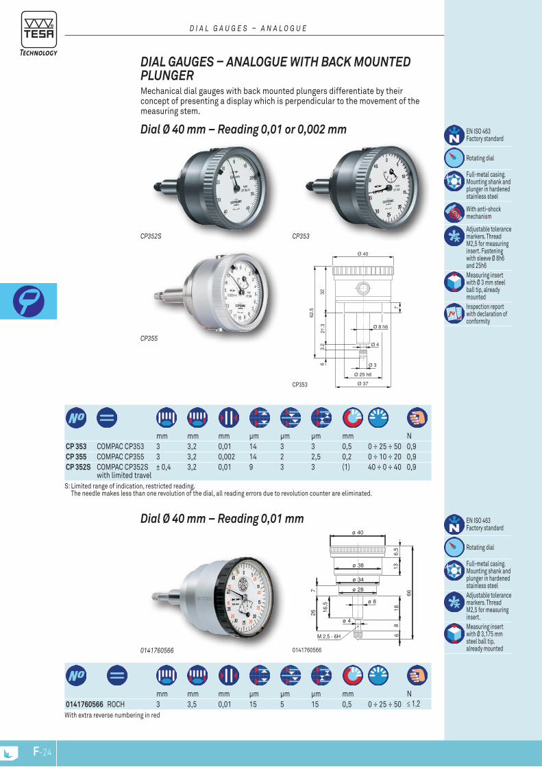
mm mm mm μm μm μm mm N
CP 353 COMPAC CP353 3 3,2 0,01 14 3 3 0,5 0 ÷ 25 ÷ 50 0,9CP 355 COMPAC CP355 3 3,2 0,002 14 2 2,5 0,2 0 ÷ 10 ÷ 20 0,9CP 352S COMPAC CP352S
with limited travel± 0,4 3,2 0,01 9 3 3 (1) 40 ÷ 0 ÷ 40 0,9
S: Limited range of indication, restricted reading. The needle makes less than one revolution of the dial, all reading errors due to revolution counter are eliminated.
Dial Ø 40 mm – Reading 0,01 or 0,002 mm
DIAL GAUGES – ANALOGUE wITH bACk MOUNTED PLUNGER Mechanical dial gauges with back mounted plungers differentiate by their concept of presenting a display which is perpendicular to the movement of the measuring stem.
EN ISO 463 Factory standard
Rotating dial
Full-metal casing. Mounting shank and plunger in hardened stainless steel
With anti-shock mechanism
Adjustable tolerance markers. Thread M2,5 for measuring insert. Fastening with sleeve Ø 8h6 and 25h6 Measuring insert with Ø 3 mm steel ball tip, already mountedInspection report with declaration of conformity
D i a l G a u G E S – a n a l O G u E
Ø 40
Ø 37
Ø 25 h6
Ø 3
21.3
32
62.5
63.
2Ø 8 h6
Ø 4
7
CP353
CP355
CP353CP352S
0141760566
0141760566 ROCH 3 3,5 0,01 15 5 15 0,5 0 ÷ 25 ÷ 50 ≤ 1,2
mm mm mm μm μm μm mm N
With extra reverse numbering in red
Dial Ø 40 mm – Reading 0,01 mmø 40
ø 38
ø 4
ø 8
66
136,
518
86
16,5
267
M 2,5 - 6H
ø 34
ø 28
0141760566
EN ISO 463 Factory standard
Rotating dial
Full-metal casing. Mounting shank and plunger in hardened stainless steelAdjustable tolerance markers. Thread M2,5 for measuring insert. Measuring insert with Ø 3,175 mm steel ball tip, already mounted
F-25F-24
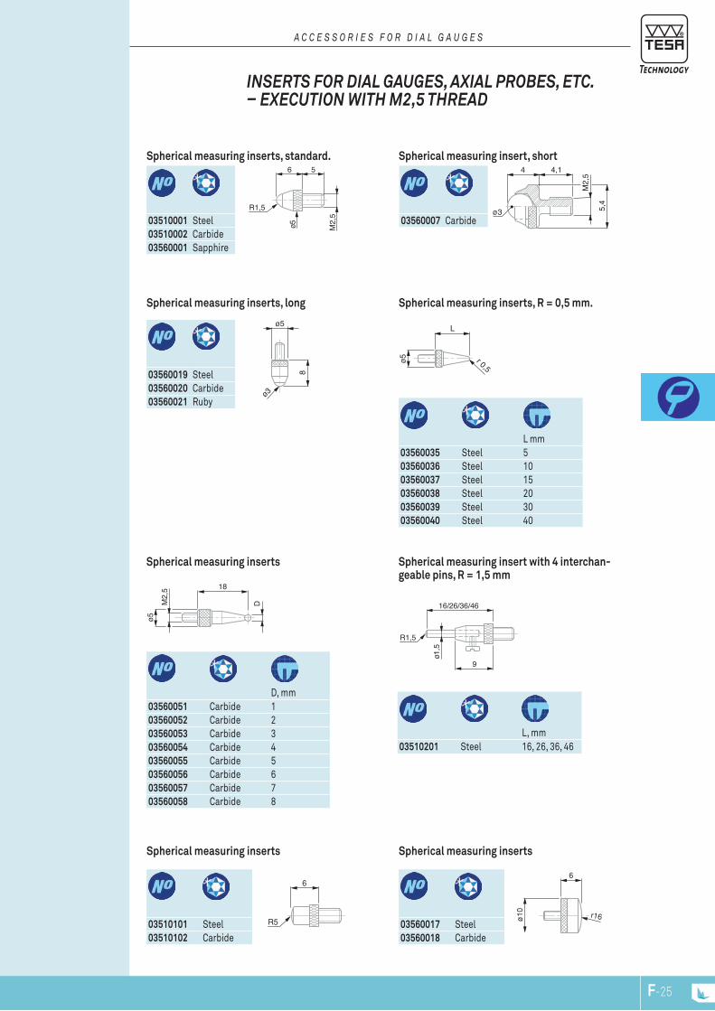
ø5
ø3
8
M2,
5 18
D
ø5
6
R5
ø5
L
r 0,5
16/26/36/46
R1,5
ø1,5
9
ø10
6
r16
6 5
M2,
5
ø5
R1,5 ø3 5,4
M2,
5
4 4,1
03560007 Carbide
Spherical measuring insert, short
INSERTS fOR DIAL GAUGES, AxIAL PRObES, ETC. – ExECUTION wITH M2,5 THREAD
a C C E S S O r i E S F O r D i a l G a u G E S
03510001 Steel03510002 Carbide03560001 Sapphire
Spherical measuring inserts, standard.
03560017 Steel03560018 Carbide
Spherical measuring inserts
L, mm
03510201 Steel 16, 26, 36, 46
Spherical measuring insert with 4 interchan-geable pins, R = 1,5 mm
L mm
03560035 Steel 503560036 Steel 1003560037 Steel 1503560038 Steel 2003560039 Steel 3003560040 Steel 40
Spherical measuring inserts, R = 0,5 mm.
03510101 Steel03510102 Carbide
Spherical measuring inserts
D, mm
03560051 Carbide 103560052 Carbide 203560053 Carbide 303560054 Carbide 403560055 Carbide 503560056 Carbide 603560057 Carbide 703560058 Carbide 8
Spherical measuring inserts
03560019 Steel03560020 Carbide03560021 Ruby
Spherical measuring inserts, long
F-25F-24
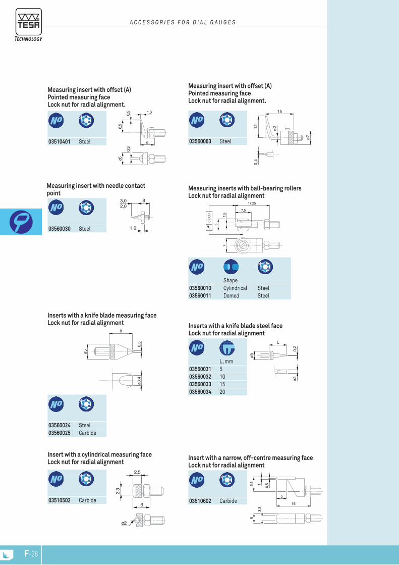
ø2
6
3,3
2,5
16
3,3
56,
5 1
5
0,5
1.6
3,02,0
8
7
7,5
17,25
5
1,5
0,00
3
ø5
8
ø3.4
0.3
ø2
ø5
L
0,2
6
1,6
ø5
0,3
0,5
6,5
ø7
ø2120,
4
15
03560063 Steel
Measuring insert with offset (A) Pointed measuring face Lock nut for radial alignment.
a C C E S S O r i E S F O r D i a l G a u G E S
03510401 Steel
Measuring insert with offset (A) Pointed measuring face Lock nut for radial alignment.
L, mm
03560031 503560032 1003560033 1503560034 20
Inserts with a knife blade steel face Lock nut for radial alignment
03560024 Steel03560025 Carbide
Inserts with a knife blade measuring face Lock nut for radial alignment
Shape
03560010 Cylindrical Steel03560011 Domed Steel
Measuring inserts with ball-bearing rollers Lock nut for radial alignment
03560030 Steel
Measuring insert with needle contact point
03510602 Carbide
Insert with a narrow, off-centre measuring face Lock nut for radial alignment
03510502 Carbide
Insert with a cylindrical measuring face Lock nut for radial alignment
F-27F-26
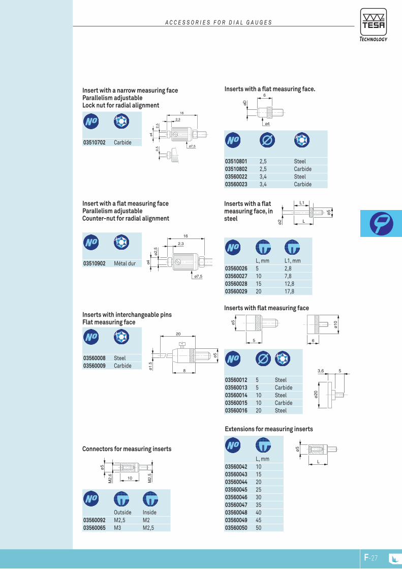
ø2,5
ø4
2,3
16
ø7,5
ø5
ø1.5
20
8
ø5
M2,
6
M2,
5
10
ø5
Lø2
L1
ø10
6
ø5
5
ø5
L
rallonge
2,5
ø4
2,3
16
0,5 ø7,5
6
øD
ø4
ø20
3,6 5
03510801 2,5 Steel03510802 2,5 Carbide03560022 3,4 Steel03560023 3,4 Carbide
Inserts with a flat measuring face.
a C C E S S O r i E S F O r D i a l G a u G E S
03510702 Carbide
Insert with a narrow measuring face Parallelism adjustable Lock nut for radial alignment
L, mm
03560042 1003560043 1503560044 2003560045 2503560046 3003560047 3503560048 4003560049 4503560050 50
Extensions for measuring inserts
03560012 5 Steel03560013 5 Carbide03560014 10 Steel03560015 10 Carbide03560016 20 Steel
Inserts with flat measuring face
L, mm L1, mm
03560026 5 2,803560027 10 7,803560028 15 12,803560029 20 17,8
Inserts with a flat measuring face, in steel
Outside Inside
03560092 M2,5 M203560065 M3 M2,5
Connectors for measuring inserts
03560008 Steel03560009 Carbide
Inserts with interchangeable pins Flat measuring face
03510902 Métal dur
Insert with a flat measuring face Parallelism adjustable Counter-nut for radial alignment
F-27F-26
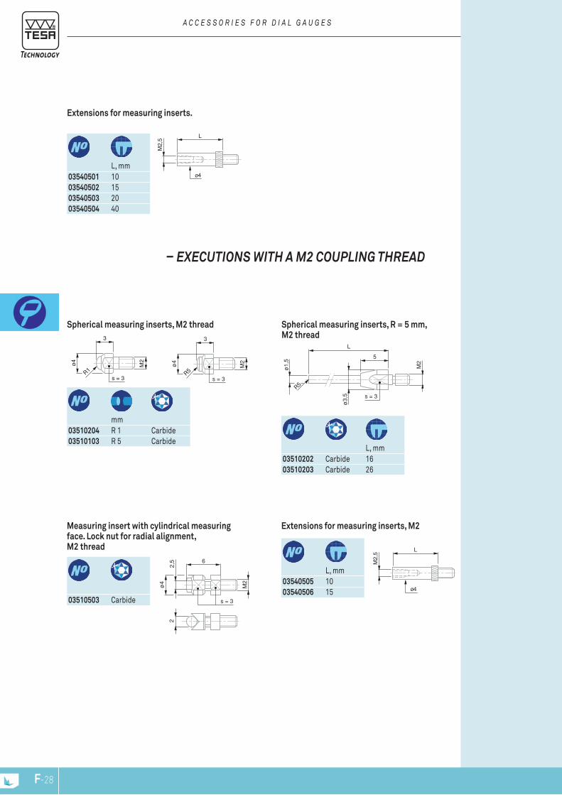
M2
ø3,
5L
5
s = 3
ø1,
5
R5
6
s = 3
M2
ø4
2,5
2
L
M2,
5
ø4
L
M2,
5
ø4
3
M2
s = 3
ø4
R5
3
M2
s = 3
ø4
R1
– ExECUTIONS wITH A M2 COUPLING THREAD
mm
03510204 R 1 Carbide03510103 R 5 Carbide
Spherical measuring inserts, M2 thread
a C C E S S O r i E S F O r D i a l G a u G E S
L, mm
03540501 1003540502 1503540503 2003540504 40
Extensions for measuring inserts.
L, mm
03540505 1003540506 15
Extensions for measuring inserts, M2
03510503 Carbide
Measuring insert with cylindrical measuring face. Lock nut for radial alignment, M2 thread
L, mm
03510202 Carbide 1603510203 Carbide 26
Spherical measuring inserts, R = 5 mm, M2 thread
F-29F-28
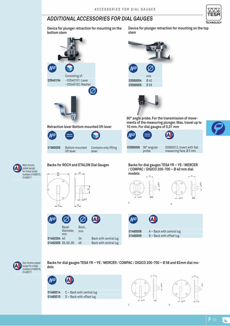
21
13
ø 5
16
5
3446
ø6.4
19
96.3
ø6.4
19
96.3
ø6.4
19
8.56.3
ø6.4
19
8.56.3
BA
Backs for dial gauges TESA YR – YE / MERCER / COMPAC / DIGICO 200-700 – Ø 40 mm dial models
Matt chrome plated except for tinted model numbers 01460010, 01460011
01460008 A – Back with central lug01460009 B – Back with offset lug
01460014 C – Back with central lug01460015 D – Back with offset lug
Dull chrome-plated except for model numbers 01460016, 01460017.
DC
Backs for dial gauges TESA YR – YE / MERCER / COMPAC / DIGICO 200-700 – Ø 58 and 82mm dial mo-dels
mm
03560004 Ø 4003560005 Ø 58
Device for plunger retraction for mounting on the top stem
ADDITIONAL ACCESSORIES fOR DIAL GAUGES
a C C E S S O r i E S F O r D i a l G a u G E S
Consisting of:
03540104 - 03540101: Lever- 03540102: Washer
Device for plunger retraction for mounting on the bottom stem
03560006 90° angular probe
03560012; Insert with flat measuring face, Ø 5 mm
90° angle probe. For the transmission of move-ments of the measuring plunger. Max. travel up to 10 mm. For dial gauges of 0,01 mm
Bezel diameter, mm
Back,mm
Backs for ROCH and ETALON Dial Gauges
01960005 Bottom mounted lift lever
Contains only lifting lever
Retraction lever Bottom mounted lift lever
01462004 40 34 Back with central lug01462005 58, 60, 80 46 Back with central lug
F-29F-28

F-NPF-30
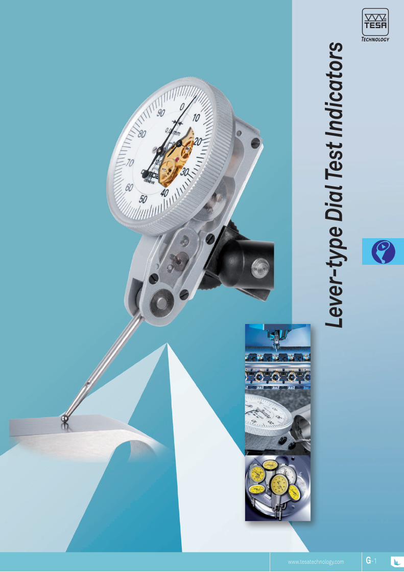
www.tesatechnology.com G-1G-NP
Leve
r-ty
pe D
ial T
est I
ndic
ator
s
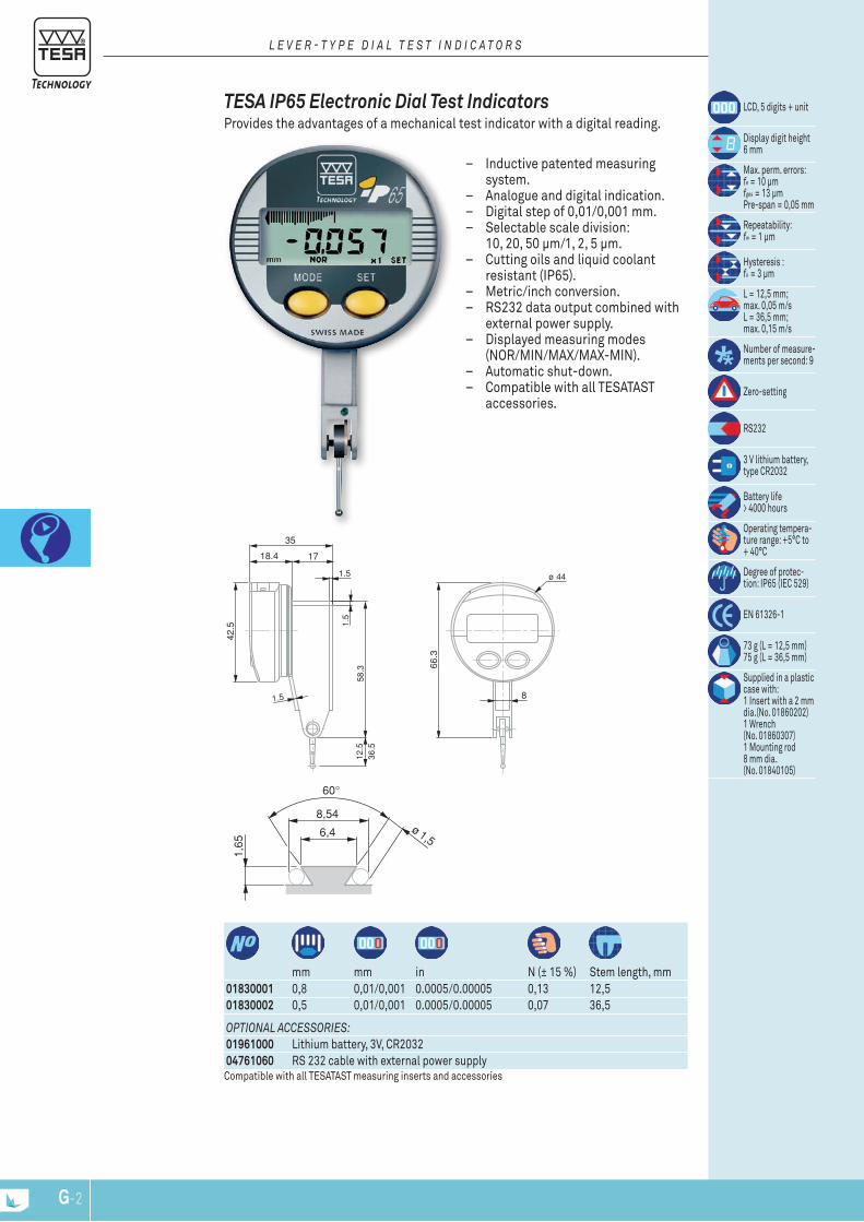
ø 44
42.5
17
1.5
58.3 66
.3
18.4
1.5
1.5 8
12.5
36.5
35
8,54
6,4 ø 1,5
1,65
G-3G-2
mm mm in N (± 15 %) Stem length, mm
01830001 0,8 0,01/0,001 0.0005/0.00005 0,13 12,5 01830002 0,5 0,01/0,001 0.0005/0.00005 0,07 36,5
LCD, 5 digits + unit
Display digit height 6 mm
Max. perm. errors: fe = 10 μm fges = 13 μm Pre-span = 0,05 mm
Repeatability: fw = 1 μm
Hysteresis :fu = 3 μm
L = 12,5 mm; max. 0,05 m/s L = 36,5 mm; max. 0,15 m/s
Number of measure-ments per second: 9
Zero-setting
RS232
3 V lithium battery, type CR2032
Battery life > 4000 hours
Operating tempera-ture range: +5°C to + 40°C
Degree of protec-tion: IP65 (IEC 529)
EN 61326-1
73 g (L = 12,5 mm) 75 g (L = 36,5 mm)
Supplied in a plastic case with: 1 Insert with a 2 mm dia.(No. 01860202) 1 Wrench (No. 01860307) 1 Mounting rod 8 mm dia. (No. 01840105)
OptiOnal accessOries:01961000 Lithium battery, 3V, CR203204761060 RS 232 cable with external power supplyCompatible with all TESATAST measuring inserts and accessories
TESA IP65 Electronic Dial Test Indicators Provides the advantages of a mechanical test indicator with a digital reading.
– Inductive patented measuring system.
– Analogue and digital indication. – Digital step of 0,01/0,001 mm. – Selectable scale division:
10, 20, 50 μm/1, 2, 5 μm. – Cutting oils and liquid coolant
resistant (IP65). – Metric/inch conversion. – RS232 data output combined with
external power supply. – Displayed measuring modes
(NOR/MIN/MAX/MAX-MIN). – Automatic shut-down. – Compatible with all TESATAST
accessories.
l e v e r - t y p e D i a l t e s t i n D i c a t O r s
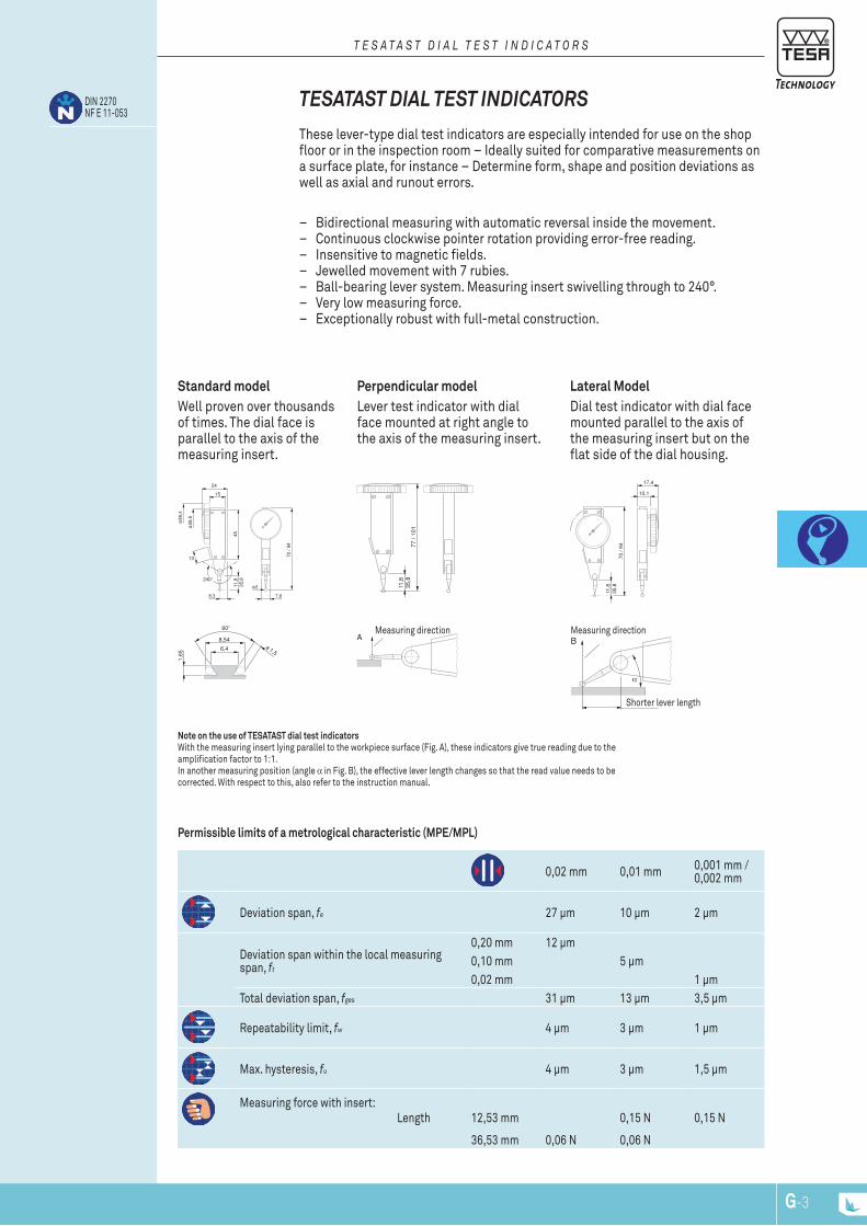
24
15
45
70 /
94
8,3 7,6
13
ø2
ø38
,4
ø28
,5
11,8
35,8
77 /
101
11,8
35,8
17,4
10,1
70 /
94
11,8
35,8
8,54
6,4 ø 1,5
1,65
A B
α
DIN 2270NF E 11-053
G-3G-2
Shorter lever length
Measuring direction
Permissible limits of a metrological characteristic (MPE/MPL)
0,02 mm 0,01 mm 0,001 mm / 0,002 mm
Deviation span, fe 27 µm 10 µm 2 µm
Deviation span within the local measuring span, ft
0,20 mm 12 µm0,10 mm 5 µm0,02 mm 1 µm
Total deviation span, fges 31 µm 13 µm 3,5 µm
Repeatability limit, fw 4 µm 3 µm 1 µm
Max. hysteresis, fu 4 µm 3 µm 1,5 µm
Measuring force with insert: Length 12,53 mm 0,15 N 0,15 N
36,53 mm 0,06 N 0,06 N
Lateral Model Dial test indicator with dial face mounted parallel to the axis of the measuring insert but on the flat side of the dial housing.
Measuring direction
Perpendicular model Lever test indicator with dial face mounted at right angle to the axis of the measuring insert.
Standard model Well proven over thousands of times. The dial face is parallel to the axis of the measuring insert.
Note on the use of TESATAST dial test indicators With the measuring insert lying parallel to the workpiece surface (Fig. A), these indicators give true reading due to the amplification factor to 1:1. In another measuring position (angle α in Fig. B), the effective lever length changes so that the read value needs to be corrected. With respect to this, also refer to the instruction manual.
These lever-type dial test indicators are especially intended for use on the shop floor or in the inspection room – Ideally suited for comparative measurements on a surface plate, for instance – Determine form, shape and position deviations as well as axial and runout errors.
– Bidirectional measuring with automatic reversal inside the movement. – Continuous clockwise pointer rotation providing error-free reading. – Insensitive to magnetic fields. – Jewelled movement with 7 rubies. – Ball-bearing lever system. Measuring insert swivelling through to 240°. – Very low measuring force. – Exceptionally robust with full-metal construction.
TESATAST DIAL TEST InDIcATorS
t e s a t a s t D i a l t e s t i n D i c a t O r s
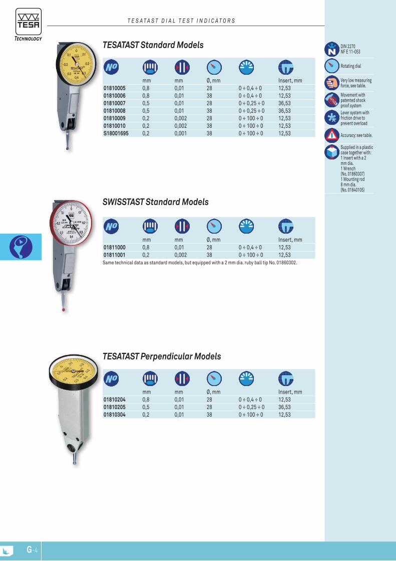
G-5G-4
mm mm Ø, mm Insert, mm
01810005 0,8 0,01 28 0 ÷ 0,4 ÷ 0 12,5301810006 0,8 0,01 38 0 ÷ 0,4 ÷ 0 12,5301810007 0,5 0,01 28 0 ÷ 0,25 ÷ 0 36,5301810008 0,5 0,01 38 0 ÷ 0,25 ÷ 0 36,5301810009 0,2 0,002 28 0 ÷ 100 ÷ 0 12,5301810010 0,2 0,002 38 0 ÷ 100 ÷ 0 12,53S18001695 0,2 0,001 38 0 ÷ 100 ÷ 0 12,53
TESATAST Standard Models DIN 2270 NF E 11-053
Rotating dial
Very low measuring force, see table.
Movement with patented shock proof systemLever system with friction drive to prevent overload
Accuracy: see table.
Supplied in a plastic case together with: 1 Insert with a 2 mm dia. 1 Wrench (No. 01860307) 1 Mounting rod 8 mm dia. (No. 01840105)
t e s a t a s t D i a l t e s t i n D i c a t O r s
mm mm Ø, mm Insert, mm
01810204 0,8 0,01 28 0 ÷ 0,4 ÷ 0 12,5301810205 0,5 0,01 28 0 ÷ 0,25 ÷ 0 36,5301810304 0,2 0,01 38 0 ÷ 100 ÷ 0 12,53
TESATAST Perpendicular Models
mm mm Ø, mm Insert, mm
01811000 0,8 0,01 28 0 ÷ 0,4 ÷ 0 12,5301811001 0,2 0,002 38 0 ÷ 100 ÷ 0 12,53Same technical data as standard models, but equipped with a 2 mm dia. ruby ball tip No. 01860302.
SWISSTAST Standard Models
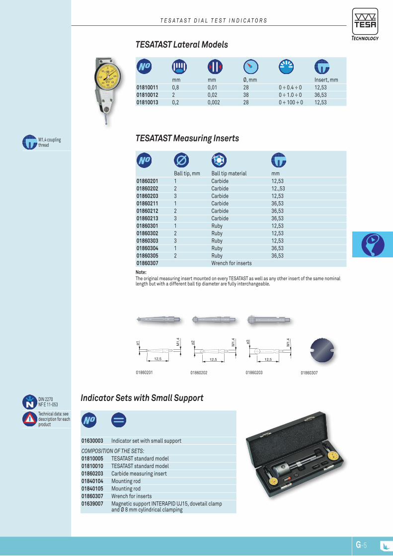
12,5
M1,
4
ø2
12,5
M1,
4
ø3
12,5
M1,
4
ø1
G-5G-4
01860307
Note: The original measuring insert mounted on every TESATAST as well as any other insert of the same nominal length but with a different ball tip diameter are fully interchangeable.
Ball tip, mm Ball tip material mm
01860201 1 Carbide 12,5301860202 2 Carbide 12.,5301860203 3 Carbide 12,5301860211 1 Carbide 36,5301860212 2 Carbide 36,5301860213 3 Carbide 36,5301860301 1 Ruby 12,5301860302 2 Ruby 12,5301860303 3 Ruby 12,5301860304 1 Ruby 36,5301860305 2 Ruby 36,5301860307 Wrench for inserts
M1,4 coupling thread
01860201
TESATAST Measuring Inserts
01860202 01860203
01630003 Indicator set with small support
DIN 2270 NF E 11-053
Technical data: see description for each product
Indicator Sets with Small Support
cOmpOsitiOn Of the sets:01810005 TESATAST standard model01810010 TESATAST standard model01860203 Carbide measuring insert01840104 Mounting rod01840105 Mounting rod01860307 Wrench for inserts01639007 Magnetic support INTERAPID UJ15, dovetail clamp
and Ø 8 mm cylindrical clamping
mm mm Ø, mm Insert, mm
01810011 0,8 0,01 28 0 ÷ 0.4 ÷ 0 12,5301810012 2 0,02 38 0 ÷ 1.0 ÷ 0 36,5301810013 0,2 0,002 28 0 ÷ 100 ÷ 0 12,53
TESATAST Lateral Models
t e s a t a s t D i a l t e s t i n D i c a t O r s

0184010501840104 0186000801840202
G-7G-6
01860401
Accessories for TESATAST
mm
01860401 Dovetail clamp with tightening screw
Ø 5,6 / Ø 9,5
clamp
a c c e s s O r i e s f O r l e v e r D i a l t e s t i n D i c a t O r s
mm
01840104 Mounting rod Ø 401840105 Mounting rod Ø 801840202 Cylindrical fixing shank Ø 8 x 80 (Ø 5,6 for
the tenon)01860008 Mounting rod Ø 6
Fixing Shank
0184040401840405
mm
01840404 Short swivel holder Ø 8 x 2501840405 Long swivel holder Ø 8 x 9001840406 Angular swivel holder Ø 8 x 25 (Ø 8 for
clamping bore)01840501 Centering holder Ø 8 x 25 (Ø 4 for
clamping point)01840407 Long sw. holder, fine adjust Ø 8 x 125
01840406
Mounting rods
01840407
01840501
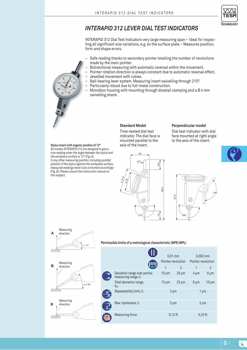
96,5
~16
16,5
ø 4
ø 3
0
ø 3
7,5
29
67,5
A
B
B
G-7G-6
measuring direction
Permissible limits of a metrological characteristic (MPE/MPL)
0,01 mm 0,002 mmPointer revolution Pointer revolution
1 2 1 2Deviation range over partial measuring range, fe
10 µm 20 µm 4 µm 8 µm
Total deviation range, fges
13 µm 23 µm 6 µm 10 µm
Repeatability limit, fw 3 µm 1 µm
Max. hysteresis, fu 3 µm 2 µm
Measuring force 0,12 N 0,25 N
measuring direction
measuring direction
Perpendicular model Dial test indicator with dial face mounted at right angle to the axis of the insert.
Standard Model Time-tested dial test indicator. The dial face is mounted parallel to the axis of the insert. Stylus insert with angular position of 12°
all models interapiD 312 are designed to give a true reading when the angle between the stylus and the workpiece surface is 12° (fig. a).in any other measuring position, including parallel position of the stylus against the workpiece surface, measured readings have to be corrected accordingly (fig. B). please consult the instruction manual on this subject.
INTERAPID 312 Dial Test Indicators very large measuring span – Ideal for inspec-ting all significant size variations, e.g. on the surface plate – Measures position, form and shape errors.
– Safe reading thanks to secondary pointer totalling the number of revolutions made by the main pointer.
– Bidirectional measuring with automatic reversal within the movement. – Pointer rotation direction is always constant due to automatic reversal effect. – Jewelled movement with rubies. – Ball-bearing lever system. Measuring insert swivelling through 210°. – Particularly robust due to full-metal construction. – Monobloc housing with mounting through dovetail clamping and a Ø 4 mm
swivelling shank.
InTErAPID 312 LEvEr DIAL TEST InDIcATorS
i n t e r a p i D 3 1 2 D i a l t e s t i n D i c a t O r s
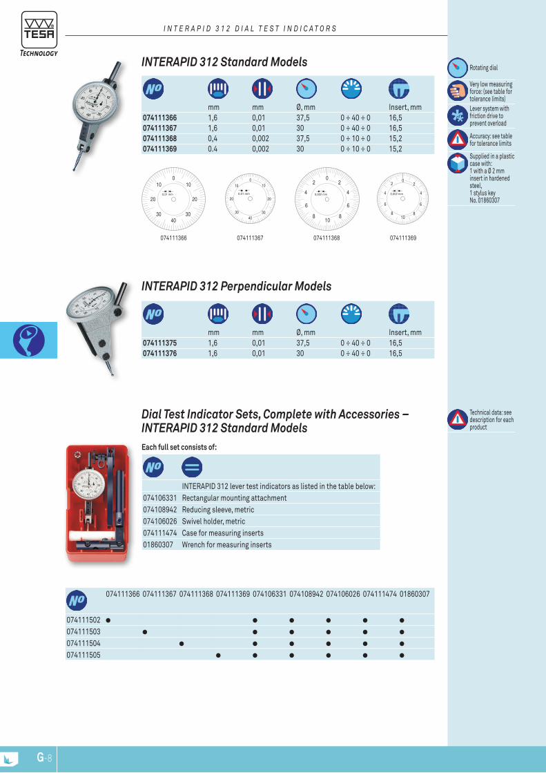
4030
20
100
30
20
10
0,01 mm
4030
20
100
30
20
10
0,01 mm
02
0,002 mm 4
6
810
8
6
4
2 02
0,002 mm 4
6
810
8
6
4
2
G-9G-8
074111367 074111369074111368074111366
mm mm Ø, mm Insert, mm
074111366 1,6 0,01 37,5 0 ÷ 40 ÷ 0 16,5074111367 1,6 0,01 30 0 ÷ 40 ÷ 0 16,5074111368 0,4 0,002 37,5 0 ÷ 10 ÷ 0 15,2074111369 0.4 0,002 30 0 ÷ 10 ÷ 0 15,2
Rotating dial
Very low measuring force: (see table for tolerance limits)Lever system with friction drive to prevent overload
Accuracy: see table for tolerance limits
Supplied in a plastic case with: 1 with a Ø 2 mm insert in hardened steel,1 stylus key No. 01860307
InTErAPID 312 Standard Models
i n t e r a p i D 3 1 2 D i a l t e s t i n D i c a t O r s
mm mm Ø, mm Insert, mm
074111375 1,6 0,01 37,5 0 ÷ 40 ÷ 0 16,5074111376 1,6 0,01 30 0 ÷ 40 ÷ 0 16,5
InTErAPID 312 Perpendicular Models
074111366 074111367 074111368 074111369 074106331 074108942 074106026 074111474 01860307
074111502074111503074111504074111505
INTERAPID 312 lever test indicators as listed in the table below:074106331 Rectangular mounting attachment074108942 Reducing sleeve, metric074106026 Swivel holder, metric074111474 Case for measuring inserts01860307 Wrench for measuring inserts
Technical data: see description for each product
Dial Test Indicator Sets, complete with Accessories – InTErAPID 312 Standard Models Each full set consists of:
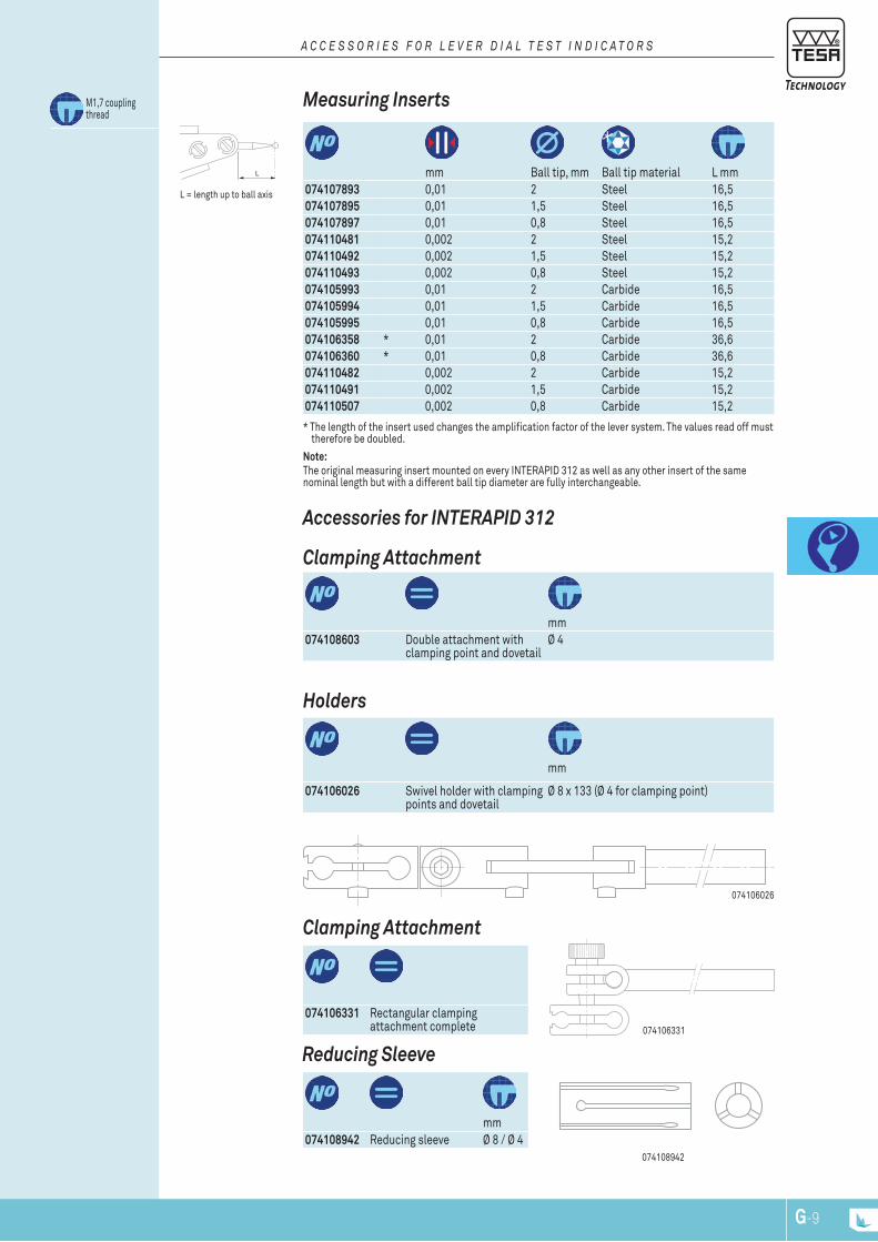
L
G-9G-8
mm
074108942 Reducing sleeve Ø 8 / Ø 4 074108942
reducing Sleeve
074106331 Rectangular clamping attachment complete 074106331
clamping Attachment
Accessories for InTErAPID 312
mm
074108603 Double attachment with clamping point and dovetail
Ø 4
clamping Attachment
mm Ball tip, mm Ball tip material L mm
074107893 0,01 2 Steel 16,5074107895 0,01 1,5 Steel 16,5074107897 0,01 0,8 Steel 16,5074110481 0,002 2 Steel 15,2074110492 0,002 1,5 Steel 15,2074110493 0,002 0,8 Steel 15,2074105993 0,01 2 Carbide 16,5074105994 0,01 1,5 Carbide 16,5074105995 0,01 0,8 Carbide 16,5074106358 * 0,01 2 Carbide 36,6074106360 * 0,01 0,8 Carbide 36,6074110482 0,002 2 Carbide 15,2074110491 0,002 1,5 Carbide 15,2074110507 0,002 0,8 Carbide 15,2
* The length of the insert used changes the amplification factor of the lever system. The values read off must therefore be doubled.
Measuring Inserts
L = length up to ball axis
M1,7 coupling thread
a c c e s s O r i e s f O r l e v e r D i a l t e s t i n D i c a t O r s
mm
074106026 Swivel holder with clamping points and dovetail
Ø 8 x 133 (Ø 4 for clamping point)
074106026
Holders
Note: The original measuring insert mounted on every INTERAPID 312 as well as any other insert of the same nominal length but with a different ball tip diameter are fully interchangeable.
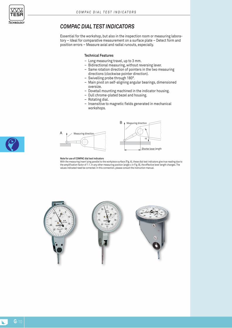
A
B
α
G-11G-10
Measuring direction
Shorter lever length
Measuring direction
Note for use of COMPAC dial test indicatorsWith the measuring insert lying parallel to the workpiece surface (Fig. A), these dial test indicators give true reading due to the amplification factor of 1:1. In any other measuring position (angle α in Fig. B), the effective lever length changes. The values indicated need be corrected. In this connection, please consult the instruction manual.
Essential for the workshop, but also in the inspection room or measuring labora-tory – Ideal for comparative measurement on a surface plate – Detect form and position errors – Measure axial and radial runouts, especially.
Technical Features – Long measuring travel, up to 3 mm. – Bidirectional measuring, without reversing lever. – Same rotation direction of pointers in the two measuring
directions (clockwise pointer direction). – Swivelling probe through 180°. – Main pivot on self-aligning angular bearings, dimensioned
oversize. – Dovetail mounting machined in the indicator housing. – Dull chrome-plated bezel and housing. – Rotating dial. – Insensitive to magnetic fields generated in mechanical
workshops.
coMPAc DIAL TEST InDIcATorS
c O m p a c D i a l t e s t i n D i c a t O r s
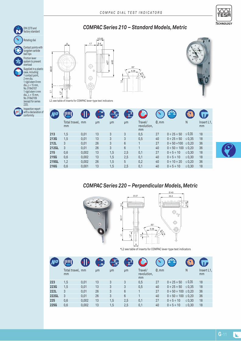
17
10.65
9.4
ø40
ø27
8
48.9
1L1
L2*
6.38 ø 0.79
1.6
8
L135
.17
9.4
Ø 27
Ø 40
33.2
10.6
5
L2*
6.38
1.6
Ø 0.79
17
58.6
L1
Ø 2
7
Ø 4
0
10.65
9.410.1
L2*
G-11G-10
223 1,5 0,01 13 3 3 0,5 27 0 ÷ 25 ÷ 50 ≤ 0,35 18 223G 1,5 0,01 13 3 3 0,5 40 0 ÷ 25 ÷ 50 ≤ 0,35 18 222L 3 0,01 26 3 6 1 27 0 ÷ 50 ÷ 100 ≤ 0,20 36 222GL 3 0,01 26 3 6 1 40 0 ÷ 50 ÷ 100 ≤ 0,20 36 225 0,6 0,002 13 1,5 2,5 0,1 27 0 ÷ 5 ÷ 10 ≤ 0,30 18 225G 0,6 0,002 13 1,5 2,5 0,1 40 0 ÷ 5 ÷ 10 ≤ 0,30 18
Total travel, mm
mm μm μm μm Travel/ revolution, mm
Ø, mm N Insert L1, mm
*L2 see table of inserts for COMPAC lever-type test indicators
coMPAc Series 220 – Perpendicular Models, Metric
DIN 2270 and factory standard
Rotating dial
Contact points with tungsten carbide ball tipsFriction lever system to prevent overloadSupplied in a plastic case, including: 1 contact point, 2 mm dia. 1 rigid stem 8 mm dia.,L = 15 mm, No. 01840107 1 rigid stem 4 mm dia., L = 15 mm, No. 01840109 (except for series 220).Inspection report with a declaration of conformity
213 1,5 0,01 13 3 3 0,5 27 0 ÷ 25 ÷ 50 ≤ 0,35 18 213G 1,5 0,01 13 3 3 0,5 40 0 ÷ 25 ÷ 50 ≤ 0,35 18 212L 3 0,01 26 3 6 1 27 0 ÷ 50 ÷100 ≤ 0,20 36 212GL 3 0,01 26 3 6 1 40 0 ÷ 50 ÷ 100 ≤ 0,20 36 215 0,6 0,002 13 1,5 2,5 0,1 27 0 ÷ 5 ÷ 10 ≤ 0,30 18 215G 0,6 0,002 13 1,5 2,5 0,1 40 0 ÷ 5 ÷ 10 ≤ 0,30 18 215GL 1,2 0,002 26 1,5 5 0,2 40 0 ÷ 10 ÷ 20 ≤ 0,20 36 216G 0,6 0,001 13 1,5 2,5 0,1 40 0 ÷ 5 ÷ 10 ≤ 0,30 18
Total travel, mm
mm μm μm μm Travel/ revolution, mm
Ø, mm N Insert L1, mm
L2; see table of inserts for COMPAC lever-type test indicators
coMPAc Series 210 – Standard Models, Metric
c O m p a c D i a l t e s t i n D i c a t O r s
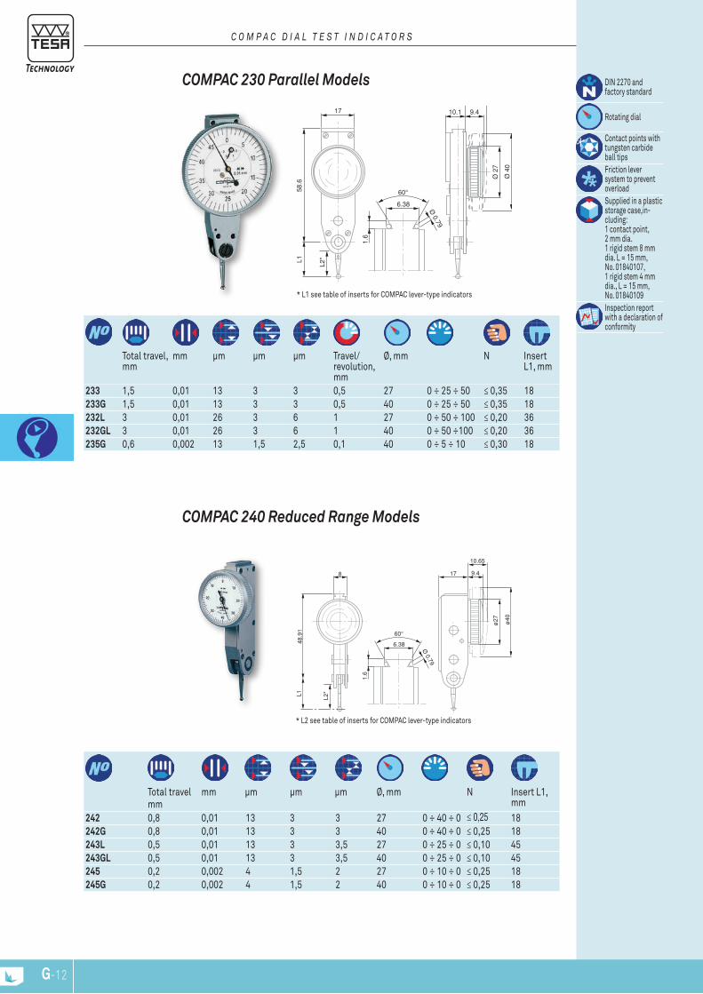
6.38
1.6
Ø 0.79
17
58.6
L1
Ø 2
7
Ø 4
0
10.65
9.410.1
L2*
8
48.9
1L1
17
10.65
9.4
ø40
ø27
L2*
6.38
1.6
Ø 0.79
G-13G-12
Total travelmm
mm μm μm μm Ø, mm N Insert L1, mm
242 0,8 0,01 13 3 3 27 0 ÷ 40 ÷ 0 ≤ 0,25 18242G 0,8 0,01 13 3 3 40 0 ÷ 40 ÷ 0 ≤ 0,25 18243L 0,5 0,01 13 3 3,5 27 0 ÷ 25 ÷ 0 ≤ 0,10 45243GL 0,5 0,01 13 3 3,5 40 0 ÷ 25 ÷ 0 ≤ 0,10 45245 0,2 0,002 4 1,5 2 27 0 ÷ 10 ÷ 0 ≤ 0,25 18245G 0,2 0,002 4 1,5 2 40 0 ÷ 10 ÷ 0 ≤ 0,25 18
* L2 see table of inserts for COMPAC lever-type indicators
coMPAc 240 reduced range Models
Total travel, mm
mm μm μm μm Travel/ revolution, mm
Ø, mm N Insert L1, mm
233 1,5 0,01 13 3 3 0,5 27 0 ÷ 25 ÷ 50 ≤ 0,35 18233G 1,5 0,01 13 3 3 0,5 40 0 ÷ 25 ÷ 50 ≤ 0,35 18232L 3 0,01 26 3 6 1 27 0 ÷ 50 ÷ 100 ≤ 0,20 36232GL 3 0,01 26 3 6 1 40 0 ÷ 50 ÷100 ≤ 0,20 36235G 0,6 0,002 13 1,5 2,5 0,1 40 0 ÷ 5 ÷ 10 ≤ 0,30 18
DIN 2270 and factory standard
Rotating dial
Contact points with tungsten carbide ball tipsFriction lever system to prevent overloadSupplied in a plastic storage case,in-cluding: 1 contact point, 2 mm dia. 1 rigid stem 8 mm dia. L = 15 mm, No. 01840107, 1 rigid stem 4 mm dia., L = 15 mm, No. 01840109Inspection report with a declaration of conformity
* L1 see table of inserts for COMPAC lever-type indicators
coMPAc 230 Parallel Models
c O m p a c D i a l t e s t i n D i c a t O r s
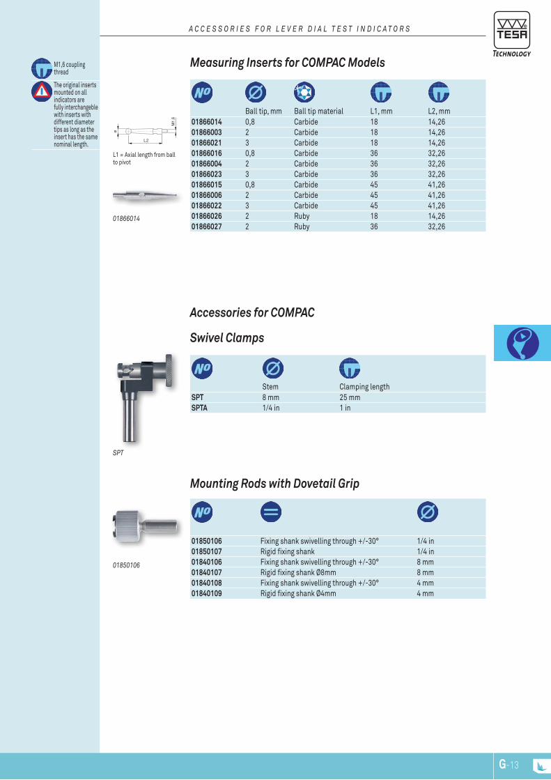
ø
L2
M1,
6
G-13G-12
L1 = Axial length from ball to pivot
Ball tip, mm Ball tip material L1, mm L2, mm
01866014 0,8 Carbide 18 14,2601866003 2 Carbide 18 14,2601866021 3 Carbide 18 14,2601866016 0,8 Carbide 36 32,2601866004 2 Carbide 36 32,2601866023 3 Carbide 36 32,2601866015 0,8 Carbide 45 41,2601866006 2 Carbide 45 41,2601866022 3 Carbide 45 41,2601866026 2 Ruby 18 14,2601866027 2 Ruby 36 32,26
M1,6 coupling thread
The original inserts mounted on all indicators are fully interchangeble with inserts with different diameter tips as long as the insert has the same nominal length.
01866014
Measuring Inserts for coMPAc Models
a c c e s s O r i e s f O r l e v e r D i a l t e s t i n D i c a t O r s
01850106
01850106 Fixing shank swivelling through +/-30° 1/4 in01850107 Rigid fixing shank 1/4 in01840106 Fixing shank swivelling through +/-30° 8 mm01840107 Rigid fixing shank Ø8mm 8 mm01840108 Fixing shank swivelling through +/-30° 4 mm01840109 Rigid fixing shank Ø4mm 4 mm
Mounting rods with Dovetail Grip
spt
Accessories for coMPAc
Stem Clamping length
SPT 8 mm 25 mmSPTA 1/4 in 1 in
Swivel clamps
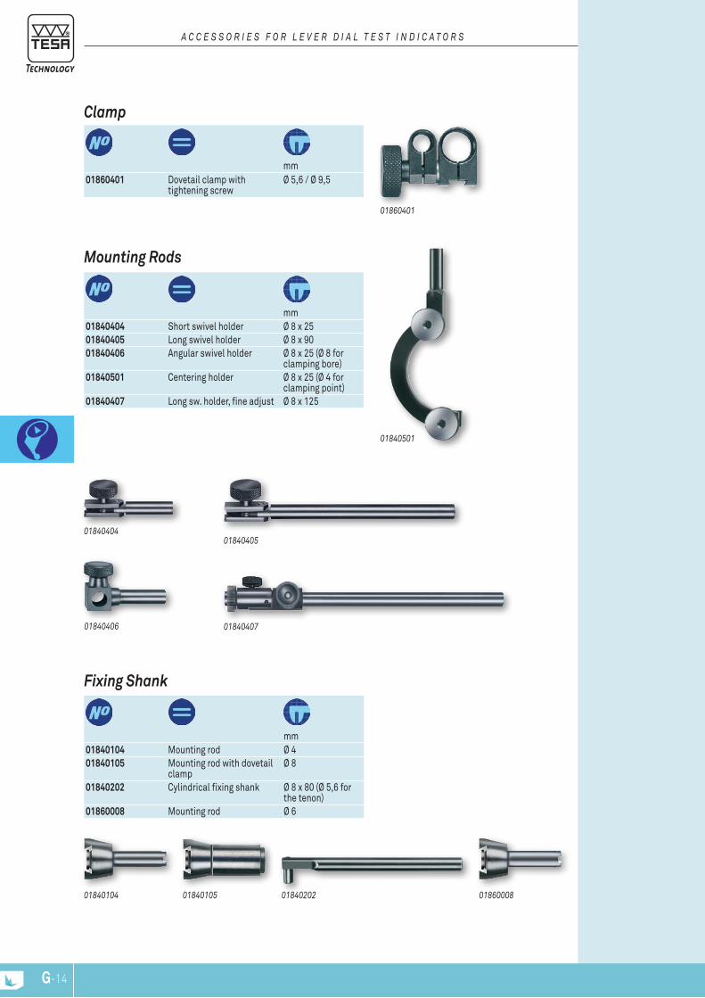
G-NPG-14
01860401
mm
01860401 Dovetail clamp with tightening screw
Ø 5,6 / Ø 9,5
clamp
a c c e s s O r i e s f O r l e v e r D i a l t e s t i n D i c a t O r s
mm
01840104 Mounting rod Ø 401840105 Mounting rod with dovetail
clampØ 8
01840202 Cylindrical fixing shank Ø 8 x 80 (Ø 5,6 for the tenon)
01860008 Mounting rod Ø 6
Fixing Shank
0184040401840405
mm
01840404 Short swivel holder Ø 8 x 2501840405 Long swivel holder Ø 8 x 9001840406 Angular swivel holder Ø 8 x 25 (Ø 8 for
clamping bore)01840501 Centering holder Ø 8 x 25 (Ø 4 for
clamping point)01840407 Long sw. holder, fine adjust Ø 8 x 125
01840406
Mounting rods
01840407
01840501
0184010501840104 0186000801840202

www.tesatechnology.com
Com
para
tive
Mea
sure
men
t
H-1H-NP

The maximum permissible errors indicated for a metrological characteristic (MPE) have been obtained at a temperature of 20° ± 0,5°C and relative humidity of 50 ± 5 %.
Internal, mm External, mm mm Kg
02130001 TESA TPS 300 0,1 ÷ 300 40 ÷ 340 610 x 300 x 270 75
02130002 TESA TPS 500 0,1 ÷ 500 40 ÷ 540 820 x 300 x 300 90
02130003 TESA TPS 1000 0,1 ÷ 1000 40 ÷ 1040 1330 x 340 x 340 240
0,001 mm
Linear 1,5 + L (mm) / 300 μm
1 μm
100/240 AC – 1,5 A 50/60 Hz
Inspection report
RS232
Holding force 240 N
TESA TPS 500 + 02160027 + 02160024 (+ DIGICO 705)
TESA TPS - Motorised setting benches The TPS are designed for setting hand-held measuring instruments and replace a complete set of ring gauges.The setting bench is typically used with comparative measuring instruments such as dial guages, lever-type dial test indicators or 2-point bore gauges.TPS is very simple to use: enter the value and the mobile slide will automatically position itself at this value.It can be used for checking internal as well as external dimensions of up to 1000 mm, according to the model.Special adapters help to position the instrument, so that is very easy and quick to use and human errors can be avoided.For versions with dimensions over 1000 mm, please contact TESA.
C O M P A r A T I v E M E A S u r E M E n T
COnSISTInG OF:02160038 Power suppy 80 ÷ 240 V, 50 ÷ 60 Hz02160027 Mobile stop adapter
H-3H-2
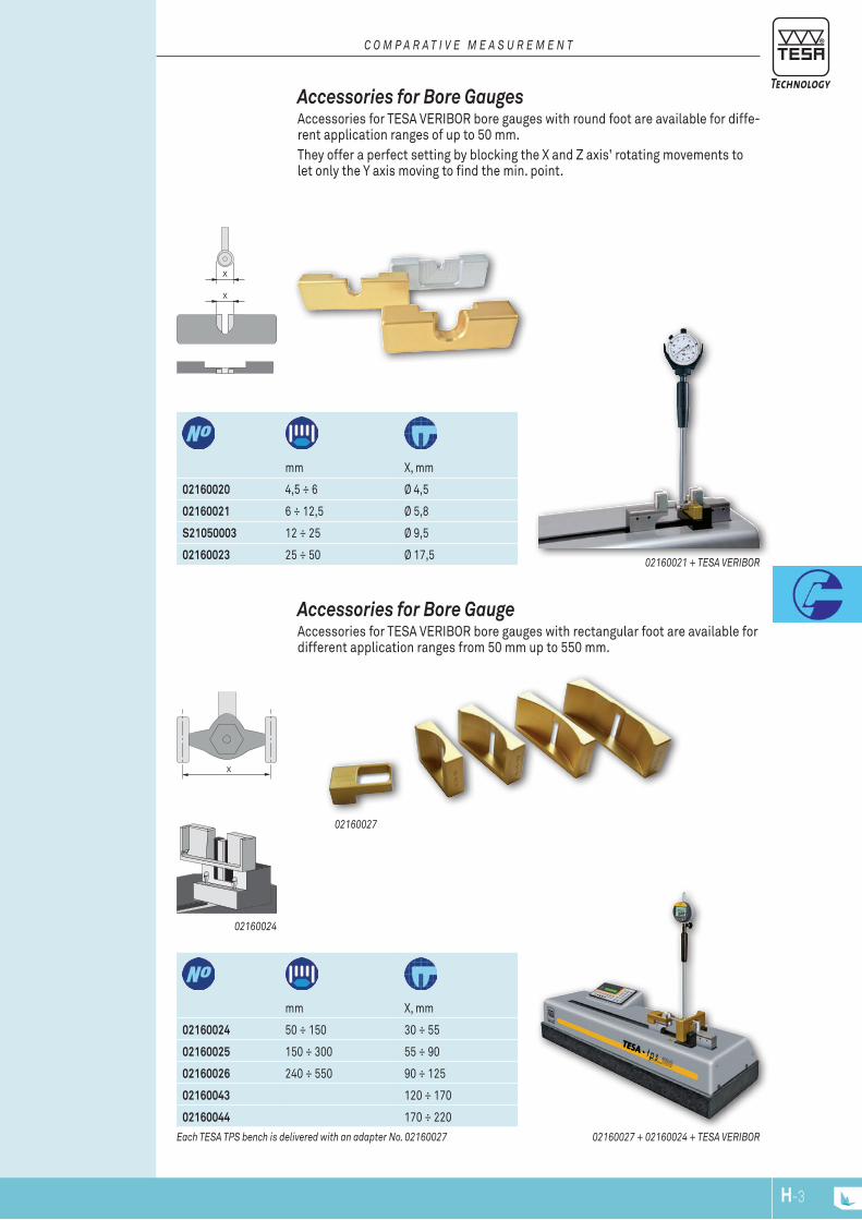
X
X
X
Each TESA TPS bench is delivered with an adapter no. 02160027
mm X, mm
02160024 50 ÷ 150 30 ÷ 55
02160025 150 ÷ 300 55 ÷ 90
02160026 240 ÷ 550 90 ÷ 125
02160043 120 ÷ 170
02160044 170 ÷ 220
02160024
02160027 + 02160024 + TESA vErIBOr
02160027
Accessories for Bore Gauge Accessories for TESA VERIBOR bore gauges with rectangular foot are available for different application ranges from 50 mm up to 550 mm.
mm X, mm
02160020 4,5 ÷ 6 Ø 4,5
02160021 6 ÷ 12,5 Ø 5,8
S21050003 12 ÷ 25 Ø 9,5
02160023 25 ÷ 50 Ø 17,502160021 + TESA vErIBOr
Accessories for Bore GaugesAccessories for TESA VERIBOR bore gauges with round foot are available for diffe-rent application ranges of up to 50 mm.They offer a perfect setting by blocking the X and Z axis' rotating movements to let only the Y axis moving to find the min. point.
C O M P A r A T I v E M E A S u r E M E n T
H-3H-2
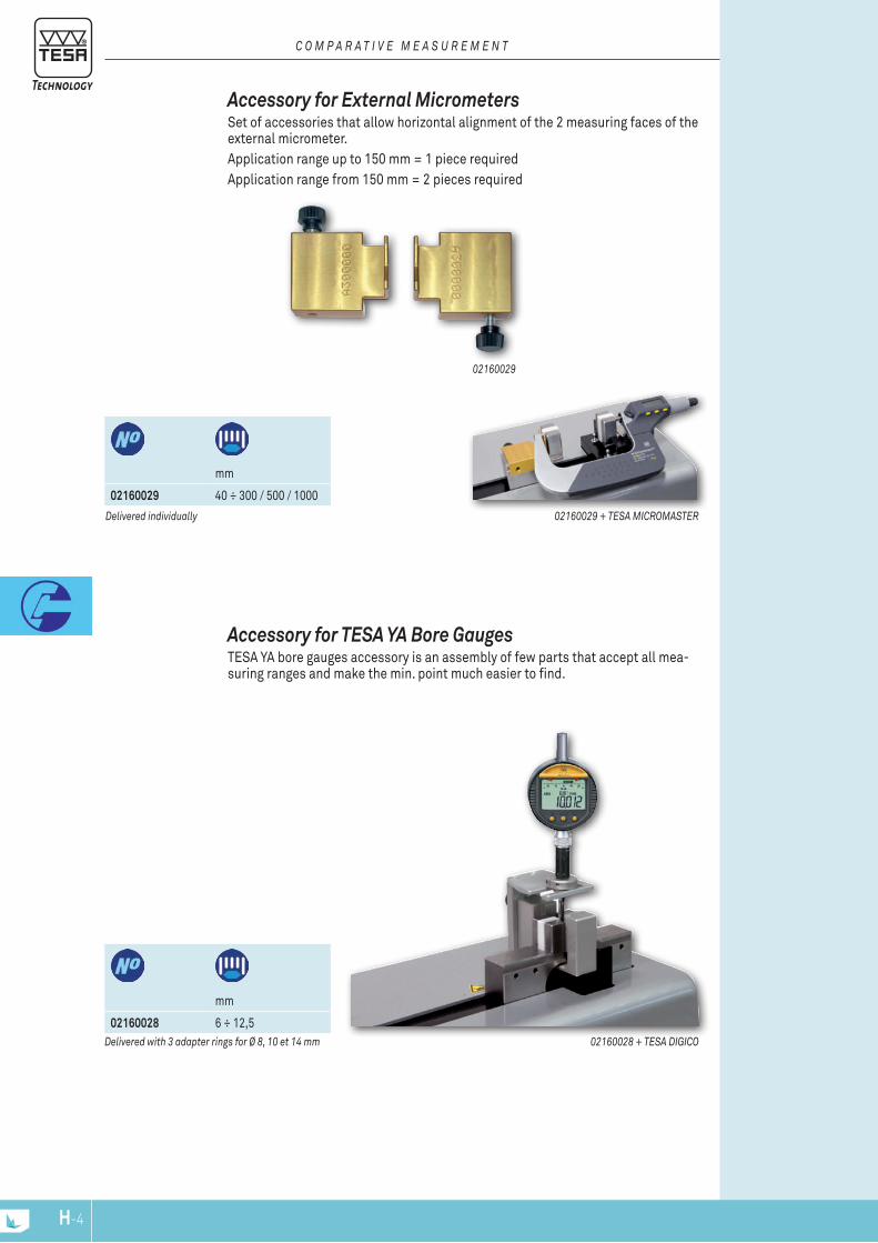
Delivered individually
mm
02160029 40 ÷ 300 / 500 / 1000
02160029 + TESA MICrOMASTEr
02160029
Accessory for External Micrometers Set of accessories that allow horizontal alignment of the 2 measuring faces of the external micrometer.Application range up to 150 mm = 1 piece requiredApplication range from 150 mm = 2 pieces required
C O M P A r A T I v E M E A S u r E M E n T
mm
02160028 6 ÷ 12,502160028 + TESA DIGICO
Accessory for TESA YA Bore Gauges TESA YA bore gauges accessory is an assembly of few parts that accept all mea-suring ranges and make the min. point much easier to find.
Delivered with 3 adapter rings for Ø 8, 10 et 14 mm
H-5H-4
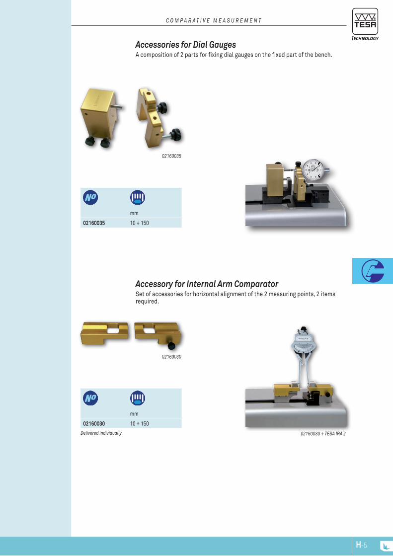
Delivered individually
mm
02160030 10 ÷ 150
02160030 + TESA IrA 2
02160030
Accessory for Internal Arm Comparator Set of accessories for horizontal alignment of the 2 measuring points, 2 items required.
mm
02160035 10 ÷ 150
02160035
Accessories for Dial Gauges A composition of 2 parts for fixing dial gauges on the fixed part of the bench.
C O M P A r A T I v E M E A S u r E M E n T
H-5H-4

40
51
ø8
ø13
.5
TESA YA CoMPlETE InSTruMEnT SETS Specially designed for small bores from 0,47 up to 12,20 mm - Checking of dimension and bore form errors through 2-point measuring - Offers an excellent repeatability. The YA bore gauges consist of an interchangeable measuring head with a built-in needle and handle with a 8 mm diameter fixing bore for a dial gauge or any other type of sensor
– Measuring heads with spherical faces for through bores. – Measuring heads for particularly deep bores.
Can be supplied on request: – Measuring heads with carbide measuring faces. – Measuring heads for special applications. – Measuring heads for blind bores and particularly deep bores with other appli-
cation ranges. – Carbide measuring needles. – Depth extensions 125, 250, 500, 750 and 1000 mm.
T E S A Y A B O r E G A u G E S
H-7H-6
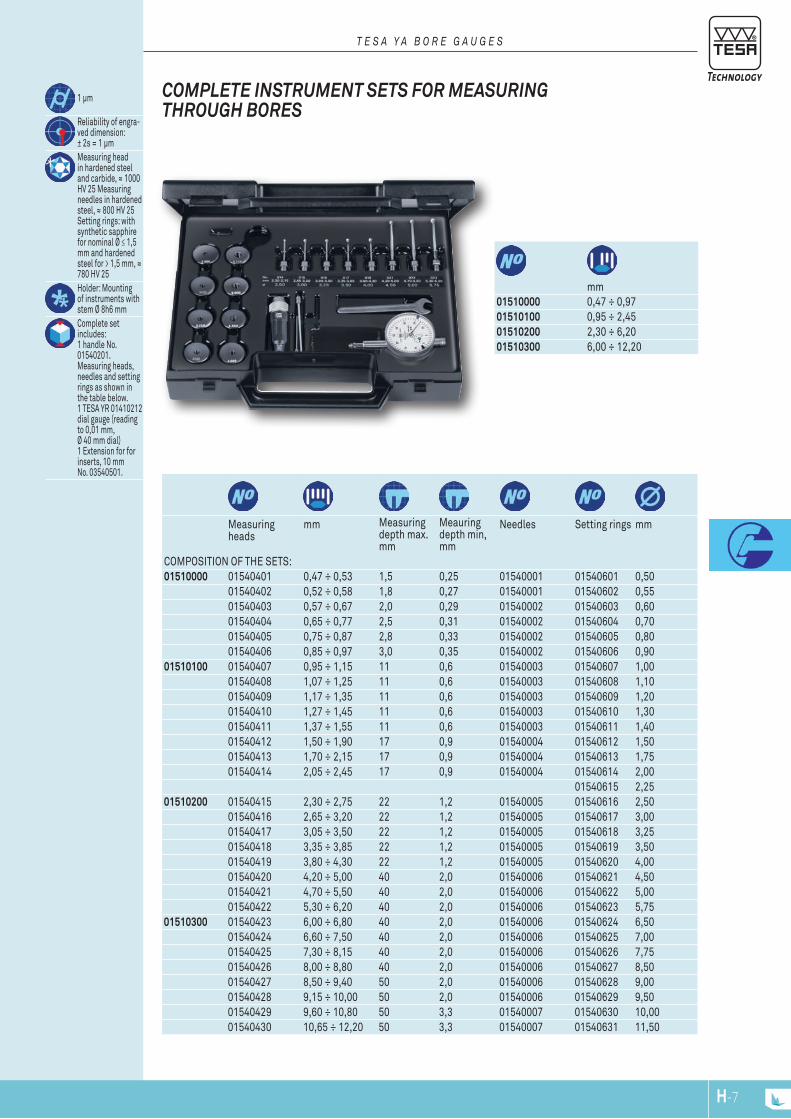
1 μm
Reliability of engra-ved dimension: ± 2s = 1 μmMeasuring head in hardened steel and carbide, ≈ 1000 HV 25 Measuring needles in hardened steel, ≈ 800 HV 25 Setting rings: with synthetic sapphire for nominal Ø ≤ 1,5 mm and hardened steel for > 1,5 mm, ≈ 780 HV 25Holder: Mounting of instruments with stem Ø 8h6 mmComplete set includes:1 handle No. 01540201.Measuring heads, needles and setting rings as shown in the table below. 1 TESA YR 01410212 dial gauge (reading to 0,01 mm, Ø 40 mm dial) 1 Extension for for inserts, 10 mm No. 03540501.
T E S A Y A B O r E G A u G E S
CoMPlETE InSTruMEnT SETS for MEASurInG ThrouGh BorES
mm
01510000 0,47 ÷ 0,9701510100 0,95 ÷ 2,4501510200 2,30 ÷ 6,2001510300 6,00 ÷ 12,20
Measuring heads
mm Measuring depth max. mm
Meauring depth min, mm
Needles Setting rings mm
COMPOSITION OF THE SETS:01510000 01540401 0,47 ÷ 0,53 1,5 0,25 01540001 01540601 0,50
01540402 0,52 ÷ 0,58 1,8 0,27 01540001 01540602 0,5501540403 0,57 ÷ 0,67 2,0 0,29 01540002 01540603 0,6001540404 0,65 ÷ 0,77 2,5 0,31 01540002 01540604 0,7001540405 0,75 ÷ 0,87 2,8 0,33 01540002 01540605 0,8001540406 0,85 ÷ 0,97 3,0 0,35 01540002 01540606 0,90
01510100 01540407 0,95 ÷ 1,15 11 0,6 01540003 01540607 1,0001540408 1,07 ÷ 1,25 11 0,6 01540003 01540608 1,1001540409 1,17 ÷ 1,35 11 0,6 01540003 01540609 1,2001540410 1,27 ÷ 1,45 11 0,6 01540003 01540610 1,3001540411 1,37 ÷ 1,55 11 0,6 01540003 01540611 1,4001540412 1,50 ÷ 1,90 17 0,9 01540004 01540612 1,5001540413 1,70 ÷ 2,15 17 0,9 01540004 01540613 1,7501540414 2,05 ÷ 2,45 17 0,9 01540004 01540614 2,00
01540615 2,2501510200 01540415 2,30 ÷ 2,75 22 1,2 01540005 01540616 2,50
01540416 2,65 ÷ 3,20 22 1,2 01540005 01540617 3,0001540417 3,05 ÷ 3,50 22 1,2 01540005 01540618 3,2501540418 3,35 ÷ 3,85 22 1,2 01540005 01540619 3,5001540419 3,80 ÷ 4,30 22 1,2 01540005 01540620 4,0001540420 4,20 ÷ 5,00 40 2,0 01540006 01540621 4,5001540421 4,70 ÷ 5,50 40 2,0 01540006 01540622 5,0001540422 5,30 ÷ 6,20 40 2,0 01540006 01540623 5,75
01510300 01540423 6,00 ÷ 6,80 40 2,0 01540006 01540624 6,5001540424 6,60 ÷ 7,50 40 2,0 01540006 01540625 7,0001540425 7,30 ÷ 8,15 40 2,0 01540006 01540626 7,7501540426 8,00 ÷ 8,80 40 2,0 01540006 01540627 8,5001540427 8,50 ÷ 9,40 50 2,0 01540006 01540628 9,0001540428 9,15 ÷ 10,00 50 2,0 01540006 01540629 9,5001540429 9,60 ÷ 10,80 50 3,3 01540007 01540630 10,0001540430 10,65 ÷ 12,20 50 3,3 01540007 01540631 11,50
H-7H-6
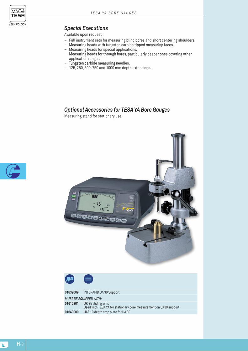
Special Executions Available upon request :
– Full instrument sets for measuring blind bores and short centering shoulders. – Measuring heads with tungsten carbide tipped measuring faces. – Measuring heads for special applications. – Measuring heads for through bores, particularly deeper ones covering other
application ranges. – Tungsten carbide measuring needles. – 125, 250, 500, 750 and 1000 mm depth extensions.
T E S A Y A B O r E G A u G E S
01639009 INTERAPID UA 30 Support
MuST BE EquIPPED wITh:01610201 UK 25 sliding arm.
Used with TESA YA for stationary bore measurement on UA30 support.01640000 UAZ 10 depth stop plate for UA 30
optional Accessories for TESA YA Bore Gauges Measuring stand for stationary use.
H-9H-8

Measuring bolt travel, mm
mm Measuring depth, mm
05710090 TESA VERIBOR light 1,30 18 ÷ 35 17605710091 TESA VERIBOR light 1,40 35 ÷ 60 17805710092 TESA VERIBOR light 1,40 50 ÷ 150 17805710093 TESA VERIBOR light 1,30 / 1,40 18 ÷ 150 176 / 178Sets delivered without dial gauge
TESA VErIBor light Instrument with 2 contact points for comparative measurement of bores and de-tection of form errors – Automatic self-centering in the bore – Can be used with a dial gauge, a precision indicator or a probe with Ø 8h6 clamping stem.
TESA VErIBor Proven design and reliability never questioned over decades –Instruments for 2-point measurements for bores from 4,5 up to 550 mm – Detects form errors – Gauge body with a 8 mm diameter clamping bore for a dial gauge, precision indi-cator or any other sensor.
– Excellent repeatability due to the circular element fixed on the instrument ensuring practically no play.
– Gauge body made of invar steel to neutralise the influence of the operator's hand warmth on the measuring result.
– Centring shoe for correct alignment of the instrument in the bore. – Tungsten carbide ball tips for high resistance to wear.
4 μm
2 μm
Measuring bolts and anvils in hardened steel, hardness 60 ± 2 and 63 ± 3 HRC, respectively
Mounting for sensor with stem Ø 8h6
Set including 1 single TESA VERI-BOR Light. 1 set of interchan-geable fixed inserts covering the entire application range
T E S A v E r I B O r B O r E G A u G E S
H-9H-8
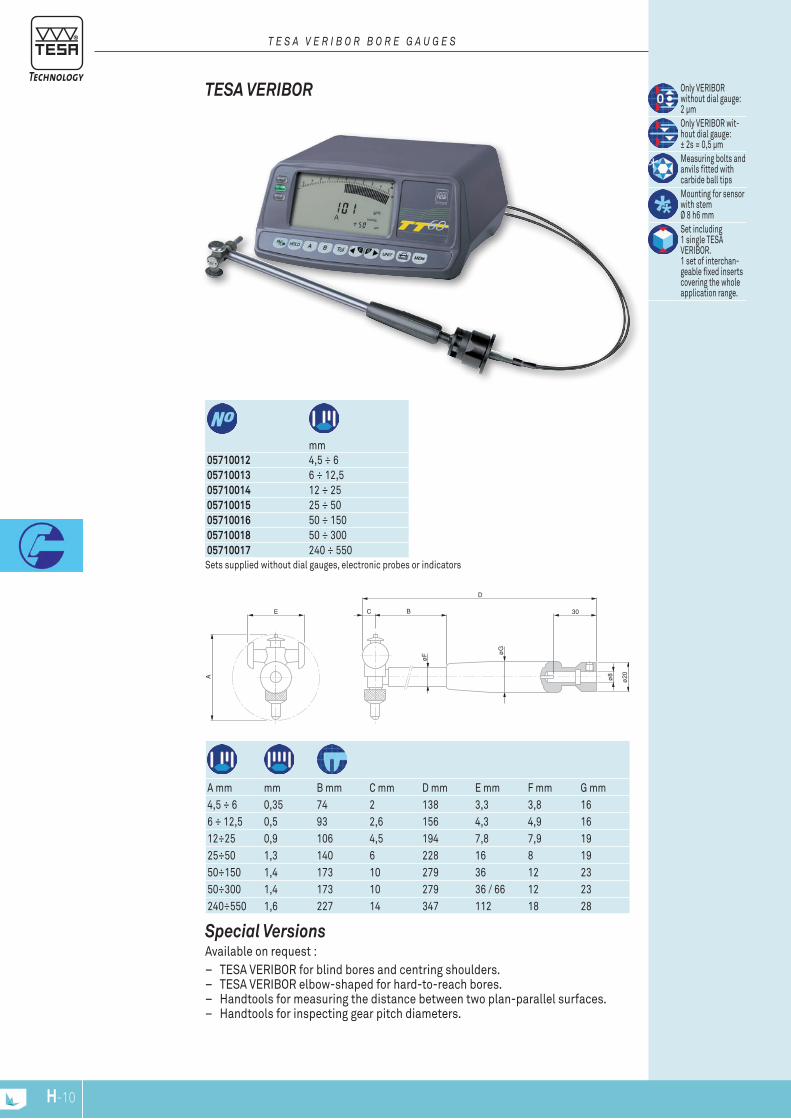
E
A
C B
D
øF ø
G
30ø
8
ø20
Sets supplied without dial gauges, electronic probes or indicators
mm
05710012 4,5 ÷ 6 05710013 6 ÷ 12,5 05710014 12 ÷ 2505710015 25 ÷ 50 05710016 50 ÷ 15005710018 50 ÷ 30005710017 240 ÷ 550
Only VERIBOR without dial gauge: 2 μmOnly VERIBOR wit-hout dial gauge: ± 2s = 0,5 μmMeasuring bolts and anvils fitted with carbide ball tipsMounting for sensor with stem Ø 8 h6 mmSet including 1 single TESA VERIBOR. 1 set of interchan-geable fixed inserts covering the wholeapplication range.
A mm mm B mm C mm D mm E mm F mm G mm4,5 ÷ 6 0,35 74 2 138 3,3 3,8 166 ÷ 12,5 0,5 93 2,6 156 4,3 4,9 1612÷25 0,9 106 4,5 194 7,8 7,9 1925÷50 1,3 140 6 228 16 8 1950÷150 1,4 173 10 279 36 12 2350÷300 1,4 173 10 279 36 / 66 12 23240÷550 1,6 227 14 347 112 18 28
TESA VErIBor
T E S A v E r I B O r B O r E G A u G E S
Special VersionsAvailable on request :
– TESA VERIBOR for blind bores and centring shoulders. – TESA VERIBOR elbow-shaped for hard-to-reach bores. – Handtools for measuring the distance between two plan-parallel surfaces. – Handtools for inspecting gear pitch diameters.
H-11H-10
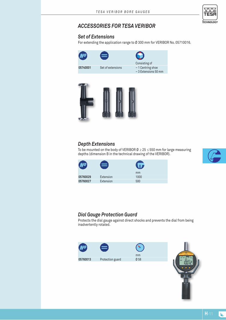
mm
05760013 Protection guard Ø 58
Dial Gauge Protection Guard Protects the dial gauge against direct shocks and prevents the dial from being inadvertently rotated.
mm
05760029 Extension 100005760027 Extension 500
Depth Extensions To be mounted on the body of VERIBOR Ø ≥ 25 ≤ 550 mm for large measuring depths (dimension B in the technical drawing of the VERIBOR).
Consisting of
05740001 Set of extensions – 1 Centring shoe– 3 Extensions 50 mm
Set of Extensions For extending the application range to Ø 300 mm for VERIBOR No. 05710016.
ACCESSorIES for TESA VErIBor
T E S A v E r I B O r B O r E G A u G E S
H-11H-10

10 -
150
mm
510
15
20IN
TER
APID
0
510
1520
SWIT
ZER
LAN
D
0
Z (2:1)
Z
M 2.3
3.5
2.5
max
.
~ 65
R2
2.2
ø3ø2.2
R2 ø3
2.2
ø1 ø32.5
3.5
ø1.4
ø3
5
6
1.4
3
0.8 6
43.
5 2
0.7
2.5
75.
5
1.5
5.5
4
079105667
079105756
079105668
079105669
079112126
079112051 Small insert set for 3-point measurement079112052 Long insert set pour 3-point measuring
optional Accessories for IrA-2 Comparative Gauge
079112052
079112051
079105704 INTERAPID IRA 2 mm079111401 INTERAPID IRA 2, carbide mm
± 0,20 mm or ± 0.008 in
10 ÷ 150 mm 0.375 ÷ 6 in
0,01 mm or 0.0005 in
Measuring inserts in hardened steel or tungsten carbide, see opposite table
3,5 N
Measuring arm clearance travel: 10 mm
IrA 2 Comparative Gauge – Large application range from 10 to 150 mm – Easy to handle thanks to its light weight and ergonomic design – Built-in indicator with 0,01 mm reading and fine setting – Centering device for 2-point measurement
ArM GAuGES Very practical comparative measuring instrument – Measures at 2 or 3 points depending on the acces-sory used – Ideal for blind or through bores – also suited for measuring grooves, flutes as well as the internal measurement of parts with parallel faces.
C O M P A r A T I v E M E A S u r E M E n T
DElIvErED wITh ThE FOllOwInG ACCESSOrIES:079105667 3 inserts, hardened steel (order number for 1 unit,
with 079105704)079105756 3 inserts, carbide (order number for 1 unit,
with 079111401)079105668 3 short inserts, hardened steel (order number for 1 unit)079105669 3 long inserts in hardened steel (order number for 1 unit)079112126 2 inserts, adjustable for internal dia. >6mm079110110 Large insert holder for 3-point measurement079108502 IRA centering arm, Ø 15-30 mm079110111 Small insert holder for 3-point measurement079105694 Special screwdriver for IRA set
Chrome plated, hardened steel
H-13H-12
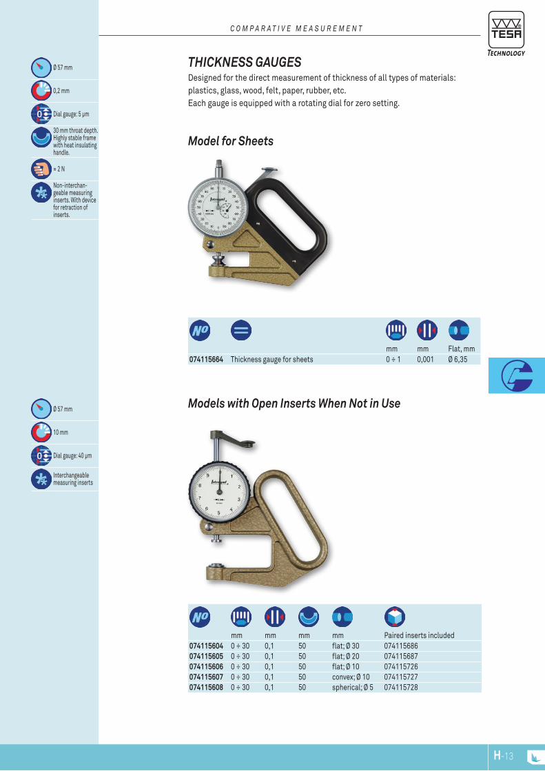
074115604 0 ÷ 30 0,1 50 flat; Ø 30 074115686074115605 0 ÷ 30 0,1 50 flat; Ø 20 074115687074115606 0 ÷ 30 0,1 50 flat; Ø 10 074115726074115607 0 ÷ 30 0,1 50 convex; Ø 10 074115727074115608 0 ÷ 30 0,1 50 spherical; Ø 5 074115728
mm mm mm mm Paired inserts included
Ø 57 mm
10 mm
Dial gauge: 40 μm
Interchangeable measuring inserts
Models with open Inserts When not in use
mm mm Flat, mm
074115664 Thickness gauge for sheets 0 ÷ 1 0,001 Ø 6,35
Ø 57 mm
0,2 mm
Dial gauge: 5 μm
30 mm throat depth. Highly stable frame with heat insulating handle.
≈ 2 N
Non-interchan-geable measuring inserts. With device for retraction of inserts.
Model for Sheets
ThICknESS GAuGES Designed for the direct measurement of thickness of all types of materials:plastics, glass, wood, felt, paper, rubber, etc.Each gauge is equipped with a rotating dial for zero setting.
C O M P A r A T I v E M E A S u r E M E n T
H-13H-12
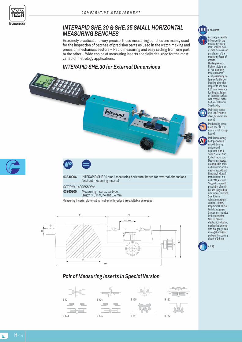
60
185
57
7491
ø8
47
03330004 INTERAPID SHE 30 small measuring horizontal bench for external dimensions (without measuring inserts)
0 to 30 mm
Accuracy is usually influenced by the measuring instru-ment used as well as both flatness and parallelism of the measuring faces of inserts. Holder precision: Flatness tolerance of two clamping faces: 0,05 mm. Axial positioning to-lerance for the two indexing pins with respect to bolt axis: 0,05 mm. Tolerance for the parallelism of the table surface with respect to the bolt axis: 0,05 mm. See drawingMain body in cast iron. Other parts in steel, hardened and groundProduced by sensor used. The SHE.30 model is not spring-loaded.Mobile measuring bolt: guided on a smooth bearing surface and equipped with a semi-circular disc for bolt retraction. Measuring inserts, assembled in pairs, and mounted on the measuring bolt and fixed anvil with a 1 mm diameter pin and 2 M1,4 screws. Support table with possibility of verti-cal and longitudinal adjustment: Surface 24 x 9,5 mm. Adjustment range: vertical: 15 mm, longitudinal: 14 mm. With fixing screw. Sensor (not included in the supply for SHE 30 bench): electronic indicator, mechanical or preci-sion dial gauge, axial analogue or digital probe with mounting shank of Ø 8 mm
2,1 kg
OPTIOnAl ACCESSOrY:03360300 Measuring inserts, carbide,
length 3,5 mm, height 0,4 mmMeasuring inserts, either cylindrical or knife-edged are available on request.
InTErAPID ShE.30 for External Dimensions
InTErAPID ShE.30 & ShE.35 SMAll horIzonTAl MEASurInG BEnChES Extremely practical and very precise, these measuring benches are mainly used for the inspection of batches of precision parts as used in the watch making and precision mechanical sectors – Rapid measuring and easy setting from one part to the other – Wide choice of measuring inserts specially designed for the most varied of metrology applications.
C O M P A r A T I v E M E A S u r E M E n T
Pair of Measuring Inserts in Special Version
B 152B 133 B 134
B 121 B 125 B 132B 124
B 151
H-15H-14
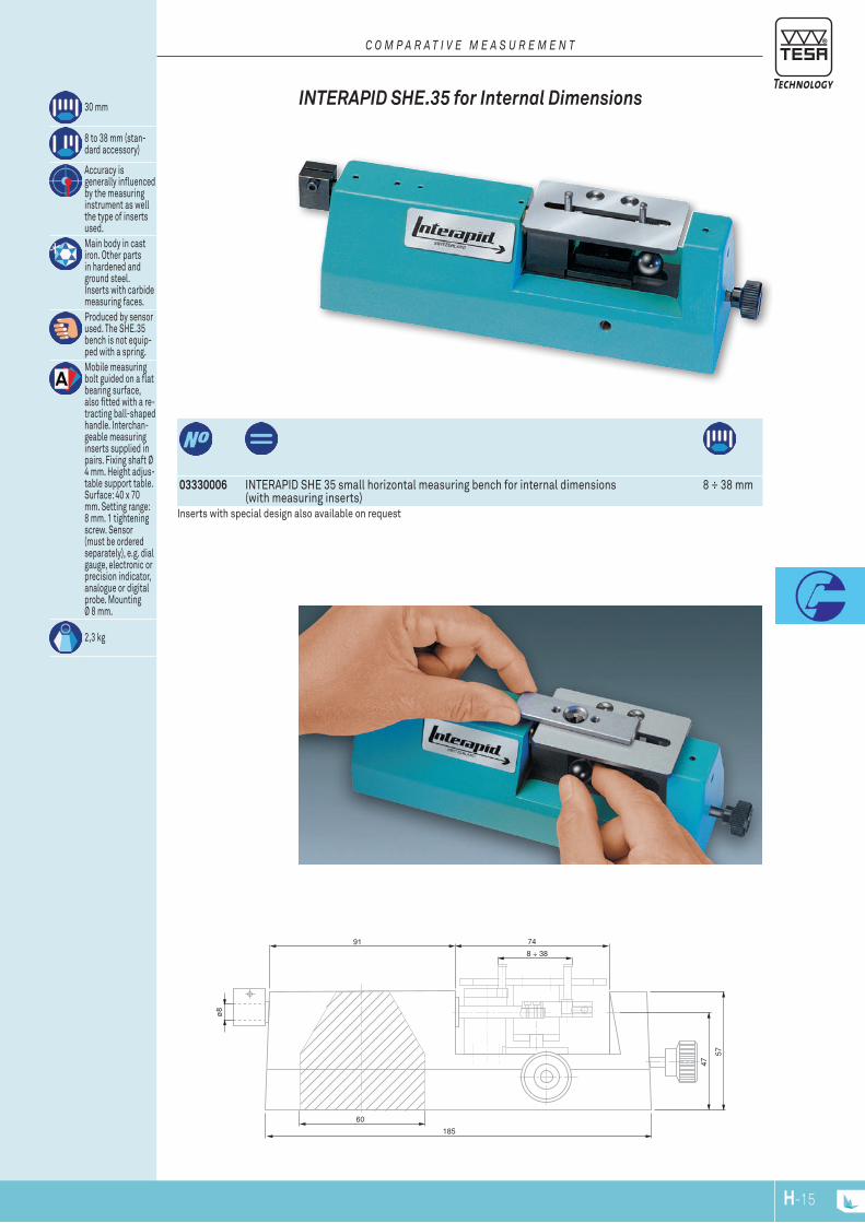
185
57
7491
ø8
47
60
03330006 INTERAPID SHE 35 small horizontal measuring bench for internal dimensions (with measuring inserts)
8 ÷ 38 mm
Inserts with special design also available on request
InTErAPID ShE.35 for Internal Dimensions 30 mm
8 to 38 mm (stan-dard accessory)
Accuracy is generally influenced by the measuring instrument as well the type of inserts used.Main body in cast iron. Other parts in hardened and ground steel. Inserts with carbide measuring faces.Produced by sensor used. The SHE.35 bench is not equip-ped with a spring.Mobile measuring bolt guided on a flat bearing surface, also fitted with a re-tracting ball-shaped handle. Interchan-geable measuring inserts supplied in pairs. Fixing shaft Ø 4 mm. Height adjus-table support table. Surface: 40 x 70 mm. Setting range: 8 mm. 1 tightening screw. Sensor (must be ordered separately), e.g. dial gauge, electronic or precision indicator, analogue or digital probe. Mounting Ø 8 mm.
2,3 kg
C O M P A r A T I v E M E A S u r E M E n T
H-15H-14
H-NPH-16
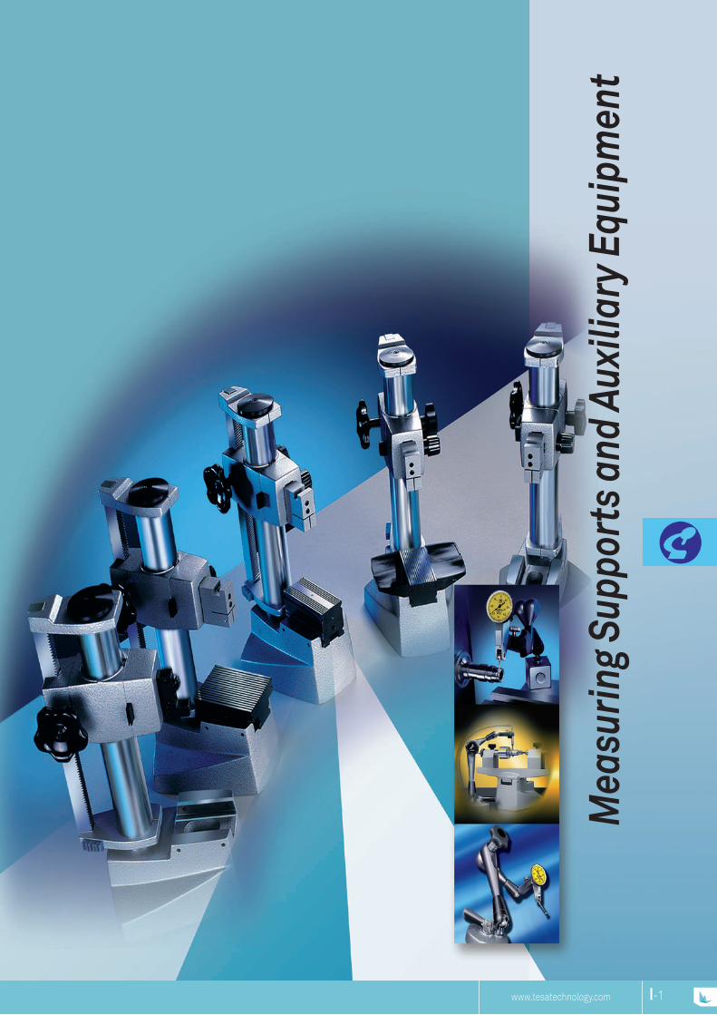
www.tesatechnology.com
Mea
surin
g Su
ppor
ts a
nd A
uxili
ary
Equi
pmen
t
I-1I-NP
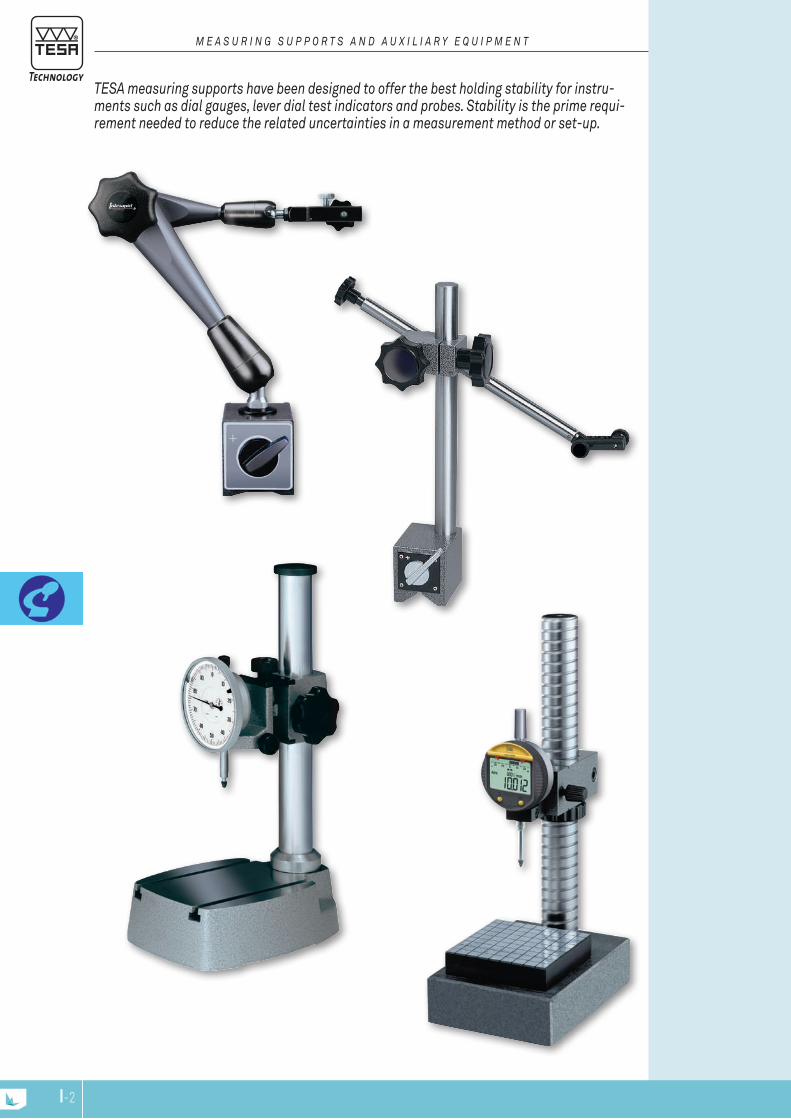
TESA measuring supports have been designed to offer the best holding stability for instru-ments such as dial gauges, lever dial test indicators and probes. Stability is the prime requi-rement needed to reduce the related uncertainties in a measurement method or set-up.
M E A S u r i n g S u p p o r T S A n d A u x i l i A r y E q u i p M E n T
I-3I-2

M8
M6
ø8
LH
49
M6
M6
ø8
120
205
49
N H mm L mm Base mm Consisting of:
01639025 Small magnetic measuring stand with articulated arm
≈ 170 205 120 30 x 30 x 30 – 1 articulated arm length 120 mm – 1 dovetail clamp with fine adjust-ment
– 1 magnetic base 30 x 30 x 30 (L x W x H)
Base with vee recess and 1 magnetic flat face. Disengageable of magnet possible. Duralumin articulations.Dovetail clamp with a Ø 8 mm clamping bore
0,4 kg
Supplied without measuring instrument
Magnetic support with articulated arm
INTERAPID Magnetic Support with Articulated Arm (small)
UNIvERSAl SUPPoRTS Magnetic measuring support with suction base or articulated arm.
M E A S u r i n g S T A n d S
N V-Base
for Ø, mmFine adjust
H mm L mm Base mm
Masskg
Consisting of:
01639022 INTERAPID magnetic support with articulated arm
≈ 800 30 ÷ 150 310 200 60 x 50 x 55
1,45 – Articulated arm – Clamp – Magnetic base
01639023 INTERAPID magnetic support with articulated arm
≈ 800 30 ÷ 150 390 280 60 x 50 x 55
1,85 – Articulated arm – Clamp – Magnetic base
Magnetic base has 1 prismatic and 2 flat faces. Articulations made from duralumin. Disengageable permanent magnet. Dovetail clamp with a Ø 8 mm clamping bore.Supplied without measuring instrument
Magnetic support with articulated arm
INTERAPID Magnetic Support with Articulated Arm Simple and secure locking using a single rotating knob- highly rigid arm and articulation.
I-3I-2
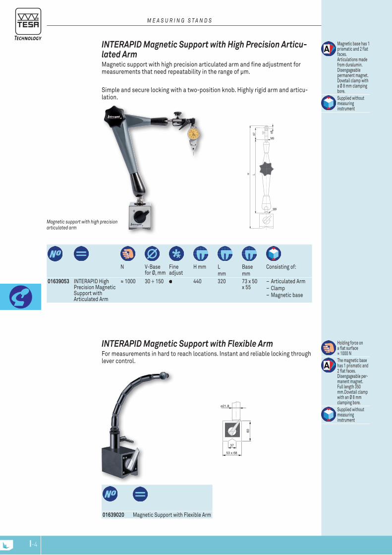
M8
M6
ø8
LH
67
60
ø21.8
53 x 68
37
N V-Base
for Ø, mmFine adjust
H mm Lmm
Base mm
Consisting of:
Magnetic base has 1 prismatic and 2 flat faces. Articulations made from duralumin. Disengageable permanent magnet. Dovetail clamp with a Ø 8 mm clamping bore.Supplied without measuring instrument
Magnetic support with high precision articulated arm
INTERAPID Magnetic Support with High Precision Articu-lated Arm Magnetic support with high precision articulated arm and fine adjustment for measurements that need repeatability in the range of μm.
Simple and secure locking with a two-position knob. Highly rigid arm and articu-lation.
M E A S u r i n g S T A n d S
01639053 INTERAPID High Precision Magnetic Support with Articulated Arm
≈ 1000 30 ÷ 150 440 320 73 x 50 x 55
– Articulated Arm – Clamp – Magnetic base
01639020 Magnetic Support with Flexible Arm
Holding force on a flat surface ≈ 1000 NThe magnetic base has 1 prismatic and 2 flat faces. Disengageable per-manent magnet. Full length 350 mm.Dovetail clamp with an Ø 8 mm clamping bore.Supplied without measuring instrument
INTERAPID Magnetic Support with Flexible Arm For measurements in hard to reach locations. Instant and reliable locking through lever control.
I-5I-4
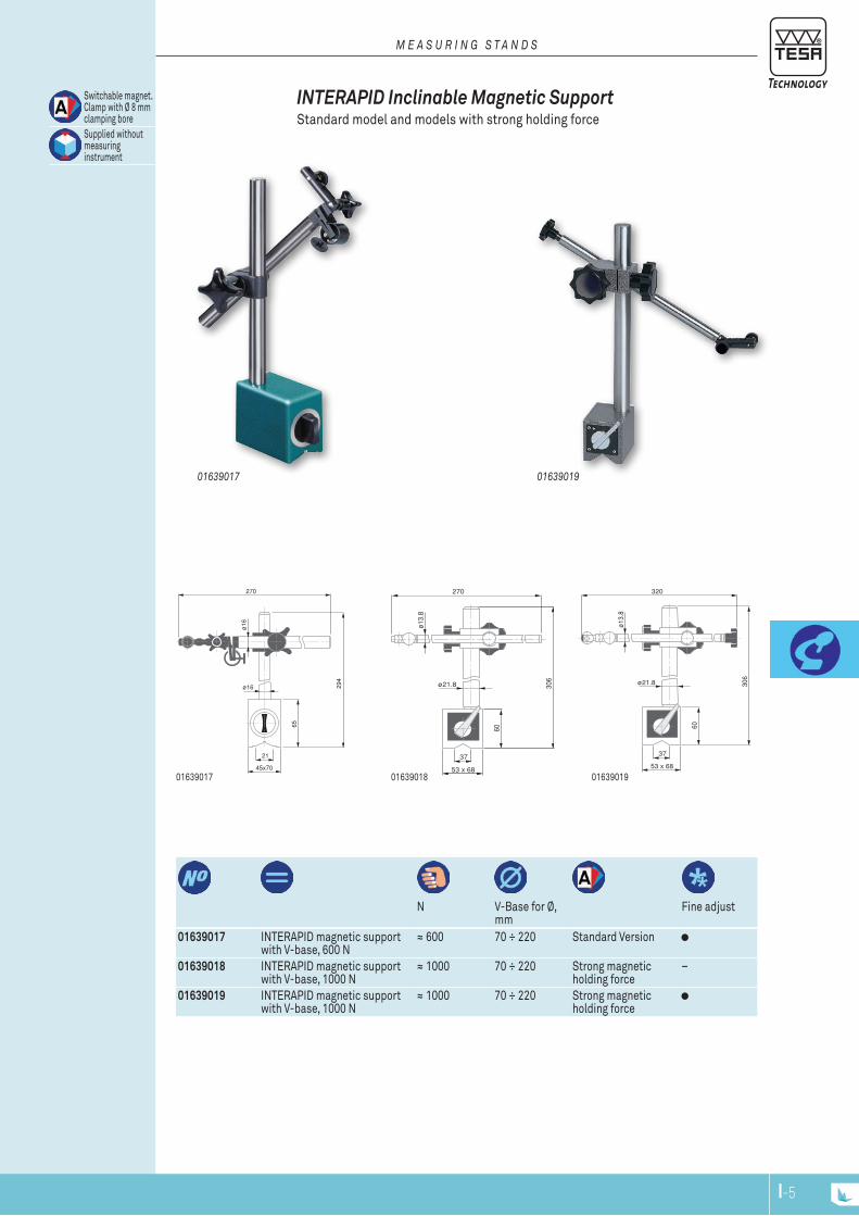
45x70
21
294
65
ø16
ø16
270
N V-Base for Ø,
mmFine adjust
01639017 INTERAPID magnetic support with V-base, 600 N
≈ 600 70 ÷ 220 Standard Version
01639018 INTERAPID magnetic support with V-base, 1000 N
≈ 1000 70 ÷ 220 Strong magnetic holding force
–
01639019 INTERAPID magnetic support with V-base, 1000 N
≈ 1000 70 ÷ 220 Strong magnetic holding force
01639017
0163901901639017
INTERAPID Inclinable Magnetic Support Standard model and models with strong holding force
Switchable magnet. Clamp with Ø 8 mm clamping boreSupplied without measuring instrument
M E A S u r i n g S T A n d S
01639019
270
306
60
ø13.
8
ø21.8
53 x 68
37
01639018
320
306
60
ø13.
8
ø21.8
53 x 68
37
I-5I-4

M8
M6
ø8
HL49
N Fine ad-
justmentH, mm L, mm Consisting of:
01639024 INTERAPID Measuring support with suction base and articu-lated arm
≈ 400 363 280 – Articulated arm – Fine adjust clamp – Round suction base
Round suction base made of aluminium (Ø 88 mm, height 28 mm) with flat suction base. Articulations made from duralumin. Suction controlled by lever switch. Dovetail clamp with an Ø 8 mm clamping bore.
1.1 kg
Supplied without measuring instrument
INTERAPID Support with Suction Base and Articulated Arm Holds firmly on any smooth and flat surface
– Clamps instantly and reliably using a suction lever switch. – Highly rigid articulated arm. – Free from magnetic fields.
M E A S u r i n g S T A n d S
I-7I-6
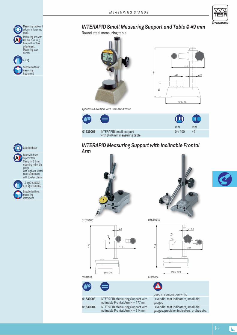
ø8
ø8
98 x 70
119177
ø17
,8
253
150 x 120
314
ø17,8
197
ø22
122
ø49
128 x 80
55
mm mm
01639006 INTERAPID small support with Ø 49 mm measuring table
0 ÷ 100 49
Measuring table and column in hardened steel.Measuring arm with Ø 8 mm clamping bore, without fine adjustment. Measuring span: 48 mm.
2,7 kg
Supplied without measuring instrument
Application example with digiCo indicator
INTERAPID Small Measuring Support and Table Ø 49 mm Round steel measuring table
M E A S u r i n g S T A n d S
Used in conjunction with:
01639003 INTERAPID Measuring Support with Inclinable Frontal Arm H = 177 mm
Lever dial test indicators, small dial gauges
01639004 INTERAPID Measuring Support with Inclinable Frontal Arm H = 314 mm
Lever dial test indicators, small dial gauges, precision indicators, probes etc.
Cast iron base
Base with front support face. Clamp for Ø 8 mm mounting rod or dial gauge with lug back. Model No 01639003 also with dovetail clamp.
1,3 kg (01639003) 4,35 kg (01639004)
Supplied without measuring instrument
0193900401939003
0163900401639003
INTERAPID Measuring Support with Inclinable Frontal Arm
I-7I-6
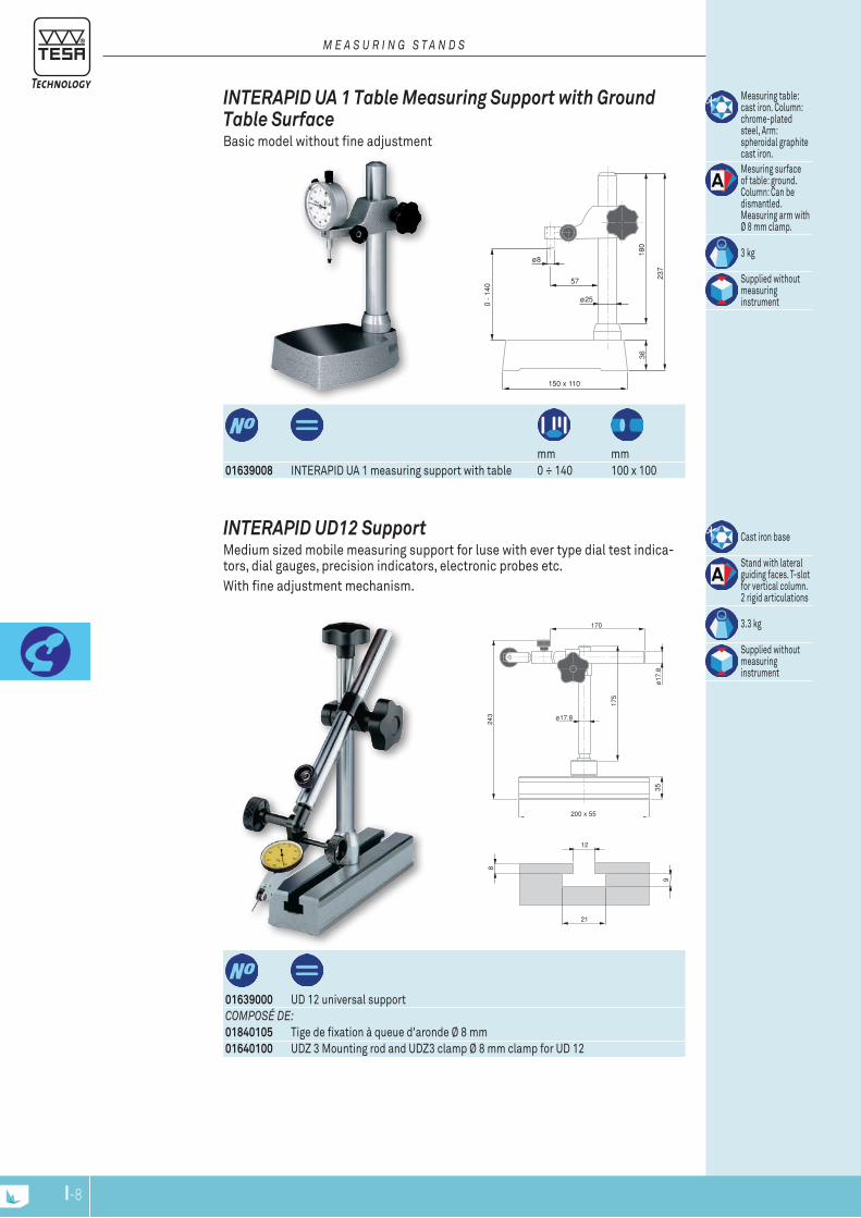
175
243
ø17
.8
170
200 x 55
ø17.8
35
21
9
12
8
237
180
36
150 x 110
0 -
140
ø25
57
ø8
mm mm
01639008 INTERAPID UA 1 measuring support with table 0 ÷ 140 100 x 100
Measuring table: cast iron. Column: chrome-plated steel, Arm: spheroidal graphite cast iron.Mesuring surface of table: ground. Column: Can be dismantled. Measuring arm with Ø 8 mm clamp.
3 kg
Supplied without measuring instrument
INTERAPID UA 1 Table Measuring Support with Ground Table Surface Basic model without fine adjustment
M E A S u r i n g S T A n d S
01639000 UD 12 universal supportCoMpoSé dE:01840105 Tige de fixation à queue d'aronde Ø 8 mm01640100 UDZ 3 Mounting rod and UDZ3 clamp Ø 8 mm clamp for UD 12
Cast iron base
Stand with lateral guiding faces. T-slot for vertical column. 2 rigid articulations
3.3 kg
Supplied without measuring instrument
INTERAPID UD12 Support Medium sized mobile measuring support for luse with ever type dial test indica-tors, dial gauges, precision indicators, electronic probes etc. With fine adjustment mechanism.
I-9I-8
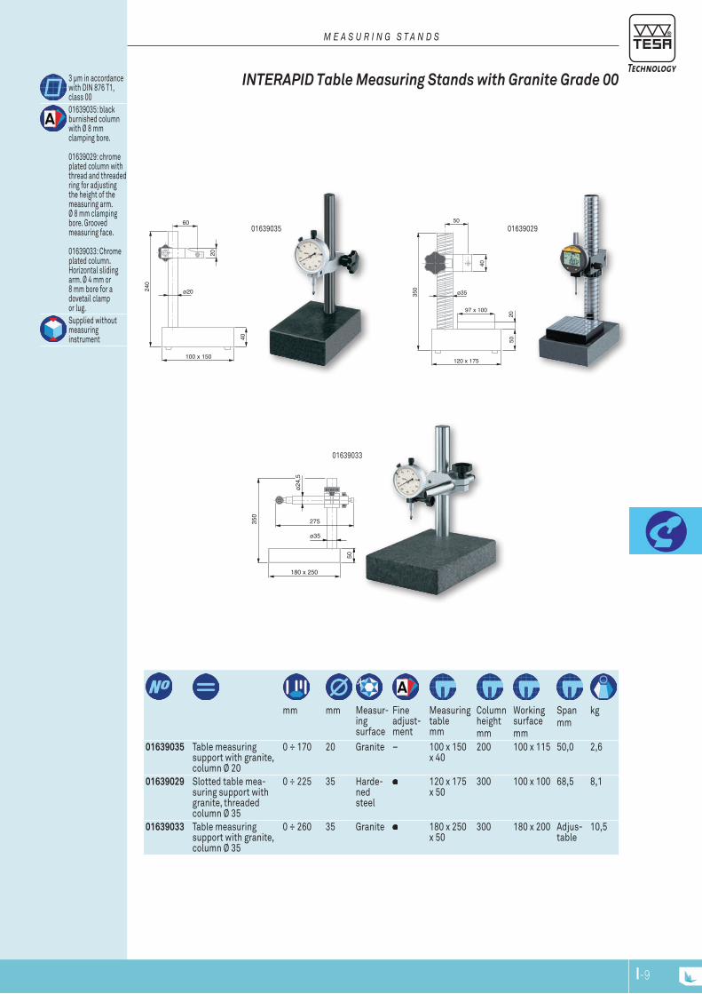
40
100 x 150
240
ø20
60
20
ø35
97 x 100
2050
120 x 175
350
50
40
ø24,
5
350
180 x 250
ø35
275
50
01639035
mm mm Measur-
ing surface
Fine adjust-ment
Measuring table mm
Column heightmm
Working surfacemm
Spanmm
kg
01639035 Table measuring support with granite, column Ø 20
0 ÷ 170 20 Granite – 100 x 150 x 40
200 100 x 115 50,0 2,6
01639029 Slotted table mea-suring support with granite, threaded column Ø 35
0 ÷ 225 35 Harde-ned steel
120 x 175 x 50
300 100 x 100 68,5 8,1
01639033 Table measuring support with granite, column Ø 35
0 ÷ 260 35 Granite 180 x 250 x 50
300 180 x 200 Adjus-table
10,5
01639033
01639029
INTERAPID Table Measuring Stands with Granite Grade 00 3 μm in accordance with DIN 876 T1, class 0001639035: black burnished column with Ø 8 mm clamping bore.
01639029: chrome plated column with thread and threaded ring for adjusting the height of the measuring arm. Ø 8 mm clamping bore. Grooved measuring face.
01639033: Chrome plated column. Horizontal sliding arm. Ø 4 mm or 8 mm bore for a dovetail clamp or lug. Supplied without measuring instrument
M E A S u r i n g S T A n d S
I-9I-8

ø 35
80
152
110
42
ø 8
ø 8
68
ø8
ø10
106
153
50
ø52
01640501 Steel base plate for UJ15 or UJ15G that become movable
50 x 80 x 20 mm
0,60 kg
Accessories for Small Magnetic Stands
01639016 UJ Magnetic support
Holding forceon a flat surface:≥ 350 NRounded basewith permanentmagnet
0,93 kg
Supplied withoutmeasuring instrument
Small magnetic support UJ 15G
01639007 Magnetic support INTERAPID UJ15, dovetail clamp and Ø 8 mm cylindrical clam-ping
Holding forceon a flat surface:≈ 220 NRounded basewith permanentmagnet
0,47 kg
Supplied withoutmeasuring instrument
01639007 + 01640501 with dial test indicator
Small magnetic support UJ 15
SMAll MAGNETIc SUPPoRTS Ideal for lever type dial test indicators, and dial gauges up to 40 mm diameter- With 2 articulation joints and fine adjustment.
M E A S u r i n g S T A n d S
I-11I-10
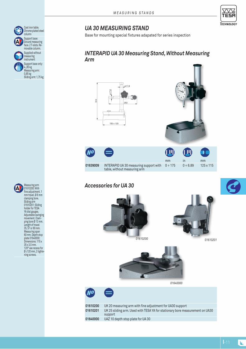
01610200 01610201
01640000
ø17
,8
253
150 x 120
314
ø17,8
Cast iron table. Chrome plated steel columnSupport base: Ground measuring face. 2 T-slots. Re-movable column.Supplied without measuring instrumentSupport base only: 4.,85 kg Measuring arm: 0,85 kg Sliding arm: 1,75 kg
mm in mm
01639009 INTERAPID UA 30 measuring support with table, without measuring arm
0 ÷ 175 0 ÷ 6.89 125 x 115
INTERAPID UA 30 Measuring Stand, Without Measuring Arm
UA 30 MEASURING STAND Base for mounting special fixtures adapated for series inspection
M E A S u r i n g S T A n d S
01610200 UK 20 measuring arm with fine adjustment for UA30 support01610201 UK 25 sliding arm. Used with TESA YA for stationary bore measurement on UA30
support01640000 UAZ 10 depth stop plate for UA 30
Measuring arm 01610200: With fine adjustment. 1 mm travel. Ø 8 mm clamping bore.Sliding arm 01610201: Sliding holder for TESA YA dial gauges. Adjustable swinging movement. Clam-ping bore Ø 13 mm. Length of travel 35, 57 or 80 mm. Measuring span 60 mm. Depth stop plate 01640000: Dimensions: 115 x 35 x 3,5 mm. 120° vee recess for Ø ≤120 mm, 2 tighte-ning screws.
Accessories for UA 30
I-11I-10

ø8
ø28
32
16
ø6.5
80
ø8
ø28
47.5
31.5
ø6.5
66
56
6.5
Diametermm
Diameterin
Widthmm
Widthin
Clampmm
Clampin
01639047 Depth foot with prismatic mea-suring face
10 ÷ 100 0.39 ÷ 3.9 16 0.64 8 0.315
Hardened steel
Lapped measuring faces. Clamp with lock for mounting a dial gauge or probeSupplied without measuring instrument
INTERAPID Depth Foot with Prismatic Measuring Face For measuring the depth of key slots on cylindrical shafts and determining circu-larity errors etc.
mm
01639046 Depth foot with flat face 80 x 16 8
Hardened steel
Lapped measuring faces. Clamp wih lock for mounting a dial gauge or probeSupplied without measuring instrument
INTERAPID Depth Foot with a Flat Face
EqUIPEMENT AUxIlIAIRES
A u x i l l i A r y E q u i p M E n T
06769006 B&S CENTER FINDER centering tool
Center Finder consisting of the following components:•cylindrical shank
for clamping on the chuck of a machine tool. •powerful round
magnetic base with strong holding capacity. •swivel joint and
dovetail collar for clamping a lever-type dial test indicator.
Brown & Sharpe cENTER FINDER centering Tool Practical for aligning the centre of a bore with respect to the spindle axis of a machine tool
– Without the clamping shaft, it can also serve as small magnetic support – Allows the clamping of a dial test indicator, either a standard or perpendicular
model.
I-13I-12
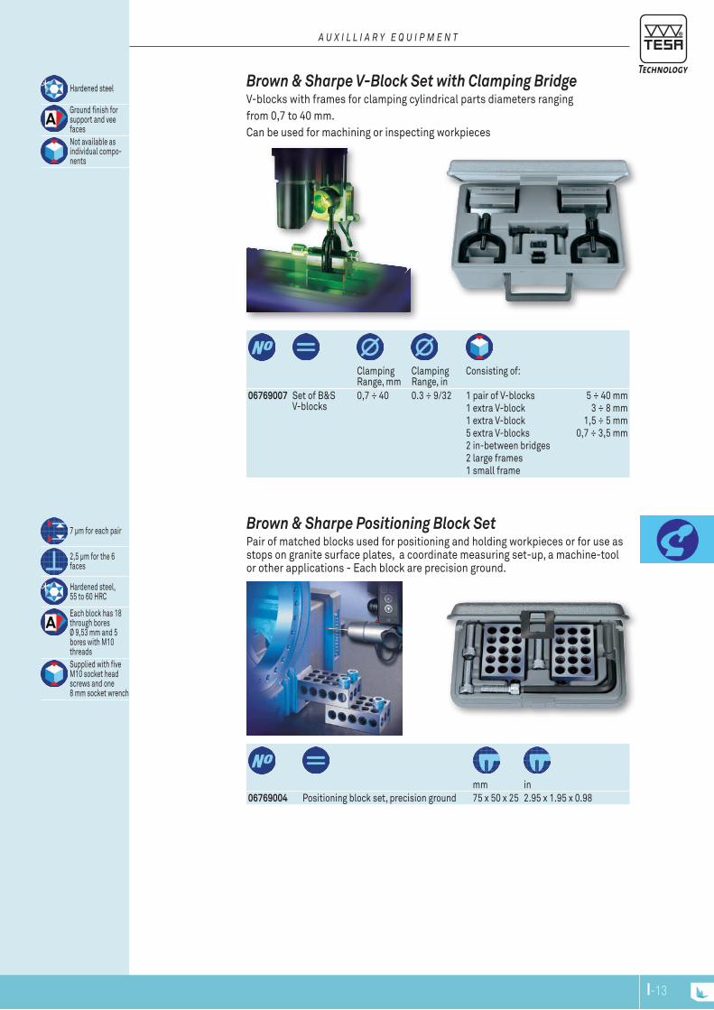
Clamping Range, mm
Clamping Range, in
Consisting of:
06769007 Set of B&S V-blocks
0,7 ÷ 40 0.3 ÷ 9/32 1 pair of V-blocks1 extra V-block1 extra V-block5 extra V-blocks2 in-between bridges2 large frames1 small frame
5 ÷ 40 mm3 ÷ 8 mm
1,5 ÷ 5 mm0,7 ÷ 3,5 mm
Hardened steel
Ground finish for support and vee facesNot available as individual compo-nents
Brown & Sharpe v-Block Set with clamping Bridge V-blocks with frames for clamping cylindrical parts diameters rangingfrom 0,7 to 40 mm.Can be used for machining or inspecting workpieces
A u x i l l i A r y E q u i p M E n T
mm in
06769004 Positioning block set, precision ground 75 x 50 x 25 2.95 x 1.95 x 0.98
7 μm for each pair
2,5 μm for the 6 faces
Hardened steel, 55 to 60 HRC
Each block has 18 through bores Ø 9,53 mm and 5 bores with M10 threadsSupplied with five M10 socket head screws and one 8 mm socket wrench
Brown & Sharpe Positioning Block SetPair of matched blocks used for positioning and holding workpieces or for use as stops on granite surface plates, a coordinate measuring set-up, a machine-tool or other applications - Each block are precision ground.
I-13I-12
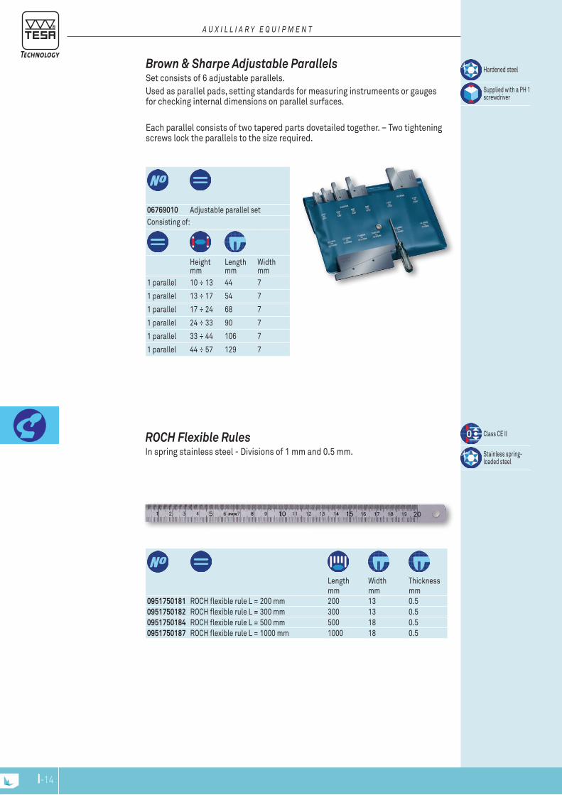
06769010 Adjustable parallel set
Hardened steel
Supplied with a PH 1 screwdriver
Consisting of:
Height mm
Length mm
Width mm
1 parallel 10 ÷ 13 44 7
1 parallel 13 ÷ 17 54 7
1 parallel 17 ÷ 24 68 7
1 parallel 24 ÷ 33 90 7
1 parallel 33 ÷ 44 106 7
1 parallel 44 ÷ 57 129 7
Brown & Sharpe Adjustable Parallels Set consists of 6 adjustable parallels. Used as parallel pads, setting standards for measuring instrumeents or gauges for checking internal dimensions on parallel surfaces.
Each parallel consists of two tapered parts dovetailed together. – Two tightening screws lock the parallels to the size required.
A u x i l l i A r y E q u i p M E n T
Lengthmm
Widthmm
Thicknessmm
0951750181 ROCH flexible rule L = 200 mm 200 13 0.50951750182 ROCH flexible rule L = 300 mm 300 13 0.50951750184 ROCH flexible rule L = 500 mm 500 18 0.50951750187 ROCH flexible rule L = 1000 mm 1000 18 0.5
Class CE II
Stainless spring-loaded steel
RocH Flexible Rules In spring stainless steel - Divisions of 1 mm and 0.5 mm.
I-15I-14
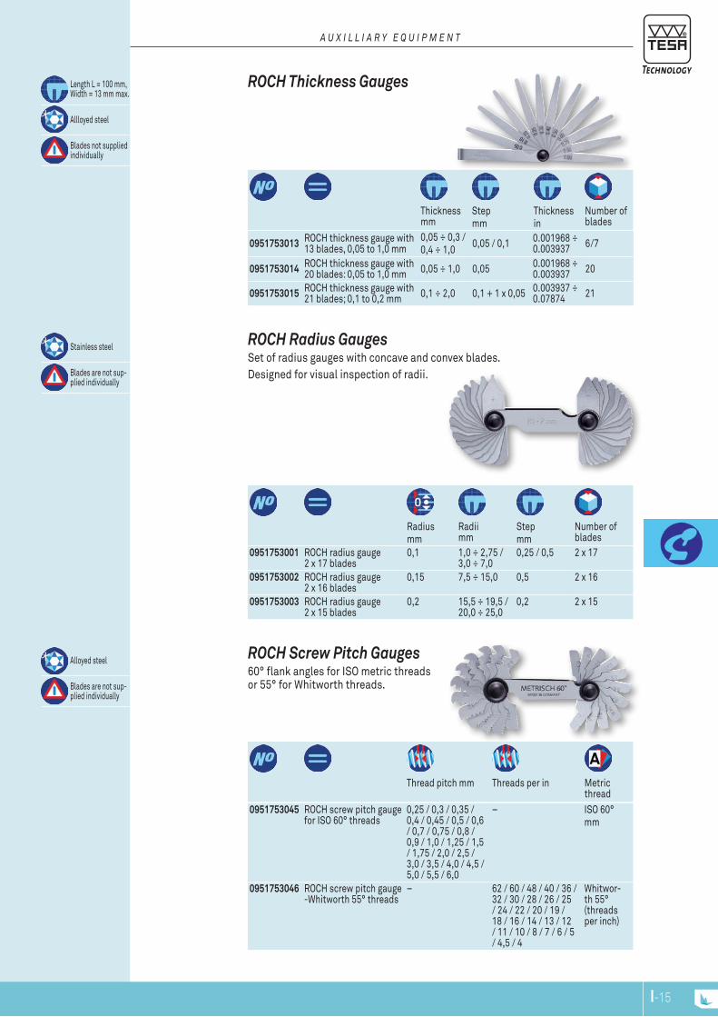
Thread pitch mm Threads per in Metric
thread0951753045 ROCH screw pitch gauge
for ISO 60° threads0,25 / 0,3 / 0,35 / 0,4 / 0,45 / 0,5 / 0,6 / 0,7 / 0,75 / 0,8 / 0,9 / 1,0 / 1,25 / 1,5 / 1,75 / 2,0 / 2,5 / 3,0 / 3,5 / 4,0 / 4,5 / 5,0 / 5,5 / 6,0
– ISO 60°mm
0951753046 ROCH screw pitch gauge -Whitworth 55° threads
– 62 / 60 / 48 / 40 / 36 / 32 / 30 / 28 / 26 / 25 / 24 / 22 / 20 / 19 / 18 / 16 / 14 / 13 / 12 / 11 / 10 / 8 / 7 / 6 / 5 / 4,5 / 4
Whitwor-th 55° (threads per inch)
Alloyed steel
Blades are not sup-plied individually
RocH Screw Pitch Gauges 60° flank angles for ISO metric threads or 55° for Whitworth threads.
Radiusmm
Radii mm
Stepmm
Number of blades
0951753001 ROCH radius gauge 2 x 17 blades
0,1 1,0 ÷ 2,75 / 3,0 ÷ 7,0
0,25 / 0,5 2 x 17
0951753002 ROCH radius gauge 2 x 16 blades
0,15 7,5 ÷ 15,0 0,5 2 x 16
0951753003 ROCH radius gauge 2 x 15 blades
0,2 15,5 ÷ 19,5 / 20,0 ÷ 25,0
0,2 2 x 15
Stainless steel
Blades are not sup-plied individually
RocH Radius Gauges Set of radius gauges with concave and convex blades.Designed for visual inspection of radii.
Thickness mm
Stepmm
Thicknessin
Number of blades
0951753013 ROCH thickness gauge with 13 blades, 0,05 to 1,0 mm
0,05 ÷ 0,3 /0,4 ÷ 1,0 0,05 / 0,1 0.001968 ÷
0.003937 6/7
0951753014 ROCH thickness gauge with 20 blades: 0,05 to 1,0 mm 0,05 ÷ 1,0 0,05 0.001968 ÷
0.003937 20
0951753015 ROCH thickness gauge with 21 blades; 0,1 to 0,2 mm 0,1 ÷ 2,0 0,1 + 1 x 0,05 0.003937 ÷
0.07874 21
Length L = 100 mm, Width = 13 mm max.
Allloyed steel
Blades not supplied individually
RocH Thickness Gauges
A u x i l l i A r y E q u i p M E n T
I-15I-14
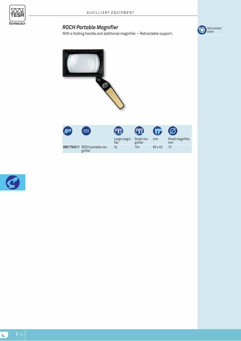
Large magni-fier
Small ma-gnifier
mm Small magnifier, mm
Solid resistant plastic
RocH Portable Magnifier With a folding handle and additional magnifier. – Retractable support.
A u x i l l i A r y E q u i p M E n T
0951754511 ROCH portable ma-gnifier
3x 10x 80 x 45 13
I-NPI-16
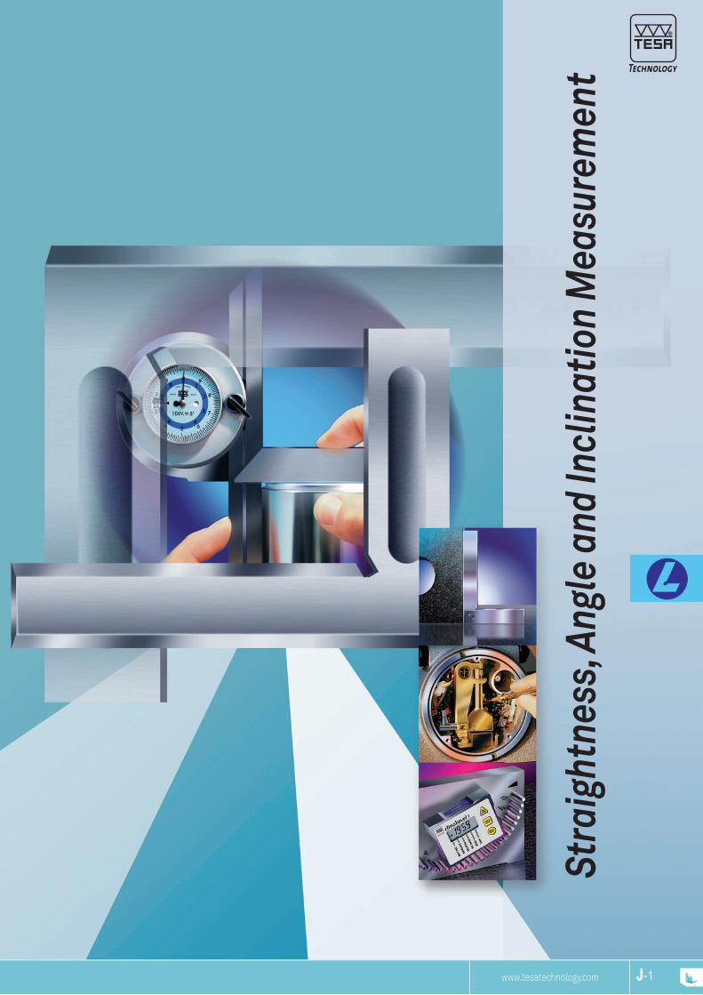
J-1www.tesatechnology.com J-1J-NP
Stra
ight
ness
, Ang
le a
nd In
clin
atio
n M
easu
rem
ent
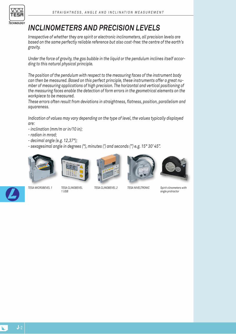
J-2 J-3J-2
TESA CLINOBEVEL 2 Spirit clinometers with angle protractor
TESA NIVELTRONICTESA CLINOBEVEL 1 USB
TESA MICROBEVEL 1
Irrespective of whether they are spirit or electronic inclinometers, all precision levels are based on the same perfectly reliable reference but also cost-free: the centre of the earth's gravity.
Under the force of gravity, the gas bubble in the liquid or the pendulum inclines itself accor-ding to this natural physical principle.
The position of the pendulum with respect to the measuring faces of the instrument body can then be measured. Based on this perfect principle, these instruments offer a great nu-mber of measuring applications of high precision. The horizontal and vertical positioning of the measuring faces enable the detection of form errors in the geometrical elements on the workpiece to be measured.These errors often result from deviations in straightness, flatness, position, parallelism and squareness.
Indication of values may vary depending on the type of level, the values typically displayed are:- inclination (mm/m or in/10 in);- radian in mrad;- decimal angle (e.g. 12,37°);- sexagesimal angle in degrees (°), minutes (’) and seconds (”) e.g. 15° 30’ 45”.
INCLINOMETERS AND PRECISION LEVELS
S T R A I g h T N E S S , A N g L E A N d I N C L I N A T I O N M E A S U R E M E N T

J-3
S W I S S M A D E
R
S W I S S M A D E
R
S W I S S M A D E
RS W I S S M A D E
R
J-3J-2
mm/m mm Livré avec:
05330203 CLinoBEVEL 1 USB electronic inclinometer
± 45° ≥ 0,02 100 x 75 x 35 CLinoSoFT software plus USB cable to host computer
Multiple applications are possible, notably the measurement of 2 flat surfaces by comparing the measured values with the help of 2 instruments. Automatic gene-ration of inspection reports using Microsoft EXCEL spreadsheet software.
CLinoBEVEL 1-USB, can be used on its 4 faces.
CLINOSOFT Software
CLINOSOFT Software
Measuring functions: A ; B ; A+B ; A-B
Electronic Inclinometer - TESA CLINOBEVEL 1 USB Compact universal instrument for direct and differential measurements – Mea-suring range ± 45° with display of measured angles or inclinations – Reinforced aluminium housing, eloxide surface – Large digital display for error free interpre-tation of readings.Supplied with CLinoSoFT software permitting the visualisation and storage of measurements as well as the USB cable to host computer.
INCLINOMETERS AND LEVELS The TESA inclinometers and levels meet the most demanding applications not only in the machine building sector but also in the civil construction sector.
OpTIONAL ACCESSORIES:04768002 4 batteries LRC 6 AA, 1,5 V for CLinoBEVEL 1 USB, CLinoBEVEL 2, MiCRoBEVEL,05360006 External switch with cable, L = 2 m, for CLinoBEVEL 1 USB05360014 External switch, wireless, for CLinoBEVEL 1 USB
Din 2276 Part 2 (Form D)
LCD angle display: Decimal or sexagesimal inclinationmm/m, in/10 or 12 in, mm or in/basis length, radian (mrad) and the likeCapacitive measuring system with gravity pendulum
2’ + 1 numerical interval
21 storable correction values (high accuracy)
Flat face 4 x 90°
100 x 75 x 35 mm
Anodised light alloy
Response time ≈1 s
Automatic shut down after 8 min
Display lock
RS485, asynchronous, 7 bits, 2 stop bits,no parity, 9600 bauds
1 1,5 V battery, type LRC 6, AA
≈ 150 hours
iP65(iEC 60529)
En 50081-1 / -2 En 50082-1 / -2
0,52 kg
inspection report with declaration of conformity
S T R A I g h T N E S S , A N g L E A N d I N C L I N A T I O N M E A S U R E M E N T
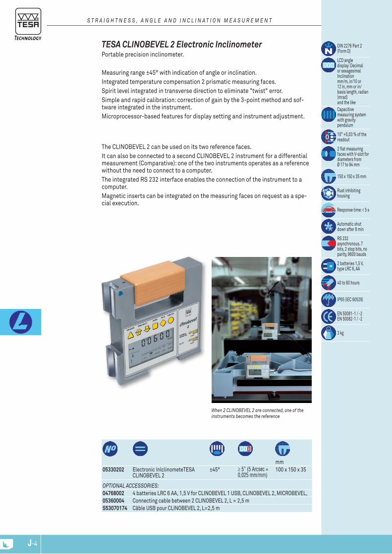
J-4 J-5J-4
mm
05330202 Electronic inlclinometeTESA CLinoBEVEL 2
±45° ≥ 5” (5 Arcsec = 0,025 mm/mm)
100 x 150 x 35
Din 2276 Part 2 (Form D)
LCD angle display: Decimal or sexagesimal inclination mm/m, in/10 or 12 in, mm or in/basis length, radian (mrad) and the likeCapacitive measuring system with gravity pendulum
10” +0,03 % of the readout
2 flat measuring faces with V-slot for diameters from Ø 17 to 94 mm
150 x 150 x 35 mm
Rust inhibiting housing
Response time: < 5 s
Automatic shut down after 8 min
RS 232 asynchronous. 7 bits, 2 stop bits, no parity, 9600 bauds
2 batteries 1,5 V, type LRC 6, AA
40 to 60 hours
iP65 (iEC 60529)
En 50081-1 / -2 En 50082-1 / -2
3 kg
The CLinoBEVEL 2 can be used on its two reference faces. it can also be connected to a second CLinoBEVEL 2 instrument for a differential measurement (Comparative): one of the two instruments operates as a reference without the need to connect to a computer. The integrated RS 232 interface enables the connection of the instrument to a computer. Magnetic inserts can be integrated on the measuring faces on request as a spe-cial execution.
When 2 CLINOBEVEL 2 are connected, one of the instruments becomes the reference
TESA CLINOBEVEL 2 Electronic Inclinometer Portable precision inclinometer.
Measuring range ±45° with indication of angle or inclination. integrated temperature compensation 2 prismatic measuring faces.Spirit level integrated in transverse direction to eliminate "twist" error.Simple and rapid calibration: correction of gain by the 3-point method and sof-tware integrated in the instrument.Microprocessor-based features for display setting and instrument adjustment.
S T R A I g h T N E S S , A N g L E A N d I N C L I N A T I O N M E A S U R E M E N T
OpTIONAL ACCESSORIES:04768002 4 batteries LRC 6 AA, 1,5 V for CLinoBEVEL 1 USB, CLinoBEVEL 2, MiCRoBEVEL,05360004 Connecting cable between 2 CLinoBEVEL 2, L = 2,5 mS53070174 Câble USB pour CLinoBEVEL 2, L=2,5 m

J-5J-5J-4
Range 1 or Range 2, mm/m
Base width, mm
Base height, mm
kg (with transport case)
Range mm/m mm/m mm G = mm/m
1 ± 20 ± 5 0,01 Flatness ≤ 5 mm/mG = 1 % of the measured value and min. 0,01 mm/m
Flatness > 5 mm/mG = 0,01 mm/m
2 ± 2 ± 2 0,001 Flatness ≤ 1 mm/mG = 1 % of the measured value and min. 0,001 mm/m
Flatness > 1 mm/mG = 1 % of (2x measured value -1)
Models with steps 0,05 to 0,005 mm/m available on request
Square modelhorizontal model
TESA MICROBEVEL 1 Inclinometer TESA MiCRoBEVEL 1 is particularly suited for measuring slightly inclined sur-faces such as the measuring of flatness of surfaces or the geometrical characte-ristics (deviation, rotation etc.) of a machine tool. Suited for operation under the most rugged conditions., protected by an alumi-nium case. Power supplied by a single standard battery AA 1,5 V for at least 100 hours of operation.
OpTIONAL ACCESSORY:04768002 4 batteries LRC 6 AA, 1,5 V for CLinoBEVEL 1 USB, CLinoBEVEL 2, MiCRoBEVEL,
Din 2276 Part 2 (Style D)
See table for max. perm. errors
LCD display according to table
Fully encapsulated measuring system with gravity pendulum
See table for max. perm. errors
2 flat measuring faces with V-slot for diameters from 20 to 120 mmCast iron base. Chromium plated side faces. Aluminium housing,lacquered
Response time < 3 s
Automatic shut down after 55 min
1 mV per unit (100 kΩ)
1,5 V battery, type LRC 6, AA
100 to 140 hours
≤ 0,1 %/°C based on the measuring range at 20 ± 5°C
En 50081-1 / -2 En 50082-1 / -2
S T R A I g h T N E S S , A N g L E A N d I N C L I N A T I O N M E A S U R E M E N T
05330003 TESA MiCRoBEVEL 1 horizontal base 110 x 45 mm
0,01 ou 0,001 110 45 1,8
05330004 TESA MiCRoBEVEL 1 horizontal base 150 x 45 mm
0,01 ou 0,001 150 45 2,1
05330005 TESA MiCRoBEVEL 1 square base 150 x 45 mm
0,01 ou 0,001 150 45 3,1
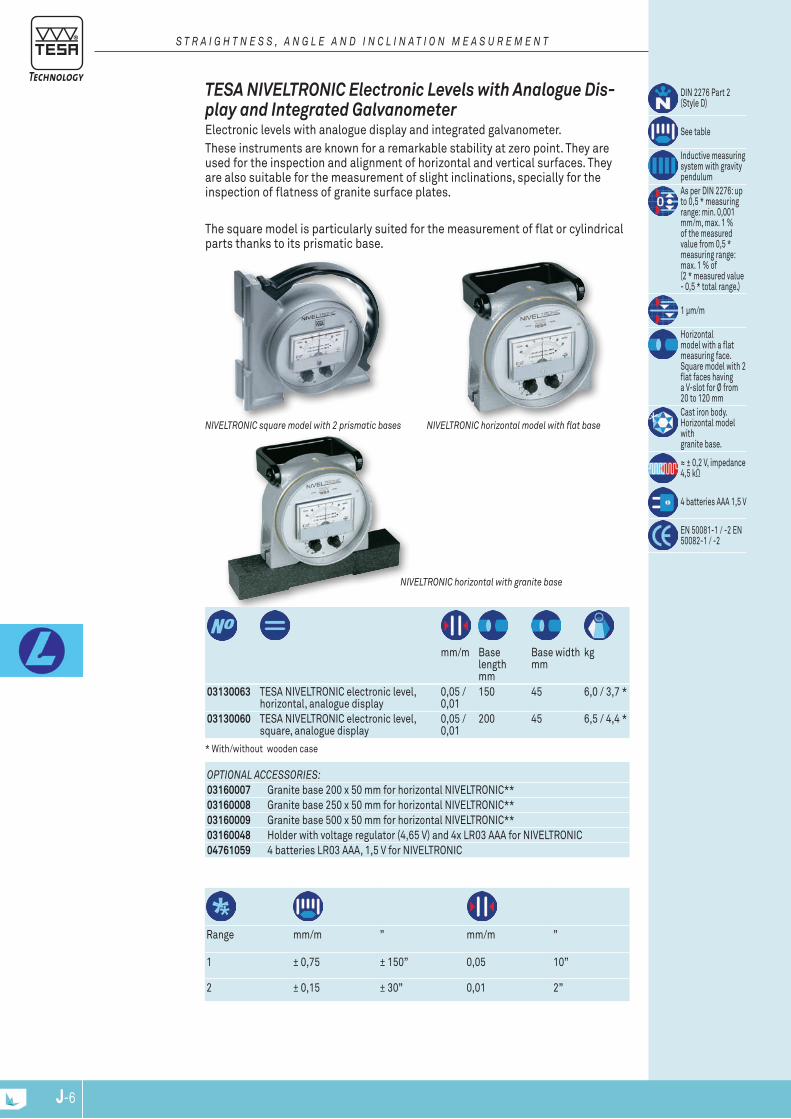
J-6 J-7J-6
mm/m Base
length mm
Base width mm
kg
03130063 TESA niVELTRoniC electronic level, horizontal, analogue display
0,05 / 0,01
150 45 6,0 / 3,7 *
03130060 TESA niVELTRoniC electronic level, square, analogue display
0,05 / 0,01
200 45 6,5 / 4,4 *
Din 2276 Part 2 (Style D)
See table
inductive measuring system with gravity pendulumAs per Din 2276: up to 0,5 * measuring range: min. 0,001 mm/m, max. 1 % of the measured value from 0,5 * measuring range: max. 1 % of (2 * measured value - 0,5 * total range.)
1 µm/m
Horizontal model with a flat measuring face. Square model with 2 flat faces havinga V-slot for Ø from 20 to 120 mmCast iron body. Horizontal model withgranite base.
≈ ± 0,2 V, impedance 4,5 kΩ
4 batteries AAA 1,5 V
En 50081-1 / -2 En 50082-1 / -2
Range mm/m ” mm/m ”
1 ± 0,75 ± 150” 0,05 10”
2 ± 0,15 ± 30” 0,01 2”
* With/without wooden case
NIVELTRONIC horizontal with granite base
NIVELTRONIC horizontal model with flat baseNIVELTRONIC square model with 2 prismatic bases
TESA NIVELTRONIC Electronic Levels with Analogue Dis-play and Integrated Galvanometer Electronic levels with analogue display and integrated galvanometer.These instruments are known for a remarkable stability at zero point. They are used for the inspection and alignment of horizontal and vertical surfaces. They are also suitable for the measurement of slight inclinations, specially for the inspection of flatness of granite surface plates.
The square model is particularly suited for the measurement of flat or cylindrical parts thanks to its prismatic base.
S T R A I g h T N E S S , A N g L E A N d I N C L I N A T I O N M E A S U R E M E N T
OpTIONAL ACCESSORIES:03160007 Granite base 200 x 50 mm for horizontal niVELTRoniC**03160008 Granite base 250 x 50 mm for horizontal niVELTRoniC**03160009 Granite base 500 x 50 mm for horizontal niVELTRoniC**03160048 Holder with voltage regulator (4,65 V) and 4x LR03 AAA for niVELTRoniC04761059 4 batteries LR03 AAA, 1,5 V for niVELTRoniC
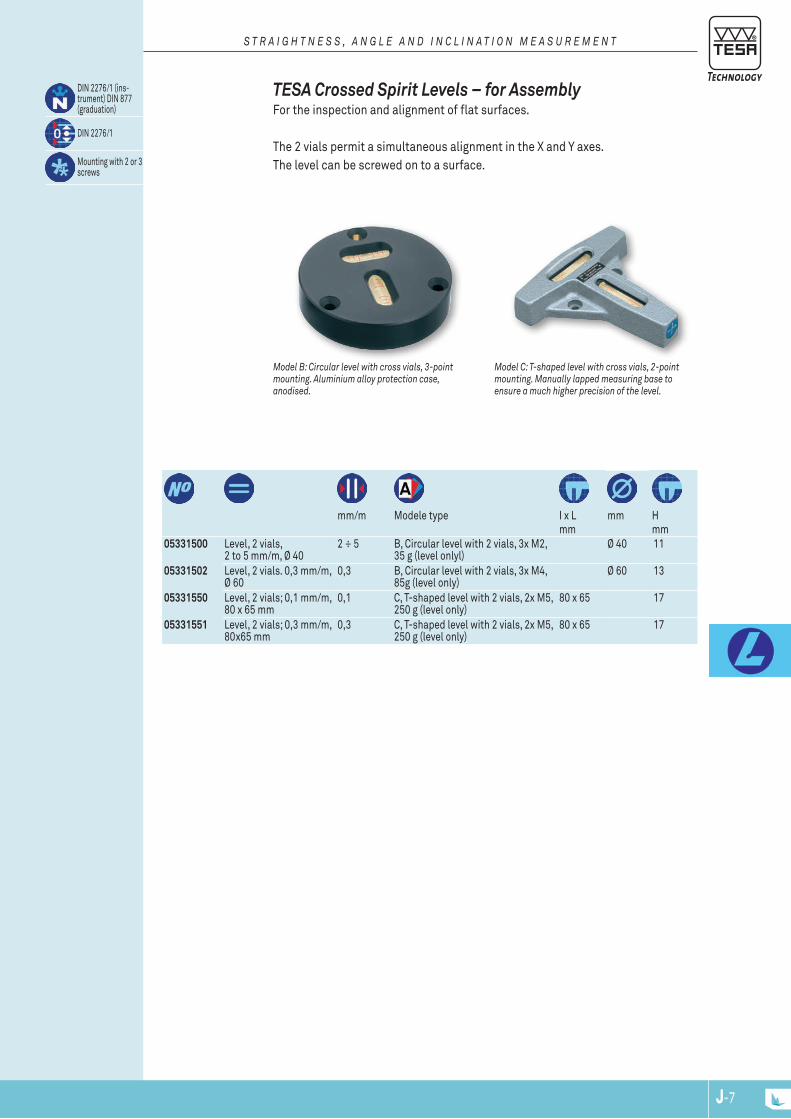
J-7J-7J-6
Model C: T-shaped level with cross vials, 2-point mounting. Manually lapped measuring base to ensure a much higher precision of the level.
Model B: Circular level with cross vials, 3-point mounting. Aluminium alloy protection case, anodised.
TESA Crossed Spirit Levels – for Assembly For the inspection and alignment of flat surfaces.
The 2 vials permit a simultaneous alignment in the X and Y axes. The level can be screwed on to a surface.
Din 2276/1 (ins-trument) Din 877 (graduation)
Din 2276/1
Mounting with 2 or 3 screws
S T R A I g h T N E S S , A N g L E A N d I N C L I N A T I O N M E A S U R E M E N T
05331500 Level, 2 vials, 2 to 5 mm/m, Ø 40
2 ÷ 5 B, Circular level with 2 vials, 3x M2, 35 g (level onlyl)
Ø 40 11
05331502 Level, 2 vials. 0,3 mm/m, Ø 60
0,3 B, Circular level with 2 vials, 3x M4, 85g (level only)
Ø 60 13
05331550 Level, 2 vials; 0,1 mm/m, 80 x 65 mm
0,1 C, T-shaped level with 2 vials, 2x M5, 250 g (level only)
80 x 65 17
05331551 Level, 2 vials; 0,3 mm/m, 80x65 mm
0,3 C, T-shaped level with 2 vials, 2x M5, 250 g (level only)
80 x 65 17
mm/m Modele type i x L
mmmm H
mm
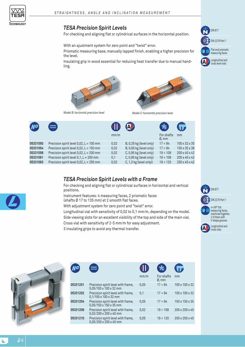
J-8 J-9J-8
mm/m For shafts
Ø, mmmm
05331050 Precision spirit level 0,02, L = 100 mm 0,02 B, 0,35 kg (level only) 17 ÷ 84 100 x 32 x 35 05331054 Precision spirit level 0,02, L = 150 mm 0,02 B, 0,65 kg (level only) 17 ÷ 94 150 x 35 x 38 05331058 Precision spirit level 0,02, L = 200 mm 0,02 C, 0,95 kg (level only) 19 ÷ 108 200 x 40 x 42 05331061 Precision spirit level 0,1, L = 200 mm 0,1 C, 0,95 kg (level only) 19 ÷ 108 200 x 40 x 42 05331063 Precision spirit level 0,02, L = 250 mm 0,02 C, 1,3 kg (level onlyl) 19 ÷ 120 250 x 45 x 42
Din 877
Din 2276 Part 1
Flat and prismatic measuring faces
Longitudinal and cross level vials
Model C: horizontal precision levelModel B: horizontal precision level
TESA Precision Spirit Levels For checking and aligning flat or cylindrical surfaces in the horizontal position.
With an ajustment system for zero point and "twist" error. Prismatic measuring base, manually lapped finish, enabling a higher precision for the level. insulating grip in wood essential for reducing heat transfer due to manual hand-ling.
S T R A I g h T N E S S , A N g L E A N d I N C L I N A T I O N M E A S U R E M E N T
mm/m For shafts
Ø, mmmm
05331201 Precision spirit level with frame, 0,05/100 x 100 x 32 mm
0,05 17 ÷ 84 100 x 100 x 32
05331202 Precision spirit level with frame, 0,1/100 x 100 x 32 mm
0,1 17 ÷ 84 100 x 100 x 32
05331204 Precision spirit level with frame, 0,05/150 x 150 x 35 mm
0,05 17 ÷ 94 150 x 150 x 35
05331206 Precision spirit level with frame, 0,02/200 x 200 x 40 mm
0,02 19 ÷ 108 200 x 200 x 40
05331210 Precision spirit level with frame, 0,05/250 x 250 x 45 mm
0,05 19 ÷ 120 250 x 250 x 45
Din 877
Din 2276 Part 1
4 x 90° flat measuring faces, machined together, 2 of them with V-shape grooves
Longitudinal and cross vials
TESA Precision Spirit Levels with a Frame For checking and aligning flat or cylindrical surfaces in horizontal and vertical positions. instrument features: 4 measuring faces, 2 prismatic faces (shafts Ø 17 to 135 mm) et 2 smooth flat faces. With adjustment system for zero point and "twist" error. Longitudinal vial with sensitivity of 0,02 to 0,1 mm/m, depending on the model. Side viewing slots for an excellent visibility of the top and side of the main vial. Cross vial with sensitivity of 2-5 mm/m for easy adjustment. 3 insulating grips to avoid any thermal transfer.
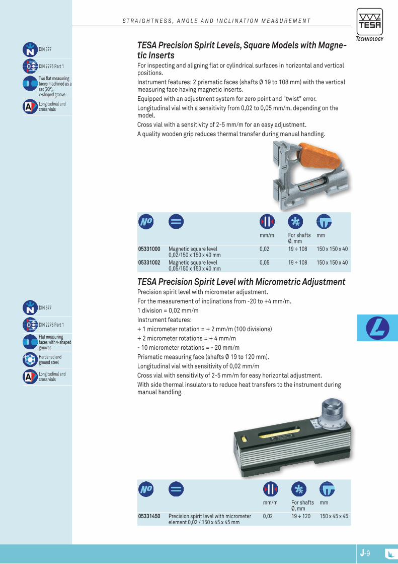
J-9J-9J-8
mm/m For shafts
Ø, mmmm
05331000 Magnetic square level 0,02/150 x 150 x 40 mm
0,02 19 ÷ 108 150 x 150 x 40
05331002 Magnetic square level 0,05/150 x 150 x 40 mm
0,05 19 ÷ 108 150 x 150 x 40
Din 877
Din 2276 Part 1
Two flat measuring faces machined as a set (90°),v-shaped groove
Longitudinal and cross vials
TESA Precision Spirit Levels, Square Models with Magne-tic Inserts For inspecting and aligning flat or cylindrical surfaces in horizontal and vertical positions.instrument features: 2 prismatic faces (shafts Ø 19 to 108 mm) with the vertical measuring face having magnetic inserts. Equipped with an adjustment system for zero point and "twist" error. Longitudinal vial with a sensitivity from 0,02 to 0,05 mm/m, depending on the model. Cross vial with a sensitivity of 2-5 mm/m for an easy adjustment. A quality wooden grip reduces thermal transfer during manual handling.
S T R A I g h T N E S S , A N g L E A N d I N C L I N A T I O N M E A S U R E M E N T
mm/m For shafts
Ø, mmmm
05331450 Precision spirit level with micrometer element 0,02 / 150 x 45 x 45 mm
0,02 19 ÷ 120 150 x 45 x 45
Din 877
Din 2276 Part 1
Flat measuring faces with v-shaped grooves
Hardened and ground steel
Longitudinal and cross vials
TESA Precision Spirit Level with Micrometric AdjustmentPrecision spirit level with micrometer adjustment. For the measurement of inclinations from -20 to +4 mm/m.1 division = 0,02 mm/m instrument features: + 1 micrometer rotation = + 2 mm/m (100 divisions) + 2 micrometer rotations = + 4 mm/m- 10 micrometer rotations = - 20 mm/m Prismatic measuring face (shafts Ø 19 to 120 mm). Longitudinal vial with sensitivity of 0,02 mm/m Cross vial with sensitivity of 2-5 mm/m for easy horizontal adjustment. With side thermal insulators to reduce heat transfers to the instrument during manual handling.

J-10 J-11J-10
Scale division of micrometer element
Scale division of level
For shafts Ø, mm
mm
05331750 Spirit clinometer with angle protractor and micrometer element
1 Arcmin 1 Arcmin (0,30 mm/m)
2 x 180° 17 ÷ 80 150 x 35 x 116
Din 877
Din 2276 part 1
Flat measuring faces with v-shaped groove
Hardened and ground steel base
Longitudinal and cross vials
1,6 kg (without case) 2,1 kg (with case)
TESA Spirit Inclinometer with Protractor and Micrometer Element Enables the measurement of angular deviations in any position of a cylindrical or flat surface. instrument features: prismatic measuring face (shafts Ø 17 to 80 mm) (Din 877 + Din 2276/1). Scale range: 2x 180°. The adjustment is executed by disengaging the micrometer element by pressing in the direction indicated by the arrow. Afterwards the vial is oriented manually before engaging the micrometer element and executing the fine adjustment with the latter. 1 scale division = 1 degree. 1 division of the micrometer element = 1 Arcmin Vial with sensivity of 0,3 mm/m (= 1 Arcmin). Error limit = 1,5 Arcmin
S T R A I g h T N E S S , A N g L E A N d I N C L I N A T I O N M E A S U R E M E N T
J-11J-11J-10
04768002 4 batteries LRC 6 AA, 1,5 V for CLinoBEVEL 1 USB, CLinoBEVEL 2, MiCRoBEVEL,05360006 External switch with cable, L = 2 m, for CLinoBEVEL 1 USB05360014 External switch, wireless, for CLinoBEVEL 1 USB05360004 Connecting cable between 2 CLinoBEVEL 2, L = 2,5 m04761059 4 batteries LR03 AAA, 1,5 V for niVELTRoniC03160007 Granite base 200 x 50 mm for horizontal niVELTRoniC03160008 Granite base 250 x 50 mm for horizontal niVELTRoniC03160009 Granite base 500 x 50 mm for horizontal niVELTRoniC03160048 Holder with voltage regulator (4,65 V) and 4x LR03 AAA for niVELTRoniC
Accessories for Clinometers and Levels
S T R A I g h T N E S S , A N g L E A N d I N C L I N A T I O N M E A S U R E M E N T

J-12 J-13J-12
μm mm
0951750002 Bevelled straight edge 2 75 0951750003 Bevelled straight edge 2 100 0951750005 Bevelled straight edge 3 150 0951750006 Bevelled straight edge 3 200 0951750007 Bevelled straight edge 3 300
Din 874 T2, nF E 11-104
Hardened steel to ≥ 650 HV 10
Straight edges up to 200 mm in a plastic case, ≥ 300 mm in a wooden case.
Bevelled edge
ROCH Bevelled Straight Edges Models with 1 bevelled edge, with insulating grip to limit the transfer of thermal heat during manual handling for optimal precision.
FLATNESS MEASURMENT
S T R A I g h T N E S S , A N g L E A N d I N C L I N A T I O N M E A S U R E M E N T
μm Length of
beams, mmSectionmm
0951751605 Try-square steel 15 With 90° hook
100 x 70 20 x 5
0951751607 Try-square steel 18 With 90° hook
150 x 100 28 x 6
Factory standard
Accuracy class 1
Accuracy class 1
Stainless steel, hardness 200 HRB,
ROCH Flat and Try Squares in Steel – Accuracy Class 1 Try square 90° flat in stainless steeel, non-hardened
SqUARES
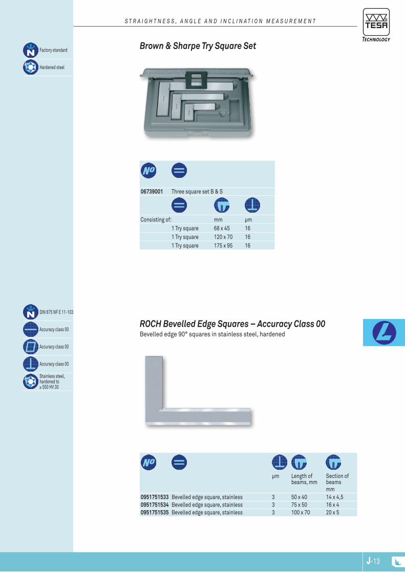
J-13
Din 875 nF E 11-103
Accuracy class 00
Accuracy class 00
Accuracy class 00
Stainless steel, hardened to ≥ 550 HV 30
J-13J-12
06739001 Three square set B & S
Factory standard
Hardened steel
Consisting of: mm µm1 Try square 68 x 45 161 Try square 120 x 70 161 Try square 175 x 95 16
Brown & Sharpe Try Square Set
S T R A I g h T N E S S , A N g L E A N d I N C L I N A T I O N M E A S U R E M E N T
μm Length of
beams, mmSection of beamsmm
0951751533 Bevelled edge square, stainless 3 50 x 40 14 x 4,5 0951751534 Bevelled edge square, stainless 3 75 x 50 16 x 4 0951751535 Bevelled edge square, stainless 3 100 x 70 20 x 5
ROCH Bevelled Edge Squares – Accuracy Class 00 Bevelled edge 90° squares in stainless steel, hardened

J-14
MODE ON / OFF
SET
SET0˚01'
R
S W I S S M A D E
J-15J-14
00630010 Angle protractor with digital display. Supplied with a scale of L = 200 mm
Measuring ranges: 1 x 360°, 2 x 180°, 4 x 90°
LCD, 5 digits + sign
0,01° / 1 minute of arc
8,5 mm
Max. permi. error.: 4 minutes of arc
Stainless steel body, hardened
Maximum rotation speed.: 1080°/s
Preset to 0° or 180°
RS232 opto-coupled
1x CR2032 3,0 V
5000 hours
iP51 (CEi 529)
410 g
Wooden case (iSPM 15 andt niPM 15)
Angle Protractor with Digital Display Measuring ranges 1x 360°, 2x 180°, 4x 90° Large decimal or sexagesimal display 2 measuring directions Fine setting with adjustment screw Locking system Scale L = 200 mm (300 or 500 mm available as options) RS232 data output
ANGLE PROTRACTORS
S T R A I g h T N E S S , A N g L E A N d I N C L I N A T I O N M E A S U R E M E N T
OpTIONAL ACCESSORIES:00660004 Scale 200 mm00660005 Scale 300 mm00660006 Scale 500 mm00660007 Supporting base with 1 flat measuring face and 1 prismatic measuring face00660008 Square for measuring sharp angles01961000 Lithium battery, 3V, CR 203204761062 opto-USB cable, duplex, bidirectional communication
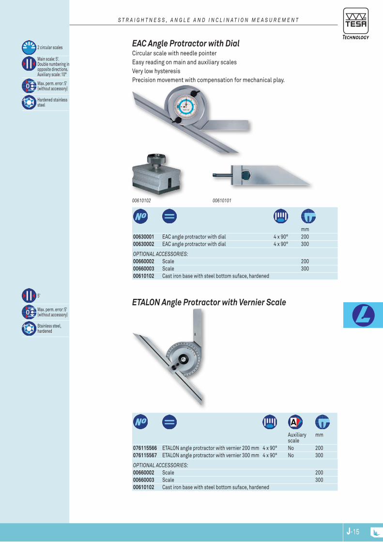
J-15J-15J-14
mm
00630001 EAC angle protractor with dial 4 x 90° 20000630002 EAC angle protractor with dial 4 x 90° 300
2 circular scales
Main scale: 5'. Double numbering in opposite directions. Auxiliary scale: 10°
Max. perm. error: 5’ (without accessory)
Hardened stainless steel
OpTIONAL ACCESSORIES:00660002 Scale 20000660003 Scale 30000610102 Cast iron base with steel bottom suface, hardened
0061010100610102
EAC Angle Protractor with Dial Circular scale with needle pointer Easy reading on main and auxiliary scales Very low hysteresis Precision movement with compensation for mechanical play.
S T R A I g h T N E S S , A N g L E A N d I N C L I N A T I O N M E A S U R E M E N T
Auxiliary scale
mm
076115566 ETALon angle protractor with vernier 200 mm 4 x 90° no 200 076115567 ETALon angle protractor with vernier 300 mm 4 x 90° no 300
5’
Max. perm. error: 5’ (without accessory)
Stainless steel, hardened
OpTIONAL ACCESSORIES:00660002 Scale 20000660003 Scale 30000610102 Cast iron base with steel bottom suface, hardened
ETALON Angle Protractor with Vernier Scale

J-16
H
α
L = 127 mm
06769005
J-NPJ-16
Consisting of:
06719000 B&S angle protractor set with multiple combina-tions
– 1 Ruler graduated in millimetres, length 300 mm – 1 Angle protractor with 2 x 90° graduations – 1 Centering square – 1 Square head with scriber
Hardened steel. Measuring faces specially treated against scratches
With spirit level With angle protractor 2x 90° graduations
With centering square
Brown & Sharpe Angle Protractor - Multiple Combinations This angle protractor combination set can be used as a scale, depth gauge, try square, centering tool, marker or even as a spirit level.
S T R A I g h T N E S S , A N g L E A N d I N C L I N A T I O N M E A S U R E M E N T
L (centre distance), mm
mm
06769005 B&S Sine bar 127 ± 0,004 123 x 25
5 μm
Hardened alloy steel
Removable front stop
Example for the calculation of an angle Given: H = height of combination gauge blocks in mm L = length of B&S sine bar in mm
Formula: H = L * sin(α) sin(α) = H/L angle = arcsin (H/L)
Calculation for determining angle knowing H et L values: angle = arcsin ( 89,803 / 127) = arcsin (0,70711) = 45°
Brown & Sharpe Sine Bar Suited for setting ranges from 0 to 60° Sine function for establishing the angle that needs to be set on the basis of the length dimensions obtained from parallel gauge blocks.
www.tesatechnology.com K-1
Leng
th a
nd A
ngle
Sta
ndar
ds
K-2
Which Material Do You NeeD? Steel Steel gauge blocks have proven their reliability for more than a hundred years. this raw material re-mains the most commonly accepted for length standards. Steel gauge blocks provide high resistance to wear associated with a good property to adhere to other gauge blocks. however, steel must be protected against corrosion. Provided gauge blocks made from this material are properly handled, they will remain reliable for many years. teSa steel gauge blocks have the following key features:
– highly alloyed steel – hardness guaranteed to 800 hV – artificially aged for optimum form and dimensional stability – coefficient of thermal expansion: (11,5 ± 1,0) x 10-6 K-1
Tungsten Carbide Gauge blocks in tungsten carbide are 10 times as resistant to wear as steel gauges. they are intended for frequent use, also where superior wringing quality is required. teSa tungsten carbide gauge blocks provide:
– hardness guaranteed to 1400 hV – coefficient of thermal expansion: (4,23 ± 0,1) x 10-6 K-1
Ceramic ceramic gauge blocks are extremely resistant to wear and scratches. Due to the properties of this ma-terial, any minor damage is unlikely to affect the wringability of their measuring faces. Being corrosion resistant, these gauge blocks are insensitive to "rusty hands", amongst other issues. Manufactured from stabilised zirconia, teSa ceramic gauge blocks have the following key features:
– Non-magnetizable – hardness guaranteed to 1400 hV – coefficient of thermal expansion: (9,7 ± 0,8) x 10-6 K-1
iSo 3650 Gauge blocks with metric nominal lengths conform to iSo 3650:1998. this international standard is based on the ones published either in a region, e.g. the european standard eN iSo 3650:1998 or in a country, e.g. the Swiss standard SN eN iSo 3650, German standard DiN eN iSo 3650 or French standard NF eN iSo 3650. Gauge blocks with imperial nominal lengths comply with BS 4311 - Part 1. compared to earlier standards, iSo 3650:1998 includes the following main changes :
– Withdrawal of the accuracy grade 00 (see "Which grade do you need"). – introduction of requirements as regards the uncertainty of measurement in relation to the declara-
tion of conformity of the product according to iSo 14253-1:1998. – review of some definitions and shortened form of terms according to normative references that are
currently applicable (see drawing).
the high accuracy of teSa’s gauge blocks is the result of years of experience in producing and making use of these products.
– use of high quality raw materials and appropriate heat treatment, thus guaranteeing a durable shape and dimensional stability of the gauge blocks over years.
– Very low deviations in flatness and parallelism of the measuring faces, resulting in highly accurate gauges.
– unique flat lapping polish as well as edge rounding techniques, leading to superior wringability. – Proper serial number marked on each gauge block.
PURCHASING GAUGE BLOCKS CALLS FOR CONFIDENCE
l e N G t h a N D a N G l e S t a N D a r D S
K-3
DeliVerieSteSa gauge blocks can be delivered individually or in full sets with nominal lengths as listed in this section. additional gauge sets and lengths can be made available upon request. Since individual gauge blocks could no be listed in their whole here, any inquiry or purchase order should specify :
– Desired nominal length – chosen material – calibration grade or any other grade
certiFicate oF caliBratioN aND traceaBilitY.all set compositions from teSa are supplied with a certificate of calibration issued by the accredited calibration laboratory of a national calibration service.this service can either be the Swiss calibration service (ScS), British calibration service (uKaS) or Deutsche akkreditierungsstelle (DakkS) depending on the manufacturer.accreditation is the authenticated assurance of the skills of the calibration laboratories as well as of the full traceability to national standards that conform with the international System of units (Si).this is for any reference standard or measuring equipment being used.owing to a multilateral agreement (Mla), any certificates of calibration issued by the members of the european cooperation for accreditation of laboratories (ea) is internationally accepted.
Which GraDe Do You NeeD? Grade 2these gauge blocks are commonly used as Working Standards in inspection rooms within a manu-facturing area to set and calibrate measuring instruments and other equipment as well as to inspect tools, fixtures and machines.Grade 1 Gauge blocks of this class are mainly used as Working Standards to set and calibrate plug gauges and measuring instruments in measuring rooms or inspection areas within a manufacturing area.Tolerence Grade 0 these gauge blocks are designated for use as Company Standards in calibration laboratories or environmentally controlled inspection rooms to set and calibrate plug gauges as well as measuring equipment.Calibration grade K Gauge blocks of this tolerance class are intended for use as Reference Standards in metrology oriented laboratories of National institutes, precision measuring rooms and other laboratories of Na-tional calibration Services, whether officially accredited or not.they should be used as masters to calibrate gauge blocks, length standards of same accuracy and also measuring instruments.Precision Grade 00 the new standard iSo 3650 no longer takes this accuracy grade into consideration as the uncertainties of measurement achieved with the procedure applied for calibration usually lead to a disparity against specified tolerances.the rules to the expression of uncertainty of measurement for proving the conformity or nonconformity of the product with the specification, as stated in the standard iSo 14253- 1:1998, have dictated the decision to withdraw the accuracy grade 00.a wide experience in practical use of gauge blocks has proven that gauges of the calibration class K could easily replace those of the earlier accuracy grade 00.as a result, gauge blocks of grade 00 are no longer available.
l e N G t h a N D a N G l e S t a N D a r D S
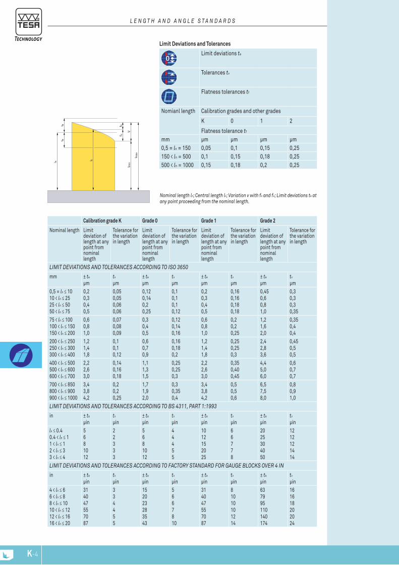
l n
V
f uf ot e
t e
l max
l min
l c
K-4
Limit Deviations and Tolerances
Calibration grade K Grade 0 Grade 1 Grade 2
Nominal length Limit deviation of length at any point from nominal length
Tolerance for the variation in length
Limit deviation of length at any point from nominal length
Tolerance for the variation in length
Limit deviation of length at any point from nominal length
Tolerance for the variation in length
Limit deviation of length at any point from nominal length
Tolerance for the variation in length
liMit DeViatioNS aND toleraNceS accorDiNG to iSo 3650
mm ± te
µmtv
µm± te
µmtv
µm± te
µmtv
µm± te
µmtv
µm0,5 = ln ≤ 1010 < ln ≤ 2525 < ln ≤ 5050 < ln ≤ 75
0,20,30,40,5
0,050,050,060,06
0,120,140,20,25
0,10,10,10,12
0,20,30,40,5
0,160,160,180,18
0,450,60,81,0
0,30,30,30,35
75 < ln ≤ 100100 < ln ≤ 150150 < ln ≤ 200
0,60,81,0
0,070,080,09
0,30,40,5
0,120,140,16
0,60,81,0
0,20,20,25
1,21,62,0
0,350,40,4
200 < ln ≤ 250250 < ln ≤ 300300 < ln ≤ 400
1,21,41,8
0,10,10,12
0,60,70,9
0,160,180,2
1,21,41,8
0,250,250,3
2,42,83,6
0,450,50,5
400 < ln ≤ 500500 < ln ≤ 600600 < ln ≤ 700
2,22,63,0
0,140,160,18
1,11,31,5
0,250,250,3
2,22,63,0
0,350,400,45
4,45,06,0
0,60,70,7
700 < ln ≤ 850800 < ln ≤ 900900 < ln ≤ 1000
3,43,84,2
0,20,20,25
1,71,92,0
0,30,350,4
3,43,84,2
0,50,50,6
6,57,58,0
0,80,91,0
liMit DeViatioNS aND toleraNceS accorDiNG to BS 4311, Part 1:1993
in ± te
µintv
µin± te
µintv
µin± te
µintv
µin± te
µintv
µinln ≤ 0.40.4 < ln ≤ 11 < ln ≤ 12 < ln ≤ 33 < ln ≤ 4
5681012
22333
5681012
44455
1012152025
66778
2025304050
1212121414
liMit DeViatioNS aND toleraNceS accorDiNG to FactorY StaNDarD For GauGe BlocKS oVer 4 iN
in ± te
µintv
µin± te
µintv
µin± te
µintv
µin± te
µintv
µin4 < ln ≤ 66 < ln ≤ 88 < ln ≤ 1010 < ln ≤ 1212 < ln ≤ 1616 < ln ≤ 20
314047557087
334455
152023283543
5667810
314047557087
81010101214
637995110140174
161618202024
Limit deviations te
Tolerances tv
Flatness tolerances tf
Nomianl length Calibration grades and other grades
K 0 1 2
Flatness tolerance tf
mm µm µm µm µm0,5 = ln = 150 0,05 0,1 0,15 0,25150 < ln = 500 0,1 0,15 0,18 0,25500 < ln = 1000 0,15 0,18 0,2 0,25
Nominal length ln; central length lc; Variation v with fo and fu; limit deviations te at any point proceeding from the nominal length.
l e N G t h a N D a N G l e S t a N D a r D S
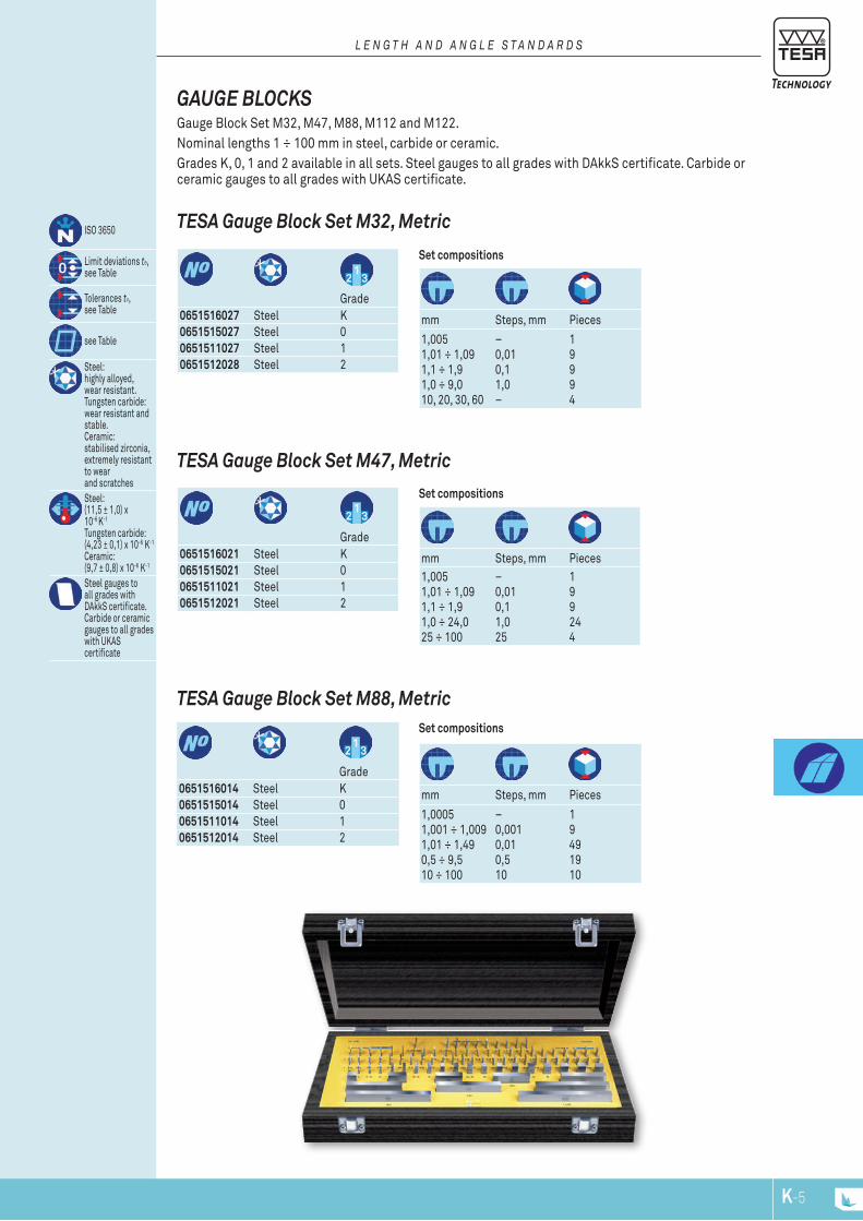
K-5
0651516014 Steel K0651515014 Steel 00651511014 Steel 10651512014 Steel 2
Grade
Set compositions
mm Steps, mm Pieces
1,00051,001 ÷ 1,0091,01 ÷ 1,490,5 ÷ 9,510 ÷ 100
–0,0010,010,510
19491910
TESA Gauge Block Set M88, Metric
Grade
0651516021 Steel K0651515021 Steel 00651511021 Steel 10651512021 Steel 2
Set compositions
mm Steps, mm Pieces1,0051,01 ÷ 1,091,1 ÷ 1,91,0 ÷ 24,025 ÷ 100
–0,010,11,025
199244
TESA Gauge Block Set M47, Metric
ISO 3650
Limit deviations te, see Table
Tolerances tv, see Table
see Table
Steel:highly alloyed,wear resistant.Tungsten carbide:wear resistant and stable.Ceramic:stabilised zirconia,extremely resistantto wearand scratchesSteel:(11,5 ± 1,0) x10-6 K-1
Tungsten carbide:(4,23 ± 0,1) x 10-6 K-1
Ceramic:(9,7 ± 0,8) x 10-6 K-1
Steel gauges toall grades withDAkkS certificate.Carbide or ceramic gauges to all grades with UKAScertificate
Grade
0651516027 Steel K0651515027 Steel 00651511027 Steel 10651512028 Steel 2
Set compositions
mm Steps, mm Pieces
1,0051,01 ÷ 1,091,1 ÷ 1,91,0 ÷ 9,010, 20, 30, 60
–0,010,11,0–
19994
TESA Gauge Block Set M32, Metric
GAUGE BLOCKS Gauge Block Set M32, M47, M88, M112 and M122.Nominal lengths 1 ÷ 100 mm in steel, carbide or ceramic. Grades K, 0, 1 and 2 available in all sets. Steel gauges to all grades with DAkkS certificate. Carbide or ceramic gauges to all grades with UKAS certificate.
l e N G t h a N D a N G l e S t a N D a r D S
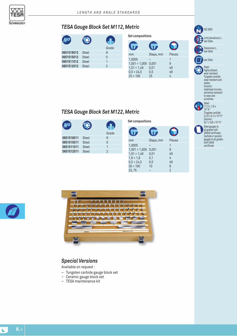
K-6
0651516011 Steel K0651515011 Steel 00651511011 Steel 10651512011 Steel 2
Grade
Set compositions
mm Steps, mm Pieces1,00051,001 ÷ 1,0091,01 ÷ 1,491,6 ÷ 1,90,5 ÷ 24,530 ÷ 10025, 75
–0,0010,010,10,510–
194944982
TESA Gauge Block Set M122, Metric
ISO 3650
Limit deviations te, see Table
Tolerances tv, see Table
see Table
Steel:highly alloyed,wear resistant.Tungsten carbide:wear resistant and stable.Ceramic:stabilised zirconia,extremely resistantto wear and scratchesSteel:(11,5 ± 1,0) x10-6 K-1
Tungsten carbide:(4,23 ± 0,1) x 10-6 K-1
Ceramic:(9,7 ± 0,8) x 10-6 K-1
Steel gauges toall grades withDAkkS certificate.Carbide or ceramic gauges to all grades with UKAScertificate
Grade
0651516012 Steel K0651515012 Steel 00651511012 Steel 10651512012 Steel 2
Set compositions
mm Steps, mm Pieces1,00051,001 ÷ 1,0091,01 ÷ 1,490,5 ÷ 24,525 ÷ 100
–0,0010,010,525
1949494
TESA Gauge Block Set M112, Metric
l e N G t h a N D a N G l e S t a N D a r D S
Special VersionsAvailable on request :
– Tungsten carbide gauge block set – Ceramic gauge block set – TESA maintenance kit
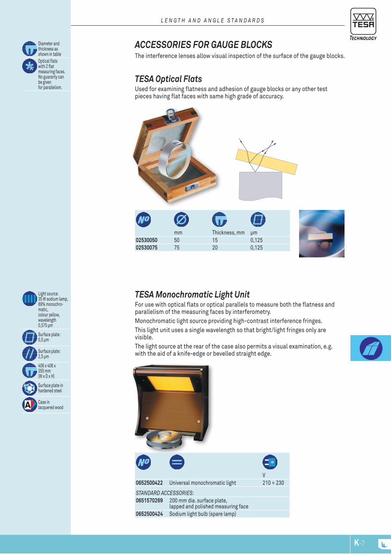
K-7
StaNDarD acceSSorieS:0651570269 200 mm dia. surface plate,
lapped and polished measuring face0652500424 Sodium light bulb (spare lamp)
0652500422 Universal monochromatic light 210 ÷ 230
V
Light source:35 W sodium lamp,89% monochro-matic,colour yellow,wavelength 0,575 μm
Surface plate:0,5 μm
Surface plate:2,5 μm
406 x 406 x355 mm(W x D x H)
Surface plate inhardened steel
Case inlacquered wood
TESA Monochromatic Light Unit For use with optical flats or optical parallels to measure both the flatness and parallelism of the measuring faces by interferometry.Monochromatic light source providing high-contrast interference fringes.This light unit uses a single wavelength so that bright/light fringes only are visible. The light source at the rear of the case also permits a visual examination, e.g. with the aid of a knife-edge or bevelled straight edge.
02530050 50 15 0,12502530075 75 20 0,125
mm Thickness, mm μm
Diameter andthickness asshown in tableOptical flatswith 2 flatmeasuring faces.No guaranty can be givenfor parallelism.
TESA Optical Flats Used for examining flatness and adhesion of gauge blocks or any other test pieces having flat faces with same high grade of accuracy.
ACCESSORIES FOR GAUGE BLOCKS The interference lenses allow visual inspection of the surface of the gauge blocks.
l e N G t h a N D a N G l e S t a N D a r D S
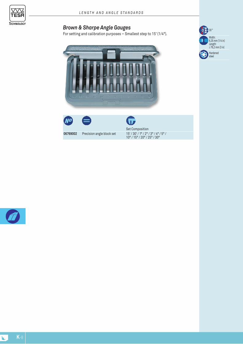
K-8
06769002 Precision angle block set 15' / 30' / 1° / 2° / 3° / 4° / 5° / 10° / 15° / 20° / 25° / 30°
Set Composition
30 ”
Width:6,35 mm (1/4 in)Length:≥ 76,2 mm (3 in)
Hardenedsteel
Brown & Sharpe Angle Gauges For setting and calibration purposes – Smallest step to 15’ (1/4°).
l e N G t h a N D a N G l e S t a N D a r D S
www.tesatechnology.com L-1
Calib
ratio
n Eq
uipm
ent
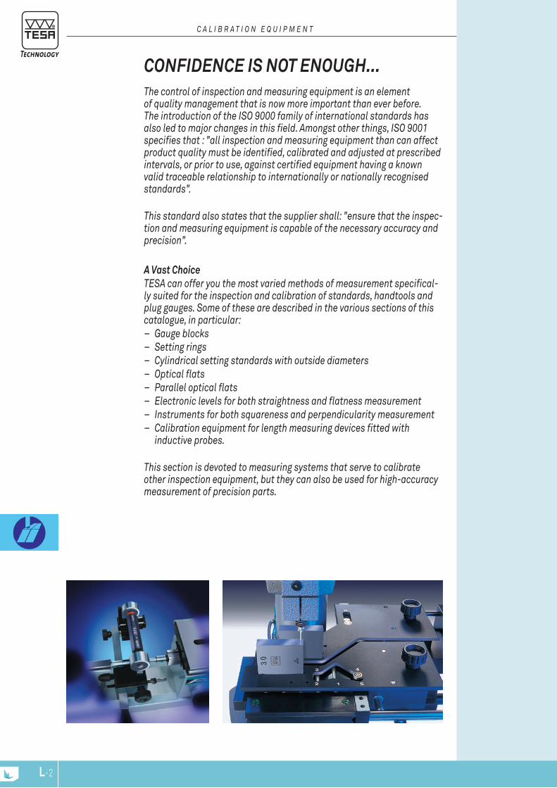
L-2
The control of inspection and measuring equipment is an element of quality management that is now more important than ever before. The introduction of the ISO 9000 family of international standards has also led to major changes in this field. Amongst other things, ISO 9001 specifies that : "all inspection and measuring equipment than can affect product quality must be identified, calibrated and adjusted at prescribed intervals, or prior to use, against certified equipment having a known valid traceable relationship to internationally or nationally recognised standards".
This standard also states that the supplier shall: "ensure that the inspec-tion and measuring equipment is capable of the necessary accuracy and precision".
A Vast Choice TESA can offer you the most varied methods of measurement specifical-ly suited for the inspection and calibration of standards, handtools and plug gauges. Some of these are described in the various sections of this catalogue, in particular:
– Gauge blocks – Setting rings – Cylindrical setting standards with outside diameters – Optical flats – Parallel optical flats – Electronic levels for both straightness and flatness measurement – Instruments for both squareness and perpendicularity measurement – Calibration equipment for length measuring devices fitted with
inductive probes.
This section is devoted to measuring systems that serve to calibrate other inspection equipment, but they can also be used for high-accuracy measurement of precision parts.
CONFIDENCE IS NOT ENOUGH...
C A l I b r A T I O n E q u I P m E n T
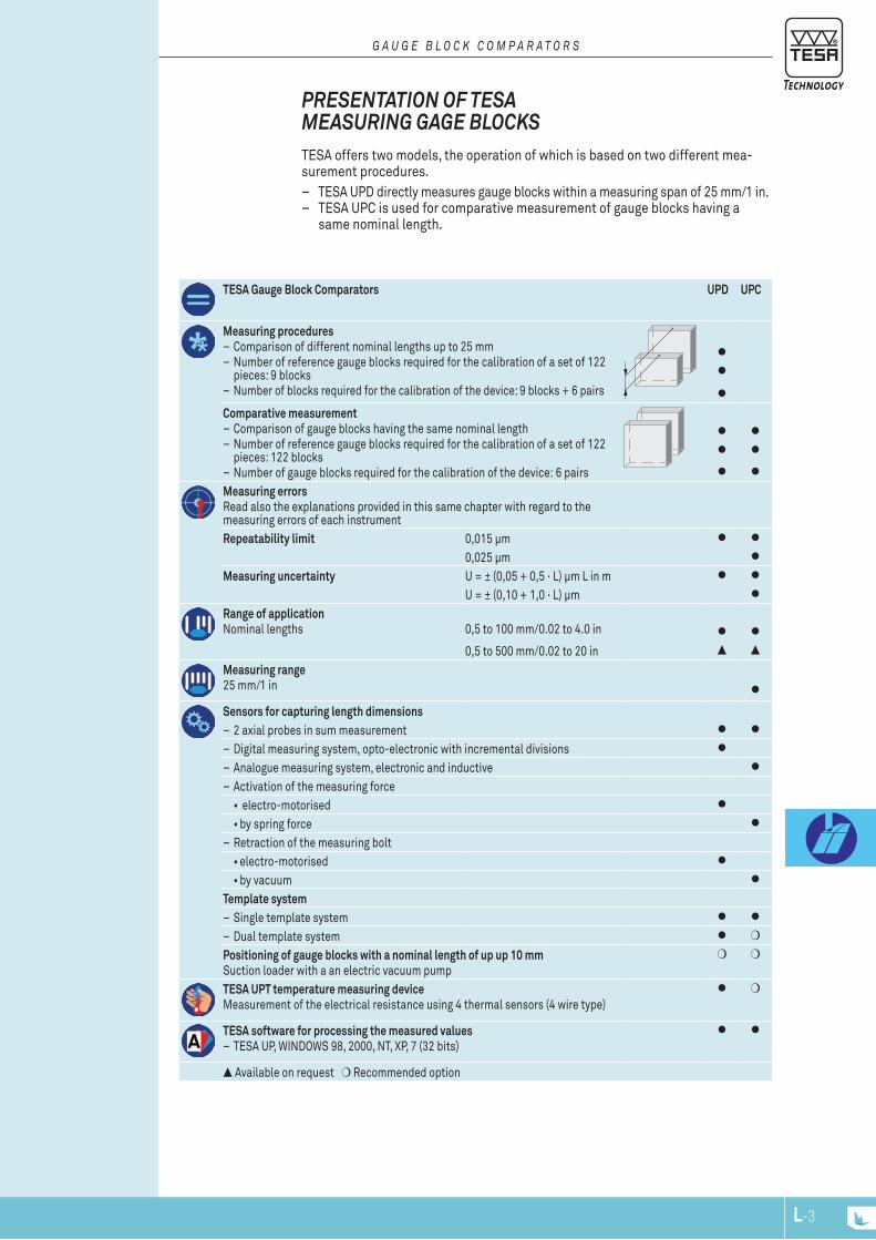
L-3
TESA offers two models, the operation of which is based on two different mea-surement procedures.
– TESA UPD directly measures gauge blocks within a measuring span of 25 mm/1 in. – TESA UPC is used for comparative measurement of gauge blocks having a
same nominal length.
PrESENTATION OF TESA mEASUrING GAGE blOCkS
G A u G E b l O C k C O m P A r A T O r S
TESA Gauge Block Comparators UPD UPC
Measuring procedures – Comparison of different nominal lengths up to 25 mm – Number of reference gauge blocks required for the calibration of a set of 122 pieces: 9 blocks
– Number of blocks required for the calibration of the device: 9 blocks + 6 pairs
Comparative measurement – Comparison of gauge blocks having the same nominal length – Number of reference gauge blocks required for the calibration of a set of 122 pieces: 122 blocks
– Number of gauge blocks required for the calibration of the device: 6 pairsMeasuring errorsRead also the explanations provided in this same chapter with regard to the measuring errors of each instrumentRepeatability limit 0,015 µm
0,025 µmMeasuring uncertainty U = ± (0,05 + 0,5 · L) µm L in m
U = ± (0,10 + 1,0 · L) µmRange of applicationNominal lengths 0,5 to 100 mm/0.02 to 4.0 in
0,5 to 500 mm/0.02 to 20 in
Measuring range25 mm/1 in
Sensors for capturing length dimensions – 2 axial probes in sum measurement – Digital measuring system, opto-electronic with incremental divisions – Analogue measuring system, electronic and inductive – Activation of the measuring force• electro-motorised•by spring force
– Retraction of the measuring bolt•electro-motorised•by vacuum
Template system – Single template system – Dual template system
Positioning of gauge blocks with a nominal length of up up 10 mmSuction loader with a an electric vacuum pump
TESA UPT temperature measuring deviceMeasurement of the electrical resistance using 4 thermal sensors (4 wire type)
TESA software for processing the measured values – TESA UP, WINDOWS 98, 2000, NT, XP, 7 (32 bits)
Available on request Recommended option

L-4
EN ISO 3650(ASME B89.1.9-2002 on request)For gauge blocks with nominal lengths from 0,5 mm to 100 mm / 0.02 in to 4 in(0,5 to 500 mm on request)measuring configurationTwo probes with mechanical contact with the measuring face to be probed are connected in sum measurement (function +A+B).
measuring pointsOn the reference gauge block: at the centre of the meas-uring face (point R). On the gauge block to be measured: at the centre (point 1) as well as the four corners of the measuring face, each lying 2 mm away from the ad-jacent faces (points 2 to 5). The central length lc is determined by probing both points R and 1. For establishing lengths at any point, the measurements shall be carried out at points R plus 1 to 5. The variation in length v is obtained from measurements taken at points 1 to 5.Calibration certificate from the supplier for the comparator or the Swiss Calibration Service for the tem-perature device.
Dual template system for the maintenance of your reference gauge blocks (TESA patented)
– The simultaneous use of two templates allows you to "rest up" your gauge blocks until you need them.
– The application of this new concept turns into significant savings in both time and money.
– During measurement cycles carried out on a routine basis, the distance tra-velled over the measuring table is reduced by nearly 70 %.•This contributes to significant reductions of the risks of damaging and wea-
ring the measurement faces. – The double protection of your reference gauge blocks leads to significant cost
savings through the reduction if the need for: •recalibration•restoration of the measuring faces•replacement of worn or damaged gauge blocks•increased downtime (whilst extending the life of your reference gauge blocks)
Single Template System – Using this system your reference gauge blocks are moved together with those
to be calibrated during the measurement cycles.
TESA UPD – for Direct and Comparative measurements – Direct measurement of gauge blocks with a variation in nominal length of up to
25 mm or 1 in. •Enables the number of reference gauge blocks required to be reduced by
nearly 80 %. – Comparative measurement of gauge blocks having a same nominal length. •Enables lower measurement uncertainties to be achieved due to weaker
influences of the systematic errors. – Equipped with HEIDENHAIN high-precision incremental probes. – Templates with a new concept for positioning the gauge blocks. •Single or dual template system to provide optimum ease of handling of the
gauge blocks – Integrated device for most accurate temperature acquisition. – On-line transfer of both measured length and temperature values. – Computer-aided data processing with all the corrections necessary included.
GAUGE blOCk COmPArATOrS In the hierarchical chain of dimensional measurements that can be traced back to the standard metre length unit, gauge blocks hold a key position. This makes them the most important material references used in metrology.The application of the length unit, based on specific wavelengths of light, to gauge blocks is achieved in the first instance by fundamental interferential measurement. Using gauge blocks measured by interferometry, defined lengths are thus transferred to other gauge blocks in measurements further down the hierarchical chain.
G A u G E b l O C k C O m P A r A T O r S
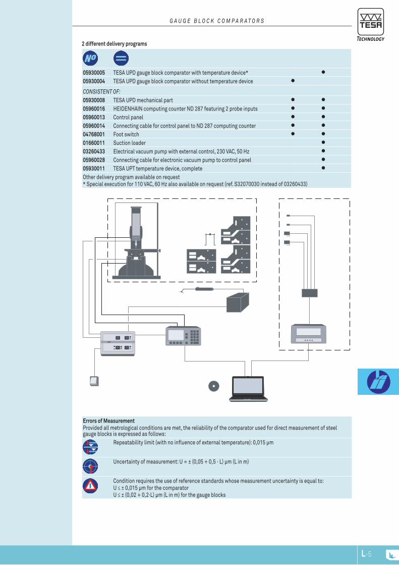
upd
L-5
2 different delivery programs
Errors of MeasurementProvided all metrological conditions are met, the reliability of the comparator used for direct measurement of steel gauge blocks is expressed as follows:
Repeatability limit (with no influence of external temperature): 0,015 µm
Uncertainty of measurement: U = ± (0,05 + 0,5 · L) µm (L in m)
Condition requires the use of reference standards whose measurement uncertainty is equal to:U ≤ ± 0,015 µm for the comparatorU ≤ ± (0,02 + 0,2·L) µm (L in m) for the gauge blocks
05930005 TESA UPD gauge block comparator with temperature device*05930004 TESA UPD gauge block comparator without temperature device
COnSISTEnT Of:05930008 TESA UPD mechanical part05960016 HEIDENHAIN computing counter ND 287 featuring 2 probe inputs05960013 Control panel05960014 Connecting cable for control panel to ND 287 computing counter04768001 Foot switch01660011 Suction loader03260433 Electrical vacuum pump with external control, 230 VAC, 50 Hz05960028 Connecting cable for electronic vacuum pump to control panel05930011 TESA UPT temperature device, completeOther delivery program available on request* Special execution for 110 VAC, 60 Hz also available on request (ref. S32070030 instead of 03260433)
G A u G E b l O C k C O m P A r A T O r S

L-6
EN ISO 3650
For gauge blocks ranging from 0,5 mm to 100 mm or 0.02 in to 4 in (0,5 to 500 mm on request)Comparative mea-surement procedure with transference of the length of a refe-rence gauge block to the gauge block being measured.
measuring confi-guration 2 probes connected in sum measure-ment (function +A+B) with mecha-nical contact with the measuring face. measuring pointsOn the reference gauge block: at the centre of the measuring face (point R). On the gauge block to be measured: at the centre (point 1) as well as the 4 corners of the measuring face, each lying 2 mm away from the adjacent faces (points 2 to 5).
Central length lc is defined by probing both points R and 1.
Establishing lengths at any point requires measurements to be taken at points R plus 1 to 5.
Variation in length v is the result of mea-surements taken at points 1 to 5.≈ 23 kg (comparator complete, but without computer). ≈ 4 kg (temperature device)All instruments with the option for greater accuracy are delivered with serial numbersIn-house calibration certificate for the version with greater accuracy or decla-ration ofconformity for the standard version. Temperature device with SCS certificate.
If specified, TESA can also provide the temperature device available as an option. This device has 4 PT100 plat-inum resistances, each capturing the temperature of the two gauge blocks along with that of both the measuring table and the support. Computer- aided data processing lets you carry out any calibration most reliably and rationally – for sure.
TESA UPC is specially designed for the calibration – or dimensional inspec-tion – of gauge blocks with nominal lenghts ranging from 0,5 to 100 mm. The configuration, which consists of two probes aligned opposite one another, associated with both the concept and quality of the measuring system provides full guarantee for an extra low uncertainty of measurement. Although TESA UPC is mainly intended for manufacturers and end-users of gauge blocks, this comparator is also widely used in nationally accredited laboratories.
TESA UPC – for Comparative measurementTESA UPC Gauge Block Comparator for Comparative Measurement
– Measures gauge blocks of same nominal length by comparison. – Comes with the new template system for positioning the gauge blocks. – Single or dual template system for optimum ease of gauge handling. – Features TESA high-precision inductive probes. – Allows ultra-precise temperature measurement, integrated. – Transfers on-line all measured length and temperature values. – Executes computer-aided data processing with all required correction values
included. – Performs calibrations that meet the requirements of both ISO standards and
EA guidelines (EAL – European cooperation for Accreditation of Laboratories). – Includes an execution for greater accuracy along with a calibration certificate
(optional).
G A u G E b l O C k C O m P A r A T O r S
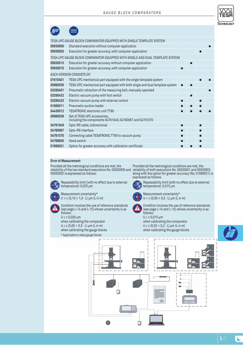
L-7
Error of MeasurementProvided all the metrological conditions are met, the reliability of the two standard executions No. 05930000 and 05930002 is expressed as follows:
Provided all the metrological conditions are met, the reliability of both executions No. 05930001 and 05930003 along with the option for greater accuracy (No. 01690021) is expressed as follows:
Repeatability limit (with no effect due to external temperature): 0,025 µm
Repeatability limit (with no effect due to external temperature): 0,015 µm
Measurement uncertainty*U = ± (0,10 + 1,0 · L) µm (L in m)
Measurement uncertainty*U = ± (0,05 + 0,5 · L) µm (L in m)
Condition involves the use of reference standards (see page L-14 and L-15) whose uncertainty is as follows:U ≤ ± 0,030 µmwhen calibrating the comparatorU ≤ ± (0,05 + 0,5 · L) µm (L in m)when calibrating the gauge blocks
Condition involves the use of reference standards (see page L-14 and L-15) whose uncertainty is as follows:U ≤ ± 0,015 µmwhen calibrating the comparatorU ≤ ± (0,02 + 0,2 · L) µm (L in m)when calibrating the gauge blocks
* Applicable to steel gauge blocks
G A u G E b l O C k C O m P A r A T O r S
TESA uPC GAuGE blOCk COmPArATOr EquIPPEd wITh SInGlE TEmPlATE SySTEm05930000 Standard execution without computer application05930003 Execution for greater accuracy, with computer application
TESA uPC GAuGE blOCk COmPArATOr EquIPPEd wITh SInGlE And duAl TEmPlATE SySTEm05930013 Execution for greater accuracy without computer application05930015 Execution for greater accuracy, with computer application
EACh vErSIOn COnSISTS Of:01610401 TESA UPC mechanical part equipped with the single template system05960030 TESA UPC mechanical part equipped with both single and dual template system03260401 Pneumatic retraction of the measuring bolt, manually operated03260432 Electric vacuum pump with foot switch03260433 Electric vacuum pump with external control01660011 Pneumatic suction loader04430012 TESATRONIC electronic unit TT9005960039 Set of TESA UPC accessories,
including the components 04761049, 04760087 and 0476107004761049 Opto-RS cable, bidirectional04760087 Opto-RS interface04761070 Connecting cable TESATRONIC TT90 to vacuum pump04768000 Hand switch01690021 Option for greater accuracy with calibration certificate
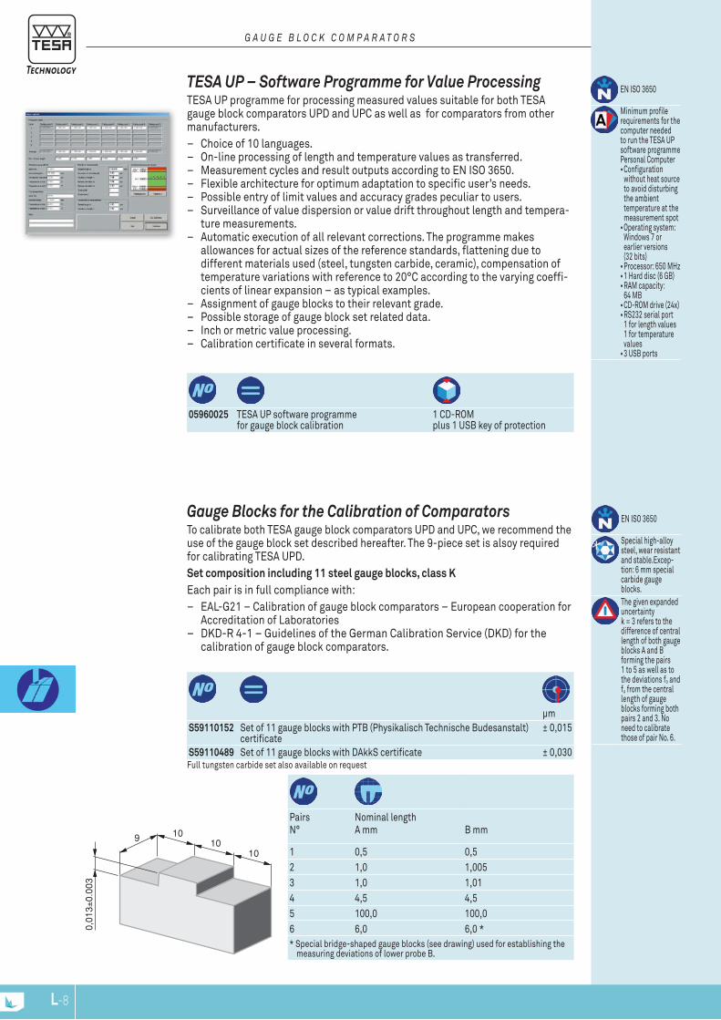
0,01
3±0.
003
9 1010
10
L-8
05960025 TESA UP software programme for gauge block calibration
1 CD-ROM plus 1 USB key of protection
EN ISO 3650
Minimum profile requirements for the computer needed to run the TESA UP software programme Personal Computer •Configuration
without heat source to avoid disturbing the ambient temperature at the measurement spot•Operating system:
Windows 7 or earlier versions (32 bits) •Processor: 650 MHz•1 Hard disc (6 GB)•RAM capacity:
64 MB•CD-ROM drive (24x)•RS232 serial port
1 for length values 1 for temperature values•3 USB ports
TESA UP – Software Programme for Value Processing TESA UP programme for processing measured values suitable for both TESA gauge block comparators UPD and UPC as well as for comparators from other manufacturers.
– Choice of 10 languages. – On-line processing of length and temperature values as transferred. – Measurement cycles and result outputs according to EN ISO 3650. – Flexible architecture for optimum adaptation to specific user’s needs. – Possible entry of limit values and accuracy grades peculiar to users. – Surveillance of value dispersion or value drift throughout length and tempera-
ture measurements. – Automatic execution of all relevant corrections. The programme makes
allowances for actual sizes of the reference standards, flattening due to different materials used (steel, tungsten carbide, ceramic), compensation of temperature variations with reference to 20°C according to the varying coeffi-cients of linear expansion – as typical examples.
– Assignment of gauge blocks to their relevant grade. – Possible storage of gauge block set related data. – Inch or metric value processing. – Calibration certificate in several formats.
G A u G E b l O C k C O m P A r A T O r S
μm
S59110152 Set of 11 gauge blocks with PTB (Physikalisch Technische Budesanstalt) certificate
± 0,015
S59110489 Set of 11 gauge blocks with DAkkS certificate ± 0,030
PairsN°
Nominal lengthA mm B mm
1 0,5 0,52 1,0 1,0053 1,0 1,014 4,5 4,55 100,0 100,06 6,0 6,0 ** Special bridge-shaped gauge blocks (see drawing) used for establishing the
measuring deviations of lower probe B.
Full tungsten carbide set also available on request
EN ISO 3650
Special high-alloy steel, wear resistant and stable.Excep-tion: 6 mm special carbide gauge blocks.The given expanded uncertainty k = 3 refers to the difference of central length of both gauge blocks A and B forming the pairs 1 to 5 as well as to the deviations fo and fu from the central length of gauge blocks forming both pairs 2 and 3. No need to calibrate those of pair No. 6.
Gauge blocks for the Calibration of Comparators To calibrate both TESA gauge block comparators UPD and UPC, we recommend the use of the gauge block set described hereafter. The 9-piece set is alsoy required for calibrating TESA UPD. Set composition including 11 steel gauge blocks, class KEach pair is in full compliance with:
– EAL-G21 – Calibration of gauge block comparators – European cooperation for Accreditation of Laboratories
– DKD-R 4-1 – Guidelines of the German Calibration Service (DKD) for the calibration of gauge block comparators.
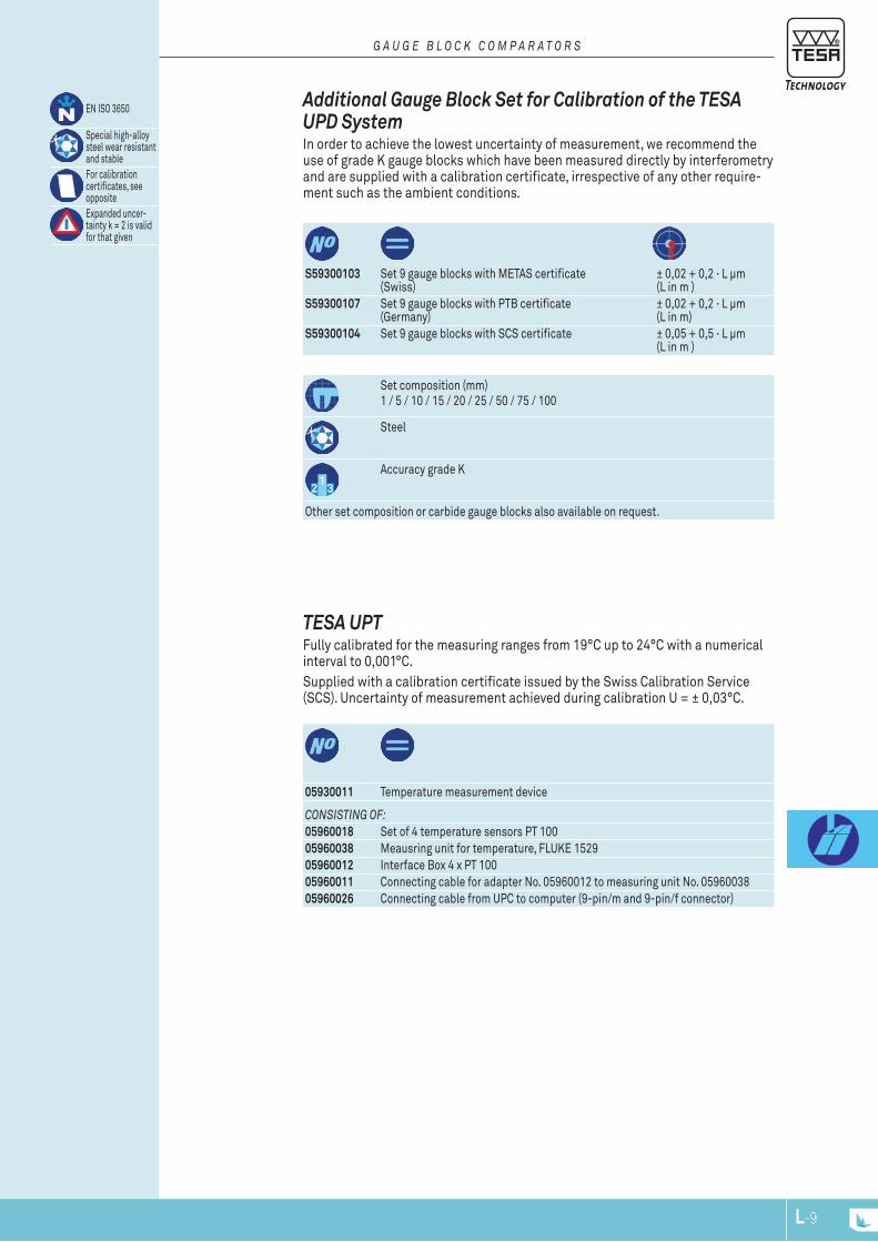
L-9
S59300103 Set 9 gauge blocks with METAS certificate (Swiss)
± 0,02 + 0,2 · L μm (L in m )
S59300107 Set 9 gauge blocks with PTB certificate (Germany)
± 0,02 + 0,2 · L μm (L in m)
S59300104 Set 9 gauge blocks with SCS certificate ± 0,05 + 0,5 · L μm (L in m )
Set composition (mm)1 / 5 / 10 / 15 / 20 / 25 / 50 / 75 / 100
Steel
Accuracy grade K
Other set composition or carbide gauge blocks also available on request.
EN ISO 3650
Special high-alloy steel wear resistant and stable For calibration certificates, see oppositeExpanded uncer-tainty k = 2 is valid for that given
Additional Gauge block Set for Calibration of the TESA UPD System In order to achieve the lowest uncertainty of measurement, we recommend the use of grade K gauge blocks which have been measured directly by interferometry and are supplied with a calibration certificate, irrespective of any other require-ment such as the ambient conditions.
G A u G E b l O C k C O m P A r A T O r S
05930011 Temperature measurement device
COnSISTInG Of:05960018 Set of 4 temperature sensors PT 10005960038 Meausring unit for temperature, FLUKE 152905960012 Interface Box 4 x PT 10005960011 Connecting cable for adapter No. 05960012 to measuring unit No. 0596003805960026 Connecting cable from UPC to computer (9-pin/m and 9-pin/f connector)
TESA UPT Fully calibrated for the measuring ranges from 19°C up to 24°C with a numerical interval to 0,001°C.Supplied with a calibration certificate issued by the Swiss Calibration Service (SCS). Uncertainty of measurement achieved during calibration U = ± 0,03°C.

L-10
A giant for small sizes – Specially designed for the control of measuring and test equipment in compliance with ISO 9000.
– Application range from 0 up to 100 mm for external dimensions of 2,5 up to 110 mm for internal dimensions – 50 mm measuring span.
– Resolution to 0,001 or 0,0001 mm – Metric/Inch conversion. – Maximum permissible error of 0,5 μm. – Measuring force from 0 to 4 N. – Comes with a calibration certificate issued by the supplier.
ETAlON POlO HOrIzONTAl mEASUrING bENCH
E T A l O n P O l O h O r I z O n T A l m E A S u r I n G b E n C h
Calibration of Standards: – Cyllindrical test pins – Setting standards with cylindrical,
plane-parallel measuring faces – Threaded reference gauges
(calibrated using the 3-wire method) – Setting masters – Setting rings
Calibration of Plus Gauges: – Limit plug gauges – Plug gauges "GO" – Plug gauges "NO GO" – Plain plug gauges – Ring gauges "GO" – Ring gauges "NO GO" – Threaded plug gauges
Workpiece Inspection:External dimensions
– Stepped shafts – Cutting tools – Cylindrical pins – Ball tips – Grooves – Short centring shoulders – Threads (measured according
to the 3-wires method)
Internal dimensions – Through bores – Blind bores – Centring grooves – Slots – Sliding guides
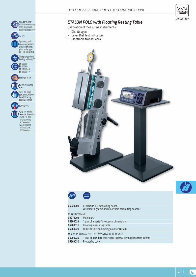
L-11
dElIvErEd wITh ThE fOllOwInG ACCESSOrIES:05969020 1 Pair of standard inserts for internal dimensions from 10 mm05969030 Protective cover
05939001 ETALON POLO measuring bench with floating table and electronic computing counter
Max. perm. error within the measuring span: 0,5 μm with standard accessories
0,1 μm
Opto-electronic measuring system with incremental glass scale, type LIF – HEIDENHAIN
Tilting range of the floating table ± 0,5°
EN 50081-1 EN 50082-2 EN 61000-4-2 EN 61000-4-4
Setting 0 to 4 N
50 mm measuring span
19 kg net (main part alone, without table). Floating table: 2,8 kg net
8,0•10-6/°C
•0 to 100 mm for external dimensions •10 to 110 mm
with standard accessories •2,5 to 110 mm
with optional accessories
COnSISTInG Of:05919002 Main part05969024 1 pair of inserts for external dimensions05969015 Floating measuring table05969029 HEIDENHAIN computing counter ND 287
ETAlON POlO with Floating resting Table Calibration of measuring instruments
– Dial Gauges – Lever Dial Test Indicators – Electronic transducers
E T A l O n P O l O h O r I z O n T A l m E A S u r I n G b E n C h
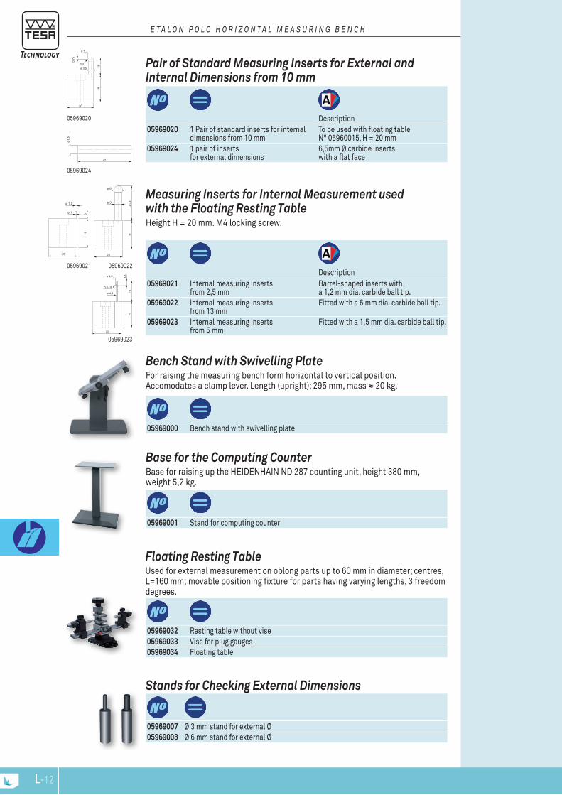
05969020
05969024
13
ø 5
H
20
0,75
R 3
ø 3,5
42
ø 6
,5
6
ø 1,2
H
20
ø 1
21,5
ø 6
H
20
ø 5
16
ø 4,9
H
22
ø 4,4
3,5
R 0,75
05969023
0596902205969021
L-12
Stands for Checking External Dimensions
05969007 Ø 3 mm stand for external Ø05969008 Ø 6 mm stand for external Ø
Floating resting Table Used for external measurement on oblong parts up to 60 mm in diameter; centres, L=160 mm; movable positioning fixture for parts having varying lengths, 3 freedom degrees.
05969032 Resting table without vise05969033 Vise for plug gauges05969034 Floating table
base for the Computing Counter Base for raising up the HEIDENHAIN ND 287 counting unit, height 380 mm, weight 5,2 kg.
05969001 Stand for computing counter
bench Stand with Swivelling Plate For raising the measuring bench form horizontal to vertical position. Accomodates a clamp lever. Length (upright): 295 mm, mass ≈ 20 kg.
05969000 Bench stand with swivelling plate
Description
measuring Inserts for Internal measurement used with the Floating resting Table Height H = 20 mm. M4 locking screw.
05969021 Internal measuring inserts from 2,5 mm
Barrel-shaped inserts with a 1,2 mm dia. carbide ball tip.
05969022 Internal measuring inserts from 13 mm
Fitted with a 6 mm dia. carbide ball tip.
05969023 Internal measuring inserts from 5 mm
Fitted with a 1,5 mm dia. carbide ball tip.
Description
Pair of Standard measuring Inserts for External and Internal Dimensions from 10 mm
05969020 1 Pair of standard inserts for internal dimensions from 10 mm
To be used with floating table N° 05960015, H = 20 mm
05969024 1 pair of inserts for external dimensions
6,5mm Ø carbide inserts with a flat face
E T A l O n P O l O h O r I z O n T A l m E A S u r I n G b E n C h
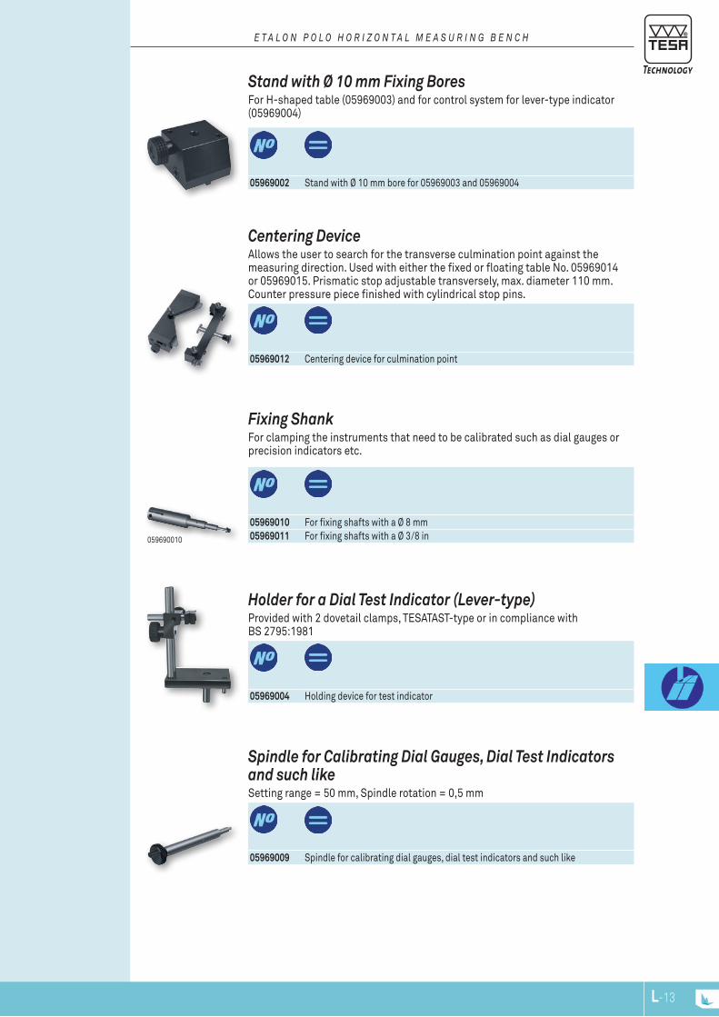
L-13
05969002 Stand with Ø 10 mm bore for 05969003 and 05969004
Stand with Ø 10 mm Fixing bores For H-shaped table (05969003) and for control system for lever-type indicator (05969004)
E T A l O n P O l O h O r I z O n T A l m E A S u r I n G b E n C h
Spindle for Calibrating Dial Gauges, Dial Test Indicators and such like Setting range = 50 mm, Spindle rotation = 0,5 mm
05969009 Spindle for calibrating dial gauges, dial test indicators and such like
Holder for a Dial Test Indicator (lever-type) Provided with 2 dovetail clamps, TESATAST-type or in compliance with BS 2795:1981
05969004 Holding device for test indicator
Fixing Shank For clamping the instruments that need to be calibrated such as dial gauges or precision indicators etc.
05969010 For fixing shafts with a Ø 8 mm05969011 For fixing shafts with a Ø 3/8 in059690010
Centering Device Allows the user to search for the transverse culmination point against the measuring direction. Used with either the fixed or floating table No. 05969014 or 05969015. Prismatic stop adjustable transversely, max. diameter 110 mm. Counter pressure piece finished with cylindrical stop pins.
05969012 Centering device for culmination point

L-14
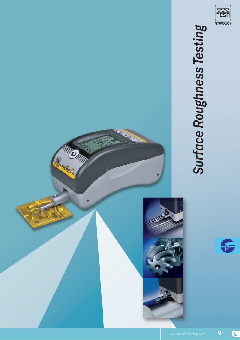
www.tesatechnology.com M-1M-NP
Surf
ace
Roug
hnes
s Tes
ting
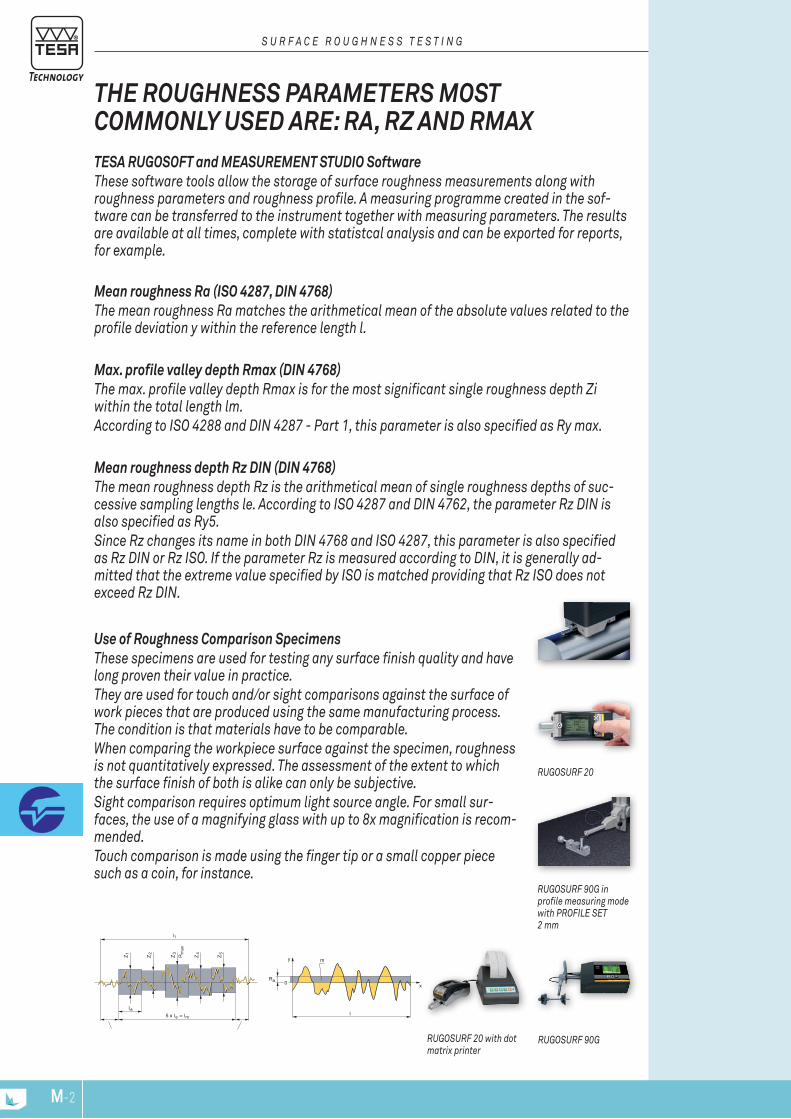
5 x l
Z Z Z Z Z
1 2 3 4 5max
R
l
= l
t
e
e m
I
0
l
y
Ra
m
x
M-3M-2
RUGOSURF 20 with dot matrix printer
RUGOSURF 90G in profile measuring mode with PROFILE SET 2 mm
RUGOSURF 90G
RUGOSURF 20
Use of Roughness Comparison Specimens These specimens are used for testing any surface finish quality and have long proven their value in practice. They are used for touch and/or sight comparisons against the surface of work pieces that are produced using the same manufacturing process. The condition is that materials have to be comparable. When comparing the workpiece surface against the specimen, roughness is not quantitatively expressed. The assessment of the extent to which the surface finish of both is alike can only be subjective. Sight comparison requires optimum light source angle. For small sur-faces, the use of a magnifying glass with up to 8x magnification is recom-mended. Touch comparison is made using the finger tip or a small copper piece such as a coin, for instance.
TESA RUGOSOFT and MEASUREMENT STUDIO Software These software tools allow the storage of surface roughness measurements along with roughness parameters and roughness profile. A measuring programme created in the sof-tware can be transferred to the instrument together with measuring parameters. The results are available at all times, complete with statistcal analysis and can be exported for reports, for example.
Mean roughness Ra (ISO 4287, DIN 4768)The mean roughness Ra matches the arithmetical mean of the absolute values related to the profile deviation y within the reference length l.
Max. profile valley depth Rmax (DIN 4768) The max. profile valley depth Rmax is for the most significant single roughness depth Zi within the total length lm.According to ISO 4288 and DIN 4287 - Part 1, this parameter is also specified as Ry max.
Mean roughness depth Rz DIN (DIN 4768) The mean roughness depth Rz is the arithmetical mean of single roughness depths of suc-cessive sampling lengths le. According to ISO 4287 and DIN 4762, the parameter Rz DIN is also specified as Ry5.Since Rz changes its name in both DIN 4768 and ISO 4287, this parameter is also specified as Rz DIN or Rz ISO. If the parameter Rz is measured according to DIN, it is generally ad-mitted that the extreme value specified by ISO is matched providing that Rz ISO does not exceed Rz DIN.
ThE ROUGhNESS PARAMETERS MOST COMMONly USED ARE: RA, Rz AND RMAx
S U R F A c E R O U G h N E S S T E S T I N G

M-3M-2
RUGOSURF 20
TESA offers a range of 3 portable RUGOSURF roughness gauges adapted for different levels of precision from the production floor to the test laboratory.These devices are particularly appreciated by operators for their ease of use, robustness and reliability.
The range includes data management software to process measured values for an optimal overview of roughness profiles, statistical data and customizable measurement reports.
RUGOSURF 20, RUGOSURF 10G, RUGOSURF 90G ROUGhNESS GAUGES
S U R F A c E R O U G h N E S S T E S T I N G
RUGOSURF 90G
RUGOSURF 10G
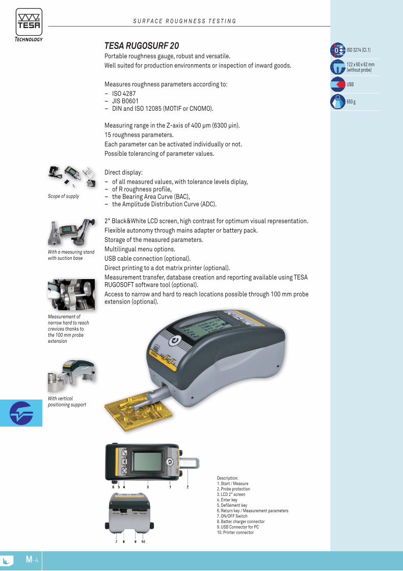
M-5M-4
S U R F A c E R O U G h N E S S T E S T I N G
With a measuring stand with suction base
Measurement of narrow hard to reach crevices thanks to the 100 mm probe extension
With vertical positioning support
Scope of supply
ISO 3274 (Cl.1)
122 x 60 x 62 mm (without probe)
USB
650 g
TESA RUGOSURF 20 Portable roughness gauge, robust and versatile. Well suited for production environments or inspection of inward goods.
Measures roughness parameters according to: – ISO 4287 – JIS B0601 – DIN and ISO 12085 (MOTIF or CNOMO).
Measuring range in the Z-axis of 400 μm (6300 μin).15 roughness parameters. Each parameter can be activated individually or not. Possible tolerancing of parameter values.
Direct display: – of all measured values, with tolerance levels diplay, – of R roughness profile, – the Bearing Area Curve (BAC), – the Amplitude Distribution Curve (ADC).
2" Black&White LCD screen, high contrast for optimum visual representation.Flexible autonomy through mains adapter or battery pack. Storage of the measured parameters. Multilingual menu options. USB cable connection (optional). Direct printing to a dot matrix printer (optional). Measurement transfer, database creation and reporting available using TESA RUGOSOFT software tool (optional). Access to narrow and hard to reach locations possible through 100 mm probe extension (optional).
Description:1. Start / Measure2. Probe protection3. LCD 2" screen 4. Enter key 5. Defilement key6. Return key / Measurement parameters 7. ON/OFF Switch 8. Batter charger connector 9. USB Connector for PC 10. Printer connector

M-5M-4
Measuring span, μm
Indication span, μm
Accuracy class
Measuring force, N
Resolution, µm
Display
Roughness parameters
Graphics
Cut-off lenght, mm
Number of cut-off
Stylus diamond tip (R = μm; angle °)
Memory capacity
Dimensions, mm
Degree of protection for keyboard (IP XX)
Digital data output (USB)
Weight, g
Included in delivery
Measuring response time
Probing speed, mm/s
Units
Power supply
06930013
TESA RUGOSURF 20 portable surface roughness tester for use in the workshopZ = ± 200 μm (± 0.0079 in) X = 16 mm (0.63 in)
400 μm (0.0157 in) on Z axis, 16 mm (0.63 in) on X axis
Ra = 0 ÷ 100 μm; Rt = 0,05 ÷ 400 μm
in accordance with ISO 3274 Class 1
0,75 mN in accordance with ISO 3274
0,001 μm
LCD 2" black/white (160 x 100 pixels)
DIN / ISO / JIS / ASME: Ra, Rq, Rt, Rc, RSm, RPcRmr, Rz, RmaxPPc, PmrMOTIF ISO 12085 (CNOMO): Pt, R, Rx, AR
Bearing Area Curve (BAC), Amplitude Distribution Curve (ADC), Profile-R
0,25 – 0,80 – 2,50 mm (0.010 – 0.030 – 0.100 in)
1 to 5
R = 5 μm, 90°
max 1000 measurements with parameters;max 20 mesurements with profile and graphics
122 x 60 x 62 mm
IP67 (membrane keyboard)
USB cable connector to PC
650 g
RUGOSURF 20SB10 standard skid probeRoughness standard Ra = 2,97 μmPositioning pin Ø 8 mm for use verticallyDetachable probe protectorIntegral rechargeable battery Charger and adapter EU/US User manual Plastic carrying and storage case
1 to 10 s
1 mm/s (2 mm/s probe retract to measuring position)
mm or inch
100 ÷ 240 VAC; 50 ÷ 60 Hz; 12 V, 400 ÷ 650 mAh
S U R F A c E R O U G h N E S S T E S T I N G
M-7M-6
OPTIONAL AccESSORIES:04760099 Cable RUGOSURF 20 to PC06960033 Printer for RUGOSURF + cables06960034 RUGOSOFT Software + Dongle06960035 Granite 400 x 250 mm with vertical support H150 mm, 25 kg, Grade 0
for Rugosurf 20 and 10G06960081 Probe SB10 2μm for RUGOSURF 20 and 10G
as SB10 but R = 2 μm06960037 SB20 probe for RUGOSURF 20 et 10G
for grooves of depth < 5 mm06960038 SB30 probe for RUGOSURF 20 and 10G
for small bores of Ø > 4 mm06960039 SB40 Probe for RUGOSURF 20 and 10G
V-shape for cylinders of Ø > 1 mm06960040 SB50 probe for RUGOSURF 20 and 10G
for concave surfaces and for measuring at 90° with RUGOSURF 10G06960057 SB110 probe for RUGOSURF 20 and 10G
for concave or convex surfaces, R > 5 mm06960056 100 mm extension for probe with skid for RUGOSURF 20, 10G, 90G06960064 Roughness standard Ra = 0,1 μm (4 μin)06960065 Roughness standard Ra = 0,5 μm (20 μin)06960066 Roughness standard Ra = 1,0 μm (40 μin)
STANDARD AccESSORIES:06960036 SB10 standard probe
for RUGOSURF 20 and 10G R = 5 µm, 90°
06960041 Roughness standard Ra = 2,97 μm (117 μin)06960045 Battery NiMH
7,2 V, 300 mAh, format PP3 for RUGOSURF 20 et 10G
057655 Vertical and adjustable positioning supports (2 parts) V-form for cylinder Ø > 100 mm for RUGOSURF 20
057941 Transport case with internal protection foam for RUGOSURF 20
S U R F A c E R O U G h N E S S T E S T I N G
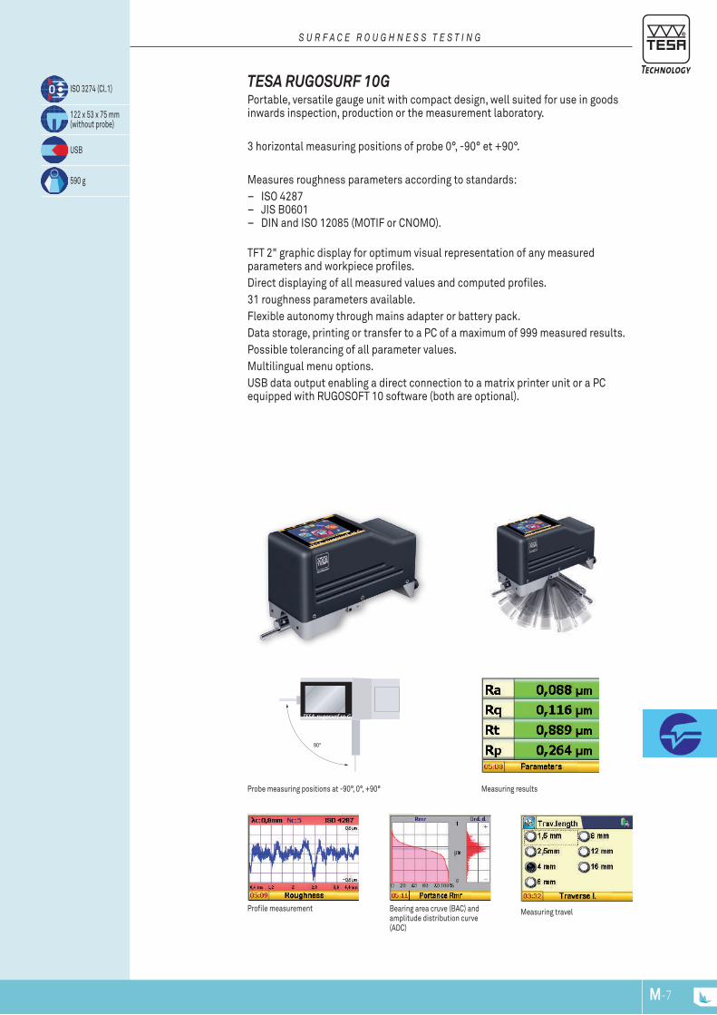
M-7M-6
Measuring travelProfile measurement
Measuring resultsProbe measuring positions at -90°, 0°, +90°
Bearing area cruve (BAC) and amplitude distribution curve (ADC)
TESA RUGOSURF 10G Portable, versatile gauge unit with compact design, well suited for use in goods inwards inspection, production or the measurement laboratory.
3 horizontal measuring positions of probe 0°, -90° et +90°.
Measures roughness parameters according to standards: – ISO 4287 – JIS B0601 – DIN and ISO 12085 (MOTIF or CNOMO).
TFT 2" graphic display for optimum visual representation of any measured parameters and workpiece profiles. Direct displaying of all measured values and computed profiles. 31 roughness parameters available. Flexible autonomy through mains adapter or battery pack. Data storage, printing or transfer to a PC of a maximum of 999 measured results. Possible tolerancing of all parameter values. Multilingual menu options. USB data output enabling a direct connection to a matrix printer unit or a PC equipped with RUGOSOFT 10 software (both are optional).
ISO 3274 (Cl.1)
122 x 53 x 75 mm (without probe)
USB
590 g
S U R F A c E R O U G h N E S S T E S T I N G
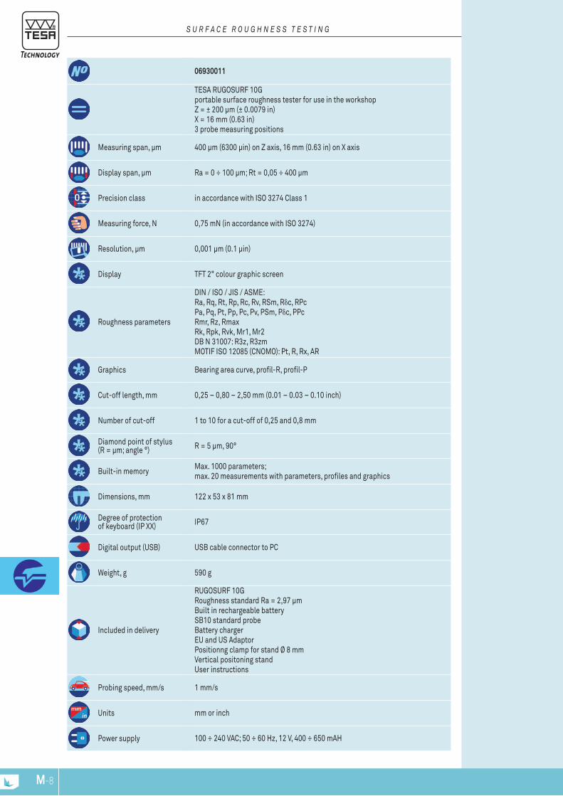
M-9M-8
Measuring span, μm
Display span, μm
Precision class
Measuring force, N
Resolution, µm
Display
Roughness parameters
Graphics
Cut-off length, mm
Number of cut-off
Diamond point of stylus (R = μm; angle °)
Built-in memory
Dimensions, mm
Degree of protection of keyboard (IP XX)
Digital output (USB)
Weight, g
Included in delivery
Probing speed, mm/s
Units
Power supply
06930011
TESA RUGOSURF 10G portable surface roughness tester for use in the workshop Z = ± 200 μm (± 0.0079 in) X = 16 mm (0.63 in) 3 probe measuring positions
400 μm (6300 μin) on Z axis, 16 mm (0.63 in) on X axis
Ra = 0 ÷ 100 μm; Rt = 0,05 ÷ 400 μm
in accordance with ISO 3274 Class 1
0,75 mN (in accordance with ISO 3274)
0,001 μm (0.1 μin)
TFT 2" colour graphic screen
DIN / ISO / JIS / ASME:Ra, Rq, Rt, Rp, Rc, Rv, RSm, Rδc, RPcPa, Pq, Pt, Pp, Pc, Pv, PSm, Pδc, PPcRmr, Rz, RmaxRk, Rpk, Rvk, Mr1, Mr2DB N 31007: R3z, R3zmMOTIF ISO 12085 (CNOMO): Pt, R, Rx, AR
Bearing area curve, profil-R, profil-P
0,25 – 0,80 – 2,50 mm (0.01 – 0.03 – 0.10 inch)
1 to 10 for a cut-off of 0,25 and 0,8 mm
R = 5 μm, 90°
Max. 1000 parameters;max. 20 measurements with parameters, profiles and graphics
122 x 53 x 81 mm
IP67
USB cable connector to PC
590 g
RUGOSURF 10GRoughness standard Ra = 2,97 μm Built in rechargeable batterySB10 standard probe Battery charger EU and US Adaptor Positionng clamp for stand Ø 8 mm Vertical positoning stand User instructions
1 mm/s
mm or inch
100 ÷ 240 VAC; 50 ÷ 60 Hz, 12 V, 400 ÷ 650 mAH
S U R F A c E R O U G h N E S S T E S T I N G
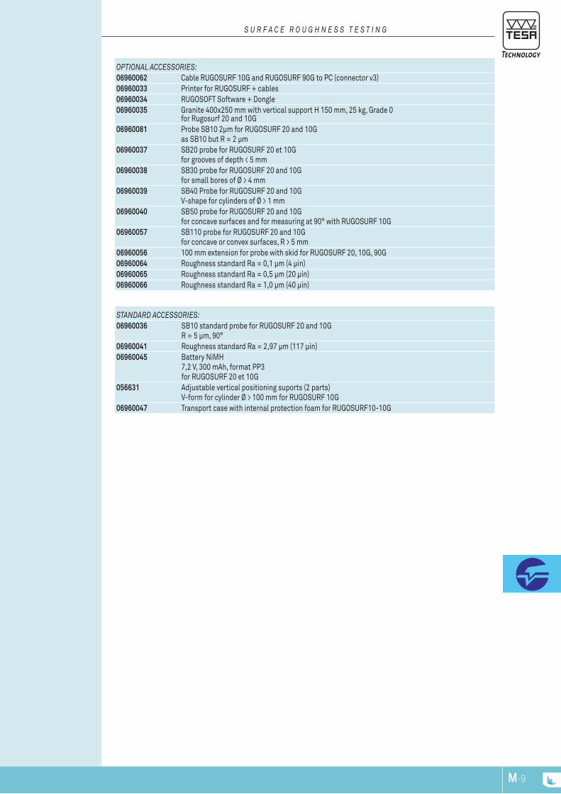
M-9M-8
OPTIONAL AccESSORIES:06960062 Cable RUGOSURF 10G and RUGOSURF 90G to PC (connector v3)06960033 Printer for RUGOSURF + cables06960034 RUGOSOFT Software + Dongle06960035 Granite 400x250 mm with vertical support H 150 mm, 25 kg, Grade 0
for Rugosurf 20 and 10G06960081 Probe SB10 2μm for RUGOSURF 20 and 10G
as SB10 but R = 2 μm06960037 SB20 probe for RUGOSURF 20 et 10G
for grooves of depth < 5 mm06960038 SB30 probe for RUGOSURF 20 and 10G
for small bores of Ø > 4 mm06960039 SB40 Probe for RUGOSURF 20 and 10G
V-shape for cylinders of Ø > 1 mm06960040 SB50 probe for RUGOSURF 20 and 10G
for concave surfaces and for measuring at 90° with RUGOSURF 10G06960057 SB110 probe for RUGOSURF 20 and 10G
for concave or convex surfaces, R > 5 mm06960056 100 mm extension for probe with skid for RUGOSURF 20, 10G, 90G06960064 Roughness standard Ra = 0,1 μm (4 μin)06960065 Roughness standard Ra = 0,5 μm (20 μin)06960066 Roughness standard Ra = 1,0 μm (40 μin)
STANDARD AccESSORIES:06960036 SB10 standard probe for RUGOSURF 20 and 10G
R = 5 µm, 90°06960041 Roughness standard Ra = 2,97 μm (117 μin)06960045 Battery NiMH
7,2 V, 300 mAh, format PP3 for RUGOSURF 20 et 10G
056631 Adjustable vertical positioning suports (2 parts)V-form for cylinder Ø > 100 mm for RUGOSURF 10G
06960047 Transport case with internal protection foam for RUGOSURF10-10G
S U R F A c E R O U G h N E S S T E S T I N G
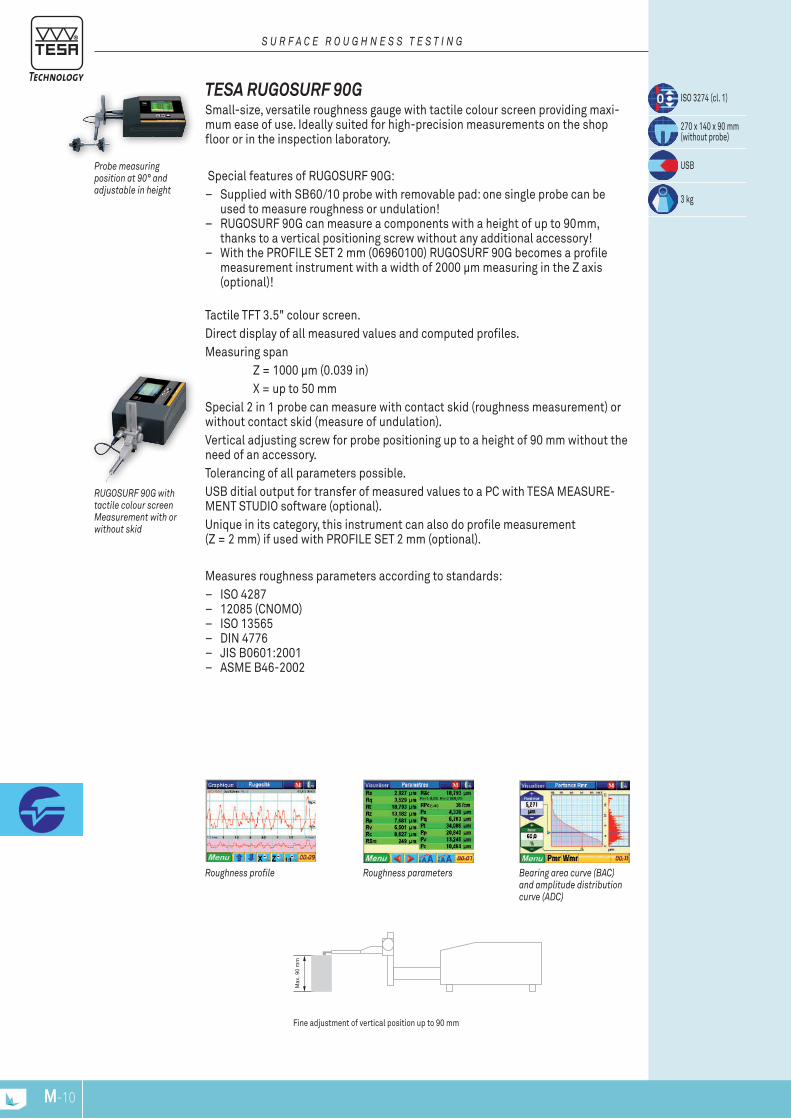
Max
. 90
mm
M-11M-10
Fine adjustment of vertical position up to 90 mm
TESA RUGOSURF 90G Small-size, versatile roughness gauge with tactile colour screen providing maxi-mum ease of use. Ideally suited for high-precision measurements on the shop floor or in the inspection laboratory.
Special features of RUGOSURF 90G: – Supplied with SB60/10 probe with removable pad: one single probe can be
used to measure roughness or undulation! – RUGOSURF 90G can measure a components with a height of up to 90mm,
thanks to a vertical positioning screw without any additional accessory! – With the PROFILE SET 2 mm (06960100) RUGOSURF 90G becomes a profile
measurement instrument with a width of 2000 μm measuring in the Z axis (optional)!
Tactile TFT 3.5" colour screen. Direct display of all measured values and computed profiles. Measuring span Z = 1000 μm (0.039 in) X = up to 50 mm Special 2 in 1 probe can measure with contact skid (roughness measurement) or without contact skid (measure of undulation). Vertical adjusting screw for probe positioning up to a height of 90 mm without the need of an accessory. Tolerancing of all parameters possible. USB ditial output for transfer of measured values to a PC with TESA MEASURE-MENT STUDIO software (optional). Unique in its category, this instrument can also do profile measurement (Z = 2 mm) if used with PROFILE SET 2 mm (optional).
Measures roughness parameters according to standards: – ISO 4287 – 12085 (CNOMO) – ISO 13565 – DIN 4776 – JIS B0601:2001 – ASME B46-2002
ISO 3274 (cl. 1)
270 x 140 x 90 mm (without probe)
USB
3 kg
Probe measuring position at 90° and adjustable in height
Bearing area curve (BAc) and amplitude distribution curve (ADc)
Roughness profile Roughness parameters
RUGOSURF 90G with tactile colour screen Measurement with or without skid
S U R F A c E R O U G h N E S S T E S T I N G
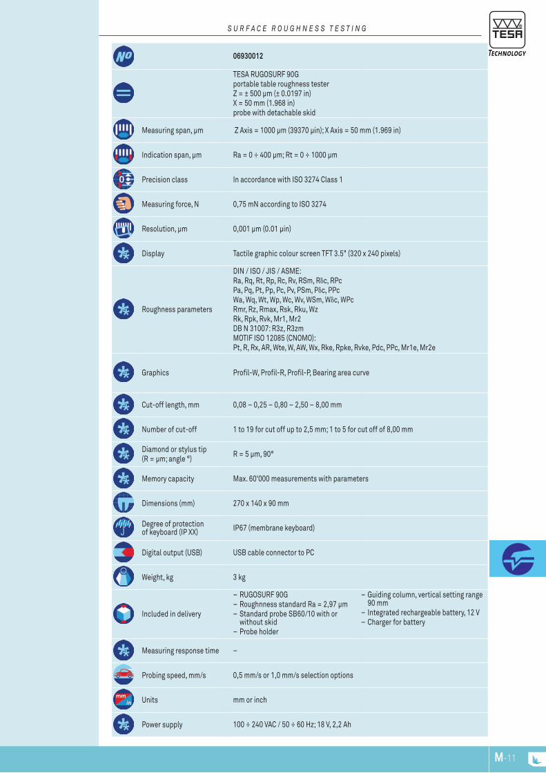
M-11M-10
Measuring span, μm
Indication span, μm
Precision class
Measuring force, N
Resolution, µm
Display
Roughness parameters
Graphics
Cut-off length, mm
Number of cut-off
Diamond or stylus tip (R = μm; angle °)
Memory capacity
Dimensions (mm)
Degree of protection of keyboard (IP XX)
Digital output (USB)
Weight, kg
Included in delivery
Measuring response time
Probing speed, mm/s
Units
Power supply
06930012
TESA RUGOSURF 90G portable table roughness tester Z = ± 500 μm (± 0.0197 in) X = 50 mm (1.968 in) probe with detachable skid
Z Axis = 1000 µm (39370 µin); X Axis = 50 mm (1.969 in)
Ra = 0 ÷ 400 µm; Rt = 0 ÷ 1000 µm
In accordance with ISO 3274 Class 1
0,75 mN according to ISO 3274
0,001 µm (0.01 µin)
Tactile graphic colour screen TFT 3.5" (320 x 240 pixels)
DIN / ISO / JIS / ASME:Ra, Rq, Rt, Rp, Rc, Rv, RSm, Rδc, RPcPa, Pq, Pt, Pp, Pc, Pv, PSm, Pδc, PPcWa, Wq, Wt, Wp, Wc, Wv, WSm, Wδc, WPcRmr, Rz, Rmax, Rsk, Rku, WzRk, Rpk, Rvk, Mr1, Mr2DB N 31007: R3z, R3zmMOTIF ISO 12085 (CNOMO):Pt, R, Rx, AR, Wte, W, AW, Wx, Rke, Rpke, Rvke, Pdc, PPc, Mr1e, Mr2e
Profil-W, Profil-R, Profil-P, Bearing area curve
0,08 – 0,25 – 0,80 – 2,50 – 8,00 mm
1 to 19 for cut off up to 2,5 mm; 1 to 5 for cut off of 8,00 mm
R = 5 µm, 90°
Max. 60'000 measurements with parameters
270 x 140 x 90 mm
IP67 (membrane keyboard)
USB cable connector to PC
3 kg
– RUGOSURF 90G – Roughnness standard Ra = 2,97 µm – Standard probe SB60/10 with or without skid
– Probe holder
– Guiding column, vertical setting range 90 mm
– Integrated rechargeable battery, 12 V – Charger for battery
–
0,5 mm/s or 1,0 mm/s selection options
mm or inch
100 ÷ 240 VAC / 50 ÷ 60 Hz; 18 V, 2,2 Ah
S U R F A c E R O U G h N E S S T E S T I N G
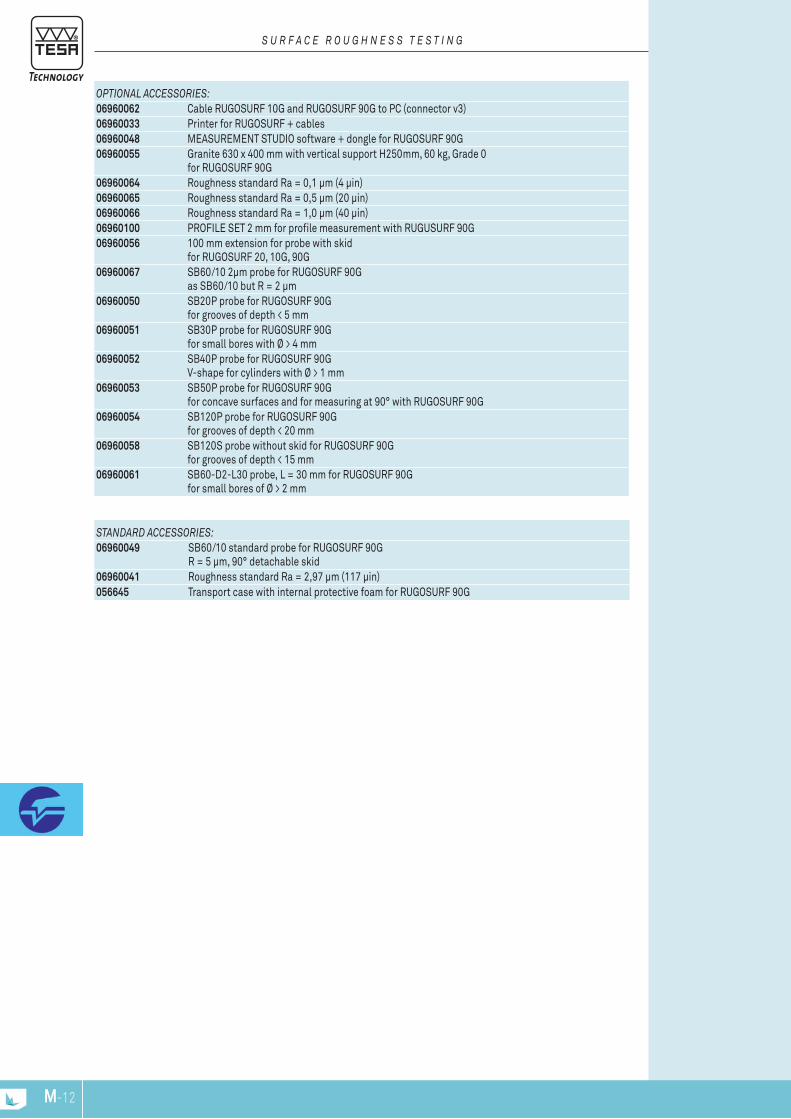
M-13M-12
OPTIONAL AccESSORIES:06960062 Cable RUGOSURF 10G and RUGOSURF 90G to PC (connector v3)06960033 Printer for RUGOSURF + cables06960048 MEASUREMENT STUDIO software + dongle for RUGOSURF 90G06960055 Granite 630 x 400 mm with vertical support H250mm, 60 kg, Grade 0
for RUGOSURF 90G06960064 Roughness standard Ra = 0,1 μm (4 μin)06960065 Roughness standard Ra = 0,5 μm (20 μin)06960066 Roughness standard Ra = 1,0 μm (40 μin)06960100 PROFILE SET 2 mm for profile measurement with RUGUSURF 90G06960056 100 mm extension for probe with skid
for RUGOSURF 20, 10G, 90G06960067 SB60/10 2μm probe for RUGOSURF 90G
as SB60/10 but R = 2 μm06960050 SB20P probe for RUGOSURF 90G
for grooves of depth < 5 mm06960051 SB30P probe for RUGOSURF 90G
for small bores with Ø > 4 mm06960052 SB40P probe for RUGOSURF 90G
V-shape for cylinders with Ø > 1 mm06960053 SB50P probe for RUGOSURF 90G
for concave surfaces and for measuring at 90° with RUGOSURF 90G06960054 SB120P probe for RUGOSURF 90G
for grooves of depth < 20 mm06960058 SB120S probe without skid for RUGOSURF 90G
for grooves of depth < 15 mm06960061 SB60-D2-L30 probe, L = 30 mm for RUGOSURF 90G
for small bores of Ø > 2 mm
STANDARD AccESSORIES:06960049 SB60/10 standard probe for RUGOSURF 90G
R = 5 µm, 90° detachable skid06960041 Roughness standard Ra = 2,97 μm (117 μin)056645 Transport case with internal protective foam for RUGOSURF 90G
S U R F A c E R O U G h N E S S T E S T I N G
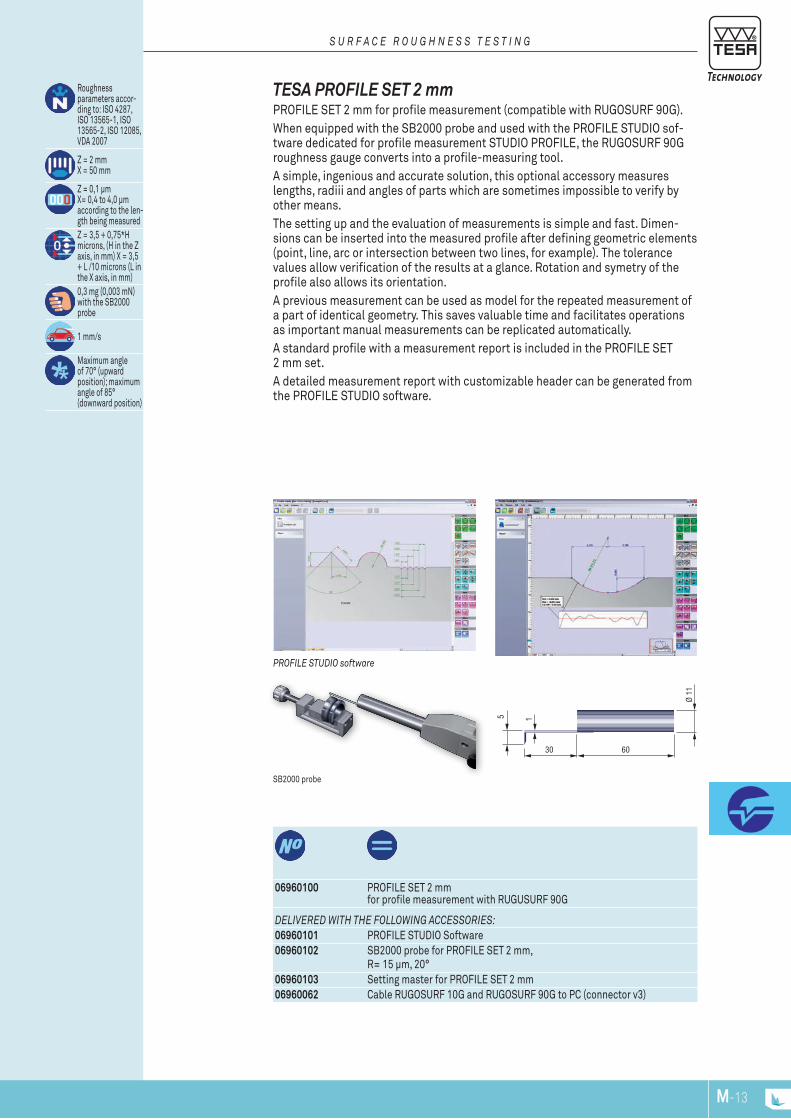
5
30
Ø 11
60
1
M-13M-12
06960100 PROFILE SET 2 mm for profile measurement with RUGUSURF 90G
DELIvERED WITh ThE FOLLOWING AccESSORIES:06960101 PROFILE STUDIO Software06960102 SB2000 probe for PROFILE SET 2 mm,
R= 15 µm, 20°06960103 Setting master for PROFILE SET 2 mm06960062 Cable RUGOSURF 10G and RUGOSURF 90G to PC (connector v3)
Roughness parameters accor-ding to: ISO 4287, ISO 13565-1, ISO 13565-2, ISO 12085, VDA 2007
Z = 2 mm X = 50 mm
Z = 0,1 μm X= 0,4 to 4,0 μmaccording to the len-gth being measuredZ = 3,5 + 0,75*H microns, (H in the Z axis, in mm) X = 3,5 + L /10 microns (L in the X axis, in mm)0,3 mg (0,003 mN) with the SB2000 probe
1 mm/s
Maximum angle of 70° (upward position); maximum angle of 85° (downward position)
SB2000 probe
PROFILE STUDIO software
TESA PROFIlE SET 2 mm PROFILE SET 2 mm for profile measurement (compatible with RUGOSURF 90G). When equipped with the SB2000 probe and used with the PROFILE STUDIO sof-tware dedicated for profile measurement STUDIO PROFILE, the RUGOSURF 90G roughness gauge converts into a profile-measuring tool.A simple, ingenious and accurate solution, this optional accessory measures lengths, radiii and angles of parts which are sometimes impossible to verify by other means. The setting up and the evaluation of measurements is simple and fast. Dimen-sions can be inserted into the measured profile after defining geometric elements (point, line, arc or intersection between two lines, for example). The tolerance values allow verification of the results at a glance. Rotation and symetry of the profile also allows its orientation. A previous measurement can be used as model for the repeated measurement of a part of identical geometry. This saves valuable time and facilitates operations as important manual measurements can be replicated automatically. A standard profile with a measurement report is included in the PROFILE SET 2 mm set.A detailed measurement report with customizable header can be generated from the PROFILE STUDIO software.
S U R F A c E R O U G h N E S S T E S T I N G
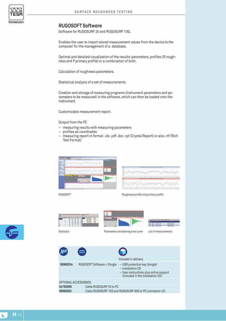
M-15M-14
06960034 RUGOSOFT Software + Dongle – USB protection key (dongle) – Installation CD – User instructions plus online support (included in the installation CD)
Included in delivery
OPTIONAL AccESSORIES:04760099 Cable RUGOSURF 20 to PC06960062 Cable RUGOSURF 10G and RUGOSURF 90G to PC (connector v3)
Statistics List of measurementsParameters and bearing area curve
Roughness profile and primary profileRUGOSOFT
RUGOSOFT Software Software for RUGOSURF 20 and RUGOSURF 10G.
Enables the user to import stored measurement values from the device to the computer for the management of a database.
Optimal and detailed visualization of the results: parameters, profiles (R rough-ness and P primary profile) or a combination of both.
Calculation of roughness parameters.
Statistical analysis of a set of measurements.
Creation and storage of measuring programs (instrument parameters and pa-rameters to be measured) in the software, which can then be loaded onto the instrument.
Customizable measurement report.
Output from the PC – measuring results with measuring parameters – profiles as coordinates – measuring report in format: .xls .pdf .doc .rpt (Crystal Report) or also .rtf (Rich
Text Format)
S U R F A c E R O U G h N E S S T E S T I N G
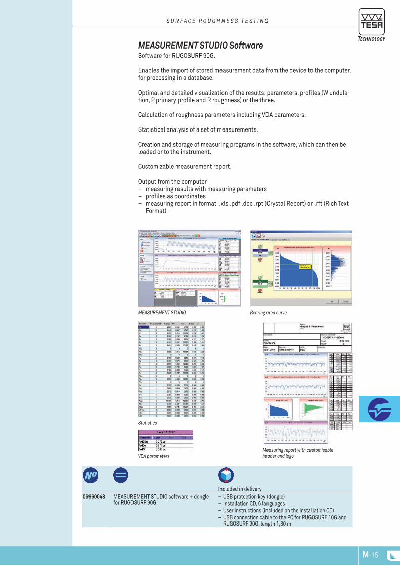
M-15M-14
06960048 MEASUREMENT STUDIO software + dongle for RUGOSURF 90G
– USB protection key (dongle) – Installation CD, 6 languages – User instructions (included on the installation CD) – USB connection cable to the PC for RUGOSURF 10G and RUGOSURF 90G, length 1,80 m
Included in delivery
Statistics
Measuring report with customisable header and logovDA parameters
Bearing area curveMEASUREMENT STUDIO
MEASUREMENT STUDIO Software Software for RUGOSURF 90G.
Enables the import of stored measurement data from the device to the computer, for processing in a database.
Optimal and detailed visualization of the results: parameters, profiles (W undula-tion, P primary profile and R roughness) or the three.
Calculation of roughness parameters including VDA parameters.
Statistical analysis of a set of measurements.
Creation and storage of measuring programs in the software, which can then be loaded onto the instrument.
Customizable measurement report.
Output from the computer – measuring results with measuring parameters – profiles as coordinates – measuring report in format .xls .pdf .doc .rpt (Crystal Report) or .rft (Rich Text
Format)
S U R F A c E R O U G h N E S S T E S T I N G

M-17M-16
CD with PROFILE STUDIO software06960101 PROFILE STUDIO Software CD with PROFILE STUDIO software
Included in delivery
OPTIONAL AccESSORIES:06960102 SB2000 probe for PROFILE SET 2 mm, R = 15 µm, 20°06960103 Setting master for PROFILE SET 2 mm06960062 Cable RUGOSURF 10G and RUGOSURF 90G to PC (connector v3)
Measurement of geometric elements PROFILE STUDIO software
PROFIlE STUDIO Software
For profile measurement using the RUGOSURF 90G.
Allows evaluation of micro and macro geometric characteristics of a surface.
Measurement programme creation that can be saved for the same measurements on a batch of identical parts from the same set or for subsequent batch measurements: it is possible to use all the dimensions and tolerances of a reference profile for a measurement of a batch of the same part.
Measurement instructions and help assistance for calibration controlled from the PC.
Import and export of measurement parameters from and to the device.
Storage of measurement results and of the measured parameters as database.
Database search with filters (date, operator, batch, etc.).
Detailed visualization of the measured profile and geometric construction tools (arc, line, point, intersection, angle, etc.).
Measurements reports with customizable header.
Languages: English, German, French, Spanish, Italian, Portuguese, Slovenian.
S U R F A c E R O U G h N E S S T E S T I N G

5,5
1,75
16 SB10
Ø 11
5
18
Ø 11
60
A2 3,2
16
Ø 11
60
2
M-17M-16
06960036 SB10 standard probe for RUGOSURF 20 and 10G R = 5 µm, 90°
06960049 SB60/10 standard probe fur RUGOSURF 90G R = 5 µm, 90° detachable skid
Unless otherwise stated, 90° diamond tip, radius R = 5 μm
Standard Probes Standard probes supplied with TESA surface roughness gauges and SB2000 probes for profile measurement
PRObES FOR TESA RUGOSURF Standard probes for TESA RUGOSURF roughness gauges, available with different geometries and sizes according to the nature and type of surface being measured.
S U R F A c E R O U G h N E S S T E S T I N G
SB2000 probe without skidSB60/10 probe with removable skid for RUGOSURF 90G
SB10 probe
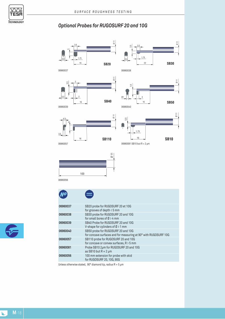
5,5
3
16 SB50
Ø 11
Ø2
5,5
1,75
16 SB10
Ø 11
100
Ø 11
5
1,75
16 SB20
Ø 11
3,6
3,6
3,5
1,75
22 SB30
Ø 11
3,5
2,5
5,5
2
16 SB40
Ø 11
3,5
3
8
16 SB110
Ø 1
1
3,5
4,5
M-19M-18
06960037 SB20 probe for RUGOSURF 20 et 10G for grooves of depth < 5 mm
06960038 SB30 probe for RUGOSURF 20 and 10G for small bores of Ø > 4 mm
06960039 SB40 Probe for RUGOSURF 20 and 10G V-shape for cylinders of Ø > 1 mm
06960040 SB50 probe for RUGOSURF 20 and 10G for concave surfaces and for measuring at 90° with RUGOSURF 10G
06960057 SB110 probe for RUGOSURF 20 and 10G for concave or convex surfaces, R > 5 mm
06960081 Probe SB10 2μm for RUGOSURF 20 and 10G as SB10 but R = 2 μm
06960056 100 mm extension for probe with skid for RUGOSURF 20, 10G, 90G
Unless otherwise stated, 90° diamond tip, radius R = 5 μm
06960057
06960039
0696003806960037
Optional Probes for RUGOSURF 20 and 10G
S U R F A c E R O U G h N E S S T E S T I N G
06960056
06960081 SB10 but R = 2 μm
06960040
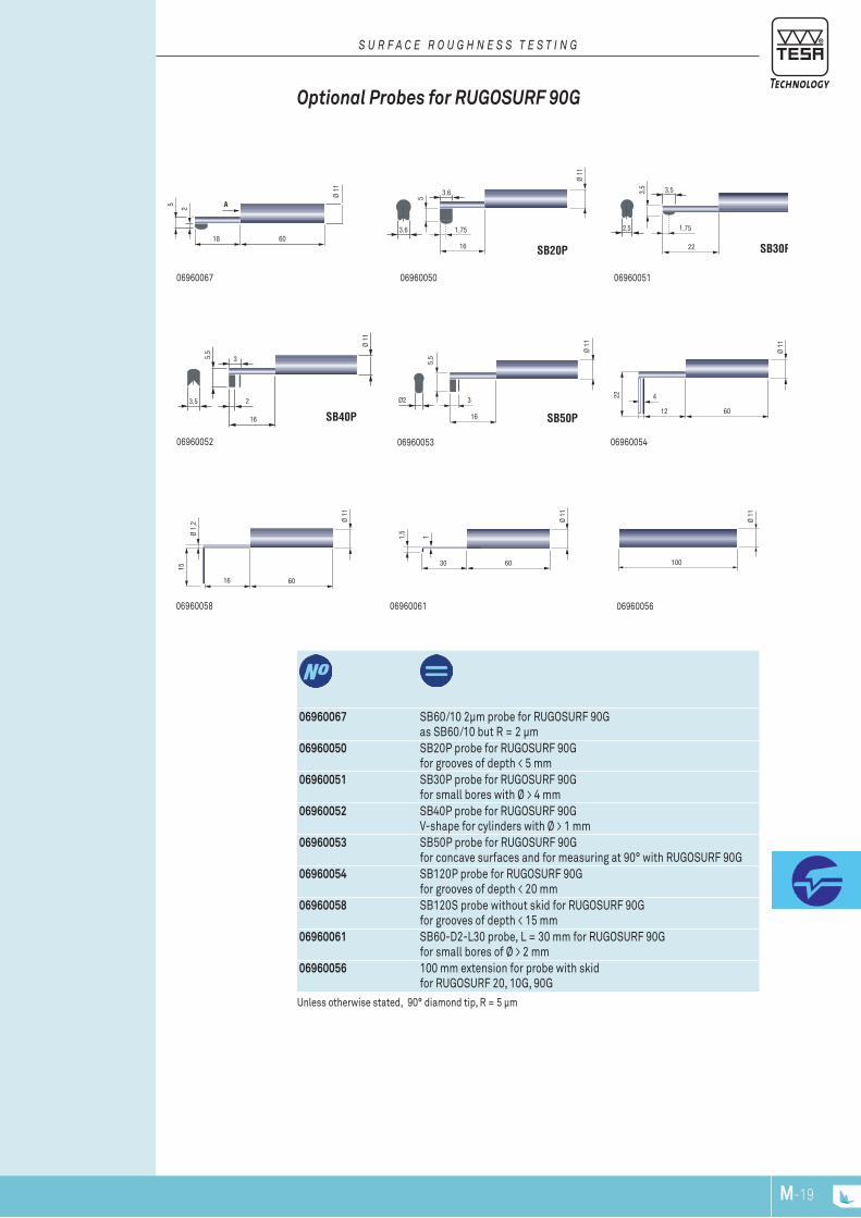
5
18
Ø 11
60
A2
5
1,75
16 SB20P
Ø 11
3,6
3,6 3,5
1,75
22 SB30P
Ø 11
2,5
3,5
5,5
2
16 SB40P
Ø 11
3,5
3 5,5
3
16 SB50P
Ø 11
Ø2
12
Ø 11
60
422
16
Ø 11
60
15
Ø 1,
2
100
Ø 11
1,5
30Ø
1160
1
M-19M-18
06960067 SB60/10 2μm probe for RUGOSURF 90G as SB60/10 but R = 2 μm
06960050 SB20P probe for RUGOSURF 90G for grooves of depth < 5 mm
06960051 SB30P probe for RUGOSURF 90G for small bores with Ø > 4 mm
06960052 SB40P probe for RUGOSURF 90G V-shape for cylinders with Ø > 1 mm
06960053 SB50P probe for RUGOSURF 90G for concave surfaces and for measuring at 90° with RUGOSURF 90G
06960054 SB120P probe for RUGOSURF 90G for grooves of depth < 20 mm
06960058 SB120S probe without skid for RUGOSURF 90G for grooves of depth < 15 mm
06960061 SB60-D2-L30 probe, L = 30 mm for RUGOSURF 90G for small bores of Ø > 2 mm
06960056 100 mm extension for probe with skid for RUGOSURF 20, 10G, 90G
Optional Probes for RUGOSURF 90 G
Unless otherwise stated, 90° diamond tip, R = 5 μm
S U R F A c E R O U G h N E S S T E S T I N G
06960052 06960054
06960058 06960061
06960067 06960051
06960053
06960050
06960056

M-21M-20
Characteristics Dimensions
L x W x H, mmWeight, g Included in delivery
06960033 Printer for RUGOSURF + cables
Print-out of measured parameters
165 x 120 x H100 mm (6.50 x 4.72 x H3.94 in)
760 g (only printer)
– Printer – Cables for connection to the RUGOSURF – Ink ribbon – Roll of paper – Rechargeable battery – User instructions – Transport case
DELIvERED WITh ThE FOLLOWING AccESSORIES:056109 Connecting cable RUGOSURF 10G and RUGOSURF 90G to dot matrix printer058213 Connecting cable RUGOSURF 20 to dot matrix printer
Roughness parameters measured
Roughness profile
Measuring results and graphics with header
PR dot matrix portable printer for RUGOSURF
PR Dot Matrix Printer Dot matrix printer for TESA RUGOSOFT roughness gauges.For printing measured parameters, and roughness profiles.Also for printing measurement data saved in the instrument memory.
DOT MATRIx PRINTER FOR RUGOSURF Dot matrix printer for TESA RUGOSURF portable roughness gauges and with built-in batteries, which enable the printing of measured parameters and roughness profiles regardless of the environment and the conditions.
It is also possible to print stored measurements data from the instrument memory.
S U R F A c E R O U G h N E S S T E S T I N G

M-21M-20
06960043 Set of 3x ink ribbons for dot matrix printer06960044 Set of 10 paper rolls
size 57 mm for dot matrix printer056133 Power supply 100 ÷ 240 V, 50 ÷ 60 Hz, 0,5 Ah,
Output 9 V DC, max. 18 W, 5,5 mm connector with EU and US adapter,for PR dot matrix printer
056223 Transport case with foam for internal protection of PR dot matrix printer
06960044
Accessories for PR Dot Matrix Printer Ink ribbon for printer Paper roll Battery Transport case
S U R F A c E R O U G h N E S S T E S T I N G
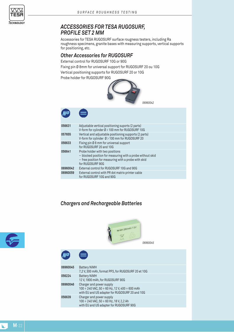
M-23M-22
06960045 Battery NiMH 7,2 V, 300 mAh, format PP3, for RUGOSURF 20 et 10G
056224 Battery NiMH 12 V, 1800 mAh, for RUGOSURF 90G
06960046 Charger and power supply 100 ÷ 240 VAC, 50 ÷ 60 Hz, 12 V, 400 ÷ 600 mAh with EU and US adapter for RUGOSURF 20 and 10G
056639 Charger and power supply 100 ÷ 240 VAC, 50 ÷ 60 Hz, 18 V, 2,2 Ah with EU and US adapter for RUGOSURF 90G
06960045
Chargers and Rechargeable batteries
056631 Adjustable vertical positioning suports (2 parts)V-form for cylinder Ø > 100 mm for RUGOSURF 10G
057655 Vertical and adjustable positioning supports (2 parts) V-form for cylinder Ø > 100 mm for RUGOSURF 20
056633 Fixing pin Ø 8 mm for universal support for RUGOSURF 20 and 10G
056641 Probe holder with two positions – blocked position for measuring with a probe without skid – free position for measuring with a probe with skid
for RUGOSURF 90G06960042 External control for RUGOSURF 10G and 90G06960059 External control with PR dot matrix printer cable
for RUGOSURF 10G and 90G
06960042
Other Accessories for RUGOSURF External control for RUGOSURF 10G or 90G Fixing pin Ø 8mm for universal support for RUGOSURF 20 ou 10G Vertical positioning supports for RUGOSURF 20 or 10G Probe holder for RUGOSURF 90G
ACCESSORIES FOR TESA RUGOSURF , PROFIlE SET 2 MMAccessories for TESA RUGOSURF surface rougness testers, including Ra roughness specimens, granite bases with measuring supports, vertical supports for positioning, etc.
S U R F A c E R O U G h N E S S T E S T I N G

M-23M-22
06960035 Granite 400 x 250 mm with vertical support H 150 mm, 25 kg, Grade 0 for Rugosurf 20 and 10G
06960055 Granite 630 x 400 mm with measuring support and manual vertical positioning device H250mm, 60 kg, Grade 0 for RUGOSURF 90G
Granite base with measuring support for RUGOSURF 90G with manual vertical positioning device
Granite base with measuring support for RUGOSURF 20 or 10G
Granite bases with Measuring Support for RUGOSURF
S U R F A c E R O U G h N E S S T E S T I N G
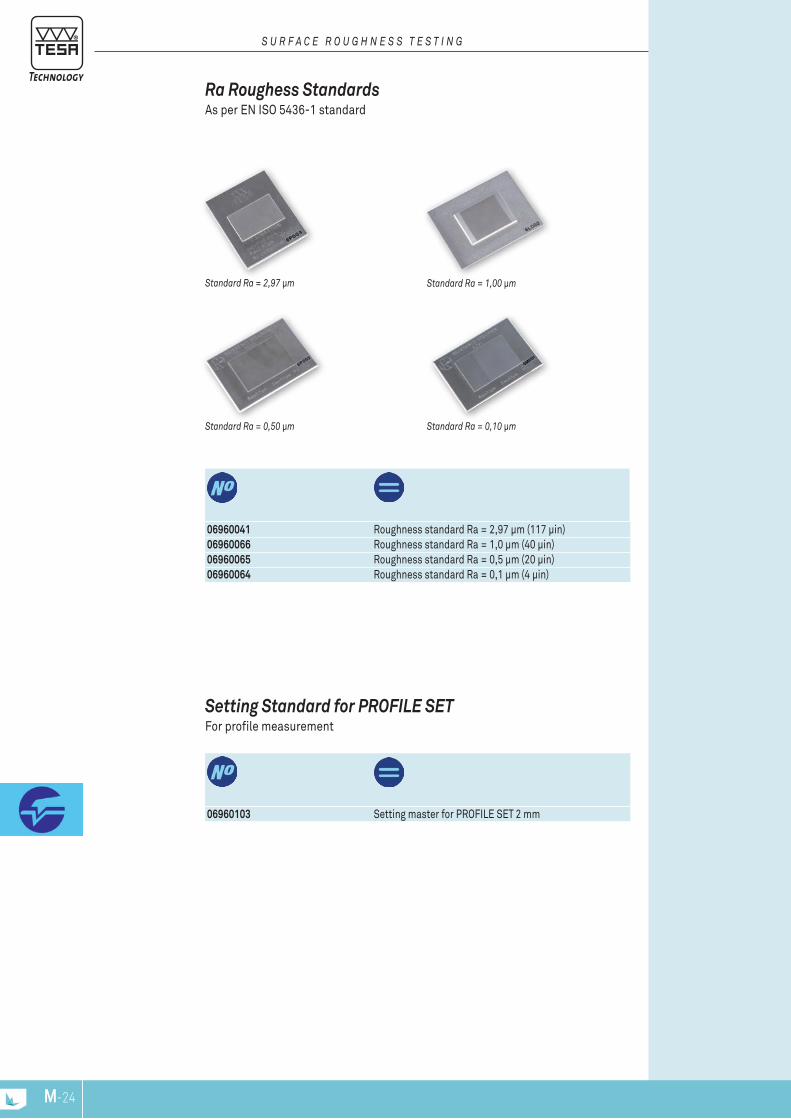
M-25M-24
06960103 Setting master for PROFILE SET 2 mm
Setting Standard for PROFIlE SET For profile measurement
06960041 Roughness standard Ra = 2,97 μm (117 μin)06960066 Roughness standard Ra = 1,0 μm (40 μin)06960065 Roughness standard Ra = 0,5 μm (20 μin)06960064 Roughness standard Ra = 0,1 μm (4 μin)
Standard Ra = 0,10 μmStandard Ra = 0,50 μm
Standard Ra = 1,00 μmStandard Ra = 2,97 μm
Ra Roughess Standards As per EN ISO 5436-1 standard
S U R F A c E R O U G h N E S S T E S T I N G

M-25M-24
RUGOTEST N°
Number of samples
ISO roughness parameters
Dimen-sions, mm
g Included in delivery
081112053 RUGOTEST 1 1 27 M1 - N10 135 x 105 160 Side milling (3 specimens), N8-N9-N10; Face milling (5 specimens), N6-N7-N8-N9-N10; Turning/Planing (5 specimens), N6-N7-N8-N9-N10; Grinding (6 specimens), N2-N3-N4-N5-N6-N7; Lapping (4 specimens), N2-N3-N4-N5; Finish grinding / honing (4 specimens), N1-N2-N3-N4
081112054 RUGOTEST 2 2 16 N6 - N11 120 x 90 160 081112055 RUGOTEST 3 3 18 N6 - N11 120 x 90 190 With samples for shot blasting,
spherical coarse grains (3 speci-mens), N9-N10-N11; With samples for shot blasting, spherical fine grains (6 speci-mens), N6-N7-N8-N9-N10-N11; With samples for shot blasting, angular coarse grains (3 speci-mens), N9-N10-N11; With samples for shot blasting, angular fine grains (6 speci-mens), N6-N7-N8-N9-N10-N11
081112056 RUGOTEST 4 4 6 N6 - N8 120 x 90 160 Straight filing (3 specimens), N6-N7-N8; Cross filing (3 specimens), N6-N7-N8
081112057 RUGOTEST 5 5 10 N0 - N4 120 x 90 200 Surface cylindrical form (5 speci-mens), N0-N1-N2-N3-N4; Surface flat form (5 specimens), N0-N1-N2-N3-N4;
081112058 RUGOTEST 101 Sanding
101 6 N6 - N11 110 x 50 110
081112059 RUGOTEST 102 Turning
102 6 N5 - N10 110 x 50 105
081112060 RUGOTEST 103 Face milling
103 6 N5 - N10 110 x 50 110
081112061 RUGOTEST 104 104 8 N1 - N8 130 x 50 125 081112062 RUGOTEST 105
Circular grinding105 8 N1 - N8 130 x 50 130
081112063 RUGOTEST 107 Spark erosion
107 6 N5 - N10 110 x 50 110
081112344 RUGOTEST Spark erosion
12 12 Charmilles 12 to 45
127 x 27 60
081112346 RUGOTEST A4 Set of 4 sets of sur-face specimens with RUGOTEST 1, 2, 3 and 4
330 x 250 710
081112345 RUGOTEST A6 Set of 6 sets of sur-face specimens with RUGOTEST 101, 102, 103, 104, 105, 107
330 x 250 780
ISO 2632 Parts 1 and 2
Rust-resistant nickel
Specimens for roughness com-parison cannot be used as reference ones. Therefore, they are not suitable for calibrating surface roughness testers.
Leather case
RUGOTEST Roughness Comparison Specimens For tactile and visual comparison of the workpiece surface finish according to various machining processes.
The specimen sets are according to individual machining processes.
ISO 2632-1 and 2632-2
S U R F A c E R O U G h N E S S T E S T I N G

M-NPM-26
ISO 2632 Parts 1 and 2
Rust-resistant nickel
The comparison specimens are not roughness standards. They should not be used for the calibration of surface roughness instruments
Leather case
S U R F A c E R O U G h N E S S T E S T I N G
ISO Roughness Parameters
Roughness Raµm (µin)
Charmilles Roughness Parameters(VDI 3400)
Roughness Raµm
N0 0,0125(0.5)
12 0,40
N1 0,025(1)
15 0,56
N2 0,05(2)
18 0,80
N3 0,1(4)
21 1,12
N4 0,2(8)
24 1,60
N5 0,4(16)
27 2,24
N6 0,8(32)
30 3,15
N7 1,6(63)
33 4,5
N8 3,2(125)
36 6,3
N9 6,3(250)
39 9,0
N10 12,5(500)
42 12,5
N11 25,0(1000)
45 18,0
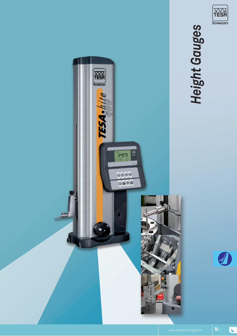
www.tesatechnology.com N-1N-NP
Hei
ght G
auge
s

N-3N-2
Height Gauges – One of TESA’s StrengthsTESA offers the largest range of height gauges for reliable one or two-dimensional measurements. End users can choose the most suitable model not only according to the requirements of their metrology applications, but also according to their financial resources.This wide range goes from the simple height and scri-bing gauge to the motorised vertical column suitable for high-precision measurements in two coordinate directions.
SCS Calibration Certificate The newly implemented TESA-HITE and TESA MICRO-HITE production line now also includes its own temperature-controlled laboratory recently certified by the Swiss Accreditation Service (SCS), so that each height gauge comes with a SCS calibration certificate provided free of charge.The negligible temperature variation along with the use of high-precision step gauges allow the lowest uncertainty of measurement to be achieved during the calibration process.As a first step, all values needed for automatic com-pensation for the systematic errors of the finished height gauge through Computer Aided Accuracy (CAA) are captured.Once conveniently calculated, each single compen-sation value is then stored in the tool memory so as to allow the automatic calculation of the measured values during calibration.Finally, the relevant calibration certificate is issued based on the values obtained during a new series of measurements taken at another measuring station, also equipped with step gauges. The applied calibra-tion procedure together with the SCS based certifica-tion ensure that every TESA height gauge is traceable to national standards.
Height gauges are single-axis handtools made to measure on a surface plate, preferably on granite. The TESA-μHITE version being offered in this section clearly shows that combining a surface plate with any height gauge can create a complete measuring system.Providing the necessary versatility, they are well suited for dimensional inspection directly on a machine or a group of machines, usually during the various setting and sampling opera-tions throughout the whole manufacturing process.They are specially made for checking parts that are difficult to machine due to their critical sizes.
TESA-HITE or TESA MICRO-HITE, whether manually operated or motor- driven, do not require any special skills. Nearly everyone working in the workshop can use them easily.
INSPECTION DURING THE COURSE OF THE MANU-FACTURING PROCESS
H E I g H T g A u g E S
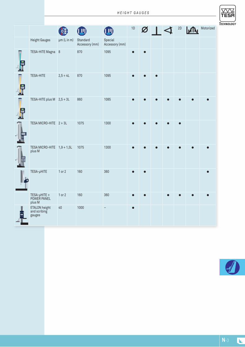
N-3N-2
H E I g H T g A u g E S
1D 2D Motorized
Height Gauges µm (L in m) Standard Accessory (mm)
Special Accessory (mm)
TESA-HITE Magna 8 870 1095
TESA-HITE 2,5 + 4L 870 1095
TESA-HITE plus M 2,5 + 3L 860 1085
TESA MICRO-HITE 2 + 3L 1075 1300
TESA MICRO-HITE plus M
1,9 + 1,5L 1075 1300
TESA-µHITE 1 or 2 160 360
TESA-µHITE + POWER PANEL plus M
1 or 2 160 360
ETALON height and scribing gauges
40 1000 –
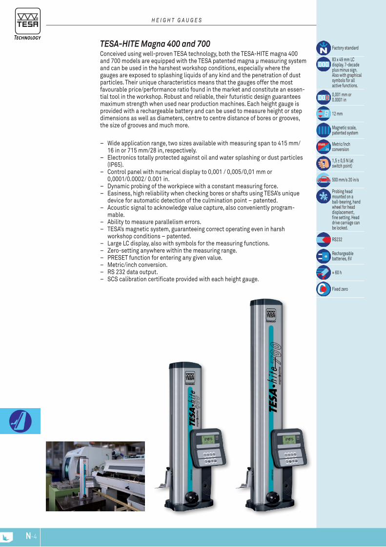
N-5N-4
TESA-HITE Magna 400 and 700 Conceived using well-proven TESA technology, both the TESA-HITE magna 400 and 700 models are equipped with the TESA patented magna μ measuring system and can be used in the harshest workshop conditions, especially where the gauges are exposed to splashing liquids of any kind and the penetration of dust particles. Their unique characteristics means that the gauges offer the most favourable price/performance ratio found in the market and constitute an essen-tial tool in the workshop. Robust and reliable, their futuristic design guarantees maximum strength when used near production machines. Each height gauge is provided with a rechargeable battery and can be used to measure height or step dimensions as well as diameters, centre to centre distance of bores or grooves, the size of grooves and much more.
– Wide application range, two sizes available with measuring span to 415 mm/ 16 in or 715 mm/28 in, respectively.
– Electronics totally protected against oil and water splashing or dust particles (IP65).
– Control panel with numerical display to 0,001 / 0,005/0,01 mm or 0,0001/0.0002/ 0.001 in.
– Dynamic probing of the workpiece with a constant measuring force. – Easiness, high reliability when checking bores or shafts using TESA’s unique
device for automatic detection of the culmination point – patented. – Acoustic signal to acknowledge value capture, also conveniently program-
mable. – Ability to measure parallelism errors. – TESA’s magnetic system, guaranteeing correct operating even in harsh
workshop conditions – patented. – Large LC display, also with symbols for the measuring functions. – Zero-setting anywhere within the measuring range. – PRESET function for entering any given value. – Metric/inch conversion. – RS 232 data output. – SCS calibration certificate provided with each height gauge.
Factory standard
83 x 49 mm LC display. 7-decade plus minus sign. Also with graphical symbols for allactive functions.
0,001 mm or 0.0001 in
12 mm
Magnetic scale, patented system
Metric/Inch conversion
1,5 ± 0,5 N (at switch point)
500 mm/s 20 in/s
Probing head mounted on a ball-bearing, hand wheel for head displacement,fine setting. Head drive carriage can be locked.
RS232
Rechargeable batteries, 6V
≈ 60 h
Fixed zero
H E I g H T g A u g E S

73
20
ø6
2522
52
ø6
ø5
82
ø40
22
6,35
10
N-5N-4
0076023100760164 00760143
Standard Accessories
Technical Data
Models TESA-HITE magna 400
TESA-HITE magna 700
mmin
41516
71528
With standard accessory mmin
0 ÷ 5700 ÷ 22
0 ÷ 8700 ÷ 34
With probe insert holder No. 00760057
mmin
0 ÷ 6250 ÷ 24
0 ÷ 9250 ÷ 36
With probe insert holder No. S07001622
mmin
0 ÷ 7950 ÷ 31
0 ÷ 10950 ÷ 43
With standard accessory µmin
< 8< 0.0003
< 8< 0.0003
With standard accessory On flat surfaces:2 σ = < 3µm / < 0.00015 inInto bores:2 σ = < 5µm / < 0.00020 in
kg 15 18
Linear expansion (12 ± 1,5) x 10-6 K-1
100 %
IP55 or IP65 for both electronics and measuring system (IEC 60529)
SCS calibration certificate
OPTIONAl ACCESSORIES:04761052 Extension cable, Sub-D 9p/f to 9p/m, 2 m04761063 Sub-D 9p/m to USB cable, 2 m
CONSISTINg OF: 400 70000760143 Standard probe insert holder00760157 Rechargeable battery, 6V00760164 Standard probe insert with 5 mm dia. steel ball tip00760231 Master piece for establishing the probe constant, nominal
dimension 6,350 mm / 0.250 in04761054 Mains adapter 100 ÷ 200 VAC / 50 ÷ 60 Hz04761055 Cable EU for mains adapter 04761056 Cable US for mains adapter
00730047 Height gauge TESA-HITE magna 400 415 1600730059 Height gauge TESA-HITE magna 700 715 28
mm in
H E I g H T g A u g E S
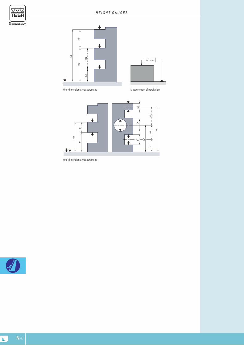
h1
h2
b1
h1a1
b2
h3
h2
a2
b1Ø
h1
h4
h2h5
h3 .....
N-7N-6
Measurement of parallelismOne-dimensional measurement
One-dimensional measurement
H E I g H T g A u g E S

N-7N-6
TESA-HITE 400 / 700 By their robustness and reliability, the TESA-HITE 400 and 700 provided with its optoelectronic incremental rule (TESA patented) measurement system are ideally suited for applications in the workshop. Their battery power gives them full autonomy. Each version allows, among other things, the entry height dimensions or staged, the diameter, the distance between two grooves or two holes and groove width.
– Integrated air-bearing for easy displacement across the granite plate. – Electronics totally protected against oil and water splashing, dust particles
(IP65). – Control panel with numerical display to 0,0001 / 0,001 / 0,01 mm or 0.00001 /
0.0001 / 0.001 in. – Dynamic probing of the workpiece with a constant measuring force. – Easiness, high reliability when checking bores or shafts using TESA’s unique
device for automatic detection of the culmination point – patented. – Acoustic signal to acknowledge value capture, also conveniently program-
mable. – Ability to measure any deviation in parallelism. – Possible use of a digital sensor for determining perpendicularity errors with
stated angle of the linear regression line. – Patented TESA’s opto-electronic system. Long-lasting stability of the glass
scale for unbroken high accuracy. – Large LC display with symbols for the measuring functions. – Zero-setting anywhere within the measuring range. – PRESET function for entering any given value. – Metric/inch conversion. – RS 232 data output. – SCS calibration certificate provided with each height gauge.
Factory standard
83 x 49 mm LC display. 7-decade plus minus sign. Also with graphical symbols for allactive functions.
0,0001 mm or 0.00001 in
12 mm
Incremental glass scale, opto-elec-tronic
mm/In conversion
1,5 ± 0,5 N (at switch point)
500 mm/s 20 in/s
Air-cushionfor easydisplacementover the surface plate.Probing head mounted on a ball-bearing, hand wheel for head displacement, fine setting. Head drive carriage can be locked.
RS232
Rechargeable batteries, 6V
≈ 60 h
Fixed zero
H E I g H T g A u g E S
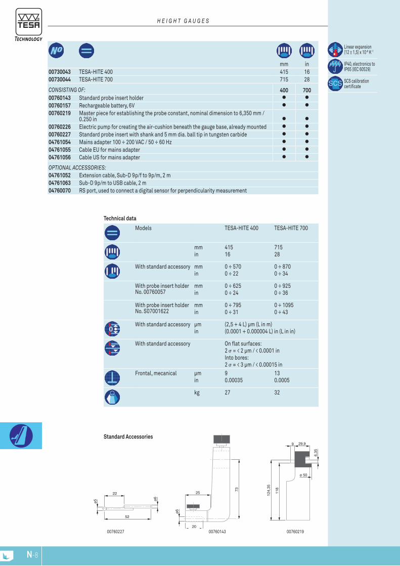
22
52
ø6ø5
29,9
118
124,
35
ø 50
9
6,35
73
20
ø6
25
N-9N-8
0076021900760227 00760143
Standard Accessories
OPTIONAl ACCESSORIES:04761052 Extension cable, Sub-D 9p/f to 9p/m, 2 m04761063 Sub-D 9p/m to USB cable, 2 m04760070 RS port, used to connect a digital sensor for perpendicularity measurement
CONSISTINg OF: 400 70000760143 Standard probe insert holder00760157 Rechargeable battery, 6V00760219 Master piece for establishing the probe constant, nominal dimension to 6,350 mm /
0.250 in00760226 Electric pump for creating the air-cushion beneath the gauge base, already mounted00760227 Standard probe insert with shank and 5 mm dia. ball tip in tungsten carbide04761054 Mains adapter 100 ÷ 200 VAC / 50 ÷ 60 Hz04761055 Cable EU for mains adapter04761056 Cable US for mains adapter
Linear expansion (12 ± 1,5) x 10-6 K-1
IP40, electronics to IP65 (IEC 60529)
SCS calibration certificate
Technical data
Models TESA-HITE 400 TESA-HITE 700
mmin
41516
71528
With standard accessory mmin
0 ÷ 5700 ÷ 22
0 ÷ 8700 ÷ 34
With probe insert holder No. 00760057
mmin
0 ÷ 6250 ÷ 24
0 ÷ 9250 ÷ 36
With probe insert holder No. S07001622
mmin
0 ÷ 7950 ÷ 31
0 ÷ 10950 ÷ 43
With standard accessory µmin
(2,5 + 4 L) µm (L in m)(0.0001 + 0.000004 L) in (L in in)
With standard accessory On flat surfaces:2 σ = < 2 µm / < 0.0001 inInto bores: 2 σ = < 3 µm / < 0.00015 in
Frontal, mecanical µmin
90.00035
130.0005
kg 27 32
00730043 TESA-HITE 400 415 1600730044 TESA-HITE 700 715 28
mm in
H E I g H T g A u g E S
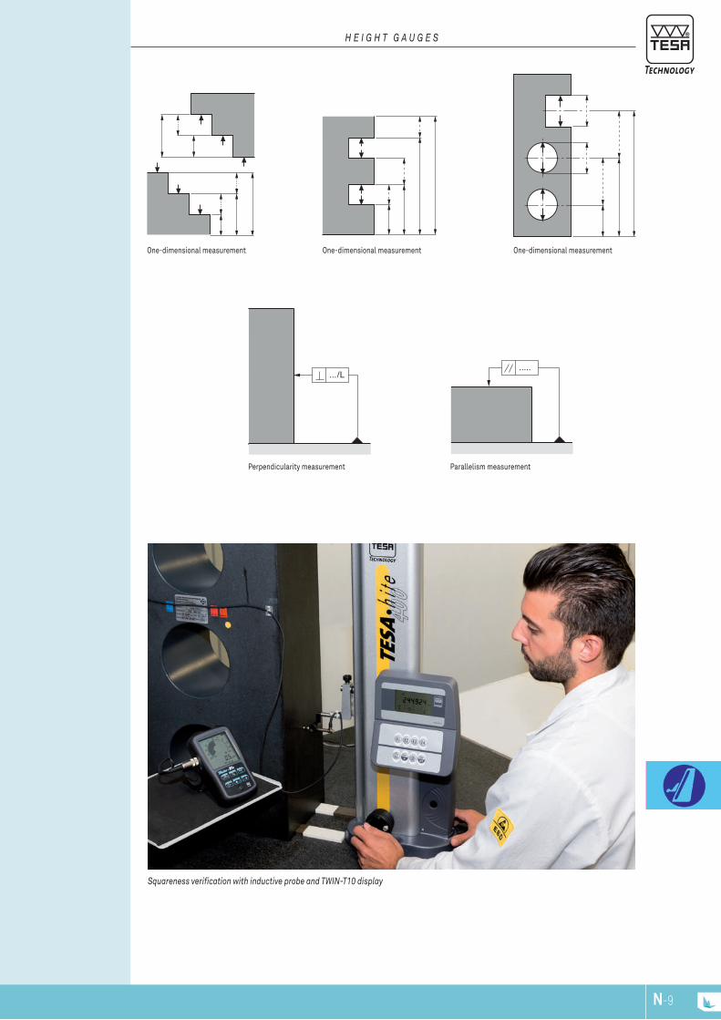
......../L
Squareness verification with inductive probe and TWIN-T10 display
N-9N-8
H E I g H T g A u g E S
Parallelism measurementPerpendicularity measurement
One-dimensional measurementOne-dimensional measurementOne-dimensional measurement
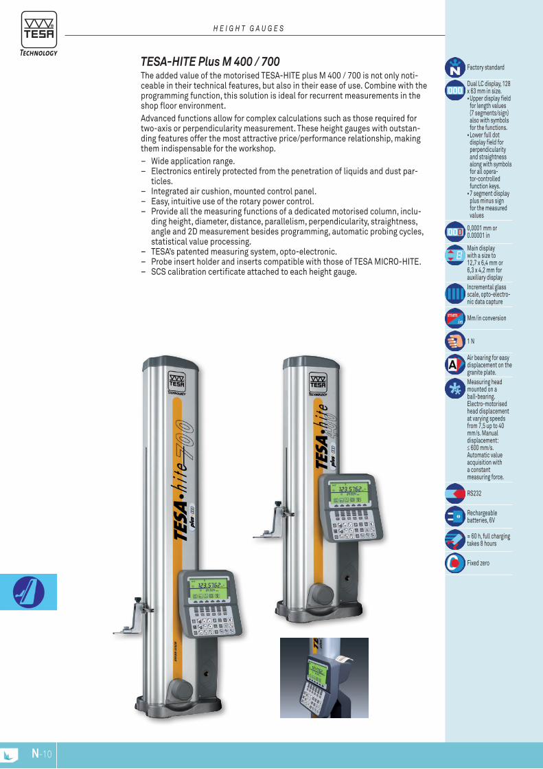
N-11N-10
TESA-HITE Plus M 400 / 700 The added value of the motorised TESA-HITE plus M 400 / 700 is not only noti-ceable in their technical features, but also in their ease of use. Combine with the programming function, this solution is ideal for recurrent measurements in the shop floor environment. Advanced functions allow for complex calculations such as those required for two-axis or perpendicularity measurement. These height gauges with outstan-ding features offer the most attractive price/performance relationship, making them indispensable for the workshop.
– Wide application range. – Electronics entirely protected from the penetration of liquids and dust par-
ticles. – Integrated air cushion, mounted control panel. – Easy, intuitive use of the rotary power control. – Provide all the measuring functions of a dedicated motorised column, inclu-
ding height, diameter, distance, parallelism, perpendicularity, straightness, angle and 2D measurement besides programming, automatic probing cycles, statistical value processing.
– TESA’s patented measuring system, opto-electronic. – Probe insert holder and inserts compatible with those of TESA MICRO-HITE. – SCS calibration certificate attached to each height gauge.
Factory standard
Dual LC display, 128 x 63 mm in size.•Upper display field
for length values (7 segments/sign) also with symbols for the functions. •Lower full dot
display field for perpendicularity and straightness along with symbols for all opera-tor-controlled function keys. •7 segment display
plus minus sign for the measured values
0,0001 mm or 0.00001 in
Main display with a size to 12,7 x 6,4 mm or 6,3 x 4,2 mm for auxiliary displayIncremental glass scale, opto-electro-nic data capture
Mm/in conversion
1 N
Air bearing for easy displacement on the granite plate.Measuring head mounted on a ball-bearing. Electro-motorised head displacement at varying speeds from 7,5 up to 40 mm/s. Manual displacement: ≤ 600 mm/s. Automatic value acquisition with a constant measuring force.
RS232
Rechargeable batteries, 6V
≈ 60 h, full charging takes 8 hours
Fixed zero
H E I g H T g A u g E S
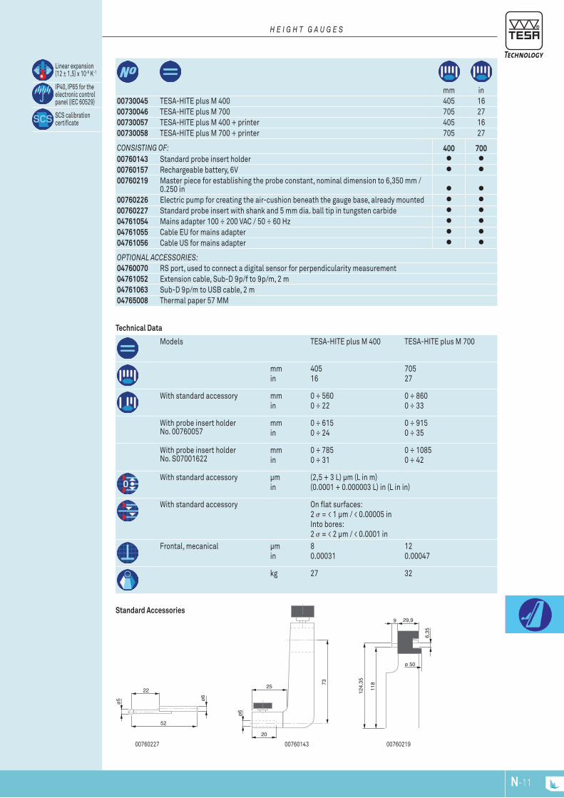
22
52
ø6ø5
29,9
118
124,
35
ø 50
9
6,35
73
20
ø6
25
N-11N-10
0076021900760227 00760143
Standard Accessories
OPTIONAl ACCESSORIES:04760070 RS port, used to connect a digital sensor for perpendicularity measurement04761052 Extension cable, Sub-D 9p/f to 9p/m, 2 m04761063 Sub-D 9p/m to USB cable, 2 m04765008 Thermal paper 57 MM
CONSISTINg OF: 400 70000760143 Standard probe insert holder00760157 Rechargeable battery, 6V00760219 Master piece for establishing the probe constant, nominal dimension to 6,350 mm /
0.250 in00760226 Electric pump for creating the air-cushion beneath the gauge base, already mounted00760227 Standard probe insert with shank and 5 mm dia. ball tip in tungsten carbide04761054 Mains adapter 100 ÷ 200 VAC / 50 ÷ 60 Hz04761055 Cable EU for mains adapter04761056 Cable US for mains adapter
Linear expansion (12 ± 1,5) x 10-6 K-1
IP40, IP65 for the electronic control panel (IEC 60529)
SCS calibration certificate
mm in00730045 TESA-HITE plus M 400 405 1600730046 TESA-HITE plus M 700 705 2700730057 TESA-HITE plus M 400 + printer 405 1600730058 TESA-HITE plus M 700 + printer 705 27
H E I g H T g A u g E S
Models TESA-HITE plus M 400 TESA-HITE plus M 700
mmin
40516
70527
With standard accessory mmin
0 ÷ 5600 ÷ 22
0 ÷ 8600 ÷ 33
With probe insert holder No. 00760057
mmin
0 ÷ 6150 ÷ 24
0 ÷ 9150 ÷ 35
With probe insert holder No. S07001622
mmin
0 ÷ 7850 ÷ 31
0 ÷ 10850 ÷ 42
With standard accessory µmin
(2,5 + 3 L) µm (L in m)(0.0001 + 0.000003 L) in (L in in)
With standard accessory On flat surfaces:2 σ = < 1 µm / < 0.00005 inInto bores:2 σ = < 2 µm / < 0.0001 in
Frontal, mecanical µmin
80.00031
120.00047
kg 27 32
Technical Data
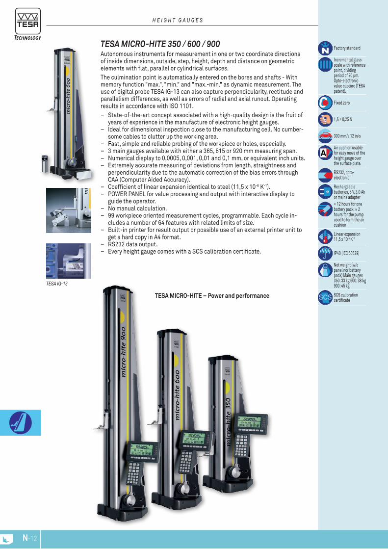
N-13N-12
TESA MICRO-HITE 350 / 600 / 900 Autonomous instruments for measurement in one or two coordinate directions of inside dimensions, outside, step, height, depth and distance on geometric elements with flat, parallel or cylindrical surfaces. The culmination point is automatically entered on the bores and shafts - With memory function "max.", "min." and "max.-min." as dynamic measurement. The use of digital probe TESA IG-13 can also capture perpendicularity, rectitude and parallelism differences, as well as errors of radial and axial runout. Operating results in accordance with ISO 1101.
– State-of-the-art concept associated with a high-quality design is the fruit of years of experience in the manufacture of electronic height gauges.
– Ideal for dimensional inspection close to the manufacturing cell. No cumber-some cables to clutter up the working area.
– Fast, simple and reliable probing of the workpiece or holes, especially. – 3 main gauges available with either a 365, 615 or 920 mm measuring span. – Numerical display to 0,0005, 0,001, 0,01 and 0,1 mm, or equivalent inch units. – Extremely accurate measuring of deviations from length, straightness and
perpendicularity due to the automatic correction of the bias errors through CAA (Computer Aided Accuracy).
– Coefficient of linear expansion identical to steel (11,5 x 10⁻⁶ K-1). – POWER PANEL for value processing and output with interactive display to
guide the operator. – No manual calculation. – 99 workpiece oriented measurement cycles, programmable. Each cycle in-
cludes a number of 64 features with related limits of size. – Built-in printer for result output or possible use of an external printer unit to
get a hard copy in A4 format. – RS232 data output. – Every height gauge comes with a SCS calibration certificate.
Factory standard
Incremental glass scale with reference point, dividing period of 20 μm. Opto-electronic value capture (TESA patent).
Fixed zero
1,6 ± 0,25 N
300 mm/s 12 in/s
Air cushion usable for easy move of the height gauge over the surface plate.
RS232, opto- electronic
Rechargeable batteries, 6 V, 3,0 Ah or mains adapter≈ 12 hours for one battery pack; ≈ 2 hours for the pump used to form the air cushion
Linear expansion 11,5 x 10⁻⁶ K-1
IP40 (IEC 60529)
Net weight (w/o panel nor battery pack) Main gauges 350: 33 kg 600: 38 kg 900: 45 kg
SCS calibration certificate
TESA MICRO-HITE – Power and performance
H E I g H T g A u g E S
TESA Ig-13

22
52
ø6ø5
73
20
ø6
25
ø55
117,
5 ø50
150
20±0
,000
5
N-13N-12
Standard Accessories
0076015000760227 00760143
OPTIONAl ACCESSORIES:00760144 Add-on fine adjust device for extra fine movement of the measuring head, complete00760157 Rechargeable battery, 6V04761023 Cable: miniDIN 8p/m to Sub-D 9p/f, 2m for TT10 and MICRO-HITE manual versions 10/11/1204761056 Cable US for mains adapter
CONSISTINg OF: 350 600 90000760141 Rechargeable battery pack00760142 Electric pump for creating the air-cushion beneath the gauge base, already
mounted00760143 Standard probe insert holder00760150 Master piece for establishing the probe constant, nominal dimension to 20,000 mm
/ 0.78740 in00760151 Dust cover for TESA MICRO-HITE 35000760152 Dust cover for TESA MICRO-HITE 60000760153 Dust cover for TESA MICRO-HITE 90000760227 Standard probe insert with shank and 5 mm dia. ball tip in tungsten carbide04761054 Mains adapter 100 ÷ 200 VAC / 50 ÷ 60 Hz04761055 Cable EU for mains adapter
Technical Data
Models MICRO-HITE350
MICRO-HITE 600
MICRO-HITE 900
mmin
36514
61524
92036
With standard accessory mmin
0 ÷ 5200 ÷ 20
0 ÷ 7700 ÷ 30
0 ÷ 10750 ÷ 42
With probe holder No. 00760057 mmin
0 ÷ 5750 ÷ 22
0 ÷ 8250 ÷ 32
0 ÷ 11300 ÷ 44
With probe holder No. S07001622 mmin
0 ÷ 7450 ÷ 29
0 ÷ 9950 ÷ 39
0 ÷ 13000 ÷ 51
With standard accessory (2 + 3 L) µm (L in m)(0.0001 + 0.000003 L) in (L in in)
With standard accessory 2 σ = ≤ 1 µm / ≤ 0.00005 in
Frontal, mechanical µmin
70.00028
90.00035
110.00043
Frontal and lateral with TESA IG-13 probe
µmin
60.00024
80.00031
100.00039
00730033 SET MICRO-HITE 350 365 1400730034 SET MICRO-HITE 600 615 2400730035 SET MICRO-HITE 900 920 36
mm in
H E I g H T g A u g E S

0
0
0
Y
X0
A
6xø ... A
.../L
.../L
0
YW
XW
0YG
XG
N-15N-14
One-dimensional measurement
One-dimensional measurement One-dimensional measurement
H E I g H T g A u g E S
Programme functions for the detection of form and position errors.With use of a TESA IG-13 digital probe.
Two-Dimensional Measurement
Two-Dimensional Measurement
Two-Dimensional Measurement
Two-Dimensional Measurement
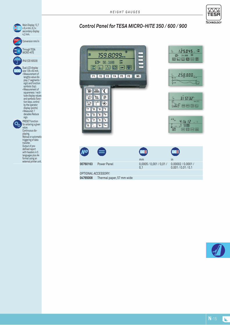
N-15N-14
OPTIONAl ACCESSORy:04765008 Thermal paper, 57 mm wide
mm in
00760163 Power Panel 0,0005 / 0,001 / 0,01 / 0,1
0.00002 / 0.0001 / 0.001 / 0.01 / 0.1
Main Display 12,7 x 6,4 mm, 6,3 x secondary display 4,2 mm.
Conversion mm/in
Through TESA MICRO-HITE
IP40 (CEI 60529)
Dual LCD display size 128 x 63 mm.•Measurement of
lengths value dis-play (7 segments / sign) and function symbols (top).•Measurement of
squareness / recti-tude display values and symbols (func-tion keys, control by the operator display (points) •Measured: 7
decades Reduce sign.
PRESET function for entering a given value. Continuous dis-playing. Manual or automatic triggering of data transfer. Output of pre-defined report with headers in 5 languages plus A4 format using an external printer unit.
Control Panel for TESA MICRO-HITE 350 / 600 / 900
H E I g H T g A u g E S
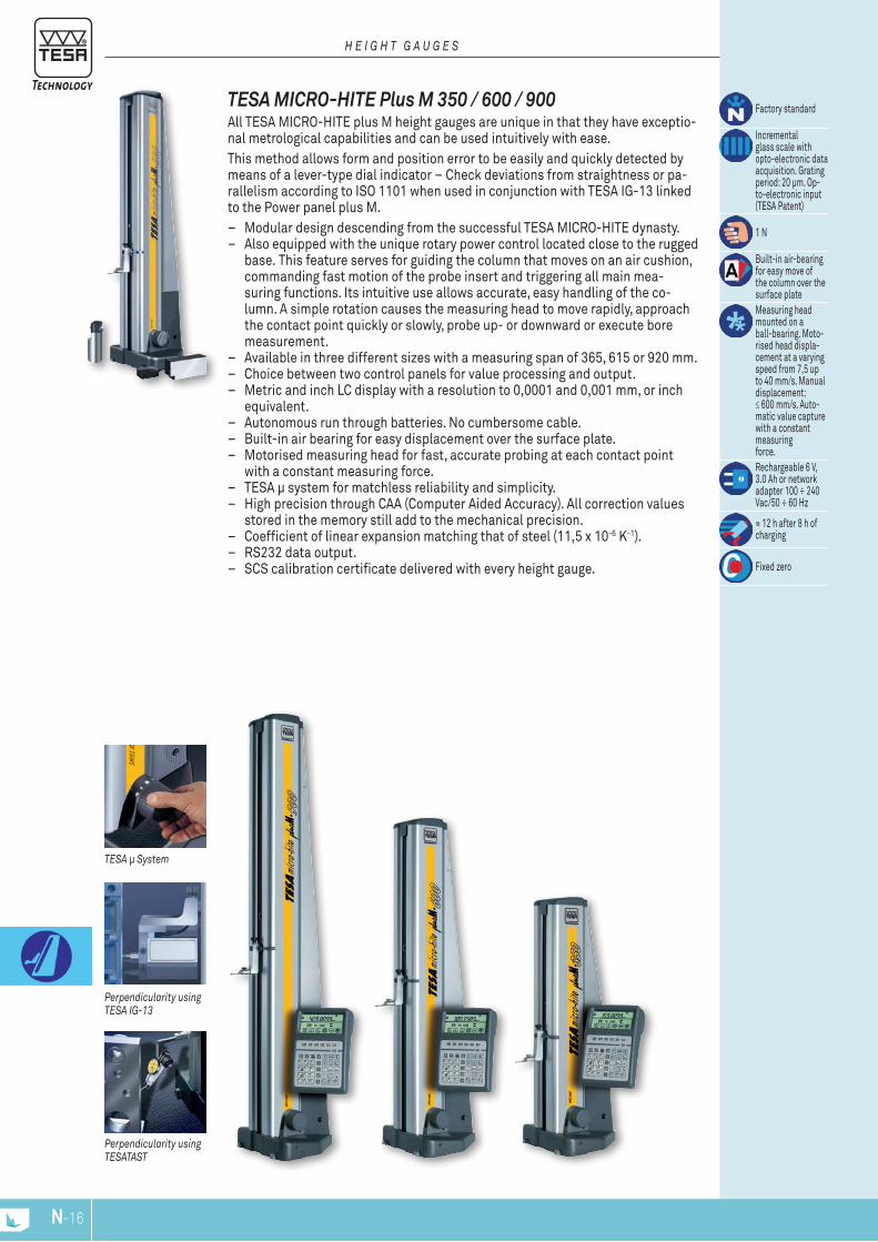
N-17N-16
TESA MICRO-HITE Plus M 350 / 600 / 900 All TESA MICRO-HITE plus M height gauges are unique in that they have exceptio-nal metrological capabilities and can be used intuitively with ease. This method allows form and position error to be easily and quickly detected by means of a lever-type dial indicator – Check deviations from straightness or pa-rallelism according to ISO 1101 when used in conjunction with TESA IG-13 linked to the Power panel plus M.
– Modular design descending from the successful TESA MICRO-HITE dynasty. – Also equipped with the unique rotary power control located close to the rugged
base. This feature serves for guiding the column that moves on an air cushion, commanding fast motion of the probe insert and triggering all main mea-suring functions. Its intuitive use allows accurate, easy handling of the co-lumn. A simple rotation causes the measuring head to move rapidly, approach the contact point quickly or slowly, probe up- or downward or execute bore measurement.
– Available in three different sizes with a measuring span of 365, 615 or 920 mm. – Choice between two control panels for value processing and output. – Metric and inch LC display with a resolution to 0,0001 and 0,001 mm, or inch
equivalent. – Autonomous run through batteries. No cumbersome cable. – Built-in air bearing for easy displacement over the surface plate. – Motorised measuring head for fast, accurate probing at each contact point
with a constant measuring force. – TESA μ system for matchless reliability and simplicity. – High precision through CAA (Computer Aided Accuracy). All correction values
stored in the memory still add to the mechanical precision. – Coefficient of linear expansion matching that of steel (11,5 x 10⁻⁶ K-1). – RS232 data output. – SCS calibration certificate delivered with every height gauge.
Factory standard
Incremental glass scale with opto-electronic data acquisition. Grating period: 20 μm. Op-to-electronic input (TESA Patent)
1 N
Built-in air-bearing for easy move of the column over the surface plateMeasuring head mounted on a ball-bearing. Moto-rised head displa-cement at a varying speed from 7,5 up to 40 mm/s. Manual displacement: ≤ 600 mm/s. Auto-matic value capturewith a constant measuringforce.Rechargeable 6 V, 3.0 Ah or network adapter 100 ÷ 240 Vac/50 ÷ 60 Hz
≈ 12 h after 8 h of charging
Fixed zero
H E I g H T g A u g E S
TESA µ System
Perpendicularity using TESA Ig-13
Perpendicularity using TESATAST

0076014300760227 00760219
22
52
ø6ø5
29,9
118
124,
35
ø 50
9
6,35
73
20
ø6
25
N-17N-16
Standard Accessories
Technical data
Models MICRO-HITE plus M 350
MICRO-HITE plus M 600
MICRO-HITE plus M 900
mmin
36514
61524
92036
With standard accessory mmin
0 ÷ 5200 ÷ 20
0 ÷ 7700 ÷ 30
0 ÷ 10750 ÷ 42
With probe insert holder No. 00760057
mmin
0 ÷ 5750 ÷ 22
0 ÷ 8250 ÷ 32
0 ÷ 11300 ÷ 44
With probe insert holder No. S07001622
mmin
0 ÷ 7450 ÷ 29
0 ÷ 9950 ÷ 39
0 ÷ 13000 ÷ 51
With standard accessory (1,9 + 1,5 L) µm (L in m)(0.0001 + 0.0000015 L) in (L in in)
With standard accessory On flat surfaces:2 σ = ≤ 0,5 µm / ≤ 0.000025 inInto bores:2 σ = ≤ 1 µm / ≤ 0.00005 in
Frontal, mechanicalFrontal and lateral using TESA IG-13
µmin
50,00020
70,00028
90,00035
OPTIONAl ACCESSORy:00760157 Rechargeable battery, 6V
CONSISTINg OF: 350 600 90000760141 Rechargeable battery pack00760142 Electric pump for creating the air-cushion beneath the gauge base,
already mounted00760143 Standard probe insert holder00760219 Master piece for establishing the probe constant,
nominal dimension to 6,350 mm / 0.250 in00760151 Dust cover for TESA MICRO-HITE 35000760152 Dust cover for TESA MICRO-HITE 60000760153 Dust cover for TESA MICRO-HITE 90000760227 Standard probe insert with shank and 5 mm dia. ball tip in tungsten carbide04761054 Mains adapter 100 ÷ 200 VAC / 50 ÷ 60 Hz04761055 Cable EU for mains adapter04761056 Cable US for mains adapter
Linear expansion 11,5 x 10⁻⁶ K-1
IP40 (CEI 60529)
Net weight without desks or block batteries. Basic instrument 350: 33 kg, 600: 38 kg, 900: 45 kg
Calibration certificate SCS
00730063 Set MICRO-HITE plus M 350 365 1400730064 Set MICRO-HITE plus M 600 615 2400730065 Set MICRO-HITE plus M 900 920 36
mm in
H E I g H T g A u g E S
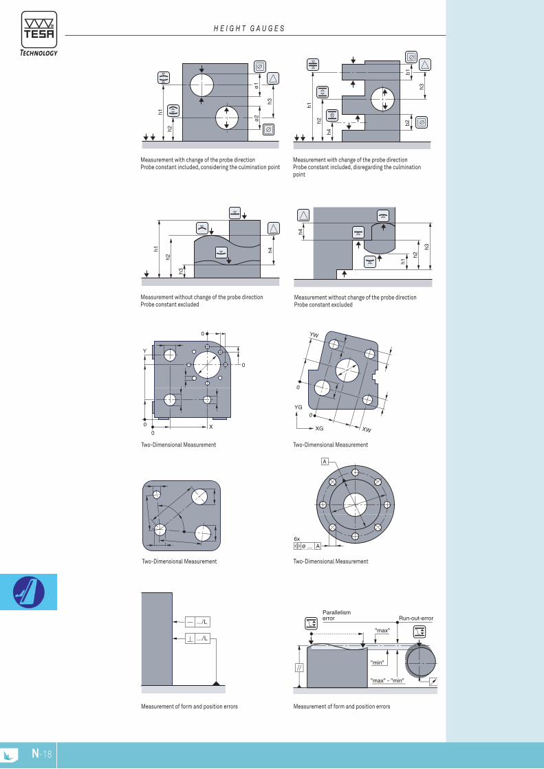
Two-Dimensional MeasurementTwo-Dimensional Measurement
h2
h1
ø2
ø1
h3
0
YW
XW
0YG
XG
A
6xø ... A
Measurement with change of the probe directionProbe constant included, considering the culmination point
Two-Dimensional Measurement
0
0
0
Y
X0
h2
h1 h4
h3
h2
h1
h4
h3
h4
h1
b2b1
h3
h2
Measurement without change of the probe directionProbe constant excluded
Measurement without change of the probe directionProbe constant excluded
Measurement with change of the probe directionProbe constant included, disregarding the culmination point
.../L
.../L
N-19N-18
Measurement of form and position errorsMeasurement of form and position errors
Two-Dimensional Measurement
H E I g H T g A u g E S

N-19N-18
OPTIONAl ACCESSORIES:04765008 Thermal paper, 57 mm wide04761052 Extension cable, Sub-D 9p/f to 9p/m, 2 m04761063 Sub-D 9p/m to USB cable, 2 m
mm in
00760220 Power Panel for MICRO-HITE plus M with printer
0,0001 / 0,001 / 0,01 0.00001 / 0.0001 / 0.001
00760221 Power Panel for MICRO-HITE plus M
0,0001 / 0,001 / 0,01 0.00001 / 0.0001 / 0.001
12,7 x 6,4 mm main display, 6,3 x 4,2 or 3,8 x 2,9 mm auxiliary display
mm/in conversion
Via TESA MICRO- HITE plus M
IP50 (IEC 60529)
Bidirectional RS232, optoelectronic and CentronicsLC dual display, 128 x 63 mm in size.•Length measure-
ment: 7-segment/digit upper display field for values plus symbols for the functions.•Straightness or
perpendicularity measurement: display field for va-lues plus symbols (function keys). Operator controlled operations (full dot display).•Measured values:
7-decade display plus minus sign.
PRESET function for entering a given value. Acoustic signal. Manual or automatic triggering of data transfer. Output of predefined reports with headers in 5 languages (plus a programmable one)using an external printer unit (A4 format).
Control Panels for TESA MICRO-HITE Plus M 350 / 600 / 900
H E I g H T g A u g E S
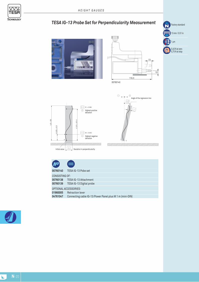
10
116,3
13
0
L(Z
) =
250
L2 (
Z2)
= 2
1.9
L1 (
Z1)
= 2
21.4
X2 =-0.023:
X1 = 0.068:
0
N-21N-20
Initial value Deviation in perpendicularity
Highest negative deviation
Highest positive deviation
00760140
Angle of the regression line
Factory standard
13 mm / 0.51 in
1 µm
0,45 N at zero 0,75 N at stop
TESA IG-13 Probe Set for Perpendicularity Measurement
H E I g H T g A u g E S
OPTIONAl ACCESSORIES:01960005 Retraction lever04761047 Connecting cable IG-13/Power Panel plus M 1 m (mini-DIN)
CONSISTINg OF:00760138 TESA IG-13 Attachment00760139 TESA IG-13 Digital probe
00760140 TESA IG-13 Pobe set
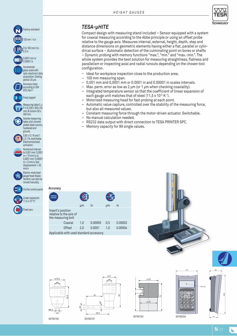
ø16,5
22,5
ø5
ø6
M2,5
ø15
26
ø6
25,5
ø4
ø5
18
ø 50
72
ø 55
44,5
200
62
8 9mmin
1
4
ONOFF PRINT
12:n
7
5
2
6
3
-.0
115
41
76 x 33
N-21N-20
00760204007601920076019700760195
μm in μm inInsert's position relative to the axis of the measuring bolt Coaxial 1,0 0.00005 0,5 0.00002 Offset 2,0 0.0001 1,0 0.00004Applicable with used standard accessory
Accuracy
TESA-μHITE Compact design with measuring stand included – Sensor equipped with a system for coaxial measuring according to the Abbe principle or using an offset probe relative to the gauge axis. Measures internal, external, height, depth, step and distance dimensions on geometric elements having either a flat, parallel or cylin-drical surface – Automatic detection of the culminating point on bores or shafts – Dynamic probing with memory functions "max.", "min." and "max.-min.". The whole system provides the best solution for measuring straightness, flatness and parallelism or inspecting axial and radial runouts depending on the chosen tool configuration.
– Ideal for workpiece inspection close to the production area. – 100 mm measuring span. – 0,001 mm and 0,0001 mm or 0.0001 in and 0.00001 in scales intervals. – Max. perm. error as low as 2 μm (or 1 μm when checking coaxiality). – Integrated temperature sensor so that the coefficient of linear expansion of
each gauge unit matches that of steel (11,5 x 10⁻⁶ K-1). – Motorised measuring head for fast probing at each point. – Automatic value capture, controlled over the stability of the measuring force,
but also all measured values. – Constant measuring force through the motor-driven actuator. Switchable. – No manual calculation needed. – RS232 data output with direct connection to TESA PRINTER SPC. – Memory capacity for 99 single values.
Factory standard
100 mm / 4 in
0 to 160 mm 0 to 6.3 in
0,0001 mm or 0.00001 in
Incremental glass scale with opto-electronic data acquisition. Grating period: 20 μm.Accuracy class according to DIN 876, Part 1
finely lapped
Measuring table (L x P x H) 200 x 300 x 50 mm, Ø column 50 x 300 mm.Granite measuring table; dull-chrome plated steel column, hardened and ground.0,63 ± 0,1 N and 1 ± 0,1 N, switchable. Electromotorised activation.Numerical interval to 0,001 mm/ 0,0001 in = 10 mm/s; to 0,0001 mm/ 0,00001 in = 5 mm/s; fast displacement = 30 mm/sElectro-motorised gauge head displa-cement; can also be moved manually.
Via the control panel
Linear expansion 11,5 x 10⁻⁶ K-1
Fixed zero
H E I g H T g A u g E S
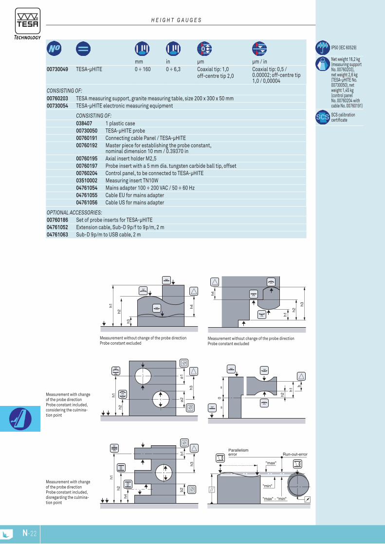
h2
h1 h4
h3
h2
h1
h4
h3
h4
h1
b2b1
h3
h2h2
h1
ø2
ø1
h3
h2
h1
= b
=0
CONSISTINg OF:038407 1 plastic case00730050 TESA-μHITE probe00760191 Connecting cable Panel / TESA-μHITE00760192 Master piece for establishing the probe constant,
nominal dimension 10 mm / 0.39370 in00760195 Axial insert holder M2,500760197 Probe insert with a 5 mm dia. tungsten carbide ball tip, offset00760204 Control panel, to be connected to TESA-μHITE03510002 Measuring insert TN10W04761054 Mains adapter 100 ÷ 200 VAC / 50 ÷ 60 Hz04761055 Cable EU for mains adapter04761056 Cable US for mains adapter
IP50 (IEC 60529)
Net weight 16,2 kg (measuring support No. 00760203), net weight 2,6 kg (TESA-µHITE No. 00730050), net weight 1,45 kg (control panel No. 00760204 with cable No. 00760191)
SCS calibration certificate
N-23N-22
OPTIONAl ACCESSORIES:00760186 Set of probe inserts for TESA-µHITE04761052 Extension cable, Sub-D 9p/f to 9p/m, 2 m04761063 Sub-D 9p/m to USB cable, 2 m
CONSISTINg OF:00760203 TESA measuring support, granite measuring table, size 200 x 300 x 50 mm00730054 TESA-μHITE electronic measuring equipment
Measurement with change of the probe direction Probe constant included, considering the culmina-tion point
00730049 TESA-μHITE 0 ÷ 160 0 ÷ 6,3 Coaxial tip: 1,0 off-centre tip 2,0
Coaxial tip: 0,5 / 0.00002; off-centre tip 1,0 / 0,00004
mm in µm µm / in
Measurement with change of the probe direction Probe constant included, disregarding the culmina-tion point
Measurement without change of the probe directionProbe constant excluded
Measurement without change of the probe direction Probe constant excluded
H E I g H T g A u g E S

ø16,5
22,5
ø5
ø6
M1,4
ø16,5
22,5
ø5
ø6
M3
ø15
28
ø4
ø6
10
M3 ø4
13
15ϒ
M1,4
M3 M1,4
ø10
6,5
1015
8
33
ø4ø5
12
31
ø4
ø3
N-23N-22
00760194 Axial probe holder for probe inserts with a M1,4 thread00760196 Axial probe holder for probe inserts with a M3 thread00760198 Radial probe holder with a 4 mm dia. mounting bore00760199 Universal probe insert holder with a 4 mm dia. clamping shank (used in conjunc-
tion with radial probe holder No. 00760198). M1,4 plus M3 threads (2 x 2) for the probe inserts
00760200 Probe insert with a 5 mm dia. tungsten carbide ball tip. Also with a 4 mm dia. fixing rod for use with radial probe holder insert No. 00760198.
00760201 Probe insert with a 3 mm dia. tungsten carbide ball tip. Also with a 4 mm dia. fixing rode for use with radial probe holder No. 00760198.
00760202 Spare batteries for control panel No. 00760204, 6 Vdc/1,2 Ah.00760207 Swivel support for control panel
Optional Accessories for TESA-µHite
H E I g H T g A u g E S
0076020100760200
00760199
007601980076019600760194
H E I g H T g A u g E S
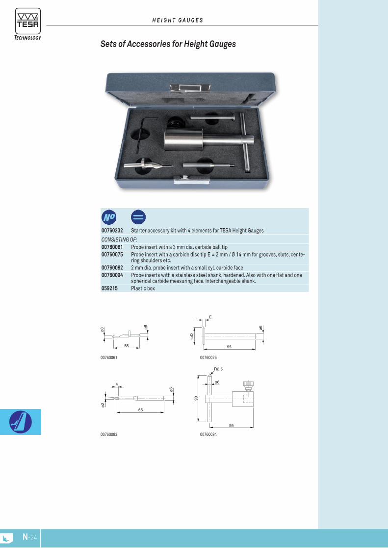
ø6
55
ø6
4
ø2
55
ø6
55
øD
ø6
E
N-25N-24
CONSISTINg OF:00760061 Probe insert with a 3 mm dia. carbide ball tip00760075 Probe insert with a carbide disc tip E = 2 mm / Ø 14 mm for grooves, slots, cente-
ring shoulders etc.00760082 2 mm dia. probe insert with a small cyl. carbide face00760094 Probe inserts with a stainless steel shank, hardened. Also with one flat and one
spherical carbide measuring face. Interchangeable shank.059215 Plastic box
00760232 Starter accessory kit with 4 elements for TESA Height Gauges
Sets of Accessories for Height Gauges
H E I g H T g A u g E SH E I g H T g A u g E S
0076009400760082
0076007500760061

ø6
55
ø6
55
ø10
ø10
91
ø6
ø6
55
ø1 4 ø6
55
ø2 8 ø6
55
ø3 8
55
øD
ø6
E
N-25N-24
CONSISTINg OF:00760061 Probe insert with a 3 mm dia. carbide ball tip00760060 Probe insert with a 10 mm dia. carbide ball tip00760075 Probe insert with a carbide disc tip E = 2 mm / Ø 14 mm for grooves, slots, cente-
ring shoulders etc.00760093 Probe insert with a cylindrical, tungsten carbide measuring face
(10 mm dia., 12 mm long). Steinless steel body, handened.00760094 Probe inserts with a stainless steel shank, hardened. Also with one flat and one
spherical carbide measuring face. Interchangeable shank.00760228 Probe insert dia. 1 mm with shank and ball tip in tungsten carbide00760229 Probe insert dia. 2 mm with shank and ball tip in tungsten carbide00760230 Probe insert dia. 3 mm with shank and ball tip in tungsten carbide
00760173 Starter accessory kit with 8 elements for TESA Height Gauges
Sets of Accessories for Height Gauges
H E I g H T g A u g E S
00760061
00760094
00760228 00760229 00760230
00760060
00760075 00760093
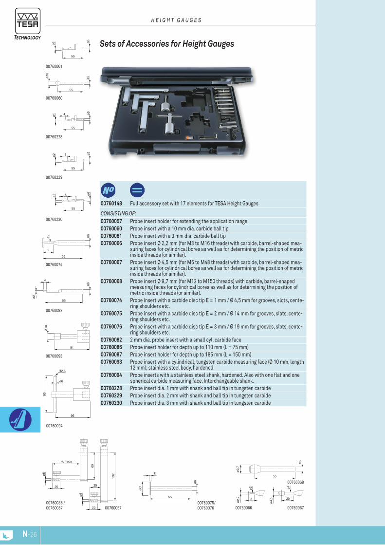
ø6
55
ø6
4
ø2
55
ø6
55
ø10
ø10
91
ø6
ø6
55
ø1 4
ø6
ø2
55
9
ø6
55
ø2 8
ø6
55
ø3 8
00760082
00760060
00760093
00760094
00760228
00760074
00760229
00760230
00760067
55
ø9,
7
ø6
ø4
ø2
8 20
ø2,
2
ø4,
5
ø6
75 / 150
69
20
ø6
25
132
20 007600660076005700760086 /00760087
00760068
00760061
55
øD
ø6
E
00760075/ 00760076
N-27N-26
CONSISTINg OF:00760057 Probe insert holder for extending the application range00760060 Probe insert with a 10 mm dia. carbide ball tip00760061 Probe insert with a 3 mm dia. carbide ball tip00760066 Probe insert Ø 2,2 mm (for M3 to M16 threads) with carbide, barrel-shaped mea-
suring faces for cylindrical bores as well as for determining the position of metric inside threads (or similar).
00760067 Probe insert Ø 4,5 mm (for M6 to M48 threads) with carbide, barrel-shaped mea-suring faces for cylindrical bores as well as for determining the position of metric inside threads (or similar).
00760068 Probe insert Ø 9,7 mm (for M12 to M150 threads) with carbide, barrel-shaped measuring faces for cylindrical bores as well as for determining the position of metric inside threads (or similar).
00760074 Probe insert with a carbide disc tip E = 1 mm / Ø 4,5 mm for grooves, slots, cente-ring shoulders etc.
00760075 Probe insert with a carbide disc tip E = 2 mm / Ø 14 mm for grooves, slots, cente-ring shoulders etc.
00760076 Probe insert with a carbide disc tip E = 3 mm / Ø 19 mm for grooves, slots, cente-ring shoulders etc.
00760082 2 mm dia. probe insert with a small cyl. carbide face00760086 Probe insert holder for depth up to 110 mm (L = 75 mm)00760087 Probe insert holder for depth up to 185 mm (L = 150 mm)00760093 Probe insert with a cylindrical, tungsten carbide measuring face (Ø 10 mm, length
12 mm); stainless steel body, hardened00760094 Probe inserts with a stainless steel shank, hardened. Also with one flat and one
spherical carbide measuring face. Interchangeable shank.00760228 Probe insert dia. 1 mm with shank and ball tip in tungsten carbide00760229 Probe insert dia. 2 mm with shank and ball tip in tungsten carbide00760230 Probe insert dia. 3 mm with shank and ball tip in tungsten carbide
00760148 Full accessory set with 17 elements for TESA Height Gauges
Sets of Accessories for Height Gauges
H E I g H T g A u g E S

N-27N-26
00760184 0076018500760183
CONSISTINg OF:00760177 Probe insert holder00760178 Hardened steel rod for grooves, centring shoulders, blind bores etc,
angled through 8°00760179 Tungsten carbide cylindrical rod for depth measurement00760180 Probe inserts with a 0,9 mm dia. hardened steel ball tip00760181 Probe inserts with a 1,9 mm dia. hardened steel ball tip00760182 Probe inserts with a 1,9 mm dia. hardened steel ball tip00760183 Hardened steel probe insert with a cone-shaped measuring face, 8 mm dia.00760184 Extension, 20 mm, with a M3 thread for inserts with M3 thread00760185 Extension, 20 mm, with a M3 thread for inserts with M2,5 thread
00760175 Set of pobe inserts for TESA-HITE, TESA-HITE plus M, TESA-HITE magna, MICRO -HITE and MICRO-HITE plus M
Sets of Accessories for Height Gauges
H E I g H T g A u g E S
00760177
00760178
0076018100760180 00760182
78
ø4
3
1,5
0,5
26,6
ø0,9
M3
23,1
26,6
ø1,9
M3
22,6
ø4
20
45
ø6
ø4
M3 M
3
M3
4,5
34
ø9
26,6ø2
,9
M3
22,1
28
ø8
M3
25
8
23
ø4 M3
20
M2,
5
23
ø4 M3
20
M3
76
ø4
ø1,2
16
00760179

78
ø4
3
1,5
0,5
26,6
ø0,9
M3
23,1
26,6
ø1,9
M3
22,6
26,6
ø2,9
M3
22,1
28
ø8
M3
25
8
23
ø4 M3
20
M2,
5
23
ø4 M3
20
M3
21
ø 6
10
00760187
76
ø4
ø1,2
16
00760179
N-29N-28
00760184 0076018500760183
00760182
CONSISTINg OF:00760178 Hardened steel rod for grooves, centring shoulders, blind bores etc,
angled through 8°00760179 Tungsten carbide cylindrical rod for depth measurement00760180 Probe inserts with a 0,9 mm dia. hardened steel ball tip00760181 Probe inserts with a 1,9 mm dia. hardened steel ball tip00760182 Probe inserts with a 2,9 mm dia. hardened steel ball tip00760183 Hardened steel probe insert with a cone-shaped measuring face, 8 mm dia.00760184 Extension, 20 mm, with a M3 thread for inserts with M3 thread00760185 Extension, 20 mm, with a M3 thread for inserts with M2,5 thread00760187 Probe insert holder
00760186 Set of probe inserts for TESA-µHITE
Sets of Accessories for Height Gauges
H E I g H T g A u g E S
00760180 00760181
00760178

21
140
ø 8
ø 8
,5
ø 2
2
⊕ 118
ø 5
⊕ 98
10
80
ø 8
ø 1
2
61
ø 1
10
11
ø 8
2m
ax. 8
6
19
93
ø 8
ø 6
ø 8
49
19
96
ø 8
ø 8
ø 1
0
60
12
19
91
ø 8
ø 1
0
ø 1
2
55
3
19
43
ø 8
12,5
ø 1
M1,4
19
97
ø 8
ø 6
55
11
67,5
20,7
ø8
N-29N-28
H E I g H T g A u g E S
00760223 Probe holder for inserts with 8 mm diameter
Probe Holder No. 00760223 for Inserts with 8 mm Diameter
00716848220071684826
0071684827
0071684820
0071684832
00716848180071684819
0071684815 Probe insert with a 4 mm dia. tungsten carbide ball tip0071684816 Probe insert with a 6 mm dia. tungsten carbide ball tip0071684817 Long probe insert with a 10 mm dia. tungsten carbide ball tip0071684818 Probe insert with a 1 mm dia. steel tip, hardened. Also with adjustable shank for
depth measurement.0071684819 Probe insert with cone-shaped measuring face in hardened steel for Ø 5 ÷ 20 mm0071684820 Probe insert with cylindrical measuring face in hardened steel, Ø 10 mm, 12 mm
long0071684822 Probe insert with cone-shaped measuring face in hardened steel, Ø 0,5 ÷ 5,5 mm0071684825 Probe insert with a 6 mm dia. tungsten carbide ball tip0071684826 Attachment for interchangeable inserts with M1,4 thread. Supplied with 1 insert
No. 01860201 having a 1 mm dia. carbide ball tip.0071684827 Probe insert with disc-shaped face Ø 12 mm, 3 mm wide0071684828 Attachment for interchangeable insert with M1,4 thread. Supplied with 2 probe
inserts No. 0186020 having a 2 mm dia. carbide ball tip0071684829 Probe insert with a 10 mm dia. tungsten carbide ball tip0071684832 Probe insert with a 8 mm dia. tungsten carbide ball tip
Optional Accessories for Use with Insert Holder No. 00760223
19
90
ø 8
ø 1
4
ø 6
55
ø 5
18
0071684825
19
94
ø 8
ø 8
ø 1
0
51
0071684829
19
158
ø 8ø 8
ø 1
0
124,5
0071684817
19
71
ø 8
ø 3
ø 4
26
0071684815
19
93
ø 8
ø 5ø 6
50
0071684816
19
ø 8
2x
M1,4ø 2
12,5
ø 89,5
94
56
2,5
0071684828
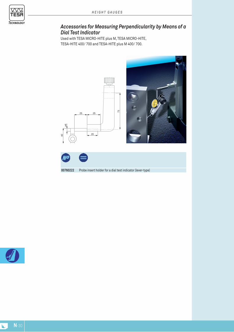
73
20
2525
40
ø6
N-31N-30
00760222 Probe insert holder for a dial test indicator (lever-type)
Accessories for Measuring Perpendicularity by Means of a Dial Test Indicator Used with TESA MICRO-HITE plus M, TESA MICRO-HITE,TESA-HITE 400/ 700 and TESA-HITE plus M 400/ 700.
H E I g H T g A u g E S
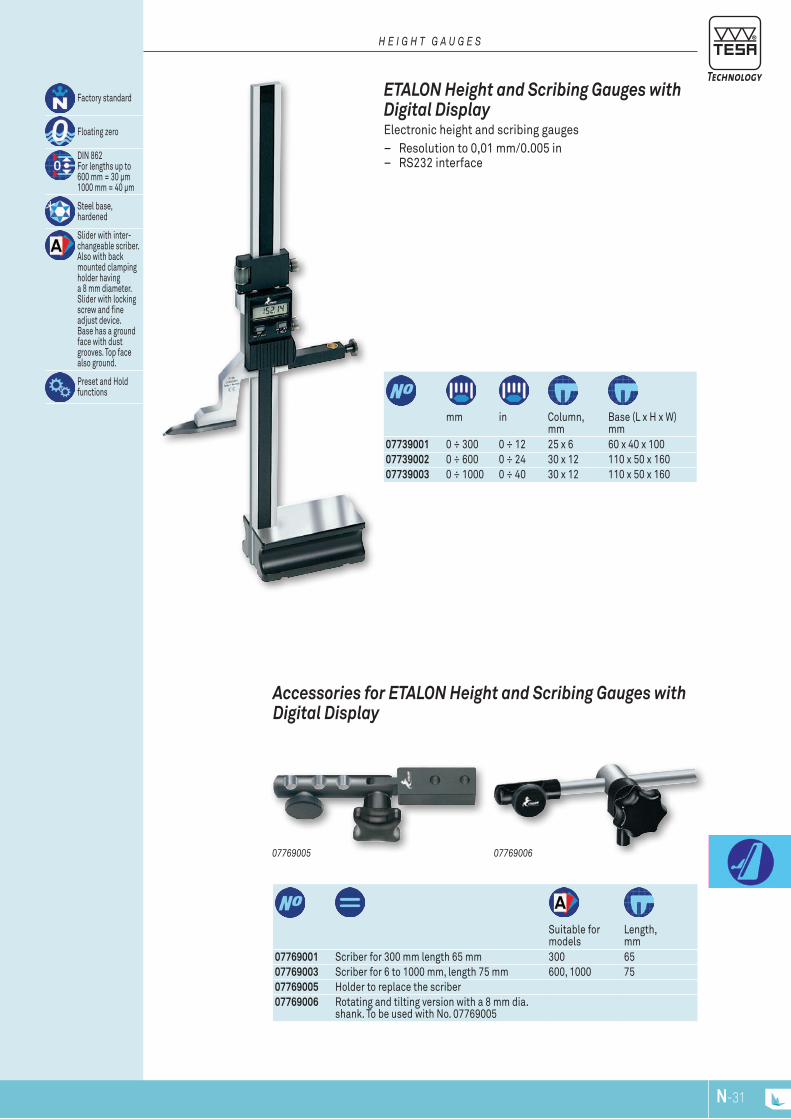
N-31N-30
0776900607769005
07769001 Scriber for 300 mm length 65 mm 300 6507769003 Scriber for 6 to 1000 mm, length 75 mm 600, 1000 7507769005 Holder to replace the scriber07769006 Rotating and tilting version with a 8 mm dia.
shank. To be used with No. 07769005
Suitable for models
Length, mm
Accessories for ETALON Height and Scribing Gauges with Digital Display
07739001 0 ÷ 300 0 ÷ 12 25 x 6 60 x 40 x 10007739002 0 ÷ 600 0 ÷ 24 30 x 12 110 x 50 x 16007739003 0 ÷ 1000 0 ÷ 40 30 x 12 110 x 50 x 160
mm in Column,
mmBase (L x H x W) mm
Factory standard
Floating zero
DIN 862 For lengths up to 600 mm = 30 μm 1000 mm = 40 μm
Steel base, hardened
Slider with inter-changeable scriber. Also with back mounted clamping holder havinga 8 mm diameter. Slider with locking screw and fine adjust device.Base has a ground face with dust grooves. Top face also ground.
Preset and Hold functions
ETALON Height and Scribing Gauges with Digital Display Electronic height and scribing gauges
– Resolution to 0,01 mm/0.005 in – RS232 interface
H E I g H T g A u g E S

N-NPN-32
O-NP O-1www.tesatechnology.com
Elec
tron
ic L
engt
h M
easu
ring
Equi
pmen
t

O-2
0-S
+U
+S
-U
Lf
L L
Wireless probe
Probe FMS
GT-31
USB probe
Typical qualities of TESA inductive probes : excellent repeatability, durability and longevity All TESA inductive axial movement are mounted on a ball bearing with the exception of miniature models. The ball bearing guidance system is insensitive to any radial force exerted on the probe hou-sing. An anti-rotation guiding system ensures perfect movement of the mechanical guide. The axial probe guide system is effectively protected against penetration of liquids (oils) or solids (dust) by sealing bellows of high elastic quality. Under normal conditions, the standard nitrile elastomer bellows provide sufficient protection against oils and solvents. For applica-tions where the probes remain in prolonged contact with coolants or lubricants and aggres-sive chemicals, Viton bellows are recommended. Viton is a fluoreleastomer resistant to the heat of oils and aggressive chemicals. The retraction (lifting) of the measuring bolt rod can be made by the suction of air (vacuum) accumulated within the probe thanks to the airtightness provided by the sealing bellows. This method of working principle does not use any mechanical device ensures the operation of the guidance system in an optimal manner. Similarly, the probe can be moved into its measuring position by a pneumatic activation (pressure), depending on the probe model. Inserts (measuring inserts) can be replaced or exchanged. A wide choice of geometrical forms and sizes are available The measuring force can be adjusted by changing the spring, depending on the probe model. The probes integrate an electronic amplifier of the signal without relying on any mechanical conversion device. Thus, these probes are distinguished by their high repeatability and very low hysteresis errors.
TESA probes: At the cutting edge of technologyTESA develops, manufactures and remains a leader in the inductive probe sector with an experience of more than 40 years. It offers a complete and unique line of probes designed to meet the requirements of varied as well as demanding applications.Dimensional inspection of medium and large batches of parts in multigauging fixtures repre-sents a major application area where measuring speed coupled with a high level of accuracy is needed.High precision inductive probes (type GTL-21 HP) are, for example, also suited for the mea-surement of gauge blocks. The display resolution can reach a digital step of 0,01 μm !On request, TESA probes can be supplied in versions compatible with the electronic equip-ment of other suppliers.
TESA inducTivE probES And ELEcTronic EquipMEnT
E L E c T r O n I c L E n G T H M E A S U r I n G E q U I P M E n T
TT20
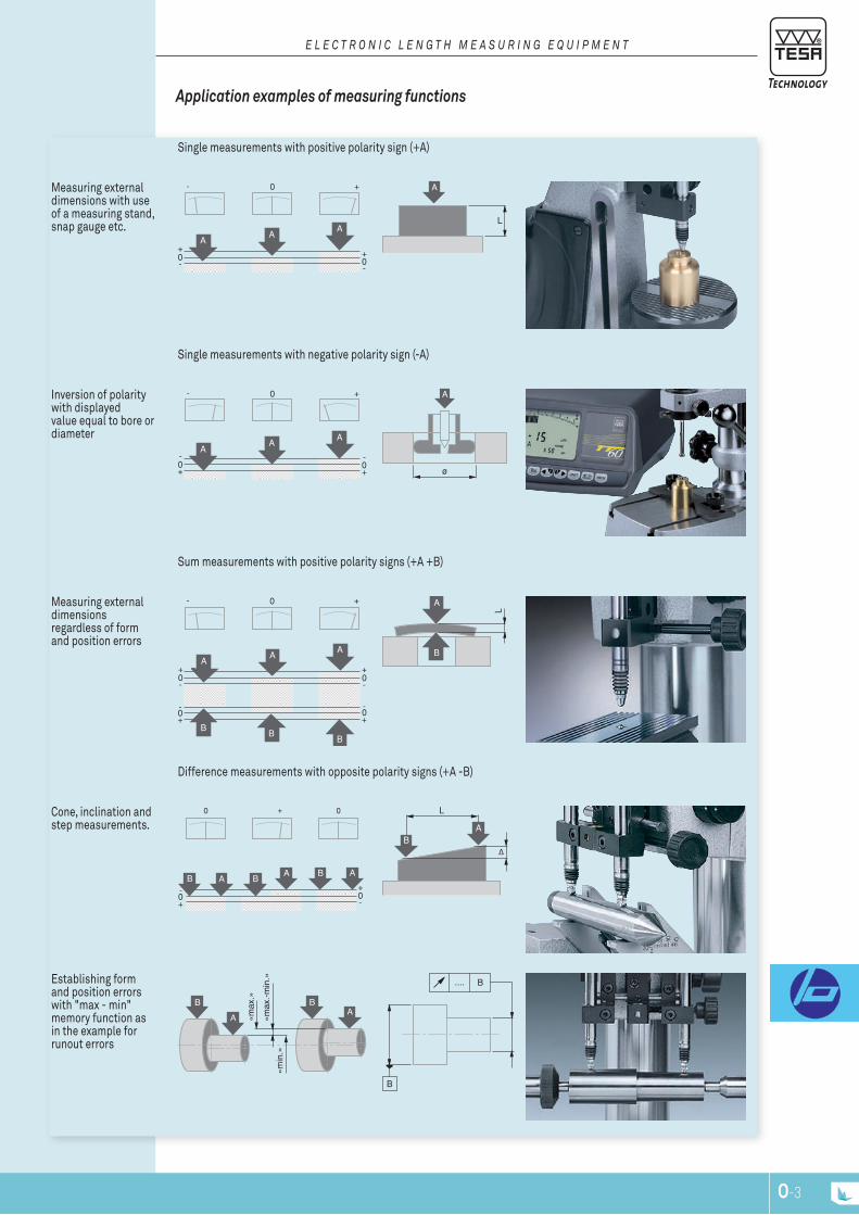
O-2 O-3
0-S
+U
+S
-U
Lf
L L
E L E c T r O n I c L E n G T H M E A S U r I n G E q U I P M E n T
Application examples of measuring functions
Single measurements with positive polarity sign (+A)
Measuring external dimensions with use of a measuring stand, snap gauge etc.
0+
- 0+
-
0 +-
AA
A
L
A
Single measurements with negative polarity sign (-A)
Inversion of polarity with displayed value equal to bore or diameter
0-
+0-
+
0 +-
AA
A
ø
A
Sum measurements with positive polarity signs (+A +B)
Measuring external dimensions regardless of form and position errors
0+
-0+
-
0+
-0+
-
0 +-
AA
BB
B
A
A
B
L
Difference measurements with opposite polarity signs (+A -B)
Cone, inclination and step measurements.
0+
-0+
-
0 + 0
B A BA B A
L
BA
∆
Establishing form and position errors with "max - min" memory function as in the example for runout errors
BB
A A
«max
.»
«max
.-min
. »«m
in.»
B....
B
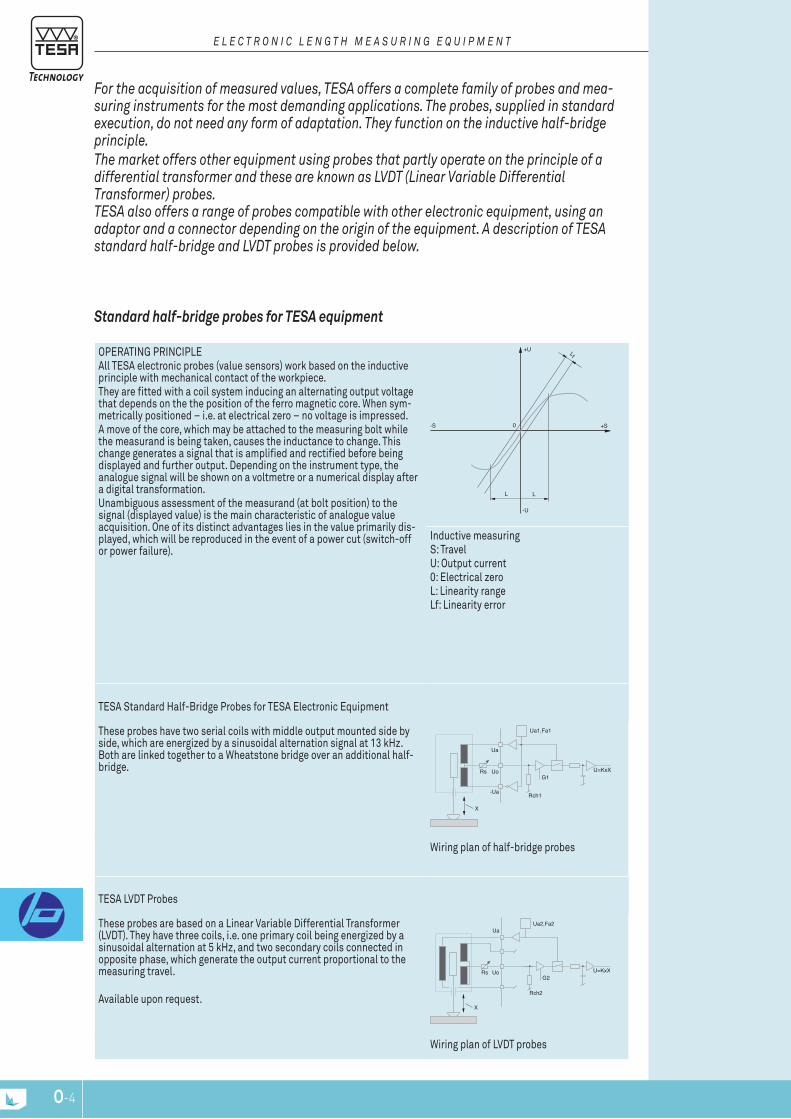
O-4
E L E c T r O n I c L E n G T H M E A S U r I n G E q U I P M E n T
For the acquisition of measured values, TESA offers a complete family of probes and mea-suring instruments for the most demanding applications. The probes, supplied in standard execution, do not need any form of adaptation. They function on the inductive half-bridge principle.The market offers other equipment using probes that partly operate on the principle of a differential transformer and these are known as LVDT (Linear Variable Differential Transformer) probes. TESA also offers a range of probes compatible with other electronic equipment, using an adaptor and a connector depending on the origin of the equipment. A description of TESA standard half-bridge and LVDT probes is provided below.
OpErAtIng prInCIplEAll tESA electronic probes (value sensors) work based on the inductive principle with mechanical contact of the workpiece. they are fitted with a coil system inducing an alternating output voltage that depends on the the position of the ferro magnetic core. When sym-metrically positioned – i.e. at electrical zero – no voltage is impressed. A move of the core, which may be attached to the measuring bolt while the measurand is being taken, causes the inductance to change. this change generates a signal that is amplified and rectified before being displayed and further output. Depending on the instrument type, the analogue signal will be shown on a voltmetre or a numerical display after a digital transformation.Unambiguous assessment of the measurand (at bolt position) to the signal (displayed value) is the main characteristic of analogue value acquisition. One of its distinct advantages lies in the value primarily dis-played, which will be reproduced in the event of a power cut (switch-off or power failure).
0-S
+U
+S
-U
Lf
L L
Inductive measuringS: travelU: Output current0: Electrical zerol: linearity rangelf: linearity error
tESA Standard Half-Bridge probes for tESA Electronic Equipment
these probes have two serial coils with middle output mounted side by side, which are energized by a sinusoidal alternation signal at 13 kHz. Both are linked together to a Wheatstone bridge over an additional half-bridge.
X
Ua
Uo
-Ua
Rs
Ua1,Fa1
Rch1
G1U=KxX
Wiring plan of half-bridge probes
tESA lVDt probes
these probes are based on a linear Variable Differential transformer (lVDt). they have three coils, i.e. one primary coil being energized by a sinusoidal alternation at 5 kHz, and two secondary coils connected in opposite phase, which generate the output current proportional to the measuring travel.
Available upon request.
Uo
Ua
Rs
Ua2,Fa2
Rch2
G2U=KxX
X
Wiring plan of lVDt probes
Standard half-bridge probes for TESA equipment

O-4 O-5
9
2
11
4
56
7
14
35
8
411
8
10
16
910212
15
12
13
31
E L E c T r O n I c L E n G T H M E A S U r I n G E q U I P M E n T
Multiple application possibilitiesTESA probes have been designed for applications for use with instruments for internal and external measurements, measuring supports or special measuring systems. For such applications, different probe executions can be supplied such as probes with an axial measuring bolt or parallel guides, re-fer also to angle lever probes. In addition, there are also special executions developed for multi-gau-ging inspection fixtures or ‘in-process’ inspection stations, which enable an economy in the number of components needed. Apart from a few exceptions, the measuring operations executed are always comparative measurements with reference to a standard such as a gauge block, a setting ring or any other component that can be used as a master.The measurements are extremely accurate. Bias error influence is negligible compared to the budget for measuring uncertainty given the fact that the comparison is being established between two almost practically equal values random errors also lose their influence in a procedure where the display setting is made under the same conditions as the subsequent probing measurementsTESA measuring instruments are equipped with an analogue and/or digital display, depending on the model.
internal processing of measured valuesDepending on the application, the electrical signals are processed in different ways within the ins-trument.
Mathematical data processing The signals can be processed with positive polarity sign as well as negative polarity sign. The use of a single probe enables single measurement of internal or external dimensions while the combination of the signals of two probes produces either a "sum measurement" or a "difference measurement".
value Storage The storage of measured values in the memory ensures the reliability of dynamic measuring cycles. The characteristic values are the two minimum and maximum values or the difference between the smallest and largest value acquired while measuring form or position errors.
classification of values The measured values can be classified after the entering of limit deviations. In this case, the control signals can be used by an external peripheral unit.
1 Mounting stem or probe housing2 Coil system3 Element mounted between the ferromagnetic core and the measuring bolt for the correction of varying coefficients of thermal expansion4 Force compression spring5 Anti-rotation guiding system6 Ball cage7 Setting element for limiting the measuring bolt travel8 probe insert9 In-between tube being part of the coil system10 Ferro-magnetic core11 Force spring stop12 Ball-bearing guiding tube13 Measuring bolt14 Sealing bellow15 Mechanical device for zero-setting
Sensitivity 73,75 mV/V/mm
29,50 mV/V/mm (gt 61, gt 62) 7,375 mV/V/mm (gt 61S, gt 62S)49,17 mV/V/mm (FMS 130, FMS 132)
All given values are valid for the following reference conditions :Drive voltageDrive frequencyAdjustment load
3 V13 kHz2 kΩ
components of a TESA inductive probe Sensivity of TESA half-bridge probes for TESA electronic interfaces and electronic displays
9
2
11
4
56
7
14
35
8
411
8
10
16
910212
15
12
13
31

O-6
E L E c T r O n I c L E n G T H M E A S U r I n G E q U I P M E n T
probes with Axial Movement, Ø 8 mm
Measuring range, mm
Measuring bolt travel, mm
Cable output Measuring bolt retraction
Sealing bel-lows
03210904 gt 21 ± 1 mm 4,3 Axial Mechanical nitrile
03210924 gt 22 ± 1 mm 4,3 radial Mechanical / vacuum
nitrile
03230057 gtl 21 ± 2 mm 4,3 Axial Mechanical Viton
03230072 gtl 211 ± 2 mm 4,3 Axial Mechanical / vacuum
Viton
03230056 gtl 22 ± 2 mm 4,3 radial Mechanical / vacuum
Viton
03230027 gt 27 ± 2 mm 10,3 Axial Mechanical Viton
03230073 gt 271 ± 2 mm 10,3 Axial Mechanical / vacuum
Viton
03230026 gt 28 ± 2 mm 10,3 radial Mechanical / vacuum
Viton
03230041 gt 61 ± 5 mm 10,3 Axial Mechanical Viton
03230042 gt 62 ± 5 mm 10,3 radial Mechanical / vacuum
Viton
03230036 gt 21 Hp ± 0,2 mm 4,3 Axial Mechanical nitrile
03230021 gt 22 Hp ± 0,2 mm 4,3 radial Mechanical / vacuum
nitrile
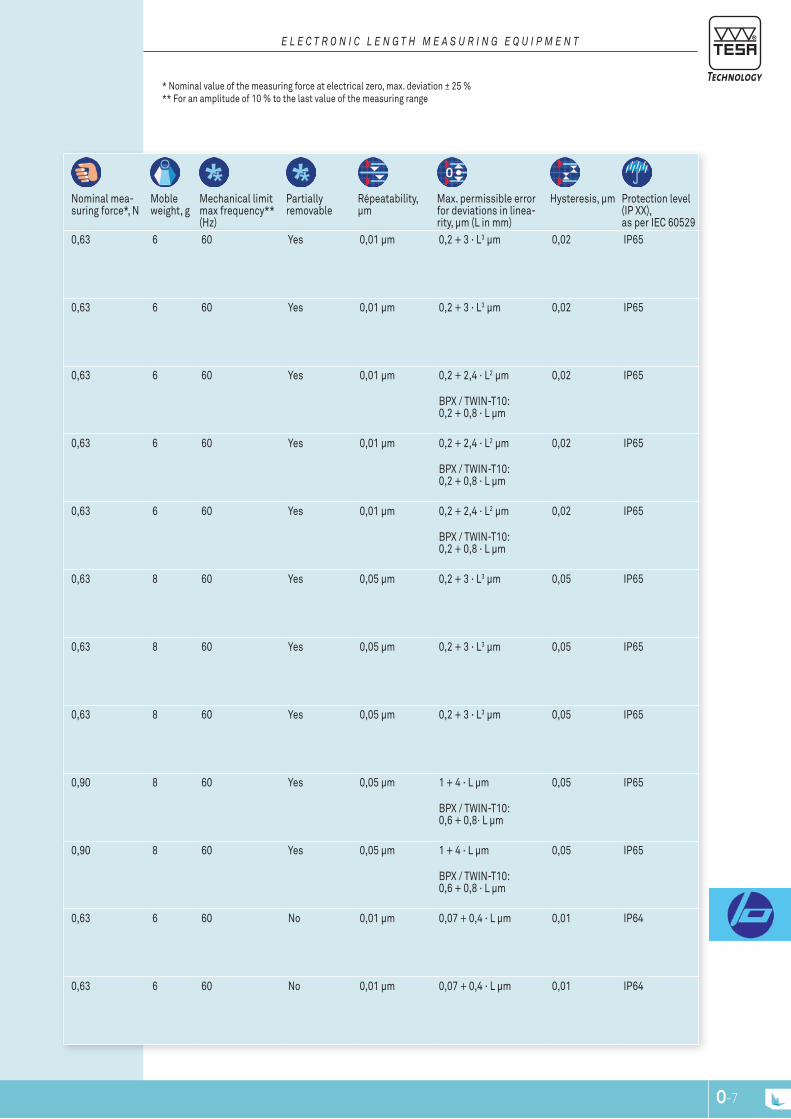
O-6 O-7
* nominal value of the measuring force at electrical zero, max. deviation ± 25 %** For an amplitude of 10 % to the last value of the measuring range
E L E c T r O n I c L E n G T H M E A S U r I n G E q U I P M E n T
nominal mea-suring force*, n
Moble weight, g
Mechanical limit max frequency** (Hz)
partially removable
répeatability, μm
Max. permissible error for deviations in linea-rity, μm (l in mm)
Hysteresis, μm protection level (Ip XX), as per IEC 60529
0,63 6 60 Yes 0,01 µm 0,2 + 3 · l3 µm 0,02 Ip65
0,63 6 60 Yes 0,01 µm 0,2 + 3 · l3 µm 0,02 Ip65
0,63 6 60 Yes 0,01 µm 0,2 + 2,4 · l2 µm
BpX / tWIn-t10: 0,2 + 0,8 · l µm
0,02 Ip65
0,63 6 60 Yes 0,01 µm 0,2 + 2,4 · l2 µm
BpX / tWIn-t10: 0,2 + 0,8 · l µm
0,02 Ip65
0,63 6 60 Yes 0,01 µm 0,2 + 2,4 · l2 µm
BpX / tWIn-t10: 0,2 + 0,8 · l µm
0,02 Ip65
0,63 8 60 Yes 0,05 µm 0,2 + 3 · l3 µm 0,05 Ip65
0,63 8 60 Yes 0,05 µm 0,2 + 3 · l3 µm 0,05 Ip65
0,63 8 60 Yes 0,05 µm 0,2 + 3 · l3 µm 0,05 Ip65
0,90 8 60 Yes 0,05 µm 1 + 4 · l µm
BpX / tWIn-t10: 0,6 + 0,8· l µm
0,05 Ip65
0,90 8 60 Yes 0,05 µm 1 + 4 · l µm
BpX / tWIn-t10: 0,6 + 0,8 · l µm
0,05 Ip65
0,63 6 60 no 0,01 µm 0,07 + 0,4 · l µm 0,01 Ip64
0,63 6 60 no 0,01 µm 0,07 + 0,4 · l µm 0,01 Ip64
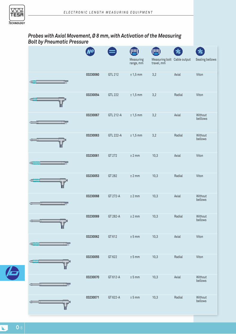
O-8
E L E c T r O n I c L E n G T H M E A S U r I n G E q U I P M E n T
probes with Axial Movement, Ø 8 mm, with Activation of the Measuring bolt by pneumatic pressure
Measuring range, mm
Measuring bolt travel, mm
Cable output Sealing bellows
03230060 gtl 212 ± 1,5 mm 3,2 Axial Viton
03230054 gtl 222 ± 1,5 mm 3,2 radial Viton
03230067 gtl 212-A ± 1,5 mm 3,2 Axial Without belllows
03230063 gtl 222-A ± 1,5 mm 3,2 radial Without bellows
03230061 gt 272 ± 2 mm 10,3 Axial Viton
03230053 gt 282 ± 2 mm 10,3 radial Viton
03230068 gt 272-A ± 2 mm 10,3 Axial Without bellows
03230069 gt 282-A ± 2 mm 10,3 radial Without bellows
03230062 gt 612 ± 5 mm 10,3 Axial Viton
03230055 gt 622 ± 5 mm 10,3 radial Viton
03230070 gt 612-A ± 5 mm 10,3 Axial Without bellows
03230071 gt 622-A ± 5 mm 10,3 radial Without bellows
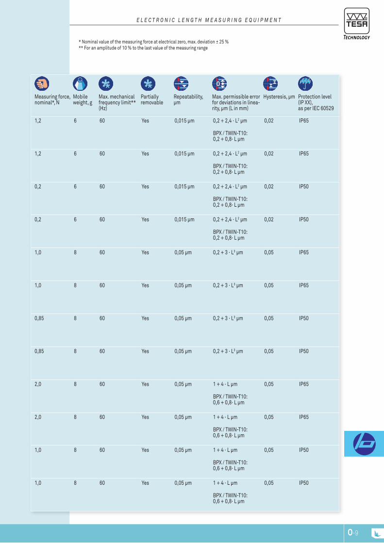
O-8 O-9
E L E c T r O n I c L E n G T H M E A S U r I n G E q U I P M E n T
Measuring force, nominal*, n
Mobile weight, g
Max. mechanical frequency limit** (Hz)
partially removable
repeatability, μm
Max. permissible error for deviations in linea-rity, μm (l in mm)
Hysteresis, μm protection level (Ip XX), as per IEC 60529
1,2 6 60 Yes 0,015 µm 0,2 + 2,4 · l2 µm
BpX / tWIn-t10: 0,2 + 0,8· l µm
0,02 Ip65
1,2 6 60 Yes 0,015 µm 0,2 + 2,4 · l2 µm
BpX / tWIn-t10: 0,2 + 0,8· l µm
0,02 Ip65
0,2 6 60 Yes 0,015 µm 0,2 + 2,4 · l2 µm
BpX / tWIn-t10: 0,2 + 0,8· l µm
0,02 Ip50
0,2 6 60 Yes 0,015 µm 0,2 + 2,4 · l2 µm
BpX / tWIn-t10: 0,2 + 0,8· l µm
0,02 Ip50
1,0 8 60 Yes 0,05 µm 0,2 + 3 · l3 µm 0,05 Ip65
1,0 8 60 Yes 0,05 µm 0,2 + 3 · l3 µm 0,05 Ip65
0,85 8 60 Yes 0,05 µm 0,2 + 3 · l3 µm 0,05 Ip50
0,85 8 60 Yes 0,05 µm 0,2 + 3 · l3 µm 0,05 Ip50
2,0 8 60 Yes 0,05 µm 1 + 4 · l µm
BpX / tWIn-t10: 0,6 + 0,8· l µm
0,05 Ip65
2,0 8 60 Yes 0,05 µm 1 + 4 · l µm
BpX / tWIn-t10: 0,6 + 0,8· l µm
0,05 Ip65
1,0 8 60 Yes 0,05 µm 1 + 4 · l µm
BpX / tWIn-t10: 0,6 + 0,8· l µm
0,05 Ip50
1,0 8 60 Yes 0,05 µm 1 + 4 · l µm
BpX / tWIn-t10: 0,6 + 0,8· l µm
0,05 Ip50
* nominal value of the measuring force at electrical zero, max. deviation ± 25 %** For an amplitude of 10 % to the last value of the measuring range
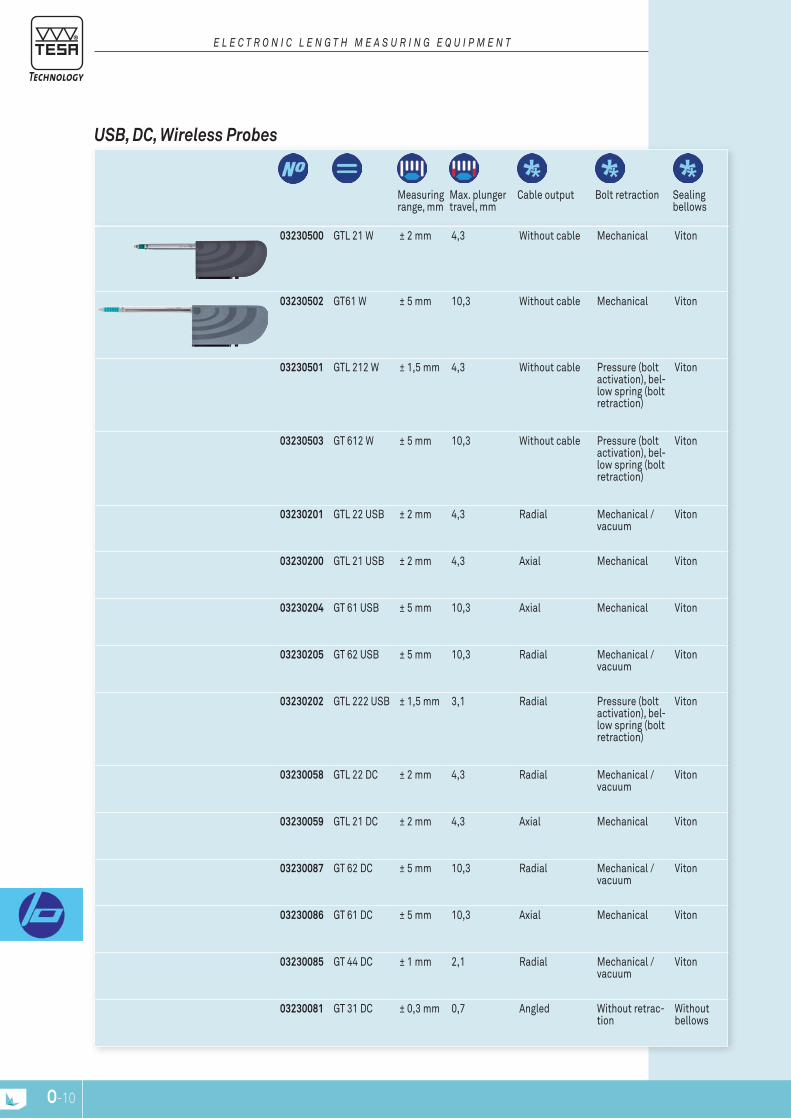
O-10
E L E c T r O n I c L E n G T H M E A S U r I n G E q U I P M E n T
uSb, dc, Wireless probes
Measuring range, mm
Max. plunger travel, mm
Cable output Bolt retraction Sealing bellows
03230500 gtl 21 W ± 2 mm 4,3 Without cable Mechanical Viton
03230502 gt61 W ± 5 mm 10,3 Without cable Mechanical Viton
03230501 gtl 212 W ± 1,5 mm 4,3 Without cable pressure (bolt activation), bel-low spring (bolt retraction)
Viton
03230503 gt 612 W ± 5 mm 10,3 Without cable pressure (bolt activation), bel-low spring (bolt retraction)
Viton
03230201 gtl 22 USB ± 2 mm 4,3 radial Mechanical / vacuum
Viton
03230200 gtl 21 USB ± 2 mm 4,3 Axial Mechanical Viton
03230204 gt 61 USB ± 5 mm 10,3 Axial Mechanical Viton
03230205 gt 62 USB ± 5 mm 10,3 radial Mechanical / vacuum
Viton
03230202 gtl 222 USB ± 1,5 mm 3,1 radial pressure (bolt activation), bel-low spring (bolt retraction)
Viton
03230058 gtl 22 DC ± 2 mm 4,3 radial Mechanical / vacuum
Viton
03230059 gtl 21 DC ± 2 mm 4,3 Axial Mechanical Viton
03230087 gt 62 DC ± 5 mm 10,3 radial Mechanical / vacuum
Viton
03230086 gt 61 DC ± 5 mm 10,3 Axial Mechanical Viton
03230085 gt 44 DC ± 1 mm 2,1 radial Mechanical / vacuum
Viton
03230081 gt 31 DC ± 0,3 mm 0,7 Angled Without retrac-
tion Without bellows
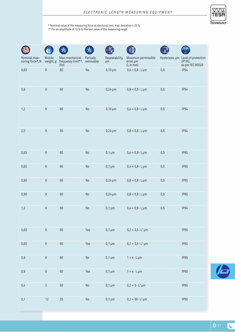
O-10 O-11
E L E c T r O n I c L E n G T H M E A S U r I n G E q U I P M E n T
nominal mea-suring force*, n
Mobile weight, g
Max. mechanical frequency limit**, (Hz)
partially removable
repeatability, μm
Maximum permissible error, μm (l in mm)
Hysteresis, μm level of protection (Ip XX), as per IEC 60529
0,63 6 60 no 0,10 µm 0,4 + 0,8 · l µm 0,5 Ip54
0,9 8 60 no 0,24 µm 0,8 + 0,8 · l µm 0,5 Ip54
1,2 6 60 no 0,10 µm 0,4 + 0,8 · l µm 0,5 Ip54
2,0 8 60 no 0,24 µm 0,8 + 0,8 · l µm 0,5 Ip54
0,63 6 60 no 0,1 µm 0,4 + 0,8 · l µm 0,5 Ip65
0,63 6 60 no 0,1 µm 0,4 + 0,8 · l µm 0,5 Ip65
0,90 8 60 no 0,24 µm 0,8 + 0,8 · l µm 0,5 Ip65
0,90 8 60 no 0,24 µm 0,8 + 0,8 · l µm 0,5 Ip65
1,2 6 60 no 0,1 µm 0,4 + 0,8 · l µm 0,5 Ip64
0,63 6 60 Yes 0,1 µm 0,2 + 3,5 · l2 µm Ip65
0,63 6 60 Yes 0,1 µm 0,2 + 3,5 · l2 µm Ip65
0,9 8 60 no 0,1 µm 1 + 4 · l µm Ip65
0,9 8 60 Yes 0,1 µm 1 + 4 · l µm Ip65
0,4 2 60 no 0,1 µm 0,2 + 5 · l2 µm Ip65
0,1 12 25 no 0,1 µm 0,2 + 50 · l2 µm Ip50
* nominal value of the measuring force at electrical zero, max. deviation ± 25 %** For an amplitude of 10 % to the last value of the measuring range

O-12
E L E c T r O n I c L E n G T H M E A S U r I n G E q U I P M E n T
probes with Axial Movement,Ø 8 mm
Measuring range, mm
Measuring bolt travel, mm
Cable output Bolt retraction Sealing bellows
03230001 gt 41 ± 0,3 mm 0,7 Axial none nitrile
03230002 gt 42 ± 0,3 mm 0,7 radial Vacuum nitrile
03230035 gt 43 ± 1 mm 2,1 Axial Mechanical Viton
03230017 gt 44 ± 1 mm 2,1 radial Vacuum Viton
unbranded Axial probes with Measuring bolt Mounted on a ball-bearing96410012 410 ± 1 mm 2,5 Axial and
radial Mechanical nitrile
96160013 160 ± 1 mm 3,3 Axial Mechanical Viton
96430029 430 ± 0,5 mm 1,25 Axial Mechanical nitrile
96441041 451 ± 0,5 mm 2,10 radial Mechanical nitrile
probe with inclinable Lever03210802 gt 31 ± 0,3 mm 0,7 Angled Without Without
bellows
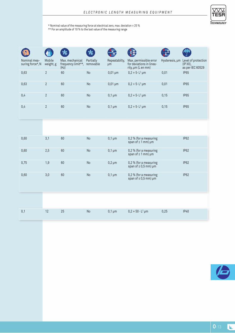
O-12 O-13
E L E c T r O n I c L E n G T H M E A S U r I n G E q U I P M E n T
nominal mea-suring force*, n
Mobile weight, g
Max. mechanical frequency limit**, (Hz)
partially removable
repeatabilty, μm
Max. permissible error for deviations in linea-rity, μm (l en mm)
Hysteresis, μm level of protection (Ip XX), as per IEC 60529
0,63 2 60 no 0,01 µm 0,2 + 5· l2 µm 0,01 Ip65
0,63 2 60 no 0,01 µm 0,2 + 5· l2 µm 0,01 Ip65
0,4 2 60 no 0,1 µm 0,2 + 5· l2 µm 0,15 Ip65
0,4 2 60 no 0,1 µm 0,2 + 5· l2 µm 0,15 Ip65
0,60 3,1 60 no 0,1 µm 0,2 % (for a measuring span of ± 1 mm) µm
Ip62
0,60 2,5 60 no 0,1 µm 0,2 % (for a measuring span of ± 1 mm) µm
Ip62
0,75 1,9 60 no 0,2 µm 0,2 % (for a measuring span of ± 0,5 mm) µm
Ip62
0,60 3,0 60 no 0,1 µm 0,2 % (for a measuring span of ± 0,5 mm) µm
Ip62
0,1 12 25 no 0,1 µm 0,2 + 50 · l2 µm 0,25 Ip40
* nominal value of the measuring force at electrical zero, max. deviation ± 25 %** For an amplitude of 10 % to the last value of the measuring range

O-14
E L E c T r O n I c L E n G T H M E A S U r I n G E q U I P M E n T
universal FMS probes
Measuring range, mm
Measuring bolt travel, mm
Cable output Bolt retraction Sealing bellows
SWISSMADE
32.30019PAT PEND
03230019 FMS 100 ± 2 mm 5,8 parallel retraction by air pressure (optional)
Without bellows
SWISSMADE
32.30049PAT PEND
03230049 FMS 130 ± 2,9 mm 5,8 parallel retraction by air pressure (optional)
Without bellows
SWISSMADE
32.30028PAT PEND
03230028 FMS 102 ± 2 mm 5,8 parallel retraction by air pressure (optional)
Without bellows
SWISSMADE
32.30050PAT PEND
03230050 FMS 132 ± 2,9 mm 5,8 parallel retraction by air pressure (optional)
Without bellows
SWISS MADEPatented
PROTECTE
D
03230037 FMS100-p ± 2 mm 5,8 parallel retraction by air pressure (optional)
Without bellows
SWISS MADEPatented
PROTECTE
D
03230051 FMS130-p ± 2,9 mm 5,8 parallel retraction by air pressure (optional)
Without bellows
SWISS MADEPatented
PROTECTE
D
03230038 FMS102-p ± 2 mm 5,8 Angled retraction through air pressure (optional)
Without bellows
SWISS MADEPatented
PROTECTE
D
03230052 FMS132-p ± 2,9 mm 5,8 Angled retraction through air pressure (optional)
Without bellows

O-14 O-15
E L E c T r O n I c L E n G T H M E A S U r I n G E q U I P M E n T
nominal mea-suring force*, n
Mobile weight, g
Max. mechanical frequency limit**, Hz
partially removable
repeatabilty, μm
Max.permissible error for deviation in linearity, μm (l in mm)
Hysteresis, μm protection level (Ip XX), as per IEC 60529
2 110 25 Yes 0,5 µm 0,2 + 3 · l3 µm 0,5 Ip50
2 110 25 Yes 0,5 µm 0,2 + 3 · l3 µm 0,5 Ip50
2 110 25 Yes 0,5 µm 0,2 + 3 · l3 µm 0,5 Ip50
2 110 25 Yes 0,5 µm 0,2 + 3 · l3 µm 0,5 Ip50
2 110 25 Yes 0,5 µm 0,2 + 3 · l3 µm 0,5 Ip54
2 110 25 Yes 0,5 µm 0,2 + 3 · l3 µm 0,5 Ip54
2 110 25 Yes 0,5 µm 0,2 + 3 · l3 µm 0,5 Ip54
2 110 25 Yes 0,5 µm 0,2 + 3 · l3 µm 0,5 Ip54
* nominal value of the measuring force at electrical zero, max. deviation ± 25 %** For an amplitude of 10 % to the last value of the measuring range
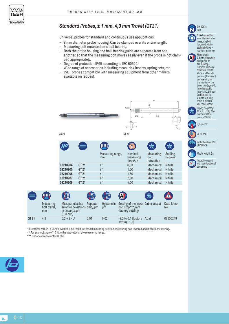
O-16
R 1,5 ø 8h
6
61,520,5
-1,2 +30
92
GT21
9
ø3
8
99
03210904 GT 21 ± 1 0,63 Mechanical nitrile03210905 GT 21 ± 1 1,00 Mechanical nitrile03210906 GT 21 ± 1 1,60 Mechanical nitrile03210907 GT 21 ± 1 2,50 Mechanical nitrile03210908 GT 21 ± 1 4,00 Mechanical nitrile
Measuring range, mm
nominal measuring force*, n
Measuring bolt retraction
Sealing bellows
Measuring bolt travel, mm
Max. permissible error for deviations in linearity, μm (l in mm)
repeata-bility, μm
Hysteresis, μm
Setting of the lower bolt stop***, mm (factory setting)
Cable output Data Sheet no.
GT 21 4,3 0,2 + 3 · l3 0,01 0,02 -2,2 to 0,1 (factory setting -1,2)
Axial 03200249
DIn 32876 part 1
nickel-plated hou-sing. Stainless steel measuring bolt, hardened. nitrile sealing bellows = resistant elastomerFixing shank Ø 8 mm. Measuring bolt guided on ball-bearing. Distance from elec-trical zero of both stops is either ad-justable (downward) or depending on the position of the lower stop (upward). Interchangeable inserts. M2,5 thread. Carbide ball tip Ø 3 mm. 2 m long cable. 5-pin DIn 45322 connector.Supply frequency: 13 kHz (± 5 %). Max mechanical fre-quency** 60 Hz.
0,15 μm/°C
20 ± 0,5°C
protection level Ip65 (IEC 60529)
Mobile weight: 6 g
Inspection report with a declaration of conformity
gt 21GT21
Standard probes, ± 1 mm, 4,3 mm Travel (GT21)
Universal probes for standard and continuous use applications. – 8 mm diameter probe housing. Can be clamped over its entire length. – Measuring bolt mounted on a ball bearing. – Both the probe housing and ball-bearing guide are separate from one
another, so that the measuring bolt moves easily even if the probe is not clam-ped appropriately.
– Degree of protection Ip65 according to IEC 60529. – Wide range of accessories including measuring inserts, spring sets, etc. – lVDt probes compatible with measuring equipment from other makers
available on request.
P r O B E S W I T H A x I A L M O V E M E n T , Ø 8 M M
* Electrical zero (n) ± 25 % deviation limit. Valid in vertical mounting position, measuring bolt lowered and in static measuring. ** For an amplitude of 10 % to the last value of the measuring range. *** Distance from electrical zero.
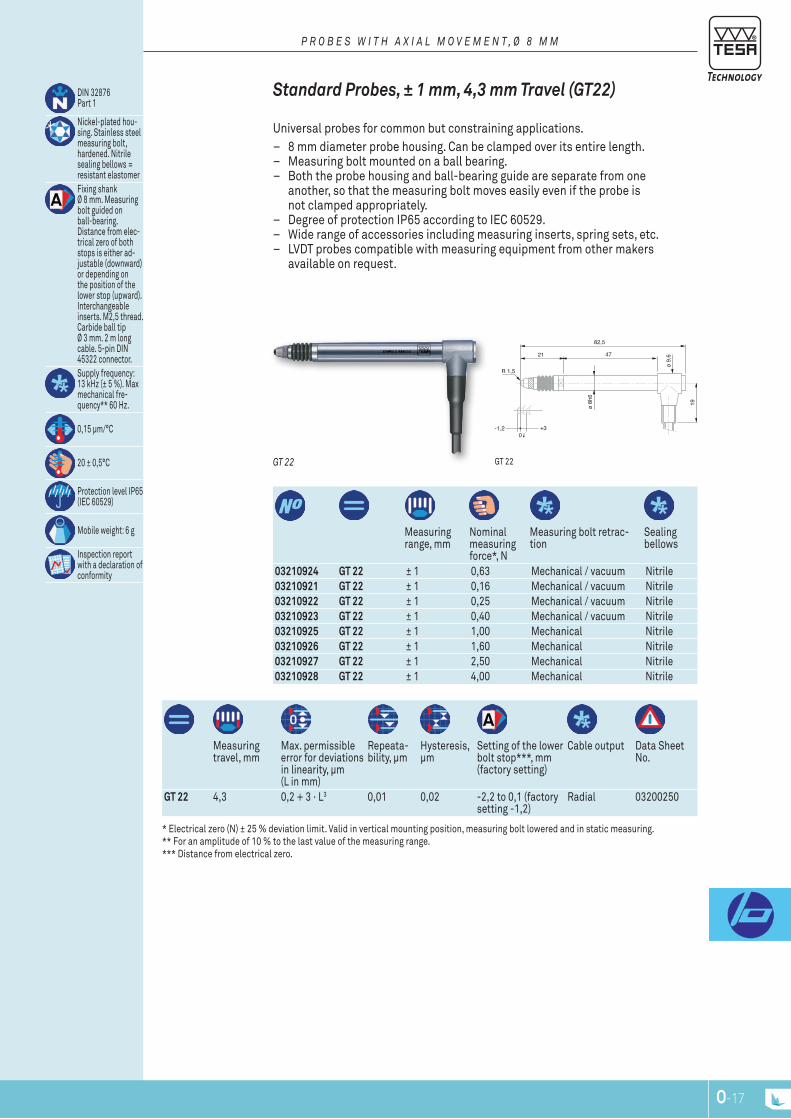
O-16 O-17
R 1,5
ø 8h
6
4721
-1,2 +30
82,5
ø 9,
6
19
03210924 GT 22 ± 1 0,63 Mechanical / vacuum nitrile03210921 GT 22 ± 1 0,16 Mechanical / vacuum nitrile03210922 GT 22 ± 1 0,25 Mechanical / vacuum nitrile03210923 GT 22 ± 1 0,40 Mechanical / vacuum nitrile03210925 GT 22 ± 1 1,00 Mechanical nitrile03210926 GT 22 ± 1 1,60 Mechanical nitrile03210927 GT 22 ± 1 2,50 Mechanical nitrile03210928 GT 22 ± 1 4,00 Mechanical nitrile
Measuring range, mm
nominal measuring force*, n
Measuring bolt retrac-tion
Sealing bellows
Measuring travel, mm
Max. permissible error for deviations in linearity, μm (l in mm)
repeata-bility, μm
Hysteresis, μm
Setting of the lower bolt stop***, mm (factory setting)
Cable output Data Sheet no.
GT 22 4,3 0,2 + 3 · l3 0,01 0,02 -2,2 to 0,1 (factory setting -1,2)
radial 03200250
DIn 32876 part 1
nickel-plated hou-sing. Stainless steel measuring bolt, hardened. nitrile sealing bellows = resistant elastomer Fixing shank Ø 8 mm. Measuring bolt guided on ball-bearing. Distance from elec-trical zero of both stops is either ad-justable (downward) or depending on the position of the lower stop (upward). Interchangeable inserts. M2,5 thread. Carbide ball tip Ø 3 mm. 2 m long cable. 5-pin DIn 45322 connector.Supply frequency: 13 kHz (± 5 %). Max mechanical fre-quency** 60 Hz.
0,15 μm/°C
20 ± 0,5°C
protection level Ip65 (IEC 60529)
Mobile weight: 6 g
Inspection report with a declaration of conformity
gt 22 GT 22
Standard probes, ± 1 mm, 4,3 mm Travel (GT22)
Universal probes for common but constraining applications. – 8 mm diameter probe housing. Can be clamped over its entire length. – Measuring bolt mounted on a ball bearing. – Both the probe housing and ball-bearing guide are separate from one
another, so that the measuring bolt moves easily even if the probe is not clamped appropriately.
– Degree of protection Ip65 according to IEC 60529. – Wide range of accessories including measuring inserts, spring sets, etc. – lVDt probes compatible with measuring equipment from other makers
available on request.
P r O B E S W I T H A x I A L M O V E M E n T , Ø 8 M M
* Electrical zero (n) ± 25 % deviation limit. Valid in vertical mounting position, measuring bolt lowered and in static measuring. ** For an amplitude of 10 % to the last value of the measuring range. *** Distance from electrical zero.
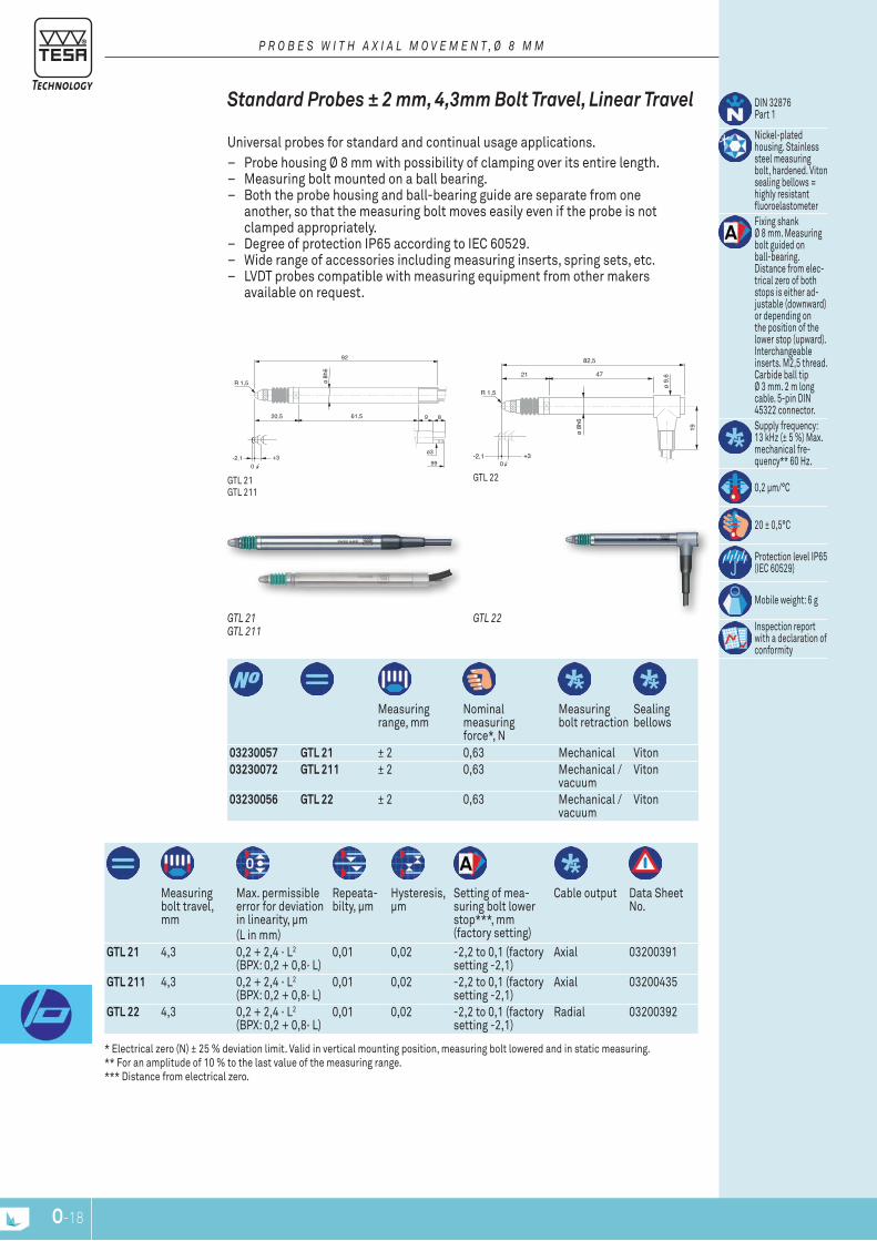
O-18
R 1,5 ø 8h
6
61,520,5
-2,1 +30
92
GTL 211
9
ø3
8
99
R 1,5
ø 8h
6
4721
-2,1 +30
82,5
ø 9,
6
19
03230057 GTL 21 ± 2 0,63 Mechanical Viton03230072 GTL 211 ± 2 0,63 Mechanical /
vacuumViton
03230056 GTL 22 ± 2 0,63 Mechanical / vacuum
Viton
Measuring range, mm
nominal measuring force*, n
Measuring bolt retraction
Sealing bellows
Measuring bolt travel, mm
Max. permissible error for deviation in linearity, μm(l in mm)
repeata-bilty, μm
Hysteresis, μm
Setting of mea-suring bolt lower stop***, mm (factory setting)
Cable output Data Sheet no.
GTL 21 4,3 0,2 + 2,4 · l2 (BpX: 0,2 + 0,8· l)
0,01 0,02 -2,2 to 0,1 (factory setting -2,1)
Axial 03200391
GTL 211 4,3 0,2 + 2,4 · l2 (BpX: 0,2 + 0,8· l)
0,01 0,02 -2,2 to 0,1 (factory setting -2,1)
Axial 03200435
GTL 22 4,3 0,2 + 2,4 · l2 (BpX: 0,2 + 0,8· l)
0,01 0,02 -2,2 to 0,1 (factory setting -2,1)
radial 03200392
DIn 32876 part 1
nickel-plated housing. Stainless steel measuring bolt, hardened. Viton sealing bellows = highly resistant fluoroelastometerFixing shank Ø 8 mm. Measuring bolt guided on ball-bearing. Distance from elec-trical zero of both stops is either ad-justable (downward) or depending on the position of the lower stop (upward). Interchangeable inserts. M2,5 thread. Carbide ball tip Ø 3 mm. 2 m long cable. 5-pin DIn 45322 connector.Supply frequency: 13 kHz (± 5 %) Max. mechanical fre-quency** 60 Hz.
0,2 μm/°C
20 ± 0,5°C
protection level Ip65 (IEC 60529)
Mobile weight: 6 g
Inspection report with a declaration of conformity
* Electrical zero (n) ± 25 % deviation limit. Valid in vertical mounting position, measuring bolt lowered and in static measuring. ** For an amplitude of 10 % to the last value of the measuring range. *** Distance from electrical zero.
gtl 22gtl 21 gtl 211
GTL 22GTL 21GTL 211
Standard probes ± 2 mm, 4,3mm bolt Travel, Linear Travel
Universal probes for standard and continual usage applications. – probe housing Ø 8 mm with possibility of clamping over its entire length. – Measuring bolt mounted on a ball bearing. – Both the probe housing and ball-bearing guide are separate from one
another, so that the measuring bolt moves easily even if the probe is not clamped appropriately.
– Degree of protection Ip65 according to IEC 60529. – Wide range of accessories including measuring inserts, spring sets, etc. – lVDt probes compatible with measuring equipment from other makers
available on request.
P r O B E S W I T H A x I A L M O V E M E n T , Ø 8 M M
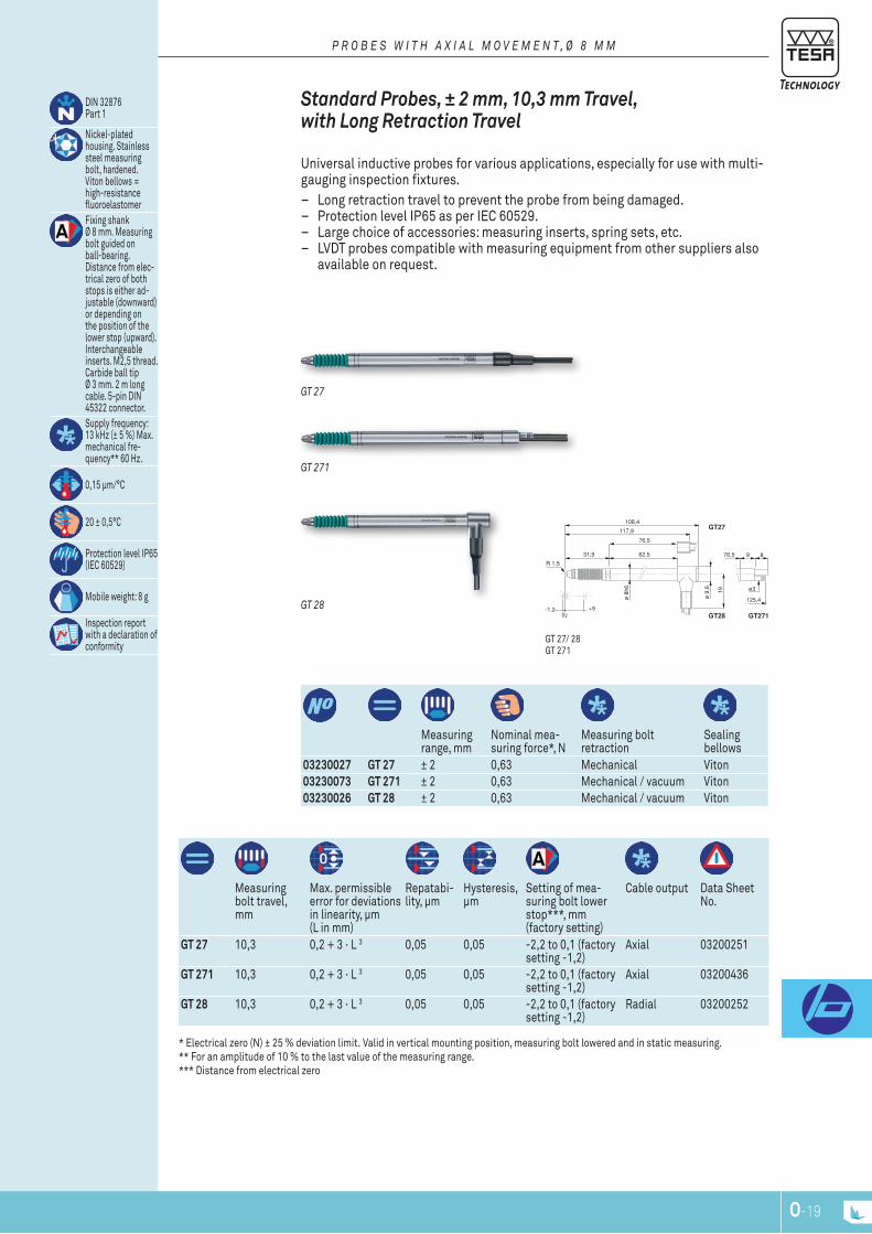
O-18 O-19
R 1,5
ø 8
h6
-1,2 +90
108,4
ø 9
,6 19
62,531,9
GT27
GT28 GT271
9
ø3
8
125,4
76,5
117,9
76,5
03230027 GT 27 ± 2 0,63 Mechanical Viton03230073 GT 271 ± 2 0,63 Mechanical / vacuum Viton03230026 GT 28 ± 2 0,63 Mechanical / vacuum Viton
Measuring range, mm
nominal mea-suring force*, n
Measuring bolt retraction
Sealing bellows
Measuring bolt travel, mm
Max. permissible error for deviations in linearity, μm (l in mm)
repatabi-lity, μm
Hysteresis, μm
Setting of mea-suring bolt lower stop***, mm (factory setting)
Cable output Data Sheet no.
GT 27 10,3 0,2 + 3 · l 3 0,05 0,05 -2,2 to 0,1 (factory setting -1,2)
Axial 03200251
GT 271 10,3 0,2 + 3 · l 3 0,05 0,05 -2,2 to 0,1 (factory setting -1,2)
Axial 03200436
GT 28 10,3 0,2 + 3 · l 3 0,05 0,05 -2,2 to 0,1 (factory setting -1,2)
radial 03200252
DIn 32876 part 1
nickel-plated housing. Stainless steel measuring bolt, hardened. Viton bellows = high-resistance fluoroelastomerFixing shank Ø 8 mm. Measuring bolt guided on ball-bearing. Distance from elec-trical zero of both stops is either ad-justable (downward) or depending on the position of the lower stop (upward). Interchangeable inserts. M2,5 thread. Carbide ball tip Ø 3 mm. 2 m long cable. 5-pin DIn 45322 connector.Supply frequency: 13 kHz (± 5 %) Max. mechanical fre-quency** 60 Hz.
0,15 μm/°C
20 ± 0,5°C
protection level Ip65 (IEC 60529)
Mobile weight: 8 g
Inspection report with a declaration of conformity
* Electrical zero (n) ± 25 % deviation limit. Valid in vertical mounting position, measuring bolt lowered and in static measuring. ** For an amplitude of 10 % to the last value of the measuring range. *** Distance from electrical zero
gt 27/ 28 gt 271
GT 28
GT 271
GT 27
Standard probes, ± 2 mm, 10,3 mm Travel, with Long retraction Travel
Universal inductive probes for various applications, especially for use with multi-gauging inspection fixtures.
– long retraction travel to prevent the probe from being damaged. – protection level Ip65 as per IEC 60529. – large choice of accessories: measuring inserts, spring sets, etc. – lVDt probes compatible with measuring equipment from other suppliers also
available on request.
P r O B E S W I T H A x I A L M O V E M E n T , Ø 8 M M
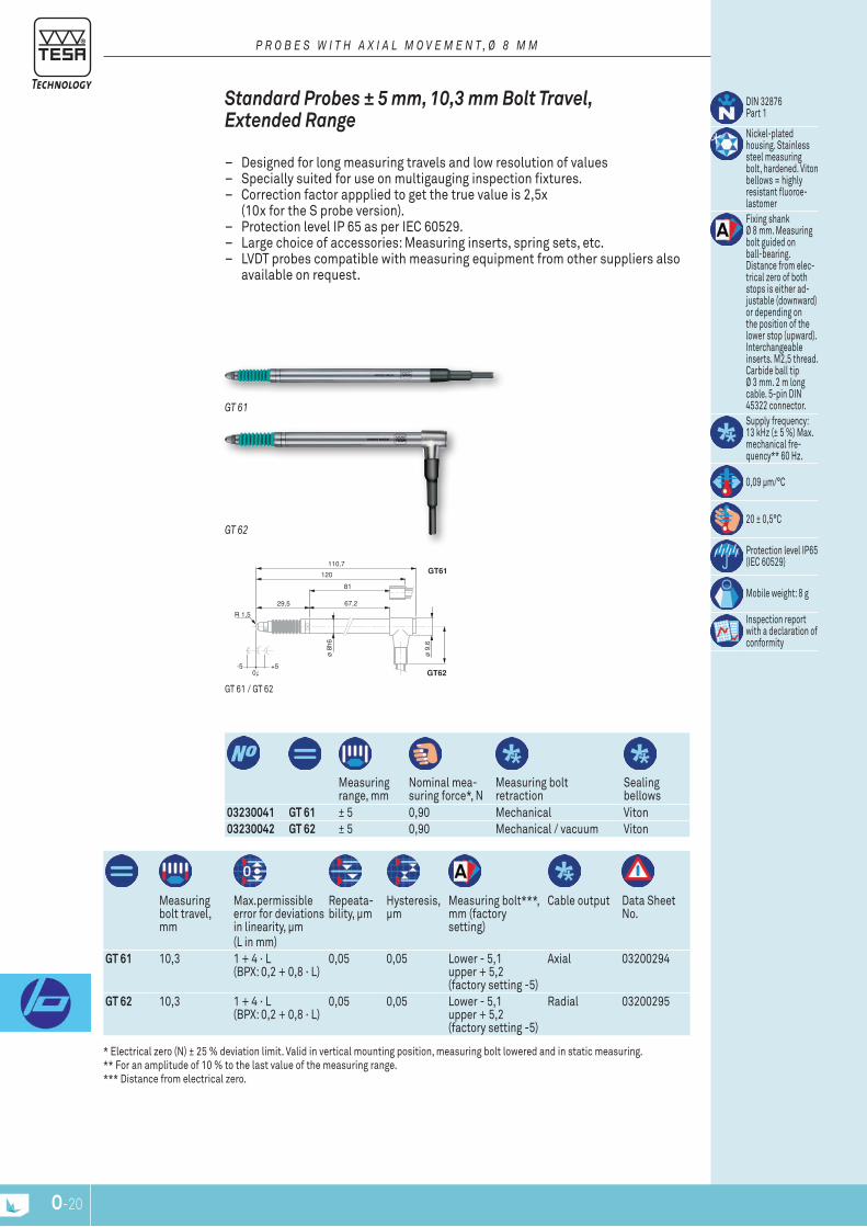
O-20
R 1,5
ø 8
h6
-5 +50
110,7
ø 9
,6
67,229,5
GT61
GT62 GT611
9
ø3
8
127.5
81
120
81
Measuring range, mm
nominal mea-suring force*, n
Measuring bolt retraction
Sealing bellows
03230041 GT 61 ± 5 0,90 Mechanical Viton03230042 GT 62 ± 5 0,90 Mechanical / vacuum Viton
Measuring bolt travel, mm
Max.permissible error for deviations in linearity, μm(l in mm)
repeata-bility, μm
Hysteresis, μm
Measuring bolt***, mm (factory setting)
Cable output Data Sheet no.
GT 61 10,3 1 + 4 · l (BpX: 0,2 + 0,8 · l)
0,05 0,05 lower - 5,1 upper + 5,2 (factory setting -5)
Axial 03200294
GT 62 10,3 1 + 4 · l (BpX: 0,2 + 0,8 · l)
0,05 0,05 lower - 5,1 upper + 5,2 (factory setting -5)
radial 03200295
DIn 32876 part 1
nickel-plated housing. Stainless steel measuring bolt, hardened. Viton bellows = highly resistant fluoroe-lastomerFixing shank Ø 8 mm. Measuring bolt guided on ball-bearing. Distance from elec-trical zero of both stops is either ad-justable (downward) or depending on the position of the lower stop (upward). Interchangeable inserts. M2,5 thread. Carbide ball tip Ø 3 mm. 2 m long cable. 5-pin DIn 45322 connector.Supply frequency: 13 kHz (± 5 %) Max. mechanical fre-quency** 60 Hz.
0,09 μm/°C
20 ± 0,5°C
protection level Ip65 (IEC 60529)
Mobile weight: 8 g
Inspection report with a declaration of conformity
gt 61 / gt 62
GT 61
GT 62
Standard probes ± 5 mm, 10,3 mm bolt Travel, Extended range
– Designed for long measuring travels and low resolution of values – Specially suited for use on multigauging inspection fixtures. – Correction factor appplied to get the true value is 2,5x
(10x for the S probe version). – protection level Ip 65 as per IEC 60529. – large choice of accessories: Measuring inserts, spring sets, etc. – lVDt probes compatible with measuring equipment from other suppliers also
available on request.
P r O B E S W I T H A x I A L M O V E M E n T , Ø 8 M M
* Electrical zero (n) ± 25 % deviation limit. Valid in vertical mounting position, measuring bolt lowered and in static measuring. ** For an amplitude of 10 % to the last value of the measuring range. *** Distance from electrical zero.
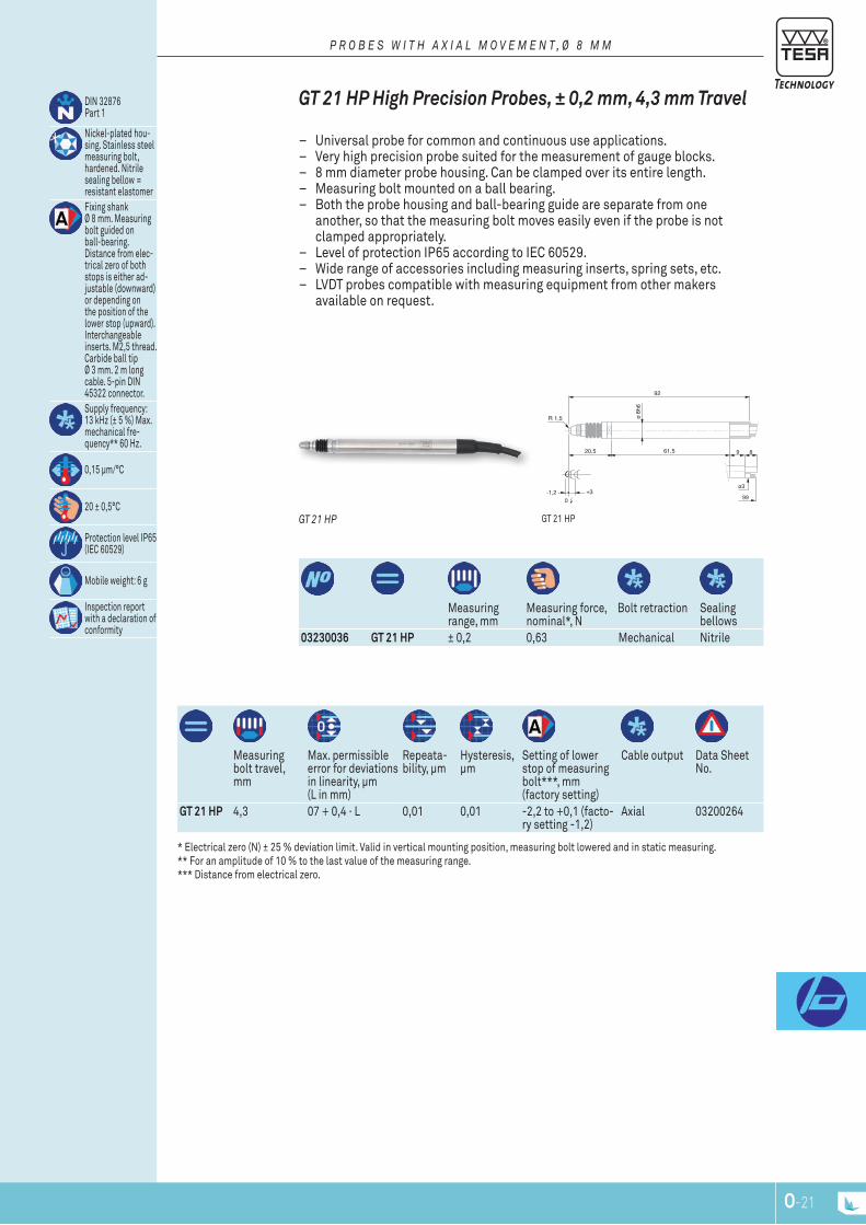
O-20 O-21
R 1,5 ø 8h
6
61,520,5
-1,2 +30
92
GT21
9
ø3
8
99
Measuring range, mm
Measuring force, nominal*, n
Bolt retraction Sealing bellows
03230036 GT 21 HP ± 0,2 0,63 Mechanical nitrile
Measuring bolt travel, mm
Max. permissible error for deviations in linearity, μm (l in mm)
repeata-bility, μm
Hysteresis, μm
Setting of lower stop of measuring bolt***, mm (factory setting)
Cable output Data Sheet no.
GT 21 HP 4,3 07 + 0,4 · l 0,01 0,01 -2,2 to +0,1 (facto-ry setting -1,2)
Axial 03200264
DIn 32876 part 1
nickel-plated hou-sing. Stainless steel measuring bolt, hardened. nitrile sealing bellow = resistant elastomerFixing shank Ø 8 mm. Measuring bolt guided on ball-bearing. Distance from elec-trical zero of both stops is either ad-justable (downward) or depending on the position of the lower stop (upward). Interchangeable inserts. M2,5 thread. Carbide ball tip Ø 3 mm. 2 m long cable. 5-pin DIn 45322 connector.Supply frequency: 13 kHz (± 5 %) Max. mechanical fre-quency** 60 Hz.
0,15 μm/°C
20 ± 0,5°C
protection level Ip65 (IEC 60529)
Mobile weight: 6 g
Inspection report with a declaration of conformity
gt 21 HpGT 21 HP
GT 21 Hp High precision probes, ± 0,2 mm, 4,3 mm Travel
– Universal probe for common and continuous use applications. – Very high precision probe suited for the measurement of gauge blocks. – 8 mm diameter probe housing. Can be clamped over its entire length. – Measuring bolt mounted on a ball bearing. – Both the probe housing and ball-bearing guide are separate from one
another, so that the measuring bolt moves easily even if the probe is not clamped appropriately.
– level of protection Ip65 according to IEC 60529. – Wide range of accessories including measuring inserts, spring sets, etc. – lVDt probes compatible with measuring equipment from other makers
available on request.
P r O B E S W I T H A x I A L M O V E M E n T , Ø 8 M M
* Electrical zero (n) ± 25 % deviation limit. Valid in vertical mounting position, measuring bolt lowered and in static measuring. ** For an amplitude of 10 % to the last value of the measuring range. *** Distance from electrical zero.

O-22
R 1,5
ø 8h
6
4721
-1,2 +30
82,5
ø 9,
6
19
Measuring range, mm
Measuring force, nominal*, n
Bolt retraction Sealing bellows
03230021 GT 22 HP ± 0,2 0,63 Mechanical / vacuum nitrile
Measuring travel, mm
Max. permissible error for deviations in linearity, μm (l in mm)
repatabi-lity, μm
Hystersis, μm
Setting of lower stop of the mea-suring bolt***, mm (factory setting)
Cable output Data Sheet no.
GT 22 HP 4,3 0,07 + 0,4 · l 0,01 0,01 -2,2 to +0,1 (usine -1,2)
radial 03200265
DIn 32876part 1
nickel-plated hou-sing. Stainless steel measuring bolt, hardened. nitrile sealing bellows = resistant elastomer Fixing shank Ø 8 mm. Measuring bolt guided on ball-bearing. Distance from elec-trical zero of both stops is either ad-justable (downward) or depending on the position of the lower stop (upward). Interchangeable inserts. M2,5 thread. Carbide ball tip Ø 3 mm. 2 m long cable. 5-pin DIn 45322 connector.Supply frequency: 13 kHz (± 5 %) Max. mechanical fre-quency*** 60 Hz.
0,15 μm/°C
20 ± 0,5°C
protection level Ip65 (IEC 60529)
Mobile weight: 6 g
Inspection report with a declaration of conformity
gt 22 HpGT 22 HP
GT 22 Hp High precision probe, ± 0,2 mm, 4,3 mm Travel
Universal probe for standard and continuous use applications. – Very high precision probe suitable for the measurement of gauge blocks. – 8 mm diameter probe housing. Can be clamped over its entire length. – Measuring bolt mounted on a ball bearing. – Both the probe housing and ball-bearing guide are separate from one
another, so that the measuring bolt moves easily even if the probe is not clamped appropriately.
– level of protection Ip65 according to IEC 60529. – Wide range of accessories including measuring inserts, spring sets, etc. – lVDt probes compatible with measuring equipment from other makers
available on request.
P r O B E S W I T H A x I A L M O V E M E n T , Ø 8 M M
* Electrical zero (n) ± 25 % deviation limit. Valid in vertical mounting position, measuring bolt lowered and in static measuring. ** For an amplitude of 10 % to the last value of the measuring range. *** Distance from electrical zero.
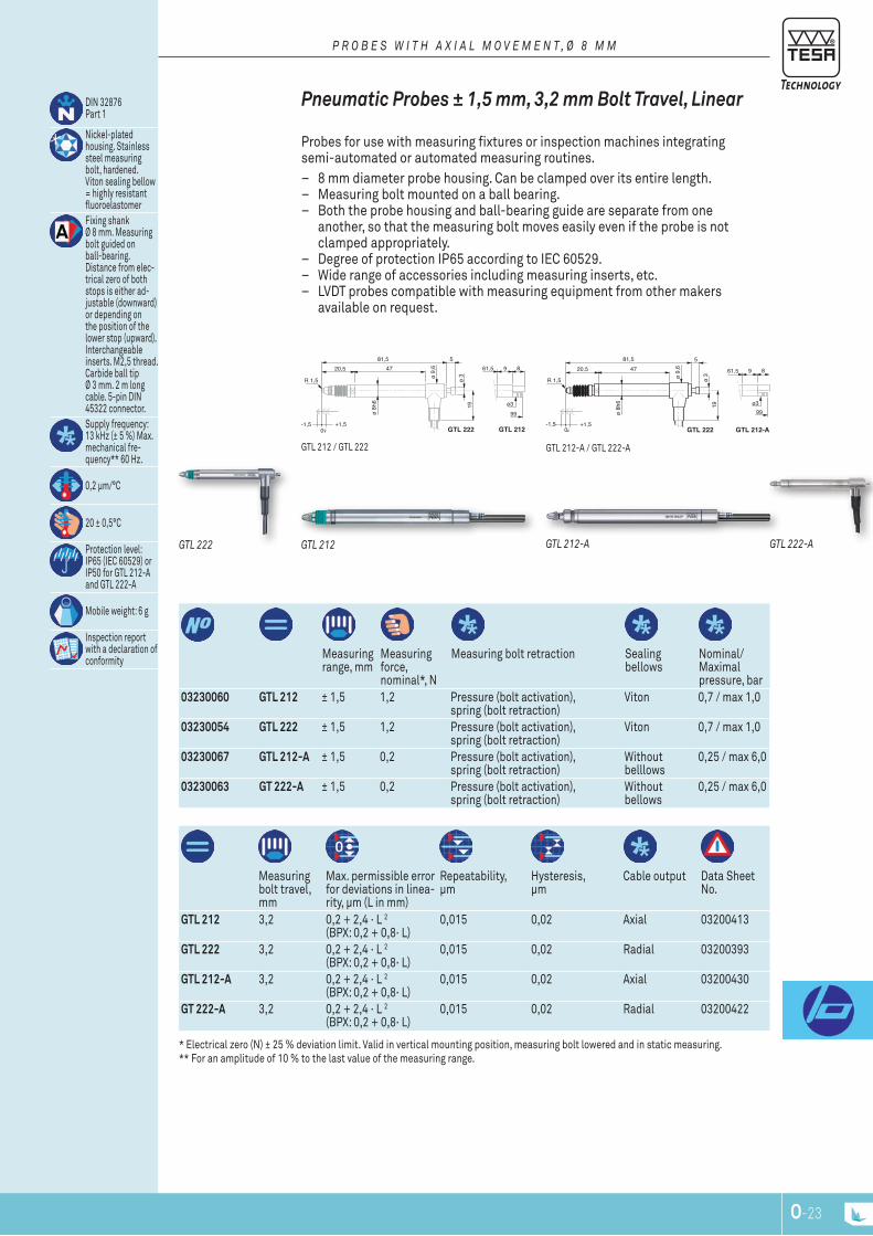
O-22 O-23
R 1,5ø
8h6
4720,5
-1,5 +1,50
81,5
ø 9,
6
19
GTL 222
5
GTL 212
99
9
ø3
861,5
ø 3
R 1,5
ø 8h
6
4720,5
-1,5 +1,50
81,5
ø 9,
6
19
GTL 222
5
GTL 212-A
99
9
ø3
861,5
ø 3
Measuring range, mm
Measuring force, nominal*, n
Measuring bolt retraction Sealing bellows
nominal/Maximal pressure, bar
03230060 GTL 212 ± 1,5 1,2 pressure (bolt activation), spring (bolt retraction)
Viton 0,7 / max 1,0
03230054 GTL 222 ± 1,5 1,2 pressure (bolt activation), spring (bolt retraction)
Viton 0,7 / max 1,0
03230067 GTL 212-A ± 1,5 0,2 pressure (bolt activation), spring (bolt retraction)
Without belllows
0,25 / max 6,0
03230063 GT 222-A ± 1,5 0,2 pressure (bolt activation), spring (bolt retraction)
Without bellows
0,25 / max 6,0
Measuring bolt travel, mm
Max. permissible error for deviations in linea-rity, μm (l in mm)
repeatability, μm
Hysteresis, μm
Cable output Data Sheet no.
GTL 212 3,2 0,2 + 2,4 · l 2 (BpX: 0,2 + 0,8· l)
0,015 0,02 Axial 03200413
GTL 222 3,2 0,2 + 2,4 · l 2 (BpX: 0,2 + 0,8· l)
0,015 0,02 radial 03200393
GTL 212-A 3,2 0,2 + 2,4 · l 2 (BpX: 0,2 + 0,8· l)
0,015 0,02 Axial 03200430
GT 222-A 3,2 0,2 + 2,4 · l 2 (BpX: 0,2 + 0,8· l)
0,015 0,02 radial 03200422
DIn 32876 part 1
nickel-plated housing. Stainless steel measuring bolt, hardened. Viton sealing bellow = highly resistant fluoroelastomer Fixing shank Ø 8 mm. Measuring bolt guided on ball-bearing. Distance from elec-trical zero of both stops is either ad-justable (downward) or depending on the position of the lower stop (upward). Interchangeable inserts. M2,5 thread. Carbide ball tip Ø 3 mm. 2 m long cable. 5-pin DIn 45322 connector.Supply frequency: 13 kHz (± 5 %) Max. mechanical fre-quency** 60 Hz.
0,2 μm/°C
20 ± 0,5°C
protection level: Ip65 (IEC 60529) or Ip50 for gtl 212-A and gtl 222-A
Mobile weight: 6 g
Inspection report with a declaration of conformity
gtl 212-A / gtl 222-Agtl 212 / gtl 222
GTL 222-AGTL 212-AGTL 222 GTL 212
pneumatic probes ± 1,5 mm, 3,2 mm bolt Travel, Linear
probes for use with measuring fixtures or inspection machines integrating semi-automated or automated measuring routines.
– 8 mm diameter probe housing. Can be clamped over its entire length. – Measuring bolt mounted on a ball bearing. – Both the probe housing and ball-bearing guide are separate from one
another, so that the measuring bolt moves easily even if the probe is not clamped appropriately.
– Degree of protection Ip65 according to IEC 60529. – Wide range of accessories including measuring inserts, etc. – lVDt probes compatible with measuring equipment from other makers
available on request.
P r O B E S W I T H A x I A L M O V E M E n T , Ø 8 M M
* Electrical zero (n) ± 25 % deviation limit. Valid in vertical mounting position, measuring bolt lowered and in static measuring. ** For an amplitude of 10 % to the last value of the measuring range.

O-24
R 1,5
ø 8h
6
-2.2 +80
108,4
ø 9,
6
19
62,531,9
GT 282 GT 272
9
ø3
8
125,4
76,5
5
ø 3R 1,5
ø 8
h6
-2.2 +80
108,4
ø 9
,6
19
62,531,9
GT 282-A GT 272-A
9
ø3
8
125,4
76,5
5
ø 3
Measuring range, mm
Measuring force, nominal*, n
Bolt retraction Sealing bellows
nominal/ Maximal pressure, bar
03230061 GT 272 ± 2 1,0 pressure (bolt activation), spring (bolt retractiom)
Viton 1,1 / max 1,5
03230053 GT 282 ± 2 1,0 pressure (bolt activation), spring (bolt retraction)
Viton 1,1 / max 1,5
03230068 GT 272-A ± 2 0,85 pressure (bolt activation), spring (bolt retraction)
Without bellows
1,0 / max 6,0
03230069 GT 282-A ± 2 0,85 pressure (bolt activation), spring (bolt retraction)
Without bellows
1,0 / max 6,0
Measuring bolt travel, mm
Max. permissible error for deviations in linearity, μm (l in mm)
repatability, μm
Hysteresis, μm
Cable output Data Sheet no.
GT 272 10,3 0,2 + 3 · l3 0,05 0,05 Axial 03200414GT 282 10,3 0,2 + 3 · l3 0,05 0,05 radial 03200390GT 272-A 10,3 0,2 + 3 · l3 0,05 0,05 Axial 03200431GT 282-A 10,3 0,2 + 3 · l3 0,05 0,05 radial 03200432
DIn 32876 part 1
nickel-plated housing. Stainless steel measuring bolt, hardened. Viton sealing bellows = highly resistant fluoroelastomerFixing shank Ø 8 mm. Measuring bolt guided on ball-bearing. Distance from elec-trical zero of both stops is either ad-justable (downward) or depending on the position of the lower stop (upward). Interchangeable inserts. M2,5 thread. Carbide ball tip Ø 3 mm. 2 m long cable. 5-pin DIn 45322 connector.Supply frequency: 13 kHz (± 5 %) Max. mechanical fre-quency** 60 Hz.
0,15 μm/°C
20 ± 0,5°C
protection level: Ip65 (IEC 60529), Ip64 for gt 21 Hp
Mobile weight: 8 g
Inspection report with a declaration of conformity
gt 282-A / gt 272-A gt 282 / gt 272GT 282-A
GT 272-AGT 282 GT 272
pneumatic probes ± 2 mm, 10,3 mm bolt Travel, with Long retraction Travel
these probes are intended for use with measuring fixtures or machines integrating automated and semi-automated measuring routines.
– 8 mm diameter probe housing. Can be clamped over its entire length. – Measuring bolt mounted on a ball bearing. – Both the probe housing and ball-bearing guide are separate from one
another, so that the measuring bolt moves easily even if the probe is not clamped appropriately.
– Degree of protection Ip65 according to IEC 60529. – Wide range of accessories including measuring inserts, etc. – lVDt probes compatible with measuring equipment from other makers
available on request.
P r O B E S W I T H A x I A L M O V E M E n T , Ø 8 M M
* Electrical zero (n) ± 25 % deviation limit. Valid in vertical mounting position, measuring bolt lowered and in static measuring. ** For an amplitude of 10 % to the last value of the measuring range.
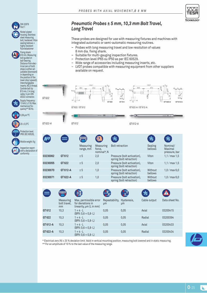
O-24 O-25
R 1,5ø
8h6
-5 +50
110,7
ø 9,
667,229,5
GT 622 GT 612
9
ø3
8
127.5
81
5
ø 3
19
R 1,5
ø 8
h6
-5 +50
110,7
ø 9
,667,229,5
GT 622-A GT 612-A
9
ø3
8
127.5
81
5
ø 3
19
Measuring range, mm
Measuring force, nominal*, n
Bolt retraction Sealing bellows
nominal/ Maximal pressure, bar
03230062 GT 612 ± 5 2,0 pressure (bolt activation), spring (bolt retraction)
Viton 1,1 / max 1,5
03230055 GT 622 ± 5 2,0 pressure (bolt activation), spring (bolt retraction)
Viton 1,1 / max 1,5
03230070 GT 612-A ± 5 1,0 pressure (bolt activation), spring (bolt retraction)
Without bellows
1,0 / max 6,0
03230071 GT 622-A ± 5 1,0 pressure (bolt activation), spring (bolt retraction)
Without bellows
1,0 / max 6,0
Measuring bolt travel, mm
Max. permissible error for deviations in linearity, μm (l in mm)
repeatability, μm
Hysteresis, μm
Cable output Data sheet no.
GT 612 10,3 1 + 4 · l (BpX: 0,6 + 0,8· l)
0,05 0,05 Axial 03200415
GT 622 10,3 1 + 4 · l (BpX: 0,6 + 0,8· l)
0,05 0,05 radial 03200394
GT 612-A 10,3 1 + 4 · l (BpX: 0,6 + 0,8· l)
0,05 0,05 Axial 03200433
GT 622-A 10,3 1 + 4 · l (BpX: 0,6 + 0,8· l)
0,05 0,05 radial 03200434
DIn 32876 part 1
nickel-plated housing. Stainless steel measuring bolt, hardened. Viton sealing bellows = highly resistant fluoroelastomer Fixing shank Ø 8 mm. Measuring bolt guided on ball-bearing. Distance from elec-trical zero of both stops is either ad-justable (downward) or depending on the position of the lower stop (upward). Interchangeable inserts. M2,5 thread. Carbide ball tip Ø 3 mm. 2 m long cable. 5-pin DIn 45322 connector.Supply frequency: 13 kHz (± 5 %) Max. mechanical fre-quency** 60 Hz.
0,09 μm/°C
20 ± 0,5°C
protection level: Ip65 (IEC 60529),
Mobile weight: 8 g
Inspection report with a declaration of conformity
gt 622-A / gt 612-Agt 622 / gt 612
GT 622-A GT 612-A
GT 622
GT 612
pneumatic probes ± 5 mm, 10,3 mm bolt Travel, Long Travel
these probes are designed for use with measuring fixtures and machines with integrated automatic or semi-automatic measuring routines.
– probes with long measuring travel and low resolution of values 8 mm dia. fixing shank.
– Suitable for multi-gauging inspection fixtures. – protection level Ip65 ou Ip50 as per IEC 60529. – Wide range of accessories including measuring inserts, etc. – lVDt probes compatible with measuring equipment from other suppliers
available on request.
P r O B E S W I T H A x I A L M O V E M E n T , Ø 8 M M
* Electrical zero (n) ± 25 % deviation limit. Valid in vertical mounting position, measuring bolt lowered and in static measuring. ** For an amplitude of 10 % to the last value of the measuring range.
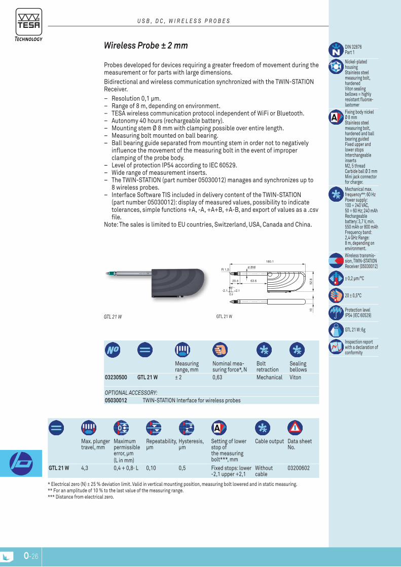
O-26
ø 8h6R 1,5
180.1
63.620.4
+2.1-2.10
52.8
10
Measuring range, mm
nominal mea-suring force*, n
Bolt retraction
Sealing bellows
03230500 GTL 21 W ± 2 0,63 Mechanical Viton
Max. plunger travel, mm
Maximum permissible error, μm(l in mm)
repeatability, μm
Hysteresis, μm
Setting of lower stop of the measuring bolt***, mm
Cable output Data sheet no.
GTL 21 W 4,3 0,4 + 0,8· l 0,10 0,5 Fixed stops: lower -2,1 upper +2,1
Without cable
03200602
DIn 32876 part 1
nickel-plated housingStainless steel measuring bolt, hardenedViton sealing bellows = highly resistant fluoroe-lastomerFixing body nickel Ø 8 mmStainless steel measuring bolt, hardened and ball bearing guidedFixed upper and lower stopsInterchangeable insertsM2, 5 threadCarbide ball Ø 3 mmMini jack connector for charger.Mechanical max. frequency**: 60 Hz power supply: 100 ÷ 240 VAC, 50 ÷ 60 Hz; 240 mAh rechargeable battery: 3,7 V, min. 550 mAh or 800 mAh Frequency band: 2,4 gHz range: 8 m, depending on environment.Wireless transmis-sion, tWIn-StAtIOn receiver (05030012)
± 0,2 μm/°C
20 ± 0,5°C
protection level Ip54 (IEC 60529)
gtl 21 W: 6g
Inspection report with a declaration of conformity
OPTIOnAL AccESSOry:05030012 tWIn-StAtIOn Interface for wireless probes
gtl 21 WGTL 21 W
Wireless probe ± 2 mm
probes developed for devices requiring a greater freedom of movement during the measurement or for parts with large dimensions.Bidirectional and wireless communication synchronized with the tWIn-StAtIOn receiver.
– resolution 0,1 μm. – range of 8 m, depending on environment. – tESA wireless communication protocol independent of WiFi or Bluetooth. – Autonomy 40 hours (rechargeable battery). – Mounting stem Ø 8 mm with clamping possible over entire length. – Measuring bolt mounted on ball bearing. – Ball bearing guide separated from mounting stem in order not to negatively
influence the movement of the measuring bolt in the event of improper clamping of the probe body.
– level of protection Ip54 according to IEC 60529. – Wide range of measurement inserts. – the tWIn-StAtIOn (part number 05030012) manages and synchronizes up to
8 wireless probes. – Interface Software tIS included in delivery content of the tWIn-StAtIOn
(part number 05030012): display of measured values, possibility to indicate tolerances, simple functions +A, -A, +A+B, +A-B, and export of values as a .csv file.
note: the sales is limited to EU countries, Switzerland, USA, Canada and China.
U S B , D c , W I r E L E S S P r O B E S
* Electrical zero (n) ± 25 % deviation limit. Valid in vertical mounting position, measuring bolt lowered and in static measuring. ** For an amplitude of 10 % to the last value of the measuring range. *** Distance from electrical zero.

O-26 O-27
ø 8h6R 1,5
208.7
8329.6
+5-50
52.8
10
Measuring range, mm
nominal mea-suring force*, n
Bolt retraction
Sealing bellows
03230502 GT 61 W ± 5 0,9 Mechanical Viton
Max. bolt travel, mm
Maximum permissible error, μm(l in mm)
repeatability, μm
Hysteresis, μm
Setting of lower stop of measuring bolt***, mm
Cable output Data sheet no.
GT 61 W 10,3 0,8 + 0,8· l 0,24 0,5 Fixed stops lower -5 upper +5
Without cable 03200621
DIn 32876 part 1
nickel-plated housingStainless steel measuring bolt, hardened. Viton = highly resistant fluoroelastomerFixing shank Ø 8 mm. Measuring bolt guided on ball-bearing. Distance from elec-trical zero of both stops is either ad-justable (downward) or depending on the position of the lower stop (upward). Interchangeable inserts. M2,5 thread. Carbide ball tip Ø 3 mm. Connector Mini-jack for charger.Mechanical max. frequency**: 60 Hz power supply: 100 ÷ 240 VAC, 50 ÷ 60 Hz; 240 mAh rechargeable battery: 3,7 V, min. 550 mAh or 800 mAh Frequency band: 2,4 gHz range: 8 m, depending on environment.Wireless transmis-sion, tWIn-StAtIOn receiver (05030012)
± 0,2 μm/°C
20 ± 0,5°C
protection operating enevelope Ip54 (IEC 60529)
gt 61 W: 8 g
Inspection report with a declaration of conformity
gt 61 WGT 61 W
Wireless probe ± 5 mm, Large Measuring range
probes developed for devices requiring a greater freedom of movement during the measurement or for parts with large dimensions.Bidirectional and wireless communication synchronized with the tWIn-StAtIOn receiver.
– resolution 0,1 μm. – range of 8 m, depending on environment. – tESA wireless communication protocol independent from WiFi or Bluetooth. – Autonomy 40 hours (rechargeable battery). – Mounting body Ø 8 mm with possoboilty of clamping over entire length. – Measuring bolt mounted on ball bearing. – Separate guide bearing on the mounting body in order not to negatively
influence the movement of the measuring bolt in the event of improper clamping on the probe body.
– level of protection Ip54 according to IEC 60529. – Wide range of measurement probes. – the tWIn-StAtIOn (part number 05030012) manages and synchronizes up
to 8 wireless probes. – Interface Software tIS included in supply content of the tWIn-StAtIOn
(part number 05030012): display of measured values, possibility to indicate tolerances, simple functions +A, -A, +A+B, +A-B, and export of values in a .csv file.
note: the sales is limited to EU countries, Switzerland, USA, Canada and China.
U S B , D c , W I r E L E S S P r O B E S
* Electrical zero (n) ± 25 % deviation limit. Valid in vertical mounting position, measuring bolt lowered and in static measuring. ** For an amplitude of 10 % to the last value of the measuring range. *** Distance from electrical zero.
OPTIOnAL AccESSOry:05030012 tWIn-StAtIOn Interface for wireless probes
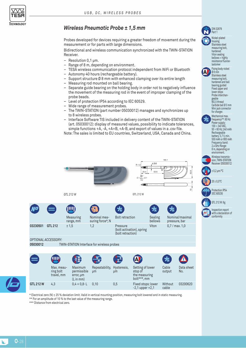
O-28
ø 8h6R 1,5
180.1
63.620.4
+2.1-2.10
52.8
10
Measuring range, mm
nominal mea-suring force*, n
Bolt retraction Sealing bellows
nominal/maximal pressure, bar
03230501 GTL 212 ± 1,5 1,2 pressure (bolt activation), spring (bolt retraction)
Viton 0,7 / max. 1,0
Max. meau-ring bolt travel, mm
Maximum permissible error, μm(l in mm)
repeatability, μm
Hysteresis, μm
Setting of lower stop of the measuring bolt***, mm
Cable output
Data sheet no.
GTL 212 W 4,3 0,4 + 0,8· l 0,10 0,5 Fixed stops: lower -2,1 upper +2,1
Without cable
03200620
DIn 32876 part 1
nickel-plated housingStainless steel measuring bolt, hardenedViton sealing bellows = highly resistance fluoroe-lastomerFixing body nickel Ø 8 mmStainless steel measuring bolt, hardened and ball bearing guidedFixed upper and lower stopsprobe interchan-geableM2,5 threadCarbide ball Ø 3 mmMini jack connector for charger.Mechanical max. frequency**: 60 Hz power supply: 100 ÷ 240 VAC, 50 ÷ 60 Hz; 240 mAh rechargeable battery: 3,7 V, min. 550 mAh or 800 mAh Frequency band: 2,4 gHz range: 8 m, depending on environment.Wireless transmis-sion, tWIn-StAtIOn receiver (05030012)
± 0,2 μm/°C
20 ± 0,5°C
protection Ip54 (IEC 60529)
gtl 212 W: 6g
Inspection report with a declaration of conformity
gtl 212 WGTL 212 W
Wireless pneumatic probe ± 1,5 mm
probes developed for devices requiring a greater freedom of movement during the measurement or for parts with large dimensions.Bidirectional and wireless communication synchronized with the tWIn-StAtIOn receiver.
– resolution 0,1 μm. – range of 8 m, depending on environment. – tESA wireless communication protocol independent from WiFi or Bluetooth – Autonomy 40 hours (rechargeable battery). – Support structure Ø 8 mm with enhanced clamping over its entire length – Measuring rod mounted on ball bearing. – Separate guide bearing on the holding body in order not to negatively influence
the movement of the measuring rod in the event of improper clamping of the probe beads.
– level of protection Ip54 according to IEC 60529. – Wide range of measurement probes. – the tWIn-StAtIOn (part number 05030012) manages and synchronizes up
to 8 wireless probes. – Interface Software tIS included in delivery content of the tWIn-StAtIOn
(art. 05030012): display of measured values, possibility to indicate tolerances, simple functions +A, -A, +A+B, +A-B, and export of values in a .csv file.
note: the sales is limited to EU countries, Switzerland, USA, Canada and China.
U S B , D c , W I r E L E S S P r O B E S
* Electrical zero (n) ± 25 % deviation limit. Valid in vertical mounting position, measuring bolt lowered and in static measuring. ** For an amplitude of 10 % to the last value of the measuring range. *** Distance from electrical zero.
OPTIOnAL AccESSOry:05030012 tWIn-StAtIOn Interface for wireless probes

O-28 O-29
ø 8h6R 1,5
209.4
83.729.6
+5-50
52.8
10
Measuring range, mm
nominal mea-suring force*, n
Bolt retraction Sealing bellows
nominal/maximal pressure, bar
03230503 GT 612 W ± 5 2,0 pressure (bolt activation), spring (bolt retraction)
Viton 1,1 / max. 1,5
Max. bolt travel, mm
Maximum permis-sible error, μm(l in mm)
repeata-bility, μm
Hysteresis, μm
Setting of lower stop of measuring bolt***, mm
Cable output Data sheet no.
GT 612 W 10,3 0,8 + 0,8· l 0,24 0,5 Fixed stops: lower -5 upper +5
Without cable 03200622
DIn 32876 part 1
nickel-plated housingStainless steel measuring bolt, hardenedViton sealing bellows = highly resistance fluoroe-lastomerFixing body nickel Ø 8 mmStainless steel measuring bolt, hardened and ball bearing guidedFixed upper and lower stopsprobe interchan-geableM2, 5 threadCarbide ball Ø 3 mmMini jack connector for chargerMechanical max. frequency**: 60 Hz power supply: 100 ÷ 240 VAC, 50 ÷ 60 Hz; 240 mAh rechargeable battery: 3,7 V, min. 550 mAh or 800 mAh Frequency band: 2,4 gHz range: 8 m, depending on environment.Wireless transmis-sion, tWIn-StAtIOn receiver (05030012)
± 0,2 μm/°C
20 ± 0,5°C
protection level Ip54 (IEC 60529)
gt 612 W: 8 g
Inspection report with a declaration of conformity
gt 612 WGT 612 W
Wireless pneumatic probe ± 5 mm, Large Measuring range
probes developed for devices requiring a greater freedom of movement during the measurement or for pieces with large dimensions.Bidirectional and wireless communication synchronized with the tWIn-StAtIOn receiver.
– resolution 0,1 μm. – range of 8 m, depending on environment. – tESA wireless communication protocol independent from WiFi or Bluetooth. – Autonomy 40 hours (rechargeable battery). – Mounting body Ø 8 mm with enhanced clamping over its entire length. – Measuring bolt mounted on ball bearing. – Separate guide bearing on the holding body in order not to negatively influence
the movement of the measuring bolt in the event of improper clamping on the probe body.
– level of protection Ip54 according to IEC 60529. – Wide range of measurement probes. – the tWIn-StAtIOn (part number 05030012) manages and synchronizes up to
8 wireless probes. – Interface Software tIS included in delivery content of the tWIn-StAtIOn
(art. 05030012): display of measured values, possibility to indicate tolerances, simple functions +A, -A, +A+B, +A-B, and export of values in a .csv file.
note: the sales is limited to EU countries, Switzerland, USA, Canada and China.
U S B , D c , W I r E L E S S P r O B E S
* Electrical zero (n) ± 25 % deviation limit. Valid in vertical mounting position, measuring bolt lowered and in static measuring. ** For an amplitude of 10 % to the last value of the measuring range. *** Distance from electrical zero.
OPTIOnAL AccESSOry:05030012 tWIn-StAtIOn Interface for wireless probes
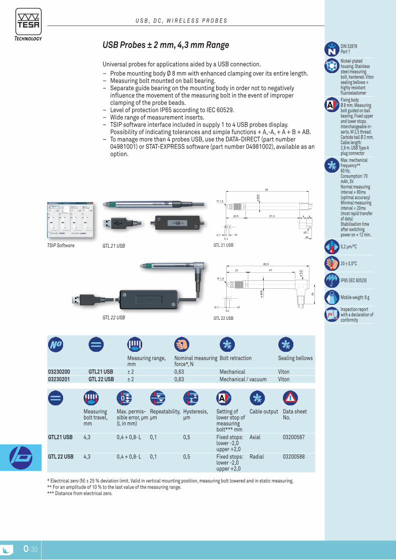
O-30
R 1,5 ø 8h
6
61,520,5
-2,1 +30
92
GTL 211
9
ø3
8
99
R 1,5
ø 8h
6
4721
-2,1 +30
82,5
ø 9,
6
19
Measuring range, mm
nominal measuring force*, n
Bolt retraction Sealing bellows
03230200 GTL21 USB ± 2 0,63 Mechanical Viton03230201 GTL 22 USB ± 2 0,63 Mechanical / vacuum Viton
Measuring bolt travel, mm
Max. permis-sible error, μm (l in mm)
repeatability, μm
Hysteresis, μm
Setting of lower stop of measuring bolt*** mm
Cable output Data sheet no.
GTL21 USB 4,3 0,4 + 0,8· l 0,1 0,5 Fixed stops: lower -2,0 upper +2,0
Axial 03200587
GTL 22 USB 4,3 0,4 + 0,8· l 0,1 0,5 Fixed stops: lower -2,0 upper +2,0
radial 03200588
DIn 32876 part 1
nickel-plated housing. Stainless steel measuring bolt, hardened. Viton sealing bellows = highly resistant fluoroelastomerFixing body Ø 8 mm. Measuring bolt guided on ball bearing. Fixed upper and lower stops. Interchangeable in-serts. M 2,5 thread. Carbide ball Ø 3 mm. Cable length: 2,9 m. USB type A plug connectorMax. mechanical frequency** 60 Hz. Consumption: 70 mAh, 5V normal measuring interval = 80ms (optimal accuracy) Minimal measuring interval = 20ms (most rapid transfer of data) Stabilisation time after switching power on = 12 min.
0,2 μm/°C
20 ± 0,5°C
Ip65 (IEC 60529)
Mobile weight: 6 g
Inspection report with a declaration of conformitygtl 22 USB
gtl 21 USBTSIP Software
GTL 22 USB
GTL 21 USB
uSb probes ± 2 mm, 4,3 mm range
Universal probes for applications aided by a USB connection. – probe mounting body Ø 8 mm with enhanced clamping over its entire length. – Measuring bolt mounted on ball bearing. – Separate guide bearing on the mounting body in order not to negatively
influence the movement of the measuring bolt in the event of improper clamping of the probe beads.
– level of protection Ip65 according to IEC 60529. – Wide range of measurement inserts. – tSIp software interface included in supply 1 to 4 USB probes display.
possibility of indicating tolerances and simple functions + A,-A, + A + B + AB. – to manage more than 4 probes USB, use the DAtA-DIrECt (part number
04981001) or StAt-EXprESS software (part number 04981002), available as an option.
U S B , D c , W I r E L E S S P r O B E S
* Electrical zero (n) ± 25 % deviation limit. Valid in vertical mounting position, measuring bolt lowered and in static measuring. ** For an amplitude of 10 % to the last value of the measuring range. *** Distance from electrical zero.
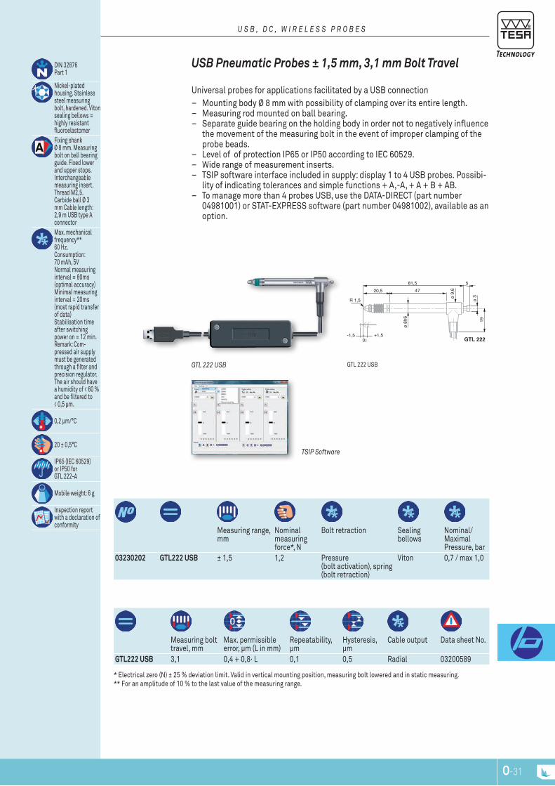
O-30 O-31
R 1,5
ø 8h
6
4720,5
-1,5 +1,50
81,5
ø 9,
6
19
GTL 222
5
GTL 212
99
9
ø3
861,5
ø 3
Measuring range, mm
nominal measuring force*, n
Bolt retraction Sealing bellows
nominal/Maximal pressure, bar
03230202 GTL222 USB ± 1,5 1,2 pressure (bolt activation), spring (bolt retraction)
Viton 0,7 / max 1,0
Measuring bolt travel, mm
Max. permissible error, μm (l in mm)
repeatability, μm
Hysteresis, μm
Cable output Data sheet no.
GTL222 USB 3,1 0,4 + 0,8· l 0,1 0,5 radial 03200589
DIn 32876 part 1
nickel-plated housing. Stainless steel measuring bolt, hardened. Viton sealing bellows = highly resistant fluoroelastomerFixing shank Ø 8 mm. Measuring bolt on ball bearing guide. Fixed lower and upper stops. Interchangeable measuring insert. thread M2,5. Carbide ball Ø 3 mm Cable length: 2,9 m USB type A connectorMax. mechanical frequency** 60 Hz. Consumption: 70 mAh, 5V normal measuring interval = 80ms (optimal accuracy) Minimal measuring interval = 20ms (most rapid transfer of data) Stabilisation time after switching power on = 12 min. remark: Com-pressed air supply must be generated through a filter and precision regulator. the air should have a humidity of < 60 % and be filtered to < 0,5 μm.
0,2 μm/°C
20 ± 0,5°C
Ip65 (IEC 60529)or Ip50 for gtl 222-A
Mobile weight: 6 g
Inspection report with a declaration of conformity
gtl 222 USB
TSIP Software
GTL 222 USB
uSb pneumatic probes ± 1,5 mm, 3,1 mm bolt Travel
Universal probes for applications facilitated by a USB connection – Mounting body Ø 8 mm with possibility of clamping over its entire length. – Measuring rod mounted on ball bearing. – Separate guide bearing on the holding body in order not to negatively influence
the movement of the measuring bolt in the event of improper clamping of the probe beads.
– level of of protection Ip65 or Ip50 according to IEC 60529. – Wide range of measurement inserts. – tSIp software interface included in supply: display 1 to 4 USB probes. possibi-
lity of indicating tolerances and simple functions + A,-A, + A + B + AB. – to manage more than 4 probes USB, use the DAtA-DIrECt (part number
04981001) or StAt-EXprESS software (part number 04981002), available as an option.
U S B , D c , W I r E L E S S P r O B E S
* Electrical zero (n) ± 25 % deviation limit. Valid in vertical mounting position, measuring bolt lowered and in static measuring. ** For an amplitude of 10 % to the last value of the measuring range.

O-32
R 1,5
ø 8
h6-5 +5
0
110,7
ø 9
,6
67,229,5
GT61
GT62 GT611
9
ø3
8
127.5
81
120
81
Measuring range, mm
nominal measuring force*, n
Bolt retraction Sealing bellows
03230204 GT61 USB ± 5 0,90 Mechanical Viton03230205 GT62 USB ± 5 0,90 Mechanical / vacuum Viton
Measuring bolt travel, mm
Max. permis-sible error, μm (l in mm)
repeatability, μm
Hysteresis, μm
Settings of lower stop of bolt***, mm
Cable output Data sheet no.
GT61 USB 10,3 0,8 + 0,8· l 0,24 0,5 Fixed stops: lower -5,0 upper +5,0
Axial 03200591
GT62 USB 10,3 0,8 + 0,8· l 0,24 0,5 Fixed stops: lower -5,0 upper +5,0
radial 03200592
DIn 32876part 1
nickel-plated housing. Stainless steel measuring bolt, hardened. Viton sealing bellows = highly resistant fluoroelastomerFixing shank Ø 8 mm. Measuring bolt guided on ball-bearing. Distance from elec-trical zero of both stops is either ad-justable (downward) or depending on the position of the lower stop (upward). Interchangeable inserts. M2,5 thread. Carbide ball tip Ø 3 mm. Cable length 2,9 m. USB type A connector. 5-pin DIn 45322 connector.Max. mechanical frequency 60 Hz power consumption: 70 mAh normal measure-ment interval = 80ms (maximum accuracy) Minimum mea-surement interval = 20ms (fastest transfer data). Stabilisation time after power on = 12 min
0,09 μm/°C
20 ± 0,5°C
Ip65 (IEC 60529)
Mobile weight: 8 g
Inspection report with a declaration of conformity
gt 61 USB / gt 62 USB
TSIP Software
GT 61 USB
uSb probes ± 5 mm, 10,3 mm bolt Travel, Extended Measuring range
USB universal probes for applications facilitated by a USB connection. – probes designed for long measuring travel and low resolution measurement
values. – probe mounting body Ø 8 mm with possibility of clamping over its entire
length. – Measuring bolt mounted on ball bearing. – Separate guide bearing on the holding body in order not to negatively influence
the movement of the measuring bolt in the event of improper clamping of the probe beads.
– level of protection Ip65 according to IEC 60529. – Wide range of measurement inserts. – tSIp software interface included in supply 1 to 4 USB probes display.
possibility of indicating tolerances, simple functions + A,-A, + A + B + AB. – to manage more than 4 USB probes, use the DAtA-DIrECt (part number
04981001) or StAt-EXprESS software (part number 04981002), available as an option.
U S B , D c , W I r E L E S S P r O B E S
* Electrical zero (n) ± 25 % deviation limit. Valid in vertical mounting position, measuring bolt lowered and in static measuring. ** For an amplitude of 10 % to the last value of the measuring range. *** Distance from electrical zero.
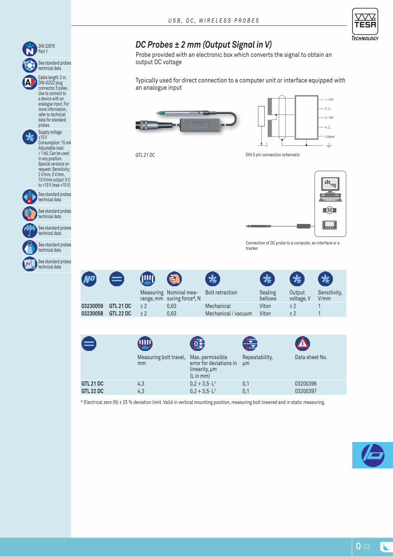
O-32 O-33
5 Signal
4
3 – 15V
2
1 + 15V
M
Measuring range, mm
nominal mea-suring force*, n
Bolt retraction Sealing bellows
Output voltage, V
Sensitivity, V/mm
03230059 GTL 21 DC ± 2 0,63 Mechanical Viton ± 2 103230058 GTL 22 DC ± 2 0,63 Mechanical / vacuum Viton ± 2 1
Measuring bolt travel, mm
Max. permissible error for deviations in linearity, μm(l in mm)
repeatability, μm
Data sheet no.
GTL 21 DC 4,3 0,2 + 3,5· l2 0,1 03200396GTL 22 DC 4,3 0,2 + 3,5· l2 0,1 03200397
DIn 32876 part 1
See standard probes technical data
Cable length: 2 m. DIn 45322 plug connector, 5 poles. Use to connect to a device with an analogue input. For more information, refer to technical data for standard probesSupply voltage: ±15 V Consumption: 15 mA Adjustable load: > 1 kΩ. Can be used in any position. Special versions on request: Sensitivity: 2 V/mm, 5 V/mm, 10 V/mm output: 0 V to +10 V (max +10 V)
See standard probes technical data
See standard probes technical data
See standard probes technical data
See standard probes technical data
See standard probes technical data
Connection of DC probe to a computer, an interface or a tracker
DIn 5 pin connection schematicGTL 21 Dc
dc probes ± 2 mm (output Signal in v) probe provided with an electronic box which converts the signal to obtain an output DC voltage
typically used for direct connection to a computer unit or interface equipped with an analogue input
U S B , D c , W I r E L E S S P r O B E S
* Electrical zero (n) ± 25 % deviation limit. Valid in vertical mounting position, measuring bolt lowered and in static measuring.
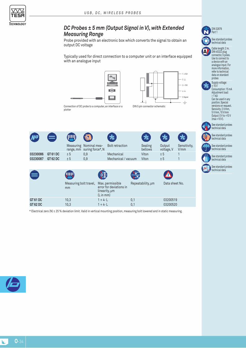
O-34
5 Signal
4
3 – 15V
2
1 + 15V
M
Measuring range, mm
nominal mea-suring force*, n
Bolt retraction Sealing bellows
Output voltage, V
Sensitivity, V/mm
03230086 GT 61 DC ± 5 0,9 Mechanical Viton ± 5 103230087 GT 62 DC ± 5 0,9 Mechanical / vacuum Viton ± 5 1
Measuring bolt travel, mm
Max. permissible error for deviations in linearity, μm(l in mm)
repeatability, μm Data sheet no.
GT 61 DC 10,3 1 + 4· l 0,1 03200519GT 62 DC 10,3 1 + 4· l 0,1 03200520
DIn 32876 part 1
See standard probes technical data
Cable length: 2 m. DIn 45322 plug connector, 5 poles. Use to connect to a device with an analogue input. For more information, refer to technical data on standard probesSupply voltage: ± 15 V Consumption: 15 mA Adjustment load: > 1 kΩ Can be used in any position. Special versions on request. Sensivity: 2 V/mm, 5 V/mm, 10 V/mm Output: 0 V to +10 V (max +10 V).
See standard probes technical data
See standard probes technical data
See standard probes technical data
See standard probes technical data
See standard probes technical data
Connection of DC probe to a computer, an interface or a plotter
DIn 5 pin connector schematic
dc probes ± 5 mm (output Signal in v), with Extended Measuring range probe provided with an electronic box which converts the signal to obtain an output DC voltage
typically used for direct connection to a computer unit or an interface equipped with an analogue input
U S B , D c , W I r E L E S S P r O B E S
* Electrical zero (n) ± 25 % deviation limit. Valid in vertical mounting position, measuring bolt lowered and in static measuring.

O-34 O-35
5 Signal
4
3 – 15V
2
1 + 15V
M
Measuring range, mm
nominal mea-suring force*, n
Bolt retraction Sealing bellows
Output voltage, V
Sensitivity, V/mm
03230085 GT 44 DC ± 1 0,4 Mechanical / vacuum Viton ± 1 1
Measuring bolt travel, mm
Max. permissible error for deviations in linearity, μm(l en mm)
repeatability, μm Data sheet no.
GT 44 DC 2,1 0,2 + 5· l3 0,1 03200518
DIn 32876 part 1
See standard probes technical data
Cable length: 2 m. DIn 45322 plug connector, 5 poles. Use to connect to a device with an ana-log input. For more information, refer to technical data for standard probesDrive voltage: ± 15 V Consumption: 15 mA Adjustment load: > 1 kΩ. Can be used in any position. Special versions on request. Sensivity: 2 V/mm, 5 V/mm, 10 V/mm Output: 0 V à +10 V (max +10 V)
See standard probes technical data
See standard probes technical data
See standard probes technical data
See standard probes technical data
See standard probes technical data
Connection of a DC probe to a computer, an interface or a plotter
DIn 5 pin connection schematic
dc Miniature probes ± 1 mm (output Signal in v) probe provided with an electronic box which converts the signal to obtain an output DC voltage
typically used for direct connection to a computer unit or an interface equipped with an analogue input
U S B , D c , W I r E L E S S P r O B E S
* Electrical zero (n) ± 25 % deviation limit. Valid in vertical mounting position, measuring bolt lowered and in static measuring.
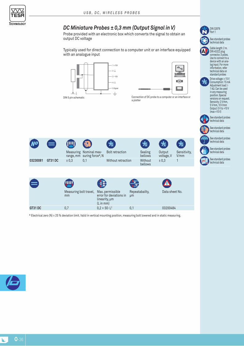
O-36
5 Signal
4
3 – 15V
2
1 + 15V
M
Measuring range, mm
nominal mea-suring force*, n
Bolt retraction Sealing bellows
Output voltage, V
Sensitivity, V/mm
03230081 GT31 DC ± 0,3 0,1 Without retraction Without bellows
± 0,3 1
Measuring bolt travel, mm
Max. permissible error for deviations in linearity, μm(l in mm)
repeatabailty, μm
Data sheet no.
GT31 DC 0,7 0,2 + 50· l2 0,1 03200484
DIn 32876part 1
See standard probes technical data
Cable length: 2 m. DIn 45322 plug connector, 5 poles. Use to connect to a device with an ana-log input. For more information, refer technical data on standard probesDrive voltage: ± 15 V Consumption: 15 mA Adjustment load: > 1 kΩ. Can be used in any measuring position. Special versions on request. Sensivity: 2 V/mm, 5 V/mm, 10 V/mm Output: 0 V to +10 V (max +10 V)
See standard probes technical data
See standard probes technical data
See standard probes technical data
See standard probes technical data
See standard probes technical data
Connection of DC probe to a computer or an interface or a plotter
DIn 5 pin schematic
dc Miniature probes ± 0,3 mm (output Signal in v) probe provided with an electronic box which converts the signal to obtain an output DC voltage
typically used for direct connection to a computer unit or an interface equipped with an analogue input
U S B , D c , W I r E L E S S P r O B E S
* Electrical zero (n) ± 25 % deviation limit. Valid in vertical mounting position, measuring bolt lowered and in static measuring.
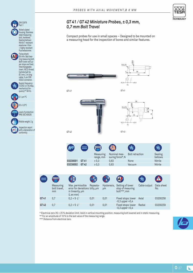
O-36 O-37
ø 8h
6
R 0,75
3447
4
+0,4-0,30
ø 8h
6
R 0,75
194
+0,4-0,30
ø 9,
6
36
19
Measuring range, mm
nominal mea-suring force*, n
Bolt retraction Sealing bellows
03230001 GT 41 ± 0,3 0,63 none nitrile03230002 GT 42 ± 0,3 0,63 Vacuum nitrile
Measuring bolt travel, mm
Max. permissible error for deviations in linearity, μm(l en mm)
repeata-bilty, μm
Hysteresis, μm
Setting of lower stop of meauring bolt***, mm
Cable output Data sheet no.
GT 41 0,7 0,2 + 5· l2 0,01 0,01 Fixed stops: lower -0,3 upper +0,4
Axial 03200258
GT 42 0,7 0,2 + 5· l2 0,01 0,01 Fixed stops: lower -0,3 upper +0,4
radial 03200259
DIn 32876 part 1
nickel-plated housing. Stainless steel measuring bolt, hardened. Sealing bellows: nitrile = resistant elastomer. Viton = highly resistant fluoroelastomer. Fixing shank Ø 8 mm. Ball-bea-ring measuring bolt. Both lower and up-per stops are fixed. Interchangeable insert. M2,5 thread. Carbide ball tip Ø 3 mm. 2 m long cable. 5-pin DIn 45322 connector.Supply frequency: 13 kHz (± 5 %) Max. mechanical fre-quency** 60 Hz.
0,1 μm/°C
20 ± 0,5°C
level of protection: Ip65 (IEC 60529)
Mobile weight: 2 g
Inspection report with a declaration of conformity gt 42
gt 41
GT 42
GT 41
GT 41 / GT 42 Miniature probes, ± 0,3 mm, 0,7 mm bolt Travel
Compact probes for use in small spaces – Designed to be mounted on a measuring head for the inspection of bores and similar features.
P r O B E S W I T H A x I A L M O V E M E n T , Ø 8 M M
* Electrical zero (n) ± 25 % deviation limit. Valid in vertical mounting position, measuring bolt lowered and in static measuring. ** For an amplitude of 10 % to the last value of the measuring range. *** Distance from electrical zero.

O-38
35,55,6
-10
51
ø 8h
6
R1
+1
18,45,6
-10
33
ø8h6
R1
29,515
9
+1
5
Measuring range, mm
nominal mea-suring force*, n
Bolt retraction Sealing bellows
03230035 GT 43 ± 1 0,4 Mechanical Viton03230017 GT44 ± 1 0,4 Vacuum Viton
Measuring bolt travel, mm
Max. permissible error for deviations in linearity, μm(l en mm)
repeata-bilty, μm
Hysteresis, μm
Setting of lower stop of bolt***, mm
Cable output Data sheet no.
GT 43 2,1 0,2 + 5· l2 0,1 0,15 Fixed stops: lower -1,05 upper +1,05
Axial 03200260
GT44 2,1 0,2 + 5· l2 0,1 0,15 Fixed stops: lower -1,05 upper +1,05
radial 03200261
DIn 32876 part 1
nickel-plated housing. Stainless steel measuring bolt, hardened. Sealing bellows: nitrile = resistant elastomer. Viton = highly resistant fluoroelastomer.Fixing shank Ø 8 mm. Ball-bea-ring measuring bolt. Both lower and up-per stops are fixed. Interchangeable insert. M2 thread. Carbide ball tip Ø 3 mm. 2 m long cable. 5-pin DIn 45322 connector.Supply frequency: 13 kHz (± 5 %) Max. mechanical fre-quency**: 60 Hz.
0,1 μm/°C
20 ± 0,5°C
level of protection: Ip65 (IEC 60529)
Mobile weight: 2 g
Inspection report with a declaration of conformity
gt 44
gt 43
GT 44
GT 43
GT 43 / GT 44 Miniature probes ± 1,0 mm, 2,1 mm bolt Travel
Compact probes for use in small spaces – Designed to be mounted on a measuring head for the inspection of bores and similar features.
P r O B E S W I T H A x I A L M O V E M E n T , Ø 8 M M
* Electrical zero (n) ± 25 % deviation limit. Valid in vertical mounting position, measuring bolt lowered and in static measuring. ** For an amplitude of 10 % to the last value of the measuring range. *** Distance from electrical zero.
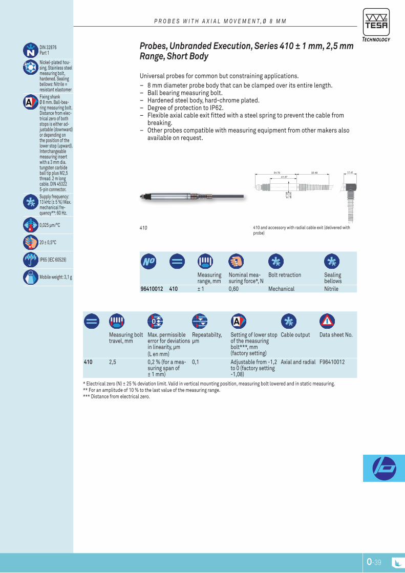
O-38 O-39
54.78 17.4132.4841.37
ø7.9
8ø8
.00
Measuring range, mm
nominal mea-suring force*, n
Bolt retraction Sealing bellows
96410012 410 ± 1 0,60 Mechanical nitrile
Measuring bolt travel, mm
Max. permissible error for deviations in linearity, μm(l en mm)
repeatabilty, μm
Setting of lower stop of the measuring bolt***, mm (factory setting)
Cable output Data sheet no.
410 2,5 0,2 % (for a mea-suring span of ± 1 mm)
0,1 Adjustable from -1,2 to 0 (factory setting -1,08)
Axial and radial F96410012
DIn 32876 part 1
nickel-plated hou-sing. Stainless steel measuring bolt, hardened. Sealing bellows: nitrile = resistant elastomerFixing shank Ø 8 mm. Ball-bea-ring measuring bolt. Distance from elec-trical zero of both stops is either ad-justable (downward) or depending on the position of the lower stop (upward). Interchangeable measuring insert with a 3 mm dia. tungsten carbide ball tip plus M2,5 thread. 2 m long cable. DIn 45322 5-pin connector.Supply frequency: 13 kHz (± 5 %) Max. mechanical fre-quency**: 60 Hz.
0,025 μm/°C
20 ± 0,5°C
Ip65 (IEC 60529)
Mobile weight: 3,1 g
410 and accessory with radial cable exit (delivered with probe)
410
probes, unbranded Execution, Series 410 ± 1 mm, 2,5 mm range, Short body
Universal probes for common but constraining applications. – 8 mm diameter probe body that can be clamped over its entire length. – Ball bearing measuring bolt. – Hardened steel body, hard-chrome plated. – Degree of protection to Ip62. – Flexible axial cable exit fitted with a steel spring to prevent the cable from
breaking. – Other probes compatible with measuring equipment from other makers also
available on request.
P r O B E S W I T H A x I A L M O V E M E n T , Ø 8 M M
* Electrical zero (n) ± 25 % deviation limit. Valid in vertical mounting position, measuring bolt lowered and in static measuring. ** For an amplitude of 10 % to the last value of the measuring range. *** Distance from electrical zero.
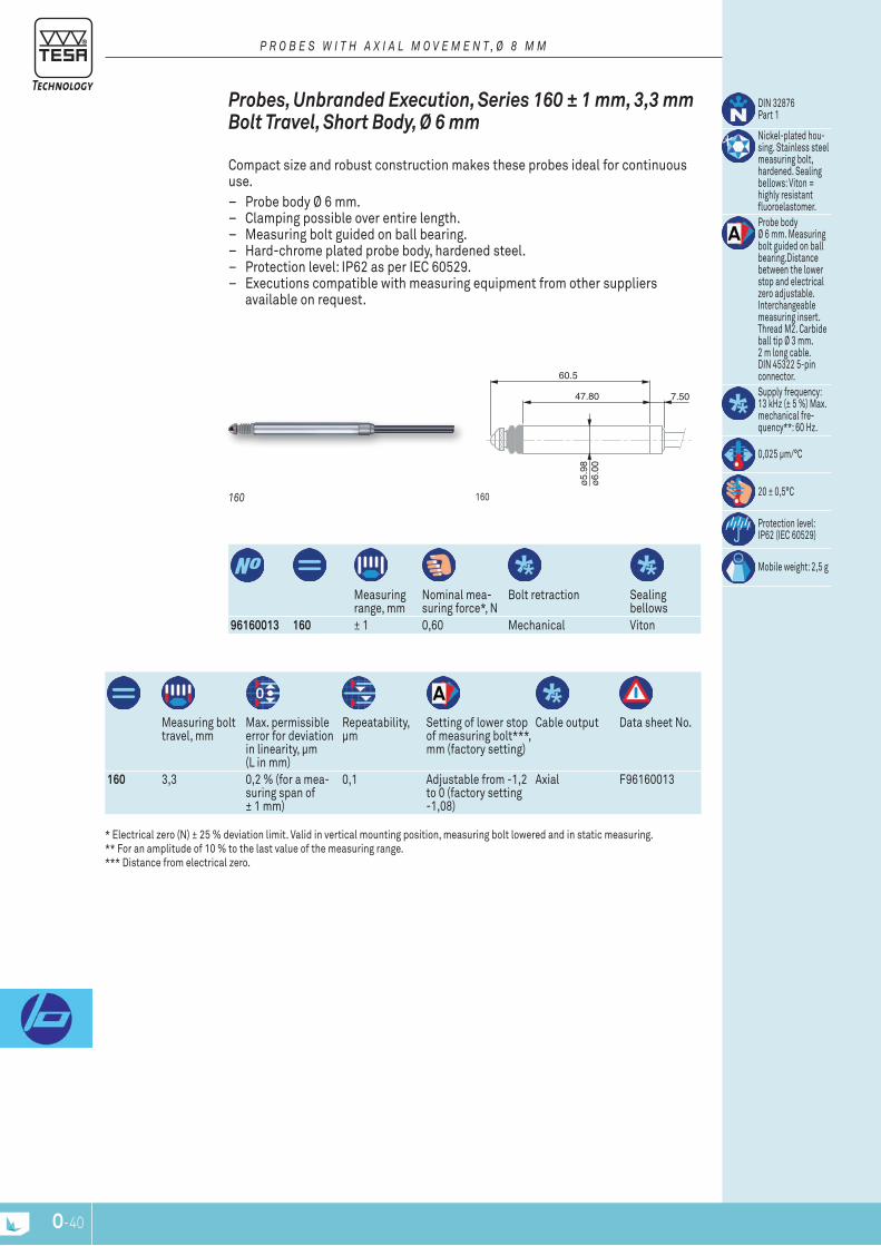
O-40
60.5
47.80 7.50
ø5.9
8ø6
.00
Measuring range, mm
nominal mea-suring force*, n
Bolt retraction Sealing bellows
96160013 160 ± 1 0,60 Mechanical Viton
Measuring bolt travel, mm
Max. permissible error for deviation in linearity, μm (l in mm)
repeatability, μm
Setting of lower stop of measuring bolt***, mm (factory setting)
Cable output Data sheet no.
160 3,3 0,2 % (for a mea-suring span of ± 1 mm)
0,1 Adjustable from -1,2 to 0 (factory setting -1,08)
Axial F96160013
DIn 32876 part 1
nickel-plated hou-sing. Stainless steel measuring bolt, hardened. Sealing bellows: Viton = highly resistant fluoroelastomer.probe body Ø 6 mm. Measuring bolt guided on ball bearing.Distance between the lower stop and electrical zero adjustable. Interchangeable measuring insert. thread M2. Carbide ball tip Ø 3 mm. 2 m long cable. DIn 45322 5-pin connector.Supply frequency: 13 kHz (± 5 %) Max. mechanical fre-quency**: 60 Hz.
0,025 μm/°C
20 ± 0,5°C
protection level: Ip62 (IEC 60529)
Mobile weight: 2,5 g
160160
probes, unbranded Execution, Series 160 ± 1 mm, 3,3 mm bolt Travel, Short body, Ø 6 mm
Compact size and robust construction makes these probes ideal for continuous use.
– probe body Ø 6 mm. – Clamping possible over entire length. – Measuring bolt guided on ball bearing. – Hard-chrome plated probe body, hardened steel. – protection level: Ip62 as per IEC 60529. – Executions compatible with measuring equipment from other suppliers
available on request.
P r O B E S W I T H A x I A L M O V E M E n T , Ø 8 M M
* Electrical zero (n) ± 25 % deviation limit. Valid in vertical mounting position, measuring bolt lowered and in static measuring. ** For an amplitude of 10 % to the last value of the measuring range. *** Distance from electrical zero.
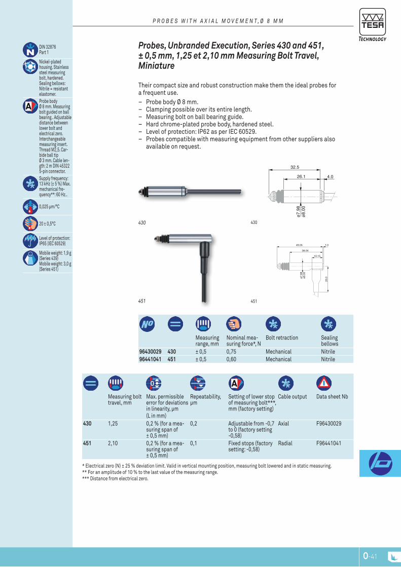
O-40 O-41
32.5
ø7.9
8ø8
.00
4.026.1
49.05
36.04
10.15
1.0
20.0ø7
.98
ø8.0
0
Measuring range, mm
nominal mea-suring force*, n
Bolt retraction Sealing bellows
96430029 430 ± 0,5 0,75 Mechanical nitrile96441041 451 ± 0,5 0,60 Mechanical nitrile
Measuring bolt travel, mm
Max. permissible error for deviations in linearity, μm(l in mm)
repeatability, μm
Setting of lower stop of measuring bolt***, mm (factory setting)
Cable output Data sheet nb
430 1,25 0,2 % (for a mea-suring span of ± 0,5 mm)
0,2 Adjustable from -0,7 to 0 (factory setting -0,58)
Axial F96430029
451 2,10 0,2 % (for a mea-suring span of ± 0,5 mm)
0,1 Fixed stops (factory setting: -0,58)
radial F96441041
DIn 32876 part 1
nickel-plated housing. Stainless steel measuring bolt, hardened. Sealing bellows: nitrile = resistant elastomer.probe body Ø 8 mm. Measuring bolt guided on ball bearing.. Adjustable distance between lower bolt and electrical zero. Interchangeable measuring insert. thread M2,5. Car-bide ball tip Ø 3 mm. Cable len-gth: 2 m DIn 45322 5-pin connector.Supply frequency: 13 kHz (± 5 %) Max. mechanical fre-quency**: 60 Hz..
0,025 μm/°C
20 ± 0,5°C
level of protection: Ip65 (IEC 60529)
Mobile weight: 1,9 g (Series 439) Mobile weight: 3,0 g (Series 451)
451
430
451
430
probes, unbranded Execution, Series 430 and 451, ± 0,5 mm, 1,25 et 2,10 mm Measuring bolt Travel, Miniature
their compact size and robust construction make them the ideal probes for a frequent use.
– probe body Ø 8 mm. – Clamping possible over its entire length. – Measuring bolt on ball bearing guide. – Hard chrome-plated probe body, hardened steel. – level of protection: Ip62 as per IEC 60529. – probes compatible with measuring equipment from other suppliers also
available on request.
P r O B E S W I T H A x I A L M O V E M E n T , Ø 8 M M
* Electrical zero (n) ± 25 % deviation limit. Valid in vertical mounting position, measuring bolt lowered and in static measuring. ** For an amplitude of 10 % to the last value of the measuring range. *** Distance from electrical zero.

O-42
8,546,4 ø 1,5
1,65
ø 2
2017
01840105
50
(90)
40
ø 8h6
L
A Measuring direction
B Measuring direction
α
Shorter lever
Measuring range, mm
nominal mea-suring force*, n
lever retraction Sealing bellows
03210802 GT 31 ± 0,3 0,1 Without Without bellows
03210801 GT 31 ± 0,3 0,02 Without Without bellows
03210803 GT 31 ± 0,3 0,2 Without Without bellows
Measuring lever travel, mm
Max. permissible error for devia-tions in linearity, μm(l in mm)
repeata-bility, μm
Hysteresis, μm
Setting of lower stop of the mea-suring insert***, mm
Cable output Data sheet no.
GT 31 0,7 0,2 + 50 · l2 0,1 0,25 Fixed lower and upper stops
Angled 03200266
DIn 32876 part 1
All-metal housing, matt-chromium finish2 dovetail attach-ments for clamping. Both lower and upper stops are fixed.Stainless steel measuring stem. Interchangeable measuring inserts. Carbide ball tip Ø 2 mm. Cable length: 2 m. DIn 45322, 5 pin connector. Other measuring inserts available as optional accesso-ries..Supply frequency: 13 kHz (± 5 %) Max. mechanical fre-quency**: 25 Hz.
20 ± 0,5°C
protection level: Ip40 (IEC 60529)
Mobile weight: 12 g
note (Fig. A) With the insert lying parallel to the workpiece surface, the leverage matches 1:1. therefore, no correction of the measured values is needed.(Fig. B, angle α) Any other position will change the effective lever length, so that read values must be corrected. In this connection, please consult the instruction manual.
gt 31 Figure B - the leverage is no longer 1:1, correction of the measured value is needed.
gt 31 Figure A - the leverage matches 1:1, no correction of the measured value needed
gt 31 side view and top view
GT 31 with lever in perpendicular position
GT 31
GT31 Lever probes ± 0,3 mm, 0,3 mm Measuring Travel, inclinable Lever
Well suited for use where probes with axial movement measuring bolts are incon-venient for measurements.
– Inclinable lever for measuring in two directions. – Balanced lever system on ball-bearing. – Interchangeable measuring insert, with carbide ball tip, inclinable through
to 180°. – Automatic reversal of the probing direction while the indication remains
unchanged. – protected against shocks by 2 safety clutches. – One-piece housing provided with 2 dovetails. – level of protection: Ip40 as per IEC 60529.
E L E c T r O n I c L E n G T H M E A S U r I n G E q U I P M E n T
* Electrical zero (n) ± 25 % deviation limit. Valid in vertical mounting position, measuring bolt lowered and in static measuring. ** For an amplitude of 10 % to the last value of the measuring range. *** Distance from electrical zero.
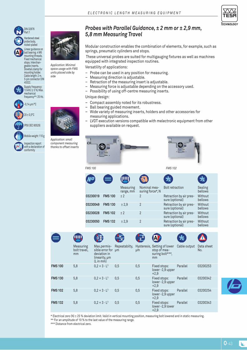
O-42 O-43
Measuring range, mm
nominal mea-suring force*, n
Bolt retraction Sealing bellows
03230019 FMS 100 ± 2 2 retraction by air pres-sure (optional)
Without bellows
03230049 FMS 130 ± 2,9 2 retraction by air pres-sure (optional)
Without bellows
03230028 FMS 102 ± 2 2 retraction by air pres-sure (optional)
Without bellows
03230050 FMS 132 ± 2,9 2 retraction by air pres-sure (optional)
Without bellows
Measuring bolt travel, mm
Max.permis-sible error for deviation in linearity, μm (l in mm)
repeatabilty, μm
Hysteresis, μm
Setting of lower stop of mea-suring bolt***, mm
Cable output Data sheet no.
FMS 100 5,8 0,2 + 3 · l3 0,5 0,5 Fixed stops: lower -2,9 upper +2,9
parallel 03200253
FMS 130 5,8 0,2 + 3 · l3 0,5 0,5 Fixed stops: lower -2,9 upper +2,9
parallel 03200342
FMS 102 5,8 0,2 + 3 · l3 0,5 0,5 Fixed stops: lower -2,9 upper +2,9
parallel 03200254
FMS 132 5,8 0,2 + 3 · l3 0,5 0,5 Fixed stops: lower -2,9 lower +2,9
parallel 03200343
DIn 32876 part 1
Hardened steel probe body, nickel-platedlinear guidance on ball bearing. 4 M6 mounting threads. Fixed mechanical stops. Interchan-geable inserts. Dovetail.clamp for mounting holder. Cable length: 2 m. 5-pin connector DIn 45322.Supply frequency: 13 kHz (± 5 %) Max. mechanicalfrequency**: 25 Hz.
-0,14 μm/°C
20 ± 0,5°C
Ip50 (IEC 60529)
Mobile weight: 110 g
Inspection report with a declaration of conformity
Application: Minimal space usage with FMS units placed side by side
Application: small component measuring thanks to offset inserts
FMS 102FMS 100
probes with parallel Guidance, ± 2 mm or ± 2,9 mm, 5,8 mm Measuring Travel
Modular construction enables the combination of elements, for example, such as springs, pneumatic cylinders and stops. these universal probes are suited for multigauging fixtures as well as machines equipped with integrated inspection routines. Versatility of applications:
– probe can be used in any position for measuring. – Measuring direction is adjustable. – retraction of the measuring insert is adjustable. – Measuring force is adjustable depending on the accessory used. – possibility of using off-centre measuring inserts.
Unique design: – Compact assembly noted for its robustness. – Ball bearing guided movement. – Wide variety of measuring inserts, holders and other accessories for
measuring applications. – lVDt execution versions compatible with melectronic equipment from other
suppliers available on request.
E L E c T r O n I c L E n G T H M E A S U r I n G E q U I P M E n T
* Electrical zero (n) ± 25 % deviation limit. Valid in vertical mounting position, measuring bolt lowered and in static measuring. ** For an amplitude of 10 % to the last value of the measuring range. *** Distance from electrical zero.
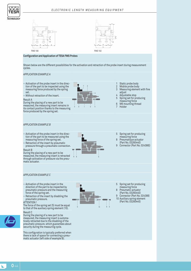
O-44
70
3015 5155
M6
8
38
13
70
3015 5155
8
M6
Configuration and Application of TESA FMS Probes
Shown below are the different possibilities for the activation and retraction of the probe insert during measurement cycles.
APPLIcATIOn ExAMPLE A
– Activation of the probe insert in the direc-tion of the part to be inspected using the measuring force produced by the spring set.
– Without retraction of the insert.
56164
3
271 Static probe body 2 Mobile probe body 3 Measuring element with fine adjust 4 Adjustable stop 5 Spring set for producing measuring force 6 M6 mounting thread 7 Holder
result A During the placing of a new part to be measured, the measuring insert remains in its contact position thanks to the measuring force produced by the spring set.
APPLIcATIOn ExAMPLE B
– Activation of the probe insert in the direc-tion of the part to be measured using the measuring force of the spring set.
– retraction of the insert by pneumatic pressure through a pneumatic connection.
589
5 Spring set for producing measuring force 8 pneumatique actuator (part no. 03260440) 9 Connector (part no. 024388))
result B During the placing of a new part to be measured, the measuring insert is retracted through activation of pressure via the pneu-matic actuator.
APPLIcATIOn ExAMPLE c
– Activation of the probe insert in the direction of the part to be inspected by pneumatic pressure and the measuring force of the spring set.
– retraction of the insert by disabling the pneumatic pressure.
AttEntIOn ! the force of the spring set (5) must be equal to that of the auxiliary spring element (10).
5 8 910
5 Spring set for producing measuring force 8 pneumatic actuator (part no. 03260440) 9 Connector (part no. 024388) 10 Auxiliary spring element (part no. 03260445)
result C During the placing of a new part to be measured, the measuring insert is automa-tically retracted due to the disabling of the pneumatic pressure. which guarantees about security during the measuring cycle. this configuration is typically preferred when there is lack of space for connecting a pneu-matic actuator (left side of example B).
FMS 102FMS 100
E L E c T r O n I c L E n G T H M E A S U r I n G E q U I P M E n T

O-44 O-45
Measuring range, mm
nominal mea-suring force*, n
Bolt retraction Sealing bellows
03230037 FMS100-P ± 2 2 retraction by air pres-sure (optional)
Without bellows
03230051 FMS130-P ± 2,9 2 retraction by air pres-sure (optional)
Without bellows
03230038 FMS102-P ± 2 2 retraction through air pressure (optional)
Without bellows
03230052 FMS132-P ± 2,9 2 retraction through air pressure (optional)
Without bellows
Measuring bolt travel, mm
Max. permis-sible errors for deviations in linearity, μm (l en mm)
repeatability, μm
Hysteresis, μm
Setting of lower stop of measuring bolt***, mm
Cable output
Data sheet no.
FMS100-P 5,8 0,2 + 3 · l3 0,5 0,5 Fixed stops: lower -2,9 upper +2,9
parallel 03200283
FMS130-P 5,8 0,2 + 3 · l3 0,5 0,5 Fixed stops: lower -2,9 upper +2,9
parallel 03200344
FMS102-P 5,8 0,2 + 3 · l3 0,5 0,5 Fixed stops: lower -2,9 upper +2,9
Angled 03200289
FMS132-P 5,8 0,2 + 3 · l3 0,5 0,5 Fixed stops: lower -2,9 upper +2,9
Angled 03200345
DIn 32876 part 1
Hardened steel probe body, nickel-platedlinear guidance on ball bearing. 4 M6 mounting threads.. Fixed mechanical stops. Interchangeable inserts. Holder with dovetail clamping. Cable length: 2 m. 5-pin connector DIn 45322.Supply frequency: 13 kHz (± 5 %). Max. mechanical fre-quency**: 25 Hz.
-0,14 μm/°C
20 ± 0,5°C
Ip54 (IEC 60529)
Mobile weight: 110 g
Inspection report with a declaration of conformity
Application: mesurement with a protected FMS
FMS 102-P
FMS 100-P
probes with parallel Guidance, ± 2 mm or ± 2,9 mm, 5,8 mm Measuring Travel – protected version
– FMS 100-p, 102 -p, 130-p, 132-p provide dust protection of the 2 side faces.
Modular concept for combining elements, for example, such as springs, pneuma-tic actuators and stops.these universal probes are suitable for mutigauging inspection fixtures as well as machines with integrated automated inspection routines.Versatility of applications:
– probe can be used in any position for measuring – Measuring direction can be changed – retraction of the measuring insert is adjustable – Measuring force is adjustable, depending on the accessory used – possibility of using off-centre measuring inserts
Unique design: – Compact assembly noted for its robustness – Ball bearing guided movement – Wide variety of measuring inserts, holders and other accessories for – measuring applications – lVDt execution versions compatible with melectronic equipment from other
suppliers available on request.
E L E c T r O n I c L E n G T H M E A S U r I n G E q U I P M E n T
* Electrical zero (n) ± 25 % deviation limit. Valid in vertical mounting position, measuring bolt lowered and in static measuring. ** For an amplitude of 10 % to the last value of the measuring range. *** Distance from electrical zero.

O-46
70
3015 5155
M6
8
38
13
70
3015 5155
8
M6
FMS 102-pFMS 100-p
E L E c T r O n I c L E n G T H M E A S U r I n G E q U I P M E n T
Configuration and Application of TESA FMS Probes
Shown below are the different possibilities for the activation and retraction of the probe insert during measurement cycles.
APPLIcATIOn ExAMPLE A
– Activation of the probe insert in the direc-tion of the part to be inspected using the measuring force produced by the spring set.
– Without retraction of the insert.
56164
3
271 Static probe body 2 Mobile probe body 3 Measuring element with fine adjust 4 Adjustable stop 5 Spring set for producing measuring force 6 M6 mounting thread 7 Holder
result A During the placing of a new part to be measured, the measuring insert remains in its contact position thanks to the measuring force produced by the spring set.
APPLIcATIOn ExAMPLE B
– Activation of the probe insert in the direc-tion of the part to be measured using the measuring force of the spring set.
– retraction of the insert by pneumatic pressure through a pneumatic connection.
589
5 Spring set for producing measuring force 8 pneumatique actuator (part no. 03260440) 9 Connector (part no. 024388))
result B During the placing of a new part to be measured, the measuring insert is retracted through activation of pressure via the pneu-matic actuator.
APPLIcATIOn ExAMPLE c
– Activation of the probe insert in the direction of the part to be inspected by pneumatic pressure and the measuring force of the spring set.
– retraction of the insert by disabling the pneumatic pressure.
AttEntIOn ! the force of the spring set (5) must be equal to that of the auxiliary spring element (10).
5 8 910
5 Spring set for producing measuring force 8 pneumatic actuator (part no. 03260440) 9 Connector (part no. 024388) 10 Auxiliary spring element (part no. 03260445)
result C During the placing of a new part to be measured, the measuring insert is automa-tically retracted due to the disabling of the pneumatic pressure. which guarantees about security during the measuring cycle. this configuration is typically preferred when there is lack of space for connecting a pneu-matic actuator (left side of example B).
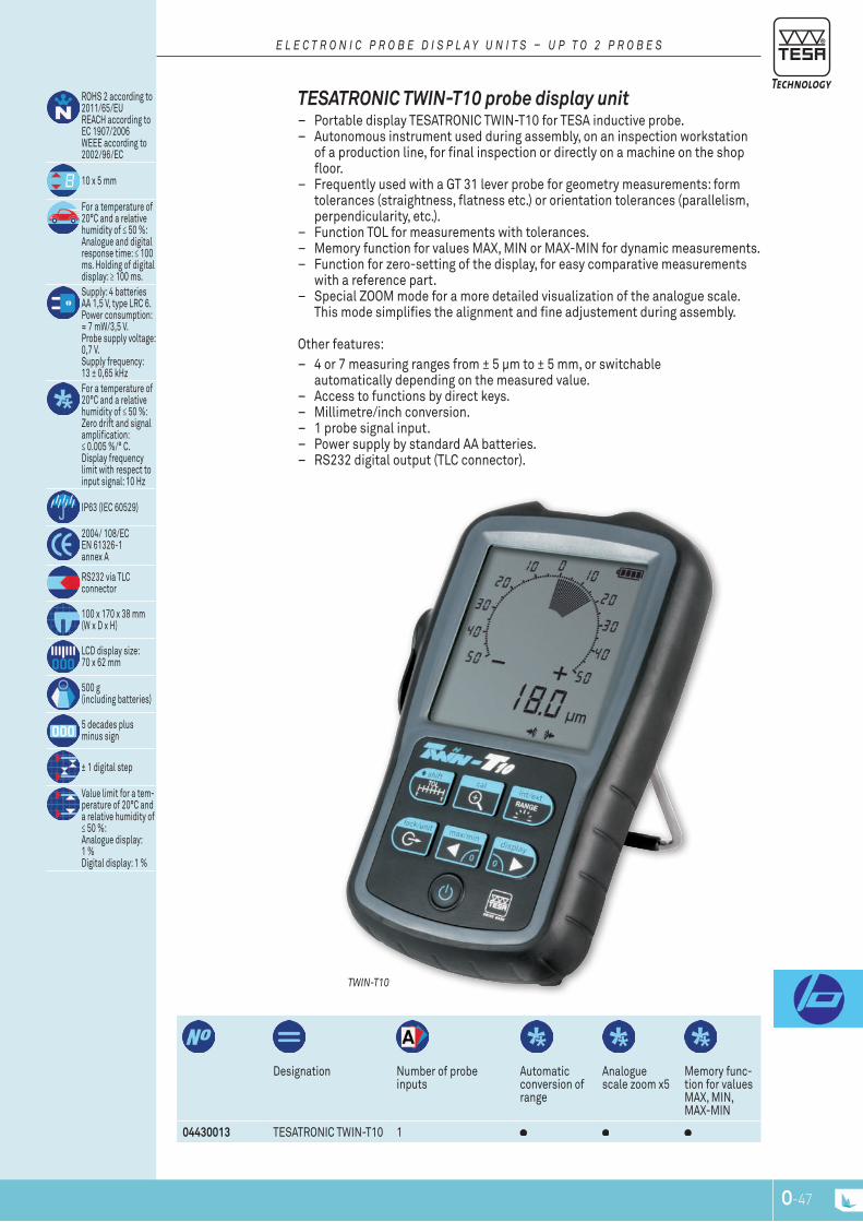
O-46 O-47
Designation number of probe inputs
Automatic conversion of range
Analogue scale zoom x5
Memory func-tion for values MAX, MIn, MAX-MIn
04430013 tESAtrOnIC tWIn-t10 1
rOHS 2 according to 2011/65/EU rEACH according to EC 1907/2006 WEEE according to 2002/96/EC
10 x 5 mm
For a temperature of 20°C and a relative humidity of ≤ 50 %: Analogue and digital response time: ≤ 100 ms. Holding of digital display: ≥ 100 ms.Supply: 4 batteries AA 1,5 V, type lrC 6. power consumption: ≈ 7 mW/3,5 V.probe supply voltage: 0,7 V.Supply frequency: 13 ± 0,65 kHzFor a temperature of 20°C and a relative humidity of ≤ 50 %: Zero drift and signal amplification: ≤ 0.005 %/° C. Display frequency limit with respect to input signal: 10 Hz
Ip63 (IEC 60529)
2004/ 108/EC En 61326-1 annex A
rS232 via tlC connector
100 x 170 x 38 mm (W x D x H)
lCD display size: 70 x 62 mm
500 g (including batteries)
5 decades plus minus sign
± 1 digital step
Value limit for a tem-perature of 20°C and a relative humidity of ≤ 50 %: Analogue display: 1 % Digital display: 1 %
TWIn-T10
TESATronic TWin-T10 probe display unit – portable display tESAtrOnIC tWIn-t10 for tESA inductive probe. – Autonomous instrument used during assembly, on an inspection workstation
of a production line, for final inspection or directly on a machine on the shop floor.
– Frequently used with a gt 31 lever probe for geometry measurements: form tolerances (straightness, flatness etc.) or orientation tolerances (parallelism, perpendicularity, etc.).
– Function tOl for measurements with tolerances. – Memory function for values MAX, MIn or MAX-MIn for dynamic measurements. – Function for zero-setting of the display, for easy comparative measurements
with a reference part. – Special ZOOM mode for a more detailed visualization of the analogue scale.
this mode simplifies the alignment and fine adjustement during assembly. Other features:
– 4 or 7 measuring ranges from ± 5 µm to ± 5 mm, or switchable automatically depending on the measured value.
– Access to functions by direct keys. – Millimetre/inch conversion. – 1 probe signal input. – power supply by standard AA batteries. – rS232 digital output (tlC connector).
E L E c T r O n I c P r O B E D I S P L A y U n I T S – U P T O 2 P r O B E S
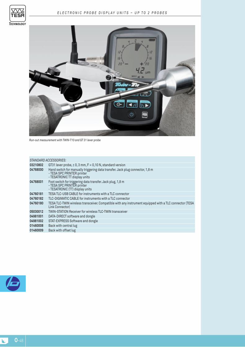
O-48
run-out measurement with TWIn-T10 and GT 31 lever probe
STAnDArD AccESSOrIES:03210802 gt31 lever probe, ± 0, 3 mm, F = 0,10 n, standard version04768000 Hand switch for manually triggering data transfer. Jack plug connector, 1,8 m
- tESA SpC prIntEr printer - tESAtrOnIC tt display units
04768001 Foot switch for triggering data transfer. Jack plug, 1,8 m - tESA SpC prIntEr printer - tESAtrOnIC (tt) display units
04760181 tESA tlC-USB CABlE for instruments with a tlC connector04760182 tlC-DIgIMAtIC CABlE for instruments with a tlC connector04760180 tESA tlC-tWIn wireless transceiver. Compatible with any instrument equipped with a tlC connector (tESA
link Connector)05030012 tWIn-StAtIOn receiver for wireless tlC-tWIn transceiver04981001 DAtA-DIrECt software and dongle04981002 StAt-EXprESS Software and dongle01460008 Back with central lug01460009 Back with offset lug
E L E c T r O n I c P r O B E D I S P L A y U n I T S – U P T O 2 P r O B E S
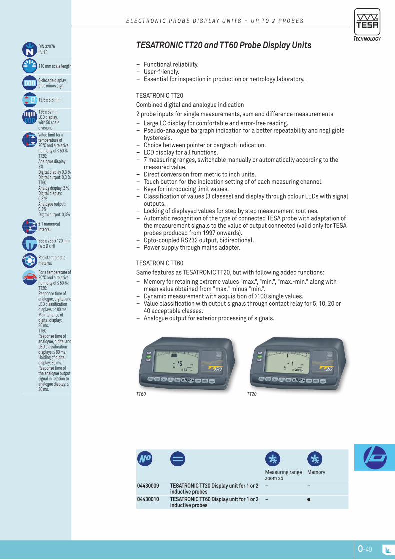
O-48 O-49
Measuring range zoom x5
Memory
04430009 TESATRONIC TT20 Display unit for 1 or 2 inductive probes
– –
04430010 TESATRONIC TT60 Display unit for 1 or 2 inductive probes
–
DIn 32876 part 1
110 mm scale length
6-decade display plus minus sign
12,5 x 6,6 mm
126 x 62 mm lCD display,with 50 scale divisionsValue limit for a temperature of 20°C and a relative humidity of ≤ 50 % tt20: Analogue display: 2% Digital display 0,3 % Digital output: 0,3 % tt60: Analog display: 2 % Digital display: 0,3 % Analogue output: 0,3% Digital output: 0,3%
± 1 numerical interval
255 x 235 x 120 mm (W x D x H)
resistant plastic material
For a temperature of 20°C and a relative humidity of ≤ 50 %: tt20: response time of analogue, digital and lED classification displays:: ≤ 80 ms. Maintenance of digital display: 80 ms. tt60: response time of analogue, digital and lED classification displays: ≤ 80 ms. Holding of digital display: 80 ms. response time of the analogue output signal in relation to analogue display: ≤ 30 ms.
tESAtrOnIC tt60 Same features as tESAtrOnIC tt20, but with following added functions:
– Memory for retaining extreme values "max.", "min.", "max.-min." along with mean value obtained from "max." minus "min.".
– Dynamic measurement with acquisition of >100 single values. – Value classification with output signals through contact relay for 5, 10, 20 or
40 acceptable classes. – Analogue output for exterior processing of signals.
TT60 TT20
TESATronic TT20 and TT60 probe display units
– Functional reliability. – User-friendly. – Essential for inspection in production or metrology laboratory.
tESAtrOnIC tt20Combined digital and analogue indication2 probe inputs for single measurements, sum and difference measurements
– large lC display for comfortable and error-free reading. – pseudo-analogue bargraph indication for a better repeatability and negligible
hysteresis. – Choice between pointer or bargraph indication. – lCD display for all functions. – 7 measuring ranges, switchable manually or automatically according to the
measured value. – Direct conversion from metric to inch units. – touch button for the indication setting of of each measuring channel. – Keys for introducing limit values. – Classification of values (3 classes) and display through colour lEDs with signal
outputs. – locking of displayed values for step by step measurement routines. – Automatic recognition of the type of connected tESA probe with adaptation of
the measurement signals to the value of output connected (valid only for tESA probes produced from 1997 onwards).
– Opto-coupled rS232 output, bidirectional. – power supply through mains adapter.
E L E c T r O n I c P r O B E D I S P L A y U n I T S – U P T O 2 P r O B E S
O-50
DELIVErED WITH THE FOLLOWInG AccESSOrIES:04761054 Battery charger 100 ÷ 200 VAC
50 ÷ 60 Hz, 6,6 V DC, 750 mAhsupplied without power cable
04761055 Mains cable EU for charger 0471054
OPTIOnAL AccESSOrIES:04768000 Hand switch for manually triggering data transfer. Jack plug connector, 1,8 m
– tESA SpC prIntEr printer – tESAtrOnIC tt display units
04768001 Foot switch for triggering data transfer. Jack plug, 1,8 m – tESA SpC prIntEr printer – tESAtrOnIC (tt) display units
04761062 Opto-USB cable, Duplex, 2m Bidirectional communication
04761049 Opto-rS cable, Duplex, 2m Bidirectional communication
number of probe inputs
Automatic switching of range
TESATRONIC TT60 Display unit for 1 or 2 inductive probes
2
TESATRONIC TT20 Display unit for 1 or 2 inductive probes
2
For a temperature of 20°C and a relative humidity of ≤ 50 %: tt20: response time of analogue, digital and lED classification displays: ≤ 80 ms. Maintenance of digital display: 80 ms. tt60: response time of analogue, digital and lED classification displays: ≤ 80 ms. Holding of digital display: 80 ms. response time of the analogue output signal in relation to analogue display: ≤ 30 ms.
rS232 opto-coupled output
tt60: Voltage range: ± 2 V to ± 10 V. Output cur-rent: ≤ 2 mA. load adjustment: ≥ 5 kΩ. Background noise (probe at elec-trical zero) ≤ 1 mV. reference potential: ground 0 V.Supply: 6,5 V DC up to 7,3 V DC. Supply frequency: 13 ± 0,65 kHz. power consumption: 2 W. Monitored voltage variations. probe supply voltage: 3 V.protection of frontal face: Ip54 (IEC 60529, DIn 40 050)IEC/En 61326-1 USA: CFr47, part 15, Subpart B, Class B, Digital Device
1,1 kg
E L E c T r O n I c P r O B E D I S P L A y U n I T S – U P T O 2 P r O B E S
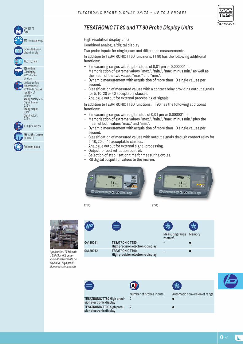
O-50 O-51
Measuring range zoom x5
Memory
number of probes inputs Automatic conversion of range
04430011 TESATRONIC TT80 High precision electronic display
–
04430012 TESATRONIC TT90 High precision electronic display
–
TESATRONIC TT80 High preci-sion electronic display
2
TESATRONIC TT90 high preci-sion electronic display
2
DIn 32876 part 1
110 mm scale length
6-decade display plus minus sign
12,5 x 6,6 mm
126 x 62 mm lCD display,with 50 scale divisionslimit value for a temperature of 20°C and a relative humidity of ≤ 50 %: Analog display: 2 % Digital display: 0,15 % Analog output: 0,3 % Digital output: 0,15 %
± 1 digital interval
255 x 235 x 120 mm (W x D x H)
resistant plastic
In addition to tESAtrOnIC tt60 functions, tt 90 has the following additional functions:
– 9 measuring ranges with digital step of 0,01 μm or 0.000001 in. – Memorisation of extreme values "max.", "min.", "max. minus min." plus the
mean of both values "max." and "min.". – Dynamic measurement with acquisition of more than 10 single values per
second. – Classification of measured values with output signals through contact relay for
5, 10, 20 or 40 acceptable classes. – Analogue output for external signal processing. – Output for bolt retraction control. – Selection of stabilisation time for measuring cycles. – rS digital output for values to the micron.
Application: TT 80 with a SIP (Société gene-voise d'instruments de physique) high preci-sion measuring bench
TT 90 TT 80
TESATronic TT 80 and TT 90 probe display units
High resolution display unitsCombined analogue/digital displaytwo probe inputs for single, sum and difference measurements. In addition to tESAtrOnIC tt60 funczions, tt 80 has the following additional functions:
– 9 measuring ranges with digital steps of 0,01 μm or 0.000001 in. – Memorisation of extreme values "max.", "min.", "max. minus min." as well as
the mean of the two values "max." and "min.". – Dynamic measurement with acquisition of more than 10 single values per
second. – Classification of measured values with a contact relay providing output signals
for 5, 10, 20 or 40 acceptable classes. – Analogue output for external processing of signals.
E L E c T r O n I c P r O B E D I S P L A y U n I T S – U P T O 2 P r O B E S

O-52
OPTIOnAL AccESSOrIES:04768000 Hand switch for manually triggering data transfer. Jack plug connector, 1,8 m
- tESA SpC prIntEr printer - tESAtrOnIC tt display units
04768001 Foot switch for triggering data transfer. Jack plug, 1,8 m - tESA SpC prIntEr printer - tESAtrOnIC (tt) display units
04761062 Opto-USB cable, Duplex, 2m Bidirectional communication
04761049 Opto-rS cable, Duplex, 2m Bidirectional communication
DELIVErED WITH THE FOLLOWInG AccESSOrIES:04761054 Battery charger 100 ÷ 200 VAC / 50 ÷ 60 Hz, 6,6 V DC, 750 mAh, supplied without power cable04761055 Mains cable EU for charger 0471054
For a temperature of 20°C and a relative humidity of ≤ 50 %: response time analogue, digi-tal and lED displays classification: ≤ 100 ms. Holding of digital display: 100 ms. response time of the analogue output signal in relation to analogue display: ≤ 30 ms.For a temperature of 20°C and a relative humidity of ≤ 50 %: Zero drift and signal amplification: ≤ 0,005 %/°C. no drift of stored values. Frequency limit for all displays frequency, analog output and memory in relation to input signal: 10 Hz
rS232 opto-coupled output
Voltage range of ± 2 V to ± 10 V. Out-put current: ≤ 2 mA. load adjustment: ≥ 5 kΩ. Background noise (probe to 0 electric) ≤ 1 mV. reference potential: analog ground 0 V6,5 Vdc up to 7,3 V DC. Consumption: 2 W. Monitored voltage fluctuation. Supply voltage for probe: 3 Vprotection of frontal face: Ip54 (IEC 60529, DIn 40 050)IEC/En 61326-1 USA: CFr47, part 15, Subpart B, Class B, Digital Device
1,1 kg
E L E c T r O n I c P r O B E D I S P L A y U n I T S – U P T O 2 P r O B E S

O-52 O-53
number of measuring ranges Min range / Max range max (µm)
Measuring range zoom x5
Memory power supply
04430003 TTA20 6 / min ± 3 max ± 1000 – – network
number of probe inputs Automatic conversion of range2 –
OPTIOnAL AccESSOry:04460004 Connector 15 pins
for analogue output and classification signal of ttA20
DELIVErED WITH THE FOLLOWInG AccESSOrIES:03160015 Mains cable CH 2 m03160016 Mains cable, EU, 2 m03160017 Mains cable without plug, 2 m for ttA20
DIn 32876 part 1
length: 100 mm
limit value for a temperature of 20°C and a relative humidity of ≤ 50 %: Analog Dis-play: 1,5 % Analog output: 0,3 %Display: negligible. Classification signals: 5 %
258 x 190 x 158 mm (W x D x H)
Die-cast aluminum case, designed for the workshopFor a temperature of 20°C and a relative humidity of ≤ 50 %: response time of the analogue display: ≤ 1 ms. response time of the analogue output signal from the analog display: 20 ms. response time for classifica-tion signals: 10 ms.For a temperature of 20°C and a relative humidity of ≤ 50 %: Zero drift: ≤ ± 0,005 % /°C. no drift of stored va-lues. Frequency limit for analogue display: 1 Hz. Frequency limit for analogue output: 50 Hz. Frequency limit for classification: 30 Hz
TTA20
TESATronic TTA20 probe display unit
Compact design with analogue indication and value classification of measured values. Aluminium housing, designed for shop floor applications, user-friendly.
– Easy-to-read analogue display with mirror strip in order to avoid parallax error. – 6 measuring ranges. – Metric/Inch conversion. – Zero setting potentiometer for display. – 2 probe inputs for single, sum or difference measurements. – 1 auxiliary signal input, e.g. for all correction values. – Colour lEDs of green for "good", yellow for "rework" and red for "Scrap". – potentiometer for setting limit tolerances. – polarity reverse switch for classification signals
(internal or external dimensions). – Switch for locking or unlocking a displayed value. – Analogue output for a display unit or external recording.
E L E c T r O n I c P r O B E D I S P L A y U n I T S – U P T O 2 P r O B E S
± 1000 50 ± 0.1 0.005± 300 10 ± 0.03 0.001± 100 5 ± 0.01 0.0005± 30 1 ± 0.003 0.0001± 10 0,5 ± 0.001 0.00005± 3 0,1 ± 0.0003 0.00001
µm µm in in
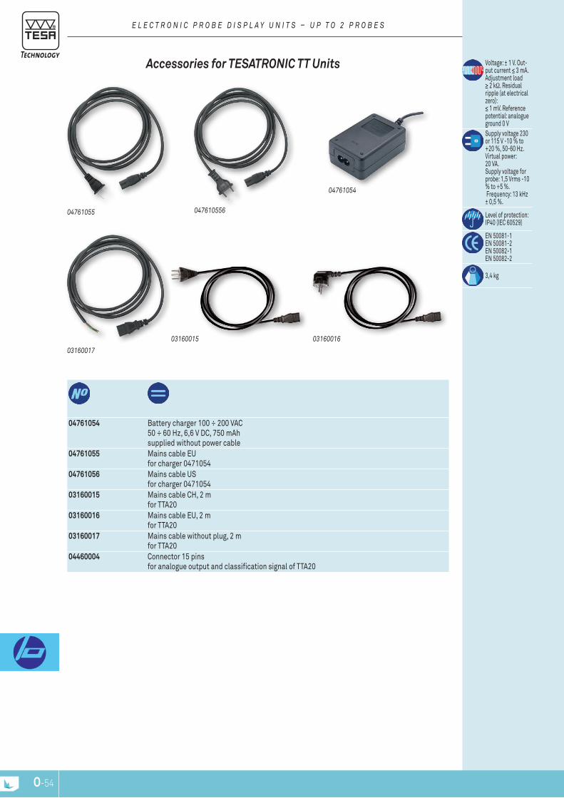
O-54
04761054 Battery charger 100 ÷ 200 VAC50 ÷ 60 Hz, 6,6 V DC, 750 mAhsupplied without power cable
04761055 Mains cable EUfor charger 0471054
04761056 Mains cable US for charger 0471054
03160015 Mains cable CH, 2 m for ttA20
03160016 Mains cable EU, 2 m for ttA20
03160017 Mains cable without plug, 2 m for ttA20
04460004 Connector 15 pins for analogue output and classification signal of ttA20
04761055 047610556
04761054
03160017
0316001603160015
Accessories for TESATronic TT units
E L E c T r O n I c P r O B E D I S P L A y U n I T S – U P T O 2 P r O B E S
Voltage: ± 1 V. Out-put current ≤ 3 mA. Adjustment load ≥ 2 kΩ. residual ripple (at electrical zero): ≤ 1 mV. reference potential: analogue ground 0 VSupply voltage 230 or 115 V -10 % to +20 %, 50-60 Hz. Virtual power: 20 VA. Supply voltage for probe: 1,5 Vrms -10 % to +5 %. Frequency: 13 kHz ± 0,5 %.
level of protection: Ip40 (IEC 60529)
En 50081-1En 50081-2En 50082-1En 50082-2
3,4 kg
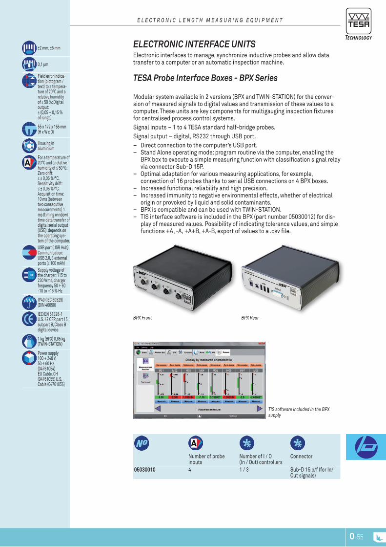
O-54 O-55
number of probe inputs
number of I / O (In / Out) controllers
Connector
05030010 4 1 / 3 Sub-D 15 p/f (for In/Out signals)
±2 mm, ±5 mm
0,1 μm
Field error indica-tion (pictogram / text) to a tempera-ture of 20°C and a relative humidity of ≤ 50 %: Digital output: ± (0,05 + 0,15 % of range)
55 x 172 x 155 mm (H x W x D)
Housing in aluminium
For a temperature of 20°C and a relative humidity of ≤ 50 %: Zero drift: ≤ ± 0,05 %/°C. Sensitivity drift: ≤ ± 0,05 %/°C. Acquisition time: 10 ms (between two consecutive measurements) 1 ms (timing window) time data transfer of digital serial output (USB): depends on the operating sys-tem of the computer.USB port (USB Hub) Communication: USB 2.0, 3 external ports (≤ 100 mAh)Supply voltage of the charger: 115 to 230 Vrms, charger frequency 50 ÷ 60 -10 to +15 % Hz
Ip40 (IEC 60529) (DIn 40050)
IEC/En 61326-1 U.S. 47 CFr part 15, subpart B, Class B digital device
1 kg (BpX) 0,85 kg (tWIn-StAtIOn)
power supply 100 ÷ 240 V, 50 ÷ 60 Hz (04761054) EU Cable, CH (04761055) U.S. Cable (04761056)
TIS software included in the BPx supply
BPx rearBPx Front
TESA probe interface boxes - bpX Series
Modular system available in 2 versions (BpX and tWIn-StAtIOn) for the conver-sion of measured signals to digital values and transmission of these values to a computer. these units are key components for multigauging inspection fixtures for centralised process control systems.Signal inputs – 1 to 4 tESA standard half-bridge probes.Signal output – digital, rS232 through USB port.
– Direct connection to the computer’s USB port. – Stand Alone operating mode: program routine via the computer, enabling the
BpX box to execute a simple measuring function with classification signal relay via connector Sub-D 15p.
– Optimal adaptation for various measuring applications, for example, connection of 16 probes thanks to serial USB connections on 4 BpX boxes.
– Increased functional reliability and high precision. – Increased immunity to negative environmental effects, whether of electrical
origin or provoked by liquid and solid contaminants. – BpX is compatible and can be used with tWIn-StAtIOn. – tIS interface software is included in the BpX (part number 05030012) for dis-
play of measured values. possibility of indicating tolerance values, and simple functions +A, -A, +A+B, +A-B, export of values to a .csv file.
ELEcTronic inTErFAcE uniTS Electronic interfaces to manage, synchronize inductive probes and allow data transfer to a computer or an automatic inspection machine.
E L E c T r O n I c L E n G T H M E A S U r I n G E q U I P M E n T
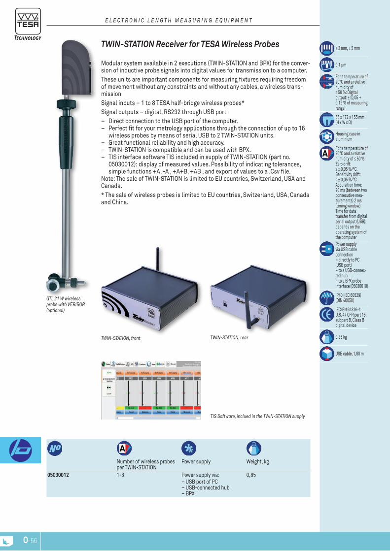
O-56
number of wireless probes per tWIn-StAtIOn
power supply Weight, kg
05030012 1-8 power supply via: – USB port of pC – USB-connected hub – BpX
0,85
± 2 mm, ± 5 mm
0,1 μm
For a temperature of 20°C and a relative humidity of ≤ 50 %: Digital output: ± (0,05 + 0,15 % of measuring range)
55 x 172 x 155 mm (H x W x D)
Housing case in aluminium
For a temperature of 20°C and a relative humidity of ≤ 50 %: Zero drift: ≤ ± 0,05 %/°C. Sensitivity drift: ≤ ± 0,05 %/°C. Acquisition time: 20 ms (between two consecutive mea-surements) 2 ms (timing window) time for data transfer from digital serial output (USB): depends on the operating system of the computerpower supply via USB cable connection – directly to pC (USB port) – to a USB-connec-ted hub – to a BpX probe interface (05030010)
Ip40 (IEC 60529) (DIn 40050)
IEC/En 61326-1 U.S. 47 CFr part 15, subpart B, Class B digital device
0,85 kg
USB cable, 1,80 m
GTL 21 W wireless probe with VErIBOr (optional)
TIS Software, inclued in the TWIn-STATIOn supply
TWIn-STATIOn, rearTWIn-STATIOn, front
TWin-STATion receiver for TESA Wireless probes
Modular system available in 2 executions (tWIn-StAtIOn and BpX) for the conver-sion of inductive probe signals into digital values for transmission to a computer.these units are important components for measuring fixtures requiring freedom of movement without any constraints and without any cables, a wireless trans-missionSignal inputs – 1 to 8 tESA half-bridge wireless probes* Signal outputs – digital, rS232 through USB port
– Direct connection to the USB port of the computer. – perfect fit for your metrology applications through the connection of up to 16
wireless probes by means of serial USB to 2 tWIn-StAtIOn units. – great functional reliability and high accuracy. – tWIn-StAtIOn is compatible and can be used with BpX. – tIS interface software tIS included in supply of tWIn-StAtIOn (part no.
05030012): display of measured values. possibility of indicating tolerances, simple functions +A, -A , +A+B, +AB , and export of values to a .Csv file.
note: the sale of tWIn-StAtIOn is limited to EU countries, Switzerland, USA and Canada.* the sale of wireless probes is limited to EU countries, Switzerland, USA, Canada and China.
E L E c T r O n I c L E n G T H M E A S U r I n G E q U I P M E n T
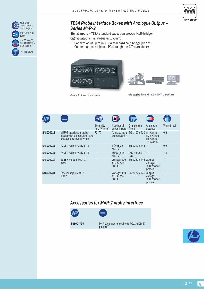
O-56 O-57
S48001725 M4p-2 connecting cable to pC, 2m DB-37 pins m/f
Accessories for M4p-2 probe interface
Sensivity (mV / V /mm)
number of probe inputs
Dimensions (mm)
Analogue outputs
Weight (kg)
S48001721 M4p-2 interface 4 probe inputs with demodulator and analogue output in V/mm
73,75 4, including a demodulator
36 x 100 x 120 ± 1 V/mm, ± 2,5 V/mm, ± 5 V/mm, ± 10V/mm
0,6
S48001722 r2M-1 rack for 2x M4p-2 – 8 (with 2x M4p-2)
55 x 212 x 144 – 0,9
S48001723 r4M-1 rack for 4x M4p-2 – 16 (with 4x M4p-2)
160 x 212 x 144
– 1,2
S48001724 Supply module MA4-2, 230V
– Voltage: 230 ±10 % Vac, 50 Hz
85 x 222 x 146 Output voltage: ± 15V for 32 probes
1,1
S48001731 power supply MA4-2, 110 V
– Voltage: 110 ±10 % Vac, 60 Hz
85 x 222 x 146 Output voltage: ± 15V for 32 probes
1,1
± 0,5 % with reference to the measuring span
± 10 to ± 15 V DC, 60 mA
≤ ±100 ppm/°C, stability at zero = ≤ ±0,2 μm/°C
Ip50 (IEC 60529)
Multi-gauging fixture with 1, 2 or 4 M4p-2 interfacesrack with 3 M4P-2 interfaces
TESA probe interface boxes with Analogue output – Series M4p-2 Signal inputs – tESA standard execution probes (Half-bridge) Signal outputs – analogue (in ± V/mm)
– Connection of up to 32 tESA standard half-bridge probes. – Connection possible to a pC through the A/D transducer.
E L E c T r O n I c L E n G T H M E A S U r I n G E q U I P M E n T

O-58
Measuring range, mm
Deviation span of indication
Zero drift
03260500 Cable adapter DIn 5p for USB. enables connection of tESA probes sensivity 73,75 mV/V/mm directly to a USB port
± 2 mm 0,3 % ± 0,1 μm ± 0,01 %/°C
03260501 Cable adapter DIn 5p for USB. enables connection of tESA probes sensivity 29,50 mV/V/mm directly to a USB port
± 5 mm 0,3 % ± 0,1 μm ± 0,01 %/°C
DIn 32876 part 1
0.1 μm
2 V effectively 13 kHz ± 0,5 %
At 20°C and relative humidity ≤ 50 %: error of 'indication = 0,3 % ± 0,1 μm zero drift ± 0,01 %/°C V. Standard refresh speed = 80 ms. Maximum refresh speed = 42 ms. Distance between the stops and the electrical zero cannot be adjusted. length of cable: 1,2 m. note: the total error should take into account the error of the probe and the error of the adapter.
USB 2.0 rS232, virtual COM port
20 ± 0,5°C
Ip51 (IEC 60529)cable adapter: DIn 5-pin connector to USB connector type A
Adaptor cable: din 5p connector to uSb Type A connector Allows for quick and easy connection of any tESA standard half bridge probe to a pC USB port.
Signal inputs – tESA standard probes (Half-bridge) Signal outputs – digital rS 323 through USB port
P r O B E A c c E S S O r I E S
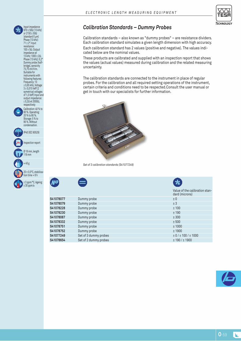
O-58 O-59
Value of the calibration stan-dard (microns)
S41078077 Dummy probe ± 0S41078079 Dummy probe ± 3S41078228 Dummy probe ± 100S41078230 Dummy probe ± 190S41078087 Dummy probe ± 300S41078332 Dummy probe ± 500S41078751 Dummy probe ± 1000S41078752 Dummy probe ± 1900S41077249 Set of 3 dummy probes ± 0 / ± 100 / ± 1000S41078654 Set of 2 dummy probes ± 190 / ± 1900
Input impedance 970 ± 50Ω (13 kHz) or 2150 ± 50Ω (standard 0 μm) phase (13 kHz): 71 ± 2°. Input resistance: 100 ± 5Ω. Output impedance at 13 kHz: 1000 ± 2Ω.phase (13 kHz): 0,2° Dummy probe (half-bridge), sensivity 73,75 mV/V/m. Suitable for instruments with following features: Frequency: 13 ± 0,65 kHz, Voltage: 3 ± 0,015 Veff (2 symetrical voltages of 1,5 Veff) Input and output impedance: ≤ 0,2Ω et 2000Ω, respectivelyCalibration: 40 % to 60 %. Operating: 20 % to 80 %. Storage: 5 % to 95 %. Without condensation.
Ip40 (IEC 60529)
Inspection report
Ø 18 mm, length 118 mm
≈ 45 g
20 ± 0,5°C, stabilisa-tion time = 8 h
± 3 ppm/°C. Ageing: ± 30 ppm/a
Set of 3 calibration standards (S41077249)
calibration Standards – dummy probes Calibration standards – also known as "dummy probes" – are resistance dividers. Each calibration standard simulates a given length dimension with high accuracy. Each calibration standard has 2 values (positive and negative). the values indi-cated below are the nominal values. these products are calibrated and supplied with an inspection report that shows the values (actual values) measured during calibration and the related measuring uncertainty.
the calibration standards are connected to the instrument in place of regular probes. For the calibration and all required setting operations of the instrument, certain criteria and conditions need to be respected.Consult the user manual or get in touch with our specialists for further information.
E L E c T r O n I c L E n G T H M E A S U r I n G E q U I P M E n T

O-60
M2
ø3,
5
L
5
s = 3
ø1,
5
R5
3
M2
s = 3
ø4
R1
3
M2
s = 3
ø4
R5
6
s = 3
M2
ø4
2,5
2
ø3,
5
M2
s = 3
L
M2
l, mm03540505 1003540506 15
Extensions for inserts with M2 Thread
03540505, 03540506
inSErTS For AXiAL probES, WiTH M2 THrEAd
A c c E S S O r I E S F O r A x I A L P r O B E S
l, mm
03510503 Carbide 6
Measuring insert with cylindrical Measuring Face, Lock nut for radial Alignment, M2 Thread
03510503
r, mm Material l, mm
03510204 r 1 Carbide 303510103 r 5 Carbide 3
Hemispherical Measuring inserts, M2 Thread
0351010303510204
l, mm
03510202 Carbide 1603510203 Carbide 26
Spherical Measuring inserts, r = 5 mm, M2 Thread
03510202, 03510203
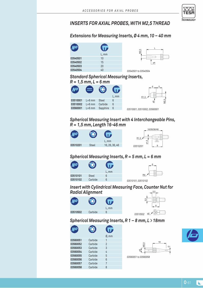
O-60 O-61
M2,
5 18
D
ø5
ø2
6
3,3
2,5
6
R5
16/26/36/46
R1,5
ø1,5
9
6 5
M2,
5
ø5
R1,5
L
M2,
5
ø4
inSErTS For AXiAL probES, WiTH M2,5 THrEAd
A c c E S S O r I E S F O r A x I A L P r O B E S
l, mm
03540501 1003540502 1503540503 2003540504 40
Extensions for Measuring inserts, Ø 4 mm, 10 – 40 mm
03540501 to 03540504
l, mm
03510001 l=6 mm Steel 603510002 l=6 mm Carbide 603560001 l=6 mm Sapphire 6
Standard Spherical Measuring inserts, r = 1,5 mm, L = 6 mm
03510001, 03510002, 03560001
l, mm
03510201 Steel 16, 26, 36, 46
Spherical Measuring insert with 4 interchangeable pins, r = 1,5 mm, Length 16-46 mm
03510201
l, mm
03510101 Steel 603510102 Carbide 6
Spherical Measuring inserts, r = 5 mm, L = 6 mm
03510101, 03510102
l, mm
03510502 Carbide 6
insert with cylindrical Measuring Face, counter nut for radial Alignment
03510502
Ø, mm
03560051 Carbide 103560052 Carbide 203560053 Carbide 303560054 Carbide 403560055 Carbide 503560056 Carbide 603560057 Carbide 703560058 Carbide 8
Spherical Measuring inserts, r 1 – 8 mm, L > 18mm
03560051 to 03560058
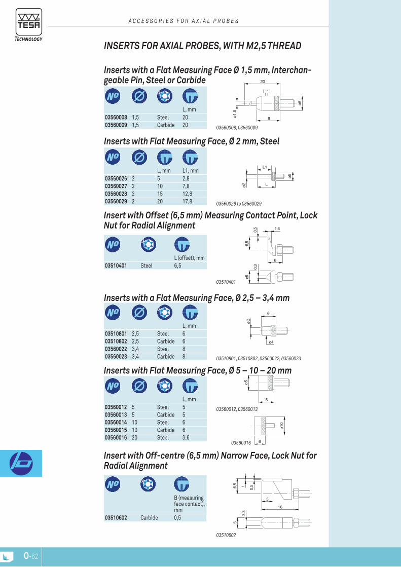
O-62
16
3,3
56,
5 1
5
0,5
ø5
5
ø10
6
6
øD
ø4
6
1,6
ø5
0,3
0,5
6,5
ø5
Lø2
L1
ø5
ø1.5
20
8
l, mm
03560008 1,5 Steel 2003560009 1,5 Carbide 20
inserts with a Flat Measuring Face Ø 1,5 mm, interchan-geable pin, Steel or carbide
03560008, 03560009
inSErTS For AXiAL probES, WiTH M2,5 THrEAd
A c c E S S O r I E S F O r A x I A L P r O B E S
l, mm l1, mm
03560026 2 5 2,803560027 2 10 7,803560028 2 15 12,803560029 2 20 17,8
inserts with Flat Measuring Face, Ø 2 mm, Steel
03560026 to 03560029
l (offset), mm
03510401 Steel 6,5
insert with offset (6,5 mm) Measuring contact point, Lock nut for radial Alignment
03510401
l, mm
03510801 2,5 Steel 603510802 2,5 Carbide 603560022 3,4 Steel 803560023 3,4 Carbide 8
inserts with a Flat Measuring Face, Ø 2,5 – 3,4 mm
03510801, 03510802, 03560022, 03560023
l, mm
03560012 5 Steel 503560013 5 Carbide 503560014 10 Steel 603560015 10 Carbide 603560016 20 Steel 3,6
inserts with Flat Measuring Face, Ø 5 – 10 – 20 mm
03560016
03560012, 03560013
B (measuring face contact), mm
03510602 Carbide 0,5
insert with off-centre (6,5 mm) narrow Face, Lock nut for radial Alignment
03510602

O-62 O-63
1.6
3,02,0
8
7
7,5
17,25
5
1,5
0,00
3
ø5
8
ø3.4
0.3
2,5
ø4
2,3
16
0,5 ø7,5
ø7
ø2120,
4
15
ø2,5
ø4
2,3
16
ø7,5
inSErTS For AXiAL probES, WiTH M2,5 THrEAd
A c c E S S O r I E S F O r A x I A L P r O B E S
03510902 2,5 Carbide 16
insert with a Flat Measuring Face, Ø 2,5 mm, Adjustable parallelism, counter-nut for radial Alignment
03510902
l (offset), mm
03560063 Steel 12
insert with offset (12 mm) contact point, Lock nut for radial Alignment
03560063
B, mm
03510702 Carbide 0,5
insert with narrow Measuring Face, Adjustable paralle-lism, counter-nut for radial Alignment
03510702
l, mm B (mea-
suring face), mm
03560024 Steel 8 0,303560025 Carbide 8 0,3
inserts with blade-shaped Measuring Face, Lock nut for radial Alignment
03560024, 03560025
roller shape l, mm
03560010 Cylindrical Steel 17,2503560011 Domed Steel 17,25
Measuring inserts with ball-bearing rollers, Lock nut for radial Alignment
03560010, 03560011
03560030
insert with needle contact point
03560030
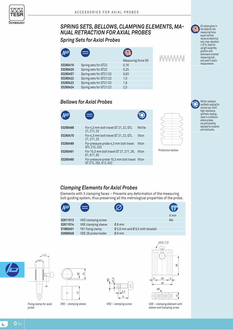
O-64
-200010
ø 10H7
M4
M4
0,7
6
ø1,5
12
10ø8
55 20
28
ø8
ø4,3 / 7,5
30
12
VDE – clamping élément with sleeve and clamping screw
Fixing clamp for axial probe
A mm
02611013 VKD clamping screw M402611014 VKE clamping sleeve Ø 8 mm01860401 Y61 fixing clamp Ø 5,6 mm and Ø 9,5 with dovetail02660048 VDE 28 probe holder Ø 8 mm
clamping Elements for Axial probes Elements with 3 clamping faces – prevents any deformation of the measuring bolt guiding system, thus preserving all the metrological properties of the probe.
VKE – clamping sleeve VKD – clamping screw
Measuring force (n)
03260419 Spring sets for gt22 0,1603260420 Spring sets for gt22 0,2503260457 Spring sets for gt21/22 0,6303260422 Spring sets for gt21/22 1,003260423 Spring sets for gt21/22 1,603260424 Spring sets for gt21/22 2,5
All values given in the table for the measuring force equal nominal values at electrical zero; max. deviation ± 25 %. Valid for upright assembly position with downward oriented measuring bolt, and used in static measurement.
Spring Sets for Axial probes
SprinG SETS, bELLoWS, cLAMpinG ELEMEnTS, MA-nuAL rETrAcTion For AXiAL probES
A c c E S S O r I E S F O r A x I A L P r O B E S
03260468 For 4,3 mm bolt travel gt 21, 22, gtl 21, 211, 22
nitrile
03260470 For 4,3 mm bolt travel gt 21, 22, gtl 21, 211, 22
Viton
03260489 For pressure probe 4,3 mm bolt travel gtl 212, 222
Viton
03260491 For 10,3 mm bolt travel gt 27, 271, 28, 61, 611, 62
Viton
03260490 For pressure probe 10,3 mm bolt travel gt 272, 282, 612, 622
Viton
nitrile: resistant synthetic sealing for normal use. Viton: high-resistance synthetic sealing. Used in conditions where probes are permanently exposed to coolants and lubricants.
bellows for Axial probes
Protection bellow

O-64 O-65
33
6,3
ø 6,4
R9
L
P r O B E A c c E S S O r I E S
03540104 tB 11 retraction device components Consisting of: – 1 Washer tB102 (03540102) – 1 lifting lever tB101 (03540101)
03260401 Manual pneumatic retraction device.
Suitable for gt 22, 271, 28, 42, 44, 611, 62 – gtl211, 22 probesConsisting of:
– 1 hand-operated vacuum pump – 1 tube of 1m, Ø 4,7 mm (ref. 03540405)
03540405 tB311 flexible tube
Manual Measuring bolt retraction for Axial probes
AccESSoriES For GT 31 LEvEr probES Stainless steel measuring insert, carbide ball tip
probe inserts for GT 31 Lever probes
0326041003260410
03240100 Fixing bracket with dovetail clamp or cylindrical bore for gt31 probe
Fixing bracket for TESA GT 31 Lever probe
03240100
03260402 1 1 : 1 32 One-piece shaft03260410 2 1 : 1 32 One-piece shaft03260403 3 1 : 1 32 One-piece shaft03590002 1 1 : 1 32 two-piece shaft03590003 2 1 : 1 32 two-piece shaft03590004 3 1 : 1 32 two-piece shaft03590005 4 1 : 1 32 two-piece shaft
lever –
amplificationl, mm
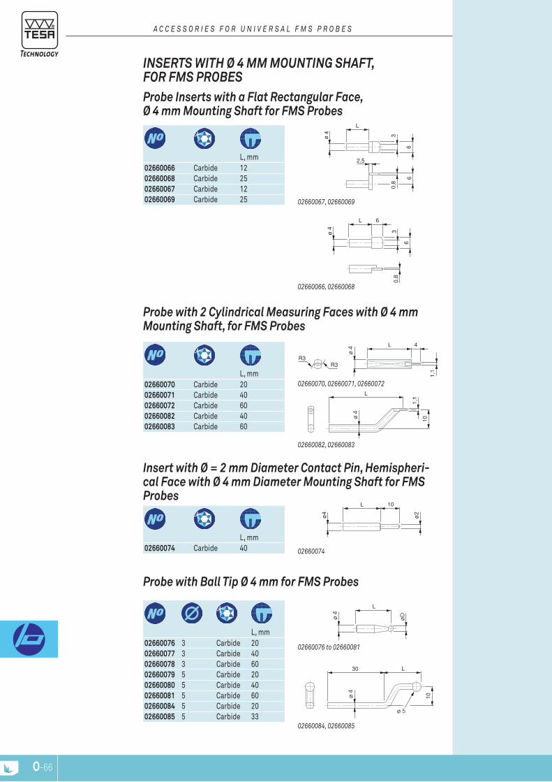
O-66
L
ø 4
øD
L30
ø 5
10ø 4
ø4
L 10
ø2
R3R3
1,1
ø 4
L 4
L
10
1,1
ø 4
ø 4 3
L 6
0,8
6
ø4 3
0,8
6
L
6
2,5
l, mm
02660066 Carbide 1202660068 Carbide 2502660067 Carbide 1202660069 Carbide 25
probe inserts with a Flat rectangular Face, Ø 4 mm Mounting Shaft for FMS probes
02660067, 02660069
02660066, 02660068
inSErTS WiTH Ø 4 MM MounTinG SHAFT, For FMS probES
A c c E S S O r I E S F O r U n I V E r S A L F M S P r O B E S
l, mm
02660070 Carbide 2002660071 Carbide 4002660072 Carbide 6002660082 Carbide 4002660083 Carbide 60
probe with 2 cylindrical Measuring Faces with Ø 4 mm Mounting Shaft, for FMS probes
02660082, 02660083
02660070, 02660071, 02660072
l, mm
02660074 Carbide 40
insert with Ø = 2 mm diameter contact pin, Hemispheri-cal Face with Ø 4 mm diameter Mounting Shaft for FMS probes
02660074
l, mm
02660076 3 Carbide 2002660077 3 Carbide 4002660078 3 Carbide 6002660079 5 Carbide 2002660080 5 Carbide 4002660081 5 Carbide 6002660084 5 Carbide 2002660085 5 Carbide 33
probe with ball Tip Ø 4 mm for FMS probes
02660084, 02660085
02660076 to 02660081
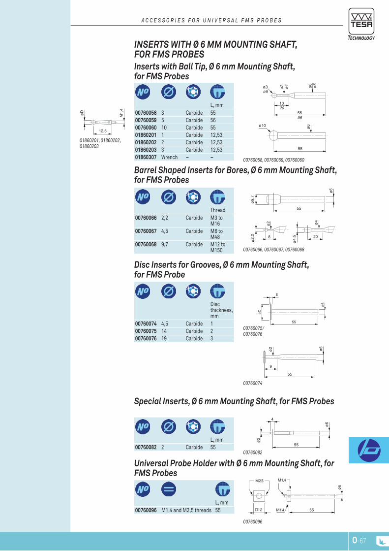
O-66 O-67
ø6
55M1,4
M2,5 M1,4
12
ø6
4
ø2
55
ø6
ø2
55
9
55
ø9,
7
ø6
ø4
ø2
8 20
ø2,
2
ø4,
5
ø3ø5
1020
5556
ø2
ø4 ø6
ø6
55
ø10 ø6
12,5
M1,
4
øD
55
øD
ø6
E
inSErTS WiTH Ø 6 MM MounTinG SHAFT, For FMS probES
A c c E S S O r I E S F O r U n I V E r S A L F M S P r O B E S
l, mm
00760058 3 Carbide 5500760059 5 Carbide 5600760060 10 Carbide 5501860201 1 Carbide 12,5301860202 2 Carbide 12,5301860203 3 Carbide 12,5301860307 Wrench – –
inserts with ball Tip, Ø 6 mm Mounting Shaft, for FMS probes
01860201, 01860202, 01860203
00760058, 00760059, 00760060
thread
00760066 2,2 Carbide M3 to M16
00760067 4,5 Carbide M6 to M48
00760068 9,7 Carbide M12 to M150
barrel Shaped inserts for bores, Ø 6 mm Mounting Shaft, for FMS probes
00760066, 00760067, 00760068
Disc thickness, mm
00760074 4,5 Carbide 100760075 14 Carbide 200760076 19 Carbide 3
disc inserts for Grooves, Ø 6 mm Mounting Shaft, for FMS probe
00760075/00760076
00760074
l, mm
00760082 2 Carbide 55
Special inserts, Ø 6 mm Mounting Shaft, for FMS probes
00760082
l, mm
00760096 M1,4 and M2,5 threads 55
universal probe Holder with Ø 6 mm Mounting Shaft, for FMS probes
00760096

O-68
max. 25
31
23,5
20
13 12
23,5
ø 6 H7ø 4 H7
ø4 H7ø6 H7
8/13
31
23,5
20 / 25
12
12
ø4 H7ø6 H7
12 / 13
23,5
/ 25
25
12
12
4 / 5
21
5 3
24,2
0,7
12,2
23,6
1
2
3
4
5
2,2
Drawing
02630047 VBM offset insert 102630048 VBn offset insert 202630049 VBO offset insert 302630050 VBp offset insert 402630051 VBQ offset insert 5
inserts with offset Measuring Faces, for FMS probes
Inserts with offset faces for FMS probes
SprinGS, pnEuMATic AcTuATorS, HoLdErS, oFF-SET inSErTS, For FMS probE
A c c E S S O r I E S F O r U n I V E r S A L F M S P r O B E S
number position
02630042 VBH fixed holder 4 2 Horizontal02630043 VBJ fixed holder 4 1 Vertical02630045 VBK fixed holder 6 2 Horizontal02630046 VBl fixed holder 6 1 Vertical
Fixed Holder, for FMS probe
03230043 03230046
02630042 02630045
mm number position
02630053 25 4 2 Horizontal02630055 25 4 1 Vertical02630052 25 6 2 Horizontal02630054 25 6 1 Vertical
Holder with Fine Adjustment for FMS probe Helps greatly for setting a FMS probe. Setting and locking screws remain accessible even when several probes are mounted side by side.
02630052 02630053
02630053
M8 x 0,75
30,5
6
2,2
27,5
17ø 3
M512
ø 9
n
03260440 pneumatic jack 11 (for 4 bars)03260441 Spring element 0,403260442 Spring element 0,6303260443 Spring element 1,003260444 Spring element 1,603260445 Spring element 2,003260446 Spring element 2,503260447 Spring element 4,0
All values given in the table for the measuring force equal nominal va-lues at electricalzero; max. deviation ± 25 %. Valid for probing movements executed horizontal-ly as wellas in static mea-suring.
Auxiliary Springs and pneumatic retraction Jack, for FMS probe
Auxiliary sping element for FMS probe Pneumatic cylinder
(jack) for FMS probe
M8 x 0,75
Meauring force, n
03260448 Spring set red 0,403260449 Spring set yellow 0,6303260450 Spring set green 1,003260451 Spring set blue 1,603260452 Spring set brown 2,503260453 Spring set black 4,0
All values given in the table for the measuring force equal nominal va-lues at electricalzero; max. deviation ± 25 %. Valid for probing movements executed horizontal-ly as wellas in static mea-suring mode
Spring Set with Specific Measuring Force, for FMS probe
Spring set for mea-suring force for FMS probe
rectangular flat measuring face
Carbide
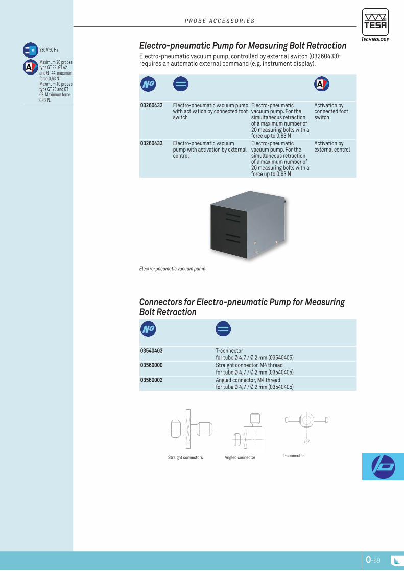
O-68 O-69
03540403 t-connector for tube Ø 4,7 / Ø 2 mm (03540405)
03560000 Straight connector, M4 thread for tube Ø 4,7 / Ø 2 mm (03540405)
03560002 Angled connector, M4 thread for tube Ø 4,7 / Ø 2 mm (03540405)
Straight connectors
connectors for Electro-pneumatic pump for Measuring bolt retraction
t-connector
03260432 Electro-pneumatic vacuum pump with activation by connected foot switch
Electro-pneumatic vacuum pump. For the simultaneous retraction of a maximum number of 20 measuring bolts with a force up to 0,63 n
Activation by connected foot switch
03260433 Electro-pneumatic vacuum pump with activation by external control
Electro-pneumatic vacuum pump. For the simultaneous retraction of a maximum number of 20 measuring bolts with a force up to 0,63 n
Activation by external control
230 V 50 Hz
Maximum 20 probes type gt 22, gt 42 and gt 44, maximum force 0,63 n. Maximum 10 probes type gt 28 and gt 62, Maximum force 0,63 n.
Electro-pneumatic vacuum pump
Electro-pneumatic pump for Measuring bolt retraction Electro-pneumatic vacuum pump, controlled by external switch (03260433): requires an automatic external command (e.g. instrument display).
P r O B E A c c E S S O r I E S
Angled connector
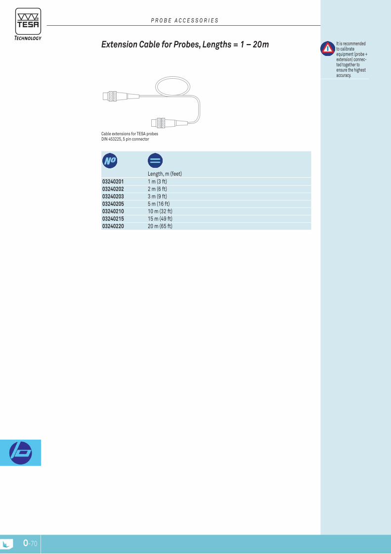
O-70
P r O B E A c c E S S O r I E S
length, m (feet)
03240201 1 m (3 ft)03240202 2 m (6 ft)03240203 3 m (9 ft)03240205 5 m (16 ft)03240210 10 m (32 ft)03240215 15 m (49 ft)03240220 20 m (65 ft)
It is recommended to calibrate equipment (probe + extension) connec-ted together to ensure the highest accuracy.
Cable extensions for tESA probes DIn 453225, 5 pin connector
Extension cable for probes, Lengths = 1 – 20m
www.tesatechnology.com P-1
Acce
ssor
ies
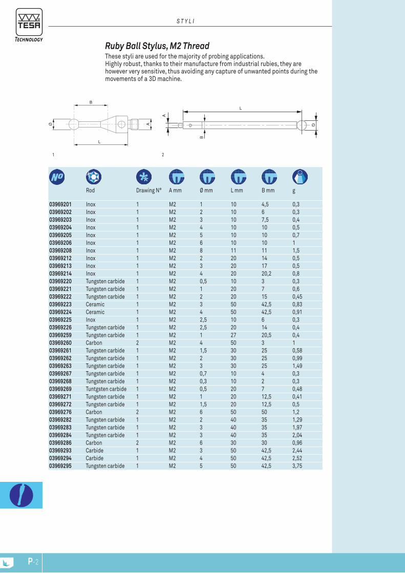
B
L
Ø A Ø
L
A
B
P-2
03969201 Inox 1 M2 1 10 4,5 0,303969202 Inox 1 M2 2 10 6 0,303969203 Inox 1 M2 3 10 7,5 0,403969204 Inox 1 M2 4 10 10 0,503969205 Inox 1 M2 5 10 10 0,703969206 Inox 1 M2 6 10 10 103969208 Inox 1 M2 8 11 11 1,503969212 Inox 1 M2 2 20 14 0,503969213 Inox 1 M2 3 20 17 0,503969214 Inox 1 M2 4 20 20,2 0,803969220 Tungsten carbide 1 M2 0,5 10 3 0,303969221 Tungsten carbide 1 M2 1 20 7 0,603969222 Tungsten carbide 1 M2 2 20 15 0,4503969223 Ceramic 1 M2 3 50 42,5 0,8303969224 Ceramic 1 M2 4 50 42,5 0,9103969225 Inox 1 M2 2,5 10 6 0,303969226 Tungsten carbide 1 M2 2,5 20 14 0,403969259 Tungsten carbide 1 M2 1 27 20,5 0,403969260 Carbon 2 M2 4 50 3 103969261 Tungsten carbide 1 M2 1,5 30 25 0,5803969262 Tungsten carbide 1 M2 2 30 25 0,9903969263 Tungsten carbide 1 M2 3 30 25 1,4903969267 Tungsten carbide 1 M2 0,7 10 4 0,303969268 Tungsten carbide 1 M2 0,3 10 2 0,303969269 Tuntgsten carbide 1 M2 0,5 20 7 0,4803969271 Tungsten carbide 1 M2 1 20 12,5 0,4103969272 Tungsten carbide 1 M2 1,5 20 12,5 0,503969276 Carbon 2 M2 6 50 50 1,203969282 Tungsten carbide 1 M2 2 40 35 1,2903969283 Tungsten carbide 1 M2 3 40 35 1,9703969284 Tungsten carbide 1 M2 3 40 35 2,0403969286 Carbon 2 M2 6 30 30 0,9603969293 Carbide 1 M2 3 50 42,5 2,4403969294 Carbide 1 M2 4 50 42,5 2,5203969295 Tungsten carbide 1 M2 5 50 42,5 3,75
Rod Drawing N° A mm Ø mm L mm B mm g
21
Ruby Ball Stylus, M2 Thread These styli are used for the majority of probing applications. Highly robust, thanks to their manufacture from industrial rubies, they are however very sensitive, thus avoiding any capture of unwanted points during the movements of a 3D machine.
S T Y L I
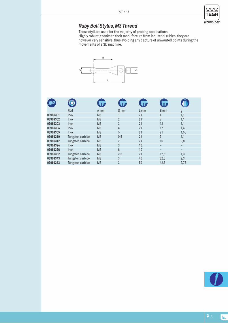
B
LØ A
P-3
03969301 Inox M3 1 21 4 1,103969302 Inox M3 2 21 8 1,103969303 Inox M3 3 21 12 1,103969304 Inox M3 4 21 17 1,403969305 Inox M3 5 21 21 1,5503969310 Tungsten carbide M3 0,5 21 3 1,103969312 Tungsten carbide M3 2 21 15 0,803969324 Inox M3 3 10 – –03969326 Inox M3 6 10 – –03969332 Tungsten carbide M3 2,5 21 12,5 1,303969343 Tungsten carbide M3 3 40 32,5 2,303969353 Tungsten carbide M3 3 50 42,5 2,78
Rod A mm Ø mm L mm B mm g
Ruby Ball Stylus, M3 Thread These styli are used for the majority of probing applications. Highly robust, thanks to their manufacture from industrial rubies, they are however very sensitive, thus avoiding any capture of unwanted points during the movements of a 3D machine.
S T Y L I
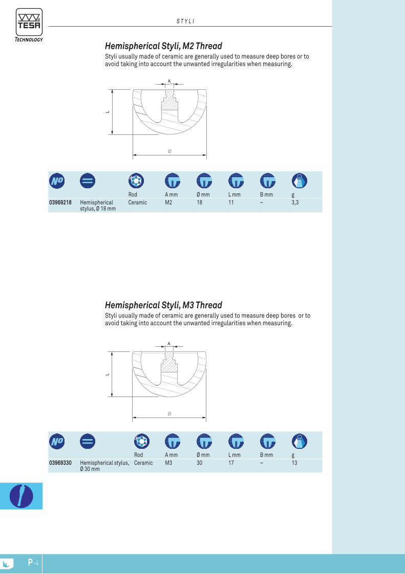
L
∅
A
L
∅
A
P-4
03969330 Hemispherical stylus, Ø 30 mm
Ceramic M3 30 17 – 13Rod A mm Ø mm L mm B mm g
Hemispherical Styli, M3 Thread Styli usually made of ceramic are generally used to measure deep bores or to avoid taking into account the unwanted irregularities when measuring.
03969218 Hemispherical stylus, Ø 18 mm
Ceramic M2 18 11 – 3,3Rod A mm Ø mm L mm B mm g
Hemispherical Styli, M2 Thread Styli usually made of ceramic are generally used to measure deep bores or to avoid taking into account the unwanted irregularities when measuring.
S T Y L I
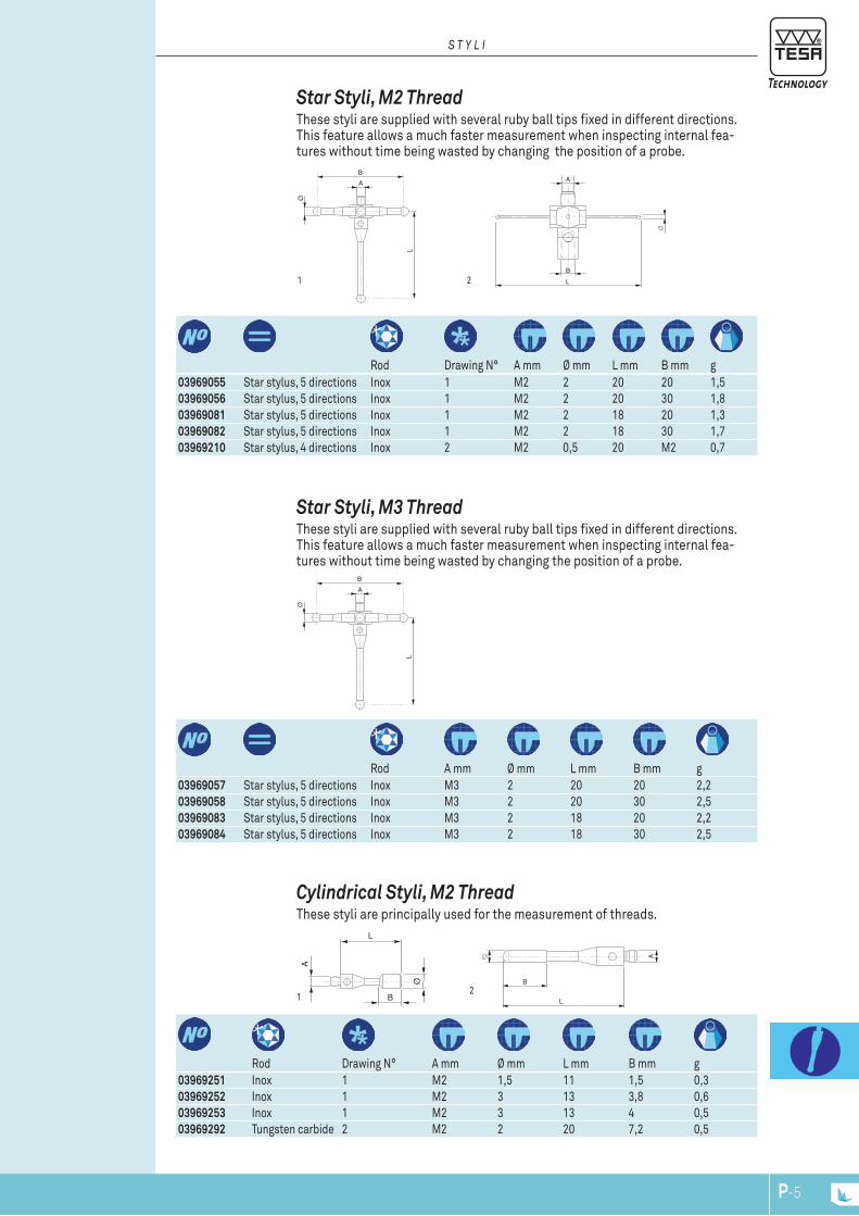
B
A
L
Ø
L
∅
B
A
A
L
Ø
B
∅
B
L
A
B
A
L
Ø
P-5
03969057 Star stylus, 5 directions Inox M3 2 20 20 2,203969058 Star stylus, 5 directions Inox M3 2 20 30 2,503969083 Star stylus, 5 directions Inox M3 2 18 20 2,203969084 Star stylus, 5 directions Inox M3 2 18 30 2,5
Rod A mm Ø mm L mm B mm g
Star Styli, M3 Thread These styli are supplied with several ruby ball tips fixed in different directions. This feature allows a much faster measurement when inspecting internal fea-tures without time being wasted by changing the position of a probe.
03969251 Inox 1 M2 1,5 11 1,5 0,303969252 Inox 1 M2 3 13 3,8 0,603969253 Inox 1 M2 3 13 4 0,503969292 Tungsten carbide 2 M2 2 20 7,2 0,5
Rod Drawing N° A mm Ø mm L mm B mm g
1
Cylindrical Styli, M2 Thread These styli are principally used for the measurement of threads.
2
Rod Drawing N° A mm Ø mm L mm B mm g03969055 Star stylus, 5 directions Inox 1 M2 2 20 20 1,503969056 Star stylus, 5 directions Inox 1 M2 2 20 30 1,803969081 Star stylus, 5 directions Inox 1 M2 2 18 20 1,303969082 Star stylus, 5 directions Inox 1 M2 2 18 30 1,703969210 Star stylus, 4 directions Inox 2 M2 0,5 20 M2 0,7
21
Star Styli, M2 Thread These styli are supplied with several ruby ball tips fixed in different directions. This feature allows a much faster measurement when inspecting internal fea-tures without time being wasted by changing the position of a probe.
S T Y L I

A∅
B
L
A A
L
A A
L
P-6
03969230 Extension, L5 mm Inox M2 3 5 – –03969231 Extension, L10 mm Inox M2 – 10 – 0,503969232 Extension, L20 mm Inox M2 – 20 – 103969233 Extension, L30 mm Inox M2 – 30 – 1,603969234 Extension, L40 mm Inox M2 3 40 – 1,803969238 Extension, L50 mm Carbon M2 3 50 – 103969239 Extension, L70 mm Carbon M2 3 70 – 1,303969240 Extension, L90 mm Carbon M2 3 90 – 1,503969246 Extension, L40 mm Ceramic M2 3 40 – 1,2203969247 Extension, L50 mm Ceramic M2 3 50 – 1,5103969270 Extension, L40 mm Carbon M2 3 40 – 0,9
Rod A mm Ø mm L mm B mm g
Extension M2 The extension allows to enlarge the distance between the probe and the tip of the stylus in order to avoid collision in the depth measurement (e.g. bore). The use of extensions can greatly reduce the accuracy of the measuring system.
03969044 Extension, L10 mm Inox M3 – 10 – 0,803969045 Extension, L20 mm Inox M3 – 20 – 1,803969320 Extension, L35 mm Inox M3 – 35 – 2,9
Rod A mm Ø mm L mm B mm g
Extension M3 The extension allows to enlarge the distance between the probe and the tip of the stylus in order to avoid collision in the depth measurement (e.g. bore). The use of extensions can greatly reduce the accuracy of the measuring system.
03969277 Carbide M2 0,5 15,3 7,8 0,303969278 Carbide M2 1 35,5 29,8 0,703969279 Carbide M2 2 16 8,5 0,803969280 Carbide M2 2 40 32 203969281 Carbide M2 3 22,5 – 2
Rod A mm Ø mm L mm B mm g
Parallel Styli, M2 Thread These styli are principally used for the measurement of threads.
S T Y L I
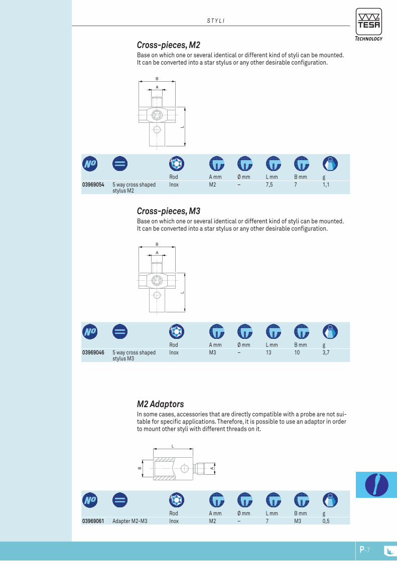
B A
L
B
A
L
B
A
L
P-7
03969054 5 way cross shaped stylus M2
Inox M2 – 7,5 7 1,1Rod A mm Ø mm L mm B mm g
Cross-pieces, M2 Base on which one or several identical or different kind of styli can be mounted. It can be converted into a star stylus or any other desirable configuration.
S T Y L I
03969046 5 way cross shaped stylus M3
Inox M3 – 13 10 3,7Rod A mm Ø mm L mm B mm g
Cross-pieces, M3 Base on which one or several identical or different kind of styli can be mounted. It can be converted into a star stylus or any other desirable configuration.
03969061 Adapter M2-M3 Inox M2 – 7 M3 0,5Rod A mm Ø mm L mm B mm g
M2 Adaptors In some cases, accessories that are directly compatible with a probe are not sui-table for specific applications. Therefore, it is possible to use an adaptor in order to mount other styli with different threads on it.
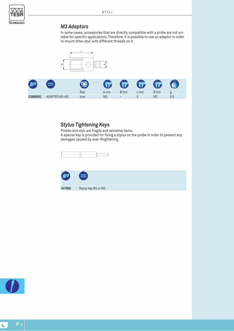
B A
L
P-8
047866 Stylus key M2 or M3
Stylus Tightening Keys Probes and styli are fragile and sensitive items. A special key is provided for fixing a stylus on the probe in order to prevent any damages caused by over-thightening.
03969062 ADAPTER M3-M2 Inox M3 – 5 M2 0,5Rod A mm Ø mm L mm B mm g
M3 Adaptors In some cases, accessories that are directly compatible with a probe are not sui-table for specific applications. Therefore, it is possible to use an adaptor in order to mount other styli with different threads on it.
S T Y L I

P-9
Kit N° 1, M2
03969086
Kit N° 2, M2
03969087
Kit N° 3, M2 + rigid probe 03969089
Kit N° 1, M3
03969101
Kit N° 2, M3 + rigid probe 03969040
03969085 Case for accessories 1047866 Stylus key M2 or M3 2049652 Key 2050697 Tightening key for carbon fibre styli 203969231 Extension, inox, M2, L = 10 mm 1 1 103969232 Extension, inox, M2, L = 20 mm 1 1 103969233 Extension, inox, M2, L = 30 mm 103969270 Extension, carbone, M2, L = 40 mm 103969044 Extension, inox, M3, L = 10 mm 1 103969045 Extension, inox, M3, L = 20 mm 1 103969054 5 way cross shaped stylus, inox, M2 1 103969046 5 way cross shaped stylus, inox, M3 1 103969082 5 way cross shaped stylus, inox, M2 103969201 Stylus, inox, ruby ball tip, M2,
Ø 1 mm, L = 10 mm1
03969202 Stylus, inox, ruby ball tip, M2, Ø 2 mm, L = 10 mm
1 1
03969203 Stylus, inox, ruby ball tip, M2, Ø 3 mm, L = 10 mm
1
03969204 Stylus, inox, ruby ball tip, M2, Ø 4 mm, L = 10 mm
1 1
03969212 Stylus, inox, ruby ball tip, M2, Ø 2 mm, L = 20 mm
2 1
03969213 Stylus, inox, ruby ball tip, M2, Ø 3 mm, L = 20 mm
2 1
03969221 Stylus, carbide, ruby ball tip, M2, Ø 1 mm, L = 20 mm
1
03969260 Stylus,carbone ruby ball tip, M2, Ø 4 mm, L = 50 mm
1
03969302 Stylus, inox, ruby ball tip, M3, Ø 2 mm, L = 21 mm
1 1
03969303 Stylus, inox, ruby ball tip, M3, Ø 3 mm, L = 21 mm
1 1
03969304 Stylus, inox, ruby ball tip, M3, Ø 4mm, L = 21 mm
1 1
03969214 Stylus, inox, ruby ball tip, Ø 4 mm, L = 20 mm
1
03969047 Rigid probe, Ø 6.35 mm 1 1
Stylus Kit In order to perform several types of measurement, it is often necessary to keep several models of styli. This is why TESA has created standard kits, comprising styli for a variety of dimensions as well as extensions to suit.
S T Y L I
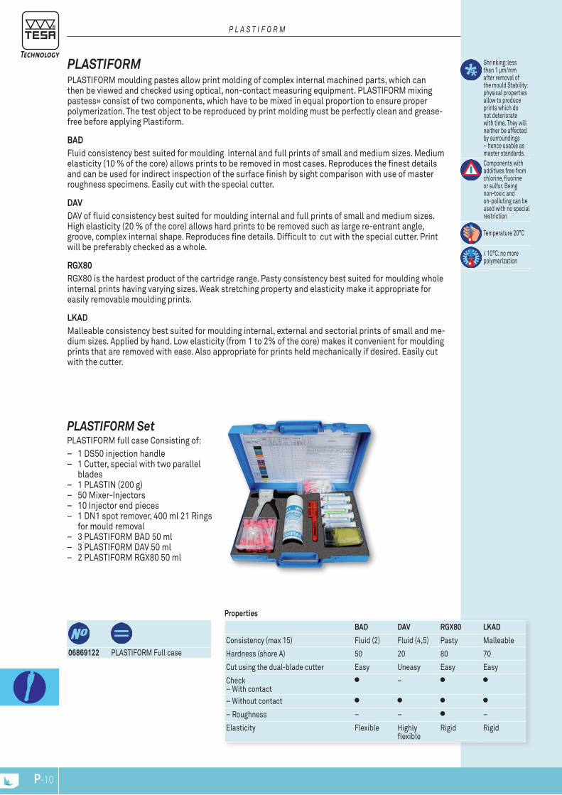
P-10
P L a S T I f o r m
PLASTIFORM PLASTIFORM moulding pastes allow print molding of complex internal machined parts, which can then be viewed and checked using optical, non-contact measuring equipment. PLASTIFORM mixing pastess» consist of two components, which have to be mixed in equal proportion to ensure proper polymerization. The test object to be reproduced by print molding must be perfectly clean and grease-free before applying Plastiform.
BAD Fluid consistency best suited for moulding internal and full prints of small and medium sizes. Medium elasticity (10 % of the core) allows prints to be removed in most cases. Reproduces the finest details and can be used for indirect inspection of the surface finish by sight comparison with use of master roughness specimens. Easily cut with the special cutter.
DAVDAV of fluid consistency best suited for moulding internal and full prints of small and medium sizes. High elasticity (20 % of the core) allows hard prints to be removed such as large re-entrant angle, groove, complex internal shape. Reproduces fine details. Difficult to cut with the special cutter. Print will be preferably checked as a whole.
RGX80RGX80 is the hardest product of the cartridge range. Pasty consistency best suited for moulding whole internal prints having varying sizes. Weak stretching property and elasticity make it appropriate for easily removable moulding prints.
LKADMalleable consistency best suited for moulding internal, external and sectorial prints of small and me-dium sizes. Applied by hand. Low elasticity (from 1 to 2% of the core) makes it convenient for moulding prints that are removed with ease. Also appropriate for prints held mechanically if desired. Easily cut with the cutter.
PLASTIFORM Set PLASTIFORM full case Consisting of:
– 1 DS50 injection handle – 1 Cutter, special with two parallel
blades – 1 PLASTIN (200 g) – 50 Mixer-Injectors – 10 Injector end pieces – 1 DN1 spot remover, 400 ml 21 Rings
for mould removal – 3 PLASTIFORM BAD 50 ml – 3 PLASTIFORM DAV 50 ml – 2 PLASTIFORM RGX80 50 ml
Shrinking: less than 1 μm/mm after removal of the mould Stability: physical properties allow to produce prints which do not deteriorate with time. They will neither be affected by surroundings – hence usable as master standards.Components with additives free from chlorine, fluorine or sulfur. Being non-toxic and on-polluting can be used with no special restriction
Temperature 20°C
< 10°C: no more polymerization
Properties
06869122 PLASTIFORM Full case
BAD DAV RGX80 LKAD
Consistency (max 15) Fluid (2) Fluid (4,5) Pasty Malleable
Hardness (shore A) 50 20 80 70
Cut using the dual-blade cutter Easy Uneasy Easy Easy
Check – With contact
–
– Without contact
– Roughness – – –
Elasticity Flexible Highly flexible
Rigid Rigid

P L a S T I f o r m
Accessories for PLASTIFORM – BAD, DAV, RGX80, LKAD Cartridges – Plastin – Tests kits – Mixers-injectors – Cutter, special with two parallel blades – Injector nozzles DS50 – DN1 spot remover, aerosol can, 400 ml
06869101 PLASTIFORM BAD 8 x 50 ml06869102 PLASTIFORM DAV 8 X 50 ml06869106 Mixing injectors, box of 50 pcs06869107 Mixing injectors, box of 100 pcs06869108 Mixing injectors, box of 200 pcs06869109 Fine nozzles box of 20 pcs06869110 Plastincine, 200 gr06869111 Special cutter with two parallel blades06869112 Plastiform pistol DS5006869113 Degreasing DN1, aerosol 400 ml06869118 PLASTIFORM RGX8 50 ml06869119 PLASTIFORM Lite KIT BAD06869120 PLASTIFORM Lite KIT DAV06869121 PLASTIFORM LK-AD
P-11

P-12P-12
T r a d e m a r k S
TRAdEMARKS REgISTEREd
– TESA
– TESA fig.
– ALESOMETRE
– CAPA µ SYSTEM fig.
– COMPAC
– COMPAC fig.
– COMPAC GENEVE fig.
– DIAMASTER
– DIGICO
– DIGIT-CAL
– DIGITMASTER
– DURA-CAL
– ETALON
– ETALON fig.
– ETALON SWITZERLAND fig.
– IMICRO
– INOTEST
– INTERAPID
– INTERAPID fig.
– ISOMASTER
– JUNIOR fig.
– MAGNA µ SYSTEM fig.
– MERCER
– MESOBOR
– MICRO-HITE
– MICROMASTER
– µHITE fig.
– ROCH FRANCE fig.
– RUGOSURF fig.
– SHOPCAL
– STANDARD GAGE fig.
– TESA DIGITMASTER
– TESA DUOTAST
– TESA EAGLE fig.
– TESA-HITE
– TESA MEMO-HITE
– TESA MICRO-HITE
– TESA SWISSCAL
– TESA SWISSTAST
– TESACAL
– TESADIA
– TESADIGIT
– TESAMASTER
– TESA-µHITE fig.
– TESANORM fig.
– TESA-SCOPE
– TESASTAR
– TESASTAR fig.
– TESATAST
– TESATRONIC
– TESATRONIC MULTILINE
– TRI-O-BOR
– TRIOMATIC
– UNIMASTER
– UNITEST
– UNITEST fig.
– VERIBOR
SWITZERLAND
®
SWITZERLAND SWITZERLAND
www.tesatechnology.com
00100110101 ........C-5, 2500110102 ............. C-500110103 ............. C-500110104 ............. C-500110105 ............. C-500110106 ............. C-500110107 ............. C-500110108 ............. C-500110109 ............. C-500110110 ............. C-500110111 ............. C-500110112 ............. C-500110113 ............. C-500110901 ............C-1100111901 ............C-1900111902 ............C-1900111903 ............C-1900111904 ............C-1900111905 ............C-1900140101 ............C-1900140301 ...... C-18, 1900160101 ............. E-700160201 ........C-3, 21
00200210001 ............C-1500210002 ............C-1500210003 ............C-1500210004 ............C-1500210101 ............. C-900210201 ............C-1300210202 ............C-1300210203 ............C-1300210204 ............C-1300211002 ........... C-2200211003 ........... C-2200211004 ........... C-2200211005 ........... C-2200211201 ........... C-2400240000 ............C-1600240001 ............C-1600240002 ............C-1600240003 ............C-1600240004 ............C-1600240005 ............C-1600240006 ............C-1600240007 ............C-1600240008 ............C-1600240009 ............C-1600240010 ............C-1600240011 ............C-1600240015 ............C-1600240501 ............C-1600240502 ............C-1600240503 ............C-1600240504 ............C-1600240505 ............C-1600240601 ............C-1600240602 ............C-1600240603 ............C-1600240700 ............C-1700240701 ............C-1700240702 ............C-1700240703 ............C-1700240704 ............C-1700240705 ............C-1700240706 ............C-1700240707 ............C-1700240708 ............C-1700240709 ............C-1700240710 ............C-1700240711 ............C-1700240712 ............C-1700240713 ............C-1700240714 ............C-1700240715 ............C-1700240716 ............C-1700250000 ............C-1600250001 ............C-1600250002 ............C-16
00250003 ............C-1600250004 ............C-1600250005 ............C-1600250006 ............C-1600250015 ............C-1600250100 ............C-1600250101 ............C-1600250102 ............C-1600250103 ............C-1600250104 ............C-1600250105 ............C-1600250106 ............C-1600250107 ............C-1600250108 ............C-1600250109 ............C-1600250115 ............C-1600250501 ............C-1600250502 ............C-1600250503 ............C-1600250504 ............C-1600250505 ............C-1600269020 ............C-1400269021 ............C-1400269022 ............C-1400269023 ............C-1400269024 ............C-1400269025 ............C-1400269026 ............C-1400269027 ............C-14
00300310001 ........C-4, 2500310002 ............. C-400310003 ............. C-400310004 ............. C-400310005 ............. C-400310006 ............. C-400310007 ............. C-400310008 ............. C-400311301 ............. C-800312301 ........... C-23
00400410001 ............C-1200410002 ............C-1200410003 ............C-1200410004 ............C-1200410005 ............C-1200410102 ............C-1200440001 ............C-1200440002 ............C-1200440003 ............C-1200440004 ............C-1200440005 ............C-1200440006 ............C-1200440007 ............C-12
00500510004 ............. B-700510008 .... B-6, C-2500510041 ............. B-900510047 ............. B-900510045 ............. B-600510046 ............. B-600510050 ............. B-600510123 ........... B-1700510124 ........... B-1700510125 ........... B-1700510133 ........... B-1700510134 ........... B-1700510143 ........... B-1700510163 ........... B-1700510173 ........... B-1700510175 ........... B-1800510177 ........... B-1800510179 ........... B-1800510181 ........... B-1800510201 ........... B-1800510202 ........... B-18
00510212 ........... B-1800510222 ........... B-1800510371 ........... B-2300510375 ........... B-2300510383 ........... B-2300510387 ........... B-2300510393 ........... B-2300510506 ........... B-1300510509 ........... B-1300510511 ........... B-1300510512 ........... B-1300510521 ........... B-1300510522 ........... B-1300510531 ........... B-1300510541 ........... B-1300510542 ........... B-1300510551 ........... B-1300510601 ........... B-1300510611 ........... B-1300510621 ........... B-1300510641 ........... B-1300510651 ........... B-1300510661 ........... B-1300510671 ........... B-1300510681 ........... B-1300510691 ........... B-1300510701 ........... B-1400510711 ........... B-1400510721 ........... B-1400510722 ........... B-1400510741 ........... B-1400510751 ........... B-1400510801 ........... B-1400510821 ........... B-1400510841 ........... B-1400510861 ........... B-1400510871 ........... B-1400510911 ........... B-2200510915 ........... B-2300510921 ........... B-2200510941 ........... B-2200512015 ........... B-2300512016 ........... B-2300512017 ........... B-230051610365......B-8, 9,...............13, 14, 18, 2200520001 ............. B-700520002 ............. B-600530020 ........... C-2500530021 ........... C-2500530094 .... B-4, C-2600530095 ............. B-400530096 ............. B-400530097 ............. B-400530103 ............. B-900530104 ............. B-900530105 ............. B-900530110 ............. B-900530111 ............. B-900530112 ............. B-900530120 ............. B-900530121 ............. B-900530130 ............. B-900530131 ............. B-900530319 .... B-3, C-2600530320 ............. B-300530321 ............. B-300530322 ............. B-300530323 ............. B-300530421 ........... B-1000530422 ........... B-1000530423 ........... B-1000530424 ........... B-1000530425 ........... B-1000530426 ........... B-1000530427 ........... B-1000530430 ........... B-1200530431 ........... B-1100530432 ........... B-1100530433 ........... B-1100530434 ........... B-1100530435 ........... B-11
00530436 ........... B-1100530437 ........... B-1100530441 ........... B-1500530442 ........... B-1500530443 ........... B-1500530444 ........... B-1500530445 ........... B-1500530446 ........... B-1500530447 ........... B-1500530448 ........... B-1600530449 ........... B-1600530450 ........... B-1600530451 ........... B-1600530471 ........... B-1900530473 ........... B-1900530474 ........... B-1900530475 ........... B-1900530509 ........... B-1300530521 ........... B-1300530531 ........... B-1300530701 ........... B-1400530721 ........... B-1400530741 ........... B-1400530821 ........... B-1400530841 ........... B-1400531004 ........... C-2600531007 ........... C-2600539390 ............. B-500539391 ............. B-500539392 ............. B-500539393 ............. B-500560013 ........ B-3, 4, .................. 5, 6, 7, 8, 9,...................... C-25, 2600560090 ........... C-2600560095 ......B-20, 2100560096 ......B-20, 2100560097 ......B-20, 2100560098 ......B-20, 2100560099 ......B-20, 2100560100 ......B-20, 2100560101 ......B-20, 2100560102 ......B-20, 2100560103 ...... B-16, 1800560104 ...... B-16, 1800560105 ...... B-16, 1800590061 ........... B-2000590062 ........... B-2000590063 ........... B-2000590064 ........... B-2000590065 ........... B-2000590066 ........... B-2000590067 ........... B-20
00600610102 ............ J-1500630001 ............ J-1500630002 ............ J-1500630010 ............ J-1400660002 ............ J-1500660003 ............ J-1500660004 ............ J-1400660005 ............ J-1400660006 ............ J-1400660007 ............ J-1400660008 ............ J-14
0070071684815........ N-290071684816........ N-290071684817........ N-290071684818........ N-290071684819........ N-290071684820........ N-290071684822........ N-290071684825........ N-290071684826........ N-290071684827........ N-290071684828........ N-290071684829........ N-29
0071684832........ N-2900730021 ........... N-1300730022 ........... N-1300730023 ........... N-1300730033 ........... N-1300730034 ........... N-1300730035 ........... N-1300730043 .............N-800730044 .............N-800730045 ........... N-1100730046 ........... N-1100730047 .............N-500730049 ........... N-2200730050 ........... N-2200730054 ........... N-2200730057 ........... N-1100730058 ........... N-1100730059 .............N-500730060 ........... N-1700730061 ........... N-1700730062 ........... N-1700730063 ........... N-1700730064 ........... N-1700730065 ........... N-1700760057 ........... N-2600760058 ........... O-6700760059 ........... O-6700760060 .....N-25, 26,........................... O-6700760061 N-24, 25, 2600760066 ..N-26, O-6700760067 ..N-26, O-6700760068 ..N-26, O-6700760074 ..N-26, O-6700760075 N-24, 25, 26,........................... O-6700760076 ..N-26, O-6700760082 .....N-24, 26,........................... O-67 00760086 ........... N-2600760087 ........... N-2600760093 ......N-25, 2600760094 N-24, 25, 2600760096 ........... O-6700760138 ........... N-2000760139 ........... N-2000760140 ........... N-2000760141 ......N-13, 1700760142 ......N-13, 1700760143 ........ N-5, 8,.................... 11, 13, 1700760144 ........... N-1300760148 ........... N-2600760150 ........... N-1300760151 ......N-13, 1700760152 ......N-13, 1700760153 ......N-13, 1700760157 ........ N-5, 8,.................... 11, 13, 1700760163 ........... N-1500760164 .............N-500760173 ........... N-2500760175 ........... N-2700760177 ........... N-2700760178 ...... N-27, 2800760179 ...... N-27, 2800760180 ...... N-27, 2800760181 ...... N-27, 2800760182 ...... N-27, 2800760183 ...... N-27, 2800760184 ...... N-27, 2800760185 ...... N-27, 2800760186 ......N-22, 2800760187 ........... N-2800760191 ........... N-2200760192 ........... N-2200760194 ........... N-2300760195 ........... N-2200760196 ........... N-2300760197 ........... N-2200760198 ........... N-2300760199 ........... N-23
00760200 ........... N-2300760201 ........... N-2300760202 ........... N-2300760203 ........... N-2200760204 ........... N-2200760207 ........... N-2300760219 .. N-8, 11, 1700760220 ........... N-1900760221 ........... N-1900760222 ...........N-3000760223 ........... N-2900760226 ....... N-8, 1100760227 .......N-8, 11,......................... 13, 1700760228 ......N-25, 2600760229 ......N-25, 2600760230 ......N-25, 2600760231 .............N-500760232 ........... N-24
00800810000 .............D-400810001 .............D-300810002 .............D-300810003 .............D-300810800 .............D-400810801 .............D-300810802 .............D-300810803 .............D-300811500 .............D-400811501 .............D-300811502 .............D-300811503 .............D-300811504 .............D-300812300 .............D-400812301 .............D-300812302 .............D-300812303 .............D-300812304 .............D-300812305 .............D-300812306 .............D-300812600 .............D-400812601 .............D-300812602 .............D-300812603 .............D-300812604 .............D-300813101 .............D-300813102 .............D-300813103 .............D-300813104 .............D-300813409 .............D-400813410 .............D-300813411 .............D-300813412 .............D-300813413 .............D-30081625081........ D-100081625082........ D-100081625083........ D-100081625084........ D-100081725001..........D-90081725003..........D-90081725006..........D-90081725008..........D-90081725010..........D-90081725012..........D-90081725014..........D-90081725016..........D-90081725018..........D-90081725020..........D-90081725022..........D-90081725024..........D-90081725026..........D-90081725028..........D-90081725030..........D-90081725032..........D-90081725034..........D-90081725036..........D-90081725038..........D-90081725063........ D-100081725066........ D-100081725068........ D-10
N u m e r i c a l i N d e x
Numerical iNdex
INFO-IINFO-NP
0081725070........ D-1000840001 .............D-800840101 ........... D-1700840102 ........... D-1700840103 ........... D-1700840104 ........... D-1700840105 ........... D-1700840106 ........... D-1700840107 ........... D-1700840108 ........... D-1700840109 ........... D-1700840110 ........... D-1700840111 ........... D-1700840112 ........... D-1700840113 ........... D-1700840114 ........... D-1700840115 ........... D-1700840116 ........... D-1700840117 ........... D-1700840118 ........... D-1700840301 .............D-800840302 .............D-800841100 .............D-800841101 .............D-800841102 .............D-800841800 .............D-800841801 .............D-800841802 .............D-800842600 .............D-800842601 .............D-800842602 .............D-800843101 ........... D-1700843200 ........... D-1700843201 ........... D-1700843230 ........... D-1700843239 ........... D-1700860001 .............D-800860007 .............D-800860008 .............D-800860011 .............D-800860012 .............D-800860015 .............D-800860016 .............D-800860017 .............D-800862601 .............D-800863005 .............D-800863016 .............D-800863017 .............D-800863035 .............D-8
00900910004 ........... D-1600910005 ........... D-1500910006 ........... D-1500910007 ........... D-1500910404 ........... D-1600910405 ........... D-1500910406 ........... D-1500910407 ........... D-1500910704 ........... D-1600910705 ........... D-1500910706 ........... D-1500910707 ........... D-1500911104 ........... D-1600911105 ........... D-1500911106 ........... D-1500911107 ........... D-1500940000 ......D-15, 16
01101110000 ............. E-501110101 ............. E-501110102 ............. E-501110103 ............. E-501110104 ............. E-501110105 ............. E-501110106 ............. E-501110112 ............. E-501110118 ............. E-501110124 ............. E-501110140 ............. E-501110203 ............. E-501110205 ............. E-501110208 ............. E-501110300 ............. E-5
01110401 ............. E-501110501 ............. E-501110700 ............. E-301110801 ............. E-301110802 ............. E-301110804 ............. E-301110808 ............. E-301110812 ............. E-301110820 ............. E-301110901 ............. E-301111900 ............. E-701112001 ............. E-701112002 ............. E-701112003 ............. E-701112004 ............. E-701112301 ............. E-701112401 ............. E-501130001 ............. E-501131901 ............. E-701131902 ............. E-701132001 ............. E-701140801 ............. E-301141001 ............. E-301141901 ............. E-701141902 ............. E-701160001 ............. E-501160701 ............. E-301160901 ............. E-301161900 ............. E-701162001 ..........E-5, 701162301 ............. E-301162302 ............. E-301162303 ............. E-7
01401410010 ............F-1701410120 ............F-1701410210 ............F-1101410520 ............F-1801410610 ............F-1201410611 ............F-1201410810 ............F-1901410910 ............F-1401412010 ............F-1101412310 ............F-1201412510 ............F-1701412511 ............F-1801412611 ............F-1801412711 ............F-1801416013 ............F-1101416014 ............F-1101416021 ............F-1201416034 ............F-160141760500.........F-200141760501.........F-200141760503.........F-200141760560.........F-210141760566.........F-240141760624.........F-220141760631.........F-220141760635.........F-220141760636.........F-220141760651.........F-220141760653.........F-220141760661.........F-220141761213.........F-2201419047 ............F-2101419048 ............F-2301419050 ............F-2301419051 ............F-1001419052 ............F-1001460008 .. F-29, O-4801460009 .. F-29, O-4801460014 ............F-2901460015 ............F-2901462004 ............F-2901462005 ............F-29
01501510000 ............. H-701510100 ............. H-701510200 ............. H-701510300 ............. H-7
01601610200 .............I-1101610201 ..... H-8, I-1101610401 .............. L-701630003 .............G-501639000 .............. I-801639003 ...............I-701639004 ...............I-701639006 ...............I-701639007 ..... G-5, I-1001639008 .............. I-801639009 ..... H-8, I-1101639016 .............I-1001639017 .............. I-501639018 .............. I-501639019 .............. I-501639020 .............. I-401639022 .............. I-301639023 .............. I-301639024 .............. I-601639025 .............. I-301639029 .............. I-901639033 .............. I-901639035 .............. I-901639046 .............I-1201639047 .............I-1201639053 .............. I-401640000 .............I-1101640000 .............H-801640100 .............. I-801640501 .............I-1001660011 .............. L-701690021 .............. L-7
01801810005 ......... G-4, 501810006 .............G-401810007 .............G-401810008 .............G-401810009 .............G-401810010 ......... G-4, 501810011 .............G-501810012 .............G-501810013 .............G-501810204 .............G-401810205 .............G-401810304 .............G-401811000 .............G-401811001 .............G-401830001 ............. G-201830002 ............. G-201840104 .... G-5, 6, 1401840105 ... G-5, 6, 14,.............................. I-801840106 ........... G-1301840107 ........... G-1301840108 ........... G-1301840109 ........... G-1301840202 ........G-6, 1401840404 ........G-6, 1401840405 .........G-6,1401840406 ........G-6, 1401840407 ........G-6, 1401840501 ........G-6, 1401850106 ........... G-1301850107 ........... G-1301860008 ........G-6, 1401860201 ....G-5, O-6701860202 ....G-5, O-6701860203 ....G-5, O-6701860211 .............G-501860212 .............G-501860213 .............G-501860301 .............G-501860302 .............G-501860303 .............G-501860304 .............G-501860305 .............G-501860307 .........G-5, 8,........................... O-6701860401 .......G-6, 14,........................... O-6401866003 ........... G-1301866004 ........... G-1301866006 ........... G-1301866014 ........... G-13
01866015 ........... G-1301866016 ........... G-1301866021 ........... G-1301866022 ........... G-1301866023 ........... G-1301866026 ........... G-1301866027 ........... G-13
01901930000 ..............F-701930001 ..............F-701930130 ............. F-801930131 ............. F-801930132 ............. F-801930133 ............. F-801930134 ............. F-901930135 ............. F-901930230 ............. F-301930231 ............. F-301930240 ............. F-401930241 ............. F-401930250 ............. F-401930255 ............. F-401930256 ............. F-501930257 ............. F-501930258 ............. F-601960005 .... F-7, 9, 29,........................... N-2001960007 ..............F-701961000 ..... B-3, 4, 5,................... 10, 11, 12,................... 16, 19, 20,.........................C-3, 8,.......................D-5, 11,..................F-6, 9, G-2, ............................ J-14 01961012 ............. F-901962002 ............. F-6
02102119021 ............. C-302130001 ............. H-202130002 ............. H-202130003 ............. H-202140001 ........... C-2002140002 ........... C-2002140003 ........... C-2002140004 ........... C-2002140005 ........... C-2002140006 ........... C-2002140007 ........... C-2002140008 ........... C-2002140009 ........... C-2002140010 ........... C-2002140011 ........... C-2002140012 ........... C-2002140013 ........... C-2002140014 ........... C-2002140015 ........... C-2002140016 ........... C-2002140017 ........... C-2002140018 ........... C-2002140019 ........... C-2002140020 ........... C-2002140103 ........... C-2002140108 ........... C-2002160020 .............H-302160021 .............H-302160023 .............H-302160024 .............H-302160025 .............H-302160026 .............H-302160028 .............H-402160027 ............. H-202160029 .............H-402160030 .............H-502160035 .............H-502160038 ............. H-202160043 .............H-302160044 .............H-3
02502510000 ........... C-2102510001 ........... C-21
02510002 ........... C-2102510003 ........... C-2102510004 ........... C-2102510100 ........... C-2102510101 ........... C-2102510102 ........... C-2102510103 ........... C-2102510200 ........... C-2102510201 ........... C-2102510202 ........... C-2102510203 ........... C-2102510300 ........... C-2102510301 ........... C-2102510302 ........... C-2102510303 ........... C-2102530050 ............. K-702530075 ............. K-7
02602611013 ........... O-6402611014 ........... O-6402630042 ........... O-6802630043 ........... O-6802630045 ........... O-6802630046 ........... O-6802630047 ........... O-6802630048 ........... O-6802630049 ........... O-6802630050 ........... O-6802630051 ........... O-6802630052 ........... O-6802630053 ........... O-6802630054 ........... O-6802630055 ........... O-6802660048 ........... O-6402660066 ........... O-6602660067 ........... O-6602660068 ........... O-6602660069 ........... O-6602660070 ........... O-6602660071 ........... O-6602660072 ........... O-6602660074 ........... O-6602660076 ........... O-6602660077 ........... O-6602660078 ........... O-6602660079 ........... O-6602660080 ........... O-6602660081 ........... O-6602660082 ........... O-6602660083 ........... O-6602660084 ........... O-6602660085 ........... O-66
03103130060 ..............J-603130063 ..............J-603160007 ........ J-6, 1103160008 ........ J-6, 1103160009 ........ J-6, 1103160015 ......O-53, 5403160016 ......O-53, 5403160017 ......O-53, 5403160048 ........ J-6, 11
03203210801 ........... O-4203210802 .O-12, 42, 4803210803 ........... O-4203210904 ........O-6, 1603210905 ........... O-1603210906 ........... O-1603210907 ........... O-1603210908 ........... O-1603210921 ........... O-1703210922 ........... O-1703210923 ........... O-1703210924 ........O-6, 1703210925 ........... O-1703210926 ........... O-1703210927 ........... O-1703210928 ........... O-1703230001 ...... O-12, 3703230002 ...... O-12, 37
03230017 ...... O-12, 3803230019 ...... O-14, 4303230021 ........O-6, 2203230026 ........O-6, 1903230027 ........O-6, 1903230028 ...... O-14, 4303230035 ...... O-12, 3803230036 ........O-6, 2103230037 ...... O-14, 4503230038 ...... O-14, 4503230041 ........O-6, 2003230042 ........O-6, 20 03230049 ...... O-14, 4303230050 ...... O-14, 4303230051 ...... O-14, 4503230052 ...... O-14, 4503230053 ........O-8, 2403230054 ........O-8, 2303230055 ........O-8, 2503230056 ........O-6, 1803230057 ........O-6, 1803230058 ...... O-10, 3303230059 ...... O-10, 3303230060 ........O-8, 2303230061 ........O-8, 2403230062 ........O-8, 2503230063 ........O-8, 2303230067 ........O-8, 2303230068 ........O-8, 2403230069 ........O-8, 2403230070 ........O-8, 2503230071 ........O-8, 2503230072 ........O-6, 1803230073 ........O-6, 1903230081 ...... O-10, 3603230085 ...... O-10, 3503230086 ...... O-10, 3403230087 .....O- 10, 3403230200 ...... O-10, 3003230201 ...... O-10, 3003230202 ...... O-10, 3103230204 ...... O-10, 3203230205 ...... O-10, 3203230500 ...... O-10, 2603230501 ...... O-10, 2803230502 ...... O-10, 2703230503 ...... O-10, 2903238013 ............. F-903240100 ........... O-6503240201 ........... O-7003240202 ........... O-7003240203 ........... O-7003240205 ........... O-7003240210 ........... O-7003240215 ........... O-7003240220 ........... O-7003260401 ..... L-7, O-6503260402 ........... O-6503260403 ........... O-6503260410 ........... O-6503260419 ........... O-6403260420 ........... O-6403260422 ........... O-6403260423 ........... O-6403260424 ........... O-6403260432 ..... L-7, O-6903260433 ..... L-7, O-6903260440 ........... O-6803260441 ........... O-6803260442 ........... O-6803260443 ........... O-6803260444 ........... O-6803260445 ........... O-6803260446 ........... O-6803260447 ........... O-6803260448 ........... O-6803260449 ........... O-6803260450 ........... O-6803260451 ........... O-6803260452 ........... O-6803260453 ........... O-6803260457 ........... O-6403260468 ........... O-6403260470 ........... O-6403260489 ........... O-6403260490 ........... O-6403260491 ........... O-64
N u m e r i c a l i N d e x
INFO-IIIINFO-II
03260500 ........... O-5803260501 ........... O-58
03303330004 ........... H-1403330006 ........... H-1503360300 ........... H-14
03503510001 .. F-25, O-6103510002 .F- 25, N-22,........................... O-6103510101 .. F-25, O-6103510102 .. F-25, O-6103510103 .. F-28, O-6003510201 .. F-25, O-6103510202 .. F-28, O-6003510203 .. F-28, O-6003510204 .. F-28, O-6003510401 .. F-26, O-6203510502 .. F-26, O-6103510503 .. F-28, O-6003510602 .. F-26, O-6203510702 ...F-27, O-6303510801 ...F-27, O-6203510802 ...F-27, O-6203510902 ...F-27, O-6303540104 .. F-29, O-6503540403 ........... O-6903540405 ........... O-6503540501 .. F-28, O-6103540502 .. F-28, O-6103540503 .. F-28, O-6103540504 .. F-28, O-6103540505 .. F-28, O-6003540506 .. F-28, O-6003560000 ........... O-6903560001 .. F-25, O-6103560002 ........... O-6903560004 ............F-2903560005 ............F-2903560006 ............F-2903560007 ............F-2503560008 ...F-27, O-6203560009 ...F-27, O-6203560010 .. F-26, O-6303560011 .. F-26, O-6303560012 ...F-27, O-6203560013 ...F-27, O-6203560014 ...F-27, O-6203560015 ...F-27, O-6203560016 ... F-27 O-6203560017 ............F-2503560018 ............F-2503560019 ............F-2503560020 ............F-2503560021 ............F-2503560022 ...F-27, O-6203560023 ...F-27, O-6203560024 .. F-26, O-6303560025 .. F-26, O-6303560026 ...F-27, O-6203560027 ...F-27, O-6203560028 ...F-27, O-6203560029 ...F-27, O-6203560030 .. F-26, O-6303560031 ............F-2603560032 ............F-2603560033 ............F-2603560034 ............F-2603560035 ............F-2503560036 ............F-2503560037 ............F-2503560038 ............F-2503560039 ............F-2503560040 ............F-2503560042 ............F-2703560043 ............F-2703560044 ............F-2703560045 ............F-2703560046 ............F-2703560047 ............F-2703560048 ............F-2703560049 ............F-2703560050 ............F-27
03560051 .. F-25, O-6103560052 .. F-25, O-6103560053 .. F-25, O-6103560054 .. F-25, O-6103560055 .. F-25, O-6103560056 .. F-25, O-6103560057 .. F-25, O-6103560058 .. F-25, O-6103560063 .. F-26, O-6303560065 ............F-2703560092 ............F-2703590002 ........... O-6503590003 ........... O-6503590004 ........... O-6503590005 ........... O-65
038038407 ............... N-22
03903969007 ............A-1003969040 ............. P-903969044 ..........P-6, 903969045 ..........P-6, 903969046 ...........P-7, 903969047 ............. P-903969054 ...........P-7, 903969055 ............. P-503969056 ............. P-503969057 ............. P-503969058 ............. P-503969061 ............. P-703969062 ............. P-803969081 ............. P-503969082 ..........P-5, 903969083 ............. P-503969084 ............. P-503969085 ............. P-903969086 ............. P-903969087 ............. P-903969089 ............. P-903969101 ............. P-903969201 ..........P-2, 903969202 ..........P-2, 903969203 ..........P-2, 903969204 ..........P-2, 903969205 ............. P-203969206 ............. P-203969208 ............. P-203969210 ............. P-5 03969212 ..........P-2, 903969213 ..........P-2, 903969214 ..........P-2, 903969218 ............. P-403969220 ............. P-203969221 ..........P-2, 903969222 ............. P-203969223 ............. P-203969224 ............. P-203969225 ............. P-2 03969226 ............. P-203969230 ............. P-603969231 ..........P-6, 903969232 ..........P-6, 903969233 ..........P-6, 903969234 ............. P-603969238 ............. P-603969239 ............. P-603969240 ............. P-603969246 ............. P-603969247 ............. P-603969251 ............. P-503969252 ............. P-503969253 ............. P-503969259 ............. P-203969260 ..........P-2, 903969261 ............. P-203969262 ............. P-203969263 ............. P-203969267 ............. P-203969268 ............. P-203969269 ............. P-203969270 ...... P-6, P-903969271 ............. P-203969272 ............. P-2
03969276 ............. P-203969277 ............. P-603969278 ............. P-603969279 ............. P-603969280 ............. P-603969281 ............. P-603969282 ............. P-203969283 ............. P-203969284 ............. P-203969286 ............. P-203969292 ............. P-503969293 ............. P-203969294 ............. P-203969295 ............. P-203969301 ............. P-303969302 ..........P-3, 903969303 ..........P-3, 903969304 ..........P-3, 903969305 ............. P-303969310 ............. P-303969312 ............. P-303969320 ............. P-603969324 ............. P-303969326 ............. P-303969330 ............. P-403969332 ............. P-303969343 ............. P-303969353 ............. P-3
04404430003 ........... O-5304430009 ........... O-4904430010 ........... O-4904430011 ........... O-5104430012 ..... L-7, O-5104430013 ........... O-4704460004 ......O-53, 54
04704760070 ....... N-8, 1104760087 .............. L-704760099 ...........A-12,........................M-6,1404760180 ............. A-7, ................... B-3, 4, 10,.............. 11, 12, 16, 19, ........................... O-4804760181 ...........A-10,................... B-3, 4, 10,.............. 11, 12, 16, 19,........................... O-4804760182 ...........A-10,................... B-3, 4, 10,.............. 11, 12, 16, 19,........................... O-4804761017 ............A-1104761023 ...A-10, N-1304761024 ............A-1004761027 ............. A-904761037 ..... A-11, F-704761038 ............A-1004761046 ............. A-904761047 ........... N-2004761049 .......A-9, L-7,......................O-50, 5204761052 ............ A-9, ................... N-5, 8, 11,......................... 19, 2204761054 ....... A-6, 11,............................ F-6,................... N-5, 8, 11,....................13, 17, 22,................ O-50, 52, 5404761055 ....... A-6, 11,............................ F-6,................... N-5, 8, 11,....................13, 17, 22, ................ O-50, 52, 5404761056 ....... A-6, 11,............................ F-6, ................... N-5, 8, 11,....................13, 17, 22, ........................... O-5404761057 ..... A-11, F-704761059 ........ J-6, 11
04761060 ....A-10, F-9,............................. G-204761062 ..... A-9, C-3,........................... J-14, ......................O-50, 5204761063 ............ A-9,................... N-5, 8, 11,......................... 19, 2204761070 .............. L-704761071 ............. A-504765008 .N-11, 15, 1904765013 ............. A-604768000 ......A-11,F-7,..............................L-7, ................ O-48, 50, 5204768001 ........... A-11, ................ O-48, 50, 5204768002 ......... J-3, 4,........................... 5, 1104768035 ............. A-6047866 ..............P-8, 9
049049652 ................. P-904981001 ......... A-3, 7,........................... O-4804981002 ..........A-4, 7........................... O-48
05005030010 ........... O-5505030012 ..........A-7, 8,................ O-26, 27, 28,.................... 29, 48, 56050697 ................. P-9
05305330003 ..............J-505330004 ..............J-505330005 ..............J-505330202 ..............J-405330203 ..............J-305331000 ..............J-905331002 ..............J-905331050 ..............J-805331054 ..............J-805331058 ..............J-805331061 ..............J-805331063 ..............J-805331201 ..............J-805331202 ..............J-805331204 ..............J-805331206 ..............J-805331210 ..............J-805331450 ..............J-905331500 ..............J-705331502 ..............J-705331550 ..............J-705331551 ..............J-705331750 ............ J-1005360004 ........ J-4, 1105360006 ........ J-3, 1105360014 ........ J-3, 11
056056109 ......A-12, M-20056133 .............. M-21056223 .............. M-21056224 .............. M-22056631 ...........M-9, 22056633 .............. M-22056639 .............. M-22056641 .............. M-22056645 ...............M-12
05705710012 ........... H-1005710013 ........... H-1005710014 ........... H-1005710015 ........... H-1005710016 ........... H-1005710017 ........... H-10
05710018 ........... H-1005710090 .............H-905710091 .............H-905710092 .............H-905710093 .............H-905740001 ........... H-1105760013 ........... H-1105760027 ........... H-1105760029 ........... H-11057655 ...........M-6, 22057941 ................ M-6
058058213 ......A-12, M-20059215 ............... N-24
05905919002 ............ L-1105930000 .............. L-705930003 .............. L-705930011 ..............L-905930013 .............. L-705930015 .............. L-705939001 ............ L-1105960011 ..............L-905960012 ..............L-905960018 ..............L-905960025 ..............L-805960026 ..............L-905960030 .............. L-705960038 ..............L-905960039 .............. L-705969000 ............ L-1205969001 ............ L-1205969002 ............ L-1305969004 ............ L-1305969007 ............ L-1205969008 ............ L-1205969009 ............ L-1305969010 ............ L-1305969011 ............ L-1305969012 ............ L-1305969015 ............ L-1105969020 .......L-11, 1205969021 ............ L-1205969022 ............ L-1205969023 ............ L-1205969024 .......L-11, 1205969024 ............ L-1105969029 ............ L-1105969030 ............ L-1105969032 ............ L-1205969033 ............ L-1205969034 ............ L-12
06006030010 ........C-3, 2606030020 ........C-3, 2606030021 ............. C-306030022 ............. C-306030023 ............. C-306030029 ............. C-306030030 ............. C-306030031 ............. C-306030032 ............. C-306030033 ............. C-306030034 ............. C-806030038 ........... C-2306030039 ........... C-2306030040 ........... C-2306030041 ............C-1306030042 ............C-1306030043 ............C-1306030044 ............C-1306030045 ............C-1406030047 ............C-1806030048 ............C-1806030049 ............C-1806030050 ............C-1806030051 ............C-1806030062 ............C-1506030063 ............C-1506030064 ............C-1506030065 ............C-15
06030069 ........... C-2206030070 ........... C-2206030071 ............. C-306030072 ............. C-306030073 ............. C-306030074 ............. C-306030075 ............. C-306030076 ............. C-306030077 ............. C-306030078 ............. C-306030079 ............C-1006030081 ............C-1006030087 ............C-1106030088 ............C-1106030089 ............C-1106030090 ............C-1106030091 ............C-1106030092 ............C-1106030093 ............C-1106030094 ............C-1106030095 ............C-1106030096 ............C-1106030097 ............C-1106030099 ............C-1406060021 ........... C-22
06106130101 .............D-506130102 .............D-506130103 .............D-506130104 .............D-506130105 .............D-506130106 .............D-506130107 .............D-506130108 .............D-506130109 .............D-506130110 .............D-506130111 .............D-506130112 .............D-506130113 .............D-506130114 .............D-506130115 .............D-506130116 .............D-506130117 .............D-506130118 .............D-506130119 .............D-506130120 .............D-506130121 .............D-506130122 .............D-506130123 .............D-506130124 .............D-506130125 .............D-506130126 .............D-506130127 .............D-506130128 .............D-506130220 .............D-606130221 .............D-606130222 .............D-606130223 .............D-606130224 .............D-606130225 .............D-606130230 ............. D-706130231 ............. D-706130232 ............. D-706130233 ............. D-706130234 ............. D-706130235 ............. D-706160002 .............D-806160003 .............D-806160005 .............D-806160006 .............D-806160007 .............D-8
06206230023 ........... D-1106230024 ........... D-1106230025 ........... D-1106230026 ........... D-1106230027 ........... D-1106230028 ........... D-1106230029 ........... D-1106230030 ........... D-1106230031 ........... D-1106230032 ........... D-1106230033 ........... D-11
N u m e r i c a l i N d e x
INFO-IIIINFO-II

06230034 ........... D-1106230035 ........... D-1106230036 ........... D-1106230037 ........... D-1106230038 ........... D-1106230039 ........... D-1106230051 ........... D-1106230052 ........... D-1106230100 ........... D-1206230110 ........... D-1206230111 ........... D-1206230112 ........... D-12
06406430000 ............. A-6
0650651511011.......... K-60651511012.......... K-60651511014.......... K-50651511021.......... K-50651511027.......... K-50651512011.......... K-60651512012.......... K-60651512014.......... K-50651512021.......... K-50651512028.......... K-50651515011.......... K-60651515012.......... K-60651515014.......... K-50651515021.......... K-50651515027.......... K-50651516011.......... K-60651516012.......... K-60651516014.......... K-50651516021.......... K-50651516027.......... K-50651570269.......... K-70652500422.......... K-70652500424.......... K-7
06706719000 ............ J-1606739001 ............ J-1306769002 ............. K-806769004 .............I-1306769005 ............ J-1606769006 .............I-1206769007 .............I-1306769010 .............I-14
06806869101 ............P-1106869102 ............P-1106869106 ............P-1106869107 ............P-1106869108 ............P-1106869109 ............P-1106869110 ............P-1106869111 ............P-1106869112 ............P-1106869113 ............P-1106869118 ............P-1106869119 ............P-1106869120 ............P-1106869121 ............P-1106869122 ............P-10
06906930011 ............ M-806930012 ...........M-1106930013 ............ M-506960033 ........M-6, 9,......................... 12, 2006960034 ... M-6, 9, 1406960035 ... M-6, 9, 2306960036 ... M-6, 9, 1706960037 ... M-6, 9, 1806960038 ... M-6, 9, 1806960039 ... M-6, 9, 1806960040 ... M-6, 9, 1806960041 ........M-6, 9,
......................... 12, 2406960042 .......... M-2206960043 .......... M-2106960044 .......... M-2106960045 ... M-6, 9, 2206960046 .......... M-2206960047 ............ M-906960048 ..... M-12, 1506960049 ..... M-12, 1706960050 ..... M-12, 1906960051 ..... M-12, 1906960052 ..... M-12, 1906960053 ..... M-12, 1906960054 ..... M-12, 1906960055 ..... M-12, 2306960056 ........M-6, 9,.................... 12, 18, 1906960057 ... M-6, 9, 1806960058 ..... M-12, 1906960059 .......... M-2206960061 ..... M-12, 1906960062 ...........A-12, ...................... M-9, 12, .................... 13, 14, 1606960064 ........M-6, 9,......................... 12, 2406960065 ........M-6, 9,......................... 12, 2406960066 ........M-6, 9,......................... 12, 2406960067 ..... M-12, 1906960081 ... M-6, 9, 1806960100 ..... M-12, 1306960101 ..... M-13, 1606960102 ..... M-13, 1606960103 M-13, 16, 24
072072103522 ........... C-9072103576 ........... E-8072103585 ........... E-8072103586 ........... E-8072105462 ........... E-8072108669 ........... C-6072108691 ........... C-6072108722 ........... C-6072109030 ........... E-8072109055 ........... E-8072109066 ........... E-8072109089 ........... E-8072109101 ........... E-8072109107 ........... E-8072109108 ........... E-8072109117 ........... E-8072109128 ........... E-8072110123 ......C-3, 21072110816 ........... C-7072110853 ........... C-7072110978 ........... C-6072112020 ......... C-20072112021 ......... C-20072115943 ......... C-24072116406 ........... C-4072116407 ........... C-4072116408 ........... C-4072116409 ........... C-4
074074105993 ...........G-9074105994 ...........G-9074105995 ...........G-9074106026 ....... G-8, 9074106331 ....... G-8, 9074106358 ...........G-9074106360 ...........G-9074107893 ...........G-9074107895 ...........G-9074107897 ...........G-9074108603 ...........G-9074108942 ....... G-8, 9074110481 ...........G-9074110482 ...........G-9074110491 ...........G-9074110492 ...........G-9074110493 ...........G-9
074110507 ...........G-9074111366 ...........G-8074111367 ...........G-8074111368 ...........G-8074111369 ...........G-8074111375 ...........G-8074111376 ...........G-8074111474 ...........G-8074111502 ...........G-8074111503 ...........G-8074111504 ...........G-8074111505 ...........G-8074115604 ......... H-13074115605 ......... H-13074115606 ......... H-13074115607 ......... H-13074115608 ......... H-13074115664 ......... H-13
075075115821 ........... B-7
076076115566 .......... J-15076115567 .......... J-15
07707739001 ...........N-3107739002 ...........N-3107739003 ...........N-3107769001 ...........N-3107769003 ...........N-3107769005 ...........N-3107769006 ...........N-31
078078110592 ......... D-14078110594 ......... D-14078110596 ......... D-14078110598 ......... D-14078110733 ......... D-13078110735 ......... D-13078110737 ......... D-13078110739 ......... D-13078112356 ......... D-13078112357 ......... D-13078112358 ......... D-13078112359 ......... D-13078112360 ......... D-13078112361 ......... D-13078112362 ......... D-13078112363 ......... D-13078112364 ......... D-13078112365 ......... D-13078112366 ......... D-13078112367 ......... D-13078112368 ......... D-13078112369 ......... D-13078112370 ......... D-13078112371 ......... D-13078112372 ......... D-13078112373 ......... D-13
079079105667 ......... H-12079105668 ......... H-12079105669 ......... H-12079105694 ......... H-12079105704 ......... H-12079105756 ......... H-12079108502 ......... H-12079110110 ......... H-12079110111 ......... H-12079111401 ......... H-12079112051 ......... H-12079112052 ......... H-12079112126 ......... H-12
081081112053 ........ M-25081112054 ........ M-25
081112055 ........ M-25081112056 ........ M-25081112057 ........ M-25081112058 ........ M-25081112059 ........ M-25081112060 ........ M-25081112061 ........ M-25081112062 ........ M-25081112063 ........ M-25081112344 ........ M-25081112345 ........ M-25081112346 ........ M-25
0950951750002......... J-120951750003......... J-120951750005......... J-120951750006......... J-120951750007......... J-120951750181..........I-140951750182..........I-140951750184..........I-140951750187..........I-140951750222.......... E-80951750223.......... E-80951750224.......... E-80951750225.......... E-80951751533......... J-130951751534......... J-130951751535......... J-130951751605......... J-120951751607......... J-120951753001..........I-150951753002..........I-150951753003..........I-150951753013..........I-150951753014..........I-150951753015..........I-150951753045..........I-150951753046..........I-150951754511..........I-16
9696160013 ...... O-12, 4096410012 ...... O-12, 3996430029 ...... O-12, 4196441041 ...... O-12, 41
300353 ......................F-11353E ....................F-11355 ......................F-15355E ....................F-15365S ....................F-15367 ......................F-17367E ....................F-17
500512K ....................F-12532 ......................F-12532E ....................F-12533S ....................F-12555 ......................F-16555E ....................F-16556 ......................F-18556E ....................F-18556G ...................F-19565S ....................F-16567 ......................F-18
700712 ......................F-13722 ......................F-13732 ......................F-13
SS18001695 ...........G-4S41077249 ......... O-59S41078077 ......... O-59S41078079 ......... O-59S41078087 ......... O-59
S41078228 ......... O-59S41078230 ......... O-59S41078332 ......... O-59S41078654 ......... O-59S41078751 ......... O-59S41078752 ......... O-59S47001891 ..........A-11S47010022 ........... A-9S47010024 ........... A-9S47010025 ........... A-9S47078588 ..........A-10S47120002 ........A-5, 9S47120003 ........... A-5S48001721 ......... O-57S48001722 ......... O-57S48001723 ......... O-57S48001724 ......... O-57S48001725 ......... O-57S48001731 ......... O-57S53070174 ... A-10, J-4S53300165 ..........A-10S59110152 ............L-8S59110489 ............L-8S59300103 ............L-9S59300104 ............L-9S59300107 ............L-9
N u m e r i c a l i N d e x
INFO-VINFO-IV INFO-VINFO-IV
N o t e s
INFO-VINFO-IV INFO-VINFO-IV
N o t e s
INFO-NPINFO-VI

L e x i c o n o f p i c t o g r a m s
Order number
Standard
Measuring range Measuring span
Range of indication Max. plunger travel
Displacement range
Application range
Analogue indication Longitudinal scale
Upper vernier
Lower vernier
Circular scale
Dial
mm or in/revolution
Scale interval
Resolution magnification
Numerical scale
Numerical interval
Height of signs/digits
Analogue/numerical indication
Material measure Measuring system
Capacitive measuring system "CAPA µ SYSTEM", patented
Magnetic measuring system "MAGNA µ SYSTEM", patented
Mm/in conversion
Maximum permissible errors Limit deviations
Deviation span of indication
Repeatability limit
Hysteresis
Maximum permissible straightness error
Maximum permissible flatness error
Maximum permissible roundness error
Maximum permissible parallelism error
Maximum permissible cylindricity error
Maximum permissible perpendicularity error
Maximum permissible runout error
Quality grade
Uncertainty of measurement accuracy
Frame
Measuring face or faces
Dimensions
Diameter
Thread pitch
Material hardness
Measuring force
Shockproof design
Maximum displacement speed
Product designation
Execution
Special features
Notes
Function mode
Floating zero
Fixed zero
Blocking of display
Digital interface
Analogue interface
Power supply
Autonomy
Coefficient of linear expansion
Working temperature range
Operating temperature range
Storage temperature range
Maximum relative humidity
Degree of protection
Electromagnetic compatibility
Mass
Included in scope of supply
Packaging
Identification number
Declaration of conformity
Inspection report
Inspection report with a declaration of conformity
SCS calibration certificate
Certificate of another type
Reverse numbering or +left
Dial locking knob
Connectivity
TWIN
ABS
Height of signs/digits 11 mm
