2013-0240 records being released in part
TRANSCRIPT
Group A____
FOIA/PA NO: 2013-0240
RECORDS BEING RELEASED IN PART
The following types of information are being withheld:
Ex. 1:[-D Records properly classified pursuant to Executive Order 13526Ex. 2:E] Records regarding personnel rules and/or human capital administrationEx. 3 :r Information about the design, manufacture, or utilization of nuclear weapons
ElInformation about the protection or security of reactors and nuclear materials--Contractor proposals not incorporated into a final contract with the NRC-]Other
Ex. 4:--1 Proprietary information provided by a submitter to the NRC--1Other
Ex. 5:D-- Draft documents or other pre-decisional deliberative documents (D.P. Privilege)FE Records prepared by counsel in anticipation of litigation (A.W.P. Privilege)El Privileged communications between counsel and a client (A.C. Privilege)W] Other
Ex. 6.1] Agency employee PII, including SSN, contact information, birthdates, etc.Fl-Third party PlI, including names, phone numbers, or other personal information
Ex. 7(A):E-]Copies of ongoing investigation case files, exhibits, notes, ROI's, etc.D--Records that reference or are related to a separate ongoing investigation(s)
Ex. 7(C):[--]Special Agent or other law enforcement PIID--PII of third parties referenced in records compiled for law enforcement purposes
Ex. 7(D):E-- Witnesses' and Allegers' PHI in law enforcement records--jConfidential Informant or law enforcement information provided by other entity
Ex. 7(E): l-]Law Enforcement Technique/Procedure used for criminal investigationsw--Technique or procedure used for security or prevention of criminal activity
Ex. 7(F): 5D Information that could aid a terrorist or compromise security
Other/Coniments:
Schapprow, Jason
From:Sent:To:
Subject:Attachments:
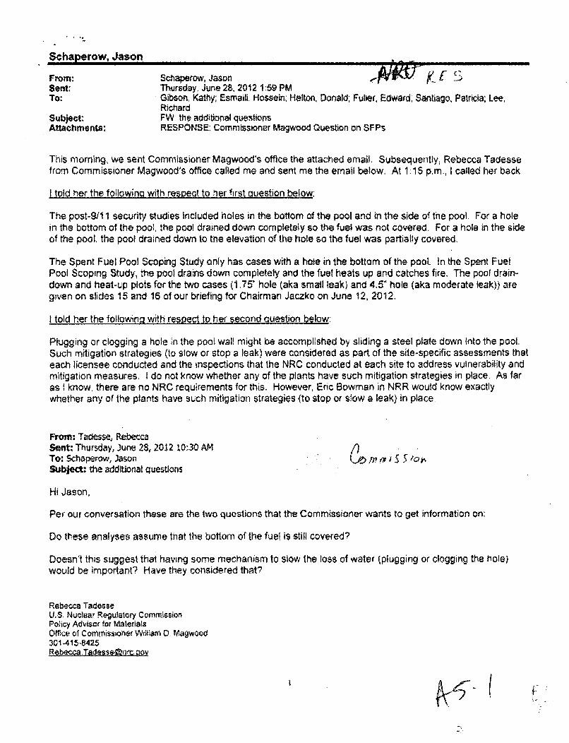
Schaperow, Jason .~WU~~ it:Thursday, June 28, 2012. 1:59 PMGibson, Kathy; Esmaili, Hossein; Helton, Donald; Fuller, Edward, Santiago, Patricia; Lee,RichardFW. the additional questionsRESPONSE: Commissioner Magwood Question on SFPs
This morning, we sent Commissioner Magwood's office the attached email. Subsequently, Rebecca Tadessefrom Commissioner Magwood's office called me and sent me the email below. At 1-15 p.m., I called her back
I told her the foilowing with respect to her first question below:
The post-9/1 1 security studies included holes in the bottom of the pool and in the side of the pool. For a holein the bottom of the pool, the pool drained down completely so the fuel was not covered. For a hole in the sideof the pool. the pool drained down to the elevation of the hole so the fuel was partialty covered.
The Spent Fuel Pool Scoping Study only has cases with a hole in the bottom of the pool. In the Spent FuelPool Scoping Study, the pool drains down completely and the fuel heats up and catches fire. The pool drain-down and heat-up plots for the two cases (1.75' hole (aka small leak) and 4.5" hole (aka moderate leak)} aregiven on slides 15 and 16 of our briefing for Chairman Jaczko on June 12, 2012.
I told her the followina with respect to her second auestson below:
Plugging or clogging a hole in the pool wall might be accomplished by sliding a steel plate down into the pool,Such mitigation strategies (to stow or stop a leak) were considered as part of the site-specific assessments thateach licensee conducted and the inspections that the NRC conducted at each site to address vulnerability andmitigation measures: I do not know whether any of the plants have such mitigation strategies in place. As faras! know, there are no NRC requirements for this. However, Eric Bowman in NRR would know exactlywhether any of the plants have such mitigation strategies (to stop or slow a leak) in place
From: Tacesse, RebeccaSent: Thursday, June 28, 2012 10:30 AMTo: Schaperow, JasonSubject: the additional questions
K3ý 'ISe I t' 5tok
Hi Jason,
Per our conversation these are the two questions that the Commissioner wants to get information on:
Do these analyses assume hiat the bottom of the fuel is still covered?
Doesn't this suggest that having some mechanism to slow the loss of water (plugging or clogging the hole)would be important? Have they considered that?
Rebecca TadesseU.S. Nuclear Regulatory CommissionPolicy Advisor for MaterialsOffice of Commissioneir W44am 0. Magwood301-415-8425Rebe=.a Taesse tirt oov
I (
Schaperow, Jason
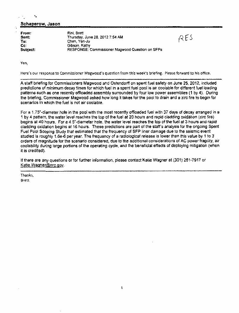
From: Rini, BrettSent: Thursday, June 28, 2012 7:54 AMTo: Chen. Yen-JuCc: Gibson. KathySubject: RESPONSE: Commissioner Magwood Question on SFPs
Yen,
Here's our response to Commissioner Magwood's question from this week's briefing. Please forward to his office.
A staff briefing for Commissioners Magwood and Ostendorff on spent fuel safety on June 25, 2012, includedpredictions of minimum decay times for which fuel in a spent fuel pool is air coolable for different fuel loadingpatterns such as one recently offloaded assembly surrounded by four low power assemblies (1 by 4). Duringthe briefing, Commissioner Magwood asked how long it takes for the pool to drain and a zirc fire to begin forscenarios in which the fuel is not air coolable.
For a 1,75"-diameter hole in the pool with the most recently offloaded fuel with 37 days of decay arranged in aI by 4 pattern, the water level reaches the top of the fuel at 20 hours and rapid cladding oxidation (zirc fire)begins at 40 hours. For a 4 5"-diameter hole, the water level reaches the top of the fuel at 3 hours and rapidcladding oxidation begins at 16 hours. These predictions are part of the staff's analysis for the ongoing SpentFuel Pool Scoping Study that estimated thal the frequency of SFP liner damage due to the seismic eventstudied is roughly 1.6e-6 per year. The frequency of a radiological release is lower than this value by 1 to 3orders of magnitude for the scenario considered, due to the additional considerations of AC power fragility, aircoolability during large portions of the operating cycle, and the beneficial effects of deploying mitigation (whenit is credited).
If there are any questions or for further information, please contact Katie Wagner at (301) 251-7917 orKatie, Wacrnieranrc..gov.
Thanks,Brett
I
/of/E
Ahn, Tae
subject:
Location:
Strt:
End:
Recurrence:
Meeting Status;
Organizer*equted Attendeer.
Optk"~a Atend~em
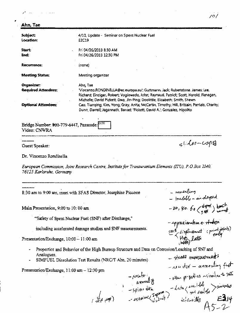
4/10, Update - Seminar on Spent Nuclear Fuel£2C19
Fr 04/26/2013 8:30 AMFri D4/26/2013 12:30 PM
(none)
Meeting organizer
Ahn, Tae'[email protected]'; Guttmanrn, Jack; Rubenstone. larnes; Lee.Richarm Einziger, Rober* Voglewede, John; Raynaud, Patrick Scott, Karold: Ranagan,Michelle; David Pickett Gwo, fin-Ping; Doolittle, Elizabeth; Smith, ShawnCao, Tianqing; Kim, Yong; Gray, Anita; W-Cartin, Timothy; Hill, Bttain; Pantaio, ChariTy;aurin, Darrell; Jagannath, Banad; Pickett, David A.'; Gonzalez, Hipolito
Bridge Number -00-779-6447, Passeode:L]7"Video: CWRA
Guest Speaker: t
Dr. Vincenzo Rondinella
European Commission, Joint Research Centre, Insrirutefor Tramsuranium Elemenrs (7TU), P. O.Box 2340.76125 Larlsruhe, Germany
8:30 am to 9:00 am, meet With SFAS Dirctor, 3osephine Piccone -
Main Presentation~, 9:00 to 10:.00 am -1,~
"S afety of Spent Nuclear Fuel (SNF) after Discharge,"
includin~g aocelerated damage studies and SNF measurements. ~
Presentaticrn/Excange, 1.0-00 - 11:00 am o I
- Proerties and Behavior of the Hiigh Burnup Structure and Data on Corrosion/Leaching of SNE and
- IFTLDislto Test Results (NRCJT Alm, 20 minutes) # w~~ 4
Presentation/Exc~hange, 1 1;00 am - 12; .30 pm 0C4%
- •- -- -•tkr

• A - mAn Ove-niew of Some Ongoing EU Projects on Radionuclides Relevant to Performance Assessment andSNF Characterization; Severe Accident StudiesScoping of Options and Analyzing Risk (SOAR) Models for Waste Form Dissolution (NC.C!T Aim., 20minutes)
Lunch, 12:30pm
Notes:
(1) Time change(2) New topic: severe accident(V) vicenzo will hear about two more NRC activities on cladding stress (he is a collaborator) and spent
fuel drying on 4/29 during International High-Level Radioactive Waste Management Conferenoe in thefollowing week, Albuquerpqe.
2
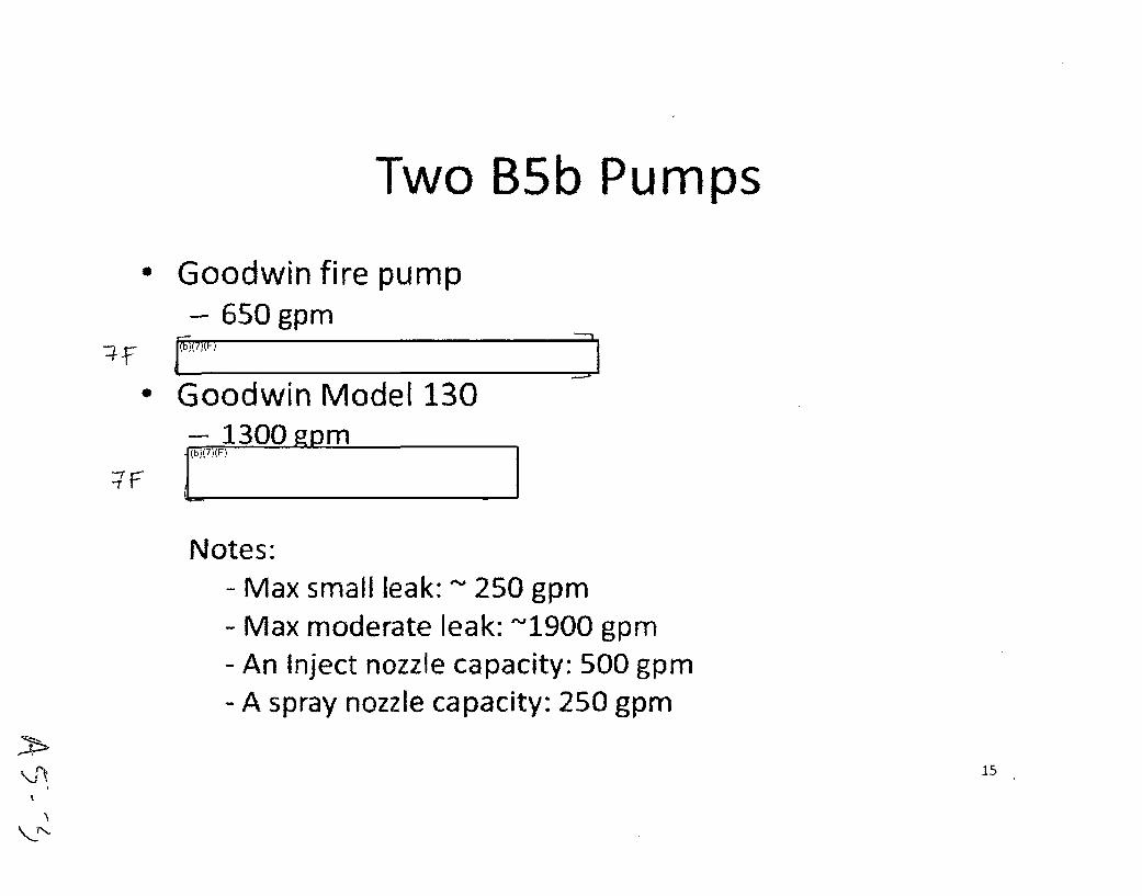
Two B5b Pumps
• Goodwin fire pump- 650 gpm
• Goodwin Model 130- 1300 fpmb),(7 (F)
Notes:- Max small leak: - 250 gpm- Max moderate leak: ~1900 gpm- An Inject nozzle capacity: 500 gpm- A spray nozzle capacity: 250 gpm
15
.eI
Pilmrose, Donald
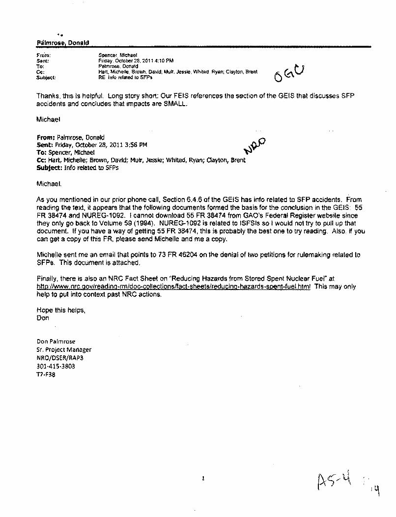
From: Spencef MichaelSent! Friday, October 28. 2011 4:10 PMTo: Palmnose. O~no;dCc: Hatt, Michelle; Browrn, DOA.,d; Muir, Jessie, Whited. Ryon; Cisyton. grentSuboCt: RE Ink• relied to .SFPs
Thanks, this is helpful. Long story short-, Our FEIS references the section of the GEIS that discusses SFP
accidents and concludes that impacts are SMALL.
Michael
From: Palmrose, DonaldSent: Friday, October 28, 2011 3:56 PMTo: Spencer, MichaelCc Hart, Michelle; Brown, David; Muir, Jessie; Whited, Ryan; Clayton, BrentSubject: Info related to SFPs
Michael.
As you mentioned in our prior phone call, Section 6.4.6 of the GElS has info related to SFP accidents. Fromreading the text, it appears that the following documents formed the basis for the conclusion in the GElS 55FR 38474 and NUREG-1092. I cannot download 55 FR 38474 from GAO's Federal Register website sincethey only go back to Volume 59 (1994). NUREG-1092 is related to ISFSIs so I would not try to pull up thatdocument. If you have a way of getting 55 FR 3B474, this is probably the best one to try reading. Also, if youcan get a copy of this FR, please send Michelle and me a copy.
Michelle sent me an email that points to 73 FR 46204 on the denial of Iwo petitions for rulemaking related toSFPs. This document is attached.
Finally, there is also an NRC Fact Sheet on "Reducing Hazards from Stored Spent Nuclear Fuel" athttp://www.nrc oov/readnc-rmidoc-collections/fact-sheets/reducing-hazards-spent:-fuel html This may onlyhelp to pul into context past NRC actions.
Hope this heWps,Don
Don PalmroseSr. Project ManagerN RO/DS.R/RAP3301-4.15-3803T7-F38
Ditzberg, BlairV
From:Sent:To:Subject:Attachments:
Tracking:
Spilzberg, BlairMonday, June 10, 2013 9:37 AMKellar. RayFW: Diablo Canyon Seismic Faultsser chptl5.pdf
Recipient
Kellar, Ray Read: /1012013 9.37 AM
From: Pay KeflarSent: Thursday, March 19, 2009 9:58 AMTo. Shana HeltonCc. Eric Benner; Blair SpitzbergSubject: ODablo Canyon Seismic Faults
Hi Shana,
(b)(5)
Thanks,
Ray
Ray L Kellar, P.E.US NRC RIVinspectorPhone: 817-860-8.164Fax! 817-860-8188Email: [email protected]
I

15 ACCIDENT ANALYSIS
15.1 Conduct of Review
The staff evaluated the applicant's accident analysis by reviewing Chapter 8, 'AccidentAnalysis," of the Diablo Canyon ISFSI SAR (Pacific Gas and Electric Company. 2003),documents cited in the SAR, and other relevant publicly available information, including websites on the Internet.
In the ISFS! SAR and in its response to the staff's Request for Additional information (RAI)(Pacific Gas and Electric Company, 2002), PG&E described the basis for selecting off-normaland accident events to ensure that all relevant potential scenarios have been considered. Theselection of these off-normal and accident event scenarios is based on guidance inNUREG-1567 (U.S Nuclear Regulatory Commission, 2000). In addition, PG&E alsoreviewed other site-specific applications and associated NRC evaluations in developing thespectrum of postulated events to be analyzed.
The dry cask storage system to be used at the proposed facility is the HI-STORM 100 System,which has been reviewed by the NRC and approved for general use under Certificate ofCompliance (CoC) No. 1014-1 (U.S. Nuclear Regulatory Commission, 2002a). As discussed inChapters 4 and 5 of this SER, the design-basis loads considered in the HI-STORM 100 SystemFinal Safety Analysis Report (FSAR) bound the loading conditions at the proposed DiabloCanyon ISFSI. Thus, where applicable, the staff relied on the review carried out during thecertification process for the HI-STORM 100 cask system, as documented in the NRCHI-STORM 100 System SER (U.S. Nuclear Regulatory Commission, 2002b).
The staff reviewed the accident analysis to determine if the following regulatory requirementshave been met:
10 CFR §72.90 requires that: (a) site characteristics that may directly affect thesafety or environmental impact of the ISFSI must be investigated and assessed;(b) proposed sites for the ISFS1 must be examined with respect to the frequencyand the severity of external natural and man-induced events that could affect thesafe operation of the ISFSIh (c) design basis external events must be determinedfor each combination of proposed site and proposed ISFSI design: (d) proposedsites with design basis external events for which adequate protection cannot beprovided through tSFS1 design shall be deemed unsuitable for the location of theISFSI; (e) pursuant to subpart A of Part 51 of Title 10 for each proposed site foran ISFSI, the potential for radiological and other environmental impacts on theregion must be evaluated with due consideration of the characteristics of thepopulation, including its distribulion, and of the regional environs, including itshistorical and esthetic values; and (1) the facility must be sited so as to avoid tothe extent possible the long-term and short-term adverse impacts associatedwith the occupancy and modification of floodplains.
10 CFR §72.92 requires that: (a) natural phenomena that may exist or that canoccur in the region of a proposed site must be identified and assessed accordingto their potential effects on the safe operation of the I SFS1. The important
15-1
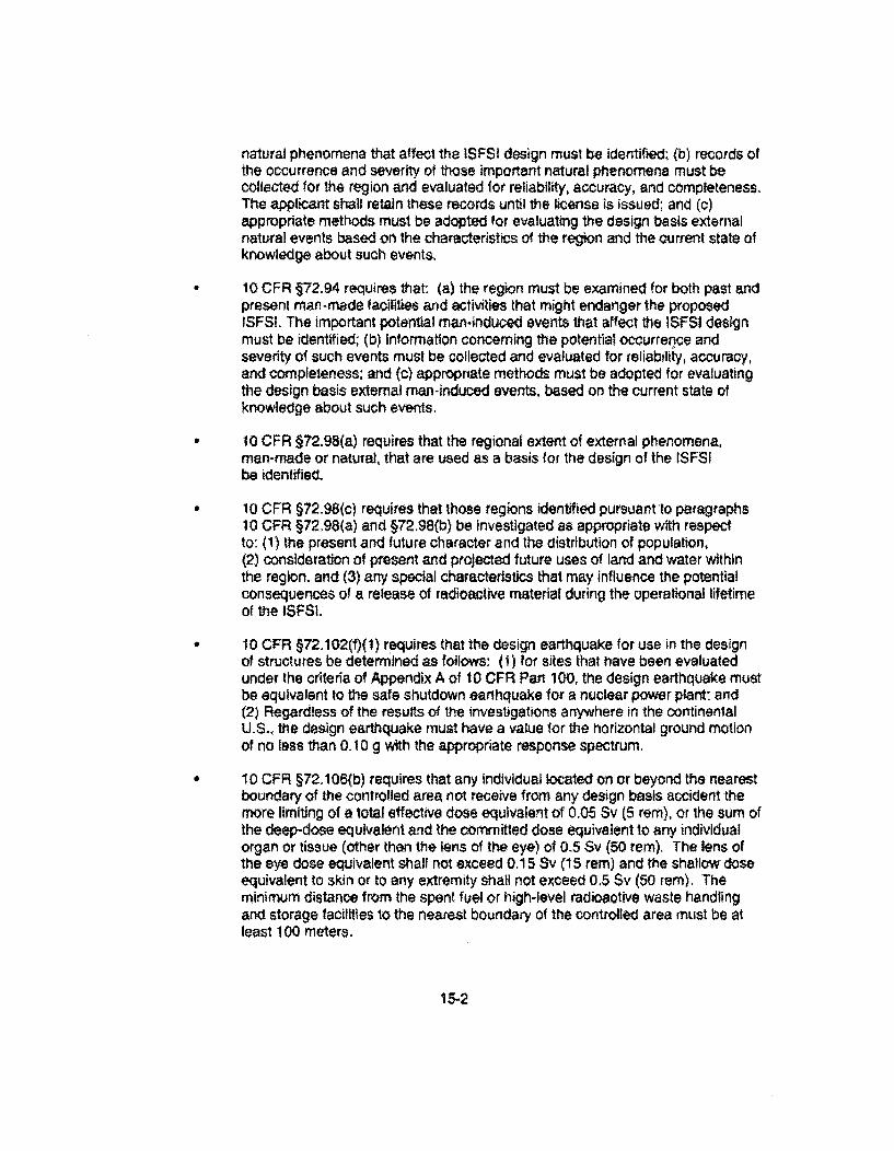
natural phenomena that affect the ISFSI design must be identified; (b) records ofthe occurrence and severity of those important natural phenomena must becollected !or the region and evaluated for reliability, accuracy, and completeness.The applicant shall retain these records until the license is issued; and (c)appropriate methods must be adopted for evaluating the design basis externalnatural events based on the characteristics of the region and the Ourrent state ofknowledge about such events.
10 CFA §72.94 requires that: (a) the region must be examined for both past andpresent man-made facilities and activities that might endanger the proposedISFSI. The important potential man-induced events that affect the ISFSl designmust be identified; (b) information concerning the potential occurrence andseverity of such events must be collected and evaluated for reliabtilty, accuracy,and completeness; and (c) appropriate methods must be adopted for evaluatingthe design basis external man-induced events, based on the current state ofknowledge about such events.
10 CFR §72.98(a) requires that the regional extent of external phenomena,man-made or natural, that are used as a basis for the design of the ISFSIbe identified.
10 CFR §72.98(c) requires that those regions identified pursuant to paragraphs10 CFR §72.98(a) and §72.98(b) be investigated as appropriate with respectto: (1) the present and future character and the distribution of population,(2) consideration of present and projected future uses of land and water withinthe region, and (3) ary special characteristics that may influence the potentialconsequences of a release of radioactive material during the operational lifetimeof the ISFSI.
10 CFR §72.102(f)(1) requires that the design earthquake for use in the designof structures be determined as follows: (1) for sites that have been evaluatedunder the criteria of Appendix A of t0 CFR Part 100, the design earthquake mustbe equivalent to the safe shutdown earthquake for a nuclear power plant; and(2) Regardless of the results of the investigations anywhere in the continenlalU.S., the design earthquake must have a value for the horizontal ground motionof no less than 0.10 g with the appropriate response spectrum.
10 CFR §72.106(b) requires that any individual located on or beyond the nearestboundary of the controlled area not receive from any design basis accident themore limiting of a total effective dose equivalent of 0.05 Sv (5 rem), or the sum ofthe deep-dose equivalent and the committed dose equivalent to any individualorgan or tissue (other than the lens of the eye) of 0.5 Sv (50 rem). The lens ofthe eye dose equivalent shall not exceed 0.15 Sv (15 rem) and the shallow doseequivalent to skin or to any extremity shall not exceed 0.5 Sv (5a rem). Theminimum distance from the spent fuel or high-level radioactive waste handlingand storage facilities to the nearest boundary of the controlled area must be atleast 100 meters.
155-2
10 CFR §72.122(b) requires that (1) structures, systems, and componentsimportant to safety be designed to accommodate the effects of, and to becompatible with, site characteristics and environmental conditions associatedwith normal operation, maintenance, and testing of the 1SFSI and to withstandpostulated accidents; and (2) Structures, systems, and components important tosafety must be designed to withstand the effects of natural phenomena such asearthquakes, tornadoes, lighting, hurricanes, floods, tsunami, and seiches,without impairing their capability to perform safety functions. The design basesfor these structures, systems, and components must reflect: (i) structures,systems, and components important to safety must be designed to withstand theeffects of natural phenomena such as earthquakes, tornadoes, lightning,hurricanes, floods, tsunami, and seiches, without impairing their capability toperform their intended design functions. The design bases for these structures,systems, and components must reflect: (A) appropriate consideration of the mostsevere of the natural phenomena reported for the site and surrounding area, withappropriate margins to take into account the limitations of the data and theperiod of time in which the data have accumulated, and (B) appropriatecombinations of the effects of normal and accident conditions and the effects ofnatural phenomena. (ii) The ISF$I also should be designed to prevent massivecollapse of building structures or the dropping of heavy objects as a result ofbuilding structural failure on the spent fuel, high-level radioactive waste or on tostructures, systems, and components important to safety.
10 CFR §72.122(c) requires that structures, systems, and components importantto safety must be designed and located so that they can continue to performtheir safety functions effectively under credible fife and explosion exposureconditions. Noncombustible and heat-resistant materials must be used whereverpractical throughout the ISFSI, particularly in locations vital to the control ofradioactive materials and to the maintenance of safety control functions.Explosion and fire detection, alarm, and suppression systems shall be designedand provided with sufficient capacity and capability to minimize the adverseeffects of fires and explosions on struCtures, systems, and compOnentsimportant to safety. The design of the ISFSI must include provisions to protectagainst adverse effects that might result from either the operation or the failureof the fire suppression system.
10 CFR §72,122(h)(1) requires that the spent fuel ciadding must be protectedduring storage against degradation that leads to gross ruptures or the fuOe mustbe otherwise confined such that degradation of the fuel during storage will notpose operational safety problems with respect to its removal from storage. Thismay be accomplished by canning of consolidated fuel rods or unconsolidatedassemblies or other means as appropriate.
10 CFR §72.122(h)(4) requires that storage confinement systems must have thecapability for continuous monitoring in a manner such that the licensee will beable to determine when corrective action needs to be taken to maintain salestorage conditions. For dry spent fuel storage, periodic monitoring is sufficientprovided that periodic monitoring is consistent with the dry spent fuel storage
15-3
cask design requirements, The monitoring period must be based upon the spentfuel storage cask design requirements.
10 CFR §72.122(h)(5) requires that the waste must be packaged in a mannerthat allows handling and retrievability without the release of radioactive materialsto the environment or radiation exposures in excess of 10 CFR Part 20 limits.The package must be designed to confine the high-level radioactive waste forthe duration of the license.
10 CFR §72.122(i) requires that instrumentation and control systems must beprovided to monitor systems that are important to safety over anticipated rangesfor normal operation and off-normal operation.
10 CFR §72.122(l requires that Storage systems must be designed to allowready retrieval of spent fuel, high-level radioactive waste for further processingor disposal.
10 CFR §72.124(a) requires spent fuel handling, packaging, transfer, andstorage systems must be designed to be maintained subcritioal and to ensurethat, before a nuclear criticality accident is possible, at least two unlikely,independent, and concurrent or sequential changes have occurred in theconditions essential to nuclear criticality safety. The design of handling,packaging, transfer, and storage systems must include margins of safety fot thenuclear criticality parameters that are commensurate with the uncertainties in thedata and methods used in calculations and demonstrate safety for the handling,packaging, transfer and storage conditions and in the nature of the Immediateenvironment under accident conditions.
10 CFR §72.128(a)(2) requires that spent fuel storage be designed with suitableshielding for radioactive protection under normal and accident conditions.
The proposed ISFSI facility must be sited, designed, constructed, and operated so theabove-mentioned regulatory requirements are met to adequately protect public health andsafety during all credible off-normal and accident events.
15.1.1 Off.Normal Events
The off-normal events are described in Section 8.1, "Off-Normal Operations," of the SAR. Thissection of the SER discusses results from the review of potential off-normal conditions, whichinclude cask drop from less than design allowable height, partial vent blockage, and operationalevents. Where applicable, the staff relied on the analyses in the HI-STORM 100 System FSARand the related staff evaluation as documented in the HI-STORM 100 System SER (U.S.Nuclear Regulatory Commission, 2002b).
15.1.1.1 Cask Drop Less Than Design Allowable Height
Due to the design features and administrative controls applied to the ISFSI-related activitiesconducted within the DCPP FHB/AB, a potential drop of the HI-TRAC 125 Transfer Cask is only
15-4
considered during the period that the loaded Transfer Cask is moved between the FHE/AB andthe Cask Transfer Facility (CTF). Similarly, the drop of a loaded storage cask is onlyconsidered during movement between the CTF and the ISFSI storage pads. In its response tothe staff's RAI (Pacific Gas and Electric Company, 2002), PG&E committed to design the casktransporter so it wil1 have redundant drop protection features and will conform to the criteria ofNUREG-0612 (U.S. Nuclear Regulatory Commission, 1980), American National StandardsInstitute (ANSI) N14.6 (American National Standards Institute, 1993), and ASME 130.9-1996(ASME International. 1996), The staff previously determined that a specific limit on cask litheight during transfers between the FHB/AS, CTF, and the storage pads is not necessary Ifthese cask transporter design requirements are met (U.S. Nuolear Regulatory Commission,2002a). Therefore, based on the applicant's commitment to these design standards, transferand storage cask drop events are not considered credible and an evaluation of a cask drop lessthan the design allowable height Is not required.
15.1.1.2 Partial Vent Blockage
The staff previously determined that the HI-STORM 100 storage cask provides adequate heatremoval capacity under partial vent blockage conditions, so long as the fuel specifications andloading conditions as defined in the HI-STORM 100 System CoC and SER (U.S. NuclearRegulatory Commission, 2002a,b) are adhered to and the environmental characteristics of thesite are bounded by the corresponding design criteria (see Section 6.1.3 of this SER). Theproposed Diablo Canyon ISFSI Technical Specifications include surveillance requirements forensuring that the cask heat removal system is operational during storage (i.e., the air ducts areinspected every 24 hours to ensure that the ducts are free of blockages).
15.1.1.3 Operational Events
Failure of Instrumentation
No off-normal events that involve failure of instruments and control systems are postulatedbecause the passive dry cask storage system does not rely on permanent instruments tomonitor the heat and radiation at the ISFSI storage pad site. The Hi-STORM 100 storagecasks will be visually inspected as required by the Technical Specifications to ensure that theoverpack inlet and outlet air ducts remain free from blockages. If a blockage is detected, it willbe removed within one operating shift. Radiation and airborne radioactivity will be monitoredusing portable hand-held radiation protection instruments and dosimelers during transferoperations at the CTF and routine maintenance at the ISFSI storage area.
Based on the staff's review of the information provided regarding failure of instrumentation,there is reasonable assurance that important to safety functions will not be affected for theproposed cask system or the proposed ISFSI.
Vehicular Impact
The staff reviewed the information presented In the ISFSI SAR Chapters 3 and 4, "PrincipalDesign Crfteria," and, "ISFSI Design;: and Section 8.4, "Drops and Tip-Over." Vehicularimpact is postulated by the staff to occur during movement of a loaded transfer cask from theFHBfAB to the CTF, or movement of a loaded storage overpack from the CTF to the storage
15-5

pads, or in the storage pad area. Vehicular impacts are postulated to result from an interactionbetween the cask transporter, an onsite service vehicle, or an off-site vehicle used by sitepersonnel and a loaded transfer Or storage cask. Equipment failure, operator error, or a naturalevent (e.g., tornado) may lead to this off-normal event. Occurrence of this event would beeasily identifiable from visual evidence, such as dents or scratches on casks, onsite vehicles.and other ISFSI facility structures, systems, and components (SSC).
As discussed in the HI-STORM 100 System FSAR, the HI.STORM 1 0OSA storage cask andHI-TRAC 125 Transfer Cask are designed to withstand a tornado missile equivalent to theimpact of an automobile weighing 1,800 kg [3,968 Ib] traveling at a speed of 202 km/h [56 m/s){126 mph [185 ft/sj] (SAR Table 3.2-2). This tornado-missile analysis for the storage cask andthe staff evaluation are provided in the HI-STORM 100 System FSAR and the related NRCSER. That analysis indicated that such impacts would not result in damage to the caskcontents. Since onsite vehicles at the DCPP are assumed to be traveling at a much lowerspeed than that assumed in the tornado missile analysis, poslulated vehicular impacts for theHI-STORM 100 System transfer and storage casks are bounded by the tornado missileanalysis, and no damage to the spent fuel contents will result from these events.
The cask transporter and CTF ate designed to withstand a tornado missile equivalent to theimpact of an automobile weighing 1,800 kg [3,968 lb] traveling at a speed of 15 rr/s {48.8 ft/s(33.3 mph)) (SAR Table 3.2-2) (Pacific Gas and Electric Company. 2003). The tornado missileanalysis and the staff's evaluation are provided In Section 8.2.2 the ISFSI SAR and Section15.1.2.10 of this SER, respectively. Onsite vehicles will generally be traveling at a much lowerspeed. Therefore, vehicular impacts for the cask transporter and CTF are also bounded by thetornado missile analysis.
The staff finds that potential vehicular impact will not impair the ability of the SSCs to maintainsuboriticality, confinement, and sufficient shielding of the stored fuel.
.Loss of Electrical Powr
The staff reviewed the information presented in Section 8.1.6., "Loss of Electrical Power," of theSAR as an off-normal event. Total loss of external afternating current power is postulated tooccur during the facility operations. The loss of electrical power at the Diablo Canyon ISFSIfacility may occur because of natural phenomena, such as lightning or high winds, or as a resultof failure of the electrical distribution system or equipment. A loss of electrical power will bedetected through loss of functions of the electric-powered equipment.
No safety features required for lifting, upending, and lowering of the HI-TRAC 125 TransferCask, multi-purpose canister (MPC) and HI-STORM 1 COSA storage cask at the CTF will beaffected by a loss of power, because these operations will be conducted by the casktransporter, which is driven by an on-board diesel engine. Similarly, the emplacementoperations of a HI-STORM 1O0SA storage cask on the ISFSI storage pad location are alsoconducted using the cask transporter and do not rely on electric power from other onsite oroflsite sources.
15-6
Electrical power is supplied through onsite sources to each of the three lifting screw jack motorsand control systems that operate the CTF lifting platform. The CTF lifting platform will raise andlower the MPC during the transfer operation of the MPC from the HI-TRAC 125 Transfer Caskto a HI-STORM 100SA storage cask. In the event of a power loss during the operations of thelifting platform, all three screw jack motors will slop simultaneously to prevent a potentialuncontrolled descent of the storage cask inside the CTF, The lift jacks will remain stopped andwill require manual action to restart upon restoration of power. In the unhkely event of anextended period of power loss, the storage cask (including the MPC) will be raised to gradelevel from the CTF lifting platform within 22 hours using the cask transporter to ensure thatshort-term cladding temperature limits will not be exceeded.
No radiological impact is expected from a loss of electric power because there is no loss ofMPC confinement during this off-normal event. In addition, the transfer cask is designed toprovide adequate shielding and decay heat removal from the canisters. The operators wouldtake measures to maintain adequate distance and additional shielding between themselves andthe CTF to minimize exposure until power is restored and the transfer operation is resumed.
The staff concludes the applicant's evaluation of loss of electrical power as an off-normal eventis adequate in providing reasonable assurance that Diablo Canyon ISESI operations can beconducted without endangering the health and safety of the public.
Cask Transporter Off-Normal Opgration
The staff reviewed the information provided in Section 8.1.7 of the SAR, "Cask TransporterOff-Normal Operation." The transporter with a loaded transfer cask will travel a distance of 1,9km [1.2 ml] along the transporter route from the OCPP to the CTF and will take approximately3.0 hours per transport. The transporter is also used in the transfer operation of an MPC fromthe HI-TRAC 125 Transfer Cask to a storage cask at the CTF and in the emplacement ofstorage casks on the ISFSI pads. The off-normal everts from operation of the cask transportercould arise from driver error or incapacitation, transporter engine failure because of mechanicalfailure, or loss of hydraulic fluid in the hydraulic system. A support team will walk with thetransporter and observe the driver and transporter movement. At the sight of driver distress orswerving of the transporter, the support personnel can stop the transporter using either of twostop switches located outside the transporter. The transporter is also equipped with automaticshutoff control to stop the vehicle in the event of incapacitation of the driver. The same controlwill also be used for emergency stops during the lifting operation at the CTF. Transporterengine failure would stop the vehicle or hydraulic brakes would engage to stop liftingoperations. Hydraulic system failure would be detected by pressure instrumentation on thetransporter, and any loss of hydraulic fluid will engage hydraulic brakes to stop liftingoperations. The transporter is designed to operate in a "fail-safe" mode so any uncontrolledlowering of a transfer cask loaded with an MPC or storage cask is precluded.
Off-normal events associated with cask transporter operation are not expected to causeradiological dose as the confinement and shielding of spent nuclear fuel will not be affected,
The staff concludes that the applicant's assessment of cask transporter off-normal operation isadequate in providing reasonable assurance that Diablo Canyon ISFS1 operations can beconducted without endangering the health and safety of the public.
15-7
15.1.1.4 Off-Normal Ambient Temperatures
The off-nofmal environmental temperature range for the Diablo Canyon ISFSI is -4.4 to 36.1 ýC[24 to 97-F]. This off-normat temperature range is bounded by the previously evaluatedoff-normal temperature ranges for the Hi-STORM 100 storage casks and HI-TRAC 125Transfer Cask. Specifically. the previously evaluated off-normal temperature range for theHI-STORM 100SA storage cask is -40 to 38 OC [ -40to 100 -F] and for the HI-TRAC 125Transfer Cask, -- 18 to 38 'C [0 to 100 *F]. The staff previously determined that theHI-STORM 1OOSA storage casks and HI-TRAC 125 Transfer Cask designs provide adequateheat removal capacity during off-normal ambient lemperature conditions so long as the fuelspecifications and loading conditions as defined in the HI-STORM 100 System CoG and SER(U.S. Nuclear Regulatory Commission, 2002ab) are met. The Diablo Canyon ISFSI TechnicalSpecifications will ensure that the relevant conditions assumed in the previous analysis for theHI-STORM 100 system are also met for the Diablo Canyon spent fuel,
15.1.1.5 Off-Normal Pressures
Section 8.1.1.1 of the Diablo Canyon ISFSI SAR indicates that the off-normal pressure withinthe MPC, which is the sole pressure boundary for the HI-STORM 1 00SA storage cask, isevaluated considering a concurrent rupture of 10 percent of the stored fuel rods while exposedto off-normal ambient temperatures of 38 'C [100 'F]. Note that this off-normal temperaturebounds the off-normal temperature for the proposed Diablo Canyon site (see Section 6.1.3 ofthis SER). The staff previously determined that the methodology used to assess this off-normalcondition is acceptable and that there are no consequences that affect the public health andsafety so long as the fuel specifications and loading conditions as defined in the HI-STORM 100System CoC and SER (U.S. Nuclear Regulatory Commission. 2002a,b) are met. The DiabloCanyon ISFSI Technical Specifications will ensure that the relevant conditions assumed in theprevious analysis for the HI-STORM 100 system are also met for the Diablo Canyon spent fuel.
15.1.2 Accidents
The ISFSI SAR includes a discussion of potential accidents resulting from both external naturaland man-induced events at the proposed facility. Natural phenomena events are discussed inChapter 2, "Site Characteristics" of the SAR. The staff's evaluation of those events isdiscussed in Chapter 2 of this SER, The accident analysis review focused on the effects of thenatural phenomena and human-induced events on SSCs important to safety. Analyticaltechniques, uncertainties, and assumptions were examined. Each event was examined toensure that it includes: (1) a discussion of the cause of the event, (2) the means of detection ofthe event, (3) an analysis of the consequences and the protection provided by devices orsystems designed to limit the extent of the consequences, and (4) any actions required of theoperator.
The Diabto Canyon ISFSI will use the HI-STORM 100 dry cask storage system. Whereapplicable, the staff relied on the analyses in the HI-STORM 100 System FSAR and the relatedstaff evaluation as documented in the HI-STORM 100 System SER.
15-8
15.1.2.1 Cask Tip-Over
The staff has previously determined that cask tip-over events need not be considered for theapproved HI-STORM 100SA system, based on the cask anchorage system used and thestorage pad design specifications (U.S. Nuclear Regulatory Commission, 2002a,b). Sections3,3.2 and 4.2.1.1of the ISFSI SAR (Pacific Gas and Electric Company, 2003) describe the caskanchoring system that will be used for the Diablo Canyon ISFSI, and this design also precludesthe need for consideration of cask tip-over events. The staff's evaluation of the storage padand anchorage system design can be found in Section 5.1.3 of this SER.
15.1.2.2 Cask Drop
Due to the design features and administrative controls applied to load handling activities in theFHBIAB, a potential drop of the loaded HI-TRAC 125 Transfer Cask is only considered duringmovement between the FHIBAB and the CTF. Similarly, a drop of a loaded HI-STORM !00SAstorage cask is only considered during transport between the CTF and the ISFSI storage pads.In its response to the staff's RAI (Pacific Gas and Electric Company, 2002), PG&E committed todesign the cask transporter so it will have redundant drop protection features and will conformto the criteria of NUREG-0612 (U.S. Nuclear Regulatory Commission, 1980), AmericanNational Standards Institute (ANSI) N14.6 (American National Standards institute, 1993), andASME B30.9-1996 (ASME International, 1996). Based on the applicant's commitment to thesedesign standards, transfer and storage cask drop events are not considered credible.Therefore, a lifting height limit need not be specified for the loaded casks during movementsbetween the FHB/AB, CTF and the storage pads, provided that all of these cask transporterdesign requirements are met.
15.1.2,3 Flood
The applicant has not considered flooding a credible accident at the Diablo Canyon ISFSI. Asdiscussed in Section 2.1.4, "Surface Hydrology," of this SER, PG&E demonstrated that localnatural and man-made drainage systems are sufficient to prevent flooding of the ISFSI pad siteand CTF.
15.1.2.4 Fire and Explosion
Fire
The staff reviewed the information presented in Section 8.2.5, "Fire,ý of the ISFSI SAR.Additional information presented in SAR Sections 4,2.3.3.2.10, "Fire;n and 4.2.3.3.2.11,'Lightning," was also considered in this review.
Locations pertaining to the proposed ISFSI that fall within the purview of 10 CFR Part 72. revieware the transport route from the DCPP FHB/AB to the CTF, within the CTF, and within the caskstorage area. Credible fire accidents potentially affecting SSCs important to safety at theproposed facility identified by PG&E are:
(1) An onsite cask transporter fuel tank fire;
15-9
(2) Other onsite vehicle fuel tank fires:
(3) Combustion of other local stationary fuel tanks;
(4) Combustion of other local combustible materials;
(5) Fire in the surrounding vegetation; and
(6) Fire from mineral oil from the Unit 2 transformers.
Additional information and the staff's evaluation are provided in Section 6.1.5.1 of this SER.
The cask transporter will be used to move the spent nuclear fuel in an MPC from the FHB/AB tothe CTF using the HI-TRAC 125 Transfer Cask. After the MPC has been transferred to theHI-STORM 1OOSA storage cask at the CTF, the cask transporter will be used to move theloaded storage cask onto the storage pad. To limit the potential exposure of the HI-TRAC 125Transfer Cask and HI-STORM 1 0OSA storage casks to a fire attributable to the transporterdiesel fuel, the fuel tank used for the transporler will be limited to a 189-L [50-gall capacity bythe ISFSI Technical Specifications.
One postulated fire scenario for the CTF or the storage pads involves the diesel-fueled casktransporter with a 189-L [50-gall fuel tank. The tank may rupture, resulting in the spilling andignition of all of the diesel fuel. The ability of the HI-TRAC 125 Transfer Cask and HI-STORMIOOSA storage casks to provide confinement and protect the spent nuclear fuel from grossdegradation as the result of a 189-L [50-gal] diesel fuel fire was previously reviewed and foundto be acceptable by the Staff (U.S. Nuclear Regulatory Commission, 2002a,b), and thesefindings also apply to the Diablo Canyon ISFSI for this analyzed event.
As described in Section 8.2.5.2 of the ISFS1 SAR, administrative controls will be implemented toensure that transient sources of fuel in volumes larger than 189 L [50 gal) will be at a sufficientdistance away from the ISFSI storage pads at all times, the CTF during active MPC transferoperations, and the transport route during cask transfer. There is at least a 30.5-m [100-ft]clearance between the storage area, CTF, or the cask transport route, and any onsitestationary fuel tanks, as described in SAR Section 2.2.2.2.
In its response to NRC additional questions on supplemental blasts and explosions (Pacific Gasand Electric Company, 2003b), PG&E indicated that a 3,028-L [800-gal] gasoline tanker truckwill use the transport route near the storage area to deliver fuel to the vehicle maintenanceshop located approximately 610 m [2,000 ft] northeast of the storage area six times a week.The tanker truck transport route passes by the storage casks on the north side of the proposeddry storage area. To determine the potential consequences of a gasoline tanker truck fireoccurring near the proposed storage facility, a bounding 7,570-L [2,000-gall fire loadinganalysis was conducted to assess the potential effects on the HI.TRAC 125 Transfer Cask,which bounds the potential effects on a Hl-STORM 1OOSA storage cask (Pacific Gas andElectric Company, 2003a). This fire loading analysis adequately demonstrated that anonengulfing 7,570-L [2,000-gal] fuel tanker fire will not adversely affect the HI-TRAC 125Transfer Cask or a HI-STORM 1 00SA storage cask at the Diablo Canyon ISFSI.
15-10
Onsite stationary fuel sources include:
(1) Three fuel tanks {946 L [250 gal] of propane, 7,571 L [2,000 gal] of No. 2 diesel,and 11,356 L [3,000 gal] of gasoline) located beside the main plant road, 366 m[1,200 ft] from the cask transport route at its nearest point; and
(2) The Unit 2 main bank transformers filled with mineral oil.
The separation distance between the three stationary fuel tanks and the transport route is366 m 11,200 ft]. Because of the separation distance, radiation is the only mechanism throughwhich released heat would be transferred to the cask. The surface area of a hemisphere with a366-m [1.200-ft] radius is in excess of 836,131 m2 [9 x 1W fte). The projected area of the caskis approximately 20 mn [220 W]. Therefore, only 0.0025 percent of the total heat energyreleased simultaneously from these tanks would be directed toward a single cask. This is asmall amount of energy, and consequently, a fire in the transporter fuel tank would bebounding.
The potential for a fire within the CTF as the result of a cask transporter or gasoline tanker truckfuel spill was addressed in response to additional NRC questions (Pacific Gas and ElectricCompany, 2003c). To mitigate the potential effects of these postulated fire events, thetransporter will be designed with a removable fuel tank, and the CTF opening will be located ata higher elevation than the surrounding area so any fuel spilled will flow away from the facility.Moreover, administrative controls will prohibit any transient fuel sources beyond that of the casktransporter from coming into close proximity of the CTF during transfer operations.
Vegetation surrounding the storage pad area is primarily grass with no significant brush or trees(Pacific Gas and Electric Company, 2003). A potential fie in the vegetation may be started byan offsite fire spreading onto tie proposed site or by a lightning or a transmission line strike.As discussed in Section 8.2.5.2 of the SAR, "Accident Analysis" (Pacific Gas and ElectricCompany, 2003), no combustible materials will be stored within the security fence of theproposed facility at any time, A walk-down of the general area and the transport route will beconducted prior to any loaded cask transport to ensure that all combustible materials arecontrolled according to the administrative procedures. PG&E will implement a maintenanceprogram to prevent uncontrolled growth of vegetation surrounding the storage area,
PG&E submitted an analysis of potential effects of wildfires on the HI-STORM I OSA storagecasks (Holtec International, 2001a). This analysis evaluated two scenarios: (1) no wind and(2) 24-krm/hr [15-mph] wind in the uphill direction. Although it is expected that facility personnelwill try to suppress or control the fire quickly, it is postulated that no fire fighting activities occur.Using simulation codes FARSITE and FLAMMAP, Hollec International developed the values forthe parameters necessary to describe the wildfire characteristics (namely, fire Intensity, rate ofspread, and flame length)(Pacific Gas and Electric Company, 2003).
There will be a minimum of a 15.2-m (50-ft] gap between the storage pads and the securityfence on the north side of the proposed facility. The gap will be at least 12.2 m [40 It] on theother three sides, The restricted area fence surrounds the area protected by the security fenceand is approximately 30.5 m [100 ft) from the storage pads. Holtec International (2001a)assumed that the area within the proposed storage facility nuisance fence would be coveredwith either gravel or concrete, Therefore, the area surrounding the storage pads would be
15-11
covered with noncombustible materials, which will not only act as a barrier for progression ofwild fires but also will not add any additional fuel to the fire.
Electrical transformers are located approximately 73 m 1240 ft] from the transporter route. Themineral oil within these transformers could be ignited by lightning strike, vehicle crash, orinternal electrical faults (Pacific Gas and Electric Company, 2003c). Administrative procedureswill prohibit movemeni of the loaded transporter during inclement weather. Additionally, DCPPtransition operations significantly reduce the potential for transformer mineral oil being ignitedby lightning or internal electric faults. Each active transformer has a fire-suppression systemthat will activate in case of a fire. Administrative procedures wilt also prohibit use of onsitevehicles during transporter operation, negating the potential of a vehicle accident initiating atransformer fire. Moreover, even if a transformer mineral oil fire were to occur, its effect on thetransfer cask during transport would be bounded by the nonengulfing 7,570-L [2,000-gall fire-loading analysis.
The staff reviewed the information provided by the applicant regarding potential onsite fires andwildfires at the proposed facility. The staff found the applicant's analysis acceptable because.
Through design and administrative procedures, potential fire events will beminimized for the CTF.
The storage casks are designed to withstand a fire from 50 gallons of diesel fuelin the fuel tank of the cask transporter.
Both the transfer and storage casks will be able to withstand a nonengulfing7,570-L (2,000-gall fuel fire.
Adequate analysis was presented about potential effects of the tanker truck fireon storage casks sitting on the pads.
The area surrounding the storage pads will be covered withnoncombustible materials.
Onsite and Of site Exgosion
The staff has reviewed the information presented in SAR Sections 2.2.2.3, KOnsile ExplosionHazards": 8.2.6, "Explosion", and 3.3.1.6, "Fire and Exploslon Protection." In addition, the staffalso reviewed analyses of potential explosion events in Holtec International (2002) and PG&ECalculation No. PRA01 -01, "Risk Assessment of Dry Cask/Spent Fuel Transportation Within theDCPP Owner Controlled Area," (Pacific Gas and Electric Company, 2003c). Potential sourcesof explosions within the proposed facility include:
(1) Detonation of a transporter or onsite vehicle fuel tank
(2) Detonation of a 3,025-L [800-gal] tanker truck while transporting fuel near thestorage pad
(3) Detonation of a propane bottle transported past the ISFSI storage pad
15-12
(4) Detonation of an acetylene bottle transported past the ISFSI storage pad
(5) Explosive decompression of a compressed gas cylinder
(6) Detonation of large stationary fuel tanks in the vicinity of the transport route
(7) Detonation of the bulk hydrogen storage facility
(8) Detonation of acetylene bottles stored on the east side of the cold machine shop
Important to safety SSCs that are required to function after an explosion event Include thestorage casks, the transportation casks, the transporter, and the CTF. Regulatory Guide 1.91(U.S. Nuclear Regulatory Commission, 1978) provides an acceptable methodology to estimatethe minimum separation distance between an explosion source and a structure so that the peakpositive incident overpressure would be tess than 6.9 KPa [1 psi]. If the minimum separationdistances calculated by following the suggested methodology of Regulatory Guide 1.91 are notsufficiently large to allow a conclusion that the peak positive incident overpressure would beless than 6.9 kPa [1 psi], an analysis of the frequency of hazardous materials shipment may beused to show the associated risk is sufficiently low, If the hazardous materials are shipped bymore than one transportation mode, the frequency of exposure for the modes should besummed. Regulatory Guide 1.91 also states that potential explosion hazards can be screenedout if, based on realistic or best estimate bases, an exposure rate less than 10-7 per year canbe demonstrated. If conservative estimates are used, an exposure rate less than 10.' per yearis sufficiently low.
Regulatory Guide 1.91 sets 6.9 kPa [1 psi] as the peak positive incident overpressure belowwhich no signifioant damage to the structures would be expected to result from an explosion.Explosion-induced ground motions are bounded by the earthquake criteria, Similarly, effects ofexplosion-generated missiles would be bounded by those associated with the air overpressurelevels if the threshold air overpressure from any explosion source is kept below 6.9 kPa [1 psi],based on Regulatory Guide 1.91.
A potential explosion event can affect (1) canister transfer operation at the CTF, (2) storagecasks placed on the pads, and (3) the transfer cask moved by the transporter from the FHBtABto the proposed facility. Potential sources of explosive materials that may affect the storagecasks and the canister transfer operation are (1) detonation of the transporter or onsle vehiclefuel tank, (2) detonation of a 3,028-L. f800-gal] tanker truck while transporting gasoline past theISFSI storage pads, (3) detonation of a propane bottle transported past the ISFSI storage pads,(4) detonation of an acetylene bottle transported past the ISFSI storage pads, (5) detonation oflarge stationary fuel tanks, and (6) an explosive decompression of a compressed gas cylinder.Other sources are far away from the proposed storage site and contain sufficiently smallamounts of explosive materials such that they do not pose a credible hazard to the storagecasks and canister transfer operations. A transfer cask loaded on a transporter could beaffected by (1) detonation of the fuel tank of the transporter or an onsite vehicle (including thepotential explosion of a parked vehicle fuel tank), (2) explosion of large stationary fuel tanks inthe vicinity of the transport route, (3) explosion of the Bulk Hydrogen Storage Facility, and(4) explosion of acetylene bottles stored on the east side of the cold machine shop, Explosionof the mineral oil In the Unit 2 main bank transformers was determined to be a non-crediblescenario.
15-i3

Trainsport-or [email protected] Tank
Potential sources of explosion considered for the Diablo Canyon ISFSI accident analysesinclude the fuel tanks of the onsite transporter or other onsite vehicles, including 3,028-L [800-gal] gasoline tanker trucks (Pacific Gas and Electric Company, 2003). The maximum capacityof the fuel tank of the onsite transporter is 189 L [50 gal] of diesel fuel, The average capacity ofthe fuel tank of any onsite vehicle is 76 L (20 gal](Pacific Gas and Electric Company, 2003c). A3,028-L [800-galg capacity gasoline tanker truck will use the onsite road near the storage padson its way to and from the maintenance shop, located approximately 666 m [2,000 ft] northeastof the storage pads. PG&E will impose administrative controls to prevent a 15..142-L 14,000-gal]fuel truck from passing near the proposed storage facility at arty time, and to also prevent itfrom entering the owner-controlled area at all while spent nuclear fuel is being transferred fromthe FHB/AB to the storage pads (Pacific Gas and Electric Company, 2003c).
Detonation of the fuel tank of a transporter and/or an onsite vehicle could potentially occur nearthe storage pads, CTF, and tranSport route. These events have been analyzed by PG&E, asthey could potentially affect the storage cask, the transfer cask, or the structure of the CTF.
In its analyses, PG&E assumed that a minimum distance of 1 5m (50 ft) will be maintainedbetween the source of explosion and the nearest storage cask because:
No gasoline-powered vehicles will be allowed within the restricted area of theproposed facility; and
A minimum distance will be maintained between the storage casks and theprotected area fence at the north side of the proposed facility.
The flash point of diesel fuel is 51.7 'C [125 ý'F. Based on the Fire Protection AssociationHandbook (National Fire Protection Association, 1997), the flash point of a liquid must be lessthan 37,8 °C 1100 °F] to be classified as a flammable liquid, Therefore, diesel in the fuel tankof a transporter does not pose a credible explosion hazard,
Regulatory Guide 1.91 provides a methodology to estimate the exposure rate r.r = n f. -s
where,n - explosion rate (per mile)t - frequency of shipment (per year)s - exposure distance (miles)
Based on data from the National Highway Traffic Safety Administration of the U.S. Departmentof Transportation, a total of 6,323,000 crashes involving all types of motor vehicles took place in2001 (U.S. Department of Transportation, 2003a). Additionally, approximatety 4,450,339 millionkm 12,781,462 million mi] were traveled in that year by all types of vehicles, Therefore, thevehicle involvement rate would be 227 per 160 million km [100 million mi] of travel. Based on2001 crash statistics compiled by U.S. Department of Transpornation, approximately 30 percentof all vehicle crashes constitute a single-vehicle crash. Additionally, approximately 30 percent
15-14
of all single-vehicle crashes took place at a speed below 48 krmrhr [30 mph]. Moreover,approximately 0.1 percent of all vehicle crashes resulted in a fire.
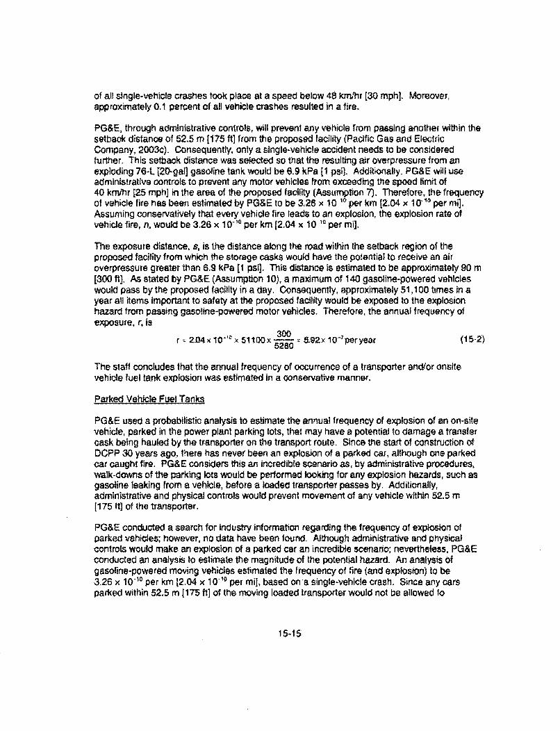
PG&E, through administrative controls, will prevent any vehicle from passing another within thesetback distance of 52.5 m [175 ftj from the proposed facility (Pacific Gas and ElectricCompany, 2003c). Consequently, only a single-vehicle accident needs to be consideredfurther. This setback distance was selected so that the resulting air overpressure from anexploding 76-L j20-gal] gasoline tank would be 6.9 kPa [1 psil. Additionally. PG&E will useadministrative controls to prevent any motor vehicles from exceeding the speed limit of40 km/hr [25 mph] in the area of the proposed facility (Assumption 7). Therefore, the frequencyof vehicle fire has been estimated by PG&E to be 3.26 x 10 '0 per km [2.04 x 10- 1 per mi].Assuming conservatively that every vehicle fire leads to an explosion, the explosion rate ofvehicle fire, n, would be 3.26 x 10-"' per km [2.04 x 10 '0 per mi].
The exposure distance, s, is the distance along the road within the setback region of theproposed facility from which the storage casks would have the potential to receive an airoverpressure greater than 6.9 kPa [I psi]. This distance Is estimated to be approximately 90 m[300 ft]. As stated by PG&E (Assumption 10), a maximum of 140 gasoline-powered vehicleswould pass by the proposed facility in a day. Consequently, approximately 51,100 times in ayear all items important to safety at the proposed facility would be exposed to the explosionhazard from passing gasoline-powered motor vehicles. Therefore, the annual frequency ofexposure, r. is
300r - 2.04x 10"0 x 51100Ox - z 5.92x 10⁻⁷ per year (15-2)
The staff concludes that the annual frequency of occurrence of a transporter and/or onsite
vehicle fuel tank explosion was estimated in a conservative manner,
Parked Vehicle Fuel Tanks
PG&E used a probabilistic analysis to estimate the annual frequency of explosion of an on-sitevehicle, parked in the power plant parking lots, that may have a potential to damage a transfercask being hauled by the transporter on the transport route. Since the start of construction ofDCPP 30 years ago., there has never been an explosion of a parked car, although one parkedcar caught fire. PG&E considers this an incredible scenario as, by administrative procedures,walk-downs of the parking lots would be performed looking for any explosion hazards, such asgasoline leaking from a vehicle, before a loaded transporter passes by. Additionally,administrative and physical controls would prevent movement of any vehicle within 52.5 m[175 ft] of the transporter.
PG&E conducted a search for industry information regarding the frequency of explosion ofparked vehicles; however, no data have been found. Although administrative and physicalcontrols would make an explosion of a parked car an incredible scenario; nevertheless, PG&Econducted an analysis to estimate the magnitude of the potential hazard. An analysis Ofgasoline-powered moving vehicles estimated the frequency of fire (and explosion) to be3.26 x 10'0 per km 12.04 x 10 10 per mi], based on a single-vehicle crash. Since any carsparked within 52,5 m 175 ft] of the moving loaded transporter would not be allowed to
15-15
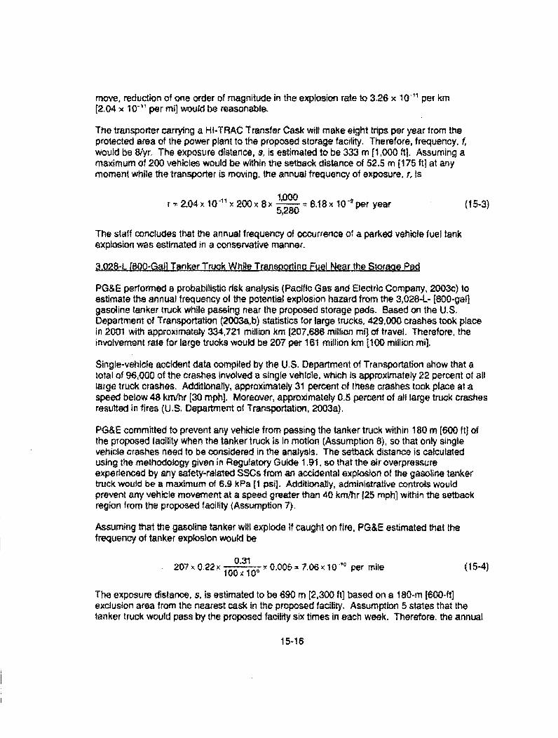
move, reduction of one order of magnitude in the explosion rate to 3.26 x 10- per km(2.04 x 10⁻¹" per mi] would be reasonable.
The transporter carrying a HI-TRAC Transfer Cask will make eight trips per year from theprotected area of the power plant to the proposed storage facility. Therefore, frequency, f,would be 8/yr. The exposure distance, s, is estimated to be 333 m [1,000 ft]. Assuming amaximum of 200 vehicles would be within the setback distance of 52.5 m [175 ftj at anymoment while the transporter is moving. the annual frequency of exposure, r, is
r -2.04x 1011 x 200x 82 x = 6.18x 10 - per year (15-3)5,280
The staff concludes that the annual frequency of occurrence of a parked vehicle fuel tank
explosion was estimated in a conservative manner-
3.028-L [800-GaWl Tanker Tuck. While Transporting Fuel Near the S-torage Pad
PG&E performed a probabilistic risk analysis (Pacific Gas and Electric Company, 2003c) toestimate the annual frequency of the potential explosion hazard from the 3,028-L- [800-gal]gasoline tanker truck while passing near the proposed storage pads. Based on the U.S.Department of Transportation (2003a,b) statistics for large trucks, 429,000 crashes took placein 2001 with approximately 334,721 million km [207,686 million mil of travel. Therefore, theinvolvement rate for large trucks would be 207 per 161 million km t1O0 million mi],
Single-vehicle accident data compiled by the U.S. Department of Transportation show that atotal of 96,000 of the crashes involved a single vehicle, which is approximately 22 percent of alllarge truck crashes. Additionally, approximately 31 percent of these crashes took place al aspeed below 48 km/hr [30 mph]. Moreover, approximately 0.5 percent of all large truck crashesresulted in fires (US. Department of Transportation, 2003a).
PG&E committed to prevent any vehicle from passing the tanker truck within 180 m [600 ft] ofthe proposed facility when the tanker truck is in motion (Assumption 8), so that only singlevehicle crashes need to be considered in the analysis. The setback distance is calculatedusing the methodology given in Regulatory Guide 1.91. so that the air overpressureexperienced by any safety-related SSCs from an accidental explosion of the gasoline tankertruck would be a maximum of 6.9 kPa [1 psi]. Additionally, administrative controls wouldprevent any vehicle movement at a speed greater than 40 km/hr 125 mph] within the setbackregion from the proposed facility (Assumption 7).
Assuming that the gasoline tanker will explode if caught on fire, PG&E estimated that thefrequency of tanker explosion would be
207 x 0.22 x 0--1 _ a- x 0.005 = 7.06 x10-'- per mile (15-4)
The exposure distance, s, is estimated to be 690 m [2,300 ft] based on a 180-m [600-fl]exclusion area from the nearest cask in the proposed facility. Assumption 5 states that thetanker truck would pass by the proposed facility six times In each week. Therefore. the annual
15-16
frequency of shipment, f, is 312. Using Regulatory Guide 1.91, the estimated exposure rate, r,is:
r=7.06x 10 30 x312x ;,300= 9.59x 10'- per year (15-5)5,280
The staff concludes that the annual frequency of occurrence of an explosion of the 3,028-L[800-gal] gasoline tanker truck while using the transport route near the proposed storage padswas estimated in a conservative manner.
Pfroane and Acetylene Bottles Tranoorted Past the Storage Pad
The maintenance facility east of the proposed ISFSI uses acetylene for the cutting torch andpropane to run forklifts. One acetylene bottle is the maximum required in I year. The forkliftuses a 25.5 L [7 gal] liquefied propane bottle which is replaced at a maximum frequency ofonce per week. Through the use of administrative controls, PG&E will ensure that allcompressed gas bottles transported past the proposed ISFSR are appropriately secured in thetransporting vehicle In the upright position (Pacific Gas and Electric Company, 2003c,Assumption 19).
In analyzing this expl•osion event, PG&E considered that the bottle containing 25.5 L [7 galg ofliquefied propane may rupture while being transported past the proposed ISFS1, releasing thecompressed gas. The propane could subsequently mix with air and the resulting vapor cloudcould detonate, which could generate an air overpressure that could be damaging to thestorage casks. For this event, Holtec International (2001 b) and PG&E (2003) assumed that theminimum distance between the point of explosion and the storage casks would be the distancebetween the storage pads and the ISFMS security fence, because no combustible materialswould be permitted inside the proposed ISFSI. The detonation of 26.5 L [7 gal] of propane isequivalent to 4.7 kg [10.37 ib] of trinitrotolune (TNT). At a distance of 15 m [50 It], the resultingair overpressure would be 16.9 kPa [2.45 psi] (Hoftec International, 2001b). Similar calculationsperformed by Holtec International for transport of the acetylene bottles, which contain smallerquantities of compressed gas, resulted in an estimated overpressure of 8.2 kPa [1.19 psi];therefore, the postulated explosion of a propane bottle is the bounding event. PG&E assertedthat because the HI-STORM I 00SA storage casks are designed to perform satisfactorily under68.9 kPa [10 psi of air overpressure for a duration of 1 second, accidental detonation of apropane or an acetylene tank while being transported past the proposed facility would notdamage the storage casks placed on the pad (Pacific Gas and Electric Company, 2003: HottecInternational, 2001 b). However, this overpressure level is greater than the recommended airoverpressure limit of 6,9 kPa [1 psi] of Regulatory Guide 1,91; therefore, PG&E conducted aprobabilistic risk analysis (Pacific Gas and Electric Company, 2003c) to estimate the annualexposure frequency of SSCs important to safety to a higher air overpressure level.
In its analysis, PG&E postulated that the motive force required for a compressed-gas bottle tofail or explode would be from a vehicle crash. Because the crashes near the proposed ISFSIare assumed to be only single-vehicle incidents, PG&E used an explosion rate, n, of7.06 x 10-'' per mile, estimated for large truck crashes, Additionally, the frequency of bottleshipment, f, is assumed to be four times a week or 208 times a year to be conservative. The
15-17
exposure distance, s, is assumed to be 690 m 12,300 ft], the same as with the tanker truckcrash. Therefore, the estimated exposure frequency, r, is
2,300r = 7.06x 10q -' 208x ×520 6.39 ×0" pcryear (15-6)
Although pressurized gas bottles may also fail along the welded seam, the bottles are requiredto meet the current industry standards. Therefore, this mode of failure of gas bottles was notconsidered credible.
The staff concludes that the annual frequency of occurrence of an explosion of the propane andacetylene bottles transported past the storage pads was estimated in a conservative manner.
CoMpressed GasCylinders
Cylinders containing compressed acetylene, air, argon, helium, nitrogen, oxygen, and propanegases are stored inside the reactor-controlled area. Internal pressure of the compressed gascylinders can be In excess of 13.8 MPa [2,000 psi]. The potential energy of the stored cylindersat such high pressures could have significant effects during a rupture because this potentialenergy would be released as kinetic energy that could potentially damage SSCs important tosafety. PG&E postulated that these compressed gas cylinders may be damaged in a way thatthe valve assembly at the top of the cylinders is broken. This failure would create a hole,approximately 5 cm [2 in] in diameter, at one end of the cylinder. Gases escaping through thishole would impart a large acceleration to the cylinder body and/or the valve assembly. Thecylinders and/or the valve assemblies could accelerate toward the cask systems resulting inImpacts (Holtec International, 2001b).
One function of both HI-TRAC 125 Transfer Cask and HI-STORM IO0SA storage masks is toprevent any missiles (e.g., gas cylinder body and valve assembly) from affecting the MPC.Based on the calculations performing by Holtec International (2001b), any missile impacting the1I-TRAC 125 Transfer Cask must penetrate a minimum of 3.8 cm (1.5 in] of steel beforeImpacting the confinement boundary of the MPC. Similarly, any missile has to penetrate atleast 5 cm [2 In] of steel before Impacting the MPC for the HI-STORM I00SA storage caskneglecting the presence of the concrete overpack. Holtec International (2001b) estimated themaximum velocity of all ruptured gas cylinders using the bounding discharge coefficient so thatthe estimated acceleration and the resulting force are maximum, and, therefore, 'he depth ofpenetration in a steel plate would be maximum.
The maximum depth of penetration by the gas cylinder body occurs with propane gas and Isequal to 0.59 cm [0.232 in]. The valve assembly produces a penetration of 0.61 cm [0.241 in].Therefore, the maximum depth of penetration for all types of cylinders and the valve assembliesis substantially less than the steel thickness available to resist penetration. Consequently, thereis reasonable assurance that no SSCs important to safety will be damaged from accidentalrupture of compressed gas cylinders.
15-18
$JaJinar FuTank Near the 7 R.LBoute
Three large stationary fuel tanks are located approximately 360 m (1,200 ft] from the transportroute at the closest point to the proposed ISFSi. These tanks include a 946-L [250-gal]propane tank, a 7,571-L [2,000-gall diesel fuel tank, and an t1,356-L (3,000-galr gasoline tank.These three fuel tanks are located close enough to each other so that an explosion of one tankcould cause potential rupture of the other two tanks. Diesel fuel does not present an explosionhazard because of its high flash point, While a rupture and subsequent detonation of either thepropane tank or the gasoline tank. could potentially rupture the diesel fuel tank, the spilled dieselfuel would burn without exploding. Consequently, the stored diesel fuel would not contribute tothe explosion overpressure. Therefore, this event is limited to the near-simultaneous explosionof both the propane and gasoline tanks to generate any Incident air overpressure. An explosionof these tanks may potentially affect the canister transfer operations at the CTF. the storagecasks placed on pads, or the loaded transfer cask en route to the CTF,
Hoftec International (2001 b) estimated the air overpressure from a simultaneous explosion of946 L [250 gall of propane and 11.356 L [3,000 gal] of gasoline. These sources are equivalentto 53.27 kg [117.33 Ib] of TNT, which generates an air overpressure of 5.79 kPa [0,84 psi] at adistance of 366 m [1,200 ft], the minimum distance between the stationary fuel tanks and thetransport route (Pacific Gas and Electric Company, 2003). Based on Regulatory Guide 1.91,an air overpressure of 5.79 kPa (0.84 psi] would not cause damage to any safety-relatedstructures. The ISFSI security fence and the CTF are further away from the storage tanks thanthe closest point on the transport route. Therefore, it is expected that the air overpressure atthese locations will be lower than 5.79 kPa [0.84 psi].
The stationary fuel tanks are more than 805 m [0.5 mi] from the proposed storage pad locationand at an elevation of approximately 61 rn [200 ft] below. These tanks are located southwest ofthe proposed facility with prevailing southeastern wind directions. Therefore, the winds wouldnormally take the vapor cloud south of the proposed facility. Additionally, the vapor cloudgenerated at the fuel tank location needs to climb the 61-m [200-ft] hill to reach the proposedfacility. Moreover, there is a major cut in the hillside directly above and east of the tanks, Thiscut would likely channel the vapor cloud away from the proposed facility. Therefore, there isreasonable assurance that any vapor cloud generated at these stationary tanks would not poseany undue hazard to the proposed facility.
The stationary fuel tanks will be periodically filled by standard fuel tankers with a capacitybetween 11,3.6 to 15,142 L [3,000 to 4,000 gal]. During any spent fuel transfer operation, thefilling of these tanks would be suspended and all vehicle movements will be administrativelycontrolled in accordance with the Cask Transportation Evaluation Program In the DiabloCanyon ISFSI Technical Specifications. Additionally, Section 8.2.6 of the SAR states thatadministrative controls will be used to ensure that the air overpressure received by anysafety-related structures from an explosion of a tanker truck would be less than the6.9-kPa [1 -psi] limit,
Bulk Hydrogen Storage Facility
A bulk hydrogen facility is located approximately 4.5 m [15 it] from the transport route fromwhere the loaded transfer casks enter and leave the FHB/AB of Unit I of the DCPP. Thisfacility contains 6 hydrogen tanks with a total capacity of approximately 8,495 L [300 ft3]. These
15-19
tanks are refilled approximately twice a month and are kept in a seismic-qualified rack enclosedin a seismic-qualified vault. The vault has a 0.3- [12-in] diameter top vent to ensure that noleaked gas builds up. The vault only opens toward the FHB/AB. The hydrogen facility isdesigned against excessive flow, overpressurization, and vehicle damage during refilling,Therefore, it is extremely difficult to accumulate significant quantities of loaded gas leading toan explosion.
The Electric Power Research Institute Fire Events database considers hydrogen fire to be acredible event and provides a frequency of 3.2 x 10 1 per year (Pacific Gas and ElectricCompany, 2003c). Therefore, the hourly frequency of fire at the bulk hydrogen facility isestimated to be 3.2 x t0"9/8760, or 3.7 x 10"7' Because the design of the facility preventsaccumulation of leaked hydrogen gas in confined spaces, it is extremely difficult to have anexplosion even in the case of a hydrogen fire. PG&E assumed that In 10 percent of the cases,a hydrogen fire would lead to an explosion in the bulk hydrogen facility and, therefore, theestimated hourly frequency of hydrogen explosion would be 3.7 x 10 7 x 0.1, or 3.7 x 10".
PG&E states that the loaded cask transporter would be in the vicinity of the hydrogen tanks forless than 1 hour during each spent fuel transfer from the FHB/AB to the storage pad(Assumption 14), and there will be eight spent fuel transfers each year (Assumption 1). To addfurther conservatism, PG&E assumed a yearly exposure of 10 hours. Therefore, the annualexposure frequency of the transfer cask to a potential hydrogen lank explosion would be
3.7x 10-8 x 10= 3.7x 10.7 per year (t5-7)
The staff concludes that the annual frequency of occurrence of an explosion of the bulkhydrogen storage facility having an impact on a loaded transfer cask was estimated in aconservative manner.
Acetylene ol Storedo on.the 5ast-Side of the Cold Machine.Shop
A maximum of 10 acetylene bottles are stored on the east side of the cold machine shop nearthe DCPP. This facility is more than 7.5 m [25 ft] from the transporter route and is protected byconcrete block wails on two sides. The third side is protected by a building. Administrativeprocedures ensure that these bottles are restrained in an upright position because of seismicconsiderations. This restraint ensures that no potential missiles, originated from an explodingbottle, would be aimed at the transporter route. Furthermore, the cold machine shop facilitylocation allows limited access of vehicles, Additionally, administrative procedures will controlany vehicle movement within 52.5 m [175 ft] of the transporter route when the transporter ishauling a loaded transfer cask. Therefore, there would be no motive force available to initiatedamage to the gas bottles leading to an explosion at those times. Consequently, PG&Econcluded that accidental detonation of acetylene bottles stored on the east side of the coldmachine shop would not be a credible hazard to any safety-related SSC for the proposedISFSI,
Mineral Oil from Diabto Canyon Power Plant Unit 2 Main Bank Transformers
There are six transformers on the Unit 2 side of the DCPP: three single-phase 500-kV, twothree-phase 25-kV, and one three-phase 12-kV. Additionally, two spare transformers are
15-20

stored adjacent to the active transformers. The three single-phase 500-kV transformers arelocated approximately 240 feet from the closest point to the transport route. The othertransformers are mostly shielded from the transport route by these 500-kV transformersbecause of the layout with respect to the transport route. Each active transformer has a fire-suppression system that will activate in case of a fire.
The mineral oil in the transformers acts as a coolant. it has a flash point of 135 1C [275 "'F].Therefore, an explosion of mineral oil does not pose a significant hazard (Holtec International,200 1b) because this is not a flammable liquid. To be classified as a flammable liquid, the flashpoint of the liquid should be less than 37,8 'IC [100 TF] (National Fire Protection Association,1997). Although an electrical fault may occur within one of the transformers, the resultingrupture of the transformer case may ignite and burn the mineral oil, but the mineral oil would notexplode. Therefore, a potential explosion of the mineral oil at Unit 2 of DCPP was notconsidered a credible hazard for ISFSI operations.
Summary of Review
The potential explosion hazards that may affect the storage casks of the cask or canistertransfer operations are: (1) detonation of the transporter or onsite vehicle fuel tank,(2) detonation of 3,028-L [800-gal] tanker truck while transporting gasoline past the ISFSIstorage pads, (3) detonation of a propane bottle transported past the ISFSI storage pads.(4) detonation of an acetylene bottle transported past the ISFSI storage pads, (5) detonation oflarge stationary fuel tanks, and (6) an explosive decompression of a compressed gas cylinder.Other sources are far away from the proposed storage site and contain sufficiently smallamounts of explosive materials to not pose a credible hazard to the storage casks and caskand canister transfer operations. A transfer cask loaded on a transporter could be affected by:(1) detonation of the fuel tank of a transporter or an onsite vehicle fuel tank (including thepotential explosion of a parked vehicle), (2) explosion of large stationary fuel tanks in the vicinityof the transport route, (3) explosion of the Bulk Hydrogen Storage Facility, and (4) explosion ofacetylene bottles stored on the east side of the cold machine shop. The Diablo Canyon ISFSITechnical Specifications will include requirements for a Cask Transportation EvaluationProgram, which will specify administrative controls to prevent movement of the tanker truck andany onsite vehicles during transporter operation, Similarly, no acetylene or propane bottles willbe transported during transporter operations. Decompression of compressed gas cylindersdoes not pose an air overpressure hazard; missiles generated by the decompression of thecylinders are the primary concern in this situation.
PG&E conducted a probabilistic risk analysis (Pacific Gas and Electric Company, 2003c) of theremaining explosion hazards that have a potential to cause damage to safety-related structuresat the proposed facility. Based on the previous discussion, the annual frequency of exposure toexplosion hazards of the storage casks placed on the storage pads at the ISFSI and thecanister transfer operation at the CTF is:
or, P, = 5.92 x 10'7 + 6.39w Y10 + 9.9x Y10- + 0 = 752 x 10- per year (15-8)
15-21
Similarly, the annual frequency of exposure to explosion hazards of the transfer cask whilebeing transported by the transporter Is:
= + + .ks + l +I.ljyj (15.9)or, P. = 0 + 63 $ x ] 0-9 + 0 + 337 x 10" + 0 = 3.76 X i0- 7 per year.
Regulatory Guide 1.91 provides an acceptable methodology to evaluate the potential hazardsby an explosion on safety-related SSCs, Regulatory Guide 1.91 also states that potentialexplosion hazards can be screened out if the annual exposure frequency Is less than 0' 6 andconservative estimates are used, PG&E made conservative estimates of the potentialexplosion hazards, so an annual frequency limit of 10" is applicable here. Therefore, the staffconcludes, based on the review of information and analyses presented by PG&E, that nosafety-related SSCs at the proposed facility will be subjected to explosion overpressures thatexceed the 6.9 kPa (1 psi] threshold.
The staff reviewed the information provided by the applicant regarding potential hazards froman accidental onsite explosion at the proposed faciity. The staff found the analysisacceptable because the applicant:
0 Appropriately identified the potential sources of hazard;
4 Used the Regulatory Guide 1.91 value of 6.9 kPa [1 psi] as the limiting airoverpressure for all safety-related structures;
0 Developed a probabilistic hazard analysis to estimate the annual frequency ofexposure of safety-related structures from each potential source of explosion forthose situations that do not meet stand-off zone criteria based on the 6.9-kPa [11-psi] air overpressure limit;
0 Summed the annual frequency of explosion hazard from each individual sourceto estimate the total hazard to the proposed facility, as recommended inRegulatory Guide 1.91: and
Used conservative assumptions to estimate the annual frequency of exposurefrom each source of the explosion hazard.
Based on the foregoing evaluation, the staff finds that the Diablo Canyon ISFSl SSCs will beable to maintain subcriticality, confinement, and sufficient shielding of the stored fuel for allpostulated onsite explosion events.
15.1.2.5 Electrical Accident
Section 8.2.8 of the SAR evaluates the potential consequences of lightning strikes and a500.kV transmission line drop on the HI-STORM IOOSA storage casks and the HI-TRAC 125Transfer Cask. Of the different 600-kV transmission line drop scenarios that were considered,the worst-case condition is defined by a line drop of a single conductor ot one phase. whichcauses a single line-to-ground fault current and a voltage-induced arc at the point of contact.
15-22
Both electrical events (i.e., lightning strike and 500-kV transmission line drop) manifestthemselves as electrical discharges that travel along the least resistive path through the cask toground. Because these events originate from sources that are outside the confines of the cask,the path of least electrical resistance for the HI-STORM 100SA storage cask Is the overpack,and for the HI-TRAC 125 Transfer Cask, the enclosure shell. As a result, the MPC will not besusceptible to any electrically induced damage in either case.
In the case of a lightning strike, it was satisfactorily demonstrated that the temperature increaseof the HI-STORM I OSA storage cask overpack and HI-TRAC 125 Transfer CaSk enclosureshell will be less than 0.6 "C [1 CF].
For the case of the 500-kV transmission line drop, it was determined that holes would becreated in both the HI-STORM 100SA storage cask and HI-TRAC 125 Transfer Cask outershells by way of material sublimation. Behind the steel outer shell of the HI-STORM 100SAstorage cask is a thick concrete layer that would exhibit only localized spalling andcrystallization in the immediate region where the steel outer shell sublimation occurred. Thestaff determined that the resulting effects on the HI-STORM 100SA storage cask decay heatremoval and radiation shielding capabilities would be minimal. A hole created in the HI-TRAC125 Transfer Cask outer shell could cause a loss of the water jacket designed to provideneutron shielding and facilitate removal of the spent nuclear fuel decay heat. As discussed inSection 8.2.11 of the SAR, a loss of the water jacket does not cause the accident radiationdose to offsite individuals to exceed the limits of 10 CFR §72.106, and the increase in fuelcladding and component material temperatures will not exceed their short-term accidenttemperature limits. Moreover, the MPC internal pressure will remain below the accident designlimit gauge pressure of 1.38 MPa [200 psi]. Additionally, these events are even less likely toImpact a loaded transfer cask, as cask transfer activities are of relativety short duration, and willgenerally not be conducted under the adverse conditions most likely to result in a lightningstrike or transmission line drop.
15.1.2.6 Earthquake
The staff has reviewed the information presented in the following SAR sections: 8.2.1,"Earthquake"; 2,6, "Geology and Seismology"; and 3.2.3. "Seismic Design." Section 4.6 of theSAR classifies the SSCs important to safety based on the Quality Assurance (QA) Programdescribed in Chapter 11 of the SAR. The importance to safety for each of these SSCs isfurther refined into three QA classification categories (Le., Categories A, B, and C) based onthe guidance contained in NUREG/CR-8407 (McConnell, et al., 1996). The Category A SSCsimportant to safety include the: (1) MPC; (2) fuel basket; (3) damaged fuel container;(4) transfer cask, (5) MPC lift cleats and downloader slings: (6) transfer cask impact limiters andlift links; (7) HI-STORM 100 System lilting brackets, mating device bolts, and shielding frame,and lift links; (8) cask transporter; and (9) lateral restraints (HI-TRAC 125 Transfer Cask andtransporter at the CTF). The classification of Category B SSCs important to safety include the:(1) HI-STORM 100SA storage cask overpack; (2) storage pads; (3) overpack anchoragehardware; (4) CTF; (5) transfer cask horizontal lift rig and lift slings: (6) upper and lower fuelspacer columns and end plates; (7) transporter connector pins; and (8) helium fill gas. Theclassification of Category C SSCs important to safety Includes the HI-STORM 100 System caskmating devices (except bolts and shielding frame).
15-23
A seismic event can occur at any time during any stage of a transfer or storage operationinvolving a cask or a canister. At a specific site, earthquake potential is often described by theannual probability of exceeding certain ground motion levels or seismic hazard curves. Thedesign earthquake, double-design earthquake, Hosgrl earthquake (HE), and long term seismicprogram (LTSP) earthquakes form the seismic licensing basis for the DCPP. The applicantindicated that, because both DCPP and the ISFSI sites are classified as rock and they havesimilar ranges of shear-wave velocities within the ro--k classification, and because the distanceto the controlling seismic source is essentially the same, the DCPP ground motions are judgedto be applicable to the ISFSI design. Section 2.1.6 of this SER provides additional informationabout the seismic ground motion hazard and the staff's review of the information.
In conducting analyses of transporter stability, slope stability, and ISFSI storage pad sliding, theapplicant developed the ISFSI long-period (ILP) earthquake spectra, The ILP are 84"percentile spectra at damping values of 2, 4, 5, and 7 percent for the horizontal and verticalcomponents that extended out 1Os and that include near-fault effects of directivity and fIing.The applicant indicates that the ILP spectra envelop the double-design earthquake spectra at 2-and 5-percent damping; the HE spectra at 4-, 5-, and 7-percent damping' and the long termseismic program earthquake spectra at 5-percent damping. The applicant further indicates thatthe use of ILP earthquake spectra for transporter stability, slope stability, and ISFS! storage padsliding would provide an extra design margin by considering long-perod energy. Five sets ofILP spectra-compatible time histories generated from large-magnitude earthquakes (M > 6.7)recorded at short distances {< 15 km [9.3 mi] from the fault) were used as input for theanalyses. Based on the statements provided in the SAR, the staff concluded that the use ofILP spectra-compatible time histories to assess transporter stability, slope stability, and ISFSIstorage pad sliding potential Is acceptable.
Seismic Analysis of Cask Trans.ortation on Transpor RJute
The transport route from the FHPSAB at the DCPP to the ISFSI storage pad is approximately1.93-km [1.2-mij long. Approximately one-third of the route is on bedrock, and the rest is onsurficial deposits over bedrock. The route is made up of slopes with an 8.5-percent nominalgrade decline and a 6-percent nominal grade incline and a 2-percent grade perpendicular to theroadway with a decline toward the hill side. The minimum roadway width is 7.92 m [26 ft], Thecask transporter carries a HI-TRAC 125 Transfer Cask in a horizontal position from the FHB/ABto the CTF for MPC transfer operation. After the MPC transfer operation is executed, the casktransporter carries the loaded overpack in a vertical orientation to the final position on the ISFSIstorage pad. The cask transporter is 5.37-m 117.625-flt wide and 7,47-m [24.5-ft] long. Theapplicant states that the maximum acceptable sliding movement along the roadway is limited tothe cask transporter track length to ensure that the transporter wilt remain on the roadway afterexiting a turn in the roadway. Assuming that the cask transporter travels along the middle ofthe roadway, the allowable lateral sliding distance is the distance between the edge of thetransporter and the edge of the roadway, which is approximately 1.28 m [4.19 ft).
During transport to the ISFSI storage pad, the cask transporter protects the MPC from theeffects of earthquake ground motions. The transporter stability assessment discussed in theSAR was analyzed three dimensionally. The cask transporter, the HI-STORM 10OSA storagecask, the HI-TRAC 125 Transfer Cask, the MPC (including the fuel basket, fuel, and lid), andthe cask lids were modeled as rigid bodies. The mass of the MPC and the contained spentnuclear fuel is lumped in a free-standing rigid cylinder. Three cases of roadway conditions were
15-24
modeled: flat surface, 6-percent grade, and 8.5-perOent grade. For all cases, the groundsurface was treated as a nondeformable boundary. The SAR states that a transporter stabilityanalysis was performed for a potential transporter overturning or sliding off the roadway usingonly the bedrock ground acceleration associated with the ILP earthquake time histories. Themaximum sliling along the roadway axis of approximately 0.77 m [2.52 ft] occurred on theportion of 8.5-percent grade roadway, and the maximum sliding transverse to the roadway axisof approximately 0.27 m (0.89 ft] occurred on the portion of the roadway with a 6-percent grade.These sliding distances are small compared to the corresponding allowable sliding distance,The analysis also demonstrated that overturning is not credible under the ILP seismic events,
The applicant indicates that peak ground accelerations at certain points along the surface ofsurficial deposits over bedrock of the transport route can be 1,5 to 2,0 times the amplitude ofthe peak ground acceleration on bedrock. PG&E did not specifically analyze the potential foroverturning and sliding of the transporter on surficmal deposits. The SAR points out that asignificant safety margin exists to prevent a transporter from overturning or sliding off theroadway while traveling on the surficial deposits even through the ground acceleration wouldbe amplified.
PG&E provided two analyses to address the potential accident scenario, in which anearthquake occurs while the cask is being transported on a portion of the roadway underlain bysoil to the CTF or ISFSI pad. The first is a risk assessment to show that this scenario is notcredible, The second is a calculation to show that transporter and cask will remain stableduring an earthquake. The staff's review of these two analyses is discussed in detail in thefollowing paragraphs. In summary, the staff agrees with the PG&E assessment that this is nota credible scenario. The staff concludes that the regulatory requirements of 10 CFR §72.90,§72.90(a), §72,98, §72,102, and §72.122 have been satisfied.
PG&E conducted a probabilistic risk assessment calculation and concluded that the annualprobability of damage to the transporter while transporting spent fuel from the power plant tothe CTF is 2.1 x 10-'•, which is substantially less than the 1 x 10'6 threshold criterionrecommended for credible events. The PG&E probabilistic risk assessment calculationincludes the 1,4 x 10⁻³ annual exposure probability for transport casks on the transport route(12 hriyr) and the 1.2 x 10 7 annual exceedence probability for two times the ILP earthquakeground motions,
The staff reviewed the PG&E probabilistic risk calculation and agrees with their conclusion.Specifically, the annual exceedence probability for earthquake-induced damage of the transfercask while in transit from the power plant to the CTF is less than 1 x 10 6 and is, therefore. nota credible hazard. The use, however, of the annual exceedence probability associated withtwice the ILP earthquake ground motions is not considered to be appropriate. Twice the ILPearthquake ground motions was used by PG&E to account for possible site responseamplification on those portions of the transport route underlain by soil, not as an added factor Inthe probability calculation. For this reason, the annual probabilities of the ILP earthquakeground motions. not the annual probabilities for twice the ILP earthquake ground motions,should be used in the probabilistic risk calculation,
The staff independently estimated the upper bound annual exceedence probability forearthquake-induced damage of the casks while in transit from the power plant to the CTF. Theestimated probability would be no more than 1,4 X 10- per year, The calculation performed by
15-25
the staff assumed a maximum annual probability for the tLP earthquake ground motions to beless than 1 X 10⁻⁴. When combined with the 1.4 x 10 3 probability of annual exposure of thetransfer casks being in transit, an upper bound value of 1.4 x 10 ' probability of annualexposure is calculated. The exact probability depends on a number of factors, Includingthe spectral frequency of interest and the statistical measure used (mean, median, or84th percentile). Based on this calculation, the staff concludes, with reasonable assurance, thatearthquake-induced damage of the loaded transfer cask while in transit from the power plant tothe CTF is not a credible hazard,
Seismic Analysis of the Cask Transfer Fagility
The staff reviewed Section 4.2.1.2 of the SAR and found that the structural analysis of the CTFdemonstrates that it is designed to mitigate the effects of seismic loading as documented inSection 5.1.4.4 of this SER.
The steel structures of the CTF were analyzed to demonstate compliance with the materialallowables (Holtec International, 2001c). This analysis addressed the following major structuralelements: main shell, lifting jacks, jack support platform, CTF base support block, and liftingplatform, The appropriate spectral values are used to acoount for possible amplification of thehorizontal accelerations of the stacked components, The applicant demonstrated that thefactors of safety for all components and all load conditions aye greater than 1.0. The adequacyof the structures has been demonstrated by the analysis results given in the SAR, as designedto satisfy the requirements of ASME Section III, Subsection NF (ASME International, 1995a),
Loads from the Holtec International structural evaluation were also used in the calculation of thenecessary thickness and reinforcement for the CTF concrete (ENERCON Services Inc.,2001 a). The analysis determined the required size and geneTal reinforcing requirements toresist the loads applied to the concrete structure. The concrete structure is designed towithstand loads from both the CTF and the transporter. Using the controlling loadcombinations, an analysis identified shear and axial forces and moments in the reinforcedconcrete structural elements of the CTF, Steel reinforcement size and placement for the padand wall were established based on these demands. The design of the concrete structure andits reinforcement are based on the requirements in American Concrete Institute (ACI) 349-97(American Concrete Institute, 1998). Results of the analysis indicate that the available designstrength of the CTF exceeds that required for the factored design loads.
Seismic Analysis of the HI-STRM10_•A-0verac~k ANrhoreg1 on the !E.SI 53ofage Pd
Structural analyses of the anchored HI-STORM 100SA overpack are provided in the HI-STORM100 System FSAR (Holtec International, 2002). The staff's evaluation of the HI-STORM 100System FSAR Is documented in the NRC HI-STORM 100 System SER (U.S. NuclearRegulatory Commission, 2002b). The Diablo Canyon ISFSI SAS Section 4.2.3 provides asummary of the analyses performed in the HI-STORM 100 System FSAR. The loadingconditions at the Diablo Canyon ISFSI are enveloped by the loading conditions considered inthe HI-STORM 100 System FSAR (Hottec International, 2002). As documented in the HI-STORM 100 System SER, the structural analysis shows that the structural integrity of theHI-STORM 100 Systemn cask system is maintained during all credible loads. Based on theresults presented in the H I-STORM 100 System FSAR, the stresses in the overpack structures
15-26
during the most critical load combinations are less than the allowable stresses of ASME Boilerand Pressure Vessel Code, Section III (ASME International, 1995b) for the structures materials.
Seismic Analysis of the ISFSI Storage Pad
SAR Section 8,2.1.2.3.1, "Cask and Anchorage Seismic Analysis," summarizes seismicanalyses of the cask and anchorage system performed by Holtec International, The staff'sreview of this analysis is summarized in Section 5.1,3.4 of this SER. Although the DiabloCanyon site-specific seismic zero period accelerations for all events are lower than thoseidentified in Appendix B of the Holtec HI-STORM 100 Certificate of Compliance (U.S. NuclearRegulatory Commission, 2002a), Holtec International performed a specific analysis of the caskanchoring system to be used at Diablo Canyon ISFSI (Holtec International, 2001d), Theprimary feason for this analysis was the difference in the number of anchor rods identified forthe Diablo Canyon ISFSI anchoring system with respect to the design basis given for the HI-STORM t0OSA System (Holtec international, 2002). The results indicate that the casks do notdevelop body decelerations that exceed the cask design basis of 45 g. The seismic eventspostulated for the Diablo Canyon ISFSI do not induce stresses in the preloaded anchor studs,cask flange, and shell that exceed the design-basis ASME Code limits. The interface loadstransferred to the ISFSI pad embedment were established using acceptable methods.
SAR Section 8.2.1.2.3.2, "Storage Pad Seismic Analyses," identifies the analysis performed toensure that the reinforced concrete pads and the anchored casks remain functional during allseismic conditions. Two analyses are covered in this section, a static analysis (ENERCONServices Inc., 2001 b) and a nonlinear pad sliding analysis (Pacific Gas and Electric, 2001 a).The static analysis was performed to determine the storage pad size and thickness required toresist the loads resulting from seismic accelerations applied to the pad and resultant loads fromthe cask dynamic analysis (Holtec International. 2001d). In addition to the cask loads, aninertial force was applied to the pad with reference to the zero period acceleration of theseismic event. The pad and cask vertical displacements are small and within acceptable limits.These maximum tensile stresses in the concrete are less than the tensile stress that will causecracking in the 34.5-MPa [5,000-psi] concrete. The maximum compressive stress issignificantly less that the 34.5-MPa f5,000-psi] design value. Sections throughout the pad wereisolated for the HE seismic event calculations and the internal forces acting upon them werecomputed. The resulting internal forces for design purposes are given in Table 11 of theENERCON calculation package (ENERCON Services Inc., 2001b). The results of the analysiswere used in Calculation No. PGE-009-CALC-007 (ENERCON Services Inc., 2003a) toevaluate the concrete per the design codes and to determine the size of the steel reinforcementneeded for compliance with the requirements of ACt 349-97 (American Concrete Institute,1998). The staff has reviewed this calculation and finds that it demonstrates compliance withthe requirements of ACI 349-97.
The anchorage system was designed to meet the ductile anchorage provision of the proposedDraft Appendix B for ACI 349-97. To satisfy the requirements of Appendix B of ACI 349-97, thediagonal tension shear capacity must exceed the anchor bar ductile design strength of 1.05 MN[235.63 kips]. The applicant has provided sufficient reinforcing steel to ensure the failure conefor concrete pullout intersects sufficient rebar to prevent brittle failure (ENERCON Services Inc,,2003a). The reinforcing steel in the storage pad (ENERCON Services Inc., 2003b) has beensized in accordance with the requirements of ACI 349-97.
15-27
15.1.2-7 Loss of Shielding
Section 8.2.11 of the SAR (Pacific Gas and Electric Company, 2003) evaluates the potentialconsequences of a loss-ol-neutron shielding for the HI-TRAC 125 Transfer Cask. The potentialconsequences of this postulated accident were determined by assuming a loss of the waterjacket and Holtite-A solid neutron shielding. The staff previously determined that themethodology used to assess this postulated accident is acceptable and the short-term fuelcladding and other component temperature limits, the MPC accident internal pressure, andthe accident dose limits defined by 10 CFA §72.106 are not exceeded, so long as the fuelspecifications and loading conditions as defined in the HI-STORM 100 System CoC and SER(U.S. Nuclear Regulatory Commission, 2002ab) are adhered to. The staff has confirmed thatappropriate limits have been incorporated Into the proposed Diablo Canyon ISFSI TechnicalSpecifications.
Section 8.2.6.3 of the SAR specifies that the consequences of postulated explosion eventsanalyzed for the Diablo Canyon ISFSI are enveloped by the design-basis accident conditions inthe HI-STORM 100 System FSAR (Holtec International, 2002). Additionally, there is no effecton shielding, criticality, thermal, or confinement capabilities of the HI-STORM 100 System as aresult of the explosion pressure toad. Based on the structural and radiological evaluationspresented in Chapters 3 and 11 of the HI-STORM 100 System FSAR, the applicant concludesthat the MPC confinement boundary will remain intact and the shielding effectiveness of thestorage and transfer casks will not be significantly affected by any potential onsite explosion.
Considering the results of the onsite explosion accident analysis evaluation presented inSection 15.1.2.4, "Fire and Explosion," of this SER, the staff finds that the maximum reductionin ISFSt radiation shielding thickness, material shielding effectiveness, or loss of temporaryshielding in all possible shielding areas caused by postulated onsite explosion events, has beenadequately evaluated by the applicant. Therefore, the information and analyses presented bythe applicant provide reasonable assurance that the accident dose to any individual beyond theowner-controlled area will not exceed the limits specified in 10 CFR §72.106(b), and theoccupational exposures from accident recovery operations will not exceed the limits specified in10 CFR Part 20,
15.1.2.8 Adiabatic Heatup
The staff has previously determined that the methodology used to estimate the time required toreach the short-term, fuel-cladding temperature limit of spent nuclear fuel stored in theHI-STORM 100 System storage cask under adiabatic conditions is acceptable (U.S. NuclearRegulatory Commisslon, 2002a,b). The HI-STORM 100 System FSAR (Holtec International,2002, Figure 11.2.6) indicates that a total cask decay heat load of 30 kW (102,360 BTU/hr],which bounds the cask decay heat load specified for the Diablo Canyon ISFSI, will not causethe short-term cladding temperature limit for the spent nuclear fuel to be exceeded for 45 hoursunder adiabatic conditions. Moreover, the internal pressure limit for the MPC Is not exceededwithin the 45-hour timeflrame for this condition.
In the event that the HI-STORM 100 System storage cask is subjected to conditions thatthermally insulate its exterior (e.g., encased within soil as the result of a landslide), thepreviously reviewed and accepted recovery operation procedures will be implemented(U.S. Nuclear Regulatory Commission, 2002a,b).
1,5-28
15.1.2.9 Full Blockage of Air Inlets and Outlets
The staff previously determined that the methodology used to estimate the time required toreach the short-term, fuel-oladding temperature limit of spent nuclear fuel stored in theHI-STORM 00SA storage cask subjected to 100-percent blockage of the air inlet ducts isacceptable (U.S. Nuclear Regulatory Commission, 2002a,b). For the bounding values of decayheat load of 30 kW [102,360 BTU/hr] and insolation of 834 w/m2 (800 g-cal/crmJ per day (387Wirme [123 BTU/hr-ftJ}, the short-term cladding temperature limit for the spent nuclear fuel willnot be exceeded for 72 hr when the HI-STORM IOOSA storage cask air inlet ducts are100-percent blocked. Moreover, the internal pressure limit for the MPG is not exceeded withinthe 72-hour timeframe for this condition. Furthermore, the HI-STORM 100 System Coc (U.S,Nuclear Regulatory Commission, 2002a, Appendix A) includes surveillance requirements forensuring that the cask heat removal system is operational during storage (i.e., the air ducts areinspected every 24 hours to ensure that the ducts are free of blockages). In the event that theHI-STORM I00SA storage cask air inlet ducts are found to be partially obstructed or blocked,the previously reviewed and accepted recovery operation procedures will be implemented(U.S. Nuclear Regulatory Commission, 2002a,b).
I S1.2.10 Tornadoes and Missiles Generated by Natural Phenomena
The staff reviewed the information presented in the Diablo Canyon 1SFSI SAR Sections 3.2.8,"Tornado and Wind Loadings;" 3.3.2.3.3, "Maximum Permissible Tornado Wind and MissileLoad;" 4.2.3.3.2.6, 'Tornado Winds and Missiles;" and 8.2.2, "Tornado.' The staff alsoreviewed responses to requests for additional information (Pacific Gas and Electric Company.2002; RAIs 4-3, 15-18, 15-19, 15-20, and 15-21), including the report. "Design Basis Wind andTornado Evaluation for DCPP", (Holtec International, 2001e, Attachment 4-1) and Section 3.3,"Wind and Tornado Loadings,' of the FSAR for DCPP, Units 1 and 2 (Pacific Gas and ElectricCompany, 2001 b). This evaluation assumed that site personnel would not have any priorwarning before the ISFSI SSCs are impacted by a potential design-basis tornado or a tornadomissile.
The annual mean number of days with tornadoes is zero for the ISFSI site. Characteristics ofthe design-basis tornado and tornado missile are given in Section 3.2.1 of the ISFSI SAR. TheSAR developed the characteristics of the design-basis tornado in accordance with the DCPPlicensing-basis wind speed of 89 mis (200 mph]. The proposed site is located In Region II asdefined in Regulatory Guide 1.76 (U.S. Nuclear Regulatory Commission, 1974). Thecharacteristics of the design-basis tornado for the proposed ISFSE are defined as a tornado witha maximum wind speed of 89 m/s (200 mph], a rotational speed of 70 m/s (157 mph], aIranslational speed of 19 m/s [43 mph], and a 5,9-kPa [0.86-psi] pressure drop at a rate of2.5 KPa/s [0,36 psi/s].
The design-basis tornado missiles considered in the Diablo Canyon ISFSI SAR are based onSpectrum 1I missiles of Section 3.5.1.4, "Missiles Generated by Natural Phenomena," ofNUREG-08-0 (U.S. Nuclear Regulatory Commission, 1981 a), the Diablo Canyon FSARUpdate (Revision 14, Pacific Gas and Electric Company, 2001 b), and the three 500-kV towermissiles specific to the ISFSI (Pacific Gas and Electric Company, 2003). These objects arepostulated to be picked up and transported by the winds of a design-basis tornado. A list ofthese missiles is provided in Table 15.1.
15-29
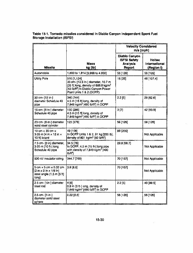
Table 15-1. Tornado missiles considered in Diablo Canyon Independent Spent FuelStorage Installation (ISFSI)
Velocity Consideredmis [mph]
Diablo CanyonISFSI Safety HolteC
Mass Analysis InternationalMissile kg [Ib] Repo1) ,Reg.on i)
Automobile 1,800 to 1,814 [3,9681o 4.0001 56 (126] 56 (126]
Utility Pole 510 (1,124] 16 t35] 48 [107.4133 cm. [13.5 in-] diameter, 10.7 m135 ft] long, density of 688.8 kg/m$(43 Ib/l'] in Diablo Canyon PowerPlant Unils I & 2 (DCPP)
30 cm- [12 in-] 340 [744] 2.2 [5) 28(62.61diameter Schedule 40 4.5 m [15 ft] long, density ofpipe 7,849 kg/m3 [490 Ib/ftj in DCPP
15 cm- [6 in-1 diameter 130 [285] 3 [7] 42(93.9)Sctedule 40 pipe 4.5 m [15 ft] long, density of
_7,849 kg/rm [490 Ibfi in DCPP
20-cm- 18-in-] diameter 125 [276] 56 [126] 56(126]sOlid steel cylinder
10cm x 30crn x 49 [108- 89 [200]3,05 m [4inx 12 in x In OCPP Units 1 &2,91 kg 1200 Ib, Not Applicabie10 ti] board density of 801 kg/qf 3 [50 lb/fe3
7.5 cm- [3 in] diameter, 34.5 [76] 298 [86,7)3.05 m [10 ft-] long In DCPP, 4. m [15 ft-] Iony pipe Not ApplicableSchedule 40 pipe with density of 7,849 kg/rn [490
Ib/tft500-kV insulator string 344.7 [760j 70 [157] Not Applicable
5 cm x 5 cmx 0.32 cm 3,9 8,6] 70 [157][2 in x 2 in x 1/8 in] Not Applicablesteel angle (1.5 m [5 ft]long)
2.5 cm- ftin-] diameter 4 [8] 22 [5) 40 (89,5]steel rod 0.9 m [3 ft-] iong, density ol
7,849 kg/rn9 [490 Ib/ in DCPP
2.5-cm-(1-in.] 0.22 [0.5' 56[126) 56 [126]diameter solid steelsphere ............
15-30
Important to safety SSCs that may be affected by design-basis tornado missiles are: (1) theCTF, (2) site transporters, (3) the transfer cask, and (4) the storage casks, These SSCs arerequired to function during this design-basis event.
Based on the resulting kinetic energy, PG&E's analysis assumed that an automobile at203 km/hr [126 mph], a 500-kV insulator string at 253 krrhr [157 mph], and a 2.5 cm-[1 in-]diameter steel rod at 144 km/hr [89.5 mph) are the bounding missiles for the large,intermediate, and small missiles categories. PG&E assumed that the impact velocity of anautomobile is consistent with that suggested In NUREG-0800. PG&E developed an equationto estimate the maximum horizontal missile velocity for a 322-km/h [200-mph] tornado from a386-km/h (240-mph] Type Ill tornado curve using Figure 16.3.1 of Simiu and Scanlan (1986).However, the basis for the equation is not clear. This formula will produce a different result forthe correlation power factor if tornados other than Type III are used.
The staff s confirmatory calculation indicated that energy imparted by the automobile issignificantly larger than that of a utility pole. Therefore, any impact of a utility pole would bebounded by the automobile impact for assessing transporter stability. Hottec International(2001 e) studied the effects of transporter stability while transporting a loaded transfer cask tothe storage area at the proposed facility. This analysis included a large missile represented bya 1,800-kg 14,000-1b] car traveling at a speed of 56 m/s [126 mph]. The impact analysis resultindicates that a loaded transporter would be displaced laterally by a distance of only 1.65 cm[0.65 in]. The transporter remains stable and does not tipover as a result of this Impact.
The staff reviewed the information provided by the applicant, evaluated the analyses ofpotential hazards from design-basis tornadoes and tornado missiles at the proposed facility,and conducted a confirmatory analysis. The staff concludes that a tornado ortornado-generated missile would not impair the ability of the SSCs to maintain subcriticality,confinement, and sufficient shielding of the spent fuel during transfer or storage.
16.1.2.11 Accidents at Nearby Sites-Aircraft Crash Hazards
The staff reviewed the information presented in the Diablo Canyon ISFSI SAR, Section 2.2(Pacific Gas and Electric Company, 2003). In addition, the staff reviewed informationpresented by PG&E in response to staff questions regarding aircraft crash hazards (Pacific Gasand Electric Company, 2003d). The purpose of this review is to ensure that the risk to theproposed facility caused by aircraft hazards has been appropriately estimated and isacceptable.
The staff reviewed the aircraft crash hazard analysis In accordance with NUREG-0800,Section 3,5.1.6, "Aircraft Hazards." The staff accepts the methodology in NUREG-0800, asapplicable, for reviewing the aircraft crash probability for the proposed ISFSI. Section 3.5-1.6 ofNUREG-0800, provides three screening criteria that must be satisfied to conclude, byinspection, that the aircraft hazards at a nuclear power plant are less than 1 x 10⁷ per year foraccidents that could result in radiological consequences greater than 10 CFR Part 100exposure guidelines. The staff's review indicates the proposed facility site does not satisfyscreening Criterion 11.1(a), which states, "The plant-to-airport distance, D is between 5 and 10statute miles, and the protected annual number of operations Is less than 500 l, or the plant-to-airport distance, D, is greater than 10 statute miles, and the projected annual number of
15-31
operations is less than 1000 0." Based on the information given in the SAR, and the air trafficincrease projected in the next 25 years by the Federal Aviation Administration (FAA). theprojected annual number of operations may not satisfy Criterion 11.1 (a). Additionally, screeningCriterion II. 1(c) states, 'The plant is at least 2 statute miles beyond the nearest edge of afederal airway, holding pattern. or approach pattern." As stated by the applicant in Section2.2.1.1 of the SAR, air traffic to San Luis Obispo County Regional Airport passes the proposedsite at a distance of 1.6 km [1 mi. Therefore, screening Criterion 11.1 .(c) is also not satisfied,and in accordance with NUREG-0800 review guidance, a detailed review is needed to assessthe aircraft crash hazards for the proposed site. PG&E provided Its detailed analysis toestimate the annual frequency of a potential aircraft crash at the proposed ISFS! (Pacific Gasand Electric Company, 2003d). Additionally, the staff conducted its own confirmatory analysis.These analyses ate discussed in the following sections.
Estimating the total probabilty of an aircraft crash onto the proposed ISFSI requires an
evaluation of crash probabitilies from several sources:
* Aircraft taking off and landing at San Luis Obispo County Regional Airport;
Aircraft taking off and landing at other municipal airports located close to the site,such as Oceano County Airport, Camp San Luis Obispo Heliport, andVandenberg Air Force Base:
Aircraft flying the low-attitude flight corridor V-27 (commercial airway) and eitherlanding at or departing from San Luis Obispo County Regional Airport, ornot landing at or deparling from San Luis Obispo County Regional Airport; and
* Aircraft flying military training route VR-249.
AirN[gt Taking Off and Landing at San Luis Obiso Couny. Realonal Ai.rort
San Luis Obispo County Regional Airport is approximately 19.3 km [12 mi east of the proposedsite. This airport has four runways. Only Runway 115s equipped for instrument landingapproach. The other three runways are used for visual landing. Some aircraft use Airway V-27to align for Instrument landing at the airport. Some of these aircraft come within approximately1.6 km [1 m!) of the proposed ISFSI site at an elevation of 914 m [3,000 ft]. Based onNUREG-0800, any aircraft flying Airway V-27 for instrument landing at San Luis ObispoCounty Regional Airport will be in an in-flight mode, Their contribution to the overall crashhazard has been accounted for in the analysis of V-27. The commonly used approach route forvisual landing at San Luis Obispo County Regional Airport passes approximately 12.8 km [8 nmi]from the proposed site.
In Section 2.2.1.3 of the ISFSI SAR, "Hazards from Air Crashes,' PG&E stales thatapproximately 92,330 operations (take offs or landings) occur annually at San Luis ObispoRegional County Airport, However, while discussing local traffic on Airway V-27, PG&E statedapproximately 16,000 takeoffs and landings occur annually at San Luis Obispo County RegionalAirport, based on an average of data from 1998-2001, by commercial or air-taxi aircraft.Primarily turboprop aircraft with a gross weight of not more than 13,608 kg [30,000 Ib] are usedin these commercial flights. Additionally, private aircraft (i.e., general aviation aircraft) landed ator took off from San Luis Obispo County Regional Airport approximately 7,560 times monthly,
15-32
based on the average of data from 1998-2001. These aircraft have gross weight of less than5,670 kg [12,500 Ib]. Consequently, at least a total of approximately 106,720 landings anddepartures took place annually at the San Luis Obispo County Regional Airport witout countingthe operations by military aircraft.
PG&E concluded that no anatysis would be necessary as the number of annual operations atSan Luis Obispo County Regional Airport is below the number needed to have an annual crashfrequency of 10 7 based on Criterion 11.1 (a) of NUREG-.0800.
The staff independently verified the number of annual operations at this airport from the FAAdatabase at <htto:!/w _•ct cTm5010WEB/default~htr> and another source at<http:/!www.airnav.com>. Based on this information, approximately 72,000 annual operationstake place at the San Luis Obispo County Regional Airport, out of which approximately 16,500operations are by commuter aircraft and approximately 55,000 operations are by generalaviation aircraft, in addition to approximately 900 operations by military aircraft, Because thenumber of annual operations given by PG&E (i.e., 106,720 with 900 additional operations bymilitary aircraft) Is bounding, the staff used that value for further review.
The staff reviewed the information and the analysis provided by the applicant with respect to thepotential hazards of aircraft taking off and landing at San Luis Obispo County Regional Airport.The staff found the hazards acceptable because adequate information has been presented todescribe the potential hazards and an acceptable methodology has been used to screen thepotential hazards. As the airport is approximately 19,3 km r12 mil away from the proposedISFSI site, the estimated annual frequency of crash onto the proposed ISFSI is insignificantusing the methodology given in NUREG-0800 to analyze the crash potential of aircraft landingat or taking off from an airport. Based on the this information, the staff has concluded thataircraft taking off and landing at San Luis Obispo County Regional Airport would not pose anyundue hazard to the proposed ISFSI.
Aircraft Taking Off and Landing at Oceano County Airport, Camp San Luis Obso Heliport, andVandenberg Air Force gage
There are several smaller municipal airports in the vicinity of the proposed site. Oceano CountyAirport is located 24 km [15 rmiJ away from the proposed site. Only general aviation aircraft withweight not. more than 5,670 kg [12,500 ib] use this airport. In the Diablo Canyon ISFSI SAR,PG&E estimated annual traffic at this airport to be no more than 26,400. Both the FAAdatabase at <httn://www.gcrl .com/5O0!WEB/defauft,htm> and another souroe at<htp:•lw•w.aimav.comrn give the estimated annual number of flight operations at this airport tobe approximately 10,000, Therefore, the estimated number for annual flights used in the SARis conservative. Again. PG&E concluded that no analysis would be necessary, based onCriterion 11,1(a) of NUREG-0800, as the number of annual operations at Oceano County Airportequates to an annual crash frequency of 10', or lower. Based on the analySis methodologygiven in NUREG-0800, the staff estimates that the frequency of aircraft crashing onto theproposed ISFSI while taking off or landing at Oceano County Airport is insignificant.
Camp San Luis Obispo airfield, located approximately 13 km [8 mil northeast of the proposedISFSI site, is a heliport owned by the U.S. Army. The staff concludes that landings and takeoffsby helicopters at this heliport do not pose a credible hazard to the proposed ISFSI because ofthe type of aircraft and the long distance from the ISFSI, based on the U.S. Department of
15-33

Energy (DOE) Standard, 'Accident Analysis for Aircraft Crash Into Hazardous Facilities."(DOE-STD-3014-96, U.S. Department of Energy, 1996),
Vandenberg Air Force Base is 56 kin [35 mil] away from the proposed site, At this distance, thenumber of takeoffs or landings per day will not exceed the NUREG-0800 criterion that wouldrequire further analysis, Therefore, any landing or takeoff operations at Vandenberg Air ForceBase will pose a negligible hazard to the proposed Diablo Canyon ISFSI.
Aircraft FDying Low-Altitude Airway Victtor 27 (V-27)
A low-altitude Airway Victor 27 (V-27) passes approximately 8 km [5 ml] east of the proposedfacility. Aircraft use this airway to fly between the Santa Barbara area and the Big Sur area.Aircraft using V-27 can either land at San Luis Obispo County Regional Airport or fly through totheir destination without landing. The majority of the aircraft using airway V-27 fly at an enroute attitude of 3,333 m [10,000 ft] above mean sea level (MSL). Occasionally, V-27 is alsoused by traffic approaching San Luis Obispo County Regional Airport from the south forinstrument landings on Runway 11, or for instrument departures to the south from Runway 11,Some landings on Runway 29, and instrument departures to the south from Runway 29 alsouse V-27. Some aircraft using this approach or departure pattern pass as close as 1.6 km[1 mril from the proposed JSFSI site at an elevation of 914 m [3,000 ft].Aircraft Landing or Qeparting San Luis Obisoo County Reoiona! Aimort Using V-27
PG&E used the FAA database .tIL w_.,i iata.faa~aov/faaatadsall.htm> to obtaininformation about commercial or air taxi (AT) and general aviation operations at San LuisObispo County Regional Airport. An average of 16,000 AT operations (i.e., takeoffs orlandings) took place annually during 1998-2001. Additionally, an average of 1,781 AT landingstook place annually at this airport under instrument meteorological conditions.
Based on the scheduled airline flight infornration at San Luis Obispo County Regional Airport,PG&E estimated approximately 65 percent of the commercial traffic is departing to orapproaching from the south. Therefore, approximately 1,781 x 0.65, or, 1,157 instrumentlandings may use the V-27 airway annually. Assuming a similar number of takeoffs usinginstrument conditions, approximately 2,314 flights will use Airway V-27 annually, and thisnumber was considered in the aircraft hazards analysis for the proposed ISFSI.
The FAA database shows that approximately 7,560 landings and takeoffs by general aviationaircraft took plaoe monthly at San Luis Obispo County Regional Airport over the 4-year periodof 1998-2001. During the same period, an average of 1,430 flights, which includes local anditinerant general aviation and military flights, landed at San Luis Obispo County Regional Airportannually under instrument conditions. PG&E again assumed that approximately 65 percent ofthe general aviation traffic is departing to or approaching from the south. Therefore, PG&Econsidered that approximately 2 x (1,430 x 0.65). or 1,860 operations (takeoffs and landings)took place annually under Instrument conditions.
The nearest major airway Intersections (CREPE and CADAB) are approximately 1 krn [111 mQand 34 km [21 mri from the proposed ISFSI site. Holding patterns at both of these intersectionswould place the aircraft even further away from the proposed ISFSI site, thus they are notconsidered to contribute to the overall aircraft hazard.
15-34
Since the Morro Bay Very-High Frequency Omnidirectional Range Navigation System is usedfor missed approaches to San Luis Obispo County Regional Airport, PG&E estimated that5 percent of all instrument landing approaches are missed, and each aircralt remains in theholding pattern for 10 passes. Therefore, for purposes of this analysis, commercial aircrafttraffic is assumed to increase by an additional 579 (2,314/2 x 0.05 x 10) annual flights andgeneral aviation aircraft traffic by 465 [1,860/2 x 0.05 x 10] additional annual flights. In itsresponse to additional staff questions, PG&E stated that the assumption that 5 percent of allinstrument landing approaches are missed is conservative based on discussions with thepersonnel at the control tower of San Luis Obispo County Regional Airport regarding thespeciic approaches available to the airport. Additionally, discussions with pilots of commercialand private aircraft support this oonclusion, San Luis Obispo County Regional Airport haslimited landing facilities. Most instrument approaches are near minimum weather requirementsfor using tAhe visual flying rule and result in a visual landing under an instrument flying ruleapproach. Essentially, zero landing misses take place under this type of approach to theairport. Runway 11 Is the only runway available with a precision instrument landing system. Ifwind and fog results in downwind landing on Runway 11, commercial aircraft will not depart SanLuis Obispo County Regional Airport,
PG&E states that aircraft approaching from the south and not during weather classified asinstrument meteorological conditions will fly to the CADAB intersection and will land onRunway 29 under visual control. These aircraft do not generally use Airway V-27 while landingat San Luis Obispo County Regional Airport. However, when San Luis Obispo County RegionalAirport is under instrument meteorological conditions, all aircraft arriving from the south will useRunway It approach, if the ceiling is below 270 to 330 m [900 to 1,100 fIt, depending on theaircraft type. This approach uses V-27. However, if the ceiling is above 270 to 330 m [900 to1,100 ft], the pilot may also use the Runway 29 approach, which does not use V-27.Consequently, a major portion of the aircraft approaching San Luis Obispo County RegionalAirport from the south (PG&E has estimated it to be approximately 65 percent) do not use V-27to land; however, PG&E has conservatively assumed that all aircraft approaching from thesouth use Airway V-27. The V-27 airway has a width of 12.8 km {8 statute miJ with a centerapproximately 8 km [5 ml] from the proposed ISFSI site. Consequently, the proposed ISFSIsite is 1.6 km [1 statute mi] from the edge of V-27 airway, and an effective width equal to 16 km[10 statute mi] is used in accordance with NUREG-0800 to estimate the probability of aircrashes from traffic using this airway at the ISFSI site.
PG&E assumed that the wingspan of commercial aircraft is 29.9 m [98 ft) with a skid distance of213 m [700 it] and cotangent of the impact angle, cot (p, equal to 10,2. Using length, width, andheight of the facility as 152, 32, and 6.1 m [500, 1495, and 20 1f], PG&E estimated the effectivearea of the facility to be 0.0580 km2 [0.0224 mi2] for commercial aircraft, using the formula givenin DOE Standard DOE-STD-3014-96. Using a wingspan of 22.3 m [73 ft), skid distance of213 m [700 it], and cot ;p of 10.2, PG&E estimated the effective area of the facitity to be0.0554 km" [0.0214 mil for general aviation aircraft.
Use of 213 m [700 ft] as the skid distance by PG&E is based on the layout of "he proposedfacility. The proposed facility Is surrounded by hills on three sides, which limits the potential skiddistance by a crashing aircraft to reach to the SSCs important to safety. The fourth side isprotected by a drop in the terrain with a slope greater than 1:1 (PG&E SAR, 2003, Figure 2.2-1).
15-35
PG&E assumed a crash rate of 2.5 x 10 '0 per km [4 x 10 10 per mi] for commercial aircraft and0.97 x 10 ' per km [1 .55 x 10- 7 per mi] for general aviation aircraft flying in this corridor. Thecrash rate for commercial aircraft is based on the suggested value in Section 3.5.1.6 ofNUREG-O800. Additionally, PG&E used Kimura, at. al (1996) to select the crash rate forgeneral aviation aircraft.
Based on the above parameters and using the formula given in NUREG-0800, Section 3.5,1.6,PG&E estimated the annual crash frequency onto the proposed ISF SI by commercial aircraft tobe 2.59 x 10 9. Similarly, the annual crash frequency of general aviation aircraft is estimated byPG&E to be 7.7 x 10⁻⁷. Therefore, the total crash frequency by aircraft flying airway V-27 Is7.73 x 10." per year.
The staff consulted the FAA database <htto:/wvww.ano.data.faa.gov/faaatadsall.htnm> toindependently verify the number of annual flights by both commercial and general aviationaircraft approaching San Luis Obispo County Regional Airport during instrument meteorologicalconditions. The staff confirmed that the 4-year (1998-2001) average of flights duringinstrument meteorological conditions for both types of aircraft are acceptable. Additionally,inclusion of 2002 data would somewhat decrease the annual average for both commercial andgeneral aviation aircraft. Therefore, the applicant's consideration of information from1998-2001 is appropriate.
Commercial Aviation
San Luis Obispo County Regional Airport is served primarily by turboprop or smaller aircraft forthe commercial or air taxi traffic. The maximum capacity of these aircraft is 41 people with amaximum gross weight of 13,608 kg [30,000 Ib]. Although PG&E used the crash rate ofcommercial aircraft equal to 4 x I0'" per mile, as suggested in Section 3,5.1.6 ofNUREG-0800, the staff used a crash rate of 9.28 x 10.. per km [5.801 x 10 ' per mij, asgiven in Table 2.13 of Kimura, et at. (1996) for off-airport crashes with destroyed aircraft oraircraft that sustained substantial damage to the airframe as a result of the crash. Staffconsiders this crash rate to be more appropriate for the type of aircraft under consideration. Asearch of the website <http:/.www.sloairipot-,om./flightlnto.htm.>. shows that certified air carriersoperate at this airport. A certified air carrier is an air carrier possessing a Certificate of PublicConvenience and Necessity issued by the U.S. Department of Transportation in accordancewith 14 CFR Part 121 to operate scheduled air services (Kimura et al., 1996). The informationobtained by the staff independently from the websites <http://airnav.com> and<htto:t/www.gcr1 2qmcom5010WEBE/default. htm> indicates that the traffic at San Luis ObispoCounty Regional Airport does not have any air-taxi operations, rather it has commercialoperations. Therefore, the staff used the crash rate of 9,28 x 10'D per km [5.801 x 10 • permi] as the Crash rate appropriate for commercial aircraft operating at San Luis Obispo CountyRegional Airport.
Although PG&E stated that San Luis Obispo County Regional Airport is primarily serviced byturboprop or smaller aircraft for commercial traffic, PG&E used a wingspan of 29.4 m [98 ft], assuggested for air carriers in commercial aviation in Table 1ý-16 of DOE StandardDOE-STD-3014-96. This table suggests that the wingspan for turboprop aircraft, classified asgeneral aviation aircraft, Is 22.3 m [73 ft]. Therefore, use of a higher value for wingspan willproduce a larger estimate of the effective area, and therefore, it is conservative. The staff useda wingspan of 29.9 m [98 ft] for commercial aviation. Additionally, the staff considered allgeneral aviation aircraft to be the turboprop type, which has the largest wingspan of all generalaviation aircraft types.
15-36
Table B-.17 of the DOE standard provides the suggested values for the mean of the cotangentof the impact angle (cot rp). For commercial aviation aircraft, the suggested value is 10.2. DOE(1996) recommends cot qp equal to 8.2 for general aviation aircraft. Mean skid distances forcommercial and general aviation aircraft are 439 and 18 m [1,440 and 60 ft], as per Table 8-18of the DOE Standard. PG&E asserted that a commercial aircraft would not have enough spaceto skid for a distance of 439 m (1,440 ft] because of the topography surrounding the proposedISFSI, The staff agrees with this conclusion and has used a skid distance of 213 m (700 ft] asan appropriate skid distance for commercial aircraft in the calculation. Nevertheless, the staffalso used 439 m [1,440 ft] in the calculation to test the sensitivity of the skiddistance parameter.
Using a wingspan of 29.9 m (98 ft], cot 9 of 10.2, and a skid distance of 213 m [700 ft], the staffestimates the effective area of the proposed facility to be 0.058 km2 [0.0224 mi2]. Using a skiddistance of 439 m [1,440 ft], however, the estimated area increases to 0.0997 krm2 [0.0385 mi2]for commercial aircrall, Using a wingspan of 22.3 m (73 ft], cot cp of 8.2, and skid distance of18 m [60 ft], the effective area is 0.01844 km2 [0.00712 mnil. As discussed before, the effectivewidth of the airway is 16 km [10 mi]. Based on this information, the staff estimates that theannual frequency of a crash of a commercial aircraft onto the proposed facility, using theformula given in NUREG-0800 Section 3.5.11.6, is approximately 3.8 x 10⁻⁹, for a skid distanceof 213 m [700 ft]. Assuming a skid distance of 439 m (1,440 ft], (which is not consideredrealistic given the topography surrounding the proposed ISFSI), the probability of a commercialaircraft crash increases to approximately 6.5 x 10 " per year.
.General Aviation
PG&E stated that the general aviation aircraft using the airport and airways near the proposedISFSI include small single- and dual-engine aircraft, and small corporate aircraft powered byeither propeller or jet. These aircraft with an average gross weight of less than 5,670 kg[12,500 ib] have a maximum capacity of eight people. Kimura, et al. (1996) provide crash ratesper flight mile for single- and multi-engine reciprocating, turboprop and turboet, rotary wing witheither reciprocating or turbine engine aircraft. Because the proportion of these aircraft is notknown, the staff considers the use of a crash rate of 2.48 x 10 per km [1.550 x 10" per mi] forall powered aircraft appropriate. As a part of the sensitivity analysis, the staff also used thecrash rates equal to 2,416 x 10"; per km (1,510 x 10 ' per mi] for all fixed-wing (single- andmulti-engine reciprocating, turboprop and turbojet) aircraft and 5.669 x 10⁷' per km[3.543 x 10 7 per mile] for all rotary.wing (reciprocating or turbine engine) aircraft. Additionally,a wingspan of 22.3 m [73 ft) has been used. As discussed before, this is a conservativeestimate of the actual wingspan as the typical wingspan of a general aviation aircraft is givenas 15.2 m [50 ft], except for a turboprop aircraft, which has a wingspan of 22.3 m [73 ft] (U.S.Department of Energy, 1996). Additionally, a skid distance of 18 M [60 ft] and oat r; of 8.2 havebeen used to estimate the effective area of the proposed facility. The effective area of theproposed facility has been estimated to be 0.01844 km 2 [0.00712 mi2l. Therefore, the staffestimates that the annual frequency of crash of a general aviation aircraft onto the proposedISFSI, using the formula given in NUREG--0800, Section 3.5.1.6, is approximately 2.6 x 10-'assuming the crash rate for total powered general aviation aircraft, Assuming the crashrates for all fixed-wing and all rotary-wing aircraft, the estimated annual frequencies of crashof a general aviation aircraft onto the proposed tSFSI are approximately 2.5 x 10' and5,9 X 10-1 per year, respectively,
15.37
The staff reviewed the information and analysis presented by the applicant with respect topotential hazards of aircraft flying airway V-27 to land at or depart from San Luis Obispo CountyRegional Airport. The staff found them acceptable because:
• Adequate information has been presented to describe the potential hazards;
appropriate bases has been provided for the assumed crash rates for bothcommercial and general aviation aircraft;
appropriate bases have been provided for the assumed number of flights of eachtype of aircraft in the vicinity of the proposed ISFSI using this flying corridor; and
conservative values of crash parameters have been used to estimate the annualcrash ffequencies for different types of aircraft.
Aircraft Not Landing or Departing San Luis Obispo .County Regional Airport Using V-27
As discussed before, V-27 is a federal airway also used by aircraft flying between the SantaBarbara and Big Sur areas. These aircraft do not land at San Luis Obispo County RegionalAirport. The majority of the aircraft in V-27 fly at an altitude of 3,333 m [10,000 ft] above MSL;however, some smaller aircraft may fly at elevations as low as 1,050 m [3,500 ft]. Based oninformation from the FAA, PG&E estimates thai mostly commercial aircraft fly in this airway at arate of approximately 20 per day or, 7,300 flights per year. Using a crash rate of 6.4 x 10 '1 perflight km [4.0 x 10-'0 per flight miu and an effective area of 0.058 km2 [0.0224 mi], PG&Eestimated the annual frequency of aircraft flying in this part of V-27 crashing onto the proposedfacility would be 6.53 x 10⁻⁹.
The staff estimated the annual crash frequency of aircraft in this category, assuming a skiddistance of 213 m [700 ft], and a crash rate of 9.282 x 10-0 per flight km [5.801 x 10 10 perflight mg, as the contribution of this activity to the overall crash frequency is relatively minor,Using the methodology given in NUREG-0800, the staff estimated the crash frequency at theISFSI for this category of aircraft to be approximately 9.5 x 10 9 per year. The staff reviewedthe information and analysis presented by the applicant with respect to potential hazards ofaircraft using Airway V-27 to transit between the Santa Barbara and Big Sur areas. The stafffound the applicant's analysis acceptable because:
a Information presented to describe the potential hazards is adequate;
* an appropriate basis has been provided for the assumed crash rate, and
an appropriate basis has been provided for the assumed number of flights ofeach type of aircraft in the vicinity of the proposed ISFSI.
Aircraft Flying in Military Trainlng Route VR-249
VR-249 is a military training route. Aircraft can fly at any elevation up to 3,333 m [10,000 fl].Flight through this route requires at least 8 km [5 mi] of visibility with a ceiling at 900 mn[3.000 ft). Aircraft using this route usually remain offshore. The ISFSI SAR indicates that theseaircraft do not fly directly over the proposed ISFSI or DCPP.
15-38
A majority of the aircraft that flew through VR-249 in the period of September 2001 toSeptember 2002 were F-18 military lets. Additionally, a limited number of F-16s, C-130s, andEA6B aircraft and some helicopters used this route. Based on the information obtained byPG&E from the Naval Air Station at Lemoore, bombs are not carried onboard a majority of theaircraft that fly VR-249, although air-to-air missiles and cannon/machine guns may be carded.The amount of explosive charges in these armaments is considered to be too small to pose ahazard to the proposed ISFSt.
The route VR-249 is used by military aircraft Infrequently; approximately 50 flights annually.Additionally, aircraft fly near the proposed ISFSI area in normal flight mode, not in high-stressmaneuvers, To be conservative, PG&E assumed that approximately 75 flights use this route ina year. PG&E assumed a wingspan of 33.5 m [110 ft1 for an F-18 aircraft, Additionally, a skiddistance of 213 m [700 ft] and cot qg of 10,2 have been assumed by PG&E. The calculatedeffective area of the proposed facility is 0.059 km2 [0,0228 rril.
PG&E was not able to obtain specific crash information for F-18 aircraft to develop a crash ratein normal inflight mode. As a result, PG&E assumed a crash rate of 4.378 x 10.6 per km[2.736 x 10.8 per mi] fto all types of aircraft flying in this oorridor, based on the crash rates forF-16s developed for a separate ISFSI license application for the Private Fuel Storage Facility(Private Fuel Storage Limited Liability Company, 2002). PG&E assumed that the crash fate forF-16 aircraft could be applied to F-18 aircraft, The centerline of the route VR-249 isapproximately 3.2 km 12 mil offshore, PG&E assumed the width of the route for estimating thecrash hazard as 1.6 km [1 mi]. The resulting crash hazard has been estimated to be4.68 x 10 8 per year.
The majority of the aircraft flying through the route VR-249 are F-18s. The staff used theinformation given in Tables B-16 through B-18 of the DOE Standard (U.S. Department ofEnergy, 1996) to estimate the effective area of the proposed ISFSI, assuming all aircraft areeither F-16s, F-18s, C-130, or EA-6B. Both F-16s and F-1Ss are high-performance smallaircraft with wingspans of 10.0 m f32 ft 10 in] and 13.62 m [45 ft], respectively. The suggestedvalue for cot ip is 10.4 and the skid distance is 136 m [447 ft] for both of these aircraft (U.S.Department of Energy, 1996). It should be noted that C-1 30s are transport aircraft and shouldbe categorized as large military aircraft. The EA-6B Is a twin-engine aircraft used for electroniccountermeasures and is based on the airframe of A-6 aircraft, It has been categorized as asmall military aircraft for estimating the effective area of the proposed ISFSL C-130s have awingspan of 40.4 m [132 ft 7 in]. EA-68s have a wingspan of 16.2 m [53 ft]. A skid distance of112 m [368 ft] and cot (p of 9.7 have been used for G-130 aircraft. Similarly, a skid distance of136 m [447 ftJ and a cot p of 10.4 have been used for EA-6B aircraft (U.S. Department ofEnergy, 1996), The estimated effective area of the proposed ISFSI is 0.0386 km2 (0.0149 mufor F-16s, 0.0396 km 2 [0.0153 mil] for F-18s, 0.0401 km 2 [0.0155 m?- for EA--6Bs, and0.0409 km2 10,0158 mi2l for C-130s. Therefore, a value of 0.0396 kmW [0.0153 mil,appropriate for F-I es, has been used by the staff. Use of the effective area for any otheraircraft would make an insignificant difference In the estimated annual frequency of aircraftcrash onto the proposed ISFSI.
The staff searched the webslte <htt://www.phinfo, naw, miaVnavpalibWf actf ile/aircraft/air-fal 8.htmnl->of the U.S. Navy and found that the F-18 is a twin-engine airoraft. It is expected that the crashrate of a twin-engine, high-performance aircraft would be less than a single-engine aircraft, suchas an F-16. The crash rate given in Table 4.8 of Kimura, et al. (1196) for F-16s and F-15s
15-39
(a twin-engine aircraft) indicates that the F-15 has a lower crash rate than F-16. Similarly, it isexpected that the crash rate for an F-18 would be less than or equal to that for an F-16 aircraft.Therefore, in the absence of specific information, assuming an F-16 crash rate of 4.378 X 10 'per km [2.736 x 10'" per mi] for an F-18 Is acceptable. This assumption Is also considered validbecause the potential crash of a military aircraft traversing route VR-249 would produce a smallcontribution to the overall aircraft crash hazard at the Diablo Canyon ISFSI.
Although the centerline of the route VR-249 is approximately 3.2 km [2 mi) offshore, PG&Eassumed the width of the route for estimating the crash hazard as 1.6 km [I mi]. Thisassumption is conservative because it places all 75 flights in a 1 .6-kmi- (1 -mi-I wide corridorcentered over the proposed ISFSI site for crash hazard estimation purpose. In reality, some ofthe aircraft would fly further away from the proposed ISFSI site. The staff also used a width ofthe route equal to 1.6 km (1 m!]. Using these parameters, the estimated crash hazard ofaircraft flying route VR--249 is approximately 3.1 x 10 $ per year.
The staff reviewed the data and analysis presented by the applicant with respect to the potentialhazards of aircraft flights in military training route VR-249. The staff found them to beacceptable because:
* Adequate information has been presented to describe the potential hazard,
* an acceptatle methodology has been used to estimate the Crash potential; and
PG&E conservatively used the crash rate of a single-engine aircraft, the F-16,which is expected io have a higher crash rate than the twin-engine F-1 8, whichis the aircraft primarily used on this route. In addition, PG&E conducted asensitivity analysis by doubling and tripling the crash rate used to show that thecrash rate for this route has only a minor effect on the cumulative aircraft crashhazard fof the proposed ISFSI.
Probability Acceptance Criterion for Aircrft Crash Hazards for the Diablo Qanyon IndependentSpent Fuel Storage Facility
NUREG--0800 Section 3.5,11.6, "Aircraft Hazards" provides the methodology to estimate theannual frequency of a crash of an aircraft onto a nuclear power plant. An operating nuclearpower plant requires active systems to control the dynamic nuclear and thermal processes thatoccur in the conversion of nuclear energy into thermaf power, In the event or a mishap, largeamounts of thermal energy within the reactor core can be affected. Emergency coolingsystems are provided as part of a reactor facility design to avoid core damage or meltdown andthe release of radioactive material into the environment.
Compared to a nuclear reactor facility, an ISFSI is a passive system that does not havecomplex control requirements and that has contents with relatively low thermal energy.Therefore, potential fuel damage and the associated radioactive source terms from a potentialaccident are significantly less than those expected from a potential accident at a nuclear reactorfacility. As a result, the estimated consequences from a potential accident at an ISFSI are lesssevere than from a potential accident at a nuclear reactor facility. Therefore, the staffconcludes that a frequency ol 1 x 10 " crashes per year is an appropriate acceptance criterionfor evaluating aircraft crash hazards at the proposed Diablo Canyon ISFSI.
15-40
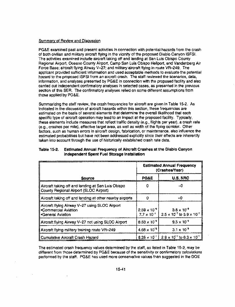
Summary of Review and Qisaussioc
PG&E examined past and present activities in connection with potential hazards from the crashof both civilian and military aircraft flying in the vicinity of the proposed Diablo Canyon ISFSI.The activities examined include aircraft taking off and landing at San Luis Obispo CountyRegional Airport, Oceano County Airport, Camp San Luis Obispo Heliport, and Vandenberg AirForce Base; aircraft flying Airway V-27; and military aircraft flying in route VR-249, Theapplicant provided sufficient information and used acceptable methods to evaluate the potentialhazard to the proposed ISFSI from an aircraft crash. The staff reviewed the scenarios, data,information, and analyses presented by PG&E in connection with the proposed facility and alsocarried out independent confirmatory analyses in selected cases, as presented in the previoussection of this SER, The confirmatory analyses relied on some different assumptions fromthose applied by PG&E.
Summarizing the staff review, the crash frequencies for aircraft are given in Table 15.2. Asindicated in the discussion of aircraft hazards within this section, these frequencies areestimaled on the basis of several elements that determine the overall likelihood that eachspecific type of aircraft operation may lead to an impact at the proposed facility. Typically,these elements include measures that reflect traffic density (e.g., flights per year), a crash rate(e.g., crashes per mile), effective target area, as well as width of the flying corridor. Otherfactors, such as human errors in aircraft design, fabrication, or maintenance, also influence theestimated probabilities but have not been addressed explicitly since their effects are inherentlytaken into account through the use of historically established crash rate data.
Table 15-2. Estimated Annual Frequency of Aircraft Crashes at the Dlablo CanyonIndependent Spent Fuel Storage Installation
Estimated Annual Frequency(Crashes/Year)
Source PG&E U.S. NRC
Aircraft taking off and landing at San Luis Obispo 0 -0County Regional Airport (SLOC Airport_
Aircraft taking off and landing at other nearby airports 0 -0
Aircraft ftying Airway V-27 using SLOC Airport*Commercial Aviation 2.59 x 10' 3.8 x 10+General Aviation 7.7 x t0' 25 x I0'7 to 5.9 x 10'7
Aircraft flying Airway V-27 not using SLOC Airport 6.53 x 10"" 9.5 x 10'•
Aircraft flying military training route VR-249 4.68 x 10⁻¹ 3.1 x 10 '
Cumulative Aircraft Crash Hazard 1 8.25 X 10' 2.9 x 10.' to 6.3 x 10'T
The estimated crash frequency values determined by the staff, as listed in Table 15-2, may bedifferent from those determined by PG&E because of the sensitivity or confirmatory calculationsperformed by the staff. PG&E has used more oonservative values than suggested in the DOE
15-41
Standard (U.S. Department of Energy, 1996) for skid distance of a crashing general aviationaircraft. Consequently, the calculated effective area and, in turn, the estimated annual crashfrequency are higher and more conservative. The values determined by PG&E have beenaccepted by the staff as reasonable. Based on the information presented in Table 15-2, whichdemonstrates that the conservative estimates of aircraft crash probabilities are below thethreshold probability criterion of 1 x 10⁻⁶ crashes per year for facilities of this type, the staffconcludes that the analysis of aircraft crash hazards for civilian and military aircraft andordnance for the proposed Diablo Canyon ISFSI is acceptable.
Future Qeveloapmen
PG&E estimated the projected growth of civilian flights based on the FAA long-range forecast(Federal Avialion Administration, 1999). Commercial aircraft operations include air carrier andoommulerlair taxi takeoffs and landings at alt United States towered and nontowered airports,Based on the FAA forecasts, the commercial aircraft operations are projected to increase from28.6 million in 1998, to 36.6 million in 2010. and to 47.6 million in 2025. Therefore, commercialaviation operations in the United States are projected to increase by 66 peroent by 2025.
The annual general aviation operations (takeoffs and landings) at all towered and nontoweredairports in the United States are projected to increase from 87.4 million in 1998 to 92.8 million in2010 and to 99.2 million in 2025 (Federal Aviation Administration, 1999). Therefore, the FAAprojects an increase of general aviation traffic by 14 percent by 2025.
PG&E has discussed the long-term trend of military aviation to project the estimated aircraftcrash probability for the proposed ISFSI. The FAA predicts that the military air traffic would notincrease appreciably, it at all, in the foreseeable future. Based on the projections of the FAA,the number of military aircraft handled by the FAA en route to traffic control centers will remainconstant at 4.2 million from 1998 through 2026.
Based on the estimated annual frequencies listed in Table 15-2 and the increase in commercialand general aviation traffic projected by the FAA, the annual frequency of aircraft crash ontothe proposed ISFSI would Increase to 9.40 x 10"' by 2025, as calculated by PG&E. Applyingthese same growth factors to the estimated crash probability of commercial and generalaviation aircraft, the staff estimates that the crash frequency will increase to 3.4 x 10 1 to7.2 x 10D" per year by 2025, from the range of 2.9 x 10⁷ to 6.3 x 10 ' shown In Table 15-2.
Conclusion
Based on the information and analysis provided by PG&E, the staff concludes that thecumulative probability of a civilian or military aircraft crashing at or affecting the proposed ISFSIis be low the threshold probability criterion of 10 W per year determined to be acceptable forthese types of facilities. Therefore, there is reasonable assurance that civilian or military aircrashes will not pose a hazard to the proposed Diablo Canyon ISFSI.
15.12.,12 Accldents at Nearby Sftes-Milsslle Testing at Vandenberg Air Force Base
In its responses to staff questions, PG&E provided information regarding operations at theVandenberg Air Force Base (Pacific Gas and electric Company, 2003d), 'The base is locatedapproximately 56 km [35 mi south-southeast of the proposed Diablo Canyon ISFSi.
15-42
Approximately 15 to 20 missiles are tested each year at this base. Missiles are fired indirections ranging from due west to southeast. Therefore, the flight paths of these missiles donot come near the ptoposed ISFS1. Addittonally, intercontinental ballistic missiles are tested atVandenberg Air Force Base. They are launched from sites at the northern part of the base andtypically fly due west. Typical launches for spacelift missions are carded out at sites on thesouthern part of the base and fly in a southerly direction. Polar orbit launches at this base axealso carried out in a southerly direction. Based on the information from the Base Chief SafetyOfficer, the most northerly missile launch site is approximately 40 km [25 mq south of theproposed ISFSI. Vandenberg Air Force Base is also a designated alternate landing site forspace shuttles, although the base has not been used yet for that purpose. The landingapproach is west to east and does not bring the shuttle within 48 km [30 ril of the proposedISFSI, Therefore, the planned flight paths for missile tests and space shuttles to and fromVandenberg Air Force Base ate always in a direction away from the proposed Diablo CanyonISFS I site.
Only a small fraction of the missiles tested deviate from the intended trajectories. If a missileafter launch deviates from its planned flight path, the missile is destroyed before the debris pathexceeds a narrow preplanned window. Therefore, the probability of missiles launched fromVandenberg Air Force Base striking any safety-related SSCs is negligibly small.
The staff reviewed the information with respect to potential hazards of missile testing atVandenberg Air Force Base. The staff found the information acceptable because:
Verifiable information from the U.S. Air Force was used to determine the numberof missile tests carried out annually and their intended flight paths,
* intended flights paths are always away from the proposed ISFSI site; and
The U.S. Air Force uses avoidance as one of the primary safety measures toprotect facilities.
Based on the foregoing information, there is reasonable assurance that different missile testsand potential space shuttle landings at Vandenberg Air Force Base will not pose a hazard to theproposed ISFSi because (1) the selected flight paths are away from the proposed ISFSI siteand (2) several low-probability events would need to occur before a missile or the space shuttlewould hit the proposed ISFS1.
15.1.2.13 Leakage Through Confinement Boundary
Section 8.2.7 of the ISFSI SAR evaluates the potential consequences of leakage resulting froma confinement boundary accident. The potential consequences of this postulated accident aredetermined by assuming that 100 percent of the cladding for the fuel rods have ruptured andthe MPC pressure boundary has been breached. The staff has previously determined that themethodology useU to assess this postulateO a=cident is acceptable and that there are noconsequences that affect the public health and safety so long as the fuel specifications andloading conditions as defined In the HI-STORM 100 System CoC and SER (U.S. NuclearRegulatory Commission, 2002ab) are met. The Diablo Canyon ISFSI Technical Specificationswill impose similar conditions and limits on spent fuel storage so that the staff's previousconclusions are applicable in this case. Moreover, NUREG-1536 (U.S. Nuclear Regulatory
15-43
Commission, 1997, Chapter 7, Section V.2) indicates that casks closed entirely by welding donot require seal monitoring. The MPC, which is the confinement system for the HI-STORM 100System, is closed using a welded seal. As a result, the staff finds the applicant proposal not toprovide monitoring of the confinement barrier for the HI-STORM 100 System acceptablebecause the casks will be loaded, welded, inspected, and tested in accordance with appropriateprocedures. The NRC staff of the Spent Fuel Project Office has issued Interim Staff Guidancedocument ISG-18, which also addresses welded steel canisters, including the Holtec HI-STORM 100 MPCs. In ISG-18, the staff concludes that there is reasonable assurance that nocredible leakage would occur from final closure welds of austenitic stainless steel canisters.
15.1.2,14 Loading of an Unauthorized Fuel Assembly
Section 8,2.9 of the ISFSI SAR Indicates that loading of an unauthorized fuel assembly into theMPC will not occur because of the Technical Specifications and administrative procedures thatwill be implemented during loading operations. The Technical Specifications and administrativeprocedures are discussed in Chapters 10 and 16 of this SER.
15.1.2.15 Partial Blockage of Multi-Purpose Canister Vent Holes
Section 8.2.13 of the SAR evaluates the potential consequences of the partial blockage of theMPC vent holes. The potential consequences of this postulated accident were determined byassuming that only the minimum semicircular area of the vents are credited in the thermalmodels. The staff previously determined that the methodology used to assess this postulatedaccident is acceptable and partial blockage of the MPC vent holes has no effect on thestructural, confinement, and thermal analyses of the MPC so long as the fuel specifications andloading conditions as defined in the HI-STORM 100 System CoG and SER (U.S. NuclearRegulatory Commission, 2002a,b) are met. The Diablo Canyon ISFSI Technical Specificationswill impose similar and appropriate limits and conditions so that the staff's previous conclusionfor the Holtec HI-STORM 100 system is applicable to the Diablo Canyon ISFSI.
15.1.2.16 100-Percent Fuel Rod Rupture
Section 8.2.14 of the ISFSI SAR evaluates the potential consequences of 100-percent fuel rodrupture within the MPC. The potential consequences of this postulated accident weredetermined by assuming that the fission-product gases and fill gas are released from the fuelrods into the MPC cavity. The staff has previously determined that the methodology used toassess this postulated accident Is acceptable and 100-percent fuel rod rupture within the MPChas no effect on the shielding, criticality, and thermal analyses of the MPC so long as the fuelspecifications and loading conditions as defined in the HI-STORM 100 System CoG and SER(U.S. Nuclear Regulatory Commission, 2002a,b) are met. The Diablo Canyon ISFSI TechnicalSpecifications will impose similar and appropriate limits and conditions so that the staff'sprevious conclusion for the Holtec HI-STORM 100 system is applicable to the Diablo CanyonISFSI.
15.1.2.17 Transmission Tower Collapse
Section 8.2.16 of the ISFSI SAR addresses the potential collapse ot two 500.kV transmissiontowers that are in the vicinity of the ISFSI storage area and the CTF. The transporter will bedesigned to protect the transfer cask from the direct impact of a collapsing tower. As a result,
15-44
an analysis of a transmission tower collapsing on the loaded Ht-TRAC 125 Transfer Cask is notnecessary.
Two lower-collapse scenarios were evaluated (Holtec International, 2001f). The first scenariowas a tower collapse onto the CTF, with the tower directly impacting the lid of an MPC, whichhas been lowered into the HI-STORM 100 System storage overpack located within the confinesof the CTF shell. The second scenario was a tower collapse onto a HI-STORM IOOSA storagecask anchored to the ISFSI storage area pad.
Using an explicit finite element modeling method, PG&E determined that the maximum impactforce on the MPC lid was 1.9 MN [427 kips], and for the anchored HI-STORM 1OOSA storagecask, 2.4 MN [534 kips]. In the case of the MPC lid, this impact force is bounded by previouslyevaluated tornado missile impact loads, as approved by the staff for the HI-STORM 100 system(U.S. Nuclear Regulatory Commission, 2002a,b). For the anchored HI-STORM 1OOSA storagecask, the impact force is predominantly oriented in the vertical direction. The horizontalcomponent of the tower collapse impact force on the anchored HI-STORM 1OOSA storagecask, 0.4 MN [93 kips), is bounded by previously evaluated tornado missile impact loadsapproved by the staff for the HI-STORM 100 system. The vertical component of: the towercollapse impact force on the anchored HI-STORM 100 SA storage cask, when converted intoan equivalent gravity load, Is also bounded by the previously reviewed and accepted equivalentgravity load for a cask drop (i.e., 45 g).
Even though an analysis of a collapsing tower impact with the HI-TRAC 125 Transfer Cask wasnot performed, the potential impact forces would be similar to those calculated for the MPC andanchored HI-STORM 1OOSA storage cask. Because these impact loads are bounded bypreviously reviewed and accepted loading conditions for the HI-STORM 100 system, the staffhaS determined that a separate analysis is not needed.
15.1.2.18 Nonstructural Failure of a Cask Transfer Facility Lift Jack
Section 8.2.17 of the ISFSI SAR evaluates a postulated failure of a CTF lift jack. The CTFlifting mechanism is configured with three lifting jacks, and the postulated lift jack failureevaluation assumes that only one of these will fail at any given time. If the failed mechanismcannot be repaired within 22 hours, (which corresponds to the time determined by analysis forthe short-term fuel cladding temperature limits to be reached due to the diminished convectivecooling eff iciency of the HI-STORM 100SA storage cask when located within the CTF), theMPC will be returned to the HI-TRAC 125 Transfer Cask and the storage cask removed fromthe CTF so the necessary repairs can be made. This will be a requirement of the DiabloCanyon ISFSI Technical Specifications.
The design of the CTF lifting mechanism is such that the three lifting jack power screws arealways loaded in tension. Because of this tension loading-only design feature, buckling failureof the lifting jack power screws, either singly or in combination, is unlkely.
15,1.2.19 Acoidents Assoclated with Pool Facilities
The proposed ISFSI will use dry storage technology only; there will be no pool at the proposedISFSI. Therefore, accidents associated with pool facilities are not applicable for the DiabloCanyon ISFSI.
15-45

15.1.2.20 Building Structural Failure and Collapse onto Structures, Syslems,and Components
Section 4.4.5 of the ISFSI SAR evaluates the CTF for response to the design criteria identifiedin Chapter 3, "Principal Design Criteria" of the SAR. The CTF Is designed to survive theseevents. (See also SER Section 15,2.2.18, "Transmission Tower Collapse"). Therefore, anaccident involving structural failure of the facility is not applicable.
15.1.2.21 Hypothetical Failure of the Confinement Boundary
The HI -STORM 100 System MPC is a seal-welded pressure vessel, designed, fabricated, andtested in accordance with ASME Code requirements and acceptable alternative methods, asdescribed in the ISFSI SAR. The MPCs have redundant welds to ensure that radioactive fuel Isconfined. The ISFSI SAR and HI-STORM 100 System FSAR have demonstrated that the MPCwould maintain its integrity and the fuel would be adequately protected under site-specific andgeneric design-basis normal, off-normal, and accident conditions. As discussed in Chapter 9 ofthis SER, the dose (at the owner-controlled area boundary) calculated from a hypotheticalfailure of the confinement boundary is below the dose limit specified in 10 CFR §72.106(b).
15.2 Evatuation Findings
The applicant has provided acceptable analyses of the design and performance of SSCsimportant to safety under credible off-normal events and accident scenarios. The followingsummrizes the findings of the staff that pertain to the off-normal event and accident review.
Off-Normal Events
PG&E has committed to design the cask transporter so it will have redundant drop protectionfeatures and will conform to the requirements of NUREG-0612 (U.S, Nuclear RegulatoryCommission, 1980), American National Standards Institute (ANSI) N14.6 (American NationalStandards Institute, 1993), and ASME B30.9-1996 (ASME International, 1996). The staffpreviously determined that a specific limit on cask lift height during transfers between theFHB/AB, CTF, and the storage pads is not necessary if these cask transporter designrequirements are met (U.S. Nuclear Regulatory Commission, 2002a). As a result, anevaluation of a cask drop less than the design allowable height is not required.
The staff has previously determined that the HI-STORM 100 System storage cask providesadequate heat removal capacity under partial vent blockage conditions so long as the fuelspecifications and loading conditions as defined in the HI-STORM 100 System CoG and SER(U.S. Nuclear Regulatory Commission, 2002ab) are met and the environmental characteristicsof the site are bounded by the corresponding design criteria (see Section 6.1.3 of this SER).The staff finds that the Diablo Canyon ISFSI Technical Specifications will impose appropriatelimits and that the environmental characteristics of the ISFSI site are within the correspondingdesign criteria, such that the staffs previous conclusions for the Hottec HI-STORM 100 systemare also applicable to the Diablo Canyon ISFSL In addition, the Diabio Canyon iSFSl TechnicalSpecifications include surveillance requirements for ensuring that the cask heat removal systemis operational during storage (i.e., the air ducts are inspected every 24 hours to ensure that theducts are tree of blockages). In the event that the HI-STORM 100SA storage cask air inletducts are found to be partially blocked, the blockage will be removed within one operating shift.
16.46
The staff finds that there is reasonable assurance that important to safety functions will not beaffected for the proposed cask system or the proposed ISFSI due to failure of instrumentation.
The staff finds that potential vehicular impact will not impair the ability of the SSCs to maintainsubcriticality, confinement, and sufficient shielding of the stored fuel.
The staff finds that the applicant's evaluation of loss of electrical power as an off-normal eventis acceptable and concludes that there is reasonable assurance that Diablo Canyon IFlSIoperations can be conducted without endangering the health and safety of the public.
The staff finds that the applicant's assessment of cask transporter off-normal operation isacceptable and concludes that there Is reasonable assurance that Diablo Canyon ISFSIoperations can be conducted without endangering the health and safety of the public.
The staff previously determined that the HI-STORM 100SA storage and HI-TRAC 125 TransferCasks provide adequate heat removal capacity during off-normal ambient temperatureconditions so long as the fuel specifications and loading conditions as defined in the HI-STORM100 System CoC and SER (U.S. Nuclear Regulatory Commission, 2002a,b) are met. The stafffinds that the Diablo Canyon ISFSI Technical Specifications will impose similar and appropriatelimits and conditions so that the staff's previous conclusion for the Holtec HI-STORM 100system is applicable to the Diablo Canyon ISFSI.
The staff previousl determined that the methodology used to assess off-normal pressure withinthe MPC is acceptable and that there are no consequences that affect the public health andsafety so long as the fuel specifications and loading conditions as defined in the HI-STORM 100System CoC and SER (U.S. Nuclear Regulatory Commission, 2002a,b) are met. The stafffinds that the Diablo Canyon ISFSI Technical Specifications will impose similar and appropriatetimits and conditions so that the staff's previous conclusion for the Holtec HI-STORM 100system is applicable to the Diablo Canyon ISFSI.
Aacidents
The staff has previously determined that cask tip-over events need not be considered If thestorage cask anchorage system and the storage pad are sufficiently designed to preclude suchan event fU.S. Nuclear Regulatory Commission, 2002a b). The staff finds that the design of thestorage pads and cask anchorage system for the Diablo Canyon ISFSI is acceptable, and issufficierrt to prevent a cask tip-over accident for the spectrum of seismic events evaluated forthe site. The staff's structural evaluation of the pad and cask anchorage system can be foundin Section 5,1.3 of this SER.
PG&E has committed to design the cask transporter such that it will have redundant dropprotection features and conform to the criteria of NUREG-0612 (U.S. Nuclear RegulatoryCommission, 1980), ANSI N14.6 (American National Standards Insthtute, 1993). and ASMEB30.9-1996 (ASME International, 1996). The staff previously determined that a specific limit oncask lift height during transfers between the FHB/AB, CTF, and the storage pads is notnecessary if these cask transporter design requirements are met (U.S. Nuclear RegulatoryCommission. 2002a), As a result, an evaluation of a cask drop is not required.
15-47
The staff finds that the inlormation provided by the applicant is sufficient to characterizeflooding as a noncredible accident at the Diablo Canyon ISFSL. As discussed in Section 2.1,4,"Surface Hydrology,' of this SER, PG&E has adequately demonstrated that local natural andman-made drainage systems are sufficient to prevent flooding of the ISFSI pad site and CTF.
The staff reviewed the information provided by the applicant regarding potential fire andexplosion hazards at the proposed facility. The staff finds that the design basis parameters forall credible on-site fire and explosion hazards will not be exceeded and that the SSCs will meetall subcriticality, confinement, and shielding requirements for the stored fuel.
The staff concludes that earthquake-induced damage of the spent fuel while in transit from thepower plant to the CTF is not a credible hazard, based on the low probability of the event andthe limited frequency and duration of the transfers.
The staff finds that the design of the CTF concrete structure and its reinforcement satisfies theapplicable codes and standards for all design basis accident loads.
The staff finds that the design basis loading conditions for the Diablo Canyon ISFSI areenveloped by the loading conditions considered In the HI.STORM 100 System FSAR (HoltecInternational, 2002). As documented in the HI-STORM 100 System SER, the structuralanalysis shows that the Structural integrity of the HI-STORM 100 System is maintained duringall credible loads. Based on the results presented iM the HI-STORM 100 System FSAR, thestresses in the storage cask and anchorage structures during the most critical loadcombinations are less than the allowable stresses of ASME Boiler and Pressure Vessel Code,Section III (ASME International, 1995b) for the materials to be used.
The staff finds that the Diablo Canyon ISFSI storage cask anchorage system was designed tomeet the ductile anchorage provision of the proposed Draft Appendix B for ACI 349-97 for themost critical toad combinations.
The staff previously determined that the methodology used to assess the loss of neutronshielding accident is acceptable and the short-term fuel cladding and other componenttemperature limits, the MPC accident internal pressure, and the accident dose limits defined by10 CFR §72.106 are not exceeded so long as the fuel specifications and loading conditions asdefined in the HI-STORM 100 System CoC and SER (U.S. Nuclear Regulatory Commission,2002a,b) are met. The staff finds that the Diablo Canyon ISFSt Technical Specifications willimpose similar and appropriate limits and conditions so that the staffs previous conclusions forthe Holtec HI-STORM 100 system are applicable to the Diablo Canyon ISFSI. In the event thatthe HI-TRAC 125 Transfer Cask loses its neutron shielding, appropriate recovery operationprocedures will be implemented.
The staff finds that the maximum reduction in ISFSI radiation shielding thickness, materialshielding effectiveness, or loss of temporary shielding in all possible shielding areas caused bypostulated on-site explosion events has been adequately evaluated by the applicant.Therefore, the information and analysis presented by the applicant provide reasonableassurance that the dose to any individual beyond the owner-controlled area will not exceed thelimits specified in 10 CFR §72.106(b) and the occupational exposures from accident recoveryoperations will not exceed the limits specified in 10 CFR Part 20.
15-48
The HI-STORM 100 System FSAR (Holtec International, 2002, Figure 11.2.6) indicates that, atotal cask decay heat load of 30 kW [102,360 BTUlhrJ, which bounds the cask decay heat loadspecified for the Diablo Canyon ISFSI, will not cause the short-term cladding temperature limitfor the spent nuclear fuel to be exceeded for 45 hours under adiabatic conditions, Moreover,the internal pressure limit for the MPC Is not exceeded within the 45-hour timeframe for thiscondition. In the event that a HI-STORM 100 System storage cask is subjected to conditionsthat thermally insulate its exterior (e.g., encased within soil as the result of a landslide),appropriate recovery operation procedures will be implemented.
The staff previously determined that the methodology used to estimale the time required toreach the short-term, fuel-cladding temperature limit of spent nuclear fuel stored in theHI-STORM t00SA storage cask subjected to 100-percent blockage of the air inlet ducts Isacceptable (U.S, Nuclear Regulatory Commission, 2002a,b). For the bounding values of decayheat load of 30 kW (102,360 BTU/hr] and insolation of 834 w/m 2 [800 g-caVcmr] per day(387 W/mr [123 BTU/hr-tfD, the short-term cladding temperature limit for the spent nuclear fuelwill not be exceeded for 72 hr when the HI-STORM 1 OSA storage cask air inlet ducts are1 00-percent blocked. Moreover, the internal pressure limit for the MPC is not exceeded withinthe 72-hour time frame for this condition. Furthermore, the Diablo Canyon ISFSI TechnicalSpecifications includes surveillance requirements for ensuring that the cask heat removalsystem is operational during storage (i.e., the air ducts are inspected every 24 hours to ensurethat the ducts are free of blockages). In the event that the HI-STORM 100SA storage cask airinlet ducts are found to be 100-percent blocked, appropriate recovery operation procedures willbe implemented.
The staff reviewed the information provided by the applicant, evaluated the analyses ofpotential hazards from design-basis tornadoes and tornado missiles at the proposed facility,and conducted a confirmatory analysis, The staff concludes that a tornado ortornado-generated missile would not impair the ability of the SSCs to maintain subcriticality,confinement, and sufficient shielding of the stored fuel.
The staff finds that the applicant has adequately demonstrated that the cumulative probability ofoccurrence of civilian and military aircraft crashes, and ordnance accidents is below thethreshold probabiity criterion of 1 x t10 1 crashes per year, As a result, the staff concludes thatcivilian and military aircraft crashes, and ordnance accidents at the Diablo Canyon ISFSI arenot credible events and require no further evaluation.
The staff finds with reasonable assurance that ddferent missile tests and potential space shuttlelandings at Vandenbefg Ait Force Base will not pose a hazard to the proposed facility because:(1) the selected flight paths are away from the proposed ISFSI site, and (2) several low-probability events would need to occur beWore a missile or the space shuttle would hit theproposed ISFSl.
The staff has previously determined that the methodology used to assess leakage through theconfinement boundary is acceptable and that there are no consequences that affect the publichealth and safety so long as the fuel specifications and loading conditions as defined in theHI-STORM 100 System CoC and SER (U.S. Nuclear Regulatory Commission, 2002a,b) aremet. The staff finds that the Diablo Canyon JSFSI Technical Specifications will impose similarand appropriate limits and conditions so that the staff's previous conclusion for the Holtec HI-STORM 100 system is applicable to the Diablo Canyon ISFSI. Moreover, NUREG-1536 (U.S.
15-49
Nuclear Regulatory Commission, 1997, Chapter 7, Section V.2) indicates that casks closedentirely by welding do not require seal monitoring, The MPC, which is the confinement systemfor the HI-STORM 100 System, is closed using a welded seal. As a result, the staff finds theapplicant's proposal not to provide monitoring of the confinement barrier for the HI-STORM 100System acceptable because the casks will be loaded, welded, inspected, and tested inaccordance with appropriate procedures.
Section 8.2.9 of the SAR (Pacific Gas and Electric Company, 2003) indicates that anunauthorized fuel assembly will not be loaded into the MPC because of the technicalspecifications and administrative procedures that will be implemented during loadingoperationrs. These technical specifications and administrative procedures are discussed inChapters 10 end 16 of this SER.
The staff previously determined that the methodology used to assess partial blockage of theMPC vent holes is acceptable and this postulated accident has no effect on the structural,confinement, and thermal analyses of the MPC so long as the fuel specifications and loadingconditions as defined in the HI-STORM 100 System CoC and SER (U,S, Nuclear RegulatoryCommission, 2002a,b) are met. The staff finds that the Diablo Canyon ISFSI TechnicalSpecifications will impose similar and appropriate limits and conditions so that the staff'sprevious conclusion for the Holtec HI-STORM 100 system is applicable to the Diablo CanyonISFSI.
The staff previously determined that the methodology used to assess the potentialconsequences of a 100-percent fuel rod rupture within the MPC is acceptable and thispostulated accident has no effect on the shielding, criticality, and thermal analyses of the MPCso long as the fuel specifications and loading conditions as defined in the HI-STORM 100System CoC and SER (US. Nuclear Regulatory Commission, 2002a,b) are met. The stafffinds that the Diablo Canyon ISFSt Technical Specifications will impose similar and appropriatelimits and conditions so that the staff's previous conclusion for the Holtec HI-STORM 100system is applicable to the Diablo Canyon ISFSt.
The staff finds that the impact loads associated with the two postulated tower-collapsescenarios are bounded by previously reviewed and accepted loading conditions (U.S. NuclearRegulatory Commission, 2002a,b).
The design of the CTF lifting mechanism is such tat the three lifting jack power screws arealways loaded in tension. Because of this tension loading-only design feature, the staff findthat a buckling failure of the lifting jack power screws, either singly or in combination, wouldnot occur.
The staff finds, based on information provided by the applicant, that an accident involvingstructural failure of the facility is not applicable.
Based on the information provided, the staff finds that a postulated failure of the confinementboundary would result in offsite accident doses below the dose limits specified in 10 CFR§72.106(b) because the HI-STORM 100 System MPC is a seal-welded pressure vessel,designed, fabricated, and tested in accordance with the applicable codes and standards.
15-50
In summary, the PG&E analyses of off,normal and accident events demonstrate that theproposed Diablo Canyon ISFSI will be sited, designed, constructed, and operated so that duringafl credible offtnormal and accident events, public health and safety will be adequatelyprotected. Based on analyses submitted by the applicant and independent confirmatoryanalyses performed by the staff, the staff finds that the proposed ISFSI will maintainsubornticality, maintain confinement, and provide sufficient shielding for all credible otf-normalevents and accident scenarios consistent with the requirements of 10 CFR §72.92, §72.94,§72.98(a), §72.98(b), §72.98(c) §72.102(f), §72.106(b), §72.122(b), §72.122(c), §72.122(h),§72.122(i), §72,122(l), §72.124(a), and §72. 128(a)(2).
15.3 References
AirNav, LLC. Morganville, NJ:. http,1Ay",aimav.cor., 2003.
American Concrete Institute. Code Requirements for Nuclear Safety Related ConcreteStrnctures, ACI 349-97. Detroit, MI: American Concrete Institute. 1998
American National Standards Institute. Radioactive Materials-Special Lifting Devices forShipping Containers Weighing 10 000 Pounds (4500 kg) or More. ANSI N14.6-1993.Washington, DC: American National Standards Institute. 1993.
ASME International. ASME Boiler and Pressure Vessel Code, Section INI, Division 1. NewYork, NY: ASME. 1995b.
ASME International. ASME Boiler and Pressure Vessel Code, Section /I. New York, NY'ASME. 1995a.
ASME International. SLINGS Safety Standard for CaWbe-Ways, Cranes, Dernicks, Hoists,Jacks, and Slings. ASME B30.9-1996. New York, NY: ASME. 1996.
ENERCON Services Inc, Cask Transfer Facility (Reinforced Concrete)..PGE-009-CALC-002, Rev 1. Tulsa, OK: ENERCON Services Inc. December 17,2001a.
ENERCON Services Inc. ISFSI Cask Storage Pad Seismic Analysis, PGE-009-CALC--003,Rev 2. Tulsa, OK: ENERCON Se rices Inc. December 14,2001 b.
ENERCON Services Inc. ISFSI Cask Storage Pad Steel Reinforcement. PGE-009-CALC-007.Tulsa, OK; ENERCON Services [nc, March 11, 2003a.
ENERCON Services Inc. Embedment Support Structure. PGE-009-CALC-001, Rev 5.Tulsa, OK: ENERCON ServicesInc. Marci 11, 2003b,
Federal Aviation Administration. FAA Long-Range Aerospace Forecasts Fiscal Years 2015,2020 and 2025. FAA-APO-99--5, Washington, DC: Federal Aviation Administration,Office of Aviation Policy and Plans. 1999.
GCR & Associates, Inc. New Orleans, LA: bttp://www.gar .coml501OWEB/default,htm. 2003.
15-51
Holtec International. Evaluation of Site-Speciftc Wild Fires for the Diablo Canyon ISFSI.HI-2012615, Marlton, NJ: Holtec International. 2001a.
Holtec International. Evaluation of Site-Specific Blasts and Explosions for the Qiablo CanyonISFSI, HI-2002512, Rev 2. Marlton, NJ: Hoftec International- 2001b.
Holtec International. Structural Evaluation of Diablo Canyon Cask Transfer Facility.Wt-2012626, Rev 7. Marlton, NJ: Holtec International. 2001c.
Holtec International. Analysis of Anchored HI-STORM Casks at the Diabto Canyon ISFSI.HI-2012618, Rev 5. Marlton, NJ: Holtec International. 2001d.
Holtec International. Design Basis Wind and Tornado Evaluation foW DCPP. HI-2012497,Rev, 1. Marlton, NJ: Holtec International. 2001e.
Hottec International, Evaluation of Effects of Lightning and a 500-kV Line Break on HoltecCasks. HI-2002559. Marlton, NJ: Holtec International. 2001 1.
Holtec International. Final Safety Analysis Report for the Holtec International Storage andTransfer Operation Reinforced Module Cask System Revision 1 (HI-STORM 100 CaskSystem). Volumes I and I, Revision 1. Ht-2002444. Docket 72-1014. MarIton, NJ:Holtec International. 2002.
Kimura, C.Y. R,E, Glaser, R.W. Mensing, T. Un, TA. Haley, A.B. Barlo, and M.A. Stutzke.Data Development Technical Support Document for the Aircraft Crash Risk AnalysisMethodology (ACRAM) Standard. UCRL-ID-124837. Livermore, CA: LawrenceLivermore National Laboratory. 1996
McConnell, J.W., Jr., A,L. Ayers, Jr., and M.J, Tyacke. Classification of Transportation Packingand Dry Spent Fuel Storage System Components According to Importance to Safety.NUREG/CR-6407. Idaho Falls, ID: Idaho National Engineering Laboratory. 1996,
National Fire Protection Association, Fire Protection Handbook. 18e Edition. Quincy, MA:National Fire Protection Association. 1997.
Pacific Gas and Electric Company. Non-Linear Seismic Sliding Analysis of the ISFSI Pad,PG&E Calculation 52.27.100.704, Rev. 0. AvIla Beach, CA: Pacific Gas and ElectricCompany 2001a.
Pacific Gas and Electric Company. Diablo Canyon Power Plant Final Safety Analysis ReportUpdate. Rev. 14. Avila Beach, CA, Pacific Gas and Electric Company. 2001b.
Pacific Gas and Eleciric Company. Diablo Canyon Independent Spent Fuel StorageInstallation: Safety Analysis Report. Amendment 2. Letter DIL-03-012, October 3. 2003.Avila Beach, CA: Pacific Gas and Electric Company, 2003.
Pacific Gas and Electric Company. Diablo Canyon Independent Spent Fuel StorageInstallation: Response to NRC Request for Additional Information for the Diablo Canyon
15-52
Independent Fuel Storage Installation (TAC No. L23399). Avila Beach, CA: Pacific Gasand EleotriC Company. October 15, 2002.
Pacific Gas and Electric Company. Diablo Canyon Independent Spent Fuel StorageInstallation: Supplemental Blasts and Explosions Responses to Additional NRCQuestions for the Diablo Canyon Independent Fuel Storage Installation Application (TACNo. L23399). Avila Beach, CA: Pacific Gas and Electric Company, 2003a. DIL-03-005,March 27, 2003.
Pacific Gas and Electric Company. Diablo Canyon Independent Spent Fuel StorageInstallation: Additional Ouestions Related to Supplemental Blasts and ExplosionsResponses to Additional NRC Questions for the Diablo Canyon Independent FuelStorage Installation (TAC No. L23399). Avila Beach, CA: Pacific Gas and ElectricCompany, 2003b. DIL.03-008, June 13. 2003,
Pacific Gas and Electric Company. Diablo Canyon Independent Spent Fuel StorageInstallation: Additional Questions Related to Supplemental Blasts and E4plsionsResponses to Additional NRC Questions for tthe Diabto Canyon Independent FuelStorage Installation (TAG No. L23399). Avila Beach, CA: Pacific Gas and ElectricCompany, 2003c. DIL-03-010. July 28, 2003.
Pacific Gas and Electric Company. Diablo Canyon Independent Spent Fuel Storagelnstallation: Revised and Supplemental Blasts and Explosions Responses to AdditionalNRC Questions for the Diablo Canyon Independent Fuel Storage Installation Application(TAC No. L23399). Avila Beach, CA: Pacific Gas and Electric Company, 2003d. DIL-03-002, February 14, 2003.
Private Fuel Storage Limited Liability Company, Aircraft Crash Impact Crash Impact Hazard atthe Private Fuel Storage Facility. Rev. 4. La Crosse, WI: Private Fuel Storage LimitedLiability Company. 2000,
San Luis Obispo County Regional Airport. San Luis Obispo, CA:http:/Aw.sloakrort•co~rnfligotitnforhtm!. 2003
Simiu, E. and RH. Scanlan. Wind Effects on Structures: An /ntroduction4 to Wind Engineersing.Second Edition. New York, NY: John Wiley and Sons. 1986.
U.S. Department of Energy. DOE Standard: Accident Analysis for Aircraft Crash IntoHazardous Facififfes, DOE-STD-3014-96. Washington, DC: U.S. Department ofEnergy. 1996.
U,S. Department of Transportation. Traffic Safety Facts 2001: 2001 Motor Vehicle CrashData from FARS and GES. http,/fwww-nrd/nhtsa.dot. govlpdf/nrd-30/NCSA1TSFAnn/TSF2001 .pdf. National Highway Traffic Safety Administtation.2003a,
U.S, Department of Transportation. Large Truck Crash Facts 2001.bEi.volIe,doj,_oy_.r~rer Research Results/PDFs/Large Truck Crash Facts2001.pdf. Federal Motor Carrier Safety Administration. 2003b.
15-53
U.S. Navy. United States Navy Fact File: F/18-18 Hornet. Washington, DC:http:/1wwwchinfo.navy. miVnavpalib/factfilelaircraftlair-f a 18. html, 2003,
U.S. Federal Aviation Administration. Washington, DC:http:L/apogdata faa. gov/faaaladsall.him. 2003,
U.S. Nuclear Regulatory Commission. Design Basis Tornados for Nuclear Power Plant,Regulatory Guide 1.76. Washington. DC: U.S. Nuclear Regulatory Commission. 1974.
U.S. Nuclear Regulatory Commission, Evaluation of Explosions Postulated to Occur onTransportation Routes Near Nuclear Power Plants. Regulatory Guide 1,91. Rev, 1.Washington. DC: U.S. Nuclear Regulatory Commission. 1978.
U.S. Nuclear Regulatory Commission, Control of Heavy Loads at Nuclear Power Plants,NUREG-.0612. Washington, DC: U.S. Nuclear Regulatory Commission. 1980.
US. Nuclear Regulatory Commission. 'Standard Review Plan Section 3.5.1.4: MissilesGenerated by Natural Phenomena." Rev. 2. Standard Review Plan for the Review ofSafety Analysis Reports for Nuclear Power Plants. NUREG-.0800. Washington, DC:U.S. Nuclear Regulatory Commission, Office of Nuclear Reactor Regulation. 1981a.
U.S. Nuclear Regulatory Commission. 'Standard Review Plan Section 3.5.1.6 AircraftHazards." Standard Review Plan for the Review of Safety Analysis Reports for NuclearPower Plants. NUREG-0800. Washington, DC: U.S. Nuclear Regulatory Commission,Office of Nuclear Reactor Regulation. 1981 b.
U.S. Nuclear Regulatory Commission. Standard Review Plan for Dry Cask Storage Systems,NUREG-1536. Washington, DC: U.S. Nuclear Regulatory Commission. 1997.
U.S. Nuclear Regulatory Commission. Standard Review Plan for Spent Fuel Dry StorageFacitities---Final Report. NUREG-1567. Washington, DC: U.S. Nuclear RegulatoryCommission. 2000.
U.S. Nuclear Regulatory Commission. I0 CFR Part 72 Certificate of Compliance No. 1014,Amendment 1, tot the HI-STORM 100 Cask System. Docket No. 72-1014.Washington, DC: U.S. Nuclear Regulatory Commission, July 15, 2002a.
U.S. Nuclear Regulatory Commission, Holtec International HI-STORM 100 Cask SystemSafety Evaluation Report. Amendment 1, Docket No. 72-1014. Washington, DC:U.S. Nuclear Regulatory Commission, 2002b,
15-54
R~omMnLh.F
cc rowy". tyru: Snrat.a Hawkns. Kviveny
Dow Triesda, APeJ 23, 2003 5:41-08 PM
SFP!S DkiDir C=QledCaMMn Q= .dcx• , _ .ql~.t_.
Impmatnneu "5h
Kim previously provided you the RES response to our comments. In a discussion with Kathy Gibsonyesterday, she ask if there were any concerns that we are aware of that would. prevent NROconcurrence on this report. She expects the report to come to NkO by the end of the month for officeconcurrence and is looking for early Indication of major issues.
If I missed someone that provided comments prevkiusl, please forward this e-mail.
Message----From: Hawkins, Kimberly
Sent: Friday, April 12, 2013 12:42 PMTo: Flanders, Scott; Shuaibi, MohammedSubject: MW: Interim DRAFT Spent Fuel Pool Scoping Study sent to ACRS todayImportance: High
Not sixe if you saw this,.. Responses to our comments on the study... some were addressed andresUtted in revisions to the study; for others, RES provided its response.
----- Original Message -From: Holahan, GarySent: Friday, April 12, 2013 9:47 AMTo: Hawkins, KimberlySubject: FW: Interim DRAFT Spent Fuel Pool Scoping Study sent to ACRS todayImportance: High
From: Tracy, GlennSent: Thursday, April 11, 2013 5:37 PHTo: Holahan, GarySubject: FW: Interim DRAFT Spent Fuel Pool Scoping Study sent to ACRS today
From: Sheron, BrianSent: Thursday, April 11, 2013 4:51 PMTo: Johnson, Michael; Weber, Michael; Leeds, Eric; Wiggins, Jim; Tracy, Glenn; Haney, Catherine;Satorius, Mark; Skeen, DavidSubject: FW: Interim DRAFT Spent Fuel Pool Scoping Study sent to ACRS todayImportance; High
FYI.
From: Gibson, KathySent: Thursday, April 11, 201.3 4:40 PM WTo: McGinty, Tim; Ader, Charles; Lombard, mark; Skeen, David; Correia, Richard; Case, Midihad;Thaggard, Mark; Miller, ChrisCc: McIntyre, David; Burnell, Scott; Richards, Stuaft; Lee, Richard; Algama, Don; Blount, Tom; Reis,Terrence; Shear, Gary; Sheron, Brian; West, Steven -4
Subject: Interim DRAFT Spent Fuel Pool Scoping Study sent to ACRS todayImportance: High
...f ,
..4

Gentlemen,The interim draft SFPSS report was due to the ACRS today at noon and we met that deadline, We are a,scheduled for an all-day briefing of the ACRS subcommittee on Materials, Metallurgy and Reactor Fuelson the study on May 8. 1 encourage you and your staff to attend all or part of the briefing as you havetime and interest. We will send out an agenda and slide package in advance of the meeting.
I am providing for your information two documents: (1) A list of the division director level commentsthat you provided in response to my request on 3/22/13 and our responses, and (2) a copy of theversion of the report that was sent today to ACRS.
I believe we were able to address your comments in this version of the report. We were not able toincorporate them all directly, but we describe why the study is the way it is and added significantclarifications to add the context that you were seeking.
The study team will now go back to addressing the comments received from your staff and BCs that wewere not able to get to before the ACRS deadline. Therefore, revisions to the report will continue.
This email will be forwarded by Don Algama to your staff and BCs that have been involved in theproject.
It was just decided by senior management this week that the study report will be released for a 30-daypublic comment period from about June 10 - July 10 (ACRS full committee meeting). We are evaluatinghow to accommodate this development within our schedule to have the report finalized by September.As I indicated previously, the offices will have at least one more opportunity to review and concur onthe report.
I appreciate your quick review and thoughtful comments on the prior version of the report. I alsoappreciate all the hard work and effort the team has put into responding to your comments, includinglate nights and some very animated conversations,I trust that you will find this version an improvement.
ADAMs links:
View ADAMS P8 PropertiesML13101A168 < https !ladamsXt.nrc.oov/WorknlaceXT intgationWebBa5edCommand?
commandid =3010&obiectStoreName= Main. .Librarv&id=cu~rent&vsId=%7bQ.7CA2DD4-EID3-4BD3-874F-978C0O47FB66%7dBiobiectyp'e=documen•>Open ADAMS P8 Package (Issuance of the DRAFT "Consequence Study of a Beyond-Design-BasisEarthquake Affecting the Spent Fuel Pool for a U.S. Mark I Boiling Water Reactor' for ACRSReview) < hltps:/,adamsxt.nrLcgoy/WorkolaceXT/getContent?obiectStoreNare= Main. .LUbraRn&id=currentg.vsIld?=o7b07CA2DD4-FlD3-4BD8-874F-
97BCO047FB66 %,Z7d&o0bectTyne=document>
(cid:[email protected]]
Comments to be addressed for ACRS SC report:
NRR1I From a DSS perspective, we believe the report needs to be revised to clearly indicate
why the study was done, why we chose the seismic response that we did, and how thiscompares to what would be expected at our 104 nuclear plants (or at least put inperspective that this is representative of a small subset of U.S. reactor designs). I reallyliked Rich's characterization in that the message is that we evaluated at the design basisand got no release. We doubled it and got no release, we tripled it and got no release sowe went to four times the design basis and finally got a release for a very small numberof unmitigated scenarios.
Response- The report was revised to incorporate the following points that address thiscomment:
" The study was done to confirm the results of past studies using state-of-the-arttools, as well as Fukushima insights, in a publicly available study.
" The study will inform the Tier 3 activity by providing an updated technical basisfor any regulatory action and input for the regulatory analysis.
" The study used design, operational, and location data for a reference site forwhich we already had information available, a BWR Mark I with an elevated SFP.The report also considered a 1x4 pattern (required after some time afteroffloading) as well as sensitivity analysis for more favorable loading (Ux8) andless favorable loading (checkerboard and uniform) and sensitivities for other keyparameters that will provide insights for analysis of other plants.
" The report was revised to make clearer that a low likelihood beyond design basisseismic event with and without mitigation was chosen to gain risk insights thatcould not be gained using a less severe seismic initiator. NRC analyzes lowlikelihood beyond design basis seismic events with and without mitigation to gaininsights on the safety margin provided by NRC s regulatory framework.
l The study concludes that the SFP is robust and not expected to leak, successfulmitigation prevents most releases, no early fatalities are expected and individualLCF is low because effectve protective actions limits individual exposure. (Notethat high and low density mitigated moderate leak scenarios in the first week(OCP 1) resulted in releases, all other scenarios that resulted in releases wereunmitigated and within the first few months (OCP 1, 2. 3) after shutdown.)
2. DSS also challenges why we are evaluating land contamination since no previous studydirectly discussed this issue. Considering that the Commission is currently reviewingwhether to change its long-standing policy on addressing land contamination, it may bepremature to evaluate this particular aspect in the report at this time.
Response: The study included land contamination to provide inputs to a regulatoryanalysis. A paragraph has been added to the introduction to describe the study'srelationship to the Tier 3 activities and how the study will be used in the currentregulatory process. Other analyses did evaluate land contamination, including somedirectly (e.g., NUREG/CR-6451, NUREG-4982) Land contamination is already part ofNRC's current regulatory framework including being used as input in SAMAISAMDAanalyses and is an input to regulatory/backfit analyses as part of the cost benefitanalysis. Chapter 7 was revised to distinguish the safety-related individual health effects
measures from other measures that are inputs to the cost-benefit analysis for theregulatory analysis.
NMSS3. The results of this study in Section 11 and in other sections need to be put into context
by comparison of the results against some standard such as the Quantitative HealthObjectives or Qualitative Safety Goals similar to the comparison to the QHOs ofNUREG-1738 results discussed on page 13. Some may argue that is comparing applesto oranges but the QSGs are based on risk to the general public of nuclear power versusother societal risks. This would give the public understandable measures to compare theresults against as opposed to results without any context.
Response: We agree that some level of comparison is appropriate. Section 7 has been EYrewritten, and now includes the statement, which will also be integrated into Section 11:
When the release frequency is considered, the latent cancer fatality risks from theevents analyzed in this study are very small, in the 1 E-12 to 2E-1 1 per year range, whenusing an LNT dose response model. For perspective, the Commission's safety goalpolicy related to the cancer fatality quantitative health objective (QHO) represents a 2E-6per year objective for an average individual within 10 miles of the nuclear plant site(NRC, 1983). While the results of this study are scenario-specific (a beyond design-basis seismic event) and related to a single spent fuel pool, staff concludes that sincethese risks are several orders of magnitude below the 0HO, it is unlikely that the resultshere would contribute significantly to a risk that would challenge the Commission'ssafety goal policy (NRC. 1986).
4. SRM dated July 16, 2012, documented the ACRS comment to ensure thatconsequences associated with e jid loading, transfer, and long-term storage needto be considered While Enclosure 1 to the draft SFPSS indicates those areas havebeen included, the assessment in Appendix 8 compares consequence results toNUREG-1864, which does not include assessment of the consequences of expeditedtransfer to dry casks. Appendix C also does not address expedited transfer in the currentcontext of the term to move all but the newest fuel out of the pool. This fact is pointed outin the SFPSS on Page 4, that the study does not address certain considerations,including expedited discharge of fuel from the pool to dry storage
Response: The approach for responding to the SRM was to obtain near term insights ýnAppendices B and C within the SFPSS project timeframe. This risk comparisontemplate is intended to inform the Tier 3 working group considering expedited transfer ofspent fuel,, The Tier 3 plan includes 3 phases. Phase 1 will use this study to determinewhether a significant safety enhancement could be achieved by expedited transfer andprovide inputs to a regulatory analysis. More detailed treatment of these issues may beaddressed as part of subsequent phases of the Tier 3 activity on expedited spent fueltransfer, as necessary.
5. Why was land contamination included on the study?
Response. Please see response to comment #2.
6. The SFPSS should make a recommendation on whether future studies are needed ornot and what they would or should entail or point to the Tier 3 effort.
Response: This scope of this study does not include making recommendations forfurther study. NRR will determine whether further analyses are needed to make anyreguiatory determinations within NRC's current regulatory framework. A paragraph hasbeen added to the introduction to describe the study's relationship to the Tier 3 activitiesand how the study will be used in the regulatory process. The following statement hasbeen added to the introduction and results sections of the report:
Other aspects of SFP risk that have not been informed by this or past studies,may be addressed by future studies, such as the site Level 3 probabilistic riskassessment (PRA), as documented in SECY-1 1-0089, 'Options for Proceedingwith Future Level 3 Probabilistic Risk Assessment Activities." dated July 7, 2011,and the associated staff requirements memorandum; or will be addressedthrough other inputs to the regulatory decision-making process, as needed.
7. Appendix B-why is the first table included on Page B-3? It does not include any dataregarding dry cask storage.
Response' Appendix B addresses part of the SRM (dated July 16, 2012) to compare theresults of the SFPSS with past studies and consider consequences associated withloading, transfer, and long-term storage, Appendix B provides a comparison of SFPSSresults to previous spent fuel pool studies and updated analyses from NUREG-1864 DryStorage. Pilor PEA, Staff will revise the introduction to Appendix B to make this clear,
NRO
8. The report needs to describe how its results could be useful in making regulatorydecisions on matters including the Japan lessons-learned Tier 3 recommendation onassessment of the transfer of spent fuel to dry-cask storage and recent Commissiondirection on economic consequences. In responding to this comment, a fullercharacterization of the purpose and usefulness of the report should be added, includingan explanation of how the study's point-estimate approach Is appropriate in the contextdescribed above.
Response: NRR will determine whether further analyses are needed to make anyregulatory determinations within NRC's current regulatory framework. A paragraph hasbeen added to describe the study's relationshio to the Tier 3 activities and how the studywill be used in the regulatory process. Using representative point-estimates with
ak,- Sensitivities fo, important parameters is appropriate in research studies to be able togain insightsand data for regulatory dectston-making in a reasonable period of time.
(o • • The study used design, operational, and location data for a reference site for which wealready had information available, a BWR Mark I with an elevated SFP. The report alsoconsidered a 1x4 pattern (required after some time after offioading) as well as sensitivityanalysis for more favorable loading (Ix8) and less favorable loading (checkerboard anduniform) and sensitivities for other key parameters that will provide insights for analysisof other plants.
9. The report needs to describe the relationship between the study results and our currentapproach to approving nucdear power plant sites and designs. In addition to describingthis approach, a column could be added to the assumptions in Chapter 2 to providecontext relative to the current regulatory approach for licensing nuclear power, plants and
:5
plants' licensing bases. Accordingly, the conclusions could also be refrained to highlightthe robustness of our regulatory framework for the safe operation of nuclear powerplants, e.g., that mitigation strategies provide a significant reduction in release rates.
Response: NRR will use the study in making related Tier 3 regulatory determinationswithin NRC's current regulatory framework. A paragraph has been added to describe thestudy's relationship to the Tier 3 activities and how the study will be used in thereguiatory process. The study's conclusions include that successful mitigation generallyprevented releases. (Note that there were mitigated scenarios that resulted in releases,)
10. The Staff Requirements Memorandum (SRM) on SECY-08-0029 directed the State-of-the-Art Reactor Consequence Analyses (SOARCA) to use individual cancer fatality riskas its latent cancer health-effects metric. The study should follow the same approach byusing this metric and not reporting the total number of cancer deaths. For example,Chapter 7, Table 29 reports total latent cancer fatalities per year. Also, Chapter 11,conclusion 11 states "For scenarios with large releases, significant numbers of latentcancer fatalities are predicted when using a dose-response model based on the linear-no threshold hypothesis, however, this would be a small fraction compared to cancerfatalities from all causes."
Response: Given the uncertainty of low doses on health effects, LCFs is being removedas a quantitative metric. For clarification, SECY-08-0029 and the related SRM did not"direct" SOARCA to exclude the reporting of LCFs or other potential societal health
effects. Rather, the Commission agreed to the staff's recommendation that SOARCAshould report individual LCF risk. The basis for reporting individual LCF risk can befound in the Qualitative Safety Goals (QSGs). However, the QSGs also provide thebasis for reporting societal health impacts, as they are an important measure of thesafety of nuclear power in general. Therefore while LCFs are not quantified in thereport, they are still discussed in broad terms. Societal dose as a surrogate provides areasonable measure for societal health effects and is not subject to the uncertainty oflow dose health effects. Societal dose is also an input to cost benefit analyses forbackfit/regulatory analyses and SAMA/SAMDA analyses. Chapter 7 was revised todistinguish the safety-related health effects measures other measures that are inputs tothe cost-benefit analysis for the regulatory analysis,
11. A memorandum to the Commission dated April 3, 2007 (OUO-SII), stated that the staffwould not report land contaminationfeconomic consequences in SOARCA because ofmodeling and policy issues. SRM-COMPBL-08-0002/COMGBJ-08-0003 directed thestaff to develop an improved economic consequence model for the MELCOR AccidentConsequence Code System (MACCS). This SRM also stated that the resulting modelmay be applied to the SOARCA results if so directed by the Commission. The studyshould follow the same approach by not reporting land contamination.
Response. Land contamination and economic consequences results from MACCS2models are routinely used as inputs in NRC's current regulatory framework inbackfit/regulatory analyses and, in SAMAISAMDA analyses, and have been reported inprevious research studies (e.g. NUREGICR-6451, NUREGiCR-4982). Regarding theuse of MACCS2 for SAMA analyses, the ASLB has ruled that the models are adequatefor the regulatory purpose (Accession No. ML1 1200A224).
A paragraph has been added to the introduction to describe the study's relationship tothe Tier 3 activities and how the study will be used in the regulatory process. Chapter 7was revised to distinguish the safety-related individual health effects measures fromother measures that are inputs to the cost-benefit analysis for the regulatory analysis..NRR wilt use these measures within NRC's current reguiatory framewok.
Regarding the memorandum to the Commission dated Apnl 3, 2007, current staffupdated its position on MACCS models in Enclosure 9 of SECY-1 2-0110 stating:
It is not obvious to current MACCS2 experts at both the NRC and SandiaNational Laboratories (SNL) that rehabilitation and clean up, land contaminationarea, or economic models and results are excessively conservative. Economicresults and some land contamination area results are controlled by user inputsand could be biased to be either conservative or nonconservative, depending onthe input values selected by the user. A MACCS2 user's guide and code manualis available for reference when deciding various parameter inputs. Other landcontamination areas produced by MACCS2 are influenced chiefly by theGaussian plume and deposition modeling. Based on the 2004 benchmarkingstudy, these values do not appear to have either a conservative ornonconservative bias.
The new economic model is not relevant to this study, It has rot been completed and isnot available for use at this time. Enclosure 9 of SECY-12-0110 also provides details onthis project..
12. Table 3 (the last entry on page 19) includes this sentence: "Vertical spectralaccelerations as high as horizontal accelerations are justified on the bases that nearbyearthquakes control the ground motions spectra for this event and that the frequenciesof interest for the study are frequencies near or above 10 Hz." Provide the basis for theassumption that nearby earthquakes control the estimated ground motions at thereference site.
Response: The revised report now reads:
A few studies (e.g., McGuire, Silva, and Costantino, 2001; ASCE, 1999) indicatethat for rock sites and frequencies near and above 10 Hz, and especially nearbyseismic sources, vertical spectral accelerations may be as high as or exceedhorizontal spectral accelerations. For this study, the frequencies of interest are.for the most part.. frequencies near or above 10 Hz. Therefore, the assumption ofequal vertical and horizontal spectral accelerations was deemed to be areasonable starting assumption. This assumption is also supported by seismichazard de-aggregation with the USGS (2008) model(http:llea uake-usgs.govhazards/apps/#deafgint) which indicates that for theseismic bin of interest (high PGA, low likelihood events) the contributors to riskwould be moderate magnitude earthquakes at nearby distances.
13. Table 3 (the first entry on page 20) includes this paragraph:
The current seismic assessment uses a model and code generated by the USGeological Survey (USGS, 2008). The USGS 2008 information is being furtherdeveloped and updated by a group of stakeholders, including the NRC, in a collaborativestudy which includes (a) the seismic source zone characterization, and (b) the groundmotion attenuation models. In addition, the NRC is developing independent methods andcomputer codes, which will be publicly available when completed, to combine (a) and(b). Although part (a) of this updating effort has been completed in early 2012, part (b)and the computer code development are still ongoing. Therefore, this study used theearlier USGS information instead of the ongoing update program.
a. It seems that the intent of this paragraph is to reference the recently publishedCentral and Eastern United States Seismic Source Characterization (CEUSSSC) model. Instead of saying: "The USGS 2008 information is being furtherdeveloped and updated by a group of stakeholders, including the NRC, in acollaborative study," the paragraph should reference the CEUS SSC model andnote that it is a new seismic source model cosponsored by EPRI, DOE, andNRC. Also, clarify that CEUS SSC is independent of the USGS 2008 model.
b. Change 'ground motion attenuation models" to 'ground motion predictionequations (GMPEs)" and make the distinction that the GMPE update effort wasnot part of the CEUS SSC model and it is an industry effort, which is still inprogress.
c. Add a sentence to justify the use of the USGS 2008 model for the purposes ofthis scoping study, since the USGS hazard model is not endorsed by the NRC inlicensing new reactors (currently the CEUS SSC model is the NRC approvedstarting model).
d. Add a disclaimer stating that the use of the USGS hazard is not consistent withthe hazard defined in the licensing basis for new reactors.
e. This comment also applies to Section 3.1 (page 29, 2"" paragraph).
Response: The revised report will read (note that for a scoping study of this type we try,to the extent possible, to avoid references to application reviews or licensing-relatedactivities)
A group of stakeholders, which includes the NRC, is developing a newprobabilistic seismic hazard model in a collaborative study which comprises twoparts. (1) the seismic source zone characterization and (2) the ground motionattenuation models. In addition, the NRC is developing independent methodsand computer codes, which will be publicly available when completed, tocombine parts (1) and (2) above. Although part (1) of this updating effort hasbeen completed (NRC, 2012b). it was not completed at the start of this scopingstudy. In addition, part (2) and the computer code development are still ongoing.Therefore, this study used the existing USGS (2008) model instead of the modelin the ongoing program.
f

14, Table 3 (the first entry on page 22) includes this paragraph:.
in general, for an aftershock to cause subsequent additional damage to a structure. itwould have to occur much closer to the site than the main event and with characteristics,for example frequency content, that would make the strvcture especially vulnerable to it.The earthquake ground motion considered in the SFP scoping study is a probabilisticquantity that aggregates motions from events with various magnitudes and distances tothe site, For this site., this probabilistic ground motion already tends to be controlled byrelatively close events in the larger magnitude range for the credible seismic sources..This main shock cracks the SFP studied but its structure is still stable after theearthquake and it cracks in a manner that allows for additional loading cycles at thislevel. Under these conditions, earthquake ground motions greater than those for themain shock would be needed to further damage the SFP. This is unlikely given that theground motion considered is already controlled by close events with magnitudes nearthe credible upper magnitudes for the site.
It would be better to just state that current probabilistic seismic hazard analysis (PSHA)models do not consider aftershocks and that is why they were not considered in thisstudy. Otherwise the statements in the above paragraph would lead to the followingcomments that should be clarified:
a. There is no discussion on the controlling earthquakes and the associated annualexceedance frequencies to support the statement that '[flor this site, thisprobabilistic ground motion already tends to be controlled by relatively closeevents in the larger magnitude range for the credible seismic sources."
b. Aftershocks can be numerous and substantial (especially if the study isconsidering very low probability events).
c. Aftershocks could in fact be closer to the site than the main shock, and that couldbe significant since the report stated previously that the estimated groundmotions at the reference site are controlled by nearby events.
Response: We verified that the contributing earthquakes are nearby events and thereport has been modified to read:
In general, for an aftershock to cause subsequent additional damage to astructure, At would have to occur siniticantly closer to the site than the mamnevent as well as spectral accelerations at frequencies that would make thestructure vulnerable to the ground motion. For this site, and for events associatedwith PGAs and spectral accelerations of interest for risk assessment (high PGA,low likelihood events), the main contributors to the ground motion hazard for thissite are expected to be moderate magnitude nearby earthquakes(http:/learthqu ake. usgs.gov/hazardsiapps/#deaggint), The main event wouldcrack the SFP studied but its structure would be stable after the earthquake andwould crack in a manner that is expected to resist additional loading cycles at thislevel. Under these cond.tions, earthquake ground motions with damage potentialgreater than that for the main event wouid be needed to further damage the SFP.This is thought to be unlikely given that the contributors to the ground motionhazard are already nearby events.
'7
15. Section 3.1 (page 29, 30 paragraph) mentions the hazard estimates for a rock site. Thereport should discuss the implications for soil sites, as well as the implications of siteswith different controlling earthquakes. Clarify how SFP characteristics vary betweendifferent operating plants and what are the implications of this variation.
Response: The study focuses on, to the extent possible, a site-specific hazard estimateto avoid assumptions that are not realistic. The site chosen is a rock site. Considerationof the items raised would be out of the scope of the work See also the response toComment #1.
16. Section 3.1 (page 29, paragraphs 4 to 6) includes bullets that compare the USGS 2008hazard estimates for the reference site with the LLNL and EPRI results, The reportshould clarify the purpose of these comparisons
Response: The report has been revised to read:
These comparisons are provided to compare the model used in this scopingstudy to well-known and extensively documented information sources (LLNLmodel and EPRI model) that were used in past SFP risk studies.
17. Section 3.1 (page 31, Figures 4 and 5) should indicate in the figure captions that these
are hard rock hazard curves.
Response- The captions have been modified to address the comment.
18. Section 3.2 (page 33, last paragraph) includes this statement: "In addition to the PGA,ground motions at a site are also characterized by their frequency content expressed interms of response spectra. Based on the USGS 2008 model, a uniform hazard siteGround Motion Response Spectrum (GMRS) (NRC, 2007b) was derived for the GI-1 99study and used in this study." It is incorrect to combine the term uniform hazardresponse spectra with the term GMRS In addition, Footnote 5 states that 'the termGMRS has a specific meaning in the context of Regulatory Guide (RG) 1.208 (NRC,2007b). In this report, the term GMRS is used more generally." The report shoulddescribe how the response spectrum for the selected site was developed. If it is notconsistent with the definition of the GMRS in RG 1.208, then use a different name.Clarify whether the response spectrum for the reference site shown in Figure 7 is auniform hazard response spectrum. In addition, do a global search for "GMRS" becauseit is used throughout the report.
Response: The footnote has been deleted. After further examination, it was confirmedthat the GMRS in the report is based on the guidance in Regulatory Guide 1.208 used inconjunction with USGS (2008) model. This is clearly noted in the report and repeatedoften. Use of a different hazard model and maybe a more detailed analysis mightproduce a somewhat different GMRS. We do not think that the footnote is neededbecause the assumptions are clearly indicated. Also, as per the response to thecomment related to the use of the USGS (2008) model (comment 13) we prefer not tomake references to licensing review aspects in a study of this type.
Nevertheless, when referring to the GMRS, the text in the report will be modified toreplace "site GMRS" with "reference GMRS." Also, the text at the end of Section 3.2 andafter Table 5 will be modified to read:
(7
Jn addition to the PGA, ground motions at a site are also characterized by theirfrequency content expressed in terms of response spectra Based on the guidancein Regulatory Guide 1,208 (NRC, 2007b) used in conjunction with the USGS 2008model, mean uniform hazard response spectra were derived to then estimate areference ground motion response spectra (GMRS) for the GI 199 study. Thisreference GMRS was subsequently scaled as indicated In Section 3.3 below toobtain the input free-field ground motion response spectra used in thts study.
The text at the beginning of Section 3.3 also will be modified to read.
The free-field reference GMRS for horizontal earthquake shaking for this srte isbased on the response spectrum and PGA used in conjunction with researchassessments for GI1399, whch utilized the USGS 2008 model. This referenceGMRS has a zero-period spectral acceleration (PGA) of about 0.34 g.
19, In Section 3.3 (page 34, 11 and 2nd paragraphs), change 'Peach Bottom" to 'referencesite* and do a global search for further changes because "Peach Bottom' appears inmultiple places.
Response. The report will be searched for that and the change made as appropriate,which include the occasions noted in this comment. Note that the report identifies theplant on which the reference plant is based.
20. The second paragraph on page 35 includes this statement:
Vertical spectral accelerations and the vertical PGA are taken to be the same as thehorizontal spectral accelerations and PGA. This is assumed on the bases that nearbyearthquakes would control the ground shaking spectra for this event and that thefrequencies of interest for this study are frequencies above 5 Hz (ASCE, 199)(McGuire, Silva and Costantino, 2001).
The report should describe how controlling earthquakes were determined.
Response: The report has been revised to read:
A few studies (e.g., McGuire, Silva, and Costantino, 2001: ASCE, 1999) indicatethat for rock sites and frequencies near and above 10 Hz, and especially nearbyseismic sources., vertical spectral accelerations may be as high as or exceedhorizontal spectral accelerations. For this study, the frequencies of interest are,for the most part, frequencies near or above 10 Hz. Therefore, the assumption ofequal vertical and horizontal spectral accelerations was deemed to be areasonable starting assumption. This assumption is also supported by seismichazard de-aggregation with the USGS (2008) model(http://earthquake~usgs.govlhazards/appsf#deaggint) which indicates that for theseismic bin of interest (high PGA, low likelihood events) the contributors to riskwould be moderate magnitude earthquakes at nearby distances.
21. Section 3.3 (page 35, 2rd paragraph) describes other "ground motion response spectraof interest for this study.' Clarify which response spectra were used in the structural
(I
analysis described later in the report.
Response: The report has been revised to clarify this. In addition information fromSection 4 will be brought to Section 3.3. The end of section 3.2 will include the following:
These spectra are of interest for comparison purposes. The spectra in theNUREG-1 1 50 study are also of interest because in-structure response spectracalculated for those ground motions were scaled (see Section 4), inapproximation, to estimate in-structure response spectra for the input free-fieldground motion used in this study.
22. Chapter 11. conclusion 5, footnote 43 gihes the timeframe during which the fuel cannotbe cooled by air. The Information Security Branch of NSIR should be consulted toconfirm that this information is not security-related sensitive unclassified non-safeguardsinformation, because the study Is intended to be made publicly available.
Response: The RES staff views the information as non-sensitive because it stems fromthe plant's response to a large seismic event (something an adversary cannot generate).Staff will confirm with NSIR and revise the report if necessary
23. Chapter 11, conclusion 6 seems to imply that the additional spent fuel poolinstrumentation required by Order EA-12-051 is not effective for mitigating spent fuelpool accidents. Text should be added to this conclusion to explain its technical basis.
Response: The report indicates that the required instrumentation is important to providereliable indication to ensure that plant personnel can prioritize emergency actions.Further indication can affect which mitigation strategy is deployed as discussed inChapter 2 of the report. Consideration of EA-12-051 was outside the scope of the studybecause it was not implemented by industry or verified by NRC at the time the plant wasanalyzed.
24. Chapter 11, conclusion 7 seems to imply that the additional mitigation capabilitiesrequired by Order EA-12-049 were not credited in the study. The additional mitigationcapabilities required by Order EA-12-049 should be credited to improve the study'srealism.
Response, Consideration of EA-1 2-049 was outside the scope of the study because itwas not implemented by industry or verified by NRC at the time the plant was analyzed.
25, Chapter 11, conclusion 16 states the study demonstrates that past spent fuel pool riskestimates from large seismic events are similar to this study for most consequencemetrics. Text should be added to this conclusion to explain its technical basis.
Response: Agreed and revised the conclusion to reference consequence comparison inAppendix B,
NSIR
26. Intro and Background Comments provided are repeated from the BC level review. Pg.8,Section 1,5, the report identifies that the majority of the risk from a seismic event is dueto the inability of the operator to inject water into the pool for an extended period of time
(e g., days). However, this is based upon a research assumption and not a direct resultof the seismic event. As such, a general comment that the research assumption ofinability of mitigation efforts to commence for 48 hours is not based upon currentEmergency Preparedness program capabilities which would assume that mitigationefforts commence significantly sooner rendering offsite release consequences moot.This acknowledgement of EP capabilities needs to be clearly stated early in thedocument and continuously throughout. If licensees presented onsite and offsitecoordinated emergency response plans with the response assumptions used in thisreport, a reasonable assurance finding would definitely be in question.
Response. The assumptions in the study and the results of the study do not call intoquestion a finding of reasonable assurance. Mitigation times for the study were chosenbased on those assumed in SOARCA and informed by Fukushima Section 5 3 hasbeen revised to include a more detailed description of emergency measures in place incase of severe accidents. This section has also been revised to make clear that thetruncation and assumed mitigation times were chosen by the team for purposes of thestudy. The report also makes clear that the initiating event chosen for analysis is wellbeyond design basis so a SFP failure resulting in offsite consequences is unlikely, Thereport also discusses the offsite response and challenges to implementing this response.
The report was ciarified to explain that NRC analyzes low likelihood beyond design basisseismic events with and without mitigation to gain insights on the safety margin providedby NRC's regulatory framework. The HRA combined with reporting both mitigated andunmitigated results provides informative data to determine possible regulatoryenhancements for consideration. The study corroborates the results of past studies.The study concludes that SFPs are robust and not expected to leak as a result of aseismic event, successful mitigation prevents most releases, no early fatalities areexpected and individual LCF is low because effective protective actions limits individualexposure
27. Major Assumptions Comments provided are repeated from the BC level review -Dispositioning of comment was not complete and needs to be completed as a DivisionDirector comment. Major assumptions should include the fact that mitigation time is not.indicative of the current EP environment,
Response: See comment #26. Section 5,3 has been updated to include a more detaileddescription of emergency measures in place in case of severe accidents. This sectionhas also been revised to make clear that the truncation and assumed mitigation timeswere chosen by the team for purposes of the study
28, Pg 60 Comments provided are repeated from the BC level review. Under "Liner Strainsand Small Leakage Rates". 1st paragraph., "Maximum effective membrane liner strainsfrom strain concentrations at the floor-walis junction are on the order of 0.037 (3.7percent)."2nd paragraph,"On the basis of the reported failure criteria, this study assumed asomewhat conservative estimate for the liner failure strain from the point of view ofleakage rate in order to characterize the leakage rate for a damage state with smallleakage flow rate, Specifically, a liner strain at failure of 0.10 (10 percent) wasassumed...' This comment was previously sent and the resolution was. "The studycalculated the strains caused by the earthquake (demands). The reviewer is citing asentence that refers to strain capacity." BC comment: clarity needs to be provided in
report as to the differences in the types of strains and the reasonsfjustirication for theassumption which appears to be extremely conservative with respect to the design
Response: To clarify the items raised in the comment, Section 4.4.1 is re-organized sothat the part on Damagie States and Relative Likelihoods will be at the beginning ofsection 4.4.1 (it was the last of three parts in this section). This is done to promptlyinform the reader that the study treats both the induced strain (demand) and the limitingfailure strains (capacity) as random variables. Although, median induced strains are lessthan median limiting failure strains, the uncertainty assessment shows that there is asmall likelihood that the liner would tear.
The text in the second and third paragraphs of the part Liner Strains and Small LeakageRates will be modified to read:
An approach and failure criteria for steel liners used in reinforced concretecontainments is used here to assess tearing of the SFP liner (Cherry 2001 and1996), Failure criteria for liners without corrosion damage reported by Cherry(1996) are used in this study to estimate limiting failure strains for the stainlesssteel SFP liner.. The approach estimates the crack width by multiplying the linerstrain at failure by the width of the finite element with the maximum inducedeffective strain, which is approximately equal to 3,7 mm (0 .15 in.) as indicatedabove.
Since both the induced strains (demands) and failure strains (capacity) aretreated as random variables, the strain at which the liner would tear, that is thecondition at which the induced strain exceeds the limiting failure strain, is alsorandom, An approach for a point estimate of that strain would be to calculate themost likely failure strain, which would be a strain greater than the estimatedmedian induced strain (demand) of 0.37 but likely less than the median limitingfailure strain (capacity) of about 0.10. Such an approach would involve a moredetailed uncertainty analysis and probabilistic modeling than that used in thisstudy. which does not seem justified given the approximations used as well asthe uncertainties involved in the assessment of the flow rates through tears in theliner, This study assumed a failure strain of 0.10 (10 percent) for the liner strainat failure which is approximately equat to the assumed median failure strain
29. Pg 61 Comments provided are repeated from the 5C level review. Under "Liner Strainsand Small Leakage Rates", "Given the estimated width, length and depth for eachlocalized liner tear and their number, it is still necessary to estimate the leakage ratethrough these tears. Estimiation of this flow rate uses the following assumptions (1) theflow rate can be estimated using an equation similar to that used for flow through theconcrete cracks and (2) the friction factor for that equation can be calculated on thebasis of test results for leakage rates through cracks in pipes. These assumptions arenot validated at this time. Therefore, considerable uncertainty exists for the resultingleakage rate estimate." This comment was previously provided and the response givenwas: 'The assumptions referred to by the reviewer relate to the leakage rate given theestimated cracks in the liner. The initiation of cracks was calculated separately based onthe strain demands and capacities." BC Comment, Response does not addresscomment as to why non-validated leakage rates were assumed. If the leakage rate hasconsiderable uncertainty, the variability in the leakage rate should be stated and theassumed leakage rate needs to be justified as to why it was chosen giver the
considerable uncertainty. More clarity needs to be provided on the basis for theassumed leakage rate.
Response: the paragraph is modified to read:
Given the estimated width, length and depth for each localized liner tear and theirnumber, it is stilI necessary to estimate the leakage rate through these tears.Estimation of this flow rate uses the following assumptions (1) the flow rate canbe estimated using an equation similar to that used for flow through the concretecracks and (2) the friction factor for that equation can be calculated on the basisof test results for leakage rates through cracks in pipes, These assumptions arenot validated at this time, Therefore, considerable uncertainty exists for theresulting leakage rate estimate. The following paragraph addresses the processused to estimate the flow rate through these liner tears as well as sources ofuncertainty for this estimation. These uncertainties may result in flow rateestimates that can vary by more than 100 %. It is noted that this damage state(small leakage rate) already is a result of binning the uncertain liner teanng intotwo discrete tearing conditions to cover a range of uncertainty for liner damageand associated flow rates. Assigning equal likelihood to the two highly distinctdamage states acknowledges these uncertainties.
30, Pg 64 Comments provided are repeated from the BC level review. "Damage to theReactor Building and Other Relevant SSCs" The response to the previously providedcomment did not address why the HRA assumed containment failure when the SFPSSdid not. The two studies should reflect the same assumptions such that mitigationefforts can be aligned between the studies. As it is, the two studies have significantlydifferent mitigation efforts for different reasons. How can a determination be made as tohow the two studies support one another with these differences? This is a fundamentalquestion that needs to be answeredlclarified within the report,
Response: The containment in HRA is the primary containment that if failed in a reactorcore damage event would make the refueling floor inaccessible for plant staff to inject orspray water into the SFP.
The SFPSS assesses offsite consequences. It provides two bounding conditions:10CFRS0.54(hh')(2) mitigation is assumed to be successfully deployed or this mitigationis assumed to not be successfully deployed. The HRA estimates the probability ofhaving Successful mitigation for various plant damage states. These two pieces ofinformation (I-e., consequence and probability) complement each other to inform SFPrisk. The HRA provides scenario-specific likelihoods for each plant damage state(considering the state of the reactor, offsite power, etc.) The HRA combined withreporting both mitigated .and unmitigated results provides informative data to gaininsights on the safety margin provided by NRC's regulatory framework as well aspossible regulatory enhancements for consideration.
31. Chapter 7 Comments provided are repeated from the BC level review, 1"' paragraph,Doses are calculated at a great distance, e.g., 500 miles. Any health effects for smalldoses at such distance are speculative. As such, there is no value added to the reportfor this highly speculative result when considering its regulatory purposes. If notremoved, then it is recommended that such health effects not be summed but rathersegmented into appropriate categories and considered separately.
Response: Given the uncertainty of low doses on health effects, LCFs is being removedas a quantitative metric. See reply to comment #10 for more information Landinterdiction, displaced persons. and societal dose are reported to inform regulatoryanalysis under NRC's current regulatory framework, The consideration of distancesbeyond 50 miles is consistent with most previous research studies (See also theresponse to comment #43).
Individual LCF risk has been separated into appropriate categories and reported as arange based On dose truncation levels, the same as what was done in SOARCA. ThisSOARCA technique is preferred because it provides a range of results (that can becompared to the qualitative health objectives, for instance).
32. Pg 27 Comments provided are repeated from the BC level review. The originalcomment (below) as previously submitted with the disposition/response is provided. The"reviewer response" provides additional BC comment on the issue to be considered Idispositioned.
There is some confusion as to the statement that dose truncation has beenimplemented. The comment was not referencing the calculation of consequences withdiffering truncation models as has been done, but rather the summing of small doses tolarge numbers of people and reporting accumulated health effects while using he LNTmodel. At the least, the NCRP technique should be used. IT would be preferable to usethe techniques of SOARCA and not report speculative dose and health effects beyondthe area of regulatory interest to NRC, i.e., 50 miles. Additionally, the reporting ofsummed health effects, Le, LCF is not as useful a metric as individual risk of LCF forrisk communication purposes. LCF is often misinterpreted as absolute deaths, ratherthan an estimate of potential consequences given a conservative treatment.
Response: Given the uncertainty of low doses on health effects, LCFs is being removedas a quantitative metric. See reply to comment #10 for more information. Landinterdiction, displaced persons., and societal dose are reported to inform regulatoryanalysis under NRC's current regulatory framework. The consideration of distancesbeyond 50 miles is consistent with most previous research studies (See also theresponse to comment #43).
individual LOF risk has been separated into appropriate categories and reported as arange based on dose truncation levels, the same as what was done in SOARCA. ThisSOARCA technique is preferred because it provides a range of results (that can becompared to the qualitative health objectives, for instance).
33. Pg 150 Comments provided are repeated from the BC level review. Add an item 3 forwhy the latent cancer fatality risk is low because: 3. of the emergency preparednessresponse mitigation efforts.
Response. Section 7.2 has since been rewritten to make this point. In addition, thestudy concludes that SFPs are robust and not expected to leak as a result of a seismicevent, successful mitigation prevents most releases, no early fatalities are expected andindividuat LCF is low because effective protective actions h~mits individual exposure.
34. Major assumption I don't agree with the assumption that offsite assistance will not arrivefor 24 hours and that mitigative efforts with such equipment (e.g., fire truck) does notbegin for 48 hours after the initiating event
Response: See response to comment #26. In Section 5,3, 'At 24hrs" has been changedto 'within 24hrs". Section 5.3 has been updated to include a more detailed description ofemergency measures in place in case of severe accidents.
35. Chap 8 The HRA improved the study analysis but was unable to judge the effectivenessof offsite resources such as a fire truck. This limitation should be noted as aconservative limitation of the study.
Response. A table was added to provide an explicit list of scope and assumptions of theHRA study. Further, new text is being explored to clarify,
36. Conclusion 13 The frequencies noted,appear to lack consideration of the HRA successprobabilities that would, I believe, reduce the frequencies reported.
Response. The reliability of mitigation is not included as stated in Table 3 in Section 2.The conclusion will be expanded to include mitigation results, The HRA providesscenario-specific likelihoods for each, plant damage state (considering the state of thereactor, offsite power, etc.) The HRA combined with reporting both mitigated andunmitigated results provides informative data to gain insights on the safety marginprovided by NRC's regulatory framework as well as possible regufatory enhancementsfor consideration.
37. Section 8.1.2 the dose rate estimate is in error. The peak dose rate at the SFP rail isused whereas the spray would be located some distance back in a lower dose rateregion. Additionally, the licensee has shielding on the floor to facilitate placement of thespray.
Response: Based on the oscillation monitors (or SFP spray nozzles) setup locations asindicated in the procedure TSG-4.1, the authors confirm that the dose rates stated in thereport are correct. In addition, NRC staff walked down this strategy at PB in May 2012with a Region I SRA as part of the B 5.b component of the triennial fire inspection with 2of the individuals (Equipment Operators) assigned to carry out the strategy. At no timedid they identify shielding that they anticipated using during deployment cf the strategy.Additionali•y, the plant did not raise this as a result of their fact check of the HRA.Perhaps it is something that has been put in place since May 2012, but if so, it's newerthan the snapshot of the plant that we set out to analyze. If the shielding can beconfirmed and would have an impact on the results, a qualitative statement to that factcan be added to the report.
38. Section 8.1.2 the timing used in the HRA to denote when mitigation cannot beaccomplished due to dose rate or steam environment, misjudges the ability of the EROto perform the relatively simple task of attaching a fire hose to a spray in a challengingenvironment. For some analyses, one hour of additional time to mitigate would allowsuccess.
Response. The high steam (or high temperature) becoming a limiting factor only occursin small leak scenarios where the available time for response is greater than 13 hours.
Adding one or a few extra hours to the available time has little effects to HRA results.This is because in these situations time is not the dominant factor affecting humanperformance. Time is more important in moderate leak scenarios in which available timeis 6 hours and 2.5 hours for refueling and non-refueling scenarios respectively. Theradiation level is the limiting factor in these situations. Based on the SFP spray nozzlessetup location indicated in TSG-4.1 the radiation level at the locations at that time isgreater than 30 rem/hr. The time is firm in this criterion.
To set up the spray nozzles on the refueling floor in a moderate leak scenario where the.leakage rate is greater than nozzle injeation rate, based on procedure instruction theplant staff would first connect two fire hoses to two spray nozzles and inject water intothe SFP, observing the change of the SFP water level (in this case the SFP water levelcontinues lowering), attach a spray, head tothe spray nozzles each to change frominjection mode to spray mode, ensuring the water spray into the SFP, and place a leadbag on top of the spray nozzle each'to damp vibration for stable SFP spray. Completingthese tasks requires some time. The 30 rem/hr is a reasonable threshold for theactivities.
Furthermore the study assumptions are consistent with Appendix EE of EPRI TR-1025295 (2012) which is the technical basis for Severe Accident Management that theindustry is relying on to update their Accident Management Programs.
39. Section 7.1,4 Please replace the second paragraph with the following: The staffmodeled offsite response organization (ORO) decision makin'g based upon the accidentsequences, timing, radiological release, knowledge of response activities and theavailability of emergency response technical support. Since actions beyond the EPZwould be taken ad hoc, there is no procedural guidance or exercise performancedocumentation upon which to base assumptions. However, state and local OROs haveshown long standing capability and understanding of response to hypotheticalradiological accidents. The accidents modeled in the SFPSS are slow to developrelative to the accident scenarios used in evaluated exercises. Additionally, there wouldbe national level assistance to help civil authorities with protective action decisionmaking. While alternative timing could be assumed the staff used a best estimateapproach to modeling ORO decision making for protective actions beyond the EPZ.
Response: Text has been added as requested.
40. Section 7.2 This section describes the use of dose truncation models in a manner thatsuggests they are a method to lower consequences rather than an alternative model.Dose truncation model use should be put in context as alternative and potentially validhealth effects model
Response: Dose truncation models provide two benefits, an alternative (and potentiallyvaiid) health effects model as well as a tool to better understand the contributions to LNTrisk. Section 7.2 has since been reorganized and now is written to better represent thedose truncation models as potentially valid health effect models.
41. Fig 96 the title is confusing; is it meant to be "% of all individuals that are displaced"?
Response Section 7.2 has since been rewritten and the figure no longer exists.
/4
42. General. My primary concern with this document is the fact that we are reportingsignificant results from a highly conservative and very low probability scenario that couldbe misinterpreted by the public. Accordingly, I believe that a section should be added tothe document that discusses the results in the context of safety and adequate protection:i.e., do we still believe that there is adequate protection with the continued use of wet-storage and is there enough of a safety enhancement from a cost-benefit perspective towarrant moving more to the use of dry storage.
Response: As stated in Section 1 of the report the U.S. Nuclear Regulatory Commission(NRC) has maintained that SFPs provide adequate protection of the public health andsafety in either low-density or high-density storage configurations. This repor does notcall into question this finding The study also does not make any determinationsregarding whether there is enough of a safety enhancement from a cost-benefitperspective to warrant moving more to the use of dry storage. That is the role of NRRand the regulatory analysis. A paragraph has been added to explain the studyrsapplicability to the Tier 3 activity and the NRC's current regulatory framewor. The studycorroborates the results of past studies. This study concludes that SFPs are robust andnot expected to leak as a result of a seismic event, successful mitigation prevents mostreleases, no early fatalities are expected and individual LCF is low because effectiveprotective actions limits individual exposure.
43. General The use of our models at great distance (i.e., up to 500 miles) becomesspeculative and indicates a level of fidelity that likely exceeds their veracity. There areuncertainties in source term, dispersion modeling, and weather at distance anddeposition at distance. The results are reported with excessive confidence. It would bemore appropriate to provide estimates out to a distance that the analysis tools couldmore confidently calculate (e.g., 50 miles) and estimate qualitatively the potentialimpacts further away. A statement that the relocation could potentially extend to 500miles in the worst case, would be more appropriate than reporting the results as theagency best estimate.
Response: Though MACCS2 has been benchmarked against other AtmosphericTransport and Dispersion models up to 100 miles with favorable results, the authorsacknowledge that uncertainty exists. In light of this, we have added the statement:
The accuracy of atmospheric transport and deposition models tend to decreasewith distance, and therefore the results should be viewed with cauUion.
In addition, the figures showing land contamination and displaced individuals at specificdistances have been replaced with tables that more generally report theseconsequences at 0-50, 0-100. and 0-500 miles, which is largely consistent with mostpast research studies.
44. Section 7.3.2 DO Comment: I am providing this comment to give the answer to the"disposition" question. Please reconsider original comment with this additionalinformation:
after reading this 1 cannot determine whether contaminated food is included Inconsequence data or not... it should not be, no one is going to eat contaminated food inthe US after this accident.
'7
The basis for stating that no contaminated food will be consumed simply comes from theknowledge of public and civil authority reaction to actual and hypothetical radiologicalincidents. In repeated exercises public officials have decided to condemn a regionalcrop rather than parse contamination levels. Public reaction to contaminated food wouldalso be extreme and anything even remotely associated with the contaminated areawould be eschewed. There is no technical document establishing this outcome, it is justthe nature of current society as alternative food sources would be widely available. Itcannot be said the "no contaminated food would be consumed"" as very low levels ofradioactivity currently exist in food currently, but the point is that no significant amount ofcontaminated food would be consumed. Pursuit of dose consequences through thisexposure pathway seems inappropriate.
Response: Latent cancer fatalities are no longer being reported, and MACCS2 does nottreat this pathway in individual LCF risk, and therefore the report no longer reports anytype of LCF metric from ingestion.
RESIDEThis report provides the methodology and results of a limited-scope consequence studyto update the best-estimate consequences expected from the application of a postulatedbeyond-design-basis earthquake (with an estimated frequency of occurrence of oneevent In 61,000 years) to a selected U.S. Mark I boiling-water reactor spent fuel pool.The primary objective of the study is to provide updated and publicly availableconsequence estimates of a representative, postulated spent fuel pool severe accidentunder high-density and low-density loading conditions. These estimates can then informongoing discussions as to whether action should be taken to require operators of U.S-nuclear power plants to expedite movement of fuel from the spent fuel pool to onsite, drycask storage.
I would delete the last sentence and replace it with this:
These estimates can be used to confirm that the current industry strategy favoring highdensity fuel storage in spent fuel pools remains adequately safe and whether a changein strategy towards low density fuel storage in spent fuel pools might represent asignificant safety improvement.
Response: We did not change the wording as suggested, but we did revise the wordingto say "The study will be used to inform regulatory decision-making regarding whetherexpedited transfer of spent fuel from spent fuel pools to casks is justified." Additionally,a paragraph has been added to the report to describe the study's relationship to the Tier3 activities and how the study will be used in the current regulatory process.
.f7
Ader, 4 'Oharles
Frmm:$ent:To.Cc:Bubj9ct4Attachmenlts.
Gibson, KathyWednerday, November 09, 2011 3:14 PMCorreia, Richard; Coe, Doug; Case, Michael; Richards, StuartScott, Michael; Lee, Richard; Sharon, Brian; Holian, Brtan; Ader, Charles; Ruland, WurwamRE: Status of Spent Fuel Pool Sooping Study Interim Deliverables and Location in ADAMSKathy Halvey Gibson.vcf
For you infc•rmation, status and location of interim deliverables In ADAMS outlined by the PM below.
WPM~
(b)(6
From: Lee, RichardSent: Wednesday, November 09, 2011 1:43 PMTo: Gibs<on Kathy
cC: S(cott, Micl.elSubject: FW; Status of Spent Fuel Pool Scoping Study Interim Deliverables and Location In ADAMS
Kathy:.
Please inform othe• RES Division Directors on the status of this activity as you see fits.
Thanks,Richard
From: Wagner, Kqtie 1, f,Sent: Tuesday, November 08, 2011 4:14 PMTo: Lee, RichardCc: Esmaill, Hos.sein; Helton, Donald; Nosek, Andrew; Murphy, Andrew; Pires, loseSubject: Status of Spent Fuel Pool Scoping Study Interim Deliverables and Location In ADAMS
F]s A q E-1
Good Afternoon Richardi
A /follows is the status of the inte - deliverables due at the end of October 2011 (which may be viewed inAL)AMS Pack-,ge ML 13110789)' as part of the Spent Fuel Pool Scoping Study:
* A 6.:af0 report documenting seismic and structural assessment activities to date as well as a draft reportOr. seismic initiators provided by DE staff. Work toward developing the initial damage states necessaryfc: initiation of the accident progression analysis is still ongoing.
. ome information has been obtained from a June 2011 DOE Science Council briefing about onsiteradiation fields at Fukushima and a contract at ORNL has been initiated (a kick-off meeting was held onOct. 31) to obtain a report regarding the specific potential radiation fields at the Peach Bottom site."Ws task is being done by DSA/FSCB staff.
I '1
;'~t~

, A draft interim report discussing probabilistic considerations has been completed by DRAIPRAB staff.
* A draft report describing MELCOR SFP modeling and capabilities familiarization activities has beencompleted by DSAiFSCB staff.
" A draft interim report discussing offsite release and consequence modeling considerations has beencompleted by DSAIAAB. This includes discussion on the scope, modeling decisions, and input data forEP, dose, and economic parameters, as well as other needed emergency and long-term phase inputparameters. Preliminary discussions with NSIR on this project have taken place, and more detaileddiscussions on emergency preparedness and response are planned for November.
* A draft communication plan has been completed by DSAIFSCB staff.
The above reports fulfill most of the requirements laid out for Phase 2 in the July 2011 SFPSS plan. Work inNovember will focus on:
" completion of the ongoing preliminary structural assessments and emergency preparedness scoping;" conduct of the ORNL task on accessibility related to radiation fields" continued MELCOR model familiarization and development" event tree model development" supporting routine briefings for other office staff and RES management" supporting emergent briefings (e.g., the NRR LT)
Thank you,
Katie WagnerGeneral EngineerU.S. Nuclear Regulatory Commission(301) [email protected]
2
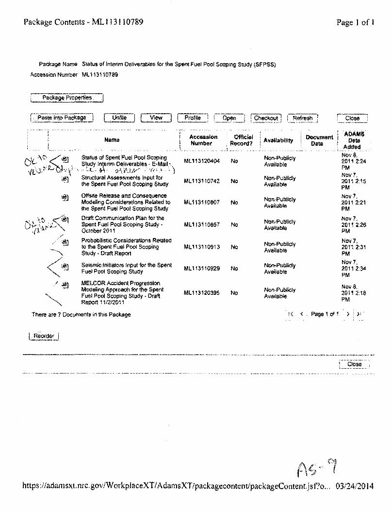
Package Contents - ML 113110789 Page ] o f
Package Name: Status of Interim Deliverables for the Spent Fuel Pool Scoping Study (SFPSS)
Accession Number' ML113, 10789
Package.Poeres
i .Paste into PackageF _VlewAI F sTioff I 71fficialeres
Name
; 0 Status of Spent Fuel Pool Scoping51udy ntedrm Deliverables - E-Mail,%
Structural Assessments Input forthe Spent Fuel Pool Scoping Study
Offsrte Release and ContsequenceModeling Considerations Related tothe Spent Fuel Pool Scoping Study
AccessionNumber
ML113120404
ML1 13110742
ML113110807
ML113110857
MLl 13110913
ML1 13110929
ML113120395
IRec~ord?
No
No
,NN
Draft Communication Plan for theSpent Fuel Pool Scoping Study -October 2011
Probaoilistic Considerations Relatedto the Spent Fuel Pool ScopingStudy - Draft Report
Seismic Initiators Input for the SpentFuel Pool Scoping Study
No
No
No
No
No
Availability... . .. . . . ..... . ... ....
Non-PubliclyAvailable
Non-PubliclyAvailable
Non-PubliclyAvailable
Non-PubliclyAvailable
Non-PubliclyAvailable
Non-PubliclyAvailable
Non-PublielyAvailable
DocumentDate
Close
ADAMSDate
AddedNov 8,2011 2:24PMNov 7,2011 2:15PMNov 7,201! 2:21PM
Nov 7,201 !2:26PM
Nov 7.2011 2:31PMNoy 7,2011 2:34PM
Nov 8,2011 2:18PM
./ • MELCOR Accident ProgressionModeling Approach for the SpentFuel Pool Scoping Study - Draft
KReport 1112120" 1
There are 7 Documents in this Package t< < page I of 1 >
ýLj
https :,'/adam sxt .nrc. goviWorkpl aceXT!/Adam sXTipackageconte nt/pack ageConten ti, sfo.., 03/24/2014
Poweill Eric
From:Sent:To:C.:Subject:Attachments:
Helton, DonaldWednesday, March 07, 2012 7T49 AMAder, CharlesPowell, Eric; Mrowca, Lynn; Wagner, KatieACIRS Slides on SFPSS - OfficiaW Use OnlyACRSSubcomm _Mar6 FINALyver2_05Mar2012,pptx
Charlie:
Per your request when we talked in the hallway yesterday afternoon, the slides we used yesterday to brief theACRS on the RES SFP Scoping Study are attached. Note that these slides are UQ nly (it was aclosed briefing). We will be presenting on the project (methods/models only) at both the RIC and an AprilACRS full committee meeting.
if you want anything else, don't hesitate to ask.
Don
Doe~ XeconDivision of Risk AnalysisNRC Office of Nudcka Regvlatory ResearchPhysic~d add~ress: 21 Church Scrt~eE, CSfl4-C9, Roxkville, MD 208.50Posta-L 2d.dress; U*SNRC / MS CSB4-C7,M /Washinrisoo. DC 203555Ph: .301 251-'7594
A, i , ;,
OUO - Internal Use Only
U.SNRCSUNITED STATES NUCLEAR REGULATORY COMMISSION
Protecting People and the Environment
Spent Fuel Pool (SFP)Scoping Study
Katie Wagner
Office of Nuclear Regulatory Research
Briefing for ACRSMarch 6, 2012
OUO - Internal Use Only
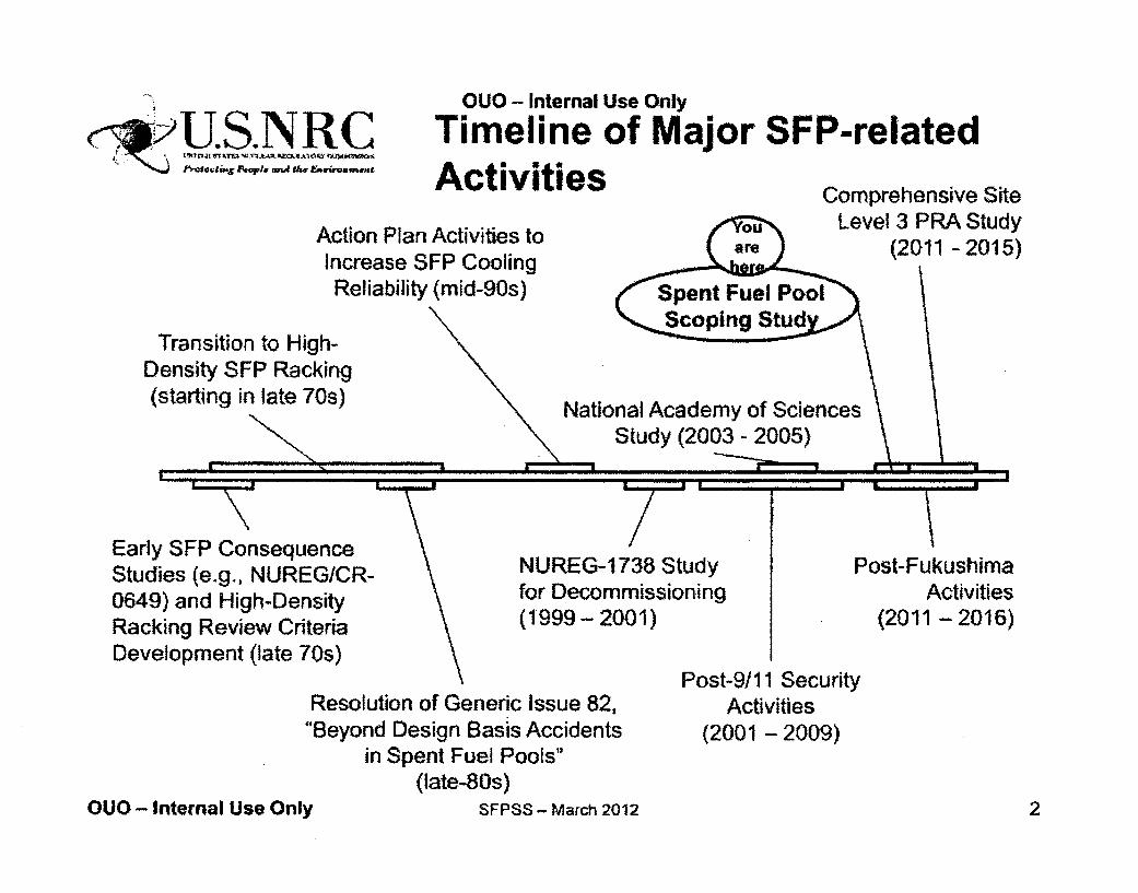
.)U.SJLVRCOUO - Internal Use Only
Timeline of Major SFP-relatedActivities
Action Plan Activities toIncrease SFP CoolingReliability (mid-90s) S:Poo
Comprehensive SiteLevel 3 PRA Study
(2011 - 2015)
Transition to High-Density SFP Racking(starting in late 70s)
Early SFP ConsequenceStudies (e.g., NUREGICR-0649) and High-DensityRacking Review CriteriaDevelopment (late 70s)
National Academy of SciencesStudy (2003 - 2005)
I
m
NUREG-1738 Studyfor Decommissioning(1999- 2001)
Post-FukushimaActivities
(2011 - 2016)
Resolution of Generic Issue 82,"'Beyond Design Basis Accidents
in Spent Fuel Pools"(late-80s)
OUO - Internal Use Only SFPSS - March 2012
Post-9/11 SecurityActivities
(2001 - 2009)
2

OUO - Internal Use Only I.-- -.
C~~U.S.NRC Background on SFP Risk
• SFP risk is low, due to the low frequency ofevents that could damage the thick reinforcedpool walls- Frequency of fuel uncovery; 6E-7 to 2E-6/yr -
NUREG-1 738- Consequences have been assessed to be large
due to the potential for heat-up of all the fuel inthe pool
- Heat-up of the fuel in the pool can lead to"zirconium fire" initiation and propagation- Large inventory of Cs-1 37
* The above has prompted questions aswhether older-fuel should be moved to
tocasks
OUO - Internal Use Only SFPSS - March 2012 3
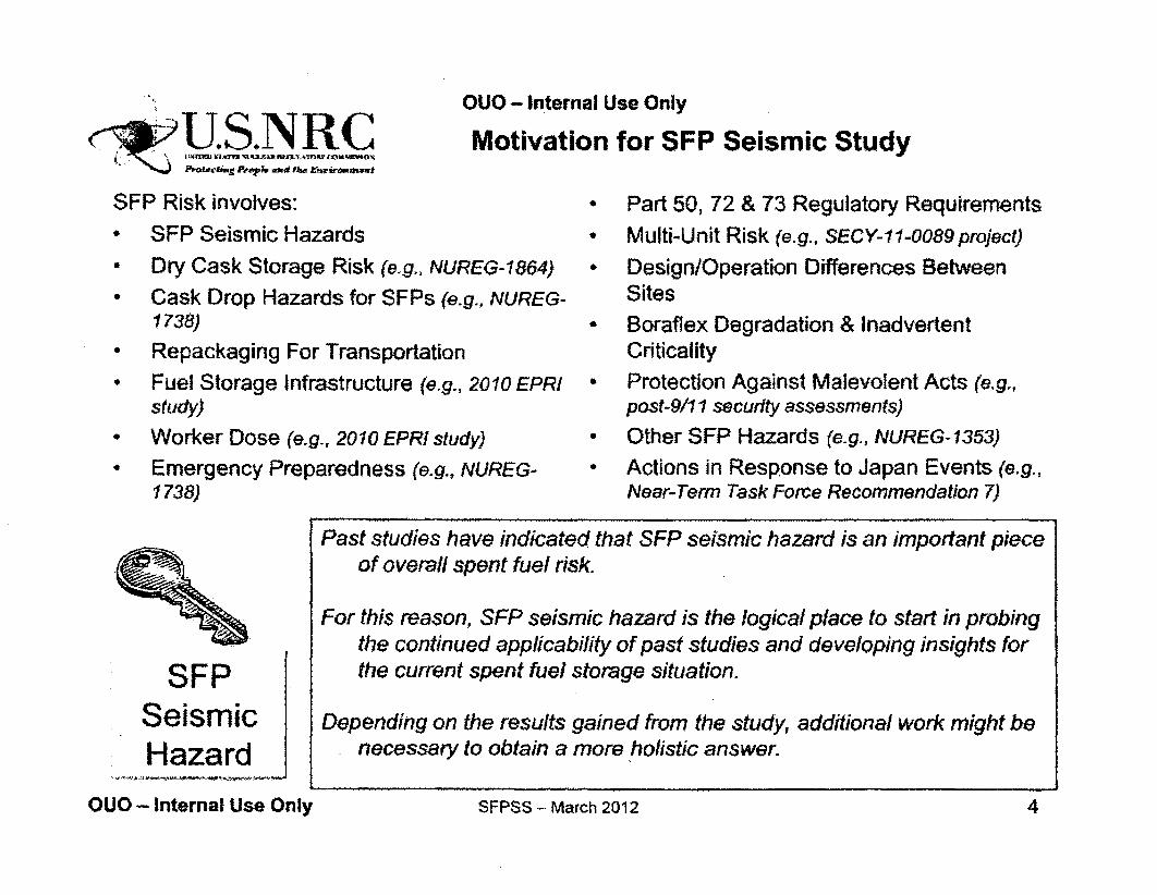
OUO - Internal Use Only
c2U.S.NRCSFP Risk involves:0 SFP Seismic Hazards
* Dry Cask Storage Risk (e.g., NUR- Cask Drop Hazards for SFPs (e.
1738)
* Repackaging For Transportation° Fuel Storage Infrastructure (e.g.,
study)* Worker Dose (e.g., 2010 EPRI stud* Emergency Preparedness (e.g.,?
1738)
f
Motivation for SFP Seismic Study
• Part 50, 72 & 73 Regulatory Requirements
* Multi-Unit Risk (e.g., SECY-11-0089 project)
'EG-1864) • Design/Operation Differences Betweeng., NUREG- Sites
- Boraflex Degradation & InadvertentCriticality
2010 EPRI - Protection Against Malevolent Acts (e.g.,post-9/11 security assessments)
ry) • Other SFP Hazards (e.g., NUREG-1353)
VUREG- ' Actions in Response to Japan Events (e.g.,Near-Term Task Force Recommendation 7)
SFPSeismicHazard
Past studies have indicated that SFP seismic hazard is an important pieceof overall spent fuel risk.
For this reason, SFP seismic hazard is the logical place to start in probingthe continued applicability of past studies and developing insights forthe current spent fuel storage situation.
Depending on the results gained from the study, additional work might benecessary to obtain a more holistic answer.
OUO - Internal Use Only SFPSS - March 2012 4
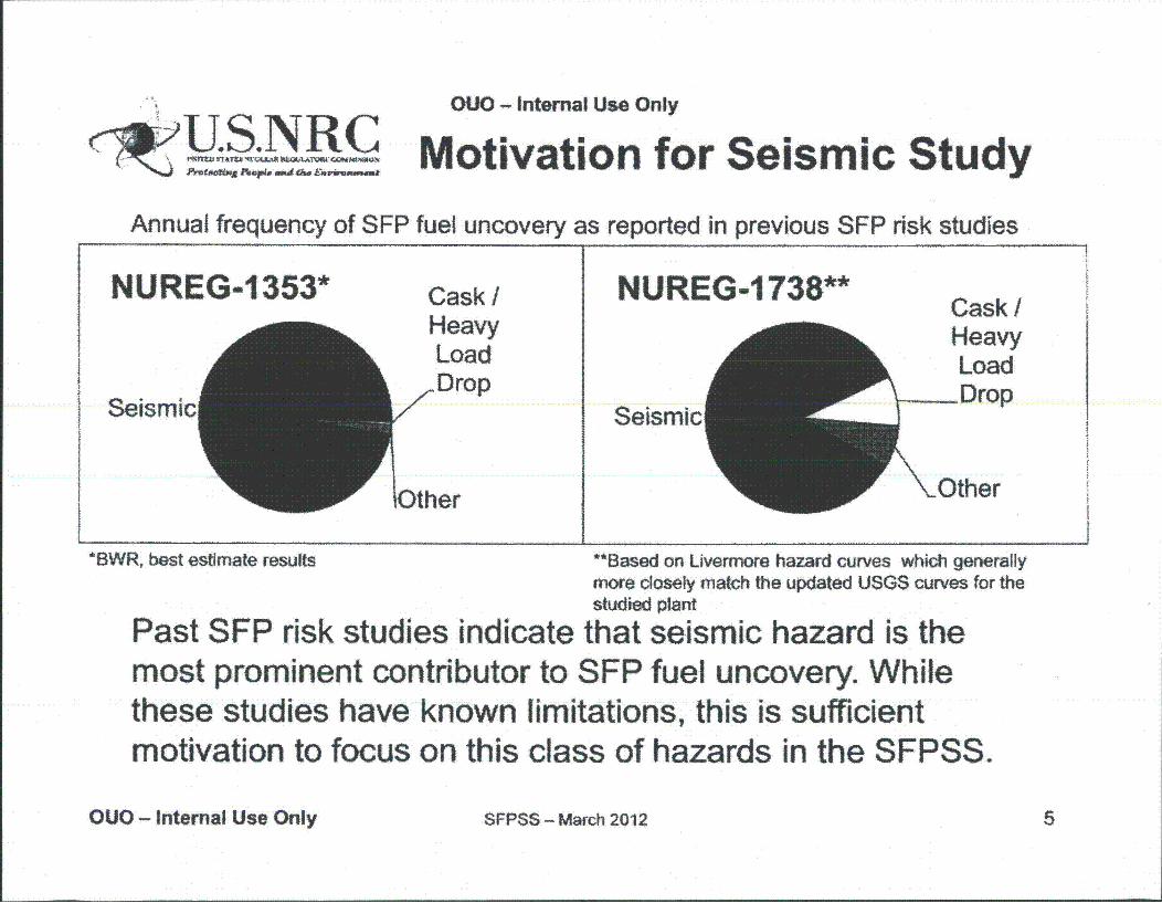
OUO - Internal Use Only
.. U.S.N..RCICR ! A-I 4M
Fr TAiwh'* Ap&~ =%dAAG~ amerm"" Motivation for Seismic StudyAnnual frequency of SFP fuel uncovery as reported in previous SFP risk studies
NUREG-1353*
SeismicA
Cask /HeavyLoadDrop
týher
NUREG-1738**
Seismic ACask/Heavy
~Load
Drop
(Other
*BWR, best estimate results *"Based on Livermore hazard curves which generallymore closely match the updated USGS curves for thestudied plant
Past SFP risk studies indicate that seismic hazard is themost prominent contributor to SFP fuel uncovery. Whilethese studies have known limitations, this is sufficientmotivation to focus on this class of hazards in the SFPSS.
OUO - Internal Use Only SFPSS - March 2012 5
OUO - Internal Use Only
SU. S. NLR COverview of Spent Fuel PoolScoping Study (SFPSS)
Focus: reexamination of the potential advantagesassociated with moving older fuel stored in the SFP to drycask storage in an expedited mannerEmphasis is given to acquiring timely results for ongoingdeliberations and external stakeholder interest. The projectis using:• Available information / methods* A representative operating cycle for a BWR Mark I (Peach Bottom)• Past studies to narrow scope
* Plan finalized: July 2011 (ML1 11570370)
* Study to be completed by: June 2012
OUO - Internal Use Only SFPSS - March 2012 6
OUO - Internal Use Only
Summary of Unique Aspects ofthe SFP Scoping Study
* Specific examination of the pool loading configuration (high-density vs. low-density) for contemporary SFP loading andrequirements
* Updated SFP beyond design basis accident (BDBA)consequence estimates (first for operating reactor since 1989)
* Site-specific (and thus more realistic) SFP BDBA consequenceestimates (not a focus of previous studies)
First public capturing of SFP BDBA consequences considering50.54(hh)(2) equipment
* First capturing of SFP BDBA seismic /structural response sincelate 1980s
0 First publicly available NRC study utilizing MELCOR (our tool ofchoice) for SFP analysis
OUO - Internal Use Only SFPSS - March 2012 7
OUO - Internal Use Only
V UTechnical Approach
" Two conditions to be considered:- Representative of the current situation for the selected site (i.e.,
high-density loading and a relatively full SFP)
- Representative of expedited movement of older fuel to a dry caskstorage facility (i.e., low-density loading)
" Elements of the study include- Seismic and structural assessments based on available information to
define initial and boundary conditions
- SCALE analysis of reactor building dose rates
- MELCOR accident progression analysis (effectiveness of mitigation, fissionproduct release, etc.)
- Emergency planning assessment- MACCS2 offsite consequence analysis (land contamination and health
effects)- Probabilistic considerations
OUO - Internal Use Only SFPSS - March 2012 8
OUO - Internal Use Only<~U.S.NRC
Seismic and StructuralMethods and
Preliminary Results
Jose Pires
OUO - Internal Use Only SFPSS - March 2012 9
OUO - Internal Use Only
SU.,S.NRC
Prescribed Seismic Scenario
Seismic event: 0.5 g to 1.0 g peak groundacceleration (PGA)
- Challenging but very low frequency of occurrence (oneevent in 61,000 years)
PGA 6 times greater than that for the SSE and beyond the seismicdesign basis for Eastern US plants
- USGS hazard models (2008) being used as startingmodel for ground motion response spectra
Review of past studies indicates that less severeevents would not challenge the SFP
OUO - Internal Use Only SFPS$ - March 2012 10
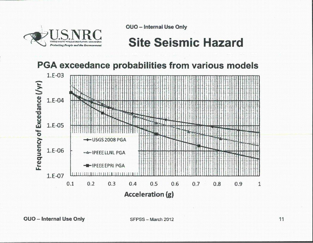
OUO - Internal Use Only
~U.S.NqR Cb1Th~ T~ ~~4AWNWA~J~ 2HG~ Site Seismic Hazard
PGA exceedance probabilities from various modelsL.E-03
LU
0
L6
11E-04
1.E-05
1.E-06
1.E-070.1 0.2 0.3 0.4 0.5 0.6 0.7 0.8 0.9 1
Acceleration (g)
OUO - Internal Use Only SFPSS - March 2012 11
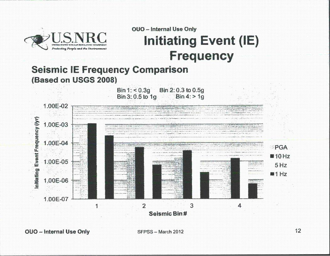
rClvU.S. NLRCOUO - Internal Use Only
Initiating Event (IE)Frequency
Seismic IE Frequency Comparison(Based on USGS 2008)
gin 1 - -O '30Bin 3: ..O'sto 19
Bln.2:i0.3 to 0.5g
C
a.eU-
C
Ic
1 .OOE-02i2
1.0OOE-.03
I .:00E-N4
t1.0E--05*
I .00E-06
.- i..........
. .... . ........ -11. - ....... ....-- -
-- -- ----------- PGA
U 10 Hz
5Hz
Ul Hz
1.00E-07 -
I 2 3 4Seismic B2012
SFPSS - March 2012OUO - Intemal Use Only 12
OUO - Internal Use Only
U .S. NR C Seismic Input
" Objective: to provide initial seismic assessment- Site Ground Motion Response Spectrum (GMRS)
" Rock site
- OBE is 0.05g
- SSE isO.12g
• Challenging damage is not expected below seismic hazard Bin 3 - 0.5gto 1.0g
- Level of 0.71g used
" USGS Hazard Assessments (2008) used as starting hazard level toobtain GMRS shape (Similar to GI-1 99 Resolution)
- Site GMRS scaled to obtain GMRS for Bin 3
" Site GMRS rich in high frequencies (5 to 25 Hz)
OUO - Internal Use Only SFPSS - March 2012 13
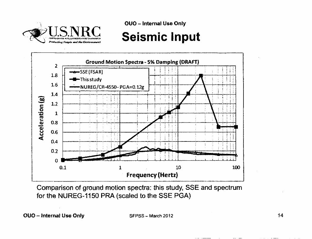
eBla.kt..mS.mRC
OUO - Internal Use Only
Seismic Input
Ground Motion Spectra - 5% Damping (DRAFT)22 - ---- -
1.8 ~~-SSE(FSAR) . -
-SP-This study .1.6 -- 'NUREG/CR-4550-PGA=O.12g
1.4 - - ~ - ~ - _ _ _ _ _ ~ .,. --
1.2.
C _ _
I -. - ____" .:_ __
U 0.6
0.4
00.1 1 10 100
Frequency (Hertz)
Comparison of ground motion spectra: this study, SSE and spectrumfor the NUREG-1150 PRA (scaled to the SSE PGA)
OUO - Internal Use Only SFPSS - March 2012 14
OUO - Intemal Use Only
Structural Input
* Objective: to determine starting point for subsequentaccident progression analysis
* Approach:- Generally follows approach used for GI-82 (NUREG/CR-5176)
* Enhanced to address specific study aspects (Finite Element Modeling)
- Uses in-structure response spectra (accelerations) calculated forthe NUREG-1 150 study (NUREG/CR-4550, Vol. 4, Part 3)
* Scaled for increased PGA (from 3xSSE to about 6xSSE)" Scaled to account for high frequency content in the site GMRS
- Uses 3D nonlinear finite element analysis of the SFP structureand its supports (subjected to equivalent static loads) tocalculate:
- displacements, concrete and reinforcement strains and stresses,structural distortion, and liner strains
OUO - Internal Use Only SFPSS - March 2012 15
OUO- Internal Use Only
Structural Input
• Analysis of the SFP structure subjected to equivalent staticseismic loads induced by the site GMRS provides input forthe estimation of the damage states for the SFP
* Loads considered- Dead loads -- weight of the pool structure (mostly concrete), spent
fuel racks and assemblies, and water- Seismic loads -- body forces from the accelerations of the pool
structure, hydrodynamic impulsive pressures and reaction forcesfrom spent fuel racks
- Combined vertical and horizontal ground shaking• Finite element programs used:
- ANSYS to estimate and verify seismic loads (especially thehydrodynamic impulsive loads and sloshing amplitudes)
- LSDYNA for the nonlinear analyses
OUO - Internal Use Only SFPSS - March 2012 16
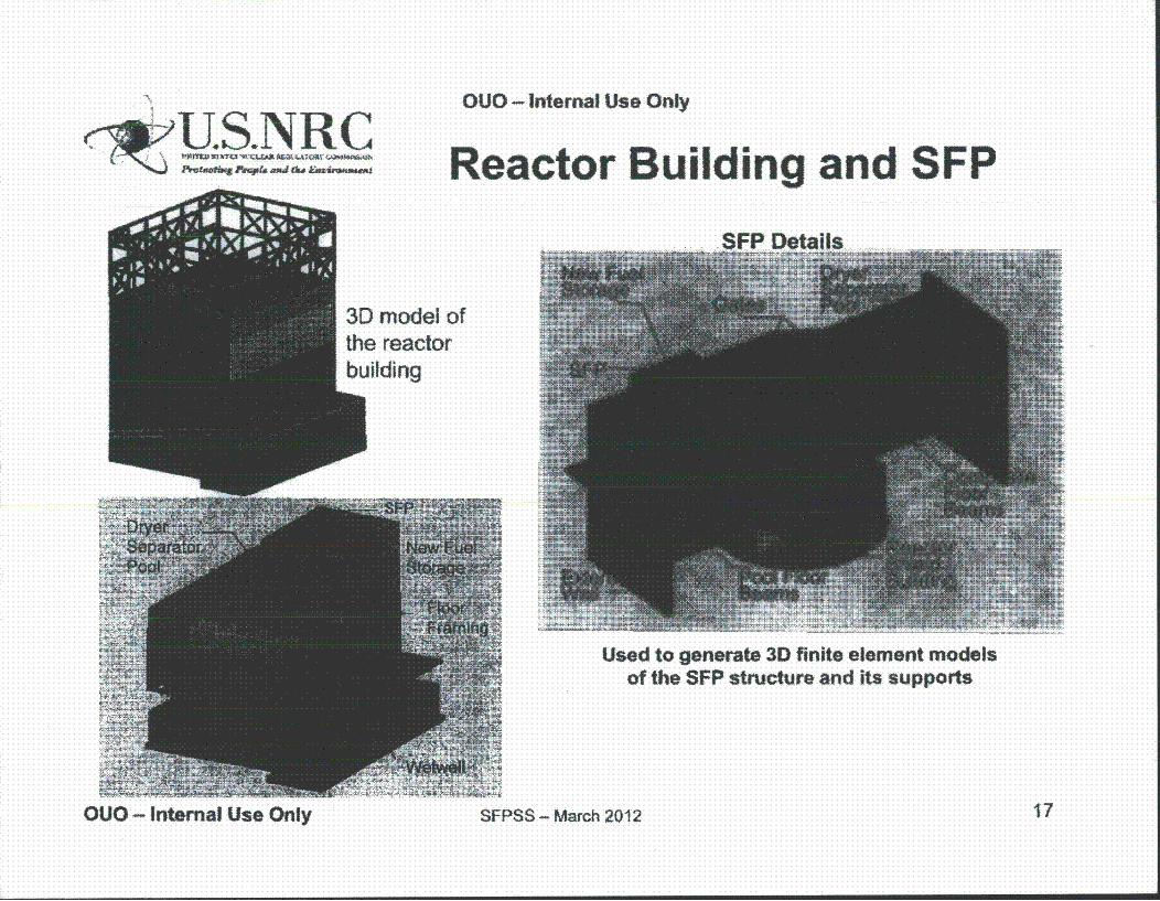
OUO - Internal Use Only
(<kjýU.S.NRC""Win M"l~' aft41IA A ~ N
0l7 ' J, tzs wipfa amda f&w Anu~wmuimI Reactor Building and SFP
Used to generate 3D finite element modelsof the SFP structure and its supports
OUO - Internal Use Only SFPSS - March 2012 17
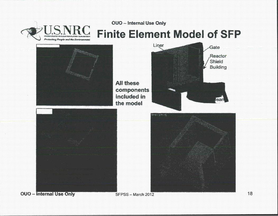
,. ! OUO- Internal Use Only
~[~~~ Finite Element Model of SFP
compon.ents included in the model
SFPSS- March 2012 18

OUO - Internal Use Only;;U.S.NRCStructural Input
• Approach (cont'd)- Simpler approaches to assess damage to:
Penetrations, support systems, other SSCs necessary for accident mitigation (e.g.,building housing a portable diesel pump), other structures
• Approximations / assumptions- Effects of ground motion incoherency on high frequency components
of floor spectra was not considered (possible conservatism)- Floor spectra do not account for coupling of SFP components to
building (possible conservatism)* Hydrodynamic pressures based on scaled floor response spectra" Dynamic time-history analyses of the whole reactor building including the SFP
were not done at this stage
- Seismic loads from spent fuel racks and assemblies approximated1 May need adjustment based on the analysis reports from the licensee submitted at
the time of the license amendment for high density racking
OUO - Internal Use Only SFPSS - March 2012 19
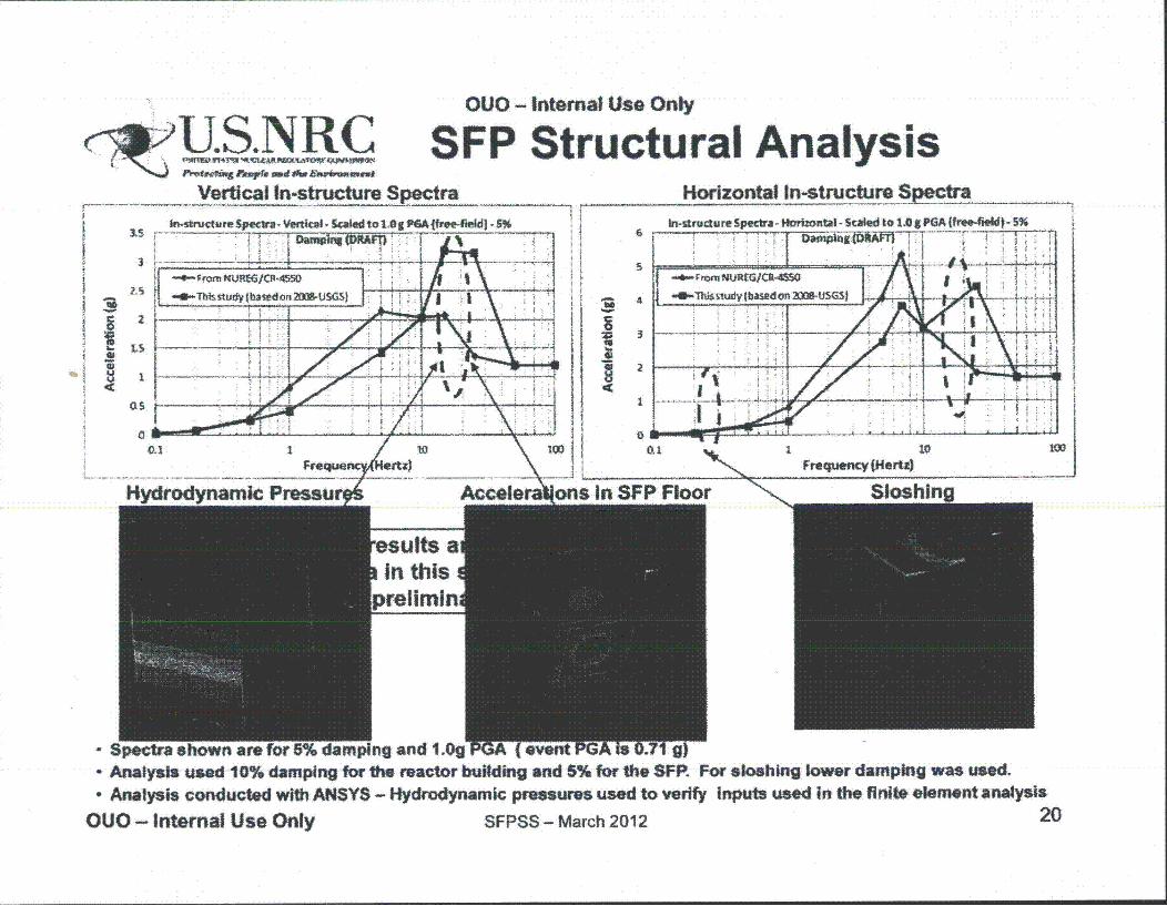
c~jS.NRC sVertical In-structure Spectra
3
ro GNJE6CFI-455O
OUO - Internal Use Only
FP Structural AnalysisHorizontal In-structuro Spectra
In-structureSpectra- Hizont- Scaled to 1.0 8PA 1e4ije - 5%
- Spectra shown are for 5% damping and I.g PGA feventPGA i. g)- Analysis used 10% damping for thO reactor building and 5% for the SFP. For sloshing lower damping was used.- Analysis conducted with ANSYS - Hydrodynamic pressures used to verify Inputs used in the finite element analysis
OUO - Internal Use Only SFPSS - March 2012 2 0

OUO - Internal Use Only
U S I Preliminary Results
• Concrete cracking - Results indicate a through-the-wallconcrete crack at the junction of the spent fuel pool wallsto the pool floor
- Crack thickness varies along this junction• Liner strains - Maximum liner strains at the junction of the
walls and floor- Analysis for the base finite element model (element size - 6 to 8
inches) shows strains in the range" 1.5E-4 to 1.9E-3 (0.0019)" Yield strain: about 1.2E-3 (0.0012)
- Detailed liner analysis done to assess strain concentrations
OUO - Internal Use Only SFPSS - March 2012 21
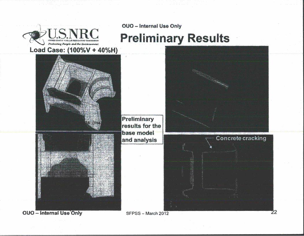
OUO - Internal Use Only
~U.S.N. RCLoad Case: tlOO%/V + 40%H)
Preliminary Results
Preliminaryresults for the
Conret - Internal
OUO - Internal
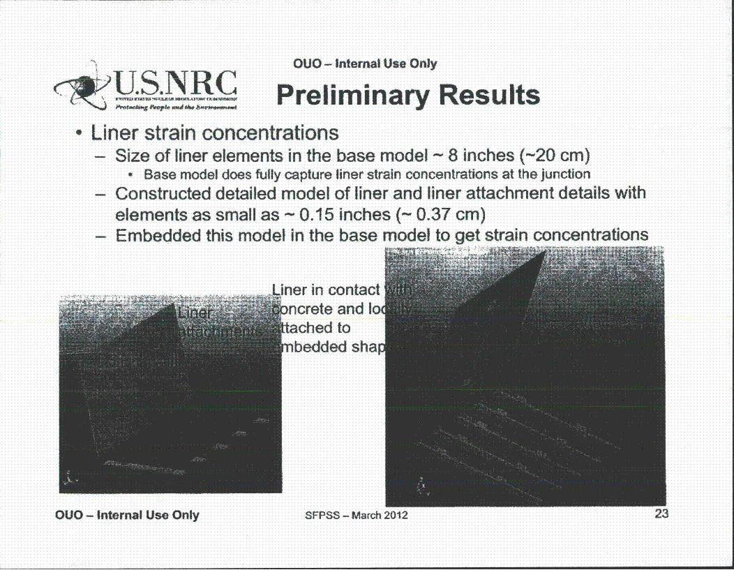
OUO - Internal Use Only
Preliminary ResultsLiner strain concentrations- Size of liner elements in the base model - 8 inches (-20 cm)
0 Base model does fully capture liner strain concentrations at the junction- Constructed detailed model of liner and liner attachment details with
elements as small as - 0.15 inches (- 0.37 cm)- Embedded this model in the base model to get strain concentrations
~ ~ ~ liner in contactnorete and loached tonbedded sha
OUO - Internal Use Only SFPSS - March 2012 23
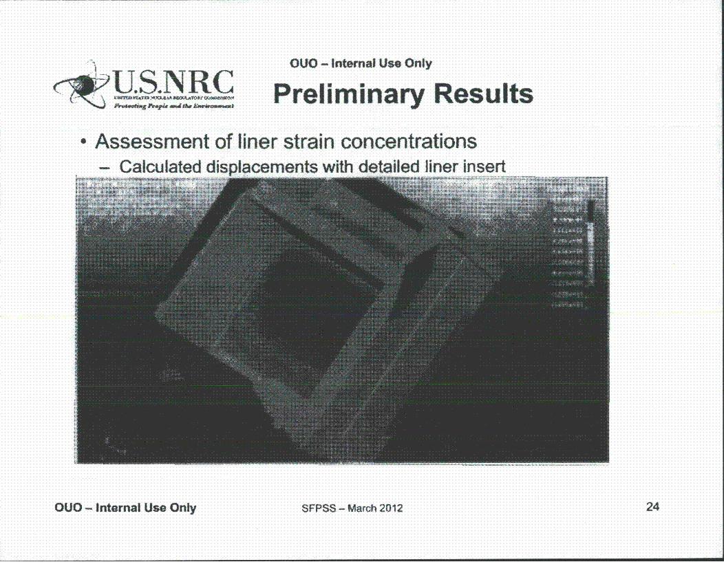
SU.S.NRC
OUO - Internal Use Only
Preliminary Results
* Assessment of liner strain concentrationscements with detailed liner insert
OUO - Internal Use Only SFPSS - March 2012 24
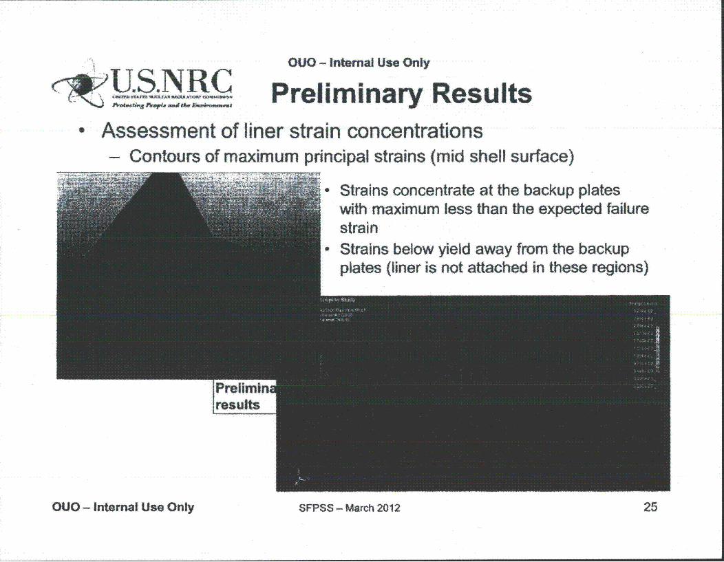
c~$.SARCOUO - Internal Use Only
Preliminary ResultsAssessment of liner strain concentrations- Contours of maximum principal strains (mid shell surface)
Strains concentrate at the backup plateswith ý maximum less than the expected failurestrainStrains below yield away from the backupplates (liner is not attached in these regions)
OUO - Internal Use Only SFPSS - March 2012 25
OUO- Internal Use Only
•"4 MAVkXP9 Preliminary Results
Damage States (SFP structure)* Most likely case no liner tearing and so no
water leaking except from sloshing
* Small relative likelihood of:- Extensive liner tearing with drainage controlled by
size of concrete cracking- Liner tearing localized at the backup plates
OUO - Internal Use Only SFPSS - March 2012 26
OUO - Internal Use Only
^Preliminary Results
Penetrations, other structures and equipment- Penetrations
° The analysis shows that the pool is stiff and the distortions small
° Damage to penetrations is not expected
- Reactor building" Fragility estimates for the NUREG-1 150 study (in NUREGICR-4550) indicate a
median fragility of about 1.6 g" Natural frequencies of the reactor building are not in the high frequency region
of the GMRS used for the site (except for the vertical mode which does notcontrol the building fragility)
" On these bases, it is concluded that the reactor building would survive this event
- Building structure above the spent fuel pool and overhead crane* Building structure above the pool is not vulnerable to earthquakes (it has low
mass and was designed to carry heavy crane loads of 125 tons)" Overhead crane, even if were to collapse, would not fall inside the pool" On these bases, damage to the pool is not expected from this part of the
building from the ground shaking
OUO - Internal Use Only SFPSS - March 2012 27
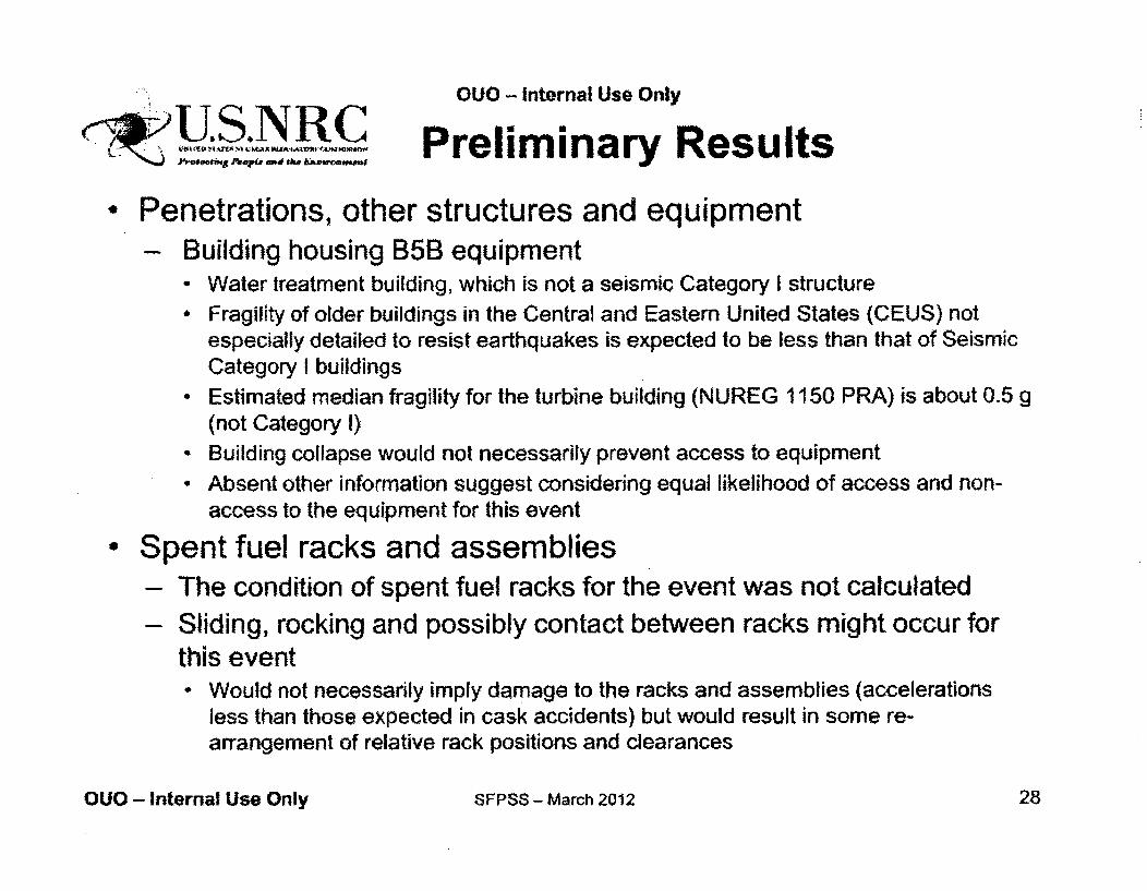
OUO - Internal Use Only
Preliminary Results
" Penetrations, other structures and equipment- Building housing B5B equipment
" Water treatment building, which is not a seismic Category I structure" Fragility of older buildings in the Central and Eastern United States (CEUS) not
especially detailed to resist earthquakes is expected to be less than that of SeismicCategory I buildings
* Estimated median fragility for the turbine building (NUREG 1150 PRA) is about 0.5 g(not Category I)
• Building collapse would not necessarily prevent access to equipment* Absent other information suggest considering equal likelihood of access and non-
access to the equipment for this event
" Spent fuel racks and assemblies- The condition of spent fuel racks for the event was not calculated- Sliding, rocking and possibly contact between racks might occur for
this eventWould not necessarily imply damage to the racks and assemblies (accelerationsless than those expected in cask accidents) but would result in some re-arrangement of relative rack positions and clearances
OUO - Internal Use Only SFPSS - March 2012 28
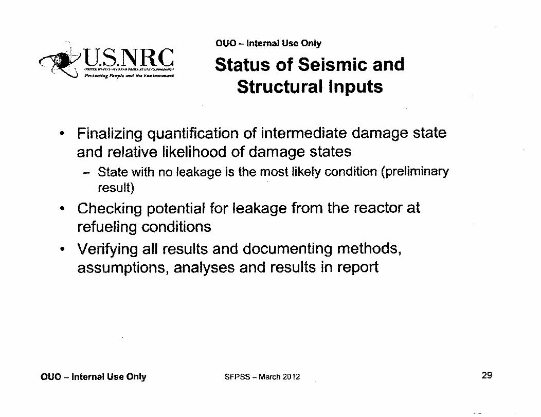
OUO - Internal Use Only
M.M7.N C ?Status of Seismic andStructural Inputs
" Finalizing quantification of intermediate damage stateand relative likelihood of damage states- State with no leakage is the most likely condition (preliminary
result)• Checking potential for leakage from the reactor at
refueling conditions* Verifying all results and documenting methods,
assumptions, analyses and results in report
OUO - Internal Use Only SFPSS - March 2012 29
OUO - Internal Use Only
c;$IU.S.NRC
Scenario Delineation
Don Helton
OUO - Internal Use Only SFPSS - March 2012 30
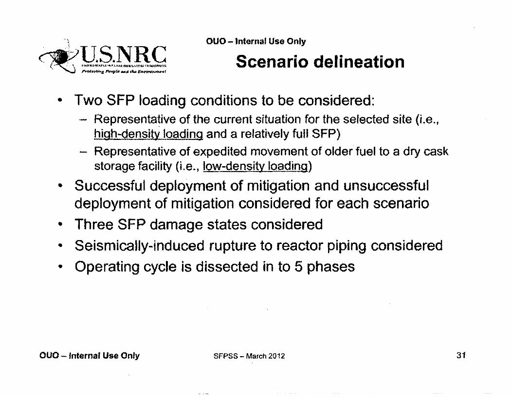
OUO - Internal Use Only
Scenario delineation
Two SFP loading conditions to be considered:- Representative of the current situation for the selected site (i.e.,
high-density loading and a relatively full SFP)
- Representative of expedited movement of older fuel to a dry caskstorage facility (i.e., low-density loading)
Successful deployment of mitigation and unsuccessfuldeployment of mitigation considered for each scenario
* Three SFP damage states considered
* Seismically-induced rupture to reactor piping considered
* Operating cycle is dissected in to 5 phases
OUO - Internal Use Only SFPSS - March 2012 31
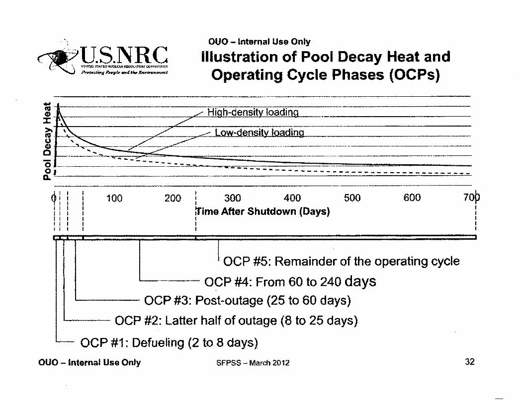
0
01C _
U4.S. NRC2t14V~h InI.Th4 *4CJfA W."k-kAf
prateviim P§WpiV Atd shp onviewnweutu
OUO - Internal Use Only
Illustration of Pool Decay Heat andOperating Cycle Phases (OCPs)
I I I 100 200 300 400 500 600 701Time After Shutdown (Days)
OCP #5: Remainder of the operating cycle
OCP #4: From 60 to 240 daysOCP #3: Post-outage (25 to 60 days)
OCP #2: Latter half of outage (8 to 25 days)
QOCP #1: Defueling (2 to 8 days)
OUO - Internal Use Only SFPSS - March 2012 32
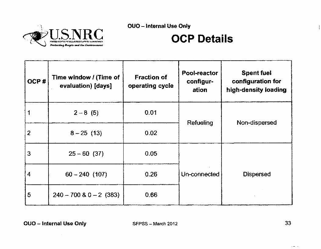
OUO - Internal Use Only
r-qwýUS.NRCPNotaifi'e Pkeot wand dzg _K~&WtMfm
OCP Details
Pool-reactor Spent fuelTime window I (Time of Fraction of Pool-re cont for
evaluation) [days] operating cycle ation high-density loading
1 2-8 (5) 0.01
Refueling Non-dispersed
2 8-25 (13) 0.02
3 25-60 (37) 0.05
4 60 - 240 (107) 0.26 Un-connected Dispersed
5 240- 700 & 0 - 2 (383) 0.66
OUO - Internal Use Only SFPSS - March 2012 33
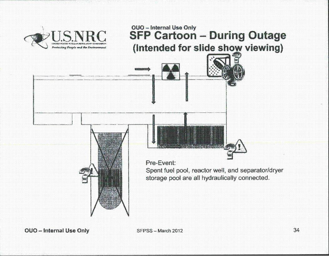
ec,:U-US.NRC( 4 I~1UWWS A~L IN Y&
Psw4.c'% tzehpa" iitwK firrmuu
OUO - Internal Use Only
SFP Cartoon - During Outage(Intended for slide show viewing)
Pre-Event:Spent fuel pool, reactor well, and separator/dryerstorage pool are all hydraulically connected.
OUO - Internal Use Only SFPSS - March 2012 34

OUO - Internal Use Only
IU5NRC SFP Cartoon - During Outage(Intended for slide show viewing)
For post-outage events:>,The major difference is that the SFP is
hydraulically isolated from the reactor.>'No damage to the fuel transfer canal gate is
predicted.>AtY other preceding descriptions remain valid.
OUO - Internal Use Only SFPSS - March 2012 35
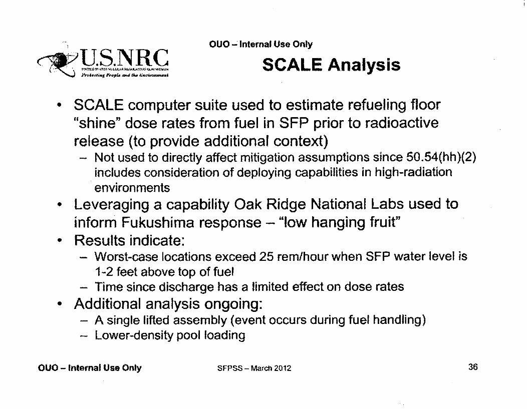
OUO - Internal Use Only
E1 ,SCALE Analysis
SCALE computer suite used to estimate refueling floor"shine" dose rates from fuel in SFP prior to radioactiverelease (to provide additional context)
- Not used to directly affect mitigation assumptions since 50.54(hh)(2)includes consideration of deploying capabilities in high-radiationenvironments
Leveraging a capability Oak Ridge National Labs used toinform Fukushima response - "low hanging fruit"Results indicate:- Worst-case locations exceed 25 rem/hour when SFP water level is
1-2 feet above top of fuel- Time since discharge has a limited effect on dose rates
* Additional analysis ongoing:- A single lifted assembly (event occurs during fuel handling)- Lower-density pool loading
OUO - Internal Use Only SFPSS - March 2012 36
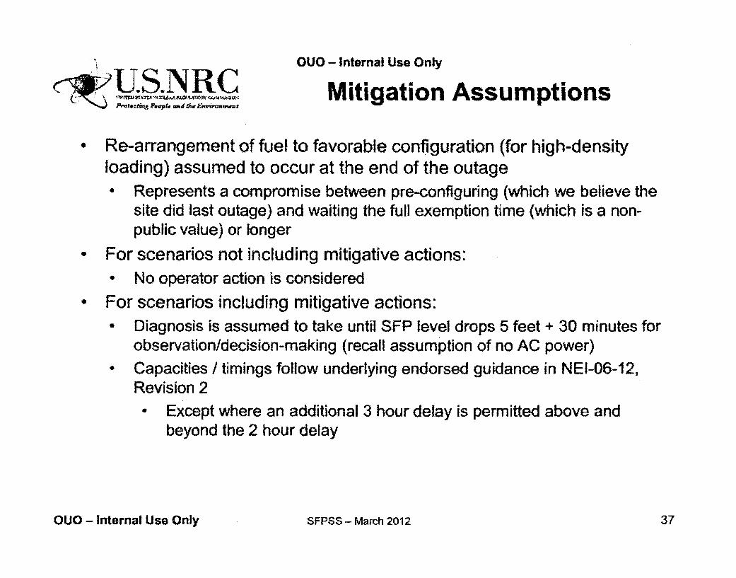
-OUO - Internal Use Only
Mitigation Assumptions
• Re-arrangement of fuel to favorable configuration (for high-densityloading) assumed to occur at the end of the outage
41 Represents a compromise between pre-configuring (which we believe thesite did last outage) and waiting the full exemption time (which is a non-public value) or longer
0 For scenarios not including mitigative actions:0 No operator action is considered
Is For scenarios including mitigative actions:• Diagnosis is assumed to take until SFP level drops 5 feet + 30 minutes for
observation/decision-making (recall assumption of no AC power)• Capacities / timings follow underlying endorsed guidance in NEI-06-12,
Revision 2Except where an additional 3 hour delay is permitted above andbeyond the 2 hour delay
OUO - Internal Use Only SFPSS - March 2012 37
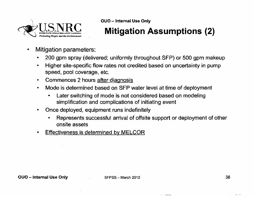
OUO - Internal Use Only!U. S. NR CUMitigation Assumptions (2)
Mitigation parameters:4 200 gpm spray (delivered; uniformly throughout SFP) or 500 gpm makeup* Higher site-specific flow rates not credited based on uncertainty in pump
speed, pool coverage, etc,a Commences 2 hours after dianosia Mode is determined based on SFP water level at time of deployment
1 Later switching of mode is not considered based on modelingsimplification and complications of initiating event
* Once deployed, equipment runs indefinitely- Represents successful arrival of offsite support or deployment of other
onsite assets
• Effectiveness is determined bv MELCOR
OUO - Internal Use Only SFPSS - March 2012 38
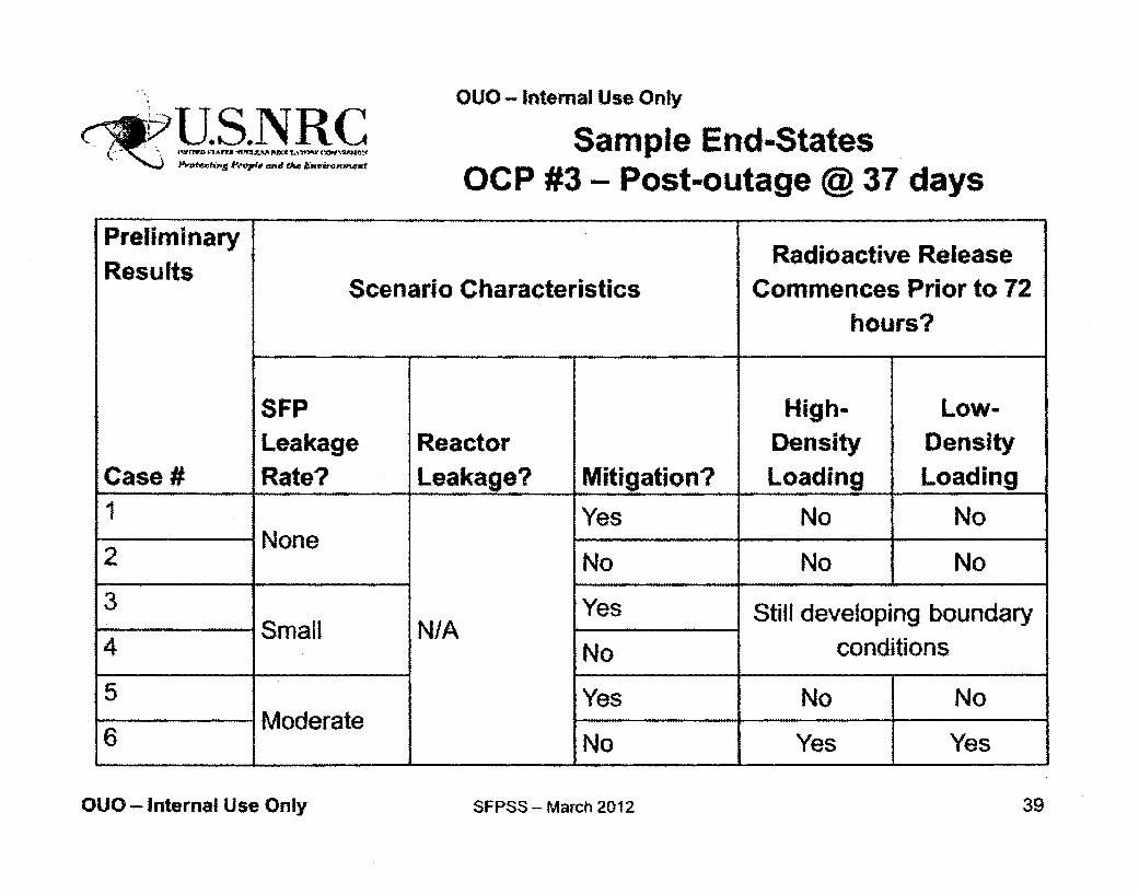
OUO - Internal Use Only
P' opt ( ,d d"4~Jmwtu
Sample End-StatesOCP #3- Post-outage @ 37 days
PreliminaryResults
Case #
Scenario CharacteristicsRadioactive Release
Commences Prior to 72hours?
a
SFPLeakageRate?
ReactorLeakage? Mitigation?
High-DensityLoading
Low-DensityLoading
22
Yes No NoNone
34 Small N/A
No No No
'Yes Still developing boundary
No conditions
Yes No No5
6Moderate
No Yes Yes1 1 1 1
OUO - Internal Use Only SFPSS - March 2012 39
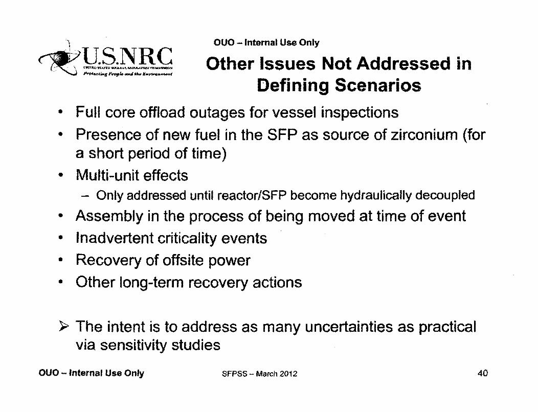
OUO - Internal Use Only
C-N '•.,ý ý Other Issues Not Addressed inDefining Scenarios
* Full core offload outages for vessel inspections0 Presence of new fuel in the SFP as source of zirconium (for
a short period of time)- Multi-unit effects
- Only addressed until reactor/SFP become hydraulically decoupled• Assembly in the process of being moved at time of event• Inadvertent criticality events* Recovery of offsite power* Other long-term recovery actions
SThe intent is to address as many uncertainties as practicalvia. sensitivity studies
OUO - Internal Use Only SFPSS - MaTch 2012 40
OUO - Internal Use Only
<•U.S.NRC
Accident ProgressionMethods and
Preliminary Results
Hossein Esmaili
OUO - Internal Use Only SFPSS - March 2012 41
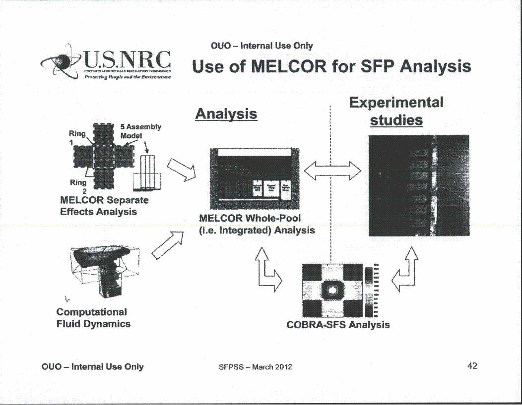
OUO - Internal Use Only
U.S.NRC Use of MELCOR for SFP Analysis
AnalysisExperimental
studies
RnngLU2
MELCOR SeparateEffects Analysis
t!
MELCOR Whole-P(i.e. Integrated) Ar
ooltalysis
COBRA-SFS AnalysisComputationalFluid Dynamics
OUO - Internal Use Only SFPSS - March 2012 42
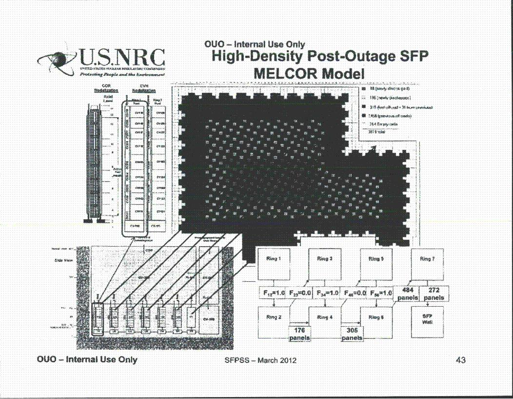
~U.S. NLR COUO - Internal Use OnlyHigh-Density Post-Outage SFP
MELCOR Model
,II
$~. atev~
'4" ~-
OUO - Internal Use Only SFPSS - Match 2012 43
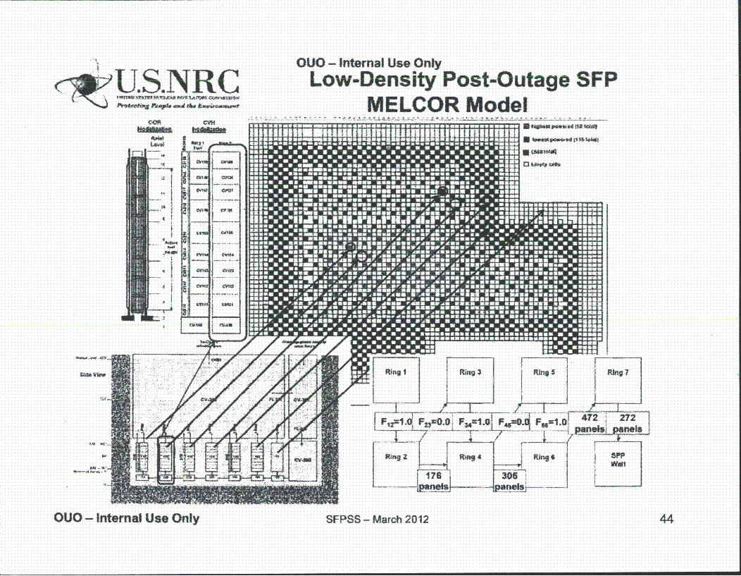
mamma*,*'"I C
5&O 11 -Owl __I
one
OUO - Internal Use OnlyLow-Density Post-Outage SFP
MELCOR ModelI3 , ,
OUO - Internal Use Only SFPSS - March 2012 44
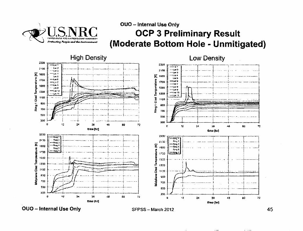
c~US.NRC/ ~~ -Wfl¶OS~7 pWT.U = dw~$~O
OUO - Internal Use Only
OCP 3 Preliminary Result(Moderate Bottom Hole - Unmitigated)
High Density
1700
1600
1300
900
300
203
1300
:10
-.- 1
.~ ... .. ..---Law
Umethi]
C
Ex
lion0
too9
ago
Low Density
I~. .w .. ......
- ... .. .... ,
.. ... ... - - ..2. .. .. ..... .. .... .... ... ....
-...... .. ..
4~.-~.+-
C
• _S •. ............. i. .............. ........... ....-9
eqa
*0
53ou
93~3
12 24 38 4a81
fline (hrl
... ... ..---
0 ? 24 36
OUO - Internal Use Only
a 12 24 38
lime [hri48 so 72
SFPSS - March 2012 45
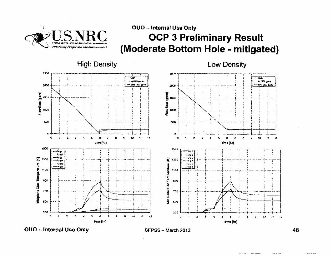
JOUO - Internal Use Only
U.S.I:C OCP 3 Preliminary Result(Moderate Bottom Hole - mitigated)
High Density Low Density
Th1:0weI
Z5
low
0
15W0
i.1011700
CLEy
-U
39L
O 1 a 1 10 11 12
lme (Ihq
0 12 1 4 5 6 11 a 9 10 11 12
tinmS "~
FE4-
0 1 2 3 4 5 E 7 a 0 10 11 12
*rme Ihr]
OUO - Internal Use Only SFPSS - March 2012 46
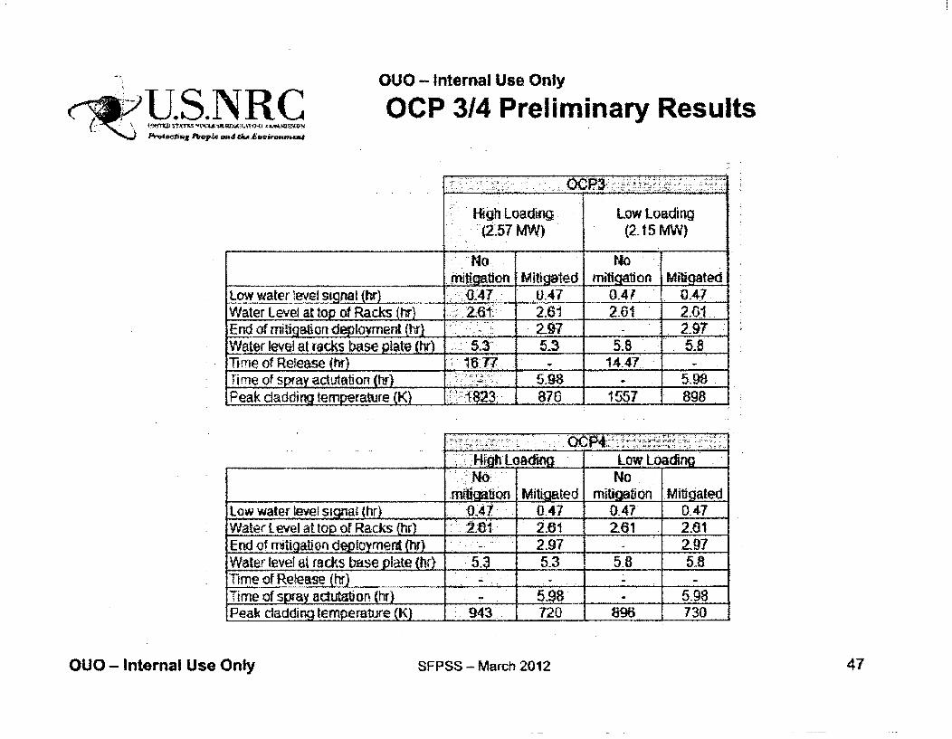
U .. 'RLAI.14
OUO - Internal Use Only
OCP 3/4 Preliminary Results
High Loading• (2.57 MW)
Low Loading(2-15 MW)
No. NO.__mitgaftion Mitigated mitigation Mitted
Low water ýeveif sinal (hr) BA. .. 0.47 0.4A 0.47..Water Level at top of Racks (hr,) 61. 2.61 261 2...End of mifigaioridploym (ty } . 27. - 2-97,_Water level at iacks base plate (hr) 5.3 5-3 5.8 5-8Time of Release (ht) 167. - 14.47Time of spray actutation (hr - 5.98 - 5. 9Peak dadding temperature (K) 1823 876 1557 898
- ~OCR--___._________._______ High Loam Low Loadigg
No. Nonmibtion Mitigted mitlobon Mitiqated
Low water level signal jhr) " .047 0.47 _ 0-47Water Level at top or Racks (hr) 1 2.61 2-61 2.01End of.•tigaton deployment (hr) 2.97 2.97Water level at rads base plate (hr . 5.3 5-3 5.8 5.8Time of Release (hr) ...... __Time of sl~ay acutab._ (hr) .598 5.98Peak cladding temperature (K) 943 720 896% 730
OUO - Internal Use Only SFPSS - March 2012 47
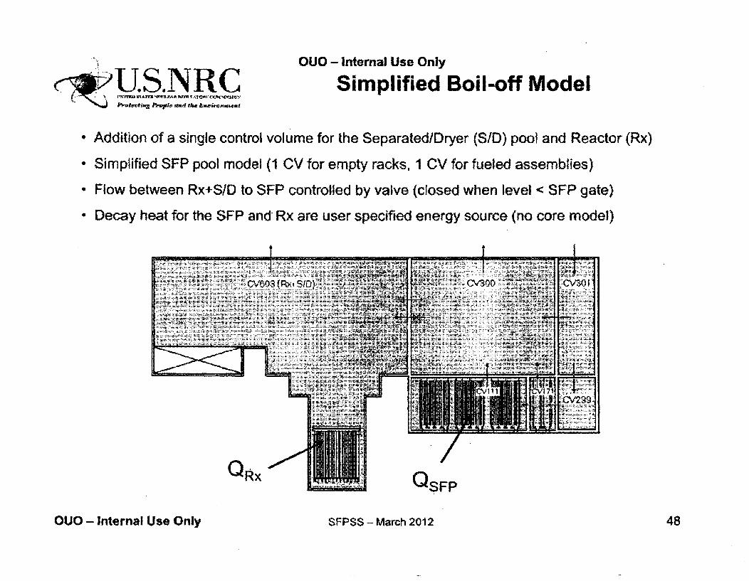
ýý1JS.NRCt -; m Im m NviJAr P - U A 1On Os
OUO - Internal Use Only
Simplified Boil-off Model
• Addition of a single control volume for the Separated/Dryer (S/D) pool and Reactor (Rx)
• Simplified SFP pool model (1 CV for empty racks, 1 CV for fueled assemblies)
* Flow between Rx+S/D to SFP controlled by valve (closed when level < SFP gate)
" Decay heat for the SFP and Rx are user specified energy source (no core model)
t
OUO - Internal Use Only SFPSS - March 2012 48
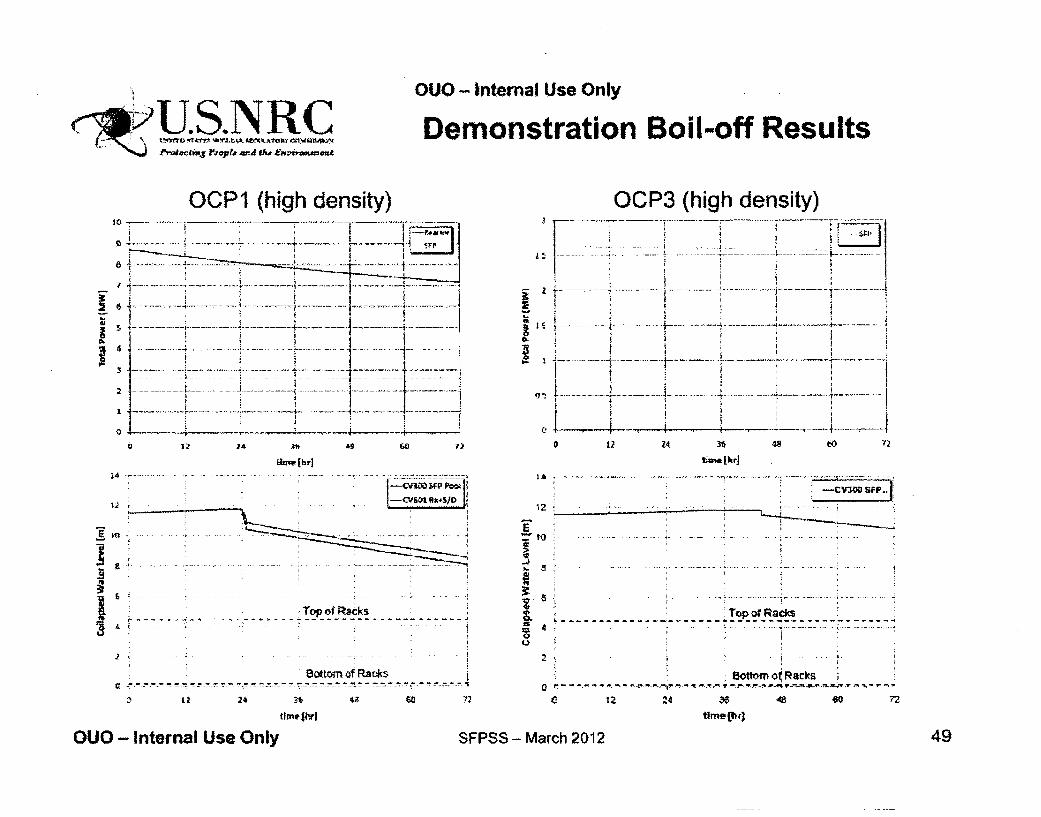
OUO- tnternal Use Only
Demonstration Boil-off Results
OCP1 (high density)
lhm>.(hr)
. . •. Top of Racks , ~------~-·----·---·---~---------·-----------· d. ( . . .. .. -··· 1
J ·•·
Bottom of Rae:ks i Q ~.-.::-~-... ""! '!l'!' ,'!'!!.,~."!!~ .. -.:,.":"": "!' .. -. ~~~.'!!..":":'.,v'!;;•'!:•--:-•~• ~ .. :':! .. ::: .. ":'".,,~,.~."": .. ~.::-. -. -:-:: .. :""-.~•••~-~~-.-: ~ .~,.::.~ .. ~, ~
24
... 8
i
OCP3 (high density)
36
tiane[lorJ
"i 5
~ l. --------- ____ · _______ ._!~~-~a~. __ --~_------s 4 '.. .. .... , ~ l u
2 . .. i ;
· Bottom of Racks 0 ~-- ~ --~ "'t· .. '"\ -.,-. ~-:!::~-~-~-~'111! .. .,.'!'!' 1: !'1"-,':'t'.~ .r.-.:-:-~ ... ~ .. ~..!111--~'!"--!'!:.-'~'!....15-'r'I.!:J...~~--"' J!'! '!t,- '!"" .,'!"'
c 12 ~4 ~ .ca ~ n time{tlrJ
QUO - Internal Use Only SFPSS- March 2012 49

OUO - Internal Use Only
U.S.NRC
Consequence AnalysisMethods
AJ Nosek
OUO - Internal Use Only SFPSS - March 2012 50
OUO - Internal Use OnlyC;U.S.NRC
Offsite Consequence Modeling
0 MACCS2 code will be used- Input: Accident source term, weather, population and
economic data, protective measures- Output: Consequences (e.g. contamination, health
effects) from atmospheric release
V Modeling will leverage best practices from draftNUREG-1935 (SOARCA)
* Population and economic data updated for 2011
OUO - Internal Use Only SFPSS - March 2012 51

OUO - Internal Use Only
>US.NRC4Z&of= MACCS2 Modeling:Code Modules
ATMOS- Atmospheric transport and dispersion- Source term from MELCOR and ORIGEN calculations
EARLY (1 week)- Early consequences
- Altered by countermeasures such as sheltering, evacuation, and relocation- Early doses also contribute to long-term consequences
• CHRONC (50 years)- Long-term consequences
Altered by countermeasures such as decontamination, interdiction, andcondemnation
OUO - Internal Use Only SFPSS - March 2012 52
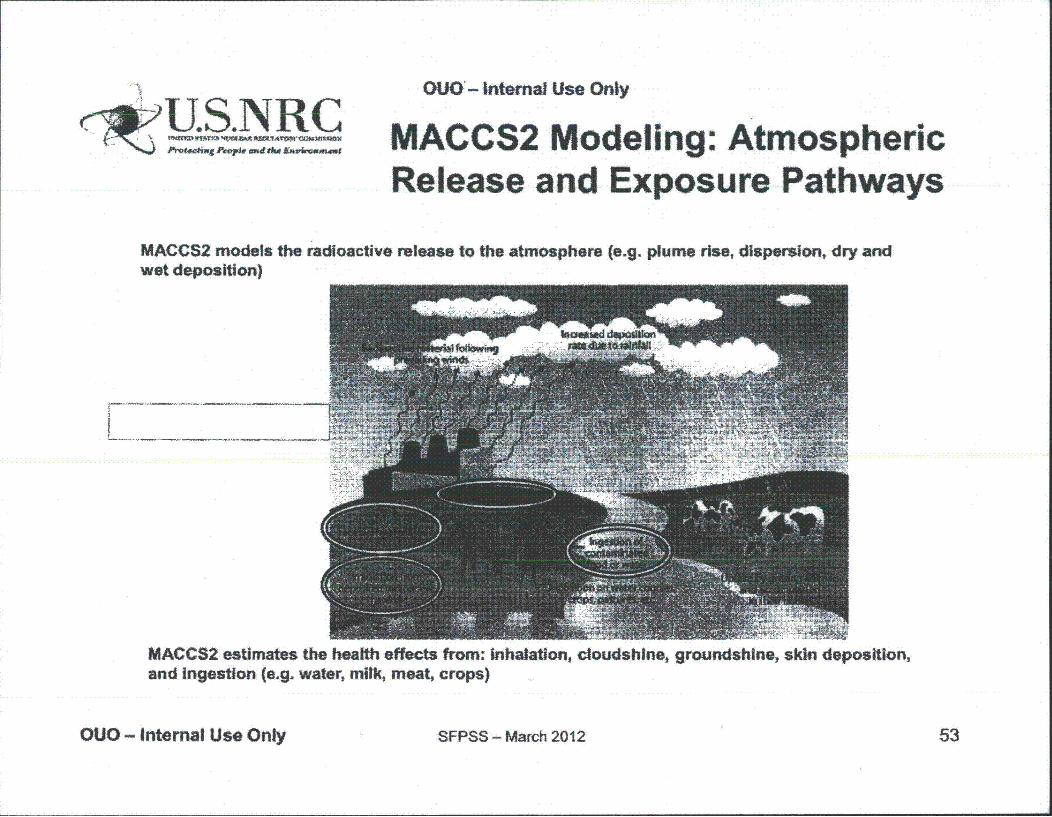
~U.S. NLR COUO'- Internal Use Only
MACCS2 Modeling: AtmosphericRelease and Exposure Pathways
MACCS2 models the radioactive release to the atmospherewet deposition)
(e.g. plume rise, dispersion, dry and
MACCS2 estimates the health effects from: inhalation, cloudshlne, groundshine, skin deposition,and Ingestion (e.g. water, milk, meat, crops)
OUO- Internal Use Only SFPSS - March 2012 53
OUO - Internal Use Only
MACCS2 Modeling: Atmospheric Transport and Dispersion (ATD)
• Dispersion based on Gaussian plume model {with provisions for meander and surface roughness effects) - Phenomena not treated in detail in this model are: lrre!;]ular terrain~
spatial variations in wind fietd, temporal variations in wtnd direction
• Meteorological data required - Wind direction and speed, Pasquill stability category, precipitation,
(seasonal {PMfAM]) mixing layer height, and boundary weather
• Multiple weather sequences (accounts for uncertainty in weather conditions at the time of the accident)
OUO - Internal Use Only SFPSS- March 2012 54
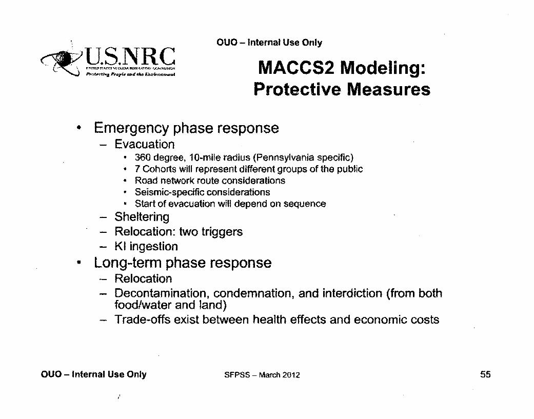
OUO - Internal Use Only
<~S NUR C( ~ totihpq P*'LA.R AMi# An th ~my MACCS2 Modeling:
Protective Measures
, Emergency phase response- Evacuation
* 360 degree, 10-mile radius (Pennsylvania specific)* 7 Cohorts will represent different groups of the public* Road network route considerations• Seismic-specific considerations• Start of evacuation will depend on sequence
- Sheltering- Relocation: two triggers- KI ingestion
• Long-term phase response- Relocation- Decontamination, condemnation, and interdiction (from both
food/water and land)- Trade-offs exist between health effects and economic costs
OUO - Internal Use Only SFPSS - March 2012 55
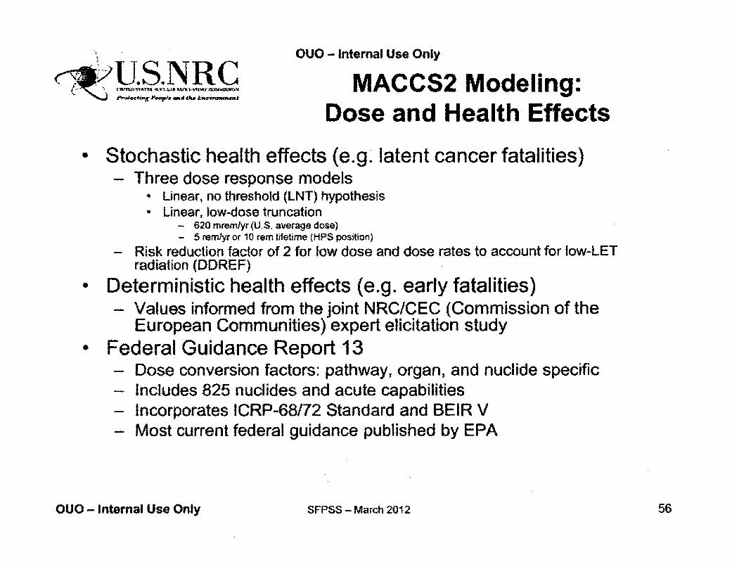
1OUO - Internal Use Only
U.S.,J_\qR MACCS2 Modeling:
Dose and Health Effects
Stochastic health effects (e.g. latent cancer fatalities)- Three dose response models
* Linear, no threshold (LNT) hypothesis* Linear, low-dose truncation
- 620 mrem/yr (U.S. average dose)- 5 rem/yr or 10 rem lifetime (HPS position)
- Risk reduction factor of 2 for low dose and dose rates to account for low-LETradiation (DDREF)
o Deterministic health effects (e.g. early fatalities)- Values informed from the joint NRC/CEC (Commission of the
European Communities) expert elicitation study- Federal Guidance Report 13
- Dose conversion factors: pathway, organ, and nuclide specific- Includes 825 nuclides and acute capabilities- Incorporates ICRP-68/72 Standard and BEIR V- Most current federal guidance published by EPA
OUO - Internal Use Only SFPSS - March 2012 56
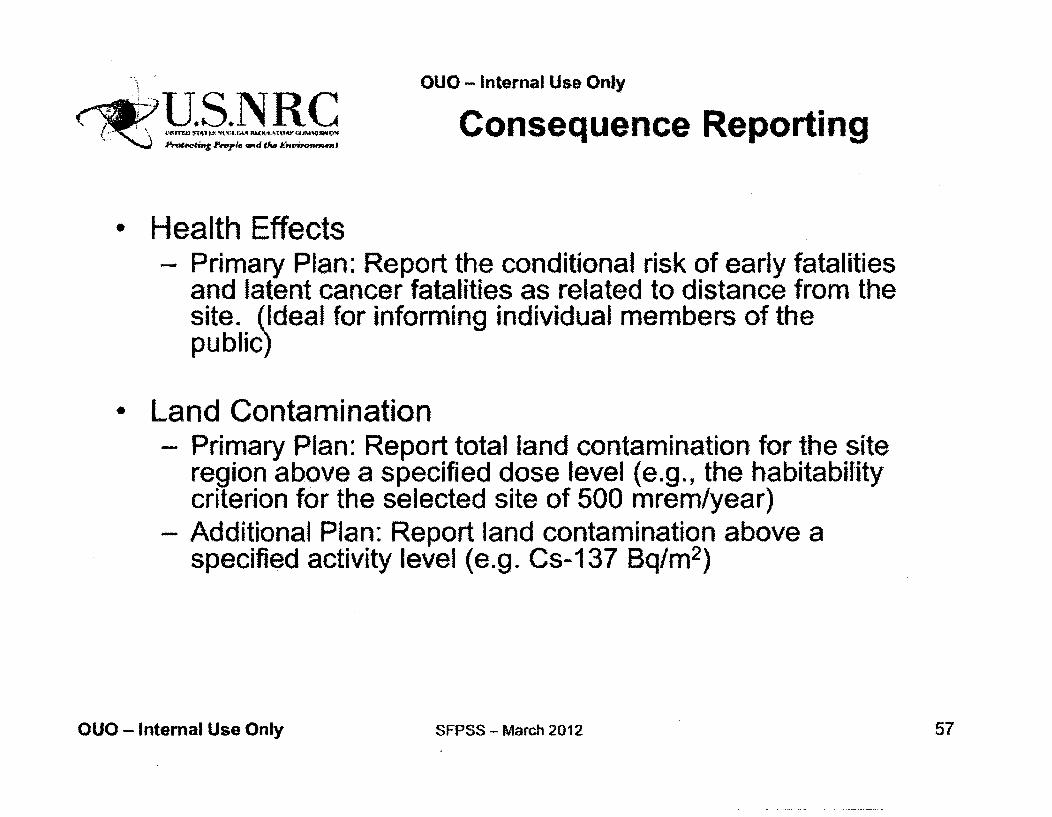
OUO - Internal Use OnlyUConsequence Reporting
Health Effects- Primary Plan: Report the conditional risk of early fatalities
and latent cancer fatalities as related to distance from thesite.. (Ideal for informing individual members of thepublic)
Land Contamination- Primary Plan: Report total land contamination for the site
region above a specified dose level (e.g., the habitabilitycriterion for the selected site of 500 mrem/year)
- Additional Plan: Report land contamination above aspecified activity level (e.g. Cs-137 Bq/m 2)
OUO - Internal Use Only SFPSS - Match 2012 57
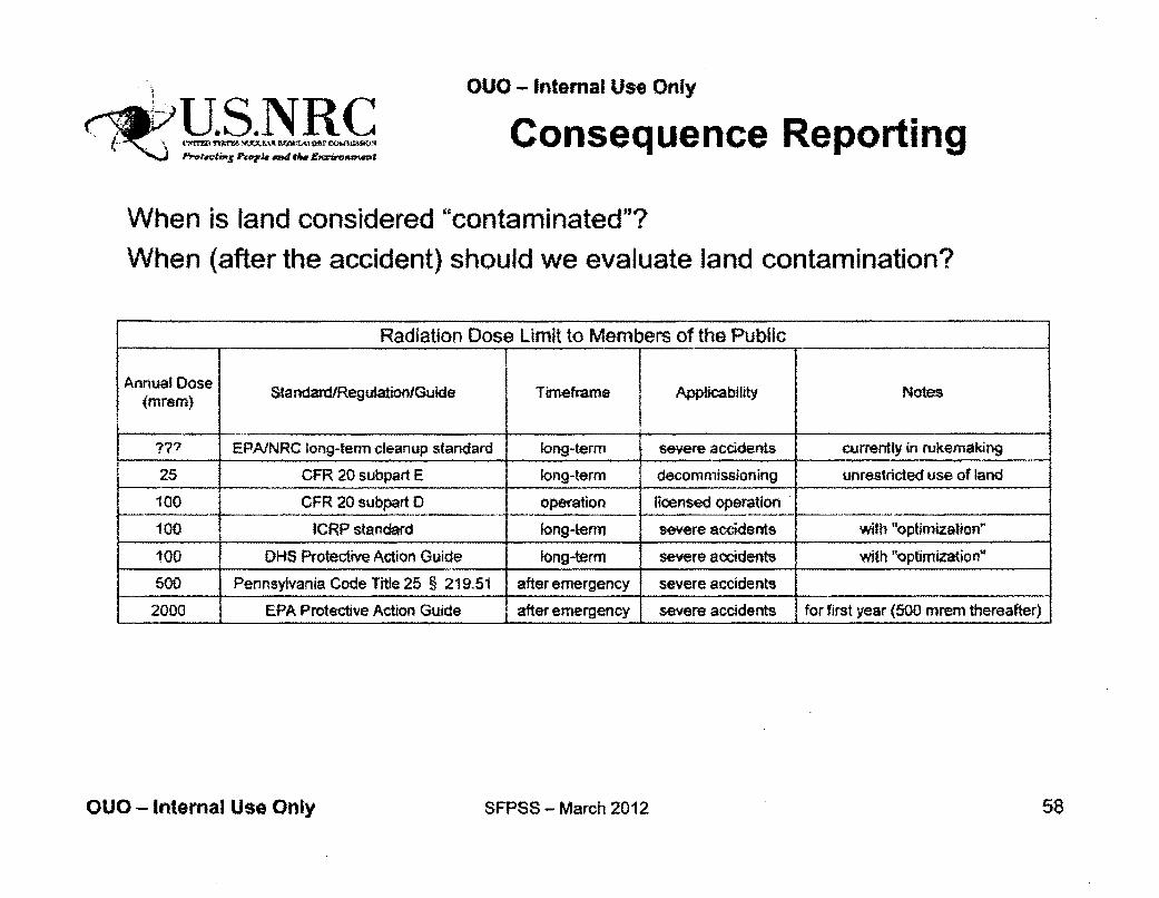
"" P('viS tT~~hU~aru and1 Ow Efwom"ep
OUO - Intemal Use Only
Consequence Reporting
When is land considered "contaminated"?
When (after the accident) should we evaluate land contamination?
Radiation Dose Limit to Members of the Public
Annual Dose AplcbltNoe(Aoreos) StandardfRegulation/Guide I Timeframe Applicability Notes
??? EPNNRC long-term cleanup standard long-term severe accidernts currently in rukemaking
25 CFR 20 subpart E long-term decommissioning unrestricted use of land
100 CFR 20 subpart 0 operation licensed operation
100 ICRP standard long-term severe accidents with "optimization"
100 DHS Protective Action Guide long-term severe accidents with "optimization"
500 Pennsylvania Code Title 25 § 219.51 after emergency severe accidents
2000 EPA Protective Action Guide after emergency severe accidents for first year (500 mrern thereafter)
OUO - Internal Use Only SFPSS - March 2012 58

OUO - Internal Use Only
•U.S.NRC
Concluding Remarks
and Questions
Katie Wagner
OUO - Internal Use Only SFPSS - March 2012 59
OUO- Internal Use Only
Coordination and CommunicationInternal:- Working with Japan Lessons Learned Project Directorate Steering
Committee on path forward- Input from program offices- Briefings for Senior Management and Commissioners
* Interactions with licensee" ACRS:
- Informal discussion- Closed March Subcommittee meeting- Planned open April Full Committee meeting (methods only)
° External:- Mentioning of study in Congressional testimony, senior
management presentations, etc.- RIC 2012 presentation- A communication plan has been drafted (currently working w/OPA)
OUO - Internal Use Only SFPSS - March 2012 60
OUO - Internal Use Only
•US .NRC SFPSS Project Team
* Katie Wagner - Overall project lead* Hossein Esmaili - Accident progression lead- Don Helton - Boundary conditions and probabilistic
aspects lead* Andy Murphy - Seismic analysis lead• AJ Nosek - Offsite consequence lead
* Jose Pires - Structural analysis lead
OUO - Internal Use Only SFPSS - March 2012 61
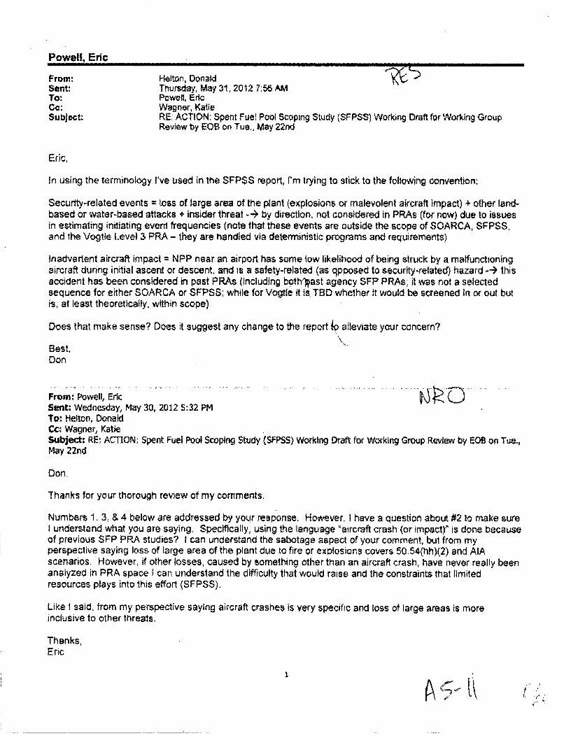
Powell, Eric
From: Helton, DonaldSent: Thursday, May 31, 2012 7:56 AMTo: Powell, EricCc: Wagner, KatieSubject: RE: ACTION: Spent Fuel Pool Scoping Study (SFPSS) Working Draft for Working Group
Review by EOS on Tue., May 22nd
Eric,
In using the terminology I've used in the SFPSS report, I'm trying to stick to the following convention,
Security-related events = loss of large area of the plant (explosions or malevolent aircraft impact) + other land-based or water-based attacks + insider threat -4> by direction, not considered in PRAs (for now) due to issuesin estimating initiating event frequencies (note that these events are outside the scope of SOARCA, SFPSS.and the Vogtle Level 3 PRA - they are handled via deterministic programs and requirements)
Inadvertent aircraft impact = NPP near an airport has some low likelihood of being struck by a malfunctioningaircraft during initial ascent or descent, and is a safety-related (as qpposed to security.related) hazard --4 thisaccident has been considered in past PRAs (including both'ýast agency SFP PRAs; it was not a selectedsequence for either SOARCA or SFPSS; while for Vogtle it is. TBD whether it would be screened in or out butis, at least theoretically, within scope)
Does that make sense? Does it suggest any change to the report ip alleviate your concern?
Best,Don
From: Powell, EricSent: Wednesday, May 30, 2012 5:32 PMTo: Helton, DonaldCc: Wagner, KatieSubject: RE, ACTION: Spent Fuel Pool Scoping Study (SFPSS) Working Draft for Working Group Review by EOB on Tue.,May 22nd
Don.
Thanks for your thorough review of my comments.
Numbers 1. 3, & 4 below are addressed by your response. However, I have a question about #2 to make sureI understand what you are saying. Specifically, using the tanguage 'aircraft crash (or impact)` is done becauseof previous SFP PRA studies? I can understand the sabotage aspect of your comment, but from myperspective saying loss of large area of the plant due to fire or explosions covers 50.54(hh)(2) and AIAscenarios. However, if other losses, caused by something other than an aircraft crash, have never really beenanalyzed in PRA space ; can understand the difficulty that would raise and the constraints that limitedresources plays into this effort (SFPSS).
Like I said, from my perspective saying aircraft crashes is very specific and loss of large areas is moreinclusive to other threats.
Thanks,Eric
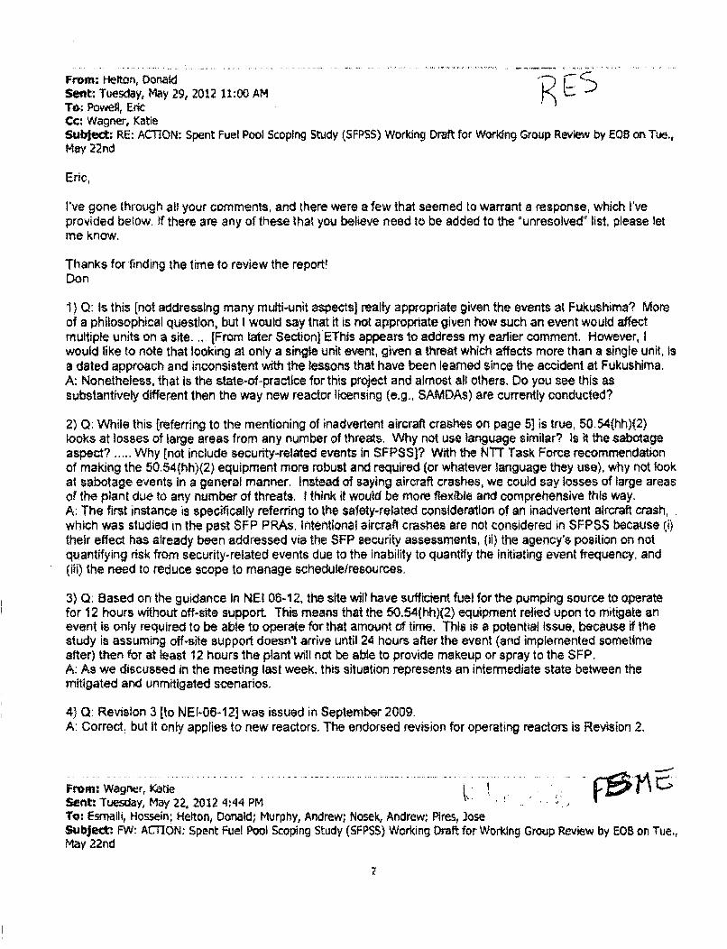
From: H-elton, OonatdSe~nt: Tuesday, May 29, 2012 11:00 AMTO: Powell, EricCc: Wagner, KatieSubject: RE: ACTION: Spent Fuel Pool Scoping Study (SFPSS) Working Draft for Working Group Review by E08 on Tue.,May 22nd
Eric,
I've gone through al0 your comments, and there were a few that seemed to warrant a response, which I'veprovided below. if there are any of these that you believe need to be added to the Ounresolved" list, please letme know.
Thanks for finding the time to review the report'Don
1) 0: Is this [not addressing many multi-unit aspects] really appropriate given the events at Fukushima? Moreof a philosophical question, but I would say that it is not appropriate given how such an event would affectmultiple units on a site..,. [From later Section] EThis appears to address my earlier comment. However, Iwould like to note that looking at only a single unit event, given a threat which affects more than a single unit, isa dated approach and inconsistent with the tessons that have been learned since the accident at Fukushima.A: Nonetheless, that is the state-of-practice for this project and almost all others. Do you see this assubstantively different then the way new reactor licensing (e.g., SAMDAs) are currently conducted?
2) 0: While this freferring to the mentioning of inadvertent aircraft crashes on page 5] is true, 50.54(hh)(2)looks at losses of large areas from any number of threats. Why not use language similar? Is it the sabotageaspect? ..... Why (not include security-related events in SFPSS3? With the NTT Task Force recommendationof making the 50.54(hh)(2) equipment more robust and required (or whatever language they use), why not lookat sabotage events in a general manner. Instead of saying aircraft crashes, we could say losses of large areasof the plant due to any number of threats. I think It would be more flexible and comprehensive this way.A: The first instance is specifically referring to the safety-related consideration of an inadvertent aircraft crash,which was studied in the past SFP PRAs. Intentional aircraft crashes are not considered in SFPSS because (i)their effect has already been addressed via the SFP security assessments, (ii) the agency's position on notquantifying risk from security-related events due to the inability to quantify the initiating event frequency, and(ifi) the need to reduce scope to manage schedule/resources.
3) Q: Based on the guidance in NEI 06-12, the site wilt have sufficient fuel for the pumping source to operatefor 12 hours without off-site support. This means that the 50.54(hh)(2) equipment relied upon to mitigate anevent is only required to be able to operate for that amount of time. This is a potential issue, because if thestudy is assuming off-site support doesn't arrive until 24 hours after the event (and implemented sometimeafter) then for at least 12 hours the plant will not be able to provide makeup or spray to the SFP.A: As we discussed in the meeting last week. this situation represents an intermediate state between themitigated and unmitigated scenarios.
4) Q: Revision 3 [to NEI-06-12] was issued in September 2009.A: Correct. but it only applies to new reactors. The endorsed revision for operating reactors is Revision 2.
From: Wagner, KatieSent: Tuesday, May 22, 2012 '1:44 PMTo: Esmalli, Hossein; Helton, Donald; Murphy, Andrew; Nosek, Andrew; Pires, JoseSubject: FW: ACTION: Spent Fuel Pool Scoping Study (SFPSS) Working Draft for Working Group Review by EOB on Tue.,May 22nd
Forwarding
From: Powell, EricSent: Tuesday, May 22, 2012 4;43 PMTo: Wagner, KatieC•: Ader, Charles; Mrowca, Lynn; Weerakkody, SurillSubject: RE; ACTION: Spent Fuel Pool Scoping Study (SFPSS) Working Draft for Working Group Review by EOB on Tue,,May 22nd
Ka!ie,
In the attached document you will find my comments.
Thanks.Eric
r .agn... K.i..... . .... ..... ............... ... ................................ . . .
Sent: Tuesday, May 15, 2012 7:42 PMTo: Barto, Andrew; Sullivan, Randy; Schrader, Eric; Jones, Steve; Mitrvanr, Jeffrey; Bowman, Eric; Witt, Kevin; Tegeler, .-- •Bret; Powell, EricCc: Gibson, Kathy; Scott, Michael; Poole, Brooke; Lewis, Robert; Ruland, William; Gfitter, Joseph; McGinty, Tim; Ader,Charles; Bergman, Thomas; Skeen, David; Evans, Michele; Clifford, James; Lee, Richard; Coyne, Kevin; Hogan,Rosemary; Santiago, Patricia; Wood, Kent; Hansel[, Samuel; Ennis, Rick; Esmalli, Hossein; Helton, Donald; Murphy,Andrew; Nosek, Andrew; Pires, JoseSubject: ACTION: Spent Fuel Pool Scoping Study (SFP55) Working Draft for Working Group Review by EOB on Tue,, May22nd
Attachment contains 0,10 - Sensitive Internal Information
All,
Attached is a working draft for review and comment by Other-Office Working Group members by end-of-business onTuesday. May 22"o. We understand that this is a large document and the review time is relatively short. we appreciateyour input to help meet our deadlines. A few notes about thtis document
" This is a working draft which has not been formally reviewed by the SFPSS Team or technical writing editors yetdue to the tight schedule involved. The formatting of the document has not been finalizea at this time.Equations which did not show up in the main .pcf document are attached in a MS Word file.
" The current plan is that the SFPS$ report will be sent by memo from Brian Sheron, RES to Eric Leeds, NRR atthe end of June for their oonsideration as part of the NTTF Tier 3 issue regarding transfer of spent fueN frompools to casks,
" RES and NRR are still determining the path and schedule to obtain public comment on the report and providing itto the Commission
" Drvision Directors have been cc'ed on this email at the request of RES Divrsion Management.
Please let me know if you have any questions or comments.
Thanks,
Katie WagnerGeneral EngineerV.5. Nuclear Regulatory Commission(301) 251.7917U~tieWaRnergnrm.gov
3
t .
Schaperowt Jason
From:Sent:To:Subject:Attachments:
Schaperow, JasonTuesday, June 05, 2012 1:46 PMSantiago, PatriciaRE: DRAFT SFPSS report for review by EOB on June 4thRE: SFPSS meeting
The analysis does not represent the Peach Bottom Atomic Power Station and is too simplified andconservative to be useful for regulatory purposes, My preliminary comments (in the attached email) need to beresolved by revising the analysis and not by adding qualitative discussion to the report, Because no one hasresolved my preliminary comments, the value of additional review is unclear.
From: Santiago, PatriciaSent: Tuesday, June 05, 2012 12:50 PMTo: Schaperow, JasonSubject: RE: DRAFT SFPSS report for review by EO8 on June 4th
... .. ... .... .. .
Can you tell me? The whole thing if you like but it is 177 pages so we should focus on what we can review toassist them. AJ analyses will not be done until Randy provides some EP input.thanks
From. Schaperow, JasonSent: Tuesday, June 05, 2012 12:40 PMTo: Santiago, PatriciaCc: Nosek, AndrewSubject: RE: DRAFT SFPSS report for review by EOB on June 4th
Thanks. What part(s) of this report do you want me to review?
From: Santiago, PatriciaSent: Tuesday, June 05, 2012 12:35 PMTo: Schaperow, JasonCc: Nosek, AndrewSubject: FW: DRAFT SFPSS report for review by EOB on June 4th
You did get it but this is what AJ gave meAnd let's set a time to discuss any input to AJ/KatieThanksl
From: Wagner, KatieSent: Tuesday, May 29, 2012 5:33 PMTo: Lee, Richard; Coyne, Kevin; Hogan, Rosemary; Santiago, PatriciaCc: Schaperow, Jason; Madni, ImtJaz; Esmaili, Hossein; Helton, Donald; Murphy, Andrew;Subject: DRAFT SFPSS report for review by EOB on June 4th
Nosek, ndrew; Pires, Jose
Good Afternoon Richard, Kevin, Rosemary, and Pat,
Attached is the draft SFPSS report for your review, which is about 200 pages long. We ask that you complete your reviewby EOB on Monday, June 41". Here are a few notes about this document:
" The SFPSS team rs still working to resolve commelits and have not reviewed each other's sections in detail.However, the leam is comfortable sending this draft forward for review at this time.
" The equations do not show up in this version of the document, so an equation list is attached for your information.
a Some MACCS2 runs have not been completed at this time due to the pending implermentation of new evacuationmodeis developed by NSIR in cooperation with Sandia staff. The team does not expect most of the results tochange dramatically once those are complete and I will send you the final offsite consequences chapter once thatchapter is complete.
* The concurrence package is currently in the process of coming together. In the package, the report wvll be anenclosure to a memo with the following characterisbcs (I will write the memo and send it to you In the next day ortwo):
o Will be from B. Sheron to E. Leeds.o Content:
" Discuss that the SFPSS Is a RES product that was executed as laid out in the July 2011 projectplan.
" Discuss that the SFPSS Is for NRR consideration as part of the Tier 3 Japan Lessons Learneditem.
" WaI contain a placeholder for a few main conclusions.• Some comments which the team has not resolved have been added to a tracking list, which is attacbed.
OPA sent exlensive comments on the abstract and executive summary of the report on the afternoon ofThursday, May 24'h. The SFPSS team has not processed these comments yet.I received comments from OTE on the afternoon of Tuesday, May 291. The SFPSS team has not processedthese comments yet either.
Note: Jason and Imtiaz have been cWed since they are acting for Pat this week.
ThankS,
Katie WagnerGeneral EngineerU.S. Nuclear Regulatory Commission(301) 251.7917Katie.•WaRner @n rcRov
2
Schaperow, Jason _From: Schaperow, Jason ( I
Sent: Wednesday, May 23, 2012 8.25 AMTo: Helton, DonaldCc: Wagner, KatieSubject: RE: SFPSS meeting
My issues are as follows:
Seismic initiator - The analysis does not include a concurrent reactor accident.* Arrangement of fuel - Peach Bottom uses a I x8 arrangement of fuel, not the 1 x4 arrangement assumed inthe study.* Pool damage - Fukushima shows that an earthquake would not make a hole in a spent fuel pool.. Mitigation - Peach Bottom-specific mitigation measures are not credited.* Mitigation - Makeup and spray are likely, because the spent fuel pool is an open system and there is a longtime available until draindown and fuel damage. Also, offsite equipment began arriving at Fukushima withinabout 8 hours (INPO report of November 201 1).- Mitigation - The operators are likely to make openings in the reactor building to aid in spent fuel pool coolingand to prevent a buildup of hydrogen from a concurrent reactor accident.• Mitigation - For one of the 'mitigated" cases, the analysis assumes makeup when spray is needed (andavailable) to prevent fuel overheating.• Mitigation - The "unmitigated" cases include some B.5.b mitigation, namely, arranging the fuel in a favorablepattern for cooling.- Release from clad-pellet gap - The assumed release of cesium (magnitude of 0.05, chemical form CsOH) isconservative.- Release from fuel pellet . The modeling was validated using in-pile tests for reactor accidents, which is notprototypical of spent fuel pool accidents which progress more slowly and have lower fuel temperatures.' Hydrogen combustion - A single node is used for the area between the refueling floor the reactor buildingroof, Simple parametric modeling is used for determining whether there will be a burn.- Public evacuation - Assuming that we can evacuate tens and even hundreds of thousands of people but wecannot get a couple of people up to the spent fuel pool with a fire hose seems illogical•Public evacuation - NRC recommended a 50'mlle evacuation for Fukushima.* Public evacuation - MELCOR and MACCS analysis was used for developing evacuation and relocalionassumptions. instead of RASCAL.- Results - The consequence/risk results presented in the study assume the probability of mitigation is zero.
I
Scha row, Jason
From: Schaperow, JasonSent: Tuesday, June 05, 2012 1:46 PMTo: Santiago, Patricia4tSubject- RE: DRAFT SFPSS report for review by EO on june4th
Attachments, RE: SFPSS meetingomit owerstation Ornd
The analysis does not represent the Peach Bottom Ato "..,power .ometsconservative to be useful for regulatory purposes. My preliminary'". n .ume ti
resolved by revising the analysis and not by adding quaita_ ev is Unclear.resolved my preliminary comments, the value of additional review I
plitfied and .edt8hd M tae tO t
From: Santiago, PatriciaSent: Tuesday, June 05, 2012 12:50 PMTo: Schaperow, Jason retie CanSubject. RE: DRAFT SFPSS report for review by EO5 on June 4th so o weWuldl fOoths re V
Can you tell me? The whole thing if you like but it is 177 pages SOe weP inp~ -- Dassist them. AJ analyses will not be done until Randy provides som-e "-pL
thanks
From: Schaperow, JasonSent: Tuesday, June 05, 2012 12A40 PMTo: Santiago, PatriciaCc: Nosek, AndrewSubject: RE: DRAFT SFPSS report for review by EOB on June 4th
Thanks. What part(s) of this report do you want me to review?
-om: SanUago, Patriciamnt: Tuesday, June 05, 2012 12:3S PM
Schaperow, JasonNosek, Andrew
iject: FW: DRAFT SFPSS report for review by EOB on June 4th
did get it but this is what AJ gave melet's set a time to discuss any input to AJ/Katiekst
Wagner, Katieruesday, May 29, 2012 5:33 PM,Richard; Coyne, Kevin; Hogan, Rosemary; Santiago, Patricia Andr'ev~ Nrk
iperow, Jason; Madni, I[mtiaz; Esmailb, Hossein; Helton, Donald; Murphy,ý
: DRAFT SFPSS report for review by' EOB on June 4th
-A
Aridrv ptr9' jse
'moon Richard, Kevin, Rosemary, and Pat,
the draft SFPSS report for your review, which is about 200 pages loll "Monday, June 4t', Here are a few notes about this document:
*~~t YWve at~v e ol- in CIO tak' ,
SFPSS team is still working to resolve comments and have not reviev' .. 5 time, att d: :
'ever, the team is comfortable sending this draft forward for review at to Ii list i!.quations do not show up in this version of the document: so an equa t i C:ý
f oro Y'a"
657-- ý "ý
* Some MACCS2 runs have not been completed at this time due to the pending implementation of new evacuationmodels developed by NSIR in cooperation with Sandia staff. The team does not expect most of the results tochange dramatically once those are complete and I will send you the final oftsite consequences chapter once thatchapter is complete.
0 The concurrence package is currently in the process of coming together. In the package, the report will be anenclosure to a memo witth the following characteristics (I will write the memo and send it to you in the next day ortwo):
o Wll be from B. Sheron to E- Leeds.o Content:
Discuss that the SFPSS is a RES product that was executed as ladi out in the July 2011 projectplan.Discuss that the SFPSS is for NRR consideration as part of the Tier 3 Japan Lessons Learneditem.
* Will contain a placehotder for a few main conclusions.# Some comments which the team has not resolved have been added to a tracking list, which is attached:& OPA sent extensive comments on the abstract and executive summary of the report on the afternoon of
Thursday, May 24ý". The SFPSS team has not processed these comments yet.0 I received comments from GTE on the afternoon of Tuesday, May 2 9th. The SFPSS team has not processed
these comments yet either.
Note: Jason and Imtiaz have been cc'ed since they are acting for Pat this week.
Thanks,
Katie WagnerGeneral EngineerU.S. Nuclear Regulatory Commissionf301) 2S1.7917Latie.Wagne~renr.ov
2
Mrowgki Lynn
Fromt PmWel, EricSent: Tuesday, August 28, 2012 11.27 AMTo: Mmwca. LynnSub"L FW; UPDATE 03: WO1 ass.ciaed wih ReS Spent Fuel Pow Sp•ing Study ýSFPSS)Atrae~hmet-,: SFPSS HRA Coillboration Group.doc•
FrO4 .j: Wagner, Katie 7 6,.-Senb Thursday, July 12, 2012 8:10 AM ,Q.K.To: Barto, Andrew; Powell, Eric; Tegeler, Bret; Jones, Steve; Mitman, Jeffrey; Bowman, Eric; Wood, Kent; Ennis, Rick; Sullivan,Rahdy; Schrader, Eric; Witt, Kevin; Bloom, StevenCC% Helton, Donald; Esmaili, Hossein; Murphy, Andrew; Nosek, Andrew; Pires, .oseS•bec FW. UPDATE #3: HRA associated with RES Spent Fuel Pool Scoptng. Study (SFPSS)
0SPSS Other-Office Working Group and Others,
below is the third update on the recently-added HRA to keep you in the loop.
Also, this afternoon (4-Spin EST) SFPSS team members will be briefing Regions I and IV at the division leve! (va VTC (imageonly) and teleconference (sound)) with the other Regions invited to paertcate via teleconference. The briefing slides wilt beextremely similar to those used for the Cmr. Magwood oriefing on July 2
Thanls,
Katie WagnerGeneral EngineerU.S. Nuclear Regulatory Commission
Kie- .WaRrne rfnrc.Rov
From: Coe, Dougient: Tuesday, July 10, 2012 12:39 PMro: Ruland, William; Clifford, James; Roberts, Darrell; Lewis, Robert; Thaggard, Mark; Evans, Michele; Giltter, Joseph; Lee,'amson; Wilson, Peter; Monnlnger, John; Weaver, Doug; Ader, Charles; Lombard, Mark; Gibson, Kathy; Scott, Michael'tf Correla, Richard; Peters, Sean; Uhle, Jennifer; Chang, James; Wagner, Katie; Weerakkody, Suill; Feger, Stephen; Wit,evin; Ennis, Rick; Kahler, Robert; Sullivan, Randy; Helton, Donald; Mitman, Jeffrey; Zoulis, Antonlos; Cahill, Christopher; Taylor,,bert; Coyne, Kevin; Kelghley, ElizabethAbJject UPDATE #3; HRA associated with RES Spent Fuel Pool Scoping Study (SFPSS)
,: Division Directors supportinglengaged on subject HRA for SFPSS initiative
I. The staff has revised the project plan based upon comments received to date. We expect to send the p-ojec!plan out for concurrence this week, in paraliel.with management briefings on the plan. We expect that oncethe plan is sufficiently vetted. we will ask the RES FO to ticket it and thereby provide a definitive tasking andschedule to be completed, for planning purposes.
2. Qur RES PM James Chang (RES1, alongi with Jeff Mitman (NRR9: Anthony Zouiis(NRR1. and .Chris Cahill (Rlwill visit Peach aottom on July 12 to gather soeciftics for the analysis. The visit will consist of accidentmitigation walkthroughs and walkdowns of the main control room, water treatment building, fire header, coolingtower basin, B5b equipment storage location, spent fuel pool cooling pump, refueling floor, and the spent fuelpool
As a reminder, the enhancements to mitigation strategies (to resist external hazards) expected fromimplementing the recent orders will NOT be included in this first HRA study, but we will hold the option ofanother KRA study when those enhancements are in place,
13
4, The NTTF Tier 3 information Commission paper is up to OEM20 For recommendation 5 (consideration ofspent fuel transfer from pools to dry storage) it notes that in addition to the Spent Fuel Scoping Study and thisHRA study. the staff will also study the effects on fuel safety associated with Increased fuel handling incident toan accelerated dry cask storage campaign. NMSS is in the lead for this latter item but is planning to engageRES for support. Additionally, similar direction.on swudvinq foe? handling mgy be forthcoming from theCommi'ssion in the currently DRAFT SRM - M120607C (from the recent ACRS meeting with theCommission).
5. I have attached an updated Collaboration Group table based upon inputs received to date. This is the M wewijuseo cMA =municte the§e qdqates. Please let James Chang, Sean Peters, Rich Correia, and I know ifyou would like to make any changes.
Thanks egain and please let us know if you have any questions, comments, or concerns,Doug
Doug CoeDeputy DirectorDivision of Risk Analysis (DRA)Office of Nuclear Regulatory Research (RES)U.S. Nuclear Regulatory CommissionRockville, MD301-25.1-7914do g.coe@nrc.,ov
14
Powll, LEr"
Ff0.1': Wagner, KatieSent: Tuesday, May 15, 2012 7:56 PMTo: Barto, Andrew, Sullivan, Randy; Schrader, Eric; Jones, Steve Mitman, Jeffrey; Bowman, Enc,
Witt, Kevin; Tegeler, Bret; PoweA, Eric-00: Gibson, Kathy; Scott, Michael' Poole, Brooke; Lewis, Robert, Ruland, William; Glitter, Joseph;
McGinty, Tim; Ader, Charles; Bergman, Thomas: Skeen, David; Evans, Michele; Clifford,James, Lee, Richard; Coyne, Kevin; Hogan, Rosemary; Santiago, Patricia; Wood, Kent;Hansell, Samuel,; Ennis, Rick; Esmail, Hossein; Helton, Donald, Murphy, Andrew; Nosek,Andrew; Pires, Jose
Subject: RE: ACTION. Spent Fuel Pool Scoping Study (SFPSS) Working Draft for Working GroupReview by EOB on Tue. !May 22nd
All - Please note that the resuts of the consequence analysis are preliminary because they are calculated with a 1 0-mileevacuation model. While a 10-mile evacuation model is apohcable to some smaller releases; it is not realistic for some ofthe larger releases. Updated results with the new evacuation models are expected in the coming weeks. - Thanks, Katie
From: Wagner, KatieSent: Tuesday, May 15, 2012 7:42 P•,lTo: Barto, Andrew; Sullivan, Randy; Schrader, Eric; Jones, Steve; Mitman, 3effrey; Bowman, Eric; Witt, Kevin; Tegeler,Bret; Powell, EricCc: Gibson, Kathy; Scott, Michael; Poole, Brooke; Lewis, Robert; Ruland, William; Gitter, loseph; McGinty, Tim; Ader,Charles; Befgman, Thomas; Skeen, David; Evans, Michele; Clifford, James; Lee, Richard; Coyne, Kevin; Hogan,Rosemary; Santiago, Patr:cia; Wood, Kent; Hansell, Samuel; Ennis, Rick; Esrnaill, Hossein; Helton, Donald; Murphy,Andrew; Nosek, Andrew; Pires, loseSubject: ACTION: Spent Fuel Pool Scoping Study (SFPSS) Working Draft for Working Group Review by EOB on Tue., May22nd
Attachment contains OUO - Sensitive Internal Information
All,
Attached is a working draft for review and comment by Other-Office Working Group members by end-of-business onTuesday, May 22nd. We understand that this is a large document and the review time is relativety short, we appreciateyour input to help meet our deadlines. A few notes about this document.:
, This is a working draft which has not been formally reviewed by the SFPSS Team or technical writing editors yetdue to the tight schedule involved. The formatting of the document has not been finalized at this time.Equations which did not show up in the main .pdf document are attached in a MS Word file.
" The current plan is that the SFPSS report will be sent by memo from Brian Sheron, RES to Eric Leeds, NRR atthe end of June for their consderation as part of the NTTF Tier 3 issue regarding transfer of spent fuel frompools to casks.
" RES and NRR are still determining the path and schedule to obtain public comment on the report and providing itto the Commission.
" Division Directors have been cc'ed on this email at the request of RES Division Management.
Please let me know if you have any questions or comments.
Thanks,
Katie Wagner6eneral EngineerU.S, Nuclear Regulatory Commission1301) [email protected]

Powell, Eric
F40m: Wagner, KatieSent: Tuesday, May 15, 20f27:56 PMTo: Barto, Andrew; Sullivan, Randy; Schrader, Eric; Jones, Steve; Mitman, Jeffrey; Bowman, Eric;
Witt, Kevin; Tegeler, Bret; PoweLA, EricGibson, Kathy; Scott, Michael, Poole Brooke; Lewis, Robert- Ruland, William, Glitter, Joseph;McGinty, Tim; Ader, Chares; Bergman, Thomas.; Skeen, DaRid; Evans, Michele; Clifford,James; Lee, Richard; Coyne, Kevinr Hogan, Rosemary; Santiago, Patricia; Wood, Kent;Hansell, Samuel; Ennis. Rick; Esmaill, Hossegn. Helton, Donald, Murphy, Andrew; Nosek;Andrew; Pires, Jose
Subject: RE: ACTION: Spent Fuel Pool Scoping Study (SFPSSV Working Draft for Working GroupReview by EOB on Tue. ,,Aay 22nd
All - Please note that the results of the consequence analysis are preliminary because they are calculated with a 1 0-mileevacuation model. While a 10-mile evacuation model is applicable to some smaller reteases, it is not realistic for some ofthe larger releases. Updated results with the new evacuation models are expected in the coming weeks. - Thanks, Katie....... ..... ..... ...... ... ... .. ~ ~. ................. .... ... .. ..... ....................i J i: .. ' .. ...From: Wagner, KatieSent: Tuesday, May 15, 2012 7:42 PMTo: Barto, Andrew; Sullivan, Randy; Schrader, Eric; Jones, Steve; Mitman, Jeffrey; Bowman, Eric; Witt, Kevin; Tegeler,Bret; Powell, EricCc: Gibson, Kathy; Scott, Michael; Poole, Brooke; Lewis, Robert; Ruland, William; Gitter, Joseph; McGinty, Tim; Ader,Charles; Bergman, Thomas; Skeen, David; Evans, Michele; Clifford, James; Lee, Richard; Coyne, Kevin; Hogan,Rosemary; Santiago, Patricia; Wood, Kent; Hanselt, Samuel; Ennis, Rick; Esmaili, Hossein; Helton, Donald; Murphy,Andrew; Nosek, Andrew; Pires, JoseSubject: ACTION: Spent Fuel Pool Scoping Study (SFPSS) Working Draft for Working Group Review by EOB on Tue., May22nd
Attachment contains 0110 - Sensitive Internal Information
All,
Attached is a working draft for review and comment by Other-Office Working Group members by end-of-business onTuesday, May 22"". We understand that this is a large document and the review time is relatively short, we appreciateyour input. to hetp meet our deadlines. A few notes about this document:
" This is a working draft which has not been formally reviewed by the SFPSS Team or technical writing editors yetdue to the tight schedule involved. The formatting of the document has not been fuialized at this timeEquations which did not show up in the main .pdf document are attached in a MS Word file
" The current plan is that the SFPSS report wil) be sent by memo from Brian Sheron, RES to Eric Leeds, NRR atthe end of June for their consideration as part of the NTTF Tier 3 issue regarding transfer of spent fuel frompools to casks.
" RES and NRR are stlif determining the path and schedule to obtain public comment on the report and providing itto the Commission.
" Division Directors lhave been cc'ed on this email at the request of RES Division Management.
Please let me know if you have any questions or comments.
Thanks,
Katie Wagner6eneral EngineerU.S. Nuclear Regulatory CommissionP301) 251,7917
I
Powell, Eric
From, Weerakkody, SunillSent: Wednesday, May 23, 2012 11:46 AMTo: Powell, EricSubject: REý ACTION: Spent Fuel Pool Scoping Study (SFPSS) Working Draft for Working Group
Review by EOB on Tue., May 22nd
Nice work! Thanks for copying. I browsed through some of the comments.
Sunil
From: Powell, EricSent: Tuesday, May 22, 2012 4:43 PM OwTo: Wagner, KatieCc Ader, Charles; Mrowca, Lynn; Weerakkody, SunilSubject: RE: ACTION: Spent Fuel Pool Scoplng Study (SFPSS) Working Draft for Working Group Review by EOB on Tue.,May 22nd
Katie,
In the attached document you will find my comments
Thanks,Eric .. ... ....... .... ..... ........ .. .. .. .... ........ .. ...... .. ..... .. ..... ... .. ..... .... .... .. ...... ...... ......... L . .From. Wagner, Katie ,.f .~Sent: Tuesday, May 15, 2012 7:42 PM ;-To: Barto, Andrew; Sullivan, Randy; Schrader, Eric; Jones, Steve; Mitman, Jeff y; 80o Wit, KevIn; Tegeler,Bret; Powell, EricCc Gibson, Kathy; Scott, Michael; Poole, Brooke; Lewis, Robert; Ruland, William; Glitter, Joseph; McGinty, Tim; Ader,Charles; Bergman, Thomas; Skeen, David; Evans, Michele; Clifford, James; Lee, Richard; Coyne, Kevin; Hogan,Rosemary; Santiago, Patricia; Wood, Kent; Hansell, Samuel; Ennis, Rick; Esmalli, Hossein; Helton, Donald; Murphy,Andrew; Nosek, Andrew; Pires, JoseSubject: ACTION; Spent Fuel Pool Soaping Study (SFPSS) Working Draft for Working Group Review by EOB on Tue., May22nd
Attachment contains OUO - Sensitive Internal Information
All,
Attached is a working draft for review and comment by Other-Office Working Group members by end-of-business onTuesday, May 22' . We understand that this is a large document and the review time is relatively short, we appreciateyour input to help meet our deadlines. A few notes about this document:
0 This is a working draft which has not been formally reviewed by the SFPSS Team or technical writing editors yetdue to the tight schedule involed. The formatting of the document has not been finalized at this time,Equations which did not show up in the main .pdf document are attached in a MS Word file,
& The current plan is that the SFPSS report will be sent by memo from Brian Sheron, RES to Eric Leeds, NRR atthe end of June fox their consideration as part of the NTTF Tier 3 issue regarding transfer of spent fuel frompools to casks.
a RES and NRR are still determining the path and schedule to obtain public comment on the report and providing itto the Commission.
SDivision Directors have been ce'ed on this email at the request of RES Division Management.
Please let me know if you have any questions or comments.

Summary of Comments on SFPSS Report - EU' Comments.pdfPage: 4
Auhr ELP "le Dible: SMY202 2 .,05 18:L PM
i-kcELP) subva! Ii9i40h Date: $j2WJOt2. M5:G7 PM
ijtOr LPS It~.i~ OM.!M Caw. %171,2012 ZO5 PM"
Wtc~ oe Mwe: 5aMIZOUZ 7-0636 P
j~A~ithor; ELPI -- suibct fHkNqht Dae: 5=20Z'1 2:05,00 R4
Page: 6TAut ELPI Stk~B&t H~Mt DvWý 5,12120 il 2 23:39 R4
* &tor~ ELPL Sop&, SUCkly Witie DBWe 5/UIZ2,oU 1"25:11 W4
Af1'or: ELPI 5.Lc Sby Datc: 5122120,12 2:25:04 R4Has Me been 01cusiuon MOM M04 of rew~ement in Uths amVo Jlu 8 amigtt
Auho ElPi aq!Et High~rt Data: 5122r'2012 7:23-.40 PM
r:Aulllr' ELPi. a!!nea: HýQhigaJ. Dal: S/22/2012 2:213:4S PIM
iw:ELP1 S~jbec: 21kk NvM Datq 5;2212012 2;.-1.4 PMI thr M frn S~Wyr
..Aumtr: ELPI Dem.c Saq~i~~524j2032 2:32132 PMThm m~ sae iR' W 5ii Mn1,1M Mbmi 5 & 8 above. On eww4 fthughtf. f Wmes W~ng wa miekh~ng cr~d t* sfe- in o low~dwOny woegwion, Isfl lie- $ame
~ ~ hh~de~s~y w~iui~~ M ~ iae. ~I cuAwP j *rm actp Wo under~tan4%mspolnt bed, butt w ited w~ pLA be~oe twee 8Iw.
ýTjAutc; ELPI Subjeti: H~gahi CDaW* SW22012 21Z9:26 PH
Jj~~hf:Wl Subjeett tWiah Vt]: W5/20,12 Z:4,14 PM
A&&Yw jLWiz lsgý*ghl Lats VvW IO 2:217:517 PM
Page: 22El-PI S~betSlkxV N Dte : %f~2212012 11:1
VWhy7 WO$I the OM1 T;;s owt~ Rr toIN týig 505PV eqwptTmrA "woe mbu m& w r -rd (Qr whwzmv iong14.g fthey -); wtii - t.zco t-tawrfina 9"real ntmnr.er. Insmad of say'~g aircfaft crOm*nes could my kmw0ageano t plant due to any inumb" of freots- I hunt it woul be more fliir~Ne
Vnd bu&rlw e r wav.
.T Adlho PLPI SUbIDtm I-1ghtbt Date: 5/22/2012 3.07:22 PM

Page: 81jk~~tr; ELPI. S~bj~at: Etký Note Daber. 512W2D2IZ 41-124 PMSasei ce ft1 Wjktam in NO -12 the sM tX 4m suflf~e" u ftM r W" pon¶p"g mutrm to owrme for 1 Z triurs y~fthxof*~f-ste. Supporwt i t 5,4eouprwit raed uponI ittaea even L9 a ory ewJtd to be .P* to~ aWeft fo tha ei1noof of lime. TM~ 6 a ~OPW'l wee becaqe 0 th *lXy 15 as "Of,a4geetdoes' wr uraI 24 bwatfV etev~en esarbd~e effited surne(INR after) Vwnq (or. last WiZ1 hove; the iA**I not Die a* to v pik~ mWkmp or If LatheSPP.
Official Use Only - Sensitive Internal Information ~j2~1D2 pIP
Scoping Study on the Consequences of a Well-BeyondOesign-Basis EarthquakeAffecting the Spent Fuel Pool at a Selected US Mark I Boiling Water Reactor
Interim Report for External Stakeholder Review and CommentJune 2012
Katie Wagner - C
Co-AuthgrsHossein EsmaitiDonald Helton
Andrew MurphyAndrew Nosek
Jose Pires
Office of Nuclear Regulatory ResearchUS Nuclear Regulatory Commission
Note - This report will eventually be made publicly available. In cases where Informatromcurrently included is specifically believed to be other than pre.decisional
reasons), these passages are
Official Use Only - Sensitive Internal Information
i o Ini
Official Use Only - Sensftive Internet Information Mytl,21May I e", 2012
ABSTRACT
This report provides the methodology and results of a lknited-scope consequence study toupdate the best-estimate consequences expected from the application of a postulated well-beyond-cesigh-basis earthquake (with an estimated frequency of occurrence of I event in61,000 years) to a selected US Mark I boiling water reactor spent fuel pool. The primaryobjective of the study is to provide updated and publicly available consequence estimates of arepresentative, postulated spent fuel pool severe accident under high-density and low-densityloading conditions to frame ongoing discussions regarding the impact (from a defense-in-depthperspective) of requiring operators of US nuclear power plants to expedite movement of fuelfrom the spent fuel pool to onsite, dry cask storage.
Regarding the event considered in this report, it is important to remember that the study isintentionally focusing on a very challenging and very unlikely event. All spent fuel pools aredesign•ed to seismic standards consistent with other important safety-related structures on thesite. The pool and s supporting systems are located within structures that protect againstnatural phenomena and flying debris. The pools' thick walls and floors provide structuralintegrity and further protection of the fuel from natural phenomena and debris. In addition, thedeep water above the stored fuel (typically more than 20 feet above the top of the spent fuelrods) would absorb the energy of debris that could fall into the pool. Finally, the racks thatsupport the fuel are designed to keep the fuel in its designed configuration after a seismic event.It is only because such a challenging event is studied that any offstte consequences arepredicted.
Official Use Only - Sensitive Internal Informationii
Official Use Only - Sensitive Internal Information May 15ý', 2012
ACKNOWLEDGEMENTS
The authors would like to acknowledge the following individuals who directly or indirectlycontributed to this work. The following individuals directly contributed in the form of analysesand support:
Don Algama, US Nuclear Regulatory CommissionNate Bixler, Sandia National LaboratoryHernando Candra, US Nuclear Regulatory CommissionIan Guald, Oak Ridge National LaboratoryAndrew Goldmarm, Sandia National LaboratoriesLarry Humphries, Sandia National LaboratoriesJoe Jones, Sandia National LaboratoryThomas Miier, Oak Ridge National LaboratoryBruce Patton, Oak Ridge National LaboratoryJoel Piper, Rotates from the Department of Homeland SecurityKenneth C. Wagner, dycoda, LLC:
The following individuals from other offices' of the NRC provided support and advice throughoutthe conduct of the study:
Andrew BartoEric BowmanSam HansellJohn Hughey
Steven JonesJeff MitmanEric PowellWayne Schmidt
Eric SchraderRandy SullivanBret TegelerKent Wood
Adam Ziedonis
Finally, the authors wish to acknowledge the guidance and support of NRC managemenL and inparticular Brian Sharon, who provided the initial direction for the study.
Official Use Only - Sensitive Internal InformationIii
Official Use Only - Sensitive Internal Information May 1 r, 2012
EXECUTIVE SUMMARY
Various risk studies (most recently NUREG-1738, 'Technical Study of Spent Fuel Pool AccidentRisk at Decommissioning Nuclear Power Plants," February 2001) have shown that storage ofspent fuel in a high-density configuration in SFPs Is safe and that the risk Is appropriately low.These studies used simplified and sometimes bounding assumptions and models forcharacterizing the likelihood and consequences of beyond-design-basis SFP accidents. As partof NRC's post-9/11 security assessments, SFP modeling using detailed thermal-hydraulic andsevere accident progression models integrated into the MELCOR code were developed andapplied to assess the realistic heatup of spent fuel under various pool draining conditions.Moreover, in conjunction with these post-91 I security assessments, NRC has requiredenhancements via 10 CFR 50.54(hh)(2) for operating reactor SFP storage that are directed atfurther improving the coolability of spent fuel under event conditions in which a substantialamount of water has drained from the storage pool. These mitigative strategies are being re-visited as part of the agency's Japan Lessons Learned imitative, and Orders have been issuedto further upgrade nuclear power plants' capabilities in these areas.
Recently, the agency restated its views on the safety of spent fuel stored in high-densityconfigurations in a number of forums, including its response to Petition for Rulemaking (PRM)-51-10 and PRM-51-12, the revision to NUREG-1437 (the Generic Environmental ImpactStatement for License Renewa) and various responses to external stakeholders related to theMarch 2011 events at the Japanese Fukusahima Daiichi reactors. However, this position reliesin part on the findings of the aforementioned security assessments, which are not publiclyavailable. The renewed interest in spent fuel storage engendered from the changes in pathforward of the planned geologic repository and from the aforementioned events in Japan hasrekindled Interest in capturing the consequences from postulated accidents associated withhigh-density SFP storage in an updated safety study. An SFP risk study is being planned aspart of a larger initiative Involving the conduct of a site Level 3 probabilistic risk assessment(PRA), as documented in SECY-1 1-0089 and the associated Staff Requirements Memorandum.
in the interim, a desire existed to produce updated consequence estimates for a particularscenario of Interest hat can in part act as a bridge between the current. state-of-knowledge(much of which lisreater then. 10 years old or security-related and, thudThnonpublicly available)and future studies. The current study fulfills that gap, investigating an important piece of theoverall puzzle. Other pieces of this puzzle haven been informed by past studies, will beaddressed -by future studies, or will be addressed through other inputs in to the decisionmakingprocess. This bigger picture is addressed via a Japan Lessons Learned activity related totransfer of spent fuel from pool to cask storage.
Two broad situations are considered in this study, which represent the following:
(1) A condition representative of the current situation for the selected site (I.e., high-densityloading in the SFP, a relatively full SFP, and current regulatory requirements withrespect to fuel configuration and preventivelmitigative capabilities); and
(2) A condition where expedited movement of oider fuel to dry cask storage has alreadybeen achieved (i.e., low-density loading in the SFP and current applicable regulatoryrequirements with respect to fuel configuration and preventive/mItigatIve capabilities).
Official Use Only - Sensitive Internal informationIv
Official Use Only - Sensitive Internal Information May I r, 2012
For purposes of obtaining a near-term perspective on the issue, a single site and singleassumed operating cycle are used. The site characterization (seismic response, decay heat,radionuclide inventory, etc.) have been based on readily available information that primarilystemmed from sources such as the NUREG-1 150 study, seismic information developed by theUnited States Geological Survey (USGS), and the post 9/11 security assessments'. Later in theproject, additional information was provided by the licensee which generally corroborates theassumptions made in this study.
A boiling water reactor plant was chosen for this analysis, in part because these types ofreactors often engender more interest from external stakeholders owing to the fact that the MarkI and Mark !1 designs have spent fuel pools are elevated relative to ground level. In the contextof safety-related events (as opposed to security-related events), the elevation of the pool willaffeW the transmission of seismic loads through the structure,. can D-Mtgually inhibit accessibilityfor taking mitigative action, and can potentially lead to flooding of safety-related equipment, ifthe pool and surrounding structures are signit•lcantly damaged. The seleStion of a boiling wateractordesign .is. n~ot.intendd! to suocest that these deakins are re vuSnerable to. sont, fel
pool agocdents, in reality, there are differences between the major design types (PWRs versusBWRs) which make each more or less susceptible to spent fuel pool accidents on a scenario-specific basis. Similarly, the selection of a site that has a separate SFP for each reactor (asopposed to a shared pool) is also not intended to suggest that these situations are inherentlymore vulnerable.
The study, which is described in much greater detail in the associated report, has led to thefollowing preliminary findings. All of the findings below are subject to the limitations spelled outin the associated report.
1. Past studies have indicated that large seismic events could lead to the loss of structuralintegrity of the spent fuel pool liner. The current work further confirms that such acondition is unlikely but possible. The specific conditions under which a failure mightoccur are very. site-specific.
2. Past studies have indicated that events that cause a loss of pool cooling, but notstructural failure of the. pool liner, lead to very slowly progressing accidents. For theconditions studied here, no set of conditions short of liner failure were sufficient forleading to a radioactive release in less than 3 days. In most cases, the available time toprevent the accident was much greater than 3 days..
3. In the cases studied, which in general did not account for multiple and concurrent reactor/ SFP accidents, the precise time to diagnose the need for SFP mitigation did not have astrong effect on the course of events.
Nevertheless, the improved feliable and available SFP indication required by theOrder of March 12, 2012, is still appropriate given its essential nature In ensuringthat plant personnel can effectively prioritize emergency actions. The availabilityof such instrumentation may have changed the mode (makeup versus sprays)deployed for some situations studied here.
The Post 911 1-secuti.y assessments inciuded considerston of SFPs and resuNed in the coiection of Informationand fthe deveypment of computer models that Provded a coNvenient starting point for the aurrent study.
Official Use Only - Sensitive Internal Informationv
Official Use Only - Sensitive internal Information May le, 2012
4. This study considered variations in both pool loading configuration and the effectivedeployment (or lack thereof) of mitigation. Of these, effective deployment of mitigationhad the largest impact on preventinq a release of radioactive material,
5. Results show that the use of favorable fuel configurations (i.e., 1x4) has a very positiveeffect in promoting coolabilIty and reducing the likelihood of a release should the SFPbecome drained. In this study, without mitigative action, fuel was air coolable at 60days", as opposed to estimates of roughly 1 year from past studies when hotter fuel wascontiguously stored. For the pattern currently employed at Peach Bottom (Ix8), an evenshorter coolability time is likely.
The following additional recommendations are preliminary, awaiting the outcome of the ongoingconsequence analyses. For the time being, they are based on preliminary results and/orinsights form past studies.
6. The difference between high-denslty and low-density loading situations were as follows:
,a In terms of whether a release occurred within 3 days (i.e., likelihood), nodifference was seen,
" In terms of the size of releases (i.e., an Indicator of consequences), in the casethat a release did occur a large difference was seen.
" Overall (i.e., likelihood and consequences) the scenario-specific offsiteconsequences were higher for high-density loading cases, but below pastestimates for both,
7. For the situations where a radioactive release was predicted, emergency preparednesswas successful in reducing the likelihood of earty health effects to essentially zero.
8, For the situations where a radioactive release was predicted, the predicted frequency ofoccurrence of latent health effects was largely affected by the pool loading configuration.
9. The general reduction in estimated consequences for the range of seismic eventsstudied here (0.5 to I g), along with the relative increase in the frequency of largerseismic events (> 1g) in the newer hazard updates, suggests that the leadingcontribution to risk may have shifted to these extremely large events. If the conditionalprobabilities of having a release for the extremely large events is commensurate withthat from the events studied here, the overall estimated scenario frequencies would stillbe well below those of past studies. This assumption presumes that the damage to thefuel, racks, and overlying building Is not substantively different from that assumed here.
10. This study has not uncovered any information that would challenge the existing agencyposition that spent fuel Is stored safety in high-density configurations. Further, it does notsuggest that past SFP risk estimates from large seismic events are non-conservative.Thus, under the existing regulatory framework. It does not challenge the establishedregulatory position that expedited fuel movement to casks is justified from a valueiimpactperspective, even without consideration of the negative aspects of expedited fuelmovement (e.g., worker dose).
2 The actual time evaluated was 37 days for thai operating cycle phase. There is reason to believe thatthe fuel may be air coolable in less than 80 days for a wide range of conditions, based on other separateeffects analyses.
Official Us. Only - Sensitive Internal Informationvi
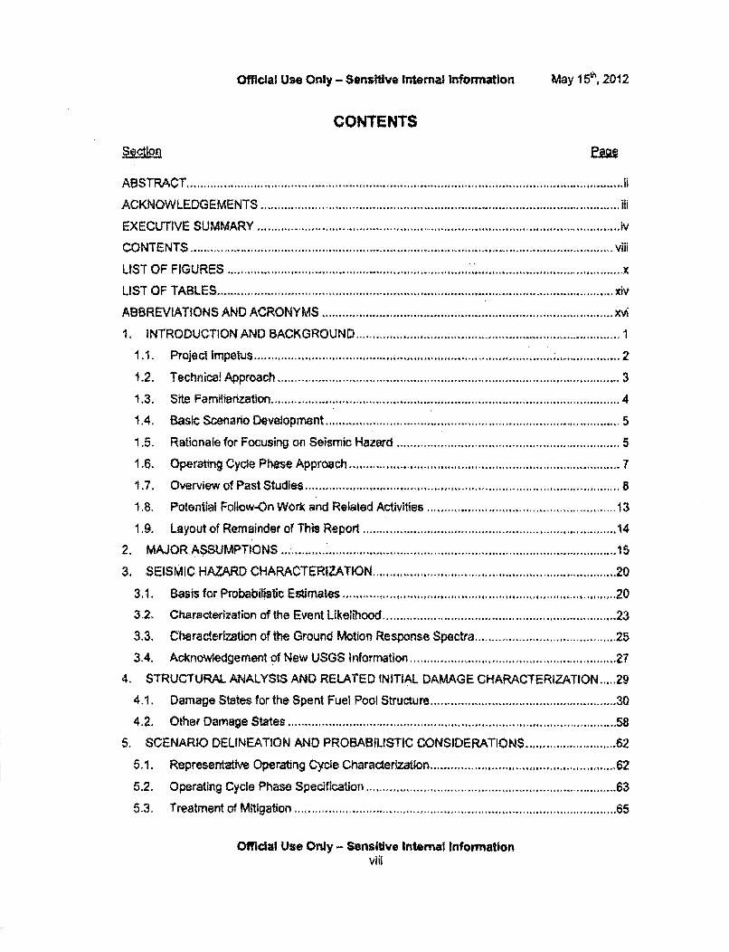
Official Use Only - Sensiftive Internal infoirmation May I V5, 2012
CONTENTS
A B ST R A C T .................................................................................. .............................................. 5i
ACKNOW LEDG EM ENTS ..................................................................................................... ili
EXECUTIVE SUMMARY..................................................iv
CONTENTS .... ................................................ viii
LIST OF FIGURES .......................................................................... x
LIST O F TA BLES ................................................................. ................................................ xiv
ABBREVIATIONS AND ACRONYMS .................................... xvi
1. INTRODUCTION AND BACKGROUND ...... ............... ........... 1
1,1. ProjectIm petus ..................... ............................................................ .. ................ 2
1.2. Technica! Approach ................................................................................................ 3
1.3. Site Familiarization ........................................... 4
1.4. Basic Scenario Development ...................................................... 5
1.5. Rationale for Focusing on Seismic Hazard ................................ 5
1.6. Operating Cycle Phtse Approach ....................................... 7
1.7. Overview of Past Studies.................. ................................................................... 8
1.8. Potential Follow-On Work and Related Activities ....... ...................... 13
1.9. Layout of Rem ainder of This Report ........................................................................ 14
2. MAJOR ASSUMPTIO NS ....................................................... ...................................... 15
3, SEISMIC HAZARD CHARACTERIZATION ............................... 20
3.1, Basis for Probabilistic Estim ates .......................................................................... 20
3.2. Characterization of the Event Likelihood ............................................................. 23
3.3. CheracterIzation of the Ground Motion Response Spectra ................. 25
3.4. Acknowledgement of New USGS Information .... ....................................... 27
4. STRUCTURAL ANALYSIS AND RELATED INITIAL DAMAGE CHARACTERIZATION... 29
4.1. Damage States for the Spent Fuel Pool Structure .................................................. 30
41 , O ther Dam age States ........................................ ................................................... 58
5. SCENARIO DELINEATION AND PROBABILISTIC CONSIDERATIONS ..................... 62
5.1. Representative Operating Cycle Characterization ................................ 62
5.2. Operating Cycle Phase Specification ................................................................... 63
5.3, Treatm ent of M itigation .......................................................................................... 65
Official Use Only - Sensitive Internal Informationviii
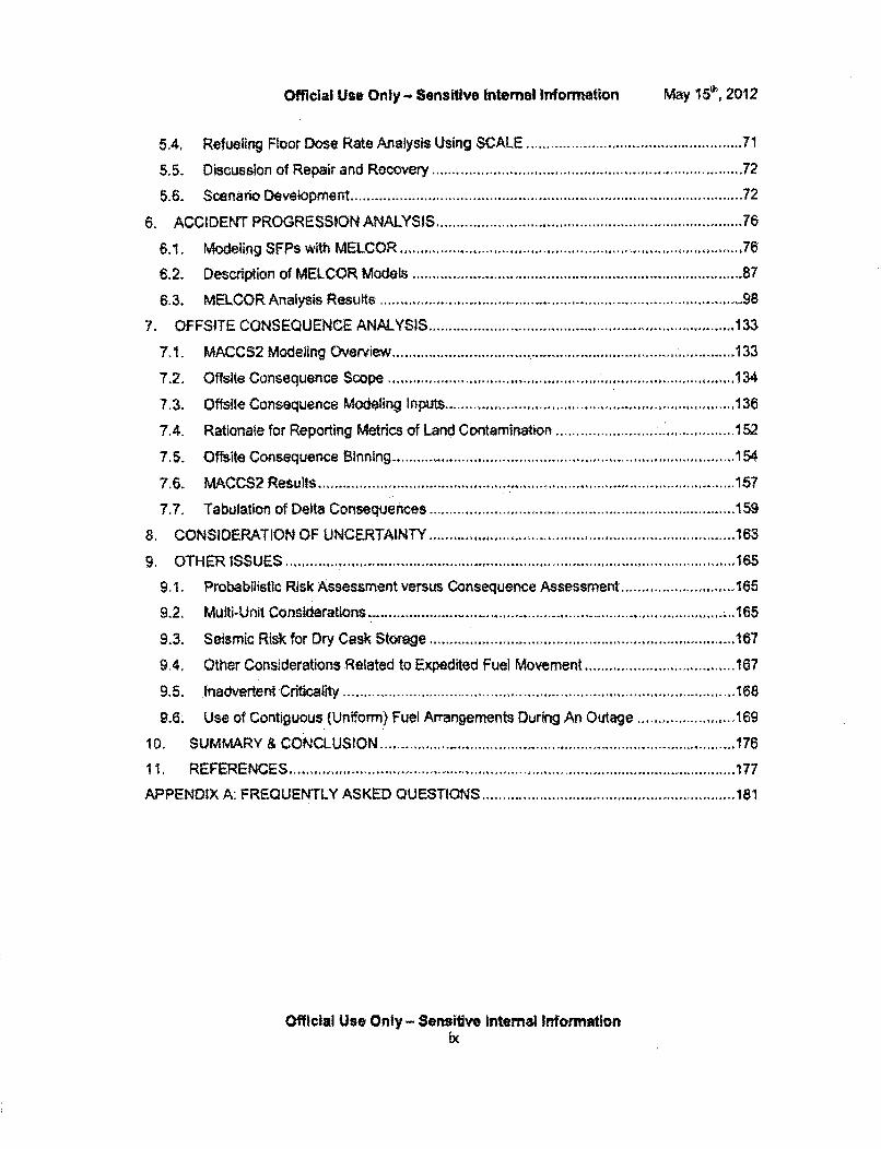
Official Use Only - Sensitive Internal Information May e5", 2012
5.4, Refueling Floor Dose Rate Analysis Using SCALE ..................................................... 71
5,5. Discussion of Repair and Recovery ...................................................................... 72
5.6. Scenario Developm ent ......................................................................................... 72
6. ACCIDENT PROGRESSION ANALYSIS ...................................................................... 76
6.1. Modeling SFPs with MELCOR,............................................ 76
6.2. Description of MELCOR Models ........................................................................... 87
6.3. M ELCOR Analysis Results ....................................................................................... 98
7. OFFSITE CONSEQUENCE ANALYSIS .................................... 133
7.1. MACCS2 Modeling Overview .................................. 133
7.2, Offslte Consequence Scope ............ ... ......... ........... 134
7.3. Offslte Consequence Modeling Inputs ................................... 136
7.4. Rationale for Reporting Metrics of Land Contamination .......................................... 152
7.5. O ftsite Consequence Binning .................................................................................... 154
7.6. MACCS2 Results ................................... ................................................. 157
7,7. Tabulation of Delta Consequences ...................................................................... 59
8. CONSIDERATION OF UNCERTAINTY .......... ................... ..................... 163
9. O T HER ISSU ES ...................................................................................................... .165
9,1. Probabilistic Risk Assessment versus Consequence Assessment ............................ 165
9.2. M uiti-U nit Considerations ........................................................................................... 165
9.3. Seism ic Risk for Dry Cask Storage ........................................................................... 167
9.4, Other Considerations Related to Expedited Fuel Movement ..................................... 167
9.5. Inadvertent C riticality ............................................................................................... 168
9.6. Use of Contiguous (Uniform) Fuel Arrangements During An Outage ................... 169
ID. SUM MARY & CONCLUSIO N ..................................................................................... 176
11, REFERENCES ... -. ............................................... 177
APPENDIX A: FREQUENTLY ASKED QUESTIONS................................. 181
Official Use Only - Sensitive Internal Informationix
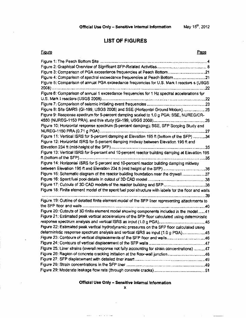
Official Use Only - Sensitive Internal Information May 19', 2012
LIST OF FIGURES
Figure 1-: The Peach Bottom Site ............................................................................................. 4Figure 2: Graphical Overview of Significant SFP-Related Activities ........................ 8Figure 3: Comparison of PGA exceedance frequencies at Peach Bottorn ............................ 21Figure 4: Comparison of spectral exceedance frequencies at Peach Bottom ....................... 21Figure 5: Comparison of annual PGA exceedance frequencies for U.S. Mark t reactors s (USGS2008) ......................................................... - ................................. 22Figure 6: Comparison of annual I exceedance frequencies for 1 Hz spectral accelerations forU.S. Mark I reactors (USGS 2008) ...... .. .................................... 22Figure 7: Comparison of seismic initiating event frequencies ..................... 23
Figure 8; Site GMRS (GI-199, USGS 2008) and SSE (Horizontal Ground Motion) .............. 25Figure 9: Response spectrum for 5-percent damping scaled to 1.0 g PGA: SSE, NUREG/CR-4550 (NUREG-1 150 PRA), and this study (GI-1 99, USGS 2008)................... 26
Figure 10: Horizontal response spectrum (5-percent damping): SSE, SFP Scoping Study andNUREG-115 oPRA (0.71 g PGA) ....................................... 27Figure 11: Vertical ISRS for 5-percent damping at Elevation 195 ft (bottom of the SFP) ..... 34Figure 12: Horizontal ISRS for 5-percent damping midway between Elevation 195 ft and
Elevation 234 ft (mid-height of the SFP) .............. ........ ........ ............................... 35Figure 13: Vertical ISRS for 5-percent and 10-percent reactor building damping at Elevation 195flt (bottom of the S FP ) ............................................................................................................... :MFigure 14: Horizontai ISRS for 5-percent and 10-percent reactor building damping midwaybetween Elevation 195 ft and Elevation 234 ft (mid height of the SFP) .................................... 36Figure 15: Schematic diagram of the reactor building foundation near the dryweal ............... 37
Figure 16: Spent fuel pool details in cutout of 30 CAD model ................................................. 38Figure 17: Cutouts of 3D CAD models of the reactor building and SFP ............................... 8.... AFigure 18: Finite element model of the spent fuel pool structure with labels for the floor and walls
I.....I...................................................................................... -...39Figure 19: Outline of detailed finite element model of the SFP liner representing attachments tothe SFP floor and walls ....... * .................................................. 40Figure 20: Cutouts of 3D finite element model showing components included in the model ...... 41Figure 21: Estimated peak vertical accelerations of the SFP floor calculated using deterministicresponse spectrum analysis and vertical ISRS as input (1.0 g PGA) ...................... 45Figure 22: Estimated peak vertical hydrodynamic pressures on the SFP floor calculated using
deterministic response spectrum analysis and vertical ISRS as input (1.0 g PGA) .............. 45Figure 23: Contours of vertical displacements of the SFP floor and walls .................... 46
Figure 24: Contours of vertical displacement of the SFP wails .......................... 47Figure 25: Uner strains (overall response not fully accounting for strain concentrations) .......... 47Figure 26: Region of concrete cracking initiation at the floor-wall, junction,......................... .8Figure 27: SFP displacement with detailed liner Insert ........................................................ 49
Figure 28: Strain concentrations in the SFP liner ............ ............ .................. ........... 49
Figure 29; Moderate leakage flow rate (through concrete cracks) ........................ 51
Official Use Only - Sensitive Internal Informationx
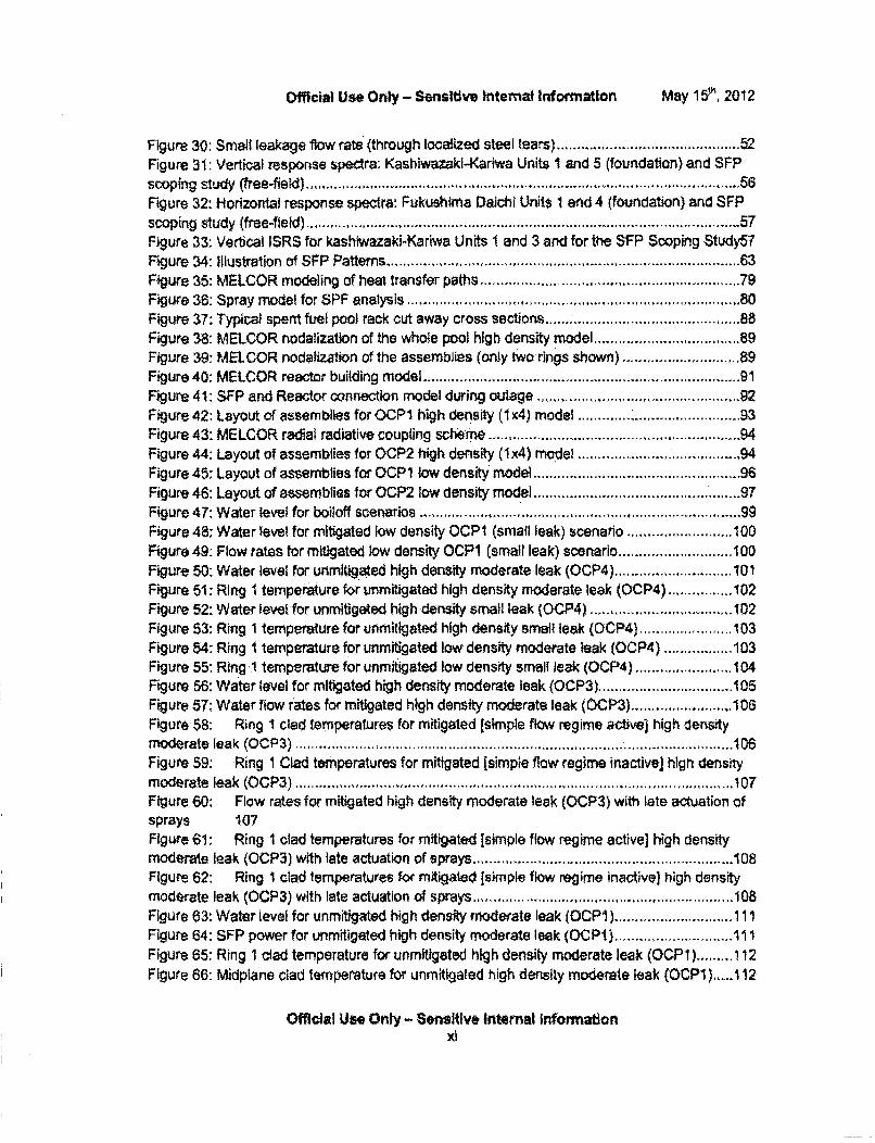
Official Use Only - Sensitive internal Information MMay 1 r, 2012
Figure 30: Small leakage flow rate (through localized steel tears) ... ........................... ....... 52Figure 31: Vertical response spectra: Kashiwazaki-Kariwa Units I and 5 (foundation) and SFPscoping study (free-fiekl ) ..................................................................................................... 56Figure 32: Horizontal response spectra: Fukushima Daichi Units 1 and 4 (foundation) and SFPscoping study (free-field) ............................................... 57Figure 33: Vertical ISRS for kashiwazaki-Kariwa Units 1 and 3 and for the SFP Scoping Study57Figure 34: Illustration of SFP Patterns ......................................... 63Figure 35: MELCOR modeling of heat transfer paths ......................................................... 79Figure 36: Spray model for SPF analysis ............................................................................. 80Figure 37: Typical spent fuel pool rack cut away cross sections .......................................... 88Figure 38: MELCOR nodalization of the whole pool high density model .................... 89Figure 39- MELCOR nodalization of the assemblies (only two rings shown) ....................... 89Figure 40: MELCOR reactor building model........................................................................ 91Figure 41: SFP and Reactor connection model during outage ............................................ 92Figure 42: Layout of assemblies for OCPI high density (1 x4) model .............. .................. 93Figure 43: MELCOR radial radiative coupling scheme ............................... 94Figure 44: Layout of assemblies for OCP2 high density (1x4) model .................. ......... 94Figure 45: Layout of assemblies for OCP1 low density model ............................ 96Figure 46: Layout of assemblies for OCP2 low density model .................................................. 97Figure 47: W ater level for boiloff scenarios ......................................................................... 99Figure 48: Water ievel for mitigated low density OCPl (small leak) scenario .......................... 100Figure 49: Flow rates for mitigated low density OCP1 (small leak) scenario ................ 100Figure 50: Water level for unmitigated high density moderate leak (OCP4) ........................ 101Figure 51: Ring I temperature for unmitigated high density moderate leak (OCP4) ................ 102Figure 52: Water level for unmitigated high density small leak (OCP4) .................... 102Figure 53: Ring 1 temperature for unmitigated high density small leak (OCP4) ...................... 103Figure 54: Ring I temperature for unmitigated low density moderate leak (OCP4) ................ 103Figure 55: Ring 1 temperature for unmitigated low density small leak (OCP4) ....................... 104Figure 56: Water level for mitigated high density moderate leak (OCP3) .............................. 105Figure 57: Water flow rates for mitigated high density moderate leak (OCP3) ...................... 106Figure 58: Ring 1 clad temperatures for mitigated (simple flow regime active] high densitymoderate leak (OCP3) ............................................. 106Figure 59: Ring I Clad temperatures for mitigated [simple flow regime inactivej high densitym oderate leak (O C P3) ........................................................................................................... 107Figure 60: Flow rates for mitigated high density moderate leak (OCP3) with late actuation ofsprays 107Figure 61: Ring I clad temperatures for mitigated [simple flow regime active] high densitymoderate leak (OCP3) with late actuation of sprays ................................................................ 108Figure 62: Ring I clad temperatures for mitigated [simple flow regime inactive] high densitymoderate leak (OCP3) with late actuation of sprays .................................. 108Figure 63: Water level for unmitigated high density moderate leak (OCPI) ..... ............. 111Figure 64: SFP power for unmitigated high density moderate leak (OCPI) ........................ 111Figure 65: Ring 1 clad temperature for unmitigated high density moderate leak (OCP1)......... 112Figure 66: Midplane clad temperature for unmitigated high density moderate leak (OCPi) ...... 112
Official Use Only - Sensitive Internal Information
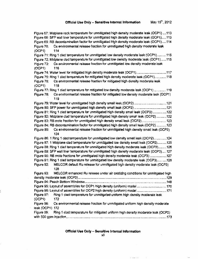
Official Use Only - Sensitive Internal Information May 115ý, 2012
Figure 67: Midplane rack temperature for unmitigated high density moderate leak (OCP1) ....1 13Figure 68: SFP wall liner temperature for unmitigated high density moderate leak (OCP1)... 113Figure 69: RB decontamination factor for unmitigated high density moderate leak (OCPI) .... 114Figure 70: Cs environmental release fraction for unmitigated high density moderate leak(OCPI) 114Figure 71: Ring 1 clad temperature for unmitigated low density moderate leak (OCPI) .......... 115Figure 72: Midplane clad temperature for unmitigated low density moderate leak (OCPI) ...... 115Figure 73: Cs environmentat release fraction for unmitigated low density moderate leak(OCPI) 116Figure 74: Water level for mitigated high density moderate leak (OCP 11) ................................. 117Figure 75: Ring 1 clad temperature for mitigated high density moderate leak (OCPI) ............. 118Figure 76: Cs environmental release fraction for mitigated high density moderate leak(OCP1) 118Figure 77: Ring 1 clad temperature for mitigated low density moderate leak (OCP1) ............... 119Figure 78: Cs environmental release fraction for mitigated low density moderate leak (OCP1)
119Figure 79: Water level for unmitigated high density small leak (OCP2) .................................. 121Figure 80: SFP power for unmitigated high density small leak (OCP2) .................... 121Figure 81: Ring I clad temperature for unmitigated high density small leak (OCP2)............... 122Figure 82: Midplane clad temperature for unmitigated high density smalI leak (OCP2) ........... 122Figure 83: RB mote fraction for unmitigated high density small leak (OCP2) ..................... 123Figure 84: RB decontamination factor for unmitigated high density small leak (OCP2) ......... 123Figure 85: Cs environmental release fraction for unmitigated high density small kak (OCP2)
124Figure 86: 1 Ring 1 clad temperature for unmitigated low density small leak (OCP2) .............. 124Figure 87: 1 Midptane clad temperature for unmitigated low density small leak (OCP2) ........... 125Figure 88: Ring 1 clad temperature for unmitigated high density moderate leak (OCP3) ......... 126Figure 89: SFP wall liner temperature for unmitigated high density moderate leak (OCP3) ..... 127Figure 90; RB mole fractions for unmitigated high density moderate leak (OCP3) .................. 127Figure 91: Ring I clad temperature for unmitigated low density moderate leak (OCP3) .......... 128Figure 92: MELCOR default Ru release for unmitigated high density moderate leak (OCP3)
128Figure 93: MELCOR enhanced Ru release under air oxidizing conditions for unmitigated highdensity moderate leak (OCP3) .................................. .-..... .. ....................................... .129Figure 94: Peach Bottom W indrose ......................... ............ ....... ..................................... 148Figure 95: Layout of assemblies for OCP1 high density (uniform) model .................. 170Figure 96: Layout of assemblies for OCP2 high density (uniform) model ................................ 171Figure 97: Ring 1 ciad temperature for unmitigated uniform high density moderate leak(OCP1) 172Figure 98: Cs environmental release fraction for unmitigated uniform high density moderateleak (OCP1) 172Figure 99: Ring 1 clad temperature for mitigated uniform high density moderate leak (OCP2)w ith 500 gpm injection .................................................... ...... ............................................. 173
Official Use Only - Sensitive Internal InformationxAi
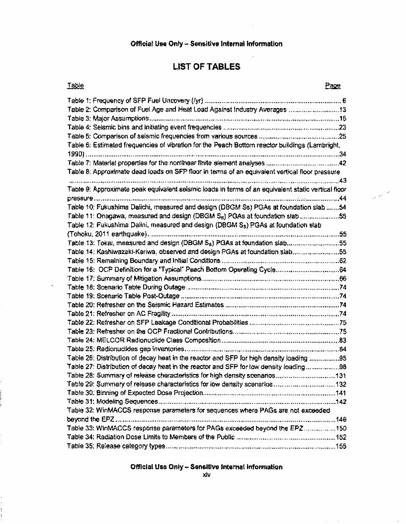
Official Use Only - Sensitive Internal Information
LIST OF TABLES
Tabl-e ____2
Tabte 1: Frequency of SFP Fuel Uncovery (Iyr) ......................................................................... 6Table 2: Comparison of Fuel Age and Heat Load Against Industry Averages ..................... 13Table 3: M ajor Assum ptions ................................................................................................ 15Table 4: Seismic bins and initiating event frequencies ......................................................... 23Table 5: Comparison of seismic frequencies from various sources ... ................................. 25Table 6: Estimated frequencies of vibration for the Peach Bottom reactor buildings (Lambright.1990) ........................ ...... .. ........ .............................. ... ................ 34Table 7: Material properties for the nonlinear finite element analyses ............................. 42Table 8: Approximate dead loads on SFP floor in terms of an equivalent vertical floor pressure..... ........................................................ 43
Table 9: Approximate peak equivalent seismic loads in terms of an equivalent static vertical floorpressure ................... ................................................. ...... 44Table 10: Fukushirna Dailchi, measured and design (DBGM Ss) PGAs at foundation slab ....... 54Table 11: Onagawa, measured and design (DBGM Ss) PGAs at foundation slab .............. 55Table 12: Fukushima Dahini, measured and design (DBGM Ss) PGAs at foundation slab(Tohoku, 2011 earthquake) .............................................. . ...................................... 55Table 13: Tokai, measured and design (DBGM Ss) PGAs at foundation slab ...................... 55Table 14: Kashiwazaki-Kariwa, observed and design PGAs at foundation slab .................... 55Table 15: Remaining Boundary and Initial Conditions........................................................ 62Table 16: OCP Definition for a 'Typicalo Peach Bottom Operating Cycle............................. 64Table 17: Summary of Mitigation Assumptions... ................................................................. 66Table 18: Scenario Table During Outage ..................... .................................................... . 74Table 19: Scenario Table Post-Outage ..... .................................... 74Table 20: Refresher on the Seismic Hazard Estimates ............................... 74Table 21. Refresher on AC Fragility ..................................................................................... 74Table 22: Refresher on SFP Leakage Conditional Probabilities .......................................... 75Table 23: Refresher on the OCP Fractional Contributions .................................................. 75Table 24: MELCOR Radionuclide Class Composition ........................................................ 83Table 25: Radionuclides gap inventories ............................................................................. 84Table 26: Distribution of decay heat in the reactor and SFP for high density loading ........... 95Table 27: Distribution of decay heat in the reactor and SFP for low density loading .................. 98Table 28: Summary of release characteristics for high density scenarios ................................ 131Table 29: Summary of release characteristics for low density scenarios ........................... 132Table 30: Binning of Expected Dose Projection ................................... 141Table 31: M odeling Sequences.................. ................................. ....................................... 142Table 32: WinMACCS response parameters for sequences where PAGs are not exceededbeyond the E PZ .......................................................... . ........................................................ 146Table 33: WinMACCS response parameters for PAGs exceeded beyond the EPZ ................ 150Table 34: Radiation Dose Limits to Members of the Public ....................... ...................... 152Table 35: Release category types,.................................................. 155
Official Use Only - Sensitive Internal Informationxiv

Official Use Only - Sensitive intemal Information
Table 36: Release category tally .......................................................................................... 155Table 37: Listing of specific sequences ..................................... ............................................ 1 56Table 38: Overall consequence results ........................................ .....................................s. 157Table 39: Dose Response Model Results ............................................................................ 158Table 40: Consequence comparison # 1: Low/High density (1x4) loading ............................... 159Table 41: Consequence Comparison #2: Low/High Density (uniform) loading ........................ 159Table 42: Consequence comparison # 3: High density (1x4 and uniform) loading ................... 159Table 43: Consequence comparison # 4: SuccessfulYUnsuccessful deployment of 50,54(hhX2)
..........= ..... I ... 1-1 ....... ..... ,,.. ..... .. " ........ ., ... -. 11 . ... I........ . .......... . . I.. ..... . .. 16WTable 44; Summary of release characteristics for high density, uniform configuration ............. 175
Official Use Only - Sensitive Internal Informationxv
Official Use Only - Sensitive Internal Information
1. INTRODUCTION AND BACKGROUND
All operating reactors in the US are of the light-water reactor design. They utilize upright fuelassemblies (usually roughly 12 feet in length) with low-enriched Uranium oxide fuel (!ess than5% Uraniurnm-235). The fuel assemblies (which are comprised of numerous fuel rods - typically80-100 rods for contemporary boiling water reactor fuel and 200 - 300 rods for contemporarypressurized water reactor fuel) are placed in the reactor for 2 to 3 operating cycles. Eachoperating cycle typically lasts 18 to 24 months. At the end of their reactor 'life" the assembliesare placed in large pools of water adjacent to the reactor (how adjacent depends on the plantdesign) that are roughly 12 meters (40 feet) deep. The fuel assemblies are later loaded in tocasks, which are then moved to an Independent Spent Fuel Storage Installation (ISFSI), usuallyonsite. The casks are drained of water and Inerted with helium during the loading process. Thissituation leads to the vernacular terms of 'wet storage* (to describe storage in the spent fuelpool) and *dry storage' (to describe storage in casks).
Spent fuel pools in the United States were originally designed to store 1-2 reactor cores worth ofspent fuel, so that the fuel could "cool down" (become less thermally and radioactively "hot")prior to its movement to a long-term storage repository. Owing to delays in the identification.licensing and construction of such a repository, US nuclear power plants "re-racked* their spentfuel pools in the 1980s and 1990s to allow for the storage of larger numbers of spent nuclearfuel assemblies (e.g., roughly 4 reactor cores worth for the plant studied in this report).Throughout this time (including present day), the NRC has maintained that spent fuel poolsprovide adequate protection of the public health and safety in either low-density or high-densitystorage configurations. The basis for this position Is discussed later in this section.
As also described later in this section, extemal stakeholders have periodically challenged thisposition. This tension is natural because there are a number of complex considerations whenweighing low-density versus high-density spent fuel storage. In understanding this tension, let'sfirst start with a few basic tenets:
" Thermal and radioactivity loads associated with freshly-discharged fuel necessitate theneed for wet storage
" All spent nuclear fuel, regardless of age (a.k.a, time since discharge from the reactor)produces both heat and radiation
Now, let's consider some !ess-obvious considerations. The list below presents considerationsfrom the perspective of the pros and cons associated with postulated transitionlng from theexisting usage of high-density racking in the US back to the usage of low-density storage. Thelist is subdivided in to two parts, those considerations that are covered within this study, andthose that are not.
Considerations covered within this study
Expedited movement of fuel from the spent fuel pool to dry storage will decrease theinventory of longer-lived radionuclides such as Cesium-1 37 present in the spent fuelpoolAs a result of the above, less radioactive material would be present In the pool if aradioactive release occurred, which would be expected to reduce potential landcontamination and economic impacts
Official Use Only - Sensitive Internal Information*1
Official Use Only - Sensitive Internal Information
" Removal of older fuel reduces the overall heat load in the pood, whicb can have theeffect of delaying the start of a radioactive release (and thus increasing the timeavailable to take mitigative action) for many types of accidents
" Removal of older fuel will increase the area available for air circulation (naturalcirculation) should the pool become completely drained (the effect of this is somewhatlimited by the nature of spent fuel racks as discussed later In this report)
* Removal of older fuel will increase the volume available for cooling water (note that thisis mathematically a small effect with the older fuel comprising on the order of 5% of thetotal pool volume - recall that most of the pool is occupied by water, not fuel)
Considerations not covered wfthin this study
* Current regulatry requirements under 10 CFR Part 72 limit (from a practicalityperspective) the ability to transfer fuel with less than roughly 3 to 5 years of cooling
" Discharging large amounts of fuel (and thus greatly increasing the amount of fuelcontained In the ISFS1) might require a Part 72 rulemaking effort (e.g., to accommodateincreases in the design-basis accident site area boundary aliowable dose limits) andpotentially increase the risk associated with the ISFSI
" Expedited discharging of fuel from the spent fuel pool to dry storage increases thefrequency of postulated cask drops, which in turn increases the risk of causing damageto the pool that could lead to a radioactive release
" Expedited discharging of fuel increases occupational doses for workers involved with themanagement and transfer of the spent fuel
" Earlier movement of fuel increases the probability that fuel will have to be re-packagedlater for shipment to the eventual long-term repository or interim storage site
For each of the items covered by this report, these items are re-visited in Section 10 byreflecting on the quantitative results provided by this study, The reader may quickly note thatthe first set of considerations are generally "prose associated with expedited fuel movement tocasks, while the latter list are generally 'cone. Why focus on the pros for this study? Theagency's position, that spent fuel storage in either pools or casks is safe is based on a numberof past studies and regulatory activities that are discussed later in this chapter, This regulatoryposition Is solid. In re-assessing this positon, we have started by investigating whether any ofthe 'pros" are more compelling than past studies suggest. If they are, then the Issue can beaddressed more holistically to see if new information challenges the existing regulatory position.Otherwise, there is insufficient motivation to spend the additional agency resources associatedwith a more holistic study, and these resources are better devoted to other aspects of theagency's mission of protecting people and the environment.
1.1. Project Impetus
Various risk studies (most recently NUREG-1738, "TechnicaW Study of Spent Fuel Pool AccidentRisk at Decommissioning Nuclear Power Plants," February 2001) have shown that storage ofspent fuel in a high-density configuration in SFPs is safe and that the risk is appropriately low.These studies used simplified and sometimes bounding assumptions and models forcharacterizing the likelihood and consequences of beyond-design-basis SFP accidents, As partof NRC's post-9/11 security assessments, SFP modeling using detailed thermal-hydraulic andsevere accident progression models integrated into the MELCOR code were developed andapplied to assess the realistic heatup of spent fuel under various pool draining conditions.
Official Use Only - Sensitive Internal Information2
Official Use Only - Sensitive Internal Information
Moreover, in conjunction with these post-9111 security assessments, NRC has requiredenhancements via 10 CFR 50.54(hhX2) for operating reactor SFP storage that are directed atfurther improving the coolabillty of spent fuel under event conditions in which a substantialamount of water has drained from the storage pool.
Recently, the agency has restated its views on the safety of spent fuel stored in high.-densityconfigurations in a response to Petition for Rulemaking (PRM)-51-10 and PRM-51 -12 as wel asthe revision to NUREG-1437 (the Generic Environmental Impact Statement for LicenseRenewal, Draft Report for Comment). However, this position relies in part on the findings of theaforementioned security assessments, which are not publicly available. The renewed interest inspent fiue: storage engendered from the changes in path forward of the planned geologicrepository and from the events in Japan following the March 2011 earthquake has rekindledinterest in capturing the consequences from postulated accidents associated with high-densitySFP storage in an updated safety study. An SFP risk study is being planned as part of a largerInitiative Involving the conduct of a site Level 3 probabilistic risk assessment (PRA), asdocumented in SECY-11-0089 and the associated Staff Requirements Memorandum. In theinterim, a desire existed to produce updated consequence estimates for a particular scenario ofinterest that can in part act as a bridge between the current state-of-knowledge (much of whichis greater than 10 years old or security-related and, thus. nonpublicly available) and futurestudies. The current study fulfills that gap, Investigating an Important piece of the overall puzzle.Other pieces of this puzzle haven been informed by past studies, will be addressed by futurestudies, or will be addressed through other inputs in to the decisionmaking process.
1.2.Technical Approach
Two broad situations are considered in this study, which represent the following:
(1) A condition representative of the current situation for the selected site (i.e., high-densityloading in the SFP, a relatively full SFP, and current regulatory requirements withrespect to fuel configuration and preventive/mitigative capabilities); and
(2) A condition where expedited movement of older fuel to dry cask storage has alreadybeen achieved (i.e., low-density loading in the SFP and current AIDlicable regulatoryrequirements with respect to fuel configuration and preventivelmitigative capabilities).
For purposes of obtaining a near-term perspective on the issue, a single site and singleassumed operating cycle are used. The site characterization (seismic response, decay heat,radionuclide inventory, etc.) have been based on readily available information that primarilystemmed from sources such as the NUREG-1 150 study, seismic Information developed by theUnited States Geological Survey (USGS), and the post 9111 security assessments3 . Later in theproject, additional information was provided by the licensee which generally corroborates theassumptions made in this study.
A boiling water reactor plant was chosen for this analysis, in part because these types ofreactors often engender more interest from external stakeholders owing to the fact that the MarkI and Mark II designs have spent fuel pools are elevated relative to ground level. In the contextof safety-related events (as opposed to security-related events), the elevation of the pool will
.I he post 9111 -security assessrnwets included consideraton of SFPs and resulted in the collection of InformTalionand the development of computer models that provided a convenient slart.' point for the current study,
Official Use Only - Sensitive Internal Information3
Official Use Only - Sensitive Internal Information
affect the transmission of seismic loads through the structure, can 22tprAIty inhibit accessibilityfor taking mitigative action, and can 29okJx lead to flooding of safety-related equipment, ifthe pool and surrounding structures are significantly damaged. The selection of g boklirc wat&rreactor design is not intended to suggest that these designs are more vulnerable to sient fuetpool accidents. In reality, there are differences between the major design types (PWRs versusBWRs) which make each more or less susceptible to spent fuel pool accidents on a scenario-specific basis. Similarly, the selection of a site that has a separate SFP for each reactor (asopposed to a shared pool) is also not intended to suggest that these situations are Inherentlymore vulnerable.
1.3. Site Familiarization
The site selected (Peach Bottom) has two General Electric Type 4 bolting water reactors withMark I containments. Unit #3 is the focus of this study (Unit #1 is no longer in operation). Eachreactor has a dedicated spent fuel pool, and the pools do not share a common refueling floor, asis the case with some plants of this design. Most other aspects of the reactor, spent fuel pool,and reactor building are similar to BWR designs of this vintage. Two small powef uprates havebeen approved for this site (1995 and 2002), with an extended power uprate submittal plannedby the licensee In the near future.
I
Regarding the SFPs, the existing high-density racks were placed in-service In 1986, and weredesigned and manufactured by Westinghouse Electric Corporation. As of 2010, the UnIt #3SFP contained 2,945 assemblies, while the Unit #2 SFP contained 2,844. Both SFPs maintainenough open locations to allow for an emergency full core offload, if required. The site also hasan Independent Spent Fuel Storage Installation (ISFSI) for dry cask storage, utilizing the TN-68cask design.
Finally, with respect to Emergency Preparedness, the site is located in a state (Pennsylvania)which has state-specific Protective Action Guidelines.
Official Use Only - Sensitive Internal Information4
Official Use Only - Sensitive Internal Information
1A4. Basic Scenario Development
There are a few key aspects of the way this study is conducted that bare mentioning at thispoint. These are:
* A large seismic event is the only initiator considered." As mentioned previously, both the current situation (a high-density loading configuration
in the pool) and an alternate situation (low-density loading configuration in the pool) areanalyzed; a situation where the pool has been re-racked to a low-density rackconfiguration is not considered, because such a situation would be inefficient In terms ofregulatory benefit given that much of the benefit of this situation could be achieved bystoring less fuel In the existing racks (recall that BWR fuel is channeled, which reducesthe benefit of cross flow If the pool were to become drained).
" The study focuses on the spent fuel pool, not the reactor, though for instances where thetwo are hydraulically connected, ot are oonsidered to a certain extent.
* The study does not attempt to quantify the reliability of mitigation, but rather treats everyscenario considering both the case with successful mitigation deployment and the casewith unsuccessful mitigation deployment.
" AJI portions of the operating cycle are considered." Detailed computer modeling is used to predict the plant's response to the event, in terms
of structural response, accident progression, mitigation effectiveness (when credited),and offsite consequences.
In cases where the above represent limitations on the study's scope or results, these arajustified in this report. In particular, Section 2 of this report provides the stidy's key limitationsand assumptions.
11.$. Rationale for Focusing on Seismic Hazard
This section seeks to provide context regarding the suite of potential initiating events that canlead to a SFP accident, and why a seismic event Is the focus of this study.
A typical risk assessment would start with a comprehensive look at relevant initiating events,and would conduct a failure modes and effect analysis. For the present study, due to (I) relativesimplicity of the SFP and its supporting infrastructure as compared to a reactor and itssupporting infrastructure and (ii) the much lower assembly decay heats, the majority of potentialSFP accident risk is believed to emanate from either:
* Events that have the potential to cause a sizable leak in the SFP, or* Events that might preclude operator action to inject water in to the pool for an extended
period of time (e.g, days)
When one considers the various possible initiators, the former criteria points to:
1. Very large (i.e., well beyond the design-basis) seismic events2. Heavy load (e.g., cask) drops, and3. Inadvertent aircraft crashes
In addition to these, the second criteria also points to:
Official Use Only - Sensitive Internal Information5
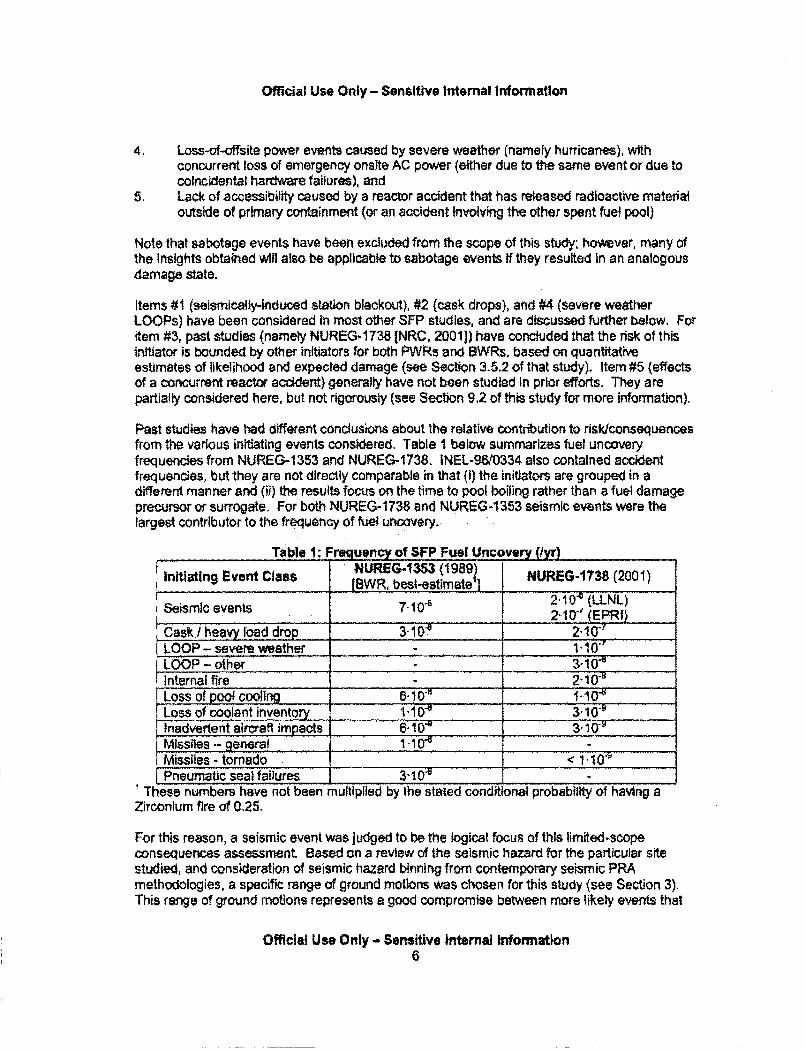
Official Use Only - Sensitive Internal Information
4. Loss-of-offsite power events caused by severe weather (namely hurricanes), withconcurrent loss of emergency onsite AC power (either due to the same event or due tocoincidental hardware failures), and
5. Lack of accessibility caused by a reactor accident that has released radioactive materialoutside of primary containment (or an accident Involving the other spent fuel pool)
Note that sabotage events have been excluded from the scope of this study; however, many ofthe insights obtained will also be applicable to sabotage events if they resulted in an analogousdamage state.
Items #1 (seismically-induced station blackout), #2 (cask drops), and #4 (severe weatherLOOPs) have been considered in most other SFP studies, and are discussed further below. Foritem #3, past studies (namely NUREG- 1738 [NRC, 2001]) have concluded that the risk of thisinitiator is bounded by other initiators for both PWRs and BWRs, based on quantitativeestimates of likelihood and expected damage (see Section 3.5.2 of that study). Item #5 (effectsof a concurrent reactor accident) generally have not been studied In prior efforts. They arepartially considered here, but not rigorously (see Section 9,2 of this study for more information).
Past studies have had different conclusions about the relative contribution to risklconsequencesfrom the various initiating events considered. Table I below summarizes fuel uncoveryfrequencies from NUREG-1353 and NUREG-1738. INEL-96/0334 also contained accidentfrequencies, but they are not directly comparable in that (i) the initiators are grouped in adifferent manner and (ii) the results focus on the time to pool boiling rather than a fuel damageprecursor or surrogate. For both NUREG-1738 and NUREG-1353 seismic events were thelargest contributor to the frequency of fuel uncovery.
Table 1: Frquency of SFP Fuel Uncovery (tyr)I :NUREG-1353 (1989) NUREG-1738 (2001)
initiating Event Class fBWR, best-estimatel2
Seismic events 7.10"6 2.0 (LLNL)_ _ 2.10-v_(EPRI)
i Cask/heavy load drop 3. 1 0 2.100LLOOP- severe weather j 1-10"
LOOP - other 3-10"Internal fire - 210•Loss of pool cooling 8___ 0____..10"_
Lo ss of co o la nt in ve n tory 6 ' 'i0 "a _ _ -_ 3 "1_-__ -
inadvertent aircraft impacts .. ......... _1 . . ... .. . 3-10___Missiles - general -Missiles - tornado <I 1-0
'-Pneumatic sea) failures 3-105 • . _____ -I- These numbers have not been multiplied by the stated conditional probability of having aZirconium fire of 0.25,
For this reason, a seismic event was judged to be the logical focus of this limited-scopeconsequences assessment. Based on a review of the seismic hazard for the particular sitestudied, and consideration of seismic hazard binning from contemporary seismic PRAmethodologies, a specific range of ground motions was chosen for this study (see Section 3).This range of ground motions represents a good compromise between more likely events that
Official Use Only - Sensitive Internal Information6
Official Use Only - Sensitive Internal Information
would not be expected to lead to any consequences versus less likely events that would lead togreater consequences (recall that risk is the product of the likelihood times the consequences),
1.6. Operating Cycle Phase Approach
During a given operating cycle, the spent fuel pool:
" will change configurations from being an isolated pool to being hydraulically connectedto the reactor vessel (and back agaln)-these will be referred to as pool-reactorconfigurations to distinguish from the different spent fuel loading configurations;
" may have spent fuel offloaded temporarily from the reactor;
• will have spent fuel offloaded permanently from the reactor;
ja will likely have spent fuel moved around within the SFP (as part of complying withregulatory requirements related to heat distribution, criticality, and boraflex couponsampling);
* may have older spent fuel offloaded in to casks;
, will experience changes in the peak assembly decay power (of interest for draindownevents and spray mitigation) due tolthe above as well as radioactive decay; and
" will experience changes in the total decay power of all assemblies (of interest for poolheatup/boiling and makeup mitigation) because of the above as well as radioactivedecay,
To faithfulty represent these temporally changing conditions, one would need to break up theoperating cycle into numerous small periods of time or Operating Cycle Phases (COPs).However, the number of OCPs considered is nearly a linear multiplier on the amount ofresources needed because each period of time requires its own set of accident progression andconsequence analyses. Past studies have taken the approach of selecting specific points intime of interest, and comparing results for those specific times. This study takes a similarapproach, but places more emphasis on the definition of these times as quasi-steadyrepresentations of the portion of the operating cycle that they represent. This allows for morefaithful representation of the annualized frequencies of offsite consequences. The specificselection of these phases is described further in Section 5.2.
Official Use Only- Sensitive Internal Information7
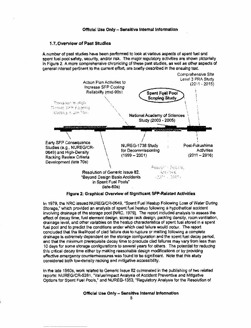
Official Use Only - Sensitive Internal Information
1.7. Overview of Past Studies
A number of past studies have been performed to look at various aspects of spent fuel andspent fuel pool safety, security, and/or risk. The major regulatory activities are shown pictoriallyin Figure 2. A more comprehensive chronicling of these past studies, as well as other aspects ofgeneral interest pertnent to the current effol, are briefly described in the ensuing text,
Action Plan Activities toincrease SFP Cooling
Reliability (mid-90s)
'.i:•,•i'•! : : : 2. - .•• " i: •"
(!Sen OI.Poo
National Academy of ScierStudy (2003 - 2005)
Comprehensive SiteLevel, 3 PRA Study
(20-1 - 2015)
noes
-Early SFP ConseiuenceStudies (e.g., NUREG/CR-0649) and High-DensityRacking Review CrileriaDevelopment (late 70s)
//
NUREG-1 738 Studyfor Decommissioning(1999 - 2001)
Post-FukushimaActivities
(2011 -2016)
Resolution of Generic Issue 82,"8eyond Design Basis Accidents
in Spent Fuel Pools'(late-80s)
* I
Figure 2: Graphical Overview of Significant SFP-Related Activities
In 1979, the NRC issued NUREG/CR-0649, "Spent Fuel Heatup Following Loss of Water DuringStorage," which provided an analysis of spent fuel heatup following a hypothetical accidentinvolving drainage of the storage pool (NRC, 19791. The report included analysis to assess theeffect of decay time, fuel element design, storage rack design, packing density, room ventilation,drainage level, and other variables on the heatup characteristics of spent fuel stored in a spentfuel pool and to predict the conditions under which clad failure would octur. The reportconcluded that the likelihood of clad failure due to rupture or melting following a completedrainage is extremely dependent on the storage configuration and the spent fuel decay period,and that the minimum prerequisite decay time to preclude clad failures may vary from less than10 days for some storage configurations to several years for others. The potential for reducingthis critical decay time either by making reasonable design modifications or by providingeffective emergency countermeasures was found to be significant. Note that this studyconsidered both low-density racking and mitigative accessibility.
In the late 19980s, work related to Generic Issue 82 culminated in the publishing of two relatedreports: NUREG/CR-5281, "Valuelimpact Analysis of Accident Preventive and MitigativeOptions for Spent Fuel Pools," and NUREG-1353, "Regulatory Analysis for the Resolution of
Official Use Only - Sensitive Internal Information8

Official Use Only - Sensitive Internal information
Generic Issue 82, "Beyond Design Basis Accidents in Spent Fuel Pools." [NRC, 1989a] and[NRC, 1989b] The former study investigated options including limited low-density re-racking ofspent fuel, installation of water sprays above the spent fuel pool, and the installation ofredundant cooling and/or makeup systems. The results of these studies indicated that themeasures were, in general, not likely to be cost effective. The reason for this is due to both thelow likelihood of a spent fuel pool accident that could result in a significant radiological releaseand the high cost of proposed modifications. The report goes on to conclude that these Insightsare largely contingent upon compliance with guidelines developed for licensees to assure thesafe handling of heavy loads in the vicinity of spent fuel pools, thus reducing the likelihood of thestructural failure of the pool and rapid loss of water Inventory due to a cask drop event.
The latter report (NUREG-1353) also includes spent fuel pool analysis, and concludes that if thedecay heat level is high enough to heat the fuel rod cladding to about 900 degrees C theoxidation becomes self -sustaining, resulting in a Zircaloy cladding fire. The conditionalprobability of a Zircaloy cladding fire given a complete loss of water was found to be 1-0 forPWRs and 0.25 for BWRs in high-density configurations. The conditional probabiity of aZircaloy cladding fire given a complete loss of water In low density storage racks is estimated tobe at least a factor of five less than for the high density configurations, The report goes on tostate that although most of the spent fuel pool risk is derived from beyond design basisearthquakes, this risk is no greater than the risk from core damage accidents due to seismicevents beyond the safe-shutdown earthquake. Therefore, reducing the risk from spent fuelpools due to events beyond the safe-shuldown earthquake would still leave at least acomparable risk due to core damage accidents. As a result of this conclusion, the resultsjustified the decision that no regulatory action was needed.
In 1996, an NRC-sponsored Idaho National Laboratories study entitled, "Loss of Spent FuelPool Cooting PRA; Model and Results," was issued. [INL, 1996) This study considered a dual-unit plant and the following initiators:
* Loss of spent fuel pool cooling* Loss of offsite power* Loss of spent fuel pool Inventory (did not include heavy load drops)* Loss of primary (reactor) coolant* Seismic events
The results of this study indicated that for plant studied, the annual probability of spent fuel poo!boiling is 5x1 0* and the annual probability of flooding associated with spent fuel pool accidentsis 1x10"3. Qualitative arguments are provided to show that the likelihood of core damage due tospent fuel pool boiling accidents is low for most U.S. commercial nuclear power plants. It is alsoshown that, depending on the design characteristics of a given plant, the likelihood of either:a) core damage due to spent fuel pool-associated flooding, or b) spent fuel damage due to pooldryout, may not be negligible.
The next year, two additional reports were issued: NUREG-1 275, Volume 12, 'OperatingExperience Feedback Report: Assessment of Spent Fuel Cooling,' and 'Follow-up Activities onthe Spent Fuel Pool Action Plan." [NRC, 1997a] and [NRC, 1997b] The former report concludedthat the typical plant may need improvements in SFP instrumentation, operator procedures andtraining, and configuration control. [Note that this is the conclusion stated in the report, and hasnot been placed in the regulatory context of balance-of-plant activities since the issuance of thatreport.1] The staff determined that loss of SFP coolant inventory greater than 1 foot occurred at
Official Use Only - Sensitive Internal Information9
Official Use Only - Sensitive Internal Information
a rate of about 1 event per 100 reactor years. Loss of SFP cooling with a temperature increasegreater than 20 degrees F occurred at a rate of approximately 3 events per 1,000 reactor years.The primary cause of these events was found to be human error. The report also concludedthat utilities' efforts to reduce outage duration resulted in full core off-loads occurring earlier inoutages, This increased fuel pool heat load was felt to be important because it reduces the timeavailable to recover from a loss of spent fuel pool cooling event early in the outage.
In the latter report (the Spent Fuel Pool Action fPn), the staff performed probabilistic screeninganalyses and found that, in most cases, event frequencies for sequences associated withidentified spent fuel pool design issues were suMciently low that further analyses were notwarranted. In one Instance where the probabilistic screening criteria were met, the staffperformed a deterministic evaluation of the issue using plant-specific information and found thatsafety enhanoements were not warranted.
A couple of years later, the agency conducted a spent fuel pool risk study for decommissioningplants to look at the relaxation of emergency preparedness requirements, and in 2001 the finalversion was Issued as NUREG-1 738, 7Technical Study of Spent Fuet Pool Accident Risk atDecommissioning Nuclear Power Plants." [NRC, 2001] The results of the study indicated thatthe risk at spent fuel pools is low and well within the Commission's Quantitative HealthObjectives (0HOs). The risk was found to be low because of the very low likelihood of azirconium fire, even though the consequences from a zirconium fire couid be serious. Thereport found that the event sequences important to risk at decommissioning plants were limitedto large earthquakes and cask drop events. This report represented a significant undertaking,and remains one of the prominent studies cited in NRC decislonmaking on spent fuel pools.However, there are some important conservatisms associated with this study that need to beconsidered if it is applied outside of Its intended context (emergency preparedness fordecommissioning reactors). These conservatlims include: (I) the use of assumed and oftenbounding configurations, (il) simplified treatment of the thermal-hydraulic response,(iii) conservative assumptions regarding structural response, and (iv) emergency preparednessresponse representative of a decommissioned site.
On the heels of the aforementioned study, the agency also released NUREG/CR-6441 in 2002.entitled, 'Analysis of Spent Fuel Heatup Following Loss of Water in a Spent Fuel Pool: A Users'Manual for the Computer Code SHARP." [NRC, 20021 This document included an analysis ofspent fuel heatup, using "representative" design parameters and fuel loading assumptions,Sensitivity calculations were also performed to study the effect of fuel burnup, buildingventilation rate, basepiate hole size, partial filling of the racks, and the amount of availablespace to the edge of the pool. The spent fuel heatup was found to be strongly affected by thetotal decay heat production in the pool, the avahlablifty of open spaces for air flows, and thebuilding ventilation rate. Note that the spent fuel pool analyses performed by the NRC after thistime did not rely on this computer code. Rather, they relied on the use of the MPLCORcomputer code, with supporting analysis using the COBRA-SFS, FLOW3D and Fluent codes,along with confirmatory experiments at Sandia National Laboratories,
In response to the events of September 11, 2001, the NRC undertook studies (referred tohereafter as security assessments) of spent fuel storage in pools and casks, While this workwas underway, Robert Alvarez et al. published the paper, 'Reducing the Hazards from StoredSpent Power-Reactor Fuel in the United States," 2003 (hereafter referred to as the 2003 Alvarezpaper). [Alvarez, 2003] In response, the NRC issued a review of the paper (also In 2003) whichconcluded that the assessment performed of possible spent fuel pool accidents stemming frompotential terrorist attacks in the 2003 Alvarez paper did not address such events in a realistic
Official Use Only - Sensitive Internal Information10
Official Use Only - Sensitive Internal Information
manner. [NRC, 2003a] The NRC response went on to state that, in many cases, the authors ofthe 2003 Alvarez paper rely on studies that made overly conservative assumptions or werebased on simplified and very conservative models. The NRC concluded that the fundamentalrecommendation of the 2003 Alvarez paper, namely that all spent fuel more than five years oldbe placed in dry casks through an expedited 1O-year program costing many billions of dollars, isnot justified.
Continued discussions on the issue of spent fuel pool safety and security led to a 2004 - 2005National Academy of Sciences study, documented In "Safety and Security of Commercial SpentNuclear Fuel Storage," the National Academies Press, 2006, [NAP, 2006] This study wasCongressionally mandated (e.g., see (Congress, 2005]). The National Academies Committeewas briefed on numerous occasions by NRC staff regarding past and ongoing studies related tothe subject topic. The study resulted in a classified report and the aforementioned publiclyavailable report. The publicly available report documented numerous findings andrecommendations, many of which were addressed as part of the NRC's continued activities inthis area (e.g., the "Phase 2" site-specific assessments). The NRC's initial response to thestudy was documented in a letter from the NRC Chairman (Nils Diaz) to Senator Peter DomeniciIn March 2008. [NRC, 2005]
In parallel to the National Academies study, the NRC continued performing the aforementionedsecurity assessments, which were completed in the 2006 - 2008 timeframe. While the resultsof these studies are non-publicly available due to their nature, the conclusions of the studieswere Integrated in to the NRC's regulatory licensing and oversight processes (e.g., the "PowerReactor Security Rulemaking" codified in 10 Code of Federal Regulations Part 50, Subpart54(hh)). Activities related to the development of new security-related requirements were laterdocumented in a memorandum to the NRC Commission entitled, "Documentation of Evolutionof Security Requirements at Commercial Nuclear Power Plants With Respect to MitiationMeasures for Large Fires and Explosions," dated February 4, 2010. [NRC, 2010]
Also in parallel to the above activities, the agency conducted a pilot PRA for dry cask storagedocumented In NUREG-1 864, "A Pilot Probabilistic Risk Assessment of a Dry Cask StorageSystem At a Nuclear Power Plant,' issued in 2007, [NRC, 2007a] The results of the report'sanalysis Indicate that dry cask storage risk is solely from latent cancer fatalities, and no promptfatalities are expected. Dry cask storage risk was found to be dominated by accidentsequences occuring in three stages of the handling phase. These involved the drop of thetransfer cask through the equipment hatch (termed Stage 18) and drops of the multi-purposecanister (MPC) into the storage overpack (Stages 20 and 21). The aggregated risk values werequite low. The estimated aggregate risk was an individual probability of a latent cancer fatalityof 1.8,10'12 during the first year of service, and 3.2 -10r" per year during subsequent years ofstorage. Note that when insufficient Information was available, "conservative boundingassumptions or estimates" were used. Other limitations of the study included no considerationof uncertainty and conservative assumptions about the translation of failure modes to holesizes.
Two other documents of regulatory Interest were issued in 2008 and 2009, respectively. Thefirst was the denial of two petitions for rulemaking (PRMs) as documented in SECY-08-0036and the associated Staff Requirements Memorandum. (NRC, 2008a] These documentsdescribe the NRC's denial of PRMs filed by the Attorney General of the Commonwealth ofMassachusetts and the Attorney General for the State of California, which presented nearlyidentical issues and requests for rulemaking concerning the environmental impacts of high-density storage of spent nuclear fuel in spent fuel pools.
Official Use Onty - Sensitive Intemal Information11
Official Use Only - Sensitive Internal Information
The second document is the issuance in 2009 of the Draft Report for Comment of Revision I tothe NRC's Generic Environmental Impact Statement (GEIS) on License Renewal (NUREG.1437, Revision 1, Draft Report for Comment). [NRC, 2009a] This document reevaluated SFPenvironmental considerations related to spent fuel pools by considering information developedsince the original License Renewal GElS was issued in 1996. INRC, 1996] The updateconcluded that the environmental impacts from accidents at spent fuel pools (as quantified InNUREG-1 738) can be comparable to those from reactor accidents at full power (as estimated inNUREG-1 150, "Severe Accident Risk- An Assessment for Five U.S. Nuclear Power Plants,*1990) [NRC, 1990]. The updated GElS goes on to state that subsequent analyses performed,and mitigative measures employed, since 2001 have further lowered the risk of spent fuel poolaccidents; and then, even the conservative estimates from NUREG-1738 are much less thanthe impacts from full power reactor accidents as estimated in the original 1996 GElS. As aresult of these considerations, the update concludes that the environmental impacts stated inthe 1996 GElS bound the Impact from SFP accidents.
Finally, In July 2011, the NRC issued, "Recommendations for Enhancing Reactor Safety in the21"' Century: The Near Term Task Force Review of Insights from the Fukushlma Dai-ichiAccident. [NRC, 201 Ia] In the section of the report on spent fuel pools, the task forceconcluded that 'lear and coherent requirements to ensure that the plant staff can understandthe condition of the spent fuel pool and Its water inventory and ooolability and to provide reliable,diverse, and simple means to cool the spent fuel pool under various circumstances are essentialto maintaining defense-in-depth.' The task force goes on to recommend Orders addressing: (I)spent fuel pool instrumentation, (iH) safety-related AC power for spent fuel pooi makeup, (ill')technical specification revision regarding onsite AC power for spent fuel pool makeup andinstrumentation, and (iv) a seismicalty-qualified spray capability. The task force alsorecommended rulemaking or licensing actions (or both) to require the above actions.
The US nuclear industry has a"so undertaken various studies related to spent fuel storage andtransportation, some of which are publicly available and some of which are referenced in relatedpublicly available reports. Examples include:
* EPRI TR-1003011, 'Dry Cask Storage Probabilistic Risk Assessment Scoping Study,'2002 (non-public)
• EPRI TR-1009691, 'Probabilistic Risk Assessment (PRA) of Bolted Storage Casks:Updated Quantification and Analysis Report,' 2004 (non-public)EPRI TR-1021049, "impacts Associated With Transfer of Spent Nuclear Fuel from SpentFuel Storage Pools to Dry Storage After Five Years of Cooling," 2010, (public)
The latter report is of particular interest for the present effort. The report assesses the cost andrisk impacts (from a worker dose perspective) associated with transfer of spent nuclear fuel fromspent fuel pools to dry storage after five years of cooling. The report concludes that expeditedfuel movement would result in an increase cost to the U.S. nuclear industry of $3.6 billion, withthe increase primarily related to the additional capital costs for new casks and constructioncosts for the dry storage facilities, The report goes on to conclude that early movement of spentfuel into dry storage would have 'significant radiological impacts." These impacts are stated interms of worker radiation exposure, and are estimated to be 507 person-rem over 60 years dueto the additional handling of spent fuel. With respect to spent fuel pool accidents, the reportestimates that an additional 711 dry storage packages would have to be handled compared tothe case without expedited fuel movement, thus increasing the risks associated with caskmovement [NAC, 2011] makes similar arguments with respect to the impacts of expediting fuel
Official Use Only - Sensitive Internal Information12
Official Use Only - Sensitive Internal Information
movement. Neither study attempts to calculate offsite consequences associated with postulatedspent fuel pool accidents.
Regarding this last point, the EPRI and NAC studies make points related to spent fuel poolsafety that warrant additional context, particularly if compared to the present study. To this end,it is helpful to start by looking at the spent fuel pool Inventories used In this study versus Industryaverages (as presented in the NAC white paper).
Table 2: ComerIson of Fuel Age and Heat Load Against Industry Averages- Mass as a % of all fuel Heat generation as a % of all fuel
Time since Industry Industry IIdischarge (yrs) average This study average i This study
<6 22% 18% 58% T 84%5 - 9 22% 27% 22% 9%10-14 16% .18% 9%,315-19 15% 19% 6% 2%20-24 10% 17% 3% 2%
i25- 29 6% 1% 1% %1%,30-34 4% . .-___ -___ < -,
[Remainder 4% -_ _ cj% -
The NAC white paper, and to a lesser extent the aforementioned 2010 EPRI study, make thecase that heat load distributions like the ones In Table 2 support the notion that moving fuelolder than 5 years has only modest effects on the overall spent fuel pooi heat load (and therebythe cooling requirements and mitigative time available for beyond design-basis spent fuel poolaccidents). The values in the table for the site studied here highlight the caution thataccompanies treating the heat toad as a point estimate.
The NAC white paper goes on to make the case that if increased fuel movement from pools tody cask storage is required, it should be for fuel older than 8 to 10 years, because currentregulatory requirements, infrastructure (e.g., cranes, cask designs), and industry practices canaccommodate this imposition with less impact than a 5 year cutoff, Of note Is the fact that boththe NAC and EPRI studies ignore the effect of the older fuel on the overall spent fuel poolradionuclide inventory, which for radionuclides like Cesium- 137 (30 year half4ife) is much moreconstant across fuel age than is the heat generation rate. However, consideration of this veryimportant aspect wouid arguably further support the benefit of moving fuel older than 8 to 10years because the older fuel would have comparable contributions to the overall radionuclideInventory for long-lived isotopes. The only caution here is that the 5 to 10 year old fuel is likelyto be higher bumup than 10+ year old fuel, so the small Increment in the half-life is not the onlyfactor affecting their relative contributions.
1.8. Potential Follow-On Work and Related Activities
As noted earlier, there are a number of follow-on activities that could be undertaken to furtherflesh out the issue at hand. For example, one could focus on other aspects of thecomprehensive risk (e.g., cask risk), general limitations of this study (e.g.. repeating the studyfor a pressurized water reactor SFP). or specific limitations of this study (e.g., detailed analysisof the effects of the seismic event on the integrated neutron poison material in the SFP racks).Which work will and will not be pursued is a decision that will be made after the current study
Official Use Only - Sensitive Internal Information13
Off-Icial Use Only - Sensitive Internal Information
has been reviewed, and in the context of the ongoing regutatory actions related to the 2011Fukushima accident (and in particular a 'Tier 3" item from these actvities specific to expeditedfuel movement), Rt is important to recognize that there are several ongoing activities that have aperipheral relatdonship to this study. These incude, but are not limited to:
* Order EA-12-049 retated to mitigation strategies for beyond-design-basis externalevents, dated March 12, 2012, and related correction dated March 13, 2012
* Order EA-12-051 related to reliable spent fuel pool instrumentation, dated March 12,2012, and related correction dated March 13, 2012
• An ongoing rulemakdng related to security requirements for ISFS~s,• Re-evaluation of the role of defense-in-depth in regulatory. declsion-making.• Re-consideration of the use of land contamination and economic consequences in the
context of regulatory decdsion-making.
Having said this, there is already a related activity underway to perform a site Level 3probabilistic risk assessment for an operating pressurized water reactor site, includingconsideration of both wet and dry storage. The details of this study are provided in SECY-1 1-0089 and the associated Staff Requirements Memorandum. While the study does notspecifically focus on expedited fuel movement, it will inherently inform the issue of comparativerisk between wet and dry storage.
1,9. Layout of Remainder of This Report
The remaining sections of this report provide:
• Major assumptions and limitationst, Seismic hazard characterization* Structural analysis methods and results, Scenario delineation and probabilistic considerations* Accident progression analysis methods and results* Offsite consequence analysis methods and results* Planned future consideration of uncertainty• Other issues warranting additional diswssion
Finally, Appendix A provides responses to Frequently Asked Questions (FAQs).
Official Use Only - Sensitive Internal Information14
Official Use Only - Sensitive Internal Information
2. MAJOR ASSUMPTIONS
Assumptions made during the conduct of this study are documented throughout this report. Forreader convenience, major assumptions are catalogued in Table 3,
Table 3: Major AssumptionsTopical Area Major Assumption CommentOverall A BWR Mark I with a This plant was chosen for a mix of reasons,Approach non-shared SFP is including availability of computer models and a
studied. perception of greater I stakeholder interestin elevated (relative., de) SFPs. Its selectiondoes not denote T that this type of design is
•more vulnerabi !
The well-beyond The earthquakVtudied -n estimateddesign basis frequen ,ccurrence or"ktime in 61,000earthquake is assumed years, •..to occur. This is a veryunlikely event. .Multi-unit I concurrent Spe • ifii the or (and its decafteat) arereactor accidents are treated 8j• xobutage until the level in thenot nnral. reactor well P drops to bow the bottom of theconsidered, i . uel transfer a., Beyond that point, and in all
. :~I..l . of the -outage scenarios, the reactor isSno as ce of steam, fission,N"w rodu...eý,ý'The intent is to scope some
oci itatlons via sensitivity studies.hat unmitigated scenarios are being treated,
AD, in part address the case where a reactor of._ WK .. ;.:F
othN FP event prevents operator action. Alsocons • that the current analysis focuses on the
A b,.a ,. een high-density and low-density1...g, either of which would be affected by a
A, -VT. .: concurrent reactor or SFP accident.Sei""'HazardChar .trinaa ion i .......... ._ __,.__,_. . •r.iza._._ ....
StructuralI ,OVd No debrin'enerated by Based on the expected structural response of theRelated I nitlai the seisrni--event building, overhead crane, etc. there is no
Damage State ýenaters pSFP. expectation that heavy debris that would damageCharacterization th fuet will be generated.
Th,•als of the Finite element analysis does not predict largerefueling gate do not deformations in this area that would suggest suchfall, an event is likely. Details of the gates provided by
the licensee show that there are two gates with agap in between and that each gate has mechanicalseals to prevent leakage. These seals are keptunder pressure by passive mechanical means (donot depend on either AC or DC power availability)that are unlikely to fail under the earthquake.
Official Use Only - Sensitive Inttemal Information15
Offic&ia Use Only - Sensitive Internal Information
Official Use Only - Sensitive Internal Information16
Official Use Only - Sensitive Internal Information
An assembly in thelifted position (i.e., inthe process of beingmoved) at the time ofthe seismic event Is nottreated. The currenttools do not allow forexplicit tteatment ofthis situation. Such asituation could lead toaccessibility issues(which are alreadytreated via thescenarios without50.54(hh)(2)equipment), but couldalso lead to a smallearlier release forsome situations. Thispossibility may beinvestigated furthe4a sensitivity study.Mode of mitigationdeployment.
*#•,11#2 w4.e "moderate" leakageCup l ployed. Other assumptions:.."•- teloytment could result in the
yment of sprays instead, i difference,shows the value of addition instrumentation,
6current state-of-knowledge in this area. PastZs for which this was a concern (namely
NUREG-1 738) used assumed source terms fromprevious studies, rather than mechanistic andintegrated modeling.
prior
Otherwise, the projectassumes the scenarioresults in no offsite
Official Use Only - Sensitive Intemal Information17
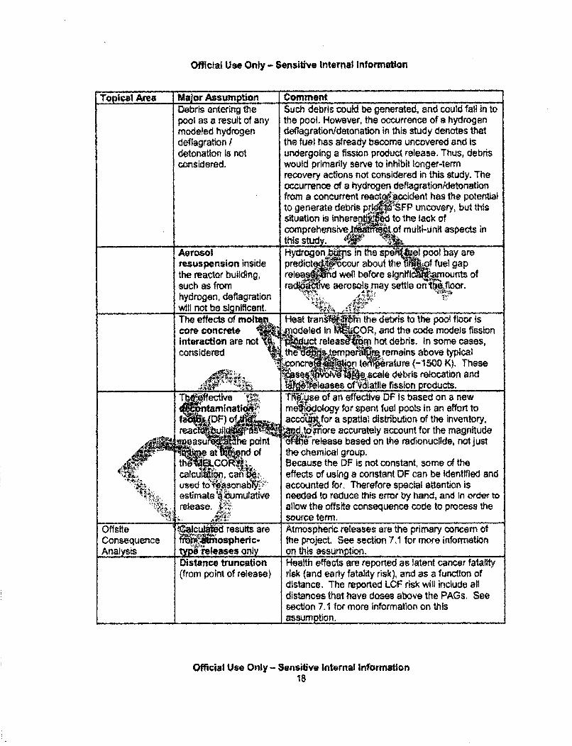
Official Use Only - Sensitive Internal Information
Topical Area Major Assumption CommentDebris entering the Such debris could be generated, and could fall in topool as a result of any the pool. However, the occurrence of a hydrogenmodeled hydrogen deflagration/detonation in this study denotes thatdeflagration / the fuel has already become uncovered and isdetonation is not undergoing a fission product release, Thus, debrisconsidered. would primarily serve to inhibit longer-term
recovery actions not considered in this study. Theoccurrence of a hydrogen deflagration/detonationfrom a concurrent react .'accident has the potentialto generate debri, p FP uncovery, but thissituation is inhere d to the lack ofcomprehensivef.W.of multi-unit aspects in
______ ___ _ ______ _this study. -
Aerosol Hydrogen ýitrs in the spi. e.I pool bay areresuspension inside predict ccur about the bof fuel gapthe reactor building, relea d well before s gnim amounts ofsuch as from radiacive aerosolsmay settle on floor.hydrogen, deflagrationwill not be significant.The effects of molten, Heat tran fthi the debris to the pool floor iscore concrete - xmodeled In COR, and the code models fissionInterartion are not•; : uct releasXrn hot debris. In some cases,
considered .tth,'is.1empe .remains above typicalAf W ature (-1500 K), These
taoS .... •,e debris relocation and,•, ';:'•7%"ii-W • eases orklatnle fission products.
T ective . TMuse of an effective DF is based on a newntarnnatmi' meftodology for spent fuel pools in an effort toDF o acco"4for a spatial distribution of the inventory,
rea~c u. ..... d ý'..nore accurately account for the magnitudeImeasu point e: release based on the radionuclide, not just
at i Of the chemical group.the co Because the DF is not constant, some of thecalcu n can effects of using a constant OF can be Identified andused t asona accounted for, Therefore special attention isestimate ' i.:umutative needed to reduce this error by hand, and In order toretease. ,."% allow the offsite consequence code to process the
___ _ source term.Offsite ' Atcuoted results are Atmospheric releases are the primary concem ofConsequence •ii ospheric- the project, See section 7.1 for more information
AnanistylA4i rleases only on this assurnption.Distance truncation Health effects are reported as latent cancer fatality(from point of release) risk (and early fatality risk), and as a function of
distance. The reported LCF risk will include alldistances that have doses above the PAGs. Seesection 7.1 for more information on thisassumption.
Official Use Only - Sensiuve Internal Informationis
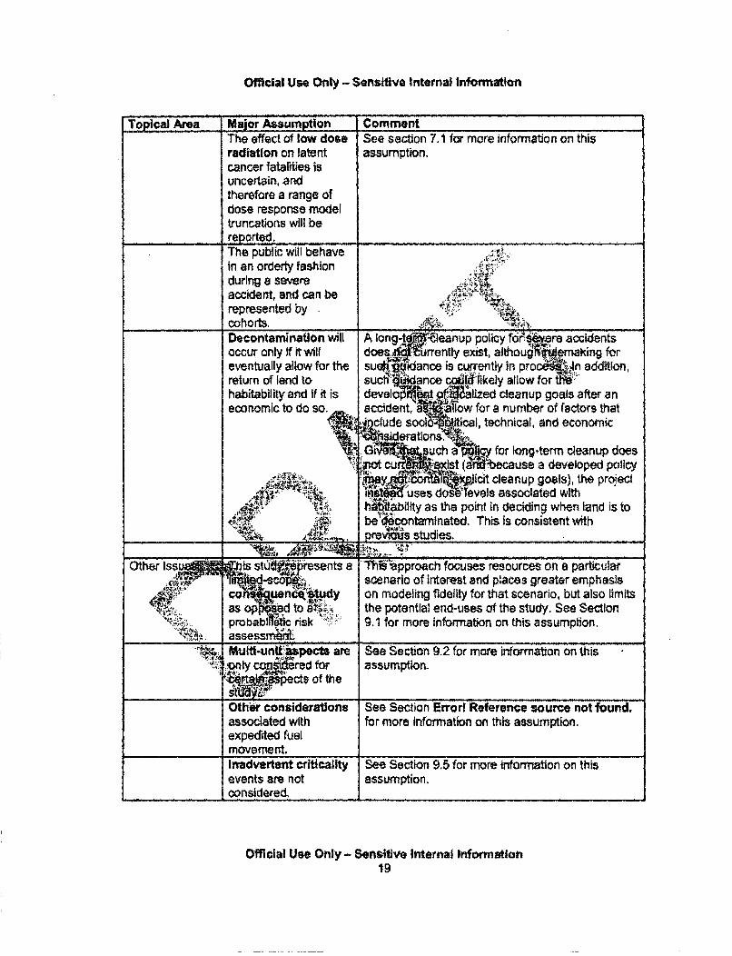
Official Use Only - Sensitive Internal Information
Top2cal Area Major Assumption CommentThe effect of low dose See section 7.1 for more information on thisradiation on latent assumption.cancer fatalities isuncertain, andtherefore a range ofdose response modeltruncations will ber e p o rte d ... .. . . .. .. .. ... ..... .. .. .. .. .. . .. ... . .. .The public will behavein an orderly fashionduring a severeaccident, and can berepresented bycohorts. :i.Decontamination will A long-te -Ieanup policy for'j:re accidentsoccur only if it wilt does. urrently exist, althouglf*nakig foreventually allow for the suabV-idance is currently in proce'.Jn addition,return of land to sucl•§Wance "@ likely allow for i"habitability and if it is develo Mt 1 llzed cleanup goals after aneconomic to do so accident, I~low for a number of factors that
" nclude socl5 ical, technical, and economicerations.~
Gi such a'pp for longterm cleanup doesdat • S•4st ause a developed policy
y ;'ai.ol:• • icit cleanup goals), the pr6jectIn ... uses dose levels associated with
I"i'abitty as the point in deciding when land is tobe •contaminated. This Is consistent with
__A= A! pre•-- studies."A,..•. , ...
Other Iss is stdu presents a "'ni-spproach focuses resources on a particularscenario of Interest and places greater emphasls
o en dy on modeling fidelity for that scenario, but also limits_ _ op4 ed to £ , the potential end-uses of the study. See Sectionprobabi t risk 9" 1 for more information on this assumption.
. Multli-unit jpects are See Section 9.2 for more information on this1nly cqndered for assumption._ _P ¶ 'ects of the
Othfe considerations See Section Errorl Reference source not found.associated with for more Information on this assumption.expedited fuelmovement,Inadvertent criticality See Section 9.5 for more information on thisevents are not assumption,considered,
Official Use Only - Sensitive Internal Information19
Official Use Only - Sensitive Internal Information
3, SEISMIC HAZARD CHARACTERIZATION
3 1 Basis for Probabilistic Estimates
The primary sources of information for seismic hazard estimates at nuclear power plant siteshave been information developed by: (I) the NRC/Lawrence Livermore National Laboratories(LLNL) (Bemreuter et at., 1989, Sobel, 1994) herein called the LLNL model; (ii) the ElectricPower Research Institute (Toro et al, 1989), herein called the EPRI model; and (iii) the UnitedStates Geological Survey (USGS) in the mid-2000s (Peterson et at, 2008), herein called theUSGS 2008 model. Both the LLNL and EPRI models were utilized : 16Be implementation of theIndividual Plant Evaluation for External Events (IPEEE) program.A1 iftG 1742). The USGS2008 has been utilized in the National Seismic Hazard MappiAtP.ieai and by the NRC for theseismic hazards estimates used in screening level assessr d:.aric Issue 199 (NRC,2012a).
The USGS 2008 information is being further develoe!nd updated by a of stakeholders,including the NRC, In a collaborative study whoc mes (a) the seismic sourm.zonecharacterization, and (b) the ground motion atteoiton modelsjo addition, the'tC. isdeveloping independent methods and computer A s, whiclzi ibe publicly availble whencompleted, to combine (a) and (b). Although part (a),... ating effort has been completedtil.qgoing Tr: .e SFP Scoping Study used the(NRC 2012b), parts (b) and (c) are still .• n rearlier USGS information instead of tt g update p. 'Fa4m
Comparisons of hazard estimates for th, ererdlte• Peach sm, a rock site, obtainedwith those three information so.rces are grMtt...i'a0l! .i 3 (PGA) and in Figure 4 (1,5 and 10 Hz spectral accAl which A-1_0 tte foilbvoseatns
* For the PG SiS 200 cts high't•annual probability of occurrence for high-level,low probabi yents, s Ily for evejwitt PGAs greaterlhan about 0.35 q.
" For moderate P f • a •o0.. LLNL is higher than USGS 2008. Abovethe gbabiity theeob kSGS 2008 is higher than LLNL until both
99rde s d1flY.Jactors of about 2.5 at 0.75 g and about 3 at 1.0g.
q hedEPRI ha r nf i afle lower than those from the U GS 2008 for all PGAs,ýSpcificalty, haza ~tiat•eased on the recent USGS update are about 2 times•V-gr at 02 g with.e difference increasing to about 10 times at 1.0 g.
Thus l:terrms of PCAkthe seismic hazard estimates used for this study are about 2.5times g er than iAtNit IPEEE estimates and about 6 times greater than EPRi IPEEEestimates., .
The USGS a' ANL curves are comparable for each representation, with USGS 2008sometimes being higher (higher annual probability of occurrence) and LLNL sometimesbeing higher,
Generally, the 10 Hz curve is the highest, followed by The 5 Hz curve, followed by thePGA curve, followed by the 1 Hz curve, The notable exception to the above is the factthat the 5 Hz LLNL curve is higher than the 10 Uz curve.
s a Only 265ftl1w20
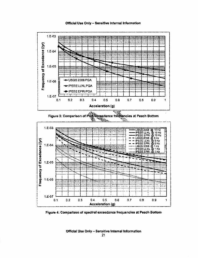
Official Use Only- Sernitive Internal Information
I.E-03
I.E-D50
I .E.06
I.E-070.1 0.2 0.3 0.4 0.5 0,6 0.7 0.8 0,9
Acceleration (g)
Figure 3: Comparison of P.1.-xeedance frewcies at Peach BottomFigure ., •' ..m"a:ri!o...f
I.E-03 . ~1 --- ~*-* .-- USGS2OO8@'SOHz. -IPEEE LLNL 10H2
- IPEEE EPRI @ 10 Hz
-- IPEEE EPRI 5Hz• • ..... sGs200 1•Hz11E-04 U G 2 HZ
= :,.r, .... " . 1.....PEEE LLNL @ HZC ao
,-10 . .0 _-: ' ._-,• ._•" :- .....
x
... ....... . ...........U i
........~ ~ ~ ~ ..... ...... .... ..... ... ..... .. !.........1.E.O7 ______
0.1 0.2 0.3 0.4 0.5 0,6 0.7 0.8 8.8Acceleration (g)
Figure 4: Comparison of spectral exceedance frequencies at Peach Bottom
Official Use Only - Sensitive Internal Information21
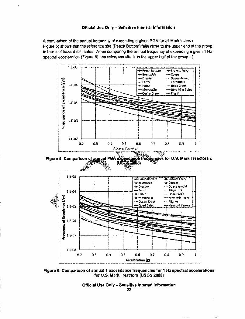
Official Use Only - Sensitive internal Information
A comparison of the annual frequency of exceeding a given PGA for all Mark I sitesFigure 5) shows that the reference site (Peach Bottom) falls close to the upper end of the groupin terms of hazard estimates, When comparing the annual frequency of exceeding a given 1 Hz
spectral acceleration (Figure 6), the reference site is in the upper half of the group. (
1E-03 I I I
0
30~S4-I'.
I.E-04
I.E-05
11-.06
-Peh 8ttn n *..-trWrIken
-Hat6 Hope Creek-*-Montkll~Io -Nhse Mile Polm*-0YSWeCr~ee - NI~ROM
0.6 0.7 0'a 0~3 1
1.E-070.2 0.3 0.4 0.S
Acceleration (j
Figure 5: Comparison PGAka ' e• for U.S. Mark I reactors s
1.E-03
.1-04
1.E.05
I* .E-07
0.2 0.3 0.4 0.5 0.6 0.7 0.8 0.9 1Acteleratlon (g)
Figure 6: Comparison of annual I exceedance frequencies for I i-Hz spectral accelerationsfor U.S. Mark I reactors (USGS 2008)
Official Use Only - Sensitive Internal Information22
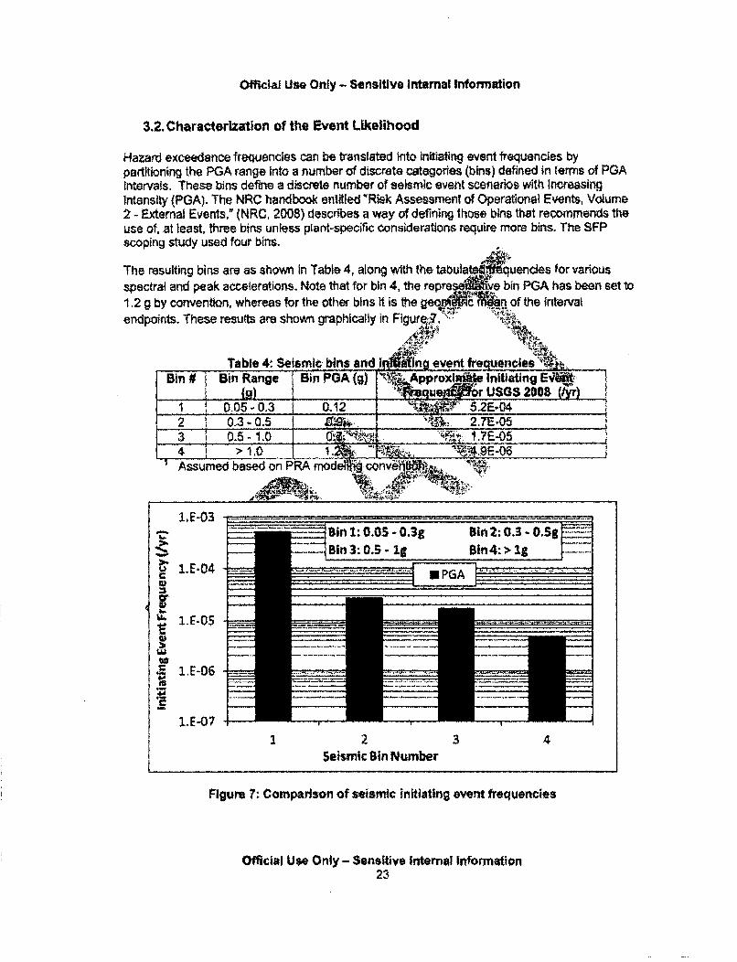
Official Use Only - Sensitive Internal Information
3.2. Characterization of the Event Likelihood
Hazard exceedance frequencies can be translated into initiating event frequencies bypartitioning the PGA range into a number of discrete categories (bins) defined in terms of PGAintervals. These bins define a discrete number of seismic event scenarios with Increasingintensity (PGA). The NRC handbook entitled "Risk Assessment of Operational Events, Volume2 - External Events," (NRC, 2008) describes a way of defining those bins that recommends theuse of, at least, three bins unless plant-specific considerations require more bins. The SFPscoping study used four bins.
The resulting bins are as shown in Table 4, along with the tabula quencies for variousspectral and peak accelerations. Note that for bin 4, the repre:ye bin PGA has been set to1.2 g by convention, whereas for the other bins It is the geo• .c nof the intervatendpoints. These resutts are shown graphically in Figure?.
Table 4, Seismic bins and liM n event fre enciesBin # -Bin Range Bin PGA(g) 'IN.Approxi Initiating E4 '
I.____ .) _USGS 2008 !I__ 0M05 - 0.3 0.12 - 5,2E-042 1 0.3 - 0.5 _. . .. 2.7E-053 1 0.5- 1.0 u•MPINM I .7E-054ssu 1,0 __se___nP__Assumed based on PR oe ovh
1. E-03
S1,E-04U?
I.E.0
.S 1E-07
Bin 1:0.OS - 0.3g--- in 3:0.5 - Ig
Bin2: 0.3 - .Sg0 1n 4: > I
1 2 3 4Seismic Bin Number
Figure 7: Comparison of seismic initiating event frequencies
Official Use Only - Sensitive Internal Information23
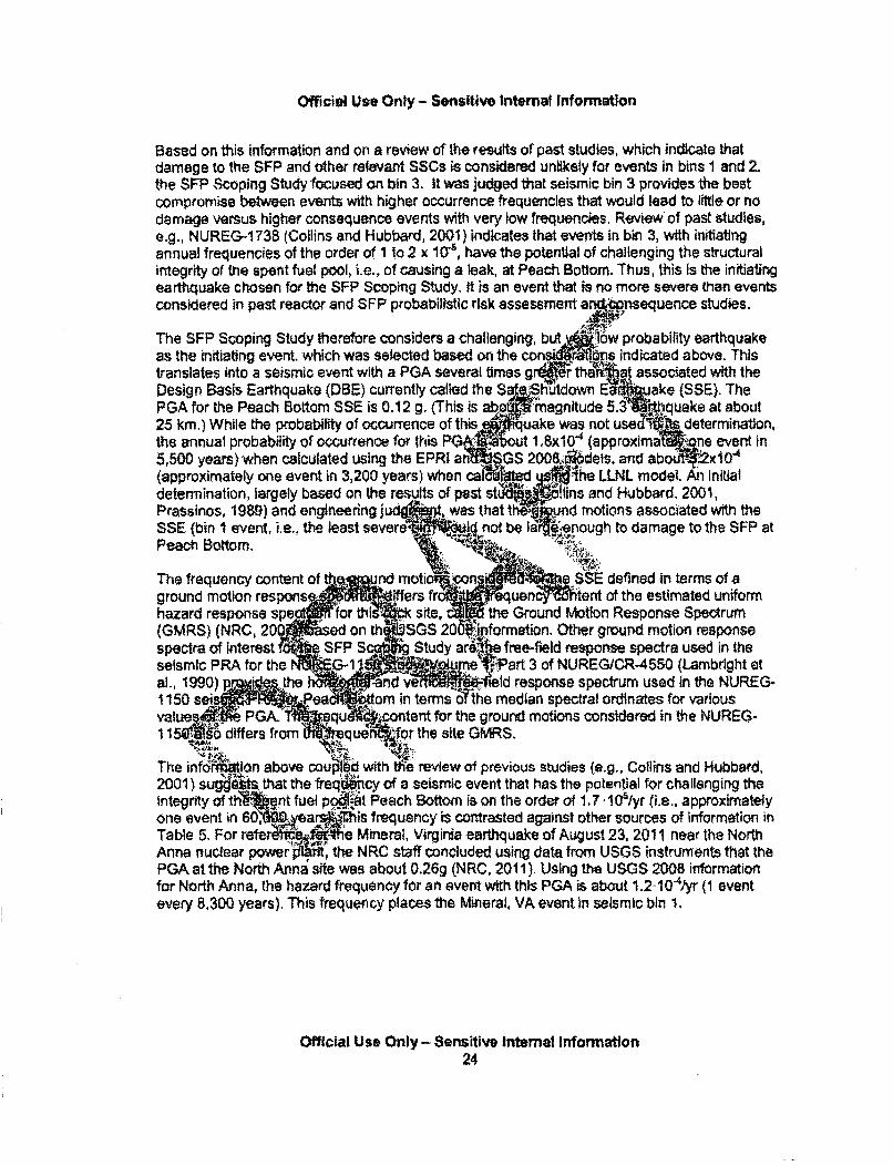
Official Use Only - Sensitive Internal Information
Based on this information and on a review of the results of past studies, which indicate thatdamage to the SFP and other relevant SSCs is considered unlikely for events In bins I and 2,the SFP Scoping Study focused on bin 3. It was judged that seismic bin 3 provides the bestcompromise between events with higher occurrence frequencies that would lead to little or nodamage versus higher consequence events with very low frequencies. Review of past studies,e.g., NUREG-1 73B (Collins and Hubbard, 2001) indicates that events in bin 3, with initiatingannual frequencies of the order of 1 to 2 x 10(, have the potential of challenging the structuralintegrity of the spent fuel pool, i.e., of causing a leak, at Peach Bottom. Thus, this is the initiatingearthquake chosen for the SFP Scoping Study. it is an event that is no more severe than eventsconsidered in past reactor and SFP probabilistic risk assessment ar6_nsequence studies.
The SFP Scoping Study therefore considers a challenging, butlow probability earthquake
as the initiating event, which was selected based on the cont ijs indicated above. Thistranslates into a seismic event with a PGA several times grI¶" tha•r..at associated with theDesign Basis Earthquake (DBE) currently called the $S ShUtdown E u.ake (SSE). ThePGA for the Peach Bottom SSE is 0.12 g. (This is ab magntude 5.3 at about25 km.) While the probability of occurrence of this uake was not use& determination,the annual probability of occurrence for this PG ! Ut 1,6x10" (approxima .ne event in5,500 years) when calculated using the EPRI an G S200& dets. and abo t-X10"(approximately one event in 3,200 years) when cal• d ,d .the LLNL model. Aý initialdetermination, largely based on the results of post studs ins and Hubbard, 2001,Prassinos, 1989) and engineering ,j was that t mund motions associated with theSSE (bin I event, i.e.. the least severe Id not be'"t la nough to damage to the SFP atPeach Bottom,
The frequency content of ind motio con a SSE defined in terms of aground motion respons ... iffers fLiuen tent of the estimated uniformhazard response spe 'for thl .1 site the Ground Motion Response Spectrum(GMRS) (NRC, 20 ased on th SGS 20O0jiformation. Other ground motion responsespectra of interest _SFP S Stdy ar free-field response spectra used in theseismic PRA for the C-1 1e bF.Part 3 of NUREG/CR-4550 (Lambrlght etal., 1990) p• the a d ye, .41eld response spectrum used in the NUREG-
-150 ea• .ttom in terms t'the median spectral ordinates for variousvalue Psfd ••iffere from qu ,ntent for the ground motions considered in the NUREG-11 d5ifko quo from r the site GMRS.
The inforftWon above cou ih review of previous studies (e.g., Collins and Hubbard,2001) suggetts that the freql~ncy of a seismic event that has the potential for challenging theintegrity of th ent fuel p*o',f.t Peach Bottom is on the order of 1,7 . I G/yr (i.e., approximatelyone event in 60 _yea. is frequency is contrasted against other sources of information inTable 5. For refe Rt e Mineral, Virginia earthquake of August 23, 2011 near the NorthAnna nuclear power •ithe NRC staff concluded using data from USGS instruments that thePGA at the North Anna site was about 0.26g (NRC, 2011). Using the USGS 2008 informationfor North Anne, the hazard frequency for an event with this PGA is about 1.2-1 ( 4 yr (1 eventevery 8,300 years). This frequency places the Mineral, VA event in seismic bin 1,
Official Use Only - Sensitive Internal Information24
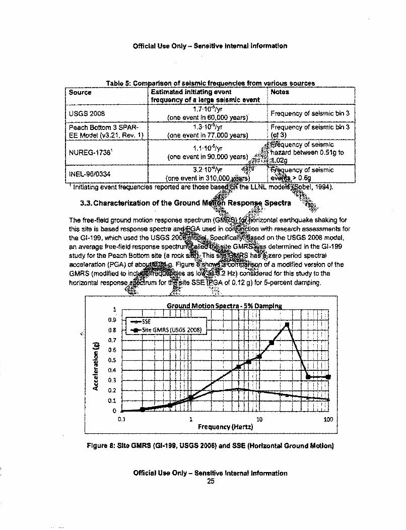
Official Use Only - Sensitive internal Information
Table 5: Com arison of seismic frequencies from various sourcesSource Estimated initiating event i Notes
frequency of a large seismic event _ _,
USGS 2008 (one event in 60,000 years) Frequency of seismic bin 3
Peach Bottom a SPAR- 1.3'1051yr j Frequency of seismic bin 3EE Model (v3.21, Rev. I) (one event in 77,000 years) ( t 3)
N.G.78,uency of seismic1.,,,,,,,,:,hazard between 0.51g to(one event in 90,000 years) ,de 0
3.2I1031yr quency of seismicINEL-96/0334 (one event in 310,0002 rs) e > 0,
Initiating event frequencies reported are those basedti•rthe LLNL modi bei, 1994).
3.3. Characterization of the Ground M!1h Responp Spect a
The free-field ground motion response spectrum (GMh¶IM rozonfl earthquake shaking forthis site is based response spectra a A sed in cdi tion with research assessments forthe GI-1 99, which used the USGS 2Secificalfoased on the USGS 2008 model,an average free-field response spectru I 4te GRi determined in the Gk199study for the Peach Bottom site (a rock a -, This s RS he zero period spectralacceleration (PGA) of ebo rig ure"96th at, of a modified version of theGMRS (modified to in req es as 10 W2 Hz) co ered for this sd to thehorizontal responses rum t ite SSE' A of 0.12 g) for 5-percent damping.
G3round Motio nepctra -3% Oamoi
a' -- Site GMRS I USGS 2008)
0,7
0.3 .1 0
Frequency (Hertz)
Figure 8S Site GMRS (Gi-1199, USGS 2008) and SSE (Horizontal Ground Motion)
Official Use Only - Sensitive Internal Information25
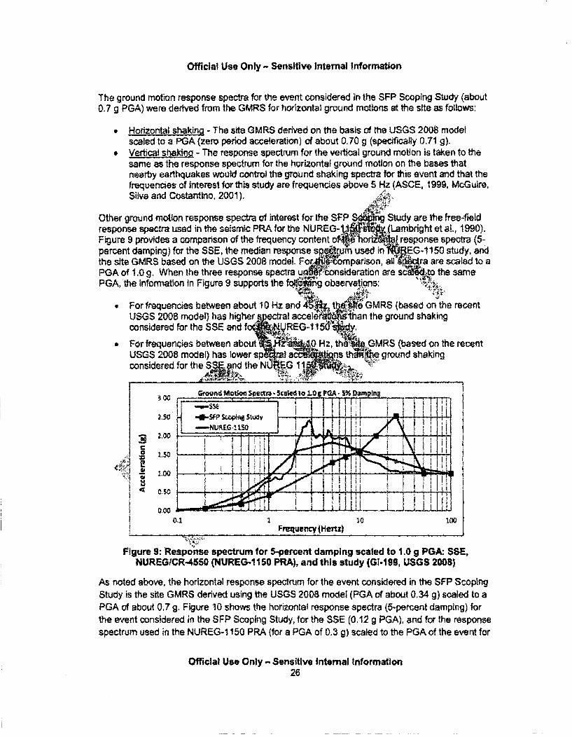
Official Use Only - Sensitive Internal Information
The ground motion response spectra for the event considered in the SFP Scoping Study (about0.7 g PGA) were derived from the GMRS for horizontal ground motions at the site as follows:
0 Horizontal shaking - The site GMRS derived on the basis of the USGS 2008 modelscaled to a PGA (zero period acceleration) of about 0.70 g (specifically 0.71 g).
, Vertical shaking - The response spectrum for the vertical ground motion is taken to thesame as the response spectrum for the horizontal ground motion on the bases thatnearby earthquakes would control the ground shaking spectra for this event arid that thefrequencies of interest for this study are frequencies above 5 Hz (ASCE, 1999, McGuire,Silva and Costantino, 2001).
Other ground motion response spectra of interest for the SFP S Study are the free-fieldresponse spectra used in the seismic PRA for the N UREG-.,(Lambright et al., 1990).Figure 9 provides a comparison of the frequency content- o'ebo~ ~a response spectra (5-percent damping) for the SSE, the median response sp"-m used in LE-1150 study, adthe site GMRS based on the USGS 2008 model. Fo parison, all •'cra are scaled to aPGA of 1.0 g. When the three response spectra u io sideration are sc4to the samePGA, the information in Figure 9 supports the fqf rg observations:
For frequencies between about 1 0 Hz and A th GMRS (based on the recentUSGS 2008 model) has higher ral acceleraro94han the ground shakingconsidered for the SSE arid f . NUREG-15 I ..
" For frequencies between about .Y 0Hz, tha. GM. based on the recentUSGS 2008 model) has lower sp .,ins th 1- ground shakingconsidered for the CO the NCIfG I
Grond motion :seca - Scatog PGA 5% D"plrng~ I
2.50 -u _ , ,P S1 i -i I. 'i f i 1
1100
K i . I ! ! !L .. !1..
P o0.7 10 td o[ Frequency jHertz)
Figure 9: Reaponise spectrum for 5-percentt damping scaled to 1,09g PGA: S$E,NUREGICR-4550 (NUREG-1150 PRA), and this study (Gi-199, USGS 2008)
As noted above, the horizontal response spectrum for the event considered in the SFP ScoptngStudy is the site GMRS derived using the USGS 2008 model (PGA of about 0.34 g) scaled to aPGA of about 0O7 g, Figure 10 show~s the horiz~ontai response spectra (5-percent damping) for
the event considered in the SFP Scoplng Study, for the SSE (0.12 g PGA), and for the responsespectrum used in the NUREG-1 150 PRA (for a PGA of 0.3 g) scaled to the PGA of the event for
Official Use Only - Sensitive Internal Information26
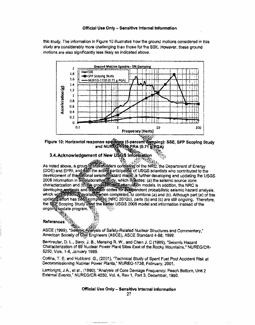
Official Use Only - Sensitive Internal Information
this study. The information in Figure 10 illustrates how the ground motions considered in thisstudy are considerably more challenging then those for the SSE. However, these groundmotions are also significantly less likely as indicated above.
Figure 10: Horizontal response sp•and NUM
3,4. Acknowledgement of New
SSE1 SFP Scoping Study
s con s. IM 'of the NRC, the Department of EnergyirUcipai "of USGS scientists who contributed to thetard mat.,is further developing and updating the USGS
which des: (a) the seismic source zonenu.M& models. In addition, the NRC is
?'s• ndent probabilistic seismic hazard analysis,mpleted, io combine (a) and (b). Adthough part (a) of thistC 2012b), parts (b) and (c) are still ongoing, Therefore,USGS 2008 model and information instead of the
References .
ASCE (1999), S~K. sis of Safety-Related Nuclear Structures and Commentary,"American Society I Engineers (ASCE), ASCE Standard 4-98. 1999.
Bemreutgr, D, L., Savy, J. B., Mensing R. W., and Chen J. C (1989), "Seismir, HazardCharacterization of 69 Nuclear Power Plant Sites East of the Rocky Mountains," NUREG/CR-5250, Vols. 1-8, January 1989.
Collins, T. E. and Hubbard, G,, (2001), 1"echnical Study of Spent Fuel Pool Accident Risk atDecommissioning Nuclear Power Plants," NUREG-1738, February, 2001.
Lambright, J.A., et al., (1990), 'Analysis of Core Damage Frequency: Peach Bottom, Unit 2Extemal Events," NUREG/CR-4550, Vol. 4, Rev 1, Part 3, December, 1990.
Official Use Only - Sensitive Internal Information27
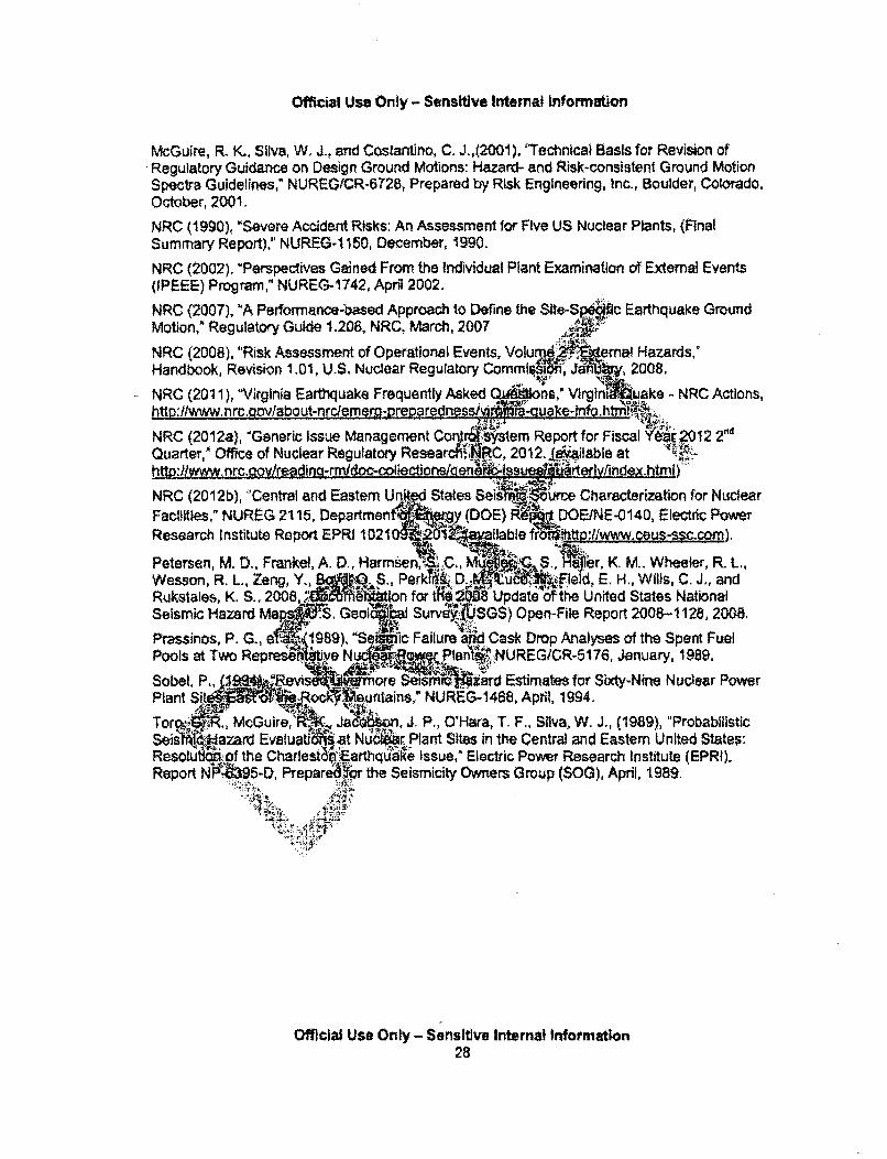
Official Use Only - Sensitive Internal Information
McGuire, R. K., Silva, W, J., and Costantino, C. J.,(2001), 'Technical Basis for Revision ofRegulatory Guidance on Design Ground Motions: Hazard- and Risk-consistent Ground MotionSpectra Guidelines," NUREGfCR-6728, Prepared by Risk Engineering, Inc., Boulder, Colorado,October, 2001.
NRC (1990), "Severe Accident Risks: An Assessment for Five US Nuclear Plants, (FinalSummary Report)," NUREG-1150, December, 1990.
NRC (2002). "Perspectives Gained From the Individual Plant Examination of External Events(IPEEE) Program," NUREG-1742, April 2002.
NRC (2007), 'A Performance-based Approach to Define the Slte-S.O Earthquake GroumdMotion," Regulatory Guide 1.208, NRC, March, 2007 T
NRC (2008), "Risk Assessment of Operational Events, Volu 4 mat Hazards,"Handbook, Revision 1.01, U.S. Nuclear Regulatory CommlIn J; 2008.
NRC (2011), "Virginia Earthquake Frequently Asked Q ns," Virgini ake - NRC Actions,http:l/www.nrc.gov/about-nrcleme•re-iorared nesstv - uake-inf .html•'•.
NRC (2012a), "Generic Issue Management Con Astem Report for Fiscal "'i"2012 2"dQuarter,* Office of Nuclear Regulatory Researcfrh 4RC, 2012. Ig"ilable at
blW:MM~rc~gy~r~dig-rr~do-col onene Isseel'M tAriv/index.htmi)NRC (2012b), "Central and Eastern UFacilities," NUREG 2115, DepartmenfResearch Institute Report EPRI 1021(
Petersen, M. D., Frankel, A. D., HarmiWesson, R. L., Zeng, Y., -.S.,Rukstales, K. S., 2008,:: mSeismic Hazard GoloPrassinos, P. G., e~1989)" tSe'Pools at Twoo Re vs~tbe N
SeisWti-$urce Characterization for Nuclear1OE)}RI. E / DOENE-0140, Electric Power
iiallable fror$'htto wwceus-ssc~com).
, r, K. M.. Wheeler, R. L.,•Fteli, E. H., Wills, C. J., and
X8 Update oth United States NationalSGS) Open-File Report 2008-1128, 2008.
d Cask Drop Analyses of the Spent Fuel" .,NUREG/CR-5176, January, 1989.
Sobwl, P.,Plant SiW
Tor ýgl N
ResolultlReport N0
•iiF aIrd Estimates for Sixty-Nine Nuclear Power." NUREG-1488, April, 1994.
on, J. P,, O'Hara, T. F., Silva, W. J,, (1989), "Probabilisticlu&•,rPlant Sites in the Central and Eastern United States:thquiae Issue," Electric Power Research Institute (EPRI),the Seismicity Owners Group ($OG), April, 1989.
.....4 , i. .• :
Official Use Only - Sensitive Internal Information28
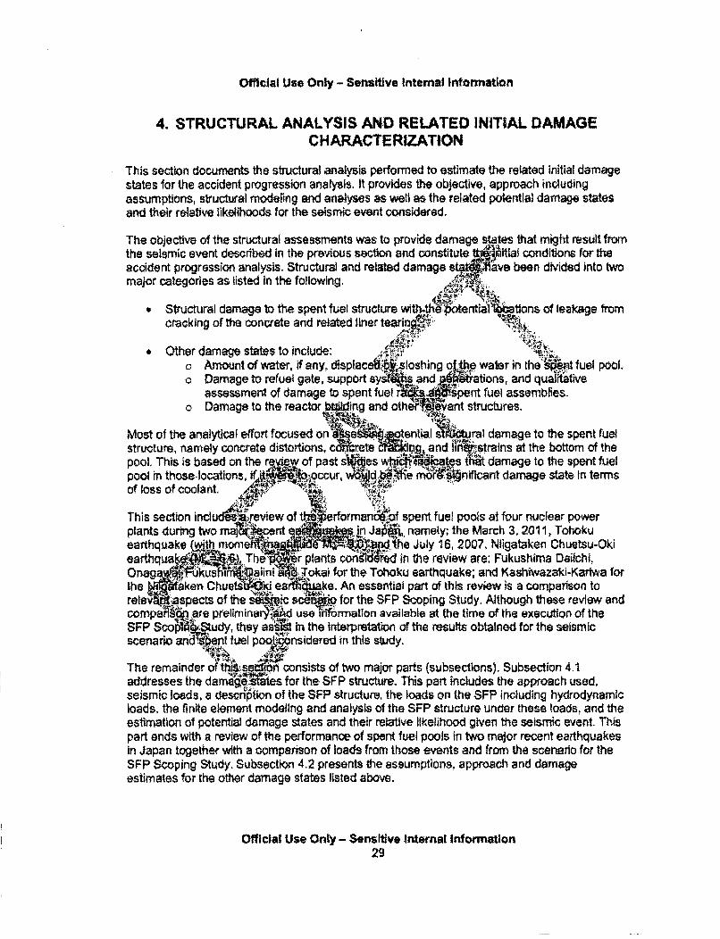
Official Use Only - Sensitive Internal Information
4. STRUCTURAL ANALYSIS AND RELATED INITIAL DAMAGECHARACTERIZATION
This section documents the structural analysis performed to estimate the related initial damagestates for the accident progression analysis. It provides the objective, approach includingassumptions, structural modeling and analyses as well as the related potential damage statesand their relative likelihoods for the seismic event considered.
The objective of the structural assessments was to provide damage states that might result fromthe seismic event described in the previous section and constitute ps itial conditions for theaccident progression analysis. Structural and related damage s ave been divided into twomajor categories as listed In the following.
• Structural damage to the spent fuel struCturecracking of tfe concrete and related liner tear
of leakage from
* Other damage states to include:* Amount of water, if any, displace •. 5ioshung of.ewater in the' Qo Damage to refuel gate, support sys and tions, and qualrt
assessment of damage to spent fuel r 1 ýpent fuel assemblies.Damage to the reactor baqing and othe evant structures.
fuel pool.
Most of the analytical effort focused on INstructure, namely concrete distortions, cc'pool. This is based on the revew, of pastpool in those-locations, if .,..occurof loss of coolant.
ural damage to the spent fuel&'strains at the bottom of thetr damage to the spent fueliffcant damage state in terms
This section inclu,plants during twoearthquake 4withearthqua.%On ag kuslthe ".j'FJit-ken Ct
of t •• rforman6iof spent fuel pools at four nuclear powere siln J namely. the March 3, 2011, Tothoku
he July 16, 2007, Nligataken Chuetsu-OkiVr plants con},'1 se in the review are: Fukushima Daqichi,
Tokal for the Tohoku earthquake; and Kashiwazaki-Kariwa fori'Ve. An essential part of this review is a comparison to
scdij@_ for the SFP Scoping Study. Although these review and,b use•itiffrmation available at the time of the execution of the4 In the interpretation of the results obtained for the seismicOnsidered in this study.
SFP Scojscenario
The remainder of I16. consists of two major parts (subsections). Subsection 4.1addresses the damarere~g.s for the SFP structure. This part includes the approach used,seismic loads, a descnotion of the SFP structure, the loads on the SFP including hydrodynamicloads, the finite element modeling and analysis of the SFP structure under these loads, and theestimation of potential damage states and their relative likelihood given the seismic event. Thispart ends with a review of the performance of spent fuel pools in two major recent earthquakesin Japan together with a comparison of loads from those events and from Lhe scenario for theSFP Scoping Study. Subsection 4.2 presents the assumptions, approach and damageestimates for the other damage states listed above.
Official Use Only - Sensitive internal Information29
Official Use Only - Sensitive Internal information
4.1. Damage States for the Spent Fuel Pool Structure
4.1.1. Approach and Seismic Loads
The general approach for the estimate of the damage states follows, with appropriatemodifications for the specific needs of this study, the approach reported in NUREG/CR-5176(Prassinos, 1989). The analyses reported in NUREGICR-5176 were conducted in conjunctionwith research activities related to Generic Issue 82 (GI-82), 'Beyond Design Basis Accidents inSpent Fuel Pools," (NRC, .2012a). Appendix 2 of NUREG-1738 (Collins and Hubbard, 2001), atechnical study of spent fuel pool accident risk at decommissioning 94ear power plants,provides a review of the approach and results in NUREGCR .51 ssinos, 1989). Aconclusion of that review Is that the overall approach in NUREG 5176 provides anacceptable means to estimate seismic structural damage to uel pool.
AoD-roach -,Z
The overall approach used in the SFP Scoping 84ti o assess damage I P structure,namely concrete cracking, concrete distortions., 'sM'trains and :iner tearing, earthquakeevent considered, consists of the following 9 st ' •
1. Obtain free-field ground motion response s a0 ontat and vertical)for the site
considered (a rock site and a reactor building w fl embedment). For ts scopingstudy, the response spectra a I- o n the US .208 model used for Generic Issue199 (GI-199) (NRC 2012b) as lf.aAizmSection 4..
2. From reliable and weol-documentn pas ;in" *ructure response spectra(ISRS) (also called - esponse I And horizontal directions atthe elevation ofhe spet W-1I (Eleven" 195 ft). For reference, theelevation at '•p of the 'eling fld '=Elevation 234 ft and the elevation at the topof the fount slab is E ion 92 ft 'It
a. The F"Scopin 0d the incnee ISRS calculated for thePeach .............. ioi1(PBAPS) for the seismic PRA performed for
joi _• RE study (N -0) and reported in Volume 4. Part 1, RevisionW J.tEGC-rc- .55O (Lmght. 1990).
-Estlmate In-strle res so spectra for the ground motions of interest for this study==tthe elevations aeres( p 2a) by scaling the ISRS from previous studies (Step
24to account for dM enoe nln the response spectra shapes of the free-field groundn6tIs considered 4he NUREG- 150 seismic PRA and in this study (see Figure 5whe respons jietra are scaled to 1.0 g PGA).
4, Use the siled I §frm Step 3 to estimate equivalent static forces to be applied, inconjunctionr ad loads, to the floor and walls of the SFP as input for a staticnonlinear push0ver analysis. These equivalent static forces account for: (I) peak verticaland horizontal accelerations of the floor and walls of the SFP structure (seismiccoefficients); (ii) peak vertical and horizontal hydrodynamic impulsive pressures on thefloor and walls of the SFP from the water in the pool; and (iii) vertical dynamic forces onthe SFP floor from the dynamic response of the racks and spent fuel assemblies. At thisstage of the analysis also estimate vertical displacement of the water surface fromstoshing.
a. The SFP Scoping Study used a simplified three-dimensional (3D) finite elementmodel of the SFP structure to estimate or verify these loads. Specifically, it used
Official Use Only- Sensitive Internal Information30
Official use Only - Sensltive Internal Information
elastic solid elements and special fluid elements to model the water, in order toestimate natural frequencies and mode shapes for the SFP structure, This modelwas then used to calculate the spatial distribution of peak vertical and horizontalaccelerations of the structural components using the ISRS from Step 3 as input.
b. Hydrodynamic Impulsive pressures, peak vertical and horizontal pressures, werecalculated on the basis of simplified methods (Housner, 1963; AEC, 1963; andMalhotra, Wenk and Wieland, 2000). The 3D finite element model used in Step4a together with the ISRS from Step 3 as input were also used to estimate peakhydrodynamic pressures. This provided a verification oj.the suitability of' thepressures calculated using simplified methods, whsc re the ones used in theanalyses. .7.•,',,;
c. The 3D finite element model used in Step 4a wlISRS from Step 3 as inputwas also used to estimate vertical displaceIfM Of yter surface fromsloshing. The estimated displacements ?emall wh p t ta- npared to the depth
of water in the SFP as indicated below., "
5. Perform a 3D static nonlinear pushover an a of the SFP structurinfg a detailed3D finite element model of the SFP stru ,,, that incude.,nonwinear mcl•. oftm od oftoA6 reinforcamen,.mbddconcrete including cracking as well as I X gI .tl reimbeddedsteel floor beams and the SFP liner. Perfo roilnear pushover analysis foradequate combinations of the •tlcal and ho round motions to account for thefact that maximum verticaJ an tal acoeler do not occur simultaneously(NRC, 2007). Accordingly, perl amolinear std l-shover analysis as follows:
a. Incrementally apply the %da load A. FP l.bure to calculate initialstresses an s*ralns. Deadabda th:i study consist of: the weightof the pooll compo Vight o r, weight of the spent fuelassenb and t'•b of the 'r4t'fuel racks.
b. Fol tep 4a wfth incremeu1 'Lapplicatiori of adequate combinations of thehorizc .nd ve qivalentMic formes estimated in Step 4. The
4ncred j track development and effects of concreteeg straiste~rmi dIng and liner strains,
in i! , Verfical seismic loads were combined with 40-percent of theS peak hw•p aA h tal IA. Alternatively, peak horizontal loads on both directions
were conMBed wit?*-.percent of the vertical loads. Preliminary analyses".. Indicated thi.ie loawcombtnation involving peak vertical loads and 40-percent
of the horizoitl loads would be the most severe combination for the SFP-"&tructure an4zed. Accordingly, this was the combination studied in more detail
"Ii~ie remal!der of the study.
d. Use 5 timate material properties for all materials, e.g., concrete,reinfo nent, steel beams and liner, based on best available information forsimilar materials used In nuclear plants and other guidance for the assessmentof extreme events and for seismic fragility assessments. Also take into accountthe effect of aging on the concrete strength as recommended for the assessmentof beyond design basis, extreme events.
6. Review and process the calculated structural distortions (as measured by thedisplacement of nearby nodes), structural deformations, concrete strains and finerstrains in order to:
Official Use Only - Sensitive Internal Information31
Official Use Only - SensHive Internal Infotrmaton
a. Assess the possible development of cracks through the floor or walls (theanalyses indicated that critical concrete cracking such as this would only developat the base of the walls along the intersection of the SFP walls with the SFPfloor), and then estimate crack lengths and average crack width.
b. Assess liner strains at the intersection of the base of the wails and floor slab inorder to assess the potential for liner tearing. Take into consideration details ofthe attachment of the liner, in discrete locations, to the concrete floor and walls,
7. Define three initial states for the subsequent accident progression analysis as follows:
a& A state with no leakage, and no loss of coolant, fro. ibottom of the SFP.This state corresponds to concrete cracking at th of the walls (estimatedto be through wall cracking for the event consid s shown in subsequentsubsections) but without tearing of the liner. A A o,
b. A state with moderate leakage rate frorn.te bottom of YýJFP, corresponding tothrough wall concrete cracking at the of the wails f tearingof the liner that propagates to an e..4uch athe water las controlled by
the size of the cracks in the con• A'A
c. A state with small leakage rate frte botto 'fthe SFP, corresponding tothrough wall concrete cracking at thel • 'fe walls and tearing of the linerthat remains localzed tthoseparts w R floor liner is attached to the SFPfloor near the wafts.
8. For the two damage states withiak. mbmate th •akage rate at the base of theSFP walls. When the rate is cont!•led by"' ing tlwconcrete (moderateleakage rate) use rT t large sca st : Jow V'vater though thick concreteslabs together witated and le to estimate the leakage rate.When the rat ntrol localiz' irr tearing use empirical date from leakagethrough cr in steel pip-"" estiraihe leakage rates.
9. Use data foii ate stra' t stypes teal used for $FF' liners, together withuncertainties 1n' ! :: .nIr.a-15 (accounting In approximation for uncertaintiesin t iimation -strctu re nd concrete properties) to estimate the
, i.,ds f three initial damage states listed in Step 8: no leakage,i derate lea rat ..'small leakage rate.
As no. le1bove, this apprh paratl'1 'part of the approach used in conjunction with theresolutio GI82 (PrassirQ.e al., 1989). It augments the earlier approach in that it usesmodern fnitnefement methA' in Steps 4 and 5. Use of finite element analyses in Step 4 isnecessary to'I c9I6 a morerlurate assessment of the natural frequencies of the SFP sttuctureitself, to estimatle 4~..Histributlon of seismic coefficients and to verify the estimatedhydrodynamic impAJW ads on the floor and wails of the SFP. Use of finite element analysesin Step 5 is necessary" itrack the development of cracking and liner strains and then relatedthose to damage states, leakage rates and their relative likelihoods.
The approach described above has potentially conservative aspects that may overestimate thedamage to the spent fuel structure. A possible conservative aspect Is that generally ISRSaccelerations do not necessarily increase proportionally (linearly) from low PGA events to anevent with a PGA as high as that considered in this study. As the load increases, the structureof the reactor building may crack and dissipate energy thus dampening the response of thebuilding. This was taken into account, in approximation, in the scaling of the ISRS from previous
Official Use Only - Sensitive Internal Information32
Official Use Only - Sensitive Internal Information
studies (using 0.36 g PGAs) by considering an increase on the damping of the reactor buildingstructure.
Another potentially conservative aspect of the analysis is that the scaling of the ISRS does nottake Into account reductions on the high frequency (greater than 10 Hz) spectral accelerationsthat may result, under some circumstances, from ground motion Incoherency, wave scattering,soil-structure interaction effects and wave passage effects. This is accounted for, in part, in thecalculation of the relative likelihood of the various damage states by considering a small rangeof reduction in the response and associated uncertainties, as discussed below.
Other approximations of note include: (i) the scaling ISRS calculat a ground motion withresponse spectra markedly different at high frequencies (greate 10 Hz) from the groundmotion spectra considered for this study; (ii) the decoupling 4 onse of the SFP from theresponse of the reactor building; and (iii) neglecting the sm 1 of the reactor building(especially for the calculation of horizontal ISRS). Follogubsections d ss theseapproximations. Another approximation is the use of sCtc pushover-iRnalysis to estimatedamage to the SFP, More detailed approaches in 6 the use of sample -histories,including sampling of incoherent ground motioný, in conjunction with 3D=Ils of theentire reactor building and soil-structure inetract nalys s to.kulate loads oA# SFPwould provide additional insights on some of these I Q.b.ervatisms. However, this wouldbe contradictory with the scoping nature of the study. ý IN
The weight of other SFP equipment a ia •enances ontl dead loads, and thermalstresses are not accounted for In the es t•afte initial stes in the SFP components(Step $a). The weight of other equipment4small I :rlson' e other loads in the pool.Thermal stresses are not a d for unr&the 00 at concrete cracking will relievethe thermal stresses. M . ase in ture 3-e water, It were to occur,would not happeniuntil:.rft er the, ination of the ground shaking.
Seismic Loads .
Section 3 s and O sthe Waeg fo.A ftee-field ground motion response spectrafor the s dnsld't ;`ed for the SFP ing Study. As noted in Section 3 other free-field ,,se s nten:this study are those documented in NUREGICR-4550.Lai t, 1990) and in th.r4obabilistic risk assessment (PRA) for NUREG-1150, That
repor ouments and pr as me.i -centered ISRS (for 5-percent damping) for the PeachBottom' or structures p•ulated J•sing Wime-history analysis and an ensemble of free-fieldground ntsao time-histone !Section 3 provides a comparison of the median-centered freet-field ground ii respons Ipectra for that ensemble of time-histories to the ground motionresponse spect. ;'or thesrmic event considered in this study.
The free-field response spectra and ISRS reported in Lambright (1990) form a set of reliableand well-documented response spectra for the Peach Bottom reactor buildings. Specifically, thatreport provides ISRS at various elevations of interest in the reactof building, namely at thebottom elevation of the SFP (Elevation 195 ft) and at the refueling floor (Elevation 234 ft), Inaddition, the report also provides estimates of frequencies of vibration for the reactor building,which are listed in Table 6. These frequencies help understand the shape of the ISRS for thePeach Bottom reactor building. It is noted that the frequencies of vibration of the SFP structure{discussed in the following section) and of the SFP floors and walls range from about 18 to 25Hz depending on the cracking of the concrete, boundary conditions (restraints) and how themass of the water is accounted for in the calculation of these frequencies. These frequencies
Official Use Only - Sensitive Internal Information33
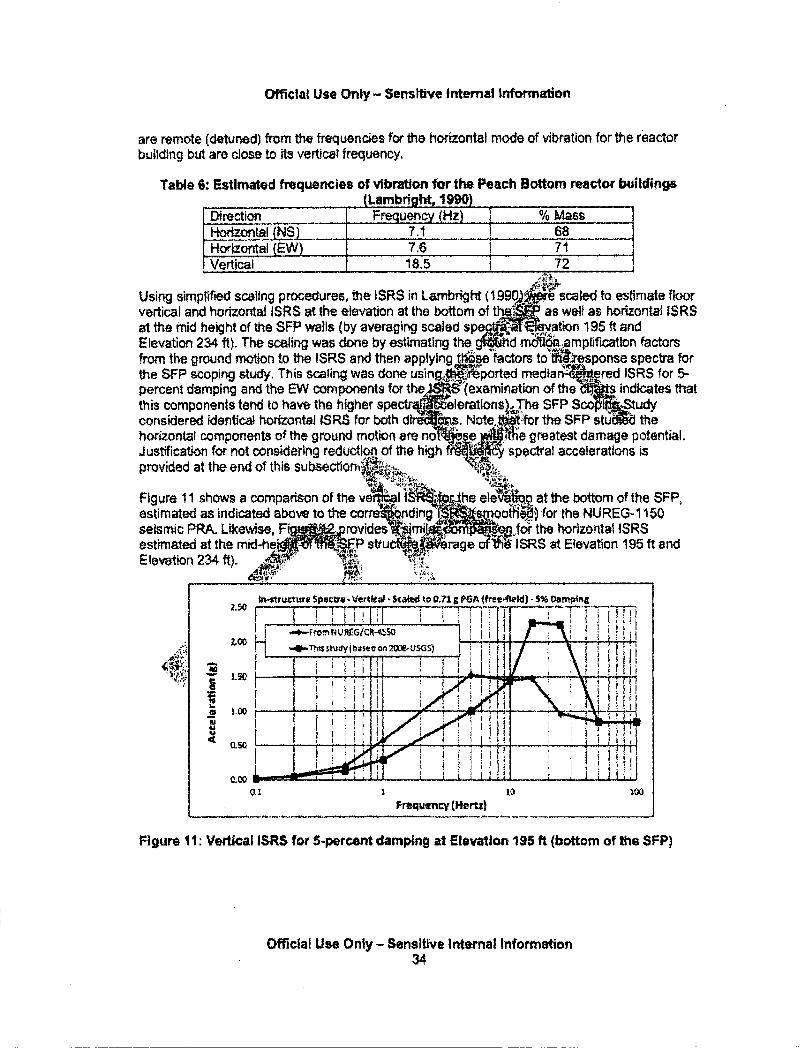
Official Use Only - Sensltive Internal Information
are remote (detuned) from the frequencies for the horizontal mode of vibration for the reactorbuilding but are close to is vertical frequency.
Table 6: Estimated frequencies of vibration for the Peach Bottom reactor buildings(Lambright, 199)
Direction F uenc Hz) % MassHorizontal NSK 7.1 68Horizontal (EW) 7.6 71.Vertical 18.5 ¶ 72
Using simplIfied scaling procedures, the ISRS in Lambright (199%V.fe scaled to estimate floorvertical and horizontal ISRS at fhe elevation at the bottom of tlj as well as horizontal ISRSat the mid height of the SFP walls (by averaging scaled sp li ation 195 ft andElevation 234 ft). The scaling was done by estimating the •hd On io mplification factorsfrom the ground motion to the ISRS and then applying thqe factors toýWresponse spectra forthe SFP scoping study, This scaling was done usin eported mediarý. red ISRS for 5-percent damping and the EW components for the.. '(examination of the indicates thatthis components tend to have the higher spe eleratlons.The SFP Sco tudyconsidered identical horizontaJ ISRS for both dir•H.s. Note, itfor the SFP stu' the
horizontal components of the ground motion are nolbbseem M1e greatest damage potential.Justification for not considering reduction of the high ff spectral accelerations isprovided at the end of this subsectioniA ,:IV
Figure 11 shows a comparison of theestimated as indicated above to the c(seismic PRA. Likewise, F1estimated at the mid-heiFElevation 234 ft). ,Jr
i at the bottom of the SFP,Mid) for the NUREG-1150.o4r the horizontal iSRS"ISRS at Elevation 195 ft and
Figure 11: Vertical ISRS for 5-percent damping at Elevation 195 ft (bottom of the SFP)
Official Use Only - Sensitive Internal Information34
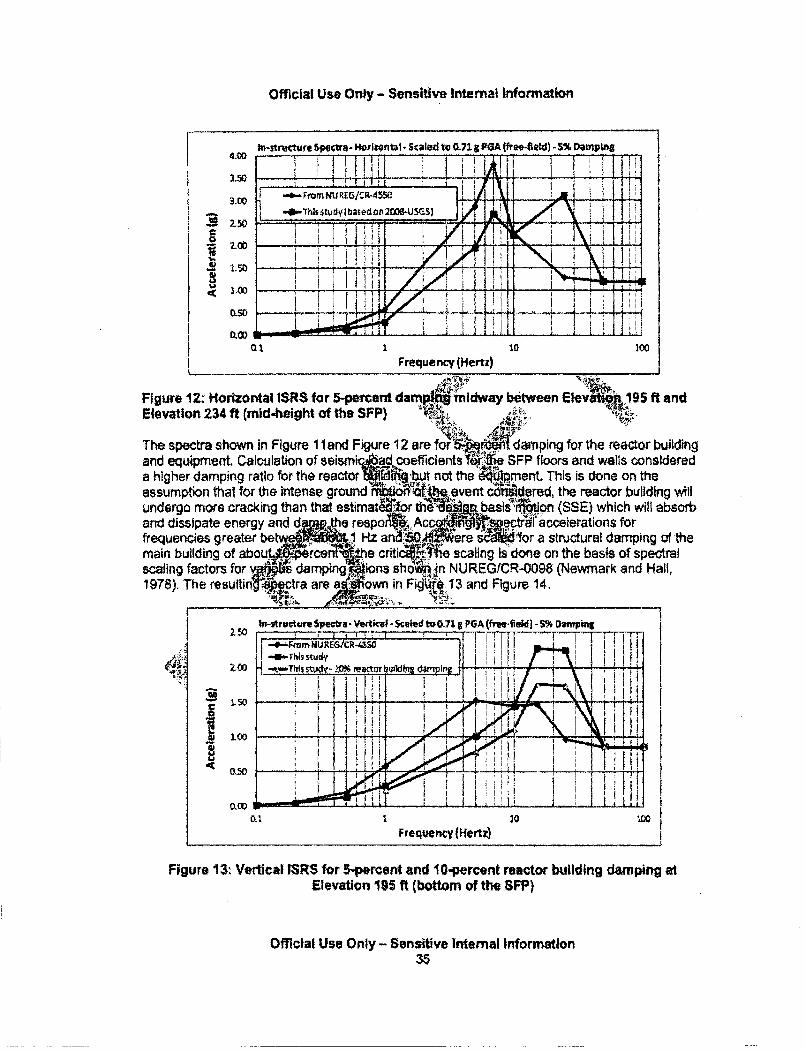
Official Use Only - Sensitive Internal Information
to-structure ~ectra- ftoriwtt- kl. ed to 0.715 POA fr~ee-eld) -5% Darnptng
3.50__ _
I - oF n NU REG/'R- I4
300
0.50
...... ... .. ..
Frequency (Hertzý
Figure 12: Horizontal WSRS for 5-percent dam midway between E1ev• np95 ft andElevation 234 ft (mid-height of the SFP) -
The spectra shown in Figure 1 land Figure 12 are fo r g lTdamping for the reactor buildingand equipment, Calculation of seismi d, coefficients a ,f1 SFP floors and walls considereda higher damping ratio for the reactor n 1r i~but not the ,.pment. This is done on theassumption that for the intense ground ft. vent c•sdered, the reactor building willundergo more cracking than that estimat th liWg basis1fton (SSE) which will absorband dissipate energy and d8 ,he respoAW, Ac ectl. accelerations forfrequencies greater be 1 Hz ana!o.&.. ere s -1dor a structural damping of themain building of abouL. cer e critic e scaling Is done on the basis of spectralscaling factors for mp ions sho .1n NUREGICR-0098 (Newmark and Hall,1978). The resultin tra a a own in Fig 13 arnd Figure 14.
Figure 13: Vertical ISR$ for 5-percent and 10-percent reactoc building damping atElevation 195 ft (bottom of the SFP)
Official Use Only - Sensive Internal Information35
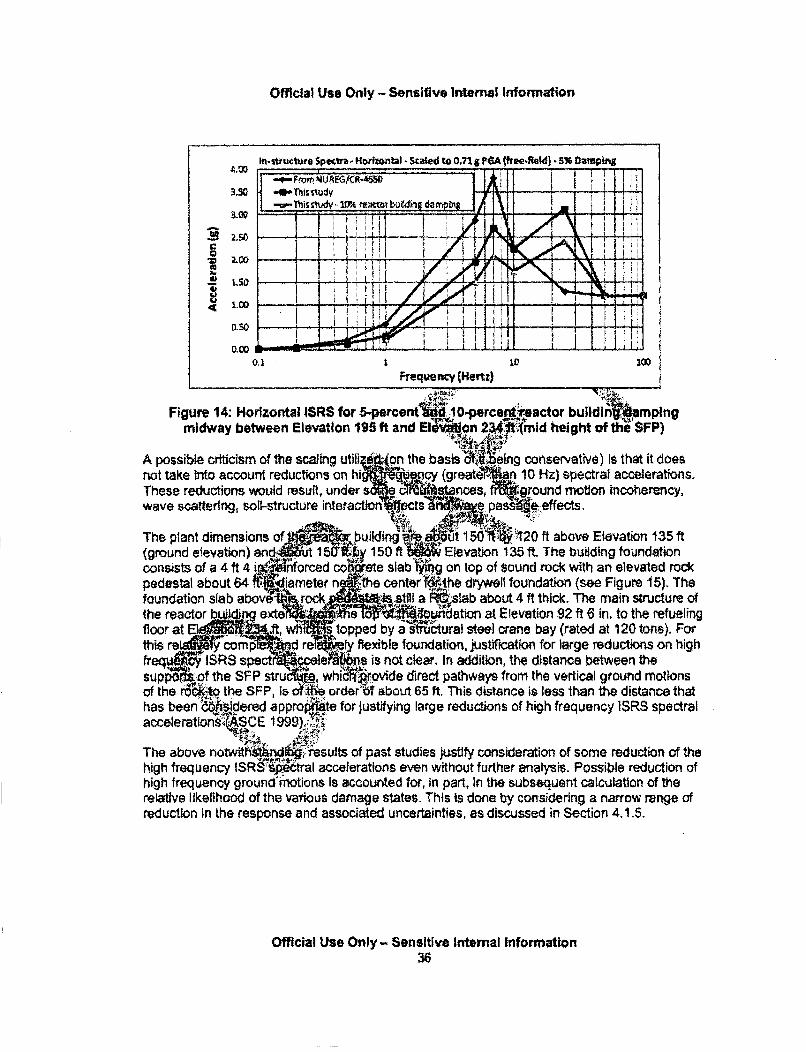
Official Use Only - Sensitive Internal 1nformation
n.,I~jien ~tm- Hrr*~nnbI - Sr~Is~d to 0.71 aPt~A ffrn~.RnM1 ~%4.00
3.50
3.00
I O
0.50
0.00
-- Fyrom UREG/CR-9,50 IRI
-0- Thi study~nis% 0%ratbuindapn *'M ~
II I I I~i~'J.I j
O, I 10 1(0Frequency (Hertz)
Figure 14: Horizontal ISRS for erunt 0.,m id heigto f I SFp)midway between Elevation 195 ft and elVon 2341"imid height of th6 SFP)
A possible criticism of the scaling utili f... an the basis %eing conservative) Is that it doesnot take into account reductions on hi .. ncgreaty r n 10 Hz) spectral accelerations.These reductions would result, under mce"s, lound motion incoherency,wave scattering, soil-structure interaction ctpes oeffects.
The plant dimensions of buildin4.:..t 1 *'V120 ft above Elevation 135 ft(ground elevation) an 15 i 150 ftt1 , Elevation 135 ft The building foundationconsists of a 4 ft 4 i R.Wforced cohrete slab 9g on top of sound rock with an elevated rockpedestal about 64 ' iameter n the centerldthe drywell foundation (see Figure 15). Thefoundation slab above-Ifnrock '4StilI a e4slab about 4 ft thick. The main structure ofthe reactor udexte ,. • .i•dation at Elevation 92 ft 6 in, to the refueling
fl topped by a itural steel crane bay (rated at 120 tons). Forthis re y comp nd re ty flexible foundation, justification for large reductions on highfreq [IRS spect I is not clear. In addition, the distance between thesup •pf the SFP stru whi rovide direct pathways from the vertical ground motionsof the r W the SFP, is t order'•T about 65 ft. This distance is less than the distance thathas been do"'sidered approrte for justifying large reductions of high frequency 1SRS spectralaccelerations,,SCE 1999),:_')
'i !•i , •i !~ :;', ..
The above notwiths~ug Tesults of past studies justify consideration of some reduction of thehigh frequency IS ~tral accelerations even without further analysis. Possible reduction ofhigh frequency ground motions is accounted for, in part, In the subsequent calculation of therelative likelihood of the various damage states. This is done by considering a narrow range ofreduction in the response and associated uncertainties, as discussed in Section 4.1.5.
Official Use Only - Sensitive Internal information36
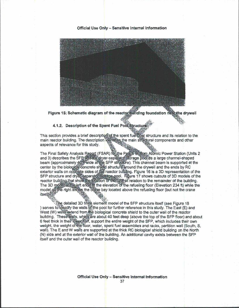
Official Use Only - Sensitive internal Information
Figure 15: Schematic dlagram of the reac
4.1.2. Description of the Spent Fuel Pi
foundation dryweIll
structure and its relation to thefyral components and other
This section provides a brief descrlpti9main reactor building. The descriptionaspects of relevance for this study.
The Final Safety Analysisand 3) describes the SFbeam (approximatelycenter by the biol %exterior wails on ol'. 4.SFP structure andreactor buil at shThe 3D r=sfte
(FSAR) e ptMmIG Power Station (Units 2r-sep rage *f a large channel-shaped
a SFP ), This channel beam Is supported at theSstructu .round the drywell and the ends by RCreactr '•n Figure 16 is a 3D representation of the
re 17 shows cutouts of 30 models ofrthee o relation to the remainder of the building,
th refueling floor (Elevation 234 ft) while theýV bay located above the refueling floor (bWt not the crane
detailed 3D fl!. elemefi model of the SFP structure itself (see, Figure 18) sers t the #Walls e pool for further reference in this study. The East (E) andWest (W) we nd M, biological concrete shield to the outer wall of the reactorbuilding. Thee s, w e about 40 feet deep (above the top of the SFP floor) and about6 feet thick in the support the entire weight of the SFP, which includes their ownweight, the weight o0 ! or, water, spent fuel assemblies and racks, partition wall (South, S,wall), The E and W wels are supported at the thck RC biological shield building on the North(N) side and at the exterior wall of the building. An additional cavity exists between the SFPitself and the outer wall of the reactor building.
Official Use Only - Sensltive Internal Information37
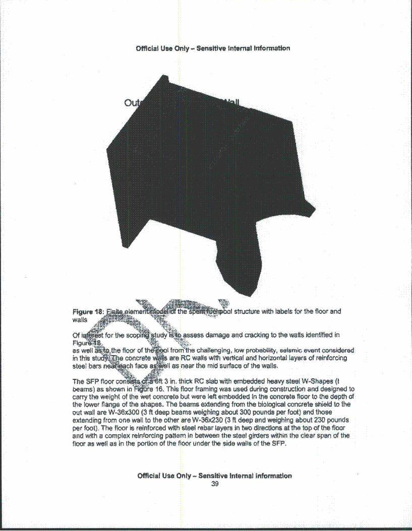
Official Ut. Only - Semltiw Internal Information
Figure l .: lame the of structure with labels for the floor andwalls "• ' i=:
Of I t for the 3Com_-. y -assess damage and cracking to the wals identifled in
as w ..,tl foor of Ii frorrithe challeNilng, low probability, saelsumi evetit conaideredin this st concrete •' are RC wags with vertical and horizontal layers of reinforcingsteel bars n oh face a It as near the mid surface of the wails.
The SFP floor con ft 3 in. thick RC slab with embedded heavy steel W-Shapes (tbeams) as show In ar e 16. This floor framing was used during construction and designed tocarry the weight of the Wet concrete but were left embedded In the concrete floor to the depth ofthe lower flange of the shapes. The beams extending from the biological concete shield to theout wall are W-36x300 (3 ft deep beams weighing about 300 pounds per foot) and thoseextending from one wall to the other are W-36x230 (3 ft deep and weighing about 230 poundsper foot). The floor is reinforced with steel rebar layers In two directions at the top of the floorand with a complex reinforcing pattern In between the steel girders within the clear span of thefloor as well as in the portion of the floor under the side walls of the SFP.
Official Use Only - Sensitive Internal Information39
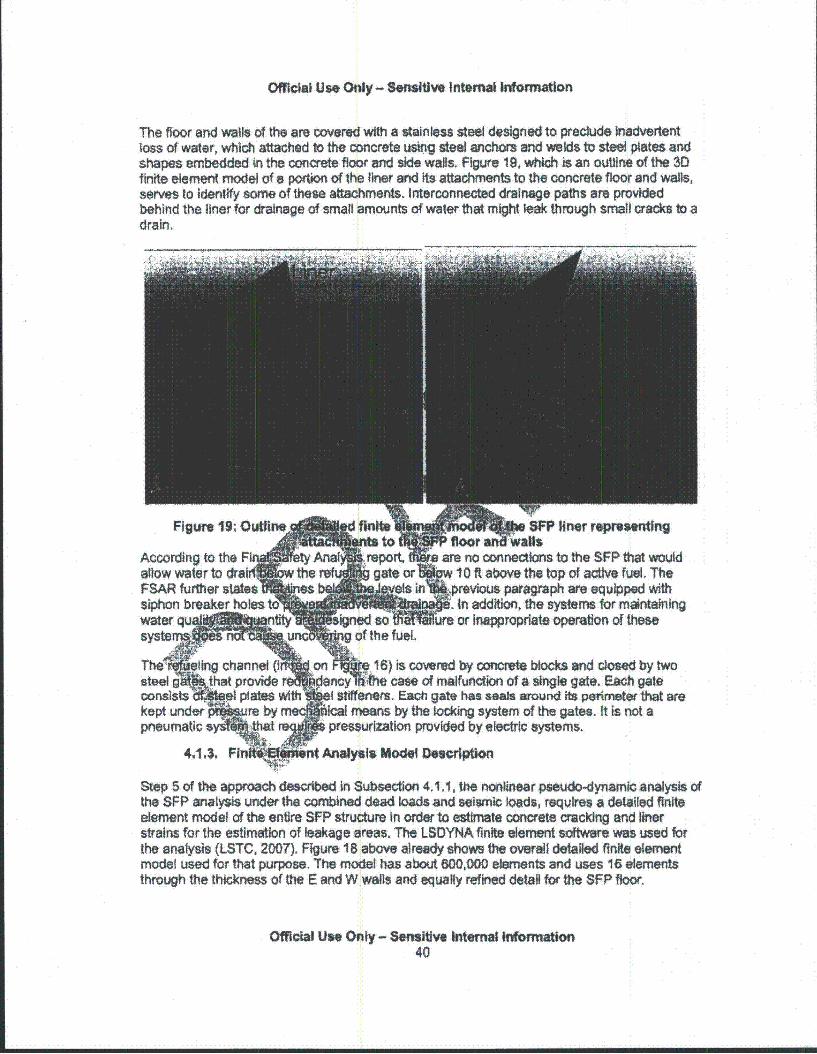
MRfcia Use Only - Sensitive Internal Information
The floor and wails of the are covered with a stainless steel designed to preclude inadvertentloss of water, which attached to the concrete using steel anchors and welds to steel plates andshapes embedded in the concrete floor and side wagls. Figure 19, which is an outline of the 3Dfinite element model ofa portion of the liner and its attachments to the concrete floor and walls,serves to identify some of these attachments. Interconnected drainage paths are providedbehind the liner for drainage of small amounts of water that might teak through small cracks to adrain,
PSFP liner reprsntingare no connections to the SFP that wouldw 10 ft asove the top of active fuel. The
1.previous paragraph are equipped withi. In addition, the systems for maintainingre or Inappropriate operation of these
n Pe16) is covered by concrete blocks and closed by twoMncy t4he case of malfunction of a single gate. Each gate
of stiffeners. Eac gate has seals around its perimeter that areilcal means by the locking system of the gates. It is not a; pressurization provided by electric systems.
t Analysis Model Descrption
Step 5 of the approach described in Subsection 4.1 1, the nonlinear pseudo-dynamic analysis ofthe SFP analysis under the combined dead loads and seismic loads, requires a detailed finiteelement model of the entire SFP structure In order to estimate concrete cracking and linerstrains for the estimation of leakage areas. The LSDYNA finite element software was used forthe analysis (LSTC, 2007). Figure 18 above already shows the overall detalled finite elementmodel used for that purpose. The model has about 600,000 elements and uses 16 elementsthrough the thickness of the E and W walls and equally refined detail for the SFP floor.
Official Use Only - Sensitive Internal nformation40
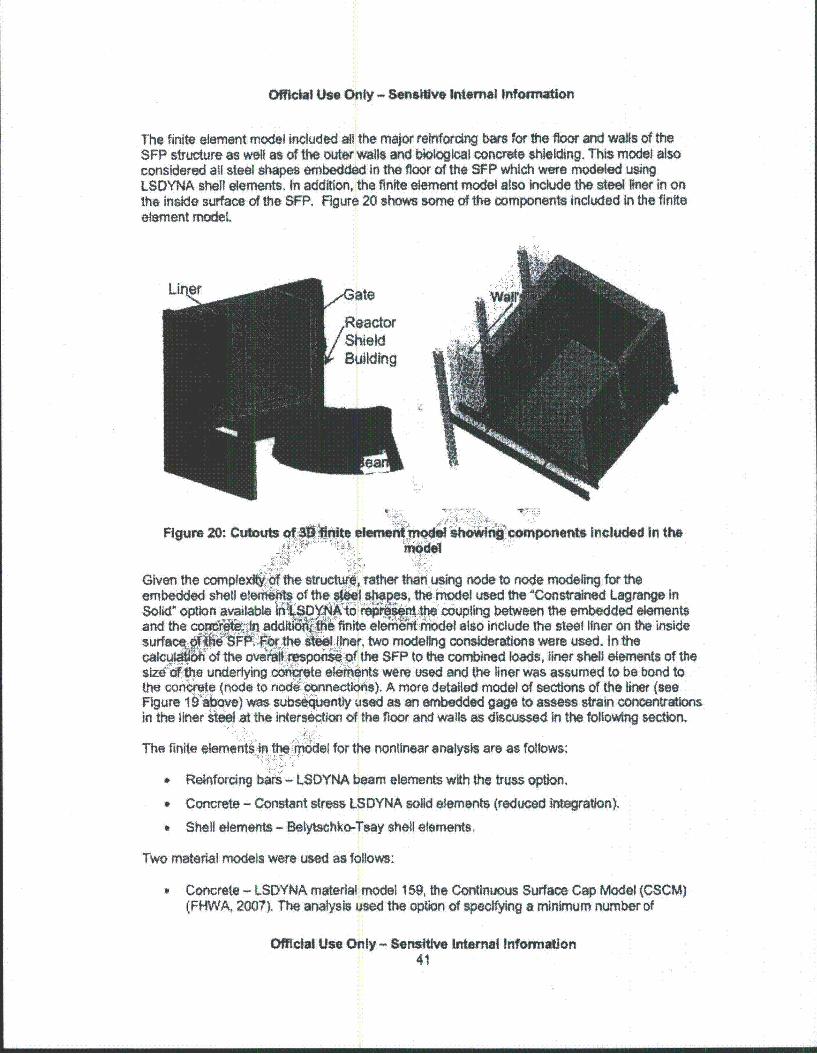
Official Use Only - Sensitive Internal Information
The finite element model included aSO the major reinforcing bars for the floor and walls of theSFP structure as well as of the outer walls and biological concrete shielding. This model alsoconsidered all steel shapes embedded in the floor of the SFP which were modeled usingLSDYNA shell elements. In addition, the finite element model also include the steel liner in onthe inside surface of the SFP. Figure 20 shows some of the components included in the finiteelement modeL
.Reactor .ShieldBuilding
Figure 20: Cutouts of. 3)ite ellernem Q*I soingcomponents Included In the
Given the complextW the structu• , rather than using node to node mrodeling for theembedded shell e ti•e~~ of the si siMpes, theniodel used the Constrained Lagrange in
Solid' option available !(SYD"YA1o:tthe coupling between the embedded elementsand the cofctn, add i'8 finite elernt MOdel also include the steel IMner on the inside
surfc al '3 " .,Fibr the i".l tner, two modeling considerations were used. In theclciz of the o sponseof the SFP to the combined loads, liner shell elements of thesize4"O4e underlying oirte el eents were used and the liner was assumed to be bond tothe con .te (node to node connections). A more detailed model of sections of the liner (seeFigure 1 9-bove) was subseiqnty used as an embedded gage to assess strain concentrationsin the liner steel at the intersection of the floor and walls as discussed in the foilowing section.
The finite elementS in the model for the nonlinear analysis are as follows:
" Reinforcing bars - LSDYNA beam elements with the truss option,
Concrete - Constant stress LSDYNA solid elements (reduced integration).
" Shell elements - Belytschko-Tsay shell elements.
Two material models were used as follows:
Concrete - LSDYNA material model 159, the Continuous Surface Cap Model (CSCM)(FHWA, 2007). The analysis used the option of specifying a minimum number of
Official Use Only - Sensitive Internal Information41
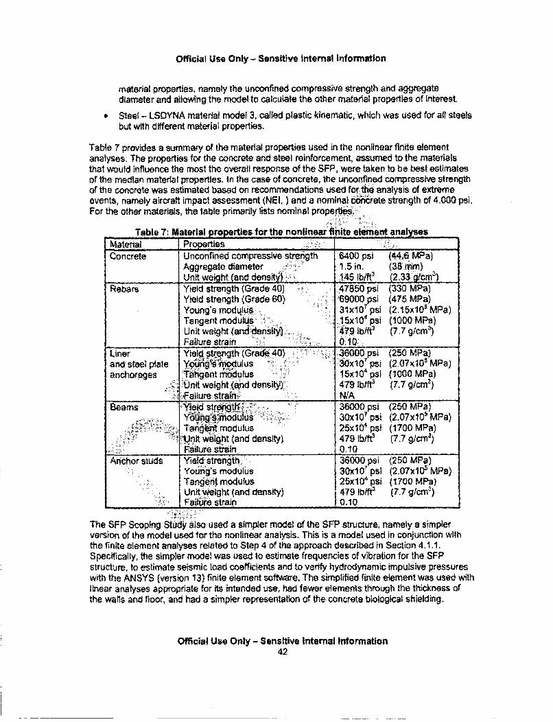
Official Use Only - Sensitive Internal Information
material properties, namely the unconfined compressive strength and aggregatediameter and ailowing the model to calculate the other material properties of interest.
Steel - LSDYNA material model 3, called plastic kinematic, which was used for all steelsbut with different material properties.
Table 7 provides a summary of the material properties used in the nonlinear finite elementanalyses. The properties for the concrete and steel reinforcement, assumed to the materialsthat would influence the most the overafl response of the SFP, were taken to be best estimatesof the median material properties. In the case of concrete, the unconfined compressive strengthof the concrete was estimated based on recommendations used forfthe analysis of extremeevents, namely aircraft impact assessment (NEI, ) and a nominal 0oncirete strength of 4,000 psi.For the other materials, the table primarily lists nominal properis.
Table 7: Material properties for the nonlinear finite element analysesMaterial Properties ..... ... . .. ____._._____
Concrete Unconfined compressive strnth 6400 psi (44.. MPa)Aggregate diameter - 1.5 in. (38 rm)Unit weight (and densit'i. .145 lb/ft' (2.336m3)
Rebars Yield strength (Grade 40) 47850 psi (330 MPa)Yield strength (Grade 60) '69000 psi (475 MPa)Young's modulus 31x10 7 psi (2 .15x1 0 MPa)Tangent modulus: . 15x10 4 psi (1000 MPa)Unit weight (and& ensit.. 479 lb/ftf (7.7 g/cnm)Failure strain 0.10.
Liner Yie. . str•.ngth (Grade 40) .. 36000 psi (250 MPa)and steel plate Y.g sp(ulus .30x10 psi (2.07J05 MPa)anchorages Tdngent imdulus 15x104 psi (1000 MPa)
-. Unit weight (and density):: 479 lb/fr3 (717 g/crn-)f..allure strain NIA
Beams "Yield stre'ngtl,'... '" 36000 psi (250 MPa)YIing!.modu. -i~i .utu .. 30x10' psi (2.07x10⁵ MPa)Tane modulus 25x10' psi (1700 MPa)
... :-.nt w ht (and density) 479 lb/ft (7.7 gJcmr)___________"__ .Failure strain 0.10Anchor studs Yiejld. strength..... 36000 psi (2.50 MPa)
Young's modulus 30X107 psi (2.07x10⁵ MPa)Tangernt modulus 25x0l psi (1700 MPa)Unit weight (and density) 479 lb/ft' (7.7 gcmn)
.... _"_:"_ Faitre strain 0.10
The SFP Scoplng Study also used a simpler model of the SFP structure, namely a simplerversion of the model used for the nonlinear analysis. This is a model used in conjunction withthe finite element analyses related to Step 4 of the approach described in Section 4.1.1.Specifically, thfe simpler model was used to estimrate frequencies of vibration for the SFPstructure, to estimate seismic load coefficients and to verify hydrodynamic impulsive pressureswith the ANSYS (version 13) finite element software. The simplified finite element was used withlinear analyses appropriate for its intended use, had fewer elements through the thickness ofthe walls and floor, and had a simpler representation of the concrete biological shielding.
Official Use Only - Sensitive Internal Information42
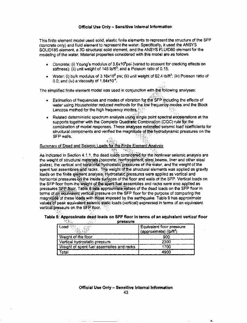
Official Use Only - Sensitive Internal Information
This finite element model used solid, elastic frinite elements to represent the structure of the SFP(concrete only) and fluid element to represent the water. Specifically, It used the ANSYSSOLIDI 85 element, a 3D structural solid element, and the ANSYS FLUID80 element for themodeling of the water, Material properties considered with this model are as follows
" Concrete: (i) Young's modulus of 3.6xl0 6psi (varied to account for cracking effects onstiffness); (ii) unit weight of 145 lb/fe; and a Poisson ratio of 0.15.
" Water; (i) bulk modulus of 3 .16x10e psi; (ii) unit weight of 62.4 ib/ft3; (ii) Poisson ratio of0.0; and (iv) a viscosity of 1.64x10 4.
The simplified finite element model was used in conjunction with the following analyses:
* Estimation of frequencies and modes of vibration fo•'he SFP ihcluding the effects ofwater using Householder reduced methods for the-low frequen'y miodes and the BlockLanczos method for the high frequency modes,.'
" Related deterministic spectrum analysis using single point spectral accelerations at thesupports together with the Complete Quadratic Combination (COC) ruletor:.thecombination of modal responses. These alatyses estim.OW seismic load coefficients forstructural components and verified the magnitude oftý~ hydrodynamic pressures on theSFP walls.
Summary of Dead and Seismic LoadLis foutheinite Element Analysis
As indicated In Section 4.1.1, the dead ioids consideedfor the " inear seismic analysis arethe weight of structural materials •concrete, reinforcent: see beams, liner and other steelplates), the vertical and ,hdnorttl!tiydrostati:prssures of the water, and the weight of the
spent fuel assembliesa'Akt racks. The weight of he structural elements was applied as gravityloads on the finite el•nt analysisý•. ydrostatid'lpressures were applied as vertical andhorizontal pressures bq the inside srfaces of thi floor and walls of the SFP. Vertical loads onthe SFP floor from the wot qlN sp*e#1i, assesomblies and racks were also applied aspressures SFPJ~oor. Table 8 I1 approxmaleyalues of the dead loads on the SFP floor interms of a'qýi'rali't verticý1: pressure on the SFP floor for the purpose of comparing themagn= 4of these as with tio so imposed by the earthquake. Table 9 has approximatevali•'~ peak equivaleti seismicsdt'ic loads (vertical) expressed in terms of an equivalentvertical pressure on the SFP .'floor.
Table 8: Approximate dead loads on SFP floor In terms of an equivalent vertical floorpressure
Load Equivalent floor pressure, ?-•. . . . . (approximate) (Ib/fl2)
Weight of the floor 900Vertical hydrostatic pressure 2300Weight of spent fuel assemblies and racks 1700Total 4900
Official Use Only - Sensitive Internal Information43
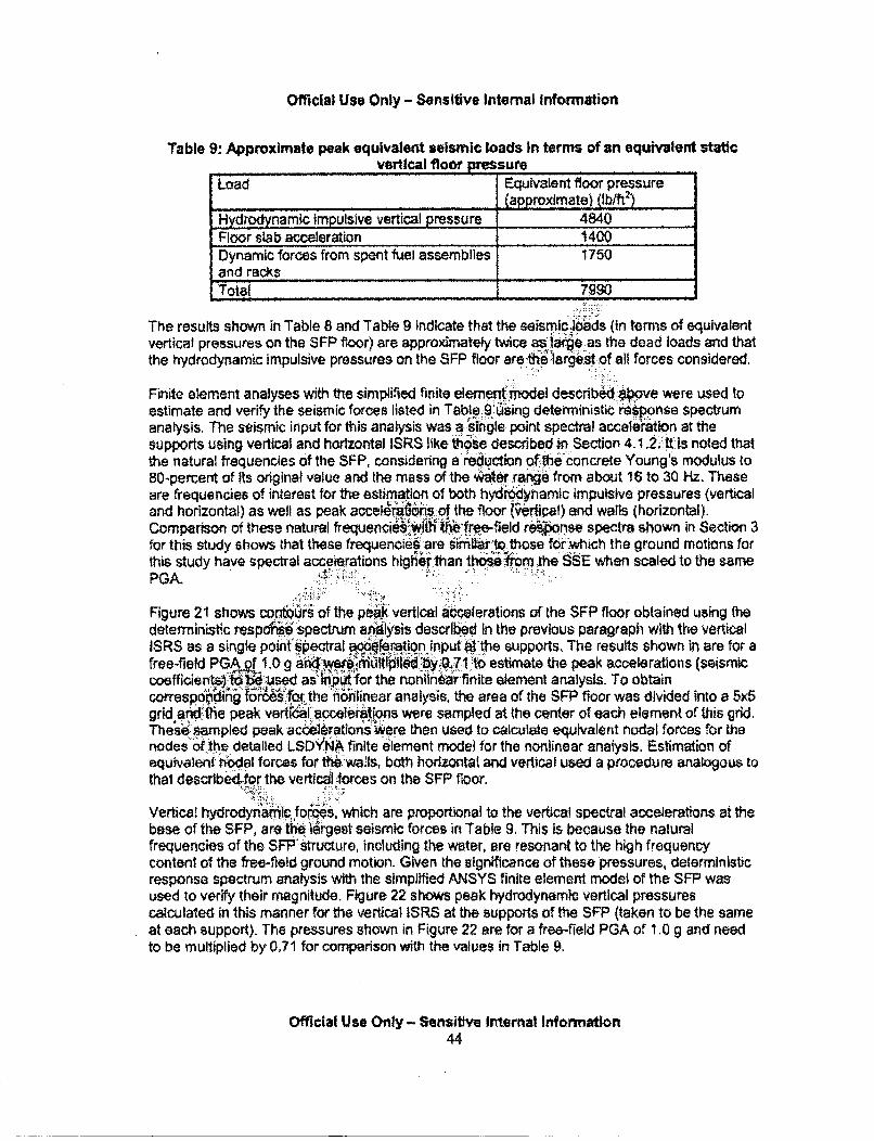
Official Use Only - Sensitive Internal Information
Table 9. Approximate peak equivalent seismic loads in terms of an equivalent staticvertical floor pressure
Load Equivalent floor pressure(approximate) (lb/ft2)
Hygrodynamic impulsive vertical pressure 4840Floor slab acceleration 1400Dynamic forces from spent fuel assemblies 1750and racksTotal 7990
The results shown in Table 8 and Table 9 indicate that the seismicdjoads (in terms of equivalentvertical pressures on the SFP floor) are approximately twice as la:ge as the dead loads and thatthe hydrodynamic Impulsive pressures on the SFP floor are. .th• larg•est.of all forces considered.
Finite element analyses with the simplified finite element -mnodel described above were used toestimate and verify the seismic forces listed in Tabl.e.. 9.•Using deterministic rosponse spectrumanalysis. The seismic input for this anaiysis was a.W'ingle point spectral accaleeWtion at thesupports using vertical and horizontal ISRS like:h ise described in Section 4.1.2'.tt s noted thatthe natural frequencies of the SFP, considering a reduction ofthe' concrete Young's modulus to80-percent of Its original value and the mass of the Wa • efrom about 16 to 30 Hz. Theseare frequencies of interest for the estimation of both hydrynamic impulsive pressures (verticaland horizontal) as well as peak accel4rtafos. of the floor (ýerical) and walls (horizontal).Comparison of these natural frequencies'wlw;th'tfr.e-field r*onse spectra shown in Section 3for this study shows that these frequencie•.are s9iir' .l tthose forfwhich the ground motions forthis study have spectral accel.erations highe'rthan those..... m the SSE when scaled to the samePGA.
Figure 21 shows contQurs of the peatk vertical ac•e•erations of the SFP floor obtained using thedeterministic respdiSie-spectrum apaysis described In the previous paragraph with the verticalISRS as a single point •pectral accl.eration input atthe supports, The results shown in are for afree-field PGA.pq 1.0 g 1i6Iiti'piei by O1to estimate the peak accelerations (seismiccoefficient tobe.used as""t- "for the nonln~hr finite element analysis. To obtainco!trspdhrih f-d.g 6.rfor the noninear analysis, the area of the SFP floor was divided into a 5x5grid and the peak verftal.acceleravions were sampled at the center of each element of this grid.Thesel mpled peak ac6eleratlons!Were then used to calculate equivalent nodal forces for thenodes of.the detailed LSDYNA finite element model for the nonlinear analysis. Estimation ofequivalent odal forces for th.6waIls, both horizontal and vertical used a procedure analogous tothat describk-for the vertical forces on the SFP floor.
Vertica! hydrodynIamc forCeS, which are proportional to the vertical spectral accelerations at thebase of the SFP, are the•.lrgest seismic forces in Table 9. This Is because the naturalfrequencies of the SFPstructure, including the water, are resonant to the high frequencycontent of the free-fleld ground motion. Given the significance of these pressures, deterministicresponse spectrum analysis with the simplified ANSYS finite element model of the SFP wasused to verify their magnitude. Figure 22 shows peak hydrodynamic vertical pressurescalculated in this manner for the vertical ISRS at the supports of the SFP (taken to be the sameat each support). The pressures shown in Figure 22 are for a free-field PGA of 1.0 g and needto be multiplied by 0.71 for comparison with the values in Table 9.
Official Use Only - Sensitive Internal Information44
Official Use Only - Sen3Mlve Internal Information
Figure 21: Estimated peak vertlodeterministic response spectrur
Figure 22: Estimated peak vertical hydrodynamic pressures on the SFP floor calculatedusing deterministic response spectrum analysis and vertical lSR$ as input (1,0 g PGA)
Official Use Only - Sensitive Internal Information45
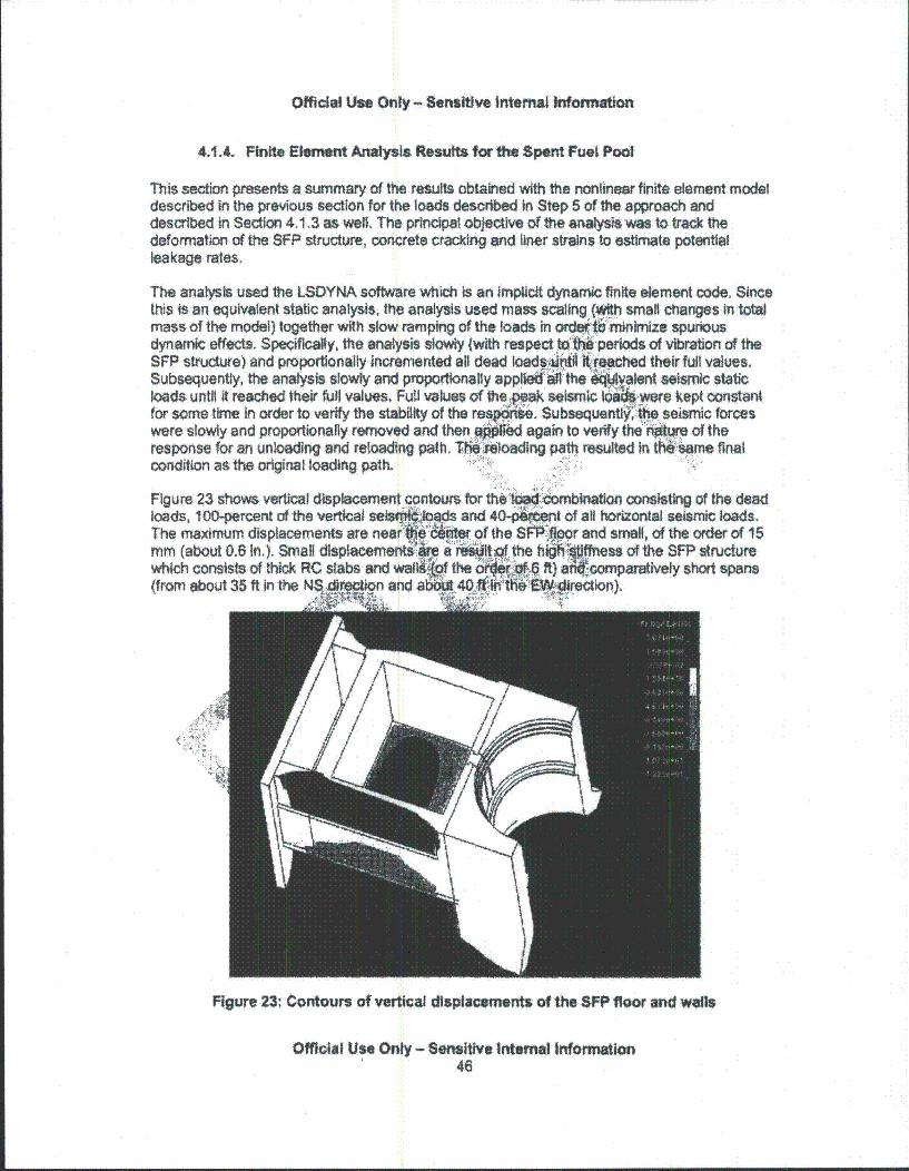
Official Use Only - Sensitive Internal Information
4.4.4 Finite Element Analysis Results for the Spent Fuel Pool
This section presents a summary of the results obtained with the nonlinear finite element modeldescribed in the previous section for the loads described In Step 5 of the approach anddescribed in Section 4.1.3 as well. The principal objective of the analysis was to track thedeformation of the SFP structure, concrete cracking and liner strains to estimate potentialleakage rates.
The analysis used the LSDYNA software which is an implicit dynamic finite element code. Sincethis is an equivalent static analysis, the analysis used mass scaling (with small changes in totalmass of the model) together with slow ramping of the foads in or: t iimize spuriousdynamic effects. Specifically, the analysis slowly (with respect to"t' -periods of vibration of theSFP structure) and proportionally incremented all dead loads .atlliti"ached their full values.Subsequently, the analysis slowly and proportionally applWed 4fthe &Mvalent seismic staticloads until it reached their full values, Full values of the pak seismic d' $-were kept constantfor some time In order to verify the stability of the rest , Subsequenttfthe seismic forceswere slowly and proportionally removed and then rW[ed again to verify the 6$.ure of theresponse for an unloading and reloading path. TeM`Ioading path resulted in iMsiame finalcondition as the original loading path.
Figure 23 shows vertical displacementloads, 100-percent of the vertical seiVThe maximum displacements are nearmm (about 0.6 In.). Small displacemerwhich consists of thick RC stabs and Y(from about 35 ft in the NS,&p ion ar
for thekqod omblnation consisting of the deadand 40-ýp ni of all horizontal seismic loads.vr of the SP W& r and small, of the order of 15
Sit•.the hiN offness of the SFP structuree ft) aA.''4 f comparatively short spans
. :'•:•: •:• :.
Figure 23: Contours of vertical displacements of the SFP floor and wafts
Official Use Only - Sensitive Internal Information46

Official Use Only - Sens&tve Internal Information
Figure 24 shows vertical displacement along the outside face of the W wall. Of special interestin Figure 24 are the disoontinulties of vertical displacement at the bottom of the SFP wall at thetop of the SFP floor, which are identifled by the transition between the blue and green contoursnear the center of span at the bottom of the wall. Discontinuities of vertical displacements In thisregion are of interest because, on the inside of the SFP, this is the region of strainconcentrations In the SFP liner as shown In Figure 25. Finaly, Figure 26 shows (with the redcontour) the region of the SFP, at the bottom of the SFP wa"ls and at the top of the SFP floorwhere the tensile strain of the concrete. is exceeded and a crack starts to develop. The crackstarts as a flexure crack and develops Into a tenslon-flexure crack though the thickness of thewall.
Figure 25: Liner strains (overall response not fully accounting for strain concentrations)
Officlal Use Only - Sensitive Internai Information47
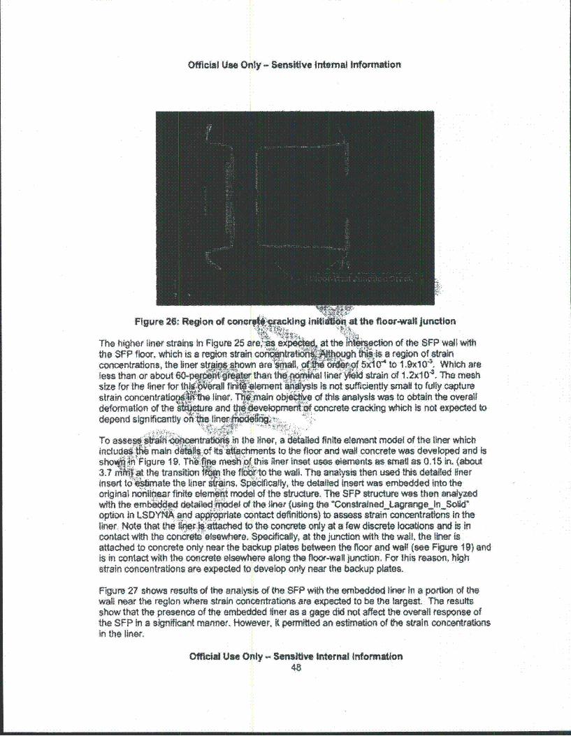
Official Use Only - Sensitive Intermal Information
Figure 26: Region of cona*Vwrong InitiM4at the flocrmwall junction
The higher liner strains In Figure 25 areý`!U a- a the Ihtereon of the SFP wall withthe SFP floor, which is a region strain to . t iQugh _-is a region of strainconcentrations, the liner str~k -shown are'siniall owi 5) ' df to I .qX10 43. Which areless than or about 60-pqi " • ]r than tIe • liner :4;ld strain of 1.2x10 V. The meshsize for the liner for Mh~ea fiJ~lmn ~hIysIss not sufficiently small to Muly capturestrain concentrat~o•f4i {tIthe liner. Tt•rnaln objeitlve of this analysis was to obtain the overalldeformation of the s4*re and fevelopmerto concrete cracking which Is not expected todepend significantly on f. lin er r: 1 -
To asse-ihi6' "Ocentratic in the liner, a detailed finite element model of the liner whichIndude : r •ain .of . nts to the floor and wall concrete was developed and Issho in Figure 19. The! es oJthis liner inset uses elements as small as 0.15 in. (about3.7 =n~~at the transition . ..he ffr1otO the wall. The analysis then used this detailed linerinsert toOriate the liner "tPins, $p kifically, the detailed insert was embedded into theoriginal n ftitlear finite erem•t model of the structure. The SFP structure was then analyzedwith the emledded d~e~, tiddet of the •lner (using the 'Constrained.JagrangeJn_Solid"option in LSDYNA and appnmwiate contact definitions) to assess strain concentrations In theliner. Note that the lrier h-a`tached to the concrete only at a few discrete locations and Is incontact with the concre:e elsewhere. Specifically, at the junction with the wall, the liner isattached to concrete only near the backup plates between the floor and wag (see Figure 19) andis in ontact with the concrete elsewhere along the floor-wall junction. For lhis reason, highstrain concentrations are expected to develop only near the backup plates.
Figure 27 shows results of the analysis of the SFP with the embedded liner In a portion of thewall near the region where strain concentrations are expected to be the largest. The resultsshow that the presence of the embedded liner as a gage did not affect the overall response ofthe SFP In a significant manner. However, it permitted an estimation of the strain concentrationsin the liner.
Official Use Only - Sensitive Internal Information48
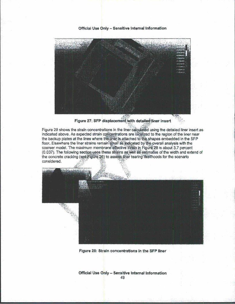
Officilu Use Only - Sensitive Internal In~formation
FIgure 27: SFP displacerne I*lh cletailled'Oner Insert
Figure 28 shows the strain oon ,trations in the liner using the detailed liner insert asindicated above. As expected strain l.!•rations ane" e to the region of the liner nearthe backup plates at the lines where tli attached to W shapes embed the SFPfloor. Elsewhere the liner strains remar it a0dlataacoarser model. The maximum membrar 4f.In Rg '28 is abouA 3.7 percent(0.037). The following the•• se as a '•a*' -timat[es of the width and extend ofthe concrete crackng ( ~ )to asm"~le tearlnj*1Wkihoods for the scenarioconsidered.
Figure 28: Strain concentrattons in the $FP oner
Official Use Only - Sensitive Internal Information49

Official Use Only - Sensitive Internal Information
4.1.5. Damage States
This section documents the results for Steps 6 to 9 of the approach defined in Section 4.1. 1,which uses results from the nonlinear finite element analysis described in Section 4.1.5 toestimate leakage rates. These leakage rates are then used in the accident progression analysisto define the rate of loss of water from leakage at the bottom of the SFP.
Concrete cracking and moderate lekage rate
Post-processing of the displacements at the top of bottom nodes of the. horizontaI layer ofconcrete finite elements at the top of the SFP floor provides an esti mrate of the width and lengthof the cracking at the bottom of the SFP walls. This first step of thtfiprocessing is the samplingof vertical displacements at the top and bottom nodes of this -.6yetrof concrete elements atvarious locations along the perimeter and through the deptl:KOfthe wall. This is achieved bydividing the length of the base of the wall into segments$ nd sampling týose quantities atlocations across the wall thickness near the center of h segment. The nex-step consists ofsubtracting the displacements of the top and botto.mnodes for a first estirate of the crack width
at the sampled locations. This estimate is then oon'ected by the vertical displao~ement of thosenodes implied by the tensile strain of the concretda't cracking., Which is compar-at4ly small. Amain assumption in this process is that a major singteioncrOte crack (,lexure-tension crack forthis SFP) develops at the floor-wall junction rather than -41et.4 f closely spaced minor cracks.The next step averages the sampled " dvvidths thoughothe thickness of the walls for eachsampled segment at the base of the walls iL aly, the procsng combines the crack areas
estimated in this manner to estimate an 'raga'crack width andlength which are as follows:average crack width of about 3.8 mm (abd0.14 in ) and aerage crack length of about 33,000mm (about 108 ft), which describe a concreiecrackwt In::S• "n-smooth and non-uniform surface.
Estimation of the flowý thr6ýh this"&ack used ljent experimental data for the flow of waterthrough thick crac 6ncrete sectkdhs for hydraulic pressures similar to those in the SFP(Kanitkar et al., 2011 l.Crack widths ýnd water pressures for those tests bracketed the averagecrack width estimated for•ihe SFpl• an'`Iwater pressures in the SFP. The thickness of theconcrete slabs, isabout hiilfbfit e thickn6• 66!of th SFP walls, meaning that these are largescale tes a~ii.nirets of thOtstudy are: an equation to estimate the leakage flow rate throughconcr acks tha In;Volves a. friction factor determined by the experiments. Specifically, thestuqyýrcmmends the use of the: following equation derived from the Navier-Stokes equationsfor incompressible flow of a.Newtornin fluid:
P v' v"- d
where P is the pressure p is the fluid density, g is the acceleration of gravity, v is the flowvelocity, d is the crack depth (concrete thickness), andfis a friction factor. The results reportedindicate that a friction factor of 0,8 is adequate for the average crack width estimated above.
Using the equation above for the leakage flow, and a friction factor of 0.8, assuming no initialloss of water and using the crack width and length estimated above, the leakage flow with timefor the SFP was calculated as shown in Figure 29 in terms of the change of the water height inthe SFP with time. The flow rate in that figure represents a moderate flow rate condition.However, for this condition to occur it is necessary that the liner strains exceed failure strains forthe liner material at the region of strain concentrations (near the backup plates), that these tears
Official Use Only - Sensitive Internal Informations0
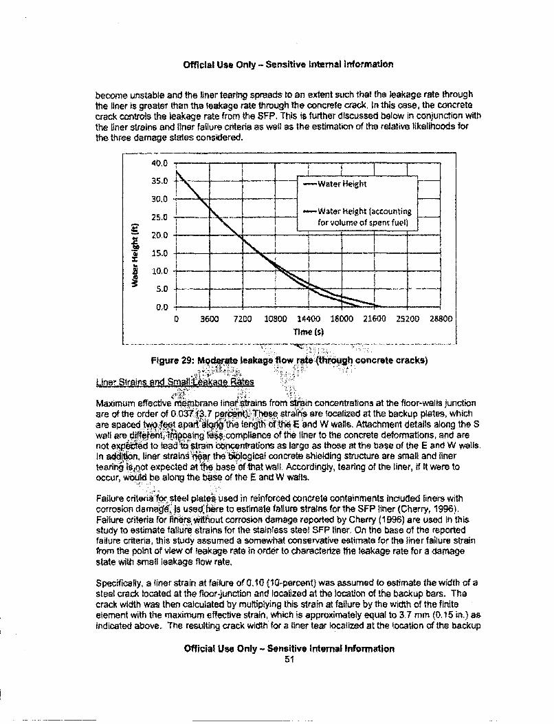
Official Use Only - Sensitive Internal Information
become unstable and the liner tearing spreads to an extent such that the leakage rate throughthe liner is greater than the leakage rate through the concrete crack. In this case, the concretecrack controls the leakage rate from the SFP, This is further discussed below in conjunction withthe liner strains and liner failure criteria as well as the estimation of the relative likelihoods forthe three damage slates considered.
35.0 -WaterHeight r20.0 -Water Height (accountingL
for volume of spent fuel) ej
20.0
41i0.0 ,
0 3600 7200 10800 14400 18000 21600 25200 28800Time (s)
.. ......... .... .. ... ........ ..... ........ ........... ......... .......... .. ...... ......... .. .... • i .... .I . • ; ii.. ........... .. : - i .... ................. ..... ...... ..... ... .... .. .. .. .....
Figure 29: Moderate leakage flow rte (through co. ncrete cracks)
Li3er_,tIrins and SMatll Laka0e Raes
Maximum effective Phemnbrane line•rs•rains from rnain concentrations at the floor-walls junctionare of the order of 0.0•TQ3.7 perctf). -hese strains are localized at the backup plates, whichare spaced to.•e•t apart •I&the lengthi oftheE "and W walls. Attachment details along the Swall are dif !A,.'e im'posing: lcompliance of the liner to the concrete deformations, and arenot expeed to lead i 1trin b~xentratlons as large as those at the base of the E and W walls.In addon,, liner stralns"ea!r theli!~logical concrete shielding structure are small and linertearing is•.not expected at fe .base of that wall. Accordingiy, tearing of the liner, if it were tooccur, woidd be along the base of the E and W walls.
Failure criterial •Or steel platei used in reinforced concrete containments incduded liners Withcorrosion damage, is use d he.re to estimate failure strains for the SFP liner (Cherry, 1996).Failure criteria for inels without corrosion damage reported by Cherry (1 996) are used in thisstudy to estimate failure strains for the stainless steel SFP liner. On the base of the reportedfailure criteria, this study assumed a somewhat conservative estimate for the liner failure strainfrom the point of view of leakage rate in order to characterize tile leakage rate for a damagestate wit1 small leakage flow rate,
Specifically, a finer strain at failure of 0.A0 (10-percent) was assumed to estimate the width of asteel crack located at the floor-junction and localized at the location of the backup bars. Thecrack width was then calculated by multiplying this strain at failure by the width of the finiteelement with the maximum effective strain, which is approximately equal to 3.7 mm, (0. 15 in,) asIndicated above. The resulting crack width for a liner tear localized at the location of the backup
Official Use Only - Sensitive Internal Information51

Official Use Only - Sensitive Internal Information
bar Is then estimated at 3.7x0.10 = 0,37 mm (0.015 in.), The crack length at each iocation istaken to be equal to the width of a backup bar which is equal to 4.0 In. (101.6 mm). Given thatthe spacing of the backup bars is 2 ft, a total of 40 backup bars (20 on each wall) are used toestimate the sum of all localized cracks at 4x40 = 160 in, The estimated width for each crack, ifit were to occur, Is then 0.015 in and the depth of the crack is the depth of the liner which isequal to 0.25 in,
Given the estimated width, length and depth for each localized liner tear and their number, it Isstill necessary to estimate the leakage rate through these tears. Estimation of this flow rate usesthe following assumptions: (I) the flow rate can be estimated using an bquation similar to thatused for flow through the concrete cracks; and (H1) the friction factar 1ilthat equation can becalculated on the basis of te-st results for leakage rates through crAs in pipes. Theseassumptions are not validated at this time. Therefore, consideir•be 4:Jprtainty exists for theresulting leakage rate estimate.
Estimation of a friction factor was made using data in Paul (1994) for leakAgeb through cracks insteel pipes. Back calculation of friction factors from date presented in this refterece shows alarge variability in the calculated friction factor. 14,tfrticular, the friction factor apears to dependheavily on the smoothness of the crack surface. Ai'ý, the fluid in. the pipe is at high -temperatureand the driving pressures are much higher than those applicbi6 to the SFP. Review of otherflow models reported in Paul (1994) indicates that for: rel'aely smooth cracks friction will below. On the bases of this information, he :equation for tlk flow through concrete cracks wasused for flow through steel cracks with sar•ialfction factor:(0,.11) for an initial estimate of theleakage flow. On that basis, the leakagei fh•iow g.h the steel: ccks (small leakage flow) wascalculated as shown in Figure 30. It is impltant to 6mphasize Kittonsiderable uncertaintyexists in the calculation of reportod leakage.rate give thlocalized liner tears.
40.0
35.0 1-Water lie~ght
-30.0 --Water Height 4accmunting for2.0 ~volume of the soe t fuel)
20.0• 15.0 .
5.0.
50000 100000 150000 200000rime is)
figure 30: Small leakage flow rate (through localized steel tears)
Official Use Only - Sensitive Internal Information52
Offiial Use Only- Sensitive Internal Information
Djampge StIR taesnd Re~latve Llkelihgod§
Step 6 of the approach (Section 4,1.1) defined three initial damage states as follows:
a. No leakag - A state with no leakage from the bottom of the pool. This state correspondsto concrete cracking at the base of the walls (estimated to be through wall cracking forthe event considered as shown in subsequent subsections) but without tearing of theliner.
b. Moderate leakage rate - A state with leakage from the bottom of the SFP, correspondingto through wall concrete cracking at the bottom of the wails arnd tearing of the liner thatpropagates to an extent such that water leakage is controfla4 b the size of the cracks inthe concrete. The estimated leakage flow rate for this d"r"e! state Is shamn in Figure29.
c. Small leakane rate - A state with leakage from the botm of the,5FP, corresponding tothrough wall concrete cracking at the bottom of .thealls and tearing of the liner thatremains iocalized to the where the floor liner isbattached to the SFP floor near the walls.The estimated leakage rate for this damage: swe is shown in Figure 30:...(• .,'• : •:i': .
This study uses strain criteria, including uncertainties, for tearing of reinforced conctete steelliners (Cherry, 1996) together with uncertainties in thezcalculaki'liner strains (acodunting inapproximation for uncertainties in the ISRS estimatiohn ehde1cnrete properties) to estimate therelative likelihoods for the three initial da'mage states listed•bove.
;?state with:•'i -1,'a, isth m stliel wt
The results of these estimates indicate that ih.d te with ro1~age Is the most likely with arelatively likelihood in excess of 90-percen;. The rve,. likelih.d: of the two states withleakage from the bottom of the SFP is les ihan 10-p.nt. Estirnýion of the relative likelihoodof the two damage states, '[aJage is sbectz, .nide61 b! uncertainties. Accordingly, theSFP Scoping Study ass.urn, thdith states atisdually likely.
4.1.6. Revi of Spent FuW Pool Pertoemance under Recent Major Earthquakes inJapan
Five Japames a.uckear power plants with a combined total of 20 reactors and 20 spent ruelpools were subied .t. severavground motions from major earthquakes in the past 5 years asfoltot'. 2
•March 3, 2011, Tohoku earthquake (with moment magnitude M,= 9.0): Fukushima Dalichl (5 BWR Mark 1 SFPs)o.Onagawa (3 BWR SFPs)o FUkushima Dalini (4 BWR SFPs)
.... ka -(1 BWR SFP)* Niigataken ChUetuO-Oki earthquake (M,= 6.6)
o Kashiwazaki-Kariwa (7 BWR SFPs)
Other than some loss of coolant from sloshing, e.g., unit 6 a loss of 12 cubic meters from theSFP at Unite 6 of Kashiwazaki-Kariawa (Kawamura, 2008), no leakage flow near the bottom ofthe SFPs has been reported for any of the SFPs in those nuclear power plants.This section provides a comparison of ground motion indices and ISRS spectral accelerationsconsidered for this study and observed at the various units of those nuclear power plants.Although these review and comparison are preliminary and use information available at the time
Official Use Only - Sensitive Internal Information53
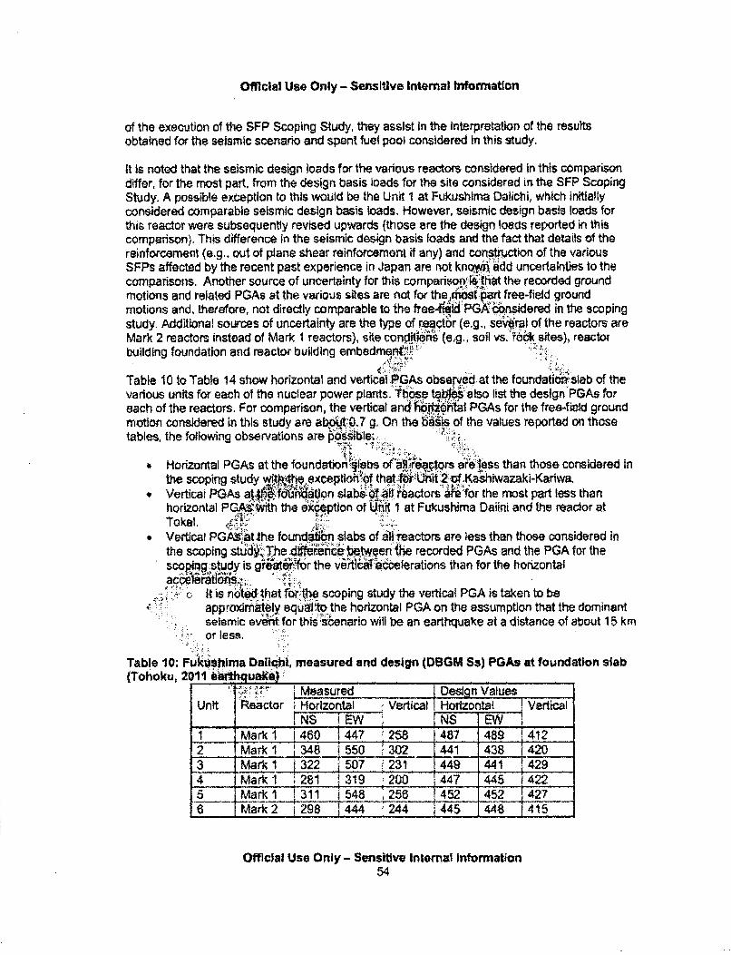
Official Use Only - SensitIve Internal Information
of the execution of the SFP Scoping Study, they assist in the interpretation of the resultsobtained for the seismic scenario and spent fuel pooi considered in this study.
It is noted that the seismic design loads for the various reactors considered in this comparisondiffer, for the most part, from the design basis loads for the site considered in the SFP ScopingStudy. A possible exception to this would be the Unit 1 at Fukushima Dalichi, which initiallyconsidered comparable seismic design basis loads. However, seismic design basis loads forthis reactor were subsequently revised upwards (those are the design loads reported in thiscomparison). This difference In the seismic design basis loads and the fact that details of thereinforcement (e.g., out of plane shear reinforcement if any) and construction of the variousSFPs affected by the recent past experience in Japan are not knc.wn add uncertainties to thecomparisons. Another source of uncertainty for this comparison. iih•at the recorded groundmotions and related PGAs at the various sites are not for thq,,dimoart free-field groundmotions and, therefore, not directly comparable to the freefil6d PG 'bbnsidered in the scopingstudy. Additional sources of uncertainty are the type of reactor (e.g., se6vral of the reactors areMark 2 reactors instead of Mark I reactors), site con iors (eg., soil vsr0zk ;.sites), reactorbuilding foundation and reactor building embedrnq, n.•r-'' ........ :.
Table 10 to Table 14 show horizontal and vertical PGAs obser.ed at the foundatidnalseb of thevarious units for each of the nuclear power plants. Thospe tab also list the design PGAs foreach of the reactors. For comparison, the vertical and n•"W&1 PGAs for the free-field groundmotion considered in this study are ab 10.7 g. On the b~is of the values reported on thosetables, the following observations are Posile;
SHorizontal PGAs at the fndato of-i'rs asieiess than those considered in
the scoping study with4th exception`of that.1 toUnit 2:of Kashlwazaki-Kariwa." Vertical P$As atý, f'ri4atlon slabsi:-f 0Pallreactors iAe for the most part less than
horizontal PGAr*.•th the ekdeptlon of IV I at Fukushima Dalini and the reaclor at
* Vertical PGMi at.the found#-n slabs of a-l reactors are less than those considered inthe scoping studI Tihe. l 1Pen; ...en %e recorded PGAs and the PGA for thescopiirgstudy Is gr 'r the vrtll aýclerations than for the horizontal
si it is n•o d rt.hat the scoping study the vetical PGA is taken to be
approximately equal'to the horizontal PGA on the assumption that the dominantseismic evea for this :senario will be an earthquake at a distance of about 15 kmor less.
Table 10: Fukushima Daflchi,. measured and design (DOGM Ss) PGAs at foundation slab(Tohoku, 2t11 'a' qcuake):
Measured Design ValuesUnit R~eactor Horizonta Vertical Horizontat Vertical
~NS iE1 N EW NS__1 Mark I 1460 1447 __58 487 489 1,4122 Mark 1 348 1550 '1302 1441 438 i 4203 Marki1 322j 507 231 449 441 4294 Mak 281 319i200 1447 1445 f4225 Mar _ 311 1548 i 256_1ý 1452 452 42_786 Mark 2 1298 144 244 44 1448 f14 ý1
Official Use Only - Sensitive Internal Information54
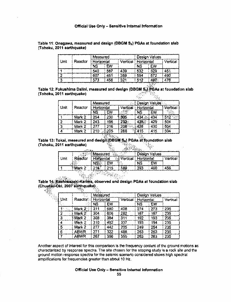
Official Use Only - Sensitive Internal Information
Table 11: Onagaw,4 measured and design (DBGM Ss) PGAs at foundation slab(Tohoku, 2011 earthquake)
Measured Design ValuesUnit. Reactor Horiontal Vertical horizontal Vertical
_NS ___ NS iEW -
1 .. _... 540 :587 }439 532 '529 1 4512........6 7 -f461 3594 1572 149 03 _ _ 573 '458 32 1 :i512 f ... 1 476
Table 12: Fukushima Dallni, measured and design (DBGM S• OGAs at foundation slab(Tohoku, 2011 earthquake)
Measured . . Design Values _b___..
Unit Reactor Horizontal Vertical Horizontal :V'tical- - NS EW NS Ew
I . Mark 2 254 230 '30-5 -34,:,,,-4 ,512Mark 2 243 196 232 .. 428" 429 1504
3 Mark 2 277 216 2063:- -w!::.:-A-.28 430 5044 j Mark 2 210 28205 " 1415 J415 1504
Table 13: Tokal, measured and desigi(DBi.M S,) PGAs a t houndation slab(Tohoku, 2011 earthquake)
....Neasured ,: D6sýn ValuesUnit Readoýr Hfiiontal ,Vertical Horizontal Vertical
_______. NS•4:. :.: I EW NS EW1 "Mark2 214,' 215 19• 393 1400 456
Table 14.; ".htWaakl-Ketiwa, observed and design PGAs at foundation slab(Chuet...ki, 200764•: hqudk •. ,
Unt RacorMea'sured iDesign ValuesUni IRectt,::Horizontal IVertical 1 Horizontal VerticalINS EW I NS i EW
.Mark2.'.. 311 .680 .. 408 274 273 2352 jMark:2: 304_I 606 282 1 167 1 ¶67 .2353 VMark2-l2 308 384 311 1 192 193 2354 - Mrk 2 310 492 337 1193 1 94 12355 IMark 2 277 442 205 249 254 2356 - ABWR 271 322 488 263 263 235
ABWR 1267 1356.-5 263 263 1235_______355 263__
Another aspect of interest for this comparison is the frequency content of the ground motions ascharacterized by response spectra. The site chosen for the scoping study is a rock site and theground motion response spectra for the seismic scenario considered shows high spectralampllifations for frequencies greater than about 10 Hz.
Official Use Only - Sensitive Internal Information55
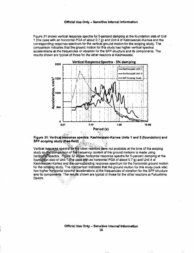
Official Use Only - Sensitive Internal Information
Figure 31 shows vertical response spectra for 5-percent damping at the foundation slab of UnitI (the case with an horizontal PGA of about 0.7 g) and Unit 4 of Kashiwazaki-Kariwa and lhecorresponding response spectrum for the vertical ground motion for the scoping study. Thecomparison indicates that the ground motion for this study has higher vertical spectralaccelerations at the frequencies of vibration for the SFP structure and its components. Theresults shown are typical of those for the other reactors at Kashiwazaki,
2000
s1500
E
O1000
0
0
Vertical ResponseSpectra - 5% damping
I Ka1~wazaki Unilt I2
I NK azki Utd, 4
*• t i pcing Study
h ::
=~ ~~~~ -. -ý4 I 'ii .
01 0,10 1.00 10.00
Period (s)
Figure 31: Vertlcati •ponse speota: Kashlwazaki-Karlwa Units 1 and 5 (foundation) andSFP scoplng study if•ee-field) ,
Vertical resp~pe sp tr'1:r.(&other read(tr:.iere not available at the time of the soopingstudy sogfi niý....n of tW. ,equency content of the ground motions is made usinghorod~ ~pectra. F~w.. 32 s horizontal response spectra for 5-percent damping at thefourd ifbn slab of Unit Tfhe casei'ith an horizontal PGA of about 0.7 g) and Unit 4 ofKashf g~ki-Ka.wa and cicorresýoding response spectrum for the horizontal ground motionfor the scoing study. The cparison indicates that the ground motion for this study (rock site)has highe -- oriontal spectralaccelerations at the frequencies of vibration for the SFP structureand its components, The results shown are typical of those for the other reactors at FukushimaDaiichi.
Official Use Only - Sensitive Internal Information56
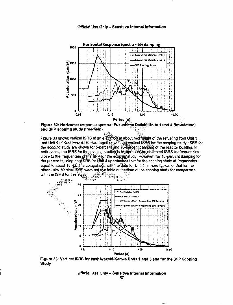
Official Use Only - Sensitive Internal Information
Horizontal Response Spectra - 5% damping
.14 100
U
~1G0
500
-. FkU4$NMU 08C~ - IJ01~
-Ft*kuinV a~i ihi - Uirt
I-SFPS lnftd -- 7
0.01 0,10 1.00 10.00
Period (s)Figure 32: Horizontal response spectra: Fukushiima DalichilUnits I and 4 (fou ndtion)and SFP scoping study (free-field)
Figure 33 shows vertical ISRS at an efýýý.at..about mid hiftht of the refueling Poor Unit Iand Unit 4 of Kashiwazakl-Kaflwa togethO wiMw*.'tjertical ISR§ for the scopirg study, ISRS forthe scoping study are shown for 5-perce and I • •et damnoA of the reactor building. Inboth cases, the ISRS for thescoping stud'iIs hig er t•h•av oserved ISRS for frequenciesclose to the frequencies rihe 0P1. for the s study. tH6wver, for 10-percent damping forthe reactor building, "hWISRS for (hh 4 appmaches that for the scoping study at frequenciesequal to about 18 1ý14 The comparii& with the'dtat for Unit 1 is more typical of that for theother units. Vertical: ISRS were nottayailable at the time of the scoping study for comparisonwith the ISRS for thisst6iy ..- :
..C , •,.-•• ,.30
25
:;.:.,..•. :#a
UP
V • r
- ~ lJ~ I
1 - sh~wd1~cI Un~
I ~ ~ ~amp~$ci~1~w~ ~4u~y. ~ ~ 1W~. Q'~'Pini
............ . ... ...... ... ..... ....
0 -- . d i A -d -
0.01 0.10 100 14090
Period (a)Figure 33: Vertical ISRS for kashiwazaki-Kartwa Units I and 3 and for the SFP ScopingStudy
Official Use Only - Sensitive Internal Information57
Official Use. Only - Sensitive internal information
The review and comparison show indicate that the seismic loads for this study tend to be morechallenging to the SFP than those for the observed events. One reason for this conclusion is thehigher frequency content of the ground motions for the rock site chosen for the scoping study atfrequencies near the natural frequencies of the SFP structure and Its components. Anotherreason is that the vertical PGA for the scoping study reason is substantially greater than that forthe observed events in Japan.
A conclusion from the review is that for the challenging events considered, leakage from thebottom of the SFPs of 20 SWR reactors was not reported. However, possible differences in thedesign and construction of the SFPs, including higher design basis seismic loads, for theJapanese plants leads to uncertainties in this preliminary comparison:=,.J
4.2. Other Damage States
Assessment of other damage stages is primary based:k. (i) finite element -deterministicresponse spectra analysis to estimate maximum vertiaai'displacements of the water surface(sloshing); (ii) seismic fragilities used in conjunckip with the NUREG.I 150 seirsi."..c.:.PRA study(Lambright, 1990); (iii) the examination of deslgn idetails for certain appurtenances:such as therefueling gate; and (iv) maximum displacements (vertical and.h6rizontal) of the SF0 floors andwalls under the applied loads.
Lo ssof Water from. Ioshin_:
Vertical displacements of the water surfad6:sloshinq) that ,may 40w to the ejection of somewater from the SFP dependr.or4he low fre flncy, o?4 ts•q:of t-fe motions at the base of theSFP. Simplified analytical iiQ A:, AEC, 1-613.; M khotra, 2000) show that the naturalfrequency of the sloshing modes fi'the SFP s1.f:he order of 0.25 Hz for a period of about 4seconds, The free-!.ld bground mo&t specified.for the scoping study does not have highspectral velocities an• .celetat.i'orqt these frequ'qncies. Consequently, sloshing amplitudesare expected to be smanireete .'•&.sponse ssiectrum analyses with the simplified ANSYSfinite elemer.m.odel of t..-Ftre dJ4r•:imate the sloshing amplitude. These analysesused asi I hrlc.lzonta•ff.RS at mid heightof the SFP {for the frequencies of interest tosloshin•:a led to K•'ping raio of 0.5-percent. The resufts indicate that the sloshing will notexcee~ibout 18 in. Given that t "Water at the pool is about 1/ to I foot below the top of theSF1P, sishing is not expee to caidie more than 1 foot of water loss. Accordingly, an initial 1foot dec~reae in the height of.:e water is considered at the end of the earthquake event for thesubsequentriacident progresi.on anatysis,
Oamage to Refufu:Gate..$FP Penetrations, Soent Fuel Assemblies and Racks
Refuel gate - A site visit and examination of the refueling gate structural drawings revealed thefollowing:
" The steel gate next to the water is backed by a similar gate,, Each of these gates consists of a steel-plated decking with steel stiffeners." Each gate has a polymeric seal around its perimeter that is pressed against the concrete
by passive mechanical means that are not expected to be lost during the seismic event.Since these are passive mechanical means the effectiveness of the seals does notdepend on the availability of AC power.
Official Use Only - Sensitive Internal Information58
Official Use Only - Sensitive Internal Information
Tolerances around the seals are sufficient to accommodate the already small distortionsof the biological concrete shielding in the refueling area from the seismic event.
Based on the above, it is concluded that the refueling will not fail under the earthquake and willcontinue to maintain its intended function during the accident progression.,
SF-P penetrations - According to the Final Safety Analysis report, there are no connections tothe SFP that would allow water to drain below the refueling gate or below 10 ft above the top ofactive fuel. The FSAR further states that lines beWow the levels In the previous paragraph areequipped with siphon breaker holes to prevent inadvertent drainage.In addition, the systems formaintaining water quality and quantity are designed so that failure.#, •,:fnappropriate operation ofthese systems does not cause uncovering of the fuel. In addltioniresults of the nonlinear finiteelement analysis also Indicate that overall distortions of the p0.'W"slJ1are small (of the order ofa few millimeters). These distortions are not expected to le.•d"1 seids ,i.aly Induced damage ofthe penetrations that would leak to potential leakage.
Spent fuel racks and assemblies - Damage to the..e fuel assemblies and cs was notcalculated as part of this study. The assumptionr6 &8made that under the applid:seismic loadsa coolable configuration would be maintained. This! assumption.':iconsistent withlh6 seismicassessments made in conjunction with the resolutidA."of Gl-.8. 6d reported in NUREG/CR-5176(Prassinos et al., 1989). As in the case considered In G :i:,-i2•e spent. fuel racks for the siteconsidered are allowed are allowed t oel.k.. which tendsbýor~duce the magnitude of the seismicaccelerations on the racks and partially, 8400tetýheir dyn .c. response from the response ofthe SFP. ..
Damaae to the Reactor Building and Other"_levat tSS .According to the fragiitnalysis foi•the NURE1l 1tW seismic PRA (Lambright, 1990), the
median fragility for.retor buildg is about•'i s:. g. The response of the reactor buildingstructure is expecte;W oe more siitlve to the horizontal ground motions than to the verticalground motions. NaturequI i••,bioratin at ihese frequencies are about 7 Hz, i.e.,frequencies.atvich the 19"Wiaccee fthe ground motion for the scenario consideredare less I. I.R...• r.the gron.d motions considered in the evaluation of the median fragility.On theises, falIlý&.of the ii.tor building would not be expected for the seismic scenarioconsi' d.'
Examinatlor. of structural drawings for the Peach Bottom reactor buildings together with asimple kinematic analysis indicates that if the crane bridge were to lose support at one of its asa consequence ~ :the ground, shaking, that end of the crane bridge would not fall inside theSFP. Depending' :...which sicde would lose support that end might fall a few feet from the poolbut not inside the .iapt-
Loss of offsite power is expected for the seismic scenario considered. Median fragilities for lossof offsite power, in terms of PGA, are 'ess than half the PGA for the seismic motion consideredin this study. Review of the fragilities estimated for NUREG-1 150 (Lambright, 1990) studyindicates a high probability of loss of onsite AC (about 0,84). This high probability estimate Isbased on either direct failure of onsite emergency diesel generators (sensitive to spectralaccelerations around the 20 Hz frequency) or failure of either the emergency service water orthe emergency cooling water which provide cooling water for the diesel generators.
Official Use Only - Sensitive Internal Information59
Official Use Only - Sensitive Internal Information
Refrerices
Ang, A. H-S. and Tang, W. H., (2006), *Probability Concepts in Engineering: Emphasis onApplications to CMi and Environmental Engineering," 2nd Edition, Wiley, 2006.
Ang, A. H-S. and Tang, W. H., (1984), "Probability Concepts in Engineering Planning andDesign: volume II - Decision, Risk and Reliability," Wiley, 1984.
AEC (1963), 'Nuclear Reactors and Eartl2uakes,' US Atomic Energy Commission (AEC),Reactor Technology Report TID-4500, 22 Edition, Prepared by Holmes and Narver, Inc.,August, 1963.
ASCE (1999), "Seismic Analysis of Safety-Related Nuclear Structures nd Commentary,"American Society of Civil Engineers (ASCE), ASCE Standard 4-•h 999.
ANSYS (2011), "ANSYS Mechanical, Release 13," Ansys Iln&;•CaY1- nsburg, PA, 2011.
Cherry, J., 1996, "Analyses of Containment Structures a h Corrosion Darbage," PVP. Vol. 343,Development, Validation, and Application of Inelasticwds for Struct0r['Anaiysis andDesign, American Society of Mechanical EngineersJASME), pp. 15-23.
Collins, T. E. and Hubbard, G., (2001), 'Techniotl:.tudy of Spent Fuel Pool Acdlent Risk atDecommissioning Nuctear Power P!ants,' NURE-,738, Feb0jary, 2001.
FHWA (2007), 'Evaluation of LSDYNA Concete Materiial-Ml6 159," Federal HighwayAdministration (FHWA), Publication Nunber FHWA-HRr.74063, McLean, VA, 2007.
Housner, G. W., (1963), "The Dynamic. h"PTior of Water Tais,"'Bulletin of the SeismologicalSociety of America, Vol. 53, No. 2, pp. 341.-381t'V: 163.
Kanitkar, R., Liu, W. W., Houlahan, G. and: 'nous:i R (2 ) Water flow through crack inthick concrete sections." Ch&e International, Apil, 2011.
Kawamura, Shintchi. P`6 8), inves aio nalyses of The NMigataken Chuestu-okiEarthquake and Kas ki-Karisl Nuclear Pder Station," The Tokyo Electric PowerCompany, Inc. (TEPI)X June, 20110...
Lambright, J;,, at e ", (1 ,0)4 ylfsl'Ore.'Dmrage Frequency: Peach Bottom, Unit 2External "tMsTNUREGCR-.4550, Vol. 4, Rdvi Part 3, December, 1990.:A !,•;•!;•~ý' ." kaH-•, "•• ;... .
LSTC-(2 0I), 'LSDY Ai keyword U:ser's Manual," Version 971, Livermore SoftwareTecHnqtogy Corporation ivermorei, Caflfomia, 2007.
Malho•tr, P. K., Wenk, T., an Wielahd, M., (2000), "Simple Procedure for Seismic Analysis ofLiquid-Storag. Tanks," Stru(mlAya Engineering International, International Association of Bridgesand Structural Engineering (I SE), 2000,
NEI (2011), "Methtidotogy or .Performing Aircraft Impact Assessments for New Plant Designs,"Nuclear Energy InsWt eI), • E NEI Report NEI 07-13, Revision 8P, April, 2011.
NERH (2011), "The Adident at TEPCO's Fukushirna Nuclear Power Stations," Report of theJapanese Government to the IAEA Ministerial Conference on Nuclear Safety, Prepared by theNuclear Emergency Response Headquarters (NERH), Government of Japan, June, 2011.
Newmark, N.M. and Hall, W,J., (1978). "Development of Criteria for Seismic Review of SelectedNuclear Power Plants," NUREG/CR-009, May, 1978,
NRC (1990), "Severe Accident Risks: An Assessment for Five US Nuclear Plants, (FinalSummary Report)," NUREG-1 150, December. 1990.
Official Use Only - Sensitive Internal Information60
Official Use Only - Sensitive Internal Information
NRC (2012a), "Resolution of Generic Safety Issues: Issue 82: Beyond Design Basis Accidentsin Spent Fuel Pools oRev. 3) ( NUREG-0933, Main Report wfth Supplements 1-34 )," Availablefrom http:l/www.nrc.aov/readino-rmldoc-colieions/nureqs/staffts 33sec3/O82r32.html.
NRC (2012b). "Generic Issue Management Control system Report for Fiscal Year 2012 24Quarter,' Office of Nuclear Regulatory Research, NRC, 2012, (available athttp:/www.nrc.qovfreading-rm/doc-coliections/gengric4,ssues/Quartearlyinex.hlmrIl
Paul, D, D., et al,, (1994), 'Evaluation and Refinement of Leak Rate Estimation Models,"NUREGJCR-5128, June, 1994.
Prassinos, P. G., et al., (1989), "Seismic Failure and Cask Drop Analyses of the Spent FuelPools at Two Representative Nuclear Power Plants," NUREGICR-,16, January, 1989.
Sato, Gatu, (2010), 'Experience of NCO Earthquake and ReaL ! shiwazaki-Kanwa NPP,"First Kashiwazaki International Symposium on Seismic Saf• NUL.cear Installations,November, 2010. (Available from hto;l/Iwww.ngns._o.jD/seism.c-svm. siuml 0Dresentationdata/content.html) .
J, * ..~
4 .. .•.=.=
Official Usee Only - Sensitive internal Information61
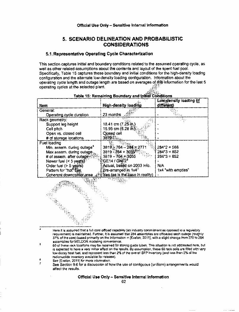
Official Use Only - Sensiltive Internal Information
5. SCENARIO DELINEATION AND PROBABILISTICCONSIDERATIONS
5.1. Representative Operating Cycle Characterization
This section captures initial and boundary conditions related to the assumed operating cycle, aswell as other related assumptions about the contents and layout of the spent fuel pool.Specifically, Table 15 captures these boundary and initial conditions for the high-density loadingconfiguration and the alternate low-density loading configuration. Information about theoperating cycle length and outage length are based on averages of th1~ information for the last 5operating cycles at the selected plant.
Table 15: Remaining Boundary and I1 p !hdlftions-________-____ Ht .. L ensity loading (of
_tem __High-de_.r_ load_ diemff)General:
Operating cycle duration I 23 months "Rack geometry:,"
Support leg height i8.41 cm ( .)Cell pitch 15.95 cm (6.28 in"'),,Open vs. closed cell Closed cell# of storage locations -1-.
Fuel loading ' ...
Min. assem. during outage4 3811,; 764- 294.7 2771 '- 284*2 = 568Max assem. during outage... 3819 .7.64 30O4 .284*3 = 852# of assem. after outag -•,. 3819 - 71543055 284*3 852Newer fuel (< 5 ye• )" .tGE 14 GN 6•'Older fuel (> 5 ii ..Actuai, baW on 2003 info. NIAPattern for "hoter l P-arraneed 1x47 1x4 "with empties"Coherent downcomerearea ,ý :V (as is the'ase in reait) -
4 Here il s assued that a ful core offioad ca.oDaby (at) industry commitment as opposed to a reguiatoryrequirement) is maintained, Furtrer, it is assurred that 284 assemblies are offloaded each outage (rOughly,37% 1/f the core) based prnmarily on the informalon i.n [Exelon, 201 11, with a slight change from 270 to 2U4assemblies for MELCOR modeling convenience.60 of these rack locations may be rese"ved for stonng guide tubes. Th" situation iso• t addressed here, butis expected to have a very mnOw effect on the results, By asw~mpton, Ihase 60 rack Cels are filed witV verytow decay heat fuet, and represent less than 2% ol the overafl SFP Inventory (and less than 2% of theradionruclide inventory available for release),
4 See [E elon. 2011] for more inrormalion,7 See Section 9.6 for a discussion of how the uise of Contiguous (uniform) arrangements would
affect the results.
Official Use Only - Sensitive Internal Information62
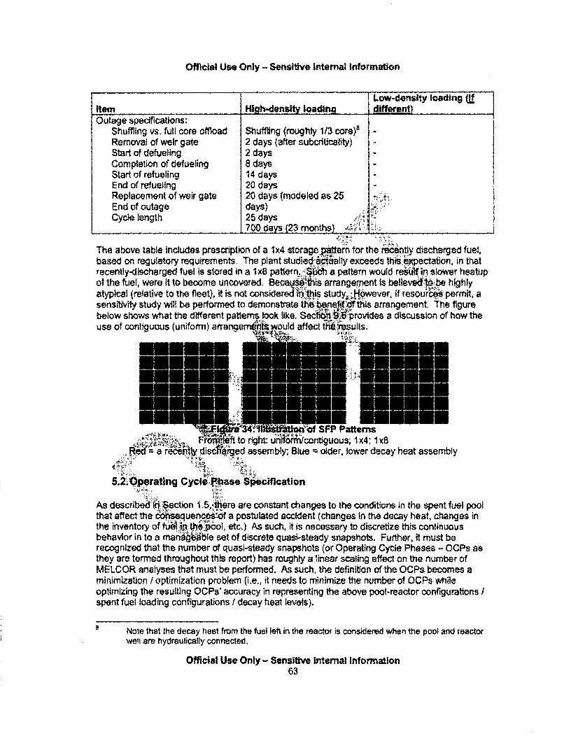
Official Use Only - Sensitive Internal Information
Low-density loading (]fItem High-density loading different)Outage specifications:
Shuffling vs. full core offload Shuffling (roughly 1/3 core)eRemoval of weir gate 2 days (after subcriticality)Start of defueling 2 daysCompletion of defueling 8 daysStart of refueling 14 daysEnd of refueling 20 daysReplacement of weir gate 20 days (modeled as 25 .,End of outage days)Cycle length 25 days .
700 days (23 months).*'.2,-
The above table includes prescription of a 1x4 storage ,p$tern for the recenty discharged fuel,based on regulatory requirements. The plant studied .ctually exceeds this :epectation, in thatrecently-discharged fuel is stored in a 1x8 pattern.s, - ;a pattern would resulltin slower heatupof the fuel, were it to become uncovered. Becau=seis arrangement is bellevtýflqbe highlyatypical (relative to the fleet), it is not considered"1h, this study.ý i.owever, if resources permit, asensitivity study will be performed to demonstrate thebenefit dl this arrangement. The figurebelow shows what the different pattems look like. Se •rovides a dtscussion of how theuse of contiguous (uniform) a"rangemu't suits
1F SFP Patterns. ft to rg•h Uniform/contiguous,1 x4; 1 x,
a r #y di ' ged assembly; Blue =older, lower decay heat assembly
5.2.Operating Cycle.Pbase $06cification
As described (0, section 1.5,74here are constant changes to the conditions In the spent fuel poolthat affect the &*mseueneiof a postulated accident (changes In the decay heat, changes inthe inventory of luhe p~I•,Jool, etc.) As such, it is necessary to discretize this continuousbehavior in to a managable set of discrete quasi-steady snapshots, Further, it must berecognized that the number of quasi-steady snapshots (or Operating Cycle Phases - OCPs asthey are termed throughout this report) has roughly a linear scaling effect on the number ofMELCOR analyses that must be performed. As such, the definition of the OCPs becomes aminimization ( optimization problem (i.e., it needs to minimize the number of OCPs whileoptimizing the resulting OCPs' accuracy in representing the above pool-reactor configurations /spent fuel loading configurations / decay heat levels).
Note that the decay heat from the fuel left in the reactor is considered when the poo) and reactorwatt are hydraulically connected.
Official Use Only - Sensilive Internal Information63
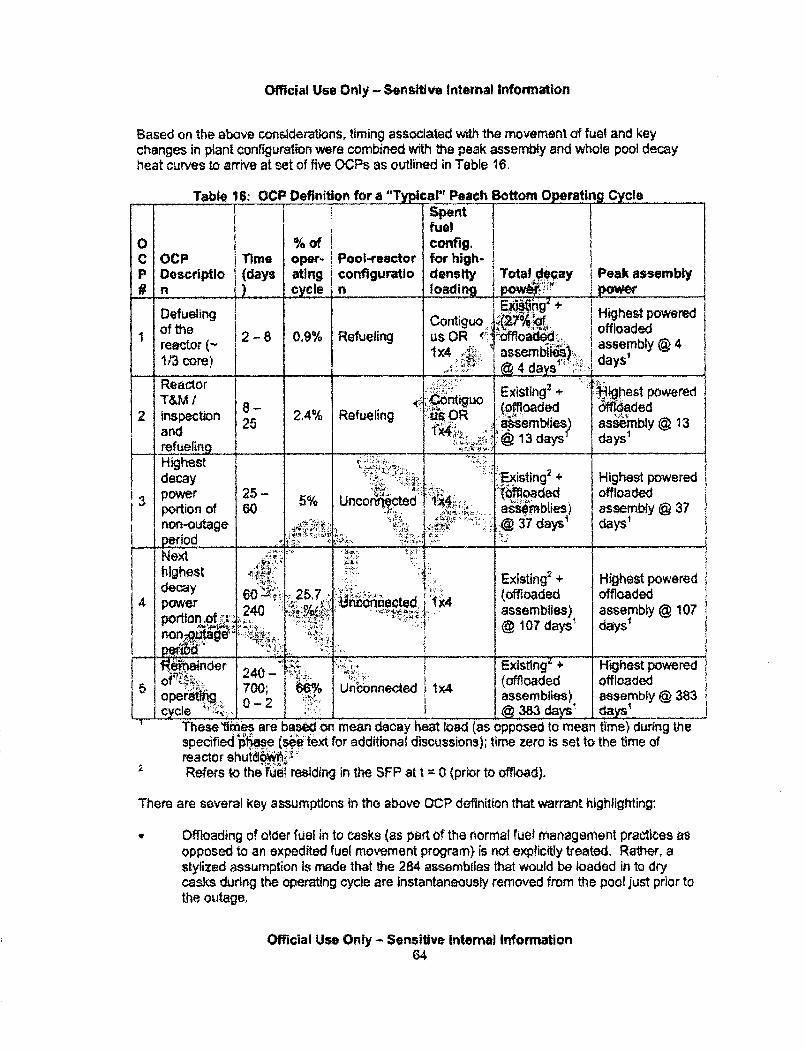
Official Use Only - Sensitive Internal Information
Based on the above considerations, timing associated with the movement of fuel and keychanges in plant configuration were combined with the peak assembly and whole pool decayheat curves to arrive at set of five OCPs as outlined in Table 16.
Table 16 OCP Definition for a "Typlicall" Peach Bottom Operating CycleISpentfuel
0 % of config,C OCP Time oper- i Pool-reactor for high-P Descriptio (days ating configuratio density i Total 0eay Peak assembly# n_ _ _ cycle in loading i pow12,
t Contiguo j.'A • I Highest powered1 of the 128 09% R usOR offloaded
reactor (~ 1x4 !: I assemb .i assembly @ 41/3 core) :4 days'
Reactor I~4 i asuoExisting, + ighest poweredT&M 1 8 (offloaded 6ff06aded
2 inspection 2 2,4% Refueling •64,3 ...0mblie. ) ,R•b".•o 1a d25 k¢;,; ;ia sem blie ) a ssembly @ 13and1x, ~~@13,daysV days'
refueling Jdecayst 'Existng 2 + Highest powered
13 pwer 5-(offloaded offloadedportion of 60 .asblies) assembly 37non-outage A.:. " 0- .: 37 days' daysperiodAI- z;Nexthighest •:••l•"/••.';}.hidheay. Existing2 + Highest powered
60 25?, (offloaded offloaded4Power Ijn,,o,....... ,coni~acted, 1x44 poern . .240 .- assemblies) assembly @ 107
ortion ": . •: : "' :@ 107 days'nonpýtg6*~ ý .y
"lRe4ainder 24 Existingz + Highest poweredof 700; | U (offloaded offloadedoper .. 0 - 2 "assemblies) assembly @ 383cycle @ 383 days y
S These Limes are based'on mean decay heat load (as opposed to mean time) during thespecified p ee .(:e text for additional discussions); time zero is set to the time ofreactor shutd0wi"Refers to the Vue6 residing in the SFP at t = 0 (prior to offload).
There are several key assumptions in the above DCP definition that warrant highlighting:
Offloading of older fuel in to casks (as part of the normal fuel management practices asopposed to an expedited fuel movement program) is not expficitly treated. Rather, astylized assumption is made that the 284 assemblies that would be loaded in to drycasks during the operating cycle are instantaneously removed from the pool just prior tothe outage,
Official Use Only - Sensitive Internal Information64
Official Use Only - Sensitive internal Information
New fuei is not treated. This fuel would be placed In to the spent fuel pool just prior tothe outage (the subject plant does not use a separate new fuel vault). Thus, the fuelwould only be present for a very short portion of the operating cycle. During the timethat the new fuel is in the SFP, it would affect the amount of zirconium present toparticipate In a piopagating zirconium fire, but would have a negligible effect on thesource term9.
* The calendar fime at which the snapshots are evaluated Is based on the mean decayheat during the OCP, as opposed to the mean calendar time. lRecall that the OCPsnapshots are intended to represent a continuous function qp:O6ssible consequences.White the likelihood of a seismic event occurring is cons 4'itn trime within one of theseOCPs, the consequences associated with the event are Furthermore, theexponential decay heat function better represents the thange.t..he post-accidenttimeline within an OCP than does a linear functio ,' and provide'.$..1 better mean estimateof the OCP's expected consequences. Theref6R, 'the exponential ctional form is usedto determine the time within the OCP that is-t for the quasi-stead'elvaiuation. In thecase of OCP#1, a minor adjustment is rpa'de from 4.4 to 3.9 days for mdWI.t)ng
convenience (the model Is nodalized such ffiat havlng,88,. recently-dischared,assemblies can be more readily representeda-nd 3'!ýds is the point at w6i"ch tis
many assemblies would have been offloaded ghvieM.T outage assumptions previouslydiscussed).
52, Treatment of Mitigation
This study does not aft9r t~rigorously quanti:the likelihood'of successful execution ofdifferent mitigative actis that mi iake plaa'.. Rather, this study takes the approach ofassuming two diffel!eotfituatiorts wihrespect to mpitigation, each of which is described in thefollowing paragraphsi,ý .". ½.The first situation is o im hieAr i'na7 ! igati ve actions are unsuccessful for an extendedperiod of t.• e tj t.e.nin.. •is no c• 'dr& pa r at recovery of damaged systems (e.g.,offsite PINMno. •recdit V.successful deployment of 5.054(hhX2) equipment. Regardingoffsite-s~ rt for W '.•situatist, the study presently assumes the following:
At- 24 hours, offsite support arrives* At 24.-4B hours, ad hc. actions are planned and staged* At 48 hours, if the fue is not uncovered and the pool can be reflooded (which Is true for
the ca$^ with no lse or a small leak), the sequence is truncated.fOtherwisi.'the s.e.qence is run to 72 hours in acknowledgement of the additional
complexitieg 01.aicessing the area of the pool when the fuel is uncovered, stopping anex-containment release-in-progress and/or performing a large leak repair.
Section 5.3.2 provides some further discussion on the rationale for developing results for thissituation.
The radioactive material that is of concern during an accident is the fission products generatedwhile the fuel is in the reactor. The UO2 present in fresh fuel would not contribute noticeably tothe source term, and in particular, not in a SFP accident where the temperatures during apostulated accident are lower than those during a reactor accident.
Official Use Only - Sensitive Internal Information65

Official Use Only - Sensitive Internal Information
The second situation is one in which (I) mitigative actions associated with the regulatoryrequirements of 10 CFR 50.54(hh)(2) are successfully deployed, (ii) additional onsitecapabilities are used to extend the use of this equipment, and (i1) arrival of offsite resourcesallows this equipment to be utilized for an extended period of time (ie.., days) until onsitecapabilities can be recovered. Each situation is summarized In Table 17.
Table 17: Summary of Mitigation AssumptionsSituations with successful Situations without
deployment of onsite successful deployment ofItem miigation onslte mitigationNormal accident mitigation Damaged by the event; reqpV'/repair not creditedequipment ...... _ _ _ _ _ _ __,_50.54(h h)(2) equipment Successfully depceyet 2 hou. :"creditec.
after diagnosis ____._____-_ _ . ..:_,,_rtSuccessfully deployed:to I
Other onsite resources extend operatiohýbf Nbt credited50.54(hhX2) e_4) e6nt I'
...... e..sourcesSuccessfuily deolbyed for terminating the accident at 48 or 72OffsIte resources __. ';'bours (see.as ociated text) 'Emený c.Preparedness Effectv;..••q :::j Effective
Mitigation equipment being "considered under NRC Order Notohsidered, ma••e substantively similar to 50.54(hhX2)EA-12-049, dated March 12, 0. capabilities withir•nte context of this study
The following sections de ,4,'lthe further assumpti ns mhiiijn carrying out this approach,provide the rationale forwt~. t6`isuation witf jsuccessful deployment of onsite resources is
useful from a decisioR01aing stan' lint and ' vide some thoughts as to how future work canuse human reliabnit•".nalysis to go'beyond this simplffied approach.
5.3i.~Aproah Eta1il and ASgifripokins
For sp nons that&6sucesfo deployment of the 10 CFR.50.54(hhX2) measures, thereare -a ',!bemadea.ýbout how that deployment is carried out. In general, this
study utIlzes some of the WONut asSociated wth these capabilities that are contained in NEI-06-2,Rntigaivcpbilh2(wity ias be .e; endorsed by the NRC'O). For instance, the time at wthich the
mitgaiv cpailtyisassumed t commence (meaning that it has b~een deployed and Isstarting top"Rte.) is 2 hour~ftil'er diagnosis. The guidance in NEI-06-1 2, Revision 2 doesinclude a provision t1hat all&vs for a deployment time of 5 hours after diagnosis for spray, if thefuel has been fav.avrably owrgured. That provision is not invoked here because the site inquestion strives to deploy the equipment within 2 hours regardless of the fuel configuration, andthe existence of cases without successful deployment of mitigation envelope this effect. Theassumption associated with the time to deployment of sprays when the fuel i's favorablyconfigured will be addressed as part of a sensitivity stdy. Future work could be aimed atdeveaoping performance-based or tamelne-oyenttied deployment times based on mitigatyive
e This document was originally endorsed for operating reactors by the NRC by letter dated December 22,2006 , and this endorsement was carried forward in the Statement of Considerations forthe associated rulemaking (see 'Power Reactor Security Requirements, Final Rule." published in theFederal Register on March 27, 2009).
Official Use Only - Sensitive Internal Information66
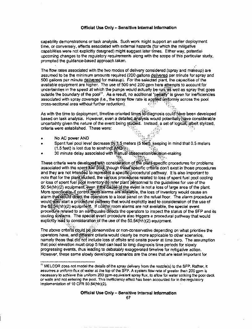
Official Use Only - Sensitive Internal Information
capability demonstrations or task analysis. Such work might support an earlier deploymenttime, or conversely, effects associated with external hazards (for which the mitigativecapabilities were not explicitly designed) might suggest later times. Either way, potentialupcoming changes to the regulatory requirements along with the scope of this particular study,prompted the guidence-based approach taken.
The low rates associated with the two modes of delivery considered (spray and makeup) areassumed to be the minimum amounts required (200 gallons delivered per minute for spray and500 gallons per minute delivered for makeup), For the selected plant, the capacities of theavailable equipment are higher. The use of 500 and 200 gpm here a.tempts to account foruncertainties in the speed at which the pumps would actually be ruri b well as spray that goesoutside the boundary of the pool". As a result, no additional 'pom " Is given for inefficienciesassociated with spray coverage (i.e., the spray flow rate is applip.d .. iformiy across the poolcross-sectional area without further reduction).
As with the time to deployment, timeline-oriented times .tdiagnosis could have been developedbased on task analysis. However, even a detaile4 I aiysis would potentialy-;hye considerableuncertainty given the nature of the event being stUidWd. Instead, a set of logici:?albeit stylized,criteria were established. These were:
* No AC power AND* Spent fuel pool level decrease-by. 1 .L meters (5 fet, *eepilng in mind that 0.5 meters
(1.5 feet) is lost due to sloshiniP%'Ad1..11V.* 30 minute delay associated with fanuaobA veration/dcison-making
These criteria were develqp4ewith consid•tlon of'the p .t -qpecific procedures for problemsassociated with the spent ~ie1 rio hough t , ec ic crteria don't exist in those proceduresand they are not intenid to repre! t-t a speck!-4procedural pathway. It is also important tonote that for the pleltaudied, the vjrous procedures related to loss of spent fuel pool coolingor loss of spent fuel p" lnventorr:dd refer poantt"rsonnel to the guidelines for use of the50.54(hh)(2) equipmentM:, n .a :the event is not a loss of large area of the plant.More specg i contrw- toc*ipalarms... ai iiale, the loss of inventory would cause analarm thart00 i the operators to a local pnel on the refuel floor. The alarm procedurewould "tart a pro d, rral a y that would explicitly lead to consideration of the use ofthe 5 (hh)(2) equipmeat. If cot•rol room alarms are not available, the special eventproced'r'e related to an e ,quake 'dects the operators to inspect the status of the SFP and itscoohng ss•.ems, The specW.:event procedure also triggers a procedural pathway that wouldexplicitly led• •o consideration: of the use of the 50.54(hh)(2) equipment.
The above criteria .. tuld bibý onservative or non-conservative depending on what priorities theoperators have, and :0ieiCnt criteria would clearly be more applicable to other scenarios,namely those that did::not include loss of offsite and onsite power at. time zero. The assumptionthat pool elevation must drop 5 feet can lead to long diagnosis time periods for slowlyprogressing events, thus leading to debatably exaggerated timeline for mitigative action,However, these same slowly deve!oping scenarios are the ones that are feast important for
" ME LCOR does not model the details of the spray delivery from the nozzle~s) to the SFP. Rather, itassumes a uniform flux of water at the top of the SFP. A system flow rate of greater than 200 gpm isnecessary to achieve this uniform 200 gpm-equivalent spray flux, to ailow for water striking the poow deckor walls and not entering the pool. This inefficiency effect has been accounted for in the regulatoryimplementation of 10 CFR 50.54(hh)(2).
Officl a Use Only - Sensitive Internal Information67
Official Use Only - Sensitive Internal information
offsite consequences (i.e., are less severe and less -likely to lead to a release), The use of a 2hour deployment time, as opposed to a 5 hour deployment time allowed in some situations, hasa compensating effect for some scenarios.
Regarding implementation mode, for cases where the water level in the pool is greater than 0.9meters (3 feet) above the top of the racks (a surrogate for high radiation levels on the refuelingfloor near the edge of the spent fuel pool - see Section 5.4) at the earliest time thesprays/makeup are ready for initiation (iLe., 2 hours after diagnosis), makeup will be utilized.Otherwise, sprays will be utilized. This represents one possible approach to the decision pointin Figure 2-1 of NEI-06-12, Revision 2 regarding whether SFP leakage1s excessive. In somerespects it is a more complicated approach then might be used, but iiijrguably a more straight-forward approach to enact in the absence of instrumentation. I ;*actice, both approaches endup prompting the same implementation mode for most scenap',tied in this report. Theexception is for the "moderate" hole for OCP #1/#2, where J" to the larger volume of watersince the SFP is connected to the reactor well and separ.M-ridryer 1phe water level has notreached the 3 foot mark (above the top of the racks) the, time mitigatio•n isdeployed. In thesecases, makeup is deployed even though the teakaot' ai actually exceeds 5Cifgpm. Asensitivity study may be run to address this assuitiifon,.
Whichever mode is initiated (spray vs. makeup), it i•%asudtb be used for the duration of theevent (i.e., no later switching to a different mode). .Practically speaking, the above set of saeo ns leads toheafollowing process when
establishing mitigation timefine boundary..ond•t•s in the MVEtOR analyses (recall that thisonly applies for half of the studied sequenoes since-dlscenavto has an unmitigated
Start of calculs67 earth~uake occur§'.,ý •When spenrgwl pool level h6as decreased by 1.5 meters (5 feet), and 30 (diagnosisdelay) plus 129(ienial deI oent delay) Idditional minutes have transpired, then:
If the watii levelV . i• e(3 bet) above the top of the fuel:M.i per mi.i.l, rr.n' makeup in to the top of the pool commences
o•,:: se]f the wat-.1evel is < 0.9 meters (3 feet) above the top of the fuel (thus,:',i;:• ndic• i•x.ceRe. leakage) then:
> 20Cgallons per minute of spray at the top of the pool commences
The aboveý assumptions are characterized as being optimistic, relative to the unmitigated(pessimistddcase). However,'it is important to note that there are aspects of these assumptionsthat assume fakiles where,•Qy may not occur. For instance, the above set of assumptionsonly credit a siriflesucce"l spray/makeup strategy, whereas multiple strategies may bedeployed. Adong the e ThieS, there are several other ways to recover makeup to the spent fuelpool, several of which .:Nve much higher capacities than the mode selected, These alternativesare captured In the Table 10.3.1 of the FSAR, and range from capacities of 25 gpm to 18,000gpm. For each of the modes capable of delivering more than 200-500 gpm (the mode selectedhere), these modes require either multiple manual alignments in the vicinity of the SFP andreactor, the availability of AC power for valve manipulations, and/or the use of equipment thatmight be Involved in reactor recovery (most notably a residual heat removal pump). Finally, asmentioned above, the selected set of assumptions does not allow for switching from one modeof makeuptspray to the other.
Official Use Only - Sensitive Internal Information68
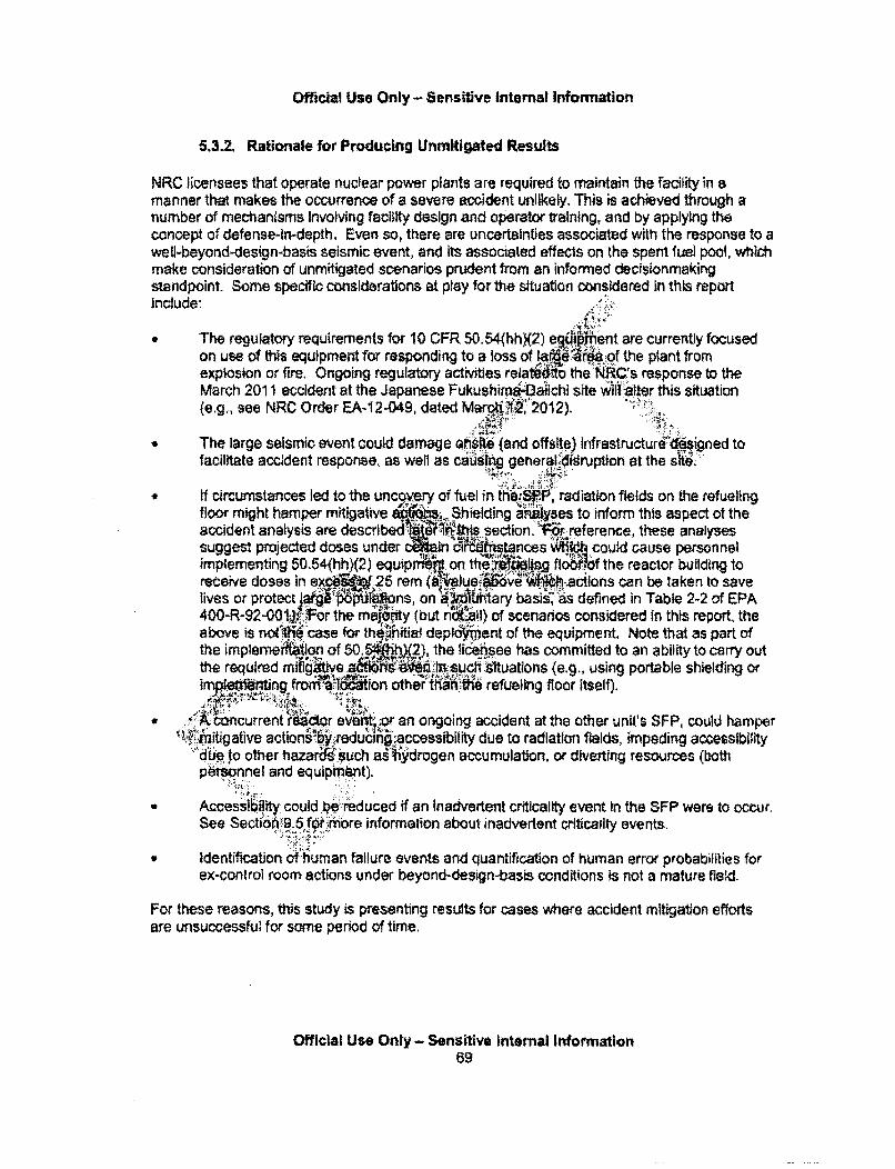
Official Use Only - Sensitve Internal Information
5.3.2. Rationale for Producing Unmitigated Results
NRC licensees that operate nuclear power plants are required to maintain the facility in amanner that makes the occurrence of a severe accident unlikely. This is achieved through anumber of mechanisms Involving facility design and operator training, and by applying theconcept of defense-in-depth, Even so, there are uncertainties associated with the response to awell-beyond-design-basis seismic event, and its associated effects on the spent fuel pool, whichmake consideration of unmitigated scenarios prudent from an informed decisionmakingstandpoint. Some specific considerations at play for the situation considered in this reportinclude:
The regulatory requirements for 10 CFR 50.54(hhX2) e#!ip ent are currently focusedon use of thfs equipment for responding to a loss of la 6!ardaof the plant fromexplosion or fire, Ongoing regulatory activities rela o the NlC.'s response to theMarch 2011 accident at the Japanese Fukushimr4aiichi site wilinalter this situation(e.g., see NRC Order EA-12-049, dated MarcJi4'2012).
* The large seismic event could damage Ghsfte (and offstte.) infrastructure dftigned tofacilitate accident response, as well as ca11 general. fsruption at the site.
* If circumstances led to the uncypery of fuel in thq 8., rad iation fields on the refuelingfloor might hamper mitigative &AM, Shielding iaMýses to Inform this aspect of theaccident analysis are describedia14t"Was section. 1r reference, these analysessuggest projected doses under 6Aln crFnstances Mlidt could cause personnelImplementing 50,54(hh)(2) equiprrAt on thei.'l..• nio O the reactor building toreceive doses in elgM.25 rem (a1ue'.to: .H.hactilons can be taken to savelives or protect ....... onsn, on aIuntary basis, as defined in Table 2-2 of EPA400-R-92-001fffbr the ma.Ony (but n'"l) of scenarios considered in this report, theabove is noK)AcWI case for tho.iniftiai depldO*ient of the equipment, Note that as part ofthe implemefaion of 50,1 2), the lic `see has committed to an ability to carry out
the required mlgtive s'In ,, 11111such situations (e.g., using portable shielding orimpl fro t ohha the refueling floor itself).
An* 'Aconcurrent r'ior ev'"'. or an ongoing accident at the other unit's SFP, could hamper•_iti:•gatIve actlons`by reducng;accessibility due to radiation fields, impeding accessibility
"d to other hazar" such as lhyrogen accumulation, or diverting resources (bothpe nnel and equipment).
Accessibiity could .b.reduced if an Inadvertent criticality event in the SFP were to occur.See Section.:9•5•fW4homre information about inadvertent criticailty events.
Identification of human failure events and quantification of human error probabilities forex-control room actions under beyond-design-basis conditions is not a mature field.
For these reasons, this study is presenting results for cases where accident mitigation effortsare unsuccessful for some period of time.
Official Use Only - Sensitive Internal Information69
Official Use Only - Sensitive Internal Information
5.3.3. Considerations for Future Human Rellablfty Analysis
For schedule and resource reasons, human reliability analysis (HRA) is not Included within thescope of this study. In the absence of HRA, no quantitative basis exists for assigning relativelikelihood between accident progression scenarios which include or preclude successfuldeployment of mitigation. The two main roles that HRA could play in a study of this type andscope are:
" The identification and quantification of human failure events that lead to heavy loaddrops, and
" The quantification of human error probabilities related to mitigative actions.
Both items present a significant challenge, in that no state-ofe pr$ce exists for either, Forthe former item, the most relevant recent work is that docutftfted in"NO4REG/CR-7016 [NRC,2011 b] and NUREG/CR-7017 [NRC, 2011 cl, which descdbe q ua ltative".A practices appliedto dry cask storage operations. Specifically, this workoIplied aspects of tte ATHEANA (ATechnique for Human Event Analysis) HRA apprqa&o examine how unsafýi~ons could leadto a cask drop event or the misload of a cask. T. r develqped scenarios i"h yng unsafeactions and error-forcing contexts to develop hun;A performanaivulnerablilties. tt.Wb workfocuses on two specific casks designs, used at a ge B66"nd PWR.
The above work reviewed relevant Plto..ation, whic' Nticuded: NUREG-1774 [NRC,2003b], relevant 10 CFR 21 notificatioeR dehdpc ssue 16614RC inspection reports,NUREG-1864 [NRC, 2007a], and RIS-2Q-25:'S nent I [NRC, 2007b]. RIS-2005-25,Supplement 1 provides a brief summary &,"ft reguj, toryheavy load droprequirements at US nuclearper plants. F"tii ft."l oropsed in that report, theevents of interest here are 8 caltcdrop" or "MP W dop" (MPC 9tands for multi-purposecanister). Other even'..'uch as an!iinplann idscent would cause a less bounding effect onthe SFP, and even• 'ict as cask Rig-ups wo•ad only be relevant if they led to a cask drop(as is the case with obe of the po td scenari'). If the current effort proceeds past thesingle seismic event un o.e=.sL ;t cs dtbp events, the above work could be used asr t• ated HRA"""!!.•!•:the launchl..1ntfor thlb:-a_.
Withregd to the cisd...mairit le for HRA stated above, the fact that the mitigative actions ofrele~ifce will be outsidVia, scoP gf both the Emergency Operating Procedures and theSever• Accident Managei*rt. GuidIihes (as well as being outside the current scope of theExtensivlbamage Mitigatid4fkGuidellnes if the event is not treated as a loss of a large area ofthe plant) iiisi.mportant co! 4deration. The application of HRA within PRA modeling isfundamentallyblased on the•Wotion that one of the important drivers for quantification is the timeavailable to tak6e..h!actio4VWhIch is in turn reliant on the identification of the specific cue thatprompts an action rolatt've 'o the time at which the action will no longer be effective (or in theworst case might be detrimental) even if it is taken. The treatment of actions outside the scopeof the EOPs and SAMGs greatly increases the uncertainty in the quantification of the probabilityof success/failure of these actions.
In this case, two recent activities may form the logical starting points for any HRA performed infollow-on phases of the SFPSS. These are (i) screening human error probability evaluationsperformed for incorporating basic events associated with the 10 CFR 50.54(hh)(2) equipmentand procedures In to the agency's SPAR models (as a de-activated portion of the model for usein sensitivity studies) and (ii) ex-control room HRA studies, most notably in the area of fire HRA.
Official Use Only - Sensitive Internal Information70
Officlial Use Only - Sensitive Internal Information
The latter work is documented in NUREG-1921, "EPRIINRC-REAnalysis Guidelines." [NRC, 2012] It includes treatment of q allquantification, scoping HRA quantification, and detailed quWAaspects of HRA quantification, the document also referstback toUsers Guide,* [NRC, 2007c] and NUREG-1 842, 'Eva*6t6n ofMethods Against Good Practices." [NRC, 2D06} ,.
-luman ReliabilityIRA, screening HRAFor more generalý!ý04, 'The ATHEANA
I..iifty AnalysisI NURE,Human
Additional items that would require attention in 'be area of HR.• ar (I) pre-rnitiat•s (II) theinterrelationship between accessibility, accident prOgression, HRA, and (iii) the truncation ofconsideration of mitigative actions at later times (e.g. ,' 4#,hq') due to sequence explosion and/or very high uncertainties, "
5.4. Refueling Floor Dose Rate M'lysis ýUin SCALE..... •i•,• ~.. ,' ;i•.' . ... ' .:.
Due to the approach of as~U rFlfithat deplimedf `Wmitigati:n1s either successful orunsuccessful, it is no• tssany "ke in to apount the complexities of accessibility in thedetermination of mlr1t@1n rellabilltq..Even so. gin opportunity existed to employ methods andmodels that were re~ IX availablei~loredicting ttiiradiological conditions on the refuel f'oor fora range of conditions 4.ciateO. $'ery of " fuel. Note that the analyses described inthis sectlonpnlyaccouni* A,;6ý61ti q ftftons stemming from beta and gamma "shine"from eWOW 'ai 4,40e maV ia, not the concern of radiological conditions associated with thereleaseW that maten •1.llowhiAvel heatup. It is expected that if a radiological release offissliproducts from tti4!•*ent fdul pIl commenced, radiation fields in the vicinity of the poolwouldiy.very high.
The analysk' described, whibli were performed by the Oak Ridge National Laboratories, lookedat a range of 6d.tions. AsjOf-this writing, aft completed and reviewed analyses are for the 'asis" condition, thdti;b an SFP-with approximately 3,000 assemblies. The times rollowingdischarge that weinrio' ibred are the same as those associated with the different operatingcycle phases. This p•I6n of the analyses is plant specific for Peach Bottom, and utilized 2001
vintage information for representing the fuel designrcharacteristics in the SFP. Calculationswere performed using the ORIGEN and MAVRIC modules of the SCALE code suite. MAVRICin turn used BONAMI, CENTRM, and DENOVO routines, along with the FW.CADISmethodology. The 1977 flux-to-dose conversion factors were used, The 200 neutron group and47 gamma group cross sections based on ENDFtB-VII distributed with SCALE 6.1 were used,Results of the analyses can be summarized as follows:
Official Use Only - Sensitive Internal Information71
Official Use Only - Sensitive Internal Information
, For water depths of 3 meters (10 feet) above the top of the racks, projected dose ratesare very, very low. This is consistent with Regulatory Guide 1.13 which uses this waterdepth as a conservative measure of adequate shielding.
" Doses for the maximally-exposed location on the refueling floor once the fuel hasbecome uncovered are very high (on the order of 1,000 rem/hr as the fuel first becomesuncovered).
" The point at which projected doses at the maximally-exposed location on the refuelingfloor surpass 25 rem/hr (a value above which actions can be taken to save lives orprotect large populations, on a voluntary basis, as defined in Table 2-2 of EPA 400-R-92-001) is on the order of 0.3 to 0.9 meters (1 to 3 feet). ;
* Dose rates elsewhere on the refueling floor could be signl'ff6 y lower than those at themaximally-exposed location.
Additional analysis is ongoing, and this section will be updafeto incdel this anatysis once it iscomplete. "'
5.5. Discussion of Repair and Recovery-,
For this version of the report, no attempt has meen rýie to agxunt for repair or recovery ofonsite equipment or offsite power, TNs is a simplifying;Murption, and is motivated in part bythe lack of quantitative Information avlto suppeor soS . determination, for the largeseismic event being considered here. 1468 Pioaes would dirctite operators to attempt torecover failed equipment. and pursue alftiate 'mr of establishing AC power such as theability to obtain AC power from a station bi**out cr o_•.st line to .• Connowingo Darn. Theassumption here is that ons•_ a1 offsite elecrical:,stril~titsystems are damaged enoughby the earthquake so as 6hntly delay these recoveri.s!ntil the 48(72 hour truncation
5.. cearoDevprnl n
6A," dkfat ey Even~ts
TheW.o asuptions "K wnthto the scenario development, based on the structuralanal . .documented in S aIc of•dther consideration, are:
* All dffs."* and onsite power is lost as a direct result of the seismic event,
" The 50.54(i.,h)(2)- "iprnent (when credited) Is available for the duration of the event(following del" with dagnosis and deployment).
' Initial water loss due to 'sloshing" will be 1-2 feet
" Tearing of the SFP liner is not the most probable outcome, but is possible.
" There is no failure of penetrations (including the refueling transfer canat gate).
" The overhead structures (building debris, crane) do not pose a threat to the SFP in
terms of failure due to the initiating event.
6ffiSear Use Only - Sensitive Internal Information72
Official Use Only - Sensitive Internal Information
Inadvertent criticality, Including seismic effects on the integrated poison rack material,are not treated.
The resulting simplified set of key events/conditions is:
1. The initiating event occurs
2. Size of leak (if any) located at the bottom of the pool - 0 (none) or value representing acrack (small) or value representing a propagating tear of the .)iier (moderate) - thesedamage states envelope a leak introduced elsewhere in thsyeim (e.g., from theseparate/dryer pool during OCP #1 - 2, from the fuel traR.a nal gate during OCP #3
3. Assembly in a lifted position (only applicable for.O.C.041 and #:ndnot explicitlytreated) ."
4, 50.54(hh)(2) mitigation successfully dep '(If credited)
5. Accident sequence is terminated at 48 hour4 .i .fuel isll covered at that time, or 72hours otherwise. (Note that for all simulations '6WOI d here, if the fuel is still coveredat 48 hours, it does not becornsm§'Ynovered in the "0sing 24 hours,)
Item #3 (assembly in a lifted position) is thex inctuded:,'A- I the time of the start ofaccident progression analysis, there was Aufficleh'tin ' ationrý rdose rates In this situationto make assertions about ft.•ect on acci•t6.ea~ment of optimistic andpessimistic mitigation srenrnos'epeiopes t c Final9, the accident progression modelsused are not well-equq to modat~his situAt!i I As a result, the effects of a single assemblybecoming exposed46iMundergolngnwzlrconiurn.fire will be studied as a stand-alone sensitivitystudy, if resources 4.it, .
5 &iScnarlo Calatiaon Matrices
The",`; " ing tables sh how the oDmbinations described thus far translate to the scenariosoons•J~, for situations'dirng and following an outage.
Official Use Only -Sensitive internal Informati~on73
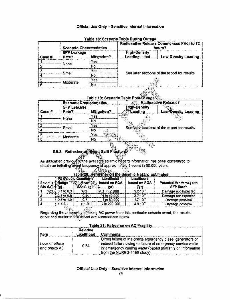
Official Use Only - Sensitive Internal Information
Table 18: Scenario Table During OutageRadioactive Release Commences Prior to 72
Scenario Characteristics hours?SFP Leakage High-Density
Case # J Rate? Mitigation? Loading- 1x4 Low-Oe• LoadingJ! _g -... .. .. x' . .. . . iý
I None Yes~None N12 !No .13 YesF - Small See later sections of the report for results
--4 No15 Yes •;..
Moderate .
Table 19: Scenario Table PostOutagei- Scenado Characteristics I_ .,_____________Radioact_ _Release?
SFP Leakage ..... .ns . io s_._Case # Rate? MiOsgation.?ty Loading
[ 1 1 :~ ~~Yes|•';--".,:.:=•""2 NoneNo
Smaoe Sections of the report for results
Moderate Ye .
5.6.3. Refresher-•i Ed t Split F•ictio,.. .
As described prev•.oLy1"Vthe availa6e seismic hazard information has been considered toobtain an initiating ..ent frequenci approximally I event in 60,000 years.
" A;! . ""4 . •i•;..
....... T a ' he smic Hazard EstimatesGeonri.t Ukeli;hood Likelihood
0Seismlec4.4nge' ILo;. Mea. go based on PGA based on PGA Potential for damage to1 131 .fig) A"•l. (g (yr) _l SFP liner?- 1: t0-o.3_ 1n2,000 02.5-210. Damagenot expected7'? ".kO.3 to O,5 0:4-•.. ",:n400 2710 Damagenotexp d '
,.3 jO.5to 1 .0 .7 in 60000 _ .namage ibe4 >I.O. >1.0' iin20.0 0 .. 4.9..10'. Oamage possibeRegarding the probabilityof losing AC power from this particular seismic event, the results
described earlier tin!:tth1report are summarized below.
Table 21: Refresher on AC Fra l!ityRelative
Item Likelihood CommentsDiret;t failure of the onsdte emergency diesel generators orLoss of offsite 0,84 indirect failure owing to failure of emergency servce water
and onsite AC 0or emergency cooling water (based primarily on information...... __I 1from the NUREG-1150 study).L..__
Official Use Only - Sensitive Internal Information74
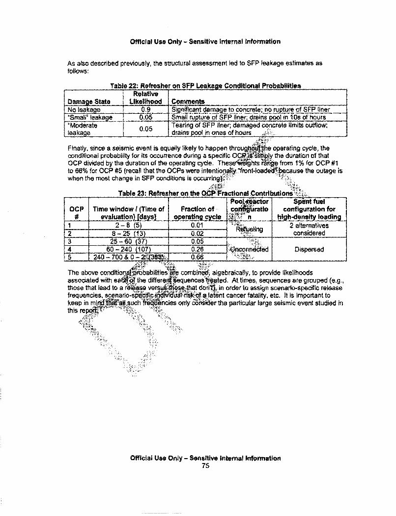
Official Use Only - Sensitive Internal Information
As also described previously, the structural assessment led to SFP leakage estimates asfollows:
Table 22: Refresher on SFP Leakage Conditional ProbabilitiesRelative
Damage State Likelihood CommentsNo leakage 0,9 Significant drnaa to concrete; no pture of SFP liner'Small' leakage 0.05 Small rupture of SFP liner; drains pool in 10s of hours11hoderate 0.05 Tearing of SFP liner; damaged concrete limits outflow;leakage j __......._00 drains p!.o in ones of hours
Finatly, since a seismic event is equally likely to happen througjithe operating cyc!e, theconditional probability for its occurrence during a specific OC,1 siip.ly the duration of thatOCP divided by the duration of the operating cycle. These hts n.ge from 1% for OCP #1to 66% for OCP #5 (recall that the OCPs were intentionpahy nt-loadd0•because the outage iswhen the most change in SFP conditions is occurring):'
Table 23: Refresher on the OC•Fractional Contributiorn'si'ýý'.Poo~i~ctar SP4"t fuel
OCP Time window / (Time of Fraction of co,:,i4ratlo configuration for# evaluation) [days] operating cycle I !$!"2"n high-density loading
1 2-8 (5) 1 0.01 i etieling 2 alternatives2 8 -25 (13) 0.02 1__R•geing considered3 25-60 (37) 0.054 60 -240 (107) 0.26 U! nconrieced Dispersedi5 240 - 7"00 &O -.0;''B•''; 0.66 i•'!i••) ..
The above ondittona~robab;lftiesar combmii, algebraically, to provide likelihoodsassociated with ea I the differer*euences''tted. At times, sequences are grouped (e.g.,those that lead to a ra'We verC stse that donft), in order to assign scenario-specific releasefrequencies, scenarlo-speoc Nic-6 d WT a latent cancer fatality, etc. It is Important tokeep in m. ldaiLsuch qncies only & r the particular large seismic event studied inthis rep ,. ,
Official Use Only - Sensitve Internal Infonrietion75
Official Use Only - Sensitive Internal information
6. ACCIDENT PROGRESSION ANALYSIS
6.1. Modellng SFPs with MELCOR
6.1.1. Overview and Experimental I Analytical Basis
The MELCOR computer code [Gauntt, 2005] represents the current state of the art in severeaccident analysis which has been developed through NRC and International research performedsince the accident at Three Mile Island in 1979. MELCOR is a fuily integrated, engineering-levelcomputer code and includes a broad spectrum of severe accident phepomena with capabilitiesto model core heat up and degradation, fission product release ap&finsport within the primarysystem and containment, core relocation to the vessel lower he _bnd ex-vessel core concreteInteraction.
The MELCOR code is composed of an executive driver.pd a number o ajor modules, orpackages, that together model the major systems of .r~actor plant and thl. enerally coupledinteractions. Plant systems and their response to..c rmal or accident ci s include:
" Thermal-hydraulic response of the primary, actor coop4 system, the reclr cavity, thecontainment, and the confinement buildings'•' :
* Core uncovering (loss of coolant), fuel heatup, -cadding oxidation, fuel degradation (lossof rod geometry), and core mat•i&r elting and r6aion
" Heatup of reactor vessel lowef"b, d'fi••n relocated"QLel materlals and the thermal andmechanical loading and failure oflhe v i ssi ,r head, :and transfer of core materials tothe reactor vessel cavityCore-concrete atttl6W ensuing a6 soj)Iterat ib:f,.
• In-vessel and ex-evW1 i0togen pr i6^661, transporf,,and combustionFission produclease (aersl and v r), transport, and deposition
• Behavior of-aioactive aerp.is in the rector containment building, including scrubbingin water pool9.nd aerosJechanics inh :the containment atmosphere such as particleagglomeration a4ii:gra l.iW!ng.
• lmMdfE erminee'i''d tV features- or hermal-hvdraulic and radionuclide behaviorlges have been written using a carefully designed modular%.d. interfaces between them, This allows the exchange ofti4,ifdrmation among them so that all phenomena are explicitlyThe ktructure also facilitates maintenance and upgrading of the
MELCOR modelihg is general and flexible, making use of a "control volume" approach indescribing the thlrfna hy.raulic response of the plant. No specific nodalization is provided,which allows a choit of tKe degree of detail appropriate to the task at hand. Reactor-specificgeometry is imposed oily in modeling the reactor core. The MELCOR code has beenmodernized (source code upgrade to Fortran95) to provide an effic4ent code structure for easeof maintenance, resulting in the release of MELCOR version 2.1. The new upgraded version ofthe code architecture supports advancements in computer hardware and software, and the codenumerics improvements are underway to carry out reasonable execution times. The inputstructure for MELCOR 2.1 is completely different from MELCOR 1.8.6. MELCOR is an ideallooi for this type of application because (1) its capabilities have been recently developed andvalidated for treating spent fuel pool accidents and (2) ft Is able to model the accidentprogression, and radionuclide release and in-building transport/retention,
Official Use Only - Sensitive Internal Information76
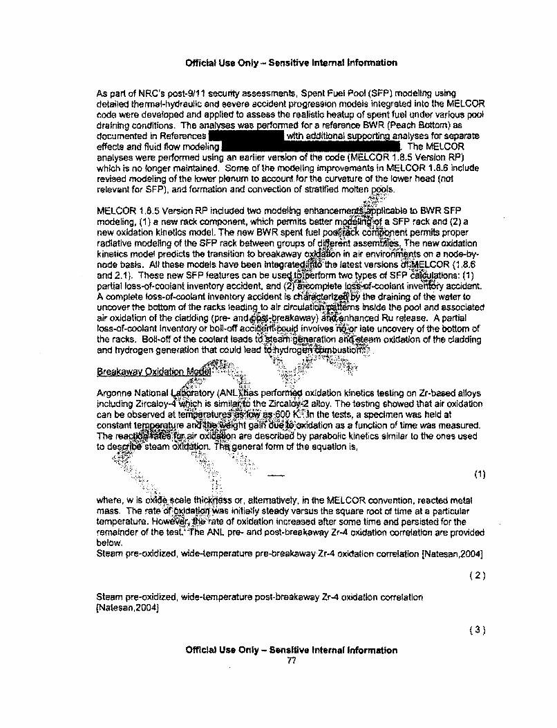
Official Use Only - Sensitive Internal Information
As part of NRC's post-9/1 1 security assessments, Spent Fuel Pool (SFP) modeling usingdetailed thermal-hydrautlic and severe accident progression models integrated into the MELCORcode were developed and applied to assess the realistic heatup of spent fuel under various pooldraining conditions, The analyes was e erormad for a reference BWR (Peach Bottom) asdocumented in References with additional suporting analyses for separateeffects and fluid flow modeling The MELCORanalyses were performed using an earlier version of the code (MELCOR 1.8.5 Version RP)which is no longer maintained, Some of the modeling improvements in MELCOR 1.8.6 includerevised modeling of the lower plenum to account for the curvature of the lower head (notrelevant for SFP), and formation and convection of stratified molten Pools.
MELCOR 1.8.5 Version RP included two modeling enhanoem ýtplicable to BWR SFPmodeling, (1) a new rack component, which permits better mng !f a SFP rack and (2) anew oxidation kinetics model. The new BWR spent fuel po co nent permits properradiative modeling of the SFP rack between groups of dMrnt assemnl. The new oxidationkinetics model predicts the transition to breakaway o n in air enviroiniartds on a node-by-node basis. All these models have been integratedi 'the latest versions dfMELCOR (1,8.6and 2.1). These new SFP features can be useý;t' ,..prform two types of SFP'c;&tations: (1)partial loss-of-coolant inventory accident, and (21'4ieomplete 100'of-coolant inve? accident.A complete loss-of-coolant inventory accident is c terize; the draining of the water touncover the bottom of the racks leadij to air circulatkfii ris inside the pool and associatedair oxidation of the cladding (pre- and" breakaway) enhanced Ru release. A partialloss-of-coolant inventory or boil-off acci r•fi uid involves rmbor late uncovery of the bottom ofthe racks. Boil-off of the coolant leads tdealteag'ineration anrqteam oxidation of the claddingand hydrogen generation that could lead t6,ydr0g6 ~ Usti;iiBre~akwa Oxidation Mo•;•":!%•. "ii:.i?;,.. " •;:
Argonne National I f ry (ANL)Ias performeo oxidation kinetics testing on Zr-based alloys
including Zircaloy-4"-t .h is similati the Zircaloy-2 alloy. The testing showed that air oxidationcan be observed at terturea as 600 1,. -In the tests, a specimen was held atconstant te~a.• .re an;I ; g -tg ".iodation as a funclion of time was measured.
The reac ' air ox ion are describe•d by parabolic kinetics similar to the ones usedto desdM: steam 'x dtion. t1 general form of the equation is,
'.!!::: :I.iii :•• • (1 )
where, w is oxide scale thickness or, alternatively, in the MELCOR convention, reacted metalmass. The rate6 ýbxidati!i was initially steady versus the square root of time at a particulartemperature. Howe"rpr:1,,ehate of oxidation increased after some time and persisted for theremainder of the test:`The ANL pre- and post-breakaway Zr-4 oxidation correlation are providedbelow.Steam pre-oxidized, wide-temperature pre-breakaway Zr-4 oxidation correlation [Natesan,2004]
(2)
Steam pre-oxidized, wide-temperature post-breakaway Zr-4 oxidation correlatloin(Natesan,2004}
(3)
Official Use Only - Sensitive Internal Information77
Official Use Only - Sensitive Internal Information
The new oxidation model was implemented in MELCOR by adding a breakaway lifetimecalculation. The model calculates an oxidation "lifetime" value for Zircaloy components in eachcell using the local Zircaloy cladding temperature.
(4)
(5)
where PLO) is the MELCOR fit of the timing for the transltion fri *p-breakaway to post-breakaway oxidation reaction kinetics for Zirlo and Zircaliy-Airiihe AL. D•periments.
The air oxidation model was benchmarked against ex ental data from hIe.,Sandia NationalLaboratories SFP facility E. h iateions with and without kawayoxidation kinetics showed different heatup rates iAwng breakay. Both th ta and thecalculation with breakaway kinetics show a sharp rk.rase in.itli ieatup rate fol"4rngbreakaway. The new breakaway kinetics model pro'dd Ja,,er prediction of the measureddata including a transition to accelered post-breaka 6q ation kinetics.
H~ydrauli; Besjstanc g dl
MELCOR modeling approach for flow patconnec_. trot volUmes Includes constitutive
relationships to specify for, 1s0', (.e., miiho #WaSn) 1frictlon losses (i.e., major orviscous) along a flow p iA ulIc flo;0 •erm to ther'Momentum equation. The formatof the user-specifled J Tt for MELCOR Is deffl" from the sum of the local viscous and majorpressure drops, - .. ...... " •'• .. .. I': .... .. ... "( 8
-:;:::': .. ,# ;:•,: . -!(7 )
wherff.0s the fluid de isty, v is" he fluid phase velocity, L is the inertial flow path length, D) is arepre ttive hydraulic: Oameteit*i K is the form loss coefficient The Jaminar friction factorMf is~~ 'as.
(8)
Where SL~ is a usek-spedifted MELCOR Input parameter, Re Is the Reynolds number (pvDlp),and p is the fluid dyr V'isoosity.
Hydraulic resistance measurements were performed on a Global Nuclear Fuel (GNF) Wx 8WRassembly at Sandia National Laboratories [Durbin.20051 to obtain the required frictional andform loss coefficients including the effects of grid spacer and partial rods. The empirical lossfactors were used drcltom elthe flow path resistance parameters in the securityassessment analysis where the axial nodalization of the core cells roughlycorresponded to various regions in the experimental setup,
Omcllat Use Onily - Sensitive Internal Informa~tion78
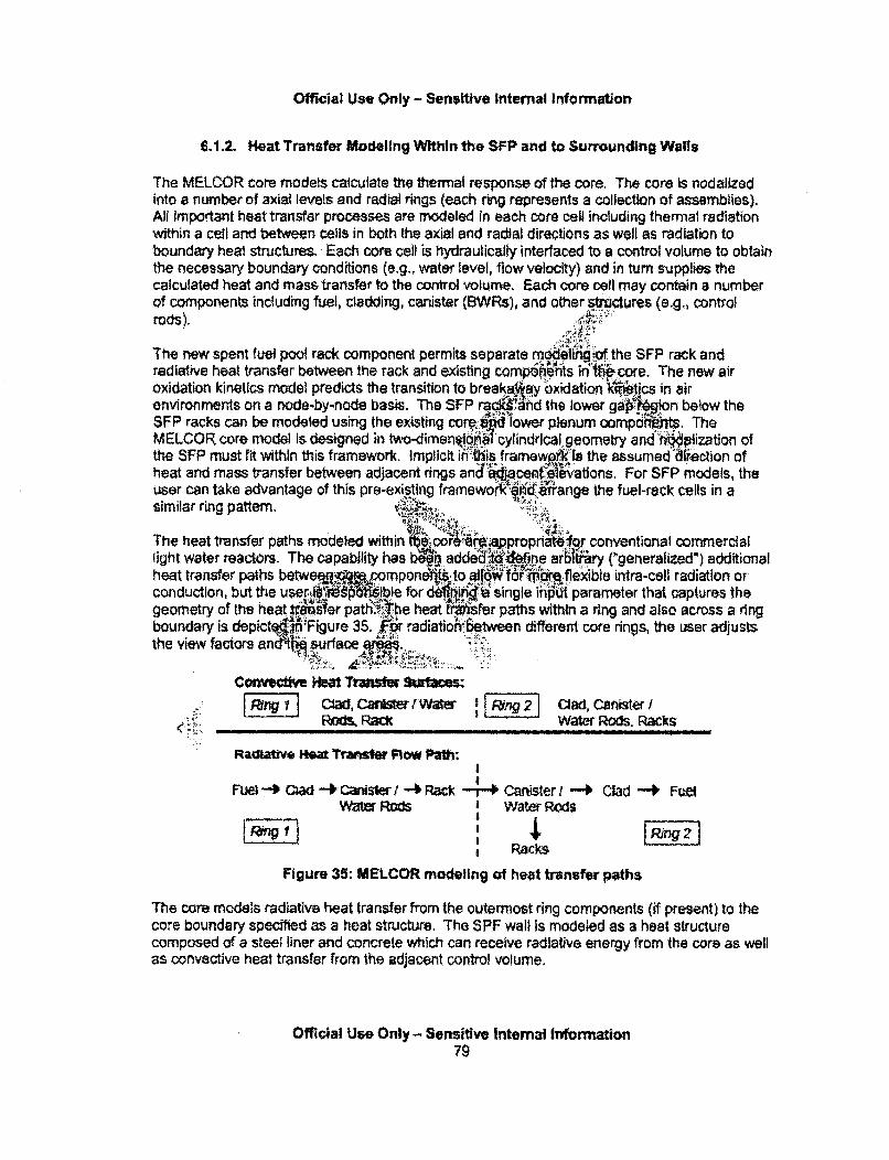
Official Use Only - Sensitive Internal Information
6.1.2. Heat Transfer Modeling Within the SFP and to Surrounding Walls
The MELCOR core models calculate the thermal response of the core. The core is nodalizedinto a number of axial levels and radial rings (each ring represents a collection of assemblies).All important heat transfer processes are modeled in each core cell including thermal radiationwithin a cell and between cells in both the axial and radial directions as well as radiation toboundary heal structures. Each core cell is hydraulically interfaced to a control volume to obtainthe necessary boundary conditions (e.g.. water level, flow velocity) and in turn supplies thecalculated heat and mass transfer to the control volume. Each core cell may contain a numberof components including fuel, cladding, canister (BWRs), and other stitctures (e.g., controlrods).
The new spent fuel pool rack component permits separate modelifigof the SFP rack andradiative heat transfer between the rack and existing compoihe~n~ts In':% core. The new airoxidation kinetics model predicts the transition to break.ay oxidation k-itjcs in airenvironments on a node-by-node basis. The SFP radWhand the lower ga9 ion below theSFP racks can be modeled using the existing cor:' d lower plenum oomphntrs. TheMELCOR core model is designed in imenrirnen l 1cylindrIcal geometry and' Vhiization ofthe SFP must fit within this framework. Implicit iKiRis framewý4(is the assumedd.e"ction ofheat and mass transfer between adjacent rings an&.'d.jaeieleivations. For SFP models, the• . . •= ~~;:• .,'.. Avr:.: if
user can take advantage of this pre-existing framewo"V~d arrange the fuel-rack cells in asimilar ring pattern. •,..
The heat transfer paths modeled within 6-oorMN.4pproprianiro conventional commerciallight water reactors. The capability has b•q addei 4fione arb1Iiery ("generalized*) additionalheat transfer paths betwe lob ompone•.to W fo~are flexible intra-cell radiation orconduction,~ ~ ~ ~ *4 4116 se.• •'..].befrd "•'• ... .. More:•...
conduction, but the use fr jn single inpo parameter that captures thegeometry of the heat Yster path.#01he heat tI Wsrer paths within a ring and also across a ringboundary is depict4if'Figure 35. • radition between different core rings, the Lser adjusts
the view factors and t .urface . -",, • rY.:. ' A .. . ,.
ConcveHct I leat Tnsfeans aficeCRad, rWaCardisterI Rr g2 Clad, CanisterI•, !:::Pwc K ROMk Wate Rods. Packs
Radtattve ffea Transfer Flow Path:
Fuel *- C---4 Ca~sWer I - Rack -j- Caniser / -+ Clad -4 FreiWater Rods Water Rods
Racks
Figure 35: MELCOR modeling of heat transfer paths
The core models radiative heat transfer from the outermost ring components (if present) to thecore boundary specified as a heat structure, The SPF wall Is modeled as a heat structurecomposed of a steel liner and concrete which can receive radiative energy from the core as wellas convective heat transfer from the adjacent control volume.
Official Uee Only - Sensitive Internal Information79

Official Us* Only - Sensitive internal Information
61.3. Modeling of Mitigative Sprays
The MELCOR containment spray model was used to calculate the thermal response of the fuelfor the mitigated scenarios involving spray activation. The spray model mechanistically modelsthe interaction of the spray droplets with the containment atmosphere, and includes droplet heatand mass transfer and fission product removal capabilities. A droplet size of 1250 microns wasused for all calculations. The spray was positioned at the top of the spent fuel pool (elevation ofthe refueling bay) allowing the droplets to be directed into the assemblies and open spacesbased on their respective cross-sectional areas.
The penetration of the spray water Into the assembly is controlled.• •jhe interphase momentummodel, which replicates the Wallis flooding curve. Once the spray.Vater enters the assembly,the spray is assumed to form a thin film on the fuel structuresw .igassembly, which drainsdownward, The MELCOR simplified flow regime model ide "'1s thep;ray flow as a film incontact with the fuel rods (see Figure 36). Heat transfer fakes place be:e. n the fuel rods andwater in core cells where the flow regime model is a #':FNucleate or film"" ling heats thewater film to saturation conditions as it drains down !1fiassembly. Simultan6 s heat transferfrom the rods and surrounding gas causes the "Y flow to bodlt The spray filfiýývelsdownward in contact with the fuel rods until the Qiýi control volrae void fraction Skomesgreater than 99.8% (i.e., a > 0.998). Due to numer'f `nqid~etions, the residual water is
converted into a shallow pool where the liquid heat tralT ia is apportioned by the depth ofthe pool in the control volume. Typicaehl remaining r bolls away in the first core cellafter the flow regime model is disabledit ,.
UJi
11.. , aim&.I~
" igure 36: Spray model for SPF analysis
it should be noted that the MELCOR thermal hydraulic model interprets the liquid film as a smallpool at the bottom of each control volume (see Figure 36). Due to the high void fraction, thephasic resistance of the steam or air flowing through the pool is relatively insignificant, which isthe expected impact of a liquid film. Similarly, the depth of the spray water penetration iscontrolled by the heat transfer rate from the fuel rather than the momentum solution. Axial,stepwise heat transfer from the core cells limits how far the spray water penetrates Into theassembly. A possible limitation of the thermal hydraulic representation is the relatively smallheat transfer area between the two phases (I.e., heat transfer through the pool and the surfaceversus a film), However, the rate of heat transfer from the gas to the water film is minor in
Official Use Only - Sensitive Internal Information80
Official Use Only - Sensitive Internal Information
comparison to the nucleate and film boiling heat transfer on the surface of the fuel rods. Adetailed nodalization is used to track the water as it penetrates into the assembly that permits abetter local representation of the fluid conditions and the location of the spray dryout.Parametric calculations will be performed to show the impact of this modeling parameter (Le.,flow regime model active or inactive).
6.1.4. Modeling of Fuel Collapse and Baseplate Failure
Fuel collapse is based on user defined cumulative fuel damage fraction logic, where the fuelfailure time is defined as a function of cladding temperature and .:a .°pplied if the unoxidizedzircaloy cladding thickness is less than 0.0001 m. The failure lofialculates the fuel damagefraction for the current timestep, if the unoxidized cladding thi;ii teria is met, and addsthat fractional damage to any previously calculated damqge&ý W-hen thail" umulative fuel damagefraction exceeds unity, the fuel is failed in the SFP MELCOR model. This lifetime damagemodel eliminates the threshold behavior present in • ther fuel failure crieria and predictsaccumulating damage if the fuel remains abovethe melting temperature of ZiroWo but belowthe absolute threshold collapse criteria of 2500 K.:"
All components other than fuel rods (fue) and cladding vd lýe'immediately converted toparticulate debris whenever the unox f-retal thickness:is txeduced below a user-definedminimum value. The minimum thicknes!•ntar:for the two'&LCOR canister components is
0.0001 m. The unoxidized metal thicknessis redi6r•d:dboth by dx'idation and by melting andcandling of metal. Molten Zircaq held up.can I siitt.I released from the fuel rods at2400 K and from the caplWO -t'N4QQ K (I.e.,"pst above the melting temperature of the Zircaloy).Particulate debris wil'býformed f anister cmrponents following the release of the moltenZircaloy or if the temorature of the tomponeni reaches the melting temperature of theassociated oxide.
Basepla'fined e grid-supported or egg-crate plate model In MELCOR. Ingenera beams that form thjrgd have sufficient strength that their failure is not an issue,and einterest Is in faklQ:,of thei b between them. Upon failure of the plate, the capability tosuppotparticulate debris o. intact components is lost, however, the plate will remain in placeuntlf it meltsl,.This model ca"t.lates baseplate failure based on the maximum stress in a plate ofuser defined ft.ickness supported by beams of user defined spacing with a total load on the areaof the ring. In thi.FP mqik the thickness of the basepiate Is deflneod as 0.0127 m with gridspacing of 0.07 m.-Thef.ieting temperature of the plate is 1700 K.
6.1.5. Radtonuclide Transport Modeling and Treatment of Hydrogen
In MELCOR, the release and transport of fission product vapors and aerosoi (referred to asradionuclides) is modeled by the RN package. Release of radionuclides can occur from thefuel-cfadding gap by exceeding a failure temperature criterion or losing intact geometry, frommaterial in the $FP using various empirical release correiations based on fuel temperatures.After release to a control volume, masses may exist as aerosols andfor vapors, depending onthe vapor pressure of the radionuclide class and the volume temperature.
Official Use Only - Sensitive Internal Infonnation81
Official Use Only - Sensitive Internal Information
Aerosol dynamic processes and the condensation and evaporation of fission product vaporsafter reiease from fuel are considered within each control volume. Aerosols can deposit directlyon surfaces and water pools, or can agglomerate and eventually fall out by gravitational settling.Aerosols deposited on surfaces can be vaporized (if volatile) but cannot currently teresuspended in MELCOR, All deposition mechanisms are mechanistically modeled. Aerosolsand vapors are transported between control volumes by bulk fluid flow of the atmosphere andthe pool.
For tracking purposes, the radionuclides are combined into material classes, which are groupsof elements (and their isotopes) with similar chemical and transport behavior. Radionuclidemasses include both the radioactive and non-radioactive mass to rfy model the transportof Fission products. In the SFP MELCOR model, there are fl ult material classes andtwo user defined classes to model the behavior of cesium IodK p J.ceslum molybdate asshown in Table 24.
The fuel release model is based on the CORSOR-.o odel that mo-8\rately predictsthe release rates from the Phebus and VERCOR riments [Gauntt,20 1 tjhe defaultMELCOR radionuclide package Input was modi fo accommodate new Insi t om the
•nd 4•0.u radionuoli~;lsePhebus experimental program. The cesium, iod n d mot um 11cl asseswere reconfigured as follows, A.
Class 4 - Characteristic released con'pd tS12v with th ult inventory wholly transferred toClass 16.
Class 7 - Characteristic released compoHI: is Mo e defau ,Iventory reduced by theamount allocated to C ass
Class 16 - Characteri ýiea pound I with the default Inventory representing all ofClass 4 and suffici ium from ss 2 to Csl.
Class 17 - Character lea d, is ( 4 using the remainder of the cesiumnot in the I ady in C;ls ready combined with the iodine in Class 16.
ufficiis in from ls Class 17 to form Cs2MoO4. The releasedvapor ire an ou is consistent with CsMoO4 .
An E ch for the esti -n of i ed Ruthenium release under air-oxidation conditions ispropos, [Gauntt, 2010]. lu (dass'8) has the lowest of vapor pressures in the defaultMELPOR I that preven -rediction of large releases'-. There is evidence of highervolatility of r•ium oxide ny orders of magnitude higher than the default MELCOR). It is
assumed [Gau•t'•10) • ere is always air present leading to formation of a moderatelyhyper-stoichio .) and release of RuO7. The default vapor pressure parametersin MELCOR are audju for Ru class to match RuO2 vapor pressure at 2200 K 3 . The new Rurelease model is applied only to scenarios Involving rapid drain down (for moderate leak rates)of the SFP pool. These cases lead to relatively early clearing of the rack baseplate and flow ofair (and possibly steam) through the assemblies. It should be noted that the model does nottake Into account the concentration of oxygen or steam during the oxidation process.
• There is a mass transfer limitation to the release from the fuel.1 The ralionale for increased Ru class release is based only on increased vapor pressure, and requiresfurther experimental validation.
Official Use Only - Sensitive Internal Information82
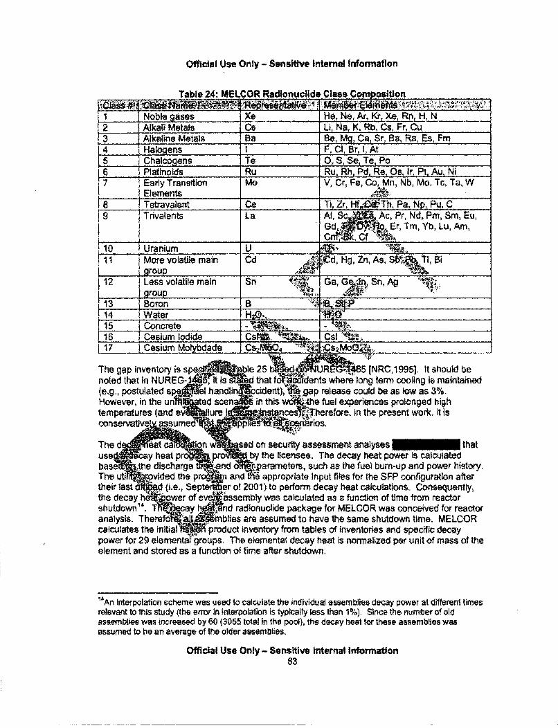
Official Use Only - Sensiltve Internal Information
Table 24: MELCOR Radionuclide Class Composition
I Noble _ases Xe He, Ne, _e _nH, N12 Alkali Metals Cs U., Na, K, Rb, Cs, Fr, Cu1 3 Alkaline Metals Ba Be, Mg, Ca, Sr, Ba, Ra, Es, Fm4 HaoesI F, CI, Br, 1, At
15 Chalcogens Te 0, S, Se, Te, Po6 ______ Platinoids Ru Ru, Rh, Pd, Re, Os, Ir, Pt, Au, Ni7 Early Transition MO V, Cr, Fe, Co, Mn, Nb, Mo, Tc, Ta, W
Elements .•.'8 1 Tetravalent Ce Ti, Zr, Hf l'Th, Pa,. Np,_ Pu, Ci 9 Trivatents La Al, So Ac, Pr, Nd, Prn, Sm, Eu,
Gd,... Er, Tm, Yb, Lu, Am,
S gUranium U ý ..11 jMore volatie main Cd Altld, Hg, Zn, As, StiQTl,Bi
112 1Ls olatile main Sn a Ga, SA_group "__ _ _ _ _ _ _"_ _ _ _ _ _
13 [Boron S4B P ________._.._._...._,
.114 I Water H_-_.._____....11-5 Concrete _ _ _ _ _ _ _ _ _ _ _ _ _ _ _ _ _ _ _ _ _ _
116 Cesium Iodide Csl. . C .17 1 Cesium Moh bdada _C.s5OCS 2. 00 '____
The gap inventory is s ble 25 sd~l. 'UR 45NRC.19951. It should benoted that In NUREG-. 5 it that f I ants where long term cooing is maintained(e.g., postulated s el handlin cident), • gap release could be as low as 3%.However, in the un ad scen in this w" 4he fuel experiences prolonged hightemperatures (and e faure I nojeclsane;Tiherefore. In the present work. It is00nervtiv aume pp15 Ho
The d t tion w sed on security assessment analyses • thatuse cay heat pr *pr by the licensee. The decay heat power is calculatedbase the discharge rnd oWI r;parameters, such as the fuei burn-up and power history,T h !e 01ed the p andtW9 appropriate Input fiWes for the SFP configuration aftertheir last {ie', Septe er of 2001) to perform decay heat calculations- Consequently,the decay h "ower of eveassembly was calculated as a functiom of time from reactorshutdown". T: ay nd radionuclide package for MELCOR was conceived for reactoranalysis. There 40i'nblies are assumed to have the same shutdown time. MELCORcalculates the initial product inventory from tables of inventories and specific decaypower for 29 elementa'•groups. The elemental decay heat is normalized per unit of mass of theelement and stored as a function of time after shutdown.
1'IAn Interpolation scheme was used to calculate the individual assemblies decay power at different timesrelevant to this study (the erro in interpolation is lypically less than 1%). Since the number of oldassemblies was increased by 60 (3055 total In the pool), the decay heal for these assemblies wasassumed to be an average of the older assemblies.
Official Use Only - Sensitive Intemal Information83
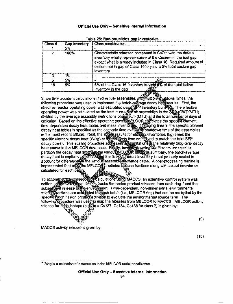
Offlcial Use Only - Sensitive Internal Information
Table 25: Radionuclides gap inventoriesClass # Gap inventory Class combination
1 2 100% Characteristic released compound is CsOH with the defaultinventory wholly representative of the Cesium in the fuel gapexcept what is already included in Class 16. Required amount ofcesium not in gap of Class 16 to yiekd a 5% total cesium gap
_ _..Inventory.
3 1%5 5% t16 5% 5% of the Class 16 inventory toyi. of the total Iodine
_______ _ invent In the ap
Since SFP accident calculations involve fuel assemblies wftmKrmutpl16" down times, thefollowing procedure was used to implement the batch age decay h ults. First, theeffective reactor operating power was estimated usilf Inventory bur effectiveoperating power was calculated as the total bur !all assemblies inthe . GWDIMTU)divided by the average assembly metric tons of Iium (MTU) d the total nfu r of days ofcriticality. Based on the effective operating powe LCOR ates e spe 'Welement,time-dependent decay heat tables and mass invent . giIng time in the specific elementdecay heat tables is spedfled as the scgnario time mini Shutdown time of the assembliesin the most recent offload. Next, the suits for el inventories (kg) times thespecific element decay heat (Wlkg) at time are d to match the total SFPdecay power. This scaling procedure a s• • 0 itation 4he relatively tong-term decayheat power in the MELCOR data base. ;iy, iv caling •efficients are used topartition the decay heat a e variou.E a mary, the batch-averagedecay heat is explicitly the fis uct i ry is not properly scaled toaccount for differen he varit assemb ischarge dates. A post-processing routine isimplemented that MELC redicted rase fractions along with actual inventoriescalculated for each "
To accom r ocnseq Aculatto - MACCS, an extensive control system waswritten i~ut fil tracks the fission product releases from each ring" and thesubs t release t :.env I ent, Time-dependent, non-dimensional environmentalrele ractions are ca ated f -. batch (i.e,, MELCOR ring) that can be multiplied by thespec tch fission prodi• activtf tWo evaluate the environmental source term. Thefollowingedure was usi&fto map the releases from MELCOR. to MACCS. MELCOR activityrelease for'ý". isotope (e..•;.R Cs137, Cs134, Cs136 for class 2) is given by:
MACCS activity release is given by:
(10)
Ring Is a collection of assemblies In the MELCOR radial nodalization.
Official Use Only - Sensitive Internal Information84
Official Us* Only - Sensitive Intemal Information
where is defined as:
(11)
(12)
Where
r = ring number (total 6 rings)m = radionuclide (1 :M) where M is the number of ORtGEN-s Lts e..•s in each classt = time since start of eventRF (t) = Environmental release fraction (ring by ring fromMELCOR)
- Environmental release fraction (by radionuclidp'oup for MACCS.A = Released Activity (Bq)A7 = Initial inventory (Bq) from ORIGEN-s (69 isotd for each MELCOR rin§i):
Radionuclide Inventories
The radiological inventories and decayheat for assembles in the spent fuel pool (SFP) werecalculated using information provided•..-h..utility for all a"mblies discharged to the poolthrough Cycle 18 (September, 2011). The..info.pation includeame assembly ID, design type,initial enrichment, discharge bumup, andsdischaft§%de The an olysis basis for the high-density SFP inventory was 3055 assemblis a nunou .onti pool capacity of 3819assemblies, reduced by 7644'".rj.blies to •m•OW- at'$ core oftfoad capability,
inforatio on .ssemble OdiscInformation on assembvditlhtard prior to, de 7 is not considered since the target pool
inventory was achieve'dWith the asiZ'blies fro .m`Cycles 7 to 18.
Assembly depletion d4ecay cit'W"Pns were peiqormed using the ORIGEN code [Gauld,20111, maintained withi•• ft. S.C.' htue :tynalysis code system (Rearden, 2012]. Thenuclear cos.! io libra{KOJIed for the biiMup analysis of the assemblies were thosedistribut~•' S0-.:1. Te:se .libraries are developed using ENDFtB-V cross sections andincludlresentative" '7q7, 8x&8:9_9 and 10x10 GE assembly designs [lias ,2006] used in thePeatsbý,tom reactor. OMfEN c l;ctations performed using these libraries have beenvalidateiaainst experiment! destruci4ve assay measurements, and calorimetermeasurernmpts of assembly.decay heat have been demonstrated in previous validationstudies[plas, }208) to be accrae within *2%.
For the burnup anri!sls, til Irradlation and decay history for each of the 3055 assemblies in thepool was simulated 'elrcitly using ORIGEN and assembly-specific design and operating historydata provided by the utiity., Each assembly was decayed to a reference date corresponding tothe end of Cycle 18 (9/11/2001), and the assembly inventories combined into analysis groups.The groups were then further decayed to calculate spent fuel assembly activities and decayheat power for analysis cooling times of 3.6, 3.9, 5.0, 13.1, 37,0, 107.0 and 383.0 days aftershutdown of the reactor, The assemblies were grouped according to the cycle they weredischarged.
Official Use Only - Sensitive Internal Information85
Official Use Only - Sensitive Internal Information
Group 1 (268 assemblies from Cycle 18)* Group 2 (272 assemblies from Cycle 17)• Group 3 (272 assemblies from Cycle 16)• Group 4 (276 assemblies from Cycle 15), Group 5 (284 assemblies from Cycle 14)* Group 6 (1683 assemblies from Cycles 7 to 13)
This division of assemblies by group facilitated use of the data for an analysis of a low-densitySFP configuration, whereby all assemblies with a cooling time greater than five years have beenremoved from the pool. For the present analysis, each offload was aisumed to be 284assemblies for modeling convenience and to avoid modifying the M.LCOR modelnodalization 5. Therefore, the actual inventories from batches AWscaled appropriately tocorrespond to the rings in MELCOR nodalization, For exarr1Ic f6r thie low density case, theCycle 18 inventories were increased by 284/268 and the SI•F!of Cyc:..i6 and 17 were scaledas 5681(272+272) resulting in 852 assemblies as oppqtSM o the actual SM2.
The spent fuel pool results were compiled for each Asembly group and all d4l, times andincluded activities (Bq) for 69 radionuclides andtdeay heat (watts). :
Results from the present analysis were compared w tiosd:•nerated previously for the PeachBottom pool using assembly data provided by the utll*-t gh 2001 (assemblies dischargedup to Cycle 13) as part of the security~s sment work. bAimitation of the 2001 data was thatthe utility did not provide the actual disch tdfumup distribt6on of assemblies from Cycles 12and 13. Consequently, previous anaty•sssuMddrUrnup d4 wbutions for these cycles basedon data from Cycles 10 and 11. Review .ie actu ," u dl diblns included in the 2011data, indicates that the aiv dscharge 6mupm &tsgns nyafter Cycle 12. The
burnup values used in th• pr• •.'ach ott analysis are significantly higher and thereforemore representative _,!.Modeam spalfuel pooI&aventories than earlier analyses. Previousanalyses using th data are re resentat•iver discharged fuel up to about 1995.Other differences ar'kobuted "hV .Mffic poweeý& the assemblies which influences the decayheat power and activiti' sri'"r .I•!pducts in the analysis time range. Informationon the spesttd~ij;r was' mvided by ih6.llfty, Notwithstanding power up-rates for theon. theap - , h"=• 4A•••=,;
Peach Bi' Ctvfb=the M. •ecent occurring in 2002, the specific power used to calculateP e ac h 6 1.006 esý •ntlnvent•rI~ for the assble n present analysis were lower than those assumed using the
earik- 01 data, The O.ent araii•s normalized the average specific power of thedischirgqgdassemtlies to .r .act& .6pac power. Previous information provided by theutility In t.10201 data includ4d the effective full power days, used to derive alighily higherspecific pow4ervalues compafed to those used in the present study.
The net impact ofdfferendis between the analyses performed using 2001 data and the presentanalysis is an increg'- iVe inventories for cooling times longer than about 30 days, attributedto higher assembly bdni'p in the 2011 data. For shorter cooling times the previous analysespredicted decay heat rates about 5% larger than the current results, likely due to moreconservative estimates of specific power used in the previous anatyses. A comparison of thepresent decay heat results with values calculated by the utility In 2001 show agreement to betterthan 3% over all cooling times, with present results being slightly larger than utility values likelydue to the increase in discharge burnup since 2001.
1 The nodartzation was based on the security assessment work up to Cycle 13. The additional data on
later cycles were received after the MELCOR model had been developed and the calculations werestarted.
Official Use Only- Sensitive Internal Information86
Official Use Only - Sensitive Internal Information
Hydrooen Burn
A bum is initiated in a control volume If the mole fraction of the reactants (hydrogen and oxygen)satisfies the burn criteria. In addition, Control volumes that are specified to contain igniters aretested against different criteria than control volumes without ignilers. In SFP calculation, ignitionis assumed to occur In the reactor building when the hydrogen concentration exceeds 10% byvolume. in addition, MELCOR checks to determine whether there is sufficient oxygen. Theminimum oxygen mole fraction for ignition is 5%, The maximum diluents mole fraction forignition (mole fraction of steam plus mole fraction of carbon dioxide) is 55%. If all theseconditions are satisfied, a bum is initiated. There may be somri,:.Micertainty regarding thecombustion of hydrogen, especially with regards to the timing ois:ontaneous ignition. It isrecognized that a hydrogen burn may occur at higher or lowe~rcorvcentrations of hydrogen, air.and steam that have both epistemir and aleatory uncertainti@qm. ýiy SFP calculations resultedin conditions where combustion was very likely or very ut ily. COsequently, the results ofcases with and without combustion are presented in th SFPSS. Rfeer, there are somecases that have conditions where the occurrence or.iiming of a combufion event has moreuncertainty that were assumed to ignite or not ille according to the !a~l, spontaneous
combustion criteria In MELCOR
6.2. Description of MELCOR Models
The spent fuel pool, 40 feet wide by 353ii ong by 38 f4ýeep, is located on the refuelingfloor of the reactor building. The pool is:rnstir'rUo , re:nfordwconcrete with a wall and floorlining of 1/4-inch thick stainless steel. Thd*alls ail!f, oor of e: spent fuel pool areapproximately 6'. In the no-t."ast comer ofTthe SFR k.aea of 10' square.
The high density SFZ rPc provd ýspent fuef-16rage at the bottom of the fuel pool, The fuelstorage racks are nonrtally coveredý.Mh about 23.ft of water for radiation shieiding. The SFPracks are freestandin full length,.. entry and are:designed to maintain the spent fuel in aspaced geometry, whi recli., • •slbilltY df:criticality. The high-density SFP racks areof the 'poiso~4~pe utili i~Wrsn a~ rmaterial to maintain a subcritical fuel array.The ract 4 ir in pe and are of nine different sizes. A total of 3819 storagetocationfJ•imoe provis dthe 3W. The racks are constructed of stainless steel materials andeaaW module is comp9sed of,81e assemblies, a base plate, and base support assemblies.Each tHýs composed of(}:.a fulllngth enclosure constructed of 0.075" thick stainless steel,(b) sectiens-of Bisco Borafle , which is a neutron absorbing material, and (c) wrapper platesconstructed. 9,020- thick stanless steel. The inside square dimension of a cell enclosure is6.07". The ceilPitcb is 6.28P'7 -The base plate is made from 0.5" thick stainless steel with 3,8"chamfered throig) tlesdfered at each storage location, which provides a seating surfacefor the fuel assem@t*,s 14,lise holes also provide passage for coolant flow.
Each rack module has base support assemblies (i.e., 'rack feet') located at the center of thecorner cells within the module and at interior locations to distribute the pool floor loading (e.g.,see Figure 37). Each base assembly is composed of a level block assembly, a leveling screw,and a support pad. The top of the leveling block assembly is welded to the bottom of the baseplate. SFP fuel cells are located above each rack foot, Four 1' holes are drilled into the side ofthe support pad, The interior of the support pad is hollow and permits flow to the opening in thebase plate. The square tube cells are used to construct the rack cells, which results in an equalnumber of cells resulting from the square tube cell checkerboard layout. Figure 37 shows the
Official Use Only - Sensitive Internal Information87
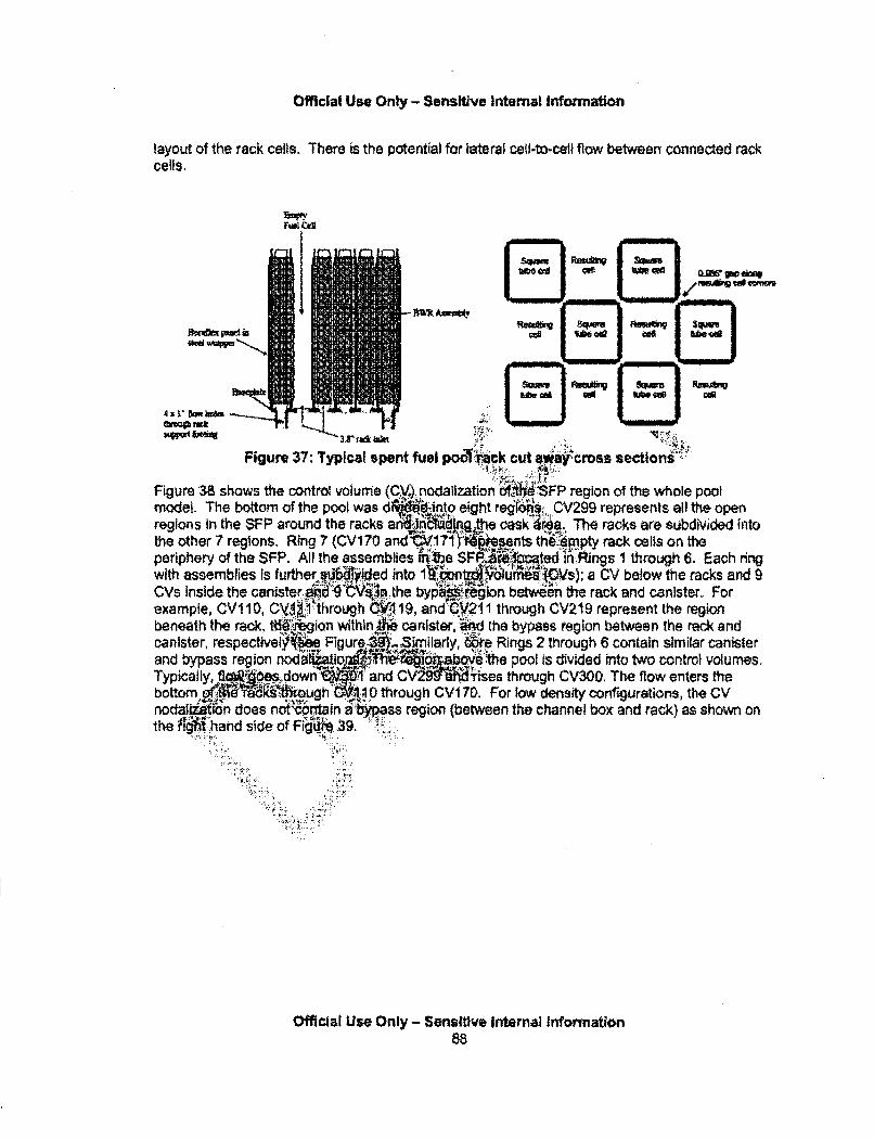
Official Use Only - Sonslitive Internal Information
layout of the rack calls. There is the potential for lateral cell-to-cell flow between connected rackcells,
Fuel Ceal
....... SOM
Az L5~e~Figure 37: Typical spent fuel poo 'a::ck cut •WWcross sections•
Figure 38 shows the control volume (Cy) _nodalization ti•SFP region of the whole poolmodeL. The bottom of the pool was d~dik:1into eight reg~iois. 0V299 represents all the openregions in the SFP around the racks arnc .,ig,.the cask &•a. The racks are subdivided intothe other 7 regions. Ring 7 (CVi70 and •37vi"4• ... thppyrc clso hperiphery of the $FP. All [he assemblies •!.he SFP £;7bpted Wi Rii ng s 1 through 6. Each ringwith asebie sfute sb':ddIt ib •ur•e i s); CV below the racks and 8CVs inside the canister. ""°'i:,.,V.. the byp rgl~••e"n._ ... ion betee the rack and canister. Forexample, CV11 0, CV!i1i14•through CV 119, and-9211 through CV2t9 represent the regionbeneath the reck,•. t .igo wihi canister, '"8 the bypass region between the rack andcanister, respectivweI Figure 3 ,.. Smilarly, c•e Rings 2 through 6 contain similar canisterand bypass region nod £bov..•e ! Tehe pool is divided into two control volumes.S " ..own :1: and Ce,0through C The flow entersth
bottom 0 ef (J ugh rio° thrugh CVI7O. For low density configurations, the CVnoda~ioAi~ n does not vbrtainabps region (between the channel box and rack) as shown onthe iOhand side of Fi 39"...
OW ,; ;i;. ...::. M:. ' .
Official Use Only - Senslftve Internal Information
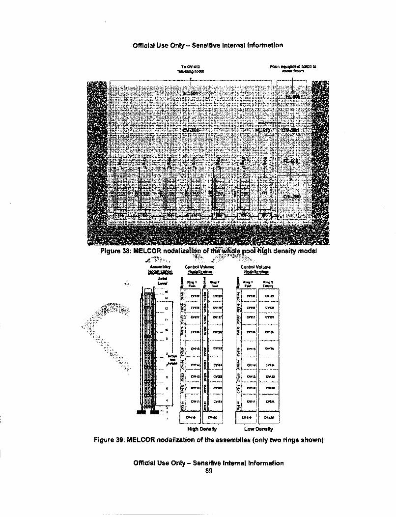
Official Use Only - Sensitive Internal Information
TO CV-412 F 4 us3plq taI o
Figure 38: MELCOR nodalization of th& WhWle pool high density model,x .!.:;, . ; ::.'':;...• - J.• • = • .
A,,mnbl Control V., m" Co."1u Volume
u.1 ......... i
14
......... .. ....... .. ....,
",Ir Onon!y MW
MO# D0nbIty Laow enety
Figure 39: MELCOR nodalization of the assemblies (only two rings shown)
Official Use Only - Sensitive Internal Information89
Official Use Only - Sensitive Internal Information
The hydraulic resistance was specified using the results from the SNL experimental testprogram [Durbin, 20051". For example, for the flow path connecting CV1 13 and CV1 14 in thefully populated region, the MELCOR input values included a loss coefficient (K) of 3.8, and afriction factor (SLw) of 31.3 (=12514 since MELCOR uses the fanning friction factor definition).The flow resistance under the racks was represented using typical contraction inertial losscoefficients and viscous losses consistent with a flow length to the center of the SFP. The BWRassembly canister is modeled with the MELCOR canister component. The rack walls aremodeled with the new rack component with stainless steel and Borafiex materials. MELCORdoes not include an option to model the two large water rods in the center of the assembly.Consequently, the water rod mass and surface area was included in the canister wall.
The axial channel and bypass wall blockage models were activewaiý ,controlled the resistance Inthe respective flow paths. The blockage model monitors the p if the materials in thechannel and bypass regions. if a debris bed forms, the flo'cSistai ':is adjusted via an Ergunflow resistance model. The canister wall radial blockagm::odel controli paths between thebypass region and the assembly, Initially, the canlster.,0 precludes floik, 44owever, If thecanster fails, a radial flow path is activated that pe:t'rflow between the twdiegions. Similarto the axial blockage model, the flow reslstance•i•i6djusted based on the local". d- Ws porosity.
A complete reactor building has been developed for Peach..cttom INRC, 2012]. However, thebulk of the reactor building does not play a significant •Miwn't;FP accidents. Consequently, thereactor building model was simplified g;.nly model the Ueiing room (I.e., within the reddashed line in Figure 40). '• -
A single control volume models the refueli6g bay. "4opern hatch riý the southeast quadrantconnects (via a flow path) thetfueling roomr!to a b Mdaidy dditiOn volume representing theflow connection to the I1 b s of the $&lr. The nominal reactor building leakage is
modeled at the center4Ation ofitie refueliri, bey and the leakage flow from elevations in thesimplified model fropf.fe lower reg~ins was tun6dto match the leakage flow rate of a detailedreactor building modw&,
6 ,
The detailed-.sector bulild l sa'nylm( .... over-pressure failure flow paths within thereactor te o mop•om m , tant flow paths were included to the simplified refuelingfloor M (1) the tfltvout p5418. on the refueling room walls and (2) a pathway representingthe OR.ural failure of'.I .eact6f.*llding roof. The refueling room blowout panels will fail ifthere lki;•'a over-pressure Pater than:720 Pa (0.25 psig). If the reactor building pressure risesabove 3450Pa (0.5 psig), structural failure of the reactor building roof will occur.
MELCOR doaetoe include rrels for stratification of hot gases. Each control volume isassumed to be Wll-.m xed~an have a single temperature. Large-scale natural circulatlon flowpatterns can be prb8,1cqdWhere the bulk temperature differences between adjacent roomscreate mixing flows. idever, it would be awkward or perhaps impossible to predict complexplume behavior within regions typically modeled with a single control volume (e.g., the roomabove the SFP). Consequently, the MELCOR calculations are expected to over-predict theamount of thermal mixing within the building. Based on insights from the Computational Fluid
"z in the preseni study, the assembly nodalization is based on the GE14C loxi0 (NRC, 2012: to accountfor the latest offloads used in the low density oonfiguration. Beth 9x9 and 10x10 configurations havepartial fuel rods. The flow area for each assembly is reduced by about 4% compared to 9x9 design. Thehydraulic resistance data are assumed to apply. Frictional loss coefficient for a 10x10 array could besomewhat different since it is a function of hydraulic diameter and grid spaces design.
Official Use Only - Sensitive Internal Information90
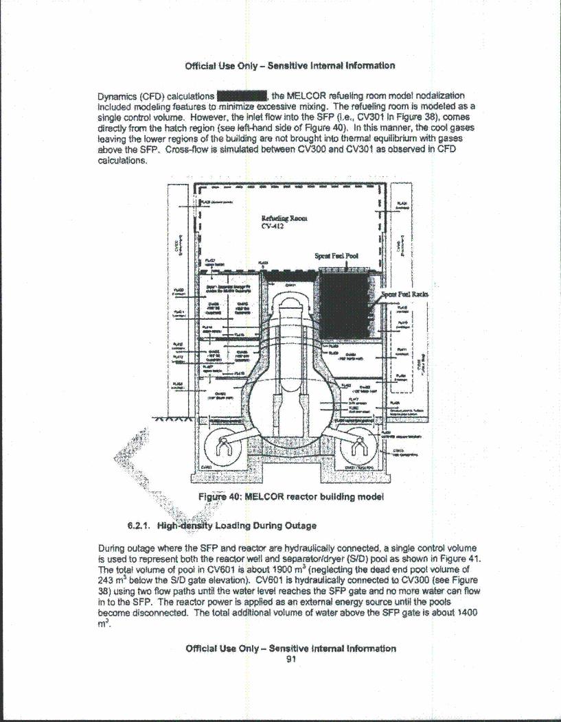
Officlal Use Only - Sensitive Internal Infonnation
Dynamics (CFD) calculations • the MELCOR refueling room model nodalizationIncluded modeling features to minimize excessive mixing. The refueling room is modeled as asingle control volume. However, the Inlet flow into the SFP (i.e,, CV301 in Figure 38), comesdirectly from the hatch region (see left-hand side of Figure 40). In this manner, the cool gasesleaving the lower regions of the building are not brought into thermal equilibrium with gasesabove the SFP. Cross-flow is simulated between CV300 and CV301 as observed In CFDcalculations.
Figure 40; MELCOR reactor building model
6.2.1. High*-4.Wuty Loading During Outage
During outage where the SFP and reactor are hydraulically connected, a single control volumeis used to represent both the reactor well and separator/dryer (S/t) pool as shown in Figure 41.The total volume of pool in CV601 is about 1900 m3 (neglecting the dead end pool volume of243 ms below the SID gate elevation). CV601 is hydraulically connected to CV300 (see Figure38) using two flow paths until the water level reaches the SFP gate and no more water can flowin to the SFP. The reactor power is applied as an external energy source until the poolsbecome disconnected. The total additional volume of water above the SFP gate Is about 1400M
Official Use Only - Sensitive Internal Information91
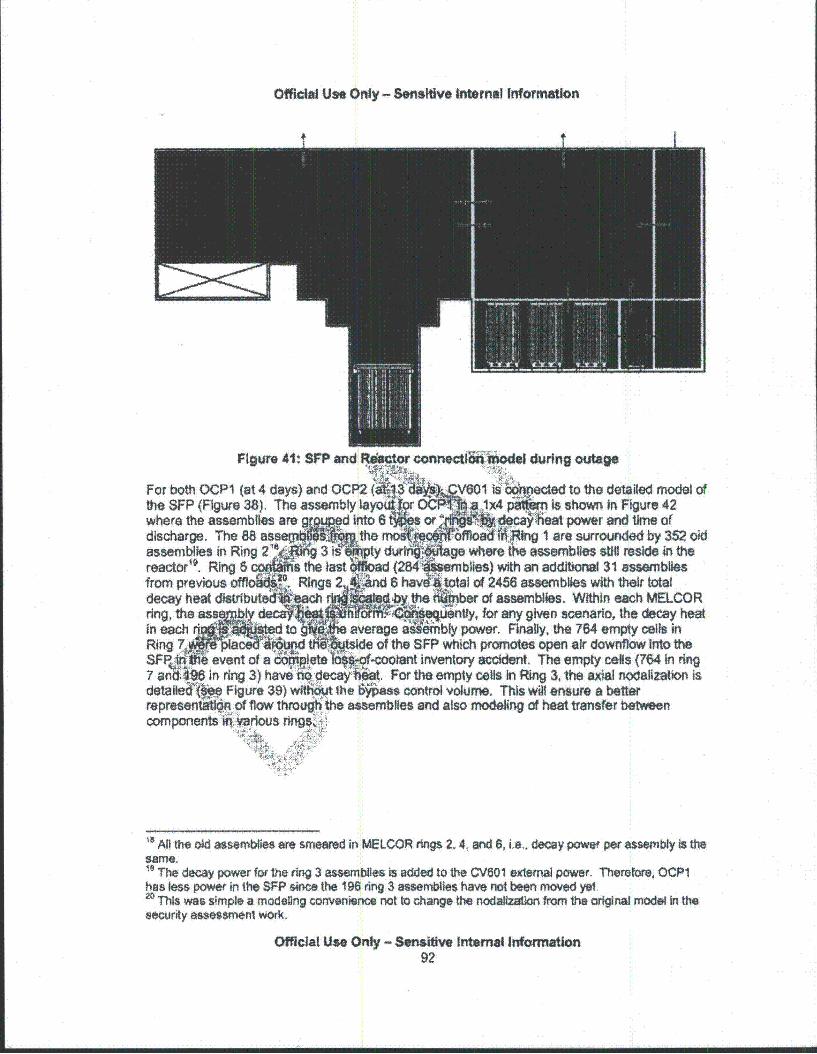
Official Use Only - Sensitive Internal Information
Figure 41: SFP and R•tor connectroK.n eJ during outage
For both OCP1 (at 4 days) and OCP2 (1 iVOi •s•oected to the detailed model ofthe SFP (Figure 38), The assembly sayolji9r 0C -,1x4 I is shown In Figure 42where the assemblies areg. d Into 6 o s poweradischarge. The 88 asseu " the rr1Tf° I are surrounded by 352 oldassemblies in Ring 2 S+ d + tge where te assemblies still reside In thereactor'o. Ring 6 a the anad (24 blies) with an additional 31 assembliesfrom previous offlo Rings 2 6 havd4total of 246 assemblies with their totaldecay heat disibute ac A~ yth•ber of assemblies. Within each MELCORring, the as s -tly, for any given scenario, the decay heatin each average a mbly power. Finally, the 764 empty cells in
Ring tside of the SFP which promotes open air downilow Into theSPFP~ir a event of a co-lookant inventory accident. The empty cells (764 In ring7 ani 496 in 3) have decay: , For the empty calls In Ring 3, the axial nodalization isdetailed'ý Figure 39) wit"h ,t the &$~s control volume. This wil ensure a betterrepresentatlg of flow throkg the assemblies and also modeling of heat transfer betweencomponentskitý.,':arious ring,+Aý;
• All the old assemblies are smeared in MELCOR rings 2.4, and 8, i.e., decay powe per assembly Is thesame,19 The decay power for the ring 3 assemblies is added to the CV601 external power. Therefore, OCP1has less power in the SFP since the 196 ring 3 assemblies have not been moved yet.20 This was simple a modeling convenience not to change the nodalization from the original model In thesecurity assessment wOrk.
Official Use Only - Sensitive Internal Infornation
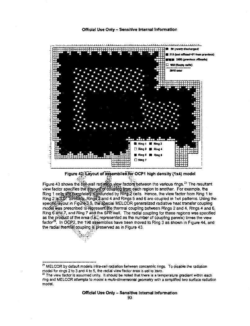
Official Use Only - Sensitive internal Information
KNOWWWWOM amw meannommm no no 'no wo am so *a wn .. Now AIM
W a K 0 .. a .man 0wasa MUM
00 "a
man sac:10.00 Aft0 a a 0 aas a
a 0 0 a aa a m aa IF a 0 a to a
was a W a a w 9 WE"41110a" a a a a a a a
now a a a In a a 000 a a a a a 0 0 it" man 000 is:an a a a I a a a a aNOW a a a a aNow- 4Odom a 0M 4, &MMC: so
ona a go was
Ong a 0 a a
low 0 IF In aso N a:80 a a 40 a am"M a a
000 a a a a ANN
00 a a a
0 aWON wa
irs
a IN aa a a m a a a 0 a a A son0 a a a a a a aam so
Un a a of 0 a a WEWON .000
was Aft"OWN
:00 wason M a awas :Name Now" OWNIM AVON ýWwww :01"
am .0 a New
an Una a0000so 0 a "is W. on Momrawaveam Sam a" is" so :*a WWW" own .
WOMOMOM63= aWwwwwo waom"mo"mmo ownsISMONAMA MW Urn
"Roomon armso 00ftwomma
W"It"s)
.ilk!
",!.,=•
Figure 42: ,yout of' as embkieAo . OCPI high density (Ix4) model
Figure 43 shows the Wlkwall radietl.,vew factcrs;between the various rings.~' The resultantview factor specifies tha Iche region to another. For example. theRing 1 cells,!a' Ielele ~unded by l' ..6 ells. Hence, the view factor from Ring 1 toRing 2 VP T• i gRi.. and 4 and Rings 5 and 6 are coupled in 1x4 patterns. Using thespecifi6yout in Figa:i.5 the6:.kAcial MELCOR generalized radiative heat transfer couplingmowdi.as prescribed to&tpresenýhe thermal coupling between Rings 2 and 4, Rings 4 and 6,Ring,6 0A'n d7, and Ring 7 a.d the SP 1.wa, The radial coupling for these regions was specifiedas the pro'1aict of the area "i'.represented as the number of coupling panels) times the viewfactor In O 2, the 196 as smblies have been moved to Ring 3 as Shown in Figure 44, andthe radial thermal coupling isjpreserved as in Figure 43.
2' MELCOR by default models intma-cel) radiation between concentric rings. To disab4e the radiationmodel for rings 2 to 3 and 4 to 5, the radial view factor area is set to zero.22 The view factor is assumed unity. It should be noted that there is a temperature gradient within eachring and MELCOR altempts to model a mufti-dimensional geometry with a simplified two surface radiationmodel.
Official Use Only - Sensitive Internal Information93
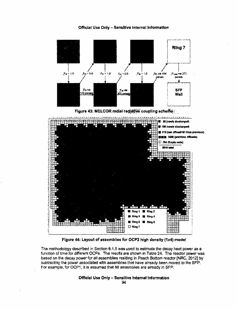
Official Use Only - Sensitive Internal Information
ip 0 / ~ 10
Ring 7
,'Far vY 484 hw; via 272
pn~ds -PIwaAs vio
ip-a"yse vDa
Figure 43: MELCOR radial radlsilve coupling scheri!i?:
am mammaan an ON me 10 as a"A a a .0 .8 a a a IN.0saw ammm
Me: 111
No OR
111 AN
wasWsun a"a aas 'no= 'aý MAIAM
:so
we am
*aUwe
MWWswowso 11MUwe
use lease
.00
ofte
irso
a a0!190 004* AM" AW NZON
r
& is "go -1"41
=0so
NIMMISam
emp am gnawswJ31, agall L.M.'Jul:MOON=
I W-)
-i
Figure 44: Layout of assemblies for OCP2 high dens ity J1x4) model
The methodology described in Section 6.1.5 was used to estimate the decay heat power as afunction of time for different OCPs. The resufts are shown In Table 24. The reactor power wasbased on the decay power for all assemblies residing in Peach Bottom reactor (NRC, 2012] bysubtracting the power associated with assemblies that have already been moved to the SFP.For example, for OCPt, it is assumed that 88 assemblies are already in 8FP.
Official Use Only- Sensitive Intemal Information94

Official Use Only - Sensitive Internal Infonnation
Table 26: Distribution of decay heat in the ractfr and SFP for hlah density loadinaSoent Fuel Pool NW)
-- ~-.----~I--.'---.---.- -
Reactor(kW) .Ring i.
. 889.sR)ng3
~0)::- .R
ing:
M32)-Ring 4(78.41 I
.Ring 6 Total(2859)
10216 316 }1927 0 I465 80 179 301 29519915 3.9 1867 0 42 80 179 301 28789006 5.0 1690 0 f 417 80 178 300 26607406 8.0 1403 0 & 358 80 178 300 23206710 10.0 1282 01 334. 80 178 30o 2174
Ring.-Das Ring, I Rlng;3 Ring 2 k Ri4 kR~n .16. otal
____ ___ :: ::18)':i,•(196)i 1 (315) J:~ j (75):::{84) (13 .0)•(~,)•
4395 13.1 1144 1533 332 80 178 30o 35674117 15.0 1077 1444 330 so 17 299 34093530 20__ ___ 0__ 791,J E76 296 3120
I
,.ays,.:
1'"(88):! Rintg 3!':(196) ~lng 6
(315)
Ring'2
(3S2~kin 19. 4
1132M:Total(305$)
37 1720 97-3 324 7 - 177 298 2571107 422 602 301 78 173 292 1868383 191 315 230 73 162 273 1245
6.2.2. Pa.d~.f~q 3 0The layout for the •~Qutage hig Ity load&iri similar to OCP2 (see Figure 44). In post-
outage, the avs~eiblle a x4 pffiii 1x, ast em, which applies to OCP 3, 4, and 5.The assemn ,•l•ut re •.tt P' However, the decay heat decreasedfrom t .he g time since reactor shutdown increased, The decay heat
pow 'fe,(ch ring is' .... an Table 26.
Low,,censityiLoading During Outage
For the low de•i.t!oad iin:figuration l onty the tatest and the previous two offloads areconsidered. Ther -ViOCP2, the total number of assemblies in the pool is 852 (=284x3),For OCP1, the 196 Mblites from the current offload are stifl in the reactor and only 88 havebeen moved resulting in only 656 assemblies in the pool. Figure 45 shows the layout ofassemblies in the SFP for OCPI, and the layout for OCP2 is shown In Figure 46. For bothconfigurations, all the old fuel has been removed from the pool, and the current offload Is in a
Ax4 pattern with empties, Due to space limitations, the last two-offloads are placed in a
23 The numbers in pareniheses are the number of assemblies.
Offidal Use Only - Sensitive Internal InformnatiOn95
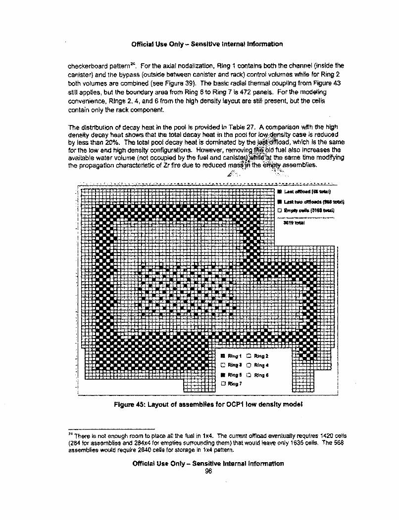
Official Use Only - Sensitive Intemal Information
checkerboard pattern2'. For the axial nodalization, Ring 1 contains both the channel (inside thecanister) and the bypass (outside between canister and rack) control volumes while for Ring 2both volumes are combined (see FiguTe 39). The basic radial thermal coupling from Figure 43
still applies, but the boundary area from Ring 6 to Ring 7 is 472 panels, For the modelingconvenience, Rings 2, 4, and 6 from the high density layout are still present, but the cells
contain only the rack component.
The distribution of decay heat In the pool Is provided in Table 27. A comparison with the highdensity decay heat shows that the total decay heat in the pool for low-density case is reducedby less than 20%. rhe total pool decy heat Is dominated by the ,..'.'load, which Is the samefor the low and high density configurations. However, removing 4£th-'-9 fuel also Increases theavailable water volume (not occupied by the fuel and canlster' •it the same time modifyingthe propagation characteristic of Zr fire due to reduced mas§-i the 6MM assemblies.
..................... "'. .... •{... ....
* Lastofllad (ittubi)8 Log tM ffw d a INS tW)
.I~~~~ F Iill I F••lll" A
I Lng I
I RingS I Ring 4
kvRing a 0• Ringt 4
Flgure 45: Layout of assemblies for OCPI low density model
24 There is not enough room to place all the fuel in 1x4. The current offload eventually requires 1420 cells
(284 for assemblies and 284x4 for empties surrounding them) that would leave only 1635 cells. The 568assemblies would require 2840 cells for slorage in 1 x4 pattern.
Official Use Only - Sensitive Internal Information96
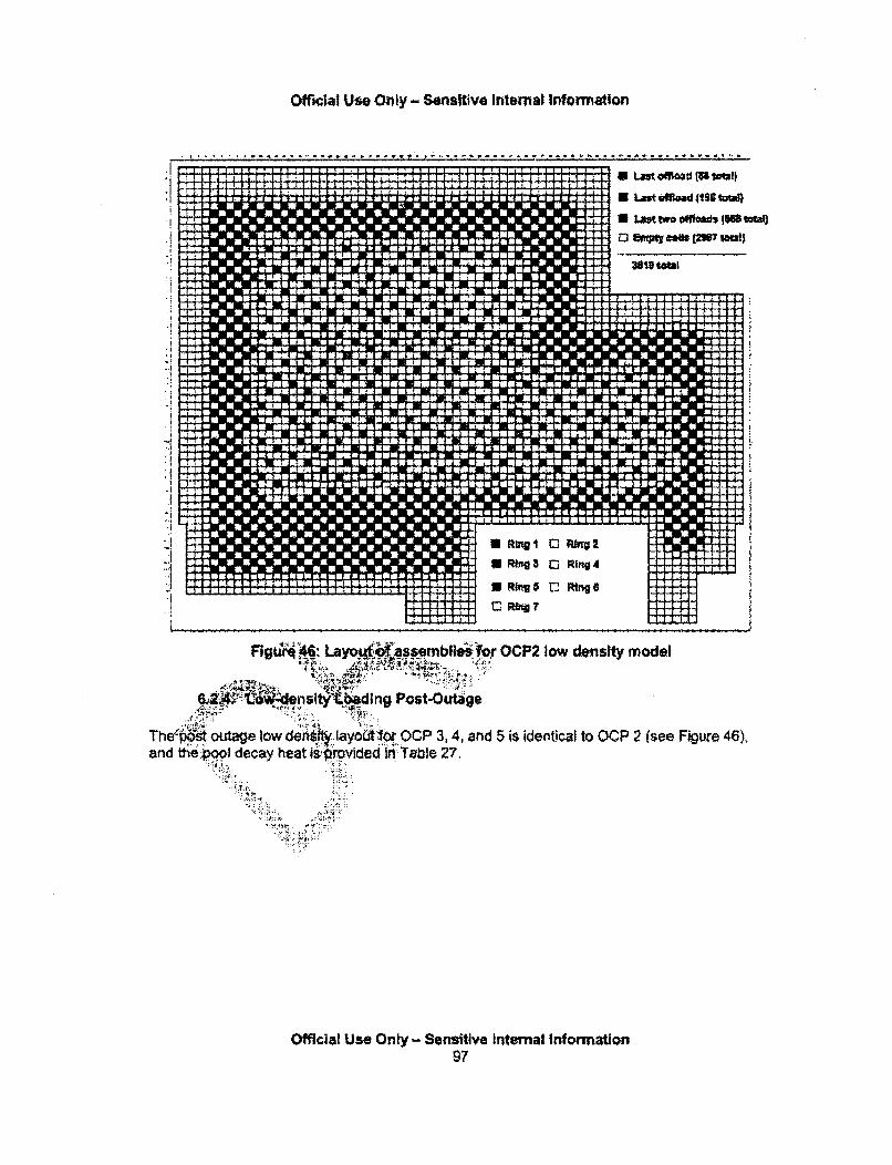
Official Use Only - Sensitive Internal Information
. I I - 1 1. 1. -- - ... - 1! ý 1. 1....;, 1... ý ........... 1. -... "... I -- -4 "...
La L~t wo offloads 15IS twta
Mgt" 46: Lay0.IA embleI :for OCP2 low density model
, Post-Outage
The•pst outage low deins!4 layout for OCP 3. 4, and 5 is identical to OCP 2 (see Figure 46),and th•eboql decay heat is$•rovided in Table 27.
Official Use Only - Sensitive Internal Infonnation97
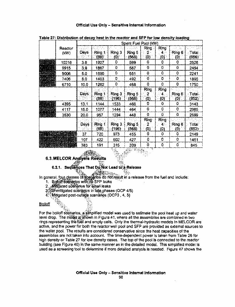
Official Use Only - Sensitive Internal Information
Table 27: Distibution of decay heat in the mattor and SFP for low density loading
I SortFuel Pool (W I_________ Fue Pool (M
Reactor(kW) Da~ :Ring 1: Ring
: 0toRing 5.(568)
Ring: Ring.4:,(0)
Ring 6..0) ý
( :656)•:
102.16 3.6 1927 0 599 0 0 0 25269915 3.9 1867 0 587 0 0 0 2454
9006 5.0 1690 0 551 0 0 0 22417406 8.0 1403 0 o 492 0 0 0 18956710 10.0 1282 0 468 0 0 __0 1750
671 1.0Ring.. .RinDy.Ring .1 Ring3 ~n5~ 4. M~g6 h
_ : :(88):: : 1(t6) 6) " .L( (T: (4LI 8"L (52)'4395 13,1 1144 1533 466 0 0 f 0 3143
4117 1.0 1077 1444 464 0 0 0 29853530 120.0J 957 1294 448 00 ___ 2899
D::ay s::R.: 1..: .(88)i Ring 3
::(M 196):Ring .5. .2
Ring4.
f0)Ring 6. (0) :.
Total
37 720 973 455 '1O 0~ 0 214910? 422 j 602 427 0 0 0 1451383 191 315. 339 10. 0. 0 845.
6.3. MELCOR AnJ yls :if i ts
'.3.1. S ••ces That D&I4,ot Lad t... .Release
in general.[60 riosses. ct;. .9os lo notrsuft.in a release from the fuel and include:I.Bo~1~ • •os0", SFP leaks2.. gated s r .... ...... for nall leaks
i•."migated s` n6's iril 1 phases (OCP 415)4". "'Mitigated post-outge scen'rs (OCP3, 4. 5)
"¶6> i:.'i ' . ...
For the boitoff s0narios, a::.pified model was used to esUimate the pool heat up and water
level drop. The rni&li 4Shown in Figure 41, where all the assemblies are combined in tworings representing th:eI fuand empty cells. Only the thermal-hydraulic models in MELCOR areactive, and the power for both the reactor well pool and SFP are provided as external sources tothe water pool. The results are considered conservative since the heat capacities of theassemblies are not taken Into account The time-dependent power is taken from Table 26 folhigh density or Table 27 for low density cases. The top of the pool Is connected to the reactorbuilding (see Figure 40) in the same manner as in the detailed model. This simplified model isused as a screening tool to determine if more detailed analysis is needed. Figure 47 shows the
Official Use Only - Sensitive Internal information98
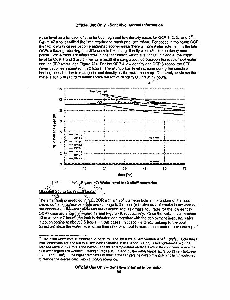
Official Use Only - Sensitive Internal Information
water level as a function of time for both high and low density cases for OCP 1, 2, 3, and 4-.Figure 47 also identified the time required to reach pool saturation, For cases in the same OCP,the high density cases become saturated sooner since there is more water volume. In the lateOCPs following refueling, the difference in the timing directly correlates to the decay heatpower. While there are differences in post saturation water level for OCP 3 and 4, the waterlevel for OCP I and 2 are similar as a result of mixing assumed between the reactor well waterand the SFP water (see Figure 41). For the OCP 4 low density and OCP 5 cases, the SFPnever becomes saturated in 72 hours. The slight water level increase during the sensibleheating period is due to change in pool density as the water heats up. The analysis shows thatthere is at 4.5 m (15 ft) of water above the top of racks in OCP 1 at 72 hours.
14! =:•''
12
10
E
p 6
0. 41U.
2
; -. - -- --- -- - - - - -L- - -
TL.........---..---------- ----------
0 12 24 38 48 so 72
time Chl.figurt47: Water level for boiloff scenarios
MitigaW Scenarios (Srm•q;L aks,• i';,i .•-• :'.'.., ..=. =... ....
The small leaik is modeled iniI:.4SLCOR with a 1. 75o diameter hole at the bottom of the poowbased on thel" kuctural ana"I s and damage to the pool (effective size of cracks in the liner andthe concrete). A :. water 16l and the injection and leak mass flow rates for the low densityOCP1 case are shlv .VfF:igure 48 and Figure 49, respectively. Once the water level reaches10 m at about 7 hour:, iit leak is detected and together with the deployment logic, the waterinjection begins at about 9.5 hours. In this cases, mitigation is direct makeup to the pool(injection) since the water level at the time of deployment Is more than a meter above the top of
'' The initial water level is assumed to be 1 m, The initial water temperature is 28"C (82"F). Both theseinitial conditions are applied to all accident scenarios in this report. During a teleconference with thelicensee (4124/2012), this is the post-outage water temperature under steady state conditions where theheat exchangers are working. Duting outage (OCP 1 and 2}, the water temperature could vary between-80F and - 100CR The higher temperature affects the sensible healing of the pool and is not expectedto change the overall conclusion of boiloff scenarios.
Official Use Only - Sensitive Internal Information99

Official Use Only - Sensitive internal Information
the racks. For this small leak, the initiaf water flow rate is about 250 gpm which is much kwerthan the makeup capacity and the water level is quickly restored. This calculation is only run for24 hours to show the effectiveness of mitigation. Therefore, It is concluded that for all slowleaks scenarios, the fuel never becomes uncovered since the makeup capacity is twice the leakrate. The leak rate is on* a function of the water level (hydrostatic head) and is independent ofthe SFP layout configuration as long as the water level remains above the top of the racks.
14
12
E 10
to 4....... .... .. ........ .... .... ..... .. . ... . .
2 + ---- -
0 - - - - - --- - - - - -
0 6 12: i8 24
6 density (smallleaktime) s•enririFigure 48: Wa;: 1•vel b ltl•:•gatedl •ldensity OCPI (small leak) scenario
400 4
300t
100j
I -
0 4 8 12 16 20 24
time [hr]
Figure 49: Flow rates for mitigated low density OCP1 (small leak) scenardo
Official Use Only - Sensitive Internal Information100
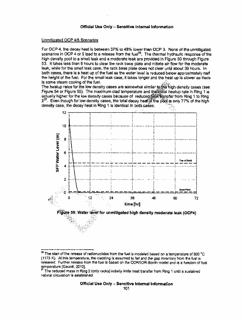
Official Use Only- Sensitive Internal Information
Unmiti!qated OCP 416 Scenarios
For OCP 4, the decay heat Is between 37% to 48% lower than OCP 3, None of the unmitigatedscenarios in OCP 4 or 5 lead to a release from the fue?6. The thermal hydraulic response of thehigh density pool to a small leak and a moderate leak are provided in Figure 50 through Figure53, it takes less than 6 hours to clear the rack base plate and initiate air flow for the moderateleak, while for the small leak case, the rack base plate does not clear until about 39 hours, Inboth cases, there is a heat up of the fuel as the water level is reduced below approximately halfthe height of the fuel. For the small leak case, it takes longer and the heat up is slower as thereis some steam cooling of the fuel. ,The heatup rates for the low density cases are somewhat similar tol-ie hfgh density cases (seeFigure 54 or Figure 55). The maximum clad temperature and thenifiaf heatup rate in Ring 1 isactually higher for the low density cases because of reduceAAi ,nsfer from Ring 1 to Ring2 Even though for low density cases, the total decay hea•ý. Ihe p•..,.s only 77% of the highdensity case, the decay heat in Ring 1 is identical in both:caes,
12
10
U.
a
63
2
0 12 24 38 48 s0 72
time [hrl
OF9re 50: Water I&W'ei for unmitigated high density moderate leak (OCP4)
The siarl of the release of radionuclides from the fuel is modeled based on a temperature of 900 OC(1173 K). At this temperature, the cladding is assumed to fail and the gap inventory from the fuel isreleased. Further release from the fuel is based on the CORSOR-Boath model and is a furnction of fueltemperature [Gaunft, 2010].
The reduced mass in Ring 2 (only racks) initialJy limits heat transfer from Ring 1 until a sustainednatural circulation is established.
Official Use Only - Sensitive Internal Informatlon101
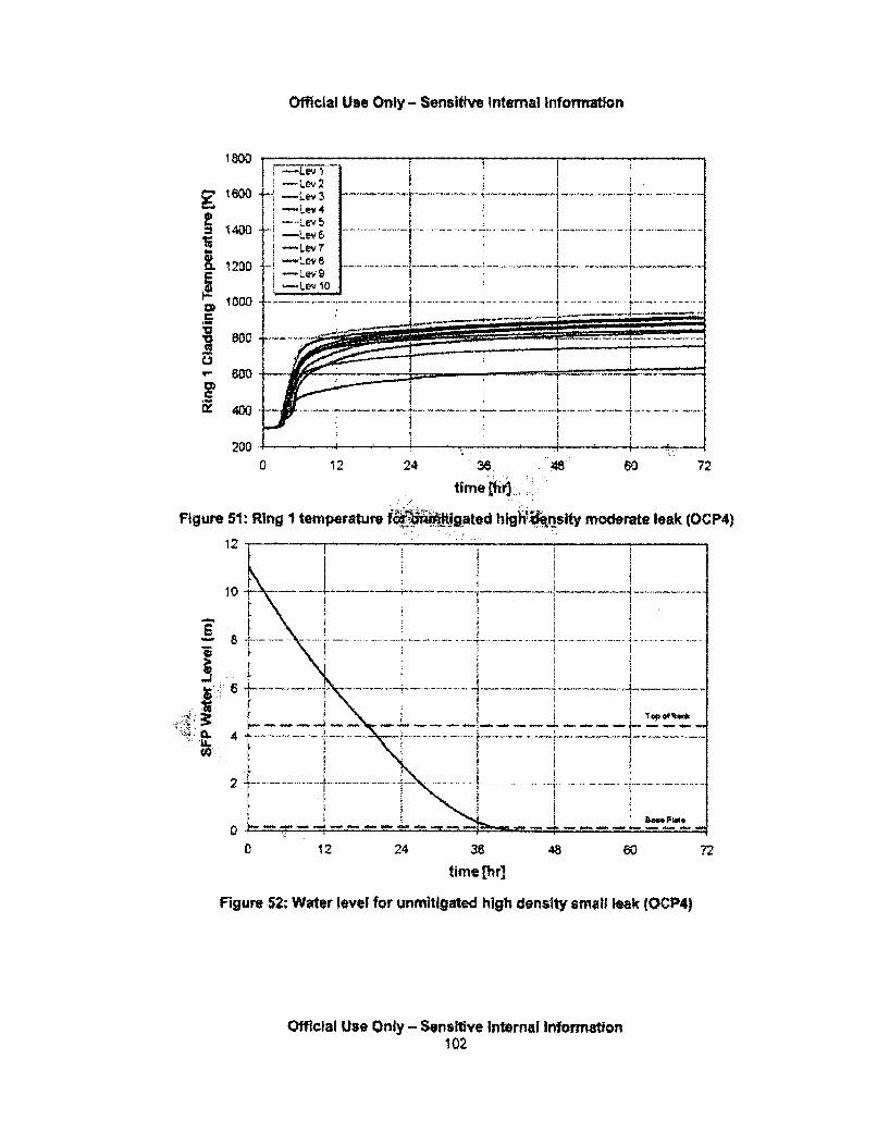
Official Use Only - Sensitive Internal Information
- Lev4 2 i " . , .
140t0 -•4
-Lev76
.. .. ... ...... .. ........ .. .. .. ...... ........ .. .. . ..... .... .... ... ........ . .... ... .-. .. . . . . . .. -. . . . . . . .4-._ ., .-.
I, I-
---- ______
----------
Ix 400- •; I
200 4• • •.
0 12 24 36 48 60 72
time Chdr
Figure 51: Ring I temperature fL igated hlghinslty-moderate leak COCP4)
12 -.
.4 ... ..... .. " .
.:. • -L,, ..... -,• . . ... . ~.•........... , ... ........... .. ... ..... .. . ... " .. .... . .. ...... . . ..... .
• •• ............ ...r i
CL 4
2 ...-. *.. ... .. ... . .... ........ .. ..
0 12 24 36 48 60 72
time [hr]
Figure 52: Water level for unmitigated high density small leak (OCP4)
Official Use Only - Sensitive Internal Information102
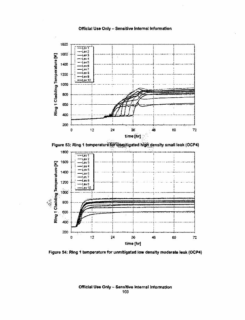
Official Use Only - Sensitive Internal Information
i -Le2
= 1400U-Lev4
- L e v 8 ... .... . ......C, 1200 - e
E 1" -Lev I D,; i o o
80 0 _______
... . ... ... .. . ... ... ... .. ... ....-
t- 600
X 400 ............
200 ,0 12 24 38 , 48 60 72
t!me[ hv]::•:
Figure 53: Ring I temperatureqimitigated hijgWdensiy small leak (OCP4)
1800 __
-Levi1 6 0 L L 3 ... .... . :.. .. ...... .. .. . ...... .. ...
-- Lev21 4 0 0 ..... .. . . .. . .... . . ... .. ... .. ... .
1600 -: -Lev3 6Ii . -Leý 7
- L e y 8 ........... . .. .. ... . . ... ..... . ....... ...... .... ....... . .................. .... . ... . . ..... . ........ ... . ..1,0o ..., -- • - . . . . . - i
IL1200 -Lev 9
~-Levl1
800 - __ _
I -• - 4.i
= ..~~~ • .. _. -.. ! ,L ... . . . .• . .......... ....... ....... .. ....... . .......... " .. ...... ._ _ L
~400 .I-
0 12 24 38 48 60 72
time [hr]
Figure 54.: Ring I temperature for unmitigated low density moderate leak (OCP4)
Official Use Only -Sensitlive Internal Information103
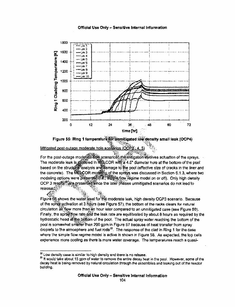
Official Use Only - Sensitive Internal Information
¶80o1~41
... ... e , ...... ............................ .... .. ....... . ... ..... ..... ... .. .......... . ... .... ... ..... ....... .
I -Lev5
i. 1 2 0oo +-• '
1 2- 6 0 0 L ..... ...... . . .. ... .. .. ... . ..... .. ........ . .. ......--, .... .....
E -Lev 10
-M -20 0 -! .. .. .............
... . . . . . . . . . . ... . . .. .......
2W00 12 24 36 48 60 72
time [hr3
Figure 55: Ring I temperaturtiWF• mitgated I ,Vu'density small leak (OCP4)
Mitigated wost-outage moderate hole sceniaros (.OP. 4. _5)'
For the post-outage mod enario tigator ives actuation of the sprays.The moderate leak is i COR wr 4.5' diameter hole at the bottom of the poolbased on the stru nalysis angiamage to the pool (effective size of cracks In the liner andthe Concrete). The • ;OR modh• ,of the sproYs. was discussed in Section 6.1.3, where twomodeling options were pRen$•i (low _rgime model on or off). Only high densityOCP 3 rresefft.eince the later phes unmitigated scenarios do not lead torelease,<
Figure56•8hows the watr level for•'i.moderate leak, high density OGP3 scenario. Becauseof the spr4;activation at 3 ýdurs (see"Figure 57), the bottom of the racks clears for naturalcirculation a. .•w more thani .. hour later compared to an unmitigated case (see Figure 50).Finally, the sprylow ra.te the leak rate are equilibrated by about 8 hours as required by thehydrostatic head atthe bto of the pool. The actual spray water reaching the bottom of thepool is somewhat s54.ie. than 200 gpm in Figure 57 because of heat transfer from spraydroplets to the atmosphere and fuel rods•g. The response of the clad in Ring I for the casewhere the simple flow regime model is active is shown in Figure 58. As expected, the top cellsexperience more cooling as there is more water coverage. The temperatures reach a quasi-
2 Low density case is similar to high dens-ty and there is no release.2" It would take about 15 gpm of water to remove the entire decay heat in the pool. However, some of thedecay heat is being removed by natural circulation through the assemblies and leaking out of the reactorbuilding.
Official Use Only - Sensitive Internal Information104
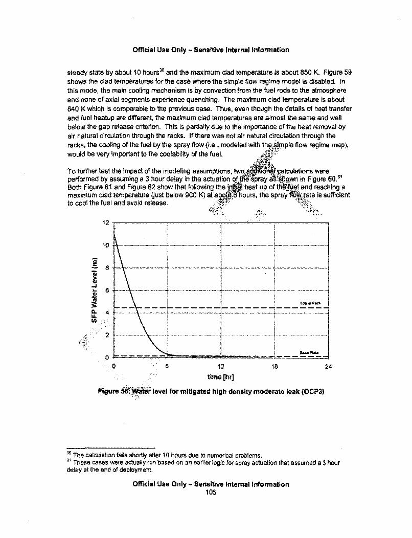
Official Use Only - Sensitive Internal Information
steady state by about 10 hours• and the maximum clad temperature is about 850 K Figure 59shows the clad temperatures for the case where the simple flow regime model is disabled. inthis mode, the main cooling mechanism Is by convection from the fuel rods to the atmosphereand none of axial segments experience quenching. The maximum clad temperature is about640 K which is comparable to the previous case. Thus, even though the details of heat transferand fuel heatup are different, the maximum ciad temperatures are almost the same and wellbelow the gap release criterion. This is partiaily due to the importance of the heat removal byair natural circulation through the racks. If there was not air natural circulatlon through theracks, the cooling of the fuel by the spray flow ce., modeled with the.Arnple flow regime map),would be very important to the coolability of the fuel.
To further test the impact of the modeling assump'ions,performed by assuming a 3 hour delay in the actuation tBoth Figure 61 and Figure 62 show that following the inlmaximum clad temperature (just below 900 K) at abo&tto cool the fuel and avoid release.
CL
U.40
12
10
6
4
2
7 .. .... .......... .. ..... .......Top oi 4w
-------------
0 ----- p .--- - - - -m
0 S 12 18 24
time [hr]
Figure 56•W•.; level for mitigated high density moderate leak (OCP3)
The calculation fails shortly after 10 hours due to numerical problems.. These cases were actually run based on an earlier logic for spray actuation that assumed a 3 hour
delay at the and of deployment.
Official Use Only- Sensitive Internal Information105
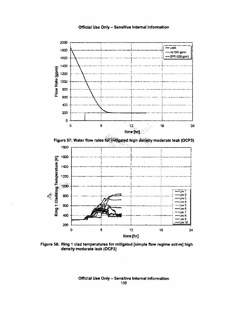
Official Use Only - Sensitive Internal Information
2000 7 ,
1600 k .. SPR(2OiJ pt~')
.... 1400 ---- ----~- ................. ...................... ... ... ... ............................
l o w ... .. .. ... .... .... ...... ...... ... ... . ... ........... ...... ._ ..... ...... .... ... ...... ..... ........ ... ..... ...
=~ ...............0
60 . ... ...
0 6 .2 18 24time [hr.:]i;
Figure 67: Water flow rates f i)i•eto d high denity moderate leak (OCP3)
1OO'
12i00 P -i4
1200o
=t 1 00 . .... .. . .. ... .... ........ .... .... .... .. . . .... .• ....... ...... .............. .. ". . ..................
-Ley I
8 0 .2 . . . . ....... . ....... ... ..... ... ............ ... .. ............. ... ....... ...... ... ........ .. ...... ... ... ... .. .. .. .... .. .. ..
- -Ley 46w - Le
-Ley 7' .. :..
•. -Ley5
= Lv !0
0 6 12 18 24
time [hr)
Figure 58: Ring I clad temperatures for mitigated [simple flow regime active] highdensity moderate leak (OCP3)
Official Use Only - Sensitive Internal Information106

Official Use Only - Sensitive Internal Information
~1500
S1400
.1200E
~800
0:400
0 6 12, 18 24
time th::
Figure 59: Ring I Clad temperatures bt#gated [sihe-flow regime inactive) highdensity moderate leak (OCP3)"'
2500
2000-
1I500.
1000.!
-Leak
I -IN (5MiQPMi)
- - . . .~- . ~ . . ., SPR 12M 9;m)
... .... .......... ..... - .- ........ . -.... .. ..... .-
v;; ,,
00 6 12
time (hr]18 24
Figure 60; Flow rates for mitigated high density moderate leak (OCP3) with late actuationof sprays
Official Use Only - Sensitive Internal Information107
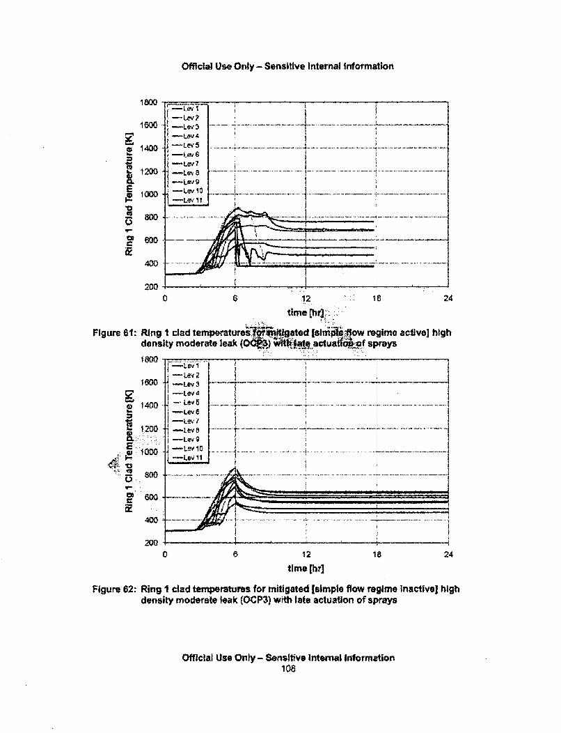
Official Use Only - Sensitive Internal Information
1800
1600
1400
•-1200
lowl
- 00
400
200
0 6 12. . 6 24
time ~r
Figure 61: Ring I clad temperaturei• b ated [s1miiiI1ow regime active] highdensity moderate leak (0) .actuad -af sprays
•,;=,:t:
1400
1.200
S1000
p600
400
2000 8 12 18
time[hr]24
Figure 62: Ring I clad temperatures for mitigated [simple flow regime Inactive] highdensity moderate leak (OCP3) with late actuation of sprays
Official Use Only - Sensitive Internal Information108
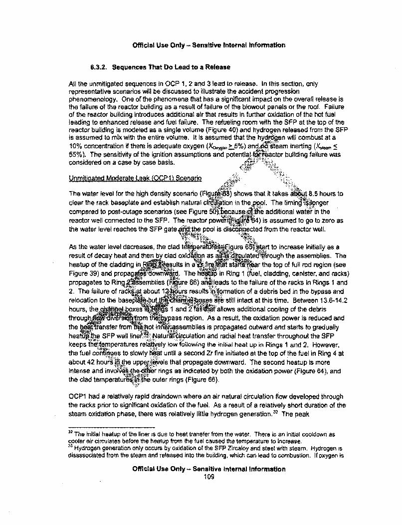
Official Use Only - Sensitive Inte4rnal Information
6.3.2. Sequences That Do Lead to a Release
All the unmitigated sequences in OCP 1, 2 and 3 lead to release. In this section, onlyrepresentative scenarios will be discussed to illustrate the accident progressionphenomenology. One of the phenomena that has a significant impact on the overall release isthe failure of the reactor building as a result of failure of the blowout panels or the roof. Failureof the reactor building Introduces additional air that results in further oxidation of the hot fuelleading to enhanced release and fuel failure. The refueling room with the SFP at the top of thereactor building is modeled as a single volume (Figure 40) and hydrogen released from the SFPis assumed to mix with the entire volume. It Is assumed that the hydren will combust at a10% concentration if them Is adequate oxygen (Xo anteam inerting (Xv, > a
55%). The sensitivity of the ignition assumptions and pterntial4,4 actor building failure wasconsidered on a case by case basis,
Urnmitigated Moderate Leak foCP ) Scenarioo V
The water level for the high density scenario (gu ) shows that. it takes jbuit 8. 5 hours toclear the rack baseplate and establish natural cfrction in thepol. The timingisangercompared to post-outage scenarios (see Figure bca~sef ie additional water in the
reactor well connected to the SFP. The reactor pow 4j _-A4) is assumed to go to zero asthe water level reaches the SFP gate, 0the pool is discohhected from the reactor well.
As the water level decreases, the clad t egure 6t-jUrl to increase initially as aresult of decay heat and then by clad olatehs fh the assemblies. The
heatup of the cladding in .. jýiesults in aa .•i sR •t ar the top of full rod region (seeFigure 39) and propag ,downM The in Ring 1 (fuel, cladding, canister, and racks)propagates to Ringj = mbizes (lre 66) aýIeads to the failure of the racks in Rings I and2. The failure of raIW;' about tý urs results Wforrmation of a debris bed in the bypass andrelocation to the basep%% but a•l•.es aNre stil intac at this time. Between 13.6-14.2hours, t 1 and2I!t- llows additional cooling of the debristhroug A r .. :M, t1I.. 1e. ass region. As a result, the oxidation power is reduced andthe i nsfer fromn ot inn iessemblles is propagated outward and starts to graduallyhea t1e SFP wall Iner P..NatuAki•tulation and radial heat transfer throughout the SFPkeeps thek.emperatures relaty low folmowing the initial heat up in Rings 1 and 2. However,the fuel c es to slowly t•it until a second Zr fire initiated at the top of the fuel in Ring 4 atabout 42 hourskthe upper,,.Ielyes that propagate downward. The second heatup is moreIntense and invotV6=h: heot1ier rings as indicated by both the oxidation power (Figure 64), andthe clad temperaturb ~ ~e outer rings (Figure 66).
OCP1 had a relatively rapid draindown where an air natural circulation flow developed throughthe racks prior to significant oxidation of the fuel. As a result of a relatively short duration of thesteam oxidation phase, there was relatively little hydrogen generation,'3 The peak
32 The initial heatup of the liner is due to heat transfer from the water. Thefe is an initial cooldown ascooler air circulates before the healup from the fuel caused the temperature to Increase." Hydrogen generation only occurs by oxidation or the SFP Zircaloy and steel with steam. Hydrogen is
disassociated from the steam and released into the building, which can lead to combustion. If oxygen is
Official Use Only - Sensitive Internal Information109
Official Use Only - Sensitive Internal Information
concentration in the refueling floor was only 5%, which is well below the minimum threshold forcombustion and below a quantity that would lead to a significant pressurization of the reactorbuilding, Consequently, there was no potential for a bum inside the reactor building, whichremains intact.
The fission product releases began at about 12 hours. Because the reactor building remainedintact, all releases to the environment are limited by the nominal leakage (see Figure 40). Thereactor building decontamination factor is shown in Figure 69"'. Aerosols also begin to depositinside the building and the decontamination factor for Cs and I aeo•oftd'remains between 3 to 4for much of the accident. The decontamination factor is defined adff6ratio of fractional releasefrom the fuel to the fractional release to the environment. As d' d before, MELCOR keepstrack of the fuel releases from individual rings. The fuel rel~ee a'i4ded by the ovralldecontamination factor to arrive at the environmental relseor each r44, It should be notedthat MELCOR mechanistically models all depositionp.ieanisms; howeveK•because of themixing within the reactor building only an overall de" mination factor canrU•defined for all
The Cs environmental release fraction for individual hrigs jsw in Figure 70, The releasestarts at about 9 hours from ring I fol•wed by the rele'ia" n ring 2 at 12 hours. The releaseprofiles are consistent with the heatuI•a•,fe 66. The C_ releases are due to the secondheatup and involve all the outer rings (riF4 for OCPIF)., The total release fraction isthe input to the MACCS code for conseqace .... i _6' and is dlned by Equation (11)", Thedecontamination factor is a dynamic quan s the t s tto release (see thefluctuations in Figure 69); e care is Mnax art•e earlier releases from innerrings to oscillate (thus 6ý"ir releas•istory),
The results of the I %iensity case. shown in'igure 71. Comparing the heatup with the highdensity case (see Fi 5), th low densit L ty
since1 th, ar aD -o of.,s clearly het u or aidiitalsince there ate a for o .f Ur' N "rrdI • (Wfth the exception of the rack component)and heat ýS' hsferred ra lfyhat results in slower heatup of the ring 5 asshown 61 i 4r•2,ven t, t,1sh' the racks fail even in this low density case, the canistersremare, c a the' Mrs thdr-.oves down initially and then upwards as shown in Figure 71.The& vironental rease frackin .for Ring I shown in Figure 73 is comparable to the high
den(Figurelee bthere is release from the older assemblies that result in areduced release fractioil Jar the low density case.
present. then only air oxidation occurs and there is no hydrogen generation. In a larger leak, the waterlevel drops below the botlomn of the racks and allows natural circulation of air, which wilt precludes steamoxidation.
SThe Integral decontamination factor is the ratio of the fission products released from the fuel to theamoumnt that reaches tthe envitonment. Upon the start of fission product releases, the quiantity is Infiniteuntil the release to the environment begins. Consequently, the initial peak is an artifact of the definition,whereas the long-term value is best characteristic of the reactor building performance.m It is an activity weighted release and is a function of the inventories in each ri Ng. Therefore, there ismore contribution from the outer rings that have higher inventories even though the release from theserings are smaller compared to ring 1.
Official 'Us Only - Sensitive Internal -i.forma.on
110
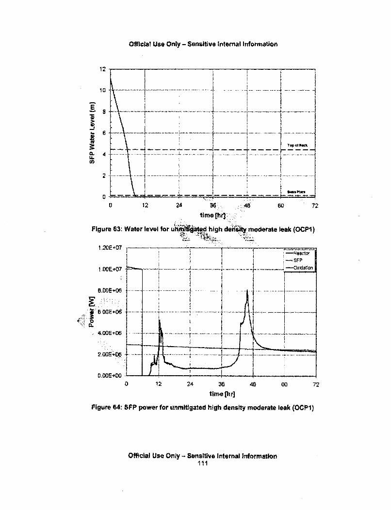
Official Use Only - Sensitive Internal Information
12 _ _ _ _r-_ _ _ _ _ _ _ _
-J4
Top W ft*c
0 12 24 ... 4 072
hi t ih duiiy modeate leak (OCPi)
1 .20E07 -
1.0011+07t~ -.
.+06 ........ ................. .... 1........................... .....
00E06 ---- --
O D L.-.••64- ... . ...... . 7-
0 12 24 38 48 60 72time [h r]
Figure 643 WFP power for unmltlgated high density moderate leak (OCPI)
Official Use Only - Sensitive Internal Informationill
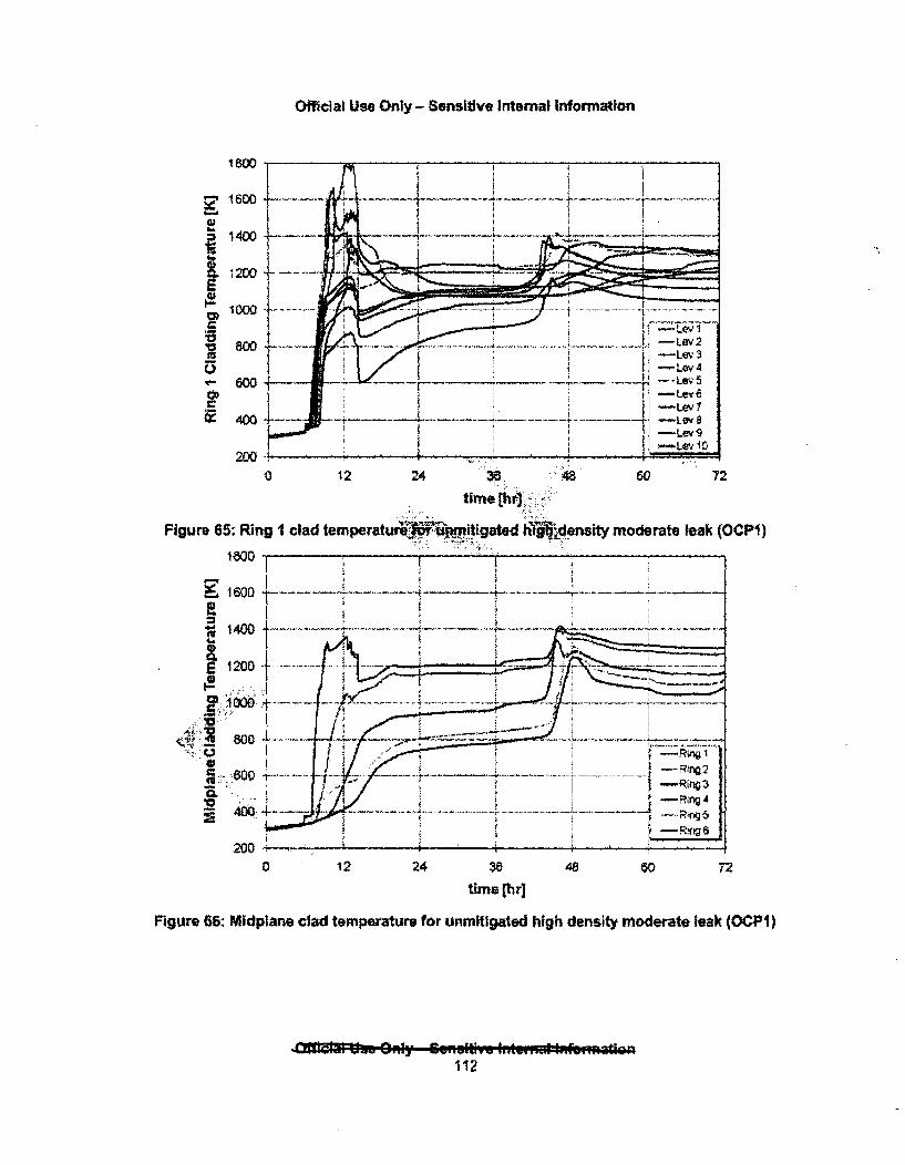
Official Use Only - Senshive Internal Information
1800
1600
= 1400
~1200E
Io018000
'-600
~400
0 12 24 36 .48 60 72
time E1bri
Figure 65: Ring I clad temperature • igated htigjensity moderate leak (OCPi)
18500 .
•;i••;;•'-.,:.i.
0 12 24 48 72
time [hr]
FigUre 66: Midplane clad temperature for unmitigated high density moderate leak (OCPI)
fl lelw O n ••lamlyivo1
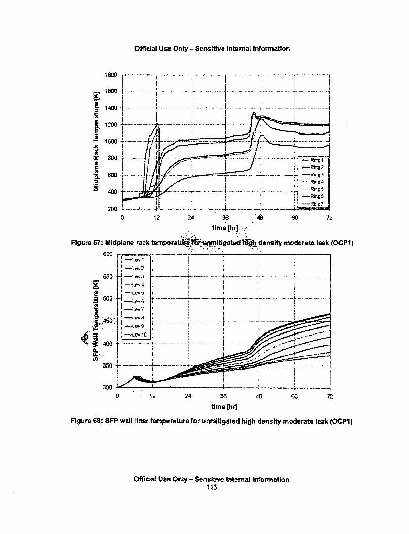
Official Use Only - Sensitive internal Information
I-
E
,a)
0.
1800
1600
1400
1200
1000
800
60w
400
200
time chtw]
Figure 67. Midplane rack temperattl ig rnt igated i density moderate leak (OCPI)
WO -LOY 3
600 -LAW~ 6 -....
.4 6 0 ... i.e ..... . .. ... . ........._... ... .. .. . . . . . . . . . . . . .
K-Lev 9
54 00 -.... ........ . . ... . .... ..... ...........35 ..S!:•. .• .................. J................................... ..... ; ..... ......
3W
0 12 24 3648 60 72
time (hi)
Figure 68: SFP wall liner temperature for unmitigated high density moderate leakc (OCPI)
Official Use Only - Sensitive Internal Information113
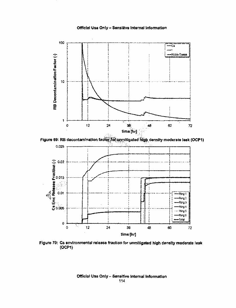
Official U&e Only - Sensitive internal Wnotrmation
100
0
= 10
E
p
0
1
figure 69: RE
O.M
z0.02$0
b.
LU'
0 .005
0 12 24 36 48 60 72
time [hi)
Figure 70: Cs environmental release fraction for unmitigated high density moderate leak(OcPI)
Official Use Only - Sensitive Internal Information114
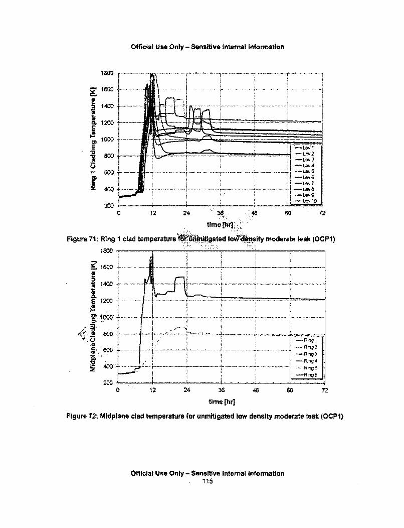
Official Use Only - Sensitive internal Information
1800 .. ...
14 00 . ... ......................
o w= .. .......... ,- .....V0 -- Lew2
800T
= •P -Lev 4
- Lev 10
2000 12 24 60 72
time [lr]
Figure 71. Ring 1 clad temperature W gated Iov sity moderate leak (OCP1)
16001400 " , ,100 .................. ..... ...... ..
=104 L+I .... -+
L1200
i . :: , , . :, ... .. ......... .... .. ... . .. 4.7 -.. . .. .... ,.... . . + • . +^.. R n,, . . . . .
1. ... ... ..... .. ... .... ... R n
12 24
Urne thri
Figure 72: Midplane clad temperature for unmitigated low density moderate leak (OCP
Official Use Only - Sensitive Internal Information
., . ... ,. .. L . .. . . . 1 1.. . .5:.... . .. .. . . . . . . . .. . . . .. . . . . .... . . .. . . . . . . ... . . .
1)
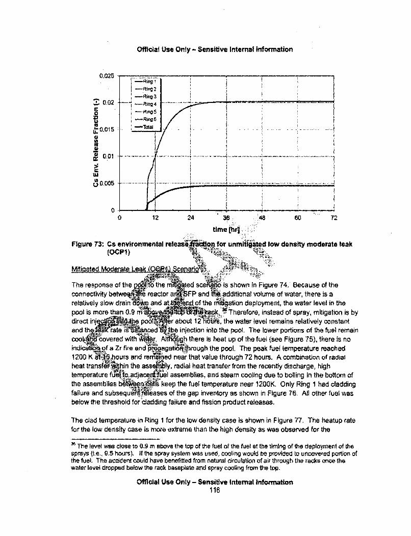
Official Use Only - Sensitive Internal Information
0.025 -
-Rino 300 -. -Riiig • i i ,w
OM -R ing 4
2. .. ......... ....
U. 0 0
I 0 .6 0 5 ... ...... .......... ....... ....... .. ........ '•...... .............. ... .. ...... ... . . .. . . ... . .. . ..: . . . . ... . ...- .. . . . . .. .... ..!
0 12 24 35 ý48: 60 72
time Chril :
Figure 73: Cs environmental releasi~fictlop for unmli4*'.d low density moderate leak(OCPI)
Mitigated Moderate Leak (OePR Scenario,Ž14, 'I
The response of the . mbt ted seTO Is shown in Figure 74- 8ecause of theconnectivity betwes e reactor a SFP and zidditional volume of water, there Is arelatively slow drain and at. t~ of the nlibgation deployment, the water level in the
'.. ,,.;,:
pool is more than (1.9 Meiro a re 7 Therefore, instead of spray, mitigation is bydirect in e p~ er about 2 -bk the water level remains relatively constantand 'W ~rat i *ced' 1ha injection finto the pool. The lower portions of the fuel remaincootw~covered wlth' r Alb "gh there Is heat up of the fuel (see Figure 75), there Is noindcýtia f a Zr Are and pp. oaa ttorough the pool. The peak Nei temperature reached1200 KS-1Obhours and remAhed near that value through 72 hours. A combination of radialheat transe ofa n the asse"ibly rad.a heat transfer from the recently discharge, hightemperature G"e 'dae 41~e assemblies, and steam cooling due to boiling in the bottom ofthe assemblies bMtW eq.&'AU6 !keep the fuel temperature near 1200K. Only Ring I had claddingfailure and subsequ 1ases of the gap inventory as shown in Figure 76. All other fuel wasbelow the threshold for cladding failure and fission product releases.
The clad temperature in Ring 1 for the low density case is sho. in Figure 77. The oeatup ratefor the low density case is more extreme than the high density as was observed for the
oThe le was cose to 0.9 m above the top of the fuel of the fuel at the timing of the deployment. of thesprays roe., 9.5 hours). If the spray system was used, coolng would be provided to uncovered portion ofthe fuel The accident could have benefithed from natural circulation of air through the racks once thewater level dropped below the rack baseplate and spray cooling from the top.
Official Use Only - Sensitive Internal Information116
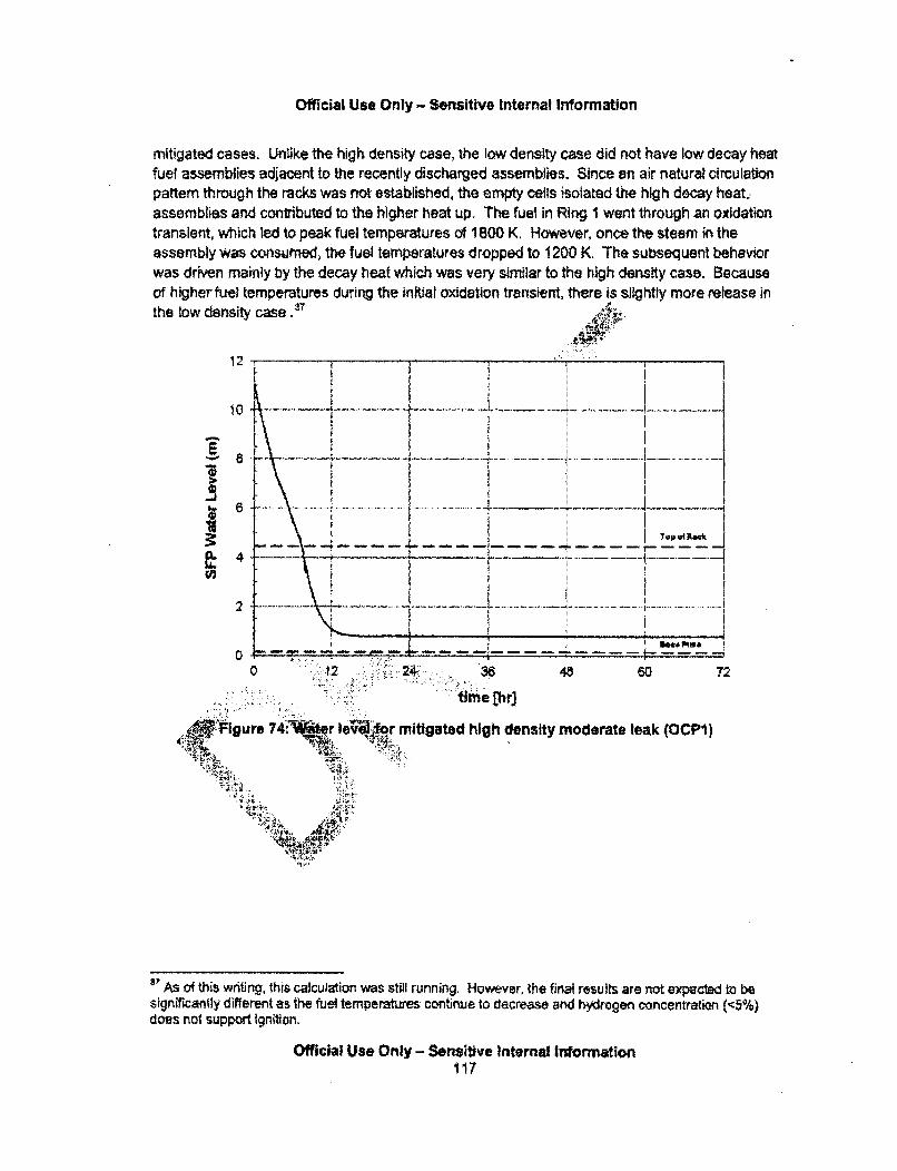
Official Use Only - Sensitive Internal Information
mitigated cases. UnUke the high density case, the low density case did not have low decay heatfuel assemblies adjacent to the recently discharged assemblies. Since an air natural circulationpattern through the racks was not established, the empty cells isolated the high decay heat,assemblies and contributed to the higher heat up. The fuel in Ring I went through an oxidationtransient, which led to peak fuel temperatures of 1800 K. However, once the steam in theassembly was consumed, the fuel temperatures dropped to 1200 K. The subsequent behaviorwas driven mainly by the decay heat which was very similar to the high density case. Becauseof higher fuel temperatures during the initial oxidation transient, there is slightly more release inthe low density case .37
.. • .: ..".. .. .. ... . .... .. .. ..
1 0 .. . . . . ...i ....... .. .... .... . ...... .. . . ... ... . .. . . . . - -. . . . . . . . . ... ... ... . . .
tapaIfta&
.. ........ ...... ... ............. .. . . .
I+ , De t'ato m o a,,
0 12 . 4: 48 60 72
time thbr
•P Igure 74,t- r Ie4l'or mitigated high density moderate leak (OCP1)
3) As of this writing, thts calculation was still running. Howevier, the final results are not expected to besignificantly different as 'the fuel temperatures conitinue to decrease and h~ydrogen concentratioan (<~5%)does not support ignition.
Official Use Only - Sensitive internal Wnormation117

Official Use Only - Sensitive Internal Information
-Levi I
-Lev4 21lo w - - Le v 3 .. . .. .. . ..... .................. ..... T ..................... ... .. ..... ..... ...... .... ..
L--ev 4PE. Lev 5 1
1200 .. . .......S -. ev 10.
1200 -T m "_ __
1000 ... _ .. . .. ... ....... .... ..... . . .. ....
600 ... .
200 -'--. '
D 12 24 48 60 72
time [f••1w]
Figure 75: Ring I clad temperata "Irti.ated hIA psity moderate leak (OCP1)
0.06SRing I
-Rino 2
-- Rin• 3*-Rho 4
M
" , 0 .0 4 -- --R ina . . .... . ...... . ... . - .. ... . .. ..
, 0.02 4.,.. f.0 .01• • T... ............................ ........ ................. ... .. . .... . .... .. .. ..- -
0 12 24 36 48 6 72
time [hr)
Figure 76; Cs environmental release fractiorn for mitigated high denstty moderate leak(OCPI)
Official Use Only - Sensitive Internal Information110
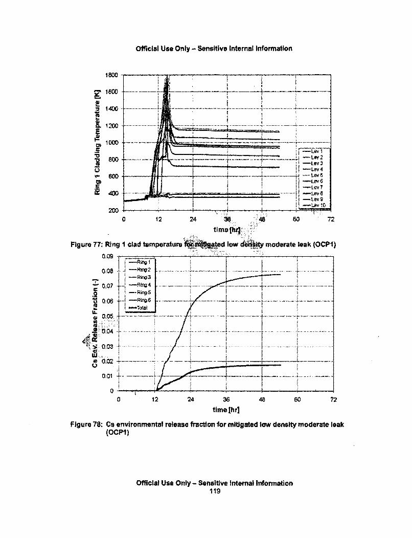
Official Use Only -- Sensitive Internal Information
1400--- -
: I n o0 .... .......... ....... .... ........ • .. ... ....... ... ...... .......... . . .... ... .... ..... ............. ... . ........ ....... •.. .. . ... ..... . ... ........... . ... ... . .
,600 .Lev
400= i 00, -- Li,,, ,
=: 4oo ~~~..........................................4., -'
2000
0 12 24 34 .: 60 72
Figure 77: Plng I clad temperature 14d• low :'d'•<+ moderat leak (OCP1)
0.09~
0.08 -1ev 2
0 . 7T ... .. .. :.......... . !
"Tf400•p.J -R_ 1--2us 4-
_- " 0 0 4 .4 - - - - • ... .. . . ... ........ ... .. ... ...... . •. .. . . . . . . ._•.. ....... . .. ..... .........
OM +6 ,,,-. .... ............... .......,.- H - / )+<- o~ s ... ..... .. .+-........., .. . .-/. - •. +.......... .. ,,...... . . .
. . ................ .
0 1224 36 48 60 7time [hrl
Figure 78: Cs environmental release fraction for mitigated low density moderate leak(OCPI)
Official Use Onl - Sensitive internal Iniformation119
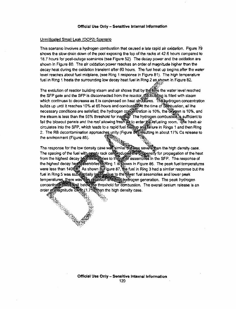
Official Use Only - Sensitive Intemal Information
Unmitigated Small Leak (OCP2) Scenario
This scenario involves a hydrogen combustion that caused a late rapid air oxidation. Figure 79shows the slow drain down of the pool exposing the top of the racks at 42.6 hours compared to18.7 hours for post-outage scenarios (see Figure 52). The decay power and the oxidation areshown in Figure 80. The air oxidation power reaches an order of magnitude higher than thedecay heat during the oxidation transient after 60 hours. The fuel heat up begins after the waterlevet reaches about fuel midplane, (see Ring 1 response in Figure 81), The high temperaturefuel in Ring I heats the surrounding low decay heat fuef in Ring 2 as ,shown in Figure 82.
The evolution of reactor building steam and air shows that by e the water level reachedthe SFP gate and the SFP Is disconnected from the reactor ,• 4t1ng is filled with steamwhich continues to decrease as it is condensed on heat st.... Th"'ydrogen concentrationbuilds up until it reaches 10% at 65 hours and co.nbus JMA the time r bthnecessary conditions aie satisfied; the hydrogen . ration is 10%, the en is 10%, andthe steam is less than the 55% threshold for ine The hydrogen combusti sufftcient tofail the blowout panels and the roof allowing fres ito enter,,"efueig room'f fresh aircirculates into the SFP, which leads to a rapid fuel h •p •up ailure in Rings I and then Ring2. The RB decontamination approach ..unity (Figure - Ii,-Iing in about 17% Cs release tothe environment (Figure 85).
The response for the low density case w simlaft sev ban the high density case.The spacing of the fuel wit rack cel k duc rsi for propagation of the heatfrom the highest decay lies to t assembes in the SFP. The response ofthe highest decay h " embfies J-ing 1 i own in Figure 86, The peak fuel temperatureswere less than 14 'As shown j..igure 87, Ite fuel in Ring 3 had a similar response but thefuel in Ring 5 was su ..tially o the ... r fuel assemblies and lower peaktemperatu ere wes ..a AMyrogen generation. The peak hydrogenconcentr bel N threshold for cmbustion. The overall cesium release is anorder.. gnitude rA (170 .an the high density case.
Official Use Only- Sensitive Intemal Information120
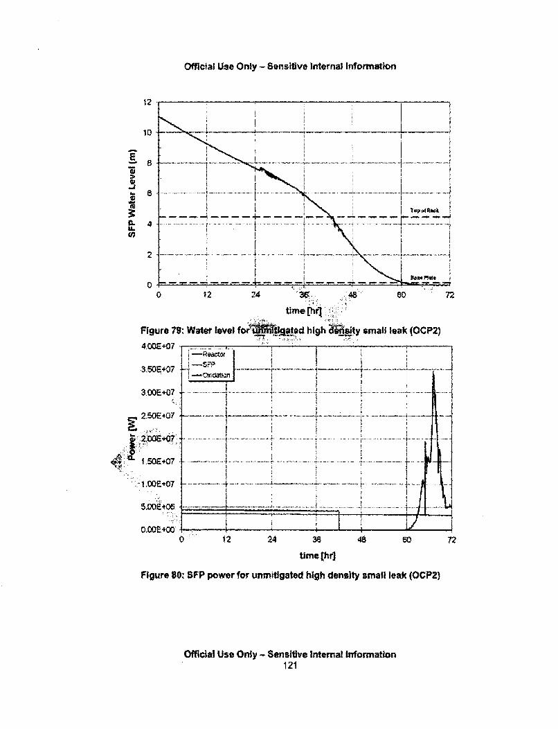
Official Use Only - Sensitive Internal Information
12
10
-JI..0
4.'*1
6
4
2
[n
.. ........ .. ..... .. . .. . . .... .. . . .. .... ....... . .. . ...... .... .... .. ..
...~~~ ~ ~ ~ .......... m...e. ... ---- .. ..
0 12 24 "36. ..48 . 72
time Chrl.
Figure 79: Water level for Iatpd high $jty small leak (OCP2)
4,00E+07
3S 0 Pi-- F . i... • * ....................
3.00E +07 -. . -
. ...... . . . ................ ............................ .... . ........ ........ .... - -- . .
2.5OE407 ~ ,~-
0 .. .E-. . - 4 - ................... . ... .... . .......
IOQ -+0 . ...
'~~~~~~~~~~~ ~~ ~~~ :..- ..E '0 ... .... . .. ... ..... .. .. . .................... .... .. ........... .. . .... .......... ..
5.00 E '05 -- ....... ....... ........ .......
O.OOE+00 ..
0 12 24 36 48 60
time (hr]
Figure 80: SFP power for unmtgated high density small leak (OCP2)
72
Official Use Only - Sensitive internal Information121
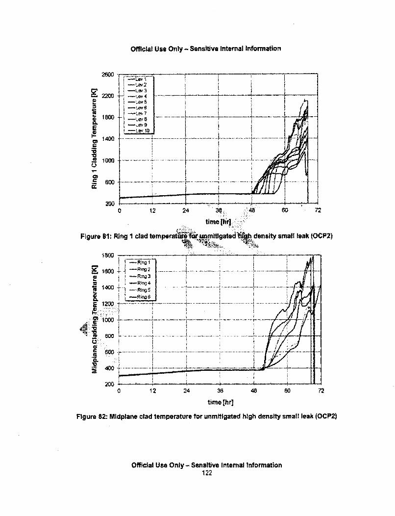
Official Use Only - Sensitive Internal Information
26D0
-Lw 3
-tLeviS, I
E Ley 0,'•;
S !-L-ev o10
" 0 0 8 • .. . . . .. . . . ....... .... ..... .. ... ......... .. ................. .. • H : • 1
I I 0 0 I
213
0 12 24 3;8 60 72
time [h ::
Figure 81: Ring I clad temperat •.runmitigated h density small leak (OCP2)"..., ,p . .. .::. ,- : : .
1400 .. -.. r- .... .-.
16 0 0 + ..-! co ...... .. ... ....... i....... . .......... .. ............................. .... ..... ." ........ . . . . ."- -.... ...
1 4 0 ; .... .... ..... .. ........ .... ......... ...... ... .. ........... .... ............ ......... ....... .. . .. .. ..... . .. ... . . ..+ . J • . .
200
2". O. 0 ! I 4. l i .
0 12 24 36 48 60 72
time [hr]
Figure 82: Midplane clad temperature for unmitigated high density small leak (OCP2)
Official Use Only - Sensitive Internal Information122
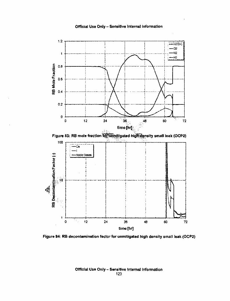
official use only - Sensitive internal Information
0 12 24 3,80 72
time (ho
Figure 84: RS decontamination factor for unmitigated high density small leak (OCP2)
Official Use Only - Sensitive Internal Information123
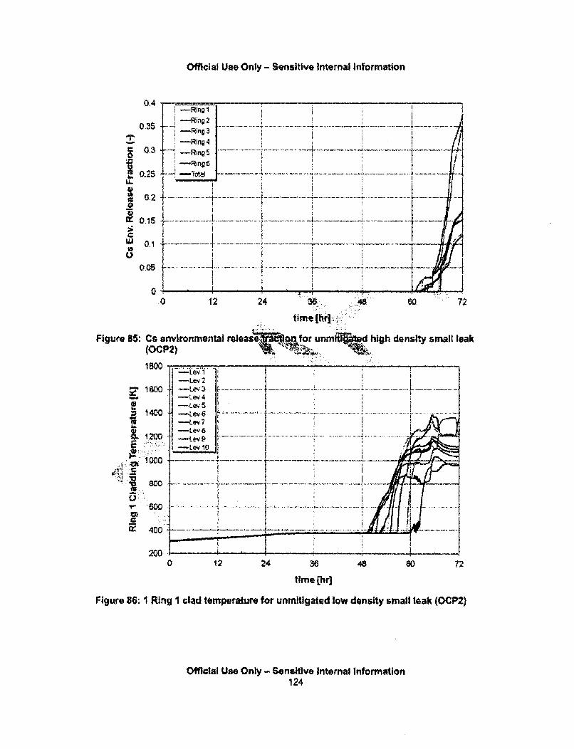
Official Use Only - Sensitive Internal Information
0.4 ,-Ring I
0.3ST 7 -
t I -- Ring 4
0-3 Ri n 5 ................. -......... ... .... .. .. it ,-R,•!, i i fl
0.2 ...... ....... . ... ......... .. ...-. ..... ...
Uo l - - ;- - -.1
•0 12 24 .48 0 72
time [hr]:..
Figure 85: Cs environmental release- on for unmht ted high density small leak(OCP2) 1
-Ley 1" 6 W• - L e v -3 .. ...... ...... .. ..... ..... .. ......: ...... ... . . .. .. .. . . . . . . .
= 1 4 0 0 - L ey. 6 ... ...... ... ... ... . .. ... ..... ............. ... ..... ........ ....... ...... ............. ....... .... ....... ........ .............. .0 -Lev2 I-7 "
6 0 0 -. - e i ........................ .. ... .......... ... ....... .41. 00 ..............
200 ............. .i-- I. .
200- _ _ _ _ _ ..........
0 12 24 36 48 60 72
time [hrl
Figure 86: 1 Ring I clad temperature for unmitigated low density small leak. (OCP2)
Official Use Only - Sensitive Internal Information124
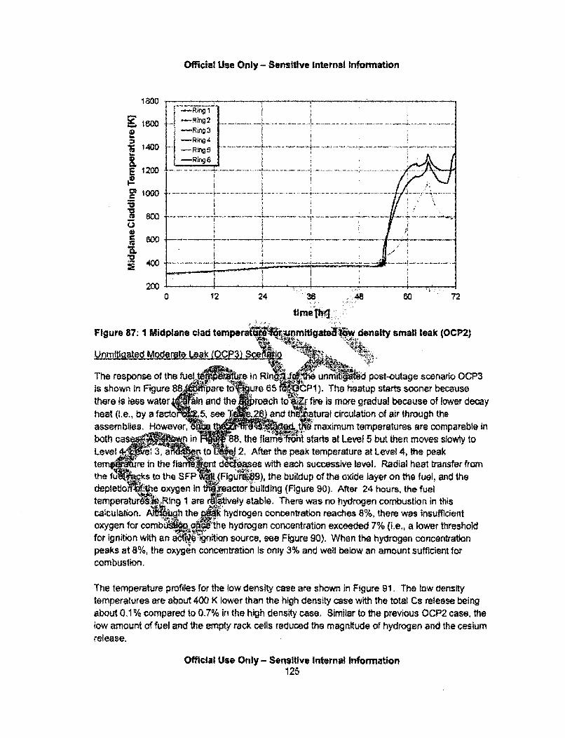
Official Use Only - Sensitive internal Information
-Rin~g3
1400 .... ...
E I -1R03 ............ ...............-. ............. .• 2 o . . . . .. .. ... .. .. . .. ............... .. . ...... ........ ......... ....... ... ....... ... ... .... ....... ... •.' -
004 00 , r
0.
2000 12 24 36 .48 60 72
Figure 87: 1 Midplane clad ternperaf~#rq4Jnm_.q -atlw density small leak (OCP2)het(~. yafco .,seT ... and U" ,aa ciclto of a through. th....
Aftgfttýqek 31 .ce i
At thw peFigure ad tem prature. at Lel 4r t peak Othere is less water 'in and th w eroach s&cEv fire is more gradual because of lower decayheat (i~e., by a facto .5, seT .2• and th aturaf circulation of air through the
asemlis.Howee, kmaximum• temperatures are comparable i
both cas w n ,t faew starts at Level 5 but then moves slowly toLevel 1,8 nt 2. After the peak temperature at Level 4, the peakte • reInth.fa nt d -ses with each successive level. Radial heat transfer from
the fu • ks to the SFP (Figu ), the buildup of the oxide layer on the fuel, and thedepletlo Ah.ie oxygen in twýxeactor building (Figure 90). After 24 hours, the fueltemperaturA.k Ring 1 are rttivey stable. There was no hydrogen combustion in thiscalculation. Alegh the;6 hydrogen concentration reaches 8%, there was insufficientoxygen for comb the hydrogen concentration exceeded 7% (i.e., a lower thresholdfor ignition with an a •inftion source, see Figure 90). When the hydrogen concentrationpeaks at 8%, the oxygen concentration Is only 3% and well below an amount sufficient forcombustion.
The temperature profiles for the low density case are shown in Figure 91. The low densItytemperatures are about 400 K lower than the high density case with the total Cs release beingabout 0.1% compared to 0.7% in the high density case, Similar to the previous OCP2 case, thelow amount of fuel and the empty rack cells reduced the magnitude of hydrogen and the cesiumrelease.
Official Use Only - Sensitive Internal Information125

Official Use Only - Sensitive intemal Information
A sensitivity was performed to examine the effect of higher vapor pressure for the air oxidizingRu releases. Figure 92 for the default Ru release model Figure 93 for the enhanced Ru releasemodel used in the present study show that there is an order of magnitude difference in Rurelease."8 All the calculations under air oxidizing conditions in this work were based on theenhanced Ru release model.
high density moderate leak (OCP3)
However, Ru release differences could be higher for scenarios in OCP 1 & 2.
Official Use Only - Sensitive Internal Information126
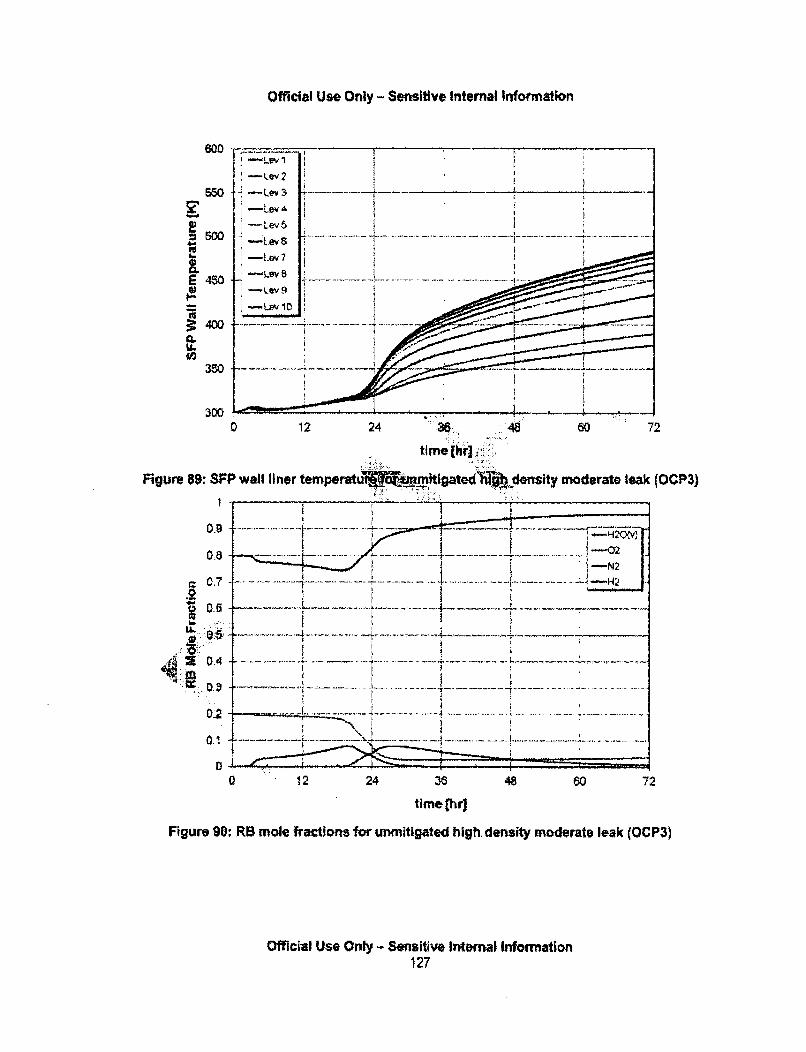
Official Use Only - Sensitive Internal Information
600 _-
-Lev
... .--, .e ... ... _ .• . . _ ..... .. .... .. ...-Lev 7
-LevB 5
. . . .. .. .. . .. .....
U!
-Levg
E48-LLv
U-
0 12 24 "3. 48 60 72
ti me [hr]
Figure 89" SFP wall liner temperatu mI titatedN4l-bjcdensity moderate leak (OCP3)
0.9C ,7 .... ... ........ . ................. -j .............. .. ... ..- H 2 ,
L.4D .3 -.. . . .. --.. . . . .. .. . . . .. . . . . -- .. . . .. . . . . . . .- . .. . .... .. .
.. .. ....... ..... ... .
S 0 .. . . .. ......1 ...... . .... .. ..... ............. ... .............. ..... ...... .................. ... . ..... ............ . .
0 12 24 36 48 60 72
time [hr)
Figure 90: RB mole fractions for unmitigated high. density moderate leak (OCP3)
Official Use Only - Sensitive Internal Information127
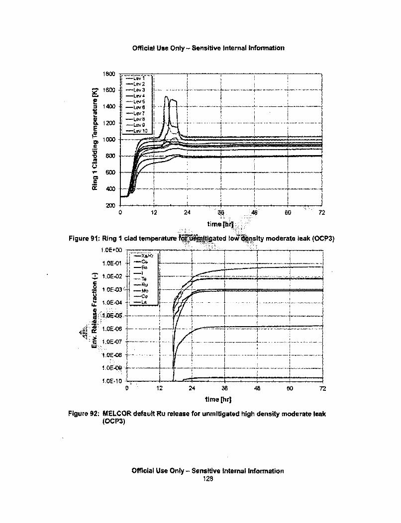
Official Use Only - Sensitive Internal information
-Lev 2
1600 ru Levr3-LevZ I
=1400 ~Lev' --1400 -- Le F
~-Lev 8
E -Lev 10_
am
6w*
'm 80 ; ; - .
0 12 24 M. I
time [h."
Figure 91: Ring 1 clad temperature ult!gated 1o qpslty moder
1.0E400 .. , ,,,
.•1.0E-02 % .. -
4-;•• " -... I ,i .. ...LE 1.QE-10U
I 1OE-06 4! ,O -0 ... ...... ...... ..... .... ......LU "
I.0E-05 -
0 12 24 38 48
time [hr]
Figure 92: MELCOR default Ru release for unmitigated high density rr(OCP3)
Official Use Only - Sensitive Internal Information128
60 72
ioderate leak
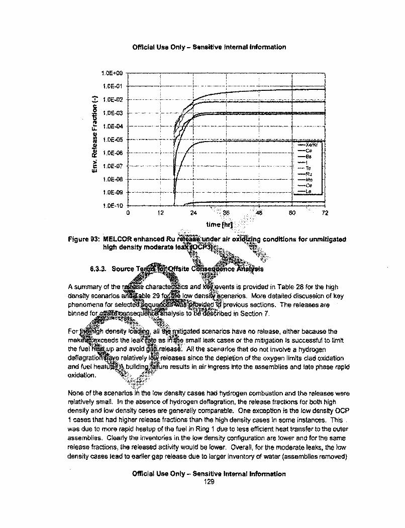
Official Use Only - Sensitive Internal Information
U.'
1,OE.OO
1 .OE-O1
1.OE-02
1 .0e-03
i.DE-04
I.DE.05
1,OE-06
1.OE-07
I . 1I IS. . . I ________I
S . I-Cs
T1-o
~ -La
IDE-08
1.QE-09
1.0E-1O0 12 24 .i.36
time thr :
,::48 60 72
Figure 93: MELCOR enhanced Ru r iunder air oxiling conditions for unmitigatedhigh density moderate lea4OP4.
A summary of thedensity scenariosphenomena for sebinned for•.ff...
nts is provided in Table 28 for the highmnaros. More detailed discussion of keyirevious sections. The releases areWd in Section 7.
vmitigated scenarios have no release, either because thee,., small leak cases or the mitigation is successful to limit
Me. All the scenarios that do not involve a hydrogeneases since the depletion of the oxygen limits clad oxidationresults in air ingress into the assemblies and late phase rapid
None of the scenarios in the tow density cases had hydrogen combustion and the releases wererelatively small. In the absence of hydrogen deflagration, the release fractions for both highdensity and low density cases are generally comparable. One exception is the low density OCP1 cases that had higher release fractions than the high density cases in some instances. Thiswas due to more rapid heatup of the fuel in Ring 1 due to less efficient heat transfer to the outerassemblies. Cleady the inventories in the low density configuration are lower and for the samerelease fractions, the released activity would be lower, Overall, for the moderate leaks, the lowdensity cases lead to earlier gap release due to larger inventory of water (assemblies removed)
Official Use Only - Sensitive Internal Information129
Official Use Only - Sensltive Internal Information
resulting in longer times for clearing the baseplate. The gap release first occurs in Ring I (hotassemblies) that has the same decay heat in both high density and lov density configurations.
6.3.4, Accumulation of Water Elsewhere in the Reactor Building
The reactor building MELCOR model is simplified (see Figure 40), Therefome, all waterleakages corresponding to the SFP damage and drain down and overflow from wateraccumulation due to condensation are directed directly to the environment. The model does nottrack the flow of the water and accumulation in other parts of the rea building.
Official Use Only - Sensitive Internal Information130

Official Use Only - Sensitive Internal Information
Official Use Only - Sensitive Internal Information131
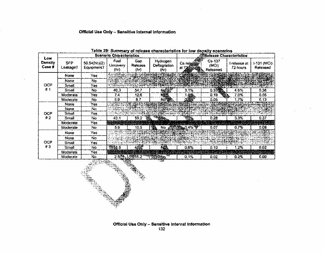
Official Use Only - Sensitive Internal Information
Table 29: Summary of release characteristics for lowScenario Characteristics
LOWDensityCase #
SFzPLeakage?
50.54(hh)(2).Equwpmerot?
None Yes
ocp# 1
None Nosmall YesSmall No
Moderate YesMocdrate No
None
OcP#2
None NoSmall YesSmall No
Moderate YesModerate No
None YesNorte NoSmall __.Yes
Small NoModerate Yes
5,9
OcP#3
Moderate No._.-.._,
'-V- %
Nu4
Official Use Only - Sensitive Internal Information132

Official Use Only - Sensitive Internal Information
7. OFFSITE CONSEQUENCE ANALYSIS
in the unlikely event of a severe accident that might damage the spent fuel pool (as detailed inthe previous sections), a release of radioactive material from the nuclear power plant site intothe atmosphere might occur. Such a release of radioactive material is expected disperse fromthe site through the atmosphere and to the surrounding population, by expanding and movingdownwind. After modeling the onsite accident progression and potential mitigation measures,the MACCS2 code (MELCOR Accident Consequence Code System. version 2) is used to modeloffsite release and consequence of radioactive material. .'
MACCS2 [I] has been developed by Sandia National Laborator -1SNL) over the past twodecades. It has the ability to evaluate the impacts of atmolec" es of radioactiveaerosols and vapors on human health and on the envir "-t The vfICS2 code has theability to use sIte-specific weather conditions, populat, ata, and evacuj plans to calculateand model the radiation exposure of the populationi :ugh all of the relevai se thways:cloudshine, inhalation, groundshine, and Ingest :i
Over the past decade, Sandia National Laboratwies':at eveloped WinMACCS for theNRC. WinMACCS is a user-friendly pnd to MACC Mat facilitates selection of inputparameters and sampling of uncertain f ar rforms sofafter the calculation. ap r n e
?.1. MACCS2 Model!Dmverview "
For the purposes of tiOP1P -G.Study, na of the input values for offsite release andconsequence mod are b -d &UREGA65. This modeling for NUREG-1935 was Inturn were based on st •uc.s N ..G-l 1S, an expert elicitation of theNRC/Commish ns of t ha eM ýEC) to update certain at transport and doseparamet! •!nup > f the dose res"onse modeling to be consistent with the latestfederal I ane re •'.at the .R-13)[1]
Slmila .ae scope and iling d''ions for this portion or the study are similar to NUREG-1935, e in instances w teo a severe accident from a spent fuel pool is expected to differfrom a re -and where thobjectives of the SFPSS are different (e.g. reporting of landcontarn !nation-).;
NUREG-1935 documents and justifies the modeling parameters used in that previous study.This study gives a general, high level understanding of the off site consequences modeling. Butbecause the off site consequence modeling for the SFP Scoping Study closely resemblesNUREG-1 935, this report will instead focus on the specific areas that are different from thisprevious research study.
Official Use Only - Sensitive Internal Information133
Official Use Onty - Sensitive Internal Information
7.2. Offslte Consequence Scope
7.2.1. Atmospheric Transport
The project focuses on atmospheric environmental releases. Atmospheric releases are mostlikely to have an immediate impact on the public, and therefore this study treats these releasesas having primary signifmcance. Release of contaminated water, on the other hand, has a moredelayed impact that can be mitigated much more easily than atmosphc releases. This studyfollows the current state-of-practice for consequence analyses, w8 cuses on the morefollowsnttehmor
immediate, more difficult to mitigate, atmospheric release pathJ & portant to note thatMACCS2, as used in this study, also accounts for depositioew.l water and runoff of
contaminants into surface water. These contribute to poteni. :doses hdrinking water,
Other types of releases, with longer-term consequiaccidental release of contaminated water tookthis water Immediately flowed into the ocean and'TFor a similar release at an inland site, freshwater reimpacted. Future studies would benefi om morereleases of contaminated water and id.. Ao m mil
7.2.2. Dose Truncation (in • ose-
arly possibl#Oor example,ukushima a , Much ofpe entered the agthdwater.i as rivers or lalKes, could be,e analyses that considerIh groundwater.
Experts generally agrestatistical precision alimits the ability toLCFs attributable to.not be statistically detepopulatioraV 1stat sti igntfica
sar ulation) Frolatent t er fatalities Isevere acdent wouldthe exposed ,.pulatlordetection of a &sticacauses among ulel a
4'1 icult to Eff~ize canb-4#sk because of the lowid wi . atiny ma numbers of excess cases at low doses. Thisendls' 'k. Fromt epidemiological standpoint, the number oft ex •f acci M1tal releases from a severe accident would
~i~~t~~,•.f cancer fatalities in the exposed'er fatalities ed are too few to allow the detection of a
the cancer fatalities expected from other causes among the;M. .. gical standpoint, in most, if not all, cases the number of
).•attrib ble to radiation exposure from accidental releases from a4if-atistically detectable above the normal rate of cancer fatalitles inie excess cancer fatalities predicted are too few to allow the
;ificant difference in the cancer fatalities expected from otherulation),
In the absence of additional information, the International Commission on RadiologicalProtection (ICRP), National Council on Radiation Protection and Measurements (NCRP), theU.S. National Academy of Sciences, and the United Nations Scientific Committee on the Effectsof Atomic Radiation (UNSCEAR) have each indicated that the current scientific evidence Isconsistent with the hypothesis that a linear, no threshold (LNT) dose response relationshipexists between exposure to ionizing radiation and the development of cancer in humans.Although most scientific organizations do not rule out the possibility of LCFs from very lowdoses, some organizations such as the Health Physics Society (HPS), French National
Official Use Only - Sensitive Internal Information134

Official Use Only - Sensitive Internal Information
Academy of Medicine, and the ICRP, consider the use of an LNT dose response model tocalculate LCFs from very low doses below a certain threshold inappropriate. While somescientific organizations take this position, few organizations have endorsed a definitive dosethreshold, other than LNT, to calculate LCFs, The HIPS concludes that quantitative estimates ofrisk should be limited to individuals receiving a whole body dose greater than 0.05 Sv (5 rem) in1 year or a lifetime dose greater than 0.1 Sv (10 remn) in addition to natural backgroundradiation. While the NCRP supports the LNT model, It also recommends bhining exposures Intoranges and considering those ranges separately.
Given the uncertainty of low dose health effects, this study sugg `.ing a range of annualdose truncation values, ranging from LNT to the HPS recomr n (5 rem/yr and 10 remlifetime). One internediate annual dose-truncation level Is analed, that being the620 rnremlyr (which is the other is the U.S.-average annual d se to th upblic from medical andbackground radiation exposures). Depending on the fteavallable, addltI&a truncation valuesmay also be analyzed.
This approach is similar to that used in NUREG-135;. NUREdt1'935 used the sari dosetruncation levels; however the approach also analyiyeaiapa dose truncation of 10 mrem,In that study, this very small dose truncton has shown duce up to a factor ol tw
difference in health effects from LNT f tlv,:ely very sma releases. However, more typicalresults from this truncation tend not to IS -i4.NT andliefore the truncation is notexpected to provide very meaningful resu r this idy Reil
This approach differs ,- analysrhiM before NUREG-1935 that have assumedan LNT dose respontfrNodei. An LN]T dose reonse model Is consistent with the current NRCregulatory appronmAc' the NRCý,•neither cha"'ging nor contemplating changing radiationprotection standards o.6 I-cY •aproch to be taken in this SFP Scoping Study.Given. th ure ap.~ah•~i
eraint oheatt rsults for these four dose-truncation levels(which •t .. .ported without bias for each of the accident scenarios.
(\4.2.3. Diste unction (From Point of Release)
The repo0f~J distances are ý4sed on the presentation of the results, which in turn are based onthe priority of :Objpctives for ýie study. The project is careful not to use a distance truncation in amanner that art ilay reduces the consequence numbers, if and when such a consideration is'~. = .. ,.:..
applicable.
Reported land contamination Includes the entire site region and is not truncated due to distance.Health effect risk, which is higher near the point of release, is primarily reported for 0 to 10miles. Both health effect risk and land contamination as a function of distance Is reported up tothe ingestion pathway emergency preparedness zone (50-miles), or a distance that which nomore protective actions are predicted, whichever is further.
Official Use Only - Sensitive Internal Information135
Official Use Only - Sensitive Internal Information
Due to the possibility of truncating consequences for certain dose response models, concernsover the effect of low doses (such as low doses at large distances) are not captured in the formof a distance truncation. Instead, the effect of low doses is explicitly captured in the differentdose response modeling,
NUREG-1935 reported LCFs out to 50 miles. Most previous analyses (e~g.. NUREG-1 150)calculated LCFs to 1,000 mites with forced deposition (i.e. boundary weather) to account for allnon-noble gas radionuclides in the dose calculation.
7.2.4. Time Truncation of Release
The time truncation used for this research project is 72 hours-'a& ý4hwrs, if at this point In time,the spent fuel pool is still covered with water). -
In the event of a prolonged severe accident, radiatWi4,d other hazards co' ii ake anytruncation of an ongoing SFP release chalIengiriA;*n the other hand, many resources areavailable at the State, regional, and national level r could betavailable to mitiggd anaccident. Considering both viewpoints on this issue' ijec ff judge 72 hours to be areasonable time truncation. The use oji;a time truncatioNE.-sa point of uncertainty that cansignificantly affect the results. See SdU 5sfor additional ciscussion on mitigationassumptions in this study, and Sectionfr p s future •hsitivity a
The use of offsite response 4g i.rces cou~le 01ýc 'An% some respects, to the use ofeqtpe• • eofste••"4 :•i, ;.W!50.54(hh)(2) equipmen o n , o.. . r' se resources could be used in similar ways
to truncate the accidewf%!?uch as &tr makeulpidor water spray onto the SFP. However, unlike,.atonfs, e sec~the onsite 50.54(ht1n1 offs, responseAons could be more ad hoc inimplementation. - .
The reiia•• 6•. .,merIV operation of tihe 50.54(hh)(2) equipment and offsite responseactionsfibt being 4u••a':titati4 Zieasured in this project, These issues will receive additionalatte1 In the upcoming-J.te Le'3 PRA research study (SECY-1 1-0089), in the context ofhuma;)Qiability analysis. ':
7.3. Offsi _aonsequnce Modeling Inputs
The parameters foun 'tA'his list are of select, high-level data and modeling Inputs to theMACCS2 models, The list is not meant to be comprehensive, in order to organize the list, thefollowing broad categories have been created: emergency response, dose, economic,emergency and long-term phases. However, the parameters found in the emergency and long-term phase could be considered the "remaining' parameters. as emergency response, dose,and economic parameters would also technically fall into one of these two phases of theaccident, (Some are applicable to both,)
Official Use Only-Sensitive Internal Information136
Official Use Only - Sensitive Internal Information
7.3.1. Atmospheric Transport & Dispersion Modeling
Source Term:
A source term definition for MACCS2 is created for each accident consequence calculationusing MELMACCS 16]. MELMACCS reads a MELCOR plot file and extracts information usefulfor MACCS2.
In addition, a. number of user options have to be input when using M@LMACCS. This includesthe reiated radionuclide chemical groups or classes to be inctud • n•e analysis (i.e., the Xe.Cs, Ba, 1, To, Ru, Mo, Ce, and La groups), as well as the relat lonuclide inventory (eg.piant-specific burnup) In order to make the analysis consist • •kNELCOR calculation.
Weather gonsideratgios.
Because MACCS2 is primarily a tool for probabi i,:,. risk assessment (PRA), it a =-unts for theweather uncertainties that are inherent to acciden htýiw migobtf& r at any time inife future.Thus, the modeled results represent the average co•e -,' attributable to the variability in
the weather.QN-
Weather Sampling:
The weather-sampling strate2&fpr this stud seap 6•niiif'm weather-binning approach inMACC$2, Weather b aA~ n' oach us •4)rMACCS2 to categorze similar sets ofweather data basei r '"Ind speed bility cf.•i, and the occurrence of precipitation. Thisapproach. which atllo the user to :,pecify a diffedrnt number of random samples to be chosenfrom each bin, has . 2 " first released [1] but was not commonly
u hed Ins, 1. ~i••s n as a means of improving the statisticalu hesedtn•. 01s0 r.tt.yrepreset~t~ah eh rther discussion on this can be found in NUREG-1 935, for
,a: uy se Of .. •whic se of this t aed.
fo or ,
Meteorologlch•l..afa used foirtiS project consisted of 1 year of hourly meteorological data(8,760 data poir'• si fr each meteorological parameter), This was primarily accomplishedvia a cooperative ef t the licensee using onsite meteorological tower observations forNUREG-1935, Peach lottom provided 2 years of weather data, including directly measuredhourly precipitation data. Stability class data were derived from temperature measurements attwo elevations on the site meteorological towers. The specific year of data chosen for eachreactor was 2005, as was based on data recovery (greater than 99 percent being desirable)done for NUREG-1935. Different trends (eg., wind-rose pattern and hours of precipitation)between the years were estimated to have a relatively minor (<25 percent) effect on the finalNUREG-1 935 results. More specific details of the weather data can be found in NUREG-1935.
Official Use Only - Sensitive Internal Information137

Official Use Only - Sensitive Internal Information
Aerosol Peposition Yeloties;
Dry deposition velocities have been updated to account for a more typical surface roughness of60cm for the Peach Bottom site. (A surface roughness of 20cm was used for NUREG-1 935.)The relative aerosol deposition velocities, as well as much of the non-site-specific data for acutehealth effects, is developed from a set of reports that document a joint NRC/Commission of theEuropean Communities (CEC) expert elicitation study [7].
Aerosol deposition velocities, combined with the different aerosol si rom MELCOR,determine the rate aerosols are depleted from the plume of radioRucls. Generally, the largeraerosols deposit more quickly and so are depleted more rapidlyj the plume. The peak in theaerosol size distribution is usually a few micrometers, whicl•0 res" is to a depositionvelocity of a few millimeters per second.
Because MACCS2 allows plume segments to trainoy oni"mpass direcorl{asdetermined by weather data, atmospheric releases I ides are discretized into (atlongest) 1hour plume segments, The.E.LCOR analyaNovide the amount eachradionuclide contributes to each aeroso -.ach plu ment. Consideration of eachradionuclide, instead of just each chem Q! e; ... a signl•ti " advancement for offsiteconsequence modeling developed for this ject,
Many plume segments cap• •f resent -tlrrioransport a6d dispersion due to possiblechanges in the wevat uch as ti4 6vnd dlreiA) during the release. Finer resolution of thesereleases was not ary to mmin the fideloitof the calculation.
7.3.2. Expo= nd..
Exl~o~sag thwavs:
The pl~ojt considers groundshine, udshine, inhalation, and ingestion dose exposurepathwaydgýTbe pincnipal expob ure pathway to members of the public occupying landcnaiae. "d. 'P• deost ofldlaciv Mcontaminated ,by deposits of' •ieactive materials from reactor incidents is expected to beexposure of the:0.le boo46 external gamma radiation. Although it is normally expected to beof only minor imip!r inhalation pathway would contribute additional doses to internalorgans. 114]
Shielding Factors:
NUREG-1935 reviewed the shielding factors applied to evacuation, normal activity, andsheltering for each dose pathway (e.g. groundshine) used In NUREG-1 150 [2] and NUREGICR6953, Vol. 1 [91. The review updated just one factor, that being the fraction of time the average
Official Use Only - Sensitive Internal Information138
Official Use Only- Sensitive Internal Information
person spends indoors for normal activity (81 percent), This study uses the same shieldingfactors as NUREG-1935.
Census Data:
Site population data has been updated to 2011. This was done with the latest version of thecode SECPOP2000 [8]. SECPOP2000 uses a multiplier to account for population growth andthe 2000 Census in orderto create site data for MACCS2. A multiplier value of 1.1051 from theUnited States Census Bureau was used to account for the average pulation growth in theUnited States from 2000 to 2011. .dlwi
The new site file was created for 16 compass sectors.supported by SECPOP2000. WinMACCS (the preproo
site files onto a 64 compass-sector grid for better spr'analysis.
gular resolutioncan interpolate these
mIe MACCS2 offsite
Dose C~effIc~ients, CQCF~S):
The DCFs to be used in this study ar•lathe DOFs, organ-specffic doses can bwith organ-spec.fic risk factors, total heigNUREG-1935 as the basis of calculating
:e Report (FGR)-13 [101. Withto radiation. In conjunctionted. This study pians to follow
NUREG-1935 reccestimate residual c,residual' ancert siboth external radiacurrently re 4hejcreated 17
e b'~sings!.se to thh'c•as as a surrogate for dose to soft tissue toirr The rean for the'boice of the pancreas dose coefficient for thebecause 9-: rves as a reasonable surrogate for the residual group for
Jwds anl, lITIM00kf racA uclides. Because MACCS2 does notfo. e conversion factor file. a workaround was
•o~se o•lcients frthe pancreas were copied into the organ called•1al ca~rs are associated with the organ called bladder wall. which
p , The inhalation factors in FC3R-1 3 were processed ton o • rtic e sires. An activity median aerodynamic diameter (AMAD) ofwith ',log-normal form for the distribution and with a geometric standardAACCS2 does not currently allow the dose coefficient to change as thevfa ges during the MACCS2 calculation. The particle size distnbution6faanges in the emitted particle sizes for different plumes or. changes'downwind and deposit material.
1 micron was assurdeviation of but 2particle size difmight change becaias the plumes progi
RiskFactq% for Latent Cancer Fatality:
In estimating health effects from a severe accident, NUREG-1935 calculated the radiationexposure to the population and then applied dose-response models to analyze early fatality andlatent cancer fatality risks. NUREG-1935 used latent cancer expression coeftcients for the USpopulation as detailed in U.S. Environmental Protection Agency's publication "Estimating
Official Use Only - Sensitive Internal Information139
Official Use Only .- Sensitive Internal Information
Racdiogenc Cancer Risks"'i 1] and implemented in the EPA's Federal Guidance Report 1.3,"Cancer Risk Coeftlcients for Environmental Exposure to Radionuclidese (FGR-1 3)[I0}. Theserisk factors include seven organ.specific cancers plus residual cancers not accounted fordirectly. In 2009, the National Research Council released the BEIR VII report, an additionalstudy of the biological effects of ionizing radiation. No one-to-one correspondence existsbetween the cancers reported in BEIR VII compared with the earlier BEIR V report. Therefore,the dose coefficients of tissues of the bod*.in FRG-13 may or may not be consistent with theBEIR VII cancer sites. Thus, this study is following the basis used in NUREG-1935 in decidingto await EPA's review of BEIR VII and subsequent update of FGR-3,peftore Implementing BEIRVII risk coefficients.
Biolocigal Eff~ectiveness Factors (BgF§):
FGR-1 3 also recommended changes to the BEFs for b radiation for1•!of the organs usedto estimate latent cancer health effects to be consl_3' with the way the rislktors for cancersassociated with those organs were evaluated. T4!O organs pre bone matronl. breast; for• ~ "Dl -A bre st ... for;.;".. '••
these organs, the BEFs for alpha radiation were crged froi^6 standard value t 20 to I and10, respectively. Doses to these organs are used to Wtuawnccurrences of leukemia andbreast cancer, respectively. The choice•.!BEFs for thtssues is dictated by the EPA [11].
Dýos anid Do~e Rate Effgctvene s_ FacW.46i
A DDREF is to be applied lses in h te a g of the offsite consequencecalculation and to thoSl eNSN early PhO. e (i.: the first week) that we lessthauain 20 nde to thes e T!K ;ertypn -•..
than 20 rmactor ac nts for the fact that protracted, low doses areperceived to be lesi•fective in ca ,rig cancertn acute doses. The DDREF for all cancers
except for bfeast was; O-and • Jatwas I';-as done in NUREG-1935.
Par eers that relate tolacute heafth effect parameters to be used for this study, as well asmuch ofie. non-site-specit`ý data us6d for consequence is taken from a set of reports thatdocument a•.int NRC/Comnrsion of the European Communities (CEC) expert ellcttation studyf7], (All of t4•7%put parame~ts extracted from the expert elicitation are median values.)
7.3.3. Emergen.cy Phase Modeling
The MACCS2 models are setup to calculate exposure in two distinct phases, the emergencyphase and the late phase. The emergency phase models calculate the emergency phase doseand associated health effects to the public, as well as the emergency preparedness protectivemeasures that protect the public. The chosen time period for the emergency phase begins withthe initiating event and continues for I week. The time length of this phase has been chosen to
Official Use Only - Sensitive Internal Information140
Official Use Only- Sensitive Internal Irrformation
ensure that the effects of the plumes have been captured, and in order to capture all thecalculated acute exposures (without exclusion to smaller exposures).
As required by 10 CFR Part 50, offsfte response organizations, (OROs) develop emergencyresponse plans for implementation to protect the public health and safety in the tnlikely event ofan accident at a nuclear power plant. These response plans are developed for the plumeexposure pathway and ingestion pathway emergency planning zones (EPZs) which aredescribed in NUREG 0654/FEMA REP 1, Revision 1, "Criteria for Preparation and Evaluation ofRadiological Emergency Response Plans and Preparedness in Sup•i :of Nuclear PowerPlants," [NRC, 1980]. The plume exposure pathway EPZ is the arobf about 10 miles around anuclear power plant. Within the EPZ, detailed emergency plane place and this planningprovides a substantial basis for expansion of response effo$,ary [NRC, 1980].
The analysis of the SFP accidents for the Peach Bolo Je allows the J'ifthe advancedconsequence modeling techniques developed and ielemented in SOARCA [NRC, 2012a;
NRC, 2012b], Specffically, the offsite response.:Ide accident may be realistiQaV&Todeled Inthe MACCS2 consequence model. This includes,*deaing et action tl!Pons ofOROs and the implementation of these protective a 3 sd ;ividual population segments.The project used a normal weather wlpser. weekday sce;jA that includes schools in session.
The SFP project identified many potentrXýac6'dk ueno perfomed preliminary
consequence modeling to identify the boukdary roftI . r I..detaifed modeling. Thesepreliminary results were us 1dentify areIsgthat' e7%y, ntally affected. Some of theas "ga • the" •odh
results showed elevate. es e tances I yond the plume exposure pathway EPZrequiring review of te emerge respo• plans to assist in determining the types ofprotective actions y be im ented in thes areas. The results of the preliminarymodeling were binred ýsupp b•i t...use &,•detalled consequence modeling todetermine po.entaretial .'.'such ac J' he binning tally, presented In Table 30 wasbase • ment.ection Agency (EPA) protective action guides (PAGs) (14]. Forthis pID, If the 4 d .qject{l dose (early phase) is expected to exceed 1 rem for a memberof 041 pubic, the PAG isle'.. eded.i. .NUREG-1935, a 7 day period was used for the earlyphase. §.\
-:•i;;: Table-SO: Sinning of Expected Dose Pr aJcIonPAG °'" Sequence TailPAG not eaxcied' ond 10 miles _ 8PAG exceededf66b'nd 10 miles but not beyond 20 milesPAG exceeded beyond 20 miles 7
The distance to which the PAG may be exceeded assisted in determining the extent of offsiteprotective actions and the type of protective actions that may be implemented such assheltering in lieu of evacuation, For each of the accident sequences, it was determined that aGeneral Emergency (GE) would be declared promptly, within 15 minutes, based on theemergency action levels for the operating reactor. The timing of significant radiological releasevaried among the accident sequences and was an important factor in the response modeling.
Official Use Only - Sensitive Internal Information141
Official Use Only - Sensitive Internal Information
The liming of significant radiological release occurs weli after evacuation of the EPZ would beaccomplished according to the site evacuation time estimate. Sensitivity calculations for fuelconfigurations not used at Peach Bottom predict earlier release, but even these do not beginuntil evacuation is well underway or completed within the EPZ.
Using the dose projection binning, three consequence models were considered for analysis asshown in Table 31. Time constraints limited the current analysis to two of these includingconsequence mode! 1 and 2.
Table 31: Modeling Sequences
Consequence 1. Re&eae to EPZ Area beyond EPZModl Environment __
1 Smaog: Does not Immediate Shadowi% cuatio'r.of 30% of the pblicexceed PAG ;evacuation from this area. Hots' Vtand normalbeyond EPZ. relocation if required. Haitability is
2 Large Late: lmmediate, •hadow evacuation of 30% of tt. publicexceeds PAG I ev•cuat 6 ;from this a*.Jeleayed evacate a;beyond EPZ' 'stance IY'es. Shelter in P•.e of
b E. area. Shadow evacuation ofWV1 public from this area Shelter-
. .. in-pla lP). Hotspot and normalrelocatl, e ulred. Habitability is
_______ '~~'~.0i'Applied A ___ ___
3 Large Early: lmrmdiate M.::Not Complete exceed*$G eva#tion.. .
The protective actioatf s described:Lin Tabe1•1 are defined below:
l Ailt EGWc '"•o Residen e b&Me he affected area, The residents are modeled asn - ff erne'" ..oreser tIfference "inesponse timing associated with these cohortg roups;. •:••i•i•, &"
Shad'64Evacuation: A siadow evalbation occurs when members of the public evacuate fromareas tra'•2a not under of0400 evacuXation orders and typically begin when a large scaleevacuation o5ordered !NRC;2005}. Although shadow evacuations are often reported andobserved ther1•,•-little quanttative data available. In a national telephone survey of residents ofEPZs, about 20 p runt leot:,e that had been asked to evacuate had also evacuated forsituaUons in which tb;Were asked not to evacuate [NRC, 2008]. These situations weretypically related to hurricane hazards, In the SFP project, the initiating event is an earthquakethat will be fet by residents of the EPZ. The event will be followed with media informationrelated to an accident at the nuclear power plant, wide spread loss of power and damage tosome buildings. It was assumed that these factors would increase the shadow evacuation to30% of the public in the environs of the piant.
,.otHosiet and Normal Relocation: Models are included In the MACCS2 code to reflect OROsrelocating people from areas that were not included in the evacuation order where the dose
Official Use Only - Sensitive Internal Information142
Official Use Only - Sensitive Internal Information
exceeds PAGs. Within the MACCS2 calculation, individuals who would be relocated becausetheir projected total committed dose from these pathways is projected to exceed the protectiveaction crteria are prevented from receiving any additional dose during the emergency phase.The emergency phase is the 4 day perod after the start of the release, This relocation dosecriterion is applied at a specified time after plume arrival at the affected area and is applied tothe entire population within the analysis area, including the non-evacuating cohort within theEPZ. The dose and time values were developed specific to each sequence and are providedbelow.
* Hotspot: 5 rem at 8 hour* Normal: I rem at 12 hour.
The delay to relocate affected populations models the p.e6%d availliof ORO radiologicalresources to locate and survey areas of potential PA This Wn9 would vary• . .,•;~~~:., ' .. . m...!,,•..
depending upon the status of the EPZ evacuationaani' sgnificant radioliogc lease. Thetiming could be shorter for releases that occur l~ffter the Ge..ml Emergencydtlarationdue to the increased availability of response resoues from &prate, local, state and national
Shelter-in-place: For those areas whe ýp` a' be reduced below the PAG through SIP,rather than evacuation, SIP is modeled en ed protede action. The emergency plansfor both states'allow for this protective act,"
For those sequences ~~ti t 14?pse exceeeti PAGs be'yond the EPZ, analysis ofgreater populations -",were consmred In SURCA was required. The population wasdivided into multipi pt rts to be"•represent th6response of the public. A cohort is apopulation group that ferent;hrom other population groups.
. . .. .. ... . • "2.. -. ..• •:
The sit ation .1sestimate (ETE) was used to inform the developmentmob times for ubli travel speeds. To model evacuation in WinMACCS, eachcoh0 loaded onto t oadw ,etworR at a specified time, and a single speed was used.Howev ,acuations o occ a dicsbution in which the percent of public evacuating the areaincreases &er.:time until all •embers of the public have evacuated. Evacuations are typicallyrepresented 6te.zurve thatJ i mlatively steep at the beginning and tends to flatten as the lastmembers of the O1•blc exi area. The point at which the curve tends to flatten occurs whenapproximately 90 p ot the population has evacuated. The last 10 percent of the populationis called the evacuatlti"tail (Wolshon, 2010) which was modeled as a separate cohort,
The site specific ETE provides information on population characteristics, rnobilization of thepubtic, special facilities, transportation Infrastructure and other information used to estimate thetime to evacuate the EPZ. A distance over time ratio was generally used to develop the speedof the general public cohorts. A distance of 13 miles was assumed as a maximum traveldistance to provide for the fact that roadways are not directly radial away from the plant.Adjustment factors within the consequence model were then used to increase or decrease
Official Use Only - Sensitive internal Information143
Official Use Only - Sensitive Internal Infofrnation
speeds for each cohort at the grid level in areas where greater congestion may be expected orin rural areas where less congestion may occur. Because MACCS2 does not currently have thecapability to move populations over time, cohoits are modeled to begin moving together at aspecific time after notification, The analysis includes the State of Pennsylvania position that, ifan evacuation is ordered, it will include the entire EPZ. This position differs from other states,where evacuation of downwind areas would be implemented rather than the full EPZ. For thisproject, a full evacuation was modeled assuming that the State of Maryland OROs would agreewith the Pennsylvania protective action decisions.
........... .. •.I.....:...Alsumptio~ns.:
The following general assumptions were applied in this analv..
" Protective actions will be implemented within tWeEPZ." Protective actions will be expanded beyond t.wl Z. •" -* Dose projections will be developed and a vYatM to support protectivne n decisions.* Residents will expect they cannot returran'will take more belongings with them,
increasing mobilization times.Residents are generally aware of an impendma..:e ncy through media broadcasts.
• For the delayed release sequen.ces where as not start for greater than 24hours, it is assumed that schoo1aSvnd the EPZ" rd be closed rather thanevacuated.
" it Is assumed that evacuees from" e EPZ tr.ansported to safe distances. There areno modeling provisions.for relocatiUgevacu vm.co 6riJate care centers which maybe located within i,&2. iies from .. ant for setiernces where doses exceed PAGsin these areas.
" There is no lTof power beýond 20 miles. Communications, traffic signals, and EASmessaging are not impacted in this area.
The chosen tim eereod ergei:.h e.begins with the initiating event and continuesfor 4 da ngt is phase has been chosen consistent with the EPA use of theearly in dev!e• g PA • iAt this time, the effect of the plume is complete, and all thecal d acute exposurs 'may be captured (without exclusion to smaller exposures).
Network. 6@gutlon .Mdel
The evacuation"ar..a was mapped onto the WinMACCS radial sector grid network. Theroadway network irt,1eh EPZ was reviewed against the site-specific evacuation p;an todetermine the likely evacuation direction In each grid element. Travel directions were Input atthe grid level to approximate travel along evacuation routes and primary roadways. Forevacuations beyond 20 miles, travel directions were set radially outward to implementevacuation In these areas, This method was necessary to meet the schedule and resourceconstraints. Speed adjustment factors were then applied at the grid element level to speed upvehicles In the rural uncongested areas and to slow vehicles in more urban settings where themodeling indicates that speeds are lower than the average values used In the analyses.
Official Use Only - Sensitive Internal Information144
Official Use Only - Sensitive Internal information
Potassium 1Iodift
The State of Pennsylvania and Maryland potassium iodide (KI) programs distribute KI taoletsthrough several different means. The WinMACCS K1 model only allows KI to be assigned bypopulation fraction, not by location. Only residents within the EPZ would have KI and only abouthalf of these would typically be assumed to have access to their KI and take it within thespecified timeframe. The KI model was turned on for the sequences where the PAGs are notexpected to be exceeded beyond the EPZ and was turned off for those sequences where PAGswould be exceeded beyond the EPZ due to computer model limitatio.
Adverse weather is typically defined as rain, ice, or snowvhat affects tF1 iresponse of the public
during on emergency, Adverse weather was addres .. :the movemearicohorts within theanalysis using the evacuation speed multiplier (EPUt parameter in WinIVIOCS to reducetravel speed when precipitation is occurring (indctd from the meteorological er file).The ESPMUL factor was set at 0.7, which effect~ieslows dQphe evacuating jMilc to 70percent of the established travel speed when precipitm]111 .
InfrastrUcture Analysis:': i:,:i ,.=•i,
The limited seismic evaluation of the pote' Iailu ;odwaylkast conducted for, ., 0 o.. , irfrstu-ur cndctd o
SOARCA identified 12 bridl nd roedwa egm ItR d fail under the postulatedconditions. The EPZ ev o s ident i•the emergency plan indicate that evacueesWest ofthe river %l V o. y o
w e1ially ev ate terly or southerly direction, and evacuees eastof the river would e ate in a no irly or easterfe direction. Thus, the loss of bridges and theConowingo Dam Roa 2lnssri94 twenninn er has a minimal effect on the evacuationtJme. TheoQ .dges ay~s ~liffth, earthquake serve sparsely populated areas
where a W ods. are ,..%0ble, Alternate routes out of the EPZ have more than sufficientcapacZ ~ support tdacuat opulafion.
'Ar,.
The se c event causes l ofall onsite and offsite power, which can affect the responsetiming an ti.ons of the puW ,' Sirens would be sounded following the GE declaration, andbecause PeacbdiBottom will.have a fully backed up siren system by about 2013, it was assumedsrens sound forthisanalysis. The loss of power affects the number of residents receivinginstructions via EAS mesaging. The residents within the EPZ will have felt the earthquakewhich will effectively serVe as the initial warning. It may be expected that the residents will usemultiple methods of communication, such as cell phones, telephones, websites, and directinterface to communicate the emergency message.
A review of the roadway network within the EPZ indicates that there are only a few traffic signalswithin the EPZ and that most intersections are controlled with stop signs. The loss of power willcause traffic signals to default to a four-way stop mode, which is less efficient than normalsignalization. It Is expected emergency response personnel would respond to these
Official Use Only - Sensitive Internal Information145
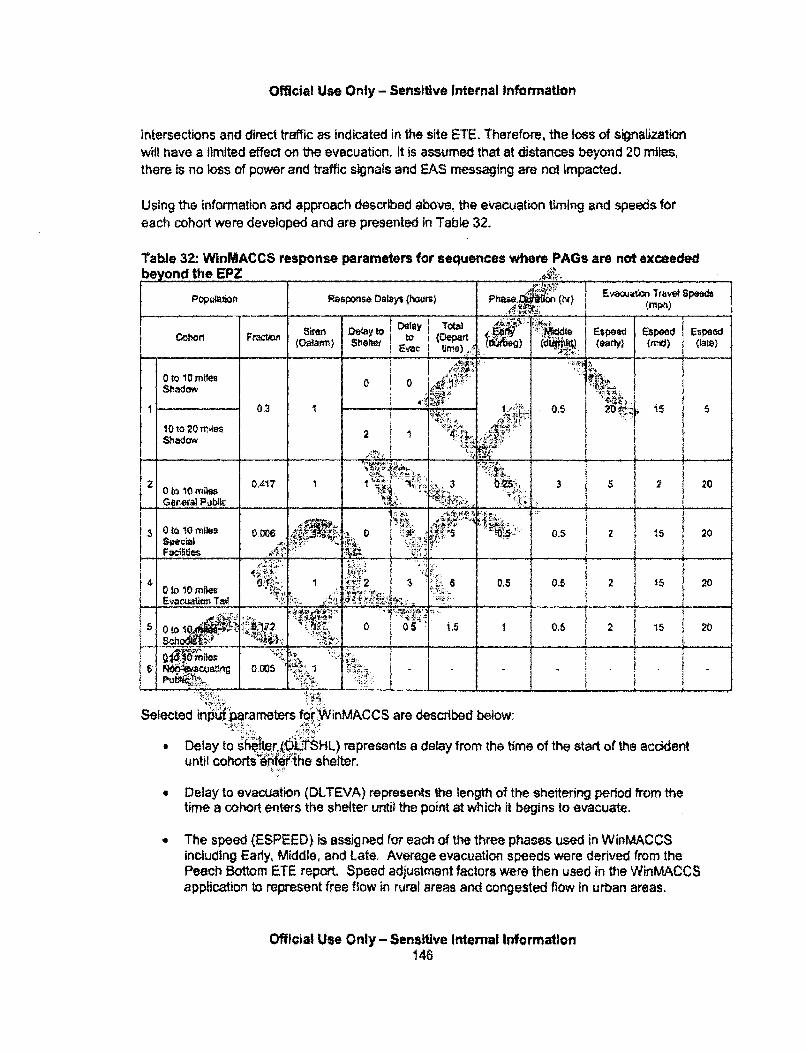
Official Use Only - Sensitive Internal Information
intersections and direct traffic as indicated in the site ETE. Therefore, the loss of signalizationwill have a limited effect on the evacuation. It is assumed that at distances beyond 20 miles,there is no loss of power and traffic signals and FAS messaging are not impacted.
Using the information and approach described above, the evacuation timing and speeds foreach cohort were developed and are presented in Table 32.
Table 32: WinMACCS response parameters for sequences where PAGs are not exceededbeyond the EPZ
popt~mp Response Delays (hours) Phase Evaoua?~cn rravet Speeds
_______ -Siren Dea toJ' I~ ~ Dely Toald {Espeed
Otl~'i~s0 0 '-1S-hadow
KI0.2 1 ý 1' 05 50 ~10 O )l'~8$2 1
shiadow ~~
2 t~oie 0.417 1 1 3 0 55 2 2
3 0 oI10 m1109 0.006 0 . 15 20
2 Ge3ia Pui ______ 04.. 2 15 20
0 to 10Miles 2Evcato _ _ _ _ %_ _ _ __ _ _ _ _ _ _ _
5 No9-~acua~dIg0005 '
i-iA
Ja a ..- ~-~---- .8. ...........- 4. -
Selected inut~ parameters for WinMACCS are described below:
" Delay to s4fter LTSHL) represents a delay from the time of the start of the accidentuntil cohorts 6nief the shelter.
" Delay to evacuation (DLTEVA) represents the length of the sheltering period from thetime a cohort enters the shelter until the point at which it begins to evacuate.
" The speed (ESPEED) is assigned for each of the three phases used in WinMACCSincluding Early, Middle, and Late. Average evacuation speeds were derived from thePeach Bottom ETE report. Speed adjustment factors were then used in the WinMACCSapplication to represent free flow in rural areas and congested flow In urban areas.
Official Use Only - Sensitive Internal Information146
Official Use 001Y - Sensitive internal information
" Duration of beginning phase (DURBEG) is the duration assigned to the beginning phaseof the evacuation and may be assigned uniquely for each cohort,
" Duration of middle phase (DURMID) is the duration assigned to the middle phase of the
evacuation and may also be assigned uniquely for each cohort
Win&MAC$.. respons parameters for secuences where PAGs are not exceeded beyond EPZ.
The following cohorts were established for SFP project-
0 to 10 ShadQw A shadow evacuation may be expected from ,t•'•e EPZ, Focus groupwork conducted with NUREG/CR 6953, Volume 2 (NRC, 200.d that some residentsare prepared and ready to evacuate at the first indication oi Facc" .a the nuclear powerplant. Results of the telephone survey conducted with NREGICR 69 howed
OR R 6 that onanational level, 20% of residents of EPZs have packed,•6-bag' and are "KYto leave,Although this may be more appropriately called an, , or spontaneous evaftton becausethe population begins to evacuate prior to receiv1M:an order to wacuate, it is do d here as ashadow evacuation. Because the accident is inF`tia"e býy a se •;arthquake it is assumed
30% of the public evacuate.
10 to 20 Shadow: A shadow evacuattn4 expected lI. area beyond the EPZ. The,Wud a el tag ofthepublicneardistribution of the shadow evacuation R wrt I Ii~ Tda sla'~ecnaeo ulcna
the boundary of the EPZ and the pe cent' Id d pt-roportlilal to the distance awayfrom the EPZ. For this a passe"-• the general public from the 10to 20 mile area shadow; 6uatel, s t icoho i begin evacuating as they observe EPZevacuees travelingj 4 h the are=6.
0 to 10 Public: This po tdaion~ir!'9& iyeacdbite as a distribution with some residentsleaving prom, gd othet ng iater." ianalysis, the cohort is modeled as a singlegrouP.~
o to !4specal Facllftiejhbis is a li but unique population group within this EPZ. There isno delajNi shetter becaus...ese residents are assumed to be in a robust. facillty when theaccident b~gins. Specialized;iehicles to evacuate these facilities take time to mobilize,
!JQ T The'l-- e• ts the last 10% of the EPZ population who typically take a longertime to begin to eva•t."
0 to 10 Schools: This cohort includes elementary, middle, and high school student populationswithin the EPZ. Schools receive early and direct warning from OROs and have response plansin place to support busing of students out of the EPZ. While the movement of school childrenare specifically considered in the evacuation model, the dose models do not treat themdifferently than the average person.
Official Use Only - Sensitive Internal Information147
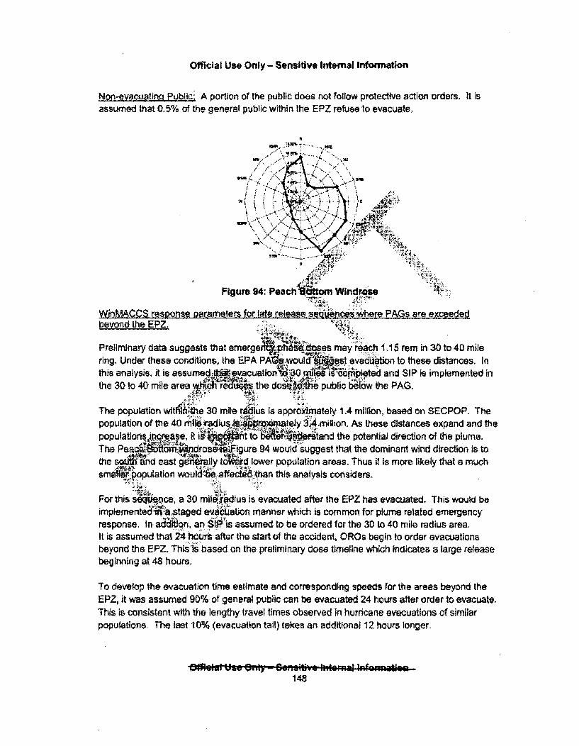
Official Use Only - Sensitive Internal Information
Non-evacuatinl Public: A portion of the public does not follow protective action orders. It isassumed that 0.5% of the general public within the EPZ refuse to evacuate.
fA-,,,7, \ ,".
/' "/ 'I" , $ "/' -' '"/:""; Y; N•
,- AM 9:
Figure 94: Peach ýitom Windrase
Win MA-CCS response pararriters for late rele-ase seuuno-hr PA re ej~reje0ebeyond the EPZ.
Preliminary data suggests that emre4!A 6 oe may rec 1. 15 rem in 30 to 40 milering. Under these conditions, the EPA PA s-woul iest evacuatin to these distances. Inthis analysis, it is assumned -nvcuation%'~30 ýýtil Fpleted and SIP is implemented inthe 30 to 40 mile area wh" :-r -e"i! the do sbe bl
e.. it ..
The population wtl~hih~te 30 mile r~ius is approximately 1.4 million, based on SECPOP. Thepopulation of the 40 mrtl - adus"Ilion. As these distances expand arnd thepopulations ijicrease, it ist! t to E~netad the potential direction of the plume.The P 6, .,`6,. 94 would suggest that the dominant wind direction is tothe 50M6des rd lower population areas. Thus it Is more likely that a muchsmnfier~popuation woul [: affec* than this analysis considers.
For this sdqence, a 30 mii*ius is evacuated after the EPZ has evacuated. This would beimplementea staged ev~aaiuon manner which is common for plume related emergencyresponse. In adddon, an SIP: is assumed to be ordered for the 3D to 40 mile radius area.It is assumed that 24E hurs after the start of the accident, ORs begin to order evacuationsbeyond the EPZ. ThisPis based on the preliminary dose timeline which indicates a large releasebeginning at 48 hours.
To develop the evacuation time estimate and corresponding speeds for the areas beyond theEPZ, it was assumed 90% of general public can be evacuated 24 hours after order to evacuate.This is consistent with the lengthy travel times observed in hurricane evacuations of similarpopulations. The last 10% (evacuation tail) takes an additional 12 hours longer.
• •: U =.:. ..• •, -• Z -.'-lt • .: r ~ t
148

Official Use Only - Sensitive Intemal Information
Because of the lengthy time for this release to the environment, this sequence is effectivelymodeled as two separate evacuations including the EPZ first foliowed later by the 10 to 30 milearea.
The following cohorts were established for SFP project:
g This cohort includes elementary, middle, and high school student populationswithin the EPZ. Schools receive early and direct warning from OROs and have response plansin place to support busing of students out of the EPZ, .i I.LA 2T,
0 to 10 Shadow. A shadow evacuation may be expected frmay be more appropriately called an early or spontaneous,begins to evacuate prior to receiving an order to evacual,,evacuation, ,6:
0 to 10 Public; This population group would evate as aleaving promptly and others leaving later. For thiw yisgroup. ,CRPý
10 to 20 4haJow: A shadow evacua expecteidistribution of the shadow evacuation w1 k% ude athe boundary of the EPZ and the per ,nt ld efrom the EPZ. For this assuto 20 mile area suadow ua ' his coh in eNevacuees traveling .,,h the arei
the populationa shadow
,es.identsed~sa single
area beyond the EPZ. Thei ,ercentage of the public nearCl to the distance away
:the general public from the 10ting as they observe EPZ
6populatlon group within this EPZ. There isdumed to be in a robust facility when thethese facilities take time to mobilize.
10% of the EPZ population who typically take a longer
population group would evacuate as a distribution with someothers leaving later. For this analysis, the cohort is modeled asresidents leavir
a single group.".•;.'•.:...
30 to 40 Shadow: A shadow evacuation may be expected in the area beyond the evacuationarea. For this analysis, it is assumed that 30 percent of the general public from the 30 to 40mile area shadow evacuate. This cohort will begin evacuating as they observe evacueestraveling through the area.
10 to 30 Tail: The tail represents the last 10% of the population of this area who typically take alonger time to begin to evacuate.
Official Use Only - Sensitive Internal Infornnation149
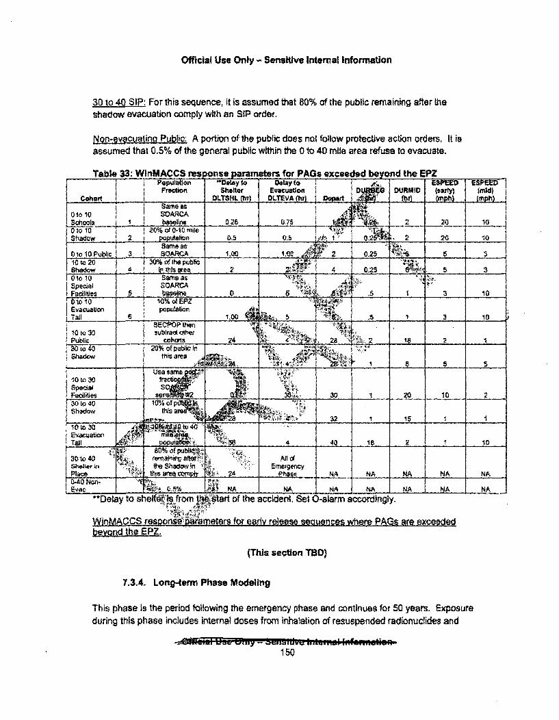
Official Use Only- Sensitive Internal Information
30 to 40 SIP: For this sequence, it is assumed that 80% of the public remaining after theshadow evacuation comply with an SIP order.
Non-ey•cuatina PubWti: A portion of the public does not folIow protective action orders, It isassumed that 0.5% of the general public within the 0 to 40 mile area refuse to evacuate.
Taible 33: WlnMACCS res ns. paraers for.PAGs exceeded bey nd the EPZ. opulation -DAyto Delay to z . ESMIED ESPEED'Frectikm Shllter Evacutou i Di8JQ DIJRMIO (earty) (midl
Cohort _OLTSHL Rai DOLEAhj I t09rt (J.,2mph)
0101 20A 1Scoos "Vn 025 075 1.ot o 20% ofOl 0 i ...
0oShadow 2 pOpulaln D.5 0.5 s r A,2Oi 1 2 2 20 10ftm* as •... . ":••.._____ 3o10Pbi SOARCA _______ 4,0 ____ 2 0.25_5_3-10 to 20 30% of Ihe•Jbl.,shado 4 i n. this .ea 2 _ -1:_ .... 0.25 .
1 i~ 0`10 10_ Sam as_ '1Fa 5 bwebm 0 5 A'i! .S 1 3 10
1010 10% ofEPZEvacuautio popu~awin
STail _ __.1.00 , _ In:,10l~~to3O SEOPOP then . _
10 to 30 sublrad :ttehw rl " .,. . . . Cohu -2 __• _ ____ . .... ' , :
30tO4, 20% of public In" 'shadow this area :'
._ . . .. • ; :. ':••! • • ,•. -:-z.• ;: __ _ __ _ - S SUse sra•?Or.
0 to t30 B
Facilities .___ _. . 30 - 30 1 . 20 10 2
30to 40 "10% of " 1 IShadow this .2.04M
Evac3uationlTail_____ ______ 4___4___ _ I a___2_ 10
Shle n1he Shadowin 2 EtmergecyPlace thr area MnoC!ip,' : 24 Phase RNA NA NA NA NA0-40 Ncn- E'I',, : . NNA NA NA NA _ AC./C••.,5 .K NA.• NA NA
"*Delay to sheftt.I from tto&1tart of the accident. Set O-alarm accordingly.
WinMACCS resoonsa :arameter9 for early release sauncs~ wl~r PA~s are •xcaed~dW1nMACCS reso aaýb eta for eadv release t;equanrA--, whqrp- PAGg arg exceededbeyond the_ EPZ.
(This section TBD)
7.3.4. Long-term Phase Modeling
This phase is the period following the emergency phase and continues for 50 years. Exposureduring this phase includes internal doses from inhalation of resuspended radionuclides and
150
Official Use Only - Sensitive Internal Information
ingestion of food/water with trace contaminants. However, exposure is mainly from externaldoses from trace contaminants that remain after the land is decontaminated, or in lightlycontaminated areas where people never had to evacuate or relocate. Depending on therelevant protective action guides and the level of ,radiation, food/water below a certain limit couldbe considered adequately safe for ingestion, and lightly contaminated areas could beconsidered habitable.
Protective Actions against Contaminated Land
Three protective actions are modeled to occur for contaminated I nuring the long-termphase: decontamination, interdiction, and condemnation. In r__i, MACCS2 will considerthese actions when land is not habitable. The actual deterq. V ni"hen land will bedecontaminated after a nuclear accident wil, be based ob:la ngterm • up strategy, which iscurrently being developed by the NRC, EPA, and othe f1ieral aencies.Rjrthermore, acleanup standard with a set dose level may purposUIW not be predetermi4 tidue to theaccident-specific and regional-dependent char stics of such in event.
In MACCS2, the models will consider land decontanii0kion 4Acontamination can make theland habitable and if the value of the la_.fljs greater than Thq cost to decontaminate, If the levelof contamination is too high, or If the I 'd nteminatl., ere assessed to be higher thanthe land value, the land Is assumed to onMdnAad. Becauseboth the land values and thelevel of possible decontamination affect d.isions o&ni, ether corninated areas can berestored to habitability, the affect pre16.d to.I.4 r es, health effects, and economic
costs.During this deconta llon perio e land isintardicted (e.g. the land is temporarilyuninhabitable), a rmor tialy interdtdd for an additional period if needed tomake the land habitabWO landa0n'idt 'be restored to habitability in 30 years, the land ismodeled as.condemned artd residents will not i~t:r: during the long-term phase. The length ofthe late phas(i. 50 years) has been chosen to provide a reasonable time period forcalculdan" gconsequences froni exposure of the average person. For some small children thetime•-•eiod is too short, butfor other :older residents it is too long.
Ha bitabil•:ritlerion: •::
Site-specific values are ued to determine long-term habitability. Most States adhere to EPAguidelines that alloodW o'se of 2 rem in the rst year and 500 mrem each year thereafter.However, Pennsylvana %as a more strict habitability criterion of 0.5 rem beginning in the firstyear and each following year), which is the value that is used for this study. This value wasused in the Peach Bottom analysis even though areas outside of Pennsylvama could alsopotentially be affected.
Land Values:
i
Official Use Only - Sensitive Internal Information151
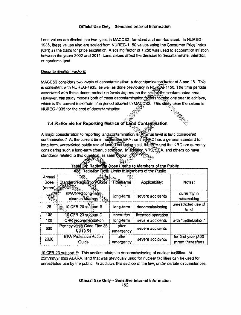
Official Use Only - Sensitive Internal Information
Land values are divided Into two types in MACCS2: farmland and non-farmland. In NUREG-1935, these values also are scaled from NUREG-1 150 values using the Consumer Price Index(CPI) as the basis for price escalation, A scaling factor of 1.250 was used to account for inflationbetween the years 2002 and 2011. Land values affect the decision to decontaminate, interdict,or condemn land.
Decontamination Factors:
MACCS2 considers two levels of decontamination: a decontarminatip••,factor of 3 and 15. Thisis consistent with NUREG-1935, as well as done previously in NU..I ft 150. The time periodsassociated with these decontamination levels depend on the siz'JCthe contaminated area.However, ttis study models both of these decontaminati:n. s t one year to achieve,which is the current maximum time period allowed in MACCS2. This •iidy uses the values in
NUREG-1935 for the cost of decontamination. .
7.4. Rationale for Reporting Mettrcs of UM ContartInation
A majoT consideration to reportin9 land wntamination W.Afjfihat level is land cccontaminated? At the current time, ndtiW6Ti1e EPA nor tHeý. has a general
long-term, unrestricted public use of lani;at •Aeing said the FPA and the NRIconsidering such a long-term cleanup strCiT . 9ion NRC"•''-,F:A and oth.standards related to this quesft., as seen. .low.
TaI.M: Radia Dose LhI.t to Members of the Public
,nsideredstandard forC are currentlyirs do have
______4*,.Radiation Doe Unmhs tboMembers of the Public
Annual ,.it 0Dose StandardlRegUl Guoidae' T•iffiaame Applicability: Notes:
(m rem ), z , .; .
EPAUNRUIRong-'t 4_r_' leanupi egy 'long-termi severeaccidents Currenuyin J
; '" !c e a n p i., j _ _ . ._ _ _ _. . . . . ru k e m a k in gdecommissioning unrestricted use of25 1CFR 20 subprt E long-term dommisioning land
1(X) 1('•CFR 20 subpart D operation icensed operation
1 100 lCFe-recorn hdation long-term severe accidents with "optimization'5W Pennsylvkni 0;Ae Title 25 after severe aciet
§ 219.51 emergency accns2000 EPA Protective Action after.e..y severe accidents for first year (500
Guide m ge..ncy..... .. mrem thereafter)
!0 QFR 2 Oup2Mrt E: This section relates to decommissioning of nuclear facilities. At25mremlyr plus ALARA, land that was previously used for nuclear facilities can be used forunrestricted use by the public. In addition, this section of the law, under certain circumstances,
Official Use Only - Sensitive Internal Information152
Official Use Only - Sensitive Internal Information
could allow a relaxation of the standard to 100 mrern/yr if there are Institutional controls placedon the land (e.g. no fishing).
While CFR 20 subpart E is specifically for 'Radiological Criteria for License Termination", thissection creates a precedent for what the NRC may consider safe for long-term public use ofland.
10 CFR 20 subpart D: This section relates to restrictions on the licensee to limit the annualdose to the members of the public to 100mreom from licensed operatio •This section of the lawallows for certain exceptions (e.g. a visitor that demonstrates a nekhd has NRC permissioncan have a 500mrem limit), as well as stricter limits for certain e paths as determined byALARA principles. However, similar to subpart E, subpart itpe i;to licensed operation,and therefore does not apply to beyond design basis accide¢, which eist outside of thelicensing basis,
ICRP recommendation: The ICRP standard forvMj -term unrestricted public u is100mremlyr + optimization. mOptimization" allows :tfj urisdiq1-?&f the Iocal area'l"adjust theultimate dose level criterion (upwards or downwards) iord:• consider the needs of theirlocale in response to a specific reacto•,,ident. For ns9e, the local jurisdiction may wish touse a lower dose standard for a playgrOnl ..
enWan d l the . to t AGsnnsYvania has a state-specific value for relocatio _..mrem i TIt an be found in the PennsylvaniaCode, Title 25 Cha 1 51 - Dp i for IndivA3ual Members of the Public.
Environmental Pro a Acency irdin v ediate p1se protective action guides: The EPA[14]states that for nuclear i"idents. Qh'is warranted when the projected sum of the doseequivalent from;ea committed effective dose equivalent from
ii ded raionuclides exceeds 2 rem in the first year.This was esla@'1i ba~ n an objective to limit the total dose to 5 rem in 50 years. 50yea5 0mthe usual length" ime gR .,for the average remaining lifetime of expo'sed individuals,and 5 r is the corresponrfirg 50- yeiv dose of the ICRP recommended 100 ,mrem/yr upperbound for 00. so urces oombin" for chronic exposure.The 5 rem lifett" dose corr*esonds to an upper bound of 2 rem from exposure during the firstyear and 0.5 rem rfom ep re during the second year when considering radioactive decayand weathering fromgo.clear reactor accident. A spent fuel pool accident is expected to havea significantly longer gVerage radioactive decay, which would affect this calculation. However,the EPA [14] has stated that:
Although these Protective Action Guides (PAGs) were developed based on expectedreleases of radioactive materials characteristic of reactor incidents, they may be appliedto any type of incident that can result in long-term exposure of the public to depositedradioactivity,
Official Use Only - Sensitive Internal Information153
Offlicial Use Only - Sensitive internal Infonnation
Another consideration in reporting land contamination is! 0At what point. In time is the land to beevaluated?" As time passes, radionuclides will transport and decay. Also, depending onsociety's capability and effort, decontamination will also affect the amount of contamination.In addition, different dose standards are applicable to different points in time, A dose level on apiece of property could be low enough for people to return, or habitable in the short-term withcertain institutional controls; however, a similar dose level may not be considered acceptable forlong-term habitation, and institutional controls for the land may be different.
Because our study is site-specific. and our SFP is In Pennsylvania, tI'research project reportsthe area of land that exceeds the dose limits In tPe Pennsylvania• :limits for habitation(500mrem), for the first year after the accident.
In addition to using the 500mrem annual dose to evaluate lai.d contamination and for selectscenario(s), the project also currently plans to report t6 area of land that.'exceeds a range ofdose levels:
" 25mrem (10 CFR 20 subpart E)" 100m rem (10 CFR 20 subpart D),* 100tmrem + optimization (ICR mmendation) 1 ,:* 500mremn (Pennsylvania dos r 4i" 2rem (EPA intermediate phase Ptlectfive: n Guide criterion for relocation)
HNModeling land contaminat.06ilmmedi•iye • er tfi dent is more straightforward
b s tdeither, EPA no"-ee lNRC currently has a general standard forlong-term, unrest_ _publiuse J.iTnd. Ultifitely, the strategy may be some form ofoptimization for looal: idictions 840 osed aiset dose value. In addition, modelingpotential land contami~fo In d[I ek,.yeatter the severe accident carries lessuncertaint 1. -te .;M e This W use economic factors such as the cost ofdeconlton a , ypetIvies, as well as ecological factors suchi as groundwatertransspor'and plant-soil' • •a .will play a role in tong-term contamination.
7.5. Offeite Consequence Sinning
In order to incorpprgi la numbers of sequences, and to avoid conveying a more significantlevel of accuracy fo-P rticular sequence, the sequences were binned by their Cs-1 37 and I-131 release activities siee Table 35),
The first criterion used to bin the sequences was Cs-137 release, because Cs-137 is the mostsignificant contributor to consequence. 1-131 was also chosen to bin the sequences, because I-131 is a good indicator for short-lived radionuclides that may be released from recentlydischarged spent nuclear fuel. These short-lived radionuclides are the largest potentialcontributors to early doses and acute health effects. The tally into each of these bins can beseen in Table 36.
Official Use Only - Sensitive Internal Information154
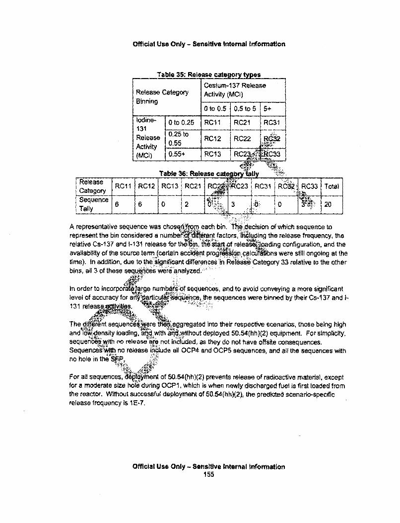
Official Use Ordy - Serteftilve internal Information
Table 35: Release category types
Cesium-137 ReleaseRelease Category Activity (MCi)Binning 0 to 0.5 0.5to5 i5+
Iodine- 0 to 0.25 RC1 1 RC2I RC31131ARtieite 0.25 to _ _ _ .Release 2RC12 iRC22 iR 2
(MCi) 0.55+ RC43 R C2 -C33RCS1 .0 C3
Table 36: Release cate " "va" TI hRese RC1I RC12 RCI3, RC21 RC2.RC23 iRC31 RC.32 RC33 Total
Category __
Sequence 0 J---2.. .. .. 3 .. . ... 2 0'. I . .
A representative sequence was chose from each bin. Tie decision of which sequence torepresent the bin considere< a numbeeb ft~p~nt factors,'i f'i ing the release frequency, therelative Cs-1 37 and 1-131 release for tAh n, ithe redeas.%Q.ding configuration, and theavailability of the source term (certain acclnt progVon" r calculabns were stilt ongoing at thetime). In addition, due to the.,ignificant differences In' ReIease Category 33 relative to the otherbins, all 3 of these sequenoes were analyzed.-:'4
In order to Incorpo0.alaIrge numbd'.of sequences, and to avoid conveying a more significantlevel of accura y for a articu.•"f touO......... 'lvloacrcfri qnce, th sequences were binned by their Cs.t 37 and 1-
131 release v . , .. '-
The didf&rrt sequences*were tfherj,;aggregated into their respective scenarios, those being highandr1 w4density loading, al6d; with a •.: thout deployed 50.54(hh)(2) equipment. For simplicity,seq uenc.wIth no release ke not indluded, as they do not have offsite consequences.Sequences.1wt no release nlude all OCP4 and OCPS sequences, and ail the sequences withno hole in the SEP. -.
For all sequences, qifjient of 60.54(hh)(2) prevents release of radioactive material, exceptfor a moderate size hoIl during OCP1, which is when newly discharged fuel is first loaded fromthe reactor. Without successful deployment of 50.54(hh)(2), the predicted scenario-specificrelease frequency is I E-7.
Official Use Only - Sensitive Internal Information155
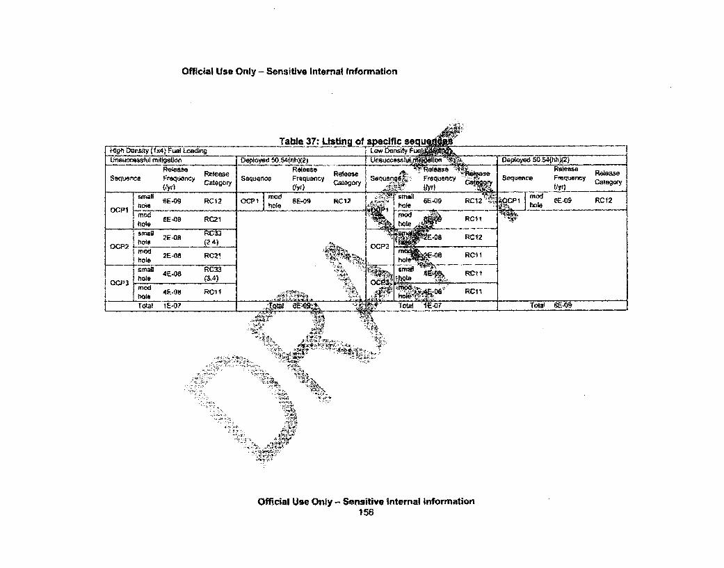
Official Use Only - Sensitive Internal information
Official Use Ony - Sensitive Internal Information156
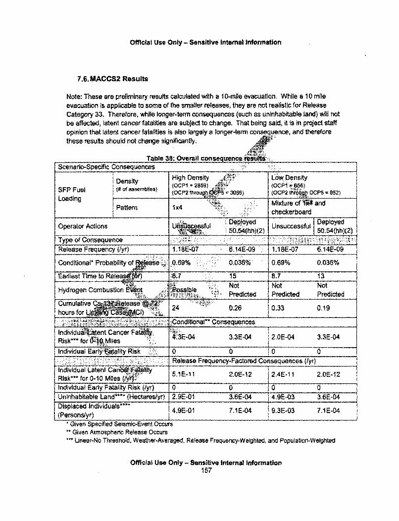
Official Use Only - Sensitive Internal Information
7.6. MACCS2 Results
Note: These are preliminary results calculated with a 1 0-mile evacuation. While a 10 mileevacuation is applicable to some of lhe smaller releases, they are not realistic for ReleaseCategory 33. Therefore, while longer-term consequences (such as uninhabitable land) will notbe affected, latent cancer fatalities are subject to change. That being said, it is in project staffopinion that latent cancer fatalities is also largely a longer-term consequence, and thereforethese results should not change significantly,
Table 38: Overall consequence it :suScenario-Specific Consequences _:_.:___:_ "'I"___""
•esiHigh Density , LowDensity
SFP Fuel i(0 af a3semblie: opi25) OP(OCP2 thro Ugh -305) (OCP2 tho.Otb OCP5 852)
Loading Loadng ';•~i• ....•i...!... Mixture ofIR4t andi Pattern 1x4 :.•:,,checkerboard
LUIccessful Depjoyed c eo Deployed
Operator Actions , 0.5(hh)(2) Unsuccessful SO.54(hh)(2)
Type of Consequence " " . .. . .. " . . ... ... ....Release Frequency (lyr) 1,18&.07 6.141-09 1.1 BE-07 6.14E-09
Conditional* Probability Of Rei~ase.: 0.69% 0.036% 0.69% 0,036%
Earliest Time to Retea Z..7 15 8.7 13.. . J ' •1 " ' -L'"'. ..' • =-=•''• ':-•J:": . " :: ' N ot N ot N ot - . . .
Hydrogen Combustion t .. k:i:i:ossible "•":, ,Psit.i ' ' Predicted Predicted Predicted
ýJumuIaNe C ~ f• ...... :=: ........ .... -
• hourf tiv• . ' 24 0.26 0.33 0,19
Frequtinl"Cnsqen-atrdCneunces (yrIndividual ent Cancer Fa. 1O- [E ERik for 64,- ..... . C X -04 3.3E-04 2.0E-04 3,3E-D4
Individual Early i k "/y 0 0 0 0
Uninhabitabeeeased Frequency-Frac2.red Consequence[s.(E..0
I ndividual Latent Can'w''F~wfty 5.1E-I 1 2,0E-12 2.4E.11I 2.0E-12Risk*** for 0-10 Miles V .i:Individual Early Fatality Risk (/yr) 0 0 ! 0 0Uninhabitable Land*"'- (Hectareslyr) 2.9E-0i1 3.65-04 4.9E-03 3.6E-04 ,
Displaced Individuals"' 49E01 7.1E-04 94.9-0I IE04 9.3E-03 7.I E.04(Personsyr) _
Given Speciried Seismic-Event OccursGiven Atmospheric Release Occurs
-" Unear-No Threshold, Weather-Averaged, Release Frequency-Weighted, and Population-Weighted
Official Use Only - Sensitive Internal Information157

Official Use Only - Sensitive Internal Information
1" 1st Year Post-Accident, Weather.Avermed, Release Frequency-Weighted; Calculation uses a doselimit of 50Omtemfyr, according to Pennsylvania Code, Title 25 § 219.51 - Dose Limits for IndividualMembers of the Public
Table 39: 0ose Response Model Results
Dose Response Model ComparisonjScenario Specific, Weather-Averaged, Release Frequency-Weighted)
Dose Fuel Loading Pattern High Density (1x4) i Low DensityResponse Dep loygi ,rf DeployedOperator Ac~~ons Unsuccessful Us l pModel '4 2) 50.54(hh)(2)
individual Latent Cancer F t.y. 2.Risk" for 0-10 Miles (tyr) .•
Liea, o Conditional* Individual Latent A ."•: :;"::Linear. NoThreshold Cancer Fatality Risk** for 0-10 4.3E-04 3.3E-04 2.0E-04 3,32-04
Miles
Latent Cancer Fatalities (/yr) 2.2EA)3, 1.5.=E.5 1 .7E,•6.. 1.5E-05
______Latent Cancef Incidence (/yr) 4.9E0 ; ýWý.05 3.9E-0O4 3.SE-05Individual Latent Cancer Fatality_ ,, .. ... .. . . 3. 1 5:" - A•:.E-16 V E-15 3.1E-16
I Risk* for 0-10 Miles /Yyr) "
Conditional* Individual Latent " ,.620mrerrt/yr " "s f.r -.10truncation Cancer Fatality Risk" for 0-10 ','---..2E-0,' s.1E: 8 2.7E-08 5.1E-08
Miles .•.. • •
Latent Cancer T8 E-07 I1.0E-05 8.4F-07_ Latent Cana vidence (1 , 4,T-04 2.0E-06 _ 2.4E-05 2.0E-06
Individual Lfht Cancer Fdtflty I1.65Eý, 1,1E-16 ]6.6E-1 6 1-1E-16Risk** for 019VIIe i,&•
5remlyr or Rlkfo 6-11.E1C rem 0-10 1.3E-07 1.8E-08 562-09 1.8E-08
lifetime ,a k:tiii lc~ationl~1. Cne
,5 JLatent Caner lýatlres Q 3.4E-05 2.1E-07 2,4E-06 2.1 E-07p__ .ent Cancer Inr ce (/yra. 7,7E-05 4.92-07 5.5E-06 4,9E-07
Given At~spheric ReleasOccursPoputationbeighted .."•.•;i,: • ,:t:.:J,.
' 4''1 ' ;!•h:'
Official Use Only - Sensitive Intemal Information158

Official Use Only - Sensitive Intemal Informaton
7.7. Tabulation of Delta Consequences
Table 40: Conseouence comoarison # 1: LowiIlah density (1x4) loadinr
Benefit of Low Density vs. High Density (Ix4) Fuel Loading{Scenario Specific, Wealfher.Averaged, Release Frequency-Weighted, Unsuccessful Deployment of 50.54(hhX(2))
T Release Frequency-Factored i Conditional"Consequences (/yr) Consequences
?AAA A .Reduction Factor (dimn pess)Release Frequency 1.0 .Individual Latent Cancer Fatality Risk"" 2,1 2,
for 0-10 Miles ___ _i_21_ _
Latent Cancer Incidence 13 J,3Latent Cancer Fatalities 13 . , ....Uninhabitable Land (Hectares) 58 _,_,,___ 5_
Displaced Individuals (Persons) 53 53 .Given Atmospheric Release Occurs .Linear-No Threshold, Population-Weighted
Table 41: Consequence Comparison ...... !gh Doens lynifonn.) loadingBenefit of Low Density vs. High Density jforr),T L. adinm,
,S i Specr. Weather-Avemgeo, Release F% n S,•.r• suc$ful Deplfo'rner.t of 50.54(hh)(,))
requen'-Factored Conditional*Type of Consequenca . ( /• lll • Cdnsequences%! •(1yr) 1Consequences
, Redu~On Factor (dimensionless)Release Fre~quenqy ~ ____________ _______
tndA idua 'Ccer F1gfy Risk** 3.3for 0- less~_____________________
L2a1~ a ancer Inciden .. 'V, __i._•___._ __ __-_-,_ _ _18_18
crFatalities V_________ _____18
Uninhabl*8 Land (Heca 8! [ 881Displaced liiniduals (Pemons)h 73 73"'Given Atmodt.c Relei!bO-Curs ...............
Linear-No Thr t 4 puiation-Weighted
Table 42: Consequence comparison # 3: High density (1x4 and unffon~n) loading
Benefit of High Density (lx4) vs. High Density (uniform) Fuel Loading(Scenano Specific, Weawher-Averaged, Release Frewenicy-Weighled. Unsuc.essful Deployment of 50.54(hhx2.))
Release Frequency-Factored Conditional*Type of Consequence Consequences (tyr) Consequences
Reduction Factor (dimensionless)
Official Use Only- Sensitive Internal Information159
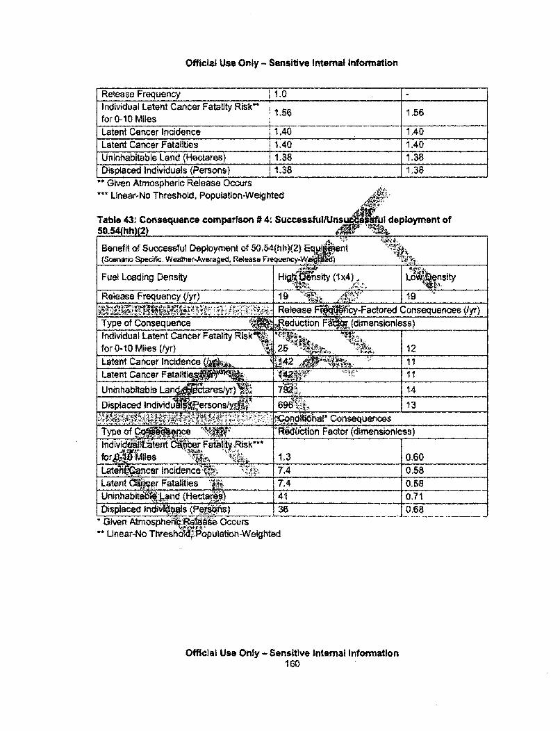
Official Use Only - Sensitive Internal Infortnation
Release Frequency 11.0Individual Latent Cancer Fatality Risk"* 56 156for 0-10 M iles I____1_Z
Latent Cancer Incidence i 1.40 1,40Latent Cancer Fatalities j 1,40 1.40Uninhabitable Land (Hectares) 1.38 1.38Displaced Individuals (Persons) . 138 1.38
Given Atmospheric Release OccursLinear-No Threshold, Population-Weighted .:
Table 43. Consequence comparhwn #4. Successfu4;Uns ui deployment of50.54(hh)(2)
Benefit of Successful Deployment of 50.54(hh)(2) Equipment(Scenaio Specific, Weather--Averaged, Reiease Freque}-Ww.k) ,_,,
Fuel Loading Density H Oi' sity (Ix4). L J fl
Reiease Frequency (•yr) 19 .'•: 19...... Release Fe 5 cy-Factored Consequences (/yr)
Type of Consequence Red.uctlon Far. (dimensionless)Individual Latent Cancer Fatality Risk . ..for 0-10 Miles (/yr) ______- __" __........_' ____ 12Latent Cancer Incidence 4&.. '42 •.-45 11 ......
Latent Cancer Fataliti• _____..______"_'_:____ 11
Uninhabitable Langde tarestyr) 792 14Displaced Indivdu ~~ersonslyr.A 6 98 13
*;-~;~i ~' ~ondU~haI* ConsequencesType of Cý.Re Rduton Factor (dimrensionless)
lbtei~ 10 Rik"
for___lies 1.3 0.60La'fiPner Incidence ~ 7.4 0.58
Latent er Fatalities i 7.4 0.58Uninhabita6W Land (Hectar.s) 41 0.71Displaced lndl 44pls (P~I-S) 36 0,68Given Atrnosphe4M"Rel, Occurs
Linear-No Thresho6,.:Population-Weighted
Official Use Only -Sensitive Internal InformationI60
Official Use Only - SensiUve Internal Information
References:
[1] Chanin, 0. and M.L. Young, NUREGICR-6613, SAND97-0594: Code Manual forMACCS2User's Guide. 1997, Sandia National Laboratories: Albuquerque, NM.[2] NUREG-1 150, V., Severe Accident Risks: An Assessment for Five U.S. Nuclear PowerPlants, 1990, US. Nuclear Regulatory Commission: Washington. D.C.13] Laur, M.N., "Meeting witf Sandia National Laboratories and an Expert Panel onMELCORtMACCS Codes in Support of the State of the Art Reactor C'nsequenceAnalysis Project," Memo to J.T, Yerokun, Agency Document Acce&Wnd Management SystemAccession Number ML062500078, U.S. Nuclear Regulatory C 6'.sion, Washington, D.C.,September, 2006.14] NUREG-0654, NUREG-0654/FEMA-REP-1, Rev, 1"titeRe for PrepAration and Evaluationof Radiological Emergency Response Plans and Prepratfwress in SuppoKi•.&,Nuclear PowerPlants. 1979, U.S. Nuclear Regulatory CommissiýB1&lshington, DC.[5] NUREG/CR-6064, Vol. 1: Identification and4A" Iysis of Factors Affecting EIegencyEvacuations: Main Report-" January 2005 -.161 McFadden, K.L., N.E. Bixler, and R.O. Gauntt, Makk4C.& System Documentation(MELCOR to MACCS2 interlace defindkop). 2005, Sand! Ntional Laboratories: Albuquerque,NM. Morro[7] Bixer, N.E., E. Clause, C. W. Mor and! -Mt1itchell.'a~ato of DistributionsRepresenting Important Non-Site Specifidparame I f .-Si4 ?"onsequence Analyses, to bepublished as a NUREG R as ndia Na&al & ra ',luquerque, NM, 2010.
(8] Bxtder, N.E., et at, NE25, RevI4 SND2003-1648P: SECPOP2000:SectorPopulation, L: racU'on, a EconomkqE•tinmation Program. 2003, Sandia NationalLaboratories: Alb ue, NM. A[91 NUREGICR-6953, bview J504 ýpler.ent 3, 'Criteria for Protective ActionRecomrnen for S idents -.97roup and Telephone Survey," U.S. NuclearReguiat iqs*n W ton, D.C., 2008[10] 2202) Fed5W Gu da Report No. 13 CD Supplement, E.-C.-.-., Rev. 1. 2002,Pre by Oak Ridge'. al Ioratory, Oak Ridge, TN for Office of Air and Radiation, U.S. Enr- ental Protetio•n en •-ýash-ington, DC.[11 ] EPA t(•4). Estimating' iogento Cancer Risk. EPA 402,R-93-076 (U.S. EnvironmentalProtection Adthy, Washint, D.C.)[12] Eckerman, ReIf Risk Coefficients for SOARCA Project, , memo, Oak RidgeNationa, Laborato ru'ry 2009,[13] NAS, Heakth Effects of Exposure to Low Levels of lonizfng Radiation: BEIR V. 1990.National Academy of Sciences, National Research Council, National Academy Press:Washington, DC.[14]Environmental Protection Agency (EPA), EPA-400-R-92.001, 4Manual of Protective ActionGuides and Protective Actions for Nuclear Incidents," Washington D.C.: EPA. May 1992, (EPA,1932). http/llwww.epa.,ovlradlataor/docs/er/400-r-92-001.pdfNuclear Regulatory Commission, OCriteria for Preparation and Evaluation of RadiologicalEmergency Response Plans and Preparedness in Support of Nuclear Power Plants." NUREG
Official Use Only - Sensitive Internal Information161

Official Use Only - Sensitive Internal Information
0654/FEMA REP 1, Rev. 1, N ucear Regulatory Commission: Washington DC. November1980.
Nuclear Regulatory Commission (U.S.) (NRC). NUREG/CR-6864. "Identifica(ion and Analysis ofFactors Affecting Emergency Evacuations." Washington D.C.: NRC, January 2005. (NRC,2005).
Nuclear Regulatory Commission (U.S.) (NRC). NUREG/CR-6953, Vol. 2. "Review of NUREG-0654, Supplement 3, 'Criteria for Protective Action Recommendatiopo. for Severe Acxidents,Focus Groups and Telephone Survey." Washington D.C.: NRC, *. r 2008. (NRC, 2008).
Nuclear Regulatory Commission (U.S.) (NRC), NUREReactor Consequence Analyses (SOARCA) Project:Washington D.C. NRC. January 2012. (NRC, 2012a
Nuclear Regulatory Commission (U.S.) (NRC).Reactor Consequence Analyses (SOARCA) Proj~iD.C. NRC. January 2012. (NRC, 2012b).
ited Analysis.'
2." of the Art
Woishon, Brian, J. Jones, and F. WaiDecision Making." Journal of EmergiNumber 1. (Wolshon, 2010).
A MAIX-n, ýri'
try 2010, Volume 8,
Official Use Only - Sensitive Intemal Information162
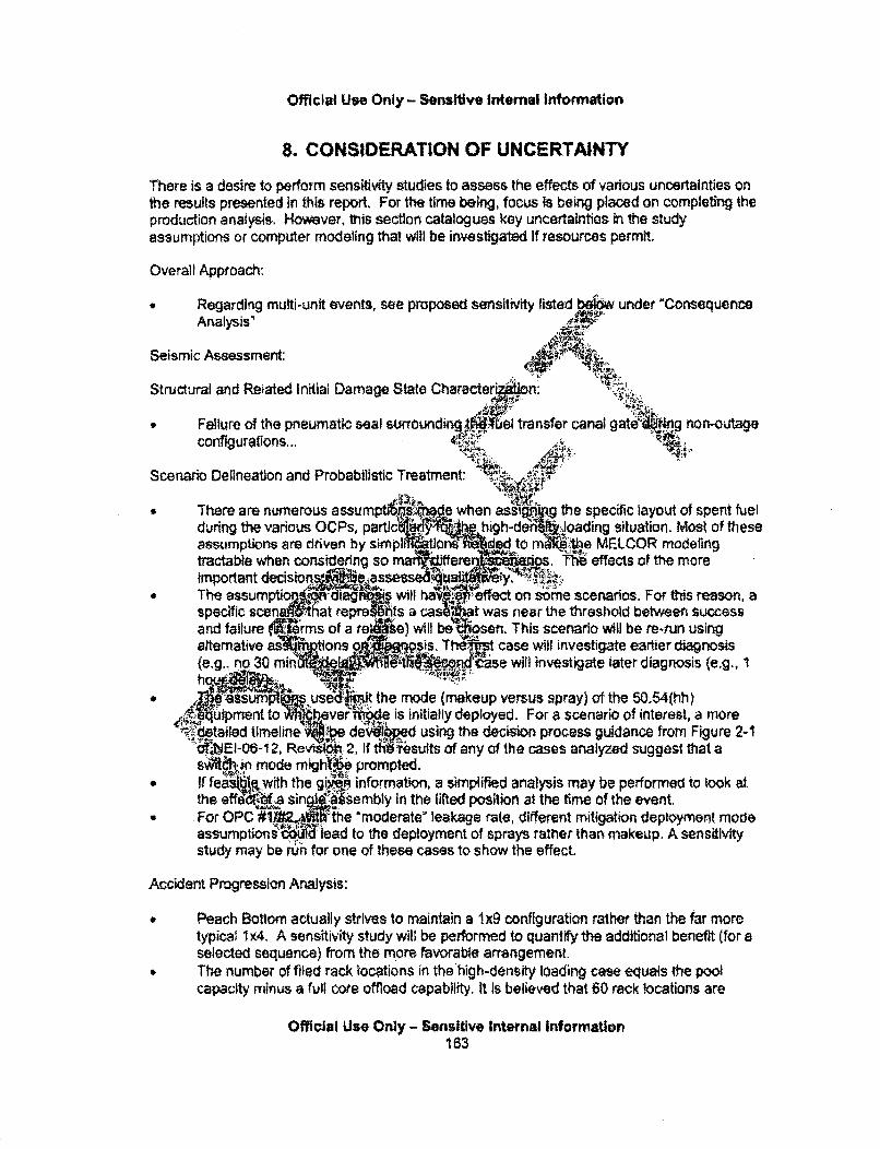
Official Use Only - Sensltive Intemal Information
8. CONSIDERATION OF UNCERTAINTY
There is a desire to perform sensitivity studies to assess the effects of various uncertainties onthe results presented in this report. For the time being, focus is being placed on completing theproduction analysis. However, this section catalogues key uncertainties in the studyassumptions or computer modeling that will be investigated If resources permit.
Overall Apptoach:
* Regarding multi-unit events, see proposed sensitvity listed bel6w under "ConsequenceAnalysis'
Seismic Assessment:
Structural and Reiated Initial Damage State Character' n:
* Failure of the pneumatic seal surrounding 'al transfer canal gateaking non-outageconfigurations,...
Scenario Delineation and Probabilistic Treatment: ". '•
There are numerous assumpt sive when assi 6199 the specific layout of spent fuelduring the various OCPs, partic .... high-deri •joading situation, Most of theseassumptions are driven by simP-11 on ded tO m• he MELCOR modelingtractable when considering so ma ear T1s * effects of the moreimportant decision 89 assel lua iy. ý~The assum:pt:or•.. diag••s-, will ffect on some scenarios. For this reason, aspecific scen '"tat repre",ts a cas ~at was near the threshold between successand failure WYRrms of a ret &0) wil b'If osen. This scenario will be re-run usingaltemative asik otions .•Q sis, Thekiws case will investigate eartier diagnosis(e.g.. no 30 min % 0-0 %on • •isdse will investigate tater diagnosis (e.g., 1
*.usedt the mode (makeup versus spray) of the 50.54(hh),,quipment to ever iode is initially deployed. For a scenario of interest, a more4`I~detaIled timeline w.be dewlie using the decision process guidance from Figure 2-1
fEI-06-1 2, RevZt& 2, If t~lrP sults of any of the cases analyzed suggest that aSA ..•n mode mlghte prompted.
4 If feasble.,with the gin n information, a simplified analysis may be performed to took atthe eff ba s ssembly In the lifted position at the time of the event.
.For OPC #1: ;the 'moderate" leakage rate, different mitigation deployment modeassumptions'i lead to the deployment of sprays rather than makeup. A sensitivitystudy may be run for one of these cases to show the effect.
Accident Progression Analysis:
Peach Bottom actually strives to maintain a 1x9 configuration rather than the far moretypical I 4. A sensitivity study will be performed to quantify the additional benefit (for aselected sequence) from the more favorable arrangement.The number of filed rack locations in the high-density loading case equals the poolcapacity minus a full core offload capability. It is believed that 60 rack locations are
Official Use Only - Sensitive Internal Information163
Official Use Only - Sensitive Internal Information
reserved for storage of other hardware (eg., guide tubes), but nonetheless, 3055 storedassemblies is used. The reduction of the assumed high-density pool inventory by 60colder assemblies will be considered by a simple assessment of the impact of theseassemblies on the projected source term (e.g., ratioing of source term considering thereduction of these assemblies).
" There is some subjectivity in the modeling needed to take a 3-D Cartesian spent fuelpool rack arrangement and translate it to a 2-D cylindrical computer model (MELCOR).An example of this has to do with the prescription of heat transfer quantities (viewfactors, surface areas) between Rings 5, 6. and 7 in the low-density pool configuration.Modeling here took a moderate approach in establishing a ned lx2 ratio of Ring 5 toRing 6 and assigning an interface that increases the surfan,•o'a between Rings 6 andRing 7. Whether these assumptions are conservative or onservative is highlysituation (and heat transfer mode) specific. While the ade are viewed asreasonable, the effect of an alternative assumption In ated.
" The current MELCOR model does not account the effects (should It occur)on the source term. This uncertainty. ill be i igated. .4aai
• Peach Bottom had a small power uprate i which is after the N analysisused for this study was completed. In , as ra cy•ave wn longer,the trend has been to take the fuel to high urnups.. euent to the , blishmentof the decay heats and Inventories used in t .• 0 .. -e licensee prOvided informationmegarding the assemblies offloaded between 2 11. Additional ORIGENcalculations were performed hgges t t ,, rrent study generallyunderestimates the long-lived -i -de.. invento He over-estimating the short-lived radionuclide inventory, A s lW will be for this new set of inventories.Since the study does not account y att I conc.WrTent accident events, asensitivity will be r. by a hy en t crs from hydrogen generatedfrom a conurre nt for cenaro rer such an event would nototherwise be Ited (e. OCP # enmitigated, moderate leak case), The timing ofthe deflagr "and the a nnt of hyd n participating, will be based on a SOARCASTS5O scen This cal i!on will be twce, once for a high-density loading caseand once for th elbtdensi.t se.
ConsequenN .iim
lp set of MACCSAý :culatill be run for a low-density and high-density OCP #3 case.tht goes to releashiNvhI combines the SFP refease with the SOARCA Peach Bottom$teBo release ,
'; •1.'• ."'
Official Use Only - Sensitive Internal Information164

Official Use Only - Sensitive Internal Information
9. OTHER ISSUES
9.1. Probabilistic Risk Assessment versus Consequence Assessment
This study is a limited-scope consequence assessment that utilizes probabilistic insights. Bylooking at these probabilistic aspects, the results can be placed in better context, via the limitedtreatment of relative likelihood. While these elements provide some of the benefits of an actualrisk assessment, there are several eiements of a risk assessment that are specifically notperformed. These are:
Failure modes and effects analysis (except fow SCsof this report)
* Data analysis and component reliability* Effects of dependencies* Human reliability analysis* System fault tree and sequence event tree 0~pm
Even so, this study does attempt to bring pobafit insighlstudy these include:
* Risk information from past studiftfof selecting 'ft4Initiating event likelihood
" Initiating event timing effects (e. h i We lkelihfcvarious operating cycle phases afffe lig•euRelative likelihood ofd aage state •aract• rassociated with off W 6Oequencec Ie eg. ,analysis)
discussed in Section 4
ant•i~ion
In terms, Wroputs to the
idied
ig an event during therred)al probabilitiesal sampling in MACCS2
In terms of assessiinputs (and simplecontext on tbesi.
i:ýof probabilistic insights uses the above*:different figures of merit, in order to place
The
Now cAfailure
Rects within the current scoping study allows for consideration ofit' i4 M' support definitive statements on risk, To elaborate,dy to6Udistinct data points along an unknown capacity function.Femenfi/goals (most notably the Safety Goals) to be a continuous,a the capacity data points to the failure function, we can gain.data generally lies in this success regime or the failure regime.her and use past studies to compare our data points to otherapproach we can draw supportable, but not definitive,capacity func
conclusions.
9,2, Multi-Unit Considerations
Observations regarding a concurrent reactor event,:
There are five broad interplays possible between the spent fuel pool and the reactor.
1 An initiating event which directly affects both the reactor and the spent fuel pool,
Official Use Only - Sensitive Internal Information165
Official Use Only - Sensitive Internal Information
2. A reactor accident which prevents accessibility to the spent fuel pool for a prolongedperiod of time, leading to a spent fuel pool accident,
3. A reactor accident that includes ex-containment energetic events (most notably ahydrogen deflagration or detonation) which presents a hazard to the spent fuel pool(e.g., by causing debris to fall in to the pool),
4. A spent fuel pool accident which prevents accessibility to key reactor systems andcomponents for a prolonged period of time, leading to a reacto !accident, and
AJ,
5. A spent fuel pool accident which creates a hazard for eSLment used to cool the reactor(e.g., the flooding of low elevations of the reactor buildi .•,to a .eak in the pool orexcessive condensation from continuous boiling of I~I fe olwter),
For each of these, large seismic events and severe wdeffi& 10 fffi er events arelogically the most relevant initiators, as they are th N of Initiators that a t likely to(a) initiate an accident at the reactor and/or spe&I pool and simuitaneousl furtherhamper accessibility to key areas, key systems a .componerftsfand key resour• To theextent practicable, this study has attempted to qua I "nt for some of these effects.For example, when the reactor and SFP are hydraull ected (during refueling), thedecay heat and water volumes from b4'•ources are c ered. However, explicitly modelingmulti-unit effects was not a focus of tW theexrstone limitations with the availablecomputational tools. The site Level 3 P.. 0 in C 1-0089 will attempt to morerigorously address these effects. y..'~~~~~~~~~~. .......... •'!:-", ... '",i'',::Observations regarding. - •vent i ..
Along with the pos of a conc nt spentAfW. pool and reactor accident, there is thepossibility for a co nt accidera the spentJl pool of one unit with an accident at thespent fuel pool or rea t hof tl a arge seismic event or a severe weatherLOOP are t • t• the; IlkeI , 1 -4ad t mul-unit event. In general, if accidents at
b ' rocM similar mannead similar timeframes, and both pools havesimila ttfuifen the resulting source term from a dual-unit event would berouI. sing ý'.!t WAW rm. In reality this type of perfect symmetry Is highly
k~ cause the two(nmore) ps are very unlikely to have the same total pool heat loador keak~ mbly heat road call that for multi-unit sites, the reactors did not usually startoperation• .f same time outages are intentionally staggered). Even if such a symmetryexisted, the 6i consKe s would not follow a linear scaling, due to a number of non-linearitles assodl~t d witt~fi portion of the analysis. Again, capturing such effects was not afocus of this study. - r. 44 'e work (SECY-1 1-0089 Level 3 PRA) will attempt to more rigorouslytreat these effects. :
Official Use Only - Sensitive Internal Information166

Official Use Only - Sensitive Internal Information
9.3. Seismic Risk for Dry Cask Storage
A logical question to ask is what effect the studied (challenging but very low frequency ofoccurrence) seismic event would have on the fuel In dry cask storage at Peach Bottom. For thereasons outlined earlier, this study does not attempt to quantitatively address that question.Even so, that issue can still be addressed to the point of providing perspective.For low to moderate seismicity sites (such as Peach Bottom), weight, cask geometry and frictionprotect against sliding or tip-over. For reference, NUREG-1 864 (a p~lptdry cask storageprobabtiistic risk assessment performed by the NRC) concludes th Ithe conditions and typeof cask studied; the PGA necessary to postulate damage to the- (from tip-over) was 1.35g,which Is well beyond the 0.71g SFPSS considers. The cask in the NUREG-1864study (Holtec HI-STORM 100) has a slightly higher aspect o6 . T.height ratio) than thecask used at Peach Bottom (TN-68). Comprehensive tric eva s are reported inNUREG/CR-6865 for a cask similar to the HI-STORW. . and for earthq with varyingground shaking characteristics including character-usimitar to those exp~d for the Central
and Eastern United States (CEUS). These evaoiafis show that tip-over of thisk studiedwould not start for an earthquake about 2.3 e.ttie earthquaAconsidered in tt[-urrentstudy. A margin of 230% is considered sufficient tor ud cask tip-over a ssumption in
the current study even taking Into account the differeirdn'l e aspect ratios of the casks.
As a real world example. the August 2 t 1 t.uake at t oth Anna site (which utilizes TN-32 casks), caused a cask to slide up to , ýIn c th % aDai-chi site utilized on-site dry cask stora th rL.. nt taecur omthe earthquake or the tsun At i± s also njl thak1'... .:,...,,been evaluated for hypotheticaldrops and tip-over with I 'loads asks of tW.i+rder of 30g, which are at leastan order of magnitude than laM- I lnertial s from earthquakes.
Even postulating a .ic event sMciently lardifor a tip-over, assuming mechanical damageto the fuel from the tip ant. cask'breach from the tip-over, the resultingradioactivie. e woulI Ite 1ge :.:seat ground level with no energetic heatcontent•, ensidering releases from multiple casks, would involve far lessradio l nate§na1s as .lated with a reactor or spent fuel pool fuel melt scenario. Tohavey.Vse a c .the seismic scenario, It would be necessary to havebreac~ ehc••hn en he of the fuel to temperatures of the order of 900 C. Thesetemper"- are much high~rthan tli}se that heating by decay heat and ow-t•emperaturecladding ox.tion (part icula iin the oxygen-limited configuration of a cask breach) coulda c h ie v e . = • ,.• .; : i :
9.4. Other Conserations Related to Expedited Fuel Movement
As stated up fronL this study focuses on offsite consequences associated with a release fromthe spent fuel pool, for the specified earthquake. The set of information provided in this reporthelps to frame specific aspects of a much larger issue, that of whether expedited movement ofspent fuel results in a sufficient benefit to warrant its requirement. As mentioned at the start ofthe report, there are many other considerations that play in to this larger decision. Theseinclude, but are not limited to, the following Issues:
Official Use Only - Sensitive Internal Information167
Official Use Only - Sensitive Internal nformation
" Current regulatory requirements under 10 CFR Part 72 limit (from a practicalityperspective) the ability to transfer fuel with less than toughly 3 to 5 years of cooling
• Discharging large amounts of fuel (and thus greatly increasing the amount of fuelcontained In the ISFSI) might require a Part 72 rulemaking effort (e.g., to accommodateincreases in the design-basis accident site area boundary allowable dose limits) andpotentially increase the risk associated with the ISFSIExpedited discharging of fuel from the spent fuel pool to dry storage increases thefrequency of postulated cask drops, which in turn increases the risk of causing damageto the pool that could lead to a radioactive release
" Expedited discharging of fuel increases occupational doses fnr workers involved with themanagement and transfer of the spent fuelAWW
" Earlier movement of fuiel Increases the probability that f .1llhave to be re-packagedlater for shipment to the eventual long-term reposito s.. storage site
issues related to design-basis accidents and risk pose0JAr dry cask stoa h~4ave received, andcontinue to receive, attention. Issues related to the .ea..'g dry cask storag;'frastructure,worker dose, and economics are discussed in [NA I 1) and/or [EPRI, 2•,,Section 1.6provides more information on each of these stua,,.
9,5.1nadvertent Criticality 'Inadvertent criticality events (ICEs) m" for spe cmbinations of conditions
(e.g., during reflood of a drained pool f¢o i4 2Kh ool 1 di higher reactivity fuelassemblies where the boron poison in theý.ck pan .. _beenN 0ifficantly displaced as aresuft of the earthquake). 9, an event b a poo! (as opposed to only aportion of a particular asa, if it o ..at a point i"n e accident where the fuel wasonly partially covere 'iQevent a rtant Impact on onsite dose rates. Designrequirements and •_.r analyses oure that . mpent fuel stored in the pool, under normalconditions, will not res An a cri .nfIuratio.tor the selected plant (and other US spentfuel pools), this is ensu • h'assembly spacing and neutron poisonaie x). voen :ll' Use reconfiguration of the fissionable material
via elth e4i.Ovmerntte tued -- on 'he fuel, (il) direct degradation of the poison material, or (iii)indi • on eittf!" e fue olson material due to high temperatures associated with anin acident, there A"e.,seve ,.•dvantageous' considerations that should to be kept inmind ,Ose are:
1. the re9ctivlty of fresh':8WR fuel is suppressed due to the high content of btumabte• :" • .. " •'!1,": ,;I:
absorI5116 b
2. the majoritydo "..fuel in the spent fuel pool has low net reactivity due to having gonethrough more a'n one operating cycle in the reactor,
3. the fuel with the highest net reactivity wili likely be the once-burned assemblies whichwill stay in the reactor during a "shuffling" refueling outage (but would not stay in thereactor fof a full core offload),
4. critical configurations of low-enriched Uranium fuel require the presence of a neutronmoderator (in this case water or steam) such that an ICE would not happen In thepresence of air,
Official Use Only - Sensitive Internal Information168
Official Use Only - Sensitive Irternal Information
5. BWR SFPs do not use borated water so the fact that the SFP may be refilled withunborated water Is not a deviation from the norm, and
6. low-enriched uranium fuel assemblies (which are used in all US reactors) aregeometrically designed to maximize reactivity (moderatorlfuel geometry) in the reactorand so any significant alteration of the geometry of a given assembly wil likely be in thedirection of a less criticality-prone configuration
Having said this, there are a few counter considerations that should also be kept in mnind:
1. the poison material in the rack panels contribute signif' o the net reactivity of theSFP configuration (i.e., they are a key component to en AV"-.sub-citicality for highreactivity assemblies) *f
2. the affects of large seismic events on aiready) ded SFP rac Own material arenot easy to quantify,
3. the rack panels and poison material have a Ioer meltirtemperature tha'tjhe claddingand fuel, and ' "
4, the possibility of a criticality evW:annot be summarih dismissed.
Finally, the offsite consequences of a cr.1l't spe occurs when overlyingwater is present) are believed to be less .ere f.:and safety standpoint thanthe offsite consequences fr i- ent' II relet.s 'r acti~e material associated wftb aprolonged uncovering oq. he SFP from nf tempting to re-flood, Inconsideration of allo ~ ve ° on act.,-=t management practices in the US cafl for theuse of any availabl 'tr in respo o fueLnovery in either the reactor or SFP. Thecurrent phase of thi + dy followRAe preceder f'ile recommending that future work be doneto better understand eel .. itions thatcould lead to ICEs during alarge sesmoe.t .
g se of Con t us (Wfrm) Fuel Arrangements During An OutageThe plarlt:udted has pre- nged the spent fuel pood such that discharged assemblies can be
placed direci*n to a 1x4 (a.ntally lxB in the case of this plant) arrangement for the last twooutages, for b:Tioperating •its, This is in keeping with the relevant regulatory requirements.However, those :1 lator;A..uirements do allow for the fuel to be stored in an unfavorableconfiguration for sor!'me following discharge if other considerations prevent pre-arrangement
There is a regulatory requirement associated with the time window by which the 1 x4arrangement must be achieved, however the specific time requirement Is not publicly-availableinformation (because it could be potentially useful to an adversary). This section posits asituation where the fuel Is unfavorably arranged during the outage to demonstrate the effect ofthis aspect on the results.
The layout of assemblies for the OCP1 and OCP2 uniform configuration is shown in Figure 95and Figure 96, For the 1x4 configuration (see Figure 42), the effective area between Rings 1and 2 was determined by the number of panels (i.e., 352 panels for 88 assemblies) since each
Official Use Only - Sensitive internal Information169
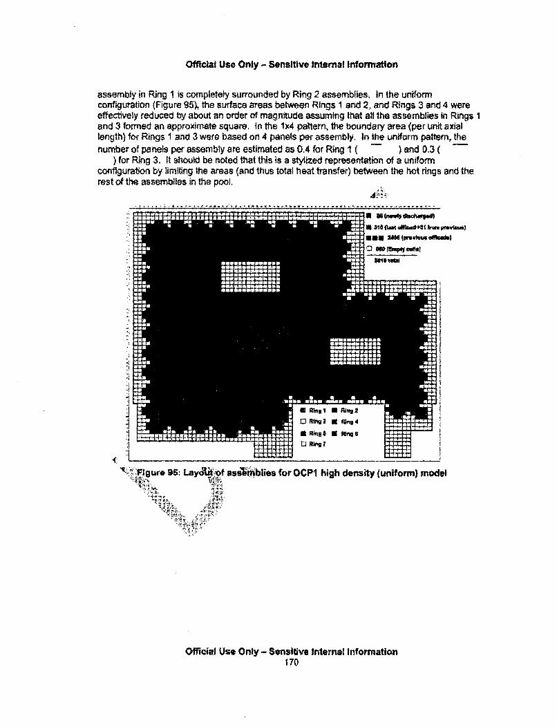
Official Use Only - Sensitive Internal Information
assembly in Ring 1 is completely surrounded by Ring 2 assemblies. In the uniformconfiguration (Figure 95), the surface areas between Rings 1 and 2, and Rings 3 and 4 wereeffectively reduced by about an order of magnitude assuming that all the assemblies in Rings Iand 3 formed an approximate square, In the 1x4 pattern, the boundary area (per unit axiallength) for Rings I and 3 were based on 4 panels per assembly. In the uniform pattern, thenumber of panels per assembly are estimated as 0.4 for Ring I ( ) and 0.3 (
) for Ring 3. It should be noted that this is a stylized representation of a uniformconfiguration by limiting the areas (and thus total heat transfer) between the hot rings and therest of the assemblies in the pool.
- .
.*1' I
~Ring 1 0 Pig 2
ItRing# a "s
Figure 9. Lay(41if as"Iblies for OCP high density (uniform) model
Official Use Only - Sensitive Internal Information170

Official Use Only - Sensitive Internal Information
fi
I
*i
"4
lip Jill-00"m-a
cam rMNO
ZL aim
At amal M
lowas 11211ra
Oft now al" a sualýg. a 'I a ý go
.:.aNK
MHOW
H LW;WW
AW
00
law" offaVON"
H.
IM:
B,
0 MW
NCR Exim41
*maft J" 413" ftlim
a a a
so :0 as 0 1*on W M.A.we a Meowasen cueso WoAM::a so~ WIL WL Jo It lama hotsoannal 0011MMKOWaMEMMEN WE" 10191 am MAIM-:*oft
pwk-)
Figure 96 Layo , fssembliior •O •i-g4ensti-y (uniform) model
Unmnit',ated Moderate - (OCPýi niforr)iarto• "t.•' ;r]. , ~ ,/:': AV•!;7
The results of the c161 for fa iform OCPI 0 are shown in Figure 97 and Figure 98. Acomparison of the head "ith "WNW , MV - (Figure 65) shows the higher temperatures inthe unifor • ,conflgo there; I urfaoe area between Ring 1 and the colderassembl he d'•he eII' thermal response, however, is comparable, At about 30hou • expen a g dial heat up as the oxygen in the building is depleted, andfo of debris res air fiNAA llrough the assemblies. Eventually, all the fuel in Ring Icollapm1 and forms a de• bed I"r• is continuous release from Rings I and 2 and theoverall Caselease to the enw.oiment is about twice of that In the Ux4 geometry (see Figure 70),
Official Use Only - Sensitive Internal information171
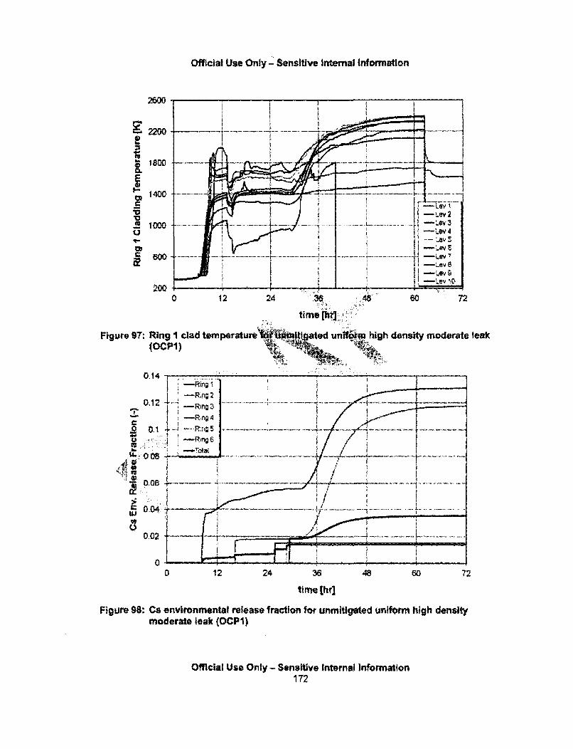
Official Use Only - Sensitive Internal information
2600
~2200
j1400
V2 1000
12
-i -LevI
* ii-Lev 1200
0 12 24 430
time [hiT]:.
60 72
Figure 97: Ring I clad temperatur&e I ttgated unfr&m_ high density moderate leak(OCPI)
0.14
0,12
0.12
~0 0
0.02
O
0 12 24 36 48 60 72
time(hr]
Figure 98: Cs environmental release fraction for unmitigated uniform high densitymoderate leak (OCP1)
Official Use Only - Sensitive Internal Information172
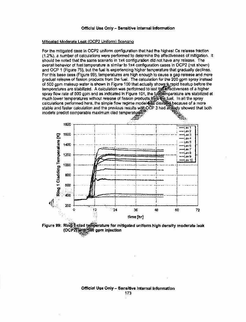
Official Use Only - Sensitive internal Information
MWoated Moderate Lgak (OCP2 Uniforml Scenario
For the mitigated case in OCP2 uniform configuration that had the highest Cs release fraction(1.2%), a number of calculations were performed to determine the effectiveness of mitigation. Itshould be noted that the same scenario in 1A4 configuration did not have any release. Theoverall behavior of fuel temperature is similar to 1x4 configuration cases in OCP2 (not shown)and OCP 1 (Figure 75), but the fuel is experiencing higher temperature that gradually declines.For this base case (Figure 99), temperatures are high enough to cause a gap release and moregradual release of fission products from the fuel. The calculation for the 200 gpm spray insteadof 500 gpm makeup water is shown In Figure 100 that actually showslrapid heatup before thetemperatures are stabilized. A calculation was performed to test tbffectiveness of a higherspray flow rate of 500 gpm end as indicated in Figure 101, the fu'rnperature are stabilized atmuch lower temperatures without release of fission products. fuel. In afl the spraycaiculations performed here, the simple flow regime model a isa because of a morestable and faster calculation and the previous results wlI#OCIP 3 had a y showed that bothmodels predict comparable maximum clad temperaturA.I..
•., •i ' -L ev 41400 --- e
'7U1-Lev$
-,Lev 10
to I DUO Le
........ ... ... .. . .. . ... . .... . . .....
, - 4 0 0 ... . . . .. .. .. .. ................... ....... ... .... . ... . . . ..... . . .., . . .. . . . . .. . . . . . . . . .
0 12 :.::"24 48 60 72
time 1h r
Figure 99: RiMADclad t rature for mitigated uniform high density moderate leak(OCP2 ;r-,.gpm Injection
Official Use Only - Sensitive Internal information173
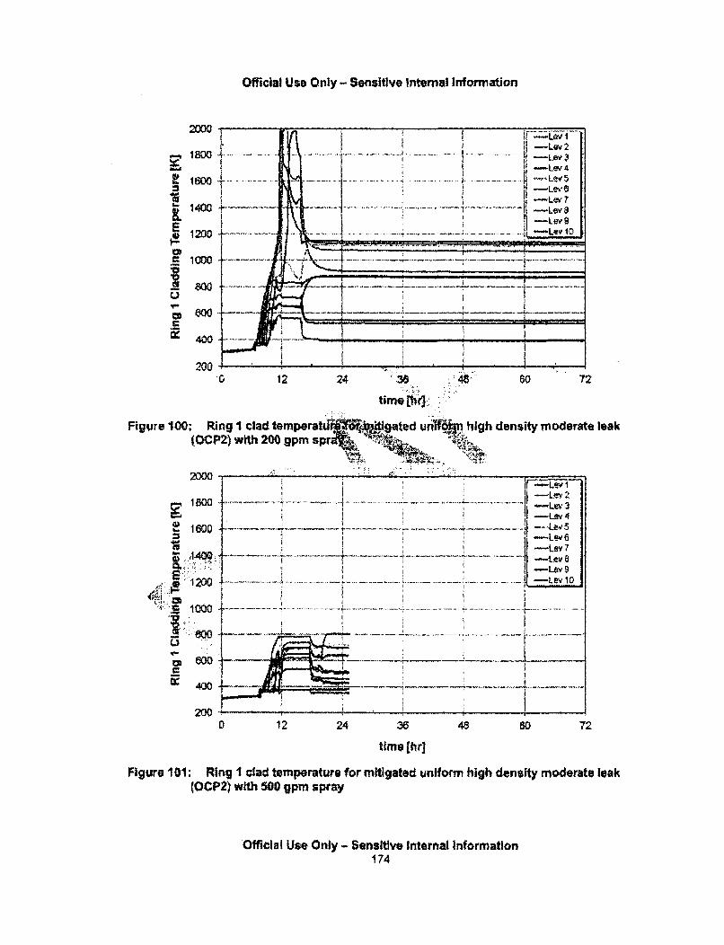
Official Use Only - Sensitive Internal Information
....... ......................... ......... --Lev
I i-Lev
€,.-Lev 1-Lev'
. . .. . .. .. ..... .
51000 .
I -
0: 4WI2 0 0' ,'' .....- ... :
0 12 24 'X.. 48 60 72
timne [h~ .i . ...
Figure 100: Ring I clad temperatu Igated un6\ high density moderate leakýým high,-, desiy-odrae ea
(OCP2) with 200 g1pmnsnaa
2100I -Levl'3
-LevZ "--Lev 3
-Lev 4
1600 .-..... - _. 5
-~-Lev 9
C• 1 0 0 f- .- -- ---. .. . . . . . . . .. .. . . . ....... °.............. .............. . . ............... ... .
2 00.
0 12 24 36 48 so 72
time [hr]
Figure 101: Ring I clad temperature for mitigated uniform high density moderate leak(OCP2) with 500 gpm spray
Official Use Only - Sensitive Internal Information174
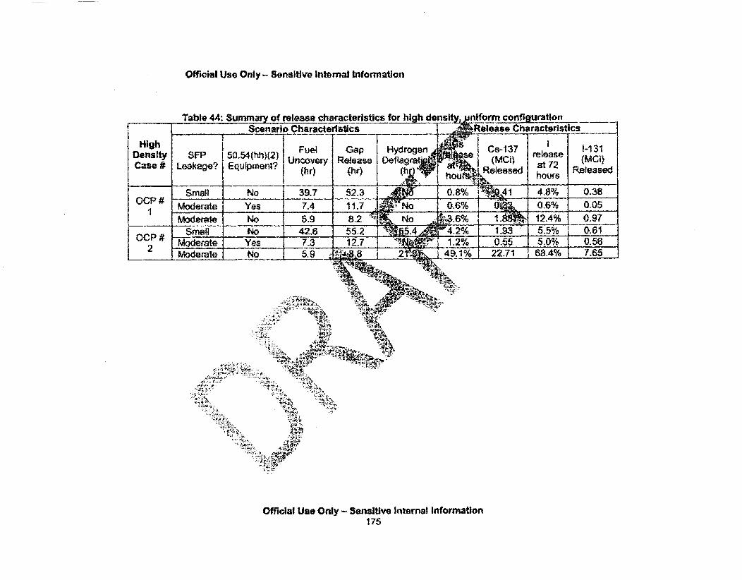
Official Use Only - Sensitive Internal Information
Table 44: Summary of release characteristics for hihhd ds • iform configuration______ Scenario Characteristics - Release Characteristics
High Fulj ----.--- - -iFae#Lekgeqimel (rrel ealeaeHigh F Gap Hydrogen. Cs-137 1-131D e n s ity S F P !50 ..54 (hh )(2 ) U n a r R el a s D e l g a( a) re e a e ( M ICe UnIteen Release iOeflaeat? (MCiRela2 (MCi
(h)Released hours
Small No 39.7 52.3 Id1 0.8% 4 1 4.8% 0.381 # Mderate Yes 7.4 1.7 No 0.6% 0.05
Moderate No 5.9 8.2 .6% No . % 2%Smail No 42.6 55.2 -: 5,4 6 4.2% 1.93 5.5% 0.61
OCP # Moderate Yes 7.3 12.7,.' 1.2% 0.55 5.0% 0.56Moderate No 5.9 8 2 49.1% 22.71 4 6 8 4- .65 --
44A-,
:A,
Wl
Official Use Only - Sensitive Internal Information175
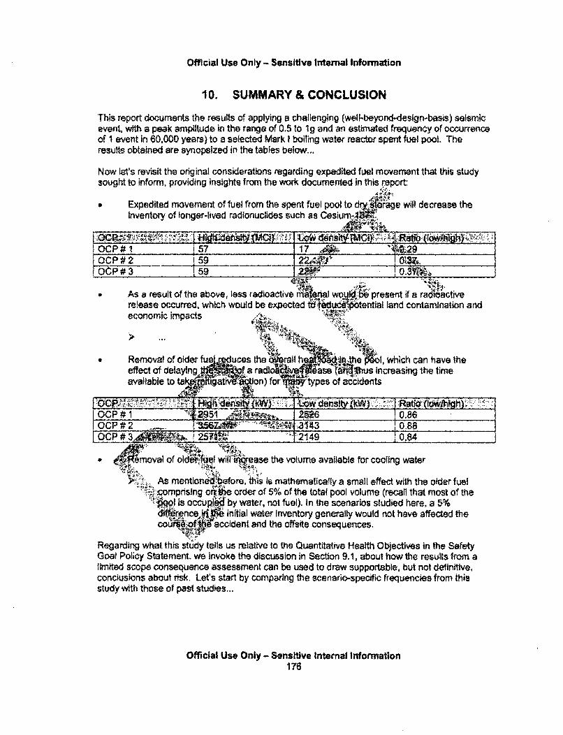
Official Use Only - Sensitive Internal Information
10. SUMMARY & CONCLUSION
This report documents the results of applying a challenging (well-beyond-deslgn-basis) seismicevent, wfth a peak amplitude in the range of 0.5 to 1g and an estimated frequency of occurrenceof I event in 60,000 years) to a selected Mark I boiling water reactor spent fuel pool. Theresults obtained are synopsized in the tables below...
Now let's revisit the original considerations regarding expedited fuel movement that this studysought to inform, providing insights from the work documented in this report:
* Expedited movement of fuel from the spent fuel pool to dr.rge will decrease theinventory of longer-lived radionuclides such as Ceslum-,lif.''
OCP# 1 57 17lOCP#2 '59 ___
. #,59 •
" As a result of the above, less radioactive mWeflal would.ý present i a ra ciativerelease occurred, which would be expected t d-uEtential land contamination and
economic impacts
-4k,
" Removal of okder fue ýduces the ralh:,the h1, which can have theeffect of delaying 'of a radic"' vease a'hm-:*tIs increasing the timeavailable to ta '.i."IgaI 'on) fo ''t"ypes of accidents
IOCP # 1 291, g6J256 10,86 ____
OCP #2 10.88OC# 0.84
-o valof oldei/Rwilt ei: ase the volume available for cooling water
As mentionebefore, this Is mathematically a small effect with the older fuelcomprsing oN.• _. order of 5% of the total pool volume (recall that most of thep.Wl is occupied by water, not fuel). In the scenarios studied here, a 5%d01'rene l.1 initial water inventory generally would not have affected thecours V; accident and the offsite consequences.
Regarding what this study teils us relative to the Quantitative Health Objectives in the SafetyGoal Policy Statement, we invoke the discussion in Section 9.1, about how the results from alimited scope consequence assessment can be used to draw supportable, but not definitive,conclusions about risk. Let's start by comparing the scenario-specific frequencies from thisstudy with those of past studies...
Official Use Only - Sensitive Internal Information176
Official Use Only - Sensitive Internal Information
11. REFERENCES
(Alvarez, 2003]
[Congress, 2005]
Alvarez, Robert, et a., 'Reducing the Hazards from Stored Spent Power-Reactor Fuel in the United States," as transmitted in a letter to Ashok C,Thadani dated April 21, 2003. IML031130327]
House Report 108-554, Energy and Water Development AppropriationsBill, 2005. Available at thomas, loc.gov
[EPRI, 2010] Electric Power Research ISpent Nuclear Fuel from 6Five Years of Cooling," EFwwweadrcm
[Exeion, 20111 Exelon Corpora6i... etterRegulatory CornI ,Limit Minimum C2'I P•[ML1116001803 .
t, 'impacts Associateiduel Storage Pools to D4-10210404ovember 20-
Transfer ofbrage After%Vallable at
I from Jesse to the U.S. NuclearAnAmendment Request - Safety
&C. dated June 8, 2011.
pINL, 1996) Zss of Spent Fuel Pool Cooling PRA: ModelSeptember 1996." INEL-
nal, "NAG White Paper on Establishing a Balanced.Wet and Dry Storage of Used Fuel at U.S. Reactors,"o 'U.S. Nuclear Regulatory CommLssion dated July 7,
2011.' .:ý*-
[NAP, 20061 I Academies' Press, "Safety and Security of Commercial SpentFuel Storage," 2006. Available at j
[NEI, 20061 Nuclear Energy Institute, 'B.5.b Phase 2 & 3 Submittal Guideline," NEI-06-12, Revision 2, December 2006. [ML070090060]
[NRC, 1979]
[NRC, 1989a]
U.S. Nuclear Regulatory Commission, "Spent Fuel Heatup Following Lossof Water During Storage,' NUREG/CR-0649, Match 1979.
U.S. Nuclear Regulatory Commission. "Valuetimpact Analyses ofAccident Preventive and Mitigative Options for Spent Fuea Pools,"NUREG/CR-5281, March 1989. [ML071690022]
Official Use Only - Sensitive Internal Information177
Official Use Only - Sensitive Internal Information
[NRC, 1989b]
[NRC, 1990]
U.S. Nuclear Regulatory Commission, "Regulatory Analysis for theResolution of Generic Issue 82, "Beyond Design Basis Accidents in SpentFuel Pools"," NUREG-1353, April 1989. [ML082330232]
U.S. Nuclear Regulatory Commission, "Severe Accident Risks: AnAssessment for Five U.S. Nuclear Power Plants,* NUREG-1 150,December 1990, (ML0823302321
[NRC, 19941 U.S. Nuclear Regulatory Commission, "Reviseglvermore SeismicHazard Estimate for Sixty-nine Nuclear Po jant Sites East of theRocky Mountain," NUREG-1488, Ap L052640591
[NRC, 1996] U.S. Nuclear Regulatory CommissioK,i-&ne- e vironmental ImpactStatement for License Renewal oPN±1iaear Planf {hdUREG-1437, May1996.
[NRC, 1997a] U.S. Nuclear Regulatory I •ission, "pra ngFeedbackReport: Assessment of Spefuel Coo A'NUREG-12G umn 12,
February 1997. [ML0106701 .. *
[NRC, 1997b] US. Nuclear Remt*try CommissAk •Memo from L. Joseph Cailan to theCommission enR-f lwup ActiV .... n the Spent Fuel Pool ActionPlan," dated Sep er " 7. [ML VINA 12]
[NRC, 20011 U.S...Nlciear ReguIA;4 co: Study of Spent FuelRisk .at rO,'•r .Study.of:Spent Fu.pod i Ri.R sk at -=mmissioning@Nuclear Power Plants,' NUREG-
.6 Febre 2001
[NRC, 2002] ,.. Nude r Ne egutatory CMmission, "Analysis of Spent Fuel Heatupin jwin in. pent Fuel Pool, A Users' ManualI for the
Co ode A 11KIREGICR-6441, March 2002.j. NMLQ 0336]
(NR L.03a] U.&,Nucle egulatory Commission, Letter from Ashok Thadani toRA l4dvare'.with enclosure entitled, "NRC Review of "Reducing theHazagi fro red Spent Power Reactor Fuel in the United States,'
-. dated*gust 19, 2003. |ML031210075]
NRC, 2003b .. U Uclear Regulatory Commission, "A Survey of Crane Operating%9;E•;rlence at U.S. Nuclear Power Plants from 1968 Through 2002."
'NUREG-1774, July 2003. [ML032060160]
(NRC, 2005]
(NRC, 2006]
U.S, Nuclear Regulatory Commission, Letter from Nils Diaz to PeteDomenic! with enclosure entitled, "U.S. NRC Report to Congress on theNAS Study on the Safety and Security of Commercial Spent Nuclear FuelStorage," dated March 14. 2005. [ML050280428]
U.S. Nuclear Regulatory Commission, "Evaluation of Human ReliabilityAnatysis Methods Against Good Practices," NUREG-1842, September2006. lML063200058]
Official Use Only - Sensitive Internal Information178
Official Use Only - Sensitive Internal Information
[NRC, 2007a) U.S. Nuclear Regulatory Commission, "A Pilot Probabilistic RiskAssessment Of a Dry Cask Storage System At a Nuclear Power Plant,"NUREG-1884, March 2007. [ML071340012)
[NRC, 2007b) U.S. Nuclear Regulatory Commission, 'Regulatory Issue Summary 2005-25, Supplement 1: Clartfication of NRC Guidelines for Control of HeavyLoads, dated May 29, 2007. httrxl/www.nrc.govtreading-rrnldoc-collections/gen-commlreg-issues/
[NRC, 2007c1 U.S. Nuclear Regulatory Commission, ýATHA. User's Guide,' NUREG-1880, June 2007. [ML071770660]
Regulatory Poetitsk fir[NRC, 2008a] U.S, Nuclear Regulatory Commiss nia wo Petitions for
Rulemaking Concerning the Envi rntal Impf High-DensityStorage of Spent Nuclear Fuel nt Fuel Pools ' g -51-10 andPRM-51-12," SECY-08-O03BO March 7, 2008 anri. M-SECY-08-0036 dated June 19, 200" L080170587, ML08170
IN RC, 2008b] U.S. Nuclear Regulatory Co" ko) . Assessment of OperationalEvents Handbook' Volume 2. •1 .01, January 2008.
[NRC, 2009a] U.S. Nuclear R nmiss, eneric Environmental ImpactStatement for Lice 1. of Nuct' fants, Draft Report forCommenl" NURE .37 R • KJLty 9.
[NRC, 2010] cumentation of Evolution of'rity R' ment Respect to Mitigabon Measures for Large
res an ions, d February 4, 2010. [ML092990438]
[NRC, 2011a] Nuc Cr Cfti "Near-Term Report and,. R rA•a on Acy Actions Following the Events in Japan,"
A • •':~~SEC .0093. July 12, 2,b 1. [ML11186A950]
[N Re•!2. 1b] U. §!uclar'koulatory Commission, "Human Reliability Analysis-lnforrgd Insighs on Cask Drops," NUREGICR-7016, February 2012.[ML1A7A135j
[NRC, 2011c] .,U.•,42uclear Regulatory Commission, "Preliminary, Qualitative Human' itity Analysis for Spent Fuel Handling," NUREGtCR-7017, February
O12 (ML12067Ai373
[NRC, 2012] U.S. Nuclear Regulatory Commission & Electric Power Research Institute"EPRIINRC-RES Fire Human Reliability Analysis Guidelines,* NUREG-1921 / EPRi TR-1023001, To be published. [Interim Finat Version atML1207904531
[USGS, 2008]
Official Use Only - Sensitive Internal information179

Official Use Only - SensWve Intemal Information
Wagner, K.C, and Gauntt, R.O,, 'Evaluation of a BWR Spent Fuel PoolAccident Response to Loss-of-Coolant Inventory Scenarios UsingMELCOR 1.8.5," Sandia Letter Report, Rev, 3. June 2008(ML082820262).Wagner, K.C. and Gauntt, R.O., "Additional MELCOR Analyses of BWRSpent Fuel Pool Assembly Accident Response," Sandia Letter Report,Rev. 3, June 2008 (ML081680064).Wagner, K.C. and Gauntt, R.O., "Analysis of Emergency Spray Mitigationof Spent Fuel Pool Loss-of-Coolant Inventory Accidents," Sandia LetterReport, Rev. 2, January 2008 (ML081 680027)Wagner, K.C., et al., 'MELCOR 1.8.5 Sep effect Analyses of SpentFuel Pool Assembly Accident Response' ia National Laboratories,Sandia Letter Repod, April 2003 (MLO)Chiffelle, R., et at., "Analysis of Spea Il P low Patterns UsingComputational Fluid Dynamics: 1 -Air C• andia NationalLaboratories, Sandia Letter R. Aril 2003 (ML N 20144),Ross, K. W., et a), 'Analysis A Pool F ms UsingComputational Fluid Dyn Part 2 - Partial Water "SandiaNational Laboratories, etter R, j-April 2003 (M 2820239).
[Natesan,2004] Natesan, K, and Soppet, W, ir n Kinetics for Zr-BasedAlloys," NUREGICR-8846, Ak nal Laboratories, June 2004.
tDurbin,200] Durbin, S. "Hye .Analysis of pent Fuel Pool Experiment,`Revision 4, San rýlaborat Internal Memo dated 11121105.
(NRC,20121 Nuclear Regulato n, "Stat$-tbe-Art Reactor ConsequenceAnalyses Project. me 1: Bottom•grated Analysis,"
INRC,1095] N. -7110, n,19 Source Terms for Lght-Waterar P lants," REG-1465,February 1995.
ail,. e.S., Iulations of Natural Convection Airflow in a'ompletel Ined Press d Water Reactor Spent Fuel Pool using
**'ffNT micatloral ratorles, Letter Report, Revision 1,
[Gauntt,20 '2-,,Gau YO., MELCORT8.5 Modeling Aspects of Fission Productea"sa ' •nsport and Deposition," Sandia Report, SAND2010-1635,A 201
[Gau 053 Ga .R.O.,• LCOR Computer Code Manuals, Vol. 1: Primer andUser ouide, V6, 2: Reference Manual, Version 1.8,6," NUREGtCR6119,'clear Regulatory Commission, Washington, D.C. 2005.
"GaUld,201 eGauld•C., et aL., 'Isotopic Depletion and Decay Methods and AnalysisKd Ca 6tles in SCALE," Nuclear Technology 174, 2, 169, 2011.
[Rearden, 2012] '-R~den, B. T., et al. , "Enhancements in SCALE 6.1," PHYSOR 2012 -*dances in Reactor Physics - Unklng Research, Industry, andEducation, Knoxville, Tennessee, USA, April 15-20, 2012, on CD-ROM,American Nuclear Society, LaGrange Park, IL, 2012.
[hlas, 20061 IHas, 0. et at,, "LWR Cross Section Libraries for ORIGEN-ARP in SCALE5.1 ," Trans. Am. Nuci. Soc. 95, 706 2006.
1llas, 2008] Ilas, G. and Gauld, I.C., 'SCALE analysis of CLAS decay heatmeasurements for LWR spent fuel assemblies," Annals of Nuclear Energy35, 37-48, 2008.
Official Use Only- Sensitive Internal Information180

Official Use Only - Sensitive Internal Information
APPENDIX A: FREQUENTLY ASKED QUESTIONS
Official Use Only - Sensitive Internal Information181