13-8-606/3 3/97 compressor operating and service manual
TRANSCRIPT
GARDNER DENVER�
ELECTRA–SCREW� STATIONARY
BASE–MOUNTED
COMPRESSORS
MODELS
EDF_KB – 60 HP
EDF_LB – 75 HP
EDH_MB – 100 HP
OPERATING ANDSERVICE MANUAL
13–8–6063rd Edition
March, 1997
13–8–606 Page i
MAINTAIN COMPRESSOR RELIABILITY AND PERFORMANCE WITHGENUINE GARDNER DENVER� COMPRESSOR
PARTS AND SUPPORT SERVICES
Gardner Denver� Compressor genuine parts, engine-ered to original tolerances, are designed for optimumdependability ––– specifically for Gardner Denver com-pressor systems. Design and material innovations arethe result of years of experience with hundreds of differ-ent compressor applications. Reliability in materialsand quality assurance are incorporated in our genuinereplacement parts.Your authorized Gardner Denver� Compressor distrib-utor offers all the backup you’ll need. A worldwide net-work of authorized distributors provides the finest prod-uct support in the air compressor industry. Your localauthorized distributor maintains a large inventory ofgenuine parts and he is backed up for emergency partsby direct access to the Gardner Denver Machinery Inc.Master Distribution Center (MDC) in Memphis, Ten-nessee.Your authorized distributor can support your GardnerDenver� air compressor with these services:
1. Trained parts specialists to assist you in selectingthe correct replacement parts.
2. Factory warranted new and remanufacturedrotary screw air ends. Most popular model reman-ufactured air ends are maintained in stock at MDCfor purchase on an exchange basis with liberalcore credit available for the replacement unit.
3. A full line of factory tested AEON� compressor lu-bricants specifically formulated for use in GardnerDenver compressors.
4. Repair and maintenance kits designed with thenecessary parts to simplify servicing your com-pressor.
Authorized distributor service technicians are factory–trained and skilled in compressor maintenance and re-pair. They are ready to respond and assist you by pro-viding fast, expert maintenance and repair services.
For the location of your local authorized Gardner Denver Air Compressor distributor refer to the yellowpages of your phone directory or contact:
Distribution Center: Factory:Gardner Denver Machinery Inc. Gardner Denver Machinery Inc.Master Distribution Center 1800 Gardner Expressway5585 East Shelby Drive Quincy, IL 62301Memphis, TN 38141 Phone: (217) 222–5400Phone: (901) 542–6100 Fax: (217) 224–7814
(800) 245–4946Fax: (901) 542–6159
REMANUFACTURED AIR ENDSWhenever an air end requires replacement or repair,Gardner Denver offers an industry unique, factory re-manufactured air end exchange program. From itsmodern Remanufacturing Center in Indianapolis, IN,Gardner Denver is committed to supplying you with thehighest quality, factory remanufactured air ends thatare guaranteed to save you time, aggravation andmoney.
Immediately Available
Repair downtime costs you money, which is why thereare over 200 remanufactured units in inventory at alltimes, ready for immediate delivery.
Skilled Craftsmen
Our Remanufacturing assembly technicians averageover 20 years experience with air compression products.
Precision Remanufacturing
All potentially usable parts are thoroughly cleaned, in-spected and analyzed. Only those parts that can bebrought back to original factory specifications are re-manufactured. Every remanufactured air end receives
a new overhaul kit: bearings, gears, seals, sleeves andgaskets.
Extensive TestingGardner Denver performs testing that repair housesjust don’t do. Magnaflux and ultrasonic inspection spotcracked or stressed castings, monochromatic lightanalysis exposes oil leaks, and coordinate measure-ment machine inspects to +/– .0001”, insuring that allremanufactured air ends meet factory performancespecifications.
WarrantyGardner Denver backs up every remanufactured airend with a new warranty . . . 18 months from purchase,12 months from service.
Gardner Denver remanufactured air ends deliver quali-ty without question . . . year in and year out.
Call Gardner Denver for information on the air end ex-change program and the name of your authorized dis-tributor.
Phone Number: 800–245–4946 orFAX: 901–542–6159
13–8–606 Page ii
FOREWORD
Gardner Denver� Electra–Screw� compressors are the result of advanced engineering and skilled manufacturing.To be assured of receiving maximum service from this machine the owner must exercise care in its operation andmaintenance. This book is written to give the operator and maintenance department essential information for day–to–day operation, maintenance and adjustment. Careful adherence to these instructions will result in economicaloperation and minimum downtime.
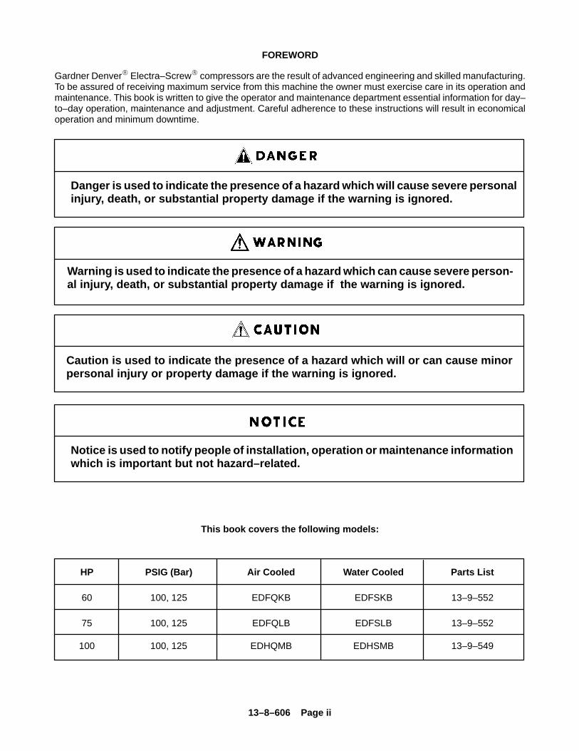
Danger is used to indicate the presence of a hazard which will cause severe personalinjury, death, or substantial property damage if the warning is ignored.
Warning is used to indicate the presence of a hazard which can cause severe person-al injury, death, or substantial property damage if the warning is ignored.
Caution is used to indicate the presence of a hazard which will or can cause minorpersonal injury or property damage if the warning is ignored.
Notice is used to notify people of installation, operation or maintenance informationwhich is important but not hazard–related.
This book covers the following models:
HP PSIG (Bar) Air Cooled Water Cooled Parts List
60 100, 125 EDFQKB EDFSKB 13–9–552
75 100, 125 EDFQLB EDFSLB 13–9–552
100 100, 125 EDHQMB EDHSMB 13–9–549
13–8–606 Page iii
TABLE OF CONTENTS
Maintain Compressor Reliability and Performance with Genuine Gardner Denver� Compressor Parts and Support Services i. . . . . . . . . . . . . . . . . . . . . . . . . . . . . . . . . . . . . . . . . . . . . . . . . . . . . . . . . . . . . . . . . . . . . . . . . .
Remanufactured Air Ends i. . . . . . . . . . . . . . . . . . . . . . . . . . . . . . . . . . . . . . . . . . . . . . . . . . . . . . . . . . . . . . . . . . . . . . . . . . .
Foreword ii. . . . . . . . . . . . . . . . . . . . . . . . . . . . . . . . . . . . . . . . . . . . . . . . . . . . . . . . . . . . . . . . . . . . . . . . . . . . . . . . . . . . . . . . .
Index iv – vi. . . . . . . . . . . . . . . . . . . . . . . . . . . . . . . . . . . . . . . . . . . . . . . . . . . . . . . . . . . . . . . . . . . . . . . . . . . . . . . . . . . . . . . .
List of Illustrations vii. . . . . . . . . . . . . . . . . . . . . . . . . . . . . . . . . . . . . . . . . . . . . . . . . . . . . . . . . . . . . . . . . . . . . . . . . . . . . . . .
Section 1, General Information 1. . . . . . . . . . . . . . . . . . . . . . . . . . . . . . . . . . . . . . . . . . . . . . . . . . . . . . . . . . . . . . . . . . . . . .
Section 2, Installation 8. . . . . . . . . . . . . . . . . . . . . . . . . . . . . . . . . . . . . . . . . . . . . . . . . . . . . . . . . . . . . . . . . . . . . . . . . . . . . .
Section 3, Starting & Operating Procedures 15. . . . . . . . . . . . . . . . . . . . . . . . . . . . . . . . . . . . . . . . . . . . . . . . . . . . . . . . . .
Section 4, Controls & Instrumentation 17. . . . . . . . . . . . . . . . . . . . . . . . . . . . . . . . . . . . . . . . . . . . . . . . . . . . . . . . . . . . . . .
Section 5, Lubrication, Oil Cooler, Oil Filter & Separator 27. . . . . . . . . . . . . . . . . . . . . . . . . . . . . . . . . . . . . . . . . . . . . . .
Section 6, Air Filter 40. . . . . . . . . . . . . . . . . . . . . . . . . . . . . . . . . . . . . . . . . . . . . . . . . . . . . . . . . . . . . . . . . . . . . . . . . . . . . . .
Section 7, Coupling 42. . . . . . . . . . . . . . . . . . . . . . . . . . . . . . . . . . . . . . . . . . . . . . . . . . . . . . . . . . . . . . . . . . . . . . . . . . . . . . .
Section 8, Maintenance Schedule 43. . . . . . . . . . . . . . . . . . . . . . . . . . . . . . . . . . . . . . . . . . . . . . . . . . . . . . . . . . . . . . . . . .
Section 9, Trouble Shooting 44. . . . . . . . . . . . . . . . . . . . . . . . . . . . . . . . . . . . . . . . . . . . . . . . . . . . . . . . . . . . . . . . . . . . . . .
Warranty 49. . . . . . . . . . . . . . . . . . . . . . . . . . . . . . . . . . . . . . . . . . . . . . . . . . . . . . . . . . . . . . . . . . . . . . . . . . . . . . . . . . . . . . . .
INSTRUCTIONS FOR ORDERING REPAIR PARTS
When ordering parts, specify Compressor MODEL,Method of Cooling, HORSEPOWER and SERIALNUMBER (see nameplate on unit). The Serial Numberis also stamped on top of the cylinder flange to the rightof the inlet housing.
All orders for Parts should be placed with the nearestauthorized distributor.
Where NOT specified, quantity of parts required percompressor or unit is one (1); where more than one is
required per unit, quantity is indicated in parenthesis.SPECIFY EXACTLY THE NUMBER OF PARTS RE-QUIRED.
DO NOT ORDER BY SETS OR GROUPS.
To determine the Right Hand and Left Hand side of acompressor, stand at the motor end and look towardthe compressor. Right Hand and Left Hand are indi-cated in parenthesis following the part name, i.e. (RH)& (LH).
13–8–606 Page iv
INDEX
Addition of Oil Between Changes 31. . . . . . . . . . . . . . .
Air Control Components 19. . . . . . . . . . . . . . . . . . . . . . .
Blowdown Valve 19. . . . . . . . . . . . . . . . . . . . . . . . . .
Inlet Valve 19. . . . . . . . . . . . . . . . . . . . . . . . . . . . . . .
Minimum Pressure/Check Valve 19. . . . . . . . . . . .
Air Ends, Remanufactured i. . . . . . . . . . . . . . . . . . . . . .
AIR FILTER, SECTION 6 40. . . . . . . . . . . . . . . . . . . . . .
Air Filter Element 40. . . . . . . . . . . . . . . . . . . . . . . . . . . . .
Air Filter Element Life 40. . . . . . . . . . . . . . . . . . . . . . . . .
Air Flow in Compressor System 1. . . . . . . . . . . . . . . . .
Air Receiver, Auxiliary 10. . . . . . . . . . . . . . . . . . . . . . . . .
Air–Cooled Units, Location 8. . . . . . . . . . . . . . . . . . . . .
AUTO LAG Button with LED 20. . . . . . . . . . . . . . . . . . .
AUTO LEAD Button with LED 20. . . . . . . . . . . . . . . . . .
Auto–Sentry S Controller with Keypad 19. . . . . . . . . .
Auxiliary Air Receiver 10. . . . . . . . . . . . . . . . . . . . . . . . .
Blowdown Valve 19. . . . . . . . . . . . . . . . . . . . . . . . . . . . .
Change Air Filter LED 20. . . . . . . . . . . . . . . . . . . . . . . . .
Change Procedure, Lubricant 31. . . . . . . . . . . . . . . . . .
Change Separator LED 20. . . . . . . . . . . . . . . . . . . . . . .
Check, Daily 16. . . . . . . . . . . . . . . . . . . . . . . . . . . . . . . . .
Cleaning and Draining Oil System 33, 34. . . . . . . . . .
Cold Ambient Operation 31. . . . . . . . . . . . . . . . . . . . . . .
Cold Weather Operation 10. . . . . . . . . . . . . . . . . . . . . .
Cold Weather Operation, Installation for 9. . . . . . . . . .
Compression Principle 1. . . . . . . . . . . . . . . . . . . . . . . . .
Compressor 1. . . . . . . . . . . . . . . . . . . . . . . . . . . . . . . . . .
Compressor (GD Eliminator) Oil Separator 37. . . . . .
Compressor Oil Cooler 35. . . . . . . . . . . . . . . . . . . . . . . .
Compressor Oil Filter 34. . . . . . . . . . . . . . . . . . . . . . . . .
Compressor Oil System 27. . . . . . . . . . . . . . . . . . . . . . .
Compressor Oil System Check 38. . . . . . . . . . . . . . . . .
Compressor System, Air Flow 1. . . . . . . . . . . . . . . . . . .
CONSTANT RUN Button with LED 20. . . . . . . . . . . . .
Control Piping 11. . . . . . . . . . . . . . . . . . . . . . . . . . . . . . .
Control System Operation 19. . . . . . . . . . . . . . . . . . . . .
AUTO LAG Button with LED 20. . . . . . . . . . . . . . .
AUTO LEAD Button with LED 20. . . . . . . . . . . . . .
Change Air Filter LED 20. . . . . . . . . . . . . . . . . . . . .
Change Separator LED 20. . . . . . . . . . . . . . . . . . . .
CONSTANT RUN Button with LED 20. . . . . . . . . .
High Air Temperature LED 20. . . . . . . . . . . . . . . . .
Motor Overload LED 20. . . . . . . . . . . . . . . . . . . . . .
Pressure and Temperature Digital Readouts 21.
STOP/RESET Button with LED 19. . . . . . . . . . . . .
Controller, Auto–Sentry S with Keypad 19. . . . . . . . . .
CONTROLS & INSTRUMENTS, SECTION 4 17. . . .
Controls & Instruments, General 17. . . . . . . . . . . . . . .
Cooler, Compressor Oil 35. . . . . . . . . . . . . . . . . . . . . . .
Cooling, Sealing and Lubrication 1. . . . . . . . . . . . . . . .
COUPLING, SECTION 7 42. . . . . . . . . . . . . . . . . . . . . .
Coupling 42. . . . . . . . . . . . . . . . . . . . . . . . . . . . . . . . . . . .
Alignment 42. . . . . . . . . . . . . . . . . . . . . . . . . . . . . . .
Individual Cushion Design 42. . . . . . . . . . . . . . . . .
Daily Check 16. . . . . . . . . . . . . . . . . . . . . . . . . . . . . . . . .
Decals 6, 7. . . . . . . . . . . . . . . . . . . . . . . . . . . . . . . . . . . . .
Definitions of Error Messages 21. . . . . . . . . . . . . . . . . .
Devices, Motor Protection 17. . . . . . . . . . . . . . . . . . . . .
Discharge Service Line 12. . . . . . . . . . . . . . . . . . . . . . .
Discharge Temperature, High 17. . . . . . . . . . . . . . . . . .
Drain, Oil Reservoir 9. . . . . . . . . . . . . . . . . . . . . . . . . . . .
Draining and Cleaning Oil System 33, 34. . . . . . . . . .
Electric Motor Grease Recommendations 14. . . . . . .
Electric Motor Regreasing Interval 14. . . . . . . . . . . . . .
Electrical Wiring 13. . . . . . . . . . . . . . . . . . . . . . . . . . . . . .
Standard Units 13. . . . . . . . . . . . . . . . . . . . . . . . . . .
Element, Air Filter 40. . . . . . . . . . . . . . . . . . . . . . . . . . . .
Element Life, Air Filter 40. . . . . . . . . . . . . . . . . . . . . . . .
Emergency Stop Pushbutton 19. . . . . . . . . . . . . . . . . . .
Enclosure 9. . . . . . . . . . . . . . . . . . . . . . . . . . . . . . . . . . . .
Filter, Compressor Oil 34. . . . . . . . . . . . . . . . . . . . . . . . .
Foundation 9. . . . . . . . . . . . . . . . . . . . . . . . . . . . . . . . . . .
Gauge, Oil Level 19, 32. . . . . . . . . . . . . . . . . . . . . . . . .
GENERAL INFORMATION, SECTION 1 1. . . . . . . . .
Grease Recommendations, Electric Motor 14. . . . . . .
13–8–606 Page v
INDEX
Grounding 13. . . . . . . . . . . . . . . . . . . . . . . . . . . . . . . . . . .
High Air Temperature LED 20. . . . . . . . . . . . . . . . . . . . .
High Discharge Temperature 17. . . . . . . . . . . . . . . . . . .
High Temperature Operation 27. . . . . . . . . . . . . . . . . . .
Hourmeter 19. . . . . . . . . . . . . . . . . . . . . . . . . . . . . . . . . . .
Inlet Line 11. . . . . . . . . . . . . . . . . . . . . . . . . . . . . . . . . . . .
Inlet Tube 41. . . . . . . . . . . . . . . . . . . . . . . . . . . . . . . . . . .
Inlet Valve 19. . . . . . . . . . . . . . . . . . . . . . . . . . . . . . . . . . .
INSTALLATION, SECTION 2 8. . . . . . . . . . . . . . . . . . .
Installation, General 8. . . . . . . . . . . . . . . . . . . . . . . . . . .
Installation for Cold Weather Operation 9. . . . . . . . . .
Instructions for Ordering Repair Parts iii. . . . . . . . . . . .
Instruments 19. . . . . . . . . . . . . . . . . . . . . . . . . . . . . . . . . .
Lead–Lag Operation of Two Compressors 23. . . . . . .
Lifting Unit 8. . . . . . . . . . . . . . . . . . . . . . . . . . . . . . . . . . . .
Line, Discharge Service 12. . . . . . . . . . . . . . . . . . . . . . .
Line, Inlet 11. . . . . . . . . . . . . . . . . . . . . . . . . . . . . . . . . . .
Load–Unload Pressure Setpoints, Programming 21.
Location 8. . . . . . . . . . . . . . . . . . . . . . . . . . . . . . . . . . . . .
Air–Cooled Units 8. . . . . . . . . . . . . . . . . . . . . . . . . .
Water–Cooled Units 9. . . . . . . . . . . . . . . . . . . . . . . .
Lubricant, Recommended 27. . . . . . . . . . . . . . . . . . . . .
Lubricant Change Procedure 31. . . . . . . . . . . . . . . . . .
Lubrication, Motor 13. . . . . . . . . . . . . . . . . . . . . . . . . . . .
Lubrication, Cooling and Sealing 1. . . . . . . . . . . . . . . .
LUBRICATION, OIL COOLER, OIL FILTER &SEPARATOR, SECTION 5 27. . . . . . . . . . . . . . . . .
MAINTENANCE SCHEDULE, SECTION 8 43. . . . . .
Minimum Pressure/Check Valve 19. . . . . . . . . . . . . . . .
Moisture in the Oil System 32. . . . . . . . . . . . . . . . . . . . .
Moisture Separator/Trap 10. . . . . . . . . . . . . . . . . . . . . .
Motor Grease Recommendations 14. . . . . . . . . . . . . .
Motor Lubrication 13. . . . . . . . . . . . . . . . . . . . . . . . . . . . .
Motor Overload LED 20. . . . . . . . . . . . . . . . . . . . . . . . . .
Motor Protection Devices 17. . . . . . . . . . . . . . . . . . . . . .
Motor Regreasing Interval 14. . . . . . . . . . . . . . . . . . . . .
Oil Change Interval 33. . . . . . . . . . . . . . . . . . . . . . . . . . .
Oil Cooler, Compressor 35. . . . . . . . . . . . . . . . . . . . . . .
Oil Filter, Compressor 34. . . . . . . . . . . . . . . . . . . . . . . . .
Oil Level Gauge 19, 32. . . . . . . . . . . . . . . . . . . . . . . . . .
Oil Reservoir 37. . . . . . . . . . . . . . . . . . . . . . . . . . . . . . . .
Oil Reservoir Drain 9. . . . . . . . . . . . . . . . . . . . . . . . . . . .
Oil Separator
Compressor (GD Eliminator) 37. . . . . . . . . . . . . . .
Inspection 38. . . . . . . . . . . . . . . . . . . . . . . . . . . . . . .
Oil Carryover 37. . . . . . . . . . . . . . . . . . . . . . . . . . . . .
Removal for Inspection or Replacement 38. . . . .
Oil Specifications 27. . . . . . . . . . . . . . . . . . . . . . . . . . . . .
Oil System
Compressor 27. . . . . . . . . . . . . . . . . . . . . . . . . . . . .
Draining and Cleaning 33, 34. . . . . . . . . . . . . . . . .
Oil System Check 38. . . . . . . . . . . . . . . . . . . . . . . . . . . .
Air and Oil Discharge Temperature 38. . . . . . . . . .
Compressor Oil Inlet Temperature 38. . . . . . . . . .
Oil Cooler Oil Pressure Differential 38. . . . . . . . . .
Oil Cooler Temperature Differential 39. . . . . . . . . .
Oil Cooler Water Pressure Differential 39. . . . . . .
Oil Inlet Pressure 38. . . . . . . . . . . . . . . . . . . . . . . . .
Operation
Cold Ambient 31. . . . . . . . . . . . . . . . . . . . . . . . . . . .
Control System 19. . . . . . . . . . . . . . . . . . . . . . . . . . .
High Temperature 27. . . . . . . . . . . . . . . . . . . . . . . .
Lead–Lag, of Two Compressors 23. . . . . . . . . . . .
Piping, Control 11. . . . . . . . . . . . . . . . . . . . . . . . . . . . . . .
Pressure and Temperature Digital Readouts 21. . . . .
Pressure Differential Gauging 38. . . . . . . . . . . . . . . . . .
Prestart–Up Instructions 15. . . . . . . . . . . . . . . . . . . . . . .
Air Filter 15. . . . . . . . . . . . . . . . . . . . . . . . . . . . . . . . .
Coupling 15. . . . . . . . . . . . . . . . . . . . . . . . . . . . . . . .
Electrical 15. . . . . . . . . . . . . . . . . . . . . . . . . . . . . . . .
Enclosure 16. . . . . . . . . . . . . . . . . . . . . . . . . . . . . . .
Grounding 15. . . . . . . . . . . . . . . . . . . . . . . . . . . . . . .
Operating Mode 16. . . . . . . . . . . . . . . . . . . . . . . . . .
Piping 15. . . . . . . . . . . . . . . . . . . . . . . . . . . . . . . . . . .
Rotation 15. . . . . . . . . . . . . . . . . . . . . . . . . . . . . . . . .
13–8–606 Page vi
INDEX
System Pressure 16. . . . . . . . . . . . . . . . . . . . . . . . .
Programming Load–Unload Pressure Setpoints 21. .
Protective Devices
Blowdown Valve 19. . . . . . . . . . . . . . . . . . . . . . . . . .
High Discharge Temperature 17. . . . . . . . . . . . . . .
Motor Protection Devices 17. . . . . . . . . . . . . . . . . .
Relief Valve 18. . . . . . . . . . . . . . . . . . . . . . . . . . . . . .
Separator Differential Pressure 17. . . . . . . . . . . . .
Recommended Lubricant 27. . . . . . . . . . . . . . . . . . . . . .
Regreasing Interval, Electric Motor 14. . . . . . . . . . . . .
Relief Valve 18. . . . . . . . . . . . . . . . . . . . . . . . . . . . . . . . .
Remanufactured Air Ends i. . . . . . . . . . . . . . . . . . . . . .
Repair Parts, Ordering Instructions iii. . . . . . . . . . . . . .
Reservoir, Oil 37. . . . . . . . . . . . . . . . . . . . . . . . . . . . . . . .
Safety Precautions 4–5. . . . . . . . . . . . . . . . . . . . . . . . . .
Sealing, Lubrication and Cleaning 1. . . . . . . . . . . . . . .
Separator, Compressor (GD Eliminator) Oil 37. . . . . .
Separator Differential Pressure 17. . . . . . . . . . . . . . . . .
Separator/Trap, Moisture 10. . . . . . . . . . . . . . . . . . . . . .
SERVICE CHECK LIST, AIR FILTER 43. . . . . . . . . . .
Service Check List 43. . . . . . . . . . . . . . . . . . . . . . . . . . .
Every 1000 Hours Operation 43. . . . . . . . . . . . . . .
Every 125 Hours Operation 43. . . . . . . . . . . . . . . .
Every 6000 Hours Operation 43. . . . . . . . . . . . . . .
Every 8 Hours Operation 43. . . . . . . . . . . . . . . . . .
Every Year 43. . . . . . . . . . . . . . . . . . . . . . . . . . . . . . .
Motor Lubrication 43. . . . . . . . . . . . . . . . . . . . . . . . .
Oil Separator 43. . . . . . . . . . . . . . . . . . . . . . . . . . . . .
Specifications, Oil 27. . . . . . . . . . . . . . . . . . . . . . . . . . . .
Starter/Control Box 19. . . . . . . . . . . . . . . . . . . . . . . . . . .
Auto–Sentry S Controller with Keypad 19. . . . . . .
Emergency Stop Pushbutton 19. . . . . . . . . . . . . . .
Hourmeter 19. . . . . . . . . . . . . . . . . . . . . . . . . . . . . . .
STARTING & OPERATING PROCEDURES,SECTION 3 15. . . . . . . . . . . . . . . . . . . . . . . . . . . . . .
Starting the Unit 16. . . . . . . . . . . . . . . . . . . . . . . . . . . . . .
Unit Cold 16. . . . . . . . . . . . . . . . . . . . . . . . . . . . . . . .
Unit Hot 16. . . . . . . . . . . . . . . . . . . . . . . . . . . . . . . . .
STOP/RESET Button with LED 19. . . . . . . . . . . . . . . .
Stopping the Unit 16. . . . . . . . . . . . . . . . . . . . . . . . . . . . .
Temperature, High Discharge 17. . . . . . . . . . . . . . . . . .
TROUBLE SHOOTING, SECTION 9 44. . . . . . . . . . . .
Trouble Shooting, Oil Carry–Over 45. . . . . . . . . . . . . .
Valve
Blowdown 19. . . . . . . . . . . . . . . . . . . . . . . . . . . . . . .
Control 19. . . . . . . . . . . . . . . . . . . . . . . . . . . . . . . . . .
Minimum Pressure/Check 19. . . . . . . . . . . . . . . . .
Relief 18. . . . . . . . . . . . . . . . . . . . . . . . . . . . . . . . . . .
Warranty Last Page. . . . . . . . . . . . . . . . . . . . . . . . . . . . .
Water–Cooled Units, Location 9. . . . . . . . . . . . . . . . . .
Wiring, Electrical 13. . . . . . . . . . . . . . . . . . . . . . . . . . . . .
13–8–606 Page vii
LIST OF ILLUSTRATIONS
Figure 1–1 Compressor Cycle 1. . . . . . . . . . . . . . . . . . . . . . . . . . . . . . . . . . . . . . . . . . . . . . . . . . . . . . . . . . . . . . . . . .
Figure 1–2 Starter Box 2. . . . . . . . . . . . . . . . . . . . . . . . . . . . . . . . . . . . . . . . . . . . . . . . . . . . . . . . . . . . . . . . . . . . . . . . .
Figure 1–3 Package – Controller & Starters 2. . . . . . . . . . . . . . . . . . . . . . . . . . . . . . . . . . . . . . . . . . . . . . . . . . . . . .
Figure 1–4 Package – Drive Motor & Air Filter 2. . . . . . . . . . . . . . . . . . . . . . . . . . . . . . . . . . . . . . . . . . . . . . . . . . . .
Figure 1–5 Package – Oil Filter, Oil Level Gauge, Mixing Valve, Minimum Pressure Valve & Check Valve 3.
Figure 1–6 Package – Air/Oil Flow Diagram 3. . . . . . . . . . . . . . . . . . . . . . . . . . . . . . . . . . . . . . . . . . . . . . . . . . . . . .
Figure 2–1 Typical Compressor Room 8. . . . . . . . . . . . . . . . . . . . . . . . . . . . . . . . . . . . . . . . . . . . . . . . . . . . . . . . . . .
Figure 2–2 Air Flow Chart 9. . . . . . . . . . . . . . . . . . . . . . . . . . . . . . . . . . . . . . . . . . . . . . . . . . . . . . . . . . . . . . . . . . . . . .
Figure 2–3 Cold Weather Installation 10. . . . . . . . . . . . . . . . . . . . . . . . . . . . . . . . . . . . . . . . . . . . . . . . . . . . . . . . . . .
Figure 2–4 Inlet Line Lengths 11. . . . . . . . . . . . . . . . . . . . . . . . . . . . . . . . . . . . . . . . . . . . . . . . . . . . . . . . . . . . . . . . . .
Figure 2–5 Heat Exchanger (Oil Cooler) Approximate Water Flow 11. . . . . . . . . . . . . . . . . . . . . . . . . . . . . . . . . .
Figure 2–6 Aftercooler Approximate Water Flow 11. . . . . . . . . . . . . . . . . . . . . . . . . . . . . . . . . . . . . . . . . . . . . . . . .
Figure 2–7 Series Piping 12. . . . . . . . . . . . . . . . . . . . . . . . . . . . . . . . . . . . . . . . . . . . . . . . . . . . . . . . . . . . . . . . . . . . . .
Figure 2–8 Parallel Piping 12. . . . . . . . . . . . . . . . . . . . . . . . . . . . . . . . . . . . . . . . . . . . . . . . . . . . . . . . . . . . . . . . . . . . .
Figure 4–1 Control Schematic 17. . . . . . . . . . . . . . . . . . . . . . . . . . . . . . . . . . . . . . . . . . . . . . . . . . . . . . . . . . . . . . . . .
Figure 4–2 Inlet Valve 18. . . . . . . . . . . . . . . . . . . . . . . . . . . . . . . . . . . . . . . . . . . . . . . . . . . . . . . . . . . . . . . . . . . . . . . .
Figure 4–3 Minimum Pressure/Check Valve 19. . . . . . . . . . . . . . . . . . . . . . . . . . . . . . . . . . . . . . . . . . . . . . . . . . . . .
Figure 4–4 Definition of Error Messages 21. . . . . . . . . . . . . . . . . . . . . . . . . . . . . . . . . . . . . . . . . . . . . . . . . . . . . . . .
Figure 4–5 Pressure Chart 24. . . . . . . . . . . . . . . . . . . . . . . . . . . . . . . . . . . . . . . . . . . . . . . . . . . . . . . . . . . . . . . . . . . .
Figure 4–6 Subtractive Pilot (Closed) 24. . . . . . . . . . . . . . . . . . . . . . . . . . . . . . . . . . . . . . . . . . . . . . . . . . . . . . . . . . .
Figure 4–7 Subtractive Pilot (Opened) 24. . . . . . . . . . . . . . . . . . . . . . . . . . . . . . . . . . . . . . . . . . . . . . . . . . . . . . . . . .
Figure 4–8 Maximum Setpoints for Auto–Sentry S Controller, PSIG 25. . . . . . . . . . . . . . . . . . . . . . . . . . . . . . . . .
Figure 4–9 Auto–Sentry S Solid State Control Touch Pad 25. . . . . . . . . . . . . . . . . . . . . . . . . . . . . . . . . . . . . . . . .
Figure 4–10 Wiring Diagram – Dual Control 26. . . . . . . . . . . . . . . . . . . . . . . . . . . . . . . . . . . . . . . . . . . . . . . . . . . . .
Figure 5–1 Flow Diagram 28. . . . . . . . . . . . . . . . . . . . . . . . . . . . . . . . . . . . . . . . . . . . . . . . . . . . . . . . . . . . . . . . . . . . .
Figure 5–2 Oil Flow Diagram – Remote Overhead Mounted 29. . . . . . . . . . . . . . . . . . . . . . . . . . . . . . . . . . . . . . .
Figure 5–3 Cooler Drain Detail 30. . . . . . . . . . . . . . . . . . . . . . . . . . . . . . . . . . . . . . . . . . . . . . . . . . . . . . . . . . . . . . . . .
Figure 5–4 Oil Level Gauge 33. . . . . . . . . . . . . . . . . . . . . . . . . . . . . . . . . . . . . . . . . . . . . . . . . . . . . . . . . . . . . . . . . . .
Figure 5–5 Oil Change Interval 33. . . . . . . . . . . . . . . . . . . . . . . . . . . . . . . . . . . . . . . . . . . . . . . . . . . . . . . . . . . . . . . .
Figure 5–6 Approximate Oil System Capacities 34. . . . . . . . . . . . . . . . . . . . . . . . . . . . . . . . . . . . . . . . . . . . . . . . . .
Figure 5–7 Compressor Oil Filter 34. . . . . . . . . . . . . . . . . . . . . . . . . . . . . . . . . . . . . . . . . . . . . . . . . . . . . . . . . . . . . . .
Figure 5–8 Thermostatic Mixing Valve Element 35. . . . . . . . . . . . . . . . . . . . . . . . . . . . . . . . . . . . . . . . . . . . . . . . . .
Figure 5–9 Water Control Valve 36. . . . . . . . . . . . . . . . . . . . . . . . . . . . . . . . . . . . . . . . . . . . . . . . . . . . . . . . . . . . . . . .
Figure 5–10 Dew Point Temperature vs. Ambient Temperature, (100% Relative Humidity) 37. . . . . . . . . . . . . .
Figure 5–11 Oil Separator 37. . . . . . . . . . . . . . . . . . . . . . . . . . . . . . . . . . . . . . . . . . . . . . . . . . . . . . . . . . . . . . . . . . . . . .
Figure 6–1 Heavy Duty Air Filter 40. . . . . . . . . . . . . . . . . . . . . . . . . . . . . . . . . . . . . . . . . . . . . . . . . . . . . . . . . . . . . . .
Figure 7–1 Installation of Coupling Cushions 42. . . . . . . . . . . . . . . . . . . . . . . . . . . . . . . . . . . . . . . . . . . . . . . . . . . .
13–8–606 Page 1
SECTION 1GENERAL INFORMATION
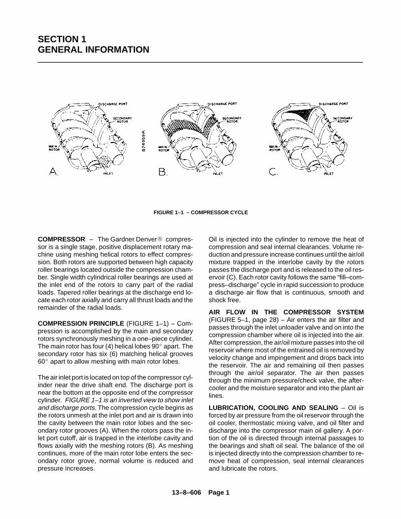
FIGURE 1–1 – COMPRESSOR CYCLE
COMPRESSOR – The Gardner Denver� compres-sor is a single stage, positive displacement rotary ma-chine using meshing helical rotors to effect compres-sion. Both rotors are supported between high capacityroller bearings located outside the compression cham-ber. Single width cylindrical roller bearings are used atthe inlet end of the rotors to carry part of the radialloads. Tapered roller bearings at the discharge end lo-cate each rotor axially and carry all thrust loads and theremainder of the radial loads.
COMPRESSION PRINCIPLE (FIGURE 1–1) – Com-pression is accomplished by the main and secondaryrotors synchronously meshing in a one–piece cylinder.The main rotor has four (4) helical lobes 90� apart. Thesecondary rotor has six (6) matching helical grooves60� apart to allow meshing with main rotor lobes.
The air inlet port is located on top of the compressor cyl-inder near the drive shaft end. The discharge port isnear the bottom at the opposite end of the compressorcylinder. FIGURE 1–1 is an inverted view to show inletand discharge ports. The compression cycle begins asthe rotors unmesh at the inlet port and air is drawn intothe cavity between the main rotor lobes and the sec-ondary rotor grooves (A). When the rotors pass the in-let port cutoff, air is trapped in the interlobe cavity andflows axially with the meshing rotors (B). As meshingcontinues, more of the main rotor lobe enters the sec-ondary rotor grove, normal volume is reduced andpressure increases.
Oil is injected into the cylinder to remove the heat ofcompression and seal internal clearances. Volume re-duction and pressure increase continues until the air/oilmixture trapped in the interlobe cavity by the rotorspasses the discharge port and is released to the oil res-ervoir (C). Each rotor cavity follows the same “fill–com-press–discharge” cycle in rapid succession to producea discharge air flow that is continuous, smooth andshock free.
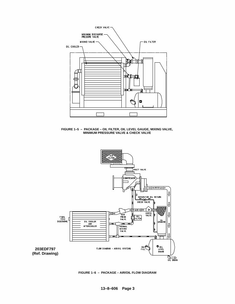
AIR FLOW IN THE COMPRESSOR SYSTEM(FIGURE 5–1, page 28) – Air enters the air filter andpasses through the inlet unloader valve and on into thecompression chamber where oil is injected into the air.After compression, the air/oil mixture passes into the oilreservoir where most of the entrained oil is removed byvelocity change and impingement and drops back intothe reservoir. The air and remaining oil then passesthrough the air/oil separator. The air then passesthrough the minimum pressure/check valve, the after-cooler and the moisture separator and into the plant airlines.
LUBRICATION, COOLING AND SEALING – Oil isforced by air pressure from the oil reservoir through theoil cooler, thermostatic mixing valve, and oil filter anddischarge into the compressor main oil gallery. A por-tion of the oil is directed through internal passages tothe bearings and shaft oil seal. The balance of the oilis injected directly into the compression chamber to re-move heat of compression, seal internal clearancesand lubricate the rotors.

13–8–606 Page 2
FIGURE 1–2 – STARTER BOX
FIGURE 1–3 – PACKAGE – CONTROLLER & STARTERS
FIGURE 1–4 – PACKAGE – DRIVE MOTOR & AIR FILTER
13–8–606 Page 3
FIGURE 1–5 – PACKAGE – OIL FILTER, OIL LEVEL GAUGE, MIXING VALVE,MINIMUM PRESSURE VALVE & CHECK VALVE
FIGURE 1–6 – PACKAGE – AIR/OIL FLOW DIAGRAM
203EDF797(Ref. Drawing)
13–8–606 Page 4
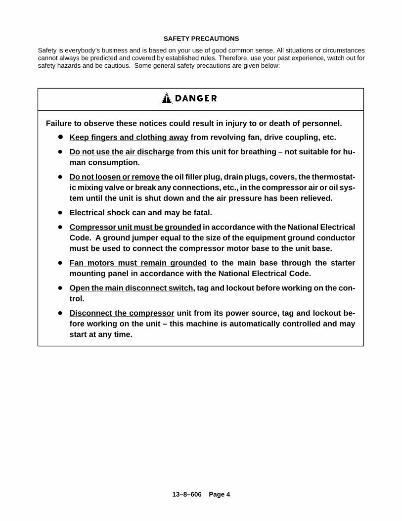
SAFETY PRECAUTIONS
Safety is everybody’s business and is based on your use of good common sense. All situations or circumstancescannot always be predicted and covered by established rules. Therefore, use your past experience, watch out forsafety hazards and be cautious. Some general safety precautions are given below:
Failure to observe these notices could result in injury to or death of personnel.
� Keep fingers and clothing away from revolving fan, drive coupling, etc.
� Do not use the air discharge from this unit for breathing – not suitable for hu-man consumption.
� Do not loosen or remove the oil filler plug, drain plugs, covers, the thermostat-ic mixing valve or break any connections, etc., in the compressor air or oil sys-tem until the unit is shut down and the air pressure has been relieved.
� Electrical shock can and may be fatal.
� Compressor unit must be grounded in accordance with the National ElectricalCode. A ground jumper equal to the size of the equipment ground conductormust be used to connect the compressor motor base to the unit base.
� Fan motors must remain grounded to the main base through the startermounting panel in accordance with the National Electrical Code.
� Open the main disconnect switch , tag and lockout before working on the con-trol.
� Disconnect the compressor unit from its power source, tag and lockout be-fore working on the unit – this machine is automatically controlled and maystart at any time.
13–8–606 Page 5
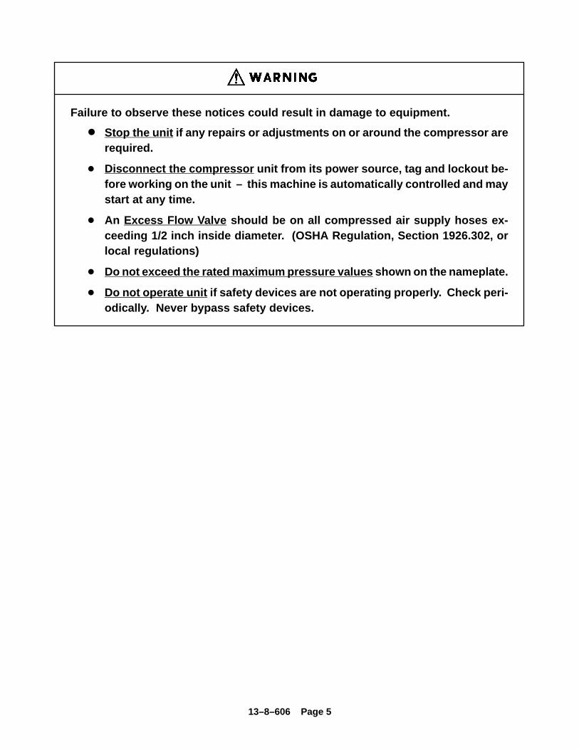
Failure to observe these notices could result in damage to equipment.
� Stop the unit if any repairs or adjustments on or around the compressor arerequired.
� Disconnect the compressor unit from its power source, tag and lockout be-fore working on the unit – this machine is automatically controlled and maystart at any time.
� An Excess Flow Valve should be on all compressed air supply hoses ex-ceeding 1/2 inch inside diameter. (OSHA Regulation, Section 1926.302, orlocal regulations)
� Do not exceed the rated maximum pressure values shown on the nameplate.
� Do not operate unit if safety devices are not operating properly. Check peri-odically. Never bypass safety devices.
13–8–606 Page 6
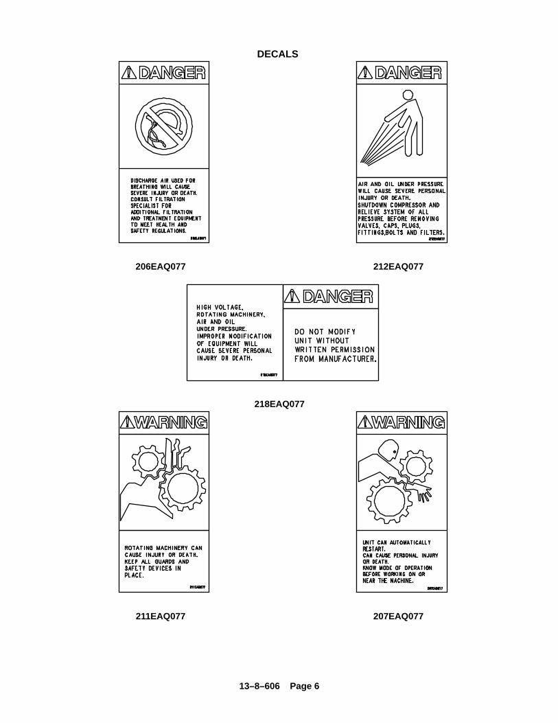
DECALS
206EAQ077 212EAQ077
218EAQ077
211EAQ077 207EAQ077
13–8–606 Page 7
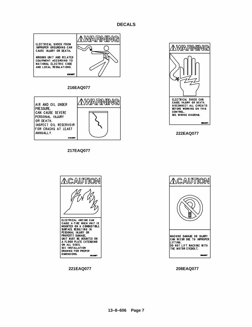
DECALS
216EAQ077
217EAQ077
222EAQ077
221EAQ077 208EAQ077
13–8–606 Page 8
SECTION 2INSTALLATION
GENERAL – On receipt of the unit, check for any dam-age that may have been incurred during transit. Reportany damage or missing parts as soon as possible.
Do not electric weld on the compres-sor or base; bearings can be damagedby passage of current.
LIFTING UNIT – Proper lifting and/or transportingmethods must be used to prevent damage. Lifting slotsare provided in the base for towmotor use. The unit mayalso be moved into location by rolling on bars.
Lift compressor unit by base only. Donot use other places such as motor,compressor or discharge manifoldpiping as lifting points.
The eyebolts or lugs provided on themotor are for lifting the motor onlyand should not be used to lift anyadditional weight. All eyebolts mustbe securely tightened. When liftingthe motor the lifting angle must notexceed 15 degrees. Failure to observethis warning may result in damage toequipment or personal injury.
Compressor, air/oil reservoir, separa-tion chamber and all piping and tub-ing may be at high temperature duringand after operation.
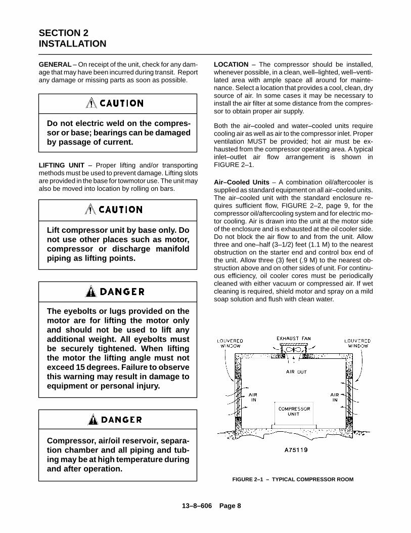
LOCATION – The compressor should be installed,whenever possible, in a clean, well–lighted, well–venti-lated area with ample space all around for mainte-nance. Select a location that provides a cool, clean, drysource of air. In some cases it may be necessary toinstall the air filter at some distance from the compres-sor to obtain proper air supply.
Both the air–cooled and water–cooled units requirecooling air as well as air to the compressor inlet. Properventilation MUST be provided; hot air must be ex-hausted from the compressor operating area. A typicalinlet–outlet air flow arrangement is shown inFIGURE 2–1.
Air–Cooled Units – A combination oil/aftercooler issupplied as standard equipment on all air–cooled units.The air–cooled unit with the standard enclosure re-quires sufficient flow, FIGURE 2–2, page 9, for thecompressor oil/aftercooling system and for electric mo-tor cooling. Air is drawn into the unit at the motor sideof the enclosure and is exhausted at the oil cooler side.Do not block the air flow to and from the unit. Allowthree and one–half (3–1/2) feet (1.1 M) to the nearestobstruction on the starter end and control box end ofthe unit. Allow three (3) feet (.9 M) to the nearest ob-struction above and on other sides of unit. For continu-ous efficiency, oil cooler cores must be periodicallycleaned with either vacuum or compressed air. If wetcleaning is required, shield motor and spray on a mildsoap solution and flush with clean water.
FIGURE 2–1 – TYPICAL COMPRESSOR ROOM
13–8–606 Page 9
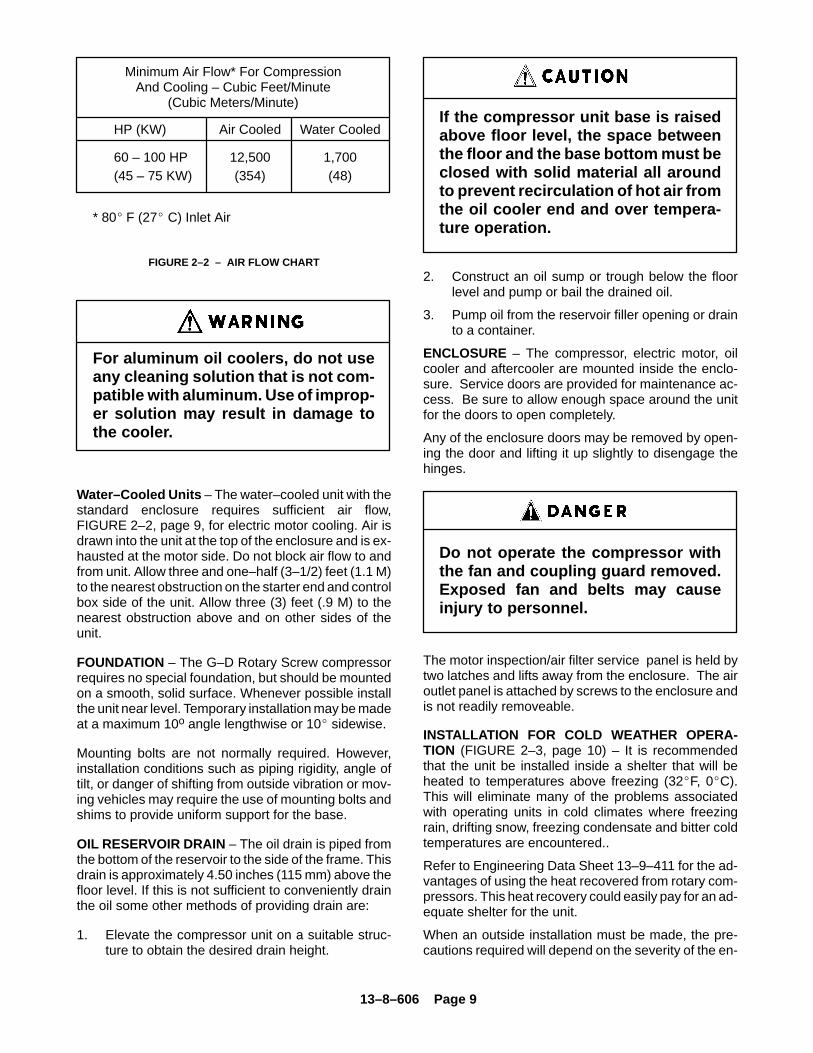
* 80� F (27� C) Inlet Air
Minimum Air Flow* For CompressionAnd Cooling – Cubic Feet/Minute
(Cubic Meters/Minute)
HP (KW) Air Cooled Water Cooled
60 – 100 HP 12,500 1,700 (45 – 75 KW) (354) (48)
FIGURE 2–2 – AIR FLOW CHART
For aluminum oil coolers, do not useany cleaning solution that is not com-patible with aluminum. Use of improp-er solution may result in damage tothe cooler.
Water–Cooled Units – The water–cooled unit with thestandard enclosure requires sufficient air flow,FIGURE 2–2, page 9, for electric motor cooling. Air isdrawn into the unit at the top of the enclosure and is ex-hausted at the motor side. Do not block air flow to andfrom unit. Allow three and one–half (3–1/2) feet (1.1 M)to the nearest obstruction on the starter end and controlbox side of the unit. Allow three (3) feet (.9 M) to thenearest obstruction above and on other sides of theunit.
FOUNDATION – The G–D Rotary Screw compressorrequires no special foundation, but should be mountedon a smooth, solid surface. Whenever possible installthe unit near level. Temporary installation may be madeat a maximum 10o angle lengthwise or 10� sidewise.
Mounting bolts are not normally required. However,installation conditions such as piping rigidity, angle oftilt, or danger of shifting from outside vibration or mov-ing vehicles may require the use of mounting bolts andshims to provide uniform support for the base.
OIL RESERVOIR DRAIN – The oil drain is piped fromthe bottom of the reservoir to the side of the frame. Thisdrain is approximately 4.50 inches (115 mm) above thefloor level. If this is not sufficient to conveniently drainthe oil some other methods of providing drain are:
1. Elevate the compressor unit on a suitable struc-ture to obtain the desired drain height.
If the compressor unit base is raisedabove floor level, the space betweenthe floor and the base bottom must beclosed with solid material all aroundto prevent recirculation of hot air fromthe oil cooler end and over tempera-ture operation.
2. Construct an oil sump or trough below the floorlevel and pump or bail the drained oil.
3. Pump oil from the reservoir filler opening or drainto a container.
ENCLOSURE – The compressor, electric motor, oilcooler and aftercooler are mounted inside the enclo-sure. Service doors are provided for maintenance ac-cess. Be sure to allow enough space around the unitfor the doors to open completely.
Any of the enclosure doors may be removed by open-ing the door and lifting it up slightly to disengage thehinges.
Do not operate the compressor withthe fan and coupling guard removed.Exposed fan and belts may causeinjury to personnel.
The motor inspection/air filter service panel is held bytwo latches and lifts away from the enclosure. The airoutlet panel is attached by screws to the enclosure andis not readily removeable.
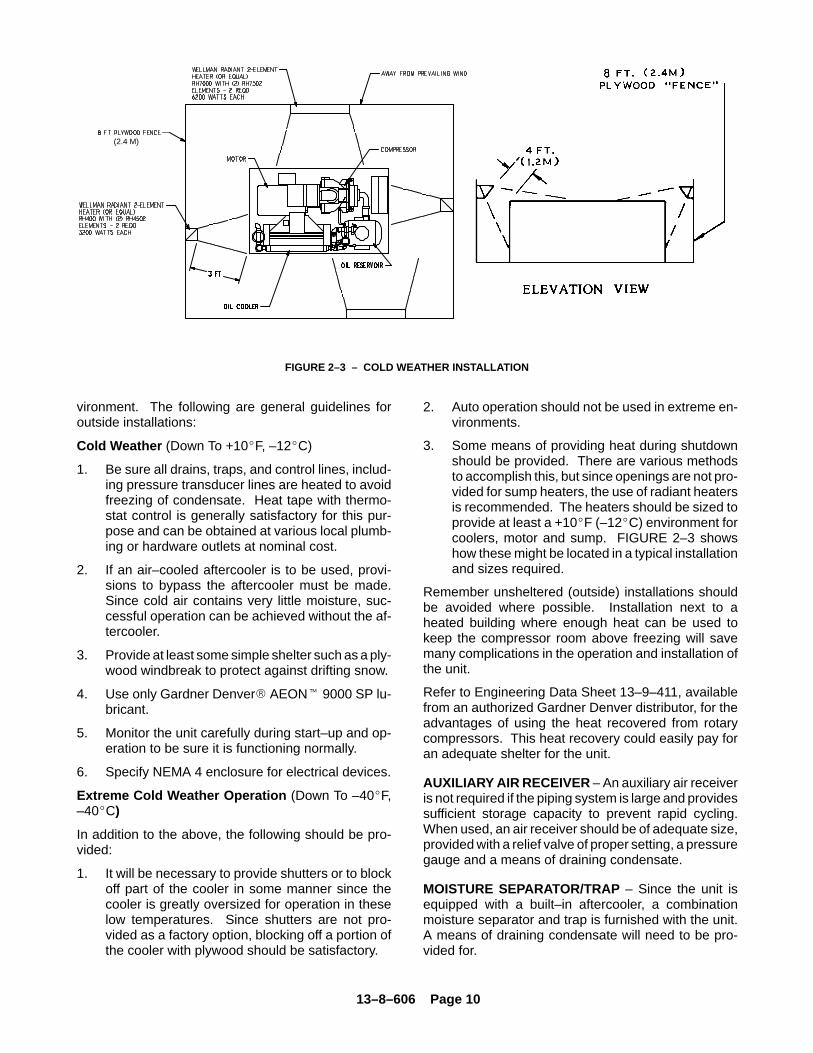
INSTALLATION FOR COLD WEATHER OPERA-TION (FIGURE 2–3, page 10) – It is recommendedthat the unit be installed inside a shelter that will beheated to temperatures above freezing (32�F, 0�C).This will eliminate many of the problems associatedwith operating units in cold climates where freezingrain, drifting snow, freezing condensate and bitter coldtemperatures are encountered..
Refer to Engineering Data Sheet 13–9–411 for the ad-vantages of using the heat recovered from rotary com-pressors. This heat recovery could easily pay for an ad-equate shelter for the unit.
When an outside installation must be made, the pre-cautions required will depend on the severity of the en-
13–8–606 Page 10
FIGURE 2–3 – COLD WEATHER INSTALLATION
(2.4 M)
vironment. The following are general guidelines foroutside installations:
Cold Weather (Down To +10�F, –12�C)
1. Be sure all drains, traps, and control lines, includ-ing pressure transducer lines are heated to avoidfreezing of condensate. Heat tape with thermo-stat control is generally satisfactory for this pur-pose and can be obtained at various local plumb-ing or hardware outlets at nominal cost.
2. If an air–cooled aftercooler is to be used, provi-sions to bypass the aftercooler must be made.Since cold air contains very little moisture, suc-cessful operation can be achieved without the af-tercooler.
3. Provide at least some simple shelter such as a ply-wood windbreak to protect against drifting snow.
4. Use only Gardner Denver� AEON� 9000 SP lu-bricant.
5. Monitor the unit carefully during start–up and op-eration to be sure it is functioning normally.
6. Specify NEMA 4 enclosure for electrical devices.
Extreme Cold Weather Operation (Down To –40�F,–40�C)
In addition to the above, the following should be pro-vided:
1. It will be necessary to provide shutters or to blockoff part of the cooler in some manner since thecooler is greatly oversized for operation in theselow temperatures. Since shutters are not pro-vided as a factory option, blocking off a portion ofthe cooler with plywood should be satisfactory.
2. Auto operation should not be used in extreme en-vironments.
3. Some means of providing heat during shutdownshould be provided. There are various methodsto accomplish this, but since openings are not pro-vided for sump heaters, the use of radiant heatersis recommended. The heaters should be sized toprovide at least a +10�F (–12�C) environment forcoolers, motor and sump. FIGURE 2–3 showshow these might be located in a typical installationand sizes required.
Remember unsheltered (outside) installations shouldbe avoided where possible. Installation next to aheated building where enough heat can be used tokeep the compressor room above freezing will savemany complications in the operation and installation ofthe unit.
Refer to Engineering Data Sheet 13–9–411, availablefrom an authorized Gardner Denver distributor, for theadvantages of using the heat recovered from rotarycompressors. This heat recovery could easily pay foran adequate shelter for the unit.
AUXILIARY AIR RECEIVER – An auxiliary air receiveris not required if the piping system is large and providessufficient storage capacity to prevent rapid cycling.When used, an air receiver should be of adequate size,provided with a relief valve of proper setting, a pressuregauge and a means of draining condensate.
MOISTURE SEPARATOR/TRAP – Since the unit isequipped with a built–in aftercooler, a combinationmoisture separator and trap is furnished with the unit.A means of draining condensate will need to be pro-vided for.
13–8–606 Page 11
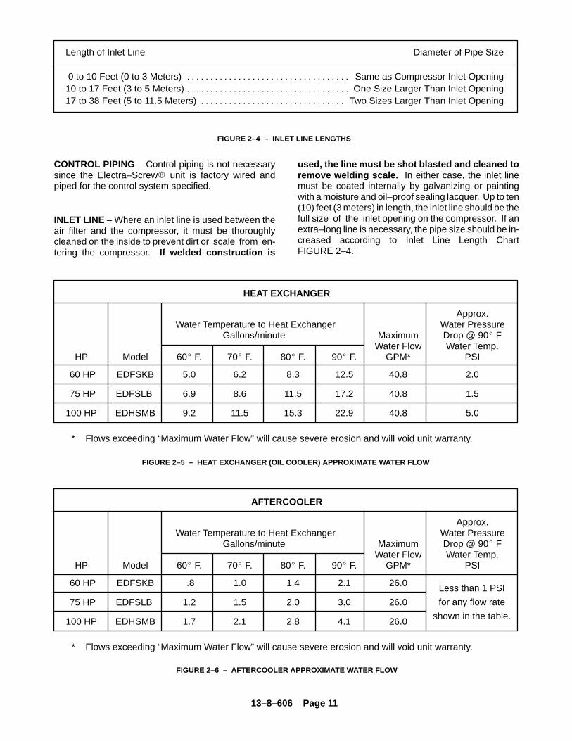
Length of Inlet Line Diameter of Pipe Size
0 to 10 Feet (0 to 3 Meters) Same as Compressor Inlet Opening. . . . . . . . . . . . . . . . . . . . . . . . . . . . . . . . . . . 10 to 17 Feet (3 to 5 Meters) One Size Larger Than Inlet Opening. . . . . . . . . . . . . . . . . . . . . . . . . . . . . . . . . . . 17 to 38 Feet (5 to 11.5 Meters) Two Sizes Larger Than Inlet Opening. . . . . . . . . . . . . . . . . . . . . . . . . . . . . . .
FIGURE 2–4 – INLET LINE LENGTHS
CONTROL PIPING – Control piping is not necessarysince the Electra–Screw� unit is factory wired andpiped for the control system specified.
INLET LINE – Where an inlet line is used between theair filter and the compressor, it must be thoroughlycleaned on the inside to prevent dirt or scale from en-tering the compressor. If welded construction is
used, the line must be shot blasted and cleaned toremove welding scale. In either case, the inlet linemust be coated internally by galvanizing or paintingwith a moisture and oil–proof sealing lacquer. Up to ten(10) feet (3 meters) in length, the inlet line should be thefull size of the inlet opening on the compressor. If anextra–long line is necessary, the pipe size should be in-creased according to Inlet Line Length ChartFIGURE 2–4.
HEAT EXCHANGER
Approx. Water Temperature to Heat Exchanger Water Pressure
Gallons/minute Maximum Drop @ 90� FWater Flow Water Temp.
HP Model 60� F. 70� F. 80� F. 90� F. GPM* PSI
60 HP EDFSKB 5.0 6.2 8.3 12.5 40.8 2.0
75 HP EDFSLB 6.9 8.6 11.5 17.2 40.8 1.5
100 HP EDHSMB 9.2 11.5 15.3 22.9 40.8 5.0
* Flows exceeding “Maximum Water Flow” will cause severe erosion and will void unit warranty.
FIGURE 2–5 – HEAT EXCHANGER (OIL COOLER) APPROXIMATE WATER FLOW
AFTERCOOLER
Approx. Water Temperature to Heat Exchanger Water Pressure
Gallons/minute Maximum Drop @ 90� FWater Flow Water Temp.
HP Model 60� F. 70� F. 80� F. 90� F. GPM* PSI
60 HP EDFSKB .8 1.0 1.4 2.1 26.0
75 HP EDFSLB 1.2 1.5 2.0 3.0 26.0
100 HP EDHSMB 1.7 2.1 2.8 4.1 26.0
* Flows exceeding “Maximum Water Flow” will cause severe erosion and will void unit warranty.
FIGURE 2–6 – AFTERCOOLER APPROXIMATE WATER FLOW
Less than 1 PSI
for any flow rate
shown in the table.
13–8–606 Page 12
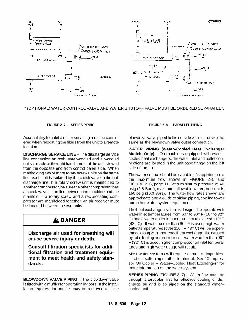
* (OPTIONAL) WATER CONTROL VALVE AND WATER SHUTOFF VALVE MUST BE ORDERED SEPARATELY.
FIGURE 2–7 – SERIES PIPING FIGURE 2–8 – PARALLEL PIPING
Accessibility for inlet air filter servicing must be consid-ered when relocating the filters from the unit to a remotelocation.
DISCHARGE SERVICE LINE – The discharge serviceline connection on both water–cooled and air–cooledunits is made at the right hand corner of the unit, viewedfrom the opposite end from control panel side. Whenmanifolding two or more rotary screw units on the sameline, each unit is isolated by the check valve in the unitdischarge line. If a rotary screw unit is manifolded toanother compressor, be sure the other compressor hasa check valve in the line between the machine and themanifold. If a rotary screw and a reciprocating com-pressor are manifolded together, an air receiver mustbe located between the two units.
Discharge air used for breathing willcause severe injury or death.
Consult filtration specialists for addi-tional filtration and treatment equip-ment to meet health and safety stan-dards.
BLOWDOWN VALVE PIPING – The blowdown valveis fitted with a muffler for operation indoors. If the instal-lation requires, the muffler may be removed and the
blowdown valve piped to the outside with a pipe size thesame as the blowdown valve outlet connection.
WATER PIPING (Water–Cooled Heat ExchangerModels Only) – On machines equipped with water–cooled heat exchangers, the water inlet and outlet con-nections are located in the unit base flange on the leftside of the unit.
The water source should be capable of supplying up tothe maximum flow shown in FIGURE 2–5 andFIGURE 2–6, page 11, at a minimum pressure of 40psig (2.8 Bars); maximum allowable water pressure is150 psig (10.3 Bars). The water flow rates shown areapproximate and a guide to sizing piping, cooling towerand other water system equipment.
The heat exchanger system is designed to operate withwater inlet temperatures from 60� to 90� F (16� to 32�C) and a water outlet temperature not to exceed 110�F(43� C). If water cooler than 60� F is used, high wateroutlet temperatures (over 110� F, 43� C) will be experi-enced along with shortened heat exchanger life causedby tube fouling and corrosion. If water warmer than 90�F (32� C) is used, higher compressor oil inlet tempera-tures and high water usage will result.
Most water systems will require control of impurities:filtration, softening or other treatment. See “Compres-sor Oil Cooler – Water–Cooled Heat Exchanger” formore information on the water system.
SERIES PIPING (FIGURE 2–7) – Water flow must bethrough aftercooler first for effective cooling of dis-charge air and is so piped on the standard water–cooled unit.
13–8–606 Page 13
PARALLEL PIPING (FIGURE 2–8, page 12) – A sepa-rate water control valve is required to control the dis-charge air temperature. If a remote (externallymounted) water–cooled aftercooler is piped in parallelwith the heat exchanger, provide a separate water con-trol valve for the aftercooler and pipe separate inlet wa-ter lines to both the aftercooler and heat exchanger.
The water control valve is to be adjusted to maintain oilout of the heat exchanger within the 140� to 150� F(60� to 66� C) range regardless of inlet water flow ortemperature as long as a minimum flow for a given tem-perature is met (FIGURE 2–5, page 11, andFIGURE 2–6, page 11. See Section 5, page 27, for ad-justment instructions and maximum allowable lubricanttemperature.
ELECTRICAL WIRING – Standard Units – The Elec-tra–Saver� compressor is factory wired for all starterto motor and control connections for the voltage speci-fied on the order. It is necessary only to connect the unitstarter to the correct power supply. The standard unitis supplied with an open drip–proof motor, a NEMA 12starter and control enclosure. See “Location” para-graph, page 8, for distance to the nearest obstructionon starter and control box sides of the unit.
Lower operating voltages (200/208) require that theunit starter be remote mounted since the starter is toolarge to be mounted within the control enclosure. If notsupplied with the compressor unit, the starter is to bea size 6 full voltage non–reversing type in NEMA(CEMA) enclosure suitable for the environment, withtwo (2) rejection type control circuit fuses (size accord-ing to motor starter manufacturer’s standard), a 200(208) volt coil, and three (3) overload heaters for 200(208) volt 100 HP (75 KW), 1.15 service factor motor.The overload heaters are to be selected according tostarter manufacturer’s tables based on motor name-plate full load amperage.
Electrical shock can cause injury ordeath. Open main disconnect switch,tag and lockout before working onstarter/control box.
GROUNDING – Equipment must be grounded in ac-cordance with Table 250–95 of the National ElectricalCode.
Failure to properly ground the com-pressor package could result in con-troller malfunction.
MOTOR LUBRICATION – Long time satisfactory op-eration of an electric motor depends in large measureon proper lubrication of the bearings. The followingcharts show recommended grease qualities and re-greasing intervals for ball bearing motors. For addition-al information refer to the motor manufacturer’sinstructions. The following procedure should be usedin regreasing:
1. Stop the unit.
2. Disconnect, tag and lockout the unit from the pow-er supply.
3. Remove the relief plug and free hole of hardenedgrease.
4. Wipe lubrication fitting clean and add grease witha hand–operated grease gun.
5. Leave the relief plug temporarily off. Reconnectthe unit and run for about 20 minutes to expell theexcess grease.
6. Stop the unit. Replace the relief plug.
7. Restart the unit.
Rotating machinery can cause injuryor death. Open main disconnect, tagand lockout power supply to the start-er before working on the electric mo-tor.

13–8–606 Page 14
ELECTRIC MOTOR GREASE RECOMMENDATIONS
Standard HighService Temperature
Worked Penetration 265–296 220–240. . . . . . . . . . . . . . . . . . . . . . . . . . . . . . . . . . . . . . . . . . .
Grease Viscosity, SSU At 100�F (38� C) 400–550 475–525. . . . . . . . . . . . . . . . . . . . . . . . .
Soap Type Lithium Lithium. . . . . . . . . . . . . . . . . . . . . . . . . . . . . . . . . . . . . . . . . . . . . . . . . . .
N–H Bomb, Minimum Hours For 20 PSI (1.4 Bar) Dropat 210�F (99�C) 750 1000. . . . . . . . . . . . . . . . . . . . . . . . . . . . . . . . . . . . . . .
Bleeding, Maximum Weight % In 500 Hours 212�F (100�C) 10 3. . . . . . . .
Rust Inhibiting Yes Yes. . . . . . . . . . . . . . . . . . . . . . . . . . . . . . . . . . . . . . . . . . . . . . . .
ELECTRIC MOTOR REGREASING INTERVAL
RelubricationType of Service Typical Examples Rating Interval
150 HP (112 KW) 18 MonthsStandard One– or Two–Shift Operation
Above 150 HP (112 KW) 12 Months
150 HP (112 KW) 9 MonthsSevere Continuous Operation
Above 150 HP (112 KW) 6 Months
150 HP (112 KW) 4 MonthsVery Severe Dirty Locations, High
Ambient Temperature Above 150 HP (112 KW) 2 Months

13–8–606 Page 15
SECTION 3STARTING & OPERATING PROCEDURES
PRESTART–UP INSTRUCTIONS – A new unit as re-ceived from the factory has been prepared for shippingonly. Do not attempt to operate the unit until checkedand serviced as follows:
1. Compressor Oil – Check the oil level in the reser-voir. Add oil only if the oil level gauge reads in thered “ADD OIL” range. Do not mix different typeoils. The unit is shipped filled with Gardner DenverAEON� 4000 Lubricating Coolant which is suit-able for the first 6000 hours under normal operat-ing conditions. AEON� 4000 is generally suitablefor use up to 6000 hours service life, provided thelubricant is monitored by periodic analysis.
REPLACE OIL FILTER EVERY 1000 HOURS.
Initial fill, or filling after a complete draining of thesystem, may show the oil level above the FULLmark (the center of the gauge). After start–up, theoil level will drop and fluctuate as the machineruns. To check for proper oil level, shut off the ma-chine and allow the foam to settle out. If neces-sary, add oil to bring the level to the FULL mark.See FIGURE 1–3, page 2.
Regular maintenance and replace-ment at required intervals of the oil fil-ter, air filter and air–oil separator isnecessary to achieve maximum ser-vice and extended drain intervals ofAEON� 4000 petroleum base lubri-cant. Use only genuine Gardner Den-ver filters designed and specified forthis compressor.
Before removing the oil filler plug,always stop the unit and release airpressure, tag and lockout the powersupply to the starter. Failure torelease pressure or properly dis-connect the power may result inpersonal injury or death.
During unloaded operation and after shutdown,the system will partially drain back into the oil res-ervoir and the oil level may read higher than whenoperating on load. DO NOT DRAIN OIL TO COR-RECT; on the next loaded cycle or start, oil willagain fill the system and the gauge will indicate theoperating level.
2. Air Filter – Inspect the air filter to be sure it is cleanand tightly assembled. Refer to Section 6, “Air Fil-ter,” page 40, for complete servicing instructions.Be sure the inlet line, if used, is tight and clean.
3. Coupling – Check all bolts and cap screws fortightness. See Section 7, page 42.
4. Piping – Refer to Section 2, “Installation,” page8, and make sure piping meets all recommenda-tions.
5. Electrical – Check the wiring diagrams furnishedwith the unit to be sure it is properly wired. SeeFIGURE 4–10, page 26, for general wiring dia-grams and Section 2, page 8 for installationinstructions.
6. Grounding – The unit must be properly groundedaccording to Section 250 of the National ElectricalCode.
Failure to properly ground the com-pressor package could result in con-troller malfunction.
7. Rotation – Check for correct motor rotation using“JOG MODE.” Compressor drive shaft rotationmust be clockwise standing facing the compres-sor coupling. See Section 4, page 22, Step 8.
Operation with incorrect motor rota-tion can damage equipment andcause oil eruption from the compres-sor inlet. When checking motor rota-tion, induce minimum rotation (lessthan one revolution if possible). Nev-er allow motor to reach full speed.
13–8–606 Page 16
8. System Pressure – Set the controls to the de-sired load pressure. DO NOT EXCEED THEMAXIMUM OPERATING PRESSURE ON THECOMPRESSOR NAMEPLATE. See Section 4,pages 21 and 23, “Programming the Load–UnloadPressure Setpoints,” for procedure.
Operation at excessive discharge airpressure can cause personal injury ordamage to equipment. Do not adjustthe full discharge air pressure abovethe maximum stamped on the unitnameplate.
8. Operating Mode – Refer to Section 4 for detailedinformation on the control system.
9. Enclosure – Check for damaged panels or doors.Check all screws and latches for tightness. Besure doors are closed and latched.
STARTING THE UNIT – Observe the following startingprocedures.
Unit Cold :
1. Close the air service valve (customer furnished)between the main air system and the check valveon the package.
2. Start the unit by pushing either the “CONSTANTRUN” or one of the “AUTO” buttons.
3. Run for approximately five minutes or until thetemperature stabilizes and then open the air ser-vice valve.
The unit is equipped with a minimum (65 psig, 4.5 Bars)pressure/check valve; no special procedure to main-tain the unit reservoir pressure is required.
Unit Hot (No warm–up period is required):
1. Close the air service valve (customer furnished)between the main air system and the check valveon the package.
2. Start the unit by pushing either the “CONSTANTRUN” or one of the “AUTO” buttons.
3. Run for approximately one minute and then openthe air service valve.
The unit is equipped with a minimum (65 psig, 4.5 Bars)pressure/check valve, no special procedure to main-tain the unit reservoir pressure is required.
DAILY CHECK – Refer to Section 8, “MaintenanceSchedule,” page 43.
STOPPING THE UNIT:
1. Close the air service valve (customer furnished)between the main air system and the check valveon the package.
2. Allow the unit to build up to full unloaded pressureand run unloaded for 1 to 2 minutes.
3. Wait a short period for the reservoir to blow down.
4. Press the “STOP–RESET” button.
Stopping the unit at a pressure below full unloaded maycause oil carry–over and can damage the air/oil sepa-rator element. The oil reservoir will automatically blowdown as the motor stops. Open the air service valve.
13–8–606 Page 17
SECTION 4CONTROLS & INSTRUMENTATION
GENERAL – The Gardner Denver� Electra–Screw�
compressor is supplied with a factory mounted starterand complete controls as standard equipment. Thestandard control system consists of constant run load/unload operation, or auto start/timed stop operation.Lead/Lag operation of two compressors is also pos-sible without additional equipment. Inlet valve modula-tion is standard.
PROTECTIVE DEVICES – All compressors incorpo-rate the following protective devices:
Standard Domestic Motor Protection Devices –Overload heaters are furnished for the starter in thevoltage range specified. There are three (3) overloadsin the starter of proper size for the starter and its enclo-sure. An overload trip is indicated by the “MOTOROVERLOAD” LED located on the control keypad.
Optional Motor Protective Devices – Wye–DeltaStarter – Overload heaters are furnished for the starterin the voltage range specified. There are three (3) over-loads in the starter of proper size for the starter and its
enclosure. Note that motor nameplate current must bemultiplied by .577 for wye–delta starters. Proper startercoil and contact action is also monitored to ensureproper operation.
Separator Differential Pressure – The Separator dif-ferential pressure is continually monitored by the mi-croprocessor controller. At a differential of approxi-mately 8 PSI (.6 Bar), the “CHANGE SEPARATOR”LED located on the control keypad flashes indicatingrequired maintenance. If the warning is ignored, andthe separator differential continues to increase, the mi-croprocessor controller will stop the unit at 15 PSI (1Bar) and the LED will remain on steady. See “ControlSystem Operation,” page 19, for further information onoperation of the microprocessor controller.
High Discharge Temperature – The compressor isprotected from high discharge temperature by two in-dependent thermistor probes. One probe is located inthe compressor discharge housing to sense compres-sor discharge air–oil mixture temperature. The second
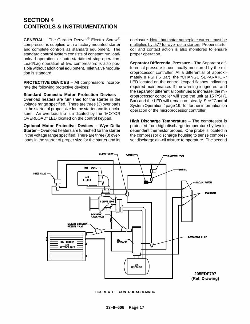
FIGURE 4–1 – CONTROL SCHEMATIC
205EDF797(Ref. Drawing)

13–8–606 Page 18
FIGURE 4–2 – INLET VALVE
210EDF797(Ref. Drawing)
probe is located at the separator discharge and sensesthe temperature of the air at the oil separator.
The microprocessor controller will shut the compressordown if the temperature sensed at either location ex-ceeds 225� F (107� C). See “High Air TemperatureLED,” page 20.
Damage will occur to the machine if itis repeatedly restarted after high tem-perature stops operation. Find andcorrect the malfunction before re-suming operation.
Relief Valve – A pressure relief valve(s) is (are)installed in the final discharge line and set at the factoryto approximately 120% of the unit’s full load operatingpressure for protection against overpressure. Periodicchecks should be made to insure that it is operatingproperly.
The relief valve should be tested for proper operationat least once every year. To test the relief valve, raisethe system operating pressure to 75% of the relief valveset pressure and manually open the valve with the handlever. Hold the valve open for a few seconds and allowit to snap shut.
When the relief valve opens, a streamof high velocity air is released, result-ing in a high noise level and possibledischarge of accumulated dirt or oth-er debris. Always wear eye and earprotection and stand clear of the dis-charge port when testing the reliefvalve to prevent injury.
Never paint, lubricate or alter a reliefvalve. Do not plug vent or restrict dis-charge.
Operation of the unit with improperrelief valve setting can result in se-vere personal injury or machine dam-age. Insure properly set valves areinstalled and maintained.
13–8–606 Page 19
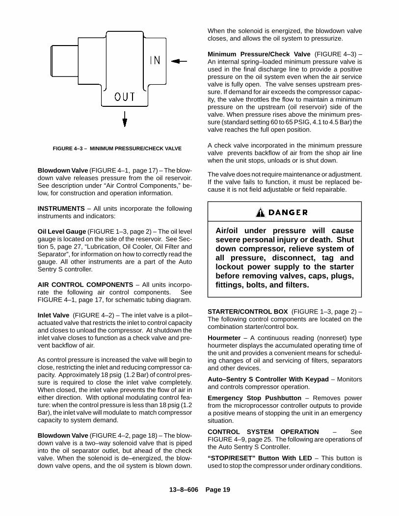
FIGURE 4–3 – MINIMUM PRESSURE/CHECK VALVE
Blowdown Valve (FIGURE 4–1, page 17) – The blow-down valve releases pressure from the oil reservoir.See description under “Air Control Components,” be-low, for construction and operation information.
INSTRUMENTS – All units incorporate the followinginstruments and indicators:
Oil Level Gauge (FIGURE 1–3, page 2) – The oil levelgauge is located on the side of the reservoir. See Sec-tion 5, page 27, “Lubrication, Oil Cooler, Oil Filter andSeparator”, for information on how to correctly read thegauge. All other instruments are a part of the AutoSentry S controller.
AIR CONTROL COMPONENTS – All units incorpo-rate the following air control components. SeeFIGURE 4–1, page 17, for schematic tubing diagram.
Inlet Valve (FIGURE 4–2) – The inlet valve is a pilot–actuated valve that restricts the inlet to control capacityand closes to unload the compressor. At shutdown theinlet valve closes to function as a check valve and pre-vent backflow of air.
As control pressure is increased the valve will begin toclose, restricting the inlet and reducing compressor ca-pacity. Approximately 18 psig (1.2 Bar) of control pres-sure is required to close the inlet valve completely.When closed, the inlet valve prevents the flow of air ineither direction. With optional modulating control fea-ture: when the control pressure is less than 18 psig (1.2Bar), the inlet valve will modulate to match compressorcapacity to system demand.
Blowdown Valve (FIGURE 4–2, page 18) – The blow-down valve is a two–way solenoid valve that is pipedinto the oil separator outlet, but ahead of the checkvalve. When the solenoid is de–energized, the blow-down valve opens, and the oil system is blown down.
When the solenoid is energized, the blowdown valvecloses, and allows the oil system to pressurize.
Minimum Pressure/Check Valve (FIGURE 4–3) –An internal spring–loaded minimum pressure valve isused in the final discharge line to provide a positivepressure on the oil system even when the air servicevalve is fully open. The valve senses upstream pres-sure. If demand for air exceeds the compressor capac-ity, the valve throttles the flow to maintain a minimumpressure on the upstream (oil reservoir) side of thevalve. When pressure rises above the minimum pres-sure (standard setting 60 to 65 PSIG, 4.1 to 4.5 Bar) thevalve reaches the full open position.
A check valve incorporated in the minimum pressurevalve prevents backflow of air from the shop air linewhen the unit stops, unloads or is shut down.
The valve does not require maintenance or adjustment.If the valve fails to function, it must be replaced be-cause it is not field adjustable or field repairable.
Air/oil under pressure will causesevere personal injury or death. Shutdown compressor, relieve system ofall pressure, disconnect, tag andlockout power supply to the starterbefore removing valves, caps, plugs,fittings, bolts, and filters.
STARTER/CONTROL BOX (FIGURE 1–3, page 2) –The following control components are located on thecombination starter/control box.
Hourmeter – A continuous reading (nonreset) typehourmeter displays the accumulated operating time ofthe unit and provides a convenient means for schedul-ing changes of oil and servicing of filters, separatorsand other devices.
Auto–Sentry S Controller With Keypad – Monitorsand controls compressor operation.
Emergency Stop Pushbutton – Removes powerfrom the microprocessor controller outputs to providea positive means of stopping the unit in an emergencysituation.
CONTROL SYSTEM OPERATION – SeeFIGURE 4–9, page 25. The following are operations ofthe Auto Sentry S Controller.
“STOP/RESET” Button With LED – This button isused to stop the compressor under ordinary conditions.
13–8–606 Page 20
It is also used to extinguish any fault LED’s that are illu-minated. In addition, it is used in the procedure to adjustoperating pressure. See “Programming the Load–Un-load Pressure Setpoints,” page 21. The LED is illumi-nated whenever the unit is stopped for any reason EX-CEPT a normal shutdown in one of the “AUTO” modes.A flashing LED indicates that a reset is required.
Damage will occur to the machine if itis repeatedly restarted after any oneof the shutdown modes stops opera-tion of the unit. Find and correct themalfunction before resuming opera-tion.
“CONSTANT RUN” Button With LED – This buttonis used to operate the unit in the constant run mode. Inthis mode, the compressor runs continuously, loadingand unloading in response to air demand. It will contin-ue to run until stopped, either manually or by a protec-tive shutdown. The LED is illuminated at all times whilerunning in this mode.
“AUTO LEAD” Button With LED – This button is usedto operate the unit in “Auto–Start–Timed–Stop” mode,either by itself, or as the lead compressor in a Lead/Lagarrangement. Loading and unloading occurs as in the“CONSTANT RUN” mode, however, if the compressorruns unloaded for a period of 10 minutes, the unit isstopped. At this point, the compressor remains in the“AUTO LEAD” mode and will restart when the systempressure reaches the ‘load’ setpoint programmed intothe controller. The LED will remain illuminated through-out the cycle.
Automatic restarting or electricalshock can cause injury or death.Open, tag and lockout main discon-nect and any other circuits beforeservicing the unit.
“AUTO LAG” Button With LED – This button is usedto select the ‘lag’ unit in a lead–lag arrangement. Op-eration is identical to “AUTO LEAD” except that thestart–load and unload setpoints are automatically 5 PSI(.3 Bar) lower than programmed.
Any mode may be selected at any timewithout stopping the compressor.
“HIGH AIR TEMPERATURE” LED – This LED is usedto indicate an over temperature condition at either thecompressor or oil separator discharge. At the time of ahigh temperature shutdown, the LED is illuminated andthe temperature digital readout is locked on to the of-fending temperature. Illumination of the decimal pointin the lower right hand corner of the digital readout indi-cates that the temperature displayed is at the oil sepa-rator. A non–illuminated decimal point indicates com-pressor discharge. Pressing “STOP/RESET” willextinguish the LED (if the temperature has lowered be-low 225� F, 107� C) and revert the digital readout to dis-playing actual discharge temperature.
“MOTOR OVERLOAD” LED – This LED indicates thatone of the motor overload relays has tripped. The over-load relay itself must be reset before pressing “STOP/RESET” will extinguish the LED.
“CHANGE SEPARATOR” LED – This LED flasheswhen the differential pressure across the oil separatorreaches approximately 8 PSI (.6 Bar). At this point,schedule the separator element for service at the earli-est opportunity. (See Section 5, page 37, for separatormaintenance.)
Should the condition be ignored and allowed to furtherdeteriorate, the compressor will be shutdown and theLED illuminated steadily when the differential pressurereaches 15 PSI (1.0 Bar).
Machine damage will occur if com-pressor is repeatedly restarted afterany one of the shutdown modesstops operation of the unit. Find andcorrect the malfunction before re-suming operation.
“CHANGE AIR FILTER” LED – This LED is used tosignal when the air filter requires servicing or changing.It is a reminder only and will not stop or impede the op-eration of the unit. Operating the compressor with theLED illuminated risks collapse of the filter and ingestioninto the compressor.
13–8–606 Page 21
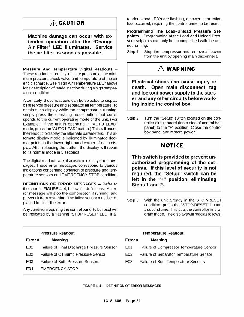
Machine damage can occur with ex-tended operation after the “ChangeAir Filter” LED illuminates. Servicethe air filter as soon as possible.
Pressure And Temperature Digital Readouts –These readouts normally indicate pressure at the mini-mum pressure check valve and temperature at the airend discharge. See “High Air Temperature LED” abovefor a description of readout action during a high temper-ature condition.
Alternately, these readouts can be selected to displayoil reservoir pressure and separator air temperature. Toobtain such display while the compressor is running,simply press the operating mode button that corre-sponds to the current operating mode of the unit. (ForExample: If the unit is operating in “AUTO LEAD”mode, press the “AUTO LEAD” button.) This will causethe readout to display the alternate parameters. This al-ternate display mode is indicated by illuminated deci-mal points in the lower right hand corner of each dis-play. After releasing the button, the display will revertto its normal mode in 5 seconds.
The digital readouts are also used to display error mes-sages. These error messages correspond to variousindications concerning condition of pressure and tem-perature sensors and EMERGENCY STOP condition.
DEFINITIONS OF ERROR MESSAGES – Refer tothe chart in FIGURE 4–4, below, for definitions. An er-ror message will stop the compressor, if running, andprevent it from restarting. The failed sensor must be re-placed to clear the error.
Any condition requiring the control panel to be reset willbe indicated by a flashing “STOP/RESET” LED. If all
readouts and LED’s are flashing, a power interruptionhas occurred, requiring the control panel to be reset.
Programming The Load–Unload Pressure Set-points – Programming of the Load and Unload Pres-sure setpoints can only be accomplished with the unitnot running.
Step 1: Stop the compressor and remove all powerfrom the unit by opening main disconnect.
Electrical shock can cause injury ordeath. Open main disconnect, tagand lockout power supply to the start-er and any other circuits before work-ing inside the control box.
Step 2: Turn the “Setup” switch located on the con-troller circuit board (inner side of control boxpanel) to the “+” position. Close the controlbox panel and restore power.
This switch is provided to prevent un-authorized programming of the set-points. If this level of security is notrequired, the “Setup” switch can beleft in the “+” position, eliminatingSteps 1 and 2.
Step 3: With the unit already in the STOP/RESETcondition, press the “STOP/RESET” buttona second time. This puts the controller in pro-gram mode. The displays will read as follows:
Pressure Readout Temperature Readout
Error # Meaning Error # Meaning
E01 Failure of Final Discharge Pressure Sensor E01 Failure of Compressor Temperature Sensor
E02 Failure of Oil Sump Pressure Sensor E02 Failure of Separator Temperature Sensor
E03 Failure of Both Pressure Sensors E03 Failure of Both Temperature Sensors
E04 EMERGENCY STOP
FIGURE 4–4 – DEFINITION OF ERROR MESSAGES

13–8–606 Page 22
Pressure: the current unload setpoint (adj.58–175 psig, 4.0 to 12.1 Bar)
Temperature: indicates that thepressure value is the “un–load” value.
Step 4: Press the “AUTO LEAD” button to raise theunload setpoint. Press “AUTO LAG” to lowerthe unload setpoint. See FIGURE 4–8, page25.
Operation at excessive discharge airpressure can cause personal injury ordamage to equipment. Do not set un-load pressure above the maximumstamped on the unit nameplate.
Step 5: When the desired unload setpoint is dis-played in the pressure readout, press the“STOP/RESET” button. This will enter thedesired unload setpoint and advance the pro-gramming function to the load setpoint. Thedisplays will now read:
Pressure: the current load setpoint (adj.50–167 psig, 3.4 to 11.5 Bars)
Temperature: indicates that thepressure value is the “load”value.
Step 6: Raise or lower the load setpoint in the samemanner as the unload setpoint in Step 4.
The load setpoint cannot be set within8 PSI (.6 Bar) of the unload setpoint.See FIGURE 4–8, page 25.
Step 7: When the desired load setpoint is displayedin the pressure readout, press the “STOP/RESET” button, entering the new load set-point and completing the programming.
Step 8: The display now indicates:
At this time, compressor rotation may be
checked by pressing any of the three operat-ing mode buttons. The correct rotation isclockwise. The starter will be momentarilyenergized giving a slight rotation that is shortenough in duration to prevent reverse oil flowin the event that rotation is reversed. Press“Stop/Reset” to exit jog mode.
Step 9: The displays will now read:
Pressure
Temperature or
If this compressor is equipped with the ex-pansion board for the remote control optionthis must be set to “yes”. The standard set-ting is “no”. This value is toggled by pressingany mode switch. Press the “Stop/Reset”button to continue to the next step.
Step 10: The display now indicates either
or
Pressing any mode key will toggle the displayfrom one set of units to the other. PSI/�Fcauses the controller to display pressures inpounds per square inch and temperatures indegrees fahrenheit. bar/�C causes the con-troller to display parameters in bars and de-grees Centigrade. Press “Stop/Reset” whenthe desired units are visible in the display tocontinue.
Step 11: When display shows dashes (–––– ––––):(The Following steps may be skipped bywaiting until the display resumes its normalnumbers.)
a) Press “Stop–Reset” – the pressure displaynow shows the current “zero” pressure forthe final discharge transducer in the left win-dow, and “P1” in the right window.
b) Press “Stop–Reset” again – this will zero thecircuit board on the final discharge pressuretransducer and move the display to the nextstep. The left window will read the current“zero” pressure for the oil reservoir transduc-er and the right window will now read “P2.”
c) Press “Stop–Reset” again – this will zero thecircuit board on the oil reservoir pressuretransducer and move the display program
13–8–606 Page 23
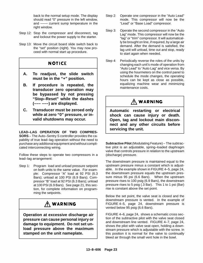
back to the normal setup mode. The displayshould read “0” pressure in the left window,and –––– current sump temperature in theright window.
Step 12: Stop the compressor and disconnect, tagand lockout the power supply to the starter.
Step 13: Move the circuit board slide switch back tothe “set” position (right). You may now pro-ceed with normal start up procedure.
A. To readjust, the slide switchmust be in the “+” position.
B. If procedure is repeated, thetransducer zero operation maybe bypassed by not pressing“Stop–Reset” while the dashes(––– –––) are displayed.
C. Transducer must be zeroed onlywhile at zero “0” pressure, or in-valid shutdowns may occur.
LEAD–LAG OPERATION OF TWO COMPRES-SORS – The Auto–Sentry S controller provides the ca-pability of true lead–lag operation without the need topurchase any additional equipment and without compli-cated interconnecting wiring.
Follow these steps to operate two compressors in alead–lag arrangement:
Step 1: Program load and unload pressure setpointon both units to the same value. For exam-ple: Compressor “A” load at 92 PSI (6.3Bars); unload at 100 PSI (6.9 Bars). Com-pressor “B” load at 92 PSI (6.3 Bars); unloadat 100 PSI (6.9 Bars). See page 21, this sec-tion, for complete information on program-ming the setpoints.
Operation at excessive discharge airpressure can cause personal injury ordamage to equipment. Do not set un-load pressure above the maximumstamped on the unit nameplate.
Step 2: Operate one compressor in the “Auto Lead”mode. This compressor will now be the“Lead” or “Base Load” compressor.
Step 3: Operate the second compressor in the “AutoLag” mode. This compressor will now be the“lag” or “trim” compressor. It will automatical-ly be brought on line, if required, by a large airdemand. After the demand is satisfied, thelag unit will unload, time out and stop, readyto start again when needed.
Step 4: Periodically reverse the roles of the units bychanging each unit’s mode of operation from“Auto Lead” to “Auto Lag” and vice versa. Byusing the hourmeters on the control panel toschedule the mode changes, the operatinghours can be kept as close as possible,equalizing machine wear and minimizingmaintenance costs.
Automatic restarting or electricalshock can cause injury or death.Open, tag and lockout main discon-nect and any other circuits beforeservicing the unit.
Subtractive Pilot (Modulating Feature) – The subtrac-tive pilot is an adjustable, spring–loaded diaphragmvalve that controls pressure in relation to the upstream(discharge) pressure.
The downstream pressure is maintained equal to theupstream pressure minus a constant which is adjust-able. In the example shown in FIGURE 4–5, page 24,the downstream pressure equals the upstream pres-sure minus 95 psi (6.6 Bars). When the upstreampressure rises to 100 psig (6.9 Bars), the downstreampressure rises to 5 psig (.3 Bar). This 1 to 1 psi (Bar)rise is constant above the set point.
Below the set point, the valve seat is closed and thedownstream pressure is vented. In the example ofFIGURE 4–5, page 24, downstream pressure isvented below 95 psig (6.6 Bars).
FIGURE 4–6, page 24, shows a schematic cross sec-tion of the subtractive pilot with the valve seat closedand downstream line vented. FIGURE 4–7, page 24,shows the pilot with valve seat open, holding a down-stream pressure which is adjustable with the screw. Inthis position it is normal for the valve to continuallybleed air through the small vent hole in the bowl.
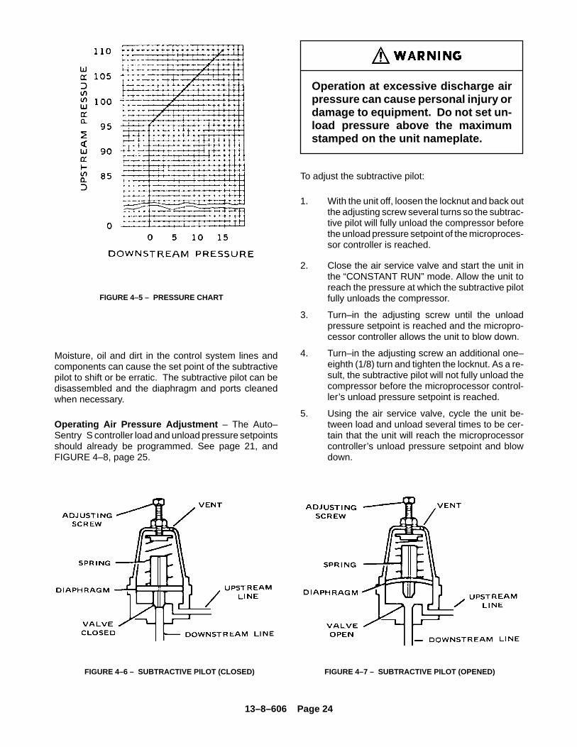
13–8–606 Page 24
FIGURE 4–5 – PRESSURE CHART
Moisture, oil and dirt in the control system lines andcomponents can cause the set point of the subtractivepilot to shift or be erratic. The subtractive pilot can bedisassembled and the diaphragm and ports cleanedwhen necessary.
Operating Air Pressure Adjustment – The Auto–Sentry S controller load and unload pressure setpointsshould already be programmed. See page 21, andFIGURE 4–8, page 25.
Operation at excessive discharge airpressure can cause personal injury ordamage to equipment. Do not set un-load pressure above the maximumstamped on the unit nameplate.
To adjust the subtractive pilot:
1. With the unit off, loosen the locknut and back outthe adjusting screw several turns so the subtrac-tive pilot will fully unload the compressor beforethe unload pressure setpoint of the microproces-sor controller is reached.
2. Close the air service valve and start the unit inthe “CONSTANT RUN” mode. Allow the unit toreach the pressure at which the subtractive pilotfully unloads the compressor.
3. Turn–in the adjusting screw until the unloadpressure setpoint is reached and the micropro-cessor controller allows the unit to blow down.
4. Turn–in the adjusting screw an additional one–eighth (1/8) turn and tighten the locknut. As a re-sult, the subtractive pilot will not fully unload thecompressor before the microprocessor control-ler’s unload pressure setpoint is reached.
5. Using the air service valve, cycle the unit be-tween load and unload several times to be cer-tain that the unit will reach the microprocessorcontroller’s unload pressure setpoint and blowdown.
FIGURE 4–6 – SUBTRACTIVE PILOT (CLOSED) FIGURE 4–7 – SUBTRACTIVE PILOT (OPENED)
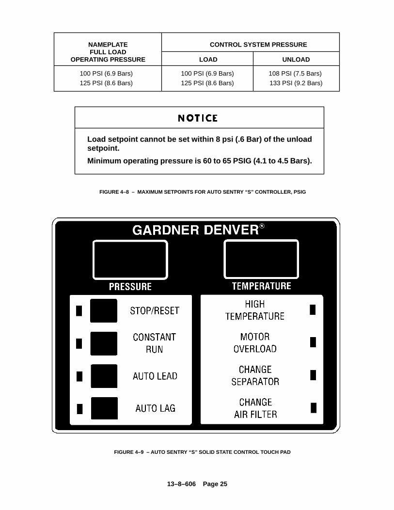
13–8–606 Page 25
Load setpoint cannot be set within 8 psi (.6 Bar) of the unloadsetpoint.
Minimum operating pressure is 60 to 65 PSIG (4.1 to 4.5 Bars).
NAMEPLATE CONTROL SYSTEM PRESSUREFULL LOAD
OPERATING PRESSURE LOAD UNLOAD
100 PSI (6.9 Bars) 100 PSI (6.9 Bars) 108 PSI (7.5 Bars)
125 PSI (8.6 Bars) 125 PSI (8.6 Bars) 133 PSI (9.2 Bars)
FIGURE 4–8 – MAXIMUM SETPOINTS FOR AUTO SENTRY “S” CONTROLLER, PSIG
FIGURE 4–9 – AUTO SENTRY “S” SOLID STATE CONTROL TOUCH PAD
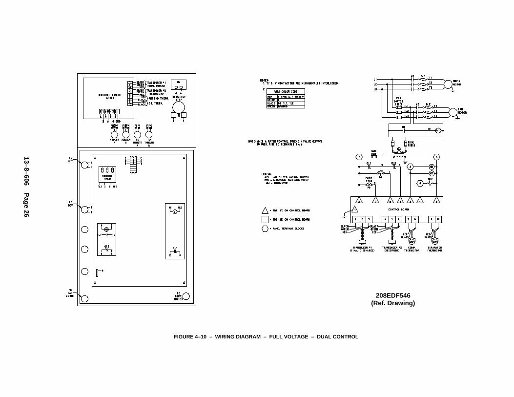
13–8–606 Page 26
FIGURE 4–10 – WIRING DIAGRAM – FULL VOLTAGE – DUAL CONTROL
208EDF546(Ref. Drawing)

13–8–606 Page 27
SECTION 5LUBRICATIONOIL COOLER, OIL FILTER & SEPARATOR
COMPRESSOR OIL SYSTEM (FIGURE 5–1, page28) cools the compressor, lubricates moving parts andseals internal clearances in the compression chamber.
The oil inlet line is connected at the bottom of the oil res-ervoir. Air pressure in the oil reservoir forces oil throughthe oil cooler, thermostatic mixing valve, oil filter andinto the compressor main oil gallery.
The oil passes through internal passages for lubrica-tion, cooling and sealing. The air–oil mixture is thendischarged to the oil reservoir where a large part ofthe entrained oil drops out of the air stream; the airthen passes through the final oil separator where mostof the remaining oil is removed. The separated oil is re-turned to the compressor and the air passes to the finaldischarge line.
RECOMMENDED LUBRICANT – Gardner Denvercompressors are factory filled with AEON lubricants.These lubricants are formulated to the highest qualitystandards and are factory authorized, tested and ap-proved for use in rotary screw compressors. AEONlubricants are available through your authorized Gard-ner Denver compressor distributor.
OIL SPECIFICATIONS – The recommended com-pressor lubricant is Gardner Denver AEON 4000 Lubri-cating Coolant which can be used for year–round op-eration except as noted in the “High TemperatureOperation” paragraph below, or low temperature, see“Installation for Cold Weather,” page 9.
AEON� 4000 Lubricating Coolant is a superior petro-leum base lubricant formulated and containing addi-tives for use in Gardner Denver compressors.
A lubricant analysis program for a periodic check of lu-bricant quality and remaining life can maximize thechange interval.
Specific AEON lubricants are recom-mended for use in this equipment.Other lubricants may cause exces-sive carryover or compressor dam-age. Do not mix different types of lu-bricants or use inferior lubricants.
Air/oil under pressure will causesevere personal injury or death. Shutdown compressor, relieve system ofall pressure, disconnect, tag andlockout power supply to the starterbefore removing valves, caps, plugs,fittings, bolts, and filters.
HIGH TEMPERATURE OPERATION – If the dis-charge temperature is sustained between 200� to210�F (93� to 99�C) for a period of more than four (4)hours due to continuing high ambient air temperature,use Gardner Denver� AEON 9000 SP LubricatingCoolant which is a superior synthetic lubricant. Shortperiods of up to four (4) hours of sustained dischargetemperatures up to 210�F (99�C) do not require achange from the recommended year–round lubricantAEON� 4000.
High temperature operation cancause damage to equipment or per-sonal injury. Do not repeatedly restartthe unit after high temperature stopsoperation. Find and correct the mal-function before resuming operation.
Compressor, air/oil reservoir, separa-tion chamber and all piping and tub-ing may be at high temperature duringand after operation.
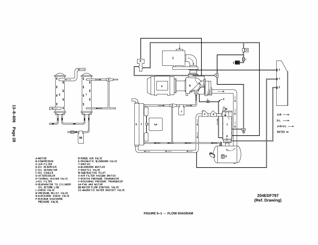
13–8–606 Page 28
FIGURE 5–1 – FLOW DIAGRAM
204EDF797(Ref. Drawing)
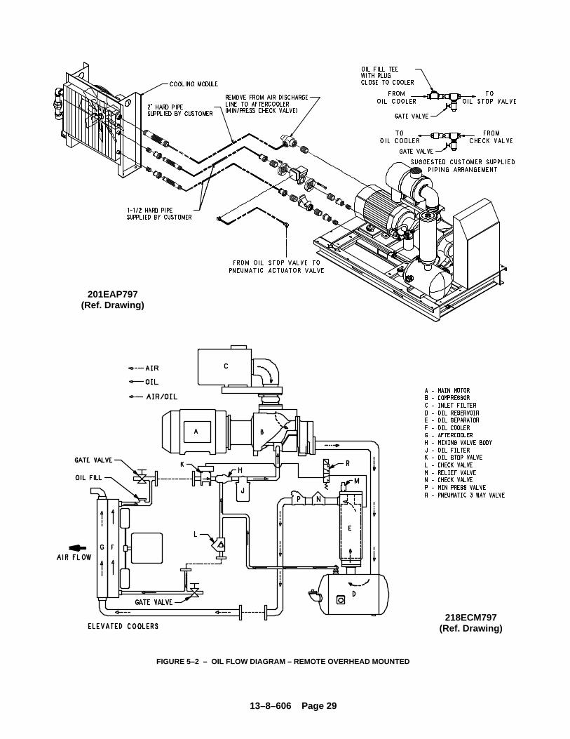
13–8–606 Page 29
201EAP797(Ref. Drawing)
FIGURE 5–2 – OIL FLOW DIAGRAM – REMOTE OVERHEAD MOUNTED
218ECM797(Ref. Drawing)
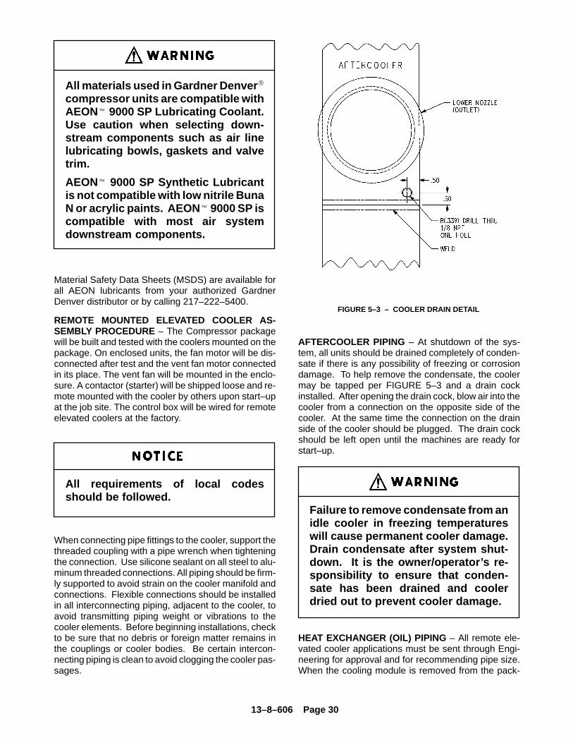
13–8–606 Page 30
All materials used in Gardner Denver �
compressor units are compatible withAEON� 9000 SP Lubricating Coolant.Use caution when selecting down-stream components such as air linelubricating bowls, gaskets and valvetrim.
AEON� 9000 SP Synthetic Lubricantis not compatible with low nitrile BunaN or acrylic paints. AEON � 9000 SP iscompatible with most air systemdownstream components.
Material Safety Data Sheets (MSDS) are available forall AEON lubricants from your authorized GardnerDenver distributor or by calling 217–222–5400.
REMOTE MOUNTED ELEVATED COOLER AS-SEMBLY PROCEDURE – The Compressor packagewill be built and tested with the coolers mounted on thepackage. On enclosed units, the fan motor will be dis-connected after test and the vent fan motor connectedin its place. The vent fan will be mounted in the enclo-sure. A contactor (starter) will be shipped loose and re-mote mounted with the cooler by others upon start–upat the job site. The control box will be wired for remoteelevated coolers at the factory.
All requirements of local codesshould be followed.
When connecting pipe fittings to the cooler, support thethreaded coupling with a pipe wrench when tighteningthe connection. Use silicone sealant on all steel to alu-minum threaded connections. All piping should be firm-ly supported to avoid strain on the cooler manifold andconnections. Flexible connections should be installedin all interconnecting piping, adjacent to the cooler, toavoid transmitting piping weight or vibrations to thecooler elements. Before beginning installations, checkto be sure that no debris or foreign matter remains inthe couplings or cooler bodies. Be certain intercon-necting piping is clean to avoid clogging the cooler pas-sages.
FIGURE 5–3 – COOLER DRAIN DETAIL
AFTERCOOLER PIPING – At shutdown of the sys-tem, all units should be drained completely of conden-sate if there is any possibility of freezing or corrosiondamage. To help remove the condensate, the coolermay be tapped per FIGURE 5–3 and a drain cockinstalled. After opening the drain cock, blow air into thecooler from a connection on the opposite side of thecooler. At the same time the connection on the drainside of the cooler should be plugged. The drain cockshould be left open until the machines are ready forstart–up.
Failure to remove condensate from anidle cooler in freezing temperatureswill cause permanent cooler damage.Drain condensate after system shut-down. It is the owner/operator’s re-sponsibility to ensure that conden-sate has been drained and coolerdried out to prevent cooler damage.
HEAT EXCHANGER (OIL) PIPING – All remote ele-vated cooler applications must be sent through Engi-neering for approval and for recommending pipe size.When the cooling module is removed from the pack-
13–8–606 Page 31
age, the thermal mixing valve (H) remains on the pack-age. Control group part number 200ECM4002 will bemounted on package at the factory. This group controlsthe oil stop valve as well as not allowing machine to runblowndown. See FIGURE 5–2, page 29.
Remote mounted elevated coolershave a maximum pipe length of 30 feet(9 M) (each way) and a maximumheight of 20 feet (6 M) with a minimumof fittings. Engineering will review allremote elevated cooler applicationsand recommend pipe size on an indi-vidual basis. Customer Serviceshould include the engineering rec-ommendation in the special ordersent to Engineering.
Kit number EAQ68330 includes the oil stop valve,check valve and flanges and must be installed on all re-mote elevated coolers per See FIGURE 5–2, page 29,and the following instructions.
1. Mount the check valve (90J113) as shown.
2. Mount the drain valves in the lowest section of thepipe on each side of the cooler connections.
3. Mount the oil stop valve (90AR243) in the line afterthe thermal mixing valve as shown.
Modifications to the control lines will be made at the fac-tory per 288ECM810 schematic. Air to the oil stop valvemust come from the upper fitting in the separator hous-ing, then pass through the 3–way pneumatic valve.Control air to the valve must be from the line betweenthe tee and the orifice in the blowdown muffler line perFIGURE 5–2, page 29. When the machine blowsdown, it will activate the pneumatic valve and it will shutoff the air and vent the line between the pneumatic con-trol valve and the oil stop valve to atmosphere. This willshut the oil stop valve and prevent excessive oil fromrunning into the reservoir.
Failure to install these parts could result in high oil car-ryover and cause the machine to shutdown on high dis-charge temperature.
COLD AMBIENT OPERATION – See “Installation forCold Weather Operation,” page 9.
ADDITION OF OIL BETWEEN CHANGES must bemade when the oil level is in the red range on the gaugeas read while the unit is on. To add oil, follow thesesteps:
1. Be sure the unit is completely off and that no airpressure is in the oil reservoir.
2. Disconnect, tag and lockout the power supply tothe starter.
3. Wipe away all dirt around the oil filler plug.
4. Remove the oil filler plug and add oil as requiredto return the oil level to the center of the greenrange on the gauge.
5. Install the oil filler plug, restore power, run andcheck for leaks.
DO NOT OVERFILL. The quantity required to raise theoil level from the red range center of the green rangeis shown in FIGURE 5–4, page 33. Repeated additionof oil between oil changes may indicate excessive oilcarry–over and should be investigated.
Air/oil under pressure will causesevere personal injury or death. Shutdown compressor, relieve system ofall pressure, disconnect, tag andlockout power supply to the starterbefore removing valves, caps, plugs,fittings, bolts, and filters.
Excessive oil carry–over can damageequipment. Never fill oil reservoirabove the “FULL” marker.
LUBRICANT CHANGE PROCEDURE – Upgrading toa longer life lubricant is essentially a very worthwhilepractice. Following are the primary steps to be com-pleted when upgrading or changing the type of lubri-cant.
1. Thoroughly drain system:
– Drain oil from air end and cooler while hot.
– Break low point connections and drain oilfrom pipe runs.
13–8–606 Page 32
– Dump oil from the filter and reinstall used fil-ter.
2. Fill the system with a 50 percent charge of the newlubricant:
– Start the machine and stay there to observe.
– Allow the machine to run about five minutesat temperature, or until temperature stabi-lizes, then shut down.
3. Thoroughly drain the machine.
4. Change to a new filter and separator.
5. Fill the system with a full charge of the new lubri-cant, then reinstall drain plug.
6. Machine should then be run normally, however,total run time after the initial changeout should be50 percent of normal anticipated service life of thenew lubricant.
– Drain all lubricant from the system, changethe filter and separator, and replace with a fullcharge of the new lubricant.
7. Subsequent lubricant changeouts should be atnormal intervals. (See “Oil Change Interval” andchart below.)
Improper equipment maintenancewith use of synthetic lubricants willdamage equipment. Oil filter and oilseparator change intervals remainthe same as for AEON � 4000 –– SeeMaintenance Schedule, page 43.
Air/oil under pressure will causesevere personal injury or death. Shutdown compressor, relieve system ofall pressure, disconnect, tag andlockout power supply to the starterbefore removing valves, caps, plugs,fittings, bolts, and filters.
High temperature operation cancause damage to equipment or per-sonal injury. Do not repeatedly restartthe unit after high temperature stopsoperation. Find and correct the mal-function before resuming operation.
All materials used in Gardner Denver �
compressor units are compatible withAEON� 9000 SP Lubricating Coolant.Use caution when selecting down-stream components such as air linelubricating bowls, gaskets and valvetrim.
AEON� 9000 SP Synthetic Lubricantis not compatible with low nitrile BunaN or acrylic paints. AEON � 9000 SP iscompatible with most air systemdownstream components.
OIL LEVEL GAUGE (FIGURE 1–6, page 3, andFIGURE 5–4, page 33) indicates the amount of oil inthe oil reservoir. Read oil level only when unit is on. Inoperation the oil level will fluctuate as the compressorloads and unloads. Add oil only when the oil is at thebottom of the red range on the gauge as read when thecompressor is on. Drain oil only when the oil level isabove the center of the green range on the gauge asread when the compressor is on.
MOISTURE IN THE OIL SYSTEM – In normal humid-ity and with normal operating temperatures and pres-sures, the thermal mixing valve controls the oil temper-ature and prevents moisture contamination of the oil.Unusual cooling of the oil reservoir, short loaded cyclein high humidity or malfunctions of the thermal valvemay result in moisture in the oil system which is detri-mental to compressor lubrication and could cause oilcarryover. If moisture is observed in the oil reservoir,drain the moisture and correct the condition causingthe accumulation. See “Compressor Oil SystemCheck,” page 38 and “Thermal Control (ThermostaticMixing) Valve,” page 35.
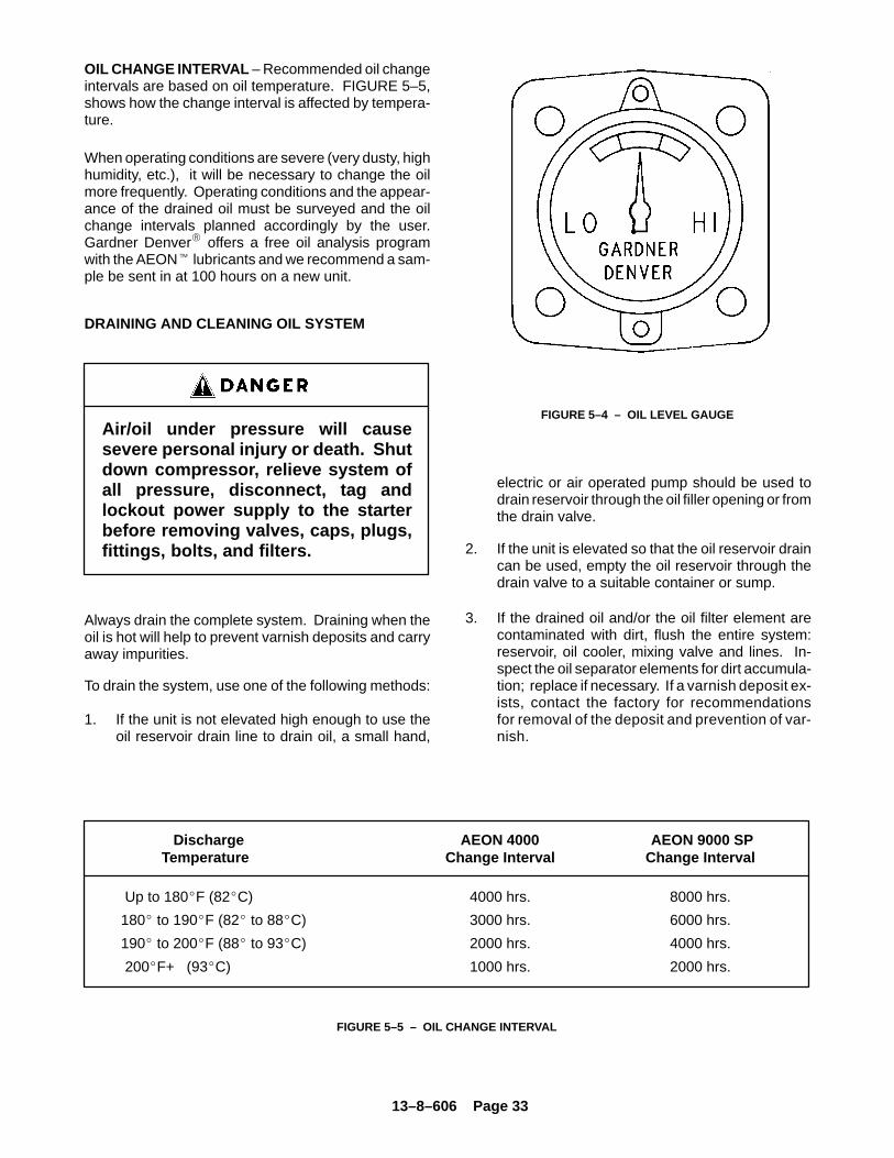
13–8–606 Page 33
OIL CHANGE INTERVAL – Recommended oil changeintervals are based on oil temperature. FIGURE 5–5,shows how the change interval is affected by tempera-ture.
When operating conditions are severe (very dusty, highhumidity, etc.), it will be necessary to change the oilmore frequently. Operating conditions and the appear-ance of the drained oil must be surveyed and the oilchange intervals planned accordingly by the user.Gardner Denver� offers a free oil analysis programwith the AEON� lubricants and we recommend a sam-ple be sent in at 100 hours on a new unit.
DRAINING AND CLEANING OIL SYSTEM
Air/oil under pressure will causesevere personal injury or death. Shutdown compressor, relieve system ofall pressure, disconnect, tag andlockout power supply to the starterbefore removing valves, caps, plugs,fittings, bolts, and filters.
Always drain the complete system. Draining when theoil is hot will help to prevent varnish deposits and carryaway impurities.
To drain the system, use one of the following methods:
1. If the unit is not elevated high enough to use theoil reservoir drain line to drain oil, a small hand,
FIGURE 5–4 – OIL LEVEL GAUGE
electric or air operated pump should be used todrain reservoir through the oil filler opening or fromthe drain valve.
2. If the unit is elevated so that the oil reservoir draincan be used, empty the oil reservoir through thedrain valve to a suitable container or sump.
3. If the drained oil and/or the oil filter element arecontaminated with dirt, flush the entire system:reservoir, oil cooler, mixing valve and lines. In-spect the oil separator elements for dirt accumula-tion; replace if necessary. If a varnish deposit ex-ists, contact the factory for recommendationsfor removal of the deposit and prevention of var-nish.
FIGURE 5–5 – OIL CHANGE INTERVAL
Discharge AEON 4000 AEON 9000 SP Temperature Change Interval Change Interval
Up to 180�F (82�C) 4000 hrs. 8000 hrs.
180� to 190�F (82� to 88�C) 3000 hrs. 6000 hrs.
190� to 200�F (88� to 93�C) 2000 hrs. 4000 hrs.
200�F+ (93�C) 1000 hrs. 2000 hrs.
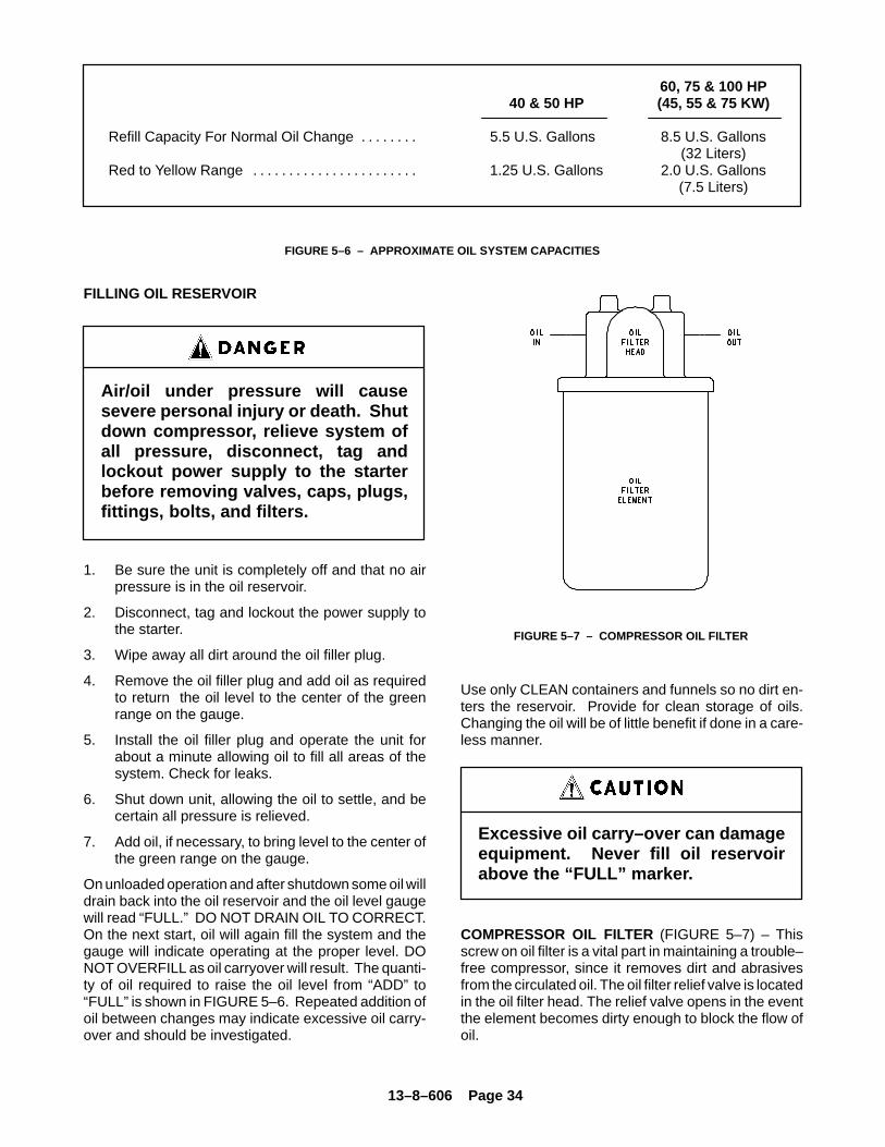
13–8–606 Page 34
60, 75 & 100 HP40 & 50 HP (45, 55 & 75 KW)
Refill Capacity For Normal Oil Change 5.5 U.S. Gallons 8.5 U.S. Gallons. . . . . . . . (32 Liters)
Red to Yellow Range 1.25 U.S. Gallons 2.0 U.S. Gallons. . . . . . . . . . . . . . . . . . . . . . . (7.5 Liters)
FIGURE 5–6 – APPROXIMATE OIL SYSTEM CAPACITIES
FILLING OIL RESERVOIR
Air/oil under pressure will causesevere personal injury or death. Shutdown compressor, relieve system ofall pressure, disconnect, tag andlockout power supply to the starterbefore removing valves, caps, plugs,fittings, bolts, and filters.
1. Be sure the unit is completely off and that no airpressure is in the oil reservoir.
2. Disconnect, tag and lockout the power supply tothe starter.
3. Wipe away all dirt around the oil filler plug.
4. Remove the oil filler plug and add oil as requiredto return the oil level to the center of the greenrange on the gauge.
5. Install the oil filler plug and operate the unit forabout a minute allowing oil to fill all areas of thesystem. Check for leaks.
6. Shut down unit, allowing the oil to settle, and becertain all pressure is relieved.
7. Add oil, if necessary, to bring level to the center ofthe green range on the gauge.
On unloaded operation and after shutdown some oil willdrain back into the oil reservoir and the oil level gaugewill read “FULL.” DO NOT DRAIN OIL TO CORRECT.On the next start, oil will again fill the system and thegauge will indicate operating at the proper level. DONOT OVERFILL as oil carryover will result. The quanti-ty of oil required to raise the oil level from “ADD” to“FULL” is shown in FIGURE 5–6. Repeated addition ofoil between changes may indicate excessive oil carry-over and should be investigated.
FIGURE 5–7 – COMPRESSOR OIL FILTER
Use only CLEAN containers and funnels so no dirt en-ters the reservoir. Provide for clean storage of oils.Changing the oil will be of little benefit if done in a care-less manner.
Excessive oil carry–over can damageequipment. Never fill oil reservoirabove the “FULL” marker.
COMPRESSOR OIL FILTER (FIGURE 5–7) – Thisscrew on oil filter is a vital part in maintaining a trouble–free compressor, since it removes dirt and abrasivesfrom the circulated oil. The oil filter relief valve is locatedin the oil filter head. The relief valve opens in the eventthe element becomes dirty enough to block the flow ofoil.
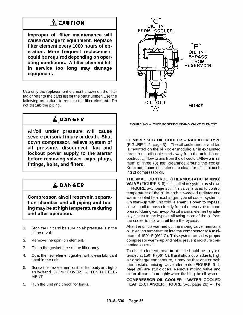
13–8–606 Page 35
Improper oil filter maintenance willcause damage to equipment. Replacefilter element every 1000 hours of op-eration. More frequent replacementcould be required depending on oper-ating conditions. A filter element leftin service too long may damageequipment.
Use only the replacement element shown on the filtertag or refer to the parts list for the part number. Use thefollowing procedure to replace the filter element. Donot disturb the piping.
Air/oil under pressure will causesevere personal injury or death. Shutdown compressor, relieve system ofall pressure, disconnect, tag andlockout power supply to the starterbefore removing valves, caps, plugs,fittings, bolts, and filters.
Compressor, air/oil reservoir, separa-tion chamber and all piping and tub-ing may be at high temperature duringand after operation.
1. Stop the unit and be sure no air pressure is in theoil reservoir.
2. Remove the spin–on element.
3. Clean the gasket face of the filter body.
4. Coat the new element gasket with clean lubricantused in the unit.
5. Screw the new element on the filter body and tight-en by hand. DO NOT OVERTIGHTEN THE ELE-MENT.
5. Run the unit and check for leaks.
FIGURE 5–8 – THERMOSTATIC MIXING VALVE ELEMENT
COMPRESSOR OIL COOLER – RADIATOR TYPE(FIGURE 1–5, page 3) – The oil cooler motor and fanis mounted on the oil cooler module; air is exhaustedthrough the oil cooler and away from the unit. Do notobstruct air flow to and from the oil cooler. Allow a mini-mum of three (3) feet clearance around the cooler.Keep both faces of cooler core clean for efficient cool-ing of compressor oil.
THERMAL CONTROL (THERMOSTATIC MIXING)VALVE (FIGURE 5–8) is installed in system as shownin FIGURE 5–1, page 28. This valve is used to controltemperature of the oil in both air–cooled radiator andwater–cooled heat exchanger type oil cooler systems.On start–up with unit cold, element is open to bypass,allowing oil to pass directly from the reservoir to com-pressor during warm–up. As oil warms, element gradu-ally closes to the bypass allowing more of the oil fromthe cooler to mix with oil from the bypass.
After the unit is warmed up, the mixing valve maintainsoil injection temperature into the compressor at a mini-mum of 150� F (66� C). This system provides propercompressor warm–up and helps prevent moisture con-tamination of oil.
To check element, heat in oil – it should be fully ex-tended at 150� F (66� C). If unit shuts down due to highair discharge temperature, it may be that one or boththermostatic mixing valve elements (FIGURE 5–1,page 28) are stuck open. Remove mixing valve andclean all parts thoroughly when flushing the oil system.
COMPRESSOR OIL COOLER – WATER–COOLEDHEAT EXCHANGER (FIGURE 5–1, page 28) – The
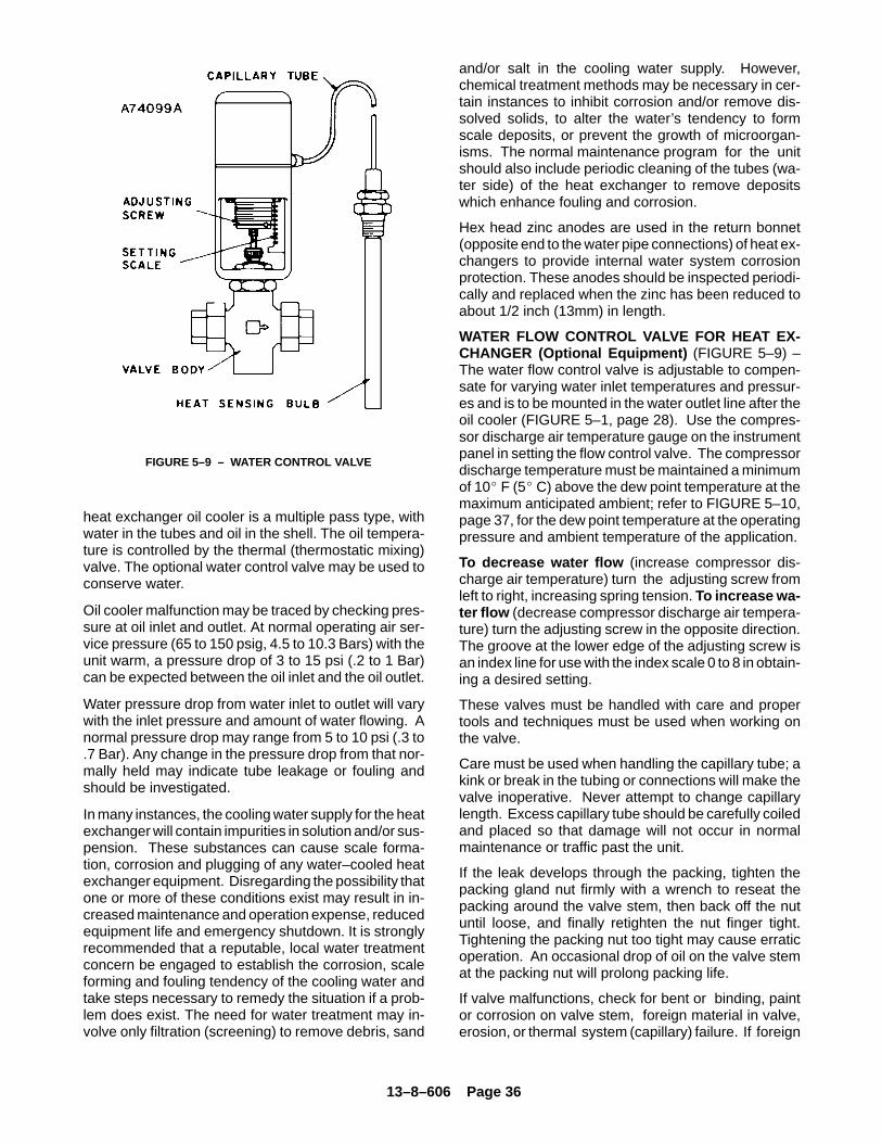
13–8–606 Page 36
FIGURE 5–9 – WATER CONTROL VALVE
heat exchanger oil cooler is a multiple pass type, withwater in the tubes and oil in the shell. The oil tempera-ture is controlled by the thermal (thermostatic mixing)valve. The optional water control valve may be used toconserve water.
Oil cooler malfunction may be traced by checking pres-sure at oil inlet and outlet. At normal operating air ser-vice pressure (65 to 150 psig, 4.5 to 10.3 Bars) with theunit warm, a pressure drop of 3 to 15 psi (.2 to 1 Bar)can be expected between the oil inlet and the oil outlet.
Water pressure drop from water inlet to outlet will varywith the inlet pressure and amount of water flowing. Anormal pressure drop may range from 5 to 10 psi (.3 to.7 Bar). Any change in the pressure drop from that nor-mally held may indicate tube leakage or fouling andshould be investigated.
In many instances, the cooling water supply for the heatexchanger will contain impurities in solution and/or sus-pension. These substances can cause scale forma-tion, corrosion and plugging of any water–cooled heatexchanger equipment. Disregarding the possibility thatone or more of these conditions exist may result in in-creased maintenance and operation expense, reducedequipment life and emergency shutdown. It is stronglyrecommended that a reputable, local water treatmentconcern be engaged to establish the corrosion, scaleforming and fouling tendency of the cooling water andtake steps necessary to remedy the situation if a prob-lem does exist. The need for water treatment may in-volve only filtration (screening) to remove debris, sand
and/or salt in the cooling water supply. However,chemical treatment methods may be necessary in cer-tain instances to inhibit corrosion and/or remove dis-solved solids, to alter the water’s tendency to formscale deposits, or prevent the growth of microorgan-isms. The normal maintenance program for the unitshould also include periodic cleaning of the tubes (wa-ter side) of the heat exchanger to remove depositswhich enhance fouling and corrosion.
Hex head zinc anodes are used in the return bonnet(opposite end to the water pipe connections) of heat ex-changers to provide internal water system corrosionprotection. These anodes should be inspected periodi-cally and replaced when the zinc has been reduced toabout 1/2 inch (13mm) in length.
WATER FLOW CONTROL VALVE FOR HEAT EX-CHANGER (Optional Equipment) (FIGURE 5–9) –The water flow control valve is adjustable to compen-sate for varying water inlet temperatures and pressur-es and is to be mounted in the water outlet line after theoil cooler (FIGURE 5–1, page 28). Use the compres-sor discharge air temperature gauge on the instrumentpanel in setting the flow control valve. The compressordischarge temperature must be maintained a minimumof 10� F (5� C) above the dew point temperature at themaximum anticipated ambient; refer to FIGURE 5–10,page 37, for the dew point temperature at the operatingpressure and ambient temperature of the application.
To decrease water flow (increase compressor dis-charge air temperature) turn the adjusting screw fromleft to right, increasing spring tension. To increase wa-ter flow (decrease compressor discharge air tempera-ture) turn the adjusting screw in the opposite direction.The groove at the lower edge of the adjusting screw isan index line for use with the index scale 0 to 8 in obtain-ing a desired setting.
These valves must be handled with care and propertools and techniques must be used when working onthe valve.
Care must be used when handling the capillary tube; akink or break in the tubing or connections will make thevalve inoperative. Never attempt to change capillarylength. Excess capillary tube should be carefully coiledand placed so that damage will not occur in normalmaintenance or traffic past the unit.
If the leak develops through the packing, tighten thepacking gland nut firmly with a wrench to reseat thepacking around the valve stem, then back off the nutuntil loose, and finally retighten the nut finger tight.Tightening the packing nut too tight may cause erraticoperation. An occasional drop of oil on the valve stemat the packing nut will prolong packing life.
If valve malfunctions, check for bent or binding, paintor corrosion on valve stem, foreign material in valve,erosion, or thermal system (capillary) failure. If foreign
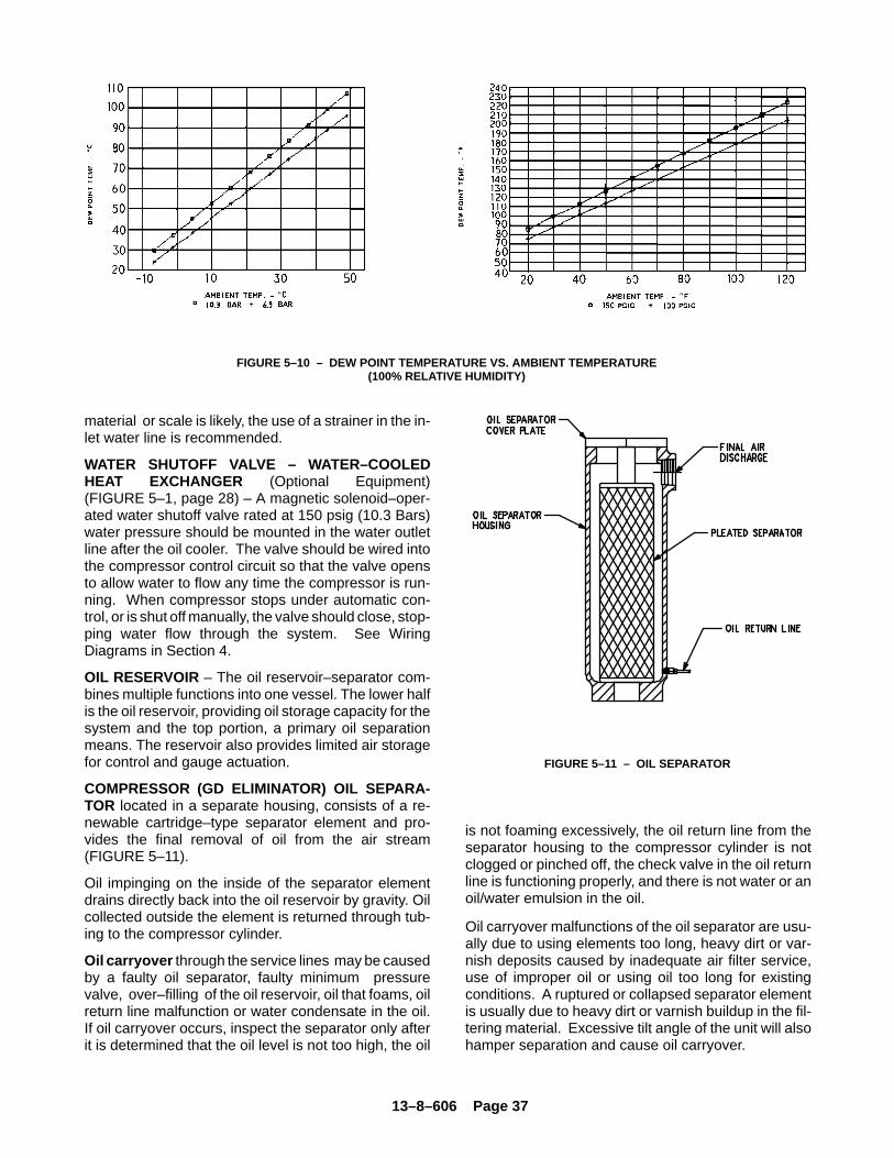
13–8–606 Page 37
FIGURE 5–10 – DEW POINT TEMPERATURE VS. AMBIENT TEMPERATURE(100% RELATIVE HUMIDITY)
material or scale is likely, the use of a strainer in the in-let water line is recommended.
WATER SHUTOFF VALVE – WATER–COOLEDHEAT EXCHANGER (Optional Equipment)(FIGURE 5–1, page 28) – A magnetic solenoid–oper-ated water shutoff valve rated at 150 psig (10.3 Bars)water pressure should be mounted in the water outletline after the oil cooler. The valve should be wired intothe compressor control circuit so that the valve opensto allow water to flow any time the compressor is run-ning. When compressor stops under automatic con-trol, or is shut off manually, the valve should close, stop-ping water flow through the system. See WiringDiagrams in Section 4.
OIL RESERVOIR – The oil reservoir–separator com-bines multiple functions into one vessel. The lower halfis the oil reservoir, providing oil storage capacity for thesystem and the top portion, a primary oil separationmeans. The reservoir also provides limited air storagefor control and gauge actuation.
COMPRESSOR (GD ELIMINATOR) OIL SEPARA-TOR located in a separate housing, consists of a re-newable cartridge–type separator element and pro-vides the final removal of oil from the air stream(FIGURE 5–11).
Oil impinging on the inside of the separator elementdrains directly back into the oil reservoir by gravity. Oilcollected outside the element is returned through tub-ing to the compressor cylinder.
Oil carryover through the service lines may be causedby a faulty oil separator, faulty minimum pressurevalve, over–filling of the oil reservoir, oil that foams, oilreturn line malfunction or water condensate in the oil.If oil carryover occurs, inspect the separator only afterit is determined that the oil level is not too high, the oil
FIGURE 5–11 – OIL SEPARATOR
is not foaming excessively, the oil return line from theseparator housing to the compressor cylinder is notclogged or pinched off, the check valve in the oil returnline is functioning properly, and there is not water or anoil/water emulsion in the oil.
Oil carryover malfunctions of the oil separator are usu-ally due to using elements too long, heavy dirt or var-nish deposits caused by inadequate air filter service,use of improper oil or using oil too long for existingconditions. A ruptured or collapsed separator elementis usually due to heavy dirt or varnish buildup in the fil-tering material. Excessive tilt angle of the unit will alsohamper separation and cause oil carryover.
13–8–606 Page 38
Oil separator element life cannot be predicted; it willvary greatly depending on the conditions of operation,the quality of the oil used and the maintenance of theoil and air filters. The condition of the separator can bedetermined by pressure differential gauging or by in-spection.
Pressure Differential Gauging – The “CHANGESEPARATOR” advisory will flash when the pressuredifferential across the oil separator reaches approxi-mately 8 PSID (.55 Bar). Replace the oil separator ele-ment at this time. If ignored, the unit will shut down andthe advisory will illuminate steadily when the pressuredifferential reaches 15 PSID (1 Bar).
Using an oil separator element at ex-cessive pressure differential cancause damage to equipment. Replacethe separator when the “Change Sep-arator” advisory appears.
A sudden drop of zero pressure differ-ential or sudden heavy oil carryovermay indicate a ruptured element.
Inspection – After removal of separator element,shine a light inside the element to reveal areas of heavydirt or varnish deposits or breaks (ruptures) in the ele-ment media.
Removal Of Oil Separator For Inspection Or Re-placement :
Air/oil under pressure will causesevere personal injury or death. Shutdown compressor, relieve system ofall pressure, disconnect, tag andlockout power supply to the starterbefore removing valves, caps, plugs,fittings, bolts, and filters.
1. Be certain unit is completely off and that no airpressure is in the oil reservoir.
2. Disconnect, tag and lockout power supply to thestarter.
3. Remove screws holding the top plate to the sepa-rator housing. Lift the top plate from the separatorhousing.
4. Lift the separator from the separator housing.
5. Inspect and/or replace the separator as neces-sary. Be sure the o–ring is not damaged. Beforeinstalling (or reinstalling) any separator applygrease to the o–ring. Oil will be wiped off by thechamfer and the o–ring could be damaged.
6. Remove any gasket material adhering to top plateor separator housing, and install new gasket.
7. Lower the separator into the housing and centerthe separator on the chamfer. Press separatordown into the housing. Do not use excessiveforce as separator damage can occur.
8. Place the spacer on the indent in the separator.Seat the top plate to the separator, spacer andseparator housing. Install and tighten all capscrews.
9. Run the unit and check for leaks.
COMPRESSOR OIL SYSTEM CHECK – The follow-ing readings are based on ambient temperature of 80�F (27� C) for air–cooled oil cooler and 80� F inlet wateron water–cooled oil cooler, with the system in goodcondition. Compressor should be at operating temper-ature at the time of checks. One–half hour of loaded op-eration is usually sufficient to reach level–out operatingtemperatures.
Air and Oil Discharge Temperature – 165� to 195�F (74� to 91� C) – Read at gauge on the instrumentpanel or check with a thermometer at the dischargehousing.
Compressor Oil Inlet Temperature – 150� to 160� F(66� to 71� C) – Install a tee at the oil filter outlet andcheck with a thermometer.
Oil Inlet Pressure – Check at the fitting in the line nearthe compressor oil inlet. With air receiver pressure at100 psi (6.9 Bar), oil inlet pressure should be 55–60psig(3.8–4.1 Bar).
Oil Cooler Oil Pressure Differential (Air–CooledRadiator) – Check differential across oil system bymeasuring oil inlet pressure as described above.
Oil Cooler Oil Pressure Differential (Water–CooledHeat Exchanger) – 2 to 25 PSID (.1 to 1.7 Bar) (65 to150 PSIG, 4.5 to 10.3 Bars Receiver Pressure) –
13–8–606 Page 39
Check that oil inlet pressure is correct or measure thedifferential between drains on the oil cooler shell.
Oil Cooler Temperature Differential (Air–CooledRadiator) – The oil temperature differential dependson the temperature of the air at the oil cooler fan andcleanliness of core faces. As ambient temperaturesand core restrictions increase, the oil cooler outlet tem-perature will increase. The oil inlet temperature isapproximately the same as air discharge temperature– see the gauge on the instrument panel. The outlet oiltemperature may be checked by installing a tee at theoil filter outlet.
Oil Cooler Temperature Differential (Water–Cooled
Heat Exchanger) – The oil temperature differential de-pends on the inlet water temperature and the water flowrate permitted by the water flow control valve setting.
The oil inlet temperature is approximately the same asthe air discharge temperature – see the gauge on theinstrument panel. The oil outlet temperature may bechecked by installing a tee at the oil filter outlet.
Oil Cooler Water Pressure Differential (Water–Cooled Heat Exchanger) – The water pressure differ-ential through the heat exchanger will depend on thesupply pressure, flow rate, cooler tube cleanliness andoutlet pressure. The inlet and outlet water pressuremay be checked at the pipe fittings supplied by the cus-tomer.
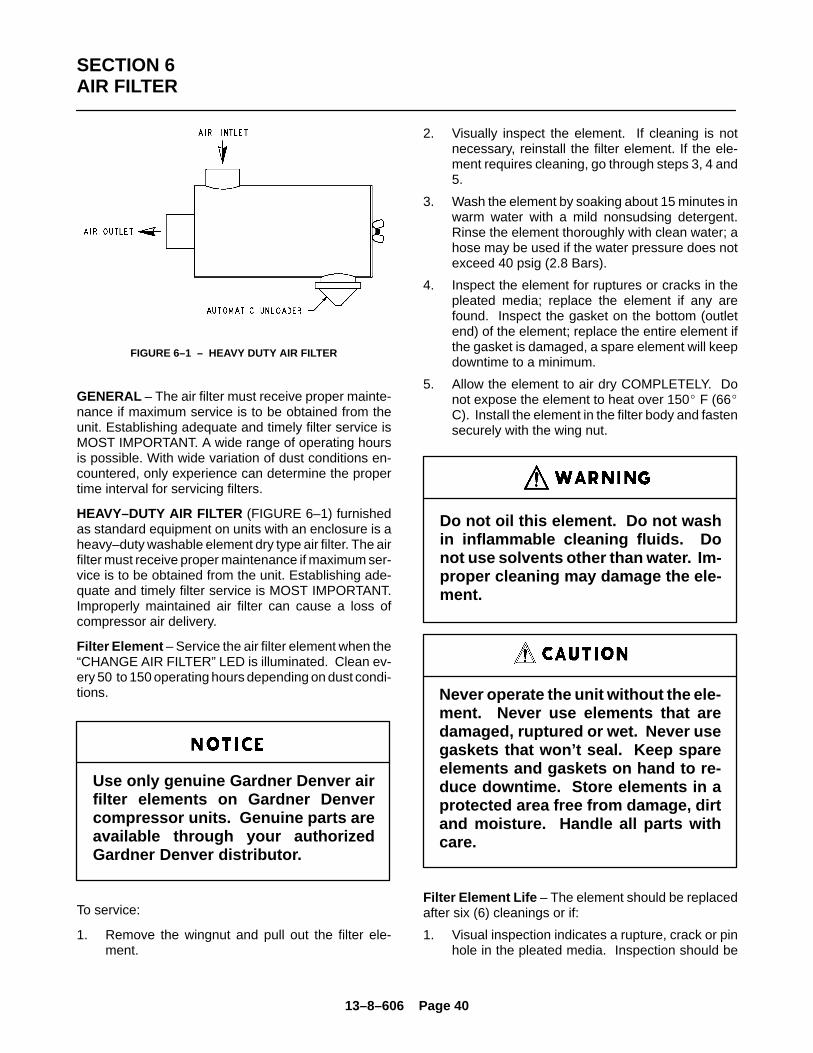
13–8–606 Page 40
SECTION 6AIR FILTER
FIGURE 6–1 – HEAVY DUTY AIR FILTER
GENERAL – The air filter must receive proper mainte-nance if maximum service is to be obtained from theunit. Establishing adequate and timely filter service isMOST IMPORTANT. A wide range of operating hoursis possible. With wide variation of dust conditions en-countered, only experience can determine the propertime interval for servicing filters.
HEAVY–DUTY AIR FILTER (FIGURE 6–1) furnishedas standard equipment on units with an enclosure is aheavy–duty washable element dry type air filter. The airfilter must receive proper maintenance if maximum ser-vice is to be obtained from the unit. Establishing ade-quate and timely filter service is MOST IMPORTANT.Improperly maintained air filter can cause a loss ofcompressor air delivery.
Filter Element – Service the air filter element when the“CHANGE AIR FILTER” LED is illuminated. Clean ev-ery 50 to 150 operating hours depending on dust condi-tions.
Use only genuine Gardner Denver airfilter elements on Gardner Denvercompressor units. Genuine parts areavailable through your authorizedGardner Denver distributor.
To service:
1. Remove the wingnut and pull out the filter ele-ment.
2. Visually inspect the element. If cleaning is notnecessary, reinstall the filter element. If the ele-ment requires cleaning, go through steps 3, 4 and5.
3. Wash the element by soaking about 15 minutes inwarm water with a mild nonsudsing detergent.Rinse the element thoroughly with clean water; ahose may be used if the water pressure does notexceed 40 psig (2.8 Bars).
4. Inspect the element for ruptures or cracks in thepleated media; replace the element if any arefound. Inspect the gasket on the bottom (outletend) of the element; replace the entire element ifthe gasket is damaged, a spare element will keepdowntime to a minimum.
5. Allow the element to air dry COMPLETELY. Donot expose the element to heat over 150� F (66�C). Install the element in the filter body and fastensecurely with the wing nut.
Do not oil this element. Do not washin inflammable cleaning fluids. Donot use solvents other than water. Im-proper cleaning may damage the ele-ment.
Never operate the unit without the ele-ment. Never use elements that aredamaged, ruptured or wet. Never usegaskets that won’t seal. Keep spareelements and gaskets on hand to re-duce downtime. Store elements in aprotected area free from damage, dirtand moisture. Handle all parts withcare.
Filter Element Life – The element should be replacedafter six (6) cleanings or if:
1. Visual inspection indicates a rupture, crack or pinhole in the pleated media. Inspection should be
13–8–606 Page 41
done by placing a bright light inside the element.
2. Pressure drop through a filter with a freshlycleaned element is below three (3) inches (76mm) of water with the compressor running at fullload – this would indicate a rupture or crack.
Inlet Tube – Inspect the inlet screen and tube for dirtaccumulation each time the filter is serviced. Clean the
tube when required by ramming a clean dry cloththrough the tube. Wipe the inside of the filter body toremove any dirt falling from the inlet tube before rein-stalling the element.
Causes of short element life include: severe dustconditions, infrequent servicing, improper cleaning, orcontamination by oil or chemical fumes.
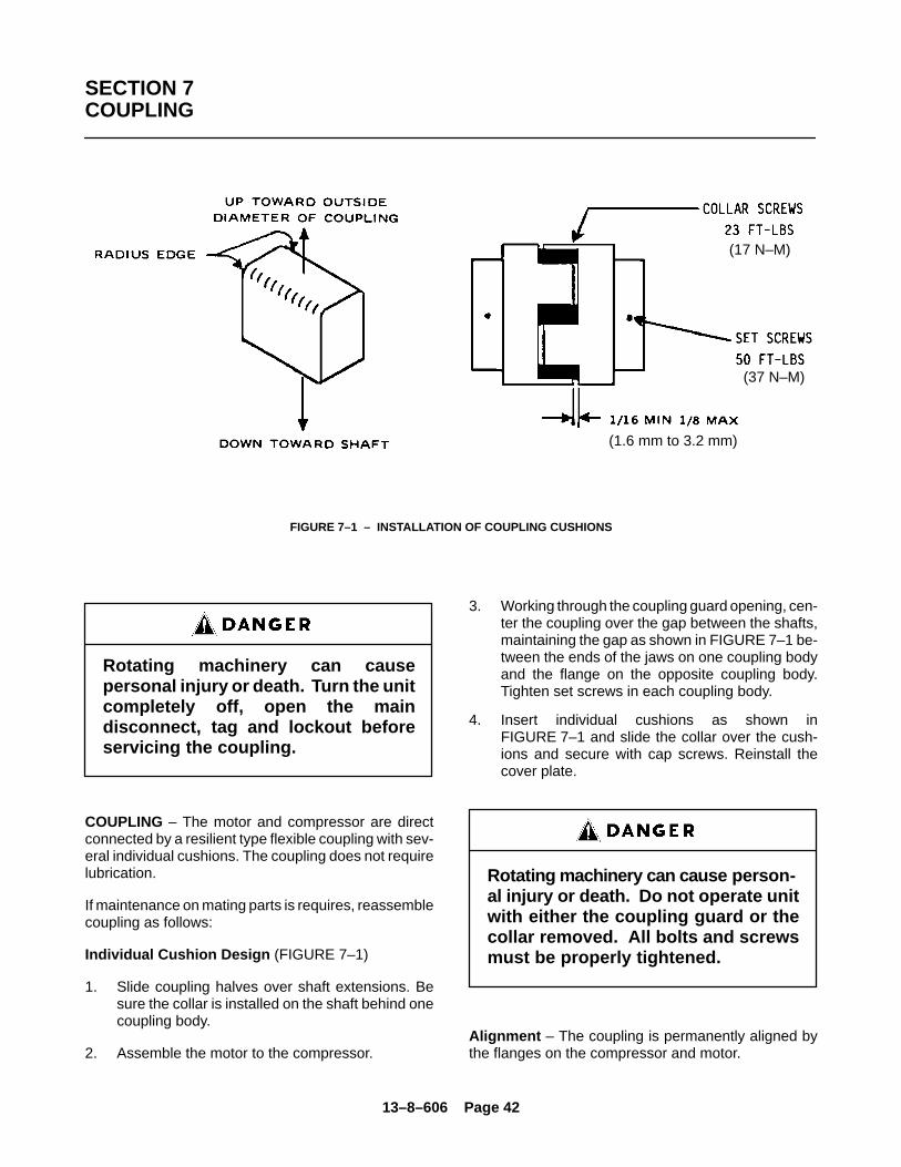
13–8–606 Page 42
SECTION 7COUPLING
FIGURE 7–1 – INSTALLATION OF COUPLING CUSHIONS
(17 N–M)
(37 N–M)
(1.6 mm to 3.2 mm)
Rotating machinery can causepersonal injury or death. Turn the unitcompletely off, open the maindisconnect, tag and lockout beforeservicing the coupling.
COUPLING – The motor and compressor are directconnected by a resilient type flexible coupling with sev-eral individual cushions. The coupling does not requirelubrication.
If maintenance on mating parts is requires, reassemblecoupling as follows:
Individual Cushion Design (FIGURE 7–1)
1. Slide coupling halves over shaft extensions. Besure the collar is installed on the shaft behind onecoupling body.
2. Assemble the motor to the compressor.
3. Working through the coupling guard opening, cen-ter the coupling over the gap between the shafts,maintaining the gap as shown in FIGURE 7–1 be-tween the ends of the jaws on one coupling bodyand the flange on the opposite coupling body.Tighten set screws in each coupling body.
4. Insert individual cushions as shown inFIGURE 7–1 and slide the collar over the cush-ions and secure with cap screws. Reinstall thecover plate.
Rotating machinery can cause person-al injury or death. Do not operate unitwith either the coupling guard or thecollar removed. All bolts and screwsmust be properly tightened.
Alignment – The coupling is permanently aligned bythe flanges on the compressor and motor.
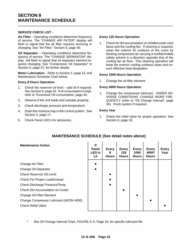
13–8–606 Page 43
SECTION 8MAINTENANCE SCHEDULE
SERVICE CHECK LIST –
Air Filter – Operating conditions determine frequencyof service. The “CHANGE AIR FILTER” display willflash to signal that the air filter requires servicing orchanging. See “Air Filter,” Section 6, page 40.
Oil Separator – Operating conditions determine fre-quency of service. The “CHANGE SEPARATOR” dis-play will flash to signal that oil separator element re-quires changing. See “Compressor Oil Separator” inSection 5, page 37, for further details.
Motor Lubrication – Refer to Section 2, page 13, andMaintenance Schedule Chart below.
Every 8 Hours Operation
1. Check the reservoir oil level – add oil if required.See Section 5, page 43. If oil consumption is high,refer to “Excessive Oil consumption, page 45.
2. Observe if the unit loads and unloads properly.
3. Check discharge pressure and temperature.
4. Drain the moisture trap in the control system. SeeSection 4, page 17.
5. Check Panel LED’s for advisories.
Every 125 Hours Operation
1. Check for dirt accumulation on oil/aftercooler corefaces and the cooling fan. If cleaning is required,clean the exterior fin surfaces of the cores byblowing compressed air carrying a nonflammablesafety solvent in a direction opposite that of thecooling fan air flow. This cleaning operation willkeep the exterior cooling surfaces clean and en-sure effective heat dissipation.
Every 1000 Hours Operation
1. Change the oil filter element.
Every 4000 Hours Operation
1. Change the compressor lubricant. UNDER AD-VERSE CONDITIONS, CHANGE MORE FRE-QUENTLY (refer to “Oil Change Interval”, page30). Flush system if required.
Every Year
1. Check the relief valve for proper operation. SeeSection 4, page 18.
MAINTENANCE SCHEDULE (See detail notes above)
Maintenance Action IfPanel Every Every Every Every EveryLED is 8 125 1000 4000* Year
Lit Hours Hours Hours Hours
Change Air Filter �
Change Oil Separator �
Check Reservoir Oil Level �
Check For Proper Load/Unload �
Check Discharge Pressure/Temp �
Check Dirt Accumulation on Cooler �
Change Oil Filter Element �
Change Compressor Lubricant (AEON 4000) �
Check Relief Valve �
* See Oil Change Interval Chart, FIGURE 5–5, Page 33, for specific lubricant life.
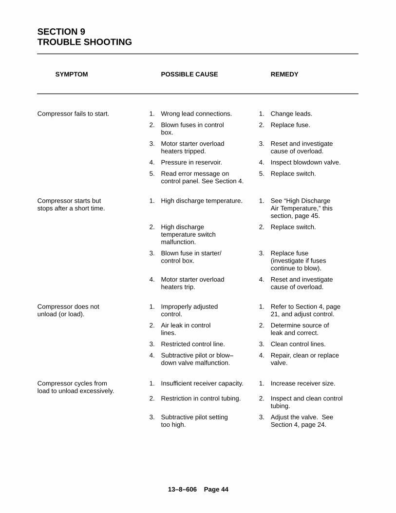
13–8–606 Page 44
SECTION 9TROUBLE SHOOTING
SYMPTOM POSSIBLE CAUSE REMEDY
Compressor fails to start. 1. Wrong lead connections. 1. Change leads.
2. Blown fuses in control 2. Replace fuse. box.
3. Motor starter overload 3. Reset and investigateheaters tripped. cause of overload.
4. Pressure in reservoir. 4. Inspect blowdown valve.
5. Read error message on 5. Replace switch.control panel. See Section 4.
Compressor starts but 1. High discharge temperature. 1. See “High Dischargestops after a short time. Air Temperature,” this section, page 45.
2. High discharge 2. Replace switch. temperature switch malfunction.
3. Blown fuse in starter/ 3. Replace fuse control box. (investigate if fuses
continue to blow).
4. Motor starter overload 4. Reset and investigate heaters trip. cause of overload.
Compressor does not 1. Improperly adjusted 1. Refer to Section 4, pageunload (or load). control. 21, and adjust control.
2. Air leak in control 2. Determine source of lines. leak and correct.
3. Restricted control line. 3. Clean control lines.
4. Subtractive pilot or blow– 4. Repair, clean or replacedown valve malfunction. valve.
Compressor cycles from 1. Insufficient receiver capacity. 1. Increase receiver size.load to unload excessively.
2. Restriction in control tubing. 2. Inspect and clean controltubing.
3. Subtractive pilot setting 3. Adjust the valve. See too high. Section 4, page 24.
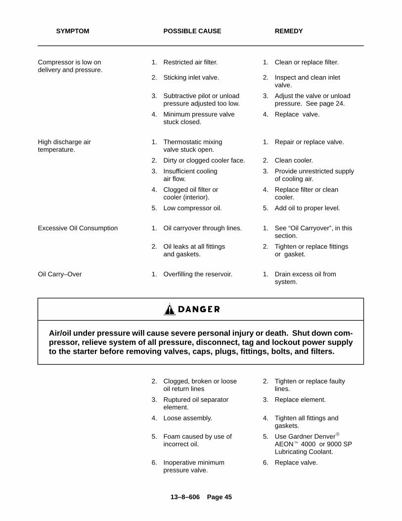
13–8–606 Page 45
SYMPTOM POSSIBLE CAUSE REMEDY
Compressor is low on 1. Restricted air filter. 1. Clean or replace filter.delivery and pressure.
2. Sticking inlet valve. 2. Inspect and clean inlet valve.
3. Subtractive pilot or unload 3. Adjust the valve or unload pressure adjusted too low. pressure. See page 24.
4. Minimum pressure valve 4. Replace valve.stuck closed.
High discharge air 1. Thermostatic mixing 1. Repair or replace valve.temperature. valve stuck open.
2. Dirty or clogged cooler face. 2. Clean cooler.
3. Insufficient cooling 3. Provide unrestricted supply air flow. of cooling air.
4. Clogged oil filter or 4. Replace filter or clean cooler (interior). cooler.
5. Low compressor oil. 5. Add oil to proper level.
Excessive Oil Consumption 1. Oil carryover through lines. 1. See “Oil Carryover”, in this section.
2. Oil leaks at all fittings 2. Tighten or replace fittings and gaskets. or gasket.
Oil Carry–Over 1. Overfilling the reservoir. 1. Drain excess oil from system.
Air/oil under pressure will cause severe personal injury or death. Shut down com-pressor, relieve system of all pressure, disconnect, tag and lockout power supplyto the starter before removing valves, caps, plugs, fittings, bolts, and filters.
2. Clogged, broken or loose 2. Tighten or replace faulty oil return lines lines.
3. Ruptured oil separator 3. Replace element. element.
4. Loose assembly. 4. Tighten all fittings and gaskets.
5. Foam caused by use of 5. Use Gardner Denver� incorrect oil. AEON� 4000 or 9000 SP
Lubricating Coolant.
6. Inoperative minimum 6. Replace valve. pressure valve.
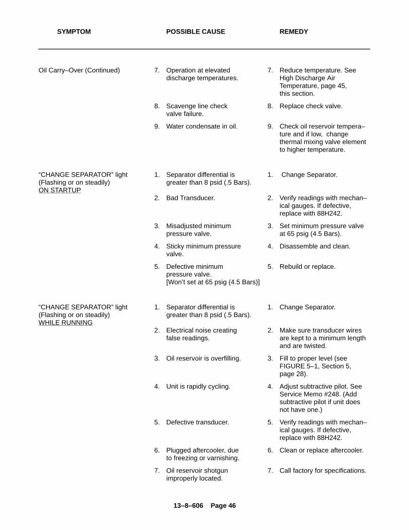
13–8–606 Page 46
SYMPTOM POSSIBLE CAUSE REMEDY
Oil Carry–Over (Continued) 7. Operation at elevated 7. Reduce temperature. Seedischarge temperatures. High Discharge Air
Temperature, page 45, this section.
8. Scavenge line check 8. Replace check valve.valve failure.
9. Water condensate in oil. 9. Check oil reservoir tempera–ture and if low, change thermal mixing valve elementto higher temperature.
“CHANGE SEPARATOR” light 1. Separator differential is 1. Change Separator.(Flashing or on steadily) greater than 8 psid (.5 Bars).ON STARTUP
2. Bad Transducer. 2. Verify readings with mechan–ical gauges. If defective,replace with 88H242.
3. Misadjusted minimum 3. Set minimum pressure valvepressure valve. at 65 psig (4.5 Bars).
4. Sticky minimum pressure 4. Disassemble and clean. valve.
5. Defective minimum 5. Rebuild or replace.pressure valve.
[Won’t set at 65 psig (4.5 Bars)]
“CHANGE SEPARATOR” light 1. Separator differential is 1. Change Separator.(Flashing or on steadily) greater than 8 psid (.5 Bars).WHILE RUNNING
2. Electrical noise creating 2. Make sure transducer wiresfalse readings. are kept to a minimum length
and are twisted.
3. Oil reservoir is overfilling. 3. Fill to proper level (see FIGURE 5–1, Section 5, page 28).
4. Unit is rapidly cycling. 4. Adjust subtractive pilot. SeeService Memo #248. (Addsubtractive pilot if unit doesnot have one.)
5. Defective transducer. 5. Verify readings with mechan–ical gauges. If defective,replace with 88H242.
6. Plugged aftercooler, due 6. Clean or replace aftercooler.to freezing or varnishing.
7. Oil reservoir shotgun 7. Call factory for specifications.improperly located.
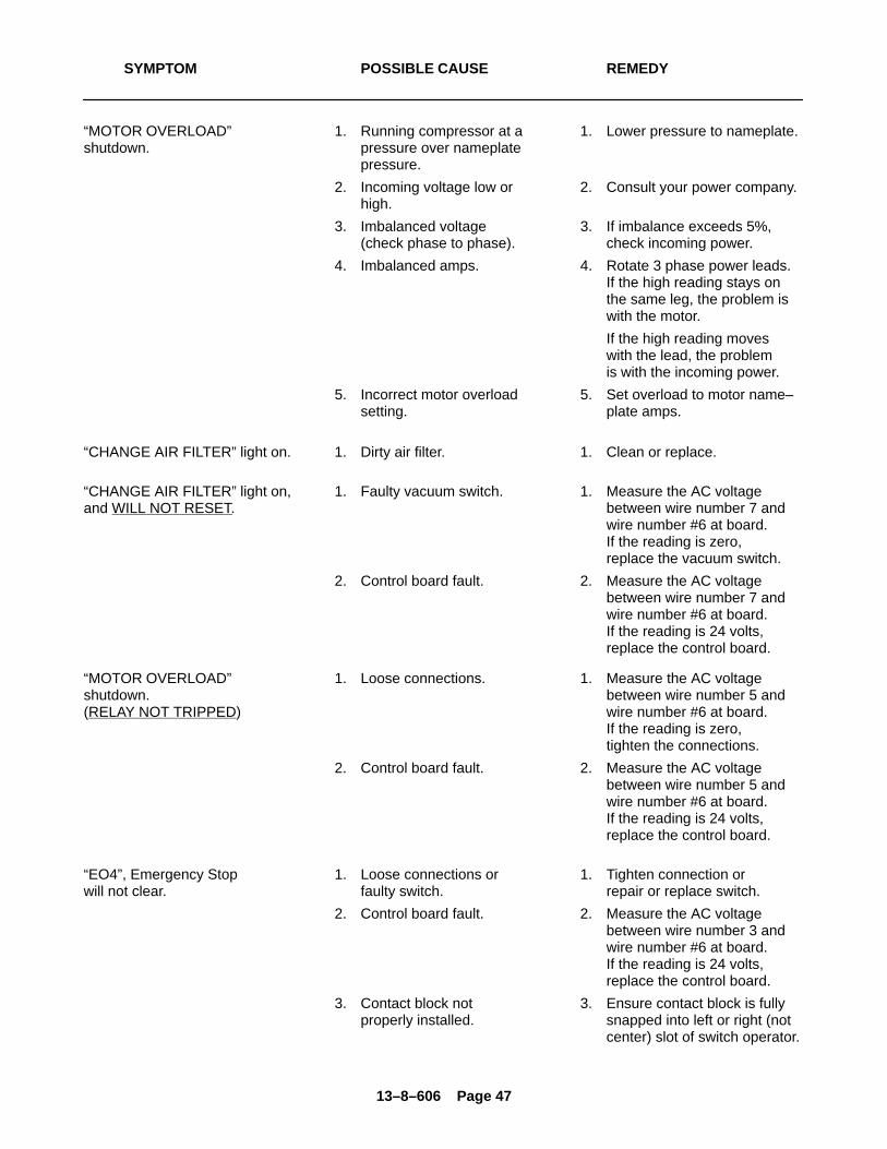
13–8–606 Page 47
SYMPTOM POSSIBLE CAUSE REMEDY
“MOTOR OVERLOAD” 1. Running compressor at a 1. Lower pressure to nameplate.shutdown. pressure over nameplate
pressure.
2. Incoming voltage low or 2. Consult your power company.high.
3. Imbalanced voltage 3. If imbalance exceeds 5%,(check phase to phase). check incoming power.
4. Imbalanced amps. 4. Rotate 3 phase power leads.If the high reading stays onthe same leg, the problem iswith the motor.
If the high reading moveswith the lead, the problemis with the incoming power.
5. Incorrect motor overload 5. Set overload to motor name–setting. plate amps.
“CHANGE AIR FILTER” light on. 1. Dirty air filter. 1. Clean or replace.
“CHANGE AIR FILTER” light on, 1. Faulty vacuum switch. 1. Measure the AC voltageand WILL NOT RESET. between wire number 7 and
wire number #6 at board.If the reading is zero,replace the vacuum switch.
2. Control board fault. 2. Measure the AC voltagebetween wire number 7 andwire number #6 at board.If the reading is 24 volts,replace the control board.
“MOTOR OVERLOAD” 1. Loose connections. 1. Measure the AC voltageshutdown. between wire number 5 and(RELAY NOT TRIPPED) wire number #6 at board.
If the reading is zero,tighten the connections.
2. Control board fault. 2. Measure the AC voltagebetween wire number 5 andwire number #6 at board. If the reading is 24 volts,replace the control board.
“EO4”, Emergency Stop 1. Loose connections or 1. Tighten connection orwill not clear. faulty switch. repair or replace switch.
2. Control board fault. 2. Measure the AC voltagebetween wire number 3 andwire number #6 at board.If the reading is 24 volts,replace the control board.
3. Contact block not 3. Ensure contact block is fullyproperly installed. snapped into left or right (not
center) slot of switch operator.
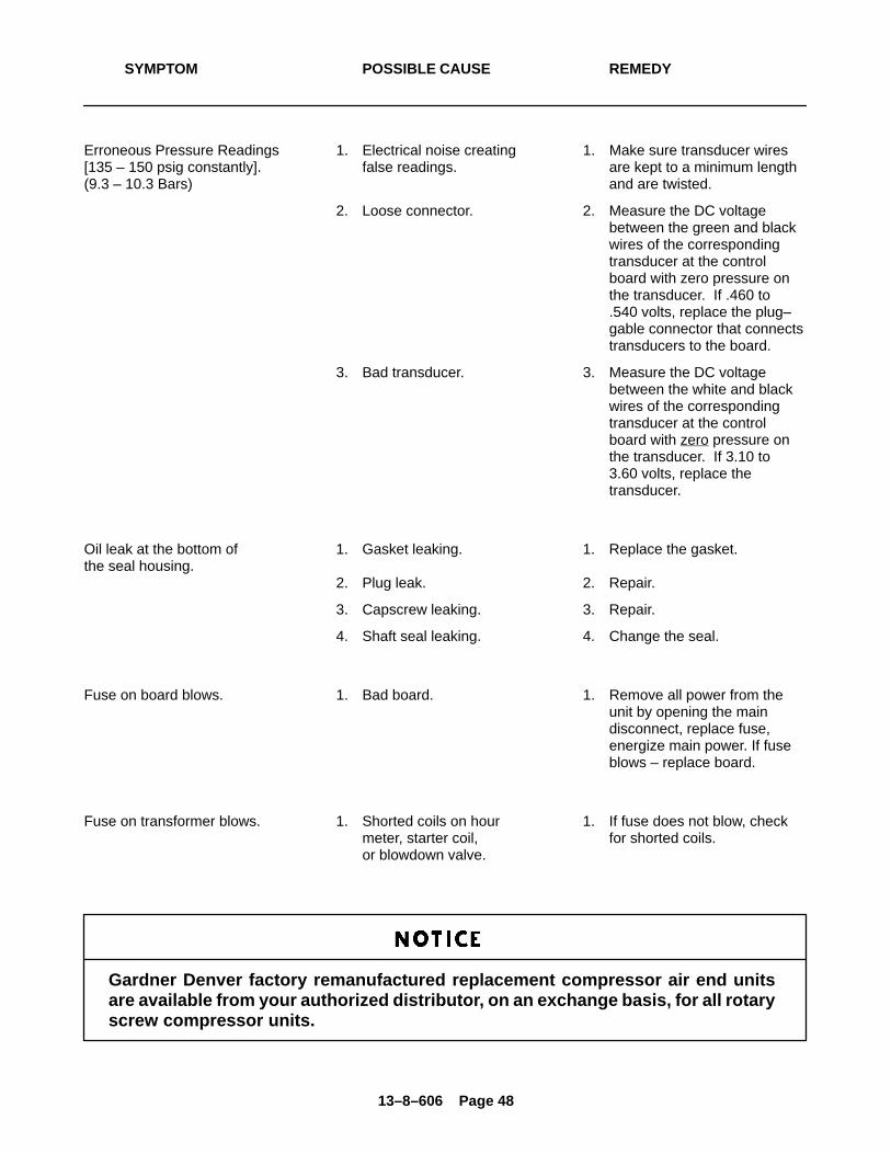
13–8–606 Page 48
SYMPTOM POSSIBLE CAUSE REMEDY
Erroneous Pressure Readings 1. Electrical noise creating 1. Make sure transducer wires[135 – 150 psig constantly]. false readings. are kept to a minimum length(9.3 – 10.3 Bars) and are twisted.
2. Loose connector. 2. Measure the DC voltagebetween the green and blackwires of the correspondingtransducer at the controlboard with zero pressure onthe transducer. If .460 to.540 volts, replace the plug–gable connector that connectstransducers to the board.
3. Bad transducer. 3. Measure the DC voltagebetween the white and blackwires of the correspondingtransducer at the controlboard with zero pressure onthe transducer. If 3.10 to3.60 volts, replace thetransducer.
Oil leak at the bottom of 1. Gasket leaking. 1. Replace the gasket.the seal housing.
2. Plug leak. 2. Repair.
3. Capscrew leaking. 3. Repair.
4. Shaft seal leaking. 4. Change the seal.
Fuse on board blows. 1. Bad board. 1. Remove all power from theunit by opening the maindisconnect, replace fuse,energize main power. If fuseblows – replace board.
Fuse on transformer blows. 1. Shorted coils on hour 1. If fuse does not blow, checkmeter, starter coil, for shorted coils.or blowdown valve.
Gardner Denver factory remanufactured replacement compressor air end unitsare available from your authorized distributor, on an exchange basis, for all rotaryscrew compressor units.
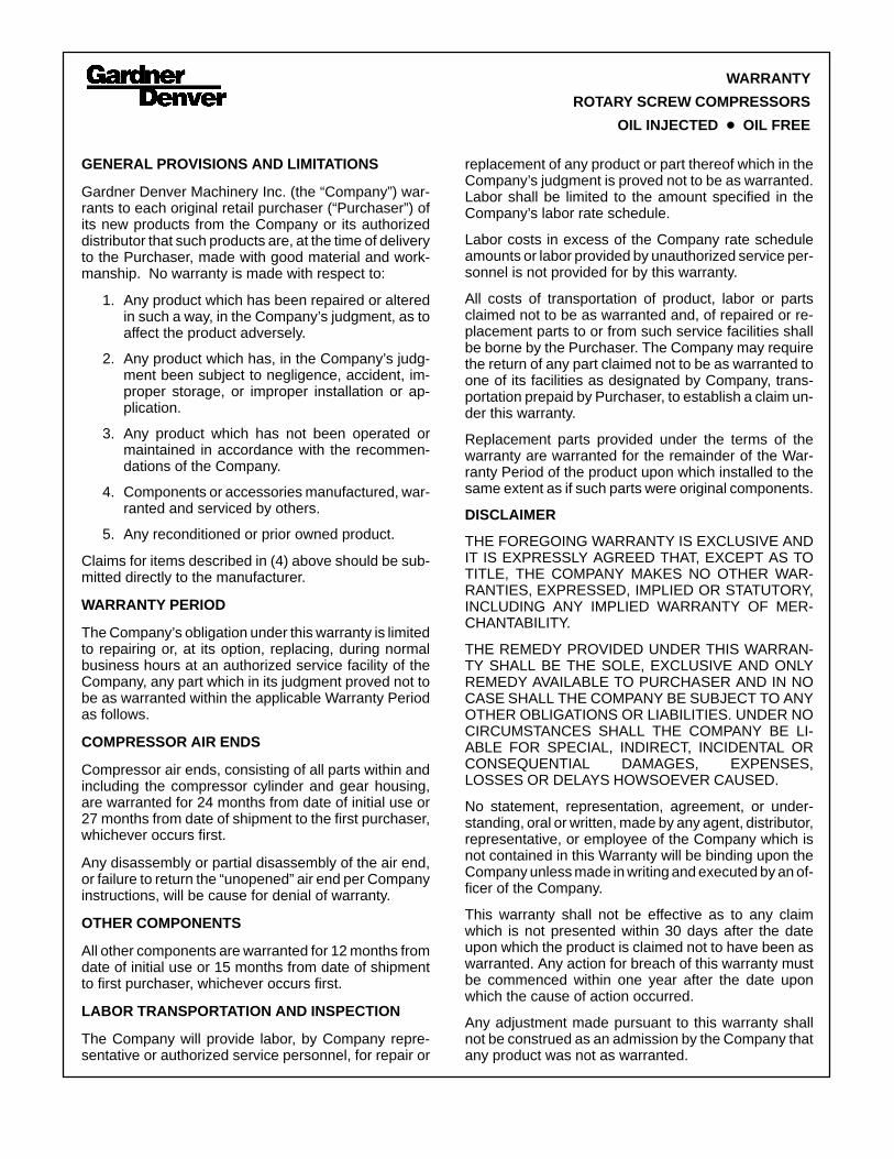
GENERAL PROVISIONS AND LIMITATIONS
Gardner Denver Machinery Inc. (the “Company”) war-rants to each original retail purchaser (“Purchaser”) ofits new products from the Company or its authorizeddistributor that such products are, at the time of deliveryto the Purchaser, made with good material and work-manship. No warranty is made with respect to:
1. Any product which has been repaired or alteredin such a way, in the Company’s judgment, as toaffect the product adversely.
2. Any product which has, in the Company’s judg-ment been subject to negligence, accident, im-proper storage, or improper installation or ap-plication.
3. Any product which has not been operated ormaintained in accordance with the recommen-dations of the Company.
4. Components or accessories manufactured, war-ranted and serviced by others.
5. Any reconditioned or prior owned product.
Claims for items described in (4) above should be sub-mitted directly to the manufacturer.
WARRANTY PERIOD
The Company’s obligation under this warranty is limitedto repairing or, at its option, replacing, during normalbusiness hours at an authorized service facility of theCompany, any part which in its judgment proved not tobe as warranted within the applicable Warranty Periodas follows.
COMPRESSOR AIR ENDS
Compressor air ends, consisting of all parts within andincluding the compressor cylinder and gear housing,are warranted for 24 months from date of initial use or27 months from date of shipment to the first purchaser,whichever occurs first.
Any disassembly or partial disassembly of the air end,or failure to return the “unopened” air end per Companyinstructions, will be cause for denial of warranty.
OTHER COMPONENTS
All other components are warranted for 12 months fromdate of initial use or 15 months from date of shipmentto first purchaser, whichever occurs first.
LABOR TRANSPORTATION AND INSPECTION
The Company will provide labor, by Company repre-sentative or authorized service personnel, for repair or
replacement of any product or part thereof which in theCompany’s judgment is proved not to be as warranted.Labor shall be limited to the amount specified in theCompany’s labor rate schedule.
Labor costs in excess of the Company rate scheduleamounts or labor provided by unauthorized service per-sonnel is not provided for by this warranty.
All costs of transportation of product, labor or partsclaimed not to be as warranted and, of repaired or re-placement parts to or from such service facilities shallbe borne by the Purchaser. The Company may requirethe return of any part claimed not to be as warranted toone of its facilities as designated by Company, trans-portation prepaid by Purchaser, to establish a claim un-der this warranty.
Replacement parts provided under the terms of thewarranty are warranted for the remainder of the War-ranty Period of the product upon which installed to thesame extent as if such parts were original components.
DISCLAIMER
THE FOREGOING WARRANTY IS EXCLUSIVE ANDIT IS EXPRESSLY AGREED THAT, EXCEPT AS TOTITLE, THE COMPANY MAKES NO OTHER WAR-RANTIES, EXPRESSED, IMPLIED OR STATUTORY,INCLUDING ANY IMPLIED WARRANTY OF MER-CHANTABILITY.
THE REMEDY PROVIDED UNDER THIS WARRAN-TY SHALL BE THE SOLE, EXCLUSIVE AND ONLYREMEDY AVAILABLE TO PURCHASER AND IN NOCASE SHALL THE COMPANY BE SUBJECT TO ANYOTHER OBLIGATIONS OR LIABILITIES. UNDER NOCIRCUMSTANCES SHALL THE COMPANY BE LI-ABLE FOR SPECIAL, INDIRECT, INCIDENTAL ORCONSEQUENTIAL DAMAGES, EXPENSES,LOSSES OR DELAYS HOWSOEVER CAUSED.
No statement, representation, agreement, or under-standing, oral or written, made by any agent, distributor,representative, or employee of the Company which isnot contained in this Warranty will be binding upon theCompany unless made in writing and executed by an of-ficer of the Company.
This warranty shall not be effective as to any claimwhich is not presented within 30 days after the dateupon which the product is claimed not to have been aswarranted. Any action for breach of this warranty mustbe commenced within one year after the date uponwhich the cause of action occurred.
Any adjustment made pursuant to this warranty shallnot be construed as an admission by the Company thatany product was not as warranted.
WARRANTY
ROTARY SCREW COMPRESSORS
OIL INJECTED � OIL FREE