1273615229 understanding lightning and lightning protection
TRANSCRIPT
Understanding Lightning and
Lightning Protection
RSP SERIES IN ELECTROSTATICS AND
ELECTROSTATIC APPLICATIONS
Series Editor: Professor J F Hughes
Electrostatic Hazards in Powder Handling
Martin Glor
Electrostatic Spraying of Liquids
Adrian Bailey
Industrial Electrostatics: Fundamentals and Measurements
David Taylor and Peter Secker
Electrostatic Particle Charging: Industrial and Health Care Applications
John Hughes
Understanding Lightning and Lightning Protection: A Multimedia Teaching Guide
Tibor Horváth
Understanding Lightning and
Lightning Protection
A Multimedia Teaching Guide
Tibor Horváth
Budapest University of Technology and Economics, Hungary
John Wiley & Sons, Ltd Research Studies Press Limited
Copyright © 2006 Research Studies Press Limited, 16 Coach House Cloisters, 10 Hitchin Street, Baldock, Hertfordshire, SG7 6AE
Published by John Wiley & Sons, Ltd., The Atrium, Southern Gate, Chichester, West Sussex PO19 8SQ, England Telephone (+44) 1243 779777
Email (for orders and customer service enquiries): [email protected] Visit our Home Page on www.wiley.com
This Work is a co-publication between Research Studies Press Limited and John Wiley & Sons, Ltd.
All Rights Reserved. No part of this publication may be reproduced, stored in a retrieval system or transmitted in any form or by any means, electronic, mechanical, photocopying, recording, scanning or otherwise, except under the terms of the Copyright, Designs and Patents Act 1988 or under the terms of a licence issued by the Copyright Licensing Agency Ltd, 90 Tottenham Court Road, London W1T 4LP, UK, without the permission in writing of the Publisher. Requests to the Publisher should be addressed to the Permissions Department, John Wiley & Sons Ltd, The Atrium, Southern Gate, Chichester, West Sussex PO19 8SQ, England, or emailed to [email protected], or faxed to (+44) 1243 770620.
Designations used by companies to distinguish their products are often claimed as trademarks. All brand names and product names used in this book are trade names, service marks, trademarks or registered trademarks of their respective owners. The Publisher is not associated with any product or vendor mentioned in this book.
This publication is designed to provide accurate and authoritative information in regard to the subject matter covered. It is sold on the understanding that the Publisher is not engaged in rendering professional services. If professional advice or other expert assistance is required, the services of a competent professional should be sought.
This book cannot be used without running the multimedia teaching guide (the PC program?), which can be found (ordered?) in [email protected].
Other Wiley Editorial Offices
John Wiley & Sons Inc., 111 River Street, Hoboken, NJ 07030, USA
Jossey-Bass, 989 Market Street, San Francisco, CA 94103-1741, USA
Wiley-VCH Verlag GmbH, Boschstr. 12, D-69469 Weinheim, Germany
John Wiley & Sons Australia Ltd, 42 McDougall Street, Milton, Queensland 4064, Australia
John Wiley & Sons (Asia) Pte Ltd, 2 Clementi Loop #02-01, Jin Xing Distripark, Singapore 129809
John Wiley & Sons Canada Ltd, 22 Worcester Road, Etobicoke, Ontario, Canada M9W 1L1
Wiley also publishes its books in a variety of electronic formats. Some content that appears in print may not be available in electronic books.
Library of Congress Cataloging-in-Publication Data
Horváth, Tibor, 1928-
Understanding Lightning and Lightning Protection: A Multimedia Teaching Guide / Tibor Horváth.
p. cm.
“This work is a co-publication between Research Studies Press Limited and John Wiley & Sons, Ltd.”
Includes bibliographical references and index.
ISBN-13 978-0-470-03018-9 (paper/cd : alk. paper)
ISBN-10 470-03018-6 (paper/cd : alk. paper)
1. Lightning protection. I. Title: A Multimedia Teaching Guide.
TH9058.H67 2006
693.8'98--dc22 2006005569
British Library Cataloguing in Publication Data
A catalogue record for this book is available from the British Library
ISBN-13 978-0-470-03018-9 (PB) ISBN-10 0-470-03018-6 (PB)
Typeset in 10/12pt Times New Roman by Laserwords Private Limited, Chennai, India Printed and bound in Great Britain by TJ International, Padstow, Cornwall This book is printed on acid-free paper responsibly manufactured from sustainable forestry in which at least two trees are planted for each one used for paper production.
v
Contents
CHAPTERS and subsections Comment Page
PREFACE xi INTRODUCTION 1 Guide to use the program 1
1. CLOUD, CYCLONE AND FRONTS 1-0 3Development of a cloud 1-1 3 Growth of a thunderstorm cloud 1-5 4 Development of a cyclone 1-13 6 Warm and cold fronts 1-21 7 Distribution of thunderstorms 1-25 7
2. ELECTRIC CHARGES IN CLOUDS 2-0 9Processes of charge separation 2-1 9
Charging process in the liquid phase 2-1 9 Charging process during freezing 2-8 10
Final distribution of charges 2-14 11 Static electric field 2-16 11 Relation to the ionosphere 2-17 12
3. DISCHARGE PROCESSES IN AIR 3-0 13Photon processes 3-1 13 Excitation by photon 3-2 13 Ionisation and absorption 3-3 14 Recombination 3-4 14 Electron collisions 3-6 14 Excitation by electron 3-9 15 Ionisation by collision 3-10 15 Discharges 3-11 15
Electron avalanche 3-11 15 Streamer discharge 3-18 16 Klydonograph 3-22 17 Leader discharge 3-25 17
4. DEVELOPMENT OF THE LIGHTNING FLASH 4-0 19Start on drops in the cloud 4-1 19 From leader to main stroke 4-5 20 Multiple stroke 4-13 21
CONTENTSvi
CHAPTERS and subsections Comment Page
Upward leader 4-16 22 The Boys-camera: Principle and construction 4-22 23 The Boys-camera: Operation 4-27 24 Boys-record of ideal lightning 4-30 24 Real Boys-records 4-36 25
5. PHYSICS OF THE LIGHTNING DISCHARGE 5-0 27Properties of a downward leader 5-1 27 Condition of connecting leader 5-5 28 Striking process 5-11 29 Development of main stroke 5-13 29 Multiple and upward stroke 5-15 30 The current wave 5-19 30 Lightning parameters 5-24 31 Distribution functions 5-28 32
6. CURIOUS LIGHTNING PHENOMENA 6-0 35Properties of ball lightning 6-1 35 Ball lightning-theories 6-7 37 Resonance theory 6-10 37 Quantum-theory 6-11 38 Theory of magnetic vortex 6-12 38 Photos of ball lightning 6-18 39 Beaded lightning 6-23 40 Stroke from clear sky 6-28 41 Discharge to the ionosphere 6-31 41
7. INDUCED VOLTAGE 7-0 43Ampère’s law 7-1 43 Rectangular loop + infinite conductor 7-5 44 Rectangular loop + cut conductor 7-8 44 Reduction to basic components 7-10 44 Triangular loop 7-13 45 Polygonal loop 7-16 45 Induced voltage due to direct stroke 7-18 46 Induced current due to direct stroke 7-23 46 Induced voltage due to distant stroke 7-28 47 Induced current due to distant stroke 7-35 48
8. DYNAMIC FORCES DUE TO LIGHTNING 8-0 51Parallel wires 8-1 51 Force due to lightning on a rod struck at the top 8-8 52 Force due to lightning on a horizontal wire 8-12 53 Force due to lightning on a metal plate 8-15 53 Force of leaded current at inversion of wire 8-18 54
CONTENTS vii
CHAPTERS and subsections Comment Page
Force of leaded current on a tube 8-20 54 Dynamic force on a console 8-22 54 Slit effect 8-27 55 Damage on tree 8-32 56
9. HEAT EFFECTS ON METAL OBJECTS 9-0 59Heating a metal plate 9-1 59 Change of temperature in a metal plate 9-4 60 Equations of melting a metal plate 9-9 61 Crater and droplets 9-15 62 Melting a wire at contact spot 9-18 62 Melting a wire leading current 9-22 63 Probability of melting 9-30 64
10. LIGHTNING ATTACHMENT 10-0 67Point of orientation 10-1 67 The striking distance 10-5 68 Distribution and density functions 10-7 68 The expected frequency of stroke 10-10 69
The principle of calculation 10-10 69 Collection space 10-17 70
11. COLLECTION SPACES OF STRUCTURES 11-0 73The principle of collection space 11-1 73 Dividing the collection space 11-3 74 Two conductors 11-6 74 Lightning rod on tower 11-9 75 Air terminations of block-house 11-13 75 The collection space of one mesh 11-25 77
12. PROTECTIVE EFFECT ON FLAT ROOF 12-0 79Air termination systems on blockhouse 12-1 79 Diagrams related to several air terminations 12-4 80 Application of rolling sphere method 12-8 81
13. PROTECTION OF INCLINED ROOF 13-0 83Types of air termination systems 13-1 83 Attraction of roof and eaves 13-6 84 Effect of electrodes on eaves 13-11 85 Effect of electrodes on the edges 13-15 85 Attraction of unprotected edges 13-23 87 Stroke-free period 13-26 87
14. RESIDUAL RISK OF LIGHTNING PROTECTION 14-0 89The flow diagram 14-1 89 Equivalent area of a structure 14-2 89 Cases of the point of strike 14-11 91 Cases of damaging stroke 14-18 92 Intercepted stroke 14-19 92
CONTENTSviii
CHAPTERS and subsections Comment Page
Striking the roof 14-23 93 Calculation of risk 14-27 94 Weighting the consequences 14-28 95 Resulting damage 14-38 97 Resulting frequency of weighted damage 14-40 97 Resulting risk 14-44 98
15. CLASSIFICATION OF STRUCTURES 15-0 101Classes of structures 15-1 101 Height and surroundings 15-12 103
High surroundings 15-13 103 Increased danger of stroke 15-18 104 Classes according to height 15-26 106
Effect of the soil profile 15-27 106 The materials of roof 15-31 107 Further classifications 15-37 108
16. AIR TERMINATION SYSTEMS 16-0 111Level of risk and protection 16-1 111 Construction methods 16-3 111
Protective angle 16-3 111 Rolling sphere 16-7 112 Mesh size 16-9 112
Degrees of Hungarian standard 16-12 113 Natural air termination 16-13 113 Simplified air termination 16-17 114 Data of higher degrees 16-19 114 Distance to the structure 16-21 115 Forms of air terminations 16-28 116
17. DOWN CONDUCTORS AND METAL OBJECTS 17-0 119Down conductors 17-1 119 Calculation of current paths 17-1 119
Example of current path 17-9 120 Positioning along the perimeter 17-15 121 Degrees of down conductors 17-17 121 Forms of down conductors 17-22 122
Vertical metal structures 17-26 123 Dangerous loops 17-26 123 Bonding metal structures 17-30 124 Insulating spacers 17-34 124 Elevators 17-37 125
18. EARTHING OF LIGHTNING PROTECTION SYSTEM 18-0 127Degrees of earthing 18-1 127 Natural earthing 18-2 127 Simple earthing systems 18-5 128

CONTENTS ix
CHAPTERS and subsections Comment Page
Earthing resistance 18-10 129 Normal and enhanced systems 18-17 130 Earthing by foundation 18-22 131 Soil resistivity 18-27 132 Measurement of earthing resistance 18-30 132 Impulse earthing 18-32 132
19. LIGHTNING ELECTROMAGNETIC IMPULSE 19-0 135 Conductive coupling 19-1 135
Inductive coupling 19-3 136 Capacitive coupling 19-5 136 Distribution of current 19-7 136 Arriving current along a single line 19-10 137 Arriving current along branching line 19-15 138 Faraday holes 19-20 139 Shielded entrance 19-25 139 Shielded cable 19-30 140 Circuit of lightning 19-32 141
20. GRADED SURGE-PROTECTION 20-0 143Operation principles 20-1 143 Three stage with resistors 20-6 144 Influence of distance between stages 20-11 145 Propagation of waves 20-19 146 Waves on devices 20-27 147
21. SURGE PROTECTION DEVICES 21-0 149Gas filled arrester 21-1 149 Arc blowing spark gap 21-5 150 Gliding spark gap 21-9 150 Encapsulated arrester 21-13 151 Characteristics of gaps 21-18 152 The varistor 21-20 152 Characteristics of varistor 21-29 153 Types of protection devices 21-33 154
22. INTERNAL LIGHTNING PROTECTION ZONES 22-0 157Structure of zones 22-1 157 Standardised lightning parameters 22-5 158 Networks of information systems 22-6 158 Tray configuration 22-17 160
23. CONNECTION TO ELECTRIC POWER NETWORK 23-0 161Striking the supply line 23-1 161 Striking the air termination 23-10 162 TT system 23-17 163 Outdoor kWh box 23-22 164
CONTENTSx
CHAPTERS and subsections Comment Page
24. PROTECTION OF ELECTRONIC DEVICES 24-0 167Protection of personal computer 24-1 167 Protection of television 24-10 169 Relay station 24-16 170
25. LIGHTNING MEASUREMENT AND LOCALIZATION 25-0 171Measuring of lightning current 25-1 171
Magnetic card 25-2 171 Magnetic link 25-5 172 Shunt resistor 25-9 172 Coil of Rogowski 25-13 173 Reflection of the current wave 25-18 174
Localising by direction finding 25-21 174 Localising by pulse arrival time 25-24 175 Lightning detection systems 25-28 175
26. THE MANKIND IN THE THUNDERSTORM 26-0 177Danger in open air 26-1 177 Danger on or beside a tree 26-5 178 Step voltage 26-11 179 What to do outdoors? 26-14 179 Danger on a bicycle 26-18 180 Danger at a car 26-22 180 Danger at a truck 26-26 181 Danger in water 26-30 182 Danger in boats and vessels 26-34 182 REFERENCES 185INDEX 189
xi
Preface
This book is attached to a computer program, and it gives textual commentaries to each picture displayed on the screen. The computer program can be used without this book, because the same commentary can be also displayed and read on the screen. It depends on the decision of the user, whether the printed or the displayed text will be preferred. The book cannot be properly used without the computer program.
The author developed this program for illustration of the special course LIGHTNING PROTECTION at the Budapest University of Technology and Economics. The series of this course began about 20 years ago and now more than 100 students choose it in each semester. Projecting this program, the lecturers almost never found it necessary to use blackboard and crayon. The examinations verified that many students learned, with good results, from this program. The success encouraged me to develop this version, which also contains on-screen comments and their printed form. Therefore, it can be an excellent medium for individual study at home. To understand some special subjects, fundamental knowledge of mathematics and physics is necessary, although most topics do not need them. It has been demonstrated by the great success of the presentation of the Chapter ‘The mankind in the thunderstorm’ for little children at a nursery in Budapest and for the students at Stanford University in USA.
Lightning was the first electrical phenomenon seen by prehistoric man, although over 1000 years passed until scientists discovered its processes and properties. In spite of our knowledge today lightning is still a mysterious phenomenon. This program tries to give a fundamental knowledge about lightning from the meteorological phenomena to the proper behaviour in open terrain during the thunderstorm. The development of a lightning flash involves many interesting processes, which are usually unknown. The computer animation can spectacularly illustrate them, and shows how complex a phenomenon lightning is. However, the investigations have discovered many details of the lightning process, though many secrets remain unexplored. One of them is ball lightning, for which the final solution is unknown in spite of several theories. Nevertheless, the most important aim of investigations is the protection against danger and damage due to lightning.
PREFACExii
Concerning this aim, the first question is: Where will be the point of strike? According to our theory, it would be on the air termination system, avoiding the structure to be protected. Since the time of Benjamin Franklin up to now, a protected space has been presumed into which the air termination excludes the penetration of lightning stroke. Several lightning strokes demonstrated that no completely protected space exists and our knowledge about the striking process initiated a probabilistic approach to this problem. The PC program deals with this topic on the base of a new theory and calculation method to estimate the efficiency of lightning interception and to evaluate the risk of damage. It was described in the book ‘Computation of Lightning Protection’ by the author published by Research Studies Press in 1991. Nevertheless, with high efficiency, we can protect the human being and his property against damage caused by lightning. Our knowledge on the processes of lightning strokes helps to understand the operation of lightning air terminal systems. The practical application of some theoretical conclusions is illustrated with the Hungarian Standard for Lightning Protection of Structures. However, the program does not intend to replace a handbook, referring the standard aims only to show the practical application. The protection of low voltage equipment and electronic equipment against over-voltage due to lightning is an actual problem of lightning protection. This topic is dealt with on the basis of the recent international recommendations. The operation of surge protection devices can be demonstratively followed on the screen. The measurement methods and the lightning localisation systems have made great developments in the last 10 years. These are also demonstrated on screen. The author has participated over 20 times in the International Conference on Lightning Protection, since 1963, which compiles current information about lightning.
Study lightning from your computer at home! Enjoy and use this program with good success!
Tibor Horváth Professor Emeritus
INTRODUCTION
Guide to using the program
This book is a manual to the educational program ‘Understanding Lightning and Lightning Protection’, which can run on a personal computer. Using this program, pictures and animations of the topics can be studied. A textual commentary accompanies each screen, which can be either read in this book or displayed on the screen. These commentaries are principally the same and independent of the form, but the screen highlights some words with different colours, which are printed with different character types in the book. This commentary can be displayed only when there is no motion on the screen. In this case, two numbers appear on the upper right. The upper figure shows the serial number of the chapter and the lower one the serial number of the text. The same numbers are above the right side of each commentary and are separated by a hyphen (e.g. 1-23). A special commentary is displayed when the list of topics is on the screen and the serial number of the topic is zero, such as 1-0. In this case, the text gives information on the menu items when a group of topics is selected. Because all commentaries can be read either on the screen or in the book, the user can choose the most convenient method.
When the program starts, the main title appears on the screen. While this is displayed, the following instruction will be shown when the key [Read me] ispressed. Different words and objects are marked with colours on the screen and by different types of characters in the book, as follows:
Highlighted words: Red colour on screen. [Key]: White letters on black background. LIST OF CHAPTERS: Blue colour on screen. List of topics: Green colour on screen.
This program has two menu lists from which the topic of study can be chosen. When the key [Start] is pressed, the LIST OF CHAPTERS appears on a blue background. A chapter can be selected by double-clicking on its name in the menu list. Then the background of the screen changes to dark green and the submenu of ____________________________________________________Understanding Lightning and Lightning Protection T. Horváth © 2006 Research Studies Press Limited
UNDERSTANDING LIGHTNING AND LIGHTNING PROTECTION2
the selected chapter is shown on a light green background. This menu contains a list of topics, which can be selected by double-clicking as before. While the green
menu is on the screen, key [Chapters] appears on top. When this is pressed, the program goes back to the BLUE MENU. After a topic is selected, the screen shows the first picture of the topic under study. On the top of the screen a key [Topics]
can be seen while the selected subject is running. On the keys [Chapters] and [Topics], small blue and green symbols show the menus, which will be displayed after pressing. The key [Exit] terminates the program and returns to Windows. After a topic is selected from the green menu, the first picture appears, sometimes after a short delay. Inside a topic the picture progresses after the screen is clicked on or [Enter] is pressed. These are disabled while the picture moves on the screen. One needs to wait until the motion is completed. At the end of the topic, the program returns to the first step and the subject can be studied again. After some topics are selected from the green menu, the program runs over several topics or even over an entire list. A textual commentary can be similarly displayed as with the key [Read me]. A press of the key again will cancel the text. When a picture is present on the screen the appropriate commentary can be displayed by pressing the key [F1].
The commentary often refers to other topics dealing with similar subjects. In this case, the subject is highlighted in the book and marked red on the screen. The appropriate chapter is printed in the book with normal characters but marked blue on the screen. The referred topic is printed in the book with italic letters and marked green on the screen. To find the given subject, the referred item is to be selected in the displayed list of topics. The subtitles of this book are not the same as the items to be selected, but the small differences should not cause a problem.
This program has been developed under Microsoft Windows 98 and experience shows that it runs correctly under Win 95, Win 98 and Win 2000 environments. Windows NT and XP systems reserve some data after closing the program, which prevents running of the program again. Therefore, these have to be deleted or the computer should be restarted before the program is run again. The program creates pictures of 800 × 600 pixels; therefore, it cannot be used with a screen of lower resolution. With the use of a higher display (e.g. 1024 × 786), the pictures cover only a part of the screen. For the best view, it is advised to set the display on 800 × 600 pixels.
CHAPTER 1
Cloud, cyclone and fronts
1-0Each item of this menu can be selected by double-clicking on it. The program displays several topics when the following items are selected: All items: from Development of a cloud to Distribution of thunderstorms.Development of a cloud: to Growing of a thunderstorm cloudCyclones and fronts: from Development of a cyclone to Warm and cold fronts.Types of thunderstorms: Thermal thunderstorm + Orographic thunderstorm +
Warm and cold fronts.
Development of a cloud 1-1
The development of clouds always starts with the elevation of a warm and wet air mass. In this picture, the vertical line shows the altitude above the ground and the horizontal line, the temperature in centigrade. At the bottom of this picture, a white band represents the warm and wet air mass, whose temperature is assumed to be 26°C. Moving upwards, the potential energy of this air mass increases, while it loses the same quantity of its thermal energy. Therefore, its temperature continuously decreases. In the next picture, a band of red lines shows the temperature in such a way that its right edge indicates the ascending air and the left one the surrounding temperature.
1-2At the bottom, an equation shows the balance of the potential and the thermal energies.
m (kg): the mass of the ascending air; g (m/s2): the gravitational acceleration; h (m): the altitude; c (J/kg °C): the specific heat of the air; to (°C): the temperature at the ground and t: in the altitude h.
____________________________________________________Understanding Lightning and Lightning Protection T. Horváth © 2006 Research Studies Press Limited
UNDERSTANDING LIGHTNING AND LIGHTNING PROTECTION4
The temperature of the ascending air decreases 1°C per every 100-m elevation. The red lines show the change of temperature in such a way that the right edge indicates the ascending air and the left one the surrounding temperature. The temperature of the air reaches its dew point (assumed to be 9°C) and condensation of water drops begins to occur.
1-3The heat of evaporation of the water is released during the condensation process, and this can be expressed by mQ in the equation of energy balance. In this case, Q(J/kg) is the evaporation heat, which decreases the temperature drop to 0.6°C per every 100-m elevation.
The precipitation of water drops produces a cloud whose base usually forms a horizontal interface.
1-4In the upper region of the cloud, the temperature falls below 0°C and freezing begins. The released melting heat reduces the temperature drop still more, which falls below 0.6°C per 100-m elevation. In the equation of the energy balance, the value Q will be greater than in lower heights.
In the picture, the red band becomes wider, illustrating that the temperature difference increases between the ascending air and its surroundings. This produces a growing lift force; therefore, the air mass is elevating faster until it will be without water and the lift force will eventually disappear.
Growth of a thunderstorm cloud 1-5
Thunderstorm clouds usually grow up to heights of 7000–8000 m, but 20 000-m high thunderstorm clouds have also been observed. However, if warm air streams into the high atmosphere, the growth of the cloud stops, and no thunderstorm develops.
The lower part of the cloud forms the well-known cauliflower shape, which expands on top and produces an anvil-shaped top. This type of cloud is called cumuli-nimbus. Under the freezing level, the cloud consists of water drops, but ice crystals and needles are formed above.
1-6Before the development of a thunderstorm, cumulus clouds appear in the sky. In this period, the sky remains mainly blue with bright white clouds. The sun is usually visible and the wind movement is slight.
1-7When the development of a thunderstorm begins, the clouds become grey and cover almost the entire sky. The sunshine becomes broken, appearing in breaks between the clouds and the wind increases.
CLOUD, CYCLONE AND FRONTS 5
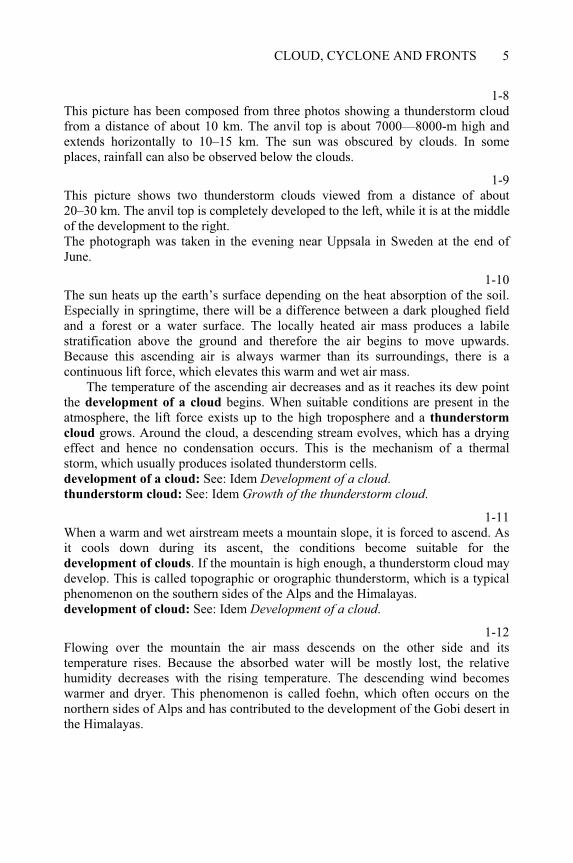
1-8This picture has been composed from three photos showing a thunderstorm cloud from a distance of about 10 km. The anvil top is about 7000—8000-m high and extends horizontally to 10–15 km. The sun was obscured by clouds. In some places, rainfall can also be observed below the clouds.
1-9This picture shows two thunderstorm clouds viewed from a distance of about 20–30 km. The anvil top is completely developed to the left, while it is at the middle of the development to the right. The photograph was taken in the evening near Uppsala in Sweden at the end of June.
1-10The sun heats up the earth’s surface depending on the heat absorption of the soil. Especially in springtime, there will be a difference between a dark ploughed field and a forest or a water surface. The locally heated air mass produces a labile stratification above the ground and therefore the air begins to move upwards. Because this ascending air is always warmer than its surroundings, there is a continuous lift force, which elevates this warm and wet air mass.
The temperature of the ascending air decreases and as it reaches its dew point the development of a cloud begins. When suitable conditions are present in the atmosphere, the lift force exists up to the high troposphere and a thunderstorm
cloud grows. Around the cloud, a descending stream evolves, which has a drying effect and hence no condensation occurs. This is the mechanism of a thermal storm, which usually produces isolated thunderstorm cells. development of a cloud: See: Idem Development of a cloud.thunderstorm cloud: See: Idem Growth of the thunderstorm cloud.
1-11When a warm and wet airstream meets a mountain slope, it is forced to ascend. As it cools down during its ascent, the conditions become suitable for the development of clouds. If the mountain is high enough, a thunderstorm cloud may develop. This is called topographic or orographic thunderstorm, which is a typical phenomenon on the southern sides of the Alps and the Himalayas. development of cloud: See: Idem Development of a cloud.
1-12Flowing over the mountain the air mass descends on the other side and its temperature rises. Because the absorbed water will be mostly lost, the relative humidity decreases with the rising temperature. The descending wind becomes warmer and dryer. This phenomenon is called foehn, which often occurs on the northern sides of Alps and has contributed to the development of the Gobi desert in the Himalayas.
UNDERSTANDING LIGHTNING AND LIGHTNING PROTECTION6
Development of a cyclone 1-13
There are two typical configurations of the isobar lines of the atmosphere: the low and the high. In the first case, the air pressure falls towards the centre of the low formation. In the other case, the barometric pressure is the highest in the centre and decreases outwards. It is evident that the air tries to move to the centre of the low configuration and to expand from the high configuration. In the northern hemisphere, cool air moves usually from north to south and warm from south to north, but in the southern hemisphere these movements are reversed.
1-14During the rotation of the earth, the peripheral speed depends on the geographical latitude, which means that the air moves with different speeds towards east. This speed is added to the speed of each individual moving air mass.
1-15In this figure, the red and blue vectors represent the speeds of warm and cool air masses respectively. The yellow lines illustrate the peripheral speed produced by the rotation of the earth.
1-16Taking the speed at the center of each configuration as the reference speed, the horizontal red and blue vectors represent the peripheral speeds of the air masses, which are added to their own speeds at the points shown in the picture.
1-17The resulting vectors of the components shown represent the starting speeds of the air masses. They do not move radially, but deviate from these directions. This phenomenon can also be explained by the effect of the Coriolis force.
1-18Because of the peripheral speed, the paths of the airstreams deviate from the straight path and all of them have tangential components. Therefore, this motion has also a moment of rotation.
1-19At the low pressure, the configuration develops into a vortex, which is known as a cyclone. Its rotation is anticlockwise in the northern hemisphere and clockwise in the southern hemisphere. In the temperate zones, it has a lateral extent of several hundred to thousand kilometres. It is associated with intensive ascending air motion, usually leading to heavy thunderstorms. At the high pressure, the rotation is clockwise in the north and anticlockwise in the southern hemisphere. This phenomenon is known as an anticyclone, and has less intensive rotation and descending air motion, which destroys the clouds. Therefore, no thunderstorms develop in an anticyclone.
CLOUD, CYCLONE AND FRONTS 7
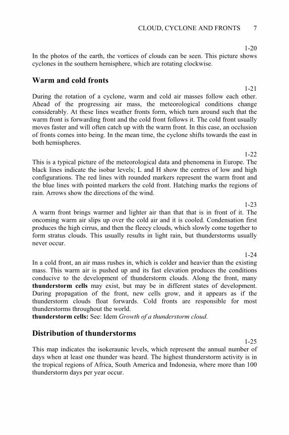
1-20In the photos of the earth, the vortices of clouds can be seen. This picture shows cyclones in the southern hemisphere, which are rotating clockwise.
Warm and cold fronts 1-21
During the rotation of a cyclone, warm and cold air masses follow each other. Ahead of the progressing air mass, the meteorological conditions change considerably. At these lines weather fronts form, which turn around such that the warm front is forwarding front and the cold front follows it. The cold front usually moves faster and will often catch up with the warm front. In this case, an occlusion of fronts comes into being. In the mean time, the cyclone shifts towards the east in both hemispheres.
1-22This is a typical picture of the meteorological data and phenomena in Europe. The black lines indicate the isobar levels; L and H show the centres of low and high configurations. The red lines with rounded markers represent the warm front and the blue lines with pointed markers the cold front. Hatching marks the regions of rain. Arrows show the directions of the wind.
1-23A warm front brings warmer and lighter air than that that is in front of it. The oncoming warm air slips up over the cold air and it is cooled. Condensation first produces the high cirrus, and then the fleecy clouds, which slowly come together to form stratus clouds. This usually results in light rain, but thunderstorms usually never occur.
1-24In a cold front, an air mass rushes in, which is colder and heavier than the existing mass. This warm air is pushed up and its fast elevation produces the conditions conducive to the development of thunderstorm clouds. Along the front, many thunderstorm cells may exist, but may be in different states of development. During propagation of the front, new cells grow, and it appears as if the thunderstorm clouds float forwards. Cold fronts are responsible for most thunderstorms throughout the world. thunderstorm cells: See: Idem Growth of a thunderstorm cloud.
Distribution of thunderstorms 1-25
This map indicates the isokeraunic levels, which represent the annual number of days when at least one thunder was heard. The highest thunderstorm activity is in the tropical regions of Africa, South America and Indonesia, where more than 100 thunderstorm days per year occur.
UNDERSTANDING LIGHTNING AND LIGHTNING PROTECTION8
1-26The isokeraunic levels are considerably lower in the temperate zones, as shown in the map of Hungary. It slightly increases in some regions where there are small mountains 500–1000-m high. Some empirical relations are available to estimate the ground-flash density from the thunderstorm days per year. Such a formula was used in this map. The new lightning localisation systems can record the ground-flash density but this takes a long time to compile. lightning localisation: See: Lightning measurement and localisation + Localising
the lightning.
1-27Because the cold fronts produce most of the thunderstorms, they occur with the highest frequency during the monsoons or at the beginning of the rainy season. In the moderate zones, the monsoon is not so intensive as in the tropics, and fewer thunderstorms occur. This diagram plots the monthly distribution of thunderstorms in Hungary, where the Atlantic monsoon arrives late springtime, if at all. In winter, thunderstorms rarely occur, but its occurrence cannot be ruled out.cold fronts: See: Idem Warm and cold fronts.
1-28The heat radiation of the sun intensifies the activity of a cold front by a similar effect as that of creating thermal thunderstorm. Therefore, thunderstorms are created with the highest frequency in the early afternoons. The diagram shows their daily distribution in Hungary. cold front: See: Idem Warm and cold fronts.thermal thunderstorm: See: Idem Thermal thunderstorm.
1-29The duration of the activity of a thunderstorm in Hungary, and probably in Europe, rarely exceeds 2 hours. In the morning or before noon, it is even shorter. When a thunderstorm begins in the evening, it is probably produced by an intensive cold
front and therefore lasts longer. May be that it is thundering during the whole night. cold front: See: Idem Warm and cold fronts.
CHAPTER 2
Electric charges in clouds
2-0Each item of this menu can be selected by double-clicking on it. The program displays several topics when the following items are selected: All items: from Processes of charge separation to Relation to the ionosphere.Processes of charge separation: from Charging process in the liquid phase to
Final distribution of charges. Charging theorises: from Charging process in the liquid phase to Charging
process during freezing.
Processes of charge separation
Charging process in the liquid phase
2-1At the base of a thunderstorm cloud, the temperature is above the freezing point and therefore it consists of water drops. Above the altitude of 0°C, supercooled water drops or ice particles exist. These different physical conditions lead to several processes of charge separation. Wind blows under the cloud and then turns upwards. Inside the cloud, a cold front can produce intensive wind, which is often upward directed. cold front: See: Cloud, cyclone and fronts Warm and cold fronts.
2-2It was observed about hundred years ago that the spray in front of waterfalls always consists of negatively charged drops. This phenomenon is called waterfall electrification.
2-3F. Lenard explained the mechanism of waterfall electrification using the droplet fragmentation theory. Later G. Simpson applied this theory to describe the electrification in the liquid zone of thunderstorm clouds. ____________________________________________________Understanding Lightning and Lightning Protection T. Horváth © 2006 Research Studies Press Limited
UNDERSTANDING LIGHTNING AND LIGHTNING PROTECTION 10
2-4The water drops fall against the wind, with the ram pressure eventually causing fragmentation. The ionosphere produces an electric field that separates the positive and negative electric charges so that the bubble becomes negative and the flange below becomes positive. ionosphere: See: Idem Relation to the ionosphere.
2-5The bubble finally fragments into negatively charged fine spray drops while larger drops are created from the lower flange with positive charge.
2-6The wind rapidly carries the small spray droplets with the negative charge upwards, while the bigger positively charged drops are much slower. As a consequence of this process, the positive and the negative charges are separated inside the cloud.
2-7In the liquid phase, the separation of charge produces a positive centre while the negative charge is dispersed in the rest of the liquid zone. The upper region of the cloud is colder than 0°C and the electrification runs according to another process.
Charging process during freezing
2-8In the upper part of a thunderstorm cloud, the temperature is below the freezing point and therefore the water drops begin to freeze. This process does not proceed in one step, but first supercooled water drops and ice particles are created. There are many electrification processes associated with freezing, but many are not sufficiently effective to produce a charge that is large enough compared to the recorded values. The mechanism according to the theory by B. J. Mason and C. F. Latham seems to be sufficiently intensive for producing the amount of charge that corresponds to the observations.
2-9Freezing begins at the surface of the water drop and produces a thin ice layer first. When the freezing progresses towards the inside of the drop, this ice shell becomes too restricted for the expanding new ice core and therefore the outer ice layer cracks.
2-10The temperature is not uniform in the drop, but is higher in the centre compared to the surface. The positive H+ ions have higher mobility than the negative OH– ions, and therefore the positive charge is spread more evenly inside the drop than the negative charge.
ELECTRIC CHARGES IN CLOUDS 11
2-11The non-uniform distributions of the positive and the negative ions cause, on the one hand, a negative dominance in the core of the drop, but, on the other hand, a positive dominance in the cracked outer ice shell.
2-12The stretching force splinters off small ice particles from the frozen grain, and the intensive wind rapidly carries them upwards with their positive charge. The heavier ice grains do not go so high, and they spread their negative charge in the middle zone of the cloud.
2-13The small ice splinters produce a large positively charged zone in the highest part of the thunderstorm cloud. The ice grains and the sprayed water droplets fill the middle zone of the cloud with a large negative charge. As a result of the charge separation in the liquid and in the ice phases, the indicated three pole charge distribution is created in the typical thunderstorm clouds.
Final distribution of charges 2-14
As a result of the charge separation in the liquid and in the ice phases, a three pole charge distribution is formed in a typical thunderstorm cell, as shown in this picture. The greatest amount of electric charge is at the top and in the freezing region. Although the lower positive centre is considerably smaller, it is also important because no rain falls usually in this place and so enhanced danger threatens people in open air.thunderstorm cells: See: Cloud, cyclone and fronts Growth of a thunderstorm
cloud.people in open air: See: Mankind in thunderstorms Danger in open air.
2-15For analytical calculations, the charge of the thunderstorm cloud is usually modelled with simplified charge distribution. Such a model has been created by G. Simpson, who assumed uniformly charged spheres of different sizes and centres at different heights, as shown in this picture.
Static electric field 2-16
The field measurements and the calculations using Simpson’s model result in an electric field gradient E directed upwards below the thunderstorm cloud, and reversed in a distance of about 10–20 km. The lower positive centre does not reverse the field but decreases it a little. The large positive charge on top of the cloud produces a high upward-directed field strength. Simpson’s model: See: Idem Final distribution of charges.
UNDERSTANDING LIGHTNING AND LIGHTNING PROTECTION 12
Relation to the ionosphere 2-17
The ground flashes carry a greater amount of negative charge to the earth than the positive charge. The cause of this difference is that about 80–90% of ground flashes start from the negative centres in the cloud. Although the positive flashes usually carry a higher charge, the lower frequency of their occurrence cannot balance the asymmetry of the polarity of ground flashes. Therefore, a surplus of positive charge remains in the cloud. This charge produces a high upward-directed field gradient above the cloud. polarity of ground flashes: See: Physics of the lightning discharge Statistical
data.
2-18The high electric field drives positive ions upwards from the top of the cloud towards the ionosphere. The thunderstorm clouds form a global generator, which transforms thermal energy of the atmosphere into electrical energy and charges up the ionosphere with positive ions. This generator produces a current of about 1500 Å along the total surface of the earth.
2-19The positive charge of the ionosphere produces an electric field gradient directed towards the earth. In regions of clear weather, this field drives positive ions downwards, which forms the fine weather current. Although its density is very low related to the total earth surface, it balances the current (1500 Å) produced by the thunderstorms.
2-20The thunderstorm activity on the earth can be indicated with the extension of the stormy regions. Plotting this against Greenwich Mean Time (GMT) the regions of highest isokeraunic levels cause peaks in the early afternoon. This is also related to the daily distribution of thunderstorms.isokeraunic levels and daily distribution of thunderstorms: See: Cloud, cyclone
and fronts Distribution of thunderstorms.
2-21The change in fine weather current is independent of location, if plotted against GMT, and the shape of the diagram follows the trend of the thunderstorm activity on earth. This supports the theory that a relation exists between the ionosphere and the thunderstorms.
CHAPTER 3
Discharge processes in air
3-0Each item of this menu can be selected by double-clicking on it. The program displays several topics when the following items are selected: All items: from Photon processes to Klydonograph and pictures.Photon processes: to Ionisation and recombination.Electron collisions: to Ionisation by collision.Discharges: from Electron avalanche to Klydonograph and pictures.Streamer discharge Klydonograph and pictures.
Photon processes
3-1Lightning flash is an electrical discharge in the atmosphere. It is useful to study the physics of discharges in air. There are some other phenomena whose interpretation also requires an understanding of gas discharges.
A gas discharge is often connected to photon processes. Each photon represents an energy (W usually expressed in eV) that can be determined with Planck’s constant (h = 6.626076 × 10⁻³⁴ eVs) and the frequency ( f, Hz). The energy of the visible radiation increases from red to violet, and is considerably higher in the case of ultraviolet, X-ray or radioactive radiations. If its energy is high enough, the photon can affect the atoms and molecules of the air.
Excitation by photon 3-2
Electrons of the atoms and molecules can have discrete energy levels. To raise the energy of an electron from the ground level to a higher level, energy of excitation Wg is required, which is a property of the atom or molecule. If the energy of a photon is high enough, it can cause excitation in case of collision. The atom does not remain in the excited state, but the electron returns to the ground level, and the atom emits a photon of excitation energy. ____________________________________________________Understanding Lightning and Lightning Protection T. Horváth © 2006 Research Studies Press Limited
UNDERSTANDING LIGHTNING AND LIGHTNING PROTECTION 14
Ionisation and absorption 3-3
To release an electron from an atom or molecule, ionising energy Wi is required, which is a property of the atom or molecule (about 14–15 eV in the air). If the energy of a photon is high enough, it can ionise the atom or molecule in case of collision. This process produces a free electron in the air, which moves away. There are certain electro-negative gases in which the external electron shell is not closed, and these can absorb electrons. Oxygen is such a gas, which binds electrons with an absorption energy of Wa = 2.2 eV. If the kinetic energy of a free electron is less then Wa, it will form a negative ion with an oxygen molecule. Therefore, free electrons exist for only very short periods in the air.
Recombination3-4
In fine weather, 5–6 ionisations happen in each cubic centimetre of air, producing both positive and negative ions. However, their number cannot grow limitless because the ions of opposite polarities attract and after contact neutralise each other. This process is called recombination, which balances the creation of ions at the density of 500–600 ions/cm3 when the weather is clear and at about 1000 ions/cm3 in stormy weather.
3-5It would appear that an electron and a positive ion could also neutralise each other by recombination, but this is not so. Since the positive ion strongly attracts the negative electron, the electron approaches it with a high velocity. The electron gains very high kinetic energy and therefore the ion cannot trap it. If the electron does not approach the ion along a straight line towards the centre, it travels beside the ion along a path similar to that of a spaceship beside a planet (e.g. Jupiter). Therefore, the recombination of electrons and ions almost never occurs.
Electron collisions 3-6
If a free electron is subjected to an electric field, a force F affects it, which is proportional to the charge qe (1.6 × 10⁻¹⁹ C) of the electron and the gradient E of the field. Because of the negative charge of the electron, this force acts in an opposite direction to the gradient.
3-7The force F accelerates the electron, which collects energy We along its free path x.This energy can be finally expressed by the potential difference (Ux – Uo) between the origin and the end of the free path.
DISCHARGE PROCESSES IN AIR 15
3-8At the point of collision, the electron has a kinetic energy We that is related to the free path distance x. If this is not high enough to affect the molecule, nothing will happen and the electron springs off without any interaction.
Excitation by electron 3-9
If the kinetic energy We, collected by the electron along the free path x, exceeds that, which is necessary to cause excitation, the molecule achieves an excited state. The electron will lose its kinetic energy on collision and its acceleration starts once again on the next free orbit. The molecule then emits the energy of excitation as a photon. excitation: See: Idem Excitation by photon.
Ionisation by collision 3-10
If the kinetic energy We, collected by the electron along the free path x exceeds that, which is necessary to cause ionisation, another electron escapes from the molecule. The first electron loses its kinetic energy on collision, but the acceleration begins once again. After an ionisation process, two electrons drift in the electric field and both can cause excitations or ionisations on further collisions. The free path required to cause ionisation is called the path length of ionisation. ionisation: See: Idem Ionisation and recombination.
Discharges
Electron avalanche
3-11When an electron moves under the influence of an electric field, collisions may occur with the molecules of air. Between two collisions, the free paths have different lengths and so they cause different effects. Sometimes, ionisation occurs and an additional electron is released. Other collisions cause excitations but some of them have no effect. This process is controlled by the number of ionisations per unit length, which is the coefficient and known as the ionisation per centimetre according to Townsend, who first analysed this process. free paths: See: Idem Electron collisions.
3-12Using the coefficient , the ionisation per centimetre, the increase in the number of electrons can be estimated along a length dx. The increase dn is proportional to the number n(x) of the arriving electrons and the length dx.
3-13The relation in the middle can be transformed by the separation of the variables into a differential equation. The left side of the equation depends only on the
UNDERSTANDING LIGHTNING AND LIGHTNING PROTECTION 16
number n while the right side depends only on the length x, simplifying to typical integrals.
3-14The integration of the previous differential equation results in the relation highlighted in yellow in the middle. On transforming, Townsend’s rule of avalanche is obtained, which shows the exponential increase of the number of electrons during the development of the discharge.
3-15Assuming a constant gradient E of electric field, the potential U linearly increases in the region, in which the electron avalanche will grow from x = 0, towards the right.
3-16The electrons move at the front of the avalanche with a velocity of 1 to 2 × 107 cm/s, but the positive ions practically remain motionless at the point of their creation. The positive and negative charges distort the potential and at the front of the avalanche the gradient E increases rapidly. It is important to note that if the number of initial electrons n(0) = 0, then the avalanche cannot develop.
3-17This is a picture of electron avalanche produced by H. Raether in a Wilson cloud chamber in 1941. The cathode (negative electrode) is on the left and the avalanche propagates against the anode (positive electrode) on the right. Along the path of the electrons the saturated steam condenses and produces the shape of the avalanche [20]
Streamer discharge
3-18At the front of the avalanche, the enhanced electric field gradient E causes intensive collisions that produce many photons of high energy. These travel at the speed of light and result in ionisation at all points ahead of the avalanche. These free electrons soon accelerate and form secondary avalanches, which immediately begin to propagate. Later, the positive and negative charges of the secondary avalanches make contact and finally join the secondary avalanches. produce many photons: See: Idem Excitation by electron.
3-19This accumulation produces filaments, where intensive ionisation occurs due to collisions and photons. The property of the discharge changes and the avalanche is transformed into a streamer discharge. This transformation usually occurs after propagating avalanches of 1–2 cm in length, when a longer streamer discharge develops.
DISCHARGE PROCESSES IN AIR 17
3-20In the streamer type of discharge, the voltage drops to 5–6 kV/cm from 30 kV/cm, which was required to initiate the development of avalanche. In addition to the ionisation by collision with electrons, the ionisation by photons also occurs. The speed of propagation increases to 7–8 × 107 cm/s because the secondary avalanches are initiated by photons moving at the speed of light. ionisation by photons: See: Idem + Ionisation and recombination.
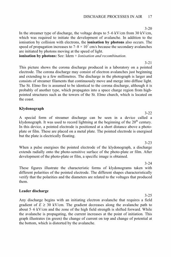
3-21This picture shows the corona discharge produced in a laboratory on a pointed electrode. The corona discharge may consist of electron avalanches just beginning and extending to a few millimetres. The discharge in the photograph is larger and consists of streamer filaments that continuously move and merge into diffuse light. The St. Elmo fire is assumed to be identical to the corona discharge, although it is probably of another type, which propagates into a space charge region from high-pointed structures such as the towers of the St. Elmo church, which is located on the coast.
Klydonograph
3-22A special form of streamer discharge can be seen in a device called a klydonograph. It was used to record lightning at the beginning of the 20th century. In this device, a pointed electrode is positioned at a short distance above a photo-plate or film. These are placed on a metal plate. The pointed electrode is energised but the plate is electrically floating.
3-23When a pulse energises the pointed electrode of the klydonograph, a discharge extends radially onto the photo-sensitive surface of the photo-plate or film. After development of the photo-plate or film, a specific image is obtained.
3-24These figures illustrate the characteristic forms of klydonograms taken with different polarities of the pointed electrode. The different shapes characteristically verify that the polarities and the diameters are related to the voltages that produced them.
Leader discharge
3-25Any discharge begins with an initiating electron avalanche that requires a field gradient of E ≥ 30 kV/cm. The gradient decreases along the avalanche path to about 5–6 kV/cm and the zone of the high field strength is shifted forward. While the avalanche is propagating, the current increases at the point of initiation. This graph illustrates (in green) the change of current on top and change of potential at the bottom, which is distorted by the avalanche.
UNDERSTANDING LIGHTNING AND LIGHTNING PROTECTION 18
3-26After the avalanche is transformed into a streamer, the discharge propagates forward with enhanced speed while the current continuously increases at the electrode. Along the streamer length the voltage drop is about 5–6 kV/cm shown in violet in the graph. Ahead of streamer, the graph illustrates the change of potential (in green). If the gradient is high enough here, the discharge can propagate forward. When the streamer current exceeds the threshold of thermal ionisation the process will change again. transformed into a streamer: See: Idem + Streamer discharge.
3-27When the current of the streamer exceeds the threshold of thermal ionisation at the point of initiation, it propagates at very high speed along the existing streamer section, and it is eventually transformed into leader discharge. The voltage drop decreases to about 1 kV/cm shown in orange in the graph. The streamer propagates forward until the gradient at its leading head is steep enough or the current exceeds the threshold of thermal ionisation.
3-28While the discharge moves forward the streamer current repeatedly exceeds the threshold of thermal ionisation, and new leader sections are created. The current increases and therefore the voltage drop finally decreases below 1 kV/cm as shown in light yellow in the graph. In this type of discharge, the ionisation by collision of electrons is negligible and the thermal ionisation becomes dominant.
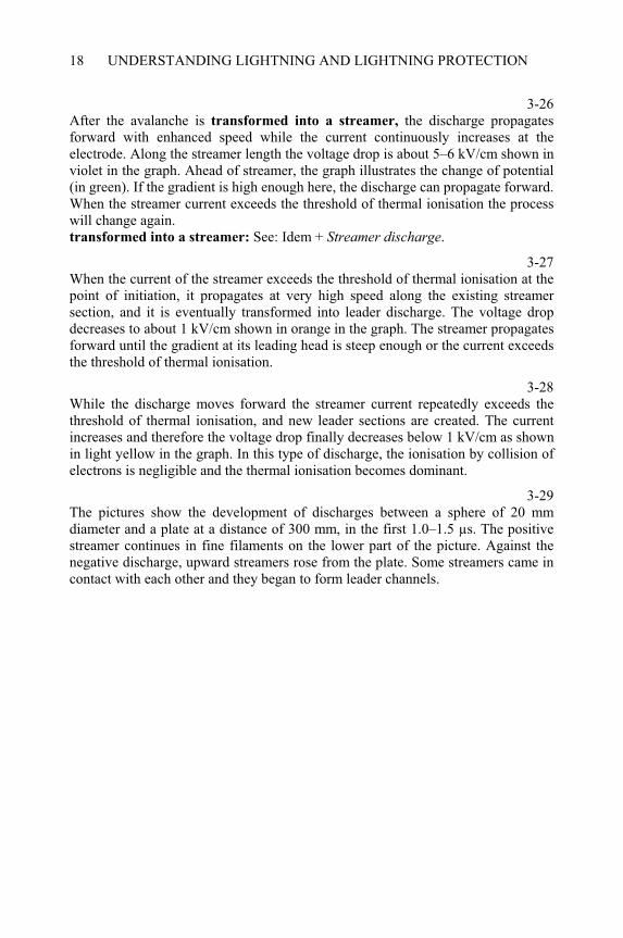
3-29The pictures show the development of discharges between a sphere of 20 mm diameter and a plate at a distance of 300 mm, in the first 1.0–1.5 µs. The positive streamer continues in fine filaments on the lower part of the picture. Against the negative discharge, upward streamers rose from the plate. Some streamers came in contact with each other and they began to form leader channels.
CHAPTER 4
Development of the lightning flash
4-0Each item of this menu can be selected by double-clicking on it. The program displays several topics when the following items are selected: All processes: from Start on drops in the cloud to Real Boys records.From leader to main stroke: from Downward leader to Upward leader.The Boys camera: from Invention and construction to Real Boys records.Striking process: a section from Boys record of ideal lightning.
Start on drops in the cloud 4-1
Inside thunderstorm clouds, turbulent winds drive electrically charged water drops up and down. These produce high electric fields but a discharge can only originate from an electrode, in this case the water drop. Although there are no direct observations available concerning this process, the first discharge probably starts as depicted by the mechanism shown in the next pictures.
4-2The water drop distorts the electric field, which can be assumed to be homogeneous with gradient Eo. The drop as a conductive sphere modifies the field so that it increases to 3Eo at two points. The field strength separates the opposite charges inside the drop.
4-3The field gradient subjects forces on the charges in the drop causing it to elongate. Because the drop is not a solid body, the electrical forces can easily distort it and the ends of the drop become increasingly pointed. The field gradient gets enhanced at these points and a corona discharge is initiated, which eventually develops into a streamer state. The current associated with this discharge heats the drop at the contact spots and the water begins to evaporate. streamer state: See: Discharge processes in air Streamer discharge.____________________________________________________Understanding Lightning and Lightning Protection T. Horváth © 2006 Research Studies Press Limited
UNDERSTANDING LIGHTNING AND LIGHTNING PROTECTION20
4-4The discharges move towards the middle of the evaporating drop, which finally disappears and the discharges join together. These streamers disappear without an electrode, but they may reappear in large numbers, eventually recombining to form a discharge. Although many of these will also disappear, some may persist leading to a low probability of the growth of a discharge.
4-5Inside thunderstorm clouds, many short discharges occur, but they generally do not develop over great distances. These persistent discharges produce electromagnetic waves that have been recorded by lightning detection systems. Nevertheless, one of these discharges may grow and develop out of the cloud with low probability. This is the first phase of a lightning flash. lightning detection: See: Lightning measurement and localization Lightning detection systems.
From leader to main stroke 4-6
A long discharge, which can grow out of the cloud, is transformed into a leader type: at least in the core of its channel. The voltage drop is low along the leader
channel and therefore it can be assumed to be a conductive channel, similar to a piece of wire. At the ends of this channel, the gradient of the electric field is high enough to create conditions conducive to forward propagation. leader channel: See: Discharge processes in air Leader discharge.
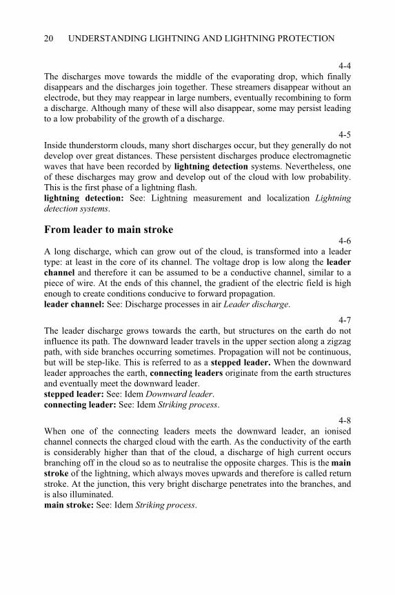
4-7The leader discharge grows towards the earth, but structures on the earth do not influence its path. The downward leader travels in the upper section along a zigzag path, with side branches occurring sometimes. Propagation will not be continuous, but will be step-like. This is referred to as a stepped leader. When the downward leader approaches the earth, connecting leaders originate from the earth structures and eventually meet the downward leader. stepped leader: See: Idem Downward leader.connecting leader: See: Idem Striking process.
4-8When one of the connecting leaders meets the downward leader, an ionised channel connects the charged cloud with the earth. As the conductivity of the earth is considerably higher than that of the cloud, a discharge of high current occurs branching off in the cloud so as to neutralise the opposite charges. This is the main
stroke of the lightning, which always moves upwards and therefore is called return stroke. At the junction, this very bright discharge penetrates into the branches, and is also illuminated. main stroke: See: Idem Striking process.
DEVELOPMENT OF THE LIGHTNING FLASH 21
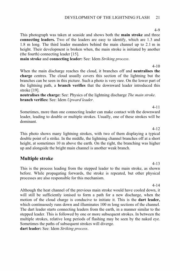
4-9This photograph was taken at seaside and shows both the main stroke and three connecting leaders. Two of the leaders are easy to identify, which are 1.3 and 1.8 m long. The third leader meanders behind the main channel up to 2.1 m in height. Their development is broken when, the main stroke is initiated by another (the fourth) connecting leader [15]. main stroke and connecting leader: See: Idem Striking process.
4-10When the main discharge reaches the cloud, it branches off and neutralises the
charge centres. The cloud usually covers this section of the lightning but the branches can be seen in this picture. Such a photo is very rare. On the lower part of the lightning path, a branch verifies that the downward leader introduced this stroke [19]. neutralises the charge: See: Physics of the lightning discharge The main stroke.branch verifies: See: Idem Upward leader.
4-11Sometimes, more than one connecting leader can make contact with the downward leader, leading to double or multiple strokes. Usually, one of these strokes will be dominant.
4-12This photo shows many lightning strokes, with two of them displaying a typical double point of a strike. In the middle, the lightning channel branches off at a short height, at sometimes 10 m above the earth. On the right, the branching was higher up and alongside the bright main channel is another weak branch.
Multiple stroke 4-13
This is the process leading from the stepped leader to the main stroke, as shown before. While propagating forwards, the stroke is repeated, but other physical processes are also responsible for this mechanism.
4-14Although the heat channel of the previous main stroke would have cooled down, it will still be sufficiently ionised to form a path for a new discharge, when the motion of the cloud charge is conducive to initiate it. This is the dart leader,
which continuously runs down and illuminates 100 m long sections of the channel. The dart leader starts connecting leaders from the earth, in a manner similar to the stepped leader. This is followed by one or more subsequent strokes. In between the multiple strokes, relative long periods of flashing may be seen by the naked eye. Sometimes the paths of subsequent strokes will diverge. dart leader: See: Idem Striking process.
UNDERSTANDING LIGHTNING AND LIGHTNING PROTECTION22
4-15When the lightning starts from positive charge in a cloud, only one stroke is usually observed. Conversely, when the lightning starts from negative charge a single stroke occurs at a frequency of less than 50%. To the author’s knowledge, the highest observed number of subsequent strokes was 46. The physical
parameters of the first and the subsequent strokes differ considerably from each other. physical parameters: See: Physics of the lightning discharge Lightning
parameters.
Upward leader 4-16
On the top of high structures, the electric field is intensified to initiate a leader that propagates upwards. It is analogous to a connecting leader produced by the charges of the cloud, or by a downward leader, which is hidden in the cloud. The step-like propagation is not characteristic at the upward leader and its branching differs considerably to that of a downward leader.
4-17Although the upward leader propagates in the opposite direction to the downward leader, the main stroke starts always from an object on earth. Its physical
parameters are, however, very different. physical parameters: See: Physics of the lightning discharge Lightning
parameters.
4-18This photo illustrates the typical form of a lightning stroke, which started with an upward leader. The path branches at sharp angles and does not deviate much from the vertical [2].
4-19This photo illustrates the different forms of branching of lightning initiated by a downward leader. The shape of some branches is almost rectangular, with paths turning upwards.
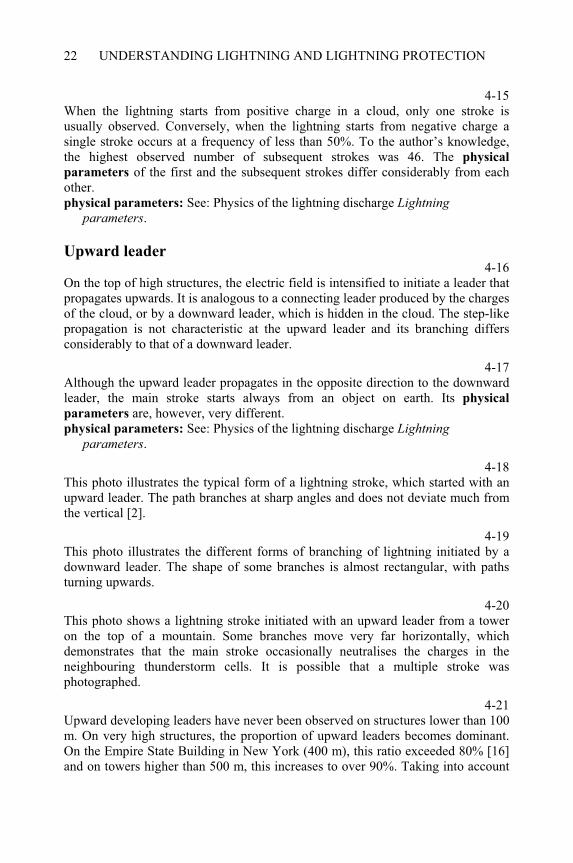
4-20This photo shows a lightning stroke initiated with an upward leader from a tower on the top of a mountain. Some branches move very far horizontally, which demonstrates that the main stroke occasionally neutralises the charges in the neighbouring thunderstorm cells. It is possible that a multiple stroke was photographed.
4-21Upward developing leaders have never been observed on structures lower than 100 m. On very high structures, the proportion of upward leaders becomes dominant. On the Empire State Building in New York (400 m), this ratio exceeded 80% [16] and on towers higher than 500 m, this increases to over 90%. Taking into account
DEVELOPMENT OF THE LIGHTNING FLASH 23
the physical conditions associated with the development of such lightning, theoretical calculations resulted in the diagram shown here. calculation: See: The striking process Calculation of expected frequency.
The Boys camera: principle and construction 4-22
The Boys camera is a special device used to record the development of lightning. The lightning flash is such a rapid phenomenon that its development cannot be seen without the use of special recording equipment. The human eye at best can only observe the flash of multiple strokes. This may be recorded accidentally when lightning is photographed with a hand-held camera. In this case, the camera usually moves, and so the image of the lightning will be shifted, although the lightning propagates along the same path. If the camera continuously moves during the subsequent strokes, then each stroke will appear on the photograph as well. subsequent strokes: See: Idem Multiple stroke.
4-23This amateur photograph shows the shift of the image of a lightning path when the camera moved. This picture was taken with an amateur camera at Lake Balaton 10 years ago.
4-24This is an old photograph taken with an early camera, and shows the picture of a multiple stroke. Either the motion of the camera or the wind caused a shift of the path images. This figure indicated the phases of the lightning development, which led to the invention of the Boys camera.
4-25Sir C. V. Boys began to develop his camera in the beginning of the 20th century, and according to one of his letters, he made the first successful record in 1926. In the following 10 years, many Boys records were made, which eventually made possible the recording of the finer details of the lightning mechanism [2].
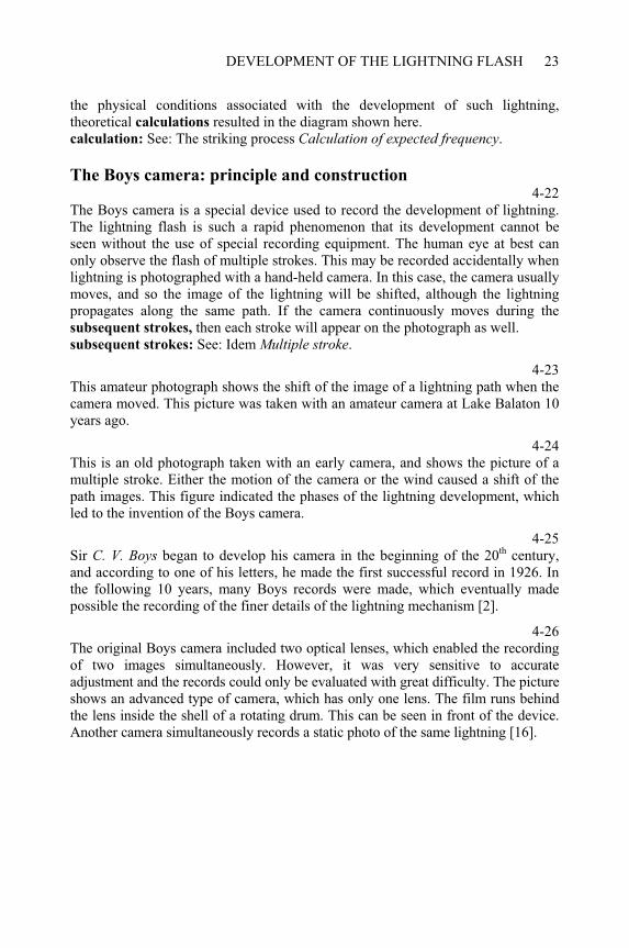
4-26The original Boys camera included two optical lenses, which enabled the recording of two images simultaneously. However, it was very sensitive to accurate adjustment and the records could only be evaluated with great difficulty. The picture shows an advanced type of camera, which has only one lens. The film runs behind the lens inside the shell of a rotating drum. This can be seen in front of the device. Another camera simultaneously records a static photo of the same lightning [16].
UNDERSTANDING LIGHTNING AND LIGHTNING PROTECTION24
The Boys camera: Operation 4-27
When a bright spot runs straight down, it will appear as an inclined line on the film moving with constant speed to the left. While the spot moves downwards, its track is shifted to right on the film. It can therefore be taken that time progresses to the right on the Boys record. The motion of the bright spot was seen in the blue field on the right side.
4-28When a bright spot runs straight upwards, the line on the moving film inclines in the opposite direction than as in the previous case. Therefore, the track of the spot will also be shifted to right on the film, while the spot moves upwards. It can therefore be generally stated that: Images on the right of the Boys record indicate later events in any particular sequence as before. The motion of the bright spot was seen in the blue field on the right side.
4-29When a bright spot moves upwards while behind it remains a lighting channel, its track yields an inclined line with an exposed area to its right on the moving film. As result, a white trapeze shape appears on the photograph. Therefore, a line on the film corresponds to a moving spot, while an area indicates a growing channel.
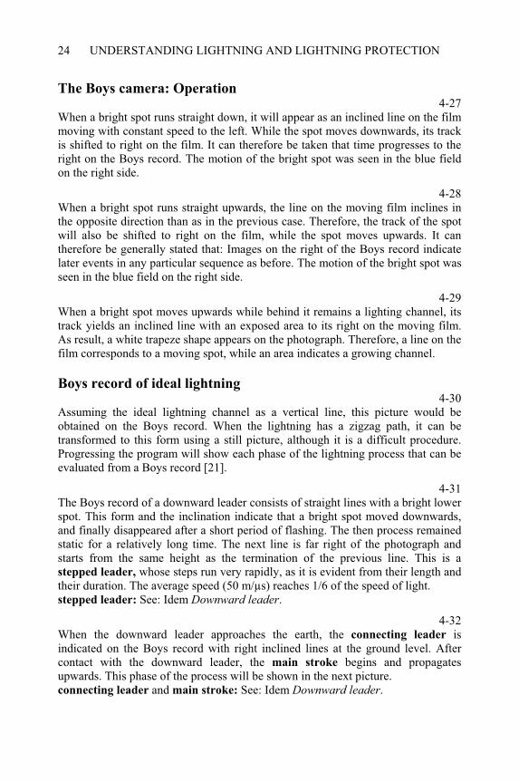
Boys record of ideal lightning 4-30
Assuming the ideal lightning channel as a vertical line, this picture would be obtained on the Boys record. When the lightning has a zigzag path, it can be transformed to this form using a still picture, although it is a difficult procedure. Progressing the program will show each phase of the lightning process that can be evaluated from a Boys record [21].
4-31The Boys record of a downward leader consists of straight lines with a bright lower spot. This form and the inclination indicate that a bright spot moved downwards, and finally disappeared after a short period of flashing. The then process remained static for a relatively long time. The next line is far right of the photograph and starts from the same height as the termination of the previous line. This is a stepped leader, whose steps run very rapidly, as it is evident from their length and their duration. The average speed (50 m/µs) reaches 1/6 of the speed of light. stepped leader: See: Idem Downward leader.
4-32When the downward leader approaches the earth, the connecting leader is indicated on the Boys record with right inclined lines at the ground level. After contact with the downward leader, the main stroke begins and propagates upwards. This phase of the process will be shown in the next picture. connecting leader and main stroke: See: Idem Downward leader.
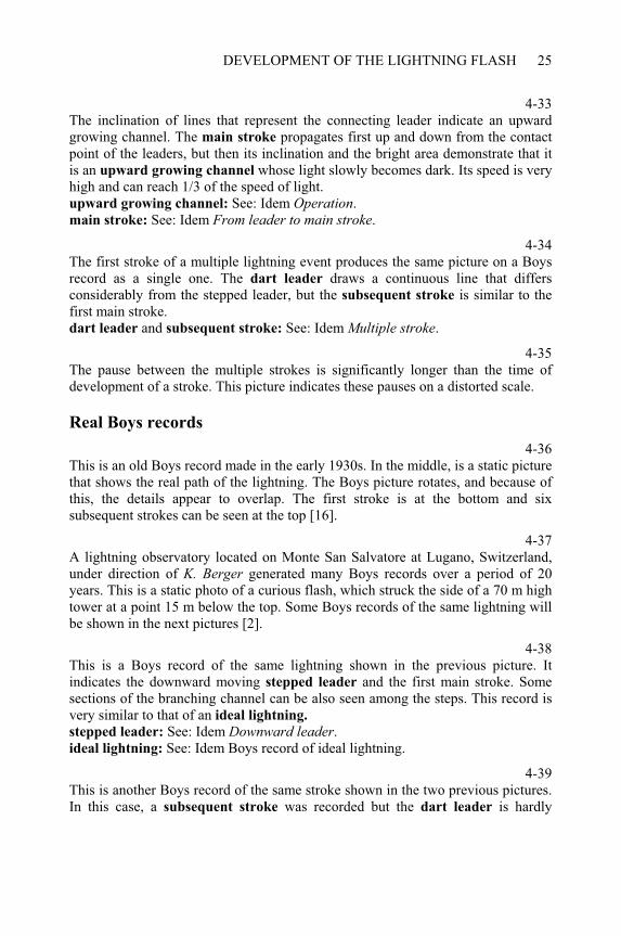
DEVELOPMENT OF THE LIGHTNING FLASH 25
4-33The inclination of lines that represent the connecting leader indicate an upward growing channel. The main stroke propagates first up and down from the contact point of the leaders, but then its inclination and the bright area demonstrate that it is an upward growing channel whose light slowly becomes dark. Its speed is very high and can reach 1/3 of the speed of light. upward growing channel: See: Idem Operation.main stroke: See: Idem From leader to main stroke.
4-34The first stroke of a multiple lightning event produces the same picture on a Boys record as a single one. The dart leader draws a continuous line that differs considerably from the stepped leader, but the subsequent stroke is similar to the first main stroke. dart leader and subsequent stroke: See: Idem Multiple stroke.
4-35The pause between the multiple strokes is significantly longer than the time of development of a stroke. This picture indicates these pauses on a distorted scale.
Real Boys records
4-36This is an old Boys record made in the early 1930s. In the middle, is a static picture that shows the real path of the lightning. The Boys picture rotates, and because of this, the details appear to overlap. The first stroke is at the bottom and six subsequent strokes can be seen at the top [16].
4-37A lightning observatory located on Monte San Salvatore at Lugano, Switzerland, under direction of K. Berger generated many Boys records over a period of 20 years. This is a static photo of a curious flash, which struck the side of a 70 m high tower at a point 15 m below the top. Some Boys records of the same lightning will be shown in the next pictures [2].
4-38This is a Boys record of the same lightning shown in the previous picture. It indicates the downward moving stepped leader and the first main stroke. Some sections of the branching channel can be also seen among the steps. This record is very similar to that of an ideal lightning.
stepped leader: See: Idem Downward leader.ideal lightning: See: Idem Boys record of ideal lightning.
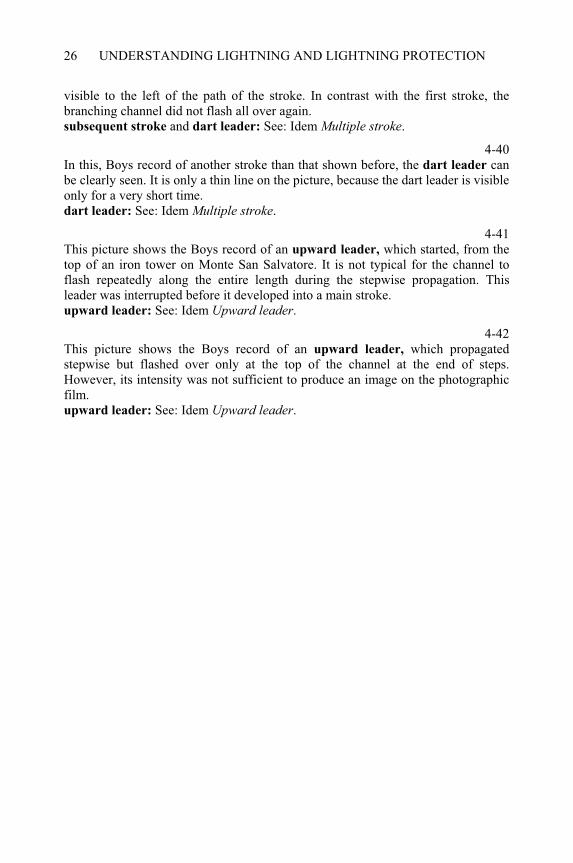
4-39This is another Boys record of the same stroke shown in the two previous pictures. In this case, a subsequent stroke was recorded but the dart leader is hardly
UNDERSTANDING LIGHTNING AND LIGHTNING PROTECTION26
visible to the left of the path of the stroke. In contrast with the first stroke, the branching channel did not flash all over again. subsequent stroke and dart leader: See: Idem Multiple stroke.
4-40In this, Boys record of another stroke than that shown before, the dart leader can be clearly seen. It is only a thin line on the picture, because the dart leader is visible only for a very short time. dart leader: See: Idem Multiple stroke.
4-41This picture shows the Boys record of an upward leader, which started, from the top of an iron tower on Monte San Salvatore. It is not typical for the channel to flash repeatedly along the entire length during the stepwise propagation. This leader was interrupted before it developed into a main stroke. upward leader: See: Idem Upward leader.
4-42This picture shows the Boys record of an upward leader, which propagated stepwise but flashed over only at the top of the channel at the end of steps. However, its intensity was not sufficient to produce an image on the photographic film. upward leader: See: Idem Upward leader.
CHAPTER 5
Physics of the lightning discharge
5-0Each item of this menu can be selected by double-clicking on it. The program displays several topics when the following items are selected: All items: from Properties of downward leader to Distribution functions. The main stroke: from Development of main stroke to Lightning parameters.Lightning parameters: to Distribution functions
Properties of a downward leader 5-1
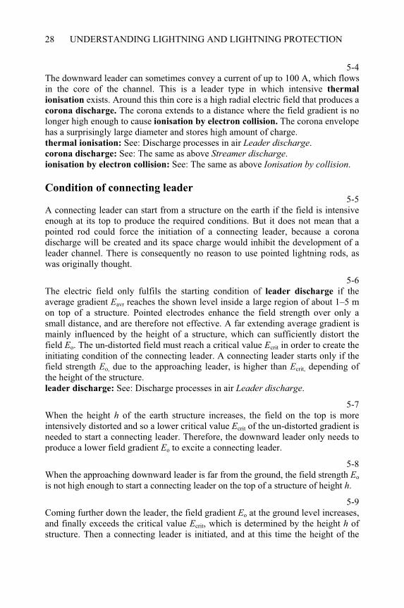
The downward leader brings charge from the cloud and distributes it along the channel. In this case, it is assumed as negative. The specific density of charge q(z)increases downwards and reaches the highest value at the head of the leader. This charge produces an electric field at the ground surface, whose gradient Eo is directed upwards when the leader channel is negative.
5-2This picture illustrates the equipotential lines of the electric field produced by the charge of the leader channel. High gradients exist only near the head of the leader. This high field determines the direction of propagation of the leader, which is not influenced by the structures on the earth. Near the ground surface, the electric field can be assumed homogeneous with a constant gradient Eo that increases proportionally to the specific charge q of the leader channel.
5-3When the leader approaches the earth, the gradient of the electric field increases at the ground surface. Thus, the field strength Eo is also a function of the height z of the head of the leader.
____________________________________________________Understanding Lightning and Lightning Protection T. Horváth © 2006 Research Studies Press Limited
UNDERSTANDING LIGHTNING AND LIGHTNING PROTECTION28
5-4The downward leader can sometimes convey a current of up to 100 A, which flows in the core of the channel. This is a leader type in which intensive thermal
ionisation exists. Around this thin core is a high radial electric field that produces a corona discharge. The corona extends to a distance where the field gradient is no longer high enough to cause ionisation by electron collision. The corona envelope has a surprisingly large diameter and stores high amount of charge. thermal ionisation: See: Discharge processes in air Leader discharge.corona discharge: See: The same as above Streamer discharge.ionisation by electron collision: See: The same as above Ionisation by collision.
Condition of connecting leader 5-5
A connecting leader can start from a structure on the earth if the field is intensive enough at its top to produce the required conditions. But it does not mean that a pointed rod could force the initiation of a connecting leader, because a corona discharge will be created and its space charge would inhibit the development of a leader channel. There is consequently no reason to use pointed lightning rods, as was originally thought.
5-6The electric field only fulfils the starting condition of leader discharge if the average gradient Eavr reaches the shown level inside a large region of about 1–5 m on top of a structure. Pointed electrodes enhance the field strength over only a small distance, and are therefore not effective. A far extending average gradient is mainly influenced by the height of a structure, which can sufficiently distort the field Eo. The un-distorted field must reach a critical value Ecrit in order to create the initiating condition of the connecting leader. A connecting leader starts only if the field strength Eo, due to the approaching leader, is higher than Ecrit, depending of the height of the structure. leader discharge: See: Discharge processes in air Leader discharge.
5-7When the height h of the earth structure increases, the field on the top is more intensively distorted and so a lower critical value Ecrit of the un-distorted gradient is needed to start a connecting leader. Therefore, the downward leader only needs to produce a lower field gradient Eo to excite a connecting leader.
5-8When the approaching downward leader is far from the ground, the field strength Eo
is not high enough to start a connecting leader on the top of a structure of height h.
5-9Coming further down the leader, the field gradient Eo at the ground level increases, and finally exceeds the critical value Ecrit, which is determined by the height h of structure. Then a connecting leader is initiated, and at this time the height of the
PHYSICS OF THE LIGHTNING DISCHARGE 29
leader head can be taken as zcrit. Using the earlier found equations, a relation can be defined between this height, the charge q of leader and the height h of the earth structure.earlier found equations: See: Idem Properties of downward leader.
5-10The connecting leader propagates against the downward leader and oppositely charged channels collide at the contact point. These produce a high electric field and therefore a very high energy collision begins.
Striking process 5-11
The collision of negative and positive charges heats up the channel and it leads to intensive thermal ionisation. As a consequence, hot plasma begins to extend upwards and towards the earth as well.
5-12After contact with the earth, a large quantity of charge rushes into the hot channel and the main stroke carries upwards a polarity charge that is opposite to that of the downward leader. In this case, positive charges move upwards and neutralise the negative charges of the leader channel. The upward moving electric charges represent a current that corresponds to the rate of change of charge. After some transformation, this current i becomes a function of the specific charge q stored in the leader channel. The critical height zcrit can be finally expressed by the lightning current.
Development of main stroke 5-13
Assuming that the downward leader started from a negative centre of the cloud, its core will be enclosed by a negative corona envelope. This has a diameter of 5–10 m. Within the core, thermal ionisation probably occurs, which can contribute some hundred amperes of flowing current. corona envelope: See: Idem Properties of downward leader.
5-14The main stroke of the lightning carries positive charges upwards, which attracts to itself the negative charges from the corona envelope, leading to neutralisation. During this process, a new section of the plasma channel is heated up and the main stroke propagates further. A high current flows in the plasma channel and it creates a magnetic field around itself. This magnetic force compresses the channel to a diameter of 50–100 mm. The temperature increases to 30 000 K, which is much higher than that of the sun (6000 K).
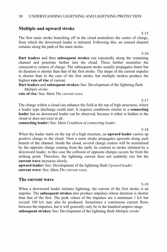
UNDERSTANDING LIGHTNING AND LIGHTNING PROTECTION30
Multiple and upward stroke 5-15
The first main stroke branching off in the cloud neutralises the centre of charge, from which the downward leader is initiated. Following this, an ionised channel remains along the path of the main stroke.
5-16Dart leaders and then subsequent strokes run repeatedly along the remaining channel and penetrate further into the cloud. These further neutralise the consecutive centres of charge. The subsequent stroke usually propagates faster but its duration is shorter than that of the first stroke. The shape of the current impulse is shorter than in the case of the first stroke, but multiple strokes produce the highest rate of rise of current. Dart leaders and subsequent strokes: See: Development of the lightning flash
Multiple stroke.rate of rise: See: Idem The current wave.
5-17The charge within a cloud can enhance the field at the top of high structures, where a leader type discharge could start. It requires conditions similar to a connecting
leader but no downward leader can be observed, because it either is hidden in the cloud or does not exist at all. connecting leader: See: Idem Condition of connecting leader.
5-18When the leader starts on the top of a high structure, an upward leader carries up positive charge to the cloud. Then a main stroke propagates upwards along each branch of the channel. Inside the cloud, several charge centres will be neutralised by the opposite charge coming from the earth. In contrast to stroke initiated by a downward leader, in this case the collision of opposite charges occurs far from the striking point. Therefore, the lightning current does not suddenly rise but the current wave increases slowly. upward leader: See: Development of the lightning flash Upward leader.current wave: See: Idem The current wave.
The current wave 5-19
When a downward leader initiates lightning, the current of the first stroke is an impulse. The subsequent strokes also produce impulses whose duration is shorter than that of the first. The peak values of the impulses are a minimum 1 kA but several 100 kA may also be produced. Sometimes a continuous current flows between the impulses, but it will generally only be in the hundred ampere range. subsequent strokes: See: Development of the lightning flash Multiple stroke.
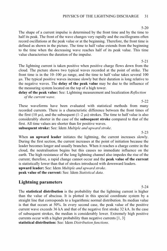
PHYSICS OF THE LIGHTNING DISCHARGE 31
5-20The shape of a current impulse is determined by the front time and by the time to half its peak. The front of the wave changes very rapidly and the oscillograms often record oscillations at the peak value or at the beginning. Therefore, the front time is defined as shown in the picture. The time to half value extends from the beginning to the time when the decreasing wave reaches half of its peak value. This time value characterises the duration of the impulse.
5-21The lightning current is taken positive when positive charge flows down from the cloud. The picture shows two typical waves recorded at the point of strike. The front time is in the 10–100 µs range, and the time to half value takes several 100 µs. The typical positive waves increase slowly but their duration is long relative to the negative waves. The delay of the peak value may be due to the influence of the measuring system located on the top of a high tower. delay of the peak value: See: Lightning measurement and localization Reflection
of the current wave.5-22
These waveforms have been evaluated with statistical methods from many recorded currents. There is a characteristic difference between the front times of the first (10 µs), and the subsequent (1–2 µs) strokes. The time to half value is also considerably shorter in the case of the subsequent stroke compared to that of the first. All time values are shorter than for positive waves. subsequent stroke: See: Idem Multiple and upward stroke.
5-23When an upward leader initiates the lightning, the current increases slowly. During the first section, the current increases at the point of initiation because the leader becomes longer and usually branches. When it reaches a charge centre in the cloud, the neutralisation begins but this causes no immediate influence on the earth. The high resistance of the long lightning channel also impedes the rise of the current; therefore, a rapid change cannot occur and the peak value of the current
is statistically lower than that of strokes introduced with downward leaders. upward leader: See: Idem Multiple and upward stroke.peak value of the current: See: Idem Statistical data.
Lightning parameters 5-24
The statistical distribution is the probability that the lightning current is higher than the value of abscissa. It is plotted in this special coordinate system by a straight line that corresponds to a logarithmic normal distribution. Its median value is that that occurs at 50%. In every second case, the peak value of the positive current wave exceeds 36 kA and that of the negative first stroke 32 kA. In the case of subsequent strokes, the median is considerably lower. Extremely high positive currents occur with a higher probability than negative currents [1, 3] statistical distribution: See: Idem Distribution functions.
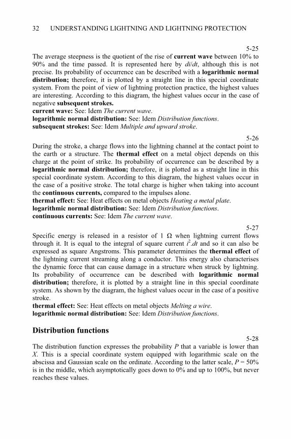
UNDERSTANDING LIGHTNING AND LIGHTNING PROTECTION32
5-25The average steepness is the quotient of the rise of current wave between 10% to 90% and the time passed. It is represented here by di/dt, although this is not precise. Its probability of occurrence can be described with a logarithmic normal
distribution; therefore, it is plotted by a straight line in this special coordinate system. From the point of view of lightning protection practice, the highest values are interesting. According to this diagram, the highest values occur in the case of negative subsequent strokes.
current wave: See: Idem The current wave.logarithmic normal distribution: See: Idem Distribution functions.subsequent strokes: See: Idem Multiple and upward stroke.
5-26During the stroke, a charge flows into the lightning channel at the contact point to the earth or a structure. The thermal effect on a metal object depends on this charge at the point of strike. Its probability of occurrence can be described by a logarithmic normal distribution; therefore, it is plotted as a straight line in this special coordinate system. According to this diagram, the highest values occur in the case of a positive stroke. The total charge is higher when taking into account the continuous currents, compared to the impulses alone. thermal effect: See: Heat effects on metal objects Heating a metal plate.logarithmic normal distribution: See: Idem Distribution functions.continuous currents: See: Idem The current wave.
5-27Specific energy is released in a resistor of 1 when lightning current flows through it. It is equal to the integral of square current i2.dt and so it can also be expressed as square Angstroms. This parameter determines the thermal effect of the lightning current streaming along a conductor. This energy also characterises the dynamic force that can cause damage in a structure when struck by lightning. Its probability of occurrence can be described with logarithmic normal
distribution; therefore, it is plotted by a straight line in this special coordinate system. As shown by the diagram, the highest values occur in the case of a positive stroke. thermal effect: See: Heat effects on metal objects Melting a wire.logarithmic normal distribution: See: Idem Distribution functions.
Distribution functions 5-28
The distribution function expresses the probability P that a variable is lower than X. This is a special coordinate system equipped with logarithmic scale on the abscissa and Gaussian scale on the ordinate. According to the latter scale, P = 50% is in the middle, which asymptotically goes down to 0% and up to 100%, but never reaches these values.
PHYSICS OF THE LIGHTNING DISCHARGE 33
5-29In the case of logarithmic normal distribution, the function is plotted with a straight line. Median value Xm represents 50% and its change shifts the diagram horizontally. The coefficient s determines the slope of the line. It depends on the deviation of distribution but it is not identical to it.
5-30The function and the diagram in black give the probability that the actual value is lower than X. In contrast, the blue marked formula and diagram give the probability of exceeding X. In practice, the latter version is mostly used.
5-31Here it is the Gaussian error function that changes from zero to one if the argument x goes from minus infinity to plus infinity, as shown by the diagram. It represents a normal distribution that takes the value 0.5 at x = 0 corresponding to the mean value. In addition to (x), there are also other error functions, which differ only in coefficients such as, erf(x) function.
5-32The formula of the logarithmic normal distribution uses the Gaussian error function, but with the logarithm of the variable. If X = Xm, the function becomes P = 0.5. The coefficient s depends on the deviation of distribution, as shown earlier. In a linear scaled diagram, this function is plotted with a curve going from zero to one if the argument X grows from zero to infinity.

CHAPTER 6
Curious lightning phenomena
6-0Each item of this menu may be selected by double-clicking on it. The program displays several topics when the following items are selected: All phenomena: from Properties of ball lightning to Discharge to the ionosphere.All over ball lightning: from Properties of ball lightning to Photos of ball
lightning.Ball lightning theories: to Theory of magnetic vortex.
Properties of ball lightning 6-1
Ball lightning is the most mysterious phenomenon of atmospheric electricity. There are some general problems: it unexpectedly appears anywhere, it can be seen only from a short distance, its lifetime is short and it has never been artificially reproduced. Regarding these properties, no measurements have been possible, and they are known only from the descriptions of eyewitnesses. Because of the sudden appearance of ball lightning, these descriptions are often uncertain. Some experts are sceptical of the actual existence of ball lightning, but with so many observations, it certainly should be accepted as a real phenomenon [8, 23].
Based on the lightning development, two processes could be suggested as the origins of ball lightning. When the channel of the downward leader is interrupted at high altitude, the ionised section left behind is separated and after contraction, the lightning event is presented as a ball. This process is shown on the left of the screen. Following the main discharge the channel cools unequally and an ionised region is retained. In this way, ball lightning can be created from the main discharge of lightning, as shown on the right. According to some observations, ball lightning has been sighted in absence of any lightning, or just in clear weather. These cases cannot be explained yet. downward leader: See: Physics of the lightning discharge Properties of a
downward leader.____________________________________________________Understanding Lightning and Lightning Protection T. Horváth © 2006 Research Studies Press Limited
UNDERSTANDING LIGHTNING AND LIGHTNING PROTECTION36
main discharge: See: Physics of the lightning discharge The main stroke.
6-2Descriptions of ball lightning mention almost every colour of the spectrum. Nevertheless, red and orange colours occur most frequently, which correspond to lower temperatures than those associated white and yellow. It is interesting that blue and violet colours have been reported with large diameter ball phenomena. These balls are similar to the corona discharge. Green ball lightning is rarely reported, and this cannot be explained. The size of the observed balls varies over a large range, which suggests that there are two types of the ball lightning. One of them is red or yellow and probably hot with a diameter of 5–50 cm, while the other is blue or violet with a considerably larger diameter and a lower temperature. corona discharge: See: Discharge processes in air Streamer discharge.
6-3Ball lightning moves slowly, with a velocity comparable to that of a walking man. According to some observations, ball lightning moved opposite to the direction wind but this statement should be treated with caution. Witnesses usually feel the wind where they are, even though the location of the event may be some distance away. During thunderstorms, turbulent winds are often generated, and the direction varies considerably at different locations.
6-4Many reports describe ball lightning having penetrated into a room through an open window, then sweeping around the walls and leaving the room through the same window. Although this path is surprising, it can be explained if the air circulation pattern inside the room is considered. For example, wind that scrapes the wall outside can produce a vortex inside.
6-5On the assumption, that ball lightning and the air move together, the path suggested may not be so surprising. Ball lightning probably consists of the same material as air, but it is in an excited state and radiates light. Consequently, the ball lightning can follow the air motion without any inertia.
6-6The lifetime of a ball lightning is probably one minute or less. Although witnesses have reported the event as being for much longer, it is possible that this was due their state of shock. Observers noted the decease of ball lightning, which may be because of two different processes. According to one process, the ball slowly contracted without any sound. Another version is the explosion of the ball accompanied with crack. In both cases, a brown cloud of gas was generated, which was accompanied by a pungent smell. This may be because of the generation of nitrogen oxide, which is produced during the discharge processes.
CURIOUS LIGHTNING PHENOMENA 37
Ball lightning theories 6-7
The most difficult problem to describe is the source of energy to the ball lightning during its lifetime. The thermal energy stored in the hot gas is only sufficient to contribute about a tenth of a second of the entire event, since the radiated energy (Prad) increases faster with the temperature (T) than that thermally stored in the gas. Two theoretical explanations are suggested for this. The first is that an external supply continuously recovers the radiated energy, and the second is a process of energy storage as an internal supply. Despite all efforts to adequately explain this phenomenon, no universally accepted theory yet exists. The following pictures will depict some suggested models, without any intention to give the final solution of this problem [8, 23].
6-8An external supply can continuously recover the energy needed to maintain the ball lightning and extend its duration. However, it is disappointing that there are very few physical processes, which adequately fulfil these requirements. The final solution fails in spite of some suggestions that considered many processes from the fine weather current to impact of anti-particles from outer space. Here, the resonance theory is shown as an example of this. fine weather current: See: Electric charges in the cloud Relation to the
ionosphere.
6-9There are many processes, which can result in the storage of energy, but it is usually not sufficient to recover the energy, which is needed to maintain the ball lightning for its entire duration. Many theories have been suggested, including special chemical state of the air gases, to the combustion of organic material of birds within the lightning path. Here, a quantum-mechanical theory and the theory of magnetic vortex are shown as typical examples.
Resonance theory 6-10
A Russian physicist, Kapitza, studied the problem of thermonuclear processes and found that high-frequency electromagnetic field can supply a hot plasma sphere when resonance exists between them. Suppose that during a thunderstorm such an electromagnetic field is also produced which could also supply the ball lightning. Although this phenomenon has only been observed in a laboratory, no such electromagnetic wave could be recorded in the required frequency range during thunderstorms. The frequency falls into the range of mobile phones and so nothing would obstruct the measurements. Another contradiction is that the required field exists in front of radar antennas, and so ball lightning would be expected to occur there but none have ever been observed.
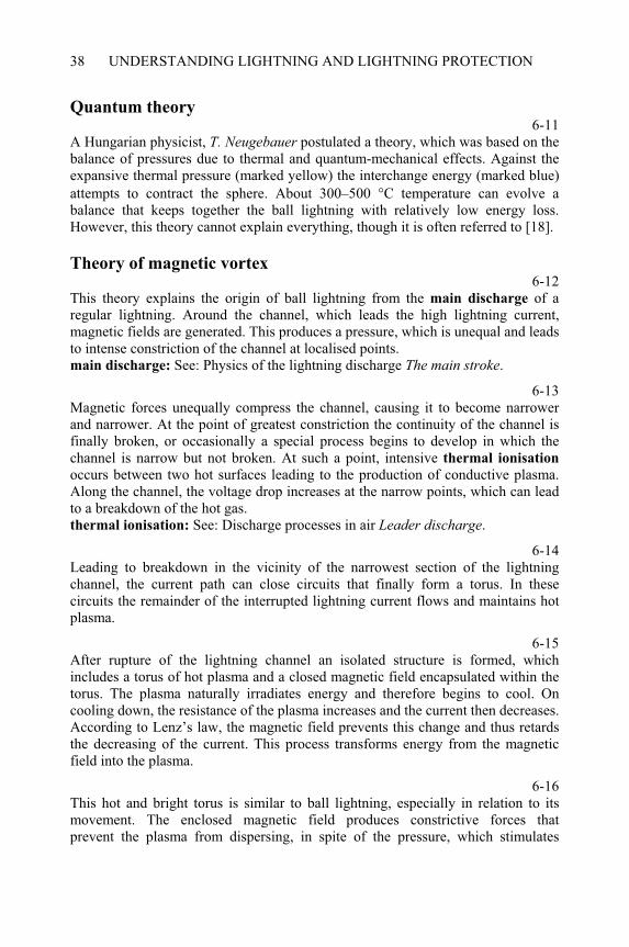
UNDERSTANDING LIGHTNING AND LIGHTNING PROTECTION38
Quantum theory 6-11
A Hungarian physicist, T. Neugebauer postulated a theory, which was based on the balance of pressures due to thermal and quantum-mechanical effects. Against the expansive thermal pressure (marked yellow) the interchange energy (marked blue) attempts to contract the sphere. About 300–500 °C temperature can evolve a balance that keeps together the ball lightning with relatively low energy loss. However, this theory cannot explain everything, though it is often referred to [18].
Theory of magnetic vortex 6-12
This theory explains the origin of ball lightning from the main discharge of a regular lightning. Around the channel, which leads the high lightning current, magnetic fields are generated. This produces a pressure, which is unequal and leads to intense constriction of the channel at localised points. main discharge: See: Physics of the lightning discharge The main stroke.
6-13Magnetic forces unequally compress the channel, causing it to become narrower and narrower. At the point of greatest constriction the continuity of the channel is finally broken, or occasionally a special process begins to develop in which the channel is narrow but not broken. At such a point, intensive thermal ionisation
occurs between two hot surfaces leading to the production of conductive plasma. Along the channel, the voltage drop increases at the narrow points, which can lead to a breakdown of the hot gas. thermal ionisation: See: Discharge processes in air Leader discharge.
6-14Leading to breakdown in the vicinity of the narrowest section of the lightning channel, the current path can close circuits that finally form a torus. In these circuits the remainder of the interrupted lightning current flows and maintains hot plasma.
6-15After rupture of the lightning channel an isolated structure is formed, which includes a torus of hot plasma and a closed magnetic field encapsulated within the torus. The plasma naturally irradiates energy and therefore begins to cool. On cooling down, the resistance of the plasma increases and the current then decreases. According to Lenz’s law, the magnetic field prevents this change and thus retards the decreasing of the current. This process transforms energy from the magnetic field into the plasma.
6-16This hot and bright torus is similar to ball lightning, especially in relation to its movement. The enclosed magnetic field produces constrictive forces that prevent the plasma from dispersing, in spite of the pressure, which stimulates
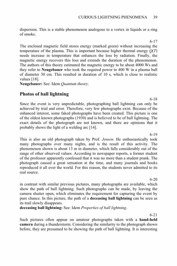
CURIOUS LIGHTNING PHENOMENA 39
dispersion. This is a stable phenomenon analogous to a vortex in liquids or a ring of smoke.
6-17The enclosed magnetic field stores energy (marked green) without increasing the temperature of the plasma. This is important because higher thermal energy Q(T)needs increase in temperature that enhances the loss by radiation. Finally, the magnetic energy recovers this loss and extends the duration of the phenomenon. The authors of this theory estimated the magnetic energy to be about 4000 Ws and they refer to Neugebauer who took the required power to 400 W in a plasma ball of diameter 30 cm. This resulted in duration of 10 s, which is close to realistic values [18]. Neugebauer: See: Idem Quantum theory.
Photos of ball lightning 6-18
Since the event is very unpredictable, photographing ball lightning can only be achieved by trial and error. Therefore, very few photographs exist. Because of the enhanced interest, some faked photographs have been created. This picture is one of the oldest known photographs (1930) and is believed to be of ball lightning. The exact details of the photograph are not known, and there are opinions that it probably shows the light of a welding arc [14].
6-19This is also an old photograph taken by Prof. Jensen. He enthusiastically took many photographs over many nights, and is the result of this activity. The phenomenon shown is about 13 m in diameter, which falls considerably out of the range of other observed values. According to newspaper reports, a former student of the professor apparently confessed that it was no more than a student prank. The photograph caused a great sensation at the time, and many journals and books reproduced it all over the world. For this reason, the students never admitted to its real source.
6-20in contrast with similar previous pictures, many photographs are available, which show the path of ball lightning. Such photographs can be made, by leaving the camera shutter open, which eliminates the requirement for capturing the event by pure chance. In this picture, the path of a deceasing ball lightning can be seen as its trail slowly disappears. deceasing ball lightning: See: Idem Properties of ball lightning.
6-21Such pictures often appear on amateur photographs taken with a hand-held
camera during a thunderstorm. Considering the similarity to the photograph shown before, they are presumed to be showing the path of ball lightning. It is interesting
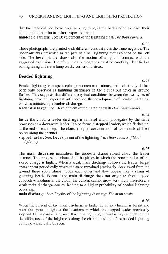
UNDERSTANDING LIGHTNING AND LIGHTNING PROTECTION40
that the trees did not move because a lightning in the background exposed their contour onto the film in a short exposure period. hand-held camera: See: Development of the lightning flash The Boys camera.
6-22These photographs are printed with different contrast from the same negative. The upper one was presented as the path of a ball lightning that exploded on the left side. The lower picture shows also the motion of a light in contrast with the suggested explosion. Therefore, such photographs must be carefully identified as ball lightning and not a lamp on the corner of a street.
Beaded lightning 6-23
Beaded lightning is a spectacular phenomenon of atmospheric electricity. It has been only observed as lightning discharges in the clouds but never as ground flashes. This suggests that different physical conditions between the two types of lightning have an important influence on the development of beaded lightning, which is initiated by a leader discharge.leader discharge: See: Development of the lightning flash Downward leader.
6-24Inside the cloud, a leader discharge is initiated and it propagates by the same processes as a downward leader. It also forms a stepped leader, which flashes up, at the end of each step. Therefore, a higher concentration of ions exists at these points along the channel. stepped leader: See: Development of the lightning flash Boys record of ideal
lightning.
6-25The main discharge neutralises the opposite charge stored along the leader channel. This process is enhanced at the places in which the concentration of the stored charge is higher. When a weak main discharge follows the leader, bright spots appear periodically where the steps remained previously. As viewed from the ground these spots almost touch each other and they appear like a string of gleaming beads. Because the main discharge does not originate from a good conductive medium in the cloud, the current cannot grow very high. Therefore, a weak main discharge occurs, leading to a higher probability of beaded lightning occurring. main discharge: See: Physics of the lightning discharge The main stroke.
6-26When the current of the main discharge is high, the entire channel is bright and blurs the spots of light at the locations in which the stepped leader previously stopped. In the case of a ground flash, the lightning current is high enough to hide the differences of the brightness along the channel and therefore beaded lightning could never, actually be seen.
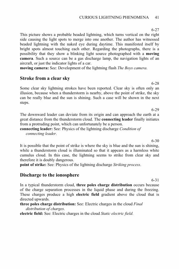
CURIOUS LIGHTNING PHENOMENA 41
6-27This picture shows a probable beaded lightning, which turns vertical on the right side causing the light spots to merge into one another. The author has witnessed beaded lightning with the naked eye during daytime. This manifested itself by bright spots almost touching each other. Regarding the photographs, there is a possibility that they show a blinking light source photographed with a moving
camera. Such a source can be a gas discharge lamp, the navigation lights of an aircraft, or just the indicator lights of a car. moving camera: See: Development of the lightning flash The Boys camera.
Stroke from a clear sky 6-28
Some clear sky lightning strokes have been reported. Clear sky is often only an illusion, because when a thunderstorm is nearby, above the point of strike, the sky can be really blue and the sun is shining. Such a case will be shown in the next steps.
6-29The downward leader can deviate from its origin and can approach the earth at a great distance from the thunderstorm cloud. The connecting leader finally initiates from a protruding point, which can unfortunately be a person. connecting leader: See: Physics of the lightning discharge Condition of
connecting leader.
6-30It is possible that the point of strike is where the sky is blue and the sun is shining, while a thunderstorm cloud is illuminated so that it appears as a harmless white cumulus cloud. In this case, the lightning seems to strike from clear sky and therefore it is doubly dangerous. point of strike: See: Physics of the lightning discharge Striking process.
Discharge to the ionosphere 6-31
In a typical thunderstorm cloud, three poles charge distribution occurs because of the charge separation processes in the liquid phase and during the freezing. These charges produce a high electric field gradient above the cloud that is directed upwards.three poles charge distribution: See: Electric charges in the cloud Final
distribution of charges.electric field: See: Electric charges in the cloud Static electric field.
UNDERSTANDING LIGHTNING AND LIGHTNING PROTECTION42
6-32The electric field drives positive ions upwards from the top of the thunderstorm cloud to the ionosphere. On progressing upwards, the air density decreases and the free path lengths of the ions become longer. The field can accelerate the ions to high speeds, which results in collisions either with each other or with neutral molecules. This mechanism leads to, free electrons that appear in the air. They can initiate discharge processes following sufficient acceleration. The discharge is similar to that in vacuum tubes but different from that in the air at ground level. ionosphere: See: Electric charges in the cloud Relation to the ionosphere.discharge processes: See: Discharge processes in air Discharges.
6-33Above the thunderstorm clouds discharges were recently recorded in the high atmosphere. These displayed low-luminous intensity for a short time; usually less than a second. A special high-speed camera and photo multiplier is necessary to photograph them. A typical form, known as a sprite is usually red and extends vertically. An example of this can be seen in this picture.
6-34Another type of sprite is similar to the flare shown in this picture. The vertical extension of such a discharge is sometimes 10 km and reaches the height of 50– 80 km above ground level.
6-35In addition to sprites, giant rings appeared as flashes at altitudes of 80–100 km, while the diameter also extended to similar dimensions. This picture shows a sector of the ring recorded by an electronic camera.
CHAPTER 7
Induced voltage
7-0Each item of this menu can be selected by double-clicking on it. The program displays several topics when the following items are selected: All calculations: from Ampère’s law to - distant stroke. Rectangular loops: from loop + infinite conductor to reduction to basic
components. Calculated examples: from direct stroke to distant stroke.
Ampère’s law 7-1
Current produces a magnetic field around the conductor in which it is flowing. The intensity of the field is expressed by the magnetic flux density B (Vs/m2), which is a vector directed tangential on a circle around the conductor. It is positive, if directed as a right-hand screw, moving in the direction of the current. In the picture, B is positive if it turns out of the screen. In the formula on the screen, µo = 4 ·10–7
Vs/Am is the magnetic permeability of vacuum. The angles A and B are positive if they turn anticlockwise as indicated here. The current flows from B to A.
7-2If the end B of the considered section of the conductor is placed as in this picture, the corresponding angle B becomes negative, because it turns clockwise in contrast to the previous case. The formula does not change, but sin B also reverses the sign.
7-3When the conductor is infinitely long in both directions, the angles become rectangular, and correspondingly, A = /2 and B = – /2.
7-4Since sin ( /2) = 1 and sin (– /2) = –1, the formula gives the well-known expression for the magnetic flux density around an infinitely long conductor.
____________________________________________________Understanding Lightning and Lightning Protection T. Horváth © 2006 Research Studies Press Limited
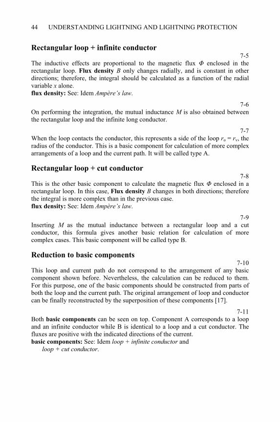
UNDERSTANDING LIGHTNING AND LIGHTNING PROTECTION44
Rectangular loop + infinite conductor 7-5
The inductive effects are proportional to the magnetic flux enclosed in the rectangular loop. Flux density B only changes radially, and is constant in other directions; therefore, the integral should be calculated as a function of the radial variable x alone. flux density: See: Idem Ampère’s law.
7-6On performing the integration, the mutual inductance M is also obtained between the rectangular loop and the infinite long conductor.
7-7When the loop contacts the conductor, this represents a side of the loop ro = rv, the radius of the conductor. This is a basic component for calculation of more complex arrangements of a loop and the current path. It will be called type A.
Rectangular loop + cut conductor 7-8
This is the other basic component to calculate the magnetic flux enclosed in a rectangular loop. In this case, Flux density B changes in both directions; therefore the integral is more complex than in the previous case. flux density: See: Idem Ampère’s law.
7-9Inserting M as the mutual inductance between a rectangular loop and a cut conductor, this formula gives another basic relation for calculation of more complex cases. This basic component will be called type B.
Reduction to basic components 7-10
This loop and current path do not correspond to the arrangement of any basic component shown before. Nevertheless, the calculation can be reduced to them. For this purpose, one of the basic components should be constructed from parts of both the loop and the current path. The original arrangement of loop and conductor can be finally reconstructed by the superposition of these components [17].
7-11Both basic components can be seen on top. Component A corresponds to a loop and an infinite conductor while B is identical to a loop and a cut conductor. The fluxes are positive with the indicated directions of the current. basic components: See: Idem loop + infinite conductor and
loop + cut conductor.
INDUCED VOLTAGE 45
7-12These four basic components can be constructed from the original loop and conductor. At the left top, two half loops form two basic components type B with the horizontal section of the conductor. The opposite fluxes balance one other and so the resulting value is zero. At top right, the upper half loop forms a basic component type B with the vertical section of the conductor. This flux is the resulting value in this half loop. In the lower half of the loop, the vertical section of the conductor induces a voltage. This situation can be replaced with a component A as shown bottom left, and with another type B as shown bottom right, with an opposite current balancing that on the left side.
Triangular loop 7-13
A polygonal loop can always be divided into triangles that represent basic elements for general use in the calculation of induced voltages. In the case of a common triangle, the three corners have different coordinates. Numbering the corners anticlockwise, a positive result of the calculation means that the flux is directed into the face. polygonal loop: See: Idem Polygonal loop.
7-14These are the general formulae used to calculate the flux enclosed in the triangular loop. They cannot be used if the r coordinates of two corners are equal, because division by zero would be necessary. The solution comes in the next step of the program.
7-15When two corners of the triangular loop are equally distanced from the conductor, this formula can more easily be deduced than from the previous general relations. However, a simple calculation will provide the same result.
Polygonal loop 7-16
In buildings, several conductive structures usually form three-dimensional loops. When the corners are turned around the straight current path into a meridian plane, a polygon is obtained. Its corners may be convex or concave, and the sides may cross each other without any contact but curved sides are out of consideration here. The polygonal loop can be divided into triangular loops that give the basic elements for calculation. triangular loops: See: Idem Triangular loop.
7-17When the corners of the polygon are numbered anticlockwise, the sign of the flux will be correctly obtained. As this picture shows, positive (red) and negative (green) fluxes follow each other. They must be finally summed according to their signs.
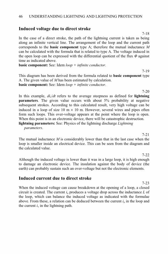
UNDERSTANDING LIGHTNING AND LIGHTNING PROTECTION46
Induced voltage due to direct stroke 7-18
In the case of a direct stroke, the path of the lightning current is taken as being along an infinite vertical line. The arrangement of the loop and the current path corresponds to the basic component type A; therefore the mutual inductance Mcan be calculated with the formula that is related to type A. The voltage induced in the open loop can be expressed with the differential quotient of the flux against time as indicated above. basic component: See: Idem loop + infinite conductor.
7-19This diagram has been derived from the formula related to basic component type A. The given value of M has been estimated by calculation. basic component: See: Idem loop + infinite conductor.
7-20In this example, div/dt refers to the average steepness as defined for lightning
parameters. The given value occurs with about 5% probability at negative subsequent strokes. According to this calculated result, very high voltage can be induced in a loop of size 10 m × 10 m. However, several wires and pipes often form such loops. This over-voltage appears at the point where the loop is open. When this point is in an electronic device, there will be catastrophic destruction. lightning parameters: See: Physics of the lightning discharge Lightning
parameters.
7-21The mutual inductance M is considerably lower than that in the last case when the loop is smaller inside an electrical device. This can be seen from the diagram and the calculated value.
7-22Although the induced voltage is lower than it was in a large loop, it is high enough to damage an electronic device. The insulation against the body of device (the earth) can probably sustain such an over-voltage but not the electronic elements.
Induced current due to direct stroke 7-23
When the induced voltage can cause breakdown at the opening of a loop, a closed circuit is created. The current io produces a voltage drop across the inductance L of the loop, which can balance the induced voltage as indicated with the formulae above. From these, a relation can be deduced between the current io in the loop and the current iv in the lightning path.
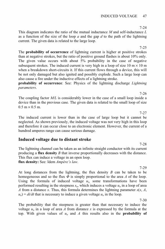
INDUCED VOLTAGE 47
7-24This diagram indicates the ratio of the mutual inductance M and self-inductance Las a function of the size of the loop a and the gap d to the path of the lightning current. The given data is related to the large loop.
7-25The probability of occurrence of lightning current is higher at positive strokes than at negative strokes, but the ratio of positive ground flashes is about 10% only. The given value occurs with about 5% probability in the case of negative subsequent strokes. The induced current is very high in a loop of size 10 m × 10 m when a breakdown short-circuits it. If this current flows through a device, this will be not only damaged but also ignited and possibly explode. Such a large loop can also cause a fire under the inductive effects of a lightning stroke. probability of occurrence: See: Physics of the lightning discharge Lightning parameters.
7-26The coupling factor M/L is considerably lower in the case of a small loop inside a device than in the previous case. The given data is related to the small loop of size 0.5 m × 0.5 m.
7-27The induced current is lower than in the case of large loop but it cannot be neglected. As shown previously, the induced voltage was not very high in this loop and therefore it can occur close to an electronic element. However, the current of a hundred amperes range can cause serious damage.
Induced voltage due to distant stroke 7-28
The lightning channel can be taken as an infinite straight conductor with its current producing a flux density B that inverse proportionally decreases with the distance. This flux can induce a voltage in an open loop. flux density: See: Idem Ampère’s law.
7-29At long distances from the lightning, the flux density B can be taken to be homogeneous and so the flux is simply proportional to the area A of the loop. Using the formula of induced voltage uo, some transformations have been performed resulting in the steepness sx, which induces a voltage uo in a loop of area A from a distance x. Thus, this formula determines the lightning parameter s(x, A,uo) = di/dt that is necessary to induce a given voltage uo in the loop.
7-30The probability that the steepness is greater than that necessary to induce the voltage uo in a loop of area A from distance x is expressed by the formula at the top. With given values of uo and A this results also in the probability of
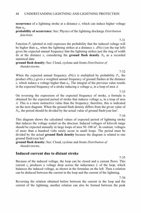
UNDERSTANDING LIGHTNING AND LIGHTNING PROTECTION48
occurrence of a lightning stroke at a distance x, which can induce higher voltage than uo.probability of occurrence: See: Physics of the lightning discharge Distribution
functions.
7-31Function Px (plotted in red) expresses the probability that the induced voltage will be higher than uo, when the lightning strikes at a distance x. dN(x) (on the top left) gives the expected annual frequency that the lightning strikes just the ring of width dx at the distance x, considering the ground flash density NG as a recorded statistical date. ground flash density: See: Cloud, cyclone and fronts Distribution of
thunderstorms.
7-32When the expected annual frequency dN(x) is multiplied by probability Px, the product dN(sx) gives a weighted annual frequency of ground flashes at the distance x, which induce a voltage higher than uo. The integral of the previous value results in the expected frequency of a stroke inducing a voltage uo in a loop of area A.
7-33On reversing the expression of the expected frequency of stroke, a formula is obtained for the expected period of stroke that induces voltage uo in a loop of area A. This is a more instructive value than the frequency; therefore, this is indicated on the next diagram. When the ground flash density differs from the given value of NG, the period should be divided by the actual value of ground flash/year km2.
7-34This diagram shows the calculated values of expected period of lightning stroke that induces the voltage scaled on the abscissa. Induced voltages of kilovolt range should be expected annually in large loops of area 50–100 m2. In contrast, voltages of more than a hundred volts rarely occur in small loops. The period must be divided by the actual ground flash density because the diagram is related to one ground flash/year km2.ground flash density: See: Cloud, cyclone and fronts Distribution of
thunderstorms.
Induced current due to distant stroke 7-35
Because of the induced voltage, the loop can be closed and a current flows. This current io produces a voltage drop across the inductance L of the loop, which balances the induced voltage, as shown in the formulae on the left. Then a relation can be deduced between the current in the loop and the current of the lightning.
7-36Reversing the relation obtained before between the current in the loop and the current of the lightning, another relation can also be formed between the peak
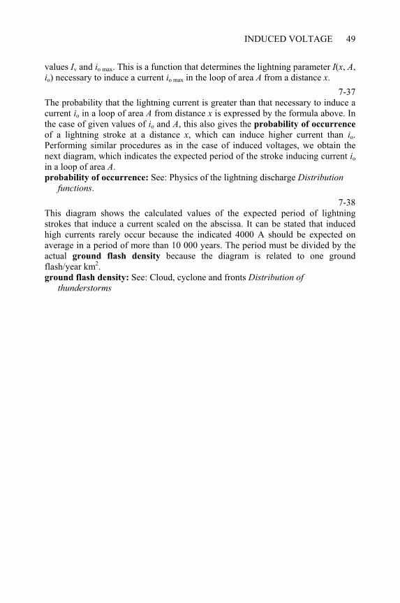
INDUCED VOLTAGE 49
values Iv and io max. This is a function that determines the lightning parameter I(x, A,io) necessary to induce a current io max in the loop of area A from a distance x.
7-37The probability that the lightning current is greater than that necessary to induce a current io in a loop of area A from distance x is expressed by the formula above. In the case of given values of io and A, this also gives the probability of occurrence
of a lightning stroke at a distance x, which can induce higher current than io.Performing similar procedures as in the case of induced voltages, we obtain the next diagram, which indicates the expected period of the stroke inducing current io
in a loop of area A.probability of occurrence: See: Physics of the lightning discharge Distribution
functions.
7-38This diagram shows the calculated values of the expected period of lightning strokes that induce a current scaled on the abscissa. It can be stated that induced high currents rarely occur because the indicated 4000 A should be expected on average in a period of more than 10 000 years. The period must be divided by the actual ground flash density because the diagram is related to one ground flash/year km2.ground flash density: See: Cloud, cyclone and fronts Distribution of
thunderstorms

CHAPTER 8
Dynamic forces due to lightning
8-0Each item of this menu can be selected by double-clicking on it. The program displays several topics when the following items are selected: Force on metal structures: from Parallel wires to Dynamic force on a console.Force due to lightning: from - on a rod struck on top to - on a metal plate.Force of leaded current: from - at inversion of wire to - on a tube.
Parallel wires 8-1
When a current i flows in a conductor that is in a magnetic field of flux density B, a force is produced as expressed by the formula on the right. This indicates that the cross product i × B is maximum if i and B are perpendicular to each other. On the other hand, the collinear vectors of i and B do not produce any force. The force vector is perpendicular to both i and B. It is directed as a right-handed screw moves, when vector i turns to vector B so that the angle of rotation is less than 180°.
8-2The current flowing along the conductor also produces a magnetic field, which coaxially encompasses the conductor. This gives another method to determine the direction of the force. Accordingly, the force is directed towards the direction where the magnetic field due to current i is opposite to the vector B.
8-3When there are two parallel conductors carrying current, both produce coaxial magnetic fields. The net force is the result of the interaction of the current i flowing in one conductor with the magnetic flux density B due to the current in the other conductor. If both currents have the same magnitudes and directions, the force F is proportional to i2. Considering the directions of the vectors of i and B, the forces
____________________________________________________Understanding Lightning and Lightning Protection T. Horváth © 2006 Research Studies Press Limited
UNDERSTANDING LIGHTNING AND LIGHTNING PROTECTION52
produce attraction between the conductors. It can be stated as a general rule that equally directed parallel currents attract each other. magnetic flux density: See: Induced voltage and current Ampère’s law.
8-4When the currents flowing in parallel conductors are in opposite directions, the magnitude of the force produced F is the same as in the previous case, but the direction changes. At the places of interactions, either current i or magnetic flux density B reverse their directions; therefore, the force is also reversed on both conductors. In contrast to the previous case, it can be stated as a general rule that oppositely directed parallel currents repel each other.
8-5These pictures show two versions of experiments to demonstrate the dynamic forces due to impulse current. On the left, the currents flow in the same directions in parallel conductors, whose cross sections are also illustrated. On the right, the conductor forms a loop and so the currents are oppositely directed in the parallel sections of the conductor.
8-6This experiment has been performed with an impulse current of peak value 377 kA. The dynamic forces pressed the conductors together and deformed the cylindrical cross sections as shown on the left. It should be considered that the current also heated up the conductor annealing its copper material and thus decreasing its strength [5].
8-7This picture does not illustrate the result of the experiment performed, but it shows the typical deformation of a loop. The impulse current produces repelling forces, which try to enlarge the loop. The annealed conductor can be fractured at highly curved points as a consequence of these forces.
Force due to lightning on a rod struck on top 8-8
When lightning strikes a vertical rod so that its channel falls into the same vertical line as the rod, no force will be produced. This happens because the magnetic field that encompasses the channel and the line do not cross the current path at any point. no force: See: Idem Parallel wires.
8-9When the lightning strikes a vertical rod at an angle to its top, the magnetic field crosses the current path in the rod and so dynamic force will be produced. It is higher if the angle between the axis of channel and the vertical is greater. This force is maximum at the top of the rod and decreases downwards.
DYNAMIC FORCES DUE TO LIGHTNING 53
8-10While dF/dx indicates the distribution of the force along the rod, the total force Floads the rod summing it from top to the bottom.
8-11The moment M increases from zero to a maximum along the rod from the top to the base. The indicated maximum value results in a bending load at the supporting point of the rod.
Force due to lightning on a horizontal wire 8-12
In this case, the magnetic field produced by the lightning channel affects the currents flowing along the wire in both directions. The formula of dF/dx is similar as that in the case of a rod, but the channel is orthogonal ( = /2) and the magnetic field interacts with half the lightning current.
8-13The total force F loading the wire on 2l long section between marked supporting points depends also on the diameter of the lightning channel, which can be estimated as d = 50–100 mm. diameter of the lightning channel: See: Physics of the lightning discharge
Propagation of main stroke.
8-14The maximum moment M is produced at the point of strike in the middle between the supporting points. This moment causes the highest bending load on the wire.
Force due to lightning on a metal plate 8-15
In this case, the magnetic field produced by the lightning channel affects the currents flowing radially in the plate. The forces can be expressed this time as pressure decreasing with distance from the point of strike.
8-16The total force F can be related to a round surface of radius x. This force depends also on the diameter of the lightning channel, which can be taken as d = 50–100 mm. diameter of the lightning channel: See: Physics of the lightning discharge
Propagation of main stroke.
8-17This picture shows the cover plate of a telescope gasholder destroyed by a lightning stroke. This aged metal plate was about 3-mm thick and supported the weight of the holder as a membrane. It was fastened around only the perimeter of the 54-m large cylindrical structure. The lightning hit this membrane like a hammer-stroke, inducing resonance vibration. The load probably increased at the nodes of the vibration and the brittle metal was fractured along an almost regular
UNDERSTANDING LIGHTNING AND LIGHTNING PROTECTION54
circle of about 30-m diameter. Then the ripped plate rolled back like the cover of a sardine tin and the gas slowly rose as a burning ball without explosion.
Force of leaded current at inversion of wire 8-18
This is a similar geometric situation to that when lightning strikes a rod at an angle on the top. One of the straight sections of the conductor corresponds to the lightning channel and the other to the rod. lightning strikes a rod: See: Idem Force due to lightning on a rod struck on top.
8-19In this case, the magnetic field of one section crosses the current path of the other section and so dynamic forces will be produced. It increases as , the angle of inclination, increases. On approaching the point of inclination, the force increases to infinity with zero radius of curvature. This cannot occur in the practice because the minimum is equal to the diameter of the wire. Nevertheless, the highest force loads the wire at this point and causes its fracture.
Force of leaded current on a tube 8-20
The current forms many parallel paths and flows equally directed along these paths. According to the general rule, as stated before, equally directed parallel currents attract each other. This statement is related to the parallel lightning path in the tube as well. general rule: See: Idem Parallel wires.
8-21The attractive forces produced between the parallel, unidirectional currents cause a pressure, which tries to crush the tube. A rain pipe often collapses owing to this pressure, but high lightning currents can compress strong pipes too.
Dynamic force on a console 8-22
When lightning strikes the end of a horizontally protruding console, the force can be expressed by the same formulas as in the case of a vertical rod struck sideways at an angle = /2. In the formula shown on the right, r stands for the radius of
lightning channel.vertical rod: See: Idem Force due to lightning - on a rod struck on top.radius of lightning channel: See: Physics of the lightning discharge Propagation
of main stroke.
8-23The force F is distributed along the console but it can be replaced by a concentrated force at a reduced distance lred from the supporting point. The concentrated force, F, must produce the same bending moment, M, as the
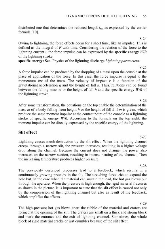
DYNAMIC FORCES DUE TO LIGHTNING 55
distributed one that determines the reduced length lred as expressed by the earlier formula [10].
8-24Owing to lightning, the force effects occur for a short time, like an impulse. This is defined as the integral of F with time. Considering the relation of the force to the lightning current i, the force impulse can be expressed by the specific energy W/Rof the lightning stroke. specific energy: See: Physics of the lightning discharge Lightning parameters.
8-25A force impulse can be produced by the dropping of a mass upon the console at the place of application of the force. In this case, the force impulse is equal to the momentum mv of the mass. The velocity of impact v is a function of the gravitational acceleration g and the height of fall h. Thus, relations can be found between the falling mass m or the height of fall h and the specific energy W/R of the lightning stroke.
8-26After some transformation, the equations on the top enable the determination of the mass m of a body falling from height h or the height of fall h if m is given, which produce the same moment impulse at the contact point of the console as a lightning stroke of specific energy W/R. According to the formula on the top right, the moment impulse can be directly expressed by the specific energy of the lightning.
Slit effect 8-27
Lightning causes much destruction by the slit effect. When the lightning channel creeps through a narrow slit, the pressure increases, resulting in a higher voltage drop along the channel. Because the current does not change, the power also increases on the narrow section, resulting in intense heating of the channel. Then the increasing temperature produces higher pressure.
8-28The previously described processes lead to a feedback, which results in a continuously growing pressure in the slit. The stretching force tries to expand the hole but, in the case when the material can sustain the load, the hot gas blows out through the aperture. When the pressure is high enough, the rigid material fractures as shown in the picture. It is important to state that the slit effect is caused not only by the compression of the lightning channel but also as result of the feedback, which amplifies the effects.
8-29The high-pressure hot gas blows apart the rubble of the material and craters are formed at the opening of the slit. The craters are small on a thick and strong block and mark the entrance and the exit of lightning channel. Sometimes, the whole block of rigid material cracks or just crumbles because of the slit effect.
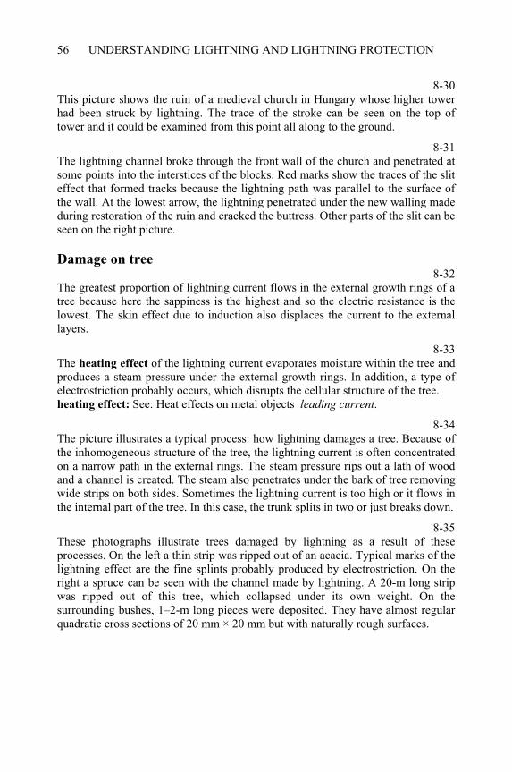
UNDERSTANDING LIGHTNING AND LIGHTNING PROTECTION56
8-30This picture shows the ruin of a medieval church in Hungary whose higher tower had been struck by lightning. The trace of the stroke can be seen on the top of tower and it could be examined from this point all along to the ground.
8-31The lightning channel broke through the front wall of the church and penetrated at some points into the interstices of the blocks. Red marks show the traces of the slit effect that formed tracks because the lightning path was parallel to the surface of the wall. At the lowest arrow, the lightning penetrated under the new walling made during restoration of the ruin and cracked the buttress. Other parts of the slit can be seen on the right picture.
Damage on tree 8-32
The greatest proportion of lightning current flows in the external growth rings of a tree because here the sappiness is the highest and so the electric resistance is the lowest. The skin effect due to induction also displaces the current to the external layers.
8-33The heating effect of the lightning current evaporates moisture within the tree and produces a steam pressure under the external growth rings. In addition, a type of electrostriction probably occurs, which disrupts the cellular structure of the tree. heating effect: See: Heat effects on metal objects leading current.
8-34The picture illustrates a typical process: how lightning damages a tree. Because of the inhomogeneous structure of the tree, the lightning current is often concentrated on a narrow path in the external rings. The steam pressure rips out a lath of wood and a channel is created. The steam also penetrates under the bark of tree removing wide strips on both sides. Sometimes the lightning current is too high or it flows in the internal part of the tree. In this case, the trunk splits in two or just breaks down.
8-35These photographs illustrate trees damaged by lightning as a result of these processes. On the left a thin strip was ripped out of an acacia. Typical marks of the lightning effect are the fine splints probably produced by electrostriction. On the right a spruce can be seen with the channel made by lightning. A 20-m long strip was ripped out of this tree, which collapsed under its own weight. On the surrounding bushes, 1–2-m long pieces were deposited. They have almost regular quadratic cross sections of 20 mm × 20 mm but with naturally rough surfaces.
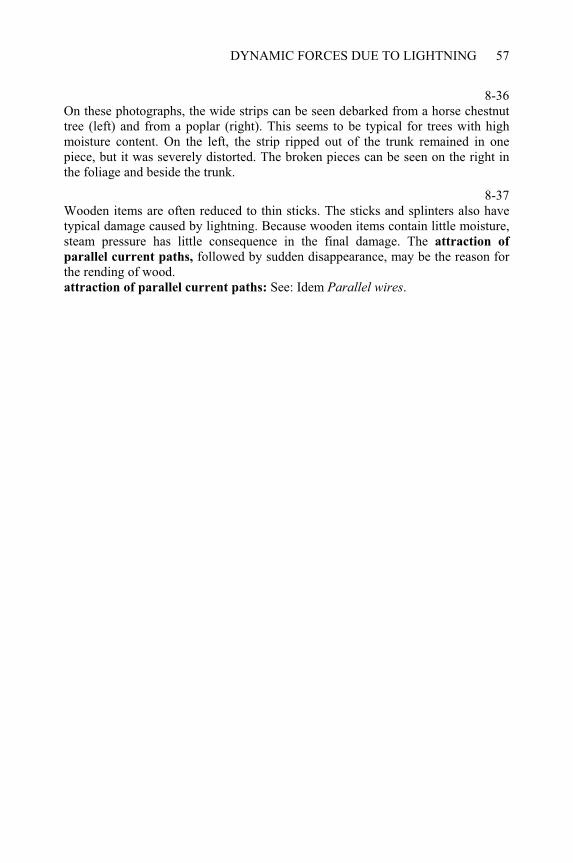
DYNAMIC FORCES DUE TO LIGHTNING 57
8-36On these photographs, the wide strips can be seen debarked from a horse chestnut tree (left) and from a poplar (right). This seems to be typical for trees with high moisture content. On the left, the strip ripped out of the trunk remained in one piece, but it was severely distorted. The broken pieces can be seen on the right in the foliage and beside the trunk.
8-37Wooden items are often reduced to thin sticks. The sticks and splinters also have typical damage caused by lightning. Because wooden items contain little moisture, steam pressure has little consequence in the final damage. The attraction of
parallel current paths, followed by sudden disappearance, may be the reason for the rending of wood. attraction of parallel current paths: See: Idem Parallel wires.

CHAPTER 9
Heat effects on metal objects
9-0Each item of this menu can be selected by double-clicking on it. The program displays several topics when the following items are selected: All items: from Heating a metal plate to Probability of melting.Heating a metal plate: from Heat convection to Crater and droplets.Change of temperature: from Thick plate to Melting the plate.Melting a wire: from at contact spot to leading current.
Heating a metal plate 9-1
When lightning strikes a metal plate, the hot plasma channel contacts the metal surface on a round spot of diameter about 50–100 mm. At this point, a voltage drop Usp occurs similar to the anode and cathode of an electric arc. This voltage drop is 10–20 V below the effect of lightning current.
9-2The lightning drives the current i through the contact spot and this determines the supplied power P with the voltage drop Usp. The generated thermal energy W can be calculated by the integration of the power with respect to time. The voltage drop can be assumed constant and so the supplied energy is proportional to the neutralised electric charge Q during the lightning discharge. neutralised electric charge: See: Physics of the lightning discharge Lightning
parameters.
9-3The supply of thermal energy continues during this time as long as the current is flowing. In the case of a positive lightning impulse, this time is less than 1 ms. The negative impulses are much shorter but they may occur repeatedly. In contrast, the time constants of leading thermal energy in metals fall into the range of 100 ms, which is much greater than the duration of the supply. Therefore, the heating ____________________________________________________Understanding Lightning and Lightning Protection T. Horváth © 2006 Research Studies Press Limited
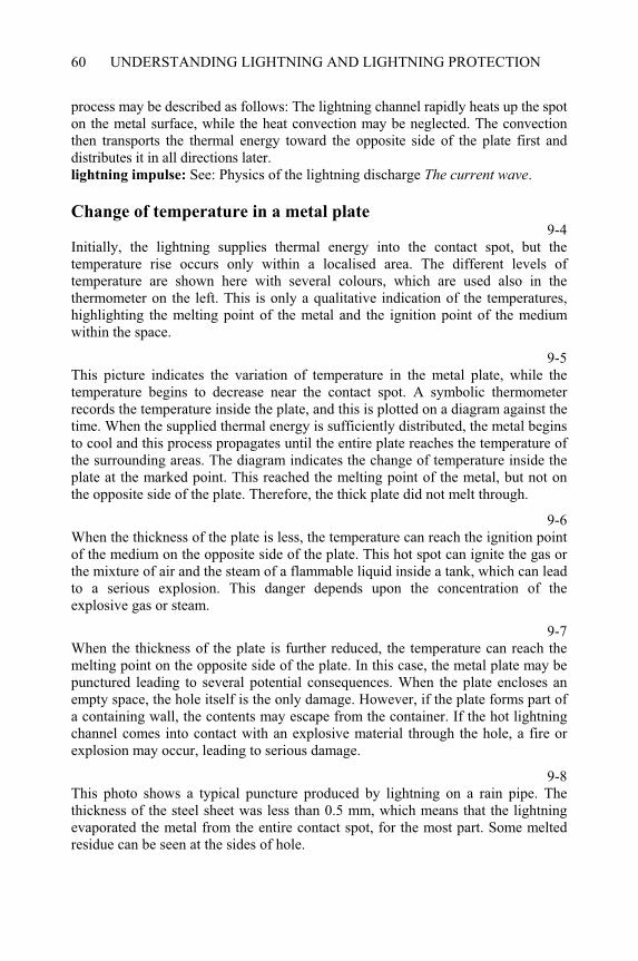
UNDERSTANDING LIGHTNING AND LIGHTNING PROTECTION60
process may be described as follows: The lightning channel rapidly heats up the spot on the metal surface, while the heat convection may be neglected. The convection then transports the thermal energy toward the opposite side of the plate first and distributes it in all directions later. lightning impulse: See: Physics of the lightning discharge The current wave.
Change of temperature in a metal plate 9-4
Initially, the lightning supplies thermal energy into the contact spot, but the temperature rise occurs only within a localised area. The different levels of temperature are shown here with several colours, which are used also in the thermometer on the left. This is only a qualitative indication of the temperatures, highlighting the melting point of the metal and the ignition point of the medium within the space.
9-5This picture indicates the variation of temperature in the metal plate, while the temperature begins to decrease near the contact spot. A symbolic thermometer records the temperature inside the plate, and this is plotted on a diagram against the time. When the supplied thermal energy is sufficiently distributed, the metal begins to cool and this process propagates until the entire plate reaches the temperature of the surrounding areas. The diagram indicates the change of temperature inside the plate at the marked point. This reached the melting point of the metal, but not on the opposite side of the plate. Therefore, the thick plate did not melt through.
9-6When the thickness of the plate is less, the temperature can reach the ignition point of the medium on the opposite side of the plate. This hot spot can ignite the gas or the mixture of air and the steam of a flammable liquid inside a tank, which can lead to a serious explosion. This danger depends upon the concentration of the explosive gas or steam.
9-7When the thickness of the plate is further reduced, the temperature can reach the melting point on the opposite side of the plate. In this case, the metal plate may be punctured leading to several potential consequences. When the plate encloses an empty space, the hole itself is the only damage. However, if the plate forms part of a containing wall, the contents may escape from the container. If the hot lightning channel comes into contact with an explosive material through the hole, a fire or explosion may occur, leading to serious damage.
9-8This photo shows a typical puncture produced by lightning on a rain pipe. The thickness of the steel sheet was less than 0.5 mm, which means that the lightning evaporated the metal from the entire contact spot, for the most part. Some melted residue can be seen at the sides of hole.
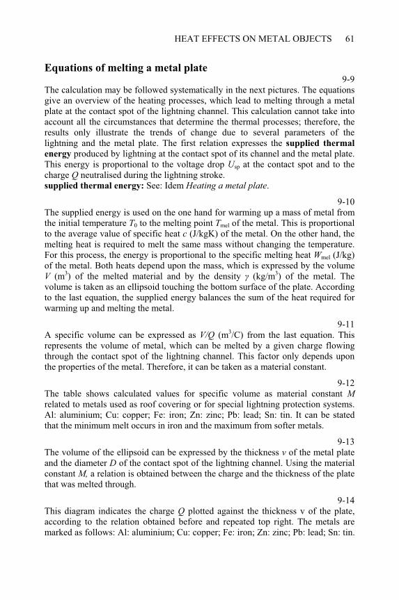
HEAT EFFECTS ON METAL OBJECTS 61
Equations of melting a metal plate 9-9
The calculation may be followed systematically in the next pictures. The equations give an overview of the heating processes, which lead to melting through a metal plate at the contact spot of the lightning channel. This calculation cannot take into account all the circumstances that determine the thermal processes; therefore, the results only illustrate the trends of change due to several parameters of the lightning and the metal plate. The first relation expresses the supplied thermal
energy produced by lightning at the contact spot of its channel and the metal plate. This energy is proportional to the voltage drop Usp at the contact spot and to the charge Q neutralised during the lightning stroke. supplied thermal energy: See: Idem Heating a metal plate.
9-10The supplied energy is used on the one hand for warming up a mass of metal from the initial temperature T0 to the melting point Tmel of the metal. This is proportional to the average value of specific heat c (J/kgK) of the metal. On the other hand, the melting heat is required to melt the same mass without changing the temperature. For this process, the energy is proportional to the specific melting heat Wmel (J/kg) of the metal. Both heats depend upon the mass, which is expressed by the volume V (m3) of the melted material and by the density (kg/m3) of the metal. The volume is taken as an ellipsoid touching the bottom surface of the plate. According to the last equation, the supplied energy balances the sum of the heat required for warming up and melting the metal.
9-11A specific volume can be expressed as V/Q (m3/C) from the last equation. This represents the volume of metal, which can be melted by a given charge flowing through the contact spot of the lightning channel. This factor only depends upon the properties of the metal. Therefore, it can be taken as a material constant.
9-12The table shows calculated values for specific volume as material constant Mrelated to metals used as roof covering or for special lightning protection systems. Al: aluminium; Cu: copper; Fe: iron; Zn: zinc; Pb: lead; Sn: tin. It can be stated that the minimum melt occurs in iron and the maximum from softer metals.
9-13The volume of the ellipsoid can be expressed by the thickness v of the metal plate and the diameter D of the contact spot of the lightning channel. Using the material constant M, a relation is obtained between the charge and the thickness of the plate that was melted through.
9-14This diagram indicates the charge Q plotted against the thickness v of the plate, according to the relation obtained before and repeated top right. The metals are marked as follows: Al: aluminium; Cu: copper; Fe: iron; Zn: zinc; Pb: lead; Sn: tin.
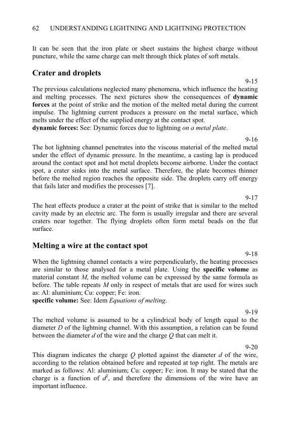
UNDERSTANDING LIGHTNING AND LIGHTNING PROTECTION62
It can be seen that the iron plate or sheet sustains the highest charge without puncture, while the same charge can melt through thick plates of soft metals.
Crater and droplets 9-15
The previous calculations neglected many phenomena, which influence the heating and melting processes. The next pictures show the consequences of dynamic
forces at the point of strike and the motion of the melted metal during the current impulse. The lightning current produces a pressure on the metal surface, which melts under the effect of the supplied energy at the contact spot. dynamic forces: See: Dynamic forces due to lightning on a metal plate.
9-16The hot lightning channel penetrates into the viscous material of the melted metal under the effect of dynamic pressure. In the meantime, a casting lap is produced around the contact spot and hot metal droplets become airborne. Under the contact spot, a crater sinks into the metal surface. Therefore, the plate becomes thinner before the melted region reaches the opposite side. The droplets carry off energy that fails later and modifies the processes [7].
9-17The heat effects produce a crater at the point of strike that is similar to the melted cavity made by an electric arc. The form is usually irregular and there are several craters near together. The flying droplets often form metal beads on the flat surface.
Melting a wire at the contact spot 9-18
When the lightning channel contacts a wire perpendicularly, the heating processes are similar to those analysed for a metal plate. Using the specific volume as material constant M, the melted volume can be expressed by the same formula as before. The table repeats M only in respect of metals that are used for wires such as: Al: aluminium; Cu: copper; Fe: iron. specific volume: See: Idem Equations of melting.
9-19The melted volume is assumed to be a cylindrical body of length equal to the diameter D of the lightning channel. With this assumption, a relation can be found between the diameter d of the wire and the charge Q that can melt it.
9-20This diagram indicates the charge Q plotted against the diameter d of the wire, according to the relation obtained before and repeated at top right. The metals are marked as follows: Al: aluminium; Cu: copper; Fe: iron. It may be stated that the charge is a function of d2, and therefore the dimensions of the wire have an important influence.
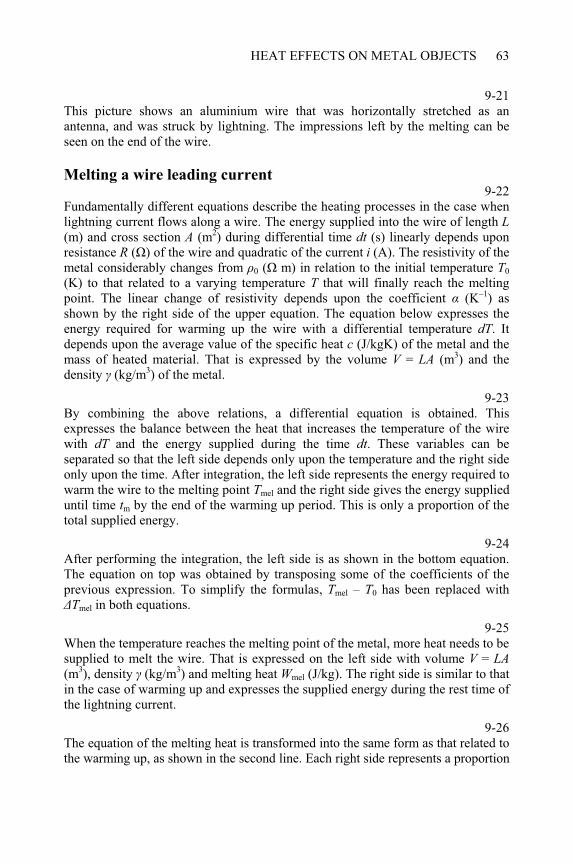
HEAT EFFECTS ON METAL OBJECTS 63
9-21This picture shows an aluminium wire that was horizontally stretched as an antenna, and was struck by lightning. The impressions left by the melting can be seen on the end of the wire.
Melting a wire leading current 9-22
Fundamentally different equations describe the heating processes in the case when lightning current flows along a wire. The energy supplied into the wire of length L(m) and cross section A (m2) during differential time dt (s) linearly depends upon resistance R ( ) of the wire and quadratic of the current i (A). The resistivity of the metal considerably changes from 0 ( m) in relation to the initial temperature T0
(K) to that related to a varying temperature T that will finally reach the melting point. The linear change of resistivity depends upon the coefficient (K–1) as shown by the right side of the upper equation. The equation below expresses the energy required for warming up the wire with a differential temperature dT. It depends upon the average value of the specific heat c (J/kgK) of the metal and the mass of heated material. That is expressed by the volume V = LA (m3) and the density (kg/m3) of the metal.
9-23By combining the above relations, a differential equation is obtained. This expresses the balance between the heat that increases the temperature of the wire with dT and the energy supplied during the time dt. These variables can be separated so that the left side depends only upon the temperature and the right side only upon the time. After integration, the left side represents the energy required to warm the wire to the melting point Tmel and the right side gives the energy supplied until time tm by the end of the warming up period. This is only a proportion of the total supplied energy.
9-24After performing the integration, the left side is as shown in the bottom equation. The equation on top was obtained by transposing some of the coefficients of the previous expression. To simplify the formulas, Tmel – T0 has been replaced with
Tmel in both equations.
9-25When the temperature reaches the melting point of the metal, more heat needs to be supplied to melt the wire. That is expressed on the left side with volume V = LA(m3), density (kg/m3) and melting heat Wmel (J/kg). The right side is similar to that in the case of warming up and expresses the supplied energy during the rest time of the lightning current.
9-26The equation of the melting heat is transformed into the same form as that related to the warming up, as shown in the second line. Each right side represents a proportion
UNDERSTANDING LIGHTNING AND LIGHTNING PROTECTION64
of the current impulse, namely, on top until the time tm of reaching the melting point and below until the end of the impulse (infinity).
9-27Summing both equations, the right side represents the total specific energy W/Rdue to the lightning stroke. The left side is a function of A2 and depends upon the cross section of the wire. The other coefficients are either constants or determined by the metal. These can be unified into the factor K, which represents the metal as a material constant. specific energy: See: Physics of the lightning discharge Lightning parameters.
9-28After several algebraic transformations, the factor K is expressed as a material constant that determines the melting of a wire conducting the lightning current. It is, therefore, important to note that this factor changes with the fourth power of the diameter of wire. So even a small decrease of the diameter of any conductor should be avoided. There is also a characteristic contrast to melting at the contact spot ofthe lightning channel. A copper (Cu) wire can sustain the highest load, followed by aluminium (Al). Because of high resistivity, iron (Fe) wire is the worst from this point of view. melting at contact spot: See: Idem Melting a wire - at contact spot.
9-29This diagram shows the specific energy W/R plotted against the diameter d of the wire, which conducts the lightning current. The metals are marked as follows: Al: aluminium; Cu: copper; Fe: iron. It can be seen that the specific energy decreases in the ratio one to five if the diameter changes from 6 mm– 4 mm.
Probability of melting 9-30
To melt through a metal plate, a given charge must be flowing in the contact spot of the lightning channel. With the application of the statistical distribution of the lightning charge, the probability of the occurrence of melting can be estimated as plotted in this diagram. Metals are marked here and in the next diagram as follows: Al: aluminium; Cu: copper; Fe: iron; Zn: zinc; Pb: lead; Sn: tin. melt through a metal plate: See: Idem Melting the plate.statistical distribution: See: Physics of the lightning discharge Lightning
parameters.9-31
To melt a wire at the point of strike, a given charge must be flowing through the contact spot of the lightning channel. With the application of the statistical distribution to the lightning charge, the probability of occurrence can be estimated as plotted in the diagram, marking metals as first. melt a wire: See: Idem Melting a wire - at contact spot.
HEAT EFFECTS ON METAL OBJECTS 65
9-32For melting a wire by leaded current, a given specific energy is required. With the application of the statistical distribution of specific energy, the probability of the occurrence of melting can be estimated as plotted in the diagram, marking metals as first. melting a wire by leaded current: See: Idem leading current.statistical distribution: See: Physics of the lightning discharge Lightning parameters.

CHAPTER 10
Lightning attachment
10-0Each item of this menu can be selected by double-clicking on it. The program displays several topics when the following items are selected: The striking process: from The orientation of lightning to Calculation of expected frequency.The orientation of lightning: from Point of orientation to Distribution and density functions.The expected frequency of stroke: from The principle of calculation to Calculation of expected frequency.
Point of orientation 10-1
A downward leader can start anywhere from the thunderstorm cloud without consideration of objects on the earth. It only turns toward the striking point at lower levels.
10-2The downward leader approaches the earth along a zigzag path, with branches that are not shown here. The earth structures do not influence this section of the path, except when their heights are commensurate to the height of the cloud base.
10-3The point of strike is determined when the first connecting leader starts upward from the earth or from any earth structure against the approaching leader. The orientation point will be called that point where the head of the leader is when the connecting leader starts. In the case of several connecting leaders, different striking points can occur but the orientation point should not change. connecting leader: See: Physics of the lightning discharge + Condition of
connecting leader.
____________________________________________________Understanding Lightning and Lightning Protection T. Horváth © 2006 Research Studies Press Limited
UNDERSTANDING LIGHTNING AND LIGHTNING PROTECTION68
The striking distance 10-4
The intertwining of lightning paths verifies that the downward leader and the connecting leader join at the place marked by the red arrow. This is at a height of about 20 m. Based on this data, it can be estimated that the orientation distance will be about 40 m in the case of this stroke [7].
10-5The orientation distance is the gap between the orientation point and the expected point of strike. When several points of strike are expected, different orientation distances may be associated with each of them. A well-known term is the striking distance, the definition of which is slightly different to that of the orientation distance, but their functions are the same and therefore, they will both be used. From the starting condition of a connecting leader, it follows that the orientation distance r depends on the lightning current I. This is usually assumed as a power function of exponent p = 1.2–2.0. rm and Im are the median values. starting condition: See: Physics of the lightning discharge + Striking process.
10-6The last equation expressed the probability that the actual lightning current is less than the value I, according to the distribution function of the lightning
parameters. Replacing I with r in this function, exponent p becomes a coefficient before the logarithm. The changed members are highlighted yellow in the new function, which expresses the probability that the actual orientation distance is less than the value r, if rm is the median value. lightning parameters: See: Physics of the lightning discharge + Lightning parameters.
Distribution and density functions 10-7
In the case of orientation distance, the probability of occurrence can be expressed by logarithmic normal distribution. This gives the value 0.5 (50%) if r = rm and so every second distance is less then the median value. logarithmic normal distribution: See: Physics of the lightning discharge +
Distribution functions.
10-8As it has been previously shown, the density function of orientation distance is the derivative of its distribution function. This expresses the probability that the orientation distance falls into a unit wide band of the given distance r. It can be stated that small and very big values occur with a low probability, approaching zero. The maximum is at a smaller orientation distance than the median value rm.This function will be permanently used to further calculations with coefficient p = 1.5. The statistical distribution of lightning current determines the constants Im
and s depending upon the polarity.
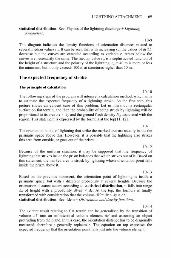
LIGHTNING ATTACHMENT 69
statistical distribution: See: Physics of the lightning discharge + Lightning parameters.
10-9This diagram indicates the density functions of orientation distances related to several median values rm. It can be seen that with increasing rm, the values of dP/drdecrease but the curves are extended according to variable r. Areas below the curves are necessarily the same. The median value rm is a sophisticated function of the height of a structure and the polarity of the lightning. rm = 40 m is more or less the minimum, but it only exceeds 100 m at structures higher than 50 m.
The expected frequency of stroke
The principle of calculation
10-10The following steps of the program will interpret a calculation method, which aims to estimate the expected frequency of a lightning stroke. As the first step, this picture shows an evident case of this problem. Let us mark out a rectangular surface on flat terrain, and then the probability of being struck by lightning will be proportional to its area x × y and the ground flash density NG associated with the region. This statement is expressed by the formula at the top[11, 12].
10-11The orientation points of lightning that strike the marked area are usually inside the prismatic space above this. However, it is possible that the lightning also strikes this area from outside, or goes out of the prism.
10-12Because of the uniform situation, it may be supposed that the frequency of lightning that strikes inside the prism balances that which strikes out of it. Based on this statement, the marked area is struck by lightning whose orientation point falls inside the prism above it.
10-13Based on the previous statement, the orientation point of lightning is inside a prismatic space, but with a different probability at several heights. Because the orientation distance occurs according to statistical distribution, it falls into range
z of height with a probability dP/dr × z. At the top, the formula is finally transformed with consideration that the volume V = x × y × z.statistical distribution: See: Idem + Distribution and density functions.
10-14The evident result relating to flat terrain can be generalised by the transition of volume V into an infinitesimal volume element dV and assuming an object protruding from the plane. In this case, the orientation distance has to be diagonally measured; therefore r generally replaces z. The equation on top expresses the expected frequency that the orientation point falls just into the volume element.
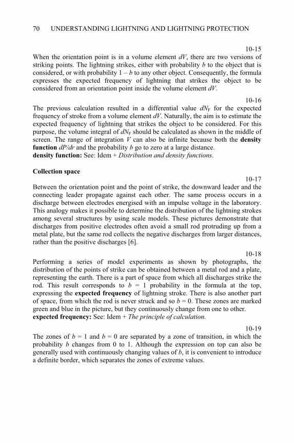
UNDERSTANDING LIGHTNING AND LIGHTNING PROTECTION70
10-15When the orientation point is in a volume element dV, there are two versions of striking points. The lightning strikes, either with probability b to the object that is considered, or with probability 1 – b to any other object. Consequently, the formula expresses the expected frequency of lightning that strikes the object to be considered from an orientation point inside the volume element dV.
10-16The previous calculation resulted in a differential value dNF for the expected frequency of stroke from a volume element dV. Naturally, the aim is to estimate the expected frequency of lightning that strikes the object to be considered. For this purpose, the volume integral of dNF should be calculated as shown in the middle of screen. The range of integration V can also be infinite because both the density
function dP/dr and the probability b go to zero at a large distance. density function: See: Idem + Distribution and density functions.
Collection space
10-17Between the orientation point and the point of strike, the downward leader and the connecting leader propagate against each other. The same process occurs in a discharge between electrodes energised with an impulse voltage in the laboratory. This analogy makes it possible to determine the distribution of the lightning strokes among several structures by using scale models. These pictures demonstrate that discharges from positive electrodes often avoid a small rod protruding up from a metal plate, but the same rod collects the negative discharges from larger distances, rather than the positive discharges [6].
10-18Performing a series of model experiments as shown by photographs, the distribution of the points of strike can be obtained between a metal rod and a plate, representing the earth. There is a part of space from which all discharges strike the rod. This result corresponds to b = 1 probability in the formula at the top, expressing the expected frequency of lightning stroke. There is also another part of space, from which the rod is never struck and so b = 0. These zones are marked green and blue in the picture, but they continuously change from one to other. expected frequency: See: Idem + The principle of calculation.
10-19The zones of b = 1 and b = 0 are separated by a zone of transition, in which the probability b changes from 0 to 1. Although the expression on top can also be generally used with continuously changing values of b, it is convenient to introduce a definite border, which separates the zones of extreme values.
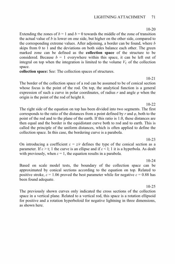
LIGHTNING ATTACHMENT 71
10-20Extending the zones of b = 1 and b = 0 towards the middle of the zone of transition the actual value of b is lower on one side, but higher on the other side, compared to the corresponding extreme values. After adjoining, a border can be found, where bskips from 0 to 1 and the deviations on both sides balance each other. The green marked zone can be defined as the collection space of the structure to be considered. Because b = 1 everywhere within this space, it can be left out of integral on top when the integration is limited to the volume VC of the collection space.collection space: See: The collection spaces of structures.
10-21The border of the collection space of a rod can be assumed to be of conical section whose focus is the point of the rod. On top, the analytical function is a general expression of such a curve in polar coordinates, of radius r and angle when the origin is the point of the rod of height h.
10-22The right side of the equation on top has been divided into two segments. The first corresponds to the ratio of the distances from a point defined by r and , both to the point of the rod and to the plane of the earth. If this ratio is 1.0, these distances are then equal and the border is the equidistant curve both to rod and to earth. This is called the principle of the uniform distances, which is often applied to define the collection space. In this case, the bordering curve is a parabola.
10-23On introducing a coefficient = z/r defines the type of the conical section as a parameter. If > t; 1 the curve is an ellipse and if < l; 1 it is a hyperbola. As dealt with previously, when = 1, the equation results in a parabola.
10-24Based on scale model tests, the boundary of the collection space can be approximated by conical sections according to the equation on top. Related to positive stroke, = 1.06 proved the best parameter while for negative = 0.88 has been found adequate.
10-25The previously shown curves only indicated the cross sections of the collection space in a vertical plane. Related to a vertical rod, this space is a rotation ellipsoid for positive and a rotation hyperboloid for negative lightning in three dimensions, as shown here.
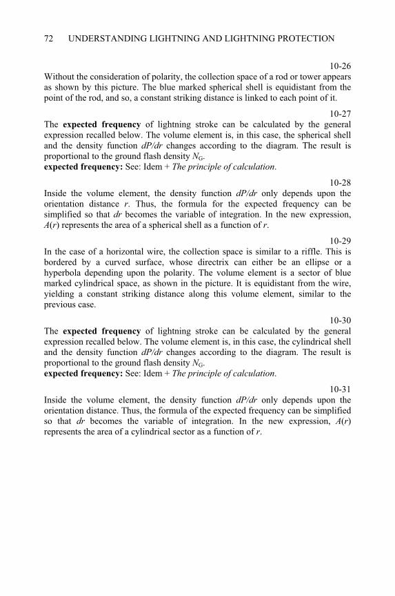
UNDERSTANDING LIGHTNING AND LIGHTNING PROTECTION72
10-26Without the consideration of polarity, the collection space of a rod or tower appears as shown by this picture. The blue marked spherical shell is equidistant from the point of the rod, and so, a constant striking distance is linked to each point of it.
10-27The expected frequency of lightning stroke can be calculated by the general expression recalled below. The volume element is, in this case, the spherical shell and the density function dP/dr changes according to the diagram. The result is proportional to the ground flash density NG.expected frequency: See: Idem + The principle of calculation.
10-28Inside the volume element, the density function dP/dr only depends upon the orientation distance r. Thus, the formula for the expected frequency can be simplified so that dr becomes the variable of integration. In the new expression, A(r) represents the area of a spherical shell as a function of r.
10-29In the case of a horizontal wire, the collection space is similar to a riffle. This is bordered by a curved surface, whose directrix can either be an ellipse or a hyperbola depending upon the polarity. The volume element is a sector of blue marked cylindrical space, as shown in the picture. It is equidistant from the wire, yielding a constant striking distance along this volume element, similar to the previous case.
10-30The expected frequency of lightning stroke can be calculated by the general expression recalled below. The volume element is, in this case, the cylindrical shell and the density function dP/dr changes according to the diagram. The result is proportional to the ground flash density NG.expected frequency: See: Idem + The principle of calculation.
10-31Inside the volume element, the density function dP/dr only depends upon the orientation distance. Thus, the formula of the expected frequency can be simplified so that dr becomes the variable of integration. In the new expression, A(r)represents the area of a cylindrical sector as a function of r.
CHAPTER 11
Collection spaces of structures
11-0Each item of this menu can be selected by double-clicking on it. The program displays several topics when the following items are selected: The principle of collection space: from Dividing the collection space to Lightning
rod on tower.Air terminations of blockhouse: from Network of long meshes to Regularly
arranged rods. - Only the air terminations. Comparison of collection spaces: from Network of long meshes to Regularly
arranged rods. - Only the collection spaces.
The principle of collection space
11-1The principle of construction of the collection space will be first dealt with as a two-dimensional problem and called collection zone. In a vertical plane, a point represents either the top of a vertical rod or the cross section of a horizontal wire. The border of collection zone is a conical section whose focus is the point mentioned before. This is marked red in the picture. border of a collection zone: See: Lightning attachment + Collection space.
11-2A part of the collection space is nearer to the point than a minimum striking distance rmin, which is associated with the lightning current Imin. More often than not, it can be assumed that a stroke of current lower than Imin cannot cause any damage. In the case of high voltage lines, this is evident and depends upon the insulation level. Concerning other structures, such a minimum cannot be exactly defined, but an acceptable limit is Imin = 1 kA, because any discharge carrying a lower current does not represent a true lightning stroke. associated with the lightning current: See: Lightning attachment + Striking
distance.____________________________________________________Understanding Lightning and Lightning Protection T. Horváth © 2006 Research Studies Press Limited
UNDERSTANDING LIGHTNING AND LIGHTNING PROTECTION74
Dividing the collection space 11-3
This has to be considered when there is another point that also has a collection zone. Because of the shifted position of the blue marked point, the corresponding collection zone is also moved as illustrated with its contour lines in the picture.
11-4Taking the red marked point to be the object of consideration, the left sides of the collection zones can be removed, because no lightning stroke should be expected to occur on the red marked point from this side. The basis of this statement is that each point on the left side of the collection zone is evidently closer either to the blue marked point or to the ground surface than the red marked point.
11-5When the blue marked point represents the air termination and the red marked point the object to be protected, then the red zone is the remainder of the original collection zone. The boundary between the collection zones of both points is their perpendicular bisector.
Two conductors 11-6
After removing the construction lines, the red marked zone represents the collection zone of the object to be protected. A lightning stroke should be expected in this case only if the orientation point is inside this zone. The air termination produces a protective effect by decreasing the collection zone of the object to be protected. A comparison with the first picture demonstrates the considerable decrease of the collection zone caused by the air termination.
11-7The previous two-dimensional picture only represented the principle of the collection zone as a cross section in a vertical plain. This picture must be transformed into a three-dimensional form in order to create a real collection space. By creating the reflected image of the previous picture, and then shifting it along a straight line, the collection space of two conductors and a protective wire can be visualised. This corresponds to a simple transmission line [4]
11-8With the indicated sizes, the expected frequency can be expressed by the formula shown on the right. It is similar to that obtained earlier, related to one horizontal conductor. However, there is a fundamental difference that the expected frequency is related to the lightning which strikes the conductors to be protected, in spite of the protective wire. This result is usually called expected frequency of shielding failure, and expresses the protective effect due to an earthed wire. Because it is proportional to the length of the line, the number of strokes/100 km per year is regularly used [11, 12]
COLLECTION SPACES OF STRUCTURES 75
expected frequency: See: Lightning attachment + Calculation of expected frequency.
Lightning rod on tower11-9
Another typical structure is a cylindrical building that is protected with a vertical rod on the roof. In this case, the object to be protected is the circular flange of the roof.
11-10The vertical section of the collection space results in the collection zone of two points, similar to that dealt with in connection with the previous principles. In this picture, the blue marked point represents the top of the rod and the red marked point corresponds to the flange of the roof. collection zone: See: Idem + Dividing the collection space.
11-11Because the tower forms an axially symmetrical structure, its collection space can be created by rotation around the axis of the rod and tower. This picture shows half of this space. During the rotation, the blue marked point remains in the axis, while the red marked point draws the flange of the roof.
11-12With the indicated sizes, the expected frequency can be expressed by the formula shown on the right. This is the general expression deduced earlier regarding the lightning stroke to a rod or tower. However, it now gives the expected frequency of lightning, which strikes the flange of the tower in spite of the air termination rod. This result is the expected frequency of shielding failure, and expresses the protective effect produced by the lightning rod [12] expected frequency: See: Lightning attachment + Calculation of expected
frequency.
Air terminations of blockhouse 11-13
On the flat roof of a blockhouse, several air termination systems can be used. One type consists of parallel wires, as shown here. The external conductors are above the edges of the roof. The perpendicular ends of the roof are not equipped with any conductor, and so, they must be taken as unprotected. The unit element of this system is a part of a roof between two conductors, which will be called the mesh.
11-14When the air termination system consists of three parallel wires as show here, the number of meshes is two. In the previous case, this number was one.
UNDERSTANDING LIGHTNING AND LIGHTNING PROTECTION76
11-15On progressing this argument, the number of meshes always becomes double the previous value. In actual fact, the air termination consists of four meshes.
11-16On further doubling the number of meshes, the air termination consists of eight meshes that correspond to nine parallel conductors. The protective effect of an air termination system evidently increases with the growing number of meshes and conductors.
11-17One type of air termination system consists of perpendicular conductors that form square meshes as shown here. Using this on the flat roof of a blockhouse, the external conductors are always just above the edges of the roof. The unit element of this system is taken as a quadratic mesh. This type of air termination produces protection for all edges of the roof.
11-18When two conductors are additionally given to the air termination system as shown here, the number of meshes becomes double in both directions. Thus, the total number of meshes increases fourfold.
11-19By progressing further, the number of meshes always becomes double in both directions than that in the previous case. The total number of meshes increases fourfold when each mesh width is cut in half.
11-20On further dividing all mesh widths in two, the air termination consists of eight meshes in both directions. This corresponds to nine crossing conductors. The protective effect of the air termination system evidently increases with the growing number of meshes and conductors.
11-21The flat roof of a blockhouse can be protected by vertical rods, which are regularly positioned into the corners of imaginary square meshes, as shown here. The height of each rod is the same. The external rods are always just on the edges or at the corners of the roof. The unit element of this system is taken as a quadratic mesh between four rods at the corners. This type of air termination produces protective effects for all edges of the roof, but it never gives full protection.
11-22When the number of rods is increased so that the distances between them become half the previous one, the number of imaginary meshes double in both directions, as shown here. The total number of meshes increases to four, and the number of rods to nine.
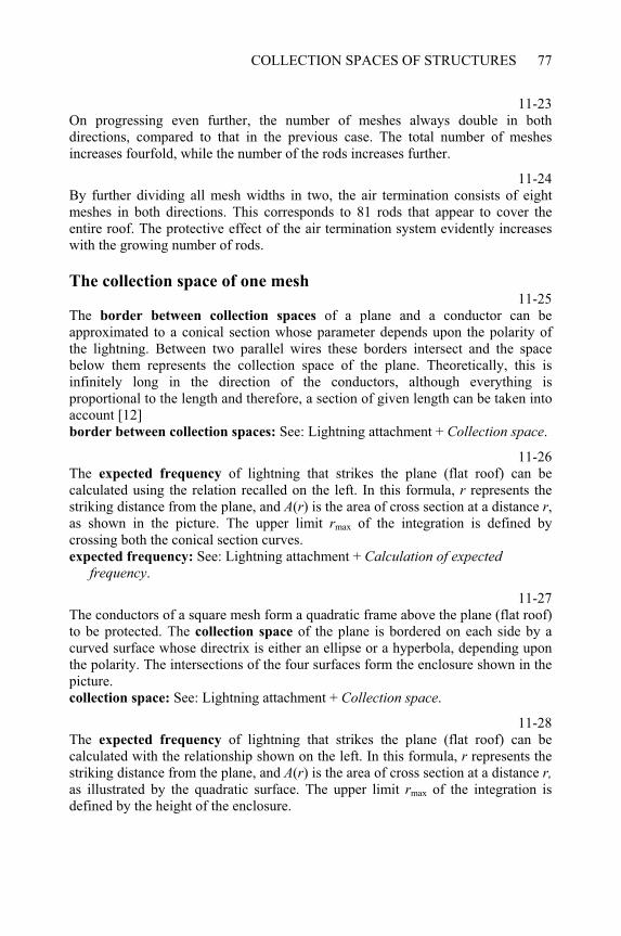
COLLECTION SPACES OF STRUCTURES 77
11-23On progressing even further, the number of meshes always double in both directions, compared to that in the previous case. The total number of meshes increases fourfold, while the number of the rods increases further.
11-24By further dividing all mesh widths in two, the air termination consists of eight meshes in both directions. This corresponds to 81 rods that appear to cover the entire roof. The protective effect of the air termination system evidently increases with the growing number of rods.
The collection space of one mesh11-25
The border between collection spaces of a plane and a conductor can be approximated to a conical section whose parameter depends upon the polarity of the lightning. Between two parallel wires these borders intersect and the space below them represents the collection space of the plane. Theoretically, this is infinitely long in the direction of the conductors, although everything is proportional to the length and therefore, a section of given length can be taken into account [12] border between collection spaces: See: Lightning attachment + Collection space.
11-26The expected frequency of lightning that strikes the plane (flat roof) can be calculated using the relation recalled on the left. In this formula, r represents the striking distance from the plane, and A(r) is the area of cross section at a distance r,as shown in the picture. The upper limit rmax of the integration is defined by crossing both the conical section curves. expected frequency: See: Lightning attachment + Calculation of expected
frequency.
11-27The conductors of a square mesh form a quadratic frame above the plane (flat roof) to be protected. The collection space of the plane is bordered on each side by a curved surface whose directrix is either an ellipse or a hyperbola, depending upon the polarity. The intersections of the four surfaces form the enclosure shown in the picture. collection space: See: Lightning attachment + Collection space.
11-28The expected frequency of lightning that strikes the plane (flat roof) can be calculated with the relationship shown on the left. In this formula, r represents the striking distance from the plane, and A(r) is the area of cross section at a distance r,as illustrated by the quadratic surface. The upper limit rmax of the integration is defined by the height of the enclosure.
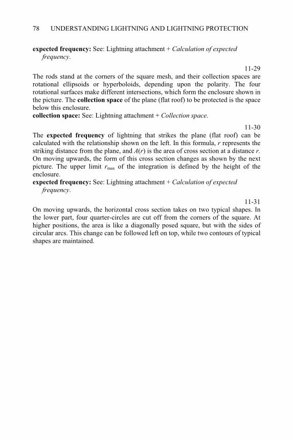
UNDERSTANDING LIGHTNING AND LIGHTNING PROTECTION78
expected frequency: See: Lightning attachment + Calculation of expected frequency.
11-29The rods stand at the corners of the square mesh, and their collection spaces are rotational ellipsoids or hyperboloids, depending upon the polarity. The four rotational surfaces make different intersections, which form the enclosure shown in the picture. The collection space of the plane (flat roof) to be protected is the space below this enclosure. collection space: See: Lightning attachment + Collection space.
11-30The expected frequency of lightning that strikes the plane (flat roof) can be calculated with the relationship shown on the left. In this formula, r represents the striking distance from the plane, and A(r) is the area of cross section at a distance r.On moving upwards, the form of this cross section changes as shown by the next picture. The upper limit rmax of the integration is defined by the height of the enclosure.expected frequency: See: Lightning attachment + Calculation of expected
frequency.
11-31On moving upwards, the horizontal cross section takes on two typical shapes. In the lower part, four quarter-circles are cut off from the corners of the square. At higher positions, the area is like a diagonally posed square, but with the sides of circular arcs. This change can be followed left on top, while two contours of typical shapes are maintained.
CHAPTER 12
Protective effect on flat roof
12-0Each item of this menu can be selected by double-clicking on it. The program displays several topics when the following items are selected: Air termination systems on blockhouse: from Network of parallel conductors to Regularly arranged rods. - Only the air terminations. Diagrams of interception: from parallel conductors to rods in quadratic
arrangement. - Only the diagrams. Display the comments by pressing key F1 and follow the instructions to see the effect of several parameters!
Air termination systems on blockhouse
12-1In this chapter, calculated results can be studied that are related to the same blockhouse. The picture indicates the dimensions of the structure to be protected. One type of air termination systems consists of parallel wires as shown here. Parameter n represents the number of tracts between the conductors. The external conductors are above the edges of the roof. The perpendicular edges of the roof are also equipped with wires but they always lie on the surface of the roof; therefore the collection space of the roof is cut by vertical planes at these locations. collection space: See: Collection spaces of structures Network of long meshes.
12-2In this chapter, calculated results can be studied that are related to the same blockhouse. The picture indicates the dimensions of this structure to be protected. One type of air termination system consists of perpendicular conductors that form a network with square meshes, as shown here. Parameter n represents the number of tracts (meshes) along one side of the roof. The external conductors are always just above the edges of the roof. The collection space of each mesh is separated from all other volumes. ____________________________________________________Understanding Lightning and Lightning Protection T. Horváth © 2006 Research Studies Press Limited
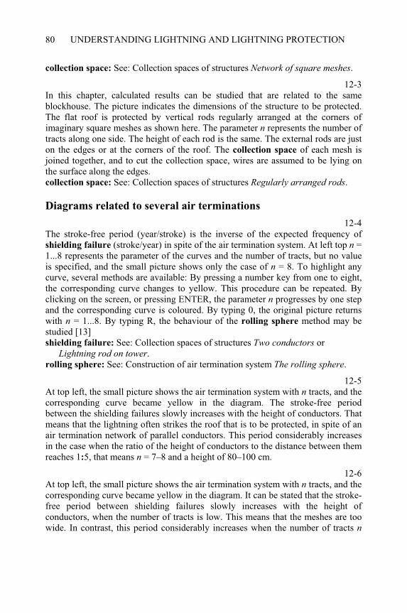
UNDERSTANDING LIGHTNING AND LIGHTNING PROTECTION80
collection space: See: Collection spaces of structures Network of square meshes.
12-3In this chapter, calculated results can be studied that are related to the same blockhouse. The picture indicates the dimensions of the structure to be protected. The flat roof is protected by vertical rods regularly arranged at the corners of imaginary square meshes as shown here. The parameter n represents the number of tracts along one side. The height of each rod is the same. The external rods are just on the edges or at the corners of the roof. The collection space of each mesh is joined together, and to cut the collection space, wires are assumed to be lying on the surface along the edges. collection space: See: Collection spaces of structures Regularly arranged rods.
Diagrams related to several air terminations
12-4The stroke-free period (year/stroke) is the inverse of the expected frequency of shielding failure (stroke/year) in spite of the air termination system. At left top n = 1...8 represents the parameter of the curves and the number of tracts, but no value is specified, and the small picture shows only the case of n = 8. To highlight any curve, several methods are available: By pressing a number key from one to eight, the corresponding curve changes to yellow. This procedure can be repeated. By clicking on the screen, or pressing ENTER, the parameter n progresses by one step and the corresponding curve is coloured. By typing 0, the original picture returns with n = 1...8. By typing R, the behaviour of the rolling sphere method may be studied [13] shielding failure: See: Collection spaces of structures Two conductors or
Lightning rod on tower.rolling sphere: See: Construction of air termination system The rolling sphere.
12-5At top left, the small picture shows the air termination system with n tracts, and the corresponding curve became yellow in the diagram. The stroke-free period between the shielding failures slowly increases with the height of conductors. That means that the lightning often strikes the roof that is to be protected, in spite of an air termination network of parallel conductors. This period considerably increases in the case when the ratio of the height of conductors to the distance between them reaches 1:5, that means n = 7–8 and a height of 80–100 cm.
12-6At top left, the small picture shows the air termination system with n tracts, and the corresponding curve became yellow in the diagram. It can be stated that the stroke-free period between shielding failures slowly increases with the height of conductors, when the number of tracts is low. This means that the meshes are too wide. In contrast, this period considerably increases when the number of tracts n
PROTECTIVE EFFECT ON FLAT ROOF 81
becomes greater. A comparison to the diagram related to the network of parallel conductors demonstrates the higher interception efficiency of square meshes.
12-7At top left, the small picture shows the air termination system with n tracts, and the corresponding curve became yellow in the diagram. Because high air termination rods can be built without difficulty, the abscissa is scaled to 200 cm, which is double the height of the conductors. It can be stated that the stroke-free period of the shielding failures slowly increases with the height of rods, when the number of tracts is low. This is due to the large distance between the rods. This period considerably increases when the number of tracts n becomes greater. A comparison to the diagram related to the network of square meshes shows that higher rods can produce a similar level of interception efficiency.
Application of rolling sphere method 12-8
The rolling sphere method is one of the most recent procedures used to construct the air termination system. According to its principle, a sphere of radius R should never intersect the surface to be protected without settling on the elements of the air termination. In actual case, the positions of conductors and rods are fixed, and therefore, their height is to be constructed with the rolling sphere method. This method results in higher conductors or rods when the distance is large between them. The height of the air termination also grows if the radius R is decreased. Insert the assumed radius, and then press ENTER. rolling sphere: See: Construction of air termination system The rolling sphere.
12-9Flashing red spots mark the points on curves that correspond to the heights obtained with the rolling sphere method and the assumed radius. After inputting another radius R, additional flashing spots make a comparison possible. To delete the spots, type 0, and then a new radius can be assumed. It can be stated that a given radius results in a stroke-free period that does not change much as a function of the number of tracts (parallel conductors). A lower number of high conductors can produce more efficient protection than a higher number of low ones. Finally, a smaller radius results in higher efficiency of protection.
12-10Flashing red spots mark the points on the curves that correspond to the heights obtained with the rolling sphere method and the assumed radius. After inputting another radius R, additional flashing spots make a comparison possible. To delete the spots type 0, and then a new radius can be assumed. It can be stated that a given radius results in a stroke-free period that does not change much as a function of the number of meshes. In addition, a low number of high conductors can offer more efficient protection than a high number of low conductors. Finally, the radius influences the stroke-free period more intensively than in the case of parallel conductors. Smaller radii result in a higher efficiency of protection, than before.
UNDERSTANDING LIGHTNING AND LIGHTNING PROTECTION82
12-11Flashing red spots mark the points on the curves that correspond to the heights obtained with the rolling sphere method and the assumed radius. After inputting another radius R, further flashing red spots make a comparison possible. To delete the spots type 0, and then a new radius can be assumed. It can be stated that a given radius results in a stroke-free period that does not change much as a function of the number of rods. In addition, a lower number of high rods can offer more efficient protection than a higher number of low rods. The radius influences the stroke-free period more intensively than in the case of networks of conductors, but the rods must be higher. Smaller radii result in a higher efficiency of protection.
CHAPTER 13
Protection of inclined roof
13-0Each item of this menu can be selected by double-clicking on it. The program displays several topics when the following items are selected: All cases of inclined roof: from Types of air termination systems to Stroke-free
period.Collection volumes in several cases: from Attraction of roof and eaves to Effect of
electrodes on the edges.
Types of air termination systems 13-1
A building with a double inclined roof is a more complicated structure than a blockhouse. The air termination system can consist of several types of conductors. The ridge conductor is a constant element of air termination systems, which will be shown in the following pictures. In some cases, it can produce acceptable protection by itself, but often other conductors are also necessary.
13-2It is often assumed that the edges of the roof are covered with metal flange plates, which operate as air termination elements. They behave as if the collection space of the roof is cut with vertical planes at the ends. In this case, no conductor is assumed along the eaves, and therefore they are taken as unprotected.
13-3When the eaves are also equipped with metal flange plates, or there are metal rain gutters along them, they can be used as elements of the air termination system. The edges of the roof are covered with metal flange plates as before. They behave as if the collection space of the roof is cut by planes perpendicular to the flat roof in the front, back and at the eaves.
____________________________________________________Understanding Lightning and Lightning Protection T. Horváth © 2006 Research Studies Press Limited
UNDERSTANDING LIGHTNING AND LIGHTNING PROTECTION84
13-4When air termination conductors are above the eaves, they produce similar protection at this side of the roof as the ridge conductor on top. As in the previous cases, the metal flange plates cut the collection space of the roof with vertical planes at both ends in the front and at the back.
13-5There are air termination conductors raised above each roof edge that can produce similar protective effects in the front and at the back, similar to the ridge conductor at the top. In this case, the eaves are assumed to be without any protection.
13-6When the eaves are also equipped with metal flange plates, or there are metal rain gutters along them, they can be used as elements of the air termination system. The collection space of the roof is cut with a plane perpendicular to the flat roof. The air termination conductors are raised above each edge of the roof and they can produce similar protective effect in the front and back, like the ridge conductor on the top.
13-7Finally, both flats of a double inclined roof are enclosed into frames of air termination conductors, which rise above the ridge, with eaves and each edge. These conductors decrease the collection space of the roof from all sides and so they offer an enhanced protective effect.
Attraction of roof and eaves 13-8
The collection space consists of two parts in this case. That of the plane of the roof is separated from the collection space of the ridge conductor by a bent surface, whose directrix is an ellipse or a hyperbola, depending on the polarity. This surface ends at the line of intersection with the bisector of the angle between the plane of the roof and the ground, as indicated by the yellow lines in the picture. Then the border follows the bisector until it intersects with the perpendicular plane coming from the eaves. collection space: See: Lightning attachment + Collection space.
13-9The collection space of the eaves is separated from the collection space of ground by a curved surface, whose directrix is an ellipse or a hyperbola, depending on the polarity. This is the same surface as the border of collection space defined earlier for a horizontal wire above the ground. border of collection space: See: Lightning attachment + Calculation of expected
frequency.
13-10The resulting form of the collection space is always bordered by two curved surfaces. One of them separates the collection spaces of the ridge conductor and the
PROTECTION OF INCLINED ROOF 85
plane of the roof. The other one is between the line of the eaves and the plane of ground. Depending upon the polarity, the directrix of the border surface is either an ellipse or a hyperbola. The space bordered by these surfaces can be cut with a bisector of angle between the plane of the roof and the ground. The last part of the border depends upon the slope of the roof, but it is sometimes missing. directrix of the border surface: See: Lightning attachment + Calculation of
expected frequency.
Effect of electrodes on eaves 13-11
When the eaves are equipped with metal flange plate, this is no further part of the object to be protected. Yellow lines show a plane, which cuts the collection space perpendicular to the surface of the roof in two. The lower part is nearer to the eaves and is therefore omitted, while the upper part belongs to the flat of the roof.
13-12Under the effect of the metal flange plate along the eaves, the collection space of the roof decreases, as shown in the picture. In consequence, the expected frequency of stroke also decreases in relation to the roof to be protected. Metal rain gutters can produce similar results when they are set in the air termination system.
13-13When there is an air termination conductor above the eaves, this cuts the collection volume with a curved surface into two parts. This is similar to the connection with a horizontal conductor and a plane, as defined earlier. The upper part is nearer to the eaves conductor than the roof; and therefore it has been omitted. The rest of the collection space is associated with the flat of the roof to be protected. curved surface: See: Lightning attachment + Calculation of expected frequency.
13-14The ridge conductor on top and the eaves conductor below considerably decrease the collection space of the roof, as shown in the picture. In consequence, the expected frequency of stroke also decreases, relating to the roof. By installation of an eaves conductor, the efficiency of lightning protection can be considerably enhanced.
Effect of electrodes on the edges 13-15
When the ends of the roof are also equipped with raised air termination conductors, they cut off a part of the collection space in the front and at the back with curved
surfaces. This is similar to that defined in connection with a horizontal conductor and a plane. In consequence, these parts of the space are not associated with the collection space of the flat of the roof to be protected. curved surfaces: See: Lightning attachment + Calculation of expected frequency.
UNDERSTANDING LIGHTNING AND LIGHTNING PROTECTION86
13-16Under the effect of air termination conductors, the collection space of the roof considerably decreases in the front and at the back, as shown in the picture. The frames of the conductors create an enhanced efficiency of lightning protection system by decreasing the expected frequency of stroke to the roof to be protected.
13-17This was the picture of the collection space of the flat of the roof, when metal flange plates covered each end of the roof and the eaves. In this case, vertical planes close the collection space on both ends, in the front and at the back. picture of the collection space: See: Idem + Effect of electrodes on eaves.
13-18When the ends of the roof are also equipped with raised air termination conductors, they cut off a part of the collection space at both ends with a curved surface. In consequence, these parts of the space are no longer associated with the collection space of the flat of the roof to be protected. curved surface: See: Lightning attachment + Calculation of expected frequency.
13-19Under the effect of air termination conductors, the collection space of the roof considerably decreases in the front and at the back, as shown in the picture. If the building is not too long, the air termination conductors on both ends can enhance the efficiency of the lightning protection system by decreasing the expected frequency of stroke to the roof to be protected.
13-20This is the picture of the collection space of the flat of the roof, when metal flange plates cover each end of the roof, but with the eaves unprotected. In this case, vertical planes close the collection space on both ends, in the front and at the back.picture of the collection space: See: Idem + Effect of electrodes on eaves.
13-21The air termination conductors at both ends of the roof cut off a part of the collection space with curved surfaces, as illustrated by yellow lines in the picture. In consequence, these parts of the space are no longer associated with the collection space of the flat of the roof to be protected. curved surfaces: See: Lightning attachment + Calculation of expected frequency.
13-22If there are raised air termination conductors above both ends of the roof, the collection space decreases in the front and at the back. This effect is considerable if the building is short and the curved surfaces intersect one another from both ends. For a long building, such an intersection cannot occur. In spite of the unprotected eaves, the expected frequency of stroke to the roof can be decreased, but it always depends upon the length of building and the slope of the roof.
PROTECTION OF INCLINED ROOF 87
Attraction of unprotected edges 13-23
When the air termination system consists of the ridge conductor alone, the ends in the front and at the back are unprotected. The collection space was closed at both ends by vertical planes in previous cases dealing with the flats of the double inclined roof. On the outside of these planes, additional parts of collecting space are associated with the unprotected edges.
13-24The border of the collection space consists of several components that can be best studied by viewing the yellow lines. The edge of the roof as a line and the end of the ridge conductor as a point are separated with a curved surface, whose directrix is an ellipse or a hyperbola. It is marked in light rose-red. Between the edge and the ground surface, the border is illustrated by conical section curves moving along the edge. A section of this is coloured dark red in the picture. The lower end of the edge as a point forms a rotational ellipsoid or hyperboloid with the ground. curved surface: See: Lightning attachment + Calculation of expected frequency.
13-25This picture shows the final form of the collection volume of the edges outside of the vertical planes at the ends of the roof. This space has a large extent when the slope of the roof is small. That means a high frequency of stroke; and therefore the protection produced by a ridge conductor alone cannot be adequate.
Stroke-free period 13-26
The next pictures show diagrams indicating calculated results. These are related to double inclined roofs with the sizes given here. On the diagrams, the height h of the eaves changes within the range shown. The ridge conductor is always considered but the flange plates are only considered once.
13-27In this diagram, the average stroke-free period between shielding failures is plotted against the height h of the eaves of a double inclined roof. Other sizes are given prior to this. It can be stated that the efficiency of protection considerably decreases when the eaves are sloping upwards. stroke-free period: See: Protective effect on flat roof + Diagrams of interception.
13-28The lower curve is related to a roof whose edges are unprotected on both ends in contrast to the upper curve. It can be stated that the difference is negligible with small h, which represents a high-pitched (Alpine) roof. The ratio increases to over seven to one with height h = 13 m, as for very shallow slopes typical of a Mediterranean roof.

CHAPTER 14
Residual risk of lightning
protection
14-0Each item of this menu can be selected by double-clicking on it. The program displays several topics when the following items are selected: The steps of risk calculation: from Equivalent area of a structure to Resulting risk – dealing with all details according to the flow diagram. The flow diagram: Selecting only the steps of the flow diagram. Cases of damaging stroke: from Intercepted stroke to Striking the roof.Calculation of risk: from Weighing the consequences to Resulting risk.
The flow diagram 14-1
A residual risk of lightning strikes exists in spite of lightning protection system. This flow chart of the calculation offers a way to estimate the risk of damage. If the program has been started by selecting The steps of risk calculation then the further steps follow the flow diagram, and give detailed information relating to each step. On the other hand, after selecting The flow diagram, the program goes to each step of the flow diagram without considering related details [26]
Equivalent area of a structure 14-2
The first step is the estimation of the expected annual frequency of lightning that strikes the structure to be protected. This is the resulting value of the following two components. The equivalent area is defined as the area of such a field in flat terrain, which would be struck by lightning with the same frequency as the structure to be protected. It is connected to the structure independent of the lightning activity in the region. On the other hand, the ground flash density is a meteorological date related to the country of the structure. ____________________________________________________Understanding Lightning and Lightning Protection T. Horváth © 2006 Research Studies Press Limited
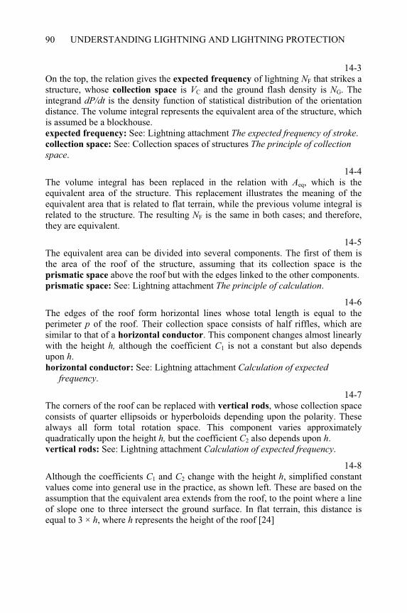
UNDERSTANDING LIGHTNING AND LIGHTNING PROTECTION90
14-3On the top, the relation gives the expected frequency of lightning NF that strikes a structure, whose collection space is VC and the ground flash density is NG. The integrand dP/dt is the density function of statistical distribution of the orientation distance. The volume integral represents the equivalent area of the structure, which is assumed be a blockhouse. expected frequency: See: Lightning attachment The expected frequency of stroke.collection space: See: Collection spaces of structures The principle of collectionspace.
14-4The volume integral has been replaced in the relation with Aeq, which is the equivalent area of the structure. This replacement illustrates the meaning of the equivalent area that is related to flat terrain, while the previous volume integral is related to the structure. The resulting NF is the same in both cases; and therefore, they are equivalent.
14-5The equivalent area can be divided into several components. The first of them is the area of the roof of the structure, assuming that its collection space is the prismatic space above the roof but with the edges linked to the other components. prismatic space: See: Lightning attachment The principle of calculation.
14-6The edges of the roof form horizontal lines whose total length is equal to the perimeter p of the roof. Their collection space consists of half riffles, which are similar to that of a horizontal conductor. This component changes almost linearly with the height h, although the coefficient C1 is not a constant but also depends upon h.horizontal conductor: See: Lightning attachment Calculation of expected
frequency.
14-7The corners of the roof can be replaced with vertical rods, whose collection space consists of quarter ellipsoids or hyperboloids depending upon the polarity. These always all form total rotation space. This component varies approximately quadratically upon the height h, but the coefficient C2 also depends upon h.vertical rods: See: Lightning attachment Calculation of expected frequency.
14-8Although the coefficients C1 and C2 change with the height h, simplified constant values come into general use in the practice, as shown left. These are based on the assumption that the equivalent area extends from the roof, to the point where a line of slope one to three intersect the ground surface. In flat terrain, this distance is equal to 3 × h, where h represents the height of the roof [24]
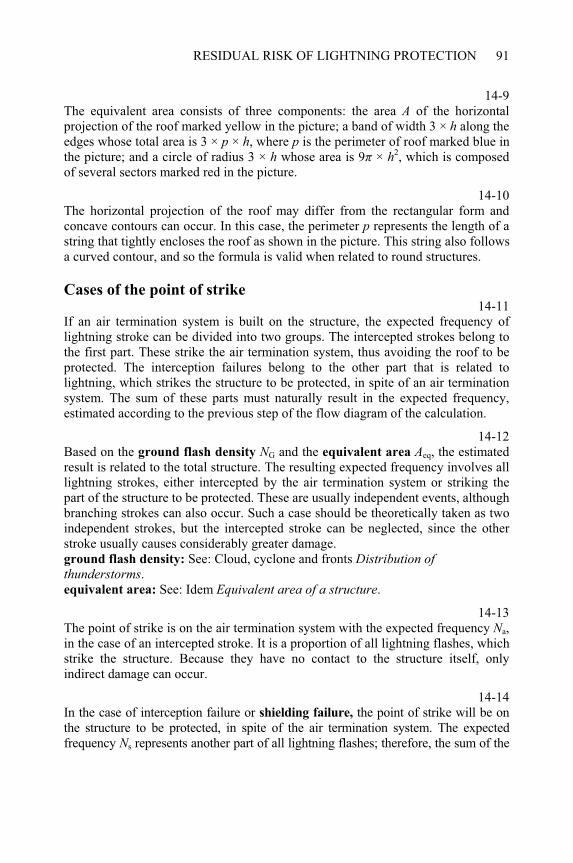
RESIDUAL RISK OF LIGHTNING PROTECTION 91
14-9The equivalent area consists of three components: the area A of the horizontal projection of the roof marked yellow in the picture; a band of width 3 × h along the edges whose total area is 3 × p × h, where p is the perimeter of roof marked blue in the picture; and a circle of radius 3 × h whose area is 9 × h2, which is composed of several sectors marked red in the picture.
14-10The horizontal projection of the roof may differ from the rectangular form and concave contours can occur. In this case, the perimeter p represents the length of a string that tightly encloses the roof as shown in the picture. This string also follows a curved contour, and so the formula is valid when related to round structures.
Cases of the point of strike 14-11
If an air termination system is built on the structure, the expected frequency of lightning stroke can be divided into two groups. The intercepted strokes belong to the first part. These strike the air termination system, thus avoiding the roof to be protected. The interception failures belong to the other part that is related to lightning, which strikes the structure to be protected, in spite of an air termination system. The sum of these parts must naturally result in the expected frequency, estimated according to the previous step of the flow diagram of the calculation.
14-12Based on the ground flash density NG and the equivalent area Aeq, the estimated result is related to the total structure. The resulting expected frequency involves all lightning strokes, either intercepted by the air termination system or striking the part of the structure to be protected. These are usually independent events, although branching strokes can also occur. Such a case should be theoretically taken as two independent strokes, but the intercepted stroke can be neglected, since the other stroke usually causes considerably greater damage. ground flash density: See: Cloud, cyclone and fronts Distribution of thunderstorms.equivalent area: See: Idem Equivalent area of a structure.
14-13The point of strike is on the air termination system with the expected frequency Na,in the case of an intercepted stroke. It is a proportion of all lightning flashes, which strike the structure. Because they have no contact to the structure itself, only indirect damage can occur.
14-14In the case of interception failure or shielding failure, the point of strike will be on the structure to be protected, in spite of the air termination system. The expected frequency Ns represents another part of all lightning flashes; therefore, the sum of the
UNDERSTANDING LIGHTNING AND LIGHTNING PROTECTION92
frequencies of the intercepted stroke Na and the shielding failure Ns will be equal to the frequency of all lightning flashes NF, which strike the structure together. shielding failure: See: Collection spaces of structures The principle of collection
space.
14-15The efficiency b of the air termination system is the ratio between the frequency of interception failure Ns and that of all lightning flashes NF, therefore it is in the range 0 and 1.0 (100%). Using this value, either the frequency of intercepted strokes Na or that of shielding failure Ns can be expressed as a function of the total frequency of strokes NF.
14-16There is a third type of ground flash, which strikes in a distance to the structure. These distant strokes can also cause damage inside a structure by several coupling
processes. A chapter will follow later on this topic. coupling processes: See: Lightning Electromagnetic imPulse Coupling of
lightning.
14-17When the lightning strikes down apart the structure, it can cause damage inside the structure by (Lightning ElectroMagnetic imPulse) LEMP effects. This topic will be discussed in detail in a later chapter. The frequency of such a flash is independent of that related to the structure. The frequency Nf of such strokes is proportional to the ground flash density NG although it is independent of frequency NF.LEMP effects: See: Lightning Electromagnetic imPulse Coupling of lightning.
Cases of damaging stroke 14-18
Independent of the point of strike, lightning can cause damage with a probability that is determined by several conditions. Other kinds of strokes occur without causing any damage. The probabilities of strokes causing damage and without damage combine to 1.0 (100%). In the case of distant flashes, the damaging strokes are only considered, neglecting those striking without any damage. Therefore, the frequency of occurrence can be taken into account in the last case, because the probability cannot be defined.
Intercepted stroke 14-19
In the case of an intercepted stroke, the lightning current flows through the conductors of the lightning protection system into the earth. This current produces a rise of potential across the earth resistance RE, which penetrates into the structure. If the lightning current I, exceeds a critical threshold Icr, a breakdown can occur inside the structure that can cause damage. Based on the statistical distribution of lightning
RESIDUAL RISK OF LIGHTNING PROTECTION 93
current, the probability pI that such an event occurs can be estimated with the formulae shown left. statistical distribution: See: Physics of the lightning discharge Lightning
parameters.
14-20The heat effect of intercepted strokes depends upon the charge flowing through the contact spot of the lightning channel on the metal surface. If this charge Q exceeds a critical threshold Qcr, the elements of the air termination system can melt, thus damaging the structure. Based on the statistical distribution of charge, the probability pQ, occurrence of such an event can be estimated with the formulae shown left. heat effect: See: Heat effects on metal objects Equations of melting.statistical distribution: See: Physics of the lightning discharge Lightning
parameters.
14-21Either the heat effect or the dynamic force depends upon the specific energy represented by the current flowing along a conductor. If the specific energy Wexceeds a critical threshold Wcr, an air termination conductor can be ripped at some point along the current path, leading to serious damage to the structure. Based on the statistical distribution of specific energy, the probability pw, occurrence of such an event can be estimated with the formulae shown left. heat effect: See: Heat effects on metal objects Melting a wire – leading current.dynamic force: See: Dynamic forces due to lightning Dynamic force on a console.statistical distribution: See: Physics of the lightning discharge Lightning
parameters.
14-22In the case of an intercepted stroke, the lightning current can create an induced
voltage in the loops inside the structure. If the differential quotient of current di/dt,which will be identified as ‘d’ in this chapter, exceeds a critical threshold dcr, either sparks are produced, which initiate a fire or explosion, or electrical devices can be damaged by over-voltage. The probability pd for such an event can be estimated on the basis of statistical distribution of di/dt as shown left. induced voltage: See: Induced voltage and current Calculated examples – direct
stroke.statistical distribution: See: Physics of the lightning discharge Lightning
parameters.
Striking the roof 14-23
In the case of interception failure, the lightning flash strikes the roof to be protected. Its effect depends upon the materials and structure of the roof. In the case of a flammable roof, the peak value of lightning current I, the charge Q and the specific energy W exceed critical thresholds. Therefore, the corresponding probabilities pI, pQ
UNDERSTANDING LIGHTNING AND LIGHTNING PROTECTION94
and pw are nearly 1.0 (100%). It means that if lightning strikes a flammable roof, a fire must be expected almost every time, independent of the lightning parameters.
14-24In the case of interception failure, when the lightning flash strikes a metal roof, damage can occur after melting the metal. For this to occur, the charge Q flowing through a contact spot of the lightning channel on the metal surface exceeds a critical threshold. The probability for such an event pQ can be estimated on the basis of the statistical distribution of charge with similar function as in the case of an intercepted stroke. Other parameters have low importance. melting the metal: See: Heat effects on metal objects Equations of melting.statistical distribution: See: Physics of the lightning discharge Lightning
parameters.
14-25A neutral roof, such as tile or slate, does not contain flammable material or metal elements. In the case of interception failure, the lightning flash can result in damage with a high probability that is almost independent of the lightning parameters. Therefore, the probabilities pI, pQ and pw can be assumed to have similar values to those shown above.
14-26From the point of view of induced voltage, there is no difference between the intercepted stroke and the interception failure when the lightning strikes the roof to be protected. Damage can occur if the differential quotient of current di/dt,identified by ‘d’ in this chapter, exceeds a critical threshold dcr. In both cases, either sparks are produced, which initiate a fire or an explosion, or electrical devices can be damaged by over-voltage. Based on the statistical distribution of di/dt, the probability for such an event pd can be estimated as shown above. induced voltage: See: Induced voltage and current Calculated examples – direct stroke.statistical distribution: See: Physics of the lightning discharge Lightning
parameters.
Calculation of risk 14-27
When a lightning stroke causes any damage, the consequences can be very divergent. Due to interception failure, the lightning will almost certainly damage the roof, but this may only lead to the fracture of a few tiles. In this case, the damage is very light. In contrast, an intercepted stroke can produce an explosion by induced voltage initiated by internal sparking. This can lead to serious damage, although the lightning protection system may function correctly. These circumstances can be taken into account with weighting factors.
RESIDUAL RISK OF LIGHTNING PROTECTION 95
Weighting the consequences 14-28
The numerical expression of the weighting factor requires exact definition, although its estimation needs some degree of subjective judgement. From the point of view of the calculation method, the weighting factor is a dimensionless value that is usually in the range from 0–1, but higher values are not excluded. According to the above formula, the numerator represents the actual damage. In principle, this could be expressed in terms of the monetary value required to restore to the original state. The denominator represents the total value of the structure to be protected. It can be occasionally extended onto the surroundings that is also threatened by the consequences of a lightning stroke. For example, such a case occurs when dangerous chemicals or radioactive materials can escape from the structure due to lightning stroke. Although the upper definition is theoretically correct, it can only be applied in practice with difficulty. For routine applications, subjective estimation can be applied, assuming immediately the weighting factor c as a relative value.
14-29This, and the following pictures, gives us some examples to aid us with the assumption of a weighting factor related to several structures. The first case is related to a building equipped with lightning protection system. Inside the building, nothing enhances the danger of damage, in contrast to some of the following cases. The roof and walls are made of materials which cannot be heavily damaged by lightning. Therefore, light damage should be expected along the path of the lightning current routed through the conductors of the lightning protection system. The weighting factor c is only related to the consequences but not to the occurrence of damage.
14-30This example deals with interception failure in the case of a building equipped with a lightning protection system. Inside the building, nothing enhances the danger of damage similar to the previous case. The roof and the walls are made of materials, which cannot be severely damaged by lightning. Therefore, light damage should be expected along the path of the lightning current. These would usually be broken tiles on the roof or plaster damage on the walls, which can be easily restored.
14-31The danger is considerably enhanced when many people are within the building. If there are no other circumstances, which enhance the danger of severe damage, the assumed value can be accepted. There were efforts to express the damage by the cost of assurance but this has not been widely adopted. The assumed value c of the weighting factor finally depends upon the subjective estimation with consideration to the number of people and such circumstances as the motility.
UNDERSTANDING LIGHTNING AND LIGHTNING PROTECTION96
14-32The danger can be considerably enhanced when the loss of irrecoverable cultural treasures have to be expected. This can be a building such as the Taj Mahal in India, an archaeological tomb such as Tut Ankh Amon, a museum such as the Louvre in Paris, an archive such as the Library in the Vatican, a memorial as Statue of Freedom in New York and many others. The weighting factor is naturally very high in such exceptional cases, but it can never be estimated without subjective judgement of everyday structures.
14-33A fire due to lightning stroke can lead to several consequences. The lightning frequently ignites flammable roofs so that only the cover burns down, because other parts of the building are well separated and do not contain flammable materials. This may lead to serious damage but a large part of the building may remain intact. For the estimation of the weighting factor, the comparison of destroyed and intact parts of the structure gives a real basis.
14-34The fire ignited by a lightning stroke can extend onto the entire structure when it consists of flammable materials, or contains flammable materials. Even if the total structure is burnt down, it does not necessarily follow that the weighting factor must be taken as 1.0 (100%), because the walls and the foundation occasionally can be used during the restoration. In this case, a value in the range of 0. 9–1.0 is a reasonable estimation for the weighting factor.
14-35When explosions are expected inside the structure due to a lightning stroke, the damage extends onto the total structure, or at least to a great proportion of it. The weighting factor is always nearly 1.0 (100%). Danger of explosion is frequently caused by the mixture of air and explosive gas or spray, but organic powder floating in the air can also be dangerous, for example, in flour mills. Explosion of detonating material can also threaten the surroundings. Therefore, the weighting factor can exceed 1.0.
14-36A structure causes danger to its surroundings if an exhaust of harmful materials occurs as a consequence of the lightning stroke. This is a typical example for such a case when the weighting factor is higher than 1, because more than the structure itself is threatened. This is theoretically possible, although it causes difficulties at the numerical evaluation, and therefore it is preferable to include the total damage in the denominator of the formula upper right, and so the weighting factor does not need to exceed 1.
14-37In principle, the weighting factor can be defined in the case of an environmental catastrophe, but it is out of the scope of the risk evaluation described here. The weighting factor should be estimated as higher than 1, but this causes difficulties in
RESIDUAL RISK OF LIGHTNING PROTECTION 97
the numerical evaluation. This problem can be theoretically eliminated, when the total damage involves the surroundings in the denominator of the formula upper right, because the weighting factor never exceeds 1. Altogether, this special case requires special solutions either for risk evaluation or for the construction of a lightning protection system.
Resulting damage
14-38The lightning stoke can cause damage with several probabilities, which depend upon the points of strike and the statistical distribution of lightning parameters. This results in the probability that any type of damage occurs at all. The consequences of damage are also divergent, which can be expressed by weighting factors. Occurrence and weighting finally conclude into the weighted damage related to each type of damage. That involves the frequency of stroke, the probability for causing damage and the weighting of the consequences.
14-39The intercepted strokes, the interception failures and the LEMP effects of distant flashes are independent events. Therefore, the resulting weighted damage can be calculated by summing the weighted damages related to the relevant strokes.
Resulting frequency of weighted damage 14-40
Lightning causes several damages whose occurrence depends upon the point of strike and upon the statistical distribution of lightning parameters. The coefficients pI, pQ, pw, pd do not represent independent probabilities, because a lightning stroke can create them all at the same time. A weighting factor is related to each case of damage and modifies the probability. several damages: See: Idem Cases of damaging stroke.weighting factor: See: Idem Weighting the consequences.
14-41In these relations, Nx represents the annual frequency (stroke/year) of any type of the point of strike as: Na intercepted stroke, Ns interception failure, Nf far lightning flash. The coefficient wj is the weighted probability that a type of damage occurs. Index j means the serial number of the relevant case, which go up from j = 1 as necessary. The coefficients pj and cj sign any of that shown above, but both should be related to the same damage. The product Nxwj expresses the annual frequency of a type of weighted damage. Because either pj or cj or just Nx is very low in many cases, it is not required to take them all into account , but a considerable part can be neglected. For example: Apart from the burning down of a building, the damage to some roof tiles has no importance! annual frequency: See: Idem The point of strike.
UNDERSTANDING LIGHTNING AND LIGHTNING PROTECTION98
14-42Because the values wj do not represent probabilities of independent events, the resulting value cannot be calculated by summation, but the relation must be used as that shown above. Symbol means the product of factors (1–wj) from j = 1 to n or according to another form: (1–w1) (1–w2) (1–w3) . . . (1–wn). This formula results in an unreal value if wj > 1, at least one time. In this case, the resulting value wx is equal to this and all other factors must be omitted [26]
14-43Because the frequencies of intercepted strokes, interception failures and LEMP effects of distant flashes are independent from each other, the sum of all Nxwx
products gives the expected frequency of resulting weighted damage. In the last member aNG = Nf means the frequency of distant ground flashes, which can cause damage by LEMP effects. The coefficient a can be estimated by analysing the distant effects, for example, the induced voltage or current. The reciprocal value of T gives the average period of damage in years. induced voltage: See: Induced voltage and current Calculated results – stroke far
away.
Resulting risk 14-44
The previous calculation resulted in the expected annual frequency of weighted damage. That is an average value, which gives no information on what should be expected in the next year. The lightning events follow one another according to the Poisson’s process. The Poisson relations express the probability of a given number of events during a given time. This calculation finally results in the probability called Risk of damage.
14-45The resulting frequency of weighted damage D is an average value that expresses the danger due to lightning. When there is a lightning protection system installed, its value is usually too low to be easily interpreted. It is better to understand the period T, which is the average interval between two total damages caused by lightning. This is usually too long a time, and can cause false conclusions concerning the safety. A more comprehensive view can be obtained with further evaluation.
14-46This simplified form of the Poisson relations expresses the probability that total damage occurs during the time t when T is the average period of damage. Relating to a year (t = 1), this value is in magnitude R(1) = 10–5–10–7 when the structure is equipped with an adequate lightning protection system. Related to longer time, the risk of damage becomes easier to understand [26]
RESIDUAL RISK OF LIGHTNING PROTECTION 99
14-47The risk is commonly related to a year (t = 1), and its accepted level is R(1) < 10–5
but a false form of 10–5 per year is also used. A more acceptable value can be obtained by relating the risk to 100 years. Taking this as the limit of the lifetime of a human being, it can suggest that the risk R(100) expresses the probability that inside this time a fatal event will be caused by lightning. Because the probability for another fatal event is almost 1.0 (100%), a considerably lower risk due to lightning can be accepted. The level at the bottom is nearly equivalent to the accepted level related to one year. According to another interpretation, 1 to 1000 is the risk that the lightning produces a fatal event, which must be expected with high probability for other reasons.

CHAPTER 15
Classification of structures
15-0Each item of this menu can be selected by double-clicking on it. The program displays several topics when the following items are selected: All types of classification: from Classes of structures to The materials of the roof.Height and surroundings: from High surroundings to Classes according to height.
Classes of structures (Hungarian code) 15-1
The consequences of damage due to lightning can be considered in practice by the classification of the structures to be protected according to their functions. The Hungarian Standard for Lightning Protection of Structures defines five classes marked by R1 to R5 as indicated on the screen. An increasing serial number represents a greater weighting of the consequences. The highlighted class R1 involves ‘Common structures’; that is, structures that do not belong to any of the other classes. Some typical examples can be seen in the next picture [28] consequences of damage: See: Residual risk of lightning protection Weighting the
consequences.
15-2In class R1, the following are the most typical structures: Family, tenement and holiday houses; pensions, small hotels and restaurants; agricultural buildings as stalls, machine and tractor stations; industrial and commercial structures as storehouses, factories, business and office houses; railway and other stations, garages and many structures. These do not fall into any other class because of the danger for many people, fire or explosion.
15-3The highlighted class R2 involves ‘Important structures’; that is, structures that increase the weight of consequences either by representing or containing irrecoverable cultural treasures or by threatening many people. Some typical ____________________________________________________Understanding Lightning and Lightning Protection T. Horváth © 2006 Research Studies Press Limited
UNDERSTANDING LIGHTNING AND LIGHTNING PROTECTION102
examples can be seen in the next pictures. If such a structure involves a danger of fire or explosion, it falls into a higher class. weight of consequences: See: Residual risk of lightning protection Weighting the
consequences.
15-4The pictures show some buildings that fall into class R2, because damage due to lightning can cause the loss of irrecoverable cultural treasures. Typical examples are the churches all over the world. Similar consequences have to be expected in the case of historical monuments such as castles and fortresses. Concerning their contents, museums, libraries, archives, galleries and similar buildings also belong to this class.
15-5The structures shown by these pictures also fall into class R2, because many people can be exposed to danger caused by lightning. A congress or concert hall, a theatre, a sports ground or hall and big department stores are all vulnerable because many people have to escape quickly and panic can spread easily. Similar danger is presented when people are unable to move such as in a hospital, or when they cannot escape unaided, such as little children in a nursery or a school.
15-6The highlighted class R3 involves ‘Structures of fire hazard’; that is, such structures which may contain large quantities of combustible materials. Due to this, a fire caused by lightning probably extends onto the complete structure. When the structure has a roof of flammable material, it must be considered from other points of view of classification. roof of flammable material: See: Idem The materials of the roof.
15-7The pictures show two buildings that fall into class R3, because they contain a large amount of combustible materials. Typical cases are agricultural buildings storing hay, straw, grain or similar products. Stores and factories working with wood, paper, textiles, flammable plastics, mills and meat and other food processing units that work with combustible organic materials also belong to this class.
15-8The highlighted class R4 involves structures of ‘Risk of explosion’; that is, such structures that contain considerable amounts of explosive materials or in which explosive air mixtures can regularly occur. Because lightning can initiate an explosion by a small spark, total destruction of the complete structure must be expected. If the explosion also threatens the surroundings, the structure falls into the highest class. threatens the surroundings: See: Residual risk of lightning protection Weighting
the consequences.
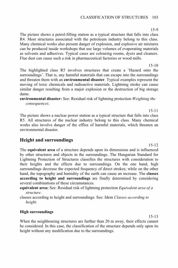
CLASSIFICATION OF STRUCTURES 103
15-9The picture shows a petrol-filling station as a typical structure that falls into class R4. Most structures associated with the petroleum industry belong to this class. Many chemical works also present danger of explosion, and explosive air mixtures can be produced inside workshops that use large volumes of evaporating materials as solvents and adhesives. Typical cases are colouring rooms, dyers and cleaners. Flue dust can cause such a risk in pharmaceutical factories or wood mills.
15-10The highlighted class R5 involves structures that create a ‘Hazard onto the surroundings’. That is, any harmful materials that can escape into the surroundings and threaten them with an environmental disaster. Typical examples represent the moving of toxic chemicals and radioactive materials. Lightning stroke can cause similar danger resulting from a major explosion or the destruction of big storage dams. environmental disaster: See: Residual risk of lightning protection Weighting the
consequences.
15-11The picture shows a nuclear power station as a typical structure that falls into class R5. All structures of the nuclear industry belong to this class. Many chemical works also involve danger of the efflux of harmful materials, which threaten an environmental disaster.
Height and surroundings 15-12
The equivalent area of a structure depends upon its dimensions and is influenced by other structures and objects in the surroundings. The Hungarian Standard for Lightning Protection of Structures classifies the structures with consideration to their heights and the effects due to surroundings. On the one hand, high surroundings decrease the expected frequency of direct strokes; while on the other hand, the topography and humidity of the earth can cause an increase. The classes
according to height and surroundings are finally determined by considering several combinations of these circumstances. equivalent area: See: Residual risk of lightning protection Equivalent area of a
structure.classes according to height and surroundings: See: Idem Classes according to
height.
High surroundings
15-13When the neighbouring structures are further than 20 m away, their effects cannot be considered. In this case, the classification of the structure depends only upon its height without any modification due to the surroundings.
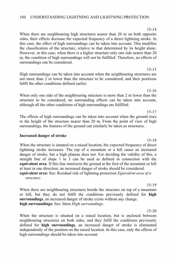
UNDERSTANDING LIGHTNING AND LIGHTNING PROTECTION104
15-14When there are neighbouring high structures nearer than 20 m on both opposite sides, their effects decrease the expected frequency of a direct lightning stroke. In this case, the effect of high surroundings can be taken into account. This modifies the classification of the structure, relative to that determined by its height alone. However, in this case, when there is a higher structure only one side nearer than 20 m, the condition of high surroundings will not be fulfilled. Therefore, no effects of surroundings can be considered.
15-15High surroundings can be taken into account when the neighbouring structures are not more than 2 m lower than the structure to be considered, and their positions fulfil the other conditions defined earlier.
15-16When only one side of the neighbouring structure is more than 2 m lower than the structure to be considered, no surrounding effects can be taken into account, although all the other conditions of high surroundings are fulfilled.
15-17The effects of high surroundings can be taken into account when the ground rises to the height of the structure nearer than 20 m. From the point of view of high surroundings, the features of the ground can similarly be taken as structures.
Increased danger of stroke
15-18When the structure is situated on a raised location, the expected frequency of direct lightning stroke increases. The top of a mountain or a hill cause an increased danger of stroke, but a high plateau does not. For deciding the validity of this, a straight line of slope 1 to 3 can be used as defined in connection with the equivalent area. If this line intersects the ground at the foot of the mountain or hill at least in one direction, an increased danger of stroke should be considered. equivalent area: See: Residual risk of lightning protection Equivalent area of a
structure.
15-19When there are neighbouring structures beside the structure on top of a mountain or hill, but they do not fulfil the conditions previously defined for high
surroundings, an increased danger of stroke exists without any change. high surroundings: See: Idem High surroundings.
15-20When the structure is situated on a raised location, but is enclosed between neighbouring structures on both sides, and they fulfil the conditions previously defined for high surroundings, an increased danger of stroke is eliminated independently of the position on the raised location. In this case, only the effects of high surroundings should be taken into account.
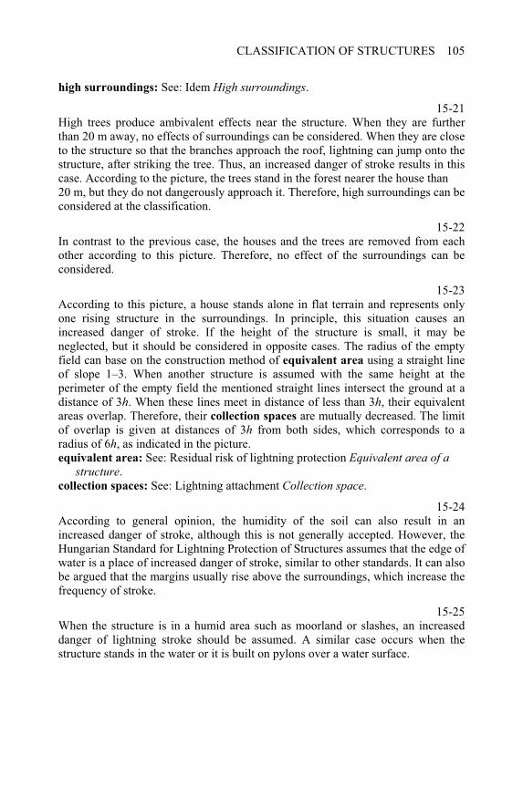
CLASSIFICATION OF STRUCTURES 105
high surroundings: See: Idem High surroundings.
15-21High trees produce ambivalent effects near the structure. When they are further than 20 m away, no effects of surroundings can be considered. When they are close to the structure so that the branches approach the roof, lightning can jump onto the structure, after striking the tree. Thus, an increased danger of stroke results in this case. According to the picture, the trees stand in the forest nearer the house than 20 m, but they do not dangerously approach it. Therefore, high surroundings can be considered at the classification.
15-22In contrast to the previous case, the houses and the trees are removed from each other according to this picture. Therefore, no effect of the surroundings can be considered.
15-23According to this picture, a house stands alone in flat terrain and represents only one rising structure in the surroundings. In principle, this situation causes an increased danger of stroke. If the height of the structure is small, it may be neglected, but it should be considered in opposite cases. The radius of the empty field can base on the construction method of equivalent area using a straight line of slope 1–3. When another structure is assumed with the same height at the perimeter of the empty field the mentioned straight lines intersect the ground at a distance of 3h. When these lines meet in distance of less than 3h, their equivalent areas overlap. Therefore, their collection spaces are mutually decreased. The limit of overlap is given at distances of 3h from both sides, which corresponds to a radius of 6h, as indicated in the picture. equivalent area: See: Residual risk of lightning protection Equivalent area of a
structure.collection spaces: See: Lightning attachment Collection space.
15-24According to general opinion, the humidity of the soil can also result in an increased danger of stroke, although this is not generally accepted. However, the Hungarian Standard for Lightning Protection of Structures assumes that the edge of water is a place of increased danger of stroke, similar to other standards. It can also be argued that the margins usually rise above the surroundings, which increase the frequency of stroke.
15-25When the structure is in a humid area such as moorland or slashes, an increased danger of lightning stroke should be assumed. A similar case occurs when the structure stands in the water or it is built on pylons over a water surface.
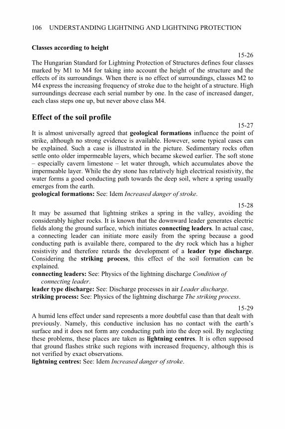
UNDERSTANDING LIGHTNING AND LIGHTNING PROTECTION106
Classes according to height
15-26The Hungarian Standard for Lightning Protection of Structures defines four classes marked by M1 to M4 for taking into account the height of the structure and the effects of its surroundings. When there is no effect of surroundings, classes M2 to M4 express the increasing frequency of stroke due to the height of a structure. High surroundings decrease each serial number by one. In the case of increased danger, each class steps one up, but never above class M4.
Effect of the soil profile 15-27
It is almost universally agreed that geological formations influence the point of strike, although no strong evidence is available. However, some typical cases can be explained. Such a case is illustrated in the picture. Sedimentary rocks often settle onto older impermeable layers, which became skewed earlier. The soft stone – especially cavern limestone – let water through, which accumulates above the impermeable layer. While the dry stone has relatively high electrical resistivity, the water forms a good conducting path towards the deep soil, where a spring usually emerges from the earth. geological formations: See: Idem Increased danger of stroke.
15-28It may be assumed that lightning strikes a spring in the valley, avoiding the considerably higher rocks. It is known that the downward leader generates electric fields along the ground surface, which initiates connecting leaders. In actual case, a connecting leader can initiate more easily from the spring because a good conducting path is available there, compared to the dry rock which has a higher resistivity and therefore retards the development of a leader type discharge.Considering the striking process, this effect of the soil formation can be explained. connecting leaders: See: Physics of the lightning discharge Condition of
connecting leader.leader type discharge: See: Discharge processes in air Leader discharge.striking process: See: Physics of the lightning discharge The striking process.
15-29A humid lens effect under sand represents a more doubtful case than that dealt with previously. Namely, this conductive inclusion has no contact with the earth’s surface and it does not form any conducting path into the deep soil. By neglecting these problems, these places are taken as lightning centres. It is often supposed that ground flashes strike such regions with increased frequency, although this is not verified by exact observations. lightning centres: See: Idem Increased danger of stroke.
CLASSIFICATION OF STRUCTURES 107
15-30The ground flash density could be increased by the soil properties if conditions for starting a connecting leader would be suitable in the region. However, while there is sand everywhere on the ground surface, the humid lens effect cannot modify the field distribution above it. The high resistivity of sand retards the development of the connecting leader everywhere, independently of the conductive inclusion deeper down. It should be stated that humid lenses do not form lightning centres of high ground flash density. connecting leader: See: Physics of the lightning discharge Condition of
connecting leader.
The materials of roof 15-31
A roof is mostly exposed to the effects of lightning, either in the case of an intercepted stroke or a shielding failure. From the point of view of these effects, the roof covering and the trussing can be distinguished. The roof covering is the outside layer of the roof, which is also exposed to the effects of an intercepted stroke. These can be the radiated heat of the hot channel or hot particles flying away from the point of strike. The trussing includes everything below the covering that is exposed to lightning effects in the case of shielding failure. It usually consists of framework, floor and filling materials as thermal insulation. shielding failure: See: Residual risk of lightning protection The point of strike.
15-32The materials of a roof covering can be arranged into several groups that are marked by colours, as shown in the picture. When a roof covering contains no combustible material and no metal elements, the lightning causes no fire and the damage is usually limited. When the covering consists of such metal elements, which can sustain a lightning stroke without any damage, it can be used as an air termination. When covering consists of combustible material but contains no metal element, the lightning probably causes fire. When the covering also contains metal elements, these can form the contact spot of the lightning channel that will probably ignite the burning material. A combination of combustible material with metal elements causes the highest danger of fire.
15-33The materials of trussing are arranged into the same groups as before and marked by colours as shown in the picture. When the trussing contains no combustible material and no metal elements, the lightning causes no fire and the damage is usually limited. When the trussing consists of metal parts, the lightning occasionally breaks through the covering and strikes the trussing in the case of shielding failure. When the trussing contains combustible materials but no metal part, the lightning can cause fire if the covering is punctured. When the trussing contains combustible materials and metal elements in equal parts, the lightning
UNDERSTANDING LIGHTNING AND LIGHTNING PROTECTION108
occasionally strikes the metal part of the trussing after breaking through the covering. This can result in a fire on the roof.
15-34The Hungarian Standard for Lightning Protection of Structures defines five classes marked by T1 to T5 for taking into account the materials of a roof. The weighting of consequences increases with the serial number of class. These are determined by several combinations of covering and trussing. The columns represent the roof covering and the trussing varies according to rows.
15-35The background colours demonstrate the ambivalent effect of metal structures in covering and trussing. Class T1 occurs if, either the metal covering can sustain the lightning stroke and so any trussing is not dangerous below, or the metal trussing is covered by non-combustible material that is probably slightly damaged. Class T5 should be settled if the metal elements are combined with combustible materials, except for a complete metal covering.
Further classifications 15-36
The previously detailed classifications can be continued according to further points of view. The highlighted classification is based on the materials of walls. The Hungarian Standard for Lightning Protection of Structures defines three classes, depending on the combustibility of the external walls. This class influences the construction of the down conductors. However, the details of this topic are not dealt with here.
15-37The pollution of the air determines the corrosion of the conductors and other elements of the external lightning protection system. The Hungarian Standard for Lightning Protection of Structures defines six classes, which change from clear air to corrosive atmosphere due to aggressive chemical agents. This classification determines the minimum dimensions and the materials of the metal elements used for external lightning protection system. However, the details of this topic are not dealt with here.
15-38The internal lightning protection is an actual problem, which is dealt with by international standards, but these do not apply to the previously described classification system. The Hungarian Standard for Lightning Protection of Structures introduced additional classifications dependent on the choice of the
CLASSIFICATION OF STRUCTURES 109
internal lightning protection. This aims to manage the problems arising from different systems of standards. Some chapters deal with internal lightning protection, while the Hungarian classification system will not be described in details. internal lightning protection: See: Internal lightning protection zones Structure of
zones

CHAPTER 16
Air termination systems
16-0Each item of this menu can be selected by double-clicking on it. The program displays several topics when the following items are selected: Construction methods: from The protective angle to The mesh size.Data of the Hungarian standard: from Simplified air termination to Distance to the
structure.
Level of risk and protection 16-1
A complete calculation cannot be performed to estimate the residual risk of the lightning protection system in all cases. Therefore, simplified methods should be used. The classification of structures represents the level of risk without protection, as the graph illustrates in this picture. classification: See: Classification of structures Classes of structures.
16-2The lightning protection system should decrease the risk to an accepted level,which is low enough, but independent of the original level. This aim can be reached with several degrees of efficiency of protection, as illustrated by the graph. This degree is not a general measure, but depends on the component of the lightning protection system. accepted level: See: Residual risk of lightning protection Resulting risk.
Construction methods
Protective angle
16-3Although the terms of protected space or zone and so on are generally used in practice, it must be understood that they do not exist in reality. The expected
frequency can be used alone to express more accurately the protective effect of an____________________________________________________Understanding Lightning and Lightning Protection T. Horváth © 2006 Research Studies Press Limited
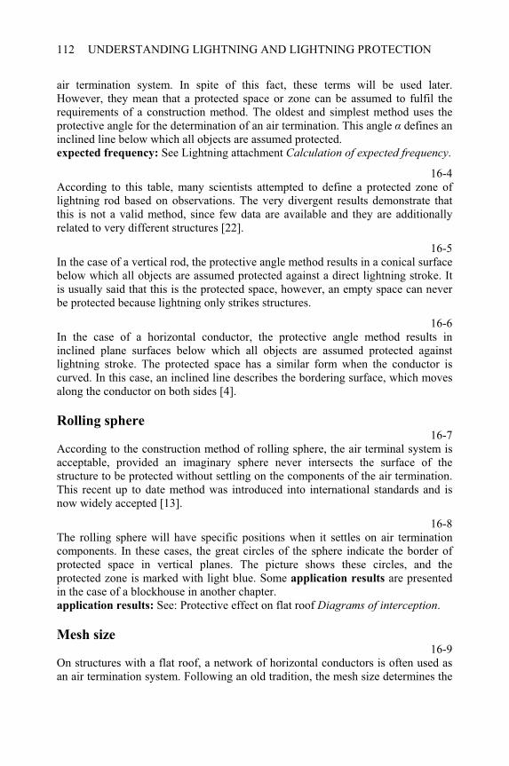
UNDERSTANDING LIGHTNING AND LIGHTNING PROTECTION112
air termination system. In spite of this fact, these terms will be used later. However, they mean that a protected space or zone can be assumed to fulfil the requirements of a construction method. The oldest and simplest method uses the protective angle for the determination of an air termination. This angle defines an inclined line below which all objects are assumed protected. expected frequency: See Lightning attachment Calculation of expected frequency.
16-4According to this table, many scientists attempted to define a protected zone of lightning rod based on observations. The very divergent results demonstrate that this is not a valid method, since few data are available and they are additionally related to very different structures [22].
16-5In the case of a vertical rod, the protective angle method results in a conical surface below which all objects are assumed protected against a direct lightning stroke. It is usually said that this is the protected space, however, an empty space can never be protected because lightning only strikes structures.
16-6In the case of a horizontal conductor, the protective angle method results in inclined plane surfaces below which all objects are assumed protected against lightning stroke. The protected space has a similar form when the conductor is curved. In this case, an inclined line describes the bordering surface, which moves along the conductor on both sides [4].
Rolling sphere 16-7
According to the construction method of rolling sphere, the air terminal system is acceptable, provided an imaginary sphere never intersects the surface of the structure to be protected without settling on the components of the air termination. This recent up to date method was introduced into international standards and is now widely accepted [13].
16-8The rolling sphere will have specific positions when it settles on air termination components. In these cases, the great circles of the sphere indicate the border of protected space in vertical planes. The picture shows these circles, and the protected zone is marked with light blue. Some application results are presented in the case of a blockhouse in another chapter. application results: See: Protective effect on flat roof Diagrams of interception.
Mesh size 16-9
On structures with a flat roof, a network of horizontal conductors is often used as an air termination system. Following an old tradition, the mesh size determines the
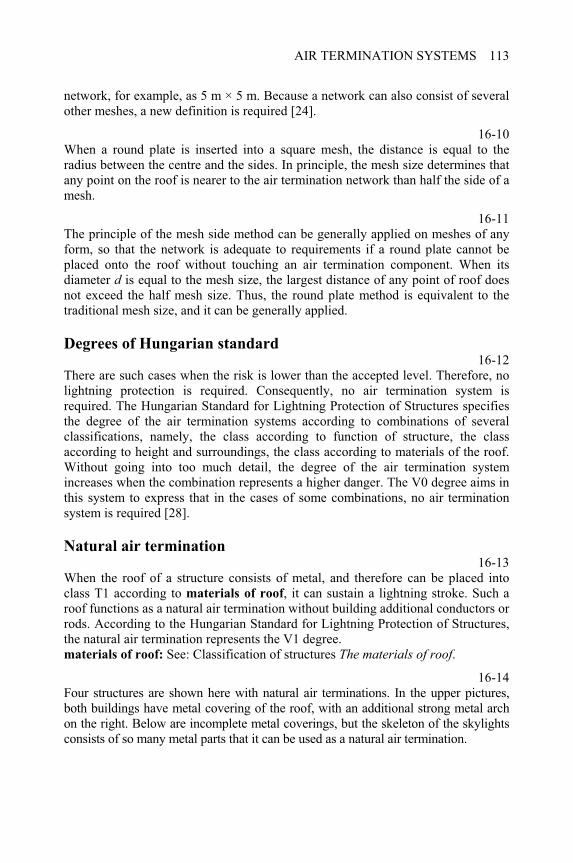
AIR TERMINATION SYSTEMS 113
network, for example, as 5 m × 5 m. Because a network can also consist of several other meshes, a new definition is required [24].
16-10When a round plate is inserted into a square mesh, the distance is equal to the radius between the centre and the sides. In principle, the mesh size determines that any point on the roof is nearer to the air termination network than half the side of a mesh.
16-11The principle of the mesh side method can be generally applied on meshes of any form, so that the network is adequate to requirements if a round plate cannot be placed onto the roof without touching an air termination component. When its diameter d is equal to the mesh size, the largest distance of any point of roof does not exceed the half mesh size. Thus, the round plate method is equivalent to the traditional mesh size, and it can be generally applied.
Degrees of Hungarian standard 16-12
There are such cases when the risk is lower than the accepted level. Therefore, no lightning protection is required. Consequently, no air termination system is required. The Hungarian Standard for Lightning Protection of Structures specifies the degree of the air termination systems according to combinations of several classifications, namely, the class according to function of structure, the class according to height and surroundings, the class according to materials of the roof. Without going into too much detail, the degree of the air termination system increases when the combination represents a higher danger. The V0 degree aims in this system to express that in the cases of some combinations, no air termination system is required [28].
Natural air termination 16-13
When the roof of a structure consists of metal, and therefore can be placed into class T1 according to materials of roof, it can sustain a lightning stroke. Such a roof functions as a natural air termination without building additional conductors or rods. According to the Hungarian Standard for Lightning Protection of Structures, the natural air termination represents the V1 degree. materials of roof: See: Classification of structures The materials of roof.
16-14Four structures are shown here with natural air terminations. In the upper pictures, both buildings have metal covering of the roof, with an additional strong metal arch on the right. Below are incomplete metal coverings, but the skeleton of the skylights consists of so many metal parts that it can be used as a natural air termination.
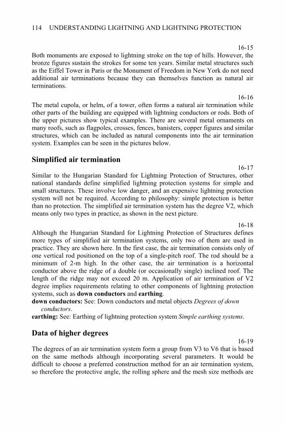
UNDERSTANDING LIGHTNING AND LIGHTNING PROTECTION114
16-15Both monuments are exposed to lightning stroke on the top of hills. However, the bronze figures sustain the strokes for some ten years. Similar metal structures such as the Eiffel Tower in Paris or the Monument of Freedom in New York do not need additional air terminations because they can themselves function as natural air terminations.
16-16The metal cupola, or helm, of a tower, often forms a natural air termination while other parts of the building are equipped with lightning conductors or rods. Both of the upper pictures show typical examples. There are several metal ornaments on many roofs, such as flagpoles, crosses, fences, banisters, copper figures and similar structures, which can be included as natural components into the air termination system. Examples can be seen in the pictures below.
Simplified air termination 16-17
Similar to the Hungarian Standard for Lightning Protection of Structures, other national standards define simplified lightning protection systems for simple and small structures. These involve low danger, and an expensive lightning protection system will not be required. According to philosophy: simple protection is better than no protection. The simplified air termination system has the degree V2, which means only two types in practice, as shown in the next picture.
16-18Although the Hungarian Standard for Lightning Protection of Structures defines more types of simplified air termination systems, only two of them are used in practice. They are shown here. In the first case, the air termination consists only of one vertical rod positioned on the top of a single-pitch roof. The rod should be a minimum of 2-m high. In the other case, the air termination is a horizontal conductor above the ridge of a double (or occasionally single) inclined roof. The length of the ridge may not exceed 20 m. Application of air termination of V2 degree implies requirements relating to other components of lightning protection systems, such as down conductors and earthing.down conductors: See: Down conductors and metal objects Degrees of down
conductors.earthing: See: Earthing of lightning protection system Simple earthing systems.
Data of higher degrees 16-19
The degrees of an air termination system form a group from V3 to V6 that is based on the same methods although incorporating several parameters. It would be difficult to choose a preferred construction method for an air termination system, so therefore the protective angle, the rolling sphere and the mesh size methods are
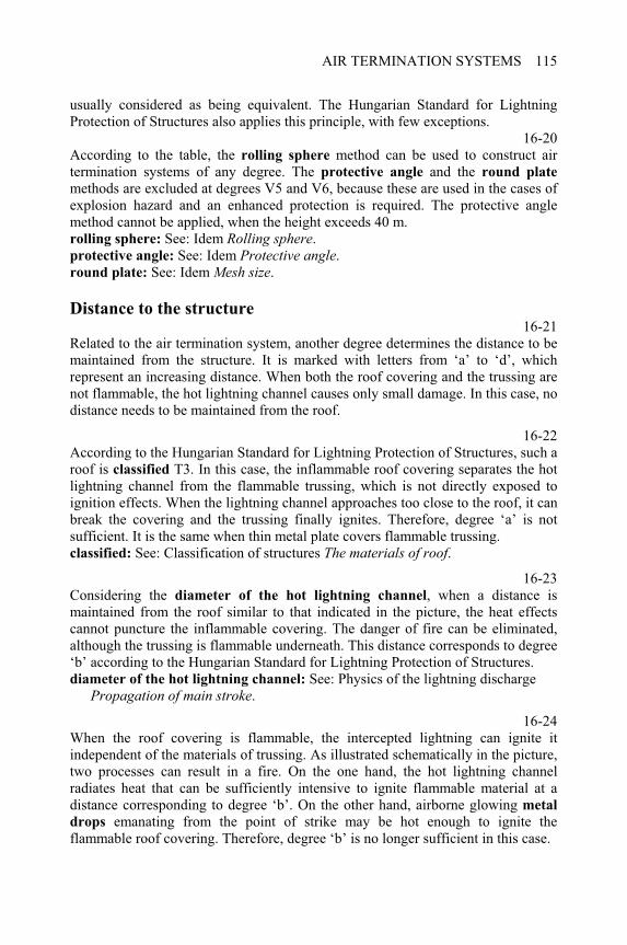
AIR TERMINATION SYSTEMS 115
usually considered as being equivalent. The Hungarian Standard for Lightning Protection of Structures also applies this principle, with few exceptions.
16-20According to the table, the rolling sphere method can be used to construct air termination systems of any degree. The protective angle and the round plate
methods are excluded at degrees V5 and V6, because these are used in the cases of explosion hazard and an enhanced protection is required. The protective angle method cannot be applied, when the height exceeds 40 m. rolling sphere: See: Idem Rolling sphere.protective angle: See: Idem Protective angle.round plate: See: Idem Mesh size.
Distance to the structure 16-21
Related to the air termination system, another degree determines the distance to be maintained from the structure. It is marked with letters from ‘a’ to ‘d’, which represent an increasing distance. When both the roof covering and the trussing are not flammable, the hot lightning channel causes only small damage. In this case, no distance needs to be maintained from the roof.
16-22According to the Hungarian Standard for Lightning Protection of Structures, such a roof is classified T3. In this case, the inflammable roof covering separates the hot lightning channel from the flammable trussing, which is not directly exposed to ignition effects. When the lightning channel approaches too close to the roof, it can break the covering and the trussing finally ignites. Therefore, degree ‘a’ is not sufficient. It is the same when thin metal plate covers flammable trussing. classified: See: Classification of structures The materials of roof.
16-23Considering the diameter of the hot lightning channel, when a distance is maintained from the roof similar to that indicated in the picture, the heat effects cannot puncture the inflammable covering. The danger of fire can be eliminated, although the trussing is flammable underneath. This distance corresponds to degree ‘b’ according to the Hungarian Standard for Lightning Protection of Structures. diameter of the hot lightning channel: See: Physics of the lightning discharge
Propagation of main stroke.
16-24When the roof covering is flammable, the intercepted lightning can ignite it independent of the materials of trussing. As illustrated schematically in the picture, two processes can result in a fire. On the one hand, the hot lightning channel radiates heat that can be sufficiently intensive to ignite flammable material at a distance corresponding to degree ‘b’. On the other hand, airborne glowing metal
drops emanating from the point of strike may be hot enough to ignite the flammable roof covering. Therefore, degree ‘b’ is no longer sufficient in this case.
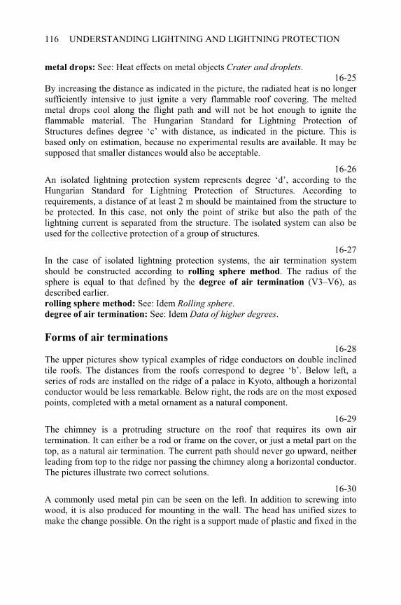
UNDERSTANDING LIGHTNING AND LIGHTNING PROTECTION116
metal drops: See: Heat effects on metal objects Crater and droplets.16-25
By increasing the distance as indicated in the picture, the radiated heat is no longer sufficiently intensive to just ignite a very flammable roof covering. The melted metal drops cool along the flight path and will not be hot enough to ignite the flammable material. The Hungarian Standard for Lightning Protection of Structures defines degree ‘c’ with distance, as indicated in the picture. This is based only on estimation, because no experimental results are available. It may be supposed that smaller distances would also be acceptable.
16-26An isolated lightning protection system represents degree ‘d’, according to the Hungarian Standard for Lightning Protection of Structures. According to requirements, a distance of at least 2 m should be maintained from the structure to be protected. In this case, not only the point of strike but also the path of the lightning current is separated from the structure. The isolated system can also be used for the collective protection of a group of structures.
16-27In the case of isolated lightning protection systems, the air termination system should be constructed according to rolling sphere method. The radius of the sphere is equal to that defined by the degree of air termination (V3–V6), as described earlier. rolling sphere method: See: Idem Rolling sphere.degree of air termination: See: Idem Data of higher degrees.
Forms of air terminations 16-28
The upper pictures show typical examples of ridge conductors on double inclined tile roofs. The distances from the roofs correspond to degree ‘b’. Below left, a series of rods are installed on the ridge of a palace in Kyoto, although a horizontal conductor would be less remarkable. Below right, the rods are on the most exposed points, completed with a metal ornament as a natural component.
16-29The chimney is a protruding structure on the roof that requires its own air termination. It can either be a rod or frame on the cover, or just a metal part on the top, as a natural air termination. The current path should never go upward, neither leading from top to the ridge nor passing the chimney along a horizontal conductor. The pictures illustrate two correct solutions.
16-30A commonly used metal pin can be seen on the left. In addition to screwing into wood, it is also produced for mounting in the wall. The head has unified sizes to make the change possible. On the right is a support made of plastic and fixed in the
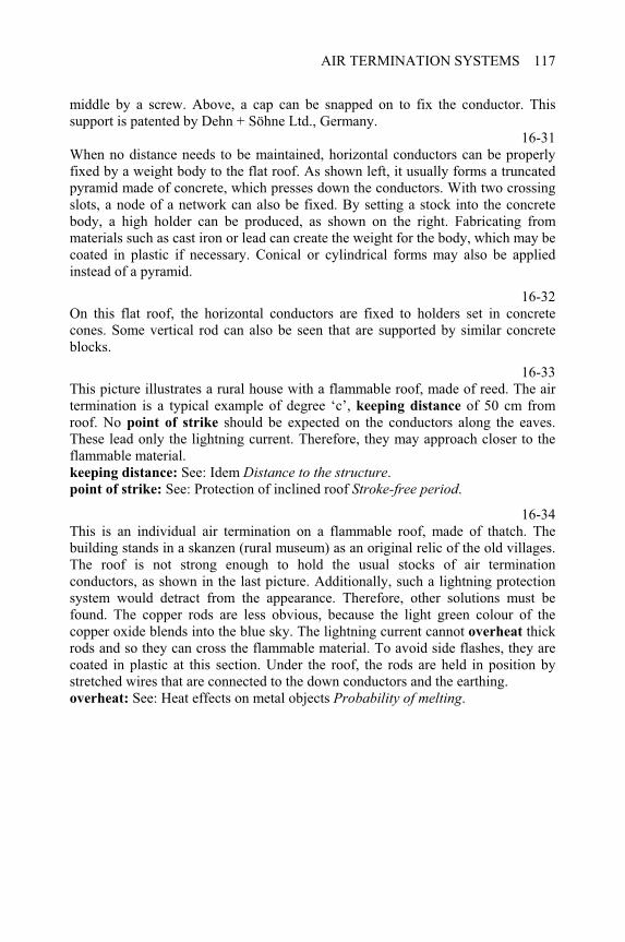
AIR TERMINATION SYSTEMS 117
middle by a screw. Above, a cap can be snapped on to fix the conductor. This support is patented by Dehn + Söhne Ltd., Germany.
16-31When no distance needs to be maintained, horizontal conductors can be properly fixed by a weight body to the flat roof. As shown left, it usually forms a truncated pyramid made of concrete, which presses down the conductors. With two crossing slots, a node of a network can also be fixed. By setting a stock into the concrete body, a high holder can be produced, as shown on the right. Fabricating from materials such as cast iron or lead can create the weight for the body, which may be coated in plastic if necessary. Conical or cylindrical forms may also be applied instead of a pyramid.
16-32On this flat roof, the horizontal conductors are fixed to holders set in concrete cones. Some vertical rod can also be seen that are supported by similar concrete blocks.
16-33This picture illustrates a rural house with a flammable roof, made of reed. The air termination is a typical example of degree ‘c’, keeping distance of 50 cm from roof. No point of strike should be expected on the conductors along the eaves. These lead only the lightning current. Therefore, they may approach closer to the flammable material. keeping distance: See: Idem Distance to the structure.point of strike: See: Protection of inclined roof Stroke-free period.
16-34This is an individual air termination on a flammable roof, made of thatch. The building stands in a skanzen (rural museum) as an original relic of the old villages. The roof is not strong enough to hold the usual stocks of air termination conductors, as shown in the last picture. Additionally, such a lightning protection system would detract from the appearance. Therefore, other solutions must be found. The copper rods are less obvious, because the light green colour of the copper oxide blends into the blue sky. The lightning current cannot overheat thick rods and so they can cross the flammable material. To avoid side flashes, they are coated in plastic at this section. Under the roof, the rods are held in position by stretched wires that are connected to the down conductors and the earthing. overheat: See: Heat effects on metal objects Probability of melting.

CHAPTER 17
Down conductors and metal objects
17-0Each item of this menu can be selected by double-clicking on it. The program displays several topics when the following items are selected: Down conductors: from Calculation of current paths to Forms of down conductors Vertical metal structures: from Dangerous loops to Elevators
Down conductors
Calculation of current paths
17-1Positioning the down conductors can be determined according to the requirement that the horizontal path of the lightning current should be as short as possible from any point of strike to the down conductor. Along this path, a voltage drop is produced which is proportional to the impedance of the conductors, and therefore, to the length of path. The impedance also depends upon the resistance and the inductance of the conductors, but they change within small ranges, and therefore the length can be considered as a relevant parameter.
17-2The horizontal path of the lightning current can be seen below in the case of a worst point of strike. The resulting value is the sum of the lengths of individual sections similar to series impedances. When the resulting length has an accepted limit, this determines the conditions of use by either the number or the given arrangement of the down conductors.
17-3This is another position of a single one down conductor that gives two symmetrical paths for the lightning current. The worst point of strike is at one of the ends of ridge, however because of the symmetry, they are equivalent.
____________________________________________________Understanding Lightning and Lightning Protection T. Horváth © 2006 Research Studies Press Limited
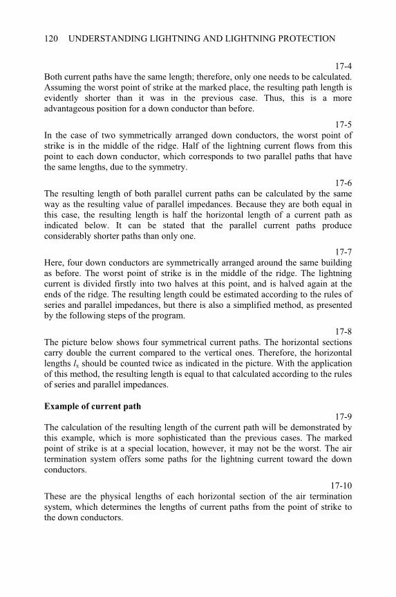
UNDERSTANDING LIGHTNING AND LIGHTNING PROTECTION120
17-4Both current paths have the same length; therefore, only one needs to be calculated. Assuming the worst point of strike at the marked place, the resulting path length is evidently shorter than it was in the previous case. Thus, this is a more advantageous position for a down conductor than before.
17-5In the case of two symmetrically arranged down conductors, the worst point of strike is in the middle of the ridge. Half of the lightning current flows from this point to each down conductor, which corresponds to two parallel paths that have the same lengths, due to the symmetry.
17-6The resulting length of both parallel current paths can be calculated by the same way as the resulting value of parallel impedances. Because they are both equal in this case, the resulting length is half the horizontal length of a current path as indicated below. It can be stated that the parallel current paths produce considerably shorter paths than only one.
17-7Here, four down conductors are symmetrically arranged around the same building as before. The worst point of strike is in the middle of the ridge. The lightning current is divided firstly into two halves at this point, and is halved again at the ends of the ridge. The resulting length could be estimated according to the rules of series and parallel impedances, but there is also a simplified method, as presented by the following steps of the program.
17-8The picture below shows four symmetrical current paths. The horizontal sections carry double the current compared to the vertical ones. Therefore, the horizontal lengths lx should be counted twice as indicated in the picture. With the application of this method, the resulting length is equal to that calculated according to the rules of series and parallel impedances.
Example of current path
17-9The calculation of the resulting length of the current path will be demonstrated by this example, which is more sophisticated than the previous cases. The marked point of strike is at a special location, however, it may not be the worst. The air termination system offers some paths for the lightning current toward the down conductors.
17-10These are the physical lengths of each horizontal section of the air termination system, which determines the lengths of current paths from the point of strike to the down conductors.
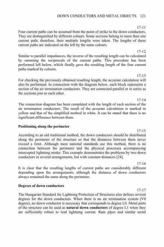
DOWN CONDUCTORS AND METAL OBJECTS 121
17-11Four current paths can be assumed from the point of strike to the down conductors. They are distinguished by different colours. Some sections belong to more than one current path; therefore, their multiple lengths were taken. The lengths of these current paths are indicated on the left by the same colours.
17-12Similar to parallel impedances, the inverse of the resulting length can be calculated by summing the reciprocals of the current paths. This procedure has been performed left below, which finally gave the resulting length of the four current paths marked by colours.
17-13For checking the previously obtained resulting length, the accurate calculation will also be performed. In connection with the diagram below, each block represents a section of the air termination conductors. They are connected parallel or in series as the sections join to each other.
17-14The connection diagram has been completed with the length of each section of the air termination conductors. The result of the accurate calculation is marked in yellow and that of the simplified method in white. It can be stated that there is no significant difference between them.
Positioning along the perimeter
17-15According to an old traditional method, the down conductors should be distributed along the perimeter of the structure so that the distances between them never exceed a limit. Although most national standards use this method, there is no connection between the perimeter and the physical processes accompanying intercepted lightning stroke. This example demonstrates the problems by two down conductors in several arrangements, but with constant distances [24].
17-16It is clear that the resulting lengths of current paths are considerably different depending upon the arrangements, although the distance of down conductors always remained the same along the perimeter.
Degrees of down conductors
17-17The Hungarian Standard for Lightning Protection of Structures also defines several degrees for the down conductors. When there is no air termination system (V0 degree), no down conductor is necessary that corresponds to degree L0. Metal parts of the structure can be used as natural down conductors of degree L1 when they are sufficiently robust to lead lightning current. Rain pipes and similar metal
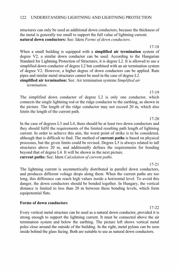
UNDERSTANDING LIGHTNING AND LIGHTNING PROTECTION122
structures can only be used as additional down conductors, because the thickness of the metal is generally too small to support the full value of lightning current. natural down conductors: See: Idem Forms of down conductors.
17-18When a small building is equipped with a simplified air termination system of degree V2, a similar down conductor can be used. According to the Hungarian Standard for Lightning Protection of Structures, it is degree L2. It is allowed to use a simplified down conductor of degree L2 but combined with an air termination system of degree V2. However, a higher degree of down conductors can be applied. Rain pipes and similar metal structures cannot be used in the case of degree L2. simplified air termination: See: Air termination systems Simplified air
termination.
17-19The simplified down conductor of degree L2 is only one conductor, which connects the single lightning rod or the ridge conductor to the earthing, as shown in the picture. The length of the ridge conductor may not exceed 20 m, which also limits the length of the current path.
17-20In the case of degrees L3 and L4, there should be at least two down conductors and they should fulfil the requirements of the limited resulting path length of lightning current. In order to achieve this aim, the worst point of strike is to be considered, although that is difficult to find. The method of current paths is based on physical processes, but the given limits could be revised. Degree L5 is always related to tall structures above 20 m, and additionally defines the requirements for bonding beyond that of degree L4. It will be shown in the next picture. current paths: See: Idem Calculation of current paths.
17-21The lightning current is asymmetrically distributed in parallel down conductors, and produces different voltage drops along them. When the current paths are too long, this difference can reach high values inside a horizontal level. To avoid this danger, the down conductors should be bonded together. In Hungary, the vertical distance is limited to less than 20 m between these bonding levels, which form equipotential flats.
Forms of down conductors
17-22Every vertical metal structure can be used as a natural down conductor, provided it is strong enough to support the lightning current. It must be connected above the air termination system and below the earthing. The picture left shows vertical metal poles close around the outside of the building. In the right, metal pylons can be seen inside behind the glass facing. Both are suitable to use as natural down conductors.
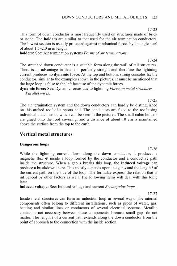
DOWN CONDUCTORS AND METAL OBJECTS 123
17-23This form of down conductor is most frequently used on structures made of brick or stone. The holders are similar to that used for the air termination conductors. The lowest section is usually protected against mechanical forces by an angle steel of about 1.5–2.0 m in length. holders: See: Air termination systems Forms of air terminations.
17-24The stretched down conductor is a suitable form along the wall of tall structures. There is an advantage in that it is perfectly straight and therefore the lightning current produces no dynamic force. At the top and bottom, strong consoles fix the conductor, similar to the examples shown in the pictures. It must be mentioned that the large loop is false to the left because of the dynamic forces. dynamic force: See: Dynamic forces due to lightning Force on metal structures -
Parallel wires.
17-25The air termination system and the down conductors can hardly be distinguished on this arched roof of a sports hall. The conductors are fixed to the roof using individual attachments, which can be seen in the pictures. The small cubic holders are glued onto the roof covering, and a distance of about 10 cm is maintained above the surface from the top to the earth.
Vertical metal structures
Dangerous loops
17-26While the lightning current flows along the down conductor, it produces a magnetic flux inside a loop formed by the conductor and a conductive path inside the structure. When a gap s breaks this loop, the induced voltage can produce a breakdown there. This mostly depends upon the gap s and the length l of the current path on the side of the loop. The formulae express the relation that is influenced by other factors as well. The following items will deal with this topic later.induced voltage: See: Induced voltage and current Rectangular loops.
17-27Inside metal structures can form an induction loop in several ways. The internal components often belong to different installations, such as pipes of water, gas, heating and similar lines or conductors of several electrical systems. Metallic contact is not necessary between these components, because small gaps do not matter. The length l of a current path extends along the down conductor from the point of approach to the connection with the inside section.
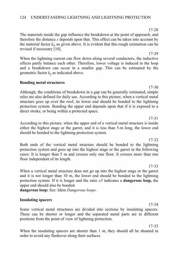
UNDERSTANDING LIGHTNING AND LIGHTNING PROTECTION124
17-28The materials inside the gap influence the breakdown at the point of approach; and therefore the distance s depends upon that. This effect can be taken into account by the material factor km as given above. It is evident that this rough estimation can be revised if necessary [10].
17-29When the lightning current can flow down along several conductors, the inductive effects partly balance each other. Therefore, lower voltage is induced in the loop and a breakdown can occur in a smaller gap. This can be estimated by the geometric factor kg as indicated above.
Bonding metal structures
17-30Although, the conditions of breakdown in a gap can be generally estimated, simple rules are also defined for daily use. According to this picture, when a vertical metal structure goes up over the roof, its lower end should be bonded to the lightning protection system. Bonding the upper end depends upon that if it is exposed to a direct stroke, or being within a protected space.
17-31According to this picture, when the upper end of a vertical metal structure is inside either the highest stage or the garret, and it is less than 5-m long, the lower end should be bonded to the lightning protection system.
17-32Both ends of the vertical metal structure should be bonded to the lightning protection system and goes up into the highest stage or the garret in the following cases: It is longer than 5 m and crosses only one floor. It crosses more than one floor independent of its length.
17-33When a vertical metal structure does not go up into the highest stage or the garret and it is not longer than 10 m, the lower end should be bonded to the lightning protection system. If it is longer and the ratio s/l indicates a dangerous loop, the upper end should also be bonded. dangerous loop: See: Idem Dangerous loops.
Insulating spacers
17-34Some vertical metal structures are divided into sections by insulating spacers. These can be shorter or longer and the separated metal parts are in different positions from the point of view of lightning protection.
17-35When the insulating spacers are shorter than 1 m, they should all be shunted in order to avoid any flashover along their surfaces.
DOWN CONDUCTORS AND METAL OBJECTS 125
17-36When the insulating spacers are longer than 1 m, the upper and lower metal parts should be bonded to the lightning protection system in all cases. When the structure is classified as an enhanced danger, either all separated metal sections should be bonded (as illustrated here), or every insulating spacer should be shunted. classified: See: Classification of structures Classes of structures.
Elevators17-37
The elevators represent typical examples for vertical metal structures with their lift guides and cables, which extend from the top to the ground. The engine room often protrudes above the roof and the lift control consists of electronic equipment. Therefore, the lightning cannot only cause damage, but also threatens the people travelling in the elevators.
17-38The lightning current cannot be turned out of the lift guides, but they must lead it down without damage. Therefore, the rails should be connected together at the top and bottom, bonding them above the air termination system and below the earthing. The rails are always strong enough to sustain the effects of lightning current. To avoid any side flash, the connection to the earth should never lead the current upwards.

CHAPTER 18
Earthing of lightning protection
system
18-0Each item of this menu can be selected by double-clicking on it. The program displays several topics when the following items are selected: Lightning protection earthing: from Degrees of earthing to Earthing by foundation.Degrees of earthing: from Natural earthing to Normal and enhanced systems.Measuring of earth resistance: from Soil resistivity to Resistance of earth electrode.
Degrees of earthing 18-1
Lightning protection earthing aims to distribute lightning current in the soil without causing any damage. The Hungarian Standard for Lightning Protection of Structures defines several degrees of earthing systems with consideration of the danger of consequences due to a lightning stroke. Degree F0 means that no earthing is necessary because there is no lightning protection system to be earthed. Degree F1 marks natural earthing that can either be a metal structure in the soil or embedded in concrete under the earth. A metal structure is not suitable as an earthing electrode if it is coated with insulating material.
Natural earthing 18-2
Several pipelines represent typical examples of natural earthing electrodes. The pipes are usually strong enough to support lightning current and to create good contact to the soil over large surfaces. A thin insulating coat cannot prevent the lightning current from flowing into the earth. However, the current will be concentrated in some point at a puncture, which melts holes in the pipe. Therefore, insulated pipes are not suitable for earthing. When the pipeline is equipped with cathodic protection against corrosion, the pipes are suitable for earthing electrodes, ____________________________________________________Understanding Lightning and Lightning Protection T. Horváth © 2006 Research Studies Press Limited
UNDERSTANDING LIGHTNING AND LIGHTNING PROTECTION128
because they are in direct contact with the earth, but the electrical equipment needs adequate surge protection.surge protection: See: Surge protection devices + Types of protection devices.
18-3The bore rod produces such a good contact to the earth and distribution of the lightning current, that it surpasses any building earthing system. Thus, it is an ideal earth electrode for lightning protection. Any other structure should be connected to the boring tower in the surroundings.
18-4The pylons of overhead pipelines usually have reinforced concrete foundation blocks, which are embedded into the soil without any insulation. Such foundation forms good natural earthing for lightning protection and therefore, no additional earth electrode is necessary.
Simple earthing systems 18-5
A simplified lightning protection system consists of only one down conductor
that contacts to a simple earthing system of degree F2/x, in which ‘x’ means that the standard determines only the typical forms and the required smallest sizes of earth electrodes. However, there is no other prescription concerning the earthing
resistance in this case simplified lightning protection: See: Air termination systems + Simplified air
termination.down conductor: See: Down conductors and metal objects + Degrees of down
conductors.earthing resistance: See: Idem + Normal and enhanced systems.
18-6The earthing rod is the most frequently used type of earth electrode, whose length is minimised by degree F2/x as indicated in the picture. The material and the smallest thickness depend upon the corrosion. Therefore, aluminium must not be used in the earth. It is also known that the pipes sustain worse corrosion than solid bars.
18-7The horizontal earth electrode is preferred when the soil contains stones or becomes too hard at depth. There are also many other cases when it is easier to dig a ditch rather than drive a rod into the earth. However, the horizontal earth electrode should be laid at a depth of about 0.8–1.0-m.
18-8An old traditional type of simple earth electrode is a vertical metal plate. According to degree F2/x, the area that contacts to the soil should be greater than 5 m2, as indicated in the picture. That usually means both sides of the plate, if it is perpendicular to a wall. The plate must not be laid horizontally, because water can wash away the soil below it.
EARTHING OF LIGHTNING PROTECTION SYSTEM 129
18-9A foundation made of reinforced concrete can also form earthing of degree F2/x when the area that comes into contact with the soil is greater 5 m2, as indicated in the picture. If the concrete surface has waterproof coating that insulates it from the earth, then the foundation is not suitable as earthing for lightning protection. waterproof coating: See: Idem + Earthing by foundation.
Earthing resistance 18-10
The earthing resistance can be represented by an imaginary resistor whose one clamp is the earth electrode and the other the earth, at a theoretically infinite distance. To put it more simply, the phenomena will be studied on a hemispherical earth electrode. Although such a shape does not occur in practice, other types of earth electrodes are often reduced to this. The current penetrates radially into the earth from this electrode and its density changes according to the formula indicated at the top.
18-11The continuously distributed current produces an electric field in the earth, whose equipotential lines are plotted by white circular arcs in the picture. The gradient E(V/m) of this field can be expressed by the displayed formula in which ( m) is the resistivity of the soil and J (A/m2) the current density. The field gradient naturally decreases with increasing distance x (m) until it finally becomes zero at an infinite distance.
18-12Assuming zero potential in infinity, the potential changes in the earth as plotted by red in the diagram, against the distance x. The highest voltage is expressed on top with the integral of field strength E from infinity to radius r of the hemispherical electrode. The current produces this voltage drop along the resistance of the earth.
18-13With replacing the relevant relations and after performing the operations, the upper formula represents the rise of potential U on the hemispherical electrode in relation to infinity. It is a function of the current i that flows into the earth through the earth electrode. The earthing resistance RF can be expressed by their quotient as indicated by the lower formula shown above.
18-14It seems to be evident that the earthing resistance should be low in order to limit the rise of voltage to an acceptable level. However, it is a vain hope to make an earthing system that can limit the voltage to the millivolt range if 100 kA is flowing. According to another concept, a side flash must be avoided from earth electrodes to any extraneous metal structure in earth. Large structures are usually bonded to the earthing system; therefore, small ones are only to be expected. This suggests that the earthing system should be significantly larger than any other structure. This principle can be written so that the radius of an equivalent
UNDERSTANDING LIGHTNING AND LIGHTNING PROTECTION130
hemispherical electrode of the earthing system should be at least (for example) a tenth of its extension. It will be applied and explained in the next few steps.
18-15The principle that the radius of a sphere should be a tenth the size of the structure suggests that the ratio of areas should be 1 to 100. The relation between the radius rand the area A can be replaced in the relation for the earthing resistance that was quoted in the last formula.
18-16After performing the numerical operations, and with the simplification of the coefficient, the lowest relation determines the upper limit of the resulting earthing resistance. This should be lower with decreasing resistivity of the soil ( m) and with the increasing area A (m2) of the structure.
Normal and enhanced systems 18-17
The degrees F3/r and F4/r define the requirements for the earthing resistance that the letter ‘r’ symbolises. Because at least two down conductors are always connected to the earthing, at least two earth electrodes are required. The limits are the same in both cases, and based on the relationship that has been obtained following the principle that the earthing resistance of the lightning protection system should be significantly lower than that of any metal structure in earth. Degree F4/r defines an additional requirement that the earthing system should form a frame around the structure or a network under its area.
18-18It can be seen that the earthing resistance of each individual earth electrode can be double of that related to the total earthing system as resulting value. Both formulae are based on the study performed earlier. If the earthing resistance is less than 2
, then it should be acceptable independent of the result of the formulae. During the measurement of the resulting value, all down conductors should be connected to the earthing, as shown left. To measure the individual values, each connection should be opened in turn while all the others are closed, as shown right. It is dangerous to open all the connections at the same time. study performed earlier: See: Idem + Earthing resistance.
18-19When the resulting value of earthing resistance is sufficient, but an individual value does not fulfil the requirements, some earth electrodes should be connected together until the earthing resistance of this group is acceptable. The connection can be made either above or below the ground level, but near it, as shown in the pictures. In this case, the permanently connected group represents an individual component of the earthing system.
EARTHING OF LIGHTNING PROTECTION SYSTEM 131
18-20Opening the connections to the earthing system can be utilised to check the continuity of external lightning protection system above the earth. When considerably higher resistance would be measured between the open clamps than the resulting earthing resistance, then a continuity failure can be assumed. This method has an important advantage in that it is not necessary to climb to great heights.
18-21Degree F4/r requires a frame or network that always form permanently connected earthing systems. Therefore, any individual earthing resistance cannot be defined. The resulting earthing resistance can be measured at any connection point, and it must result in almost the same value. A big difference would indicate an underground failure of the earthing that has probably been caused by corrosion.
Earthing by foundation 18-22
Concrete foundations draw water from the soil and become electrically conductive. The resistivity is similar to the earth; that is neither too wet nor too dry. Therefore, metal electrodes embedded in concrete can be used as earth terminals of a lightning protection system. The groundwork evidently begins with bench excavation. resistivity: See: Idem + Soil resistivity.
18-23First, the bedplate is covered with a layer of gravel on top of which the earthing electrodes can be prepared. They usually form a frame or a mat consisting of horizontal conductors. The connections should be made by welding or by screw clamps. The connecting terminals also need to be prepared at this time, because installation would become impossible later on in the construction sequence.
18-24The electrodes are embedded in the base concrete, which is not insulated against the soil moisture. This sheet is loaded only by the pressure of the weight of the structure, and therefore the metal elements have no reinforcing purpose.
18-25The waterproof sheet separates the upper concrete body of foundation from the moist soil, while the adjacent concrete contacts the wet earth. This sheet is not only waterproof but also electrically insulating. The connecting terminals should cross this sealed sheet.
18-26Strictly speaking, the foundation is the reinforced concrete body that is insulated from earth. In contrast, the earthing system consists of the frame or mat lying in concrete under the insulation. However, in this case, it only functions when the connecting terminals are prepared in good time.
UNDERSTANDING LIGHTNING AND LIGHTNING PROTECTION132
Soil resistivity 18-27
The soil resistivity is equal to the resistance of a cube of unit side length between two opposite faces, as shown in the picture. It is related to path length 1 m and cross section 1 m2, which result the dimension Ohmmetre.
18-28It can be stated that the resistivity of several types of soil varies over a great range and it is considerably influenced by the moisture and the embedded stones [9].
18-29The current paths and the equipotential surfaces may be calculated accurately in homogeneous soil, when the current flows between the external electrodes. The current and the voltage measured between the internal electrodes give a relation from which the resistivity can be expressed. In the case of inhomogeneous soil, the larger the distance a between the electrodes, the deeper the layers of soil used to determine the resistivity.
Measurement of earthing resistance 18-30
The source G drives a measured current through the earth between the earthing terminal and a distant earth electrode. The voltage is measured between the terminal and is related to another earth probe that is usually located approximately in the middle.
18-31The earthing resistance is defined as the quotient of the rise of potential u related to infinity and the current i flowing in the earthing terminal. The inserted diagram shows the potential between the external electrodes, from which zero potential can be assumed to be in the middle. Thus, the instrument V measures the voltage rise related to the neutral earth potential. earthing resistance: See Idem + Earthing resistance.
Impulse earthing 18-32
When lightning current flows into the earth, the impulse current produces a high electric field around the earth electrode, which causes breakdowns in the soil. While the current grows, the breakdown propagates in the soil and virtually extends to the dimension of the earth electrode.
18-33This is the sand fused by lightning current in a desert. The dry sand could be easily removed; therefore, only thin branches have broken off.
EARTHING OF LIGHTNING PROTECTION SYSTEM 133
18-34The quotient of voltage and current continuously changes, and so, the earthing resistance cannot be exactly defined. The momentary value decreases due to the breakdown in the soil around the earth electrode. The quotient of the peak values is usually taken as an impulse resistance. However, they occur at different times.

CHAPTER 19
Lightning electromagnetic impulse
19-0Each item of this menu can be selected by double-clicking on it. The program displays several topics when the following items are selected: Coupling of lightning effects: from Conductive coupling to Capacitive coupling.Conducted current: from Distribution to Arriving on branched line.Shielding: from Faraday holes to Shielded cable.
Conductive coupling 19-1
The lightning current produces a voltage drop u on earthing resistance RF, led away by conductors or other metal structures. This is known as conductive coupling. Consequently, the potential of the entire structure rises relative to neutral earth potential. Because the median lightning current is about 30 kA, and 1 is an excellent earthing resistance, the raised potential can frequently exceed 30 kV. earthing resistance: See: Earthing of lightning protection system Earthing
resistance.median lightning current: See: Physics of the lightning discharge Lightning
parameters.
19-2When an insulated line enters the structure, the remote potential is also led into it. This is separated from the raised potential inside the connected device by a small gap. The high over-voltage first produces a breakdown followed by a high impulse current inside the device, symbolised with red filling left. After destroying this device, the raised potential is led into the structure right, which in turn also results in damage. The lightning effects are transported by conductive coupling onto the distant surroundings. lightning effects are transported: See: Idem Conducted current.
____________________________________________________Understanding Lightning and Lightning Protection T. Horváth © 2006 Research Studies Press Limited
UNDERSTANDING LIGHTNING AND LIGHTNING PROTECTION136
Inductive coupling 19-3
The lightning current produces a magnetic field around its path, which can create inductive coupling to electric systems, which can also occur in the case of a distant stroke. The electric lines form loops that are sometimes completed by other metal structures or the earth. When a loop encloses magnetic flux due to lightning, induced voltage and current are produced, which can reach high values causing severe damage. induced voltage and current: See: Induced voltage and current Calculated
examples.
19-4The induced voltage u can be calculated using the relationship indicated below. In this formula, M represents the mutual inductance between the loop and the path of the lightning current; div/dt is the steepness of the lightning current iv, which occurs according to statistical distribution. When electrical devices are inserted into the loop, the induced voltage appears across small gaps inside them, leading first to a breakdown and then an impulse current, which causes damage. statistical distribution: See: Physics of the lightning discharge Lightning
parameters.
Capacitive coupling 19-5
The electric field produced by the lightning channel affects the conductors and other insulated metal structures. This effect can be represented by capacitors Cv
between the conductors and the lightning channel, which have a capacity CF to ground. The voltage uv of the lightning channel is divided by the capacities according to the relation shown below. This expresses the voltage u on the insulated conductors or metal structures, which also appears in the connected devices.
19-6When breakdowns are caused by the capacitive divided voltage in electrical devices symbolised with red filling, the capacity CF to the ground becomes short-circuited. Then capacitive current flows from the lightning channel through the capacity Cv toward the earth, which is distributed among the damaged devices. Below, a relation expresses the sum of these currents. Because Cv is small, the current iC is low and does not cause severe damage.
Distribution of current 19-7
According to a simple assumption, half the lightning current flows down the local earthing. The other half current is distributed among the outgoing conductors and other metal structures. In spite of the rough approximation, it is widely used as a first estimation [9, 10].
LIGHTNING ELECTROMAGNETIC IMPULSE 137
19-8The earthing of the structure and all other objects to be earthed are interconnected by the equipotential bonding bar (EBB). According to further simplification, the arriving current is equally distributed here among the outgoing conductors and metal lines. The picture shows an electrical conductor and a pipeline, each carrying a current i/4.
19-9The electrical line branches again at the pole in the street. By application of the previous assumption, half the arriving current flows to the local earthing that means i/8. The remainder is distributed in the three branches of the line and so each line carries a current of i/24. It can be stated that after more branching the current decreases considerably.
Arriving current along a single line 19-10
In contrast to the distribution of known current, the question is here: How big a lightning current should flow at the point of strike to arrive at a given current at a structure? In this case, a single line leads the current to each pole that is earthed, the current branches and a part flows down to the earth. If this is a low voltage or a telecommunication line, the insulators will certainly be shorted by flashovers, but the same happens with medium voltage lines up to 30 kV rated voltage. This line also models an overhead pipeline.
19-11When the lightning strikes the line at any pole, half of the current flows down to the earthing, while the remainder is distributed on the line in both directions. The ratios of the currents in different branches are always the same.
19-12To achieve a current i at the structure, the indicated 4i should be the lightning current at the first pole indexed by k = 1. The red marked values are related to the lightning current at the corresponding point. The blue marked values represent the current flowing along the section of the line.
19-13The point of strike removed pole-by-pole results in the red marked currents at the point of strike, and the blue marked ones in the line sections. The sections have the same index k as the point of strike at their right end. The coefficients can be calculated with the relations marked red and blue in the middle. The last current distribution is shown below. It can be assumed that the farther the stroke, the higher lightning current is required to produce the same arriving current.
19-14Because higher lightning current is required to produce a given arriving current, its probability of occurrence decreases. Considering the statistical distribution of
UNDERSTANDING LIGHTNING AND LIGHTNING PROTECTION138
lightning current, the expected period of the arriving current can be estimated. This diagram is related to a single line with several spacings between the poles. statistical distribution: See: Physics of the lightning discharge Lightning
parameters.
Arriving current along branching line 19-15
In this case, the question is the same as last time: How big a lightning current should flow at the point of strike to arrive at a given current at a structure? This time, the line that leads the current branches at each pole. Therefore, a proportion flows down to the earth while the remainder is distributed in three directions. The line can be part of a low voltage or telecommunication network either cable or overhead. This configuration models the distribution network of a built-up area in a town or a village. The building density determines the distances between the nodes or earthing points along the line.
19-16When the lightning strikes the line at any node, half of the current flows down to the earthing, while the remainder is distributed on the lines in all directions. The ratios of the currents in different branches are always the same.
19-17To achieve a current i at the structure, the indicated 8i should be the lightning current at the first node, indexed by k = 1. The red marked values represent the lightning current at the corresponding point. The blue marked values represent the current flowing along the section of the line.
19-18With the point of strike removed node by node, this results in the red marked currents at the point of strike and the blue marked ones in the line sections. The sections have the same index k as the point of strike at their right end. The coefficients can be calculated with the relations marked red and blue in the middle. The last current distribution is shown below. On removing the point of strike, a considerably higher lightning current is necessary to create the same arriving current.
19-19Because higher lightning current is required to produce a given arriving current, its probability of occurrence decreases. Considering the statistical distribution of lightning current, the expected period of the arriving current can be estimated. This diagram is related to a branching line with several distances between nodes. It can be assumed that the occurrences of high currents are very rare. statistical distribution: See: Physics of the lightning discharge Lightning
parameters.
LIGHTNING ELECTROMAGNETIC IMPULSE 139
Faraday holes 19-20
The full shielding excludes the penetration of all electromagnetic field into the shielded space, but it can only be realised rarely with a completely continuous encapsulation made of thick metal plate. It is called a Faraday cage. In contrast, walls made of bricks, stones, concrete, cob or similar electrical conductive materials mostly produce partial shielding against electric fields. However, the magnetic field penetrates into the structures built of these materials [9].
19-21When the continuity of shielding is broken, the electromagnetic fields can penetrate inside the structure through the Faraday hole. The high frequency electromagnetic waves propagate as if the hole was a source of the penetrating field. This is valid in relation to the high frequency components of electromagnetic fields created by lightning.
19-22In practice, the shielding does not exclude the electromagnetic field, but damps it to a lower level. The shielding usually forms a grid consisting of metal rods or wires. The damping is more effective if the mesh gauge of the grid is small, the metal elements are good conductive and thick. On moving towards the interior of the shielded room, the damping usually increases. This follows from the fact that the external field can penetrate deeper if the mesh gauge is large.
19-23Faraday holes can also occur in the case when the shielding seems to be continuous. The cables represent a typical example, if they lead external potential along insulated conductors into the shielded room. This time, the end of such a cable or the connecting device operates as an antenna and radiates an electromagnetic field inside the shielded room. This type of Faraday hole can be very difficult to detect.
19-24The magnetic field can penetrate into the shielded room if the lightning current passes through. Although the cable has no connection inside the room, its current produces a magnetic field around itself, which can cause damage by induction. A small relay station represents a typical example, where the cables from the aerial tower enter the shielded room on one side and the power supply is on the opposite side. The different systems meet inside the equipment with small gaps that can break down under the effects of lightning current. relay station: See: Protection of electronic devices Relay station.
Shielded entrance 19-25
A shielded cable should be connected to an encapsulated room of a device that the shielding reserves the continuity. For this purpose, the cable shielding should join
UNDERSTANDING LIGHTNING AND LIGHTNING PROTECTION140
to a connecting tube of plug, which can slip into a counter tube of the receptacle on the wall of the device. The picture illustrates the connection prior to plugging.
19-26After plugging the connection, the fitting tubes of the plug and the socket ensure continuous connection of cable shielding to the metal encapsulation of the device. Thus, the connection forms a Faraday cage inside the cable and the device.
19-27In this case, the cable shielding joins to metal parts of the plug, but the tube fails, which could make contact to the receptacle on the wall of the device. This is the structure of a simple banana plug, which can also be connected to a shielded receptor of a device.
19-28After plugging, the plug does not present a continuous connection between the cable shielding and the receptacle. Therefore, a Faraday hole appears at this point. The simple banana plug cannot ensure adequate shielding even if the cable shielding is bonded to the device by a bridging conductor.
19-29In the case of a constant connection, the shielded cable can be led into the device crossing the metal plate of the encapsulation. The edge of the entrance hole is usually equipped with an elastic ring to avoid mechanical damage to the cable. Because it is made of insulating material, a Faraday hole appears around the cable. If the cable shielding penetrates, then it radiates an electromagnetic field like an antenna, and removal of the shielding will not solve this problem. Bonding the cable shielding either outside or inside will be also useless. Thus, the ring should be made of conductive material.
Shielded cable 19-30
When a shielded cable terminates in a structure, which can be struck by lightning, lightning current flows away along the shielding. If it is assumed that a protection
device limits the voltage difference between the conductor and the shielding of the cable at this place, then it begs the question: How does this voltage change if the lightning current flows in the shielding along the cable? protection device: See: Surge protection devices Types of surge protectors.
19-31The impulse current produces a voltage drop along the shielding of the cable, which consists of resistive and inductive components. Capacitive coupling also occurs between the cable shielding and the inside conductor. Due to this capacitive coupling, the potential of the conductor experiences an inductive drop. Therefore, a resistive voltage only appears at the end between the conductor and the shielding. In the relations, Ro represents the impulse resistance of the shielding, which differs from the direct-current resistance due to ferromagnetic behaviour and eddy currents.
LIGHTNING ELECTROMAGNETIC IMPULSE 141
Circuit of lightning 19-32
The fact that lightning current does not form a closed circuit appears to contradict the general rules of physics. However, in reality, the electric field rapidly changes between the cloud and the ground that produces a displacement current in a large area. Although this is surprising, this current can just balance the highest lightning current. Thus, the circuit of the lightning current is closed in this way.

CHAPTER 20
Graded surge protection
20-0Each item of this menu can be selected by double-clicking on it. The program displays several topics when the following items are selected: Surge protection systems: from Operation principles to Short distance.Propagation of waves: from Waves on short distance to Waves on devices.
Operation principles 20-1
The entering wave of over-voltage due to lightning is usually in the 10 to 100 kV range. If the electrical distribution system is equipped with surge protection, which limits the over-voltages to be expected, then a peak value of 10 kV is assumed here. The surge protection aims to limit the voltage before it grows too high. It follows from the requirement that the system must operate during the front of wave. Therefore, the timescale has been expanded in the picture. In the next pictures, the scale of the voltage is changed, mostly from the point of view that no detail should be too small, which would not be visible on the screen. Therefore, it cannot be taken as an example for application in daily practice.
20-2The spark gap is an important type of surge protection device. Its breakdown voltage is usually in the range of some kV, however, the best value is recently less than 1 kV, as assumed here. A spark gap operates so that its insulation suddenly turns into connection, as in switching devices. After breakdown, the voltage falls down to 15–20 V while the current jumps up and then quickly increases.
20-3The varistor and other nonlinear resistances behave as insulators under the operation voltage. Above that, these devices maintain an almost constant voltage, while the current grows with the increasing wave. Because the voltage does not collapse, the current produces large power, which heats the device and finally
____________________________________________________Understanding Lightning and Lightning Protection T. Horváth © 2006 Research Studies Press Limited
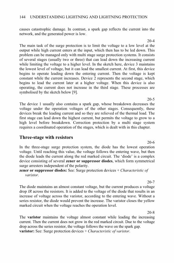
UNDERSTANDING LIGHTNING AND LIGHTNING PROTECTION144
causes catastrophic damage. In contrast, a spark gap reflects the current into the network, and the generated power is low.
20-4The main task of the surge protection is to limit the voltage to a low level at the output while high current enters at the input, which then has to be led down. This problem can be managed only with multi stage surge protection systems. It consists of several stages (usually two or three) that can lead down the increasing current while limiting the voltage to a higher level. In the sketch here, device 3 maintains the lowest level of voltage, but it can lead the smallest current. At first, this device begins to operate leading down the entering current. Then the voltage is kept constant while the current increases. Device 2 represents the second stage, which begins to lead the current later at a higher voltage. When this device is also operating, the current does not increase in the third stage. These processes are symbolised by the sketch below [9].
20-5The device 1 usually also contains a spark gap, whose breakdown decreases the voltage under the operation voltages of the other stages. Consequently, these devices break the leading current and so they are relieved of the thermal load. The first stage can lead down the highest current, but permits the voltage to grow to a high level before breakdown. Correction protection by a multi stage system requires a coordinated operation of the stages, which is dealt with in this chapter.
Three-stage with resistors 20-6
In the three-stage surge protection system, the diode has the lowest operation voltage. Until reaching this value, the voltage follows the entering wave, but then the diode leads the current along the red marked circuit. The ‘diode’ is a complex device consisting of several zener or suppressor diodes, which form symmetrical surge arresters independent of the polarity. zener or suppressor diodes: See: Surge protection devices + Characteristic of
varistor.
20-7The diode maintains an almost constant voltage, but the current produces a voltage drop IR across the resistors. It is added to the voltage of the diode that results in an increase of voltage across the varistor, according to the entering wave. Without a series resistor, the diode would prevent the increase. The varistor closes the yellow marked circuit when the voltage reaches the operation level.
20-8The varistor maintains the voltage almost constant while leading the increasing current. Then the current does not grow in the red marked circuit. Due to the voltage drop across the series resistor, the voltage follows the wave on the spark gap. varistor: See: Surge protection devices + Characteristic of varistor.
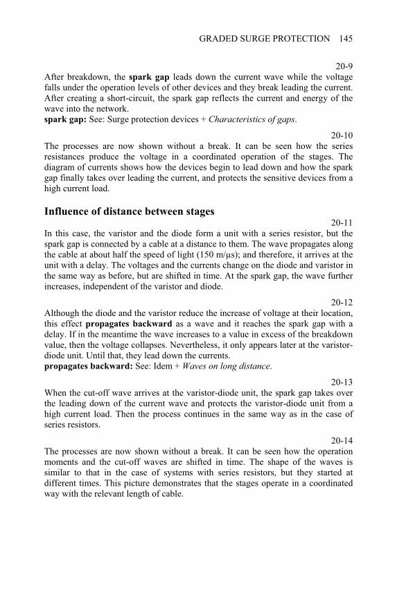
GRADED SURGE PROTECTION 145
20-9After breakdown, the spark gap leads down the current wave while the voltage falls under the operation levels of other devices and they break leading the current. After creating a short-circuit, the spark gap reflects the current and energy of the wave into the network. spark gap: See: Surge protection devices + Characteristics of gaps.
20-10The processes are now shown without a break. It can be seen how the series resistances produce the voltage in a coordinated operation of the stages. The diagram of currents shows how the devices begin to lead down and how the spark gap finally takes over leading the current, and protects the sensitive devices from a high current load.
Influence of distance between stages 20-11
In this case, the varistor and the diode form a unit with a series resistor, but the spark gap is connected by a cable at a distance to them. The wave propagates along the cable at about half the speed of light (150 m/µs); and therefore, it arrives at the unit with a delay. The voltages and the currents change on the diode and varistor in the same way as before, but are shifted in time. At the spark gap, the wave further increases, independent of the varistor and diode.
20-12Although the diode and the varistor reduce the increase of voltage at their location, this effect propagates backward as a wave and it reaches the spark gap with a delay. If in the meantime the wave increases to a value in excess of the breakdown value, then the voltage collapses. Nevertheless, it only appears later at the varistor-diode unit. Until that, they lead down the currents. propagates backward: See: Idem + Waves on long distance.
20-13When the cut-off wave arrives at the varistor-diode unit, the spark gap takes over the leading down of the current wave and protects the varistor-diode unit from a high current load. Then the process continues in the same way as in the case of series resistors.
20-14The processes are now shown without a break. It can be seen how the operation moments and the cut-off waves are shifted in time. The shape of the waves is similar to that in the case of systems with series resistors, but they started at different times. This picture demonstrates that the stages operate in a coordinated way with the relevant length of cable.
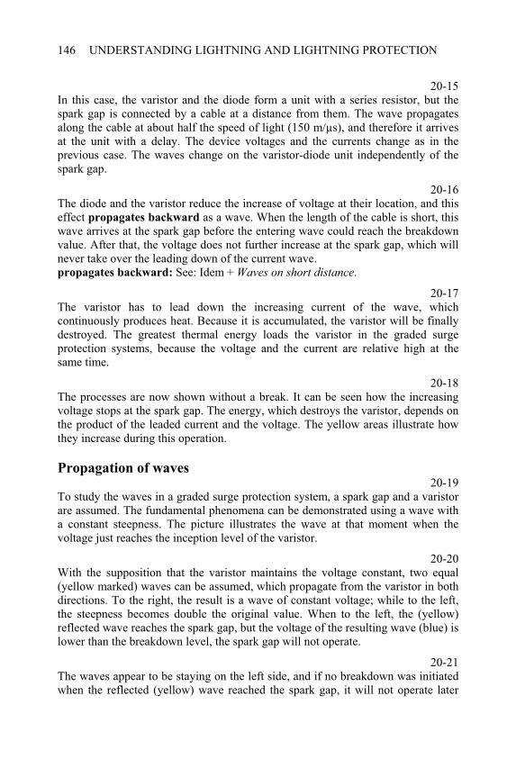
UNDERSTANDING LIGHTNING AND LIGHTNING PROTECTION146
20-15In this case, the varistor and the diode form a unit with a series resistor, but the spark gap is connected by a cable at a distance from them. The wave propagates along the cable at about half the speed of light (150 m/µs), and therefore it arrives at the unit with a delay. The device voltages and the currents change as in the previous case. The waves change on the varistor-diode unit independently of the spark gap.
20-16The diode and the varistor reduce the increase of voltage at their location, and this effect propagates backward as a wave. When the length of the cable is short, this wave arrives at the spark gap before the entering wave could reach the breakdown value. After that, the voltage does not further increase at the spark gap, which will never take over the leading down of the current wave. propagates backward: See: Idem + Waves on short distance.
20-17The varistor has to lead down the increasing current of the wave, which continuously produces heat. Because it is accumulated, the varistor will be finally destroyed. The greatest thermal energy loads the varistor in the graded surge protection systems, because the voltage and the current are relative high at the same time.
20-18The processes are now shown without a break. It can be seen how the increasing voltage stops at the spark gap. The energy, which destroys the varistor, depends on the product of the leaded current and the voltage. The yellow areas illustrate how they increase during this operation.
Propagation of waves 20-19
To study the waves in a graded surge protection system, a spark gap and a varistor are assumed. The fundamental phenomena can be demonstrated using a wave with a constant steepness. The picture illustrates the wave at that moment when the voltage just reaches the inception level of the varistor.
20-20With the supposition that the varistor maintains the voltage constant, two equal (yellow marked) waves can be assumed, which propagate from the varistor in both directions. To the right, the result is a wave of constant voltage; while to the left, the steepness becomes double the original value. When to the left, the (yellow) reflected wave reaches the spark gap, but the voltage of the resulting wave (blue) is lower than the breakdown level, the spark gap will not operate.
20-21The waves appear to be staying on the left side, and if no breakdown was initiated when the reflected (yellow) wave reached the spark gap, it will not operate later
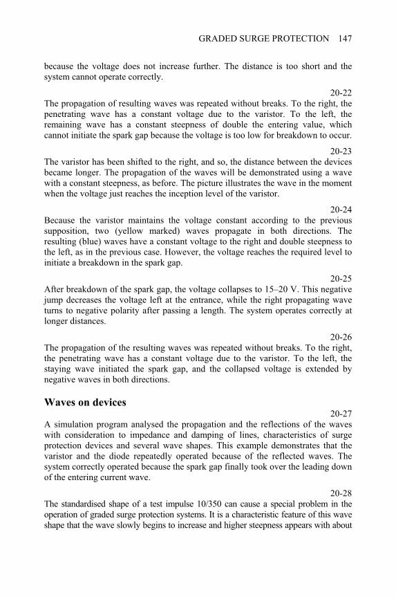
GRADED SURGE PROTECTION 147
because the voltage does not increase further. The distance is too short and the system cannot operate correctly.
20-22The propagation of resulting waves was repeated without breaks. To the right, the penetrating wave has a constant voltage due to the varistor. To the left, the remaining wave has a constant steepness of double the entering value, which cannot initiate the spark gap because the voltage is too low for breakdown to occur.
20-23The varistor has been shifted to the right, and so, the distance between the devices became longer. The propagation of the waves will be demonstrated using a wave with a constant steepness, as before. The picture illustrates the wave in the moment when the voltage just reaches the inception level of the varistor.
20-24Because the varistor maintains the voltage constant according to the previous supposition, two (yellow marked) waves propagate in both directions. The resulting (blue) waves have a constant voltage to the right and double steepness to the left, as in the previous case. However, the voltage reaches the required level to initiate a breakdown in the spark gap.
20-25After breakdown of the spark gap, the voltage collapses to 15–20 V. This negative jump decreases the voltage left at the entrance, while the right propagating wave turns to negative polarity after passing a length. The system operates correctly at longer distances.
20-26The propagation of the resulting waves was repeated without breaks. To the right, the penetrating wave has a constant voltage due to the varistor. To the left, the staying wave initiated the spark gap, and the collapsed voltage is extended by negative waves in both directions.
Waves on devices 20-27
A simulation program analysed the propagation and the reflections of the waves with consideration to impedance and damping of lines, characteristics of surge protection devices and several wave shapes. This example demonstrates that the varistor and the diode repeatedly operated because of the reflected waves. The system correctly operated because the spark gap finally took over the leading down of the entering current wave.
20-28The standardised shape of a test impulse 10/350 can cause a special problem in the operation of graded surge protection systems. It is a characteristic feature of this wave shape that the wave slowly begins to increase and higher steepness appears with about
UNDERSTANDING LIGHTNING AND LIGHTNING PROTECTION148
a 15 µs delay. As a consequence, the leading head of the wave could penetrate into the protected zone before the voltage or current reached the operation level of the protection device at the entrance. The next pictures will illustrate this phenomenon.
20-29This figure shows the front of the wave from 12 µs after initiation. The shape of the wave is 10/350 and the peak value would be 10 kV. However, it falls far out of the scales. The first section was omitted because of the extremely low voltage. The graded surge protection system consists of a spark gap and a varistor-diode unit.
20-30The penetrating wave reaches the inception level of the diode after 15 µs and that of the varistor after 16 µs and they begin to lead down the current wave. The wave arrives earlier at the spark gap and the voltage increases further according to the entering wave, in spite of limitation due to the diode.
20-31The reflected wave arrives at the spark gap and stops the increasing voltage at a relatively low level, because the wave slowly increases in this section. However, this voltage is much lower than that required to initiate a breakdown of the gap; therefore, the spark gap does not take over the leading down of the current wave. This overloads the varistor (or the diode), which will finally be destroyed. reflected wave: See: Idem + Propagation of waves.

CHAPTER 21
Surge protection devices
21-0Each item of this menu can be selected by double-clicking on it. The program displays several topics when the following items are selected: All devices: from Gas discharge arrester to Types of protection devices. Spark gaps: from Gas discharge arrester to Characteristics of gaps. The varistor: from Structure of ZnO ceramic to Characteristics of varistor.
Gas filled arrester 21-1
This is the most frequently used type of surge arrester in low voltage systems. It can lead down impulse currents of peak value 5–10 kA. However, its diameter and length are not more than 6–8 mm. The connection wires can be soldered, but there are many types without connection wires. In this case, the arrester is clamped between two spring contacts.
21-2The electrodes and the insulating tube are the most important elements of gas filled arresters. The spark gap is formed by plate electrodes, which are distanced less than 1 mm in order to reach a low breakdown voltage. The plates result in more rapid operations compared to point electrodes. To avoid any flashover, a larger distance is needed between the electrodes along the surface of the insulator, which is usually made of ceramic or glass.
21-3The accelerator is not used in all gas filled arresters. It produces free electrons inside the arrester, which can initiate electron avalanche if the electric field increases in the gap. The accelerator usually contains a soft radioactive material in order to ionise the gas, but this can also be achieved by adding tritium to the gas. The activating layer decreases the emission energy of electrons from the electrodes.
____________________________________________________Understanding Lightning and Lightning Protection T. Horváth © 2006 Research Studies Press Limited
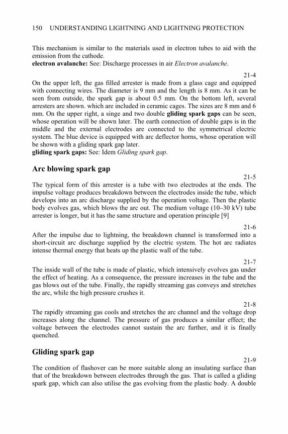
UNDERSTANDING LIGHTNING AND LIGHTNING PROTECTION150
This mechanism is similar to the materials used in electron tubes to aid with the emission from the cathode. electron avalanche: See: Discharge processes in air Electron avalanche.
21-4On the upper left, the gas filled arrester is made from a glass cage and equipped with connecting wires. The diameter is 9 mm and the length is 8 mm. As it can be seen from outside, the spark gap is about 0.5 mm. On the bottom left, several arresters are shown. which are included in ceramic cages. The sizes are 8 mm and 6 mm. On the upper right, a singe and two double gliding spark gaps can be seen, whose operation will be shown later. The earth connection of double gaps is in the middle and the external electrodes are connected to the symmetrical electric system. The blue device is equipped with arc deflector horns, whose operation will be shown with a gliding spark gap later. gliding spark gaps: See: Idem Gliding spark gap.
Arc blowing spark gap 21-5
The typical form of this arrester is a tube with two electrodes at the ends. The impulse voltage produces breakdown between the electrodes inside the tube, which develops into an arc discharge supplied by the operation voltage. Then the plastic body evolves gas, which blows the arc out. The medium voltage (10–30 kV) tube arrester is longer, but it has the same structure and operation principle [9]
21-6After the impulse due to lightning, the breakdown channel is transformed into a short-circuit arc discharge supplied by the electric system. The hot arc radiates intense thermal energy that heats up the plastic wall of the tube.
21-7The inside wall of the tube is made of plastic, which intensively evolves gas under the effect of heating. As a consequence, the pressure increases in the tube and the gas blows out of the tube. Finally, the rapidly streaming gas conveys and stretches the arc, while the high pressure crushes it.
21-8The rapidly streaming gas cools and stretches the arc channel and the voltage drop increases along the channel. The pressure of gas produces a similar effect; the voltage between the electrodes cannot sustain the arc further, and it is finally quenched.
Gliding spark gap 21-9
The condition of flashover can be more suitable along an insulating surface than that of the breakdown between electrodes through the gas. That is called a gliding spark gap, which can also utilise the gas evolving from the plastic body. A double
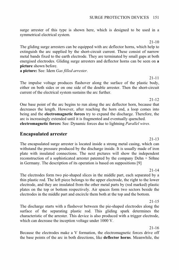
SURGE PROTECTION DEVICES 151
surge arrester of this type is shown here, which is designed to be used in a symmetrical electrical system.
21-10The gliding surge arresters can be equipped with arc deflector horns, which help to extinguish the arc supplied by the short-circuit current. These consist of narrow metal bands fixed to the earth electrode. They are terminated by small gaps at both energised electrodes. Gliding surge arresters and deflector horns can be seen on apicture shown before. a picture: See: Idem Gas filled arrester.
21-11The impulse voltage produces flashover along the surface of the plastic body, either on both sides or on one side of the double arrester. Then the short-circuit current of the electrical system sustains the arc further.
21-12One base point of the arc begins to run along the arc deflector horn, because that decreases the length. However, after reaching the horn end, a loop comes into being and the electromagnetic forces try to expand the discharge. Therefore, the arc is increasingly extended until it is fragmented and eventually quenched. electromagnetic forces: See: Dynamic forces due to lightning Parallel wires.
Encapsulated arrester 21-13
The encapsulated surge arrester is located inside a strong metal casing, which can withstand the pressure produced by the discharge inside. It is usually made of iron plate with insulated connections. The next pictures will show the independent reconstruction of a sophisticated arrester patented by the company Dehn + Söhne in Germany. The description of its operation is based on suppositions [9]
21-14The electrodes form two pie-shaped slices in the middle part, each separated by a thin plastic rod. The left piece belongs to the upper electrode, the right to the lower electrode, and they are insulated from the other metal parts by (red marked) plastic plates on the top or bottom respectively. Air spaces form two sectors beside the electrodes in the middle part and encircle them both at the top and the bottom.
21-15The discharge starts with a flashover between the pie-shaped electrodes along the surface of the separating plastic rod. This gliding spark determines the characteristic of the arrester. This device is also produced with a trigger electrode, which can decrease the inception voltage under 1000 V.
21-16Because the electrodes make a V formation, the electromagnetic forces drive off the base points of the arc in both directions, like deflector horns. Meanwhile, the
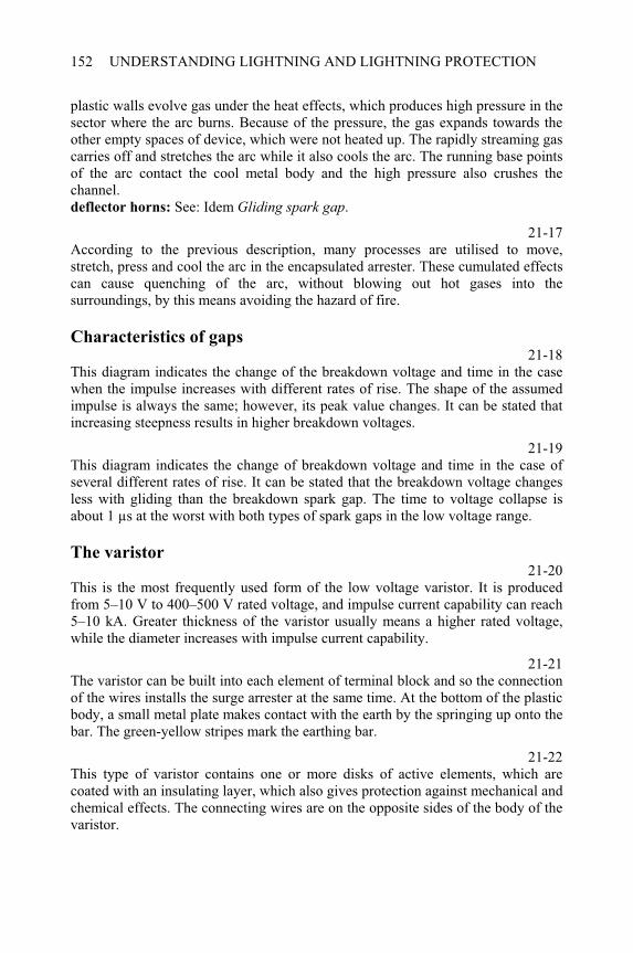
UNDERSTANDING LIGHTNING AND LIGHTNING PROTECTION152
plastic walls evolve gas under the heat effects, which produces high pressure in the sector where the arc burns. Because of the pressure, the gas expands towards the other empty spaces of device, which were not heated up. The rapidly streaming gas carries off and stretches the arc while it also cools the arc. The running base points of the arc contact the cool metal body and the high pressure also crushes the channel.deflector horns: See: Idem Gliding spark gap.
21-17According to the previous description, many processes are utilised to move, stretch, press and cool the arc in the encapsulated arrester. These cumulated effects can cause quenching of the arc, without blowing out hot gases into the surroundings, by this means avoiding the hazard of fire.
Characteristics of gaps 21-18
This diagram indicates the change of the breakdown voltage and time in the case when the impulse increases with different rates of rise. The shape of the assumed impulse is always the same; however, its peak value changes. It can be stated that increasing steepness results in higher breakdown voltages.
21-19This diagram indicates the change of breakdown voltage and time in the case of several different rates of rise. It can be stated that the breakdown voltage changes less with gliding than the breakdown spark gap. The time to voltage collapse is about 1 µs at the worst with both types of spark gaps in the low voltage range.
The varistor 21-20
This is the most frequently used form of the low voltage varistor. It is produced from 5–10 V to 400–500 V rated voltage, and impulse current capability can reach 5–10 kA. Greater thickness of the varistor usually means a higher rated voltage, while the diameter increases with impulse current capability.
21-21The varistor can be built into each element of terminal block and so the connection of the wires installs the surge arrester at the same time. At the bottom of the plastic body, a small metal plate makes contact with the earth by the springing up onto the bar. The green-yellow stripes mark the earthing bar.
21-22This type of varistor contains one or more disks of active elements, which are coated with an insulating layer, which also gives protection against mechanical and chemical effects. The connecting wires are on the opposite sides of the body of the varistor.
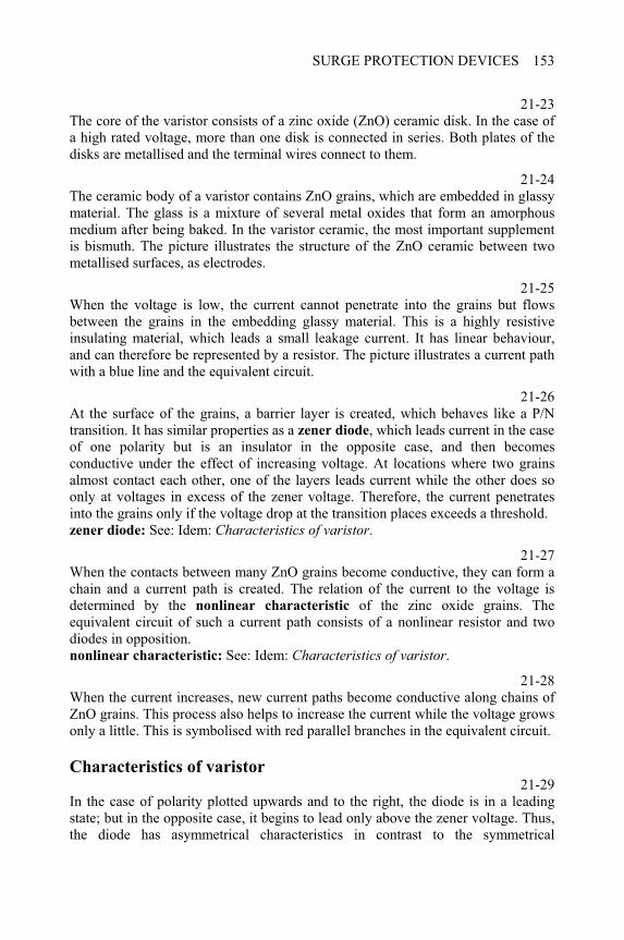
SURGE PROTECTION DEVICES 153
21-23The core of the varistor consists of a zinc oxide (ZnO) ceramic disk. In the case of a high rated voltage, more than one disk is connected in series. Both plates of the disks are metallised and the terminal wires connect to them.
21-24The ceramic body of a varistor contains ZnO grains, which are embedded in glassy material. The glass is a mixture of several metal oxides that form an amorphous medium after being baked. In the varistor ceramic, the most important supplement is bismuth. The picture illustrates the structure of the ZnO ceramic between two metallised surfaces, as electrodes.
21-25When the voltage is low, the current cannot penetrate into the grains but flows between the grains in the embedding glassy material. This is a highly resistive insulating material, which leads a small leakage current. It has linear behaviour, and can therefore be represented by a resistor. The picture illustrates a current path with a blue line and the equivalent circuit.
21-26At the surface of the grains, a barrier layer is created, which behaves like a P/N transition. It has similar properties as a zener diode, which leads current in the case of one polarity but is an insulator in the opposite case, and then becomes conductive under the effect of increasing voltage. At locations where two grains almost contact each other, one of the layers leads current while the other does so only at voltages in excess of the zener voltage. Therefore, the current penetrates into the grains only if the voltage drop at the transition places exceeds a threshold. zener diode: See: Idem: Characteristics of varistor.
21-27When the contacts between many ZnO grains become conductive, they can form a chain and a current path is created. The relation of the current to the voltage is determined by the nonlinear characteristic of the zinc oxide grains. The equivalent circuit of such a current path consists of a nonlinear resistor and two diodes in opposition. nonlinear characteristic: See: Idem: Characteristics of varistor.
21-28When the current increases, new current paths become conductive along chains of ZnO grains. This process also helps to increase the current while the voltage grows only a little. This is symbolised with red parallel branches in the equivalent circuit.
Characteristics of varistor 21-29
In the case of polarity plotted upwards and to the right, the diode is in a leading state; but in the opposite case, it begins to lead only above the zener voltage. Thus, the diode has asymmetrical characteristics in contrast to the symmetrical
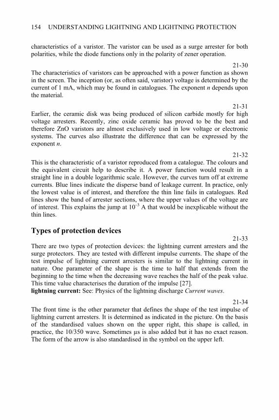
UNDERSTANDING LIGHTNING AND LIGHTNING PROTECTION154
characteristics of a varistor. The varistor can be used as a surge arrester for both polarities, while the diode functions only in the polarity of zener operation.
21-30The characteristics of varistors can be approached with a power function as shown in the screen. The inception (or, as often said, varistor) voltage is determined by the current of 1 mA, which may be found in catalogues. The exponent n depends upon the material.
21-31Earlier, the ceramic disk was being produced of silicon carbide mostly for high voltage arresters. Recently, zinc oxide ceramic has proved to be the best and therefore ZnO varistors are almost exclusively used in low voltage or electronic systems. The curves also illustrate the difference that can be expressed by the exponent n.
21-32This is the characteristic of a varistor reproduced from a catalogue. The colours and the equivalent circuit help to describe it. A power function would result in a straight line in a double logarithmic scale. However, the curves turn off at extreme currents. Blue lines indicate the disperse band of leakage current. In practice, only the lowest value is of interest, and therefore the thin line fails in catalogues. Red lines show the band of arrester sections, where the upper values of the voltage are of interest. This explains the jump at 10–3 A that would be inexplicable without the thin lines.
Types of protection devices 21-33
There are two types of protection devices: the lightning current arresters and the surge protectors. They are tested with different impulse currents. The shape of the test impulse of lightning current arresters is similar to the lightning current in nature. One parameter of the shape is the time to half that extends from the beginning to the time when the decreasing wave reaches the half of the peak value. This time value characterises the duration of the impulse [27]. lightning current: See: Physics of the lightning discharge Current waves.
21-34The front time is the other parameter that defines the shape of the test impulse of lightning current arresters. It is determined as indicated in the picture. On the basis of the standardised values shown on the upper right, this shape is called, in practice, the 10/350 wave. Sometimes µs is also added but it has no exact reason. The form of the arrow is also standardised in the symbol on the upper left.
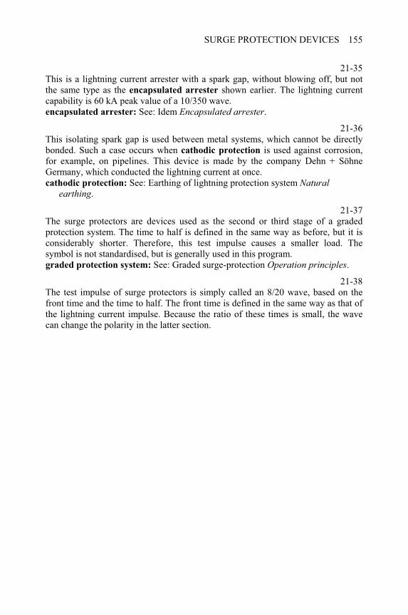
SURGE PROTECTION DEVICES 155
21-35This is a lightning current arrester with a spark gap, without blowing off, but not the same type as the encapsulated arrester shown earlier. The lightning current capability is 60 kA peak value of a 10/350 wave. encapsulated arrester: See: Idem Encapsulated arrester.
21-36This isolating spark gap is used between metal systems, which cannot be directly bonded. Such a case occurs when cathodic protection is used against corrosion, for example, on pipelines. This device is made by the company Dehn + Söhne Germany, which conducted the lightning current at once. cathodic protection: See: Earthing of lightning protection system Natural
earthing.
21-37The surge protectors are devices used as the second or third stage of a gradedprotection system. The time to half is defined in the same way as before, but it isconsiderably shorter. Therefore, this test impulse causes a smaller load. Thesymbol is not standardised, but is generally used in this program.graded protection system: See: Graded surge-protection Operation principles.
21-38The test impulse of surge protectors is simply called an 8/20 wave, based on the front time and the time to half. The front time is defined in the same way as that of the lightning current impulse. Because the ratio of these times is small, the wave can change the polarity in the latter section.

CHAPTER 22
Internal lightning protection zones
22-0Each item of this menu can be selected by double-clicking on it. The program displays several topics when the following items are selected: Lightning protection zones: from Structure of zones to Tray configuration.Networks of information systems: from Bonding and earthing to Network
configurations.
Structure of zones 22-1
According to the concept of lightning protection zones (LPZ), the space is divided into parts in which the occurrence of lightning parameters and electromagnetic fields have different levels. Together, these are called the effects of lightning electromagnetic impulse (LEMP). The picture shows two zones, but both belong to LPZ 0. The appearance of the lightning channel should be expected inside LPZ 0A
without any limitation of the lightning parameters and fields. However, the lightning itself cannot penetrate into LPZ 0B, and its electromagnetic effects are not damped. The last zone coincides with the suggested protected space of the air termination system [25] protected space: See: Air termination systems + Construction methods.
22-2The internal room of a structure is usually the first zone, called LPZ 1, in which the LEMP effects appear with limitation. For this purpose, the electromagnetic field can be damped by shielding, and all entrances of lines should be equipped with surge protection in order to prevent the penetration of conducted effects. Because a considerable proportion of lightning current is expected at the entrance of lines, a lightning current arrester is also required in the case of connection by cable. shielding: See: Lightning electromagnetic impulse + Shielding.
____________________________________________________Understanding Lightning and Lightning Protection T. Horváth © 2006 Research Studies Press Limited
UNDERSTANDING LIGHTNING AND LIGHTNING PROTECTION158
lightning current arrester: See: Surge protection devices + Types of protection devices.
22-3A specially shielded room or the inside of any metal-clad device or equipment can form the next zone, like LPZ 2 in the picture. In addition to the shielding, the penetration of conducted effects should also be prevented at all entry points of lines. Considering the first stage of the protection, surge protectors can also be used here. In principle, subsequent zones could be provided as LPZ 3, and so on. However, it is necessary only in exceptional cases. surge protectors: See: Surge protection devices + Types of protection devices.
22-4When a line goes out of a zone, higher LEMP effects can penetrate in this way. Such a situation occurs by connecting a lamp in the garden, a bell at the door or a pump outside the house. In this case, the surge protection device should be adequate to the requirements of the zone outside. Therefore, it is considered as a lightning current arrester in the picture.
Standardised lightning parameters 22-5
The international standard ‘Protection of structures against lightning, Part 1. General principles’ defines four protection levels. During the construction of a lightning protection system, the standardised lightning parameters should be considered corresponding to the protection level. They also determine the requirements against the lightning current arresters. Protection level I represents the highest level, which decreases towards protection level IV [24]
Networks of information systems 22-6
Four examples are shown here concerning several versions of connections to entering lines and to the earthing. In the first case, all lines enter at one place, where the earthed points are connected to the equipotential bonding bar (EBB). Because everything is bonded at one point, the earthing and the reinforcement of the structure are also connected to the EBB [25]
22-7When the lines enter the structure at different points, they should be bonded to more than one EBB. To avoid high potential differences inside the structure, these should be interconnected by a ring bar, but the reinforcement and the earthing are connected to only one of them. In this case, the potential difference is as expected when created inside the system.
22-8The lines enter the structure at different points and are bonded in several places to EBB, similar to the previous case. Although these are interconnected along the
INTERNAL LIGHTNING PROTECTION ZONES 159
earthing route, this forms a frame around the structure. The reinforcement is consequently connected to the local EBB. In this case, no EBB is distinguished among the others.
22-9This is a special case of tall structures, when equipotential planes should be created by bonding the down conductors. Similar to the previous cases, the lines enter the structure at different points, and they are bonded in several places to EBB. These are interconnected by a ring bar that limits the potential differences inside the structure. tall structures: See: Down conductors and metal objects + Degrees of down
conductors.
22-10When the connecting lines go between the devices along different routes, an induction loop can be created, which encloses a magnetic flux due to lightning. Then the induced voltage can occur in any of devices and can lead to damage. Such connections can lead to dangerous situations and hence should never be used.
22-11By leading the connecting line along the same route, the induction loop becomes considerably smaller. The induced voltage decreases further when twisted lines are used.
22-12The danger of induced voltages can be eliminated by shielding the complete space within the structure. It is symbolised by a red contour. Since the efficient shielding involves technological difficulties in a large room, this is an expensive solution.
22-13It is not so expensive to use shielded cables instead of shielding the complete room. However, lightning can induce damaging voltages in spite of shielding, especially if the connecting lines form loops. Efficient shielding can be created only with thick-walled metal tubes, which can also be expensive. Ideally, loops should also be avoided in this case.
22-14The conductors can connect the devices to the equipotential network in several forms. The star type (S) connects each device by an individual conductor to a central earthing point, which is known as the Earthing Reference Point (ERP). In this system, this is the only connection to the earthing system of the structure. The mesh type forms a network by interconnecting all devices. It can be earthed at many points, and the devices are not independent of one another. Of late, the mesh type is favoured.
22-15In this case, there is a ring bar or shielding that is connected to the star type network at the ERP alone. The devices are insulated from the ring bar and the
UNDERSTANDING LIGHTNING AND LIGHTNING PROTECTION160
shielding. This is called as the SS type. In contrast, and ideally, the mesh type network is interconnected to the ring bar or shielding at all points. This is called as the MM type.
22-16The star and the mesh type can also be used in combination. On the left side, a mesh type unit is connected to a star type network and they form a mixed system. On the right, a star type unit is connected only at one point to a meshed network. In this system, the ERP point is connected to the earthing only by the mesh type network.
Tray configuration 22-17
In tall buildings, several lines often produce loops, which can lead to an enhanced hazard from induced voltages due to lightning stroke. The tray configuration is a suitable form of network to build up a zone system and to avoid the hazard.
22-18The picture shows a four-storied building as an example for tray configuration of electrical installation. To produce sufficient potential equalisation, a mesh type network is built in each floor. This system forms a tray that is connected to the central distribution box on each floor. This is the common bonding point of all devices on the floor.
22-19On each floor, many information devices are interconnected by the mesh type network. The floor represents a LPZ that has all external connections entering at the central distribution box. These connecting cables go down to the main distribution station together with the earthing conductor. However, there are no connecting cables or conductors directly between the floors. Thus, the devices on different floors can communicate only through the main distribution station, which is on the lowest floor. This is the entry point of all external lines and the bonding point equipped with lightning current arresters.
22-20This is the sketch of a tray configuration in a large building. The large dimensions require the dividing of the trays inside the floors and therefore four mesh type networks can be seen on each floor. They are connected to the earthing system at the corners by vertical conductors, although they are isolated from the air terminals and down conductors of the external lightning protection system.
22-21The red marked connections illustrate typical failures to be avoided. These produce dangerous loops and disrupt the potential equalisation in the trays. The communication may go via the main distribution stations that are in the lowest floor.
CHAPTER 23
Connection to electric power
network
23-0Each item of this menu can be selected by double-clicking on it. The program displays several topics when the following items are selected: Connection to network: From Changing point of strikes and arrangements to
Outdoor kWh box.After selecting other items, the program follows several series by jumps.
Striking the supply line 23-1
The first stage of a graded surge protection system should obviously be some type of lightning current arrester. When it is in front of the kWh metre, the main fuse of the structure is only in the path of the entering current. The lightning current does not load the kWh metre [9] first stage: See: Graded surge protection + Operation principles.
23-2The lightning current produces a voltage drop while flowing down through the arrester. Under the effect of this voltage, a small part of the current penetrates into the installation. However, the second stage of surge protection can lead the current down. The kWh metre can sustain this load without damage, thereby protecting remote equipment.
23-3The current flows through the lightning current arrester on one side by EBB (Equipotential Bonding Bar) to the earthing and on the other side by the PEN (Protection Earth and Neutral) conductor back to the transformer. Both current paths can sustain the load due to lightning current without damage.
____________________________________________________Understanding Lightning and Lightning Protection T. Horváth © 2006 Research Studies Press Limited
UNDERSTANDING LIGHTNING AND LIGHTNING PROTECTION162
23-4When the first stage of a graded surge protection system is transposed behind the kWh metre, then it is in the path of the entering current. This current is high and the kWh metre will certainly be damaged. first stage: See: Graded surge protection + Operation principles.
23-5The lightning current produces a voltage drop while flowing down through the arrester. Under the effect of this voltage, a small part of the current penetrates into the installation. However, the second stage of surge protection can lead this current down. Remote equipment will be protected from this load.
23-6The current flows through the lightning current arrester on one side by EBB to the earthing and on the other side by the PEN conductor back to the transformer as in the previous case.
23-7When the first stage of a graded surge protection system fails, the lightning current penetrates through the kWh metre to the surge protectors. These are fine devices, and the lightning current will destroy them. surge protectors: See: Surge protection devices + Types of protection devices.
23-8Because the second stage of a surge protection system cannot direct the entering high current downwards, it is possible that a considerable load will be placed on more remote devices. Thus, the destruction can spread inside the structure.
23-9After destruction of the second stage devices, the lightning current flows on one side of the EBB to the earthing and on the other side by the PEN conductor back to the transformer.
Striking the air termination 23-10
The current of an intercepted lightning stroke flows from the air termination along the down conductors to the earthing and produces a voltage drop on the earthing resistance. Because of the raised potential of the earthing, about half the lightning current flows towards EBB, and raises its potential [9] raised potential: See: Lightning electromagnetic impulse + Conductive coupling.
23-11Under the effect of the raised potential, all arresters are initiated and they lead the current, along with the PEN conductor, towards the transformer. The current produces a voltage drop on the arresters, and therefore, a small part of the current penetrates into the installation. However, there will be no damage.
CONNECTION TO ELECTRIC POWER NETWORK 163
23-12By interchanging the positions of the kWh metre and the first stage of the surge protection system, the current of the intercepted lightning stroke produces a voltage drop across the earthing resistance. Because of the raised potential of the earthing, about half of the lightning current flows toward EBB and raises its potential. raised potential: See: Lightning electromagnetic impulse + Conductive coupling.
23-13Under the effect of the raised potential, all arresters are initiated and they lead the current, along with the PEN conductor, towards the transformer. In contrast to the previous positions, all the tree currents flow from the lightning current arresters through the kWh metre, which will almost certainly be damaged. However, the other installations will not be damaged.
23-14When the first stage of a graded surge protection system fails, the current of an intercepted lightning stroke produces a voltage drop across the earthing resistance. Because of the raised potential of the earthing, about half of the lightning current flows toward EBB, and raises its potential. raised potential: See: Lightning electromagnetic impulse + Conductive coupling.
23-15Under the effect of the raised potential, all surge protectors are initiated in the second stage of the graded surge protection system. Because they are sized to direct lower currents downwards, compared to the majority of the lightning current, then they will most certainly be destroyed. Then the currents flow along the phase and the PEN conductors towards the transformer. surge protectors: See: Surge protection devices + Types of protection devices.
23-16While the second stage of a surge protection system cannot direct the backward flowing high current downwards, it is possible that a considerable load is experienced by more remote devices. Thus, the destruction can spread inside the structure.
TT system 23-17
In the TT system the neutral (N) conductor is earthed only at the transformer, while in the TN-C-S system, the PEN conductor represents the combined protection of the earth and the neutral conductors. Inside the structure, the N conductor is isolated from the earthed PE conductor by a spark gap as shown in the picture. When the lightning strikes the supply line, the lightning current arrester directs it downwards through the series connected spark gap. Thus, the spark gap isolates the N conductor, but connects it to the PE conductor when the lightning current flows down.
UNDERSTANDING LIGHTNING AND LIGHTNING PROTECTION164
23-18While the arrester and the spark gap lead the current, a voltage drop is created. Under the effect of this voltage, a small part of the current penetrates into the installation. However, the second stage of the surge protection system can lead it down. The more remote equipment will be protected from this load. The interchanging of positions of the kWh metre and the first stage of protection causes the same consequences as in the TN-C-S system.
23-19The lightning current flows on one side to EBB and the earthing, and on the other side to the star-point of the transformer along the neutral conductor of the network.
23-20The current of an intercepted lightning stroke flows from the air termination along the down conductors to the earthing and produces a voltage drop across the earthing resistance. Because of the raised potential of the earthing, about half the lightning current flows towards EBB and raises its potential. However, the electrical system is isolated from it by the spark gaps. raised potential: See: Lightning electromagnetic impulse + Conductive coupling.
23-21When the raised potential is high enough, a breakdown occurs in the spark gap. At this point, nearly half the lightning current flows through the arresters of the first stage toward the transformer. A small part of the current loads the kWh metre, but it can sustain this without damage.
Outdoor kWh box 23-22
The main connection is located at the border of a plot of the costumer, but the local earthing is never as good as that of the building. However, a considerable part of the lightning current flows along the earth conductor towards EBB, when the first stage of surge protection is operating.
23-23In this case, high voltage is produced between the struck conductor and the EBB to initiate the second stage of protection. Then the current will flow through the kWh metre, and will also probably damage the surge protectors of the second stage.
23-24After the destruction of the surge protectors of the second stage, the damage will spread to the costumer devices, because the fine protection is also initiated.
23-25The trouble is initiated in the voltage in the second stage of the protection system. It is the sum of the voltage drop uSPD on the first surge protection device and uIND
along the inductance of the earth conductor. Because the length of this conductor can be in the 10 to 50 m range, the voltage drop uIND can be quite high.
CONNECTION TO ELECTRIC POWER NETWORK 165
23-26The current of an intercepted stroke flows to the earth and produces a voltage drop
on the earthing resistance. About half the lightning current flows from the EBB on one side along the PEN conductor, and on the other side through surge protectors of the second stage towards the supply network. voltage drop: See: Lightning electromagnetic impulse + Conductive coupling.
23-27While the second stage of the surge protection system cannot direct the backward flowing high current downwards, it is possible that a considerable load is placed on the more remote devices. Thus, the destruction can spread inside the structure.
23-28The currents reach the lightning current arresters only after the destruction of the electrical equipment of the building. Thus, they cannot offer protection to them and we can conclude that placing the kWh metre and the lightning current arresters outside the building can be hazardous.

CHAPTER 24
Protection of electronic devices
24-0Each item of this menu can be selected by double-clicking on it. The program displays several topics when the following items are selected: Electronic devices in the building: from Protection of personal computer to Relay
station.Protection of personal computer: from Protection of power entrance to Protection
device of the PC.Protection of television: from Roof aerial to Receiving paraboloid
Protection of personal computer 24-1
Owing to lightning, the lightning electromagnetic impulse (LEMP) mostly threatens the electronic devices that are connected to different distribution networks. A typical case is the computer, which needs both electric power and data communication. The lines of these systems are often led in different ways to the computer. According to the picture, the entry ports of systems are equipped with surge protection [9]
24-2According to the picture, the entry ports of systems are equipped with surge protection. Because the electric power and data communication lines go from the lightning protection zone (LPZ) 0B zone, they are exposed to a considerable part of the lightning current. Thus, the surge protection devices should be lightning
current arrester types here, as illustrated by the symbols. It can be said that a bonding point is at the entry port where the potential differences are limited. lightning current arrester: See: Surge protection devices + Types of protection
devices.
____________________________________________________Understanding Lightning and Lightning Protection T. Horváth © 2006 Research Studies Press Limited
UNDERSTANDING LIGHTNING AND LIGHTNING PROTECTION168
24-3The protection device PD01 is at the entry port of the power line from the LPZ 0B
into LPZ 1. The mark PD01 refers to the zones. However, it is only used in this program. This protection device bonds the phase and the neutral conductor to the equipotential bonding bar (EBB) and to the protection earth (PE) conductor by spark gaps, marked with green and yellow colours. lightning protection zone: See: Internal lightning protection zones + Structure of
zones.
24-4The protection device of a data communication cable should limit the voltage between the cable shielding and the earthed EBB. Because a considerable part of the lightning current can flow here, a spark gap is usually used. In addition, a multistage device limits the voltage inside the cable. That is usually a surge protector type, because it is not exposed to the lightning current. multistage device: See: Graded surge protection + Three stage with resistors.
24-5The protection devices produce efficient bonding at the entry ports that prevents the penetration of conducted over-voltage into the electrical equipment of a building.
24-6When the electric power line and the data communication cable are led in a different way in the building, an induction loop is created. The current of an intercepted lightning stroke induces voltage that can be very high in the large loop. Because that voltage can produce a breakdown inside the computer, the induced currents can destroy it. This suggests that bonding at an entry port cannot secure effective protection within the entire building. induces voltage: See: Induced voltage and current + Calculated examples.
24-7An internal room housing a PC should be considered as an enhanced LPZ 2, whose entrance is equipped with surge protection. This protection device should prevent a high potential difference from penetrating via the different connecting lines. As shown in the picture, this combined device is connected both to the electric power line and to the data communication cable.
24-8The combined protection device consists of two parts. Both parts comprise sensitive surge protectors, which limit the voltage inside the system. These can be suppressor diodes as well as varistors. The shielding of the communication cable and the green yellow marked PE conductor of the power line are bonded by a spark gap. This isolates the systems during normal operation, but connects them during a surge impulse.
PROTECTION OF ELECTRONIC DEVICES 169
24-9The surge protection devices usually form a mobile connector block with the cables for connection by plugs to the relevant fix receptacles of the power and data systems. Plugs to the mobile block also connect the computer.
Protection of television 24-10
The roof aerial is exposed to a direct lightning stroke, and therefore, if a television is connected to it without any protection, it will most certainly be destroyed. That is, the lightning current will find only one way from the point of strike towards the earth along the aerial cable and the power supply line. However, the path leads through the television receiver, which cannot sustain such a load.
24-11When the building is equipped with an external lightning protection system, supporting structure of the roof aerial can be connected to them. The isolated conductors of an aerial cable should be bonded by lightning current arresters on the top. The entry point of an electric power line can also be equipped with the relevant protection devices, as shown in the picture. In spite of these protection devices, a proportion of the lightning current will flow through the television, and therefore, a surge protection system is necessary just ahead of it. electric power line: See: Idem + Protection at the power entrance.
24-12For the protection of the television, a mobile device can be used, which contains surge protectors of the power system (red symbol) and another of the communication system (yellow symbol). These are built according to similar principles as shown earlier, concerning the protection of personal computer. The current caused by lightning flows through the protection device towards the earthing while bypassing the protected television. The normal connection plugs of a television are connected to the mobile protection block instead of the receptacles of the power and data systems. protection of personal computer: See: Idem + Protection device of PC.
24-13When the television is connected to a video recorder, they require common protection, as shown in the picture. In this case, the current caused by lightning flows through the protection device towards the earthing while bypassing the television and the video recorder to be protected. The mobile protection block contains receptacles to plug both the television and the video.
24-14The receiving paraboloids are used for the reception of satellite programs, and therefore suffer primary exposure to lightning stroke. The paraboloid shell is usually made of metal plate, which is thick enough to sustain a direct lightning stroke without much damage. It can be earthed, and so, there is nothing to exclude its connection to
UNDERSTANDING LIGHTNING AND LIGHTNING PROTECTION170
the external lightning protection system. The entry port of the electric power line can also be equipped with the relevant protection devices. In spite of these protection devices, a part of the lightning current will flow through the coupler unit of the television, and therefore a surge protection system is necessary just ahead of it. electric power line: See: Idem + Protection at the power entrance.
24-15For the protection of the coupler unit, a similar mobile device can be used, as in the case of a video receiver shown earlier. This contains surge protectors of the power system (red symbol) and another of the communication system (yellow symbol). These are built according to a similar principle as that of the protection of
personal computer. The current caused by lightning flows through the protection device towards the earthing, while bypassing the coupler unit and the protected television. protection of personal computer: See: Idem + Protection device of PC.
Relay station24-16
The relay station of a mobile phone system requires a complex surge protection system. The antenna tower is exposed to direct lightning strokes that can cause potential rises in the telecommunication cables and in the supply line of the warning lamps. Its penetration should be prevented at the entry port to the transmitter cabin by lightning current arresters. Devices of the power system are marked red and that of the communication yellow. The cabin is often a metal container that gives good shielding to LPZ 1. The metal cases of the telecommunication and the electric power equipment form LPZ two rooms, and therefore, all entry ports are protected by surge protectors.
CHAPTER 25
Lightning measurement
and localisation
25-0Each item of this menu can be selected by double-clicking on it. The program displays several topics when the following items are selected: Measuring of lightning current: from Measurement by magnetizing to Reflection of the current wave. Measurement by magnetizing: from Magnetic card to Magnetic link. Localizing the lightning: from Direction finding to Lightning detection systems
Measuring of lightning current 25-1
The lightning current is usually measured at ground level where it flows along only one conductor to the earth. If the current is distributed among parallel down conductors, the results cannot be simply summarised because the waves are different in the branches.
Magnetic card
25-2The simplest measuring method is based on the magnetic field produced by lightning. To record it, a plastic card is placed on the down conductor. In this case, it is inside a plastic box, which can be easily fixed to the conductor.
25-3When lightning current flows down the conductor, a magnetic field is produced around it. The magnetic flux density B decreases inversely proportional to the distance from the conductor.
____________________________________________________Understanding Lightning and Lightning Protection T. Horváth © 2006 Research Studies Press Limited
UNDERSTANDING LIGHTNING AND LIGHTNING PROTECTION172
25-4The magnetic field magnetises a ferromagnetic band on the card, which is taken out after thunderstorms or at a predetermined period. The lightning produces continuously decreasing magnetism in the band, which can be evaluated in a suitable measuring instrument. The higher the peak value of the lightning current, the farther the saturation of the magnetic band. This method is very simple and inexpensive, and therefore can be used in high numbers. However, the precision is not so good.
Magnetic link
25-5This is the oldest successful method of measuring lightning current. The earliest type consisted of thin ferromagnetic wires that were sealed in a glass tube of about 8-mm diameter. The thin wires decrease the disturbances due to Foucault currents.
25-6Thin magnetic strips have similar properties as the wires and they form a compact link embedded in plastic material. An important advantage is that this type is not fragile.
25-7Powdered iron offers another possibility to avoid Foucault currents. This type can be mass-produced both cheaply and quickly. The magnetic links give useful information about the lightning current in view of the high volume of data.
25-8The magnetic links must be positioned tangentially to the magnetic field due to the lightning current. Metal objects could distort the magnetic field, and therefore wooden holders are most suitable for the magnetic links. Because high lightning current magnetises the near link to over-saturation, an additional link should be positioned at a greater distance. The links are periodically collected and evaluated in the laboratory.
Shunt resistor
25-9The resistive shunt represents the classical method to measure high current and so is also used in lightning current measurements. However, the lightning current quickly changes and on one side produces eddy currents, while on the other side induces voltages in the measuring circuits. The high current and energy can cause other problems. The shunt is usually positioned on the top of high towers, because the lightning current is concentrated in a conductor but not distributed in parallel paths [2]
25-10The lightning current produces heat in the shunt resistor, which is proportional to the specific energy W/R due to the lightning. Because of the short time, no heat
LIGHTNING MEASUREMENT AND LOCALISATION 173
dissipation is expected, and therefore the resistor must absorb the heat according to its thermal capacity. This determines the smallest mass of the resistor. It must also be considered that any inclination of the current path creates inductance. specific energy: See: Physics of the lightning discharge + Lightning parameters.
25-11The shunt consists of coaxial cylinders that are connected in series in a meander form. The oppositely directed currents produce a smaller inductance. The input and output of the connection cable are located as near to each other as possible. In the picture, the cable core is connected to the input and the sheath to the output of the resistor. This aims to avoid the induced voltages in the measuring system. For the same reason, an optical fibre transfers down the measured signal.
25-12At the foot of the tower, the optical signal is transformed to an electrical signal, which can be stored and evaluated in a computer. Measuring with a shunt resistor seems to be the most suitable method, although in the case of a very rapid change of current a low inductance can also cause problems.
Coil of Rogowski
25-13The measuring coil of Rogowski detects the magnetic field of lightning current. It is usually positioned on top of high towers, because the lightning current flow will be concentrated in a conductor and not distributed in parallel paths.
25-14The coil of Rogowski forms an air-cored toroidal winding that concentrically closes around the conductor, which leads the lightning current. An iron-cored coil would not be suitable because it would delay the creation of the magnetic field. It is also important that there is no conductive connection between the coil and the lightning conductor.
25-15The lightning current creates a magnetic field inside the toroidal coil, which will follow all changes in the current wave. The magnetic field induces a voltage in the coil, which is proportional to the differential quotient di/dt of the lightning current, and the mutual inductance M between the coil and the lightning conductor. Thus, the induced voltage u(t) indicates the change of the current, but not its amplitude.
25-16The induced voltage is the output signal of the coil of Rogowski, which is transferred in the shortest way to an opto-converter. This short connecting line is a sensitive part of the measuring system, because any induced voltage should be excluded from this section. The opto-converter transforms the induced voltage to an optical signal, which can be transferred down without electromagnetic interference.
UNDERSTANDING LIGHTNING AND LIGHTNING PROTECTION174
25-17At the foot of the tower, the optical signal is transformed to an electrical signal again, which can be stored and evaluated in a computer. The computer reproduces the lightning current as a function of time by integrating the signal. Because very short time constants can be reached with this measuring system, high-speed changes of lightning current can also be recorded.
Reflection of the current wave
25-18When lightning current is measured on the top of a high tower, the current wave reaches the measuring point earlier than it reaches the earth. The upper instrument (marked green) records the wave that is shown in the diagram, while nothing can be recorded at the bottom by the other instrument (marked orange). However, the surge impedance ZF is lower than that of the tower ZT, which results in a reflected component of the current wave.
25-19The instrument records the orange marked wave shape at the foot of the tower. However, the upper instrument senses the reflected current with a delay. Therefore, the upper-recorded wave begins to increase when the reflected component arrives at the top. This can be seen on the green wave shape.
25-20The changes of recorded currents are shown without a break. It can be stated that a jump appeared at the front of the wave that was recorded in green on the top of the tower. However, the current continuously increased at the foot, which is shown in orange. This effect can also be observed in recorded current waves.
waves of lightning currents: See: Physics of the lightning discharge + The current wave.
Localising by direction finding 25-21
The position of the ground flash can be found with sensors, which record the direction of the arriving electromagnetic impulse due to lightning. Because of the inaccuracy of the measurement, there is a bad-bearing sector, although two sensors determine an area in which the ground flash can be assumed. The third sensor only improves the accuracy.
25-22Two sensors cannot determine the position of the ground flash when it falls on the line between them. Therefore, without the detected direction of the third sensor, it is impossible to determine the location of the lightning stroke. Considering that the lightning can strike the ground at any point, at least three sensors are necessary.
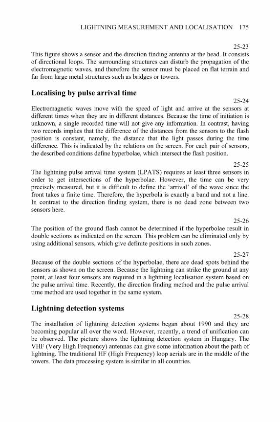
LIGHTNING MEASUREMENT AND LOCALISATION 175
25-23This figure shows a sensor and the direction finding antenna at the head. It consists of directional loops. The surrounding structures can disturb the propagation of the electromagnetic waves, and therefore the sensor must be placed on flat terrain and far from large metal structures such as bridges or towers.
Localising by pulse arrival time 25-24
Electromagnetic waves move with the speed of light and arrive at the sensors at different times when they are in different distances. Because the time of initiation is unknown, a single recorded time will not give any information. In contrast, having two records implies that the difference of the distances from the sensors to the flash position is constant, namely, the distance that the light passes during the time difference. This is indicated by the relations on the screen. For each pair of sensors, the described conditions define hyperbolae, which intersect the flash position.
25-25The lightning pulse arrival time system (LPATS) requires at least three sensors in order to get intersections of the hyperbolae. However, the time can be very precisely measured, but it is difficult to define the ‘arrival’ of the wave since the front takes a finite time. Therefore, the hyperbola is exactly a band and not a line. In contrast to the direction finding system, there is no dead zone between two sensors here.
25-26The position of the ground flash cannot be determined if the hyperbolae result in double sections as indicated on the screen. This problem can be eliminated only by using additional sensors, which give definite positions in such zones.
25-27Because of the double sections of the hyperbolae, there are dead spots behind the sensors as shown on the screen. Because the lightning can strike the ground at any point, at least four sensors are required in a lightning localisation system based on the pulse arrival time. Recently, the direction finding method and the pulse arrival time method are used together in the same system.
Lightning detection systems 25-28
The installation of lightning detection systems began about 1990 and they are becoming popular all over the word. However, recently, a trend of unification can be observed. The picture shows the lightning detection system in Hungary. The VHF (Very High Frequency) antennas can give some information about the path of lightning. The traditional HF (High Frequency) loop aerials are in the middle of the towers. The data processing system is similar in all countries.
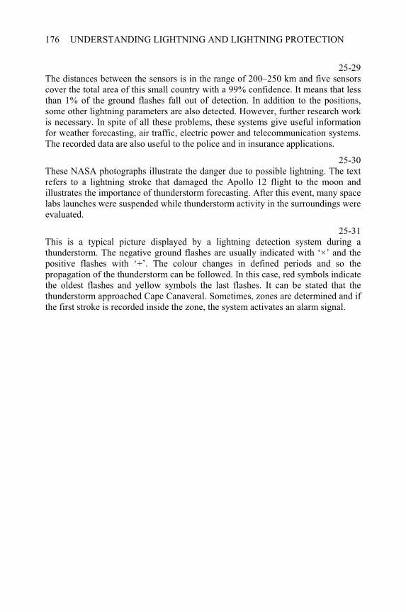
UNDERSTANDING LIGHTNING AND LIGHTNING PROTECTION176
25-29The distances between the sensors is in the range of 200–250 km and five sensors cover the total area of this small country with a 99% confidence. It means that less than 1% of the ground flashes fall out of detection. In addition to the positions, some other lightning parameters are also detected. However, further research work is necessary. In spite of all these problems, these systems give useful information for weather forecasting, air traffic, electric power and telecommunication systems. The recorded data are also useful to the police and in insurance applications.
25-30These NASA photographs illustrate the danger due to possible lightning. The text refers to a lightning stroke that damaged the Apollo 12 flight to the moon and illustrates the importance of thunderstorm forecasting. After this event, many space labs launches were suspended while thunderstorm activity in the surroundings were evaluated.
25-31This is a typical picture displayed by a lightning detection system during a thunderstorm. The negative ground flashes are usually indicated with ‘×’ and the positive flashes with ‘+’. The colour changes in defined periods and so the propagation of the thunderstorm can be followed. In this case, red symbols indicate the oldest flashes and yellow symbols the last flashes. It can be stated that the thunderstorm approached Cape Canaveral. Sometimes, zones are determined and if the first stroke is recorded inside the zone, the system activates an alarm signal.
CHAPTER 26
The mankind in the thunderstorm
26-0Each item of this menu can be selected by double-clicking on it. The program displays several topics when the following items are selected: Dangerous situations: from Man in the field to Danger in boats and vessels.Man in the field: from Danger in open air to What to do outdoors? Stroke on vehicles: from - bicycle to - truck.
Danger in open air 26-1
The downward leader initiates connecting leaders from the earth or earth objects when it approaches ground level. In flat terrain, a person forms a protruding point and so a connecting leader starts from the human body. A woman reported the experience of ‘warm stroke’ on the head when a girl beside her was killed by a lightning stroke. She probably felt the effect of the connecting leader. connecting leaders: See: Development of the lightning flash From leader to main
stroke.
26-2The connecting leader guides the main stroke of lightning to its starting point and the consequences are usually fatal. However, about 10% of people struck by a direct lightning stroke have survived. It is especially dangerous as the ground flashes occur before the onset of rain.
26-3Lightning often strikes people when the rain stops, and the thunderstorm appears to terminate. This is especially true for tourists who may be inclined to leave a sheltered place to continue their walk in the open air.
____________________________________________________Understanding Lightning and Lightning Protection T. Horváth © 2006 Research Studies Press Limited
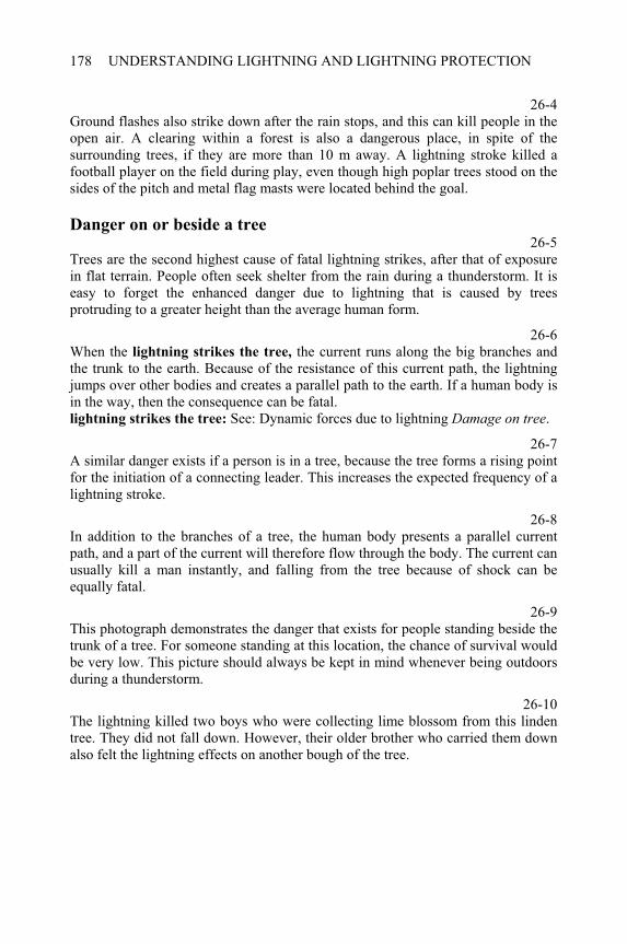
UNDERSTANDING LIGHTNING AND LIGHTNING PROTECTION178
26-4Ground flashes also strike down after the rain stops, and this can kill people in the open air. A clearing within a forest is also a dangerous place, in spite of the surrounding trees, if they are more than 10 m away. A lightning stroke killed a football player on the field during play, even though high poplar trees stood on the sides of the pitch and metal flag masts were located behind the goal.
Danger on or beside a tree 26-5
Trees are the second highest cause of fatal lightning strikes, after that of exposure in flat terrain. People often seek shelter from the rain during a thunderstorm. It is easy to forget the enhanced danger due to lightning that is caused by trees protruding to a greater height than the average human form.
26-6When the lightning strikes the tree, the current runs along the big branches and the trunk to the earth. Because of the resistance of this current path, the lightning jumps over other bodies and creates a parallel path to the earth. If a human body is in the way, then the consequence can be fatal. lightning strikes the tree: See: Dynamic forces due to lightning Damage on tree.
26-7A similar danger exists if a person is in a tree, because the tree forms a rising point for the initiation of a connecting leader. This increases the expected frequency of a lightning stroke.
26-8In addition to the branches of a tree, the human body presents a parallel current path, and a part of the current will therefore flow through the body. The current can usually kill a man instantly, and falling from the tree because of shock can be equally fatal.
26-9This photograph demonstrates the danger that exists for people standing beside the trunk of a tree. For someone standing at this location, the chance of survival would be very low. This picture should always be kept in mind whenever being outdoors during a thunderstorm.
26-10The lightning killed two boys who were collecting lime blossom from this linden tree. They did not fall down. However, their older brother who carried them down also felt the lightning effects on another bough of the tree.
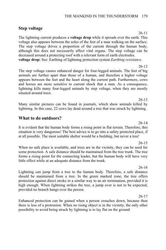
THE MANKIND IN THE THUNDERSTORM 179
Step voltage 26-11
The lightning current produces a voltage drop while it spreads over the earth. This voltage also appears between the soles of the feet of a man walking on the surface. The step voltage drives a proportion of the current through the human body, although this does not necessarily affect vital organs. The step voltage can be decreased around a protecting roof with a relevant form of earth electrodes. voltage drop: See: Earthing of lightning protection system Earthing resistance.
26-12The step voltage causes enhanced danger for four-legged animals. The feet of big animals are further apart than those of a human, and therefore a higher voltage appears between the feet and the heart along the current path. Furthermore, cows and horses are more sensitive to current shock that a man. As a consequence, lightning kills many four-legged animals by step voltage, when they are mostly situated around trees.
26-13Many similar pictures can be found in journals, which show animals killed by lightning. In this case, 22 cows lay dead around a tree that was struck by lightning.
What to do outdoors? 26-14
It is evident that the human body forms a rising point in flat terrain. Therefore, this situation is very dangerous! The best advice is to go into a safety protected place, if at all possible. The most suitable shelter would be a building, but never a tree!
26-15When no safe place is available, and trees are in the vicinity, they can be used for some protection. A safe distance should be maintained from the tree trunk. The tree forms a rising point for the connecting leader, but the human body will have very little effect while at an adequate distance from the trunk.
26-16Lightning can jump from a tree to the human body. Therefore, a safe distance should be maintained from a tree. In the green marked zone, the tree offers protection against direct stroke in a similar way to an air termination, provided it is high enough. When lightning strikes the tree, a jump over is not to be expected, provided no branch hangs over the person.
26-17Enhanced protection can be gained when a person crouches down, because then there is less of a protrusion. When no rising object is in the vicinity, the only other possibility to avoid being struck by lightning is to lay flat on the ground.
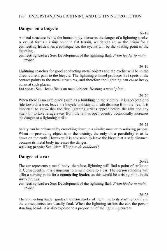
UNDERSTANDING LIGHTNING AND LIGHTNING PROTECTION180
Danger on a bicycle 26-18
A metal structure below the human body increases the danger of a lightning stroke. A cyclist forms a rising point in flat terrain, which can act as the origin for a connecting leader. As a consequence, the cyclist will be the striking point of the lightning. connecting leader: See: Development of the lightning flash From leader to main
stroke.
26-19Lightning searches for good conducting metal objects and the cyclist will be in the direct current path to the bicycle. The lightning channel produces hot spots at the contact points to the metal structures, and therefore the lightning can cause heavy burns at such places. hot spots: See: Heat effects on metal objects Heating a metal plate.
26-20When there is no safe place (such as a building) in the vicinity, it is acceptable to ride towards a tree, leave the bicycle and stay at a safe distance from the tree. It is important to know that the first lightning strikes appear before the rain and any intention to take refuge away from the rain in open country occasionally increases the danger of a lightning strike.
26-21Safety can be enhanced by crouching down in a similar manner to walking people.
When no protruding object is in the vicinity, the only other possibility is to lie down on the earth. However, it is advisable to leave the bicycle at a safe distance, because its metal body increases the danger. walking people: See: Idem What’s to do outdoors?
Danger at a car 26-22
The car represents a metal body; therefore, lightning will find a point of strike on it. Consequently, it is dangerous to remain close to a car. The person standing will offer a starting point for a connecting leader, as this would be a rising point in the surroundings. connecting leader: See: Development of the lightning flash From leader to main
stroke.
26-23The connecting leader guides the main stroke of lightning to its starting point and the consequences are usually fatal. When the lightning strikes the car, the person standing beside it is also exposed to a proportion of the lightning current.
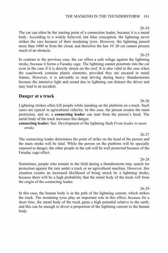
THE MANKIND IN THE THUNDERSTORM 181
26-24The car can often be the starting point of a connection leader, because it is a metal body. According to a widely believed, but false conception, the lightning never strikes the cars because of their insulating tyres. However, the lightning passed more than 1000 m from the cloud, and therefore the last 10–20 cm cannot present much of an obstacle.
26-25In contrast to the previous case, the car offers a safe refuge against the lightning stroke, because it forms a Faraday cage. The lightning cannot penetrate into the car even in the case if it is directly struck on the roof. It is also valid in the case when the coachwork contains plastic elements, provided they are encased in metal frames. However, it is advisable to stop driving during heavy thunderstorms because the intensive light and sound due to lightning can distract the driver and may lead to an accident.
Danger at a truck 26-26
Lightning strokes often kill people while standing on the platform on a truck. Such cases are typical in agricultural vehicles. In this case, the person creates the main protrusion, and so, a connecting leader can start from the person’s head. The metal body of the track increases this danger. connecting leader: See: Development of the lightning flash From leader to main
stroke.
26-27The connecting leader determines the point of strike on the head of the person and the main stroke will be fatal. While the person on the platform will be specially exposed to danger, the other people in the cab will be well protected because of the Faraday cage effect.
26-28Sometimes, people who remain in the field during a thunderstorm may search for protection against the rain under a truck or an agricultural machine. However, this situation creates an increased likelihood of being struck by a lightning stroke, because there will be a high probability that the metal body of the truck will form the origin of the connecting leader.
26-29In this case, the human body is in the path of the lightning current, which strikes the truck. The insulating tyres play an important role in this effect, because for a short time, the metal body of the truck gains a high potential relative to the earth, and this can be enough to divert a proportion of the lightning current to the human body.
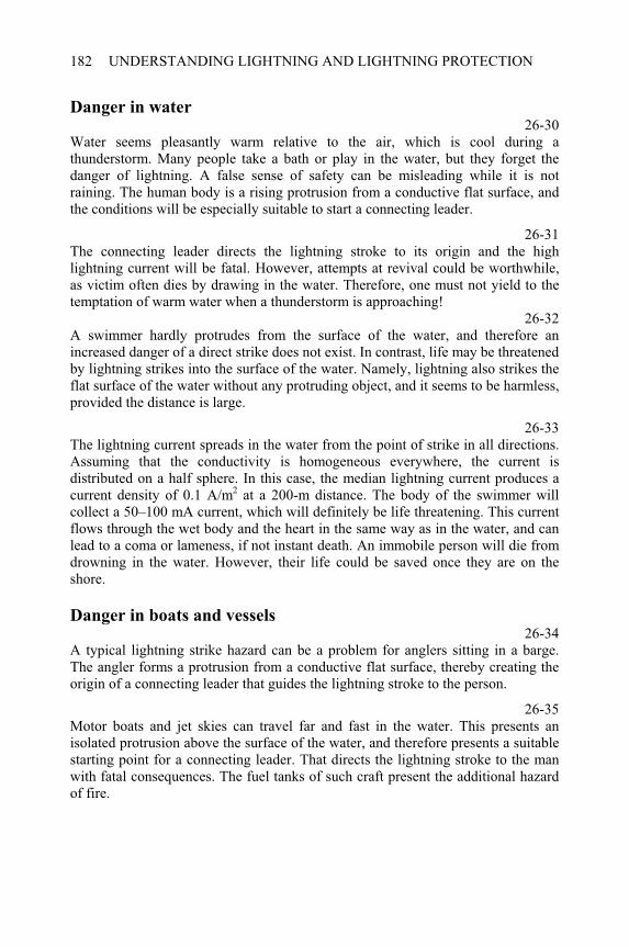
UNDERSTANDING LIGHTNING AND LIGHTNING PROTECTION182
Danger in water 26-30
Water seems pleasantly warm relative to the air, which is cool during a thunderstorm. Many people take a bath or play in the water, but they forget the danger of lightning. A false sense of safety can be misleading while it is not raining. The human body is a rising protrusion from a conductive flat surface, and the conditions will be especially suitable to start a connecting leader.
26-31The connecting leader directs the lightning stroke to its origin and the high lightning current will be fatal. However, attempts at revival could be worthwhile, as victim often dies by drawing in the water. Therefore, one must not yield to the temptation of warm water when a thunderstorm is approaching!
26-32A swimmer hardly protrudes from the surface of the water, and therefore an increased danger of a direct strike does not exist. In contrast, life may be threatened by lightning strikes into the surface of the water. Namely, lightning also strikes the flat surface of the water without any protruding object, and it seems to be harmless, provided the distance is large.
26-33The lightning current spreads in the water from the point of strike in all directions. Assuming that the conductivity is homogeneous everywhere, the current is distributed on a half sphere. In this case, the median lightning current produces a current density of 0.1 A/m2 at a 200-m distance. The body of the swimmer will collect a 50–100 mA current, which will definitely be life threatening. This current flows through the wet body and the heart in the same way as in the water, and can lead to a coma or lameness, if not instant death. An immobile person will die from drowning in the water. However, their life could be saved once they are on the shore.
Danger in boats and vessels 26-34
A typical lightning strike hazard can be a problem for anglers sitting in a barge. The angler forms a protrusion from a conductive flat surface, thereby creating the origin of a connecting leader that guides the lightning stroke to the person.
26-35Motor boats and jet skies can travel far and fast in the water. This presents an isolated protrusion above the surface of the water, and therefore presents a suitable starting point for a connecting leader. That directs the lightning stroke to the man with fatal consequences. The fuel tanks of such craft present the additional hazard of fire.
THE MANKIND IN THE THUNDERSTORM 183
26-36Sailing ships and high vessels form a protrusion above the surface of the water and are therefore struck by lightning with increased frequency. However, modern mast and other components are made of metal that can direct the lightning current downwards. To avoid any damage, these metal elements should be connected to other metal components of the vessel, which are in contact with the water. In this case, the lightning current will be excluded from the interior and the living quarters. It is interesting to note that traditional seafaring nations had rigorous precautionary measures for the lightning protection of sailing ships.

References
Books and papers
[1] Anderson, R.B., Ericsson, A.J., Lightning parameters for engineering application. CIGRÉ Electra, Vol. 69 (1980), pp. 65–72.
[2] Berger, K., Novel observations on lightning discharges: Results of research on mount San Salvatore. Journal of Franklin Institute, Vol. 283 (1967), pp. 478–525.
[3] Berger, K., Garbagnaty, E., Lightning current parameters – results obtained in Switzerland and in Italy, U. R. S. I., Italy, September, 1984.
[4] Darveniza, M., Popolansky, F., Whitehead, E.R., Lightning protection of UHV transmission lines. CIGRÉ Electra, Vol. 41 (1975), pp. 39–69.
[5] Frühauf, G., Modellmessungen mit Blitzströmen. Elektrotechnische Zeitschrift,Vol. 82-A (1961), pp. 265–272.
[6] Golde, R.H., The validity of lightning tests with scale models. Journal of The Institution of Electrical Engineers, Vol. 88-II (1941), pp. 67–68.
[7] Golde, R.H., Lightning Protection. Edward Arnold Press, London, 1973.
[8] Golde, R.H., Lightning. Academic Press, London, 1977.
[9] Hasse, P., Overvoltage Protection of Low Voltage Systems. The Institution of Electrical Engineers, London, 2000.
[10] Hasse, P., Wiesinger, J., Handbuch für Blitzschutz und Erdung. Pflaum – VDE Verlag, Berlin, 1989.
[11] Horváth, T., Schutzwirkung von Fangvorrichtungen. ElektrotechnischeZeitschrift, Vol. 99-A (1978), pp. 661–663. ____________________________________________________Understanding Lightning and Lightning Protection T. Horváth © 2006 Research Studies Press Limited
REFERENCES186
[12] Horváth, T., Computation of Lightning Protection. Research Studies Press, Taunton, 1991.
[13] Horváth T., Rolling sphere. Theory and application, 25th International Conference on Lightning Protection, Rodes, 2000, Paper 4.8, Proceedings, pp. 301–305.
[14] Kilinsky, E., Lehrbuch der Luftelektrizitat. Akademischer Verlag, Leipzig, 1958.
[15] McEachron, K.B., Playing with Lightning. Random House, New York, 1940.
[16] McEachron, K.B., Lightning to the empire state building. Transactions of American Institute of Electrical Engineering, Vol. 60 (1941), pp. 885–889.
[17] Müller, E., Steinbigler, H., Wieseinger, J., Zur numerischen Berechnung von induzierten Schleifenspannungen. Bulletin des Schweizerischen Elektotechnischen Vereins, Vol. 63 (1972), pp. 1025–1032.
[18] Neugebauer, T., Zu dem problem des Kugelblitzes. Zeitschrift für Physik, Vol. 106 (1937), p. 474.
[19] Prinz, H., Feuer, Blitz und Funke. F. Bruckmann K G Verlag, Munich, 1965.
[20] Raether, H., Über die Aufbau von Gasentladungen. Zeitschrift für Physik, Vol. 117 (1941), pp. 375–398.
[21] Schonland, B.F.J., The lightning discharge. Handbuch der Physik, Vol. 22 (1956), pp. 576–628.
[22] Schwaiger, A., Der Schutzbereich von Blitzableitern. Oldenbourg Verlag, Munich, 1938.
[23] Uman, M.A., The Lightning Discharge. Academic Press. Orlando, 1987.
International und Hungarian standards
[24] IEC 61024-1: Protection of structures against lightning. Part 1. General principles. International Electrotechnical Commission, Geneva, 1990.
[25] IEC 61312-1: Protection against lightning electromagnetic impulse. Part 1. General principles. International Electrotechnical Commission, Geneva, 1995.
REFERENCES 187
[26] IEC 61662: Assessment of the risk of damage due to lightning. International Electrotechnical Commission, Geneva, 1995.
[27] IEC 61643: Surge protective devices connected to low voltage power distribution systems – Part 1: Performance, requirements and testing methods. International Electrotechnical Commission, Geneva, 1998.
[28] MSZ 274: Lightning protection of structures. Hungarian Standard, Budapest, 1972.

Index
A
absorption 3-3 14 accelerator 21-3 149 acceptable risk 14-47, 16-2 99,111 activating layer 21-3 149 air termination systems 16-0 111 air terminations of blockhouse 11-13, 12-1 75, 79 alpine roof 13-28 87 Ampere’s law 7-1, 8-3, 7-28 43, 51, 47 angler 26-34 182 animals killing 26-12 179 annual frequency 14-41 97 antenna of direction finding 25-23 175 anticyclone 1-19 6 Apollo moon flight 25-30 176 arable soil 18-28 132 arc blowing spark gap 21-5 150 arc deflector 21-10 151 arc discharge 21-6 150 arc quenching 21-8, 21-12, 21-17 150, 151, 152 arresters 21-0 149 arriving current 19-10, 19-15 137, 138 attraction of roof and eaves 13-8 84 attraction of edges of inclined roof 13-23 87 attraction 8-3, 8-20, 8-37 51, 54, 57 avalanche 3-14, 3-18, 3-25,
21-316, 16, 17, 149
average period of damage 14-43 98
____________________________________________________Understanding Lightning and Lightning Protection T. Horváth © 2006 Research Studies Press Limited
INDEX190
Bball lightning 6-1 35 ball lightning-theories 6-7 37 bank of water 15-24 105 beaded lightning 6-23 40 bicycle 26-18 180 blockhouse 11-13, 12-1 75, 79 blowing out 21-7, 21-13 150, 151 boat 26-35 182 Boltzmann’s-constant 6-11 38 bonded groups 18-19 130 bonding 22-6, 17-20, 17-30 158, 122, 124 boring tower 18-3 128 Boys camera 4-22, 6-21, 6-27 23, 39, 41 Boys record 4-7, 6-24, 4-30,
4-36, 4-38 20, 40, 24, 25, 25
branch of lightning 4-10 21 branching line 19-15, 19-19 138, 138 branching stroke 4-11 21 breakdown arrester 21-18 152 breakdown due to current 14-19, 20-2, 20-9,
20-12, 20-20,20-24
92, 143, 145, 145, 146, 147
burning material 15-32 107 burning the roof and the garret 14-33 96
Ccalculation of current paths length 17-1 119 calculation of expected frequency 10-10, 10-18,
10-26, 10-27,10-30
69, 70, 72, 72, 72
calculation of induced values 7-18 46 calculation of risk 14-27 94 capacitive coupling 19-5 136 Cape Canaveral 25-31 176 car 26-22 180 cases of damaging stroke 14-18 92 cathodic protection 21-36 155 causing damage 14-19 92 characteristic of varistor 20-3, 20-6, 20-20,
20-24, 21-26,21-29
143, 144, 146, 147, 153, 153
characteristics of diode 21-18, 21-29 152, 153 characteristics of gaps 20-9, 20-21, 20-25 145, 146, 147 charge distribution in the cloud 6-31 41
INDEX 191
charge of lightning 5-26 32 charging processes in the cloud 2-1, 2-7 9, 10 charging theorises 2-3 9 checking the continuity 18-20 131 circuit of lightning 19-32 141 cirrus cloud 1-23 7 classes according to height 15-12, 15-26 103, 106 classes of roof 15-31, 15-34,
16-12, 16-21 107, 108, 113, 115
classes of structures 15-1, 17-36 101, 125 classification of structures 15-0, 16-1 101, 111 cloud, cyclone and fronts 1-0 3 coil of Rogowski 25-13 173 cold fronts 1-24, 1-27–29, 2-1 7, 8, 9 collection space of edges of inclined roof
13-24 87
collection space 10-17, 10-20, 10-26, 10-29,11-1,11-25, 11-27,11-29, 12-1,13-8–24, 14-3,15-23
70, 71, 72, 72, 73, 77, 77, 78, 79,84–87, 90, 105
collection spaces of structures 11-0 73 combustible roof 15-32 107 common structures 15-1, 16-2 101, 111 comparison of collection spaces 11-25 77 concrete base 18-24 131 condensation 1-3 4 conducted current 19-2, 19-7 135, 136 conductive coupling 19-1, 23-10, 23-20,
23-26135, 162, 164, 165
conductors above the eaves 13-13–16 85–86 conductors on the edges of inclined roof
13-15–16,13-18–19,13-21–22
85–86, 86, 86
connecting leader 4-7, 4-9, 4-32, 5-5, 5-17, 6-29, 10-3, 15-28, 15-30, 26-1, 26-18, 26-22,26-30
20, 21, 24, 28, 30, 41, 67, 106, 107, 177, 180, 180, 182
connection to electric power network 23-0 161 consequences of damage 14-40, 15-1 97, 101 construction methods 16-3 111 contact spot 9-1 59
INDEX192
continuous current 5-19, 5-26 30, 32 Coriolis force 1-17 6 corona discharge 3-21, 5-4, 5-31, 6-2 17, 28, 33, 36 corona envelope 5-2, 5-13 27, 29 coupler device 24-14 169 coupling of lightning 14-16, 19-1 92, 135 covering of roof 15-31, 16-21 107, 115 crater, melted 9-15 62 crater, broken 8-29 55 cultural values 14-32 96 cumuli-nimbus 1-5 4 curious lightning phenomena 6-0 35 current distribution 19-7 136 current impulse 5-19, 5-26 30, 32 current paths length 17-1, 17-9,17-15 119, 120, 121 current wave 5-16, 5-18, 5-19,
5-25, 9-3, 21-33, 25-18, 25-20
30, 30, 30, 32, 59, 154, 174, 174
cyclone 1-13, 1-19 6, 6
Ddaily distribution of thunderstorms 2-20 12 damage along current path 14-30 95 damage at lightning conductors 14-29 95 damage on tree 8-32 56 damaging strokes 14-40 97 damping 19-22 139 danger at car 26-22 180 danger at track 26-26 181 danger in boats and vessels 26-34 182 danger in open air 2-14, 26-1 11, 177 danger in the water 26-30 182 danger on bicycle 26-18 180 danger on or beside a tree 26-5, 26-7 178, 178 dangerous loops 17-26, 17-33 123, 124 dangerous situations 26-1 177 dart leader 4-14, 4-34, 4-39,
4-40, 5-16 21, 25, 25, 26, 30
data entrance 24-1 167 dayly distribution of thunderstorms 1-28 8 dead zones of lightning detection 25-22, 25-27 174, 175 deceasing ball lightning 6-20 39 deflector horn 21-16 151 degree of air termination 16-12, 16-20,
16-27113, 115, 116
INDEX 193
degree of down conductors 16-18, 17-17 114, 121 degrees of earthing 18-1 127 delay of the peak value 5-21 31 density functions 10-8, 10-13 10-16 68, 69, 70 detection of lightning 25-28, 25-31 175, 176 development of a cloud 1-1, 1-10, 1-11 3, 5, 5 development of a cyclone 1-13 6 development of the lightning flash 4-0 19 devices of surge protection 21-0 149 diagrams of interception 12-4, 16-8 80, 112 diameter of lightning channel 8-13, 8-16, 9-1,
16-2353, 53, 59, 115
diameter of round plate 16-20 115 diode 20-6, 20-11 144, 145 diode, characteristics 21-29 153 direct stroke 7-18 46 direction finding 25-21, 25-23 174, 175 directional loop 25-23 175 disaster in environment 14-37 96 discharge on drops in the cloud 4-3 19 discharge processes in air 3-0, 6-32 13, 42 discharge to the ionosphere 6-31 41 discharges 3-11 15 distance between down conductors 17-15 121 distance of surge protectors 20-11 145 distance to the structure 16-21, 16-33 115, 117 distant stroke 7-28 47 distribution and density functions 10-7, 10-13 68, 69 distribution functions 5-24, 5-28, 7-30,
7-37, 10-7 31, 32, 47, 49, 68
distribution of current 19-7 136 distribution of thunderstorms 1-25, 2-20, 7-31,
7-34, 7-38 7, 12, 48, 48, 49
dividing the collection space 11-3, 11-10, 11-25 74, 75, 77 down conductor, simplified 18-5 128 down conductors along the perimeter 17-15 121 down conductors and metal objects 17-0 119 down conductors distance 17-15 121 down conductors positioning 17-1, 17-15 119, 121 down conductor 16-18, 17-1, 22-9,
25-1114, 119, 159, 171
downward leader 4-7, 4-31,4-32, 4-38, 5-1, 5-9, 6-1
20, 24, 24, 25, 27, 28, 35
droplets, metal 9-16, 16-24 62, 115
INDEX194
duration of thunderstorms 1-29 8 dynamic force 8-22, 9-15, 14-21,
17-24, 21-12 54, 62, 93, 123, 151
dynamic forces due to lightning 8-0 51
Eearthing by foundation 18-22 131 earthing impulse resistance 18-34 133 earthing of lightning protection system
16-18, 18-0 114, 127
earthing reference point 22-14 159 earthing resistance 18-1, 18-5, 18-10,
18-17, 18-31, 18-34, 19-1, 26-11
127, 128, 129, 130, 132, 133, 135, 179
eaves with conductors 13-13–16 85 eaves with flange plates 13-11–12,
13-17–1985, 86
eaves without any protection 13-8–10, 13-20–22 84, 86 EBB 19-7, 22-6, 23-1,
23-4, 23-7, 23-10, 23-17, 23-22, 23-26
136, 158, 161, 162, 162, 162, 163, 164, 165
edges of inclined roof with conductors
13-15–16,13-18–19,13-21–22
85, 86, 86
edges of inclined roof with flange plates
13-8–14, 13-17, 13-20
84–85, 86, 86
edges of inclined roof, collection space
13-23 87
effect of the soil profile 15-27 106 efficiency of protection 16-2 111 electric charges in clouds 2-0, 6-31 9, 41 electric field of cloud 2-16, 6-31 11, 41 electric power line 24-11, 24-14 169, 169 electrodes on eaves 13-10 84 electrodes on the edges of inclined roof
13-4 84
electromagnetic forces 8-0, 21-12 51, 151 electron avalanche 3-14, 3-18, 3-25,
21-316, 16, 17, 149
electron collisions 3-6, 3-11, 14, 15 electronic devices in the building 24-1 167 elevators 17-37 125 Elmo fire 3-21 17 encapsulated arrester 21-13, 21-35 151, 154
INDEX 195
enhanced air termination system 16-12, 16-19 113, 114 enhanced earthing systems 18-21 131 environmental disaster 14-37, 15-10, 16-2 96, 103, 111 equipotential bonding bar (EBB) 22-6 158 equivalent area of a structure 14-2 89 equivalent area 14-12, 15-12,
15-18, 15-23 91, 103, 104, 105
ERP 22-14 159 example of current path 17-9 120 excitation by electron 3-9, 3-11, 3-18 15, 15, 16 excitation by photon 3-9 15 expected frequency of stroke 7-31, 7-33, 10-10,
10-14,10-18,10-28, 10-31
48, 48, 69, 69, 70, 72, 72
expected frequency 11-8, 11-12, 11-26, 11-28, 11-30, 13-9, 13-15, 13-18,13-21, 14-3, 16-3
74, 75, 77, 77, 78, 84, 85, 86, 86, 90, 111
expected period 7-34, 7-38, 19-14, 19-19
48, 49, 137, 138
explosion hazard 16-2 111 explosion inside the structure 14-35 96 external LPS 24-1 167
FFaraday holes 19-21 139 Faraday-cage 26-25, 26-27 181, 181 fatal stroke 26-2, 26-19, 26-23,
26-27,26-29,26-31, 26-34,26-35
177, 180, 180, 181, 181, 182, 182, 182
final distribution of charges 2-14, 2-16 11, 11 fine protection 23-7 162 fine weather current 2-19, 6-8 12, 37 fire hazard 14-34, 16-2 96, 111 first stage of surge-protection 23-1, 23-4 161, 162 first stroke 4-13, 5-22 21, 31 flameproof plastics 15-32 107 flameproof wood 15-33 107 flammable materials of roof 15-32 107 flammable roof 14-23, 16-22 93, 115
INDEX196
flange plates on eaves 13-11–12, 13-17–19
85, 86
flange plates on edges of inclined roof
13-8–14, 13-17, 13-20
84–85, 86, 86
flash-over 21-11, 21-15 151, 151 flat roof, diagrams 12-4 80 fleecy clouds 1-23 7 flow diagram 14-1 89 flux density 7-5, 7-8, 7-28 44, 44, 47 foehn 1-12 5 force due to lightning 8-8 52 force of leaded current 8-18 54 force on a loop 17-24 123 force on a plate 8-15 53 force on a rod 8-8 52 force on a tube 8-20 54 force on a wire 8-12, 8-18 53, 54 force on metal structures 8-1 51 force onto arc 21-12 151 forced air termination system 16-12, 16-19 113, 114 forecasting the thunderstorm 25-30 176 forms of air terminations 16-28, 17-23 116, 123 forms of down conductors 17-22 122 Foucault currents 25-5 172 foundation earthing 18-4, 18-9 128, 129 frame earthing 18-17 130 free path 3-7, 3-11 14, 15 freezing 1-4, 2-9 4, 10 frequency of stroke 11-8, 11-12 74, 75 frequency of weighted damage 14-41 97 friable stone 15-27 106 from leader to main stroke 4-6 20 front time 5-20 31 fronts 1-21 7 fulgurit 17-33 124 further classifications 15-36 108
Ggas evolving plastic 21-5, 21-9, 21-14 150, 150, 151 gas filled arrester 21-1, 21-10 149, 151 Gaussian scale 5-28 32 geological formations 15-27 106 gliding spark gap 21-4, 21-9, 21-16,
21-19150, 150, 151, 152
graded surge-protection 20-0, 21-37, 24-4 143, 155, 168
INDEX 197
gravel base 18-23 131 gravel 18-28 132 gritty soil 18-28 132 ground flash density 1-26, 7-31, 7-33,
7-34, 7-38, 14-2, 14-12
8, 48, 48, 48, 49, 89, 91
ground water 18-28 132 growth of a thunderstorm cloud 1-5, 1-24, 2-14 4, 7, 11
Hhand-held camera 6-21 39 harmful materials leaking 14-36 96 hazard onto the surroundings 15-10 103 heat convection 9-3 59 heat effect on tree 8-33 56 heat effects 14-20, 16-21,
16-3493, 115, 117
heat effects on metal objects 9-0 59 heating a metal plate 5-26, 9-1, 9-9 32, 59, 61 heating through a metal plate 9-6 60 height and surroundings 15-12, 16-12 103, 113 hemisphere earth electrode 18-10 129 HF loop aerial 25-28 175 high surroundings 15-13, 15-19,
15-26103, 104, 106
holders 17-23 123 horizontal conductor 14-6 90 horizontal earth electrode 18-7 128 hot spots 9-6, 26-19 60, 180 humid area 15-25, 15-29 105, 106 Hungarian Standard for Lightning Protection of Structures
15-1, 16-12, 17-17, 18-1
101, 113, 121, 127
Iideal lightning 4-38 25 ignition inside a metal tank 9-6 60 impermeable layer 15-27, 15-29 106, 106 important structures 15-3, 16-2 101, 111 impulse current 5-19, 5-26, 30, 32 impulse earthing 18-32 132 impulse resistance of earthing 18-34 133 inception 20-19, 20-23 146, 147 inclined roof 13-1, 16-33 83, 117 inclined roof, diagrams of interception.
13-27 87
INDEX198
incombustible material 15-35 108 incombustible roof 15-32 107 increased danger of stroke 15-18, 15-26,
15-27, 15-29 104, 106, 106, 106
induced current 7-23, 7-35, 19-3 46, 48, 136 induced voltage and current 7-0 43 induced voltage 7-18, 7-28, 14-22,
14-26, 14-43, 17-26, 19-3, 24-6, 25-15
46, 47, 93, 94, 98, 123, 136, 168, 173
induction loop 17-26 123 induction 19-24 139 inductive coupling 19-3 136 inflammable roof 16-21 115 influence of distance between stages 20-11 145 insulating spacers 17-34 124 intercepted stroke 14-14, 14-19 91, 92 interception failures 14-14 91 internal connections 22-10 159 internal hot spot 9-6 60 internal lightning protection zones 22-0 157 internal lightning protection 15-38 108 inversion of wire 8-18 54 ionisation by collision 3-10, 5-4, 5-31 15, 28, 33 ionisation by electron 3-10 15 ionisation by photons 3-3, 3-20 14, 17 ionosphere 2-4, 2-17, 6-8, 6-32 10, 12, 37, 42 isokeraunic level 1-25, 2-20 7, 12 isolated air termination 16-26 116
Jjumping over of a lightning 26-6 178
KKapitza 6-10 37 keeping distance 16-33 117 klydonograph 3-22 17 kWh meter 23-1, 23-4, 23-7,
23-26161, 162, 162, 165
LLatham 2-8 10 leader channel 4-6 20 leader discharge 4-7, 4-32, 5-4, 5-6,
5-31, 15-28 20, 24, 28, 28, 33, 106
INDEX 199
leader type discharge 3-25, 3-29 17, 18 leakage of harmful materials 14-36 96 LEMP effects 14-17, 22-1, 24-1 92, 157, 167 Lenard 2-3 9 Lenz’s law 6-15 38 lethal shock 26-33 182 level of risk and protection 16-1 111 lightning attachment 10-0, 16-3 67, 111 lightning centres 15-29 106 lightning current arrester 21-33, 22-1, 24-2, 154, 157, 167 lightning current 5-23, 5-24, 11-2,
21-33, 25-1, 25-15 31, 31, 73, 154, 171, 173
lightning detection 4-5, 25-28 20, 175 Lightning ElectroMagnetic imPulse (LEMP)
14-17, 19-0, 22-1 92, 135, 157
lightning impulse 9-3 59 lightning localisation 1-26, 4-5, 25-28 8, 20, 175 lightning measurement and localisation
25-0 171
lightning measurement 5-21 31 lightning parameters 2-17, 4-15, 4-17,
5-24, 7-20, 7-25,8-24, 9-2, 9-27,9-30, 9-32, 10-6, 10-8, 14-19, 14-24, 14-40, 19-1, 19-4, 19-14, 19-19, 25-1, 25-10
12, 22, 22, 31, 46, 47, 55, 59, 64, 64, 65, 68, 68, 92, 94, 97, 135, 136, 137, 138, 171, 172
lightning protection earthing 18-1 127 lightning protection zone 15-38, 24-1, 24-3,
24-16108, 167, 168, 170
lightning pulse arrival time system (LPATS)
25-25 175
lightning rod on tower 11-9 75 lightning rods 11-21,11-29, 12-3 76, 78, 80 lime rock 18-28 132 localising the lightning 1-26, 25-1, 25-21 8, 171, 174 logarithmic normal distribution 5-25–29, 10-7 32–33, 68 long distance 20-11, 20-23 145, 147 loop+cut conductor 7-8 44 loop+infinite conductor 7-5 44 LPATS 25-25 175 LPZ 15-38, 24-1, 24-3,
24-16108, 167, 168, 170
INDEX200
Mmagnetic card 25-4 172 magnetic field due to lightning 25-2, 25-14 171, 173 magnetic flux density 7-5, 7-8, 7-28, 8-3 44, 44, 47, 51 magnetic link 25-5, 25-8 172, 172 main discharge 6-24, 6-25 40, 40 main stroke 4-8, 4-9, 4-32,
4-33, 5-13, 6-1,6-12
20, 21, 24, 25, 29, 35, 38
man in the field 26-1 177 mankind in the thunderstorm 2-14, 26-0 11, 177 many people exposed to danger 14-31 95 Mason 2-8 10 materials of roof 15-6, 15-31, 16-12,
16-21102, 107, 113, 115
measurement by magnetising 25-2 171 measurement of earthing resistance 18-30 132 measurement of soil resistivity 18-29 132 measuring the lightning current 25-1 171 median lightning current 19-1 135 mediterranean roof 13-28 87 melt through 15-32 107 melted volume 9-12, 9-18 61, 62 melting a metal plate 9-7, 9-9, 9-30,
14-2460, 61, 64, 94
melting at contact spot 9-7, 9-9, 9-18, 9-30, 14-20, 9-31, 14-20, 14-24
60, 61, 62, 64, 93, 64, 93, 94
melting a wire 5-27, 9-18, 9-22, 9-31
32, 62, 63, 64
melting by leading current 5-27, 9-22, 9-32 32, 63, 65 melting energy 9-9, 9-25 61, 63 mesh size 16-9, 16-20 112, 115 meshed system 22-14 159 metal ceiling 15-33 107 metal drops 16-24 115 metal parts of roof 15-32, 15-34 107, 108 metal plate, heat effects of lightning 9-1 59 metal plate, force due to lightning 8-15 53 metal roof 14-24, 15-32 94, 107 minimum sizes of earth electrodes 18-9 129 mixed system 22-16 160 monthly distribution of thunderstorms
1-27 8
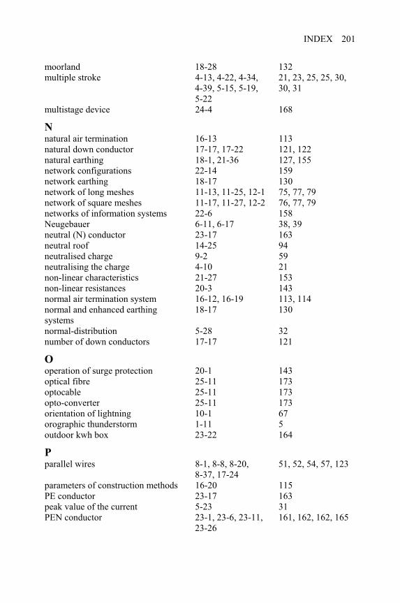
INDEX 201
moorland 18-28 132 multiple stroke 4-13, 4-22, 4-34,
4-39, 5-15, 5-19,5-22
21, 23, 25, 25, 30, 30, 31
multistage device 24-4 168
Nnatural air termination 16-13 113 natural down conductor 17-17, 17-22 121, 122 natural earthing 18-1, 21-36 127, 155 network configurations 22-14 159 network earthing 18-17 130 network of long meshes 11-13, 11-25, 12-1 75, 77, 79 network of square meshes 11-17, 11-27, 12-2 76, 77, 79 networks of information systems 22-6 158 Neugebauer 6-11, 6-17 38, 39 neutral (N) conductor 23-17 163 neutral roof 14-25 94 neutralised charge 9-2 59 neutralising the charge 4-10 21 non-linear characteristics 21-27 153 non-linear resistances 20-3 143 normal air termination system 16-12, 16-19 113, 114 normal and enhanced earthing systems
18-17 130
normal-distribution 5-28 32 number of down conductors 17-17 121
Ooperation of surge protection 20-1 143 optical fibre 25-11 173 optocable 25-11 173 opto-converter 25-11 173 orientation of lightning 10-1 67 orographic thunderstorm 1-11 5 outdoor kwh box 23-22 164
Pparallel wires 8-1, 8-8, 8-20,
8-37, 17-24 51, 52, 54, 57, 123
parameters of construction methods 16-20 115 PE conductor 23-17 163 peak value of the current 5-23 31 PEN conductor 23-1, 23-6, 23-11,
23-26161, 162, 162, 165
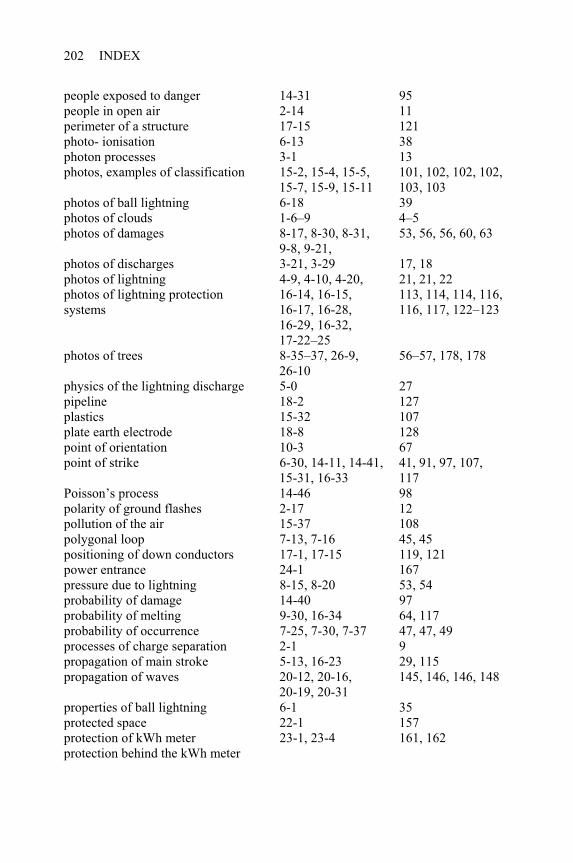
INDEX202
people exposed to danger 14-31 95 people in open air 2-14 11 perimeter of a structure 17-15 121 photo- ionisation 6-13 38 photon processes 3-1 13 photos, examples of classification 15-2, 15-4, 15-5,
15-7, 15-9, 15-11 101, 102, 102, 102, 103, 103
photos of ball lightning 6-18 39 photos of clouds 1-6–9 4–5 photos of damages 8-17, 8-30, 8-31,
9-8, 9-21, 53, 56, 56, 60, 63
photos of discharges 3-21, 3-29 17, 18 photos of lightning 4-9, 4-10, 4-20, 21, 21, 22 photos of lightning protection systems
16-14, 16-15,16-17, 16-28, 16-29, 16-32, 17-22–25
113, 114, 114, 116, 116, 117, 122–123
photos of trees 8-35–37, 26-9, 26-10
56–57, 178, 178
physics of the lightning discharge 5-0 27 pipeline 18-2 127 plastics 15-32 107 plate earth electrode 18-8 128 point of orientation 10-3 67 point of strike 6-30, 14-11, 14-41,
15-31, 16-33 41, 91, 97, 107, 117
Poisson’s process 14-46 98 polarity of ground flashes 2-17 12 pollution of the air 15-37 108 polygonal loop 7-13, 7-16 45, 45 positioning of down conductors 17-1, 17-15 119, 121 power entrance 24-1 167 pressure due to lightning 8-15, 8-20 53, 54 probability of damage 14-40 97 probability of melting 9-30, 16-34 64, 117 probability of occurrence 7-25, 7-30, 7-37 47, 47, 49 processes of charge separation 2-1 9 propagation of main stroke 5-13, 16-23 29, 115 propagation of waves 20-12, 20-16,
20-19, 20-31 145, 146, 146, 148
properties of ball lightning 6-1 35 protected space 22-1 157 protection of kWh meter 23-1, 23-4 161, 162 protection behind the kWh meter
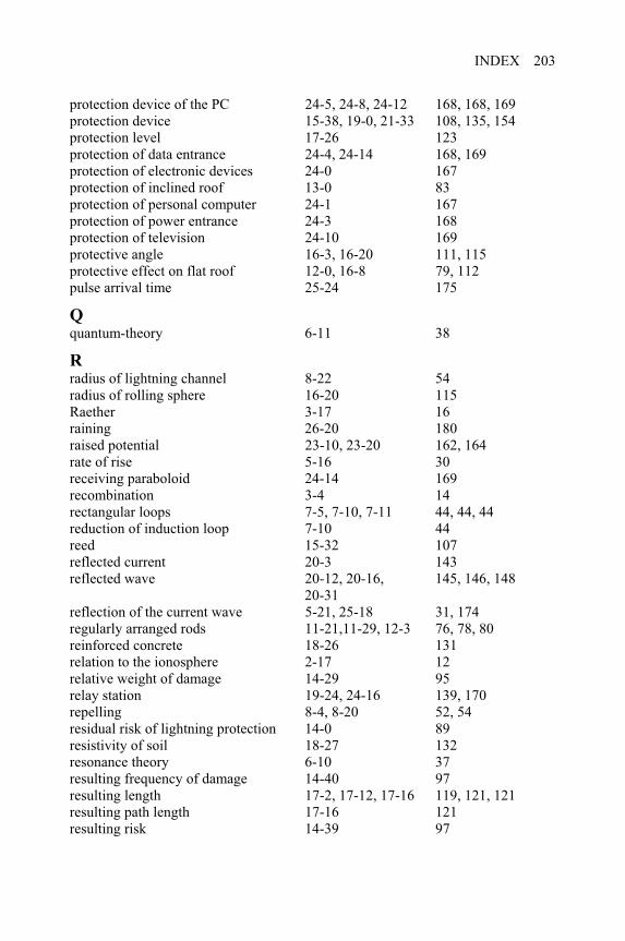
INDEX 203
protection device of the PC 24-5, 24-8, 24-12 168, 168, 169 protection device 15-38, 19-0, 21-33 108, 135, 154 protection level 17-26 123 protection of data entrance 24-4, 24-14 168, 169 protection of electronic devices 24-0 167 protection of inclined roof 13-0 83 protection of personal computer 24-1 167 protection of power entrance 24-3 168 protection of television 24-10 169 protective angle 16-3, 16-20 111, 115 protective effect on flat roof 12-0, 16-8 79, 112 pulse arrival time 25-24 175
Qquantum-theory 6-11 38
Rradius of lightning channel 8-22 54 radius of rolling sphere 16-20 115 Raether 3-17 16 raining 26-20 180 raised potential 23-10, 23-20 162, 164 rate of rise 5-16 30 receiving paraboloid 24-14 169 recombination 3-4 14 rectangular loops 7-5, 7-10, 7-11 44, 44, 44 reduction of induction loop 7-10 44 reed 15-32 107 reflected current 20-3 143 reflected wave 20-12, 20-16,
20-31145, 146, 148
reflection of the current wave 5-21, 25-18 31, 174 regularly arranged rods 11-21,11-29, 12-3 76, 78, 80 reinforced concrete 18-26 131 relation to the ionosphere 2-17 12 relative weight of damage 14-29 95 relay station 19-24, 24-16 139, 170 repelling 8-4, 8-20 52, 54 residual risk of lightning protection 14-0 89 resistivity of soil 18-27 132 resonance theory 6-10 37 resulting frequency of damage 14-40 97 resulting length 17-2, 17-12, 17-16 119, 121, 121 resulting path length 17-16 121 resulting risk 14-39 97
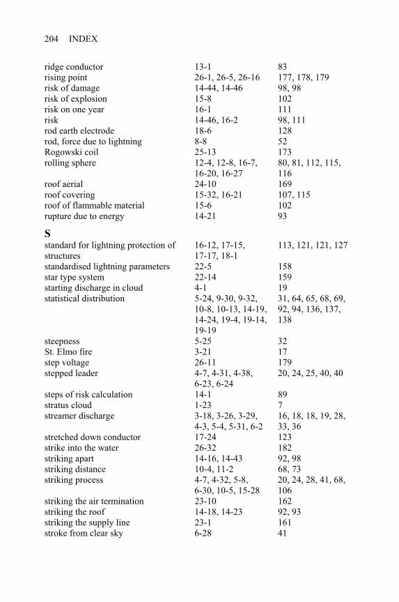
INDEX204
ridge conductor 13-1 83 rising point 26-1, 26-5, 26-16 177, 178, 179 risk of damage 14-44, 14-46 98, 98 risk of explosion 15-8 102 risk on one year 16-1 111 risk 14-46, 16-2 98, 111 rod earth electrode 18-6 128 rod, force due to lightning 8-8 52 Rogowski coil 25-13 173 rolling sphere 12-4, 12-8, 16-7,
16-20, 16-27 80, 81, 112, 115, 116
roof aerial 24-10 169 roof covering 15-32, 16-21 107, 115 roof of flammable material 15-6 102 rupture due to energy 14-21 93
Sstandard for lightning protection of structures
16-12, 17-15,17-17, 18-1
113, 121, 121, 127
standardised lightning parameters 22-5 158 star type system 22-14 159 starting discharge in cloud 4-1 19 statistical distribution 5-24, 9-30, 9-32,
10-8, 10-13, 14-19, 14-24, 19-4, 19-14, 19-19
31, 64, 65, 68, 69, 92, 94, 136, 137, 138
steepness 5-25 32 St. Elmo fire 3-21 17 step voltage 26-11 179 stepped leader 4-7, 4-31, 4-38,
6-23, 6-24 20, 24, 25, 40, 40
steps of risk calculation 14-1 89 stratus cloud 1-23 7 streamer discharge 3-18, 3-26, 3-29,
4-3, 5-4, 5-31, 6-2 16, 18, 18, 19, 28, 33, 36
stretched down conductor 17-24 123 strike into the water 26-32 182 striking apart 14-16, 14-43 92, 98 striking distance 10-4, 11-2 68, 73 striking process 4-7, 4-32, 5-8,
6-30, 10-5, 15-28 20, 24, 28, 41, 68, 106
striking the air termination 23-10 162 striking the roof 14-18, 14-23 92, 93 striking the supply line 23-1 161 stroke from clear sky 6-28 41
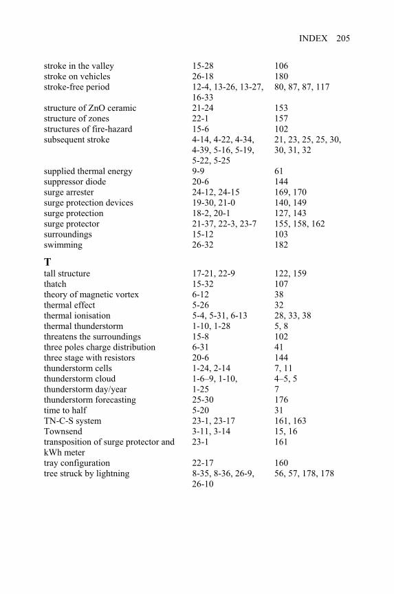
INDEX 205
stroke in the valley 15-28 106 stroke on vehicles 26-18 180 stroke-free period 12-4, 13-26, 13-27,
16-3380, 87, 87, 117
structure of ZnO ceramic 21-24 153 structure of zones 22-1 157 structures of fire-hazard 15-6 102 subsequent stroke 4-14, 4-22, 4-34,
4-39, 5-16, 5-19,5-22, 5-25
21, 23, 25, 25, 30, 30, 31, 32
supplied thermal energy 9-9 61 suppressor diode 20-6 144 surge arrester 24-12, 24-15 169, 170 surge protection devices 19-30, 21-0 140, 149 surge protection 18-2, 20-1 127, 143 surge protector 21-37, 22-3, 23-7 155, 158, 162 surroundings 15-12 103 swimming 26-32 182
Ttall structure 17-21, 22-9 122, 159 thatch 15-32 107 theory of magnetic vortex 6-12 38 thermal effect 5-26 32 thermal ionisation 5-4, 5-31, 6-13 28, 33, 38 thermal thunderstorm 1-10, 1-28 5, 8 threatens the surroundings 15-8 102 three poles charge distribution 6-31 41 three stage with resistors 20-6 144 thunderstorm cells 1-24, 2-14 7, 11 thunderstorm cloud 1-6–9, 1-10, 4–5, 5 thunderstorm day/year 1-25 7 thunderstorm forecasting 25-30 176 time to half 5-20 31 TN-C-S system 23-1, 23-17 161, 163 Townsend 3-11, 3-14 15, 16 transposition of surge protector and kWh meter
23-1 161
tray configuration 22-17 160 tree struck by lightning 8-35, 8-36, 26-9,
26-1056, 57, 178, 178
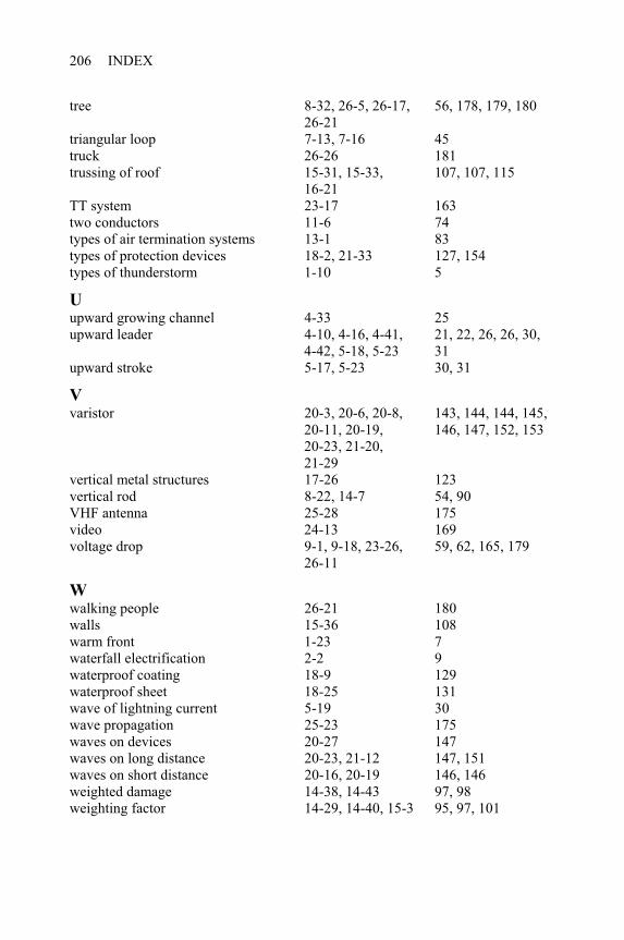
INDEX206
tree 8-32, 26-5, 26-17, 26-21
56, 178, 179, 180
triangular loop 7-13, 7-16 45 truck 26-26 181 trussing of roof 15-31, 15-33,
16-21107, 107, 115
TT system 23-17 163 two conductors 11-6 74 types of air termination systems 13-1 83 types of protection devices 18-2, 21-33 127, 154 types of thunderstorm 1-10 5
Uupward growing channel 4-33 25 upward leader 4-10, 4-16, 4-41,
4-42, 5-18, 5-23 21, 22, 26, 26, 30, 31
upward stroke 5-17, 5-23 30, 31
Vvaristor 20-3, 20-6, 20-8,
20-11, 20-19,20-23, 21-20,21-29
143, 144, 144, 145, 146, 147, 152, 153
vertical metal structures 17-26 123 vertical rod 8-22, 14-7 54, 90 VHF antenna 25-28 175 video 24-13 169 voltage drop 9-1, 9-18, 23-26,
26-1159, 62, 165, 179
Wwalking people 26-21 180 walls 15-36 108 warm front 1-23 7 waterfall electrification 2-2 9 waterproof coating 18-9 129 waterproof sheet 18-25 131 wave of lightning current 5-19 30 wave propagation 25-23 175 waves on devices 20-27 147 waves on long distance 20-23, 21-12 147, 151 waves on short distance 20-16, 20-19 146, 146 weighted damage 14-38, 14-43 97, 98 weighting factor 14-29, 14-40, 15-3 95, 97, 101
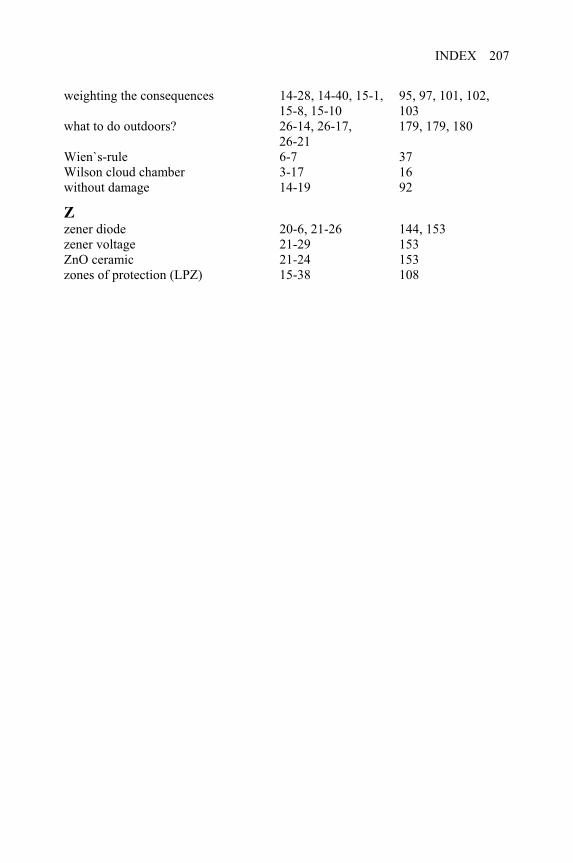
INDEX 207
weighting the consequences 14-28, 14-40, 15-1, 15-8, 15-10
95, 97, 101, 102, 103
what to do outdoors? 26-14, 26-17, 26-21
179, 179, 180
Wien`s-rule 6-7 37 Wilson cloud chamber 3-17 16 without damage 14-19 92
Zzener diode 20-6, 21-26 144, 153 zener voltage 21-29 153 ZnO ceramic 21-24 153 zones of protection (LPZ) 15-38 108