0071770208 ch01
TRANSCRIPT
CHAPTER 1Distillation Tray
Malfunctions
I search for something once well known, but long since forgotten.
Don’t mess with the Internal Revenue Service. I have just been audited, and it’s no joke. The IRS examiner was quite unreasonable. I had written off, as a business expense, my
vacation in Costa Rica. I explained to Mr. Himmel that I needed to recover from a stressful incident at the Coffeyville Refinery.
“So, Mr. Lieberman, did you sustain an injury at the refinery? Resulting medical expenses are deductible.”
“Yes, but the injury was emotional, rather than physical. Kind of a cerebral stress injury. Hence the trip to Costa Rica—for therapy.”
“Cerebral, stress-type injury? It rather sounds like . . .”“No, Mr. Himmel! Let me explain. One of my fundamental beliefs
was shattered!”“Mr. Lieberman, the IRS cannot concern themselves with the
beliefs of taxpayers.”“Kindly let me explain. I’ve always believed that as you increase
the vapor flow through a distillation tower, the pressure drop across the trays increases.”
“Mr. Lieberman, are we now talking about stills? Let me warn you that everything you say can and will be used against you. Did you have a federal license to operate this distillation apparatus?”
“No, I’m not talking about whiskey. I’m talking about a crude distillation tower in Coffeyville, Kansas.”
Decreasing Tower Delta PEvery calculation procedure for predicting the pressure drop through trays predicts that the tray delta P increases with vapor flow because the velocity of vapor through the tray deck caps or orifices
1
01_Lieberman_Ch01.indd 101_Lieberman_Ch01.indd 1 16/06/11 11:23 AM16/06/11 11:23 AM
2 C h a p t e r O n e
increases. Higher velocities must always result in larger pressure drops. The fact that pressure drop varies with velocity squared:
Delta P = (V )2 × (Density) × K
is a fundamental belief I carry in my heart. And yet, for many years, I have actually had hidden doubts. For instance, I know for sure that often there is a negative delta P across heat exchangers even when the inlet and outlet pressures are measured at the same elevation. I’m sure because I’ve measured it myself, using calibrated pressure gauges in Aruba. It’s related to velocity reductions through the exchanger.
But the response of certain trays in some towers is quite different. As the vapor flow is increased, delta P increases in a normal and predictable manner. But suddenly the delta P slips down, above a certain vapor rate, and then stabilizes at a lower value!
“Mr. Lieberman, I’ve been a tax examiner for 20 years,” Himmel objected, “And I’ve never heard such nonsense.”
“About my legitimate tax deduction in Costa Rica?”“No! About pressure drops in trays going down as flow goes up.
Don’t try to bamboozle the IRS. Even the layman knows that resistance to flow goes up when more gas flows through a restriction. That’s just common sense.”
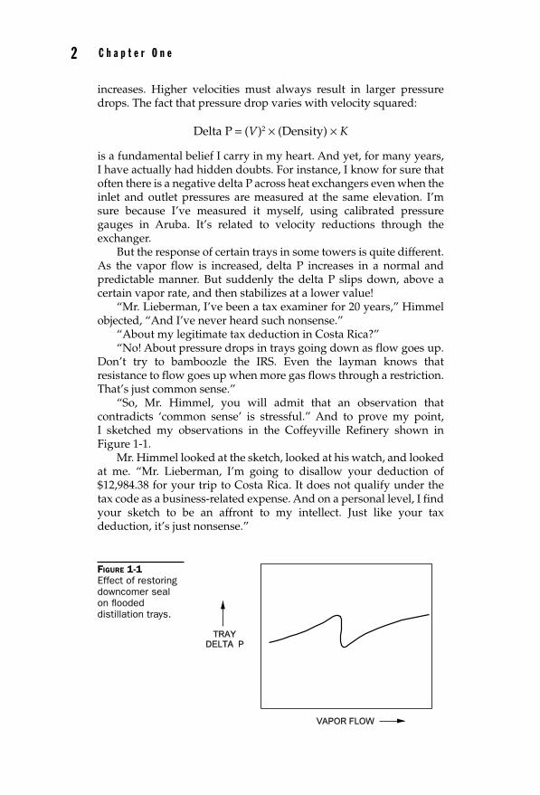
“So, Mr. Himmel, you will admit that an observation that contradicts ‘common sense’ is stressful.” And to prove my point, I sketched my observations in the Coffeyville Refinery shown in Figure 1-1.
Mr. Himmel looked at the sketch, looked at his watch, and looked at me. “Mr. Lieberman, I’m going to disallow your deduction of $12,984.38 for your trip to Costa Rica. It does not qualify under the tax code as a business-related expense. And on a personal level, I find your sketch to be an affront to my intellect. Just like your tax deduction, it’s just nonsense.”
FIGURE 1-1 Effect of restoring downcomer seal on fl ooded distillation trays.
01_Lieberman_Ch01.indd 201_Lieberman_Ch01.indd 2 16/06/11 11:23 AM16/06/11 11:23 AM
D i s t i l l a t i o n T r a y M a l f u n c t i o n s 3
Resealing DowncomersTo understand the malfunction that leads to the nonlinear response of tray delta P to increasing vapor flow, we need to understand two terms:
• Delta P dry
• Delta P hydraulic
Delta P dry is the pressure drop of the vapor flowing through the orifices or valve caps on the tray floor. Delta P dry must always increase with the vapor flow rate, squared.
Delta P hydraulic is the height, or the depth, of the liquid sitting on the tray deck. It’s mainly a function of the overflow or outlet weir height. If there are 3 inches of liquid sitting on the tray deck, then the vapor has to push those 3 inches of liquid out of its way and thus loses 3 inches’ worth of pressure.
The problem is that if delta P hydraulic gets much bigger than delta P dry, then the tray decks will begin to leak. Valve trays may be a little better in retarding leakage than sieve or grid trays, but not by much.
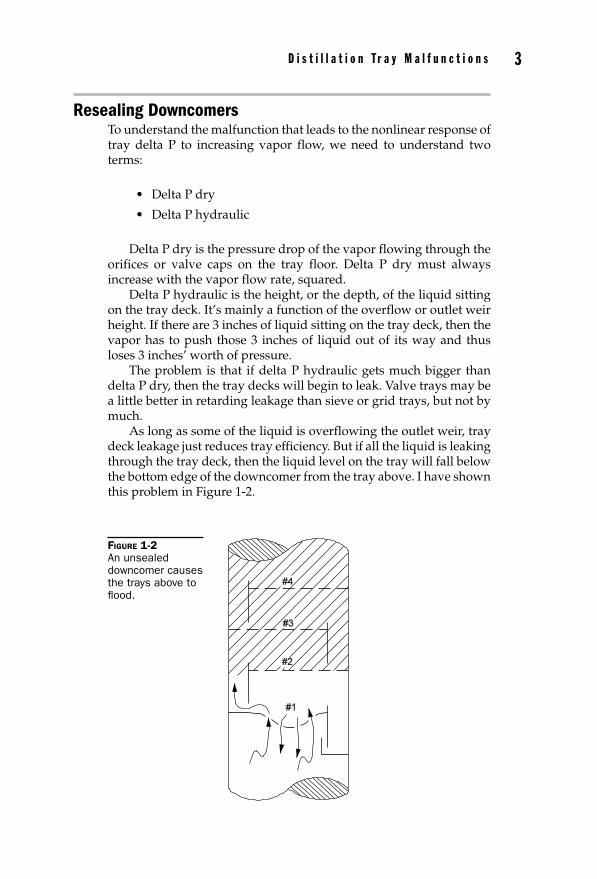
As long as some of the liquid is overflowing the outlet weir, tray deck leakage just reduces tray efficiency. But if all the liquid is leaking through the tray deck, then the liquid level on the tray will fall below the bottom edge of the downcomer from the tray above. I have shown this problem in Figure 1-2.
FIGURE 1-2 An unsealed downcomer causes the trays above to fl ood.
01_Lieberman_Ch01.indd 301_Lieberman_Ch01.indd 3 16/06/11 11:23 AM16/06/11 11:23 AM
4 C h a p t e r O n e
Tray deck #1 is sagging. The depth of liquid at the sag has caused 100% of the liquid flow to bypass tray #1’s outlet weir and thus uncover the bottom edge of the downcomer from the tray above. The liquid in the downcomer from tray #2 is pushed up onto tray #2’s deck, which then floods. The flooding progresses up the tower, until all the trays above tray #1 are flooded.
How could I be so smart on this subject? Because, at the Chevron Refinery in Port Arthur, Texas, they have a 4-inch diameter glass distillation tower. Unsealing any downcomer caused all the trays above to flood. Also, when we opened the tower for inspection at the Coffeyville crude distillation unit, we found tray #1 sagging.
How does this then explain the nonlinear response of pressure drop to the vapor flow shown in Figure 1-1 and through the stripping trays shown in Figure 1-2?
• Liquid drains through the tray deck #1 because of the low delta P dry and the sag in the middle of the tray deck.
• The liquid level on tray deck #1 drops below its outlet weir.
• The bottom edge of the downcomer from tray #2 becomes unsealed. Meaning, it is no longer submerged in the liquid level on tray deck #1.
• Vapor starts to flow up through the unsealed tray #2 downcomer. This vapor displaces the liquid out of the tray #2 downcomer. The liquid is pushed up onto tray deck #2.
• Tray #2 floods. As flooding progresses up the tower, trays #3 and #4 will also flood with time.
• As the vapor flow increases, the ability for liquid to flow down through the tray #2 downcomer becomes less and less. Flooding becomes progressively worse, and the tower delta P becomes progressively larger.
• However, the increased vapor flow, as shown in Figure 1-1, causes an increase in delta P dry through tray deck #1, and reduces the amount of liquid leaking through tray deck #1.
• The height of the liquid on the tray deck #1 increases until the liquid begins to overflow its weir.
• The downcomer seal from tray #2 is reestablished. Now the liquid can once again drain freely from the tray #2 downcomer, onto tray deck #1.
• Also, trays #3 and #4 drain down. The reduced weight of liquid on tray decks #2, #3, and #4 reduces tower delta P.
• As vapor flow continues to rise, the tray delta P goes up in a normal manner as shown in Figure 1-1, due to the increased delta P dry.
01_Lieberman_Ch01.indd 401_Lieberman_Ch01.indd 4 16/06/11 11:23 AM16/06/11 11:23 AM
D i s t i l l a t i o n T r a y M a l f u n c t i o n s 5
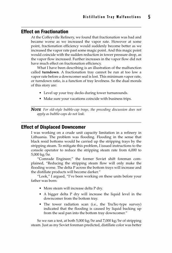
Effect on FractionationAt the Coffeyville Refinery, we found that fractionation was bad and became worse as we increased the vapor rate. However at some point, fractionation efficiency would suddenly become better as we increased the vapor rate past some magic point. And this magic point would coincide with the sudden reduction in tower pressure drop, as the vapor flow increased. Further increases in the vapor flow did not have much effect on fractionation efficiency.
What I have been describing is an illustration of the malfunction called turndown. A fractionation tray cannot be run at too low a vapor rate before a downcomer seal is lost. This minimum vapor rate, or turndown ratio, is a function of tray levelness. So the dual morals of this story are:
• Level up your tray decks during tower turnarounds.
• Make sure your vacations coincide with business trips.
NOTE NOTE For old-style bubble-cap trays, the preceding discussion does not apply as bubble-caps do not leak.
Effect of Displaced DowncomerI was working on a crude unit capacity limitation in a refinery in Lithuania. The problem was flooding. Flooding in the sense that black resid bottoms would be carried up the stripping trays by the stripping steam. To mitigate this problem, I issued instructions to the console operator to reduce the stripping steam rate from 6,000 to 5,000 kg/hr.
“Comrade Engineer,” the former Soviet shift foreman com-plained, “Reducing the stripping steam flow will only make the flooding worse. The delta P across the bottom trays will increase and the distillate products will become darker.”
“Look,” I argued, “I’ve been working on these units before your father was born:
• More steam will increase delta P dry.
• A bigger delta P dry will increase the liquid level in the downcomer from the bottom tray.
• The tower radiation scan (i.e., the TruTec-type survey) indicated that the flooding is caused by liquid backing up from the seal pan into the bottom tray downcomer.”
So we ran a test, at both 5,000 kg/hr and 7,000 kg/hr of stripping steam. Just as my Soviet foreman predicted, distillate color was better
01_Lieberman_Ch01.indd 501_Lieberman_Ch01.indd 5 16/06/11 11:23 AM16/06/11 11:23 AM
6 C h a p t e r O n e
and the stripping tray delta P was lower at the higher steam rates. So I tried 8,000 kg/hr of steam and the distillate product went black.
Now what?“See Comrade Engineer, American capitalists don’t know
everything.”I now did what I should have done in the first place. I pulled out
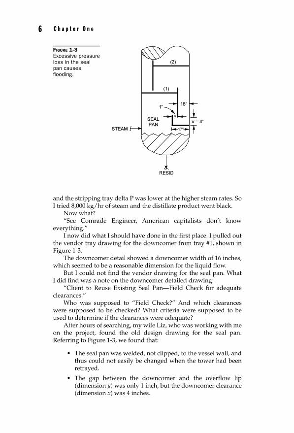
the vendor tray drawing for the downcomer from tray #1, shown in Figure 1-3.
The downcomer detail showed a downcomer width of 16 inches, which seemed to be a reasonable dimension for the liquid flow.
But I could not find the vendor drawing for the seal pan. What I did find was a note on the downcomer detailed drawing:
“Client to Reuse Existing Seal Pan—Field Check for adequate clearances.”
Who was supposed to “Field Check?” And which clearances were supposed to be checked? What criteria were supposed to be used to determine if the clearances were adequate?
After hours of searching, my wife Liz, who was working with me on the project, found the old design drawing for the seal pan. Referring to Figure 1-3, we found that:
• The seal pan was welded, not clipped, to the vessel wall, and thus could not easily be changed when the tower had been retrayed.
• The gap between the downcomer and the overflow lip (dimension y) was only 1 inch, but the downcomer clearance (dimension x) was 4 inches.
FIGURE 1-3 Excessive pressure loss in the seal pan causes fl ooding.
01_Lieberman_Ch01.indd 601_Lieberman_Ch01.indd 6 16/06/11 11:23 AM16/06/11 11:23 AM
D i s t i l l a t i o n T r a y M a l f u n c t i o n s 7
The calculated head loss under the downcomer (i.e., pressure drop of the flowing liquid) was:
Delta P = 0.6 × (Velocity)2
where delta P = inches of liquid velocity = feet per second 0.6 = typical coeffi cient for a smooth, sharp-edged orifi ce
Therefore, the head loss (x) under the downcomer = 1 inchBut the head loss ( y) between the downcomer and the seal pan
overflow lip = 16 inchesThe 16-inch head loss would result in excessive downcomer backup
from the seal pan and would flood the bottom downcomer. The flooding would progress up the tower and turn the distillates black.
But why did more stripping steam partially relieve this flooding? The answer was also provided by the old seal pan drawing.
Downcomer Bracing BracketsThe side edges of downcomers are rigidly supported by the downcomer bolting bars that are welded to the vessel wall. If the width of the downcomer is not more than 4 feet, this is sufficient to prevent the downcomer from flexing. If the downcomer (typically made from 2 mm or 14 gauge steel) is wider than 6 feet, then it may be quite flexible. And this usually is bad. Bad in the sense that the delta P of the flowing vapor through the tray deck above tends to push the vertical downcomer wall up against the vessel wall and reduce the open area at the bottom of the downcomer. This might result in excessive downcomer backup.
Normally this is prevented by the downcomer bracing brackets. (Note to reader: Terms in bold are explained in the Glossary, at the end of this text.) These are “L”-shaped brackets that bolt onto the seal pan floor or the tray floor, and to the downcomer’s bottom edge. This keeps the bottom edge of the downcomer rigid. But, in my Lithuania stripper, the designer had left out the downcomer bracing brackets, even though the width of the downcomer was 10 feet.
The flexibility of the downcomer had an unexpected benefit. When the stripping steam rate was increased, the bottom edge of the downcomer was pushed away by the steam pressure from the seal pan’s overflow lip. Dimension y in Figure 1-3 was slightly increased. This reduced the downcomer backup. Of course, too much steam at some point would cause normal tray flooding.
A few months later, we shut the tower down to replace the seal pan. I had the width of the seal pan extended from 17 to 20 inches. The lesson is to be careful when retraying towers. Don’t try to reuse existing components (i.e., the seal pan) in conjunction with the new trays, unless you plan to inspect the final installation yourself.
01_Lieberman_Ch01.indd 701_Lieberman_Ch01.indd 7 16/06/11 11:23 AM16/06/11 11:23 AM
8 C h a p t e r O n e
Top Tray FloodingWhat are the indications of a distillation tower flooding?
1. Fractionation gets worse instead of better, as the reflux and reboiler duty increase.
2. The delta T across the tower (bottom minus top temperature) gets smaller, as reflux rates are increased.
3. Increasing the reflux rate does not cause the reboiler duty to increase, even though the reboiler is in Auto.
4. Increasing the reflux rate does not cause the bottoms product flow rate to increase, even though the reboiler duty is fixed (i.e., in the manual mode of control).
5. Opening the vent at the top of the tower causes liquid, rather than vapor, to vent to the atmosphere.
And how about the delta P? That differential pressure which we learned about in class—should not the differential pressure drop across the trays also increase and indicate flooding? Maybe not.
Forty years ago, as a young process engineer, I had this problem on a 60-tray propylene-versus-propane splitter in Whiting, Indiana. How could this tower be flooding, yet the delta P (which I measured myself) be rather normal?
The tower was 150 feet (i.e., 30-inch tray spacing) across the trays. The SG of propane is about 0.5. Aerated, the normal condition of liquid on the trays, the SG of the liquid between the trays would be roughly 0.3. Thus, for 150 feet of height, the observed pressure drop across the 60 trays, if they flooded, would be:
(150 feet) × (0.3) ÷ (2.31) = 20 psi
NOTE NOTE There are 2.31 feet of water in each 1 psi of head pressure.
My observed delta P was only 4 psi! How could this tower be in flood, with a normal tower pressure drop of only 4 psi?
In this calculation, I have made an assumption that the flooding is starting at the bottom tray of the tower. But suppose the flooding is starting at the top tray. Here’s the source of confusion:
• Flooding progresses up a tower.
• If the top tray floods, then an increment of reflux does not go down the tower, but recirculates, in a liquid state, back to the reflux drum. The 59 trays below the top tray are not flooded. They simply do not fractionate efficiently because of a low internal reflux rate.
01_Lieberman_Ch01.indd 801_Lieberman_Ch01.indd 8 16/06/11 11:23 AM16/06/11 11:23 AM
D i s t i l l a t i o n T r a y M a l f u n c t i o n s 9
It’s true that the reflux rate is high. But only the top tray realizes this. The other 59 trays and the reboiler think that the reflux rate is still low. In the case of my propylene-propane splitter in Indiana, the top tray flooded because the tray deck was fouled. Corrosion deposits and salts from the reflux drum accumulated on the top tray deck. This raised only the top tray delta P, promoting entrainment of the top reflux. Water washing the top of the tower corrected this malfunction.
The lesson is that delta P surveys are not a definitive method of determining if a tower is flooded. Perhaps the best method is by heat balance. That is, if the reflux can be increased without a proportional increase in the reboiler duty, then the tower is flooded. And if this observation does not coincide with an increase in the tower delta P, then the problem is flooding starting at an upper tray deck.
Loss of Liquid Level on Tray DecksI was working on a diesel oil recovery tower in Convent, Louisiana, that had 20 trays. The design vapor flow through the trays was 100,000 lb/hr. The trays were modern grid-type MVG-type decks. The design pressure drop per tray was:
• Delta P dry—The pressure drop of the vapor flowing through the tray deck perforations = 0.1 psi per tray.
• Delta P hydraulic—The equivalent height of the liquid on the tray due to the weir = 0.1 psi.
• The total tower design delta P was then:
20 trays (0.1 + 0.1) = 4 psi
At an operating vapor flow through the trays of 50,000 lb/hr, what delta P do you think I observed?
Well, the vapor delta P varies with velocity squared. Since the flow had gone down by 50%, the new delta P dry should have been 0.025 psi per tray.
The weight of liquid on the tray due to the weir should not have changed with the reduced vapor rate. Therefore the observed delta P should have been about:
20 trays (0.025 + 0.1) = 2 1 _ 2 psi
But the observed delta P, which I measured on the tower, was zero! Now what? How could the pressure drop of the trays, at half the design vapor flow, be too small to measure? The following explanation applies to:
• Sieve trays
• Valve trays
01_Lieberman_Ch01.indd 901_Lieberman_Ch01.indd 9 16/06/11 11:23 AM16/06/11 11:23 AM
10 C h a p t e r O n e
• Jet tab trays
• Grid trays
• Any modern type of proprietary perforated tray deck
However, it does not apply to old-style bubble- or tunnel-cap trays, which are immune to tray deck dumping, leaking, or weeping. I’ll explain why this is so later.
Valve-type caps, contrary to vendor claims, leak almost as badly at low vapor rates as do sieve or grid trays. When vapor flow falls to 50% of design, delta P dry falls to 25% of design as explained above. But a small delta P dry causes the tray to leak. In larger-diameter towers (2 or more meters), a small amount of tray deck out-of-levelness will cause the problem to be magnified. Typically, when the vapor flow rate is 30% to 50% of design, the flow of liquid over the weir drops to zero. Why? Because all of the liquid is dumping through the tray deck.
Now the depth of the liquid on the tray falls below the bottom edge of the downcomer of the tray above. Vapor now begins to blow through this unsealed downcomer. The vapor is bypassing the tray decks through the downcomer. This further reduces delta P dry and promotes more tray deck dumping. The larger tray deck dumping rate further reduces the hydraulic delta P (i.e., the weight of liquid on the tray).
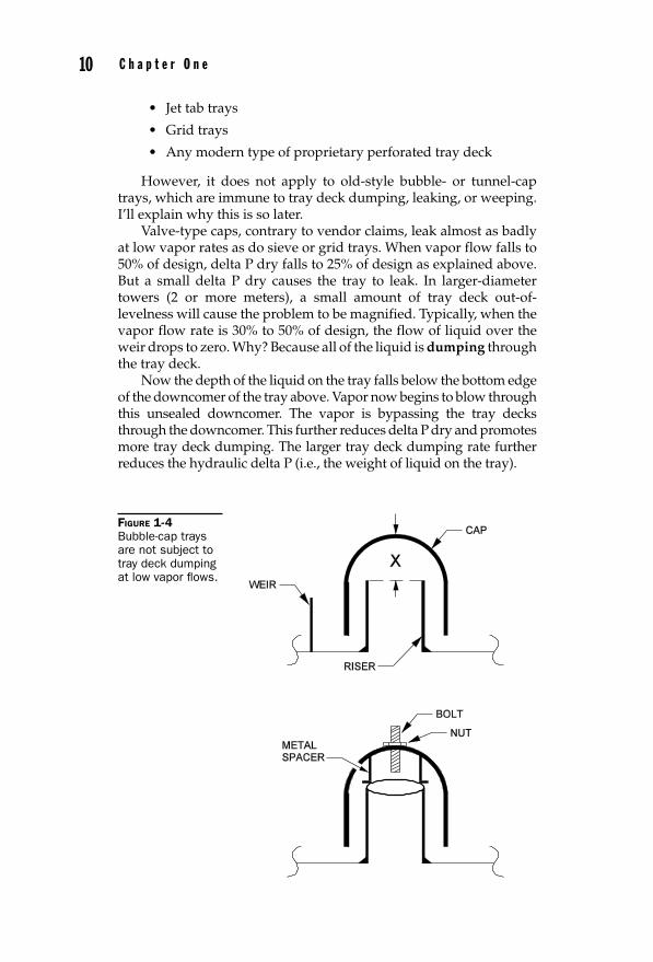
FIGURE 1-4 Bubble-cap trays are not subject to tray deck dumping at low vapor fl ows.
01_Lieberman_Ch01.indd 1001_Lieberman_Ch01.indd 10 16/06/11 11:23 AM16/06/11 11:23 AM
D i s t i l l a t i o n T r a y M a l f u n c t i o n s 11
In summary, delta P dry is further reduced because vapor is short-circuiting the tray decks through the downcomers. Delta P hydraulic is further reduced because of increasing tray deck leakage. The overall delta P on the 20-tray tower becomes too small to measure with a single gauge, delta P survey. I’ll leave it to the reader to understand how the blown downcomer seal and leaking tray deck affect fractionation efficiency.
The bubble cap shown in Figure 1-4 is not subject to tray deck leakage, as long as the top of the chimney is an inch or so above the outlet weir. For this reason, bubble-cap trays are inherently superior to valve, sieve, or grid trays, except for their lower vapor handling capacity.
Lost Bubble Cap ClearanceThe bubble cap is fixed to the top of the chimney by a bolt sticking up through the chimney. A metal spacer is used to maintain dimension x, shown in Figure 1-4. This dimension determines the delta P dry of the tray. It is maintained by a metal spacer around 1 to 2 inches high.
At a visbreaker fractionator in Convent, Louisiana, I was troubleshooting a tower flooding problem. I suspected that coke had accumulated underneath the cap and restricted vapor flow. This caused a higher delta P dry, which backed the liquid up in the downcomers and caused the tower to flood at 40,000 BSD of feed.
I had all the caps removed, cleared out the accumulated coke, and with complete confidence, had the tower restreamed. The next day, Ken Starr, the operating manager, called me.
“Lieberman. Thanks to you, instead of the frac flooding at 40,000 BSD, it now floods at 30,000 BSD. Get out here and fix the problem.”
I phoned the plant from Singapore where I was working, and spoke to John Henry, the maintenance supervisor. “Mr. Henry, I want you to take off every cap. And this time, clean properly underneath each cap. Also, make sure each riser is clear and free of coke.”
“Look, Lieberman, we did that last time.”“Well,” I said, “You must have missed some of the coke underneath
some caps, because the tower is flooding.” When I returned home the following week, I found this message from Ken Starr.
“Lieberman. Thanks to you, instead of the tower flooding at 30,000 BSD, it now floods at 20,000 BSD. Get out here and fix the problem.”
When Liz and I crawled through the tower, I noticed something odd. The bolts that stuck up from the tops of the bubble caps protruded by 2 inches above the caps. The first time I had been in the tower, the bolts only stuck up about an inch. So I unscrewed one of the nuts with my wrench and pulled off a cap. The spacer between the top of the chimney and the inside of the cap was crushed (see Figure 1-4). The cap was jammed up against the chimney.
01_Lieberman_Ch01.indd 1101_Lieberman_Ch01.indd 11 16/06/11 11:23 AM16/06/11 11:23 AM
12 C h a p t e r O n e
“Yeah, Lieberman,” Mr. Henry explained. “I sure didn’t want to have you complain that we didn’t tighten up them caps. So I got my guys to use an air gun wrench on them nuts. Kinda looks like we overtightened a few caps.”
The lesson we learn from this story is not to try to fix bubble-cap tray malfunctions long distance. You’ve got to get real close to the problem.
Directional Flow Tray PanelsA modern grid-type tray might use:
• MVG Caps—Sulzer (Nutter) (Good)
• Provalves—Koch-Glitsch (Better)
Such trays will have up to 10% more capacity than older-style valve or sieve trays. This benefit is largely a consequence of the use of push-type perforations on the tray deck. These perforations cause the gas to escape from the tray deck with horizontal components of velocity directed toward the outlet weir. This keeps the liquid level from backing up at the inlet side of the tray (i.e., near the downcomer from the tray above). Having a higher liquid level at the tray inlet side promotes entrainment and flooding at the inlet side of the tray. When I was young in the 1960s, we used to use step-down trays.
The grid decks accomplish the same purpose as the archaic step-down trays, but without any added mechanical complexity. With this objective in mind, a tower in Aruba was modified with directional flow grid trays, to replace the older sieve decks. Instead of an increase in capacity of 10%, a 10% decrease in capacity was observed.
Liz, my coworker and wife, crawled through the tower to determine the malfunction. There were 50 trays. All were installed correctly, except for tray #28. As Liz noted, the panels on this tray were installed backwards!
The installation contractor claimed that he had done 98% of the job correctly; that no one is perfect. Unfortunately, with the push valves installed backwards, the natural liquid gradient on the tray deck #28 was increased, which caused tray #28 to flood. As flooding progressed up a tower:
• The trays above tray #28 also flooded and lost fractionation efficiency.
• The trays below tray #28 began to dry out, due to low internal reflux rate, and also lost fractionation efficiency.
As fractionation got worse, the operators cranked up the reflux ratio. But this just made the flooding worse. So, to restore product purities to the required specifications, they reduced the feed rate to
01_Lieberman_Ch01.indd 1201_Lieberman_Ch01.indd 12 16/06/11 11:23 AM16/06/11 11:23 AM
D i s t i l l a t i o n T r a y M a l f u n c t i o n s 13
the tower. We reoriented the misguided tray panels, and when the tower was restreamed, all was well.
Especially on multi-pass trays, it’s difficult to see if an MVG-type grid tray panel has been installed in the proper direction of liquid flow.
Missing Reboiler Return Impingement PlateOn the same tower on which Liz had found that the grid tray panels were reversed, we had also encountered a more serious flooding initiated from the bottom tray, rather than just tray #28. On startup, this new debutanizer flooded at less than half of its design rate.
Both a radiation scan and a delta P survey indicated the tower was flooding from close to the bottom tray. As the debutanizer feed was contaminated with water-insoluble iron sulfide particulates, I concluded the flooding was most likely a consequence of tray fouling.
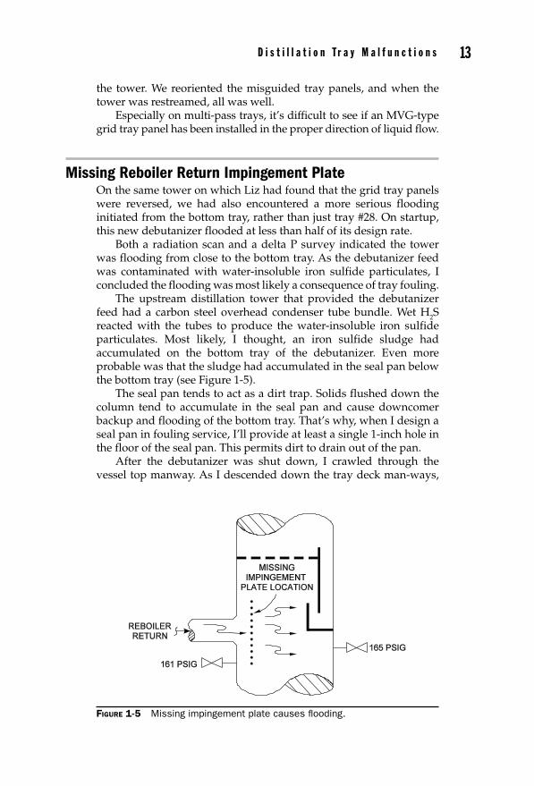
The upstream distillation tower that provided the debutanizer feed had a carbon steel overhead condenser tube bundle. Wet H2S reacted with the tubes to produce the water-insoluble iron sulfide particulates. Most likely, I thought, an iron sulfide sludge had accumulated on the bottom tray of the debutanizer. Even more probable was that the sludge had accumulated in the seal pan below the bottom tray (see Figure 1-5).
The seal pan tends to act as a dirt trap. Solids flushed down the column tend to accumulate in the seal pan and cause downcomer backup and flooding of the bottom tray. That’s why, when I design a seal pan in fouling service, I’ll provide at least a single 1-inch hole in the floor of the seal pan. This permits dirt to drain out of the pan.
After the debutanizer was shut down, I crawled through the vessel top manway. As I descended down the tray deck man-ways,
FIGURE 1-5 Missing impingement plate causes fl ooding.
01_Lieberman_Ch01.indd 1301_Lieberman_Ch01.indd 13 16/06/11 11:23 AM16/06/11 11:23 AM
14 C h a p t e r O n e
I noted that all the trays were reasonably clean—as was the seal pan! It’s true that the tower had been water washed. But iron sulfide is not soluble in water.
Now what?Feeling bad, I slumped down in the bottom of the dark tower.
Other people in Aruba were relaxing on the white sand beach or snorkeling in the crystal clear blue water. But not me. When I snapped my flashlight back on, I found myself staring at a round 16-inch hole in the opposite wall of the vessel.
“That’s the reboiler return nozzle,” I recall thinking. “But why is it, that I can see this nozzle? Shouldn’t it be covered over by an impingement plate?” (see Figure 1-5).
But there was no impingement plate. A circular 24-inch impingement plate was shown on the vessel sketch. But it was never installed in the debutanizer when the tower was fabricated. How could the missing impingement plate account for the tower flooding?
I suddenly recalled a pressure survey that I had conducted the previous week. That survey indicated:
• The pressure of the tower just opposite the reboiler return nozzle was 165 psig.
• The pressure of the tower adjacent to the reboiler return nozzle was 161 psig.
I had ignored this 4 psig discrepancy because it didn’t make any sense. But now it made lots of sense. Without the impingement plate to dissipate the momentum (mass times velocity) of the reboiler outlet flow, the returning vapor-liquid mixed phase would rush across the 10-foot-diameter tower. It would hit the opposing wall, near the bottom tray seal pan. The momentum of the fluid, in accordance with Bernoulli’s equation, would be converted to pressure. Pressure, in the sense that a localized pressure 4 psig above the surrounding pressure, would be created. Localized in the sense that pressure in the region of the seal pan would be 4 psig greater than the pressure of the vapor flowing up through the bottom tray.
If the SG of the fluid in the downcomer was about 0.70, then the liquid level in the downcomer would have been pushed up an additional 13 feet. But the downcomer length was only 2½ feet. Thus, the liquid from the seal pan would have backed up onto the bottom tray. As flooding progressed up a tower, the entire tower would have flooded. To suppress the flooding, the operators would have had to reduce reboiler duty. This would force them to cut reflux. The lower reflux rate would in turn cause a reduction in feed rate to control the heavier components in the butane overhead product.
I had the 24-inch-diameter impingement plate installed 12 inches in front of the 16-inch reboiler return nozzle. (Unfortunately, I failed
01_Lieberman_Ch01.indd 1401_Lieberman_Ch01.indd 14 16/06/11 11:23 AM16/06/11 11:23 AM
D i s t i l l a t i o n T r a y M a l f u n c t i o n s 15
to inspect the rest of the tower, and missed the incorrectly oriented grid deck panel on tray #28.) As a precaution, I had several 1½-inch holes drilled in the floor of the seal pan. The number of holes was determined so that 25% of the liquid flow would drain through the holes, to keep sludge from accumulating in the seal pan.
Flow Path LengthIn 1965, I began work as a process design engineer for American Oil. My first project was an absorber revamp at the El Dorado, Arkansas, refinery. The idea was to expand the lean oil circulation rate, so as to increase recovery of propylene from a catalytic cracker wet gas stream. The current lean oil circulation rate was limited by flooding and consequent lean oil carryover into the fuel gas system. The tower was rather small at 4 feet, 6 inches I.D.
My calculated percent of jet flood (flooding due to entrainment) was 90%, consistent with the observed tower operating limit. Percent jet flood is a function of:
• Liquid and vapor density
• Gas rate
• Weir loading
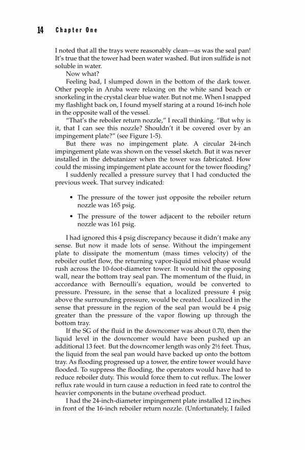
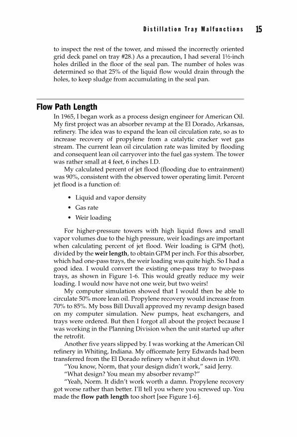
For higher-pressure towers with high liquid flows and small vapor volumes due to the high pressure, weir loadings are important when calculating percent of jet flood. Weir loading is GPM (hot), divided by the weir length, to obtain GPM per inch. For this absorber, which had one-pass trays, the weir loading was quite high. So I had a good idea. I would convert the existing one-pass tray to two-pass trays, as shown in Figure 1-6. This would greatly reduce my weir loading. I would now have not one weir, but two weirs!
My computer simulation showed that I would then be able to circulate 50% more lean oil. Propylene recovery would increase from 70% to 85%. My boss Bill Duvall approved my revamp design based on my computer simulation. New pumps, heat exchangers, and trays were ordered. But then I forgot all about the project because I was working in the Planning Division when the unit started up after the retrofit.
Another five years slipped by. I was working at the American Oil refinery in Whiting, Indiana. My officemate Jerry Edwards had been transferred from the El Dorado refinery when it shut down in 1970.
“You know, Norm, that your design didn’t work,” said Jerry.“What design? You mean my absorber revamp?”“Yeah, Norm. It didn’t work worth a damn. Propylene recovery
got worse rather than better. I’ll tell you where you screwed up. You made the flow path length too short [see Figure 1-6].
01_Lieberman_Ch01.indd 1501_Lieberman_Ch01.indd 15 16/06/11 11:23 AM16/06/11 11:23 AM
16 C h a p t e r O n e
“That old flow path length on the 4-foot, 6-inch ID tower was okay. It was 28 inches. But the new flow path length on the two-pass trays was only 12 inches wide. Real short flow path lengths for valve trays mean that there are only a few rows of caps. So, some of the liquid can bypass the caps, and then it doesn’t contribute to absorption efficiency. So propylene absorption got worse. You know, Mr. Norm, the minimum tower ID for using two-pass trays is something over 5 feet ID,” Jerry concluded.
But American Oil never followed up on the results of projects to see if they actually worked. My project was judged a good job by my
FIGURE 1-6 Reduction of fl ow path length can hurt tray effi ciency.
01_Lieberman_Ch01.indd 1601_Lieberman_Ch01.indd 16 16/06/11 11:23 AM16/06/11 11:23 AM
D i s t i l l a t i o n T r a y M a l f u n c t i o n s 17
supervisor because I had simulated the tower on my computer model with great success.
Discriminating Between Flooding and DumpingTo summarize, perforated tray decks are subject to two malfunctions:
• Dumping or weeping
• Flooding or excessive entrainment
Perforated trays means all types of modern trays, including valves, sieves, or grids. But not ancient bubble-cap trays, which cannot dump.
All perforated trays of industrial size diameter—that is, more than 1 meter—are both dumping and entraining to some degree, at the same time, and thus degrading tray fractionation efficiency. But how can I tell, when I walk into the control center, which is the controlling malfunction? I can perform two tests:
1. Lower the tower pressure. Does fractionation get better or worse? If I had online gas chromatographs (GCs) for the products, that would be fine. But most towers do not have such luxuries. Also, I am too impatient to wait for lab results. What I do look at is the temperature difference between the top and bottom of the fractionator. If this delta T goes up, then fractionation is improving. This indicates trays were losing fractionation efficiency due to tray deck dumping, or weeping, or leaking. This test must be carried out at a constant reflux rate.
2. Raise reflux rate. The presumption here is that the reboiler duty is on automatic temperature control, thus the tower bottoms temperature is constant. If raising the top reflux flow causes the fractionator top temperature to increase, then fractionation efficiency is degraded because of flooding or excessive entrainment. This test must be carried out at a constant operating pressure.
If a tower is shown to be flooding by this test, a delta P survey helps to identify the malfunctioning tray. A big delta P means flooding starting at a lower tray. A small delta P means flooding starting at an upper tray.
How about an Isoscan (TruTec or radiation scan)? Not for me. My rules for identifying tray malfunctions are:
• You have to do it in one day.
• You have to be able to do it with the tools at hand.
• You have to be able to do it yourself.
01_Lieberman_Ch01.indd 1701_Lieberman_Ch01.indd 17 16/06/11 11:23 AM16/06/11 11:23 AM
18 C h a p t e r O n e
After 46 years, I have accumulated hundreds of these stories. Many of the other tray and packed tower distillation malfunction incidents are described in the books I have authored. But the most comprehensive summary is in Henry Z. Kister’s book, Distillation Troubleshooting, Wiley, 2006.
Shed- or Baffle-Type TraysThere is another whole class of trays that does not allow the vapor to flow through their decked area. These trays are called baffle trays. Trays that fit this description are:
• Side-to-side baffles
• Disk-and-donut trays
• Shower decks
• Shed trays
Baffle-type trays do not work at all well in fractionation or steam stripping service. They simply do not have the ability to bring the vapor and liquid into intimate contact. I’ve been working this month on a 40-baffle steam stripper. Field tests conducted by varying the stripping steam rate suggest essentially no stripping efficiency. If there is a way to make baffle trays effective, I’ve not found it—and I’ve tried often.
Baffle trays, especially shower decks, do a reasonably good job in heat transfer pumparound service. They are widely used in slurry oil pumparound (i.e., bottom pumparound) in fluid catalytic crackers. A half dozen such baffles will act like one theoretical stage, as far as heat transfer rates are concerned.
Author’s Observations: Concepts versus CalculationsNow that you have read the first chapter of this text, permit me to make a suggestion. My intent is not to write a reference book. There are better books available to guide one in making engineering calculations. As my coworker, Dave, observed:
“Norm, when you’re out in the plant, alone, at midnight; when you’re too hungry, cold, wet, and discouraged; when a tower won’t fractionate, and you don’t know why; when black smoke is belching out of the heater stack and the O2 analyzer shows 6%; when hydrocarbon vapors are boiling out of your cooling tower and the plant manager has just classified you as expendable, it’s not calculations that are needed. What you want is a basic understanding of process and chemical engineering concepts.”
When I’m faced with field malfunctions of a pump, fractionator, or heater, I’ll first try to classify the problem. How does this set of
01_Lieberman_Ch01.indd 1801_Lieberman_Ch01.indd 18 16/06/11 11:23 AM16/06/11 11:23 AM
D i s t i l l a t i o n T r a y M a l f u n c t i o n s 19
symptoms relate to other experiences I’ve had with similar equip-ment? Is this a problem with heat transfer, vapor-liquid equilibrium, mixing, hydraulics, or entrainment? What field measurements or samples should I obtain? What questions should I ask the plant operators? Maybe it’s not a process equipment malfunction at all, but a process control problem.
Pretty far down on my list of concerns is how to quantify the malfunction. As Dave also said, “I can calculate anything, Norm, if only I know what it is I’m supposed to calculate.”
Yes, Dave, that’s the problem. If we only knew what is the question, the engineering or operational answer would follow quite easily. Understanding the nature of the question is the real challenge in correcting process equipment malfunctions. Thus, my suggestion to you, the reader, is to read the entire text. The process concepts fit together. Like any puzzle, you’ll have to have all the pieces in the right spots to assemble the process solution completely and correctly.
01_Lieberman_Ch01.indd 1901_Lieberman_Ch01.indd 19 16/06/11 11:23 AM16/06/11 11:23 AM

01_Lieberman_Ch01.indd 2001_Lieberman_Ch01.indd 20 16/06/11 11:23 AM16/06/11 11:23 AM