減速機総合カタログ(同芯軸タイプ) - nidec corporation
TRANSCRIPT

■このカタログは2021年11月現在の内容です。製品の外観・仕様などは改善のために変更することがあります。■Outside appearance and dimensions are subject to change without notice. This catalogue has been printed as of November 2021.
72050KSK-2111015
減速機総合カタログ(同芯軸タイプ)
VRXF シリーズ VRXF series
VRG シリーズ VRG series
VRS シリーズ VRS series
VRT シリーズ VRT series
小型シリーズ Compact series
• VRB-042C • VRL-050C
同芯軸タイプCoaxial shaft type
www.nidec.com/jp/nidec-shimpo
同芯軸タイプ

エイブル減速機
ABLE REDUCER
エイブル減速機
ABLE REDUCER
1
Nidec - Shimpo has a lineup with a lot of product variation; Able reducersエイブル減速機は豊富なバリエーションでお客様の要望にお応え
INDEX
NETWORK
QUALITY
本社・京都府長岡京市Headquarters, Kyoto
中国・平湖P i n g h u
インド・バンガロールIndia, Bangalore
スペイン・ログローニョS p a i n , L o g r o ñ o
香 港Hong Kong
北 京Beijing
上 海Shanghai
ソウルSe o u l
台 湾Ta i w a n
サンパウロSão Paulo
メキシコ・ケレタロMexico, Querétaro
アメリカ・シカゴAmerica, Chicago
日本電産本社・京都市NIDEC Corporation in Kyoto
全社的品質管理の考えのもと、品質向上に努めています。We are making efforts for quality improvement on thebasis of the concept of total quality control.
品質管理の優れた企業に与えられるデミング賞も受賞。Deming Award to be given to enterprises practicing excellent quality control
■日本電産シンポ株式会社は品質保証に関する ISO 9001/ISO 14001 の認証を取得しています。■NIDEC-SHIMPO has obtained ISO 9001/ISO 14001 certification of quality assurance.
アメリカ・シカゴChicago in U.S.
本社・京都府長岡京市Headquarters, Kyoto Nagaokakyo
in Japan
韓国・ソウルSeoul
in Republic of Korea
中国・平湖Pinghu in China
ロサンゼルスLos Angeles
アメリカ・オハイオAmer ica , Oh io
アメリカ・ピッツバーグAmerica, Pittsburgh
ドイツ・デッテンハウゼンGermany, Dettenhausen
ドイツ・デッテンハウゼンDettenhausenin Germany
ドイツ・アルンスベルクGermany ,Arnsbe rg
ドイツ・アルンスベルクArnsberg
in Germany
ISO 9001■認証範囲:以下の製品の設計 ・ 開発、製造、修理、営業1. 駆動機器 2. プレス機器 3. 計測機器 4. 工芸機器●本社 ・ 京都工場、上田工場
■This certificate is valid for the following scope:Design, Development, Manufacture, Repair and Sales of1. Power Transmission Equipment 2. Press Machines3. Measuring Instruments 4. Pottery Equipment●Kyoto factory, Ueda factory
ISO 14001■認証範囲:以下の製品の設計 ・ 開発、製造、修理、営業1. 駆動機器 2. プレス機器 3. 計測機器 4. 工芸機器●本社 ・ 京都工場、上田工場
■This certificate is valid for the following scope:Design, Development, Manufacture, Repair and Sales of1. Power Transmission Equipment 2. Press Machines3. Measuring Instruments 4. Pottery Equipment●Kyoto factory, Ueda factory
国内拠点:東京支店/関西支店/名古屋営業所/金沢営業所/福岡営業所Bases in Japan: Tokyo branch/Kansai branch/Nagoya office/Kanazawa office/Fukuoka office
日本電産グループ:日本電産株式会社/日本電産サンキョー株式会社/日本電産コパル株式会社/日本電産トーソク株式会社/日本電産コパル電子株式会社/日本電産サーボ株式会社/日本電産リード株式会社/日本電産テクノモータ株式会社/日本電産ロジステック株式会社/日本電産マシナリー株式会社/日本電産ピジョン株式会社/日本電産グローバルサービス株式会社
NIDEC Group: NIDEC Corporation/ NIDEC SANKYO Corporation/ NIDEC COPAL/ NIDEC TOSOK Corporation/ NIDEC COPAL Electronics Corporation/ NIDEC Servo Corporation/ NIDEC LEAD Corporation/ NIDEC TECHNO MOTOR CORPORATION/ NIDEC Logistic Corpora-tion/ NIDEC Machinery Corporation/ NIDEC Pigeon Corporation/ NIDEC Global Service Corporation
Headquarters ☎Kyoto (075) 958-3670 Nagoya office ☎Nagoya (052) 589-1338Tokyo branch ☎Tokyo (03) 3494-0721 Kanazawa office ☎Kanazawa (076) 233-2626Kansai branch ☎Kyoto (075) 958-3670 Fukuoka office ☎Fukuoka (092) 411-4750
同芯軸タイプABLE Reducer
静音、高精度、コンパクトサーボモータ市場をリードするエイブル減速機。各種シリーズでお客様の要望にお応えします。
11
VRS series
■バックラッシ Backlash : 3arc-min
■減速比 Ratio : 1 段 Single 1/3, 1/4, 1/5, 1/6, 1/7, 1/8, 1/9, 1/10 2 段 Double 1/15, 1/16, 1/20, 1/25, 1/28, 1/30, 1/35 1/40, 1/45, 1/50, 1/60, 1/70, 1/80, 1/90, 1/100※減速比は実減速比です※Reduction ratio is actual reduction ratio.
Quiet, high rigidity, big capacity Type
■サイズ Frame size : 060C 075C 100C 140C 180C 210C 240C
静音、高剛性、大容量タイプ
半導体装置、工作機械など高精度をお求めのお客様に 特徴………………………55
機種・型式記号……………56
性能一覧…………………57
寸法一覧…………………65
特性………………………85
効率特性……………… 121
Features
Model number
Performance table
Dimensions
Characteristics
Efficiency
For those customers who seek for high precision for Semiconductor and industrial application
54
■減速比 Ratio : 1段 Single 1/3.67★, 1/4★, 1/5, 1/7★, 1/9, 1/10★
2 段 Double 1/11, 1/15.4, 1/20 ★ , 1/21, 1/25 ★ , 1/33, 1/35 ★
1/40 ★ , 1/45, 1/50 ★ , 1/70 ★ , 1/81, 1/100 ★
★受注生産品 : Made-to-order products
※減速比1/3.67は3/11=1/3.666… 他の減速比は実減速比です※Reduction ratio 1/3.67 is 3/11 = 1/3.666… Other reduction ratios are actual reduction ratios.
Quiet, high rigidity, precision Type
VRG series
■バックラッシ Backlash : 1arc-min (made-to-order products), 3arc-min
■サイズ Frame size : B60P C90/C90P D120 E170
半導体装置、工作機械など高精度をお求めのお客様に
静音、高剛性、精密タイプ
特徴………………………31
機種・型式記号……………32
減速比・枠番………………33
性能一覧…………………34
寸法一覧…………………38
特性………………………44
効率特性…………………46
作動原理…………………50
減速機選定手順…………51
主軸受寿命………………52
Features
Model number
Reduction ratio / Frame size
Performance table
Dimensions
Characteristics
Efficiency
Operating principle
Reducer selection procedure
Main bearing life
For those customers who seek for high precision for Semiconductor and industrial application
30
■減速比 Ratio : 1 段 Single 1/3, 1/5, 1/9 2 段 Double 1/15, 1/20, 1/25, 1/35, 1/45, 1/81※減速比は実減速比です※Reduction ratio is actual reduction ratio.
High-precision, quiet, light weight, standard type
VRXF series
■バックラッシ Backlash : 3arc-min 5arc-min 10arc-min 15arc-min
■サイズ Frame size : B C D E
ガントリー、包装機械など軽量、コンパクトをご要求されるお客様に
高精度・静音・軽量・標準タイプ
特徴……………………… 8
種類……………………… 9
減速比・枠番………………11
機種・型式記号……… 12・16
性能一覧…………… 13・17
寸法一覧…………… 14・19
モータマッチング表… ……15
効率特性…………………24
作動原理…………………26
技術資料…………………27
Features
Kind
Reduction ratio / Frame size
Model number
Performance table
Dimensions
Motor matching table
Efficiency
Operating principle
Technical data
For those customers who seek for light weight and compact size for gantry and packaging application
※B枠のみ
8

エイブル減速機
ABLE REDUCER
エイブル減速機
ABLE REDUCER
Nidec - Shimpo has a lineup with a lot of product variation; Able reducers to meet customer's requirement.エイブル減速機は豊富なバリエーションでお客様の要望にお応え します。
INDEX
Able reducer at the forefront of the compact servo motor market as Quiet, High precision There are various series to meet customer's requirement.
Coaxial shaftABLE Reducer
安全上のご注意137
取付方法
ネットワーク140
Installation
Network
Safety Precautions
減速機選定ツール3
サーボモータメーカ一覧
アプリケーション
6
7
Servo Motor Manufacturer List
Applications
Reducer Selection Tool
135
Compact series
■バックラッシ Backlash : 3arc-min 5arc-min
■サイズ Frame size : 042C
小型シリーズ
VRB-042C 業界最小クラスをラインアップ
■減速比 Ratio : 1 段 Single 1/3, 1/4, 1/5, 1/6, 1/7, 1/8, 1/9, 1/10 2 段 Double 1/15, 1/16, 1/20, 1/25, 1/28, 1/30, 1/35 1/40, 1/45, 1/50, 1/60, 1/70, 1/80, 1/90, 1/100※減速比は実減速比です※Reduction ratio is actual reduction ratio.
■バックラッシ Backlash : 5arc-min 7arc-min
■サイズ Frame size : 050C
VRL-050C 業界最小クラスをラインアップ
■減速比 Ratio : 1 段 Single 1/3, 1/4, 1/5, 1/6, 1/7, 1/8, 1/9, 1/10 2 段 Double 1/15, 1/16, 1/20, 1/25, 1/28, 1/30, 1/35 1/40, 1/45, 1/50, 1/60, 1/70, 1/80, 1/90, 1/100※減速比は実減速比です※Reduction ratio is actual reduction ratio.
特徴/機種・型式記号… 127
性能一覧……………… 128
寸法一覧……………… 129
特性・効率特性………… 130
特徴/機種・型式記号… 131
性能一覧……………… 132
寸法一覧……………… 133
特性・効率特性………… 134
Features / Model number
Performance table
Dimensions
Characteristic・Efficiency
Features / Model number
Performance table
Dimensions
Characteristic・Efficiency
World smallest class reducers
World smallest class reducers
特徴………………………87
機種・型式記号……………88
性能一覧…………………89
寸法一覧…………………99
特性…………………… 120
効率特性……………… 121
Features
Model number
Performance table
Dimensions
Characteristics
Efficiency
Quiet, high rigidity, big capacity, flange output Type
VRT series
■バックラッシ Backlash : 3arc-min
■減速比 Ratio : 1 段 Single 1/4, 1/5, 1/6, 1/7, 1/8, 1/9, 1/10 2 段 Double 1/16, 1/20, 1/25, 1/28, 1/35, 1/40 1/45, 1/50, 1/60, 1/70, 1/80, 1/90, 1/100
フレームサイズが110C以上は、減速比が変わります。Reduction ratios are different for frame size 110C or larger.
※減速比は実減速比です※Reduction ratio is actual reduction ratio.
※サイズ042C・047Cの2段のみ、5arc-min※Only for frame size 042C, 047C of double reduction, 5 arc-min
■サイズ Frame size : 042C ※ 047C ※ 064C 090C 110C 140C 200C 255C 285C
半導体装置、工作機械など高精度をお求めのお客様に
静音、高剛性、大容量、フランジ出力タイプ
For those customers who seek for high precision for Semiconductor and industrial application
126
131
87
2

エイブル減速機
ABLE REDUCER
エイブル減速機
ABLE REDUCER
減速機選定ツール
Reducer Selection Tool
減速機選定ツール
Reducer Selection Tool
NEW!
STEP1
STEP2
STEP3
STEP4
STEP5
STEP3
STEP4
STEP3
STEP4
・ 弊社 HP のトップ画面下方の Pick Up! より「減速機選定ツール」のバナーをクリック
下記の画面が立ち上がります。
選定方法は以下の 4 種類があります。
アプリケーションを選択する。
取付モータと減速機を選択する
・ 取付けるサーボモータメーカとモータ型式を選択します。
・ 取付ける減速機のシリーズと減速比を選択します。
・ モータ型式によっては、 選択できるサイズとできないサイズがあります。
・ 減速機サイズを選択して をクリックします。
注) VRB-042C,VRL-050C は VRS シリーズ、 VRT-042C は、 VRG シリーズを
選択してください。
運転パターン数、 減速比、 ラジアル ・ 回転速度
スラスト荷重、 荷重距離、 係数を入力します。
ここでは、 カタログをダウンロードできます。
・ 選択が終わったら、 ボタンをクリックします。
①取付モータから減速機を選定
②負荷条件から減速機を選定
③アプリケーションから減速機を選定
④型式から減速機を選定
①取付モータから減速機を選定
②負荷条件から減速機を選定減速機のシリーズを選択する
減速機サイズを選択する
次ページへ
次ページへ
次ページへ
次ページへ
③アプリケーションから減速機を選定
負荷条件を入力する
アプリケーションの運転条件を入力する
必要に応じて荷重距離、 係数を入力します。
Input operation cycle of the application
Select the reducer model and reduction ratio
Input load distance and fomula if needed
減速機シリーズ、 減速比を選択する
はじめちゃん
注 )EVRG および STH シリーズは掲載されておりません。
STEP3
④型式から減速機を選定Specify the reducer from the model name nomenclature
EVRG and STH series are not listed.
・ Click the "Servo Reducer Selection tool"
Select the reducer sizeMake a selection from the motor listSelect the motor and the reducer
The screen below appears
There are 4 ways to select the reducer
NEW!
①Make a selection from the motor list
②Make a selection from load condition
③Select the reducer model based on the application
④Specify the reducer from the model name
nomenclature
Select the application
Select the reducer type
・ Select the servo motor maker and model name
・ Select the reducer type and reduction ration
* Here, you can download the catalogue
・ After making a selection click "Back" or "Next"
Make a selection from load condition
Select the reducer model based on the application
Input load condition
input operaion cycle, reduction ration
radial, rpm, thrust load, load distance, fomula
to Next page
to Next page
to Next page
to Next page
・ Depending on the motor model, certain sizes cannot be selected
・ Select the reducer size and click "Back" or "Next"
In the motor selection option, VRB-042C and VRL-050C are found in VRS-series, and VRT-042C is in VRG-series.
減速機選定ツールReducer Selection Tool
3

エイブル減速機
ABLE REDUCER
エイブル減速機
ABLE REDUCER
減速機選定ツール
Reducer Selection Tool
減速機選定ツール
Reducer Selection Tool
NEW!
STEP1
STEP2
STEP3
STEP4
STEP5
STEP3
STEP4
STEP3
STEP4
・ 弊社 HP のトップ画面下方の Pick Up! より「減速機選定ツール」のバナーをクリック
下記の画面が立ち上がります。
選定方法は以下の 4 種類があります。
アプリケーションを選択する。
取付モータと減速機を選択する
・ 取付けるサーボモータメーカとモータ型式を選択します。
・ 取付ける減速機のシリーズと減速比を選択します。
・ モータ型式によっては、 選択できるサイズとできないサイズがあります。
・ 減速機サイズを選択して をクリックします。
注) VRB-042C,VRL-050C は VRS シリーズ、 VRT-042C は、 VRG シリーズを
選択してください。
運転パターン数、 減速比、 ラジアル ・ 回転速度
スラスト荷重、 荷重距離、 係数を入力します。
ここでは、 カタログをダウンロードできます。
・ 選択が終わったら、 ボタンをクリックします。
①取付モータから減速機を選定
②負荷条件から減速機を選定
③アプリケーションから減速機を選定
④型式から減速機を選定
①取付モータから減速機を選定
②負荷条件から減速機を選定減速機のシリーズを選択する
減速機サイズを選択する
次ページへ
次ページへ
次ページへ
次ページへ
③アプリケーションから減速機を選定
負荷条件を入力する
アプリケーションの運転条件を入力する
必要に応じて荷重距離、 係数を入力します。
Input operation cycle of the application
Select the reducer model and reduction ratio
Input load distance and fomula if needed
減速機シリーズ、 減速比を選択する
はじめちゃん
注 )EVRG および STH シリーズは掲載されておりません。
STEP3
④型式から減速機を選定Specify the reducer from the model name nomenclature
EVRG and STH series are not listed.
・ Click the "Servo Reducer Selection tool"
Select the reducer sizeMake a selection from the motor listSelect the motor and the reducer
The screen below appears
There are 4 ways to select the reducer
NEW!
①Make a selection from the motor list
②Make a selection from load condition
③Select the reducer model based on the application
④Specify the reducer from the model name
nomenclature
Select the application
Select the reducer type
・ Select the servo motor maker and model name
・ Select the reducer type and reduction ration
* Here, you can download the catalogue
・ After making a selection click "Back" or "Next"
Make a selection from load condition
Select the reducer model based on the application
Input load condition
input operaion cycle, reduction ration
radial, rpm, thrust load, load distance, fomula
to Next page
to Next page
to Next page
to Next page
・ Depending on the motor model, certain sizes cannot be selected
・ Select the reducer size and click "Back" or "Next"
In the motor selection option, VRB-042C and VRL-050C are found in VRS-series, and VRT-042C is in VRG-series.
4

減速機選定ツール
Reducer Selection Tool
減速機選定ツール
Reducer Selection Tool
①取付モータから減速機を選定
②負荷条件から減速機を選定
③アプリケーションから減速機を選定
STEP6
STEP5 STEP
6STEP5
条件によっては選択できるサイズと
選択できないサイズがあります。
減速機の選定結果には、 減速機型番、 減速機仕様、
取付モータ仕様が表示されます。 また、 仕様表、 外形
寸法図 (PDF、 2D、 3D) がダウンロードできます。
負荷条件出力可能なモータが選択できます。
減速機サイズを選択する
モータメーカ、 型式を選択する
選定した型式について、 仕様表が
ダウンロードできるようになりました。
( 登録不要 )
選定
完了Finish
selection
Make a selection from load condition
Select the reducer model based on the application
④型式から減速機を選定Specify the reducer from the model name nomenclature
Make a selection from the motor list
This is just one example of how to utilize our Reducer Selection Tool
We will keep making the improvment in its function of the Servo Reducer
Selection Tool with the aim of making the best user friendly tool
DXF、 IGS、 STP の型式でダウンロードできます。
仕様表のダウンロード
CADデータのダウンロード
Select the reducer size
Select the motor make and the model name
Depending on the condition, certain sizes
cannot be chosen or can be chosenThe motor which can provide load condition can be selected
DXF, IGS, STP format data can be downloaded.
Download CAD file
Download specification
The result page shows the model number of the reducer
and the specification of the reducer and the motor.
The specification sheet, and dimension of the reducer
(PDF, CAD drawing in DXF, IGS, and STP) can be
downloaded from the same page.
The specification sheet of the selected
reducer can be downloaded.
(No registration required)
減速機の選定結果
The result of the reducer selection
減速機選定ツールReducer Selection Tool
5

エイブル減速機
ABLE REDUCER
サーボモータメーカ一覧
Servo Motor M
anufacturer List
6
サーボモータメーカ一覧Servo Motor Manufacturer List
サーボモータメーカ一覧表 Servo Motor Manufacturer List
■国内主要サーボモータメーカ Japanese Servo Motor Manufacturer
パナソニック株式会社Panasonic Corporation
ファナック株式会社FANUC CORPORATION
株式会社安川電機YASKAWA Electric Corporation
多摩川精機株式会社TAMAGAWA SEIKI CO.,LTD.
三菱電機株式会社Mitsubishi Electric Corporation
CKD 日機電装株式会社CKD NIKKI DENSO CO.,LTD.
富士電機株式会社FUJI ELECTRIC CO.,LTD.
株式会社日立産機システムHitachi Industrial Equipment Systems Co.,Ltd.
オムロン株式会社OMRON Corporation
株式会社三明Sanmei Co.,Inc.
山洋電気株式会社SANYO DENKI CO.,LTD.
日本電産サンキョー株式会社NIDEC SANKYO CORPORATION
株式会社キーエンスKEYENCE CORPORATION.
オリエンタルモーター株式会社ORIENTAL MOTOR Co.,Ltd.
東芝機械株式会社TOSHIBA MACHINE CO.,LTD.
■海外主要サーボモータメーカ Global Servo Motor Manufacturer
ALLEN BRADLEY BECKHOFF
ABB LENZE
B&R LUST
BALDOR PARKER
BAUMULLER SAMSUNG
BOSCH REXROTH SCHNEIDER
DELTA SIEMENS
EMERSON(CONTROL TECHNIQUES) TECO
ESTUN GOLDEN AGE
*各社モータシリーズによっては、取付けができないものもあります。詳細についてはお問い合わせください。
*May not be applicable depending on other company motor series. (For details, contact us.)

■ガントリーロボット Gantry robot
■印刷機 Printer
■包装機(縦型ピロー) Packing machine (vertical pillow)
■ディスペンサーロボット Dispenser robot
■ベルトコンベア Conveyer-belt
■ローダーロボット Loader robot
■ターレットヘッド Turret head
実例いろいろ。様々な装置に取付けられています。Attachable and applicable to a rangeof applications and devices.
■包装機(横型ピロー) Packing machine (horizontal pillow)
アプリケーション Applications
■自動箱詰め機 Auto packing sealing machine
アプリケーション
Applications
アプリケーション
Applications
7
アプリケーションApplications

For servo motor ABLE REDUCER
VRXFSeries
サーボモータ専用

同芯軸
VRXFCoaxial shaft
series VRXF series
同芯軸 Coaxial shaft
VRXF
VRXF series
VR
VRXF
VRXF series
VR
VRXF series
新設計の歯車と総コロ式構造により伝達トルクアップ※当社従来比
Superior torque transmission by the newly designed gear profile and the roller bearings.※compared with our current product
瞬時許容トルクは多くのサーボモータに対応する定格の350%まで対応(E枠は300%まで対応)
Compat ib le with most servomotors ' requirement with its peak allowable torque being up to 350% of the rated torque. (Up to 300% for E frame)
新しいはすば歯車の採用でさらに静音化※当社従来比
Further reduction of noise achieved with new helical gears.※compared with our current product
高性能グリースの採用でより高効率※
で漏油対策も万全※当社従来比
Higher efficiency ※ and leakage-free with high-performance grease.※compared with our current product
6,000rpmの高速入力にも対応 Capable to handle high input speed up to 6,000rpm.
VRSFシリーズと取付寸法は同じで互換が可能
Same dimension as our VRSF series and fully compatible and replaceable.
出力軸は、ご要望の多いストレート軸(キー溝レス)を標準化
Straight shaft output (no key groove) is standard equipped, corresponding to customer feedback.
ダイレクト結合方式とアダプタ・ブッシュ結合方式のいずれかで世界中のサーボモータに取付可能
Works with all servomotors built anywhere in the world, either attached directly or with adapter/bushing system.
IP65相当(オプション) IP65 (optional)防滴対応で、あらゆる環境下においても減速機の性能をフルに発揮します。※オプションです
Drip proof and fully utilizes the performance of the reducer under any environment.※Optional
特徴Features
9

同芯軸
VRXFCoaxial shaft
series VRXF series
同芯軸 Coaxial shaft
VRXF
VRXF series
VR
VRXF
VRXF series
VR
<減速機の選定について>HPに掲載しております「減速機選定ツール」からも減速機を
選定していただけますので、ご活用ください。
HPアドレスhttp://www.nidec-shimpo.co.jp/
<Servo Reducer Selection>The "online selector" tool on our website.
Websitehttp://www.nidec-shimpo.co.jp/
ダイレクトタイプ Direct type
型式 Model
VRXF - □ - 15C - S - 400モータ容量が入るMotor Capacity
※詳細はP12参照※Refer to page 12, to more details
対応範囲・入力回転速度3,000rpm時にて、モータ容量50W〜750W(サイズD枠まで)・特定のモータメーカ、モータシリーズに対応詳細は、選定ツールにてご確認ください。
アダプタタイプ Adapter type
型式 Model
VRXF - □ - 15C - S -アダプタ、ブッシュコードが入るadapter, Bush code
※詳細はP16参照※Refer to page 16, to more details
対応範囲・入力回転速度3,000rpm時にて、モータ容量50W〜5,000W・国内、海外のモータメーカに対応詳細は、選定ツールにてご確認ください。
”Cover range” Motors・At Input speed 3,000rpm, Motor capacity 50w~750w(Up to Frame D size)・For certain motor maker, and series.As to the details, go to the "online selection".
”Cover range” Motors・At Input speed 3,000rpm, Motor capacity 50w~5,000w・For various kinds of Motor Maker, and series.As to the details, go to the "online selection".
種類Kind
10

同芯軸
VRXFCoaxial shaft
series VRXF series
同芯軸 Coaxial shaft
VRXF
VRXF series
VR
VRXF
VRXF series
VR
1 段減速 (Single) 2 段減速 (Double)
1/3 1/5 1/9 1/15 1/20 1/25 1/35 1/45 1/81
50 B B B B B B B C C
100 B B B B B B C C D
200 B B C C C C C D E
400 B C C C C C D E
750 C C D D D D E E
1000 D D E E E E
1500 D D E E
2000 D E E E
2500 E E E
3000 E E E
3500 E E
4000 E E
4500 E
5000 E
Input speed : 3,000rpm
容量(W)Capacity
減速比Ratio
※ダイレクトタイプは、 の範囲のみとなります (但し、 指定モータシリーズのみ)
※ Choose direct type from area (only for certain motor series)
減速比・枠番Reduction ratio / Frame size
11
同芯軸
VRXFCoaxial shaft
series VRXF series
同芯軸 Coaxial shaft
VRXF
VRXF series
VR
VRXF
VRXF series
VR
VRXF series
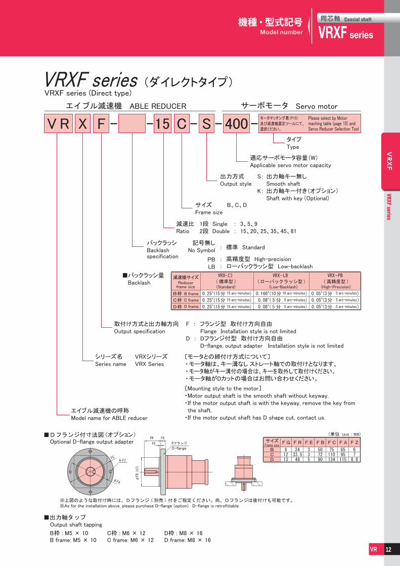
エイブル減速機の呼称Model name for ABLE reducer
シリーズ名Series name
VRXシリーズVRX Series
取付け方式と出力軸方向Output specification
減速比Ratio
1段 Single : 3、5、9 2段 Double : 15、20、25、35、45、81
F : フランジ型 取付け方向自由 Flange Installation style is not limitedD : Dフランジ付型 取付け方向自由 D-flange, output adapter Installation style is not limited
F 15 C 400
Servo motorABLE REDUCER
VRXF series (Direct type)
タイプType
適応サーボモータ容量(W)Applicable servo motor capacity
サイズFrame size
B、C、D
S
出力方式Output style
S:
K:
出力軸キー無し Smooth shaft出力軸キー付き(オプション) Shaft with key (Optional)
バックラッシBacklash specification
■バックラッシ量 Backlash
記号無しNo Symbol
PBLB
: 標準 Standard
: 高精度型 High-precision: ローバックラッシ型 Low-backlash
Reducerframe size (Standard) (Low-Backlash) (High-Precision)
B frame
C frame
D frame
15 arc-minutes
15 arc-minutes
15 arc-minutes
10 arc-minutes
5 arc-minutes
5 arc-minutes
3 arc-minutes
3 arc-minutes
3 arc-minutes
Optional D-flange output adapter
B frame: M5 × 10 C frame: M6 × 12 D frame: M8 × 16B枠 : M5 × 10 C枠 : M6 × 12 D枠 : M8 × 16
D-flangeFrame size
Unit
Output shaft tapping
※As for the installation above, please purchase D-flange (option). D-flange is retrofittable.
(オプション)
減速機サイズ
サイズ
(ダイレクトタイプ)
〔モータとの締付け方式について〕・モータ軸は、キー溝なし ストレート軸での取付けとなります。・モータ軸がキー溝付の場合は、キーを取外して取付けください。・モータ軸がDカットの場合はお問い合わせください。
〔Mounting style to the motor〕・Motor output shaft is the smooth shaft without keyway.・If the motor output shaft is with the keyway, remove the key from the shaft.
・If the motor output shaft has D shape cut, contact us.
Please select by Motor maching table (page 15) and Servo Reducer Selection Tool
モータマッチング表(P15)
及び減速機選定ツールにて、
選択ください。X
機種・型式記号Model number
12

同芯軸
VRXFCoaxial shaft
series VRXF series
同芯軸 Coaxial shaft
VRXF
VRXF series
VR
VRXF
VRXF series
VR
Input speed : 3,000rpm
VRXF series (Direct type)(ダイレクトタイプ)VRXF series
Same specification applies to all types, Standard, Low-backlash, High-precision.
ABLE reducer in-line shaft dimensions list Unit :
Model number Output shaftOverall length Flange
Framesize
Motorcapacity
Ratio
※1 The output shaft rotates in the same direction as the motor.
※2 Output shaft key, key groove dimensions and tolerances conform to
JIS B 1301-1996 (tightening type)
※1 出力軸回転方向はモータ入力回転と同方向になります。
※2 出力軸のキー及びキー溝寸法 ・ 公差は JIS B1301-1996(締込形)
に準じます
サイズ
VRXF series (Direct type)(ダイレクトタイプ)VRXF series
F
□DQ LE
LR
L
φLA
φLB
(h7)
□F
4-LZ深X
4-LZ depth X
S(h6
)T
W
UQK
QMS(
h6)
ST深Y
ST depth Y
ST深Y
ST depth Y
キー無し キー付き
性能一覧(50W 〜 750W)Performance table (50W ~ 750W)
減速比
Ratio
型 式
Model number
出力軸 回転速度
Output speed
許容平均 トルク
Nominal output torque
許容最大 トルク
Maximum output torque
許容 ラジアル荷重
Permitted radial load
許容 スラスト荷重
Permitted axial load
質量
Mass
慣性モーメント
Moment of inertia
機種
Model
減速比
Ratio
枠番
Frame number
出力方式
Output style
モータ容量
Motor capacity
[rpm] [Nm] [Nm] [N] [N] [kg] [kgcm2]
1/3
VRXF -3 B - □ -50 1000 4.46 12.0 392 196 0.55 0.0888
VRXF -3 B - □ -100 1000 4.46 12.0 392 196 0.55 0.0888
VRXF -3 B - □ -200 1000 4.46 12.0 392 196 0.72 0.175
VRXF -3 B - □ -400 1000 4.46 12.0 392 196 0.71 0.175
VRXF -3 C - □ -750 1000 8.92 24.0 784 392 2.1 1.02
1/5
VRXF -5 B - □ -50 600 3.69 9.94 490 245 0.55 0.0604
VRXF -5 B - □ -100 600 3.69 9.94 490 245 0.55 0.0604
VRXF -5 B - □ -200 600 3.69 9.94 490 245 0.72 0.147
VRXF -5 C - □ -400 600 15.0 40.3 980 490 1.7 0.370
VRXF -5 C - □ -750 600 15.0 40.3 980 490 2.1 0.817
1/9
VRXF -9 B - □ -50 333 3.06 8.23 588 294 0.55 0.0497
VRXF -9 B - □ -100 333 3.06 8.23 588 294 0.55 0.0497
VRXF -9 C - □ -200 333 12.6 34.0 1180 588 1.7 0.273
VRXF -9 C - □ -400 333 12.6 34.0 1180 588 1.7 0.273
VRXF -9 D - □ -750 333 23.7 63.7 1470 735 3.4 0.755
1/15
VRXF -15 B - □ -50 200 5.23 14.1 784 392 0.7 0.0526
VRXF -15 B - □ -100 200 5.23 14.1 784 392 0.7 0.0526
VRXF -15 C - □ -200 200 21.1 56.7 1470 735 2.1 0.302
VRXF -15 C - □ -400 200 21.1 56.7 1470 735 2.1 0.302
VRXF -15 D - □ -750 200 39.5 106 1760 882 3.8 0.685
1/20
VRXF -20 B - □ -50 150 6.50 17.5 804 402 0.7 0.0517
VRXF -20 B - □ -100 150 6.50 17.5 804 402 0.7 0.0517
VRXF -20 C - □ -200 150 27.4 73.9 1570 785 2.1 0.296
VRXF -20 C - □ -400 150 27.4 73.9 1570 785 2.1 0.296
VRXF -20 D - □ -750 150 52.8 142 1910 955 3.8 0.664
1/25
VRXF -25 B - □ -50 120 8.15 21.9 882 441 0.7 0.0514
VRXF -25 B - □ -100 120 8.15 21.9 882 441 0.7 0.0514
VRXF -25 C - □ -200 120 34.3 92.4 1670 833 2.1 0.293
VRXF -25 C - □ -400 120 34.3 92.4 1670 833 2.1 0.293
VRXF -25 D - □ -750 120 65.9 177 2060 1030 3.8 0.658
1/35
VRXF -35 B - □ -50 85 4.99 13.4 882 441 0.7 0.0512
VRXF -35 C - □ -100 85 20.2 54.3 1670 833 2.0 0.0853
VRXF -35 C - □ -200 85 20.2 54.3 1670 833 2.1 0.291
VRXF -35 D - □ -400 85 48.1 130 2060 1030 3.8 0.328
1/45
VRXF -45 C - □ -50 66 12.4 33.3 1670 833 2.0 0.0635
VRXF -45 C - □ -100 66 12.4 33.3 1670 833 2.0 0.0635
VRXF -45 D - □ -200 66 36.8 99.1 2060 1030 3.8 0.275
1/81VRXF -81 C - □ -50 37 12.6 34.0 1670 833 2.0 0.0626
VRXF -81 D - □ -100 37 23.1 62.3 2060 1030 3.6 0.0682
※1 表中の機種は、標準型、LB(ローバックラッシ)型、PB(高精度)型す
べてに対応しています。
※2 慣性モーメントは減速機(単体)入力軸換算の値を示します。
※3 許容最高入力回転速度は6,000rpm。許容平均入力回転速度は
3,000rpmとなります。
※4 許容ラジアル荷重は出力軸の軸中央部での値を示します。
※5 許容スラスト荷重は出力軸芯に作用する時の値を示します。
※ 1 Models in the table are available in all three types; Standard, LB
(Low-backlash), PB (High-precision).
※ 2 The moment of inertia is that of the input shaft.
※3 Maximum input speed is 6,000rpm. Nominal input speed is 3,000rpm.
※ 4 The allowable radial load is measured at the center of the output
shaft length.
※ 5 Permitted thrust load value is at the center of the output shaft.
13

同芯軸
VRXFCoaxial shaft
series VRXF series
同芯軸 Coaxial shaft
VRXF
VRXF series
VR
VRXF
VRXF series
VR
ABLE reducer in-line shaft dimensions list Unit :
Model number Output shaftOverall length Flange
Framesize
Motorcapacity
Ratio
※1 The output shaft rotates in the same direction as the motor.
※2 Output shaft key, key groove dimensions and tolerances conform to
JIS B 1301-1996 (tightening type)
※1 出力軸回転方向はモータ入力回転と同方向になります。
※2 出力軸のキー及びキー溝寸法 ・ 公差は JIS B1301-1996(締込形)
に準じます
サイズ
VRXF series (Direct type)(ダイレクトタイプ)VRXF series
F
□DQ LE
LR
L
φLA
φLB
(h7)
□F
4-LZ深X
4-LZ depth X
S(h6
)T
W
UQK
QMS(
h6)
ST深Y
ST depth Y
ST深Y
ST depth Y
キー無し キー付き
寸法一覧(50W 〜 750W)Dimensions (50W ~ 750W)
14

同芯軸
VRXFCoaxial shaft
series VRXF series
同芯軸 Coaxial shaft
VRXF
VRXF series
VR
VRXF
VRXF series
VR
上記以外にも下記サーボモータメーカ他、各社サーボモータシリーズへの取付対応も致します。ホームページ上の選定ツールにて、マウントコードの確認ができます。不明は場合は、お問い合わせください。
VR reducers can attach to all brands of servo motors, including the following. Please contact our nearest sales branch or distributor.
他 Otherシンフォニアテクノロジー㈱ Sinfonia Technology Co., Ltd. 日本電産サンキョー㈱ NIDEC Sankyo Corporation Allen-Bradley
モータマッチング表Motor matching table
Input speed入力回転速度 3,000rpmの時ڦ : 3,000rpm
モータメーカMotor manufacturer
モータシリーズMotor series
モータ容量 (W) Motor capacity (W)50W 100W 200W 400W 750W
パナソニック㈱Panasonic
MSME TYPE1MSMD TYPE1
MUMAアダプタタイプ
8AC8Adapter type
TYPE1
㈱安川電機Yaskawa Electric
SGMJV TYPE3SGMAV TYPE3SGMAS TYPE2SGM7J TYPE3SGM7A TYPE3
三菱電機㈱Mitsubishi Electric
HF-KP TYPE3HF-MP TYPE3HF-KN TYPE3 -HC-PQ TYPE3 -HC-KQ TYPE3 -HC-KFS TYPE3HC-MFS TYPE3HG-KR TYPE3HG-MR TYPE3
オムロン㈱Omron
R88M-K (200V) TYPE3 TYPE1
R88M-K (400V) TYPE3 TYPE1アダプタタイプ
19FB19Adapter type
R88M-G TYPE3 TYPE1R88M-W TYPE2R7M-A TYPE2R7M-Z - TYPE2R88M-U TYPE2
富士電機機器制御㈱Fuji Electric
GYS ※ TYPE2
GYC -アダプタタイプ
8BE8Adapter type
アダプタタイプ14DF14
Adapter type
アダプタタイプ19FA16
Adapter type
山洋電気㈱Sanyo Denki
P30B TYPE3 TYPE2
Q1 TYPE3アダプタタイプ
19DB16Adapter type
㈱キーエンスKeyence
SV TYPE3
MV TYPE3アダプタタイプ
19DB16Adapter type
東芝機械㈱Toshiba Machine
VLBSV-Z ※アダプタタイプ
8AG8Adapter type
TYPE3
VLBSV-ZA ※アダプタタイプ
8AG8Adapter type
TYPE3
VLBST-Zアダプタタイプ
8AG8Adapter type
TYPE3
多摩川精機㈱Tamagawa Seiki
TBL-i ※ TYPE3 -TBL-i Ⅱ※ TYPE3TBL-i Ⅳ
TSM3102/3104/3202/3204/3304
TYPE3
TBL-i ⅣTSM3201/3301/3302
-アダプタタイプ
14BK14Adapter type
アダプタタイプ19DC19
Adapter type-
日機電装㈱Nikki Denso
NA80 ※ TYPE3NA70 ※ TYPE3 -
NA50 TYPE1㈱三明Sanmei
TS ※ TYPE3 -SS ※ TYPE3
㈱日立産機システムHitachi Industrial Equipment Systems
ADMA TYPE3
三木プーリ㈱Miki Pulley
SA3 TYPE1
注1 オイルシール無しと寸法が異なる場合、オイルシール付モータ取付はアダプタ対応となります。
注2 モータ軸がDカット、テーパタイプのものは別途お問い合わせください。
注3 モータ容量(対応表※のモータ)と減速比の組み合せにより、瞬間最大出力トルク時に発生スラスト力がサーボモータ許容スラスト力をこえる場合がありますのでご注意ください。
注4 1,000W以上のモータは、アダプタ対応となります。注5 クランプ締付け方式のみのマッチング表となります。
Note 1 Mounting of oil-seal motors different from non-oil-sealed motors in dimension can be supported by the adapter. For details, contact us.
Note 2 Contact us separately for motors with a D-cut motor shaft or tapered motor shaft.
Note 3 Please note that generated thrust force may exceed the allowable servo motor thrust force at the instantaneous maximum output torque due to combination of the motor capacity (motor with ※ in the correspondence table) and reduction ratio.
Note 4 Motor of 1,000W or more can be supported by the adapter. For details, contact us.
Note 5 This is a matching table for a clamp tightening system only.
15

同芯軸
VRXFCoaxial shaft
series VRXF series
同芯軸 Coaxial shaft
VRXF
VRXF series
VR
VRXF
VRXF series
VR
VRXF series
エイブル減速機の呼称Model name for ABLE reducer
※1 マウントコード
マウントコードは取付モータによって決まります。ホームページ上の選定ツールにて確認できます。不明な場合はお問い合わせください。
〔モータとの締付け方式について〕・モータ軸は、キー溝なし ストレート軸での取付けとなります。・モータ軸がキー溝付の場合は、キーを取外して取付けください。・モータ軸がDカットの場合はお問い合わせください。
※1 Mount code
Mount code varies depending on the motor.Please refer to reducer selection tool or contact us for more information.
〔Mounting style to the motor〕・Motor output shaft is the smooth shaft without keyway.・If the motor output shaft is with the keyway, remove the key from the shaft.
・If the motor output shaft has D shape cut, contact us.
シリーズ名Series name
VRXシリーズVRX Series
取付け方式と出力軸方向Output specification
減速比Ratio
1段 Single : 3、5、9 2段 Double : 15、20、25、35、45、81
F : フランジ型 取付け方向自由 Flange Installation style is not limited
F 15 C
ABLE REDUCER
(アダプタタイプ)
バックラッシBacklash specification
記号無しNo Symbol
PBLB
: 標準 Standard
: 高精度型 High-precision: ローバックラッシ型 Low-backlash
S 19HB16マウントコード(※1)Mount code(※1)
アダプタ
ブッシング
アダプタタイプの特長
※アダプタ、ブッシングの仕組みを説明したイラストです。 外観が異なる場合があります。
モータ取付け部品であるアダプタとブッシングを取替えるだけで世界の様々なモータに取付けが可能になります。
Shimpo’s adapter flange motor mounting methodology allows for nearly limitless motor mounting options.
Adapter
Bushing
■バックラッシ量 Backlash Reducer
frame size (Standard) (Low-Backlash) (High-Precision)
B frame
C frame
D frame
E frame
15 arc-minutes
15 arc-minutes
15 arc-minutes
15 arc-minutes
10 arc-minutes
5 arc-minutes
5 arc-minutes
5 arc-minutes
3 arc-minutes
3 arc-minutes
3 arc-minutes
3 arc-minutes
Output shaft tapping
B frame: M5 × 10 C frame: M6 × 12 D frame: M8 × 16 E frame: M10 × 20
B枠 : M5 × 10 C枠 : M6 × 12 D枠 : M8 × 16 E枠 : M10 × 20
減速機サイズ
VRXF series (Adapter type)
X
出力方式Output style
S:
K:
出力軸キー無し Smooth shaft出力軸キー付き(オプション) Shaft with key (Optional)サイズ
Frame sizeB、C、D、E
■選定ツール(日本語)(http://www.nidec-shimpo.co.jp/selection/jpn/)
■Selection tool (English)(http://www.nidec-shimpo.co.jp/selection/eng/)
E
機種・型式記号Model number
16

同芯軸
VRXFCoaxial shaft
series VRXF series
同芯軸 Coaxial shaft
VRXF
VRXF series
VR
VRXF
VRXF series
VR
性能一覧Performance table
VRXF-□-□B※1 ※2
※3 ※4
質量[kg] 慣性モーメント[kgcm2]
入力軸内径 入力軸内径
(≦φ8) (≦φ14) (≦φ8) (≦φ14)
0.089
0.060
0.050
0.057
0.056
0.055
0.055
0.65
0.87
0.75
0.95
0.18
0.15
0.14
0.14
0.14
0.14
0.14
Input speed : 3,000rpm
VRXF series (Adapter type)(アダプタタイプ)VRXF series
RatioFramenumber
Nominaloutput torque
Maximumoutput torque
Nominalinput speed
Maximuminput speed
Mass Moment of inertia
Input Bore Input BoreRatioFrame
number
Permittedaxial load
Permittedradial load
RatioFramenumber
Nominaloutput torque
Maximumoutput torque
Nominalinput speed
Maximuminput speed
Mass Moment of inertia
Input Bore Input BoreRatioFrame
number
Permittedaxial load
Permittedradial load
枠番
枠番
枠番
枠番
※1 ※2
※3 ※4
質量[kg] 慣性モーメント[kgcm2]
入力軸内径 入力軸内径
(≦φ8) (≦φ14) (≦φ19) (≦φ8) (≦φ14) (≦φ19)
−
−
−
0.145
0.140
0.137
0.135
0.113
0.112
0.57
0.37
0.27
0.30
0.30
0.29
0.29
0.27
0.27
1.0
0.82
0.74
−
−
−
−
−
−
1.9−
2.1
2.2
2.3 −
VRXF-□-□CInput speed : 3,000rpm
※1 許容ラジアル荷重は出力軸中央に作用する時の値を示します。
※2 許容スラスト荷重は出力軸芯に作用する時の値を示します。
※3 質量は減速比および入力軸寸法により若干異なります。
※4 慣性モーメントは減速機(単体)入力軸換算の値を示します。
※1 Permitted radial load is measured at the middle of the output shaft.
※2 Permitted thrust load is measured at the center of the output
shaft.
※3 The mass varies slightly depending on the input bore size and
reduction ratio.
※4 The moment of inertia is reflected to the input shaft of the reducer.
許容平均トルク
許容最大トルク
許容平均入力回転速度
許容最高入力回転速度
許容平均トルク
許容最大トルク
許容平均入力回転速度
許容最高入力回転速度
4.46
3.69
3.06
5.23
6.50
8.15
4.99
12.0
9.94
8.23
14.1
17.5
21.9
13.4
3000
3000
3000
3000
3000
3000
3000
6000
6000
6000
6000
6000
6000
6000
8.92
15.0
12.6
21.1
27.4
34.3
20.2
12.4
12.6
24.0
40.3
34.0
56.7
73.9
92.4
54.3
33.3
34.0
3000
3000
3000
3000
3000
3000
3000
3000
3000
6000
6000
6000
6000
6000
6000
6000
6000
6000
17

同芯軸
VRXFCoaxial shaft
series VRXF series
同芯軸 Coaxial shaft
VRXF
VRXF series
VR
VRXF
VRXF series
VR
RatioFramenumber
Nominaloutput torque
Maximumoutput torque
Nominalinput speed
Maximuminput speed
Mass Moment of inertia
Input Bore Input BoreRatioFrame
number
Permittedaxial load
Permittedradial load
RatioFramenumber
Nominaloutput torque
Maximumoutput torque
Nominalinput speed
Maximuminput speed
Mass Moment of inertia
Input Bore Input BoreRatioFrame
number
Permittedaxial load
Permittedradial load
※1 ※2
※3 ※4
質量[kg] 慣性モーメント[kgcm2]
入力軸内径 入力軸内径
(≦φ8) (≦φ14) (≦φ19) (≦φ28) (≦φ8) (≦φ14) (≦φ19) (≦φ28)
−
−
−
−
−
−
−
−
0.12
1.23
0.55
0.34
0.36
0.34
0.33
0.33
0.28
0.27
1.71
1.04
0.80
0.82
0.80
0.79
0.78
0.73
0.73
3.44
2.76
2.52
2.54
2.52
2.51
−
−
−
3.0−
3.8
3.4
3.9 4.2
4.1
5.0
VRXF-□-□DInput speed : 3,000rpm
※1 ※2
※3 ※4
質量[kg] 慣性モーメント[kgcm2]
入力軸内径 入力軸内径
VRXF-□-□EInput speed : 3,000rpm
※1 許容ラジアル荷重は出力軸中央に作用する時の値を示します。
※2 許容スラスト荷重は出力軸芯に作用する時の値を示します。
※3 質量は減速比および入力軸寸法により若干異なります。
※4 慣性モーメントは減速機(単体)入力軸換算の値を示します。
※1 Permitted radial load is measured at the middle of the output shaft.
※2 Permitted thrust load is measured at the center of the output
shaft.
※3 The mass varies slightly depending on the input bore size and
reduction ratio.
※4 The moment of inertia is reflected to the input shaft of the reducer.
枠番
枠番
枠番
枠番
VRXF series (Adapter type)(アダプタタイプ)VRXF series
57.3
73.8
95.6
119
102
85.0
92.3
119
56.3
132
171
221
274
235
196
213
274
130
3000
3000
3000
3000
3000
3000
3000
3000
3000
6000
6000
6000
6000
6000
6000
6000
6000
6000
(≦φ14) (≦φ19) (≦φ28) (≦φ38) (≦φ14) (≦φ19) (≦φ28) (≦φ38)
−
−
−
0.65
0.58
0.56
0.54
0.36
0.35
4.0
1.8
1.0
1.1
1.0
1.0
0.99
0.81
0.80
5.8
3.6
2.7
2.8
2.8
2.7
2.7
2.5
2.5
13
11
10
11
10
10
−
−
−
6.3−
7.3
7.1
7.7 8.4
9.4
10.8
許容平均トルク
許容最大トルク
許容平均入力回転速度
許容最高入力回転速度
許容平均トルク
許容最大トルク
許容平均入力回転速度
許容最高入力回転速度
23.8
30.6
23.7
39.5
52.8
65.9
48.1
36.8
23.1
64.1
82.3
63.7
106
142
177
130
99.1
62.3
3000
3000
3000
3000
3000
3000
3000
3000
3000
6000
6000
6000
6000
6000
6000
6000
6000
6000
性能一覧Performance table
18

同芯軸
VRXFCoaxial shaft
series VRXF series
同芯軸 Coaxial shaft
VRXF
VRXF series
VR
VRXF
VRXF series
VR
寸法一覧(本体)Dimensions (Main body)
VRXF series (Adapter type)(アダプタタイプ)VRXF series
※1 1段減速:1/3〜1/9、2段減速:1/15〜1/81(サイズBは1/15〜1/35)
※2 モータ軸径が入力軸径と異なる場合は、ブッシングが挿入されます。
※3 取付けモータにより寸法が異なります。詳細は寸法一覧(アダプタ)を
参照ください。(P20~P23参照)
※4 出力軸のキー及びキー溝寸法・公差はJIS B1301-1996(締込形)に
準じます。
P20参照
入力軸内径
P21参照
P22参照
P23参照
Dimensions
Input shaftbore E
StageFramesize
Single
Double
Single
Double
Single
Double
Single
Double
Refer to page 20
Refer to page 21
Refer to page 22
Refer to page 23
※1 Single reduction ratios include: 1/3 ~ 1/9, Double reduction ratios
include: 1/15 ~ 1/81 (Frame Size B, 1/15 ~ 1/35).
※2 Bushings are available to accommodate motor shaft sizes not listed.
※3 These values may vary with the motor / adapter flange selected.
For details, refer to the adapter flange dimensions list on pages 20-23.
※4 Output shaft key, key groove dimensions and tolerances conform to
JIS B 1301-1996 (tightening type)
□DQ LE
LR
L
φLA
φLB
(h7)
4-LZ深X4-LZ depth X
S(h6
)T
W
UST深YST depth Y
QK
QMS(
h6)
ST深YST depth Y
φE(G
7)
キー無し キー付き
※3
19

同芯軸
VRXFCoaxial shaft
series VRXF series
同芯軸 Coaxial shaft
VRXF
VRXF series
VR
VRXF
VRXF series
VR
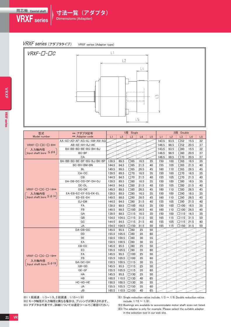
寸法一覧(アダプタ)Dimensions (Adapter)
VRXF series (Adapter type)(アダプタタイプ)VRXF series
※1 1段減速:1/3〜1/9、2段減速:1/15〜1/81(サイズBは1/15〜1/35)
※2 モータ軸径が入力軸径と異なる場合は、ブッシングが挿入されます。
※3 取付けモータにより寸法が異なります。詳細は寸法一覧(アダプタ)を
参照ください。(P20~P23参照)
※4 出力軸のキー及びキー溝寸法・公差はJIS B1301-1996(締込形)に
準じます。
P20参照
入力軸内径
P21参照
P22参照
P23参照
Dimensions
Input shaftbore E
StageFramesize
Single
Double
Single
Double
Single
Double
Single
Double
Refer to page 20
Refer to page 21
Refer to page 22
Refer to page 23
※1 Single reduction ratios include: 1/3 ~ 1/9, Double reduction ratios
include: 1/15 ~ 1/81 (Frame Size B, 1/15 ~ 1/35).
※2 Bushings are available to accommodate motor shaft sizes not listed.
※3 These values may vary with the motor / adapter flange selected.
For details, refer to the adapter flange dimensions list on pages 20-23.
※4 Output shaft key, key groove dimensions and tolerances conform to
JIS B 1301-1996 (tightening type)
□DQ LE
LR
L
φLA
φLB
(h7)
4-LZ深X4-LZ depth X
S(h6
)T
W
UST深YST depth Y
QK
QMS(
h6)
ST深YST depth Y
φE(G
7)
キー無し キー付き
※3
VRXF-□-□B
入力軸内径 Input shaft bore
入力軸内径 Input shaft bore
VRXF series (Adapter type)(アダプタタイプ)VRXF series
Model number
Single Double
**:Adapter code
※1 Single reduction ratios include: 1/3 〜 1/9, Double reduction ratios
include: 1/15 〜 1/35.
※2 Bushings are available to accommodate motor shaft sizes not listed.
※3 The adapter is only for example. Please select the suitable adapter
in the selection tool in our web site.
※1 1 段減速 : 1/3〜1/9、2 段減速 : 1/15〜1/35
※2 モータ軸径が入力軸径と異なる場合は、ブッシングが挿入されます。
※3 アダプタは代表です。詳細については選定ツールでご確認ください。
VRXF
VRXF
AA・AC・AD・AF・AG・AL・AM・AN・AQ
BA・BB・BD・BE・BG・BH・BJ
BA・BB・BD・BE・BF・BG・BJ・BK・BP
BC・BH・BM・BN
CA・CC
DA・DB・DC・DD・DF・DH・DJ
DE・DL
DG・DK
EA・EB・EC・EF・EG・EK・EL
ED・EE・EH
EJ・EM
FA
FB
99.5
104.5
99.5
104.5
104.5
104.5
109.5
114.5
104.5
109.5
104.5
109.5
114.5
104.5
114.5
109.5
104.5
114.5
67.5
72.5
67.5
72.5
72.5
72.5
77.5
82.5
72.5
77.5
72.5
77.5
82.5
72.5
82.5
77.5
72.5
82.5
15.5
20.5
15.5
20.5
20.5
16.5
21.5
26.5
16.5
21.5
16.5
21.5
26.5
16.5
26.5
21.5
16.5
26.5
32
37
32
37
37
35
40
45
35
40
35
40
45
35
45
40
35
45
115.5
120.5
115.5
120.5
120.5
118.5
123.5
128.5
118.5
123.5
118.5
123.5
128.5
118.5
128.5
123.5
118.5
128.5
83.5
88.5
83.5
88.5
88.5
86.5
91.5
96.5
86.5
91.5
86.5
91.5
96.5
86.5
96.5
91.5
86.5
96.5
□52
□52
□60
□60
□70
□65
□65
□65
□70
□70
□80
□80
□80
□90
□90
□90
□100
□100
15.5
20.5
15.5
20.5
20.5
16.5
21.5
26.5
16.5
21.5
16.5
21.5
26.5
16.5
26.5
21.5
16.5
26.5
32
37
32
37
37
35
40
45
35
40
35
40
45
35
45
40
35
45
□52
□52
□60
□60
□70
□65
□65
□65
□70
□70
□80
□80
□80
□90
□90
□90
□100
□100
20
同芯軸
VRXFCoaxial shaft
series VRXF series
同芯軸 Coaxial shaft
VRXF
VRXF series
VR
VRXF
VRXF series
VR
寸法一覧(アダプタ)Dimensions (Adapter)
VRXF-□-□C
入力軸内径 Input shaft bore
入力軸内径 Input shaft bore
入力軸内径 Input shaft bore
Model number
Single Double
**:Adapter code
※1 Single reduction ratios include: 1/3 〜 1/9, Double reduction ratios
include: 1/15 〜 1/81.
※2 Bushings are available to accommodate motor shaft sizes not listed.
※3 The adapter is only for example. Please select the suitable adapter
in the selection tool in our web site.
※1 1 段減速 : 1/3〜1/9、2 段減速 : 1/15〜1/81
※2 モータ軸径が入力軸径と異なる場合は、ブッシングが挿入されます。
※3 アダプタは代表です。詳細については選定ツールでご確認ください。
VRXF series (Adapter type)(アダプタタイプ)VRXF series
VRXF
VRXF
VRXF
AA・AC・AD・AF・AG・AL・AM・AN・AQ
AB・AE・AH・AJ・AK
BA・BB・BD・BE・BG・BH・BJ
BC・BF
CA
BA・BB・BD・BE・BF・BG・BJ・BK・BP
BC・BH・BM・BN
BL
CA・CC
CB
DA・DB・DC・DD・DF・DH・DJ
DE・DL
DG・DK
EA・EB・EC・EF・EG・EK・EL
ED・EE・EH
EJ・EM
FA
FB
GA
GB
GC
JA
DA・DB・DC
DD
DE
EA
EB・ED
EC
FA
FB
GA・GC・GH
GB・GD
GE・GF
HA
HB
HC・HD・HE
JA
JB
139.5
144.5
149.5
139.5
144.5
139.5
144.5
149.5
139.5
149.5
144.5
139.5
149.5
139.5
154.5
144.5
154.5
145.5
155.5
150.5
150.5
145.5
155.5
145.5
155.5
150.5
145.5
155.5
145.5
160.5
150.5
155.5
160.5
89.5
94.5
99.5
89.5
94.5
89.5
94.5
99.5
89.5
99.5
94.5
89.5
99.5
89.5
104.5
94.5
104.5
95.5
105.5
100.5
100.5
95.5
105.5
95.5
105.5
100.5
95.5
105.5
95.5
110.5
100.5
105.5
110.5
□65
□65
□65
□70
□70
□80
□80
□80
□90
□90
□90
□100
□100
□115
□115
□115
□150
□80
□80
□80
□90
□90
□90
□100
□100
□115
□115
□115
□130
□130
□130
□150
□150
16.5
21.5
26.5
16.5
21.5
16.5
21.5
26.5
16.5
26.5
21.5
16.5
26.5
16.5
31.5
21.5
31.5
25
35
30
30
25
35
25
35
30
25
35
25
40
30
35
40
35
40
45
35
40
35
40
45
35
45
40
35
45
35
50
40
50
50
60
55
55
50
60
50
60
55
50
60
50
65
55
60
65
143.5
148.5
143.5
148.5
148.5
150
155
160
150
155
150
155
160
150
160
155
150
160
150
165
155
165
93.5
98.5
93.5
98.5
98.5
100
105
110
100
105
100
105
110
100
110
105
100
110
100
115
105
115
□52
□52
□60
□60
□70
□65
□65
□65
□70
□70
□80
□80
□80
□90
□90
□90
□100
□100
□115
□115
□115
□150
15.5
20.5
15.5
20.5
20.5
16.5
21.5
26.5
16.5
21.5
16.5
21.5
26.5
16.5
26.5
21.5
16.5
26.5
16.5
31.5
21.5
31.5
32
37
32
37
37
35
40
45
35
40
35
40
45
35
45
40
35
45
35
50
40
50
21

同芯軸
VRXFCoaxial shaft
series VRXF series
同芯軸 Coaxial shaft
VRXF
VRXF series
VR
VRXF
VRXF series
VR
寸法一覧(アダプタ)Dimensions (Adapter)
VRXF-□-□D
入力軸内径 Input shaft bore
入力軸内径 Input shaft bore
入力軸内径 Input shaft bore
入力軸内径 Input shaft bore
Model number
Single Double
**:Adapter code
VRXF series (Adapter type)(アダプタタイプ)VRXF series
※1 Single reduction ratios include: 1/3 〜 1/9, Double reduction ratios
include: 1/15 〜 1/81.
※2 Bushings are available to accommodate motor shaft sizes not listed.
※3 The adapter is only for example. Please select the suitable adapter
in the selection tool in our web site.
※1 1 段減速 : 1/3〜1/9、2 段減速 : 1/15〜1/81
※2 モータ軸径が入力軸径と異なる場合は、ブッシングが挿入されます。
※3 アダプタは代表です。詳細については選定ツールでご確認ください。
VRXF
VRXF
VRXF
VRXF
AA・AC・AD・AF・AG・AL・AM・AN・AQAB・AE・AH・AJ・AK
BA・BB・BD・BE・BG・BH・BJBC・BF
CABA・BB・BD・BE・BF・BG・BJ・BK・BP
BC・BH・BM・BNBL
CA・CCCB
DA・DB・DC・DD・DF・DH・DJDE・DLDG・DK
EA・EB・EC・EF・EG・EK・ELED・EE・EH
EJ・EMFAFBGAGBGCJA
DA・DB・DCDDDEEA
EB・EDECFAFB
GA・GC・GHGB・GDGE・GF
HAHB
HC・HD・HEJAJB
FA・FB・FCFD・FE
GA・GB・GC・GD・GE・GF・GG・GHHA・HC・HD
HBHEHF
JA・JB・JC・JFJDJE
KA・KB・KEKD
149154159149154149154159149159154149159149164154164164174169169164174164174169164174164179169174179181176181181191196176181201191181191
889398889388939888989388988810393103103113108108103113103113108103113103118108113118120115120120130135115120140130120130
□65□65□65□70□70□80□80□80□90□90□90□100□100□115□115□115□150□80□80□80□90□90□90□100□100□115□115□115□130□130□130□150□150□100□100□115□130□130□130□130□150□150□150□180□180
16.521.526.516.521.516.521.526.516.526.521.516.526.516.531.521.531.525353030253525353025352540303540353035354550303555453545
354045354035404535454035453550405050605555506050605550605065556065676267677782626787776777
163168163168168165170175165170165170175165175170165175165180170180178188183183178188178188183178188178193183188193195190195195205210190195215205195205
102107102107107104109114104109104109114104114109104114104119109119117127122122117127117127122117127117132122127132134129134134144149129134154144134144
□52□52□60□60□70□65□65□65□70□70□80□80□80□90□90□90□100□100□115□115□115□150□80□80□80□90□90□90□100□100□115□115□115□130□130□130□150□150□100□100□115□130□130□130□130□150□150□150□180□180
15.520.515.520.520.516.521.526.516.521.516.521.526.516.526.521.516.526.516.531.521.531.525353030253525353025352540303540353035354550303555453545
3237323737354045354035404535454035453550405050605555506050605550605065556065676267677782626787776777
22

同芯軸
VRXFCoaxial shaft
series VRXF series
同芯軸 Coaxial shaft
VRXF
VRXF series
VR
VRXF
VRXF series
VR
寸法一覧(アダプタ)Dimensions (Adapter)
VRXF-□-□E
入力軸内径 Input shaft bore
入力軸内径 Input shaft bore
入力軸内径 Input shaft bore
Model number
Single Double
**:Adapter code
入力軸内径 Input shaft bore
VRXF series (Adapter type)(アダプタタイプ)VRXF series
※1 Single reduction ratios include: 1/3 〜 1/9, Double reduction ratios
include: 1/15 〜 1/81.
※2 Bushings are available to accommodate motor shaft sizes not listed.
※3 The adapter is only for example. Please select the suitable adapter
in the selection tool in our web site.
※1 1 段減速 : 1/3〜1/9、2 段減速 : 1/15〜1/81
※2 モータ軸径が入力軸径と異なる場合は、ブッシングが挿入されます。
※3 アダプタは代表です。詳細については選定ツールでご確認ください。
VRXF
VRXF
VRXF
VRXF
BA・BB・BD・BE・BF・BG・BJ・BK・BPBC・BH・BM・BN
BLCA・CC
CBDA・DB・DC・DD・DF・DH・DJ
DE・DLDG・DK
EA・EB・EC・EF・EG・EK・ELED・EE・EH
EJ・EMFAFBGAGBGCJA
DA・DB・DCDDDEEA
EB・EDECFAFB
GA・GC・GHGB・GDGE・GF
HAHB
HC・HD・HEJAJB
FA・FB・FCFD・FE
GA・GB・GC・GD・GE・GF・GG・GHHA・HC・HD
HBHEHF
JA・JB・JC・JFJDJE
KA・KB・KEKDHA
HB・HEHC・HD
JAKA・KB・KC
KDKELALB
MA・MBMCMD
198208203203198208198208203198208198213203208213211206211211221226206211231221211221226221231226226261241226236226241236
123133128128123133123133128123133123138128133138136131136136146151131136156146136146151146156151151186166151161151166161
□80□80□80□90□90□90□100□100□115□115□115□130□130□130□150□150□100□100□115□130□130□130□130□150□150□150□180□180□130□130□130□150□180□180□180□200□200□220□220□220
25353030253525353025352540303540353035354550303555453545454050454580604555456055
506055555060506055506050655560656762676777826267877767778277878282117978292829792
200205210200205200205210200210205200210200215205215210220215215210220210220215210220210225215220225227222227227237242222227247237227237242237247242242277257242252242257252
125130135125130125130135125135130125135125140130140135145140140135145135145140135145135150140145150152147152152162167147152172162152162167162172167167202182167177167182177
□65□65□65□70□70□80□80□80□90□90□90□100□100□115□115□115□150□80□80□80□90□90□90□100□100□115□115□115□130□130□130□150□150□100□100□115□130□130□130□130□150□150□150□180□180□130□130□130□150□180□180□180□200□200□220□220□220
16.521.526.516.521.516.521.526.516.526.521.516.526.516.531.521.531.525353030253525353025352540303540353035354550303555453545454050454580604555456055
3540453540354045354540354535504050506055555060506055506050655560656762676777826267877767778277878282117978292829792
23
同芯軸
VRXFCoaxial shaft
series VRXF series
同芯軸 Coaxial shaft
VRXF
VRXF series
VR
VRXF
VRXF series
VR
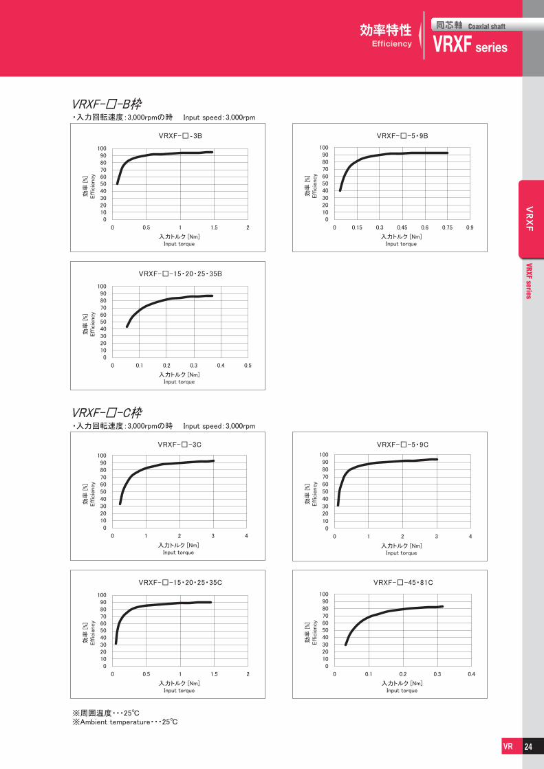
効率特性Efficiency
VRXF-□-3C
0102030405060708090
100
0 1 2 3 4
VRXF-□-45・81C
0102030405060708090
100
0 0.1 0.2 0.3 0.4
VRXF-□-15・20・25・35C
0102030405060708090
100
0 0.5 1 1.5 2
VRXF-□-5・9C
0102030405060708090
100
0 1 2 3 4
VRXF-□‐3B
0102030405060708090
100
0 0.5 1 1.5 2
VRXF-□-5・9B
0102030405060708090
100
0 0.15 0.3 0.45 0.6 0.75 0.9
VRXF-□-15・20・25・35B
0102030405060708090
100
0 0.1 0.2 0.3 0.4 0.5
Input torque
Input torqueInput torque
Input torque
Input torque Input torque
Input torque
Effic
iency
Effic
iency
Effic
iency
Effic
iency
Effic
iency
Effic
iency
Effic
iency
※Ambient temperature・・・25℃
VRXF-□-C枠
Input speed:3,000rpm
Input speed:3,000rpm
入力トルク [Nm]
入力トルク [Nm]入力トルク [Nm]
入力トルク [Nm]
入力トルク [Nm] 入力トルク [Nm]
入力トルク [Nm]
効率
[%]
効率
[%]
効率
[%]
効率
[%]
効率
[%]
効率
[%]
効率
[%]
※周囲温度・・・25℃
VRXF-□-B枠・入力回転速度:3,000rpmの時
・入力回転速度:3,000rpmの時
24

同芯軸
VRXFCoaxial shaft
series VRXF series
同芯軸 Coaxial shaft
VRXF
VRXF series
VR
VRXF
VRXF series
VR
効率特性Efficiency
※Ambient temperature・・・25℃
VRXF-□-3D
0102030405060708090
100
0 2 4 6 8 10
VRXF-□-5・9D
0102030405060708090
100
0 1 2 3 4 5 6
VRXF-□-45・81D
0102030405060708090
100
0 0.2 0.4 0.6 0.8 1
VRXF-□-15・20・25・35D
0102030405060708090
100
0 0.5 1 1.5 2 2.5 3
VRXF-□-3E
0102030405060708090
100
0 5 10 15 20
VRXF-□-5・9E
0102030405060708090
100
0 5 10 15 20
VRXF-□-45・81E
0102030405060708090
100
0 0.5 1 1.5 2 2.5 3
VRXF-□-15・20・25・35E
0102030405060708090
100
0 2 4 6 8 10
Input torque Input torque
Input torqueInput torque
Input torque Input torque
Input torqueInput torque
Eff
icie
ncy
Eff
icie
ncy
Eff
icie
ncy
Eff
icie
ncy
Eff
icie
ncy
Eff
icie
ncy
Eff
icie
ncy
Eff
icie
ncy
効率
[%]
効率
[%]
効率
[%]
効率
[%]
効率
[%]
効率
[%]
効率
[%]
効率
[%]
VRXF-□-D枠
VRXF-□-E枠
Input speed:3,000rpm
Input speed:3,000rpm
入力トルク [Nm] 入力トルク [Nm]
入力トルク [Nm]入力トルク [Nm]
入力トルク [Nm] 入力トルク [Nm]
入力トルク [Nm]入力トルク [Nm]
※周囲温度・・・25℃
・入力回転速度:3,000rpmの時
・入力回転速度:3,000rpmの時
25

同芯軸
VRXFCoaxial shaft
series VRXF series
同芯軸 Coaxial shaft
VRXF
VRXF series
VR
VRXF
VRXF series
VR
Input gear (Sun gear)
* The explanation in ( ) shows the parts in second reduction.
Planetary gear A (Planetary gear B)
* The explanation in ( ) shows the parts in second reduction.
Internal gear A (Internal gear B)
* The explanation in ( ) shows the parts in second reduction.
1st stage reduction section Motor ∼ Input gear ∼ Planetary gear A ∼ Carrier
2nd stage reduction section Carrier ∼ Sun gear ∼ Planetary gear B ∼ Output shaft
Rotation from the motor is transmitted from the input gear mounted to the Input
shaft. The input gear engages planetary gear A, which in turn engages internal gear
A to produce an orbital motion to the planetary gears A. This rotates the 2nd
stage carrier.
The direction of rotation at
the output is the same as
the direction of rotation at
the input.
Rotation from the carrier is transmitted to the sun gear at the output of the car-
rier. The input gear engages planetary gear B, which engages the internal gear to
produce an orbital motion to planetary gears B.
The direction of rotation at
the output is the same as
the direction of rotation at
the input.
The explanation above describes how a double reduction (2 stage) reducer works.
For explanation of how a single reduction (1 stage) reducer works, refer to the 2nd stage reduction section above.
BBB
Internal gear B
Planetary gear B
Output shaft
Sun gear
Planetary gear AInternal gear A
Carrier
Input Gear Input shaft
作動原理Operating principle
26

同芯軸
VRXFCoaxial shaft
series VRXF series
同芯軸 Coaxial shaft
VRXF
VRXF series
VR
VRXF
VRXF series
VR
型式の決定Determination of model
※ いずれか一つでも当てはまらない項目が有る場合には、ひとつ上の型式で再検討するか、負荷トルクなどの条件の低減を検討してください。
*If there are values that do not fit within the maximum, examine the model again, or consider conditions such as load torque.
型番選定 Selection of model No.
■負荷トルクパターンの確認 Checkup of load torque pattern
■型式選定手順 Model selection procedure
エイブル減速機はモータ容量と減速比が決まれば、「減速比 ・ 枠番表」から減速機の型式を簡単に選定することが出来ますが、標準外の組み
合わせをする場合や、詳細な計算が必要な場合には、以下に示す計算式から該当する減速機の型式を選定してください。
For ABLE REDUCER, once the motor capacity and reduction ratio are fixed, the reducer model can be simply selected according to the “Reduction ratio & frame size table.” However, in a case that a non-standard combination is made or detailed calculation is necessary, select the applicable reducer model according to the calculations as suggested below:
減速機に掛かる負荷トルクのパターンを確認します。
Check the load torque pattern to be given to the reducer.
■各種記号の説明 Description of symbols
T1 ~ Tn(N ・ m) : 負荷トルク Load torquet1 ~ tn(sec) : 時間 Timen1~ nn(rpm) : 出力回転速度(加減速時は平均回転速度)
Output speed (mean rotational speed at the time of acceleration & reduction)
nOUT : 最高出力回転速度 Max. output speed (rpm)≧ n1 ~ nn
nIN : 最高入力回転速度 Max. input speed (rpm)≧ n1 × R ~ nn × RR : 減速比 Reduction ratio
以下の手順に従って型式選定を行います。
Select a model according to the following procedure:
T1
T2
T3
T4
t1 t2 t3 t4
n1
n2
n3
n4
+
-
Load
torq
ue
負荷トルク
Outp
ut
speed
出力回転速度
負荷トルクパターンから、出力軸にかかる平均負荷トルクを算出します。
Calculate mean load torque given to the output shaft from the load torque pattern.
平均負荷トルク Mean load torque : Ta (N ・ m)
負荷トルクパターンから、平均出力回転速度を算出します。
Calculate mean output speed from the load torque pattern.
平均出力回転速度 Mean output speed : naOUT(rpm)
1 平均出力回転速度naOUT と減速比(R)から平均入力回転速度naIN
を算出します。
Calculate mean input speed naIN from mean output speed naOUT and reduction ratio (R).
4
最高入力回転速度が許容最高入力回転速度以下であることを
確認します。
Ensure that max. input speed is less than or equal to the fixed max. input speed.
5
T1、T3 が性能表の許容最大トルクの値以内であることを確認
します。
Ensure that T1 and T3 are within the values of max. instantaneous allowable output torque in the performance table.
6
次式の条件に当てはまるように、型式の仮選定をしてください。
Temporarily select a model to meet the following equation.
(各型式の許容平均トルクは性能表をご参照ください。)
( For nominal output torque of each model, see the performance table.)
2
最高出力回転速度(nOUT)と最高入力回転速度(nIN)から
減速比(R)を決定します。
Determine reduction ratio (R) from max. output speed (nOUT) and max. input speed (nIN).
(nIN はモータなどにより制限されます。) (nIN is limited by motors, etc.)
最高出力回転速度(nOUT)と減速比(R)から最高入力回転速度(nIN)を
算出します。
Calculate max. input speed from max. output speed (nOUT) and reduction ratio (R).
3
10/3 n1t1│T1│10/3+ n2t2│T2│10/3+…+ nntn│Tn│10/3Ta =
n1t1 + n2t2 +…+nntn
n1t1 + n2t2 +…+nntnt1 + t2 +…+ tn
naOUT =
nIN = nOUTR
Ta ≦ 許容平均トルク Nominal output torque
nINnOUT
≧ R
naIN = naOUTR ≦ 3,000(rpm)
nIN ≦ 6,000(rpm)
OK
OK
OK
OK
OK
OK
技術資料Technical data
27

同芯軸
VRXFCoaxial shaft
series VRXF series
同芯軸 Coaxial shaft
VRXF
VRXF series
VR
VRXF
VRXF series
VR
■型式選定例 Examples of model selection
[運転パターン Operating pattern]
起動時 At acceleration : T1 =90(Nm) t1 =0.5(sec) n1 =90(rpm)
定常運転時 During normal operation : T2 =35(Nm) t2 =5(sec) n2 =180(rpm)
減速時 At deceleration : T3 =-70(Nm) t3 =1(sec) n3 =90(rpm)
停止時 While stopped : T4 =0(Nm) t4 =10(sec) n4 =0(rpm)
[最高回転速度 Max. number of rotations]
最高出力回転速度 Max. output speed : nOUT =180(rpm)
最高入力回転速度 Max. input speed : nIN =5000(rpm)
(モータにより制限 limited by the motor)
1 平均出力回転速度naOUT と減速比(R)から平均入力回転速度naIN
を算出します。
Calculate mean input speed naIN from mean output speed naOUT and reduction ratio (R).
5
最高入力回転速度が許容最高入力回転速度以下であることを
確認します。
Ensure that max. input speed is less than or equal to the fixed max. input speed.
6
T1、T3 が性能表の許容最大トルクの値以内であることを
確認します。
Ensure that T1 and T3 are within the values of max. instantaneous allowable output torque in the performance table.
7負荷トルクパターンから、出力軸にかかる平均負荷トルクを算出
します。
Calculate mean load torque given to the output shaft from the load torque pattern.
平均負荷トルク Mean load torque : Ta (N ・ m)
負荷トルクパターンから、平均出力回転速度を算出します。
Calculate mean output speed from the load torque pattern.
平均出力回転速度 Mean output speed : naOUT(rpm)
2
最高出力回転速度(nOUT)と最高入力回転速度(nIN)から
減速比(R)を決定します。
Determine reduction ratio (R) from max. output speed (nOUT) and max. input speed (nIN).
最高出力回転速度(nOUT)と減速比(R)から最高入力回転速度(nIN)を
算出します。
Calculate max. input speed (nIN) from max. output speed (nOUT) and reduction ratio (R).
4
型式の仮選定をします。
Temporarily select the model.
(性能表よりVRXF-25D を選定)
(Select VRXF-25D from the performance table)
3
10/3 90×0.5×│90│10/3+180×5×│35│10/3+90×1×│-70│10/3+0Ta =
90×0.5+180×5+90×1+0
= 47.5(Nm)
naOUT = = 62.7(rpm)90×0.5+180×5+90×1+0
0.5 + 5 + 1+ 10
nIN = 180 × 25 = 4,500(rpm)
VRXF-25D に決定
Selected VRXF-25D
47.5≦ 65.9(Nm)
= 27.8 ≧ 251805000
naIN= 62.7 × 25 = 1567.5 ≦ 3,000(rpm)
nIN = 4,500 ≦ 6,000(rpm)
T1 = 90 ≦ 177(Nm)T3 = 70 ≦ 177(Nm)
減速機選定ツールを使用することで、上記のような選定を簡単に行うことができます。詳しくはP3をご参照ください。
With the selection tool, proper reducer model can be easily selected. For detail, please refer to page 3.
OK
OK
OK
OK
OK
OK
OK
技術資料Technical data
28

同芯軸
VRXFCoaxial shaft
series VRXF series
同芯軸 Coaxial shaft
VRXF
VRXF series
VR
VRXF
VRXF series
VR
MEMO
29

For servo motor ABLE REDUCER
VRGSeries
サーボモータ専用

同芯軸
VRGCoaxial shaft
series VRG series
同芯軸 Coaxial shaft
VRG
VRG series
VR
VRG
VRG series
VR
特徴Features
VRG series
静音 Quiet振動、騒音低減に適した遊星歯車減速機構とはすば歯車を採用その強みを最大限に生かし、静音化を実現
More Quiet than current VRSF series, which uses helical gears.
高剛性 High stiffness高剛性クロスローラベアリングを主軸受に採用コンパクト ・ 頑強なボディから高い出力トルクを発揮
High stiffness cross-roller bearing at output.
Compact and strong body produces high power.
高精度 High precisionバックラッシ 0.05(3分)の高精度シリーズ Precision backlash series 0.05°(3 arc-min) or below.
コンパクト Compact大口径クロスローラベアリングを採用し、フランジ出力型をシリーズ化省スペースにより、装置設計の自由度が飛躍的に向上
Flange output by large diameter cross-roller bearing.Compact design contributes to apprication flexibility.
長寿命 Long life潤滑油に耐久性に優れ、摩耗が少ない高級グリースを使用し、長期間メンテナンスの必要がありません。(約 20,000時間)
No grease change required due to high-grade grease packed in sealed body. No maintainance required for a long period (about 20,000 hours) due to high-durability and less wear.
簡単取付 Easy installation各社サーボモータ、各シリーズの取付けに対応しており、モータと減速機の取付けも簡単
Easy installation to any servo motors.
31

同芯軸
VRGCoaxial shaft
series VRG series
同芯軸 Coaxial shaft
VRG
VRG series
VR
VRG
VRG series
VR
(3.67)、 (4)、5、(7)、9、(10)、11、15[15.4※]、(20)、21、
(25)、33、(35)、(40)、45、(50)、(70)、81、(100)(19種類)
減速比は、実減速比です。Reduction ratio is actual reduction ratio.
( )内は受注生産品です。( ) is inquiry basis
※ C90、D120、E170は15.4になります。※ 15.4 reduction ratio is available for C90, D120, E170
マウントコード(※1)
Mount code(※1)
バックラッシ なし・・・ 3分 3arc-min
Backlash None
N ・・・ 1分 1arc-min
(減速比:5、9、11、15[15.4]、
Ratio 21、33、45、81)
出力方式
Output styleF・・・ フランジ出力型 Flange output
S・・・ 延長軸出力型 Extension shaft type
減速比:Ratio
シリーズ名Series name
VRGシリーズVRG Series
エイブル減速機の呼称Model name for ABLE reducer
G F
減速機サイズ
Reducer frame sizeB60P C90/C90P D120 E170
C 9 0 1 9 H B 1 61 1
19kinds
※1 マウントコード
マウントコードは取付モータによって決まります。ホームページ上の選定ツールにて確認できます。不明な場合はお問い合わせください。
〔モータとの締付け方式について〕・モータ軸は、キー溝なし ストレート軸での取付けとなります。・モータ軸がキー溝付の場合は、キーを取外して取付けください。・モータ軸がDカットの場合はお問い合わせください。
※1 Mount code
Mount code varies depending on the motor.Please refer to reducer selection tool or contact us for more information.
〔Mounting style to the motor〕・Motor output shaft is the smooth shaft without keyway.・If the motor output shaft is with the keyway, remove the key from the shaft.
・If the motor output shaft has D shape cut, contact us.
アダプタ
ブッシング
アダプタタイプの特長
※アダプタ、ブッシングの仕組みを説明したイラストです。 外観が異なる場合があります。
モータ取付け部品であるアダプタとブッシングを取替えるだけで世界の様々なモータに取付けが可能になります。
Shimpo’s adapter flange motor mounting methodology allows for nearly limitless motor mounting options.
Adapter
Bushing
VRG series
機種・型式記号Model number
32

同芯軸
VRGCoaxial shaft
series VRG series
同芯軸 Coaxial shaft
VRG
VRG series
VR
VRG
VRG series
VR
容量
Capacity
(W)
減速比 (1 段型 )
Ratio (Single)
減速比 (2 段型 )
Ratio (Double)
1/3.67 ★ 1/4 ★ 1/5 1/7 ★ 1/9 1/10 ★ 1/111/15
(1/15.4)1/20 ★ 1/21 1/25 ★ 1/33 1/35 ★ 1/40 ★ 1/45 1/50 ★ 1/70 ★ 1/81 1/100 ★
30
50
100
200
400
750
1000
1500
2000
2500
3000
3500
4000
4500
5000
B60P
※ 1 ※ 2
C90 C90P D120 E170
※ 1 減速比 1/3.67 は 3/11 = 1/3.666… ※ 1 Reduction ratio 1/3.67 is 3/11=1-3.6666….※ 2 B 枠は 1/15、 C ~ E 枠は 1/15.4 ※ 2 B frame size is 1/15, and C to E frame size 1/15.4★は受注生産品です ★ is on inquiry basis
Input speed : 3,000rpm
減速比・枠番Reduction ratio / Frame size
■潤滑油について
●潤滑 : グリース
●交換 : 不要
注) 上記枠番表と選定ツールの選定結果が異なる場合がございます。
■About lubrication
●Lubrication : Grease
●Replacement : Not necessary
Note) In some cases this chart could show the different results from our
web selection tool.
33

同芯軸
VRGCoaxial shaft
series VRG series
同芯軸 Coaxial shaft
VRG
VRG series
VR
VRG
VRG series
VR
VRG□-B60P
B60P
許容モーメント
Allowablemoment
[Nm]
慣性モーメント
※11
Momentof inertia(≦φ8) (≦φ14)
慣性モーメント
※11
Momentof inertiaサイズ
Framesize
減速比
Ratio
質量
Mass
フランジFlangeoutput
出力軸Shaftoutput
1.1
1.3
1.2
1.4
フランジFlangeoutput
出力軸Shaftoutput
0.08220.07600.06410.05420.05040.04940.08700.08490.05760.06250.05720.04850.05670.04780.04830.04760.04750.04810.0475
0.09280.08490.06980.05710.05210.05080.08810.08560.05800.06290.05740.04860.05680.04790.04830.04770.04760.04810.0475
フランジFlangeoutput
出力軸Shaftoutput
0.1610.1550.1430.1330.1290.1280.1670.1650.1360.1410.1360.1270.1350.1270.1270.1260.1260.1270.126
0.1720.1640.1490.1360.1310.1300.1680.1660.1370.1420.1360.1270.1360.1270.1270.1260.1260.1270.126
フランジFlangeoutput
出力軸Shaftoutput
0.3160.3100.2980.2880.2850.284
-------------
0.3270.3190.3040.2910.2860.285
-------------
3.67
4
5
7
9
10
11
15
20
21
25
33
35
40
45
50
70
81
100
38
(≦φ19)
慣性モーメント
※11
Momentof inertia
サイズ
B60P
Framesize
減速比許容平均
トルク許容平均
入力回転速度許容最高
入力回転速度
許容ラジアル荷重 許容
スラスト荷重
Permittedaxial load
Permittedradial load
Maximuminput speed
フランジFlangeoutput
出力軸Shaftoutput
Nominalinput speed
許容最大トルク
非常時最大トルク
Emergencystop torque
Maximumoutput torque
Nominaloutput torque
Ratio
3.67
4
5
7
9
10
11
15
20
21
25
33
35
40
45
50
70
81
100
6.827.167.879.2910.510.89.4310.911.512.012.713.113.013.414.414.413.011.810.8
24.827.027.025.723.721.626.428.826.828.828.826.425.926.828.828.825.923.621.6
49.654.154.151.347.343.352.757.553.757.557.552.751.853.757.557.551.847.243.1
3000300030003000300030003000300030003000300030003000300030003000300030003000
6000600060006000600060006000600060006000600060006000600060006000600060006000
55356860767272474776984492093498410701090113011701210134014001490
202207221245264272280308335340359390397413428442488510544
826847906927927927927927927927927927927927927927927927927
性能一覧Performance table
※ 1 許容平均入力回転速度の時、寿命20,000時間となる値
※ 2 起動 ・ 停止時に許容する最大値
※ 3 衝撃等が作用した時に許容する最大値(頻度は1,000回まで)
※ 4 運転中の平均入力回転速度の許容最大値
※ 5 連続運転ではない条件下での許容最高入力回転速度
※ 6 許容ラジアル荷重(フランジ)はクロスローラ軸受に作用する時
の値(スラスト荷重ゼロ)
※ 7 許容平均入力回転速度の時、寿命20,000時間となる値
(軸中央に作用、スラスト荷重が0のとき)
※ 8 許容平均入力回転速度の時、寿命20,000時間となる値
(軸芯に作用、ラジアル荷重が0のとき)
※ 9 許容モーメントは主軸受が許容できるモーメントの最大値
※10 減速比及び入力軸寸法により若干異なります
※11 減速機(単体)入力軸換算の値を示します
※ 1 With nominal input speed, service life is 20,000 hours.※ 2 The maximum torque when starting and stopping.※ 3 The maximum torque when it receives shock. (up to 1,000 times)※ 4 The maximum average input speed.※ 5 The maximum momentary input speed.※ 6 Permitted radial load (flange) is the value applied on the cross roller bearing.
(no thrust load)※ 7 With this load and nominal input speed, service life will be 20,000 hours.
(Applied to the output shaft center, at axial load 0)※ 8 With this load and nominal input speed, service life will be 20,000 hours.
(Applied to the output side bearing, at radial load 0)※ 9 The allowable moment is the maximum value of the moment that the main
bearing can tolerate.※10 The mass may vary slightly model to model.※11 The moment of inertia indicates the input shaft converted value of the
reducer only.
34

同芯軸
VRGCoaxial shaft
series VRG series
同芯軸 Coaxial shaft
VRG
VRG series
VR
VRG
VRG series
VR
性能一覧Performance table
サイズ
C90
VRG□-C90(P)
Framesize
C90
C90P
C90P
減速比許容平均
トルク
許容モーメント
許容平均入力回転速度
許容最高入力回転速度
許容ラジアル荷重 許容
スラスト荷重
Permittedaxial load
Permittedradial load
Maximuminput speed
フランジFlangeoutput
出力軸Shaftoutput
Nominalinput speed
許容最大トルク
非常時最大トルク
Emergencystop torque
Maximumoutput torque
Nominaloutput torque
Allowablemoment
[Nm]
慣性モーメント
※11 ※11 ※11 ※11
Momentof inertia(≦φ8) (≦φ14)
慣性モーメントMomentof inertia
Ratio
サイズ
Framesize
減速比
Ratio
3.67
4
5
7
9
10
11
15.4
20
21
25
33
35
40
45
50
70
81
100
21.722.524.628.632.434.123.233.236.237.739.741.746.144.647.348.850.340.836.4
92.610110610181.973.181.811011612312311010311612312310181.772.9
185202212203164146164220232246246220207232246246201163146
3000300030003000300030003000300030003000300030003000300030003000300030003000
6000600060006000600060006000600060006000600060006000600060006000600060006000
1070109011701290140014401480164017701800190020602100218022602330258027002870
448460491544586605622689745756796865881917950980108011301210
質量
Mass
フランジFlangeoutput
出力軸Shaftoutput
2.7
3.3
3.1
3.7
フランジFlangeoutput
出力軸Shaftoutput
------
0.3650.2770.2360.2690.2320.1550.2380.1490.1530.1480.1470.04870.0479
------
0.3720.2810.2380.2710.2330.1560.2390.1490.1540.1480.1470.04890.0480
フランジFlangeoutput
出力軸Shaftoutput
0.5620.5100.4180.3390.3100.3010.4900.4020.3610.3940.3570.2950.3630.2890.2930.2880.2870.1270.127
0.6320.5680.4560.3580.3210.3110.4980.4060.3630.3960.3590.2960.3640.2900.2940.2880.2870.1280.127
フランジFlangeoutput
出力軸Shaftoutput
1.050.9940.9030.8230.7940.7860.9530.8650.8240.8560.8200.7580.8260.7510.7560.7510.750
--
1.121.050.9400.8420.8060.7950.9600.8690.8260.8590.8210.7580.8260.7520.7560.7510.750
--
フランジFlangeoutput
出力軸Shaftoutput
2.272.222.122.042.022.012.202.112.072.112.072.012.072.002.012.002.00--
2.342.272.162.062.032.022.212.122.082.112.072.012.082.002.012.002.00--
1590163017501930208021502210245026502650265026502650265026502650265026502650
3.67
4
5
7
9
10
11
15.4
20
21
25
33
35
40
45
50
70
81
100
138
(≦φ19)
慣性モーメントMomentof inertia
(≦φ28)
慣性モーメントMomentof inertia
※ 1 許容平均入力回転速度の時、寿命20,000時間となる値
※ 2 起動 ・ 停止時に許容する最大値
※ 3 衝撃等が作用した時に許容する最大値(頻度は1,000回まで)
※ 4 運転中の平均入力回転速度の許容最大値
※ 5 連続運転ではない条件下での許容最高入力回転速度
※ 6 許容ラジアル荷重(フランジ)はクロスローラ軸受に作用する時
の値(スラスト荷重ゼロ)
※ 7 許容平均入力回転速度の時、寿命20,000時間となる値
(軸中央に作用、スラスト荷重が0のとき)
※ 8 許容平均入力回転速度の時、寿命20,000時間となる値
(軸芯に作用、ラジアル荷重が0のとき)
※ 9 許容モーメントは主軸受が許容できるモーメントの最大値
※10 減速比及び入力軸寸法により若干異なります
※11 減速機(単体)入力軸換算の値を示します
※ 1 With nominal input speed, service life is 20,000 hours.※ 2 The maximum torque when starting and stopping.※ 3 The maximum torque when it receives shock. (up to 1,000 times)※ 4 The maximum average input speed.※ 5 The maximum momentary input speed.※ 6 Permitted radial load (flange) is the value applied on the cross roller bearing.
(no thrust load)※ 7 With this load and nominal input speed, service life will be 20,000 hours.
(Applied to the output shaft center, at axial load 0)※ 8 With this load and nominal input speed, service life will be 20,000 hours.
(Applied to the output side bearing, at radial load 0)※ 9 The allowable moment is the maximum value of the moment that the main
bearing can tolerate.※10 The mass may vary slightly model to model.※11 The moment of inertia indicates the input shaft converted value of the
reducer only.
35

同芯軸
VRGCoaxial shaft
series VRG series
同芯軸 Coaxial shaft
VRG
VRG series
VR
VRG
VRG series
VR
サイズ
D120
VRG□-D120
Framesize
D120
減速比許容平均トルク
許容モーメント
許容平均入力回転速度
許容最高入力回転速度
許容ラジアル荷重 許容
スラスト荷重
Permittedaxial load
Permittedradial load
Maximuminput speed
フランジFlangeoutput
出力軸Shaftoutput
Nominalinput speed
許容最大トルク
非常時最大トルク
Emergencystop torque
Maximumoutput torque
Nominaloutput torque
Allowablemoment
[Nm]
慣性モーメントMomentof inertia(≦φ8) (≦φ14)
慣性モーメントMomentof inertia
Ratio
サイズ
Framesize
減速比
Ratio
3.67
4
5
7
9
10
11
15.4
20
21
25
33
35
40
45
50
70
81
100
71.974.782.696.596.080.860.511012012613313813214615915913295.780.6
255262295240192162206285292318318285265292318318265191161
511524589480384323411570585635635570529585635635529383322
3000300030003000300030003000300030003000300030003000300030003000300030003000
4200420060006000600060006000600060006000600060006000600060006000600060006000
1860191020402260244025102590286031003140331036003660381039504070451047105020
700718768850916946973108011601180124013501380143014801530170017701890
質量
Mass
フランジFlangeoutput
出力軸Shaftoutput
6.2
7.7
7.6
9.1
フランジFlangeoutput
出力軸Shaftoutput
-----------------
0.1720.165
-----------------
0.1730.166
フランジFlangeoutput
出力軸Shaftoutput
---
0.5740.4540.4181.170.8780.6800.8440.6650.3950.6490.3680.3870.3640.3610.2980.291
---
0.6850.5210.4731.210.9010.6940.8570.6740.4000.6530.3710.3900.3660.3620.2990.292
フランジFlangeoutput
出力軸Shaftoutput
2.131.901.521.191.071.041.681.391.191.361.180.8801.160.8530.8720.8500.8460.7600.754
2.532.241.741.311.141.091.721.411.211.371.190.8851.160.8570.8750.8520.8470.7610.754
フランジFlangeoutput
出力軸Shaftoutput
3.713.483.102.772.652.623.343.052.863.022.842.542.822.522.542.512.51--
4.113.823.322.892.722.673.393.082.873.032.852.552.832.522.542.522.51--
2780285030503370364037403740374037403740374037403740374037403740374037403740
3.67
4
5
7
9
10
11
15.4
20
21
25
33
35
40
45
50
70
81
100
360
(≦φ19)
慣性モーメントMomentof inertia
(≦φ28)
慣性モーメントMomentof inertia
フランジFlangeoutput
出力軸Shaftoutput
11.210.910.610.210.110.110.710.410.210.410.29.9310.29.909.929.909.89--
11.611.310.810.310.210.110.810.510.310.410.29.9310.29.909.929.909.90--
(≦φ38)
慣性モーメント
※11 ※11 ※11 ※11 ※11
Momentof inertia
性能一覧Performance table
※ 1 許容平均入力回転速度の時、寿命20,000時間となる値
※ 2 起動 ・ 停止時に許容する最大値
※ 3 衝撃等が作用した時に許容する最大値(頻度は1,000回まで)
※ 4 運転中の平均入力回転速度の許容最大値
※ 5 連続運転ではない条件下での許容最高入力回転速度
※ 6 許容ラジアル荷重(フランジ)はクロスローラ軸受に作用する時
の値(スラスト荷重ゼロ)
※ 7 許容平均入力回転速度の時、寿命20,000時間となる値
(軸中央に作用、スラスト荷重が0のとき)
※ 8 許容平均入力回転速度の時、寿命20,000時間となる値
(軸芯に作用、ラジアル荷重が0のとき)
※ 9 許容モーメントは主軸受が許容できるモーメントの最大値
※10 減速比及び入力軸寸法により若干異なります
※11 減速機(単体)入力軸換算の値を示します
※ 1 With nominal input speed, service life is 20,000 hours.※ 2 The maximum torque when starting and stopping.※ 3 The maximum torque when it receives shock. (up to 1,000 times)※ 4 The maximum average input speed.※ 5 The maximum momentary input speed.※ 6 Permitted radial load (flange) is the value applied on the cross roller bearing.
(no thrust load)※ 7 With this load and nominal input speed, service life will be 20,000 hours.
(Applied to the output shaft center, at axial load 0)※ 8 With this load and nominal input speed, service life will be 20,000 hours.
(Applied to the output side bearing, at radial load 0)※ 9 The allowable moment is the maximum value of the moment that the main
bearing can tolerate.※10 The mass may vary slightly model to model.※11 The moment of inertia indicates the input shaft converted value of the
reducer only.
36

同芯軸
VRGCoaxial shaft
series VRG series
同芯軸 Coaxial shaft
VRG
VRG series
VR
VRG
VRG series
VR
サイズ
E170
VRG□-E170
Framesize
E170
減速比許容平均トルク
許容モーメント
許容平均入力回転速度
許容最高入力回転速度
許容ラジアル荷重 許容
スラスト荷重
Permittedaxial load
Permittedradial load
Maximuminput speed
フランジFlangeoutput
出力軸Shaftoutput
Nominalinput speed
許容最大トルク
非常時最大トルク
Emergencystop torque
Maximumoutput torque
Nominaloutput torque
Allowablemoment
[Nm]
慣性モーメントMomentof inertia(≦φ14) (≦φ19)
慣性モーメントMomentof inertia
Ratio
サイズ
Framesize
減速比
Ratio
3.67
4
5
7
9
10
11
15.4
20
21
25
33
35
40
45
50
70
81
100
174187202245200199170266301309326335316358355355316200198
669644639578400398501702715710710765632715710710632399397
134012901280116080179610001400143014201420153012601430142014201260798793
2000200020002000200020002000200020002000200020002000200020002000200020002000
3000300042004200420042004200500050005000500050005000500050005000500050005000
4170428045805070547056405800642069407050743080708210855088609140101001060011300
1750179019202120229023602430269029102950311033803440358037103830423044204710
質量
Mass
フランジFlangeoutput
出力軸Shaftoutput
17
19
20
22
フランジFlangeoutput
出力軸Shaftoutput
-----------------
0.3850.361
-----------------
0.3890.364
フランジFlangeoutput
出力軸Shaftoutput
---
2.691.911.735.123.432.563.232.461.362.531.261.321.231.210.8700.846
---
3.302.282.035.363.562.633.302.511.392.551.271.331.241.220.8750.849
フランジFlangeoutput
出力軸Shaftoutput
11.110.07.505.594.824.636.985.294.425.094.323.134.393.023.092.992.972.532.51
13.311.88.696.205.194.937.225.424.495.164.373.164.413.043.103.012.982.542.51
フランジFlangeoutput
出力軸Shaftoutput
17.716.614.112.211.411.314.412.711.812.511.710.511.810.410.510.410.3--
19.918.515.312.811.811.614.612.811.912.511.810.511.810.410.510.410.4--
623064006840756081608420866095801040010500108001080010800108001080010800108001080010800
3.67
4
5
7
9
10
11
15.4
20
21
25
33
35
40
45
50
70
81
100
1037
(≦φ28)
慣性モーメントMomentof inertia
(≦φ38)
慣性モーメントMomentof inertia
フランジFlangeoutput
出力軸Shaftoutput
38.137.034.632.731.931.7-------------
40.438.935.833.332.332.0-------------
(≦φ48)
慣性モーメント
※11 ※11 ※11 ※11 ※11
Momentof inertia
性能一覧Performance table
※ 1 許容平均入力回転速度の時、寿命20,000時間となる値
※ 2 起動 ・ 停止時に許容する最大値
※ 3 衝撃等が作用した時に許容する最大値(頻度は1,000回まで)
※ 4 運転中の平均入力回転速度の許容最大値
※ 5 連続運転ではない条件下での許容最高入力回転速度
※ 6 許容ラジアル荷重(フランジ)はクロスローラ軸受に作用する時
の値(スラスト荷重ゼロ)
※ 7 許容平均入力回転速度の時、寿命20,000時間となる値
(軸中央に作用、スラスト荷重が0のとき)
※ 8 許容平均入力回転速度の時、寿命20,000時間となる値
(軸芯に作用、ラジアル荷重が0のとき)
※ 9 許容モーメントは主軸受が許容できるモーメントの最大値
※10 減速比及び入力軸寸法により若干異なります
※11 減速機(単体)入力軸換算の値を示します
※ 1 With nominal input speed, service life is 20,000 hours.※ 2 The maximum torque when starting and stopping.※ 3 The maximum torque when it receives shock. (up to 1,000 times)※ 4 The maximum average input speed.※ 5 The maximum momentary input speed.※ 6 Permitted radial load (flange) is the value applied on the cross roller bearing.
(no thrust load)※ 7 With this load and nominal input speed, service life will be 20,000 hours.
(Applied to the output shaft center, at axial load 0)※ 8 With this load and nominal input speed, service life will be 20,000 hours.
(Applied to the output side bearing, at radial load 0)※ 9 The allowable moment is the maximum value of the moment that the main
bearing can tolerate.※10 The mass may vary slightly model to model.※11 The moment of inertia indicates the input shaft converted value of the
reducer only.
37

同芯軸
VRGCoaxial shaft
series VRG series
同芯軸 Coaxial shaft
VRG
VRG series
VR
VRG
VRG series
VR
6-LT Tap14-LT Tap
LFDL LA LB LC LZ LG LH LE DF SH HD LT LJ - - -
≦φ8 59≦φ14 63≦φ19 75
P40参照
P41参照
P42参照
P43参照
Refor topage 40
Refor topage 41
Refor topage 42
Refor topage 43
≦φ8 59≦φ14 63≦φ14 88≦φ19 88≦φ28 90≦φ8 88≦φ14 88≦φ19 88≦φ28 90≦φ8 88≦φ14 88≦φ14 118≦φ19 118≦φ28 118≦φ38 120≦φ14 118≦φ19 118≦φ28 118≦φ38 120≦φ8 118≦φ14 118≦φ19 118≦φ19 167≦φ28 167≦φ38 167≦φ48 170≦φ19 167≦φ28 167≦φ38 167≦φ14 167≦φ19 167≦φ28 167
11-70
81・100
47 6
M8深12
10053 120170 14 16 22E170
3.67-10
190 165
11-70
81・100
32 5
M8深12
6035 79120 11 13 15D120
3.67-10
135 115
11-70
81・100
24 5 45
M6深10
27 5890 9 10 11
3.67-10
105 85
C90
C90P
11-100
14 5 30
M4深7
M8depth 12
M8depth 12
M6depth 10
M4depth 7
21 3860 5.5 8 6.5B60P
3.67-10
70 56
サイズ 減速比 入力軸内径E
各部寸法 Dimensions
※2Framesize
Input shaftbore ERatio
B60P,C90(P),D120の場合
In the case of B60P, C90(P), D120E170の場合
In the case of E170
寸法一覧(フランジ出力型)Dimensions (Flange output)
※ 1 モータ軸径が入力軸径と異なる場合は、ブッシングが挿入されます
※ 2 全長は、取付モータにより変化します。詳細は寸法一覧(アダプタ)
(P40~P43)を参照ください
※ 1 Bushing will be inserted to adapt to motor shaft.
※ 2 Total length changes depending on the installed motor.
As for the details, refer to the dimension list on pages 40-43.
38

同芯軸
VRGCoaxial shaft
series VRG series
同芯軸 Coaxial shaft
VRG
VRG series
VR
VRG
VRG series
VR
ST Tap
B60P,C90(P),D120の場合
In the case of B60P, C90(P), D120E170の場合
In the case of E170
LSDL LA LB LC LZ LG LH LR Q DS S ST W T U QK
≦φ8
≦φ14
≦φ19
≦φ8
≦φ14
≦φ14
≦φ19
≦φ28
≦φ8
≦φ14
≦φ19
≦φ28
≦φ8
≦φ14
≦φ14
≦φ19
≦φ28
≦φ38
≦φ14
≦φ19
≦φ28
≦φ38
≦φ8
≦φ14
≦φ19
≦φ19
≦φ28
≦φ38
≦φ48
≦φ19
≦φ28
≦φ38
≦φ14
≦φ19
≦φ28
C90
C90P
各部寸法
5 70
9 5.5 70
3 25
7 4 36105
135
190
5
8
2214 16
39
25
165 170
3.67-10
11-100
70
11-70
81・100
81・100
115
8265 58
11 80
5.5 8 6.5
E170
60
90
D120
3.67-10
B60P
3.67-10
3.67-10
85
M6深12
M4深8
16 5
8589 10
120 11 13 15
42
12
50 41651 118
M10深20
82
40133 7811-70
81・100
11-70
M10深20
82
※2
M10depth 20
M10depth 20
M6depth 12
M4depth 8
サイズ 減速比 入力軸内径E
Dimensions
Framesize
Input shaftbore ERatio
59
63
75
59
63
88
88
90
88
88
88
90
88
88
118
118
118
120
118
118
118
120
118
118
118
167
167
170
167
167
167
167
167
167
167
P40参照
P41参照
P42参照
P43参照
Refor topage 40
Refor topage 41
Refor topage 42
Refor topage 43
寸法一覧(延長軸出力型)Dimensions (Extension shaft type)
※ 1 モータ軸径が入力軸径と異なる場合は、ブッシングが挿入されます
※ 2 全長は、取付モータにより変化します。詳細は寸法一覧(アダプタ)
(P40~P43)を参照ください
※ 3 出力軸のキー及びキー溝寸法 ・ 公差はJIS B 1301-1996(締込形)に
準じます
※ 1 Bushing will be inserted to adapt to motor shaft.
※ 2 Total length changes depending on the installed motor.
As for the details, refer to the dimension list on pages 40-43.
※3 Output shaft key, key groove dimensions and tolerances conform
to JIS B 1301-1996 (tightening type)
39

同芯軸
VRGCoaxial shaft
series VRG series
同芯軸 Coaxial shaft
VRG
VRG series
VR
VRG
VRG series
VR
8
VRGF-□B60P VRGS-□B60P
**:Adapter code**:アダプタ記号
LF LS LF LS - - L1 L2 L3
AA・AC・AD・AF・AG 70.5 107.5 88 125 □52 15.5 32AB・AE・AH・AJ・AK 75.5 112.5 93 130 □52 20.5 37BA・BB・BD・BE 70.5 107.5 88 125 □60 15.5 32
BC・BF 75.5 112.5 93 130 □60 20.5 37CA 75.5 112.5 93 130 □70 20.5 37
BA・BB・BD・BE・BF・BG・BJ・BK 75 112 92.5 129.5 □65 16.5 35BC・BH・BM 80 117 97.5 134.5 □65 21.5 40
BL 85 122 102.5 139.5 □65 26.5 45CA 75 112 92.5 129.5 □70 16.5 35CB 80 117 97.5 134.5 □70 21.5 40
DA・DB・DC・DD・DF・DH 75 112 92.5 129.5 □80 16.5 35DE 80 117 97.5 134.5 □80 21.5 40DG 85 122 102.5 139.5 □80 26.5 45
EA・EB・EC 75 112 92.5 129.5 □90 16.5 35ED 85 122 102.5 139.5 □90 26.5 45FA 75 112 92.5 129.5 □100 16.5 35GA 75 112 92.5 129.5 □115 16.5 35
DA・DB・DC 055208□3216DD 065308□33169DE 550308□82119EA 550309□82119EB 055209□32168EC 065309□33169FA 0552001□32168FB 0653001□33169
GA・GC 5503511□82119GB・GD 0552511□32168
HA 0552031□32168HB 5604031□831101
HC・HD・HE 5503031□82119
3.67-10入力部
Input part11-100 -
VRG□-□B60P-8**
入力軸内径
VRG□-□B60P-14**
入力軸内径
型式Model number
VRG□-□B60P-19**
入力軸内径
≦φ8
≦φ14
≦φ19
Input shaft bore
Input shaft bore
Input shaft bore
減速比Ratio
寸法一覧(アダプタ)Dimensions (Adapter)
※1 モータ軸径が入力軸径と異なる場合は、ブッシングが挿入されます
※2 アダプタは代表です。詳細については選定ツールでご確認ください。
※1 Bushing will be inserted to adapt to motor shaft.
※2 The adapter is only for example. Please select the suitable adapter
in the selection tool in our web site.
40

同芯軸
VRGCoaxial shaft
series VRG series
同芯軸 Coaxial shaft
VRG
VRG series
VR
VRG
VRG series
VR
VRGF-□C90(P) VRGS-□C90(P)
**:アダプタ記号LF LS LF LS LF LS L1 L2 L3
AA・AC・AD・AF・AG 99.5 152.5 97 150 □52 15.5 32AB・AE・AH・AJ・AK 104.5 157.5 102 155 □52 20.5 37
BA・BB・BD・BE 99.5 152.5 97 150 □60 15.5 32BC・BF 104.5 157.5 102 155 □60 20.5 37
CA 104.5 157.5 102 155 □70 20.5 37BA・BB・BD・BE・BF・BG・BJ・BK
BC・BH・BM 87 140 109 162 106.5 159.5 □65 21.5 40BL 92 145 114 167 111.5 164.5 □65 26.5 45CA 82 135 104 157 101.5 154.5 □70 16.5 35CB 87 140 109 162 106.5 159.5 □70 21.5 40
DA・DB・DC・DD・DF・DH 82 135 104 157 101.5 154.5 □80 16.5 35DE 87 140 109 162 106.5 159.5 □80 21.5 40DG 92 145 114 167 111.5 164.5 □80 26.5 45
EA・EB・EC 82 135 104 157 101.5 154.5 □90 16.5 35ED 92 145 114 167 111.5 164.5 □90 26.5 45FA 82 135 104 157 101.5 154.5 □100 16.5 35GA 82 135 104 157 101.5 154.5 □115 16.5 35
DA・DB・DC 94.5 147.5 116 169 □80 25 50DD 104.5 157.5 126 179 □80 35 60DE 99.5 152.5 121 174 □80 30 55EA 99.5 152.5 121 174 □90 30 55EB 94.5 147.5 116 169 □90 25 50EC 104.5 157.5 126 179 □90 35 60FA 94.5 147.5 116 169 □100 25 50FB 104.5 157.5 126 179 □100 35 60
GA・GC 99.5 152.5 121 174 □115 30 55GB・GD 94.5 147.5 116 169 □115 25 50
HA 94.5 147.5 116 169 □130 25 50HB 109.5 162.5 131 184 □130 40 65
HC・HD・HE 99.5 152.5 121 174 □130 30 55FA・FB・FC 110.5 163.5 133 186 □100 35 67
GA・GB・GC・GD・GE・GF・GG 110.5 163.5 133 186 □115 35 67HA・HC・HD 110.5 163.5 133 186 □130 35 67
HB 120.5 173.5 143 196 □130 45 77JA・JB・JC 110.5 163.5 133 186 □150 35 67
KA・KB 110.5 163.5 133 186 □180 35 67KD 120.5 173.5 143 196 □180 45 77LA 110.5 163.5 133 186 □200 35 67MA 110.5 163.5 133 186 □220 35 67
VRG□-□C90(P)-19**
入力軸内径
11-70
VRG□-□C90(P)-8**
入力軸内径
型式Model number
VRG□-□C90(P)-28*
入力軸内径
VRG□-□C90(P)-14**
入力軸内径
≦φ19
≦φ8
≦φ28
≦φ14
入部力Input part
81・1003.67-10
82 135 104 157 101.5 154.5 □65 16.5 35
Input shaft bore
Input shaft bore
Input shaft bore
Input shaft bore
**:Adapter code
減速比Ratio
寸法一覧(アダプタ)Dimensions (Adapter)
※1 モータ軸径が入力軸径と異なる場合は、ブッシングが挿入されます
※2 アダプタは代表です。詳細については選定ツールでご確認ください。
※1 Bushing will be inserted to adapt to motor shaft.
※2 The adapter is only for example. Please select the suitable adapter
in the selection tool in our web site.
41

同芯軸
VRGCoaxial shaft
series VRG series
同芯軸 Coaxial shaft
VRG
VRG series
VR
VRG
VRG series
VR
VRGF-□D120 VRGS-□D120
**:アダプタ記号LF LS LF LS LF LS L1 L2 L3
AA・AC・AD・AF・AG 116 214 □52 15.5 32AB・AE・AH・AJ・AK 121 219 □52 20.5 37
BA・BB・BD・BE 116 214 □60 15.5 32BC・BF 121 219 □60 20.5 37
CA 121 219 □70 20.5 37BA・BB・BD・BE・BF・BG・BJ・BK
BC・BH・BM 103 201 130.5 228.5 125.5 223.5 □65 21.5 40BL 108 206 135.5 233.5 130.5 228.5 □65 26.5 45CA 98 196 125.5 223.5 120.5 218.5 □70 16.5 35CB 103 201 130.5 228.5 125.5 223.5 □70 21.5 40
DA・DB・DC・DD・DF・DH 98 196 125.5 223.5 120.5 218.5 □80 16.5 35DE 103 201 130.5 228.5 125.5 223.5 □80 21.5 40DG 108 206 135.5 233.5 130.5 228.5 □80 26.5 45
EA・EB・EC 98 196 125.5 223.5 120.5 218.5 □90 16.5 35ED 108 206 135.5 233.5 130.5 228.5 □90 26.5 45FA 98 196 125.5 223.5 120.5 218.5 □100 16.5 35GA 98 196 125.5 223.5 120.5 218.5 □115 16.5 35
DA・DB・DC 109 207 136 234 132.5 230.5 □80 25 50DD 119 217 146 244 142.5 240.5 □80 35 60DE 114 212 141 239 137.5 235.5 □80 30 55EA 114 212 141 239 137.5 235.5 □90 30 55EB 109 207 136 234 132.5 230.5 □90 25 50EC 119 217 146 244 142.5 240.5 □90 35 60FA 109 207 136 234 132.5 230.5 □100 25 50FB 119 217 146 244 142.5 240.5 □100 35 60
GA・GC 114 212 141 239 137.5 235.5 □115 30 55GB・GD 109 207 136 234 132.5 230.5 □115 25 50
HA 109 207 136 234 132.5 230.5 □130 25 50HB 124 222 151 249 147.5 245.5 □130 40 65
HC・HD・HE 114 212 141 239 137.5 235.5 □130 30 55FA・FB・FC
GA・GB・GC・GD・GE・GF・GG
HA・HC・HD
HB
JA・JB・JC
KA・KB
KD
LA
MA
HA
HB
JA
KA・KB・KC
LA
LB
MA・MB
NA
VRG□-□D120-14**
入力軸内径
VRG□-□D120-38**
入力軸内径
VRG□-□D120-19**
入力軸内径
型式Model number
VRG□-□D120-8**
入力軸内径
VRG□-□D120-28**
入力軸内径
≦φ14
≦φ38
≦φ19
≦φ8
≦φ28
98 196 125.5 223.5 120.5 218.5 □65 16.5 35
126 224 152 250 □100 35 67126 224 152 250 □115 35 67126 224 152 250 □130 35 67136 234 162 260 □130 45 77126 224 152 250 □150 35 67126 224 152 250 □180 35 67136 234 162 260 □180 45 77126 224 152 250 □200 35 67126 224 152 250 □220 35 67141 239 168 266 □130 45 82136 234 163 261 □130 40 77141 239 168 266 □150 45 82141 239 168 266 □180 45 82141 239 168 266 □200 45 82151 249 178 276 □200 55 92141 239 168 266 □220 45 82141 239 168 266 □250 45 82
Input shaft bore
Input shaft bore
Input shaft bore
Input shaft bore
Input shaft bore
**:Adapter code
減速比Ratio
11-70 81・100入力部
Input part3.67-10
寸法一覧(アダプタ)Dimensions (Adapter)
※1 モータ軸径が入力軸径と異なる場合は、ブッシングが挿入されます
※2 アダプタは代表です。詳細については選定ツールでご確認ください。
※1 Bushing will be inserted to adapt to motor shaft.
※2 The adapter is only for example. Please select the suitable adapter
in the selection tool in our web site.
42

同芯軸
VRGCoaxial shaft
series VRG series
同芯軸 Coaxial shaft
VRG
VRG series
VR
VRG
VRG series
VR
VRGF-□E170 VRGS-□E170
**:アダプタ記号LF LS LF LS LF LS L1 L2 L3
BA・BB・BD・BE・BF・BG・BJ・BK
BC・BH・BM
BL
CA
CB
DA・DB・DC・DD・DF・DH
DE
DG
EA・EB・EC
ED
FA
GA
DA・DB・DC
DD
DE
EA
EB
EC
FA
FB
GA・GC
GB・GD
HA
HB
HC・HD・HE
FA・FB・FC
GA・GB・GC・GD・GE・GF・GG
HA・HC・HD
HB
JA・JB・JC
KA・KB
KD
LA
MA
HA
HB
JA
KA・KB・KC
LA
LB
MA・MB
NA
KB・KC
KA
LA
MA
MB
NA
PA
VRG□-□E170-48**
入力軸内径 ≦φ48
11-70 81・100入力部
Input part3.67-10
VRG□-□E170-38**
入力軸内径
型式Model number
VRG□-□E170-28**
入力軸内径
VRG□-□E170-14**
入力軸内径
VRG□-□E170-19**
入力軸内径
≦φ38
≦φ28
≦φ14
≦φ19
137.5 240.5 171 274 164 267 □80 25 50147.5 250.5 181 284 174 277 □80 35 60142.5 245.5 176 279 169 272 □80 30 55142.5 245.5 176 279 169 272 □90 30 55137.5 240.5 171 274 164 267 □90 25 50147.5 250.5 181 284 174 277 □90 35 60137.5 240.5 171 274 164 267 □100 25 50147.5 250.5 181 284 174 277 □100 35 60142.5 245.5 176 279 169 272 □115 30 55137.5 240.5 171 274 164 267 □115 25 50137.5 240.5 171 274 164 267 □130 25 50152.5 255.5 186 289 179 282 □130 40 65142.5 245.5 176 279 169 272 □130 30 55159 262 188 291 180 283 □100 35 67159 262 188 291 180 283 □115 35 67159 262 188 291 180 283 □130 35 67169 272 198 301 190 293 □130 45 77159 262 188 291 180 283 □150 35 67159 262 188 291 180 283 □180 35 67169 272 198 301 190 293 □180 45 77159 262 188 291 180 283 □200 35 67159 262 188 291 180 283 □220 35 67
170.5 273.5 203 306 □130 45 82165.5 268.5 198 301 □130 40 77170.5 273.5 203 306 □150 45 82170.5 273.5 203 306 □180 45 82170.5 273.5 203 306 □200 45 82180.5 283.5 213 316 □200 55 92170.5 273.5 203 306 □220 45 82170.5 273.5 203 306 □250 45 82
92881138029288192881138021380213802
8955081□181157081□18955002□18955022□181157022□181157052□181157082□1
153.5 256.5 □65 16.5 35158.5 261.5 □65 21.5 40163.5 266.5 □65 26.5 45153.5 256.5 □70 16.5 35158.5 261.5 □70 21.5 40153.5 256.5 □80 16.5 35158.5 261.5 □80 21.5 40163.5 266.5 □80 26.5 45153.5 256.5 □90 16.5 35163.5 266.5 □90 26.5 45153.5 256.5 □100 16.5 35153.5 256.5 □115 16.5 35
Input shaft bore
Input shaft bore
Input shaft bore
Input shaft bore
Input shaft bore
**:Adapter code
減速比Ratio
寸法一覧(アダプタ)Dimensions (Adapter)
※1 モータ軸径が入力軸径と異なる場合は、ブッシングが挿入されます
※2 アダプタは代表です。詳細については選定ツールでご確認ください。
※1 Bushing will be inserted to adapt to motor shaft.
※2 The adapter is only for example. Please select the suitable adapter
in the selection tool in our web site.43

同芯軸
VRGCoaxial shaft
series VRG series
同芯軸 Coaxial shaft
VRG
VRG series
VR
VRG
VRG series
VR
バックラッシ
Backlash
ねじり剛性 最大ねじり角度
Torsional rigidity Maximum torsion angle
※1 ※2 ※3
A/B C
[arc-min] [×10-4rad] [Nm/arc-min] [×100Nm/rad] [arc-min] [×10-4rad]
B60P
3.67・4・5
3 8.7 2.0 69
6 17.57・9・10
11
6 17.5
15
20・21・25
33・35
40・45・50・70
81・100
C90
C90P
3.67・4・5
3 8.7 10 344
5 14.57・9・10
11
6 17.5
15.4
20・21・25
33・35
40・45・50・70
81・100
D120
3.67・4・5
3 8.7 30 1031
5 14.57・9・10
11
6 17.5
15.4
20・21・25
33・35
40・45・50・70
81・100
E170
3.67・4・5
3 8.7 80 2750
4 11.67・9・10
11
4 11.6
15.4
20・21・25
33・35
40・45・50・70
81・100
ねじり角度
許容出力トルク
Torsionangle
Allowableoutput torque
トルク
A
B
C
バックラッシTorqueBacklash
■トルク-ねじり角線図
型番 減速比
Model number Ratio
Torsion angle graph
特性(バックラッシ ・ ねじり剛性)Characteristics (Backlash / Torsional rigidity)
※ 1 バックラッシ…トルク-ねじり角度線図のゼロトルク部分
※ 2 ねじり剛性…トルク-ねじり角度線図の直線(剛性)部分
※ 3 最大ねじり角度…許容出力トルク負荷における片側最大ねじり角度
※ 1 Backlash: Torque-no torque are on the torsion angle graph
※ 2 Torsion durability: Torque-straight are on the torsion angle graph
※ 3 Maximum torsion angle: One side maximum torsion angle on the
permitted output torque
44
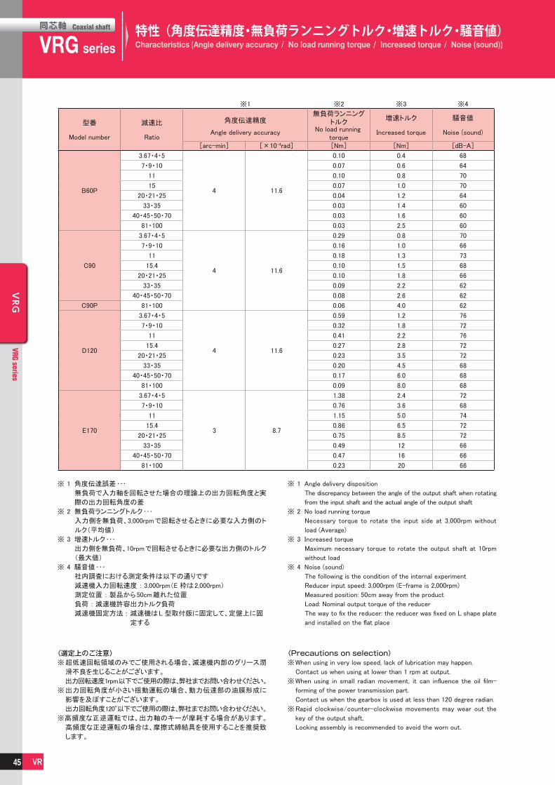
同芯軸
VRGCoaxial shaft
series VRG series
同芯軸 Coaxial shaft
VRG
VRG series
VR
VRG
VRG series
VR
型番 減速比 角度伝達精度
※1
無負荷ランニングトルク
※2
増速トルク
※3
騒音値
Model number RatioAngle delivery accuracy No load running
torqueIncreased torque Noise (sound)
※4
[arc-min] [×10-4rad] [Nm] [Nm] [dB-A]
B60P
3.67・4・5
4 11.6
0.10 0.4 68
7・9・10 0.07 0.6 64
11 0.10 0.8 70
15 0.07 1.0 70
20・21・25 0.04 1.2 64
33・35 0.03 1.4 60
40・45・50・70 0.03 1.6 60
81・100 0.03 2.5 60
C90
C90P
3.67・4・5
4 11.6
0.29 0.8 70
7・9・10 0.16 1.0 66
11 0.18 1.3 73
15.4 0.10 1.5 68
20・21・25 0.10 1.8 66
33・35 0.09 2.2 62
40・45・50・70 0.08 2.6 62
81・100 0.06 4.0 62
D120
3.67・4・5
4 11.6
0.59 1.2 76
7・9・10 0.32 1.8 72
11 0.41 2.2 76
15.4 0.27 2.8 72
20・21・25 0.23 3.5 72
33・35 0.20 4.5 68
40・45・50・70 0.17 6.0 68
81・100 0.09 8.0 68
E170
3.67・4・5
3 8.7
1.38 2.4 72
7・9・10 0.76 3.6 68
11 1.15 5.0 74
15.4 0.86 6.5 72
20・21・25 0.75 8.5 72
33・35 0.49 12 66
40・45・50・70 0.47 16 66
81・100 0.23 20 66
特性(角度伝達精度・無負荷ランニングトルク・増速トルク・騒音値)Characteristics (Angle delivery accuracy / No load running torque / Increased torque / Noise (sound))
※ 1 角度伝達誤差・・・
無負荷で入力軸を回転させた場合の理論上の出力回転角度と実
際の出力回転角度の差
※ 2 無負荷ランニングトルク・・・
入力側を無負荷、3,000rpmで回転させるときに必要な入力側のト
ルク(平均値)
※ 3 増速トルク・・・
出力側を無負荷、10rpmで回転させるときに必要な出力側のトルク
(最大値)
※ 4 騒音値・・・
社内調査における測定条件は以下の通りです
減速機入力回転速度 : 3,000rpm(E 枠は2,000rpm)
測定位置 : 製品から50cm離れた位置
負荷 : 減速機許容出力トルク負荷
減速機固定方法 : 減速機はL 型取付版に固定して、定盤上に固
定する
※ 1 Angle delivery disposition
The discrepancy between the angle of the output shaft when rotating
from the input shaft and the actual angle of the output shaft
※ 2 No load running torque
Necessary torque to rotate the input side at 3,000rpm without
load (Average)
※ 3 Increased torque
Maximum necessary torque to rotate the output shaft at 10rpm
without load
※ 4 Noise (sound)
The following is the condition of the internal experiment
Reducer input speed: 3,000rpm (E-frame is 2,000rpm)
Measured position: 50cm away from the product
Load: Nominal output torque of the reducer
The way to fix the reducer: the reducer was fixed on L shape plate
and installed on the flat place
〈選定上のご注意〉※ 超低速回転領域のみでご使用される場合、減速機内部のグリース潤
滑不良を生じることがございます。
出力回転速度1rpm以下でご使用の際は、弊社までお問い合わせください。
※ 出力回転角度が小さい揺動運転の場合、動力伝達部の油膜形成に
影響を及ぼすことがございます。
出力回転角度120°以下でご使用の際は、弊社までお問い合わせください。
※高頻度な正逆運転では、出力軸のキーが摩耗する場合があります。
高頻度な正逆運転の場合は、摩擦式締結具を使用することを推奨致
します。
〈Precautions on selection〉※When using in very low speed, lack of lubrication may happen.
Contact us when using at lower than 1 rpm at output.
※When using in small radian movement, it can influence the oil film-
forming of the power transmission part.
Contact us when the gearbox is used at less than 120 degree radian.
※Rapid clockwise/counter-clockwise movements may wear out the
key of the output shaft.
Locking assembly is recommended to avoid the worn out.
45

同芯軸
VRGCoaxial shaft
series VRG series
同芯軸 Coaxial shaft
VRG
VRG series
VR
VRG
VRG series
VR
Input speed:3,000rpm
VRG□-3.67・4・5B60P-□
0102030405060708090
100
0.0 0.5 1.0 1.5 2.0
VRG□-7・9・10B60P-□
0102030405060708090
100
0.0 0.5 1.0 1.5
VRG□-11B60P-□
0102030405060708090
100
0102030405060708090
100
0.0 0.2 0.4 0.6 0.8 1.0 1.2
VRG□-15・20B60P-□
0102030405060708090
100
0.0 0.2 0.4 0.6 0.8 1.0
VRG□-21・25・33・35B60P-□
0.0 0.2 0.4 0.6 0.8
0102030405060708090
100
VRG□-40・45・50・70・81・100B60P-□
0.0 0.1 0.2 0.3 0.4 0.5
Eff
icie
ncy
Eff
icie
ncy
Eff
icie
ncy
Eff
icie
ncy
Eff
icie
ncy
Eff
icie
ncy
Input torque
Input torque
Input torque Input torque
Input torque
Input torque
※Ambient temperature・・・25℃
・入力回転速度:3,000rpmの時
効率
[%]
効率
[%]
効率
[%]
効率
[%]
効率
[%]
効率
[%]
入力トルク [Nm]
入力トルク [Nm]
入力トルク [Nm] 入力トルク [Nm]
入力トルク [Nm]
入力トルク [Nm]
VRG□-B60P
※周囲温度・・・25℃
効率特性Efficiency
46

同芯軸
VRGCoaxial shaft
series VRG series
同芯軸 Coaxial shaft
VRG
VRG series
VR
VRG
VRG series
VR
Input speed:3,000rpm
Input torque Input torque
Input torqueInput torque
Input torque Input torque
Eff
icie
ncy
VRG□-3.67・4・5C90-□
0102030405060708090
100
0.0 2.0 4.0 6.0 8.0
VRG□-7・9・10C90-□
0102030405060708090
100
0.0 1.0 2.0 3.0 4.0 5.0
VRG□-11C90-□
0102030405060708090
100
0.0 0.5 1.0 1.5 2.0 2.5 3.0
VRG□-15.4・20・21・25・35C90-□
0102030405060708090
100
0.0 0.5 1.0 1.5 2.0 2.5 3.0
VRG□-33・40・45・50・70C90-□
0102030405060708090
100
0.0 0.5 1.0 1.5 2.0
VRG□-81・100C90P-□
0102030405060708090
100
0.0 0.2 0.4 0.6 0.8
Eff
icie
ncy
Eff
icie
ncy
Eff
icie
ncy
Eff
icie
ncy
Eff
icie
ncy
※Ambient temperature・・・25℃
入力トルク [Nm]
効率
[%]
効率
[%]
効率
[%]
効率
[%]
効率
[%]
効率
[%]
・入力回転速度:3,000rpmの時
入力トルク [Nm]
入力トルク [Nm]入力トルク [Nm]
入力トルク [Nm] 入力トルク [Nm]
VRG□-C90(P)
※周囲温度・・・25℃
効率特性Efficiency
47

同芯軸
VRGCoaxial shaft
series VRG series
同芯軸 Coaxial shaft
VRG
VRG series
VR
VRG
VRG series
VR
Input speed:3,000rpm
VRG□-3.67・4・5D120-□
0102030405060708090
100
0 5 10 15 20 25
VRG□-7・9・10D120-□
0102030405060708090
100
0 5 10 15
VRG□-11D120-□
0102030405060708090
100
0 2 4 6 8
VRG□-15.4・20・21・25・35D120-□
0102030405060708090
100
0 2 4 6 8 10
VRG□-33・40・45・50・70D120-□
0 1 2 3 4 5
VRG□-81・100D120-□
0.0 0.5 1.0 1.5 2.00
102030405060708090
100
0102030405060708090
100
Eff
icie
ncy
Eff
icie
ncy
Eff
icie
ncy
Eff
icie
ncy
Eff
icie
ncy
Eff
icie
ncy
Input torque Input torque
Input torqueInput torque
Input torque Input torque
※Ambient temperature・・・25℃
・入力回転速度:3,000rpmの時
効率
[%]
効率
[%]
効率
[%]
効率
[%]
効率
[%]
効率
[%]
入力トルク [Nm] 入力トルク [Nm]
入力トルク [Nm]入力トルク [Nm]
入力トルク [Nm] 入力トルク [Nm]
VRG□-D120
※周囲温度・・・25℃
効率特性Efficiency
48

同芯軸
VRGCoaxial shaft
series VRG series
同芯軸 Coaxial shaft
VRG
VRG series
VR
VRG
VRG series
VR
Input speed:3,000rpm
VRG□-3.67・4・5E170-□
01020304050
60708090
100
0 10 20 30 40 50
VRG□-7・9・10E170-□
01020304050
60708090
100
0 5 10 15 20 25 30
VRG□-11E170-□
01020304050
60708090
100
0 5 10 15 20
VRG□-15.4・20・21・25・35E170-□
01020304050
60708090
100
01020304050
60708090
100
0 5 10 15 20
VRG□-33・40・45・50・70E170-□
0 2 4 6 8 10 12
VRG□-81・100E170-□
0 1 2 3 40
1020304050
60708090
100
Effic
iency
Eff
icie
ncy
Eff
icie
ncy
Effic
iency
Eff
icie
ncy
Eff
icie
ncy
Input torque Input torque
Input torqueInput torque
Input torque Input torque
For dimensional precision of mechanical mounting of extended shaft output type (VRGS) and flange output type (VRGF), see the following:
(Unit : mm)
Extended shaft output type Flange output type
※Ambient temperature・・・25℃
・入力回転速度:3,000rpmの時
効率
[%]
効率
[%]
効率
[%]
効率
[%]
効率
[%]
効率
[%]
入力トルク [Nm] 入力トルク [Nm]
入力トルク [Nm]入力トルク [Nm]
入力トルク [Nm] 入力トルク [Nm]
VRG□-E170
延長軸出力型(VRGS)及びフランジ出力型(VRGF)の機械取付寸法精度は以下を参照してください。
(単位:mm)
AA
B B
0.04
B
B
A
0.06
0.05
0.04
B
B
A
A
0.06
0.05
0.04
◆フランジ出力型(VRGF)◆延長軸出力型(VRGS)
※周囲温度・・・25℃
効率特性Efficiency
49

同芯軸
VRGCoaxial shaft
series VRG series
同芯軸 Coaxial shaft
VRG
VRG series
VR
VRG
VRG series
VR
1st stage reduction section Motor ∼ Input gear ∼ Planetary gear A ∼ Carrier
2nd stage reduction section Carrier ∼ Sun gear ∼ Planetary gear B ∼ Output flange
モータ~入力ギヤ~遊星ギヤA~キャリア
キャリア~太陽ギヤ~遊星ギヤB~出力フランジ
1段目減速部
2段目減速部
Rotation from the motor is transmitted from the input gear mounted to the Input
shaft. The input gear engages planetary gear A, which in turn engages internal gear
A to produce an orbital motion to the planetary gears A. This rotates the 2nd
stage carrier.
The direction of rotation at
the output is the same as
the direction of rotation at
the input.
回転方向は入力回転と
同じ方向になります。
回転方向は入力回転と
同じ方向になります。
Rotation from the carrier is transmitted to the sun gear at the output flange of
the carrier. The input gear engages planetary gear B, which engages the internal
gear to produce an orbital motion to planetary gears B.
キャリアの回転は、キャリアに取付けられている太陽ギヤに伝えられ、インタナルギヤBと噛合状態にある遊星ギヤBと噛合うことにより、遊星ギヤBに公転運動を与えます。その公転運動により出力フランジが回転します。
モータからの回転は入力軸に取付けられている入力ギヤに伝えられ、入力ギヤは、インタナルギヤAと噛合状態にある遊星ギヤAと噛合うことにより、遊星ギヤAに公転運動を与え、キャリアを介して2段目の太陽ギヤが回転します。
The direction of rotation at
the output is the same as
the direction of rotation at
the input.
The explanation above describes how a double reduction (2 stage) reducer works.
For explanation of how a single reduction (1 stage) reducer works, refer to the 2nd stage reduction section above.
上記は2段型減速機での説明です。
1段型減速機の場合は、2段目減速部のみの作動原理となります。
Internal gear B
Planetary gear A
Internal gear A
Carrier
Output flange
Sun gear Input Gear Input shaft
Cross roller bearing
Planetary gear B
作動原理Operating principle
50
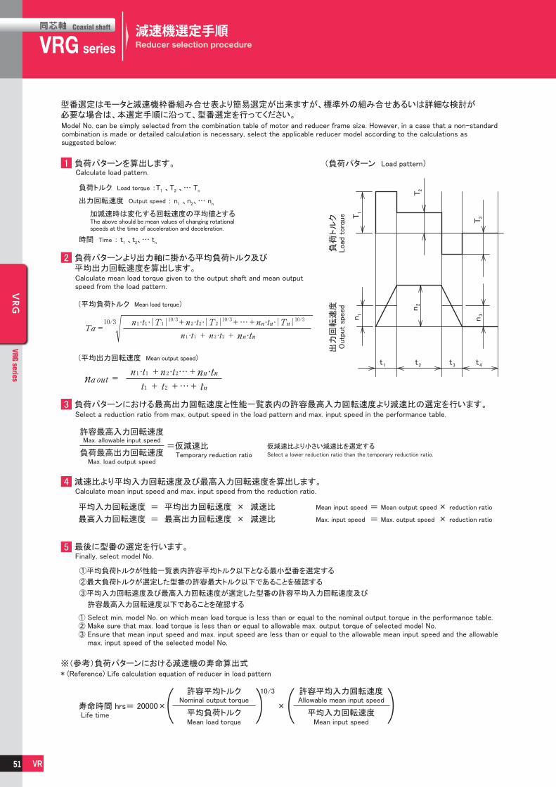
同芯軸
VRGCoaxial shaft
series VRG series
同芯軸 Coaxial shaft
VRG
VRG series
VR
VRG
VRG series
VR
型番選定はモータと減速機枠番組み合せ表より簡易選定が出来ますが、標準外の組み合せあるいは詳細な検討が必要な場合は、本選定手順に沿って、型番選定を行ってください。
1
2
3
4
5
負荷パターンを算出します。
負荷トルク Load torque :T1 、T2 、… Tn
出力回転速度 Output speed : n1 、n2、… nn
加減速時は変化する回転速度の平均値とする
時間 Time : t1 、t2、… tn
負荷パターンより出力軸に掛かる平均負荷トルク及び平均出力回転速度を算出します。
(平均負荷トルク Mean load torque)
(平均出力回転速度 Mean output speed)
負荷パターンにおける最高出力回転速度と性能一覧表内の許容最高入力回転速度より減速比の選定を行います。
仮減速比より小さい減速比を選定する
減速比より平均入力回転速度及び最高入力回転速度を算出します。
平均入力回転速度 = 平均出力回転速度 × 減速比
最高入力回転速度 = 最高出力回転速度 × 減速比
Mean input speed = Mean output speed × reduction ratio
Max. input speed = Max. output speed × reduction ratio
最後に型番の選定を行います。
①平均負荷トルクが性能一覧表内許容平均トルク以下となる最小型番を選定する
②最大負荷トルクが選定した型番の許容最大トルク以下であることを確認する
③平均入力回転速度及び最高入力回転速度が選定した型番の許容平均入力回転速度及び
許容最高入力回転速度以下であることを確認する
※(参考)負荷パターンにおける減速機の寿命算出式
許容最高入力回転速度
負荷最高出力回転速度=仮減速比
寿命時間 hrs= 20000× ×
10/3 許容平均トルク
平均負荷トルク
許容平均入力回転速度
平均入力回転速度
T1
T2
n1
n2
T3
n3
t1 t2 t3 t4
(負荷パターン Load pattern)
負荷
トル
ク出
力回
転速
度
Model No. can be simply selected from the combination table of motor and reducer frame size. However, in a case that a non-standard combination is made or detailed calculation is necessary, select the applicable reducer model according to the calculations as suggested below:
Calculate mean load torque given to the output shaft and mean output speed from the load pattern.
Load
torq
ue
Outp
ut
speed
Select a reduction ratio from max. output speed in the load pattern and max. input speed in the performance table.
Max. allowable input speed
Max. load output speedTemporary reduction ratio Select a lower reduction ratio than the temporary reduction ratio.
Calculate mean input speed and max. input speed from the reduction ratio.
① Select min. model No. on which mean load torque is less than or equal to the nominal output torque in the performance table.② Make sure that max. load torque is less than or equal to allowable max. output torque of selected model No.③ Ensure that mean input speed and max. input speed are less than or equal to the allowable mean input speed and the allowable
max. input speed of the selected model No.
Life time
Nominal output torque
Mean load torque
Allowable mean input speed
Mean input speed
Finally, select model No.
* (Reference) Life calculation equation of reducer in load pattern
Calculate load pattern.
The above should be mean values of changing rotational speeds at the time of acceleration and deceleration.
減速機選定手順Reducer selection procedure
51

同芯軸
VRGCoaxial shaft
series VRG series
同芯軸 Coaxial shaft
VRG
VRG series
VR
VRG
VRG series
VR
型番選定はモータと減速機枠番組み合せ表より簡易選定が出来ますが、標準外の組み合せあるいは詳細な検討が必要な場合は、本選定手順に沿って、型番選定を行ってください。
1
2
3
4
5
負荷パターンを算出します。
負荷トルク Load torque :T1 、T2 、… Tn
出力回転速度 Output speed : n1 、n2、… nn
加減速時は変化する回転速度の平均値とする
時間 Time : t1 、t2、… tn
負荷パターンより出力軸に掛かる平均負荷トルク及び平均出力回転速度を算出します。
(平均負荷トルク Mean load torque)
(平均出力回転速度 Mean output speed)
負荷パターンにおける最高出力回転速度と性能一覧表内の許容最高入力回転速度より減速比の選定を行います。
仮減速比より小さい減速比を選定する
減速比より平均入力回転速度及び最高入力回転速度を算出します。
平均入力回転速度 = 平均出力回転速度 × 減速比
最高入力回転速度 = 最高出力回転速度 × 減速比
Mean input speed = Mean output speed × reduction ratio
Max. input speed = Max. output speed × reduction ratio
最後に型番の選定を行います。
①平均負荷トルクが性能一覧表内許容平均トルク以下となる最小型番を選定する
②最大負荷トルクが選定した型番の許容最大トルク以下であることを確認する
③平均入力回転速度及び最高入力回転速度が選定した型番の許容平均入力回転速度及び
許容最高入力回転速度以下であることを確認する
※(参考)負荷パターンにおける減速機の寿命算出式
許容最高入力回転速度
負荷最高出力回転速度=仮減速比
寿命時間 hrs= 20000× ×
10/3 許容平均トルク
平均負荷トルク
許容平均入力回転速度
平均入力回転速度
T1
T2
n1
n2
T3
n3
t1 t2 t3 t4
(負荷パターン Load pattern)
負荷
トル
ク出
力回
転速
度
Model No. can be simply selected from the combination table of motor and reducer frame size. However, in a case that a non-standard combination is made or detailed calculation is necessary, select the applicable reducer model according to the calculations as suggested below:
Calculate mean load torque given to the output shaft and mean output speed from the load pattern.
Load
torq
ue
Outp
ut
speed
Select a reduction ratio from max. output speed in the load pattern and max. input speed in the performance table.
Max. allowable input speed
Max. load output speedTemporary reduction ratio Select a lower reduction ratio than the temporary reduction ratio.
Calculate mean input speed and max. input speed from the reduction ratio.
① Select min. model No. on which mean load torque is less than or equal to the nominal output torque in the performance table.② Make sure that max. load torque is less than or equal to allowable max. output torque of selected model No.③ Ensure that mean input speed and max. input speed are less than or equal to the allowable mean input speed and the allowable
max. input speed of the selected model No.
Life time
Nominal output torque
Mean load torque
Allowable mean input speed
Mean input speed
Finally, select model No.
* (Reference) Life calculation equation of reducer in load pattern
Calculate load pattern.
The above should be mean values of changing rotational speeds at the time of acceleration and deceleration.
If external load (radial load & thrust load) is applied, the main bearing life shall be calculated according to the following procedure:
2 軸受寿命時間の確認Checkup of bearing life time
Make sure that max. load moment by the acted external load is within the allowable moment.
Calculate equivalent radial load form the acted external load, and then make sure that bearing life time satisfies the required time.[Calculate external load pattern, mean external load, mean output number of rotation, and mean load moment.]
Note) The moment is added and subtracted based on the load direction.
Note) The moment is added and subtracted based on the load direction.
1 最大負荷モーメントの確認Checkup of max. load moment
Following the conditional equations: Radial load factor Thrust load factor
*Max. thrust load must not exceed max. allowable load in the following table.
外部荷重(ラジアル荷重・スラスト荷重)が作用した場合、以下の手順に沿って、主軸受の寿命を算出します。
作用する外部荷重よりの最大負荷モーメントが許容モーメント以内にあるか確認します。
[最大負荷モーメント(Mmax)を算出します。 Calculate max. load moment (Mmax).]
[許容モーメントMal以下であることを確認します。 Ensure that it is within the allowable moment (Mal).]
※最大スラスト荷重は下表の許容量大荷重を超えないこと。
枠番 寸法Mal
(Nm)
B 11 38
C 11.5 138
D 13.5 360
E 22 1037
枠番 許容最大スラスト荷重
B 927
C 2650
D 3740
E 10800
作用する外部荷重より等価ラジアル荷重を算出し、軸受寿命時間が要求時間を満足するか確認します。[外部荷重パターン平均外部荷重、平均出力回転速度及び平均負荷モーメントを算出します。]
(平均ラジアル荷重 Mean radial load)
(平均スラスト荷重 Mean thrust load)
(平均出力回転速度 Mean output number of rotation) (平均負荷モーメント Mean load moment)
[荷重係数を算出します。Calculate load factor.]
条件式より
[動等価ラジアル荷重を算出します。 Calculate dynamic equivalent radial load.]
[出力部軸受の寿命時間を算出します。Calculate the life time of bearing in output part.]
ラジアル荷重係数 スラスト荷重係数 軸受仕様 Bearing spec.
枠番 基本動定格荷重
C(N)
コロPCD Dm
(mm)
B 4370 39
C 8420 63
D 14700 85
E 29200 121
衝撃係数 fw Impact factor fw
With no impact
With slight impact
With vibration impact
衝撃の程度 Degree of impact fw
衝撃を伴わない場合 1.0
多少の衝撃を伴う場合 1.2
振動衝撃を伴う場合 1.5
Ft
Lt
Lr S
Dm
Fr
Fr 1
Fr 1
Fr 2
Fr 3
Ft 2
n1 n
2
Ft 3
n3
t1 t2 t3 t4
(荷重パターン Load pattern)
出力フランジ面Output flange surface
Frame size
Frame sizeBasic dynamic rated load Roller PCD Dm
DimensionsFrame size
Allowable max. thrust load S(mm) (N)
主軸受寿命Main bearing life
52

同芯軸
VRGCoaxial shaft
series VRG series
同芯軸 Coaxial shaft
VRG
VRG series
VR
VRG
VRG series
VR
MEMO
53

For servo motor ABLE REDUCER
VRSSeriesVRTSeries
サーボモータ専用

同芯軸
VRSCoaxial shaft
series VRS series
同芯軸 Coaxial shaft
VRS
VRS series
VR
VRS
VRS series
VR
特徴Features
VRS series
高精度 High precisionバックラッシは3分以下、精密な位置決めに威力を発揮
Standard backlash is 3 arc-min, ideal for precision control.
高剛性・高トルク High rigidity & torque総ころ形軸受を採用し、剛性 ・ トルクを大幅にアップ High rigidity & high torque were achived by uncaged
needle roller bearings.
高荷重容量 High load capacity主軸受にテーパローラベアリングを採用し、高荷重容量を実現
Adopting taper roller bearing for the main output shaftto increase radial and axial load.
アダプタ・ブッシング方式 Adapter-bushing connection世界中のモータに取付可能 Can be attached to any motor all over the world.
グリース漏れ無し No grease leakage高粘度で分離しにくいグリースを採用し、万全の漏油対策を実施
Perfect solution using high viscosity anti-separation grease.
メンテナンスフリー Maintenance-free製品寿命内はグリース交換不要取付姿勢も自由自在
No need to replace the grease for the life of the unit.Can be attached in any position.
55

VRS series
エイブル減速機の呼称Model name for ABLE reducer
シリーズ名Series name
VRSシリーズVRS Series
サイズFrame size
バージョンVersion
減速比Ratio
出力方式Output style
バックラッシBacklash
マウントコード(※1)Mount code(※1)
3分3arc-min
出力軸キー付きShaft with key
S・・・
K・・・
3・・・
出力軸キー無しSmooth shaft
1段Single
2段Double
060、075、100、140、180、210、240
: 3、4、5、6、7、8、9、10
: 15、16、20、25、28、30、35、4045、50、60、70、80、90、100
C
C
同芯軸
VRSCoaxial shaft
series VRS series
同芯軸 Coaxial shaft
VRS
VRS series
VR
VRS
VRS series
VR
機種・型式記号Model number
※1 マウントコード ※1 Mount code
マウントコードは取付けモータによって決まります。 Mount code varies depending on the motor.
ホームページ上の選定ツールにて確認できます。 Please refer to reducer selection tool or contact us
不明な場合はお問い合わせください。 for more information.
〔モータとの締付け方式について〕・ モータ軸は、キー溝なし ストレート軸での取付けと
なります。・ モータ軸がキー溝付の場合は、キーを取外して取付
けください。・ モータ軸がDカットの場合はお問い合わせください。
〔Mounting style to the motor〕・ Motor output shaft is the smooth shaft without
keyway.・ If the motor output shaft is with the keyway,
remove the key from the shaft.・ If the motor output shaft has D shape cut, contact us.
56

同芯軸
VRSCoaxial shaft
series VRS series
同芯軸 Coaxial shaft
VRS
VRS series
VR
VRS
VRS series
VR
性能一覧Performance table
サイズ
060C
VRS-060C
Framesize
段数
1段
2段
Single
Double
060C
1段
2段
Single
Double
Stage
減速比許容平均トルク
許容最大ラジアル荷重
許容平均入力回転速度
許容最高入力回転速度
許容ラジアル荷重
許容スラスト荷重Permittedaxial load
Permittedradial load
Maximuminput speed
Nominalinput speed
許容最大トルク
非常時最大トルク
Emergencystop torque
Maximumoutput torque
Nominaloutput torque
Maximumradial load
許容最大スラスト荷重
Maximumaxial load
慣性モーメントMomentof inertia
慣性モーメントMomentof inertia
慣性モーメント※11 ※11 ※11
Momentof inertia
質量
Mass
Ratio
サイズ
Framesize
段数
Stage
減速比
Ratio
0.150.100.0800.0700.0640.0600.0580.0560.0640.0700.0620.0620.0680.0520.0610.0510.0610.0510.0510.0510.0510.0510.051
0.260.210.190.180.180.170.170.170.180.180.170.170.180.160.170.160.170.160.160.160.160.160.16
0.540.490.470.460.450.450.450.44---------------
※ 1 許容平均入力回転速度の時、寿命20,000時間となる値※ 2 起動 ・ 停止時に許容する最大値※ 3 衝撃等が作用した時に許容する最大値(頻度は1,000回まで) ※ 4 運転中の平均入力回転速度の許容最大値※ 5 連続運転ではない条件下での許容最高入力回転速度※ 6 許容平均入力回転速度の時、寿命20,000時間となる値
(軸中央に作用、スラスト荷重が0のとき)※ 7 許容平均入力回転速度の時、寿命20,000時間となる値
(軸芯に作用、ラジアル荷重が0のとき)※ 8 ラジアル荷重の許容最大値※ 9 スラスト荷重の許容最大値※10 減速比及び入力軸寸法により若干異なります※11 減速機(単体)入力軸換算の値を示します
※ 1 With nominal input speed, service life is 20,000 hours.※ 2 The maximum torque when starting and stopping.※ 3 The maximum torque when it receives shock. (up to 1,000 times)※ 4 The maximum average input speed.※ 5 The maximum momentary input speed.※ 6 With this load and nominal input speed, service life will be 20,000 hours.
(Applied to the output shaft center, at axial load 0)※ 7 With this load and nominal input speed, service life will be 20,000 hours.
(Applied to the output side bearing, at radial load 0)※ 8 The maximum radial load the reducer can accept.※ 9 The maximum axial load the reducer can accept.※10 The mass may vary slightly model to model.※11 The moment of inertia indicates the input shaft converted value of the
reducer only.
57

同芯軸
VRSCoaxial shaft
series VRS series
同芯軸 Coaxial shaft
VRS
VRS series
VR
VRS
VRS series
VR
サイズ
075C
Framesize
段数
1段
2段
Single
Double
075C
1段
2段
Single
Double
Stage
減速比許容平均トルク
許容最大ラジアル荷重
許容平均入力回転速度
許容最高入力回転速度
許容ラジアル荷重
許容スラスト荷重Permittedaxial load
Permittedradial load
Maximuminput speed
Nominalinput speed
許容最大トルク
非常時最大トルク
Emergencystop torque
Maximumoutput torque
Nominaloutput torque
Maximumradial load
許容最大スラスト荷重
Maximumaxial load
慣性モーメントMomentof inertia
慣性モーメントMomentof inertia
慣性モーメントMomentof inertia
慣性モーメント※11 ※11 ※11 ※11
Momentof inertia
質量
Mass
Ratio
サイズ
Framesize
段数
Stage
減速比
Ratio
VRS-075C
--------
0.200.250.190.190.240.120.180.110.180.110.110.110.110.110.11
0.680.480.390.340.320.310.300.290.360.410.350.350.400.280.340.270.340.270.270.270.270.270.27
1.10.870.790.740.720.710.700.690.750.790.740.730.780.670.730.670.730.670.670.670.670.670.67
2.92.62.62.52.52.52.52.4---------------
性能一覧Performance table
※ 1 許容平均入力回転速度の時、寿命20,000時間となる値※ 2 起動 ・ 停止時に許容する最大値※ 3 衝撃等が作用した時に許容する最大値(頻度は1,000回まで) ※ 4 運転中の平均入力回転速度の許容最大値※ 5 連続運転ではない条件下での許容最高入力回転速度※ 6 許容平均入力回転速度の時、寿命20,000時間となる値
(軸中央に作用、スラスト荷重が0のとき)※ 7 許容平均入力回転速度の時、寿命20,000時間となる値
(軸芯に作用、ラジアル荷重が0のとき)※ 8 ラジアル荷重の許容最大値※ 9 スラスト荷重の許容最大値※10 減速比及び入力軸寸法により若干異なります※11 減速機(単体)入力軸換算の値を示します
※ 1 With nominal input speed, service life is 20,000 hours.※ 2 The maximum torque when starting and stopping.※ 3 The maximum torque when it receives shock. (up to 1,000 times)※ 4 The maximum average input speed.※ 5 The maximum momentary input speed.※ 6 With this load and nominal input speed, service life will be 20,000 hours.
(Applied to the output shaft center, at axial load 0)※ 7 With this load and nominal input speed, service life will be 20,000 hours.
(Applied to the output side bearing, at radial load 0)※ 8 The maximum radial load the reducer can accept.※ 9 The maximum axial load the reducer can accept.※10 The mass may vary slightly model to model.※11 The moment of inertia indicates the input shaft converted value of the
reducer only.58

同芯軸
VRSCoaxial shaft
series VRS series
同芯軸 Coaxial shaft
VRS
VRS series
VR
VRS
VRS series
VR
VRS-100Cサイズ
100C
Framesize
段数
1段
2段
Single
Double
100C
1段
2段
Single
Double
Stage
減速比許容平均トルク
許容最大ラジアル荷重
許容平均入力回転速度
許容最高入力回転速度
許容ラジアル荷重
許容スラスト荷重Permittedaxial load
Permittedradial load
Maximuminput speed
Nominalinput speed
許容最大トルク
非常時最大トルク
Emergencystop torque
Maximumoutput torque
Nominaloutput torque
Maximumradial load
許容最大スラスト荷重
Maximumaxial load
慣性モーメントMomentof inertia
慣性モーメントMomentof inertia
慣性モーメントMomentof inertia
慣性モーメント※11 ※11 ※11 ※11
Momentof inertia
質量
Mass
Ratio
サイズ
Framesize
段数
Stage
減速比
Ratio
--------
0.760.970.720.700.920.380.680.370.680.360.360.360.360.360.36
3.11.91.41.11.00.90.850.821.11.41.11.11.30.781.10.771.10.760.760.760.760.760.76
5.03.73.12.82.72.62.62.52.93.12.82.83.02.52.82.52.82.52.52.52.52.52.5
12109.59.29.18.98.98.8---------------
性能一覧Performance table
※ 1 許容平均入力回転速度の時、寿命20,000時間となる値※ 2 起動 ・ 停止時に許容する最大値※ 3 衝撃等が作用した時に許容する最大値(頻度は1,000回まで)※ 4 運転中の平均入力回転速度の許容最大値※ 5 連続運転ではない条件下での許容最高入力回転速度※ 6 許容平均入力回転速度の時、寿命20,000時間となる値
(軸中央に作用、スラスト荷重が0のとき)※ 7 許容平均入力回転速度の時、寿命20,000時間となる値
(軸芯に作用、ラジアル荷重が0のとき)※ 8 ラジアル荷重の許容最大値※ 9 スラスト荷重の許容最大値※10 減速比及び入力軸寸法により若干異なります※11 減速機(単体)入力軸換算の値を示します
※ 1 With nominal input speed, service life is 20,000 hours.※ 2 The maximum torque when starting and stopping.※ 3 The maximum torque when it receives shock. (up to 1,000 times)※ 4 The maximum average input speed.※ 5 The maximum momentary input speed.※ 6 With this load and nominal input speed, service life will be 20,000 hours.
(Applied to the output shaft center, at axial load 0)※ 7 With this load and nominal input speed, service life will be 20,000 hours.
(Applied to the output side bearing, at radial load 0)※ 8 The maximum radial load the reducer can accept.※ 9 The maximum axial load the reducer can accept.※10 The mass may vary slightly model to model.※11 The moment of inertia indicates the input shaft converted value of the
reducer only.
59

同芯軸
VRSCoaxial shaft
series VRS series
同芯軸 Coaxial shaft
VRS
VRS series
VR
VRS
VRS series
VR
VRS-140Cサイズ
140C
Framesize
段数
1段
2段
Single
Double
140C
1段
2段
Single
Double
Stage
減速比許容平均トルク
許容最大ラジアル荷重
許容平均入力回転速度
許容最高入力回転速度
許容ラジアル荷重
許容スラスト荷重Permittedaxial load
Permittedradial load
Maximuminput speed
Nominalinput speed
許容最大トルク
非常時最大トルク
Emergencystop torque
Maximumoutput torque
Nominaloutput torque
Maximumradial load
許容最大スラスト荷重
Maximumaxial load
慣性モーメントMomentof inertia
慣性モーメントMomentof inertia
慣性モーメントMomentof inertia
慣性モーメント※11 ※11 ※11 ※11
Momentof inertia
質量
Mass
Ratio
サイズ
Framesize
段数
Stage
減速比
Ratio
--------
2.63.52.42.43.31.12.31.12.31.11.11.11.11.11.1
127.25.24.33.83.53.33.24.45.34.24.15.12.94.12.84.02.82.82.82.82.82.8
18141211109.99.79.611121010119.2109.1109.19.19.19.19.19.1
3529272625252525---------------
性能一覧Performance table
※ 1 許容平均入力回転速度の時、寿命20,000時間となる値※ 2 起動 ・ 停止時に許容する最大値※ 3 衝撃等が作用した時に許容する最大値(頻度は1,000回まで) ※ 4 運転中の平均入力回転速度の許容最大値※ 5 連続運転ではない条件下での許容最高入力回転速度※ 6 許容平均入力回転速度の時、寿命20,000時間となる値
(軸中央に作用、スラスト荷重が0のとき)※ 7 許容平均入力回転速度の時、寿命20,000時間となる値
(軸芯に作用、ラジアル荷重が0のとき)※ 8 ラジアル荷重の許容最大値※ 9 スラスト荷重の許容最大値※10 減速比及び入力軸寸法により若干異なります※11 減速機(単体)入力軸換算の値を示します
※ 1 With nominal input speed, service life is 20,000 hours.※ 2 The maximum torque when starting and stopping.※ 3 The maximum torque when it receives shock. (up to 1,000 times)※ 4 The maximum average input speed.※ 5 The maximum momentary input speed.※ 6 With this load and nominal input speed, service life will be 20,000 hours.
(Applied to the output shaft center, at axial load 0)※ 7 With this load and nominal input speed, service life will be 20,000 hours.
(Applied to the output side bearing, at radial load 0)※ 8 The maximum radial load the reducer can accept.※ 9 The maximum axial load the reducer can accept.※10 The mass may vary slightly model to model.※11 The moment of inertia indicates the input shaft converted value of the
reducer only.60

同芯軸
VRSCoaxial shaft
series VRS series
同芯軸 Coaxial shaft
VRS
VRS series
VR
VRS
VRS series
VR
サイズ
180C
Framesize
段数
1段
2段
Single
Double
180C
1段
2段
Single
Double
Stage
減速比許容平均トルク
許容最大ラジアル荷重
許容平均入力回転速度
許容最高入力回転速度
許容ラジアル荷重
許容スラスト荷重Permittedaxial load
Permittedradial load
Maximuminput speed
Nominalinput speed
許容最大トルク
非常時最大トルク
Emergencystop torque
Maximumoutput torque
Nominaloutput torque
Maximumradial load
許容最大スラスト荷重
Maximumaxial load
慣性モーメントMomentof inertia
慣性モーメントMomentof inertia
慣性モーメントMomentof inertia
慣性モーメント※11 ※11 ※11 ※11
Momentof inertia
質量
Mass
Ratio
サイズ
Framesize
段数
Stage
減速比
Ratio
VRS-180C
--------
8.7118.17.8114.07.63.97.63.83.83.83.73.73.7
4125181513121211151814141710141014101010101010
5540333029272726303229293225292529252525252525
11084787473717170---------------
※ 1 許容平均入力回転速度の時、寿命20,000時間となる値※ 2 起動 ・ 停止時に許容する最大値※ 3 衝撃等が作用した時に許容する最大値(頻度は1,000回まで)※ 4 運転中の平均入力回転速度の許容最大値※ 5 連続運転ではない条件下での許容最高入力回転速度※ 6 許容平均入力回転速度の時、寿命20,000時間となる値
(軸中央に作用、スラスト荷重が0のとき)※ 7 許容平均入力回転速度の時、寿命20,000時間となる値
(軸芯に作用、ラジアル荷重が0のとき)※ 8 ラジアル荷重の許容最大値※ 9 スラスト荷重の許容最大値※10 減速比及び入力軸寸法により若干異なります※11 減速機(単体)入力軸換算の値を示します
※ 1 With nominal input speed, service life is 20,000 hours.※ 2 The maximum torque when starting and stopping.※ 3 The maximum torque when it receives shock. (up to 1,000 times)※ 4 The maximum average input speed.※ 5 The maximum momentary input speed.※ 6 With this load and nominal input speed, service life will be 20,000 hours.
(Applied to the output shaft center, at axial load 0)※ 7 With this load and nominal input speed, service life will be 20,000 hours.
(Applied to the output side bearing, at radial load 0)※ 8 The maximum radial load the reducer can accept.※ 9 The maximum axial load the reducer can accept.※10 The mass may vary slightly model to model.※11 The moment of inertia indicates the input shaft converted value of the
reducer only.
性能一覧Performance table
61

同芯軸
VRSCoaxial shaft
series VRS series
同芯軸 Coaxial shaft
VRS
VRS series
VR
VRS
VRS series
VR
サイズ
210C
Framesize
段数
1段
2段
Single
Double
210C
1段
2段
Single
Double
Stage
減速比許容平均トルク
許容最大ラジアル荷重
許容平均入力回転速度
許容最高入力回転速度
許容ラジアル荷重
許容スラスト荷重Permittedaxial load
Permittedradial load
Maximuminput speed
Nominalinput speed
許容最大トルク
非常時最大トルク
Emergencystop torque
Maximumoutput torque
Nominaloutput torque
Maximumradial load
許容最大スラスト荷重
Maximumaxial load
慣性モーメントMomentof inertia
慣性モーメントMomentof inertia
慣性モーメント※11 ※11 ※11
Momentof inertia
質量
Mass
Ratio
サイズ
Framesize
段数
Stage
減速比
Ratio
VRS-210C
--------202419182312181218121111111111
11055423633312928343933333826322632262626262626
16099868077747372---------------
性能一覧Performance table
※ 1 許容平均入力回転速度の時、寿命20,000時間となる値※ 2 起動 ・ 停止時に許容する最大値※ 3 衝撃等が作用した時に許容する最大値(頻度は1,000回まで) ※ 4 運転中の平均入力回転速度の許容最大値※ 5 連続運転ではない条件下での許容最高入力回転速度※ 6 許容平均入力回転速度の時、寿命20,000時間となる値
(軸中央に作用、スラスト荷重が0のとき)※ 7 許容平均入力回転速度の時、寿命20,000時間となる値
(軸芯に作用、ラジアル荷重が0のとき)※ 8 ラジアル荷重の許容最大値※ 9 スラスト荷重の許容最大値※10 減速比及び入力軸寸法により若干異なります※11 減速機(単体)入力軸換算の値を示します
※ 1 With nominal input speed, service life is 20,000 hours.※ 2 The maximum torque when starting and stopping.※ 3 The maximum torque when it receives shock. (up to 1,000 times)※ 4 The maximum average input speed.※ 5 The maximum momentary input speed.※ 6 With this load and nominal input speed, service life will be 20,000 hours.
(Applied to the output shaft center, at axial load 0)※ 7 With this load and nominal input speed, service life will be 20,000 hours.
(Applied to the output side bearing, at radial load 0)※ 8 The maximum radial load the reducer can accept.※ 9 The maximum axial load the reducer can accept.※10 The mass may vary slightly model to model.※11 The moment of inertia indicates the input shaft converted value of the
reducer only.62

同芯軸
VRSCoaxial shaft
series VRS series
同芯軸 Coaxial shaft
VRS
VRS series
VR
VRS
VRS series
VR
サイズ
240C
Framesize
段数
1段
2段
Single
Double
240C
1段
2段
Single
Double
Stage
減速比許容平均トルク
許容最大ラジアル荷重
許容平均入力回転速度
許容最高入力回転速度
許容ラジアル荷重
許容スラスト荷重Permittedaxial load
Permittedradial load
Maximuminput speed
Nominalinput speed
許容最大トルク
非常時最大トルク
Emergencystop torque
Maximumoutput torque
Nominaloutput torque
Maximumradial load
許容最大スラスト荷重
Maximumaxial load
慣性モーメントMomentof inertia
慣性モーメント※11 ※11
Momentof inertia
質量
Mass
Ratio
サイズ
Framesize
段数
Stage
減速比
Ratio
VRS-240C
--------475545445232433143313131313131
2301301109286817877---------------
※ 1 許容平均入力回転速度の時、寿命20,000時間となる値※ 2 起動 ・ 停止時に許容する最大値※ 3 衝撃等が作用した時に許容する最大値(頻度は1,000回まで)※ 4 運転中の平均入力回転速度の許容最大値※ 5 連続運転ではない条件下での許容最高入力回転速度※ 6 許容平均入力回転速度の時、寿命20,000時間となる値
(軸中央に作用、スラスト荷重が0のとき)※ 7 許容平均入力回転速度の時、寿命20,000時間となる値
(軸芯に作用、ラジアル荷重が0のとき)※ 8 ラジアル荷重の許容最大値※ 9 スラスト荷重の許容最大値※10 減速比及び入力軸寸法により若干異なります※11 減速機(単体)入力軸換算の値を示します
※ 1 With nominal input speed, service life is 20,000 hours.※ 2 The maximum torque when starting and stopping.※ 3 The maximum torque when it receives shock. (up to 1,000 times)※ 4 The maximum average input speed.※ 5 The maximum momentary input speed.※ 6 With this load and nominal input speed, service life will be 20,000 hours.
(Applied to the output shaft center, at axial load 0)※ 7 With this load and nominal input speed, service life will be 20,000 hours.
(Applied to the output side bearing, at radial load 0)※ 8 The maximum radial load the reducer can accept.※ 9 The maximum axial load the reducer can accept.※10 The mass may vary slightly model to model.※11 The moment of inertia indicates the input shaft converted value of the
reducer only.
性能一覧Performance table
63

同芯軸
VRSCoaxial shaft
series VRS series
同芯軸 Coaxial shaft
VRS
VRS series
VR
VRS
VRS series
VR
MEMO
64

同芯軸
VRSCoaxial shaft
series VRS series
同芯軸 Coaxial shaft
VRS
VRS series
VR
VRS
VRS series
VR
入力軸内径 Input shaft bore ≦φ8
VRS-060C 1段 1stage
入力軸内径 Input shaft bore ≦φ14
入力軸内径 Input shaft bore ≦φ19
※1 取付けモータにより変化する場合があります
※2 モータ軸径が入力軸径と異なる場合は、ブッシングが挿入されます
※3 出力軸のキー及びキー溝寸法 ・ 公差はJIS B1301-1996(締込形)に準じます
※1 Length will vary depending on motor.
※2 Bushing will be inserted to adapt to motor shaft.
※3 Output shaft key, key groove dimensions and tolerances conform to
JIS B 1301-1996 (tightening type)
寸法一覧Dimensions
65

同芯軸
VRSCoaxial shaft
series VRS series
同芯軸 Coaxial shaft
VRS
VRS series
VR
VRS
VRS series
VR
VRS-060C 2段 2stage
入力軸内径 Input shaft bore ≦φ8
入力軸内径 Input shaft bore ≦φ14
※1 取付けモータにより変化する場合があります
※2 モータ軸径が入力軸径と異なる場合は、ブッシングが挿入されます
※3 出力軸のキー及びキー溝寸法 ・ 公差はJIS B1301-1996(締込形)に準じます
※1 Length will vary depending on motor.
※2 Bushing will be inserted to adapt to motor shaft.
※3 Output shaft key, key groove dimensions and tolerances conform to
JIS B 1301-1996 (tightening type)
寸法一覧Dimensions
66

同芯軸
VRSCoaxial shaft
series VRS series
同芯軸 Coaxial shaft
VRS
VRS series
VR
VRS
VRS series
VR
VRS-075C 1段 1stage
入力軸内径 Input shaft bore ≦φ14
入力軸内径 Input shaft bore ≦φ19
入力軸内径 Input shaft bore ≦φ28
※1 取付けモータにより変化する場合があります
※2 モータ軸径が入力軸径と異なる場合は、ブッシングが挿入されます
※3 出力軸のキー及びキー溝寸法 ・ 公差はJIS B1301-1996(締込形)に準じます
※1 Length will vary depending on motor.
※2 Bushing will be inserted to adapt to motor shaft.
※3 Output shaft key, key groove dimensions and tolerances conform to
JIS B 1301-1996 (tightening type)
寸法一覧Dimensions
67

同芯軸
VRSCoaxial shaft
series VRS series
同芯軸 Coaxial shaft
VRS
VRS series
VR
VRS
VRS series
VR
入力軸内径 Input shaft bore ≦φ8
入力軸内径 Input shaft bore ≦φ14
入力軸内径 Input shaft bore ≦φ19
VRS-075C 2段 2stage
※1 取付けモータにより変化する場合があります
※2 モータ軸径が入力軸径と異なる場合は、ブッシングが挿入されます
※3 出力軸のキー及びキー溝寸法 ・ 公差はJIS B1301-1996(締込形)に準じます
※1 Length will vary depending on motor.
※2 Bushing will be inserted to adapt to motor shaft.
※3 Output shaft key, key groove dimensions and tolerances conform to
JIS B 1301-1996 (tightening type)
寸法一覧Dimensions
68

同芯軸
VRSCoaxial shaft
series VRS series
同芯軸 Coaxial shaft
VRS
VRS series
VR
VRS
VRS series
VR
VRS-100C 1段 1stage
入力軸内径 Input shaft bore ≦φ19
入力軸内径 Input shaft bore ≦φ28
入力軸内径 Input shaft bore ≦φ38
※1 取付けモータにより変化する場合があります
※2 モータ軸径が入力軸径と異なる場合は、ブッシングが挿入されます
※3 出力軸のキー及びキー溝寸法 ・ 公差はJIS B1301-1996(締込形)に準じます
※1 Length will vary depending on motor.
※2 Bushing will be inserted to adapt to motor shaft.
※3 Output shaft key, key groove dimensions and tolerances conform to
JIS B 1301-1996 (tightening type)
寸法一覧Dimensions
69

同芯軸
VRSCoaxial shaft
series VRS series
同芯軸 Coaxial shaft
VRS
VRS series
VR
VRS
VRS series
VR
VRS-100C 2段 2stage
入力軸内径 Input shaft bore ≦φ14
入力軸内径 Input shaft bore ≦φ19
入力軸内径 Input shaft bore ≦φ28
※1 取付けモータにより変化する場合があります
※2 モータ軸径が入力軸径と異なる場合は、ブッシングが挿入されます
※3 出力軸のキー及びキー溝寸法 ・ 公差はJIS B1301-1996(締込形)に準じます
※1 Length will vary depending on motor.
※2 Bushing will be inserted to adapt to motor shaft.
※3 Output shaft key, key groove dimensions and tolerances conform to
JIS B 1301-1996 (tightening type)
寸法一覧Dimensions
70

同芯軸
VRSCoaxial shaft
series VRS series
同芯軸 Coaxial shaft
VRS
VRS series
VR
VRS
VRS series
VR
VRS-140C 1段 1stage
入力軸内径 Input shaft bore ≦φ28
入力軸内径 Input shaft bore ≦φ38
入力軸内径 Input shaft bore ≦φ48
※1 取付けモータにより変化する場合があります
※2 モータ軸径が入力軸径と異なる場合は、ブッシングが挿入されます
※3 出力軸のキー及びキー溝寸法 ・ 公差はJIS B1301-1996(締込形)に準じます
※1 Length will vary depending on motor.
※2 Bushing will be inserted to adapt to motor shaft.
※3 Output shaft key, key groove dimensions and tolerances conform to
JIS B 1301-1996 (tightening type)
寸法一覧Dimensions
71

同芯軸
VRSCoaxial shaft
series VRS series
同芯軸 Coaxial shaft
VRS
VRS series
VR
VRS
VRS series
VR
VRS-140C 2段 2stage
入力軸内径 Input shaft bore ≦φ19
入力軸内径 Input shaft bore ≦φ28
入力軸内径 Input shaft bore ≦φ38
※1 取付けモータにより変化する場合があります
※2 モータ軸径が入力軸径と異なる場合は、ブッシングが挿入されます
※3 出力軸のキー及びキー溝寸法 ・ 公差はJIS B1301-1996(締込形)に準じます
※1 Length will vary depending on motor.
※2 Bushing will be inserted to adapt to motor shaft.
※3 Output shaft key, key groove dimensions and tolerances conform to
JIS B 1301-1996 (tightening type)
寸法一覧Dimensions
72

同芯軸
VRSCoaxial shaft
series VRS series
同芯軸 Coaxial shaft
VRS
VRS series
VR
VRS
VRS series
VR
VRS-180C 1段 1stage
入力軸内径 Input shaft bore ≦φ38
入力軸内径 Input shaft bore ≦φ48
入力軸内径 Input shaft bore ≦φ65
※1 取付けモータにより変化する場合があります
※2 モータ軸径が入力軸径と異なる場合は、ブッシングが挿入されます
※3 出力軸のキー及びキー溝寸法 ・ 公差はJIS B1301-1996(締込形)に準じます
※1 Length will vary depending on motor.
※2 Bushing will be inserted to adapt to motor shaft.
※3 Output shaft key, key groove dimensions and tolerances conform to
JIS B 1301-1996 (tightening type)
寸法一覧Dimensions
73

同芯軸
VRSCoaxial shaft
series VRS series
同芯軸 Coaxial shaft
VRS
VRS series
VR
VRS
VRS series
VR
VRS-180C 2段 2stage
入力軸内径 Input shaft bore ≦φ28
入力軸内径 Input shaft bore ≦φ38
入力軸内径 Input shaft bore ≦φ48
※1 取付けモータにより変化する場合があります
※2 モータ軸径が入力軸径と異なる場合は、ブッシングが挿入されます
※3 出力軸のキー及びキー溝寸法 ・ 公差はJIS B1301-1996(締込形)に準じます
※1 Length will vary depending on motor.
※2 Bushing will be inserted to adapt to motor shaft.
※3 Output shaft key, key groove dimensions and tolerances conform to
JIS B 1301-1996 (tightening type)
寸法一覧Dimensions
74

同芯軸
VRSCoaxial shaft
series VRS series
同芯軸 Coaxial shaft
VRS
VRS series
VR
VRS
VRS series
VR
VRS-210C 1段 1stage
入力軸内径 Input shaft bore ≦φ48
入力軸内径 Input shaft bore ≦φ65
※1 取付けモータにより変化する場合があります
※2 モータ軸径が入力軸径と異なる場合は、ブッシングが挿入されます
※3 出力軸のキー及びキー溝寸法 ・ 公差はJIS B1301-1996(締込形)に準じます
※1 Length will vary depending on motor.
※2 Bushing will be inserted to adapt to motor shaft.
※3 Output shaft key, key groove dimensions and tolerances conform to
JIS B 1301-1996 (tightening type)
寸法一覧Dimensions
75

同芯軸
VRSCoaxial shaft
series VRS series
同芯軸 Coaxial shaft
VRS
VRS series
VR
VRS
VRS series
VR
VRS-210C 2段 2stage
入力軸内径 Input shaft bore ≦φ38
入力軸内径 Input shaft bore ≦φ48
※1 取付けモータにより変化する場合があります
※2 モータ軸径が入力軸径と異なる場合は、ブッシングが挿入されます
※3 出力軸のキー及びキー溝寸法 ・ 公差はJIS B1301-1996(締込形)に準じます
※1 Length will vary depending on motor.
※2 Bushing will be inserted to adapt to motor shaft.
※3 Output shaft key, key groove dimensions and tolerances conform to
JIS B 1301-1996 (tightening type)
寸法一覧Dimensions
76

同芯軸
VRSCoaxial shaft
series VRS series
同芯軸 Coaxial shaft
VRS
VRS series
VR
VRS
VRS series
VR
VRS-240C 1段 1stage
VRS-240C 2段 2stage
入力軸内径 Input shaft bore ≦φ65
入力軸内径 Input shaft bore ≦φ48
※1 取付けモータにより変化する場合があります
※2 モータ軸径が入力軸径と異なる場合は、ブッシングが挿入されます
※3 出力軸のキー及びキー溝寸法 ・ 公差はJIS B1301-1996(締込形)に準じます
※1 Length will vary depending on motor.
※2 Bushing will be inserted to adapt to motor shaft.
※3 Output shaft key, key groove dimensions and tolerances conform to
JIS B 1301-1996 (tightening type)
寸法一覧Dimensions
77

同芯軸
VRSCoaxial shaft
series VRS series
同芯軸 Coaxial shaft
VRS
VRS series
VR
VRS
VRS series
VR
VRS-060C
型式Model number
入力軸内径 Input shaft bore
VRS-060C-□-□-8**
VRS-060C-□-□-14**
VRS-060C-□-□-19**
入力軸内径 Input shaft bore
入力軸内径 Input shaft bore
**:アダプタ記号 1段 Single 2段 Double
**:Adapter code
寸法一覧(アダプタ)Dimensions(Adapter)
※1 1段減速 : 1/3~1/10、2段減速 : 1/15~1/100
※2 モータ軸径が入力軸径と異なる場合は、ブッシングが挿入されます
※3 アダプタは代表です。詳細については選定ツールでご確認ください。
※1 Single reduction : 1/3~1/10, Double reduction : 1/15~1/100.
※2 Bushing will be inserted to adapt to motor shaft.
※3 The adapter is only for example. Please select the suitable adapter
in the selection tool in our web site.
78

同芯軸
VRSCoaxial shaft
series VRS series
同芯軸 Coaxial shaft
VRS
VRS series
VR
VRS
VRS series
VR
VRS-075C
型式Model number
入力軸内径 Input shaft bore
入力軸内径 Input shaft bore
入力軸内径 Input shaft bore
入力軸内径 Input shaft bore
**:アダプタ記号 1段 Single 2段 Double
**:Adapter code
VRS-075C-□-□-8**
VRS-075C-□-□-14**
VRS-075C-□-□-19**
VRS-075C-□-□-28**
※1 1段減速 : 1/3~1/10、2段減速 : 1/15~1/100
※2 モータ軸径が入力軸径と異なる場合は、ブッシングが挿入されます
※3 アダプタは代表です。詳細については選定ツールでご確認ください。
※1 Single reduction : 1/3~1/10, Double reduction : 1/15~1/100.
※2 Bushing will be inserted to adapt to motor shaft.
※3 The adapter is only for example. Please select the suitable adapter
in the selection tool in our web site.
寸法一覧(アダプタ)Dimensions(Adapter)
79

同芯軸
VRSCoaxial shaft
series VRS series
同芯軸 Coaxial shaft
VRS
VRS series
VR
VRS
VRS series
VR
型式Model number
入力軸内径 Input shaft bore
入力軸内径 Input shaft bore
入力軸内径 Input shaft bore
入力軸内径 Input shaft bore
**:アダプタ記号 1段 Single 2段 Double
**:Adapter code
VRS-100C
VRS-100C-□-□-14**
VRS-100C-□-□-19**
VRS-100C-□-□-28**
VRS-100C-□-□-38**
寸法一覧(アダプタ)Dimensions(Adapter)
※1 1段減速 : 1/3~1/10、2段減速 : 1/15~1/100
※2 モータ軸径が入力軸径と異なる場合は、ブッシングが挿入されます
※3 アダプタは代表です。詳細については選定ツールでご確認ください。
※1 Single reduction : 1/3~1/10, Double reduction : 1/15~1/100.
※2 Bushing will be inserted to adapt to motor shaft.
※3 The adapter is only for example. Please select the suitable adapter
in the selection tool in our web site. 80

同芯軸
VRSCoaxial shaft
series VRS series
同芯軸 Coaxial shaft
VRS
VRS series
VR
VRS
VRS series
VR
型式Model number
入力軸内径 Input shaft bore
入力軸内径 Input shaft bore
入力軸内径 Input shaft bore
入力軸内径 Input shaft bore
**:アダプタ記号 1段 Single 2段 Double
**:Adapter code
VRS-140C
VRS-140C-□-□-19**
VRS-140C-□-□-28**
VRS-140C-□-□-38**
VRS-140C-□-□-48**
寸法一覧(アダプタ)Dimensions(Adapter)
※1 1段減速 : 1/3~1/10、2段減速 : 1/15~1/100
※2 モータ軸径が入力軸径と異なる場合は、ブッシングが挿入されます
※3 アダプタは代表です。詳細については選定ツールでご確認ください。
※1 Single reduction : 1/3~1/10, Double reduction : 1/15~1/100.
※2 Bushing will be inserted to adapt to motor shaft.
※3 The adapter is only for example. Please select the suitable adapter
in the selection tool in our web site.
81

同芯軸
VRSCoaxial shaft
series VRS series
同芯軸 Coaxial shaft
VRS
VRS series
VR
VRS
VRS series
VR
VRS-180C
型式Model number
入力軸内径 Input shaft bore
入力軸内径 Input shaft bore
入力軸内径 Input shaft bore
入力軸内径 Input shaft bore
**:アダプタ記号 1段 Single 2段 Double
**:Adapter code
VRS-180C-□-□-28**
VRS-180C-□-□-38**
VRS-180C-□-□-48**
VRS-180C-□-□-65**
寸法一覧(アダプタ)Dimensions(Adapter)
※1 1段減速 : 1/3~1/10、2段減速 : 1/15~1/100
※2 モータ軸径が入力軸径と異なる場合は、ブッシングが挿入されます
※3 アダプタは代表です。詳細については選定ツールでご確認ください。
※1 Single reduction : 1/3~1/10, Double reduction : 1/15~1/100.
※2 Bushing will be inserted to adapt to motor shaft.
※3 The adapter is only for example. Please select the suitable adapter
in the selection tool in our web site.
82

同芯軸
VRSCoaxial shaft
series VRS series
同芯軸 Coaxial shaft
VRS
VRS series
VR
VRS
VRS series
VR
VRS-210C
型式Model number
入力軸内径 Input shaft bore
入力軸内径 Input shaft bore
入力軸内径 Input shaft bore
**:アダプタ記号 1段 Single 2段 Double
**:Adapter code
VRS-210C-□-□-38**
VRS-210C-□-□-48**
VRS-210C-□-□-65**
※1 1段減速 : 1/3~1/10、2段減速 : 1/15~1/100
※2 モータ軸径が入力軸径と異なる場合は、ブッシングが挿入されます
※3 アダプタは代表です。詳細については選定ツールでご確認ください。
※1 Single reduction : 1/3~1/10, Double reduction : 1/15~1/100.
※2 Bushing will be inserted to adapt to motor shaft.
※3 The adapter is only for example. Please select the suitable adapter
in the selection tool in our web site.
寸法一覧(アダプタ)Dimensions(Adapter)
83

同芯軸
VRSCoaxial shaft
series VRS series
同芯軸 Coaxial shaft
VRS
VRS series
VR
VRS
VRS series
VR
VRS-240C
型式Model number
入力軸内径 Input shaft bore
入力軸内径 Input shaft bore
**:アダプタ記号 1段 Single 2段 Double
**:Adapter code
VRS-240C-□-□-48**
VRS-240C-□-□-65**
寸法一覧(アダプタ)Dimensions(Adapter)
※1 1段減速 : 1/3~1/10、2段減速 : 1/15~1/100
※2 モータ軸径が入力軸径と異なる場合は、ブッシングが挿入されます
※3 アダプタは代表です。詳細については選定ツールでご確認ください。
※1 Single reduction : 1/3~1/10, Double reduction : 1/15~1/100.
※2 Bushing will be inserted to adapt to motor shaft.
※3 The adapter is only for example. Please select the suitable adapter
in the selection tool in our web site.
84

同芯軸
VRSCoaxial shaft
series VRS series
同芯軸 Coaxial shaft
VRS
VRS series
VR
VRS
VRS series
VR
※ 1 ※ 2 ※ 3 ※ 4
サイズ 段数 バックラッシ ねじり剛性無負荷
ランニングトルク周囲温度
減速機許容最高温度
Framesize
Stage BacklashTorsionalrigidity
No loadrunning torque
Ambienttemperature
Permittedhousing
temperature
[arc-min] [Nm/arc-min] [Nm] [℃ ] [℃ ]
VRS-060C
1 段Single
3 3
0.08
0-40 90
2 段Double
0.04
VRS-075C
1 段Single
3 10
0.17
2 段Double
0.05
VRS-100C
1 段Single
3 31
0.77
2 段Double
0.17
VRS-140C
1 段Single
3 60
1.0
2 段Double
0.54
VRS-180C
1 段Single
3 175
1.9
2 段Double
1.3
VRS-210C
1 段Single
3 400
1.5
2 段Double
1.1
VRS-240C
1 段Single
3 550
2.5
2 段Double
1.0
※ 1 トルク - ねじり角度線図のゼロトルク部分
※ 2 トルク - ねじり角度線図の直線 (剛性) 部分
※ 3 入力側を許容平均入力回転速度、 無負荷で回転させるときに必要
な入力側のトルク
減速比 (1 段型) : 1/10
減速比 (2 段型) : 1/70
※ 4 減速機が耐えられる最高温度
連続運転の場合、 負荷の大きさにより許容値を超える場合がある
ため強制冷却の準備が必要となります
※ 1 Torque - part of the zero torque twist angle diagram
※ 2 Torque - twist angle of the straight line diagram (stiffness) part
※ 3 Average allowable input rotational speed input side, the input side of
the torque required when rotating with no load
Reduction ratio (single reduction): 1/10
Reduction ratio (double reduction): 1/70
※ 4 The maximum temperature a reduction gear can withstand
For continuous operation, it is necessary to prepare the forced
cooling because it may exceed the allowable temperature
depending on the size of the load
〈選定上のご注意〉※ 超低速回転領域のみでご使用される場合、減速機内部のグリース潤
滑不良を生じることがございます。
出力回転速度1rpm以下でご使用の際は、弊社までお問い合わせください。
※ 出力回転角度が小さい揺動運転の場合、動力伝達部の油膜形成に
影響を及ぼすことがございます。
出力回転角度120°以下でご使用の際は、弊社までお問い合わせください。
※高頻度な正逆運転では、出力軸のキーが摩耗する場合があります。
高頻度な正逆運転の場合は、摩擦式締結具を使用することを推奨致
します。
※ VRS-140C枠~VRS-240C枠において、減速機とモータの質量比(モー
タ/減速機)が2以上、又は、寸法比(LM/LS)が3以上となる場合、使
用条件によってはモータ側に振動が発生することがございます。
補強等の処置を施してください。
※ 下記の機種におきまして、減速機とモータの質量比(モータ/減速機)、
寸法比(LM/LS)が0.8を同時に超える場合、モータ側に振動が発生
することがございます。補強等の処置を施してください。
・ VRS-140C 入力軸内径≦φ19 2段
・ VRS-180C 入力軸内径≦φ28 2段
・ VRS-210C 入力軸内径≦φ38 2段
〈Precautions on selection〉※ When using in very low speed, lack of lubrication may happen.
Contact us when using at lower than 1 rpm at output.
※ When using in small radian movement, it can influence the oil film-
forming of the power transmission part.
Contact us when the gearbox is used at less than 120 degree radian.
※Rapid clockwise/counter-clockwise movements may wear out the
key of the output shaft.
Locking assembly is recommended to avoid the worn out.
※For frame size VRS-140C to 240C, if the ratio of the mass (motor/
gearbox) is over 2, or the ratio of the length (LM/LS) is over 3, the
servo motor can create certain vibration.
In theas cases, make sure to reinforce the equiment.
※If the ratios of the mass (motor/gearbox) and the length (LM/LS)
are both over 0.8, it can create certain vibration so make sure to
renforce the equipment.
・ VRS-140C input bote ≦φ19 Double reduction
・ VRS-180C input bore ≦φ28 Double reduction
・ VRS-210C input bore ≦φ38 Double reduction
モータ (motor)
イン
ロー
径
(Pilo
t diam
eter)
VRS
特性Characteristics
85
同芯軸
VRSCoaxial shaft
series VRS series
同芯軸 Coaxial shaft
VRS
VRS series
VR
VRS
VRS series
VR
MEMO
86

同芯軸
VRTCoaxial shaft
series VRT series
同芯軸 Coaxial shaft
VRT
VRT series
VR
VRT
VRT series
VR
特徴Features
VRT seriesVRT-042 series
高精度 High precisionバックラッシは3分以下、精密な位置決めに威力を発揮※サイズ042 ・ 047の2段のみ、5arc-min
Standard backlash is 3 arc-min, ideal for precision control.※Only for frame size 042 ・ 047 of double reduction,
5 arc-min.
高剛性・高トルク High rigidity & torque総ころ形軸受を採用し、剛性 ・ トルクを大幅にアップ High rigidity & high torque were achived by uncaged
needle roller bearings.
高荷重容量 High load capacity
主軸受にテーパローラベアリングを採用し、高荷重容量を実現※サイズ042・047・064・090はボールベアリングを採用
Adopting taper roller bearing for the main output shaft to increase radial and axial load.※Frame size 042 ・ 047 ・ 064 ・ 090 adopt ball bearing.
アダプタ・ブッシング方式 Adapter-bushing connection世界中のモータに取付可能 Can be attached to any motor all over the world.
グリース漏れ無し No grease leakage高粘度で分離しにくいグリースを採用し、万全の漏油対策を実施
Perfect solution using high viscosity anti-separation grease.
メンテナンスフリー Maintenance-free製品寿命内はグリース交換不要取付姿勢も自由自在
No need to replace the grease for the life of the unit.Can be attached in any position.
コンパクト Compact取付寸法42mm
業界最小クラスのコンパクト設計
Maunting dimensions of 42mm
World smallest class reducers are ready
87

同芯軸
VRTCoaxial shaft
series VRT series
同芯軸 Coaxial shaft
VRT
VRT series
VR
VRT
VRT series
VR
VRT series
サイズが042、047、064、090の場合
In case of frame size 042, 047, 064, 090
1段 : 4、5、6、7、8、9、10
Single
2段 : 16、20、25、28、35、40
Double 45、50、60、70、80、90、100
サイズが110、140、200、255、285の場合
In case of frame size 110, 140, 200, 255, 285
1段 : 4、5、7、10
Single
2段 : 16、20、25、28、35、40
Double 50、70、100
マウントコード(※1)
Mount code(※1)
バックラッシ 3・・・
3分(※2)
Backlash 3arc-min(※2)
出力方式
Output styleF・・・ フランジ出力 Flange output
減速比Ratio
サイズFrame size
シリーズ名Series name
VRTシリーズVRT Series
エイブル減速機の呼称Model name for ABLE reducer
042、047、064、090、110、140、200、255、285
バージョン Version
C
C
機種・型式記号Model number
※1 マウントコード ※1 Mount code
マウントコードは取付けモータによって決まります。 Mount code varies depending on the motor.
ホームページ上の選定ツールにて確認できます。 Please refer to reducer selection tool or contact us
不明な場合はお問い合わせください。 for more information.
※2 サイズ042 ・ 047の2段のみ、5arc-min※2 Only for frame size 042・047 of double reduction,
5 arc-min
〔モータとの締付け方式について〕・ モータ軸は、キー溝なし ストレート軸での取付けと
なります。・ モータ軸がキー溝付の場合は、キーを取外して取付
けください。・ モータ軸がDカットの場合はお問い合わせください。
〔Mounting style to the motor〕・ Motor output shaft is the smooth shaft without
keyway.・ If the motor output shaft is with the keyway, remove
the key from the shaft.・ If the motor output shaft has D shape cut, contact us.
88

同芯軸
VRTCoaxial shaft
series VRT series
同芯軸 Coaxial shaft
VRT
VRT series
VR
VRT
VRT series
VR
サイズ
042C
VRT-042C
Framesize
段数
1段
2段
Single
Double
042C
1段
2段
Single
Double
Stage
減速比許容平均トルク
許容最大ラジアル荷重
許容平均入力回転速度
許容最高入力回転速度
許容ラジアル荷重
許容スラスト荷重Permittedaxial load
Permittedradial load
Maximuminput speed
Nominalinput speed
許容最大トルク
非常時最大トルク
Emergencystop torque
Maximumoutput torque
Nominaloutput torque
Maximumradial load
許容最大スラスト荷重
Maximumaxial load
慣性モーメントMomentof inertia
慣性モーメント※11 ※11
Momentof inertia
質量
Mass
Ratio
サイズ
Framesize
段数
Stage
減速比
Ratio
4
5
6
7
8
9
10
16
20
25
28
35
40
45
50
60
70
80
90
100
99999669999996999966
1818181818121218181818181812181818181212
3535353535303035353535353530353535353030
40004000400040004000400040004000400040004000400040004000400040004000400040004000
80008000800080008000800080008000800080008000800080008000800080008000800080008000
290310330350360380390460490530550590620650670710750780810840
300330360380410430450500500500500500500500500500500500500500
4
5
6
7
8
9
10
16
20
25
28
35
40
45
50
60
70
80
90
100
0.1600.1500.1500.1500.1500.1500.150
-------------
0.0440.0380.0350.0330.0320.0310.0310.0390.0340.0340.0380.0340.0300.0340.0300.0300.0300.0300.0300.030
500500500500500500500500500500500500500500500500500500500500
10001000100010001000100010001000100010001000100010001000100010001000100010001000
0.5
0.7
※ 1 許容平均入力回転速度の時、寿命20,000時間となる値
※ 2 起動 ・ 停止時に許容する最大値
※ 3 衝撃等が作用した時に許容する最大値(頻度は1,000回まで)
※ 4 運転中の平均入力回転速度の許容最大値
※ 5 連続運転ではない条件下での許容最高入力回転速度
※ 6 許容平均入力回転速度の時、寿命20,000時間となる値
(出力フランジ面に作用、スラスト荷重が0のとき)
※ 7 許容平均入力回転速度の時、寿命20,000時間となる値
(軸芯に作用、ラジアル荷重が0のとき)
※ 8 ラジアル荷重の許容最大値
※ 9 スラスト荷重の許容最大値
※10 減速比及び入力軸寸法により若干異なります
※11 減速機(単体)入力軸換算の値を示します
※ 1 With nominal input speed, service life is 20,000 hours.
※ 2 The maximum torque when starting and stopping.
※ 3 The maximum torque when it receives shock. (up to 1,000 times)
※ 4 The maximum average input speed.
※ 5 The maximum momentary input speed.
※ 6 With this load and nominal input speed, service life will be 20,000 hours.
(Applied to the output flange, at axial load 0)
※ 7 With this load and nominal input speed, service life will be 20,000 hours.
(Applied to the output side bearing, at radial load 0)
※ 8 The maximum radial load the reducer can accept.
※ 9 The maximum axial load the reducer can accept.
※10 The mass may vary slightly model to model.
※11 The moment of inertia indicates the input shaft converted value of the
reducer only.
性能一覧Performance table
89

同芯軸
VRTCoaxial shaft
series VRT series
同芯軸 Coaxial shaft
VRT
VRT series
VR
VRT
VRT series
VR
サイズ
047C
VRT-047C
Framesize
段数
1段
2段
Single
Double
047C
1段
2段
Single
Double
Stage
減速比許容平均トルク
許容最大ラジアル荷重
許容平均入力回転速度
許容最高入力回転速度
許容ラジアル荷重
許容スラスト荷重Permittedaxial load
Permittedradial load
Maximuminput speed
Nominalinput speed
許容最大トルク
非常時最大トルク
Emergencystop torque
Maximumoutput torque
Nominaloutput torque
Maximumradial load
許容最大スラスト荷重
Maximumaxial load
慣性モーメントMomentof inertia
慣性モーメント※11 ※11
Momentof inertia
質量
Mass
Ratio
サイズ
Framesize
段数
Stage
減速比
Ratio
4
5
6
7
8
9
10
16
20
25
28
35
40
45
50
60
70
80
90
100
99999669999996999966
1818181818121218181818181812181818181212
3535353535303035353535353530353535353030
40004000400040004000400040004000400040004000400040004000400040004000400040004000
80008000800080008000800080008000800080008000800080008000800080008000800080008000
270300310330350360370440470510530570590620640680710750780800
300330360390410430450550550550550550550550550550550550550550
4
5
6
7
8
9
10
16
20
25
28
35
40
45
50
60
70
80
90
100
0.1700.1600.1500.1500.1500.1500.150
-------------
0.0520.0430.0380.0360.0340.0330.0320.0390.0350.0340.0380.0340.0300.0340.0300.0300.0300.0300.0300.030
550550550550550550550550550550550550550550550550550550550550
11001100110011001100110011001100110011001100110011001100110011001100110011001100
0.7
0.8
性能一覧Performance table
※ 1 許容平均入力回転速度の時、寿命20,000時間となる値
※ 2 起動 ・ 停止時に許容する最大値
※ 3 衝撃等が作用した時に許容する最大値(頻度は1,000回まで)
※ 4 運転中の平均入力回転速度の許容最大値
※ 5 連続運転ではない条件下での許容最高入力回転速度
※ 6 許容平均入力回転速度の時、寿命20,000時間となる値
(出力フランジ面に作用、スラスト荷重が0のとき)
※ 7 許容平均入力回転速度の時、寿命20,000時間となる値
(軸芯に作用、ラジアル荷重が0のとき)
※ 8 ラジアル荷重の許容最大値
※ 9 スラスト荷重の許容最大値
※10 減速比及び入力軸寸法により若干異なります
※11 減速機(単体)入力軸換算の値を示します
※ 1 With nominal input speed, service life is 20,000 hours.
※ 2 The maximum torque when starting and stopping.
※ 3 The maximum torque when it receives shock. (up to 1,000 times)
※ 4 The maximum average input speed.
※ 5 The maximum momentary input speed.
※ 6 With this load and nominal input speed, service life will be 20,000 hours.
(Applied to the output flange, at axial load 0)
※ 7 With this load and nominal input speed, service life will be 20,000 hours.
(Applied to the output side bearing, at radial load 0)
※ 8 The maximum radial load the reducer can accept.
※ 9 The maximum axial load the reducer can accept.
※10 The mass may vary slightly model to model.
※11 The moment of inertia indicates the input shaft converted value of the
reducer only.
90

同芯軸
VRTCoaxial shaft
series VRT series
同芯軸 Coaxial shaft
VRT
VRT series
VR
VRT
VRT series
VR
0.130.100.0850.0750.0680.0640.0620.0720.0640.0620.0690.0610.0510.0610.0510.0510.0510.0510.0510.051
0.240.210.200.190.180.180.170.180.180.170.180.170.160.170.160.160.160.160.160.16
0.520.490.470.460.460.450.45-------------
サイズ
064C
Framesize
段数
1段
2段
Single
Double
064C
1段
2段
Single
Double
Stage
減速比許容平均トルク
許容最大ラジアル荷重
許容平均入力回転速度
許容最高入力回転速度
許容ラジアル荷重
許容スラスト荷重Permittedaxial load
Permittedradial load
Maximuminput speed
Nominalinput speed
許容最大トルク
非常時最大トルク
Emergencystop torque
Maximumoutput torque
Nominaloutput torque
Maximumradial load
許容最大スラスト荷重
Maximumaxial load
慣性モーメントMomentof inertia
慣性モーメントMomentof inertia
慣性モーメント※11 ※11 ※11
Momentof inertia
質量
Mass
Ratio
サイズ
Framesize
段数
Stage
減速比
Ratio
VRT-064C
性能一覧Performance table
※ 1 許容平均入力回転速度の時、寿命20,000時間となる値
※ 2 起動 ・ 停止時に許容する最大値
※ 3 衝撃等が作用した時に許容する最大値(頻度は1,000回まで)
※ 4 運転中の平均入力回転速度の許容最大値
※ 5 連続運転ではない条件下での許容最高入力回転速度
※ 6 許容平均入力回転速度の時、寿命20,000時間となる値
(出力フランジ面に作用、スラスト荷重が0のとき)
※ 7 許容平均入力回転速度の時、寿命20,000時間となる値
(軸芯に作用、ラジアル荷重が0のとき)
※ 8 ラジアル荷重の許容最大値
※ 9 スラスト荷重の許容最大値
※10 減速比及び入力軸寸法により若干異なります
※11 減速機(単体)入力軸換算の値を示します
※ 1 With nominal input speed, service life is 20,000 hours.
※ 2 The maximum torque when starting and stopping.
※ 3 The maximum torque when it receives shock. (up to 1,000 times)
※ 4 The maximum average input speed.
※ 5 The maximum momentary input speed.
※ 6 With this load and nominal input speed, service life will be 20,000 hours.
(Applied to the output flange, at axial load 0)
※ 7 With this load and nominal input speed, service life will be 20,000 hours.
(Applied to the output side bearing, at radial load 0)
※ 8 The maximum radial load the reducer can accept.
※ 9 The maximum axial load the reducer can accept.
※10 The mass may vary slightly model to model.
※11 The moment of inertia indicates the input shaft converted value of the
reducer only.
91

同芯軸
VRTCoaxial shaft
series VRT series
同芯軸 Coaxial shaft
VRT
VRT series
VR
VRT
VRT series
VR
サイズ
090C
Framesize
段数
1段
2段
Single
Double
090C
1段
2段
Single
Double
Stage
減速比許容平均トルク
許容最大ラジアル荷重
許容平均入力回転速度
許容最高入力回転速度
許容ラジアル荷重
許容スラスト荷重Permittedaxial load
Permittedradial load
Maximuminput speed
Nominalinput speed
許容最大トルク
非常時最大トルク
Emergencystop torque
Maximumoutput torque
Nominaloutput torque
Maximumradial load
許容最大スラスト荷重
Maximumaxial load
慣性モーメントMomentof inertia
慣性モーメントMomentof inertia
慣性モーメントMomentof inertia
慣性モーメント※11 ※11 ※11 ※11
Momentof inertia
質量
Mass
Ratio
サイズ
Framesize
段数
Stage
減速比
Ratio
VRT-090C
-------
0.260.200.190.240.190.120.190.120.110.110.110.110.11
0.780.580.480.420.380.360.340.430.360.360.400.350.280.350.280.270.270.270.270.27
1.21.00.870.820.780.750.740.810.750.740.790.740.670.730.670.670.670.670.670.67
2.92.72.62.62.52.52.5-------------
性能一覧Performance table
※ 1 許容平均入力回転速度の時、寿命20,000時間となる値
※ 2 起動 ・ 停止時に許容する最大値
※ 3 衝撃等が作用した時に許容する最大値(頻度は1,000回まで)
※ 4 運転中の平均入力回転速度の許容最大値
※ 5 連続運転ではない条件下での許容最高入力回転速度
※ 6 許容平均入力回転速度の時、寿命20,000時間となる値
(出力フランジ面に作用、スラスト荷重が0のとき)
※ 7 許容平均入力回転速度の時、寿命20,000時間となる値
(軸芯に作用、ラジアル荷重が0のとき)
※ 8 ラジアル荷重の許容最大値
※ 9 スラスト荷重の許容最大値
※10 減速比及び入力軸寸法により若干異なります
※11 減速機(単体)入力軸換算の値を示します
※ 1 With nominal input speed, service life is 20,000 hours.
※ 2 The maximum torque when starting and stopping.
※ 3 The maximum torque when it receives shock. (up to 1,000 times)
※ 4 The maximum average input speed.
※ 5 The maximum momentary input speed.
※ 6 With this load and nominal input speed, service life will be 20,000 hours.
(Applied to the output flange, at axial load 0)
※ 7 With this load and nominal input speed, service life will be 20,000 hours.
(Applied to the output side bearing, at radial load 0)
※ 8 The maximum radial load the reducer can accept.
※ 9 The maximum axial load the reducer can accept.
※10 The mass may vary slightly model to model.
※11 The moment of inertia indicates the input shaft converted value of the
reducer only.
92

同芯軸
VRTCoaxial shaft
series VRT series
同芯軸 Coaxial shaft
VRT
VRT series
VR
VRT
VRT series
VR
サイズ
110C
Framesize
段数
1段
2段
Single
Double
110C
1段
2段
Single
Double
Stage
減速比許容平均トルク
許容最大ラジアル荷重
許容平均入力回転速度
許容最高入力回転速度
許容ラジアル荷重
許容スラスト荷重Permittedaxial load
Permittedradial load
Maximuminput speed
Nominalinput speed
許容最大トルク
非常時最大トルク
Emergencystop torque
Maximumoutput torque
Nominaloutput torque
Maximumradial load
許容最大スラスト荷重
Maximumaxial load
慣性モーメントMomentof inertia(≦φ14)
慣性モーメントMomentof inertia(≦φ19)
慣性モーメントMomentof inertia(≦φ28)
慣性モーメント※11 ※11 ※11 ※11
Momentof inertia(≦φ38)
質量
Mass
Ratio
サイズ
Framesize
段数
Stage
減速比
Ratio
VRT-110C
4
5
7
10
16
20
25
28
35
40
50
70
100
120
180
180
120
180
180
180
180
180
180
180
180
120
330
330
330
225
330
330
330
330
330
330
330
330
225
625
625
625
500
625
625
625
625
625
625
625
625
500
3000
3000
3000
3000
3000
3000
3000
3000
3000
3000
3000
3000
3000
6000
6000
6000
6000
6000
6000
6000
6000
6000
6000
6000
6000
6000
4700
5000
5600
6200
7100
7600
8200
8500
9000
9400
10000
11000
12000
3200
3400
3800
4200
4800
5200
5500
5700
6100
6400
6800
7500
8400
4
5
7
10
16
20
25
28
35
40
50
70
100
12000
12000
12000
12000
12000
12000
12000
12000
12000
12000
12000
12000
12000
8800
8800
8800
8800
8800
8800
8800
8800
8800
8800
8800
8800
8800
7.8
8.6
-
-
-
-
1.0
0.76
0.73
0.94
0.70
0.38
0.37
0.36
0.36
3.1
2.1
1.3
1.0
1.4
1.1
1.1
1.3
1.1
0.78
0.77
0.76
0.76
4.8
3.8
3.1
2.7
3.2
2.9
2.9
3.1
2.8
2.5
2.5
2.5
2.5
11
10
9.5
9
-
-
-
-
-
-
-
-
-
性能一覧Performance table
※ 1 許容平均入力回転速度の時、寿命20,000時間となる値
※ 2 起動 ・ 停止時に許容する最大値
※ 3 衝撃等が作用した時に許容する最大値(頻度は1,000回まで)
※ 4 運転中の平均入力回転速度の許容最大値
※ 5 連続運転ではない条件下での許容最高入力回転速度
※ 6 許容平均入力回転速度の時、寿命20,000時間となる値
(出力フランジ面に作用、スラスト荷重が0のとき)
※ 7 許容平均入力回転速度の時、寿命20,000時間となる値
(軸芯に作用、ラジアル荷重が0のとき)
※ 8 ラジアル荷重の許容最大値
※ 9 スラスト荷重の許容最大値
※10 減速比及び入力軸寸法により若干異なります
※11 減速機(単体)入力軸換算の値を示します
※ 1 With nominal input speed, service life is 20,000 hours.
※ 2 The maximum torque when starting and stopping.
※ 3 The maximum torque when it receives shock. (up to 1,000 times)
※ 4 The maximum average input speed.
※ 5 The maximum momentary input speed.
※ 6 With this load and nominal input speed, service life will be 20,000 hours.
(Applied to the output flange, at axial load 0)
※ 7 With this load and nominal input speed, service life will be 20,000 hours.
(Applied to the output side bearing, at radial load 0)
※ 8 The maximum radial load the reducer can accept.
※ 9 The maximum axial load the reducer can accept.
※10 The mass may vary slightly model to model.
※11 The moment of inertia indicates the input shaft converted value of the
reducer only.
93

同芯軸
VRTCoaxial shaft
series VRT series
同芯軸 Coaxial shaft
VRT
VRT series
VR
VRT
VRT series
VR
サイズ
140C
Framesize
段数
1段
2段
Single
Double
140C
1段
2段
Single
Double
Stage
減速比許容平均トルク
許容最大ラジアル荷重
許容平均入力回転速度
許容最高入力回転速度
許容ラジアル荷重
許容スラスト荷重Permittedaxial load
Permittedradial load
Maximuminput speed
Nominalinput speed
許容最大トルク
非常時最大トルク
Emergencystop torque
Maximumoutput torque
Nominaloutput torque
Maximumradial load
許容最大スラスト荷重
Maximumaxial load
慣性モーメントMomentof inertia(≦φ19)
慣性モーメントMomentof inertia(≦φ28)
慣性モーメントMomentof inertia(≦φ38)
慣性モーメント※11 ※11 ※11 ※11
Momentof inertia(≦φ48)
質量
Mass
Ratio
サイズ
Framesize
段数
Stage
減速比
Ratio
VRT-140C
4
5
7
10
16
20
25
28
35
40
50
70
100
240
360
360
240
360
360
360
360
360
360
360
360
240
700
700
700
470
700
700
700
700
700
700
700
700
470
1250
1250
1250
1000
1250
1250
1250
1250
1250
1250
1250
1250
1000
2000
2000
2000
2000
2000
2000
2000
2000
2000
2000
2000
2000
2000
4000
4000
4000
4000
4000
4000
4000
4000
4000
4000
4000
4000
4000
8000
8500
9400
10000
12000
13000
14000
14000
15000
16000
17000
19000
19000
5600
6000
6700
7400
8500
9100
9800
10000
11000
11000
12000
13000
14000
4
5
7
10
16
20
25
28
35
40
50
70
100
19000
19000
19000
19000
19000
19000
19000
19000
19000
19000
19000
19000
19000
14000
14000
14000
14000
14000
14000
14000
14000
14000
14000
14000
14000
14000
15
17
-
-
-
-
3.8
2.6
2.5
3.4
2.4
1.1
1.1
1.1
1.1
11.0
7.7
5.1
3.8
5.5
4.3
4.2
5.1
4.1
2.9
2.9
2.8
2.8
18
14
12
10
12
11
11
11
10
9.2
9.1
9.1
9.1
33
29
27
25
-
-
-
-
-
-
-
-
-
性能一覧Performance table
※ 1 許容平均入力回転速度の時、寿命20,000時間となる値
※ 2 起動 ・ 停止時に許容する最大値
※ 3 衝撃等が作用した時に許容する最大値(頻度は1,000回まで)
※ 4 運転中の平均入力回転速度の許容最大値
※ 5 連続運転ではない条件下での許容最高入力回転速度
※ 6 許容平均入力回転速度の時、寿命20,000時間となる値
(出力フランジ面に作用、スラスト荷重が0のとき)
※ 7 許容平均入力回転速度の時、寿命20,000時間となる値
(軸芯に作用、ラジアル荷重が0のとき)
※ 8 ラジアル荷重の許容最大値
※ 9 スラスト荷重の許容最大値
※10 減速比及び入力軸寸法により若干異なります
※11 減速機(単体)入力軸換算の値を示します
※ 1 With nominal input speed, service life is 20,000 hours.
※ 2 The maximum torque when starting and stopping.
※ 3 The maximum torque when it receives shock. (up to 1,000 times)
※ 4 The maximum average input speed.
※ 5 The maximum momentary input speed.
※ 6 With this load and nominal input speed, service life will be 20,000 hours.
(Applied to the output flange, at axial load 0)
※ 7 With this load and nominal input speed, service life will be 20,000 hours.
(Applied to the output side bearing, at radial load 0)
※ 8 The maximum radial load the reducer can accept.
※ 9 The maximum axial load the reducer can accept.
※10 The mass may vary slightly model to model.
※11 The moment of inertia indicates the input shaft converted value of the
reducer only.
94

同芯軸
VRTCoaxial shaft
series VRT series
同芯軸 Coaxial shaft
VRT
VRT series
VR
VRT
VRT series
VR
サイズ
200C
Framesize
段数
1段
2段
Single
Double
200C
1段
2段
Single
Double
Stage
減速比許容平均トルク
許容最大ラジアル荷重
許容平均入力回転速度
許容最高入力回転速度
許容ラジアル荷重
許容スラスト荷重Permittedaxial load
Permittedradial load
Maximuminput speed
Nominalinput speed
許容最大トルク
非常時最大トルク
Emergencystop torque
Maximumoutput torque
Nominaloutput torque
Maximumradial load
許容最大スラスト荷重
Maximumaxial load
慣性モーメントMomentof inertia(≦φ28)
慣性モーメントMomentof inertia(≦φ38)
慣性モーメントMomentof inertia(≦φ48)
慣性モーメント※11 ※11 ※11 ※11
Momentof inertia(≦φ65)
質量
Mass
Ratio
サイズ
Framesize
段数
Stage
減速比
Ratio
VRT-200C
4
5
7
10
16
20
25
28
35
40
50
70
100
750
750
750
500
750
750
750
750
750
750
750
750
500
1400
1400
1400
970
1400
1400
1400
1400
1400
1400
1400
1400
970
2750
2750
2750
2200
2750
2750
2750
2750
2750
2750
2750
2750
2200
1500
1500
1500
1500
1500
1500
1500
1500
1500
1500
1500
1500
1500
3000
3000
3000
3000
3000
3000
3000
3000
3000
3000
3000
3000
3000
18000
19000
21000
23000
27000
28000
30000
31000
34000
35000
37000
40000
40000
12000
13000
14000
16000
18000
19000
21000
21000
23000
24000
25000
28000
30000
4
5
7
10
16
20
25
28
35
40
50
70
100
40000
40000
40000
40000
40000
40000
40000
40000
40000
40000
40000
40000
40000
30000
30000
30000
30000
30000
30000
30000
30000
30000
30000
30000
30000
30000
42
43
-
-
-
-
13
9.2
8.6
11
8.0
4.1
4.0
3.8
3.8
53
36
23
16
19
15
15
18
14
10
10
10
10
68
51
37
31
34
30
30
32
29
25
25
25
25
110
95
81
75
-
-
-
-
-
-
-
-
-
性能一覧Performance table
※ 1 許容平均入力回転速度の時、寿命20,000時間となる値
※ 2 起動 ・ 停止時に許容する最大値
※ 3 衝撃等が作用した時に許容する最大値(頻度は1,000回まで)
※ 4 運転中の平均入力回転速度の許容最大値
※ 5 連続運転ではない条件下での許容最高入力回転速度
※ 6 許容平均入力回転速度の時、寿命20,000時間となる値
(出力フランジ面に作用、スラスト荷重が0のとき)
※ 7 許容平均入力回転速度の時、寿命20,000時間となる値
(軸芯に作用、ラジアル荷重が0のとき)
※ 8 ラジアル荷重の許容最大値
※ 9 スラスト荷重の許容最大値
※10 減速比及び入力軸寸法により若干異なります
※11 減速機(単体)入力軸換算の値を示します
※ 1 With nominal input speed, service life is 20,000 hours.
※ 2 The maximum torque when starting and stopping.
※ 3 The maximum torque when it receives shock. (up to 1,000 times)
※ 4 The maximum average input speed.
※ 5 The maximum momentary input speed.
※ 6 With this load and nominal input speed, service life will be 20,000 hours.
(Applied to the output flange, at axial load 0)
※ 7 With this load and nominal input speed, service life will be 20,000 hours.
(Applied to the output side bearing, at radial load 0)
※ 8 The maximum radial load the reducer can accept.
※ 9 The maximum axial load the reducer can accept.
※10 The mass may vary slightly model to model.
※11 The moment of inertia indicates the input shaft converted value of the
reducer only.
95

同芯軸
VRTCoaxial shaft
series VRT series
同芯軸 Coaxial shaft
VRT
VRT series
VR
VRT
VRT series
VR
サイズ
255C
Framesize
段数
1段
2段
Single
Double
255C
1段
2段
Single
Double
Stage
減速比許容平均トルク
許容最大ラジアル荷重
許容平均入力回転速度
許容最高入力回転速度
許容ラジアル荷重
許容スラスト荷重Permittedaxial load
Permittedradial load
Maximuminput speed
Nominalinput speed
許容最大トルク
非常時最大トルク
Emergencystop torque
Maximumoutput torque
Nominaloutput torque
Maximumradial load
許容最大スラスト荷重
Maximumaxial load
慣性モーメントMomentof inertia(≦φ48)
慣性モーメント※11 ※11
Momentof inertia(≦φ65)
質量
Mass
Ratio
サイズ
Framesize
段数
Stage
減速比
Ratio
VRT-255C
4
5
7
10
16
20
25
28
35
40
50
70
100
2400
2400
2400
1600
2400
2400
2400
2400
2400
2400
2400
2400
1600
3700
3700
3700
2600
3700
3700
3700
3700
3700
3700
3700
3700
1800
8000
8000
8000
6000
8000
8000
8000
8000
8000
8000
8000
8000
6000
1000
1000
1000
1000
1000
1000
1000
1000
1000
1000
1000
1000
1000
2000
2000
2000
2000
2000
2000
2000
2000
2000
2000
2000
2000
2000
31000
33000
36000
40000
46000
49000
53000
55000
59000
61000
64000
64000
64000
22000
24000
26000
29000
34000
36000
38000
40000
42000
44000
47000
48000
48000
4
5
7
10
16
20
25
28
35
40
50
70
100
64000
64000
64000
64000
64000
64000
64000
64000
64000
64000
64000
64000
64000
48000
48000
48000
48000
48000
48000
48000
48000
48000
48000
48000
48000
48000
84
89
-
-
-
-
58
47
45
53
44
32
32
31
31
180
130
100
84
-
-
-
-
-
-
-
-
-
性能一覧Performance table
※ 1 許容平均入力回転速度の時、寿命20,000時間となる値
※ 2 起動 ・ 停止時に許容する最大値
※ 3 衝撃等が作用した時に許容する最大値(頻度は1,000回まで)
※ 4 運転中の平均入力回転速度の許容最大値
※ 5 連続運転ではない条件下での許容最高入力回転速度
※ 6 許容平均入力回転速度の時、寿命20,000時間となる値
(出力フランジ面に作用、スラスト荷重が0のとき)
※ 7 許容平均入力回転速度の時、寿命20,000時間となる値
(軸芯に作用、ラジアル荷重が0のとき)
※ 8 ラジアル荷重の許容最大値
※ 9 スラスト荷重の許容最大値
※10 減速比及び入力軸寸法により若干異なります
※11 減速機(単体)入力軸換算の値を示します
※ 1 With nominal input speed, service life is 20,000 hours.
※ 2 The maximum torque when starting and stopping.
※ 3 The maximum torque when it receives shock. (up to 1,000 times)
※ 4 The maximum average input speed.
※ 5 The maximum momentary input speed.
※ 6 With this load and nominal input speed, service life will be 20,000 hours.
(Applied to the output flange, at axial load 0)
※ 7 With this load and nominal input speed, service life will be 20,000 hours.
(Applied to the output side bearing, at radial load 0)
※ 8 The maximum radial load the reducer can accept.
※ 9 The maximum axial load the reducer can accept.
※10 The mass may vary slightly model to model.
※11 The moment of inertia indicates the input shaft converted value of the
reducer only.
96

同芯軸
VRTCoaxial shaft
series VRT series
同芯軸 Coaxial shaft
VRT
VRT series
VR
VRT
VRT series
VR
サイズ
285C
Framesize
段数
1段
2段
Single
Double
285C
1段
2段
Single
Double
Stage
減速比許容平均トルク
許容最大ラジアル荷重
許容平均入力回転速度
許容最高入力回転速度
許容ラジアル荷重
許容スラスト荷重Permittedaxial load
Permittedradial load
Maximuminput speed
Nominalinput speed
許容最大トルク
非常時最大トルク
Emergencystop torque
Maximumoutput torque
Nominaloutput torque
Maximumradial load
許容最大スラスト荷重
Maximumaxial load
慣性モーメントMomentof inertia(≦φ48)
慣性モーメント※11 ※11
Momentof inertia(≦φ65)
質量
Mass
Ratio
サイズ
Framesize
段数
Stage
減速比
Ratio
VRT-285C
4
5
7
10
16
20
25
28
35
40
50
70
100
3300
3300
3300
2200
2750
3300
3300
3300
3300
3300
3300
3300
2200
5300
5300
5300
3700
5300
5300
5300
5300
5300
5300
5300
5300
2500
12000
12000
12000
10000
12000
12000
12000
12000
12000
12000
12000
12000
10000
1000
1000
1000
1000
1000
1000
1000
1000
1000
1000
1000
1000
1000
2000
2000
2000
2000
2000
2000
2000
2000
2000
2000
2000
2000
2000
40000
42000
47000
52000
60000
64000
69000
71000
76000
79000
85000
86000
86000
34000
36000
40000
45000
51000
55000
59000
61000
64000
64000
64000
64000
64000
4
5
7
10
16
20
25
28
35
40
50
70
100
86000
86000
86000
86000
86000
86000
86000
86000
86000
86000
86000
86000
86000
64000
64000
64000
64000
64000
64000
64000
64000
64000
64000
64000
64000
64000
110
120
-
-
-
-
63
50
47
55
45
33
32
31
31
270
190
130
96
-
-
-
-
-
-
-
-
-
性能一覧Performance table
※ 1 許容平均入力回転速度の時、寿命20,000時間となる値
※ 2 起動 ・ 停止時に許容する最大値
※ 3 衝撃等が作用した時に許容する最大値(頻度は1,000回まで)
※ 4 運転中の平均入力回転速度の許容最大値
※ 5 連続運転ではない条件下での許容最高入力回転速度
※ 6 許容平均入力回転速度の時、寿命20,000時間となる値
(出力フランジ面に作用、スラスト荷重が0のとき)
※ 7 許容平均入力回転速度の時、寿命20,000時間となる値
(軸芯に作用、ラジアル荷重が0のとき)
※ 8 ラジアル荷重の許容最大値
※ 9 スラスト荷重の許容最大値
※10 減速比及び入力軸寸法により若干異なります
※11 減速機(単体)入力軸換算の値を示します
※ 1 With nominal input speed, service life is 20,000 hours.
※ 2 The maximum torque when starting and stopping.
※ 3 The maximum torque when it receives shock. (up to 1,000 times)
※ 4 The maximum average input speed.
※ 5 The maximum momentary input speed.
※ 6 With this load and nominal input speed, service life will be 20,000 hours.
(Applied to the output flange, at axial load 0)
※ 7 With this load and nominal input speed, service life will be 20,000 hours.
(Applied to the output side bearing, at radial load 0)
※ 8 The maximum radial load the reducer can accept.
※ 9 The maximum axial load the reducer can accept.
※10 The mass may vary slightly model to model.
※11 The moment of inertia indicates the input shaft converted value of the
reducer only.
97

同芯軸
VRTCoaxial shaft
series VRT series
同芯軸 Coaxial shaft
VRT
VRT series
VR
VRT
VRT series
VR
MEMO
98

同芯軸
VRTCoaxial shaft
series VRT series
同芯軸 Coaxial shaft
VRT
VRT series
VR
VRT
VRT series
VR
入力軸内径 Input shaft bore ≦φ8
VRT-042C 1段 1stage
VRT-042C 2段 2stage
入力軸内径 Input shaft bore ≦φ14
入力軸内径 Input shaft bore ≦φ8
※1 取付けモータにより変化する場合があります
※2 モータ軸径が入力軸径と異なる場合は、
ブッシングが挿入されます
※1 Length will vary depending on motor.
※2 Bushing will be inserted to adapt to motor shaft.
寸法一覧Dimensions
99

同芯軸
VRTCoaxial shaft
series VRT series
同芯軸 Coaxial shaft
VRT
VRT series
VR
VRT
VRT series
VR
入力軸内径 Input shaft bore ≦φ8
VRT-047C 1段 1stage
VRT-047C 2段 2stage
入力軸内径 Input shaft bore ≦φ14
入力軸内径 Input shaft bore ≦φ8
寸法一覧Dimensions
※1 取付けモータにより変化する場合があります
※2 モータ軸径が入力軸径と異なる場合は、
ブッシングが挿入されます
※1 Length will vary depending on motor.
※2 Bushing will be inserted to adapt to motor shaft.
100

同芯軸
VRTCoaxial shaft
series VRT series
同芯軸 Coaxial shaft
VRT
VRT series
VR
VRT
VRT series
VR
VRT-064C 1段 1stage
入力軸内径 Input shaft bore ≦φ8
入力軸内径 Input shaft bore ≦φ14
入力軸内径 Input shaft bore ≦φ19
A部詳細図Enlarged deta i l A
※1 取付けモータにより変化する場合があります
※2 モータ軸径が入力軸径と異なる場合は、
ブッシングが挿入されます
※1 Length will vary depending on motor.
※2 Bushing will be inserted to adapt to motor shaft.
寸法一覧Dimensions
101

同芯軸
VRTCoaxial shaft
series VRT series
同芯軸 Coaxial shaft
VRT
VRT series
VR
VRT
VRT series
VR
VRT-064C 2段 2stage
入力軸内径 Input shaft bore ≦φ8
入力軸内径 Input shaft bore ≦φ14
A部詳細図Enlarged deta i l A
※1 取付けモータにより変化する場合があります
※2 モータ軸径が入力軸径と異なる場合は、
ブッシングが挿入されます
※1 Length will vary depending on motor.
※2 Bushing will be inserted to adapt to motor shaft.
寸法一覧Dimensions
102

同芯軸
VRTCoaxial shaft
series VRT series
同芯軸 Coaxial shaft
VRT
VRT series
VR
VRT
VRT series
VR
A部詳細図Enlarged deta i l A
VRT-090C 1段 1stage
入力軸内径 Input shaft bore ≦φ14
入力軸内径 Input shaft bore ≦φ19
入力軸内径 Input shaft bore ≦φ28
※1 取付けモータにより変化する場合があります
※2 モータ軸径が入力軸径と異なる場合は、
ブッシングが挿入されます
※1 Length will vary depending on motor.
※2 Bushing will be inserted to adapt to motor shaft.
寸法一覧Dimensions
103

同芯軸
VRTCoaxial shaft
series VRT series
同芯軸 Coaxial shaft
VRT
VRT series
VR
VRT
VRT series
VR
VRT-090C 2段 2stage
入力軸内径 Input shaft bore ≦φ8
入力軸内径 Input shaft bore ≦φ14
入力軸内径 Input shaft bore ≦φ19
A部詳細図Enlarged deta i l A
※1 取付けモータにより変化する場合があります
※2 モータ軸径が入力軸径と異なる場合は、
ブッシングが挿入されます
※1 Length will vary depending on motor.
※2 Bushing will be inserted to adapt to motor shaft.
寸法一覧Dimensions
104

同芯軸
VRTCoaxial shaft
series VRT series
同芯軸 Coaxial shaft
VRT
VRT series
VR
VRT
VRT series
VR
VRT-110C 1段 1stage
入力軸内径 Input shaft bore ≦φ19
入力軸内径 Input shaft bore ≦φ28
入力軸内径 Input shaft bore ≦φ38
A部詳細図Enlarged deta i l A
※1 取付けモータにより変化する場合があります
※2 モータ軸径が入力軸径と異なる場合は、
ブッシングが挿入されます
※1 Length will vary depending on motor.
※2 Bushing will be inserted to adapt to motor shaft.
寸法一覧Dimensions
105

同芯軸
VRTCoaxial shaft
series VRT series
同芯軸 Coaxial shaft
VRT
VRT series
VR
VRT
VRT series
VR
VRT-110C 2段 2stage
入力軸内径 Input shaft bore ≦φ14
入力軸内径 Input shaft bore ≦φ19
入力軸内径 Input shaft bore ≦φ28
A部詳細図Enlarged deta i l A
※1 取付けモータにより変化する場合があります
※2 モータ軸径が入力軸径と異なる場合は、
ブッシングが挿入されます
※1 Length will vary depending on motor.
※2 Bushing will be inserted to adapt to motor shaft.
寸法一覧Dimensions
106

同芯軸
VRTCoaxial shaft
series VRT series
同芯軸 Coaxial shaft
VRT
VRT series
VR
VRT
VRT series
VR
VRT-140C 1段 1stage
入力軸内径 Input shaft bore ≦φ28
入力軸内径 Input shaft bore ≦φ38
入力軸内径 Input shaft bore ≦φ48
A部詳細図Enlarged deta i l A
※1 取付けモータにより変化する場合があります
※2 モータ軸径が入力軸径と異なる場合は、
ブッシングが挿入されます
※1 Length will vary depending on motor.
※2 Bushing will be inserted to adapt to motor shaft.
寸法一覧Dimensions
107

同芯軸
VRTCoaxial shaft
series VRT series
同芯軸 Coaxial shaft
VRT
VRT series
VR
VRT
VRT series
VR
VRT-140C 2段 2stage
入力軸内径 Input shaft bore ≦φ19
入力軸内径 Input shaft bore ≦φ28
入力軸内径 Input shaft bore ≦φ38
A部詳細図Enlarged deta i l A
※1 取付けモータにより変化する場合があります
※2 モータ軸径が入力軸径と異なる場合は、
ブッシングが挿入されます
※1 Length will vary depending on motor.
※2 Bushing will be inserted to adapt to motor shaft.
寸法一覧Dimensions
108

同芯軸
VRTCoaxial shaft
series VRT series
同芯軸 Coaxial shaft
VRT
VRT series
VR
VRT
VRT series
VR
VRT-200C 1段 1stage
入力軸内径 Input shaft bore ≦φ38
入力軸内径 Input shaft bore ≦φ48
入力軸内径 Input shaft bore ≦φ65
A部詳細図Enlarged deta i l A
※1 取付けモータにより変化する場合があります
※2 モータ軸径が入力軸径と異なる場合は、
ブッシングが挿入されます
※1 Length will vary depending on motor.
※2 Bushing will be inserted to adapt to motor shaft.
寸法一覧Dimensions
109

同芯軸
VRTCoaxial shaft
series VRT series
同芯軸 Coaxial shaft
VRT
VRT series
VR
VRT
VRT series
VR
VRT-200C 2段 2stage
入力軸内径 Input shaft bore ≦φ28
入力軸内径 Input shaft bore ≦φ38
入力軸内径 Input shaft bore ≦φ48
A部詳細図Enlarged deta i l A
※1 取付けモータにより変化する場合があります
※2 モータ軸径が入力軸径と異なる場合は、
ブッシングが挿入されます
※1 Length will vary depending on motor.
※2 Bushing will be inserted to adapt to motor shaft.
寸法一覧Dimensions
110

同芯軸
VRTCoaxial shaft
series VRT series
同芯軸 Coaxial shaft
VRT
VRT series
VR
VRT
VRT series
VR
VRT-255C 1段 1stage
VRT-255C 2段 2stage
入力軸内径 Input shaft bore ≦φ65
入力軸内径 Input shaft bore ≦φ48
A部詳細図Enlarged deta i l A
※1 取付けモータにより変化する場合があります
※2 モータ軸径が入力軸径と異なる場合は、
ブッシングが挿入されます
※1 Length will vary depending on motor.
※2 Bushing will be inserted to adapt to motor shaft.
寸法一覧Dimensions
111

同芯軸
VRTCoaxial shaft
series VRT series
同芯軸 Coaxial shaft
VRT
VRT series
VR
VRT
VRT series
VR
VRT-285C 1段 1stage
VRT-285C 2段 2stage
入力軸内径 Input shaft bore ≦φ65
入力軸内径 Input shaft bore ≦φ48
A部詳細図Enlarged deta i l A
※1 取付けモータにより変化する場合があります
※2 モータ軸径が入力軸径と異なる場合は、
ブッシングが挿入されます
※1 Length will vary depending on motor.
※2 Bushing will be inserted to adapt to motor shaft.
寸法一覧Dimensions
112

同芯軸
VRTCoaxial shaft
series VRT series
同芯軸 Coaxial shaft
VRT
VRT series
VR
VRT
VRT series
VR
VRT-064C- -8**
VRT-064C- -14**
VRT-064C- -19**
VRT-064C
型式Model number
入力軸内径 Input shaft bore
入力軸内径 Input shaft bore
入力軸内径 Input shaft bore
**:アダプタ記号 1段 Single 2段 Double**:Adapter code
※1 1段減速 : 1/4~1/10、2段減速 : 1/16~1/100
※2 モータ軸径が入力軸径と異なる場合は、ブッシングが挿入されます
※3 アダプタは代表です。詳細については選定ツールでご確認ください。
※1 Single reduction : 1/4~1/10, Double reduction : 1/16~1/100.
※2 Bushing will be inserted to adapt to motor shaft.
※3 The adapter is only for example. Please select the suitable adapter in
the selection tool in our web site.
寸法一覧(アダプタ①)Dimensions (Adapter① )
113

同芯軸
VRTCoaxial shaft
series VRT series
同芯軸 Coaxial shaft
VRT
VRT series
VR
VRT
VRT series
VR
VRT-090C- -8**
VRT-090C- -14**
VRT-090C- -19**
VRT-090C- -28**
VRT-090C
入力軸内径 Input shaft bore
入力軸内径 Input shaft bore
入力軸内径 Input shaft bore
入力軸内径 Input shaft bore
**:アダプタ記号 1段 Single 2段 Double
**:Adapter code型式
Model number
寸法一覧(アダプタ①)Dimensions (Adapter① )
※1 1段減速 : 1/4~1/10、2段減速 : 1/16~1/100
※2 モータ軸径が入力軸径と異なる場合は、ブッシングが挿入されます
※3 アダプタは代表です。詳細については選定ツールでご確認ください。
※1 Single reduction : 1/4~1/10, Double reduction : 1/16~1/100.
※2 Bushing will be inserted to adapt to motor shaft.
※3 The adapter is only for example. Please select the suitable adapter in
the selection tool in our web site.
114

同芯軸
VRTCoaxial shaft
series VRT series
同芯軸 Coaxial shaft
VRT
VRT series
VR
VRT
VRT series
VR
VRT-110C
入力軸内径 Input shaft bore
入力軸内径 Input shaft bore
入力軸内径 Input shaft bore
入力軸内径 Input shaft bore
VRT-110C-□-□-14**
VRT-110C-□-□-19**
VRT-110C-□-□-28**
VRT-110C-□-□-38**
※1 1段減速 : 1/4~1/10、2段減速 : 1/16~1/100
※2 モータ軸径が入力軸径と異なる場合は、ブッシングが挿入されます
※3 アダプタは代表です。詳細については選定ツールでご確認ください。
※1 Single reduction : 1/4~1/10, Double reduction : 1/16~1/100.
※2 Bushing will be inserted to adapt to motor shaft.
※3 The adapter is only for example. Please select the suitable adapter in
the selection tool in our web site.
寸法一覧(アダプタ①)Dimensions (Adapter① )
115

同芯軸
VRTCoaxial shaft
series VRT series
同芯軸 Coaxial shaft
VRT
VRT series
VR
VRT
VRT series
VR
VRT-140C
入力軸内径 Input shaft bore
入力軸内径 Input shaft bore
入力軸内径 Input shaft bore
入力軸内径 Input shaft bore
VRT-140C-□-□-19**
VRT-140C-□-□-28**
VRT-140C-□-□-38**
VRT-140C-□-□-48**
寸法一覧(アダプタ①)Dimensions (Adapter① )
※1 1段減速 : 1/4~1/10、2段減速 : 1/16~1/100
※2 モータ軸径が入力軸径と異なる場合は、ブッシングが挿入されます
※3 アダプタは代表です。詳細については選定ツールでご確認ください。
※1 Single reduction : 1/4~1/10, Double reduction : 1/15~1/100.
※2 Bushing will be inserted to adapt to motor shaft.
※3 The adapter is only for example. Please select the suitable adapter in
the selection tool in our web site.
116
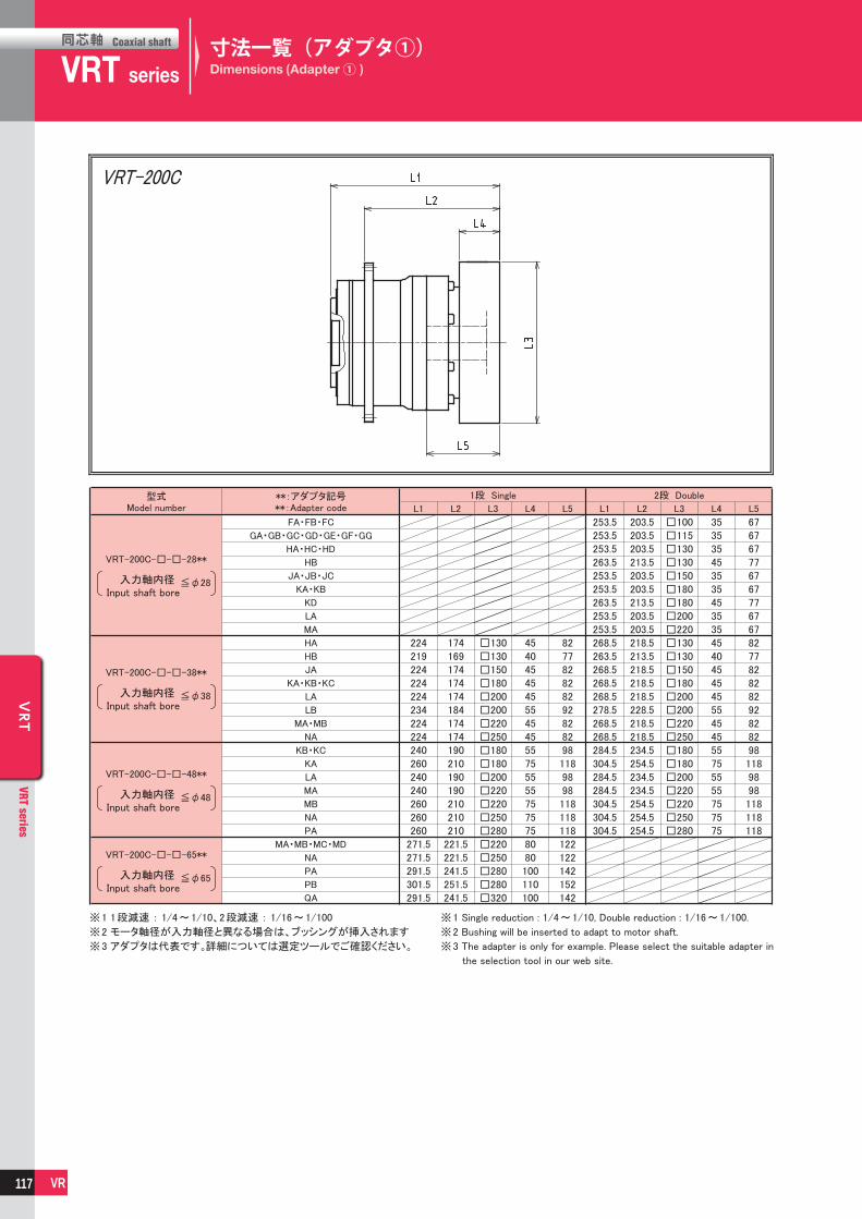
同芯軸
VRTCoaxial shaft
series VRT series
同芯軸 Coaxial shaft
VRT
VRT series
VR
VRT
VRT series
VR
VRT-200C
入力軸内径 Input shaft bore
入力軸内径 Input shaft bore
入力軸内径 Input shaft bore
入力軸内径 Input shaft bore
VRT-200C-□-□-28**
VRT-200C-□-□-38**
VRT-200C-□-□-48**
VRT-200C-□-□-65**
※1 1段減速 : 1/4~1/10、2段減速 : 1/16~1/100
※2 モータ軸径が入力軸径と異なる場合は、ブッシングが挿入されます
※3 アダプタは代表です。詳細については選定ツールでご確認ください。
※1 Single reduction : 1/4~1/10, Double reduction : 1/16~1/100.
※2 Bushing will be inserted to adapt to motor shaft.
※3 The adapter is only for example. Please select the suitable adapter in
the selection tool in our web site.
寸法一覧(アダプタ①)Dimensions (Adapter① )
117

同芯軸
VRTCoaxial shaft
series VRT series
同芯軸 Coaxial shaft
VRT
VRT series
VR
VRT
VRT series
VR
VRT-255C
入力軸内径 Input shaft bore
入力軸内径 Input shaft bore
VRT-255C-□-□-48**
VRT-255C-□-□-65**
寸法一覧(アダプタ①)Dimensions (Adapter① )
※1 1段減速 : 1/4~1/10、2段減速 : 1/16~1/100
※2 モータ軸径が入力軸径と異なる場合は、ブッシングが挿入されます
※3 アダプタは代表です。詳細については選定ツールでご確認ください。
※1 Single reduction : 1/4~1/10, Double reduction : 1/15~1/100.
※2 Bushing will be inserted to adapt to motor shaft.
※3 The adapter is only for example. Please select the suitable adapter in
the selection tool in our web site.
118

同芯軸
VRTCoaxial shaft
series VRT series
同芯軸 Coaxial shaft
VRT
VRT series
VR
VRT
VRT series
VR
VRT-285C
入力軸内径 Input shaft bore
入力軸内径 Input shaft bore
VRT-285C-□-□-48**
VRT-285C-□-□-65**
※1 1段減速 : 1/4~1/10、2段減速 : 1/16~1/100
※2 モータ軸径が入力軸径と異なる場合は、ブッシングが挿入されます
※3 アダプタは代表です。詳細については選定ツールでご確認ください。
※1 Single reduction : 1/4~1/10, Double reduction : 1/16~1/100.
※2 Bushing will be inserted to adapt to motor shaft.
※3 The adapter is only for example. Please select the suitable adapter in
the selection tool in our web site.
寸法一覧(アダプタ①)Dimensions (Adapter① )
119

同芯軸
VRTCoaxial shaft
series VRT series
同芯軸 Coaxial shaft
VRT
VRT series
VR
VRT
VRT series
VR
※ 1 ※ 2 ※ 3 ※ 4
サイズ 段数 バックラッシ ねじり剛性無負荷
ランニングトルク周囲温度
減速機許容最高温度
Framesize
Stage BacklashTorsionalrigidity
No loadrunning torque
Ambienttemperature
Permittedhousing
temperature
[arc-min] [Nm/arc-min] [Nm] [℃ ] [℃ ]
VRT-042C
1 段Single
3
2
0.03
0-40 90
2 段Double
5 0.01
VRT-047C
1 段Single
3
2
0.03
2 段Double
5 0.01
VRT-064C
1 段Single
3 3
0.08
2 段Double
0.04
VRT-090C
1 段Single
3 10
0.17
2 段Double
0.05
VRT-110C
1 段Single
3 31
0.77
2 段Double
0.17
VRT-140C
1 段Single
3 60
1.0
2 段Double
0.54
VRT-200C
1 段Single
3 175
1.9
2 段Double
1.3
VRT-255C
1 段Single
3 550
2.5
2 段Double
1.0
VRT-285C
1 段Single
3 850
2.7
2 段Double
0.6
※ 1 トルク - ねじり角度線図のゼロトルク部分※ 2 トルク - ねじり角度線図の直線 (剛性) 部分※ 3 入力側を許容平均入力回転速度、 無負荷で回転させるときに必要
な入力側のトルク 減速比 (1 段型) : 1/10 減速比 (2 段型) : 1/70
※ 4 減速機が耐えられる最高温度 連続運転の場合、 負荷の大きさにより許容値を超える場合があるため強制冷却の準備が必要となります
※ 1 Torque - part of the zero torque twist angle diagram※ 2 Torque - twist angle of the straight line diagram (stiffness) part※ 3 Average allowable input rotational speed input side, the input side of
the torque required when rotating with no load Reduction ratio (single reduction): 1/10 Reduction ratio (double reduction): 1/70
※ 4 The maximum temperature a reduction gear can withstand For continuous operation, it is necessary to prepare the forced cooling because it may exceed the allowable temperature depending on the size of the load
〈選定上のご注意〉※ 超低速回転領域のみでご使用される場合、減速機内部のグリース潤
滑不良を生じることがございます。 出力回転速度1rpm以下でご使用の際は、弊社までお問い合わせください。※ 出力回転角度が小さい揺動運転の場合、動力伝達部の油膜形成に
影響を及ぼすことがございます。 出力回転角度120°以下でご使用の際は、弊社までお問い合わせください。※高頻度な正逆運転では、出力軸のキーが摩耗する場合があります。
高頻度な正逆運転の場合は、摩擦式締結具を使用することを推奨致します。
※ VRT-140C枠~VRT-285C枠において、減速機とモータの質量比(モータ/減速機)が2以上、又は、寸法比(LM/L)が3以上となる場合、使用条件によってはモータ側に振動が発生することがございます。
補強等の処置を施してください。※ 下記の機種におきまして、減速機とモータの質量比(モータ/減速機)、
寸法比(LM/L)が0.8を同時に超える場合、モータ側に振動が発生することがございます。補強等の処置を施してください。
・ VRT-140C 入力軸内径≦φ19 2段 ・ VRT-200C 入力軸内径≦φ28 2段
〈Precautions on selection〉※ When using in very low speed, lack of lubrication may happen. Contact us when using at lower than 1 rpm at output.※ When using in small radian movement, it can influence the oil film-
forming of the power transmission part. Contact us when the gearbox is used at less than 120 degree radian.※Rapid clockwise/counter-clockwise movements may wear out the
key of the output shaft. Locking assembly is recommended to avoid the worn out.※ For frame size VRT-140C to 285C, if the ratio of the mass (motor/
gearbox) is over 2, or the ratio of the length (LM/L) is over 3, the servo motor can create certain vibration.
In theas cases, make sure to reinforce the equiment.※ If the ratios of the mass (motor/gearbox) and the length (LM/L)
are both over 0.8, it can create certain vibration so make sure to renforce the equipment.
・ VRT-140C input bote ≦φ19 Double reduction ・ VRT-200C input bore ≦φ28 Double reduction
特性Characteristics
モータ (motor) VRT 120

同芯軸
VRSCoaxial shaft
series
VRT series
VRS series
VRT series
同芯軸 Coaxial shaft
VRS / V
RTVRS series / VRT series
VR
VRS / V
RTVRS series / VRT series
VR
※Ambient temperature・・・25℃
VRS-060C-3・4/VRT-064C-4
0102030405060708090
100
0 2 4 6 8
VRS-060C-15~45/VRT-064C-16~45
0102030405060708090
100
0.0 0.3 0.6 0.9 1.2 1.5 1.8
VRS-060C-50~100/VRT-064C-50~100
0102030405060708090
100
0.0 0.1 0.2 0.3 0.4 0.5 0.6
VRS-060C-5~10/VRT-064C-5~10
0102030405060708090
100
0 1 2 3 4 5 6
VRS-075C-3・4/VRT-090C-4
0102030405060708090
100
0 5 10 15 20
VRS-075C-15~45/VRT-090C-16~45
0102030405060708090
100
0 1 2 3 4 5
VRS-075C-50~100/VRT-090C-50~100
0102030405060708090
100
0.0 0.3 0.6 0.9 1.2 1.5 1.8
VRS-075C-5~10/VRT-090C-5~10
0102030405060708090
100
0 3 6 9 12 15 18
Input torque Input torque
Input torqueInput torque
Input torque Input torque
Input torqueInput torque
Eff
icie
ncy
Eff
icie
ncy
Eff
icie
ncy
Eff
icie
ncy
Eff
icie
ncy
Eff
icie
ncy
Eff
icie
ncy
Eff
icie
ncy
効率
[%]
効率
[%]
効率
[%]
効率
[%]
効率
[%]
効率
[%]
効率
[%]
効率
[%]
VRS-060C/VRT-064C
VRS-075C/VRT-090C
Input speed:3,000rpm
Input speed:3,000rpm
入力トルク [Nm] 入力トルク [Nm]
入力トルク [Nm]入力トルク [Nm]
入力トルク [Nm] 入力トルク [Nm]
入力トルク [Nm]入力トルク [Nm]
※周囲温度・・・25℃
・入力回転速度:3,000rpmの時
・入力回転速度:3,000rpmの時
効率特性Efficiency
121

同芯軸
VRSCoaxial shaft
series
VRT series
VRS series
VRT series
同芯軸 Coaxial shaft
VRS / V
RTVRS series / VRT series
VR
VRS / V
RTVRS series / VRT series
VR
VRS-140C-3・4/VRT-140C-4
0102030405060708090
100
0 20 40 60 80 100
VRS-140C-50~100/VRT-140C-50~100
0102030405060708090
100
0 2 4 6 8
VRS-140C-5~10/VRT-140C-5~10
0102030405060708090
100
0 20 40 60 80
VRS-140C-15~45/VRT-140C-16~40
0102030405060708090
100
0 5 10 15 20 25
VRS-100C-3・4/VRT-110C-4
0102030405060708090
100
0 10 20 30 40 50
VRS-100C-15~45/VRT-110C-16~40
0102030405060708090
100
0 2 4 6 8 10 12
VRS-100C-50~100/VRT-110C-50~100
0102030405060708090
100
0 1 2 3 4
VRS-100C-5~10/VRT-110C-5~10
0102030405060708090
100
0 10 20 30 40
Input torque
Input torqueInput torque
Input torque
Input torque Input torque
Input torqueInput torque
Effic
iency
Effic
iency
Effic
iency
Effic
iency
Effic
iency
Effic
iency
Effic
iency
Effic
iency
※Ambient temperature・・・25℃
VRS-140C/VRT-140C
Input speed:3,000rpm
Input speed:2,000rpm
入力トルク [Nm]
入力トルク [Nm]入力トルク [Nm]
入力トルク [Nm]
入力トルク [Nm] 入力トルク [Nm]
入力トルク [Nm]入力トルク [Nm]
効率
[%]
効率
[%]
効率
[%]
効率
[%]
効率
[%]
効率
[%]
効率
[%]
効率
[%]
※周囲温度・・・25℃
VRS-100C/VRT-110C・入力回転速度:3,000rpmの時
・入力回転速度:2,000rpmの時
効率特性Efficiency
122

同芯軸
VRSCoaxial shaft
series
VRT series
VRS series
VRT series
同芯軸 Coaxial shaft
VRS / V
RTVRS series / VRT series
VR
VRS / V
RTVRS series / VRT series
VR
VRS-180C-3・4/VRT-200C-4
0102030405060708090
100
0 50 100 150 200
VRS-180C-15~45/VRT-200C-16~40
0102030405060708090
100
0 10 20 30 40 50
VRS-180C-50~100/VRT-200C-50~100
0102030405060708090
100
0 3 6 9 12 15 18
VRS-180C-5~10/VRT-200C-5~10
0102030405060708090
100
0 30 60 90 120 150 180
VRS-210C-3・4
0102030405060708090
100
0 100 200 300 400
VRS-210C-15~45
0102030405060708090
100
0 20 40 60 80 100
VRS-210C-50~100
0102030405060708090
100
0 10 20 30 40
VRS-210C-5~10
0102030405060708090
100
0 50 100 150 200 250 300 350
Input torque Input torque
Input torqueInput torque
Input torque Input torque
Input torqueInput torque
Eff
icie
ncy
Eff
icie
ncy
Eff
icie
ncy
Eff
icie
ncy
Eff
icie
ncy
Eff
icie
ncy
Eff
icie
ncy
Eff
icie
ncy
※Ambient temperature・・・25℃
VRS-210C
Input speed:1,500rpm
Input speed:1,000rpm
入力トルク [Nm] 入力トルク [Nm]
入力トルク [Nm]入力トルク [Nm]
入力トルク [Nm] 入力トルク [Nm]
入力トルク [Nm]入力トルク [Nm]
効率
[%]
効率
[%]
効率
[%]
効率
[%]
効率
[%]
効率
[%]
効率
[%]
効率
[%]
※周囲温度・・・25℃
VRS-180C/VRT-200C・入力回転速度:1,500rpmの時
・入力回転速度:1,000rpmの時
効率特性Efficiency
123

同芯軸
VRSCoaxial shaft
series
VRT series
VRS series
VRT series
同芯軸 Coaxial shaft
VRS / V
RTVRS series / VRT series
VR
VRS / V
RTVRS series / VRT series
VR
VRS-240C-3・4/VRT-255C-4
0102030405060708090
100
0 150 300 450 600 750
VRS-240C-15~45/VRT-255C-16~40
0102030405060708090
100
0 30 60 90 120 150 180
VRS-240C-50~100/VRT-255C-50~100
0102030405060708090
100
0 10 20 30 40 50
VRS-240C-5~10/VRT-255C-5~10
0102030405060708090
100
0 100 200 300 400 500
Input torque Input torque
Input torqueInput torque
Eff
icie
ncy
Eff
icie
ncy
Eff
icie
ncy
Eff
icie
ncy
※Ambient temperature・・・25℃
Input speed:1,000rpm
入力トルク [Nm] 入力トルク [Nm]
入力トルク [Nm]入力トルク [Nm]
効率
[%]
効率
[%]
効率
[%]
効率
[%]
※周囲温度・・・25℃
VRS-240C/VRT-255C・入力回転速度:1,000rpmの時
効率特性Efficiency
124

同芯軸
VRSCoaxial shaft
series
VRT series
VRS series
VRT series
同芯軸 Coaxial shaft
VRS / V
RTVRS series / VRT series
VR
VRS / V
RTVRS series / VRT series
VR
MEMO
125

For servo motor ABLE REDUCER
Compact Series
サーボモータ専用

同芯軸
Compact series
VRB-042C
Coaxial shaft
Compact series
VRB-042C
同芯軸 Coaxial shaft
VRB
Compact series
VR
VRB
Compact series
VR
VR 7 KB C
エイブル減速機の呼称Model name for ABLE reducer
シリーズ名Series name
VRBシリーズVRB Series
サイズFrame size
減速比Ratio
出力方式Output style
: 3, 4, 5, 6, 7, 8, 9, 10
: 15, 16, 20, 25, 28, 30, 35, 40, 45, 50, 60, 70, 80, 90, 100
1段Single2段Double
K… 出力軸キー付き Shaft with keyS… 出力軸キー無し Smooth shaft
バックラッシBacklash
3… 3分(1段減速) 3arc-min(Single)5… 5分(2段減速) 5arc-min(Double)
マウントコード(※1)Mount code(※1)
- - -- 3 S8ZG6042
バージョンVersion
C
特徴/機種・型式記号Features / Model number
VRB-042C
コンパクト Compact取付寸法42mm業界最小クラスのコンパクト設計
Maunting dimensions of 42mmWorld smallest class reducers are ready
静音 Quietはすば歯車を採用し、滑らかで静粛な運転を実現
Using a helical gear provides smooth and quiet operation
高精度 High precisionバックラッシは1段型3分以下、2段型5分以下精密な位置決めに威力を発揮
Backlash: less than 3 arc-mins for single reduction and less than 5 arc-mins for double reductionAccurate position is possible.
高剛性・高トルク High rigidity & torque総ころ形軸受を採用し、剛性 ・ トルクを大幅にアップ High rigidity & high torque were achived by uncaged
needle roller bearings.
アダプタ・ブッシング方式 Adapter-bushing connection世界中のモータに取付可能 Can be attached to any motor all over the world.
グリース漏れ無し No grease leakage高粘度で分離しにくいグリースを採用し、万全の漏油対策を実施
Perfect solution using high viscosity anti-separation grease.
メンテナンスフリー Maintenance-free製品寿命内はグリース交換不要取付姿勢も自由自在
No need to replace the grease for the life of the unit.Can be attached in any position.
※1 マウントコード ※1 Mount code
マウントコードは取付けモータによって決まります。 Mount code varies depending on the motor.
ホームページ上の選定ツールにて確認できます。 Please refer to reducer selection tool or contact
不明な場合はお問い合わせください。 us for more information.
〔モータとの締付け方式について〕
・ モータ軸は、キー溝なし ストレート軸での取付けとなります。
・ モータ軸がキー溝付の場合は、キーを取外して取付けください。
・ モータ軸がDカットの場合はお問い合わせください。
〔Mounting style to the motor〕
・ Motor output shaft is the smooth shaft without keyway.
・ If the motor output shaft is with the keyway, remove the key from the shaft.
・ If the motor output shaft has D shape cut, contact us.
127

同芯軸
Compact series
VRB-042C
Coaxial shaft
Compact series
VRB-042C
同芯軸 Coaxial shaft
VRB
Compact series
VR
VRB
Compact series
VR
サイズ
042C
VRB-042C
Framesize
段数
1段
2段
Single
Double
042C
1段
2段
Single
Double
Stage
減速比許容平均トルク
許容最大ラジアル荷重
許容平均入力回転速度
許容最高入力回転速度
許容ラジアル荷重
許容スラスト荷重Permittedaxial load
Permittedradial load
Maximuminput speed
Nominalinput speed
許容最大トルク
非常時最大トルク
Emergencystop torque
Maximumoutput torque
Nominaloutput torque
Maximumradial load
許容最大スラスト荷重
Maximumaxial load
慣性モーメントMomentof inertia
慣性モーメント※11 ※11
Momentof inertia
質量
Mass
Ratio
サイズ
Framesize
段数
Stage
減速比
Ratio
3
4
5
6
7
8
9
10
15
16
20
25
28
30
35
40
45
50
60
70
80
90
100
69999966699996996999966
1218181818181212121818181812181812181818181212
3035353535353030303535353530353530353535353030
40004000400040004000400040004000400040004000400040004000400040004000400040004000400040004000
80008000800080008000800080008000800080008000800080008000800080008000800080008000800080008000
240270290310320340350360410420460490510520550570600620660690710710710
270300330360380410430450540550610640640640640640640640640640640640640
3
4
5
6
7
8
9
10
15
16
20
25
28
30
35
40
45
50
60
70
80
90
100
0.1700.1600.1500.1500.1500.1500.1500.150
---------------
0.0530.0410.0360.0340.0320.0310.0310.0300.0350.0380.0340.0340.0380.0300.0340.0300.0340.0300.0300.0300.0300.0300.030
640640640640640640640640640640640640640640640640640640640640640640640
710710710710710710710710710710710710710710710710710710710710710710710
0.6
0.7
性能一覧Performance table
※ 1 許容平均入力回転速度の時、寿命20,00時間となる値※ 2 起動 ・ 停止時に許容する最大値※ 3 衝撃等が作用した時に許容する最大値(頻度は1,000回まで)※ 4 運転中の平均入力回転速度の許容最大値※ 5 連続運転ではない条件下での許容最高入力回転速度※ 6 許容平均入力回転速度の時、寿命20,000時間となる値
(軸中央に作用、スラスト荷重が0のとき)※ 7 許容平均入力回転速度の時、寿命20,000時間となる値
(軸芯に作用、ラジアル荷重が0のとき)※ 8 ラジアル荷重の許容最大値※ 9 スラスト荷重の許容最大値※10 減速比及び入力軸寸法により若干異なります※11 減速機(単体)入力軸換算の値を示します
※ 1 With nominal input speed, service life is 20,000 hours.※ 2 The maximum torque when starting and stopping.※ 3 The maximum torque when it receives shock. (up to 1,000 times)※ 4 The maximum average input speed.※ 5 The maximum momentary input speed.※ 6 With this load and nominal input speed, service life will be 20,000 hours.
(Applied to the output shaft center, at axial load 0)※ 7 With this load and nominal input speed, service life will be 20,000 hours.
(Applied to the output side bearing, at radial load 0)※ 8 The maximum radial load the reducer can accept.※ 9 The maximum axial load the reducer can accept.※10 The mass may vary slightly model to model.※11 The moment of inertia indicates the input shaft converted value of the
reducer only.
128

同芯軸
Compact series
VRB-042C
Coaxial shaft
Compact series
VRB-042C
同芯軸 Coaxial shaft
VRB
Compact series
VR
VRB
Compact series
VR
入力軸内径 Input shaft bore ≦φ8
VRB-042C 1段 1stage
VRB-042C 2段 2stage
入力軸内径 Input shaft bore ≦φ14
入力軸内径 Input shaft bore ≦φ8
寸法一覧Dimensions
※1 取付けモータにより変化する場合があります
※2 モータ軸径が入力軸径と異なる場合は、
ブッシングが挿入されます
※3 出力軸のキー及びキー溝寸法 ・ 公差はJIS B1301-
1996(締込形)に準じます
※1 Length will vary depending on motor.
※2 Bushing will be inserted to adapt to motor shaft.
※3 Output shaft key, key groove dimensions and tolerances
conform to JIS B 1301-1996 (tightening type)
129

同芯軸
Compact series
VRB-042C
Coaxial shaft
Compact series
VRB-042C
同芯軸 Coaxial shaft
VRB
Compact series
VR
VRB
Compact series
VR
VRB-042C-□(3・4)
0102030405060708090
100
0 0.5 1.0 1.5 2.0 2.5
VRB-042C-□(15-45)
0102030405060708090
100
0 0.15 0.30 0.45 0.60
VRB-042C-□(50-100)
0102030405060708090
100
0 0.05 0.10 0.15 0.20
VRB-042C-□(5-10)
0102030405060708090
100
0 0.5 1.0 1.5 2.0
Input torque Input torque
Input torqueInput torque
Effic
iency
Effic
iency
Eff
icie
ncy
Eff
icie
ncy
Input speed:4,000rpm
入力トルク [Nm] 入力トルク [Nm]
入力トルク [Nm]入力トルク [Nm]
効率
[%]
効率
[%]
効率
[%]
効率
[%]
VRB-042C・入力回転速度:4,000rpmの時
特性・効率特性Characteristic・Efficiency
※ 1 ※ 2 ※ 3 ※ 4
サイズ 段数 バックラッシ ねじり剛性無負荷
ランニングトルク周囲温度
減速機許容最高温度
Framesize
Stage BacklashTorsionalrigidity
No loadrunning torque
Ambienttemperature
Permittedhousing
temperature
[arc-min] [Nm/arc-min] [Nm] [℃ ] [℃ ]
VRB-042C
1 段Single
3
2
0.03
0-40 902 段
Double5 0.01
※ 1 トルク - ねじり角度線図のゼロトルク部分
※ 2 トルク - ねじり角度線図の直線 (剛性) 部分
※ 3 入力側を許容平均入力回転速度、 無負荷で回転させるときに必要
な入力側のトルク
減速比 (1 段型) : 1/10
減速比 (2 段型) : 1/70
※ 4 減速機が耐えられる最高温度
連続運転の場合、 負荷の大きさにより許容値を超える場合がある
ため強制冷却の準備が必要となります
※ 1 Torque - part of the zero torque twist angle diagram
※ 2 Torque - twist angle of the straight line diagram (stiffness) part
※ 3 Average allowable input rotational speed input side, the input side of
the torque required when rotating with no load
Reduction ratio (single reduction): 1/10
Reduction ratio (double reduction): 1/70
※ 4 The maximum temperature a reduction gear can withstand
For continuous operation, it is necessary to prepare the forced
cooling because it may exceed the allowable temperature
depending on the size of the load
〈選定上のご注意〉※ 超低速回転領域のみでご使用される場合、減速機内部のグリース潤
滑不良を生じることがございます。
出力回転速度1rpm以下でご使用の際は、弊社までお問い合わせください。
※ 出力回転角度が小さい揺動運転の場合、動力伝達部の油膜形成に
影響を及ぼすことがございます。
出力回転角度120°以下でご使用の際は、弊社までお問い合わせください。
※高頻度な正逆運転では、出力軸のキーが摩耗する場合があります。
高頻度な正逆運転の場合は、摩擦式締結具を使用することを推奨致
します。
〈Precautions on selection〉※When using in very low speed, lack of lubrication may happen.
Contact us when using at lower than 1 rpm at output.
※When using in small radian movement, it can influence the oil film-
forming of the power transmission part.
Contact us when the gearbox is used at less than 120 degree radian.
※Rapid clockwise/counter-clockwise movements may wear out the
key of the output shaft.
Locking assembly is recommended to avoid the worn out.
130

同芯軸
Compact series
VRL-050C
Coaxial shaft
Compact series
VRL-050C
同芯軸 Coaxial shaft
VRL
Compact series
VR
VRL
Compact series
VR
VR 5 KL C
エイブル減速機の呼称Model name for ABLE reducer
シリーズ名Series name
VRLシリーズVRL Series
サイズFrame size
減速比Ratio
出力方式Output style
: 3, 4, 5, 6, 7, 8, 9, 10
: 15, 16, 20, 25, 28, 30, 35, 40, 45, 50, 60, 70, 80, 90, 100
1段Single2段Double
K… 出力軸キー付き Shaft with keyS… 出力軸キー無し Smooth shaft
バックラッシBacklash
5… 5分(1段減速) 5arc-min(Single)7… 7分(2段減速) 7arc-min(Double)
マウントコード(※1)Mount code(※1)
- - -- 5 S8ZG6050
バージョンVersion
C
コンパクト Compact取付寸法50mm業界最小クラスのコンパクト設計
Maunting dimensions of 50mmWorld smallest class reducers are ready
静音 Quietはすば歯車を採用し、滑らかで静粛な運転を実現
Using a helical gear provides smooth and quiet operation
高精度 High precisionバックラッシは1段型5分以下、2段型7分以下精密な位置決めに威力を発揮
Backlash: less than 5 arc-mins for single reduction and less than 7 arc-mins for double reductionAccurate position is possible.
高剛性・高トルク High rigidity & torque総ころ形軸受を採用し、剛性 ・ トルクを大幅にアップ High rigidity & high torque were achived by uncaged
needle roller bearings.
アダプタ・ブッシング方式 Adapter-bushing connection世界中のモータに取付可能 Can be attached to any motor all over the world.
グリース漏れ無し No grease leakage高粘度で分離しにくいグリースを採用し、万全の漏油対策を実施
Perfect solution using high viscosity anti-separation grease.
メンテナンスフリー Maintenance-free製品寿命内はグリース交換不要取付姿勢も自由自在
No need to replace the grease for the life of the unit.Can be attached in any position.
※1 マウントコード ※1 Mount code
マウントコードは取付けモータによって決まります。 Mount code varies depending on the motor.
ホームページ上の選定ツールにて確認できます。 Please refer to reducer selection tool or contact
不明な場合はお問い合わせください。 us for more information.
特徴/機種・型式記号Features / Model number
VRL-050C
〔モータとの締付け方式について〕
・ モータ軸は、キー溝なし ストレート軸での取付けとなります。
・ モータ軸がキー溝付の場合は、キーを取外して取付けください。
・ モータ軸がDカットの場合はお問い合わせください。
〔Mounting style to the motor〕
・ Motor output shaft is the smooth shaft without keyway.
・ If the motor output shaft is with the keyway, remove the key from the shaft.
・ If the motor output shaft has D shape cut, contact us.
131

同芯軸
Compact series
VRL-050C
Coaxial shaft
Compact series
VRL-050C
同芯軸 Coaxial shaft
VRL
Compact series
VR
VRL
Compact series
VR
サイズ
050C
VRL-050C
Framesize
段数
1段
2段
Single
Double
050C
1段
2段
Single
Double
Stage
減速比許容平均トルク
許容最大ラジアル荷重
許容平均入力回転速度
許容最高入力回転速度
許容ラジアル荷重
許容スラスト荷重Permittedaxial load
Permittedradial load
Maximuminput speed
Nominalinput speed
許容最大トルク
非常時最大トルク
Emergencystop torque
Maximumoutput torque
Nominaloutput torque
Maximumradial load
許容最大スラスト荷重
Maximumaxial load
慣性モーメントMomentof inertia
慣性モーメント※11 ※11
Momentof inertia
質量
Mass
Ratio
サイズ
Framesize
段数
Stage
減速比
Ratio
3
4
5
6
7
8
9
10
15
16
20
25
28
30
35
40
45
50
60
70
80
90
100
69999966699996996999966
1218181818181212121818181812181812181818181212
3035353535353030303535353530353530353535353030
40004000400040004000400040004000400040004000400040004000400040004000400040004000400040004000
80008000800080008000800080008000800080008000800080008000800080008000800080008000800080008000
240270290310320340350360410420460490510520550570600620660690710710710
270300330360380410430450540550610640640640640640640640640640640640640
3
4
5
6
7
8
9
10
15
16
20
25
28
30
35
40
45
50
60
70
80
90
100
0.1700.1600.1500.1500.1500.1500.1500.150
---------------
0.0530.0410.0360.0340.0320.0310.0310.0300.0350.0380.0340.0340.0380.0300.0340.0300.0340.0300.0300.0300.0300.0300.030
640640640640640640640640640640640640640640640640640640640640640640640
710710710710710710710710710710710710710710710710710710710710710710710
0.7
0.8
性能一覧Performance table
※ 1 許容平均入力回転速度の時、寿命20,000時間となる値※ 2 起動 ・ 停止時に許容する最大値※ 3 衝撃等が作用した時に許容する最大値(頻度は1,000回まで)※ 4 運転中の平均入力回転速度の許容最大値※ 5 連続運転ではない条件下での許容最高入力回転速度※ 6 許容平均入力回転速度の時、寿命20,000時間となる値
(軸中央に作用、スラスト荷重が0のとき)※ 7 許容平均入力回転速度の時、寿命20,000時間となる値
(軸芯に作用、ラジアル荷重が0のとき)※ 8 ラジアル荷重の許容最大値※ 9 スラスト荷重の許容最大値※10 減速比及び入力軸寸法により若干異なります※11 減速機(単体)入力軸換算の値を示します
※ 1 With nominal input speed, service life is 20,000 hours.※ 2 The maximum torque when starting and stopping.※ 3 The maximum torque when it receives shock. (up to 1,000 times)※ 4 The maximum average input speed.※ 5 The maximum momentary input speed.※ 6 With this load and nominal input speed, service life will be 20,000 hours.
(Applied to the output shaft center, at axial load 0)※ 7 With this load and nominal input speed, service life will be 20,000 hours.
(Applied to the output side bearing, at radial load 0)※ 8 The maximum radial load the reducer can accept.※ 9 The maximum axial load the reducer can accept.※10 The mass may vary slightly model to model.※11 The moment of inertia indicates the input shaft converted value of the
reducer only.
132

同芯軸
Compact series
VRL-050C
Coaxial shaft
Compact series
VRL-050C
同芯軸 Coaxial shaft
VRL
Compact series
VR
VRL
Compact series
VR
入力軸内径 Input shaft bore ≦φ8
VRL-050C 1段 1stage
VRL-050C 2段 2stage
入力軸内径 Input shaft bore ≦φ14
入力軸内径 Input shaft bore ≦φ8
寸法一覧Dimensions
※1 取付けモータにより変化する場合があります
※2 モータ軸径が入力軸径と異なる場合は、
ブッシングが挿入されます
※3 出力軸のキー及びキー溝寸法 ・ 公差はJIS B1301-
1996(締込形)に準じます
※1 Length will vary depending on motor.
※2 Bushing will be inserted to adapt to motor shaft.
※3 Output shaft key, key groove dimensions and tolerances
conform to JIS B 1301-1996 (tightening type)
133

同芯軸
Compact series
VRL-050C
Coaxial shaft
Compact series
VRL-050C
同芯軸 Coaxial shaft
VRL
Compact series
VR
VRL
Compact series
VR
VRL-050C-□(3・4)
0102030405060708090
100
0 0.5 1.0 1.5 2.0 2.5
VRL-050C-□(15-45)
0102030405060708090
100
0 0.15 0.30 0.45 0.60
VRL-050C-□(50-100)
0102030405060708090
100
0 0.05 0.10 0.15 0.20
VRL-050C-□(5-10)
0102030405060708090
100
0 0.5 1.0 1.5 2.0
Input torque Input torque
Input torqueInput torque
Eff
icie
ncy
Eff
icie
ncy
Eff
icie
ncy
Eff
icie
ncy
Input speed:4,000rpm
入力トルク [Nm] 入力トルク [Nm]
入力トルク [Nm]入力トルク [Nm]
効率
[%]
効率
[%]
効率
[%]
効率
[%]
VRL-050C・入力回転速度:4,000rpmの時
特性・効率特性Characteristic・Efficiency
※ 1 ※ 2 ※ 3 ※ 4
サイズ 段数 バックラッシ ねじり剛性無負荷
ランニングトルク周囲温度
減速機許容最高温度
Framesize
Stage BacklashTorsionalrigidity
No loadrunning torque
Ambienttemperature
Permittedhousing
temperature
[arc-min] [Nm/arc-min] [Nm] [℃ ] [℃ ]
VRL-050C
1 段Single
5
2
0.03
0-40 902 段
Double7 0.01
※ 1 トルク - ねじり角度線図のゼロトルク部分
※ 2 トルク - ねじり角度線図の直線 (剛性) 部分
※ 3 入力側を許容平均入力回転速度、 無負荷で回転させるときに必要
な入力側のトルク
減速比 (1 段型) : 1/10
減速比 (2 段型) : 1/70
※ 4 減速機が耐えられる最高温度
連続運転の場合、 負荷の大きさにより許容値を超える場合がある
ため強制冷却の準備が必要となります
※ 1 Torque - part of the zero torque twist angle diagram
※ 2 Torque - twist angle of the straight line diagram (stiffness) part
※ 3 Average allowable input rotational speed input side, the input side of
the torque required when rotating with no load
Reduction ratio (single reduction): 1/10
Reduction ratio (double reduction): 1/70
※ 4 The maximum temperature a reduction gear can withstand
For continuous operation, it is necessary to prepare the forced
cooling because it may exceed the allowable temperature
depending on the size of the load
〈選定上のご注意〉※ 超低速回転領域のみでご使用される場合、減速機内部のグリース潤
滑不良を生じることがございます。
出力回転速度1rpm以下でご使用の際は、弊社までお問い合わせください。
※ 出力回転角度が小さい揺動運転の場合、動力伝達部の油膜形成に
影響を及ぼすことがございます。
出力回転角度120°以下でご使用の際は、弊社までお問い合わせください。
※高頻度な正逆運転では、出力軸のキーが摩耗する場合があります。
高頻度な正逆運転の場合は、摩擦式締結具を使用することを推奨致
します。
〈Precautions on selection〉※When using in very low speed, lack of lubrication may happen.
Contact us when using at lower than 1 rpm at output.
※When using in small radian movement, it can influence the oil film-
forming of the power transmission part.
Contact us when the gearbox is used at less than 120 degree radian
※Rapid clockwise/counter-clockwise movements may wear out the
key of the output shaft.
Locking assembly is recommended to avoid the worn out.
134

同芯軸 Coaxial shaft
同芯軸 Coaxial shaft
取付方法(アダプタタイプ)
Installation(Adapter type)
VR
取付方法(ダイレクトタイプ)Installation(Direct type)
VR
VRS, VRB, VRL, VRT, VRXF(アダプタタイプ),VRG
VRXF(ダイレクトタイプ)
モータ取付手順 Mounting procedure to the motor
減速機の取付け装置へ減速機を取付ける場合は、 取付け面が平坦でかつバリ等がないことを確認した上、 ボルトにてトルクレンチ等を使って指定の締付トルクで締付けてください。 (表 2、 表 3 参照)
Reducer installation
After confirming the installation surface is flat and clean, tighten the bolt using a torque wrench to the proper torque. (See table2, table3)
表 1 Table 1
ボルトサイズ
モータ取付ボルト
N・m kgf・m N・m kgf・m
Motor mounting bolt Clamping bolt
クランプボルト
Bolt size
※推奨ボルト:強度区分12.9以上
※Recommended bolt:Strength 12.9
表 2 Table 2 (VRG, VRS, VRL, VRT) 表 3 Table 3 (VRXF)
ボルトサイズ
締付トルクTightening torque
Bolt size N・m kgf・m
ボルトサイズ
締付トルクTightening torque
Bolt size N・m kgf・m
5.8
9.8
19.6
39.2
M5
M6
M8
M10
0.6
1.0
2.0
4.0
取付方法(アダプタタイプ)Installation (Adapter type)
6プラグを取付けて、 作業は終了です。
Reinstall the plug. The procedure is done.
5
クランプボルトをトルクレンチ等を使用し、 指定の締付トルクで締付
けます。 (表 1 参照)
Tighten the clamping bolt of the input shaft with torque wrench to the proper torque. (See table1)
3
入力軸をまわしてクランプボルトの頭をプラグ穴に合わせます。この時クランプボルトが緩んでいることを確認してください。 尚、 型番によって位置決めボルトがございますが、 このボルトには触らないようにしてください。Turn the input shaft until the cap screw is seen. Make sure the cap screw is loosened. There are positioning bolt depending on the model, but do not touch this bolt.
ブッシュが付属されている場合は、 図のようにクランプ部の割りとブッシュの割り位置を合わせてください。 また、 モータ軸にキー溝がある場合は、クランプ部の割りとキー溝の位置を合わせてください。In case the bushing has been attached, please align the groove of the clamp part with that of the bushing. If the motor shaft has a keyway, please align the groove of the clamp part with the keyway.
クランプボルトClamping bolt
位置決めボルトPositioning bolt
ブッシュBushing
1モータ軸の防錆剤 ・ 油分等をふき取ります。Wipe off anti-rust agent and oil on the motor shaft.
2プラグを取外します。Remove the plug.
4
減速機のモータ取付け面が上側にくる様、 平坦な場所に減速機を垂直に置きます。 モータ軸を入力軸へ衝撃を与えない様ゆっくりと挿入しモータフランジ面が減速機フランジ面に密着したことを確認してください。 モータ取付ボルトを指定の締付トルクで締付けます。 (表 1 参照)Please place reducer vertically on the flat surface so the motor mounting part faces up. Carefully insert the motor shaft into the input shaft. (It should be inserted smoothly) Make sure the motor flange is perfectly fit to the reducer's flange.Tighten the motor mounting bolts to the proper torque. (See table1)
※ キー付モータのキーを取り外せば、 上記キー無しモータ取付けにてご使
用頂けます。 滑りの心配はございません。
※ By removing the key from the motors shaft, a keyed shaft can be mounted per the instructions above.(If completed correvtly,no slipping will occur)
135
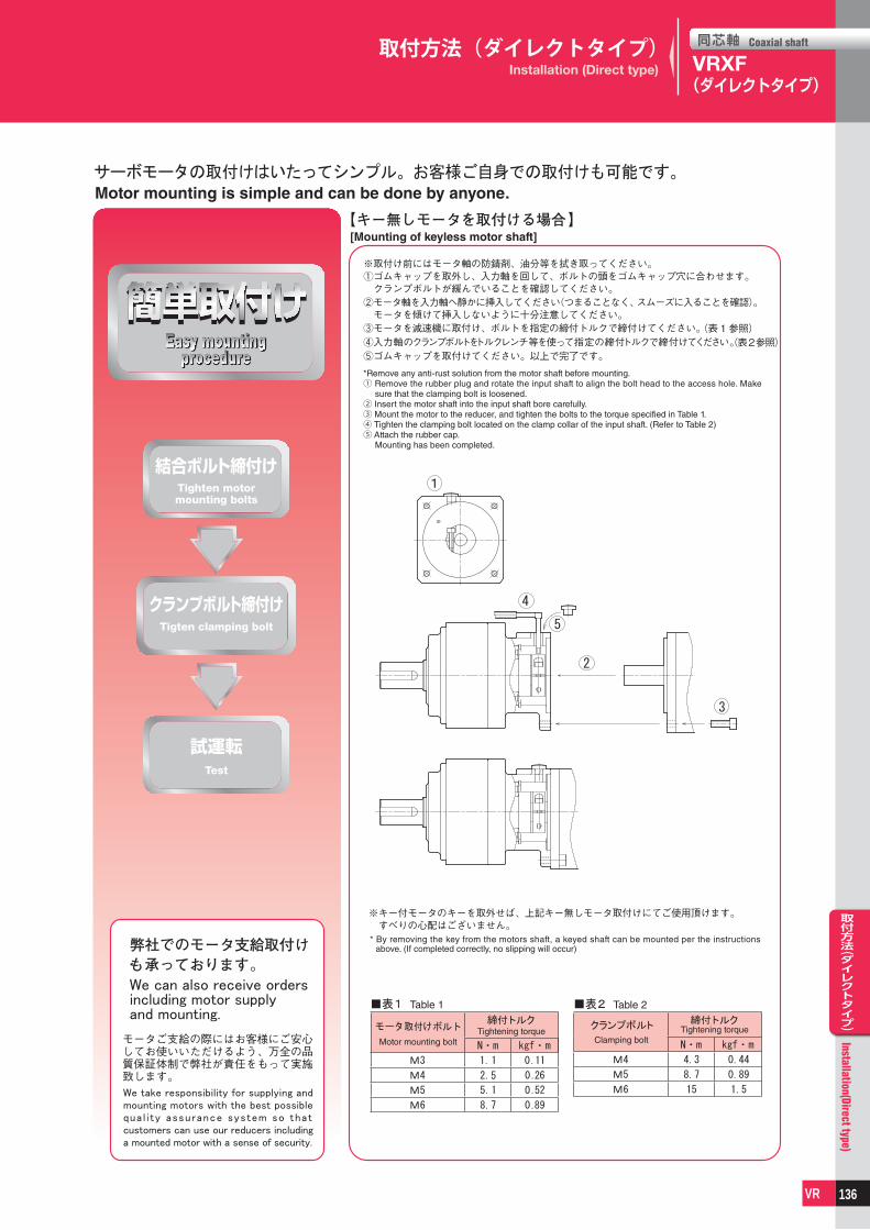
同芯軸 Coaxial shaft
同芯軸 Coaxial shaft
取付方法(アダプタタイプ)
Installation(Adapter type)
VR
取付方法(ダイレクトタイプ)Installation(Direct type)
VR
VRS, VRB, VRL, VRT, VRXF(アダプタタイプ),VRG
VRXF(ダイレクトタイプ)
(表1参照)(表2参照)
結合ボルト締付け
クランプボルト締付け
クランプ
クランプ
We can also receive orders including motor supply and mounting.
We take responsibility for supplying and mounting motors with the best possible qua l i ty assurance system so that customers can use our reducers including a mounted motor with a sense of security.
[Mounting of keyless motor shaft]
*Remove any anti-rust solution from the motor shaft before mounting.① Remove the rubber plug and rotate the input shaft to align the bolt head to the access hole. Make
sure that the clamping bolt is loosened.② Insert the motor shaft into the input shaft bore carefully. ③ Mount the motor to the reducer, and tighten the bolts to the torque specified in Table 1.④ Tighten the clamping bolt located on the clamp collar of the input shaft. (Refer to Table 2)⑤ Attach the rubber cap.
Mounting has been completed.
* By removing the key from the motors shaft, a keyed shaft can be mounted per the instructions above. (If completed correctly, no slipping will occur)
Tigten clamping bolt
Tighten motormounting bolts
Test
Easy mountingprocedure
Motor mounting is simple and can be done by anyone.
Table 1
Motor mounting boltTightening torque
Table 2
4.3
8.7
15
0.44
0.89
1.5
Clamping boltTightening torqueクランプボルト
取付方法(ダイレクトタイプ)Installation (Direct type)
136

同芯軸 Coaxial shaft
同芯軸 Coaxial shaft
安全上のご注意
Safety Precautions
VR
安全上のご注意
Safety Precautions
VR
保管時のご注意
本製品を一時的に保管される場合は、下記要領にて保管してください。
①清潔で乾燥した場所に保管してください。②�屋外や湿気のある場所に保管するときは、箱などに入れ直接、
雨水や外気にあたらないようにビニールシートなどで覆いをしてください(結露や錆のでないように処置してください)。
■運転時の注意
■減速機が到着しましたら・・・ご注文いただきました減速機型番と到着した減速機のメイバン型式表示が同じか、ご確認ください。減速機出入力軸は防錆剤が塗布してありますので、拭き取ってください。※入力軸のゴムキャップを外し、防錆剤を拭き取ってください。※減速機には、潤滑油(グリース)を充填済みです。���そのままご使用になれます。
■据付け、設置について ●�雨や水が直接かかる場所でのご使用は避けてください。 ・�屋外や粉塵、水滴のかかる場所で使用される場合は、事前に
ご相談ください。 ●�周囲温度が、0℃~�40℃の環境に設置してください。 ・�上記の範囲以外の温度でご使用の場合は、必ず弊社までご�
相談ください。 ●�振動のない強固な据付け台にボルトなどで確実に固定してく
ださい。 ●保守、点検に便利なように設置をしてください。
■運転開始前の注意事項 ●潤滑油は工場出荷時に規定量のグリースを充填していますの で、到着後そのままご使用いただけます。 ●初めて運転する場合は、出力軸の回転方向を確認の上、徐々に 負荷をかけてください。
■運転中の注意事項 ●過負荷にならないように注意してください。 ●�入力回転速度は、規定以上の回転速度にならないようにして
ください。 ●次のような場合は、一旦運転を止めて点検してください。 ・急に温度が上がりはじめた ・急に異常音が大きく出はじめた ・急に回転速度が不安定になりはじめた
Cautions�for�storage
Whenever temporarily keeping the product, keep the following directions:
①�Keep�in�a�clean�and�dry�place.②�Whenever�storing�outdoors�or� in�a�humid�place,�put� in�a�
box�so�that�it�does�not�directly�contact�rain�or�external�air�and�cover�with�a�vinyl�sheet� (Take�a�measure�to�prevent�rust.).
■Cautions for operation
■When the reducer is delivered to you ・・・ �When�the�product�delivered,�please�confirm�that�you�received�
the�exact�same�model�you�have�ordered. �Please�wipe�out� the� input� and�output� shaft� of� the� reducer�
which�is�covered�by�anti-corrosive�oil. *�Please�remove�the�rubber�cap�on�the�input�shaft�before�you�
wipe�the�shafts.� *Lubricant�(grease)�is�already�filled�in�the�reducer. �It�is�available�as�it�is.
■Fixation & installation ● Avoid�use�in�a�place�where�rain�or�water�drops�directly. ・�In� case� of� use� outdoors� or� in� a�place�where�dust� and�
water�drops,�consult�in�advance. ● �Install�at�0℃�~40℃�of�surrounding�temperature. ・�In�case�of�use�at�temperature�out�of�the�above-mentioned�
range,�contact�the�headquarters�and�consult�on�this. ● Firmly�fix�with�a�bolt�onto�a�solid�stand�without�vibration. ● �Install� in� consideration� of� convenience� in� repair� and�
inspection.
■Cautions prior to starting the operation ● �Reducer�can�be�used�soon�after�arrival,�since�it�has�already�
been�filled�out�with�lubrication. ● �At� initial� operation,� check� the� rotating�direction� of� the�
output�shaft�and�then�gradually�apply�load.
■Cautions during operation ● Avoid�overload. ● �Ensure� that� input� speed� shall� not� be� the� number� of�
revolutions�beyond�the�specification. ● �In� the� following�cases,� stop� the�operation�and�check� the�
following�points: ・If�temperature�sharply�increases ・If�an�abnormal�noise�appears�sharply ・If�the�number�of�revolutions�becomes�unstable�sharply
安全上のご注意Safety Precautions
●保証規定について・製品の保証対象地域は日本国内に限ります。・保証範囲は納入製品単体のみです。
・以下の費用及び損害は保証の範囲に含まれません1)当製品に伴う輸送費2)当製品が他の装置等と連結または組み込まれている場合の当該装置等からの取外し、取付け、その他付帯する工事の費用3)当製品の故障により利用者に発生した使用機会の逸失、業務の中断等による間接的損害4)その他一切の派生的または付随的損害
137

同芯軸 Coaxial shaft
同芯軸 Coaxial shaft
安全上のご注意
Safety Precautions
VR
安全上のご注意
Safety Precautions
VR
●�これらの原因は次の事項が考えられますので、速やかに対処するか弊社までご連絡ください。
・過負荷状態になっていないか ・潤滑油の不足、劣化または異種を使用していないか ・軸受、ギヤ、伝動面に損傷はないか ・相手機械との連結などの条件が悪くないか
■分解 ●エイブル減速機は分解できない構造となっています。
■保証 ●保証期間は製品納入後1�年間となっております。
■潤滑油管理 ●エイブル減速機は、全機種ともグリース潤滑密閉方式です。 �工場出荷時に規定量のグリースを充填していますので、到着
後そのままご使用いただけます。 ●グリースの交換はできません。 ●�常時0℃~�40℃以外の周囲温度で使用される場合は、事前にご
照会ください。
■毎日の点検について ●�運転中の減速機のケース温度が異常に高くないか。(周囲温度
+�50℃位までなら特に問題はありません) ●ベアリング、ギヤ部などに異常音はないか。 ●減速機に異常な振動はないか。 ※�これらの異常現象が発生した場合は、直ちに運転を中止し
て、弊社までご連絡ください。 ●潤滑油の漏れている個所はないか。 ※油脂の漏れが発生した場合は、弊社までご連絡ください。
■定期点検について ●無理な負荷状態、異常回転でないか。 ●�プーリ、スプロケット、減速機取付けボルトなどは緩んでいな
いか。 ●電気系統に異常はないか。 ●主要部品の点検と整備 ※�異常現象が発生した場合は、直ちに運転を中止して、弊社まで
ご連絡ください。 ●潤滑油の不具合 ※油脂の漏れが発生した場合は、弊社までご連絡ください。
■廃棄方法 �エイブル減速機を廃棄する場合は、部品を材質別に分類し法令・
各自治体の条例などに従い、産業廃棄物として処理してください。
部品の材質は、次の4�種類に分類できます。 ①�ゴム系部品:オイルシール、シートパッキン、ゴムキャップ、
モータフランジ側のベアリングに使用されているシール部 ②アルミ系部品:モータフランジ、出力軸ホルダ ③�グリース:部品に付着しているグリースは乾いた布などでふ
きとり、油類として廃棄してください。 ④鉄系部品:上記以外の部品
● �These�may�be�caused�by�the�following�matters,�so�rapidly�respond�to�it�or�contact�us.
・Is�it�under�overload�condition? ・�Is� lubricant� insufficient�or�deteriorated,�or� is� lubricant�of�
other�type�used? ・Is�the�axis,�gear,�and�motor�side�damaged? ・Is�jointing�with�other�machines�poor?
■Disassembly ●ABLE�REDUCER�is�designed�not�to�allow�disassembly.
■Warranty ● �A�warranty�period�is�one�year�after�the�product�is�delivered�to�you.
■Lubricant use ● �The�ABLE�REDUCER�is�of�grease-seal�type�in�all�models. �A�specified�amount�of�grease�is�filled�at�factory�release,�so�
you�can�use�as�soon�as�it�is�delivered�to�you. ● �It�is�impossible�to�exchange�grease. ● �In�case�of�use�at�0℃�~40℃�of�surrounding�temperature�at�
usual�times,�consider�this�in�advance.
■Daily check points ● �Is� reducer� case� temperature� excessively� high� during�
operation?�(Up�to�+�50℃�is�not�significant.) ● �Is�there�an�abnormal�noise�in�the�bearing,�gear,�etc? ● �Is�there�abnormal�vibration�in�the�reducer? * �Upon�an�abnormal�phenomenon,� immediately� stop� the�
operation�and�contact�us. ● Is�there�a�lubricant�leak? * �Upon�an�oil�leak,�contact�us.
■Periodic check points ● Are�there�overload�and�abnormal�rotation? ● Are�free,�sprocket,�and�reducer�assembling�bolts�loose? ● Is�there�an�abnormal�condition�in�the�electric�system? ● Checkup�and�repair�of�major�parts ※ �Upon�an�abnormal�condition,�immediately�stop�the�operation�
and�contact�us. ● Oil�leak ※ Upon�an�oil�leak,�contact�us.
■Scrapping �Whenever�scrapping�the�ABLE�REDUCER,�classify�the�parts�
by�material�into�industrial�wastes�as�specified�in�the�laws�and �regulations�of�self-governing�bodies.�Material�of�parts�can�be�
divided�into�four: ① �Rubber�parts�:�Oil�seal,�seat�packing,�rubber�cap,�seal�used�
for�bearing�on�the�motor�flange,�etc. ② �Aluminum�parts�:�Motor�flange,�output�shaft�holder ③ �Grease� :�Wipe�off�grease�attached�to�parts�with�dry�cloth�
and�scrap�into�oils. ④ �Iron�parts�:�Parts�other�than�those�mentioned�in�the�above
安全上のご注意Safety Precautions
WARRANTY PROVISION・Warranty scope is limited to the use in Japan only.・Warranty scope is the delivered product only.
■ THE EXPENSES AND LOSSES THAT MENTIONED BELOW ARE NOT INCLUDED IN WARRANTY1)�The�transport�charges�for�repairing�of�our�products.2)�The�fee�for�the�removal�operation,�reinstallation�and�other�related�operation�in�case�our�product�is�installed�to�the�other�machine.3)�The�loss�of�the�chances�of�use�and�indirect�damages�caused�by�the�interruption�of�the�services�caused�by�our�product's�defects.4)�All�other�secondary�expenses�and�losses.
138

同芯軸 Coaxial shaft
同芯軸 Coaxial shaft
エイブル減速機
ABLE REDUCER
VR
エイブル減速機
ABLE REDUCER
VR
MEMO
139

同芯軸 Coaxial shaft
同芯軸 Coaxial shaft
エイブル減速機
ABLE REDUCER
VR
エイブル減速機
ABLE REDUCER
VR
MEMO
140

同芯軸 Coaxial shaft
同芯軸 Coaxial shaft
エイブル減速機
ABLE REDUCER
VR
エイブル減速機
ABLE REDUCER
VR
MEMO
141

エイブル減速機
ABLE REDUCER
エイブル減速機
ABLE REDUCER
1
Nidec - Shimpo has a lineup with a lot of product variation; Able reducersエイブル減速機は豊富なバリエーションでお客様の要望にお応え
INDEX
NETWORK
QUALITY
本社・京都府長岡京市Headquarters, Kyoto
中国・平湖P i n g h u
インド・バンガロールIndia, Bangalore
スペイン・ログローニョS p a i n , L o g r o ñ o
香 港Hong Kong
北 京Beijing
上 海Shanghai
ソウルSe o u l
台 湾Ta i w a n
サンパウロSão Paulo
メキシコ・ケレタロMexico, Querétaro
アメリカ・シカゴAmerica, Chicago
日本電産本社・京都市NIDEC Corporation in Kyoto
全社的品質管理の考えのもと、品質向上に努めています。We are making efforts for quality improvement on thebasis of the concept of total quality control.
品質管理の優れた企業に与えられるデミング賞も受賞。Deming Award to be given to enterprises practicing excellent quality control
■日本電産シンポ株式会社は品質保証に関する ISO 9001/ISO 14001 の認証を取得しています。■NIDEC-SHIMPO has obtained ISO 9001/ISO 14001 certification of quality assurance.
アメリカ・シカゴChicago in U.S.
本社・京都府長岡京市Headquarters, Kyoto Nagaokakyo
in Japan
韓国・ソウルSeoul
in Republic of Korea
中国・平湖Pinghu in China
ロサンゼルスLos Angeles
アメリカ・オハイオAmer ica , Oh io
アメリカ・ピッツバーグAmerica, Pittsburgh
ドイツ・デッテンハウゼンGermany, Dettenhausen
ドイツ・デッテンハウゼンDettenhausenin Germany
ドイツ・アルンスベルクGermany ,Arnsbe rg
ドイツ・アルンスベルクArnsberg
in Germany
ISO 9001■認証範囲:以下の製品の設計 ・ 開発、製造、修理、営業1. 駆動機器 2. プレス機器 3. 計測機器 4. 工芸機器●本社 ・ 京都工場、上田工場
■This certificate is valid for the following scope:Design, Development, Manufacture, Repair and Sales of1. Power Transmission Equipment 2. Press Machines3. Measuring Instruments 4. Pottery Equipment●Kyoto factory, Ueda factory
ISO 14001■認証範囲:以下の製品の設計 ・ 開発、製造、修理、営業1. 駆動機器 2. プレス機器 3. 計測機器 4. 工芸機器●本社 ・ 京都工場、上田工場
■This certificate is valid for the following scope:Design, Development, Manufacture, Repair and Sales of1. Power Transmission Equipment 2. Press Machines3. Measuring Instruments 4. Pottery Equipment●Kyoto factory, Ueda factory
国内拠点:東京支店/関西支店/名古屋営業所/金沢営業所/福岡営業所Bases in Japan: Tokyo branch/Kansai branch/Nagoya office/Kanazawa office/Fukuoka office
日本電産グループ:日本電産株式会社/日本電産サンキョー株式会社/日本電産コパル株式会社/日本電産トーソク株式会社/日本電産コパル電子株式会社/日本電産サーボ株式会社/日本電産リード株式会社/日本電産テクノモータ株式会社/日本電産ロジステック株式会社/日本電産マシナリー株式会社/日本電産ピジョン株式会社/日本電産グローバルサービス株式会社
NIDEC Group: NIDEC Corporation/ NIDEC SANKYO Corporation/ NIDEC COPAL/ NIDEC TOSOK Corporation/ NIDEC COPAL Electronics Corporation/ NIDEC Servo Corporation/ NIDEC LEAD Corporation/ NIDEC TECHNO MOTOR CORPORATION/ NIDEC Logistic Corpora-tion/ NIDEC Machinery Corporation/ NIDEC Pigeon Corporation/ NIDEC Global Service Corporation
Headquarters ☎Kyoto (075) 958-3670 Nagoya office ☎Nagoya (052) 589-1338Tokyo branch ☎Tokyo (03) 3494-0721 Kanazawa office ☎Kanazawa (076) 233-2626Kansai branch ☎Kyoto (075) 958-3670 Fukuoka office ☎Fukuoka (092) 411-4750
同芯軸タイプABLE Reducer
静音、高精度、コンパクトサーボモータ市場をリードするエイブル減速機。各種シリーズでお客様の要望にお応えします。
11
VRS series
■バックラッシ Backlash : 3arc-min
■減速比 Ratio : 1 段 Single 1/3, 1/4, 1/5, 1/6, 1/7, 1/8, 1/9, 1/10 2 段 Double 1/15, 1/16, 1/20, 1/25, 1/28, 1/30, 1/35 1/40, 1/45, 1/50, 1/60, 1/70, 1/80, 1/90, 1/100※減速比は実減速比です※Reduction ratio is actual reduction ratio.
Quiet, high rigidity, big capacity Type
■サイズ Frame size : 060C 075C 100C 140C 180C 210C 240C
静音、高剛性、大容量タイプ
半導体装置、工作機械など高精度をお求めのお客様に 特徴………………………55
機種・型式記号……………56
性能一覧…………………57
寸法一覧…………………65
特性………………………85
効率特性……………… 121
Features
Model number
Performance table
Dimensions
Characteristics
Efficiency
For those customers who seek for high precision for Semiconductor and industrial application
54
■減速比 Ratio : 1段 Single 1/3.67★, 1/4★, 1/5, 1/7★, 1/9, 1/10★
2 段 Double 1/11, 1/15.4, 1/20 ★ , 1/21, 1/25 ★ , 1/33, 1/35 ★
1/40 ★ , 1/45, 1/50 ★ , 1/70 ★ , 1/81, 1/100 ★
★受注生産品 : Made-to-order products
※減速比1/3.67は3/11=1/3.666… 他の減速比は実減速比です※Reduction ratio 1/3.67 is 3/11 = 1/3.666… Other reduction ratios are actual reduction ratios.
Quiet, high rigidity, precision Type
VRG series
■バックラッシ Backlash : 1arc-min (made-to-order products), 3arc-min
■サイズ Frame size : B60P C90/C90P D120 E170
半導体装置、工作機械など高精度をお求めのお客様に
静音、高剛性、精密タイプ
特徴………………………31
機種・型式記号……………32
減速比・枠番………………33
性能一覧…………………34
寸法一覧…………………38
特性………………………44
効率特性…………………46
作動原理…………………50
減速機選定手順…………51
主軸受寿命………………52
Features
Model number
Reduction ratio / Frame size
Performance table
Dimensions
Characteristics
Efficiency
Operating principle
Reducer selection procedure
Main bearing life
For those customers who seek for high precision for Semiconductor and industrial application
30
■減速比 Ratio : 1 段 Single 1/3, 1/5, 1/9 2 段 Double 1/15, 1/20, 1/25, 1/35, 1/45, 1/81※減速比は実減速比です※Reduction ratio is actual reduction ratio.
High-precision, quiet, light weight, standard type
VRXF series
■バックラッシ Backlash : 3arc-min 5arc-min 10arc-min 15arc-min
■サイズ Frame size : B C D E
ガントリー、包装機械など軽量、コンパクトをご要求されるお客様に
高精度・静音・軽量・標準タイプ
特徴……………………… 8
種類……………………… 9
減速比・枠番………………11
機種・型式記号……… 12・16
性能一覧…………… 13・17
寸法一覧…………… 14・19
モータマッチング表… ……15
効率特性…………………24
作動原理…………………26
技術資料…………………27
Features
Kind
Reduction ratio / Frame size
Model number
Performance table
Dimensions
Motor matching table
Efficiency
Operating principle
Technical data
For those customers who seek for light weight and compact size for gantry and packaging application
※B枠のみ
8

■このカタログは2021年11月現在の内容です。製品の外観・仕様などは改善のために変更することがあります。■Outside appearance and dimensions are subject to change without notice. This catalogue has been printed as of November 2021.
72050KSK-2111015
減速機総合カタログ(同芯軸タイプ)
VRXF シリーズ VRXF series
VRG シリーズ VRG series
VRS シリーズ VRS series
VRT シリーズ VRT series
小型シリーズ Compact series
• VRB-042C • VRL-050C
同芯軸タイプCoaxial shaft type
www.nidec.com/jp/nidec-shimpo
同芯軸タイプ