— lmt series safety manual for magnetostrictive level ... - abb
TRANSCRIPT

— ABB ME A SUREMENT & ANALY TIC S | SAFET Y MANUAL
LMT SeriesSafety manual for magnetostrictive level transmitter
K-TEK Level products
This document shall be read in conjunction with LMT series operating manual.
Measurement made Easy
2 LMT S E R I E S | M AG N E TOS TR I C TI V E L E V EL TR A NSM IT TER | SM/L MT 10 0/2 0 0/ 3 0 0 - EN R E V. C
1 Table of Contents
1 General . . . . . . . . . . . . . . . . . . . . . . . . . . . . . . . . . . . . . 4Introduction 4Product description 4General safety information 4Information on WEEE2 Directive (Waste Electrical and Electronic Equipment) 4Pressure Equipment Directive (PED) (2014/68/EU) 4Use of instruction 4
2 Installation in Hazardous Locations . . . . . . . . . . . . . . . . . . . 6Explosives atmospheres installation 6Safety information for electrical installation 6Safety information for inspection and maintenance 6Operator liability 6Qualified personnel 6Mounting 7Certification nameplates 7Nameplate marking procedure (declaration of protection concept) 7Identification 7IP Protection and designation 9Cable connection 9
Remote version: Connection to remote mount design 9Remote version: Cutting the signal cable to length and terminating it 9Remote version: Connecting the signal cable 10
Grounding 10Protective grounding 10General guidelines 11Flame-proof / explosion-proof installations 11
Installation requirements 11Temperature classification 11Flameproof marking 11
Protection by enclosure installation 11Installation requirements 11Temperature classification 11Protection by enclosure marking 12
Intrinsic safety / non-Incendive installation 12Installation requirements 12Temperature classification 12Intrinsic / Non-Incendive marking 12
EPL Ga installation requirements 12Applicable standards 12Technical limit values 13Specific conditions for use 13Intrinsic safety installation drawing 15
3 Functional safety (for HART version) . . . . . . . . . . . . . . . . . . 17SIL General Information 17SIL Standards and definitions of terms 19
LMT Transmitter related standards 19LMT Sensor related standards 19Dangerous failure 19Safety-related system 19Safety function 19
Determine the Safety Integrity Level (SIL) 19Alarm response and current output 19
Sales Service
LMT S E R I E S | M AG N E TOS TR I C TI V E L E V EL TR A NSM IT TER | SM/L MT 10 0/2 0 0/ 3 0 0 - EN R E V. C 3
Overall safety accuracy 20LMT sensor functional Safety relevant specifications 20Role and responsibilities 20
The Level meter as part of the safety function system 21Device specific data related to functional safety 21
Wiring 22Installation 22
For LMT transmitter 22For LMT sensor 22
Maintenance 22LMT transmitter maintenance 22LMT sensor maintenance 23
Application 23Descriptions of application requirements 23SIL 2 Application 23SIL 3 Application 24
Commissioning 24Commissioning 24
Proof Test 24Test of the LMT transmitter 24Test of LMT sensor 24
Configuration 25Checklist before safety operation 25Enabling/Disabling the write protection 25High/Low alarm configuration 25Reconfiguration device 25Safety critical parameters 26Possible error messages 27
Repair 29Manufacturer Notification 29Appendix 30
SIL2 for HFT=0, SIL3 for HFT=1 certificate 30Return form 31
4 LMT S E R I E S | M AG N E TOS TR I C TI V E L E V EL TR A NSM IT TER | SM/L MT 10 0/2 0 0/ 3 0 0 - EN R E V. C
1 General
Introduction This LMT-series is comprised of the LMT100, LMT200 and LMT300 models The mounting between LMT100 and LMT200 is different LMT100 is used for insertion mounting LMT200 is used for external mounting, For LMT300 is used for sanitary applications and has polished surface For all of them, the configuration, PCBA and firmware are same This manual provides an overview of the safety aspects that must be observed for the installation and operation of the device
Product description The LMT-series of level transmitters is a modular range of field mounted, microprocessor-based electronic transmitters, utilizing multiple sensor technologies Accurate and reliable measurement of liquid levels is provided in even the most difficult and hazardous industrial environments The LMT-series can be configured to provide specific industrial output signals, including 4-20 mA with HART digital communication, FOUNDATION Fieldbus and Profibus communication The LMT-series consists of three models: LMT100 (insertion-mounted), LMT200 (mounted on gauge (KM26) and LMT300 (insertion-mounted, sanitary)
General safety information The device is constructed in accordance with international and local regulations and is deemed to be operationally safe Additionally, the device is tested and shipped from the factory in perfect working condition The information contained within this manual, as well as all applicable documentation and certification, must be observed and adhered to in order to maintain the factory-deployed condition throughout the LMT-series period of operation
Full compliance with the general safety requirements must be observed during handling, installation, maintenance or operation of the device In addition to providing general information, the individual sections within this manual contain descriptions, processes and / or procedural instructions with specific safety information for that corresponding action
Only by observing all of the safety information can the user minimize the risk of hazards to personnel and / or the environment The provided instructions are intended as an overview only and do not contain detailed information on all available models or every conceivable scenario that may arise during setup, operation and / or maintenance work This document shall be used in conjunction with the operation/instructions manual (3KX-L141000R4201 - OI LMT100200-EN)
For additional information, or in the event of specific issues not covered within these operating instructions, please contact the manufacturer ABB declares the contents of this manual are not part of any prior or existing agreements, commitments or legal
relationships and are not intended to amend those that are already in place
In addition, the user must observe all relevant safety regulations regarding the installation and operation of electrical systems and the relevant standards, regulations and guidelines concerning explosion protection
Information on WEEE2 Directive (Waste Electrical and Electronic Equipment)
Note : Starting from August 15th 2018, electrical and electronic equipment marked with the crossed-out wheeled bin symbol may not be disposed as unsorted municipal waste Waste of electrical and electronic equipment (WEEE) shall be treated separately using the national collection framework
available to customers for the return, recycling and treatment of WEEE
Bear the following points in mind when disposing of them:• As of 8/15/2018, this product will be under the open scope of
the WEEE Directive 2012/19/EU and relevant national laws (for example, ElektroG - Electrical Equipment Act - in Germany)
• The product must be supplied to a specialist recycling company Do not use municipal waste collection points These may be used for privately used products only in accordance with WEEE Directive 2012/19/EU
Pressure Equipment Directive (PED) (2014/68/EU) This product conforms to the EU directives listed in the device-specific EU declaration of conformity It is designed in accordance with safe engineering practices to meet state of the art safety requirements, has been tested and left the factory in a condition in which they are safe to operate
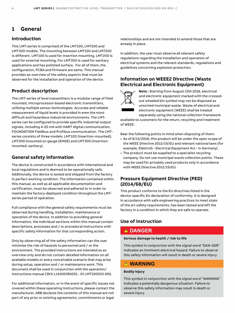
Use of instruction
DANGERSerious damage to health / risk to life
This symbol in conjunction with the signal word “DAN-GER” indicates an imminent electrical hazard Failure to observe this safety information will result in death or severe injury
WARNING Bodily injury
This symbol in conjunction with the signal word “WARNING” indicates a potentially dangerous situation Failure to observe this safety information may result in death or severe injury
LMT S E R I E S | M AG N E TOS TR I C TI V E L E V EL TR A NSM IT TER | SM/L MT 10 0/2 0 0/ 3 0 0 - EN R E V. C 5
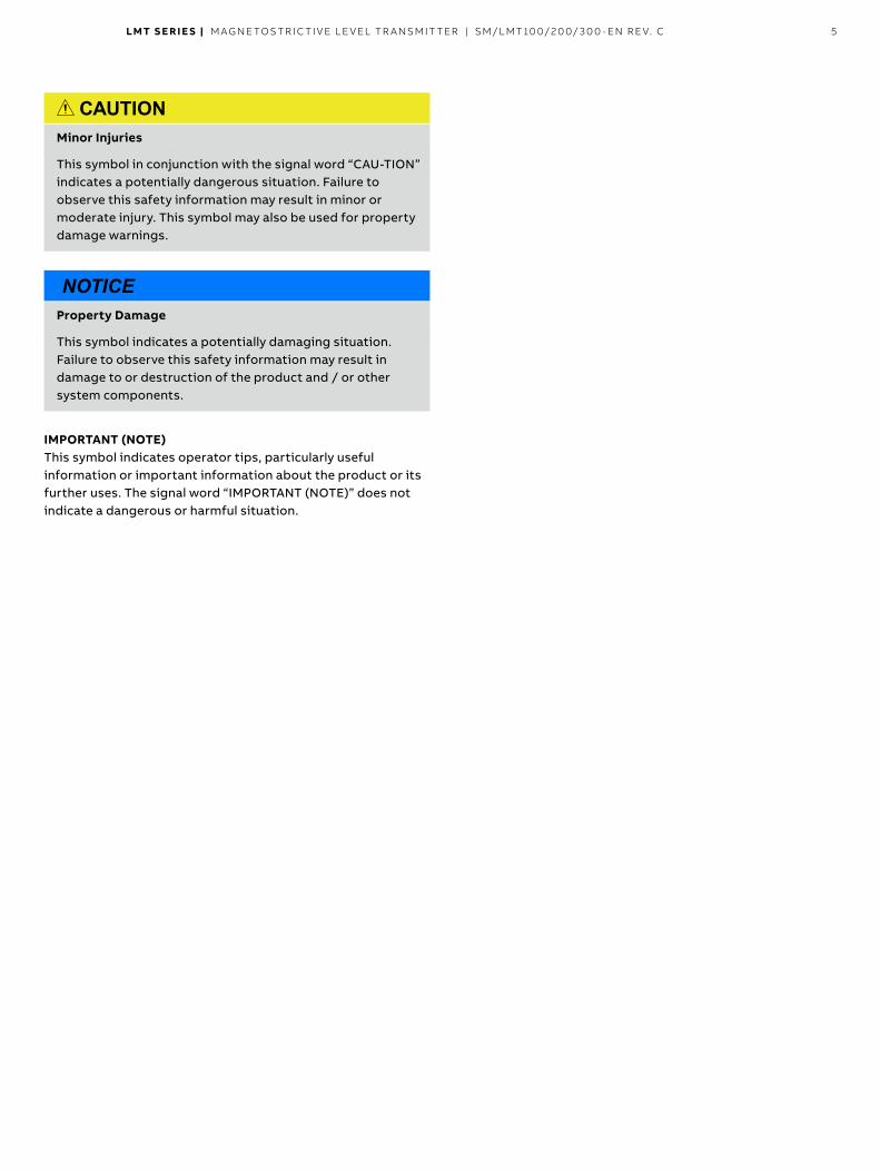
CAUTIONMinor Injuries
This symbol in conjunction with the signal word “CAU-TION” indicates a potentially dangerous situation Failure to observe this safety information may result in minor or moderate injury This symbol may also be used for property damage warnings
NOTICEProperty Damage
This symbol indicates a potentially damaging situation Failure to observe this safety information may result in damage to or destruction of the product and / or other system components
IMPORTANT (NOTE) This symbol indicates operator tips, particularly useful information or important information about the product or its further uses The signal word “IMPORTANT (NOTE)” does not indicate a dangerous or harmful situation
6 LMT S E R I E S | M AG N E TOS TR I C TI V E L E V EL TR A NSM IT TER | SM/L MT 10 0/2 0 0/ 3 0 0 - EN R E V. C
2 Installation in Hazardous Locations
Explosives atmospheres installation For installation requirements in Explosives Atmospheres applications refer to IEC 60079-14 and any local Safety or Electric Code regulations mandatory in your area For specific conditions for safe use of the LMT100 / LMT200 & LMT300 refer to section “Specific conditions for use” of this manual
WARNINGBodily injury .
The device can be operated at high levels of pressure and with aggressive media As a result, serious injury or significant property damage may occur if this device is operated incorrectly
AVERTISSEMENT- Blessure corporelle .
L'appareil peut fonctionner à des niveaux de pression élevés et avec des fluides agressifs Par conséquent, des blessures graves ou des dommages matériels importants peuvent se produire si cet appareil est utilisé de manière incorrecte
CAUTIONMinor injuries .
Only qualified and authorized personnel are to be tasked with the installation, electrical connection, commissioning and maintenance of the transmitter Qualified personnel are those individuals who have experience in the installation, electrical connection, commissioning and operation of the transmitter or similar devices and hold the necessary qualifications These qualifications include:
— Training or instruction — C authorization to operate and maintain devices or systems according to safety engineering standards for electrical circuits, high pressures and aggressive media
— Training or instruction in accordance with safety engineering standards regarding maintenance and use of adequate safety systems
For reasons of safety, ABB recommends that only sufficiently insulated tools, conforming to IEC EN 60900, be used
Since the transmitter may form a link within a safety chain, it is recommended that the device be replaced immediately if defects are detected In the event of use in a hazardous area, only non-sparking tools shall be used
Safety information for electrical installation
WARNINGGeneral risks .
Electrical connections may only be established by authorized personnel in accordance with the electrical circuit diagrams The electrical connection information in the manual must be observed; otherwise, the application protection type may be affected Ground the measurement system according to requirements
AVERTISSEMENT - Risques généraux .
Les connexions électriques ne doivent être établies que par du personnel autorisé conformément aux schémas électriques Les informations de connexion électrique dans le manuel doivent être respectées; Dans le cas contraire, le type de protection de l'application peut être affecté Mettre à la terre le système de mesure en fonction des besoins
Safety information for inspection and maintenance Corrective maintenance work may be performed only by trained personnel • Before removing the device, depressurize the device and any
adjacent lines or containers • Check whether hazardous materials have been used as
measured materials before opening the device Residual amounts of hazardous substances may still be present in the device and could escape when the device is open
• Within the scope of operator responsibility, check the following as part of a regular inspection: • Pressure-bearing walls / lining of the level device • Measurement-related function • Leak-tightness • Wear (corrosion)
Operator liability In instances where corrosive and / or abrasive materials are being measured, the user must check the level of resistance of all parts that are coming into contact with these materials ABB offers guidance in the selection of material but does not accept liability in performing this service The user must strictly observe the applicable national regulations with regards to installing, functional testing, repairing and maintaining electrical devices
Qualified personnel Installing, commissioning and maintaining the device may be per-formed only by trained personnel who are authorized by the plant operator These trained personnel must have read and under-stood this manual and must comply with its instructions
LMT S E R I E S | M AG N E TOS TR I C TI V E L E V EL TR A NSM IT TER | SM/L MT 10 0/2 0 0/ 3 0 0 - EN R E V. C 7
Mounting Read the following installation instructions carefully before proceeding Failure to observe the warnings and instructions may cause a malfunction or personal hazard Before installing the transmitter, ensure the device design meets the requirements of the measurement point from both a measure technology and safety point of view This applies in respect to: • Explosion-protection certification • Measuring range • Pressure • Temperature • Operating voltage
Check the suitability of the materials in regards to their resistance to the media This applies to the: • Gasket • Process connection and seals • Float • Probe • End connection
In addition, the relevant directives, regulations, standards and accident prevention regulations must be observed Measurement accuracy is largely dependent on the correct installation of the level transmitter and, if applicable, mounting arrangement In instances where it is possible, the measuring setup should be free from critical ambient conditions such as large variations in temperature, vibrations or shocks
Certification nameplates Please refer to the section “Identification” of this manual for details
Nameplate marking procedure (declaration of protection concept) Before installing or the first time using the instrument, permanently indicate the protection concept associated with the hazardous area by marking the corresponding box on the product label
Only one box shall be marked The chosen protection concept cannot be altered and shall govern the use of the product until end of life If more than one protection concept is marked, all the hazardous area classification becomes invalid, and the transmitter must be removed from the hazardous area immediately • If the instrument is not intended for use in any of the
applicable hazardous areas classifications, mark the General Purpose box on the product label (See figure 1)
IMPORTANT NOTE Read this manual thoroughly before using this equipment If you do not understand the content of this manual, contact ABB service personnel
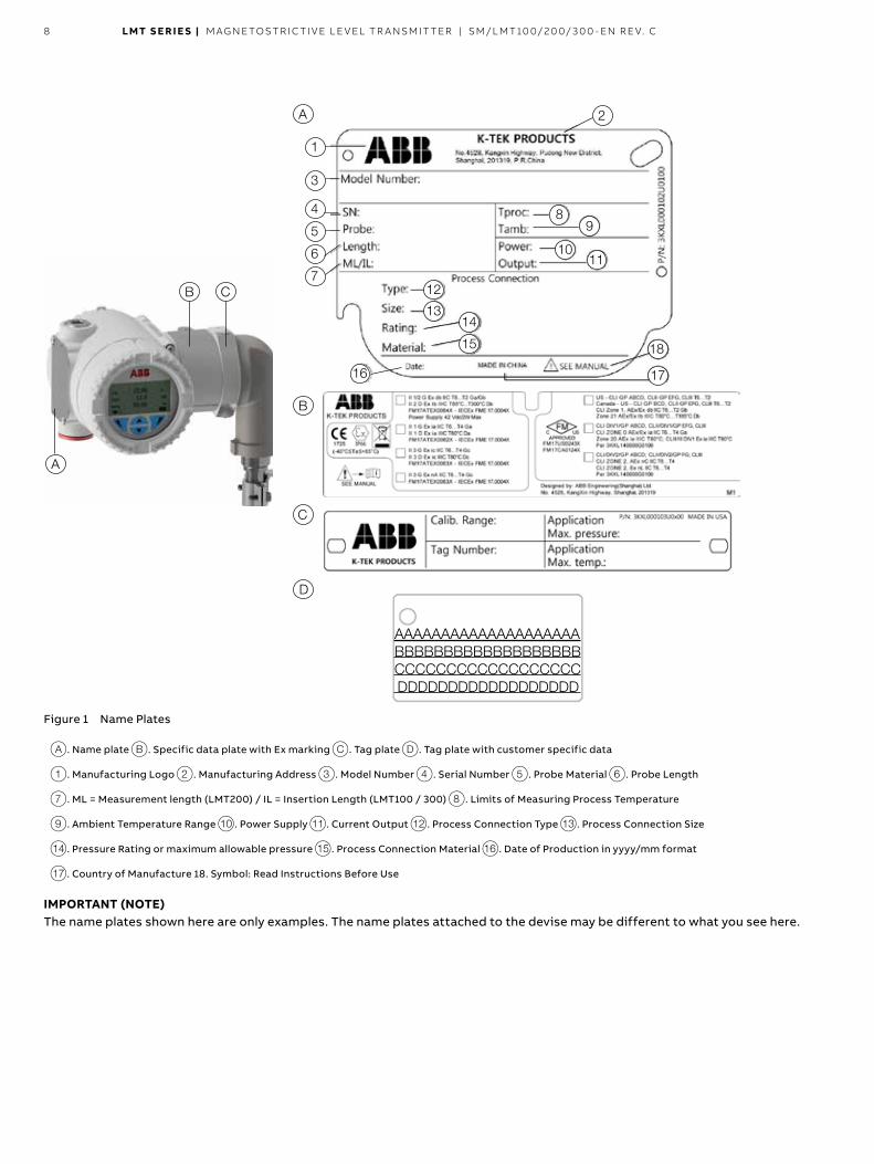
Identification The transmitter is identified by the name plates B The certification plate contains the certification-related parameters for use in a hazardous area
A The nameplate provides information (see figure 1) concerning the model number, probe length, sensor material, process connection type, process connection material, maximum pressure ratings, power supply, output signal, serial number, maximum processed temperature limits and Maximum ambient temperature limits
Please refer to the serial number when speaking to ABB service department personnel
IMPORTANT (NOTE)The name plates shown here are only examples The name plates attached to the devise may be different to what you see below
8 LMT S E R I E S | M AG N E TOS TR I C TI V E L E V EL TR A NSM IT TER | SM/L MT 10 0/2 0 0/ 3 0 0 - EN R E V. C
Figure 1 Name Plates
A Name plate B Specific data plate with Ex marking C Tag plate D Tag plate with customer specific data
1 Manufacturing Logo 2 Manufacturing Address 3 Model Number 4 Serial Number 5 Probe Material 6 Probe Length
7 ML = Measurement length (LMT200) / IL = Insertion Length (LMT100 / 300) 8 Limits of Measuring Process Temperature
9 Ambient Temperature Range 0 Power Supply k Current Output l Process Connection Type m Process Connection Size
n Pressure Rating or maximum allowable pressure o Process Connection Material p Date of Production in yyyy/mm format
q Country of Manufacture 18 Symbol: Read Instructions Before Use
IMPORTANT (NOTE)The name plates shown here are only examples The name plates attached to the devise may be different to what you see here
LMT S E R I E S | M AG N E TOS TR I C TI V E L E V EL TR A NSM IT TER | SM/L MT 10 0/2 0 0/ 3 0 0 - EN R E V. C 9
IP Protection and designation The housing for the LMT-series transmitters is certified as conforming to protection type IP66 (according to IEC 60529) or NEMA 4X (according to NEMA 250)
Cable connection Depending on the design supplied, the electrical connection is established via a cable entry, M20 x 1 5 or 1/2-4 NPT thread
IMPORTANT NOTE With Category 3 transmitters for use in “Zone 2”, a qualified cable gland for this type of protection must be installed by the customer (see the Hazardous Area Consideration section) M20 x 1 5 threads are located in the electronics housing for this purpose For transmitters with a flame-proof enclosure (Exd type of protection, the housing cover must be secured using the locking screw The screw plug that may have been supplied with the transmitter must be sealed at the plant using Molykote DX The installer assumes responsibility for any other type of sealing medium used Increased force is required to unscrew the housing cover after an interval of several weeks This is not caused by the threads but is due to the type of gasket
CAUTION • The cable entry device shall comply with the requirements
of EN 60079-0 and maintain IP 54 or better as required by the installation conditions
• Field wiring should be rated at least 10°C above the maxi-mum ambient temperature
WARNING General risks Cable, cable gland and unused port plug must be in accordance with the intended type of protection (for example, intrinsically safe and explosion-proof) and the degree of protection (for example, IP6x according to IEC EN 60529 or NEMA 4x) See also the addendum for Ex Safety Aspects and IP Protection In particular, for explosion-proof installation, remove the red, temporary plastic cap and plug the unused opening with a plug certified for explosion containment
ATTENTION
Risques généraux Le câble, le presse-étoupe et le bouchon d'orifice non utilisé doivent être conformes au type de protection prévu (par exemple, intrinsèquement sûr et antidéflagrant) et au degré de protection (par exemple IP6x selon IEC EN 60529 ou NEMA 4x) Voir aussi l'addendum pour les aspects de sécurité Ex et la protection de la propriété intellectuelle En particulier, pour une installation antidéflagrante, retirez le capuchon en plastique rouge et branchez l'ouverture inutilisée avec une prise certifiée pour le confinement de l'explosion
Remote version: Connection to remote mount design The signal cable connects the measuring sensor to the transmitter The cable is fixed to the transmitter, however, it can be separated as needed
When laying the signal cable, observe the following points: – Install the signal cable in the shortest path between the measuring sensor and the transmitter Shorten the signal cable accordingly as needed
– The maximum permissible signal cable length is 30 m (99 ft) – Avoid installing the signal cable in the vicinity of electrical equipment or switching elements that can create stray fields, switching pulses and induction If this is not possible, run the signal cable through a metal pipe and connect this to operational ground
– Carry out all terminal connections carefully – Lay the wires in the terminal box in such a way that they are not affected by vibrations
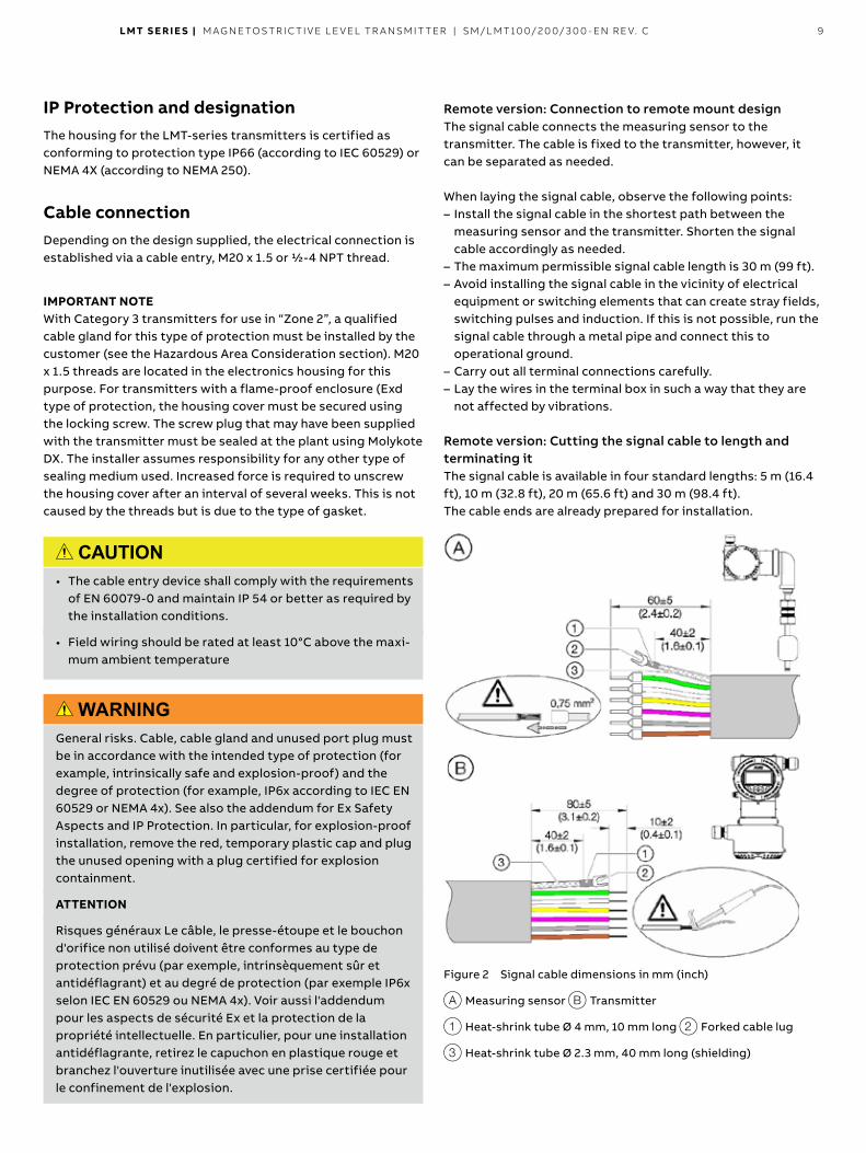
Remote version: Cutting the signal cable to length and terminating it The signal cable is available in four standard lengths: 5 m (16 4 ft), 10 m (32 8 ft), 20 m (65 6 ft) and 30 m (98 4 ft) The cable ends are already prepared for installation
Figure 2 Signal cable dimensions in mm (inch)
A Measuring sensor B Transmitter
1 Heat-shrink tube Ø 4 mm, 10 mm long 2 Forked cable lug
3 Heat-shrink tube Ø 2 3 mm, 40 mm long (shielding)
10 LMT S E R I E S | M AG N E TOS TR I C TI V E L E V EL TR A NSM IT TER | SM/L MT 10 0/2 0 0/ 3 0 0 - EN R E V. C 10
The signal cable can also be cut to any length Then the cable ends must be prepared as below – Twist the shield, shorten and insulate with heat-shrink tube 3 Crimp a matching forked cable lug 2 and insulate the crimping with a heat-shrink tube 1
– Provide the wires on the measuring sensor side with wire-end ferrules (0 75 mm2)
– Twist the wires to the transmitter side and solder
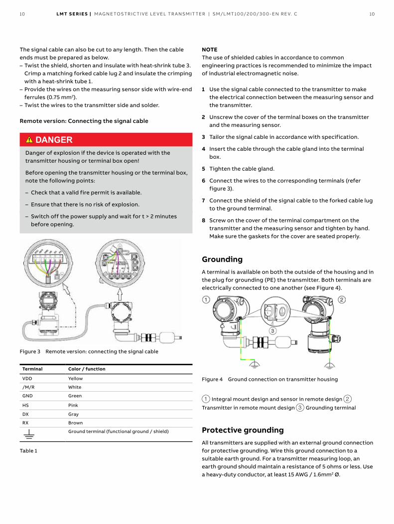
Remote version: Connecting the signal cable
DANGER Danger of explosion if the device is operated with the transmitter housing or terminal box open!
Before opening the transmitter housing or the terminal box, note the following points:
– Check that a valid fire permit is available
– Ensure that there is no risk of explosion
– Switch off the power supply and wait for t > 2 minutes before opening
Figure 3 Remote version: connecting the signal cable
Terminal Color / function
VDD Yellow
/M/R White
GND Green
HS Pink
DX Gray
RX Brown
Ground terminal (functional ground / shield)
Table 1
NOTE The use of shielded cables in accordance to common engineering practices is recommended to minimize the impact of industrial electromagnetic noise
1 Use the signal cable connected to the transmitter to make the electrical connection between the measuring sensor and the transmitter
2 Unscrew the cover of the terminal boxes on the transmitter and the measuring sensor
3 Tailor the signal cable in accordance with specification
4 Insert the cable through the cable gland into the terminal box
5 Tighten the cable gland
6 Connect the wires to the corresponding terminals (refer figure 3)
7 Connect the shield of the signal cable to the forked cable lug to the ground terminal
8 Screw on the cover of the terminal compartment on the transmitter and the measuring sensor and tighten by hand Make sure the gaskets for the cover are seated properly
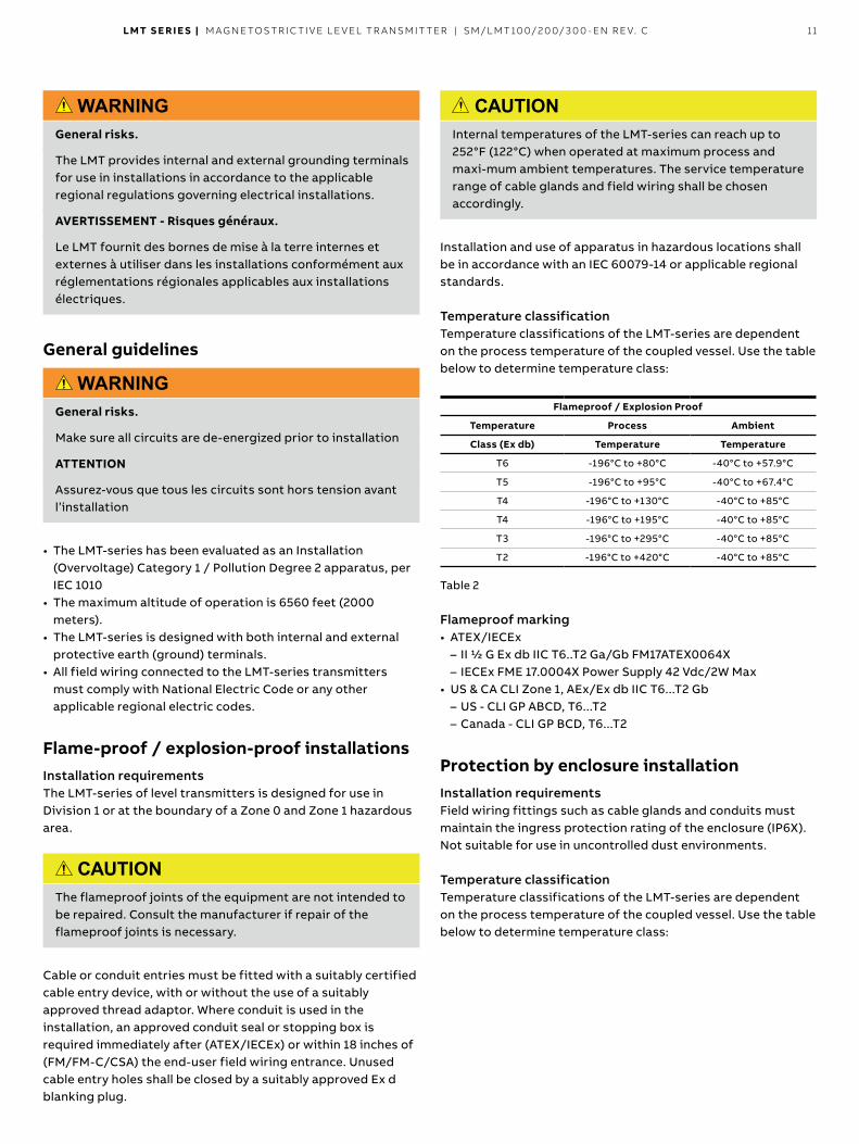
Grounding A terminal is available on both the outside of the housing and in the plug for grounding (PE) the transmitter Both terminals are electrically connected to one another (see Figure 4)
Figure 4 Ground connection on transmitter housing
1 Integral mount design and sensor in remote design 2
Transmitter in remote mount design 3 Grounding terminal
Protective grounding All transmitters are supplied with an external ground connection for protective grounding Wire this ground connection to a suitable earth ground For a transmitter measuring loop, an earth ground should maintain a resistance of 5 ohms or less Use a heavy-duty conductor, at least 15 AWG / 1 6mm2 Ø
LMT S E R I E S | M AG N E TOS TR I C TI V E L E V EL TR A NSM IT TER | SM/L MT 10 0/2 0 0/ 3 0 0 - EN R E V. C 11
WARNINGGeneral risks .
The LMT provides internal and external grounding terminals for use in installations in accordance to the applicable regional regulations governing electrical installations
AVERTISSEMENT - Risques généraux .
Le LMT fournit des bornes de mise à la terre internes et externes à utiliser dans les installations conformément aux réglementations régionales applicables aux installations électriques
General guidelines
WARNINGGeneral risks .
Make sure all circuits are de-energized prior to installation
ATTENTION
Assurez-vous que tous les circuits sont hors tension avant l’installation
• The LMT-series has been evaluated as an Installation (Overvoltage) Category 1 / Pollution Degree 2 apparatus, per IEC 1010
• The maximum altitude of operation is 6560 feet (2000 meters)
• The LMT-series is designed with both internal and external protective earth (ground) terminals
• All field wiring connected to the LMT-series transmitters must comply with National Electric Code or any other applicable regional electric codes
Flame-proof / explosion-proof installations Installation requirements The LMT-series of level transmitters is designed for use in Division 1 or at the boundary of a Zone 0 and Zone 1 hazardous area
CAUTION The flameproof joints of the equipment are not intended to be repaired Consult the manufacturer if repair of the flameproof joints is necessary
Cable or conduit entries must be fitted with a suitably certified cable entry device, with or without the use of a suitably approved thread adaptor Where conduit is used in the installation, an approved conduit seal or stopping box is required immediately after (ATEX/IECEx) or within 18 inches of (FM/FM-C/CSA) the end-user field wiring entrance Unused cable entry holes shall be closed by a suitably approved Ex d blanking plug
CAUTION Internal temperatures of the LMT-series can reach up to 252°F (122°C) when operated at maximum process and maxi-mum ambient temperatures The service temperature range of cable glands and field wiring shall be chosen accordingly
Installation and use of apparatus in hazardous locations shall be in accordance with an IEC 60079-14 or applicable regional standards
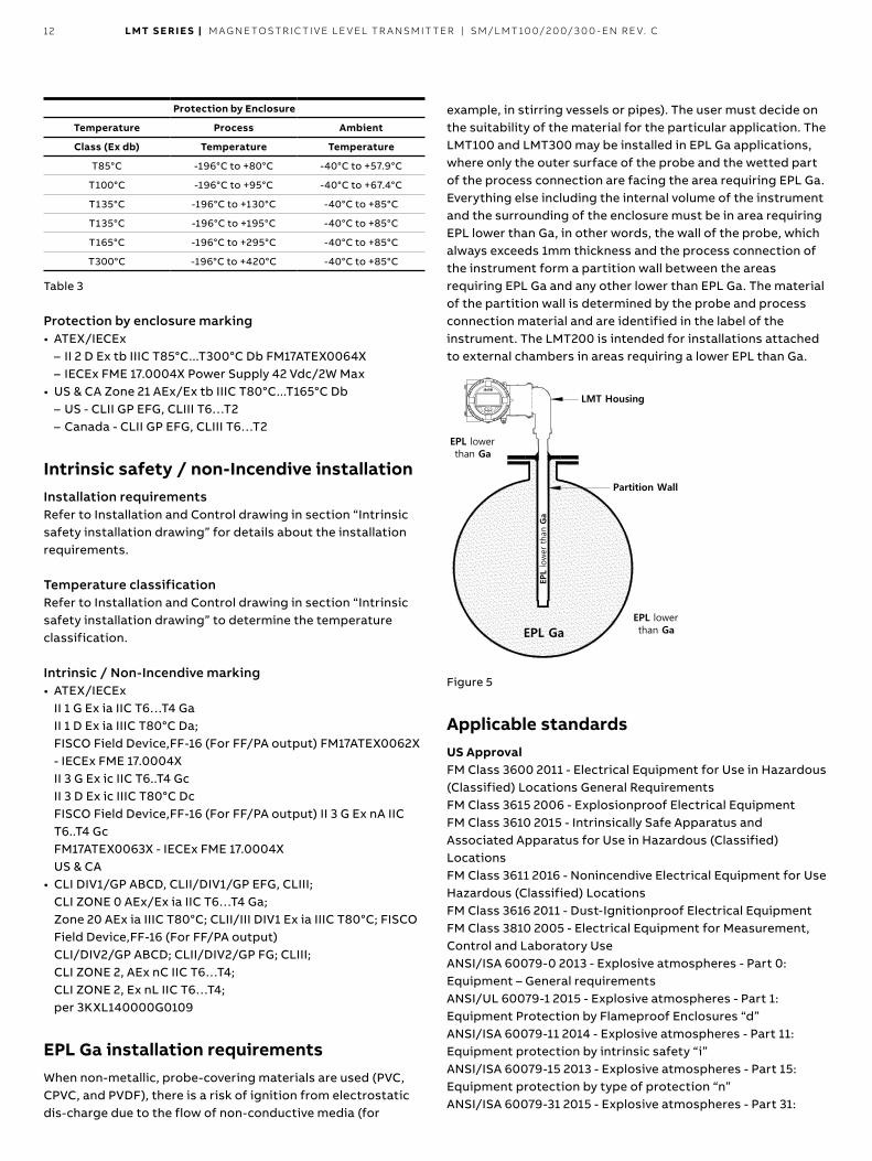
Temperature classification Temperature classifications of the LMT-series are dependent on the process temperature of the coupled vessel Use the table below to determine temperature class:
Flameproof / Explosion Proof
Temperature Process Ambient
Class (Ex db) Temperature Temperature
T6 -196°C to +80°C -40°C to +57.9°C
T5 -196°C to +95°C -40°C to +67.4°C
T4 -196°C to +130°C -40°C to +85°C
T4 -196°C to +195°C -40°C to +85°C
T3 -196°C to +295°C -40°C to +85°C
T2 -196°C to +420°C -40°C to +85°C
Table 2
Flameproof marking • ATEX/IECEx
– II 1/2 G Ex db IIC T6 T2 Ga/Gb FM17ATEX0064X – IECEx FME 17 0004X Power Supply 42 Vdc/2W Max
• US & CA CLI Zone 1, AEx/Ex db IIC T6 T2 Gb – US - CLI GP ABCD, T6 T2 – Canada - CLI GP BCD, T6 T2
Protection by enclosure installation Installation requirements Field wiring fittings such as cable glands and conduits must maintain the ingress protection rating of the enclosure (IP6X) Not suitable for use in uncontrolled dust environments
Temperature classification Temperature classifications of the LMT-series are dependent on the process temperature of the coupled vessel Use the table below to determine temperature class:
12 LMT S E R I E S | M AG N E TOS TR I C TI V E L E V EL TR A NSM IT TER | SM/L MT 10 0/2 0 0/ 3 0 0 - EN R E V. C
Protection by Enclosure
Temperature Process Ambient
Class (Ex db) Temperature Temperature
T85°C -196°C to +80°C -40°C to +57.9°C
T100°C -196°C to +95°C -40°C to +67.4°C
T135°C -196°C to +130°C -40°C to +85°C
T135°C -196°C to +195°C -40°C to +85°C
T165°C -196°C to +295°C -40°C to +85°C
T300°C -196°C to +420°C -40°C to +85°C
Table 3
Protection by enclosure marking • ATEX/IECEx
– II 2 D Ex tb IIIC T85°C T300°C Db FM17ATEX0064X – IECEx FME 17 0004X Power Supply 42 Vdc/2W Max
• US & CA Zone 21 AEx/Ex tb IIIC T80°C T165°C Db – US - CLII GP EFG, CLIII T6…T2 – Canada - CLII GP EFG, CLIII T6…T2
Intrinsic safety / non-Incendive installation Installation requirements Refer to Installation and Control drawing in section “Intrinsic safety installation drawing” for details about the installation requirements
Temperature classification Refer to Installation and Control drawing in section “Intrinsic safety installation drawing” to determine the temperature classification
Intrinsic / Non-Incendive marking • ATEX/IECEx
II 1 G Ex ia IIC T6…T4 Ga II 1 D Ex ia IIIC T80°C Da; FISCO Field Device,FF-16 (For FF/PA output) FM17ATEX0062X - IECEx FME 17 0004X II 3 G Ex ic IIC T6 T4 Gc II 3 D Ex ic IIIC T80°C Dc FISCO Field Device,FF-16 (For FF/PA output) II 3 G Ex nA IIC T6 T4 Gc FM17ATEX0063X - IECEx FME 17 0004X US & CA
• CLI DIV1/GP ABCD, CLII/DIV1/GP EFG, CLIII; CLI ZONE 0 AEx/Ex ia IIC T6…T4 Ga; Zone 20 AEx ia IIIC T80°C; CLII/III DIV1 Ex ia IIIC T80°C; FISCO Field Device,FF-16 (For FF/PA output) CLI/DIV2/GP ABCD; CLII/DIV2/GP FG; CLIII; CLI ZONE 2, AEx nC IIC T6…T4; CLI ZONE 2, Ex nL IIC T6…T4; per 3KXL140000G0109
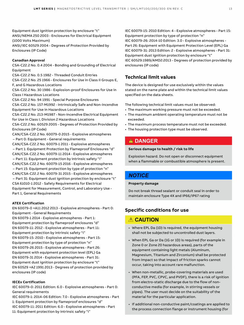
EPL Ga installation requirements When non-metallic, probe-covering materials are used (PVC, CPVC, and PVDF), there is a risk of ignition from electrostatic dis-charge due to the flow of non-conductive media (for
example, in stirring vessels or pipes) The user must decide on the suitability of the material for the particular application The LMT100 and LMT300 may be installed in EPL Ga applications, where only the outer surface of the probe and the wetted part of the process connection are facing the area requiring EPL Ga Everything else including the internal volume of the instrument and the surrounding of the enclosure must be in area requiring EPL lower than Ga, in other words, the wall of the probe, which always exceeds 1mm thickness and the process connection of the instrument form a partition wall between the areas requiring EPL Ga and any other lower than EPL Ga The material of the partition wall is determined by the probe and process connection material and are identified in the label of the instrument The LMT200 is intended for installations attached to external chambers in areas requiring a lower EPL than Ga
LMT Housing
Partition Wall
EPL GaEPL lowerthan Ga
EPL lowerthan Ga
EPL
low
er tha
n G
a
Figure 5
Applicable standards US Approval FM Class 3600 2011 - Electrical Equipment for Use in Hazardous (Classified) Locations General Requirements FM Class 3615 2006 - Explosionproof Electrical Equipment FM Class 3610 2015 - Intrinsically Safe Apparatus and Associated Apparatus for Use in Hazardous (Classified) Locations FM Class 3611 2016 - Nonincendive Electrical Equipment for Use Hazardous (Classified) Locations FM Class 3616 2011 - Dust-Ignitionproof Electrical Equipment FM Class 3810 2005 - Electrical Equipment for Measurement, Control and Laboratory Use ANSI/ISA 60079-0 2013 - Explosive atmospheres - Part 0: Equipment – General requirements ANSI/UL 60079-1 2015 - Explosive atmospheres - Part 1: Equipment Protection by Flameproof Enclosures “d” ANSI/ISA 60079-11 2014 - Explosive atmospheres - Part 11: Equipment protection by intrinsic safety “i” ANSI/ISA 60079-15 2013 - Explosive atmospheres - Part 15: Equipment protection by type of protection “n” ANSI/ISA 60079-31 2015 - Explosive atmospheres - Part 31:
LMT S E R I E S | M AG N E TOS TR I C TI V E L E V EL TR A NSM IT TER | SM/L MT 10 0/2 0 0/ 3 0 0 - EN R E V. C 13
Equipment dust ignition protection by enclosure “t” ANSI/NEMA 250 2003 - Enclosures for Electrical Equipment (1000 Volts Maximum) ANSI/IEC 60529 2004 - Degrees of Protection Provided by Enclosures (IP Code)
Canadian Approval CSA-C22 2 No 0 4 2004 - Bonding and Grounding of Electrical Equipment CSA-C22 2 No 0 5 1982 - Threaded Conduit Entries CSA-C22 2 No 25 1966 - Enclosures for Use in Class II Groups E, F, and G Hazardous Locations CSA-C22 2 No 30 1986 - Explosion-proof Enclosures for Use in Class I Hazardous Locations CSA-C22 2 No 94 1991 - Special Purpose Enclosures CSA-C22 2 No 157-M1992 - Intrinsically Safe and Non-Incendive Equipment for Use in Hazardous Locations CSA-C22 2 No 213-M1987 - Non-Incendive Electrical Equipment for Use in Class I, Division 2 Hazardous Locations CSA-C22 2 No 60529 2005 - Degrees of Protection Provided by Enclosures (IP Code) CAN/CSA-C22 2 No 60079-0 2015 - Explosive atmospheres
– Part 0: Equipment - General requirements CAN/CSA-C22 2 No 60079-1 2011 - Explosive atmospheres
– Part 1: Equipment Protection by Flameproof Enclosures “d” CAN/CSA-C22 2 No 60079-11 2014 - Explosive atmospheres
– Part 11: Equipment protection by intrinsic safety “i” CAN/CSA-C22 2 No 60079-15 2016 - Explosive atmospheres
– Part 15: Equipment protection by type of protection “n” CAN/CSA-C22 2 No 60079-31 2015 - Explosive atmospheres
– Part 31: Equipment dust ignition protection by enclosure “t” CSA 61010-1 2012 - Safety Requirements for Electrical Equipment for Measurement, Control, and Laboratory Use - Part 1, General Requirements
ATEX Certification EN 60079-0 +A11 2012 2013 - Explosive atmospheres - Part 0: Equipment - General Requirements EN 60079-1 2014 - Explosive atmospheres - Part 1: Equipment protection by flameproof enclosures “d” EN 60079-11: 2012 - Explosive atmospheres - Part 11: Equipment protection by intrinsic safety “i” EN 60079-15: 2010 - Explosive atmospheres - Part 15: Equipment protection by type of protection “n” EN 60079-26 2015 - Explosive atmospheres - Part 26: Equipment with equipment protection level (EPL) Ga EN 60079-31 2014 - Explosive atmospheres - Part 31: Equipment dust ignition protection by enclosure “t” EN 60529 +A2 1991 2013 - Degrees of protection provided by enclosures (IP code)
IECEx Certification IEC 60079-0: 2011 Edition: 6 0 - Explosive atmospheres - Part 0: General requirements IEC 60079-1: 2014-06 Edition: 7 0 - Explosive atmospheres - Part 1: Equipment protection by flameproof enclosures “d” IEC 60079-11: 2011 Edition: 6 0 - Explosive atmospheres - Part 11: Equipment protection by intrinsic safety “i”
IEC 60079-15: 2010 Edition: 4 - Explosive atmospheres - Part 15: Equipment protection by type of protection “n” IEC 60079-26: 2014-10 Edition: 3 0 - Explosive atmospheres - Part 26: Equipment with Equipment Protection Level (EPL) Ga IEC 60079-31: 2013 Edition: 2 - Explosive atmospheres - Part 31: Equipment dust ignition protection by enclosure “t” IEC 60529:1989/AMD2:2013 - Degrees of protection provided by enclosures (IP code)
Technical limit values The device is designed for use exclusively within the values stated on the name plate and within the technical limit values specified on the data sheets
The following technical limit values must be observed: • The maximum working pressure must not be exceeded • The maximum ambient operating temperature must not be
exceeded • The maximum process temperature must not be exceeded • The housing protection type must be observed
DANGER Serious damage to health / risk to life
Explosion hazard Do not open or disconnect equipment when a flammable or combustible atmosphere is present
NOTICEProperty damage
Do not break thread sealant or conduit seal in order to maintain enclosure Type 4X and IP66/IP67 rating
Specific conditions for use
CAUTION • Where EPL Da (1D) is required, the equipment housing
shall not be subjected to uncontrolled dust layers
• When EPL Ga or Da (1G or 1D) is required (for example in Zone 0 or Zone 20 hazardous areas), parts of the equipment containing light metals (Aluminum, Magnesium, Titanium and Zirconium) shall be protected from impact so that impact of friction sparks cannot occur, taking into account rare malfunction
• When non-metallic, probe-covering materials are used (PFA, FEP, PVC, CPVC, and PVDF), there is a risk of ignition from electro-static discharge due to the flow of non-conductive media (for example, in stirring vessels or pipes) The user must decide on the suitability of the material for the particular application
• If additional non-conductive paint/coatings are applied to the process connection flange or instrument housing (for
14 LMT S E R I E S | M AG N E TOS TR I C TI V E L E V EL TR A NSM IT TER | SM/L MT 10 0/2 0 0/ 3 0 0 - EN R E V. C
example, to provide additional corrosion resistance) there may exist a risk of electrostatic discharge due to charge build-up on the non-conductive paint/coating layer The user shall take appropriate mitigations measures in accordance with their own risk assessment
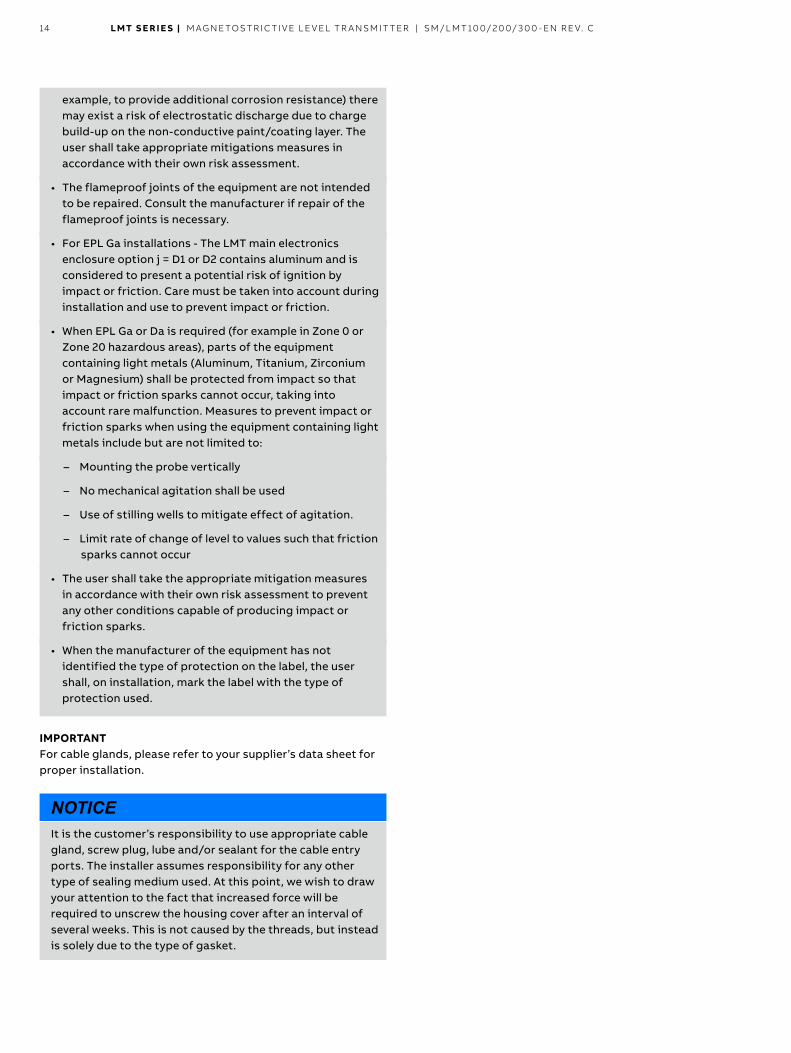
• The flameproof joints of the equipment are not intended to be repaired Consult the manufacturer if repair of the flameproof joints is necessary
• For EPL Ga installations - The LMT main electronics enclosure option j = D1 or D2 contains aluminum and is considered to present a potential risk of ignition by impact or friction Care must be taken into account during installation and use to prevent impact or friction
• When EPL Ga or Da is required (for example in Zone 0 or Zone 20 hazardous areas), parts of the equipment containing light metals (Aluminum, Titanium, Zirconium or Magnesium) shall be protected from impact so that impact or friction sparks cannot occur, taking into account rare malfunction Measures to prevent impact or friction sparks when using the equipment containing light metals include but are not limited to:
– Mounting the probe vertically
– No mechanical agitation shall be used
– Use of stilling wells to mitigate effect of agitation
– Limit rate of change of level to values such that friction sparks cannot occur
• The user shall take the appropriate mitigation measures in accordance with their own risk assessment to prevent any other conditions capable of producing impact or friction sparks
• When the manufacturer of the equipment has not identified the type of protection on the label, the user shall, on installation, mark the label with the type of protection used
IMPORTANTFor cable glands, please refer to your supplier’s data sheet for proper installation
NOTICEIt is the customer’s responsibility to use appropriate cable gland, screw plug, lube and/or sealant for the cable entry ports The installer assumes responsibility for any other type of sealing medium used At this point, we wish to draw your attention to the fact that increased force will be required to unscrew the housing cover after an interval of several weeks This is not caused by the threads, but instead is solely due to the type of gasket
LMT S E R I E S | M AG N E TOS TR I C TI V E L E V EL TR A NSM IT TER | SM/L MT 10 0/2 0 0/ 3 0 0 - EN R E V. C 15
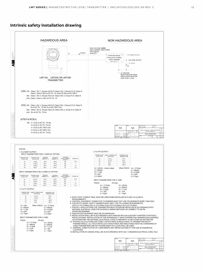
Intrinsic safety installation drawing
R
+
I.S. GROUNDRESISTANCE BETWEENGND & EARTH MUST BELESS THAN 1.0 ohm
+ APPROVED SINGLEOR MULTIPLE CHANNEL
SAFETY BARRIERSEE NOTE 7
VOLTAGE OUTPUT
4~20mA
+ +V,POWER SOUCE
3
1
2017-10-10 Kevin.Qu
N/AN/A
NC 2016-10-21 Norman.W.G
00 2017-10-11 Kevin.Qu
INSTALLATION AND CONTROL DRAWINGSFOR LMT PRODUCTS
3KXL140000G0109
-
4~20mA
MAX.VOLTAGE 30VDCMAX.CURRENT AND POWERPER TABLESIN NOTE 1
- -
HAZARDOUS AREA NON HAZARDOUS AREA
LMT100 LMT200 OR LMT300TRANSMITTER
(US) (IS) Class I, Div 1, Groups A,B,C,D; Class II,Div 1,Group E,F,G; Class III
(NI) Class I, Div 2, Groups A,B,C,D; Class II,Div 2, Group F,G; Class III(nA) Class I, Zone 2, AEx nA IIC T6...T4
(CA) (IS) Class I, Div 1, Groups A,B,C,D; Class II,Div 1,Group E,F,G; Class III
(NI) Class I, Div 2, Groups A,B,C,D; Class II,Div 2, Group F,G; Class III(nA) Ex nA IIC T6...T4 Gc
(ATEX & IECEx)(IS) II 1 G Ex ia IIC T6...T4 Ga;
II 3 G Ex ic IIC T6...T4 Gc;II 1 D Ex ia IIIC T80°C Da;II 3 D Ex ic IIIC T80°C Dc;II 3 G Ex ic IIC T6...T4 Gc;
Class I, Zone 0 AEx ia IIC T6...T4; Zone 20 AEx ia IIIC T80°C
Ex ia IIC T6...T4 Ga; Ex ia IIIC T80°C Da
01 2018-01-09 Kevin.Qu
3
2
2017-10-10 Kevin.Qu
N/AN/A
NC 2016-10-21 Norman.W.G
00 2017-10-11 Kevin.Qu
INSTALLATION AND CONTROL DRAWINGSFOR LMT PRODUCTS
3KXL140000G0109
NOTES:
TEMPERATURECLASS- GAS
T4
Imax(mA)
TEMPERATURECLASS- DUST
MINIMUMAMBIENT(°C)
MAXIMUMAMBIENT(°C)
MAXIMUMINPUT-CURRENT POWER (W)
T4T5
T6
T135°CT135°C
T100°C
T85°C
+85°C
+70°C+40°C
+40°C
-40°C
-40°C
-40°C-40°C
100
160
100
50
0.75
11.4
0.4
TEMPERATURECLASS- GAS
T4
Imax(mA)
TEMPERATURECLASS- DUST
MINIMUMAMBIENT(°C)
MAXIMUMAMBIENT(°C)
MAXIMUMINPUT-CURRENT POWER (W)
T4T5
T6
T135°CT135°C
T100°C
T85°C
+60°C
+60°C+56°C
+44°C
-40°C
-40°C
-40°C-40°C
100
160
100
50
0.75
11.4
0.4
INPUT PARAMETERS FOR L2 DISPLAY OPTION
INPUT PARAMETERS FOR L1 DISPLAY OPTION
4. DUST-TIGHT CONDUIT SEAL MUST BE USED WHEN INSTALLED IN CLASS II & CLASS IIIENVIRONMENTS.
5. CONTROL EQUIPMENT CONNECTED TO BARRIER MUST NOT USE OR GENERATE MORE THAN 250V.6. FOR ENTITY MODEL SAFETY BARRIER MUST MEET THE FOLLOWING REQUIREMENTS:
V(OC) or V(T)<V(Max),I(SC) or I(T)<I(Max),C(A)>(C(I)+C(Cable)),L(A)>(L(I)+L(Cable)).7. FOR DIV 2 APPLICATIONS,THE TRANSMITTER MUST EITHER BE INSTALLED IN ACCORDANCE WITH
NATIONAL ELETRICAL CODE FOR DIVISION 2 WIRING METHODS OR CONNECT TO AN FMAPPROVED BARRIER.
8. ASSOCIATED EQUIPMENT MUST BE FM APPROVED.9. INSTALLATION SHALL BE IN ACCORDANCE WITH ANSI/ISA RP12.06.01(EXCEPT CHAPTER 5 FOR FISCO
INSTALLATIONS) "INSTALLATION OF THE INTRINSICALLY SAFE SYSTEMS FOR HAZARDOUS(CLASSIFIED)LOCATIONS"AND THE NATIONAL ELECTRICAL CODE ® (ANSI/NFPA 70) SECTIONS 504,505 AND 506.
10. SYSTEM CALCULATIONS:ADD CABLE CAPACITANCE & INDUCTANCE TO TRANSMITTER ENTITYPARAMETERS(I.E. ALL FIELD INSTALLED CAPACITANCE AND INDUCTANCE MUST BE CONSIDERED) IFCABLE PARAMETERS ARE NOT KNOWN,60pF/FT& 0.2uH/ft SHALL BE USED.
11. WARNING: SUBSTITUTION OF COMPONENTS MAY IMPAIR SUITABILITY FOR USE IN HAZARDOUSLOCATIONS.
12.INSTALLATION IN CANADA SHALL BE IN ACCORDANCE WITH C22.1 CANADIAN ELECTRICAL CODE, Part I.
1. For HART OUTPUT:
2. For FF OUTPUT:
TEMPERATURECLASS- GAS
T6
AMIENT TMPERATURELIMITATION
T5T4
T4
57.9°C67.4°C
85°C
85°C
80°C
95°C
130°C195°C
MAXIMUM FLUIDTEMPERATURE
Ui = 24VIi = 250mAPi = 1.2WCi 5nFLi 10µH
Ui = 17.5VdcIi = 380mAPi = 5.32WCi 5nFLi 20µH
When FISCO:
INPUT PARAMETERS FOR 'ic" ARE:
Ui = 17.5VdcIi = 380mAPi = 5.32WCi < 5nFLi <10µH
Ui = 32VdcIi = 250mAPi = 1.2 WCi < 5nFLi < 10µH
FISCO: FF-816
3. For PA OUTPUT:
TEMPERATURECLASS- GAS
T6
AMIENT TMPERATURELIMITATION
T5T4
T4
57.9°C67.4°C
85°C
85°C
80°C
95°C
130°C195°C
MAXIMUM FLUIDTEMPERATURE
Ui = 24Vdc - Linear outputIi = 250mAPi = 1.2WCi 5nFLi 20µH
Ui = 17.5VdcIi = 360mAPi = 2.52WCi 5nFLi 10µH
When FISCO:
INPUT PARAMETERS FOR 'ic" ARE:
Ui = 17.5VdcIi = 380mAPi = 5.32WCi < 5nFLi <10µH
Ui = 32VdcIi = 250mAPi = 1.2 WCi < 5nFLi < 10µH
FISCO: FF-816
01 2018-01-09 Kevin.Qu
16 LMT S E R I E S | M AG N E TOS TR I C TI V E L E V EL TR A NSM IT TER | SM/L MT 10 0/2 0 0/ 3 0 0 - EN R E V. C
3
3
2017-10-10 Kevin.Qu
N/AN/A
NC 2016-10-21 Norman.W.G
00 2017-10-11 Kevin.Qu
INSTALLATION AND CONTROL DRAWINGSFOR LMT PRODUCTS
3KXL140000G0109
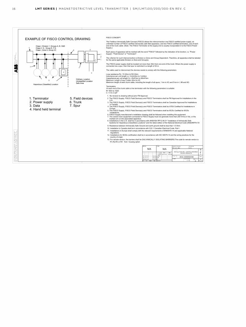
EXAMPLE OF FISCO CONTROL DRAWING
1. Terminator2. Power supply3. Data4. Hand held terminal
5. Field devices6. Trunk7. Spur
FISCO CONCEPT
The Fieldbus Intrinsically Safe Concept (FISCO) allows the interconnection one FISCO certified power supply, anunlimited number of FISCO certified intrinsically safe field apparatus, and two FISCO certified terminators, one of eachend of the trunk cable. (Note: The FISCO Terminator at the supply end is usually incorporated in to the FISCO PowerSupply.)
Each piece of apparatus will be marked with the word "FISCO" followed by the indication of its function, i.e. "PowerSupply", "Field Device" or "Terminator".
The criterion for such interconnection is Division or Zone and Group Dependent. Therefore, all apparatus shall be labeledfor the same applicable Division or Zone and Group(s).
The FISCO power supply shall be located not more than 30m from one end of the trunk. Where the power supply isconnected via a spur, then that spur is restricted to a length of 30 m.
The cable used to interconnect the devices needs to comply with the following parameters:
Loop resistance Rc: 15 /km to150 /kmInductance per unit length Lc: 0.4mH/km to 1mH/kmCapacitance per unit length Cc: 45nF/km to 200nF/kmMaximum Length of spur Cable: 60m for IICMaximum length of each trunk cable, including the length of all spurs, 1 km in IIC and 5 km in I, IIB and IIIC.
TerminatorsAt each end of the trunk cable a line terminator with the following parameters is suitable:R= 90 to 102C = 0 to 2.2µF
1. No revision to drawing without prior FM Approval.2. The FISCO Supply, FISCO Field Device(s) and FISCO Terminators shall be FM Approved for installations in the
U.S.3. The FISCO Supply, FISCO Field Device(s) and FISCO Terminators shall be Canadian Approved for Installations
in Canada.4. The FISCO Supply, FISCO Field Device(s) and FISCO Terminators shall be ATEX Certified for Installations in
Europe.5. The FISCO Supply, FISCO Field Device(s) and FISCO Terminators shall be IECEx Certified for IECEx
installations.6. FISCO Supply manufacturer's installation drawing shall be followed when installing this equipment.7. The control room equipment connected to FISCO Supply must not generate more than 250 Vrms or Vdc, or the
marked Um on the associated apparatus.8. Installations in the U.S. shall be in accordance with ANSI/ISA RP12.06.01 "installation of Intrinsically Safe
Systems for Hazardous (Classified) Locations" and the latest edition of the National Electrical Code (ANSI/NFPA 70)
9. Resistance between Intrinsically Safe Ground and earth ground shall be less than 1.0 Ohm.10. Installation in Canada shall be in accordance with C22.1 Canadian Electrical Code, Part I.11. Installations in Europe shall comply with the relevant requirements of EN60079-14 and applicable National
regulations.12. Installations for IECEx certification shall be in accordance with IEC 60079-14 and the wiring practices for the
country of origin.
01 2018-01-09 Kevin.Qu
13. For remote version, the barriers shall be GALVANICALLY ISOLATING BARRIERS.The code for remote version isR1,R2,R3 or R4 from housing option
LMT S E R I E S | M AG N E TOS TR I C TI V E L E V EL TR A NSM IT TER | SM/L MT 10 0/2 0 0/ 3 0 0 - EN R E V. C 17
3 Functional safety (for HART version)
SIL General Information
NOTE This functional safety is valid for Magnetostrictive level transmitter LMT100/200/300 with Hart output signal (H1 — Single 4 ... 20 mA + HART") and”SIL2 for HFT=0, SIL3 for HFT=1 --- certified acc. to IEC 61508".
Each device design has a specific type designation The parts of the model number relating to the SIL approval are listed in the table of device data sheet The complete key to model numbers is described in the device data sheet The type designation is located on the name plate of the device
CAUTION The HART protocol is non-safety related, which is only used for setup, calibration, and diagnostic purposes, not during operation
The HART protocol shall never be used in safety related applications
• LMT Sensor The sensor used in this transmitter is based on the magnetostriction principle Sensor includes a magnetostrictive wire through which current pass to generate a magnet field, the magnets within the float generate orthotropic magnet field The interaction between these two orthotropic magnet fields produces a torsion on the sensor wire LMT series includes the following types: LMT100 LMT200, LMT300 The mounting between LMT100 and LMT200 is different LMT100 is intended for insertion mounting LMT200 is intended for external mounting, For LMT300 is used in sanitary application and has polished surface For all of them, the configuration, PCBA and firmware are the same
• Reference Documents – TüV Report and Certificate – FMEDA Report
• Acronyms and abbreviations
18 LMT S E R I E S | M AG N E TOS TR I C TI V E L E V EL TR A NSM IT TER | SM/L MT 10 0/2 0 0/ 3 0 0 - EN R E V. C
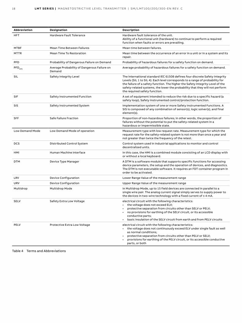
Abbreviation Designation Description
HFT Hardware Fault Tolerance Hardware fault tolerance of the unit Ability of a functional unit (hardware) to continue to perform a required function when faults or errors are prevailing
MTBF Mean Time Between Failures Mean time between failures
MTTR Mean Time To Restoration Mean time between the occurrence of an error in a unit or in a system and its repair
PFD Probability of Dangerous Failure on Demand Probability of hazardous failures for a safety function on demand
PFDAVG Average Probability of Dangerous Failure on Demand
Average probability of hazardous failures for a safety function on demand
SIL Safety Integrity Level The international standard IEC 61508 defines four discrete Safety Integrity Levels (SIL 1 to SIL 4). Each level corresponds to a range of probability for the failure of a safety function The higher the Safety Integrity Level of the safety-related systems, the lower the probability that they will not perform the required safety function
SIF Safety Instrumented Function A set of equipment intended to reduce the risk due to a specific hazard (a safety loop), Safety instrumented control/protection function
SIS Safety Instrumented System Implementation system of one or more Safety Instrumented Functions A SIS is composed of any combination of sensor(s), logic solver(s), and final element(s)
SFF Safe Failure Fraction Proportion of non-hazardous failures; in other words, the proportion of failures without the potential to put the safety-related system in a hazardous or impermissible state
Low Demand Mode Low Demand Mode of operation Measurement type with low request rate Measurement type for which the request rate for the safety-related system is not more than once a year and not greater than twice the frequency of the retest
DCS Distributed Control System Control system used in industrial applications to monitor and control decentralized units
HMI Human Machine Interface In this case, the HMI is a combined module consisting of an LCD display with or without a local keyboard
DTM Device Type Manager A DTM is a software module that supports specific functions for accessing device parameters, the setup and the operation of devices, and diagnostics The DTM is not executable software It requires an FDT container program in order to be activated
LRV Device Configuration Lower Range Value of the measurement range
URV Device Configuration Upper Range Value of the measurement range
Multidrop Multidrop Mode In Multidrop Mode, up to 15 field devices are connected in parallel to a single wire pair The analog current signal simply serves to supply power to the devices in two-wire technology with a fixed current of ≤ 4 mA.
SELV Safety Extra Low Voltage electrical circuit with the following characteristics: • the voltage does not exceed ELV; • protective separation from circuits other than SELV or PELV; • no provisions for earthing of the SELV circuit, or its accessible
conductive parts; • basic insulation of the SELV circuit from earth and from PELV circuits
PELV Protective Extra Low Voltage electrical circuit with the following characteristics: • the voltage does not continuously exceed ELV under single fault as well
as normal conditions; • protective separation from circuits other than PELV or SELV; • provisions for earthing of the PELV circuit, or its accessible conductive
parts, or both
Table 4 Terms and Abbreviations
LMT S E R I E S | M AG N E TOS TR I C TI V E L E V EL TR A NSM IT TER | SM/L MT 10 0/2 0 0/ 3 0 0 - EN R E V. C 19
SIL Standards and definitions of terms LMT Transmitter related standards • Standard IEC 61508 (2010) (Edition 2), Part 1 to 7 – English Functional safety of electrical / electronic / programmable electronic safety-related systems (Target group: Manufacturers and Suppliers of Devices)
– German Funktionale Sicherheit sicherheitsbezogener elektrischer / elektronischer / programmierbarer elektronischer Systeme (Zielgruppe: Hersteller und Lieferanten von Geräten)
LMT Sensor related standards • IEC 61508 Parts 1-2 and 4-7:2010 Functional safety of
electrical/electronic/ programmable electronic safety-related systems
• IEC 61511 Parts 1-3:2016 Functional safety - Safety instrumented systems for the process industry sector
Dangerous failure A failure that has the potential to place the safety-related system in a dangerous state or render the system inoperative
Safety-related system A safety-related system performs the safety functions that are required to achieve or maintain a safe condition, e g , in a plant Example: pressure meter, logics unit (e g , limit signal generator) and valve form a safety-related system
Safety function A specified function that is performed by a safety-related system with the goal, under consideration of a defined hazardous incident, of achieving or maintaining a safe condition for the plant Example: limit pressure monitoring
Determine the Safety Integrity Level (SIL) The transmitter produces an analog signal (4 20 mA) proportional to the level value The total valid range of the output signal shall be configured to a minimum of 3 8 mA and a maximum of 20 5 mA (Factory Default) The safety related function of the transmitter is the safe monitoring of the level value within a range of ±2 % of span (±2 % of 16 mA) The safety state is that the output current is <= 3 6 mA or >= 21 mA
Alarm response and current output In case of detected critical faults the configured alarm current will be produced - this is fed to a subsequent logic unit, e g a DCS and monitored for violation of a defined maximum value
There are two selectable modes for this alarm current: – HIGH (Max Alarm current) – LOW (Min Alarm current) which is the factory default setting
The low alarm current value is configurable from 3 5 to 3 6 mA with a factory default setting to 3 55 mA The high alarm current value is configurable from 21 0 mA to 22 6 mA with a factory default setting at 21 0 mA The current output during power up is 3 5 mA The reaction time after the occurrence of a critical error until the output of the alarm current amounts to ≤ 15 min.
General failures will be immediately signaled with LOW or HIGH depending of the configured value (Factory Default Alarm Failure Mode = LOW) CPU internal faults will always result in LOW alarm independently of the selected Alarm Failure Mode If a current drift failure (mismatch between actual and intended current output) id detected the alarm will be triggered according below rules:
– The detected current drift exceeds the expected value by more than 0 32mA, in this case High alarm will be triggered independently of the selected Alarm Failure Mode
– The detected current drift falls behind the expected value by more than 0 32mA, in this case Low alarm will be triggered independently of the selected Alarm Failure Mode
NOTE For a safe fault monitoring the following conditions must be fulfilled:
– The LOW ALARM must be configured with a value <= 3 6 mA
– The HIGH ALARM must be configured with a value >= 21 mA
– The DCS must be capable of recognizing the configured High Alarms or Low Alarms as a malfunction detection
– For a safe current output operation the terminal voltage at the device must be given from 12 42 V
Note: SELV/PELV is requirement for external power supply
The DCS loop must be capable to provide the required voltage level even if the current output operates on the configured HIGH alarm
The device is not safety compliant during the following conditions: – During Configuration – If the HART Multidrop mode is activated – During Simulation – During Test of the safety function – During Device software updates/hardware change
The fraction of failures without the potential to put the device into a dangerous function status is given by the SFF value shown in chapter “Device specific data related to functional safety”
20 LMT S E R I E S | M AG N E TOS TR I C TI V E L E V EL TR A NSM IT TER | SM/L MT 10 0/2 0 0/ 3 0 0 - EN R E V. C
Overall safety accuracy The defined value for the “Total Safety Accuracy” of the safety function of this device is: ±2 % of span (±2 % of 16 mA)
LMT sensor functional Safety relevant specifications
LMT sensor safety function LMT Float/Magnets are considered part of the safety function because they determine the level/position measured by the instrument When located at the target position will generate a torsional wave that propagates along the magnetostrictive sensor wire with a speed of approximately 2822 m/s The piezoelectric sensor detect the torsional wave and convert it into electrical signal Finally, the built-in electronics measures the propagation time, typically between 150us-8100us, from which the level/position is calculated
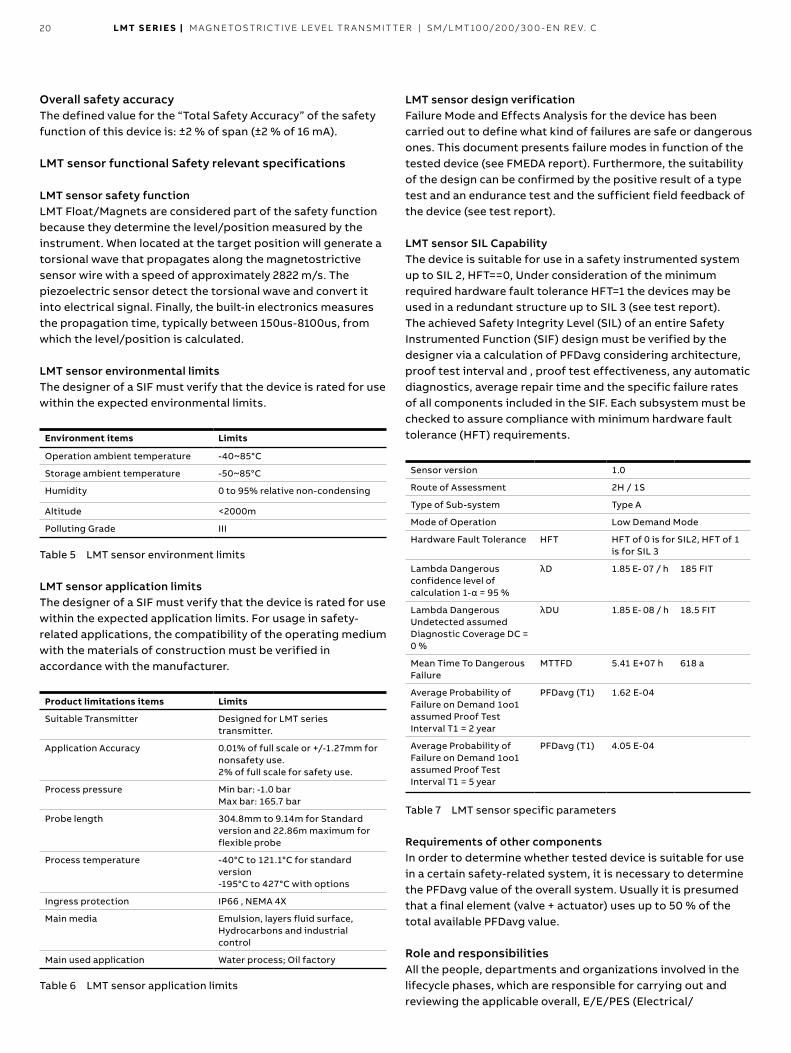
LMT sensor environmental limits The designer of a SIF must verify that the device is rated for use within the expected environmental limits
Environment items Limits
Operation ambient temperature -40~85°C
Storage ambient temperature -50~85°C
Humidity 0 to 95% relative non-condensing
Altitude <2000m
Polluting Grade III
Table 5 LMT sensor environment limits
LMT sensor application limits The designer of a SIF must verify that the device is rated for use within the expected application limits For usage in safety-related applications, the compatibility of the operating medium with the materials of construction must be verified in accordance with the manufacturer
Product limitations items Limits
Suitable Transmitter Designed for LMT series transmitter
Application Accuracy 0.01% of full scale or +/-1.27mm for nonsafety use 2% of full scale for safety use.
Process pressure Min bar: -1.0 barMax bar: 165.7 bar
Probe length 304.8mm to 9.14m for Standard version and 22.86m maximum for flexible probe
Process temperature -40°C to 121.1°C for standard version -195°C to 427°C with options
Ingress protection IP66 , NEMA 4X
Main media Emulsion, layers fluid surface, Hydrocarbons and industrial control
Main used application Water process; Oil factory
Table 6 LMT sensor application limits
LMT sensor design verification Failure Mode and Effects Analysis for the device has been carried out to define what kind of failures are safe or dangerous ones This document presents failure modes in function of the tested device (see FMEDA report) Furthermore, the suitability of the design can be confirmed by the positive result of a type test and an endurance test and the sufficient field feedback of the device (see test report)
LMT sensor SIL Capability The device is suitable for use in a safety instrumented system up to SIL 2, HFT==0, Under consideration of the minimum required hardware fault tolerance HFT=1 the devices may be used in a redundant structure up to SIL 3 (see test report) The achieved Safety Integrity Level (SIL) of an entire Safety Instrumented Function (SIF) design must be verified by the designer via a calculation of PFDavg considering architecture, proof test interval and , proof test effectiveness, any automatic diagnostics, average repair time and the specific failure rates of all components included in the SIF Each subsystem must be checked to assure compliance with minimum hardware fault tolerance (HFT) requirements
Sensor version 1.0
Route of Assessment 2H / 1S
Type of Sub-system Type A
Mode of Operation Low Demand Mode
Hardware Fault Tolerance HFT HFT of 0 is for SIL2, HFT of 1 is for SIL 3
Lambda Dangerous confidence level of calculation 1-α = 95 %
λD 1.85 E- 07 / h 185 FIT
Lambda Dangerous Undetected assumed Diagnostic Coverage DC = 0 %
λDU 1.85 E- 08 / h 18.5 FIT
Mean Time To Dangerous Failure
MTTFD 5.41 E+07 h 618 a
Average Probability of Failure on Demand 1oo1 assumed Proof Test Interval T1 = 2 year
PFDavg (T1) 1.62 E-04
Average Probability of Failure on Demand 1oo1 assumed Proof Test Interval T1 = 5 year
PFDavg (T1) 4.05 E-04
Table 7 LMT sensor specific parameters
Requirements of other components In order to determine whether tested device is suitable for use in a certain safety-related system, it is necessary to determine the PFDavg value of the overall system Usually it is presumed that a final element (valve + actuator) uses up to 50 % of the total available PFDavg value
Role and responsibilities All the people, departments and organizations involved in the lifecycle phases, which are responsible for carrying out and reviewing the applicable overall, E/E/PES (Electrical/
LMT S E R I E S | M AG N E TOS TR I C TI V E L E V EL TR A NSM IT TER | SM/L MT 10 0/2 0 0/ 3 0 0 - EN R E V. C 21
Electronic/ Programmable Electronic System) or software safety lifecycle phases of a Safety Instrumented System shall be identified All those specified as responsible for management of functional safety activities shall be informed of the responsibilities assigned to them All persons involved in any overall, E/E/PES or software safety lifecycle activity, including management activities, should have the appropriate training, technical knowledge, experience and qualifications relevant to the specific duties they have to perform The safety of design and operation of a safety-related system, in which the device is implemented, must be ensured by manufacturer and operator
Responsibility of manufacturer • Safe design of the device • Providing of all safety-related information to the operator of
the overall system • Compliance to all regulations and guidelines that allow a safe
commissioning
Responsibility of operator • Instructing of personnel working on the overall system • Maintaining the safe operation of the overall system • Compliance to all regulations and guidelines regarding
occupational safety • Ensuring of periodic test of the overall system by qualified
employees
The Level meter as part of the safety function system
Figure 6 Safety function (e g min / max Level value monitoring) with Level meter as a sub-system
A Level meter b Notebook with configuration Tool such as SMART VISION c FSKModem d Handheld-Terminal e Automation System, Logic-Unit, PLC, limit signal generator, etc f Actuator
The Level meter transmitter generates an analog signal (4 20 mA) proportional to the level value The analog signal is fed to a downstream logics unit such as a PLC or a limit signal generator, and is monitored for exceeding a specified maximum or minimum value
NOTE The safety-related signal is the 4 20 mA analog output signal of the level meter transmitter
All safety functions refer exclusively to this analog output
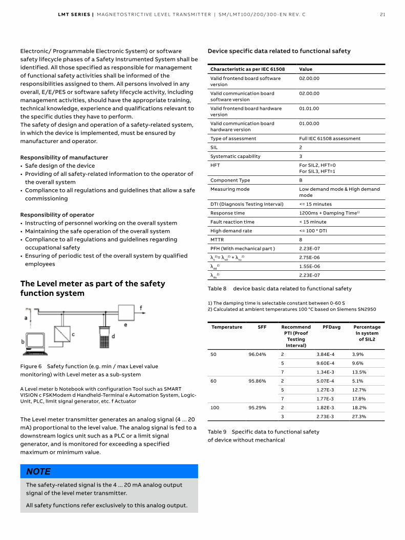
Device specific data related to functional safety
Characteristic as per IEC 61508 Value
Valid frontend board software version
02.00.00
Valid communication board software version
02.00.00
Valid frontend board hardware version
01.01.00
Valid communication board hardware version
01.00.00
Type of assessment Full IEC 61508 assessment
SIL 2
Systematic capability 3
HFT For SIL2, HFT=0 For SIL3, HFT=1
Component Type B
Measuring mode Low demand mode & High demand mode
DTI (Diagnosis Testing Interval) <= 15 minutes
Response time 1200ms + Damping Time1)
Fault reaction time < 15 minute
High demand rate <= 100 * DTI
MTTR 8
PFH (With mechanical part ) 2.23E-07
λs2)= λsd
2) + λsu2) 2.75E-06
λdd2) 1.55E-06
λdu2) 2.23E-07
Table 8 device basic data related to functional safety
1) The damping time is selectable constant between 0-60 S 2) Calculated at ambient temperatures 100 °C based on Siemens SN2950
Temperature SFF Recommend PTI (Proof
Testing Interval)
PFDavg Percentage in system
of SIL2
50 96.04% 2 3.84E-4 3.9%
5 9.60E-4 9.6%
7 1.34E-3 13.5%
60 95.86% 2 5.07E-4 5.1%
5 1.27E-3 12.7%
7 1.77E-3 17.8%
100 95.29% 2 1.82E-3 18.2%
3 2.73E-3 27.3%
Table 9 Specific data to functional safety of device without mechanical
22 LMT S E R I E S | M AG N E TOS TR I C TI V E L E V EL TR A NSM IT TER | SM/L MT 10 0/2 0 0/ 3 0 0 - EN R E V. C
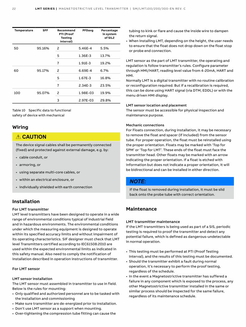
Temperature SFF Recommend PTI (Proof
Testing Interval)
PFDavg Percentage in system
of SIL2
50 95 16% 2 5 46E-4 5 5%
5 1 36E-3 13 7%
7 1 91E-3 19 2%
60 95 17% 2 6 69E-4 6 7%
5 1 67E-3 16 8%
7 2 34E-3 23 5%
100 95 07% 2 1 98E-03 19 9%
3 2 97E-03 29 8%
Table 10 Specific data to functional safety of device with mechanical
Wiring
CAUTION The device signal cables shall be permanently connected (fixed) and protected against external damage, e g by:
• cable conduit, or
• armoring, or
• using separate multi-core cables, or
• within an electrical enclosure, or
• individually shielded with earth connection
Installation For LMT transmitter LMT level transmitters have been designed to operate in a wide range of environmental conditions typical of industrial field and in hazardous environments The environmental conditions under which the measuring equipment is designed to operate within its specified accuracy limits and without impairment of its operating characteristics SIF designer must check that LMT level Transmitters certified according to IEC61508:2010 are used within the expected environmental limits as indicated in this safety manual Also need to comply the notification of installation described in operation instructions of transmitter
For LMT sensor
LMT sensor installation The LMT sensor must assembled in transmitter to use in field Below is the rules for mounting: • Only qualified and authorized personnel are to be tasked with
the installation and commissioning • Make sure transmitter are de-energized prior to installation • Don’t use LMT sensor as a support when mounting • Over-tightening the compression tube fitting can cause the
tubing to kink or flare and cause the inside wire to dampen the return signal
• When installing LMT, depending on the height, the user needs to ensure that the float does not drop down on the float stop or probe end connection
LMT sensor as the part of LMT transmitter, the operating and regulation is follow transmitter’s rules Configure parameter through HMI/HART, reading level value from 4-20mA, HART and HMI Normally LMT is a digital transmitter with no routine calibration or reconfiguration required But if a recalibration is required, this can be done using HART signal (via DTM, EDDL) or with the menu driven HMI display
LMT sensor location and placement The sensor must be accessible for physical inspection and maintenance purpose
Mechanic connections For Floats connection, during installation, it may be necessary to remove the float and spacer (if included) from the sensor tube For proper operation, the float must be reinstalled using the proper orientation Floats may be marked with ‘Top for SPM’ or ‘Top for LMT’ These ends of the float must face the transmitter head Other floats may be marked with an arrow indicating the proper orientation If a float is etched with information but does not indicate a proper orientation, it will be bidirectional and can be installed in either direction
NOTE: If the float is removed during installation, it must be slid back onto the probe tube with correct orientation
Maintenance
LMT transmitter maintenance If the LMT transmitters is being used as part of a SIS, periodic testing is required to proof the transmitter and detect any potential failure, which is defined as dangerous-undetectable in normal operation
• This testing must be performed at PTI (Proof Testing Interval), and the results of this testing must be documented
• Should the transmitter exhibit a fault during normal operation, it’s necessary to perform the proof testing, regardless of the schedule
• In the event a Magnetostrictive transmitter has suffered a failure in any component which is exposed to the process, any other Magnetostrictive transmitter installed in the same or similar process should be inspected for the same failure, regardless of its maintenance schedule
LMT S E R I E S | M AG N E TOS TR I C TI V E L E V EL TR A NSM IT TER | SM/L MT 10 0/2 0 0/ 3 0 0 - EN R E V. C 23
LMT sensor maintenance • Maintenance interval shall be at the user’s calculated
requirement If a user calculation is not performed, the manufacturer recommends 5 years
In the event a Magnetostrictive transmitter has suffered a failure in any component which is exposed to the process, any other Magnetostrictive transmitter installed in the same or similar process should be inspected for the same failure, regardless of its maintenance schedule For LMT sensor these common cause failure include: (1), float collapse due to over pressure;
(2), damage due to material incompatibility;
(3), damage of the sensor due to improper installation
Float inspection: The LMT will detect and report the position of the float on its sensor tube (or magnetic level gauge) as a level of fluid in the process In order to measure the fluid in the process properly, the float must move freely up and down the sensor tube (or magnetic level gauge) partially submerged in the liquid level If the float were to become damaged or stuck on the sensor tube (or magnetic level gauge), the transmitter will still report the float position regardless of the actual process fluid level This by definition is a dangerous undetectable failure To prevent this failure the float will need to be inspected for integrity and movement (1), move the float up and down the length of the sensor tube (or magnetic level gauge) It should move freely all over the moving space, for LMT 100 is from the bottom of the sensor tube to the process connection and for LMT200 is the entire moving space in magnetic level gauge
(2), remove the float from the sensor tube by removing the retaining clip or bolt from the end of the transmitter (or from magnetic level gauge) Inspect the float for signs of excessive wear of damage
(3), submerge the float in a container of water to check for leaks as air bubbles escaping from the float The float is a sealed unit and any holes in the shell of the float could allow process fluid to seep inside Upon completion of float inspection, place the float back on the sensor tube (or magnetic level gauge) paying careful attention to float orientation Some LMT transmitters will be equipped with float spacers designed to keep the float positioned in the measurable range of the sensor tube It’s important that the spacer be replaced when the transmitter is reassembled
Sensor inspection: The sensor of the LMT consists of a metal tube containing several wires The sensor tube will measure the float location properly if the tube is straight and the float can travel freely up and down its length Perform a visual inspection on the sensor tube to make sure it is straight, free from pits or gouges, and does not show excessive wear patterns
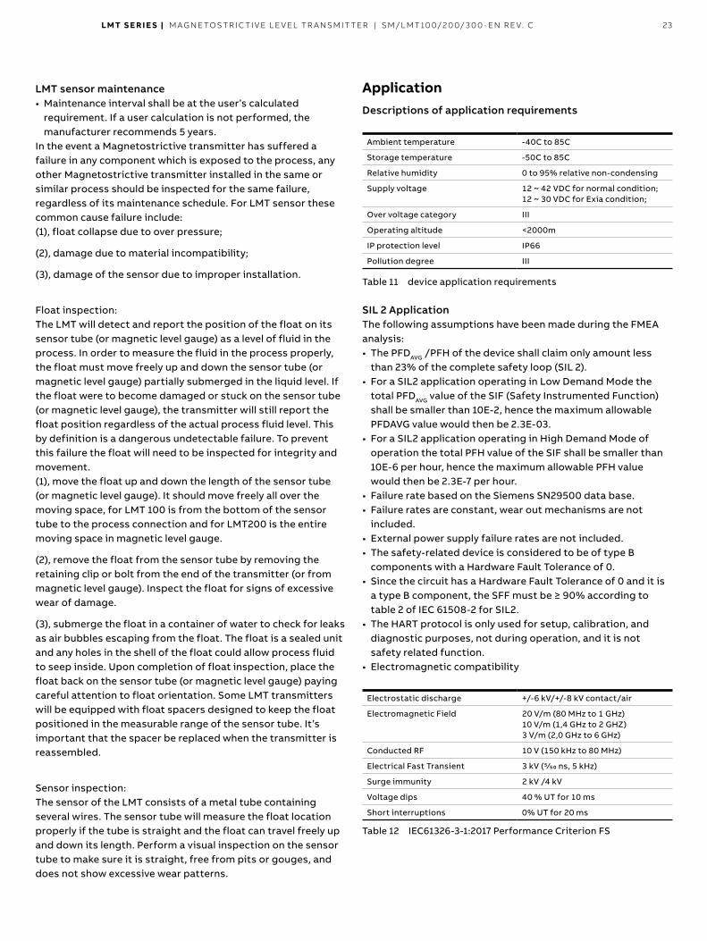
Application Descriptions of application requirements
Ambient temperature -40C to 85C
Storage temperature -50C to 85C
Relative humidity 0 to 95% relative non-condensing
Supply voltage 12 ~ 42 VDC for normal condition; 12 ~ 30 VDC for Exia condition;
Over voltage category III
Operating altitude <2000m
IP protection level IP66
Pollution degree III
Table 11 device application requirements
SIL 2 Application The following assumptions have been made during the FMEA analysis: • The PFDAVG /PFH of the device shall claim only amount less
than 23% of the complete safety loop (SIL 2) • For a SIL2 application operating in Low Demand Mode the
total PFDAVG value of the SIF (Safety Instrumented Function) shall be smaller than 10E-2, hence the maximum allowable PFDAVG value would then be 2 3E-03
• For a SIL2 application operating in High Demand Mode of operation the total PFH value of the SIF shall be smaller than 10E-6 per hour, hence the maximum allowable PFH value would then be 2 3E-7 per hour
• Failure rate based on the Siemens SN29500 data base • Failure rates are constant, wear out mechanisms are not
included • External power supply failure rates are not included • The safety-related device is considered to be of type B
components with a Hardware Fault Tolerance of 0 • Since the circuit has a Hardware Fault Tolerance of 0 and it is
a type B component, the SFF must be ≥ 90% according to table 2 of IEC 61508-2 for SIL2
• The HART protocol is only used for setup, calibration, and diagnostic purposes, not during operation, and it is not safety related function
• Electromagnetic compatibility
Electrostatic discharge +/-6 kV/+/-8 kV contact/air
Electromagnetic Field 20 V/m (80 MHz to 1 GHz)10 V/m (1,4 GHz to 2 GHZ)3 V/m (2,0 GHz to 6 GHz)
Conducted RF 10 V (150 kHz to 80 MHz)
Electrical Fast Transient 3 kV (5/50 ns, 5 kHz)
Surge immunity 2 kV /4 kV
Voltage dips 40 % UT for 10 ms
Short interruptions 0% UT for 20 ms
Table 12 IEC61326-3-1:2017 Performance Criterion FS
24 LMT S E R I E S | M AG N E TOS TR I C TI V E L E V EL TR A NSM IT TER | SM/L MT 10 0/2 0 0/ 3 0 0 - EN R E V. C
SIL 3 Application
CAUTION If the user would like to achieve SIL 3 safety related application by using two pieces (dual redundant configuration, HFT=1) of isolated barriers LMT types, the following Common Cause Failure (CCF) factors acc to IEC 61508-6 must be considered:
• β = βD = 5%
Commissioning Commissioning The activities to validate the required safety functionality of the system together with the level transmitter according to the safety requirement specification are the following: 1 Enable write protection (See chapter “Enabling/Disabling
the write protection”)
2 Power-on the transmitter: the transmitter performs automatically a self-test that consists in the operations below:
– ROM test – RAM test – Instruction Test – Nonvolatile memory test
Proof Test In accordance with IEC 61508, the safety function of the measuring device must be checked at appropriate time intervals The operator must determine the checking interval and take this into account when determining the probability of failure PFDavg of the Level meter The test must be carried out in such a way that it verifies correct operation of the device
Test of the LMT transmitter For check the safety function of the device proceed as follows: 1 Bridge the safety DCS or take other appropriate measures to
prevent inadvertent triggering of alarms
2 Deactivate the write lock (see Chapter “Configuration” on page 9)
3 Set the current output of the transmitter to 12mA by means of the push buttons of the LCD-display, HART communication by using a DTM in combination with DAT200 (Asset vision basic) or with the Field Information Manager (FIM-Tool) using simulation function (Menu: Diagnostics / Simulation Mode / Current Out)
4 Check the current output accuracy is comply with requirement of safety function
5 Set the current output of the transmitter to a HIGH ALARM value by means of the push buttons of the LCD-display, HART communication by using a DTM in combination with DAT200
(Asset vision basic) or with the Field Information Manager (FIM-Tool) using simulation function (Menu: Diagnostics / Simulation Mode / Current Out)
6 Check whether the current output signal reaches this value
7 Set the current output of the transmitter to a LOW ALARM value by means of the push buttons of the LCD-display, HART communication by using a DTM in combination with DAT200 (Asset vision basic) or with the Field Information Manager (FIM-Tool) using simulation function (Menu: Diagnostics / Simulation Mode / Current Out)
8 Check whether the current output signal reaches this value
9 Terminate the simulation mode after finishing the output simulation!
10 Activate the write lock (see Chapter “Configuration” on page 9) and wait 10 seconds
11 Restart the device by power down
12 Check at 3 to 5 measuring points by adjust the level in the vessel and record the measured values at distances for the reference which can be verified Perform a calculation to determine if the error is within the acceptable error specified in this safety manual
13 Remove the bridging of the safety DCS or restore normal operation in another way
14 After the test has been performed, the results must be documented and stored in a suitable manner
NOTE By using this test method of dangerous, undetected failures are detected The influence of systematic errors like e g medium properties, operating conditions, build-up or corrosion on the safety function is not fully covered by the test
• If one of the test criteria from the test procedure described above is not fulfilled, the device may no longer be used as part of a protective system
• Take measures to reduce systematic errors
Test of LMT sensor The objective of proof testing is to detect failures within the device that are not detected by any automatic diagnostics of the system Of main concern are undetected failures that prevent the SIF from performing its intended safety function The frequency of proof testing, or the proof test interval, is to be determined in reliability calculations for the SIF for which a device is applied The proof tests must be performed at least as frequently as specified in the calculation in order to maintain the required safety integrity of the SIF Recommended PTI (years) refer table 9 and table 10: Specific data to functional safety of device’ Proof Test Coverage Factor PTC names how many of the
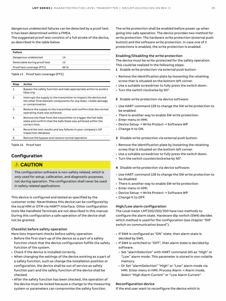
LMT S E R I E S | M AG N E TOS TR I C TI V E L E V EL TR A NSM IT TER | SM/L MT 10 0/2 0 0/ 3 0 0 - EN R E V. C 25
dangerous undetected failures can be detected by a proof test It has been determined within a FMEA The suggested proof test consists of a full stroke of the device, as described in the table below
Failure
Dangerous undetected 14
Detectable during proof test 12
Proof test coverage (PTC) 86 %
Table 13 Proof test coverage (PTC)
Step Action
1 Bypass the safety function and take appropriate action to avoid a false trip
2 Interrupt the supply to the transmitter to inspect the device and the other final element components for any leaks, visible damage or contamination
3 Restore the supply to the transmitter and confirm that the normal operating state was achieved
4 Remove the float from the transmitter to trigger the Fail-Safe state and confirm that the Safe State was achieved within the correct time
5 Record the test results and any failures in your company's SIF inspection database
6 Remove the bypass and restore normal operation
Table 14 Proof test
Configuration
CAUTION The configuration software is non-safety related, which is only used for setup, calibration, and diagnostic purposes, not during operation The configuration shall never be used in safety related applications
This device is configured and tested as specified by the customer order Nevertheless this device can be configured by the local HMI or DTM via HART® Interface Other configuration tools like Handheld Terminals are not described in this manual During this configuration a safe operation of the device shall not be granted
Checklist before safety operation Here lists important checks before safety operation: • Before the first start-up of the device as a part of a safety
function check that the device configuration fulfills the safety function of the system
• Check if the device is installed correctly • When changing the settings of the device working as a part of
a safety function, such as change the installation position or configuration, the device shall be out of service as safety function part and the safety function of the device shall be checked
• After the safety function has been checked, the operation of the device must be locked because a change to the measuring system or parameters can compromise the safety function
The write protection shall be enabled before power up when going into safe operation The device provides two method for write protection: The hardware write protection (external push button) and the software write protection In case one of 2 protections is enabled, the write protection is enabled
Enabling/Disabling the write protection The device must be write-protected for the safety operation This could be realized in the following steps:1 Enable write protection via external push button:
• Remove the identification plate by loosening the retaining screw that is situated on the bottom left corner
• Use a suitable screwdriver to fully press the switch down • Turn the switch clockwise by 90°
2 Enable write protection via device software:
• Use HART command 128 to change the SW write protection to be enabled
• There is another way to enable SW write protection: • Enter menu in HMI: • Device Setup → Write Protect → Software WP • Change it to ON
3 Disable write protection via external push button:
• Remove the identification plate by loosening the retaining screw that is situated on the bottom left corner
• Use a suitable screwdriver to fully press the switch down • Turn the switch counterclockwise by 90°
4 Disable write protection via device software:
• Use HART command 128 to change the SW write protection to be disabled
• There is another way to enable SW write protection: • Enter menu in HMI: • Device Setup → Write Protect → Software WP • Change it to OFF
High/Low alarm configuration The Level meter LMT100/200/300 have two methods to configure the alarm state Hardware dip-switch (SW4) decides which method is used for the configuration (see chapter “DIP switch on communication board”)
• If SW4 is configured as “ON” state, then alarm state is decided by SW5
• If SW4 is switched to “OFF”, then alarm state is decided by software – Set “alarmSelection” with HART command 165 as “High” or “Low” alarm mode This parameter is stored in non-volatile memory
– Or Set “alarmSelection” “High” or “Low” alarm mode via HMI. Enter menu in HMI: Process Alarm → Alarm mode, Select “High Alarm Current” or “Low Alarm Current”
Reconfiguration device If the end user want to reconfigure the device which is
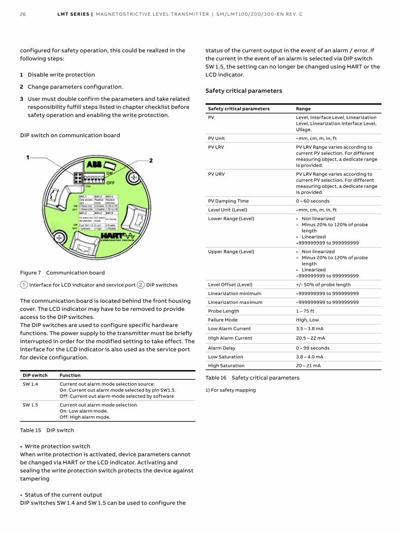
26 LMT S E R I E S | M AG N E TOS TR I C TI V E L E V EL TR A NSM IT TER | SM/L MT 10 0/2 0 0/ 3 0 0 - EN R E V. C
configured for safety operation, this could be realized in the following steps:
1 Disable write protection
2 Change parameters configuration
3 User must double confirm the parameters and take related responsibility fulfill steps listed in chapter checklist before safety operation and enabling the write protection
DIP switch on communication board
1 2
Figure 7 Communication board
1 Interface for LCD indicator and service port 2 DIP switches
The communication board is located behind the front housing cover The LCD indicator may have to be removed to provide access to the DIP switches The DIP switches are used to configure specific hardware functions The power supply to the transmitter must be briefly interrupted in order for the modified setting to take effect The interface for the LCD indicator is also used as the service port for device configuration
DIP switch Function
SW 1.4 Current out alarm mode selection source: On: Current out alarm mode selected by pin SW1.5. Off: Current out alarm mode selected by software
SW 1.5 Current out alarm mode selection On: Low alarm mode Off: High alarm mode
Table 15 DIP switch
• Write protection switch When write protection is activated, device parameters cannot be changed via HART or the LCD indicator Activating and sealing the write protection switch protects the device against tampering
• Status of the current output DIP switches SW 1 4 and SW 1 5 can be used to configure the
status of the current output in the event of an alarm / error If the current in the event of an alarm is selected via DIP switch SW 1 5, the setting can no longer be changed using HART or the LCD indicator
Safety critical parameters
Safety critical parameters Range
PV Level, Interface Level, Linearization Level, Linearization interface Level, Ullage
PV Unit –mm, cm, m, in, ft
PV LRV PV LRV Range varies according to current PV selection For different measuring object, a dedicate range is provided
PV URV PV LRV Range varies according to current PV selection For different measuring object, a dedicate range is provided
PV Damping Time 0 – 60 seconds
Level Unit (Level) –mm, cm, m, in, ft
Lower Range (Level) • Non linearized – Minus 20% to 120% of probe
length • Linearized –999999999 to 999999999
Upper Range (Level) • Non linearized – Minus 20% to 120% of probe
length • Linearized –999999999 to 999999999
Level Offset (Level) +/- 50% of probe length
Linearization minimum –999999999 to 999999999
Linearization maximum –999999999 to 999999999
Probe Length 1 – 75 ft
Failure Mode High, Low
Low Alarm Current 3.5 – 3.8 mA
High Alarm Current 20.5 – 22 mA
Alarm Delay 0 – 99 seconds
Low Saturation 3.8 – 4.0 mA
High Saturation 20 – 21 mA
Table 16 Safety critical parameters
1) For safety mapping
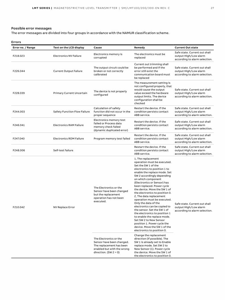
LMT S E R I E S | M AG N E TOS TR I C TI V E L E V EL TR A NSM IT TER | SM/L MT 10 0/2 0 0/ 3 0 0 - EN R E V. C 27
Possible error messages The error messages are divided into four groups in accordance with the NAMUR classification scheme
Errors
Error no . / Range Text on the LCD display Cause Remedy Current Out state
F218.023 Electronics NV FailureElectronics memory is corrupted
The electronics must be replaced
Safe state Current out shall output High/Low alarm according to alarm selection
F226.044 Current Output Failure The output circuit could be broken or not correctly calibrated
Current out trimming shall be performed and if the error still exist the communication board must be replaced
Safe state Current out shall output High/Low alarm according to alarm selection
F228.039 Primary Current Uncertain The device is not properly configured
The measurement setting is not configured properly, that would cause the output value exceed the hardware output limits The device configuration shall be checked
Safe state Current out shall output High/Low alarm according to alarm selection
F244.003 Safety Function Flow Failure Calculation of safety function did not occur in the proper sequence
Restart the device If the condition persists contact ABB service
Safe state Current out shall output High/Low alarm according to alarm selection
F246.041 Electronics RAM Failure
Electronics memory test failed or Process data memory check failed (dynamic duplicated error)
Restart the device If the condition persists contact ABB service
Safe state Current out shall output High/Low alarm according to alarm selection
F247.040 Electronics ROM Failure Program memory test failed Restart the device If the condition persists contact ABB service
Safe state Current out shall output High/Low alarm according to alarm selection
F248.006 Self-test failureRestart the device If the condition persists contact ABB service
Safe state Current out shall output High/Low alarm according to alarm selection
F210.042 NV Replace Error
The Electronics or the Sensor have been changed but the replacement operation has not been executed
1, The replacement operation must be executed Set the SW 1 of the electronics to position 1 to enable the replace mode Set SW 2 accordingly depending on which component (Electronics or Sensor) has been replaced Power cycle the device. Move the SW 1 of the electronics to position 0.2, The data replacement operation must be executed Only the data of the electronics can be copied to the sensor. Set the SW 1 of the electronics to position 1 to enable the replace mode Set SW 2 to New Sensor position 1. Power cycle the device. Move the SW 1 of the electronics to position 0.
Safe state Current out shall output High/Low alarm according to alarm selection
The Electronics or the Sensor have been changed The replacement has been enabled but with the wrong direction. (SW 2 = 0)
Change the replacement direction (if possible) The SW 1 is already set to Enable replace mode. Set SW 2 to New Sensor (1). Power cycle the device. Move the SW 1 of the electronics to position 0.
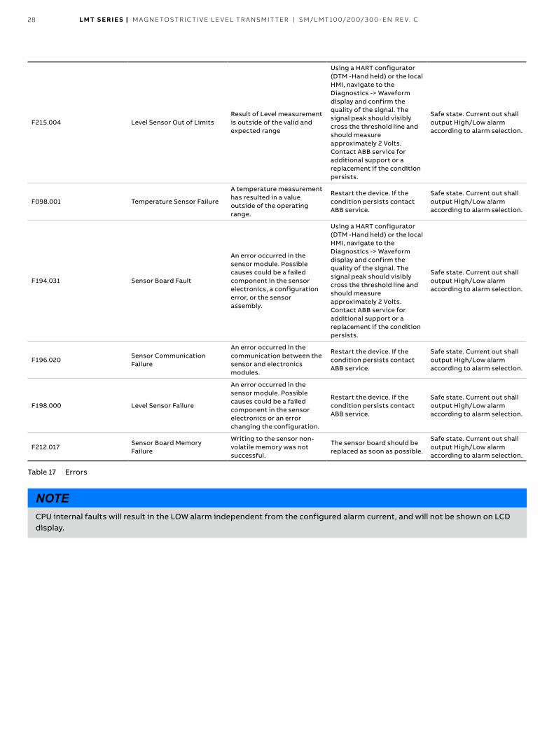
28 LMT S E R I E S | M AG N E TOS TR I C TI V E L E V EL TR A NSM IT TER | SM/L MT 10 0/2 0 0/ 3 0 0 - EN R E V. C
F215.004 Level Sensor Out of LimitsResult of Level measurement is outside of the valid and expected range
Using a HART configurator (DTM -Hand held) or the local HMI, navigate to the Diagnostics -> Waveform display and confirm the quality of the signal The signal peak should visibly cross the threshold line and should measure approximately 2 Volts. Contact ABB service for additional support or a replacement if the condition persists
Safe state Current out shall output High/Low alarm according to alarm selection
F098.001 Temperature Sensor Failure
A temperature measurement has resulted in a value outside of the operating range
Restart the device If the condition persists contact ABB service
Safe state Current out shall output High/Low alarm according to alarm selection
F194.031 Sensor Board Fault
An error occurred in the sensor module Possible causes could be a failed component in the sensor electronics, a configuration error, or the sensor assembly
Using a HART configurator (DTM -Hand held) or the local HMI, navigate to the Diagnostics -> Waveform display and confirm the quality of the signal The signal peak should visibly cross the threshold line and should measure approximately 2 Volts. Contact ABB service for additional support or a replacement if the condition persists
Safe state Current out shall output High/Low alarm according to alarm selection
F196.020Sensor Communication Failure
An error occurred in the communication between the sensor and electronics modules
Restart the device If the condition persists contact ABB service
Safe state Current out shall output High/Low alarm according to alarm selection
F198.000 Level Sensor Failure
An error occurred in the sensor module Possible causes could be a failed component in the sensor electronics or an error changing the configuration
Restart the device If the condition persists contact ABB service
Safe state Current out shall output High/Low alarm according to alarm selection
F212.017Sensor Board Memory Failure
Writing to the sensor non-volatile memory was not successful
The sensor board should be replaced as soon as possible
Safe state Current out shall output High/Low alarm according to alarm selection
Table 17 Errors
NOTE CPU internal faults will result in the LOW alarm independent from the configured alarm current, and will not be shown on LCD display
LMT S E R I E S | M AG N E TOS TR I C TI V E L E V EL TR A NSM IT TER | SM/L MT 10 0/2 0 0/ 3 0 0 - EN R E V. C 29
Repair To ensure the safety related function, repairs have to be Performed by ABB
Replacing modular components by original ABB spare parts is permitted if personnel was trained by ABB for this purpose The “Declaration of contamination and cleaning” must be enclosed when returning the defective device Refer to instruction manual for further details
Manufacturer Notification All faults must be reported to manufacturer for recording purposes, by contacting the Quality Department at address below All defective devices must be returned to manufacturer for investigation and rectification
Address:
ABB Engineering (Shanghai) Ltd
Process Automation No 4528, Kangxin Highway, Pudong New District Shanghai, 201319, P R China Tel: +86(0) 21 6105 6666 Fax: +86(0) 21 6105 6677
ABB Inc
Process Automation 125 E County Line Road Warminster, PA 18974 USA Tel: +1 215 674 6000 Fax: +1 215 674 7183
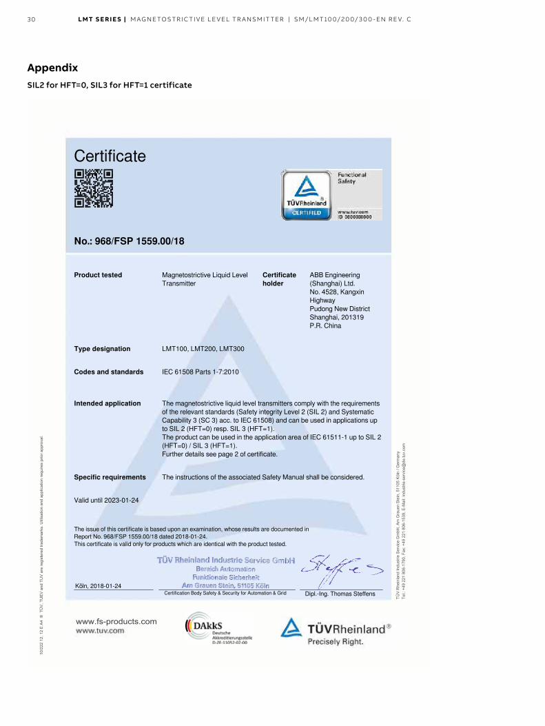
30 LMT S E R I E S | M AG N E TOS TR I C TI V E L E V EL TR A NSM IT TER | SM/L MT 10 0/2 0 0/ 3 0 0 - EN R E V. C
Appendix SIL2 for HFT=0, SIL3 for HFT=1 certificate
Certificate
No.: 968/FSP 1559.00/18
Product tested Magnetostrictive Liquid LevelTransmitter
Certificateholder
ABB Engineering(Shanghai) Ltd.No. 4528, KangxinHighwayPudong New DistrictShanghai, 201319P.R. China
Type designation LMT100, LMT200, LMT300
Codes and standards IEC 61508 Parts 1-7:2010
Intended application The magnetostrictive liquid level transmitters comply with the requirementsof the relevant standards (Safety integrity Level 2 (SIL 2) and SystematicCapability 3 (SC 3) acc. to IEC 61508) and can be used in applications upto SIL 2 (HFT=0) resp. SIL 3 (HFT=1).The product can be used in the application area of IEC 61511-1 up to SIL 2(HFT=0) / SIL 3 (HFT=1).Further details see page 2 of certificate.
Specific requirements The instructions of the associated Safety Manual shall be considered.
Valid until 2023-01-24
The issue of this certificate is based upon an examination, whose results are documented inReport No. 968/FSP 1559.00/18 dated 2018-01-24.This certificate is valid only for products which are identical with the product tested.
Certification Body Safety & Security for Automation & Grid
Dipl.-Ing. Thomas Steffens
Köln, 2018-01-24
10/2
22 1
2. 1
2 E
A4
® T
ÜV
, TU
EV
and
TU
V a
re re
gist
ered
trad
emar
ks. U
tilis
atio
n an
d ap
plic
atio
n re
quire
s pr
ior a
ppro
val.
TÜV
Rhe
inla
nd In
dust
rie S
ervi
ce G
mbH
, Am
Gra
uen
Ste
in, 5
1105
Köl
n / G
erm
any
Tel.:
+49
221
806
-179
0, F
ax: +
49 2
21 8
06-1
539,
E-M
ail:
indu
strie
-ser
vice
@de
.tuv.
com
www.fs-products.com
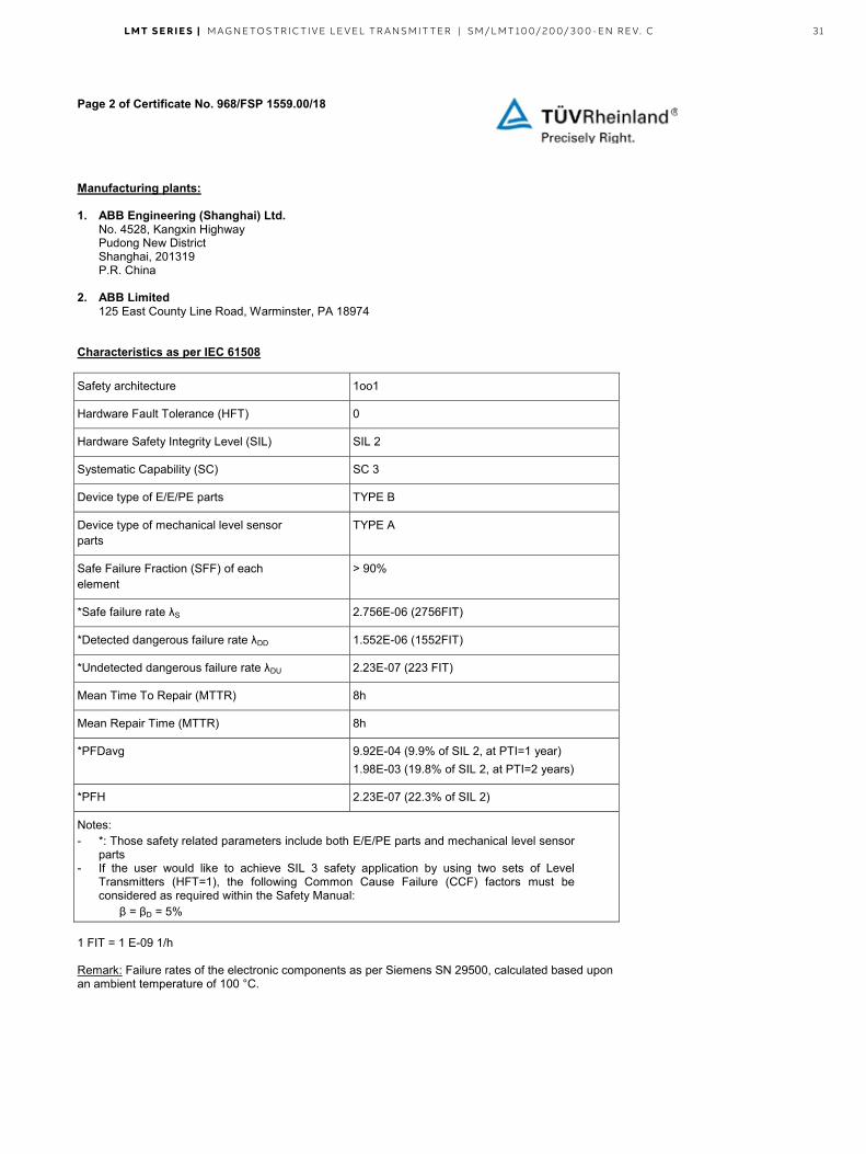
LMT S E R I E S | M AG N E TOS TR I C TI V E L E V EL TR A NSM IT TER | SM/L MT 10 0/2 0 0/ 3 0 0 - EN R E V. C 31
Page 2 of Certificate No. 968/FSP 1559.00/18
Manufacturing plants: 1. ABB Engineering (Shanghai) Ltd.
No. 4528, Kangxin Highway Pudong New District Shanghai, 201319 P.R. China
2. ABB Limited
125 East County Line Road, Warminster, PA 18974 Characteristics as per IEC 61508
Safety architecture 1oo1
Hardware Fault Tolerance (HFT) 0
Hardware Safety Integrity Level (SIL) SIL 2
Systematic Capability (SC) SC 3
Device type of E/E/PE parts TYPE B
Device type of mechanical level sensor parts
TYPE A
Safe Failure Fraction (SFF) of each element
> 90%
*Safe failure rate λS 2.756E-06 (2756FIT)
*Detected dangerous failure rate λDD 1.552E-06 (1552FIT)
*Undetected dangerous failure rate λDU 2.23E-07 (223 FIT)
Mean Time To Repair (MTTR) 8h
Mean Repair Time (MTTR) 8h
*PFDavg 9.92E-04 (9.9% of SIL 2, at PTI=1 year) 1.98E-03 (19.8% of SIL 2, at PTI=2 years)
*PFH 2.23E-07 (22.3% of SIL 2)
Notes: - *: Those safety related parameters include both E/E/PE parts and mechanical level sensor
parts - If the user would like to achieve SIL 3 safety application by using two sets of Level
Transmitters (HFT=1), the following Common Cause Failure (CCF) factors must be considered as required within the Safety Manual:
β = βD = 5%
1 FIT = 1 E-09 1/h Remark: Failure rates of the electronic components as per Siemens SN 29500, calculated based upon an ambient temperature of 100 °C.
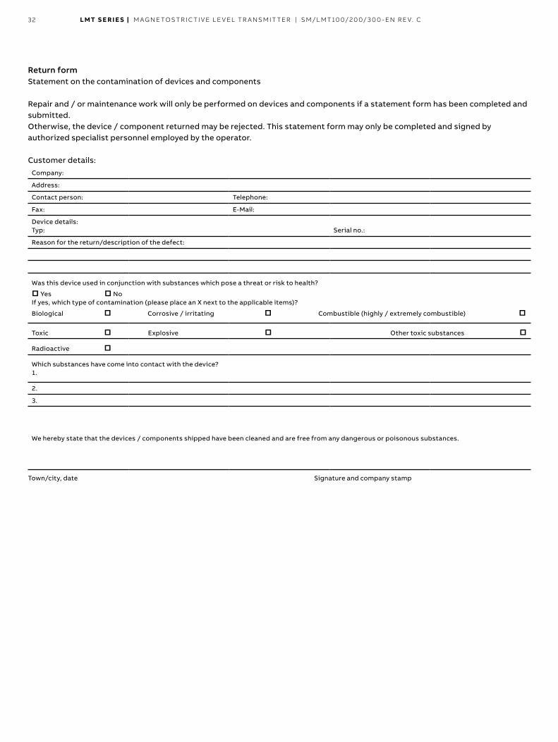
32 LMT S E R I E S | M AG N E TOS TR I C TI V E L E V EL TR A NSM IT TER | SM/L MT 10 0/2 0 0/ 3 0 0 - EN R E V. C
Return form Statement on the contamination of devices and components
Repair and / or maintenance work will only be performed on devices and components if a statement form has been completed and submitted Otherwise, the device / component returned may be rejected This statement form may only be completed and signed by authorized specialist personnel employed by the operator
Customer details:
Company:
Address:
Contact person: Telephone:
Fax: E-Mail:
Device details: Typ: Serial no :
Reason for the return/description of the defect:
Was this device used in conjunction with substances which pose a threat or risk to health?
□ Yes □ NoIf yes, which type of contamination (please place an X next to the applicable items)?
Biological □ Corrosive / irritating □ Combustible (highly / extremely combustible) □
Toxic □ Explosive □ Other toxic substances □Radioactive □Which substances have come into contact with the device? 1.
2.
3.
We hereby state that the devices / components shipped have been cleaned and are free from any dangerous or poisonous substances
Town/city, date Signature and company stamp

LMT S E R I E S | M AG N E TOS TR I C TI V E L E V EL TR A NSM IT TER | SM/L MT 10 0/2 0 0/ 3 0 0 - EN R E V. C 33
Notes

34 LMT S E R I E S | M AG N E TOS TR I C TI V E L E V EL TR A NSM IT TER | SM/L MT 10 0/2 0 0/ 3 0 0 - EN R E V. C
Notes

LMT S E R I E S | M AG N E TOS TR I C TI V E L E V EL TR A NSM IT TER | SM/L MT 10 0/2 0 0/ 3 0 0 - EN R E V. C 35
Notes
SM
_LM
T10
0/2
00
/30
0-E
N R
ev.C
_08
.20
18
—We reserve the right to make technical changes or modify the contents of this document without prior notice. With regard to purchase orders, the agreed particulars shall prevail. ABB does not accept any responsibility whatsoever for potential errors or possible lack of information in this document.We reserve all rights in this document and in the subject matter and illustrations contained therein. Any reproduction, disclosure to third parties or utilization of its contents – in whole or in parts – is forbidden without prior written consent of ABB. Copyright© 2018 ABB All rights reserved
—ABB Inc . Measurement & Analytics 125 E. County Line Road Warminster, PA 18974 USA Tel: +1 215 674 6000 Fax: +1 215 674 7183
ABB Engineering (Shanghai) Ltd .No. 4528, KangXin Hwy. Pudong New District District Shanghai, 201319, P.R. China Phone: +86 10 64231407 Service: +86 4008209696 E-mail: [email protected] Service e-mail: [email protected]
www .abb .com/Level