— electric. digital. connected. - abb
TRANSCRIPT

—Gener ations
Electric.Digital.Connected.


introduction — 4–9
01 the future of mobility — 10–23
02 the steps to autonomy — 24–37
03 Digital: the great enabler — 38–47
04 China – the next marine power — 48–69
05 technical insight — 70–151
— Table of contents

electrification, digitalization and connectivity are converging with cloud computing and machine learning. sensors are getting smaller, and big data is getting bigger. augmented and virtual realities are unlocking possibilities unheard of only years, or even months ago.
We believe that future ships will be built on the foundation of electricity. Hybrid solutions combining sustainable fuels with electric power systems are cleaner and more robust, require less maintenance, are highly programmable, and are easily monitored and managed remotely.
electrical propulsion integrated with automa-tion and control systems is already moving the industry closer to autonomous shipping, with collaborative, remote and highly automated oper-ations showing the way.
aBB has provided electric systems for vessels for more than 110 years. today, well over 1,300 ships employ aBB electric systems, and close to 1,000 vessels are connected to the aBB ability™ Collaborative operation Centers for remote support.
it is our role as an industry frontrunner to drive this transformation and equip the marine industry with electric, digital and connected solu-tions that maximize the full potential of vessels.
in this series of Generations articles we explore the innovations, visions and transformations made possible by the most powerful combination of change enablers that the maritime industry has seen for decades.
Welcome to a look into the future of shipping!
The maritime industry continues to explore new energy sources and autonomous operations – and the electric, digital and connected approach is helping us define a better future, bringing new levels of reliability, efficiency and sustainability to shipping.
—Gener ations
Electric. Digital. Connected.
Juha KosKElaManaging DirectorABB Marine & Ports
4 GenerATions

inTroDUCTion 5
there is a lot of talk about the Fourth industrial revolution, with electrification, digitalization and connectivity converging across industries.
electrification is the logical choice for future power systems. Compared to mechanical sys-tems, electricity enables more flexible solutions
that require less maintenance. it also allows power to be applied more precisely, including installing more power in smaller spaces.
Digitalization enables small-scale efficiency, but it also helps keep costs under control if we want to expand the scope of an application or oper-ation. the level of complexity no longer has to increase when scaling up; operating 100 things does not have to mean that systems become 100 times more complex.
Connectivity has been primarily a consumer-driven trend, enabled by mobile and broadband technolo-gies, but these days it is becoming well established in the industrial space. Buyers of equipment in-creasingly realize that those who build the machines can also help optimize operations from remote loca-tions, and industrial customers want that help.
there are also examples of industrial digital tech-nology migrating into the consumer space, such as GPs. this phenomenon is a lot less frequent, but still very significant. Back in the 1970s and 1980s there was a lot of government spending on military digital technology. these were the early investments that eventually gave birth to silicon Valley, and the pendulum of innovation swung from the industrial to the consumer space.
We already have an example of this in aBB Marine & Ports, where our aBB ability™ Marine advisory system – oCtoPUs, originally designed to help
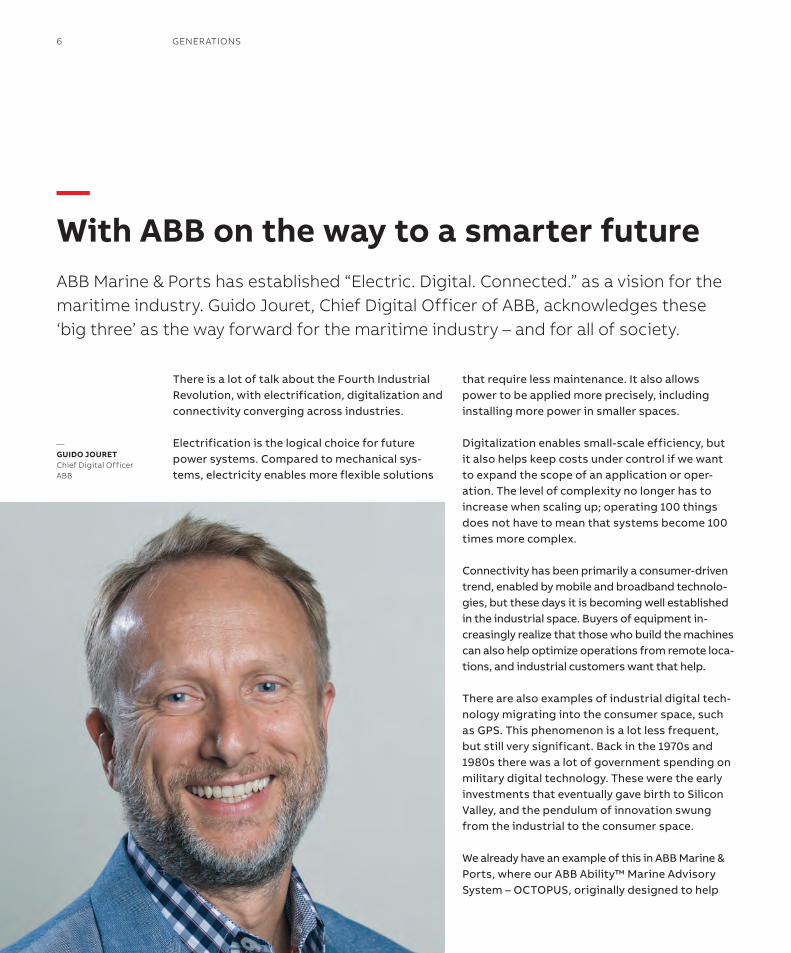
ABB Marine & Ports has established “electric. Digital. Connected.” as a vision for the maritime industry. Guido Jouret, Chief Digital officer of ABB, acknowledges these ‘big three’ as the way forward for the maritime industry – and for all of society.
—GuiDo JourETChief Digital officerABB
—With aBB on the way to a smarter future
6 GenerATions

guide some of the biggest ships in the world, is now being applied to the seaBubbles urban water taxi concept. this shows that industrial digital in-novations are highly scalable, and that opens the door for application in many different spaces.
Planet 4.0We are in the middle of massive change, and we are seeing it all across society. the planetary operating system is being revised. How we man-age food processing, water and energy supply, manufacturing of goods or moving people – all these areas are being reinvented using digital technology.
aBB is well positioned to be a major player in this ongoing development, and we are experi-encing growing momentum. as an indicator of this, the number of applicants for employment in aBB has doubled in the past year. Working with digital technology in a maker company like aBB is different than working in a software company. We get to help solve issues of sustainability, trans-portation, and electrification. People can see the impact of what they do on society. in my opinion, this is the reason we are able to attract employ-ees in a highly competitive environment.
With this growing interest in doing things that make a difference, i believe the time is now for industrials to get involved and drive the develop-ment of the things that matter for everyone.
in the mobility segment, aBB is the title sponsor of Formula e racing, the fastest electric powered racing cars on the planet. this may seem frivol-ous at first glance, but it is about much more than just fast cars. it is about the electrification of transportation.
racing can serve as an incubator for innovation. aBB Fia Formula e Championship racing puts un-imaginable stress on the cars and the power sys-tems. the technology has to deal with heat and loads far beyond those in commercial vehicles. Participating in the aBB Fia Formula e Champi-onship allows the industrial partners to bring this advanced technology into the consumer space at a much faster pace.
While technology in traditional Formula 1 is maturing, there is still a lot of innovation left in aBB Fia Formula e Championship. one clear example of this is that this season they will need only one car to finish a race, instead of the two they have used since the start of the Champion-ship in 2014. also the fact that they race in a city or urban environment, not on isolated tracks, makes electric transportation visible and access-ible for everybody.
—electrification is the logical choice for future power systems.
inTroDUCTion 7
No end in sighti honestly don’t see any horizon for the potential of electric, digital, and connected. the revolution is different this time because it’s not just one thing. By contrast to previous disruptions like steam power or electrification, the Fourth industrial re-volution involves multiple elements. in fact it can be difficult to articulate the current shift, because it is made up of so many things. Digitalization, connectivity and cloud computing are all conver-ging, with machine learning and artificial intelli-gence amplifying their impact. sensors are getting smaller and big data is getting bigger. augmen-ted and virtual reality technologies continue to provide previously unattainable perspectives.
But despite these advances, any machine we can make today remains relatively primitive, compared to human brain. We are basically trying to make a model of the brain, and what has been achieved so far might even be called baby steps. Computer models have the potential to be a million times better than today, not just faster and cheaper.
Looking ahead to the ‘next big thing’, i hope we rediscover that small is beautiful. industrial technology in the 19th and 20th centuries was all about making things bigger and achieving efficiency of scale. now digital technology en-ables efficiency at any level. 3D printing is a good example of small-scale efficiency, delivering tailor made components at the point of consumption. By moving bits, not atoms, we are reinventing the way we run the modern economy.
in a way we are going back to our roots, by enabling smaller, closer and smarter solutions. only 30 percent of our planet remains jungle and rain forest. if we want to avoid eating into un-developed land, and clearly we do, cities will have to absorb the bulk of population growth. that means we will need to think and work in new ways to create dense, but sustainable and attractive urban solutions. i believe that innovative use of electric, digital and connected technologies will be the key to finding smarter ways to manage our new future.
—ABB has provided electric systems for vessels for more than 110 years
8 GenerATions
inTroDUCTion 9


— 01 The future of mobility
aBB Formula e:
Completing the circuit—12–17
Welcome aboard!
Hydrogen on the high seas—18–21
the future fuel picture:
More than just hydrogen—22–23
But if there’s a single branch of e-mobility devel-opment that would take the prize for high-profile, pioneering innovation, it would surely be the aBB Fia Formula e championship, which pits 22 of the world’s most talented drivers against each other in the most advanced electric racecars yet created, to fight for honors in a global motors-port championship.
Perhaps the most notable aspect of aBB Formula e is the noise – or, more accurately, the lack of it.
as the world’s first global all-electric motor racing category, the aBB Fia Formula e Championship, to use its full name, was born of an idea that would shatter one of the most dearly held conventions in motorsport: that racing should be ear-split-tingly noisy, thanks to power derived from highly tuned internal combustion engines burning fossil fuels while spinning at up to 20,000 rpm.
since its inception in 2014, aBB Formula e has taken a radically different approach, instead adopt-
ing battery-powered cars driven by high-efficiency electric powertrains that use some of the world’s most advanced e-mobility technology. and in doing so, to the sound only of a high-pitched whine that accompanies the cars as they compete at city-centre racetracks around the planet, it has silenced the critics.
in less than five years, aBB Formula e has blos-somed from an audacious start-up that was dismissed as a niche curio by both hardcore motorsport fans and the less visionary quarters of the automotive sector, into a sporting property of such relevance that major car manufacturers are now thrusting their way into the champion-ship, frightened of missing the chance to flaunt their e-mobility credentials through competition success. already the likes of audi, BMW, nissan and Jaguar field leading teams; next season they will be joined by blue-chip industry titans Porsche and Mercedes-Benz.
the championship, title-partnered by aBB since January 2018, is flourishing because of the in-herent ‘rightness’ of its proposition at a time of growing concern over matters of sustainability, energy efficiency, pollution and urban conges-tion. in a single package that maintains a visceral sporting appeal at its core, aBB Formula e is able to showcase simultaneously: advanced electrification technology; urban transport
—The battery’s increased capacity and efficiency allows ABB Formula e cars to complete a full race distance on a single charge.
—aBB Formula ECompleting the circuitThe global e-mobility revolution takes myriad forms: be it experimental electric aircrafts, autonomous ferries, fast-charged bus fleets or the increasingly familiar sight of web-connected eVs on public roads.
01
12 GenerATions

solutions; the latest ideas in connected mobility; smart city visions and developments in sustain-able power generation.
the heart of the championship remains a field of fast, dramatic, electric racing cars driven by 22 of the world’s most talented drivers – many of whom have been drawn from Formula 1. each of the 11 two-car, two-driver, teams competes with their own variant of the same basic machine. it’s an open-cockpit single-seater built around an im-pact-resistant and highly protective carbon-fibre monocoque, which cocoons the driver. the suspen-sion is hung from this central component and aero-dynamic bodywork clothes the inner workings. this much is relatively conventional and typical of almost any contemporary single-seat racer.
But it is behind the driver that the defining hardware of an aBB Formula e racecar is hidden. instead of a fuel tank, internal combustion engine and a multi-speed semi-automatic gearbox, the ‘Gen2’ racer introduced for this season packages a large, high-efficiency battery, one or two motors
and a single-speed transmission. these are the elements that put the ‘e’ in to ‘aBB Formula e’. the battery, built and supplied by McLaren applied technologies (Mat) – a sister company of the fam-ous McLaren racing team – is common to every car and is absolutely central to their performance.
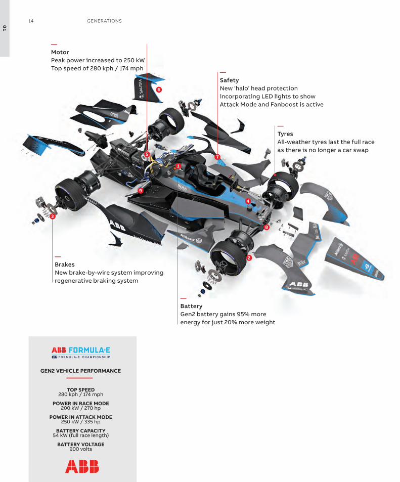
Weighing around 385 kg, it is both larger and heavier than the unit supplied for the earlier generation of cars that raced from seasons one to four and its peak output of 900 volts is an in-crease of 200 volts over the previous technology. it permits peak power of 250 kw – approximately 335 hp – and can push the cars to top speeds of around 280 km/h.
—All cars incorporate regenerative braking systems, to harvest significant amounts of energy under repeated intensive deceleration every lap.
01
The FUTUre oF MoBiliTy 13
!
"
#
$
%
&
'
(
)
GEN2 VEHICLE PERFORMANCE
TOP SPEED280 kph / 174 mph
POWER IN RACE MODE 200 kW / 270 hp
POWER IN ATTACK MODE 250 kW / 335 hp
BATTERY CAPACITY54 kW (full race length)
BATTERY VOLTAGE900 volts
!
"
#
$
%
&
'
(
)
GEN2 VEHICLE PERFORMANCE
TOP SPEED280 kph / 174 mph
POWER IN RACE MODE 200 kW / 270 hp
POWER IN ATTACK MODE 250 kW / 335 hp
BATTERY CAPACITY54 kW (full race length)
BATTERY VOLTAGE900 volts
—MotorPeak power increased to 250 kWtop speed of 280 kph / 174 mph —
Safetynew ‘halo’ head protection incorporating LeD lights to show attack Mode and Fanboost is active
—Tyresall-weather tyres last the full race as there is no longer a car swap
—BatteryGen2 battery gains 95% more energy for just 20% more weight
—Brakesnew brake-by-wire system improving regenerative braking system
01
14 GenerATions

More significant than these headline figures, however, is that the battery’s increased capacity and efficiency allows aBB Formula e cars to com-plete a full race distance on a single charge. over the first four seasons of racing, technological limitations meant that drivers would use two cars per race: starting in one until its battery emptied and stopping at half distance for a mid-race car-swap to an identical machine with a full battery.
While this unique procedure lent a distinct spec-tacle to aBB Formula e, it also drew attention to a specific consumer hesitancy that has hindered widespread eV adoption: range anxiety. the Gen2 car’s bigger battery pack has dismissed that con-cern, however, thanks to a 95 percent energy in-crease for a 20 percent weight gain. in this aspect more than any other, aBB Formula e has demon-strated the rapid pace of technical advancement across the e-mobility landscape.
Mat’s Gen2 battery pack was developed with particular regard for temperature management.
its internal lithium cells are highly sensitive to temperature: too cool and efficiency is not optim-ized; too hot and output life suffers. Homogenous cooling across the multiple individual cells inside the pack was therefore a key design goal.
elsewhere beneath the aggressively styled body-work of the Gen2 cars lie experimental technical developments being tested by manufacturers in a racing environment as part of their wider r&D pro-grams. twin-motor installations, whereby one of the pair is dedicated to one of the rear wheels (rather than drive from a single motor being split between two) have been evaluated for potential traction and drivetrain efficiency benefits, for example.
—ABB Formula e has demonstrated the rapid pace of technical advancement across the e-mobility landscape.
01
The FUTUre oF MoBiliTy 15
and all cars incorporate regenerative braking systems, to harvest significant amounts of energy under repeated intensive deceleration every lap. Until this season, each car’s so-called ‘regen balance’ was controlled by the driver but electronic control introduced for season 5 has enhanced the process. this is precisely the kind of sophisticated energy management technology that is invaluable to manufacturers in developing class-leading road car models.
aBB, meantime, has brought its own technical ex-pertise to the Jaguar i-PaCe etroPHY series that supports aBB Formula e at 10 races this season.
the race-prepared version of the i-PaCe, Jaguar’s all-electric sUV which recently won the prestigious Car of the Year award, is powered at circuits by cus-tom-made variants of aBB’s terra 53 DC charger.
to meet the series’ demands for a charger that could be both mobile at race tracks and easily
transported between them, aBB commissioned a team of its engineers in india to reconfigure a standard terra unit into a smaller package, with wheels, for easy freighting and manoeuvrability. By mid-season they had operated with a 100 per-cent success rate.
Clearly, these are exciting times for aBB Formula e, with the championship in rude health and further aBB technical collaborations under discussion.
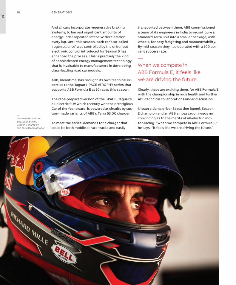
nissan e.dams driver sébastien Buemi, season 2 champion and an aBB ambassador, needs no convincing as to the merits of all-electric mo-tor-racing: “When we compete in aBB Formula e,” he says, “it feels like we are driving the future.”
—When we compete inABB Formula e, it feels likewe are driving the future.
—nissan e.dams driver sébastien Buemi, season 2 champion and an ABB ambassador.
01
16 GenerATions

Gen2 (Season 5) Gen1 (Season 1-4)
Top speed, kph (mph) 280 (174) 225 (140)
Acceleration, 0 - 100 kph (0 - 62 mph) 2.8 seconds 3.0 seconds
Power in race mode, kW (hp) 200 (270) 180 (240)
Maximum power, attack mode 250 (335) n/a
Battery capacity, kWh 54 (full race length) 28 (car swap mid-race)
Battery voltage 900 volt 700 volt
Battery weight, kg (pounds) 385 (849) 320 (705)
Minimum weight, kg (pounds) 900 (1,984) 880 (1,940)
Race length 45 minutes + 1 lap Laps varied by track
01
The FUTUre oF MoBiliTy 17
as a global provider of innovative clean energy solutions, Ballard Power systems has years of experience in the deployment of hydrogen fuel cell systems for land-based use, with the first developments dating back to 1983. Ballard’s work with marine hydrogen as a fuel goes back to their role as advisors to the Canadian military.
“the Canadian navy has had fuel cells in theirsubmarines since 1993,” says George skinner.“this fact alone demystifies hydrogen as high risk – the last place you want a dangerous fuel is on board is in a steel tube hundreds of meters under the sea.”
the company’s focus in the use of hydrogen for marine applications turned to more commer-cial areas around the year of 2000, with a few projects for large cruise and ferry companies. “Beyond its properties as a fuel, hydrogen is in-teresting as a carbon neutral alternative. it basic-ally sidesteps emissions issues that the maritime industry needs to resolve,” skinner observes.
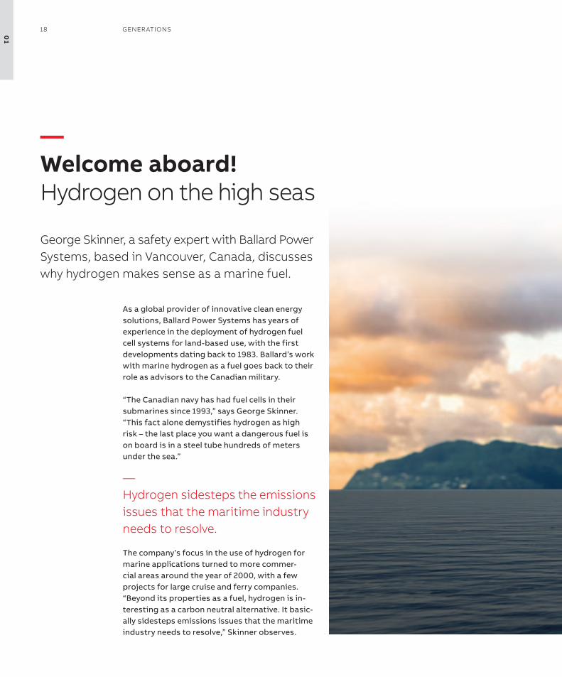
—Welcome aboard! hydrogen on the high seas
George skinner, a safety expert with Ballard Power systems, based in Vancouver, Canada, discusses why hydrogen makes sense as a marine fuel.
—hydrogen sidesteps the emissions issues that the maritime industry needs to resolve.
01
18 GenerATions
01
The FUTUre oF MoBiliTy 19

“once you are set up with hydrogen, you are flex-ible. regardless of how it is produced – by solar, gas, hydropower, or wind – hydrogen is the energy carrier.” a good example is Denmark, he says, where they have periodic surplus power from wind that they convert into hydrogen for later use.
size matters“the bigger the better for fuel cells,” skinner says. “Hydrogen takes more room than fossil fuels, but it is lighter, and it can be compressed to very high pressures. Basically, you just keep liquid hydrogen in a giant thermos. the tank is heavy, so it is not always efficient for small machines. a hydrogen solution is likely more practical for shipping, where they can also have a better insulated tank.”
DnV GL, a globally leading quality assurance and risk management company, published the first rules for hydrogen on ships in January 2018. the rules are linked into codes and standards for other industries with a longer hydrogen history. “the basic principles are the same for LnG (lique-fied natural gas) or other low flashpoint fuels. We already know how to handle liquid gas, so the technology is broken in. the real challenge now is developing the infrastructure,” says skinner.
though skinner reports an uptick in interest from inland waterway operators, ferries and cruise are still the frontrunners. “For the cruise industry, it is a combination of environmental, regulatory and marketing advantages. they are looking at
the long term, and they would rather be set up for hydrogen than rely on the future of carbon fuels. We believe that as a first step, the cruise industry will look toward a hybrid solution, using fuel cells to power hotel functions in ports and when in protected fjords. eventually they could apply it to provide power for the entire vessel, including propulsion.”
skinner points out the many potential advant-ages for hydrogen as marine fuel. “all-electric drives are already common, so the power plants could simply be exchanged. Ultimately the need for diesel on a ship would be greatly reduced or eliminated. Hydrogen systems also allow more freedom of placement in the vessel. and hydro-gen-powered fuel cells produce water that can be used for other purposes on board.”
it’s the same, only differentWith decades of experience, skinner can assure the public that hydrogen is not necessarily more dangerous or safer than other fuels – just dif-ferent. “other considerations have to be made. Hydrogen has a less explosive energy, it burns quicker and colder, and it disperses straight up. it is very easy to ignite, so it is important to prevent leaks, install sufficient detection systems, and always have enough ventilation. the international Code of safety for ships using Gases or other Low-flashpoint Fuels already lays out ways to deal with it, and DnV GL is looking into improved pip-ing systems. new codes and standards are also under development.”
“Ultimately, the objective is to make a failsafe fuel cell power plant. We have done this on land, so it can be done at sea. Fuel cells have a long life
—Fuel cells have a long life and they are relatively low in maintenance.
Demystifying hydrogen •Hydrogen is the lightest element known to mankind. it is tasteless, odorless, and non-toxic.•Hydrogen very quickly disperses in air, rapidly dropping below flammability level.•Hydrogen gas does not have a lot of ‘bang-power’ per volume compared to other common fuels.• rapid burn rate means that personnel, equipment or facility exposure to heat or flame will be extremely brief.•objects near a hydrogen fire will receive very low levels of radiant heat.•Hydrogen has a high auto-ignition threshold, but the spark-energy needed to ignite hydrogen can be
far less than for other fuels – thus bonding and grounding are important.
01
20 GenerATions

and they are relatively low in maintenance. Just turn them on and let them run.” skinner main-tains that the main problems with hydrogen have been connected to perceptions from the past, such as negative associations with the Hinden-burg case – the German passenger airship LZ 129 Hindenburg occurred on May 6, 1937, as it caught fire and was destroyed – and the hydrogen bomb. “in fact the hydrogen bomb is a nuclear reaction, so this is a total misrepresentation. Hydrogen is ubiquitous in industry, aerospace, and many forms of transportation.”
He points out nasa’s decades of experience using hydrogen as rocket fuel. Ballard also runs its own fuel cell lab on liquid hydrogen. “We have been get-ting deliveries twice a week for 20 years. Getting it from shore to ship will be basically the same thing. after all,” he smiles, “it’s only rocket science.”
in 2018, aBB and Ballard signed a Memorandum of Understanding (MoU) on developing next-gen-eration fuel cell systems for the marine industry. the new fuel cell power system will be jointly designed, developed and validated, and is anticip-ated to play a significant part in accelerating the
industry-wide adoption of sustainable solutions for marine e-mobility, and help shipowners meet the increasing demands for clean operations.
together with Ballard, aBB will leverage the existing kilowatt-scale fuel cell technologies and optimize them to create a pioneering mega-watt-scale solution suitable for powering larger ships. With an electrical generating capacity of 3MW (4000 HP), the new system will fit within a single module no bigger in size than a traditional marine engine running on fossil fuels.
skinner sees the trend toward marine hydrogen fuel as an exciting opportunity. “the quantities in marine will get energy companies engaged, which will solve the infrastructure conundrum. and once hydrogen is available in ports for ships it can be used to fuel trucks and other movers of goods and people. the onset of marine hydrogen will be a ma-jor catalyst for kicking off the hydrogen economy.”
NEl and Nikola – from visionary to viable, in just one year in the last issue of Generations, we reported on oslo-based neL and their vision for hydrogen as ‘the perfect fuel’ for transportation. the article featured a side story on start-up nikola Motors, who had recently revealed the first of their hydrogen-electric semi tractor-trailer trucks, promising 1,000,000 miles of free fuel with each vehicle purchased. now anheuser-Busch has placed an order for up to 800 of the nikola trucks, and neL has been chosen by nikola to supply the 448 electrolysers and support-ing equipment needed to fuel the huge fleet. rollout of the first trucks and stations is scheduled for sometime in 2020.
—once you are set up with hydrogen, you are flexible.
01
The FUTUre oF MoBiliTy 21

the challenge, according to aBB Marine & Ports experts Klaus Vanska and sami Kanerva, is to help customers understand the wide range of alternatives, and the complexity of selecting the best one for their needs. “Different fuels will be available depending on regions, market demands, operational and trading patterns, and more,” says Kanerva, r&D senior Principal engineer.
Diversity is the keyKanerva notes that achieving the international Maritime organization’s (iMo) target to at least halve the ship greenhouse gas emissions by 2050, the industry will need to consider multiple future fuel sources. “the need cannot be met by just one or two, and each alternative fuel will have their own markets and uses,” says Kanerva.
among these, Kanerva and Vanska name biod-iesel, fuels from from biomass including waste, and renewable sources including solar, wave and wind. “We can bind the electricity generated by renewables and use it to split molecules and create hydrogen,” says Vanska, Global Business Development Manager. “We can also generate synthetic fuels, ammonia, methane or methanol.” Production of these fuels is largely based on fossil fuel today, but all of them can be renew-able in the future.” He adds that the cost of fuels within renewables could be similar. “the differen-tiators will be in the way in which they are used, as well as their availability.”
Turning power into propulsionBoth experts point out that that the tried and true internal combustion can still be used to burn several of the alternative fuels, such as ammonia, though engine modification would be required in most cases. Fuel cells are another option.
Vanska points out that fuel cells are relatively easy to connect with current marine drive systems. “Fuel cell systems are highly scalable. Modern marine drives are already electric, so only the power plant is exchanged.”
Vanska and Kanerva agree that the public dis-cussion has not been giving enough attention to the viability of alternative fuels. “there are concrete examples out there today that can serve to show the way for others,” says Kan-erva. He cites nikola Motors’ plans for wind and solar-powered stations to generate hydrogen to fuel their trucks. “not only is the nikola concept feasible, they intend to compete on price in the near future.”
—We can bind the electricity generated by renewables and use it to split molecules and create hydrogen.
—The future fuel pictureMore than just hydrogen
With hydrogen fuel coming of age, marine industry experts continue to explore alternatives to fossil fuels to meet the needs of a diverse and developing industry.
01
22 GenerATions
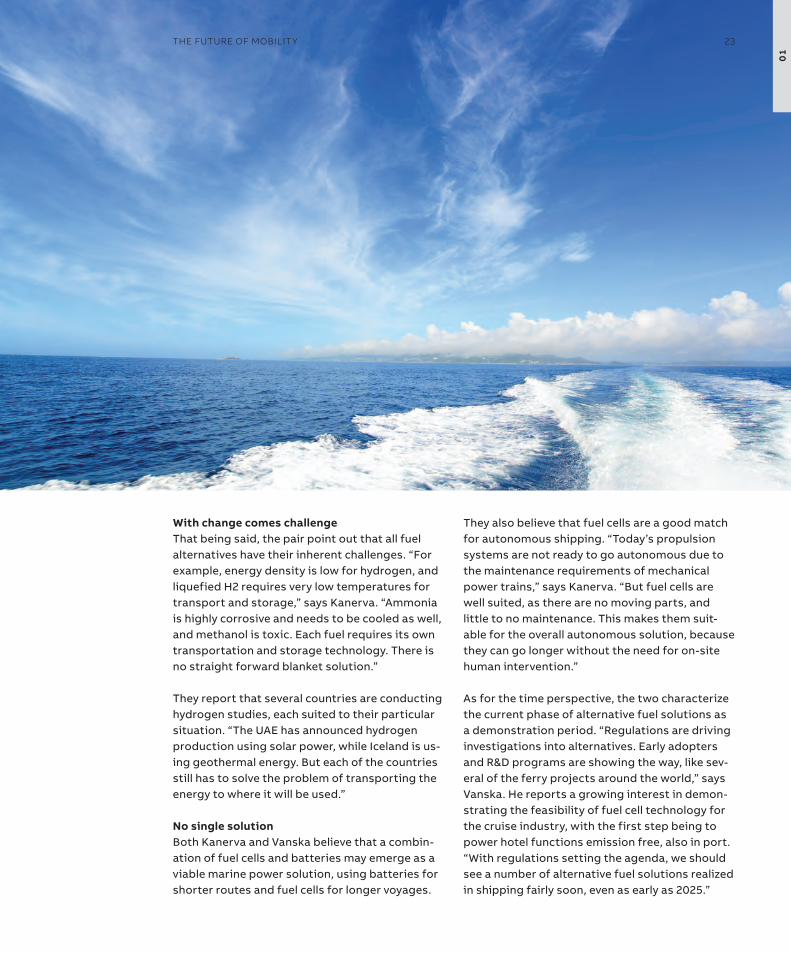
With change comes challengethat being said, the pair point out that all fuel alternatives have their inherent challenges. “For example, energy density is low for hydrogen, and liquefied H2 requires very low temperatures for transport and storage,” says Kanerva. “ammonia is highly corrosive and needs to be cooled as well, and methanol is toxic. each fuel requires its own transportation and storage technology. there is no straight forward blanket solution.”
they report that several countries are conducting hydrogen studies, each suited to their particular situation. “the Uae has announced hydrogen production using solar power, while iceland is us-ing geothermal energy. But each of the countries still has to solve the problem of transporting the energy to where it will be used.”
No single solutionBoth Kanerva and Vanska believe that a combin-ation of fuel cells and batteries may emerge as a viable marine power solution, using batteries for shorter routes and fuel cells for longer voyages.
they also believe that fuel cells are a good match for autonomous shipping. “today’s propulsion systems are not ready to go autonomous due to the maintenance requirements of mechanical power trains,” says Kanerva. “But fuel cells are well suited, as there are no moving parts, and little to no maintenance. this makes them suit-able for the overall autonomous solution, because they can go longer without the need for on-site human intervention.”
as for the time perspective, the two characterize the current phase of alternative fuel solutions as a demonstration period. “regulations are driving investigations into alternatives. early adopters and r&D programs are showing the way, like sev-eral of the ferry projects around the world,” says Vanska. He reports a growing interest in demon-strating the feasibility of fuel cell technology for the cruise industry, with the first step being to power hotel functions emission free, also in port. “With regulations setting the agenda, we should see a number of alternative fuel solutions realized in shipping fairly soon, even as early as 2025.”
01
The FUTUre oF MoBiliTy 23


— 02 The steps to autonomy
Making history in Helsinki:
autonomous, not unmanned—26–29
the reality of autonomous shipping:
striking the balance between
captains and computers—30–31
Control is the key:
When the makers meet their machines—32–33
at the helm:
Captain radhika Menon—34–37
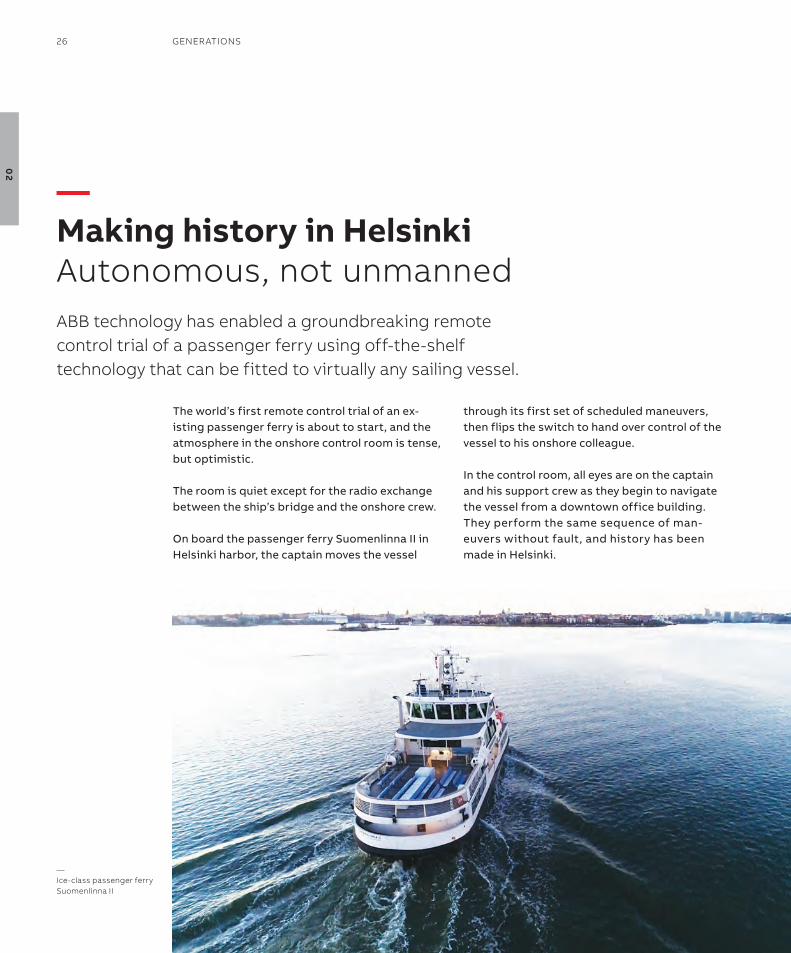
the world’s first remote control trial of an ex-isting passenger ferry is about to start, and the atmosphere in the onshore control room is tense, but optimistic.
the room is quiet except for the radio exchange between the ship’s bridge and the onshore crew.
on board the passenger ferry suomenlinna ii in Helsinki harbor, the captain moves the vessel
through its first set of scheduled maneuvers, then flips the switch to hand over control of the vessel to his onshore colleague.
in the control room, all eyes are on the captain and his support crew as they begin to navigate the vessel from a downtown office building. they perform the same sequence of man-euvers without fault, and history has been made in Helsinki.
—Making history in helsinkiAutonomous, not unmannedABB technology has enabled a groundbreaking remote control trial of a passenger ferry using off-the-shelf technology that can be fitted to virtually any sailing vessel.
—ice-class passenger ferry suomenlinna ii
26 GenerATions
02
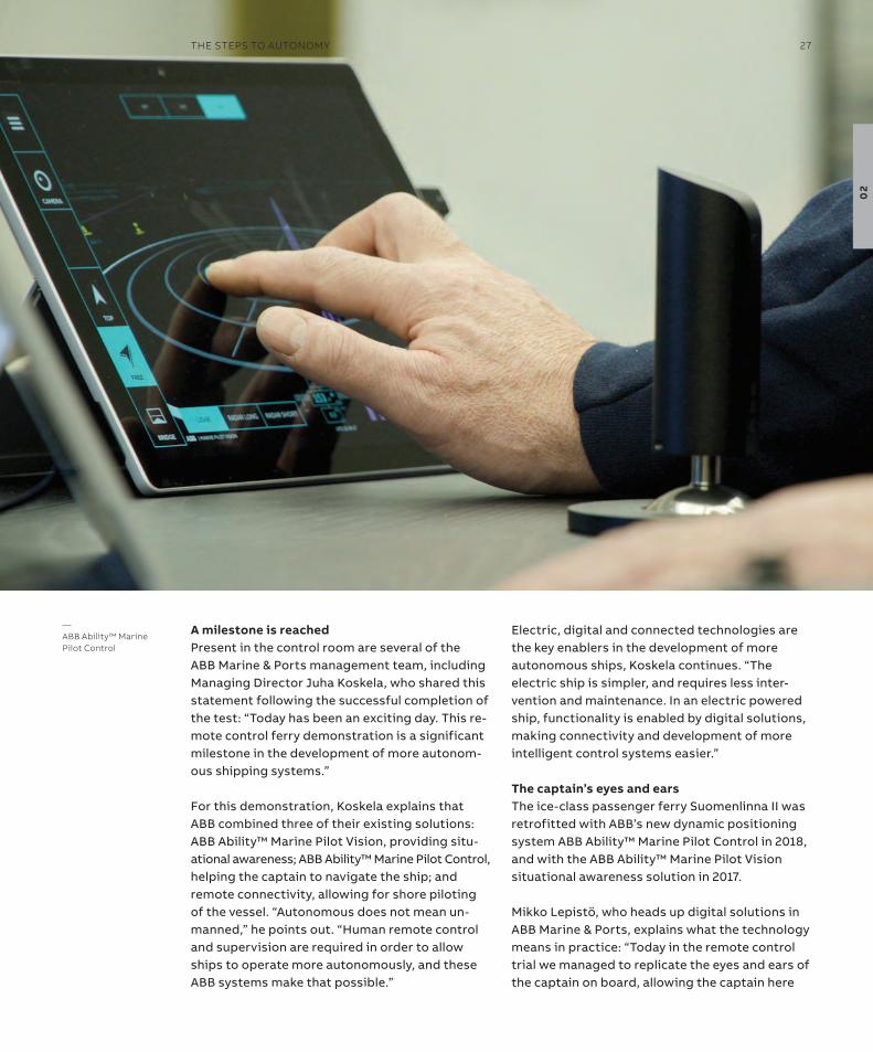
—ABB Ability™ Marine Pilot Control
a milestone is reachedPresent in the control room are several of the aBB Marine & Ports management team, including Managing Director Juha Koskela, who shared this statement following the successful completion of the test: “today has been an exciting day. this re-mote control ferry demonstration is a significant milestone in the development of more autonom-ous shipping systems.”
For this demonstration, Koskela explains that aBB combined three of their existing solutions: aBB ability™ Marine Pilot Vision, providing situ-ational awareness; aBB ability™ Marine Pilot Control, helping the captain to navigate the ship; and remote connectivity, allowing for shore piloting of the vessel. “autonomous does not mean un-manned,” he points out. “Human remote control and supervision are required in order to allow ships to operate more autonomously, and these aBB systems make that possible.”
electric, digital and connected technologies are the key enablers in the development of more autonomous ships, Koskela continues. “the electric ship is simpler, and requires less inter-vention and maintenance. in an electric powered ship, functionality is enabled by digital solutions, making connectivity and development of more intelligent control systems easier.”
The captain’s eyes and earsthe ice-class passenger ferry suomenlinna ii was retrofitted with aBB’s new dynamic positioning system aBB ability™ Marine Pilot Control in 2018, and with the aBB ability™ Marine Pilot Vision situational awareness solution in 2017.
Mikko Lepistö, who heads up digital solutions in aBB Marine & Ports, explains what the technology means in practice: “today in the remote control trial we managed to replicate the eyes and ears of the captain on board, allowing the captain here
The sTePs To AUTonoMy 27
02
in the control room to have the same situational awareness as on board.”
He points out another feature of the technology: “the remarkable thing about this remote control trial is that we used our existing products to achieve something completely new. aBB ability™ Marine Pilot Vision and aBB ability™ Marine Pilot Control, as well as our connectivity solutions, are available off the shelf in the commercial market and can be retrofitted to any commercial ship. Basically, we can repeat what we did today on any vessel. this means that a significant step on the road to autonomy is now available for virtually all ships sailing today.”
in addition come the operational benefits, Lepistö says. “the use of our technology on board will improve the performance of the crew oper-ating the vessel. More than creating improved situational awareness, it can also enable the ship to sail more safely and more efficiently.
the crew will no longer experience blind spots. aBB ability™ Marine Pilot Control can provide more accurate motion and movement information than could be created in the past. on shore, the technology can be used to monitor operations and provide support the crew in case they have an issue.”
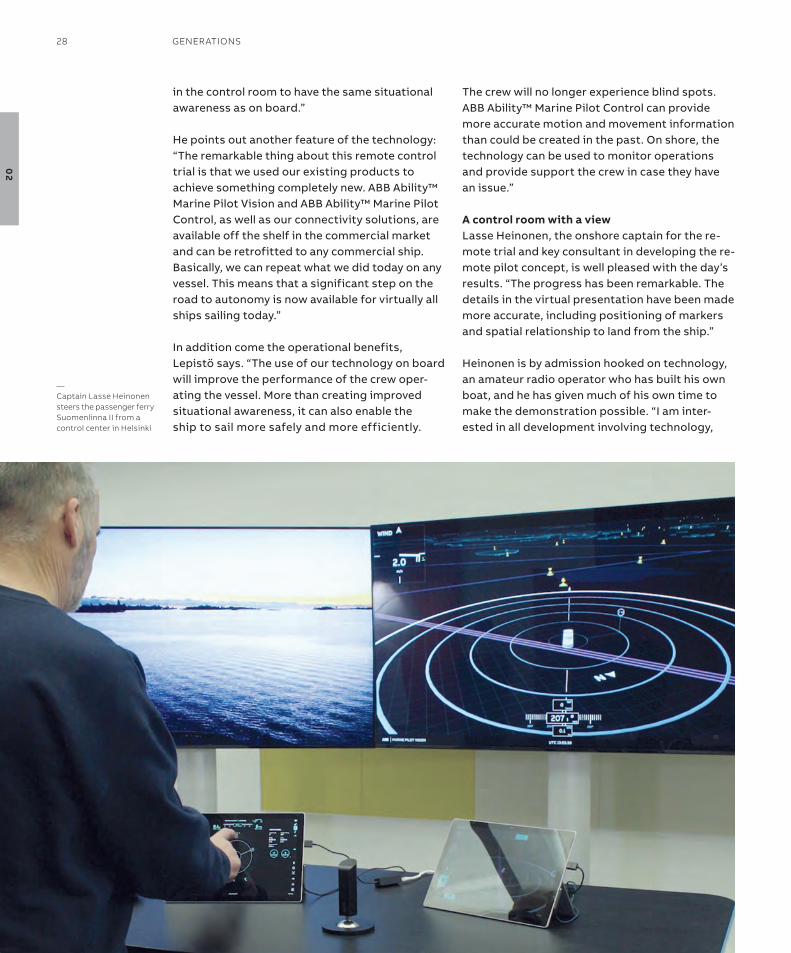
a control room with a viewLasse Heinonen, the onshore captain for the re-mote trial and key consultant in developing the re-mote pilot concept, is well pleased with the day’s results. “the progress has been remarkable. the details in the virtual presentation have been made more accurate, including positioning of markers and spatial relationship to land from the ship.”
Heinonen is by admission hooked on technology, an amateur radio operator who has built his own boat, and he has given much of his own time to make the demonstration possible. “i am inter-ested in all development involving technology,
—Captain lasse heinonen steers the passenger ferry suomenlinna ii from a control center in helsinki
28 GenerATions
02

so i am willing to invest my time to help move new technologies forward. i am very happy to be involved in this project.”
overall, Heinonen has only praise for the collab-orative effort with aBB: “they are engineers, and we are seafarers, so i expected there would be a learning curve. it takes a while to comprehend the reality of the situation, but aBB has realized the sensitive points in our operations. in some ways, for them it’s like being a new captain having to get to know their first ship.”
a shared visionWorking closely together with the captain was only one of the many collaborations necessary to make the remote pilot control vision a reality, Mikko Lepistö says. “this has been a remarkable collaboration between all parties. aBB has of course had close interaction with the client, sLL oy ferry company, and Helsinki City transport, but also traFi, the Finnish transport safety
agency, the authority supporting the project. the teamwork has been truly amazing.”
From a captain’s viewpoint, what would Lasse Heinonen like to see in the future? “as pilot of the vessel, i would naturally like to see a remote bridge as close to reality as possible. today we have taken a very important step toward prov-ing that remote operations are possible, and i believe we are on the right track to making the necessary adjustments.”
Juha Koskela shares that view: “as vessels become more electric, digital and connected, aBB is able to equip seafarers with existing solutions that augment their skillsets. in this way, we are enhan-cing the overall safety of marine operations,” he observes, noting that the day’s success is only the beginning: “We went from vision to reality on this trial in a relatively short time, and i believe the pace of development of autonomous and auto-matic systems will only continue to accelerate.”
The sTePs To AUTonoMy 29
02
When people start to get carried away on the sub-ject of autonomous shipping, eero Lehtovaara, Head of regulatory affairs at aBB Marine & Ports, likes to bring the conversation back down to earth: an autonomous vessel is not necessary unmanned but an unmanned vessel is, by default, autonomous to a high degree.
one of Lehtovaara’s main areas of focus is regula-tions governing responsibility for a ship, on board and on shore. that places him squarely in the middle of the current discourse on unmanned ships.
together with his aBB Marine & Ports colleague Dr. Kalevi tervo, Lehtovaara recently published a white paper titled “B0 – a conditionally and periodically unmanned bridge” where ‘B0’ stands for ‘Bridge zero’. the ‘bridge zero’ concept is decidedly not about unmanned shipping, but rather using digital and connected technology to enhance crew performance and optimize the human presence on board.
“B0 is the first realistic way of designing a partly autonomous vessel,” Lehtovaara says. “the pub-licity generated by the unmanned or autonom-ous discussion is good for drawing attention to the subject, but truly unmanned shipping is not within realistic range right now, and may never be. that being said, there are varying degrees of
autonomy, and some can be explored and imple-mented today.”
the degrees he refers to can be divided into three basic and distinct categories: 1. Pier to pier, including docking, the most
demanding of the three.2. Pilot to pilot, meaning the part (or parts) of the
voyage in between when the pilot has command.3. open or deep-water transport, the least
complex level of automated operations.
“We recognize all three, but we have to start simple and move up the scale,” Lehtovaara says. “in open water, the crew could manage their working hours in a different way than today if they were not obliged to stand watch on the bridge. they could avoid boredom and fatigue, and at the same time tend to other practical tasks, while autonomous systems keep the ship on course and watch for potential danger.”
Jonathan earthy, Human Factors Coordinator with the marine classification society Lloyd’s register, echoes Lehtovaara’s arguments: “automation is about empowering people with technology, not replacing them.”
all use of advanced technology, earthy observes, must be preceded by consideration of how
—The reality of autonomous shippingstriking the balance between captains and computersABB Marine & Ports’ eero lehtovaara and lloyd’s register’s Jonathan earthy weigh in on the visions and reality of ships sailing themselves.
30 GenerATions
02
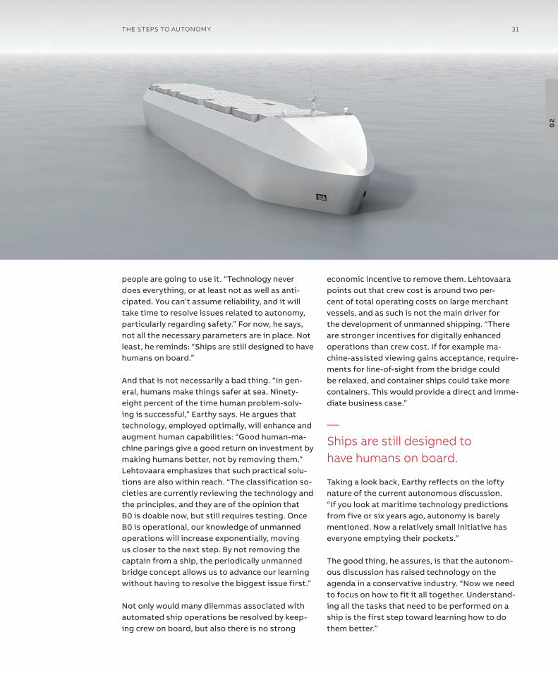
people are going to use it. “technology never does everything, or at least not as well as anti-cipated. You can’t assume reliability, and it will take time to resolve issues related to autonomy, particularly regarding safety.” For now, he says, not all the necessary parameters are in place. not least, he reminds: “ships are still designed to have humans on board.”
and that is not necessarily a bad thing. “in gen-eral, humans make things safer at sea. ninety-eight percent of the time human problem-solv-ing is successful,” earthy says. He argues that technology, employed optimally, will enhance and augment human capabilities: “Good human-ma-chine parings give a good return on investment by making humans better, not by removing them.”Lehtovaara emphasizes that such practical solu-tions are also within reach. “the classification so-cieties are currently reviewing the technology and the principles, and they are of the opinion that B0 is doable now, but still requires testing. once B0 is operational, our knowledge of unmanned operations will increase exponentially, moving us closer to the next step. By not removing the captain from a ship, the periodically unmanned bridge concept allows us to advance our learning without having to resolve the biggest issue first.”
not only would many dilemmas associated with automated ship operations be resolved by keep-ing crew on board, but also there is no strong
economic incentive to remove them. Lehtovaara points out that crew cost is around two per-cent of total operating costs on large merchant vessels, and as such is not the main driver for the development of unmanned shipping. “there are stronger incentives for digitally enhanced operations than crew cost. if for example ma-chine-assisted viewing gains acceptance, require-ments for line-of-sight from the bridge could be relaxed, and container ships could take more containers. this would provide a direct and imme-diate business case.”
taking a look back, earthy reflects on the lofty nature of the current autonomous discussion. “if you look at maritime technology predictions from five or six years ago, autonomy is barely mentioned. now a relatively small initiative has everyone emptying their pockets.”
the good thing, he assures, is that the autonom-ous discussion has raised technology on the agenda in a conservative industry. “now we need to focus on how to fit it all together. Understand-ing all the tasks that need to be performed on a ship is the first step toward learning how to do them better.”
—ships are still designed to have humans on board.
The sTePs To AUTonoMy 31
02
“What changes when the balance of control is shifted from humans to machines? People are highly responsible, but responsibility is a legal term. the challenge to humans arises when they are not sure what they are in control of.”
autopilot systems pose a relevant case, Brooks says, because some system control is hidden from human operators. But what happens when the system fails?
“it takes time for humans to figure out the status,” Brooks explains. “Can they analyse the problem and make an appropriate decision? the more automation, or the higher the level, the more the balance of control is skewed. this is why automation systems have to make the state of the system visible to humans, because they must be able to regain control if the system goes hay-wire. then it becomes more an issue of control than responsibility.”
show me the moneyLooking at automation or varying degrees of autonomy in the bigger picture of shipping, Brooks believes that the biggest economic bene-fits may not come from reducing crew. in fact, he says, the biggest benefits could instead centre around berth utilisation in ports. “We need to be
quicker to take advantage of space. When ports and ships start to talk to each other and vessels are making return calls, then it is worth investing in advanced automation. an owner could prob-ably pay off investments in a few years.”
“Here we have to be willing to learn from other transport modes and get our inspiration from outside shipping. i recently saw an airline auto-pilot video from the 1990s, when commercial aviation started to embrace automation. it looked like a giant step back in time, but it could have been shipping today,” Brooks adds.
“in 10 years we will have a combination of meth-ods for moving a ship in and out of harbours and ports. there will be some remote pilotage, and some will be the same as today. We are talking about evolution, not revolution. it also depends on the technical level of ships. But by then, even if we have not achieved autonomous berth-to-berth, we may be seeing port-to-port solutions in operation.”
—Control is the keyWhen the makers meet their machinesWhile the discussion around the feasibility of autonomous shipping continues, Benjamin Brooks, a human behaviour specialist and associate professor at the University of Tasmania in Australia, is more concerned with the impact of autonomous systems on humans.
—The challenge to humans arises when they are not sure what they are in control of.
32 GenerATions
02
We’re only human‘to err is human’ goes the old saying. if this is the case, can humans ever devise a perfect system? “no,” comes the answer from Brooks. “With automation, we can never be completely certain that the system will not fail. the best we can do is strive for development of error-tolerant, or resilient systems. Progress in understanding humans and human error has improved, but it has taken an extremely long time. We still do not have a complete understanding of where errors occur in shipping.”
it also has to do with computer capability, he says. “Let machines do what they do well, and help them enable humans to do what they do best. We have a long way to go in the maritime business before computers are cleverer than humans.”
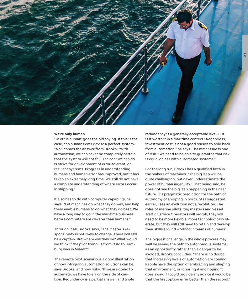
through it all, Brooks says, “the Master’s re-sponsibility is not likely to change. there will still be a captain. But where will they be? What would we think if the pilot flying us from oslo to Ham-burg was in Miami?”
the remote pilot scenario is a good illustration of how intriguing automation solutions can be, says Brooks, and how risky. “if we are going to automate, we have to err on the side of cau-tion. redundancy is a partial answer, and triple
redundancy is a generally acceptable level. But is it worth it in a maritime context? regardless, investment cost is not a good reason to hold back from automation,” he says. the main issue is one of risk: “We need to be able to guarantee that risk is equal or less with automated systems.”
For the long run, Brooks has a qualified faith in the makers of machines: “the big leap will be quite challenging, but never underestimate the power of human ingenuity.” that being said, he does not see the big leap happening in the near future. His pragmatic prediction for the path of autonomy of shipping in ports: “as i suggested earlier, i see an evolution not a revolution. the roles of marine pilots, tug masters and Vessel traffic service operators will morph, they will need to be more flexible, more technologically lit-erate, but they will still need to retain and develop their skills around working in teams of humans”.
the biggest challenge in the whole process may well be seeing the path to autonomous systems as an opportunity rather than a danger to be avoided, Brooks concludes. “there is no doubt that increasing levels of automation are coming. People have the option of embracing and shaping that environment, or ignoring it and hoping it goes away. if i could provide any advice it would be that the first option is far better than the second.”
The sTePs To AUTonoMy 33
02
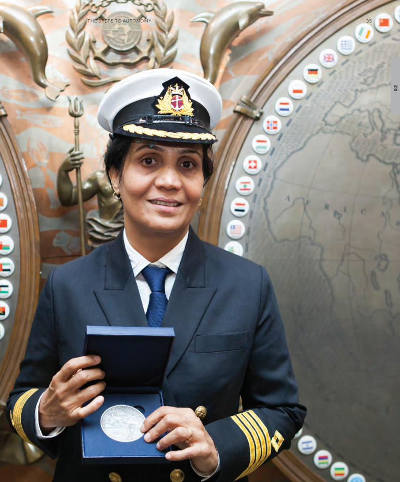
When Captain radhika Menon saw a boy frantic-ally waving from a boat caught in a storm, she knew she had to act fast. Had the bridge been un-manned, the fate of seven fishermen would have been at the mercy of the sea.
saving lives at sea“the boat was barely visible through the binocu-lars,” says Captain Menon, recalling the sighting of a fishing vessel from onboard the oil tanker Mt sampurna swarajya in the Bay of Bengal in June 2015. she immediately ordered a rescue opera-tion, saving the lives of the seven fishermen. the success of the operation has earned her the iMo (international Maritime organization) award for exceptional Bravery at sea – a first for a woman.
“the seas were stormy, with 60-70 knot winds and wave height of up to 9 meters. the fish-ermen didn’t stand a chance in that weather,” says Captain Menon. she points out that in such conditions the vessel radar would not have been able to pick up the boat as a target – there had to be a human on the bridge to see the boat. “this simple boat didn’t even have a satellite tracker,” she adds.
—at the helmCaptain radhika Menonin the era of increasingly sophisticated autonomous technologies, looking out the bridge window can still be the key to saving lives at sea.
—Captain radhika Menon received the 2016 iMo Award for exceptional Bravery at sea
34 GenerATions
02
The sTePs To AUTonoMy 35
02

While positive to the recent advances in shipping technology, she firmly believes that fully un-manned vessels still have a way to go. “the posi-tion that autonomous shouldn’t mean unmanned is a very good one. Keep the skilled people on board and give them the latest technology to support them.”
Captain Menon credits much of the success of the operation to her team. When she told the crew
that they would start maneuvering for the rescue, there wasn’t a second of hesitation. “they trus-ted me, and they did exactly what i wanted them to do. i really admire my team, and i am thankful to them for agreeing to go on an open deck in such weather.”
the first attempt failed due to the strong winds pulling the boat away towards the stern of the tanker. Captain Menon had to stop the engines and allow the boat to clear the propeller area of the tanker. only then was she able to make a second approach to the boat and rescue two of the fisherman with the help of a pilot ladder – a specialized rope ladder used on vessels. it took another attempt to bring the remaining five fish-ermen safely on board.
among those rescued was the 15-year-old boy whom Captain Menon first saw from the bridge. When he was climbing the ladder, just two short steps away from the deck, a gust of wind sent the ladder flying parallel to the deck, with the young fisherman clinging to it for his life. “if that ladder crashed on the side of the ship, the kid would have been gone,” recalls Captain Menon. “Luckily the wind kept the ladder parallel to the deck for about 30-40 seconds, and one of my crew, a very tall guy, picked up the boy and pulled him onto the deck.”
after the fishermen were safely on board, they called their homes using an onboard satellite phone – just in time to stop their funeral prayers. the fishermen had been missing for seven days, floating in open seas, with no food or water, and their families had lost all hope of ever seeing them alive.
When the rescue operation was completed, Cap-tain Menon called the shipping Corporation of india. “i forgot to inform them that i was turning the ship around,” she says, laughing. “When i told them what happened, they couldn’t believe it!”
—Keep the skilled people on board and give them the latest technology to support them.
—Captain radhika Menon is the first female to receive the iMo Award for exceptional Bravery at sea
36 GenerATions
02

opening the seas for womennot only is Captain Menon the first woman to receive the highest iMo bravery recognition; she is also the first female captain in the indian Mer-chant navy.
Her career at sea started with a desire to do some-thing other than a “regular nine-to-five job.” When she first started as a radio officer at the shipping Corporation of india, she was filled with enthusi-asm, even though her parents didn’t know much about the profession: “it was difficult. i was ques-tioning how suitable this choice was for a girl.”
this is no longer the case, with Captain Menon ac-knowledging that she has been successful in her career. Part of that, she believes, is the constant striving for excellence: “Whatever action i take, it has to be perfect. Women have no room for mis-takes in this profession – if anything goes wrong, people will be very unforgiving.”
Building trust took time. “out at sea, or with any job you do, you are answerable to yourself and to God. if people don’t accept me, it doesn’t matter to me. i’m on a ship and i’m doing the best job i can. When people you work with see that you’re doing your job well and that you are reliable, you can expect support and respect from them.”
in 2017, to help young women pursuing a career at sea, Captain Menon established the interna-tional Women seafarers Foundation (iWsF). even though today the doors of maritime training institutes are open to women, many of them still face challenges finding employment.
“not all shipping companies are accepting girls. if there are 10 boys and 10 girls among applicants, probably one or two girls will get a chance for a fair interview – but boys will always get a chance,” says Captain Menon.
iWsF helps young female graduates get on a path towards a career at sea. “We are not asking shipping
companies to accept a girl just because she is a girl. Give her a fair chance for a fair interview – that’s all we’re asking,” says Menon.
the Foundation is also supporting women while they are out at sea. Captain Menon and her iWsF colleagues consult female seafarers before they go on board, making sure they are mentally prepared for months of social isolation and being some of the few – if not the only – females in the team.
“if they have problems on board, they call us. We talk to them; sometimes that helps resolve the issue, but we have also dealt with a few cases of harassment,” says Captain Menon. iWsF tackles these cases by speaking directly to the ship-ping company, and resolving them in a way that wouldn’t affect a woman’s career at sea.
“since girls are new to the sea, most of the com-panies don’t have procedures for handling these situations,” says Captain Menon. “things can get out of proportion; a girl would be signed off, and the shipping company would think that girls are a problem – and shut doors to other girls coming into the profession.” Here is where iWsF comes in, investigating and mediating the issue.
seafaring as a male profession is a wrong concept, believes Captain Menon: “there is no stamp on any profession saying that it is for males or females. Professions are not gender based.”
looking into the futureone day, Captain Menon hopes, the attitude towards women at sea will change for the better: “With more women coming into this field, seafar-ing will become more open.” she acknowledges that she has seen progress since she started on her seafaring studies, with parents no longer as skeptical to sending their daughters to sea.
as for the advances in technology – in partic-ular, the increasing levels automation in ship navigation, steering and control – she believes focusing on the people on board is key. “techno-logy is advancing, and i am sure the day of fully autonomous shipping will come. But for now, make sure the technology is supporting the end user, be it a seafarer or a fisherman. and to me, that’s an advantage.”
—There is no stamp on any profession saying that it is for males or females.
The sTePs To AUTonoMy 37
02


—03 Digital: the great enabler
the drive to digital:
Plotting the right course—40–41
the road to a cyber resilient vessel—42–43
Learning to live with risk—44–45
sensors:
not only a game changer, a real lifesaver—46–47
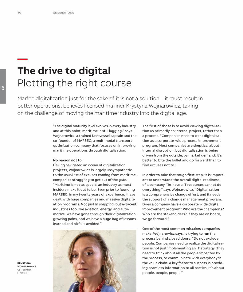
“the digital maturity level evolves in every industry, and at this point, maritime is still lagging,” says Wojnarowicz, a trained fast vessel captain and the co-founder of MarseC, a multimodal transport optimization company that focuses on improving maritime operations through digitalization.
No reason not toHaving navigated an ocean of digitalization projects, Wojnarowicz is largely unsympathetic to the usual list of excuses coming from maritime companies struggling to get out of the gate. “Maritime is not as special an industry as most insiders make it out to be. even prior to founding MarseC, in my twenty years of experience, i have dealt with huge companies and massive digitaliz-ation programs. not just in shipping, but adjacent industries too, like aviation, energy, and auto-motive. We have gone through their digitalization growing pains, and we have a huge bag of lessons learned and pitfalls avoided.”
the first of those is to avoid viewing digitaliza-tion as primarily an internal project, rather than a process. “Companies need to treat digitaliza-tion as a corporate-wide process improvement program. Most companies are skeptical about internal disruption, but digitalization is being driven from the outside, by market demand. it’s better to bite the bullet and go forward than to find excuses not to.”
in order to take that tough first step, it is import-ant to understand the overall digital readiness of a company. “in-house it resources cannot do everything,” says Wojnarowicz. “Digitalization is a comprehensive change effort, and it needs the support of a change management program. Does a company have a corporate wide digital improvement program? Who are the champions? Who are the stakeholders? if they are on board, we go forward.”
one of the most common mistakes companies make, Wojnarowicz says, is trying to run the process behind closed doors. “Do not exclude people. Companies need to realize the digitaliza-tion is not just implementing an it strategy. they need to think about all the people impacted by the process, to communicate with everybody in the value chain. a key factor to success is provid-ing seamless information to all parties. it’s about people, people, people.”
—The drive to digitalPlotting the right courseMarine digitalization just for the sake of it is not a solution – it must result in better operations, believes licensed mariner Krystyna Wojnarowicz, taking on the challenge of moving the maritime industry into the digital age.
—KrysTyNa WoJNaroWiCzCo-founderMArseC
40 GenerATions
03

showing the way“the maritime industry has a conservative repu-tation, but i really think they are just realistic. When everyone is saying you have to do some-thing it can be intimidating. they all feel they have to go digital, but most companies have one leg here, one leg there, and the pressure on the it de-partment becomes too high, especially when the in-house digital talent is missing. Companies in silicon Valley understand this issue and address it adequately. shipping could learn a lesson here.”
Wojnarowicz believes that easing companies into the digitalization process by showing employees the concrete potential for improvement is the key. this means helping people to do their jobs better, Wojnarowicz says, not threatening jobs. “some people are understandably skeptical, but if we de-liver tools that are easy to use, then we eliminate tedious tasks. People try it out and like it. We give them tools that can help make their lives easier.”
another success factor is to stay focused on the rewards that digitalization can provide. “Maritime traditionally has a lot of data that is collected but wasted,” Wojnarowicz observes. “Legacy equip-ment data is typically not correlated with digital systems. We have even seen digital data recorded on paper. often there is too little focus on creat-ing seamless processes. We go in thinking about how to keep digital data digital.”
Think big, start smallWojnarowicz refers to a survey conducted by McKinsey in 2018, where they found that in busi-nesses running digitalization pilots, less than 30
percent of projects were moving forward. “First of all, there is no proper plan, and no budget. they rush into it thinking, ‘it can’t be that difficult’. then they discover the pitfalls when they first be-gin to run pilots, and they get discouraged. Most often this has nothing to do with technology, only with politics in the organization, and this applies to all industries, not just maritime.”
a successful maritime digitalization process typ-ically starts by addressing cost savings, providing tools for analytics of routes, fuel consumption, emissions, and fleet management. “these are the first points of attack. after that is understood, the next level is addressing new products and services that they can offer. then they can start to monetize their data.
“the main point is not to do digitalization for the sake of digitalization. the result must make the operation faster, cheaper, and better. if a com-pany applies automation to inefficient operations, that will just multiply bad practices. identify your best practice first, then implement that digitally.”
Wojnarowicz encourages enterprises to think big, but start small. “if the foundation for change is robust, then we try things out for some months and arrive at proof of concept. then we move on to the pilot phase, and after that we scale it into production. the point is to create a learning or-ganization. start with a small dedicated process improvement group within your organization. Learn from the experience of others, and make it fit for you. even though digitalization is urgent, you don’t have to rush.”
DiGiTAl: The GreAT enABler 41
03
Like every other digital industry, shipping is exposed to malware and multiple other cyber threats. However, the viruses that threaten to break the maritime supply chain and delay cargo delivery carry additional risks. infected systems can compromise navigation or propulsion, threat-ening ship safety itself as well as the marine en-vironment. With broadband internet connectivity available for vessels globally, and viruses such as notPetya and Wannacry exposing the vulnerabil-ity of older, legacy systems often found on board ships worldwide, the industry is waking up to the scale of the cyber menace.
Human error can often be the leading cause of cybersecurity problems. no matter how strong the firewall, a system is only as secure as its least well-trained user. Without formal train-ing, bad habits that include inserting poten-tially infected UsB sticks can be hard to break. in the global shipping industry, ships often have no cyber threat management technology on board, and even the most highly skilled crews may have had little or no training specific to cybersecurity.
shipping’s well-publicized journey towards digitalization and greater automation therefore
demands an accompanying commitment to increase it security and mitigate cyber risks through system robustness, but also through additional training and continuous aware-ness-raising.
in general, industries considered to be fur-ther advanced in that journey have recognized vendors, rather than third parties, as best placed to develop integrated security solutions risk mitigation, including monitoring, analysis and re-sponse. Given its role in electric systems covering ship power, propulsion, automation and control, for example, it is not surprising that aBB has a mature position on the in-depth security required for digital solutions.
the maturity of the group’s thinking on cyberse-curity quickly became clear to me when i joined aBB Marine & Ports back in 2017. Here, i was able to put to good use the it and cybersecurity experience i have gathered over the last 20 years, with the italian navy, then in an it security con-sultancy, and most recently with Costa Crociere as Fleet it Manager.
in my experience, no cybersecurity protection can claim 100 percent resilience. this is why cyber-security is a process for risk mitigation, and not a product. it is not a destination but an evolving risk management strategy that needs to cover people, processes and technologies that face fast-changing threats.
—The road to a cyber resilient vessel Cyber threats are ever-present in the connected world, and shipping has woken up to what is at stake. Andrea Crosetti, ABB Marine & Ports’ Cybersecurity solutions Manager, shares his insights.
—no cybersecurity protection can claim 100 percent resilience.
42 GenerATions
03
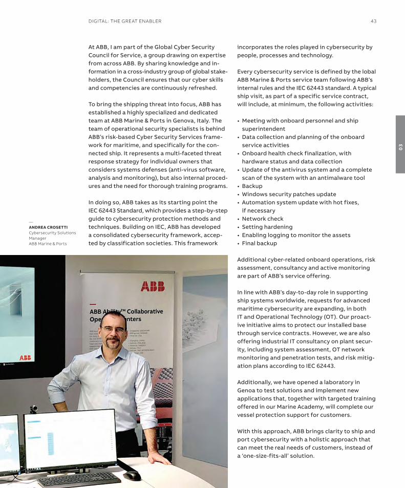
at aBB, i am part of the Global Cyber security Council for service, a group drawing on expertise from across aBB. By sharing knowledge and in-formation in a cross-industry group of global stake-holders, the Council ensures that our cyber skills and competencies are continuously refreshed.
to bring the shipping threat into focus, aBB has established a highly specialized and dedicated team at aBB Marine & Ports in Genova, italy. the team of operational security specialists is behind aBB’s risk-based Cyber security services frame-work for maritime, and specifically for the con-nected ship. it represents a multi-faceted threat response strategy for individual owners that considers systems defenses (anti-virus software, analysis and monitoring), but also internal proced-ures and the need for thorough training programs.
in doing so, aBB takes as its starting point the ieC 62443 standard, which provides a step-by-step guide to cybersecurity protection methods and techniques. Building on ieC, aBB has developed a consolidated cybersecurity framework, accep-ted by classification societies. this framework
incorporates the roles played in cybersecurity by people, processes and technology.
every cybersecurity service is defined by the lobal aBB Marine & Ports service team following aBB’s internal rules and the ieC 62443 standard. a typical ship visit, as part of a specific service contract, will include, at minimum, the following activities:
•Meeting with onboard personnel and ship superintendent
•Data collection and planning of the onboard service activities
•onboard health check finalization, with hardware status and data collection
•Update of the antivirus system and a complete scan of the system with an antimalware tool
• Backup•Windows security patches update • automation system update with hot fixes,
if necessary•network check• setting hardening • enabling logging to monitor the assets• Final backup
additional cyber-related onboard operations, risk assessment, consultancy and active monitoring are part of aBB’s service offering.
in line with aBB’s day-to-day role in supporting ship systems worldwide, requests for advanced maritime cybersecurity are expanding, in both it and operational technology (ot). our proact-ive initiative aims to protect our installed base through service contracts. However, we are also offering industrial it consultancy on plant secur-ity, including system assessment, ot network monitoring and penetration tests, and risk mitig-ation plans according to ieC 62443.
additionally, we have opened a laboratory in Genoa to test solutions and implement new applications that, together with targeted training offered in our Marine academy, will complete our vessel protection support for customers.
With this approach, aBB brings clarity to ship and port cybersecurity with a holistic approach that can meet the real needs of customers, instead of a ‘one-size-fits-all’ solution.
—aNDrEa CrosETTiCybersecurity solutions ManagerABB Marine & Ports
DiGiTAl: The GreAT enABler 43
03
Patricia aas has her curiosity to thank for casting her into the international spotlight. “i was won-dering about how the norwegian elections were run, so i started asking questions. i never inten-ded to become a public figure,” she says.
she did become a public figure though, literally overnight. “When i learned that norway was going to count a large percentage of votes only elec-tronically, i began to wonder how they could be so sure nothing could go wrong.” Her inquiries led to norwegian officials making a historic turnaround just days before the election: all votes would also be counted by hand. the story made headlines in norway, and around the world.
“there are so many things that can go wrong with computer systems, but we get lulled into com-placency by our own success,” aas says. electoral system may be an example of this, but the same principles apply to other industries, and maritime is no exception. “once a thing has worked for a
while, we just assume it will keep working. there needs to be a way to detect if something fails, and there needs to be a plan for how to fix it if it does.”
the absence of such plans has often nothing to do with technology at all, aas says, but more with differences in understanding. “it can be diffi-cult to discuss computer security with decision makers if they don’t have it experience. either they don’t understand, or they claim the expert is being too cautious. that makes it hard to get support for proper security measures.”
Taking the blame out of security aas observes that though we have become a compu-terized society, most people have not been taught how it systems work. on the other side are the specialists who are more informed about computer risk, and she believes these experts must be allowed to bring up risk issues without consequence.
“the personal cost to the bearer of bad news can be huge. You become a constant burden, a noise-maker, and this can damage careers. Businesses want positive input from their employees, so there is really never a scenario where you are a hero when you bring bad news.”
one way to reverse this trend is to stop playing the blame game, aas says. the it industry has be-gun to employ what they call the ‘blameless post mortem’, where all stakeholders take a time-out
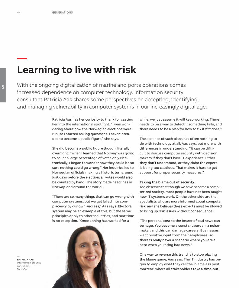
—learning to live with riskWith the ongoing digitalization of marine and ports operations comes increased dependence on computer technology. information security consultant Patricia Aas shares some perspectives on accepting, identifying, and managing vulnerability in computer systems in our increasingly digital age.
—PaTriCia aasinformation security consultantTurtlesec
44 GenerATions
03

to figure out what went wrong in a system failure, without assigning blame to teams or individuals. “Blame does not solve problems. instead we need continuous learning and a larger understanding of responsibility. it’s more important to ask, ‘What can we do next time?’”
For only a few?With only a small segment of the population aware of how computers work, the rest are often left to rely on the experts for the ‘truth’ – not always a healthy situation, aas believes. she likes to relate the story of Martin Luther who challenged the ‘ex-perts’ back when biblical texts and sermons were in Latin, and with his translation of the bible to German, helped people begin constructing their own understanding of the order of things.
aas looks forward to the same level of mutual enlightenment in it – across all industries. “some efforts are being made, like Code Clubs in UK. We have also considered offering coding classes for executives. this is not about programming, or
being a programmer, but simply understanding what coding is. i think this kind of investment would impact the bottom line, if we started deal-ing with risk through informed decisions, on a par with business decisions.”
understanding riskMore aspects of business are exposed in the age of Big Data and cloud computing, aas points out, and many exposures are not detected. “We do not understand the inherent risk. this requires an un-derstanding of it as a function that underpins the entire business. it also requires systems thinking, and accepting that relationships between things influence each other. there is never one single cause for an incident.”
acknowledging risk may require resources, but the alternative can be far worse, aas believes. “system failures impact not just earnings, but brands. a company’s entire trust base could be wiped out in a single major incident.”
Far from preaching doomsday, though, aas is merely advocating awareness. “it’s easy to start depend-ing on a system without realizing how dependent you are, and dependence is vulnerability. With the proper awareness it is possible to mitigate vulner-ability and avoid disaster, but it starts with learning to accept computers as things that might fail.”
—With the proper awareness it is possible to mitigate vulnerability and aviod disaster.
DiGiTAl: The GreAT enABler 45
03
Locating crew on a ship in the event of an ac-cident has always posed problems, and failure to do so can cost lives. When the Hurtigruten ship Kong Harald was struck by fire in 2011, the captain did not trigger the Co2-based fire ex-tinguishing system because he was uncertain of the whereabouts of the engine room crew. two crewmen died in the fire.
that tragic outcome triggered action. “We thought it must be possible to solve the problem of not being able to locate crew, so we started to investigate possible solutions,” says John roger nesje, the co-founder and Ceo of norway-based maritime iot company scanreach.
in 2014, the group began to look at possibilities for locating personnel on ships, including cabling, triangulation, and other technologies. obstacles linked to cabling became apparent straight away. “First of all, we realized it would be virtually impossible to run cables through all rooms in an existing vessel. and even if you managed, or in-stalled cables in a newbuild, they would probably not work in the event of a fire,” says nesje.
this ‘dead end’ lead to a solution: a completely wireless alternative employing sensors through-out the ship, and personal tag bracelets worn by crewmembers. “this could work on existing ships too, not just newbuilds, which was very import-ant,” nesje adds.
the norwegian navy made a ship at their headquarters available for testing. at the begin-ning of testing, the signal functioned very poorly in the steel environment. “We spent thousands of hours fine-tuning frequencies and tinkering with software protocols. eventually it began to work,” nesje says.
once it started working, new applications began to present themselves. “When we started to see what the technology could do, we realized that personnel safety would be only one of the features we could deliver. We could track goods on board, the location of safety equipment, the performance of equipment – basically anything that could be monitored by sensors. in addition we could collect information from all the rooms on a ship, which allows us to detect leakage, gas, heat, and smoke,” says nesje.
“We also began to get inquiries from third-party vendors with specialized sensors but without solutions for transporting data. now we are working to integrate their data with our platform.
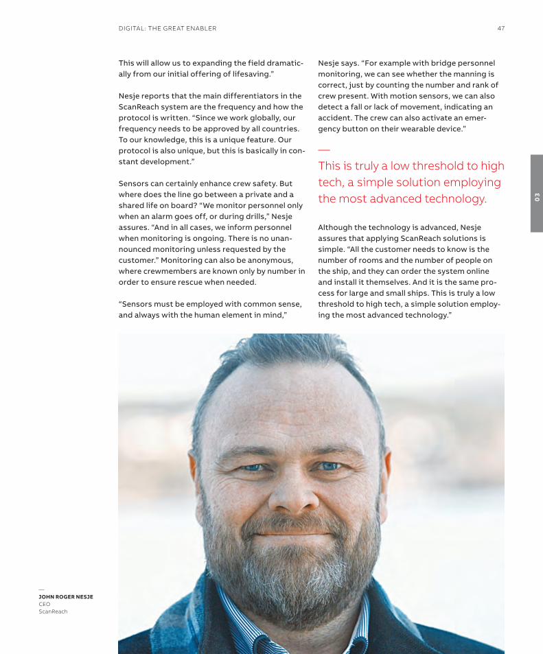
—sensorsnot only a game changer, a real lifesaversensors have made their way into nearly every part of our everyday lives, changing the way we do virtually everything. Beyond changing lives, they can also help save lives, as scanreach Ceo John roger nesje tells here.
—sensors must be employed with common sense, and always with the human element in mind.
46 GenerATions
03
this will allow us to expanding the field dramatic-ally from our initial offering of lifesaving.”
nesje reports that the main differentiators in the scanreach system are the frequency and how the protocol is written. “since we work globally, our frequency needs to be approved by all countries. to our knowledge, this is a unique feature. our protocol is also unique, but this is basically in con-stant development.”
sensors can certainly enhance crew safety. But where does the line go between a private and a shared life on board? “We monitor personnel only when an alarm goes off, or during drills,” nesje assures. “and in all cases, we inform personnel when monitoring is ongoing. there is no unan-nounced monitoring unless requested by the customer.” Monitoring can also be anonymous, where crewmembers are known only by number in order to ensure rescue when needed.
“sensors must be employed with common sense, and always with the human element in mind,”
nesje says. “For example with bridge personnel monitoring, we can see whether the manning is correct, just by counting the number and rank of crew present. With motion sensors, we can also detect a fall or lack of movement, indicating an accident. the crew can also activate an emer-gency button on their wearable device.”
although the technology is advanced, nesje assures that applying scanreach solutions is simple. “all the customer needs to know is the number of rooms and the number of people on the ship, and they can order the system online and install it themselves. and it is the same pro-cess for large and small ships. this is truly a low threshold to high tech, a simple solution employ-ing the most advanced technology.”
—This is truly a low threshold to high tech, a simple solution employing the most advanced technology.
—JohN roGEr NEsJECeoscanreach
DiGiTAl: The GreAT enABler 47
03


— 04 China – the next marine power
the emergence of China—52–53
China’s role in Marine 4.0—54–57
Cruising into China—58–61
the impact of LnG on maritime China—62–65
answering to the environment—66–67
Carving a polar niche:
China’s first home-built icebreaker—68–69

50 GenerATions
04

ChinA – The nexT MArine PoWer 51
04
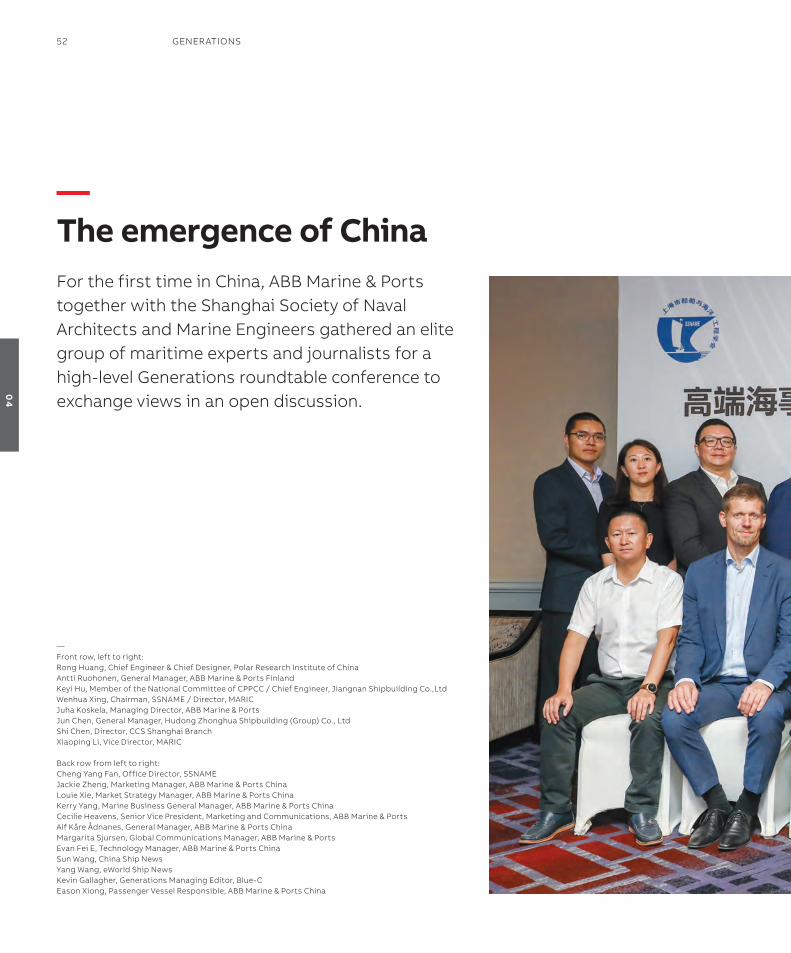
—The emergence of ChinaFor the first time in China, ABB Marine & Ports together with the shanghai society of naval Architects and Marine engineers gathered an elite group of maritime experts and journalists for a high-level Generations roundtable conference to exchange views in an open discussion.
—Front row, left to right:rong huang, Chief engineer & Chief Designer, Polar research institute of China Antti ruohonen, General Manager, ABB Marine & Ports FinlandKeyi hu, Member of the national Committee of CPPCC / Chief engineer, Jiangnan shipbuilding Co.,ltdWenhua xing, Chairman, ssnAMe / Director, MAriCJuha Koskela, Managing Director, ABB Marine & PortsJun Chen, General Manager, hudong Zhonghua shipbuilding (Group) Co., ltdshi Chen, Director, CCs shanghai Branch xiaoping li, Vice Director, MAriC
Back row from left to right:Cheng yang Fan, office Director, ssnAMeJackie Zheng, Marketing Manager, ABB Marine & Ports Chinalouie xie, Market strategy Manager, ABB Marine & Ports ChinaKerry yang, Marine Business General Manager, ABB Marine & Ports China Cecilie heavens, senior Vice President, Marketing and Communications, ABB Marine & PortsAlf Kåre Ådnanes, General Manager, ABB Marine & Ports ChinaMargarita sjursen, Global Communications Manager, ABB Marine & Portsevan Fei e, Technology Manager, ABB Marine & Ports Chinasun Wang, China ship newsyang Wang, eWorld ship newsKevin Gallagher, Generations Managing editor, Blue-Ceason xiong, Passenger Vessel responsible, ABB Marine & Ports China
52 GenerATions
04

ChinA – The nexT MArine PoWer 53
04
China commands the world’s second largest eco-nomy, and is the largest shipbuilding nation in the world. China’s ongoing ‘Belt and road’ economic development project encompasses some 65 coun-tries representing more than 30 percent of global GDP. Maritime initiatives in the project aim to ex-pand shipping lanes and port investments through-out southeast asia, oceania, africa, and europe.
Working from such a solid base and with such am-bitious plans, the future of the Chinese maritime industry will impact not just global shipping, but the global economy. that future will be determ-ined by government policies, the evolution of the domestic shipbuilding industry, and the ambi-tions of the Chinese shipowning community.
opening the discussion, moderator Wenhua Xing, Chairman of the shanghai society of naval archi-tects & ocean engineers (ssnaMe) and Director of the Marine Design and research institute of China (MariC), shared his own perspectives on Maritime 4.0. “the internet and sensor techno-logy have brought on great change, and will con-tinue to have a great impact on our lives. there is steadily more online commercial activity, and this has impacted retailers. online vendors can offer
quicker delivery and lower price, and this applies to vendors in the maritime industry as well.”
new technologies also have advantages for en-vironmental protection, Xing added, mentioning fuel cells specifically. “We need to consider the owners,” he added. “they want to see return on their investments, and then it becomes about more than just technology. We need to think about technology and the advantages in effi-ciency it can provide for the whole industry.”
He also noted the increasing investment in intelligent and near-autonomous vessels. “We now believe that the autonomous vessel is within reach. But what are the advantages? this we still do not know.”
Keyi Hu, Chief engineer at Jiangnan shipbuilding Co., Ltd, reminded the group that the intelligent vessel is still a general concept in the early stages of development. “there are and will be varying degrees of autonomy. We will need a stepwise de-velopment as we move toward the ultimate goal,” he maintained.
“With the development of new technologies, especially digitalization and the iot, there is more and more high-level automation, and implement-ation of these technologies requires involvement from the integrators. there are many strong integrators, but there is risk involved for ship-
—China’s role in Marine 4.0At the Generations roundtable session in shanghai, China’s leading shipbuilders, shipowners, industry organizations and service providers gathered to discuss the technologies likely to influence the development of shipping in China, and their expectations for Chinese and international maritime markets.
—intelligent and sustainable shipping are the inevitable trends.
54 GenerATions
04

builders using third parties to carry out work. if half the total cost of a vessel is in the hands of the integrators, shipbuilders might not feel secure, and there is also a potential risk for owners.”
so how can shipyards can minimize risk? “it be-comes very important how integration suppliers convince shipyards to apply new technologies in projects, and shipbuilders need to know how they can control risk when integrating suppliers,” said Hu.
intelligence and the environmentChina Classification society (CCs) shanghai Branch Director shi Chen shared his vision of two direc-tions for the industry over the next 20-30 years: in-telligent shipping and sustainable shipping. “these are the inevitable trends,” he emphasized.
“intelligent shipping is enabled by suppliers of in-telligent equipment. in 2015, we worked to release intelligent vessel regulations, cooperating with aBB on different aspects. the response was over-whelmingly positive. now we are performing r&D on intelligent operations in 10 vessel segments.”
Chen explained that they have accomplished a lot in just a few years. “We recently developed new unmanned vessel regulations, which we now are calling autonomous cargo ship regulations, launched during sMM maritime trade fair in 2018. We have divided the cargo regulations into 10 or 12 systems for separate risk assessments.
Depending on whether we are talking about unmanned or not, different requirements for systems and equipment would apply.”
in addition to regulations for cargo vessels, CCs has prepared requirements for more complex ves-sel types, Chen said. “the system for cargo ves-sels is relatively clear and robust, so this will form the basis of further regulations. i believe that by releasing these regulations we can provide good direction for the further development of autonom-ous shipping and the shipbuilding industry.”
Moving on to environmental issues, Chen focused on likely scenarios shaping the power of the future: “as environmental regulations continue to get stricter, we believe in fuel cells as a viable power source,” he continued. “Fuel cell techno-logy is developing to allow higher energy densit-ies, and this will enable us to gradually transform our vessels to pure electric propulsion.”
Chen acknowledged there are issues to be re-solved in electrical power storage, but pointed
—Wenhua xingAlf Kåre Ådnanesshi Chen
—We need to think about technology and the advantages in efficiency it can provide for the whole industry.
ChinA – The nexT MArine PoWer 55
04
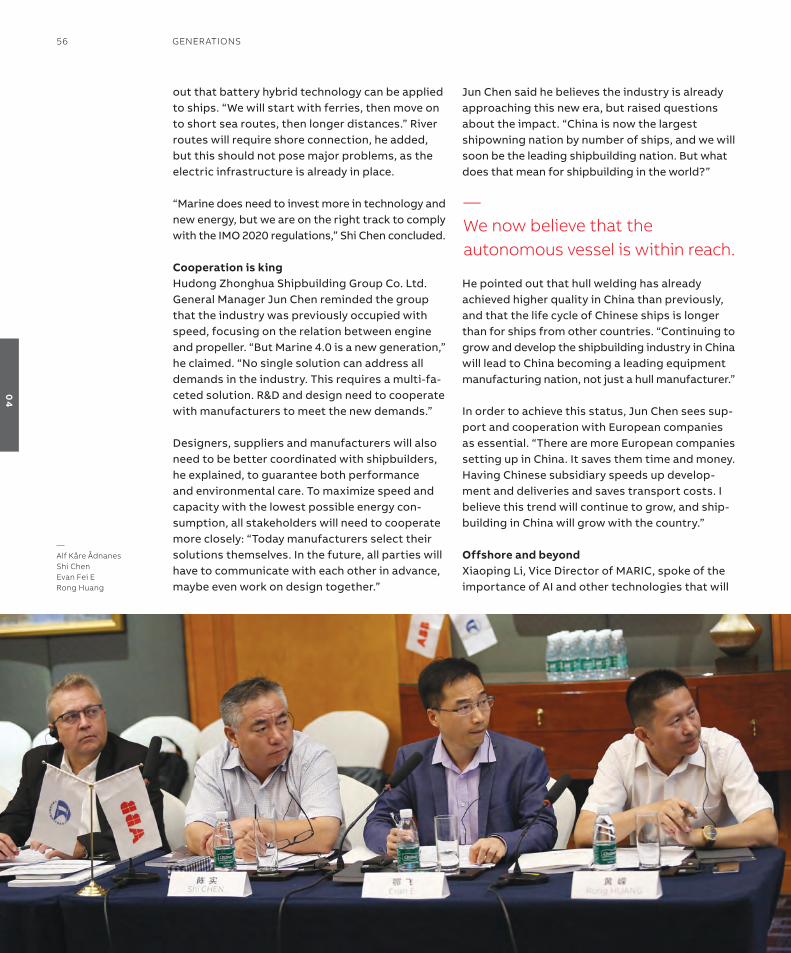
out that battery hybrid technology can be applied to ships. “We will start with ferries, then move on to short sea routes, then longer distances.” river routes will require shore connection, he added, but this should not pose major problems, as the electric infrastructure is already in place.
“Marine does need to invest more in technology and new energy, but we are on the right track to comply with the iMo 2020 regulations,” shi Chen concluded.
Cooperation is kingHudong Zhonghua shipbuilding Group Co. Ltd. General Manager Jun Chen reminded the group that the industry was previously occupied with speed, focusing on the relation between engine and propeller. “But Marine 4.0 is a new generation,” he claimed. “no single solution can address all demands in the industry. this requires a multi-fa-ceted solution. r&D and design need to cooperate with manufacturers to meet the new demands.”
Designers, suppliers and manufacturers will also need to be better coordinated with shipbuilders, he explained, to guarantee both performance and environmental care. to maximize speed and capacity with the lowest possible energy con-sumption, all stakeholders will need to cooperate more closely: “today manufacturers select their solutions themselves. in the future, all parties will have to communicate with each other in advance, maybe even work on design together.”
Jun Chen said he believes the industry is already approaching this new era, but raised questions about the impact. “China is now the largest shipowning nation by number of ships, and we will soon be the leading shipbuilding nation. But what does that mean for shipbuilding in the world?”
He pointed out that hull welding has already achieved higher quality in China than previously, and that the life cycle of Chinese ships is longer than for ships from other countries. “Continuing to grow and develop the shipbuilding industry in China will lead to China becoming a leading equipment manufacturing nation, not just a hull manufacturer.”
in order to achieve this status, Jun Chen sees sup-port and cooperation with european companies as essential. “there are more european companies setting up in China. it saves them time and money. Having Chinese subsidiary speeds up develop-ment and deliveries and saves transport costs. i believe this trend will continue to grow, and ship-building in China will grow with the country.”
offshore and beyondXiaoping Li, Vice Director of MariC, spoke of the importance of ai and other technologies that will
—Alf Kåre Ådnanesshi Chenevan Fei erong huang
—We now believe that the autonomous vessel is within reach.
56 GenerATions
04
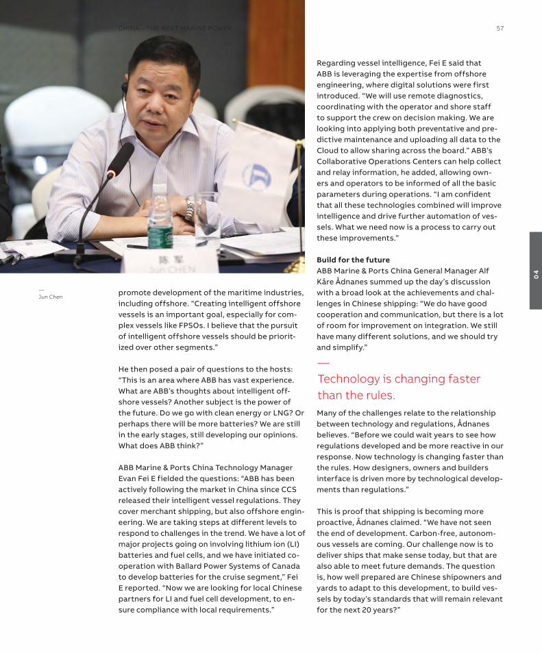
promote development of the maritime industries, including offshore. “Creating intelligent offshore vessels is an important goal, especially for com-plex vessels like FPsos. i believe that the pursuit of intelligent offshore vessels should be priorit-ized over other segments.”
He then posed a pair of questions to the hosts: “this is an area where aBB has vast experience. What are aBB’s thoughts about intelligent off-shore vessels? another subject is the power of the future. Do we go with clean energy or LnG? or perhaps there will be more batteries? We are still in the early stages, still developing our opinions. What does aBB think?”
aBB Marine & Ports China technology Manager evan Fei e fielded the questions: “aBB has been actively following the market in China since CCs released their intelligent vessel regulations. they cover merchant shipping, but also offshore engin-eering. We are taking steps at different levels to respond to challenges in the trend. We have a lot of major projects going on involving lithium ion (Li) batteries and fuel cells, and we have initiated co-operation with Ballard Power systems of Canada to develop batteries for the cruise segment,” Fei e reported. “now we are looking for local Chinese partners for Li and fuel cell development, to en-sure compliance with local requirements.”
regarding vessel intelligence, Fei e said that aBB is leveraging the expertise from offshore engineering, where digital solutions were first introduced. “We will use remote diagnostics, coordinating with the operator and shore staff to support the crew on decision making. We are looking into applying both preventative and pre-dictive maintenance and uploading all data to the Cloud to allow sharing across the board.” aBB’s Collaborative operations Centers can help collect and relay information, he added, allowing own-ers and operators to be informed of all the basic parameters during operations. “i am confident that all these technologies combined will improve intelligence and drive further automation of ves-sels. What we need now is a process to carry out these improvements.”
Build for the futureaBB Marine & Ports China General Manager alf Kåre Ådnanes summed up the day’s discussion with a broad look at the achievements and chal-lenges in Chinese shipping: “We do have good cooperation and communication, but there is a lot of room for improvement on integration. We still have many different solutions, and we should try and simplify.”
Many of the challenges relate to the relationship between technology and regulations, Ådnanes believes. “Before we could wait years to see how regulations developed and be more reactive in our response. now technology is changing faster than the rules. How designers, owners and builders interface is driven more by technological develop-ments than regulations.”
this is proof that shipping is becoming more proactive, Ådnanes claimed. “We have not seen the end of development. Carbon-free, autonom-ous vessels are coming. our challenge now is to deliver ships that make sense today, but that are also able to meet future demands. the question is, how well prepared are Chinese shipowners and yards to adapt to this development, to build ves-sels by today’s standards that will remain relevant for the next 20 years?”
—Technology is changing faster than the rules.
—Jun Chen
ChinA – The nexT MArine PoWer 57
04
the domestic cruise industry in China seemed poised to take off in 2016, posting record growth. Following a decline in 2017, the industry acknow-ledged the need to rethink and regroup. now, op-timism is back and China’s first domestically built cruise ship is on order. What does this mean for the Chinese operators and builders? What are China’s biggest challenges in the domestic and global cruise markets? and can China compete at the top level with european builders and operators?
Moderator Wenhua Xing, chairman of the shang-hai society of naval architects & ocean engineers (ssnaMe), was optimistic in his opening remarks to the roundtable discussion.
“Cruise is considered one of the pearls in the Chinese shipbuilding industry. China is bullish on cruise, both the consumer market and ship-building, despite the recent downturn.” the big question for both segments, he asked, is how to make money.
“Many yards want to move into cruise including China state shipbuilding Corporation (CssC) and shanghai Waigaoqiao shipbuilding Co (sWs).
More and more people want to travel overseas as well, and we believe many of these will want to travel on cruise ships.”
the potential of China’s huge consumer market speaks for itself, Wenhua Xing pointed out, but there is still a need for caution. “We need to learn from historic losses in Japan when they attemp-ted to build their first cruise ships. Cruise is dif-ferent, and the vessels are different. everything, from the philosophy, to supply chain manage-ment, to construction in the cruise industry is unfamiliar territory in China.”
Yet China is developing rapidly as a shipbuilder, he pointed out, and despite the challenges, they see great opportunities. “China may be emerging as an industrial power, but can we really build cruise ships?”
Cost is keythe first response came from Keyi Hu, technical director at the Jiangnan shipyard.
“there are four major challenges for Chinese yards. First, we need to meet the standards and specifications. the second issue is meeting qual-ity requirements. the third is controlling cost, and the forth is ensuring on-time delivery.”
specifications, he believed, would be the easiest of the requirements to accommodate. “We can
—Cruise is considered one of the pearls in the Chinese shipbuilding industry.
—Cruising into Chinahow is Chinese shipbuilding going to take advantage of the opportunities and deal with the challenges of the cruise segment? As part of the Generations roundtable series, ABB Marine & Ports has gathered a group of shipbuilders and specialists in shanghai to search for the answers.
58 GenerATions
04
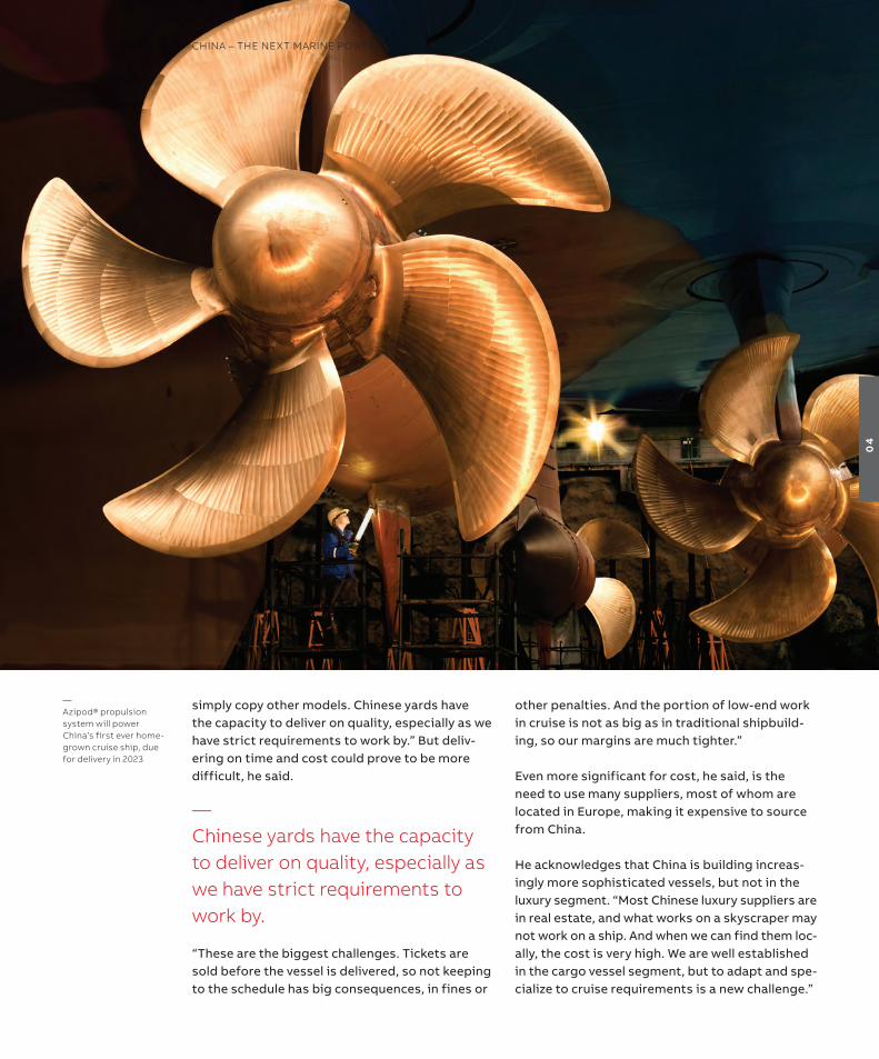
simply copy other models. Chinese yards have the capacity to deliver on quality, especially as we have strict requirements to work by.” But deliv-ering on time and cost could prove to be more difficult, he said.
“these are the biggest challenges. tickets are sold before the vessel is delivered, so not keeping to the schedule has big consequences, in fines or
other penalties. and the portion of low-end work in cruise is not as big as in traditional shipbuild-ing, so our margins are much tighter.”
even more significant for cost, he said, is the need to use many suppliers, most of whom are located in europe, making it expensive to source from China.
He acknowledges that China is building increas-ingly more sophisticated vessels, but not in the luxury segment. “Most Chinese luxury suppliers are in real estate, and what works on a skyscraper may not work on a ship. and when we can find them loc-ally, the cost is very high. We are well established in the cargo vessel segment, but to adapt and spe-cialize to cruise requirements is a new challenge.”
—Azipod® propulsion system will power China’s first ever home-grown cruise ship, due for delivery in 2023
—Chinese yards have the capacity to deliver on quality, especially as we have strict requirements to work by.
ChinA – The nexT MArine PoWer 59
04

Vacation, not transportation China Classification society (CCs) shanghai branch director shi Chen believes China is pre-pared for this market technologically. Lack of experience with cruise specifications, however, is an issue, as well as cooperation with suppliers.
He said that looking at previous standards or fixed designs is of little help, as these do not apply directly to cruise. to move forward, he said, China needs cooperation and joint discussion between owners, operators, builders, classifica-tion societies and equipment suppliers – prefer-ably before the ship is designed. “We need to keep the discussion going throughout the building process, adjusting and improving the design and construction as we go along.”
the key questions that need to be addressed, he believes, include the style of the cruise, and which routes the ship will be trafficking. “this is very different than traditional shipbuilding, and we are still dependent on europe for their experience in the field. also China does not have the investment apparatus for cruise, or investors with the know-ledge of the industry.”
He notes that the outbound cruise market is still growing, despite the recent downturn. “Penetra-tion is still very low and the population is big, so there is a lot of potential. For a while, cruise was a novelty and everyone was eager to try it. But even then many used it as a way to buy tax-free goods. they spent more on duty free than on a ticket to Korea or Japan. that is not cruising. We still do not know how to enjoy cruise as a destination by itself.” the Chinese are gradually adopting their own version of the european model, he believes, with a focus on cruise as travel, not just as “tax-free transportation”.
“the Chinese have more time and money now, and there is a natural development in awareness, but
Chinese customers need time to adapt. the long-term trend will be toward more cruise, when we be-gin to see it as a vacation, not just transportation.”
Defining a new nicheDespite these trends, shi Chen believes that true acceptance of cruising in China will depend on more than the changing mindset of customers. “european builders keep to european customs, but Chinese guests don’t want to lay in the sun or sit in the library. Different cultures have different habits, and that means different markets with dif-ferent needs.” this, he believes, is one key reason why the competition between european and Chinese builders will not be a significant issue in the long term.
“everyone knows the major yards are full, with orders through 2025. this opens up opportunities for Chinese yards. even if there may be surplus capacity in the future, those ships will not be suit-able for the Chinese market. on the contrary, our market will grow on its own terms. it will prob-ably not be highest end luxury, but somewhere between three and four stars, economical and comfortable. First, we must control cost. then we can grow the idea that cruise is a part of enjoying a better life.”
strength in numbersHudong Zhonghua shipbuilding Group Co. Ltd. general manager Jun Chen took the opportun-ity to present the case for China cruise by the numbers: “China has a big population. if just two out of one hundred people take only one cruise per year, that would mean 20-30 million people on cruises annually. to cover this, seven or eight ships would need to be built a year. the numbers are very strong. there will be a big demand, even with limited interest.”
understanding the valuesthough the numbers may be strong, the key to unlocking the market, Jun Chen proposed, may be through a better understanding of Chinese val-ues. “Wealth is growing in China, so the number of people cruising should grow, but it has to grow on Chinese terms.”
But he warns that simply copying the european experience will never float on the Chinese market.
—Wealth is growing in China, so the number of people cruising should grow, but it has to grow on Chinese terms.
60 GenerATions
04
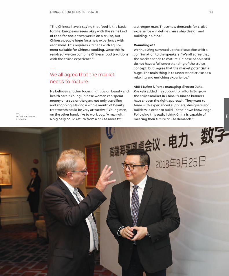
“the Chinese have a saying that food is the basis for life. europeans seem okay with the same kind of food for one or two weeks on a cruise, but Chinese people hope for a new experience with each meal. this requires kitchens with equip-ment suitable for Chinese cooking. once this is resolved, we can combine Chinese food traditions with the cruise experience.”
He believes another focus might be on beauty and health care. “Young Chinese women can spend money on a spa or the gym, not only travelling and shopping. Having a whole month of beauty treatments could be very attractive.” Young men, on the other hand, like to work out. “a man with a big belly could return from a cruise more fit,
a stronger man. these new demands for cruise experience will define cruise ship design and building in China.”
rounding offWenhua Xing summed up the discussion with a confirmation to the speakers. “We all agree that the market needs to mature. Chinese people still do not have a full understanding of the cruise concept, but i agree that the market potential is huge. the main thing is to understand cruise as a relaxing and enriching experience.”
aBB Marine & Ports managing director Juha Koskela added his support for efforts to grow the cruise market in China: “Chinese builders have chosen the right approach. they want to team with experienced suppliers, designers and builders in order to build up their own knowledge. Following this path, i think China is capable of meeting their future cruise demands.”
—Alf Kåre Ådnaneslouie xie
—We all agree that the market needs to mature.
ChinA – The nexT MArine PoWer 61
04
—The impact of lNG on maritime ChinaChina is steadily increasing its focus on reducing pollution in general, particularly in ports and coastal regions. The goal is a cleaner, greener fleet, and lnG is seen as an important part of the solution.
as the world works to clean up it skies and oceans, use of LnG in land-based and marine ap-plications is on the rise. LnG, though not carbon neutral, is a cleaner alternative to other carbon energy sources such as coal or diesel.
increased use of LnG is having a significant effect on the global maritime industry, with the number of ships supplying LnG to land-based consumers rising, and more vessels burning LnG as fuel to accommodate ever-stricter marine emissions re-quirements. and though China has only a limited stake in LnG shipbuilding at present, the industry is busy plotting a course for increased particip-ation in the growing segment – which has been central to the discussions at the Generations roundtable discussion in shanghai.
Moderator Wenhua Xing, Chairman of the shang-hai society of naval architects & ocean engineers (ssnaMe), started the discussion by highlighting the tightening environmental regulations on shipping in China: “Pollution caused by mari-time traffic is getting a lot of attention from the government now, under the Blue sky Protection Campaign, and the industry is beginning to respond. Last year, China state shipbuilding Cor-poration (CssC) signed a contract with Gasfin
for a dual fuel container ship. also, clean fuel is now required for ships trafficking the Yangtze and Pearl rivers.”
Xing noted that electric power solutions for marine use, while on the rise, are not yet viable on a large enough scale to meet these new environ-mental restrictions in China: “LnG can provide the alternative solution, but China does not have broad experience in LnG yet.” as an example, he observed that Hudong Zhonghua is the only ship-builder with LnG experience.
accommodating lNGJun Chen, General Manager at Hudong Zhonghua shipbuilding (Group) Co. Ltd, elaborated: “envir-onmental protection policies get wide public sup-port in China. We are gaining experience with LnG on land too, where demand is increasing. Power plants and households are increasingly using nat-ural gas. in fact, China is the largest consumer of LnG in asia.” this development has emerged over recent years, he said, but the trend is clear. “LnG produces less pollution than coal, and demand was greater than supply last winter for the first time. emission restrictions will dictate increased use, and demand will grow.”
only a small amount of LnG is transported in pipelines in China, he noted, with the bulk of transport being handled by sea. “With growing demand, the vessel infrastructure needs to be expanded to allow for large-scale usage. Present rules and regulations restrict marine LnG trans-
—Pollution caused by maritime traffic is getting a lot of attention from the government.
62 GenerATions
04

port, especially on inland waterways and rivers. But demand will continue to grow for the next 10-15 years, so regulations need to be adjusted to accommodate this.”
stepping up to meet new needsChen confirmed moderator Xing’s observation that construction of LnG vessels is limited in China. “We are the only yard, and that is not enough to meet demand the way it is increas-ing now.” He observed that there are only two LnG shipowners in China as well, China LnG and shanghai LnG.
“China does not have enough trained to crew to meet growing demand. right now, we are dependent on hiring foreign tonnage, and foreign crew,” said Chen.
addressing the issue of how Chinese yards can compete with other builders with more experi-ence, Chen said: “i believe we need to look at the whole picture, to consider vessel types, contracts,
and operations. Higher investments are required for LnG vessels than for standard vessel types. this has an impact on decisions to build and operate. With LnG, quality is the most important for operations, not price. With an operating cycle of up to 35 or even 40 years, standards are higher than for bulk ships. there are important quality issues related to maintenance and operation.”
this would mean raising standards in China, he maintained, though he believes the quality of con-struction is already good and will get better. “this is recognized in U.s. and Japan. in fact, quality in China is in many areas already higher than in Korea. We have equipment and ships at the highest international level, using international equipment suppliers, including aBB. But we rely on other suppliers for raw materials such as insulation. these must be imported from europe or Korea, and this can cause delays. Delivery time is critical, and we need domestic feeder markets for materi-als to keep to schedules. this may actually end up being more important than equipment supply.”
—eason xiongAntti ruohonenKeyi hu
ChinA – The nexT MArine PoWer 63
04

64 GenerATions
04
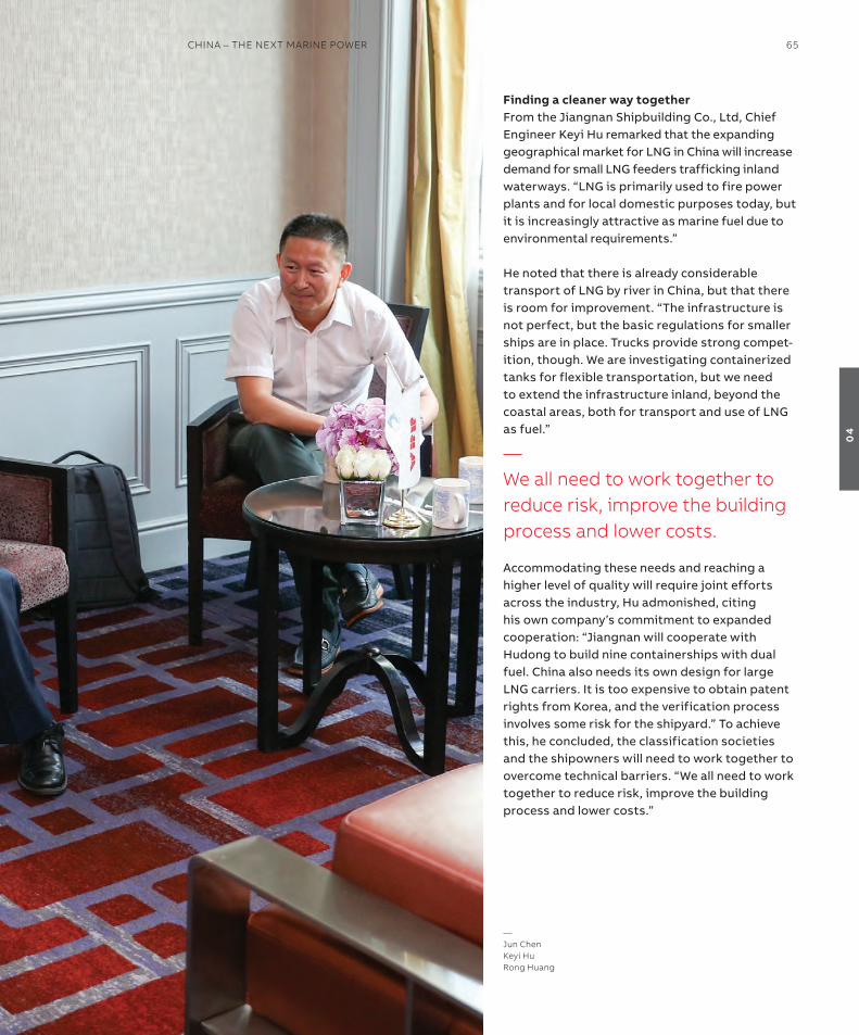
Finding a cleaner way togetherFrom the Jiangnan shipbuilding Co., Ltd, Chief engineer Keyi Hu remarked that the expanding geographical market for LnG in China will increase demand for small LnG feeders trafficking inland waterways. “LnG is primarily used to fire power plants and for local domestic purposes today, but it is increasingly attractive as marine fuel due to environmental requirements.”
He noted that there is already considerable transport of LnG by river in China, but that there is room for improvement. “the infrastructure is not perfect, but the basic regulations for smaller ships are in place. trucks provide strong compet-ition, though. We are investigating containerized tanks for flexible transportation, but we need to extend the infrastructure inland, beyond the coastal areas, both for transport and use of LnG as fuel.”
accommodating these needs and reaching a higher level of quality will require joint efforts across the industry, Hu admonished, citing his own company’s commitment to expanded cooperation: “Jiangnan will cooperate with Hudong to build nine containerships with dual fuel. China also needs its own design for large LnG carriers. it is too expensive to obtain patent rights from Korea, and the verification process involves some risk for the shipyard.” to achieve this, he concluded, the classification societies and the shipowners will need to work together to overcome technical barriers. “We all need to work together to reduce risk, improve the building process and lower costs.”
—We all need to work together to reduce risk, improve the building process and lower costs.
—Jun ChenKeyi hurong huang
ChinA – The nexT MArine PoWer 65
04

as part of the program, the Chinese maritime industry, and all maritime activities in China, have come under increased scrutiny by the authorities. the Blue sky Protection Campaign launched in 2018 was subsequently expanded to include the Yangtze river delta and several inland waterways, meaning that strict emissions control will be enforced in China’s busiest waterways, and on a fairly short timeline.
China’s environmental policy and how it’s re-flected on the shipping industry was one of the key topics discussed during the Generations roundtable in shanghai.
Moderator Wenhua Xing, Chairman, shanghai soci-ety of naval architects & ocean engineers (ssnaMe), noted that shipowners are by now fully aware of the challenges and risks they face. at the same time there are also many options open to shipown-ers, including clean fuel, fuel cells, and scrubbers.
Xing added that ssnaMe is conducting its own environmental research projects focusing on clean power for river traffic, including fuel cells and liquified natural gas (LnG). He invited the China Classification society (CCs) to elaborate on their environmental efforts, as the leading authority on regulations and their impact on the industry.
shi Chen, Director of CCs, shanghai branch, informed that China’s Ministry of transport and the Ministry of environmental Protection have recently issued five new documents outlining emissions standards. China is determined to lead the way in environmental responsibility, Chen assured, with the new regulations weighing in as some of the world’s most demanding. “China can now become a world leader in environmental pro-tection. if we want to live a better life, we have to have a better environment. We cannot just make money, we have to be clean and green too.”
However, Chen saw more obstacles than oppor-tunities for LnG as a fuel for river traffic. “i don’t see a bright future for river transportation of LnG, simply because it is classified as hazardous material, and transportation is governed by strict space restrictions that are difficult to enforce on inland waterways. Many places in the world have already banned LnG-powered river vessels.”
He also noted that many existing river vessels are not suitable for conversion due their small size. in addition, ports would have to be converted to handle hazardous materials. “it is much easier to use LnG for open water transportation. For inland waterways, i think batteries or fuel cells could be better options.”
To lNG and beyondModerator Xing invited evan Fei e, technology Manager, aBB Marine & Ports China, to share some of the results of aBB’s extensive research
—answering to the environmentWhen China decides to solve a challenge, they do it large. Facing critical industrial pollution issues, China has taken up powerful measures to clean up cities, waterways, and coastlines.
—China can now become a world leader in environmental protection.
66 GenerATions
04

on the viability of fuel cell power, including energy density and large-scale applications. “Because hydrogen exhaust is basically water, it is con-sidered an attractive fuel where emissions are a concern. aBB is actively involved in collaborative development of the fuel cell technology for mar-ine applications, including research, testing and a pilot installation implementation,” Fei e said.
regulations also pose a challenge for fuel cells, he noted, as different classification societies can have different rules. “Most of our work is going on in europe now. CCs may have other require-ments, and we will follow up with talks to har-monize the solutions.”
alf Kåre Ådnanes, General Manager, aBB Marine & Ports China, concurred: “after having been the
‘next big thing’ for many years, fuel cells are really happening now.”
at the same time, he said, incentives for LnG are growing, and use of LnG as fuel is expanding. “LnG is already in broad use in the north sea and in northern europe, also for traffic closer to shore.”
Developments in LnG transport, storage and bunkering may also have relevance for LnG, he offered. “a lot of the lessons we have learned can be used as references as we continue to work toward fuel cells using hydrogen on ships.”
—evan Fei erong huang
—if we want to live a better life, we have to have a better environment.
ChinA – The nexT MArine PoWer 67
04
China already has one foreign-built polar scientific study vessel, on duty since 1993. after several years of successful polar operations, the decision was made to add another vessel to the fleet.
“the first vessel was not originally an icebreaker, but an arctic supply and transportation ship that was later converted to a research vessel with ice-going capabilities,” explains rong Huang, Chief engineer and Designer of the Polar re-search institute of China. “the second ship was designed from the start with full icebreaking capabilities, and it will be able to perform a much broader scope of duties in the polar regions.” He adds that the new vessel will shift with the sea-sons between arctic and antarctic operations.
Polar-ready technologyHuang tells that the Xue Long 2 (snow Dragon 2), due for delivery in 2019, will contain environment-ally friendly technological features. “Xue Long 2 will be fully compliant with the Polar Code, and will be using low sulphur fuel and electric propulsion
to make operations as clean and sustainable as possible. Consideration for the environment has influenced much of the design on the new vessel.”
Xue Long 2 was designed by the Finnish engin-eering company aker arctic and is under con-struction at shanghai’s Jiangnan shipyard. the 122-meter vessel will be outfitted with wet and dry laboratories, a large aft working deck served by several cranes, and a moon pool – an opening at the base of the hull for access to the water below. the ship has space for 90 scientists and crew, and enough capacity to undertake resupply missions to research stations. the inclusion of aBB’s two azipod® propulsion units will enable the new vessel to continuously break through ice up to 1.5m thick plus snow up to 0.2 meter at the speed of 2-3 three knots, moving ahead or astern.
“two key goals for the Xue Long 2 were max-imum flexibility and durability,” says Huang. “the proven azipod® propulsion system ensures that the new vessel will be able to carry out her mis-sions in varying arctic and antarctic ice condi-tions with the highest possible regularity.”
Moving forward togetherHuang confirms China’s growing ambitions for research at both poles. “there is still much
—Two key goals for the xue long 2 were maximum flexibility and durability.
—Carving a polar nicheChina’s first home-built icebreakerChina’s interest in the polar regions is growing, as are the objectives for advancing the domestic shipbuilding industry. The first icebreaker built entirely in China, the xue long 2 research vessel, will go a long way toward serving both these interests.
68 GenerATions
04
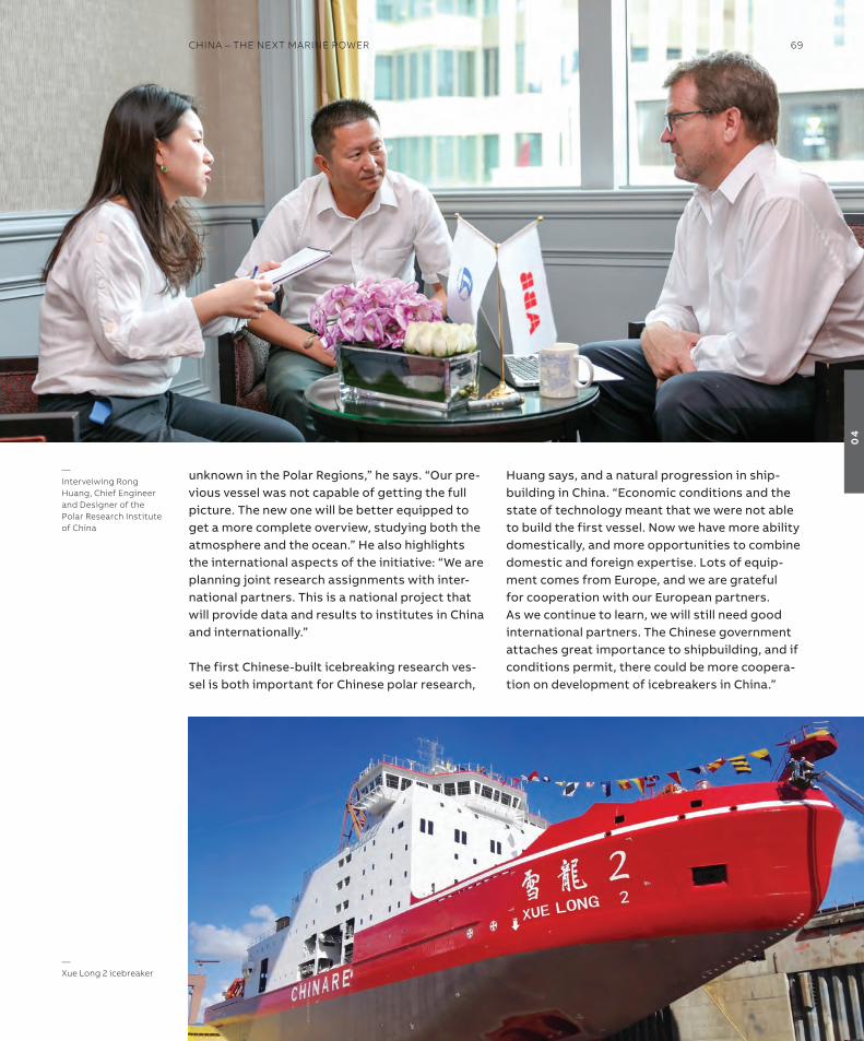
unknown in the Polar regions,” he says. “our pre-vious vessel was not capable of getting the full picture. the new one will be better equipped to get a more complete overview, studying both the atmosphere and the ocean.” He also highlights the international aspects of the initiative: “We are planning joint research assignments with inter-national partners. this is a national project that will provide data and results to institutes in China and internationally.”
the first Chinese-built icebreaking research ves-sel is both important for Chinese polar research,
Huang says, and a natural progression in ship-building in China. “economic conditions and the state of technology meant that we were not able to build the first vessel. now we have more ability domestically, and more opportunities to combine domestic and foreign expertise. Lots of equip-ment comes from europe, and we are grateful for cooperation with our european partners. as we continue to learn, we will still need good international partners. the Chinese government attaches great importance to shipbuilding, and if conditions permit, there could be more coopera-tion on development of icebreakers in China.”
—xue long 2 icebreaker
—interveiwing rong huang, Chief engineer and Designer of the Polar research institute of China
ChinA – The nexT MArine PoWer 69
04

—05 Technical insight
B0 – a conditionally and
periodically unmanned bridge—72–79
situational awareness isn’t a luxury,
so why guess what’s out there?—80–81
Paving the way to autonomy:
aBB ability™ Marine Pilot Control—82–85
Your systems may be optimized
but digital twins could learn to do it better—86–99
autonomy requires fault tolerant, reconfigurable
and connected electrical grid for propulsion—100–105
anticipating technical faults with machine learning—106–111

Battery power on board:
Maximizing the benefits—112–115
optimizing fuel efficiency and emission
reduction through intelligent power
management for hybrid electric vessels—116–122
no more loss of containers—124–127
saving energy on board with
aBB’s chiller optimization solution—128–129
innovation at the extremes:
technology for a universal polar icebreaker—130–137
Faster, safer, cleaner:
azipod® M propulsion for ferries and roPax vessels—138–147
next level remote operations:
the remote crane operator and beyond—148–151

as a basic definition an autonomous vessel is not necessarily unmanned but an unmanned vessel is, by default, autonomous to a high degree.
it is also important to make a distinct and clear difference between the technical readiness and capability of the vessel versus the status of usage of the vessel at any given time. in cer-tain conditions, the crew onboard may be given the opportunity to change vessel operation from crew to machine operated.
this article presents a concept of B0 – conditionally and periodic-ally unmanned bridge – which enables more efficient utilization of vessel crew, reduction in fatigue and increases safety by enabling an unmanned bridge provided that certain conditions are met. it also reviews the main tasks of the crew at the bridge and elab-orates the benefits of B0 concept. a review of the regulatory background that will either require amendment or a demonstrated equivalent or better status with the appropriate use of technology to enable B0 operations. the technology requirements and implic-ations are discussed in the last section of the article.
The officer of the watcha Deck officer assigned with the duties of watch keeping and nav-igation on a ship’s bridge is known as the officer of the watch (ooW). While keeping a watch on the bridge, the ooW is the representative of the ship’s master and has the total responsibility of safe and smooth navigation of the ship. the captain of the vessel when on bridge and has assumed ‘the conn’ has the status of ooW in this context.
the ooW is also in charge of the bridge team, which is there to support him or her in the navigation process. the ooW is also
—B0 – a conditionally and periodically unmanned bridgeThe recent development in sensor technology, data analytics and computing power enables to increase the level of automation in ship navigation, steering and control.
Capt. EEro lEhToVaarahead of regulatory AffairsABB Marine & Ports
Dr. KalEVi TErVoGlobal Program ManagerABB Marine & Ports
72 GenerATions
05
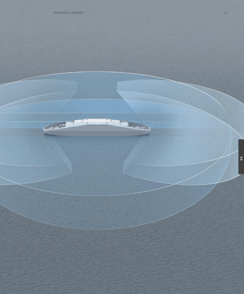
TeChniCAl insiGhT 73
05

responsible to ensure that the ship complies with CoLreGs and is operated with the utmost safety under all conditions. the main duties of the ooW can very broadly be defined as: navigation, watch keeping and radio watch.
the examples below comprise a generalized approach to the duties of the ooW on bridge. Key rules could be grouped into the following: • Check navigational equipment in use at regular
interval of time.• Prepare, execute and monitor a safe passage plan.• ask for support whenever required.• Contact the master when need arise. •not leave the bridge unattended during the
assigned watch.
in more details the ooW will routinely perform the actions outlined below:the ooW must check the position for per-sonal situational awareness and verifying (and reverifying) to ensure the best possible ‘mental picture’ of the operation is formed. the previous positions affect the future position and there-fore, in order to maintain maximum accuracy of the plot, is by necessity an iterative process. When starting or finishing the watch it is crucial that the communication when changing watches cover all relevant information. this is due to the fact that navigation of the vessel is by nature dy-namic and all conditions at any given time affect the ship.
even in the 21st century, following the working and the reliability of the ship’s compasses is still required as is the operation of the depth sounder. this is done in order to have as precise a win-dow within which the errors can be made good, particularly in poorly charted areas such as the antarctic. should a gyrocompass fail, Gnss1 will in most cases provide location data but will af-fect the autopilot if no other redundant systems are available.
rule 5 of CoLreGs2 puts special emphasis on lookout and states that “every vessel shall at all times maintain a proper lookout by sight and hearing as well as by all available means ap-propriate in the prevailing circumstances and conditions so as to make a full appraisal of the situation and of the risk of collision.” this is further emphasized when the vessel operates in restricted visibility (rule 19 of CoLreGs) wherein the role of the lookout man is paramount.
the radio watch (GMDss3) watch is crucial to the safety of all and must be maintained on the stip-ulated frequencies as per regulations. Whether or not information received affects the ship immedi-ately is not the primary task but to determine if it affects the ship.
When applicable, the ooW should ensure other members of the bridge team are alert and awake at all times. During times when the engine Control room is in unmanned operation, the ooW may also send another bridge team member to inspect the machinery rooms to ensure that all is well.
B0 benefitsalthough the number of crew, especially in ocean-going cargo vessels, has decreased during the last decades, at least one person on the bridge is required regardless of the conditions. While this is very much justified in situations where the ship is approaching other ships or areas where more traffic is anticipated, crossing an ocean in very good and clear conditions can lead to a situation where the ooW is on the bridge for the entire work shift without touching any equipment or doing any-thing but looking at radar screens and outside the window making sure that there is nothing out there. this can cause mental fatigue with an associated loss of alertness and can lead to a situation where a human reacts too late to an event which could have been anticipated significantly earlier if the ooW would have been more alert during the situation.
Bridge status Required crew on bridge Conditions
B3 ooW, lookout, helmsman special conditions
B2 ooW, lookout night, good conditions
B1 ooW Day, good conditions
—Table 1: The principles of the typical crew onthe bridge and the operating conditions
—
1 Global navigation satellite system. A navigational system that utilizes satellites to determine the ship’s position. The American GPs, or Global Positioning system, is one system available to Gnss but other systems such as GlonAss from russia, Galileo from the eU, the Chinese BeiDou are also in use. More regional systems are coming on line.
2 international Maritime organization, “Convention on the international regulations for Preventing Collisions at sea”, 1972.
3 Global Maritime Distress and safety system. on board, this generally includes emergency position-indicating radio beacons (ePirBs), nAVTex, satellite Communications, high Frequency radio as well as search and rescue Transponders.
74 GenerATions
05
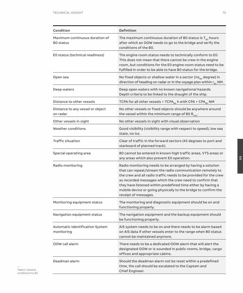
Condition Definition
Maximum continuous duration of B0 status
the maximum continuous duration of B0 status is tB0 hours after which an ooW needs to go to the bridge and verify the conditions of the B0.
e0 status (technical readiness) the engine room status needs to technically conform to e0. this does not mean that there cannot be crew in the engine room, but conditions for the e0 engine room status need to be fulfilled in order to be able to have B0 status for the bridge.
open sea Nofixedobjectsorshallowwaterinasector(±αB0 degree) in direction of heading on radar or in the voyage plan within rB0 nM.
Deep waters Deep open waters with no known navigational hazards. Depth criteria to be linked to the draught of the ship.
Distance to other vessels tCPa for all other vessels > tCPaB0 h with CPa > CPaB0 nM
Distance to any vessel or object on radar
no other vessels or fixed objects should be anywhere around the vessel within the minimum range of B0 rmin.
other vessels in sight no other vessels in sight with visual observation
Weather conditions Good visibility (visibility range with respect to speed), low sea state, no ice.
traffic situation Clear of traffic in the forward sectors (45 degrees to port and starboard of planned track).
special operating area B0 cannot be entered in known high traffic areas, Vts areas or any areas which also prevent e0 operation.
radio monitoring radio monitoring needs to be arranged by having a solution that can repeat/stream the radio communication remotely to the crew and all radio traffic needs to be provided for the crew as recorded messages which the crew need to confirm that they have listened within predefined time either by having a mobile device or going physically to the bridge to confirm the receipt of messages.
Monitoring equipment status the monitoring and diagnostic equipment should be on and functioning properly.
navigation equipment status the navigation equipment and the backup equipment should be functioning properly.
automatic identification system monitoring
ais system needs to be on and there needs to be alarm based on ais data if other vessels enter to the range when B0 status cannot be maintained anymore.
ooW call alarm there needs to be a dedicated ooW alarm that will alert the designated ooW or is sounded in public rooms, bridge, cargo offices and appropriate cabins.
Deadman alarm should the deadman alarm not be reset within a predefined time, the call should be escalated to the Captain and Chief engineer.
—Table 2: General conditions for B0
TeChniCAl insiGhT 75
05
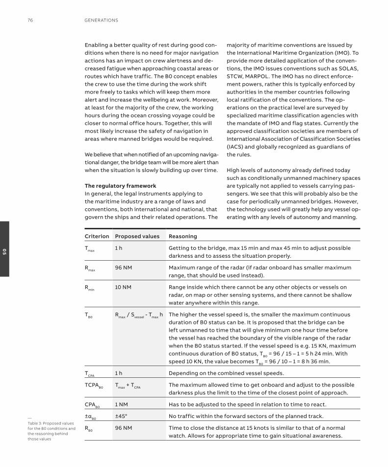
enabling a better quality of rest during good con-ditions when there is no need for major navigation actions has an impact on crew alertness and de-creased fatigue when approaching coastal areas or routes which have traffic. the B0 concept enables the crew to use the time during the work shift more freely to tasks which will keep them more alert and increase the wellbeing at work. Moreover, at least for the majority of the crew, the working hours during the ocean crossing voyage could be closer to normal office hours. together, this will most likely increase the safety of navigation in areas where manned bridges would be required.
We believe that when notified of an upcoming naviga-tional danger, the bridge team will be more alert than when the situation is slowly building up over time.
The regulatory frameworkin general, the legal instruments applying to the maritime industry are a range of laws and conventions, both international and national, that govern the ships and their related operations. the
majority of maritime conventions are issued by the international Maritime organization (iMo). to provide more detailed application of the conven-tions, the iMo issues conventions such as soLas, stCW, MarPoL. the iMo has no direct enforce-ment powers, rather this is typically enforced by authorities in the member countries following local ratification of the conventions. the op-erations on the practical level are surveyed by specialized maritime classification agencies with the mandate of iMo and flag states. Currently the approved classification societies are members of international association of Classification societies (iaCs) and globally recognized as guardians of the rules.
High levels of autonomy already defined today such as conditionally unmanned machinery spaces are typically not applied to vessels carrying pas-sengers. We see that this will probably also be the case for periodically unmanned bridges. However, the technology used will greatly help any vessel op-erating with any levels of autonomy and manning.
—Table 3: Proposed values for the B0 conditions and the reasoning behindthose values
Criterion Proposed values Reasoning
tmax 1 h Getting to the bridge, max 15 min and max 45 min to adjust possible darkness and to assess the situation properly.
rmax 96 nM Maximum range of the radar (if radar onboard has smaller maximum range, that should be used instead).
rmin 10 nM range inside which there cannot be any other objects or vessels on radar, on map or other sensing systems, and there cannot be shallow water anywhere within this range.
tB0 rmax / svessel - tmax h the higher the vessel speed is, the smaller the maximum continuous duration of B0 status can be. it is proposed that the bridge can be left unmanned to time that will give minimum one hour time before the vessel has reached the boundary of the visible range of the radar when the B0 status started. if the vessel speed is e.g. 15 Kn, maximum continuous duration of B0 status, tB0 = 96 / 15 – 1 = 5 h 24 min. With speed 10 Kn, the value becomes tB0 = 96 / 10 – 1 = 8 h 36 min.
tCPa 1 h Depending on the combined vessel speeds.
tCPaB0 tmax + tCPa the maximum allowed time to get onboard and adjust to the possible darkness plus the limit to the time of the closest point of approach.
CPaB0 1 nM Has to be adjusted to the speed in relation to time to react.
±αB0 ±45° no traffic within the forward sectors of the planned track.
rB0 96 nM time to close the distance at 15 knots is similar to that of a normal watch. allows for appropriate time to gain situational awareness.
76 GenerATions
05

the possibility to safely operate the vessel without direct, continuous and active supervi-sion of the master, or the person who has the delegated responsibility, will likely require a fundamental revision of the legal system. in the first stages the change will probably affect some aspects of the construction of the bridge and the operations in open waters with clearly defined requirements for conditions to apply.
Jurisdictionone of the central rules to understand is the jur-isdiction of the states’ rights and obligations to regulate the maritime industry. the main body of rules is the Un convention from 1982 on the Law of the seas (UnCLos).
Bridge visibilitythe international Convention for the safety of Life at sea (soLas) Ch. 5, req. 22, defines the required construction of the bridge. the most important aspect is the visibility outside the windows of the bridge. From the main conning position, the vessel must have 225 degrees visibil-ity with a view of the sea surface not “obscured by more than two ship lengths, or 500 m, whichever is the less, forward of the bow to 10° on either side under all conditions of draught, trim and deck cargo”. When going towards unmanned bridges, these requirements needs to be met by a virtual line of sight.
Competence in watchkeepingstCW4 defines conditions for the required crew on bridge and in what conditions the status is accepted. the principles of the typical crew on the bridge and the operating conditions are de-scribed in table 1.
the B0 concept outlines the general conditions on when it could be possible to enable transferring the monitoring responsibility from the ooW to a machine for a certain period of time.
in order to maintain the command hierarchy, B0 needs to be linked to the engine room status. ooW/Captain is legally responsible for the ship and in case Unmanned engine Control room status is lost, he/she needs to take the decision on when it is safe to revert back to e0 and B0. therefore, e0 or UMs5 notation is linked to B0.
When the engine room has the e0 status, there needs to be alarm system in place to provide alarms for the bridge and the chief engineer. as part of the risk management of B0, smart filtra-tion of alarms with regards to propulsion or escal-ation of unanswered alarms, will need to apply.
General conditions for B0the general conditions for B0 are described in table 2. the principle is that the weather condi-tions are good, visibility clear, technical status should correspond to e0/UMs, no fixed objects visible in the forward sector nor any vessels vis-ible with a CPa and tCPa6 below certain values. in addition, there should be no radio traffic. if these conditions apply, the ooW work in B1 situations nowadays is to monitor the radar, look outside the window and make sure that nothing is to be done. it is proposed that during these situations the ooW could leave the bridge unmanned.
Distance and time considerationsthe conditions for B0 are heavily dependent on range with respect to distance and time. How far are the other ships? When considering the B0 status, one needs to take into account not only the speed of the own vessel but that of the others as well.
in general, radar range can be considered to be up to 96 nautical miles. a target at this range will be reached in six hours and 24 minutes if the vessel is sailing at 15 knots. However, if the other vessel is also sailing at 15 knots, the time when the vessels meet naturally be half the time (three hours and 12 minutes).
there are several ways to define the criteria. For example, one can use fixed values for each cri-terion or those can be made dynamic to be based on vessel svessel, maximum allowed reaction time tmax. the maneuvering capabilities of the vessels can be factored in also.
table 3 presents proposed values for the B0 conditions and explains the reasoning behind those values.
using B0When entering the B0 status, the ooW needs to ensure that the navigation equipment, monitoring
—
4 international Maritime organization, “international Convention on standards of Training, Certification and Watchkeeping for seafarers”, 2010.
5 Unmanned Machinery space. A notation where systems are in place to allow the ship to operate without engineering personnel on 24 hour shifts in the engine Control room. Used interchangeably with e0.
6 Closest Point of Approach & Time to Closest Point of Approach. A calculation to evaluate the risk of collision between a ship and another object, where the distance between the two will be at its minimum and when that will be.
TeChniCAl insiGhT 77
05

systems and alarm systems deployed to automat-ically call the ooW to the bridge are all in order. therefore, at a minimum, the following tests and activities need to be performed:• test procedures for navigation equipment• Checklist of critical operations and functionalities• Check the alarms and related internal shipboard
connectivity• Check that B0 conditions hold and there are no
vessels or fixed objects in radar or in the voyage plan within the B0 range rB0
• record the event, checklist and conditions of entering to the B0 status on the ship logbook
alarm hierarchyin case there is an alarm that will cause the loss of the e0 status, an engineer and an ooW will be alerted to return to their respective places of duty. that will cause the loss of the B0 status. the principle is that the engine room alarm, which causes the loss of the e0 status, will always cause a need for the ooW to return to the bridge. Depending on the severity of the alarm, the Captain might be called as well. therefore, the alarm hierarchy related to engine room alarms is as follows:
e0 status alarm > engineer, ooW > Captain.
in case there is an alarm which causes the loss of the B0 status, the ooW will be commanded on duty. that will not cause loss of e0 status by default. therefore the alarm hierarchy related to bridge alarms is as follows:
B0 status alarm > ooW > Captain.
When the B0 status is deactivated due to the B0 status alarm, the ooW will decide if there is a need to call the Captain to the bridge and possibly the duty engineer to the engine room. However, in case of the e0 status remaining unchanged, the B0 status alarm will not automatically cause the loss of the e0 status.
requirements for technologyin order to maintain the B0 status, the B0 condi-tions need to be monitored by means of techno-logy. there should be at least two independent means for all measurement and situational aware-ness technologies.
Monitoring and diagnostics of all navigation sensors and equipmentin order to leave the bridge unmanned for a period of time, monitoring and diagnostics for critical equipment such as navigation equipment is required. Currently this is an ooW task, but in a B0 situation, there needs to be a system which can monitor the status of the navigation equip-ment, such as the error of gyrocompass, radar performance or stability of the Gnss.
Provide equivalency to lookout by means of technologyregulations require people to look out the window due to the fact that for safe operation, one cannot rely on the radar only. the basis for the B0 bridge is to provide continuous visibility from the bridge with cameras and possibly other sensors which offer an equivalent field of view to an unaided human eye. it is also vital to state the requirement to always have two independent sources of information supporting the machine line of sight maintaining the B0 watch. such technology could also alleviate the challenges of night-time operations. additional infrared tech-nologies (cameras and lights) can be deployed by either having night cameras operating on infrared wavelengths as well as appropriate infrared lights, or recognizing other traffic based on lights and normal daytime cameras.
if no human operator is maintaining a lookout, an automated target identification and classification needs to be deployed to provide equivalency to the soLas Ch. 5, req. 2. aBB is already deploying a technology that combines camera and sensor data to produce an algorithm which performs classification of the targets – currently alongside bridge staff.
there would also be a need to have system in place that would recognize and identify land from camera data and continuously monitor it from the video stream. if land is seen on the hori-zon in the forward sector, the B0 condition needs to be terminated.
another condition would be having an arrange-ment of audio microphones at the bridge and outside the vessel to provide means to sense aud-ible signals, as well as an analysis solution that
78 GenerATions
05
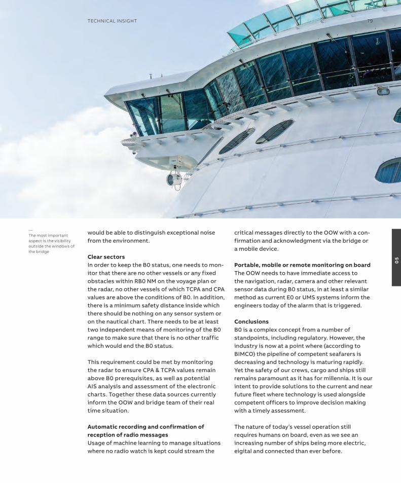
would be able to distinguish exceptional noise from the environment.
Clear sectorsin order to keep the B0 status, one needs to mon-itor that there are no other vessels or any fixed obstacles within rB0 nM on the voyage plan or the radar, no other vessels of which tCPa and CPa values are above the conditions of B0. in addition, there is a minimum safety distance inside which there should be nothing on any sensor system or on the nautical chart. there needs to be at least two independent means of monitoring of the B0 range to make sure that there is no other traffic which would end the B0 status.
this requirement could be met by monitoring the radar to ensure CPa & tCPa values remain above B0 prerequisites, as well as potential ais analysis and assessment of the electronic charts. together these data sources currently inform the ooW and bridge team of their real time situation.
automatic recording and confirmation of reception of radio messagesUsage of machine learning to manage situations where no radio watch is kept could stream the
critical messages directly to the ooW with a con-firmation and acknowledgment via the bridge or a mobile device.
Portable, mobile or remote monitoring on boardthe ooW needs to have immediate access to the navigation, radar, camera and other relevant sensor data during B0 status, in at least a similar method as current e0 or UMs systems inform the engineers today of the alarm that is triggered.
ConclusionsB0 is a complex concept from a number of standpoints, including regulatory. However, the industry is now at a point where (according to BiMCo) the pipeline of competent seafarers is decreasing and technology is maturing rapidly. Yet the safety of our crews, cargo and ships still remains paramount as it has for millennia. it is our intent to provide solutions to the current and near future fleet where technology is used alongside competent officers to improve decision making with a timely assessment.
the nature of today’s vessel operation still requires humans on board, even as we see an increasing number of ships being more electric, eigital and connected than ever before.
—The most important aspect is the visibility outside the windows of the bridge
TeChniCAl insiGhT 79
05
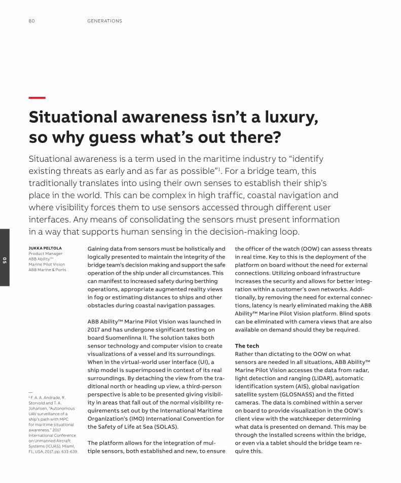
Gaining data from sensors must be holistically and logically presented to maintain the integrity of the bridge team’s decision making and support the safe operation of the ship under all circumstances. this can manifest to increased safety during berthing operations, appropriate augmented reality views in fog or estimating distances to ships and other obstacles during coastal navigation passages.
aBB ability™ Marine Pilot Vision was launched in 2017 and has undergone significant testing on board suomenlinna ii. the solution takes both sensor technology and computer vision to create visualizations of a vessel and its surroundings. When in the virtual-world user interface (Ui), a ship model is superimposed in context of its real surroundings. By detaching the view from the tra-ditional north or heading up view, a third-person perspective is able to be presented giving visibil-ity in areas that fall out of the normal visibility re-quirements set out by the international Maritime organization’s (iMo) international Convention for the safety of Life at sea (soLas).
the platform allows for the integration of mul-tiple sensors, both established and new, to ensure
the officer of the watch (ooW) can assess threats in real time. Key to this is the deployment of the platform on board without the need for external connections. Utilizing onboard infrastructure increases the security and allows for better integ-ration within a customer’s own networks. addi-tionally, by removing the need for external connec-tions, latency is nearly eliminated making the aBB ability™ Marine Pilot Vision platform. Blind spots can be eliminated with camera views that are also available on demand should they be required.
The techrather than dictating to the ooW on what sensors are needed in all situations, aBB ability™ Marine Pilot Vision accesses the data from radar, light detection and ranging (LiDar), automatic identification system (ais), global navigation satellite system (GLosnass) and the fitted cameras. the data is combined within a server on board to provide visualization in the ooW’s client view with the watchkeeper determining what data is presented on demand. this may be through the installed screens within the bridge, or even via a tablet should the bridge team re-quire this.
—situational awareness isn’t a luxury, so why guess what’s out there?situational awareness is a term used in the maritime industry to “identify existing threats as early and as far as possible”1. For a bridge team, this traditionally translates into using their own senses to establish their ship’s place in the world. This can be complex in high traffic, coastal navigation and where visibility forces them to use sensors accessed through different user interfaces. Any means of consolidating the sensors must present information in a way that supports human sensing in the decision-making loop.
JuKKa PElTolaProduct Manager ABB AbilityTM Marine Pilot Vision ABB Marine & Ports
—1 F. A. A. Andrade, r. storvold and T. A. Johansen, “Autonomous UAV surveillance of a ship’s path with MPC for maritime situational awareness,” 2017 international Conference on Unmanned Aircraft systems (iCUAs), Miami, Fl, UsA, 2017, pp. 633-639.
80 GenerATions
05
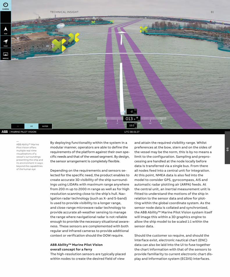
By deploying functionality within the system in a modular manner, operators are able to define the requirements of the platform against their own spe-cific needs and that of the vessel segment. By design, the sensor arrangement is completely flexible.
Depending on the requirements and sensors se-lected for the specific need, the product enables to create accurate 3D visibility of the ship surround-ings using LiDars with maximum range anywhere from 200 m up to 2000 m range as well as for high resolution scanning close to the ship’s hull. nav-igation radar technology (such as X- and s-band) is used to provide visibility to a longer range, and close-range microwave radar technology to provide accurate all-weather sensing to manage the range where navigational radar is not reliable enough to provide the necessary situational aware-ness. these sensors are complemented with both regular and infrared cameras to provide additional context or verification should the ooW require.
aBB ability™ Marine Pilot Vision overall concept for a ferrythe high-resolution sensors are typically placed within nodes to create the desired field of view
and attain the required visibility range. Whilst preferences at the bow, stern and on the sides of the vessel may be the norm, this is by no means a limit to the configuration. sampling and prepro-cessing are handled at the node locally before data is transferred via a single bus. From there all nodes feed into a central unit for integration. at this point, nMea data is also fed into the model to consider GPs, gyrocompass, ais and automatic radar plotting air (arPa) feeds. at the central unit, an inertial measurement unit is fitted to understand the motions of the ship in relation to the sensor data and allow for plot-ting within the global coordinate system. as the sensor node data is collated and synchronized, the aBB ability™ Marine Pilot Vision system itself will image this within a 3D graphics engine to allow the ship model to be scaled 1:1 within the sensor data.
should the customer so require, and should the interface exist, electronic nautical chart (enC) data can also be laid into the Ui to fuse together the chart information with that of the sensors to provide familiarity to current electronic chart dis-play and information system (eCDis) interfaces.
—ABB Ability™ Marine Pilot Vision offers multiple real-time visualizations of a vessel’s surroundings presenting the ship and its environment in ways beyond the capabilities of the human eye
TeChniCAl insiGhT 81
05
When we started to develop aBB ability™ Marine Pilot Control, putting the user experience first – and enabling full vessel control literally at the fingertip – was a priority. our in-house designers and engineers run the product devel-opment and client workshops as an interactive process, collaboratively building a tool that would pave the way toward autonomous shipping.
the result is a control system that allows the user to maneuver the vessel through the full speed-range, not just low speed DP operations. With aBB Marine ability™ Pilot Control, the operator can maneuver the vessel from dock to dock without having to change control position or system. this would be analogous to changing the steering wheel in a car from one side to the other as you move from suburban roads to a highway. the touch-based operator panel is intuitive and easy to use and is designed based on the input from operators and users from our reference team.
With the new DP system now part of aBB’s port-folio, our customers can benefit from the full integration of solutions – from office to propeller.
Further down the line is an autonomous ship – a highly sophisticated vessel that can operate,
maneuver and navigate without human interac-tion. the journey to this transformation, however, needs to happen in a step by step manner. What we are doing today is giving the operators a help-ing hand in achieving a better overview, aware-ness and easier decision making.
the new DP system is part of aBB ability™ Marine Pilot family and cannot be considered separately from aBB ability™ Marine Pilot Vision, the situ-ational awareness system that takes advantage of digital twin technology to offer multiple visu-alizations of a ship’s surroundings in real time. all of the products in this family have champion the same user-centric experience and feature a similar look and feel. they seamlessly collate all the available information, alarms and measure-ment values from several different systems to ultimately enable easy access to big data analyt-ics. indeed, under current regulations, the sense- decide- act cycle is fully achievable with a Marine Pilot Vision providing the sensing, the officer of the Watch making the decision and executing that act through Marine Pilot Control.
under the hoodBelow the surface, aBB ability™ Marine Pilot Control consist of an interface module, an MPC
—Paving the way to autonomyABB Ability™ Marine Pilot ControlMoving towards increasingly autonomous operations require a ‘sense-decide-act’ cycle, where a captain receives information, then plans the next move and acts. This, in turn, requires a solution that is more than a regular dynamic positioning (DP) system. Keen to respond to customer requests we developed ABB Ability™ Marine Pilot Control – the first solution that can ‘act’ across the entire speed range.
VEGarD saETErliDGlobal r&DProduct ManagerABB Ability™ MarinePilot ControlABB Marine & Ports
82 GenerATions
05
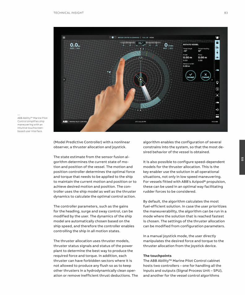
(Model Predictive Controller) with a nonlinear observer, a thruster allocation and joystick.
the state estimate from the sensor fusion al-gorithm determines the current state of mo-tion and position of the vessel. the motion and position controller determines the optimal force and torque that needs to be applied to the ship to maintain the current motion and position or to achieve desired motion and position. the con-troller uses the ship model as well as the thruster dynamics to calculate the optimal control action.
the controller parameters, such as the gains for the heading, surge and sway control, can be modified by the user. the dynamics of the ship model are automatically chosen based on the ship speed, and therefore the controller enables controlling the ship in all motion states.
the thruster allocation uses thruster models, thruster status signals and status of the power plant to determine the best way to produce the required force and torque. in addition, each thruster can have forbidden sectors where it is not allowed to produce any flush so as to keep other thrusters in a hydrodynamically clean oper-ation or remove inefficient thrust deductions. the
algorithm enables the configuration of several constrains into the system, so that the most de-sired behavior of the vessel is obtained.
it is also possible to configure speed-dependent models for the thruster allocation. this is the key enabler use the solution in all operational situations, not only in low speed maneuvering. For vessels fitted with aBB’s azipod® propulsion, these can be used in an optimal way facilitating rudder forces to be considered.
By default, the algorithm calculates the most fuel-efficient solution. in case the user prioritizes the maneuverability, the algorithm can be run in a mode where the solution that is reached fastest is chosen. the settings of the thruster allocation can be modified from configuration parameters.
in a manual joystick mode, the user directly manipulates the desired force and torque to the thruster allocation from the joystick device.
The touchpointsthe aBB ability™ Marine Pilot Control cabinet hosts two controllers – one for handling all the inputs and outputs (signal Process Unit – sPU), and another for the vessel control algorithms
—ABB Ability™ Marine Pilot Control simplifies ship maneuvering with an intuitive touchscreen-based user interface.
TeChniCAl insiGhT 83
05
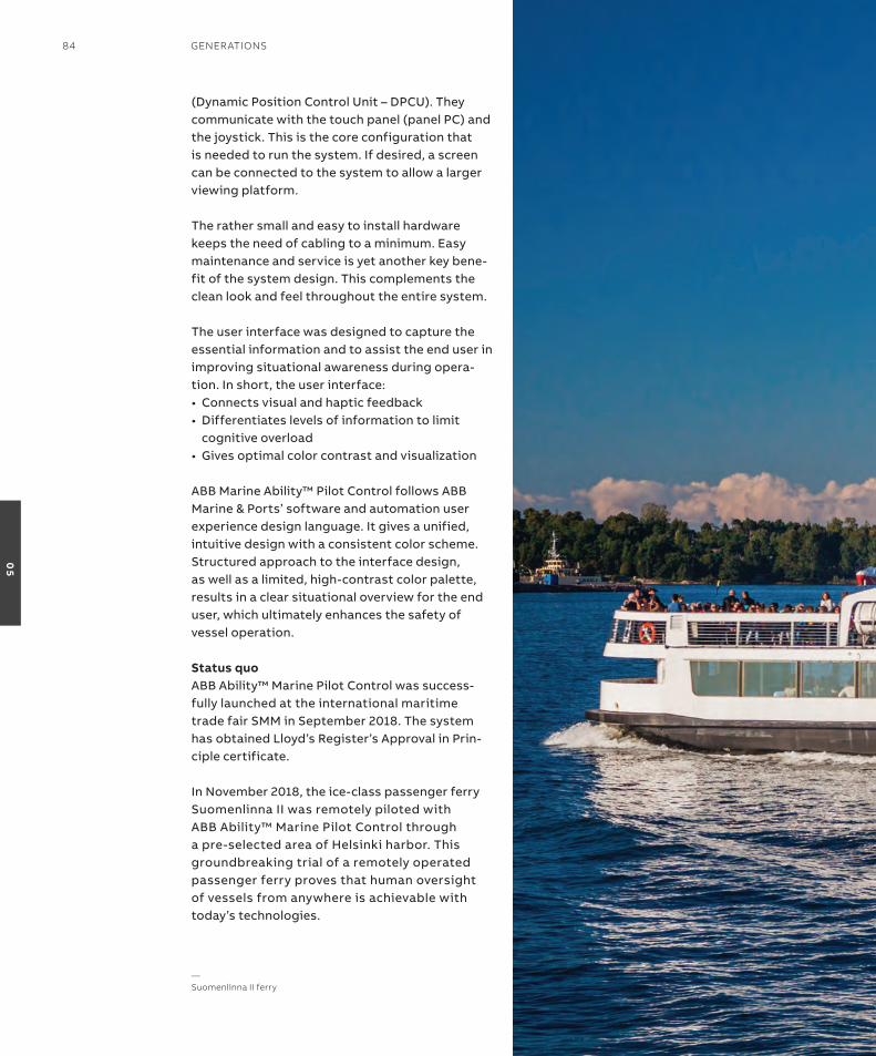
(Dynamic Position Control Unit – DPCU). they communicate with the touch panel (panel PC) and the joystick. this is the core configuration that is needed to run the system. if desired, a screen can be connected to the system to allow a larger viewing platform.
the rather small and easy to install hardware keeps the need of cabling to a minimum. easy maintenance and service is yet another key bene-fit of the system design. this complements the clean look and feel throughout the entire system.
the user interface was designed to capture the essential information and to assist the end user in improving situational awareness during opera-tion. in short, the user interface:• Connects visual and haptic feedback•Differentiates levels of information to limit
cognitive overload•Gives optimal color contrast and visualization
aBB Marine ability™ Pilot Control follows aBB Marine & Ports’ software and automation user experience design language. it gives a unified, intuitive design with a consistent color scheme. structured approach to the interface design, as well as a limited, high-contrast color palette, results in a clear situational overview for the end user, which ultimately enhances the safety of vessel operation.
status quoaBB ability™ Marine Pilot Control was success-fully launched at the international maritime trade fair sMM in september 2018. the system has obtained Lloyd’s register’s approval in Prin-ciple certificate.
in november 2018, the ice-class passenger ferry suomenlinna ii was remotely piloted with aBB ability™ Marine Pilot Control through a pre-selected area of Helsinki harbor. this groundbreaking trial of a remotely operated passenger ferry proves that human oversight of vessels from anywhere is achievable with today’s technologies.
—suomenlinna ii ferry
84 GenerATions
05
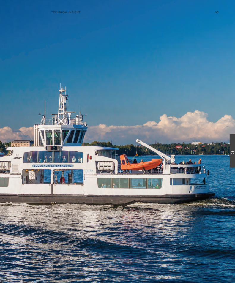
TeChniCAl insiGhT 85
05
introductionthere have been many attempts to describe and define the concept of digital twins, but it is fair to say that disagreements remain as to the term’s meaning. in all humility, the authors of this paper will avoid theoretical discussions and exercise restrain over futuristic visions on what digital twins can become. instead, we will focus on the benefits available outlining how digital twins can be implemented and used to provide digital services that add value to marine systems. the paper will also demonstrate how the digital twins are integrated into systems on board and on shore, and describe the infrastruc-ture that facilitates their development, deploy-ment and updating.
two use cases will be offered, where digital twins are used: for benchmarking and measur-ing performance in a DC-grid electric propulsion system; and for condition monitoring of rotating machinery;. the use cases will illustrate practical themes that can be overlooked when digital twins are discussed. an electrical propulsion motor is a component in all the two use cases, but the corresponding motor models share few if any common structures. the digital twin must be
adapted to the application, rather than encom-passing all possible information. First, therefore, the cases will demonstrate how different applic-ations require different models, structure and inputs. second, they will illustrate a key supple-mentary point of this paper – that the develop-ment, application and maintenance of digital twins is an iterative process. one example will demonstrate how several iterations and onboard changes were needed to improve data quality to a sufficient level for the model to be considered accurate enough. in a second example, the digital twin was applied to modify and improve the on-board system.
Digital twinsthe treatment of digital twins in this paper will lean heavily on the systematic treatment, con-cepts and classification provided by Cabos and rostock (2018). they propose the following four business drivers for investing in digital twins:1. to increase manufacturing flexibility and competitiveness2. to improve product design performance3. to forecast the health and performance of
products over lifetime4. to improve efficiency and quality in manufacturing
—your systems may be optimized but digital twins could learn to do it betterDigital transformation in the marine industry is creating a new collaborative mentality, where shared data and integrated systems can work to meet common challenges. ABB is leading the way in with a data driven, iterative approach to building digital twins as a key element of the cloud infrastructure, integrating edge-based analytics from equipment at sea and vessel models to achieve continuous improvement in both product development and life cycle management.
Jarosław Nowakequipment AnalyticsABB Marine & Ports
MorTEN sTaKKElaNDData scientistABB Marine & Ports
86 GenerATions
05
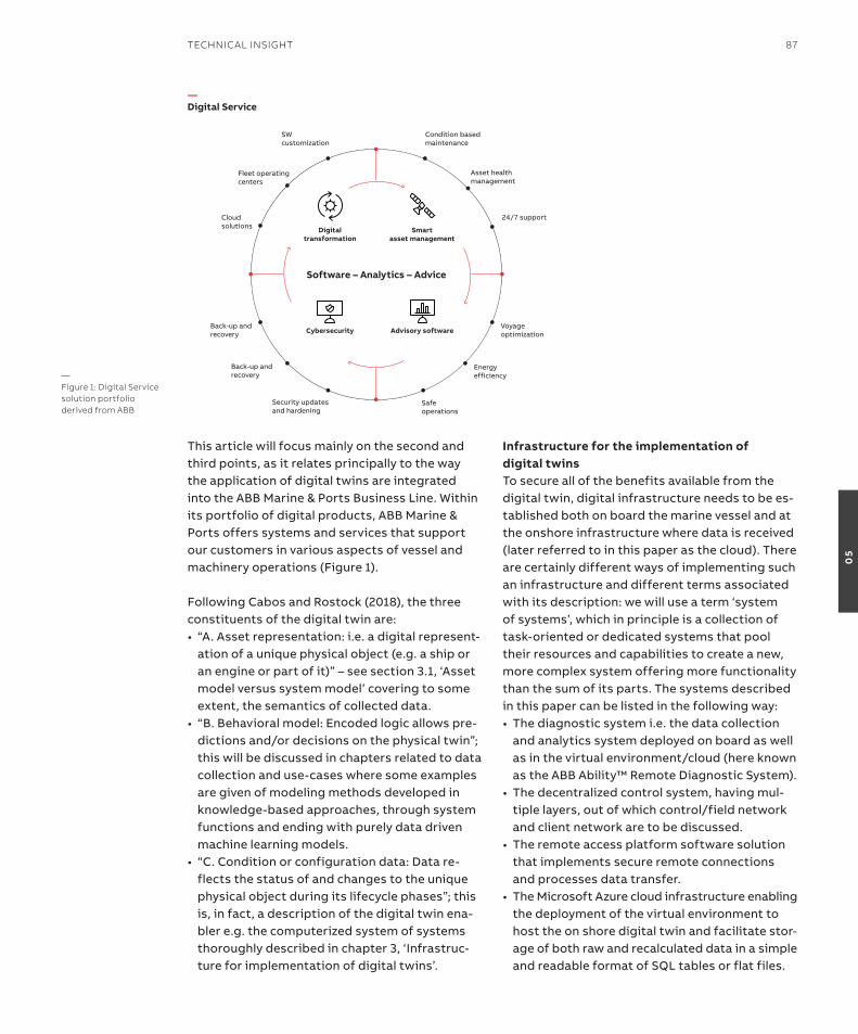
this article will focus mainly on the second and third points, as it relates principally to the way the application of digital twins are integrated into the aBB Marine & Ports Business Line. Within its portfolio of digital products, aBB Marine & Ports offers systems and services that support our customers in various aspects of vessel and machinery operations (Figure 1). Following Cabos and rostock (2018), the three constituents of the digital twin are:• “A.Assetrepresentation:i.e.adigitalrepresent-
ation of a unique physical object (e.g. a ship or an engine or part of it)” – see section 3.1, ‘asset model versus system model’ covering to some extent, the semantics of collected data.
• “B.Behavioralmodel:Encodedlogicallowspre-dictions and/or decisions on the physical twin”; this will be discussed in chapters related to data collection and use-cases where some examples are given of modeling methods developed in knowledge-based approaches, through system functions and ending with purely data driven machine learning models.
• “C.Conditionorconfigurationdata:Datare-flects the status of and changes to the unique physical object during its lifecycle phases”; this is, in fact, a description of the digital twin ena-bler e.g. the computerized system of systems thoroughly described in chapter 3, ‘infrastruc-ture for implementation of digital twins’.
infrastructure for the implementation of digital twinsto secure all of the benefits available from the digital twin, digital infrastructure needs to be es-tablished both on board the marine vessel and at the onshore infrastructure where data is received (later referred to in this paper as the cloud). there are certainly different ways of implementing such an infrastructure and different terms associated with its description: we will use a term ‘system of systems’, which in principle is a collection of task-oriented or dedicated systems that pool their resources and capabilities to create a new, more complex system offering more functionality than the sum of its parts. the systems described in this paper can be listed in the following way:• Thediagnosticsystemi.e.thedatacollection
and analytics system deployed on board as well as in the virtual environment/cloud (here known as the aBB ability™ remote Diagnostic system).
• Thedecentralizedcontrolsystem,havingmul-tiple layers, out of which control/field network and client network are to be discussed.
• Theremoteaccessplatformsoftwaresolutionthat implements secure remote connections and processes data transfer.
• TheMicrosoftAzurecloudinfrastructureenablingthe deployment of the virtual environment to host the on shore digital twin and facilitate stor-age of both raw and recalculated data in a simple and readable format of sQL tables or flat files.
Digitaltransformation
Smart asset management
Cybersecurity Advisory software
Software – Analytics – Advice
Energyefficiency
Safeoperations
Security updates and hardening
Voyage optimization
24/7 support
Asset health management
Fleet operating centers
Cloudsolutions
Back-up and recovery
Back-up and recovery
Condition based maintenance
SW customization
—Digital Service
—Figure 1: Digital service solution portfolio derived from ABB
TeChniCAl insiGhT 87
05
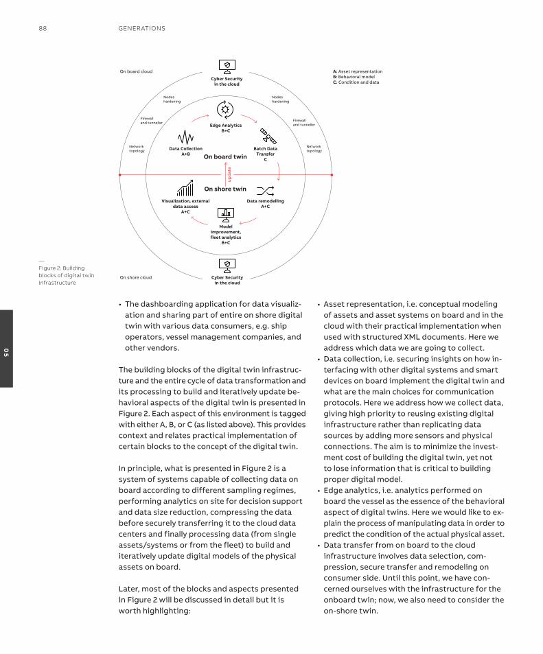
• Thedashboardingapplicationfordatavisualiz-ation and sharing part of entire on shore digital twin with various data consumers, e.g. ship operators, vessel management companies, and other vendors.
the building blocks of the digital twin infrastruc-ture and the entire cycle of data transformation and its processing to build and iteratively update be-havioral aspects of the digital twin is presented in Figure 2. each aspect of this environment is tagged with either a, B, or C (as listed above). this provides context and relates practical implementation of certain blocks to the concept of the digital twin.
in principle, what is presented in Figure 2 is a system of systems capable of collecting data on board according to different sampling regimes, performing analytics on site for decision support and data size reduction, compressing the data before securely transferring it to the cloud data centers and finally processing data (from single assets/systems or from the fleet) to build and iteratively update digital models of the physical assets on board.
Later, most of the blocks and aspects presented in Figure 2 will be discussed in detail but it is worth highlighting:
• Assetrepresentation,i.e.conceptualmodelingof assets and asset systems on board and in the cloud with their practical implementation when used with structured XML documents. Here we address which data we are going to collect.
• Datacollection,i.e.securinginsightsonhowin-terfacing with other digital systems and smart devices on board implement the digital twin and what are the main choices for communication protocols. Here we address how we collect data, giving high priority to reusing existing digital infrastructure rather than replicating data sources by adding more sensors and physical connections. the aim is to minimize the invest-ment cost of building the digital twin, yet not to lose information that is critical to building proper digital model.
• Edgeanalytics,i.e.analyticsperformedonboard the vessel as the essence of the behavioral aspect of digital twins. Here we would like to ex-plain the process of manipulating data in order to predict the condition of the actual physical asset.
• Datatransferfromonboardtothecloudinfrastructure involves data selection, com-pression, secure transfer and remodeling on consumer side. Until this point, we have con-cerned ourselves with the infrastructure for the onboard twin; now, we also need to consider the on-shore twin.
Data CollectionA+B
Visualization, external data access
A+C
Edge AnalyticsB+C
Model improvement,fleet analytics
B+C
Batch DataTransfer
C
Data remodellingA+C
Cyber Securityin the cloud
Firewalland tunneller
Networktopology
Nodeshardening
Firewalland tunneller
Networktopology
Nodeshardening
On board twin
On shore twin
Cyber Securityin the cloud
On board cloud
On shore cloud
A: Asset representationB: Behavioral modelC: Condition and data
—Figure 2: Building blocks of digital twin infrastructure
88 GenerATions
05

• Cybersecurityisalsoconsideredinallstepspresented in Figure 2, and therefore merits a separate chapter beneath.
• Oncedataleavesthevessel,theyareprocessedfurther on the cloud side. this process often requires remodeling the structure and meta data information so that fleet-level analytics can be applied. Having data in the cloud also opens opportunities for collaborative work involving human experts from different disciplines to improve models and analytics without neces-sarily connecting to the infrastructure on board. improved models and recommendations can then be applied to the on board digital twin to maintain consistency between the digital rep-resentation of the physical asset on board and on shore.
asset vs system representationthere are different ways of structuring informa-tion and the data that describe digital represent-ations of physical assets. one way of modelling a physical asset is to provide static information that will not change over its lifetime. these types of information are called asset inFos and might include the bearing type, serial number, rating plate information such as the nominal speed of the motor or the nominal power. another type of information that is more dynamic concerns actual measurements – otherwise known as inPUts. example of inputs are measured speed, temperat-ure or current. inPUts are representative meas-urements taken from source (such as sensor or other digital system) without any pre-processing. interesting factors in the definition of the inPUt include its type (numerical or textual, time series or equispaced vector), its origin (e.g. information about data source location) and the sampling rate in the case of simple data readers. the third type of information covers resULts, which is the digital information on how the inPUts and asset inFos have been processed according to the behavioral aspects of the digital twin model. resULts can also be numerical values (for instance root mean square values calculated from raw vibration data) or textual (such as warning in-formation that the condition of the physical asset is starting to deteriorate).
an important note at this point is that although we typically have some predefined structure for
asset inFos, inPUts and resULts that describe the physical asset (i.e., we have an equipment model in place), these definitions can and will change over the course of the iterative process of updating models and digital twins. therefore, it is important that our infrastructure can accept multiple changes in the definition of, for example, inPUts where the sampling rate of the signal changes or resULts where the underlying as-sumptions we use in equations and analytics are altered, e.g. by economic impacts.
one language (or to be precise, one markup lan-guage) that can be used to describe the physical asset in the digital world is XML – extensible markup language – which is widely used in it, mainly in soa (service oriented architecture) applications. XML also finds an application in describing the configuration of the digital twin discussed here, mainly because it combines flexibility with clear syntax. in addition, although XML does not use standardized semantics, conventions in XML naming mean it is practically self-explanatory for any domain expert wanting to understand the difference between motor speed and hull number.
another aspect of modeling physical assets that needs considering is the structure of the meta model. in principle, meta models should describe relations between digital data collected to build the digital twin so that it reflects the function of the modelled assets or its place in the wider hierarchy. in this case, we are using the term asset model as a definition of a single physical, repetit-ive object, as opposed to a system model where strict criteria for encapsulating the meta model are released. For example, instead of building the meta model for an electric motor, we are more interested in the meta model of all of the energy producers and consumers that are playing a role in the behavioral model of the vessel’s energy efficiency calculation. in case of asset type mod-elling, it is crucial that the model can be stand-ardized and deployed multiple times without additional re-configuration (or engineering).
an example of such an object modelled as an asset would be an electric motor, or pump or propulsion control system. in all of these cases we can define a standard set of XML elements
TeChniCAl insiGhT 89
05

and attributes and treat them as a template for the digital representation of the motor, pump or specific local control system. As a consequence, the names of properties and attributes will be the same for all instances of assets modelled this way. It is still possible to position such an asset in the broader hierarchy of subsystem or system so that its individual associations or location are treated as unique asset identifiers.
There are many reasons why templates and predefined asset models are applied but the main drivers will obviously be economic. It is much quicker, easier and cheaper to engineer and deploy digital infrastructure of complete vessel propulsion machinery if we simply install multiple standardized asset models. One example could be deployment of an electric propulsion system that consists of digital representations of 2 frequency converters, 2 electric motors, 2 trans-formers and 2 propulsion control systems, where each of them is deployed as an equipment type template. Another example could involve sensor fusion techniques for system level fault detection: here we could identify the effect as it appears within the asset (for instance high temperature of motor winding) and correlate that with the real cause that may have originated elsewhere in the
hierarchy (for instance, it may be due to subop-timal performance of the motor’s control loop). In this case, we should translate the asset model properties to system model properties. In the era of big data, cheap cloud storage and systems that easily scale up for different calculations needs, such an approach is far more reasonable than was the case even 10 years ago.
Figure 3 shows a very simple example of an asset model-type xml template used to describe differ-ent properties of a frequency converter which can be translated into another system. Highlighted with the red boxes are examples of ASSET INFO or INPUT with various properties describing how ac-tual values are going to be acquired (data source address and sampling rate) and where they are going to be stored (database, flat files, volatile memory). In the system model example that fol-lows the same XML syntax, there is an example of the RESULT element with the attribute <formula> that describes the equation – in this case using proprietary calculation expressions.
One final note on the modelling of physical assets in digital application is that this process is ex-pected to be done in iterative way. However, this depends on the business model: there may still be
ASSET MODEL
TRANSLATION TABLE
SYSTEM MODEL
—Figure 3: Asset vs system models and translation table examples
90 GenerAtions
05
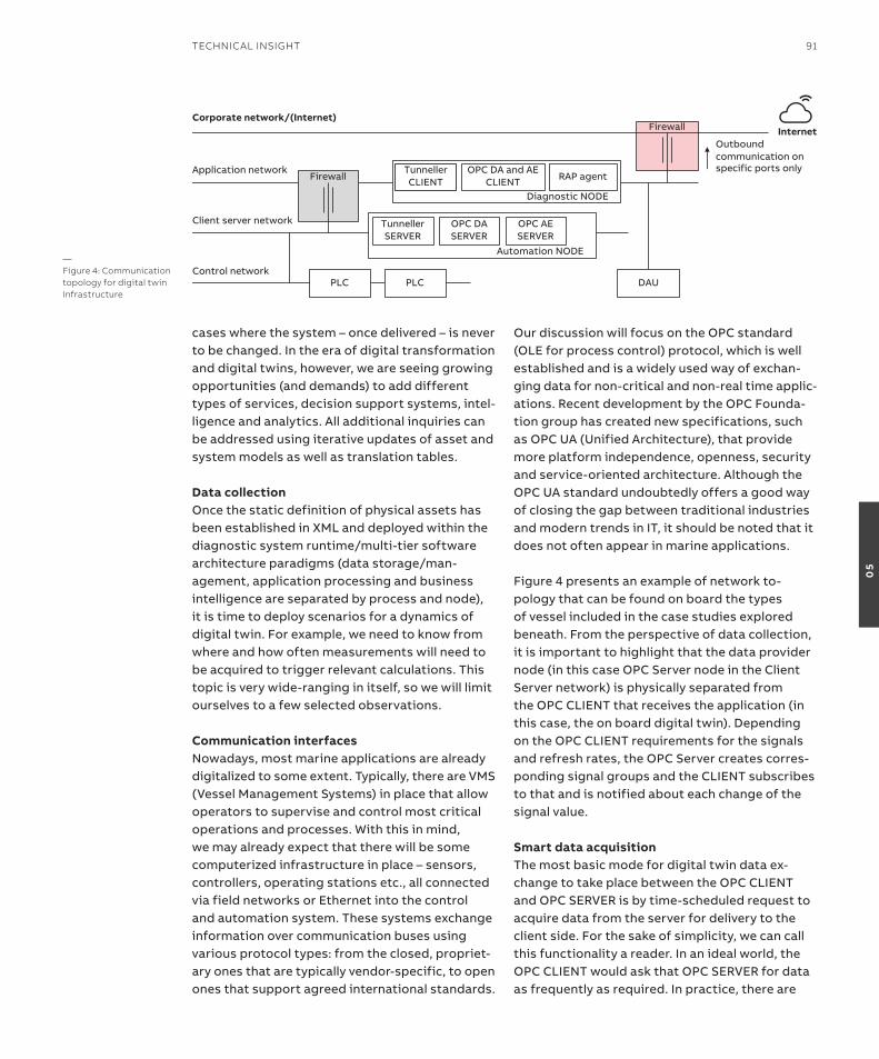
cases where the system – once delivered – is never to be changed. In the era of digital transformation and digital twins, however, we are seeing growing opportunities (and demands) to add different types of services, decision support systems, intel-ligence and analytics. All additional inquiries can be addressed using iterative updates of asset and system models as well as translation tables.
Data collectionOnce the static definition of physical assets has been established in XML and deployed within the diagnostic system runtime/multi-tier software architecture paradigms (data storage/man-agement, application processing and business intelligence are separated by process and node), it is time to deploy scenarios for a dynamics of digital twin. For example, we need to know from where and how often measurements will need to be acquired to trigger relevant calculations. This topic is very wide-ranging in itself, so we will limit ourselves to a few selected observations.
Communication interfacesNowadays, most marine applications are already digitalized to some extent. Typically, there are VMS (Vessel Management Systems) in place that allow operators to supervise and control most critical operations and processes. With this in mind, we may already expect that there will be some computerized infrastructure in place – sensors, controllers, operating stations etc., all connected via field networks or Ethernet into the control and automation system. These systems exchange information over communication buses using various protocol types: from the closed, propriet-ary ones that are typically vendor-specific, to open ones that support agreed international standards.
Our discussion will focus on the OPC standard (OLE for process control) protocol, which is well established and is a widely used way of exchan-ging data for non-critical and non-real time applic-ations. Recent development by the OPC Founda-tion group has created new specifications, such as OPC UA (Unified Architecture), that provide more platform independence, openness, security and service-oriented architecture. Although the OPC UA standard undoubtedly offers a good way of closing the gap between traditional industries and modern trends in IT, it should be noted that it does not often appear in marine applications.
Figure 4 presents an example of network to-pology that can be found on board the types of vessel included in the case studies explored beneath. From the perspective of data collection, it is important to highlight that the data provider node (in this case OPC Server node in the Client Server network) is physically separated from the OPC CLIENT that receives the application (in this case, the on board digital twin). Depending on the OPC CLIENT requirements for the signals and refresh rates, the OPC Server creates corres-ponding signal groups and the CLIENT subscribes to that and is notified about each change of the signal value.
Smart data acquisitionThe most basic mode for digital twin data ex-change to take place between the OPC CLIENT and OPC SERVER is by time-scheduled request to acquire data from the server for delivery to the client side. For the sake of simplicity, we can call this functionality a reader. In an ideal world, the OPC CLIENT would ask that OPC SERVER for data as frequently as required. In practice, there are
Automation NODE
Diagnostic NODE
Firewall
Firewall
Control network
Client server network
Application network
Corporate network/(Internet)
PLC PLC
OPC DA SERVER
OPC AE SERVER
OPC DA and AE CLIENT
TunnellerSERVER
TunnellerCLIENT RAP agent
DAU
Outbound communication on specific ports only
Internet
—Figure 4: Communication topology for digital twin infrastructure
teChniCAl insiGht 91
05
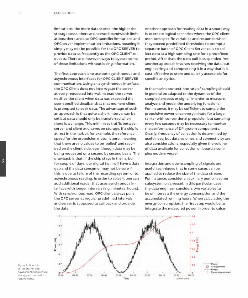
limitations: the more data stored, the higher the storage costs; there are network bandwidth limit-ations; there are also oPC tunneller limitations and oPC server implementation limitations, meaning it simply may not be possible for the oPC serVer to provide data as frequently as the oPC CLient re-quests. there are, however, ways to bypass some of these limitations without losing information.
the first approach is to use both synchronous and asynchronous interfaces for oPC CLient-serVer communication. Using an asynchronous interface, the oPC Client does not interrogate the server at every requested interval. instead the server notifies the client when data has exceeded the user-specified deadband; at that moment client is prompted to seek data. the advantage of such an approach is that quite a short interval can be set but data should only be transferred when there is a change. this minimizes traffic between server and client and saves on storage. if a ship is at rest in the harbor, for example, the reference speed for the propulsion motor is zero, meaning that there are no values to be ‘pulled’ and recor-ded on the client side, even though data may be being requested on a second by second basis. the drawback is that, if the ship stays in the harbor for couple of days, our digital twin will have a data gap and the data consumer may not be sure if this is due to failure of the recording system or to asynchronous reading. in order to solve it one can add additional reader that uses synchronous in-terface with longer intervals (e.g. minutes, hours). With synchronous read, oPC client always polls the oPC server at regular predefined intervals and server is supposed to call back and provide the data.
another approach for reading data in a smart way is to create logical scenarios where the oPC client monitors specific variables and responds when they exceed predefined thresholds to prompt a separate batch of oPC Client server calls to col-lect data at a high sampling rate for a predefined period. after that, the data pull is suspended. Yet another approach involves receiving the data, but engineering and compressing it in a way that it is cost-effective to store and quickly accessible for specific analytics.
in the marine context, the rate of sampling should in general be adapted to the dynamics of the sampled process or signal, in order to measure, analyze and model the underlying functions. For instance, it may be sufficient to sample the propulsive power once every minute for a large tanker with conventional propulsion but sampling every few seconds may be necessary to monitor the performance of DP system components. Clearly, frequency of collection is determined by usefulness, but data volumes and connectivity are also considerations, especially given the volume of data available for collection on board a com-plex modern vessel.
integration and downsampling of signals are useful techniques that in some cases can be applied to reduce the size of the data stream. For instance, consider an auxiliary pump in some subsystem on a vessel. in this particular case, the data engineer considers two variables to be of interest; the energy consumption and the accumulated running hours. When calculating the energy consumption, the first step would be to integrate the measured power in order to calcu-
—Figure 5: Principle of integration and downsampling to reduce storage and bandwidth requirements
92 GenerATions
05
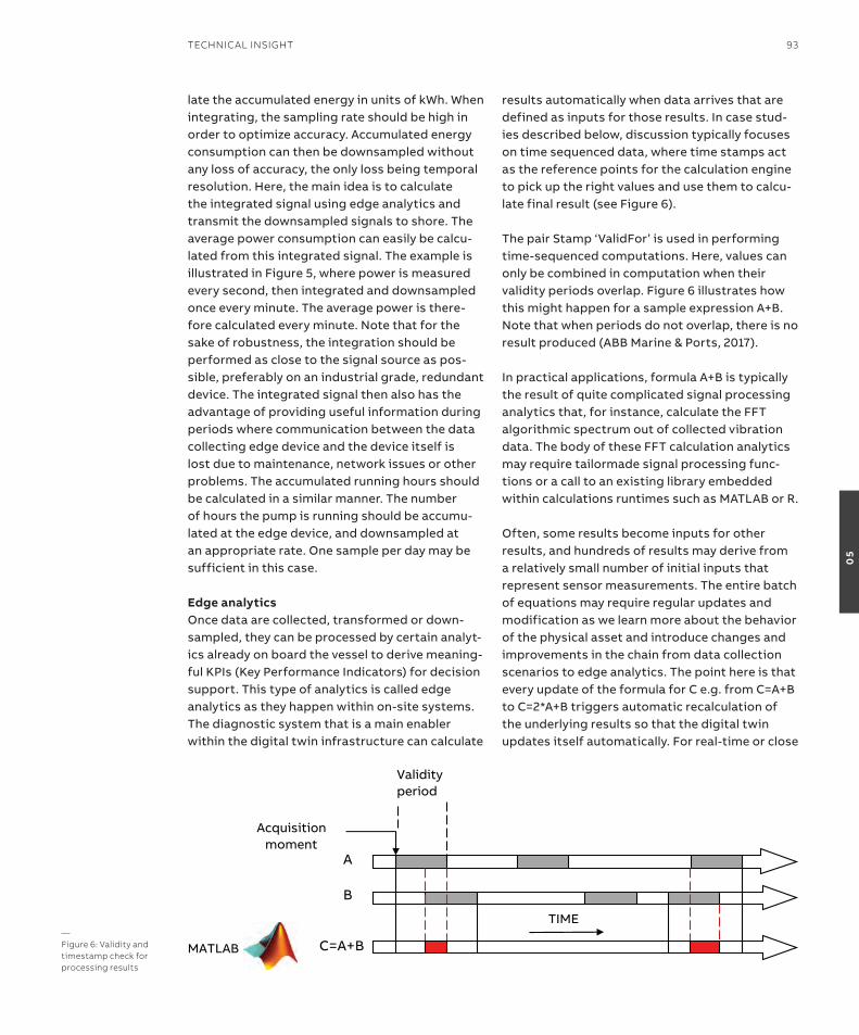
late the accumulated energy in units of kWh. When integrating, the sampling rate should be high in order to optimize accuracy. accumulated energy consumption can then be downsampled without any loss of accuracy, the only loss being temporal resolution. Here, the main idea is to calculate the integrated signal using edge analytics and transmit the downsampled signals to shore. the average power consumption can easily be calcu-lated from this integrated signal. the example is illustrated in Figure 5, where power is measured every second, then integrated and downsampled once every minute. the average power is there-fore calculated every minute. note that for the sake of robustness, the integration should be performed as close to the signal source as pos-sible, preferably on an industrial grade, redundant device. the integrated signal then also has the advantage of providing useful information during periods where communication between the data collecting edge device and the device itself is lost due to maintenance, network issues or other problems. the accumulated running hours should be calculated in a similar manner. the number of hours the pump is running should be accumu-lated at the edge device, and downsampled at an appropriate rate. one sample per day may be sufficient in this case.
Edge analyticsonce data are collected, transformed or down-sampled, they can be processed by certain analyt-ics already on board the vessel to derive meaning-ful KPis (Key Performance indicators) for decision support. this type of analytics is called edge analytics as they happen within on-site systems. the diagnostic system that is a main enabler within the digital twin infrastructure can calculate
results automatically when data arrives that are defined as inputs for those results. in case stud-ies described below, discussion typically focuses on time sequenced data, where time stamps act as the reference points for the calculation engine to pick up the right values and use them to calcu-late final result (see Figure 6).
the pair stamp ‘ValidFor’ is used in performing time-sequenced computations. Here, values can only be combined in computation when their validity periods overlap. Figure 6 illustrates how this might happen for a sample expression a+B. note that when periods do not overlap, there is no result produced (aBB Marine & Ports, 2017). in practical applications, formula a+B is typically the result of quite complicated signal processing analytics that, for instance, calculate the FFt algorithmic spectrum out of collected vibration data. the body of these FFt calculation analytics may require tailormade signal processing func-tions or a call to an existing library embedded within calculations runtimes such as MatLaB or r.
often, some results become inputs for other results, and hundreds of results may derive from a relatively small number of initial inputs that represent sensor measurements. the entire batch of equations may require regular updates and modification as we learn more about the behavior of the physical asset and introduce changes and improvements in the chain from data collection scenarios to edge analytics. the point here is that every update of the formula for C e.g. from C=a+B to C=2*a+B triggers automatic recalculation of the underlying results so that the digital twin updates itself automatically. For real-time or close
A
B
C=A+B
Acquisition moment
TIME
Validityperiod
MATLAB—Figure 6: Validity and timestamp check for processing results
TeChniCAl insiGhT 93
05

to real time applications, where criticality of edge analytics is high, one must consider transferring calculations to the control layer and deploying them on board programable controllers. an ex-ample of such an approach is described below in the use case for motor temperature protection.
CybersecurityFrom marine market observations over last 5-8 years, there has been a significant increase in cyber security awareness. traditional vendors of digitalized systems, especially global companies such as aBB have long had the cyber security mindset, tools, procedures, rules and solutions in place, mainly because other industries such an oil & gas, power (especially nuclear), chemicals demanded it. as the marine industry progresses through the digital transformation process, the concept and implementation of digital twins raises strong concerns on the safety and secur-ity of the data transitions and accesses needed to build digital copies. as depicted in Figure 2, the aBB solution for both the onboard and cloud twin is embraced by cyber security frameworks. in fact, space does not permit the inclusion of all of the techniques that secure our system; once more, we will restrict ourselves to the most relev-ant examples in the following paragraphs.
Cybersecurity starts on board or on site. the way computers, smart devices, networks and commu-nication protocols are secured there determines the vulnerability of entire system. as shown in Figure 4, the heart of the digital twin infrastruc-ture for a diagnostic system interconnects with all vital components and network segments on board the ship. therefore, it is essential to control and restrict network traffic that flows between non-critical application network, the critical auto-mation and control network and the customer’s network (or open internet). For secure oPC communication between the digital twin infra-structure and the automation system, there must be an oPC tunneller and firewall in place. the oPC tunneller disables a vulnerability existing in DCoM (Distributed Component object Model) since its creation, which randomly assigns and uses com-munication ports over a wide range, forcing open firewalls between oPC client and server side. the oPC tunneller drives oPC traffic through single, deterministically configured port (see Figure 4).
another potential weak point against a cyber at-tack is the physical computer where the software hosting the digital twin is running. some import-ant ways of protecting computers are listed below:• Witheachreleaseofnewsoftware,perform
attack surface analysis to identify potential attack points.
• Forentrypointsthathavetobeopen,runandsuccessfully pass security tests performed by authorized and an independent Device security assurance Center (DsaC).
• Performsystemhardeningwithuseofanem-bedded Windows os firewall to whitelist ports that are needed and block all others that are not used by application.
• DisableUSBusageformassstoragemedia.• Applyregularoperatingsystemupdatesand
patches – this is governed and executed within a cyber security service contract.
• Installandupdateantivirusapplicationsonaregular basis.
• Allcodethatisrunningdigitaltwinapplicationshould be signed with use of PKi (Public-key infrastructure) digital certificates.
• Strictlymanageaccesscontrolbyintroducingpassword policies, authorization and role-based mechanisms on all possible levels e.g. from the operating system to the application itself.
Cyber attacks can be executed externally and via the internet, but they can also come from the inside: a person or application can be trying to breach the system while being on board. external attacks are more likely as the digital systems running on board critical vessels as cruise liners or LnG (Liquefied natural Gas) tankers present prized targets for hackers. therefore, protecting ship-to-shore connections that facilitate for re-mote access from vendors’ companies to com-puters on board or data transfer itself between ship and shore demands special attention. aBB’s solution is called remote access Platform: this consists of the software agent (raP) deployed at the vessel side to create a secure link and com-municate with the service center – the server side application that functions as the core of the sys-tem and acts as a knowledge repository, control center and communications hub. an important point here is that ship-shore communication is always initiated by the ship side and therefore the firewall marked with red fill on Figure 4 is
94 GenerATions
05
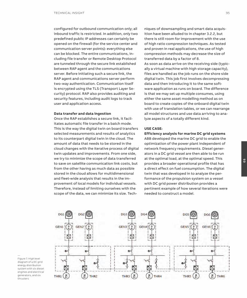
configured for outbound communication only; all inbound traffic is restricted. in addition, only two predefined public iP addresses can certainly be opened on the firewall (for the service center and communication server points): everything else can be blocked. the entire communications, in-cluding file transfer or remote Desktop Protocol are tunneled through the secure link established between raP agent and the communications server. Before initiating such a secure link, the raP agent and communications server perform two-way authentication. Communication itself is encrypted using the tLs (transport Layer se-curity) protocol. raP also provides auditing and security features, including audit logs to track user and application access.
Data transfer and data ingestiononce the raP establishes a secure link, it facil-itates automatic file transfer in a batch mode. this is the way the digital twin on board transfers selected measurements and results of analytics to its counterpart digital twin in the cloud. the amount of data that needs to be stored in the cloud changes with the iterative process of digital twin updates and improvements. From one side, we try to minimize the scope of data transferred to save on satellite communication link costs, but from the other having as much data as possible stored in the cloud allows for multidimensional and fleet-wide analysis that results in the im-provement of local models for individual vessels. therefore, instead of limiting ourselves with the scope of the data, we can minimize its size. tech-
niques of downsampling and smart data acquis-ition have been alluded to in chapter 3.2.2, but there is still room for improvement with the use of high ratio compression techniques. as tested and proven in real applications, the use of high compression methods may decrease the size of transferred data by a factor of 8.as soon as data arrive on the receiving side (typic-ally a virtual machine with high storage capacity), files are handled as the job runs on the shore side digital twin. this job first involves decompressing data and then introducing it to the same soft-ware application as runs on board. the difference is that we may set up multiple consumes, using either the same asset modelling method as on board to create copies of the onboard digital twin with use of translation tables, or we can rearrange all model structures and use data arriving to ana-lyze aspects of a totally different kind.
usE CasE:Efficiency analysis for marine DC grid systemsaBB developed the marine DC grid to enable the optimization of the power plant independent of network frequency requirements. Diesel gener-ators in a DC grid vessel are then able to be run at the optimal load, at the optimal speed. this provides a broader operational profile that has a direct effect on fuel consumption. the digital twin that was developed in to analyze the per-formance of the propulsion system on a vessel with DC grid power distribution provides a pertinent example of how several iterations were needed to construct a model.
—Figure 7: high level diagram of a DC grid energy distribution system with six diesel engines and electrical generators, and six thrusters
TeChniCAl insiGhT 95
05
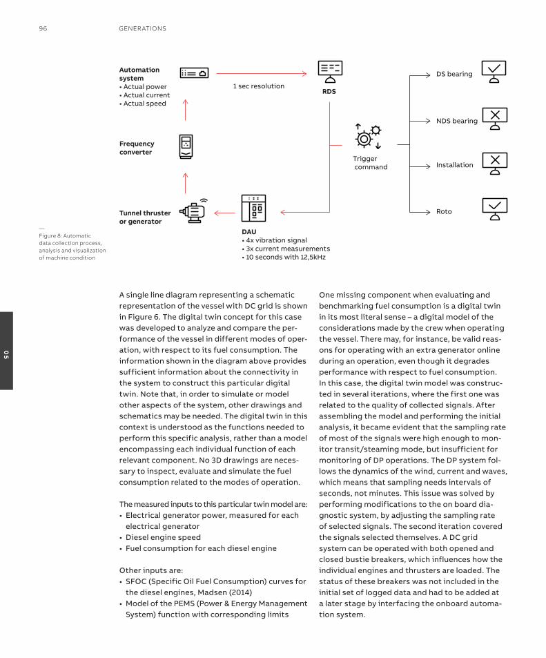
a single line diagram representing a schematic representation of the vessel with DC grid is shown in Figure 6. the digital twin concept for this case was developed to analyze and compare the per-formance of the vessel in different modes of oper-ation, with respect to its fuel consumption. the information shown in the diagram above provides sufficient information about the connectivity in the system to construct this particular digital twin. note that, in order to simulate or model other aspects of the system, other drawings and schematics may be needed. the digital twin in this context is understood as the functions needed to perform this specific analysis, rather than a model encompassing each individual function of each relevant component. no 3D drawings are neces-sary to inspect, evaluate and simulate the fuel consumption related to the modes of operation.
the measured inputs to this particular twin model are:• Electricalgeneratorpower,measuredforeach
electrical generator• Dieselenginespeed• Fuelconsumptionforeachdieselengine
other inputs are:• SFOC(SpecificOilFuelConsumption)curvesfor
the diesel engines, Madsen (2014)• ModelofthePEMS(Power&EnergyManagement
system) function with corresponding limits
one missing component when evaluating and benchmarking fuel consumption is a digital twin in its most literal sense – a digital model of the considerations made by the crew when operating the vessel. there may, for instance, be valid reas-ons for operating with an extra generator online during an operation, even though it degrades performance with respect to fuel consumption.in this case, the digital twin model was construc-ted in several iterations, where the first one was related to the quality of collected signals. after assembling the model and performing the initial analysis, it became evident that the sampling rate of most of the signals were high enough to mon-itor transit/steaming mode, but insufficient for monitoring of DP operations. the DP system fol-lows the dynamics of the wind, current and waves, which means that sampling needs intervals of seconds, not minutes. this issue was solved by performing modifications to the on board dia-gnostic system, by adjusting the sampling rate of selected signals. the second iteration covered the signals selected themselves. a DC grid system can be operated with both opened and closed bustie breakers, which influences how the individual engines and thrusters are loaded. the status of these breakers was not included in the initial set of logged data and had to be added at a later stage by interfacing the onboard automa-tion system.
Automationsystem• Actual power• Actual current• Actual speed
DAU• 4x vibration signal• 3x current measurements• 10 seconds with 12,5kHz
Frequencyconverter
1 sec resolutionRDS
Trigger command
Tunnel thrusteror generator
DS bearing
Roto
NDS bearing
Installation
—Figure 8: Automatic data collection process, analysis and visualization of machine condition
96 GenerATions
05
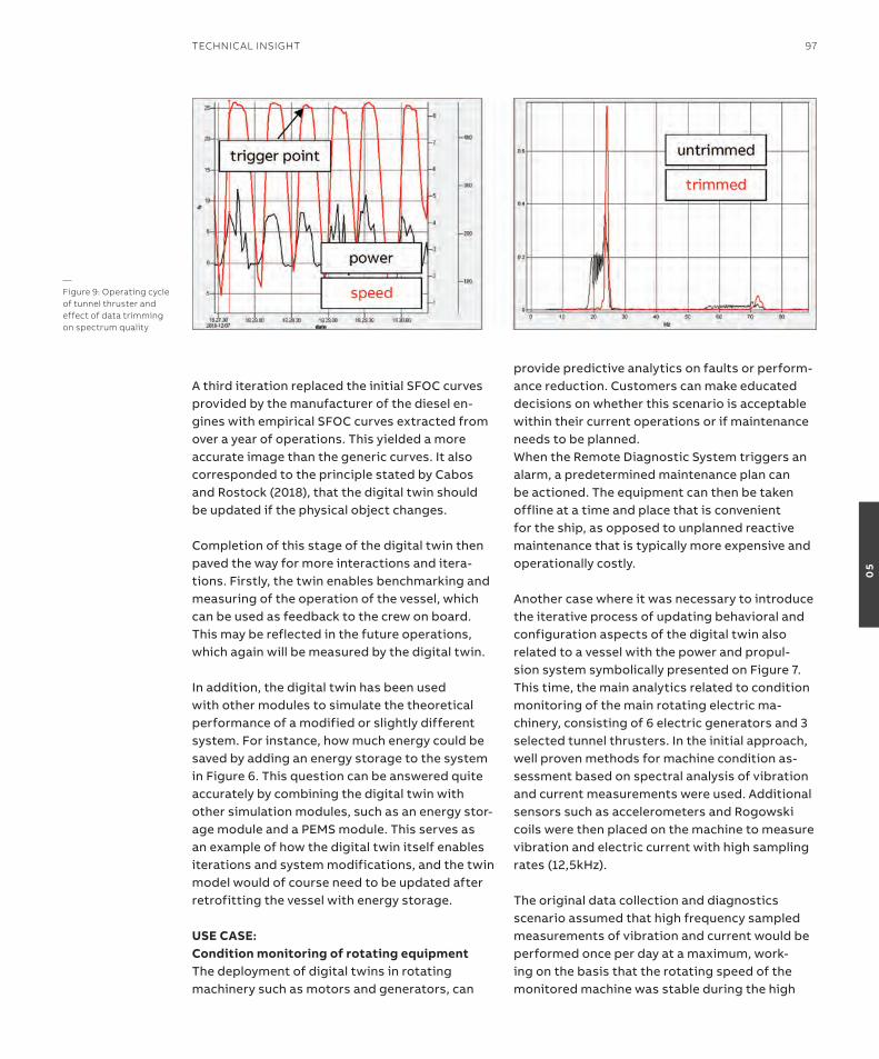
a third iteration replaced the initial sFoC curves provided by the manufacturer of the diesel en-gines with empirical sFoC curves extracted from over a year of operations. this yielded a more accurate image than the generic curves. it also corresponded to the principle stated by Cabos and rostock (2018), that the digital twin should be updated if the physical object changes.
Completion of this stage of the digital twin then paved the way for more interactions and itera-tions. Firstly, the twin enables benchmarking and measuring of the operation of the vessel, which can be used as feedback to the crew on board. this may be reflected in the future operations, which again will be measured by the digital twin.
in addition, the digital twin has been used with other modules to simulate the theoretical performance of a modified or slightly different system. For instance, how much energy could be saved by adding an energy storage to the system in Figure 6. this question can be answered quite accurately by combining the digital twin with other simulation modules, such as an energy stor-age module and a PeMs module. this serves as an example of how the digital twin itself enables iterations and system modifications, and the twin model would of course need to be updated after retrofitting the vessel with energy storage.
usE CasE: Condition monitoring of rotating equipmentthe deployment of digital twins in rotating machinery such as motors and generators, can
provide predictive analytics on faults or perform-ance reduction. Customers can make educated decisions on whether this scenario is acceptable within their current operations or if maintenance needs to be planned.When the remote Diagnostic system triggers an alarm, a predetermined maintenance plan can be actioned. the equipment can then be taken offline at a time and place that is convenient for the ship, as opposed to unplanned reactive maintenance that is typically more expensive and operationally costly.
another case where it was necessary to introduce the iterative process of updating behavioral and configuration aspects of the digital twin also related to a vessel with the power and propul-sion system symbolically presented on Figure 7. this time, the main analytics related to condition monitoring of the main rotating electric ma-chinery, consisting of 6 electric generators and 3 selected tunnel thrusters. in the initial approach, well proven methods for machine condition as-sessment based on spectral analysis of vibration and current measurements were used. additional sensors such as accelerometers and rogowski coils were then placed on the machine to measure vibration and electric current with high sampling rates (12,5kHz).
the original data collection and diagnostics scenario assumed that high frequency sampled measurements of vibration and current would be performed once per day at a maximum, work-ing on the basis that the rotating speed of the monitored machine was stable during the high
—Figure 9: operating cycle of tunnel thruster and effect of data trimming on spectrum quality
TeChniCAl insiGhT 97
05

frequency measurement and the load of machine exceeded levels predefined in the system (for instance more than 60 percent of nominal load). these requirements were needed because:• Toperformeffectiveautomaticfaultidentifica-
tion based on the vibration or current spectrum, the corresponding spectrum must be distinct, and this can be achieved only if the variation of the speed is as low as possible.
• Toanalyzetrendsbasedonspecificindicatorsderived from the spectrum, we should expect at least one measurement point per day to catch dynamics of mechanical faults that may develop in the machine over weeks.
• Thehighertheloadonthemachinethebetterthe signal to noise ratio, and thus the higher the reliability of the automatic diagnosis.
there is a certain limitation in the measurement system described, i.e. although vibration and cur-rent are sampled with a high sampling rate of 12.5 kHz for the duration (of, e.g. 10 s), the rotation speed itself can only be acquired once per second. this is because there has no additional tacho-meter installed and the speed is acquired from the automation system using the oPC commu-nication protocol described in chapter 3.2.1. High frequency sampled measurements of vibration and current together with average speed and load calculated while high frequency sampled meas-urements were taken arrive at the diagnostic sys-tem and are checked against calculation criteria; the average load must exceed the threshold level and the variance of the speed must not exceed the specific level. in case the criteria are fulfilled,
input measurements are processed using mul-tiple analytics from the domain of signal filter-ing, spectral analysis and harmonics matching and checked against the warning limit. Very final information is presented to the users on board graphically with traffic lights corresponding to different machine faults (see Figure 8).
the scenario presented has been successfully im-plemented on numerous vessels and has proved very effective, especially for typical propulsion motors, aC generators or direct online motors. However, in the case under discussion, it was quickly discovered that the way data covering the vessel’s tunnel thruster motors were collected and pre-processed before actual analysis could be improved because the tunnel thruster motors were mainly used in the DP mode. analysis of the speed and load measurements derived from the digital twin showed speed variations that could exceed 50% within 10 s duration (Figure 9). this was mainly an effect of wave impact compensa-tion while keeping station. in consequence, even though the diagnostic system was triggering the measurements hourly, measurements were not further processed as they did not fulfil precon-ditions related to minimal speed variance. as a result, main indicator trends contained very few points and did not allow machine experts to give reliable diagnoses and worthwhile recommenda-tions on maintenance actions. in the first step of iterative improvements the emphasis was put on increasing the number of measurements. this was achieved by changing the condition scenario. instead of checking the level of speed variance once per hour, the dia-gnostic scenario checked every second whether the motor was at peak acceleration within a single work cycle. Measurements were triggered immediately to establish whether this condition had been fulfilled (see trigger point, Figure 9). as a result, multiple measurements were taken daily. However, many of them contained the high to low transition speed falling edge, representing a speed variance that had to be taken out of the analysis. this would not have been known if the analysis was based only on low resolution time stamp measurements of speed. the solution was found by analyzing data sampled at high frequency. By analyzing the frequency of supply
Physical assetelectric motor
Tests onPCU simulator
Propulsion control unit
Data collection
Machinelearning model
Batch data transfer
Dataremodelling
On board twin
On shore twin
On board cloud
On shore cloud
—Figure 10: Process overview where digital twin is used to add inboard protection systems
98 GenerATions
05
current wave, the time window for measurement could be cut for most stable speeds, as long as enough time was available to fulfil spectrum res-olution requirements and speed variance. once the window start and end point had been derived using an optimization algorithm, the same time coordinates were used to cut out the correspond-ing window for vibration measurements (as all vibration and current channels were sampled sim-ultaneously by the DaU – Data acquisition Unit).
after trimming the high frequency sampled data in this way, they were further processed through the same analytics as was used in the initial deployment. the right-hand chart if Figure 9 shows the vibration spectrum before (black) and after (red) trimming. it is clear that the spectrum derived from trimmed data has a much more dominant main harmonic; thus fault identification analytics is to be more reliable.
the last iteration of the digital twin modified the baseline method and offered proper calculation of warning limits. in the original approach, warn-ing limits were based on initial, single baseline measurements acquired from monitored ma-chines in the early stage of their lifetime. Warning limits were also checked against international standards such as iso 10816-3:2009 (2009). How-ever, this approach proved inaccurate because one part of its measured values such as velocity rMs multiple times lower than the warning limit given by the iso standard, while the variance of calculated vibration indicators for each meas-urement point during the first few months of the machine lifetime was so high that it could exceed baseline limit derived from a single measurement. as a result, the digital twin produced false alarms that were both confusing and undesirable on board. High variance of resulting indicators again originated from high dynamics in the motors’ operating profile and even though diagnostic system checked criteria for the load range, meas-urement captured instances of extremely high energy that exceeded baseline warning limits.
Here, the was to include statistical variance in the baseline and in the warning limit calculations. in-stead of using single measurement as a baseline, a larger set of measurements have been taken into the analysis.
the time range to collect such samples was set at half a year and, with an average of 4-6 measurement points per month, a good set of approximately 30 observations was logged. Following recommendations given by MoBiUs institUte (2017) for statistical alarm calcu-lations and based on the assumption that vibration indicators spread follows normal distribution, the alarm limit was calculated as a function of the average value and its stand-ard deviation. it is important to note that this new approach was applied individually to each machine, which resulted in different values for the warning limits that corresponded to actual and observed energy vibration levels specific to each machine.
the entire analysis described above has been performed using an on shore digital twin as it is much easier to manipulate data, experiment with different equations and scale the analyt-ics engine in the cloud. since the core of the on shore digital twin is based on the same software infrastructure as the one on board, updating the behavioral definition of the onboard twin was a matter of a single operation performed using a remote connection.
summarythe marine industry is currently going through an accelerated process of digital transformation. a very stimulating and open-minded environment has been created where all key players in the market – ship owners, shipyards, system vendors and integrators – are willing and trying to collab-orate, integrate and exchange information and data to solve various challenges together. in such an environment, there is a common and strong belief that building digital twins is a fundamental step forward that will add value and eventually result in measurable business gains. By demon-strating how digital twins were used in specific use cases, and the multiple lessons learnt when integrating models, we hope to have highlighted that the marine digital infrastructure must be in place for the iterative and to some extent continu-ous process of improvement required by digital twins can flourish. From the business perspective investments will be required both by customers and vendors, followed by continuous, advanced service efforts.
—references:CABos, C; rosToCK, C. (2018), Digital Twin or Digital Model?, 17th CoMPiT Conf., Pavone, pp.403-411
iso 10816-3:2009 (2009), Mechanical vibration – evaluation of machine vibration by measurements on non-rotating parts – Part 3: industrial machines with nominal power above 15 kW and nominal speeds between 120 r/min and 15000 r/min when measured in situ
TeChniCAl insiGhT 99
05
With autonomous technologies maturing fast, there is still a need to establish standards for design and operation of self-sailing ships. rules and regulations ensuring safety and reliability of autonomous vessel operations also need to be in place. in the meantime, we will see a stepwise development with automated systems, remote connectivity and software for operational sup-port being deployed. each of these consecutive steps will add value for crews, fleet owners and service providers.
Central to autonomous concepts are the meth-odologies for visualizing and analyzing the ship’s surroundings, as well as controls for maneuver-ing and voyage planning. this includes sensor technologies, software analytics and artificial intelligence or machine learning methods for safe and optimal operations between ports. remote connectivity is essential to monitor and interact with the vessels.
it is equally important to ensure that the ship’s essential systems for docking, maneuvering and navigating are ready for increasingly autonomous operations. the traditional mechanical propul-sion train does not support high fault tolerance and redundancy, and is dependent on the ability
of engineers to intervene in case of failures. in unmanned vessels, such failures must be avoided. alternatively, the system should be able to reconfigure into a safe mode for continuous operation, either through automatic self-healing or by means of interaction with onboard digit-alized control and monitoring system through remote connectivity. this is one of the reasons aBB believes that the next generation of ships – including increasingly autonomous vessels – will be electric, digital and connected.
in the past, integrating different shipboard sys-tems was restricted by limited communication between hardware and proprietary technologies, as well as by the inadequate performance and high cost of ship/shore communication via satel-lite or radio.
now, the digital revolution, cloud technologies and the internet of things, services and People (iotsP) have changed the game. Platforms and standards are in place for collecting and transmitting more data from thousands of embedded sensors, ulti-mately enhancing vessel management. aBB has established aBB ability™, the company’s unified, cross-industry, digital offering – extending from device to edge to cloud – with devices, systems,
—autonomy requires fault tolerant, reconfigurable and connected electrical grid for propulsionThe vision of autonomous shipping may be closer than many may think. some of the key technologies are already available today, and pioneering shipowners are gearing up to put them to the test in commercial applications.
alF KårE åDNaNEselectric solutions leadABB Marine & Ports
MiKKo lEPisToDigital solutions leadABB Marine & Ports
100 GenerATions
05
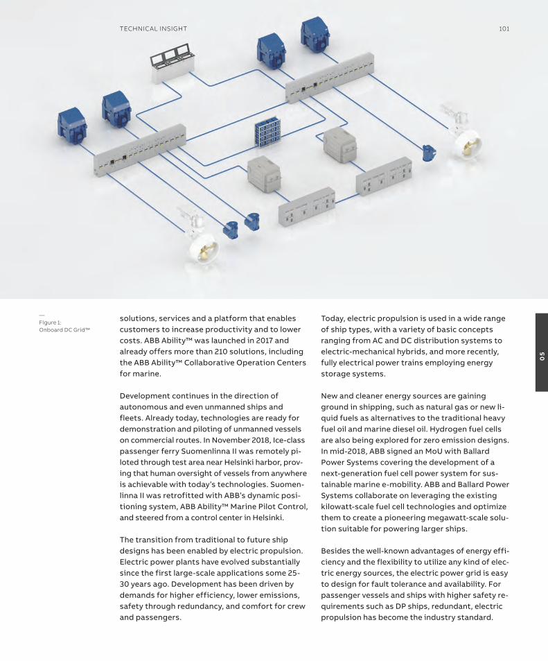
solutions, services and a platform that enables customers to increase productivity and to lower costs. aBB ability™ was launched in 2017 and already offers more than 210 solutions, including the aBB ability™ Collaborative operation Centers for marine.
Development continues in the direction of autonomous and even unmanned ships and fleets. already today, technologies are ready for demonstration and piloting of unmanned vessels on commercial routes. in november 2018, ice-class passenger ferry suomenlinna ii was remotely pi-loted through test area near Helsinki harbor, prov-ing that human oversight of vessels from anywhere is achievable with today’s technologies. suomen-linna ii was retrofitted with aBB’s dynamic posi-tioning system, aBB ability™ Marine Pilot Control, and steered from a control center in Helsinki.
the transition from traditional to future ship designs has been enabled by electric propulsion. electric power plants have evolved substantially since the first large-scale applications some 25-30 years ago. Development has been driven by demands for higher efficiency, lower emissions, safety through redundancy, and comfort for crew and passengers.
today, electric propulsion is used in a wide range of ship types, with a variety of basic concepts ranging from aC and DC distribution systems to electric-mechanical hybrids, and more recently, fully electrical power trains employing energy storage systems.
new and cleaner energy sources are gaining ground in shipping, such as natural gas or new li-quid fuels as alternatives to the traditional heavy fuel oil and marine diesel oil. Hydrogen fuel cells are also being explored for zero emission designs. in mid-2018, aBB signed an MoU with Ballard Power systems covering the development of a next-generation fuel cell power system for sus-tainable marine e-mobility. aBB and Ballard Power systems collaborate on leveraging the existing kilowatt-scale fuel cell technologies and optimize them to create a pioneering megawatt-scale solu-tion suitable for powering larger ships.
Besides the well-known advantages of energy effi-ciency and the flexibility to utilize any kind of elec-tric energy sources, the electric power grid is easy to design for fault tolerance and availability. For passenger vessels and ships with higher safety re-quirements such as DP ships, redundant, electric propulsion has become the industry standard.
—Figure 1: onboard DC Grid™
TeChniCAl insiGhT 101
05

For autonomous and unmanned vessels, the electric power and propulsion system is the fun-dament for achieving the robustness and availab-ility required to overcome the need for onboard maintenance crew.
this paper sets out a holistic approach to system design, showing that fault tolerance automated, remote, or manual reconfigurations are benefi-cial in themselves. it also provides a platform for enhancing safe navigation and docking, and these building blocks will ultimately make autonomous and unmanned vessel operations feasible.
Electric propulsion as the backbonean electric power generation and distribution system enables tight integration with automation and control systems, transforming ship install-ations from merely connected ‘blocks’ into a collaborative and highly automated system. the electrical ‘backbone’ also expands the range of viable energy sources beyond conventional com-bustion, accommodating environmentally friendly batteries and fuel cells.
Flexibility in the design of electric propulsion can provide high availability and efficiency through optimal engine control and loading, use of propulsors with high reliability such as azipod® propulsion, and mechanical and hydro-dynamic efficiency.
a recent, transformative technology is onboard DC Grid™, a DC-based power system enabling simple, flexible and functional integration of energy sources such as variable speed gensets and shaft generators, batteries and fuel cells, Figure 1. Un-like aC based distribution systems, where connec-ted generators need to match system voltage and frequency, the onboard DC Grid™ only requires the generators to match system voltage. this means that generator and engine speed can be dynamic-ally optimized to the system load situation. When engine load decreases, engine speed is also re-duced. For a medium speed diesel engine working at part load, this can result in more than 20 percent reduction in specific fuel consumption, as well as lower emissions and maintenance requirements. since the power is individually controlled from each source, loading can be optimized for effi-ciency, performance, and lifetime management.
onboard DC Grid™ is a good choice for its sim-plicity, heightened fault tolerance, ease of energy storage integration, and alternative fuel sources that reduce emissions such as LnG or hydrogen in power production. system integration and control play to the strengths of the various energy sources in the system, and keep strict control of consumers using a Power and energy Manage-ment system (PeMs) to manage the balance of power and energy in the system.
stepwise evolution towards autonomythe list of benefits may already appear compel-ling, but intelligent and environmentally-friendly vessels benefit from the electric backbone for yet another reason: automation systems can be fully integrated, with all information needed to operate the vessel available in one system and one platform.
onboard DC Grid™ with power electronics provides a unique platform for digital solutions on board a vessel. Using sensors and commu-nication infrastructure, data is transmitted between systems in an instant. this provides access to information that enables the bridge to monitor and optimize performance, either manu-ally or automatically.
this unified platform makes it possible to sup-port full integration between the automation and power systems and the vessel’s digitalized connectivity. Ultimately, this provides the gate-way through which ever-increasing computing capabilities in the cloud can be exploited on the owner’s terms, allowing machine learning and connected data analytics to provide what has not previously been possible in energy efficiency, asset and equipment maintenance management, and vessel safety.
the high level of integration onboard DC Grid™ also means that high quality information on status and performance is available to onboard or remote operators and maintenance engineers as needed.
From this starting point, the path to fully autonomous and eventually unmanned vessels is achievable with a stepwise approach, with each step demonstrating results of individual value to ship operations.
102 GenerATions
05
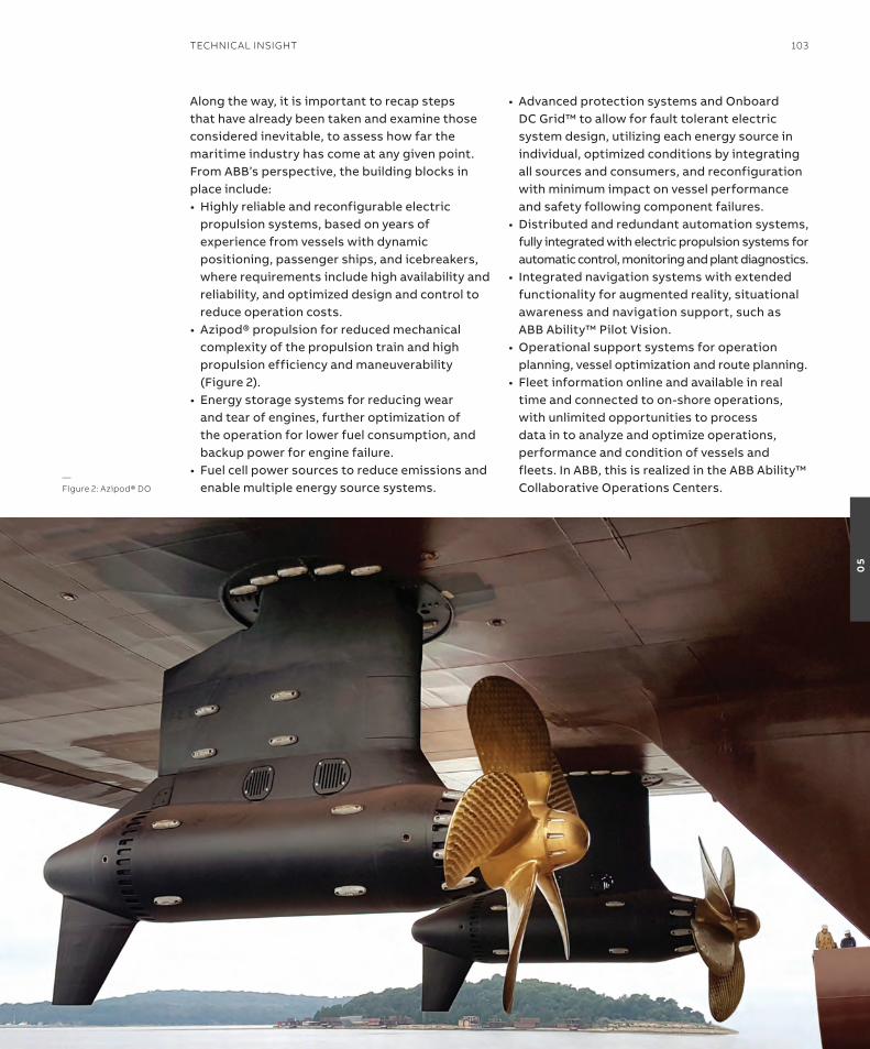
along the way, it is important to recap steps that have already been taken and examine those considered inevitable, to assess how far the maritime industry has come at any given point. From aBB’s perspective, the building blocks in place include:•Highly reliable and reconfigurable electric
propulsion systems, based on years of experience from vessels with dynamic positioning, passenger ships, and icebreakers, where requirements include high availability and reliability, and optimized design and control to reduce operation costs.
• azipod® propulsion for reduced mechanical complexity of the propulsion train and high propulsion efficiency and maneuverability (Figure 2).
• energy storage systems for reducing wear and tear of engines, further optimization of the operation for lower fuel consumption, and backup power for engine failure.
• Fuel cell power sources to reduce emissions and enable multiple energy source systems.
• advanced protection systems and onboard DC Grid™ to allow for fault tolerant electric system design, utilizing each energy source in individual, optimized conditions by integrating all sources and consumers, and reconfiguration with minimum impact on vessel performance and safety following component failures.
•Distributed and redundant automation systems, fully integrated with electric propulsion systems for automatic control, monitoring and plant diagnostics.
• integrated navigation systems with extended functionality for augmented reality, situational awareness and navigation support, such as aBB ability™ Pilot Vision.
•operational support systems for operation planning, vessel optimization and route planning.
• Fleet information online and available in real time and connected to on-shore operations, with unlimited opportunities to process data in to analyze and optimize operations, performance and condition of vessels and fleets. in aBB, this is realized in the aBB ability™ Collaborative operations Centers.
—Figure 2: Azipod® Do
TeChniCAl insiGhT 103
05
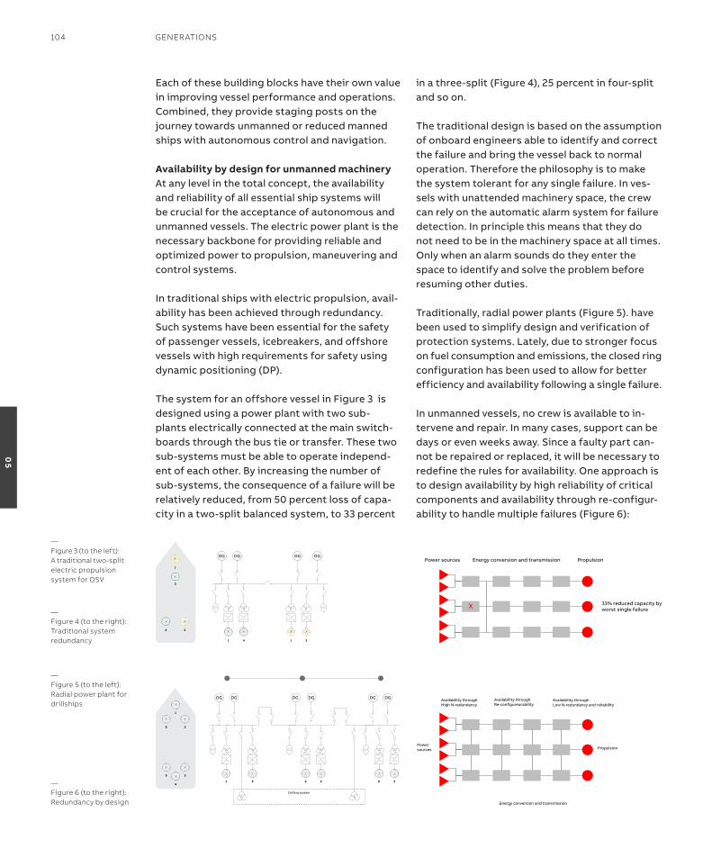
each of these building blocks have their own value in improving vessel performance and operations. Combined, they provide staging posts on the journey towards unmanned or reduced manned ships with autonomous control and navigation.
availability by design for unmanned machineryat any level in the total concept, the availability and reliability of all essential ship systems will be crucial for the acceptance of autonomous and unmanned vessels. the electric power plant is the necessary backbone for providing reliable and optimized power to propulsion, maneuvering and control systems.
in traditional ships with electric propulsion, avail-ability has been achieved through redundancy. such systems have been essential for the safety of passenger vessels, icebreakers, and offshore vessels with high requirements for safety using dynamic positioning (DP).
the system for an offshore vessel in Figure 3 is designed using a power plant with two sub-plants electrically connected at the main switch-boards through the bus tie or transfer. these two sub-systems must be able to operate independ-ent of each other. By increasing the number of sub-systems, the consequence of a failure will be relatively reduced, from 50 percent loss of capa-city in a two-split balanced system, to 33 percent
in a three-split (Figure 4), 25 percent in four-split and so on.
the traditional design is based on the assumption of onboard engineers able to identify and correct the failure and bring the vessel back to normal operation. therefore the philosophy is to make the system tolerant for any single failure. in ves-sels with unattended machinery space, the crew can rely on the automatic alarm system for failure detection. in principle this means that they do not need to be in the machinery space at all times. only when an alarm sounds do they enter the space to identify and solve the problem before resuming other duties.
traditionally, radial power plants (Figure 5). have been used to simplify design and verification of protection systems. Lately, due to stronger focus on fuel consumption and emissions, the closed ring configuration has been used to allow for better efficiency and availability following a single failure.
in unmanned vessels, no crew is available to in-tervene and repair. in many cases, support can be days or even weeks away. since a faulty part can-not be repaired or replaced, it will be necessary to redefine the rules for availability. one approach is to design availability by high reliability of critical components and availability through re-configur-ability to handle multiple failures (Figure 6):
DG DG DGDG
42 31
3
2
4
1
—Figure 3 (to the left): A traditional two-split electric propulsion system for osV
Figure 4: Traditional system redundancy
Power sources PropulsionEnergy conversion and transmission
33% reduced capacity byworst single failureX
—Figure 4 (to the right): Traditional system redundancy
DG DG DGDG
51 42
DG DG
36
Drilling system
3
2
5
1
6
4
—Figure 5 (to the left): radial power plant for drillships
Figure 6: Redundancy by design
Powersources Propulsion
Energy conversion and transmission
Availability throughHigh N-redundancy
Availability throughLow N-redundancy and reliability
Availability throughRe-configureurability
—Figure 6 (to the right):redundancy by design
104 GenerATions
05
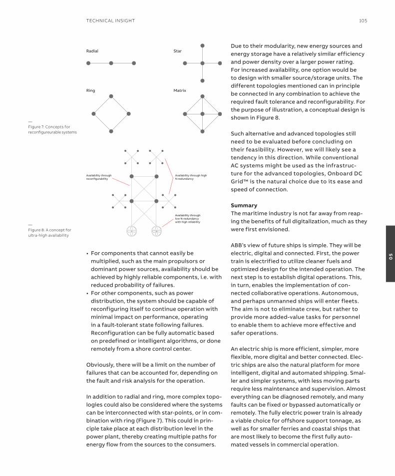
• For components that cannot easily be multiplied, such as the main propulsors or dominant power sources, availability should be achieved by highly reliable components, i.e. with reduced probability of failures.
• For other components, such as power distribution, the system should be capable of reconfiguring itself to continue operation with minimal impact on performance, operating in a fault-tolerant state following failures. reconfiguration can be fully automatic based on predefined or intelligent algorithms, or done remotely from a shore control center.
obviously, there will be a limit on the number of failures that can be accounted for, depending on the fault and risk analysis for the operation.
in addition to radial and ring, more complex topo-logies could also be considered where the systems can be interconnected with star-points, or in com-bination with ring (Figure 7). this could in prin-ciple take place at each distribution level in the power plant, thereby creating multiple paths for energy flow from the sources to the consumers.
Due to their modularity, new energy sources and energy storage have a relatively similar efficiency and power density over a larger power rating. For increased availability, one option would be to design with smaller source/storage units. the different topologies mentioned can in principle be connected in any combination to achieve the required fault tolerance and reconfigurability. For the purpose of illustration, a conceptual design is shown in Figure 8.
such alternative and advanced topologies still need to be evaluated before concluding on their feasibility. However, we will likely see a tendency in this direction. While conventional aC systems might be used as the infrastruc-ture for the advanced topologies, onboard DC Grid™ is the natural choice due to its ease and speed of connection.
summarythe maritime industry is not far away from reap-ing the benefits of full digitalization, much as they were first envisioned.
aBB’s view of future ships is simple. they will be electric, digital and connected. First, the power train is electrified to utilize cleaner fuels and optimized design for the intended operation. the next step is to establish digital operations. this, in turn, enables the implementation of con-nected collaborative operations. autonomous, and perhaps unmanned ships will enter fleets. the aim is not to eliminate crew, but rather to provide more added-value tasks for personnel to enable them to achieve more effective and safer operations.
an electric ship is more efficient, simpler, more flexible, more digital and better connected. elec-tric ships are also the natural platform for more intelligent, digital and automated shipping. smal-ler and simpler systems, with less moving parts require less maintenance and supervision. almost everything can be diagnosed remotely, and many faults can be fixed or bypassed automatically or remotely. the fully electric power train is already a viable choice for offshore support tonnage, as well as for smaller ferries and coastal ships that are most likely to become the first fully auto-mated vessels in commercial operation.
Availability through high N-redundancy
Availability through reconfigurability
Availability through low N-redundancy with high reliability
—Figure 8: A concept for ultra-high availability
Radial
Ring
Star
Matrix
—Figure 7: Concepts for reconfigureurable systems
TeChniCAl insiGhT 105
05
the advance analytics team in smart asset Management is able to support and help key Marine players to make the correct decisions based on data by analyzing the vast amount of information collected over the years and apply-ing machine learning applications. another key application from the results provided by the advance analytics team is that our aBB products and digital solutions can be improved and optim-ized to provide additional value by adjusting and enhancing current designs, for example thermal protection used on the Propulsion Control Unit application in aBB ability™ system 800xa.
the recently developed prediction model has a representation of the motor cooling unit independent from the Pt100 motor winding temperature measurements. all the required data for the model is collected by rDs from the frequency converter (actual power and actual torque signals) and the propulsion motor cool-ing system (cooling air temperature signal). the prediction model is coded in PCU controller ap-plication and can calculate the ‘predicted motor winding temperature’.
the predicted motor winding temperature is used so that average winding temperature is compared with the model temperature for all the range of motor temperature, and notify the alarm system or reduce the propulsion power if the condition persists.
this prediction model can be configured and extended to other heavy machinery applic-ations, including propulsion transformer or diesel generator.
The applicationthe scope of the work was to develop a thermal protection function for high performance marine propulsion motors. a generic overview of the system can be found in Figure 1. this specific generic configuration is frequently used in marine propulsion systems where an onboard freshwater cooling system is used to remove heat produced by the propulsion motor. the motor is cooled by an air cooling loop, where air is circu-lated by one or more fans. Heat is transferred from the hot air to the fresh water cooling system in a heat exchanger.
—anticipating technical faults with machine learningFailures in critical onboard machinery can result in production loss, delays, or even worse, endanger the ship and its crew. For the past decade, ABB Ability™ Marine remote Diagnostic systems have been collecting data to provide technical support when needed as well as time based reports related to the status and operation onboard the vessel. With the volume of data collected, owners are able to augment onboard crews’ skills and increase the efficiency of fleetwide operations adding value on a daily basis.
MorTEN sTaKKElaNDData scientistABB Marine & Ports
Bo WoN lEEManagerPropulsion Control UnitABB Marine & Ports
yaGo ParroNDoProduct Area Managersmart Asset ManagementABB Marine & Ports
106 GenerATions
05

the temperature of the air is measured on the in-let and outlet of the heat exchanger. the rotation speed of the motor is either measured directly or provided by the Propulsion Control Unit (PCU). the Propulsion Control Unit (PCU) is a control-ler application integrated with the propulsion frequency converter that controls the speed and power of the propulsion motors. the mechanical torque and electrical power are calculated and provided by the PCU. More instrumentation may be available on some vessels, but a minimum set was chosen for training.
Until now, all the propulsion winding temperature protections have been based on physically moun-ted Pt100 temperature sensors on the motors. there is a fixed limit (typically at 155 degrees C) in the propulsion control software that enables only single point of critical temperature level protec-tion, and this does not cover the entire range of temperature below the critical set point. Based on the mounting spot of the Pt100 sensors, effi-ciency and accuracy of the protection system may vary – the highest temperature of windings may be on a different spot on the area.
the main target of the development work was to implement a thermal protection function that can detect an abnormal state prior to reaching the HH temperature limit, as past experience shows that the motor may already be damaged when this temperature is reached. Given the critical function of the class of high performance marine propulsion motors under consideration here, the ability to detect failures at an early stage adds value for the customers. The peoplethe effort to develop the thermal protection function involved people from several sections within aBB Marine, but also cooperation with
external academic partners through the Big insight project, where aBB is a funding industrial partner. aBB contributes in the sensors systems work package, selecting research tasks, provid-ing data, and actively contributing in the work. Morten stakkeland is employed part-time in the department of statistics at the University of oslo as associate Professor ii, while Jaroslaw nowak has started working on an industrial PhD in close cooperation with the project.
the bulk of development work within aBB has been performed by the analytics team in the Marine Digital service department. the main function of the team is to extract knowledge from the existing pool of past data collected by rDs and other sources, and develop the digital functions that will be sold to our customers in the future. Jaroslaw nowak had a key function in the early stage of the project, delivering problem definition, signal selection and establishing a data pipeline, while Morten stakkeland has sup-ported most of the cross-team academic work. in this project, researchers from the norwegian Computing Center provided support with statist-ical analysis.
the implementation and adaptation of the developed algorithms to the PCU platform has been led and carried out by Bo-Won Lee from the technology department.
The dataall data has been collected by the aBB ability™ Marine remote Diagnostic system (rDs). For all the propulsion motors in the dataset, the follow-ing measurements were collected:• air temperature on both sides of the heat exchanger •Mechanical torque• speed • Power• redundant temperature measurements
on each winding
two datasets were collected, from two separate classes of vessels and propulsion motors. the first dataset consisted of data from two vessels with two propulsion motors on each vessel, and the duration of the dataset was approximately one year. the second dataset consisted of data from five individual vessels, with durations
—Figure 1: schematic system overview
TeChniCAl insiGhT 107
05
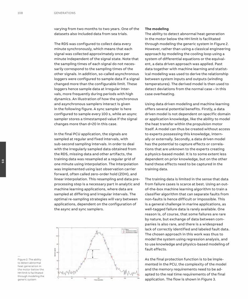
varying from two months to two years. one of the datasets also included data from sea trials.
the rDs was configured to collect data every minute synchronously, which means that each signal was collected approximately once per minute independent of the signal state. note that the sampling times of each signal do not neces-sarily correspond to the sampling times of the other signals. in addition, so-called asynchronous loggers were configured to sample data if a signal changed more than the configurable limit. these loggers hence sample data at irregular inter-vals, more frequently during periods with high dynamics. an illustration of how the synchronous and asynchronous samplers interact is given in the following figure. a sync sampler is here configured to sample every 100 s, while an async sampler stores a timestamped value if the signal changes more than d=20 in this case. in the final PCU application, the signals are sampled at regular and fixed intervals, with sub-second sampling intervals. in order to deal with the irregularly sampled data obtained from the rDs, missing data and other artifacts, the training data was resampled at a regular grid of one minute using interpolation. the interpolation was implemented using last observation carrier forward, often called zero-order hold (ZoH), and linear interpolation. this resampling and data pre-processing step is a necessary part in analytic and machine learning applications, where data are sampled at differing and irregular intervals. the optimal re-sampling strategies will vary between applications, dependent on the configuration of the async and sync samplers.
The modelingthe ability to detect abnormal heat generation in the motor below the HH limit is facilitated through modeling the generic system in Figure 2. However, rather than using a classical engineering approach by modeling the cooling loop using a system of differential equations or the equival-ent, a data driven approach was applied. Past data together with machine learning and statist-ical modeling was used to derive the relationship between system inputs and outputs (winding temperatures). the derived model is then used to detect deviations from the normal case – in this case overheating.
Using data driven modeling and machine learning offers several potential benefits. Firstly, a data driven model is not dependent on specific domain or application knowledge, like the ability to model the heat transfer within the propulsion motor itself. a model can thus be created without access to experts possessing this knowledge, intern-ally or externally. secondly, a data driven model has the potential to capture effects or correla-tions that are unknown to the experts creating a physics-based model. it is to some extent less dependent on prior knowledge, but on the other hand these effects need to be captured in the training data.
the training data is limited in the sense that data from failure cases is scarce at best. Using an out-of-the-box machine learning algorithm to train a classifier algorithm that can separate faults from non-faults is hence difficult or impossible. this is a general challenge in marine applications, as well-tagged failure data is rarely available. one reason is, of course, that some failures are rare by nature, but exchange of data between com-panies is also rare, and there is a widespread lack of correctly identified and labeled fault data. the chosen approach in this work was thus to model the system using regression analysis, and to use knowledge and physics-based modeling of fault effects.
as the final protection function is to be imple-mented in the PCU, the complexity of the model and the memory requirements need to be ad-apted to the real time requirements of the final application. the flow is shown in Figure 3.
—Figure 2: The ability to detect abnormal heat generation in the motor below the hh limit is facilitated through modeling the generic system
108 GenerATions
05
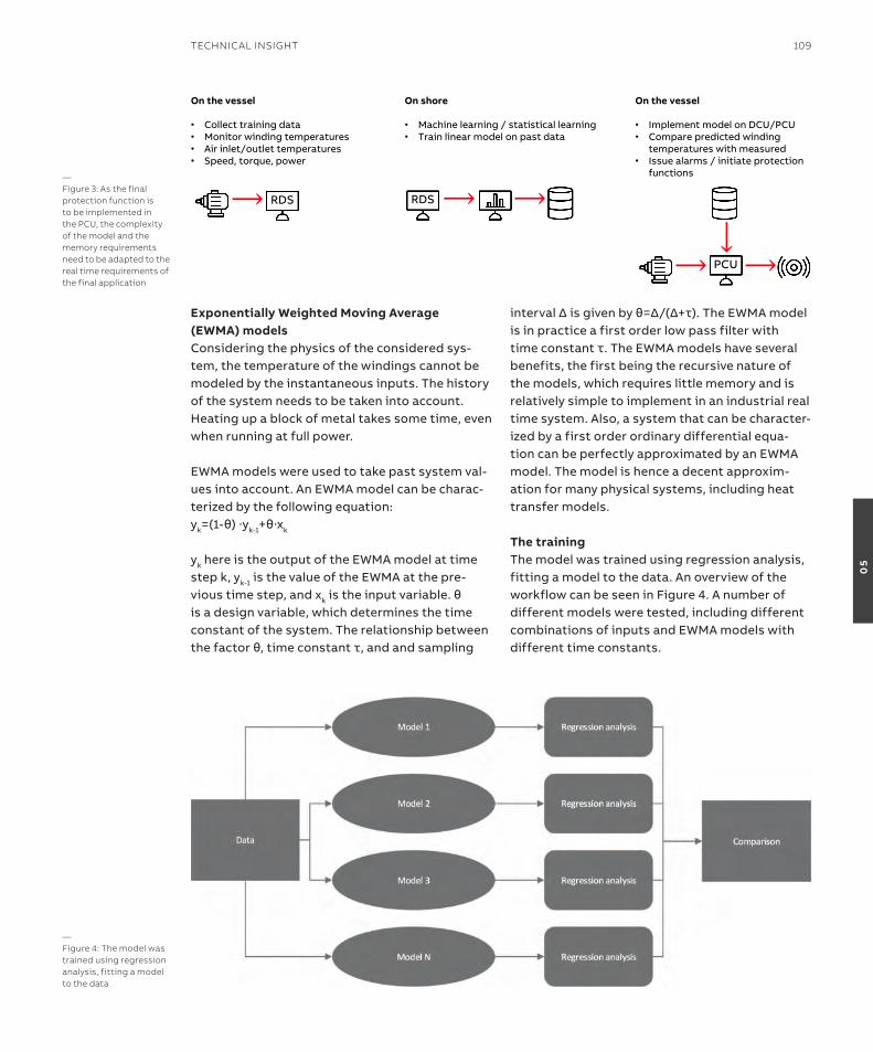
Exponentially Weighted Moving average (EWMa) models Considering the physics of the considered sys-tem, the temperature of the windings cannot be modeled by the instantaneous inputs. the history of the system needs to be taken into account. Heating up a block of metal takes some time, even when running at full power.
eWMa models were used to take past system val-ues into account. an eWMa model can be charac-terized by the following equation:yk=(1-θ)∙yk-1+θ∙xk
yk here is the output of the eWMa model at time step k, yk-1 is the value of the eWMa at the pre-vious time step, and xkistheinputvariable.θis a design variable, which determines the time constant of the system. the relationship between thefactorθ,timeconstantτ,andandsampling
intervalΔisgivenbyθ=Δ/(Δ+τ).TheEWMAmodelis in practice a first order low pass filter with timeconstantτ.TheEWMAmodelshaveseveralbenefits, the first being the recursive nature of the models, which requires little memory and is relatively simple to implement in an industrial real time system. also, a system that can be character-ized by a first order ordinary differential equa-tion can be perfectly approximated by an eWMa model. the model is hence a decent approxim-ation for many physical systems, including heat transfer models.
The trainingthe model was trained using regression analysis, fitting a model to the data. an overview of the workflow can be seen in Figure 4. a number of different models were tested, including different combinations of inputs and eWMa models with different time constants.
On the vessel
• Collect training data• Monitor winding temperatures• Air inlet/outlet temperatures• Speed, torque, power
On shore
• Machine learning / statistical learning• Train linear model on past data
On the vessel
• Implement model on DCU/PCU• Compare predicted winding
temperatures with measured• Issue alarms / initiate protection
functions
⟶ RDS RDS ⟶ ⟶
⟶ PCU ⟶
⟶—Figure 3: As the final protection function is to be implemented in the PCU, the complexity of the model and the memory requirements need to be adapted to the real time requirements of the final application
—Figure 4: The model was trained using regression analysis, fitting a model to the data
TeChniCAl insiGhT 109
05

the performance of the monitors was evaluated using a measure of accuracy called the root Mean square error (rMse), which is given by the follow-ing equation: RMSE=√(∑(tp-t)2)
note that in the final application, we are not very concerned with the rMse, but rather with the following parameters:• the false alarm rate• the probability of missed detection given a fault• the time to detection given a fault
the rMse is still a useful measure of the accuracy of the model, even though the three parameters also depend on other statistical properties of the model residual.
several similar models and parameter combina-tions were shown to provide similar accuracy in the sense of rMse. However, the following model was selected based on the following criteria:•Minimize the number of variables • Use physical knowledge where available – know that
the heat generation is a function of torque squared
the selected model is given by the following equation, where the inputs are described in the table below.
a lagged variable here means that the variable is used as input to a eWMa model.
note that the structure of the model is relatively simple, and only the values of the eWMa models at the previous time steps are stored in memory. this means that the model and monitor can be implemented without requiring significant com-putational power or memory.
an example of comparison between the predicted and actual temperatures on a motor, with data recorded during sea trial, is shown in Figure 5.
the plot shows how the prediction is close to the winding temperatures, with an error smaller than 10 degrees Kelvin. the data and corresponding estimates are from a sea trial, from a motor that was not included in the training data.
in the verification phase, leave-ship-out and leave-motor-out where used to verify that the model was not overfitted to the training data. When running a leave-motor-out analysis, a single motor was left out of the training data when estimating the para-meters of the model. the model was then tested on the left-out motor, to check the degree of fit. in addition to leave-ship and leave-motor-out
Parameter Description Units
tin Cooling air inlet temperature at time k Degrees Celsius
tout Cooling air outlet temperature at time k Degrees Celsius
P Power at time k % of max power
P2 Power squared at time k (% of max power)^2
P2 lag Lagged squared power calculated recursively using squared power
as input variable, and a given time constant(% of max power)^2
t absolute value of torque at time k % of max torque
tlag Lagged torque calculated recursively using absolute value of torque as input variable, and a given time constant
% of max torque
t2 torque squared at time k (% of max torque)^2
t2 lag Lagged squared torque calculated recursively using squared
torque as input variable, and a given time constant(% of max torque)^2
P · t absolute value of power multiplied by absolute value of torque (% of max power) *(% of max torque)
tp(k) = a0 + a1 · tin + a2 · tout + a3 · P2 + a4 · P
2 lag + a5 · t + a6 · tlag + a7 · t
2 + a8 · t2 lag + a9 · P · t
110 GenerATions
05
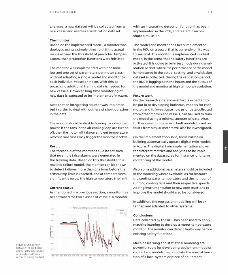
analyses, a new dataset will be collected from a new vessel and used as a verification dataset.
The monitorBased on the implemented model, a monitor was deployed using a simple threshold. if the actual minus exceed the threshold of predicted temper-atures, then protection functions were initiated.
the monitor was implemented with one mon-itor and one set of parameters per motor class, without adapting a single model and monitor to each individual vessel or motor. With this ap-proach, no additional training data is needed for new vessels. However, long time monitoring of new data is expected to be implemented in azure.
note that an integrating counter was implemen-ted in order to deal with outliers of short duration in the data.
the monitor should be disabled during periods of zero power. if the fans in the air cooling loop are turned off, then the motor will take on ambient temperature, which in rare cases may trigger the monitor if active.
resultthe threshold of the monitor could be set such that no single false alarms were generated in the training data. Based on this threshold and a realistic failure model, the monitor can be shown to detect failures more than one hour before the critical trip limit is reached, and at temperatures significantly below the high temperature trip limit.
Current statusas mentioned in a previous section, a monitor has been trained for two classes of vessels. a monitor
with an integrating detection function has been implemented in the PCU, and tested in an on-shore simulation.
the model and monitor has been implemented in the PCU on a vessel that is currently on its way to sea trial. the monitor is implemented in a test mode, in the sense that no safety functions are activated. it is going to be in test mode during a val-idation period, where the performance of the model is monitored in the actual setting, and a validation dataset is collected. During the validation period, the rDs is logging both the inputs and the output of the model and monitor at high temporal resolution.
Future workon the research side, some effort is expected to be put in to developing individual models for each motor, and to investigate how prior data collected from other motors and vessels, can be used to train the model using a minimal amount of data. also, further developing generic fault models based on faults from similar motors will also be investigated.
on the implementation side, focus will be on building automatically update digital twin models in azure. the digital twin implementation allows for different metrics and analytics to be imple-mented on the dataset, as for instance long term monitoring of the model.
also, some additional parameters should be included in the modeling where available, as for instance the cooling water temperature and the number of running cooling fans and their respective speeds. adding instrumentation to new constructions to improve the model should also be considered.
in addition, the regression modelling will be ex-tended and adapted to other systems.
ConclusionsData collected by the rDs has been used to apply machine learning to develop a motor temperature monitor. the monitor can detect faults way before existing safety functions.
Machine learning and statistical modeling are powerful tools for developing equipment models; digital twin models that simulate the normal func-tion of a local system or piece of equipment.
—Figure 5: Comparison between the predicted and actual temperatures on a motor, with data recorded during sea trial
TeChniCAl insiGhT 111
05

in reducing operational cost, either directly by reducing fuel consumption or indirectly by avoid-ing emission penalties, the motivation to install batteries is increasing. this can be achieved in several ways:• Certain areas have local restrictions on the use
of fossil fuels close to harbors and cities, and in environmentally sensitive areas – a large battery can be charged with renewable energy from a shore connection for use during transit.
• Fuel efficiency is improved by having batteries supply transient loads or by replacing engines for redundancy purposes.
When employing batteries, operators must man-age both the constraint of limited energy and a dynamic power capacity. Presenting the battery capacity as always available to the propulsion will result in a battery that will simply run flat. Care-ful considerations on how and when to restrict
—Battery power on boardMaximizing the benefitsWith the recent rise in the number of hybrid and fully electric vessels, battery power is establishing itself as a real force for change towards more sustainable and energy efficient operations. however, the full benefits of this technology can only be achieved with an advanced power management system on board.
håVarD KNaPPsKoGProduct ownerPower and energy Management systemABB Marine & Ports
ola hJuKsEProduct Area ManagerDs Power ProductsABB Marine & Ports
—Figure 1: A battery can take the rapid variations and let the engines deliver the mean load on the power plant
112 GenerATions
05
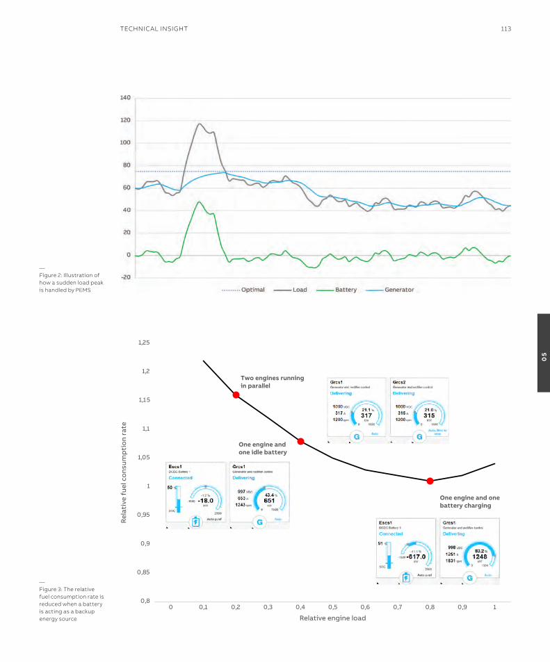
—Figure 2: illustration of how a sudden load peak is handled by PeMs
4/25/19 8
Two engines running in parallel
One engine and one idle battery
One engine and one battery charging
0,8
0,85
0,9
0,95
1
1,05
1,1
1,15
1,2
1,25
0 0,1 0,2 0,3 0,4 0,5 0,6 0,7 0,8 0,9 1
Rel
ativ
e fu
el c
ons
ump
tio
n ra
te
Relative engine load
—Figure 3: The relative fuel consumption rate is reduced when a battery is acting as a backup energy source
TeChniCAl insiGhT 113
05
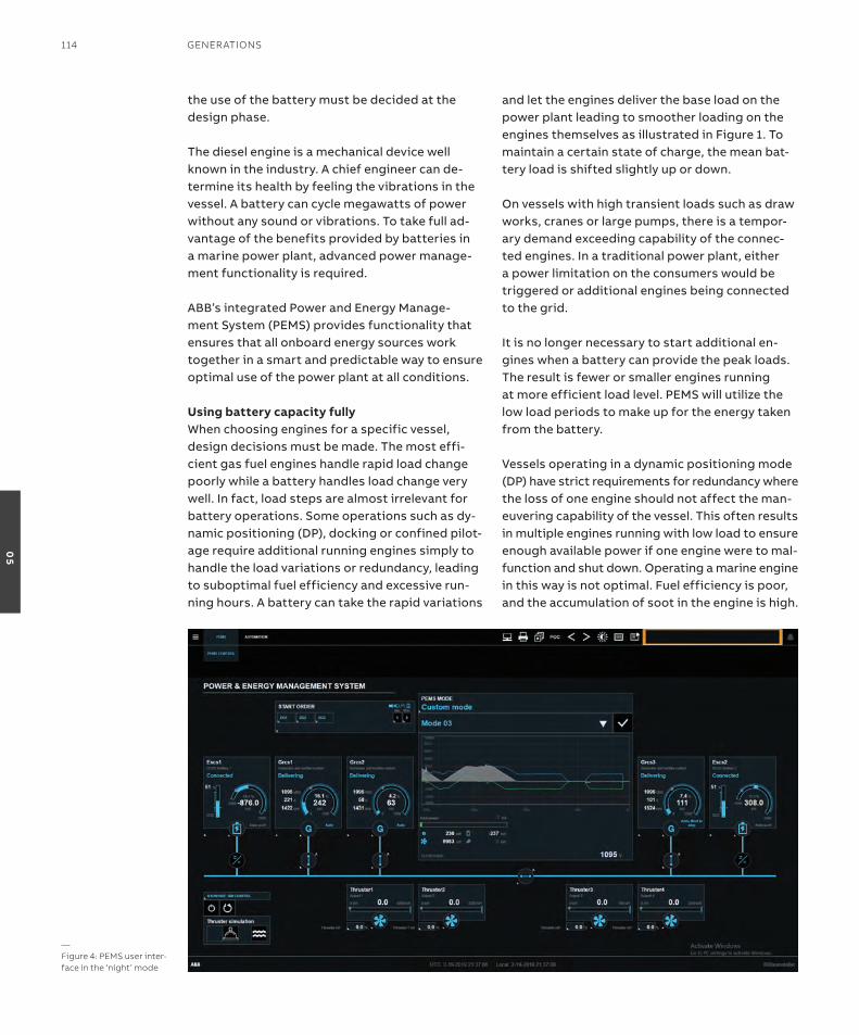
the use of the battery must be decided at the design phase.
the diesel engine is a mechanical device well known in the industry. a chief engineer can de-termine its health by feeling the vibrations in the vessel. a battery can cycle megawatts of power without any sound or vibrations. to take full ad-vantage of the benefits provided by batteries in a marine power plant, advanced power manage-ment functionality is required.
aBB’s integrated Power and energy Manage-ment system (PeMs) provides functionality that ensures that all onboard energy sources work together in a smart and predictable way to ensure optimal use of the power plant at all conditions.
using battery capacity fullyWhen choosing engines for a specific vessel, design decisions must be made. the most effi-cient gas fuel engines handle rapid load change poorly while a battery handles load change very well. in fact, load steps are almost irrelevant for battery operations. some operations such as dy-namic positioning (DP), docking or confined pilot-age require additional running engines simply to handle the load variations or redundancy, leading to suboptimal fuel efficiency and excessive run-ning hours. a battery can take the rapid variations
and let the engines deliver the base load on the power plant leading to smoother loading on the engines themselves as illustrated in Figure 1. to maintain a certain state of charge, the mean bat-tery load is shifted slightly up or down. on vessels with high transient loads such as draw works, cranes or large pumps, there is a tempor-ary demand exceeding capability of the connec-ted engines. in a traditional power plant, either a power limitation on the consumers would be triggered or additional engines being connected to the grid.
it is no longer necessary to start additional en-gines when a battery can provide the peak loads. the result is fewer or smaller engines running at more efficient load level. PeMs will utilize the low load periods to make up for the energy taken from the battery. Vessels operating in a dynamic positioning mode (DP) have strict requirements for redundancy where the loss of one engine should not affect the man-euvering capability of the vessel. this often results in multiple engines running with low load to ensure enough available power if one engine were to mal-function and shut down. operating a marine engine in this way is not optimal. Fuel efficiency is poor, and the accumulation of soot in the engine is high.
—Figure 4: PeMs user inter-face in the ‘night’ mode
114 GenerATions
05
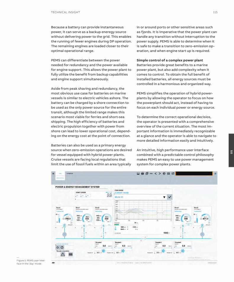
Because a battery can provide instantaneous power, it can serve as a backup eneregy source without delivering power to the grid. this enables the running of fewer engines during DP operation. the remaining engines are loaded closer to their optimal operational range.
PeMs can differentiate between the power needed for redundancy and the power available for engine support. this allows the power plant to fully utilize the benefit from backup capabilities and engine support simultaneously. aside from peak shaving and redundancy, the most obvious use case for batteries on marine vessels is similar to electric vehicles ashore. the battery can be charged by a shore connection to be used as the only power source for the entire transit, although the limited range makes this scenario most viable for ferries and short-sea shipping. the high efficiency of batteries and electric propulsion together with power from shore can lead to lower operational cost, depend-ing on the energy cost at the point of connection.
Batteries can also be used as a primary energy source when zero-emission operations are desired for vessel equipped with hybrid power plants. Cruise vessels are facing local regulations that limit the use of fossil fuels within an area typically
in or around ports or other sensitive areas such as fjords. it is imperative that the power plant can handle any transition without interruption to the power supply. PeMs is able to determine when it is safe to make a transition to zero-emission op-eration, and when engine start up is required.
simple control of a complex power plantBatteries provide great benefits to a marine power plant, but also add complexity when it comes to control. to obtain the full benefit of installed batteries, all energy sources must be controlled in a harmonious and organized way.
PeMs simplifies the operation of hybrid power-plants by allowing the operator to focus on how the powerplant should act, instead of having to focus on each individual power or energy source.
to determine the correct operational decisios, the operator is presented with a comprehensive overview of the current situation. the most im-portant information is immediately recognizable at a glance and the operator is able to navigate to more detailed information easily and intuitively.
an intuitive, high performance user interface combined with a predictable control philosophy makes PeMs an easy to use power management system for complex power plants.
—Figure 5: PeMs user inter-face in the ‘day’ mode
TeChniCAl insiGhT 115
05
With the increasing focus on environmental conservation actions from all sectors, concerns have been raised over the expected increase in emissions from the shipping industry with the potential rise in international shipping. in re-sponse, the international Maritime organization (iMo) set out to cut carbon emissions by half in 20501 and implement stringent limits on soX and noX in emission Control areas (eCas)2.
With the new regulations, ship operators are faced with increasing pressure to find solutions for more energy-efficient operations. Conven-tionally, ships have been designed using a single operating point as a reference where the energy sources can be tuned at the highest efficiency level. such method has been proven optimal for ocean going vessels, such as container ships. However, such approach may not be ideal for other vessel types, such as tugboats and offshore supply vessels (osVs), where the operational pro-file is dynamic, which means that energy efficient operations cannot be guaranteed.
the so-called ‘tugboat dilemma’ is an example, where tugs are designed according to their
maximum bollard pull, but they rarely operate in that range. the three main modes of a harbor tug operation can be broadly categorized as ‘(i) transit’, ‘(ii) standby or idle’, and ‘(iii) ship assist operation’. the power requirements and dura-tion of each operation mode are vastly different, which can be seen from the tug’s load distribu-tion as shown in Figure 1, represented by the solid black line. specifically, tugs have been known to spend only a fraction of the operation time in the ship assist mode, while majority of the time (>80 percent) they are in the transit and standby mode where the power requirements are significantly lower. in comparison with the specific fuel oil con-sumption (sFoC) of the engine shown in dotted line shown in Figure 1, it can be clearly seen that the engine operates below the fuel-efficient range most of the time, leading to higher fuel con-sumption and greenhouse gas (GHG) emissions. electric propulsion can offer a solution to address the challenges of poor fuel efficiency for such vessels. in 2010, aBB introduced its onboard DC Grid™ power distribution system, which has since then demonstrated reduction of carbon foot-print for a number of vessel types. the DC-based
With the increasingly stringent environmental regulations, shipowners and operators are facing the pressures of switching to more energy-efficient operations. With optimization-based power management control strategies, forward-thinking owners can unlock efficiencies that not only help achieve more sustainable operation, but also reduce operational costs.
liza ChuaAssociate r&D engineerelectric solutionsABB Marine & Ports
riCKy ChaNr&D Managerelectric solutionsABB Marine & Ports
TEGoEh TJahJoWiDoDoAssociate ProfessornTU
GEralD sEETAssociate ProfessornTU
—optimizing fuel efficiency and emission reduction through intelligent power management for hybrid electric vessels
116 GenerATions
05
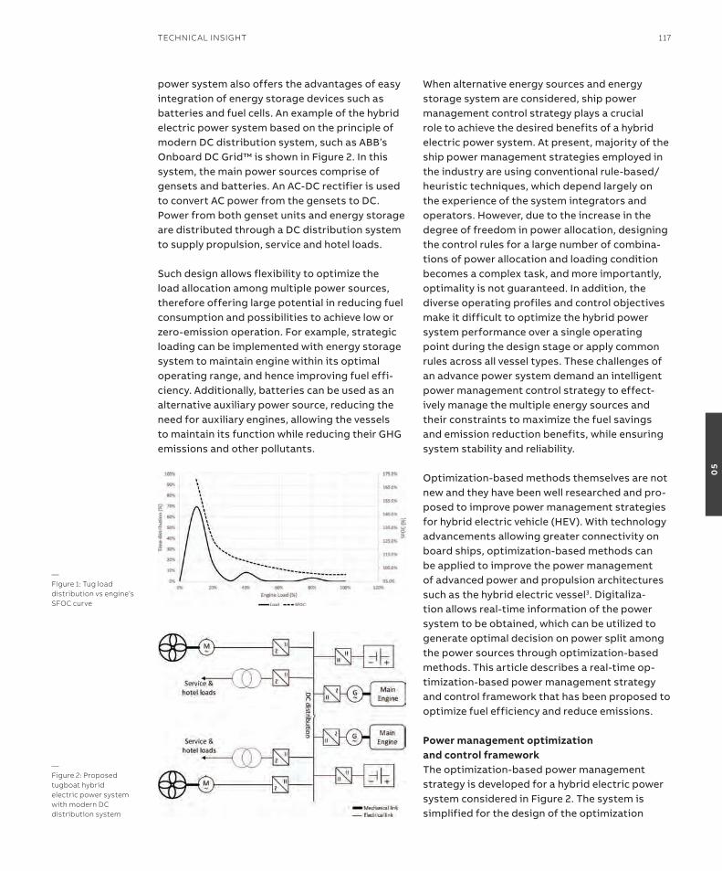
power system also offers the advantages of easy integration of energy storage devices such as batteries and fuel cells. an example of the hybrid electric power system based on the principle of modern DC distribution system, such as aBB’s onboard DC Grid™ is shown in Figure 2. in this system, the main power sources comprise of gensets and batteries. an aC-DC rectifier is used to convert aC power from the gensets to DC. Power from both genset units and energy storage are distributed through a DC distribution system to supply propulsion, service and hotel loads.
such design allows flexibility to optimize the load allocation among multiple power sources, therefore offering large potential in reducing fuel consumption and possibilities to achieve low or zero-emission operation. For example, strategic loading can be implemented with energy storage system to maintain engine within its optimal operating range, and hence improving fuel effi-ciency. additionally, batteries can be used as an alternative auxiliary power source, reducing the need for auxiliary engines, allowing the vessels to maintain its function while reducing their GHG emissions and other pollutants.
When alternative energy sources and energy storage system are considered, ship power management control strategy plays a crucial role to achieve the desired benefits of a hybrid electric power system. at present, majority of the ship power management strategies employed in the industry are using conventional rule-based/heuristic techniques, which depend largely on the experience of the system integrators and operators. However, due to the increase in the degree of freedom in power allocation, designing the control rules for a large number of combina-tions of power allocation and loading condition becomes a complex task, and more importantly, optimality is not guaranteed. in addition, the diverse operating profiles and control objectives make it difficult to optimize the hybrid power system performance over a single operating point during the design stage or apply common rules across all vessel types. these challenges of an advance power system demand an intelligent power management control strategy to effect-ively manage the multiple energy sources and their constraints to maximize the fuel savings and emission reduction benefits, while ensuring system stability and reliability.
optimization-based methods themselves are not new and they have been well researched and pro-posed to improve power management strategies for hybrid electric vehicle (HeV). With technology advancements allowing greater connectivity on board ships, optimization-based methods can be applied to improve the power management of advanced power and propulsion architectures such as the hybrid electric vessel3. Digitaliza-tion allows real-time information of the power system to be obtained, which can be utilized to generate optimal decision on power split among the power sources through optimization-based methods. this article describes a real-time op-timization-based power management strategy and control framework that has been proposed to optimize fuel efficiency and reduce emissions. Power management optimization and control frameworkthe optimization-based power management strategy is developed for a hybrid electric power system considered in Figure 2. the system is simplified for the design of the optimization
—Figure 1: Tug load distribution vs engine’s sFoC curve
—Figure 2: Proposed tugboat hybrid electric power system with modern DC distribution system
TeChniCAl insiGhT 117
05
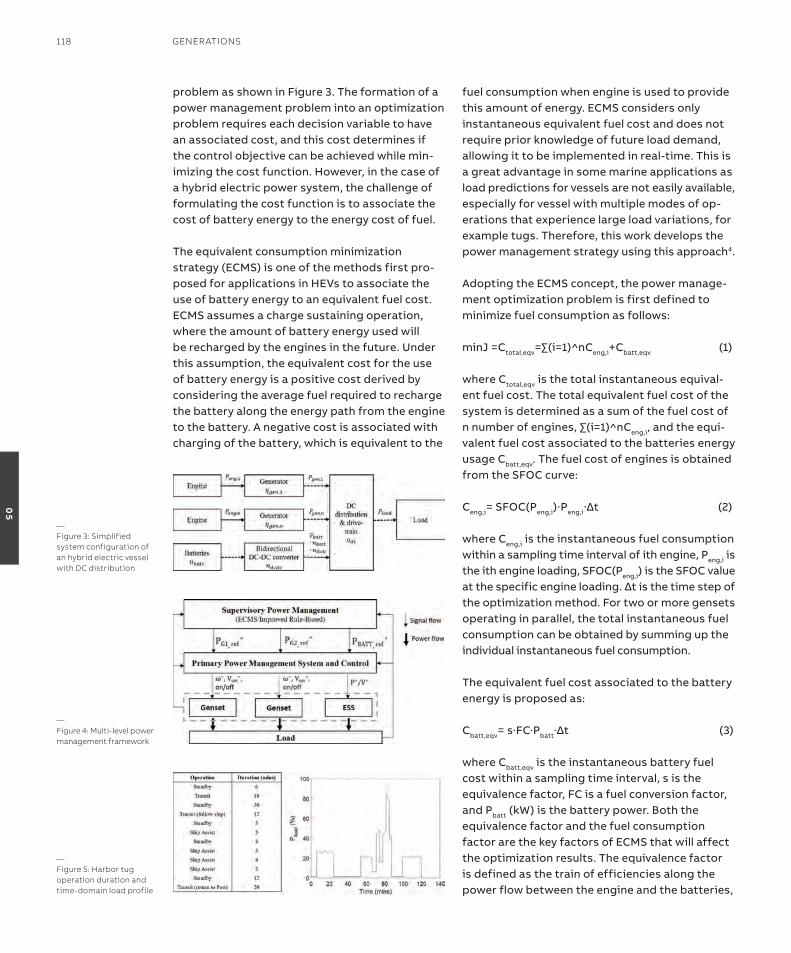
problem as shown in Figure 3. the formation of a power management problem into an optimization problem requires each decision variable to have an associated cost, and this cost determines if the control objective can be achieved while min-imizing the cost function. However, in the case of a hybrid electric power system, the challenge of formulating the cost function is to associate the cost of battery energy to the energy cost of fuel. the equivalent consumption minimization strategy (eCMs) is one of the methods first pro-posed for applications in HeVs to associate the use of battery energy to an equivalent fuel cost. eCMs assumes a charge sustaining operation, where the amount of battery energy used will be recharged by the engines in the future. Under this assumption, the equivalent cost for the use of battery energy is a positive cost derived by considering the average fuel required to recharge the battery along the energy path from the engine to the battery. a negative cost is associated with charging of the battery, which is equivalent to the
fuel consumption when engine is used to provide this amount of energy. eCMs considers only instantaneous equivalent fuel cost and does not require prior knowledge of future load demand, allowing it to be implemented in real-time. this is a great advantage in some marine applications as load predictions for vessels are not easily available, especially for vessel with multiple modes of op-erations that experience large load variations, for example tugs. therefore, this work develops the power management strategy using this approach4.
adopting the eCMs concept, the power manage-ment optimization problem is first defined to minimize fuel consumption as follows:
minJ =Ctotal,eqv=∑(i=1)^nCeng,i+Cbatt,eqv (1)
where Ctotal,eqv is the total instantaneous equival-ent fuel cost. the total equivalent fuel cost of the system is determined as a sum of the fuel cost of nnumberofengines,∑(i=1)^nCeng,i, and the equi-valent fuel cost associated to the batteries energy usage Cbatt,eqv. the fuel cost of engines is obtained from the sFoC curve:
Ceng,i= sFoC(Peng,i)∙Peng,i∙∆t (2)
where Ceng,i is the instantaneous fuel consumption within a sampling time interval of ith engine, Peng,i is the ith engine loading, sFoC(Peng,i) is the sFoC value atthespecificengineloading.∆tisthetimestepofthe optimization method. For two or more gensets operating in parallel, the total instantaneous fuel consumption can be obtained by summing up the individual instantaneous fuel consumption.
the equivalent fuel cost associated to the battery energy is proposed as:
Cbatt,eqv=s∙FC∙Pbatt∙∆t (3)
where Cbatt,eqv is the instantaneous battery fuel cost within a sampling time interval, s is the equivalence factor, FC is a fuel conversion factor, and Pbatt (kW) is the battery power. Both the equivalence factor and the fuel consumption factor are the key factors of eCMs that will affect the optimization results. the equivalence factor is defined as the train of efficiencies along the power flow between the engine and the batteries,
—Figure 3: simplified system configuration of an hybrid electric vessel with DC distribution
—Figure 4: Multi-level power management framework
—Figure 5: harbor tug operation duration and time-domain load profile
118 GenerATions
05
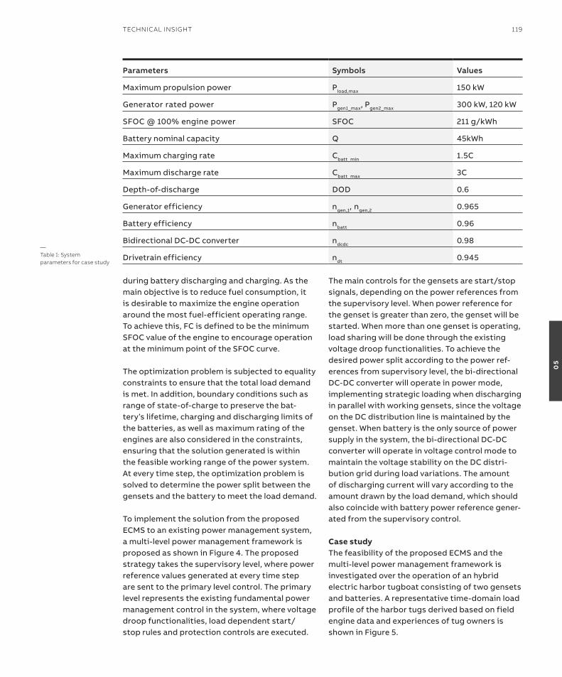
during battery discharging and charging. as the main objective is to reduce fuel consumption, it is desirable to maximize the engine operation around the most fuel-efficient operating range. to achieve this, FC is defined to be the minimum sFoC value of the engine to encourage operation at the minimum point of the sFoC curve.
the optimization problem is subjected to equality constraints to ensure that the total load demand is met. in addition, boundary conditions such as range of state-of-charge to preserve the bat-tery’s lifetime, charging and discharging limits of the batteries, as well as maximum rating of the engines are also considered in the constraints, ensuring that the solution generated is within the feasible working range of the power system. at every time step, the optimization problem is solved to determine the power split between the gensets and the battery to meet the load demand.
to implement the solution from the proposed eCMs to an existing power management system, a multi-level power management framework is proposed as shown in Figure 4. the proposed strategy takes the supervisory level, where power reference values generated at every time step are sent to the primary level control. the primary level represents the existing fundamental power management control in the system, where voltage droop functionalities, load dependent start/stop rules and protection controls are executed.
the main controls for the gensets are start/stop signals, depending on the power references from the supervisory level. When power reference for the genset is greater than zero, the genset will be started. When more than one genset is operating, load sharing will be done through the existing voltage droop functionalities. to achieve the desired power split according to the power ref-erences from supervisory level, the bi-directional DC-DC converter will operate in power mode, implementing strategic loading when discharging in parallel with working gensets, since the voltage on the DC distribution line is maintained by the genset. When battery is the only source of power supply in the system, the bi-directional DC-DC converter will operate in voltage control mode to maintain the voltage stability on the DC distri-bution grid during load variations. the amount of discharging current will vary according to the amount drawn by the load demand, which should also coincide with battery power reference gener-ated from the supervisory control.
Case study the feasibility of the proposed eCMs and the multi-level power management framework is investigated over the operation of an hybrid electric harbor tugboat consisting of two gensets and batteries. a representative time-domain load profile of the harbor tugs derived based on field engine data and experiences of tug owners is shown in Figure 5.
Parameters Symbols Values
Maximum propulsion power Pload,max 150 kW
Generator rated power Pgen1_max, Pgen2_max 300 kW, 120 kW
sFoC @ 100% engine power sFoC 211 g/kWh
Battery nominal capacity Q 45kWh
Maximum charging rate Cbatt_min 1.5C
Maximum discharge rate Cbatt_max 3C
Depth-of-discharge DoD 0.6
Generator efficiency ngen,1, ngen,2 0.965
Battery efficiency nbatt 0.96
Bidirectional DC-DC converter ndcdc 0.98
Drivetrain efficiency ndt 0.945—Table 1: system parameters for case study
TeChniCAl insiGhT 119
05
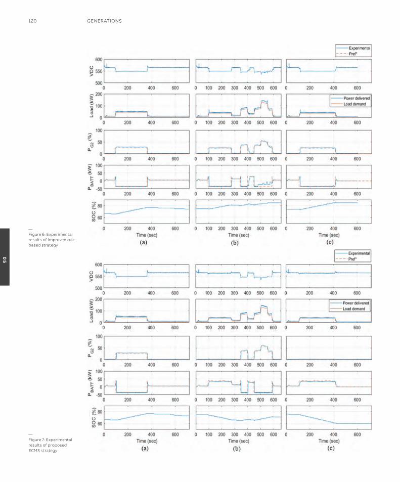
—Figure 7: experimental results of proposed eCMs strategy
—Figure 6: experimental results of improved rule-based strategy
120 GenerATions
05
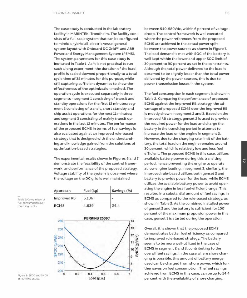
the case study is conducted in the laboratory facility in MarinteK, trondheim. the facility con-sists of a full-scale system that can be configured to mimic a hybrid all-electric vessel general system layout with onboard DC Grid™ and aBB Power and energy Management system (PeMs). the system parameters for this case study is indicated in table 1. as it is not practical to run such a long experiment, the duration of the load profile is scaled downed proportionally to a total cycle time of 35 minutes for this purpose, while still capturing sufficient dynamics to show the effectiveness of the optimization method. the operation cycle is executed separately in three segments – segment 1 consisting of transit and standby operations for the first 12 minutes; seg-ment 2 consisting of transit, short standby and ship assist operations for the next 11 minutes; and segment 3 consisting of mainly transit op-erations in the last 12 minutes. the performance of the proposed eCMs in terms of fuel savings is also evaluated against an improved rule-based strategy that is designed with the understand-ing and knowledge gained from the solutions of optimization-based strategies.
the experimental results shown in Figures 6 and 7 demonstrate the feasibility of the control frame-work, and performance of the proposed strategy. Voltage stability of the system is observed where the voltage on the DC grid is well maintained
between 540-580Vdc, within 6 percent of voltage droop. the control framework is well executed where the power references from the proposed eCMs are achieved in the actual power split between the power sources as shown in Figure 7. the load demand is met with soC of the battery is well kept within the lower and upper soC limit of 30 percent to 90 percent as set in the constraints. although the total power delivered to the load is observed to be slightly lesser than the total power delivered by the power sources, this is due to power transmission losses in the system.
the fuel consumption in each segment is shown in table 2. Comparing the performance of proposed eCMs against the improved rB strategy, the ad-vantage of proposed eCMs over the improved rB is mostly shown in segment 2 and 3. Based on the improved rB strategy, genset 2 is used to provide the required power for the load and charge the battery in the transiting period in attempt to increase the load on the engine in segment 2. However, due to the charging rate limit of the bat-tery, the total load on the engine remains around 30 percent, which is relatively low and less fuel efficient. the proposed eCMs in this case, utilizes available battery power during this transiting period, hence preventing the engine to operate at low engine loading. in segment 3, similarly, the improved rule-based utilizes both genset 2 and battery to provide power for the load, while eCMs utilizes the available battery power to avoid oper-ating the engine in less fuel-efficient range. this resulted in a substantial amount of fuel savings in eCMs as compared to the rule-based strategy, as shown in table 2. as the combined installed power of genset 2 and the battery is sufficient for 100 percent of the maximum propulsion power in this case, genset 1 is started during the operation.
overall, it is shown that the proposed eCMs demonstrates better fuel efficiency as compared to improved rule-based strategy. the battery seems to be more well-utilized in the case of eCMs in segment 2 and 3, contributing to the overall fuel savings. in the case where shore char-ging is possible, this amount of battery energy used can be charged from shore power, which fur-ther saves on fuel consumption. the fuel savings achieved from eCMs in this case, can be up to 24.4 percent with the availability of shore charging.
Approach Fuel (kg) Savings (%)
improved rB 6.136 -
eCMs 4.639 24.4
—Table 2: Comparison of fuel consumption over three segments
—Figure 8: sFoC and snox of PerKins 2506C
TeChniCAl insiGhT 121
05

Dealing with emissions – managing the trade-off between NoX emission and fuel consumptiona minimization of fuel consumption will lead to a reduction in emission only if the emission and fuel consumption are proportional. However, among the major composition of ship emissions (Co2, noX, so2, HC, Co, PM), a possible trade-off between noX emission and fuel consumption has been highlighted. an example is the specific noX emission (snoX) and sFoC curve as shown in Figure 85, where it can be observed that there is an increase in noX emission when fuel consump-tion is low in certain operating range. although there are existing technologies in the market such as exhaust gas recirculation (eGr) and selective catalytic reduction (sCr) to reduce noX emis-sions, such devices may have their constraints such as requiring addition operating power or space limitations on smaller vessels. therefore, the possibility to optimize noX emission reduc-tion and fuel consumption during engine oper-ation, through the power management control approach, is investigated.
With the validated performance of the proposed eCMs, the optimization strategy is extended to further consider the minimization of ship emis-sion. to manage the increase in fuel consumption due to the effects of noX emissions, a method is proposed to include a control weighting KnoX that defines the amount of priority given to noX emission reduction. the proposed cost function formulation is expressed as:
minG=(1-KnoX)∙Ctotal,eqv+KnoX∙Etotal,eqv (4)
where Ctotal,eqv represents the total equivalent fuel consumption defined in equation (1)-(3), and etotal,eqv is the total equivalent noX emission that can be obtained by replacing the sFoC terms in equation (1)-(3) to the engine’s snoX values. the value of KnoX is in the range of 0 to 1, where a value of 0 omits the noX emission and considers only fuel consumption in the optimization problem, while a value of 1 considers only noX emission. in this way, the ship operators are given the flex-ibility to prioritize between fuel efficient and
—Figure 9: simulation results of proposed approach at (a) Knox = 0 and (b) Knox = 0.6
122 GenerATions
05
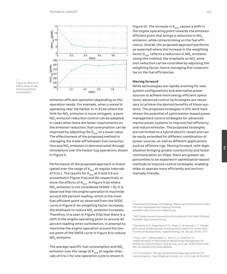
emission efficient operation depending on the operation needs. For example, when a vessel is operating near the harbor or in eCas where the limit for noX emission is more stringent, a pure noX emission reduction control can be adopted. in cases when there are lesser requirements on the emission reduction, fuel consumption can be improved by adjusting the KnoX to a lower value. the effectiveness of the proposed method in managing the trade-off between fuel consump-tion and noX emission is demonstrated through simulations over the harbor tug operations shown in Figure 5.
Performance of the proposed approach is invest-igated over the range of KnoX at regular intervals of 0 to 1. the results for KnoX at 0 and 0.6 are presented in Figure 9 (a) and (b) respectively to show the effects of KnoX. in Figure 9 (a) where noX emission is not considered (KnoX = 0), it is observed that the engine operation is maximize around 100 percent loading, which is the most fuel-efficient point as observed from the sFoC curve in Figure 8. as weighting factor increases, the emphasis to reduce noX emission increases. therefore, it is seen in Figure 9 (b) that there is a shift in the engine operating point to around 40 percent loading when switched on, in attempt to maximize the engine operation around the low-est point of the snoX curve in Figure 8 to reduce noX emission.
the average specific fuel consumption and noX emission over the range of KnoX at regular inter-vals of 0 to 1 for one operation cycle is shown in
Figure 10. the increase in KnoX causes a shift in the engine operating point towards the emission efficient point that brings a reduction in noX emission, while compromising on the fuel effi-ciency. overall, the proposed approach performs as expected where the increase in the weighting factor KnoX reflects a reduction in noX emission. Using this method, the emphasis on noX emis-sion reduction can be controlled by adjusting the weighting factor, hence managing the comprom-ise on the fuel efficiencies.
Moving forwardWhile technologies are rapidly evolving for new system configurations and alternative power sources to achieve more energy efficient opera-tions, advanced control technologies are neces-sary to achieve the desired benefits of these sys-tems. the proposed strategies in this work have shown the potential of optimization-based power management control strategies for advanced marine power systems to improve fuel efficiency and reduce emission. the proposed strategies are not limited to a hybrid electric vessel and can be easily extended for different combination of power sources, as well as different applications such as offshore rigs. Moving forward, with digit-alization bringing greater connectivity and faster communication on ships, there are greater op-portunities to be explored in optimization-based methods to improve control strategies, enabling ships to operate more efficiently and environ-mentally friendly.
—1 international Chamber of shipping, “reducing Co2 emissions to Zero: The ‘Paris Agreement for shipping’”[online].Available: http://www.ics-shipping.org
2 iMo,“Marpol annex Vi prevention of air pollution from ships.”[online]. Available: http://www.imo.org
3 Geertsma, r. D., negenborn, r. r., Visser, K., & hopman, J. J. “Design and control of hybrid power and propulsion systems for smart ships:A review of developments, “Applied energy, vol. 194, pp. 30-54., 2017.
4 Chua, l.W.y., Tjahjowidodo, T., seet, G.l.s. and Chan, r. “implementation of optimization-Based Power Management forAll-electric hybrid Vessels”, ieee Access, vol. 6, pp. 74339-74354, 2018.Doi: 10.1109/ACCess.2018.2883324.
5 h. o. Kristensen, “energy demand and exhaust gas emissions of marine engines”, Clean shipping Currents, vol. 1, no. 6, pp. 18-26, 2012.
—Figure 10: effects of Knox values on nox emission and fuel consumption
TeChniCAl insiGhT 123
05
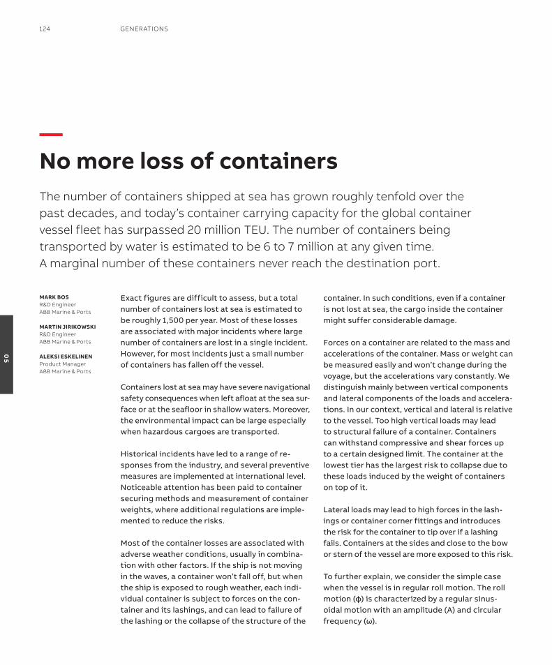
exact figures are difficult to assess, but a total number of containers lost at sea is estimated to be roughly 1,500 per year. Most of these losses are associated with major incidents where large number of containers are lost in a single incident. However, for most incidents just a small number of containers has fallen off the vessel.
Containers lost at sea may have severe navigational safety consequences when left afloat at the sea sur-face or at the seafloor in shallow waters. Moreover, the environmental impact can be large especially when hazardous cargoes are transported.
Historical incidents have led to a range of re-sponses from the industry, and several preventive measures are implemented at international level. noticeable attention has been paid to container securing methods and measurement of container weights, where additional regulations are imple-mented to reduce the risks.
Most of the container losses are associated with adverse weather conditions, usually in combina-tion with other factors. if the ship is not moving in the waves, a container won’t fall off, but when the ship is exposed to rough weather, each indi-vidual container is subject to forces on the con-tainer and its lashings, and can lead to failure of the lashing or the collapse of the structure of the
container. in such conditions, even if a container is not lost at sea, the cargo inside the container might suffer considerable damage.
Forces on a container are related to the mass and accelerations of the container. Mass or weight can be measured easily and won’t change during the voyage, but the accelerations vary constantly. We distinguish mainly between vertical components and lateral components of the loads and accelera-tions. in our context, vertical and lateral is relative to the vessel. too high vertical loads may lead to structural failure of a container. Containers can withstand compressive and shear forces up to a certain designed limit. the container at the lowest tier has the largest risk to collapse due to these loads induced by the weight of containers on top of it.
Lateral loads may lead to high forces in the lash-ings or container corner fittings and introduces the risk for the container to tip over if a lashing fails. Containers at the sides and close to the bow or stern of the vessel are more exposed to this risk.
to further explain, we consider the simple case when the vessel is in regular roll motion. the roll motion(φ)ischaracterizedbyaregularsinus-oidal motion with an amplitude (a) and circular frequency(ω).
MarK Bosr&D engineerABB Marine & Ports
MarTiN JiriKoWsKir&D engineerABB Marine & Ports
alEKsi EsKEliNENProduct ManagerABB Marine & Ports
—No more loss of containersThe number of containers shipped at sea has grown roughly tenfold over the past decades, and today’s container carrying capacity for the global container vessel fleet has surpassed 20 million TeU. The number of containers being transported by water is estimated to be 6 to 7 million at any given time. A marginal number of these containers never reach the destination port.
124 GenerATions
05

TeChniCAl insiGhT 125
05
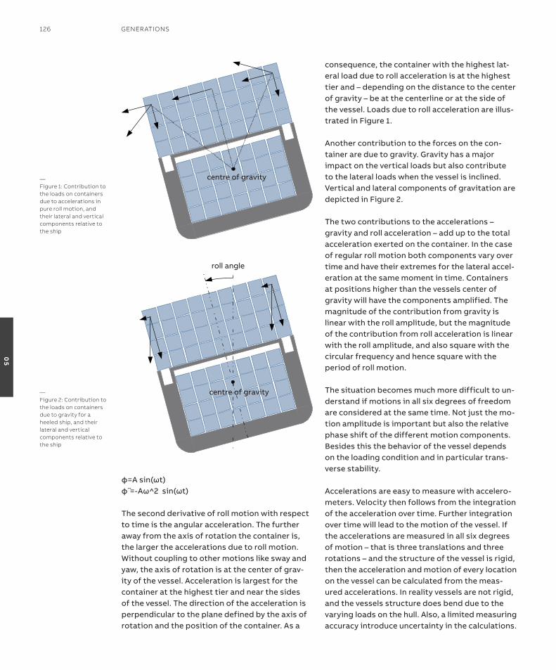
φ=Asin(ωt)φ̈=-Aω^2sin(ωt)
the second derivative of roll motion with respect to time is the angular acceleration. the further away from the axis of rotation the container is, the larger the accelerations due to roll motion. Without coupling to other motions like sway and yaw, the axis of rotation is at the center of grav-ity of the vessel. acceleration is largest for the container at the highest tier and near the sides of the vessel. the direction of the acceleration is perpendicular to the plane defined by the axis of rotation and the position of the container. as a
consequence, the container with the highest lat-eral load due to roll acceleration is at the highest tier and – depending on the distance to the center of gravity – be at the centerline or at the side of the vessel. Loads due to roll acceleration are illus-trated in Figure 1.
another contribution to the forces on the con-tainer are due to gravity. Gravity has a major impact on the vertical loads but also contribute to the lateral loads when the vessel is inclined. Vertical and lateral components of gravitation are depicted in Figure 2. the two contributions to the accelerations – gravity and roll acceleration – add up to the total acceleration exerted on the container. in the case of regular roll motion both components vary over time and have their extremes for the lateral accel-eration at the same moment in time. Containers at positions higher than the vessels center of gravity will have the components amplified. the magnitude of the contribution from gravity is linear with the roll amplitude, but the magnitude of the contribution from roll acceleration is linear with the roll amplitude, and also square with the circular frequency and hence square with the period of roll motion.
the situation becomes much more difficult to un-derstand if motions in all six degrees of freedom are considered at the same time. not just the mo-tion amplitude is important but also the relative phase shift of the different motion components. Besides this the behavior of the vessel depends on the loading condition and in particular trans-verse stability.
accelerations are easy to measure with accelero-meters. Velocity then follows from the integration of the acceleration over time. Further integration over time will lead to the motion of the vessel. if the accelerations are measured in all six degrees of motion – that is three translations and three rotations – and the structure of the vessel is rigid, then the acceleration and motion of every location on the vessel can be calculated from the meas-ured accelerations. in reality vessels are not rigid, and the vessels structure does bend due to the varying loads on the hull. also, a limited measuring accuracy introduce uncertainty in the calculations.
—Figure 1: Contribution to the loads on containers due to accelerations in pure roll motion, and their lateral and vertical components relative to the ship
—Figure 2: Contribution to the loads on containers due to gravity for a heeled ship, and their lateral and vertical components relative to the ship
centre of gravity
roll angle
centre of gravity
126 GenerATions
05
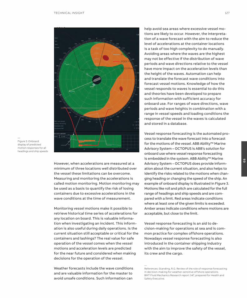
However, when accelerations are measured at a minimum of three locations well distributed over the vessel these limitations can be overcome. Measuring and monitoring the accelerations is called motion monitoring. Motion monitoring may be used as a basis to quantify the risk of losing containers due to excessive accelerations in the wave conditions at the time of measurement.
Monitoring vessel motions make it possible to retrieve historical time series of accelerations for any location on board. this is valuable informa-tion when investigating an incident. this inform-ation is also useful during daily operations. is the current situation still acceptable or critical for the containers and lashings? the real value for safe operation of the vessel comes when the vessel motions and acceleration levels are predicted for the near future and considered when making decisions for the operation of the vessel.
Weather forecasts include the wave conditions and are valuable information for the master to avoid unsafe conditions. such information can
help avoid sea areas where excessive vessel mo-tions are likely to occur. However, the interpreta-tion of a wave forecast with the aim to reduce the level of accelerations at the container locations is a task of too high complexity to do manually. avoiding areas where the waves are the highest may not be effective if the distribution of wave periods and wave directions relative to the vessel have more impact on the acceleration levels than the height of the waves. automation can help and translate the forecast wave conditions into forecast vessel motions. Knowledge of how the vessel responds to waves is essential to do this and theories have been developed to prepare such information with sufficient accuracy for onboard use. For ranges of wave directions, wave periods and wave heights in combination with a range in vessel speeds and loading conditions the response of the vessel in the waves is calculated and stored in a database.
Vessel response forecasting is the automated pro-cess to translate the wave forecast into a forecast for the motions of the vessel. aBB ability™ Marine advisory system – oCtoPUs is aBB’s solution for onboard use where vessel response forecasting is embedded in the system. aBB ability™ Marine advisory system – oCtoPUs does provide inform-ation about the current situation, and also helps to identify the risks related to the motions when chan-ging heading or changing the speed of the ship. an example of onboard display is illustrated in Figure 3. Motions like roll and pitch are calculated for the full range of headings and ship speeds and are com-pared with a limit. red areas indicate conditions where at least one of the given limits is exceeded. amber areas indicate conditions where motions are acceptable, but close to the limit. Vessel response forecasting is an aid to de-cision-making for operations at sea and is com-mon practice for complex offshore operations. nowadays vessel response forecasting is also introduced in the container shipping industry with the aim to improve the safety of the vessel, its crew and the cargo.
—references: standing, r.G. review of the role of response forecasting in decision-making for weather-sensitive offshore operations.BMT Fluid Mechanics research report 347, prepared for health and safety executive.
45
35
30
25
20
15
10
5
0477 480 483 486
Total P without lB
Total P with lB
lBU Total load
P [MW]
t [s]
40
PoD1 Power
PoD2 Power
PoD3 Power
—Figure 3: onboard display of predicted motion responses for all headings and ship speeds
TeChniCAl insiGhT 127
05
in passenger vessels, HVaC system is the second largest consumer of energy after propulsion. it is estimated that up to 30 percent of the total energy consumption of a passenger ship comes from HVaC systems used for cabins, public areas and galley ventilation. When the ship is berthed in the port, the HVaC system becomes the main energy consumer. needless to say, the HVaC system is not a negligible value, and the gains regarding energy efficiency are more than clear. With increasing fuel costs and fast approaching regulations for emission reductions, innovative developments from land-based systems are making their way into the marine markets to help meet these challenges. Where the energy savings come fromHVaC is the technology of indoor environmental comfort; its goal is to provide thermal comfort and acceptable indoor air quality. in passenger vessels, such as cruise ship or ferries, the HVaC system is essential for the passenger comfort.
the total energy consumption of a HVaC system can be divided by the following areas:• chillers• air handling units and fans• pumps
Chiller operationHVaC systems use chillers to cool water, which flows through coils, thus cooling the air in a room.
Chillers and rooms have separate thermostats. the room thermostat stops cooling the room down by regulating or closing the water flow through a coil, without affecting the chiller’s op-eration. on the other hand, the chiller’s thermo-stat does not directly affect the temperature in the rooms.
Chillers are designed to handle demanding weather conditions, such as high temperatures and humidity. as a rule, the water temperature is chosen by the installation company. For example, for an outdoor temperature of +30°C, the chiller may supply water at +6°C to provide the desired conditions inside the chilled spaces. But for a lower outdoor temperature, for instance +16°C, these conditions may be achieved with water at the temperature of +10°C or higher.
the higher the required water temperature, the lower the energy required to produce it. this hap-pens when the increase of a chiller’s efficiency – the CoP (Coefficient of Performance) – is higher for higher set points. in a chiller, the electrical power absorbed by the compressor motor depends on the pressure difference that the compressor has to produce. increasing the chilled water temper-ature set point causes a decrease in the pressure difference, which leads to a subsequent decrease in the absorbed power. increasing the chilled wa-ter temperature set point by +1°C takes down the electric power consumption by 3-4 percent.
—saving energy on board with aBB’s chiller optimization solutionABB’s chiller optimization targets the substantial hotel load required for a heating ventilation and air conditioning (hVAC) system on board passenger ships – and the solution gives consistent energy savings.
sErGio DiVaNosenior hVAC engineer ABB Marine & Ports
128 GenerATions
05
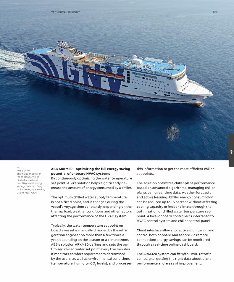
aBB arKM20 – optimizing the full energy saving potential of onboard hVaC systemsBy continuously optimizing the water temperature set point, aBB’s solution helps significantly de-crease the amount of energy consumed by a chiller.
the optimum chilled water supply temperature is not a fixed point, and it changes during the vessel’s voyage time constantly, depending on the thermal load, weather conditions and other factors affecting the performance of the HVaC system.
typically, the water temperature set point on board a vessel is manually changed by the refri-geration engineer no more than a few times a year, depending on the season or a climate zone. aBB’s solution arKM20 defines and sets the op-timized chilled water set point every five minutes. it monitors comfort requirements determined by the users, as well as environmental conditions (temperature, humidity, Co2 levels), and processes
this information to get the most efficient chiller set points.
the solution optimizes chiller plant performance based on advanced algorithms, managing chiller plants using real-time data, weather forecasts and active learning. Chiller energy consumption can be reduced up to 15 percent without affecting cooling capacity or indoor climate through the optimization of chilled water temperature set-point. a local onboard controller is interfaced to HVaC control system and chiller control panel.
Client interface allows for active monitoring and control both onboard and ashore via remote connection: energy savings can be monitored through a real-time online dashboard.
the arKM20 system can fit with HVaC retrofit campaigns, getting the right data about plant performance and areas of improvement.
—ABB’s chiller optimization solution for passenger ships has helped achieve over 18 percent energy savings on board ferry la suprema, operated by Grandi navi Veloci
TeChniCAl insiGhT 129
05
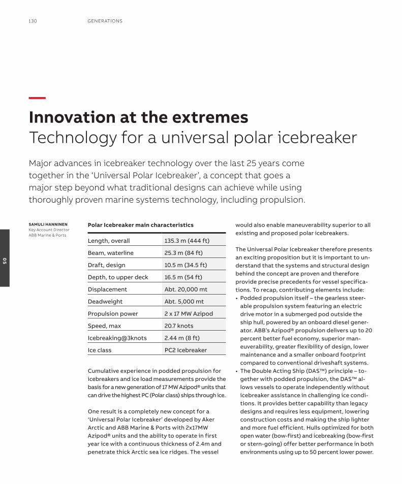
Polar icebreaker main characteristics
Cumulative experience in podded propulsion for icebreakers and ice load measurements provide the basis for a new generation of 17 MW azipod® units that can drive the highest PC (Polar class) ships through ice.
one result is a completely new concept for a ‘Universal Polar icebreaker’ developed by aker arctic and aBB Marine & Ports with 2x17MW azipod® units and the ability to operate in first year ice with a continuous thickness of 2.4m and penetrate thick arctic sea ice ridges. the vessel
would also enable maneuverability superior to all existing and proposed polar icebreakers.
the Universal Polar icebreaker therefore presents an exciting proposition but it is important to un-derstand that the systems and structural design behind the concept are proven and therefore provide precise precedents for vessel specifica-tions. to recap, contributing elements include:• Poddedpropulsionitself–thegearlesssteer-
able propulsion system featuring an electric drive motor in a submerged pod outside the ship hull, powered by an onboard diesel gener-ator. aBB’s azipod® propulsion delivers up to 20 percent better fuel economy, superior man-euverability, greater flexibility of design, lower maintenance and a smaller onboard footprint compared to conventional driveshaft systems.
• TheDoubleActingShip(DAS™)principle–to-gether with podded propulsion, the Das™ al-lows vessels to operate independently without icebreaker assistance in challenging ice condi-tions. it provides better capability than legacy designs and requires less equipment, lowering construction costs and making the ship lighter and more fuel efficient. Hulls optimized for both open water (bow-first) and icebreaking (bow-first or stern-going) offer better performance in both environments using up to 50 percent lower power.
Major advances in icebreaker technology over the last 25 years come together in the ‘Universal Polar icebreaker’, a concept that goes a major step beyond what traditional designs can achieve while using thoroughly proven marine systems technology, including propulsion.
saMuli haNNiNENKey Account DirectorABB Marine & Ports
—innovation at the extremesTechnology for a universal polar icebreaker
Length, overall 135.3 m (444 ft)
Beam, waterline 25.3 m (84 ft)
Draft, design 10.5 m (34.5 ft)
Depth, to upper deck 16.5 m (54 ft)
Displacement abt. 20,000 mt
Deadweight abt. 5,000 mt
Propulsion power 2 x 17 MW azipod
speed, max 20.7 knots
icebreaking@3knots 2.44 m (8 ft)
ice class PC2 icebreaker
130 GenerATions
05
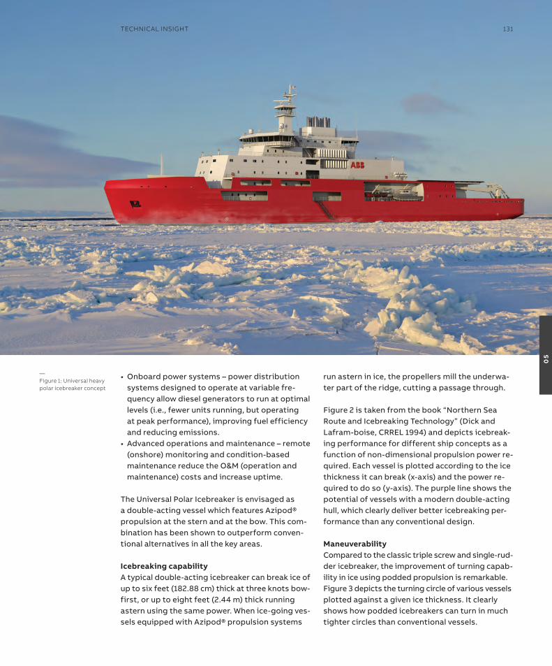
• Onboardpowersystems–powerdistributionsystems designed to operate at variable fre-quency allow diesel generators to run at optimal levels (i.e., fewer units running, but operating at peak performance), improving fuel efficiency and reducing emissions.
• Advancedoperationsandmaintenance–remote(onshore) monitoring and condition-based maintenance reduce the o&M (operation and maintenance) costs and increase uptime.
the Universal Polar icebreaker is envisaged as a double-acting vessel which features azipod® propulsion at the stern and at the bow. this com-bination has been shown to outperform conven-tional alternatives in all the key areas.
icebreaking capabilitya typical double-acting icebreaker can break ice of up to six feet (182.88 cm) thick at three knots bow-first, or up to eight feet (2.44 m) thick running astern using the same power. When ice-going ves-sels equipped with azipod® propulsion systems
run astern in ice, the propellers mill the underwa-ter part of the ridge, cutting a passage through.
Figure 2 is taken from the book “northern searoute and icebreaking technology” (Dick and Lafram-boise, CrreL 1994) and depicts icebreak-ing performance for different ship concepts as a function of non-dimensional propulsion power re-quired. each vessel is plotted according to the ice thickness it can break (x-axis) and the power re-quired to do so (y-axis). the purple line shows the potential of vessels with a modern double-acting hull, which clearly deliver better icebreaking per-formance than any conventional design. ManeuverabilityCompared to the classic triple screw and single-rud-der icebreaker, the improvement of turning capab-ility in ice using podded propulsion is remarkable. Figure 3 depicts the turning circle of various vessels plotted against a given ice thickness. it clearly shows how podded icebreakers can turn in much tighter circles than conventional vessels.
—Figure 1: Universal heavy polar icebreaker concept
TeChniCAl insiGhT 131
05
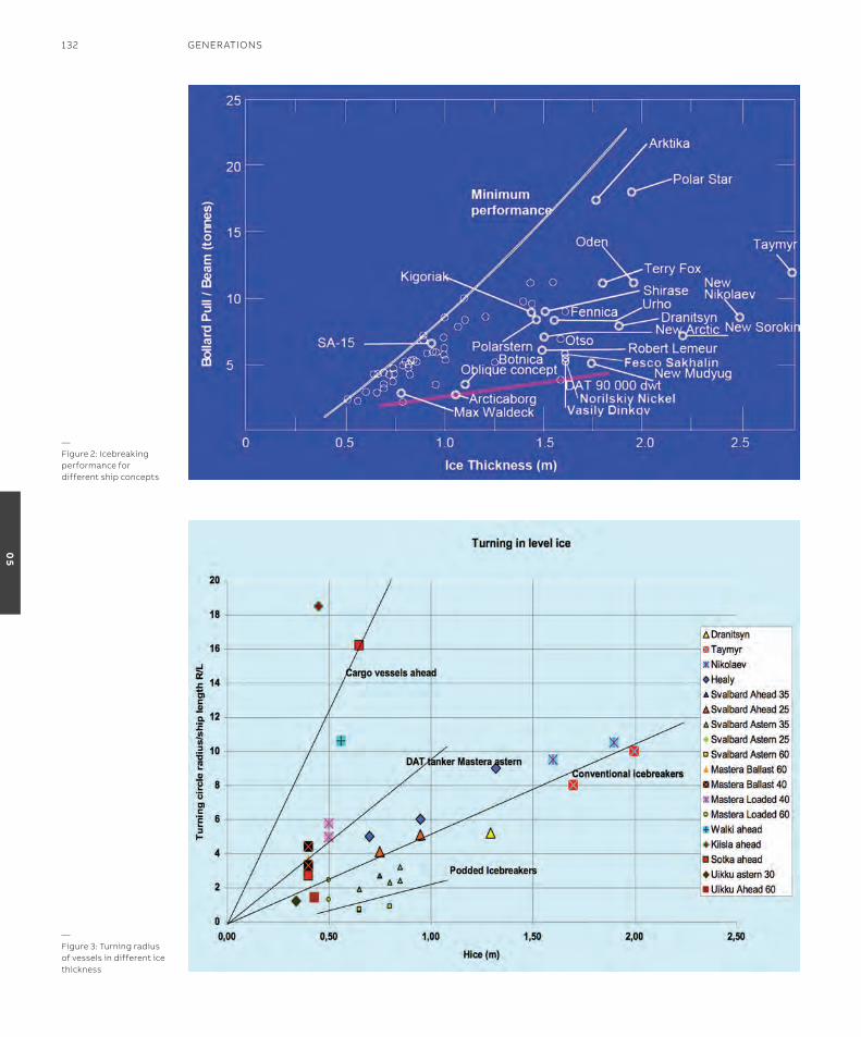
—Figure 2: icebreaking performance for different ship concepts
—Figure 3: Turning radius of vessels in different ice thickness
132 GenerATions
05

Fuel consumptionthe Das™ design combined with podded propul-sion offers a clear advantage in fuel economy, not only in icebreaking operations but in open water. the hull design reduces friction while the superior efficiency of the electric motors means that more of the combustion energy is converted into thrust.
Figure 4 compares the performance of vessels equipped with azipod® propulsion with conven-tional shaftline alternatives on a range of metrics. on almost every level, the combination of Das™ and podded propulsion delivers superior performance.
affordabilitythere are numerous affordability advantages to Das™ vessels with podded propulsion. First, podded systems are more compact and use sig-nificantly less equipment compared to traditional designs (Figure 5). By eliminating the need for the shaft, main engines, generators, rudders and auxiliary machinery, podded propulsion systems also reduce construction and equipment costs. in addition, space savings from the compact system provide the customer with more flexibility in ship design and mission. For example, a shipowner can
use the extra space on board for additional fuel storage, providing greater endurance and mission capability. shipowners can also reduce the overall size of the vessel, saving on materials.
secondly, Das™ vessels with podded propulsion are significantly more fuel efficient because the optimized hull design and the system’s reduced power requirement can in some cases lead to a 50 percent boost in efficiency over conventional driveshaft vessels, reducing fuel costs and in-creasing endurance.
the Dynamic aC, or DaC, power systems used in podded propulsion are designed specifically to operate at variable frequency, which allows the propulsion system to run at varying rPMs in response to changing demands. this has two benefits. it can deliver fuel savings of up to six percent compared to conventional power distri-bution systems and it allows the engines to run at optimal levels in relation to fuel economy and long-term durability while still delivering out-standing performance. this is especially import-ant in the constantly changing conditions that icebreakers encounter.
Ahead Astern
azipod® shaftline azipod® shaftline
old channel
ice ridges
Compressive ice
Channel widening
star turn
ice blocks left in broken channel
Breaking out of channel
ability to free from beset situation
Maneuvering
shallow water operation
seaworthiness
open water resistance
Freeing beset vessel
ability to dock in an ice-covered port —Figure 4
TeChniCAl insiGhT 133
05
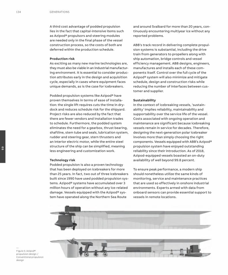
a third cost advantage of podded propulsion lies in the fact that capital-intensive items such as azipod® propulsors and steering modules are needed only in the final phase of the vessel construction process, so the costs of both are deferred within the production schedule.
Production riskas exciting as many new marine technologies are, they must also be viable in an industrial manufactur-ing environment. it is essential to consider produc-tion attributes early in the design and acquisition cycle, especially in cases where equipment faces unique demands, as is the case for icebreakers.
Podded propulsion systems like azipod® have proven themselves in terms of ease of installa-tion: the single lift requires cuts the time in dry-dock and reduces schedule risk for the shipyard. Project risks are also reduced by the fact that there are fewer vendors and installation trades to schedule. Furthermore, the podded system eliminates the need for a gearbox, thrust bearing, shaftline, stem tube and seals, lubrication system, rudder and steering gear, stern thrusters and an interior electric motor, while the entire steel structure of the ship can be simplified, meaning less engineering and customization work.
Technology riskPodded propulsion is also a proven technology that has been deployed on icebreakers for more than 25 years. in fact, two out of three icebreakers built since 1990 have used podded propulsion sys-tems. azipod® systems have accumulated over 3 million hours of operation without any ice-related damage. Vessels equipped with the azipod® sys-tem have operated along the northern sea route
and around svalbard for more than 20 years, con-tinuously encountering multiyear ice without any reported problems.
aBB’s track record in delivering complete propul-sion systems is substantial, including the drive train from generators to propellers along with ship automation, bridge controls and vessel efficiency management. aBB designs, engineers, manufactures and installs each of these com-ponents itself. Control over the full cycle of the azipod® system will also minimize and mitigate schedule, design and construction risks while reducing the number of interfaces between cus-tomer and supplier.
sustainabilityin the context of icebreaking vessels, ‘sustain-ability’ implies reliability, maintainability and supportability over the service life of the vessel. Costs associated with ongoing operation and maintenance are significant because icebreaking vessels remain in service for decades. therefore, designing the next-generation polar icebreaker involves more than simply choosing the right components. Vessels equipped with aBB’s azipod® propulsion system have enjoyed outstanding reliability since their introduction. as of 2018, azipod-equipped vessels boasted an on-duty availability of well beyond 99.8 percent.
to ensure peak performance, a modern ship should nonetheless utilize the same kinds of monitoring, service and maintenance practices that are used so effectively in onshore industrial environments. experts armed with data from onboard sensors can provide essential support to vessels in remote locations.
—Figure 5: Azipod® propulsion design / Conventional propulsion design
134 GenerATions
05

—Figure 6: oblique test widening the ice channel, and thruster orientation
—Figure 7: Turning in place and thruster orientation
TeChniCAl insiGhT 135
05

aBB has a long history providing such data-driven intelligence, both on shore and at sea, and re-cently established a 24/7 monitoring center at its Helsinki facility. the company is already monitor-ing close to 1,000 ships worldwide and expects to increase that number to 3,000 by 2020. the Hel-sinki facility, like a similar one opened in the U.s. in 2018, enables operators to identify and address potential problems early, reduce downtime and schedule risk.
Polaris is the first icebreaker to have benefited from a full size, bow mounted azipod® unit and started her first season in January 2017. as a DAS™vessel,PolarishasthreeAzipod®units−two in the stern and one in the bow.
Generally, the ice performance of Polaris has ful-filled and even exceeded expectations, subject to certain operational refinements.
Following initial trials of the ship’s ice manage-ment capabilities with stern propellers running with different steering angles and powers, for example, Polaris was kept in position using bow propeller thrust. While the propeller cleared the area behind the ship efficiently, the operation was not energy efficient. Better energy and time effi-ciency is achieved by keeping the ship in motion, with the hull breaking the ice and the propeller creating an ice-free area.
another refinement was made after trials of oblique operations – the method used by Polaris to cut a wide channel by steering at an approxim-ately 40 degree angle, with total power of 13 MW. Here, the test’s success was reliant on the ability of the highly experienced master to keep the ship on course by manually controlling all three
propulsors. a more practical way to make a wide and clear channel involves turning stern propellers inwards so the propeller blows ice to the sides of the channel. this method is in constant use when assisting ships in ice.
some adjustments were made after a run made in the ice ridge field. Because of the high speed of 10 – 15 knots, the run proved to be the highest loading situation in the ice trial voyage. the bow propulsor loads were the highest, but signific-antly lower than the maximum design loads for the propulsor.
the Finnish icebreaker Polaris has now seen two winters of navigation in the northern Baltic, with its ice breaking duty time amounting to about 1,500 hours per year. Most of the time operations have called for less than half of the ship’s max-imum propulsion power. after two years of oper-ational experience, the maximum loads measured were about 40 percent of design loads, see Figure 8. it can be concluded that the maximum loads experienced by bow and stern mounted thrusters are of the same magnitude.
aBB has measured the ice loads on the bow and on one of the stern azipod® units and concludes that Polaris can be operated without limitations, as with other Baltic icebreakers. When utilizing its unique capability provided by the bow mounted azipod® unit, the vessel outperforms its contemporaries.
The universal Polar icebreakerthe 17 MW azipod® units included as part of the Universal Polar icebreaker concept should there-fore be seen as a kind of culmination of all that has gone before, as a solution enabled for the highest Polar Class ice-going vessels.
in general, these mighty units incorporate familiar advantages: hydro dynamically favorable azipod® unit position enabling hull form optimization for lower resistance; superior maneuverability ahead and astern; power generation based on the Dynamic aC enabling the fuel and performance efficiencies available to variable frequency.
in particular, though, the concept study con-firmed that a polar icebreaker with two such high power podded propulsion units would be among
4/25/19 9
0%
5%
10%
15%
20%
25%
30%
35%
40%
45%
Longit. shaft Longit. middle Side middle
Measured loads, winter 2017 and 2018
Stern Bow
—Figure 8: Measured loads compared to design loads
136 GenerATions
05
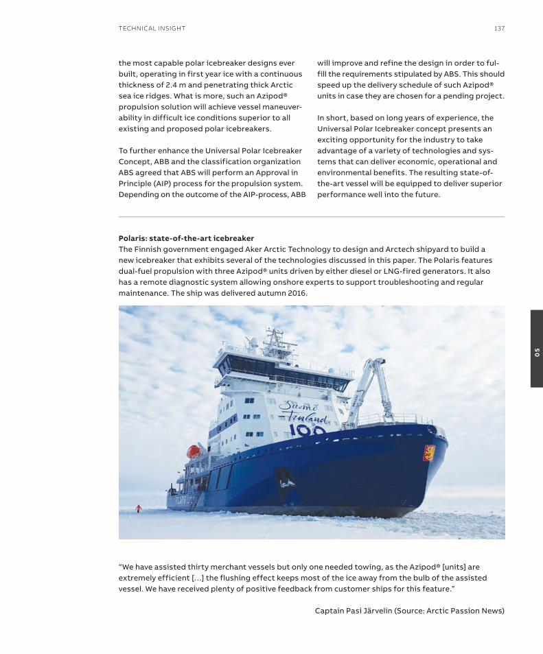
the most capable polar icebreaker designs ever built, operating in first year ice with a continuous thickness of 2.4 m and penetrating thick arctic sea ice ridges. What is more, such an azipod® propulsion solution will achieve vessel maneuver-ability in difficult ice conditions superior to all existing and proposed polar icebreakers.
to further enhance the Universal Polar icebreaker Concept, aBB and the classification organization aBs agreed that aBs will perform an approval in Principle (aiP) process for the propulsion system. Depending on the outcome of the aiP-process, aBB
will improve and refine the design in order to ful-fill the requirements stipulated by aBs. this should speed up the delivery schedule of such azipod® units in case they are chosen for a pending project.
in short, based on long years of experience, the Universal Polar icebreaker concept presents an exciting opportunity for the industry to take advantage of a variety of technologies and sys-tems that can deliver economic, operational and environmental benefits. the resulting state-of-the-art vessel will be equipped to deliver superior performance well into the future.
Polaris: state-of-the-art icebreakerthe Finnish government engaged aker arctic technology to design and arctech shipyard to build a new icebreaker that exhibits several of the technologies discussed in this paper. the Polaris features dual-fuel propulsion with three azipod® units driven by either diesel or LnG-fired generators. it also has a remote diagnostic system allowing onshore experts to support troubleshooting and regular maintenance. the ship was delivered autumn 2016.
“We have assisted thirty merchant vessels but only one needed towing, as the azipod® [units] are extremely efficient […] the flushing effect keeps most of the ice away from the bulb of the assisted vessel. We have received plenty of positive feedback from customer ships for this feature.”
Captain Pasi Järvelin (source: arctic Passion news)
TeChniCAl insiGhT 137
05
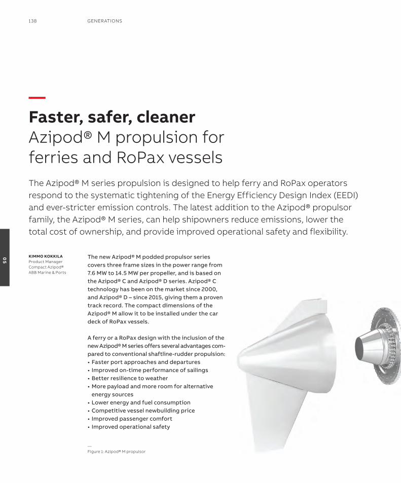
the new azipod® M podded propulsor series covers three frame sizes in the power range from 7.6 MW to 14.5 MW per propeller, and is based on the azipod® C and azipod® D series. azipod® C technology has been on the market since 2000, and azipod® D – since 2015, giving them a proven track record. the compact dimensions of the azipod® M allow it to be installed under the car deck of roPax vessels.
a ferry or a roPax design with the inclusion of the new azipod® M series offers several advantages com-pared to conventional shaftline-rudder propulsion:•Fasterportapproachesanddepartures•Improvedon-timeperformanceofsailings•Betterresiliencetoweather•Morepayloadandmoreroomforalternative
energy sources•Lowerenergyandfuelconsumption•Competitivevesselnewbuildingprice•Improvedpassengercomfort• Improvedoperationalsafety
The Azipod® M series propulsion is designed to help ferry and roPax operators respond to the systematic tightening of the energy efficiency Design index (eeDi) and ever-stricter emission controls. The latest addition to the Azipod® propulsor family, the Azipod® M series, can help shipowners reduce emissions, lower the total cost of ownership, and provide improved operational safety and flexibility.
KiMMo KoKKilaProduct ManagerCompact Azipod®ABB Marine & Ports
—Faster, safer, cleanerAzipod® M propulsion for ferries and roPax vessels
—Figure 1: Azipod® M propulsor
138 GenerATions
05
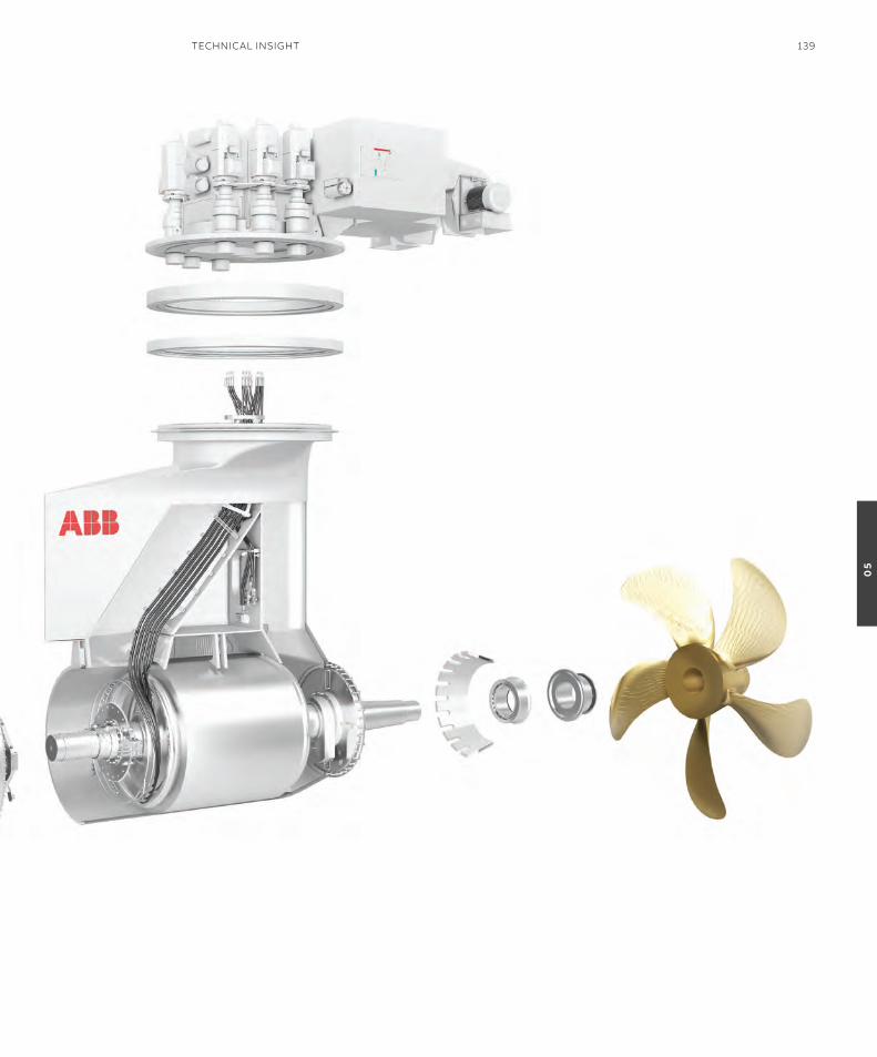
TeChniCAl insiGhT 139
05
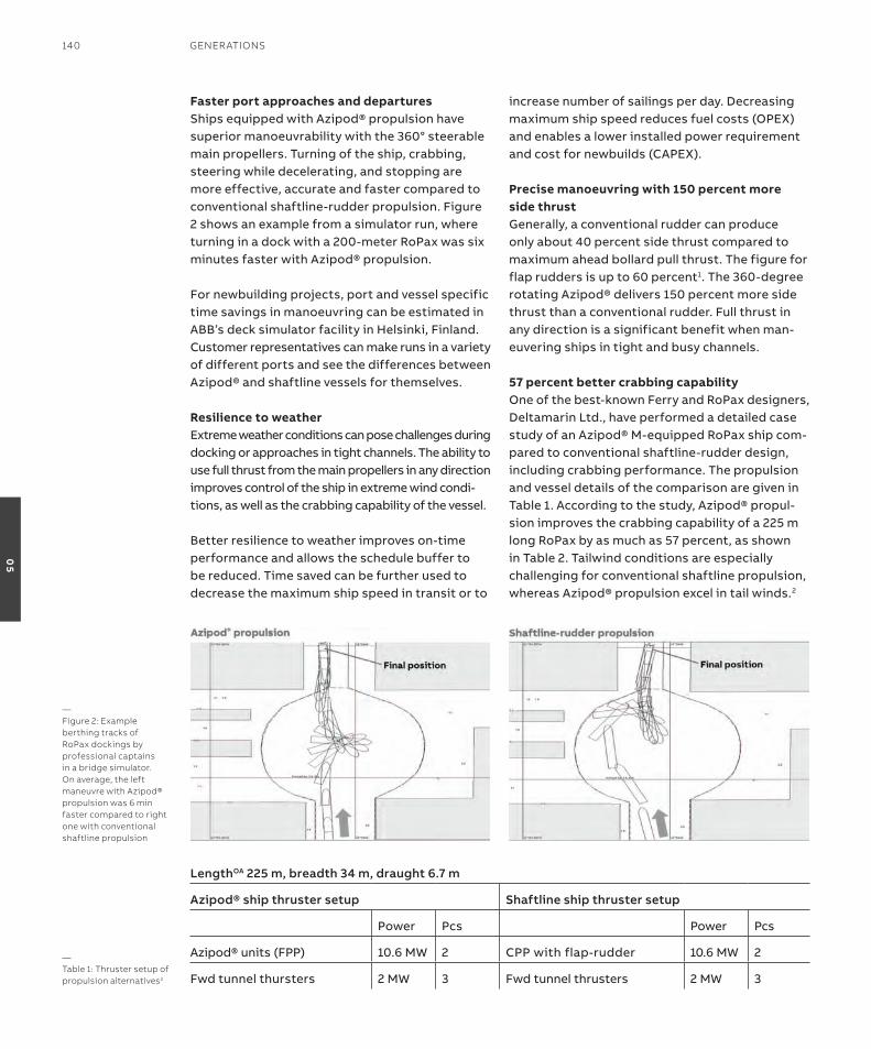
Faster port approaches and departuresships equipped with azipod® propulsion have superior manoeuvrability with the 360° steerable main propellers. turning of the ship, crabbing, steering while decelerating, and stopping are more effective, accurate and faster compared to conventional shaftline-rudder propulsion. Figure 2 shows an example from a simulator run, where turning in a dock with a 200-meter roPax was six minutes faster with azipod® propulsion.
For newbuilding projects, port and vessel specific time savings in manoeuvring can be estimated in aBB’s deck simulator facility in Helsinki, Finland. Customer representatives can make runs in a variety of different ports and see the differences between azipod® and shaftline vessels for themselves. resilience to weatherextreme weather conditions can pose challenges during docking or approaches in tight channels. the ability to use full thrust from the main propellers in any direction improves control of the ship in extreme wind condi-tions, as well as the crabbing capability of the vessel.
Better resilience to weather improves on-time performance and allows the schedule buffer to be reduced. time saved can be further used to decrease the maximum ship speed in transit or to
increase number of sailings per day. Decreasing maximum ship speed reduces fuel costs (oPeX) and enables a lower installed power requirement and cost for newbuilds (CaPeX).
Precise manoeuvring with 150 percent more side thrustGenerally, a conventional rudder can produce only about 40 percent side thrust compared to maximum ahead bollard pull thrust. the figure for flap rudders is up to 60 percent1. the 360-degree rotating azipod® delivers 150 percent more side thrust than a conventional rudder. Full thrust in any direction is a significant benefit when man-euvering ships in tight and busy channels.
57 percent better crabbing capabilityone of the best-known Ferry and roPax designers, Deltamarin Ltd., have performed a detailed case study of an azipod® M-equipped roPax ship com-pared to conventional shaftline-rudder design, including crabbing performance. the propulsion and vessel details of the comparison are given in table 1. according to the study, azipod® propul-sion improves the crabbing capability of a 225 m long roPax by as much as 57 percent, as shown in table 2. tailwind conditions are especially challenging for conventional shaftline propulsion, whereas azipod® propulsion excel in tail winds.2
—Figure 2: example berthing tracks of roPax dockings by professional captains in a bridge simulator. on average, the left maneuvre with Azipod® propulsion was 6 min faster compared to right one with conventional shaftline propulsion
—Table 1: Thruster setup of propulsion alternatives2
LengthOA 225 m, breadth 34 m, draught 6.7 m
Azipod® ship thruster setup Shaftline ship thruster setup
Power Pcs Power Pcs
azipod® units (FPP) 10.6 MW 2 CPP with flap-rudder 10.6 MW 2
Fwd tunnel thursters 2 MW 3 Fwd tunnel thrusters 2 MW 3
140 GenerATions
05

More payload, more room for alternative energy sourcesazipod® propulsion enables a flexible machinery arrangement that is easy to design for the ves-sel’s specific requirements and priorities. in the case study, azipod® propulsion motors installed outside the vessel hull, without long shaftlines, saved 255 m2 of machinery footprint compared to conventional diesel-mechanical shaftline propulsion, see Figure 3. Lack of fixed shaftlines gives more freedom for locating propulsion and power plant machinery, enabling re-arrangement for higher payload, and clearing additional space needed for alternative energy sources such as LnG tanks, batteries or fuel cells. table 3 demon-strates some benefits of re-arranging the general arrangement for the case vessel.3
similar space savings were also achieved by ship designer Foreship Ltd., who concluded that azipod® M propulsion would enable main engine rooms to be located in one watertight compartment aft, saving at least 10 m compared to mechanical propulsion for safe return to Port (srtP) designs, as seen in Figure 4. this would leave more space in the forward part of the vessel for additional stowage, LnG tank rooms or lower trailer holds.2
—Table 2: Maximum allowed wind speed for crabbing for the propulsion alternatives2
Wind direction Max. Allowed wind speed [m/s] improvement with azipod®
azipod® shaftline
15° 34 33 3 %
30° 24 23 4 %
45° 21 20 5 %
60° 22 21 5 %
75° 22 20 10 %
90° 23 20 15 %
105° 24 19 26 %
120° 25 18 39 %
135° 26 17 53 %
150° 33 21 57 %
165° 41 27 52 %
—Figure 3: re-arrangement of the case vessel’s tank top plan with Azipod® propulsion freed total 255 m2 foot-print2
—Figure 4: Azipod® arrangement allows more valuable space in front of engine rooms4
TeChniCAl insiGhT 141
05

$1,700,000 annual savings in fuel and energy consumptionoperational costs of conventional and azipod® M propulsion were also included in the case study. the main fuel consumption advantages with a twin azipod® vessel stem from lower vessel resistance and better propulsion efficiency. as shown in table 4, the difference in resistance was only 10 percent because the shaftline alternative was not equipped with stern tunnel thrusters, which typically increase resistance. savings with podded propulsion increase further compared to shaftline propulsion due to undis-turbed water flow to the propeller and optimum propeller angle towards the inflow which both increase propeller efficiency, Figure 5. according to the case study, the savings on delivered power (PD) at 22 kts was 12.0 percent with azipod® propulsion, see table 5. taking into account mechanical losses (3.5 percent) for shaftline propulsion employing 10 bearings and a gearbox on a mechanical drive train, and electrical losses of azipod® propulsion drive train (9 percent) including propulsion motor, transformer, frequency converter and generators, the savings in engine power (PB) with azipod® propulsion is 6.6 percent.
—Table 3: examples of utilization of freed space2
Utilisation Effect Impact
re-arranging Ga and Ma for extra passenger cabins
the total extra income depends on each individual case. an average price for an a-class cabin per trip is €80. the vessel would have one round trip per day. the price is an average of seasons and cruise types.
Yearly increased income of +€700 800/a
re-arranging Ga and Ma for extra cargo space(cars, trailers, etc.)
the total extra income depends on each individual case. an average price per car per trip is €32. the vessel would have one round trip per day.
Yearly increased income of +€1 168 000/a
increased LnG capacity
the total extra autonomy depends on each individual case.For case vessel, the consumption at design point is 106.0 t/d.the total extra volume is around 1000m3, which utilised in C-type cylinderical LnG tanks is around 750m3 (due to filling rate, cofferdam, etc.)
autonomy capacity increase of 3.2 days in case vessel
increased MGo capacity
the total extra autonomy depends on each individual case. For case vessel, the consumption at design point is 121.6 t/d. the total extra volume is around 1000m3, which utilised in MGo tanks would be around 800m3 (due to filling rate, cofferdam, etc.)
autonomy capacity increase of 5.9 days in case vessel
—Table 4: effect of appendages on hull resistance2
Effect on hull resistance
shaftline Podded
interceptor -2,00 % -2,00 %
Bow thruster tunnels 4,00 % 4,00 %
shaft arrangement 7,00 % 0,00 %
rudders 2,00 % 0,00 %
Headboxed 1,00 % 0,00 %
recesses for stabilizer fins 0,50 % 0,50 %
Bilge keels 1,00 % 1,00 %
total 13,50 % 3,50 %
Difference 10,00 %
—Table 5: Delivered power requirement for the case vessel at 22 kts2
Comparison at 22kn
shaftline version
azipod® Mo1800
Diameter [m] 5,1 5,1
speed [rpm] 139 139
Power [kW/unit] 10274 9045
Propeller / azipod® unit efficiency
0,686 0,708
142 GenerATions
05
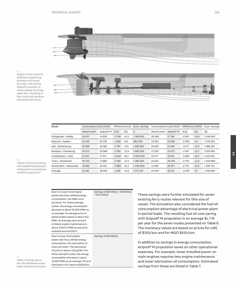
these savings were further simulated for seven existing ferry routes relevant for this size of vessel. the simulation also considered the fuel oil consumption advantage of electrical power plant in partial loads. the resulting fuel oil cost saving with azipod® M propulsion is on average $1.7 M per year for the seven routes presented on table 6. the monetary values are based on prices for LnG of $355/ton and for MGo $555/ton. in addition to savings in energy consumption, azipod® M propulsion saves on other operational expenses. For example, lower installed power on main engines requires less engine maintenance and lower lubrication oil consumption. estimated savings from these are listed in table 7.
—Figure 5: Due to lack of shaftline, supporting brackets and tunnel thrusters, the pulling Azipod® propeller re-ceives steady incoming water flow, resulting in less noise and vibration, and better efficiency
—Table 6: Fuel oil cost saving with Azipod® M propulsion compared to conventional shaftline propulsion2
Route Consumption [t/a] (LnG) Difference [t/a] econ. savings Consumption [t/a] (MGo) Difference (MGo) econ. savings
Diesel-mech. azipod® M [t/a] [%] $ Diesel-mech. azipod® M [t/a] [%] [$]
Puttgarden - rodby 18 437 15 638 -2 799 -15.2 1 399 500 20 406 17 796 -2 610 -12.8 1 448 550
rostock - Gedser 22 146 20 178 -1 968 -8.9 984 000 23 065 23 065 -2 300 -9.1 1 276 500
Kiel - Gothenburg 22 269 18 482 -3 787 -17.0 1 893 500 24 662 21 085 -3 577 -14.5 1 985 235
rosslare - Cherbourg 24 373 20 588 -3 785 -15.5 1 892 500 27 320 23 573 -3 747 -13.7 2 079 585
Fredrikshavn - oslo 21 225 17 173 -4 052 -19.1 2 026 000 23 477 19 651 -3 826 -16.3 2 123 430
turku - stockholm 20 752 17 968 -2 784 -13.4 1 392 000 23 255 20 479 -2 776 -11.9 1 540 680
amsterdam - newcastle 18 982 16 102 -2 880 -15.2 1 440 000 21 060 18 347 -2 713 -12.9 1 505 715
average 21 169 18 000 -3 169 -15.0 1 575 357 23 649 20 571 -3 078 -13 1 708 528
—Table 7: savings due to less Me maintenance and lower lubrication oil costs2
Due to a lower total engine power and thus utilised energy consumption, the M&r costs are lower. For these example routes, the energy consumption decrease is about 32,000 MWh as an average. an average price of diesel-engine spares is about €2/MWh. an average work amount of diesel-engine maintenance is about 0.044 h/MWh/a and price onboard around €35/h.
savings of €64 000/a + €49 000/a = €113 000/a
Due to lower total engine power and thus utilised energy consumption, the lubrication oil costs are lower. the lubrication oil price is about. 0.8 g/kWh. For these example routes, the energy consumption decrease is about 32,000 MWh as an average. Price of lubrication oil is about €1000/ton.
savings of €25 600/a
TeChniCAl insiGhT 143
05
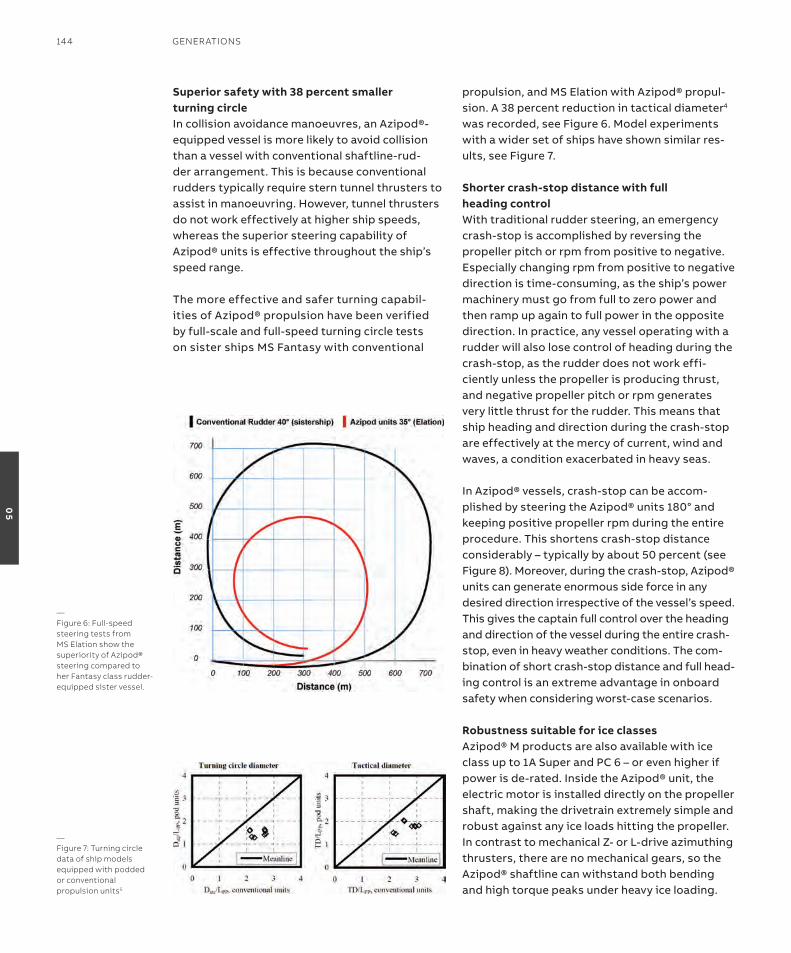
superior safety with 38 percent smaller turning circlein collision avoidance manoeuvres, an azipod®-equipped vessel is more likely to avoid collision than a vessel with conventional shaftline-rud-der arrangement. this is because conventional rudders typically require stern tunnel thrusters to assist in manoeuvring. However, tunnel thrusters do not work effectively at higher ship speeds, whereas the superior steering capability of azipod® units is effective throughout the ship’s speed range.
the more effective and safer turning capabil-ities of azipod® propulsion have been verified by full-scale and full-speed turning circle tests on sister ships Ms Fantasy with conventional
propulsion, and Ms elation with azipod® propul-sion. a 38 percent reduction in tactical diameter4 was recorded, see Figure 6. Model experiments with a wider set of ships have shown similar res-ults, see Figure 7.
shorter crash-stop distance with full heading controlWith traditional rudder steering, an emergency crash-stop is accomplished by reversing the propeller pitch or rpm from positive to negative. especially changing rpm from positive to negative direction is time-consuming, as the ship’s power machinery must go from full to zero power and then ramp up again to full power in the opposite direction. in practice, any vessel operating with a rudder will also lose control of heading during the crash-stop, as the rudder does not work effi-ciently unless the propeller is producing thrust, and negative propeller pitch or rpm generates very little thrust for the rudder. this means that ship heading and direction during the crash-stop are effectively at the mercy of current, wind and waves, a condition exacerbated in heavy seas.
in azipod® vessels, crash-stop can be accom-plished by steering the azipod® units 180° and keeping positive propeller rpm during the entire procedure. this shortens crash-stop distance considerably – typically by about 50 percent (see Figure 8). Moreover, during the crash-stop, azipod® units can generate enormous side force in any desired direction irrespective of the vessel’s speed. this gives the captain full control over the heading and direction of the vessel during the entire crash-stop, even in heavy weather conditions. the com-bination of short crash-stop distance and full head-ing control is an extreme advantage in onboard safety when considering worst-case scenarios. robustness suitable for ice classesazipod® M products are also available with ice class up to 1a super and PC 6 – or even higher if power is de-rated. inside the azipod® unit, the electric motor is installed directly on the propeller shaft, making the drivetrain extremely simple and robust against any ice loads hitting the propeller. in contrast to mechanical Z- or L-drive azimuthing thrusters, there are no mechanical gears, so the azipod® shaftline can withstand both bending and high torque peaks under heavy ice loading.
—Figure 6: Full-speed steering tests from Ms elation show the superiority of Azipod® steering compared to her Fantasy class rudder-equipped sister vessel.
—Figure 7: Turning circle data of ship models equipped with podded or conventional propulsion units5
144 GenerATions
05
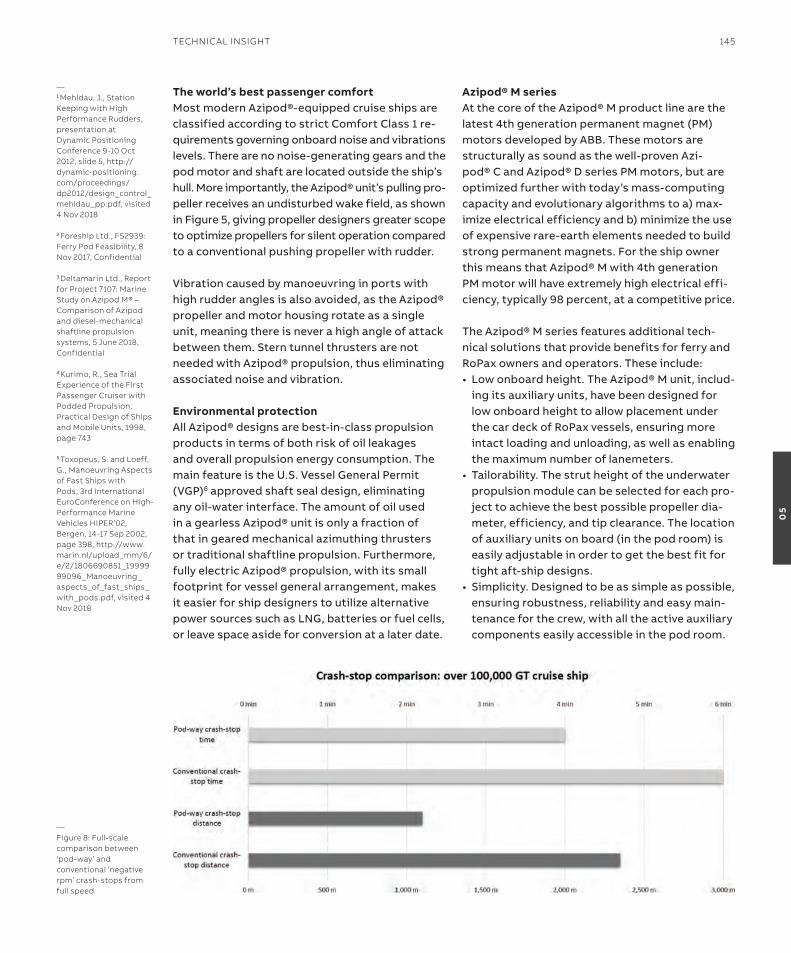
The world’s best passenger comfortMost modern azipod®-equipped cruise ships are classified according to strict Comfort Class 1 re-quirements governing onboard noise and vibrations levels. there are no noise-generating gears and the pod motor and shaft are located outside the ship’s hull. More importantly, the azipod® unit’s pulling pro-peller receives an undisturbed wake field, as shown in Figure 5, giving propeller designers greater scope to optimize propellers for silent operation compared to a conventional pushing propeller with rudder.
Vibration caused by manoeuvring in ports with high rudder angles is also avoided, as the azipod® propeller and motor housing rotate as a single unit, meaning there is never a high angle of attack between them. stern tunnel thrusters are not needed with azipod® propulsion, thus eliminating associated noise and vibration.
Environmental protectionall azipod® designs are best-in-class propulsion products in terms of both risk of oil leakages and overall propulsion energy consumption. the main feature is the U.s. Vessel General Permit (VGP)6 approved shaft seal design, eliminating any oil-water interface. the amount of oil used in a gearless azipod® unit is only a fraction of that in geared mechanical azimuthing thrusters or traditional shaftline propulsion. Furthermore, fully electric azipod® propulsion, with its small footprint for vessel general arrangement, makes it easier for ship designers to utilize alternative power sources such as LnG, batteries or fuel cells, or leave space aside for conversion at a later date.
azipod® M seriesat the core of the azipod® M product line are the latest 4th generation permanent magnet (PM) motors developed by aBB. these motors are structurally as sound as the well-proven azi-pod® C and azipod® D series PM motors, but are optimized further with today’s mass-computing capacity and evolutionary algorithms to a) max-imize electrical efficiency and b) minimize the use of expensive rare-earth elements needed to build strong permanent magnets. For the ship owner this means that azipod® M with 4th generation PM motor will have extremely high electrical effi-ciency, typically 98 percent, at a competitive price.
the azipod® M series features additional tech-nical solutions that provide benefits for ferry and roPax owners and operators. these include:• Lowonboardheight.TheAzipod®Munit,includ-
ing its auxiliary units, have been designed for low onboard height to allow placement under the car deck of roPax vessels, ensuring more intact loading and unloading, as well as enabling the maximum number of lanemeters.
• Tailorability.Thestrutheightoftheunderwaterpropulsion module can be selected for each pro-ject to achieve the best possible propeller dia-meter, efficiency, and tip clearance. the location of auxiliary units on board (in the pod room) is easily adjustable in order to get the best fit for tight aft-ship designs.
• Simplicity.Designedtobeassimpleaspossible,ensuring robustness, reliability and easy main-tenance for the crew, with all the active auxiliary components easily accessible in the pod room.
—Figure 8: Full-scale comparison between ‘pod-way’ and conventional ‘negative rpm’ crash-stops from full speed
—1 Mehldau, J., station Keeping with high Performance rudders, presentation at Dynamic Positioning Conference 9-10 oct 2012, slide 5, http://dynamic-positioning.com/proceedings/dp2012/design_control_mehldau_pp.pdf, visited 4 nov 2018
2 Foreship ltd., Fs2939: Ferry Pod Feasibility, 8 nov 2017, Confidential
3 Deltamarin ltd., report for Project 7107: Marine study on Azipod M® – Comparison of Azipod and diesel-mechanical shaftline propulsion systems, 5 June 2018, Confidential
4 Kurimo, r., sea Trial experience of the First Passenger Cruiser with Podded Propulsion, Practical Design of ships and Mobile Units, 1998, page 743
5 Toxopeus, s. and loeff, G., Manoeuvring Aspects of Fast ships with Pods, 3rd international euroConference on high-Performance Marine Vehicles hiPer’02, Bergen, 14-17 sep 2002, page 398, http://www.marin.nl/upload_mm/6/e/2/1806690851_1999999096_Manoeuvring_aspects_of_fast_ships_with_pods.pdf, visited 4 nov 2018
TeChniCAl insiGhT 145
05

—Figure 9: The Azipod® propulsion motor is integrated onto propeller shaft, making the drive train gearless and robust
146 GenerATions
05
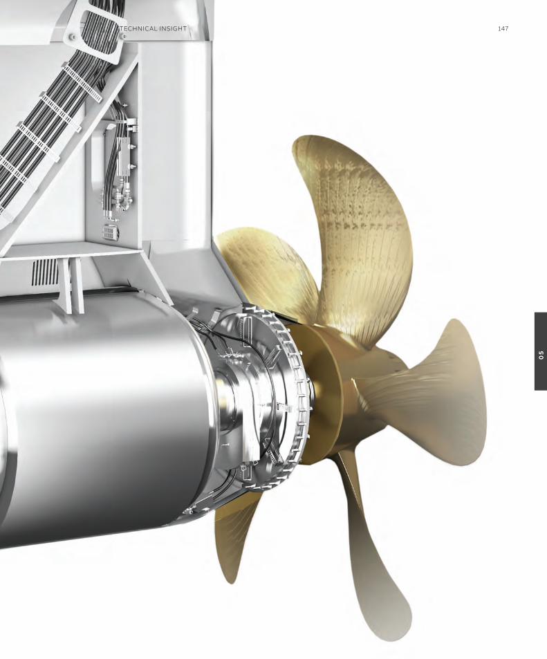
TeChniCAl insiGhT 147
05
how it all startedthe story of remote container crane operation started more than two decades ago when the first stacking cranes were automated and re-mote operation introduced. a lot has happened since then, and today almost all stacking cranes ordered come equipped with automation and re-mote operation. in fact, now that stacking cranes are capable of performing automatic pick-up/landing of containers on road chassis, it is more accurate to consider remote supervision rather than remote operation, since an operator’s input is only needed for handling exceptions.
the last decade has shown that something many thought would hardly be possible has become reality: remote sts crane operation. already, the total number of remotely operated quay cranes exceeds 100 units and, recently, one more terminal went ‘cabinless’, marking a new era when they acquired more cranes to their existing remotely operated quay crane fleet.
the introduction of automation and remote operation in container terminals has also meant taking the first steps in adopting digitalization
to enable new ways of doing things. Combined, automation, remote operation and the tools provided by digitalization are increasing safety and productivity in container terminals by separ-ating humans from big machines and eliminating bottlenecks, as well as combating inefficient manual processes.
examples of digitalization include gate automa-tion that digitalized gate transactions, and crane optical character recognition system (oCr) which makes the automation and digitalization of con-tainer hand-offs possible. in both cases, automa-tion and digitalization enabled a centralized way of handling exceptions remotely from an office building. But more remains to be done to reap the benefits of digitalization at the quay.
Digitalized quay operationBy fully digitalizing the information exchange between remote operator, checker and deckman, i.e. within the team involved in the operation of sts cranes, the whole quay operation can be digitalized.
Data related to a container move, as well as the status of the bay, what is waiting under a crane
Automation and digitalization continue to drive changes in roles and processes, thereby impacting the entire terminal operation and challenging us to evolve the roles of port workers. This paper takes on that brief by making a case that it is time to take remote operations beyond the remote crane operator. We believe such an initiative will increase safety and productivity at the quay by digitalizing the whole of the ship-to-shore (sTs) crane operation.
BJörN hENriKssoNTechnology ManagerABB Ports, sweden
—Next level remote operationsThe remote crane operator and beyond
148 GenerATions
05
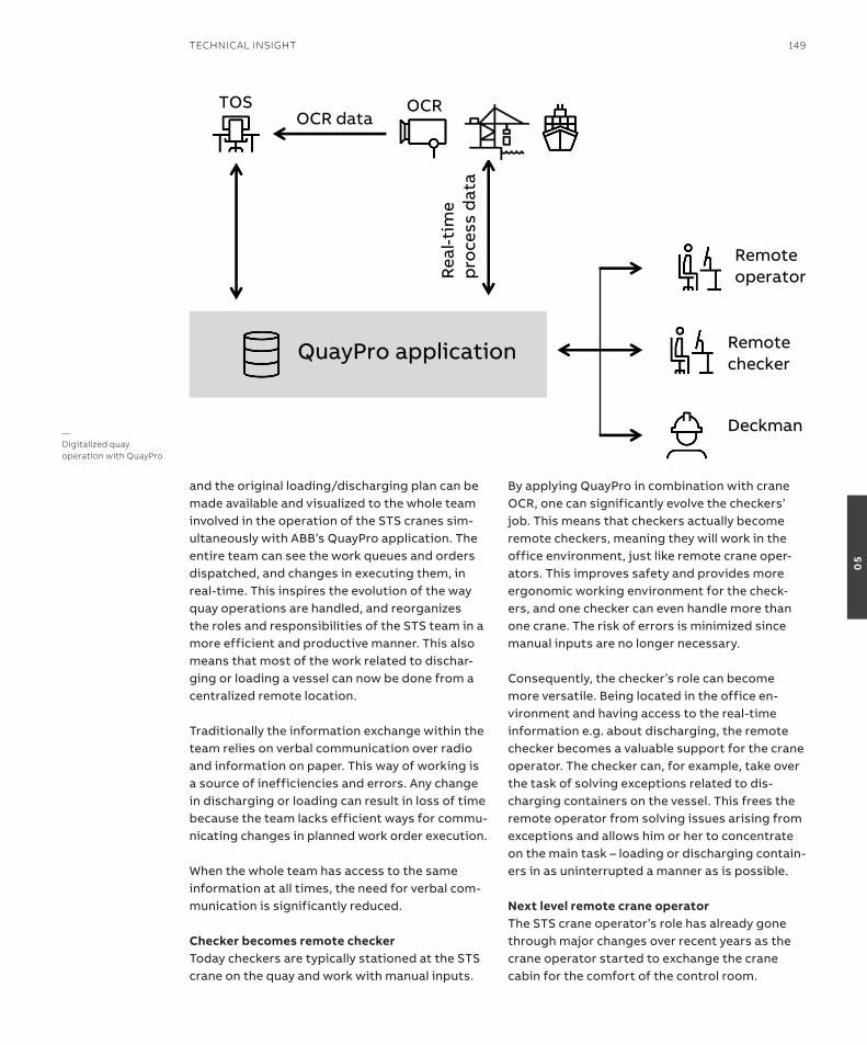
and the original loading/discharging plan can be made available and visualized to the whole team involved in the operation of the sts cranes sim-ultaneously with aBB’s QuayPro application. the entire team can see the work queues and orders dispatched, and changes in executing them, in real-time. this inspires the evolution of the way quay operations are handled, and reorganizes the roles and responsibilities of the sts team in a more efficient and productive manner. this also means that most of the work related to dischar-ging or loading a vessel can now be done from a centralized remote location.
traditionally the information exchange within the team relies on verbal communication over radio and information on paper. this way of working is a source of inefficiencies and errors. any change in discharging or loading can result in loss of time because the team lacks efficient ways for commu-nicating changes in planned work order execution.
When the whole team has access to the same information at all times, the need for verbal com-munication is significantly reduced.
Checker becomes remote checkertoday checkers are typically stationed at the sts crane on the quay and work with manual inputs.
By applying QuayPro in combination with crane oCr, one can significantly evolve the checkers’ job. this means that checkers actually become remote checkers, meaning they will work in the office environment, just like remote crane oper-ators. this improves safety and provides more ergonomic working environment for the check-ers, and one checker can even handle more than one crane. the risk of errors is minimized since manual inputs are no longer necessary.
Consequently, the checker’s role can become more versatile. Being located in the office en-vironment and having access to the real-time information e.g. about discharging, the remote checker becomes a valuable support for the crane operator. the checker can, for example, take over the task of solving exceptions related to dis-charging containers on the vessel. this frees the remote operator from solving issues arising from exceptions and allows him or her to concentrate on the main task – loading or discharging contain-ers in as uninterrupted a manner as is possible.
Next level remote crane operatorthe sts crane operator’s role has already gone through major changes over recent years as the crane operator started to exchange the crane cabin for the comfort of the control room.
4/30/19 1
QuayPro application
TOSOCR data
OCR
Rea
l-tim
ep
roce
ss d
ata
Remoteoperator
Remotechecker
Deckman—Digitalized quay operation with QuayPro
TeChniCAl insiGhT 149
05
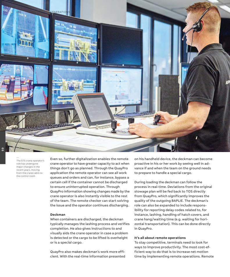
even so, further digitalization enables the remote crane operator to have greater capacity to act when things don’t go as planned. through the QuayPro application the remote operator can see all work queues and orders and can, for instance, bypass a certain cell if the container cannot be discharged to ensure uninterrupted operation. through QuayPro information showing changes made by the crane operator is also instantly visible to the rest of the team. the remote checker can start solving the issue and the operator continues discharging.
DeckmanWhen containers are discharged, the deckman typically manages the lashing process and verifies completion. He also gives instructions to and visually aids the crane operator in case a problem is detected or the cargo to be lifted is overheight or is a special cargo.
QuayPro also makes deckman’s work more effi-cient. With the real-time information presented
on his handheld device, the deckman can become proactive in his or her work by seeing well in ad-vance if and when the team on the ground needs to prepare to handle a special cargo.
During loading the deckman can follow the process in real-time. Deviations from the original stowage plan will be fed back to tos directly from QuayPro, which significantly improves the quality of the outgoing BaPLie. the deckman’s role can also be expanded to include respons-ibility for reporting delay codes related to, for instance, lashing, handling of hatch covers, and crane hang/waiting time (e.g. waiting for hori-zontal transportation). this can be done directly in QuayPro.
it’s all about remote operations to stay competitive, terminals need to look for ways to improve productivity. the most cost-ef-ficient way to do that is to increase net motion time by implementing remote operations. remote
—The sTs crane operator’s role has undergone major changes in the recent years, moving from the crane cabin to the control room
150 GenerATions
05

operations throughout the terminal, now also including the remote checker, will minimize the requirement to transport people to and from cranes. shift changes and breaks can also be handled smoothly at the desk in the control room. automation and digitalization are key enablers in making this happen.
analytics for performance improvementVisualizing everything the terminal’s numerous systems already know allows changing the way of operating the terminal. in addition, analysis of the data provides valuable insights for process and performance improvements. analytics can be used for locating bottlenecks in production,
finding the root cause for delays and for veri-fying that work orders have been executed in the correct manner. the crane cycle can also be analyzed to see where performance falls behind the optimum cycle. these insights can be used for training purposes to create an understanding of how decisions taken during operations have an impact on the performance of equipment and the entire terminal.
Being able to see what the systems already knew but couldn’t tell empowers users when it comes to understanding, changing and improving job roles and operations in ways that make container terminals safer, greener and more productive.
TeChniCAl insiGhT 151
05

—Publisher
Generations is published by ABB Marine & Ports, a Business Line of ABB.
Reprints or reproductions are permitted subject to full acknowledgement. Publisher and copyright ©2019 ABB Marine & Ports
Generations is free of charge.
ISSN 1894-1079
—Editorial Board
Juha KoskelaManaging DirectorABB Marine & Ports
Alf Kåre ÅdnanesGeneral ManagerABB Marine & Ports China
Mikko LepistöSenior Vice PresidentDigital SolutionsABB Marine & Ports
Uno BryforsSenior Vice PresidentABB Ports
Cecilie HeavensSenior Vice PresidentMarketing and CommunicationsABB Marine & Ports
Margarita SjursenGenerations Executive EditorGlobal Communications ManagerABB Marine & Ports
—Editorial team
ABB Marine & PortsPriscila FaesterPalemia FieldMaria GordeevaReza-Gustavia GosalIlona HaarlaaCherie HusileBente Lund-LarsenKristine MollerMaarit NystromJackie Zheng
—Writing, editing and production
Kevin GallagherManaging EditorBlue-C
Kari LybækProduction ManagerBlue-C
Anthony RowlinsonEditorial and Content ManagerABB Formula E
Andrea CrosettiCybersecurity Solutions ManagerABB Marine & Ports
—Layout
Elizabeth WalmannDesignAid
—Photography and artwork
ABBIMOBilleasy on UnsplashJordan McQueen on UnsplashCoolmomoPolar Research Institute of China3D GrafikerGrandi Navi VelociAker ArcticUljanik
—Printer
Hansaprint Oy
—Disclaimer
The information contained herein reflects the views of the authors and is for informational purposes only. Readers should not act upon the information contained herein without seeking professional advice. We make publications available with the understanding that the authors are not rendering technical or other professional advice or opinions on specific facts or matters and assume no liability whatsoever in connection with their use.The companies of the ABB Group do not make any warranty or guarantee, or promise, expressed or implied, concerning the content or accuracy of the views expressed herein.
—Feedback
We welcome feedback and suggestions. If you have any questions or ideas, please contact us at [email protected].