document number ts2006002 1394 beta plus phy...
TRANSCRIPT

Document number TS2006002
1394 Beta Plus PHY-Link interface
Feb. 08, 2007 Sponsored by:
1394 Trade Association
Accepted for publication by
1394 Trade Association Board of Directors
Abstract
This specification defines signaling, protocol, and electrical characteristics of Beta Plus PHY-Link interface, which can support up to S3200 mode.
Keywords
IEEE 13994, Serial Bus, PHY-Link interface
1394 Trade Association Specification
1394 Trade Association Specifications are developed within Working Groups of the 1394 Trade Association, a non-profit industry association devoted to the promotion of and growth of the market for IEEE 1394-compliant products. Participants in Working Groups serve voluntarily and without compensation from the Trade Association. Most participants represent member organizations of the 1394 Trade Association. The specifications developed within the working groups represent a consensus of the expertise represented by the participants.
Use of a 1394 Trade Association Specification is wholly voluntary. The existence of a 1394 Trade Association Specification is not meant to imply that there are not other ways to produce, test, measure, purchase, market or provide other goods and services related to the scope of the 1394 Trade Association Specification. Furthermore, the viewpoint expressed at the time a specification is accepted and issued is subject to change brought about through developments in the state of the art and comments received from users of the specification. Users are cautioned to check to determine that they have the latest revision of any 1394 Trade Association Specification.
Comments for revision of 1394 Trade Association Specifications are welcome from any interested party, regardless of membership affiliation with the 1394 Trade Association. Suggestions for changes in documents should be in the form of a proposed change of text, together with appropriate supporting comments.
Interpretations: Occasionally, questions may arise about the meaning of specifications in relationship to specific applications. When the need for interpretations is brought to the attention of the 1394 Trade Association, the Association will initiate action to prepare appropriate responses.
Comments on specifications and requests for interpretations should be addressed to:
Editor, 1394 Trade Association Office 1560 East Southlake Blvd., Suite 242 Southlake, TX 76092, USA Phone: 817-416-2200 Fax: 817-416-2256
1394 Trade Association Specifications are adopted by the 1394 Trade Association without regard to patents which may exist on articles, materials or processes or to other proprietary intellectual property which may exist within a specification. Adoption of a specification by the 1394 Trade Association does not assume any liability to any patent owner or any obligation whatsoever to those parties who rely on the specification documents. Readers of this document are advised to make an independent determination regarding the existence of intellectual property rights, which may be infringed by conformance to this specification.
Published by 1394 Trade Association 1560 East Southlake Blvd., Suite 242 Southlake, TX 76092 ,USA Copyright © 2007 by 1394 Trade Association All rights reserved. Printed in the United States of America

1394 TA TS2006002 Revision 0.2
Copyright © 2007, 1394 Trade Association. All rights reserved. This is an unaccepted draft specification, subject to change.
i
Contents
Revision history............................................................................................................................... iii
1 Scope and purpose......................................................................................................................... 1 1.1 Scope ...................................................................................................................................... 1 1.2 Purpose ................................................................................................................................... 1
2 Normative references..................................................................................................................... 3 2.1 Reference scope...................................................................................................................... 3
3 Definitions and notation ................................................................................................................ 5 3.1 Definitions .............................................................................................................................. 5
3.1.1 Conformance ................................................................................................................... 5
4 Beta Plus PHY-link interface......................................................................................................... 6 4.1 Beta Plus PHY-link interface characteristics .......................................................................... 6 4.2 Beta Plus PHY-link interface signals...................................................................................... 7
4.2.1 Interface signal descriptions ............................................................................................ 7 4.2.2 PHY and Link signals...................................................................................................... 8 4.2.3 Detailed signal descriptions............................................................................................. 8
4.3 Interface initialization, reset, and disable ............................................................................... 8 4.4 Link-on and interrupt indications ........................................................................................... 9 4.5 Link requests and notifications............................................................................................... 9 4.6 Interface data transfers ......................................................................................................... 10
4.6.1 Packet Reception ........................................................................................................... 10 4.6.2 Packet Transmission ...................................................................................................... 12 4.6.3 Note on transmission and reception of dual byte traffic at S3200 mode ...................... 15
4.7 Format of received and transmitted data .............................................................................. 15 4.7.1 S3200 Data .................................................................................................................... 16 4.7.2 S1600 Data .................................................................................................................... 16 4.7.3 S800 – S100 Data .......................................................................................................... 17
4.8 Status transfers and notifications from the PHY .................................................................. 18 4.9 Legacy link and Beta Link support....................................................................................... 18 4.10 Electrical characteristics ..................................................................................................... 19
4.10.1 DC signal levels and waveforms ................................................................................. 19 4.10.2 AC timing .................................................................................................................... 19
Tables
Table 4-1 Beta Plus PHY-link interface signal description............................................................... 7 Table 4-2 Interface types for Beta Plus PHY/ Link device............................................................... 8 Table 4-3 Timing parameters specified in terms of absolute time .................................................... 9 Table 4-4 Timing parameters specified in terms of number of PClk or LClk. ................................. 9 Table 4-5 Description of RS [0:3] in link request in Beta Plus mode............................................. 10 Table 4-6 SPD - receiving packet ................................................................................................... 12 Table 4-7 Description of D[5:7] in GRANT cycle in Beta Plus mode. .......................................... 15 Table 4-8 Description of D[5:7] in MORE_INFO cycle in Beta Plus mode. ................................. 15 Table 4-9 DC characteristics........................................................................................................... 19 Table 4-10 AC timing parameters................................................................................................... 21
1394 TA TS2006002 Revision 0.2
Copyright © 2007, 1394 Trade Association. All rights reserved. This is an unaccepted draft specification, subject to change.
ii
Fehler! Es konnten keine Einträge für ein Abbildungsverzeichnis gefunden werden.Figures
Figure 4-1 PHY-link interface logical signaling ...............................................................................7 Figure 4-2 PHY-Link packet receive operation at S3200 mode .....................................................11 Figure 4-3 PHY-Link packet receive operation in S1600 mode .....................................................11 Figure 4-4 PHY-Link packet transmit operation in S3200 mode....................................................13 Figure 4-5 PHY-Link packet transmit operation at S1600 mode ....................................................14 Figure 4-6 Format of Interface data transfers at S3200 mode ........................................................16 Figure 4-7 Format of Interface data transfers at S1600 mode ........................................................16 Figure 4-8 Format of Interface data transfers at S800 mode ..........................................................17 Figure 4-9 Format of Interface data transfers at S400 mode ..........................................................17 Figure 4-10 Format of Interface data transfers at S200 mode ........................................................17 Figure 4-11 Format of Interface data transfers at S100 mode.........................................................18 Figure 4-12 Rising and falling time ................................................................................................20 Figure 4-13 Transfer waveform at the source .................................................................................20 Figure 4-14 Transfer waveform at the destination ..........................................................................20
Annexes
Annex A (informative) Bibliography .............................................................................................22
1394 TA TS2006002 Revision 0.2
Copyright © 2007, 1394 Trade Association. All rights reserved. This is an unaccepted draft specification, subject to change.
iii
Foreword (This foreword is not part of 1394 Trade Association Specification 2006002)
This specification defines signaling, protocol, and electrical characteristics of Beta Plus PHY-Link interface, which can support up to S3200 mode.
There is one annex in this specification, which is informative and is not considered part of this specification.
This specification was accepted by the Board of Directors of the 1394 Trade Association. Board of Directors acceptance of this specification does not necessarily imply that all board members voted for acceptance. At the time it accepted this specification, the 1394 Trade Association. Board of Directors had the following members:
Eric Anderson, Chair Zephra Freeman, Vice-Chair Dave Thompson, Secretary Organization Represented Name of Representative Apple .................................................................................................................. Eric Anderson AV Connections .................................................................................................. Hans van der Ven Fraunhofer IPMS ................................................................................................ Michael Scholles LSI Logic............................................................................................................. Dave Thompson Microsoft. ............................................................................................................ Mark Slezak Oxford Semiconductor......................................................................................... Jalil Oraee Samsung ............................................................................................................. Hyunchin Kim Symwave ............................................................................................................. Jack Bell Texas Instruments ................................................................................................ Zephra Freeman
The Silicon Working Group, which developed and reviewed this specification, had the following members:
Colin Whitby-Strevens, Chair Morten Lave, Secretary Tatsutoshi Abe Hiroki Ishikawa Bill Russell Eric Anderson DJ Johnson Steven Saffer Yasaman Bahrein Brian Karr John Santhoff Les Baxter Hyunchin Kim Michael Scholles Duncan Beadnell Ingo Lewerendt Bill Shvodian Matthew Coady Sam Liu Fred Speckeen Klas Dalbjorn Paul Messick Chris Thomas Zephra Freeman Richard Mourn Dave Thompson Klaus Frommhagen Michael O'Gorman Koen van den Brande Junichi Fujimori Jalil Oraee Hans van der Ven Robby Gurdan Kim Rishoj Barry Walker Will Harris Michael Rucks Matt Welborn Peter Helfet Hiroki Ishikawa Andy Yanowitz
1394 TA TS2006002 Revision 0.2
Copyright © 2007, 1394 Trade Association. All rights reserved. This is an unaccepted draft specification, subject to change.
iv
1394 TA TS2006002 Revision 0.2
Copyright © 2007, 1394 Trade Association. All rights reserved. This is an unaccepted draft specification, subject to change.
v
Revision history
Revision 0.1 (Dec. 07, 2006)
Table 1 – Content change for version 0.1 Category Description Editorial Technical Initial version
Revision 0.2 (Feb. 08, 2007)
Table 2 – Content change for version 0.2 Category Description Editorial Update TA address, title of Apple Inc, revision number, date and so on.
Editorial changes on section 3.1.3, 4.3 and 4.7.3
Technical Update section 4.7.3 on the handling of single byte (ACK) packets and packets with odd numbers of bytes.
Technical In Table 4-10, the “Signal propagation delay from PHY to link” (and vice-versa) of 0.5ns has been relaxed to 1ns.
Technical Figures under 4.7.1 that refers to “transmitted or received,” have been redrawn for clarity and accuracy.
Technical "Added DATA_HIGH_VALID" following WG ballot"


1394 TA TS2006002 Revision 0.2
Copyright © 2007, 1394 Trade Association. All rights reserved. This is an unaccepted draft specification, subject to change.
1
1394 Beta Plus PHY-Link interface
1 Scope and purpose
1.1 Scope
This specification defines signaling, protocol, and electrical characteristics of Beta Plus PHY-Link interface, which can support up to S3200 mode.
1.2 Purpose
The purpose of this specification is fulfilling the Beta Plus PHY-Link interface which is yet defined in 1394b-2002.


1394 TA TS2006002 Revision 0.2
Copyright © 2007, 1394 Trade Association. All rights reserved. This is an unaccepted draft specification, subject to change.
3
2 Normative references
2.1 Reference scope
The following standards contain provisions, which through reference in this document, constitute provisions of this standard. All the standards listed are normative references. Informative references are given in Annex A. At the time of publication, the editions indicated were valid. All standards are subject to revision, and parties to agreements based on this standard are encouraged to investigate the possibility of applying the most recent editions of the standards indicated below.
[R1] IEEE Std 1394b-2002, Standard for a High Performance Serial Bus (High Speed Supplement)


1394 TA TS2006002 Revision 0.2
Copyright © 2007, 1394 Trade Association. All rights reserved. This is an unaccepted draft specification, subject to change.
5
3 Definitions and notation
3.1 Definitions
3.1.1 Conformance
Several keywords are used to differentiate levels of requirements and optionality, as follows:
3.1.1.1 expected: A keyword used to describe the behavior of the hardware or software in the design models assumed by this specification. Other hardware and software design models may also be implemented.
3.1.1.2 ignored: A keyword that describes bits, bytes, quadlets, octlets or fields whose values are not checked by the recipient.
3.1.1.3 may: A keyword that indicates flexibility of choice with no implied preference.
3.1.1.4 reserved: A keyword used to describe objects (bits, bytes, quadlets, octlets and fields) or the code values assigned to these objects in cases where either the object or the code value is set aside for future standardization. Usage and interpretation may be specified by future extensions to this or other specifications. A reserved object shall be zeroed or, upon development of a future specification, set to a value specified by such a specification. The recipient of a reserved object shall ignore its value. The recipient of an object defined by this specification as other than reserved shall inspect its value and reject reserved code values.
3.1.1.5 shall: A keyword that indicates a mandatory requirement. Designers are required to implement all such mandatory requirements to assure interoperability with other products conforming to this specification.
3.1.1.6 should: A keyword that denotes flexibility of choice with a strongly preferred alternative. Equivalent to the phrase “is recommended.”

1394 TA TS2006002 Revision 0.2
Copyright © 2007, 1394 Trade Association. All rights reserved. This is an unaccepted draft specification, subject to change.
6
4 Beta Plus PHY-link interface This clause specifies the signaling, protocol, and electrical characteristics of the interface between a discrete PHY and a link up to S3200 mode. The interface is described independently of other operational characteristics of either PHY or link. Implementation of the PHY-link interface at speeds up to S3200 may be achieved using a 16 bit parallel interface. The PHY-link interface provides mechanisms to support communication between a discrete PHY and link at speeds of S100, S200, S400, S800, S1600, and S3200. For S1600 and below, the width of the data path is 8 bits, while for S3200, the data path is 16 bits. Transfer speeds lower than S1600 are accommodated by data padding and repetition. This specification does not preclude implementation of PHYs that are capable of supporting links compliant with Beta Plus link in this clause, Beta link in IEEE Std 1394b-2002 and with A link in IEEE Std 1394a-2000. When attached to a link that is compliant with IEEE Std 1394a-2000, the PHY shall follow all the link specifications of that standard. When attached to a link compliant with IEEE Std 1394b-2002, the PHY shall follow the link specification of that standard. When attached to a link compliant with Beta Plus Link, the PHY shall follow all the link specification contained in this clause.
4.1 Beta Plus PHY-link interface characteristics The following are the characteristics of the Beta Plus PHY-link interface:
a) Provides for bidirectional packet data transfer at speeds of S100, S200, S400, S800, S1600, and S3200; b) Provides a mechanism for status information transfer from the PHY to the link; c) Provides a mechanism for the link to access a register space within the PHY; d) Provides a means for the link to request services from the PHY; and e) Provides a means for the PHY to interrupt the link during an operation.
1394 TA TS2006002 Revision 0.2
Copyright © 2007, 1394 Trade Association. All rights reserved. This is an unaccepted draft specification, subject to change.
7
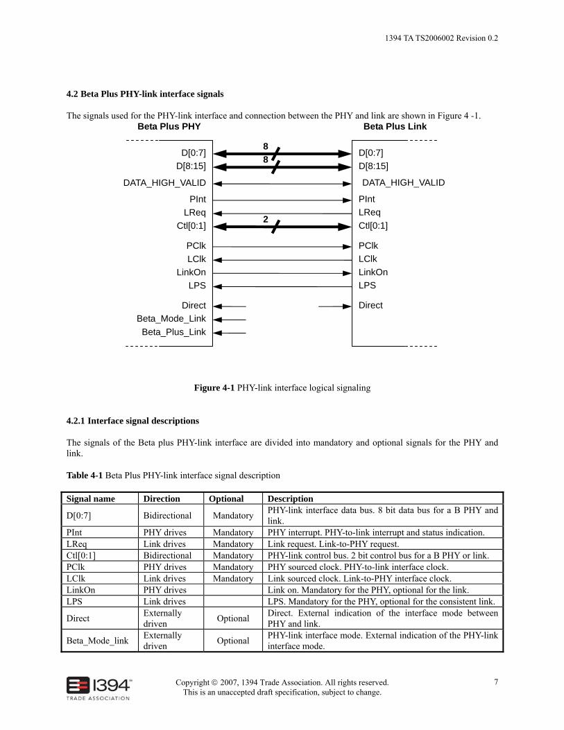
4.2 Beta Plus PHY-link interface signals
The signals used for the PHY-link interface and connection between the PHY and link are shown in Figure 4 -1.
Figure 4-1 PHY-link interface logical signaling
4.2.1 Interface signal descriptions
The signals of the Beta plus PHY-link interface are divided into mandatory and optional signals for the PHY and link.
Table 4-1 Beta Plus PHY-link interface signal description
Signal name Direction Optional Description
D[0:7] Bidirectional Mandatory PHY-link interface data bus. 8 bit data bus for a B PHY and link.
PInt PHY drives Mandatory PHY interrupt. PHY-to-link interrupt and status indication. LReq Link drives Mandatory Link request. Link-to-PHY request. Ctl[0:1] Bidirectional Mandatory PHY-link control bus. 2 bit control bus for a B PHY or link. PClk PHY drives Mandatory PHY sourced clock. PHY-to-link interface clock. LClk Link drives Mandatory Link sourced clock. Link-to-PHY interface clock. LinkOn PHY drives Link on. Mandatory for the PHY, optional for the link. LPS Link drives LPS. Mandatory for the PHY, optional for the consistent link.
Direct Externally driven Optional Direct. External indication of the interface mode between
PHY and link.
Beta_Mode_link Externally driven Optional PHY-link interface mode. External indication of the PHY-link
interface mode.
D[0:7] D[8:15]
PInt LReq
Ctl[0:1]
PClk LClk
LinkOn LPS
Direct Beta_Mode_Link
Beta_Plus_Link
D[0:7] D[8:15]
PInt LReq Ctl[0:1]
PClk LClk LinkOn LPS
Direct
Beta Plus PHY Beta Plus Link
88
2
DATA_HIGH_VALID DATA_HIGH_VALID

1394 TA TS2006002 Revision 0.2
Copyright © 2007, 1394 Trade Association. All rights reserved. This is an unaccepted draft specification, subject to change.
8
Signal name Direction Optional Description
Beta_Plus_link Externally driven Optional Beta_Plus interface mode indication
D[8:15] Bidirectional Optional 2nd 8 bit data bus for a 16 bit Beta Plus PHY and link at S3200
DATA_HIGH_VALID
Bidirectional Optional Valid indication for 2nd 8 bit data bus for a 16 bit Beta Plus PHY and link at S3200.
4.2.2 PHY and Link signals
In addition to Beta PHY-Link interface signals, there are two groups of optional signals for PHY and Link, Beta_Plus_link and D [8:15].
4.2.3 Detailed signal descriptions
Detailed descriptions of the additional two group interface signals are as follows:
a) Beta_Plus_link is hard switch signal to alternate Beta_Plus mode and Beta mode. For a typical Beta_Plus PHY or Link device, there are two categories depending whether Beta_Plus_Link indication is provided or not.
If Beta_Plus_Link indication is present and asserted, the PHY-link interface is Beta_Plus mode. If Beta_Plus_Link indication is provided but deasserted, the PHY-link interface is Beta mode or A mode depending on whether Beta_Mode_Link is High, Non-present or Low respectively.
If the Beta_Plus_Link indication is absent, the PHY-link interface is Beta_Plus mode.
Table 4-2 Interface types for Beta Plus PHY/ Link device
Beta_Plus_Link Beta_Mode_Link
Low Non present High
Low A Not allowed for Beta Plus device Beta Plus Non present Beta Beta Plus Beta Plus High Beta Not allowed for Beta Plus device Beta Plus
b) D[8:15] and DATA_HIGH_VALID is 2nd 8 bit bidirectional data bus of 16 bit Beta Plus PHY and link device supporting transfers up to S3200. This 2nd 8bit bidirectional data bus is not provided unless the Beta Plus device supports S3200. Upon a reset of the interface, this bus is driven by the PHY. When driven by the PHY, data on this bus is synchronous to PClk. When driven by the link, data on this bus is synchronous to LClk.
4.3 Interface initialization, reset, and disable
Except the 200MHz operation frequency which is different from 100MHz in Beta mode, the procedure of initialization, reset and disable of Beta_Plus interface is handled exactly same as Beta mode interface specified in IEEE1394b-2002.
Timing parameters specified in terms of absolute time, such as TLPS_RESET, T LPS_DISABLE and TRESTORE, are remaining same as specified in Beta mode. Meanwhile, other timing parameters are specified in terms of number PClk or LClk
1394 TA TS2006002 Revision 0.2
Copyright © 2007, 1394 Trade Association. All rights reserved. This is an unaccepted draft specification, subject to change.
9
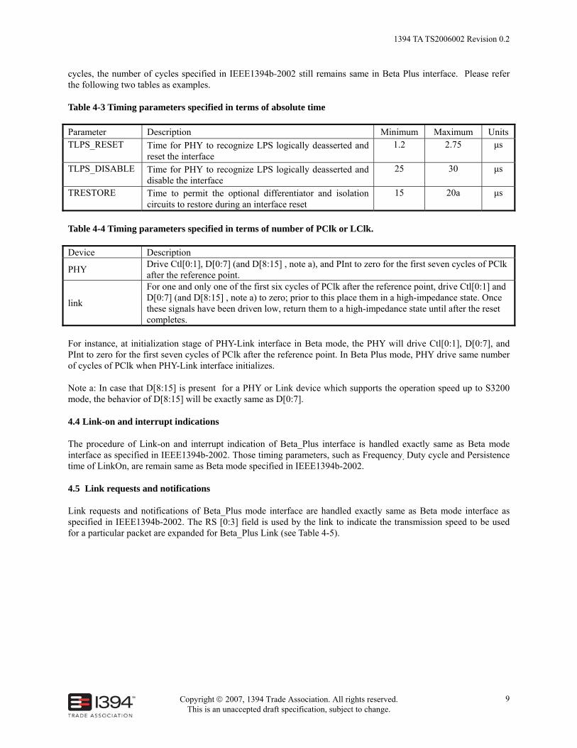
cycles, the number of cycles specified in IEEE1394b-2002 still remains same in Beta Plus interface. Please refer the following two tables as examples.
Table 4-3 Timing parameters specified in terms of absolute time
Parameter Description Minimum Maximum Units TLPS_RESET Time for PHY to recognize LPS logically deasserted and
reset the interface 1.2 2.75 μs
TLPS_DISABLE Time for PHY to recognize LPS logically deasserted and disable the interface
25 30 μs
TRESTORE Time to permit the optional differentiator and isolation circuits to restore during an interface reset
15 20a μs
Table 4-4 Timing parameters specified in terms of number of PClk or LClk.
Device Description
PHY Drive Ctl[0:1], D[0:7] (and D[8:15] , note a), and PInt to zero for the first seven cycles of PClk after the reference point.
link
For one and only one of the first six cycles of PClk after the reference point, drive Ctl[0:1] and D[0:7] (and D[8:15] , note a) to zero; prior to this place them in a high-impedance state. Once these signals have been driven low, return them to a high-impedance state until after the reset completes.
For instance, at initialization stage of PHY-Link interface in Beta mode, the PHY will drive Ctl[0:1], D[0:7], and PInt to zero for the first seven cycles of PClk after the reference point. In Beta Plus mode, PHY drive same number of cycles of PClk when PHY-Link interface initializes.
Note a: In case that D[8:15] is present for a PHY or Link device which supports the operation speed up to S3200 mode, the behavior of D[8:15] will be exactly same as D[0:7].
4.4 Link-on and interrupt indications
The procedure of Link-on and interrupt indication of Beta_Plus interface is handled exactly same as Beta mode interface as specified in IEEE1394b-2002. Those timing parameters, such as Frequency, Duty cycle and Persistence time of LinkOn, are remain same as Beta mode specified in IEEE1394b-2002.
4.5 Link requests and notifications
Link requests and notifications of Beta_Plus mode interface are handled exactly same as Beta mode interface as specified in IEEE1394b-2002. The RS [0:3] field is used by the link to indicate the transmission speed to be used for a particular packet are expanded for Beta_Plus Link (see Table 4-5).

1394 TA TS2006002 Revision 0.2
Copyright © 2007, 1394 Trade Association. All rights reserved. This is an unaccepted draft specification, subject to change.
10
Table 4-5 Description of RS [0:3] in link request in Beta Plus mode.
Beta_Plus Mode RS[0:3] value Meaning RS[0:3] value Meaning
0000 S100 0111-1101 Reserved 0001 Reserved 1110 S3200 Beta Plus 0010 S200 1111 S1600 Beta Plus 0011 Reserved 0100 S400 0101 Reserved 0110 S800
4.6 Interface data transfers
The mechanism of data transfer operations that are carried out over the PHY-link interface are handled same as Beta mode interface specified in IEEE1394b-2002 except the 196.608MHz operation frequency. The discrete PHY-link interface supports data transfers at data rates of S100, S200, S400, S800, S1600 and S3200.
The data transfer operations that are carried out over the PHY-link interface are
a) Packet transmit (data transferred from link to PHY)
b) Packet receive (data transferred from PHY to link)
4.6.1 Packet Reception
The PHY uses the both D[0:7] and D[8:15] data interface to send the following information to the link:
a) Data on indication
b) Packet speed information
c) Packet data
d) Packet grant and interface handover information
e) Bus status information Packet reception timing in S3200
The ways handling single byte traffic and multi-byte traffic are different in S3200 mode. For example, Data On, Packet Speed, Packet Grant, More Info and Interface Handover are single byte control traffic defined in IEEE1394b-2002. Bus Status and Acknowledge are single byte data traffic while all other data traffic are quadlets defined in IEEE1394b-2002.
All single byte control traffic and data traffic defined in IEEE1394b-2002 are expanded to dual byte with the second byte 00 in S3200 mode. For control traffic, D[8:15] is set to 00 when CTL[0:1] in 00,01 and 11 phases. For single byte data traffic, The D[8:15] is set to 00 when the current cycle is used to send Data On and Packet speed when CTL[0:1] in 10 phase. For multi-byte data traffic, both D[0:7] and D[8:15] are used to send packet data when CTL[0:1] in 10 phase. At other occasions, D [8:15] shall be placed in high impedance if D [0:7] is placed in high impedance when interface is being handover.
DATA_HIGH_VALID is always high impedance whenever D[8:15] is high impedance. DATA_HIGH_VALID is always 0 when D [8:15] is not carrying actual data. DATA_HIGH_VALID is 1 for all cycles where packet data is
1394 TA TS2006002 Revision 0.2
Copyright © 2007, 1394 Trade Association. All rights reserved. This is an unaccepted draft specification, subject to change.
11
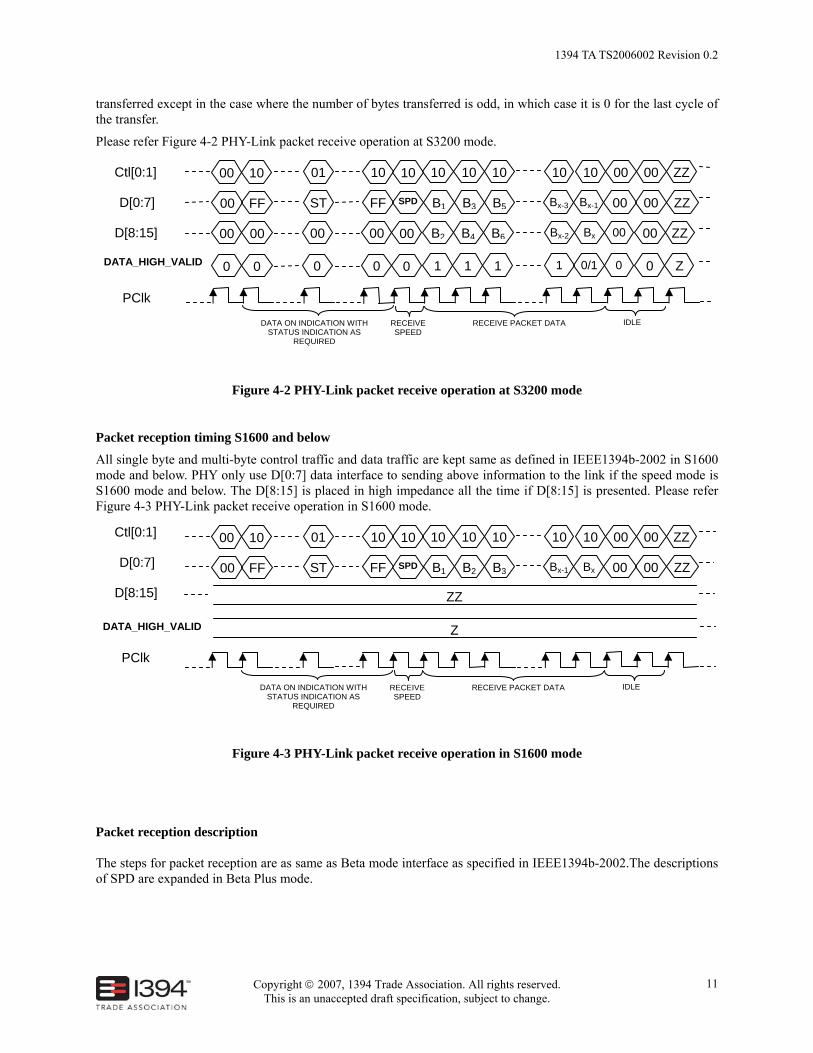
transferred except in the case where the number of bytes transferred is odd, in which case it is 0 for the last cycle of the transfer.
Please refer Figure 4-2 PHY-Link packet receive operation at S3200 mode.
Figure 4-2 PHY-Link packet receive operation at S3200 mode
Packet reception timing S1600 and below
All single byte and multi-byte control traffic and data traffic are kept same as defined in IEEE1394b-2002 in S1600 mode and below. PHY only use D[0:7] data interface to sending above information to the link if the speed mode is S1600 mode and below. The D[8:15] is placed in high impedance all the time if D[8:15] is presented. Please refer Figure 4-3 PHY-Link packet receive operation in S1600 mode.
Figure 4-3 PHY-Link packet receive operation in S1600 mode
Packet reception description The steps for packet reception are as same as Beta mode interface as specified in IEEE1394b-2002.The descriptions of SPD are expanded in Beta Plus mode.
Ctl[0:1]
D[8:15]
PClk
00 10 10 10 10
D[0:7] 00 FF B1 B2 B3 Bx 00 Bx-1
10 00
00 ZZ
00 ZZ1001
ST FF
10
SPD
10
DATA ON INDICATION WITH STATUS INDICATION AS
REQUIRED
RECEIVE SPEED
RECEIVE PACKET DATA IDLE
DATA_HIGH_VALID Z
ZZ
Ctl[0:1]
D[8:15]
PClk
00
00
10
00
10
B2 B4
10
B6
10
Bx 00 Bx-2
D[0:7] 00 FF B1 B3 B5 Bx-1 00 Bx-3
10 00
00 ZZ
00 ZZ
00 ZZ10
00
01
ST
00
FF
10
00
SPD
10
DATA ON INDICATION WITH STATUS INDICATION AS
REQUIRED
RECEIVE SPEED
RECEIVE PACKET DATA IDLE
DATA_HIGH_VALID 0 0 1 1 1 0/1 0 1 0 Z0 0 0

1394 TA TS2006002 Revision 0.2
Copyright © 2007, 1394 Trade Association. All rights reserved. This is an unaccepted draft specification, subject to change.
12
Table 4-6 SPD - receiving packet
Beta_Plus Mode
D[0:7] during SPD cycle Receive packet speed and format D[0:7] during SPD cycle Receive packet speed and
format 0000 0000 S100 Legacy 0000 1111 S1600 Beta Plus 0000 0001 S100 Beta 0000 1011 S3200 Beta Plus 0000 0100 S200 Legacy 1111 1111 DATA_ON 0000 0101 S200 Beta Other values Reserved 0000 1000 S400 Legacy 0000 1001 S400 Beta 0000 1101 S800 Beta
4.6.2 Packet Transmission The link uses both D[0:7] and D[8:15] data interface to send the following information to the PHY:
a) Interface Hold indication
b) Packet data
c) Link requests
d) Interface handover information Packet transmission timing in S3200
All single byte control traffic and data traffic defined in IEEE1394b-2002 are expanded to dual byte with the second byte 00 in S3200 mode.
For control traffic, D[8:15] is placed in 00 when CTL[0:1] in 00 and 11 phases. For data traffic, the both D[0:7] and D[8:15] are used to send packet data when CTL[0:1] in 10 phase. At other occasions, D [8:15] shall be placed in high impedance as well if D [0:7] is placed in high impedance when interface is being handover.
DATA_HIGH_VALID is always high impedance whenever D[8:15] is high impedance. DATA_HIGH_VALID is always 0 when D [8:15] is not carrying actual data. DATA_HIGH_VALID is 1 for all cycles where packet data is transferred except in the case where the number of bytes transferred is odd, in which case it is 0 for the last cycle of the transfer.
Please refer Figure 4-4 PHY-Link packet transmit operation in S3200 mode.

1394 TA TS2006002 Revision 0.2
Copyright © 2007, 1394 Trade Association. All rights reserved. This is an unaccepted draft specification, subject to change.
13
Figure 4-4 PHY-Link packet transmit operation in S3200 mode
Packet transmission timing in S1600 and below
All single byte and multi-byte control traffic and data traffic are same as defined in IEEE1394b-2002 in S1600 mode and below. Link only use D[0:7] data interface to sending above information to the PHY if the speed mode is S1600 mode or below. The D[8:15] is placed in high impedance all the time if D[8:15] is presented. Please refer Figure 4-5 PHY-Link packet transmit operation at S1600 mode.
PHY Ctl[0:1]
PHY D[8:15]
P/LCLK
00
00
11
00 ZZ
ZZ
ZZ
PHY D[0:7] 00 GT ZZ ZZ
ZZ
ZZ
ZZ ZZ
ZZ
ZZ
ZZ
ZZ
ZZ
ZZ
ZZ
ZZ
ZZ
00
00
00
LINK Ctl[0:1]
LINK D[8:15]
ZZ
ZZ
ZZ
ZZ 00
11
B2
LINK D[0:7] ZZ ZZ 00 B1
B4
B3
0101
ZZ
ZZ
ZZ
ZZ
ZZ
ZZ
00
00
11
ZZ
ZZ
ZZ
INTERFACE GRANT AND RELEASE
INTERFACE HOLD DATA TRANSFER
PHY Ctl[0:1]
PHY D[8:15]
ZZ
ZZ
ZZ
ZZ 00
00
00
PHY D[0:7] ZZ ZZ 00 00
00
00
0000
ZZ
ZZ
ZZ
ZZ
ZZ
ZZ
ZZ
ZZ
ZZ
ZZ
ZZ
ZZ
LINK Ctl[0:1]
LINK D[8:15]
01
Bx-3
01
Bx ZZ
ZZ
ZZ
LINK D[0:7] Bx- Bx- ZZ ZZ
ZZ
ZZ
ZZZZ
00
00
00
ZZ
ZZ
ZZ
ZZ
ZZ
ZZ
00
11
AI
INTERFACE REALSE DATA TRANSFER
INTERFACE HOLD
OPTIONAL ADDTION INFOMATION
DATA_HIGH_VALID Z Z 0 1 1 Z Z 0Z
DATA_HIGH_VALID 1 0/1 Z Z Z0 Z Z0

1394 TA TS2006002 Revision 0.2
Copyright © 2007, 1394 Trade Association. All rights reserved. This is an unaccepted draft specification, subject to change.
14
Figure 4-5 PHY-Link packet transmit operation at S1600 mode
PHY Ctl[0:1]
P/LCLK
00 11 ZZ
PHY D[0:7] 00 GT ZZ ZZ ZZ
ZZ ZZZZ
ZZ ZZ
ZZ
ZZ
ZZ00
00
LINK Ctl[0:1]
PHY/LINK D[8:15]
ZZ
ZZ
ZZ
ZZ ZZ
11
ZZ
LINK D[0:7] ZZ ZZ 00 B1
ZZ
B2
0101
ZZ
ZZ
ZZ
ZZ
ZZ
ZZ
ZZ
00
11
ZZ
ZZ
ZZ
INTERFACE GRANT AND RELEASE
INTERFACE HOLD DATA TRANSFER
PHY Ctl[0:1] ZZ ZZ 00
PHY D[0:7] ZZ ZZ 00 00 00
0000ZZ
ZZ ZZ
ZZ
ZZ
ZZZZ
ZZ
LINK Ctl[0:1]
PHY/LINK D[8:15]
01
ZZ
01
ZZ ZZ
ZZ
ZZ
LINK D[0:7] Bx- Bx ZZ ZZ
ZZ
ZZ
ZZZZ
ZZ
00
00
ZZ
ZZ
ZZ
ZZ
ZZ
ZZ
ZZ
11
AI
INTERFACE REALSE DATA TRANSFER
INTERFACE HOLD
OPTIONAL ADDTION INFOMATION
DATA_HIGH_VALID Z Z Z Z Z Z Z ZZ
DATA_HIGH_VALID Z Z Z Z ZZ Z ZZZ
1394 TA TS2006002 Revision 0.2
Copyright © 2007, 1394 Trade Association. All rights reserved. This is an unaccepted draft specification, subject to change.
15
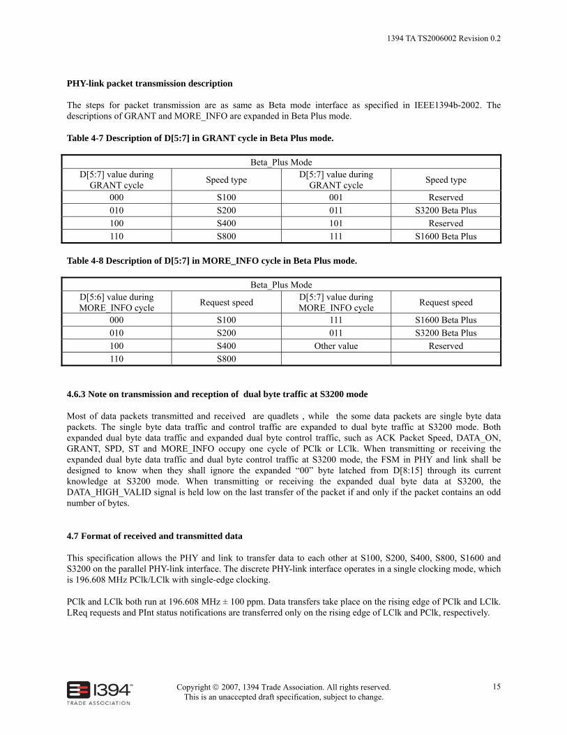
PHY-link packet transmission description The steps for packet transmission are as same as Beta mode interface as specified in IEEE1394b-2002. The descriptions of GRANT and MORE_INFO are expanded in Beta Plus mode.
Table 4-7 Description of D[5:7] in GRANT cycle in Beta Plus mode.
Beta_Plus Mode D[5:7] value during
GRANT cycle Speed type D[5:7] value during GRANT cycle Speed type
000 S100 001 Reserved 010 S200 011 S3200 Beta Plus 100 S400 101 Reserved 110 S800 111 S1600 Beta Plus
Table 4-8 Description of D[5:7] in MORE_INFO cycle in Beta Plus mode.
Beta_Plus Mode D[5:6] value during MORE_INFO cycle Request speed D[5:7] value during
MORE_INFO cycle Request speed
000 S100 111 S1600 Beta Plus 010 S200 011 S3200 Beta Plus 100 S400 Other value Reserved 110 S800
4.6.3 Note on transmission and reception of dual byte traffic at S3200 mode
Most of data packets transmitted and received are quadlets , while the some data packets are single byte data packets. The single byte data traffic and control traffic are expanded to dual byte traffic at S3200 mode. Both expanded dual byte data traffic and expanded dual byte control traffic, such as ACK Packet Speed, DATA_ON, GRANT, SPD, ST and MORE_INFO occupy one cycle of PClk or LClk. When transmitting or receiving the expanded dual byte data traffic and dual byte control traffic at S3200 mode, the FSM in PHY and link shall be designed to know when they shall ignore the expanded “00” byte latched from D[8:15] through its current knowledge at S3200 mode. When transmitting or receiving the expanded dual byte data at S3200, the DATA_HIGH_VALID signal is held low on the last transfer of the packet if and only if the packet contains an odd number of bytes.
4.7 Format of received and transmitted data
This specification allows the PHY and link to transfer data to each other at S100, S200, S400, S800, S1600 and S3200 on the parallel PHY-link interface. The discrete PHY-link interface operates in a single clocking mode, which is 196.608 MHz PClk/LClk with single-edge clocking.
PClk and LClk both run at 196.608 MHz ± 100 ppm. Data transfers take place on the rising edge of PClk and LClk. LReq requests and PInt status notifications are transferred only on the rising edge of LClk and PClk, respectively.
1394 TA TS2006002 Revision 0.2
Copyright © 2007, 1394 Trade Association. All rights reserved. This is an unaccepted draft specification, subject to change.
16
Format of traffic at S3200 mode
The data traffic of quadlet type shall be transmitted in such way that the first byte and second byte of quadlet are transmitted or received by D [0:7] and D [8:15] respectively, followed by the third byte and forth byte of quadlet are transmitted or received by D [0:7] and D [8:15] respectively as described in 4.7.1. The PHY or link shall transmit or receive quadlet type packet data continually till it finishes operation. Format of traffic at S1600 mode
Data transfers between the PHY and link are handled exactly same as Beta mode interface as specified in IEEE1394b-2002 except the PClk and LClk both run at 196.608 MHz as described in 4.7.2. Format of traffic at S800 mode and below
Data transfers between the PHY and link are accomplished by appropriate padding of the lower rate data as described in 4.7.3 at S800 and below. Data on D[0:7] should be latched by the receiving device at the end of the first cycle in a repeating series for data transfers at S800 and below. The transmitting device should drive the same data on D [0:7] for all cycles of a repeating series in above modes.
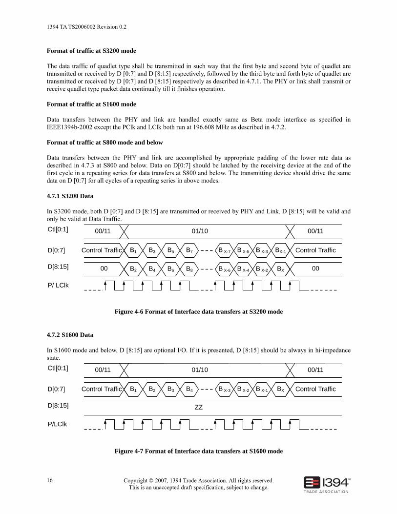
4.7.1 S3200 Data
In S3200 mode, both D [0:7] and D [8:15] are transmitted or received by PHY and Link. D [8:15] will be valid and only be valid at Data Traffic.
Figure 4-6 Format of Interface data transfers at S3200 mode
4.7.2 S1600 Data
In S1600 mode and below, D [8:15] are optional I/O. If it is presented, D [8:15] should be always in hi-impedance state.
Figure 4-7 Format of Interface data transfers at S1600 mode
Ctl[0:1]
D[8:15]
P/LClk
D[0:7] B1 B2 B3 B4 B X-3 B X-2 B X-1 BX
01/10 00/11
ZZ
Control Traffic
00/11
Control Traffic
Ctl[0:1]
D[8:15]
P/ LClk
D[0:7]
B2
B1
B4
B3
B6
B5
B8
B7
B X-6
B X-7
B X-4
B X-5
B X-2
B X-3
BX
BX-1
01/10 00/11
00
Control Traffic
00/11
00
Control Traffic

1394 TA TS2006002 Revision 0.2
Copyright © 2007, 1394 Trade Association. All rights reserved. This is an unaccepted draft specification, subject to change.
17
4.7.3 S800 – S100 Data
For S800 and below, the width of the data path is 8 bits, data traffic are accommodated by data padding and repetition.
Figure 4-8 Format of Interface data transfers at S800 mode
Figure 4-9 Format of Interface data transfers at S400 mode
Figure 4-10 Format of Interface data transfers at S200 mode
Ctl[0:1]
D[8:15]
P/LClk
D[0:7] B1 BX
01/10 00/11
ZZ
Control Traffic
00/11
Control Traffic
8 PClk/LClk cycles
Ctl[0:1]
D[8:15]
P/LClk
D[0:7] B1 BX
01/10 00/11
ZZ
Control Traffic
00/11
Control Traffic
4 PClk/LClk cycles
Ctl[0:1]
D[8:15]
P/LClk
D[0:7] B1 B2 B X-1 BX
01/10 00/11
ZZ
Control Traffic
00/11
Control Traffic

1394 TA TS2006002 Revision 0.2
Copyright © 2007, 1394 Trade Association. All rights reserved. This is an unaccepted draft specification, subject to change.
18
Figure 4-11 Format of Interface data transfers at S100 mode
Note: the subscript “x” of Bx is integer times 4, e.g. 4, 8, 12 and so on. This reflects that most of data packets transmitted and received are quadlets.
4.8 Status transfers and notifications from the PHY
Apart from the 200MHz operation frequency, the procedures of Status transfers and notifications of Beta Plus interface is handled exactly same as Beta mode interface as specified in IEEE1394b-2002.
4.9 Legacy link and Beta Link support
When PHY and Link are configured as Legacy Link, the PHY-link interface complies with the PHY-link interface as specified in IEEE Std 1394a-2000. If PHY and Link are configured as Beta Link, the PHY-link interface complies with IEEE Std 1394b-2002.
In case of Legacy Link, Beta Link or Beta Plus Link at S1600 and below, when D [8:15] is presented, D[8:15] is high impedance.
If the PHY design allows the mode of the PHY-link interface to be changed while the PHY is powered and if the mode is changed, the PHY shall place all ports in the Disconnected state and begin initialization as if the PHY had just been powered on.
Ctl[0:1]
D[8:15]
P/LClk
D[0:7] B1 BX
01/10 00/11
ZZ
Control Traffic
00/11
Control Traffic
16 PClk /LClk cycles
1394 TA TS2006002 Revision 0.2
Copyright © 2007, 1394 Trade Association. All rights reserved. This is an unaccepted draft specification, subject to change.
19
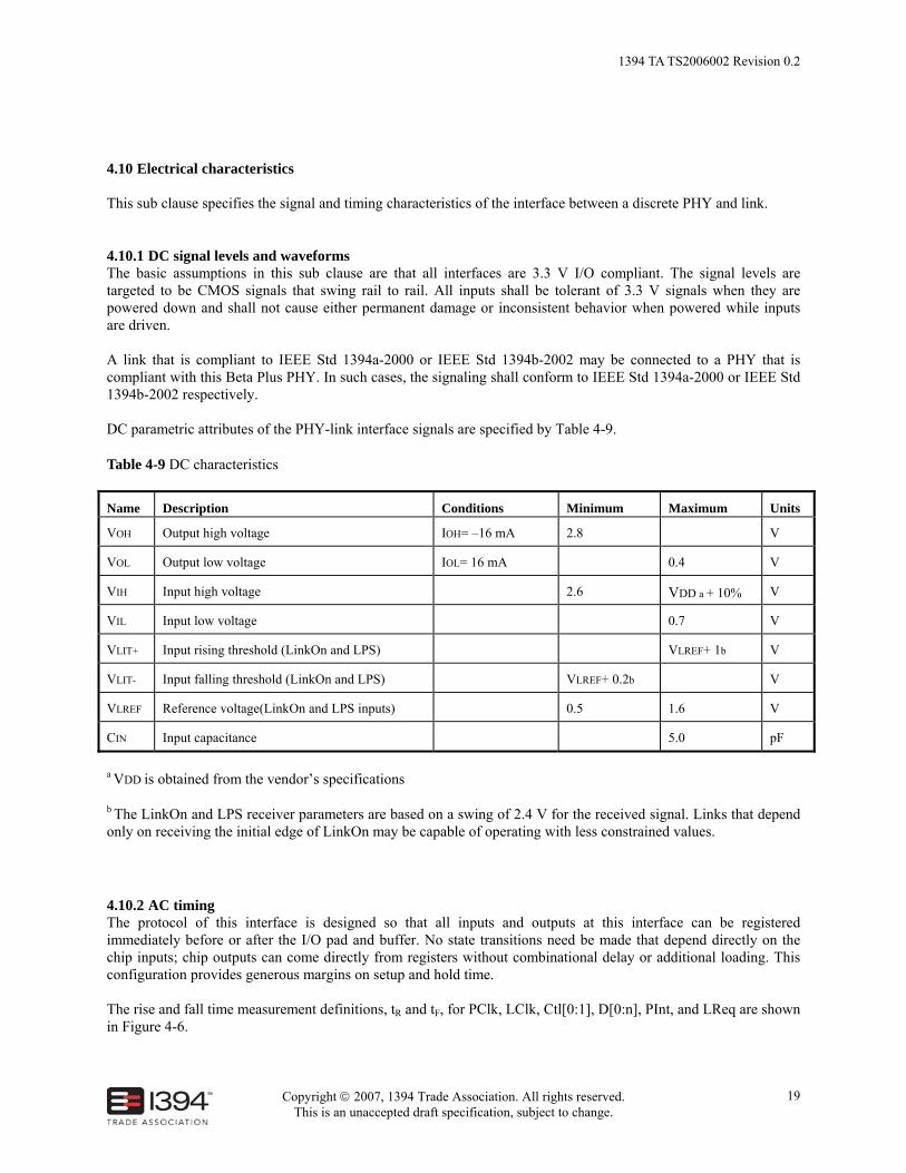
4.10 Electrical characteristics This sub clause specifies the signal and timing characteristics of the interface between a discrete PHY and link.
4.10.1 DC signal levels and waveforms The basic assumptions in this sub clause are that all interfaces are 3.3 V I/O compliant. The signal levels are targeted to be CMOS signals that swing rail to rail. All inputs shall be tolerant of 3.3 V signals when they are powered down and shall not cause either permanent damage or inconsistent behavior when powered while inputs are driven. A link that is compliant to IEEE Std 1394a-2000 or IEEE Std 1394b-2002 may be connected to a PHY that is compliant with this Beta Plus PHY. In such cases, the signaling shall conform to IEEE Std 1394a-2000 or IEEE Std 1394b-2002 respectively. DC parametric attributes of the PHY-link interface signals are specified by Table 4-9.
Table 4-9 DC characteristics
Name Description Conditions Minimum Maximum Units
VOH Output high voltage IOH= –16 mA 2.8 V
VOL Output low voltage IOL= 16 mA 0.4 V
VIH Input high voltage 2.6 VDD a + 10% V
VIL Input low voltage 0.7 V
VLIT+ Input rising threshold (LinkOn and LPS) VLREF+ 1b V
VLIT- Input falling threshold (LinkOn and LPS) VLREF+ 0.2b V
VLREF Reference voltage(LinkOn and LPS inputs) 0.5 1.6 V
CIN Input capacitance 5.0 pF
a VDD is obtained from the vendor’s specifications
b The LinkOn and LPS receiver parameters are based on a swing of 2.4 V for the received signal. Links that depend only on receiving the initial edge of LinkOn may be capable of operating with less constrained values.
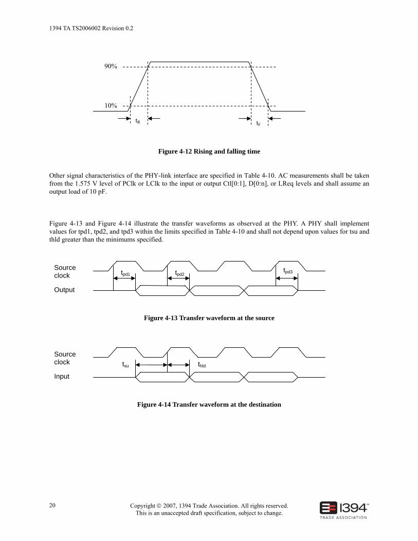
4.10.2 AC timing The protocol of this interface is designed so that all inputs and outputs at this interface can be registered immediately before or after the I/O pad and buffer. No state transitions need be made that depend directly on the chip inputs; chip outputs can come directly from registers without combinational delay or additional loading. This configuration provides generous margins on setup and hold time. The rise and fall time measurement definitions, tR and tF, for PClk, LClk, Ctl[0:1], D[0:n], PInt, and LReq are shown in Figure 4-6.
1394 TA TS2006002 Revision 0.2
Copyright © 2007, 1394 Trade Association. All rights reserved. This is an unaccepted draft specification, subject to change.
20
Figure 4-12 Rising and falling time
Other signal characteristics of the PHY-link interface are specified in Table 4-10. AC measurements shall be taken from the 1.575 V level of PClk or LClk to the input or output Ctl[0:1], D[0:n], or LReq levels and shall assume an output load of 10 pF. Figure 4-13 and Figure 4-14 illustrate the transfer waveforms as observed at the PHY. A PHY shall implement values for tpd1, tpd2, and tpd3 within the limits specified in Table 4-10 and shall not depend upon values for tsu and thld greater than the minimums specified.
Figure 4-13 Transfer waveform at the source
Figure 4-14 Transfer waveform at the destination
Source clock
Input
tsu thld
90%
10%
tR tF
Source clock
Output
tpd1 tpd2 tpd3

1394 TA TS2006002 Revision 0.2
Copyright © 2007, 1394 Trade Association. All rights reserved. This is an unaccepted draft specification, subject to change.
21
Table 4-10 AC timing parameters
Name Description Min Max Unit
PClk or LClk frequency 196.608 +/- 100 ppm MHz
DCP PClk duty cycle 45 55 %
DCL LClk duty cycle DCP – 5 DCP + 5 %
jL LClk jitter (pk-pk) jP+ 0.50 ns
tR Rise time -- 2.0 ns
tF Fall time -- 2.0 ns
tPL Delay from rising edge of PClk into the link to the rising edge of LClk from the link
4.0 ns
tpdPL Signal propagation delay from PHY to link 1 ns
tpdLP Signal propagation delay from link to PHY 1 ns
tpd1 Delay time,PClk/LClk output high to initial instance of D[0:n], Ctl[0:1], PInt/LReq outputs valid
0.5 3.5 ns
tpd2 Delay time, PClk/LClk output high to subsequent instance(s) of D[0:n], Ctl[0:1], PInt/LReq outputs valid
0.5 3.5 ns
tpd3 Delay time, PClk/LClk output high to D[0:n], Ctl[0:1] invalid (high-impedance)
0.5 3.5 ns
tsu Setup time, D[0:n], Ctl[0:1], and PInt/LReq inputs before PClk/LClk 1.5 ns
thld Hold time, D[0:n], Ctl[0:1], and PInt/LReq inputs after PClk/LClk 0.0 ns
1394 TA TS2006002 Revision 0.2
Copyright © 2007, 1394 Trade Association. All rights reserved. This is an unaccepted draft specification, subject to change.
22
Annex A
(informative)
Bibliography
[B1] IEEE Std 1394b-2002, Standard for a High Performance Serial Bus—Amendment 2