doconeit more - ed
TRANSCRIPT

BD 179 391
'AUTHOR:TITLE
INSTITUTIONSPONS AGENCYPUB DATEGRANTNOTE
n
EDRS PRICEDESCRIPTORS
DOCONEIT MORE
aSE 029 295,.
Hamilton, Howard B.Power Processing, Part 1. Electic MachineryAnalyiis. )
Pittsburgh Onii., Pa.National Science Foundation, Washingtcn,70NSF-GY-41384913.; For related documents, see SE 029 296-298
ABSTRACT A
MF01/PC10 PusiPostage.*College Science; Ciirriculum Develoiment;ElectricityrFlectrOmechanical lechnology:Electronics; *Fagineering.Education; HigherEducation;,Instructional'Materials; *Science Courses;Science Curiiculum:.*Science Education; *ScienceMaterials; SCientific Concepts
This publication was developed as a portion of atwo-semester sequence commeicing at either the sixth cr'seventh termof,the undergraduate program in electrical engineering at theUniversity of Pittsburgh. The materials of the two courses, produced
by a ional Science Foundation grant, are concerned with powerconvrs systems comprising power electronic devices,electrouthchanical energy converters, and associated,logicConfigurations necessary to cause the system to behave in aprescribed fashion. The emphisis in this portion of the two coursesequence (Part 1) is on electric machinery analysis. lechniguesapp;icable'to electric machines under dynamic conditions areanallzed. This publication consists of seven chapters which cW-al
with: (1) basic principles: (2) elementary concept of torque and
geherated voltage; (3) tile generalized machine; (4i direct currentmacrimes; (5) cross field machines; (6),synchronous machines; and (7)
polyphase asynchronous machines. (HM) a
(
**0******************,*************************************************** Reproductions supplied by EDRS are the best that can be made *
* from the original document. *
Y

CT%
Co%f-11-4
LL1
fr
,1
LAL
fat
ft
1.
POWER PROCESSING
Part I_
-4
"Electric Machinery Analysis
Howard B. HamiltonUniversity of Pittsbtirgh
1970
e
U S. OII'AR1MNT Ca, HEALTH.moucotriceN a bviiIrAneNATIONAL INS muTe OF
I/01)CA TION
140, uME N I I4A Ot IN e PRO-Dts( ED e )(AC It y AS RISC Elver) t ROMTHE PE R fON OR ORGANIZATION ORIGIN-AIINGII POIN IS OF VIEW OR OPINIONS
TA1ED DO NO1 NFC f SSARIL Y R r PNE%E N I W F IAL NA IONAl INSTIILfle orPout A'TION POSI 1 ION OR rOL Y
"PERMISSION TO REPRODUCE THISMATERIAL HAS BEEN GRANTED BY
TO 1HE EDUCATIONAL RESOURCESINFORMATION CENTER (ERIC)"

The preparation of this daterial hasbeen partially supported by Grant GY-4138entitled "Course Content improvement ,
Project for Power Processing" made to theUniversity of Pittsburgh by the NalionalScience Foundation.
Copyright, 1970 by Howard B. Hamilton
4
4,
a,
4
.0'""

0
GENERAL DESCRIPTION OF PROJECT
The overall objectiVe' of the project was development of a model two
semester sequence of lecture-laboratory courses, senior yhr level, to prepare
t he undergraduate student with the necessary background in electric machineryt,
and to present the fundamental concepts of modeling power processing devices
and circuits necessary for future professional activity in Power Processing.
It is felt that the development of this sequence of courses will be
of vital interest to educators. It will strengthen the Electrical Engineering
curriculum because it will accomplish the following:
Nv.
1. make the electric machinery.and power topics much
more interesting and meaningful to the student.
2. better preparation, for the student, for a productive
professional career in this vital area.
3. reinforce the learning gleaned from earlier courses
in logic theory and solid state electronics.
Courses involving the theory of electric machinery and associated
phenomenon have always been an integral part of the electrical engineering
undergraduate curriculum. Prior to 1950, colleges and universities were in
more or less geneial agreement concerning the portion of the total curriculum
devoted to electric machinery (and power) and to the specific course content.
The technological.: developments associated with the 1940's placed tremendous
pressures upon the curriculum. The phenomena associated with new
technologies such as solid state theory, control system analysis etc. had
04

3
to be included and at the same time, the total time available for the first degree
was even decreased in many instances. These pressures resulted in elimination or
suppression of the "how-to-do" type courses and also resulted, in a reduction of
time allotted to certain areas within the currkula. The courses in electric
machinery and power were victims of the latter economy.
Usually, the electrical machinery (pre 1950) consisted of detailed
study of t he physical bspects ,of the particular machine and from these aspects,
the input-output characteristics were -deduced for the static, or steady state
situation. Coincident with the widespread introduction of control system, or
servo meclianisms, the time allotted for machinery was again reduced so that
the majority of colleges and universities attempted to optimize the machinery
S
offering by presenting the subject matter as if it consisted of devices with input
output terminals and considering that only these aspects of the machine were
necessary for study ofr- the machine in dynamic systems. The rationale for this
approach was that only a very small percentage of the students were interested
in, or would be professionally involved -in, the design of the machine. The power
courses usually were completeiy eliminated from the curriculum.
The past few years have seen tremendous strides in the areas of solid
state electronks and digital logic theory. The potential applications and
useage of these technologies, taken in combination, ale just beginning to be
aripleciated. The useage of these phenomena in electric machinery control and
in power systems has opened a new era of technology, i.e., "Power Processing"
5
4
or "Power Conditioning". As evidence of its importance and the fact that the
rhole concept needs research and definition - the National Aeronautics and Space
'Administration, in iti NASA Research Topics Bulletin SC/RTB-12, dated
September 14, 1966, stated:
"Development and applkation trends in electric power processing(conditioning) indicate a need for further fundamental research toexplore and define the principles, and theoretical and physicallimitations of-related circuits and components. Expected beneficialresults of such resecrech would include: a. The forlyulation oftheoretical criteria for physically realizable power processingcircuits and systems. b. The provision of meaningful guidesand objectives to researchers in related fields (e.g. magnetics,'dielectrics, semi-conductors, etc.) and c. The establishment oflong-range goals for component development through the rig6rousanalysis and cluantitative identification of perfprmance limitingcharacteristics of components and related circuits".
Several of the major .electrical manufacturers have substantial research
efforts underway in this general area. Many of the engineers working in this
area are European. Whether it is inclination, desire, availability, or prior
education that results in this' manpower situation is pure conjecture. The facts
that do emerge are that engineering students graduating from U.S. colleges
and universities have not had an interest in electric machinery or power, they
have not had formal training in the marriage of solid state devices, logic,
and power systems, and they are not prepared to move into this important,
challenging, aspect of electrical engineering.
As further evidence of professional concert for including this type of
material in the education and training\of engineers, it should be noted that
this is a topic of concetn to a group entitled, "Interagency Advanced Powr
GroUp". This group has a Power Conditioning Panel (under the Electrical
6

5
Working Group). It is composed of representatives from NASA, AFAP1, USAECOM
and others. Indicative of their concern for this topic is the "Guest List" at
their meeting of 8 December 1966. This list includes representatives from
Westinghouse I Honeywell, Boeing, General Electric, TRW Systems, etc. as well
as personnel from MIT and Duke University. In the meeting minutes, under
paragraphs 2.14 and 2.15 appear the following:
... "The ultimate need (for work in this area) is a power systemsengineer with broad education in electrical power engineerinincluding a working knowledge of communications and system t eory,who understands the specified requirements and one who cancommunicate with his colleagues. Students are wary of going i tothe field of conventional utifity type power engineering...they dre
\ looking toward more challenging fields, as electric power processing) could be if it were properly interpreted anci presented.
Thus, it appears that a need does exist for educational courses (not "how-to" type
training) that will better prepare undergraduates for productive careers in this
field. Few, if any U.S. universities offer work with emphasis in Power
Processing but there is discussion and interest, which manifests itself at pro-
fessional meetings, in the topic.
An ekareness of the above stimulated our interest in the courseX ---
development.
The most descriptive assessment of the final orientation of the project is
contained in the prefaces to Part I and Part II. rortions of ?Mese prefaces are
as follows.
44
A Quote from Preface to Power Processing, Part I
This material was developed as a portion of a two course sequence concernedwith power conversion sMemst. comprising power electronic devices, electro-mechanicalenergy converters and ssockited logic configurations necessary to cause the system tobehave in a prescribed 1bhion. The emphasis in this portion of the two coursesequence will be on electr c machinery analysis.
7

A
/1
6
Electric machines re members of a large class of devices known generallyas "elearo-mechankal con erters". The name imples conversion of energy fromeleditical to mechanical form - or vice versa. The devices range from verysmall signal devices, such as microphones, through very large generators supplyingas much as 1000 megawatts of power. In some devices, the mechanical motionis linear; in others it is rotary. All deviceLare based, to an extent, on acommon phenomenon and there are many fine textbooks which present a completelygeneralized approach to electro-mechanical energy conversion. Some of thesetexts are listed in Appendix I. Time limitations preclude complete coveiage ofall aspects of electro-mechanical energy conversion. For this reason, theemphasis in lehi s course will be restricted to the analysis techniques applicable toelectric machines under dynamic conditions.
There areinely facets to the general area of electric macMnes. At oneextreme is the'ljpecialized area of design o specific mac s. At the other1extreme is the applic ion aspect of choosi a machine for specific use orapplication. This c urse will avoid detailed design aspects and will concentrateon analysis of performance. In order to become proficient in analysis, if willbe necessary to closely examine some of the internal processes involved inaccomplishing the change in energy form, i.e., the torque and voltage producingprocesses, commutation, le9kage, flux, etc., as well as the physical arrangementof various types of machine .
The majority of electrical engineers who come into contact with electricmachines are either designers of or analyzers of, systems of which the electricmachine is an integral part. Some systems are of the extremely simple "open"type. An example is a simple motor driving a load such as a tool, a puirrp, oran electric fon. The motor is energized, comes up to spet d and performs inthe steady state. The control for this' system is usually art, "on-off" type andthe transient performance of the motor is of limited interest. Veyy little skillis necessary to match morot voltage, speed, and torque ratings to the loadrequirement. However, as applications become more demanding and the machinebecomes part of a complex system, or a process, a owledge of the transient,or dynamic, behavior is necessary.
The past few years have seen the advent of sophisticated control systems,widespread usage of computers and logic machines, and the development of semi-:conductor devices with control features and power ratings which have had a tremen-dous impaci on the design of systems involving electric machines. Indeed, awhole new area of specialization has emerged within the electrical engineeringfield. This is the area of "Power Processing" or "Power Conditioning". Power
Processing involves conversion of power or energy from the form and levplexisting in the available power to the form and level necessary for itt utilizationin some 'end' device. The ability to make the pecessary changes has beenconsiderably enhanced by the development and ammercial availability of solidstate (semi-conductor) devices. To make use of these devices, certain sequences
411

7
and combinations of events must be provided for. Thus, logic circuitry andcomputing mackines and their relationship to the semi-conductor devkes must alsobe studied if skill and competence in systerii design are to be achieved. The
other course in this two couise sequence concerned itself with tMs relationshipas well as the considerations involved when the logic sub-system - semi-conductorsub-system is utilized to modulate electro-mechankal (electric machine,' convertersarid electrkal level converters. ,
These courses were developed as a two semester sequence commencing ateither tfie sixth or seventh term of the undergraduate prograth in ElectrkalEngineering at the Universiy pf Pittsburgh.
For the electrk machinery portion, student familiarity with-'the followingtopics is presumed:
1. electric andlmagnetic circuits, fiekl theory and transformers.
2. a limitea knowledge of 'linear system analysis and techniquesto include Laplace Transf,orm usage function and blockdiagram representation.
3. solving engineering problems on the analog and digitalcomputer.
Concurrent with the electric machinery portion of the two course sequencethe student should have a first course in semi-conductor electronics and anexposure to logic circuitry principles.
Quote from Preface to Power Processing, Part II
This b ok is int nded for use as a text in the senior elective course"Power Proce sing II", Electrical Engineering Department, University, of Pittsburgh.The laterial presented here has been successfully used as fhe course content fortwo trimesters. Although several available books were considered and tried astexts, none were found to be suitable in the light of the objectives of thecourse, and therefore this book has been written to fulfill the needs of thecourse.
There are thtee objectives in )le course "Power Processing II" which are:interesting ugtergraduate students in-lhe power area of electrical engineering,providing the students with factual information and some experience relating to
..,...Ais ikonductor power electronks, and to develop the students ability to modelysical problems. Student interest is fostered by the students' growing competence
in the semiconductor power area, frequent classroom reference to the currentengineering relevance of the types of problems being considered, and by makingthe problems and laboratory sessions as realistic as possible. Also, the area ofsemkonductor applications to power processing, the subject material of the course,
1

8
is an area of great interest and expansion in the present day power industry and istherefore "relevant". Skill jdeling is encouraged in tv.,;o ways. First, theproblems the stidents gieuIred to work 'are framed in terms of real circuitelements. The students must decide what .idealizations can be nide. Secondly,as 'the course progresses, the sophistication of the modeling required to solve theproblems in a reasonable time inecreases, and hopefully the students' skill willincrease as they work the gradually more scyhisticated p'roblems.
The author considersimodeling the most important asilect of the course a5
reflected by the subject material and organization of this botk. Two of the mostvaluable attributes of an engineer are his ability to assimilate'new technology,and his ability to apply basic science and technology (new or old) to new Problems.Without these attributes, the en6ineer is soon relegated to the position of acompetent technician. One of the most, if not the most, powerful tool usedto maintain theset attributes is the engineer's skill in modeling physical pro ems;that is, to simplify tire problem to the extreme so that the basic parameters andoperations becorhe obvious, and then to replace the necessary complexities untilthe model sufficiently approaches the real physicol problem to give validengineering answers. The author therefore feels that the gain in examining andmodeling the problems in some detail far outweigh the disadvantage that lessmaterial (fewer circuits, problems, and applications) can be consider d in the igiven time.
There are several reasons for stressing modeling in the particular courseon semiconductor pwer processing. The pr ary objective in offering the course"Power Processing II" is to interest studèrts he power area of engineering.By incorporating the learning of a fundamenta engineering skill (modeling)into the course, it may be possible to attract more of the "uncertain" studentswho may not want to commit themselves to a specific area of electricalengineering. The subject material may then provide sufficient challenge tointerest these students in power engineering. Also, starting from the studentsundergraduate background in electronics, logic, and physics, the students,actually experience the extensim of their knowledge into an unfamiliartechnological area (semiconductor power processing) using the tool of modelingas well as using modeling to solve complicated problems. And of course, eventhe simplest problems in power processing can only 4e solved by the straight-fcizard applkation of Kirchoff's laws with utm9st difficulty, further impressingupon the student the value of modeling as a problem solving tool.
The laboratory requires some special mention. The laboratory problemsdo not designate specific experiments to be performed by the students, nor isa "typicbl" formal laboratory report required of each student. While real-lifesituations sometimes require a "laboratory report", as in the testing andevaluation of an item or system, the most frequent use of an industriallaboratory is as an aid to finding the answer to a problem. The realisticltiboratory problem associated with any problem is "What laboratory experin-ent"

should be done?" The student is given the choice of using the laboratory togather data, confirm his theory, check assumptions, as an aid to understandingdevice or circuit operation, or any combination of these. The students arenot permitted to enter the laboratory without a "plan" in which each 'studentmust identify a specifk objective for, the laboratory experiment, and a detailedplan to carry out the experiment. The students are graded on the basis ofhow.effective cr3;fatory objective will be in enabling them to soNv theproblem, and whether their detailed plan has a reasonable assurance ofenabling the students to accomplish their immediate objective. After thelaboratory session, the students complete their assigned problem, presentingIIan answer" which is backed up by laboratory experiment and data. Thistype of laboratory has proveetoch more interesting to the studenrs and seemsmore in keeping with an engineering education than simply "verifying calculations"or "demonstrating effects."
End Quote
The courses were developed on the basis of determination .of what should
be in the course and the general approach to the method of presentation.
Dr. T. W. Sze of the University of Pittsburgh and Mr. Alec H. 'B. Walker
of Westinghouse Research and .Devefopment were active in the former activIty
and worked closely with Dr. Frank E. Ackér and Dr. H. B. Hamilton 'throughout`Y.
the life of the project. Class lecture notes were-prepared, presented, revised,
presented again' and again revised based on the classroom experience and
student reaction.
Student reaction has been favorable, especially in the power semi-
conductor work in Part II,. It is the authors opiniorl that Part I, Electric
Machinery Analysis, is excellent for the average and above average student.
However, the below average student does have a difficult time with the
material because of the mathematical rigor involvbd in .thepresentatioit.
14 4
a-

tt,,
10
Emphtisis throughout is on modeling techniques. Stiaents 1.yho develop
the ability to model devkes and systems seem to be well prepared for Orofessional
careers win both design and analysis. Further,' ihe ability to model an entity
insures that the student does have the capability-for professional involvement
in new and different activities and situations. It appears to mitigate, against
early technological obsolescence.
Two different individuals had direct responsibility for the two spirrses and
the text material which- evolved has different formats.Wit
Part I, "Electric Machinery Analysis", consiSts of three bound booklets
the lecture notes, a problen manual, and a laboratory manual. The lecture
notes emphasize modeling of a generalized machine and *re resulting dynamic
equations are then reduced (or modified) to portray specific types of real
machines. Steady state behavior is obtained by an application of the Final
Value Theorem to the Laplace transform of the describing equations. The
laboratory work is an effort to relate thedynamic model studied in the class-
room to the real world machine. The problems, from a variety of sources,
serve to illustrate the lecture material'.
Part II, Modeling Power Processing Devices and Circuits" deals
with pbwer semiconductors - modeling their behavior, the thermal and Other,--
application problems and utilization of the theory to design and analyze a
d.c. motor drive. Problemi have been formulated and inserted in Jhe te
Laboratory ptoblems are 'also included at the end of each chapter which provide
exercise in the laboratory application of classroom tl-eory.

!liCt -.nvi
. o
0
c.
DISTRIBUTION
11
A set of the resulting project material, wit-I/the letter' of transmittal
detailed as Attachment #1 to this reporWhas been forwarded to each,Pectrical
Engineering Deportment in the U.S.A. and Canada.
In addition, requests-for the material have been received from Mexico,
Colombia, ichile and Greece. At this' time, no firm decisions on publication
and additional distribution have been formulated. Requests for suggestions
have been sent out with the sets of project materials.
a Notice of the material will be presented to the Power Engineeringnb,
WIST
$.
Education 'Committee of the Institute or tlectrical and Electronic Engineers4
and to othet 'appropriate groups.
CONCLUSION
The air-hors feel that the objectives of the project have been realized.44
and that classroom tested text material, problems, and lab work suitable for
a two semester course"in power processing have evolved. Ve sincerely
hopt: that surficient interest will develop in other schools andruniversities
to warrant further publication and distribution of the npterial.,
The two sequence course will continue at the University of Pittsburgh.
Part I cis a required unit and Part II as an elective. Our faculty fe-el that
this material is an essential ingredient in the educational process for
electrical engineers.

This'matconterned with powelectro-mechanical eto cause the systemportion of tile ty.Co.course
PREFACE
eloped as a portion of a two course sequencesystems comprising powerelectronic devices,
erters and associated logic configurations necessaryin a prescribed fashion. The emphasis in this
sequence will be on electric machinery analysis.
electric .machines are members of a large class of devkes ktiowngenerally as "electro-mechonical converters". The name implies conversionof energy from teectrical to meaanical form - or'vice versa. The devicesrange from verymall signal devkes, such as microphones, through verylarge generators supplying as much as 1000 megawatts of power. In somedevices, the mechanical motion is linear; in others it is rotary. All devicesare based, to an extent, on a common'phenomenon and there are,manx finetextbooks which present a completely generalized approach to electro-mechanicalenergy conversion. Some of these texts are listed in Appendix I. Timelimitations preclude coMplete coverage of all aspects of electro-Thechanicalenergy conversion . For this reason, the emphasis, in this course will berestricted to the analysis techniques tipplicdble to electric machines underdynamic conditions.
There are many facets to the general area of electric machines. Atone extreme is the specialized area of design of specifictmachines. At theother extreme is the application aspect of choosing a me9hine for a specificuse *or application. This course will avoid detailed design aspects and willconcentrate on analysis of performance. In order to become proficient inanalysis, it will be necessary to closely examine some of the internal, processesinvolved in accomplkhing the change in energy form, i.e4 the torque andvoltage prOducing processes, commutation, leakage, flux, et`c., as well asthe physical arrangement of various types of machines.
The majority of electrical engineers who come into contact withelectric machines are either designers of or analyzers of, systems of whichthe electric machine is an integral part. Some systems are of the extremelysimple "open" type. An example is a simple motor drMng a load such as atool, a pump, or an electric fan. The motor is energized, comes up to speedand performs in the steady state. The contrdl for this system is usually anl'on-off" type and the transient performance of the motor is of limited interest.Verr44ittle skill is necessary to match motor Noltage, speed, andi torque ratingsto the lodd requirment. However, as applications become more cle4nanding andthe machire becomes part of a complex system, or a process, a khowledge ofthe transient, or dynamic, behavior is necessary.
14

The past few years have seen tilie_advent,pf sophlisticated control sYstems,wklespread usage oT computers and logic machines, and the evelopment, of semi-. conductor devices with control features and power ratings vAich have had a tremen-dous Impact on the design of systems involving electric machines, Indeed, a wholenew area of specialization has emerged within the electrical engineering field.This is. the area of "Power Processing" or "Power Conditioning". Power Processinginvolves conversion of power or enprgy from the form and Nivel existing in theavailable power to the form and ,level necessary for its utilization in some 'end'device. The ability to make the necessary Changes has been considerably enhancedby theidevelopment and commercial availability of solid state (semi-conductor)devices. To make use of these devic6, certain sequenCis and combinations ofevents must be provided for. Thus, logk circuitry and computing machines andtheir relationship to the semi-conductor devices must also, be studied if skill andcompetence in system design are to be achieved. The Other courso in. this twocourse sequence concerned itself with this relationship as well as the considerationsinvolved when the logk sub-system - semi-conductor sub-system is utilized tomodulate electro-mechanical (electric machine) converters and ele,Ftrical levelconverters.
These courses were developed as a two semester sequence commencingat either the sixth or seventh term of the undergraduate program im ElectricalEngineering at the University of Pittsburgh.
For .the electric machinery portion, student familiarity with thefollowing topics is presumed:
9
1. electric and magnetic qircuits, field theory and transformers.
2, a limited knowledge of linear system analysis techniquesto include Laplace Transform usage function and blockdiagram representation.
3. solving engineering problems on the, analog and digitalcomputer.
Concurrent with the electric machinery portion- of the two coursesequence the student should have a first course in semi-conductor electronicsand an exposure to logic circuitry principles.
.<7

INDEX
Chapter I - BASIC PR1NCA:ES
Page
1
1.1 IntroduCtion 1
1.2 Perturbations 1
1.3 Electrical, Mechanical, and Field Energy 3
1.4 Torque and'Forcet 61.5 Relationships in Multiple Excited Systems 11
1.6 Electrostatic 'Relationships 13
1.7 Electromagnetic vs Electrostatic Energy Converters 14
Chapter 11 ELEMENTARY CONCEPTS OF TORQUE AND GENERATEDVOLTAGE 16
11.1 The D.C. pachine 16
11.2 The Alternating Current Machine 18
Chapter 111 - THE GENERALIZED MACHINE 27
111.1 The Basic Machine 27"111.2 The Per Unit System-, .4" 32 0.
111.3 Indticed Voltages 42111.4 Developed Torques 52111.5 Summary 55
Chapter IV - D.C. MACHINES 56
IV. 1 Introduction 56IV.2 The Shunt Connected, Separately Excited GeneLator with
Switched Load 59IVA3 The Shunt Conncted, Separately Excited D.C. Motor 71
IVA Block Diagrams 78
IV.5 The Serie D.C. Motor 83IV.6 Self Excited D.C. Machine On Short Circuit 88
Chapter V - CROSS FIELD MACHINES 93
V.1 Introduction 93V.2 The Basic Metadyne Analysist 93
zkr '
1 6

Chapter VI
VI.1VI.2V1.3VI.4VI.5VI.6VI.7VI.8VI.9
VI.10VI.11VI.12VI.13VI.14VI.15
2
- SYNCHRONOUS MACHINES
-*!'The Revolving MagneHc FieilaSYnchronous Machine Flux Linkages.The a-b-c to d-q-o TransformationThree Phase Machine Per Unit QuantitiesSummary'of Synchronous Machine EquationsEquation Rearrangement for Block Diagmm RepresentationThe Synchronous Machine Under Steady State Conditi.onsThe Power Angle and Povter Converted Steady StateCharacteristic Curves of the Synchronous MotorAn Alternator on Short CircuitSwitched Load StudiesSynchronous Machine DramicsSynchronous Machine Parameters by TestSynchronous Motor ApplicationsSynchronous Machine Simulation and Modeling
CC
Chapter VII - POLYPHA§E ASYNCHRONOUS MACHINES'
VII.1,VII.2VII.3VII 4VII.5V11.6VII.7VII.8V11.9
Introduction and`Construction FeaturesInduction Motor AnalysisSteady State RepresAtationSteady State PerformanceAn Approximate Expression for TorqueMachine Parameters by Test4;nchronous GeneratorsStarting ProblemsVariable Frequency Operation
APPENDIX I - Selected Reference Textbooks
APPENDIX II - Units Conversion Multipliers and Constants
CV
F.
1 7
Page
102
102107109114116118135143147151
173173181
182185
195
195197207,'212216217219221222

aCHAPTER I - BASIC PRINCIPLES
LI ITRODUCTION: This text was prepared with a specific orientation whichdiffers Trom the classkol texts inTelectric machinery. It is oriented toward,"power processing" and views the machine as an entity in,a system whichconverts energy from, one level, or form, .to another lefel, or form. The,emphasisis on analysis of machine behavior With only enough of the why of the behavioras is necessary to 10erstand how behavior may- be modified.
The system of units used is the rationalized mksc system. This systemis generally accepted as the most useful for electrkal engineering. In the mkscsystem many troublesome constants relating widely used quantities (such as power,torque, velocity, for example) are eliininated. It is not possible to eliminateall constants, however, The usage of the term 'rationalized' denotes an inclusionof the quantity 417 in` such things as permeability of free space, etc. rather thanUsage as a constant- fOr the relationship. Thus, Maxwell's equations can bewritten without use of the 4r . The English system of units is still in ratherwidesprepd usage ih sornei s = such as magnetic cir`cuit design. However, itis being superceded by thd mksc system.
4a
It it aiso recommended that the student obtain and use a copy of therelatively inexpensive "Basic Tables in. Electrical Engineering" (McGraw-Hill,196) by Korn. This' reference contains much useful 4data on control systems,coniaLter representatiOn; Motor characteristics, Laplace transform pairsi etc.,plUs other useful data and tables.
1.2 PERTURBATIONS: A very useful concept of the analysis of systems is thatof the dynaniic taa-.4vior of a' system about a steady state operating point. Theidea is that some small. , change, or perturbbtion, is introduced and the resultingsystem (or device) behavior analyzed. This concept can often be used to linearizea non-linear system qnd thus bring to bear on the analysis the powerful mathe-matical tools of ,operotional mathemctics that are available#
Ail interesting application of this concept is in the application of theprinciple of knservation pf Energy used to develop the relationships of the baskelectro-mechTnical conversion process. If we apply this principle and neglectelectro-magnetic radiation (negligible at power frequencies) we can account farthe various forms of energy present in the energy conversion process involvingconversion from electrical to mechanical form, i.e., an eleClrical motor, asfollows:
a
Energy input t mechanical increase in energyfrom electrical- = energy output + ^energy stored in. the + converted (1-1)sources coupling field to heat

2
For a generator, the electrical and mechanical energy terms would havenegative valves. The energyetonverted to heat results from 12R electrical losses,friction and windage mechanical losses, and either magnetic or electric field losses.If these losses are grouped with the corresponding terms in (1-1), we have:
Electricalr** Energy Input .
minusResistanceLosses
mechanicalenergy outputplus frictionand- windagelosses
energy increasestored incoupling fieldplusfield losses
(1-2)
Denoting energy by W and incremental, or small changes, by AW andusing an appropr. subscript to distinguish between electrical, mechanical and fifOldenergies, we can express (I-2) for the static, or steady state, case as:
Welecw
mech fld
If a small change, or perturbation, <:iccurs it will effect the energybalance, and we must rewrite (I-3) as:
( Wmech + AWmech) +(Wfld-+ A Wfld)elec elec
Subtracting 1-3) from (1-,4) and allowing AW-* dW U(the differential of W) yields:
dWelec = dW + dWmech fld
(1-3)
1-4)
11-5)
For small changes the losses are substantially constant and (1-5) can beapplied to quanifileTonly and neglecting losses. We will examine these quantitieson a term by term basis and draw meaningful concusions.
The procedure of using \only incremental changes in variables can alsobe used, in some instances, to linearize sxstems of non-linear differential equationsif second and higher order terms are neglected. This method will be explored indetail in later chapters.
1.;
l
3
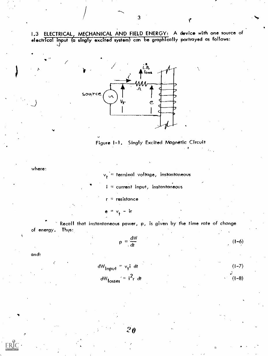
1.3 ELECTRICAL, MECHANICAL AND FIELD ENERGY: A device with one source ofelectrical Input (a stVitiCirea77--stem) can be grapMcally portrayed as follows:
u
where:
Sou..ece
.1
Figure 1-1. Singly Excited Mogneftic Circuit4
vt = terminal voltage, instantaneous
= current input, instantaneous
r = resistance
e = vt ir
Recall that instantaneous power, p, is given by the time rate of changeof energy. Thys:
and:
II
dW
P dt
dWinput = vti dt
dW losses =.2o r dt
(1-6)
(1-7)

4
Now the el ectrical energy input rniAus resistance losses is given by
dWelec vti dt i2r
If electrical energy inputelectrical energy input is the sum of
dt = (vt ir)i dt e i dt
is supplied from multiple sources, the totalterms of the16i441-9).
(1-9)
In Figure 1-1, a magnetic circuit is depicted as receiving an instantan-eous power, ei. Faraday's law gives the relationship between the induced voltage,e, and the instantaneous flux linkages, A. Lenz's law provides us with thedirectional relationship shown in Figure 1-1. That is:
edt
(1-10)
where t is time, and the quantities are in the mks system. If the magnetic circuithas N turns, we can define an equivalent flux q) which is:
A.(1)
From (1-9), (1-10), and (i-11), we have
dWelec=idA=Nid0=Fdost.
where F = Ni is defined as magnetomotive force (mmf). Now mmf and flux areproportional to each other, the constant of proportionality is defined as thereluctance, R. Thus:
(1-12)
F (PR (1-13)
We are now in a position tto evaluate total field energy Wfid as:
2Wfld = f OR c14) =
0
if the reluctance is constant. -
(1-14)

\ 5
'Suppose the reluctance is not constant dnd That some value of flux, 4, ,exists. If we use the value of reluctciWe prevailing at that fluX level, defined asR, we have a total energy stored 'in the field of:
Wfld= --
2
Now, if the energy stored is changed by an amount' AWnd, flux andreluctance change by Ai) and AR respectively. We have then,
or
2vvfld
fld = 1 (R tR)(4) A(1))2
(1-15)
(1-16)
1 2 2 2W AW = IR 4) 1- AR(I) 1-2R(I)A(I) 2AR(I) AcI) RA(I)2 ARM) I (1-17)fld fld 2
Discarding second and higher order differentials and subtracting (1-15) from(1-17) yields,
Thus,
or
where
1 2AAwfld = ROLA) ARO
2
As the incremental changes become smaller and smaller:
A wfld +dWfIrlf A4) 4-4:14) and AR dR
1
dW fld = R4)d(I) (I) dR.'2
We can evaluate mechanical energy by noting that:
= fx; translational motionWmech
= TO; rotational motionrnech
.x = linear displacement6 = rotational displacementf = component of- force in direction of xT = component of torque in the direction of 0
(1-18)
(1-19)
(1-20)
(1-21)

6
for incremental changes:
Wmech + AWmech = (T + AT)(e + AV
= T o + OA T + Tiro + ATA
Subtracting (1-21) fvom (1-22), neglecting the second order effect andpassing to the limit as the incremental change approaches zero yields:
(1,22)
dWmechr = Td e + odT (1-23)
Further, for very small changes' in e we can assume that the torque(or the force, if appropriate) remains constant over e and we can write:
. .dWmech = Tdo or T = fdx (1-24)
1.4 TORdUE AND FORCE: 'We can now sUbstitute (1-12, -19and -24) into (1-5),yielding:
1Fd4) = Tcle + R4)d4) +
2dR
7
Noting that F = OR, 1 25) becomes:
or
T 1 q2 dRgiT
(rotational)
1 2 dRf = 4) i-Tc. (translational)
(1-25)
This says that the force involved in a small change of configuration isproportional to the change of reluctance with respect to the displacement involvedand the square of the flux in the system. The negative sign merely indieates thatthe force, or torque, Is in a direction to reduce the reluctance.
Let us reexamine 'the stored energy in the fiel-d, (1-15). If we, hadmerely taken the partial derivative with respect to R., 4), we would have obtained
2_0dWfld
dR + ORd
(1-26)
(1-27)
(1-28)

7
4Which isithe same as (1-19). This will allow us to develop o generalization for torque
(or force) by considering the two situations, a) constant flux or b) constant mmf. To
do so, rewrite (1-15) as:
Wfld = R+2 =2
a) Fors = conistant with varying F;
dW = dFflci 2
(1729)
(1-30)
from (1-12), -24 and -30)
but, ds = 0. Therefore:
b)' For F = constant with varyIng
dW
and, substitut ing into the
FM.
or
If we note that, from (1-29)
1. Wfld
in (I-5) , we
Fd. = Td0 + e2
dF
have:
dF
4
equation yields
dF
(1-31)
(1-32)
(1-33)
(1-34)
(1-35)
(1-36)
(1-37)
d
tI);
fld 2
energy balance
= Tde +2
T = +2 do
tI)= constant
= constant
5)
and
aWfld
=2 d
F. ds
a 2 d
2 4

we ccn rewrite (1-32) and (1-35) as
a wflc,
" 0 CollitantA
'awfldT = --D 0
8
F constant
Equation (1-38) and (1-39) are extremely useful to us because they enableus to express force or torque as functions of variables such as reluctance, flux ,
linkages, current, inductance, etc. For exampIe.1/4
(1-40)
(4-38)
(1-39)
where
Ni Li 1 2W = = ()( ) = L ifld 2 2 -FT 2
= magnetic ?Inductance (1 = N(1)%
For constant rnmf, i = constant and,- in terms of force:
aWfld=
a x
or, for another example
where
a 1 .2 i2' dL
a x 2= constant ,
Wfld = 1 F4) =,,.F (FP) =2P
2 2
1P = magnetic circuit permeance, (P =
For constant mmf, in terms of force
and so on.
wfld
= constant,
F2P F2. a P
ax,( 2 ) 2 x
I/
(.1-41),
(1-42)
(1-43)
From (1-41) we cai draw a very important conclusion Concerning electricmachines. If we-note, that, a constant .mrnf,, Li = A and idL = dA we have(using torque rather tlu n forc
4.
25
ir

9
(1-44)
Whereas- the voltage inducing phenomeng. k related to the -.Hine rate of change
Of flux linkages, the torque producing mechanism is based- on the an9uTOT-rate df change
of Hui( linkage.
To summarize, the torque or forces, act as follows:
1. To decritase the stored energy at constant flux.
2. To increase the stored energyot constant mmf.
3. To decrease the reluctance (or increase the permeance_
4.- To inc ase the inductance.
Actually, the torques and fqrces are on the iron member itself in an ironcored magnetic circuit. The presence of a winding-of some sort merely serves toestablish the field. Thus windings in slots on a rotor ttte not themselves subjected
to the torques exerted on the iron. The same force that tenck to reduce,.reluctancealso produces a stress within the iron itself. This stress sets up strains within theiron circuit which causes a change in shape. This general phenomena is known asmognetostriction. if the magnetic field is an alternating field, the periodicchange in shape of the magnetic structure causes pressure waves in the surroundingmedia. The pressure waves cause audible noise in some instances.
It is sometimes useful to analyze problems using energy density, or fieldenergy per unit volume. Thus
Wfldw
F4) = (t.j..4)fld vol 2(R. 2 t
where 9. and A are length and cross sectional area of the magnetic circuit under
Niconsideration. Since: = H, magnetic field intensity,
and: flux density
1'1
B2= BH =
.41 fld
where u is the permeability of the circuit and B =u
g.
(1-45)
(1-46)
A

104.1
A'S an example of the usefulness of this approach, we will _drive anexpression for the force of attraction between twO parallel faces of high permeabilityPermanent iron magnets with flux passing between them as shown in Figure 1-2.
s,
Figu,T 1-2. Air gop between two Magnets
sb A-c tAA rriL k
Tr- X, 167
;U. 1V-o6
>>.,-(4.
We will neglect flux fringing. The permeability of the iron is very high. an'd4hal of the air 'between the faces is relatively low. Therefore the energy density, is much higher in the air gap than in the iron. Therefore we will consider onlythe energy density in th,e air gap.
B2
wfld
1 B2Vstfl 2
Po
The mmf is constant since these are permanent magrts. The forceinvolved here is in a directio to reduce the reluctance, i.e., a force ofattnartioit. An incremental cha ge can only be one where R is reduced by aninfinitesimal amount.
but
DWfld 1 B2Af
Dx 2 uo dx
dx = -
1 B2A.
2 P o
where the negative sign indicates force is in the drect7 to reduce .
(1-47)
(1-48)
(1-49)
(1-50)

-
i
I.
1.5 RELATIONSHIPS IN MULTIPLE EXCINEDLYSTEMS:: We will now extend 'ouranalyirs- to Cover an eneriy conve-WO-nae-vicTe'virtrlialtii3le electrical inputs.(A very simplified version). Figure 1-3 portrays such...a device. One winding ison the stationary member, the other on the moveable member. Each winding hos
a self. indUctance, Lir and 122, respectively.. In addition, a. mutual inductance,111, represents the magnetic qtupling betWeen the two wincilngs. Each of theseirictuctances Is a function Of the Ongular displacement of the moveable member
(or rotor).
c_____;te
Figure 1-3. A Multiple Excited Electromechanical Energy Converter
.
The analysis will be based on an incremental change in angular displace-ment, d , as used in the Agly excited system analysis. However, we will utilizethe inductances to express the various electrical quantities. Recall that flux linkagescan be expressed as the product of curreni'and inductance.
Thus, from 415,-12):
dWelec ild
=2d L11 + i111011
i2L22c1i2+ i2 i
1
cll.12
+ i2
L12
di1
i2dA2
i2L 12) + 12d(i2L22
Also, recall that, in terms of inductance:
28
+ i1L12)
+.ilL12di2
(1-51)

12
1
W = 1 i 2+ E 2
+fld .2 11 1 2 2z 2 12 1 2
and,therefore;
1 2 1
dW = + di + 1 2d1 + di + ifld 2 1 11 1 11 1 2 2 22 2 22 2 12
from:
we have:
+ L12
12 di1
+1
i2d
112
dWelec dWmech dWfld
1 11111C111. 1112c1112 + i1112di2 i2 122 12122d12
+ i2i1dL12 + 2L121 = Ide
+ di + L i di t i di + d12 12 1 2 12 2 1 1 2 122 22
dLil d1 2 / 2 22
L12T = + + i/ 1 CO 2 2 de 1 2 d 0
(1-53).
(1-54)
(1-5)
(1-55)
(1-56)
Note that the torque (or force, if 0 is ,replaced by x in a translationalsystem) is a result of changes of inductance with angular displacement. There maywq,11 be changes of current due to electrical transients but these changes are noteffective in the production of torque.
Further' insight into ttth can be obtained by examination of one of theinduced voltages. For example:
el = + 112121cit
= L L12 + 7j5.-11 dt
di1
di2 dL11 ad?) dd:
2 9
(1-58)

S. 13
c,
The first two' terms on ,the right hand side-are "transformer" voltages whichoccur in any magnptic 'circuit when the flux linkages change with respect to time.The last two terms on the right are "speed" or rotational voltages, since speed
dL.Note that only terms appear in (1-56), sthe expression for torque. Thus, we concludethat speedo voltaas and not t'ransformer,voltages are tictive in the energy conversionprocess. Our physical reasoning verifies thii because we know that (neglecting losses)no energy conversion takes place in a transformer!
1.6 ELECTROSTATIC RELAT1ONSH1PS: The, same energy balance analysis can beapplied 'to an'eWsta7tio energy conve;ter system,. That is:
potential fe.
where:
and
dW dW dW`elec mech
Consider a parallel plate capacitor excited from a single source of
dWelec = ei cit = e dq
wdq = differential charge idt
Further, stored energy in the electrostatic field is given by:
dWfld
for incremental changes.
Wfld =1 Ce
27
1
= e dC + eC de2
(1-5)
(1-59)
(1-60)
(1-61)
Applying the energy balance and using the relationships (1-20), 1,59), and(I-61) yields:
where:
1e dq = e2 dC + eC de + f dx
2
f = force on the capacitor plates
dx = incremental displacemertt that would change C
3 0
(1-62):4
"
I.
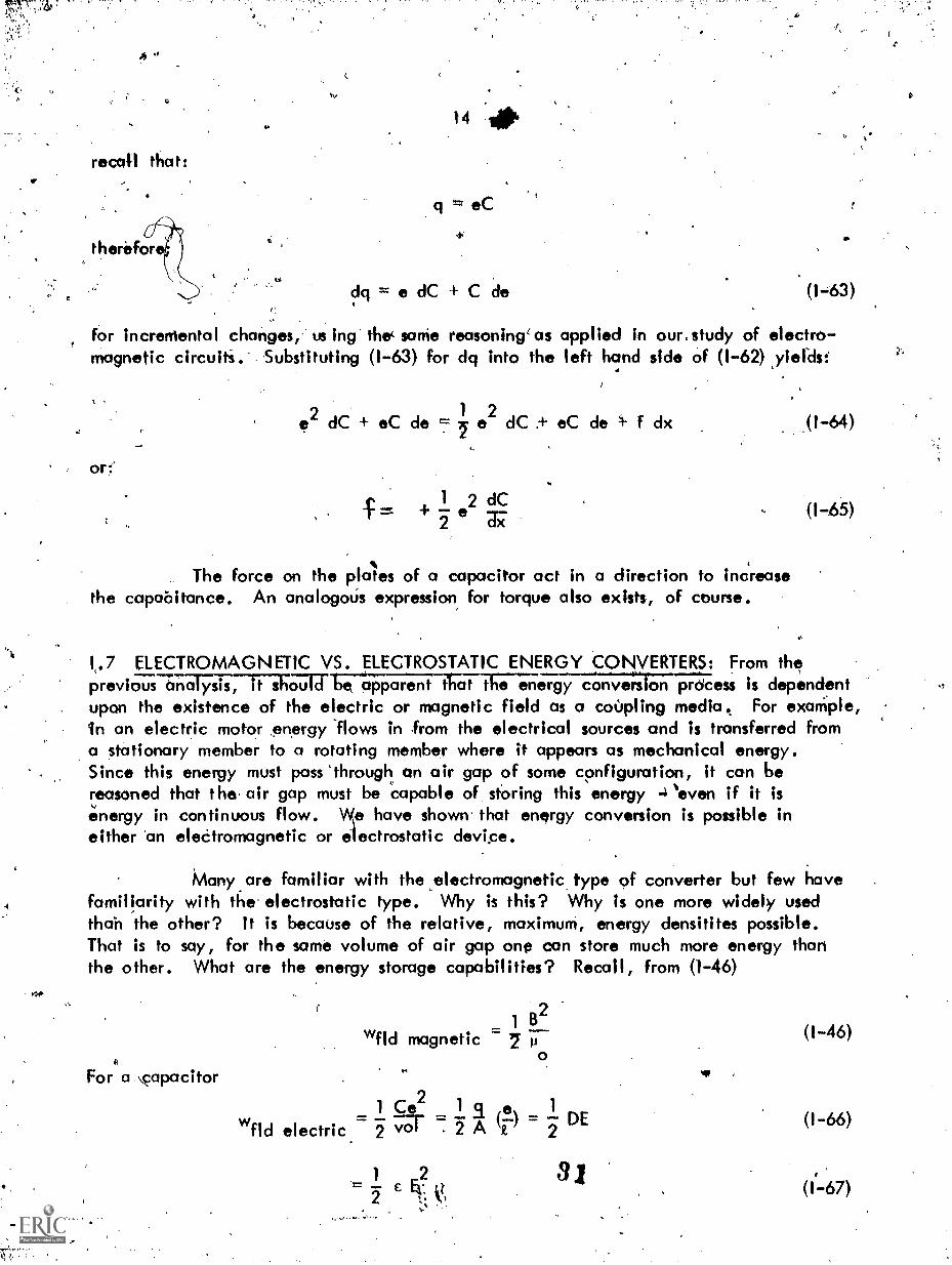
recall that:
t/
chi e dC + C de 1 63)
for incremental changes, us ing the( sortie reasoning'as applied in our,study of electro-magnetic circuiti. Substituting (1-63) for dq into the left hand side of (1-62) ,yiekIst
or:'
1 2dC + eC de e dC eC de 4- f dx
The force on the plates of a capacitor act in a direction to increasethe capabitance. An analogotis expression for torque also exists, of course.
.(1-64)
(1-65)
1,.7 ELECTROMAGNETIC VS. ELECTROSTATIC ENERGY CONVERTERS: From theprevious a-ncilYiTT1,3" b aktarent ttlat the energ-yOel;ror",proess is dependentupon the existence of the electric or magnetic field as a coOpling media. For exaMple,in an electric motor .energy 'flows in from the electrical sources and is transferred froma stationary member to a rotating member where it appears as mechanical energy.Since this enemy must pass 'through an air gap of some configuration, it can bereasoned that the, air gap must be capable of sthring this energy 4`even if it is
energy in continuous flow. \Me have shown. that energy conversion is possible ineither 'an eleCtromagnetic or electrostatic device.
Many are familiar with the ,electromagnetic type f converter but few havefamiliarity with the' electrostatic type. Why is this? Why is one more widely usedthan the other? It is because of the relative, maximum, energy densitites possible.That is to soy, for the same volume of air gap one can store much more energy thanthe other. What are the energy storage capabilities? Recall, from (1-46)
For a \capacitor
1 B2wfld magnetic 7 p
=1T1-2-wfld electric.- 2 A DE
(1-46)
(1-66)
(1-67)

where:
`.
Flux donsitieselectke field.intensity Ofinsulator, or dielectrR),of arr is 8.85 x
1 5
C
E 12 electric field intensity, volts/meter
electrostatic flux density, c6ulombs/meter
=perMittivity of the dielectric medium
2
of 1 weber/mgter2 are quite common whereas the paximumair it 3 x 10 volts/meter (with failure ot sthe air as anThe permeability of air, p , 'is 41T x The permittivity
Thus, from (1-46) and (1-6)3
wfld mareti_ELL_nax,wfld
electric, iriax.
B2
7 177E7 .
02
1
(1-68)
4 Tr x 1077 x 8.85 x 10-129 x- 1017
.7,10,000
t,
It would require 104 times as much volume to store the same energy in anelectrostatic field in air as it would be to store electromagnetic energy in air. Also,it should be noted that high power electromagnetic devices involve high currents atthe necessary driving voltage, whereas electrostatic energy converters involve highvoltage, if their power or energy rating is to be substantial. We provide conductotsize for high currents and insulatiOn for high voltage. The mechanical design probleMsore thus quite different!
3 2

16
CHAPTER II - ELEMENTARY CONCEPTS OF TORQUE AND GENERATED:VOLTAGE
11.1 THE D.C. MACHINE: The simplest possible visualization of generated voltage inan electiic macHne (whether generator or motor) -can be gained froM the study of an
. elementary d.c. machine. A simplified ,version of a d.c.inackine is shown inFigure 11-1
7,'
Figure 1171. pementary D.C. Machaine
.Our elementary d.c. machine has an exciting winding, usually caned the
"field" winding on the stationary member of the machine (usually referred to as the"stator"): This winding establishes the flux,4) , which passes from the "pole", acrossthe air gap, through the rotating member, or "rotor", Through the air gap again andback into the stator pole. In an actual machine, the winding on the rotor would bedistributed around the periphery of the rotor with the various coils connected in somespecific series-parallel combination t`o yield the desired volt-ampere rating of themachine. In the particular simplified elementary machine to be analyzed here, wewill assume only one coil, consisting of one turn only. As the coil rotates, the fluxlinking it changes, with time. Not shown is the mechanical scvitching device (commutator)whkh is essential to the machine if a unidirectional voltage is to-exist at the collectingmechanism (brushes) connected to the rotating coil. However, we can examine thevoltage generating mechanism. When the coil is rotated 1,/4 of the revolution (1. radians),
2the flux linking the coil chm ges from4) to zero. if the coil is rotating at w radians/sec,the time to rotate - radians is, At . If the machine had p poles, the rotor would
n 2rotate through electrical radians. this would be C7)/p/2 mechanical radians. For theTT
p pole machine, then, AtP w
eiAg. tqf

as:
17
The voltage induced in the one turn coil is given by Fan 'day's law
e_AA - 0 Ett
= =At TrIM11.11111.
Ptd,
Now,, consider a more cqmplicatect rotor winding. ssume there are a totalof Z inductors on the rotoe forming ± one turn coils. If the winding is arranged so thatihere are "a" parallel paths through2the rotor winding (the current to the rotor entersone collector, divides into "d' parallel paths, recomIllnes into the original current andekits through the other collector) then,there must be 4:7_ one' turn coils in series. Thetotal voltage across the collectors is the sum of WI ON series voltages, i.e.;
P
e- = (-;,;-.1)(1117-)
If: n revolutions/minute
= revolutions/second60
ztea 2') (11-2)
Note, in (11-,:2), that revolutions/second also. If the blocked term,27r
involving radians/second, in (11-2)is replaced by its equivalent in terms ofrevolutions/second, we have:
?ala 601,
(11-3)
If a current, i, flows in the winding, electric power is associated with themachine. If it is a motor; the current flows against the induced voltage and isabsorbed. The absorption of this power corresponds to the power being converted tomechanical form. If the current flows in the direction of the induced voltage, poweris supplied to an external load and the machine acts as a generator. This source ofpower can only come from mechanical shaft input power and the device behaves asa generator.
If: T = torque, in newton meters
P = power, in watts
34
(11-4)

1'
Equation (IIutilized to yield:
4 ) an be solved-For torque and the relationship in -(11-2)
ZT = =
o= k3si
(t) 2tra
wheite
k
(11-5)
It should be nOted that k is a constant whose value is determined by thedesign of the machine. If the value of k is substituted in (11-2), we have:
e (271c7).w k (11)-6)
In the d.c. machine considered here, botli developed torque and inducedvoltage, sometimes called "couriter electromotive force" (cemf).or "back" emf (becauseof its polarity relative tojhat of the external circuit), are proportional to the fluxin the air gap resulting mainly from the excitation or field windingthe torque isalso proportional to the magnitude of current through the rotor (also collect thearmature). Thus we could generalize by noting that the torque is the result ofinteraction between a magnetic field and an mmf. The voltage induced is pro-portional to the angulat velocity of the rotor inductors with respect to the magneticfield flux. In each case, the constant of proportionality is,the some - but only inthe mks system of units. That this is so one would expect from the consistency ofthe F = Bi t, e = Btv relationships applicable to individual conductors. The deviceanalyzed here has merely been a mechanical configuration to utilize the fundamentalprinciples and to make use of multiple conductors with an appropriate series-parallelconnection.
11.2 THE ALTERNATING CURRENT MACHINE: An elementary alternating currentmachine is shown in Figure 11:27 orl'-i-ii7;-tat the one turn coil on the statoris stationary and that the flux density (constant in magnitude, sinusoidal in spacedistribution, and directed along the axis of the rotating member) rotates at angular
mavelocity co. The flux is everywh e normal to the surface of the gnetic circuit.The flux density has a linear vel city tangential to the radius and each side ofthe one turn coil has a voltage Induced in it of magnitude:
e = B(0)tv (11-7) .

where
41.
19
B(e) flux density, webers/meter2
t = length of the coil side in Meters
= relative linear velocity, meters/sec betweenstator coil-and the flux.
-turn *Tone coil
flu.% tionza:y =am ca-o 8(6 ;. elPe. 0.1
ftfi wind 'leg
Figure 11-2. Elementary One Turn A.C. Generator(or Alternator)
Under the assumption ef sinusoidal distributionin space 'of the fluxdensity., the flux density can be evressed as
B(e) = Bm cos e
where
S.
Bm = maximum value of flux density
e = space angle measured from the axis of the rotor
Since there are two sides in the one turn coil, the total induced voltage in thecoil is:
2B(e) R. v = 2 Bm tv cos0 (II 9)
If there are N turns on the statOr oil, and the turns are connected inseries, the voltage in the coil is giyen by
e = 2N B(0) IV (11-10
3 6

0
Since:
where:
20
= cot and v r
t = time, in secondsr -= rtdius of the rotor, in meters
The expression for indOced voltage, (II-10),becomes:
e = 2N fru) Bm cos tot 111-11)
or:
e = E cos to tmax
Recall that flux, is related to flux density by:4.
= BdAA
where A. is -41he area normal to the flux density, B.
.The area element, for the configuration in Figure 11-2 is:
C (11-13)
dA = tr de (11-14)
Note that the incremental angle do is actual, or so called "mechanical'',radians whereas the flux density distribution is in.electrical radians. That is, inpassing through two magnetic poles, 2iT electrical radians are traversed - which maynot be the same number of mechanical radians in the same angle. If the mechanicalangle is multiplied by the number of pairs of fries, it is converted to' an equivalentelectrical angle. Thus,
Mechanical El ectrical
dde
F72.
In terms of electrical radians, (11-14) becomes:
dAr d 0
p/Z. C.
( 1-16)

If% ;.;Ti''':
)21
In order to determine the flux, i)er pole, we can evaluate .(11-13)utilizing (I1-8) and (11-10 yielding:
w/2 r m
p/2
From (11-11) and (11-12):
From (11-17):
cos e do
E = 21\11, r Bmax m
2tr Bm=4)
Substituting (11-19) into(11-18) yields:
E = N wmax
2 tr Bm(11.-17)p/2
C.
(11-18)
(11719)
(11-20)
Note that rotation of the rotor through an angle whkh includes a pair..
of poles will produee 1 cycle of voltage variation. A complete revolution, throughp/2 pairs of poles will produce p/2 c'ydes. Now, co/2w revolutions/secoild,throughp/2 pairs of poles will produce:
and,
W(-) "
2cycles in each second
21T
Thus, the cyclic frequency of variation of voltags,, f, k siven by:
2 z-t 2 Tr f
Since the induced voltage is sinusoklal,in terms of foot-mean-square (rms) value as:
-1
e-e9)rms t
38,
(11-22)
(11-23)
from (11-20) clan be expressed
(11-24)
`t
. 1....441.
'1;.

4.
From (11-23),
o. 62E)
2 Tr
rms(2, (-7) NO 4.44 NO f (I1-25)e
/2-
.22
An actual machine has windings distributed over the entire periphery of theestator cod the various inductors connected in some sertes-parallel arrangrreent. Thenumber of turns, N, in (11-25) then becomes the number of turns conpected in series.However the induced voltages, at any instant., in the vatIous turns are not equalbecaus of the distribution of flux density, Also, for purposes of suppressing 'Undesiredharmonics in the induced voltage some windings have coils whose sides do not spanan exact pole pitch. Thus, the,actual voltage is less than the value calculated by(11-25) in an actual-machine. To aecount for the factors (11-25) is multiplied bya constant called the winding constant, whose value is determined by the specificwinding configuractions.
The relationship given in (11-25) applies to the induced voltage in anycoil - such as a transformer, for example - which has sinusoidal voltages antl fluxespresent.
tt
Consider the N turn coil and core in Figure 11-3 .
1/74
Figure 1-3. Core and Coil with Sinusoidal Excitation
Neglecting winding resistance, a voltage is induced in the coil equal and opposite toe. From Faraday's Law,
e = Em sinwt N (11-26)dt
where the subscript m denotes maximum value.
If the flu* is sinusoidal, it can be expressed as
=..cos
(11-27)
and the induced voltage; which must equal the applied voltage, (if the resistance iszero) is given by:
e = N 4'1700 sinw t = E sin wt (11-28)
3 9
6
I

`k! 23
From (11-28)
Em = 114)m w N fm (2wf)
The rms value of induced voltage can be then determined as:.1
Em 2 nE Nsf4.44 /44)f
rms vr"
The produgtion Of torque is an elementary d.c. machine was developed inthe previous section, equation (11-5). We will now examine 'the torque resulting fromo different mechanical configuratiOn - one which is used for machines supplied frothalternating current (A.C.) sources. Commerdal A.C. sources have pertodic variationsand thus consist of predominately a fundamental sinusoid With the possibility existingof additional sinusoids that are multiples of the fondamentals; i.e., harmonics.
The configuration we will analyze is shown in Figure 11-4 and consistsof two windings mounted on concentric magnetit cylinders.
e I fE
rotor tu'inciilntil.w..tmvtc...t
it:=4.111%
(
4441S %14; Via %NI 0,46s
slijor ;"(1 sktc- nIkActo.mce., Ls,
r'Figure 11-4. Cylindrkal Rotor Model
This is a simplified version of what could be either a statkmary or rotatingdevice. For example, the stator winding (or coil) as shown might be a fictitious windingto represent the source of an mmf which is rotating. The only stipulation, if thewindings are rotating, is that the axis of the two windings be stationary with respecet toeach other under steady state (i.e. constant torque load) conditions. This is essentialif avera6e torque is to,be produced.
Since the structuie is concentric, the self inductances are constant. The
mutual inductance is a function of the angle between the,two axis, e. We willassume that the variation of mutlal inductance is sinusoidal and that the mmfs of eachwinding are sinusoidally distributed, also. Further, we will assume that the iron isinfinitely permeable. Although Figure 11-4 is for a 2 pole device, our derivationwill be for a p pole device. Only two poles are shown for simplicity. Each
winding will have an mmf, F and Fr, and the net mmf in the air gap, F will bethe resultant of the two mmfss. Since the mmfs are sinuioklal, their resulkint willalso be 'inusoidal and tan be obtained, by.using phtasors to represent the peak mmfs and,combining them using the Law of Cosines. Figure 11-5 depicts the phasor relationshiiibetween the rotor mmf, F
r the stator mmf F and the air gap mmf F ./ 1 sr
1 40.
4.*

%.
'
2
E.* s irk 0
ote, 8 I a. s (KA amok le.Q
not 1t corrt s()o Rn
/Fsrt
Xe pf
1111
Figure 11-5. Phasor Diagram of mmfs
(Ftorn Figure 11-5 applying the Law of Cosines:
*drr2 + 2 Fs Fr cos 0
We Will defi e an angle, (Sr, to be the angle (in electrical radiansbetween the axis of the r or and the axis of the net air gap mmf. Geometricand trigonometric cons iderattons -indicate that:
F = Fsin e sin 6rs sr (11-32)
In order to obtain the torque produced, we will use the derived relationslip,for 0 = constant, from Chapter 1,
3 WfldT = (1-38)
The factor p/2 takes into account our p pole machine.
To obtairi. WfIcli w Will use average energy density times gap volume.If the diameter of the air gap mid point is d, the gap length is g, and the axiallength of the gap is 2, then,
24
^
total air gap volume = nd tg'40
Lett.14

25
Pron.., (1-46), the energy 'density Is!
I
1 B2 1 2w = = - p H
fld 2.0o
(I -46)
This is energy density qt any point in the air gap. The average energydensity is given by:
r, Po
wfld (H2) average (11-34)
\ Since flux density is sinusoidally distributed in space, the corresponding .
mmfs ae'e a6o sinusoklally distributed.
If F is the peak value of air gap mmf, the peak value of magnetizingis gnerr1 I
1, srH (11-35)
P
and:
.The aver6ge
H ='H cos()
value of the square of the H' can be determined as:
e de =2
Tr/2(H2) ave. = f H
2cos
2
-w/2 P
From (11-33), (11-34) and (11-37), total energy in the.air gap is:2
Po H
Wfld (wfid)(vbl.ume) Trd A g
Substitut4ng (11-35) for Hp yields:
w =_4tirdt"fld o Ter sr"
From (1-38):
E d A 2T = (P F )
2 ae o 49 sr
Using the value of F from (11-31) in (11-40) yields:
= Pon clz Fs Fr sin e41,1,
4.2
(11-36)
(11-37)
(11-38)
(11-39)
(11-40)
(11-41)

26
From (11-32), Fs can be replaced. in (11-42) yielding:
T=-5u ndIF F sino . sr r r
From (11-35):
(11-42)
srF =gH =g-w 1(11-43)sr p
where Bsr is the peak value of net flux density sinusoidally distributed in the air gapand that, for sinusoidal distribution:
2 Bsr
Bove It (11-44)
therefore, utilizing (11-44), (11-43) 4:ecorites:
F = EL Bsr 2 ti OVe
oNote also that:
d( ) (area under each pole)
2 2
Substituing (11-45) and (11-46) into (11-42) yields
Now,
wher7
(11-45)-
(11-46),
iT
T = (E2)2 (area under each pole) Bove Fr sinr
(11-47)
Then, (11-47) becomes:
)(area under ach pole) =4) (11-48)(Bove sr
(I) =sr
flux per pole in the air gap
D 2 nT = (1=2-) F sin
rsr r(11-49)
This equation .expresses torque as the interaction between a field and anmmf or between two fields. It shOuld be noted that no torque (or power) is possiblewithout a finite angle, 6 it is very appropriately referred to as the "Power" angleor "Vorque" angle and will appear again in every device which we study.. For thed.c. machine the angle is fixed at n radians by the geometry of the machine. Thus,7although it does not appear in the equation for torque in the d.c. machine it wouldbe there if we had an angle other than Tr/2 radians between the flux density,corresponding to IS, and the mmf, corresponding to rotor current.
10 4 3

4
27
CHAPTER III - THE GENERALIZED MACHINE
III.1 THE BASIC MACHINE: All types of electrical machines have many features incommon andNum 711-77. "raepicts these features.
z
Atr4°1
a
,ncror
c4re__
iron" uu vt IA'
A ate t- UJ vaiti
6.earioci:
-47-- \-%
- hatil4
0 r r Vr1
Figure III-1. The Basic Electric Machine
Oh'
There are two magnetic cores - one common with the shaft and theother fixed to the frame, or housing. Many variations of this basic configurationare possible. The most common is to have The outer memberotationary (the "stator 1)and the inner member, with shaft, the rotating member (the "rotor"). The twocores are separated by an air' gap. There are brwsual configurations involving stationaryinner members and rolZttng frames,' or, even, both members rotating with respect' to.afixed reference and with respect to each other.
Each core has (usually) a winding. A machine with a perManent magnetfield would be an exception. The winding consists of conductors carryinv currentand running parallel to the axis of the machine in the !active' per tion of, the machine,i.e., the part that contains the narrow separation of rotor and stator called the airgap. The conductors are connected into windina. The eact nature of the connectionand the typt-of winding is a function'of th'e- type,and form of the electrical supply,.In order to produce a net conversion of energy from' electrical to mechanical form,the magnetic fields associated with the rotor and stator mtat be stationary withrespect to ach other even though they may not necessaril be stationarr withrespect to a stationary reference. The exact na,ture of the Winding configurationanci connection is of extreme imOortance to the designer. To the analyst, theconnections are of importance onty to the extent that the machine has specifiedinput-output relationships and that the ma4ine parameters are thus determined.

28
The machine parameters will characterize Machine behavior under specific conditionsexisting within an overall system.
The three common typesof windings are
1. Coil winding2.. Polyphase connection 44 colts3. Commutator winding
.Coil windings are Concentrated and the mmf and magnetic field associatedwith this type of winding acts along the axis of the coil winding. The windingitself consists of coils on all poles connected into a. single circuit.
A polyphase winding consists of individual conductors distributed in slOtsaround the periphery of the stator or rotor. The individual conductors actuallyare connected to form phase windings which may be coil windings and which,individually, have magnetic fields stationary in space (acting along the effectiveaxis of the phase winding). However, polyphase windings are-energized fromalternating current sources so the magnitude of the magnetic field puloates with atime variation even though it is stationary in space. Thus, the individual phasewinding can be idealized by a single coil. The phasewindings, if properlyspaced and energized from alternating current of the proper phase, will "Cause aresultant magnetic field which (under steady state conditions) is of constant magnitudeand revolving at constant anwrlar velocity. For example, a three phase Machine hasthree phase windings spaced 42 electrical radians apart and when energtzed from a3 Phase supply product', an mmf 3/2 greater than the maximum mmf in any onephase. The mmf rota& at the synchronous angular velocity of the supply frequency.This will be developedmathematically in a later section.
A commutaior.winding is composed of conductors located in ,slotis andconnected to commutator segments in some cOntinuous se4uence: 'The Current flowsinto and out of this type of winding through carbon brushes (stationary)whichbeor on the copper commutator segments, or bars. The individual condUctorscomprising the winding are connected in some series-paraliel combination to yieldthe desired current-voltage relationship, or rating, of the winding. There arealways at least two and often times' more, parallel paths through the winding.Commutator windings always, are rotating windings. The purpose of the most simplecommutator.winding is to switch the revolving conductors, as they pass under thebrushes,'so that the Conductors under any given'pole al.ways ?arry durrent in the
,same direction. The net result is that the axis of the commutator winding isalways stationary with the axis of the pair of brushes.
Synchronous machines usually have a coil windincron the rotor (the"field") and a polyphase winding on the stator. Asynchronous, or "induction"machines have polyphase windings clkt both,rotor and stator. "(This statement isnot true for single phase induction motors). Direct currenrmachines have a coilwinding ("field") on the stator and a commutator winding on the rotor, or as it isusually called, the armature.
-4 5

29
In generalized machine analysis, we will find it helpful to define twomain axis. The "direct" and the "quadrature" axis. In the case of the d.c. machineand of the synchrorrus machine, the direct axis is the axis along which the field(or excitation) mmf acts. The quadrature axis is Tr/2 radians advanced (in the directionof rotatiortr from the direct axis,. These axis are usually referred to as the d and qaxis.
Any machine, whether comprised of polyphase, coil, or commutatorwindings can be shown to be equivalent to an idealized machine consisting ofcoils located on the d and q axis. Even though the rotor rotates, the coils arefixed along these axis! To achieve this equivalence, it is necessary to convert,by suit4ble transformation, polyphase wirklings into equivalent rotating two'phasewindings. This transformation will be derived later. Since actual windings onthe rotor have rotational voltages induced in them, we must ascribe specialproperties to the rotating winding. These two properties are possessed by acommutator winding. They are:
1. a current in the winding produces an mmr and a magneticfield which is stationary in space.
2. even though the mmf and the field are stationary in space,rotational voltages are induced in the coil.
The idealized machine we are developing will be referred to as a"Generalized Machine". The "Generalized Machine" will have only two polesand any results obtained will have to be altered to courespond to the actualmachine.
At this point, the obvious advantages to the student of a "Generd izedMachine" model should be apparent. If the various common machines can be rep-resented by one model, then we need develop equations and analysis techniquesonly for the one model. Of course, some degree of skill and machine familiarityis necessary to ielette model to actual machine types and vice-versa.
We are interested in dynamic, or transient, behavior of the machine withstatic, or steady state, situations as special cases of the dynamic situations. -Dynamicbehavior implies variation of performance with respect to time. Thus, our equationswill be differential equations.
In order to bring to bear the sophisticated techniques of linear systemsanalysts to the behavior of our generalized machine, it will be necessary toascribe certain other attributes which are not possessed by a physical machine. Theattributes are really fundamental assumptions made for ease of solution of the differ-ential equations which describe our model. They are:

*.l.c.:,T.TIT::. .1"....1..; ' .,!..!, ':', .' , ` .!.-1` ....1-: ' rk...,..,1...t: f",,...!7 1-:......,,...,
. . .
30
0
1. No saturation exists in the magnetic circuit, i.e., the'system' is linear and the principle of superposition can be,applied. This enables us to sum mmfs, torques, voltages,,etc. because by definition superposition means ,th:tt thenet effect is the sum of the causes.
2. Flux density harmohics are not present and the flux densityis sinusoldally distributed in space. The main flux is con-sidered to be determined by the fundamental component ofthe flux density. The radial line where the flux density isa maximum is the axis of the flux.
3. In calcutating flux density from.mpgnetomotove force, themmf is coAsidered to be acting only in the air gap. In otherwords, theAron is infinitely permeable and no mmf is requiredto sustain the flux in the iron.
The fluqinking any winding' is considered to consist of mutualand lealOge flux. The leakage flux links only that particularwinding:The mutual flux links all other windings lying on thesame, a4s.
:The above assumptions do introduce tnaccuracies into the results obtainedby mathematical andlysis: Certainly, with nonlinear devices (which is always thecase in an eleCtromagnetic device comprised of iron) nothing yields 'more reliableresults than actual test on the device itself. SucK lests may not be possibleunder the desired conditions or in the system desigri stage. However, without theassumptions, analysis would be very nearly impossible even with computers becauseexpressing the non-linearities mathematically introduces approximations. PreJiouswork and experience indicates that the pattern of behavior emerges in spite of theassumptions! CorrespOndence between linear analysis results and test results issurprisingly close, as you can verify in laboratory work. Since some degree ofsaturation-Of-the iron in the magnetic circuit is usually present, .it is possible torefine results obtained by analysis if one makes a proper choice of var iable toaccount for saturation effects. For closely coupled coils on an iron circuit,the assumption regarding a commun mutual flux -is reasonably valid if differentvalues of leakage are assigned for each winding or coil. The question of the effectof neglecAng flux 'density space harmonics can be dealt with only if the type ofmachine is considered. For example, in d.c. machines, it is total flux per polewhich is of concern in the steady state torque and voltage constants. However,under transient conditions that is no longer ture. There are other effects (to bedealt with later) which .tend to "swamp out" the errors introduced by the assumptionof sinusoidal flux density. In a.c. machines, the harmonics of the flux density arerotating at a speed other than the speeeof the rotor flux density and thus are noteffective in produci ng average torque. The value of instantaneous torque doesvary, however, and some parasitic effects manifest themselves (n'oise, etc.). Also,of course, the flux density harmonics result in harmonics in the induced (bothtransformer and rotational) voltages.
4 7

/ 31
To summarize the effect of the assumptions, one can only agree that theydo result in errors analytical results. It is not possible to assign magnitude of errorswithout comparison with actual test results. The analytical results do give reasonablyclose results and yield valuable information to-the system designer. Without theassumptions, analysis would be very nearly impossible.
We can represent, diagramatically, a generalized machine model as shownin Figure III-2 This particular model has only 4 coils - 2 in each axis with onein each axis on the rotor and one in each axis on the stator. We -will use only a4 coil machine in our derivations in order to reduce the number of equations involvedin the analysis. Some machines, such as the most simple d.c. machine will haveonly an,F and a Q coil. A "cross field" type of d.c. machines may very well haveadditional oF coils (usually designated as F1, F2,...,etc.) A synchronous machineoften times will have additional circuitry on the rotor (damper circuits) and theseare usuqlly denoted as KQ and KD windings. However, a thorough understandingof the bafic 4 coil nodel is essential to analysis of more complex configurations .The 4 coil model is a compromise between the completely general case and asimplified configuration without obscuring .complexity.t 5
Figure III-2. 4 Coil Generalized Machine Diagram
In our derivation, we will assume the machine is rotating clockwise(cw) and that it is operating as a motor. Thus, positive current is the current that
flows as a result of an ekternal source and positive torque is torque in the direction ofrotation. Further, we will resort to the per unit system, or basis, for defining thevarious paramete-s. This is discussed in the next section.
4 t9s-

32
.111.2 THE PER UNIT SYSTEM! The use of ratios to express results as normalizeddimensicTriliisTquatictireiliWi; common. Such ratios as portent efficiency, percentregulation, percent of rated load, power factor, teso are widely used. If a quantitysuch as voltage drop, is expressed as per tent (or per unit) of rated voltage it ismuch, more meaningful than if it is expressed in terms Of Its actual 'value. This 11especially true if one is attempting to compare the perforMance, or the parameters,of a system with that of another system of different rating.. In addition, as aresult of standardization trends in design of equipment, many of the performancecharactiristics and parameters of machines are almost constant-over a wide rangein ratings if they are expressed as ratiOs. The use of such quantities has beenapplied to circuit analysis --greatly simplifying calculations in circuits involvingtransformer.: and:circuits coupled Magnetically.... We can 'Summarize the advaqtagesas follows!
1. The use of per unit values facilities scaling and programmingcomputers used for system studies.
2. The use of per unit vafues in problems solution yields resultsthat are generalized and braddly applicable.'
3. The solution of networks containing magnetically coupled circuitsis facilitated.. For example, with' the proper choice of 'unit, orbase, quantities the mutual inductance in per unit is the sameregardless of whkh winding it is viewed from and regardlessof the turns-ratio of the windings.
4. Since the constants of machines, transformers and other equipment'lie wihin--a relatively narrow range when expressed as a fraction ofthe'iciuipinent rating one can make "educated" guesses as to probable,value or per unit constants in the absence of definite designinformation. This is of assistance to the analyst when operatingwithout complete device information.
It seems preferable to use per unit rather than per cent because of theproblem encountered when two per cent quantities are multiplied together. Forexample, if:
A = 0.05 per unit or 5%
B = 0.20 per unit or 20%
and we take the product, (A)(B) = (0.05)(0.20) = 0.01 per unit. If we use percentages,(A)(B) = (5)(20) = 100%,--whoreas it should be 1%. We will use per unit in thiscourse and we will deal with auantities such as current I, voltage V, power P,reactive power Q, voltamperes VA, resistance R, reactance X, impedance Z, etc.

33
By definition,
actual vc,.&_,Its 9uantHyQuan tity in per 'unit = base value of the quantity
Actual quantity refers to its value in volts, ohms or whatever is applicable.Within limits, thelbase values may be chosen as any convenient number. However, formachine analysis they are usually chosen based on the mating of the machine. In power,systems analysis, there ore many factors that enter into the choice. We will not attempta discussion of these factors at this time because our.primary concern bere is theanalysis of machines.
We must select the base values so that the fundament61 laws of electricalphenomenon pre still valid in the per unit system. Ohm's law states that: (in actualvalues)
V = Z1 (111-2)
If we select, ony two values for V6, 16 and Zb. (where the subscript bdenotes base values) then the-Aird value is determined by the relationship
dividing (111-2) by (01-3) yields
which is, according to (III 1)
Vb = Z6I6
V ZI k
(F)(T) (111-4)
b b b
V = Z 1pu Pu
where the subscript pu denotes per unit value.
\It is common practice to select the voltampere base, VAb'and the
voltage base, Vb. Then, for single phase circuits
VAb=--
b Vband Zb
(111-5)

- 34
Zb 2 wfbLb w bib (111-7)
where Lb is base inductance' fb is base frequency and tob is base electrical angularvelocity.
It should be noted that 1.0 perunit power corresponds to the voltampererating of the machine - not the actual power rating. These values are the same. na d.c, machine but may"'"-- different in an a.C. machine. As on example, if wehad an a.c. machine ratecis 10000 kva, 0.85 p.f., the rated power is 8500 kw.Howeier, 1-.0 per unit pyr s taken as 10000. Thus on a per unftbatIs , ratedpower is 0.85, not 1.0 per unit. 1
We will now examine flux and flux linkages and how they relate to theper unit system.
Consider two coils coupled as shown in Figure 111-3 . each coil is
assumed to be concentrated. By concentrated, we mean that the same flux linksall turns in either coil. However, since the coils themselves exist gs' separateentities, not all of the flux which links ,one coil also links the othek coil. We?an define the fly,x linking coils as the main, or mutual flux, and the fluxwhich links onit a particular coil as the leakage flux of that coll 1 .11 1 2e
CP2 1: L-1(614cell 2.
VIAGML/Tior
t44 tint -c it X
jipac6/4.L..i.i6zst clux
mann//NW
4tr
Figure III-3. Mutually Coupled Coils
Thus, there are three fluxes present in Figure (111-3).
= mutual, or main flux linking both coils,resulting from both i and i2
((13 = leakage flux, due to current and linking
coil 1 but not finking coil 2
leakage flux, due to current i2 and linkingcoil 2 but hat linking coil 1.
61

35
In the definitiont used here, V represents voltage impressed on the coilfrom an external source and the current i is the current that flows as a result ofV. Thus, if V and i are positive the device absorbs electric power.
The value of Fy linkages, Am1, in coil .1 due to current i2 in coil 2ris:
mL i
l IL 2
where L12 is the mutual inductance of the two coils.
Similarly, the vplue of flux linkages,in coil 1 is:
and:
1.5
in coil 2 due to current i1
m2= L21 i
1
Converting (111-9) and (111-10) to per unit values yields:.
ml pu
m2 pu
ml 1-12 12 L12 12b i2 puL i L lb bt lb ,lb lb -1
A m2=
1- 2 1 ei1 121 ilb Li Flu_
2b 1213 I2b 1213 2b
rearranging (111-11) and (111-12) tO obtain the ratio of per unit flux linkages in 1 coilto per unit current in the other coil yields:
L122b
pu r113-171-13 ;
/_;1122.L_\ 21
i.1b
pu 2b 2b(111-13)
It is desirable to have the per unit flux linkages per unit current the samein either coil. (In other words, the per unit mutual inductance is the same whenviewed from either coil!) We can ascertain the conditions necessary to achieve this byequating the ratios in (111-13). Also we recognize that in actual values, 112 = L21Further, we will divide each side of the equations by w b. Thus:
12b i lb
°ID Llb ilb b 2b 1213
5-49
(111-14y,,

Ptglcyrs'',Vnii9r,Tr "1,tr 'I` 0' eV, If.' ' %7, t.7
-Recognizing that:
and:
WI,Lb Z1?
Zb ib = Vb
we can- rearrange (I11-14) to yield:_
.t
36
(111-15)
(111-16) 1
Si
V i =V i (111-17)b2 b2 b1 b1I
=dst. the. result of this is.tilat if,we,clioctpe the same voltampere batefor each coil; equal values of per unit current in tile coils res4ailIti-equalyvalues of.mutual flux I kages and the per unit value of mutual inductance is the same whenviewed from ither coil.
One other, quantity requkes specfal consideration. That is the basevalue of electrical angular velocity. This must be chosen as equal to 1.0 ifthe time relationships are to be preserved. That this is so can be seen from thefollowing example.
Example
An R71 circuit is eriergized from a-source, v = V sin cot as shown inFigure III-4. The solution for current, i(t) is:
Lv Rr-
i(t) 2(el)
tr- UR' sin
R
tan-1 w L,
+
Figpre 111-4. R-L Circuit Energheil from Sinusoidal Source
(111-18)

37
We can divide each side of the equation by lk and can divkle numeratorand denominator of various rattos by. Zb as shown in (I11-20). Recall that:
and
t-
(*LAI) Lb .
i(t) V f Os-lb R lb ut /Gib 1 2
R1 + ( )
-,
Note that:
i(t)-r- tkr4pu
i ( t) pu
s
Zb6)13 b
L'A.`)b Lb sin (w/cobt - tan-1 wl./40131b)R/Rb +
/----w 1.1-.-TT.-2-1,
v _vEy. t-= vFr Rb Vb pu
R(i--), . b
w L
b b...-z: --r-- r. (IF) actual
Rbpu
R/Rb
(111-19)
(In -20)
(111-21)
(111-22)
(111-23)
L
w L L. iDb bv.I, --P-LIL - (-)actua if tic. = 1.0 (111-24)/R w R R R
b pu pu i
From (111-21) through (111-24) we can write (111-20) as:
_p_u___tan_
w Lpu puL
R t
pu Pu Lsin (w t
Rw
V pu pu.22 RET +cR
4- ( R ) , il + ( R /
pu (.0 L 2 w L 2pu pu _p_u__Eu,
pu pu1
(111-25)

faults.
From(111.18)2
3
This prsupposes that 13 ra 1.0. Let us apply some actual values and checkFor example, If:
V = 100, R = 50 ohms, L = 10 henrys, w =5 rad/sec
- t/0.2i(t) = + /2 sin (5t 450)
In psr unit, we will arbitrarily choose VAbaut = 400, yb,= 209,1.04 Then; ,
.`
VAbase 400
Vb- = 2.0 amperes
(III-26)
200 1Rb = Zb
= Lb
= NIr = 100 (if wb = 1.0)z , t.)
and the circuit values, in per unit become: ,.k
st 50 100MY = 0.5 Vpu
10= 0,1
pu
pu 200
5
Wpu 1.0 5
Substituting values in (III-25);
5 x 0.10.5 .1 0.5
i(t) pu0 5 5X0.1 21 +
c
aci!Now,
and
0.5 ttET
c +
-V. 2 /2c +
2sin (5f - 45':;)
2
I = (I )act pu base,
.(42.0)2
rno
-1 _5 x 0______,_ 1sin (5t - tan
1,0 ampere
= (2.0) //amperes
5x0.1 7/#4 +
III '27)
(I11-28)
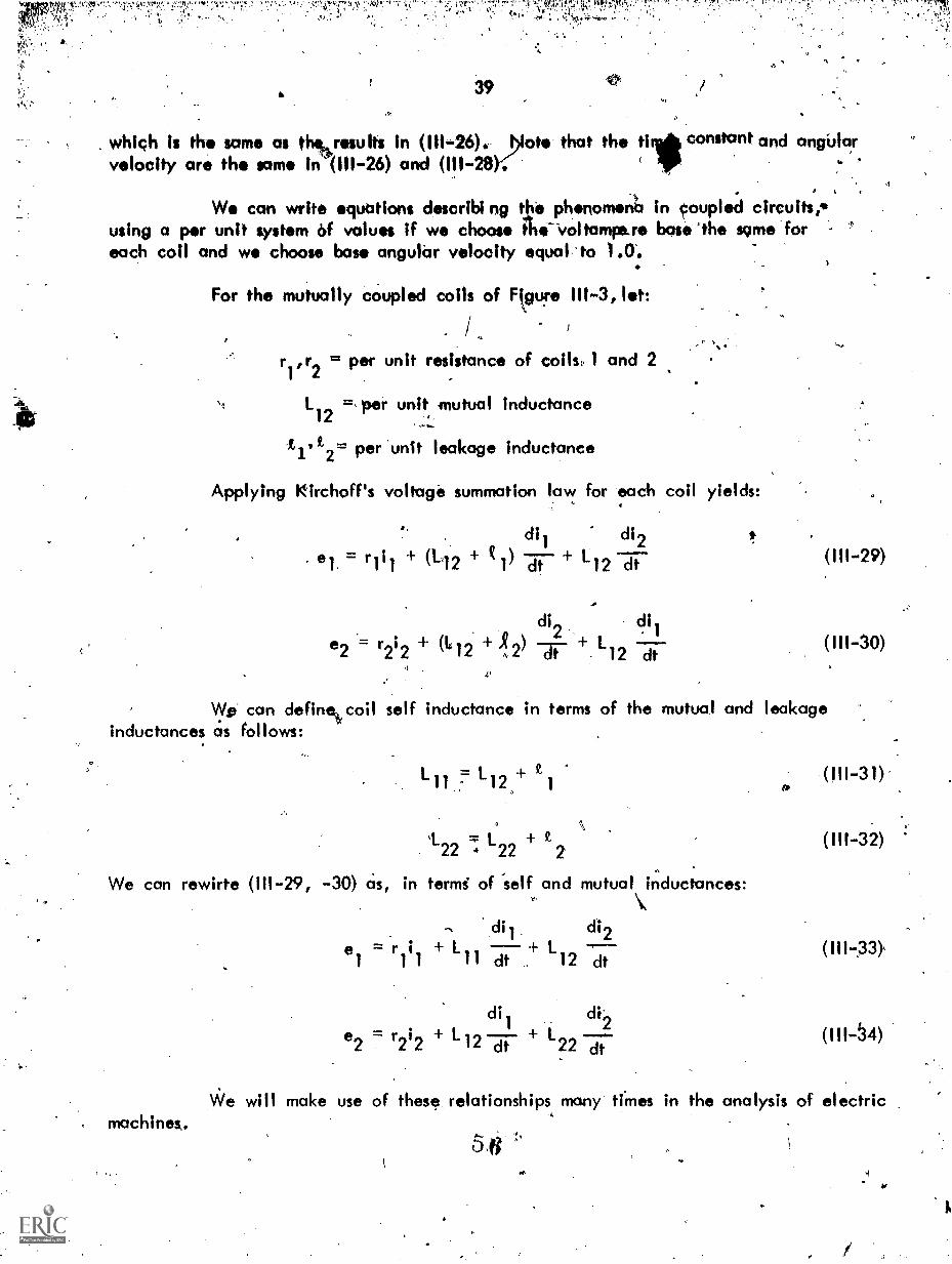
.1 ., V
39
q:1? n ftlt" ; s.; .4K+14, .
which is th same as t results in (111-26).. blot. that the till constant and angblbrvelocity are the same in (111-26) and (111-28) I 6
We can write qubtions describi ng tkó phonomen6 in coupled circuits,*using a per unit system of values if we choose the-'voltamre.re base/he same foreach coil and we choose base angular velocity equal to 1.0.
For the mutually cbupled coils of F.gu!e 111-3, let:
r ,r2
= per unit resistance of coils, 1
112 =,per unit mutual inductance
tf It2= per unit leakage inductance
Applying Kirchoff's voltage summation law for each coil yields:
,
and 2
a.
= r111 + (112 +
+ (Li
dil di2) Ldt 12 dt
di2. di1
) 'Tr -12 dt
(111-29)
(111-30)
Wzi can define,Joil self inductance in terms of the mutual and leakageinductances as follows:
L = L +. 1 1 12
L +22 a .22 2
We can rewirte (111-29, -30) cis, in termi of 'self and mutual\inductances:
machines.
di] di2el = r
1
i1
+ L + L11 dt 12 dt
di2
di1
112 dt 1-22 dt
,(111-3 1)'
(111-32)
(111-33),
(111-54)
We will make use of these:: relationships many ames in the analysis of electric
5.6 .

40
Since we will be concerned with the electromechanicbl.dynamics of thevarious machines we must also define Ipeed, torque, and inertia in terms of theper unit system. v,
4
The per unit value of speed is the actual value, in rad/soc because basswas taken as 1.0 in order to preserve the proper time relationship. Actual speed maybe.denoted by w and may be above or biloW rated. The per unit value of 'torqueis that torqUe whkh produces unit poWer at nominal speed.
,
The moment of inertia in the per unit system is based on the usage ofa defined quantity, H, called the inertia constant. The-inertia constant turns out tobe a very useful number because its value varies over a relatively small range for awide range of machine designs of different sizes-and speeds. For example, synchronousmachines have an inertia constant which lies (Usually) between two and six. In theabsence of specific data on the moment of inertia for a given 'machine, Ore canclosely estimate the value of H based on the machine type and rating.
We wHI now investigate the inertia constant, H, and its relationship toactual moment.of iriertia In the derivation that follows, these symbols are use&
Now:
and:et's
Therefore:
ils = electrical angle, in radians, from some reference
6 mechanical angle, in radians, from the same reference
J = polar moment of inertia, newton-mefer-sec2
o = mechanical speed, radians/sec
td. = electrical speed, radians/sec
f = electrical frequency, cycles/sec
p = number of poles on machine
= number of poles on .machine
to i
f = (III-35)21'
EW (111-36)2o
wo P= (-27?(5) (111-37)

!
and:
By definition:-
..-'7"!X`f.'"'.':!'",'`, ry,t7:4.1,i` r7 t r;
,
41
6 42 m
21 J.%en stored in rotor
. (III-38)
rated volt-amperes of the mac ne / VA (111-39)rated
For situations v:itiere unit power is chosen differentthat- power as VA
bc!". d2ZNow is a power term, In watts, corresponding to Aertia power,.+ m
in an electromechtinic61 system. To put this power on a per ukt bosis, divide by
from V Aratecil we define
VA'baser Thus, per unit inertia power is:
s d260 M
VA 2base dt
Solving equation (111-39) for Jwo, we have:
0
.2(VArated) Hw
(111-40)
(111-4 1)
If this is substituted in (111-40) we have the per unit inertia in terms ofmechanical angle or speed.
C.
62(VAr9ted) H d
2
)2H "'rated dwo.1.1
w (VA ) dt2 VAbose dto base
(111-42)
Many problems are expressed in terms of electrical angle, S , and electrical''frequency,' F. From (111-37, -38, -42)
es.
VArated 1 1121_ ,VArated. H d26
2/1( VA ) 27rf TO-dt
2 VAbase ) Tr fdt
2
,
J
5- 8
(111-43)

'
42
Another Often used defined quantity is called th "Per Unit Moment ofmrtice, M. Thin,,,by analogy,
VArated H.
base "(111-44)
This -M, I based on electrical angle in radians. M is sometimes defined in'terms. of electrical degrees in which case it is replaced by 180 inequation (111-44)..
0.
The &moment of inertia of machines is often expressq.as Wk2(weight timesthe square of the radiusof gyration) in English units of 11).-ft.4. To relate WK
to H,, we cen use the formula,
(W1:2)(0.231)(rpm)2(111-45)
(kVA ) 106base
With the concept expressed here we can express' the per unit power, correspondingto inertia torque, in an electromechanical system as
,2_
M "per unit powerdt2
where the angle .6 is in electrical radians, and M is defined in (111-44).T
(111-46)
In order to mathematically describe our defined model (the generalizedmachine) we must determine pagnitude and polarity of induced voltages - bothrotational and transformer types - and 'of the torques on the rotor. This will be donein the subsequent sections.
111.3 INDUCED VOLTAGES: In our model, all coils lie on either the d (direct) orq (quadrature) axis. Since the machine is assumed to be linear, we can consider thephenomena of direct axis .and quadrature axis flux acting on the two possible coilconfigurations in 4e axis, i.e., either rotating or stationary. The net effect isthe sum of the kid vidual effects obtained by the principle of superposition. Theresults obtained can be applied to coils in the other axis by analogy.
It was previously specified that positive iirrents and voltages correspondto motor action, i.e., the machine absorbs power from the electrical sources. Inorder to determine actual polarities and directions, we must indicate the directionof current flow in the various coils, shown in Figure 111-2. The defined directionsare as shown in Figure (111-5).
5 9

.....:.....k,
43
,
as follows
%.Zto
F towtal
Figure III:5. Defined Direction of Positive Current Flow andRotational Direction for the Generalized Machine(Motor)
The various inductances in the machine in Figure III-5 will be denoted
Mutuat Inductances
L 41.c. 3 t
Leaka9e Inductances
77elf Inductances
L ; L , La 3 ?,
c

44
The relationshili between these various inductances is:
La co+ tq (111-47)
19 tg (111-48)
Ld = L d (111-49)df
f = L_ df+ (111-50)
Current in the various coils causes flux linkages in every coil along thataxis. We will denote flux linkages as follows:
Total Coil Flux Linkages
A A Ad f
The mutual flux linkages correspond to the flux in the air gap andwhich is common to all coils on that axis. The total coil flux linkages correspondto the flux linking a specific coil only and is the sum of the mutual and leakagecomponents.
Flux linkage is the product of current and inductance. We can expressthe various flux linkages as: .
= 1.9 iq f- Lgqig
= ig Lgq iq
q axis air gap = Lgq
(i + ig
)
d 1clid Ldfif
A = Lfif Ldfid
d axis air gap = Ldf (id + if)6 1
(111-51)
,(111-52)
(111-53)
(111-54)
,(111-55)
(111-56)1'

. .45
t' A positive sign for the flux linkage. in the air gapflux directed outward in the convention for current polarity chosen.
denotes
-,The effect of d axis flux linkages on coil D will be analyzed for thesituation where the flux is varying'with respect to time and for the situation whereinthe 'conductors are moving with respect to the flux.
2711.
The coil on the rotating member (the rotor) is assumed to be distributedover the periphery of the rotor. The coil is olso assumed to be Formed by a commutatortype winding. Suffice to say, at this point, that the commutotor, winding has brusheswhich bear on copper commutator segments and that the net effect of the commutatoris to perform a swtiching operation which renders the revolving coil stationary, in space.As Ale winding rotates, the brushes switch direction of current flow and-reconnectsthe winding continuously. Referring to Figure III-6, we con describe what happensto any specific conductor by stating that the conductor is co r4cted with a certainpolarity as it passes through 0= 0. It maintains this poloril fort( electrical radiansat which time its relative polarity in the circuit is reversed
As the rotor rotates, all conductors lying betwe 0 and 1T radians havecurrent flowing in them in the same direction, i.e., into the page in Figure III-6.Also, any induced voltages, due to rotations wHI be induced in a direction so asto be additive. Conductors lying between Tr and 2 w radians have current flowing inthe opposite direction and the induced voltages are in such a direction as to beadditive with the induced voltages in the other port of the winding. The commutatorwinding behaves as a stationary coil with fixed current direction but it also has thecapability of having a rotational voltage induced in the coil.
Consider that the coil is distributed over the periphery with a den`sity ofz conductors per radian.
Figure III-6. Distributed D Coil, Formed by a Commutator Winding
'% ;A 62,

I
2..1,
The shaded area in the conductor layer .represents some iums of a coilwith coil sides at 0 and at (0 +0 radiani.
In practice, the flux density B associated with flux ft.d can have anydistribution. However, regardless of space distribution it can be rtsolved Trite anInfinite series of trigonom.tric functions by.means of Fourier Analysis techniques.As stated previously, in this analysis we 'will Consider onlif the linear case andeffects related to the fundamental . Since the flux density -Is a maximum along thedirect axis (0= 0) We can express it as B Bm cos 0. If the rotor length isA and its radius r, we can relate flux and"flux density as follows:
r/2 r/2t r de = / Bm cos 6 dO = 2 Bmit r-r/2 (III-57)
-Tr/2
The flux linking the turn (shown shaded in Figure III-6 ) is:
(1) f 11. cos 0 et de= 2 Bm tr. sine = Od sin 0. (111,058)
4-04-43) m
If the flux is. vbrying with respect to time, a transformer voltage, et, isinduced in the turn. It is:
et = (ki sin 0 (111-59)
The shaded area contains zde conductors. The summation of all theconductors lying befween 0 = 0 and e = nwill yield the total voltage induced in thewinding (assuming the conductors are connected in a series additive configuration).Denote!
Then:
e = sum of voltages induced in thed.t
series connected winding
de = f sin e)z d 0 (111-60)
cL
odt
dt
0%.
04) z sin e d 0 = (24)dz)
63
(111761)

47
'From Faraday's law, the voltage induced by time varying flux is simplyequal to the time rate of change of flux linkages linking the coil. Thus,
dAct,
ect dt
fik
(I11-62)
where Ad is-the direct axis flux linkage. Faraday's induced voltage relationshipenables us to relate totar .flux (associated with sinusoidal distribution of flux density),conductor density,, and flux linkages by comparing (III-61) and (I11-62), yielding:
2 z = Ad (111-63)
This important relationship will be used later in this sectior).
Note that it is necessary to integrate only 'from 0 to it in order to includeall turns because the elemental turn has two sides. From (III-61) it can be seen that.a"transformer" voltage exists if the flux is changing in the rotor winding (formed bybrushes) located alon? the:axis of the time varyinb flux.
Now, consider the effect of the quadrature dxis flux, , on the rotorcircuit formed by brushes in the direct axis. The development woad be similar exceptthe flux density is a maximum at 0 = w/2 and would ge expressed as B = Bm sin 0 .
The flux linking_the turn in Figure (I11-6) "would be:
0
(I) = I B sin 6 d 0= -2 Bm r cos'e = - 4). cos
The induced transformer voltage in the turn, et, is: .
et(-4)% cos .0)
(111-64),
(I11-65)
and eQt' the sUm of the transformer voltages in all the turns due to q axis flux, is:
e =dt
z cos 0 d0 = 0 (111-66)1,
No transformer voltage exists in the direct axis rotor winding due to timevarying quadrature axis flux (and vice versa, of course). We 'could have forseen thisby noting that the two windings are in quadrature and that the mutual inductance couplingcoefficieni is zero.
':".1c:Ntrk
"

4s
The polarity of the induced transformer voltage can be determined fromthe fact that it is always in.the direction such that, if current could flow, it wouldftcw in a direction such as to oppose a change in flux linkages. Thus it opposesth driving voltage. For a cail with no rotational voltages, suCh as F, applicationof rchoff's law for voltage rises yields:
4,
(111,-67)
To investigate the rotational, or "speed" voltage induced in the D coil,recall that this type of voltage is determined by: -(in vector form)-
e rot = (v X B)cit -.(111-68)
where v is linear velocity, if is flux d nsity and dg is an element of condUctor length.The bar on top denotes a vector uantit - one which has magnitude and direct*. Fromelectro-magnetic field theory, flt44nsity leaves an interface between two media ofdifferent permeability perpendicul9r tcthe interface. In a machine, the flux densityis thus perpendicular to the surfdce the iron at the air gap. For small air gap wecan assume that the conductor elemt is perpendicular to the flux density because itslinear velocity id tangential to khe swface. Since the conductor length is mutuallyperpendicular to the velocity aria thit flux density, (111:68) reduces to:
e at v rt.)rot
(III-69)
This is the voltage induced in each conductor of the elemental coil shownshaded in Figure 111-6. Since each turn has two cOnductor sides, each turn would havetwo times the value given in (111-69). There are zdo conductors in the shaded area.Thus, for total rotational voltage in the shaded area,
(BR,r4(2)(zdO)erot (I11-70)
Total rotational voltage in the winding i obtained by summing over the anglefrom 0 = 0 to 0 =n Thus:
erof 13trtaz de (111-7 1)t
mkrtaz cosed0 = 0 (I11-72)
CI 5

49
W conclude that no rotational voltage exists if -the flux density axis andthe windihg axis coincide.
In order to evaluate the rotational voltage in the direct axis due toquadrature axis flux, we can us equatiuon (111-72) except that the flux densityis a sine function rather than a cosine function. (Thk because the,flux is centeredon the quadrature axis and is thus a maximum at e = w /2). With this change,(111-72) yields:
e rot = f B tod2z sin ed e = 2(28 r)z wm
o
recall that (fr analogy with (Ill-57))
Ot = 2 Bmtr
refore, we can express (111-73) as:
ed rot = 2z4)w
(111-73)
(111774)
(111-75)
By analogy to (111-63), we can express the rotational voltage induced inthe direct axis rotor circuit due to quadrature axis flux as:
where:
.= qwed roth
X = 2z 4)
Similarly, the rotational voltage in the,q axis, due to d axis flux is:
t rot d
(111-76)
(111-77)
.(111-78)
The direction, or polarity, of 'these rotational voltages, relative to drivingvoltage must be ascertained before mathematical models of the machine can be formulated.

rT,.,eprlr-r-,r ;17t-r4,
fo
;,' , "- ;fnyr .
- 50
We can summarize our investigation thin far Cif follows: In n rotating rotorcoil with properties Oreviously ascribed to suchAdr Coil, both rotational and transformervoltages can be induced. The traniformor voltages are induced by the time varyingflux along the axis of the winding. The rotational voltages are induced in the windingwhose axis is in quadrature with the flux under consideration. Thus:
dA4e
clX5,
e t dt
e to X(111-79)cs rot
=wAd%rot (III-80)
where the subscripts t and rot denote transformer and rotational, .or speed voltages andq and d denote coils on the quadrature and direct axis, respectively. The F and Gcoils are stationary and rotational voltages ,thus cannot exist in them. Rotationalvoltages can exist in the 'rotor coils if flux is present in the other axis.
The equations for transformer voltages.are valid under any considerationin so far as flux density space distAbution is concerned. The equations for rotationalvoltage are valid for sinusoidal space distribution, and the magnitude of the fluxlinkage, x , is given by:
X =24z (111-8 1)
where *is total flux per pole, z is the number of conductors per electrical radian on therotor periphery.
What if this flux density space distribution is not sinusoidal? As a matterof fact, most d.c. machines have a trapazoidal distribution at no load which becomesdistorted as load increases. However, the spacial flux density distribution is pericdicond can be resolved into a fundamental and harmonics of the fundamental. In Section 11.1on the elementary d.c. machine, it was shown that the constant relating rotationalvoltage and speed is actually proportional to the total flux per pole and is not a functionof distribution.
To determine the'direction of the induced rotational voltages, refer toequation (111-68). An application of the vector implications of this equation towindings D and Q is shown in Figure 111-7. Only one turn of each of these coilsis shown in order to simplify the diagram.
1)6 7
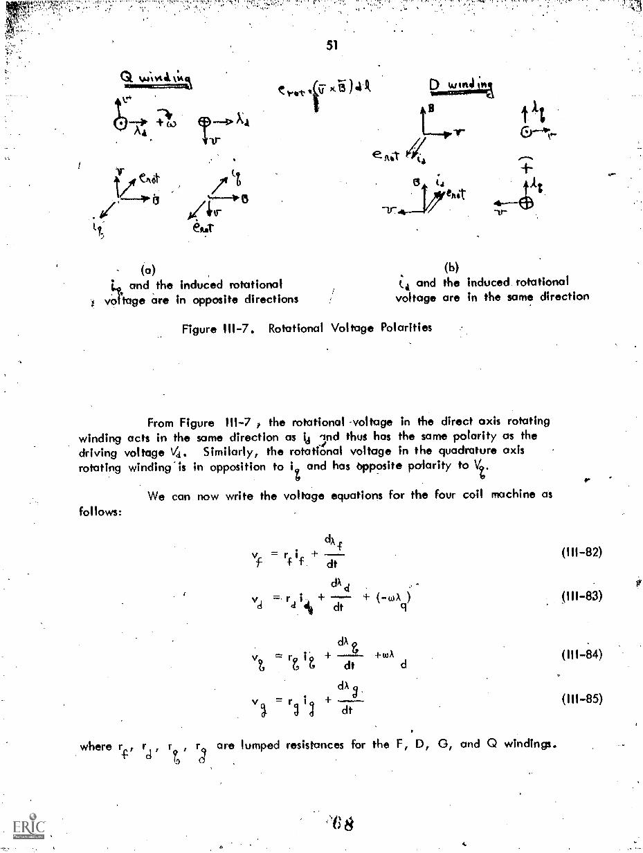
"
1/fieAct tt
4*trtt, emit
(a)
rift.
and the induced rotationalvo tage are in opposite directions
r
51
..44.1.4%.1.r
jø
e
1.17.4
t
4--ktetZ
(b)(.4 and the induced rotationalvoltage are in the same direction
Figure 111-7. Rotational Voltage Polarities
From Figure 111-7 ? the rotational -voltage in the direct axis rotatingwinding acts in the same direction as ki 3nd thus has the same polarity as thedriving voltage Va. Similarly, the rotational voltage in the quadrature axisrotating winding is in opposiHon to i and has opposite polarity to Vt.
We can now write the voltage equations for the four coil machine asfollows:
whererg
=
dA
+ ((A
+WA
-
)
(111-82)
(111-83)
(111-84)
(111-85)
dt
dA d+
dt
dt
clA
+dt
are lumped resistances for the F, D, 0, and Q windings.
2i1

,52
111.4 DEVELOPED TORQUES: In order to. evaluate torque at the shaft of III*'Generalized Machine, consider the total eledtrical power, P. supplied to themachine.
k Xvi= k(vf i + vaid + it + (111.-86)
The value of k and the reason for k will be discussed later. The individualwinding power inputs are obtained by substituting the value of Att.. various voltagesfibril (111-82) through (I11-85) into (111-86). Thus
rt)ix
d.
. rd 18 2 +i a dt cr --
dAi. ...CI A'-'svcic = rfi4 2 + i 4. li
f dt
= i' il .4 ..v. ...
dk...-.c-2,t. . ,v i = ro i 9 + I 9
il:.!"
The i 2r terms are, Z'5f--course, ohmic power loss which appears as heat.Terms of the form:
dA
dt
(I11-87)
(I11-88)
(111-89)
(111-90)
_ "
(III-91)
are terms expressing the time rate of change of stored field energy. To visualizethat this is so, refer to the value of Ad from (111-54) and substitute it in (111-91),yielding:
dx0
di difid dt Id` ci cl7 iciLdf dt
and:
Recall that stored magnetic energy is given by:-
1 2W = L ifld 2
d
dt "fld L i didt
6 9
'3
(111-92)
(111-93)
(111-94)

represent,Thus, terms representing time rate of change of stored field energy do not
oi express, enirgy converted to mechanical form. Only the terms:. ,
tj ks d (1,)179
(111-95)
contribute to shaft power (after conversion to mechanical form) or are a result of shaftpower bbfore conversion to electrical form (as in a generator). The power convertedto or from .mechanical form is, from (I11-86) through (I11-95) then,
P = k (i i )w% d dq (111-96)
In the case, of a motor this power is shaft output plus the mechanical lOsiesof ,triction and'windage. For'a generator, this power is shafrmbchanical power inputminus the mechanical losses of friction and windage:
The electromechanical torque, in the mks system is:
Te = = k (i )d dq (111-97)
The value of k is chosen to make the per unit torque equal to 1.0 whenunit torque and unit flux linkages are prisent. For the four coil machine, two maincircuits are present, i.e., the D ind Q coils. For this machine, k = 1/2. In
general, k is the reciprocal of the number of main circuits.
To ascertain the direction of the electromechanical torque recall thebasic relationship', from electromagnetic flux field theory, for-force, F, on anelemental-length, d , of a conductor lying in d magnetic field of intensity,
, and carryihg a current, I. (The bar on top denotes a vector quantity, i.e., one'which has both direction and magnitude).
r = (1- X 13)d
Torques are exerted on the rotor and stator (equal and opposite) but sincethe rotor is free to turn we shall consider the torques only on the rotor. Recall thatthe cross product of two quantities along the same axis is zero. Therefore, we needonly consider the effect of Ad on the Q winding and A on the D winding in thismachine. This was verified analytically in the previoj section.
4
1;1:
7

ft
54
*N-
Figure depicts, the force on solecwindings.
AA AA(;) f.* tits to
(a)Torque resOlting on winding is
w and is in the direction ofthe rotation
inductors for the D "and Q
(3
v ,t"
(b)Torque resulting on winding istcwand is opposite to the direction ofrotatiori-
Figure III-8. Torque Directions
Thelorque on the Q winding is in the direction of natation. This is amotor; therefore, this is logically positive torque. The torque on the D windingis then negative torque because it is opposite to the direction of rotation.Equation (III-97) agreecaipebraically with the physical reasoning presented here.This is the reason for defining the specific current directions in the D and Qwindings.
mechan ithe loaddynamics
where:
4
We must also describe the electromechanical relationship between electro-1 torque, the moment of inertia (in per unit), and the torque required byLoad torque is usually a function of speed. From Newton's Law of
for a mechanical system;
Te = T (w) + ML dt
TL(w) = load torque
Tes= developed machine torque
M = moment of inertia of rotor and load
7
111
(111-98)

111.5 SUMMARY: We can how sUmmariz the mathematical relations which model, ordescribe, the 4 winding generalized chine. ositive quantities denote a motor. Theequations used are (111-51, -52, -54 -55) for th flux linkages, (111-82, -83, -84, -85)for the voliage-curreM relationships nd (111-97, 8) for the electromechanical relationships:
A
dxfV = r i +f f dt
dAd
Vd r= tox
did + dt 9t, d A
V = r i (A9 q q dt d
. (IA
V = r i + -49 g 9 dt
k ( qx d igq)
dw= IL(w) + M
Lfif + Ldfid
Ad
=Lid
+L id df
=L i +1 i51 q q qg g
= Lgig + Lcigiq
.11
In subsequent chapters, we will relate specific types of machines to thegeneralized machine model developed here. Since we have derived the applicableequations, behavior can beranalyzed by mathematical manipulations on the appropriateequations (111-99) through (I11-108). We must study specific types, of machines inorder to deterntne which of these equations appl); to a specific machine Configuration.These equations are written for a motor.14For a generator, the direction of current inthe power windings, or coils would reverse. Also, of course, TL would reverse(negative sign) because mechanicalpower flows into the shaft, rather than out asl forthe motor. Te would have a nedgive sign because of the change in direction of thecurrents.
a
PA. -.1.

56
CHAPTER- IV - D.C. MACHINES
IV.1 INTRODUCTION: The basic, essential, features of o d.c. machine are shown. in Figure 1V-1. Note that this is a two pole machine while, in practice, ,the machine
may have multiple pairs of poles.
Ski ,
c";fkAl e_ed)(FlAll Vat)
11
arlrexture )(or rotot-)D.;vt4
Figure IV-I. Schematic Representation of a Conventional D.C. Machine
Note that the rotor has been designated as the armature and the FwiAding designated as the "field". This is customary in d.c. mdchines. Theconventional D.C. machine does not have a D winding on the rotor, nor doesit have a G winding along the q axis on the stator. It would be difficult toimagine a more simple configuration for analysis.
The field winding (F winding) is either a concentrated coil consistingof a few turns of large cross sectional area wire or many turns of relatively fine,or small, cross sectional wire. The former is usually called a "series field"and the latter a "shunt field". Common types of electrical connection for theD.C. machine are shown in Figure IV-2.

V
57
0.) SAc b) Sirtro. it? Excitii.4.
1,%tuAt totAtitcficvv,S wLwt C,t&wtcr t 4-4/1c-- ) S s
CAA.W. c-
Figure IV-2. Common Types of Connections, D.C. Machines
The field winding provides "excitation", i.e., establkhes the magneticfield, A d. Since flux linkages are Proportional to the pr,oduct of current andinductance and inductance is proportional to the square of the number of tums, thegeneml idea in the shunt connection is to use a relatively large number of turns tokeep the current (and power converted to heat) as low as possible. For.the.serieswound machine, the current from the power circuit flows through the series.winding. The current in the power circuit is on the order of 20-30 times largerthan that which flows in the shunt field circuit in a well designed machine.From ,the standpoint 'of losses as heat, the coil for a series-wound machine shouldbe designed with low ohmic resistance. There ate other reasons why this isdesirable (such as "regulation" -either voltage tir ipeed) and these wHI be developedlater. Since the current is relatively large, fewer turns can be made to yieldthe same value of flux linkages as p wfnding with many turns carrying a smallvalue of current. The point of this discussion is that the field coil and thearmature can either be in series or in parallel, but the field cal must be designedfor the desired combination. Some d.c. machines have two field coils - onefor series connection and one for shunt connection. These machines are classifiedas "Compound-wound" and would have two F windings, F1 and F2, as discussedearlier in connection with the description of the generalized machine. The shuntcoil is usually 'much stronger than the series coil. nd the machine has characteristicssimilar to the shun machine although modified\ by e load current through theseries coil. The c mpound wound machine can be further classified as cumulativeor differential -compound depending on whether the series flux is in the same orin the opposite directitn as shunt winding flux. The schematic representation fora compound wound machine is shown in Figure IV-3,
74

1-KA L vc.te C)
Figure IW3.
58
F,- sisttovt C%-(11
46
kIsfatzt 'Zt,;tvkt" Cbtovests.'An
Compound Cqpnections, 1),.C.fiMa,chines)
.r \\
In describing the shunt coil as being connected in parallel with the
armature coil, we should perhaps describe it as being designed for connection ifwe so desire, That is to say, it is designed for rated voltage of the armature
-coil and may either be connected directly in parallel with the armature ("Selfexcitedi or connected across a separate circuit of the same voltage rating as therated voltage in whith case it is "separately excited". These terms are especiallyappropriate when we refer to a generator or to a motor powered from a variablevoltage source.
Examination of a large d.c. machine may indicate the presence ofadditional windings, such as series connected turns on small poles between themain poles. The masin poles are located on the d axis. The small poles referredto here are located on the q axis. The purpose of these small poles, called inter-poles, is to assist in the commutation process, i.e., the switching of conductorconnection by the commutator as the rotor turns and commutator segments passunder the brushes. Another form of winding consists of inductors (or conductors)embedded in the main pole face and series connected. These are called"compensating" windingi and their purppse is to compensate for the flux changesin the air gap that results from armature,current and magnetic non linearity. Thisphenomena is referred to as "armature reaction". Both the commutating and thecompensating windings act to correct phenomena which cause the machine to departfrom an idealized machine and do not contribute to the energy conversion process.An' understanding of their specific details is not essential to an analysis of machinebehavior based on the linearized version of theimachine.
The equations describing the generalized machine can be modified, oradapted, to the d.c. machine if we specify how the d.c. machine is connectedand in what mode it operates, i.e., as a motor or generator. Several examplesinvolving various configurations will be analyzed In this chcp ter. They are:
is
/.
k
'

59
1. The Shunt Connected( Separately Excited-Generator2. The Shunt Connected, Separately Excited Motor.3. The Series Connected Motor.4. The Self Excited, Compound Connected DC Machine on Short Circuit.
One might reasonably ask why we choose a separately excited generatorrather Orn---self excited. There are two reasons - the first being that this is .acommon method of operation in control systems and the second being that t heOperation of a self exCited machine acting as a generator depends on the non-Ilnearities present. With a linear machine (i.e., linear flux vs. excitation)the mathematks willconvince you that it cannot work. The physical reasoningis that when load is switched on, the voltage across the field drops, excitationdecreases, causing stilt more voltage drop etc. until the voltage cc:Alai:nes com-,pletely. However, a real machine, with non linearity, does vsork. There aretechniques available (graphical, by coMputer, and by iteration) which enable usto analyze self excited machines with.non linearities.
IV.2 THE SHUNT CONNECTED, SEPARATELY EXCITED GENERATOR WITH SWITCHED LOAD:In this analysis we will assume:
1. The generator, is driven at constant rated speed, i.e.,w 1.0 per Unit.
2. A load consisting of resistance, R1 and inductance, Li is switchedat t = 0.
3. We will excite the F coil from/a constant voltage source andwill collect D.C. Current from the Q coil. (The usual configuration).
Recall that the equations for the generalized Machine (III-99) through(III-106), were written for motor action. For the generator, the current is in theopposite direction fronfthat used, for motor action. We will denote the terminalvoltage and load current by Ow subscript a.
Thus:
'Similarly,
e = ea
L = La r r ;tNote the absence of the D winding and the G winding. Also, since
= constant, equation (III-105) becomes:
TeL(w)
(1V-1)
(1V-2)
(IV-3)
A

60
The minus sign indkates mechanical power enters the shaft, rather than
.being taken from the shaft and the equality states that the mechanical power used
to drive the machine is all converted to electrical form. This is true only if weneglect the mechanical losses in the machine (friction and windage losses). The
appropriate equations from (III-99) through (III-106) can then be rewritten as follows:
cftf
rfif + If dt (IV-4)
diava + roia + La = adfif
4
= " T L(44) Pmech (IV:6)
w (-1A) = iifdfL= P (IV-7)ad a mech
where Pmech is the mechanical shaft power into the generator.
The F and Q windingf are in quadrature. .Therefore changes of eurrent,in the Q winding do not affelct the F winding since no magnetic coupling exists
between them. At t = 0, if is in the steady state condition and has a value,
i f remains constant at this value. 4
Taking the Laplace transform of (IC/-5) yields:
w Ldfif.v(s) + (r + L s) I (s) La i
a(0)
a a a
Frdm the problem statement., (0) = 0. However, since the generatorwas rotating and excitation current if exiaed, a no load voltage existed at theterminals of the generator. From (IV-5) with ia = 0,
va(0) = wLdf if
(IV-8)
(IV-9)
( IV-10)

If this
61
From (IV-10), if can be determined as a function of no load voltage.,'is done and substituted in (IV-9), we have:
required inrelationshipia.. Thus:
probably
v(0)va (s) + (r + L s) I (s1
a a
IN (VI-11) 'We have two vartables, vn(s) and ia(s). Another equa on sorder to obtain a solution. This addiiional equation can come from thebetween terminal voltage va' and load current - which h the current
diav =Ri +1a L a L dt
(IV-12) yields the transformed equation:
va(s) = (Rt. + Lis) la(s)
Equations (IV-11) and (IV-13) can be solved for either la or v-. V isa athe variable of, interest so we will solve for va(t). Thus:
where:
whic h is:
wher*:
v (s) =
va(s)
v (4)a
111(1 + To) va(0)(IV-14)
(IV-15)
(IV-16)
(IV-17)
r0(1 + Tas)
0 -R (1 + T s)
1 r0(1 + Tas)
1 -R 1(1 + TLs)
, L, a
s1R1(1 + To) + r0(1 + Tas)
1
- LL.T =
a r ' L RLa
RLva(0) (1 ;t- T s)
s (1 + T s
+ LaT=r
a L

62
We can apply the Initial Value and FiLI Value Theorems to (IV-16) todetermine the terminal voltage at the instant of closing Ihe switch and after themachine reaches o steady state condition. Thus, I
1
r +_Tt.R
Limit Va(t) = Limit s Va(s) = Limit1
oz)
V0(0) (IV-,18)
t -to t-we s + T L a
or: L.limit V (t)
rv
a(0) = + \go) (IV-19)
L a a
Note that 40) is the) terminal voltage before load is switched. Limit+-bo
V 0(0 is the instantaneous voltage immediately after the load is switched. Foe thesteady state value:
Limit V a(t) Limit s Va(s) = limit Va(0) (1V-20)e -to s -to L a
or:RL
Limit Va(t) + V0(0) = Vo (Iv41)
where Va is the steady state terminal voltage. IF (IV-21) is rearranged, we have
Var va(0)L
Recognize that the steady state current iais steady state voltage divided by load
resistance. Thus:
ia =va
If (IV-23) is substituted in (IV-22), we have the steady state terminalvoltage characteristic of the separately excited shunt generatorno load voltage,tind armature resistance. Thus,
Va = rala + Va(0)
This is a linear relationsIlip and
(IV-22)
(IV-23)
in terms of load current,
(IV-24)
plots as shown in Figure IV-4.
7 9
'

,17
63
vai..11-4twu,si-`e
f,/ rivA.* Jta.
Figure IV-4.
loccl(rartA CAA rrevil)
tate Voltage-Current Characteristic, Separatel)'Excited Shunt Generator
A measure of the ability of a generator to maintain nearly constantvoltage is the so called "voltage regulation'. By definition;
Va(0) Va(full'Ioad).% Voltage Regulation Va (full-1-60d) 100
It should be emphasized that the above is representative of the steady staterelationship between terminal voltage and -loccurrent. It may be that .the termlnal'voltage as a function of time, after load is switched, is desired. This informationcan be obtained from the inverse of (IV-16). Thus;
va(t) (Va(s)) =Rt. Tt. T
/F7- r Y0(9)' +L a
RL
= V0(0)RI + ra
Lot.11 -E +Lt.
L
-0
Va(0) -t/T V(0) -VT= - +
LaRL , r-,
L
+
The response described in (IV-27) can be plotted as a function' of time by-plottingeach term and them,graphically summing. This is as shown in Figure (IV-5).
8 0
(IV-25)
(IV-26)
(IV-27)

1' '
4 I Vatic)
4;:s t
64
. ..1001.
Vo) .-egt.vise
yrvci.4)
"
V (0)cf -DS (Steal.
RL "-40
-...44444`.
Vt4(0)SIsitz
Vo. to )
Rt.
Figure IV-5. VP) for the Separately Excited Shunr Generator.
We can summarize the response by noting that the voltage dips instan-faneously and then varies in an exponential fashion to the final steady state 'valuedetermined by the load resistance. The initial dip would occur in spite of a voltageregulator which would sense changes in output or terminal voltage and thep act tochange Vf or rf in order to mstore \t/0 to its prior value. The time constantassociated with the voltage variation is deiermined by the total inductance andresistance in the armature circuit.
81
laps

_
65
Alr.r?s,
To investigate the transient behavior of the shaft power input to thegenerator, refer to (IV-7) and (IV-10):
or
Then:
where:
V(0)pmech wi
adf = iaLdf(717,3) i V0(0). (IV-28)
df a
=mech( -Va(0) la(s) (IV-29)Ps)
We can use a value of la(s) as determined from (IV-11) and (IV-13).
Pmech(s) -Va(0)
Va(0)
0
(r + L S)a a
1 -(11 + 11s)
V a2(0)1
+ R s (1 + T 5)
Applying the Initial Value Theorem:
(IV-30)
(IV-31)
.11 + LaT (IV-32)RL + r
a
limit Pmech(t) = limit s Pmech(s) = 0t4,0 s
4:1(IV-33)
This should not be surprising since the machine is at no load, electrically,and we are not including mechanical losses (friction and windage). Therefore
mech at t = 01,s zero.
Applying the Final Value Theorem yields:2Va(0)
limit Pmech(t) = limit s P (s) = r R
st mechs ari
8 2
(IV-34)

-
66
Again, this is a reasonable answei for a physical reasoning standpoint.Since field current and speed do not cha4e, the induced voltage remain the sameas the no load terminal voltage and the steady.state power inpurwill be the totalpower dissipated as heat in ra and It1.
From the inverse transform of (IV741), we haveh
V02(0)
Pmech(t) (1-
The minus sign means mechanical power into the machine.
(IV-35)
Ain e xample will serve to illustrate the use of the equations an'd 'also*4conversion from actual values to per unit values.
Example
A D.C. machine, operating as a Renerator, has the following rating:200 Kw, 250 volts, 900 rpm.
A,
Test res-ults yield the following:
t-,
field restance'I r f 33.7 ohms
q axis armature resistance, ra = 0.0125 ohms
field inductance, Lf = 25 henry
q axis,armature inductance, La = 0.008 henry
When driven at rated speed, no load, an emf appears.across the q axisarmorure.winding equal to 22.8 volts per field ampere or excitation. In this problem,the Igeneratoi' is being driven at 1500 rprrh At t = 0, a series load of 0.313 ohmsresistance, Ri, find 1.62 henrjf. inductance, LL, is switIched onto the q axis armaturw*nding. Prror to t = 0, the field winding has 230 volts impressed upon it andth current in the field has re6ched steady state.% Find Va(t).
The value of Cdfcen be ieterniined from the, no load test informationby using equation (IV-5):
dia
0 Va raia + La cli" =et" Ldfif
For:ia = 0
VaLdf=
I f""--
63
04t1
(IV-36)
(IV-37)

p,1,
0116
67
Now, 22.8 when w= Ry- x 2 7(= 94.4 rad/sec) From which900
e..
L, d= 0.242 henryf= 04 4
Using actual values, anCI sulAstituting the values in (IV-17) and (IV-27)yields;
Va(t)
4' La 1 .42 + 0.0085.0+ ra.,,- 0.313 -t 0.0125
va(o)(1 - c
ra
Va(0) -t/TLa E
1 + 1 +KL
230For t <0, Vf = 230 and i = = 6 82af .33.7
V(0) = coLdiif= (1500 x
(0.242)(6.82) = 259.1.-60
ra 1 + 0..01251 +
RE.=
0.3131:0399'
La 1 + 0.0081 + = 1.0049 '
L 1.62
-t/5.0V(t) = 249.16 (1 + 257.84 E
(IV-27)
(IV38)
(IV-39)
The initiy value of voltage, after fhe switch is closed is 258 volts.s. The steady state value', for t- >3T, t > (3)(5) is 249.
.41011.
If we worked this in per unit, we woulchoose a voltampere base of...200,000 watts, a vola base angular velocity of 1.0. Then
200 000lb 1, 2150 "
8 4
ed as follows: Firsl!,se of 250,volts, and
44.
,

a
Rb
68
250= = 0.3125 =
'1b = 1.0 0.3125 6 0.3125
1
yieldsConverting the various actual values for the machine to per'unit values
\,. f 4
r
230at t = 6, e
10.92 pu
rf33.7
= 107.84 pu0.3125
25L =0..3125
= 80 puf
ir(0) = 0.92 = 0.0085I 107.84
. 0.0125r =0 0.3125
0.04
=0'313 = 1.00.3125
0.008L 0
0.3125.0256
1.62LL 0.3125
5.184
900 rpm = 307r rad/sec = 30n pu
I5a 1500 rpm = x = 50n pi,
An open circuit, at rated speed
and; from (lV-37)
0
Va(0) = 22.8 volts/field ampere
22.8L = wif 30 w
0 242 henry
0.?420.7745 pu,
Lcif 0.3125
8 5
(

r
7V!,-.7-"T , ,!.,1\r, 1,1-, 1,, 4,,
Using per unit values,
V(t) pu
69
5.184 x 0.02561.0 + 0.04. =
V0(0) = toLdfiu
1
(56/1)(0.7745)(196'79284 ) 1.03735
La.=IL
0.041 + 1 04
0.02561 +. = 1.0049
1.03735 01 1.03735 '475' 6-t/5.
-1.04 (1-I- 1.0049
11
-t/5.0 -t/5.0 \.. = 0.99745 (1 - c ) + 1.03229 c \
, (IV-40),,
\The value of Va(t), in per unit, at t = 0, k 1.03229. Thk is 'an a\tual value of(1.Q3220)(250) = 258. , .
\
1.
\
The values of Va(t), in per unit, at values of t > (3)(5) is 0.99745.This Is an actual value of 249.
These values obtainód' by ccilculation in per unit agree with those obtainedby calculation using actual values.
'The voltage before load was switched and while the machine is .running,at 1500 rpm is:
(1500)(2n) 230Va() 77R 0.242)(177) for t
.= 259
.
714,

70
A Plat a Va(t) for this example is shown in Figure IV-6.-tak.;,Asi
Z-11.t
0
Figure IV-6. Terminal Voltage as a Function of Time
The voltage regulation can be calculated as (since 1.0 pu lodd wa
switched on):
% voltage regulation = + .(259
249- 249) 100 = 4.02%
The steady state voltage-load characteristic for this example is shown
(assuming linearity) in Figure IV-7.
Vo- 1-etwU4al ttt
2.11b
7 tam-% /
800e...11.0 -no.=
249
80t5
I bail c-ALY'relArrut-es
Figure IV-7. 'Steady State Terminal Voltage as a Function of Load CurrentEt 7

A
;
71
IV.3 THE SHUNT CONNECTED SEPARATELY EXCITED D.C. MOTOR: This motory-use n Wry ecause o I ease w w c te spee s -torque characteristic
,qf the motor can be varied. Schematically, the windings are connected as shown in.-Flgure (IV-8).
VA) TarboiNal001141e
.4
1
Vi. c .te, ( j U t ,t.;:it4Z.
Figure IV-8. Separately Excited D.C. Shunt' Motor
Our analysis is concerned with the speed variation with load torque. Wewill assume the mechanical losses (friction and windage) of the motor are negligible(or they could be included with the load torque requirement). The values of rf andra include the resktance .in each of the windings as well as any external resistancewe might acid in order to obtain a desired characteristic. The moment of inertia,J, includes the total moment of inertia connected tol the shaft, for boththe motor 6rmature and load. We can mathematically describe thel motor as follows:
difVf = ref + f dt
diaV =ri +1 --tw 1dcf
dwLcif ifia = T ) + J
dt
(IV-41)
(IV,-421
(IV-43)

72
In order to proceed with the analysis, initial conditions are required.The initial conditions required are the values of if, 0, i , etc. at t 0. Att = b, the machine is operating in a steady state conditrou. Therefore, all timederivatives are zero. From (IV-41, -42, -43) denoting TL(w) at t = 0 a's Ti(0),w at t = 0 as w(0) etc.
Vf = rfif (o) i(0) = viirf
TL(0) =Ldfif(0) 1 a(0)
TL(0) rfia Ldf-f
Varf ra T1(0) rf?
(0) dU 2 2Ldi ef .
(IV-44)
(IV-45)
(IV-46)
In this analysis, we will investigate only variations resulting from changiAg
mechanical load. Of course, the armature cuirent will vary with time, but the fieldcurrent will remain constant (no coupling between armature and field). We need onlysolve the latter two of the three equations (IV-4I, -42, -43). Taking the transform ofthese, we have:
Va
do. La= r
a(1 + s)I (s) L i (0) +1-df w (s) (IV-48)
$ r a a a
T (s)
a
d if ia(s) sW(0) (IV-49)-
In order to obtain behavior characteristics for the simplest case, considerthat the machine is at no load at t = 0 and that armature inductance is negligible(an often used assumption) and that a step type torque load is impressed. For, no
load, from (III-106);
Te = 0 = I,q Ad --- d iaLdfif
P9
p(IV-50)
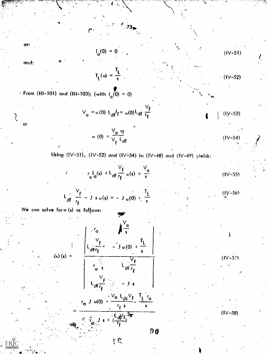
1
-
r
or:
and:
7 1'73-14.
ia(0) = 0 . (IV-51)
TL
TL(w) =s
From (III-101) and (I11-103); (with ia(0) = 0)
or
Using (IV-51
V1Va w (0) Ldfif= w(0)1-df
Va rf6,) (0) ,
vf Ldf
(IV-52)
I I (Iy-53)
(IV-52) arTd'(IV:-54) in (IV-48) and (IV-49) yields:
Vf Var 1 (s) + Ldf
,(s)a 0 f
Vf TL
Ldi s w(S) w(0) s.f
We can solve fort, (s) as follows:
rc,
. .
=
Ve
L A - J (0) +rf
ra
V fL.
cif r, f
- J s
,Va lTdc\lfw(0) +
rf s
J $ + (--)rf
TL ra
90
(IV-54)L
(IV-55)
(IY-56)
(IV-57).
.
(IV-58)

a
I/
74
Applying the Final Va lue Theorein yields:
.... 2Vie rf II ra rf
foss = limit w ( t) 1W limit' 1 w (s) ' '97: 4- 2t-o $ 49 L Vf Ldf,Applying the Initial Value Theorem jlelas:
0(0) = limit w(t) =`. icd,(s) w (0)t -40 s- "
We will define on apparent tiMis constant, T, as:
, 2ra rf
, 2 , 2Lcif f
with this defined value of T, and the value to prom.(IV-59), we can express w (s),ssin (lV-8kas .
T w(°) s + I
(IV-59)
(IV-6I)
w wSS s(T s + I)
The inverse *form of (IV-62) yieldso(t) as:
-yr(05(0 z (1isre ) 463(0)
ttis solution is plotted in Figi;e411/$)).
41,
(IV-62)
Of*.
(IV-63)4
11/
Figure IV-9...w (t) for Step Torque Load on a Separately Excited Shunt Motor
1

75
From Figure (IV-9) the speed change with time is exponentially decreasingto its steady state value. The time constant associated with the machine is a functionbf armature circuit resistant., moment.of inertia,the field resistance, field voltageand mutual inductance of the d axis.
The steady state speed-torque characteristis is of extreme interest and thefact that it can bar.--igily varied, or altered, in a D.C. shUnt motor accounts for thewidespread useage an4' Popularity of this.t motor, in spite of the necessity for providinga source of DC power and the increased maintenance problems (due to brushes, mainly)associated with the DC machine.
From (14he variables which affect the speed torque relationship are:
1. the arma"). voltage, Va2. the armature Circuit resistance, ra3. the field current, changed by changing Vf and/or rf.
Replacing the ratio Vf to rf by the field current, if, (IV-59) becomes:
1 Va rato
ss (1711 (174(7f21TLcif(IV-64)
In order to examine the various possibilities we will examine (IV-64) undervarious conditions. For example, consider all external resistance in the field circUitremoved and rated voltage applied to the field circuit. if is constant and (IV-64)becomes
Va rao (IV-65)ss
This is the equation of a straight line when steady state speed is plottedagainst load tdrque. A family of curves are obtainable, as shown in Figure IV-10( )if the voltage applied to the armature circuit is varied from zero up to rated valueThe slope of the characteristic (for fixed Va) is proportional to the armature' circuitresistance. This is shown in Figure IV:-10(b), which depicts the situation where if andVa are constant but various values of armature resistance, ra, are used.
Now, consider that rated armature voltage, Va, and rated field voltage Vfare applied and that all external resisttince from the field circuit is removed. Theresulting speed is the so called "base speed" of the motor. In order to increase thespeed above the base speed value, the field current, if, must be reduced - either byincreasing field circuit resistance, rf, or by reducing the voltage applied to the fid d,Vf. The resulting speed torque characteristics are shown in Figure IV-10(c).
9 2

X
76
t ree-41541. Sr44
NCI-414LS
41.PW MtIle lirl141
VO.,
(a) Speed-Toque Variation Below "Base Speed".. Full. Field Current Appliedand Maintained Cdhstant and Armature Resistance Constant.
4
1,1 Crerks
cm-woott+4 Nr.
irel; t.1%IrCktItt.
rebt4e.
(b) Speed-Torque Variation by Changing ra. Applied Armature Voltagt, andField Current Constant.
ttc.V. 441,11
d 4scromitirn
VAI1AWAIAA
Je4
(c) Speed ,Control, Above Base Speed.Rated Va and varying Vf or rf.
Figure W-10. Shurit Motor Speed Control
93
.,

fashion,
77
v)foltageregulation was previously dfined for the generator. In the same
can define percentage speed reoulation. Thus:
(0(0) - tiuli 100.4)x 100% Speed Regulation .. (IN.66)
W
full load
Note that speed regulation increases with increasing ra when wing fixed field,variable armature voltage control and with increasing ( , (decreasing if) when usingfixed armature circuit voltage and resistance with variable field excitation control.
In addition to "base speed" as defined above, machines have a "top speed"limitation as determined by mechanical considerations, i.e., bearings, winding centrifugal'stresses, etc.
Below base speed, the field current is constant at its inaximum value. Thereis a maximum value of armature current possible because of the heating losses in thearmature winding. Since, in steady state, thek,torque is roporicknal to if and ia thetoi.que limitation is constant at the continuous,.maximum va e for speeds from zero to basespeed. With ,constant torque, the power rating is linearly proportional to speed.
Figure IV-11 depicts the torque 'and Power limitation over the same speedrange. When base speed iv reached, higher speed is obtained on y by decreasing thefield current. For purposes of illustration, with negligible armature resistance, from(IV-64):
W eX. 1
f
and from (I11-103) and (III-106)
jT ex. if
From (IV-67) and .(IV-1168)
T Pc1
to
(IV-67)
(IV-69)
Thus, the torque-speed limitatio between base speed and top speed ishyperbolic, as shown in FigUre IV-11. If. both sides of (IV-69) ore 'multiplied by(A), it can be seen that the poWer is proportional to.a. constant for the speed rangeobtained by fie.ld control, as shown*,in Figure IV-114
;.L,.".,..

tip}.*:Ari .4:nvs!,
A
',"7 -.^ .. .
78
otuer
I
Atiltivillk I cit ti I
ViaMut czo-,..01
t.44. !
441st T>")
st"
Figure IV 11. Torque and Power Limitations - DC Shunt Motor
Irsit
P'
IV.4 BLOCK DIAGRAMS: In system analysis it is often helpful, to have block diagramrepresentation of- entities comprising the system. To illustrate the procedures to befollowed in the derivation of the block diagram, we will go through the procedure for
the shunt connected d.c. motor analyzed in Section IV.3.
Block diagram representation is simply combining the various transfer
functions, derived from the mathematical model of the device being represented,to 'represent the system as a whole. A transfer function cannot include initialconditions but initial. conditions can be incorporated into the block diagram. To
insure the absence of initial conditions, we will deal with changes ill the votioustariables and add the initial conditions after deriving the representation for thechanges in the variable. If 'all changes result from something that takes place at
t = 0, the changes a6 not have initial conditions and transfer function representation is valid:
The block diagram representa-tion is 9ften obtained as a prflude to computerrepresentation of the clevice or system. Since oth fiel d voltage and armature voltagecan alter the shunt. conrlected DC motor lor, the representation will1be based onall three ofthe describing equations, (IV-41, -42\and -43).
These equations are:,dif
Vf rfif + L1
di.V = r
a a a La dt +41Lcifif
Ldf ;Oa = TI + aidw
., 95
(IV-41),
(IV-42)
(IV-43)

4riPI),It'r
.
79
Consider that.the variables, Vf,if,Vado,TL arra in these equationsrepresenrthe steady state value prevailing before t 0 plus the portion of thevariable that changes after t 0. Thus:
If in 4(0) + if
Vf VP) Vf
Va ia(0) + Ala
414/a = V0(01 + AV0
w w(0) ew
Ti = I(0) + A 'rt.
(IV-41) becomes, using (IV-70):
Vf(0) + AVf = rf(if(0) + Ay + dar of(o) + Ay
(IV-~79))
(IV-71)
(IV-72)
(IV-73)
(IV-74)
(IV-75)
Also, the steady state relationship, for t < 0 prevails, i.e.,
V1(0) = rf i(0) (IV-77)
Subtracting (1\/-77) from (IV-76) and finding the Laplace Transform yields:
4iVçrAi1+L1s Asti
IfA V1 rf (1 + Ts) if
4
(IV-78)
(IV-79)
It is current, tharprovides excitation HuX and is thus the variable ofinterest in our modeling and block diagram. (IV-79) should-be solved for Aiç to obtainthe transfer function as shown in Figure.IV-12.
A if Yowl.
. 1
1.4rf0A Vf
9 6
(IV-80)

Thus:
80
.
-11106- *
1
I 6 t f
Mi. Mf(l 1 WS)7
,
Pigure IV-12. Block Diagram Representation Transfer Function)for (IV-80).
N*. -
Equation (IV-42) can be subjected to _the same manipulation as (IV-41).
V43(0) + A Va ra(ia(0).+ eia) + c4r 00(0) +A ia) +'
( 03(0) + Aw ) l.d.Vf(0)°+ A if) (IV-81)
Va(0) raia(0) + to(0) Laif(0) (IV-82)
Subtracting (IV-82) from (IV-81) and transforming, yields:
A Va = ra A ia + Las eia + 141 f(0)eto Air(0) +A ifAco) (IV-83)
c
Note that Ai f Ato is a second order effect which will be neglected.
In determining which variable, or variables, will be inputs and which willbet' outputs in the blo-ck diagram representation of (IV-83) we reason that V is an inputand that in the overall diggram 43 is an output. An output is available to-be used asan input if necessary (feedback). Some experienCe is helpful in deciding how theblock diagram h to be arranged. In this situation, ins will use, as a first effort atleast, the arrangement shown in (IV-84) and Figuye IV-13.
A ia
ow"
OkVa Ldfif(0) Ato ide (0)A if
V r (1' + s)a ra
tc' (IV-84)

4.(0
t
and:.
fp.
81
Fi-om which;h.
Figure IV-13. Block Diagram for (IV-84).
1411*-.
For it-43, applying the same' procedure!,
L (0) + (0) + Ai = (T +A T.) + (0(o) +AO -85)dr f f a a L
L j (0) ir(0) = Tidt r"
1Ato = + L + LI a!
.)0(0)AidJs r dt
ntc,.
10)
if (-0
J.3--s
(k)
Figure IV-14. Block Diagram for (IV-871.
98
p.

82
vt
W. are now in a position to formulate the Block Diagram for the completesystem by combining Figure IV-,12, IV-13, and IV-14. The result is as depicted inFigure IV-15 and Figure IV-16.
A "ri_
Ftyry_
wr-e_
Figure IV-15. Connection Diagram tor)Figures IV-12, -13, and -14.
k
.54 (% t Ws)
c't
-IV
Ap(o )
JI o,
.Figure IV-16. Block Diagram for Shunt Connected DC Moto?
9

83
If the field circuit parameters )14,1f, etc. are maintained ,consni, theBlock Diagram of F4gure 1V-17 h considerably simplified and is as shownFigure IV-17.
11
7Figure IV-17. Block Diagram for Shunt Connected DC Motor with Constant Excitation.
/.
Aft. f
From the Block Diagram, it can be seen that the shunt motor comprises'
a negative feedback system.
IV.5 THE SERIES D.C. MOTOR: ,The Seri, D.C. motor has rather wide, usage inapplications requiring Maximum torque near zero (or stall) speed - such as intraction systems, etc. Because of the nonlinearity inherent in the analysis it willbe instructive to examine the method of analysis in detail.
The series rnachine has a field winding which h connected in series
with the armature circuit. The applicable equations are:
2.
d(,)T = + J
e L dt
diaV =ri +1 +toAd
a a a .0 dt
Ad =di.
ia
2T = i L
e d a Orr a
_too,v
(1V-88)
(IV-89)4
(IV-90)
(11-91)
-

a
84
The ia2. term in these equation results in the system of equations'
being non linear. A technique for dealing with' this will be presented. First,
we will examine the steady -state characteristic of the motor. In the steadystate, neglecting mechanical losses;
dfi2
V `i2". r 4-adfiaa a a
a.
i can be eliminated from (IV-92) and (IV-93) yielding:a
Va 2.
ra + wL )
From (IV-94), asto -+ o1
.. , .
2,, V -
T '-* L F-La
L di 2 df a-, ra
(IV-92)
(IV-931
(IV-94)
(kV, -95
In other.words,,IL is proportional -to the square of-the current flowing when,current is deterr6Ned only by applied voltage and armature circuit resistance, i.e.,no counter electromotive force, (La, exists to limit current.. Further, ps T
,- '''''- L.:: °
The steady state characteristic is shown in Figure IV-18.
d
Figure IV-18. Series DC Motor Speed Torque Characteristic

85
Because of the excessively high speeds*resulting as Tr_ 4 0, care must.be exercised in the apPlication aspects of series motors. Belt drives are nwrused,because of the possibility of st belt failure and -consequent unloading andoverspeeding.,
Because' of the non linear differptial equations whlai describe the DCseries motor, (IV-88, -89, -90, -91) the dynamics of ihe motor are l;est studieilusing a coriputer.- However, we can ut4ze the technique of, linearizing aipout anoperating point" to eliminate the non linearity. ,This technique is only valid forextremety small changes in operating condition from the steady state operatingpoint. It does yield considerable insight into the, pattern of the dynamic behaviorand does permit the application of lincor analysis techniques tq the soya4on of thedescribing Ouations. 11.
In eifect, we will consider the machine to be in--the sieady statebondltion with some load,. Ti(0). We -will introduce a small change 1,1 load,ATI and observe the oscillations ,which result. We will denotto all the othervailables in the same fashion. thus, at steady state,
1d102(0) = Ti(0)
Va(0) rai0 (0) Adfla(b) w(0)
For small changes, (IV-88, -89, -90, L91) beComes:d ,,l-df(ia (0) + Ma)2 = T L(0) -17A TL + J (w(0) + Aut)
dt
Va(0) ; AVa r0(1a(0) + A ia) + La (1a(0) + i.)
+ (w(o) + Aw )Ldf (i.co f,A ia)
ay
Subtracting (IV-96) from (IV-98) and (IV-97) from (IV-99) taking theEaplace transform and neglecting the second order differential yields:
(tfli
AT =a i (0)A i ..1 s AwL cif a a
A Vc; - (ra + 03 (0) LA t 1
r4e
s+ w(0) Ldi,
Aici
+
'1.-E(Ld110(0) Aw
ig
(IV-96)
(IV-97)
(IV-98)
(IV-99)
(IV-100)
(IV-101)
I.

In this analysis, assume that Va remains constant, ie , AVa = 0 andthat the perturbation arises from .ATi. If ATL is a small step input type perturbation
ATKrt. =
Alsof wew111 denotek
La La
ra w 0) L Ra
(Iy-102)
(IV-103)
where T is the "apparent" time constant of the armature circuit and Ra is the "apparetpt"armature circui t resistance.
We can solve for Aw from:
AT2L dfia(0) "1"
Ra (1 + T s) 0
- J s
Ra(1 + T s) L (0)
Ra
2 2AT
2Ld fia(0)
This is of the general form;
AT Ro (1 + T s)
sIJ Las2 + J R s + 2L 2 i 2(0)a d fa
J La J Ra,s + 1):s(s22l.
d2fia2(0)-2L 2 id f a,
1 + T s= A 1
2+: 1)
703
yaw
(IV-104)
(IV-105)
. (IV-106)
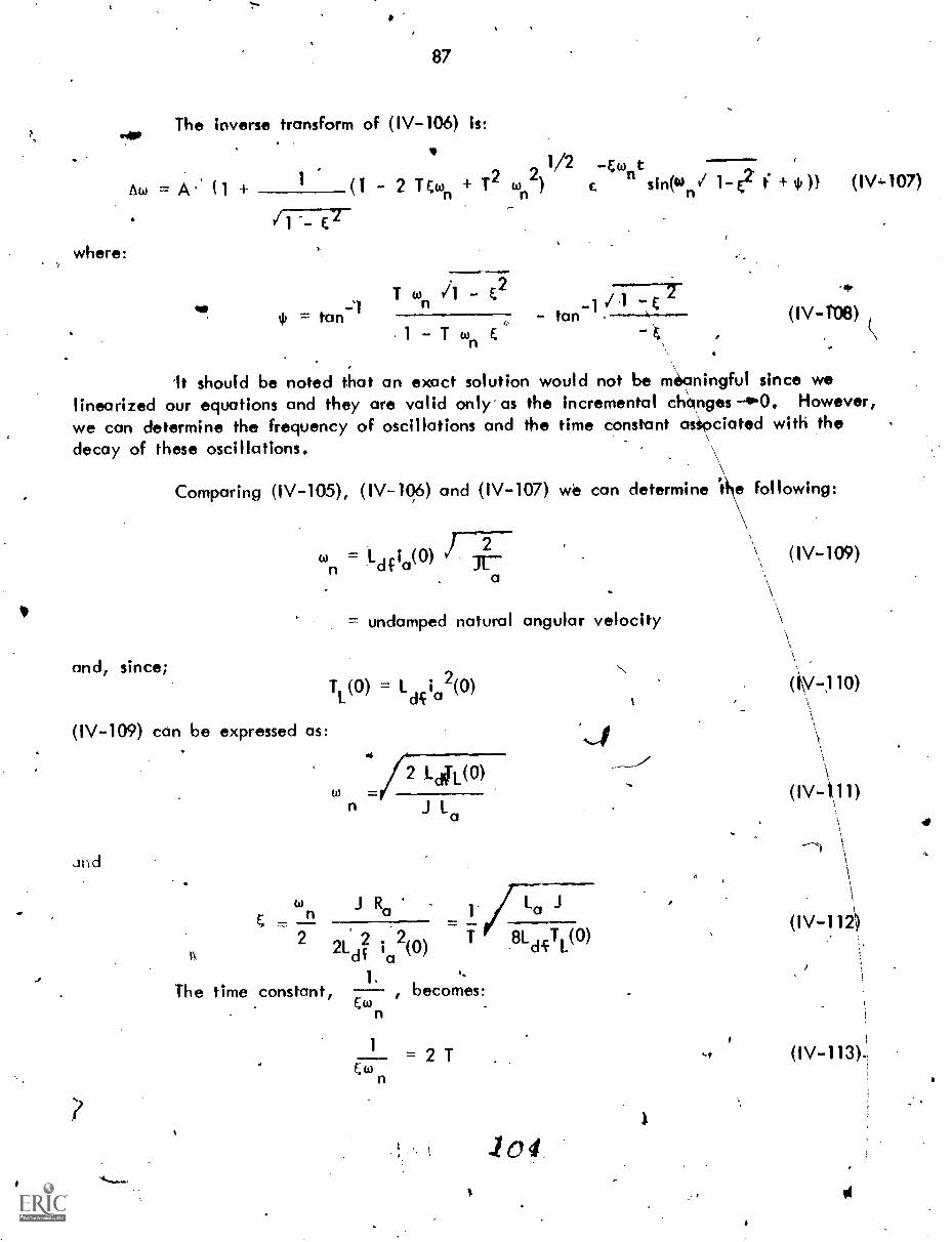
where:,
87
The inverse transform of (IV-106) is:
tad = A.' f (1 - 2 TEton + 121/2 -&tont
ton2) sin(wn/ 1-E2 t + (1V,107)
T ton E2gip -1 /.1 u-&
tan - tan1 E. -E
(IV-1'08)
'It should be noted that an exact solution would not be m6aningful since welinearized our equations and they are valid only-as the incremental ch\anges--0-0. However,we can determine the frequency of oscillations and the time constant asipciated with thedecay of these oscillations.
Comparing (IV-105), (IV-10,6) and (1V-107) we can determine '47 following:
FT-ton =
dfia(0) a
and, since;
(IV-109) cern be expressed as:
Jnd
= undamped natural angular velocity
T (0) = L i 2(0)di a
to4-72 LA(0)
J La
to J Ra_/ La J
....
2 2 22Ld5 ia (0) T 81di-T
L(0)A
1 .4,
The time constant, , becomes:Ewn .
1
Et.)n
= 2 T
104
(IV-109)
(iy-,110
(1V-1.,11)
(IV-113).:
01

88
The actual angular velocity Of the oscillation is given by
/
(IV-114)
An analysis of tbis- type, while not yielding an exact solution, does giveinsight into dynamid behavior.
1V.6 SELF'EXCITED D.C. MACHINE ON SHORT CIRCUIT: The 'ideal' d.c. machinewould, if self excited, have a steady state short circuit current equal to zero sbecause
the fid d winding would also be short circuited. In reality, a steady state shortcurrent does persist'because the residual mpgnetism does prdvide some excitation inthe direct axis. If the machine were tested by driving iheat the regular-speed,\ivith no field current and with the armature open circuited, a small voltage would 4,manifest itself in the\q axis brushes. This voltage, Vo, is the rotational voltagecorresponding to resid6,a1 magnetism.. The effect of residual magnetisq is shown inFigure IV-20. *If the machine is driven at a constant, speed, 63, and ihe armaturecircuit does not have connected load prior to the short circuit the armature currentflowing is only that.which flows in the shunt field. This is very small relative torated current and especially small compared to the short circuit current. It willbe neglected.'r 4
The circuit configuration we will investigate is shown in Figure IV-19.Most d.c. generators-which are compound wound, Le., 'both series and- shunt field,are cum-ulative connected. The series and shunt field ampere turns act in thesame direction.
YO .AA? Awsikji has. au..al *AKA-, 11441-
Ill StrtesField 5
stv.ottFit 41, F
z :UMc_10
Figure IV-19. Compound DC Machine on Short Circuit
ft

89
The applicable equationlsCfrom (III-99) through (III-106) are: addingthe S winding and taking into' account residual magnetism)..
d114 dia
Vf(s) rfif 1c1fCrt(IV-115)
diaV (s) = ra a a dti - L
a+ i + k col i + V (1V-116)df f df a o
The mutual inductance between the series field 'and the shunt field ,is fd.f. Them is atransformer type voltage in winding F due to changing current ia. Also, there is asimilar type voltage in the armature circuit due to-changing current in the field,circuit: This voltage is neglected because it has a small magnitude relative to othervoltages in the armature circuit. The ratio of series fielif turns to shunt fieldturns is denoted by k. There are thus k times as many flux linkages resultingfrom a
as from
For < 0,
Vo(0) =Vf(0) =w Ldfif(0)/+ Vo
* if(0) ; 1a(0) = 0
For t > 0
Va
Vf = 0 -
Transforming IIV-115) and (IV-116), we have:
Lf= r,(1 + s) Ir - Lfif(0) L s I
r rf cif a
La Vo0 - (r k u.3L411 + s1 I +0.11-. I +
ra - k Ldf
where i (0) is,given by (IV-118).
4
(IV-119)
I.,We will define the following time constants 'and apparent armature circuit
resistance Ra.c
-. (--, Ra = ro - k w Ld.c. (iV-122)
106

Ta
Tf.
Ra
If=
(1V-120) and (IV-121) can be solved for la as follows.:
la ^
la,=
rf(1 + Ifs) -1 s,dw Ldf -Ra(1 Tas)
Vo V(0) Vorf(1 + Ifs)s + Ldi widf
rf- Ro(1 +.T1s)(1 + Ta
s)
(IV-123)
. ,(IV-:124)
(IV-125)
(IV-126).
Vo Tf .
1D( + If s) + Ra N(0) - Vof(IV-127)
2w Ldf1 + (Tf + a jis + T T
Rarf a f
In order to simplify our analysis, we will define new time constants,Ta' and Tf' such that
2L
(1 + Ia
n's)(1 + TO) = 1 + (T + T - )5 + if s2
f a ra f
From (IV-128)
T'T'=T T''a f a -f
andi- 2
wdCT
ai-+ If' =' Ta + If ,---
. rRarr
(IV-128)
(IV-129)
(IV-130)

91
4 )
-(-
'In geneealf field circuit -tiMe donstants are much larger than armature circirittime constant's. Therefore, we con write: .
,r
T ' ),f . ' f
(Ind (IV-130) becornesi 'with (IV-13
TIf
ft
un-df dfTf(1 - )
and, tubstituting (IV-132) into (IV-1:29)
--Tf T
aT ' T
a a=
2If1 - itact
Using (IV-128), in (IV-127) yiekls:
Vo (1. If s)s(1 + Tf 's)(1' + T )
1+ IVa(0) Vl R (1 + T11s)(1 + Ta's)a
The inverse transform of (IV-134) gives ia(0 as:
V Ta'ia Ra(t) = 9 (1 + T ,
- If `Via - T\'
Ta'Tfs Ta'
.-t/Tr+
f-IV - V011(
1
sic a '"T - Tf' ) c
:k..
(1\1-131)
(IV-T32):
(1\/:-133)
(IV-134)
(IV-135)
Viithk,the assumption that Tf' >) Ta', an appr6ximate expression for (IV-135) is:,
Tt Va. Vo
'CP) + ;MT + R T 1 (va(0) Vo)a a a of
t
+
Tf(V
a(0) - V 0)
R Tf' (IV-136)

-
.
t
;
r4
.0 4
.
We will now define:
92
,Tf 1
T 'R Rf att a
When this is su4stituted in (IV-136), we have;st
Vo Vo(0) Vo Vo(0) -t/To'io(t) 1-1-- - c
R ' C
a
(IV-137)
(IV-138)
Equation (IV-138) is plotted in Figure IV-20.- 4
-V
...< .. -,..-Irp"...
i -v. T If
, -1-tA R.0_iPk-7_7 V E ,
/1 0.
M.N. +do.
.Z 43,1lAtitv /
0.
Figure IV-20. io(t).- for Short Circuited, Self ExcitedCompound DC Generafor
Note the current rises to a value very 9early equal to: 4,
Vo(0)(IV-139)
":
For this reason, IV is denoted as the "transient apparent armature resistance'.The current fipally settles down to a steady state value' as determined by the voltagecorresponding to residual magnetism and the apparent drmature resistance. From (IV-122)this vatue is less than the actual armature circuit-resistance.
Analysis based on valid assumptions, as acck,mplished here, are quitecommon in the study of the dynamic behavior of electric machines. Because ofhysteresis effects and the impossibility of exact repeatability of experimental resultsextreme accuracy of solutions to machine problems is not warranted - nor is itmeaningful. We will do the analysis of other types of machines by similarsimplifying assumptions in later chapters.
'ni t
109

93
CHAPTER. V - CROSS FIELD MACHINES
The 2 Axis or Cross Field D.C. Machine (Metadyne)
V.1 INTRODUCTION: Machines with power windings and brushes in (both the qand d axis are called metadynes. They can be used in d variety df applicationsusually control systems - where power amplification with high speed response isnecessary.,,Our analysis will deal with the basic- metadyne operating as a poweramplifiert 1.e., we will introduce a signal into the field circuit and will extractbn output' with considerably greater power level from one of the armature circuits.The actual high polo...4'r level output comes, of course, from conversion ofmechanical power (to electric form) which comes into the machine through- theshall. The input signal controls, or modulates, the flow of mechaniCal power.The basic configuration which will be studied is shown in Figure,V-1.
ti
V.2 THE BASIC METADYNE;'ANALYSIS: In the basic configuration, current incoil F establishes flux in the d axis. A rotational voltage is induced in the Q
'winding, which is short circuited. Ort ly a relatively la the Qwinding-is necessary, for a heavy current ia to flow. e currrit i results ip).
an mmf and resulting flw5 in the q axis. the q 4s flux Itnkpges with the /D winding result in a rotational voltage appearing tit the brushes in the Dwihding . TK D winding supplies the load.
.
{ 'Figure V-1. Basic Mertadyne Configuration
1 0
.4.

94
k ..?The machine is ch:rven at constant spoeci. The'lnput signal is Vpif.
machine does not have a G winding. The Q w nding is short circuited.refore Va,= 0. Since ppwer is token from the D winding, la =*-id. However,
Vd = Va. ana rd = ra.,
t.
.From ( l 99) throUgh' (111-108), the describing equations.are:
dif dia
.
Yr = r i L,r f f f -f dt 1 ":4-"T
dia
di fVa = -rola La dt L c-t + wLqq
dig0 = r i + +
q q dt
Since a load RL. is connected across Va'
f +4'Ldfi
a
\V =Ri.+dia
L '-9 L a L dt
Assume the sy.stem-lt-in i tia I I y.9nexc ited, i .e . ,
if = 0, ia = 0, Va = 0
The Laplace transform of (V-1, -2, -3, and 1-4) is:
where:
A
f(s) = r,(1 + Tfs
V(s) = R (1 + T s) i(s)-
4 la(s)
Va(g) = -r0 (1 + Tas) 10(s) dr if +w gig (s)
0.= ,rq (1 + Tq s) lq (s)+wLciflf(s) + toLd a (s)
LfTt ,f
La;
ra
1 1 1
:
( V - 1 )
(V-3)
(V-4)
*
(V-5)e
(V-6)
(V-10)
r

95
Also, since (...) is a constant, it is customary to. define:
w K to d = Kih to dfq
In order to gain insight into cl-oss fie1d machine behaviar.and to simpl fythe analysis, assumptiotis whicil are Compatible with eitperimental results, obtainablwill be made. Theselassumptions are:
I. The transformer voltages induced in ire winding lafcurrent change_in anOther winding are negligible.
2.. The time constants associated with the D -and Qwindings are nearly zer, or at least negli§ible.
3. The direct axis armature winding resistance is verymuch less than -the lold resistance.
With these assumptions', equations, (V-6, -7-, -8, r-9) become:
s,4 IfVf(s) = rf(1 17-f--s) Ifcs
LL
Va(s) = RIL(1 + i(s)
Lir4
Vs) ra la(s) + Kg Icifsr.
0 = rqlq(s) Kd Kd la(s)
V;.
,A block diagram representation of these equations is shown in Figure V-2.For convenience, assume a negative Vf(s) in the,
.--r
...1.1H05) .114-kt Tis
Ia( S
.T to
Vats)
Figure V-2. Block Diagram for Basic ,Metadyne
1

1
Since:
.1 96
We will elfminelte Vq(s) from (V-11, 7
r ( 1 + Tfs) If(s) V(s)°
(ra
+ RL) (1 + + rL a
We can Solve for 10(s) as:
From vrIlich:
Ia(s
1J
I.
la(s) =
-13, 714), leaving:
Kcilf.(s).+ 1<dla(s) + rcilq(s) = 0
R + r Ra
LL
RL + raTL
rf(1 + Ifs) Yf(t) 0
0 0 Kq
Kd 0 4.
r1(1 + Tfs) 0 0
0a
+RL.)11+T 1- Kq
Kd .1(d ,r
K K V (s)d .q f --rf RL ra( 1 + T
Ls)(1 + 'Ls) Kd K rf(1 + s)
Kd1<q
V (s
2rf(RL rq Kq) + (r1 rq L + 'rq dKqLf) f- rqlfltsvd
1 1 3t.
9
(V -At)
(V-20)
(V-21)
(V-22)

97
The minus sign means the current ftow (and erminal voltage),4re oppositeto what we assumed they would be.
VfIf WAsaassume Vf is a step input, .e., f(s) Y.= 7 and apply the Final
Value Theorem, We have:
Lim t i (t) = limit s la(s)t-* 5-. o
Kq Vf
rf iPR.Lrq + KdKg) t.
V-23)
Refer back to the Block diagram For the metadyne, Figure V-.1.2. Note thenegative feedback loon which acts against the field (F winding) excitation. In effect,the load current tends to glemagnetize the magnetic circuit. If we put another windingon the stator in the d axis and pass armature current through it, i.e., connect it inseries with .,the D minding, and-we connect it with a polarity such that -it opposes thisApendèncy to demaprietize (act against the tiinfinding mmf) referred to above we can, by
choosing the pt*er number of ampere turns, cancel out the KA ia(s) term in the lastexpression,in (V-,.14). This eliminates one of the negative fee&ack loops and is theprinciple of, the "Ainplidyne" or "c4:Sinpensated" metadyne. For such a c'enfiguratioh,(V-20) .becomes:
=
rf(1 + Ifs)
0
Kd
Vc(s)
O.
0 rq
(V-24)
rf(1 + TrO 0 0
0 -RL(1 + T s) K
Kdp.
0
Kd Kg V(s)I (sa -rgrfRi(1 + Tfs)(1 + To)
If we'apply the Final Va lue Theorem to (V-25), assuming a step inputwe have:
K d lecrikff
-rq R1 rf
I.
(V-25)
V-26)

Comparisonoutput to input) whichTo see why this is so,with the Kd la(s) term
98
of (V-26) with (V 23) indicates a much higher gain (ratio ofis important if the machine is considered as an amplifier.rewrite, for the block diagrams study, (V-11, -12, -13, -14)not present and we have:
I.
1 Va(s)la(s) P1( ,1 +
K I ra la(s) V(S)q q
Ka
If(s)( ,-T1)
The Block 'diagram representation of (V-27, -28, -29; -30 is showFigure V-3. Note that we haye eliminated oae of the .egative feedback loops.This explains .why the "gain" is higher. ,Load current no,longer acts in opposition.to the input signalVr.
(V-27)
(V-28)
(V-7
(V-30)
-I ,)+Tt,$)
j","1
Figure V73.. Block Diagram fOr A`rnplidyne C mpensated Metadyne)
We can, now calculate the power gain of the Amplidyne. This% is ofinteriSst because the main usage of the Amplidyne is as a rotating amplifier.
Let
P. = power into the 'field circui t
P = power output to the load ndw 2Y f
Dr rf
1 5
Ark
Mckt s)
(V-31)
(V-32)

S.
99
I.
Pi la2 Ri rf27
2V
From V-26):.
and
Kd Kq Vf
ja rq RL rf
2Kd K2
Pi 2 rf
(V-34)54.7, ,
.(V-35)
This can be an extremely high value in properly designed 'O'bilike. VAueson the order of 2000-50000 are not uncommon. Thus it is possible to get, power on theorder of-kilowatts out of such a device. The amplidyne has been used as the linkbetween' low power error signals and the power stage in many practical servomechanisms..Usually an Amplidyne has multiple input windings, F11F2,...,etc. in order to providefor maximum flexibility.
The, valUes of the various constants, for a specific machine, necessary forperformance calculations c an be determined by a rather simple rnput-output test usingsinusoidal input and the tec 'quo of .plotting the voltage gain as a -function of inputfrequency (Bode p t). This ,teNt,s is described in the laboratorY manual:-
The follo ng example will illustrate the effect of compensaiion on a meta-dyne -and- is illustrative of the power amplification possible with a well designed machine.
parameters:
s,
Assume a "cross fiel d"
Ex ple
e of machine with the following rating and
2000 watts, 200 volt3,'?,1800 rpm
rf = 20 ohms; If = 4 henry
rg
=.4 ohms; Lg
= 0.04 ohms1.
r d r =0'4 LdLa = 0.04 ohms
Kd = 120 volts per ampere/
KV- 240 volts per ampere
7'16

100
A series load of 20 ohms resistance and 2 henrys inductance is connected tothe d-axis brushes.
Part-1. For a metadyne configuration (no4compensattng field) find:
a),
theloadacrossVf necessary to produce 530 volts d.c. steady state
\ .
b) Determine the steady state power gdin.
200 volts dc steady state across, the load of 20 ohms is an armature currentof 10 amperes. From (V-23)
V = rrq Kg,
Kd
20 (20 x ..4 + 120 x 240) HP: 200120 X 246
In fact, in the steady state,
Vf Kd Kg-1'7--rf rq RL Kd K If r R
qKd K
q
In this example, for:
or t
0.4 RL
(120)(24 0 )
R <<7200 ohms
(V-L36)
(V737)
(V-38)
la If independent of Rt. and The metadyne acts as a currenttransformer wherein output current is equal to input current. The steady state powergain is
la? R 21
I
f2 rf qP.
I
r
Kd q
-f
-RL 20= =rf 20
.o
(V-39)

101 4I4..
Part 2. Part 1 will be repeated for' a metadyne with compensaHng field (an Amtilidyne).In addition, find V(t) for a step input of Vf necessary for la = 10 amperes in the steady
. state.
From (V-25)
From t(V-26)i r RL rf la
V q 1
f C. KKAu q '
0.020(2010) _ 1 ivo IS(120)(240)
PL la
V
2 RL
2
t (1420)(20) 13 x 106
18
4
170
(V-40)
(V-41)
I(120)(240)(1i-61, -s--
(V-42)20 20
(0.4)(20)(20)11 sill4 2
Va(s) = RL(1 + To) la(s
200 (1 + 10 s) = 200Va(0 f5s)04-100-s(1 + 5s)
-t/5Va(t) = 200(1 - c ) volts (V-44)
it should be noted that the "constant current" characteristic of the metadynedoes not apply to the Amplidyne. In fact, in the steady state, for constant RL, we seefro (V-40) that
Va,x_Vf
and the machine behaves as a yoltage amplifier. Fro/V-40)
VL Kd Kq (120)(240)V- rrf q f (0.4)( 20)-
,
The advantages of a pr6porti,onal amplifier capable of handling largeamounts of power should be obvkiapsl.
(V-45)

1
. 102 /CHAPTER VI - SYNCHRONOUS MACHINES //
VI.1 THE REVOLVING MAGNETIC FIELD: In the polyphase synchronous machine, anumber a cons are dishAbuted around the peri t ery of one member of "the machine(usually the stator) and ar4 connected in such, . fashion as to form a winding consistingof theNppropriate number of phase windings. (i.e., three for a machine designed for athree-Phaie system) for each pair of poles desired. The timber of poles is determinedfrom the specification of desired speed the machine is to either run at et- to be drivenat - depending on whether it is a motor or a generator (usually called aJtematar) andthe frequency of the alternating Current associated with the machine. As develbpedpreviously, angular velocity, frequency, and the number of poles are related by
where
Rom
4
f = frequency, 1ièrtzp = number of poles
= angular velocity, rad/sec (mechanical)n = angular velocity, rev/min
(VI-1)
'The phaw windings, through distributed around the periphery (for fullutilization of the magnetic structure) are located so that the axis of thek variousphase windings are displaced in space by an angle corresponding to the "time"anglt associated with the electrical supply, i.e., 120° in space for three phase,90° in space for two phase supply, etc. Figure (VI-1) indicates, schematically,the configtiration for a two phase and a three phase winding in a 2 pole machine.The phase windings are shown concentrated for simplicity.
rrnP1.41.1.e_
Pluts e. 0-
44.f.oiN
Figure VI-1. Schematic Diagram Indicating Space Displacementof Polyphase Windings
Each phase winding is sypplied with alternating, sinusoidal current in thecase bf a motor, or each winding has such a current flowing in it in normal balcncedoperation of an alternator. These currents are displaced in time corresponding to 9()0for a two phase system or 120° For a three phase system. An mmf results for eachphase winding. The magnitude of each phase mmf pulsates with time and acts along the'axis of that particular phase winding. The coil distribution and the design of themagnetic circuit are such as to secure as nearly as possible, a sinusoidal distribution
1 19

103
in space of each of the phase mmfs. The phiise mmfs combine to form a note orresultant, rnmf in the air gap of the' machine. We can analyze the net mmf by(examining the individual phase mmfs and (applying the principle of superposition)taking' their sum... We will do this for a three phase machine.
Assume a symmetrical winckng and voltage source, i.e., balanced.The instantaneous three phase currents are:
= Im cos wt (VI-2)r
i = Im
cos (w t 120°)
ic = Im cos ((a 1200)
where Im is the maximum value ahd the time origin is' orbit rily taken lei the instant'when i0 is a positive maximum. The plus or minus is used so cis to include either,a-b-c or a-c-b.phase sequence. We will denote space angle as 0 and the phase mmfs,denoted by F, can be expressed at any instant by:
(VI-3)
(VI-4)
Fa = Fa (t) cos 0
Fb = Fb(t) cos (0 -120)
Fc F(t) cos (0'120)A
where F(t) is the value of the mmf along its axis at any time t.' Now F(t) is directlyproportional to phase current (assuming a linear magnetic circuit) and we can utilizethe time relationships in (VI-2, -3, -4) to establish the F(t)s for tht vari6us phases.
(VI-5)
(VI-6)
(VI-7)
Thus:
Fo(t) F cos (0' t
Fb(t) =.Fm cos t 120).
Fc(t) = Fm cos (ot I 120)
Note that the maximum value of the mmf in each phase,is the same because we have assumedthat the machine is balanced - i.e. sxmmetrical - for edch phase winding. (The samenumber of turns per coil, same number of coils, same space distribution, etc.). The netair gap mmf will be denoted by F(e,t) since it is a function of both space and time_
F(0,0 Fa
+ Fb
+ (VI-11)
Fm: cos 0 cos w t Fm
cos (0420) cos (tot 120)
Fcos (0E120) cos (wt ± 120) (V1-12)
m!" . 3

104,
= F 0 cos to t + ((cis o cos 120 t sin 0 sin 120)
(cos wt cos 120 I sin w t sin 120) +
(cos 0 cos 120 - sin 0 sin 120)(cos w t cos 120 -T- sin uit sin 120)1 (VI-11)..
1 / f 75= F
m(cos 0 cos wt + (- cos 0 cosw t T cos 0 sin w +
. 4 I-,
+- 3sin 0 cos w t - sin 0 +
(2r cos 0 cow± 3
+ 3- -4 sin 0 sin w t)y (VI-14)
3 10+= F
m1,- cos 0 cos w t - sin e sinw ti (0-15) ,
2 2
3's n wt + sin 0 cos to t +
4
a Fm cos (01-_,t)
From (VI-16) we determine the following: ,.1) F(0,0 is sinusoidally distributed in space and is revolving with
an angular velocity co -
2) maximum value of F(t,t) is 3/2 times the maximum value ofy one phase thmf. In fact, it can be shown that it is q/2 time
he maximum value of any- one phase mmf, where q is the numberof4 phases.
3) the direction of which F(0,t) revolves is deterMined by the signof CO t which is established by the phase seuqnce of the phase currents.Thus, for a motor, it we reversed any two phase leads of thesupply source, we would reverse the direction of rotation of F(0,t)(and thus reverse the direction of rotation of She motor).
the angular velocity, w, is in electrical radians per second andw = 274 where f is supply frequency. The mechanical angularvelocity, is related to the electrical angular velocity by
`lIkrrd
(VI-16)
w E w2 m
121

A4V
Thus:,c CZnIP
411 = f
105
verifying our earlier derivations for this relationship.
It has also been shown previously that a necessary condition for the productionof steady torque is that the magnetic field associated with the rotor and with the statorbe stationary with respect to each other (not necessarily with respect to a stationaryreference frame). Since the stator mmf (and resulting magnetic field) rotates at a velocitygiven by (VI-17), it is then obvious that the steady state rotor speed must also be equal
to this vglue. (Recall that, for a synchronous machine, the rotor is excited by directcurrent and the rotor field is therefore stationary with respect to the rotor),
The 2 pole synchronous machine0..A. o5
C.
otok.- rvit,1^
-kotor
da.mirEr-(13 tv4t4i/
bays
is depicted in Figure VI-2.-
'1vr (1 os
e 14,1 s
Figure V1-2. 2 Pole Synchronous Machinet.1,
ttO-St 0, CLAM
a-to:tor-
v.) tva t:t4
Figure VI-2 depicts a stator with concentrated coils, a-a", b-b', c4-c',forming the polyphase stator winding. It should be emphasized that this, vrinding isfor a three phase, 2 pok machine. The rotor has a coil wound on it and supplied withd.c. current via slip rings. In the general case, the rotor also has "damper" oramortissuer windings imbedded in the pole face. These windings are shorted togetherby connecting bars at the end of the rotor and thus form a "squirrel cage" type winding.In some machines, the connecting bars al the end extend from pole to pole and thusAfinite windings whose axis are centered along the rotor direct and quadrature axis.
It-

S.
106
Even where no deliberate pole to pole connection is made, the rotor iron itself formsKoch a circuit, allowing eddy currents to floNO during transient or unbalanced conditions.In the steady -state, since these damper windings rotate,at the same speed as the statorand rotor fields (Ond thus do not have relative motion to magnetic fields) no inducedvoltage exists in them, no current flows in them, and they are completely inactive.However, if a transient situation develops whereby, the rotor and the stator field arerotating dt differnt velocities, induced voltages do appear, currents flow and "asynchronous"torques .exist. These torquesNAre-ivalogous to these present in the induction motorwhich will be studied later. indeed, if this was not possible, the synchronoUs motorcould not be self-starting because the average torqoe, with the rotor stationary, wouldbe iero. In practice, the motor starts ai an induction motor, comes, up to nearlysynchronous speed,, field excitation is applied, and the motor pulls into step and thenruns as ,a synchronous motor at synchronous speed.
.
os
1, Thit electrical schematic of the lynchronous machine, including the short ., circuited damper winding is shown in Figure IV-3. As on approximation, the currents
in tie damper winding, or iti the paths formed by the iron, are assumed to flow in two .
closed circuits, ,c)ne in each axis. The effective circuits are denoted as KD and KQ -."'.------windings.
Note that the stator windings are coupled magnetically with each other andAth the rotor windings. Also, since the rotor may be "salient" (at shown in Figure .11-2),rather than "cylindrical" (or magnetically symmetrical) the magnetic performance is higher:In the direct axis thert in .the quadrature axis. Because of the 'difference in permeance,the magnetic coupling (and thus the various self and mutual inductances) varies withrotor position and time (because the rotor turns).
0
Figure VI-3. Rotor and Stator Circuits all Phase SynchronousMotor, with Damper Circuits
Note that in the generalized and D.C. machine, the F winding was stationary andthe D windingabotates. The direction, with assumed current convention, is D clock-
.'1.4ife with' respect to F. If D is stationary ahd F rotates, the Same convention resultsin IF rotating counter-clockwise with respect to D.
23
t

107
VI.2 SYNCHRONOUS MACHINE FLUX LINKAGES: The damper ,circuits referred to are,shown as KO and KO.' The field winding; cir excitation source, is designated as F. Thecurrent directions are taken to be for a motor. At any instant of Hme we can writeexpressions for the flux linkages. For example, the flux linkages, AO, in pfrise,are:
So =10010 Lbib Tacic +Lfif ±Lsy ikd +lakqikqwherejaa is the self inductance of phase "a"
(VI-18)
'Lab,lac,141.1f,-144,10ka are mutudl inductances of the various other windingswith respect to p ase "a' wiridling.
As the rotor, changes position,. the Permeance Of the magnetic pircuit changds.Thus the various inductance values are functions of time. However, the variations areperiodic and can be represented' by Fourier Series eXpansion. Because of the distributednature of the windings and the design objectives,' it has been determined (from many tests)that we rieed only consider the Fundamental term of the Fourier series in order tockidauatelyrepresent the angular variation of ihductanCe. Thus, since the mutual inductance betweena phase and the rotor circuits is a maximum when a rotor wi iing is alig ed with the akisof a phase, we can write:
c
ifSSIafos
Iakd Lakd cc's o
lakq -Lakq sin
The reason for the minus sign should be obvious when -one examines the con-.figuration shown in Figure VI-3. Similar equations can be written for phases "b" and"c" with 0 replaced by (0-1200) and (0-240°) respectively.
The stator self inductance,I. of phase "a" has a variation with angle0 as shown in Figure VI-4.
I :
2Sn

Thui,
3 It1:
0, FMA Ct ( tA eI.
ir
= L + L cos 2 0 <V1-22)aaoaa aa2
.The mutual inductance between "a" and "b" phases is a maximum when
0=430° or 2100, and between "a" and "c" phases when e -300 or,150° ond it hasa double angle variation. We can, therefore, write:
Labo + Lab2 c os (20 - 60) (V1-23)
L= L L cos (28 + 60)t (V1-24)c eico ac2
, The coefficients !al and L as well as Loo iz-. and 12 are respectivelyac
equal os a result of symmetry oT the stator. Further, 1aa2, 1ab2, and Lac-2, must beequal because it is variation in the air gap permeance which causes the variation andthe variation is the same in each case. We can now write the flux linkages for threephase windings, using the angular variations, as follows:
Aa = i alLaao + Laa21
cos 2o1 L boa(i b+ i ) Loa21b cos (2e + 60)
c
- Laa2ic cos (26 - 60) + Laf if cos 0 + L i cos e +akd kd
.Lakqikqsin 0
2 5
(VI-25)

imilarly:
and:
109t z
K'
AL r"' 11_11 + L cos (20 + 120)] - (i + 1 ) - L cos (20 + 1 0° aao aa2` abo c aa2 c
- Laa2 la cos (2 0+ 6()) + (*of i
1akqkqi sin (0 - 120)
Lakd kd) cos (0 - VO) +
(VI-26)
Loci2 cos (20,- 120)] - ,Labe(ia + iL) cos (20 - 60) +A'c ic 11aao 11. lda2ia
Laci2ib cos (2 0 + 180) + (La i
L sin (0 -240)akq kq
)a d kd cos (0 - 240) +
(V1-27)
The equations for flux linkates linking the field (F) winding and the damperwindings (KD,, and l(Q) are:
A =Li +1 i +I II cosf f f &el kd . af a + ib cos /- 120) + ic cos ,(0 240)] (VI-28)
= +L it+ L i + L cos 0 + ib cos (0 - 120) f ic cos (0 - 240)] (VI-29)kd ficd f kd kd akd a
= Lkq
ikq akq a
sin 0 + ib sin (0 - 120) + ic sin (0 240)]kq
(VI-30)4,\
41.3 THE a-b-c to d-q-o TRANSFORMATION: Recall that, in a previous section, wediscussed the possibility (by suitable transformation) of an analysis of all types of machineson a "generalized" basis. The generalized machine has all coils, windings, mmfs, eft.acting along either the direct or quadrature axts of the rotor. xa, xt,, xc are orientedalong the axis of the phase windings and, since they are stationary and the robr rotatesthey cannot, individually, be considered as acting along either. the q or d axis of the rotor.However, in Section (VI:1) it was shown that the mmfs of the individal phases combineto form a resultant mmf. This mmf is responsible for a resultant air gap flux d'ensityonLi flux, and of cow-se flux linkages). This mmf is revolvim at synchronous speed, as.
die rotor, and we ;hould be able to use this information to determine a transformation7-1
rlat will relate Xa, X b, and X to compohénts of the net revolving flux linkage thatt
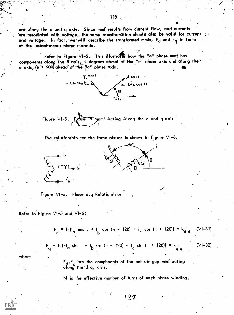
"
110
are along the d and q axis. Since mmf results from current flow, and currentsare associated with voltage, the same transformation should also be valid for currentand voltage. In kict, wwwill describe the transformed mmfs, Fd and Fq 'in termsof the instantaneous phase currents.
itRefer to Figure VI-5. This illustrahow the ."a", phase mmf hascomponents_along the a' axis,_,C$ degrees ahead 'of the."a" phase axis and along theq axis, (04+ 909) ahead'of-the 7a""phase axis. Ift
t sous
K.Its..stAt roc c..os e
Figure VI-5. ssenmf Acting Along the d and q axisA
The relationship for the three phases is shown in Figure VI-6.
90. A
=-"
Figure VI-6. Phase d,q Relationships
Refer to Figure VI-5 and VI-6:
where
F = Nlia
cos 0 i cos (0 - 120) + ic cos (0 I- 120)1 = kdid (VI-31)
F = NI-ia sin o i sin (e - 120) - ic
sin ( 0+ 120)f = k i (VI-32)b q q
FA,F tire the components of the net air gap mmf actinga ong axis.
N is the effective number of turns of each phase winding.
1 7

r"rr,;....14,"
41,.Nr
t
4.1
St
kdrice, ace 'the ffective number ,of turns on fictitiouswindihgs, 0, Q, located on the d,q, -axis
!,o .,.. ,i ' I are currents that must now in windings D, toi,,
cli , * -\and
atesult in fhe same not air gapkmmf as established
. by actual currents ia,1b,ic.i .
tL Note that 3 'vdriablbs are'present in the phase quahtities, (ia;ib, and idand. we must have t variables in the transformed quantities in order to perf m an inverse-transformatkin. ,Now the two currents, id and ici, as define produce 'the 4orr.ctmqgnetic field,' Therefore, the,third Valiable - we will de it as in - must bedefined in such a'way dir to produce no space fundamental in the lir gap. If noneutral, or 4th wiie current, exists this requirement can be t if v.ve definb it as:
fi
\I:,
(VI-33)
r The fact16/3 is completely arbitrary bUt is used becaulse this is the wayin which "zero sequ current is defined in the method of Symmetrical Components -used in the analysis of unbalanced 3 phase power systems. Since ia produces no fluxlinking the rotor, it must be associated Afith the stator leakage inductances. Forreasons which will be apparent later, the ratios N/kd and ,KAq are taken as 2/3.Then, we can write (VI-31-32, and':-33) as:
id
2
3
IS
COS
sin
0
0
io
cos (0-120) cos (0120)
sin(e-i20) . -Sin(0 -1- 1 20)
1
7 2
ia
ib (VI-34)
From the inverse
ia
of (VI-34), we have:
cos e sin 1
ib cos (0-120) - sin (0-120) 1 ,(VI-35)
ic cos (0+,120) - sin ( 0F120) 1 io
Since this transformation is valid for trahsforming stationary phase quantities-twintities along the d,q, rotor axis - which are stationary with respect to the rotor
the transformation should elimina4 the time variation of tie inductances and isally valid for either flux linkages, voltages or currents, as argued,previously,
28

It
112
Using the transfetion 'defined above, wö obtoin from (VI-25, -26 -27)
(L - 2L (V1-11),aao abo o
3 JP
AL I 10 i (VI-37)
d (Laa +.o abo L d 4.+ .2- aa2)' 10 r 4- Lakd kd
3A 4 L , - 7 L ...) i + L 4 ki,, (VI-38)1 ci.ao apbo :4,4 aaz q 0q
c,
We can cktfing new, fictitious, armature inductances\as:
= L 210130 (VI-39)ago
3Ld = Laao Labo Laa2 (VI740)
Li3
L + Laao abo
- L (V.1-41)2 aa2
Ld,Lci;Lo are defin d inductances that relate to measurable inductances that actuallyexist. However, 4en though they are only defined, it Iv:livens that these definedinductances are t. uIintitles whose value can be obtained relotively-easily from-testdata. We can also use the- current transformations in (VI-35), to obtain rotor fluxI inkages:
A -kdf kq
tit
In /terms of:i id' f
Thus, from (VI-28,-29,and -30):
73, L If Ler Lfkdikd L of d
3kd = Lfk
d if L Lakd id
3= ikq
+ Lakq qkq
(VI-42)
(VI43)
(VI-44)

Also, substituting (V1-39,4' -40;41) in V1-36,-37,-38) yiel
X =1 +Lq q q a q 1lq
= L did + afif Lakdikd
S.
NOW, the voltage equations. for the actual stator and 'rotor circuits are:
Va
= t + r ia
dAb
Vb dt r ib
Vc
Vf
d Xc=
dt
dx=
dt+ rt.f
dAkd
dt 411<dikr
dA
0 = 4 rdt kq kq
(VI-45)
(V1.-46)
(VI-47)
(VF-48)
(VI-49)
(V1-50)
(VI-51)
(VI-52)
(VI-53)
0
where r is the stator winding resistance r.k d and rk are equivalent kd and kq circuitresistances.
If we define Vd, Vo, and Vo with the same transformation used for currentand flux linkages and transform Vile phase voltages and curients in (VI-48,-49,-50) tod-q-o quantities we have-,
dAd
Vd dt q r id
dX
V9 dt Ad 5C-11, r iq
dkoV ,= + r io
130
(V1-54)
(VI-55)
(VI-56)

doWe recognize that -di- = (4,speed. Also," if we assume that a common mutual
-flux links all windings on one axis and that this commOn mutual flux differs from thetotal flux linking any one winding by the amount of leakage flux auociated with thatparticular winding w e can make additional simplifications in the equatiuons we have.derived.
C.
The equations as derived so far are in terms of demperes, volts, henries, etc.,i.e., they are actual quantities. It is appropriate (prior to introducing the common'mutual fluxes.and the leakage fluxes) to convert to a per unit system in such a, fashionas to make the flux linkage equations have reciprocal mutual inductances that is to saytile per unitt value of the mutual inductance along a given axis is the, same regardlessof which winding we are considering it from.
VI.4' THREE PHASE MACHINE PER UNIT QUANTITIES: The basic considerations involvingthe 'use of the Per unit system were developed in 'Section 111.2 The development ,in thatsectipn dealt with a single, phase machine, .or a DC machine.., The section will. extend-the per unit usage to coyer three phase machines. Two very important concepts developedin Section 111.2 which also apply here as:
1. in coupled coils, or windings, the tame voltampere base shouldbe chosen in each Coil (to make the mutual indtretane the samewhen viewed from either coil)
2. base value of electrical angular velocity should be chosen as equalto:1.0 if the time relationships are to be preserved in the analysis.
e winir
For the three phase machine, base voltage and base current in the armature(pow ding) are best taken as the maximum of the instantaneous phase valuescorretponding to machine voltampere rating. Thus; if
Vmb = base voltage which is also the maximum 45r. crest uefphase voltage
1mb = base current which is also the maximum, or crest value of thephase current
Vmb 1mb
3( )( 3 phase:machine voltampere rating (VI-57)
= 3 phase voltampere- base
3 Vmblmb = VAbase 3 phase (VI-58)
131.

,
To see how thmachine, pots the flux IIflux linkages in the D wi
For the former;'
otresponds to the equations developed for the:iynchronous$ in the field winding .due.to current in the D winding and
ing due to current in the field winding.
froin (VI-42):
3A due to i = L if . d 2 af d
For We latter, from (VI-47):
If these
4
):d due to if = Lafif
two quantities are to be equal, in per unit;
3L f id
Lf base if base
If w = 1 0. (VI-61) can be written asbase
37 (Zf
base If base) if base (Zd baseid base) id base
1-0f id if base
Laf if
d base d base
C
(VI-59)
' (VI-60)
(VI-61)
i-af if id' base (VI-62)
3 d base if/if baseV
f base f Vd baseid base
If3 v 3 ;
d base'd base=..VAbcise
The, flux linkages are equal when:
id if
d base if base
(VI-63)-
3 phase (VI-64)
(VI-65)
(VI-65) equates the per unit current in the two windings. Thus, the cc;nclusion is thatif tbe volt ampere baseqn the field and the armat tr e are equal - and are in turn thethree phas volt:ampere rating of the machine, then we have equal per unit flux r
litkages in the two cirCuits-(due to mutual coUpling) When the pler unit Currenti in thearmature and field are equal; Thus the mutual inductancei/are equal and reciprocal.The same argument can be extended to the mutual inductances between the dampercircuits and the armature circuits, .i.e., the volt ampere base in the damper circuitsmust be the same as the 3 phase volt ampere rating of the machine.
132

116t
4.5 SUMMARY OF SYNCHRONOUS MACHINE EQUATIONS: The synchronousmachine three Owe stator winding rs transformed Into 15, 0, type windings by thed-q-o transformation (VI-34)". The synchronous machine 'configuration is similar tothat the Generalized Machine except:
1. The D and 0 windings are on the stator.
2. The "G" winding on the Generalized Aichine is denotedas the KQ winding, is closed on itself and is on the rotor.
3. The F winding is on the rotor.
4. Another winding, denoted as the KD winding is coaxial with theF wiriding and is also on the rotor. It is closed on itsetf electrically.
5. A "zero" component winding exists mathematically in order topermit dqo to a-b-c (phase quantity) transformation. It does notcontribute flux linkages to the rotor winding and is thusassociated with stator leakage reactance.
CorrespOnding to (111-47 thrilugh -50) we (can express the self, mutisal andleakage inductances for the F, D, Q, KQ windings and for the zero comporentwinding. Similarly we pan then write the expressksns,for flux linkages at developedin (VI-42 thsough VI-47). These correspond to (IN-51, -52,-54,-55) for the GeneralizedMchine. Finally, from (V1-51 through -56) we have the voltage equations for variouswindings. These are similar to (111-99 through -102) tor the Generalized Machine. Thetwo equations describing the electromechanical dynamics are, of course, the same forboth machines since-power is converted from mechanical to electrical form, or viceversa, in the armature circuit only (the D,Q, windings).
The equations for the synchronous machine at% repeated immediately below.Comparison of these with the corresponding equations for the Generalized Machineindicates thdt they 'could have been written by analogy.
Ldf = mutual inductance, d axis windings
L9g
= mOtual inductance, q- axis windings.
Lo = zero component inductance
Lf = self inductance of F winding
t- = motual inductance of _ winding, etc,
Lf Ldf + (VI-66)
.;-
Ld = Lcic+ Rd (V1-67)Ts:31 3

A
117
+t1cd ç kd
L + Iq q
14 Lqg +
A f L + dfIkd+ dfId
A =I +L Id df df kd a d
Akd Ldfir Lkdikd 1cled
A +Lq q qg kg
A
kg Lgglg ICkgikg
L IA0 0 c)
dAf.
rV +f f cit
d
Vd °did dt (41
kd0 = r +kd kd
d A
V = r +q
dk kot04= r +kg kg dt
4:I A
= r +0 0 dt
wAci
T Ic(i i A )e q
Ad d q
+ J
134a-
e
'
(V1-70)
(VI-71)
- (VI-72)
(VI-73)
(V1-74)
(V1-75)
(V1-76)
(VI-77)
(V1-78)
(V1-79)
(VI-80)
(VI-81)
(VI-82)
(V1-83)
(VI-84)
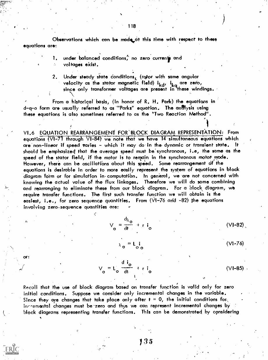
kst:15-
118 4
Observations which can be madekiat this time with respect- to theseequations aro:
1. under balanced conditions:' no zero current andvoltages eidst.
2. Under steady state Conditionsc (rotor with same angularvelocity as the stator magnetic field) ikd, ik are zetO,since only transformer voltages are present ingthese windings.
From a historical basis, (in honor of R. H. Park) the equations ind-q-o form are usually referred to as 'Parks" equation. The analysis, usingthese equations is also sometimes referred to as the "Two Reaction Method".
VI.6 EQUATION REARRANGEMENT FOR' BLOCK DIAGRAM REPRESENT:010N: Fromequations (VI-71 through VI-84) we note that 7.ftTliave lrjMultaneous equations whichare non-linear if speed varies - which it may do in the, dynamic or transient state. Itshould be emphasized that the average speed must be:synchronous, i.e, the same as thespeed of the stator field, if the motor is to rervin in the synchronous motto mode.However, there can be oscillatiOns about this speed. Some rearrangement Of theequations is desirable in order to more easily represent the system of equations in blockdiagram form or for simulation in.computatiOn. In general, we are not concerned withknowing the actual value of the flux linkages. Therefore we will do some combiningand rearranging to eliminate these from our block diagram. For a block diagram, werequire transfer functions. The first such transfer function we will obtain is theeasiest, i.e., for zero sequence quantities. From (VI-76 arid -82) the equationsinvolving zero-sequence quantities are:
dA0
V = r io dt o
= L i0 o 0
or:d io
+ r iVo
= L0 dt o
(VI-76)
(V1-85)
Roca!l that the use of block diagram based on transfer function is valid only for zeroinitial conditions. Suppose we consider only incremental changes in the variable.Since they aye changes that take place only after t = 0, the initial conditions forinr-remental changes must be.zero and thus we can represent incremental changes byblock diagrams representing transfer functions. This can be demonstrated by considering
1 3 5
r

119
(V1-85) and denoting increinental values of the vailable by A preceding the variable.The value of the variable at t..0 (the steady Oat* '$ialue preceding the change) Isdenoted by the variable followed by (0). Thus:
(V00) + Ay) Lo ( 0(0) eio) + r 10(0) + r 410
and:
..,V0(0).= r
Subtracting (VI-87) frOm (VI-.86)
from/ whkh:
A v0 = L a + r eio
A 10 = A Vo
-After taking tIe Laplace transform.
eo)
ceps) eets)
Now
1
rWe can represent this in block diagram form as':
1.(0)
(VI-89)
011464(.(s)
Figure VI-7. Zero Sequence Block Diagram
That this yields correct results can be seen from taking a step input
e
Vo(s)s
Vo(s)AV
Vo(0)io(s) = 1V0(3) ---;"11(r
1
+ Lao
A V.11m 10(0 lim s io(s) = lim r + I si
t-÷ S .4 00 S -4- 00 0
/
+ 10(0) = 10(0),
(VI490)
(VI-91)
(V1-92)
(VI-93)
"

and
. but sincis
120
lim 10(0 lim $ i(s)t 4 so 4 0
"n1 idt) r4 co
whkh woad be the new steady state value,f.
A VT (V1-94)
(VI-9-5)
V6(VI-96)
At this point, it would be wellk to examine (VI-71 through -76) and determinethe initial value of the various flux linkages at t <0, i.e., Ig(0), Ad(o), A0(0, fo,00) and )(q(0).. To da this, consider that the machine, operating as a motor, is in
a ileady state situation.at rated speed. Thus, all terms involving the time derivative,such as. CIA/Cit f are zero. -Also, ikd bire z beCause there is no driving voltage,, .
for these currents other than induced transformer type voltages. DenOting t=0 values as(0), saeh as if(0), A'q(0) etc. we have (with the above conditioni),
or:
from wilich:
or:
from which:
A 0(°) = 10 ;0(0)
V0(0) = r i0(0)
. . 0(0) = Lo iu _(0) or ALo V0(0)
1df ;go) idid(o)
'V1(0) wA 10) + r
) = V (0) - r i (0)
00) = Lci 9(0)ocl -4
Vd(0) =d(0) + r
- VA) + r(o
1 3/
II
(VI-97)
(V1-98)'
(V1-99)
(V1-100)
(V1-101)
(V17102)
(V1-103)
(V1-104)
(VI-105)

121
(0) 1 (0)kq Qqgq
kd(0)Ldfif(0) + 1dfid(0)
Vf(0) rfif(0)
X(0) 32 L OP) Ldfid(0)
,
(VI-106)
(VI-107)'
(V1-108)
(VI-109)
These-equations give appropriate expressions for initial conditions.
Next, consider that we want Aq as a function of tfi. From (VI-74,-75 -81)the appropriate equations are:
Lqici + Lcigikg = Xci
Lcigiq + - = 0,
kq'kq
ikq dt
= 0
Taking the Laplace transform siind rearranging to indicate iii(s) as ther dependent variable yields: (Considering all variables iare incremental 'Wye: of the
variable but not bothering to denote by ti
cfrom which:
ciaikg(s) = Lqici(s)
Lkciikg(s) Akci(s) = Lcigici(s)
rkqikq(s) s kg( = 0
- 19 i 9(s) 1qg 0
i (s) L99 ci kq
rkq+s
-.1- 1qg
0 kq-1
lka 8-4
(VI-116)

now:
Since:
where
v
9
(
; "
122
L [1
4.(1.,,Lkq * Lqg2)51
1 (s)rkg Uci
Lkg s
rkq
tv ."''
L. 2
+ t 1-499 kq Is
rkq
L (L - L )q gq
szi
(VI-119)
C t
4r:4'
rkqInt"
tkq
rkq
Lkq = Lqg + kkq
t = L Lq qg
We can define the following time constants(Lqq+
T" = rkq
LkT" =
clo rkq
T" = quadrature axis subtransient open cirgyitqo
time constant
Tq" = quadrature axis subtransient short circuittime constant
4 139
(VI-117)
(VI-1113)
(VI-120)

123
TH0 is the time constant one Would see if the damper winding was openedand no coupling existed between the kq daniper winding and bny other winding. Tr".
Is the time constant associated with t he damper winding if it is opened but coupled'to the q winding, considered with zero resistance and short circuited. This can beseen if we write equations for our fictitious, opened kq winding with r 0 and shortcircuited r
from which
Vkg(s) (rkg + Lkq s)ikg(s) + Lqgs 1.1(s)
0 = $ ikq(s) s i (s)q
ikq(s)rkq (Lci Lkq x 1.192)41s
L rk9 9.
If t kq and ft. from VI-121,-122 are used in (VI-123) for T", we have
cil"kg Lqg2
(VI-124)
(VI-125),
(VI-126)
(VI 127)
and it can be seen that the time constant associated with (VI-126) is the sane as T.
Hence the designation 'short circuit' as opposed to open circuit for Tq"0.The reason for coiling it 'sub-transient' will be discussed in conhection with .thederivation of the d axis quantities. Now, returning to (V1-117) we can write this as:
(1 + T" s)k()q(s) = q ( 1
iT" s) q
(VI-128)s
qo
The block diagram for this equation (recalling that i (s) and A (s) are,really A i (s) and AA (s)) is shown in Figure VI-8.
1 4 0
It1

!,41!
1ST.; 11
124
Al()Te to.. OLP f_
Figure \ A -8 . Quadrature Axis Block Diagram
We will now go through the seitne procedure for the d axis'flux linkages,again using equations involving increment41 changes until we get to the block diagramat which time we will denote initial values, total values and incremental vake's ot thevariables.
The equations relating events in the three windings on the direct axisare, from the equations for the synchronous machine,
Ldid Ldfif + Ld =Ad
Ldfid 1111 Lcifi; kd
Lkdikd Akd
dxf
\If dt
A kddt rkd 'kd
From (VI-132) we can transform and solve for f(s). Thus
_Vf(s) + rf if(s)
s
Transform (V1-130) and subititute into (V1-134) yielding:
s Ldfid(s) + (rf, + s Lf)if(s) + s ik'd(s) ='Vf(s)
V1 A
(VI-129)
(V1-130)
(VI-131)
(VI-132)
(VI-133)
(VI-134)
(V1-135)

yielding:
125
Transform (V1-133), solve for Xkd(s), substitute in the transformed (VI-131)
s Ldr if(s) + s Ldr if(*) -fit% - f a Lkd) 1kd(s) 0
(VI-129) is the remolning equation in the group. Transforming it, we have:
id id(s) idf 1f(s) Ldf ikd(s) Ads)
Although we want Ad(s).as the output of our block diagram with id(s), NO)as inputs, it is less complicated to solve for id(s) as a function of Qs), Vf(s)-- and thenrearrange to obtain Ad(s) as desired. Thus, from (VI-135, -136,-137) 'we hove:
vf(s)
Ws)
Ldr s
(rk-d 1-kci
Ldr
s Ldf (rf + Le)
s Ldf Lde (rkd Lkdo
Ld Ldr Ldf
Solving first for A :
2Lkd 11kd Ldf 2
i (s) D (rfrkd)I1 + (IT rkd) rf rkd) s 1 Ad(s)
recall that:
Lkd Ldf(rkdLdf)11 + rkd si VP)
f Ldr .4- A f
= L +Akd df kd
'`0'
112
(VI-138)
(VI-139)
(VI-140)
(VI-141)

and note that:
from which:
alsO:
and:
defining:
S.
126
2t f)(Ldf itkd) Ldf
(t1 kAdf ;4- tekd
= (La + tf)tial + Ldftf
d( fdf itf)( Ikd
Ldef
tLft:kd Ldf2
kd df f
rf rkdr f
rkd
kd Ldf tkdL Ldf Ldf
rkd rkd rkd
Lf - Ldf Ldf + tf - Ldf tfrf
3
LfT1
12
tkd Ldf + t f
rf rf
Ldf + t frf
Lkd
rkd
Ldr f
rkd
143
S.
(V1-142)
1
(V1-143)
(VI-144)
6
(V1-145)
(VI-146)
(V1-147)
(VI-148)
.1.
AO

UT. r4
tTkd /11.1
fAt F
Using the defined quantities (y11-146 through VI-150) w:can express'(VI-139) as:
id(s)D rekdl //if 1+T2)s 1113121V° i+TkdslVf(s)
wi Otami4:the titns conskintS clefined-abov. We rote theft Tiand Ti .e> ZT because TA is associatd with the field winding consisting of many turnsin order 41 provide the/necessary ampere turns of excitation and the main air gap fluxwhereas 42 and 13 arefassociated with the damper winding which is a cage ofreratively-few turns. 1W. will introduce the approximation that;
T + T T + T1 3 Vi 2
127
%.
(VI.-149)
(VI-150)
(VI-151)
from which:.
/1 + (Ti + T2)s + T1
T3
2Ns (1 + Tis)(1 + T3s)
We will.dignifi 11, 13 by a Oprmal name and a standard subscript. Thus:
(VI-152)
T1
T' = the direct axis transient open circuit time constant- do
13 = Tdo" = the direct axis subtransient open circuit timo constant
Tkd = the ,direct 'axis damper leakage time constant
Note that TA% the "subtransient" open circuit time constant involves thedamper: winder, kd, andis thus much smaller than Li, the "transient" open circuittime c/onstant which is the field circuit considered aMve and is relatively long.HenCei the name subtransient - to designate the first (and shortest lived)- transientphenoMena.
We can now write (VI-151) as:
id(s)D rfrkd A9do s)(1 Tido s) Vs) rkdlelf(i Tkds) VO)
of (VI-138) is expanded, yielding:Now, the denoMinator
D = rf s Lf)(r.s
+ s L 21:3 s L2k 2 3
- (cif s df df -rf
- s212 s L2. (r + s L )df d df kd kd
(VI-154)
(VI-155)

128, 2Laf L2df
,
D LdIrfrkdl 1dirk4I-df f) 4 rf(Ldf t ke1)---7 rfd
rkd "T.-1
+ ILdLf Lkd 4- 2 L3dr-
2
{
LdfR. 1--)
Ldrekd 1 ++
df+
f d
rf
, 3 , 2 ,Ldlf Lkd+ ( df `df `f
rfrkdNow,
Similarly
(Ldi
2Ldf
+ tk
rkd
Ld
2
kd1s
2Ldf kLdf + 1.,f)(1-df + t d)
Ldf +tf. d
Ld
d
Ldf
td Ldft +Ldf d
2Ldf t Laar
rd
L + tdf kd Rkd Ldf tdd;d-
The coefficient of s2 can be simplified as follows:
3 2rf r
kdIL
dL fL
k+ 2Ld1 Ldf (Lf + Ld -f Lkd)l
1
l(L + t 4.
r f kd df d df
2Ldf (Ldf tkd)]
3 2td(Ldf R, ko) + 2L
t- L
df(L
df+
d
1
rt.
r ILA,(kd kd + Rdtf + 'dtkd) td kd1
tf)
(VI-156)
(VI7157)
(VI-158)
(VI-159)
- L2 (Ldf df
(VI-160)

129
In order to determine a product which yields this and to make one of the terms ofthis product the same as one term of the-sum which forms th Coefficient of s, dividethe bracketrl portion of (VI-160) ,by (VI-159) noting that:
Id Ldf tdtf + + If) Ldf+ L + t Lddf d
idLd kd, ;),
I(1 ct k d ldf(it +Lei 4. idlI(d)
VOW 14.- Leek iclikd)-
tdf d f
we can express the result of the division operation in (VI-162) as:
Ldedtf Ld
Let kd tif + (I + t
The coefficient of s2 in (VI-155) is then:
Ld
7--rkd
Ritkd
L t t td Ldfdf d Jiff +
dftd
+itf t+Ldftf ) df Id
d
Using (VI-158,-159,-164) we can define the following time constants:
Ld df
+1T df
rf
itd1-dt,
kd+
Ldf + td
'\ ,
(VI-161)
(VI-162)
(VI-163)
(VI-164)
(VI-165)
15 (VI-166)rkd

0,17.111:,7 r7;" " 3 .4 \,(11:7
130
Ldfldti16 111 ticc1 Ldftd + tfld + Latlf
With these time constants (VI-157) becomes
D Ld
r_t rkd
+ (14 + 15): + T4 16121
t. ion
(V1:-167)
(VI 168)
Again using the argument that time constants associated with the field aremuch larger than those 'associated with the damper circuits w can assume:
14 » 15 and (14 f 16) "..t.(14 + 15)
we can express (V1-168) as tjae approximation:
D Ldrfrkd (1 + T45)(1 + Tós) (V1-170)
We will denote the time constants 14 and To as:
'17.11,TrAN
(VI-169) .
14 = T' = direct axis short circuit transient time constantd
TA = T" ='direct axis short circuit subtransient time constantd
and we can then express (V1-168) as:
D Ldrfrkd [(1 + T'ds)(1 +
From (VI-165,-166,-167,-154) Wie have:
Ldrfrkd( 1 + T ids)( 1 + Ts)id(s) = rfrkd(1 + rdos)(1 t T", s) .(s)ao
-rkdLdf (1 + "rkds) Vf(s),.
Solving (V1-172) for Ad(s) yields:
Id() + T'ds)(1 + Ts(?)Us) +
d (1 + 1'd0s)(1 + Taos) u
,rt
(VI-171)
(VI.-172)
Ldf (1 + Tkds)
r (1 + T s)(1 + T" s)Vf(3)- (VI-173)
f do ,do
FAd
(s) i_i(s) and Vf(s)) in (V1-173) are incremental values es discussed previously.block diagram form:
(
In

;.37.1F-0; I
Vi Cs) Ito
131'
( -erl 19( +roigi)0 4-1141)(t +TILT.).
Lell(itTS)J140 rfjelbj.
S.
Figure VI-9. Direct Ails Block Diagram
We are now in a position to summarize the equations we have developedand to present additional defined reactances. The fundamenlal quantities are:
r = resistance
rf = field resistance
rkd = direct axis damper effective resistance
rk = quadrature axis damper effective resist6nce9
Ldf = direct axis mutual inductance
L = quadrature axis mutual inductance
td = tq = ta = armature leakage (d winding, q winding) inductance
= field leakage (F winding) inductance)
tkq = quadrature axis damper OM) winding leakage inductance
kd = direct axis damper (M) winding leakage inductance
L Lqg + quadrature axis synchronous reactance
Ld = Ldf + to = direct axis synchronoyyrctance
,

;-4!"'!;'-; ',IXTr:7:%7.!". OF,yrn711":i'Vli z.,, i
112
We can also define additional inductances s follows:
L"
Ldftf*Ur direct
a 1axis transient reactance
1; 7 4: Tf
Ldftfilcd= dIrect axis subtransient reactance
a Idf tfilcd Ldr kd
S-..1 .7'
I IL ,cm Kg
L" = t + +t, leg quadrature aids subtransient reactance/q qg kq
!),
i The following time (constants woredefined:./
Ldf +direct axis trkinsient open circuit time constant
do rf
T' =
Ldf t+
tcifTLôf- direct axis transient short circutt time constant
Idefkd ) direct axis subtransient,open circuit Hme constant
rkd
1ldftatf
"rl= ktdkect axis subtransient short circuitc".- kd7 +LA +tt
kd di a dr f f a time constant
1
T" = (Lqg+ t kg
= quadrcttuie axis subtransient open circuit time constantqo r.
kq
/1/£= 1 it . qgI + t a)rkg,
q9
T" quadrature axis SubtrOnsient short circuit time consb nt
kdTk = direct axis damper leakage time constant
rkd
bther relationships relating Ld,Lq and various time constants to L'dfcan be obtained by noting that:
,1 4 9

133
L Idf a .
Id' f .cri717-1- (Ldf t f
do
1dit aL = (1 + )df df
+ if1
f + Ldf)
Similarly
(LcIf Ldft r Ldftf= +
Ldf tf a f + tf
= L'
TjP'-;,!. = L
d d rdo
;rd. T'ci= Ld T' T"
do do
T"L" = -9-
T"qo
(VI-174)
(VI-175)
(VI-176)
(VI-177)
(VI-178
(VI-179)
These last relationships are helpful' when the machine constants are determinedby test. They are also 'useful in analog simulation and in estimating short circuit levelsfor synchronous.generator.
The equations, as developed are now:1
dAd
vd dt -`" q+ r id
dAtivq
dt+La r
dAov + r i
dt
o= L i0 0
Aq(s) = X1(s) ici(s)
A.:1(s) = X2(s) id(s) X3(s) ef(s)
150
c-
(VI-180)
(VI-181)
(VI-182)
(VI-183)
(VI-184)
(VI-185)

when)
71t
and ts
,t
4 s,"
134
(1 + T"s)
1
= 1" q (1 + T" s)qa
(1 + rds)(1: + Ts)X (s) =2 d (1 + fidos)(1 + T)
LdfX3(s) = rf
(1 + Tkd )
+ Ts s)1 + T"do d6
-Te Oa)) + cIt
Te k(ictAd idAq).
(VI-186)
(VI-187)
, (yI-188). r r
(VI-1,89)
(Vi-190)
In .order-k'to efaluate k, recall that the instantaneous power converted to mechankalform is given by
,a a+ Vbib (V1-191)
We can eliminate the "phase quantities by the use of the transformation given'in (V1-34). When this is done, tile instantaneous power becomes
3p (Vdid + Vgiq + 2 v010) (VI-192)
or, using the relationships for d,q, voltages
3 clAd2dt wAqici + r Id-
dA
q. dt,
dx2
+diq +r i +2i +2i2 (V1-19o cit 0
dRecall that terms such as i I...represent a change. _stored energy and that the i r termsare ohmic loss. The remain ng terms represent power conversion from electrkal tomechanical foritta. Therefore, shaft power, .ps, isL Olen by:
.cmdTe
,.i )2 d q q d
=Ps .
w 7(dq cedf
3.
151
(V1-194)
(VI-195)
(V1-196)
4

135
We now have the describting,equations for the sy hronous motor. Theequations for the gertikator, or alternator,r4re obtained by nging the sign ofthe current. The equations are based on a transformation of variables from phase .
quantities to d-q-o quantities. This change in variable has enabled 'us to rePloCetime varying inductances by constant value itductances (neglecting saturation effects)and our abilit) to simulate the machine by computer for dynamic studies is enhanced.
To use the equations, one must study the problem to be solyed,adaptthe equations to the specific problem, introduce the initial conditions and,restraintsand proceed either by computer or by/the application of operationsal mathematicaltechniques.. In the subsequent sections we. will examine.the behayliv of the s'ynChronousmachine under various conditions in ,order to illustrate problem solving procedures.
VI.7 THE SYNCHRONOUS MACHINE. UNDER STEADY STATE CONDITIONS: Bymeans of the transformation used to convert phase quantifies to d-q-o quantities wewere able to definq fictitious inductances Los f df and .L -40, and 741) toreplace the actual inductances in the machine, which ore functions of angular positianof the rotor and thus (since the rotor revolves) also functions of time. We will now:apply the equatians we have derived to the machine operating in the steady state:
Fdr the general case;
where:
0 =wt + ci (VI-197)
= angle between the rotor axis (direct axis) andthe axis of phase 'a"
= rotor- position at t = 0.
Since is completely arbitrarOwe will assume a = 0 for this analysis.This will not result in any loss of generality. With this assumption
The phase currents in the stator windings of a 3 phase machine can beexpressed as
(VI-198)
= I Cos (.t +.13) (VI-199)
b = I cos ,1 t - 120) (VI-200)
= )1, I cos (a) t + 240) (V1-201)
1 5 2

where:
136
I Tv root rnectp square value of the balancid phase currents13 the phasi angle of la with respect to the time origin,
I.e., at t /. I0
/2 I cos B.
The- d-q-o currents, corresponding to the actual phasei currents are determinedfrom (VI-199,-200,201) by using th, trpnsformation (V1-34). Thus:
id = v/-2- I cos 6 (Vl-202)
i = I sin 0 (Vl-203)
10 = 0 (V1-204)
The fact that.these currents are not time varying is coMpletely proper 'becausethese currents are associated with D, Q windings. which (since the inductance relationshipsassociataed with -these windings is constant) hay& constant posiiiqn with. respect to thefield, (F) windirg . Since the id,icif o currents result in the same mmf as the phasecurrents which yieht a constant Aangitude mmf revolving at the same !peal as the rotorit is necessary that the d,q,o currents have constant magnitude to yield, also, a constartmmf. Thi; is true only for steady state conditions.
(Physical insight into what has been accomplished can be gained by consklering
that in he actual machine we have stationary stator windings which have a net mmf whichrevolves with the same speed as the rotor. If an observer is on the revolving rotor andexamined the mmf of the stator, he could very easily as,sume that this mmf resultld froma coil rotating at rotor speed and at some fixed angular displacement from the axis ofthe rotor Or, he could assume that the mmf resuIted from two coils, revolving atrotor speed, (one along the axis of the rotor and one in quadrature with the rotor) whosenet mmf wad such that it yielded the proper magnitude and phase rel\ationships of statormmf with respect to the rotor.
From (V1-36,-37, and -38) it can be seen that if the various currents areeither -zero or of constant value the air gap flux linkages are also constant.
Since we are dssuming steady state condi tions in this particular analysis
ikd 2; 'kg
because the fluX linkages linking the KD, KQ windings are constant.at%
if =- constant
because of constant excitation (steady state)
i = 0
are constant from EVI-202,-203, and -2041.1 53 xst
(Vl-205)
(V1-206)
(Vl-207)

..%
0..
137
.1f flux linkages are constant, the terms involving traniformer voltages(based on time rate of change of flux link5ies) are zero,
Using theabove, we can write the equations for a generator, or alternator,in the steady state as: (From (VI-180) through (V1-190) with currents id and i havingopposite sign because,thes. equations doscribl motor action).
vd r id
:1/4
se
(V1-20$),
(V1-209)
(VI-210)
(VI-211)
(VI-212)
(V1-213)
(V1-214).-
Construction of a phasor diagram is helpful in visualizing the *wady stateoperating condition. Note that in (VI*-198), 0 "140 t. Using this in the inverse transfor-mation, (VI-35), for voltage, rather than current, the."a" phase voltage is written as:
va(t) vd coswt v sin w t
Now, - sin wt = cos (u)t + 90). Therefore:
V. = ,COS CO t t V COS 40 t 4 90)aA -
`It
(V1-215)
(VI-216)
When we Construct a phasor diagram, our choice of time is completelyarbitrary. Therefore, we will choose t = 0 for simplicity, yielding from (V1-216):
va vd + I vg (V1-217)
From (VI-216), va(t) is the instantaneous terminal voltage of "a" phase andtherefore vd and v correspond to maximum values.' Therefore v4; is the maximum valueof "a" phase voltages, with, our time reference. If we denote the rms terminal voltageas Vta, We have:
Va\fa t vd= = V + j V.
d qIf /1.34
(VI-218)

. >Z.S';% -
1.4 . f '
}.
138
where Vd and Vci correspond to rms values,-
id .3.1I Mt . + as I 1
a a
.?,
(VI-219)
Now, referring to (V1-208,-209) with the values of flux link es from (VI-211,-212)substituted, we have:
Let:
v
vd =21 - rq d
if id - r 1g
(VI-220)
(V1-221)
(VI-222)
(VI-223)
substitute4-(V1-220) and (VI-221) into (VI-218) and divide every item by /7, yielding:
va id (i) f f id LI"
= r Xd (VI-224)riva
Vta = = X I -i Xdld + I Ef - (Idtf" "
Note that Vta, lq, Id and la = Id + I I q are rms values and;
wi.df ifEf =
(VI-225)
Ef is the rms voltage that would appear at the machine terminals if Idand were zero - in other words the "open circuit" voltage and it is due to fieldexcitalion only. It is commonly referred to as the "excitation voltage".
(VI-225) can be rearranged as (in rms values)
49
(lq Xq
- la r) (Ef IdXd)ta
155
(VI-227)

0.
,
139
Recognizing that Vta and la are phasors, we can rewrite (VI-227). as
A
Via + lar + IdXd Xqlq W Ef (VI-228)
A phassordiagram can be constructed from (VI-228). Tx) draw the phasordiagrams, we will first draw in the direct and quadrature axis (the q axis 900 aheadof the d axis) and consider the d axis as the 'real' axis and the q axis as the imaginaryaxis. Thus, if wo plot 'real' quantities, from above, along the d axis, we will plotthe imaginary quantities (rotated 900 ahead because of the j operator) along the qaxis. For convenienc (and to conform to rather, widespread custom) we will locate theq axis horizontally. Doing this, we have the phasor diagram shown in Figure VI-10.
Note that:
tx4-1,A
Figure VI-10. Phasor Diagram, Generator
3 11,xt
a) I X is in the negative 'real' direction,
b). I X 'and IpiXri are voltage drops across an inductance and theylead /hel currenis lq and Id by 90° respectively. For' this reason itis cuitomary to denote these voltage drops by the operator j toindicate the phase relationship with current.
_ittu(s
Novo, suppose we are given a specific sitloation at the terminals, i.e., anarmature phase current, la,sza' terminal voltage, Vt, and a power factor angle, 0 . We
do not know 6 and thus cainnot resolve la into components id and Ici
which are necessaryto proceed with the construction of the phasor diagram. This difficulty can be curcum-vented by a relationship we can obtain from Figure VI-11.
. ,i

.P''
140
.,
Figure VI-H. To locate point a'
From geometrical considerations:
but:
. .o'a'
Therefore,Ior parallel (in phase)locates point a'. Draj IdXd, I lq Xq. Thisgiven machine - loadhomework problem.
O'a',_. b'a'INF 13a
Oa = la ; b'ce = j lq Xq; ba = lq
19Xq= (1a)( 0 ) j la Xqb'a'
(V1-229)
(VI-230)
we can proceed as follows: Vta, and la separaied by?). Drawwith la. Draw o'a' perpendicular to the direcHon of la, This
w a line through points 0-0'. Resolve la into lq,ld and constructlocates Ef which in turn determines theNnecessary excitation for asituation. A relationship for in a motor is the subject of a
In the situation considered above it should be noted that we can control themagnitude of Ef by changing field excitation, if. Suppose our alternator is paralleledwith another machine of size, or rating, much larger Ihan the machine under consideration.(or in other, more common 'terms, our machine is connected to an "infinite bus" which maywell mean that we are looking at one machine in a very large system). If the capacityparalleled with the machine under consideration is very large, the terminal voltage, Vta,will be determined by the large capacity system and will remain constant regardless of themagnitude of Ef of the machine under study. The current supplied by our machine willchange its position with respect to V ta
in order to satisfy the mathematical relationship(in effect, Kirchoff's law). Under some conditions of magnitude of Ef, the current, la,
1571+.
re A

141
may lead the voltage, V. Thus, with an alternator paralleled to an infinite bus, wecan cause that machine to supply current at either lagging, unity or leading power factorinto 'The infinite bus (even though the load on the total syitem may require net current atopposite power factor conditions). Of course, if the net current to the system load waslagging power factor and some machine (or machines) delivered leading current, othermachines would have to "absorb" this by delivering current at a lagging power factor inexcess of net system power factor. rigure VI-12 portrays an alternator with reducedexcitation. Note that, the current now leads the voltage. This condition, for analternator, is referred to as "under-excited" whereas the lagging power factor conditionis referred to as "over-excited". The distinction between "under" and "over" excited'occurs at the excitation corresponding to unity power factor.
Figure VI-12. Phasor Diagram, Under-Excited Alternator
Note that, in each diagram, Vta lags Ef by an angle S. S is the "powerangle" or torque angle" previously encountered in connection with the reluctance motor.We will examine it in more detail in the next section. Fctr now, note that Ef will lag
in the phasor diagram for.a synchronous motor. To develop the phasor diagram forVtathe motor we will reverse the direction of la with respect to Vta, (corresponding to areversal of power flow) used in the alternator phasor diagram . The diagram for an overexcited synchronous motor is shown in Figure VI-13.
Figure V.I-13. Phasor DiagraM, Over-Excited Motor
o

rtfITE:):'"17,'
"Pt,
142
Thi phasor diagram for an under-v(0W synchronous motor is shown. in
Nur. VI-14.
Figure VI-14. Phasor Diagram, Under-Excited Motor
In order to determine, quantiatively, the power factor relationships for themptor, compare Figure Vl-12 and VI-137 The phase relationship between Vta and lais perserved (except for direction of power flow). However, Ef for the motor is muchlarger than for the sarne power factor relationship for the alternator. In each case, then,the power factor is leading.. However the apernator is under excited; the motor is overexcited. By the same token, an oveiviexcited,diternator, delivers lagging power factorcurrent into an infinite bus system whereas an under excited motor absorbs power at
4lagging power factor.
This ability to vary the phase relationship between current and voltage bymanipulating the excitation is a major'advantage enjoyed by a synchronous motor over andsynchronous, or induction, motor. Many industrial firms purchase energy from asupplier (an electric utility) under a cost contract which provides for a more favor:61e(to the customer) rate for energy used at near unity power factor. In practice, themaiority of loads ar herently inductive. The power factor of energy taken by theindustrial custom0-acan b improved (increased) by either installation of static capacitorsor by providing synchronous otors operating over excited and taking energy at leading
power factor.
A synchronous motor develops average torque only at synchronous speed(when the rotor field and stator field are stationary with respect to each other). Thus,
it has no starting torque as a synchronous motor, per se. However, the damper windings,KQ and KD, (or the F winding if short circuited) do behave in the same fashion
as the rotor windhig of a squirrel cage induction.motor and do provide an asynchronoustorque for starting. When the motor nears synchronous speed (it, can never reach synchronousspeed running\ as an asynchronous mot or because as the mechanical speed approachessynchronous the relative motion betWeen the rotor windings and the stator field approach
zero, no flux is cut, no voltage and consequent currents in KD and KQ are availableand the torque goes to zero) the field winding is energized and the.synchronous motor
,"pulls into step", i.e., runs synchronously.

143
The necessity for control circuitry to apply the field excitation at preciselythe proper time ond the requirement to provide a source of d.c. for excitation (usuallyfrom a small d.c. generator which is direct shaft connected to the motor and called an"exciter") cause the synchronous motor to be more expensive thanv induction motor ofthe same power rating. An exception to this is for motors to run off relatively slowspeeds. For the general case, however, the economics may very well be in favor of thesynchronous mdtor when its power factor correcfing capability is evaluated economicallyagainst an induction motor plus static capacitors.-
Synchronous .motors are designated as .having "unity pover factor" or"0.8 power.factor" capability. The 0.8 p.f. refers to leading power factor capability.These ratings mean that the field winding resistance is low enouph so that excitation
' current necessary for that power factor at rated shaft power output can be obtainedwithout exceeding the thermal rating of the machine. Since 0.8 power factor leadingrating involves higher excitation level than does the unity power factor rating ("overexcitation") a larger exciter and lower resistance (more 'copper) field winding are required.Thus, it costs more. Each application is evaluated on its own economic merits.
VI.8 THE POWER ANGLE AND POWER CONVERTED/STEADY STATE: In Section VI.7we encounteTe-a the power, or torqueTiii-g1T,Twilich angk between the terminalvoltage of "a" phase and the axis of the field mmf (also denoted as EF). This angle hasa definite relationship to the magnitude,of torque and power resulting from the conversionprocess. To analytically' investigate this, we will consider a synchronous alternatorparalleled, through an impedance, with an infinite bus. The external impedance mayvery well represent a transformer changing the alternator voltage level to that of the
tronsmission system to which the alternator is supplying energy. For large machines,the ratio of reactance to resistance of machines and transformers is usually greaterthan 10. Therefore, it seems valid to neglect resistare in .our derivation. The
phosor diagram for such a configuration involving an over excited alternator is shownin Figure VI-15.
bP14 Es
a Yt
JLLX
-4. )7A
>"r-^- 0fL
cirw.4
Figure Vl-15. Phasor Diagram, Alternator Connected to InfiniteBus through Series Reactance r 0

144
NINO
The machine 'direct and quadrature axis reactance ts designated as )ci and
in order to distinguish thern.from total-reactances as calculated. below. Note thatta infinite bus voltage is denoted as Vb and-that it differi from Vta, the alternatorterminal voltage by the voltage drop j laXe,wliich can: *resolved info componenti
14Xl and j laXv We are considering the power transfer from the shaft inpurto the
power input to the infinite bus. Thus w are'concemed MO; the .angle.G existingbetween. Vb and Ef and we can consider the remittance X. to be a part of the' total .
reactance of a machine connected to the infinite bus by adding Xe to the reactancesZ1 and 7 of the machine. The'phasor diagram then becomes:
S.
Figure -V1-16. Phasor Diagram of Figure V1-15 with Xe Included withMachine Reactances
cirrt
Recall that power is the product of the in-phase components of currentand voltage. Thus:
and:
P = IdVb stn 6 + IciVb cos 6 (VI-231)
Id and lq can be determined from Figure VI-16 as:
Ef - Vb cot 6Id X
1g Vb sinx6.
Substituting (VI-232,-233) in (VI-231) yields:
2 -
E VP f b 1= --v sin 6 +
V1?
--2-- (7.nd
This relationship is shown in Figure VI-17;
(V1-232)
(V1-233)
sin 2 6 (V1-234)

i;,4aweAiro4A* s 'efCeefIt
Atimcoe.,,
Figure VI-17. Synchronous Machin* Power Angle Characteristic
Some synchronous machines have a rotor structure which is cylindrical(notably two ond four pole high speed alternators for steam turbine drive service)and the rotor in these maclines presents uniform (regardless of rotor position) magnetic.reluctance to flux. For till% situation, Xd a Xq Zig Xs and the power expression,corresponding to (VI-194), is:
01.
p EfVb= sin 4 (VI-235)
This is, in fact, the relationship existing for power transfer between twovoltages connected through' a reactance. If the reactance were replaced by animpedance consisting of 'an inductive reactance, X, and resistance,R it can be shownthat the power transfer relationships ore:
and
where
Ps EfVbsin tan-1 R) + E
2 Lf Z2
Pr ETVb -1 RZ si" + tan ) E
2
X f z2
P = sending end power
Pr = receiving end power
Ef,Vb are as defined above as they can beconsidered as the sending end and receivingend voltage magnitudes
Z = R + I X, the series impedance
(y1-236)
(VI-237)
The difference between Pr and Ps is power dissipated as ohmic loss (heat)in the resistance R.

146'.
Let us examine the nature of the double angle, 2, part of the expression
for power transfet between a "salient pole" alternator (non-cylindrical rotor configuration)and an infinite bus. Recall that inductancti, L, is related to reluctance, R, by
From- (V1-238)
where
and
where:
2Ni) N
Xq =w Lc, = N2 4-) N2 w
(VI-238)
(y1-239)
.R = quadrature axis relOctence = Rmax
Xd = N2to ( 1Rmin
Rd = direct axis reluctance = Rmin
From (VI-239,-240) and the last term in (VI-234)
V 2Vb2
1 1r) 2N2 (Rmaxd 4.0
(VI-240)
Rmin) sin 2 6 (VI-241)
Referring back to equation (11-29) for the relationship between voltage, flux,and turns we have (for a device with 2 poles)
Erms
N w .rtn
Substituting (VI-242) for Vb in the right hand side of (VI-201) yields
Ni2 24) 2 R R 2
m max mIn 41r
2' )( ) sin 2 d (R - R r ) sin 2 64 MaX
2 to N2
(VI-242)
(VI-243)
(VI-243) is an expression for power in a specific configuration of machinewith a magnetic reluctance variation. Comparison of (VI-243) 'with the expressionderived for torque in a simple reluctance motor indicates tki t the two expressions areof the same form. Thus, we conclude that a reluctance torque (and a corresponding power)exists in a salient pole synchronous machine. (Obviously, it cannot exist in a cylindricalrotor machine). We- refer to both synchronous torque, or power and reluctance torque,or power as contributing to the energy conversion process.
1 63

147
From Figur VI-17 and (VI-2, ) it is readily seen that for any givencondi tion of load, voltage and excitatio there eklits a unique power angle,6 , atwhich the machine will operate. Furth. , there is some maximum value of powerand if power. In xcess of this maximum capability is demanded of the machine Itsimply cannot deliver it and loss of synchronous results. For the most simple case,consider the cylindrical rotor machine. Maximum power transfer occurs when
IF ir/2 radians. If this value it exceeded, loss of synchronism may result. The
word "may" Is mid because the circumstances of how the load is increased aroimportant. If the load is slowly added so that there are no transient excinsions
of 6, It/2 would be the limiting value of 6 . Thin, rr/2 is refrred to as the"steady skit*" maximum. During transient swings, resulting fran impact typeloads, 6 may exceed w/2 while the rotor Is oscillating toward its' new steady statepositiorv. Determination of whether iynchronism will be lost or maintained must bestudied for each specific situation. Such studies are referred to as "stability studies".
/
111 Th'e steady state maximum power which can be transferred between sourceand load if saliency is involved is determined from (VI-234) as follows:
dP
d6
EfVb-5-c- cos 6
d
where 6m =6 for maximum power transfer.
2 1
Vb \R.- 7-1 cos Lam 7 0
q d
(VI-244)
We can solve for dm to satisfx, (VI-244) and then substitute it in (VI-234)to obtain Pmax. Because of the nature of (VI-244) it is necessary to resort to "cut andtry", iterative procedures on a computer, or grdphical methods.
If the situation under study involved two salient pole machines (one as Ithe other as source) (VI-234) is still applicable if we let Xd,Xa be the suM of thevalues for both machines and Vb be the excitation voltage for tlie. second machine.
VI.9 CHARACTERISTIC CURVES OF THE SYNCHRONOUS MOTOR: The ability to causea synchronous motqr to ta e power at var ous power actors. eterm ned by the value offield excitation' was discutsed in Sectio% VI.7. In this section we will derive equationsnecessary to plot armature current as a 'function of excitation current for specific valuesof converted power. We will consider a cylindrical rotor synchronous motor withXs » r so that r can be neglected. In effect, the results will relate Ormat re currentto field excitation for constant input power. Actual shaft power output Id be inputpower Minus losses - notably the i2r loss and the friction and windage loss.
Consider the power input to the motor. It is:
P = 3 VbIa cos . (VI-245)
'''
where P is the three phase power input, It is also given, for the cylindrical rotor machinewith negligible armature ,resistance, by:
3VbEI
sin 6 Gd (VI -246)
;s6

4.
From the phasor diagram Figure VI-18:
(a)
rt)
or:
Lagging p.f.
From (VI-245):
148
(b) Leading ksf.
Figure VI-18. Cylindrical Rotor Synchrofryips Motor, r 04
4,, w
Ef co+
id - laXs trit4.4 ,;.- - -.
-1)4... s'
r--
(10 Sin 4)
ET cos)2
46- Xs
2P(Ia cos qv
s.;
Adding (VI-248) and (VI-249) and recognizing that cosN. + Sin; = 1, we have:"
where, from (VI-246):
= sin-1P
3VbEf
.and:
if LdfE =
I 25,4
4
(VI-247)
(VI-248)
(V17249)
(V1-250)
(VI-251)
44,
(VI-252)

iXtc, 17.
.
1
149
Now, poviSir`, P, .and terminal voltage Vb, and .X$ aro specifiekl. W. can-then .calculate Ef for various if (from V1,7252) substitute in (Vl-251) to detrmine 6.These values can then be subeltuted in (Vi-250) to determine la corresponding to fixed,P, Yb, Xs and the chosen_ value of if.
Th'e minimum vidue of Ef is detorMind from stability bonsiderations. For anygiven values of P, Xs, VI) the minimutp value of Ef possible is that which'r6 = Y17.2. Thus, fitOm (A-251/-252) for sin w/2 = 1:
Ef min/ 2 P xsIf min Z:1 toi (VI-253)s
df.-\ df b
The maximum, value of If is detrmined by the ratinfrof 'he excitation sj,sieni.Values of if chosen would, then; be,over the.range
if miri ` if "'if max.,,
A typical synchronous tnotor 'characteristic, called the'Vee CuFigure,Vl719: l. Iwces tic cOvt.Sta.m.,
P21.0
P a a
Is shown in .
ciA44.AAA f 6AA,v, 1 , v;eN
I
S Ott ,(1,01-1
VI a
Figure Vl-19.. .Synchronoui. Motor Vee Curves, Cylindrical Rotor
The current will be a Minimum when, for a given.. power,.and la sin., = 0. From (Vl248) this occiirs when
F."
cos 6
(Vl-254)
41,
cos =, a
, (Vl-255)

Dividing (Vi-255) into N-246) .yielpoint on a Vee curve)
for unity`power factor and minimum
X Ps
3 Vb2
(VI-256)
of course, a curve for P 0 is snot possible in practice because even if no`rshaft load is present there are .finite losses Present.
We conclude ttlat the synchronous nptor, when under excited absorbs laggingpower factor reactive power. When over excited, it absorbs leading power factor reactivepower (it appears as a capacitive load to the supply). We can also say that the overexcited motor delivers, or supplies, lagging power factor ceactive power back into thesystem. Refer. to Figure VI-20. Either convention is correct.
(a) "Load" Convention (b)
tvjL
,y4- ,1 x
"Source" Convention
Figure Vr0. d" and "Source" Convention for Reactive Power Flows
)It should be emphasized that saturation has.been neglected in our calculation.
In t e actual machine, as excitation is increased and the magnetic circuit saturates, ittakes a greater increment of current for succeeding equal increments of increasing"excitation" voltage.
To calculate the "Vee curves" for a salien t pole motor, refer to t heexpression for the power angle, in terms of various parameters, derived in a homeworkassignment, i.e.,-
Since,
I X cos, + Ia
r sin 4)atan 6 - v
b+ Ia
qX sin 4) - lar cost
cos -= 3V I13 a
,(VI-257)
,(VI-258)

h
we am clotermine:`
A
151
V1.43 b a) P23Vb a
,For specific Vb and P we can.assume a value of la.
a) Ccil.cuiate cos , sin. from (VI-258, -259)ti
b) Caiculate tan 6 from (VI-257)
c) From b, find sin 6, sin 225,
d) Solve-,(VI-234) for Ef as follows:51 Vb
(3rq rd) sin 26'
Ef
r2 Efe) Find if = C U L di
use values corresponding to:it
Ef mln< Ef. Ef
Wo then:
(V1:4623
as discussed previously (after determining Ef for stability from.the procedures discussedin connection with (VI-204).
In subsequent sections we will analyze transient situations involvingsynchronous mochines.
VI.10 AN ALTERNATOR ON SHORT CIRCUIT: We will study the behavior of analternator sutiected to a short 117-0Vuit lor iRree reasons:
1) the results will provide insight into physical meaning of someof the defined constants and inductances developed previously
2) the.,results will enable us to determine various parameters, whichare( used in analysis,..fiom test results
3) the procedure developed is easily adaptailNto the study .oftransients asiociated, with the switching a Oath'.
4
t"\

152
The first situation we will consider is that of a three phase alternator beingdriven at rated speed. ilumed that:
1. the alternator is initially unloaded (an open circuit)and the open circuit voltage is Vta volts, rms, per phase
2. the speed is constant at rated value and remains soduring the time of our study
3. 'all three phases are switched simultaneously at t = 0(therefore no zero sequence quantities exist)
4. the field excitation voltage, Ef, remains constant
If we use the equations (VI-180 through -190) we must remember that thetransfer funciion 'obtained did not 'include initial conditions, such as the flux linkagesexisting at t b. These eqoations, since they do not provide for initial values, arestrictly valid only for the change, or incremental values, of the ktriable. The resul tswe obtain are also, only changesor incremental values of the variables. Recall it wasstated that tlie iricremental values must be added to the initial values to obtain the totalvariable.uppose .we, in this problem, determine the value of vd and vq, at time beforeswitching (t4:1) when everything is in steady state. If we mathematically introduce
vdvd(s) = and va(s) = at t = 0 the total value of the variables are vd = 0,v = whtch correkiponds tosthe short circuit condition.
Let ,us examine the situation prior to t = 0. With an open circuit condition,id, iq are zero' and the fruXes d and A can be determined as, from (VI-180 thourgh -190):
Now
Ldf vAd
Aq = 0
dxd
0 anddt
vci 'Ldf
Therefore;,.
169
(/1-260)
(VI-261)
(VI-262)
(VI-263)

From (VI-35), with vd 0,
153
v sin tdt va Vta sin wt
4.. v 12ta
(VI-264)
(VI-265)
At t 0, we will insert, mathematically, the negative of tills in accordance with ourdiscussion above, 1.e.
sp vta to°1 vta
vd(s) 1" 0; \fp) ( (V1-266)
Since We specified that the field xcitation voltage 'is to be teld constant,
yr(*) se 0. From (VI-180 thretugh ,-190) we can now write appropriate equations as
follows:
$ kl(s) tux q(s) r id(s) = 0
12' ytato, d(s) s (5.) r
q(s)
where t
Xd(sY = X2(s) 'ids) and Aq(s) = X1(s) ig(s)
Substituting (VI-269) into (VI-267,-268) yields:
Solving for_ i (s (s)
Er + s X2
(s)E id(s) (ii X1
(s) q(s) 0
/2 V(1) X2(s) id(s) + Er + s X1(s)1 ig(sr=
- wX1(s)
. r + s X1(s)
r + s X 2(s) - wX1(s)
w X2(s) r.+ s X1(s)
7 e
(VI-267)
(V1-268)
(VI-269)
(VI-270)
(VI-271)
(VI-272)

8
5,
From VI-272)
firkk`.?f 31.1, , '?:1:tiVer(V:,; k M.t
154
r s -X 2(s)
X2(4Vta
r $ X 2(s) - Xl(s).°
to X 2(s)
ti2 Vta$
X1(s),,110 = (VI-274)
r2 + (r X1(s) + r X2(s)): + s2 (s)X2(s) + X1(s) X2(s) w2 4
.r
''.1e7.,`.:.9' '
(yI-273),
4
5. ytato
X2 (s)
Is2
4- X its, + X2(s) ,
s +1 +
2
X1(0 X 2(s)
1014
(V1-275)
In (VI-275) we note that r is usually On a well designed machine) relativelysmall on a per unit. basis. We will neglect the r4 term completely. Thus,
'111
2 r2 2
X1( X2(s)
(V1-276)
Further, If rf, rkj, and ritai are small, we can greatly simplify the coefficientof $ in the denominator of (VI-275) belause, with this assumption:
1 + T' s -9. T $ 1 + T" sdo - do do do
1 + T' s 4- T' s 1 + T" s -, T"d sd -d d
1 + T" s 1 + T" s $qo qo
(VI-277)

... t.ben,
From (V1-178):
From (V1-7279);
and;
TV1 2
155
Tco" s
9 9
(r& s)(rcio s)
CltPc1 s)(1"c'l sF
T' T"do do 1
. T` L"d d d
T"1
' 1 TIT L "9 9
1- 1
Wt;) (17 + -1.7)2 q d
(VI-278)
(VI--279)
(V1-280)
(VI-281)
lising the value bf X2(s). and thIs approximations (V1-281 ond -276) in (VI-275) yields:
where:
(ei) w Vto /(1 + T'do s)(.1 + T'clo s)
1.
PO,
2s (1 + Ted s)(1 + s)( s2 + 2as + w )
r 1 1
a (I7d -q
(V1-282)
(V1-283)
Inc,order to obtain id(t), several assumptions will be made. Past experienceindicates that the results obtained, after simplifying assumptions are made, agree veryclosely with experimental results. We will first examine the terni:
s2 + 2as + w2
.Thisik'can be factored into:
large, and:
s = - a ± j - a
Since r is a relatively small number, a is also sMall,w is relatively
2 2a .« \ (V1-286)
1 72

dit
e..
from which:
156
(VI-287)
or:
- s (VI-288)s - a2
where
_ct ... a + a 1(0' (VI-289)1
The portion of (VI-282) in brackets can be written as: (using partial.frcictionexpansion techniques):
(1 + T'dos)(1 + rcio s) K 1 k2
s + 1 + T'ss(1 + T'd s)(1 + T" s)(s 4- dd a1)(s 4- a2)
. t 1
1
K3
K4 1
/a, K5/a2'.. + +
1--7-74 $ $d + 1 + 1
ala
2 .
The coefficients in (VI-290) can be evaluated in the conventional fashion as:
(1 + T'do s)(1 + T, s) .1' ."
= (VI-291)
(V1-290)
4
(1 + T'd s)(1 + Tr1ci s)(s2 + 2as +. w
2)
(1 T' s)(1 + T" s)do do
K2 = 2 . 2s(1 + T" s)(w + 2as-+- s )
9k.
T' T"do 'do
(1T
)(-19d)' T'
(1{rd 1 2a
+Tili
d
Now, from our previous discussion, We know that;
T " 'T" T' " T"d do d d.
73
1
(VI-292)
(VI-293).4

.,157
because the trqnsient phenomena time 'coristants are associated with the. fld d.circtet(F) whereas the subtransient are determined from the damper circuits, KD and :KO.I'd is on the order of several seconds and "a" is less than one. Therefore, we-rbonalso make the approximation that .
3,c,L+w2)
T'd
and (V1-292) becomes:
Similarly,
(1 + Tido s)(1,+ Tao s)K3
2s(1 + T'd s)(s + 2as + w
T' .T1do d
(-2 ) (V1-295)':
w
(V1-291)
-T' T"
(1)(1do
)T"
Using the same assumptions as abo'vetre
K3 2w.T,
Tido (T'cio T)
do 1 2a*11 =mar
T" 2+
w2)
(V1-296)
(V1-297)4
Similarly:
1C4
(1 + Ido' s)(1 + T" s)510
= _a1
(1 - %)(I a 11"cl0)
s(1 + T'd s)(1 + Tsci s)s + a 2) -(a1)(1 T'd'A)(1 4- a
(V1 298)
. If all":30, al Tao, a 1T'd, a Tic" are all considerably larger than 1,
K4 ft'
T' T"do .do,'r-1:71.--d d
(VI-299)
This is a reasonable assumption because' ap (32 in magnitude are greaterthan the magnitude, co
1 7 44,

158
Using the values of '11%2 from (VI-2/0,,-288)
Of
(Vl-299) becomes
From (Vl-274),
`1.
1- 6' ;6 2 uta +14)
a - ; ci2 103
TId T''doK4RI
T'T" 2'w2d d
Tido 17,1k,
ITJ
and we oan write (V1-302)"as, using (VI-303)
1C4
K5 can be determined as, using.the sam approximation
thefor
A
Using the expression for K1 I K2 1 K31 KA
partial fraction expansion (Vl-290)landid(s) as:
*(12 Vta
^
Ld2 y
La to
(Vl-300)
(V1-301)
(Vl-302)
(V1-303)
(Vl-304)
(Vl-395)
and K5 as determined above in2) we And the approximate expression
( 1 (Tilio - 'It'd) 'd (T'ac, 7 T.
s
5)-+$ (1 + T'd s) + '." (1 t T" )
d d, i
1.
.
Ld i
1 Pid 1 1/4 2 1.}
7.1:7:ci (). 15/477171 + 13
3 1 75
(VI-306).

!""- "4-1;
Note/that:
t
159
.` The inverse transform of the two terms containing a in (VI-306) becomes:
_cifLdEI + c-alt 2 . Ld -at ckut'+ -itot L. -at
2c 112 C Os t (VI-308)L" I 2 = L L
d
(VI-307).
We can define a time constant;
-whete a has th (VI-283), i.e.,
1" L"2 d q
To )r L" + L"d q
We can now write the inverse transform of (VI-306) as:
rif vt. (rdo - T:d) -t/r4id (Tao - Ta) -vra
'a(t) - .4)Th----_---- 4 1 + T1 e + r ri "rdic, c
d d d d. .
Rearranging (VI-311) yields:
id(t) Vio
From (VI-177):
-t/TaE
L" COS tO
(
Tdi 1 -t/1":1 1 T:do Tao
(b.1--f" wt. ) (wt. 7.47-7-rd d d d d d d d
WL"- d
-t/Tacost') t
176
(VI-309)
(VI-310)
(VI-311)
(VI-312)
r.

- VV
From (VI-178).
160"
T'do 1
ti.51-1TAd d
Tha Tscio1
d d d
We will denote the following reactances
cuid = direct axis synchronous reactance = Xd
(01.'d = direct Oxis transient reactance = X'd
coLeci = direct axis subtransient reactance = XJ
(VI-313)
(VI-314)
(VI-315)
(V1-316)
(VI-317)
With these definitions, we can express the current in (VI-312) as a functionof voltage and impedance. Thus:
Vta 1 1
id(t) xd + tri (--7x - Etocl d
1 1-tira /2 e-t/Ta
+ tY Via (vT xVd"
'cos(*) td
We will now find i (t) from (VI-273)t
(s),Vta (r + s X2(s))
s ' fr2 + r(X1(s) + X2(s))s + X1(s) X2(s) s2 + w2X1(s) X2(s)0
V 2 Vta1
1 1
Ti('s) 72TO
2+w
7 7
(VI-318)
(VI-319)
(VI-320)
(VI-321)

161
using the value of X1(s) from (VI-186), the value of a from (VI-283) and the 90M.assumptions used in simplifyng the expression for id(s).
Again, using partial fractiOn expansion
(1 + T" s) Ko 1(7/ a K8/%2
( 1 4. T" s)(s2 + 2as + (& 2) (1 + sq" 1 2 4-a
where a a have the valued as defined in (VI-289):1' 2
K6(1 + T" s)
go
s2 + 2a +w 2
.1
T" T"
2T"
go
using the same arguments, as before, regarding relative values of time constants.
For a large nymber of machines, the coupling b'etween the KQ and Qwindings is rather poor because of the high reluctance of the path through the airgap along thse axis and:
which results in:
K7(1 + T"s)(s +0(2)
T" T"q
I,go
I(1 + T./0" s ,
(VI-322)
(VI-323)
(VI-324)
K6 0 (VI-34)
(1 - 0(1 Tclo)
(1 - T")(
from which, with previous arguments and assumption:
K.7
(VI-326)
(VI-327)

or
(1 + Tic;c3 s)Kg =-6-477; s
Using the values of K6,
17. vtici(S)
q
From (VI-179):s)
K8
s=
-
..162
.T; ct2X:ai -1 a 2)
K7, 'and K8 in (VI-322) arid (VI-321)
T"
`T" ----1f`s/ct + 4- ;/ 7"".-------f:210
T"1 1
wq ° q
Wt." x"q
where X" = quadrature axis subtransient. reactance.
Using (VI-331) in (VI-330) and taking the inverse_ transform yields:
0
(
cr.
12 Vta
q(t) = x"
P2 vta+.
X"
For balanced
-at hot t
E
(VI-328)
(VI-329
(VI-330)
(VI-331)
(V1-332)
sin,eut (VI-333)
conditiOns, i.e.', no zero sequence quantities, from (VI-35):
ia = 'd cos 0 - iq sin 0 (VI-334)
where. e =u) t + fi and B is an arbitrary phase angle.
-\
4
1 79

From (V1-318):
whom
of
From (VI-333):
where:
Then
163
vX"
d.
i = C sin w t
X"
1--2-7Vta -t/Ta
ia(t) = (A - B cos w4 cos (wt + B ) C sin .wt sin(wt )
(VI-335)
(V1-336)
ia(t) = A cos (wt +0 ) [B cos w t cos 4 t + B ) + C sin w t sin (wt + 0)1 (V1.-340)
Now:
B
C sin wt sin wt + B= -2 [cos B - cos
(V1-340) becomes:
ia(t1= A cos (tot +.0 ) - (.1342C.") cos 0 - cos(2 Wt f 13)os.
(V1-343)
Using the values of A, B, and C from (V1-335,..-336, and'-338) we have:
'St>
0.0

4
4'.',.;i:44,e.'t A
164
,ia(t) _ wriThlta (-7 - r---) c + (.7; - ;7) e cos (ut + 0)Xd x ^ci
f I 1 ...tfil 1 .1
+
Vta 2X".'X"q d
ag.
-12 vta (x2-i:xxj1"oos ) Cos (Zoi ri) (V1-344)q d
The values of 11; and la would be of the same form cis the expression. for
2,T 4ffexcept we would replace by (0 - -T) and ( 5) respectively.,
f,
We note from (VI-344) that the short circuit current consists of three distinctcomponents - a componept at synakonous frequency, a unidirectional component and adoulbe frequency component. The fundamental frequency component has an initial value
of:
1'T Vto Cos 8
X"(V1-345)
and it decays at a rate determined by the transient and subtransient time constants. The -subtranslent time constant is primarily determined by t he damper bars. The transient timeconstant is most heavily influenced by the field circuit and is considerably longer thanthe subtransient time constant. The fundamental frequency component has a "steady state"
Vtavalue of ampere rrns. The unidirection component magnitude I. determined by the e)cact
Xd
position of the rotor at the instant of short circuit. If 0 lc .it is a maximum and ia is
said to be "fully offset", i.e., it is fully asymmetrical about the zero current axis. Ifthe rotor position at the instant of shortvcircuit I. such that 0=1r/2,71/2+20,or ir /2+4 V3, oneof the phase currents wfll not have a unidirecronal component and will have "zero offset"or it can be referred to as "symmetrical4".
The seciond harmonic yariation'arises because of the "saliency" 6f the..rotor.If the rotor were "cylindrical", Le., the reluctance is the same in, the q-and d axis,(x" - x:.1) is zero and no second harmonic of current exists. Figure VI-21 shows oscillogrpmsorthe three phase ctrrenti. Phase "a" current is symmetrical the, Other two phases have
offset. Figure VI-22 shows the envelope of the steady state, the transient, end the sub-transient portion of the fundPmental component of the short,,circuit current.
la
If

c4,4 10411.$1.-
165
-Figure VI-21. Typical Alternator Phase Currents on Short Circuit
Cv.r1-114.
Figkire VI-22. 'Short Circuit Component Envelopes
r
182

Sigalair:MOW5"" ;. ':k4rPrfrIMIFX k`.
#
7
166
ikivinsttuative to look,at the "worst" case inso far as magnitude isconcerned. thenygnitude is important because of the mechanical forces on thewinding wbick resdit and because protective devices must be capable of interruptingthe CUfftito ficito that, from (VI-318), 10(0) is zero. This is in accordance with'the initial conditions chosen, i.e., no load prior to t 0. If we assume a .
cylindrical 'rotor the second harmonic term ig tsro - in a salient pole machine it ismuch 'less than the unidirectional component under 'any circumstance. Therefore wewill neglect It - which is also a way of saying. that xa xq".' If we are interestedin the maximum value of i, which can ocCur within rA cycle, we can also assume
no decay of the transient portion. This assumption is. consrvative because the actualdecay results in a lesser value of la than that calcuroted without decay. Then:
which is:
2 Vkiia(t) X" cos (tort +0 ) cos 01
Obviously, for 8 Tr and (to t (3) 10(t) hos its maximum value,
ia(t)max'2tri Vta
(v1-346)
(VI-347)
Thus, as an approximation we can say that a full offset wave, i.e., for thesituation where 113= IT the resulting maximum value of currentwis two times the maximumvalue for a symmetrical wave, 8 occurs at time t seconds after switching.This is 1/2 cycle after t = 0. Also', the maximum value is Jetermined from the ratio ofexcitation voltage to subtransient reactance for the condition of no load prior to theshort cireuit.
Because of the changing fluxes in the machine, voltages .will be inducedcurrents will flow in field circuit Winding. In order to evaluate these, refer to
e appropriate equation.
At t = 0, with id = 0, iq = 0, Vci = Vta and at rated speed,Using (VI-263):
and, ince:
= WAYq d or
*.
Ad-vri \Ito
Lk)
df=
rfV =
df l(0)d
(VI-348)
(VI-349)

167'
VtaIf(0) (VI-350)
k
In the same fashion as before, we will determin the transient porHon of ifond add it to the steady state value If(0) existing at t 0.
From tlie transformed equations (VI-129) through (VI-133), we(VI-130) for Af into (VI-132) yielding? (Since Vf constont, the changevoltage is zero).
Lfsrf,(1 + if(s) + s L f 1140 = s Ldf ids)
Substituting (VI-131) for Xkd into (VI-133), yields
Lkd.-
Ldf if(5) rkd (I )16(s) = if<s)
Solving for if(s),
f(s) =
SI
OW,
we have:
if(s) =
- s Ld id(s) rkd'kdrkd s)
ikds Ldf rkd (1 + 17kd
s)
rf (1 + IT)
I, kd Ldf
Ldf rkd " si lb)rkd
s Ldf
L2df 2"1-kd ifrf rkd [1 + + s + ( s
rkd rf rf rkd
Lkd 1df ,tkd
rkd rk kd
can substitutein excitation
(VI-351)
(VI-352)
(VI-353)
(VI-358)
(VI-359)

168
as previously defined.
Note the bracketed portion of 1-358), in the denominator, is the tame asthe.coefficient of Ad(s) in (VI-139). With the approximations used there and using the'
same defined time corkstcnts, (VI-358) becomes:
where:
Ldf Tk_i_s.122e,.._*Jo)rf ((I + T'dos)(1, T'clos)1
.Using id(s) from (VI-282) in (VI-360) yields:
/2 wV1.0 Ldf
ifs) td (171 10
N.
(1 Tkd s)
(V1-360)
T'd s)(1 + Tsci s)(s2 + 2as + (d2)
(VI-361)
Again with partial fraction expansion,
1 + Tkd sK1 K2 K3/a1
=
(1 + T s)(I + T" st,s2 s/ai+iA + 2as + 032) (1+Tds-s) 1+Tdus
d d
K4/a2+
s/6 2 + 1
KI
a2 a +
1 + Tkd s
( 1 4- 1.11 3)(S2 2as +to 2)
(V1-.3q)
(VI-363) \
(VI-364)
(VI-365)

K2(1 + J'd s)ks + 2as 4
,, Tkd, RI ----'--2
(1 ..,,,
-i
Tic,c;
w .
s= Trri ..:.
-3Tkd s)
"
Tkd
(I + rds)(1 + Ties + a 2) (- Tdiia )( T)(a2 - ce .1)
and
(1 Tkd s)K
4 (1 + Tid 0(1 + s)(s +ci
_
a2
Ldf1
if(s) = tfir "ta (-74-) 77: 1
cri
Frorit,(V1-350)
/01Tkd 1 1A 2+
T T s/11 sP 2 '
(V1-366)
(V1-367 )
(V1-369)
(V1-370)
(V1-371)

,
a
Now
,
170
Using (V1-371) in (/1-370) and taking the invorse transform
If(t) -
Tkdc.. 005 61
From the d
(811-375) becomes:
4.
wit
Tkd
Tit )-.
Ldf
ta) -Fc-11
rtlTLdff. ff)1
T'
i tions
f a df)
Ldf g.fT'
rdirea axis transient open circuit time caistant
do ".f
a
,(V1-372)
\t(V1-373)
,
(V1-374).
(V1-375)
Tdt = direct axis transient short cid'uit ilre constant
- Of a
r,
4
95.
1 8.7
,
.5
(V1-376)

171
The chang in field current (VI-372) becomes then,
(T'do - Ted)if(t) I(0)
From (VI-17)
f
.1
( 1
Tkd)
L'd T;zi
rd..= °rdo
T' T Ld
- L'do d d
T'9:11
di
(VI-377)
(VI-378)
(VI-377) is the transient 'portion of the field current. This can be added to thl,steadystate portion,lf(0), to obtain total field current as a function of time after the alternator,at no load and driven at constant speed, is subjected to a 3 phase,short circuit. Thus
if(4t) = -lf(0),(Ld - Lid) -t/T'd Tkd Tkd -t/To
cos to, tl + I (0), (VI-379.)L' II -T"d
A typical oscillogram of the field current under these corklitions is shown inFigure VI-23.
Zt.
f -N rCtAt
t4-14
ifiTONATATATATATILTACW.W7,-7.-- T (. )c
41
Figuie VI-23. Typical Field Current of Alternator on Short Circuit
In the above derivatio , it was assumed that the alternator 'was operatingat ano load condition prior to t0. Nf we wish to study the effects 'of initial, load pHs*. to theshort circuit it is only- necessary to determine Vd(Q). and Vq(0) for that steady state conditionand switqh the negatiye of these yalues in the equatiqns describing the behavior"- the sameprocedure as used previously. The current solution, it will be recalled, is the change ofcurrent that results. Thik change of current is added to the steady state current existingat t0 to obtain ,the total current as a function of time.. Schematically, this situation iSshown in Figure VI-24 by means of a "one line" diagram. "One kine" diagrams are usedto represent polyphase systems under balanced ctonditions. Note thOt this.diagram'repmentsan alternator connected to a bus through a transfoimer. The transformer is represented by

-5
172
Its P-tkorii-ut" impedance. At t. <0 the 'bus voltage is V(0) and the alternator issupplying ci Current 10(0) either directly fo q load or into the remainder of a systemwhich may-be loads and other alternators.
Aitti-eZr
t
. sivo-ver
L.
Figure "One Line" .Diaiyam Representation
t
At t 0, the switch .is closed simUltaneously in all three phases and itis assumed, as before, that the:speed remains constant during the periodof -time of the study.
The effect' of the transformer impedance (negligible resistance) can be dealtwith in the iame fashion as in the steady state situations discussed in- V1.8, i.e., it-is- added to each of the machine reaCtances because id and ia-bOth flow through thisreactance. Thus,
Xd = xd + xt
X' = x' xtd d
Xd = xt
x xtq q
X" = X". + Xq q t
The first.step is to construct a steady sta;te ph16so diagram, based onV (0) f .1a (0) and. to .determine Vd(0), Vq(0). as shown in igure VI-25.
ta
-,. - ....
1.
vito/) I ,
T..t44.1t1.4to) Xd
Figure V1-25. 5teady State Phasor Diagram, i < 0..'r
8 9
4.
(V1-380)
\

. 173
The components of V(0) along the d and q axis are, of course, Vd(0)and Vn(0). These values are r.m.s. and must be converted to vd(0), vq(0) bymultiprying /2 as in (VI-225). We can also find Id(0) and WO). After solvingfor id(t), ici(f), as in the derivation for the no load case above, we add id(0) andi (0) and solve for ia(t).
VI.11 SWITCHED LOAD STUDIES: Problems involiing transients whkh occur when loadsare switched can be studied quite readily using the principles and equations 'fromSection V1.10. For example, suppose it is desired to study the bus voltage variationWhen an impedance 42 is switched on an alternator supplying load current to an,initial load representea by impedance, Zi.j. The one line diagram for this situationand its equivalent are shown in Figure VI-26.
Figure VI-26. Equivalence of Situation
R,%,..122.,:_flz.
A1.1 tiNtse
A.4)X4.
)(us XtXt-tXL.
t.r s.
Alt./kt advt. i2 K4-
We can treat this as if it were an alternator on short circuit supplying aninitial load (as in Section VI.10). After determining Vd(0), Va$(0), id0), and ie,(0)the equations for the change in id and iq can be obtain'ed. ToVal ia can then 131calculated by adding to these the values of.id(0) and WO). It should be carefullynoted and recognized that pe equations for id and iq were derived based on very lowvalues of resistance which made several simplifying assumptions possible. If this .
not the situation for the specific case being studied, one must go back and obtain neWexpressions for the change in current id(t) and ig(t). However, most voltage transientstudies of this type deal with the switching o loads, which appear very nearly completelyreactive when switched on (for example, the Itarting of large motors, arc furnaces, etc.)After the value ia(t) is determined, the variation of V(t) can be obtained by takingthe product of the seriei impedance equivalent (to the parallel coml?ination Z11 and Z21)and ia(t).
Ve.12 SYNCHRONOUS MACHINE'DYNAMICS: When shaft torque is changed - eitherby increaling load.on a 'motor -or changing the prime mover torque of an alternator, theiotor assumes a new position with respect to the stator field. That is, the power angle,8, changes., It will go through a transient period before settling down to its new steady,state position. The factors affecting this transient reiponse are very complex as will be

174
shown in this section. However, by making .appropridte simplifying assumptions we con
obtain results which will yield information of value about this period. Most machines
exhibit under damping. That is, O, oscillates about its steady state position with the
magnitude of oscillations decaying expo9entially. If shaft torque due to the connected
device is also oscillating at frequencies' near the "natural" frequency _of the machine,
very large omp tudes may result because of the resonance effect. In order to examine
damping and frJçuency of oscillation we will assume the following:
1. T -dscHlations are small sinusoidal excursionS about
the steady state..operating point (power angle)
1
2. Steady state speed, 0.) , is at rated speedt
.3. Excitation voltage and terminal voltage are constant
The effects of,saturation are neglected
5. The applied stator phase "a" voltage is:
va Vm sin (cot ar (VI-381)
6. The stator rotating magnetic field position, Os, which will be areference, is given by:
(A) (V1-382)
In the above, ct is the arbitraiy angle necessary to relate stator field position
a'nd applied voltage. The angular position of the rotor, 0, is related to the stator field
position by:
- 0 3C (.0t - (VI-3831).'4,
Tihis convention is for a motor, where the rotor axis I T the stator field axis..If the rotor is changing position, 6 = 6 (t), an,I we can express irstantaneous rotor angular
velocity as:d 6
w (t) Tt- w
(.0 (t) denotes the actual angular velocity; 43 is the steady state angular velocity.terms of rotor angle, .0, we can express applied voltage (VI-381) ase
./
Vm sin ( + a )
(VI-384)
Vm jp 0 cos ( a ) + Vm cos 6 sin ( + (VI-385)40
From, the transformation, (VI7384), va can rbe,ezpressed in terms of vd, v as:

,
175
va Vd COg 0 v sin 0
From o comparison vof (VI-385) and (VI-386) we see tat:
vd = Vm sin ( 6 + a)and:
vg = - Vm cos (d +vat)
(VI-386)
(VI-387)
Prom (V1-180)r through (V1-190) the applicable equations for balancedconditions are using (V1-387) and (VI-388):
d= Vm sin (d +ce )
dt
dx
(I) (t) r
vq = - Vm cos (6 +ce )
7;1 + w (f) X + r iq
3 d(0-4'1 Ad id Aq) T load + F
d(s) = Xis) id(s) + X3(s) vf(s)
q(s) = X1(s) ig(s).
(VI-389)
(V1-390)
(VI491)
(VI-392)
r
(V1-393)
where X1(s), X2(s) and X3(s) are as previous4 defined in (V1-186,487,--188).
Now, assume an incremental load perturbation, AT, is introduced. Thevariables, i.e., currents, flux linkages, and load angle change by small increinents,derioted by4 , from -the steady state \fakes denoted by the subscript o. The totalvalue of the variable is the sum of the incremental change and the steady state value.'Thus,
= + A iclo q
= + Aid .do d
Ad Atio AAd
q=
qo + AAq
6 = do + A6
(VI-394)
where 0 denotes steady stateAngle power angle minu-the arbitrary angle, a , andw(t) is as defined in (VI-384)-.
4
9 2
f,\

176
The first of the describing equations, (VI-389) becomes, using vd from
(VI-387) and noting that:
VIII sin (6o + AA) ms Vm
sin ,1) cos AA + Vm cos 6 jan A6
. d-Vm
sin 6o Cos A6 + Vm cos 8 sin Ad Ill dt (xo +AA/d) +9
(60 +A6)1(), + /ace + Rod° 7-.A90
For small excursions of power angle:
Also, of course,
cos A.6 't hO
dAdod tb
gtOgp
dt
Using these relationships and neglecting second order differentials,(VI-396) simplifies to:
(V1-395)
(VI-396)
(VI-397)
(VI-398)
. (VI-399)
sin + V (AO cos 6 Aid -43A -wAA 4' Ad +o o of cio q go dt
r ido + r A id
In the steady state, this relationship is:
From (VI-185), with Vf constant
+ Vm sin 6 = - w)t r ido
(VI-400)
(V1-401)
X2(s) A ids) = AAd(s) (VI-402)
Subtracting the'Laplace Trgnsform of (VI-401) from, the Laplace Transform of (V1-400)and using (VI-402) for A id(s) yields:
(Vin cos .60 - A cpS) 46 + wAA - + AA d = 02
(V1-403)

177
It shauld_be noted tFat X3(s) is not iq this equation because 'If F 0 Alsothe (s) designation for transformed vaiiablesjias been dropped but is implied;
(Similarly, for (VI 390), VI-3471) for step torque change I , we have:
(Vm sin 8 + Ados)INS -A 1
.11)4Aq 7 Edo, 0
3J s2 Ad+
qo
AIL3 A do
4" 7
(VI-404)
(VI-405)
(VI-403, -404, -405), with appropriate initial conditions can 'be solved toyield a solution for AS(t). However, it should br noted that the expression willcontain terms with s_to the 5th power because of:
iks X1(s) X2(s) s2 J (V1-406)
A computer is necesiary to deal with the equations as written. In order toproceed, without a computer, some simplifying assumptions can be macte. As an illustration,assume a step load of torque is inipressed upon ,a synchronous motor under no load conditionsfor t <O.'
Thus:
sin do = 0 ido = 0 (VI-407)
cos 6 = 1 i 0o qo
=
A qo °
We will neglect the transformer type voltages, soch as:
d
dt ' dt u
in this analysis. /so, with the assumptions used in (VI-276) andl(VI-277)
2
N,
1 1 1
Ci ; 57) it 1:112 s d
2
f) 4
(V1-408)-
(VI-409)
(V1-410)

From (VI-390),
178
0, (no load)
\IF . v m
s do to
_-
With these approximans (V1-41* -404 and -405) become:
4
With these equations:
4 ,
Vm
lwAX AX = 0L" d
Vm0s I AX
3 Vm INTL
.1 52 - AA =2w1" q s
0 L"
L"
3 Ym
2w L"
4111P(0
2'J s
495
v
(Vi.-411)
(y1-412)
4:

,
Ad
179
2 r2 A TL
GI) 1-177-r\).
22
3 r Vm. ,3Vm2 j s2 sL"
q d 2 w2
1."
2 X"w ATq
3 V m2 $
This is of the form:
where
A TL
2v is
1
s2
.1- 1-
--wily s + 1 ,
v = natural undamped angular velocity of oscillation
E..= the damping ratio
32 w J X"
The invers9 transform of (VV-417) yields:
T
(t) =J
v
c, Avt
n-1where =
sin v
96
J2 t-
(VI-415)
(V,1-416)
(VI-417)
(VI-418Y
(VI-419)
(VI-420)

180
From (VI-420) several observations can be mode:
.1. The relationship between steady state change in power angle andchange in torque is:
Cs Ad = ATL
where 'Cs = v2 J (VI-421)
The dampingseffect approaches zero as r 4. 0. tjhe maximum amplitude- of the oscillation is given by (approximately)
TL
-
% -... .
v2 jii-E2. v jThe time constant for the decay of sinusoidal oscillations is:
2
T =4 w X"d x" Jq
Ev r Vm2
(VI-422)
(V1-423)
5. Now Vm c.c.Vf. If either r or Vf are small, the time constant fordampingout the oscillations approaches infinity and the machinetends to "hunt". 'This is indeed the situation for an under excitedsynchronous motor.
,
. If A T(t) was a sinusoidal\ function, 'rather than a step ftinction; 11g(t) wouldoscillate at two angylar .v4ocities - one corresponding to that\ of the driving torque andthe other the natOnll angulcilocity NI found here. If these \two angular velocities-have the same value, resonance results and very large amplitudes of oscillation will beexperienced.
It should be notea that the analysis and repreientation above is for smalloscillations and for the machine at no load. Results are not accurate for other conditions,however; the analysis tioes indicate which parameters influence the synchronous machine
'dyhamics.
Note that we can "work backwarde from (VI-417) and find the .
differentia( equation corresponding to the transformed-equation (VI-417). .Thtis:
From (V1-421):
1
ATL/s"
s2 + 2..Kvs + v2 J
=s
197
1
(V1-4:24)
(VI-421)

ind we will defin:
181
2 J Cd
and we can write (VI-424) as a function of time as:
d2A6
d46
dt d
(VI-425)
(VI-426)
(VI-426) is widely used os the .describing equation for the machin. In (V1-426):.*
d2
46J is the inertia torque. dt2
Cs Ad is the motor torque produced by synchronous motor action
dAS
`"clis a damping torque and. acts to resist change in 46Actually, it is an asynchronous torque identical tothe torque in an induction motor. It results from aninteraction between cuEents in the damper windings(KD and KQ) on the rotor and the stator field.
VI.13 SYNCHRONOUS MACHINE. PARAMETERS BY TEST: If We refer to Figure VI-21we see that at least two of the three Oases (one possIbly all three phases) have a uni-directional component of current in the short circuit current obtained by test. If weremove this unidirectional component, we have the fundamental component shown asphase "a" in the osFillograms of Figure VI,-21. The,envelope is' plotted in Figure VI-22..Comparison with equation (VI-344) indicates that:
/2. Vta
/2 Vtaob =
X'
ff
(VI-427)
and that the subtransient portion decays with time constant Ta, whereas the transientportion decays With time constant T1. Similarly, from arecording of if(t), we candetermine Ta.
198

g
182
The Institute of Electrical and Electronic Engineers publication "TestProcedures for Synchronous Machines", #115 detailriprocedures for obtaining the aboveparameters as well as other parameters used in machine analysis. Applicable sectionsfor the above and othee are:
Section 7.15 - for Xd
7.20 for X9
7.25 - for Xd'
7.30 - for
7.35 - for X.
1 7.65 -cfor Td'o
7.70 - for
7.75 - for T'ao
7.80 for T'a
, Note that Ta can also be calculated from:
Ta
"2 d
L
(F) L" + L"q d
(VI-428)
The test code does not specify how to test for TKD, T, and T" , which are
necessary in some types of analysis. The quantities muit be calculated or colgtained from the
machine designer. Two classic references on the prameters are: "Calculation of SynchronousMachine Constants", by L. A. Kilgore, Trans. AIEE, Vol,;, 50, 1931, pg. 1201;"Determination df Synchronous Machine ConsAnts by Test", S. H., Wright, Trans. A1EE,Vol. 50, 1931, pg. 1331.
VI.14 SYNCHRONOUS MOTOF APPLICATION: Synohronous motors, in general,aremore expensive\ than inciuction, or asynchronous, motors except in the case of motors
designed to run at relatively slow speeds. For example, consider an application involving
a load to be driven at around 150 rpm. For a 60 cps source, the motor must havd 48
poles. Mechanically, a 48 pole induction motor is difficult to design, whereas a 48 pole
synchronous machine is possible without complication. Thus, the choice involves ahigher speed induction mobr with speed\reducing provision (either belt and pulleys orgearing) or a synchronous motor with assbciated d.c. supply and control for the fieldcircuit. The synchronous motor starts with field ,shorted and excitation is applied asit nears synchronous speed. Control drcuitry is necessary to insure the application offield voltage, or excitation at the proper t ime.
9 9

183
The decision as to whether to apply a synchronoui or an Jnduction motor toa specifk drive requirement is usually one of economics. Seldom does a.requireinent forabsolfutelr'constant speed enter into the decision in power applkations.ft A general ruleof thumb( is that "when the horsepower exceeds the rpm, the synchronous motor andcontrol alie economically advantdtmous".. It should be emphasized that thh is completelygeneral. The power factot cbrrection capability of the synchronous motor can bedecisive in an economic evaluation of which motor to ,buy. In a situation where onedesires to obtain a higher plant power factor while adding motor capability, thehigher cost of the synchronous motor, cf.c. eXcitatiori provision, and control must beevaluated againstijhe orist of the irlduction motor, its control and statk capacitorswhich yield the same power factor correction capabikity as the synchronous motor.The following example will illustrate the procedure for this type of evaluation:
Example
Assume an industrial plant with an existing connected load of 10000 Kwat a power factor of 0.8 lagging. It is necessary to add 3000 Kw of motor load(one unit) and it is desired to improve the overall plant power factor to 0.9. Threepossibilities are open. They are:
1. An induction motor with static capacitors c
2. A synchronous motor possibly with static capacitorsa. a unity p.f: capable motorb. an 0.8 p.f. (leading) capable motor
Assume tl-ot either motor is 93% efficient and .that the induction motor takespower at 0.85 power factor. A volt-ampere, power diagram for the existing situationin the plant is shown in Rgure VI-:27a, Nure VI-27b depicts the induction motor. -The combination of.existing plant plus induction motor showniin Figure, VI-27c. Also,the power-reactive power values for a 0.9 powerfactor after adding the 3000 hp motorare shown. It can be seen that for the new plant load of 13,230 Kw the Kvar permissibleis equal to 6:420 Kvar. 11owever, with thesoriginal Kyas plus that added by theinduction motor the' new total without statk capacitor correction would be7500 I- 2020 = 9520 Kvar. Since '6420 Kvar yields 0.9 p.f., 9520 - 6420 = 3100 Kvarof static capacitors will be required. If a unity power factorcapability synchronousmotor were added, rather than the induction motor, only 7500-6420 = 1080 kvar ofstqtic capacitors would,,lae required.
Figure VI-28 indicates the overall effect of using an 0.8 p.f., leadingcapability motor.
The synchronous motor would act as a capacitor and supply 2420 Kvar ofleading power factor reactive power resulting in an overall alcint power factor,- afteradding the motor - of:
ton-1 50601-7111-6 = 0.945
Thus4 the power factor has been improved to better than 0.9 'without statkcapacitors. Exactly whkh choice k to be specified would depend upon relative cost
-of the motors and 'capacitors.201S

1
by kko t KciAkctt
b44 o re tr.
-
R. O&C-ttl
P44/1 SF1 c.o.47 .$?
zr, 7rdO WU-
Exti-tivil
3rO I 0 .
2,0 2.15
R4o.t Riv44 JR 3000 2360 :icr
I 0 Co5
111..11? Kw
-toto-A PktAt
Figure VI-27. The Power-Reactive Power Situation Usingan Induction Motor.
201t

185
.1s
Figure,VI-28. Power-Reactive,Power Situation Using an 0.8.p.f.- Synchronovs*Motor
VI,15 SYNCHRONOUS MACHINE SIMULATION AND At1-DELING: If one desiresto carry t e oc iagram ..e ing o a sync ronous mac ine to a point of inter-connection of the various block diagrams formulated thus far (see Figures VI-7,-8, and -9)one must specify whether it is a motor or alternator that .is to be modeled, and the
system configuration.\
For example, a single alternator can serye a combination of loads, it canbe paralleled with other alternators of more or less equal (total) capacity, or it can.operate in parallel with an 'infinite bus' os previously\defined. Each situation is aparticular case. We 'will examine the simplest case in .'order to illustrate the method
and procedure.
Consider a single alternator; driven at constant tated speed, supplying abalanced three phasit load consisting of Rt. + j XL = Z1 ohms\(equivalent) in each phase.Assume that the, abject of our investigaHon will be the variatiep of terminal, voltagewhen load Is switched orr and that a volthge regulator is used tlk assist in the regulationof terminal voltage. Ae can assume a blo& diagram for the vottage regulating circuitand the d.c. excitation system as ihown in Figure VI-29. Recall\that for a balancedsystem, the zero sequence voltage and currents are zero and that, \from (VI-215),
m

rfts...11-111%.
Vt
186
2 2 2vd yq
4$144,644 itAL.
v. I tit
C.
eptor11%141l
(4tfortars...v-*b.. g es I re. 4)
Figure VI-29.: Voltage-R6gulator-Excitation System
(V1-429)
V (3
G(s) is the transfer function relating error signal input and output, AI'F.If this were a regulating.system utilizing an amplidyne, for example, .the actual fundlon
G(s) could be determined by modifying (V-25) by multiplying la(s) by the trans-, formed impedance of" the alternator field winding.
Note tOt inputs into the block diagrams are, in addition to evf(s),and 1 (s). We can obtain these as follows: (where It1, LL is the equivalent seriesresistachce and inductance of.the load)
d ia
va Rip1:0 LL ui
or, usin t e a, b, c - d, q, o transformation
dvd COS 0 V n
4RL LL "aPid Os 0 i sine ) (VI-431)
which yields, when expanded:
(VI-430)
d ivd cos 0 - N.1 sin 0 = itild cos 0- LL iq cov 0 + LL 0 +
dt '
. d i. . .9._.
+ R iq
sin 0 - col. i sin 0- dt Sin 0L L d
2
(VI-432)

I.
197
Equating coefficients of like trigOnometric terms and taking -the Laplace transform,considering the initial conditions as zero,' yields the following relationship for thechange in variables: (olt = Xi) (
(111 + Lis) .1d'(s) - k Alq(s) = Avd(s) (V1-433)
/`+ X A i (s) + (R1 + Lis) Ays)
d+ A Vq(s) ' (VI-434)
Solvi'ng for A id(s), A ig(s) yields:r.
(Ri Lis)A vd(s) + XL A vce
A Ids) 2LLs + 212111 s + it12. ± X12
(VI-435)
i-9i; ii. - XL A Vci(s) + .(lc. 4 .4) A vs(s),
(VI-436)q Li' s` }- 2R1LLs + RL2'.-1- XL2
In crder to obtain WO), 1d(0), we can consider' thei- steady state situation:(Load before switching; R + i X = Z) .
.., ,
/ vd(0) f I vq(0) , ---). id(0) + I i(0)
R + i X q, (VI-437)
R vd(0) + X ,vq(0 11.01Z v9(0) - X vd(0)I(V1-438)JO f I ig(0)
Z2'from which:
X Xvd(0) + 2 vq(0); ig(0)
Iv(0) vd(0) (VI-439)
Z Z Z q Z2The block diagram for (VI-432,-438) is showlh in Figure 'VI-30:
We must obtain block diagrams relating vd(s) v (s) to ), d(s),id(s) and ici(s.): From before, except changing the sign c..11 current to contorm togenerator convention:
A vd(s) s AA d(s)*,- AA q(s) A id(s) j (VI-440)
/
A vq(s),= snq(s) + AAd(s) - r A ici(s) (VI-441).
\,/

r"\4 ;
40)(-1ti. i L..3t
Li. 334- 3.1%..1.S * Tali'
188
tWitts)
Xt.2.1110..1.4. I 1' 111%)1
es
Figure V1-30. Voltage to Current Relationship, Balanced Load of111 + j toLL = Z1 per phase
The block cliagram for .(V1-440 and -441) is shown in Figure V1-31.
4Zit,ats
oValo)
Figure V1.,31. Voltage, Current and Flux Linkage Relationship.
2 0" 5
s)

189
tol4d4 the complete system of alternator, load, voltage regulator and excitation sourceFigure VI-8, -9, -29, -30 and -31 are interconnected in Figure VI-32
for the system assumed. (Note that the sign of Id, in is reversed to conform toalternator convention). The only steady state value ciV t:4c 0 required here is that ofv0(0). If this system is to be simulated on an analog computer the necessity todifferentiate6Xd and alq Yell be a complication because exact differentiation usinganalog elements is not possible because of their finite oUtput voltage limits. The
same 6omplication is present to a lesser extent in tbe load representation. It is'necessary to either resort to "approximate' differentiation or to neglect the cl/dt terms.The' reader can reler to a °text dealing with analog computer techniques for a dicsussionof the "apprxomate differentiator".
To illustrate modeling and simulation of a synchronous motor, we will dhoosea system involving a variable frequency, variable voltage to be impressed upon thesynchronous motor in order to obtain a variable speed drive system. Such a systemin its simplest form, would involve a rectifier-inverter combination energized from aconstant potential, constant frequency source. Referring to (11-25), we observe thatwe must maintain,a constant ratio of volts impressed per cycle in order to maintain aconstant value of flux (and flux density) in the magnetic circuit. Since the machineis designed for some maximum value, it is essential that we maintain this ratio constantbelow its maximum value: A power supply for accomplishing this is shown in blockdiagram form in Figure VI-33.
CAllaitaNt
pireiVaiC-ONitetkiS-rew4th1c/5okkkiciE
r cetCleri fityttlirg
Figure,Z1.--33. Frequency Converter Block Diagram
sr0.4141
43-11r.4.3
covtirojt0T
In the converter, the input is rectified and filtered to provide direct current.The inverter consists of thyristors ar4 diodes. The thyristors are switched In a definitesequence by the "gate" circuitry to or -a 3 phase output. Thq gate switches at afrequency proportional to the speed signai (since speed cind frequency in synChronousmachines are proportional) and at such an instant within the cycle so as to provide amagnitude proportional to speed. In this course, ie will not go into the details of theinverter and gate circuitry other than to hote that we can "process" the d.c. to form athree phase output whereinome ottain a magnitude such that /2 Vtafr, = constant,where (i.) = actual speed.
02 l%
1-;

Cr
V I -
Iimm
' 1
Av,Ip.1
fi
L._I
peke.reock..50114 t.
AV%
r-
1 Vo.to)
Figure VI-32. Interconnection for System SimUlation
c=.? 0 7

191
We will now rearrange the applicable equations to obtain block diagrams whichwe can then interconnect to form a model of the synchronous motor 'and load. We willneglect the d Vdt.terMs in the equations in order to simplify the simulation. From ,(VI-108)the applicable equations are (neglecting the clA/dt terms and reaignizing Ti, Vf andri-Vta/w = v0/6) as inputs);
%id+ coA
q d
= WA = r i
QA q= Q
qX1(s)
AA d *Aid X2(s) + nif X3(s)
Te Td w3= - (A i _AqId)VTL_Jdt
2 clq
In addition, we will use the relationships:
`and
2 ir Vta 2 vd.2 v 2
w ) (77) (1)
(VI-442) .
(VI-443)
(VI-444)
(VI-445)
t: (V1-446) .
(VI-447)
Pe
= = Vq iq + vd id (VI-448)
In the last equcqion Pe is instantaneous electrical power input to the motorand is the sum of the products of the in phase currents and voltages. The ohmic- loss
is neglected (as in the chan0 in stored field energy because the d Vdt terms are' notincluded above). Friction and windage!' losses are included as part of T1.
Assuming we have currents id and ia available, we can cbtain speed, wfor any load torque as shown in Figure VI-34) rrom (VI-444,-445, and -446):
From Figure VI-34,' if we have currents id,- iq and initial values.of thecurrents, and excitation available we can obtain (1) , A )\:iand as .outputs forgiven vf, I.
Next, asstime we have,.vd and vq. can use the w and NJ values .
from (VI-34) fo obtain d and iq using (VI-442, -443). This is shown in Figure VI-35.

ies)
ts)
AXto)
192
6*(9)
Aa
(4i
T5:
Figure VI-34. Speeci, Torque, Current Relationships
Figure VI-35. To obtain id, lg.
209
vt
'0+

N.-
1
193
Wo.-can now us the iemainder4ra the equations above to find vd, .. This is shown in 'Fidure VI-36.
41,
Figure VI-36. To-Again Vd, V
Interconnection of Figures'(V1-34,,-35 and -36) 'to obtain the cbmpietemodel of the synchronous motor,- with the assumptions given,, is shown in Figure VI-37.
444

. Figure VI-37. Interconnection 'for Synchronous Motor MOdel
2114
V.
vor
"l
2121

195
CHAPTER VII - POLYPHASE ASYNCHRONOUS MACHINES
V11.1 INTRODUCTION AND CONSTRUCTION FEAURES: Asynchronous machines are
a tteinatng current machines tbat do not run4ii .synchronous speed. The most common form
--of this type .machine is the "inductiqn" machine, Although the machine can functiorseither a motor or generator (that is, the energy corWgrsion proceis is reversible) the mostwidely used configuration is that of motor. Reasons f6r this will be discussed later.
The armature (usually the stator) of the induction machine and the synchronous
machine ore identical. However, th'e othermember (usually the rotor) is quite different.The syncriro:ious machine has a coil,.energized from a direct current source, which resultsin a rotor field stationary with respect to the rotor. Since the rotor and- stator fieldsmust be stationary with respect to each other in or er to produce average torque, therotor must revolve at synchronous speed. The ind ctioh machine has a polyphase winding,rather than a coil, on the rotor. The excitation Iresul ts from current flowing in the,rotor
winding. Current flows as a result of polyphase oltages existing either by induction and/or)by. injection. By -far the most common variety is,one in which induction accounts for
the voltage and' resulting current. The anCilysis In this text will deal with this configuration.The polyphase rotor may be either "wound'or "squirrel cage". The "w nd" rotor has aregular polyphase winding similar to that on the stator, i.e. it must -11 ve the same humber
of phases and poles. The terminals of the rotor winding are nnected to insulated sliprings mounted on the shaft. Carbon brushes hearing on th94lip rings make the terminals
ernally (and stationary) in order to add ad tonal (external) resistance tothe win This capability permits the user to alte the speed torque characteristic,as' will be shown krter. (If voltages of a special frequency are to be injected, theNik can
be injecteti through these brushes). The squirrel cage rotor is so named because it resembles,
in some respects, a cylindrical squirrel cage.. This winding consists of conductingJaars'imbedded in slots in the rotor iron and short circuited at each end by conducting end rings.This construction is simple, relatively inexpensive and very rugged. It results in a Widelyred motor.
It can be shown that the irlduced voltages and resulting currents in a squirrelcage rotor are such as to resul t in a rotating mmf similar to that obtained from awound type polyphase windirtg.
c.,
In order to visualize the torque-speed behavior, conskler that the rotor isstationary. By electromagnetic induction, q voltage (depending upon the turns ratiobetween rotor and stator winding) is induced in-the rotor. This action results from thestator field rotating past the'rotor- inductors and inductng a speed type voltage in therotor. Since the winding is closed upon itself, currents flow in the rotor and a revolvingfield is establi4shed on the rotor (because it is a polyphase winding). Since the rotorand stator have' the same number of phases and poles and the freqyency in each is thesame (with the rotor stationary) the fields are stationary with respect.. to each other andtorque results. Since the rotor is free to turn, it accelerates.
LI
<,
/

. 196.41
Now, corlsidr the situation at looms speed. Let:
= mechanical angular velocity of the rotor
ws = the angular velocity of the stator field
lur = the angular velocity of the rotor field with respect to the rotor.
The relative speed between stator field and the rotor structure can be impressed bs afraction of stator field speed and k defined as the "slip". Thus:
where:
w
0 = ar---s
.
° slip
(V11-1)
Since at any speed, w, the relative speed between rotor inductors bnd w is
of* 0 timesas great as at standstill, it follows that the frequency of the voltage Adcurrents ht the rotor will only be the fraction o of their value at standstill. Thus therevolvIng field of !he rotr, wr, with respect to the rotor wHI be:
= a wwr
(VII-Z
If we add wr, the speed of the field with respect to the rotor, to the rotormechanical speed, w, we have the speed with respect to a stationary reference. Thus:
Using (V11-1) in (V11-3) yields:-
) W - 7.1.. )
(V11-3)
(:111-4)
Although wr = angular velocity of the rotor field with respect to the rotor,w + co, is the angular' velocity of the rotor field with respect to a stationary reference.(V11-4) indicates that the speed 'of the rotOr field with respect to the stationary referenciiiis the same as that of the_ stator field. Therefore, .the fields are stationary with reigIctto each other ard On average toruqe is produced and the rcitor continues to accelerate.
21 4

197
If we consider the situation as 0 4 0, the mechanical speed, 03, approachss$ we see that the relative velocity lvtween stator fi Id and rotor inductor approaches
zenD and under this condition, the induced rotor volta also approaches zero. Withzero voltage.induced, no rotor current is possible and o torque can be_produced. Thus,
,somewhor. between 711.0 (rotor stationary) and a mc 0 (synchronous reed) anequilibrium situation between developed torque and 14:1 torque is reached. The motorruns, steady state, at the speed at v.hich this occurs. A typical speed torque characterJistk is shown in- Figure VII-1.
T-or t
te--
torre. ckly te WCC.4_( itra,
t1r't (56.4
-c?0,41
UL t I 1.1) I:1 VALI
(A)
Figure V11-11 Induction Motor and Load Speed-Torque Characteristic
VII.2k -INDUCTION MOTOR ANALYSIS:* The 2 pole asynchronous machine is shownschematicaily in Pigure VII-2. Note that the stator winding is depicted identical tothe stator or the synchronous machine in Figure VI-2. Although the coils for phasesca:-b-c are shown. concentrated they are usually distributed oround the periphery inpractice. The rotor winding k represented in the same fashion and the phases aredenoted as A-B-i., The schemotic representations for the machine are shown inFigure VII-2. 1% rotor windings are shown "open" rather than closed upon the mselvesand with voltages, vA, v8, and 'vc Impressed in order to.obtain comPletely generaliesults.
For analysis purposes, We can consider the instant of time when theaxis of phase A on the rotor is at an angle 62 with respect to the axis of phase a onthe stator. Since 02 js completely arbitrary, this is a generalized situation.
4t,
21,5

4.
198
o) vt(lu.j tiltA4 Tel c*it L0u i
VA
Vc
ckel 44,1
Figure VII-2. The 3 Phase Induction Machine
Now:,
or, since from (VI1-1):
62 t
2

199
If the machine has symmetrical windings (i.e. each stator phase is identicalto the other stator-phahei winding xcept displaced in sfrice, and the.same holds true forthe rotor windings).we can 'denote stator resistance as r1, rotor resistance as r2 and relatevoltages, currents and flux linkages as follows:
t
dxa
dt
cfb
vb rii, f' dt
d),
vc = riic dt
dAA
VA r21A dt
d
.vB r2iB di7
v +rC 2 C dt
or.
4,The same, assumptions made in connection with the analysis of the synchronous
machine concerning sat tion, hysteresis and eddy currents in the iron will be made here.In addition, as before, we will assume sinusoidal distribution of mmf and flux density inspace. Further, if we neglect the permeance variations in the air gap due to the slots ,
and teeth on the rotor and stator we note that all of the self inductances are independentof rotpr position.
We will define the various self inductances as:
Lauf Lbbf Lcc stator winding selr inductances
LAA, BB' LCC- rotor winding self inluctances
For a syrilmetrkal winding configuration
crid
= Lbb = Lcc
CC
217
(VII-13)
(VII-14)

I.200
,_We will define'the mutual inductances between stator windings as:
L I I. I (V11-15)'cob ac bc
aand the mutuol inductaniei between rotor windings as
:LAB = LAC 11 LBC
0
(V11-16)
However, the mbtual inductance of the rotor windings 'with respect to thestator windings (and viee versa) are functions of the rotor position whial is-a function oftiMe. (The rotor position is defined for anitlysis pur-poses as 02). .
The flux linkades in stator phase a due to rotor cUrrent IA are a maximumwhen 0 2 is zero. With the assumption of sinusoidal flux density distributiuon they canbe written as:
1ALaA cos 0 2 (V11-17)
The.flux,linkages in stator phase a due 'to rotor current iB are a maximum when62 12e. Therefore they can be written as:
BLcl'
Acos (0 - 120)
2
and for yotor current ic, the flux linkages in phase a,can be expressed-as
(VII-18)
C aA ( 2 - 240) (V11-19)
Note that the peak mutual inductance between any stator and rotor windingis the same, detkoted as LaAr by- virtue of, symmetry.
Total flux linkages in phase a are therefOre (including flux linkages due tostator currents)
Aa aaia Lob (!b ) LoA Ra
iB cos (0 2 - 120) + ic cos (0 - 2401
The flux linikages 'in rotor phase A due to variourstator currents are:
iaLCIA C°3 (32
ib120A. cos ( - 240)
icLaA COS ( 0'2 120)
218
(VII-20)
(VII-21)
(VII-22)
(VII-23)

201
Total flux 'linkages hwrotor phase A are, therefore including flux linkagesdue to rotor currents):
L (I + i ) + 1' 11 cos 0 +AB B C aA a 2
ib cos (02 - 240) + ic cos (02 -,120)). -(VII-24)
Note that the cosine expressions in A() and Xik ore not reciprocal inso far asthe argument of the angles are concerned. This because to an observer an theNtatorthe rotor appears to rotate CCW where as to an observer on the rotor, the statorappears to rotate CW.
We can apply the' same reasoning used above to write expressions for theflux linkages in the other Windings. Thus
)4°
ai + Lab Oa + it) t LaA OA cos (0 2 - 240) +
+ iB cos 02 + ic cos ( 720)1 (V11-25)
AB i Ir (i-AA + -AB A 4- C' LaA fia cos (0 2 - 120) +
+ ib cos 02 + ic cos (02 - 240)1 (VII-26)
liA cos (0 2 120) +Laaic + Lab (ia LaA
+ iB cos (02 - 240) + ic cos e 2)] (VII-27)
C LAAIC + LAB (IB + iC) + LaA Pa cos ( 02 -'240) +
+ ib cos (0 2 - 120) + ic cos 0 21 (V11-628)
yr der balanced conditions, ,ia + ib + = 0 and iA + iFt = ic = 0. This suggestsrearrangement and regrouping of terms and the defining oT fictitious inductnces, L11,L22 as follows:
and
Laaia + La (i ic) (Lao Lab)ia L11 ia (VII-29)
ikAiA + LAB (iB (LAA LAB) iA L22 iA
21 9
(V11-36

202
Using the ,defined inductances In and 122 We can summarize the flux linkage
Impressions above as:
IfAa
cos 02 + 18 cos' 120) i cos (0 - 240)1LaA
(V11-31)
f LaA 1IA 21- 240) iB cos 0 ic (e2 - 120)1
Ac Liiic aA 1i Am
cos (0 2 I 120) I cos (02 - 240) '4 t cos, 021
AA 1 221A +L li COS. 02 + igs COoA a S ( 92 240) + ic cos - 120)
AB LaA Ua cos (°2 - 120) ib cos 02 F ic cos -( 02 - 240)
LaA cos (0 2 - '240) 4 ib cos (02 - 120) + ic cos 021
(VII-32)
(V11-33)
(VII-34)
(VII-35)
(VII-36)
If the flux linkages, as expressed in (V101) through (VII-36) are used n the
voltage equations (VII-7) through (VII-12) a set of non linear differential equations ?result
because both currents and angle are functions of time. The bracketed coefficieot of L A
in (VII-31) through (VII-37) suggests the use of the same type of transformation as usec? in
the synchropous machine analysis (refer to Section VI.3). Recall in that analysis the direct
axis was chosen along the rotor axis With the quadrature axis advanced 900 ahead in the
direction of rotation. The transformation developed had the mathematical effect of con-
verting the three stationary phase windings (and-current, voltage, vxmcl flux linkages) to
two fictitious windings denoted,as d and q windings-one aligned along the direct axis and
other aligned along the quadrature axis.
The fictitious d and q windings rotate at synchronous speed and thus are
stationary with respect to the stator. The fact that the actual windings were rotating
with respect to air gap flux density is accounted for by virtue of the wA and wAd
speed voltages in the analysis.
For the induction machine we can use the same approach but we will have to
use a transformation on both the stator and rOtor winding because both windings rotate
gulative to the stator field. We will choose the diredt axis such that it rotates synchronously
with' the stator field and locate it so that it passes through the a phase winding, axis at
t = 0. From (VI-34,-35) we express the direct and quadrature axis stator currents as:
(using the additional subscript, 1, to denote'stator quantities)
id1
iql
iol
cos 0
- sin 0
.122\
cos (0 - 120)
sin (0 - 120)
1/2
cos (0 + 120)
sin(e 4 120)
1/2
ja
ib
ic
(VII-37)

4
and, from the inverseleC (Vit,-37)
ib
ic
4-
.203
cos 0
cos (0 - 120)
cos (0 + 120)
en'
sin (1.
- sin (0 -\120')
- sin (0 + 120).'
1
1
!4:11
q1
iol
where 0 =ast and to is Ale anbular velocity Of the stator field.
, The rotor windings, are at a different angle with respect to the d-q axis thanare the stator windings so the transformaHon used Tor the rotor wiridirgs will. have a difTeientangle than 0 = Lost. ,02 was previously defined as the an9le of rotor phase A .ahead ofstator Phase a winding axis. Thus, the angle between phase A axis and the d axis, whichwe-will define as -0 r the difference between 0 = kit and 02 Or,
or =w st .92; 9 2= r (V,11-39)
In the transformation (VII-37,-38) the angle between the a phase winding axisand the d. axis was used. For the rotor quantities we .would use the same transformationexcept with 0 replaced by Or, the angle between tt e d axis and the axis of rotor, phase Aand we will use,the additional subscript 2 to denote rotor quantities. As before, thetransformations are valid for- voltaget, current and flux linkages.
e,
. If- the transformations are used 'With equations .('/11-7) through (V11-12) and(V11-31) through (Vi;-36) the following results are obtained. (Balanced voltages areassumed so the zero sequence quantitits are non existent).
d ld'yid rl ild crt 19
d4-
wA
vlq rli.tq dt s ldtqw.
. d X2dd
= r +'2d '2'2d dt 2q dr.
dx d or
v2q r212, + +
dt 2d dt
221
(V11-40)
(V11-41)
(VII-42)
(V11-4)

where:
(
A id
lq
204
3i
cf+
2LaA 2q
3A2d 122I2d 2 aA ird
3A = i + L i: 2q 22 2q 2 aA lq
(V11-44)
(\1I -45)
(V11-46)
(V11-47)
Recall that 6 is the angle between the d axis, rtating at synchronous speedd
and the rotor, rotating at speed (*) Theiefore -it- is the relative speed between sthe statbfield and the rotor. From the definition of slip, :
We note that:
Ws - w
cl e row
s dt
The equations above for rotor and,stator relationships are compatible withphysical reasoning for the rotor and stator circuits. The stator equations are of the sameform as those of ihq synchronous Machine stator if we recognize that 1.11 and L22 are selfinductances and LaA is the mutual inductance between rotor and stator. For the rotor,the equations are also of the same form. For the stator phase windings, the speed voltagesare proportional to w s. For the rotor windings, the s eed voltages are proportional to
-ows because that is the' magnitude of the speed of the s xis relative to the rotor winding.
The instantaneous power aisociated with the polyph e machine is the sum ofthe products of voltage and current in each winding - either ing phase quantities orthe transformed d-q quantities. In connection' with the generalized machine analysisit was demonstrated that three type terms resitIts, i.e.,
i2r Ffeat loss
dxi change of stored enetgy
dt
power assockited with speed vol es

\ 205
4
(.
It was demonstrated that only`the power terms associated witl; speed voltagesrepresent power conyertedin'the Olectromechanjcal° conversion process. Since the 0
lectromechanical energy conversion process kikes place in the rotor, we can foci's our'attention on. terms.involving rotor speed voltages and currents to obtain the expressionfor converted power, P2, associdted With the induction machine. The result is
a
- i2q2dJ2(VII-49)
Now& - 1.4so is the roior speed with respect to the d-q axis in electricalradian/sec, because the angle et. is constantly Increasing in a negative direction4os > (1.1 ). The speed in mechanical radians per second is, then:
0
where P is the numtper of poles. Since:
P2Te
3 P= i i )
2 2 2q 2d zd 2q
c(VII-50)
(VII-51)
Of course, the usual relationship between the toritiue .produced, the loadtorque and the. inertia torque also exists, i.e.
clwT.e = I + J (VII-52)
, - In the equation developed, positive quantities pertain to motor action. If,for example, w , was greater than (1.1 (only possible if TL is negative indica ting load torqueinto the machine - or, in other worcis, the induction machine is being driven and notfunctioning as the driver) then slip, a , ts negative and mechanical power is converted toelectrical form and the machine is functioning as a generator.
We can summarize the equations developed for the induction machine as
a0.1 (.0
(ws and w musst,both be in either electrical or mechanical units)
d Ald
vic gild + wx 1 q
Aig
v li +lq = r lq dt
(VI1,53)
(VII-55)

where.
where
I .,.
.. dA, 2dv2d .1 r2i2d -17-1".
dA21
v2q Vil rell2q t cif '"wX2d
C.
A1d=Lll;ld+112;2d
tici I212q
= 12212 2 Id
, 2-A2q '22
,
12q 1121g
= stator tesis.tance/phase
r2 mIrotor resistance/phase
Lii = Lao - Lab,
122 LAA3
112.2 LaA
Laa = stator ,phase self, inductance
LAA = rotor phase self inductance
Lab
s.4
= mutual inductance between two stator phases
LAB mutual inductance betwoen two rotor phases
L oA = maximum value of mutual inductance between astator phtise ond a rotor phase (when the two phaseWindings are aligned)
3 PTe =
2 (72) (A2q i2d k2d 12q)
P = number of poles
(VII-56)
(VII-57)
. (VII-58)
(VII-59)
(VII-60)
5
(VII-62)

1/4.1
Whore . r
v.
.
1`.
1
,
-267
Lr
W at mechanical speed of rotor'
J total moment of inertia on .shaft
,
Te = t.orque ctssocickted with the conOersion process
TL
= torque to connecled load. Positive for adriven load (t`notor)
(Vll-63) _
We- are now in a position ti) -use the equations which describe the induOionmachine to malyze the .machine behAivior under various conditions and situationt.
VII.3 STEADY STATE REPRESENTATION: Under steady stqte conditions, i:e.constant slip, the transfewme4 Windings ore stational., with respect to each other andthe.flux linkages are constant. Therefore the,terms involving derivatives of fluxlinkages are zero.
Since
we can write
Similarly;
and
Va wstyid °Ds wst v1g sin
= v d cos W st v cos (wst + 90)
i
vi yid + I viq
JP,
11 =11d + I 11q for the stator
c (V11-64)
`(V11-65)
(VII-66)
12 i2d + 1' i2q for the rotor (VI 1-68)
where v1 is the instantaneous value of line to neutral (phase) voltage impressed on thestator and 11 and i2 are the instantaneous stator and rotor currents. In the normal modeof operation, the rotor.windings are closed upon themselves. Thus, with no externally
insplied`voltages t
v2d, v2q are zero
.225
(V11-69)

208
'In th. equations above, 11.1 and L72 are self inductances whereas Li2 is
the mutuar induckonce .between stator and rotor. We will introduce thie leakage reactancesLI and! 12 (of the stator and rotor respectively). Thys:'
%dr
111 1:1 112
122 12 1t2
For the induction machine in the steady state, using (VII-70,4 ) we canwrite the describi'ng equationS, from (VII 54. through -61) as follows:
(VII-70)
0/11 771 Y
vld Yid* ws (112 4.'11) 1 q ws 112 i2q
which can be written, 'for stelady state sinusokial conditions:-
Yid r1i1d ws(11*2 1-1)(I 12q) + I ws 112 (I 12q)
and
or
ViCq rii'lq +.to3(L12
j Vq ri(j ilq) +
Adding (yll-73) and (VIl-75) yields:
Y1d f I r1( 1qld + I 1)Ylq
1 w(L 2
+ -412i2d
+ 11)ild + I
(iv+ j wsl.1) +
(ild 4 1 110:1)(1 wS112) (12d 12q)(i w s L12)
wst- 12i 2d
(VII-72)
(VIIT73)
(VII-76)
Using the value of i1,i2 and vi from (VII-66,-67 and -68) enables (VII-76)to be written as:
vi = riii + (j ws Li) + (11 + 12)(j w 112) (V11:-77)
Equation (VII-77) exiresses a relationship between instantaneous values.if each term were divided 1)y WY it would express the relationship in ternis of rms Values;thus,
rill + j I1X1 + I (11 + 12) X12 (VII-78)

.'whore:t.
209
= rms- applickd voltage per phase
11112 rms stator and rotor currents.
X1 = stator leakage reactance =
X12 = stator to rotor mutual ,reactance =4712
We next apply the same procedure to the equations' involvingc.the rotorcircuits. Thus:
r2i2d 0-12 12) 12q Ows112 1_1q (VII-79)
or:
Os= r212d +0.(Ps)(112 + 112)(i I2q) 4-17 (1°S) 112(1 ilq) (VII-80)
(V11-81)and:
dr:
° = r212q 4 (3%(-12 4. L2) i2d +"s112 i1d
= r2 (1,I2q) °(w5)(1-12 L2) i2c1 4.° (i(s) 112 i1d
adding (VII-80) to (V11-82) yields:
r2(i2d i2q) ("s L12)(11d + I i2q)
12)(i2d 12q)
Converting to rms values, and using (V11-67,-68), we have:
0 = r2I2 j(0 X12)(11 + 12) 4.- X212
Where X2 = rotor Ivkage reactance at stator frequency
(VII-82)
(VII-83)
(VII-84)
#The coefficient a. in front of X12,X2 indicates that the actual rotor frequencyis stator frequency times slip. This is reasonable since the relative speed between therotor and the stator field is
Equivalent circuits are very useful because we'can then utilize conventionalcircuit theory techniques for behavior analysis. We can formulate equivalent circuitsshown in-Figure VII-3 for (V11-78) and (V11-84) if we divide the latter by slip, °.
R2 7

x,
el
0,
210
Figure V11,1. Steady State Equivalent Ciruits - Asynchronous Machines
Since these circuits have a common element, j X12 they can be combinedinto a single circuit as shown in Figure V1I-4. The total power absorbed in the rotor,per phase is:
, 2 1-
'2
Some of this pOwer,
212 r2
is clissipatedas rotor copper loss. Th/e remainder,
2 212 I r2 r2 = Po
-(VII-85)
(VII-87)
is converted to mechanical form and is the shaft power output plus the power loss associatedwith mechanical friction and windage. This suggests splitting r2/a, the rotor equivalentcircuit resistance, into two rotor resistors,
r2 and r2 (1a
to represent the absorption of rotor power.
The equivalent 'circuit is shown in Figure
(VII-88)
Figure VII-4. The Asynchronous Machine Equivalent Circuit (One Phase Only)

1N7Q!.10
;
t
circuit fordcross cl=c
211,
Another technique which will b. useful is to find the Thevenln equivalentthe stator. To do so, And the open ckcuity rotor removed, voltagein Figure VII-4. It is
V1(j X12)
I 11X12 r1
+ j(X1
+ X1
In a well designed nrchine
'
> ri and
(VII-89).
(VII-90)
To find the equivalent series impedance, RI + j X1, for the Thevenin circuit,representation, measure the impedance between a-as, with V1 replaced by a zeroimpedance connection.
(IA x12 K12Ri + I Xi (x (r1 + j xi)
1 12) -1 -12
(VII-91)
Using the values from (VII-90,-91) and wiih the alteration in rer discussedabove, we arrive at the.final yersion of the circuit representafion of one .1) ase of theasynchronbus induction machine. It is shown in Figure
R , t12.. cyK
Figure VII-5. Steady State Thevenin Equivalent Circuit
The resistor representing power cwverted to mechanical form is shownvariable because its value is dependent upon Tlip,a . Since we have assumedbalanced and symmetrical phdse, whatever we calculate for this phase is alsohappening in the other phases! Thus, quantities such as power loss, power converted,etc. must be railtiplied by three (in a three phase machine) to account for all threephases!
229

7
212'
VII A STIADY ST_TI_Vt.F2RMAtEE: For sze motor, in the steady State, the performancequantities Of' UnterestRie usually, the speed torque charactferistic, the current and theefficiency for yarious operating speeds. These quantities can be readily determined byu`se of the equivalent circuit depkted in Figure V1175.
The power, in the tliree phases, converted to mechanical form is:
P023 122r2 (222)
The torque developed is:
Since:
From
L2'
Te asa can yary over
A representstransition point.a slip m.
TePo
the equivalent circuit:
3 122 r2(1 a) P11111,...
2fff (1' 7)0
(;2i-ix';)
r 2
(Ri + +c)(i + x)
3 PNr,2
1 r2/":"77f-2 (i) 2
(r2RI +
+(xia function o fa range frommotor action;The maximum
2
(VII-92)
(V1I-95)
(VII-96)
0, and also w is plotted in Figure VII-6. Note thatCY < 0 through = 0 and then into the' region a > 0.
> 91 corresponds to, generator action. a = 0 is thetorqur developed is designaf3d as Tm and it occurs. at
rovitie
tAMITO-10.ct ILV1 T.
Frgure VII-6. AsynChronous
Go e-:
Machine Speed-Torque Characteristic

is determined by equating the6,deriviitive of Te with respect to 0 equalto zero. Thus, from (V11-96)
3 P 1d , Te TT (1) V2i r2 KR1
r2
2 .
zr-7) .4- (X1
r2 2+r) + (X1 +
V.
2 1 1r2
)(2) J( -7)-4.7)(2(R1wi 0
2 2
(VII-97) is solved for the a whkh yields Tm whieh we designate am. Thus:
_r2
(V11-97).
""):7."(VI1-98) ,
If we substitute (VII-98) into the expression for Te (VII-96) we wHI haveTm. Thus:
V1
Tm = (3 7)(Ti)(P2) /-2 (V11-99)R1 +, R1 + (X1 + x2)
At this poi nt we can make sevenal very important observations regarding thespeed-torque characteristic of an induction motor, i.e.,
(1.) From (V11-96), developed torque is propornonal to the,square of the Thevenin circuit voltage and thus approximatelyproportional to the tsquare of the applied voltage.
(2) From (V11-99) the maximum torque developed is independentof rotor resistance, r2.
.(3) Froni (VII-98), the slip, 0m, at vthich maximum torque isdeveloped is directly proportional to r2, (even though Tm itselfis independent of r2).
If we are dealing with a ,wound rotor machine We can add external resistanceat the slip rings in order to increase r2 above the value inherent in the actual rotorwinding. For thie configuation,` the speed-torque characteristic is actually a family ofcurves, as shown in Figure (V11-7). (Only the portion corresponding to motoring actionis shown).
2 3
1

214
Figure V11-7. Speed-Torque Characteristics Indicating Effect of IncreasingRotor Resistance
The capability of varying the speed torque characteristic by insertion ofexternal resistdnce in the rotor circuit is the justification for use of the wound rotormotor instead of the squirrel cage type', However, increasett mechanical complexityassociated,with slip rings, an actual winding, etc. result in a design that is moreexpensive than the simple squirrel 1c age configuration .
It is possible by the proper choice of external resistance to cause themotor to develop maximum torque at(' m = 1.0, i.e., on starting. Wound rotormotors are sometimes specified for this purpose. More often ttiey are Alizedto increase ch-cuit impedance and limit, inrush current on starting, when r2/G'is aminimum and consequently when total circuit impedance is ai its lowest value.The current for any value of slip, a , can be calculated from' the equivalent circuit.
r2Since (Xi + x2) » when a = 1, the inrush current on start is very, nearlyin quadrature with the 'voltage. In a typical squirrel cave machine its value will be5-7 times that of full load running current. Since this may result in undesirablevoltage fluctuations in the supply circuit, either additional rotor resittance orstarting on reduced voltage may be required. Section V11.8 deals with startingproblems.
The variable speed torque characteristic of the wound rotor motor can beused to obtain a variable speed drive capability from a machine energized from aconstant voltage-constant frequency alternating current system. This useage wasgreater before the advent of power semiconductors capable of supplying d.c. for ashunt dwc. motor or for obtaining variable frequency a.c. drive. This will bediscussed in Section V11.7. The disadvantage of operating an induction motor-athigh values of slip can be visualized when one considers ithat the power/ PgItransferred to the rotor from the stator is:,
r2P = 3 I
2
9 2 a
28 2
(VII-100)
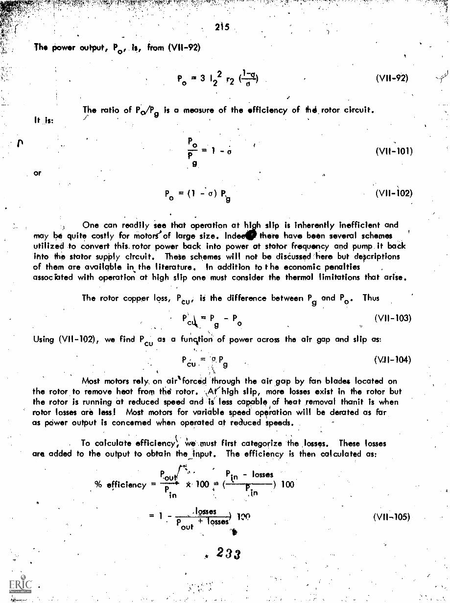
Te19.11,MMWN-
Th power output, Po, Is, from (V11-92)
It .1s:
or
The ratio of P
215
3 122 r2 ()is a measure of the efficiency of thei.rotor circuit.
P0
Po = (1 a) P,9
(VI142)
One can readily see that operation at high slip is inherently inefficient andmay be quite costly for Motoreof large size. IndeelP there have been several schemesutilized to convert this. rotor power back into power at stator frequency and pump it backinto ihe stator supOly circuit. These schemes will not be diséussed:6ere but delcriptionsof them are available in the literature. In addition to t he economic penaltiesassociated with operation at high slip one must consider the thermal limitations that arise.
The rotor copper loss, Ptu, Is the difference between P and Po. Thus
Pt=PPo (V11-103)
Using (VII-102), we find Pu
as a funqion of power across the air gap and slip as:c
PCu.= Pg(VII-104)
Most motors rely. on airlforced 'through the air.gap by fan blades located onthe rotor to remove heat from tlies rotor. -kAt'high slip, more losses exist in the rotor butthe rotor h running at reduced speed and Is less capable of heat removal thanit is whenrotor losses are less! Most motors for variable speed operation will be derated as faras pOwer output is concerned when operated at reduced speeds. .
. To calculate efficiency, we .must first categorize the .losses. These lossesare added to the output to obtain theinput. The efficiency is then calculated as:
Pr
4
Pip ;losses).ou% efficiency = *. 100 =t
in
.losses)pout + losses4
233
(VII-105)

00::t.s;-,
4. 216
In general, there are four losses to consider:
1) the 12r, Iv copper losses. These are Self explanatory and aregiven as 3. 12.9R1 + r2) for the machine.
2) mechanical losses are those associated with mechanical frictton(bearings) and windage loss.
3) no load (core) losses . These losses arise from the time varyingflux densities in the (ron. They are dependent upon the maximum valueof flux densityand,are substantially constant when the impressed voltageand frequency are constant.
4) stray load losses. These 1?sses result from non-uniform currentdistribution in the con ductorscdnd additional core loss Produced in theironby distortion of flux due to load current.
Oft times the no load and stray load losses are lumped together and classlfiedas "electrical constant" losses. For normal operation of the machine near synchronousspeed (low.slips) the mechanical lpsses are also considered constant although they varywith the 2nd or 3rd power of. speed in practke. If we define:
Ps = stray load losses
Pc = core losses
Pm = mechankal losses
Po = power converted to mechanical form(this includes the mechanical losses)
andcopper losses = 3 122 (R1Pcu
we can 'calculate efficiency, as follows:
Ps +P +pm +pc cu_ 00P +P +p +p +Pm/1
o s cu
2 1-3 12 r2(
(VII-106)
0
VII.5 AN APPROXIMATE EXPRESSION FOR TORQUE: The expression for torque (VII-96)requirei ct knowledge of the machine parameters which 'can be obtained by farily straightforward test procedures. However, the size of the machine, or the fact that the machineis not available for test at the time of an analysis make preclude such tests. An approximation .
to (VII-96)'has been found to be very useful and is based on data which can be estimatedrather easily.

217
If we assume that 111'. (X1 + x2).and neglect Rh (V11-98) becomes
and, from (V11-99):
from (V11-96):
X1rft
4+ -)(
3 V 2 r2/6
( 2 47
+ (X1 +:(2)
(VII=107)
(VII-108)
r2)oeSubstituting Xi + x2 = from (VII-107) into (V11-108,-1090 and dividing
(VII-109) by (V11-108) yields:
2 TmTe (VII-110)
a+
m a
Thus if wit know the maximum (also called breakdown) torque aiid the slipat which it ocours we 'can obtain an approximate mathematical expression for Te as afunction of slip, a .
VII.6 MACHINE PARAMETERS BY TEST: The IEEE Test Code,for polyphase inductionmotors, #500, gives complete infOrmation concerning induction motor test procedures. Thisdiscussion will Unlit itself to the bask concepts of impedance determination.
The stator resistance, r1, ,can be measured by regolar iR .drop techniques usingdirecVurrents. Then, if power, voltageand current are measured at no load we can
.detemline X12 + X1 as follows:
Let PO, in V be the no load power,, current and voltage. At no load,r2
a is very low and -6- is 'a large number, approaching. as 0.4 0. If a 0, the branchcontaining X1`2 is shunted by an infinite impedance and the impedance of.,the parallelcombination approaches 1 X12. We can calculate:
R
3 12n
andV. /15111,
n t 1 .nt
235.
"!fgj

irSPik.
3
'
from which:
218
X =i7Z Rit nt ntX as calculated from (VII:112) is very nearly:n
(V11112)
Xnt = x1 + x12 (V11-113)'
Now, if the rotor is blocked so that it cannot turn, and PBt, VBt , IBtare power, voltage and current readings taken at the terminals:
from which:
PB444444.44.44444474.KB/3
2.,
VB/6-and ZB" t
BP,
2XBt =1///-Zot RB
A
"(V11-114)
(VII-115)
This test -is made on reduced voltage (approximately 20% of rated) so thatIB is near nonnal full load current.. Now the branch, j x2 + r2/o. = j + r2(since o' = 1) is shunted by X12. However, I X12 >> x2 + r2 and we.will assumethat the impedance of the parallel combination approaches the rmpecktnce r2 + j x2.This test is similar to the "short circuit" test on a transformer. With the assumptionsmade:
from which:
and
PBtr2 23 1B
VBtand \Z
3.1B t
x2 =1/ZBt2 (r1
2
(V11-116)
(VII-117)
PBt
r23 I
2 rl (V 11-118)
Pot
At this point, an estimate of the ratio x l/x2 must be made. There areempirical ,values of this ratio available for different motor designs. For example, woundrotor motors and cage motors designed for normal skirting torque-normal starting current,and cage type motors designed for high starting. torque-high running slip have an empiricalratio x1/x2 = 1.0. On the other hand, the class of motor designed for normal startingtorque-row starting current has a ratio xi/x.) =' .67. From'this ratio and (V11-118), avalue for xi can be obtained. The valtfe sit xi_and (VII-1'13) enables us to determinex12. Thus, all parameters con be obtained. It should be emPhasized that the testprocedures given in IEEE 0500 should be followed ior accurate results. The procedures,presented here aro to yield insight onlj,. They .pre relatively unsophisticated.
0 4'.
2as
(0
A

l'!".:" ."
219
4
Typical motors have maximum torque values between 200 and 350% of ratedtorque values. Except in the case of "high slip" motors, this maximum torque usuallyoccurs at a slip of 8-129.f). "High slip" motors usually have a maximum torque in excessof 300% with the maximum value oiscuning at slipswin xcess of'60%. Starting torquesrange from 150-300% of rated torque values (for starting at rated voltage). The highslip motor usuqlly has larger values of starting torque than conventional slip motors.
VII.7 ASYNCHRONOUS GENERATORS: Note from Equation (VII-96) that if the slipis negat ve the riumerr c anges sign whereas the denominator retains the positive signbecause of the presence of slip in squared form. This means torque becomes negativeand corresponds to generator action on the part of the asynchronous machine. This is,.shown in graphic form in Figure V11-6. Physically the, negative slip, i.e., slip lessthan 0, corresponds to a rotor speed greater than synchronous speed which means`-practkallythat the rotor is being driven so that it runs ahead of the synchronously rotating magneticfield. It should be noted that the rotating magnetic field in the polyphase induction.motor owes its .existence to the current supplied to the stator winding from the line andthat there is nO other source of excitation' in the machine. Thi s means that If we areto operate the induction machine as an asynchronous generator this supply of magnetizingcurrent must continue to be available to the machine after the speed has passed beyondsynchronous speed and the machine is in a generating mode. In other words, a generatorof this type is not self-exciting but must be operated in parallel with other generators,an electrical system, or static capacitors which are capable of supplying the *machinewit exating current. if the asynchronous generator is Oerated in parallel withanotler system, or other generators, the9 can supply it with the necessary excitationat fi d frequency.
So long as the exciting current is supplied at fixed frequency (through thestator windi.ng) the frequency relationship between rotor winding and the mechanicalspeed of the rotor winding, will adjust to insure that power at the supply frequencyis maintained and supplied back tothe stator. Thus the asynchronous 'generator cansupply fixed frequency power back into the system r egardless of speed of thesynchronous, generator rotor. Practically, the range over which synchronousgenerator con be operated varies from a slip of zero up to proba five to eight percentnegative. This in turn corresponds to very nearly rated torque'Of he machine anddoes not pose any special problem.
It can be shown quite readily that the power factor of the power suppliedby an asynchronous generator is fixed by the.amcu nt of power being supplied and bythe constants of the machine. One can reason this out by cbnsidering that aninductiOn motor is started in the ustial way and is brought up to its normal runningspeed which would be slightly below synchronous speed. The electrical input from thesupply will consist of the magnetizing current, which is in quadrature with the .yoltage,and also the power component of current which is required to supply the rotational lossesassociated with the induction machine and Whatever is on the same shaft. In order tohave asynchronous operation we would have to assume that 'what is on the shaft is a
ONO
23 7

V,Irtt .47; 1' -11';;: `.1,1,:
210
7'..; j`;'1'
turbine or drive of 'some sort. If we now introduce energy into the turbine theturbine speed will increase and Some of the induction machine and shaft losses willbe picked up by the driving turbine and the power component of current for theinduction machine Worn the source will decrease. At some point, when we go
through zero.slipi the power component from the. supply would fall to zero.However, we Would 1HD lake the quadrature component of currnt which is necessaryto supply the excitation requirements of the induction machine. As the speed of theturbine is further increased the torque, and power, become negative - which is tosay they are flowing from th asynchronous machine stator back- into the lino.However, the excitation requirements remain substantially constant;------Thus, 'the
power factor of power supplied by the asynchronous-generator is determined by theload which it is supplying ond the constants of the machine
Induction machines operating as generators have a very limited fieldof usefulness in electrical power systems. The inability to control the flow ofreactive power is one of the reasons why they do have limited usefulness.However, they do have some positive advantages which can be considered in aneyaluation involving asynchronous machines. One of the advantagel is the factthat an induction, or asynchronous generator, does not have to be synchronized priorto connecting it into the system as does a synchronous machine. The machine canbe connected to the system and running at no load for an indefinite period of time.It is instantly available for supply and emergency overload because all thdtnecessary is to adrpit energy into, the prime mover connected to the same shaft.
Also, it is suitable for high speed operation because of the simplcity and ruggednessof the rotor construction and since its voltage and frquency are controlled by theelectrical sYstem with which 'it is paralleled, rt requires no attention to the synchrodiing
problem. Therefore it is suited to automatic or isolated hydraulic plants controlledfrom remote locations. There is no hunting, or oscillation problem, because of theasynchronous property of the machine itself. If the machine is short circuited thevoltage at the terminals of the machine will drop which will reduce the excitationand will limit the short circui t current. If a dead short circuit occurs at the terminals,there will be a transient short.circuit current but the steady state value of the shortcurrent has to be zero because there is no excitatjorn in the steady state short circuit
*condition. If an induction motor is used to Power something like an electric locomotive,a crane hoist, etc. which has the capoll lity, of running at a speed greater:than zeroslip, the induction machine is available as a generator if the speed does go abovesynchronous speed and thus it can provide a regenerative braking action where required.
It should be noted that he governor reqUired for a prime mover which isto drive an asynchronous generator must be different from the governor and controlsystem for a synchronous generator drive. This is so because provision must be madefor varying the speed of the asynchronous machine in order to make it assume thedesired amount of real load.
23°8

221
VII .8 STARTING PROBLEMS: Reference to the equivalent circuit for t he inductionmachine with a 1r; t-citx-wtc-T-, i.e.,. the rotor stationary indicates that minimum impedanceexists in the circuit to limit the current into the machine from the supply circuit. Undernormal conditions, wherein the rotor is free to turn, torque developed will immediatelyaccelerate the rotor and, as the rotor accelerates and the slip decreases, the impedanceincreases and current decreases continuously until the steady state running condition isreached. Thus the current in-rush is a transient condition and does not persist anylonger than the time requked for the motor to accelerate from standstill to nearnormal running speed. However, 'this in-rush current can be on the order of five toeight times normal running current and Can create a problem for the electrical systemsupplying the motor. This high current can cause excessive voltage dips on the circuitssupplying the motor, resulting in light flicker for lighting loads and it introduces thepossibility of magnetic contactors connected to the system becoming deenergized anddisconnecting other connected loads. It is necessary, in an application of a relativelylarge induction motor, to examine carefully the effect that the motor starting willhave on the rest of the system.
The basic problem is to reduce the in-rush current if its magnitude will beobjectionable. This can be done either by inserting additional impedance in the circuit,external to the stator or in the rotor, or to reduce the voltage applied to the motorduring the start.
If the motor is a wound rotor type, insertion of exttrnal resistance in therotor circuit is relatively easy and,this serves not only to limit the current but also theamount of resistance can be selected to yield very high torques under the startingcondition (refer to VII-98). If the rotor is a squirrel cage rotor the additional externalimpedance must be placed in the stator circuit. This serves to limit the current butit also results in reduced voltage across the motor stator and it should be recalled thatthe torque developed is proportional to the square of the applied voltage. Use of atransformer to provide reduced voltage on starting will risduce the in-rush current butit also reduces the available torque. It will be shown below that the torque reductionis much less-than the reduction suffered with inserted impedance for the same reductionin current from the supply.
Consider a motor with locked rotor impedance, Zm, of 0.20 p.u. When1.0 p.u.. voltage is applied, a starting current of 5.0 p.u. results. Suppose it isdesirable to reduce this current to 2.0 p.u. Total circuit impedance, whkh is the sumof Z and Z0, external impedance, must be:m
V 1-0Zm Ze
= 0.5 p.u. (VII-119)1I 2.0
/*from which Ze = 0.5 - Zm = 0.5 - 0.2 = 0.3 p.u.
The voltage across the motor, the voltage across Zm is:
Vni = ImZm = (2.0)(0.2) = 0.4 p.u. (Y11-1201
21 9

222
Since TgaeV2, the starting torc(ui, under this condition', is:
Ts 112 (0.4)2 T y = 0.16 Tsiv p.u., . (V11-121)sl
where Toy = torque dev,eloped with "full", or rated,voltage starting.
Suppose an auto transformer was inserted between the supply, V = 1.0,and the motor. Let the turns ratio of the auto transformer be:
N1where N1_.> N2
N2
The motor wo.uld have an apparent impedance, Z' , to t he source of:m)
Z' = (N1)2 ZN2
.m
Vt.
(VII-122)
(VII-123)
If the "apparent value" was 0.5..p.u. the starting current (from the source)would be 2.0 p.u. Thus from (VII-123):
N1 .5
N2 7-/(1).2 l 8"The voltage across Zm would be, from (V11-123):
N2 1.0V2 =
and the starting torque is:
0.632 p.u.V1 1.58NI
(VII-124)
(VII-125)
Ts = (0.632)2 Isly = 0.4 Tsly p.u. (VII-126)
Compare this value with.that obtained by external reactance starting, i.e.,(VII-121) which results in the same value of starting current drawn from the supply! Ofcourse, an autotransformer costs more than a simple impedance but it may be necessaryto spend the extra money in order to have the additionalstarting torque on starting fora given supply in-rush current restriction.
VII.9 VARIABLE FREQUENCY OPERATION: Variable speed motors are widely used inindustry'. one reason for the widespread usage of the d.c. shunt motor is the" ease withwhich it can be varied in.,speed. This usage is in spite of the relatively high maintananceassociated with the brushes on the d.c. machine. Improvements in power semiconcilctortechnology have made possible variable frequency supply from fixed frequency sources.
24 0

.e
'1; '24;
223
Since, in induction or synchronous machines, speed is determined from the appliedfrequency, the availabilit of variable frequency ,makes the induction motor a seriouscompetitor to the d.c. shunt machine in variable speed applications. A variablefrequency invrtr is certainly more complex and expensive than an a.c. to d.cvariable voltage converter but the ruggedness and cost of the squirrel cage inductionmotor are attractive enough to often offset the additional cost of the power supply.
Several simplifying assumptions will be made in the analysis of anasynchrdhous machine sublect to variable frequency. These assumptions will bedetailed as the derivation proceeds.
Figure (Vll-8) portrays the equivalent circuit of an asynchronous machinewith all vdriables in the rotor referred to the stator, and both stator and rotor quititiesat stator frequency.
AMAAr-l)M3
eLt, toJ1,
44)41
Figure Induction Motor Equivalent Circuit
The power transferreicl to the rotor is:
P = Ig 2
2 r2
r2
al2
L r2+
2
Now, the rotor frequency, or electrical angular velocity., is given by:
2
r2+ ( 6.4.2)2.
(VII-127)
(VII-128)
(VII-129)

r.^,'.v
and wo will define a Hmo constant, T
(VII-128) become*s:
224
2
2C
'2 2 2T W
I ) (1.2)(")' T
ft11.2)(1.2)(ow)11 + r 2-(43,02.1 W2
,2w2)
sYncIYonót4.tçru7 acrts the air gap to the rotor:
P.T
w 2
Since mechanical argulal. velocity = 1371. wheris P/2 = number of pairs of poles.
With (V11-131)., (VII-132) becomes:
2 Mr= (7) (7--)( 9 9) 2
2 +
To normalize the torque, we will determine, tor, for maximum torque. Thus:
E 2 (1 +di = tFri: 2 w 12
12Wr2) T TWr(212 Wr)
+r2Wr2)2
Solving for indicates that maximum torque occurs when:
w =.1r
(V11-130)
(V11-131) .
(VII-132)
(V11-133)
(V11-134)
(vIrAis)
If the value of W. fro (V11-135) is substituted in (VII-133), maximum torque,T is determined as:
1 E *2 PTm 2= H
w 1 2(VII-136)
2
Substiuting, from (V11-136):
2E p
2, 2 2 Tmw L2
(V11-137)

%!..":.XL3C171M.N:1:74..,
, into (VII-133) yields:
's 225
2 torrm + 7to
(V11,138)
We see that maximum torque is independent of r2 (as shown previously)and occurs at
(VII-139)
Since ti) r = ow , we find that maximum torque ccurs at a slip, am, o :
am
r2
(42
Contrast this with the value of am from (VII.-98), i.e.,
amr2
(VII-98)
The difference between (VII-98) and (VII-140) is that ri, Li ore 'neglected'.This is another way of saying that E. = Va In the expression above, TWr is normalized
, slip. (VII-138) in normalized form is plotted in Figure VII-9.
vvA
1.0
Figure VII-9. Normalized Torque Frequency Characteristic
2 3
vovimoAtle lir
(
- I
1

226
A fundamental relationship of an asynchronbus machine IA that:w-m.
where w = rotor speed 111 elec circuit rad/sec.
speed is:
If
From (V11-139) and (VII-141) maximum torque k prbduced when the machine
wm including zero, if. the drive frequency
142)
Also, of course, this equation indicates that the motor can be adjusted(V.toyield maximum torque at any desired speed
,
wrn = w 71.
or stator frequency is set at:-1
tt) T
f = (VII-143)
The purpose of the deiivations! involvhIg variable frequency operation is to permitus to visualize a drive system wherein either torque, T, or motor speed, w m can be varied(as desired) between zero and maximum. It will be assumed that the drive system includesa three phase source at constant frequency powering a squirrel cage motor i/ith a smalltachometer generator mounted on the shaft. The tachometer generator in its simplest formwould be a 'permanent magnet excited,generator with the-same number of pales astheinduction motor. Theoutput voltage and frequency are proportional to the inductionmotor speed. The output is rectified tO yield a dc voltage proportional to speed, wm
A solid state frequency converter accepts the fixed frequency power from thethree phase source and converts in into power at a specific frequency and voltage asdetermined by the control 'circuitry.
The power output from the frequency converter is impressed upon theinduction motor. Note that both frequency and voltage must be controlled because,for an a.c. device* the volts/cycle must be held constant for constant flux density(refer to equation (11-30).
Two possible inputs are desired speed or desired torque.
We_ will examine a system based on maintaining constant torque. From,(V11-138) we can. solve for a value of rotor angular velocity'corresponding to a desiredtorque. Thus
Tm Pm 2r 7/7 ( 1)
An analog circuit for obtaining w r is as shown in Figure VII-10.
(V11-144)
241 I.

t
41t4VP114114.
163 %WM% Atli%
/14
227
cs2)i
r-
Figure VII-10. Analog Circuit to Obtain° from T Desired
VP'
(0))
Tke-+
sign in (VII-144) corresponds to values of TWke: 1.0 or (13 1 1.0.Normal oper4ting range for induction motor is for TW r 1.0, Therefore the minus signtis c osen. frwr is added to the actual signal' tom proportional to motor speed. Thisyiel , from! (VII-141), a signal corresponding to desired stator frequency. This analogsignal is converted to digital form and compared with the digital value of actualconverter frequency. The difference is used to in0ease or decrease the gate pulsesto the converter. Similarly, the actual volts/cycle .output is compared to a tilferencevalue based on the machine design, digitized and used to raise or lower the outputvopage of the converter.
A simplified block diagram of a
htzt-cf,'el-c-o v:11,olt d"ttLr
ac.trai%tf`lik 5
u%t.,1
"If
1:11.ts4stet
(4-)-L4
V uti,,i
converter is shown in Figure VII-11.itidtv-tick:4A
PA oilok tot;r(is Ir. te-ti
r t. utv
c..urcuA,
Tv"(ct utAtc.
.1411:ivi T.,
FtsivAL V II-
fr.Trct duce-
'Figure VII-11. Variable Speed Drive, Constant Torque Control

4-.' `.! :
228
The speed torque aharaCteristic of this type of drive is as shown inFigure V11-12.
A
Teriv.e..
A? cratermti;t1sitnil net ftj
Figure V11-12 . Speed-Torque., Chciracteristic
t-Atc-1.-
Details of the rectifier-inverer and the gatin9 circuits are not developedin this text. Also, of course, various sophisticaHons of circuitry and combinirxrofdevice functions are possible. The system is showri only in outline form to indkajepossibilities.
.wdr"
24 is

311c4Tt tP.g1'.-
'
APPENDIX I
Slected Referenie Textbooks
A. 'Peneralized Apyroach to Electromechanical Eceity!Conversion .
T. t
Chapman! "Eleotromeahariical Energy Conversion!`,, Blaiidelal, 1965
I
Crosno, "Fundamentals of.flectromechanical ConversiOe, Harcourt Braci."c770-Woil d , 1968.
Gourishankar, "Electromechanical Energy Convirsion" lhtemaiional Textbook c#,1965.. /
Levi and Panzer, "Electromechanical Power Conyersion", McQkow-41ill,' 1966.
Majmudar, "Electromechanical Energy. Converters", Allyrv_8.!. Bacon, 1965
Meisel, "Electromechanical Energy dionversion", McGraw-414C 1966.
41asar, "Electromagnetic Energy Conversion Devices anti Systems," Prentice Hall,1177?5:
O'Kelly and Simmonds, "IntroductiOn to Generalized Machine Theory",McGrow:HHI,, 1968.
Seely, "Electromechanical Energy Conversion", McGraw-Hill, 1962.
Sleman, '"Magnetoelectric Devices", Wiley 1966.
White.and Woodson, "Electromagnetic Energy Conversion", Wiley, 1959.
B. Texts Emphasizing Electric Machines
Adkins "General Theory of .Electric Machines", Wiley 1957.
Alger, "The Nature of fnduCtion Machines", Gordon and Breach, 1965.
Botvinnik, "Asynchronous Synchronous Machinels3":, Macmillan, 1964.t r.st
Cajji. "Electric Machinery", Wiley 1958t,
Concordiaq
"Syrichronous
erald and Kingiley, "Electric Math; ", McGraw-Hk 2nd edition.
Gil_21as. "Tensors in Electric Maehine Theo "; 'Chapman and Hall, 1952.
Hague, "The Principles of Electromagnetian Applied to Electric Machinen,;ier, .1962.
247
1 s

,OP
- -r,
Jivons, "Electrroal 'Machine Theory",. American ElseVier, 1966.'
.)onesr "The Unified4heory of Electric Mcyttlins", Plenum tOss, 1967.
ett al., "Direct Current Machinery", Macmillpn 1934.
Kron, "Equivalent ,Ctrtuits of Eloctrib Dove! 1967.
Ku, !'Electrk Energy ConVeMon", Ronald 1959.
e.,
Kuhlman,. "Design of Electrical Apparyttus", 3rd Edition, Wiley, 195P.
sLan sdorf, 'Theory of Alternating Current Machinery, McGraw-Hill, 1955,fld dltIofl.
Lawrence and Richards, "Principtil of Alternating Current Machinery",McGraw-Hill, 1933, 4tli edition.
e.
Liwschitz-Gaiik ana Whipple, "Direct Current Maghinee, Van Nostrand,1956, 2nct
LiwschitrTGarik -and Whipple, "Alttrnating Current Machines", Van Nostrand,19-61, 2nd edititin:
I.
Lyon, "Transient Analysis of Alternating Current Machinery", Wiley 1954.
'Puchstein, Lloyd, Conrad, "Alternating Current Machines", WHey 1954,1rd edition.
Pestarini, "Metadyne SIt'atics", MIT Press, 1952.
Sah, "Fundamentals of Alternating Cgrrent Machines", McGraw-Hill, 1936,.*.o.
'Thaler and Wilcox, "Electric Mochines", .Wiley 1966.
Lewis," "Principles of Synchronous Machinery", ITT Press, ,1959.
24 8
I.

l
1P1CY
\
rr,
.,,,, ...f", ,,' .r' . ... v.y , .,' .
% ,
.s1 ,,
,A
APPENDIX Ii
Uniti COnversion Multipliers land Constants. -,
iendth
1 meter.= 3.281 feet = 39.37 inches
1 kilogram = 2.205 lb.
1 newtan = 0.225 lb,
tvlass -
- Force -
- Torque -
1 newton-meter = 0.738 ft.-lbs.
- Energy
joule = 1 watt-sec = 0.738 ft.lbs
er
1 watt = 1.341 x horsepower
- Moment of Inertia -
1 kilogram-meter2 = 23.7 lb.-ft.2
- Magnet Relationship -
1 ampere turn/meter = 0.0254 ampere turn/inch
1 weber/meter2 = 10000 gauss = 64.5 kilolines/inch2
1 weber = 108maxwells \108 lines
S.,
a
Permeability of FreekSpoce .= .= 4rr x 107weber/ampere turn meter
Permittivity 'of Free Space = coo= 8.854 x 10⁻¹² coulomb2/newton meter2'Gravity 'effect = g = 32.2 ft./sec.2 = 9.807 meter/sec2
2
sS
'
.,
r-
,