dnvgl-ru-ship-pt5ch6 chemical tankers
TRANSCRIPT
The content of this service document is the subject of intellectual property rights reserved by DNV GL AS ("DNV GL"). The useraccepts that it is prohibited by anyone else but DNV GL and/or its licensees to offer and/or perform classification, certificationand/or verification services, including the issuance of certificates and/or declarations of conformity, wholly or partly, on thebasis of and/or pursuant to this document whether free of charge or chargeable, without DNV GL's prior written consent.DNV GL is not responsible for the consequences arising from any use of this document by others.
The electronic pdf version of this document, available free of chargefrom http://www.dnvgl.com, is the officially binding version.
DNV GL AS
RULES FOR CLASSIFICATION
ShipsEdition October 2015
Part 5 Ship types
Chapter 6 Chemical tankers
FOREWORD
DNV GL rules for classification contain procedural and technical requirements related to obtainingand retaining a class certificate. The rules represent all requirements adopted by the Society asbasis for classification.
© DNV GL AS October 2015
Any comments may be sent by e-mail to [email protected]
If any person suffers loss or damage which is proved to have been caused by any negligent act or omission of DNV GL, then DNV GL shallpay compensation to such person for his proved direct loss or damage. However, the compensation shall not exceed an amount equal to tentimes the fee charged for the service in question, provided that the maximum compensation shall never exceed USD 2 million.
In this provision "DNV GL" shall mean DNV GL AS, its direct and indirect owners as well as all its affiliates, subsidiaries, directors, officers,employees, agents and any other acting on behalf of DNV GL.
Part
5 C
hapt
er 6
Cha
nges
- c
urre
nt
Rules for classification: Ships — DNVGL-RU-SHIP-Pt5Ch6. Edition October 2015 Page 3Chemical tankers
DNV GL AS
CHANGES – CURRENT
This is a new document.
The rules enter into force 1 January 2016.
Part
5 C
hapt
er 6
Con
tent
s
Rules for classification: Ships — DNVGL-RU-SHIP-Pt5Ch6. Edition October 2015 Page 4Chemical tankers
DNV GL AS
CONTENTS
Changes – current...................................................................................................... 3
Section 1 General..................................................................................................... 101 Introduction..........................................................................................10
1.1 Introduction.......................................................................................101.2 Scope............................................................................................... 101.3 Application.........................................................................................10
2 Class notations..................................................................................... 112.1 Ship type notations............................................................................ 112.2 Additional notations............................................................................ 112.3 Register information........................................................................... 122.4 Tank types.........................................................................................132.5 Filling limits for cargo tanks................................................................ 142.6 Signboards........................................................................................ 142.7 Cargo information.............................................................................. 142.8 Procedures and arrangements manual.................................................. 152.9 Definitions......................................................................................... 15
3 Documentation and certification...........................................................183.1 Documentation requirements............................................................... 183.2 Certification requirements....................................................................22
4 Testing..................................................................................................244.1 Testing during newbuilding.................................................................. 24
Section 2 Hull...........................................................................................................251 General................................................................................................. 252 Materials............................................................................................... 25
2.1 Selection and testing.......................................................................... 252.2 Materials for cargo tanks.....................................................................252.3 Materials for cargo piping....................................................................25
3 Strength................................................................................................253.1 Independent tanks............................................................................. 263.2 Emergency towing..............................................................................263.3 Vertically corrugated bulkhead without stool.......................................... 263.4 Small confined spaces within or adjacent to cargo tanks..........................26
4 Fatigue assessment.............................................................................. 265 Direct strength calculations..................................................................26
Part
5 C
hapt
er 6
Con
tent
s
Rules for classification: Ships — DNVGL-RU-SHIP-Pt5Ch6. Edition October 2015 Page 5Chemical tankers
DNV GL AS
Section 3 Ship arrangements................................................................................... 271 Cargo tank location.............................................................................. 27
1.1 General............................................................................................. 272 Location and separation of spaces........................................................27
2.1 General............................................................................................. 273 Arrangement of entrances and other openings.....................................28
3.1 Accommodation and non-hazardous spaces........................................... 283.2 Hazardous spaces and cargo tanks....................................................... 293.3 Access to and within cargo tanks, void spaces and other spaces in the
cargo area...........................................................................................304 Protection of crew................................................................................ 30
4.1 Arrangement......................................................................................305 Cargo pump rooms, cofferdams and pipe tunnels................................. 30
5.1 General............................................................................................. 306 Diesel engines driving emergency fire pumps, etc................................ 31
6.1 General............................................................................................. 317 Chain locker and windlass.................................................................... 318 Anodes, washing machines and other fittings in tanks and cofferdams..319 Slop tanks.............................................................................................31
9.1 Arrangement......................................................................................3110 Stowage of cargo samples..................................................................32
10.1 General........................................................................................... 3210.2 Arrangement.................................................................................... 32
11 Signboards..........................................................................................32
Section 4 Arrangement in hold spaces..................................................................... 331 General................................................................................................. 33
1.1 Distance between tanks and hull..........................................................332 Gas pressure relief devices...................................................................33
2.1 Pressure/vacuum relief valves..............................................................333 Sealing around tanks............................................................................334 Earth connections................................................................................. 33
Section 5 Testing of cargo tanks..............................................................................341 Requirements for testing of welds and non-destructive testing............ 34
1.1 General............................................................................................. 341.2 Weld production tests......................................................................... 34
Section 6 Piping systems in the cargo area............................................................. 35
Part
5 C
hapt
er 6
Con
tent
s
Rules for classification: Ships — DNVGL-RU-SHIP-Pt5Ch6. Edition October 2015 Page 6Chemical tankers
DNV GL AS
1 Piping systems not used for cargo....................................................... 351.1 General............................................................................................. 351.2 Cargo pump rooms.............................................................................351.3 Cofferdams and pipe tunnels............................................................... 361.4 Spaces for independent tanks.............................................................. 361.5 Ballast systems.................................................................................. 361.6 Forepeak ballast tank......................................................................... 371.7 Fuel oil tanks.....................................................................................37
2 Cargo piping system............................................................................. 372.1 General............................................................................................. 372.2 Cargo pumps..................................................................................... 382.3 Arrangement and general design..........................................................382.4 Pressure indication............................................................................. 402.5 Welding procedure tests......................................................................402.6 Testing.............................................................................................. 40
3 Stripping of cargo tank and cargo lines................................................413.1 General............................................................................................. 41
4 Discharge of contaminated water......................................................... 414.1 Location of discharge outlet.................................................................414.2 Sizing of the discharge outlet.............................................................. 414.3 Cargo record book and SMPEP............................................................. 42
5 Stern loading and unloading arrangements.......................................... 425.1 General............................................................................................. 425.2 Piping arrangement............................................................................ 425.3 Accommodation entrances................................................................... 425.4 Electrical equipment — fire fighting...................................................... 43
6 Cargo hoses..........................................................................................436.1 General............................................................................................. 43
Section 7 Cargo heating and cooling arrangements................................................. 441 Cargo heating....................................................................................... 44
1.1 General............................................................................................. 441.2 Heating of cargoes with temperatures above 80°C..................................451.3 Cargo cooling system......................................................................... 46
Section 8 Marking of tanks, pipes and valves...........................................................471 General................................................................................................. 47
1.1 Marking plates................................................................................... 471.2 Pipelines............................................................................................47
Part
5 C
hapt
er 6
Con
tent
s
Rules for classification: Ships — DNVGL-RU-SHIP-Pt5Ch6. Edition October 2015 Page 7Chemical tankers
DNV GL AS
1.3 Marking of independent tanks..............................................................47
Section 9 Gas freeing and venting of cargo tanks.................................................... 481 Gas freeing of cargo tanks................................................................... 48
1.1 General............................................................................................. 482 Tank venting systems...........................................................................49
2.1 General............................................................................................. 492.2 Tank venting system, type c1 (open)....................................................502.3 Tank venting system, type c2 (controlled)............................................. 502.4 Tank venting system, type c3 (controlled venting for toxic products)..........51
Section 10 Mechanical ventilation in the cargo area outside the cargo tanks............531 System requirements............................................................................53
1.1 General............................................................................................. 531.2 Fans serving hazardous spaces............................................................ 54
2 Ventilation arrangement and capacity requirements.............................542.1 General............................................................................................. 542.2 Non-hazardous spaces........................................................................ 552.3 Cargo handling spaces........................................................................ 562.4 Other hazardous spaces normally entered............................................. 562.5 Spaces not normally entered............................................................... 56
Section 11 Fire protection and extinction.................................................................571 General................................................................................................. 57
1.1 Application.........................................................................................572 Fire extinguishing.................................................................................57
2.1 Fire extinguishing in cargo area........................................................... 572.2 Deck fire extinguishing system in cargo area......................................... 572.3 Fire extinguishing in cargo pump rooms................................................58
Section 12 Area classification and electrical installations.........................................601 General................................................................................................. 60
1.1 Application.........................................................................................601.2 Insulation monitoring..........................................................................60
2 Electrical installations in hazardous areas............................................ 602.1 General............................................................................................. 60
3 Area classification.................................................................................613.1 General............................................................................................. 613.2 Tankers for carriage of products with flashpoint not exceeding 60°C.......... 613.3 Tankers for carriage of products with flashpoint exceeding 60°C................63
Part
5 C
hapt
er 6
Con
tent
s
Rules for classification: Ships — DNVGL-RU-SHIP-Pt5Ch6. Edition October 2015 Page 8Chemical tankers
DNV GL AS
3.4 Tankers for carriage of products (e.g. acids) reacting with other products/materials to evolve flammable gases...................................................... 63
4 Inspection and testing..........................................................................634.1 General............................................................................................. 63
5 Maintenance..........................................................................................645.1 General............................................................................................. 64
6 Signboards............................................................................................646.1 General............................................................................................. 64
Section 13 Instrumentation and automation............................................................661 General requirements........................................................................... 66
1.1 General............................................................................................. 662 Alarm, indicating and recording systems..............................................66
2.1 Cargo tank level gauging.................................................................... 662.2 Overflow control.................................................................................672.3 Vapour detection................................................................................ 672.4 Cargo temperature measurement......................................................... 672.5 Leakage alarms..................................................................................672.6 Computer (PLC) based systems for cargo handling................................. 672.7 Centralised cargo control.....................................................................672.8 Integrated cargo and ballast systems................................................... 682.9 Gas detection in cargo pump room for flammable liquids with flashpoint
not exceeding 60°C..............................................................................68
Section 14 Tests after installation............................................................................691 General................................................................................................. 69
1.1 Application.........................................................................................69
Section 15 Additional requirements for certain cargoes...........................................701 General requirements........................................................................... 70
1.1 Application.........................................................................................701.2 Materials of construction..................................................................... 701.3 Segregation of cargo from bunker tanks............................................... 701.4 Separate piping systems..................................................................... 701.5 Cargo contamination...........................................................................701.6 Inert gas...........................................................................................701.7 Moisture control (Drying).................................................................... 711.8 Cargo pumps in tank..........................................................................711.9 Products not to be exposed to excessive heat........................................ 711.10 Cargo pump temperature sensors.......................................................71
Part
5 C
hapt
er 6
Con
tent
s
Rules for classification: Ships — DNVGL-RU-SHIP-Pt5Ch6. Edition October 2015 Page 9Chemical tankers
DNV GL AS
1.11 Increased ventilation of cargo handling spaces..................................... 712 Additional requirements for certain groups of products........................72
2.1 Acids.................................................................................................722.2 Products which have a vapour pressure greater than 1.013 bar at 37.8°C...72
3 Additional requirements for certain chemicals......................................733.1 Ammonium nitrate solution, 93% or less...............................................733.2 Carbon disulphide...............................................................................733.3 Diethyl ether..................................................................................... 733.4 Hydrogen peroxide solutions of 60% but not over 70% by mass............... 733.5 Hydrogen peroxide solutions over 8% but not over 60% by mass..............733.6 Phosphorus, yellow or white................................................................ 733.7 Propylene oxide and mixtures of ethylene oxide/ propylene oxide with
ethylene oxide content of not more than 30% by weight........................... 733.8 Sulphuric acid.................................................................................... 763.9 Sulphur liquid.................................................................................... 773.10 Alkyl (C7 — C9) nitrates................................................................... 77
Section 16 Inert gas systems...................................................................................781 General................................................................................................. 78
1.1 Application.........................................................................................781.2 Documentation...................................................................................78
2 Materials, arrangement and design...................................................... 782.1 General............................................................................................. 782.2 Inert gas systems based on other means than combustion of hydrocarbons..792.3 Nitrogen inert gas systems fitted for other purposes............................... 81
3 Instrumentation....................................................................................813.1 General............................................................................................. 81
Section 17 Personnel protection...............................................................................851 General requirements........................................................................... 85
1.1 Protective equipment.......................................................................... 852 Safety equipment..................................................................................85
2.1 Safety equipment............................................................................... 853 Medical first-aid equipment.................................................................. 86
3.1 General............................................................................................. 864 Decontamination showers and eye washes...........................................86
4.1 General............................................................................................. 86
Part
5 C
hapt
er 6
Sec
tion
1
Rules for classification: Ships — DNVGL-RU-SHIP-Pt5Ch6. Edition October 2015 Page 10Chemical tankers
DNV GL AS
SECTION 1 GENERAL
1 Introduction
1.1 IntroductionThese rules apply to ships intended for carriage of liquid chemicals in bulk.
1.2 Scope
1.2.1 The requirements of this chapter are considered to meet the requirements of the international code forthe construction and equipment of ships carrying dangerous chemicals in bulk (IBC code) and MARPOL 73/78Annex II.
1.2.2 Machinery installations and their auxiliary systems that support cargo handling shall meet the samerule requirements as if they were considered to support a main function: ref. Pt.1 Ch.1 Sec.1 [2.1].
1.3 Application
1.3.1 Cargoes covered by the classification in accordance with this chapter are considered to be those listedin the IBC code chapter 17 and 18 and the agreed additions given in the latest IMO MEPC.2/Circ.xx List 1.Non-hazardous cargoes except oil, are covered by the general requirements for main class unless otherwisestated.
1.3.2 Chemical tankers also intended for carriage of oil shall comply with the requirements in Ch.5.
1.3.3 The requirements in this chapter are supplementary to those given for assignment of main class.
1.3.4 Simultaneous carriage of dry cargo (including vehicles and passengers) and liquid chemicals in bulkwith flashpoint not exceeding 60°C is not permitted for ships with class notations as stated in [2.1].
1.3.5 For cargo tanks intended for cargoes with specific gravity exceeding 1025 kg/m3, reference is madetoPt.6 Ch.1 Sec.3.
1.3.6 These rules apply to ships intended for carriage of liquid chemicals in bulk with a flash point notexceeding 60°C (closed cup test), as well as ships heating its cargo to within 15°C or more of its flashpoint.
1.3.7 For other ships intended for carriage of liquid chemicals in bulk that are non-flammable or have aflashpoint exceeding 60°C, the requirement will be specially considered.
Part
5 C
hapt
er 6
Sec
tion
1
Rules for classification: Ships — DNVGL-RU-SHIP-Pt5Ch6. Edition October 2015 Page 11Chemical tankers
DNV GL AS
2 Class notations
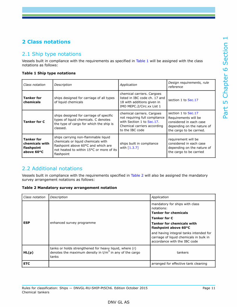
2.1 Ship type notationsVessels built in compliance with the requirements as specified in Table 1 will be assigned with the classnotations as follows:
Table 1 Ship type notations
Class notation Description Application Design requirements, rulereference
Tanker forchemicals
ships designed for carriage of all typesof liquid chemicals
chemical carriers. Cargoeslisted in IBC code ch. 17 and18 with additions given inIMO MEPC.2/Circ.xx List 1
section 1 to Sec.17
Tanker for C
ships designed for carriage of specifictypes of liquid chemicals. C denotesthe type of cargo for which the ship isclassed.
chemical carriers. Cargoesnot requiring full compliancewith Section 1 to Sec.17.Chemical carriers accordingto the IBC code
section 1 to Sec.17Requirements will beconsidered in each casedepending on the nature ofthe cargo to be carried.
Tanker forchemicals withflashpointabove 60°C
ships carrying non-flammable liquidchemicals or liquid chemicals withflashpoint above 60°C and which arenot heated to within 15°C or more of itsflashpoint
ships built in compliancewith [1.3.7]
requirement will beconsidered in each casedepending on the nature ofthe cargo to be carried
2.2 Additional notationsVessels built in compliance with the requirements specified in Table 2 will also be assigned the mandatorysurvey arrangement notations as follows:
Table 2 Mandatory survey arrangement notation
Class notation Description Application
ESP enhanced survey programme
mandatory for ships with classnotations:Tanker for chemicals
Tanker for C
Tanker for chemicals withflashpoint above 60°C
and having integral tanks intended forcarriage of liquid chemicals in bulk inaccordance with the IBC code
HL(ρ)tanks or holds strengthened for heavy liquid, where (r)denotes the maximum density in t/m3 in any of the cargotanks
tankers
ETC arranged for effective tank cleaning
Part
5 C
hapt
er 6
Sec
tion
1
Rules for classification: Ships — DNVGL-RU-SHIP-Pt5Ch6. Edition October 2015 Page 12Chemical tankers
DNV GL AS
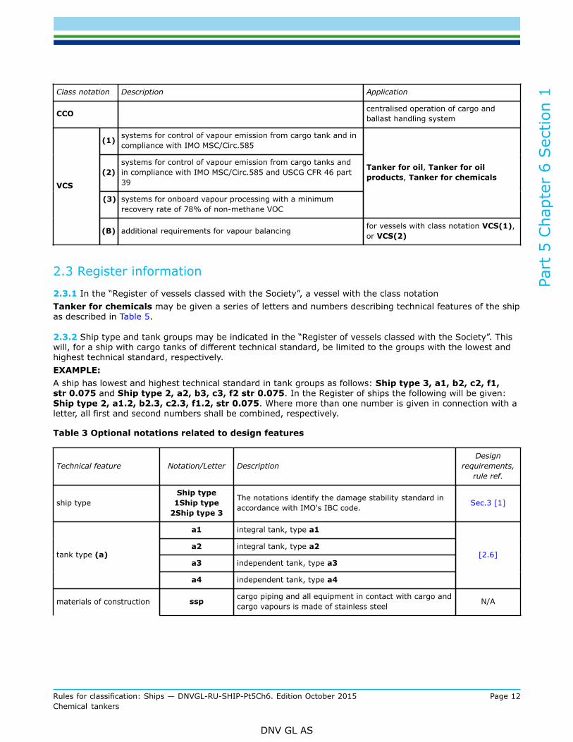
Class notation Description Application
CCO centralised operation of cargo andballast handling system
(1) systems for control of vapour emission from cargo tank and incompliance with IMO MSC/Circ.585
(2)systems for control of vapour emission from cargo tanks andin compliance with IMO MSC/Circ.585 and USCG CFR 46 part39
(3) systems for onboard vapour processing with a minimumrecovery rate of 78% of non-methane VOC
Tanker for oil, Tanker for oilproducts, Tanker for chemicals
VCS
(B) additional requirements for vapour balancing for vessels with class notation VCS(1),or VCS(2)
2.3 Register information
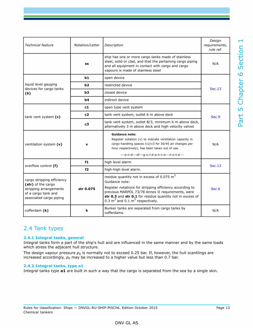
2.3.1 In the “Register of vessels classed with the Society”, a vessel with the class notationTanker for chemicals may be given a series of letters and numbers describing technical features of the shipas described in Table 5.
2.3.2 Ship type and tank groups may be indicated in the “Register of vessels classed with the Society”. Thiswill, for a ship with cargo tanks of different technical standard, be limited to the groups with the lowest andhighest technical standard, respectively.EXAMPLE:A ship has lowest and highest technical standard in tank groups as follows: Ship type 3, a1, b2, c2, f1,str 0.075 and Ship type 2, a2, b3, c3, f2 str 0.075. In the Register of ships the following will be given:Ship type 2, a1.2, b2.3, c2.3, f1.2, str 0.075. Where more than one number is given in connection with aletter, all first and second numbers shall be combined, respectively.
Table 3 Optional notations related to design features
Technical feature Notation/Letter DescriptionDesign
requirements,rule ref.
ship typeShip type
1Ship type2Ship type 3
The notations identify the damage stability standard inaccordance with IMO's IBC code. Sec.3 [1]
a1 integral tank, type a1
a2 integral tank, type a2
a3 independent tank, type a3tank type (a)
a4 independent tank, type a4
[2.6]
materials of construction ssp cargo piping and all equipment in contact with cargo andcargo vapours is made of stainless steel N/A
Part
5 C
hapt
er 6
Sec
tion
1
Rules for classification: Ships — DNVGL-RU-SHIP-Pt5Ch6. Edition October 2015 Page 13Chemical tankers
DNV GL AS
Technical feature Notation/Letter DescriptionDesign
requirements,rule ref.
ss
ship has one or more cargo tanks made of stainlesssteel, solid or clad, and that the pertaining cargo pipingand all equipment in contact with cargo and cargovapours is made of stainless steel
N/A
b1 open device
b2 restricted device
b3 closed device
liquid level gaugingdevices for cargo tanks(b)
b4 indirect device
Sec.13
c1 open type vent system
c2 tank vent system, outlet 6 m above decktank vent system (c)
c3 tank vent system, outlet B/3, minimum 6 m above deck,alternatively 3 m above deck and high velocity valves
Sec.9
ventilation system (v) v
Guidance note:Register notation (v) to indicate ventilation capacity incargo handling spaces (v2/v3 for 30/45 air changes perhour respectively), has been taken out of use.
---e-n-d---of---g-u-i-d-a-n-c-e---n-o-t-e---
N/A
f1 high level alarmoverflow control (f)
f2 high-high level alarm.Sec.13
cargo stripping efficiency(str) of the cargostripping arrangementsof a cargo tank andassociated cargo piping
str 0.075
residue quantity not in excess of 0.075 m3
Guidance note:
Register notations for stripping efficiency according toprevious MARPOL 73/78 Annex II requirements, werestr 0.3 and str 0.1 for residue quantity not in excess of0.3 m3 and 0.1 m3 respectively.
Sec.6
cofferdam (k) k Bunker tanks are separated from cargo tanks bycofferdams. N/A
2.4 Tank types2.4.1 Integral tanks, generalIntegral tanks form a part of the ship's hull and are influenced in the same manner and by the same loadswhich stress the adjacent hull structure.The design vapour pressure p0 is normally not to exceed 0.25 bar. If, however, the hull scantlings areincreased accordingly, p0 may be increased to a higher value but less than 0.7 bar.
2.4.2 Integral tanks, type a1Integral tanks type a1 are built in such a way that the cargo is separated from the sea by a single skin.
Part
5 C
hapt
er 6
Sec
tion
1
Rules for classification: Ships — DNVGL-RU-SHIP-Pt5Ch6. Edition October 2015 Page 14Chemical tankers
DNV GL AS
2.4.3 Integral tanks, type a2Integral tanks type a2 are built in such a way that the cargo is separated from the sea by a double skin.The distance between the ship’s shell plating (bottom and side) shall comply with the distances given inSec.3 [1.1.1] for Ship type 1 and Sec.3 [1.1.2] for Ship type 2.
Guidance note:If a cargo tank is positioned adjacent to a sea chest, a loading restriction for water reactive cargoes will be given on the internationalcertificate of fitness for the carriage of dangerous chemical in bulk.
---e-n-d---of---g-u-i-d-a-n-c-e---n-o-t-e---
2.4.4 Independent tanks, generalIndependent tanks do not form a part of the ship's hull. An independent tank is built and installed in such away that the influence on the tank by the hull's deformation and stresses is minimised. An independent tankdoes not contribute to the hull strength. An independent tank is normally to have longitudinally rigid fixtureto the ship in only one transverse plane. Distance between tanks and hull: see Sec.3 [1.1].
2.4.5 Independent tanks, type a3Independent tanks type a3 are self-supporting tanks with a design vapour pressure p0 not exceeding 0.7 bar.
2.4.6 Independent tanks, type a4Independent tanks type a4 tanks are self-supporting pressure vessels with a design vapour pressure higherthan 0.7 bar and where the internal pressure is carried mainly as tensile membrane stresses in the tank skin(cylinders, spheres, etc.).
2.5 Filling limits for cargo tanksTanks for liquid cargo shall be so loaded as to avoid the tank becoming liquid full during the voyage takinginto consideration the highest temperature which the cargo may reach.
2.6 SignboardsSignboards are required by the rules for:
— plates bolted to boundaries facing the cargo area and which can be opened for removal of machinery.These shall be fitted with signboard giving instructions that the plates shall be kept closed unless the shipis gas-free.
— marking plates for independent tanks— Pumps and compressors shall not be started before the ventilation system in the electric motor room has
been in operation for 15 minutes.— opening of a lighting fitting. Before opening, its supply circuit shall be disconnected.— Ventilation to be in operation before lighting is turned on in cargo pump rooms.— portable electrical equipment supplied by flexible cables. This equipment shall not be used in areas where
there is danger.— welding apparatus. These shall not be used unless the working space and adjacent spaces are gas-free.
2.7 Cargo information
2.7.1 A copy of the international code for construction and equipment of ships carrying dangerous chemicalsin bulk, provisions of this code, shall be on board every ship covered by this code.
2.7.2 Information shall be on board, and available to all concerned, giving the necessary data for the safecarriage of the cargo. Such information should include a cargo stowage plan to be kept in an accessible place,indicating all cargo on board, including each dangerous chemical carried:
Part
5 C
hapt
er 6
Sec
tion
1
Rules for classification: Ships — DNVGL-RU-SHIP-Pt5Ch6. Edition October 2015 Page 15Chemical tankers
DNV GL AS
1) a full description of the physical and chemical properties, including reactivity, necessary for the safecontainment of the cargo
2) action to be taken in the event of spills or leaks3) countermeasures against accidental personal contact4) fire-fighting procedure and fire-fighting media.5) procedures for cargo transfer, tank cleaning, gas-freeing and ballasting6) For those cargoes required to be stabilized or inhibited, the cargo should be refused if the certificate
required by these paragraphs is not supplied.
2.8 Procedures and arrangements manual
2.8.1 Each ship shall be provided with a Procedures and Arrangements Manual (P & A Manual) developedfor the ship in accordance with MARPOL Annex II, Appendix 4 - standard format for the procedures andarrangements manual, and approved by the Society.
2.8.2 Each ship shall be fitted with equipment and arrangements identified in its P & A Manual.
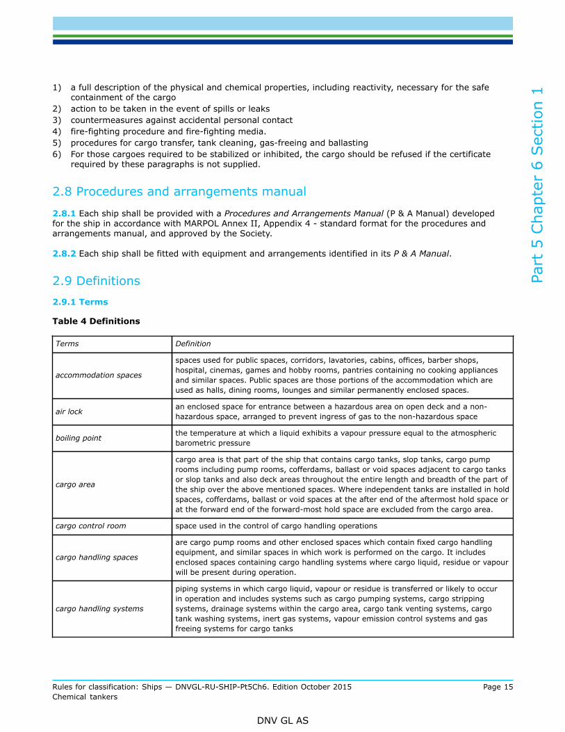
2.9 Definitions2.9.1 Terms
Table 4 Definitions
Terms Definition
accommodation spaces
spaces used for public spaces, corridors, lavatories, cabins, offices, barber shops,hospital, cinemas, games and hobby rooms, pantries containing no cooking appliancesand similar spaces. Public spaces are those portions of the accommodation which areused as halls, dining rooms, lounges and similar permanently enclosed spaces.
air lock an enclosed space for entrance between a hazardous area on open deck and a non-hazardous space, arranged to prevent ingress of gas to the non-hazardous space
boiling point the temperature at which a liquid exhibits a vapour pressure equal to the atmosphericbarometric pressure
cargo area
cargo area is that part of the ship that contains cargo tanks, slop tanks, cargo pumprooms including pump rooms, cofferdams, ballast or void spaces adjacent to cargo tanksor slop tanks and also deck areas throughout the entire length and breadth of the part ofthe ship over the above mentioned spaces. Where independent tanks are installed in holdspaces, cofferdams, ballast or void spaces at the after end of the aftermost hold space orat the forward end of the forward-most hold space are excluded from the cargo area.
cargo control room space used in the control of cargo handling operations
cargo handling spaces
are cargo pump rooms and other enclosed spaces which contain fixed cargo handlingequipment, and similar spaces in which work is performed on the cargo. It includesenclosed spaces containing cargo handling systems where cargo liquid, residue or vapourwill be present during operation.
cargo handling systems
piping systems in which cargo liquid, vapour or residue is transferred or likely to occurin operation and includes systems such as cargo pumping systems, cargo strippingsystems, drainage systems within the cargo area, cargo tank venting systems, cargotank washing systems, inert gas systems, vapour emission control systems and gasfreeing systems for cargo tanks
Part
5 C
hapt
er 6
Sec
tion
1
Rules for classification: Ships — DNVGL-RU-SHIP-Pt5Ch6. Edition October 2015 Page 16Chemical tankers
DNV GL AS
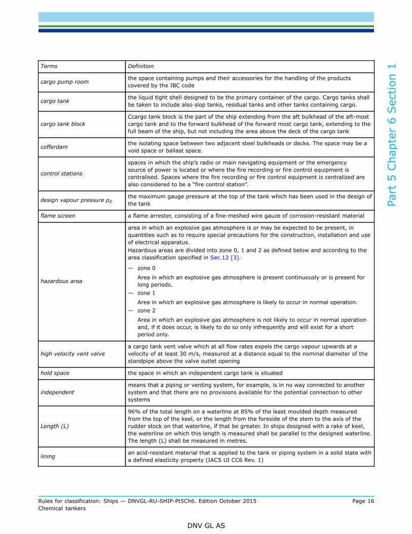
Terms Definition
cargo pump room the space containing pumps and their accessories for the handling of the productscovered by the IBC code
cargo tank the liquid tight shell designed to be the primary container of the cargo. Cargo tanks shallbe taken to include also slop tanks, residual tanks and other tanks containing cargo.
cargo tank blockCcargo tank block is the part of the ship extending from the aft bulkhead of the aft-mostcargo tank and to the forward bulkhead of the forward most cargo tank, extending to thefull beam of the ship, but not including the area above the deck of the cargo tank
cofferdam the isolating space between two adjacent steel bulkheads or decks. The space may be avoid space or ballast space.
control stations
spaces in which the ship’s radio or main navigating equipment or the emergencysource of power is located or where the fire recording or fire control equipment iscentralised. Spaces where the fire recording or fire control equipment is centralized arealso considered to be a “fire control station”.
design vapour pressure p0the maximum gauge pressure at the top of the tank which has been used in the design ofthe tank
flame screen a flame arrester, consisting of a fine-meshed wire gauze of corrosion-resistant material
hazardous area
area in which an explosive gas atmosphere is or may be expected to be present, inquantities such as to require special precautions for the construction, installation and useof electrical apparatus.Hazardous areas are divided into zone 0, 1 and 2 as defined below and according to thearea classification specified in Sec.12 [3].
— zone 0
Area in which an explosive gas atmosphere is present continuously or is present forlong periods.
— zone 1
Area in which an explosive gas atmosphere is likely to occur in normal operation.— zone 2
Area in which an explosive gas atmosphere is not likely to occur in normal operationand, if it does occur, is likely to do so only infrequently and will exist for a shortperiod only.
high velocity vent valvea cargo tank vent valve which at all flow rates expels the cargo vapour upwards at avelocity of at least 30 m/s, measured at a distance equal to the nominal diameter of thestandpipe above the valve outlet opening
hold space the space in which an independent cargo tank is situated
independentmeans that a piping or venting system, for example, is in no way connected to anothersystem and that there are no provisions available for the potential connection to othersystems
Length (L)
96% of the total length on a waterline at 85% of the least moulded depth measuredfrom the top of the keel, or the length from the foreside of the stem to the axis of therudder stock on that waterline, if that be greater. In ships designed with a rake of keel,the waterline on which this length is measured shall be parallel to the designed waterline.The length (L) shall be measured in metres.
lining an acid-resistant material that is applied to the tank or piping system in a solid state witha defined elasticity property (IACS UI CC6 Rev. 1)
Part
5 C
hapt
er 6
Sec
tion
1
Rules for classification: Ships — DNVGL-RU-SHIP-Pt5Ch6. Edition October 2015 Page 17Chemical tankers
DNV GL AS
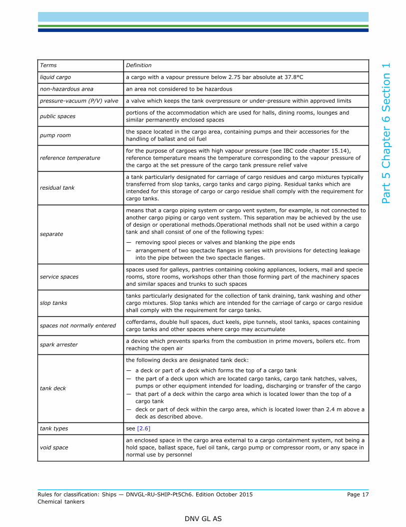
Terms Definition
liquid cargo a cargo with a vapour pressure below 2.75 bar absolute at 37.8°C
non-hazardous area an area not considered to be hazardous
pressure-vacuum (P/V) valve a valve which keeps the tank overpressure or under-pressure within approved limits
public spaces portions of the accommodation which are used for halls, dining rooms, lounges andsimilar permanently enclosed spaces
pump room the space located in the cargo area, containing pumps and their accessories for thehandling of ballast and oil fuel
reference temperaturefor the purpose of cargoes with high vapour pressure (see IBC code chapter 15.14),reference temperature means the temperature corresponding to the vapour pressure ofthe cargo at the set pressure of the cargo tank pressure relief valve
residual tank
a tank particularly designated for carriage of cargo residues and cargo mixtures typicallytransferred from slop tanks, cargo tanks and cargo piping. Residual tanks which areintended for this storage of cargo or cargo residue shall comply with the requirement forcargo tanks.
separate
means that a cargo piping system or cargo vent system, for example, is not connected toanother cargo piping or cargo vent system. This separation may be achieved by the useof design or operational methods.Operational methods shall not be used within a cargotank and shall consist of one of the following types:
— removing spool pieces or valves and blanking the pipe ends— arrangement of two spectacle flanges in series with provisions for detecting leakage
into the pipe between the two spectacle flanges.
service spacesspaces used for galleys, pantries containing cooking appliances, lockers, mail and specierooms, store rooms, workshops other than those forming part of the machinery spacesand similar spaces and trunks to such spaces
slop tankstanks particularly designated for the collection of tank draining, tank washing and othercargo mixtures. Slop tanks which are intended for the carriage of cargo or cargo residueshall comply with the requirement for cargo tanks.
spaces not normally entered cofferdams, double hull spaces, duct keels, pipe tunnels, stool tanks, spaces containingcargo tanks and other spaces where cargo may accumulate
spark arrester a device which prevents sparks from the combustion in prime movers, boilers etc. fromreaching the open air
tank deck
the following decks are designated tank deck:
— a deck or part of a deck which forms the top of a cargo tank— the part of a deck upon which are located cargo tanks, cargo tank hatches, valves,
pumps or other equipment intended for loading, discharging or transfer of the cargo— that part of a deck within the cargo area which is located lower than the top of a
cargo tank— deck or part of deck within the cargo area, which is located lower than 2.4 m above a
deck as described above.
tank types see [2.6]
void spacean enclosed space in the cargo area external to a cargo containment system, not being ahold space, ballast space, fuel oil tank, cargo pump or compressor room, or any space innormal use by personnel
Part
5 C
hapt
er 6
Sec
tion
1
Rules for classification: Ships — DNVGL-RU-SHIP-Pt5Ch6. Edition October 2015 Page 18Chemical tankers
DNV GL AS
3 Documentation and certification
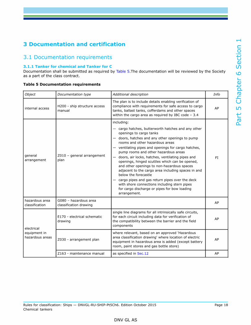
3.1 Documentation requirements3.1.1 Tanker for chemical and Tanker for CDocumentation shall be submitted as required by Table 5.The documentation will be reviewed by the Societyas a part of the class contract.
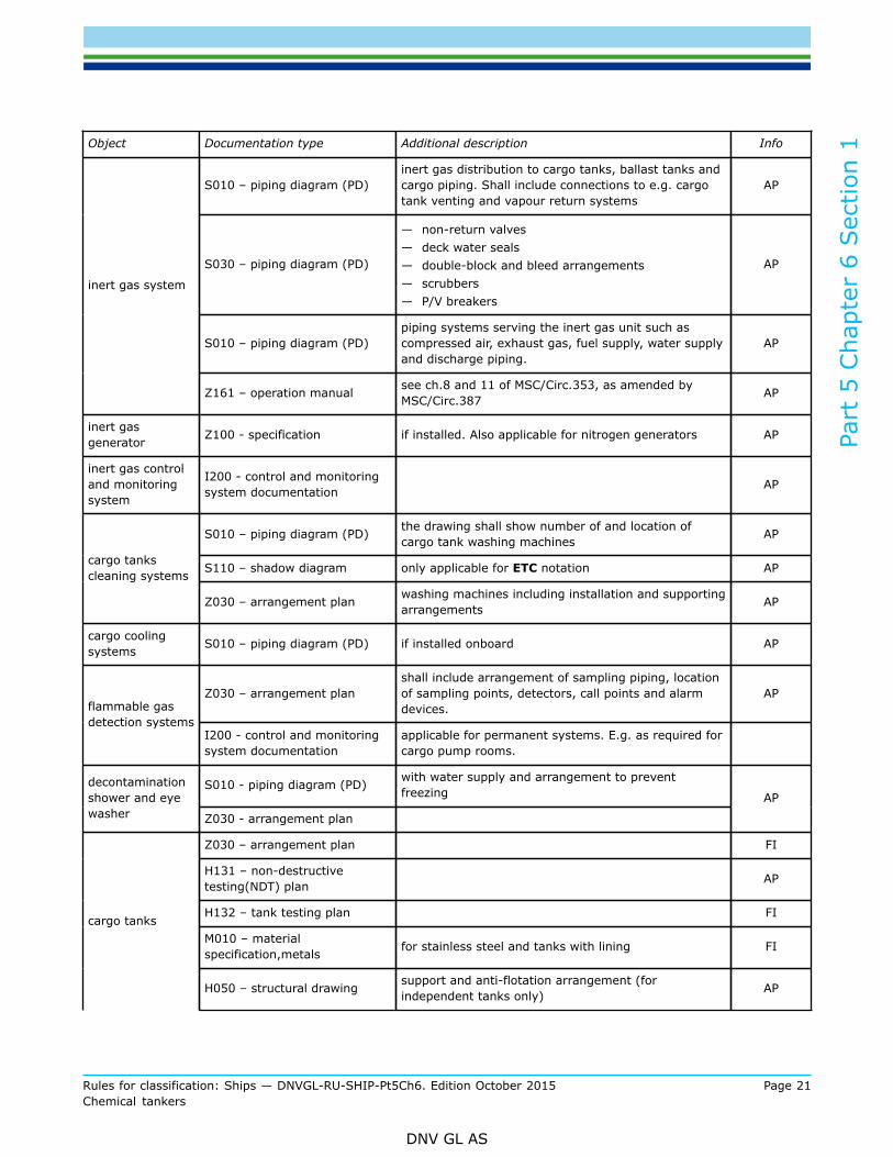
Table 5 Documentation requirements
Object Documentation type Additional description Info
internal access H200 - ship structure accessmanual
The plan is to include details enabling verification ofcompliance with requirements for safe access to cargotanks, ballast tanks, cofferdams and other spaceswithin the cargo area as required by IBC code – 3.4
AP
generalarrangement
Z010 – general arrangementplan
including:
— cargo hatches, butterworth hatches and any otheropenings to cargo tanks
— doors, hatches and any other openings to pumprooms and other hazardous areas
— ventilating pipes and openings for cargo hatches,pump rooms and other hazardous areas
— doors, air locks, hatches, ventilating pipes andopenings, hinged scuttles which can be opened,and other openings to non-hazardous spacesadjacent to the cargo area including spaces in andbelow the forecastle
— cargo pipes and gas return pipes over the deckwith shore connections including stern pipesfor cargo discharge or pipes for bow loadingarrangement.
FI
hazardous areaclassification
G080 – hazardous areaclassification drawing AP
E170 - electrical schematicdrawing
single line diagrams for all intrinsically safe circuits,for each circuit including data for verification ofthe compatibility between the barrier and the fieldcomponents
AP
Z030 - arrangement plan
where relevant, based on an approved 'Hazardousarea classification drawing' where location of electricequipment in hazardous area is added (except batteryroom, paint stores and gas bottle store)
AP
electricalequipment inhazardous areas
Z163 - maintenance manual as specified in Sec.12 AP
Part
5 C
hapt
er 6
Sec
tion
1
Rules for classification: Ships — DNVGL-RU-SHIP-Pt5Ch6. Edition October 2015 Page 19Chemical tankers
DNV GL AS
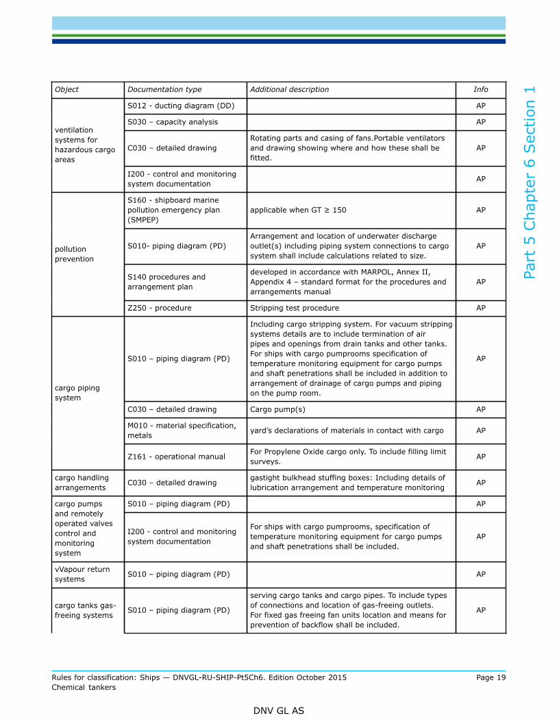
Object Documentation type Additional description Info
S012 - ducting diagram (DD) AP
S030 – capacity analysis AP
C030 – detailed drawingRotating parts and casing of fans.Portable ventilatorsand drawing showing where and how these shall befitted.
AP
ventilationsystems forhazardous cargoareas
I200 - control and monitoringsystem documentation AP
S160 - shipboard marinepollution emergency plan(SMPEP)
applicable when GT ≥ 150 AP
S010- piping diagram (PD)Arrangement and location of underwater dischargeoutlet(s) including piping system connections to cargosystem shall include calculations related to size.
AP
S140 procedures andarrangement plan
developed in accordance with MARPOL, Annex II,Appendix 4 – standard format for the procedures andarrangements manual
AP
pollutionprevention
Z250 - procedure Stripping test procedure AP
S010 – piping diagram (PD)
Including cargo stripping system. For vacuum strippingsystems details are to include termination of airpipes and openings from drain tanks and other tanks.For ships with cargo pumprooms specification oftemperature monitoring equipment for cargo pumpsand shaft penetrations shall be included in addition toarrangement of drainage of cargo pumps and pipingon the pump room.
AP
C030 – detailed drawing Cargo pump(s) AP
M010 - material specification,metals yard’s declarations of materials in contact with cargo AP
cargo pipingsystem
Z161 - operational manual For Propylene Oxide cargo only. To include filling limitsurveys. AP
cargo handlingarrangements C030 – detailed drawing gastight bulkhead stuffing boxes: Including details of
lubrication arrangement and temperature monitoring AP
S010 – piping diagram (PD) APcargo pumpsand remotelyoperated valvescontrol andmonitoringsystem
I200 - control and monitoringsystem documentation
For ships with cargo pumprooms, specification oftemperature monitoring equipment for cargo pumpsand shaft penetrations shall be included.
AP
vVapour returnsystems S010 – piping diagram (PD) AP
cargo tanks gas-freeing systems
S010 – piping diagram (PD)
serving cargo tanks and cargo pipes. To include typesof connections and location of gas-freeing outlets.For fixed gas freeing fan units location and means forprevention of backflow shall be included.
AP
Part
5 C
hapt
er 6
Sec
tion
1
Rules for classification: Ships — DNVGL-RU-SHIP-Pt5Ch6. Edition October 2015 Page 20Chemical tankers
DNV GL AS
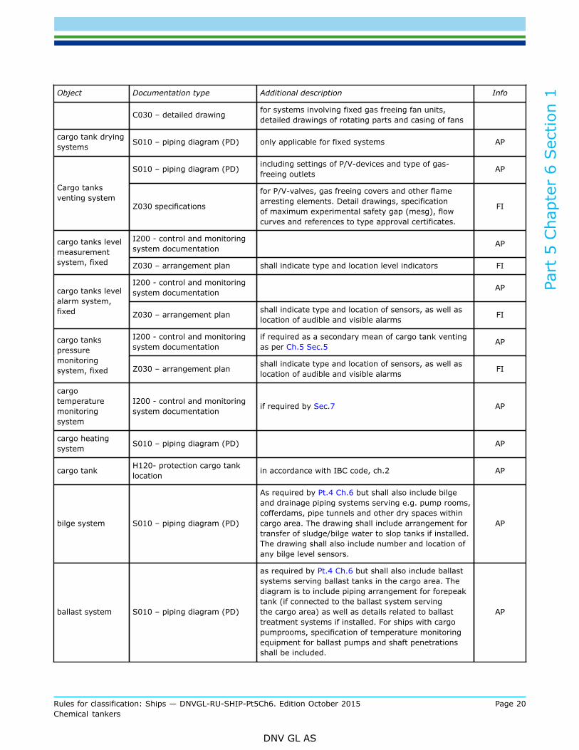
Object Documentation type Additional description Info
C030 – detailed drawing for systems involving fixed gas freeing fan units,detailed drawings of rotating parts and casing of fans
cargo tank dryingsystems S010 – piping diagram (PD) only applicable for fixed systems AP
S010 – piping diagram (PD) including settings of P/V-devices and type of gas-freeing outlets AP
Cargo tanksventing system
Z030 specifications
for P/V-valves, gas freeing covers and other flamearresting elements. Detail drawings, specificationof maximum experimental safety gap (mesg), flowcurves and references to type approval certificates.
FI
I200 - control and monitoringsystem documentation APcargo tanks level
measurementsystem, fixed Z030 – arrangement plan shall indicate type and location level indicators FI
I200 - control and monitoringsystem documentation APcargo tanks level
alarm system,fixed Z030 – arrangement plan shall indicate type and location of sensors, as well as
location of audible and visible alarms FI
I200 - control and monitoringsystem documentation
if required as a secondary mean of cargo tank ventingas per Ch.5 Sec.5 APcargo tanks
pressuremonitoringsystem, fixed Z030 – arrangement plan shall indicate type and location of sensors, as well as
location of audible and visible alarms FI
cargotemperaturemonitoringsystem
I200 - control and monitoringsystem documentation if required by Sec.7 AP
cargo heatingsystem S010 – piping diagram (PD) AP
cargo tank H120- protection cargo tanklocation in accordance with IBC code, ch.2 AP
bilge system S010 – piping diagram (PD)
As required by Pt.4 Ch.6 but shall also include bilgeand drainage piping systems serving e.g. pump rooms,cofferdams, pipe tunnels and other dry spaces withincargo area. The drawing shall include arrangement fortransfer of sludge/bilge water to slop tanks if installed.The drawing shall also include number and location ofany bilge level sensors.
AP
ballast system S010 – piping diagram (PD)
as required by Pt.4 Ch.6 but shall also include ballastsystems serving ballast tanks in the cargo area. Thediagram is to include piping arrangement for forepeaktank (if connected to the ballast system servingthe cargo area) as well as details related to ballasttreatment systems if installed. For ships with cargopumprooms, specification of temperature monitoringequipment for ballast pumps and shaft penetrationsshall be included.
AP
Part
5 C
hapt
er 6
Sec
tion
1
Rules for classification: Ships — DNVGL-RU-SHIP-Pt5Ch6. Edition October 2015 Page 21Chemical tankers
DNV GL AS
Object Documentation type Additional description Info
S010 – piping diagram (PD)inert gas distribution to cargo tanks, ballast tanks andcargo piping. Shall include connections to e.g. cargotank venting and vapour return systems
AP
S030 – piping diagram (PD)
— non-return valves— deck water seals— double-block and bleed arrangements— scrubbers— P/V breakers
AP
S010 – piping diagram (PD)piping systems serving the inert gas unit such ascompressed air, exhaust gas, fuel supply, water supplyand discharge piping.
AP
inert gas system
Z161 – operation manual see ch.8 and 11 of MSC/Circ.353, as amended byMSC/Circ.387 AP
inert gasgenerator Z100 - specification if installed. Also applicable for nitrogen generators AP
inert gas controland monitoringsystem
I200 - control and monitoringsystem documentation AP
S010 – piping diagram (PD) the drawing shall show number of and location ofcargo tank washing machines AP
S110 – shadow diagram only applicable for ETC notation APcargo tankscleaning systems
Z030 – arrangement plan washing machines including installation and supportingarrangements AP
cargo coolingsystems S010 – piping diagram (PD) if installed onboard AP
Z030 – arrangement planshall include arrangement of sampling piping, locationof sampling points, detectors, call points and alarmdevices.
APflammable gasdetection systems
I200 - control and monitoringsystem documentation
applicable for permanent systems. E.g. as required forcargo pump rooms.
S010 - piping diagram (PD) with water supply and arrangement to preventfreezing
decontaminationshower and eyewasher Z030 - arrangement plan
AP
Z030 – arrangement plan FI
H131 – non-destructivetesting(NDT) plan AP
H132 – tank testing plan FI
M010 – materialspecification,metals for stainless steel and tanks with lining FI
cargo tanks
H050 – structural drawing support and anti-flotation arrangement (forindependent tanks only) AP
Part
5 C
hapt
er 6
Sec
tion
1
Rules for classification: Ships — DNVGL-RU-SHIP-Pt5Ch6. Edition October 2015 Page 22Chemical tankers
DNV GL AS
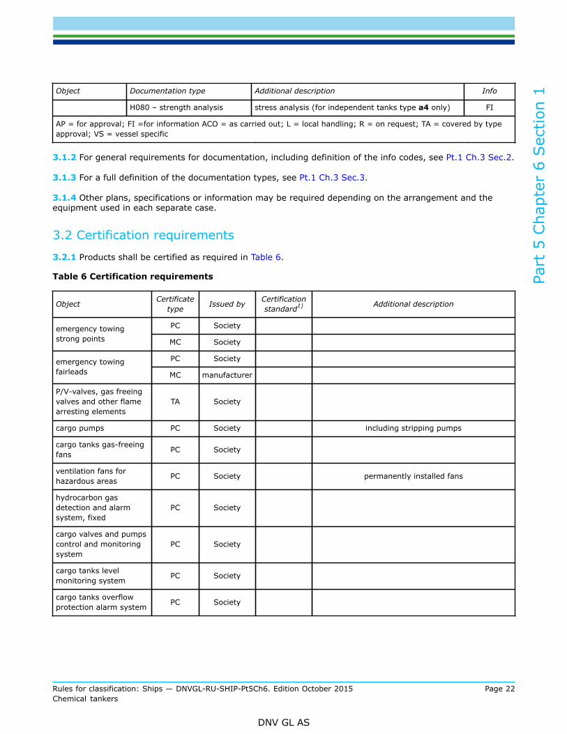
Object Documentation type Additional description Info
H080 – strength analysis stress analysis (for independent tanks type a4 only) FI
AP = for approval; FI =for information ACO = as carried out; L = local handling; R = on request; TA = covered by typeapproval; VS = vessel specific
3.1.2 For general requirements for documentation, including definition of the info codes, see Pt.1 Ch.3 Sec.2.
3.1.3 For a full definition of the documentation types, see Pt.1 Ch.3 Sec.3.
3.1.4 Other plans, specifications or information may be required depending on the arrangement and theequipment used in each separate case.
3.2 Certification requirements
3.2.1 Products shall be certified as required in Table 6.
Table 6 Certification requirements
Object Certificatetype Issued by Certification
standard1) Additional description
PC Societyemergency towingstrong points MC Society
PC Societyemergency towingfairleads MC manufacturer
P/V-valves, gas freeingvalves and other flamearresting elements
TA Society
cargo pumps PC Society including stripping pumps
cargo tanks gas-freeingfans PC Society
ventilation fans forhazardous areas PC Society permanently installed fans
hydrocarbon gasdetection and alarmsystem, fixed
PC Society
cargo valves and pumpscontrol and monitoringsystem
PC Society
cargo tanks levelmonitoring system PC Society
cargo tanks overflowprotection alarm system PC Society
Part
5 C
hapt
er 6
Sec
tion
1
Rules for classification: Ships — DNVGL-RU-SHIP-Pt5Ch6. Edition October 2015 Page 23Chemical tankers
DNV GL AS
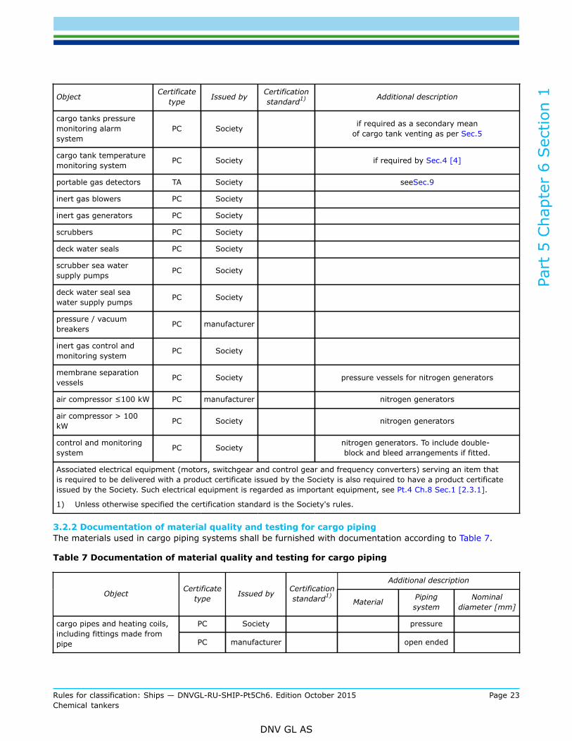
Object Certificatetype Issued by Certification
standard1) Additional description
cargo tanks pressuremonitoring alarmsystem
PC Society if required as a secondary meanof cargo tank venting as per Sec.5
cargo tank temperaturemonitoring system PC Society if required by Sec.4 [4]
portable gas detectors TA Society seeSec.9
inert gas blowers PC Society
inert gas generators PC Society
scrubbers PC Society
deck water seals PC Society
scrubber sea watersupply pumps PC Society
deck water seal seawater supply pumps PC Society
pressure / vacuumbreakers PC manufacturer
inert gas control andmonitoring system PC Society
membrane separationvessels PC Society pressure vessels for nitrogen generators
air compressor ≤100 kW PC manufacturer nitrogen generators
air compressor > 100kW PC Society nitrogen generators
control and monitoringsystem PC Society nitrogen generators. To include double-
block and bleed arrangements if fitted.
Associated electrical equipment (motors, switchgear and control gear and frequency converters) serving an item thatis required to be delivered with a product certificate issued by the Society is also required to have a product certificateissued by the Society. Such electrical equipment is regarded as important equipment, see Pt.4 Ch.8 Sec.1 [2.3.1].
1) Unless otherwise specified the certification standard is the Society's rules.
3.2.2 Documentation of material quality and testing for cargo pipingThe materials used in cargo piping systems shall be furnished with documentation according to Table 7.
Table 7 Documentation of material quality and testing for cargo piping
Additional description
Object Certificatetype Issued by Certification
standard1)Material Piping
systemNominal
diameter [mm]
PC Society pressurecargo pipes and heating coils,including fittings made frompipe PC manufacturer open ended
Part
5 C
hapt
er 6
Sec
tion
1
Rules for classification: Ships — DNVGL-RU-SHIP-Pt5Ch6. Edition October 2015 Page 24Chemical tankers
DNV GL AS
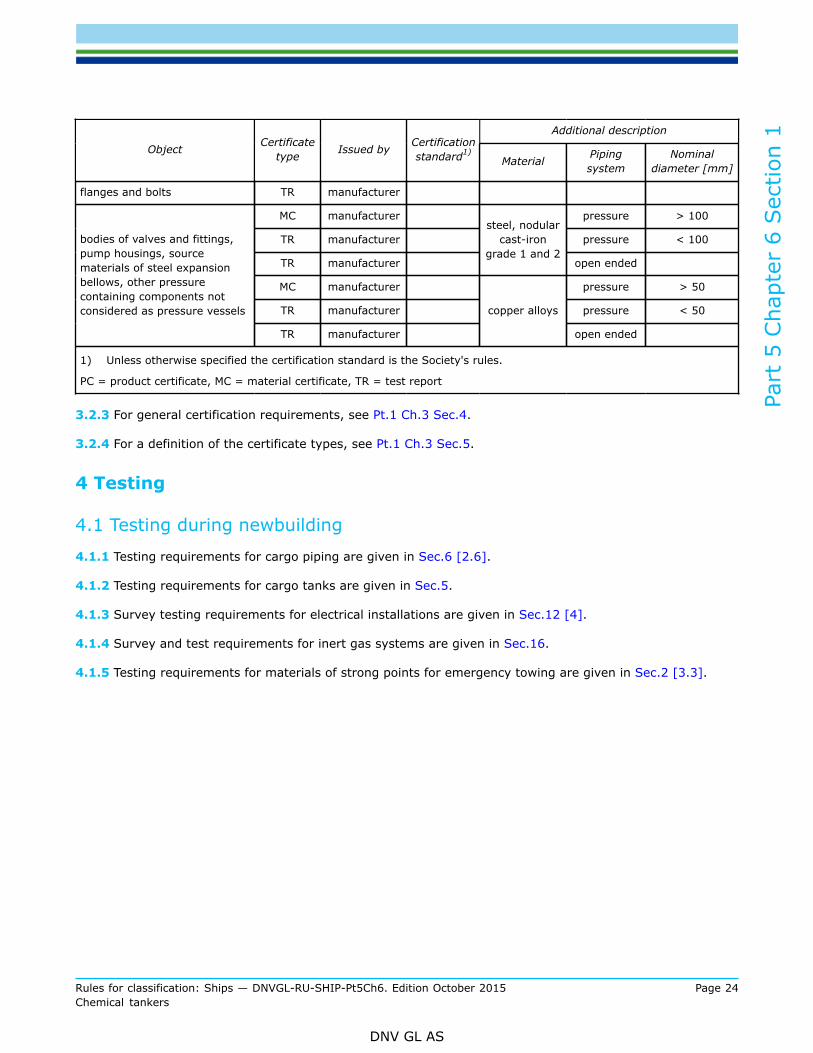
Additional description
Object Certificatetype Issued by Certification
standard1)Material Piping
systemNominal
diameter [mm]
flanges and bolts TR manufacturer
MC manufacturer pressure > 100
TR manufacturer pressure < 100
TR manufacturer
steel, nodularcast-iron
grade 1 and 2open ended
MC manufacturer pressure > 50
TR manufacturer pressure < 50
bodies of valves and fittings,pump housings, sourcematerials of steel expansionbellows, other pressurecontaining components notconsidered as pressure vessels
TR manufacturer
copper alloys
open ended
1) Unless otherwise specified the certification standard is the Society's rules.
PC = product certificate, MC = material certificate, TR = test report
3.2.3 For general certification requirements, see Pt.1 Ch.3 Sec.4.
3.2.4 For a definition of the certificate types, see Pt.1 Ch.3 Sec.5.
4 Testing
4.1 Testing during newbuilding
4.1.1 Testing requirements for cargo piping are given in Sec.6 [2.6].
4.1.2 Testing requirements for cargo tanks are given in Sec.5.
4.1.3 Survey testing requirements for electrical installations are given in Sec.12 [4].
4.1.4 Survey and test requirements for inert gas systems are given in Sec.16.
4.1.5 Testing requirements for materials of strong points for emergency towing are given in Sec.2 [3.3].
Part
5 C
hapt
er 6
Sec
tion
2
Rules for classification: Ships — DNVGL-RU-SHIP-Pt5Ch6. Edition October 2015 Page 25Chemical tankers
DNV GL AS
SECTION 2 HULL
1 GeneralRequirements for the strength of the hull structure and selection of hull materials shall follow the principlesgiven in Pt.3, supplemented by the requirements given in this section. For scantlings and testing of tanksother than integral tanks, see Ch.5 Sec.7.
2 Materials
2.1 Selection and testing
2.1.1 Where stainless steel in cargo tanks is required for the carriage of particular cargoes, the content ofmolybdenum in the material shall not be less than 2.5% if type VL 316 L or VL 316 LN is specified.
2.1.2 Clad steel will be accepted if the requirements of Pt.2 Ch.4 Sec.3 and Pt.2 Ch.4 Sec.4 are fulfilled.Acceptance of other linings necessary to protect the structural material will be specially considered.
2.1.3 Requirements for welding procedure tests and production weld tests are given in Sec.5 and Sec.6.
2.1.4 For certain cargoes as specified in Sec.15 and the IBC code chapter 15, special requirements formaterials apply.
2.2 Materials for cargo tanksMaterials for integral tanks and independent tanks type a3 may generally be selected in accordance withordinary practice as given in Pt.3 Ch.3 Sec.1 for hull materials. Materials for independent tanks type a4(pressure tanks) shall be pressure vessel steel in accordance with Pt.2 Ch.2 Sec.3.
2.3 Materials for cargo piping
2.3.1 Steel is the normal material of construction for cargo pipes. Other materials may be accepted fornonflammable chemicals. Grey cast-iron is not accepted as material of construction in cargo piping on shipswith class notation Tanker for chemicals.
2.3.2 Bodies of valves and fittings, and pump housings shall be of cast steel, nodular cast iron grade VLNCI-1 or VL NCI-2 or other approved material (see Pt.2 Ch.2 Sec.9).
2.3.3 Pipes shall be tested according to relevant parts of Pt.2 Ch.2 Sec.5.
2.3.4 Piping for liquid cargo and cargo vapour for tanks made of or protected by corrosion-resistant materialshall be made of or protected by a similar material.
Guidance note:For cargo piping made of stainless steel, the material should be in accordance with a recognised standard. It is however recommendedthat the cargo piping is specified with a minimum content of molybdenum of 2.5%.
---e-n-d---of---g-u-i-d-a-n-c-e---n-o-t-e---
2.3.5 Manifold valves and distance pieces or reducers outboard of valves, which are connected directly to thecargo pipeline’s shore connection on deck, shall be made of steel and of flanged type.
Part
5 C
hapt
er 6
Sec
tion
2
Rules for classification: Ships — DNVGL-RU-SHIP-Pt5Ch6. Edition October 2015 Page 26Chemical tankers
DNV GL AS
3 Strength
3.1 Independent tanks
3.1.1 Scantlings of independent tanks, constructed mainly of plane surfaces, shall be in accordance withrelevant requirements given in Pt.3.
3.1.2 Tanks of pressure vessel configuration type (cylinders, spheres etc.) shall be in accordance with therequirements given in Ch.7 Sec.20.
3.2 Emergency towingEmergency towing arrangements for chemical carriers of 20 000 dwt and above shall comply withrequirements in Ch.5 Sec.2 [2.3].
3.3 Vertically corrugated bulkhead without stoolReference is made to Ch.5 Sec.2 [2.1].
3.4 Small confined spaces within or adjacent to cargo tanks
3.4.1 Due to hazards related to reactivity of cargo, small confined spaces within or adjacent to cargo tanksare not acceptable. Railings, ladders and similar fittings within cargo tanks shall be of solid type, hollowprofiles will not be accepted.
3.4.2 A doubler plate within the cargo tank is in general not acceptable. If installed, this will be subject tocase by case approval.
4 Fatigue assessmentReference is made to Ch.5 Sec.2 [3].
5 Direct strength calculationsReference is made to Ch.5 Sec.2 [4].
Part
5 C
hapt
er 6
Sec
tion
3
Rules for classification: Ships — DNVGL-RU-SHIP-Pt5Ch6. Edition October 2015 Page 27Chemical tankers
DNV GL AS
SECTION 3 SHIP ARRANGEMENTS
1 Cargo tank location
1.1 General
1.1.1 Tanks intended for carriage of cargoes for which Ship type 1 is required shall be located at a minimumdistance from the ship's side shell plating of B/5 or 11.5 m, whichever is less, measured inboard from theship's side at right angle to the centre line at the level of the summer load line, and at a vertical distancefrom the moulded line of the bottom shell plating at centre line not less than B/15 or 6 m, whichever is lessbut not less than 760 mm from the shell plating.
1.1.2 Tanks intended for carriage of cargoes for which Ship type 2 is required shall be located at a verticaldistance from the moulded line of the bottom shell plating at centreline of B/15 or 6 m, whichever is less, butnot less than 760 mm from the shell plating.
1.1.3 For Ship type 3, there are no restrictions in respect of cargo tank location.
1.1.4 Except for Ship type 1, suction wells in cargo tanks may protrude into the double bottom below theboundary line defined by the distance given in [1.1.2] provided that such wells are as small as practicableand the protrusion below the inner bottom plating does not exceed 25% of the depth of the double bottom or350 mm, whichever is less.Where there is no double bottom, the protrusion of the suction well of independent tanks below the upperlimit of bottom damage shall not exceed 350 mm.
2 Location and separation of spaces
2.1 General
2.1.1 A cofferdam shall be provided at aft end of cargo area. For spaces which may be approved ascofferdams, see [5.1].
2.1.2 Fuel oil tanks shall not be situated within the cargo tank block and are not permitted to extend intoprotective area of cargo tanks required by [3]. Such tanks may, however, be situated at forward and aft endof cargo area instead of cofferdams.Ships which do not have bunker tanks arranged adjacent to cargo tanks, will get the letter k added to theseries of letters and numbers given in the “Register of vessels classed with the Society”.
2.1.3 Machinery spaces of category A and boiler spaces shall be positioned aft of the cargo area, but notnecessarily aft of fuel oil tanks.Where deemed necessary, machinery spaces other than those of category A may be permitted forward of thecargo area.Machinery spaces shall not be located fully nor partly within the cargo area including within e.g. pumproomsor other spaces approved as cofferdams, except as specified in [2.1.3].Machinery spaces other than those of category A that contain electrically driven equipment and systemsrequired for cargo handling may upon special considerations be accepted located within the cargo area. Areaclassification requirements apply. Examples of such systems are:
— hydraulic power units for cargo systems— nitrogen generators— dehumidification plants.
Part
5 C
hapt
er 6
Sec
tion
3
Rules for classification: Ships — DNVGL-RU-SHIP-Pt5Ch6. Edition October 2015 Page 28Chemical tankers
DNV GL AS
2.1.4 The lower portion of the cargo pump room may be recessed into machinery and boiler spaces toaccommodate pumps, provided the deck head of the recess is in general not more than one-third ofthe moulded depth above the keel. For ships of not more than 25 000 tons deadweight, where it can bedemonstrated that for reasons of access and satisfactory piping arrangements this is impracticable, a recessin excess of such height may be permitted, though not exceeding one half of the moulded depth above thekeel.
2.1.5 Accommodation spaces and service spaces shall be positioned outside the cargo area, but notnecessarily aft of fuel oil tanks.Accommodation spaces shall not be situated adjacent to fuel oil bunker tanks adjacent to cargo tanks.
2.1.6 Spaces mentioned in [2.1.3], except machinery spaces of category A, may be positioned forward of thecargo area after consideration in each case.
Guidance note:Machinery spaces other than those of category A may be accepted located in forecastle spaces above forepeak tanks even if saidforepeak tank is located adjacent to cargo tank. Bow thruster spaces cannot be located adjacent to cargo tanks (SOLAS Ch.II-2Reg.4.5.1.3)
---e-n-d---of---g-u-i-d-a-n-c-e---n-o-t-e---
2.1.7 Where the fitting of a navigation position above the cargo area is shown to be necessary, it shall be fornavigation purposes only, and it shall be separated from the cargo tank deck by means of an open space witha height of at least 2 m.
2.1.8 Deck spills shall be kept away from accommodation and service areas and from discharge into thesea by a permanent continuous coaming of minimum 100 mm high surrounding the cargo deck. In the aftcorners of the cargo deck the coaming must be at least 300 mm high and extend at least 4.5 m forward fromeach corner and inboard from side to side. Scupper plugs of mechanical type are required. Means of drainingor removing oil or oily water within the coamings shall be provided.
2.1.9 Where a corner-to-corner situation occurs between a non-hazardous space and a cargo tank, a smallenclosed space (cofferdam) created by a diagonal plate across the corner on the non-hazardous side, may beaccepted as separation.
2.1.10 Small enclosed spaces at the boundary of cargo tank shall be provided with means for checkingof possible leakage and inerting/gas-freeing, preferably from a space with equivalent hazardous areaclassification (other than cargo tanks) or open deck.
2.1.11 Paint lockers shall not be located within the cargo area.
3 Arrangement of entrances and other openings
3.1 Accommodation and non-hazardous spaces
3.1.1 Entrances, air inlets and openings to accommodation spaces, service spaces, control stations andmachinery spaces shall not face the cargo area. They shall be located on the end bulkhead and or on theoutboard side of the superstructure or deckhouse at a distance of at least L/25 but not less than 3 m fromthe end of the superstructure or deckhouse facing the cargo area. This distance, however, need not exceed 5m.Within the limits specified above, the following apply:
a) Bolted plates for removal of machinery may be fitted. Such plates shall be insulated to A-60 classstandard. Signboards giving instruction that the plates shall be kept closed unless the ship is gas-free,shall be posted on board.
Part
5 C
hapt
er 6
Sec
tion
3
Rules for classification: Ships — DNVGL-RU-SHIP-Pt5Ch6. Edition October 2015 Page 29Chemical tankers
DNV GL AS
b) Wheelhouse windows may be non-fixed and wheelhouse doors may be located within the limits as longas they are so designed that a rapid and efficient gas and vapour tightening of the wheelhouse can beensured.
c) Windows and sidescuttles shall be of the fixed (non-opening) type. Such windows and sidescuttles exceptwheelhouse windows, shall be constructed to A-60 class standard.
d) Sidescuttles according to c), in the first tier on the main deck shall be fitted with inside covers of steel orequivalent material.
3.1.2 Cargo control rooms, stores and other spaces not covered by [3.1.3] but located withinaccommodation, service and control stations spaces, may be permitted to have doors facing the cargo area.Where such doors are fitted, the spaces shall not have access to the spaces covered by [3.1.3] and theboundaries of the spaces shall be insulated to A-60 class.
3.1.3 For access and openings to non-hazardous spaces other than accommodation and service spaces, thefollowing provisions apply:
a) entrances shall not be arranged from hazardous spacesb) entrances from hazardous areas on the open deck shall normally not be arranged. If air locks are
arranged such entrances may, however, be approved. See [3.1.5] and [3.1.6].
3.1.4 Ventilation inlets for the spaces mentioned in [3.1.1] shall be located as far as practicable from gas-dangerous zones, and in no case are the ventilation inlets nor outlets to be located closer to the cargo areathan specified for openings in [3.1.1].
3.1.5 Entrance through air locks to non-hazardous spaces shall be arranged at a horizontal distance of atleast 3 m from any opening to a hazardous space containing gas sources, such as valves, hose connection orpumps used with the cargo.
3.1.6 Air locks shall comply with the following requirements:
— air locks shall be enclosed by gastight steel bulkheads with two substantially gas tight self-closing doorsspaced at least 1.5 m and not more than 2.5 m apart. The door sill height shall comply with requirementsgiven in Pt.3 Ch.3 Sec.7, but shall not be less than 300 mm.
— air locks shall have a simple geometrical form. They shall provide free and easy passage, and shall havea deck area not less than 1.5 m2. Air locks shall not be used for other purposes, for instance as storerooms.
— an alarm (acoustic and visual) shall be released on both sides of the air lock to indicate if more than onedoor has been moved from the closed position.
— for requirements for ventilation of air locks, see Sec.10.
3.2 Hazardous spaces and cargo tanks
3.2.1 Pump room entrances shall be from open deck.
3.2.2 Doors to hazardous spaces, situated completely upon the open deck, shall have as low a sill height aspossible.
3.2.3 For cargo tanks, no hatches, openings for ventilation, ullage plugs or inspection openings shall bearranged in enclosed compartments.
Part
5 C
hapt
er 6
Sec
tion
3
Rules for classification: Ships — DNVGL-RU-SHIP-Pt5Ch6. Edition October 2015 Page 30Chemical tankers
DNV GL AS
3.3 Access to and within cargo tanks, void spaces and other spaces in thecargo area
3.3.1 Arrangements for void spaces, cargo tanks and other spaces in the cargo area shall be such as toensure adequate access for complete inspection.
3.3.2 Access to cofferdams, ballast tanks, cargo tanks and other spaces in the cargo area shall be directlyfrom the open deck. Access to double bottom spaces may be through a cargo pump room, pump room, deepcofferdam, pipe tunnel or similar compartments, subject to consideration of ventilation aspects.
3.3.3 For access through horizontal openings, hatches or manholes, the dimensions shall be sufficient toallow a person wearing a breathing apparatus to ascend or descend without obstruction and also to provide aclear opening to facilitate the hoisting of an injured person from the bottom of the space. The minimum clearopening shall be not less than 600 mm X 600 mm.
3.3.4 For access through vertical openings, or manholes providing passage through the length and breadthof the space, the minimum clear opening shall be not less than 600 mm X 800 mm at a height of not morethan 600 mm from the bottom shell plating unless gratings or other footholds are provided.
3.3.5 Smaller dimensions than specified in [3.3.3] and [3.3.4] may be approved in special circumstances.
4 Protection of crew
4.1 Arrangement
4.1.1 Guard rails, bulwarks and arrangements for safe access to the bow shall be arranged in accordancewith Pt.3 Ch.11 Sec.3 [3]. On tank deck open guard rails are normally to be fitted. Plate bulwarks, with a 230mm high continuous opening at lower edge, may be accepted upon consideration of the deck arrangementand probable gas accumulation.Permanently constructed gangways for safe access to the bow should be of substantial strength and beconstructed of fire resistant and non-slip material.
4.1.2 Systems with a surface temperature above 60°C shall be provided with insulation or mechanicalshielding if they are so located that crew may come in contact with them during normal operation or access.
5 Cargo pump rooms, cofferdams and pipe tunnels
5.1 General
5.1.1 When the ship is certified for carriage of corrosive cargoes, the pump room tank top arrangementsshall be installed to deal with possible leakage from cargo pumps and valves in the pump room.
5.1.2 Floors or decks under pumps and pipe connections for acid shall have a lining or coating of corrosion-resistant material extending up to a minimum height of 500 mm on the bounding bulkheads or coamings.Hatches or other openings in such floors or decks shall be raised to a minimum height of 500 mm.
5.1.3 Cofferdams shall be of sufficient size for easy access to all parts. Minimum requirements for distancebetween bulkheads shall be in accordance with [3.3], however not less than 600 mm.
5.1.4 Pump rooms and ballast tanks are accepted as cofferdams. See also [3.1.2].
Part
5 C
hapt
er 6
Sec
tion
3
Rules for classification: Ships — DNVGL-RU-SHIP-Pt5Ch6. Edition October 2015 Page 31Chemical tankers
DNV GL AS
5.1.5 Spaces surrounding independent tanks, are normally accepted as cofferdams.
5.1.6 Pipe tunnels shall have ample space for inspection of the pipes, and the pipes shall be situated as highas possible above the ship's bottom.
5.1.7 On ships with integral tanks, no connection between a pipe tunnel and the engine room, either bypipes or manholes, will be accepted.
6 Diesel engines driving emergency fire pumps, etc.
6.1 General
6.1.1 Diesel engines driving emergency fire pumps etc. shall be installed in a non-hazardous area.
6.1.2 The exhaust pipe of the diesel engine shall have an effective spark arrester and shall be led out to theatmosphere at a safe distance from hazardous areas.
7 Chain locker and windlassThe chain locker shall be arranged as a non-hazardous space. Windlass and chain pipes shall be situated in anon-hazardous area.
8 Anodes, washing machines and other fittings in tanks andcofferdamsAnodes, washing machines and other permanently attached equipment units in tanks and cofferdams shallbe securely fastened to the structure. The units and their supports shall be able to withstand sloshing in thetanks and vibratory loads as well as other loads which may be imposed in service.
Guidance note:When selecting construction materials in permanently attached equipment units in tanks and cofferdams, due consideration oughtto be given to the contact spark-producing properties.
---e-n-d---of---g-u-i-d-a-n-c-e---n-o-t-e---
9 Slop tanks
9.1 Arrangement9.1.1 One or more slop tanks for storage of contaminated bilge water from cargo area and tank washings shall beprovided.
9.1.2 Means shall be provided to transfer contaminated water to on-shore slop tanks.
9.1.3 Cargo tanks may be accepted as slop tanks.
Guidance note:For ships also carrying oil as cargo, a dedicated tank must be designated in accordance with Reg. 29 of MARPOL Annex I.
---e-n-d---of---g-u-i-d-a-n-c-e---n-o-t-e---
Part
5 C
hapt
er 6
Sec
tion
3
Rules for classification: Ships — DNVGL-RU-SHIP-Pt5Ch6. Edition October 2015 Page 32Chemical tankers
DNV GL AS
10 Stowage of cargo samples
10.1 GeneralSamples, which have to be kept on board, should be stowed in a designated space situated in the cargo areaor, exceptionally, elsewhere subject to special approval.
10.2 Arrangement
10.2.1 The stowage space shall be:
a) cell-divided in order to avoid shifting of the bottles at seab) made of material fully resistant to the different liquids intended to be stowed
Guidance note:This may be achieved by placing the bottles in leak tight boxes of resistant material, or arranging a spill containment tray ofresistant material in the bottom of the locker.
---e-n-d---of---g-u-i-d-a-n-c-e---n-o-t-e---
c) equipped with adequate ventilation arrangements.
10.2.2 Samples, which react with each other dangerously, shall not be stowed close to each other.
10.2.3 Samples shall not be retained on board longer than necessary.
11 SignboardsSignboards are required by the rules in:
— [5.1.1] regarding plates bolted to boundaries facing the cargo area and which can be opened for removalof machinery. These shall be fitted with signboard giving instructions that the plates shall be kept closedunless ship is gas-free.
— Sec.8 [1.3] regarding marking plates for independent tanks.— Sec.10 [2.3.2] regarding pumps and compressors which shall not be started before the ventilation system
in the electric motor room has been in operation for 15 minutes.— Sec.12 [6.1.1] regarding opening of a lighting fitting. Before opening, its supply circuit shall be
disconnected.— Sec.12 [6.1.2] regarding ventilation to be in operation before lighting is turned on.— Sec.12 [6.1.3] regarding portable electrical equipment supplied by flexible cables. This equipment shall
not be used in areas where there is gas danger.— Sec.12 [6.1.4] regarding welding apparatus. These shall not be used unless the working space and
adjacent spaces are gas-free.
Part
5 C
hapt
er 6
Sec
tion
4
Rules for classification: Ships — DNVGL-RU-SHIP-Pt5Ch6. Edition October 2015 Page 33Chemical tankers
DNV GL AS
SECTION 4 ARRANGEMENT IN HOLD SPACES
1 General
1.1 Distance between tanks and hull
1.1.1 The distance between independent tanks and the distance between such tanks and parts of the hullshall be sufficient to give reasonable space for inspection and maintenance.
Guidance note:The free distance between independent tanks and the inner edge of ordinary frames should not be less than 500 mm. The free spacebetween tanks and web frames should be not less than 50 mm.The free distance between independent tanks and the inner bottom should generally be not less than 400 mm.
---e-n-d---of---g-u-i-d-a-n-c-e---n-o-t-e---
1.1.2 The distance between the ship's shell and an independent tank shall not be less than 760 mm.
1.1.3 The vertical distance between independent tanks and the outer bottom shall not be less than B/15.Drainage sumps will be considered in each case.
2 Gas pressure relief devices
2.1 Pressure/vacuum relief valves
2.1.1 If spaces for independent tanks can be completely closed, these spaces shall be equipped withpressure and vacuum relief valves. The number and size of these valves shall be decided depending on sizeand shape of the spaces.
2.1.2 The valves are normally to open at a pressure of 0.15 bar above and below atmospheric pressure.
3 Sealing around tanksEfficient sealing shall be provided where independent tanks extend above the upper deck. The sealingmaterial shall be such that it will not deteriorate, even with considerable movement between the tanks andthe deck.The sealing shall be able to withstand all temperatures and environmental hazards which may be expected.
4 Earth connectionsAt least two effective earth connections between each tank and the hull shall be arranged.
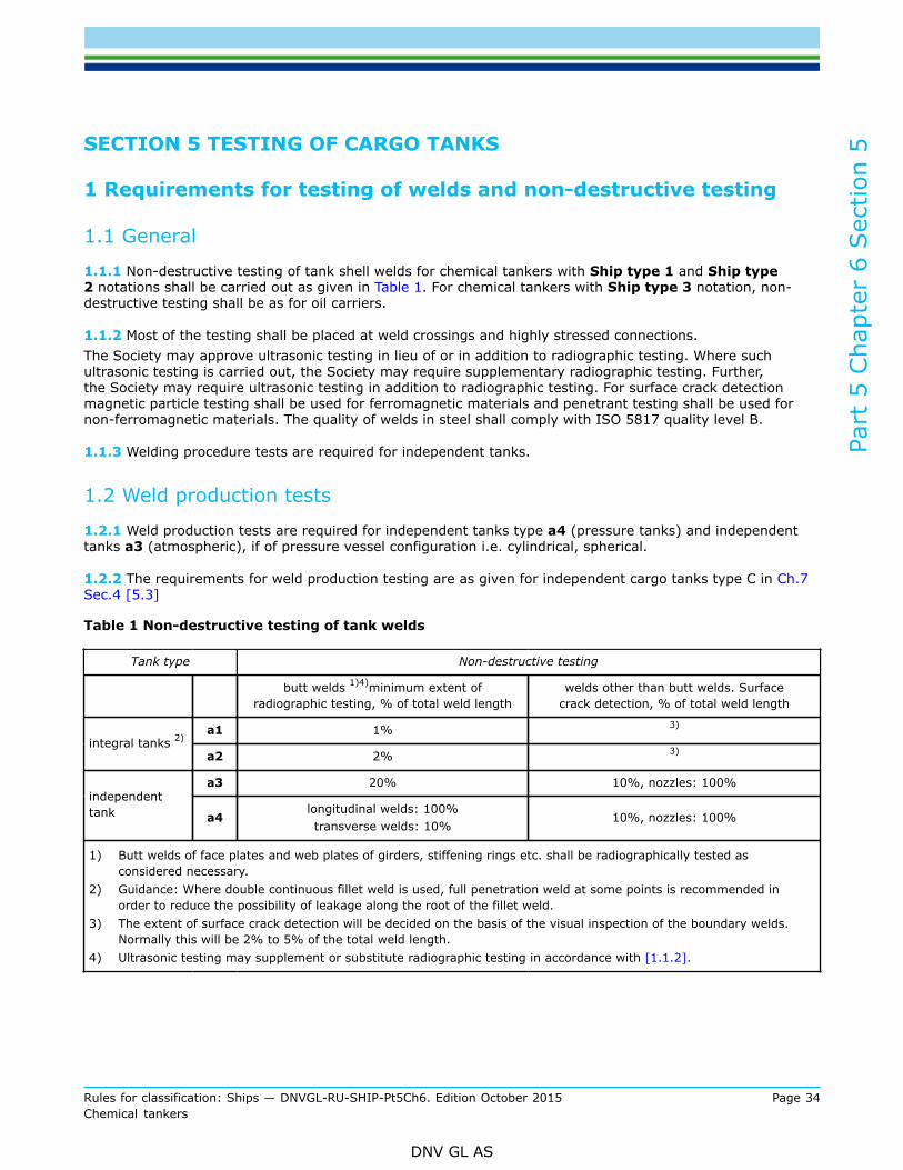
Part
5 C
hapt
er 6
Sec
tion
5
Rules for classification: Ships — DNVGL-RU-SHIP-Pt5Ch6. Edition October 2015 Page 34Chemical tankers
DNV GL AS
SECTION 5 TESTING OF CARGO TANKS
1 Requirements for testing of welds and non-destructive testing
1.1 General
1.1.1 Non-destructive testing of tank shell welds for chemical tankers with Ship type 1 and Ship type2 notations shall be carried out as given in Table 1. For chemical tankers with Ship type 3 notation, non-destructive testing shall be as for oil carriers.
1.1.2 Most of the testing shall be placed at weld crossings and highly stressed connections.The Society may approve ultrasonic testing in lieu of or in addition to radiographic testing. Where suchultrasonic testing is carried out, the Society may require supplementary radiographic testing. Further,the Society may require ultrasonic testing in addition to radiographic testing. For surface crack detectionmagnetic particle testing shall be used for ferromagnetic materials and penetrant testing shall be used fornon-ferromagnetic materials. The quality of welds in steel shall comply with ISO 5817 quality level B.
1.1.3 Welding procedure tests are required for independent tanks.
1.2 Weld production tests
1.2.1 Weld production tests are required for independent tanks type a4 (pressure tanks) and independenttanks a3 (atmospheric), if of pressure vessel configuration i.e. cylindrical, spherical.
1.2.2 The requirements for weld production testing are as given for independent cargo tanks type C in Ch.7Sec.4 [5.3]
Table 1 Non-destructive testing of tank welds
Tank type Non-destructive testing
butt welds 1)4)minimum extent ofradiographic testing, % of total weld length
welds other than butt welds. Surfacecrack detection, % of total weld length
a1 1% 3)
integral tanks 2)
a2 2% 3)
a3 20% 10%, nozzles: 100%independenttank a4
longitudinal welds: 100%transverse welds: 10%
10%, nozzles: 100%
1) Butt welds of face plates and web plates of girders, stiffening rings etc. shall be radiographically tested asconsidered necessary.
2) Guidance: Where double continuous fillet weld is used, full penetration weld at some points is recommended inorder to reduce the possibility of leakage along the root of the fillet weld.
3) The extent of surface crack detection will be decided on the basis of the visual inspection of the boundary welds.Normally this will be 2% to 5% of the total weld length.
4) Ultrasonic testing may supplement or substitute radiographic testing in accordance with [1.1.2].
Part
5 C
hapt
er 6
Sec
tion
6
Rules for classification: Ships — DNVGL-RU-SHIP-Pt5Ch6. Edition October 2015 Page 35Chemical tankers
DNV GL AS
SECTION 6 PIPING SYSTEMS IN THE CARGO AREA
1 Piping systems not used for cargo
1.1 General
1.1.1 There shall be no connection between the piping systems serving the cargo area and the systems inthe remainder of the ship except as specially permitted by this section.
Guidance note:Piping systems for e.g. hydraulic oil, bunker lines, compressed air, steam and condensate, fire and foam located in the cargo areaare generally permitted connected to systems in the remainder of the ship, provided they are not permanently connected to cargohandling systems or have open ends in the cargo tanks.
---e-n-d---of---g-u-i-d-a-n-c-e---n-o-t-e---
1.1.2 Piping systems such as compressed air and hydraulic oil which serve systems within tanks or spacesthat are not used for cargo shall not be led through cargo tanks.
1.1.3 Piping systems such as hydraulic oil serving systems within cargo tanks, shall be led to tanks fromdeck level and not penetrate boundaries between cargo tanks and tanks and compartments that do notcontain cargo.
1.1.4 In general all piping led from machinery spaces into the cargo area shall be provided with means topreserve the integrity of the machinery space bulkhead.
1.1.5 The temperature in heating systems in the cargo area shall not exceed the temperature determinedby the required temperature class of the equipment as specified for the cargoes to be carried or 220°C,whichever is less.
1.1.6 Hazardous spaces (including any compartment or tank, cofferdams or void) within the cargo area shallonly be drained by bilge pumps or ejectors located within the space itself or within a space with an equivalenthazard.
1.1.7 Pipe tunnels shall be drained from the cargo pump room or an equivalent hazardous space.
1.1.8 Ballast piping and other piping such as sounding and vent piping to ballast tanks shall not pass throughcargo tanks.
1.1.9 Filling of tanks within cargo area shall be carried out from the cargo pump room or a similar hazardousspace.
1.2 Cargo pump rooms
1.2.1 Two possibilities for drainage shall be provided, one of which shall be operable from open deck. Oneejector with two sources of supply will be accepted.
1.2.2 Bilge pump or ejector independent of the cargo pumps shall be fitted for drainage of the cargo pumprooms.
1.2.3 The bilge pipes in a cargo pump room shall not be led into the engine room.
Part
5 C
hapt
er 6
Sec
tion
6
Rules for classification: Ships — DNVGL-RU-SHIP-Pt5Ch6. Edition October 2015 Page 36Chemical tankers
DNV GL AS
1.3 Cofferdams and pipe tunnels
1.3.1 Cofferdams and pipe tunnels shall be provided with sounding pipes and with air pipes led to theatmosphere.For ships carrying flammable cargoes, the air pipes shall be fitted with flame screens at their outlets.
1.3.2 Cofferdams, pipe tunnels, voids and other dry compartments below main deck and within the cargoarea shall be provided with permanent means for bilge drainage.
Guidance note:For voids, located at main deck level with direct access from open deck (e.g. transverse upper stool spaces), portable drainingarrangements may be accepted. Arrangements where the use of the portable drainage equipment requires entry into the void willnot be accepted.
---e-n-d---of---g-u-i-d-a-n-c-e---n-o-t-e---
1.4 Spaces for independent tanks
1.4.1 Spaces for independent tanks shall be connected to a bilge system.
1.4.2 The capacity is normally to be such that the requirements given in Pt.4 Ch.6 Sec.4 are complied with.However, these requirements may be reduced by 50%, when the volume of the tanks is more than 75% ofthe total volume of the space.
1.4.3 Cargo pumps may be accepted for bilge system purposes to spaces for independent tanks when thepumps are so arranged that they effectively can be used for this purpose. The necessary pipe connectionbetween cargo pumps and the space around the tanks shall not penetrate any part of tank walls situatedin closed spaces or lower than the liquid level to maximum filling of the tank. Pipe connections shall be soarranged that cargo cannot be pumped into the spaces due to incorrect operation of valves etc.
1.5 Ballast systems
1.5.1 Filling or discharge of tanks within the cargo area with ballast shall be carried out from the cargo pumproom, a similar hazardous space or from inside ballast tanks, except as permitted by [1.5.2].
1.5.2 Pumps, ballast lines, vent lines and other similar equipment serving permanent ballast tanks shallbe independent of similar equipment serving cargo tanks and from cargo tanks themselves. Dischargearrangements for permanent ballast tanks sited immediately adjacent to cargo tanks should be outsideengine room and accommodation spaces. Filling arrangements may be in the engine room provided that sucharrangements ensure filling from tank deck level and non-return valves are fitted.
1.5.3 Filling of ballast in cargo tanks may be arranged from deck level by pumps serving permanent ballasttanks, provided that the filling line has no permanent connection to cargo tanks or piping and that non-returnvalves are fitted.
1.5.4 Filling lines to permanent ballast tanks shall be so arranged that the formation of static electricity isreduced, e.g. by reducing the free fall into the tank to a minimum.
1.5.5 Suction for seawater to permanent ballast tanks shall not be arranged in the same sea chest as usedfor discharge of ballast water from cargo tanks, see also [2.3.5].
Guidance note:Seawater suction should be arranged at the opposite side from the discharge of ballast water from cargo tanks.
---e-n-d---of---g-u-i-d-a-n-c-e---n-o-t-e---
Part
5 C
hapt
er 6
Sec
tion
6
Rules for classification: Ships — DNVGL-RU-SHIP-Pt5Ch6. Edition October 2015 Page 37Chemical tankers
DNV GL AS
1.5.6 Lines from the engine room to ballast tanks forward of the cargo area shall be carried outside cargotanks.
1.5.7 For requirements for drainage of ballast tanks, see Pt.4 Ch.6 Sec.4 [9].
1.5.8 Ballast water treatment systems are to comply with safety requirements of Pt.6 Ch.7 Sec.1.
1.6 Forepeak ballast tankThe forepeak may be ballasted with the system serving ballast tanks within the cargo area, provided:
a) The forepeak tank is considered as hazardous.b) The air pipes shall be located on open deck. The hazardous zone classification in way of the air pipe shall
be in accordance with Sec.12c) Means are provided, on the open deck, to allow measurement of flammable gas concentrations within
the tank by a suitable portable instrument.d) The access to the forepeak and the sounding arrangements are directly from open deck. In case the
forepeak tank is separated by cofferdams from the cargo tanks, an access through a gas tight boltedmanhole located in an enclosed space may be accepted. In that case, a warning sign shall be providedat the manhole stating that the tank may only be opened after it has been proven to be gas free or theelectrical equipment which is not certified safe in the enclosed space, is isolated.
1.7 Fuel oil tanksFuel oil bunker tanks situated at forward or aft end of the cargo area may be connected directly to pumps inthe engine room. The pipes shall not pass through cargo tanks.
2 Cargo piping system
2.1 General
2.1.1 The complete system of piping and pumps shall be provided for the cargo tanks and positioned withinthe cargo area, except for bow and stern loading systems complying with [5].This system shall be entirely separate from all other piping systems on board.Steam and water systems shall be connected to the cargo piping only by non-permanent means, and befitted with a non-return valve in the cargo area upstream of the first outlet branch.See Sec.9 regarding pipes for ventilation or inerting purposes.
2.1.2 The cargo piping system shall be dimensioned according to Pt.4 Ch.6 Sec.8. The design pressure p isthe maximum working pressure to which the system may be subjected. Due consideration shall be given topossible liquid hammering in connection with the closing of valves.The design pressure for cargo piping is as a minimum to be taken as 10 bar.For ships designed for the carriage of high density cargo, including partially loaded tanks, the design pressureshall take into account the density of such cargo.
Guidance note:Maximum pressure will occur with the cargo pump running at full speed against closed manifold valve.As an alternative to increased design pressure when carrying high density cargo, a pressure monitoring system which automaticallyprevents the design pressure from being exceeded may be accepted. The system shall activate an alarm at the cargo control station.The system shall not impair the operation of ballast and bilge pumps connected to the cargo pump power supply system.
---e-n-d---of---g-u-i-d-a-n-c-e---n-o-t-e---
Part
5 C
hapt
er 6
Sec
tion
6
Rules for classification: Ships — DNVGL-RU-SHIP-Pt5Ch6. Edition October 2015 Page 38Chemical tankers
DNV GL AS
2.1.3 The cargo piping shall be joined by butt welding with a minimum of flange connections. Where flangesare used they shall comply with the following:
— Flange types A and B will be accepted in piping systems with design pressure p > 16 bar. See Pt.4 Ch.6Sec.9 Figure 5.
— Flange types A, B and C will be accepted in piping systems with design pressure p ≤ 16 bar.— Flange connections in piping systems constructed of materials other than mild steel, will be especially
considered.
2.1.4 All cargo piping shall be electrically bonded to the ship's hull. The resistance to earth from any point inthe piping system shall not exceed 106 Ohm.Fix points may be considered as an effective bonding.Piping sections not permanently connected to the hull, shall be electrically bonded to the hull by bondingstraps.
2.1.5 Regarding manifold valves, distance pieces and reducers, see Sec. 2 [4.1.5]
2.2 Cargo pumps
2.2.1 At least two independently driven cargo pumps shall be connected to the system.
2.2.2 In tankers where cargo tanks are equipped with independent pumps (e.g. deep well pumps), theinstallation of one pump per tank may be approved. Satisfactory facilities shall be provided for emptying thetanks in case of failure of the regular pump.
2.2.3 Hydraulically powered pumps, submerged in cargo tanks (e.g. deep well pumps), shall be arrangedwith double barriers, preventing the hydraulic system serving the pumps from being directly exposed to thecargo. The double barrier shall be arranged for detection and drainage of possible cargo leakage.
2.2.4 Cargo pumps shall be certified as required by Pt.4 Ch.6 Sec.1 Table 5. For electrically driven pumps,associated electric motors and motor starters shall be certified as required by Pt.4 Ch.8 Sec.1 Table 3. Forsteam driven pumps, steam turbines shall be certified in accordance with Pt.4 Ch.6. For hydraulically drivenpumps, hydraulic pumps shall be certified in accordance with Pt.4 Ch.6.
2.2.5 Where machinery in the cargo pump room or other hazardous spaces are driven by shafting passinginto the pump room through bulkheads or deck plating, gastight glands shall be fitted. The glands shall beefficiently lubricated and shall be constructed so as to reduce the risk of overheating. The glands shall bevisible and easily accessible.Parts which may accidentally come into contact if the seal is badly aligned or if a bearing is damaged, shallbe of such material that no spark will occur. If an expansion below is fitted, it shall be hydraulically pressuretested.
2.2.6 Displacement pumps shall have relief valves with discharge to the suction line.
2.2.7 Means shall be provided for stopping the pumps from an easily accessible position outside the pumproom.
2.3 Arrangement and general design
2.3.1 The complete cargo piping system shall be located within the cargo area. Bow or stern loading anddischarge arrangements may be accepted by the Society after special consideration. See requirements inSec.5.
Part
5 C
hapt
er 6
Sec
tion
6
Rules for classification: Ships — DNVGL-RU-SHIP-Pt5Ch6. Edition October 2015 Page 39Chemical tankers
DNV GL AS
2.3.2 Valves or branch pieces, which connect the cargo pipeline's shore connection on deck, and cargo pipingshall be supported with due regard to load stresses.
2.3.3 Expansion elements shall be provided in the cargo piping as necessary. The elements shall not be ofthe sliding type.
2.3.4 Filling lines to cargo tanks shall be so arranged that the formation of static electricity is reduced, e.g.by reducing the free fall into the tank to a minimum.
2.3.5 The discharge of ballast water from cargo tanks shall be arranged in such a way as to prevent theballast water from being drawn into sea suctions for other pipe systems, e.g. cooling water systems formachinery.
2.3.6 Cargo piping systems shall not be installed under deck between the outboard side of the cargocontainment spaces and the skin of the ship, unless clearances required in Sec.1 [2.6] are maintained. Thisrequirement does not apply when damage to the pipe would not cause release of cargo.
2.3.7 Means for drainage of the cargo lines shall be provided.
2.3.8 Runs of cargo piping, located below the weather deck, may run from the tank they serve and penetratetank bulkheads or boundaries common to adjacent (longitudinally or transversely) cargo tanks, ballast tanksor empty tanks or pump rooms, provided that inside the tank they serve, the runs are fitted with a stop valveoperable from the weather deck.As an exception, where a cargo tank is adjacent to a pump room the stop valve operable from the weatherdeck may be situated on the tank bulkhead on the pump room side, provided an additional valve is fittedbetween the bulkhead valve and the cargo pump.Where penetrations occur in other dry compartments such as voids, cofferdams and pipe tunnels, a totallyenclosed hydraulically operated valve located outside the cargo tank may however be accepted providedthat:
— the valve is not located within the damage area as determined by damage stability requirements— the valve is specifically designed to prevent leakage in way of valves glands into the space where the
valve is located— the valve is fitted to the bulkhead to the cargo tank served— operable from a manned control station on or above weather deck— the space in which the valve is located is provided with means for detection of leakages— the space in question is arranged for containing leakages from the cargoes carried.
2.3.9 Runs of cargo piping installed in pipe tunnels shall comply with the requirements in [2.3.8] and[2.3.11]. The tunnel shall not have any other openings except to the weather deck and the pump room.
2.3.10 Runs of cargo piping through bulkheads shall not utilise flanges bolted through the bulkhead.
2.3.11 In any pump room where a pump serves more than one tank, a stop valve shall be fitted in the lineto each tank.
2.3.12 A stop valve shall be fitted at each cargo hose shore connection.
2.3.13 A stop valve capable of being manually operated, shall be fitted on each tank filling and dischargeline, located near the tank penetration. If individual deep-well pumps are installed, a stop valve at the tank isnot required on the discharge line.
2.3.14 Means for gas-freeing of the cargo lines shall be provided.
Part
5 C
hapt
er 6
Sec
tion
6
Rules for classification: Ships — DNVGL-RU-SHIP-Pt5Ch6. Edition October 2015 Page 40Chemical tankers
DNV GL AS
2.3.15 The controls necessary during transfer and or transport of cargoes other than in pump rooms whichhave been specially dealt with shall not be located below the weather deck.
2.3.16 In case of pressure type independent cargo tanks, all pipe connections shall be above the liquid level.
2.3.17 Drainage systems from cargo deck, drip trays etc. shall be arranged for transfer to cargo or sloptanks. Connections to cargo and slop tanks shall be arranged for separation by spool pieces or similar and areto be provided with means for prevention of backflow of vapour.
2.3.18 Ships that shall be certified for simultaneous carriage of cargoes, residues of cargoes or mixtureswhich react in a hazardous manner with other cargoes, residues or mixes onboard, shall have separate cargotank venting systems as well as separate cargo handling systems which shall not pass through other cargotanks containing such cargoes, residues or mixes. Means for separation shall be located outside cargo tanks,in open air and shall consist of spool pieces or similar.
Guidance note:For information regarding incompatibility of cargoes and mixes reference is made to USCG 46 CFR part 150.
---e-n-d---of---g-u-i-d-a-n-c-e---n-o-t-e---
2.4 Pressure indicationPump discharge pressure gauges shall be provided outside the pump room.
2.5 Welding procedure tests
2.5.1 Welding procedure tests are required for cargo piping of austenitic stainless steel.
2.5.2 The requirements are as given in Pt.2 Ch.4 Sec.5 except that Charpy tests are not required foraustenitic stainless steel.
2.5.3 Special welding procedure tests will not be required if previous welding procedure tests for similarmaterial, thicknesses and welding positions are satisfactorily documented.
Guidance note:In order to comply with requirements for passing radiographic testing of welding of butt joints on stainless steel pipes, it is stronglyrecommended that welding is carried out with argon-backing inside piping.
---e-n-d---of---g-u-i-d-a-n-c-e---n-o-t-e---
2.6 Testing
2.6.1 Cargo piping butt welds shall be subjected to radiographic testing covering at least 10% of the weldedconnections, when steel pipes are used. This percentage may be increased as found necessary by theSociety's surveyor. The quality of the welds in steel shall comply with ISO 5817 quality level B.
2.6.2 Cargo piping shall be hydrostatically tested in the presence of the Society's surveyor to a test pressure= 1.5 x the design pressure.If hydrostatic testing of separate lengths of piping, valves, expansion elements etc. has been carried out priorto the installation on board, a tightness test only is required after completion of the installation onboard.
2.6.3 Cargo pumps and associated pump risers shall be hydrostatically tested to 1.5 times the designpressure, with a minimum of 14 bar. For centrifugal pumps the maximum pressure shall be the maximumpressure head on the head-capacity curve. For displacement pumps the design pressure shall not be takenless than the relief valve opening pressure.
Part
5 C
hapt
er 6
Sec
tion
6
Rules for classification: Ships — DNVGL-RU-SHIP-Pt5Ch6. Edition October 2015 Page 41Chemical tankers
DNV GL AS
Hydrostatic testing of pump housings on submerged pumps will normally not be required.
2.6.4 Pump capacities shall be checked with the pump running at design condition (rated speed and pressurehead, viscosity, etc.). Capacity test may be dispensed with for pumps produced in series when previoussatisfactory tests have been carried out on similar pumps.
2.6.5 For centrifugal pumps having capacities less than 1 000 m3/h, the pump characteristic (head-capacitycurve) shall be determined for each type of pump. For centrifugal pumps having capacities equal to orgreater than 1 000 m3/h, the pump characteristic shall be determined over a suitable range on each side ofthe design point, for each pump.
2.6.6 Special survey arrangements for testing of pumps may be agreed upon.
3 Stripping of cargo tank and cargo lines
3.1 General
3.1.1 The pumping and piping arrangement shall ensure that the amount of residues in each cargo tank andits associated piping, is not in excess of 75 litres (cargo stripping performance str 0.075).
3.1.2 The verification of the above residue quantity shall be through actual testing with water and inaccordance with an approved test procedure.See MARPOL 73/78 Annex II, Appendix 5.
4 Discharge of contaminated water
4.1 Location of discharge outlet
4.1.1 For discharge of cargo contaminated water an outlet located below the waterline in vicinity of the turnof the bilge shall be arranged within the cargo area.
4.1.2 The outlet(s) shall be located such that the cargo contaminated discharges will not enter the ship'sseawater intakes.
4.2 Sizing of the discharge outletThe internal diameter of the outlet shall not be less than:
QD discharge rate (m3/h)L distance of outlet from forward perpendicular (m).
In the case of angled outlets only the velocity component of the discharge perpendicular to the ship's shellplating need to be considered when determining QD.
The discharge rate assumed as the basis for outlet(s) sizing shall not be taken less than the aggregatethroughput of the washing machines in anyone tank.
Part
5 C
hapt
er 6
Sec
tion
6
Rules for classification: Ships — DNVGL-RU-SHIP-Pt5Ch6. Edition October 2015 Page 42Chemical tankers
DNV GL AS
4.3 Cargo record book and SMPEP
4.3.1 All ships having a certificate of fitness (COF) for the carriage of liquid substances as listed in the IBCcode chapter 17 and 18, shall have on board a cargo record book according to MARPOL 73/78, Annex IIAppendix 2.
4.3.2 All ships having a certificate of fitness (COF) for the carriage of liquid substances as listed in theIBC code chapter 17 and 18, shall carry on board a shipboard marine pollution emergency Plan (SMPEP)according to MARPOL 73/78 Annex II, Reg. 17.
5 Stern loading and unloading arrangements
5.1 General
5.1.1 Subject to the approval of the Society, cargo piping may be fitted to permit stern loading andunloading. Portable arrangements will not be permitted.
5.1.2 Stern loading and unloading lines shall not be used for the transfer of products required to be carriedin Ship type 1 ships. Stern loading and unloading lines shall not be used for the transfer of cargoes emittingtoxic vapours required to comply with Sec.9 [2.4], unless specifically approved by the Society.
5.2 Piping arrangementIn addition to Pt.4 Ch.6 Sec.8, the following provisions apply:
a) The piping outside the cargo area shall be fitted at least 760 mm inboard on the open deck. Suchpiping shall be clearly identified and fitted with a shut-off valve at its connection to the cargo pipingsystem within the cargo area. At this location, it shall also be capable of being separated by means of aremovable spool piece and blank flanges when not in use.
b) The shore connection shall be fitted with a shut-off valve and a blank flange.c) The piping shall be full penetration butt welded, and fully radiographed. Flange connections in the piping
shall only be permitted within the cargo area and at the shore connection.d) Spray shields shall be provided at the connections specified in a) as well as collecting trays of sufficient
capacity with means for the disposal of drainage.e) The piping shall be self-draining to the cargo area and preferably into a cargo tank. Alternative
arrangements for draining the piping may be accepted by the Society.f) Arrangements shall be made to allow such piping to be purged after use and maintained gas-safe when
not in use. The vent pipes connected with the purge shall be located in the cargo area. The relevantconnections to the piping shall be provided with a shut-off valve and blank flange.
g) If the stern line is used for unloading the stripping requirements in [3.1] shall be complied with. Thestripping requirements shall be verified through a stripping test using the stern line.
5.3 Accommodation entrances
5.3.1 Entrances, air inlets and openings to accommodation, service and machinery spaces and controlstations shall not face the cargo shore connection location of stern loading and unloading arrangements. Theyshall be located on the outboard side of the superstructure or deckhouse at a distance of at least 4% of thelength of the ship but not less than 3 m from the end of the house facing the cargo shore connection locationof the stern loading and unloading arrangements. This distance, however, need not exceed 5 m. Sidescuttlesfacing the shore connection location and on the sides of the superstructure or deckhouse within the distancementioned above shall be of the fixed (non-opening) type. In addition, during the use of the stern loading
Part
5 C
hapt
er 6
Sec
tion
6
Rules for classification: Ships — DNVGL-RU-SHIP-Pt5Ch6. Edition October 2015 Page 43Chemical tankers
DNV GL AS
and unloading arrangements, all doors, ports and other openings on the corresponding superstructure ordeckhouse side shall be kept closed. Where, in the case of small ships, compliance with Ch.5 Sec.3 [3.1.1]and this paragraph is not possible, the Society may approve relaxations from the above requirements.
5.3.2 Air pipes and other openings to enclosed spaces not listed in [5.3.1] shall be shielded from any spraywhich may come from a burst hose or connection.
5.3.3 Escape routes shall not terminate within the coamings required by [5.3.4] or within a distance of 3 mbeyond the coamings.
5.3.4 Continuous coamings of suitable height shall be fitted to keep any spills on deck and away from theaccommodation and service areas.
5.4 Electrical equipment — fire fighting
5.4.1 Electrical equipment within the coamings required by [5.3.4] or within a distance of 3 m beyond thecoamings shall be in accordance with the requirements of Sec.12.
5.4.2 Means of communication between the cargo control station and the cargo shore connection locationshall be provided and certified safe, if necessary. Provision shall be made for the remote shutdown or cargopumps from the cargo shore connection location.
5.4.3 Ships fitted with stern loading and unloading arrangements shall be provided with one additionalfoam monitor meeting the requirements of Sec.11 [2.2.8] and one additional applicator meeting therequirements of Sec.11 [2.2.10]. The additional monitor shall be located to protect stern loading andunloading arrangements. The area of the cargo line aft of the cargo area shall be protected by the abovementioned applicator.
6 Cargo hoses
6.1 General
6.1.1 Liquid and vapour hoses used for cargo transfer shall be compatible with the cargo and suitable for thecargo temperature.
6.1.2 Hoses subject to tank pressure or the discharge pressure of pumps shall be designed for a burstingpressure not less than 5 times the maximum pressure the hose will be subjected to during cargo transfer.
6.1.3 Each type of cargo hose, complete with end-fittings, shall be prototype-tested at a normal ambienttemperature with 200 pressure cycles from zero to at least twice the specified maximum working pressure.After this cycle pressure test has been carried out, the prototype test shall demonstrate a bursting pressureof at least 5 times its specified maximum working pressure at the extreme service temperature. Hoses usedfor prototype testing shall not be used for cargo service. Thereafter, before being placed into service, eachnew length of cargo hose produced shall be hydrostatically tested at ambient temperature to a pressurenot less than 1.5 times its specified maximum working pressure but not more than two-fifths of its burstingpressure. The hose shall be stencilled or otherwise marked with the date of testing, its specified maximumworking pressure and, if used in services other than the ambient temperature services, its maximum andminimum service temperature as applicable. The specified maximum working pressure shall not be less than10 bar gauge.
Part
5 C
hapt
er 6
Sec
tion
7
Rules for classification: Ships — DNVGL-RU-SHIP-Pt5Ch6. Edition October 2015 Page 44Chemical tankers
DNV GL AS
SECTION 7 CARGO HEATING AND COOLING ARRANGEMENTS
1 Cargo heating
1.1 General
1.1.1 The requirements for thermal oil, hot water systems and steam systems given in Pt.4 Ch.6 apply, withadditional requirements given in this section.
1.1.2 The heating and cooling media shall be compatible with the cargo.
1.1.3 Heating or cooling systems shall be provided with valves to isolate the system for each tank and toallow manual regulation of flow.
1.1.4 For any heating or cooling system, means shall be provided to ensure that, when in any other butthe empty condition, a higher pressure is maintained within the system than the maximum pressure headexerted by the cargo tank content on the system.
1.1.5 Cargo heating and cooling pipes shall not penetrate the cargo tank boundaries other than on the top ofthe tank.
1.1.6 Means shall be provided for measuring the cargo temperature. When overheating or overcooling couldresult in a dangerous condition, temperature alarm shall be provided. The means for measuring the cargotemperature shall be of restricted or closed type, respectively, when a restricted or closed gauging device isrequired for individual substances as shown in the IBC code ch.17 column j.
Guidance note:
— A restricted temperature measuring device is subject to the definition for a restricted gauging device in Sec.13 [2.1.1], e.g. aportable thermometer lowered inside a gauge tube of the restricted type.
— a closed temperature measuring device is subject to the definition for a closed gauging device in Sec.13 [2.1.1], e.g. a remotethermometer of which the sensor is installed in the tank.
---e-n-d---of---g-u-i-d-a-n-c-e---n-o-t-e---
1.1.7 Where products with a significant toxic hazard (IBC code ch.17 column o refers to ch. 15.12, 15.12.1or 15.12.3) are being heated or cooled, the heating or cooling media shall operate:
— in a circuit independent of other ship's services, except for another cargo heating or cooling system, andnot enter the engine room, or
— in a circuit dependent of other services, if the condensate is not returned to the engine room, or— in a system external to the tanks, or— in a circuit where the medium is sampled to check for the presence of cargo before it is recirculated to
other ship's services or into the engine room. The sampling equipment shall be located within the cargoarea and be capable of detecting the presence of any toxic cargo being heated or cooled.
For thermal oil and hot water systems being re-circulated into the engine room, the system shall comply withthe following additional requirements:
— The system is so arranged that a positive pressure in the heating coil within a cargo tank shall be at least3 m water column above the static head of the cargo when circulating pump is not in operation. Thespecific gravity of cargo and the maximum P/V-valve setting shall be taken into account.
— Pressurized expansion tanks may be considered.— Expansion tanks shall be fitted with high and low level alarms.— Means shall be provided in expansion tanks for detection of flammable cargo vapours.
Part
5 C
hapt
er 6
Sec
tion
7
Rules for classification: Ships — DNVGL-RU-SHIP-Pt5Ch6. Edition October 2015 Page 45Chemical tankers
DNV GL AS
— Valves for the individual heating coils shall be provided with locking arrangement to ensure that the coilsare under static pressure at all times.Guidance note:The suitability of the sampling method must be documented for each product.
---e-n-d---of---g-u-i-d-a-n-c-e---n-o-t-e---
1.1.8 For thermal oil and hot water systems being re-circulated into the engine room, the system mustcomply with the following additional requirements:
— The system is so arranged that a positive pressure in the heating coil within a cargo tank shall be at least3 m water column above the static head of the cargo when circulating pump is not in operation. Thespecific gravity of cargo and the maximum P/V-valve setting must be taken into account.
— Pressurized expansion tanks may be considered.— Expansion tanks shall be fitted with high and low level alarms.— Means shall be provided in expansion tanks for detection of flammable cargo vapours.
1.1.9 Supply and return pipes for heating coils fitted in cargo tanks shall be arranged for blank flangingoutside the engine or boiler room.
1.1.10 Heating coils fitted in tanks intended for carriage of heat sensitive products (IBC code ch.17 column orefers to ch. 16.6.2) shall be arranged for blank flanging at each tank.
1.1.11 Heating medium temperature shall normally not exceed 220°C. If cargoes with an auto-ignitiontemperature lower than 220°C are carried, the heating medium temperature shall be adjusted accordinglyduring transfer of cargo.
1.1.12 Condensate from cargo heating systems shall not be used for feed water for main boilers.
1.1.13 Heating coils shall be tested according to the non-destructive testing requirement listed in Pt.4 Ch.6Sec.9.
1.2 Heating of cargoes with temperatures above 80°C
1.2.1 Heating plants for cargoes with temperatures above 80°C shall be arranged with redundancy.Redundancy is required for boilers/thermal oil heaters, heat exchangers, heating coils circuits as well asactive components (e.g. circulation pumps). Failure of a redundant component is not to reduce the installedheating capacity by more than 50%.
1.2.2 Pumps and valve systems shall be suitable for the type of cargo to be transported.
1.2.3 Temperature gauges shall be arranged in each cargo tank enabling the monitoring of temperature atbottom, middle and top of tanks.
1.2.4 For cargoes requiring heating above 120°C, cargo pumps, P/V-valves (if fitted), automatic vent heads(if fitted) and cargo lines shall be provided with arrangements for heating.
Part
5 C
hapt
er 6
Sec
tion
7
Rules for classification: Ships — DNVGL-RU-SHIP-Pt5Ch6. Edition October 2015 Page 46Chemical tankers
DNV GL AS
1.3 Cargo cooling systemAny cargo cooling system required to be installed shall be arranged in accordance with the requirements inCh.10. In addition the cooling system shall comply with the requirements given in Pt.4 Ch.6 Sec.8 to theextent these are applicable.
Guidance note:Where a cargo cooling system is not required to be installed, only the safety requirements and requirements to environmentalprotection referred to in rules should apply.
---e-n-d---of---g-u-i-d-a-n-c-e---n-o-t-e---
Part
5 C
hapt
er 6
Sec
tion
8
Rules for classification: Ships — DNVGL-RU-SHIP-Pt5Ch6. Edition October 2015 Page 47Chemical tankers
DNV GL AS
SECTION 8 MARKING OF TANKS, PIPES AND VALVES
1 General
1.1 Marking platesMarking plates shall be made of corrosion resistant material, and shall be permanently fixed to valve handles,flanges or similar parts. Markings, bolt holes, etc. in the tanks themselves shall be avoided.The lettering shall be impressed on the marking plate in letters of at least 5 mm height. The marking platesshall be placed in easily visible positions and shall not be painted.
1.2 PipelinesPumps, valves and pipelines shall be distinctively marked to identify the service and tanks which they serve.General remarks regarding marking of valves are given in Pt.4 Ch.6 Sec.3.
1.3 Marking of independent tanksEvery independent tank shall have a marking plate giving the following information as relevant:Tank No.Design vapour pressure: barMaximum cargo density: t/m3
Capacity of the tank: m3 (98% filled)Test pressure: barName of builder:Year of construction:The marking plate may also be used for the necessary marking of identification.For definitions of:Design vapour pressure po, see Sec.1 [2.9.1].Test pressure.
Part
5 C
hapt
er 6
Sec
tion
9
Rules for classification: Ships — DNVGL-RU-SHIP-Pt5Ch6. Edition October 2015 Page 48Chemical tankers
DNV GL AS
SECTION 9 GAS FREEING AND VENTING OF CARGO TANKS
1 Gas freeing of cargo tanks
1.1 General
1.1.1 Means for gas freeing of the tanks shall be provided.The arrangement for gas freeing cargo tanks shall be such as to minimize the hazards due to the dispersal offlammable or toxic vapours in the atmosphere and to flammable or toxic vapour mixtures in a cargo tank.The ventilating system for cargo tanks shall be used exclusively for ventilating purposes. Connection betweencargo tank and pump room ventilation will not be accepted.
1.1.2 Gas freeing operations shall be carried out such that vapour is initially discharged in one of thefollowing ways:
1) through the vent outlets specified in [2.3] or [2.4], or2) through outlets at least 2 m above the cargo tank deck level with a vertical efflux velocity of at least 30
m/s maintained during the gas freeing operation, or3) through outlets at least 2 m above the cargo tank deck level with a vertical efflux velocity of at least 20
m/s which are protected by suitable devices to prevent the passage of flame, or4) for ships required to be inerted when carrying flammable chemicals, before gas-freeing with air, the
cargo tanks shall be purged with inert gas through outlets pipes having a cross sectional area suchthat an exit velocity of at least 20 m/s can be maintained when any three cargo tanks are beingsimultaneously supplied with inert gas. This outlet shall be at least 2 meters above deck level andpurging of cargo tanks shall be continued until the concentration of hydrocarbon or other flammablevapours are reduced to less than 2% by volume.
Guidance note:When the flammable vapour concentration at the outlets has been reduced to 30% of the lower flammable limit and in the caseof a toxic product the vapour concentration does not present a significant health hazard, gas freeing may thereafter be continuedat cargo tank deck level.
---e-n-d---of---g-u-i-d-a-n-c-e---n-o-t-e---
1.1.3 Permanently installed ventilating and gas-freeing systems with non-permanent connections to cargotanks or cargo piping, shall comply with the following:
— Where the fans are located in a non-hazardous space, the air supply piping from the fan shall have anautomatically operated shut-off valve and a non-return valve in series.
— The valves shall be located at the bulkhead where the air supply piping leaves the non-hazardous space,with at least the non-return valve on the outside.
— The shut-off valve shall open after the fans are started, and close automatically when the fans stop.— Fans shall be of non-sparking type and certified in accordance with Sec.10 [1.2].
1.1.4 Permanent pipe connections between a ventilating plant or inert gas plant and cargo piping systemswill normally not be accepted.
Part
5 C
hapt
er 6
Sec
tion
9
Rules for classification: Ships — DNVGL-RU-SHIP-Pt5Ch6. Edition October 2015 Page 49Chemical tankers
DNV GL AS
2 Tank venting systems
2.1 General
2.1.1 In the following the term «pressure relief valve» denotes a safety valve which opens at a given internalpressure above atmospheric pressure, and the term «vacuum relief valve» denotes a safety valve whichopens at a given internal pressure below atmospheric pressure. By P/V valves are meant combined pressure/vacuum relief valves.
2.1.2 The master shall be provided with the maximum permissible loading and unloading rates for each tankor group of tanks consistent with design of the venting systems.
2.1.3 The cargo venting system shall be so designed that, taking into account the density of the cargovapour mixture, the pressure drop in the cargo tank venting system due to the gas flow rates correspondingto the maximum design loading and discharge rate does not exceed the design vapour pressures of the tank.The pressure drop shall include the pressure drop across the P/V-valve and/or other flame arresting elementsfor the gas flow corresponding to the maximum design loading and discharge rate.As a minimum any P/V-valve fitted to a cargo tank shall have a capacity for the relief of full flowoverpressure of not less than 125% of the gas volume flow corresponding to the maximum design loadingrate for each tank. The P/V-valve capacity for the relief of underpressure shall not be less than the gas flowcorresponding to the maximum design discharge rate for each tank.
Guidance note:USCG Vapour emission control systems (VECS):Note that for ship intended to comply with USCG regulations, the maximum allowable liquid loading rate when loading with vapourreturn will be determined by the capacity of the P/V-valves fitted to each tank. Under USCG regulations the P/V-valve capacity musttake into account the vapour growth rate (min. 1.25) and the air vapour density (min. recommended 3.6 kg/m3) of the cargo tobe carried.For ships provided with e.g. an in-line P/V-breather valve in connections to common cargo tank venting system or between such asystem and the mast riser outlet, the opening pressure of this P/V-breather valve shall be taken into account in the pressure dropcalculations required by the USCG. However, if the P/V-breather valve can be isolated during vapour return and procedures for sameis included in the VECS operation manual, the opening pressure need not be taken into account.
---e-n-d---of---g-u-i-d-a-n-c-e---n-o-t-e---
2.1.4 Tank venting systems as described in [2.2] - [2.4] below, shall be provided according to IBC codech.17 column g.
2.1.5 For carriage of IBC code ch.18 products with flash point not exceeding 60°C, tank venting shall at leastcomply with [2.3]
2.1.6 Any spool piece or similar means of separation provided in, or connected to a tank venting systemshall be so arranged so that mounting or dismantling does not imply exposure to cargo vapour. I.e. isolationvalves will normally be required.
Part
5 C
hapt
er 6
Sec
tion
9
Rules for classification: Ships — DNVGL-RU-SHIP-Pt5Ch6. Edition October 2015 Page 50Chemical tankers
DNV GL AS
2.2 Tank venting system, type c1 (open)2.2.1 For some particular products an open tank venting system is applicable. The height of cargo tank vent outletsshall comply with load line requirements, including requirements for automatic vent heads.
2.2.2 The venting system may consist of individual vents from each tank or the vents from each individual tankmay be connected to a common header. Due regard shall be paid to requirements for separation of pipingsystems.
2.2.3 Shut-off valves or other means of isolation shall not be fitted in cargo tank venting lines, unless alternativemeans are provided to prevent the tank being isolated from atmosphere.
2.3 Tank venting system, type c2 (controlled)
2.3.1 The tanks shall have arrangement for pressure/ vacuum relief during voyage and venting duringloading and unloading with closed tank hatch covers.
2.3.2 Pressure vacuum relief valves shall be fitted to each tank to limit the pressure or vacuum in the tank.The opening pressure of the vacuum relief valves is normally not to be lower than 0.07 bar belowatmospheric pressure.The venting system may consist of individual vents from each tank or the vents from each individual tankmay be connected on the pressure side of the P/V-valve to a common header. Due regard is in that case tobe paid to cargo segregation.
2.3.3 Shut-off valves shall not be fitted neither above nor below P/V valves, unless alternative means ofcontrolled venting are provided to prevent the tank being isolated from atmosphere.
2.3.4 The venting system shall be designed with redundancy for the relief of full flow overpressure andvacuum.One of the following arrangements may be accepted:
— Two P/V-valves fitted to each individual cargo tank, without means for isolation, each with a capacity asrequired by [2.1.5].
— Pressure sensors fitted in each individual cargo tank, and connected to an alarm system. The settingof the over-pressure alarm shall be above the pressure setting of the P/V-valve and the setting of theunder-pressure alarm shall be below the vacuum setting of the P/V-valve. The alarm settings shall bewithin the design pressures of the cargo tanks. The settings shall be fixed and not arranged for blockingor adjustment in operation, unless the ship is approved for carrying P/V-valves with different settings.
See Sec.13 regarding high level alarms, overflow systems etc.Guidance note:In case the pressure sensors required are also used for USCG vapour return purposes, then the system is to be provided with multiplefixed settings. E.g. for ships where inerting is not mandatory, the system is to be provided with mode selection so that the vapourreturn alarms are blocked except when the ship is loading with vapour return.
---e-n-d---of---g-u-i-d-a-n-c-e---n-o-t-e---
2.3.5 P/V valves shall be located on open deck and shall be of a type which allows the functioning of thevalve to be easily checked.
Part
5 C
hapt
er 6
Sec
tion
9
Rules for classification: Ships — DNVGL-RU-SHIP-Pt5Ch6. Edition October 2015 Page 51Chemical tankers
DNV GL AS
2.3.6 P/V valves and automatic vent heads shall be provided with arrangement for heating when carryingcargoes that may cause clogging
2.3.7 Intake openings of vacuum relief valves shall be located at least 1.5 m above tank deck, and shall beprotected against the sea.The arrangement shall comply with the requirements in Pt.3 Ch.12 Sec.2.
2.3.8 Cargo tank vent outlets shall be situated not less than 6 m above the weather deck or above the foreand aft gangway, if fitted within 4 m of the gangway.The vent height may be reduced to 3 m above the deck or fore and aft gangway as applicable, provided highvelocity vent valves of an approved type with an exit velocity of at least 30 m/s, are fitted.The vent exits are also to be arranged at a distance of at least 10 m from the nearest air intake or opening toaccommodation and service spaces and ignition sources. The vapour discharge shall be directed upwards inthe form of unimpeded jets.
2.3.9 Vapour outlets for tanks to be used for cargoes with flashpoint not exceeding 60°C shall be providedwith devices tested and approved according to IMO MSC/Circ.677 as amended by MSC/Circ.1009, to preventthe passage of flame into the cargo tanks. Due attention shall be paid in the design of P/V valves, flamescreens and vent heads to the possibility of the blockage of these devices by the freezing of cargo vapouror by icing up in adverse weather conditions. Provisions shall be made that the system and fittings may beinspected, operationally checked, cleaned or renewed as applicable.
2.3.10 P/V-valves, gas freeing covers and other flame arresting elements must also comply with therequirements for maximum experimental safety gap (MESG) corresponding to the gas group required foreach cargo in column "i’’ of ch.17 of the IBC code (IMO MSC.1/Circ.1324 amending IMO MSC Circ.677).
Guidance note:For ships carrying cargoes requiring gas group IIA, the corresponding MESG is 0.9 mm (oil tanker standard).For ships carrying cargoesrequiring gas group IIB, the corresponding MESG is 0.65 mm.For ships carrying cargoes requiring gas group II C, the correspondingMESG is 0.28 mm.
---e-n-d---of---g-u-i-d-a-n-c-e---n-o-t-e---
2.3.11 The venting system shall be connected to the highest point of each cargo tank and vent lines shallbe self-draining under all normal operating conditions of list and trim. Where it is necessary to drain ventingsystems above the level of any P/V valve, capped or plugged drain cooks shall be provided.
2.3.12 Provision shall be made to ensure that the liquid head in any tank does not exceed the test head ofthat tank.Overflow control systems or spill valves, together with gauging devices and tank filling proceduresmay be accepted for this purpose.
Guidance note:Where the means of limiting cargo tank overpressure includes an automatic closing valve, the valve should comply with [2.2].
---e-n-d---of---g-u-i-d-a-n-c-e---n-o-t-e---
2.4 Tank venting system, type c3 (controlled venting for toxic products)
2.4.1 Type c3 venting is required for products for which IBC code ch.17 column o refers to ch. 15.12 or partsthereof. The requirements of [2.3] apply with the additions given in [2.4.2], [2.4.3] and [2.4.4].
2.4.2 The opening pressure of the pressure relief valves is normally to be 0.20 bar above atmosphericpressure. The opening pressure of the vacuum relief valves is normally not to be lower than 0.07 bar belowatmospheric pressure.
Part
5 C
hapt
er 6
Sec
tion
9
Rules for classification: Ships — DNVGL-RU-SHIP-Pt5Ch6. Edition October 2015 Page 52Chemical tankers
DNV GL AS
2.4.3 Gas outlets are normally to be at a minimum height of B/3 or 6 m, whichever is greater above theweather deck, or in the case of a deck tank the access gangway, where B = ship's moulded breadth. Further,the outlets shall not be less than 6 m above the fore and aft gangway if fitted within a horizontal distance of6 m from the gangway.The vent height may be reduced to 3 m above the deck or fore and aft gangway as applicable provided highvelocity vent valves of an approved type, directing the vapour and air mixture upwards in an unimpeded jetwith an exit velocity of at least 30 m/s, are fitted.The outlets shall be situated at a horizontal distance of at least 15 m from air intakes, port holes or doors toaccommodation and service spaces.For ships with length less than 90 m, smaller distances may be accepted.
2.4.4 Valved pipe connections for returning the expelled gases ashore during loading, shall be provided.
Part
5 C
hapt
er 6
Sec
tion
10
Rules for classification: Ships — DNVGL-RU-SHIP-Pt5Ch6. Edition October 2015 Page 53Chemical tankers
DNV GL AS
SECTION 10 MECHANICAL VENTILATION IN THE CARGO AREAOUTSIDE THE CARGO TANKS
1 System requirements
1.1 General
1.1.1 Any ducting used for the ventilation of hazardous spaces shall be separate from that used for theventilation of non-hazardous spaces.Ventilation systems within the cargo area shall be independent of other ventilation systems.
1.1.2 Air inlets for hazardous enclosed spaces shall be taken from areas which, in the absence of theconsidered inlet, would be non-hazardous.Air inlets for non-hazardous enclosed spaces shall be taken from non-hazardous areas at least 1.5 m fromthe boundaries of any hazardous area.Where the inlet duct passes through a more hazardous space, the duct shall have over-pressure relative tothis space, unless mechanical integrity and gas-tightness of the duct will ensure that gases will not leak intoit.
1.1.3 Air outlets from non-hazardous spaces shall be located outside hazardous areas.
1.1.4 Air outlets from hazardous enclosed spaces shall be located in an open area which, in the absence ofthe considered outlet, would be of the same or lesser hazard than the ventilated space.
1.1.5 Ventilation ducts for spaces within the cargo area shall not be led through non-hazardous spaces.
1.1.6 Non-hazardous enclosed spaces shall be arranged with ventilation of the overpressure type. Hazardousspaces shall have ventilation with underpressure relative to the adjacent less hazardous spaces.
1.1.7 Starters for fans for ventilation of gas safe spaces within the cargo area shall be located outside thisarea or on open deck.If electric motors are installed in such spaces, the ventilation capacity shall be great enough to prevent thetemperature limits specified in Pt.4 Ch.8, from being exceeded, taking into account the heat generated by theelectric motors.
1.1.8 Wire mesh protection screens of not more than 13 mm square mesh shall be fitted in outside openingsof ventilation ducts.For ducts where fans are installed, protection screens are also to be fitted inside of the fan to prevent theentrance of objects into the fan housing.
1.1.9 Spare parts for fans shall be carried onboard. Normally one motor and one impeller is required for eachtype of fan serving spaces in the cargo area.
1.1.10 Ventilation inlets and outlets for spaces in the cargo area that are required to be mechanicallyventilated at sea, shall be located so that they are operable in all weather conditions. This implies that theyshall be arranged at a height above deck as required inPt.3 Ch.12 Sec.7, as a ventilator not requiring closingappliances.
Guidance note:Spaces such as cargo pumprooms, ballast pumprooms and ballast water treatment spaces do normally not require continuousventilation at sea. Spaces such as nitrogen rooms, cargo heater rooms and deck trunks containing cargo piping and cargo heatersmay however require continuous ventilation at sea.
Part
5 C
hapt
er 6
Sec
tion
10
Rules for classification: Ships — DNVGL-RU-SHIP-Pt5Ch6. Edition October 2015 Page 54Chemical tankers
DNV GL AS
---e-n-d---of---g-u-i-d-a-n-c-e---n-o-t-e---
1.2 Fans serving hazardous spaces
1.2.1 Fans shall be certified as required by Sec.1 Table 6. Associated electric motors and motor starters shallbe certified as required by Pt.4 Ch.8 Sec.1 Table 3.
Guidance note:It is recommended that fans are certified in accordance with EN13463-1, EN13463-5 and EN14986.
---e-n-d---of---g-u-i-d-a-n-c-e---n-o-t-e---
1.2.2 Electric fan motors shall not be installed in ventilation ducts for hazardous spaces.
1.2.3 Fans shall be designed with the least possible risk for spark generation.
1.2.4 Minimum safety clearances between the casing and rotating parts shall be such as to prevent anyfriction with each other.In no case is the radial air gap between the impeller and the casing to be less than 0.1 of the diameter of theimpeller shaft in way of the bearing, but not less than 2 mm. It need not be more than 13 mm.
1.2.5 The parts of the rotating body and of the casing shall be made of materials which are recognised asbeing spark proof, and they shall have antistatic properties.Furthermore, the installation on board of the ventilation units shall be such as to ensure the safe bonding tothe hull of the units themselves. Resistance between any point on the surface of the unit and the hull, shallnot be greater than 106 Ohm.The following combinations of materials and clearances used in way of the impeller and duct are consideredto be non-sparking:
— impellers and or housing of non-metallic material, due regard being paid to the elimination of staticelectricity
— impellers and housings of non-ferrous materials— impellers of aluminium alloys or magnesium alloys and a ferrous (including austenitic stainless steel)
housing on which a ring of suitable thickness of non-ferrous materials is fitted in way of the impeller, dueregard being paid to static electricity, reliability of the arrangement for securing of the ring to the housingand corrosion between ring and housing
— impellers and housing of austenitic stainless steel— any combination of ferrous (including austenitic stainless steel) impellers and housing with not less than
13 mm tip design clearance.
1.2.6 Any combination of an aluminium or magnesium alloy fixed or rotating component and a ferrous fixedor rotating component, regardless of tip clearance, is considered a sparking hazard and shall not be used inthese places.
2 Ventilation arrangement and capacity requirements
2.1 General
2.1.1 The required capacity of the ventilation plant is normally based on the total volume of the room. Anincrease in required ventilation capacity may be necessary for rooms having a complicated form.
2.1.2 In case of failure of required fixed mechanical ventilation, an audible and visual alarm shall beactivated in a permanently manned control station.
Part
5 C
hapt
er 6
Sec
tion
10
Rules for classification: Ships — DNVGL-RU-SHIP-Pt5Ch6. Edition October 2015 Page 55Chemical tankers
DNV GL AS
2.2 Non-hazardous spaces
2.2.1 Non-hazardous spaces with opening into a hazardous area shall be arranged with an air lock, and bemaintained at an overpressure relative to the external hazardous area. The following air lock arrangementsmay be accepted:
1) Air lock without independent mechanical ventilation:
a) The air-lock shall be arranged in accordance with Sec.3 [2.1.6] and Sec.3 [2.1.7].b) The air lock is connected to the ventilation system required for the protected space and maintained
with an overpressure in the space relative to the external hazardous area.c) The non-hazardous space protected by the air lock shall be arranged with an independent
mechanical ventilation system, maintaining an overpressure in the space relative to the externalhazardous area.
d) The relative overpressure or air flow shall be continuously monitored and so arranged that in theevent of ventilation failure, an audible and visual alarm is activatedin a permanently mannedcontrol station and the electrical supply to all equipment (not of the certified safe type) shall beautomatically disconnected. If the equipment in the protected space is suitable for operating in azone 2, manual programmed disconnection may be accepted in lieu of automatic disconnection.
e) In case the pressure is monitored by air flow, an alarm (acoustic and visual) shall be released onboth sides of the air lock to indicate if more than one door has been moved from the fully closedposition.
f) Before energising any electrical installations not certified safe during initial start-up or after loss ofoverpressure ventilation, the following is required:
— the overpressure ventilation system shall be arranged for pre-purging (at least 5 air changes) orconfirmation by gas measurements that the space is non-hazardous
— the protected space shall be confirmed pressurised.
2) Air lock with independent mechanical ventilation:
a) The air-lock shall be arranged in accordance with Sec.3 [2.1.6] and Sec.3 [2.1.7].b) The air lock shall be provided with independent mechanical ventilation maintaining an overpressure
in the space relative to the external hazardous area.c) The non-hazardous space protected by the air lock shall be arranged with an independent
mechanical ventilation system, maintaining an overpressure in the space relative to the externalhazardous area.
d) The relative overpressure or air flow shall be continuously monitored and so arranged that in theevent of ventilation failure, an audible and visual alarm is activatedin a permanently manned controlstation. If the pressurization cannot be restored for an extended period or if the gas concentrationis detected to above 30% LEL or above, manual programmed disconnection of power supply toelectrical equipment not suitable for operation in the relative hazardous area is required.
e) In case the pressure is monitored by air flow, an audible and visual alarm shall be released on bothsides of the air lock to indicate if more than one door has been moved from the fully closed position.
f) Before energising any electrical installations not certified safe during initial start-up or after loss ofoverpressure ventilation, the following is required:
— the overpressure ventilation system shall be arranged for pre-purging (at least 5 air changes) orconfirmation by gas measurements that the space is non-hazardous
— the protected space shall be confirmed pressurised.
Part
5 C
hapt
er 6
Sec
tion
10
Rules for classification: Ships — DNVGL-RU-SHIP-Pt5Ch6. Edition October 2015 Page 56Chemical tankers
DNV GL AS
2.2.2 Machinery necessary for maintaining the main functions, as well as safety systems such asthe emergency generator and emergency fire pumps, shall not be located in spaces where automaticdisconnection of electrical equipment is required.
Guidance note:Equipment suitable for operating in a zone 1 is not required to be disconnected. Certified flameproof lighting may have a separatedisconnection circuit.
---e-n-d---of---g-u-i-d-a-n-c-e---n-o-t-e---
2.3 Cargo handling spaces
2.3.1 A permanent mechanical ventilation system shall be installed capable of circulating sufficient air togive at least 30 air changes per hour. Extraction from above and below floor plates shall be possible, with thefollowing arrangement of exhaust trunking:
— in the pump room bilges just above the transverse floor plates or bottom longitudinals, so that air canflow over the top from adjacent spaces
— an emergency intake located 2 m above the pump room lower grating. This emergency intake would beused when the lower intakes are sealed off due to flooding in the bilges. The emergency intake shall havea damper fitted, which can be remotely opened from the exposed main deck in addition to local openingand closing arrangement at the lower grating.
For carriage of certain products, increased ventilation rates are required. See Sec.15 [1.11].
2.3.2 Ventilation systems for pump rooms, compressor rooms and other cargo handling spaces shall be inoperation when pumps or compressors are working. Warning notices to this effect shall be placed in an easilyvisible position near the control stand.
2.3.3 The exhaust outlets shall discharge upwards and shall be situated at least 4 m above tank deck and atleast 10 m in the horizontal direction from ventilation inlets to the accommodation and other gas safe spaces.
2.4 Other hazardous spaces normally entered
2.4.1 Pump rooms and other enclosed spaces below deck not covered by [2.3], where access may benecessary for normal operation and maintenance, shall be provided with a fixed separate mechanicalventilation system giving at least 20 air changes per hour.
2.4.2 Other spaces situated on or above cargo deck level (e.g. cargo handling gear lockers and cargo samplelockers) may be accepted with natural ventilation only.
2.5 Spaces not normally entered
2.5.1 All spaces mentioned in Sec.1 [2.9.1] shall be arranged for gasfreeing. Where necessary, owing tothe arrangement of the spaces, necessary ducting shall be permanently installed in order to ensure safe andefficient gasfreeing.
2.5.2 A mechanical ventilation system (permanent or portable) shall be provided, capable of circulatingsufficient air to the compartments concerned. Where a permanent ventilation system is not provided,approved means of portable mechanical ventilation shall be provided. For permanent installations thecapacity of 8 air changes per hour shall be provided and for portable systems the capacity of 16 air changesper hour. Fans or blowers shall be clear of personnel access openings, and shall comply with [1.2.5].
Part
5 C
hapt
er 6
Sec
tion
11
Rules for classification: Ships — DNVGL-RU-SHIP-Pt5Ch6. Edition October 2015 Page 57Chemical tankers
DNV GL AS
SECTION 11 FIRE PROTECTION AND EXTINCTION
1 General
1.1 Application
1.1.1 The fire safety measures in SOLAS related to tankers in generalwill apply depending on flag stateauthorisation as specified in Ch.5 Sec.7 [1.1].
1.1.2 Fire safety measures applicable to chemical tankers are specified in [2] below and in Sec.6 [5].
2 Fire extinguishing
2.1 Fire extinguishing in cargo areaSuitable fire extinguishing equipment for all products carried shall be provided. Fire extinguishing mediaconsidered to be suitable for certain products are indicated in the IBC code ch.17 column l.
2.2 Deck fire extinguishing system in cargo area
2.2.1 All ships with the class notation Tanker for chemicals or Tanker for C for dedicated chemicalcargoes, except those engaged solely in the transport of non-flammable products, shall be fitted with afixed deck foam fire-extinguishing system in accordance with the following requirements. Ships which arededicated to the carriage of specific cargoes may, however, be protected by alternative provisions to thesatisfaction of the Society when they are equally effective for the products concerned as the deck foamsystem required for the generality of flammable cargoes.
Guidance note:The term «ships which are dedicated to the carriage of specific cargoes» means ships which are dedicated to the carriage of arestricted number of cargoes.
---e-n-d---of---g-u-i-d-a-n-c-e---n-o-t-e---
2.2.2 For ships intended to carry flammable products with flash point exceeding 60°C the requirements asspecified for oil tankers in Ch.5 Sec.7 shall be applied in lieu the regulations of this section.
2.2.3 Only one type of foam concentrate shall be supplied, and it shall be effective for the maximumpossible number of cargoes intended to be carried. For other cargoes for which foam is not effective or isincompatible, additional arrangements to the satisfaction of the Society shall be provided. Basic proteinfoams shall not be used.
2.2.4 The arrangements for providing foam shall be capable of delivering foam to the entire cargo tank areaas well as into any cargo tank, the deck of which is assumed to be ruptured.
2.2.5 The deck foam system shall be capable of simple and rapid operation. The main control station for thesystem shall be suitably located outside of the cargo tank area, adjacent to the accommodation spaces andreadily accessible and operable in the event of fires in the areas protected.
2.2.6 The rate of supply of foam solution shall be not less than the greater of the following:
a) 2 l/m2 minute of the cargo deck area, where cargo deck area means the maximum breadth of the shiptimes the total longitudinal extent of the cargo tank spaces
b) 20 l/m2 minute of the horizontal sectional area of the single tank having the largest such area
Part
5 C
hapt
er 6
Sec
tion
11
Rules for classification: Ships — DNVGL-RU-SHIP-Pt5Ch6. Edition October 2015 Page 58Chemical tankers
DNV GL AS
c) 10 l/m2 minute of the area protected by the largest monitor, such area being entirely forward of themonitor, but not less than 1 250 l/minute. For ships of less than 4 000 tons deadweight, the minimumcapacity of the monitor shall be to the satisfaction of the Society.
2.2.7 The foam concentrate shall be type approved, and delivered with a declaration of conformity anda declaration of the main characteristics (sedimentation, pH-value, expansion ratio, drainage time andvolumetric mass and date of production).
2.2.8 Alcohol resistant fluorine protein based foam concentrates are subjected to a chemical stability testwith acetone before pouring into foam tank and a new chemical stability test after installation onboard(preferably as long as possible but not less than after 14 days after installation onboard).A surveyor will collect the sample and witness the test.
Guidance note:For test programme and requirements see Appendix A of Type Approval Program 474.65.
---e-n-d---of---g-u-i-d-a-n-c-e---n-o-t-e---
2.2.9 Sufficient foam concentrate shall be supplied to ensure at least 30 minutes of foam generation whenusing solution rates stipulated in [2.2.6] (a), (b) and (c), whichever is the greater.
2.2.10 Foam from the fixed foam system shall be supplied by means of monitors and foam applicators. Atleast 50% of the foam rate required in [2.2.6] (a) or (b) shall be delivered from each monitor. The capacityof any monitor shall be at least 10 l/minute of foam solution per square metre of deck area protected bythat monitor, such area being entirely forward of the monitor. Such capacity shall be not less than 1 250 l/minute. For ships of less than 4 000 tons deadweight, the minimum capacity of the monitor shall be to thesatisfaction of the Society.
2.2.11 The distance from the monitor to the farthest extremity of the protected area forward of that monitorshall be not more than 75% of the monitor throw in still air conditions.
2.2.12 A monitor and hose connection for a foam applicator shall be situated both port and starboard at thepoop front or accommodation spaces facing the cargo tanks.
2.2.13 Applicators shall be provided for flexibility of action during fire-fighting operations and to cover areasscreened from the monitors. The capacity of any applicator shall be not less than 400 l/minute and theapplicator throw in still air conditions shall be not less than 15 m.The number of foam applicators provided shall be not less than four. The number and disposition of foammain outlets shall be such that foam from at least two applicators can be directed to any part of the cargotank deck area.
2.2.14 Valves shall be provided in the foam main, and in the fire main where this is an integral part of thedeck foam system, immediately forward of any monitor position to isolate damaged sections of those mains.
2.2.15 Operation of a deck foam system at its required output shall permit the simultaneous use of theminimum required number of jets of water at the required pressure from the fire main.
2.2.16 Suitable portable fire extinguishing equipment for the products to be carried shall be provided andkept in good operating order.
2.2.17 All sources of ignition shall be excluded from spaces where flammable vapours may be present,except as permitted in Sec.12.
2.2.18 When the alternative deck fire extinguishing system permitted under [2.2.1] is a fixed dry chemicalpowder fire extinguishing system, the system shall comply with Ch.5 Sec.11.
Part
5 C
hapt
er 6
Sec
tion
11
Rules for classification: Ships — DNVGL-RU-SHIP-Pt5Ch6. Edition October 2015 Page 59Chemical tankers
DNV GL AS
2.3 Fire extinguishing in cargo pump rooms
2.3.1 Ships with the class notation Tanker for chemicals, shall be equipped with a fixed carbon dioxidefire-extinguishing system in the cargo pump room, as specified in [2.3.2] to [2.3.4] below.For ships with class notation Tanker for C for dedicated chemical cargoes, see [2.3.5].
2.3.2 A cargo pump room carbon dioxide fire extinguishing system shall comply with the requirements inSOLAS Reg. II-2/10.9.
2.3.3 The amount of gas carried shall be sufficient to provide a quantity of free gas equal to 45% of thegross volume of the cargo pump room in all cases.
2.3.4 A notice shall be exhibited at the controls stating that the system in only to be used for fireextinguishing and not inerting purposes due to the electrostatic ignition hazard.
2.3.5 Cargo pump rooms of ships which are dedicated to the carriage of specific cargoes shall be protectedto the satisfaction of the Society.
Guidance note:The term “ships which are dedicated to the carriage of specific cargoes”, means ships which are dedicated to the carriage of arestricted number of cargoes.
---e-n-d---of---g-u-i-d-a-n-c-e---n-o-t-e---
2.3.6 A fire-extinguishing system consisting of either a fixed pressure water spray system or a highexpansion foam system could be provided for the cargo pump room if it can be adequately demonstratedto the Society that cargoes will be carried which are not suited to extinguishment by carbon dioxide. TheAppendix to Classification Certificate will reflect this conditional requirement.
2.3.7 Steam smothering systems are not accepted for cargo pump rooms.
Part
5 C
hapt
er 6
Sec
tion
12
Rules for classification: Ships — DNVGL-RU-SHIP-Pt5Ch6. Edition October 2015 Page 60Chemical tankers
DNV GL AS
SECTION 12 AREA CLASSIFICATION AND ELECTRICALINSTALLATIONS
1 General
1.1 Application
1.1.1 The requirements in this section are additional to those given in Pt.4 Ch.8 and apply to tankers withthe class notations Tanker for chemicals. The requirements may be made wholly or partly valid also fortankers for dedicated chemical cargoes (Tanker for c) in some cases.
1.1.2 Tankers exclusively built to carry cargoes with flash point above 60°C will be considered in each case.See [3.3].
1.2 Insulation monitoringInsulation faultDevice(s) to continuously monitoring the insulation earth shall be installed for both insulated and eartheddistribution systems. An audible and visual alarm shall be given at a manned position in the event of anabnormally low level of insulation resistance and or high level of leakage current.
2 Electrical installations in hazardous areas
2.1 General
2.1.1 Electrical equipment and wiring are in general not to be installed in hazardous areas. Where essentialfor operational purposes, the arrangement of electrical installations in hazardous areas shall comply with Pt.4Ch.8 Sec.11, based on area classification as specified in [3].In addition, installations as specified in [2.1.2] are accepted. Except as specified in [2.1.2] and [3.3],operational procedures are not acceptable as an equivalent method of ensuring compliance with these rules.
Guidance note:Note however that for chemical tankers the requirements for gas group and temperature class are specified for each cargo in columnsi’ and ii’’ of ch.17 of the IBC code.For advanced stainless steel chemical tankers, selecting equipment complying with requirements for gas group IIB and temperatureclass T4 should be considered.
---e-n-d---of---g-u-i-d-a-n-c-e---n-o-t-e---
2.1.2 In zone 1Impressed cathodic protection equipment, electric depth-sounding devices and log devices are acceptedprovided the following is complied with:
— such equipment shall be of gas-tight construction or be housed in a gas tight enclosure— cables shall be installed in steel pipes with gas-tight joints up to the upper deck— corrosion resistant pipes, providing adequate mechanical protection, shall be used in compartments which
may be filled with seawater (e.g. permanent ballast tanks)— wall thickness of the pipes shall be as for overflow and sounding pipes through ballast or fuel tanks, in
accordance with Pt.4 Ch.6 Sec.6.
2.1.3 Additional requirements may apply for certain cargoes according to IBC code ch.15 and ch.17.
Part
5 C
hapt
er 6
Sec
tion
12
Rules for classification: Ships — DNVGL-RU-SHIP-Pt5Ch6. Edition October 2015 Page 61Chemical tankers
DNV GL AS
2.1.4 The materials used for electrical equipment shall not react dangerously with the cargo liquids or gasesto which they may be exposed, and shall be corrosion resistant against such liquids or gases.
3 Area classification
3.1 General
3.1.1 Area classification is a method of analysing and classifying the areas where explosive gas atmospheresmay occur. The object of the classification is to allow the selection of electrical apparatus able to be operatedsafely in these areas.
3.1.2 In order to facilitate the selection of appropriate electrical apparatus an the design of suitable electricalinstallations, hazardous areas are divided into zones 0, 1 and 2 according to the principles of the standardsIEC 60079-10 and IEC 60092-502.Classification of areas and spaces typical for tankers, is given in [3.2] and [3.3], based on IEC 60092-502.
3.1.3 Areas and spaces other than those classified in [3.2] and [3.4], shall be subject to specialconsideration. The principles of the IEC standards shall be applied.
3.1.4 Area classification of a space may be dependent of ventilation as specified in IEC 60092-502, table 1.Requirements for such ventilation are given in Sec.10 [2.3.4] to Sec.10 [2.3.4].
3.1.5 A space with opening to an adjacent hazardous area on open deck, may be made into a less hazardousor non-hazardous space, by means of overpressure. requirements for such pressurisation are given in Sec.10[1.2.1] to Sec.10 [1.2.5].
3.1.6 Ventilation ducts shall have the same area classification as the ventilated space.
3.1.7 With the exception of spaces arranged in accordance with [3.1.5], any space having an opening into ahazardous area or space, having a more severe classification, will be considered to have the same hazardouszone classification as the zone it has an opening into.
Guidance note:Openings are considered to be any access door, ventilation inlets or outlets or other boundary openings. Bolted plates that arenormally closed and only opened when area has been confirmed gas free may be accepted.Note that as per Sec. 3 3.1.3 a non-hazardous space will not be accepted with opening into a hazardous space.
---e-n-d---of---g-u-i-d-a-n-c-e---n-o-t-e---
3.2 Tankers for carriage of products with flashpoint not exceeding 60°C.
3.2.1 Hazardous areas zone 0The interiors of cargo tanks, slop tanks, any pipework of pressure-relief or other venting systems for cargoand slop tanks, pipes and equipment containing the cargo or developing flammable gases or vapours.
3.2.2 Hazardous area zone 1
1) void spaces and cofferdams adjacent to, above and below integral cargo tanks.2) hold spaces containing independent cargo tanks3) ballast tanks and any other tank adjacent to cargo tanks4) cargo handling spaces (including cargo pump rooms)5) enclosed or semi-enclosed spaces, immediately above cargo tanks (for example, between decks) or
having bulkheads above and in line with cargo tanks bulkheads, unless protected by a diagonal plateacceptable to the appropriate authority
Part
5 C
hapt
er 6
Sec
tion
12
Rules for classification: Ships — DNVGL-RU-SHIP-Pt5Ch6. Edition October 2015 Page 62Chemical tankers
DNV GL AS
6) spaces, other than cofferdam, adjacent to and below the top of a cargo tanks (for example, trunks,passageways, pumprooms, ballast treatment spaces and hold spaces)
7) areas on open deck, or semi- enclosed spaces on deck, within 3 m of any cargo tank outlet, gas orvapour outlet (see note), cargo manifold valve, cargo valve, cargo pipe flange, cargo pump-roomventilation outlets and cargo tank openings for pressure release provided to permit the flow of smallvolumes of gas or vapour mixtures caused by thermal variation
Guidance note:Such areas are, for example, all areas within 3 m from cargo tank hatches, sight ports, tank cleaning openings, ullage openings,sounding pipes, cargo vapour outlets.
---e-n-d---of---g-u-i-d-a-n-c-e---n-o-t-e---
8) areas on open deck, or semi-enclosed spaces on open deck above and in the vicinity of any cargo gasoutlet designed for the passage of large volumes of gas or vapour mixture during cargo loading andballasting or during discharging, within a vertical cylinder of unlimited height and 6 m radius canteredupon the centre of the outlet, and within a hemisphere of 6 m radius below the outlet
9) areas on open deck, or semi-enclosed spaces on deck, within 1.5 m of cargo pump room entrances,cargo pump room ventilation inlet, openings into cofferdams or other zone 1 spaces
10) areas on the open deck within spillage coamings surrounding cargo manifold valves and 3 m beyondthese, up to a height of 2.4 m above the deck
11) areas on open deck over all cargo tanks (including ballast tanks within the cargo tank area) wherestructures are restricting the natural ventilation and to the full breadth of the ship plus 3 m fore and aftof the forward-most and the aft-most cargo tank bulkhead up to a height of 2.4 m
12) compartments for cargo hoses and contaminated cargo equipment13) Enclosed or semi-enclosed spaces in which pipes containing liquid cargoes or cargo vapour are located.
3.2.3 Hazardous areas zone 2
1) areas within 1.5 m surrounding open or semi-enclosed spaces of zone 1 as specified in [3.2.2], if nototherwise specified in this standard
2) spaces 4 m beyond the cylinder and 4 m beyond the sphere defined in [3.2.2] 8)3) the spaces forming an air-lock as defined in Sec.1 [2.9.1] and Ch.5 Sec.3 [4.1.5] and Ch.5 Sec.3
[4.1.6].4) areas on open deck extending to the coamings fitted to keep any spills on deck and away from the
accommodation and service areas and 3 m beyond these up to a height of 2.4 m above deck5) areas on open deck over all cargo tanks (including all ballast tanks within the cargo tank area) where
unrestricted natural ventilation is guaranteed and to the full breadth of the ship plus 3 m fore and aft ofthe forward-most and aft-most cargo tank bulkhead, up to a height of 2.4 m above the deck surroundingopen or semi-enclosed spaces of zone 1
6) spaces forward of the open deck areas to which reference is made in [3.2.2] 11) and [3.2.2] 5), belowthe level of the main deck, and having an opening on to the main deck or at a level less than 0.5 mabove the main deck, unless:
a) the entrances to such spaces do not face the cargo tank area and, together with all other openingsto the spaces, including ventilating system inlets and exhausts, are situated at least 10 mhorizontally from any cargo tank outlet or gas or vapour outlet, and
b) the spaces are mechanically ventilated.
7) forepeak ballast tanks, if connected to a piping system serving ballast tanks within the cargo area. SeeSec.6 [1.6]
8) ballast pump-rooms or ballast treatment spaces which are not located adjacent to cargo tanks, but whichcould contain contaminated ballast water from ballast tanks located adjacent to cargo tanks.
Guidance note:Spaces containing ballast pumps or treatment systems only used for filling of ballast tanks and are provided with meansfor prevention of backflow are not considered hazardous. See however Pt.6 Ch.7 Sec.1 regarding ballast treatment systemsgenerating explosive gases.
Part
5 C
hapt
er 6
Sec
tion
12
Rules for classification: Ships — DNVGL-RU-SHIP-Pt5Ch6. Edition October 2015 Page 63Chemical tankers
DNV GL AS
---e-n-d---of---g-u-i-d-a-n-c-e---n-o-t-e---
3.3 Tankers for carriage of products with flashpoint exceeding 60°C
3.3.1 Unheated cargoes and cargoes heated to a temperature below and not within 15°C of their flashpoint.Hazardous areas zone 2The interiors of cargo tanks, slop tanks, any pipework of pressure-relief or other venting systems for cargoand slop tanks, pipes and equipment containing the cargo.
3.3.2 Cargoes heated above their flashpoint and cargoes heated to a temperature within 15°C of theirflashpoint.The requirements of [3.2] are applicable.
Guidance note:It is acceptable that an operational limitation is inserted in the Appendix to Class Certificate specifying that the ship is approved onthe condition that cargo is not heated to within 15°C of its flashpoint.
---e-n-d---of---g-u-i-d-a-n-c-e---n-o-t-e---
3.4 Tankers for carriage of products (e.g. acids) reacting with otherproducts/materials to evolve flammable gases
3.4.1 Hazardous areas zone 1Areas as specified in [3.2.1], [3.2.2] 4) and [3.2.2] 12).
3.4.2 Hazardous areas zone 2
1) areas of 1.5 m surrounding openings of zone 1 spaces as specified in [3.4.1], if not otherwise specified inthe rules
2) areas specified in [3.2.2] 1), [3.2.2] 2), [3.2.2] 3), [3.2.2] 5), [3.2.2] 6), [3.2.2] 13)3) areas as specified in [3.2.2] 7) and [3.2.2] 10) but with the distances of 2.4 m and 3 m reduced to 1.5
m, and areas as specified in [3.2.2] 8) but with the distance of 6 m reduced to 3 m.
4 Inspection and testing
4.1 General
4.1.1 Before the electrical installations in hazardous areas are put into service or considered ready for use,they shall be inspected and tested. All equipment, cables, etc. shall be verified to have been installed inaccordance with installations procedures and guidelines issued by the manufacturer of the equipment, cables,etc., and that the installations have been carried out in accordance to Pt.4 Ch.8 Sec.11.
4.1.2 For spaces protected by pressurisation it shall be examined and tested that the purging can beeffected. Purge time at minimum flow rate shall be documented. Required shutdowns and / or alarms uponventilation overpressure falling below prescribed values shall be tested.For other spaces where area classification depends on mechanical ventilation it shall be tested thatventilation flow rate is sufficient, and that and required ventilation failure alarm operates correctly.
4.1.3 For equipment for which safety in hazardous areas depends upon correct operation of protectivedevices (for example overload protection relays) and or operation of an alarm (for example loss of
Part
5 C
hapt
er 6
Sec
tion
12
Rules for classification: Ships — DNVGL-RU-SHIP-Pt5Ch6. Edition October 2015 Page 64Chemical tankers
DNV GL AS
pressurisation for an Ex(p) control panel) it shall be verified that the devices have correct settings and/orcorrect operation of alarms.
4.1.4 Where interlocking and shutdown arrangements are required (such as for submerged cargo pumps),they shall be tested.
4.1.5 Intrinsically safe circuits shall be verified to ensure that the equipment and wiring are correctlyinstalled.
4.1.6 Verification of the physical installation shall be documented by the yard. The documentation shall beavailable for the Society's surveyor at the site.
5 Maintenance
5.1 General
5.1.1 The maintenance manual referred to in Sec.1 [3.1.1], shall be in accordance with therecommendations in IEC 60079-17 and 60092-502 and shall contain necessary information on:
— overview of classification of hazardous areas, with information about gas groups and temperature class— records sufficient to enable the certified safe equipment to be maintained in accordance with its type of
protection (list and location of equipment, technical information, manufacturer's instructions, spares etc.)— inspection routines with information about detailing level and time intervals between the inspections,
acceptance/rejection criteria— register of inspections, with information about date of inspections and name(s) of person(s) who carried
out the inspection and maintenance work.
5.1.2 Updated documentation and maintenance manual, shall be kept onboard, with records of date andnames of companies and persons who have carried out inspections and maintenance.Inspection and maintenance of installations shall be carried out only by experienced personnel whose traininghas included instruction on the various types of protection of apparatus and installation practices to be foundon the vessel. Appropriate refresher training shall be given to such personnel on a regular basis.
6 Signboards
6.1 General
6.1.1 Where electric lighting is provided for spaces in hazardous areas, a signboard at least 200 X 300 mmshall be fitted at each entrance to such spaces with text:BEFORE A LIGHTING FITTING IS OPENEDITS SUPPLY CIRCUIT ISTO BE DISCONNECTEDAlternatively a signboard with the same text can be fitted at each individual lighting fitting.
6.1.2 Where electric lighting is provided in spaces where the ventilation must be in operation before theelectric power is connected, a signboard at least 200 X 300 mm shall be fitted at each entrance, and with asmaller signboard at the switch for each lighting circuit, with text:BEFORE THE LIGHTING IS TURNED ONTHE VENTILATION MUST BEIN OPERATION
Part
5 C
hapt
er 6
Sec
tion
12
Rules for classification: Ships — DNVGL-RU-SHIP-Pt5Ch6. Edition October 2015 Page 65Chemical tankers
DNV GL AS
6.1.3 Where socket-outlets are installed in cargo area or adjacent area, a signboard shall be fitted at eachsocket-outlet with text:PORTABLE ELECTRICAL EQUIPMENT SUPPLIEDBY FLEXIBLE CABLESIS NOT TO BE USED IN AREAS WHERE THERE ISGAS DANGERAlternatively signboards of size approximately 600 X 400 mm, with letters of height approximately 30 mm,can be fitted at each end of the tank deck.
6.1.4 Where socket-outlets for welding apparatus are installed in areas adjacent cargo area, the socketoutlet shall be provided with a signboard with text:WELDING APPARATUS NOT TO BE USED UNLESSTHE WORKING SPACEAND ADJACENT SPACES ARE GAS-FREE.
Part
5 C
hapt
er 6
Sec
tion
13
Rules for classification: Ships — DNVGL-RU-SHIP-Pt5Ch6. Edition October 2015 Page 66Chemical tankers
DNV GL AS
SECTION 13 INSTRUMENTATION AND AUTOMATION
1 General requirements
1.1 General
1.1.1 For instrumentation and automation, including computer based control and monitoring, therequirements in this chapter are additional to those given in Pt.4 Ch.9.The control and monitoring systems shall be certified according to the requirement listed in Sec.1Table 6.
1.1.2 Remote reading systems for cargo temperature and pressure shall not allow the cargo or vapour toreach gas safe spaces. Direct pipe connections will not be accepted.
1.1.3 If the loading and unloading of the ship is performed by means of remotely controlled valves andpumps, all controls and indicators associated with a given cargo tank shall be concentrated in one controlposition.
1.1.4 Ships arranged with cargo pump room, carrying chemicals with flashpoint not exceeding 60°C, shallcomply with the requirements for pump room safety as given in Ch.5 Sec.6 [2.3.2] and Ch.5 Sec.9 [2.1.2],[2.1.2], [6].
2 Alarm, indicating and recording systems
2.1 Cargo tank level gauging
2.1.1 By «gauging device» is meant an arrangement for determining the liquid level of cargo in tanks.Consideration of the hazard and physical properties of each cargo will give the basis for selecting one of thefollowing types:
— open, type b1A method which makes use of an opening in the tank and directly exposes the operator to the cargo or itsvapours. Examples of this type are ullage openings and gauge hatches.
— restricted, type b2A device which penetrates the tank and which, when in use, permits a limited quantity of cargo vapouror liquid to be expelled to the atmosphere. When not in use, the device is completely closed. Examples ofthis type are rotary tube, fixed tube, slip tube and sounding pipe.
— closed, type b3A permanently installed device which penetrates the tank, but which is part of a closed system whichkeeps the cargo containment system completely sealed off from the atmosphere. Examples of this typeare sight glasses, pressure cells, float-tape systems, electronic or magnetic probe.
— indirect, type b4A device which does not penetrate the tank shell or is independent of the tank and which makes use ofan indirect measurement for determining the amount of cargo. Examples are weighing of cargo, pipe flowmeter.
2.1.2 Each cargo tank shall be provided with at least one liquid level gauging device. Type of gauging devicesrequired for the individual cargoes are shown in the IBC code ch.17 column j.
2.1.3 If a closed gauging device is not mounted directly on the tank, it shall be provided with shut-off valvessituated as close as possible to the tank.
Part
5 C
hapt
er 6
Sec
tion
13
Rules for classification: Ships — DNVGL-RU-SHIP-Pt5Ch6. Edition October 2015 Page 67Chemical tankers
DNV GL AS
2.2 Overflow control
2.2.1 Arrangements as described below shall be provided according to the IBC code ch.17 column(references to 15.19.6 corresponds to f1, references to 15.19 corresponds to f2).
2.2.2 Type f1. The cargo tank shall be fitted with a visual and audible high level alarm.This shall be able to be function tested from the outside of the tank and is also to be independent of the levelgauging device required in [2.1.2] and the high-high level alarm required in [2.2.3].
2.2.3 Type f2. In addition to the high level alarm as described in [2.2.2], a high-high level alarm shall befitted. The high-high level alarm shall be independent of the high level alarm and the level gauging device.
2.3 Vapour detection
2.3.1 Ships carrying toxic and/or flammable cargoes (ref. IBC code ch.17 column k) shall be equipped withat least two instruments designed and calibrated for testing for the specific vapours in question. If suchinstruments are not capable of testing for both toxic concentrations and flammable concentrations, then twoseparate sets of instruments shall be provided.
2.3.2 Vapour detection instruments may be portable or fixed. If a fixed system is installed, at least oneportable instrument shall be provided.
2.3.3 In the case of portable instruments being used, provisions shall be made to facilitate easymeasurements, and where necessary fitting of guide tubes to enable gas sampling hose to be easily lead tothe space to be tested.
2.4 Cargo temperature measurementMeans for measuring the cargo temperature shall be provided. Tanks intended for carriage of cargoesrequiring cargo level gauging systems type b2,b3 or b4, shall be provided with a temperature measuringsystem providing a gas segregation equivalent to the gauging systems required.
2.5 Leakage alarmsHold spaces containing independent cargo tanks, cargo pump-rooms, spaces containing cargo piping, as wellas pipe tunnels and dry spaces adjacent to cargo tanks that are normally entered (including ballast pump-rooms) shall be provided with level alarms for detection of leakage. The alarms shall be audible and visualand are to be activated at a permanently manned control station.
2.6 Computer (PLC) based systems for cargo handlingLocal control of cargo handling systems independent of computer controlled systems will be required.
2.7 Centralised cargo controlShips having their cargo and ballast systems built and equipped, surveyed and tested in accordance with therequirements in Pt.6 Ch.6 may be given the additional class notation CCO.
Part
5 C
hapt
er 6
Sec
tion
13
Rules for classification: Ships — DNVGL-RU-SHIP-Pt5Ch6. Edition October 2015 Page 68Chemical tankers
DNV GL AS
2.8 Integrated cargo and ballast systems
2.8.1 The operation of cargo and/or ballast systems may be necessary, under certain emergencycircumstances or during the course of navigation, to enhance the safety of tankers. As such, measures shallbe taken to prevent cargo and ballast pumps becoming inoperative simultaneously due to a single failure inthe integrated cargo and ballast system, including its control and safety systems.
2.8.2 Integrated cargo and ballast systems meaning any integrated hydraulic and/or electric system usedto drive both cargo and ballast pumps (including active control and safety systems and excluding passivecomponents, e.g. piping), shall be designed and constructed as follows:
1) the emergency stop circuits of the cargo and ballast systems shall be independent from the circuits forthe control systems. A single failure in the control system circuits or the emergency stop circuits is not torender the integrated cargo and ballast system inoperative
2) manual emergency stops of the cargo pumps shall be arranged in a way that they are not to cause thestop of the power pack making ballast pumps inoperable
3) the control systems shall be provided with backup power supply, which may be satisfied by a duplicatepower supply from the main switch board. The failure of any power supply is to provide audible andvisible alarm activation at each location where the control panel is fitted
4) in the event of failure of the automatic or remote control systems, a secondary means of control shallbe made available for the operation of the integrated cargo and ballast system. This is to be achieved bymanual overriding and or redundant arrangements within the control systems.
2.9 Gas detection in cargo pump room for flammable liquids with flashpointnot exceeding 60°C
2.9.1 A system for continuous monitoring of the concentration of hydrocarbon gases shall be fitted accordingto SOLAS II-2 Reg.5.10.1.3.
2.9.2 Sequential sampling is acceptable as long as it is dedicated for the pump room only, including exhaustducts, and the sampling time is reasonably short.
Guidance note:Suitable positions may be the exhaust ventilation duct and lower parts of the pump room above the floor plates.
---e-n-d---of---g-u-i-d-a-n-c-e---n-o-t-e---
Part
5 C
hapt
er 6
Sec
tion
14
Rules for classification: Ships — DNVGL-RU-SHIP-Pt5Ch6. Edition October 2015 Page 69Chemical tankers
DNV GL AS
SECTION 14 TESTS AFTER INSTALLATION
1 General
1.1 Application
1.1.1 All systems covered by this chapter shall be tested in operation. As far as practicable, the tests shall beperformed at the building yard.
1.1.2 Remaining function tests, which cannot be carried out without cargo on board, may be carried out inconnection with the first cargo loading and transport with a representative cargo.
Part
5 C
hapt
er 6
Sec
tion
15
Rules for classification: Ships — DNVGL-RU-SHIP-Pt5Ch6. Edition October 2015 Page 70Chemical tankers
DNV GL AS
SECTION 15 ADDITIONAL REQUIREMENTS FOR CERTAIN CARGOES
1 General requirements
1.1 ApplicationThe provisions of this section are applicable where specific reference is made in the IBC code ch.17 column oto corresponding parts of the ode.The requirements are mainly of constructional nature or of a nature affecting both construction andoperation. Specific operational requirements for some of the products are given in the IBC code. It isassumed that the operational requirements are complied with during operation of the ship.
1.2 Materials of constructionWhen cargo tanks are intended for carriage of acids/corrosive products, which in the IBC code ch.17 columno have a reference to 15.11 (or to 15.11.2 or.3), the tanks and associated pipe-lines, valves, fittings andother items of equipment which may come in contact with the cargo, shall be constructed of stainless steelunless fitted with an approved lining.
1.3 Segregation of cargo from bunker tanksProducts which in the IBC code ch.17 column o have a reference to 15.12 or 15.12.3, shall not be carried intanks adjacent to bunker tanks.
1.4 Separate piping systemsProducts which in the IBC code ch.17 column o have a reference to 15.12 or 15.12.3, shall be carried intanks with separate piping systems and with vent systems separate from tanks containing other products.Separation of piping systems shall be by spool pieces or similar arrangements enabling visual confirmation ofthe status of the separation.The requirements for separation of piping systems applies to any cargo handling systems common to andconnected to tanks or piping conveying cargo liquid or vapour. Examples of such systems are tank washingsystems, inert gas systems, vapour return systems, fixed gas-freeing and drying systems, stripping systemsand cargo pipe drainage systems.
1.5 Cargo contaminationWater shall not be allowed to contaminate products which in the IBC code ch.17 column o have a referenceto 15.16.2. In addition the following provisions apply:
— Air inlets to pressure/vacuum relief valves of tanks containing this cargo shall be situated at least 2 mabove the weather deck.
— Water or steam shall not be used as the heat transfer media in a cargo temperature control system.— This cargo shall not be carried in tanks adjacent to permanent ballast or water tanks unless the tanks are
empty and dry.— This cargo shall not be carried in tanks adjacent to sea chests, slop tanks, cargo tanks containing ballast
or slops or other cargoes containing water which may react in a dangerous manner. Pumps, pipes or ventlines serving such tanks shall be separate from similar equipment serving tanks containing this cargo.Pipelines from slop tanks or ballast lines shall not pass through tanks containing this cargo unless in atunnel.
Part
5 C
hapt
er 6
Sec
tion
15
Rules for classification: Ships — DNVGL-RU-SHIP-Pt5Ch6. Edition October 2015 Page 71Chemical tankers
DNV GL AS
1.6 Inert gas
1.6.1 For products which in the IBC code ch.17 column h are assigned “Inert”, the cargo tank vapourspace and associated piping systems shall be filled and maintained with a gas (inert) which will not supportcombustion and which will not react with the cargo.
1.6.2 An adequate supply of inert gas for use in filling and discharging shall be carried or shall bemanufactured on board unless a shore supply is available.In addition, sufficient inert gas shall be available on the ship to compensate for normal losses duringtransportation.
1.6.3 The inert gas system on board the ship shall be able to maintain at least 0.07 bar over-pressure withinthe containment system at all times. In addition, the inert gas system shall not raise the cargo tank pressureto more than the tank's relief valve setting.
1.6.4 Means shall be provided for monitoring ullage spaces containing a gas blanket to ensure that thecorrect atmosphere is being maintained.
1.6.5 Inerting arrangements where used with flammable cargoes shall be such as to minimise the creation ofstatic electricity during the admission of the inerting media.
1.7 Moisture control (Drying)
1.7.1 For products which in the IBC code ch.17 column h are assigned “Dry”, the cargo tank vapour spaceand associated piping systems shall be filled and maintained with a moisture free gas or vapour which willprevent the access of water or water vapour to the cargo. For the purpose of this paragraph, “moisture free”gas or vapour is that which has a dewpoint of -40°C or below at atmospheric pressure.
1.7.2 Where dry nitrogen is used as the medium, similar arrangements for supply of the drying mediumshall be made as required in [1.6.2], [1.6.3] and [1.6.5] above. Where drying agents are used as the dryingmedium on all air inlets to the tank, sufficient media shall be carried for the duration of the voyage takinginto consideration the diurnal temperature range and the expected humidity.
1.8 Cargo pumps in tankFor products which in the IBC code ch.17 column o have a reference to 15.18, cargo pumps shall be locatedin the cargo tank or the cargo pump room shall be located on the weather deck level. Special considerationby the Society is required for other locations of the pump room.
1.9 Products not to be exposed to excessive heat
1.9.1 Products which in the IBC code ch.17 column o have a reference to 16.6 or 16.6.3, are due to theirheat sensitive nature, not to be carried in uninsulated deck tanks.
1.9.2 Products which in the IBC code ch.17 column o have a reference to 16.6 or 16.6.4, are due to theirheat sensitive nature, not to be carried in deck tanks.
1.10 Cargo pump temperature sensorsFor products which in the IBC code ch.17 column o have a reference to 15.21, temperature sensors shall beused to monitor cargo pumps located in pump rooms, to detect overheating due to pump failure.
Part
5 C
hapt
er 6
Sec
tion
15
Rules for classification: Ships — DNVGL-RU-SHIP-Pt5Ch6. Edition October 2015 Page 72Chemical tankers
DNV GL AS
1.11 Increased ventilation of cargo handling spacesFor products which in the IBC code ch.17 column o have a reference to 15.17, the ventilation system asdescribed in Sec.10 [2.3.1], shall have a capacity of at least 45 air changes per hour. The ventilation exhaustoutlets shall be situated at least 10 m from ventilation inlets to the accommodation and other non-hazardousspaces and at least 4 m above the tank deck.
2 Additional requirements for certain groups of products
2.1 Acids
2.1.1 No electrical equipment or other sources of ignition are permitted in enclosed spaces adjacent to cargotanks, except as specified in Sec.12.
2.1.2 The ship's shell plating shall not form any boundaries of tanks containing mineral acids.
2.1.3 Materials of construction of the tanks shall be approved in each case.
2.1.4 Proposals for lining steel tanks and related piping systems with corrosion-resistant materials may beconsidered by the administration. The elasticity of the lining shall not be less than that of the supportingboundary plating. For definition of lining, see Sec.1(IACS UR CC6 rev.1)
2.1.5 Unless constructed completely of corrosion-resistant materials or fitted with an approved lining, theplating thickness shall take into account the corrosiveness of the cargo.
2.1.6 Flanges of the loading and discharge manifold connections shall be provided with spray shields whichmay be portable to guard against the danger of the cargo being sprayed. Drip trays shall be provided toguard against leakage on to the deck.
2.1.7 Means for detecting leakage of cargo into adjacent spaces shall be provided.
2.1.8 Bilge pumping arrangements and drainage arrangements in pump rooms shall be of corrosion resistantmaterials.
2.2 Products which have a vapour pressure greater than 1.013 bar at37.8°C
2.2.1 Unless the tank is designed to withstand the vapour pressure of the cargo, provisions shall be made tomaintain the temperature of the cargo below its boiling point at atmospheric pressure.
2.2.2 Valved connections for returning gas ashore during loading shall be provided.
2.2.3 Each tank shall be provided with a pressure gauge indicating the pressure in the vapour space abovethe cargo.
2.2.4 Where the cargo is being cooled, each tank shall be provided with thermometers at the top and bottomof the tank.
Part
5 C
hapt
er 6
Sec
tion
15
Rules for classification: Ships — DNVGL-RU-SHIP-Pt5Ch6. Edition October 2015 Page 73Chemical tankers
DNV GL AS
3 Additional requirements for certain chemicals
3.1 Ammonium nitrate solution, 93% or lessFor applicable requirements, see the IBC code 15.2.
3.2 Carbon disulphideFor applicable requirements, see the IBC code 15.3.
3.3 Diethyl ether
3.3.1 Unless inerted, natural ventilation shall be provided for the voids around the cargo tanks while thevessel is under way. If a mechanical ventilation system is installed, all blowers shall be of non-sparkingconstruction. Mechanical ventilation equipment shall not be located in the void spaces surrounding the cargotanks.
3.3.2 Pressure relief valve settings shall not be less than 0.2 bar.
3.3.3 Inert gas displacement may be used for discharging cargo from pressure vessel tanks provided thecargo system is designed for the expected pressure.
3.3.4 No electrical equipment except for approved lighting fixtures shall be installed in enclosed spacesadjacent to cargo tanks. Lighting fixtures shall be approved for use in diethyl ether vapours. The installationof electrical equipment on the weather deck shall comply with the requirements of Sec.12.
3.3.5 In view of the fire hazard provisions shall be made to avoid any ignition source and/or heat generationin the cargo area.
3.3.6 Pumps may be used for discharging cargo provided that they are of a type designed to avoid liquidpressure against the shaft gland or are of a submerged type and are suitable for use with the cargo.
3.3.7 Provisions shall be made to maintain the inert gas pad in the cargo tank during loading, unloading andduring transit.
3.4 Hydrogen peroxide solutions of 60% but not over 70% by massFor applicable requirements, see the IBC code 15.5.1.
3.5 Hydrogen peroxide solutions over 8% but not over 60% by massFor applicable requirements, see the IBC code 15.5.2 and 15.5.3.
3.6 Phosphorus, yellow or whiteFor applicable requirements, see the IBC code 15.7.
3.7 Propylene oxide and mixtures of ethylene oxide/ propylene oxide withethylene oxide content of not more than 30% by weight
3.7.1 Propylene oxide transported under the provisions of this section shall be acetylene free.
Part
5 C
hapt
er 6
Sec
tion
15
Rules for classification: Ships — DNVGL-RU-SHIP-Pt5Ch6. Edition October 2015 Page 74Chemical tankers
DNV GL AS
3.7.2 Tanks for the carriage of propylene oxide shall be of steel or stainless steel construction.
3.7.3 Materials
1) All valves, flanges, fittings and accessory equipment shall be of a type suitable for use with propyleneoxide and shall be constructed of steel or stainless steel or other material acceptable to the Society. Thechemical composition of all material used should be submitted for approval prior to fabrication. Discs ordisc faces, seats and other wearing parts of valves shall be made of stainless steel containing not lessthan 11% chromium.
2) Gaskets shall be constructed of materials which do not react with, dissolve in or lower the auto-ignition temperature of these products and which are fire resistant and possess adequate mechanicalbehaviour. The surface presented to the cargo shall be polytetrafluoroethylene (PTFE) or materials givinga similar degree of safety by their inertness. Spirally-wound stainless steel with a filler of PTFE or similarfluorinated polymer will be accepted.
3) Insulation and packing, if used, shall be of a material which does not react with, dissolve in, or lower theauto-ignition temperature of these products.
4) The following materials are generally found unsatisfactory for gaskets, packing and similar uses incontainment systems for these products and would require testing before being approved:
— neoprene or natural rubber if it contacts propylene oxide— materials containing oxides of magnesium, such as mineral wools.
3.7.4 Threaded joints are not permitted in the cargo liquid and vapour lines.
3.7.5 Filling and discharge piping shall extend to within 100 mm of the bottom of the tank or any sump pit.
3.7.6 Containment system
1) The containment system for a tank containing these products shall have a valved vapour returnconnection.
2) The products shall be loaded and discharged in such a manner that venting of the tanks to atmospheredoes not occur. If vapour return to shore is used during tank loading, the vapour return systemconnected to a propylene oxide containment system for these products shall be independent from allother containment systems.
3) During discharging operations, the pressure in the cargo tank must be maintained above 0.07 bar gauge.
3.7.7 Tanks carrying these products shall be vented independently of tanks carrying other products. Facilitiesshall be provided for sampling the tank contents without opening the tank to the atmosphere.
3.7.8 The cargo may be discharged only by deepwell pumps, hydraulically operated submerged pumps,or inert gas displacement. Each cargo pump shall be arranged to ensure that the oxide does not heatsignificantly if the discharge line from the pump is shut off or otherwise blocked.
3.7.9 Cargo hoses used for transfer of these products shall be marked:FOR ALKYLENE OXIDE TRANSFER ONLY
3.7.10 Cargo tanks, void spaces and other enclosed spaces, adjacent to an integral gravity cargo tank,shall either contain a compatible cargo or be inerted by injection of a suitable inert gas. Any enclosed spacein which an independent cargo tank is located shall be inerted. Such inerted spaces and tanks shall bemonitored for propylene oxide and oxygen. The oxygen content of these spaces shall be maintained below2%.
3.7.11 In no case is air to be allowed to enter the cargo pump or piping system while these products arecontained within the system.
Part
5 C
hapt
er 6
Sec
tion
15
Rules for classification: Ships — DNVGL-RU-SHIP-Pt5Ch6. Edition October 2015 Page 75Chemical tankers
DNV GL AS
3.7.12 Prior to disconnecting shore-lines, the pressure in liquid and vapour lines shall be relieved throughsuitable valves installed at the loading header. Liquid and vapour from these lines shall not be discharged toatmosphere.
3.7.13 Propylene oxide may be carried in pressure tanks (a4) or in independent (a3) or in integral (a2)gravity tanks. Ethylene oxide/propylene oxide mixtures shall be carried in independent gravity tanks (a3)or in pressure tanks (a4). Tanks shall be designed for the maximum pressure expected to be encounteredduring loading, conveying and discharging cargo.
3.7.14 Tanks
1) Cargo tanks with a design pressure less than 0.6 bar gauge and tanks for the carriage of ethylene oxide/propylene oxide mixtures with a design pressure less than 1.2 bar gauge shall have a cooling system tomaintain the propylene oxide below the reference temperature (See Sec.1 Table 4).
2) The refrigeration requirement for tanks with a design pressure less than 0.6 bar gauge may be waivedby the Society for ships operating in restricted areas or in voyages of restricted duration and accountmay be taken in such cases of any insulation of the tanks. The area and times of year where and forwhich such carriage would be permitted will be included in the conditions of carriage in the Appendix tothe classification certificate.
Guidance note:For ships subject to USCG compliance, reference is also made to additional USCG requirements given in 46 CFR 153.370, 153.371and 153.438.
---e-n-d---of---g-u-i-d-a-n-c-e---n-o-t-e---
3.7.15 Cooling
1) Any cooling system shall maintain the liquid temperature below the boiling temperature at thecontainment pressure. At least two complete cooling plants automatically regulated by variations withinthe tanks shall be provided. Each cooling plant shall be complete with the necessary auxiliaries forproper operation. The control system is also to be capable of being manually operated. An alarm shallbe provided to indicate malfunctioning of the temperature controls. The capacity of each cooling systemshall be sufficient to maintain the temperature of the liquid cargo below the reference temperature (seeSec.1 Table 4) of the system.
2) An alternative arrangement may consist of three cooling plants, any two of which shall be sufficient tomaintain the liquid temperatures below the reference temperature.
3) Cooling media which are separated from the products by a single wall only shall be non-reactive with thepropylene oxide.
4) Cooling systems requiring compression of propylene oxide shall not be used.
3.7.16 Pressure relief valve settings shall not be less than 0.2 bar gauge, nor greater than 7.0 bar gauge forpressure tanks intended for the carriage of propylene oxide and not greater than 5.3 bar for the carriage ofpropylene oxide/ethylene oxide mixtures.
3.7.17 Piping
1) The piping system for tanks to be loaded with these products shall be completely separate from pipingsystems for all other tanks, including empty tanks, and from all cargo compressors. If the piping systemfor the tanks to be loaded is not independent as defined in Sec.1 Table 4, the required piping separationshall be accomplished by the removal of spool pieces, valves, or other pipe sections, and the installationof blank flanges at these locations. The required separation applies to any other possible connectionssuch as common tank washing systems, inert gas/nitrogen systems, vapour return systems, fixed gas-freeing & drying systems, stripping systems and cargo pipe drainage systems.
2) These products may be transported only in accordance with cargo handling plans that have beenapproved by the Society. Each intended loading arrangement shall be shown on a separate cargohandling plan. Cargo handling plans shall show the entire cargo piping system and the locations for
Part
5 C
hapt
er 6
Sec
tion
15
Rules for classification: Ships — DNVGL-RU-SHIP-Pt5Ch6. Edition October 2015 Page 76Chemical tankers
DNV GL AS
installation of blank flanges needed to meet the above piping separation requirements. A copy of eachapproved cargo handling plan shall be maintained on board the ship.
Guidance note:When a ship carries propylene oxide or mixtures of ethylene oxide and propylene oxide under IMO's Certificate of Fitness, theAdministration or delegated body issuing the certificate will be required to include a reference to the approved cargo handlingplans in the certificate.
---e-n-d---of---g-u-i-d-a-n-c-e---n-o-t-e---
3) Before loading propylene oxide, certification verifying that the required piping separation has beenachieved shall be obtained from a representative of the Society and carried on board the ship. Eachconnection between a blank flange and pipeline flange shall be fitted with a wire and seal by theSociety's representative to ensure that inadvertent removal of the blank flange is impossible.
3.7.18 The maximum allowable tank filling limits for each cargo tank shall be indicated for each loadingtemperature which may be applied and for the applicable maximum reference temperature, on a list to beapproved by the Society. A copy of the list shall be permanently kept on board by the master.
3.7.19 The cargo shall be carried under a suitable protective padding of nitrogen gas. An automatic nitrogenmake-up system shall be installed to prevent the tank pressure falling below 0.07 bar gauge in the eventof product temperature fall due to ambient conditions or maloperation of refrigeration systems. Sufficientnitrogen shall be available on board to satisfy the demand of the automatic pressure control. Nitrogen ofacceptable purity shall be used for padding.
3.7.20 The nitrogen system shall be capable of inerting the tank vapour space to an oxygen content of lessthan 2% prior to loading and maintaining this content during the voyage.
3.7.21 A water-spray system shall be provided in the area where loading and unloading operations areconducted. The capacity and arrangement shall be such as to blanket effectively the area surroundingthe loading manifold and the exposed deck pipework associated with product handling. The arrangementof piping and nozzles shall be such as to give a uniform distribution over the entire area protected at adischarge rate of 10 l/m2/minute. Remote manual operation should be arranged such that remote starting ofpumps supplying the water spray system and remote operation of any normally closed valves in the systemcan be carried out from a suitable location outside the cargo area, adjacent to the accommodation spacesand readily accessible and operable in the event of fire in the areas protected. The water-spray systemshall be capable of both local and remote manual operation and the arrangement shall ensure that anyspilled cargo is washed away. Additionally, a water hose with pressure to the nozzle, when atmospherictemperatures permit, shall be connected ready for immediate use during loading and unloading operations.
Guidance note:For ships subject to USCG compliance, reference is also made to additional USCG requirements to such systems given in 46 CFR153.530
---e-n-d---of---g-u-i-d-a-n-c-e---n-o-t-e---
3.7.22 A remote operational, controlled closing-rate shut-off valve shall be provided at the manifold for eachcargo hose connection used during cargo transfer.
3.8 Sulphuric acid
3.8.1 The following sulphuric acids will be accepted for the carriage in unlined mild steel tanks:
— 96% (66° Be) or higher concentrations— 78% (60° Be) or higher with or without an inhibitor, provided the corrosive effect on mild steel at 25°C is
not higher than that of 96% (66° Be) commercial sulphuric acid— spent sulphuric acid from industrial processes, provided the corrosive effect is not higher than that stated
above.
Part
5 C
hapt
er 6
Sec
tion
15
Rules for classification: Ships — DNVGL-RU-SHIP-Pt5Ch6. Edition October 2015 Page 77Chemical tankers
DNV GL AS
3.8.2 Sulphuric acid of other qualities and concentrations than stated in [3.8.1], shall be carried in tankslined or made from suitable acid-resistant materials. These will be subject to special consideration by theSociety.
3.8.3 Cargo pumps, piping and valves made from nodular cast iron, will be accepted for the followingsulphuric acids:
— 65% (51.7° Be) or higher concentrations— spent sulphuric acid from industrial processes, provided the corrosive effect is not higher than that stated
above.
3.8.4 P/V-valves and vent pipes from the cargo tank shall be made of or protected by acid-resistantmaterials. Vent pipes to unprotected cargo tanks shall extend about 50 mm into the tank.
3.8.5 Drip pans shall be provided below pump glands and at shore connections.
3.8.6 The bilge piping and pumping system in pump rooms shall be made of or lined with corrosion-resistantmaterial.
3.9 Sulphur liquid
3.9.1 Cargo tank ventilation shall be provided to maintain the concentration of H2S below one half of itslower explosive limit throughout the cargo tank vapour space for all conditions of carriage, i.e. below 1.85%by volume.
3.9.2 Where mechanical ventilation systems are used for maintaining low gas concentrations in cargo tanks,ventilation failure alarm shall be provided.
3.9.3 Ventilation systems shall be designed and arranged to preclude depositing of sulphur within thesystem.
3.9.4 Openings to void spaces adjacent to cargo tanks shall be designed and fitted to prevent the entry ofwater, sulphur or cargo vapour.
3.9.5 Connections shall be provided to enable sampling and analysis of vapour in void spaces.
3.9.6 An automatic temperature control system for the cargo shall be fitted in order to ensure that thetemperature of the sulphur does not exceed 155°C.A high temperature alarm shall be fitted.
3.10 Alkyl (C7 — C9) nitrates
3.10.1 The carriage temperature on the cargo shall be maintained below 100°C to prevent the occurrence ofa self-sustained, exothermic decomposition reaction.
3.10.2 The cargo may not be carried in independent pressure tanks (a4) permanently affixed to the ship'sdeck unless:
1) the tanks are sufficiently insulated from fire, and2) the ship has a water deluge system for the tanks such that the cargo temperature is maintained below
100°C and the temperature rise in the tanks does not exceed 1.5°C/hour for a fire of 650°C.
Part
5 C
hapt
er 6
Sec
tion
16
Rules for classification: Ships — DNVGL-RU-SHIP-Pt5Ch6. Edition October 2015 Page 78Chemical tankers
DNV GL AS
SECTION 16 INERT GAS SYSTEMS
1 General
1.1 Application
1.1.1 Chemical tankers of 8000 dwt and above, constructed on or after 1 January 2016 shall be fitted with afixed inert gas system. Requirements given for inert gas plants in the FSS Code Ch. 15 as amended by IMORes. MSC.367(93) shall apply.Chemical tankers when transporting oil with flashpoint not exceeding 60°C shall comply with the inert gasrequirements of SOLAS Reg. II-2/4.5.5.Ch. 15 of the FSS code as amended by IMO Res. MSC.367(93) have been included in table C1.SOLAS II-2 Reg. 16 as amended by IMO Res. MSC.365(93), specifies that for chemical tankers, whencarrying flammable chemicals, the application of inert gas, may take place after the cargo tank has beenloaded, but before commencement of unloading and shall continue to be applied until that cargo tank hasbeen purged of all flammable vapours before gas-freeing. Only nitrogen is acceptable as inert gas underthis provision. For ships that intend to apply this option, nitrogen generators with capacity of 125% of themaximum discharge rate must be installed.
1.1.2 Chemical tankers equal to 8 000 dwt and upwards constructed on or after 1 January 2016 shall befitted with a fixed inert gas system. Requirements given for inert gas plants in Ch.5 Sec.11 shall be followed.
Guidance note:
1) Oxygen alarm setting will from the date 01.01.2016 be reduced from 8% to 5%.
2) Inerting of cargo tanks are from the date 01.01.2016 allowed after the completion of cargo loading. In that case nitrogen isthe only acceptable inert gas medium.
Reference is also made to IMO Res. MSC.365(93).
---e-n-d---of---g-u-i-d-a-n-c-e---n-o-t-e---
1.2 DocumentationDocumentation in accordance with Sec.1 Table 5 shall be submitted for approval.
2 Materials, arrangement and design
2.1 General
2.1.1 Inert gas systems shall satisfy the requirements of Ch.5 Sec.11 to the extent these requirements areapplicable. Certification requirements for components in inert gas systems and nitrogen systems based onseparation of air are given in Sec.1 Table 6.Alternative solutions to specific requirements in above rules may be accepted as follows:
1) The water seal required by Ch.5 Sec.11 may be replaced by an alternative arrangement consisting oftwo automatically operated shut-off valves in series with a venting valve in between (double block andbleed). The following conditions apply:
— The operation of the valve shall be automatically executed. Signals for opening and closing shall betaken from the process directly, e.g. inert gas flow or differential pressure. An arrangement wherenitrogen supply directly from the process is used to control the valves (maintain block valves openand bleed valve closed) may be accepted, provided the nitrogen supply pressure is higher than the
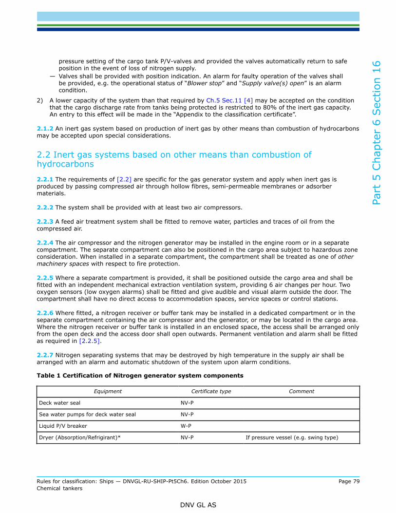
Part
5 C
hapt
er 6
Sec
tion
16
Rules for classification: Ships — DNVGL-RU-SHIP-Pt5Ch6. Edition October 2015 Page 79Chemical tankers
DNV GL AS
pressure setting of the cargo tank P/V-valves and provided the valves automatically return to safeposition in the event of loss of nitrogen supply.
— Valves shall be provided with position indication. An alarm for faulty operation of the valves shallbe provided, e.g. the operational status of “Blower stop” and “Supply valve(s) open” is an alarmcondition.
2) A lower capacity of the system than that required by Ch.5 Sec.11 [4] may be accepted on the conditionthat the cargo discharge rate from tanks being protected is restricted to 80% of the inert gas capacity.An entry to this effect will be made in the “Appendix to the classification certificate”.
2.1.2 An inert gas system based on production of inert gas by other means than combustion of hydrocarbonsmay be accepted upon special considerations.
2.2 Inert gas systems based on other means than combustion ofhydrocarbons
2.2.1 The requirements of [2.2] are specific for the gas generator system and apply when inert gas isproduced by passing compressed air through hollow fibres, semi-permeable membranes or adsorbermaterials.
2.2.2 The system shall be provided with at least two air compressors.
2.2.3 A feed air treatment system shall be fitted to remove water, particles and traces of oil from thecompressed air.
2.2.4 The air compressor and the nitrogen generator may be installed in the engine room or in a separatecompartment. The separate compartment can also be positioned in the cargo area subject to hazardous zoneconsideration. When installed in a separate compartment, the compartment shall be treated as one of othermachinery spaces with respect to fire protection.
2.2.5 Where a separate compartment is provided, it shall be positioned outside the cargo area and shall befitted with an independent mechanical extraction ventilation system, providing 6 air changes per hour. Twooxygen sensors (low oxygen alarms) shall be fitted and give audible and visual alarm outside the door. Thecompartment shall have no direct access to accommodation spaces, service spaces or control stations.
2.2.6 Where fitted, a nitrogen receiver or buffer tank may be installed in a dedicated compartment or in theseparate compartment containing the air compressor and the generator, or may be located in the cargo area.Where the nitrogen receiver or buffer tank is installed in an enclosed space, the access shall be arranged onlyfrom the open deck and the access door shall open outwards. Permanent ventilation and alarm shall be fittedas required in [2.2.5].
2.2.7 Nitrogen separating systems that may be destroyed by high temperature in the supply air shall bearranged with an alarm and automatic shutdown of the system upon alarm conditions.
Table 1 Certification of Nitrogen generator system components
Equipment Certificate type Comment
Deck water seal NV-P
Sea water pumps for deck water seal NV-P
Liquid P/V breaker W-P
Dryer (Absorption/Refrigirant)* NV-P If pressure vessel (e.g. swing type)
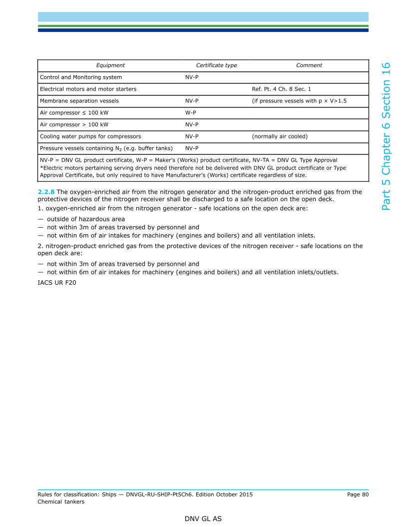
Part
5 C
hapt
er 6
Sec
tion
16
Rules for classification: Ships — DNVGL-RU-SHIP-Pt5Ch6. Edition October 2015 Page 80Chemical tankers
DNV GL AS
Equipment Certificate type Comment
Control and Monitoring system NV-P
Electrical motors and motor starters Ref. Pt. 4 Ch. 8 Sec. 1
Membrane separation vessels NV-P (if pressure vessels with p × V>1.5
Air compressor ≤ 100 kW W-P
Air compressor > 100 kW NV-P
Cooling water pumps for compressors NV-P (normally air cooled)
Pressure vessels containing N2 (e.g. buffer tanks) NV-P
NV-P = DNV GL product certificate, W-P = Maker's (Works) product certificate, NV-TA = DNV GL Type Approval*Electric motors pertaining serving dryers need therefore not be delivered with DNV GL product certificate or TypeApproval Certificate, but only required to have Manufacturer's (Works) certificate regardless of size.
2.2.8 The oxygen-enriched air from the nitrogen generator and the nitrogen-product enriched gas from theprotective devices of the nitrogen receiver shall be discharged to a safe location on the open deck.1. oxygen-enriched air from the nitrogen generator - safe locations on the open deck are:
— outside of hazardous area— not within 3m of areas traversed by personnel and— not within 6m of air intakes for machinery (engines and boilers) and all ventilation inlets.
2. nitrogen-product enriched gas from the protective devices of the nitrogen receiver - safe locations on theopen deck are:
— not within 3m of areas traversed by personnel and— not within 6m of air intakes for machinery (engines and boilers) and all ventilation inlets/outlets.
IACS UR F20
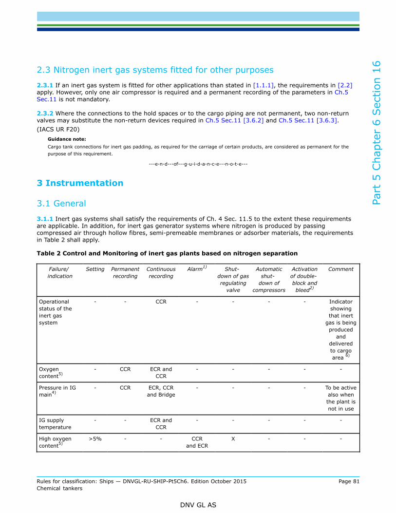
Part
5 C
hapt
er 6
Sec
tion
16
Rules for classification: Ships — DNVGL-RU-SHIP-Pt5Ch6. Edition October 2015 Page 81Chemical tankers
DNV GL AS
2.3 Nitrogen inert gas systems fitted for other purposes
2.3.1 If an inert gas system is fitted for other applications than stated in [1.1.1], the requirements in [2.2]apply. However, only one air compressor is required and a permanent recording of the parameters in Ch.5Sec.11 is not mandatory.
2.3.2 Where the connections to the hold spaces or to the cargo piping are not permanent, two non-returnvalves may substitute the non-return devices required in Ch.5 Sec.11 [3.6.2] and Ch.5 Sec.11 [3.6.3].(IACS UR F20)
Guidance note:Cargo tank connections for inert gas padding, as required for the carriage of certain products, are considered as permanent for thepurpose of this requirement.
---e-n-d---of---g-u-i-d-a-n-c-e---n-o-t-e---
3 Instrumentation
3.1 General
3.1.1 Inert gas systems shall satisfy the requirements of Ch. 4 Sec. 11.5 to the extent these requirementsare applicable. In addition, for inert gas generator systems where nitrogen is produced by passingcompressed air through hollow fibres, semi-premeable membranes or adsorber materials, the requirementsin Table 2 shall apply.
Table 2 Control and Monitoring of inert gas plants based on nitrogen separation
Failure/indication
Setting Permanentrecording
Continuousrecording
Alarm1) Shut-down of gasregulating
valve
Automaticshut-
down ofcompressors
Activationof double-block andbleed2)
Comment
Operationalstatus of theinert gassystem
- - CCR - - - - Indicatorshowingthat inert
gas is beingproduced
anddeliveredto cargoarea 6)
Oxygencontent5)
- CCR ECR andCCR
- - - - -
Pressure in IGmain4)
- CCR ECR, CCRand Bridge
- - - - To be activealso whenthe plant isnot in use
IG supplytemperature
- - ECR andCCR
- - - - -
High oxygencontent5)
>5% - - CCRand ECR
X - - -
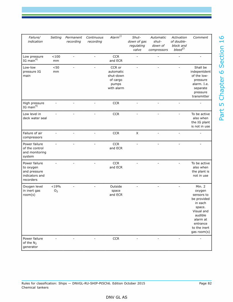
Part
5 C
hapt
er 6
Sec
tion
16
Rules for classification: Ships — DNVGL-RU-SHIP-Pt5Ch6. Edition October 2015 Page 82Chemical tankers
DNV GL AS
Failure/indication
Setting Permanentrecording
Continuousrecording
Alarm1) Shut-down of gasregulating
valve
Automaticshut-
down ofcompressors
Activationof double-block andbleed2)
Comment
Low pressureIG main4)
<100mm
- - CCRand ECR
- - - -
Low-lowpressure IGmain
<50mm
- - CCR orautomaticshut-downof cargopumps
with alarm
- - - Shall beindepentdentof the low-
pressurealarm. I.e.separatepressure
transmitter
High pressureIG main4)
- - - CCR - - - -
Low level indeck water seal
- - - CCR - - - To be activealso when
the IG plantis not in use
Failure of aircompressors
- - - CCR X - - -
Power failureof the controland monitoringsystem
- - - CCRand ECR
- - - -
Power failureto oxygenand pressureindicators andrecorders
- - - CCRand ECR
- - - To be activealso whenthe plant isnot in use
Oxygen levelin inert gasroom(s)
<19%O2
- - Outsidespace
and ECR
- - - Min. 2oxygen
sensors tobe provided
in eachspace.
Visual andaudiblealarm atentrance
to the inertgas room(s)
Power failureof the N2generator
- - - CCR - - - -
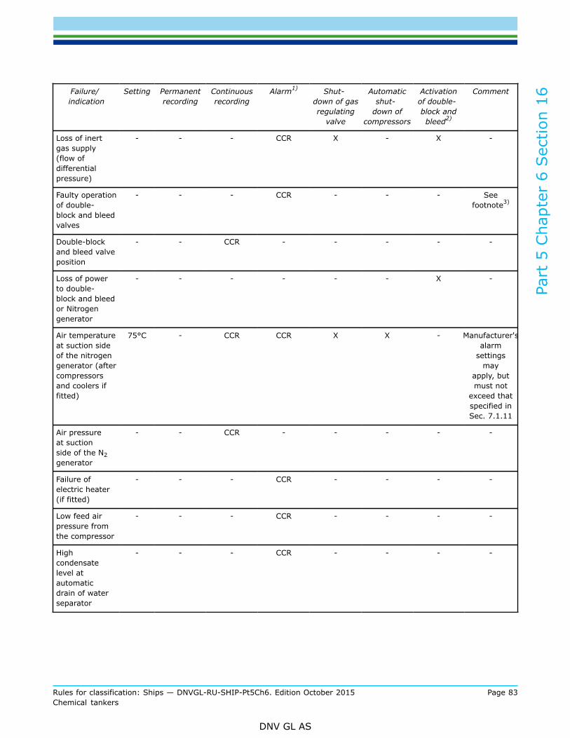
Part
5 C
hapt
er 6
Sec
tion
16
Rules for classification: Ships — DNVGL-RU-SHIP-Pt5Ch6. Edition October 2015 Page 83Chemical tankers
DNV GL AS
Failure/indication
Setting Permanentrecording
Continuousrecording
Alarm1) Shut-down of gasregulating
valve
Automaticshut-
down ofcompressors
Activationof double-block andbleed2)
Comment
Loss of inertgas supply(flow ofdifferentialpressure)
- - - CCR X - X -
Faulty operationof double-block and bleedvalves
- - - CCR - - - Seefootnote3)
Double-blockand bleed valveposition
- - CCR - - - - -
Loss of powerto double-block and bleedor Nitrogengenerator
- - - - - - X -
Air temperatureat suction sideof the nitrogengenerator (aftercompressorsand coolers iffitted)
75°C - CCR CCR X X - Manufacturer'salarm
settingsmay
apply, butmust not
exceed thatspecified inSec. 7.1.11
Air pressureat suctionside of the N2generator
- - CCR - - - - -
Failure ofelectric heater(if fitted)
- - - CCR - - - -
Low feed airpressure fromthe compressor
- - - CCR - - - -
Highcondensatelevel atautomaticdrain of waterseparator
- - - CCR - - - -
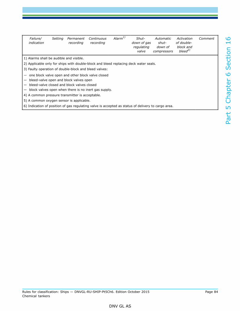
Part
5 C
hapt
er 6
Sec
tion
16
Rules for classification: Ships — DNVGL-RU-SHIP-Pt5Ch6. Edition October 2015 Page 84Chemical tankers
DNV GL AS
Failure/indication
Setting Permanentrecording
Continuousrecording
Alarm1) Shut-down of gasregulating
valve
Automaticshut-
down ofcompressors
Activationof double-block andbleed2)
Comment
1) Alarms shall be audible and visible.
2) Applicable only for ships with double-block and bleed replacing deck water seals.
3) Faulty operation of double-block and bleed valves:
— one block valve open and other block valve closed— bleed-valve open and block valves open— bleed-valve closed and block valves closed— block valves open when there is no inert gas supply.
4) A common pressure transmitter is acceptable.
5) A common oxygen sensor is applicable.
6) Indication of position of gas regulating valve is accepted as status of delivery to cargo area.
Part
5 C
hapt
er 6
Sec
tion
17
Rules for classification: Ships — DNVGL-RU-SHIP-Pt5Ch6. Edition October 2015 Page 85Chemical tankers
DNV GL AS
SECTION 17 PERSONNEL PROTECTION
1 General requirements
1.1 Protective equipment
1.1.1 For the protection of crew members who are engaged in loading and discharging operations, theship shall have on board suitable protective equipment consisting of large aprons, special gloves with longsleeves, suitable footwear, coveralls of chemical-resistant material, and tight-fitting goggles or face shields orboth. The protective clothing and equipment shall cover all skin so that no part of the body is unprotected.Six (6) sets of protective clothing and equipment shall be carried onboard.
1.1.2 Work clothes and protective equipment shall be kept in easily accessible places and in special lockers.Such equipment shall not be kept within accommodation spaces, with the exception of new, unusedequipment and equipment which has not been used since undergoing a thorough cleaning process. Storagerooms for such equipment may, however, upon special consideration be approved within accommodationspaces if adequately segregated from living spaces such as cabins, passageways, dining rooms, bathrooms,etc.
2 Safety equipment
2.1 Safety equipment
2.1.1 Ships intended for carriage of toxic products for which the IBC Code Ch.17 column o refers to 15.12,15.12.1 or 15.12.3, shall have on board sufficient, but not less than three complete sets of safety equipmenteach permitting personnel to enter a gas filled compartment and perform work there for at least 20 minutes.Such equipment shall be in addition to that required by SOLAS regulation II-2/10.10.
2.1.2 One complete set of safety equipment shall consist of:
1) one self-contained air-breathing apparatus (not using stored oxygen),2) protective clothing, boots, gloves and tight-fitting goggles,3) fireproof lifeline with belt resistant to the cargoes carried,
and4) explosion-proof lamp.
2.1.3 For the safety equipment required in [2.1.1], all ships shall carry the following, either:
1) one set of fully charged spare air bottles for each breathing apparatus,2) a special air compressor suitable for the supply of high-pressure air of the required purity,3) a charging manifold capable of dealing with sufficient spare breathing apparatus air bottles for the
breathing apparatusor
4) fully charged spare air bottles with a total free air capacity of at least 6 000 l for each breathingapparatus on board in excess of the requirements of SOLAS regulation II-2/10.10.
2.1.4 A cargo pump-room on ships carrying cargoes which are subject to the requirements of Sec.15 [1.8]or cargoes for which in the IBC code ch.17 column k, toxic vapour detection equipment is required, but is notavailable shall have either:
1) a low-pressure line system with hose connections suitable for use with the breathing apparatus requiredby [2.1.1]. This system shall provide sufficient high-pressure air capacity to supply, through pressure
Part
5 C
hapt
er 6
Sec
tion
17
Rules for classification: Ships — DNVGL-RU-SHIP-Pt5Ch6. Edition October 2015 Page 86Chemical tankers
DNV GL AS
reduction devices, enough low-pressure air to enable two men to work in a hazardous space for atleast 1 h without using the air bottles and breathing apparatus air bottles from a special air compressorsuitable for the supply of high-pressure air of the required purityor
2) an equivalent quantity of spare bottled air in lieu of the low-pressure air line.
2.1.5 At least one set of safety equipment as required by [2.1.2] shall be kept in a suitable clearly markedlocker in a readily accessible place near the cargo pump-room. The other sets of safety equipment shouldalso be kept in suitable, clearly marked, easily accessible, place.
2.1.6 A stretcher which is suitable for hoisting an injured person up from spaces such as the cargo pump-room shall be placed in a readily accessible location.
2.1.7 Ships intended for the carriage of products which in the IBC Code Ch.17 column n are assigned“Yes”, shall be provided with suitable respiratory and eye protection sufficient for every person on board foremergency escape purposes, subject to the following:
1) self-contained breathing apparatus shall normally have a duration of service of at least 15 min2) emergency escape respiratory protection shall not be used for fire-fighting or cargo handling purposes
and should be marked to that effect.
2.1.8 For ships intended for the carriage of products which in the IBC code ch.17 column n are assigned“Yes”, lifeboats shall be provided with a self-contained air support system complying with the requirements ofthe international life-saving appliance (LSA) code.
3 Medical first-aid equipment
3.1 GeneralThe ship shall have on board medical first-aid equipment including oxygen resuscitation equipment andantidotes for cargoes carried based on the guidelines developed by IMO.
Guidance note:See the Medical First Aid Guide for Use in Accidents Involving Dangerous Goods (MFAG) which provides advice on the treatmentof casualties in accordance with the symptoms exhibited as well as equipment and antidotes that may be appropriate for treatingthe casualty.
---e-n-d---of---g-u-i-d-a-n-c-e---n-o-t-e---
4 Decontamination showers and eye washes
4.1 GeneralSuitably marked decontamination showers and eyewashes shall be available on deck in convenient locations.The showers and eyewashes shall be operable in all ambient conditions.Decontamination shower and eye wash units should be located on both sides of the ship in the cargomanifold area and at the aft end of the cargo area. A heating system with temperature control is consideredrequired. Water supply capacity shall be sufficient for simultaneous use of at least two units.
Guidance note:Thermal insulation is not considered as an alternative to a system with temperature control.
---e-n-d---of---g-u-i-d-a-n-c-e---n-o-t-e---

DNV GLDriven by our purpose of safeguarding life, property and the environment, DNV GL enablesorganizations to advance the safety and sustainability of their business. We provide classification andtechnical assurance along with software and independent expert advisory services to the maritime,oil and gas, and energy industries. We also provide certification services to customers across a widerange of industries. Operating in more than 100 countries, our 16 000 professionals are dedicated tohelping our customers make the world safer, smarter and greener.
SAFER, SMARTER, GREENER