dnvgl-ru-ship-pt4ch10 steering gear€¦ · 2.12 connection between steering gear and rudder stock...
TRANSCRIPT
The content of this service document is the subject of intellectual property rights reserved by DNV GL AS ("DNV GL"). The useraccepts that it is prohibited by anyone else but DNV GL and/or its licensees to offer and/or perform classification, certificationand/or verification services, including the issuance of certificates and/or declarations of conformity, wholly or partly, on thebasis of and/or pursuant to this document whether free of charge or chargeable, without DNV GL's prior written consent.DNV GL is not responsible for the consequences arising from any use of this document by others.
The electronic pdf version of this document, available free of chargefrom http://www.dnvgl.com, is the officially binding version.
DNV GL AS
RULES FOR CLASSIFICATION
ShipsEdition October 2015
Part 4 Systems and components
Chapter 10 Steering gear
FOREWORD
DNV GL rules for classification contain procedural and technical requirements related to obtainingand retaining a class certificate. The rules represent all requirements adopted by the Society asbasis for classification.
© DNV GL AS October 2015
Any comments may be sent by e-mail to [email protected]
If any person suffers loss or damage which is proved to have been caused by any negligent act or omission of DNV GL, then DNV GL shallpay compensation to such person for his proved direct loss or damage. However, the compensation shall not exceed an amount equal to tentimes the fee charged for the service in question, provided that the maximum compensation shall never exceed USD 2 million.
In this provision "DNV GL" shall mean DNV GL AS, its direct and indirect owners as well as all its affiliates, subsidiaries, directors, officers,employees, agents and any other acting on behalf of DNV GL.
Part
4 C
hapt
er 1
0 C
hang
es -
cur
rent
Rules for classification: Ships — DNVGL-RU-SHIP-Pt4Ch10. Edition October 2015 Page 3Steering gear
DNV GL AS
CHANGES – CURRENT
This is a new document.
The rules enter into force 1 January 2016.
Part
4 C
hapt
er 1
0 C
onte
nts
Rules for classification: Ships — DNVGL-RU-SHIP-Pt4Ch10. Edition October 2015 Page 4Steering gear
DNV GL AS
CONTENTS
Changes – current...................................................................................................... 3
Section 1 General....................................................................................................... 61 Introduction............................................................................................6
1.1 Application.......................................................................................... 61.2 Nomenclature...................................................................................... 61.3 Definitions...........................................................................................91.4 Documentation requirements............................................................... 101.5 Certification requirements....................................................................14
2 Design...................................................................................................172.1 General............................................................................................. 172.2 Materials........................................................................................... 172.3 Arrangement generally........................................................................182.4 Main steering gear............................................................................. 192.5 Auxiliary steering gear........................................................................ 192.6 Exceptions where auxiliary steering gear is not required.......................... 202.7 Additional requirements for vessels above 70 000 gross tonnage.............. 212.8 Additional requirements for oil carriers, chemical carriers and liquefied gas
carriers............................................................................................... 212.9 Over balanced rudders........................................................................212.10 Hydraulics and piping........................................................................222.11 Actuator and actuating mechanism..................................................... 232.12 Connection between steering gear and rudder stock..............................302.13 Stopper arrangement........................................................................ 382.14 Bearings.......................................................................................... 382.15 Oil seals.......................................................................................... 38
3 Inspection and Testing......................................................................... 393.1 General............................................................................................. 393.2 Inspection and testing of parts............................................................ 39
4 Workshop Testing.................................................................................394.1 General............................................................................................. 39
5 Power Supply, Control and Monitoring..................................................405.1 General............................................................................................. 405.2 Main power supply............................................................................. 405.3 Emergency power supply.................................................................... 405.4 Control gear and associated protective functions.................................... 41
Part
4 C
hapt
er 1
0 C
onte
nts
Rules for classification: Ships — DNVGL-RU-SHIP-Pt4Ch10. Edition October 2015 Page 5Steering gear
DNV GL AS
5.5 General requirements, steering gear control system................................415.6 Arrangement of electric and control systems..........................................425.7 Monitoring......................................................................................... 425.8 Additional Requirements for vessels with DP notation..............................42
6 Arrangement for Installation Onboard..................................................446.1 Fastening arrangement to foundation....................................................446.2 Steering gear compartment................................................................. 44
7 (Intentionally left blank)...................................................................... 457.1 ........................................................................................................45
8 Installation........................................................................................... 458.1 Connection between steering gear and rudder stock............................... 458.2 Fastening to foundation.......................................................................45
9 Shipboard Testing.................................................................................459.1 Shipboard testing............................................................................... 459.2 Trials.................................................................................................469.3 Additional requirements for vessels with DP notation...............................47
Appendix A Additional Requirements for Non-Duplicated Rudder Actuators............. 481 General................................................................................................. 48
1.1 Application.........................................................................................481.2 Documentation...................................................................................48
2 Design...................................................................................................482.1 General............................................................................................. 482.2 Dynamic loads for fatigue and fracture mechanics analyses......................482.3 Allowable stresses.............................................................................. 48
3 Inspection and Testing......................................................................... 493.1 Non-destructive testing....................................................................... 49
Part
4 C
hapt
er 1
0 Sec
tion
1
Rules for classification: Ships — DNVGL-RU-SHIP-Pt4Ch10. Edition October 2015 Page 6Steering gear
DNV GL AS
SECTION 1 GENERAL
1 Introduction
1.1 Application
1.1.1 The rules in this section apply to electro hydraulic and hand hydraulic steering gear operating a rudderfor the purpose of steering the vessel.
1.1.2 Steering gear, other than electro hydraulic type, will be accepted provided that safety and reliabilitycan be documented to be equivalent to or better than the requirements of this section.
1.1.3 Requirements for rudders are given in Pt.3 Ch.14 and in Rules for Classification of High speed, lightcraft and naval surface craft HSLC Pt.3 Ch.5.
1.1.4 Requirements to steering of podded and geared thrusters are given in Ch.5 Sec.3. Requirements tosteering of water jets are given in Ch.5 Sec.2.
1.1.5 For additional requirements for vessel navigation in ice (Ice, PC) see Pt.6 Ch.6 and for Ice breakersee Pt.5 Ch.10 Sec.10. For additional requirements for Naval and Naval support vessels see Pt.5 Ch.13.For additional requirements to vessels with additional notation Redundant propulsion (RP(1, x), RP(2, x),RP(3, x)) see Pt.6 Ch.2 Sec.7. For additional requirements to vessels with additional notation Dynamicpositioning systems (DYNPOS and DPS) see Pt.6 Ch.3 Sec.1 and Pt.6 Ch.3 Sec.2.
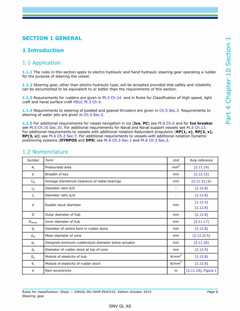
1.2 NomenclatureSymbol Term Unit Rule reference
Ai Pressurised area mm2 [2.11.19]
b Breadth of key mm [2.12.12]
CD Average diametrical clearance of radial bearings mm [2.11.21] b)
ce Diameter ratio d/D - [2.12.8]
ci Diameter ratio di/d - [2.12.8]
d Rudder stock diameter mm[2.12.4]
[2.12.8]
D Outer diameter of hub mm [2.12.8]
Dinner Inner diameter of hub mm [2.11.17]
di Diameter of centre bore in rudder stock mm [2.12.8]
dm Mean diameter of cone mm [2.12.3] h)
ds Designed minimum rudderstock diameter below actuator mm [2.11.20]
dt Diameter of rudder stock at top of cone mm [2.12.9]
Ee Module of elasticity of hub N/mm2 [2.12.8]
Ei Module of elasticity of rudder stock N/mm2 [2.12.8]
e Ram eccentricity m [2.11.19], Figure 1
Part
4 C
hapt
er 1
0 Sec
tion
1
Rules for classification: Ships — DNVGL-RU-SHIP-Pt4Ch10. Edition October 2015 Page 7Steering gear
DNV GL AS
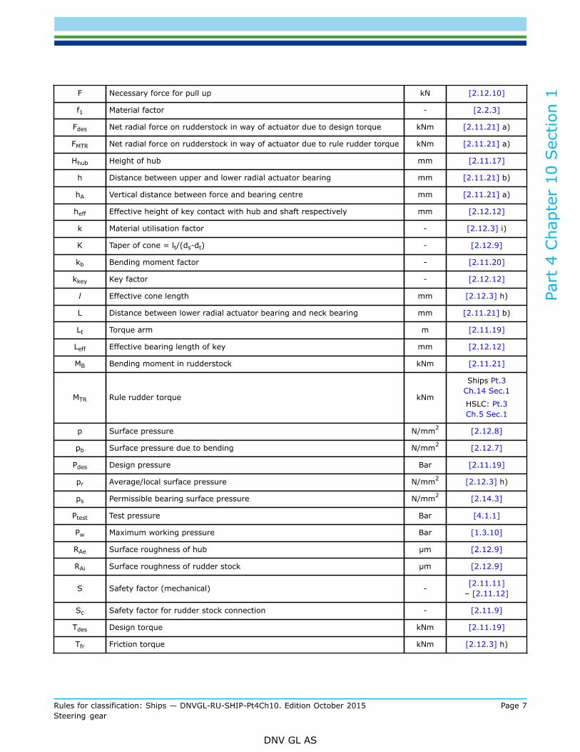
F Necessary force for pull up kN [2.12.10]
f1 Material factor - [2.2.3]
Fdes Net radial force on rudderstock in way of actuator due to design torque kNm [2.11.21] a)
FMTR Net radial force on rudderstock in way of actuator due to rule rudder torque kNm [2.11.21] a)
Hhub Height of hub mm [2.11.17]
h Distance between upper and lower radial actuator bearing mm [2.11.21] b)
hA Vertical distance between force and bearing centre mm [2.11.21] a)
heff Effective height of key contact with hub and shaft respectively mm [2.12.12]
k Material utilisation factor - [2.12.3] i)
K Taper of cone = lt/(ds-dt) - [2.12.9]
kb Bending moment factor - [2.11.20]
kkey Key factor - [2.12.12]
l Effective cone length mm [2.12.3] h)
L Distance between lower radial actuator bearing and neck bearing mm [2.11.21] b)
Lt Torque arm m [2.11.19]
Leff Effective bearing length of key mm [2.12.12]
MB Bending moment in rudderstock kNm [2.11.21]
MTR Rule rudder torque kNm
Ships Pt.3Ch.14 Sec.1
HSLC: Pt.3Ch.5 Sec.1
p Surface pressure N/mm2 [2.12.8]
pb Surface pressure due to bending N/mm2 [2.12.7]
Pdes Design pressure Bar [2.11.19]
pr Average/local surface pressure N/mm2 [2.12.3] h)
ps Permissible bearing surface pressure N/mm2 [2.14.3]
Ptest Test pressure Bar [4.1.1]
Pw Maximum working pressure Bar [1.3.10]
RAe Surface roughness of hub μm [2.12.9]
RAi Surface roughness of rudder stock μm [2.12.9]
S Safety factor (mechanical) - [2.11.11]– [2.11.12]
Sc Safety factor for rudder stock connection - [2.11.9]
Tdes Design torque kNm [2.11.19]
Tfr Friction torque kNm [2.12.3] h)
Part
4 C
hapt
er 1
0 Sec
tion
1
Rules for classification: Ships — DNVGL-RU-SHIP-Pt4Ch10. Edition October 2015 Page 8Steering gear
DNV GL AS
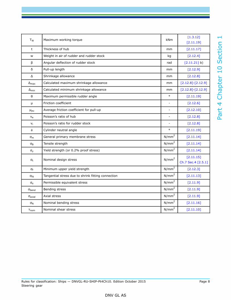
TW Maximum working torque kNm[1.3.12]
[2.11.19]
t Thickness of hub mm [2.11.17]
w Weight in air of rudder and rudder stock kg [2.12.4]
β Angular deflection of rudder stock rad [2.11.21] b)
δ Pull-up length mm [2.12.9]
Δ Shrinkage allowance mm [2.12.8]
Δmax Calculated maximum shrinkage allowance mm [2.12.8]-[2.12.9]
Δmin Calculated minimum shrinkage allowance mm [2.12.8]-[2.12.9]
θ Maximum permissible rudder angle ° [2.11.19]
μ Friction coefficient - [2.12.6]
μpu Average friction coefficient for pull-up - [2.12.10]
νe Poisson’s ratio of hub - [2.12.8]
νi Poisson’s ratio for rudder stock - [2.12.8]
ϕ Cylinder neutral angle ° [2.11.19]
σm General primary membrane stress N/mm2 [2.11.14]
σB Tensile strength N/mm2 [2.11.14]
σy Yield strength (or 0.2% proof stress) N/mm2 [2.11.14]
σt Nominal design stress N/mm2 [2.11.15]
Ch.7 Sec.4 [2.5.1]
σf Minimum upper yield strength N/mm2 [2.12.3]
σfit Tangential stress due to shrink fitting connection N/mm2 [2.11.13]
σe Permissible equivalent stress N/mm2 [2.11.9]
σbend Bending stress N/mm2 [2.11.9]
σaxial Axial stress N/mm2 [2.11.9]
σN Nominal bending stress N/mm2 [2.11.16]
τnom Nominal shear stress N/mm2 [2.11.10]
Part
4 C
hapt
er 1
0 Sec
tion
1
Rules for classification: Ships — DNVGL-RU-SHIP-Pt4Ch10. Edition October 2015 Page 9Steering gear
DNV GL AS
1.3 Definitions
1.3.1 Main steering gear means the machinery necessary for effecting movement of the rudder for thepurpose of steering the ship under normal service conditions.For example this may include:
— rudder actuator(s)— steering gear power units (if any)— ancillary equipment— the means of applying torque to the rudder stock (e.g. tiller or quadrant).
1.3.2 Auxiliary steering gear means the equipment other than any part of the main steering gear necessaryfor effecting movement of the rudder for the purpose of steering the ship in the event of failure of the mainsteering gear but not including the tiller, quadrant or components serving the same purpose.
Guidance note:Auxiliary steering gear may share the tiller or similar component with the main steering gear.
---e-n-d---of---g-u-i-d-a-n-c-e---n-o-t-e---
1.3.3 Steering gear control system means the equipment by which orders are transmitted to the steeringgear power units and other parts necessary for operating the steering gear.Steering gear control systems may comprise:
— transmitters— receivers— programmable electronic units— hydraulic control pumps— associated motors— associated motor controllers and frequency converters— piping— cables.
1.3.4 Rudder actuator means the component which converts directly hydraulic pressure into mechanicalaction to move the rudder.
1.3.5 Rudder actuating mechanism means the parts transmitting force from actuator to rudder stock,including tiller.
1.3.6 Steering gear power unit means:
— in the case of electric steering gear; an electric motor and its associated electrical equipment— in the case of electro hydraulic steering gear; an electric motor and its associated electrical equipment
and connected pump— in the case of other hydraulic steering gear; a driving engine and connected pump.
1.3.7 Power actuating system means the hydraulic equipment provided for supplying power to turn therudder stock, comprising:
— steering gear power units— associated pipes and fittings— rudder actuator.
The power actuating systems may share common mechanical components, i.e. tiller, quadrant and rudderstock, or components serving the same purpose.
Part
4 C
hapt
er 1
0 Sec
tion
1
Rules for classification: Ships — DNVGL-RU-SHIP-Pt4Ch10. Edition October 2015 Page 10Steering gear
DNV GL AS
1.3.8 Maximum ahead service speed
— For vessels complying with rules for ships: means the maximum speed corresponding to maximumnominal shaft RPM and corresponding engine MCR in service at sea on summer load waterline.
— For vessels complying with rules for HSLC: maximum service speed as defined in Pt.3 Ch.5 Sec.1,at fullload condition.
1.3.9 Maximum astern speed is the estimated speed which the ship can attain at the designed maximumastern power at the deepest seagoing draught.
1.3.10 Maximum working pressure PW:
— For vessels complying with rules for ships: the maximum oil pressure in the system when the steeringgear is operated according to [2.4.1] b.1).
— For vessels complying with rules for HSLC: the expected pressure in the system when the steering gear isoperated according to [2.4.1] b.2).
1.3.11 Design pressure means the maximum pressure for which the actuator is designed.Design pressure shall as a minimum be 1.25 times the maximum working pressure and shall not be less thanthe set pressure of the safety relief valve.
1.3.12 Maximum working torque (TW) is the maximum torque in the steering gear when operating at maximumworking pressure (PW). Maximum working torque may be calculated according to formula in 2.11.19 byreplacing the design pressure by the maximum working pressure.
1.4 Documentation requirements
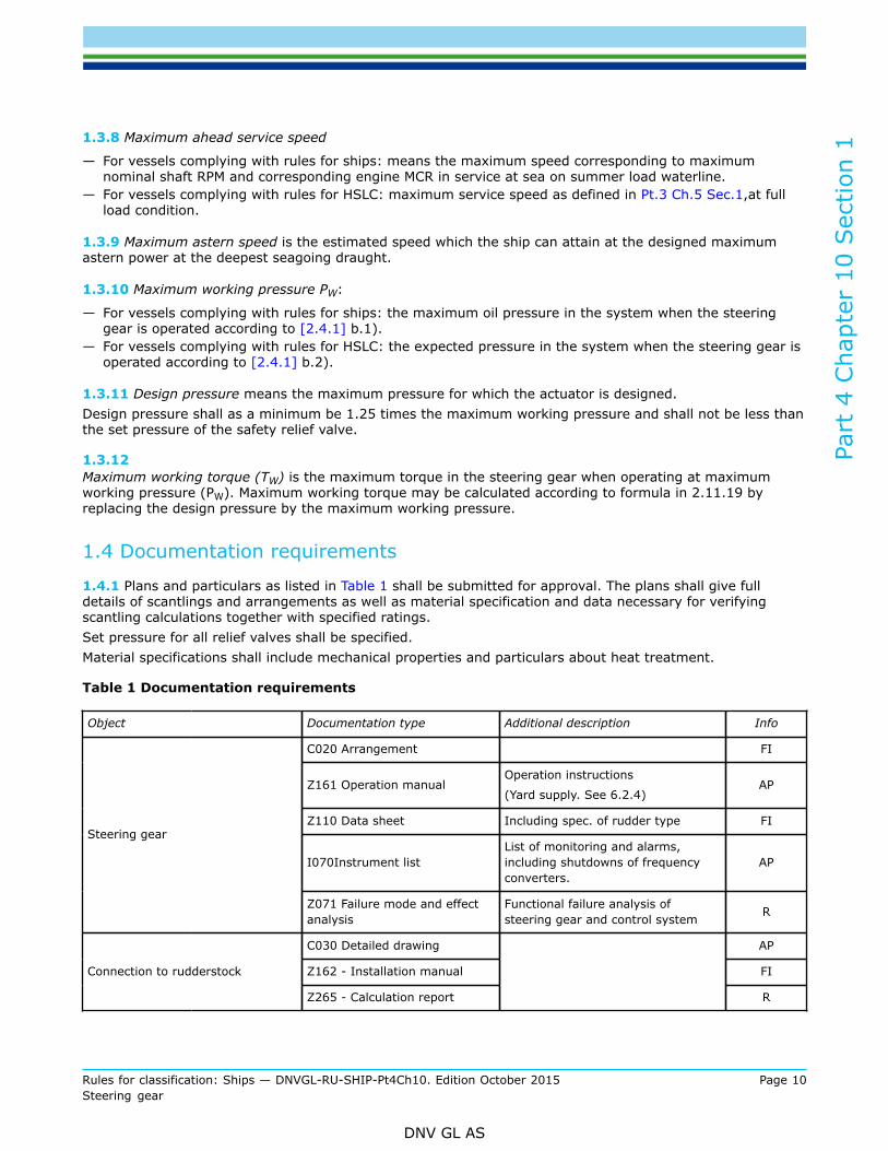
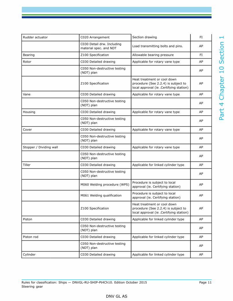
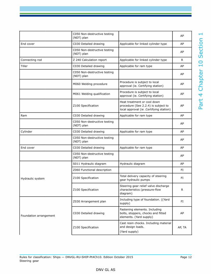
1.4.1 Plans and particulars as listed in Table 1 shall be submitted for approval. The plans shall give fulldetails of scantlings and arrangements as well as material specification and data necessary for verifyingscantling calculations together with specified ratings.Set pressure for all relief valves shall be specified.Material specifications shall include mechanical properties and particulars about heat treatment.
Table 1 Documentation requirements
Object Documentation type Additional description Info
C020 Arrangement FI
Z161 Operation manualOperation instructions
(Yard supply. See 6.2.4)AP
Z110 Data sheet Including spec. of rudder type FI
I070Instrument listList of monitoring and alarms,including shutdowns of frequencyconverters.
AP
Steering gear
Z071 Failure mode and effectanalysis
Functional failure analysis ofsteering gear and control system R
C030 Detailed drawing AP
Z162 - Installation manual FIConnection to rudderstock
Z265 - Calculation report
R
Part
4 C
hapt
er 1
0 Sec
tion
1
Rules for classification: Ships — DNVGL-RU-SHIP-Pt4Ch10. Edition October 2015 Page 11Steering gear
DNV GL AS
Rudder actuator C020 Arrangement Section drawing FI
C030 Detail drw. Includingmaterial spec. and NDT Load transmitting bolts and pins. AP
Bearing Z100 Specification Allowable bearing pressure FI
Rotor C030 Detailed drawing Applicable for rotary vane type AP
C050 Non-destructive testing(NDT) plan AP
Z100 SpecificationHeat treatment or cool downprocedure (See 2.2.4) is subject tolocal approval (ie .Certifying station)
AP
Vane C030 Detailed drawing Applicable for rotary vane type AP
C050 Non-destructive testing(NDT) plan AP
Housing C030 Detailed drawing Applicable for rotary vane type AP
C050 Non-destructive testing(NDT) plan AP
Cover C030 Detailed drawing Applicable for rotary vane type AP
C050 Non-destructive testing(NDT) plan AP
Stopper / Dividing wall C030 Detailed drawing Applicable for rotary vane type AP
C050 Non-destructive testing(NDT) plan AP
Tiller C030 Detailed drawing Applicable for linked cylinder type AP
C050 Non-destructive testing(NDT) plan AP
M060 Welding procedure (WPS) Procedure is subject to localapproval (ie. Certifying station) AP
M061 Welding qualification Procedure is subject to localapproval (ie. Certifying station) AP
Z100 SpecificationHeat treatment or cool downprocedure (See 2.2.4) is subject tolocal approval (ie .Certifying station)
AP
Piston C030 Detailed drawing Applicable for linked cylinder type AP
C050 Non-destructive testing(NDT) plan AP
Piston rod C030 Detailed drawing Applicable for linked cylinder type AP
C050 Non-destructive testing(NDT) plan AP
Cylinder C030 Detailed drawing Applicable for linked cylinder type AP
Part
4 C
hapt
er 1
0 Sec
tion
1
Rules for classification: Ships — DNVGL-RU-SHIP-Pt4Ch10. Edition October 2015 Page 12Steering gear
DNV GL AS
C050 Non-destructive testing(NDT) plan AP
End cover C030 Detailed drawing Applicable for linked cylinder type AP
C050 Non-destructive testing(NDT) plan AP
Connecting rod Z 240 Calculation report Applicable for linked cylinder type R
Tiller C030 Detailed drawing Applicable for ram type AP
C050 Non-destructive testing(NDT) plan AP
M060 Welding procedure Procedure is subject to localapproval (ie. Certifying station) AP
M061 Welding qualification Procedure is subject to localapproval (ie. Certifying station) AP
Z100 SpecificationHeat treatment or cool downprocedure (See 2.2.4) is subject tolocal approval (ie .Certifying station)
AP
Ram C030 Detailed drawing Applicable for ram type AP
C050 Non-destructive testing(NDT) plan AP
Cylinder C030 Detailed drawing Applicable for ram type AP
C050 Non-destructive testing(NDT) plan AP
End cover C030 Detailed drawing Applicable for ram type AP
C050 Non-destructive testing(NDT) plan AP
S011 Hydraulic diagram Hydraulic diagram AP
Z060 Functional description FI
Z100 Specification Total delivery capacity of steeringgear hydraulic pumps FIHydraulic system
Z100 SpecificationSteering gear relief valve dischargecharacteristics (pressure-flowdiagram)
R
Z030 Arrangement plan Including type of foundation. ((Yardsupply) FI
C030 Detailed drawingFastening elements. Includingbolts, stoppers, chocks and fittedelements. (Yard supply)
APFoundation arrangement
Z100 SpecificationCast resin chocks. Including materialand design loads.
(Yard supply)AP, TA

Part
4 C
hapt
er 1
0 Sec
tion
1
Rules for classification: Ships — DNVGL-RU-SHIP-Pt4Ch10. Edition October 2015 Page 13Steering gear
DNV GL AS
C040 Design analysis Cast resin chocks. Loads on chocksand fastening devices. (Yard supply) FI
Conventional steeringarrangements Z030 Arrangement plan
General arrangement drawings ofsteering gear compartment (Yardsupply)
FI
Electric systems E170 Electric schematicdrawing
Electric systems shall bedocumented as required in Ch.8 AP
Control system I 200 Control and monitoringsystem documentation
Control system shall be documentedas required in Ch.9 AP
AP = For approval; FI = For information; R = On request; TA = Covered by Type approval
1.4.2 For general requirements for documentation, including definition of the Info codes, see Pt.1 Ch.3Sec.2.
1.4.3 For a full definition of the documentation types, see Pt.1 Ch.3 Sec.3.
1.4.4 For important components of welded construction (e.g. tiller), full details of the joints, weldingprocedure, filler metal and heat treatment after welding shall be specified on the plans.
1.4.5 Associated electrical equipment (motors, frequency converters, switchgear and control gear) isregarded as important equipment and documentation shall be submitted as required in Ch.8 Sec.1 [2.2].
1.4.6 Steering gear manufacturers who intend their product to comply with the requirements of the IMOGuidelines for non-duplicated rudder actuators shall submit additional documentation as given in App.A.
1.4.7 For rudders included under DP-control documentation of expected life time of bearings subjected toextra ordinary wear rate due to DP shall be submitted for approval.
Part
4 C
hapt
er 1
0 Sec
tion
1
Rules for classification: Ships — DNVGL-RU-SHIP-Pt4Ch10. Edition October 2015 Page 14Steering gear
DNV GL AS
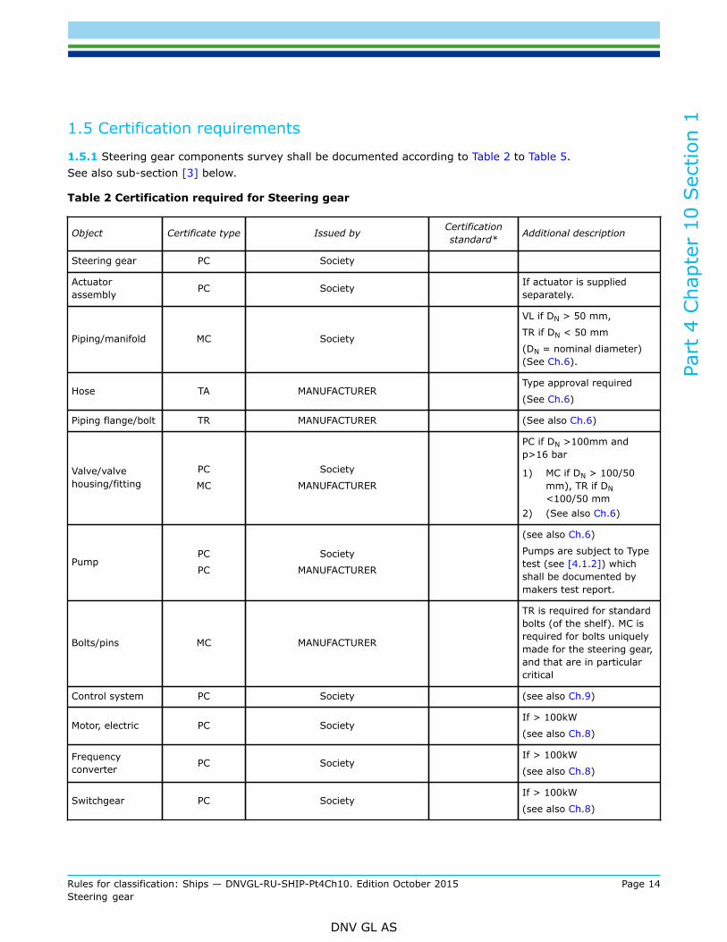
1.5 Certification requirements
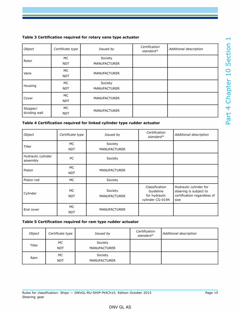
1.5.1 Steering gear components survey shall be documented according to Table 2 to Table 5.See also sub-section [3] below.
Table 2 Certification required for Steering gear
Object Certificate type Issued by Certificationstandard* Additional description
Steering gear PC Society
Actuatorassembly PC Society If actuator is supplied
separately.
Piping/manifold MC Society
VL if DN > 50 mm,
TR if DN < 50 mm
(DN = nominal diameter)(See Ch.6).
Hose TA MANUFACTURER Type approval required
(See Ch.6)
Piping flange/bolt TR MANUFACTURER (See also Ch.6)
Valve/valvehousing/fitting
PC
MC
Society
MANUFACTURER
PC if DN >100mm andp>16 bar
1) MC if DN > 100/50mm), TR if DN<100/50 mm
2) (See also Ch.6)
PumpPC
PC
Society
MANUFACTURER
(see also Ch.6)
Pumps are subject to Typetest (see [4.1.2]) whichshall be documented bymakers test report.
Bolts/pins MC MANUFACTURER
TR is required for standardbolts (of the shelf). MC isrequired for bolts uniquelymade for the steering gear,and that are in particularcritical
Control system PC Society (see also Ch.9)
Motor, electric PC Society If > 100kW
(see also Ch.8)
Frequencyconverter PC Society
If > 100kW
(see also Ch.8)
Switchgear PC Society If > 100kW
(see also Ch.8)
Part
4 C
hapt
er 1
0 Sec
tion
1
Rules for classification: Ships — DNVGL-RU-SHIP-Pt4Ch10. Edition October 2015 Page 15Steering gear
DNV GL AS
Table 3 Certification required for rotary vane type actuator
Object Certificate type Issued by Certificationstandard* Additional description
RotorMC
NDT
Society
MANUFACTURER
VaneMC
NDTMANUFACTURER
HousingMC
NDT
Society
MANUFACTURER
CoverMC
NDTMANUFACTURER
Stopper/dividing wall
MC
NDTMANUFACTURER
Table 4 Certification required for linked cylinder type rudder actuator
Object Certificate type Issued by Certificationstandard* Additional description
TillerMC
NDT
Society
MANUFACTURER
Hydraulic cylinderassembly PC Society
PistonMC
NDTMANUFACTURER
Piston rod MC Society
CylinderMC
NDT
Society
MANUFACTURER
ClassificationGuideline
for hydrauliccylinder CG-0194
Hydraulic cylinder forsteering is subject tocertification regardless ofsize
End coverMC
NDTMANUFACTURER
Table 5 Certification required for ram type rudder actuator
Object Certificate type Issued by Certificationstandard* Additional description
TillerMC
NDT
Society
MANUFACTURER
RamMC
NDT
Society
MANUFACTURER
Part
4 C
hapt
er 1
0 Sec
tion
1
Rules for classification: Ships — DNVGL-RU-SHIP-Pt4Ch10. Edition October 2015 Page 16Steering gear
DNV GL AS
CylinderMC
NDT
Society
MANUFACTURER
End coverMC
NDTMANUFACTURER
*Unless otherwise specified the certification standard is DNVGL Ship Rules.
1.5.2 For a full definition of the certificate types, see Pt.1 Ch.3 Sec.5.
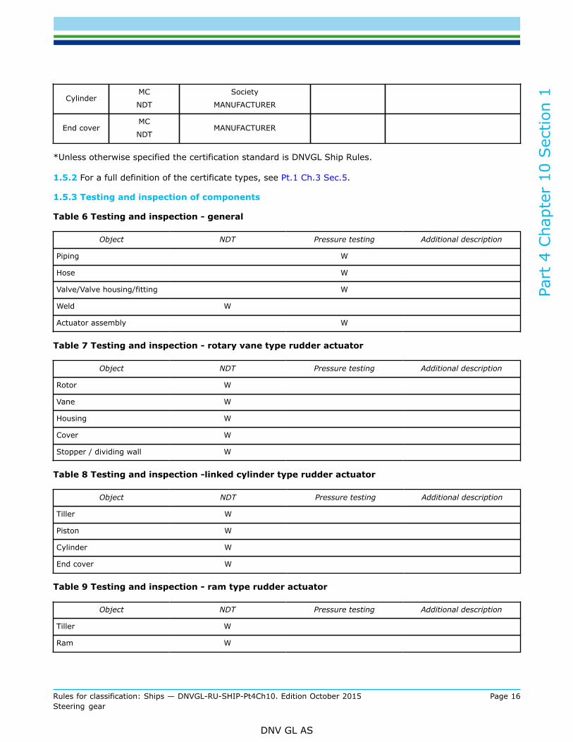
1.5.3 Testing and inspection of components
Table 6 Testing and inspection - general
Object NDT Pressure testing Additional description
Piping W
Hose W
Valve/Valve housing/fitting W
Weld W
Actuator assembly W
Table 7 Testing and inspection - rotary vane type rudder actuator
Object NDT Pressure testing Additional description
Rotor W
Vane W
Housing W
Cover W
Stopper / dividing wall W
Table 8 Testing and inspection -linked cylinder type rudder actuator
Object NDT Pressure testing Additional description
Tiller W
Piston W
Cylinder W
End cover W
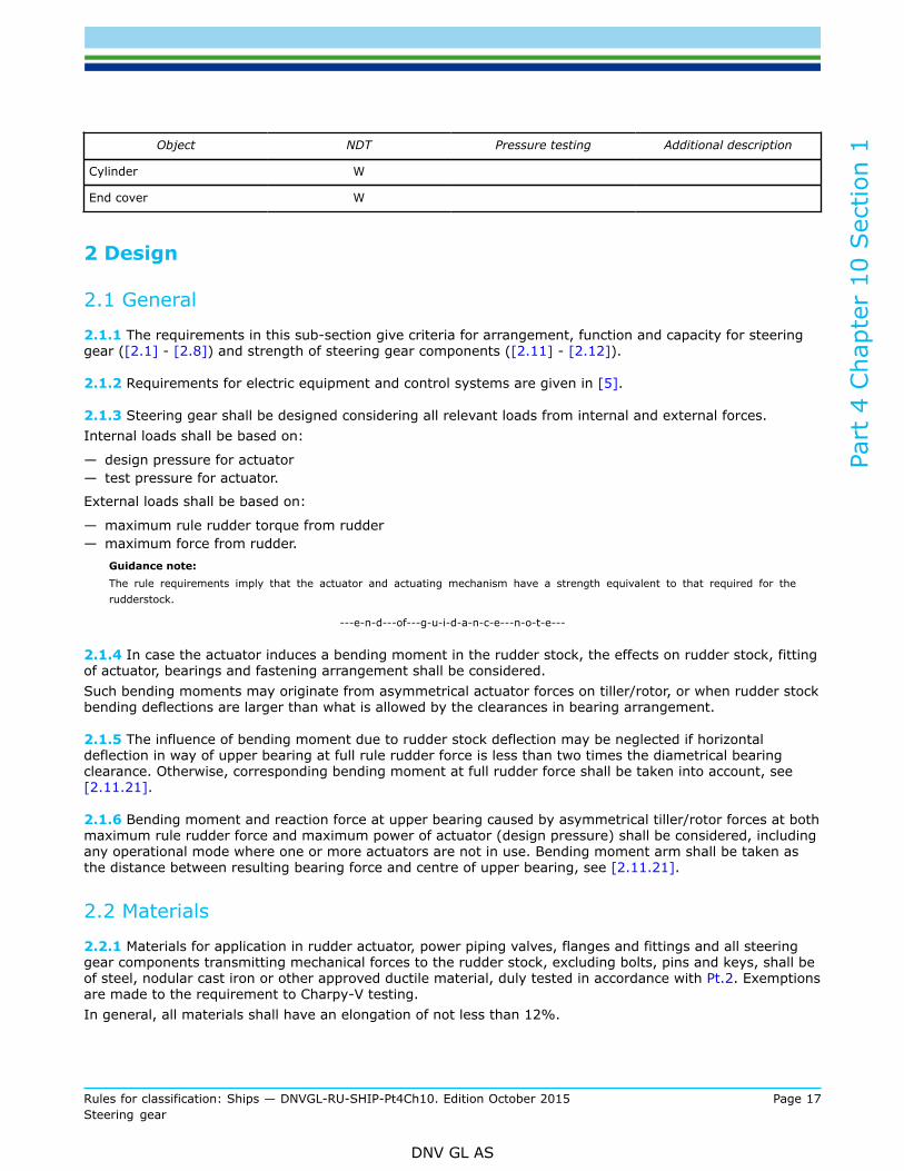
Table 9 Testing and inspection - ram type rudder actuator
Object NDT Pressure testing Additional description
Tiller W
Ram W
Part
4 C
hapt
er 1
0 Sec
tion
1
Rules for classification: Ships — DNVGL-RU-SHIP-Pt4Ch10. Edition October 2015 Page 17Steering gear
DNV GL AS
Object NDT Pressure testing Additional description
Cylinder W
End cover W
2 Design
2.1 General
2.1.1 The requirements in this sub-section give criteria for arrangement, function and capacity for steeringgear ([2.1] - [2.8]) and strength of steering gear components ([2.11] - [2.12]).
2.1.2 Requirements for electric equipment and control systems are given in [5].
2.1.3 Steering gear shall be designed considering all relevant loads from internal and external forces.Internal loads shall be based on:
— design pressure for actuator— test pressure for actuator.
External loads shall be based on:
— maximum rule rudder torque from rudder— maximum force from rudder.
Guidance note:The rule requirements imply that the actuator and actuating mechanism have a strength equivalent to that required for therudderstock.
---e-n-d---of---g-u-i-d-a-n-c-e---n-o-t-e---
2.1.4 In case the actuator induces a bending moment in the rudder stock, the effects on rudder stock, fittingof actuator, bearings and fastening arrangement shall be considered.Such bending moments may originate from asymmetrical actuator forces on tiller/rotor, or when rudder stockbending deflections are larger than what is allowed by the clearances in bearing arrangement.
2.1.5 The influence of bending moment due to rudder stock deflection may be neglected if horizontaldeflection in way of upper bearing at full rule rudder force is less than two times the diametrical bearingclearance. Otherwise, corresponding bending moment at full rudder force shall be taken into account, see[2.11.21].
2.1.6 Bending moment and reaction force at upper bearing caused by asymmetrical tiller/rotor forces at bothmaximum rule rudder force and maximum power of actuator (design pressure) shall be considered, includingany operational mode where one or more actuators are not in use. Bending moment arm shall be taken asthe distance between resulting bearing force and centre of upper bearing, see [2.11.21].
2.2 Materials
2.2.1 Materials for application in rudder actuator, power piping valves, flanges and fittings and all steeringgear components transmitting mechanical forces to the rudder stock, excluding bolts, pins and keys, shall beof steel, nodular cast iron or other approved ductile material, duly tested in accordance with Pt.2. Exemptionsare made to the requirement to Charpy-V testing.In general, all materials shall have an elongation of not less than 12%.
Part
4 C
hapt
er 1
0 Sec
tion
1
Rules for classification: Ships — DNVGL-RU-SHIP-Pt4Ch10. Edition October 2015 Page 18Steering gear
DNV GL AS
The following materials may only be accepted upon special consideration:
— materials with tensile strength in excess of 650 N/mm2
— grey cast iron for use in redundant parts with low stress level, excluding hydraulic cylinders— structural steel for components exposed to internal hydraulic pressure.
2.2.2 Materials in bolts, pins and keys shall be of rolled, forged or cast steel in accordance with Pt.2. Ingeneral, such material shall have a minimum specified tensile strength in the range of 400 N/mm2 to 900 N/mm2. Higher tensile strength may be accepted upon special considerations related to ductility and fatigueproperties versus application. Yield stress shall not be less than 200 N/mm2.
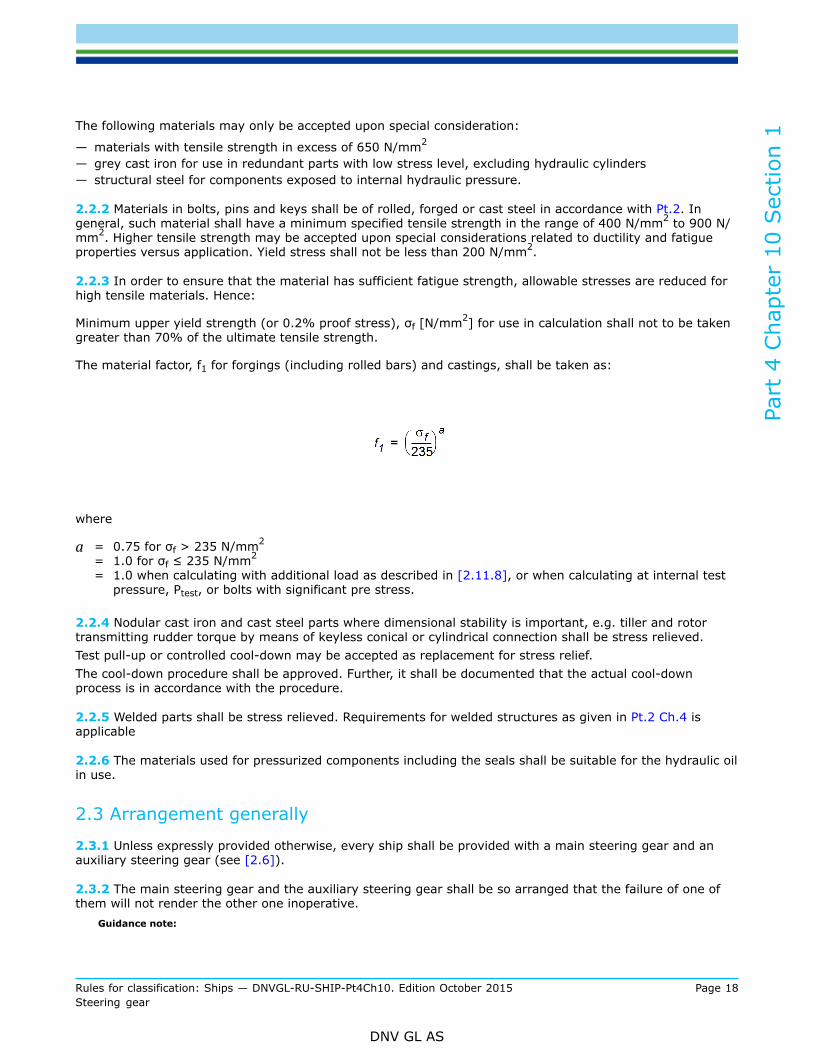
2.2.3 In order to ensure that the material has sufficient fatigue strength, allowable stresses are reduced forhigh tensile materials. Hence:
Minimum upper yield strength (or 0.2% proof stress), σf [N/mm2] for use in calculation shall not to be takengreater than 70% of the ultimate tensile strength.
The material factor, f1 for forgings (including rolled bars) and castings, shall be taken as:
where
a = 0.75 for σf > 235 N/mm2
= 1.0 for σf ≤ 235 N/mm2
= 1.0 when calculating with additional load as described in [2.11.8], or when calculating at internal testpressure, Ptest, or bolts with significant pre stress.
2.2.4 Nodular cast iron and cast steel parts where dimensional stability is important, e.g. tiller and rotortransmitting rudder torque by means of keyless conical or cylindrical connection shall be stress relieved.Test pull-up or controlled cool-down may be accepted as replacement for stress relief.The cool-down procedure shall be approved. Further, it shall be documented that the actual cool-downprocess is in accordance with the procedure.
2.2.5 Welded parts shall be stress relieved. Requirements for welded structures as given in Pt.2 Ch.4 isapplicable
2.2.6 The materials used for pressurized components including the seals shall be suitable for the hydraulic oilin use.
2.3 Arrangement generally
2.3.1 Unless expressly provided otherwise, every ship shall be provided with a main steering gear and anauxiliary steering gear (see [2.6]).
2.3.2 The main steering gear and the auxiliary steering gear shall be so arranged that the failure of one ofthem will not render the other one inoperative.
Guidance note:
Part
4 C
hapt
er 1
0 Sec
tion
1
Rules for classification: Ships — DNVGL-RU-SHIP-Pt4Ch10. Edition October 2015 Page 19Steering gear
DNV GL AS
When considering fail scenarios for main/auxiliary steering gear in this context the tiller and connection to rudder stock is consideredas a non-failing component.
---e-n-d---of---g-u-i-d-a-n-c-e---n-o-t-e---
Guidance note:For guidance to hydraulic arrangements see Class Guideline CG-0040 “Schematic Principles for Steering Gear Hydraulics”.
---e-n-d---of---g-u-i-d-a-n-c-e---n-o-t-e---
2.3.3 Steering gear systems shall be equipped with a locking system effective in all rudder positions.Locking may be provided by hydraulic system with shut-off valves directly fitted at the actuator. For steeringgears with cylinder units which may be independently operated the shut-off valves do not have to be fitteddirectly on the cylinders.
2.4 Main steering gear
2.4.1 The main steering gear shall:
a) be capable of operating the rudder for the purpose of steering the ship at maximum ahead service speedwhich shall be demonstrated
b) have capacity to turn the rudder from side to side according to requirements given below at maximumahead service speed
1) For vessels complying with rules for ships the main steering gear shall comply with the following:
— turning the rudder over from 35° on one side to 35° on the other and visa versa— turning rudder from 35° on either side to 30° on the other sides respectively within 28 seconds— for class notations Tug or Offshore service vessel, or polar class notation: PC with relevant
qualifier, turning the rudder from 35° on either side to 30° on the other sides respectively within20 seconds
— for class notation Icebreaker turning rudder from 35° on either side to 30° on the other sidesrespectively within 15 seconds
— For class notation Pusher, turning the rudder from 35° on either side to 30° on the other sidesrespectively within 20 seconds.
— turning rudder back to neutral position from any possible steering angle that intentionallyor unintentionally may be initiated. See also [2.9] for over-balanced rudders and rudders ofunconventional design.
2) For vessels complying with rules for HSLC the main steering gear shall have capacity to turn therudder during the following:
— steering performance (zig zag) test— turning circle test— low speed steering test— single unit steering (for vessels with twin units).
c) be operated by power when the rules require a rudder stock diameter above 120 mm in way of the tiller,excluding strengthening for navigation in ice
d) be so designed that neither steering gear nor rudderstock will be damaged at maximum astern speedand rudder angle.
Guidance note:A rule rudder stock with diameter of 120 mm equals a rule rudder torque of 23.3 kNm.
---e-n-d---of---g-u-i-d-a-n-c-e---n-o-t-e---
2.5 Auxiliary steering gear
Part
4 C
hapt
er 1
0 Sec
tion
1
Rules for classification: Ships — DNVGL-RU-SHIP-Pt4Ch10. Edition October 2015 Page 20Steering gear
DNV GL AS
2.5.1 The auxiliary steering gear shall:
a) be capable of operating the rudder for the purpose of steering the ship at navigable speed and of beingbrought speedily into action.
b) have capacity to turn the rudder from side to side according to requirements given below
1) For vessels complying with rules for ships the auxiliary steering gear shall comply with the following:
— turning the rudder over from 15° on one side to 15° on the other side in not more than 60seconds with the ship on summer load waterline and running ahead at one half of the maximumahead service speed or 7 knots, whichever is the greater.
2) For vessels complying with rules for HSLC the auxiliary steering gear shall have capacity to turn therudder during the following:
— steering performance (zig zag) test— low speed steering test— turning circle test— single unit steering (for vessels with twin units)
c) be operated by power when the rules require a rudder stock diameter above 230 mm in way of the tiller,excluding strengthening for navigation in ice.
Guidance note:Speedily normally means less than 15 minutes.
---e-n-d---of---g-u-i-d-a-n-c-e---n-o-t-e---
Guidance note:Manually operated steering gears are only acceptable when the operation does not require an effort exceeding 160 N under normalconditions.
---e-n-d---of---g-u-i-d-a-n-c-e---n-o-t-e---
2.6 Exceptions where auxiliary steering gear is not required
2.6.1 Auxiliary steering gear need not be fitted when the ship is provided with either:
a) two rudders, each with its own steering gear and capable of steering the vessel with any one of therudders out of operation
b) approved alternative means of steering, capable of steering the vessel with the rudder out of operationand provided with approved remote control from the bridge. Such means may be:
— azimuth thrusters— two or more independent propulsion units, located eccentric from the ships centre line
c) for non-propelled vessels.
2.6.2 Where the main steering gear comprises two or more identical power units, an auxiliary steering gearneed not be fitted provided that requirements below are complied with:
a) Isolation:
1) a single failure in the main steering gear piping system or one of the power units can be isolated andsteering capability can be maintained or speedily regained.
b) Capacity:
1) for a passenger ship, the main steering gear shall be capable of operating the rudder as required in[2.4.1] b) while any one of the power units is out of operation
2) for a cargo ship, the main steering gear shall be capable of operating the rudder as required in[2.4.1] b) while operating with all power units.
Part
4 C
hapt
er 1
0 Sec
tion
1
Rules for classification: Ships — DNVGL-RU-SHIP-Pt4Ch10. Edition October 2015 Page 21Steering gear
DNV GL AS
2.7 Additional requirements for vessels above 70 000 gross tonnage
2.7.1 In every ship of 70 000 gross tonnage and upwards, the main steering gear shall comprise two ormore identical power units complying with the requirements given in [2.6.2].
2.8 Additional requirements for oil carriers, chemical carriers and liquefiedgas carriers
2.8.1 Oil carriers, chemical carriers or liquefied gas carriers of 10 000 gross tonnage and upwards shallcomply with the following:
a) The main steering gear shall be so arranged that in the event of loss of steering capability due to a singlefailure in any part of one of the power actuating systems, excluding the tiller or components serving thesame purpose, steering capability shall be regained in less than 45 seconds.
b) Capacity:
1) The main steering gear shall comprise of two independent and separate power actuating systems, eachcapable of meeting the requirements in [2.4.1] b).
2) Alternatively, at least two identical power actuating systems may be fitted which:
— acting simultaneously in normal operation are capable of meeting the requirements in [2.4.1] b)— are able to detect loss of hydraulic fluid from one system— automatically isolates such a defect so that the other actuating system(s) remains fully operational.
Guidance note:Steering gear complying with requirements in this paragraph are commonly referred to as "IMO steering gears".
---e-n-d---of---g-u-i-d-a-n-c-e---n-o-t-e---
2.8.2 For tankers of 10 000 gross tonnage and upwards but less than 100 000 dead weight tons duplicationof actuator is not required provided that an equivalent safety level can be documented according to App.Aand the following is complied with:
a) the main steering gear shall comprise two or more identical power units capable of operating the rudderaccording to [2.4.1] b) while operating with all power units.
b) after loss of steering capability due to a single failure of any part of the piping system or in one of thepower units, steering capability shall be regained within 45 seconds.
Guidance note:Steering gear complying with requirements in [2.8.2] are commonly referred to as “Appendix A steering gears”. See App.A.
---e-n-d---of---g-u-i-d-a-n-c-e---n-o-t-e---
2.9 Over balanced rudders
2.9.1 Paragraphs in [2.9] are relevant for steering gear for over-balanced rudders and rudders ofunconventional design. See also Pt.3 Ch.14 [3.1.5] .The influence of increased friction due to age and wear of bearings on steering gear torque capacity shallbe duly considered. Unless such friction losses are accounted for and specified in submitted approvaldocumentation, the friction coefficient for the bearing in worn condition shall be taken at least twice as whennew.
2.9.2 Loss of steering torque due to a single failure in the steering gear power or control systems (inclusivefailure in power supply) shall not cause a sudden turn of rudder.
Part
4 C
hapt
er 1
0 Sec
tion
1
Rules for classification: Ships — DNVGL-RU-SHIP-Pt4Ch10. Edition October 2015 Page 22Steering gear
DNV GL AS
2.9.3 Steering gear shall be capable of bringing the rudder from any rudder angle back to neutral position.This shall be verified by testing on sea trial.
2.10 Hydraulics and piping
2.10.1 Piping, joints, valves, flanges and other fittings shall comply with the requirements of Ch.6 for designpressure as defined in [1.3.11]. Piping intended for power piping shall comply with requirements to Class Ipipes.
2.10.2 Hydraulic power operated steering gears shall be provided with:
a) arrangements to maintain the cleanliness of the hydraulic fluid taking into consideration the type anddesign of the hydraulic system
b) a fixed storage tank having sufficient capacity to recharge at least one power actuating system includingthe reservoir, where the main steering gear is required to be power operated. The storage tank shall bepermanently connected by piping in such a manner that the hydraulic systems can be readily rechargedfrom a position within the steering gear compartment and provided with a contents gauge
c) indicator for clogged filter on all filters with “by-pass” functiond) arrangement so that transfer between units can be readily effected.
Guidance note:Specification of a pressure filter for maintaining suitable fluid cleanliness may be 16/14/11 according to ISO 4406:1999 and β6-7
(c) = 200 according to ISO 16889:1999.
---e-n-d---of---g-u-i-d-a-n-c-e---n-o-t-e---
2.10.3 Hydraulic power actuating system for steering gear shall not to be used for other purposes.
2.10.4 For all vessels with non-duplicated actuators isolating valves directly fitted on the actuator shall beprovided at the connection of pipes to the actuator.
2.10.5 Main and auxiliary steering gear shall be provided with separate hydraulic power supply pipes. Whenmain steering gear is arranged in accordance with [2.6.2], each hydraulic power unit shall be provided withseparate power pipes. Interconnections between power pipes shall be provided with quick operating isolatingvalves.
2.10.6 Relief valves shall be fitted to any part of the hydraulic system which can be isolated and in whichpressure can be generated from the power source or from external forces. Relief valves shall comply with thefollowing:
a) the setting pressure shall not be less than 1.25 times the maximum working pressureGuidance note:A relief valve located directly after hydraulic pump may have a set value that is lower. However not lower than maximumworking pressure.Such reduction in set value will normally not be accepted for arrangements with overbalanced rudders.
---e-n-d---of---g-u-i-d-a-n-c-e---n-o-t-e---
b) the setting of the relief valves shall not exceed the design pressurec) the minimum discharge capacity of the relief valves shall not be less than the larger of :
— 110 % of the total capacity of the pumps which can deliver through it (them)— oil flow corresponding to a rudder movement of 5 deg./second.
Under such conditions the rise in pressure shall not exceed 10 % of the setting pressure. In this regard,due consideration shall be given to extreme foreseen ambient conditions in respect of oil viscosity.

Part
4 C
hapt
er 1
0 Sec
tion
1
Rules for classification: Ships — DNVGL-RU-SHIP-Pt4Ch10. Edition October 2015 Page 23Steering gear
DNV GL AS
2.10.7 Where the steering gear is so arranged that more than one system (either power or control) can besimultaneously operated, the risk of hydraulic locking caused by a single failure shall be considered.For alarm requirement see [5.7] “Monitoring”.
Guidance note:”Hydraulic locking” includes all situations where two hydraulic systems (usually identical) oppose each other in such a way that itmay lead to loss of steering. It can either be caused by pressure in the two hydraulic systems working against each other or byhydraulic “by-pass” meaning that the systems puncture each other and cause pressure drop on both sides or make it impossibleto build up pressure.
---e-n-d---of---g-u-i-d-a-n-c-e---n-o-t-e---
2.10.8 Flexible hoses may be used between two points where flexibility is required but shall not be subjectedto torsional deflection (twisting) under normal operating conditions. In general, the hose should be limitedto the length necessary to provide for flexibility and for proper operation of machinery. Hoses shall be typeapproved.
2.10.9 Hoses shall be high pressure hydraulic hoses according to recognised standards and suitable forthe fluids, pressures, temperatures and ambient conditions in question. For detailed requirements forconstruction and testing of flexible hoses, see Ch.6 Sec.10 [4].
2.11 Actuator and actuating mechanism
2.11.1 Actuator housing and cylinders are considered as Class I pressure vessels with respect to testing andcertification, except for Charpy-V testing which is not required.
2.11.2 The structural design of the actuator shall be chosen with due respect to transmission of reactionforces to the seating.
2.11.3 The construction shall be such that the local stress concentrations are minimised.
2.11.4 All welding joints within the pressure boundary of a rudder actuator or actuating mechanism shall befull penetration type or of equivalent strength.
2.11.5 Where rudder carrier and/or radial bearings are integrated in the actuator, the actuator shall bedesigned to withstand additional reaction forces due to bending moment set up in the rudder stock.
2.11.6 The actuator and actuating mechanism shall be designed to withstand all possible loads that can begenerated from rudder or power unit during operation. As a minimum, sufficient strength in the followingconditions shall be considered:
— rudder exposed to a load corresponding to rule rudder torque, MTR, and force, FR— actuator(s) working at design pressure, Pdes— actuator(s) exposed to internal test pressure, Ptest.
Relevant additional loading due to bolt pretension, shrink fitting of hubs, from supports and connected piping,etc. shall be duly considered.
2.11.7 Unless fatigue is suspected to be a possible mode of failure, fatigue strength needs not to bedocumented. Normally, this provides that:
— fillets are smooth and well rounded so that geometrical stress concentration factors do not exceed 1.5(otherwise safety factor shall be increased correspondingly)
— static strength fulfils the criteria in [2.11.8]-[2.11.18].
2.11.8 If forces from one actuator can be transferred to another, for instance by means of a connectingrod, the actuator and actuating mechanism shall not be permanently damaged when exposed to the sum of
Part
4 C
hapt
er 1
0 Sec
tion
1
Rules for classification: Ships — DNVGL-RU-SHIP-Pt4Ch10. Edition October 2015 Page 24Steering gear
DNV GL AS
actuating forces (actuators working at design pressure). When calculating the material factor f1 shall be takenas σy /235
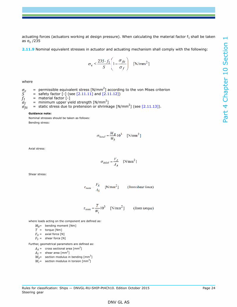
2.11.9 Nominal equivalent stresses in actuator and actuating mechanism shall comply with the following:
where
σe = permissible equivalent stress [N/mm2] according to the von Mises criterionS = safety factor [-] (see [2.11.11] and [2.11.12])f1 = material factor [-]σf = minimum upper yield strength [N/mm2]σfit = static stress due to pretension or shrinkage [N/mm2] (see [2.11.13]).
Guidance note:Nominal stresses should be taken as follows:Bending stress:
Axial stress:
Shear stress:
where loads acting on the component are defined as:
MB= bending moment [Nm]T = torque [Nm]FA = axial force [N]FS = shear force [N]
Further, geometrical parameters are defined as:
AA = cross sectional area [mm2]AS = shear area [mm2]Wb= section modulus in bending [mm3]Wt= section modulus in torsion [mm3]
Part
4 C
hapt
er 1
0 Sec
tion
1
Rules for classification: Ships — DNVGL-RU-SHIP-Pt4Ch10. Edition October 2015 Page 25Steering gear
DNV GL AS
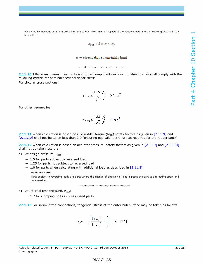
For bolted connections with high pretension the safety factor may be applied to the variable load, and the following equation maybe applied:
---e-n-d---of---g-u-i-d-a-n-c-e---n-o-t-e---
2.11.10 Tiller arms, vanes, pins, bolts and other components exposed to shear forces shall comply with thefollowing criteria for nominal sectional shear stress:For circular cross sections:
For other geometries:
2.11.11 When calculation is based on rule rudder torque (MTR) safety factors as given in [2.11.9] and[2.11.10] shall not be taken less than 2.0 (ensuring equivalent strength as required for the rudder stock).
2.11.12 When calculation is based on actuator pressure, safety factors as given in [2.11.9] and [2.11.10]shall not be taken less than:
a) At design pressure, Pdes:
— 1.5 for parts subject to reversed load— 1.25 for parts not subject to reversed load— 1.0 for parts when calculating with additional load as described in [2.11.8].
Guidance note:Parts subject to reversing loads are parts where the change of direction of load exposes the part to alternating strain andcompression.
---e-n-d---of---g-u-i-d-a-n-c-e---n-o-t-e---
b) At internal test pressure, Ptest:
— 1.2 for clamping bolts in pressurised parts.
2.11.13 For shrink fitted connections, tangential stress at the outer hub surface may be taken as follows:
Part
4 C
hapt
er 1
0 Sec
tion
1
Rules for classification: Ships — DNVGL-RU-SHIP-Pt4Ch10. Edition October 2015 Page 26Steering gear
DNV GL AS
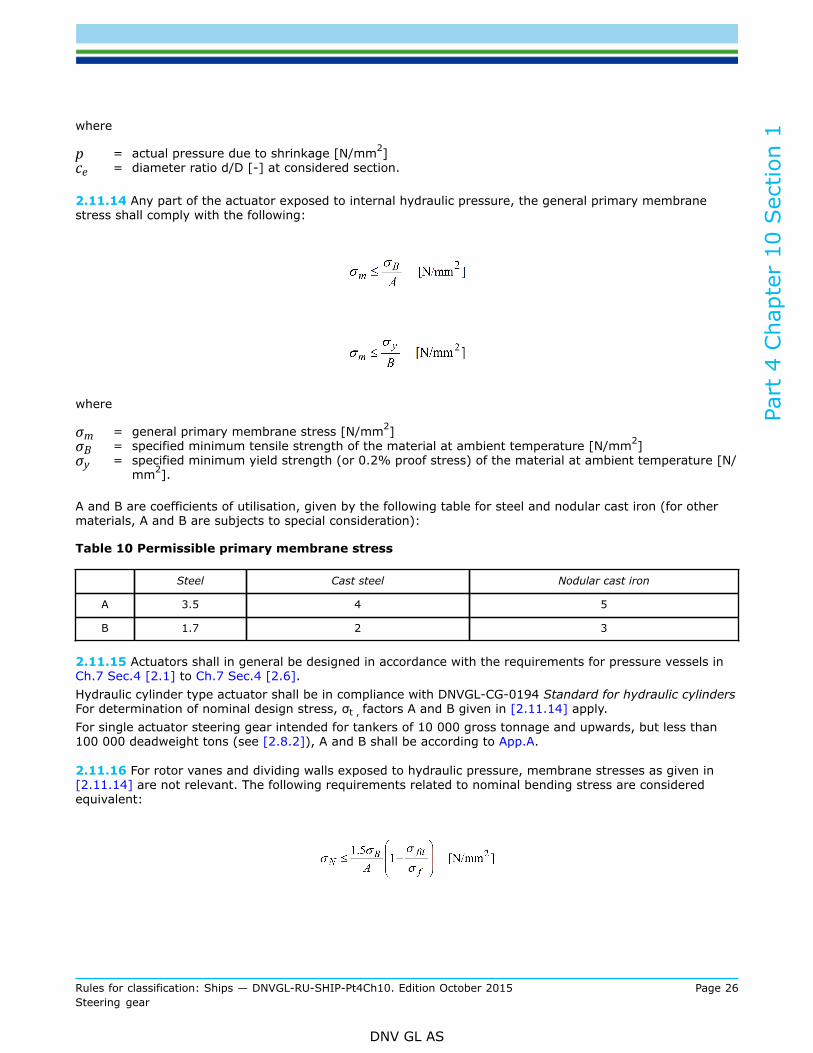
where
p = actual pressure due to shrinkage [N/mm2]ce = diameter ratio d/D [-] at considered section.
2.11.14 Any part of the actuator exposed to internal hydraulic pressure, the general primary membranestress shall comply with the following:
where
σm = general primary membrane stress [N/mm2]σB = specified minimum tensile strength of the material at ambient temperature [N/mm2]σy = specified minimum yield strength (or 0.2% proof stress) of the material at ambient temperature [N/
mm2].
A and B are coefficients of utilisation, given by the following table for steel and nodular cast iron (for othermaterials, A and B are subjects to special consideration):
Table 10 Permissible primary membrane stress
Steel Cast steel Nodular cast iron
A 3.5 4 5
B 1.7 2 3
2.11.15 Actuators shall in general be designed in accordance with the requirements for pressure vessels inCh.7 Sec.4 [2.1] to Ch.7 Sec.4 [2.6].Hydraulic cylinder type actuator shall be in compliance with DNVGL-CG-0194 Standard for hydraulic cylindersFor determination of nominal design stress, σt , factors A and B given in [2.11.14] apply.For single actuator steering gear intended for tankers of 10 000 gross tonnage and upwards, but less than100 000 deadweight tons (see [2.8.2]), A and B shall be according to App.A.
2.11.16 For rotor vanes and dividing walls exposed to hydraulic pressure, membrane stresses as given in[2.11.14] are not relevant. The following requirements related to nominal bending stress are consideredequivalent:
Part
4 C
hapt
er 1
0 Sec
tion
1
Rules for classification: Ships — DNVGL-RU-SHIP-Pt4Ch10. Edition October 2015 Page 27Steering gear
DNV GL AS
where
σN = nominal bending stress [N/mm2]
A and B are given in Table 10.
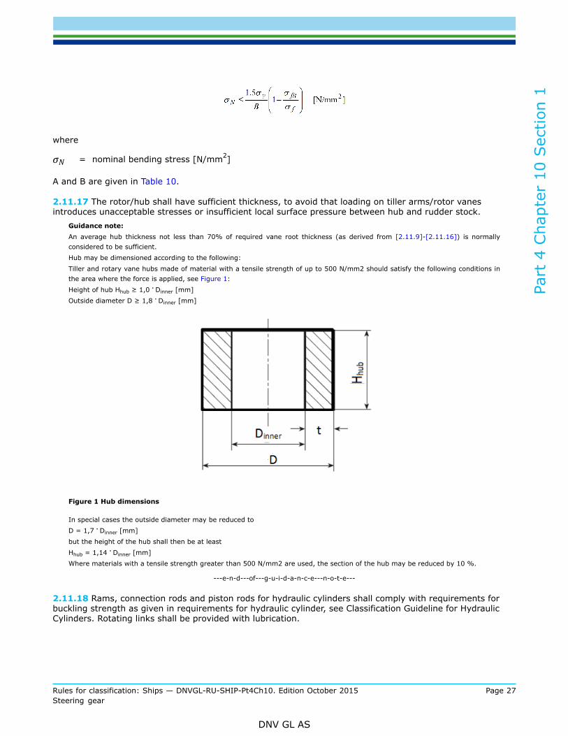
2.11.17 The rotor/hub shall have sufficient thickness, to avoid that loading on tiller arms/rotor vanesintroduces unacceptable stresses or insufficient local surface pressure between hub and rudder stock.
Guidance note:An average hub thickness not less than 70% of required vane root thickness (as derived from [2.11.9]-[2.11.16]) is normallyconsidered to be sufficient.Hub may be dimensioned according to the following:Tiller and rotary vane hubs made of material with a tensile strength of up to 500 N/mm2 should satisfy the following conditions inthe area where the force is applied, see Figure 1:Height of hub Hhub ≥ 1,0 . Dinner [mm]Outside diameter D ≥ 1,8 . Dinner [mm]
Figure 1 Hub dimensions
In special cases the outside diameter may be reduced toD = 1,7 . Dinner [mm]but the height of the hub shall then be at leastHhub = 1,14 . Dinner [mm]Where materials with a tensile strength greater than 500 N/mm2 are used, the section of the hub may be reduced by 10 %.
---e-n-d---of---g-u-i-d-a-n-c-e---n-o-t-e---
2.11.18 Rams, connection rods and piston rods for hydraulic cylinders shall comply with requirements forbuckling strength as given in requirements for hydraulic cylinder, see Classification Guideline for HydraulicCylinders. Rotating links shall be provided with lubrication.
Part
4 C
hapt
er 1
0 Sec
tion
1
Rules for classification: Ships — DNVGL-RU-SHIP-Pt4Ch10. Edition October 2015 Page 28Steering gear
DNV GL AS
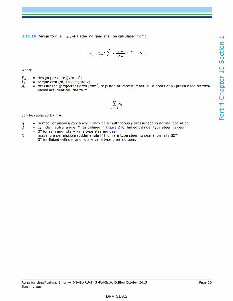
2.11.19 Design torque, Tdes of a steering gear shall be calculated from:
where
Pdes = design pressure [N/mm2]Lt = torque arm [m] (see Figure 2)Ai = pressurised (projected) area [mm2] of piston or vane number “i”. If areas of all pressurised pistons/
vanes are identical, the term
can be replaced by n A.
n = number of pistons/vanes which may be simultaneously pressurised in normal operationϕ = cylinder neutral angle [°] as defined in Figure 2 for linked cylinder type steering gear
= 0° for ram and rotary vane type steering gearθ = maximum permissible rudder angle [°] for ram type steering gear (normally 35°)
= 0° for linked cylinder and rotary vane type steering gear.
Part
4 C
hapt
er 1
0 Sec
tion
1
Rules for classification: Ships — DNVGL-RU-SHIP-Pt4Ch10. Edition October 2015 Page 29Steering gear
DNV GL AS
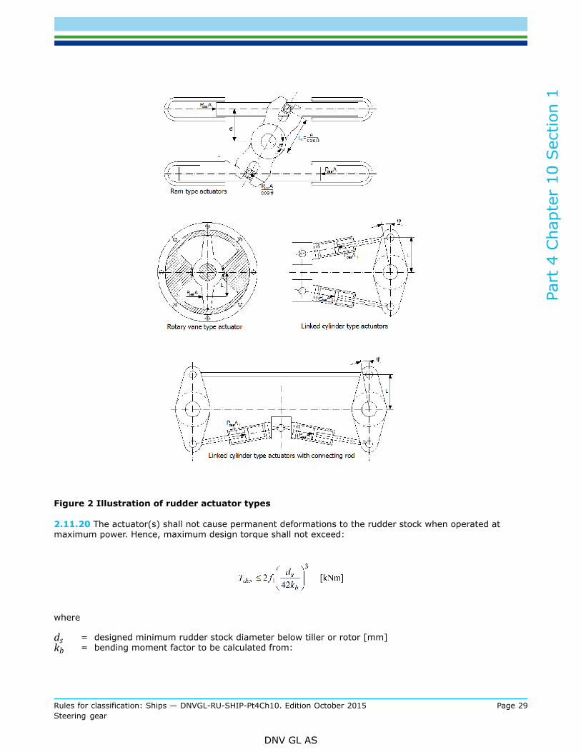
Figure 2 Illustration of rudder actuator types
2.11.20 The actuator(s) shall not cause permanent deformations to the rudder stock when operated atmaximum power. Hence, maximum design torque shall not exceed:
where
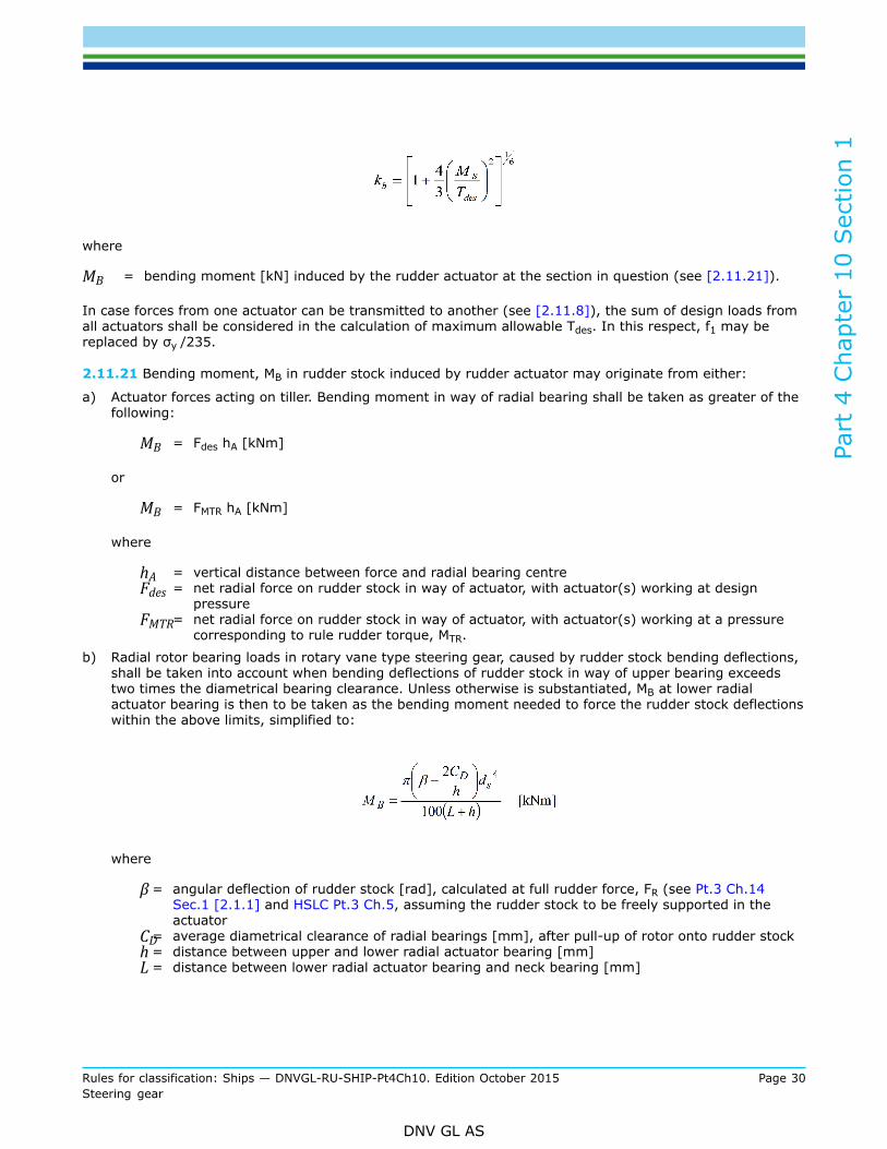
ds = designed minimum rudder stock diameter below tiller or rotor [mm]kb = bending moment factor to be calculated from:
Part
4 C
hapt
er 1
0 Sec
tion
1
Rules for classification: Ships — DNVGL-RU-SHIP-Pt4Ch10. Edition October 2015 Page 30Steering gear
DNV GL AS
where
MB = bending moment [kN] induced by the rudder actuator at the section in question (see [2.11.21]).
In case forces from one actuator can be transmitted to another (see [2.11.8]), the sum of design loads fromall actuators shall be considered in the calculation of maximum allowable Tdes. In this respect, f1 may bereplaced by σy /235.
2.11.21 Bending moment, MB in rudder stock induced by rudder actuator may originate from either:
a) Actuator forces acting on tiller. Bending moment in way of radial bearing shall be taken as greater of thefollowing:
MB = Fdes hA [kNm]
or
MB = FMTR hA [kNm]
where
hA = vertical distance between force and radial bearing centreFdes = net radial force on rudder stock in way of actuator, with actuator(s) working at design
pressureFMTR= net radial force on rudder stock in way of actuator, with actuator(s) working at a pressure
corresponding to rule rudder torque, MTR.
b) Radial rotor bearing loads in rotary vane type steering gear, caused by rudder stock bending deflections,shall be taken into account when bending deflections of rudder stock in way of upper bearing exceedstwo times the diametrical bearing clearance. Unless otherwise is substantiated, MB at lower radialactuator bearing is then to be taken as the bending moment needed to force the rudder stock deflectionswithin the above limits, simplified to:
where
β = angular deflection of rudder stock [rad], calculated at full rudder force, FR (see Pt.3 Ch.14Sec.1 [2.1.1] and HSLC Pt.3 Ch.5, assuming the rudder stock to be freely supported in theactuator
CD= average diametrical clearance of radial bearings [mm], after pull-up of rotor onto rudder stockh = distance between upper and lower radial actuator bearing [mm]L = distance between lower radial actuator bearing and neck bearing [mm]

Part
4 C
hapt
er 1
0 Sec
tion
1
Rules for classification: Ships — DNVGL-RU-SHIP-Pt4Ch10. Edition October 2015 Page 31Steering gear
DNV GL AS
2.12 Connection between steering gear and rudder stock
2.12.1 The steering gear shall be fitted to the rudder stock in such a way that forces from the actuator areeffectively transmitted to the rudder stock in all operating conditions.The connection shall not be damaged if the steering gear is operated at full power, taking into accountpossible arrangements for transmission of forces between actuators.Dismantling of connection shall be possible without causing damage to the rudder stock or steering gear.
2.12.2 The connection between steering gear and rudder stock shall have a torque capacity not less than thegreatest of:
a) Twice the rule rudder torque (MTR).b) Vessels complying with the rules for classification of ships:
— in case the torque is transmitted by friction alone:twice the design torque (Tdes)
— in case the torque is transmitted by a combination of friction and shear (i.e. keyed connections):1.5 times the design torque.
c) Vessels complying with the rules for classification of HSLC:
— the design torque.
2.12.3 Friction connections, with or without key, shall comply with the following:
a) Tapered contact area shall be evenly distributed and shall not be less than 70% of total contact area.b) If oil (or similar) is used for fitting the design shall enable escape of oil from between the mating
surfaces. Where necessary tapered connections shall be provided with suitable means to facilitatedismantling of the hub (e.g. oil grooves and bores to connect hydraulic injection pump).
c) Tapered connections shall be secured against axial displacement between rudder stock and steering gearby means of a nut properly tightened and secured to the shaft.
d) Tapered connections shall be designed so that correct pull-up easily can be verified (see [2.12.8] to[2.12.10]).
e) Keyless tapered connections shall have a taper ≤1:15, while taper shall be ≤1:10 for keyed taperedconnections.
Figure 3 Example of tapered rudder stock connectionf) Cylindrical connections shall be duly secured with regard to axial loads.g) When special locking assemblies (see also [2.12.4] b) are applied for fitting of steering gear to rudder
stock, the arrangement shall be such that their mutual influence on surface pressure is as small as
Part
4 C
hapt
er 1
0 Sec
tion
1
Rules for classification: Ships — DNVGL-RU-SHIP-Pt4Ch10. Edition October 2015 Page 32Steering gear
DNV GL AS
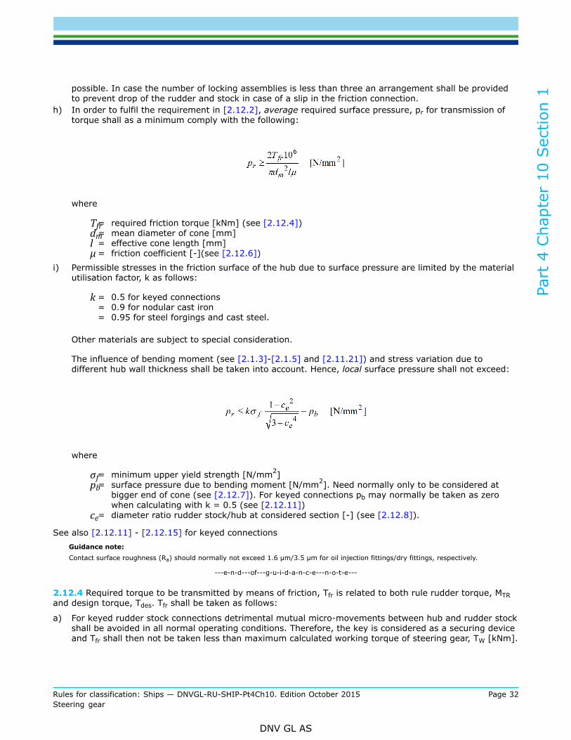
possible. In case the number of locking assemblies is less than three an arrangement shall be providedto prevent drop of the rudder and stock in case of a slip in the friction connection.
h) In order to fulfil the requirement in [2.12.2], average required surface pressure, pr for transmission oftorque shall as a minimum comply with the following:
where
Tfr= required friction torque [kNm] (see [2.12.4])dm= mean diameter of cone [mm]l = effective cone length [mm]μ = friction coefficient [-](see [2.12.6])
i) Permissible stresses in the friction surface of the hub due to surface pressure are limited by the materialutilisation factor, k as follows:
k = 0.5 for keyed connections= 0.9 for nodular cast iron= 0.95 for steel forgings and cast steel.
Other materials are subject to special consideration.
The influence of bending moment (see [2.1.3]-[2.1.5] and [2.11.21]) and stress variation due todifferent hub wall thickness shall be taken into account. Hence, local surface pressure shall not exceed:
where
σf= minimum upper yield strength [N/mm2]pb= surface pressure due to bending moment [N/mm2]. Need normally only to be considered at
bigger end of cone (see [2.12.7]). For keyed connections pb may normally be taken as zerowhen calculating with k = 0.5 (see [2.12.11])
ce= diameter ratio rudder stock/hub at considered section [-] (see [2.12.8]).
See also [2.12.11] - [2.12.15] for keyed connectionsGuidance note:Contact surface roughness (Ra) should normally not exceed 1.6 µm/3.5 µm for oil injection fittings/dry fittings, respectively.
---e-n-d---of---g-u-i-d-a-n-c-e---n-o-t-e---
2.12.4 Required torque to be transmitted by means of friction, Tfr is related to both rule rudder torque, MTRand design torque, Tdes. Tfr shall be taken as follows:
a) For keyed rudder stock connections detrimental mutual micro-movements between hub and rudder stockshall be avoided in all normal operating conditions. Therefore, the key is considered as a securing deviceand Tfr shall then not be taken less than maximum calculated working torque of steering gear, TW [kNm].
Part
4 C
hapt
er 1
0 Sec
tion
1
Rules for classification: Ships — DNVGL-RU-SHIP-Pt4Ch10. Edition October 2015 Page 33Steering gear
DNV GL AS
After special consideration, a lower friction capacity may be accepted for tight key connections. However,Tfr shall not be taken less than 0.25TW (See also [2.12.11] – [2.12.15]).
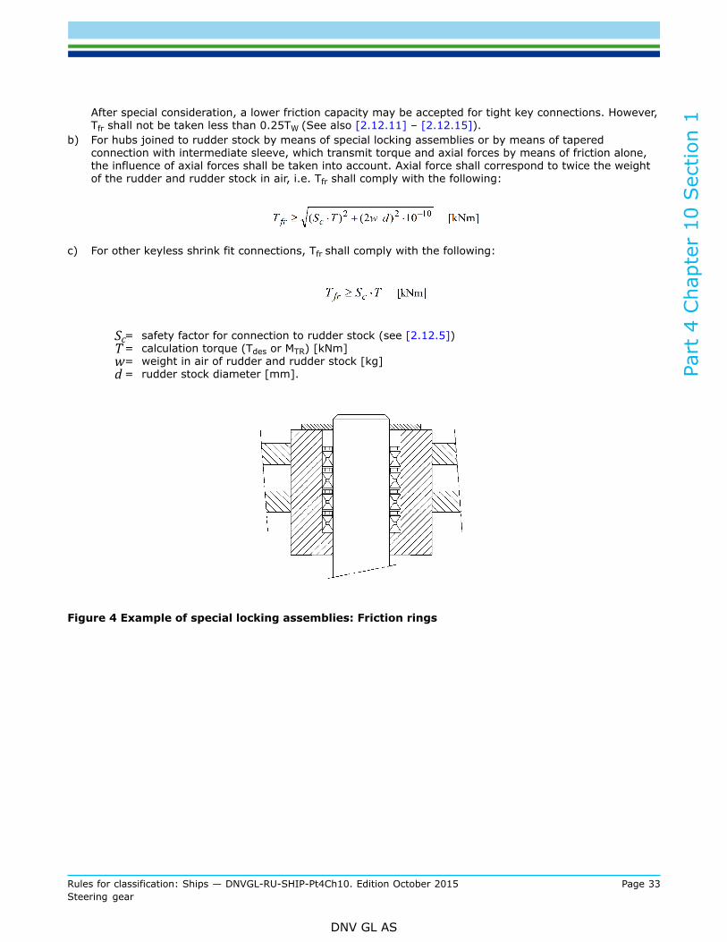
b) For hubs joined to rudder stock by means of special locking assemblies or by means of taperedconnection with intermediate sleeve, which transmit torque and axial forces by means of friction alone,the influence of axial forces shall be taken into account. Axial force shall correspond to twice the weightof the rudder and rudder stock in air, i.e. Tfr shall comply with the following:
c) For other keyless shrink fit connections, Tfr shall comply with the following:
Sc= safety factor for connection to rudder stock (see [2.12.5])T = calculation torque (Tdes or MTR) [kNm]w= weight in air of rudder and rudder stock [kg]d = rudder stock diameter [mm].
Figure 4 Example of special locking assemblies: Friction rings
Part
4 C
hapt
er 1
0 Sec
tion
1
Rules for classification: Ships — DNVGL-RU-SHIP-Pt4Ch10. Edition October 2015 Page 34Steering gear
DNV GL AS
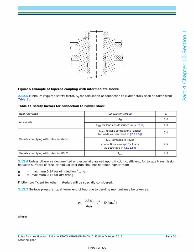
Figure 5 Example of tapered coupling with intermediate sleeve
2.12.5 Minimum required safety factor, Sc for calculation of connection to rudder stock shall be taken fromTable 11:
Table 11 Safety factors for connection to rudder stock
Rule relevance Calculation torque Sc
MTR 2.0All vessels
Tdes for loads as described in [2.11.8] 1.0
Tdes, keyless connections (exceptfor loads as described in [2.11.8]) 2.0
Vessels complying with rules for ships Tdes, stresses in keyed
connections (except for loadsas described in [2.11.8])
1.5
Vessels complying with rules for HSLC Tdes 1.0
2.12.6 Unless otherwise documented and especially agreed upon, friction coefficient, for torque transmissionbetween surfaces of steel or nodular cast iron shall not be taken higher than:
μ = maximum 0.14 for oil injection fittingμ = maximum 0.17 for dry fitting.
Friction coefficient for other materials will be specially considered.
2.12.7 Surface pressure, pb at lower end of hub due to bending moment may be taken as:
where
Part
4 C
hapt
er 1
0 Sec
tion
1
Rules for classification: Ships — DNVGL-RU-SHIP-Pt4Ch10. Edition October 2015 Page 35Steering gear
DNV GL AS
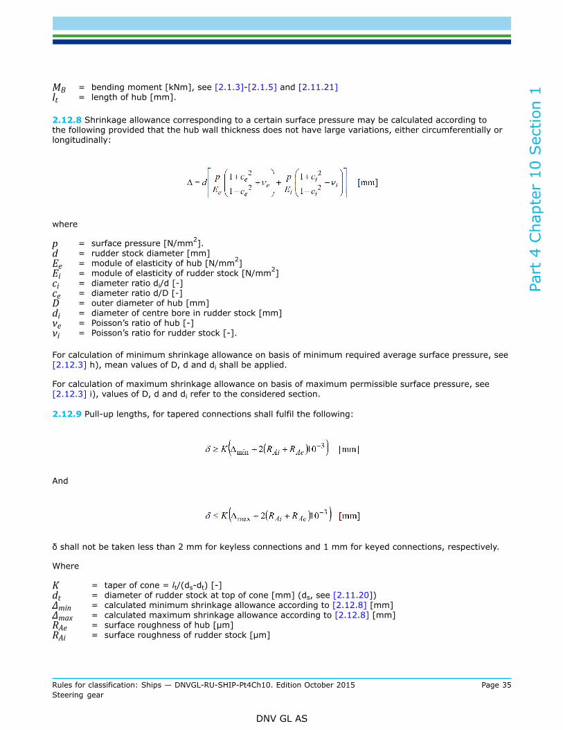
MB = bending moment [kNm], see [2.1.3]-[2.1.5] and [2.11.21]lt = length of hub [mm].
2.12.8 Shrinkage allowance corresponding to a certain surface pressure may be calculated according tothe following provided that the hub wall thickness does not have large variations, either circumferentially orlongitudinally:
where
p = surface pressure [N/mm2].d = rudder stock diameter [mm]Ee = module of elasticity of hub [N/mm2]Ei = module of elasticity of rudder stock [N/mm2]ci = diameter ratio di/d [-]ce = diameter ratio d/D [-]D = outer diameter of hub [mm]di = diameter of centre bore in rudder stock [mm]νe = Poisson’s ratio of hub [-]νi = Poisson’s ratio for rudder stock [-].
For calculation of minimum shrinkage allowance on basis of minimum required average surface pressure, see[2.12.3] h), mean values of D, d and di shall be applied.
For calculation of maximum shrinkage allowance on basis of maximum permissible surface pressure, see[2.12.3] i), values of D, d and di refer to the considered section.
2.12.9 Pull-up lengths, for tapered connections shall fulfil the following:
And
δ shall not be taken less than 2 mm for keyless connections and 1 mm for keyed connections, respectively.
Where
K = taper of cone = lt/(ds-dt) [-]dt = diameter of rudder stock at top of cone [mm] (ds, see [2.11.20])Δmin = calculated minimum shrinkage allowance according to [2.12.8] [mm]Δmax = calculated maximum shrinkage allowance according to [2.12.8] [mm]RAe = surface roughness of hub [μm]RAi = surface roughness of rudder stock [μm]
Part
4 C
hapt
er 1
0 Sec
tion
1
Rules for classification: Ships — DNVGL-RU-SHIP-Pt4Ch10. Edition October 2015 Page 36Steering gear
DNV GL AS
Guidance note:Specified pull-up length should cover a range of minimum 0.5 mm.
---e-n-d---of---g-u-i-d-a-n-c-e---n-o-t-e---
2.12.10 For tapered connections necessary force for pull-up, F may be found from:
where
μpu = average friction coefficient for pull-up (for oil injection: usually in the range 0.01 to 0.03. For dryfitting: usually in the range 0.1 to 0.2, typically 0.15).
2.12.11 Keyways shall not be located in areas with high bending stresses in the rudder stock. Fillets inkeyways shall be provided with sufficient radii. Fillet radius larger than 2% of key breadth is normallyconsidered as satisfactory.
2.12.12 The key shear stress and surface pressures in the rudder stock and hub keyways shall be calculatedtaking into account the friction torque depending on method for verification of frictional fitting.
Shear stress, τ in key:
Side pressure, σp (for contact with rudder stock and hub):
where
T = calculation torque (MTR or Tdes) [kNm]kkey = factor determined by expected accuracy of the method for verification of fitting:
Table 12 Correction for verification method
Verification method kkey
Diametrical expansion of hub 1.0
Interference, cylindrical connection 1.0
Pull-up force, dry fitting 1.0
Part
4 C
hapt
er 1
0 Sec
tion
1
Rules for classification: Ships — DNVGL-RU-SHIP-Pt4Ch10. Edition October 2015 Page 37Steering gear
DNV GL AS
Pull-up length 0.9
Bolt tightening (clamped connections) 0.7
Tfr = torque capacity of friction connection [kNm], can be derived from formula in [2.12.3] h)Sc = safety factor, (see [2.12.5])Leff = effective bearing length of key [mm]b = breadth of key [mm]heff = effective height of key contact with shaft and hub, respectively [mm]. I.e. key chamfer and keyway
fillets shall be accounted for.
In case two keys are fitted, uneven loading shall be considered, reducing the load by only 2/3 of the valueachieved when calculating with one key.
2.12.13 Shear stresses in key, τ [N/mm2] as calculated in [2.12.12] shall not exceed:
in case Tfr ≥TW
in case Tfr < TW
See also [2.12.4]a).
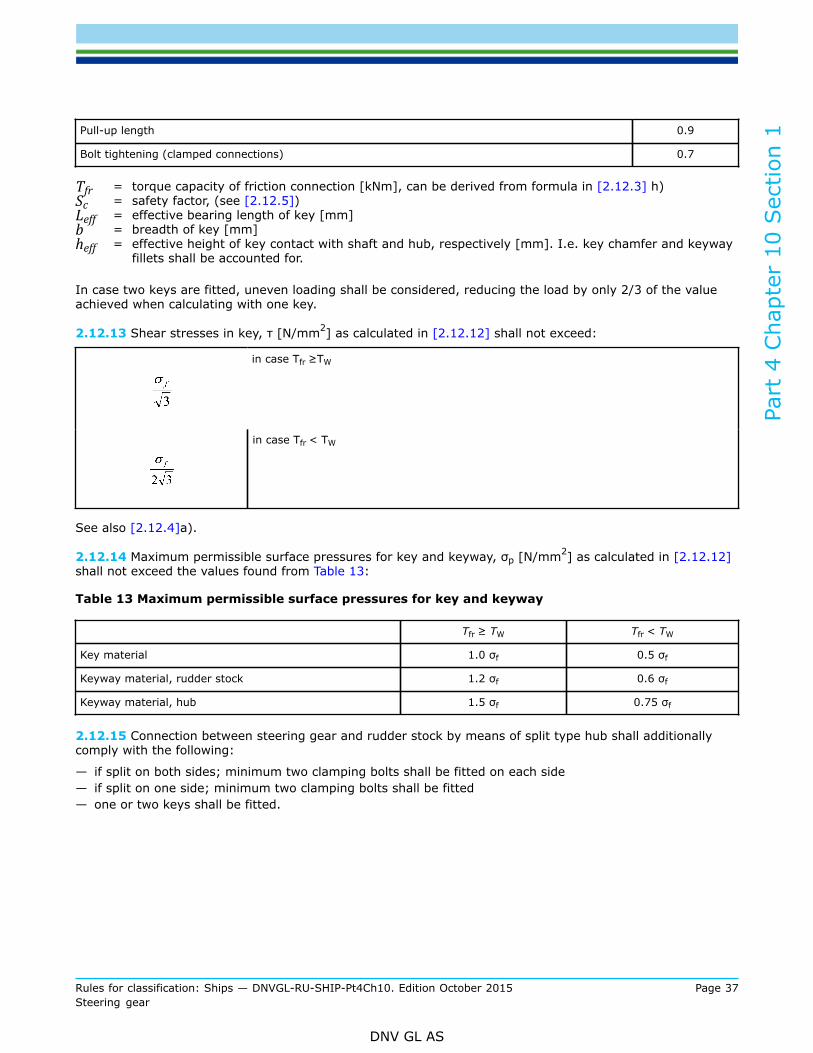
2.12.14 Maximum permissible surface pressures for key and keyway, σp [N/mm2] as calculated in [2.12.12]shall not exceed the values found from Table 13:
Table 13 Maximum permissible surface pressures for key and keyway
Tfr ≥ TW Tfr < TW
Key material 1.0 σf 0.5 σf
Keyway material, rudder stock 1.2 σf 0.6 σf
Keyway material, hub 1.5 σf 0.75 σf
2.12.15 Connection between steering gear and rudder stock by means of split type hub shall additionallycomply with the following:
— if split on both sides; minimum two clamping bolts shall be fitted on each side— if split on one side; minimum two clamping bolts shall be fitted— one or two keys shall be fitted.
Part
4 C
hapt
er 1
0 Sec
tion
1
Rules for classification: Ships — DNVGL-RU-SHIP-Pt4Ch10. Edition October 2015 Page 38Steering gear
DNV GL AS
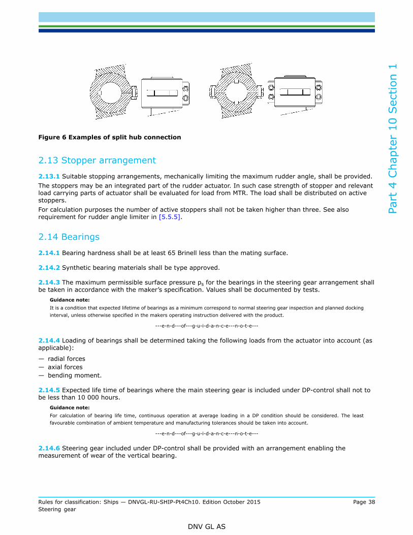
Figure 6 Examples of split hub connection
2.13 Stopper arrangement
2.13.1 Suitable stopping arrangements, mechanically limiting the maximum rudder angle, shall be provided.The stoppers may be an integrated part of the rudder actuator. In such case strength of stopper and relevantload carrying parts of actuator shall be evaluated for load from MTR. The load shall be distributed on activestoppers.For calculation purposes the number of active stoppers shall not be taken higher than three. See alsorequirement for rudder angle limiter in [5.5.5].
2.14 Bearings
2.14.1 Bearing hardness shall be at least 65 Brinell less than the mating surface.
2.14.2 Synthetic bearing materials shall be type approved.
2.14.3 The maximum permissible surface pressure ps for the bearings in the steering gear arrangement shallbe taken in accordance with the maker’s specification. Values shall be documented by tests.
Guidance note:It is a condition that expected lifetime of bearings as a minimum correspond to normal steering gear inspection and planned dockinginterval, unless otherwise specified in the makers operating instruction delivered with the product.
---e-n-d---of---g-u-i-d-a-n-c-e---n-o-t-e---
2.14.4 Loading of bearings shall be determined taking the following loads from the actuator into account (asapplicable):
— radial forces— axial forces— bending moment.
2.14.5 Expected life time of bearings where the main steering gear is included under DP-control shall not tobe less than 10 000 hours.
Guidance note:For calculation of bearing life time, continuous operation at average loading in a DP condition should be considered. The leastfavourable combination of ambient temperature and manufacturing tolerances should be taken into account.
---e-n-d---of---g-u-i-d-a-n-c-e---n-o-t-e---
2.14.6 Steering gear included under DP-control shall be provided with an arrangement enabling themeasurement of wear of the vertical bearing.
Part
4 C
hapt
er 1
0 Sec
tion
1
Rules for classification: Ships — DNVGL-RU-SHIP-Pt4Ch10. Edition October 2015 Page 39Steering gear
DNV GL AS
2.15 Oil seals
2.15.1 Oil seals between non-moving parts, forming part of the external pressure boundary, shall be of themetal upon metal type or of an equivalent type.
2.15.2 Oil seals between moving parts, forming part of the external pressure boundary, shall be duplicatedso that the failure of one seal does not render the actuator inoperative. Alternative arrangements providingequivalent protection against leakage may be accepted.
3 Inspection and Testing
3.1 General
3.1.1 The certification principles are described in Pt.1 Ch.1 Sec.4. The principles of manufacturing surveyarrangement is described in Pt.1 Ch.1 Sec.4 [2.5].
3.2 Inspection and testing of parts
3.2.1 Steering gear components shall be inspected and tested according to Table 2 to Table 5. Visualinspection of components shall be performed to verify compliance with approved drawings. Emphasis shall bepaid to critical dimensions, clearances and stress raisers.
3.2.2 NDT shall be performed according to manufacturers approved specification.
3.2.3 Steering gear shall be delivered with a DNV GL product certificate.
3.2.4 Autopilots are required to be type approved according to applicable IMO performance standard.
3.2.5 The control and monitoring systems for steering gears shall be certified according to Ch.9.
3.2.6 Associated electrical equipment (motors, frequency converters, switchgear and controlgear) isregarded as essential equipment and shall be delivered with a DNVGL Product Certificate. (see Ch.8 Sec.1[2.3.1])
4 Workshop Testing
4.1 General
4.1.1 The rule requirements related to the testing of class I pressure vessels, piping and related fittingsapply.The steering gear is subject to internal pressure testing for a test pressure, Ptest, 1.5 times the designpressure.Holding time shall be sufficient for detection of leakages, however not less than 15 minutes (see Ch.6 Sec.5[8.5.2]).
4.1.2 Each type of power unit pump shall be subjected to a type test.
a) The type test shall be for duration of not less than 100 hours.b) The test arrangements shall be such that the pump may run in idling conditions, and at maximum
delivery capacity at maximum working pressure.
Part
4 C
hapt
er 1
0 Sec
tion
1
Rules for classification: Ships — DNVGL-RU-SHIP-Pt4Ch10. Edition October 2015 Page 40Steering gear
DNV GL AS
c) During the test, idling periods shall be alternated with periods at maximum delivery capacity atmaximum working pressure.
d) The passage from one condition to another should occur at least as quickly as on board.e) During the whole test no abnormal heating, excessive vibration or other irregularities are permitted.f) After the test, the pump shall be dismantled and inspected.
Type tests may be waived for a power unit which has been proven to be reliable in marine service.
4.1.3 The assembled steering gear is subject to function test and setting of safety valve in workshop.If the manufacturer does not have the facilities to perform function test in loaded condition the test may belimited to a no-load condition.
5 Power Supply, Control and Monitoring
5.1 General
5.1.1 Main and auxiliary steering gear power units shall be:
— arranged to restart automatically when power is restored after a power failure— capable of being brought into operation from a position on the navigating bridge.
5.1.2 Electro motors for steering gear shall at least have a rating of S6-25% for electro hydraulic systemsand S3-40% for electro mechanical systems according to IEC60034-1 . Additional class notations or specialtypes of vessels may require other ratings.
5.2 Main power supply
5.2.1 Power supply shall be arranged with redundancy. A separate circuit shall be provided for each powerunit, however two circuits are considered sufficient in case of more than two power units.
5.2.2 Each of the separate circuits shall be fed from the main switchboard, alternatively one may be fed fromthe emergency switchboard.
5.2.3 In ships of less than 1 600 gross tonnage, if provided with an auxiliary steering gear independent ofelectrical power supply, the main steering gear may be fed by one circuit from the main switchboard.
5.3 Emergency power supply
5.3.1 Where the rudder stock is required to be over 230 mm diameter in way of the tiller, excludingstrengthening for navigation in ice, an alternative power supply shall be provided automatically within 45seconds. Exceptions will be granted for fishing vessels and other vessels not required to comply with SOLAS.The alternative power supply may either be from the emergency source of electrical power or from anindependent source of power located in the steering gear compartment. This independent source of powershall be used only for this purpose.The alternative power supply shall be sufficient to supply the steering gear power unit which complies withthe requirements in [2.5], and its associated control system and the rudder angle indicator.
5.3.2 In every ship of 10 000 gross tonnage and upwards, the alternative power supply shall have a capacityfor at least 30 minutes of continuous operation and in any other ship for at least 10 minutes.
5.3.3 Where the alternative power source is a generator, or an engine driven pump, starting arrangementsshall comply with the requirements relating to the starting arrangements of emergency generators.
Part
4 C
hapt
er 1
0 Sec
tion
1
Rules for classification: Ships — DNVGL-RU-SHIP-Pt4Ch10. Edition October 2015 Page 41Steering gear
DNV GL AS
5.4 Control gear and associated protective functions
5.4.1 Steering gear circuits for electro hydraulic steering gear shall only trip upon short circuit. However ifadditional over-current trip is used the release current shall be at least 200% of the full load current with atime delay of minimum 60 seconds.Steering gear motor circuits obtaining their power supply via an electronic converter, e.g. for speed control,and which are limited to full load current are exempt from the requirement to provide protection againstexcess current, including starting current, of not less than twice the full load current of the motor.
5.4.2 An overload alarm shall be activated when the current exceeds full load working current.
5.4.3 The protective shutdown functions associated with the steering gear shall be limited to those necessaryto prevent immediate machinery breakdown. Any protective shutdown shall initiate an alarm.
5.5 General requirements, steering gear control system
5.5.1 Steering gear control system is defined in [1.3.3].
5.5.2 Steering gear motors shall be remotely controlled from the bridge and locally controlled from thesteering gear compartment. When remote control is arranged from two or more positions, the arrangementshall be such that the motor can be started independently from any of these positions.
5.5.3 Steering gear control shall be provided as follows:
a) For the main steering gear, both on the navigating bridge and in the steering gear compartment.b) When the main steering gear is arranged in accordance with [2.6.2] by two independent control
systems, both shall be operable from the navigating bridge. In case the control system consists of anhydraulic telemotor, a second independent system operable from the bridge need not be fitted, except inoil carriers, chemical carriers or liquefied gas carriers of 10 000 tons gross and upwards.
c) For the auxiliary steering gear, in the steering gear compartment and, if power operated, it shall also beoperable from the navigating bridge. Any control system for auxiliary steering gear shall be independentof the control system for the main steering gear.
5.5.4 Any main and auxiliary steering gear control system operable from the navigating bridge shall complywith the following:
a) If electric, it shall be served by its own separate circuit supplied from a steering gear power circuit froma point within the steering gear compartment, or directly from switchboard busbars supplying thatsteering gear power circuit at a point on the switchboard adjacent to the supply to the steering gearpower circuit.
b) Means shall be provided in the steering gear compartment for disconnecting any control system operablefrom the navigating bridge from the steering gear it serves.
c) The system shall be capable of being brought into operation from a position on the navigating bridge.d) Short circuit protection only shall be provided for steering gear control supply circuits.e) Failure detection and response to failures shall be arranged in accordance with Ch.9 Sec.2 [2] and Ch.9
Sec.3 [1.2.4].Guidance note:The least critical condition is normally to freeze the rudder in its present position. For systems and/or operational modes wheremidship position is considered to be the least critical condition, this may also be accepted
---e-n-d---of---g-u-i-d-a-n-c-e---n-o-t-e---
5.5.5 The actuator shall be equipped with necessary device in order to limit maximum helm angle of rudderenforced by the steering gear. Such a device shall be:
Part
4 C
hapt
er 1
0 Sec
tion
1
Rules for classification: Ships — DNVGL-RU-SHIP-Pt4Ch10. Edition October 2015 Page 42Steering gear
DNV GL AS
— activated at smaller helm angle than limited by the mechanical stopper arrangement— synchronised with the physical actuator position and overriding the control system.
5.6 Arrangement of electric and control systems
5.6.1 The electric power circuits shall be separated as far as practicable throughout their length.
5.6.2 When two or more control systems are used, these shall be kept separated and not be located in thesame enclosure (cabinet, desk, panel), unless a flame retardant partition is installed between the controlsystems within the enclosure. Cables and pipes shall be separated as far as practicable throughout thelength.
5.6.3 The requirement in [5.6.2] may be waived for main steering stand provided the systems are separatedas far as practicable and cables and components are securely installed.
5.6.4 Steering order devices for control systems may be operated by the same lever shaft.
5.6.5 Steering mode and steering station selectors may also be operated by the same shaft, provided thearrangement is of reliable construction.
5.6.6 If additional steering stations are arranged with control circuits branched off from a main steeringstation, it shall be possible to disconnect each such circuit by a multipole switch on the main steering station.
5.7 Monitoring
5.7.1 Alarm and indication requirements are specified in Table 14.
5.7.2 All alarms associated with steering gear faults shall be indicated on the navigating bridge and inmachinery space. The alarm indicators on bridge shall be readily observable from main steering stand.
5.7.3 The rudder angle indicating system shall be independent of any control system. For vessels complyingwith the rules for classification of ships the rudder angle indicating system shall be so arranged that a singlefailure in power supply or anywhere in the indicating system does not cause loss of rudder angle indicationon the bridge.
5.7.4 Where hydraulic locking, caused by a single failure, may lead to loss of steering, an alarm, whichidentifies the failed system, shall be provided.
Guidance note:This alarm should be activated when there is disagreement between the given order versus control system output/execution.For instance when:
— position of the variable displacement pump control system does not correspond with given order, or
— incorrect position of 3-way full flow valve or similar in constant delivery pump system is detected.
---e-n-d---of---g-u-i-d-a-n-c-e---n-o-t-e---
5.8 Additional Requirements for vessels with DP notation
5.8.1 For steering gears under DP-control, the sensors for high temperature alarm and the temperatureindication of the steering gear hydraulic oil system (see Table 14) shall be located in oil inlet to actuator.
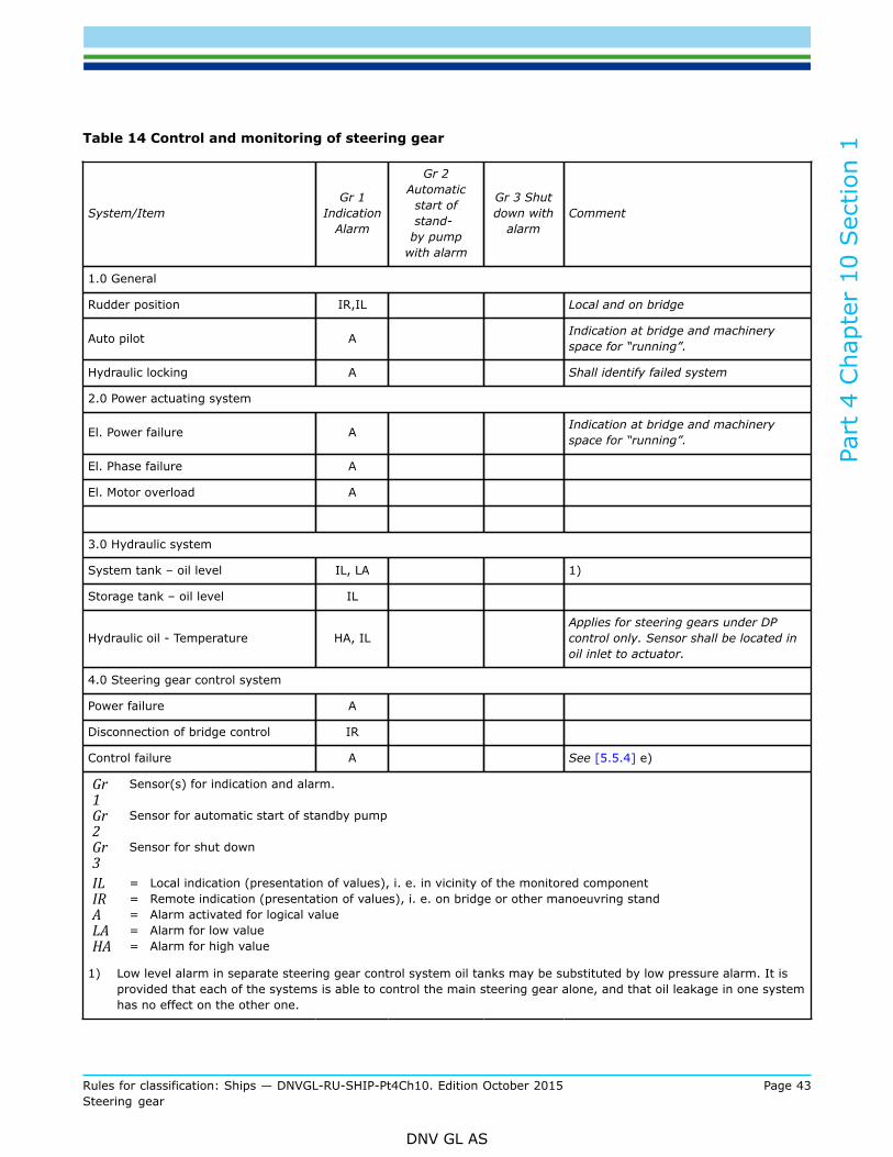
Part
4 C
hapt
er 1
0 Sec
tion
1
Rules for classification: Ships — DNVGL-RU-SHIP-Pt4Ch10. Edition October 2015 Page 43Steering gear
DNV GL AS
Table 14 Control and monitoring of steering gear
System/ItemGr 1
IndicationAlarm
Gr 2Automatic
start ofstand-
by pumpwith alarm
Gr 3 Shutdown with
alarmComment
1.0 General
Rudder position IR,IL Local and on bridge
Auto pilot A Indication at bridge and machineryspace for “running”.
Hydraulic locking A Shall identify failed system
2.0 Power actuating system
El. Power failure A Indication at bridge and machineryspace for “running”.
El. Phase failure A
El. Motor overload A
3.0 Hydraulic system
System tank – oil level IL, LA 1)
Storage tank – oil level IL
Hydraulic oil - Temperature HA, IL Applies for steering gears under DPcontrol only. Sensor shall be located inoil inlet to actuator.
4.0 Steering gear control system
Power failure A
Disconnection of bridge control IR
Control failure A See [5.5.4] e)
Gr1
Sensor(s) for indication and alarm.
Gr2
Sensor for automatic start of standby pump
Gr3
Sensor for shut down
IL = Local indication (presentation of values), i. e. in vicinity of the monitored componentIR = Remote indication (presentation of values), i. e. on bridge or other manoeuvring standA = Alarm activated for logical valueLA = Alarm for low valueHA = Alarm for high value
1) Low level alarm in separate steering gear control system oil tanks may be substituted by low pressure alarm. It isprovided that each of the systems is able to control the main steering gear alone, and that oil leakage in one systemhas no effect on the other one.
Part
4 C
hapt
er 1
0 Sec
tion
1
Rules for classification: Ships — DNVGL-RU-SHIP-Pt4Ch10. Edition October 2015 Page 44Steering gear
DNV GL AS
6 Arrangement for Installation Onboard
6.1 Fastening arrangement to foundation
6.1.1 The fastening arrangement for fixing the steering gear to the foundation shall be designed to withstandall possible loads generated from rudder or power unit during operation. As a minimum sufficient strengthand capacity in the following conditions shall be considered with safety factors as specified in [6.1.2]:
— rudder exposed to a load corresponding to rule rudder torque, MTR— actuator working at design pressure, Pdes.
Reaction forces due to bending set up in rudder stock and radial/axial forces shall be taken into account asapplicable.Relevant additional loading due to thermal expansion etc. shall be duly considered.
6.1.2 The safety factors applicable for acting forces shall not be taken less than:When calculating against MTR: S = 2.0When calculating against Pdes: S = 1.5
6.2 Steering gear compartment
6.2.1 The steering gear compartment shall be:
— readily accessible and, as far as practicable, separated from machinery spaces— provided with suitable arrangements to ensure working access to steering gear machinery and controls.
These arrangements shall include handrails and gratings or other non-slip surfaces to ensure suitableworking conditions in the event of hydraulic fluid leakage.
6.2.2 Electrical power units shall be placed on elevated platforms or comply with enclosure type IP44 inorder to safeguard against water splash.
6.2.3 Local steering control shall be arranged to enable steering by a single person.Means of communication to navigating bridge shall be available from this control position.Rudder indicator and heading information shall be visible from this control position.Heading information shall be automatically updated when power is restored after a power failure.
6.2.4 Operation instructions shall be permanently displayed on the bridge and in steering gear compartment.The operation instruction shall provide the operator with information of the steering system, consisting ofcontrol system and steering gear. Further the operation instruction shall give instruction of the differentoperation modes that are available and how to switch between the operation modesThe instruction shall contain:
— arrangement and function of steering gear and control system— instruction for how to handle failure modes— Procedure for change–over to/from local control and other operation modes— procedure for change-over between control modes on the bridge and in steering gear compartment— procedure for operation of power units in the different operation modes.
Guidance note:Examples of operation modes may be steering gear operation by “follow up” mode, “Non follow up” mode, local control from steeringgear compartment or other pre-defined modes which request that steering gear is operated differently.
---e-n-d---of---g-u-i-d-a-n-c-e---n-o-t-e---

Part
4 C
hapt
er 1
0 Sec
tion
1
Rules for classification: Ships — DNVGL-RU-SHIP-Pt4Ch10. Edition October 2015 Page 45Steering gear
DNV GL AS
Guidance note:Failure modes are the foreseen, most common causes of steering failure.
---e-n-d---of---g-u-i-d-a-n-c-e---n-o-t-e---
7 (Intentionally left blank)
7.1 7.1.1
8 Installation
8.1 Connection between steering gear and rudder stock
8.1.1 Contact area of conical connections shall be (minimum 70%) verified by means of paint test (e.g. tool-maker blue) in presence of the surveyor. Circumferential or full length non-contact bands are not acceptable.
8.1.2 Test pull-up to control the contact area may be required before final assembly for conical keylessconnections intended for injection fitting, when calculations are considered inaccurate due to a non-symmetric design or other relevant reasons. Pull-up length during test pull-up shall not be less than finalpull-up length.
8.1.3 Final connection of steering gear to rudderstock shall be performed according to approved procedure,in presence of the surveyor.
8.2 Fastening to foundation
8.2.1 For mounting on metallic chocks the clearance between mating surfaces shall be checked with feelergauge and shall be less than 0.1 mm unless otherwise approved.
8.2.2 For mounting on epoxy resin, it shall be checked that:
— the resin is type approved— the mixing, casting and curing is carried out as per maker's instructions— the cleanliness of tank top and bedplate before casting is as per maker's instructions— the area and height of resin are within approved dimensions— the resin is properly cured before bolt tightening.
8.2.3 Stoppers taking load in longitudinal and/or transversal direction (as applicable) shall be checkedaccording to the arrangement drawing.
8.2.4 The tightening of the holding down bolts shall be checked versus approved specification.
9 Shipboard Testing
9.1 Shipboard testing
9.1.1 After installation on board the vessel, and prior to seatrial the steering gear shall be subjected to therequired hydrostatic and running tests.
Part
4 C
hapt
er 1
0 Sec
tion
1
Rules for classification: Ships — DNVGL-RU-SHIP-Pt4Ch10. Edition October 2015 Page 46Steering gear
DNV GL AS
The test shall as a minimum comprise of:
a) hydrostatic testing
— parts of steering gear that has not been pressure tested at workshop shall be tested at 1.5 timesdesign pressure
— assembly shall be tested at minimum 1.5 times maximum working pressure
b) function testing of the steering gear
c) testing alarms and indicators
d) autostart test of power units
e) testing all start and stop functions
f) test control transfer between bridge and local control
g) test safety valve setting (if not performed during Workshop test)
h) testing function and setting of overcurrent protection
i) test and check functions and settings in frequency converter (if applicable)
j) checking mechanical rudder indicator.
9.1.2 On double rudder installations where the two units are synchronised by mechanical means, mutualadjustment shall be tested.
9.2 Trials
9.2.1 The steering gear shall be tested on sea trial in order to demonstrate the function of the steering gearand that the rule requirements have been met. Design requirements in [2.4.1] need not be proved at trialsby going with maximum astern speed and maximum rudder angle.The test shall include the following:
a) Testing of steering gear function and capacity. Acceptance criteria are given in [2.4.1] and [2.5.1].b) The steering gear power units, including transfer between steering gear power units.c) The isolation of one power actuating system, checking the time for regaining steering capability.d) The hydraulic fluid recharging system.e) The emergency power supply required in [5.3].f) The steering gear controls, including transfer of control and local control.g) The means of communication between the steering gear compartment and the wheelhouse. Also the
engine room if applicable.h) Where steering gear is designed to avoid hydraulic locking this feature shall be demonstrated.i) Steering gear for over-balanced rudders or rudders of unconventional design (such as flap rudders) shall
additionally be tested turning the rudder over from maximum rudder angle on one side to maximumrudder angle on the other side and vice versa,see [2.4].Test items d) and g) may be carried out and completed at the dockside.
9.2.2 The trial shall be performed under the following operational conditions:For vessels complying with the rules for classification of ships:
— loaded on summer load waterline. If this can not be done alternative trial conditions may be speciallyconsidered. See [9.2.4] and [9.2.5]
— running ahead at maximum service speed corresponding to maximum nominal shaft RPM and maximumcontinuous rating (MCR) of the main engine(s) and if equipped with controllable pitch propeller(s), thepropeller pitch shall be at the maximum design pitch corresponding to the nominal shaft RPM and MCR ofthe main engine(s).
Part
4 C
hapt
er 1
0 Sec
tion
1
Rules for classification: Ships — DNVGL-RU-SHIP-Pt4Ch10. Edition October 2015 Page 47Steering gear
DNV GL AS
For vessels complying with the rules for HSLC:
— full load condition— running ahead at maximum service speed as defined in HSLC Pt.3 Ch.5— both in calm water and, as far as practically possible, in a sea state corresponding to upper part of
operational condition.
9.2.3 A record of the steering gear parameters during test shall be presented to the attending surveyor.As minimum the following parameters shall be logged: vessel speed and propulsion engine speed, steeringangle, hydraulic pressure and time used for moving of rudder as defined.
9.2.4 When performance test is carried out at reduced draught with partly submerged rudder, calculationsshowing corresponding rudder force and torque for the trials shall be submitted on request.
9.2.5 Ships fitted with semi-spade rudders shall be tested with the rudders completely submerged.However, when satisfactory results are proved by sister ships, tests according to [9.2.4] with partlysubmerged rudder may be accepted.Calculations of the expected rudder force and torque for the trials shall be submitted.If test results for sister vessels are not available, steering gear test with rudder partly submerged may beaccepted upon special consideration in each case.
9.3 Additional requirements for vessels with DP notation
9.3.1 For steering gears included under DP-control it shall be verified that the steering gear is designed forcontinuous operation by testing according Pt.6 Ch.3 Sec.1 [3.6.10]and Pt.6 Ch.3 Sec.2 [3.6.9].
Part
4 C
hapt
er 1
0 App
endi
x A
Rules for classification: Ships — DNVGL-RU-SHIP-Pt4Ch10. Edition October 2015 Page 48Steering gear
DNV GL AS
APPENDIX A ADDITIONAL REQUIREMENTS FOR NON-DUPLICATEDRUDDER ACTUATORS
1 General
1.1 Application
1.1.1 The requirements given in this Section are in compliance with IMO “Guidelines” for the acceptance ofnon-duplicated rudder actuators for oil carriers, chemical carriers and liquefied gas carriers of 10 000 grosstonnage and upwards but of less than 100 000 tonnes deadweight.
1.2 Documentation
1.2.1 In addition to documentation required in Sec.1 [1.4], the following shall be submitted:
a) A detailed stress analysis of the pressure retaining parts of the actuator, exposed to design pressure (forinformation)
b) Detailed calculations showing the suitability of the design for the intended service (upon request).c) Where considered necessary because of the design complexity or manufacturing procedures: fatigue
analysis and fracture mechanics analysis (upon request). In connection with these analyses, all foreseendynamic loads should be taken into account.
Experimental stress analysis may be required in addition to, or in lieu of, theoretical calculations dependingupon the complexity of the design.
2 Design
2.1 General
2.1.1 Special consideration shall be given to the installation of sealing arrangements, to testing andinspection and to the provision of effective maintenance.
2.2 Dynamic loads for fatigue and fracture mechanics analyses
2.2.1 Where applicable, dynamic loads for evaluation of fatigue strength and fracture mechanics shallcomprise both the case of high cycle and cumulative fatigue.
2.3 Allowable stresses
2.3.1 For the purpose of determining the general scantlings of parts of rudder actuators subject to internalhydraulic pressure the allowable stresses shall not exceed:
σm ≤ f
σ1 ≤ 1.5 f
σbend ≤ 1.5 f
σ1 + σbend ≤ 1.5 f
σm + σbend ≤ 1.5 f
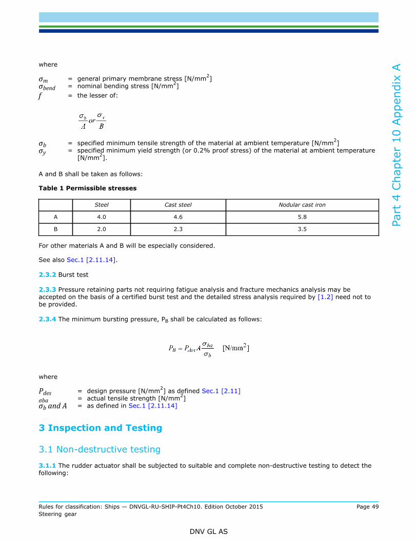
Part
4 C
hapt
er 1
0 App
endi
x A
Rules for classification: Ships — DNVGL-RU-SHIP-Pt4Ch10. Edition October 2015 Page 49Steering gear
DNV GL AS
where
σm = general primary membrane stress [N/mm2]σbend = nominal bending stress [N/mm2]f = the lesser of:
σb = specified minimum tensile strength of the material at ambient temperature [N/mm2]σy = specified minimum yield strength (or 0.2% proof stress) of the material at ambient temperature
[N/mm2].
A and B shall be taken as follows:
Table 1 Permissible stresses
Steel Cast steel Nodular cast iron
A 4.0 4.6 5.8
B 2.0 2.3 3.5
For other materials A and B will be especially considered.
See also Sec.1 [2.11.14].
2.3.2 Burst test
2.3.3 Pressure retaining parts not requiring fatigue analysis and fracture mechanics analysis may beaccepted on the basis of a certified burst test and the detailed stress analysis required by [1.2] need not tobe provided.
2.3.4 The minimum bursting pressure, PB shall be calculated as follows:
where
Pdes = design pressure [N/mm2] as defined Sec.1 [2.11]σba = actual tensile strength [N/mm2]σb and A = as defined in Sec.1 [2.11.14]
3 Inspection and Testing
3.1 Non-destructive testing
3.1.1 The rudder actuator shall be subjected to suitable and complete non-destructive testing to detect thefollowing:
Part
4 C
hapt
er 1
0 App
endi
x A
Rules for classification: Ships — DNVGL-RU-SHIP-Pt4Ch10. Edition October 2015 Page 50Steering gear
DNV GL AS
— surface flaws— volumetric flaws.
If recognised test methods are expected to fail, testing may be omitted, provided that the risk andconsequence of material defects are especially considered. Magnetic particle testing (MT) shall be carried outfor all machined surfaces of the housing and coverThe procedures and acceptance criteria for non-destructive testing shall be in accordance with requirementsof recognised standards.If found necessary, fracture mechanics analysis may be used for determining maximum allowable flaw size.

DNV GLDriven by our purpose of safeguarding life, property and the environment, DNV GL enablesorganizations to advance the safety and sustainability of their business. We provide classification andtechnical assurance along with software and independent expert advisory services to the maritime,oil and gas, and energy industries. We also provide certification services to customers across a widerange of industries. Operating in more than 100 countries, our 16 000 professionals are dedicated tohelping our customers make the world safer, smarter and greener.
SAFER, SMARTER, GREENER